Operating Manual - PacDrive Servo Amplifier MC-4 - ASTOR
77
PacDrive Servo Amplifier MC-4 07.2013 Operating Manual (Translation of the original German Operating Manual)
-
Upload
khangminh22 -
Category
Documents
-
view
1 -
download
0
Transcript of Operating Manual - PacDrive Servo Amplifier MC-4 - ASTOR

PacDrive
Servo Amplifier MC-407.2013
Operating Manual(Translation of the original German Operating Manual)

The information provided in this documentation contains general descriptions and/ortechnical characteristics of the performance of the products contained herein. Thisdocumentation is not intended as a substitute for and is not to be used for determiningsuitability or reliability of these products for specific user applications. It is the duty ofany such user or integrator to perform the appropriate and complete risk analysis,evaluation and testing of the products with respect to the relevant specific applicationor use thereof. Neither Schneider Electric nor any of its affiliated or subsidiary com‐panies are responsible or liable for a misuse of the information contained herein. If youhave any suggestions for improvements or amendments or have found errors in thispublication, please notify us.No part of this document may be reproduced in any form or by any means, electronicor mechanical, including photocopying, without express written permission of Schneid‐er Electric.All pertinent state, regional, and local safety regulations must be observed when in‐stalling and using this product. For reasons of safety and to help ensure compliancewith documented system data, only the manufacturer should perform repairs to com‐ponents.When devices are used for applications with technical safety requirements, the rele‐vant instructions must be followed.Failure to use Schneider Electric software or approved software with our hardwareproducts may result in injury, harm, or improper operating results.Failure to observe this information can result in injury or equipment damage.© 2013 Schneider Electric. All rights reserved.
Imprint
2 PacDrive Servo Amplifier MC-4 Schneider Electric

Contents
1 About this manual 61.1 Introduction ............................................................................................................... 61.2 Symbols, designator and display format of safety messages .................................. 7
2 Safety information 92.1 Proper use ................................................................................................................ 92.2 Qualification of Personnel ...................................................................................... 102.3 Residual risks ......................................................................................................... 112.3.1 Electrical parts ........................................................................................................ 112.3.2 Assembly and handling .......................................................................................... 112.3.3 Hot surfaces ........................................................................................................... 122.3.4 Magnetic and electromagnetic fields ...................................................................... 122.3.5 Hazardous movements .......................................................................................... 132.3.6 PELV circuits .......................................................................................................... 14
3 System overview 153.1 PacDrive Controller Family ..................................................................................... 153.2 PacDrive MC-4 Servo Amplifier .............................................................................. 163.3 PacDrive Servo Motor ............................................................................................ 163.4 Type code ............................................................................................................... 173.5 Nameplate descriptions .......................................................................................... 17
4 Indicators and control elements 204.1 Example of a diagnostic message .......................................................................... 204.2 Displays and operating elements on the MC-4 servo amplifier .............................. 214.2.1 pow LED ................................................................................................................. 214.2.2 err LED ................................................................................................................... 224.2.3 bus err LED ............................................................................................................ 224.2.4 S1/S2 Rotary switch for sercos address ................................................................ 224.2.5 S3 switch ................................................................................................................ 224.2.6 reset button ............................................................................................................ 224.3 Displays and operating elements on the BM-4 Braking resistor Module ................ 234.3.1 pow LED ................................................................................................................. 234.3.2 err LED ................................................................................................................... 244.3.3 bla LED ................................................................................................................... 244.3.4 reset button ............................................................................................................ 24
Contents
Schneider Electric PacDrive Servo Amplifier MC-4 3

5 Installation and maintenance 255.1 Commissioning ....................................................................................................... 255.1.1 Preparing commissioning ....................................................................................... 255.1.2 Cabling of the servo amplifier ................................................................................. 265.1.3 Completion of commissioning ................................................................................ 285.1.4 Performing the function test ................................................................................... 295.2 Electromagnetic compatibility, EMC ....................................................................... 295.3 Maintenance, repair, cleaning ................................................................................ 315.3.1 Repair ..................................................................................................................... 325.3.2 Cleaning ................................................................................................................. 325.4 Spare part inventory ............................................................................................... 335.5 Device-, parts- or cable exchange .......................................................................... 335.5.1 Device replacement ................................................................................................ 335.5.2 Cable replacement ................................................................................................. 35
6 Technical data 366.1 Ambient conditions ................................................................................................. 366.2 Standards and regulations ..................................................................................... 366.3 Mechanical and electrical data ............................................................................... 376.3.1 MC-4 / 1.5 A Servo Amplifier .................................................................................. 376.3.2 MC-4 / 3 A Servo Amplifier ..................................................................................... 386.3.3 MC-4 / 5 A Servo Amplifier ..................................................................................... 396.3.4 MC-4 / 10 A Servo Amplifier ................................................................................... 406.3.5 MC-4 / 22 A Servo Amplifier ................................................................................... 416.3.6 MC-4 / 50 A Servo Amplifier ................................................................................... 426.3.7 BM-4 Braking resistor module ................................................................................ 436.4 Electrical connections ............................................................................................. 446.4.1 Connection overview MC-4 Servo Amplifier ........................................................... 446.4.2 MC-4 Servo Amplifier / 1.5 A .................................................................................. 456.4.3 MC-4 Servo Amplifier / 3 A ..................................................................................... 486.4.4 MC-4 Servo Amplifier / 5 A ..................................................................................... 516.4.5 MC-4 Servo Amplifier / 10 A ................................................................................... 546.4.6 MC-4 Servo Amplifier / 22 A ................................................................................... 576.4.7 MC-4 Servo Amplifier / 50 A ................................................................................... 596.4.8 BM4 braking resistor module connection overview ................................................ 616.4.9 Braking resistor module BM-4 ................................................................................ 626.5 Dimensions ............................................................................................................. 636.5.1 MC-4 / 1.5 A and 3 A servo amplifier ..................................................................... 636.5.2 MC-4 / 5 A Servo Amplifier ..................................................................................... 646.5.3 MC-4 / 10 A Servo Amplifier ................................................................................... 656.5.4 MC-4 / 22 A Servo Amplifier ................................................................................... 666.5.5 MC-4 / 50 A Servo Amplifier ................................................................................... 676.5.6 Mains filter ............................................................................................................. 686.5.7 Line chokes ............................................................................................................ 696.5.8 BM-4 Braking resistor module ................................................................................ 70
Contents
4 PacDrive Servo Amplifier MC-4 Schneider Electric

7 Appendix 717.1 Contact addresses ................................................................................................. 717.2 Product training courses ......................................................................................... 717.3 EC declaration of conformity .................................................................................. 727.4 Electrical tests ........................................................................................................ 737.5 Hardware/software compatibility list ....................................................................... 737.6 Changes ................................................................................................................. 747.7 Units and conversion tables ................................................................................... 757.7.1 Length .................................................................................................................... 757.7.2 Mass ....................................................................................................................... 757.7.3 Force ...................................................................................................................... 757.7.4 Power ..................................................................................................................... 757.7.5 Rotation .................................................................................................................. 757.7.6 Torque .................................................................................................................... 767.7.7 Moment of inertia .................................................................................................... 767.7.8 Temperature ........................................................................................................... 767.7.9 Conductor cross-section ......................................................................................... 76
Contents
Schneider Electric PacDrive Servo Amplifier MC-4 5

1 About this manual
1.1 Introduction
Read and understand the material contained in this manual before you work on thePacDrive Servo Amplifier for the first time. Take particular note of the safety information(see 2.3 Residual risks). As described in section 2.2, only those persons who meetthe "Selection and qualification of employees" are allowed to work on the PacDriveServo Amplifier.A copy of this manual must be available for personnel who work on the PacDrive ServoAmplifier.This manual is supposed to help you use the capabilities of the PacDrive Servo Am‐plifier safely and properly.Follow the instructions within this manual to:
• avoid risks• reduce repair costs and downtime of the PacDrive Servo Amplifier• increase the service life of of the PacDrive Servo Amplifier,• increase reliability of the PacDrive Servo Amplifier.
1 About this manual
6 PacDrive Servo Amplifier MC-4 Schneider Electric

1.2 Symbols, designator and display format of safety messages
Important InformationNOTE The following special messages may appear throughout this documentation or on the
equipment to warn of potential hazards or to call attention to information that clarifiesor simplifies a procedure.
The addition of this symbol to a Danger or Warning safety label indicates that an electricalhazard exists, which will result in personal injury if the instructions are not followed.
This is the safety alert symbol. It is used to warn the user of potential personal injuryhazards. Obey all safety messages that follow this symbol to avoid possible injury ordeath.
DANGERDANGER indicates an imminently hazardous situation which, if not avoided, will result in deathor serious injury.
WARNINGWARNING indicates a potentially hazardous situation which, if not avoided, can result in deathor serious injury.
CAUTIONCAUTION indicates a potentially hazardous situation which, if not avoided, can result in minoror moderate injury.
NOTICENOTICE, used without the safety alert symbol, indicates a potentially hazardous situationwhich, if not avoided, can result in equipment damage.
1.2 Symbols, designator and display format of safety messages
Schneider Electric PacDrive Servo Amplifier MC-4 7

The following symbols and designators are used in this document:
Symbol/Character MeaningInformation Symbol: After this symbol, you will find important informationand useful tips on using the components.
Marker: After this symbol, you will find references for further information.
Prerequisite symbol: This symbol indicates a prerequisite you have tofulfill before you start to implement an instruction.Problem symbol: This symbol is followed by a description of the problemand an instruction how to solve the problem.
► Activity symbol: After this symbol, you will find an instruction. Follow theinstructions in sequence from top to bottom.
ü Result symbol: The text after this symbol contains the result of an action.
(1), (2), (3) Image numbers in the text always refer to the image numbers in thereferenced figure.Orientation aid: Information serving as an orientation aid regarding thesection's contents follows this symbol.
bold If the descriptive text contains keywords, such as parameters, they arehighlighted in bold.
lBuffSelect Program code is written using a different font.
1 About this manual
8 PacDrive Servo Amplifier MC-4 Schneider Electric

2 Safety information
This section contains information regarding working with the PacDrive Servo Amplifier.Qualified personnel working on the PacDrive Servo Amplifier must read and observethis information. The servo amplifier is conform to recognized technical safety regula‐tions.
2.1 Proper use
The PacDrive Servo Amplifier is must only be installed in a closed electrical equipment(for example, control cabinet). The closed electrical equipment must be lockable byusing a key or tool.
Provide forprotectivemeasures
Before installing the device, provide for appropriate protective devices in compliancewith local and national standards. Do not commission components without suitableprotective devices. After installation, commissioning, or repair, test the protective de‐vices used.Perform a risk evaluation concerning the specific use before operating the product andtake appropriate security measures.If circumstances occur that affect the safety or cause changes to the operating be‐havior of the of the PacDrive Servo Amplifier, then immediately shut down the thePacDrive Servo Amplifier and contact your Schneider Electric contact person.
Use original-equipment
only
Use only the accessories and mounting parts specified in the documentation and nothird-party devices or components that have not been expressly approved by Schneid‐er Electric. Do not change the PacDrive Servo Amplifier inappropriately.The components must not be used in the following environments:
Forbiddenenvironments
• In hazardous (explosive) atmospheres• In mobile, movable or floating systems• In life support systems• In domestic appliances• underground
Installationand operating
conditions
Only use the components in accordance with the installation and operating conditionsdescribed in this documentation. The operating conditions at the installation locationmust be inspected and maintained in accordance with the required technical data(performance data and ambient conditions). Commissioning is prohibited until theusable machine or system in which the PacDrive Servo Amplifier is installed meets allrequirements of EC guidelines 2006/42/EC (machinery directive).In addition, the following standards, directives and regulations are to be observed:
• EN ISO 13849-1 Safety of machinery - Safety-related parts of control systems -Part 1: General principles for design
• EN 60204-1 Safety of machinery - Electrical equipment of machines - Part 1: Gen‐eral requirements
• EN ISO 12100-1 - Safety of machines - Basic terms, general principles for design- Part 1: Basic terminology, methodology
• EN ISO 12100-2 - Safety of machines - Basic terms, general principles of design- Part 2: Technical guidelines
• EN 50178 - Electronic equipment for use in power installations
• EN 61800-3 Adjustable speed electrical power drive systems - Part 3: EMC re‐quirements and specific test methods
2.1 Proper use
Schneider Electric PacDrive Servo Amplifier MC-4 9

• The generally applicable local and national safety and accident prevention regu‐lations.
• The rules and regulations on accident prevention and environmental protection thatapply in the country where the product is used.
2.2 Qualification of Personnel
Target audi‐ence
for this manual
Electrical equipment must be installed, operated, serviced, and maintained only byqualified personnel. No responsibility is assumed by Schneider Electric for any con‐sequences arising out of the use of this material.
Qualified per‐son
A qualified person is one who has skills and knowledge related to the construction andoperation of electrical equipment and the installation, and has received safety trainingto recognize and avoid the hazards involved.The qualified personnel must be able to detect possible hazards that may arise fromparameterization, changing parameter values and generally from mechanical, electri‐cal or electronic equipment. The qualified personnel must be familiar with the stand‐ards, provisions and regulations for the prevention of industrial accidents, which theymust observe when working on the drive system.
Inverter Enablefunction
Qualified personnel that work with the Inverter Enable function must be trained ac‐cording to the complexity of the machines and the requirements of the EN954-1 (Cat‐egory 3). The training must include the production process and the relation betweenInverter Enable function and machine.Qualification guidelines are available in the following publication: Safety, Competencyand Commitment: Competency Guidelines for Safety-Related System Practitioners.IEEE Publications, ISBN 0 85296 787 X, 1999.
2 Safety information
10 PacDrive Servo Amplifier MC-4 Schneider Electric

2.3 Residual risks
Health risks arising from the PacDrive Servo Amplifier have been reduced. Howevera residual risk remains, since the PacDrive Servo Amplifier works with electrical volt‐age and electrical currents.
If activities involve residual risks, a safety message is made at the appropriate points.This includes potential hazard(s) that may arise, their possible consequences, anddescribes preventive measures to avoid the hazard(s). The following types of warningsconcerning residual risks which cannot be assigned to a specific handling. The struc‐ture of a warning instruction is identical to that of a safety label.
2.3.1 Electrical parts
DANGERHAZARD OF ELECTRIC SHOCK, EXPLOSION, OR ARC FLASH
• Operate electrical components only with a connected protective conductor.• After the installation, verify the fixed connection of the protective conductor to all
electrical devices to ensure that connection complies with the connection dia‐gram.
• Before enabling the device, safely cover the live components to prevent contact.• Do not touch the electrical connection points of the components when the unit is
switched on.• Provide protection against indirect contact (EN 50178).• Disconnect/plug in Plug-in connectors of the cables and plug-in terminals on the
device only when the system is disconnected from the power supply.• Isolate the unused conductors on both ends of the motor cable because AC vol‐
tages in the motor cable can couple to unused conductors.Failure to follow these instructions will result in death or serious injury.
2.3.2 Assembly and handling
DANGERHAZARD OF ELECTRIC SHOCK CAUSED BY HIGH TOUCH VOLTAGE
• Connect devices with a leakage current of 3.5 mAac or more through a fixedconnection to the power supply network.
• In addition, implement one of the measures according to EN 50178:1997, Section5.3.2.1.
Failure to follow these instructions will result in death or serious injury.
2.3 Residual risks
Schneider Electric PacDrive Servo Amplifier MC-4 11

WARNINGCRUSHING, SHEARING, CUTTING AND HITTING DURING HANDLING
• Observe the general construction and safety regulations for handling and as‐sembly.
• Use suitable mounting and transport equipment correctly and use special toolsif necessary.
• Prevent clamping and crushing by taking appropriate precautions.• Cover edges and angles to protect against cutting damage.• Wear suitable protective clothing (e.g. safety goggles, safety boots, protective
gloves) if necessary.Failure to follow these instructions can result in death or serious injury.
2.3.3 Hot surfaces
CAUTIONHOT SURFACES OVER 70ºC / 158ºF
• Wait until the surface temperature has cooled to allow safe contact.• Wear protective gloves.• Attach protective cover or touch guardFailure to follow these instructions can result in injury.
2.3.4 Magnetic and electromagnetic fields
WARNINGMAGNETIC AND ELECTROMAGNETIC FIELDS
• Do not allow personnel with pacemakers or similar sensitive implants to work inthe immediate vicinity of live conductors and motor permanent magnets.
Failure to follow these instructions can result in death or serious injury.
2 Safety information
12 PacDrive Servo Amplifier MC-4 Schneider Electric

2.3.5 Hazardous movements
There can be different causes of hazardous movements:
• Missing or incorrect homing of the drive• Wiring or cabling errors• Errors in the application program• Potential component errors• Potential error in the measured value and signal transmitter
Provide for personal safety by primary equipment monitoring or measures. Do not relyonly on the internal monitoring of the drive components. Adapt the monitoring or otherarrangements and measures to the specific conditions of the installation in accordancewith a risk and error analysis carried out by the system manufacturer.
DANGERMISSING PROTECTIVE DEVICE OR INCORRECT PROTECTION
• Prevent entry to a hazard area, for example with protective fencing, mesh guards,protective coverings, or light barriers.
• Dimension the protective devices properly and do not remove them.• Do not carry out any changes that can invalidate the protection device.• Before accessing the drives or entering the hazard area, bring the drives to a
stop.• Protect existing work stations and operating terminals against unauthorized op‐
eration.• Position EMERGENCY STOP switches so that they are easily accessible and
can be quickly reached.• Check the functionality of EMERGENCY STOP equipment before start-up and
during maintenance periods.• Prevent unintentional start-up by disconnecting the power connection of the drive
using the EMERGENCY STOP circuit or using an appropriate lock-out tag-outsequence.
• Check the system and installation before the initial start-up for possible glitchesin all general purposes.
• Avoid operating high-frequency, remote control, and radio devices close to thesystem electronics and their feed lines. If necessary, perform a special EMCcheck of the system.
Failure to follow these instructions will result in death or serious injury.
2.3 Residual risks
Schneider Electric PacDrive Servo Amplifier MC-4 13

2.3.6 PELV circuits
The signal voltage and the control voltage of the devices are < 30 Vdc and have tobe designed as PELV circuits. In this range the specification as PELV system, ac‐cording to IEC 60364-4-41 contains a protective measure against direct and indirectcontact with dangerous voltage through a implemented safe separation in the system/machine of the primary and the secondary side. We recommend to design the system/machine with a safe separation (PELV Protective-Extra-Low-Voltage).
DANGERHAZARD OF ELECTRIC SHOCK BY INADEQUATE PROTECTIVE SEPARATION
• Only connect devices, electrical components or lines to the signal voltage con‐nectors of these components that feature a sufficient, protective separation fromthe connected circuits in accordance with the standards (EN 50178: 1999 - Elec‐tronic equipment for use in power installations - Section 5.2.14.2).
Failure to follow these instructions will result in death or serious injury.▶ Achieve a safe separation in the entire process of the electric circuit.▶ To protect from direct contact, always cover connections and contacts which guide
FELV (Functional Extra Low Voltage) voltages.▶ Avoid using FELV current circuits for safety reasons.▶ Design the cover or device connection so that it can only be removed by using a
tool.▶ The protection measures have to be followed on all connected devices.
2 Safety information
14 PacDrive Servo Amplifier MC-4 Schneider Electric

3 System overviewThe control system consists of several single components, depending on its applica‐tion.
TM
Figure 3-1: PacDrive System overview
3.1 PacDrive Controller Family
The PacDrive Controller, microprocessor-based control hardware with the VxWorksreal-time operating system, centrally implements the PLC and motion functions. APacDrive Controller synchronizes, coordinates, and creates the motion functions formaximum
• 2 drives for the PacDrive Controller C200 A2• 8 drives for the PacDrive Controller C200• 8 drives for the PacDrive Controller C400 A8• 16 drives for the PacDrive Controller C400• 99 drives for the PacDrive Controller C600of a food and packaging machine.
3.1 PacDrive Controller Family
Schneider Electric PacDrive Servo Amplifier MC-4 15

3.2 PacDrive MC-4 Servo Amplifier
The digital Servo Amplifier MC-4 features compact, closed, wall-mountable construc‐tion as well as state of the art technology. For the innovative MC-4, the power supplyunit, the power stage and the software servo regulator for an axis are housed in aspace-saving housing. Because it communicates with the PacDrive Controller exclu‐sively via fiber optic cable, it is also suitable for peripheral layout. It does not requirea user program, processes single or multi-turn encoders, and configures itself usingthe electronic nameplate in the SH motor.
The highlights:
• wide voltage range• Integrated power supply unit• Max. 34.5/69 kVA output• Automatic motor detection• Minimal design• Safety input inverter enable (according to EN ISO 13849-1)• 250 % overload• Integrated sercos interface
3.3 PacDrive Servo Motor
The servo motors meet rigorous requirements of dynamics and precision. Five flangesizes with different torque outputs offer the right drive solution for application.
high dynamicAC
servo motors
Because of the low inertia and a high overload capability, the motor SH3 fulfills therequirements concerning the accuracy, dynamics and efficiency.
The SH3 motors are available in five different flange sizes:
• SH3-055• SH3-070• SH3-100• SH3-140• SH3-205
The highlights:
• Developed for high dynamics and precision• Single tooth winding• compact size• high power density• Low internal moment of inertia• high overload capability• Low detent torque
3 System overview
16 PacDrive Servo Amplifier MC-4 Schneider Electric
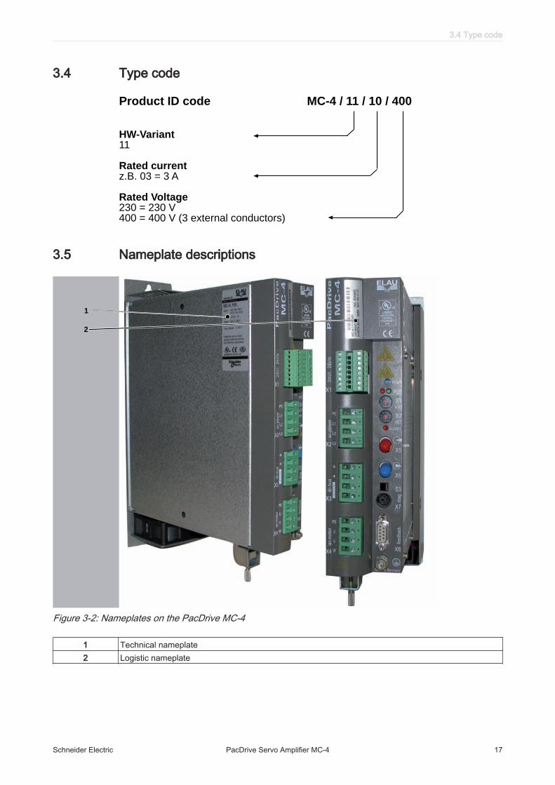
3.4 Type code
Product ID code MC-4 / 11 / 10 / 400
HW-Variant11
Rated currentz.B. 03 = 3 A
Rated Voltage230 = 230 V400 = 400 V (3 external conductors)
3.5 Nameplate descriptions
TM
1
2
Figure 3-2: Nameplates on the PacDrive MC-4
1 Technical nameplate2 Logistic nameplate
3.4 Type code
Schneider Electric PacDrive Servo Amplifier MC-4 17

Figure 3-3: Logistic nameplate of a PacDrive MC-4
Label MeaningMC-4 Device type, see type code13130247 Item no.897773.0010 4808 Serial numberHW Hardware versionSW Software version
Table 3-1: Explanation of the nameplate
To execute a firmware update, proceed as follows:▶ For MC-4 with bootloader version ≥ 3.30, the firmware must be updated using the
sercos Firmware Assistant V2.1 or higher.The sercos Firmware Assistant from V2.1 is part of the "EPAS-4 Automation Tool‐kit" or the "PacDrive Service CD".
3 System overview
18 PacDrive Servo Amplifier MC-4 Schneider Electric

Figure 3-4: Technical nameplate of a PacDrive MC-4
Label MeaningMC-4 Device type, see type codeInput 1 Rated voltage and rated current of the power supplyInput 2 Rated voltage and rated current of the electronicsOutput 1 Rated voltage and rated current of the power supplyAmbient temp. Permitted ambient temperatureCE CE markcULus (symbol) UL certification for the US and Canada
Table 3-2: Explanation of the nameplate
3.5 Nameplate descriptions
Schneider Electric PacDrive Servo Amplifier MC-4 19

4 Indicators and control elementsThe PacDrive System supports the user by means of its diagnostic system which con‐tains a powerful message logger in which additional diagnostic information is recordedHow to use the diagnostic system:▶ Read out diagnostic messages using the EPAS-4 Automation Toolkit or PD Di‐
agnostics.▶ If applicable, read out diagnostic messages on the control panel of the machine.▶ Then contact the machine manufacturer.
Detailed information on diagnostic is available in the Online Help of the EPAS-4Automation Toolkit or the PD Diagnostics tool.
4.1 Example of a diagnostic message
The diagnostic message 121 "Braking resistor temperature too high" is displayed.Meaning of diagnostic message:
• Class 2 error• Diagnostic code 121
The meaning of the diagnostic code is explained more thoroughly in the online helpsection of the EPAS-4 Automation Toolkit.121 Braking resistor Temperature Too HighDiagnostic class (Standard): 2Reaction: BThe braking resistor is overloaded.
▪ The drive sizing is incorrect.▶ Check drive sizing.
▪ Potential hardware error detected: The braking resistor or triggering is not oper‐ating properly.
▶ Contact the Schneider Electric customer service.
4 Indicators and control elements
20 PacDrive Servo Amplifier MC-4 Schneider Electric

4.2 Displays and operating elements on the MC-4 servo amplifier
X1
X2
X4
X3
X8
X7
X5
X6
S1
S2di
agfe
edba
ck
reset
errpow
buserr
ac-p
ower
dc-b
usac
-mot
or
MC-4
S3
!
Made in Germany
PE
L1
L2
L3
m a x .
to r q u e
0 . 5 N m
PE
U
V
W
1
2
4
5
3
Figure 4-1: Diagnosis LEDs of the MC-4 servo amplifier
1 reset button2 pow LED (control voltage display)3 err LED (error display)4 S1/S2 (Address setting for the sercos bus)5 bus err LED (sercos bus error display)
4.2.1 pow LED
pow
errState Meaning
OFF The control voltage (24 Vdc) is missing or too low.ON (green) Normal operation
Table 4-1: pow LED (control voltage display)
4.2 Displays and operating elements on the MC-4 servo amplifier
Schneider Electric PacDrive Servo Amplifier MC-4 21

4.2.2 err LED
pow
errState Meaning
OFF Normal operationslow flashing (1/4 Hz)(red) from V00.20xx
sercos error
slow flashing (1/2 Hz)(red) from V00.16xx
sercos error
quick flashing (2Hz)(red)
A potential general error has been detected.
ON (red) A non repairable error has been detected.
Table 4-2: err LED (error display)
4.2.3 bus err LED
bus
errState Meaning
OFF Normal operationON / flashing (red) Detected communication error.
Possible Causes:
• Fiber-optic connection problem• The transmitting power is too low or too high• Broken cable
Table 4-3: bus err LED (sercos bus error display)
4.2.4 S1/S2 Rotary switch for sercos address
S1ð0
5
1
23
4 6
78
9
S2ð0
5
1
23
4 6
78
9
x10
x01
Switch MeaningS1 Tens position of the sercos addressS2 Digits position of the sercos address
Table 4-4: S1/S2 address setting with rotary switch
4.2.5 S3 switch
S3
21
▶ DIL switch S3 at the front plate for setting the transmitter intensity of the fibre-opticlight source.
4.2.6 reset button
reset
▶ Press the reset button to restart the servo amplifier.
4 Indicators and control elements
22 PacDrive Servo Amplifier MC-4 Schneider Electric
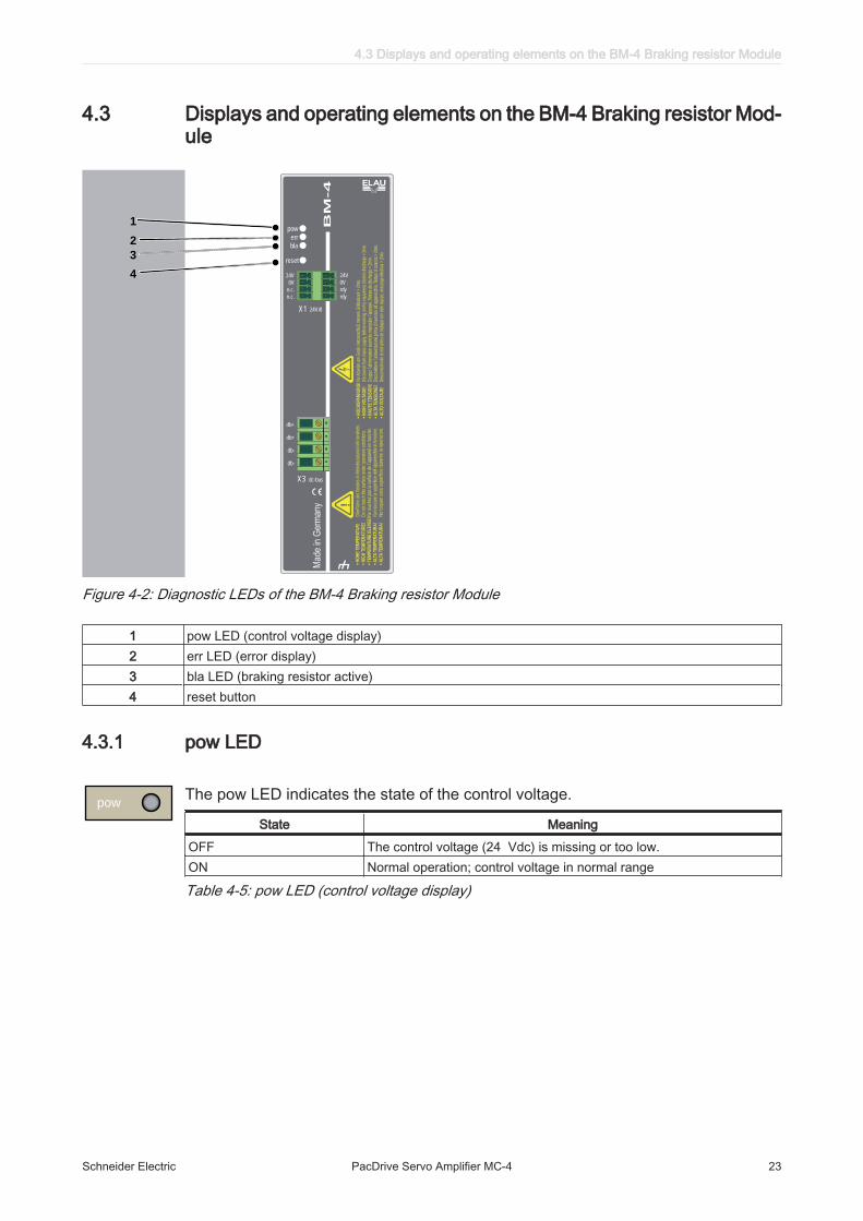
4.3 Displays and operating elements on the BM-4 Braking resistor Mod‐ule
1
2
3
4
X1
X3 dc-bus
BM
-4
24V/0
db+
db+
db-
db-
24V
0V
rdy
rdy
24V
0V
n.c.
n.c.
!•
HO
CH
SP
AN
NU
NG
! Vor
Arb
eite
n am
Ger
ät, N
etza
nsch
luß
trenn
en. E
ntla
deze
it >
2min
.•
HIG
H V
OLTA
GE
!
Disc
onne
ct fr
om m
ains
sup
ply,
befo
re w
orkin
g on
this
equi
pmen
t, El
ectri
c di
scha
rge
> 2m
in.
• H
AU
TE
TE
NS
ION
! C
oupe
z l´a
limen
tatio
n av
ant d
e m
anip
uler
l´ap
pare
il. T
emps
de
déch
arge
> 2
min
.•
ALTA
TE
NS
ION
E!
Dis
cone
ttter
e l`a
limen
tazi
one
prim
a di
lavo
rare
all`
appa
recc
hio.
Tem
po d
i sca
rica
> 2m
in.
• A
LT
O V
OLTA
JE
! D
esco
nect
en d
e la
red
ante
s de
trab
ajar
con
est
e eq
uipo
, des
carg
a el
ectri
ca >
2m
in.
• H
OH
E T
EM
PE
RA
TU
R!
O
berfl
äche
des
Ger
ätes
im B
etrie
bszu
stan
d ni
cht b
erüh
ren.
• H
IGH
TE
MP
ER
AT
UR
E!
Do
not t
ouch
this
sur
face
und
er o
pera
tion
cond
ition
s.•
TE
MP
ER
AT
UR
E E
LE
VE
E! N
e to
uche
z pa
s la
sur
face
de
l´app
arei
l en
mar
che.
• A
LTA
TE
MP
ER
AT
UR
A!
Non
tocc
are
la s
uper
ficie
del
l`app
arec
chio
in fu
ncio
ne.
• A
LTA
TE
MP
ER
AT
UR
A!
No
toqu
en e
sta
supe
rfic
ie d
uran
te la
ope
raci
on.
pow
err
bla
reset
Figure 4-2: Diagnostic LEDs of the BM-4 Braking resistor Module
1 pow LED (control voltage display)2 err LED (error display)3 bla LED (braking resistor active)4 reset button
4.3.1 pow LED
powThe pow LED indicates the state of the control voltage.
State MeaningOFF The control voltage (24 Vdc) is missing or too low.ON Normal operation; control voltage in normal range
Table 4-5: pow LED (control voltage display)
4.3 Displays and operating elements on the BM-4 Braking resistor Module
Schneider Electric PacDrive Servo Amplifier MC-4 23

4.3.2 err LED
errThe err LED indicates errors.
State MeaningOFF Normal operation, no error detectedFlashes slowly (ON: 500 ms / OFF: 2000 ms)
Braking resistor I²t at the limit
Flashes fast (ON: 500 ms / OFF: 500 ms)
- Intermediate circuit voltage too high - supply voltage too low - Temperature too high (no reset necessary; device is ready to operateagain after cooling)
ON Braking resistor error detected
Table 4-6: err LED (error display)
4.3.3 bla LED
bla State MeaningOFF PacDrive BM-4 not activeON PacDrive BM-4 active
Table 4-7: bla LED
4.3.4 reset button
resetReset buttonPressing the "reset" button only restarts the MC-4. Any other PacDrive Controllers thatmay be connected have their own reset button.
4 Indicators and control elements
24 PacDrive Servo Amplifier MC-4 Schneider Electric

5 Installation and maintenanceFor warranty reasons, we recommend that you employ Schneider Electric personnelfor initial start-up. The Schneider Electric personnel
• will check the equipment,• determine the optimal configuration• and instruct the operating staff.
▶ Proceed with care during the following steps and take all precautions describedin order to help to avoid the following points:
• Injuries and material damage• Incorrect installation and programming of components• the incorrect operation of components• The use of non-authorized cables or modified components
5.1 Commissioning
DANGERHAZARD OF ELECTRIC SHOCK, EXPLOSION, OR ARC FLASH
• Operate electrical components only with a connected protective conductor.• After the installation, verify the fixed connection of the protective conductor to all
electrical devices to ensure that connection complies with the connection dia‐gram.
• Before enabling the device, safely cover the live components to prevent contact.• Do not touch the electrical connection points of the components when the unit is
switched on.• Provide protection against indirect contact (EN 50178).• Disconnect/plug in Plug-in connectors of the cables and plug-in terminals on the
device only when the system is disconnected from the power supply.• Isolate the unused conductors on both ends of the motor cable because AC vol‐
tages in the motor cable can couple to unused conductors.Failure to follow these instructions will result in death or serious injury.
5.1.1 Preparing commissioning▶ Check safety circuits for proper function, if applicable.
ESD protection ▶ Observe the following instructions for ESD protection in order to avoid any damagedue to electrostatic discharge:
NOTICEELECTROSTATIC DISCHARGE
• Do not touch any of the electrical connections.• Prevent electrostatic charges; e.g., by wearing appropriate clothing.• Remove existing static charge by touching a grounded, metallic surface, like
for example, a grounded housing.Failure to follow these instructions can result in equipment damage.
5.1 Commissioning
Schneider Electric PacDrive Servo Amplifier MC-4 25

Unpacking How to unpack the device:▶ Remove packaging.▶ Dispose of the packaging material in accordance with the relevant local regula‐
tions.Verifying How to check the device:
▶ Verify that the delivery is complete.▶ Verify if the device is in working condition.
WARNINGDAMAGED OR MODIFIED DRIVE SYSTEMS
• Do not mount or commission damaged drive systems.• Do not modify the drive systems.• Send back inoperative devices.Failure to follow these instructions can result in death or serious injury.
▶ Check data against type plates.
▶ Observe requirements for the installation location.▶ Observe requirements for the degree of protection and the EMC rules.
5.1.2 Cabling of the servo amplifier
DANGERHAZARD OF ELECTRIC SHOCK CAUSED BY HIGH TOUCH VOLTAGE
• Connect devices as of 3.5 mA AC or more via a fixed connection with thepower supply network.
• In addition, implement one of the measures according to DIN EN 50178, inorder to provide the required protection against electrical shock by indirectcontact.
Failure to follow these instructions will result in death or serious injury.
▶ Connect devices, beginning with the ground conductor.▶ Check if the terminals are fastened securely and the necessary cable cross sec‐
tions are correct.
Grounding ▶ Use the ring cable lug for M5 (d = 5.3 mm² / 0.21 in.) to connect MC-4 1.5-22 Aand BM-4 (cross section 10 mm² / 0.39 in.) with the ground bolt.
▶ Use the ring cable lug for M6 (d = 6.4 mm² / 0.25 in.) to connect MC-4 50 A (crosssection 5.3 mm² / 0.21 in.) with the ground bolt.
▶ Check that shielding is completely correct.▶ Eliminate the possibility of short circuits and interruptions.▶ Check the continuity of the protective conductor system.▶ Use an appropriate tool to assign an unambiguous, two-digit sercos address (00 ...
99) for the sercos slave in the loop on the front of the MC-4 (S1/S2).
5 Installation and maintenance
26 PacDrive Servo Amplifier MC-4 Schneider Electric

▶ Set the transmitter intensity of the fiber-optic light source on the PacDrive bymeans of the DIL switch (S3) on the front plate of the MC-4 according to the cablelength to the next participant.
Cable length [m] / [ft] Curr_P_Gain switch position0.1 ... 1 / 0.33 ... 3.28 1
21
1.1 ... 20 / 3.61 ... 65.62 2
21
20.1 ... 40 / 65.94 ...131.32 3
21
40.1 ... 50 / 131.56 ... 164.04 4
21
Table 5-1: S3 fiber-optic cable intensity with respective cable length
Protecting ▶ According to UL508C, an overtemperature detection of the motor by the drivemodule is not intended. Thus, connect the temperature sensor of the motor to the connection X1 of theMC-4 servo amplifier.
Control voltage
▶ Check the power supply voltage and control voltage.▶ Connect external 24 Vdc control voltage.
▶ Check the control voltage (≥ 24 Vdc) so that the fans work with the necessarypower until the specified ambient temperatures are reached.
NOTICEOVERHEATING BECAUSE OF TOO HIGH AMBIENT TEMPERATURES
• For ambient temperatures > 45 °C / 113 °F, ensure that there is additionalrecirculation of the cooling air in the control cabinet (external fan).
Failure to follow these instructions can result in equipment damage.
For further information on this (see 6.1 Ambient conditions).
PacDrive Servo Amplifier initializes and the LEDs show the following condi‐tion:pow: ONerr: FLASHESbuserr: ON
▶ Check thermal contact of motor or PTC (posistor sensor).For more information see the operating instructions for the motors connected.
5.1 Commissioning
Schneider Electric PacDrive Servo Amplifier MC-4 27

5.1.3 Completion of commissioning▶ Check safety functions such as the EMERGENCY STOP switch.▶ Ensure that the supply voltage matches the rated voltage of the servo amplifier.
NOTICESUPPLY VOLTAGE TOO HIGH
• Only connect mains voltage if the supply voltage matches the rated voltageof the servo amplifier.
Failure to follow these instructions can result in equipment damage.
This is how to connect the mains voltage:▶ Activate EMERGENCY STOP switch.▶ Check with a suitable measuring instrument that it is off-circuit.▶ Connect mains voltage.▶ Check status displays for proper function.▶ Release EMERGENCY STOP switch and activate ON switch.This is how to move the axis:▶ When moving the axis for the first time, use a reliable, tested application program
which covers the following motions / functions: checking - the correct direction of rotation of the axis,- the correct setting of the limit switches and- the braking distance in both directions.
From the electronic nameplate of the motor, the servo amplifier automatically deter‐mines the motor and the corresponding motor data when the 24 Vdc control voltageis connected.This is how to transmit the configuration and the program:▶ Transfer project with the EPAS-4 automation toolkit to the PacDrive controller.
WARNINGHAZARDOUS MOVEMENTS
• Ensure that no persons are in the danger zone.• Remove all tools, loose parts and other working aids not belonging to the
axis/machine/system from the area of movement.• Engaged the engine only after the function test has been successfully per‐
formed.Failure to follow these instructions can result in death or serious injury.
5 Installation and maintenance
28 PacDrive Servo Amplifier MC-4 Schneider Electric

5.1.4 Performing the function test▶ Verify devices and wiring again.▶ If you haven't already done so, connect the mains voltage.▶ Carry out function test using a checklist for axis/machine/system functions.▶ Resume system operation according to the operating manual (from the machine
manufacturer and servo amplifier).
5.2 Electromagnetic compatibility, EMC
WARNINGRISK OF ELECTROMAGNETIC DISTURBANCES OF SIGNALS AND DEVICES
• Use proper EMC shielding techniques to help prevent unexpected device oper‐ation.
Failure to follow these instructions can result in death or serious injury.
Enclosure layout
The prerequisite for compliance with the specified limit values is an EMC compatiblelayout. Comply with the following specifications:
EMC measures TargetUse galvanized or chromium-plated sub plates, bond metallic partsacross large surface areas, remove paint layer from contact surfaces.
Good conductivity by surfacearea contact
Ground enclosure, door and sub plates by using grounding strips orgrounding cables with a cross-section of 10 mm2 (AWG 6).
Reduce emission.
Supplement switch devices such as contactors, relays or magneticvalves with interference suppression combinations or spark supressorelements (e.g. diodes, varistors, RC elements).
Reduces mutual interference
Fit power and control components separately. Reduces mutual interference
Shieldedcables
EMC measures TargetPlace cable shields on the surface, use cable clamps and groundingstrips.
Reduce emission.
At the control cabinet outfeed, connect the shield of all shielded cablesvia cable clamps to the sub plate across large surface areas.
Reduce emission.
Ground shields of digital signal cables on both sides across large surfaceareas or through conducting connector housings.
Reduce interference action onsignal cables, reduce emis‐sions.
Ground shield of analog signal cables directly on the device (signal in‐put), insulate the shield at the other cable end or ground the samethrough a capacitor, such as 10 nF.
Reduce grounding loops bylow frequency interferences.
Use only shielded motor supply cables with a copper braid and at least85% cover, ground shield on both sides across a large surface area.
Specifically discharge interfer‐ence currents, reduce emis‐sions.
5.2 Electromagnetic compatibility, EMC
Schneider Electric PacDrive Servo Amplifier MC-4 29

Cable routing
EMC measures TargetDo not route fieldbus cables and signal cables together with cabling fordirect and alternating voltages above 60 V in the same cable duct (field‐bus cables can be routed together with signal cables and analog cablesin the same duct). Recommendation: Routing in separated cable cutswith a distance of at least 20 cm (7.84 in.).
Reduces mutual interference
Keep the cables as short as possible. Do not install any unnecessarycable loops, short cable routing from a central grounding point in thecontrol cabinet to the external grounding connection.
Reduce capacitive and induc‐tive interference couplings.
Insert a potential equalization for:
• large surface installation• different voltage infeeds• networking across buildings
Reduce current on cableshield, reduce emissions.
Use fine wire potential equalization conductor. Discharging of high frequencyinterference currents.
If motor and machine are not connected in a conducting fashion, e.g. dueto an insulated flange or a connection not across a full surface, the motormust be grounded via a grounding cable > 10 mm2 (AWG 6) or a ground‐ing strip.
Reduce emissions, increaseinterference resistance.
Use twisted pair for 24 Vdc signals. Reduce interference action onsignal cables, reduce emis‐sions.
Voltage supply
EMC measures TargetOperate product on mains with a grounded neutral. Enable the effect of the inte‐
grated mains filter.Protection circuit if there is a risk of overvoltage. Reduce risk of damage due to
overvoltages.
Motor and encoder cables
From an EMC point of view, motor supply cables and encoder cables are particularlycritical. Only use pre-configured cables, or cables with the prescribed properties, andcomply with the following EMC measures.
EMC measures TargetDo not install switching elements in motor cables or encoder cables. Reduces interference.Route motor cable with a distance of at least 20 cm (7.84 in.) to thesignal cables or insert shield plates between the motor supply cable andthe signal cable.
Reduces mutual interference
For long cabling, use potential equalization cables. Reduce current on cableshield.
Route motor supply cables and encoder cables without any separationpoint. 1)
Reduces emission.
1) If a cable must be cut through for installation purposes, the cables must be connected at the point ofseparation by means of screen connections and metal housing.
5 Installation and maintenance
30 PacDrive Servo Amplifier MC-4 Schneider Electric

Additionalmeasures forimproving the
EMC
Depending on the respective application, the following measures may lead to a EMCcompatible layout:
EMC measures TargetUpstream connection of line chokes Reduction of the harmonic
network oscillations, exten‐sion of the service life of theproduct.
Upstream connection of external integrated mains filters Improvement of the EMC limitvalues.
Special EMC-suitable layout, e.g. within an enclosed control cabinetcomplete with 15 dB attenuation of the interferences emitted
Improvement of the EMC limitvalues.
5.3 Maintenance, repair, cleaning▶ Observe the following instructions before carrying out maintenance on Device:How to de-energize the system:▶ Set main switch to "OFF Position".▶ Prevent main switch from being switched back on.▶ After switching off, wait 15 minutes so that the DC bus can discharge.
DANGERHAZARD OF ELECTRIC SHOCK, EXPLOSION, OR ARC FLASH
• Turn off all power supplying this equipment before working on or insideequipment.
Failure to follow these instructions will result in death or serious injury.
▶ Check the DC bus with a measuring instrument to make sure that it is de-energized(< 42,4 Vdc).
Help in case of an unforeseen issue:DC bus does not discharge completely.
▶ Do not repair or operate component.▶ Contact the Schneider Electric Customer Service.
5.3 Maintenance, repair, cleaning
Schneider Electric PacDrive Servo Amplifier MC-4 31

5.3.1 Repair
In case of repair proceed as follows :▶ Contact the Schneider Electric Customer Service.▶ Observe the following instructions for ESD protection in order to avoid any damage
due to electrostatic discharge:
NOTICEELECTROSTATIC DISCHARGE
• Do not touch any of the electrical connections.• Prevent electrostatic charges; e.g., by wearing appropriate clothing.• Remove existing static charge by touching a grounded, metallic surface, like
for example, a grounded housing.Failure to follow these instructions can result in equipment damage.
5.3.2 Cleaning
How to clean the PacDrive Servo Amplifier:▶ De-energize PacDrive Servo Amplifier.▶ Remove PacDrive Servo Amplifier.
It is not possible to test in advance all materials of the Schneider Electric productrange that are used at the moment and in the future for compatibility with thecleaning agents available on the market.
NOTICEDAMAGE CAUSED BY CLEANING AGENTS
• Before using a cleaning agent, carry out a compatibility test in relation to thecleaning agent and the component affected.
• Do not use alkaline detergent as the polycarbonate can lose its stability ifyou come into contact with it.
• Do not use any chloride-containing cleaning agents as these corrode thestainless steel and in particular the welds, and thus reduce the strength ofthe mechanics.
Failure to follow these instructions can result in equipment damage.
For more information on the material properties of your component (see 6.3 Me‐chanical and electrical data).
▶ Then blow out PacDrive Servo Amplifier with dry pressurized air (max. 1 bar / 14.5PSI).
5 Installation and maintenance
32 PacDrive Servo Amplifier MC-4 Schneider Electric

5.4 Spare part inventory▶ Keep a stock of the most important components to make certain the equipment is
functioning and ready for operation at all times.▶ Only exchange devices with the same hardware configuration.▶ Indicate the following information on the spare part order:Item name: e.g. PacDrive MC-4/11/10/400Item no.: e.g. 13130247Hardware code: e.g. HW: D0H503Software version: e.g. SW: 00.12.31
This information can be found on the nameplate.
5.5 Device-, parts- or cable exchange
DANGERHAZARD OF ELECTRIC SHOCK, EXPLOSION, OR ARC FLASH
• Operate electrical components only with a connected protective conductor.• After the installation, verify the fixed connection of the protective conductor to all
electrical devices to ensure that connection complies with the connection dia‐gram.
• Before enabling the device, safely cover the live components to prevent contact.• Do not touch the electrical connection points of the components when the unit is
switched on.• Provide protection against indirect contact (EN 50178).• Disconnect/plug in Plug-in connectors of the cables and plug-in terminals on the
device only when the system is disconnected from the power supply.• Isolate the unused conductors on both ends of the motor cable because AC vol‐
tages in the motor cable can couple to unused conductors.Failure to follow these instructions will result in death or serious injury.
5.5.1 Device replacement
CAUTIONHOT SURFACES OVER 70ºC / 158ºF
• Wait until the surface temperature has cooled to allow safe contact.• Wear protective gloves.• Attach protective cover or touch guardFailure to follow these instructions can result in injury.
5.4 Spare part inventory
Schneider Electric PacDrive Servo Amplifier MC-4 33

How to de-energize the system:▶ Set main switch to "OFF Position".▶ Prevent main switch from being switched back on.▶ After switching off, wait 15 minutes so that the DC bus can discharge.
DANGERHAZARD OF ELECTRIC SHOCK, EXPLOSION, OR ARC FLASH
• Turn off all power supplying this equipment before working on or insideequipment.
Failure to follow these instructions will result in death or serious injury.
▶ Check the DC bus with a measuring instrument to make sure that it is de-energized(< 42,4 Vdc).
Help in case of an unforeseen issue:DC bus does not discharge completely.
▶ Do not repair or operate component.▶ Contact the Schneider Electric Customer Service.
NOTICEIMPROPER REPLACEMENT / COMMISSIONING
• Do not open Servo Drives for commissioning or replacement.Failure to follow these instructions can result in equipment damage.
▶ When exchanging the of the servo amplifier, in addition to the following instruc‐tions, the specifications of the manufacturer have to be observed also.
▶ Disconnect cables of the MC-4.▶ Remove the screws from the top and bottom of the housing.▶ Remove the MC-4 and exchange the complete unit.▶ Install New MC-4 and tighten screws.▶ Connect the MC-4 according to the circuit diagram of the machine.
DANGERINCORRECT ASSIGNMENT OF NEW CABLES
• If you are not using prefabricated cables, make certain that the configurationof the new cables matches the connection diagram of the machine manu‐facturer.
Failure to follow these instructions will result in death or serious injury.
▶ Following replacement of the PacDrive Servo Amplifier proceed as for the initialstart-up.
5 Installation and maintenance
34 PacDrive Servo Amplifier MC-4 Schneider Electric

5.5.2 Cable replacement
How to de-energize the system:▶ Set main switch to "OFF Position".▶ Prevent main switch from being switched back on.▶ After switching off, wait 15 minutes so that the DC bus can discharge.
DANGERHAZARD OF ELECTRIC SHOCK, EXPLOSION, OR ARC FLASH
• Turn off all power supplying this equipment before working on or insideequipment.
Failure to follow these instructions will result in death or serious injury.
▶ Check the DC bus with a measuring instrument to make sure that it is de-energized(< 42,4 Vdc).
Help in case of an unforeseen issue:DC bus does not discharge completely.
▶ Do not repair or operate component.▶ Contact the Schneider Electric Customer Service.
Proceed as follows for cable replacement:
DANGERLOSS OF THE INVERTER ENABLE FUNCTION
• Test the proper functioning of the Inverter Enable after every device replace‐ment and every change of the wiring.
Failure to follow these instructions will result in death or serious injury.
▶ Exchange the cable according to the machine manufacturer's specifications.
5.5 Device-, parts- or cable exchange
Schneider Electric PacDrive Servo Amplifier MC-4 35

6 Technical data
6.1 Ambient conditions
Procedure Parameter Value BasisOperation Class 3K3 IEC/EN 60721-3-3
Degree of protection housing IP 20Degree of protection installationsite
IP 54, if safety circuit with InverterEnableis used
Isolation class Pollution degree 2Ambient temperature +5 °C ... +45 °C / 41 °F ... 113°F Ambient temperature in the caseof power reduction
+5 °C ... +55 °C / 41 °F ... 131 °F(-2% per K for INC and ISC)
Condensation ProhibitedIcing Prohibitedother liquid ProhibitedRelative humidity 5% ... 85%
Transport Class 2K3 IEC/EN 60721-3-2Isolation class Pollution degree 2Ambient temperature -25 °C ... +70 °C / -13 °F ... +158°F Condensation ProhibitedIcing Prohibitedother liquid ProhibitedRelative humidity 5% ... 85%
Long-term storage intransport packaging
Class 1K4 IEC/EN 60721-3-1Isolation class Pollution degree 2Ambient temperature -25 °C ... +55 °C / -13 °F ... 131°F Condensation ProhibitedIcing Prohibitedother liquid ProhibitedRelative humidity 5% ... 85%
Table 6-1: Ambient conditions for control cabinet devices
6.2 Standards and regulations
Declarations MC-4 1.5 A / 3 A / 5 A / 10 A / 22 A CEMC-4 50 A CEBM-4 CE
Certifications MC-4 1.5 A / 3 A / 5 A / 10 A / 22 A cULusBM-4 cULus
Table 6-2: Declarations and certifications MC-4 Servo amplifier
6 Technical data
36 PacDrive Servo Amplifier MC-4 Schneider Electric

6.3 Mechanical and electrical data
Firmware version supported rated speed of the connected motor≤ V00.22.XX ≤ 6000 rpm> V00.22.XX ≤ 12,000 rpm
6.3.1 MC-4 / 1.5 A Servo Amplifier
Category Parameter ValueProductconfiguration
Item name MC-4 / 11 / 01 / 400 VOrder number 13 13 02 44
Power supply Rated supply voltage Min. 3 380 Vac (-10 %)Max. 3 480 Vac (+10 %)
Supply frequency 48 ... 62 HzControl voltage / -current 24 Vdc (-15 % / +25 %) / 1 A
DC circuit DC_Bus Voltage 530 ... 680 VdcCapacitance 165 µFUBleeder ON 820 VdcUBleeder OFF 800 VdcOvervoltage 860 VdcBraking resistor resistor 120 ohmBraking resistor-continuous power 50 WBraking resistor-peak power 5 kW
Motor connection Rated current 8 kHz (INC) 1.5 AeffPeak current 1 s (ISC) 3.75 AeffRated power 1.1 kVA
Power loss Electronics power supply approx. 12 WBraking resistor (internal) 0 ... 50 W (depending on the application)Power unit approx. 15 W / A
inputs Input voltage / -current 20 ... 30 Vdc / 5 mAie-input 20 ... 30 Vdc / 30 mAInput filter [5 ms]
Outputs Relay-outputs 20 ... 30 Vdc / 2 ADimensions Dimensions packaging DxWxH (mm) / (in.): 320x100x400 / 12.6x3.9x15.7Weight Weight (with packaging) 3.1 kg (4.0 kg) / 6.8 lbs (8.8 lbs)Ventilation Natural convectionOvervoltage category
K III, T2 (DIN VDE 0110)
Overvoltage protection
Class 1 (DIN VDE 0160)
Radio interfer‐ence level
Class A EN 55011 / EN 61800 - 3
Table 6-3: Technical Data MC-4 / 1.5 A Servo Amplifier
Only use the PacDrive MC-4 / 1.5 A from firmware version V00.22.XX and only inconnection with SH Motor 055. If you are using a motor with a deviation in performance,then the diagnostic message „138 impermissible motor“ will appear.
6.3 Mechanical and electrical data
Schneider Electric PacDrive Servo Amplifier MC-4 37

6.3.2 MC-4 / 3 A Servo Amplifier
Category Parameter ValueProductconfiguration
Item name MC-4 / 11 / 03 / 400 VOrder number 13 13 02 45
Power supply Rated supply voltage Min. 3 380 Vac (-10 %)Max. 3 480 Vac (+10 %)
Supply frequency 48 ... 62 HzControl voltage / -current 24 Vdc (-15 % / +25 %) / 1 A
DC circuit DC_Bus Voltage 530 ... 680 VdcCapacitance 165 µFUBleeder ON 820 VdcUBleeder OFF 800 VdcOvervoltage 860 VdcBraking resistor resistor 120 ohmBraking resistor-continuous power 50 WBraking resistor-peak power 5 kW
Motor connection Rated current 8 kHz (INC) 3 AeffPeak current 1 s (ISC) 7.5 AeffRated power 2.1 kVA
Power loss Electronics power supply approx. 12 WBraking resistor (internal) 0 ... 50 W (depending on the application)Power unit approx. 15 W / A
inputs Input voltage / -current 20 ... 30 Vdc / 5 mAie-input 20 ... 30 Vdc / 30 mAInput filter [5 ms]
Outputs Relay-outputs 20 ... 30 Vdc / 2 ADimensions Dimensions packaging DxWxH (mm) / (in.): 320x100x400 / 12.6x3.9x15.7Weight Weight (with packaging) 3.1 kg (4.0 kg) / 6.8 lbs (8.8 lbs)Ventilation Natural convectionOvervoltage category
K III, T2 (DIN VDE 0110)
Overvoltage protection
Class 1 (DIN VDE 0160)
Radio interfer‐ence level
Class A EN 55011 / EN 61800 - 3
Table 6-4: Technical Data MC-4 / 03 A Servo Amplifier
6 Technical data
38 PacDrive Servo Amplifier MC-4 Schneider Electric

6.3.3 MC-4 / 5 A Servo Amplifier
Category Parameter ValueProductconfiguration
Item name MC-4 / 11 / 05 / 230 VOrder number 13 13 02 46
Power supply Rated supply voltage Min. 3 / 1 220 Vac (-10 %)Max. 3 / 1 240 Vac (+10 %)
Supply frequency 48 ... 62 HzControl voltage / -current 24 Vdc (-15 % / +25 %) / 1 A
DC circuit DC_Bus Voltage 260 ... 370 VdcCapacitance 660 µFUBleeder ON 410 VdcUBleeder OFF 400 VdcOvervoltage 430 VdcBraking resistor resistor 33 ohmBraking resistor-continuous power 50 WBraking resistor-peak power 5 kW
Motor connection Rated current 8 kHz 5 AeffPeak current 1 s 12.5 AeffRated power 1.9 kVA
Power loss Electronics power supply approx. 12 WBraking resistor (internal) 0 ... 50 W (depending on the application)Power unit approx. 15 W / A
inputs Input voltage / -current 20 ... 30 Vdc / 5 mAie-input 20 ... 30 Vdc / 30 mAInput filter [5 ms]
Outputs Relay-outputs 20 ... 30 Vdc / 2 ADimensions Dimensions packaging DxWxH (mm) / (in.): 320x100x400 / 12.6x3.9x15.7Weight Weight (with packaging) 3.1 kg (4.0 kg) / 6.8 lbs (8.8 lbs)Ventilation Natural convectionOvervoltage category
K III, T2 (DIN VDE 0110)
Overvoltage protection
Class 1 (DIN VDE 0160)
Radio interfer‐ence level
Class A EN 55011 / EN 61800 - 3
Table 6-5: Technical Data MC-4 / 05 A Servo Amplifier
6.3 Mechanical and electrical data
Schneider Electric PacDrive Servo Amplifier MC-4 39

6.3.4 MC-4 / 10 A Servo Amplifier
Category Parameter ValueProductconfiguration
Item name MC-4 / 11 / 10 / 400 VOrder number 13 13 02 47
Power supply Rated supply voltage Min. 3 380 Vac (-10 %)Max. 3 480 Vac (+10 %)
Supply frequency 48 ... 62 HzControl voltage / -current 24 Vdc (-15 % / +25 %) / 1 A
DC circuit DC_Bus Voltage 530 ... 680 VdcCapacitance 330 µFUBleeder ON 820 VdcUBleeder OFF 800 VdcOvervoltage 860 VdcBraking resistor resistor 60 ohmBraking resistor-continuous power 100 WBraking resistor-peak power 10 kW
Motor connection Rated current 8 kHz (INC) 10 AeffPeak current 1 s (ISC) 25 AeffRated power 6.9 kVA
Power loss Electronics power supply approx. 12 WBraking resistor (internal) 0 ... 100 W (depending on the application)Power unit approx. 15 W / A
inputs Input voltage / -current 20 ... 30 Vdc / 5 mAie-input 20 ... 30 Vdc / 30 mAInput filter [5 ms]
Dimensions Dimensions packaging DxWxH (mm) / (in.): 320x100x400 / 12.6x3.9x15.7Weight Weight (with packaging) 3.1 kg (4.0 kg) / 6.8 lbs (8.8 lbs)Ventilation Fan internal, temperature-controlled, (switching on threshold
= 55 °C / 131 °F)Overvoltage category
K III, T2 (DIN VDE 0110)
Overvoltage protection
Class 1 (DIN VDE 0160)
Radio interfer‐ence level
Class A EN 55011 / EN 61800 - 3
Table 6-6: Technical Data MC-4 / 10 A Servo Amplifier
6 Technical data
40 PacDrive Servo Amplifier MC-4 Schneider Electric

6.3.5 MC-4 / 22 A Servo Amplifier
Category Parameter ValueProductconfiguration
Item name MC-4 / 11 / 22 / 400 VOrder number 13 13 02 54
Power supply Rated supply voltage Min. 3 380 Vac (-10 %)Max. 3 480 Vac (+10 %)
Supply frequency (INC) 48 ... 62 HzControl voltage / -current (ISC) 24 Vdc (-15 % / +25 %) / 1 A
DC circuit DC_Bus Voltage 530 Vdc ... 680 VdcCapacitance 705 µFUBleeder ON 820 VdcUBleeder OFF 800 VdcOvervoltage 860 VdcBraking resistor resistor 42 ohmBraking resistor-continuous power 150 WBraking resistor-peak power 15 kW
Motor connection Rated current 8 kHz 22 AeffPeak current 1 s 55 AeffRated power 15.2 kVA
Power loss Electronics power supply approx. 12 WBraking resistor (internal) 0 ... 150 W (depending on the application)Power unit approx. 15 W / A
inputs Input voltage / -current 20 ... 30 Vdc / 5 mAie-input 20 ... 30 Vdc / 30 mAInput filter [5 ms]
Outputs Relay-outputs 20 ... 30 Vdc / 2 ADimensions Dimensions packaging DxWxH (mm) / (in.): 310x160x400 / 12.2x6.3x15.7Weight Weight (with packaging) 6.3 kg (7.0 kg) / 13.9 lbs (15.4 lbs)Ventilation Fan internal, temperature-controlled, (switching on threshold
= 55 °C / 131 °F)Overvoltage category
K III, T2 (DIN VDE 0110)
Overvoltage protection
Class 1 (DIN VDE 0160)
Radio interfer‐ence level
Class A EN 55011 / EN 61800 - 3
Table 6-7: Technical Data MC-4 / 22 A Servo Amplifier
6.3 Mechanical and electrical data
Schneider Electric PacDrive Servo Amplifier MC-4 41

6.3.6 MC-4 / 50 A Servo Amplifier▶ Use an external mains filter to comply with EMC directives.
WARNINGLOSS OF TECHNICAL SAFETY FUNCTIONS
• Use the PacDrive MC-4 / 50 A only with the original firmware of the deliverycondition.
• Only use the PacDrive MC-4 / 50 A with firmware version V00.11.XX or higher.• If the firmware must be replaced, only use versions ≥ V00.11.XX.Failure to follow these instructions can result in death or serious injury.
Category Parameter ValueProductconfiguration
Item name MC-4 / 11 / 50 / 400 VOrder number 13 13 02 56
Power supply Rated supply voltage Min. 3 380 Vac (-10 %)Max. 3 480 Vac (+10 % )
Supply frequency 48 ... 62 HzControl voltage / -current 24 Vdc (-15 % / +25 %) / 1 A
DC circuit DC_Bus Voltage 530 Vdc ... 680 VdcCapacitance 1400 µFUBleeder ON 820 VdcUBleeder OFF 800 VdcOvervoltage 860 VdcBraking resistor resistor 18 ohmBraking resistor-continuous power approx. 600 W at 45 °C / 113 °F ambient temperatureBraking resistor-peak power 35 kW
Motor connection Rated current 8 kHz (INC) 50 AeffPeak current 1 s (ISC) 125 AeffRated power 34.6 kVA
Power loss Electronics power supply approx. 55 WBraking resistor (internal) 0 ... 600 W (depending on the application)Power unit approx. 15 W / A
inputs Input voltage / -current 20 ... 30 Vdc / 5 mAie-input 20 ... 30 Vdc / 30 mAInput filter [5 ms]
Outputs Relay-outputs 20 ... 30 Vdc / 2 ADimensions Dimensions packaging DxWxH (mm) / (in.): 310x350x450 / 12.2x13.8x17.7Weight Weight (with packaging) 16.5kg (19.0 kg) / 36.4 lbs (41.9 lbs)Ventilation Fan internal, temperature-controlled, (switching on threshold
= 55 °C / 131 °F)Overvoltage category
K III, T2 (DIN VDE 0110)
Overvoltage protection
Class 1 (DIN VDE 0160)
6 Technical data
42 PacDrive Servo Amplifier MC-4 Schneider Electric

Category Parameter Value
Radio interfer‐ence level
Class A EN 55011 / EN 61800 - 3
Table 6-8: Technical Data MC-4 / 50 A Servo Amplifier
6.3.7 BM-4 Braking resistor module
- Parameter ValueProductconfiguration
Item name Braking resistor module BM-4Order number 13 27 00 13
Power supply Supply voltage 24 Vdc (-15 / +25 %), 0.5 ABraking resistor thresholds
- UBleeder ON 790 ... 820 Vdc in 10 V increments- UBleeder OFF 20 V below UBleeder ON
Power ratings
Resistance 18 ohmPermanent power 800 WPeak power 45 kW
Outputs Relay-outputs 20 ... 30 Vdc / 2 ADimensions Dimensions packaging DxWxH (mm) / (in.): 320x100x400 / 12.6x3.9x15.8Weight - 2.5 kg / 5.5 lbsOvervoltage category
- K III, T2 (DIN VDE 0110)
Overvoltage protection
- Class 1 (DIN VDE 0160)
Radio interfer‐ence level
- Class A EN 55011 / EN 61800 - 3
Table 6-9: Technical data of the Braking resistor Module BM-4
6.3 Mechanical and electrical data
Schneider Electric PacDrive Servo Amplifier MC-4 43

6.4 Electrical connections
6.4.1 Connection overview MC-4 Servo Amplifier
X1
X2
X4
X3
X8
X7
X5
X6
S1
S2
diag
feed
back
reset
errpow
buserr
ac-p
ower
dc-b
usac
-mot
or
MC-4
S3
!
Made in Germany
PE
L1
L2
L3
m a x .
to r q u e
0 . 5 N m
PE
U
V
W
X1
X2
X3
X4
X5
X6
X7
X8
Connection Meaning max. terminal cross section[mm2]/ [AWG]
Tightening torque[Nm / lbf in]
X1 Control voltage 1.5 28 - 16 0.2 - 0.25 / 1.77 - 2.21X2 Mains connection 2.5 (MC-4/ 1.5..10 A) 24 - 12 0.4 - 0.5 / 3.54 - 4.43
4 (MC-4/ 22 A) 22 - 10 0.5 - 0.6 / 4.43 - 5.3116 (MC-4/ 50 A) 20 - 4 2.0 - 2.3 / 17.70 - 20.36
X3 DC circuit 2.5 (MC-4/ 1.5..10 A) 24 - 12 0.4 - 0.5 / 3.54 - 4.434 (MC-4/ 22 A) 22 - 10 0.5 - 0.6 / 4.43 - 5.3116 (MC-4/ 50 A) 20 - 4 2.0 - 2.3 / 17.70 - 20.36
X4 Motor connection 2.5 (MC-4/ 1.5..10 A) 24 - 12 0.4 - 0.5 / 3.54 - 4.434 (MC-4/ 22 A) 22 - 10 0.5 - 0.6 / 4.43 - 5.3116 (MC-4/ 50 A) 20 - 4 2.0 - 2.3 / 17.70 - 20.36
X5 sercos LWL IN - - 0.8 / 7.08X6 sercos LWL OUT - - 0.8 / 7.08X7 Diagnostics 0.25 - -X8 Encoder Connection 0.25 - -
Ground conductor connec‐tion (flexible)
10 (1.5 A - 22 A) - -16 (50 A) - -
- Shield guard motor supplycable
For routing motor connection cables with a cross section of maximally 1.5mm2 / 15 AWG.
Table 6-10: Connection overview MC-4 servo amplifier
6 Technical data
44 PacDrive Servo Amplifier MC-4 Schneider Electric

6.4.2 MC-4 Servo Amplifier / 1.5 A
X1 - Control voltage
1 9
8 16
Pin Designation Meaning Range1 24 V Supply voltage -15 % / +25 %2 0 V Supply voltage3 iei Inverter Enable 20 ... 30 Vdc / 30 mA4 en Enable 24 Vdc (corresponds to
IEC61131-2 type I)5 ϑ (5) PTC Motortemp. -6 ϑ (6) PTC Motortemp. -7 bi+ Supply holding brake +24 Vdc8 bi- Supply holding brake 0 Vdc9 24 V Bridged with pin 1 -10 0 V Bridged with pin 2 -11 ieo inverter enable output 20 ... 30 Vdc / 2 A12 ieo inverter enable output 20 ... 30 Vdc / 2 A13 rdy Ready contact 20 ... 30 Vdc / 2 A14 rdy Ready contact 20 ... 30 Vdc / 2 A15 bo+ (8) Holding brake connection +24 Vdc16 bo- (7) Holding brake connection 0 Vdc
Table 6-11: Electrical connections MC-4 (1.5 ... 10 A) / X1
X2 - Mains connection
PE
L1
L2
L3
Pin Designation Meaning Range1 PE Protective ground conductor connection -2 L1 Phase L1 3 380 ... 480 Vac3 L2 Phase L2 3 380 ... 480 Vac4 L3 Phase L3 3 380 ... 480 Vac
Table 6-12: Electrical connections MC-4 (1.5 ... 10 A) / X2
The permissible permanent current of the X2 power terminal is 24 A. The voltagerange of the MC-4 / 5 A with three-phase or single-phase infeed is 220 ... 240 Vac.In the case of single-phase infeed, connect L to L1 and N to L2. L3 must remain un‐used.
NOTICENO RELIABLE CONTACT
• Use conductor sleeves without a plastic collar with a length of at least 12 mm orconductor sleeves with a plastic collar and a metal socket length of at least 12mm.
Failure to follow these instructions can result in equipment damage.
6.4 Electrical connections
Schneider Electric PacDrive Servo Amplifier MC-4 45

X3 - DC bus
db+
db+
db-
db-
Pin Designation Meaning Range1 db + DC bus voltage + 0 ... 860 Vdc2 db + DC bus voltage + 0 ... 860 Vdc3 db - DC bus voltage - 0 ... 860 Vdc4 db - DC bus voltage - 0 ... 860 Vdc
Table 6-13: Electrical connections MC-4 (1.5 ... 10 A) / X3
The permissible permanent current of the X3 power terminal is 24 A.
NOTICENO RELIABLE CONTACT
• Use conductor sleeves without a plastic collar with a length of at least 12 mm orconductor sleeves with a plastic collar and a metal socket length of at least 12mm.
Failure to follow these instructions can result in equipment damage.
X4 - motor connection
PE
U
V
W
Pin Designation Meaning Range1 PE Protective ground conductor connection2 U Phase U 3 0 ... 480 Vac3 V Phase V 3 0 ... 480 Vac4 W Phase W 3 0 ... 480 Vac
Table 6-14: Electrical connections MC-4 (1.5 ... 10 A) / X4
The permissible permanent current of the X4 power terminal is 24 A.
NOTICENO RELIABLE CONTACT
• Use conductor sleeves without a plastic collar with a length of at least 12 mm orconductor sleeves with a plastic collar and a metal socket length of at least 12mm.
Failure to follow these instructions can result in equipment damage.
X7 - Diagnosis
Pin Designation Meaning Range1 PRO_SEL2 RxD Receive Data3 TxD Transmit Data4 GND Signal Ground5 RS232_SEL6 VCC
Table 6-15: Electrical connections MC-4 / X7
6 Technical data
46 PacDrive Servo Amplifier MC-4 Schneider Electric

X8 - Motor encoder (SinCos)
Pin Designation Meaning1 REFSIN Reference signal sine2 SIN Sinusoidal trace3 REFCOS Reference Signal Cosinus4 COS Cosine track5 +12 V Supply voltage6 RS485 Parameter channel -7 RS485 Parameter channel +8 SC_SEL Encoder plugged (bridge to GND)9 GND Supply voltage
Table 6-16: Electrical connections MC-4 / X8
NOTICEREMOVAL OF LIVE SINCOS ENCODER PLUG
• SinCos encoder plug only to be withdrawn or connected when in an off-circuitcondition.
Failure to follow these instructions can result in equipment damage.
6.4 Electrical connections
Schneider Electric PacDrive Servo Amplifier MC-4 47

6.4.3 MC-4 Servo Amplifier / 3 A
X1 - Control voltage
1 9
8 16
Pin Designation Meaning Range1 24 V Supply voltage -15 % / +25 %2 0 V Supply voltage3 iei Inverter Enable 20 ... 30 Vdc / 30 mA4 en Enable 24 Vdc (corresponds to
IEC61131-2 type I)5 ϑ (5) PTC Motortemp. -6 ϑ (6) PTC Motortemp. -7 bi+ Supply holding brake +24 Vdc8 bi- Supply holding brake 0 Vdc9 24 V Bridged with pin 1 -10 0 V Bridged with pin 2 -11 ieo inverter enable output 20 ... 30 Vdc / 2 A12 ieo inverter enable output 20 ... 30 Vdc / 2 A13 rdy Ready contact 20 ... 30 Vdc / 2 A14 rdy Ready contact 20 ... 30 Vdc / 2 A15 bo+ (8) Holding brake connection +24 Vdc16 bo- (7) Holding brake connection 0 Vdc
Table 6-17: Electrical connections MC-4 (1.5 ... 10 A) / X1
X2 - Mains connection
PE
L1
L2
L3
Pin Designation Meaning Range1 PE Protective ground conductor connection2 L1 Phase L1 3/1 220 ... 240 Vac3 L2 Phase L2 3/1 220 ... 240 Vac4 L3 Phase L3 3/1 220 ... 240 Vac
Table 6-18: Electrical connections MC-4 (1.5 ... 10 A) / X2
The permissible permanent current of the X2 power terminal is 24 A. The voltagerange of the MC-4 / 5 A with three-phase or single-phase infeed is 220 ... 240 Vac. Inthe case of single-phase infeed, connect L to L1 and N to L2. L3 must remain unused.
NOTICENO RELIABLE CONTACT
• Use conductor sleeves without a plastic collar with a length of at least 12 mm orconductor sleeves with a plastic collar and a metal socket length of at least 12mm.
Failure to follow these instructions can result in equipment damage.
6 Technical data
48 PacDrive Servo Amplifier MC-4 Schneider Electric

X3 - DC bus
db+
db+
db-
db-
Pin Designation Meaning Range1 db + DC bus voltage + 0 ... 860 Vdc2 db + DC bus voltage + 0 ... 860 Vdc3 db - DC bus voltage - 0 ... 860 Vdc4 db - DC bus voltage - 0 ... 860 Vdc
Table 6-19: Electrical connections MC-4 (1.5 ... 10 A) / X3
The permissible permanent current of the X3 power terminal is 24 A.
NOTICENO RELIABLE CONTACT
• Use conductor sleeves without a plastic collar with a length of at least 12 mm orconductor sleeves with a plastic collar and a metal socket length of at least 12mm.
Failure to follow these instructions can result in equipment damage.
X4 - motor connection
PE
U
V
W
Pin Designation Meaning Range1 PE Protective ground conductor connection2 U Phase U 3 0 ... 480 Vac3 V Phase V 3 0 ... 480 Vac4 W Phase W 3 0 ... 480 Vac
Table 6-20: Electrical connections MC-4 (1.5 ... 10 A) / X4
The permissible permanent current of the X4 power terminal is 24 A.
NOTICENO RELIABLE CONTACT
• Use conductor sleeves without a plastic collar with a length of at least 12 mm orconductor sleeves with a plastic collar and a metal socket length of at least 12mm.
Failure to follow these instructions can result in equipment damage.
X7 - Diagnosis
Pin Designation Meaning Range1 PRO_SEL2 RxD Receive Data3 TxD Transmit Data4 GND Signal Ground5 RS232_SEL6 VCC
Table 6-21: Electrical connections MC-4 / X7
6.4 Electrical connections
Schneider Electric PacDrive Servo Amplifier MC-4 49

X8 - Motor encoder (SinCos)
Pin Designation Meaning1 REFSIN Reference signal sine2 SIN Sinusoidal trace3 REFCOS Reference Signal Cosinus4 COS Cosine track5 +12 V Supply voltage6 RS485 Parameter channel -7 RS485 Parameter channel +8 SC_SEL Encoder plugged (bridge to GND)9 GND Supply voltage
Table 6-22: Electrical connections MC-4 / X8
NOTICEREMOVAL OF LIVE SINCOS ENCODER PLUG
• SinCos encoder plug only to be withdrawn or connected when in an off-circuitcondition.
Failure to follow these instructions can result in equipment damage.
6 Technical data
50 PacDrive Servo Amplifier MC-4 Schneider Electric

6.4.4 MC-4 Servo Amplifier / 5 A
X1 - Control voltage
1 9
8 16
Pin Designation Meaning Range1 24 V Supply voltage -15 % / +25 %2 0 V Supply voltage3 iei Inverter Enable 20 ... 30 Vdc / 30 mA4 en Enable 24 Vdc (corresponds to
IEC61131-2 type I)5 ϑ (5) PTC Motortemp. -6 ϑ (6) PTC Motortemp. -7 bi+ Supply holding brake +24 Vdc8 bi- Supply holding brake 0 Vdc9 24 V Bridged with pin 1 -10 0 V Bridged with pin 2 -11 ieo inverter enable output 20 ... 30 Vdc / 2 A12 ieo inverter enable output 20 ... 30 Vdc / 2 A13 rdy Ready contact 20 ... 30 Vdc / 2 A14 rdy Ready contact 20 ... 30 Vdc / 2 A15 bo+ (8) Holding brake connection +24 Vdc16 bo- (7) Holding brake connection 0 Vdc
Table 6-23: Electrical connections MC-4 (1.5 ... 10 A) / X1
X2 - Mains connection
PE
L1
L2
L3
Pin Designation Meaning Range1 PE Protective ground conductor connection -2 L1 Phase L1 3 380 ... 480 Vac3 L2 Phase L2 3 380 ... 480 Vac4 L3 Phase L3 3 380 ... 480 Vac
Table 6-24: Electrical connections MC-4 (1.5 ... 10 A) / X2
The permissible permanent current of the X2 power terminal is 24 A. The voltagerange of the MC-4 / 5 A with three-phase or single-phase infeed is 220 ... 240 Vac.In the case of single-phase infeed, connect L to L1 and N to L2. L3 must remain un‐used.
NOTICENO RELIABLE CONTACT
• Use conductor sleeves without a plastic collar with a length of at least 12 mm orconductor sleeves with a plastic collar and a metal socket length of at least 12mm.
Failure to follow these instructions can result in equipment damage.
6.4 Electrical connections
Schneider Electric PacDrive Servo Amplifier MC-4 51

X3 - DC bus
db+
db+
db-
db-
Pin Designation Meaning Range1 db + DC bus voltage + 0 ... 860 Vdc2 db + DC bus voltage + 0 ... 860 Vdc3 db - DC bus voltage - 0 ... 860 Vdc4 db - DC bus voltage - 0 ... 860 Vdc
Table 6-25: Electrical connections MC-4 (1.5 ... 10 A) / X3
The permissible permanent current of the X3 power terminal is 24 A.
NOTICENO RELIABLE CONTACT
• Use conductor sleeves without a plastic collar with a length of at least 12 mm orconductor sleeves with a plastic collar and a metal socket length of at least 12mm.
Failure to follow these instructions can result in equipment damage.
X4 - motor connection
PE
U
V
W
Pin Designation Meaning Range1 PE Protective ground conductor connection2 U Phase U 3 0 ... 480 Vac3 V Phase V 3 0 ... 480 Vac4 W Phase W 3 0 ... 480 Vac
Table 6-26: Electrical connections MC-4 (1.5 ... 10 A) / X4
The permissible permanent current of the X4 power terminal is 24 A.
NOTICENO RELIABLE CONTACT
• Use conductor sleeves without a plastic collar with a length of at least 12 mm orconductor sleeves with a plastic collar and a metal socket length of at least 12mm.
Failure to follow these instructions can result in equipment damage.
X7 - Diagnosis
Pin Designation Meaning Range1 PRO_SEL2 RxD Receive Data3 TxD Transmit Data4 GND Signal Ground5 RS232_SEL6 VCC
Table 6-27: Electrical connections MC-4 / X7
6 Technical data
52 PacDrive Servo Amplifier MC-4 Schneider Electric

X8 - Motor encoder (SinCos)
Pin Designation Meaning1 REFSIN Reference signal sine2 SIN Sinusoidal trace3 REFCOS Reference Signal Cosinus4 COS Cosine track5 +12 V Supply voltage6 RS485 Parameter channel -7 RS485 Parameter channel +8 SC_SEL Encoder plugged (bridge to GND)9 GND Supply voltage
Table 6-28: Electrical connections MC-4 / X8
NOTICEREMOVAL OF LIVE SINCOS ENCODER PLUG
• SinCos encoder plug only to be withdrawn or connected when in an off-circuitcondition.
Failure to follow these instructions can result in equipment damage.
6.4 Electrical connections
Schneider Electric PacDrive Servo Amplifier MC-4 53

6.4.5 MC-4 Servo Amplifier / 10 A
X1 - Control voltage
1 9
8 16
Pin Designation Meaning Range1 24 V Supply voltage -15 % / +25 %2 0 V Supply voltage3 iei Inverter Enable 20 ... 30 Vdc / 30 mA4 en Enable 24 Vdc (corresponds to
IEC61131-2 type I)5 ϑ (5) PTC Motortemp. -6 ϑ (6) PTC Motortemp. -7 bi+ Supply holding brake +24 Vdc8 bi- Supply holding brake 0 Vdc9 24 V Bridged with pin 1 -10 0 V Bridged with pin 2 -11 ieo inverter enable output 20 ... 30 Vdc / 2 A12 ieo inverter enable output 20 ... 30 Vdc / 2 A13 rdy Ready contact 20 ... 30 Vdc / 2 A14 rdy Ready contact 20 ... 30 Vdc / 2 A15 bo+ (8) Holding brake connection +24 Vdc16 bo- (7) Holding brake connection 0 Vdc
Table 6-29: Electrical connections MC-4 (1.5 ... 10 A) / X1
X2 - Mains connection
PE
L1
L2
L3
Pin Designation Meaning Range1 PE Protective ground conductor connection -2 L1 Phase L1 3 380 ... 480 Vac3 L2 Phase L2 3 380 ... 480 Vac4 L3 Phase L3 3 380 ... 480 Vac
Table 6-30: Electrical connections MC-4 (1.5 ... 10 A) / X2
The permissible permanent current of the X2 power terminal is 24 A. The voltagerange of the MC-4 / 5 A with three-phase or single-phase infeed is 220 ... 240 Vac.In the case of single-phase infeed, connect L to L1 and N to L2. L3 must remain un‐used.
NOTICENO RELIABLE CONTACT
• Use conductor sleeves without a plastic collar with a length of at least 12 mm orconductor sleeves with a plastic collar and a metal socket length of at least 12mm.
Failure to follow these instructions can result in equipment damage.
6 Technical data
54 PacDrive Servo Amplifier MC-4 Schneider Electric

X3 - DC bus
db+
db+
db-
db-
Pin Designation Meaning Range1 db + DC bus voltage + 0 ... 860 Vdc2 db + DC bus voltage + 0 ... 860 Vdc3 db - DC bus voltage - 0 ... 860 Vdc4 db - DC bus voltage - 0 ... 860 Vdc
Table 6-31: Electrical connections MC-4 (1.5 ... 10 A) / X3
The permissible permanent current of the X3 power terminal is 24 A.
NOTICENO RELIABLE CONTACT
• Use conductor sleeves without a plastic collar with a length of at least 12 mm orconductor sleeves with a plastic collar and a metal socket length of at least 12mm.
Failure to follow these instructions can result in equipment damage.
X4 - motor connection
PE
U
V
W
Pin Designation Meaning Range1 PE Protective ground conductor connection2 U Phase U 3 0 ... 480 Vac3 V Phase V 3 0 ... 480 Vac4 W Phase W 3 0 ... 480 Vac
Table 6-32: Electrical connections MC-4 (1.5 ... 10 A) / X4
The permissible permanent current of the X4 power terminal is 24 A.
NOTICENO RELIABLE CONTACT
• Use conductor sleeves without a plastic collar with a length of at least 12 mm orconductor sleeves with a plastic collar and a metal socket length of at least 12mm.
Failure to follow these instructions can result in equipment damage.
X7 - Diagnosis
Pin Designation Meaning Range1 PRO_SEL2 RxD Receive Data3 TxD Transmit Data4 GND Signal Ground5 RS232_SEL6 VCC
Table 6-33: Electrical connections MC-4 / X7
6.4 Electrical connections
Schneider Electric PacDrive Servo Amplifier MC-4 55
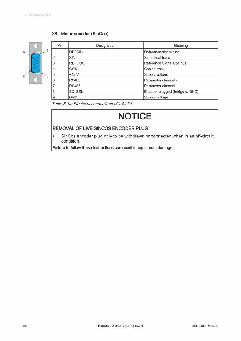
X8 - Motor encoder (SinCos)
Pin Designation Meaning1 REFSIN Reference signal sine2 SIN Sinusoidal trace3 REFCOS Reference Signal Cosinus4 COS Cosine track5 +12 V Supply voltage6 RS485 Parameter channel -7 RS485 Parameter channel +8 SC_SEL Encoder plugged (bridge to GND)9 GND Supply voltage
Table 6-34: Electrical connections MC-4 / X8
NOTICEREMOVAL OF LIVE SINCOS ENCODER PLUG
• SinCos encoder plug only to be withdrawn or connected when in an off-circuitcondition.
Failure to follow these instructions can result in equipment damage.
6 Technical data
56 PacDrive Servo Amplifier MC-4 Schneider Electric

6.4.6 MC-4 Servo Amplifier / 22 A
X1 - Control voltage
X1
24V24V0V0Venrdy+rdy-ieiieo+ieo-J
J
bi+bo+bi-bo-
Pin Designation Meaning Range1 24 V Supply voltage -15 % / +25 %2 24 V Bridged with pin 1 -3 0 V Supply voltage -4 0 V Bridged with pin 3 -5 en Enable 24 Vdc (corresponds to
IEC61131-2 type I)6 rdy+ Ready contact 20...30 Vdc / 2 A7 rdy - Ready contact 20...30 Vdc / 2 A8 iei Inverter Enable 20...30 Vdc / 30 mA9 ieo+ inverter enable output 20...30 Vdc / 2 A10 ieo- inverter enable output 20...30 Vdc / 2 A11 (5) PTC Motortemp. -12 (6) PTC Motortemp. -13 bi+ Supply holding brake +24 Vdc14 bo+ (8) Holding brake connection +24 Vdc15 bi- Supply holding brake 0 Vdc16 bo- (7) Holding brake connection 0 Vdc
Table 6-35: Electrical connections MC-4 (22 A, 50 A) / X1
X2 - Mains connection
PE
L1
L2
L3
Pin Designation Meaning Range1 PE Protective ground conductor connection2 L1 Phase L1 3 380 ... 480 Vac3 L2 Phase L2 3 380 ... 480 Vac4 L3 Phase L3 3 380 ... 480 Vac
Table 6-36: Electrical connections MC-4 / X2
X3 - DC bus
db-
db-
db+
db+
Pin Designation Meaning Range1 db + DC bus voltage + 0 ... 860 Vdc2 db + DC bus voltage + 0 ... 860 Vdc3 db - DC bus voltage - 0 ... 860 Vdc4 db - DC bus voltage - 0 ... 860 Vdc
Table 6-37: Electrical connections MC-4 / X3
6.4 Electrical connections
Schneider Electric PacDrive Servo Amplifier MC-4 57

X4 - motor connection
PE
U
V
W
Pin Designation Meaning Range1 PE Protective ground conductor connection2 U (1) Phase U 3 0 ... 480 Vac3 V (2) Phase V 3 0 ... 480 Vac4 W (3) Phase W 3 0 ... 480 Vac
Table 6-38: Electrical connections MC-4 / X4
X7 - Diagnosis
Pin Designation Meaning Range1 PRO_SEL2 RxD Receive Data3 TxD Transmit Data4 GND Signal Ground5 RS232_SEL6 VCC
Table 6-39: Electrical connections MC-4 / X7
X8 - Motor encoder (SinCos)
Pin Designation Meaning1 REFSIN Reference signal sine2 SIN Sinusoidal trace3 REFCOS Reference Signal Cosinus4 COS Cosine track5 +12 V Supply voltage6 RS485 Parameter channel -7 RS485 Parameter channel +8 SC_SEL Encoder plugged (bridge to GND)9 GND Supply voltage
Table 6-40: Electrical connections MC-4 / X8
NOTICEREMOVAL OF LIVE SINCOS ENCODER PLUG
• SinCos encoder plug only to be withdrawn or connected when in an off-circuitcondition.
Failure to follow these instructions can result in equipment damage.
6 Technical data
58 PacDrive Servo Amplifier MC-4 Schneider Electric

6.4.7 MC-4 Servo Amplifier / 50 A
X1 - Control voltage
X1
24V24V0V0Venrdy+rdy-ieiieo+ieo-J
J
bi+bo+bi-bo-
Pin Designation Meaning Range1 24 V Supply voltage -15 % / +25 %2 24 V Bridged with pin 1 -3 0 V Supply voltage -4 0 V Bridged with pin 3 -5 en Enable 24 Vdc (corresponds to
IEC61131-2 type I)6 rdy+ Ready contact 20...30 Vdc / 2 A7 rdy - Ready contact 20...30 Vdc / 2 A8 iei Inverter Enable 20...30 Vdc / 30 mA9 ieo+ inverter enable output 20...30 Vdc / 2 A10 ieo- inverter enable output 20...30 Vdc / 2 A11 (5) PTC Motortemp. -12 (6) PTC Motortemp. -13 bi+ Supply holding brake +24 Vdc14 bo+ (8) Holding brake connection +24 Vdc15 bi- Supply holding brake 0 Vdc16 bo- (7) Holding brake connection 0 Vdc
Table 6-41: Electrical connections MC-4 (22 A, 50 A) / X1
X2 - Mains connection
PE
L1
L2
L3 Pin Designation Meaning Range
1 PE Protective ground conductor connection2 L1 Phase L1 3 380 ... 480 Vac3 L2 Phase L2 3 380 ... 480 Vac4 L3 Phase L3 3 380 ... 480 Vac
Table 6-42: Electrical connections MC-4 (50 A) / X2
X3 - DC bus
db+
db+
db-
db- Pin Designation Meaning Range
1 db + DC bus voltage + 0 ... 860 Vdc2 db + DC bus voltage + 0 ... 860 Vdc3 db - DC bus voltage - 0 ... 860 Vdc4 db - DC bus voltage - 0 ... 860 Vdc
Table 6-43: Electrical connections MC-4 (50 A) / X3
X4 - motor connection
PE
W V U Pin Designation Meaning Range1 PE Protective ground conductor connection2 W (3) Phase W 3 0 ... 480 Vac3 V (2) Phase V 3 0 ... 480 Vac4 U (1) Phase U 3 0 ... 480 Vac
Table 6-44: Electrical connections MC-4 (50 A) / X4
6.4 Electrical connections
Schneider Electric PacDrive Servo Amplifier MC-4 59

X7 - Diagnosis
Pin Designation Meaning Range1 PRO_SEL2 RxD Receive Data3 TxD Transmit Data4 GND Signal Ground5 RS232_SEL6 VCC
Table 6-45: Electrical connections MC-4 / X7
X8 - Motor encoder (SinCos)
Pin Designation Meaning1 REFSIN Reference signal sine2 SIN Sinusoidal trace3 REFCOS Reference Signal Cosinus4 COS Cosine track5 +12 V Supply voltage6 RS485 Parameter channel -7 RS485 Parameter channel +8 SC_SEL Encoder plugged (bridge to GND)9 GND Supply voltage
Table 6-46: Electrical connections MC-4 / X8
NOTICEREMOVAL OF LIVE SINCOS ENCODER PLUG
• SinCos encoder plug only to be withdrawn or connected when in an off-circuitcondition.
Failure to follow these instructions can result in equipment damage.
6 Technical data
60 PacDrive Servo Amplifier MC-4 Schneider Electric

6.4.8 BM4 braking resistor module connection overview
X1
X3 dc-bus
BM
-4
24V/0
db+
db+
db-
db-
24V
0V
rdy
rdy
24V
0V
n.c.
n.c.
!•
HO
CH
SP
AN
NU
NG
! Vor
Arb
eite
n am
Ger
ät, N
etza
nsch
luß
trenn
en. E
ntla
deze
it >
2min
.•
HIG
H V
OLTA
GE
!
Disc
onne
ct fr
om m
ains
sup
ply,
befo
re w
orkin
g on
this
equi
pmen
t, El
ectri
c di
scha
rge
> 2m
in.
• H
AU
TE
TE
NS
ION
! C
oupe
z l´a
limen
tatio
n av
ant d
e m
anip
uler
l´ap
pare
il. T
emps
de
déch
arge
> 2
min
.•
ALTA
TE
NS
ION
E!
Dis
cone
ttter
e l`a
limen
tazi
one
prim
a di
lavo
rare
all`
appa
recc
hio.
Tem
po d
i sca
rica
> 2m
in.
• A
LT
O V
OLTA
JE
! D
esco
nect
en d
e la
red
ante
s de
trab
ajar
con
est
e eq
uipo
, des
carg
a el
ectri
ca >
2m
in.
• H
OH
E T
EM
PE
RA
TU
R!
O
berfl
äche
des
Ger
ätes
im B
etrie
bszu
stan
d ni
cht b
erüh
ren.
• H
IGH
TE
MP
ER
AT
UR
E!
Do
not t
ouch
this
sur
face
und
er o
pera
tion
cond
ition
s.•
TE
MP
ER
AT
UR
E E
LE
VE
E! N
e to
uche
z pa
s la
sur
face
de
l´app
arei
l en
mar
che.
• A
LTA
TE
MP
ER
AT
UR
A!
Non
tocc
are
la s
uper
ficie
del
l`app
arec
chio
in fu
ncio
ne.
• A
LTA
TE
MP
ER
AT
UR
A!
No
toqu
en e
sta
supe
rfic
ie d
uran
te la
ope
raci
on.
pow
err
bla
reset
TM
X1
X3
Connection Meaning max. terminal cross-section [mm2]/ [AWG] Tightening torque[Nm] / [lbf in]
X1 Control voltage 1.5 28-16 0.2-0,25 / 1.77-2.21X3 DC circuit 2.5 24-12 0.4-0,5 / 3.54-4.43
Protective groundconductor connec‐tion
10 - -
Table 6-47: Connection overview BM-4 Braking resistor Module
6.4 Electrical connections
Schneider Electric PacDrive Servo Amplifier MC-4 61

6.4.9 Braking resistor module BM-4
X1 - Power supply / Watch Dog
1
2
3
4
5
6
7
8
Pin Designation Meaning Range1 +24 Vdc Supply voltage -15 % / +25 %2 0 Vdc Supply voltage3 Reserved4 Reserved5 +24 Vdc Supply voltage -15 % / +25 %6 0 Vdc Supply voltage7 rdy Ready8 rdy Ready
Table 6-48: Electrical connections BM-4 / X1
X2 - DC bus
db+
db+
db-
db-
Pin Designation Meaning Range1 db + DC bus voltage + 530 ... 860 Vdc2 db + DC bus voltage + 530 ... 860 Vdc3 db - DC bus voltage - 530 ... 860 Vdc4 db - DC bus voltage - 530 ... 860 Vdc
Table 6-49: Electrical connections BM-4 / X2
6 Technical data
62 PacDrive Servo Amplifier MC-4 Schneider Electric

6.5 Dimensions
For a table to convert the mm dimension specifications (see 7.7.1 Length).
6.5.1 MC-4 / 1.5 A and 3 A servo amplifier
310
240
7.0
25.5
296
7.0
44.5
Made in Germany
230
260 max. dimension
65
69
60
X1
X2
X4
X3
X8
X7
X5
X6
S1
S2
dia
gfe
ed
ba
ck
reset
errpow
buserr
ac-p
ow
er
dc-b
us
ac-m
oto
r24V
/o
MC
-4
S3
24V
/i Inst
ruct
ion
s se
e c
ove
r si
de
!
!
C US
LISTED(INDUSTRIAL
CONTROL
EQUIPMENT)
72KL
AU
34.5 34.5
Ø6.5
� ACHTUNG! � ATTENTION! �
� HOCHSPANNUNG! Vor Arbeiten am Gerät, Netzanschluß trennen. Entladezeit > 2min.
� ERHÖHTER ABLEITSTROM! Betrieb nur mit angeschlossenem Schutzleiter.
� HOHE TEMPERATUR! Oberfläche des Gerätes im Betriebszustand nicht berühren.
� INSTALLATION! Bei Inbetriebnahme, Installationshinweise in der Bedienungsanleitung beachten.
� HIGH VOLTAGE! Disconnect from mains supply, before working on this equipment, Electric discharge> 2min.
� HIGH LEAKAGE CURRENT! Operation only with connected safety ground.
� HIGH TEMPERATURE! Do not touch this surface under operation conditions.
� INSTALLATION! Read installation instruction before installing.
� HAUTE TENSION! Coupez l´alimentation avant de manipuler l´appareil. Temps de décharge > 2min.
� COURANT DE FUITE ELEVEE! Fonctionnement uniquement avec conducteur de protection raccordé.
� TEMPERATURE ELEVEE! ne touchez pas la surface de l´appareil en marche.
� INSTALLATION! Respectez le manuel d´instruction lors de la mise en marche.
� ALTA TENSIONE! Disconetttere l`alimentazione prima di lavorare all`apparecchio. Tempo di scarica > 2min.
� ALTA DISPERSIONE DI CORRENTE! Operare solo con il conduttore di scarico a terra collegato.
� ALTA TEMPERATURA! Non toccare la superficie dell`apparecchio in funcione.
� INSTALLATIONE! Prima della messa in funzione dell`apparecchio consultare il manuale di istruzione
� ALTO VOLTAJE! Desconecten de la red antes de trabajar con este equipo, descarga electrica > 2min.
� ALTA TENSION! Operen solo con una conexion a tierra segura.
� ALTA TEMPERATURA! No toquen esta superficie durante la operacion.
� INSTALACION! Lean las instrucciones de montaje antes de instalar.
!
MC4_3A_Ansicht_deutsch.FH8
max.
torque
0,5Nm
Figure 6-1: Dimensions of the PacDrive MC-4 / 1.5 A and 3 A
6.5 Dimensions
Schneider Electric PacDrive Servo Amplifier MC-4 63

6.5.2 MC-4 / 5 A Servo Amplifier
310
240
7.0
25.5
296
7.0
44.5
Made in Germany
230
260 max. dimension
65
69
60
X1
X2
X4
X3
X8
X7
X5
X6
S1
S2
dia
gfe
ed
ba
ck
reset
errpow
buserr
ac-p
ow
er
dc-b
us
ac-m
oto
r2
4V
/o
MC
-4
S3
24
V/i In
stru
ctio
ns
see
co
ver
sid
e!
!
C US
LISTED(INDUSTRIAL
CONTROL
EQUIPMENT)
72KL
AU
34.5 34.5
Ø6.5
� ACHTUNG! � ATTENTION! �
� HOCHSPANNUNG! Vor Arbeiten am Gerät, Netzanschluß trennen. Entladezeit > 2min.
� ERHÖHTER ABLEITSTROM! Betrieb nur mit angeschlossenem Schutzleiter.
� HOHE TEMPERATUR! Oberfläche des Gerätes im Betriebszustand nicht berühren.
� INSTALLATION! Bei Inbetriebnahme, Installationshinweise in der Bedienungsanleitung beachten.
� HIGH VOLTAGE! Disconnect from mains supply, before working on this equipment, Electric discharge> 2min.
� HIGH LEAKAGE CURRENT! Operation only with connected safety ground.
� HIGH TEMPERATURE! Do not touch this surface under operation conditions.
� INSTALLATION! Read installation instruction before installing.
� HAUTE TENSION! Coupez l´alimentation avant de manipuler l´appareil. Temps de décharge > 2min.
� COURANT DE FUITE ELEVEE! Fonctionnement uniquement avec conducteur de protection raccordé.
� TEMPERATURE ELEVEE! ne touchez pas la surface de l´appareil en marche.
� INSTALLATION! Respectez le manuel d´instruction lors de la mise en marche.
� ALTA TENSIONE! Disconetttere l`alimentazione prima di lavorare all`apparecchio. Tempo di scarica > 2min.
� ALTA DISPERSIONE DI CORRENTE! Operare solo con il conduttore di scarico a terra collegato.
� ALTA TEMPERATURA! Non toccare la superficie dell`apparecchio in funcione.
� INSTALLATIONE! Prima della messa in funzione dell`apparecchio consultare il manuale di istruzione
� ALTO VOLTAJE! Desconecten de la red antes de trabajar con este equipo, descarga electrica > 2min.
� ALTA TENSION! Operen solo con una conexion a tierra segura.
� ALTA TEMPERATURA! No toquen esta superficie durante la operacion.
� INSTALACION! Lean las instrucciones de montaje antes de instalar.
!
MC4_5A_Ansicht_deutsch.FH8
230 VOLT
max.
torque
0,5Nm
Figure 6-2: Dimensions of the PacDrive MC-4 / 5 A
6 Technical data
64 PacDrive Servo Amplifier MC-4 Schneider Electric

6.5.3 MC-4 / 10 A Servo Amplifier
310
240
7.0
25.5
296
7.0
44.5
230
260 max. dimension
70
69
60
Made in Germany
X1
X2
X4
X3
X8
X7
X5
X6
S1
S2
dia
gfe
edback
reset
errpow
buserr
ac-p
ow
er
dc-b
us
ac-m
oto
r24V
/o
MC
-4
S3
24V
/i Inst
ruct
ion
s se
e c
ove
r si
de
!
!
C US
LISTED(INDUSTRIAL
CONTROL
EQUIPMENT)
72KL
AU
34.5 34.5
Ø6.5
� ACHTUNG! � ATTENTION! �
� HOCHSPANNUNG! Vor Arbeiten am Gerät, Netzanschluß trennen. Entladezeit > 2min.
� ERHÖHTER ABLEITSTROM! Betrieb nur mit angeschlossenem Schutzleiter.
� HOHE TEMPERATUR! Oberfläche des Gerätes im Betriebszustand nicht berühren.
� INSTALLATION! Bei Inbetriebnahme, Installationshinweise in der Bedienungsanleitung beachten.
� HIGH VOLTAGE! Disconnect from mains supply, before working on this equipment, Electric discharge> 2min.
� HIGH LEAKAGE CURRENT! Operation only with connected safety ground.
� HIGH TEMPERATURE! Do not touch this surface under operation conditions.
� INSTALLATION! Read installation instruction before installing.
� HAUTE TENSION! Coupez l´alimentation avant de manipuler l´appareil. Temps de décharge > 2min.
� COURANT DE FUITE ELEVEE! Fonctionnement uniquement avec conducteur de protection raccordé.
� TEMPERATURE ELEVEE! ne touchez pas la surface de l´appareil en marche.
� INSTALLATION! Respectez le manuel d´instruction lors de la mise en marche.
� ALTA TENSIONE! Disconetttere l`alimentazione prima di lavorare all`apparecchio. Tempo di scarica > 2min.
� ALTA DISPERSIONE DI CORRENTE! Operare solo con il conduttore di scarico a terra collegato.
� ALTA TEMPERATURA! Non toccare la superficie dell`apparecchio in funcione.
� INSTALLATIONE! Prima della messa in funzione dell`apparecchio consultare il manuale di istruzione
� ALTO VOLTAJE! Desconecten de la red antes de trabajar con este equipo, descarga electrica > 2min.
� ALTA TENSION! Operen solo con una conexion a tierra segura.
� ALTA TEMPERATURA! No toquen esta superficie durante la operacion.
� INSTALACION! Lean las instrucciones de montaje antes de instalar.
!
MC4_10A_Ansicht_deutsch.FH8
max.
torque
0,5Nm
Figure 6-3: Dimensions of the PacDrive MC-4 / 10 A
6.5 Dimensions
Schneider Electric PacDrive Servo Amplifier MC-4 65

6.5.4 MC-4 / 22 A Servo Amplifier
310
240
7,0
25,5
296
7,0
44,5
230
260 max. dimension
133124
Made in Germany
X1
X2
X8
X7
X5
X6
S1
S2
dia
gfe
edback
reset
errpow
buserr
ac-p
ow
er
dc-b
us
MC-4
S3
24
V
i/o
Inst
ruct
ions
see c
ove
r si
de!
Hin
weis
e s
iehe S
eite
nw
and!
!
C US
LISTED(INDUSTRIAL
CONTROL
EQUIPMENT)
72KL
27
Ø6,5
X4
ac-m
oto
r
X3
2770
24V
24V
0V
0V
en
rdy+
rdy-
iei
ieo+
ieo-
J
J
bi+
bo+
bi-
bo-
PE
L1
L2
L3
PE
U
V
W AC
HT
UN
G: H
och
spannung!
WA
RN
ING
: H
igh v
olta
ge!
db-
db-
db+
db+
MC4_22A_Ansicht_deutsch.FH8
max.
torque
0,5Nm
Figure 6-4: Dimensions of the PacDrive MC-4 / 22 A
6 Technical data
66 PacDrive Servo Amplifier MC-4 Schneider Electric

6.5.5 MC-4 / 50 A Servo Amplifier
MC-4
X1
X8
X7
X5
X6
S1
S2
diag
feed
back
reset
errpow
buserr
S324V
i/o
24V24V0V0Venrdy+rdy-ieiieo+ieo-!!bi+bo+bi-bo-
! Instructions see cover side!Hinweise siehe Seitenwand!
ACHTUNG: Hochspannung!WARNING: High voltage!
47
24
0
31
0
23
312
PE L1 L2 L3 db+
db+
db-
db-
PE
W V U
X4 ac-motorX3 dc-busX2 ac-power
Made in Germany
51 70 70 7070 51
72
96
7
Gewindebolzen M6
6,5
6,5
• ACHTUNG! • ATTENTION! •
• HOCHSPANNUNG! Vor Arbeiten am Gerät, Netzanschluß trennen. Entladezeit > 2min.• ERHÖHTER ABLEITSTROM! Betrieb nur mit angeschlossenem Schutzleiter.• HOHE TEMPERATUR! Oberfläche des Gerätes im Betriebszustand nicht berühren.• INSTALLATION! Bei Inbetriebnahme, Installationshinweise in der Bedienungsanleitung beachten. • HIGH VOLTAGE! Disconnect from mains supply, before working on this equipment, Electric discharge> 2min.• HIGH LEAKAGE CURRENT! Operation only with connected safety ground.• HIGH TEMPERATURE! Do not touch this surface under operation conditions.• INSTALLATION! Read installation instruction before installing.
• HAUTE TENSION! Coupez l´alimentation avant de manipuler l´appareil. Temps de décharge > 2min.• COURANT DE FUITE ELEVEE! Fonctionnement uniquement avec conducteur de protection raccordé.• TEMPERATURE ELEVEE! ne touchez pas la surface de l´appareil en marche. • INSTALLATION! Respectez le manuel d´instruction lors de la mise en marche.
• ALTA TENSIONE! Disconetttere l`alimentazione prima di lavorare all`apparecchio. Tempo di scarica > 2min.• ALTA DISPERSIONE DI CORRENTE! Operare solo con il conduttore di scarico a terra collegato.• ALTA TEMPERATURA! Non toccare la superficie dell`apparecchio in funcione.• INSTALLATIONE! Prima della messa in funzione dell`apparecchio consultare il manuale di istruzione
• ALTO VOLTAJE! Desconecten de la red antes de trabajar con este equipo, descarga electrica > 2min.• ALTA TENSION! Operen solo con una conexion a tierra segura.• ALTA TEMPERATURA! No toquen esta superficie durante la operacion.• INSTALACION! Lean las instrucciones de montaje antes de instalar.
31
0
255
220
27
01
72
3
!
max.torque0,5Nm
MC4_50A_Masszeichnung_de0010.fh8
Figure 6-5: Dimensions of the PacDrive MC-4 / 50 A
6.5 Dimensions
Schneider Electric PacDrive Servo Amplifier MC-4 67

6.5.6 Mains filter
FI 07876 / 8A
A
F
EB
H
CD
G
L
Lin
e/N
etz
L1
L2
L3
Lo
ad
/La
st
L1
.1L
2.1
L3
.1
Hig
h V
oltage.
Danger
of ele
ctr
ical shock.
Gro
und (
PE
) m
ust alw
ays b
e
connecte
d.
Do n
ot to
uch e
lectr
ical
connections w
hen s
witched o
n.
DA
NG
ER
!!
GE
FA
HR
!!
Hohe S
pannung.
Lebensgefa
hr.
Ste
ts m
it E
rd-/
Schutz
leiter
fest verb
inden.
Im B
etr
ieb A
nschlu
sskle
mm
en
nic
ht berü
hre
n.
FI0
7876
Lin
e F
ilte
r 3
AC
48
0V
8A
CU
FF
U 3
X08 K
-K
3 x
AC
48
0V
5
0/6
0 H
z
8A
@ 5
0°C
PD_Netzfilter_FFU3XAbmess.FH8
Figure 6-6: Dimensions of mains filter
Item name (Orderno.)
A[mm]
B[mm]
C[mm]
D [mm]
E[mm]
F[mm]
G [mm]
H L[mm]
FFU 3X08 K-K(FI07876)
190 40 70 20 180 160 5.4 M5 185
FFU 3X30 K-K(FI07877)
270 50 85 30 255 240 5.4 M5 265
FFU 3X55 K-K(FI07878)
250 85 90 60 235 220 5.4 M5 258
Table 6-50: Legend in [mm]
6 Technical data
68 PacDrive Servo Amplifier MC-4 Schneider Electric

6.5.7 Line chokes
Figure 6-7: 10 A and 25 A line chokes NKD 10 / 2.93 and NKD 25 / 1.17
Figure 6-8: 50 A line choke NKD 50 / 0.59
Item name(Order no.)
A B C D 1 D2 D3 E1 E2 E3 F G
NKD 10 /2.93
148 76 151 90 100 136 39 45 49 110 69
NKD 25 /1.17
178 106 175 113 130 166 64.5 71.5 69.5 133 89.5
NKD 50 /0.59
267 115 265 176 180 249 71 98 79 200 115
Table 6-51: Legend in [mm]
6.5 Dimensions
Schneider Electric PacDrive Servo Amplifier MC-4 69

6.5.8 BM-4 Braking resistor module
Figure 6-9: Dimensions BM-4 braking resistor module
6 Technical data
70 PacDrive Servo Amplifier MC-4 Schneider Electric

7 Appendix
7.1 Contact addresses
Schneider Electric Automation GmbHSchneiderplatz 197828 Marktheidenfeld, GermanyPhone: +49 (0) 9391 / 606 - 0Fax: +49 (0) 9391 / 606 - 4000Email: [email protected]: www.schneider-electric.com
Machine Solution ServiceSchneiderplatz 197828 Marktheidenfeld, GermanyPhone: +49 (0) 9391 / 606 - 3265Fax: +49 (0) 9391 / 606 - 3340Email: [email protected]: www.schneider-electric.com
See the homepage for additional contact addresses:www.schneider-electric.com
7.2 Product training courses
Schneider Electric offers a number of product training courses.Our training instructors will help you take advantage of the extensive possibilities of‐fered by the system.
See the homepage (www.schneider-electric.com) for further information and our cur‐rent seminar schedule.
7.1 Contact addresses
Schneider Electric PacDrive Servo Amplifier MC-4 71

7.3 EC declaration of conformity
EC DECLARATION OF CONFORMITY (Original)
Document number / Month.Year: HRB7495300_00 / 02.2013
We: Schneider Electric Industries SA 35, rue Joseph Monier 92506 Rueil Malmaison France
Hereby declare that the products
Trademark: Schneider Electric
Product, Type, Function: MC-4 Drives
Models: VDM
Serial number: YYZZXXXXXX (YY: Year, 22=2012, 23=2013; ZZ: Supplier Code; XXXXXX:Continuous number)
Reference Description
VDM01D10zzxx SERVODRIVE MC 4, 400V, 10 25A
VDM01D22zzxx SERVODRIVE MC 4, 400V, 22 55A
VDM01D50zzxx SERVODRIVE MC 4, 400V, 50 125A
VDM01U15zzxx SERVODRIVE MC 4, 400V, 1,5 3,75A
VDM01U30zzxx SERVODRIVE MC 4, 400V, 3 7,5A
VDM01U50zzxx SERVODRIVE MC 4, 230V, 5 12,5A
VDM02D10zzxx SERVODRIVE MC 4, 400V, 10 25A
VDM02D22zzxx SERVODRIVE MC 4, 400V, 22 55A
VDM02U15zzxx SERVODRIVE MC 4, 400V, 1,5 3,75A
VDM02U30zzxx SERVODRIVE MC 4, 400V, 3 7,5A
z are letters, x are numbers for different variations
are in conformity with the requirements of the following directives and conformity was checked in accordance with the following standards:
Directive Harmonized Standard
DIRECTIVE 2004/108/EC OF THE EUROPEANPARLIAMENT AND OF THE COUNCIL
of 15 December 2004 on the approximation of the laws of the Member States relating to electromagnetic compatibility and repealing Directive 89/336/EEC
EN 61800-3:2004 + A1:2012
Adjustable speed electrical power drive systems - Part 3: EMC requirements and specific test methods (IEC 61800-3:2004 + A1:2011
DIRECTIVE 2006/42/EC OF THE EUROPEAN PARLIAMENT AND OF THE COUNCIL of 17 May 2006 on machinery, and amending Directive 95/16/EC (recast)
Applying article 12(3)a)
EN ISO 13849-1/2:2008Safety of machinery - Safety-related parts of control systems
EN 61800-5-2:2007Adjustable speed electrical power drivesystems - Part 5-2: Safety requirements – Functional
EN 62061:2005Safety of machinery - Functional safety of safety-related electrical, electronic and programmable electronic control systems
and also the standard EN 61800-5-1:2007: Adjustable speed electrical power drive systems – Part 5-1: Safety
requirements - Electrical, thermal and energy.
It is important that the component is subject to correct installation, maintenance and use conforming to its intended purpose, to the applicable regulations and standards, to the supplier’s instructions, user manual and to the accepted rules of the art.
Person in charge of documentation: Eric Barry, Schneider Electric Automation GmbH, Schneiderplatz 1, 97828 Marktheidenfeld, Germany
First year of affixing CE Marking: 2001
France -Rueil Malmaison, February 2013
i.A. Peter Spitzfaden Machine Solution Certification Manager
7 Appendix
72 PacDrive Servo Amplifier MC-4 Schneider Electric
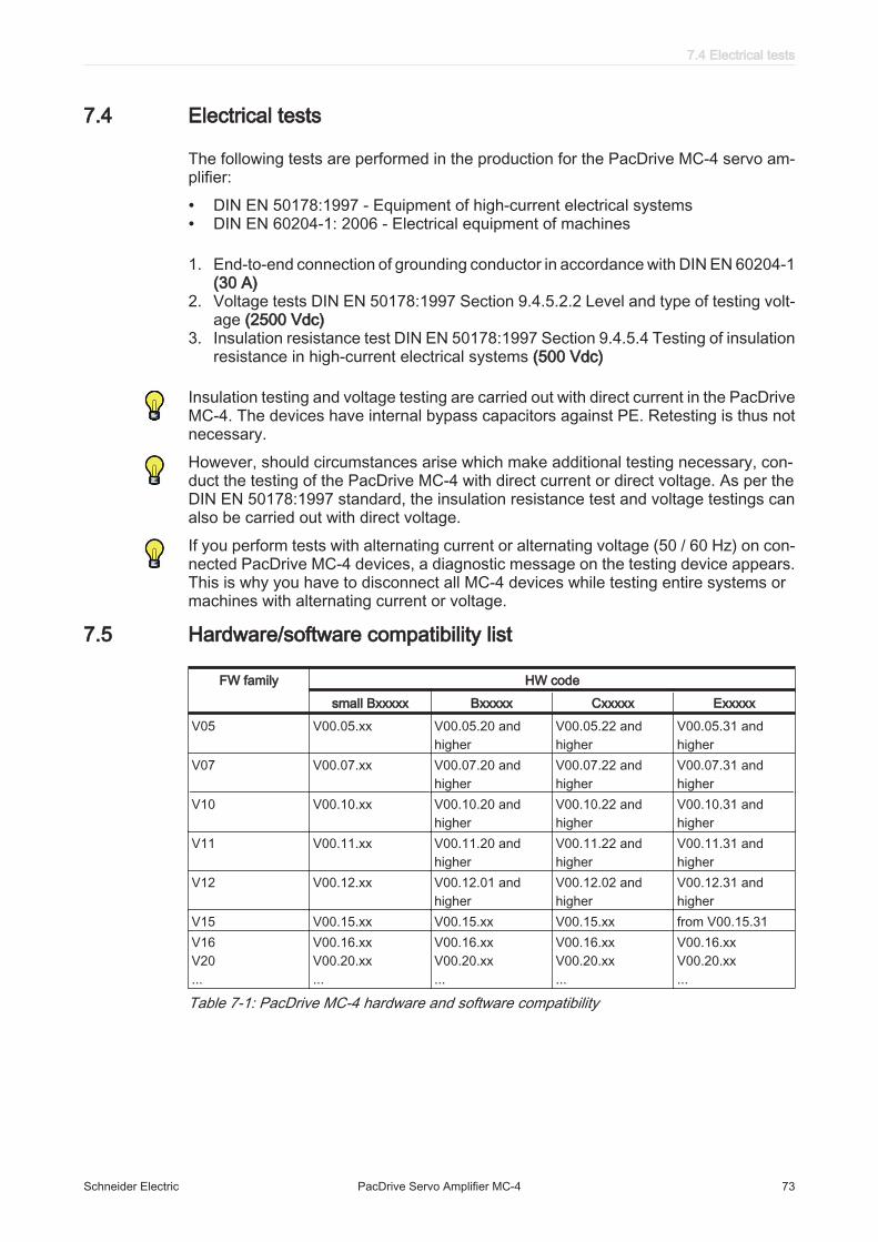
7.4 Electrical tests
The following tests are performed in the production for the PacDrive MC-4 servo am‐plifier:
• DIN EN 50178:1997 - Equipment of high-current electrical systems• DIN EN 60204-1: 2006 - Electrical equipment of machines
1. End-to-end connection of grounding conductor in accordance with DIN EN 60204-1(30 A)
2. Voltage tests DIN EN 50178:1997 Section 9.4.5.2.2 Level and type of testing volt‐age (2500 Vdc)
3. Insulation resistance test DIN EN 50178:1997 Section 9.4.5.4 Testing of insulationresistance in high-current electrical systems (500 Vdc)
Insulation testing and voltage testing are carried out with direct current in the PacDriveMC-4. The devices have internal bypass capacitors against PE. Retesting is thus notnecessary.However, should circumstances arise which make additional testing necessary, con‐duct the testing of the PacDrive MC-4 with direct current or direct voltage. As per theDIN EN 50178:1997 standard, the insulation resistance test and voltage testings canalso be carried out with direct voltage.If you perform tests with alternating current or alternating voltage (50 / 60 Hz) on con‐nected PacDrive MC-4 devices, a diagnostic message on the testing device appears.This is why you have to disconnect all MC-4 devices while testing entire systems ormachines with alternating current or voltage.
7.5 Hardware/software compatibility list
FW family HW codesmall Bxxxxx Bxxxxx Cxxxxx Exxxxx
V05 V00.05.xx V00.05.20 andhigher
V00.05.22 andhigher
V00.05.31 andhigher
V07 V00.07.xx V00.07.20 andhigher
V00.07.22 andhigher
V00.07.31 andhigher
V10 V00.10.xx V00.10.20 andhigher
V00.10.22 andhigher
V00.10.31 andhigher
V11 V00.11.xx V00.11.20 andhigher
V00.11.22 andhigher
V00.11.31 andhigher
V12 V00.12.xx V00.12.01 andhigher
V00.12.02 andhigher
V00.12.31 andhigher
V15 V00.15.xx V00.15.xx V00.15.xx from V00.15.31V16 V20...
V00.16.xx V00.20.xx ...
V00.16.xx V00.20.xx ...
V00.16.xx V00.20.xx ...
V00.16.xx V00.20.xx ...
Table 7-1: PacDrive MC-4 hardware and software compatibility
7.4 Electrical tests
Schneider Electric PacDrive Servo Amplifier MC-4 73

7.6 Changes
01 / 2001
• MC-4 / 50 / 400 new• Mains filter HLD 110-500/55 new
08 / 2004
• New series of mains filter added• Layout of document revised• Product names and terms adapted
05 / 2005
• New chapter entitled Line Chokes added
12 / 2005
• MC-4 / 1.5 A added
04 / 2007
• Various motor supply cables added
12 / 2008
• Revision of the chapter entitled "Technical Data"• Revision of the chapter entitled "Installation and Maintenance"• Adaptation of document layout• Adaptation of the corporate design
07 / 2009
• Revisions of the safety messages• Improvement of the mechanical and electrical data• Improvement of the electrical connections
10 / 2010
• Revising the whole documentation
11 / 2012
• Note about overtemperature detection added
07 / 2013
• Revision of EC declaration of conformity
7 Appendix
74 PacDrive Servo Amplifier MC-4 Schneider Electric

7.7 Units and conversion tables
7.7.1 Length
in ft yd m cm mmin - / 12 / 36 * 0.0254 * 2.54 * 25.4ft * 12 - /3 * 0.30479 * 30.479 * 304.79yd * 36 * 3 - * 0.9144 * 91.44 * 914.4m / 0.0254 / 0.30479 / 0.9144 - *100 * 1000cm / 2.54 / 30.479 / 91.44 / 100 - * 10mm / 25.4 / 304.79 / 914.4 / 1000 / 10 -
7.7.2 Mass
lb oz slug 0.22 kg glb - * 16 * 0.03108095 * 0.4535924 * 453.5924oz / 16 - * 1.942559*10-3 * 0.02834952 * 28.34952slug / 0.03108095 / 1.942559*10-3 - * 14.5939 * 14593.90.22 kg / 0.45359237 / 0.02834952 / 14.5939 - * 1000g / 453.59237 / 28.34952 / 14593.9 / 1000 -
7.7.3 Force
lb oz p dyne Nlb - * 16 * 453.55358 * 444822.2 * 4.448222oz / 16 - * 28.349524 * 27801 * 0.27801p / 453.55358 / 28.349524 - * 980.7 * 9.807*10-3
dyne / 444822.2 / 27801 / 980.7 - / 100*103
N / 4.448222 / 0.27801 / 9.807*10-3 * 100*103 -
7.7.4 Power
HP WHP - * 746W / 746 -
7.7.5 Rotation
min-1(rpm) rad/s deg./smin-1(rpm) - * π / 30 * 6rad/s * 30 / π - * 57.295deg./s / 6 / 57.295 -
7.7 Units and conversion tables
Schneider Electric PacDrive Servo Amplifier MC-4 75

7.7.6 Torque
lb•in lb•ft oz•in Nm kp•m kp•cm dyne•cmlb•in - / 12 * 16 * 0.112985 * 0.011521 * 1.1521 * 1.129*106
lb•ft * 12 - * 192 * 1.355822 * 0.138255 * 13.8255 * 13.558*106
oz•in / 16 / 192 - * 7.0616*10-3 * 720.07*10-6 * 72.007*10-3 * 70615.5Nm / 0.112985 / 1.355822 / 7.0616*10-3 - * 0.101972 * 10.1972 * 10*106
kp•m / 0.011521 / 0.138255 / 720.07*10-6 / 0.101972 - * 100 * 98.066*106
kp•cm / 1.1521 / 13.8255 / 72.007*10-3 / 10.1972 / 100 - * 0.9806*106
dyne•cm / 1.129*106 / 13.558*106 / 70615.5 / 10*106 / 98.066*106 / 0.9806*106 -
7.7.7 Moment of inertia
lb•in2 lb•ft2 kg•m2 kg•cm2 kg•cm2•s2 oz•in2
lb•in2 - / 144 / 3417.16 / 0.341716 / 335.109 * 16lb•ft2 * 144 - /3 *0.30479 *30.479 *304.79kg•m2 * 3417.16 / 0.04214 - *0.9144 *91.44 *914.4kg•cm2 * 0.341716 / 421.4 /0.9144 - *100 *1000kg•cm2•s2 * 335.109 / 0.429711 /91.44 /100 - *10oz•in2 / 16 / 2304 / 54674 / 5.46 / 5361.74 -
7.7.8 Temperature
°F max K°F - (°F - 32) * 5/9 (°F - 32) * 5/9 + 273.15max °C * 9/5 + 32 - °C + 273.15K (K - 273.15) * 9/5 + 32 K - 273.15 -
7.7.9 Conductor cross-section
AWG 1 2 3 4 5 6 7 8 9 10 11 12 13mm2 42.4 33.6 26.7 21.2 16.8 13.3 10.5 8.4 6.6 5.3 4.2 3.3 2.6
AWG 14 15 16 17 18 19 20 21 22 23 24 25 26mm2 2.1 1.7 1.3 1.0 0.82 0.65 0.52 0.41 0.33 0.26 0.20 0.16 0.13
7 Appendix
76 PacDrive Servo Amplifier MC-4 Schneider Electric

Index
BBM-4 70
CCertifications 36Contact addresses 71
DDiagnostic message 20Diagnostics 20domestic appliances 9
Eerr 24
Ffloating systems 9flying systems 9
Hhazardous, explosive atmospheres 9Hazards 11Homepage 71
Llife support systems 9
MMains filter 68MC-4 16, 63MC-4 / 05 A 39MC-4 / 1.5 A 37MC-4 / 10 A 40MC-4 / 22 A 41MC-4 / 50 A 42mobile systems 9
Pportable systems 9
QQualification of Personnel 10Qualified person 10
RResidual risks 11
SSeminars 71Service addresses 71Status display 24Symbols 8
TTraining 10Training courses 71
Uunderground 9
Index
Schneider Electric PacDrive Servo Amplifier MC-4 77