Operating instructions for authorized experts Light oil burners ...
12
09/2005 - Art. Nr. 13 019 533A Operating instructions for authorized experts Light oil burners EK4...L-ZA Designs: Basis CEN DIN
-
Upload
khangminh22 -
Category
Documents
-
view
1 -
download
0
Transcript of Operating instructions for authorized experts Light oil burners ...
09/2005 - Art. Nr. 13 019 533A
Operating instructionsfor authorized experts
Light oil burnersEK4...L-ZA
Designs:BasisCENDIN
09/2005 - Art. Nr. 13 019 533A2
Survey
Table of contentsGeneral information
Table of contents Page
Survey Contents . . . . . . . . . . . . . . . . . . . . . . . . . . . . . . . . . . . . 2General information . . . . . . . . . . . . . . . . . . . . . . . . . . . . . . 2Technical data . . . . . . . . . . . . . . . . . . . . . . . . . . . . . . . . . 3Performance charts . . . . . . . . . . . . . . . . . . . . . . . . . . . . . . 3Dimensions. . . . . . . . . . . . . . . . . . . . . . . . . . . . . . . . . . . 4
Burner functions Functional description . . . . . . . . . . . . . . . . . . . . . . . . . . . . . 5Functional diagram. . . . . . . . . . . . . . . . . . . . . . . . . . . . . . . 5Functional sequence LAL 1 . . . . . . . . . . . . . . . . . . . . . . . . . . 6
Installation Mounting the burner to the heat generator . . . . . . . . . . . . . . . . . . . 7Zero point adjustment (flame cup) . . . . . . . . . . . . . . . . . . . . . . . 7Electrical connection . . . . . . . . . . . . . . . . . . . . . . . . . . . . . . 7Oil connection . . . . . . . . . . . . . . . . . . . . . . . . . . . . . . . . . 8Oil pressure regulation . . . . . . . . . . . . . . . . . . . . . . . . . . . . . 8Start-up. . . . . . . . . . . . . . . . . . . . . . . . . . . . . . . . . . . . . 8
Adjustments Burner head setting dimensions . . . . . . . . . . . . . . . . . . . . . . . . 9Air regulation . . . . . . . . . . . . . . . . . . . . . . . . . . . . . . . . . . 10
Service instructions Maintenance . . . . . . . . . . . . . . . . . . . . . . . . . . . . . . . . . . 11Troubleshooting . . . . . . . . . . . . . . . . . . . . . . . . . . . . . . . . 11
General informationThe EK4...L-ZA series of ELCO light oilburners, featuring monobloc design andfully automatic two-stage operation, aresuitable for the combustion of extra-light fuel oil. Design and performance ofthe burners comply with currently appli-cable guidelines and regulations.Burner installation and start-up must beperformed by a qualified expert who isresponsible for the proper execution ofthese tasks.The burner complies with the standards
EN 267DIN 4787
Observe the following standards toensure safe, environmentally friendlyand energy-saving operation of theburner.
DIN 4755Oil-burning installations in heatingsystems.
DIN 4789Connection of atomizing oil burners andblower gas burners to heat generators.
EN 60335-1Safety of electrical appliances fordomestic use
Site of installationThe burner must not be operated inrooms with aggressive fumes (e.g.hairspray, tetrachloroethylene, carbontetrachloride), dust-laden air or highatmospheric humidity (e.g. laundryrooms).
ELCO rejects all warranty claims fordamage resulting from one of thefollowing reasons:– Improper use– Inexpert installation or mainten-
ance by the purchaser or thirdpersons, including the installationof parts other than genuine partssupplied by the manufacturer.
Start-upInitial start-up of the oil burning installa-tion must be performed by the installer,manufacturer, or by another expertdesignated by them.
Delivery and operating instructionsAt the time of delivery at the latest, thecompany installing the oil burner mustsupply the user with a set of Operatingand Service Instructions. These shouldbe kept in the room where the heatgenerator is installed.The address and telephone number ofthe nearest service representative mustbe entered in the Instructions.
Note for the userThe system should be serviced by anexpert at least once a year. To ensuremaintenance at regular intervals, werecommend you to conclude a servicecontract.
Scope of deliveryEach burner is delivered in a separatepacking case. The following compo-nents are included in delivery:– Burner with burner head– Movable mounting flange and insula-
ting base– Two oil tubes– Automatic burner control unit with
plug-in socket– Document folder

09/2005 - Art. Nr. 13 019 533A 3
Survey
Technical dataPerformance charts
Burner type EK 4.100 L-ZA EK 4.160 L-ZA
Technical data
Thermal output . . . . . . . . . . . . min. 360 kW 580 kWThermal output . . . . . . . . . . . . max. 1070 kW 1660 kWOil flow . . . . . . . . . . . . . . . . min. 31 kg/h 49 kg/hOil flow . . . . . . . . . . . . . . . . max. 90 kg/h 140 kg/hFuel oil . . . . . . . . . . . . . . . . Extra Light, DIN 51603 Extra Light, DIN 51603Hydraulic system/standard . . . . . . 2-stage, 2 nozzles/CEN 2-stage, 2 nozzles/DINAir regulation . . . . . . . . . . . . . suction side Air cut-off valve Air cut-off valveAir regulation . . . . . . . . . . . . . pressure side in burner head in burner headControl ratio . . . . . . . . . . . . . max. 60/100% 60/100%Voltage . . . . . . . . . . . . . . . . 230/400 V, 50/60 Hz 230/400 V, 50/60 HzPower consumption . . . . . . . . . 2.5 kW 2.5 kWWeight approx. . . . . . . . . . . . . 83 kg 98 kg
Burner equipment
Electric motor 2800 min.–1 2.2 kW 2.2 kWAutomatic burner control unit LAL 1.25 LAL 1.25Flame monitor QRB 1 QRB 1Ignition transformer ZM 20/10 ZM 20/10Solenoid valves Nozzle control 2-way on pump 2-waySolenoid values 3-way 3-wayAir damper drive hydraulic hydraulicOil pressure pump A2L95D, 110 l/h at 18 bar RSA 125
Performance chartsThe performance charts reflectthe values approved during officialhomologation.
Determining the required thermal output
KF
N�
�
QF = Thermal output (kW)QN = Rated boiler capacity (kW)�K = Boiler efficiency (%)
Thermal output QF
Oil throughput
Fur
nace
pres
sure
EK4.100 L-ZA EK4.100 L-ZA

09/2005 - Art. Nr. 13 019 533A4
Survey
Dimensions
KeyEK = Manufacturer4 = Size160 = Performance ratingL = Fuel oil Extra LightZ = Two-stageA = Automatic burner control unit
1 Return line connection2 Suction line connection3 Solenoid valve, nozzle 24 Solenoid valve, nozzle 15 Solenoid valve for hydraulic air
damper drive
6 Switch box with automatic burnercontrol unit, switch, protectivemotor switch and connectingterminals
7 Connecting flange8 Insulating base9 Burner tube10 Flame cup
11 Electric motor12 Flame monitor13 Burner housing14 Air suction box15 Oil pressure pump16 Hydraulic air damper drive17 Inspection glass18 Ignition transformer
Burner type Thermaloutput kW
A B C dø Dø Eø* Type No.
EK 4.100 L-ZA 360–1070 455 176 179 159 190 240–300* BN19787/89
EK 4.160 L-ZA 580–1660 455 176 179 185 220 280 BN19787/89
Customized designs and voltages on request.* Long holes in burner connecting flange, graduated circle from … to …
Burner type F ø Fig. G H J K L M N O
EK 4.100 L-ZA 330 1 222 M12 200 430 520 120–406 382 307
EK 4.160 L-ZA 310 2 222 M12 230 430 535 125–380 382 332
Holes in the boiler connecting plate
Fig. 1 Fig. 2
09/2005 - Art. Nr. 13 019 533A 5
Burner Functions
Functional DescriptionFunctional Diagram
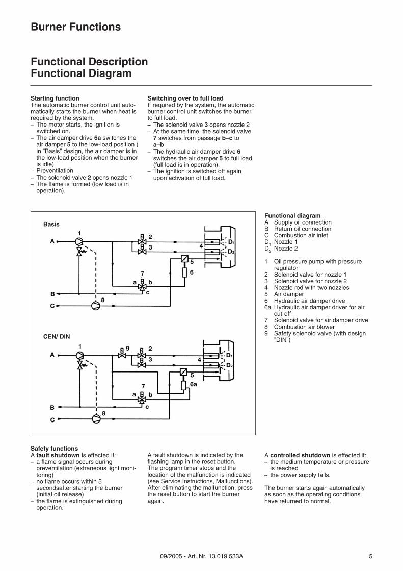
Starting functionThe automatic burner control unit auto-matically starts the burner when heat isrequired by the system.– The motor starts, the ignition is
switched on.– The air damper drive 6a switches the
air damper 5 to the low-load position (in ”Basis” design, the air damper is inthe low-load position when the burneris idle)
– Preventilation– The solenoid valve 2 opens nozzle 1– The flame is formed (low load is in
operation).
Switching over to full loadIf required by the system, the automaticburner control unit switches the burnerto full load.– The solenoid valve 3 opens nozzle 2– At the same time, the solenoid valve
7 switches from passage b–c toa–b
– The hydraulic air damper drive 6switches the air damper 5 to full load(full load is in operation).
– The ignition is switched off againupon activation of full load.
Functional diagramA Supply oil connectionB Return oil connectionC Combustion air inletD1 Nozzle 1D2 Nozzle 2
1 Oil pressure pump with pressureregulator
2 Solenoid valve for nozzle 13 Solenoid valve for nozzle 24 Nozzle rod with two nozzles5 Air damper6 Hydraulic air damper drive6a Hydraulic air damper driver for air
cut-off7 Solenoid valve for air damper drive8 Combustion air blower9 Safety solenoid valve (with design
”DIN”)
Safety functionsA fault shutdown is effected if:– a flame signal occurs during
preventilation (extraneous light moni-toring)
– no flame occurs within 5secondsafter starting the burner(initial oil release)
– the flame is extinguished duringoperation.
A fault shutdown is indicated by theflashing lamp in the reset button.The program timer stops and thelocation of the malfunction is indicated(see Service Instructions, Malfunctions).After eliminating the malfunction, pressthe reset button to start the burneragain.
A controlled shutdown is effected if:– the medium temperature or pressure
is reached– the power supply fails.
The burner starts again automaticallyas soon as the operating conditionshave returned to normal.
Basis
CEN/ DIN
09/2005 - Art. Nr. 13 019 533A6
Burner functions
Functional sequence of burner control units LAL 1...
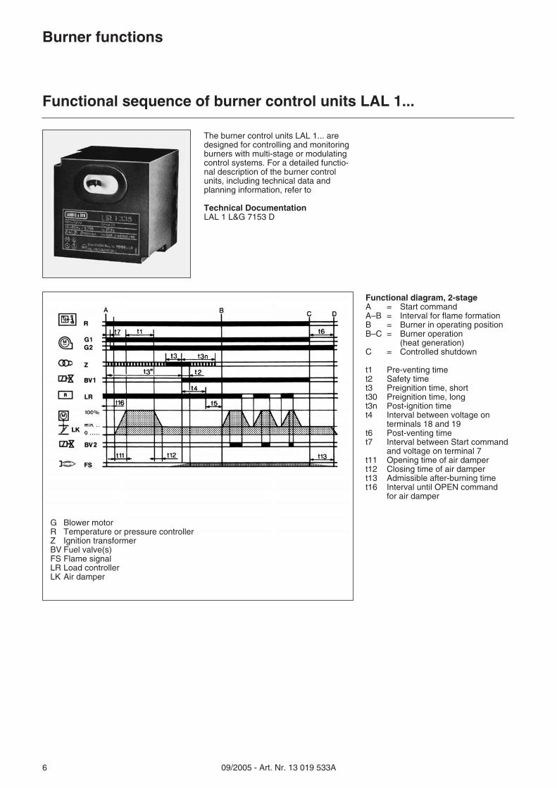
The burner control units LAL 1... aredesigned for controlling and monitoringburners with multi-stage or modulatingcontrol systems. For a detailed functio-nal description of the burner controlunits, including technical data andplanning information, refer to
Technical DocumentationLAL 1 L&G 7153 D
Functional diagram, 2-stageA = Start commandA–B = Interval for flame formationB = Burner in operating positionB–C = Burner operation
(heat generation)C = Controlled shutdown
t1 Pre-venting timet2 Safety timet3 Preignition time, shortt30 Preignition time, longt3n Post-ignition timet4 Interval between voltage on
terminals 18 and 19t6 Post-venting timet7 Interval between Start command
and voltage on terminal 7t11 Opening time of air dampert12 Closing time of air dampert13 Admissible after-burning timet16 Interval until OPEN command
for air damper
G Blower motorR Temperature or pressure controllerZ Ignition transformerBV Fuel valve(s)FS Flame signalLR Load controllerLK Air damper

09/2005 - Art. Nr. 13 019 533A 7
Installation
Mounting the burner to the heat generatorZero point adjustmentElectrical connection
Mounting the burner to the heatgeneratorTo mount the burner connecting flangeto the heat generator, prepare the con-necting plate according to the dimen-sions given on page 4. The connectingflange 4 with the insulating base 3 havebeen factory-mounted to the front of theburner tube.� Set the desired burner tube length in
the furnace by moving the flange onthe burner tube
� Insert the burner into the opening ofthe heat generator and secure it.
Inspection glass coolingTo keep the boiler inspection glass cooland clean, a cooling line may beconnected to connection 12 R1/4”.The cooling line can be either a hose ora copper pipe.A hose union is enclosed with theburner.To connect a copper pipe, a suitableclamping ring connection is required.
Zero point adjustment, flame cupBefore the burner is operated for thefirst time, the zero point must bechecked and adjusted, if necessary, sothat the zero mark on the scale corre-sponds to the zero position in theburner head. Adjustment is made bydisplacing the flame cup after releasingthe screw 1.
Electrical connectionElectric wiring must be carried out byan authorized electrician according tothe enclosed wiring diagram.The connecting terminals are located inthe built-in switch box.
For cable connection, ensure thefollowing:� Connect to terminal strip 8.� Provide sufficient length of cable so
that the burner and the boiler doorcan be opened.
� Do not install the sensor lead in themulti-conductor cable.
The electric module can be removed forconnection, replacement or adjustmentof components.5 Lock nut for electric module
6 Pushbutton, stage 1 - stage 27 Pushbutton On/Off8 El. connecting terminals9 Overload relay10 Protective motor switch11 Automatic burner control unit with
reset button12 Connection for inspection glass
cooling
Disassembling the electric module� Set the main switch to off, remove
the fuse� Release the lock nuts 5� Carefully remove the electric module.
Caution!Never apply voltage to the electricmodule after disassembly.After making the connections, check allsystem components for correct wiring.Then start the motor for a short time tocheck its sense of rotation.

09/2005 - Art. Nr. 13 019 533A8
Installation
Oil connectionOil pressure regulationStart-up
Oil connectionHoses are used for connecting theoil pipes and the valve system. Thehoses must be properly installed(suspended if possible) to avoid kinkingand the risk of fracture. For the dimen-sions of the supply and return pipesfrom the valve system to the tank,please consult the relevant technicaldata sheets.
Mounting options– Direct single-pipe installation– Single pipe installation with vent
filter– Two-pipe installation
FiltersTo protect the burner pump and thehydraulic system, suitable filters mustbe installed upstream of the burner.
Conversion from two-pipe to single-pipe installationThe burners are delivered with thepumps fitted for two-pipe installation.
Conversion� Remove the bypass plug from the
return line connection and close thereturn line R with the screw suppliedwith the burner.
Attaching the measuringinstruments� Suction line vacuum gauge to con-
nection 3� Oil pressure gauge to connection 4
Oil pressure regulationThe oil pressure is regulated by thepressure regulator incorporated in thepump. The correct setting is approx.15–20 bar, depending on the burnercapacity.The pressure regulator is actuated byturning the screw 6.
Vacuum test (suction line)The maximum permissible vacuum is0.4 bar. A higher vacuum will cause theheating oil to vaporize and may causemalfunctions.
Pump type for EK4.160 L-ZA
R Return line connectionS Suction line connection
1 Solenoid valve, nozzle 2 (full load)2 Connection, nozzle 23 Vacuum gauge connection
(suction line)4 Pressure gauge connection
(oil pressure)5 Screws for pump cover6 Oil pressure regulator7 Connection, nozzle 18 Connection, hydraulic air damper
drive9 Solenoid valve, nozzle 1 (low load)10 Pressure output
Start-up and ventilationSwitch on the burner for a short whileand check whether the sense ofrotation is correct. Loosen the oil pipeunion at the pressure output (7 or 10),switch on the burner and run the burneruntil bubble-free oil emerges. Thenreconnect the oil pipe.
Important!The hydraulic system has been filledwith test oil at the factory. This maycause ignition problems when startingthe burner for the first time.
Adjustment sequence� Start the burner� Adjust the oil pressure (15–20 bar)� Provisionally adjust low load� Switch over to full load� Finally adjust full load� Switch back to low load� Finally adjust low load
Pump type for EK4.100 L-ZA

09/2005 - Art. Nr. 13 019 533A 9
Start-up
Burner head setting dimensions
The setting dimensions are standardvalues which refer to 80% of themaximum burner capacity. They can bereadjusted depending on operating con-ditions, flue gas analysis and combu-stion behaviour.
Important!Check the settings by means of thetable before starting the burner for thefirst time. Remove the nozzle connec-tion for this purpose.
Ignition electrodesThe ignition electrodes are directed tonozzle 1.Spare ignition electrodes must be bentfor replacement (at an angle of approx.30° to the nozzle).
Burner head1 Oil connection, minimum low load1a Oil connection, maximum full load2 Ignition electrode3 Flame cup4 Nozzle rod5 Baffle plate holder6 Nozzle7 Baffle plate
Burner type Standard settings
A C D E H K L
Baf
flepl
ate/
nozz
lero
d
Ele
ctro
de/a
xis
Ele
ctro
de/
nozz
lero
d
Ele
ctro
dega
p
Baf
flepl
ate/
flam
ecu
p
max
.lon
gitu
di-
nala
djus
tmen
t
Oil
fille
rne
ck/
scal
epl
ate
0
EK 4.100 L-ZA 27 7 20 3 20 50EK 4.160 L-ZA 27 7 20 3 20 50
View Z

09/2005 - Art. Nr. 13 019 533A10
Start-up
Air regulation
Design ”Basis”
Low load� Release the lock nut 1� Use the screw 2 to adjust the
low-load air� Tighten the lock nut after
adjustment.
Full load� Release the lock nut 3� Use the screw 4 to adjust the
full-load air� Tighten the lock nut after
adjustment.
Air regulation, suction sideThe combustion air is adjusted on thehydraulic air damper drive.
Design ”CEN”/”DIN”The closed air damper position isadjusted by means of the screw 6(standard factory setting).
Low load� Release the plug screw 5. The screw
behind it is now accessible foradjusting the low-load air.
� Retighten the plug screw.
Full load� Release the lock nut 3� Use the screw 4 to adjust the
full-load air� Tighten the lock nut after
adjustment.
Important!Make sure that you do not turn the stopsof the hydraulic drive forcefully towardseach other, i.e. adjust the stop screwsonly as long as the air dampers movesynchronously. Violent and excessiveturning will destroy the pinion.
1 Lock nut2 Air regulator, low load (Basis)3 Lock nut4 Air regulator, full load5 Air regulator, low load (CEN)6 Air regulator, air damper closed
(CEN)7 Locking screws for longitudinal
nozzle rod adjustment8 Fixing screw, nozzle rod
Air regulation, pressure sideMoving the nozzle rod changes theavailable sectional area F in the flamecup.
Adjusting the nozzle rod� Release the screws 7� Adjust the nozzle rod� Tighten the screws after adjustment.The ideal position of the nozzle rodis determined by analyzing the combustionquality at low and full load.To disassemble the nozzle rod, releasethe screw 8.

09/2005 - Art. Nr. 13 019 533A 11
Service instructions
MaintenanceTroubleshooting
MaintenanceBurner installations should be servicedonce a year. The combustion andemission values should be checked andreadjusted, if necessary. All mechanicaland hydraulic functions should also bechecked and wearing parts should bereplaced, if necessary.
Any maintenance and repair jobsmay be carried out by authorizedexperts only.
Check for operating abilityIf a malfunction occurs, check firstwhether all requirements for troublefreeoperation have been met.
1. Check fuel level2. Check power supply3. Check if all control and safety
features, such as thermostat, safetylimiter, low-water cutout, electriclimit switches etc. are operative andproperly adjusted
Burner malfunction, electricBurner malfunctions are indicated by amalfunction lamp. The automatic burnercontrol unit LAL 1 is equipped with amalfunction indicator that is very usefulfor locating the cause of a malfunction.
Malfunction control program andmalfunction indicatorAutomatic burner control unit LAL 1; fordetailed information, see L and G 7153.Basically, the program timer and themalfunction indicator stop whenever amalfunction occurs. The symboldisplayed above the reading markindicates the type of malfunction:
� No Start, e.g. because theCLOSED signal from limitreversing switch ”Z” (or fromauxiliary switch ”M”) is missing onterminal 8, or because a contactis open between terminals 4 and5.
� Start aborted because the OPENsignal from limit reversing switch”A” is missing on terminal 8.Terminals 6, 7 and 15 remainenergized until the fault iseliminated!
Burner malfunction, generalIn the event of any burner malfunctionwhose cause is not immediately identifi-able, check the program sequence bymeans of the applicable wiring diagramand the hydraulic system descriptionuntil you locate the fault.
� Fault shutdown because theflame supervising circuit isdefective.
� Start aborted because theposition signal from auxiliaryswitch ”M” for the small flameposition is missing on terminal 8.Terminals 6, 7 and 15 remainenergized until the fault iseliminated!
1 Fault shutdown because no flamesignal is present upon expiry ofthe safety time.
� Fault shutdown because theflame signal has failed duringburner operation.
� Fault shutdown on or aftercompletion of the controlprogram because of extraneouslight (e.g. flame not extinguished,leaky fuel valves or shutoffelements in the nozzle rod,defective flame supervisingcircuit, etc.).
a–b Starting programb–b’ ”Blank spaces”
(no contacts actuated)b(b’)–a Post-venting program
The automatic control unit can be resetimmediately after a fault shutdown.After resetting (as well as after a powerfailure or after eliminating a malfunctionwhich caused a fault shutdown), theprogram timer will always returns to itsstarting position, supplying voltage toterminals 7, 9, 10 and 11 only, as deter-mined by the control program. Onlythen will the control unit initiate anotherstarting sequence of the burner.
Note:Operate the reset button for 20seconds at the most.

09/2005 - Art. Nr. 13 019 533A12
Fabriqué en EU. Made in EU. Hergestellt in der EU.Document non contractuel. Non contractual document. Angaben ohne Gewähr.
Adresse Service-Hotline
ELCO Austria GmbHAredstr.16-182544 Leobersdorf
0810-400010
ELCO Belgium n.v./s.a.Pontbeeklaan-531731 Zellik
02-4631902
ELCOTHERM AGSarganserstrasse 1007324 Vilters
0848 808 808
ELCO GmbHDreieichstr.1064546 Mörfelden-Walldorf
0180-3526180
ELCO France18 rue des Buchillons74106 Annemasse
0450877624
ELCO-Rendamax B.V.Amsterdamsestraatweg 271410 AB Naarden
035-6957350NL
FR
DE
BE
AT
CH