Authorized electrician Important safety instructions - Prime Solar
28
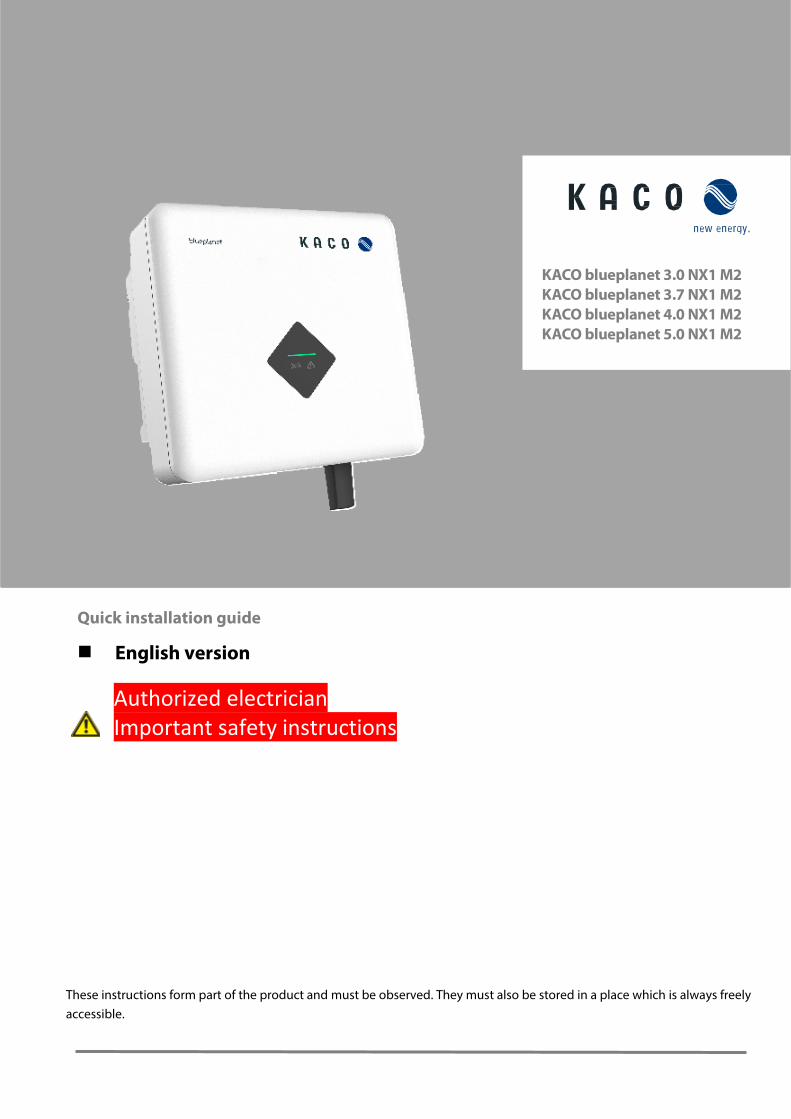
These instructions form part of the product and must be observed. They must also be stored in a place which is always freely accessible. Quick installation guide English version Authorized electrician Important safety instructions KACO blueplanet 3.0 NX1 M2 KACO blueplanet 3.7 NX1 M2 KACO blueplanet 4.0 NX1 M2 KACO blueplanet 5.0 NX1 M2
-
Upload
khangminh22 -
Category
Documents
-
view
1 -
download
0
Transcript of Authorized electrician Important safety instructions - Prime Solar
These instructions form part of the product and must be observed. They must also be stored in a place which is always freely
accessible.
Quick installation guide
English version
Authorized electrician
Important safety instructions
KACO blueplanet 3.0 NX1 M2
KACO blueplanet 3.7 NX1 M2
KACO blueplanet 4.0 NX1 M2
KACO blueplanet 5.0 NX1 M2

Contents 1 NX1 Setup app ........................................................................................................................................................ 1
1.1 App download ....................................................................................................................................................................................................... 1
2 WLAN Network Configuration ............................................................................................................................... 1
2.1 Authorization ......................................................................................................................................................................................................... 1
2.2 Network configuration ....................................................................................................................................................................................... 2
3 Inverter Parameters Settings ................................................................................................................................. 4
3.1 Connect to Wi-Fi stick ......................................................................................................................................................................................... 4
3.1.1 Connect Wi-Fi stick directly through the Wi-Fi stick’s hotspot ..................................................................................................... 4
3.1.2 Connect Wi-Fi stick through the router ................................................................................................................................................. 5
3.2 Inverter parameter settings .............................................................................................................................................................................. 6
3.2.1 Connect to inverter ........................................................................................................................................................................................ 6
3.2.2 Enabling Inverter functions ........................................................................................................................................................................ 7
3.2.3 Inverter grid parameter setting: grid standards ................................................................................................................................. 8
3.2.4 Inverter grid parameter setting: power up ........................................................................................................................................... 8
3.2.5 Inverter grid parameter setting: voltage protection ......................................................................................................................... 9
3.2.6 Inverter grid parameter setting: frequency protection ................................................................................................................ 10
3.2.7 Inverter grid parameter setting: reconnection time ...................................................................................................................... 11
3.2.8 Inverter active power setting: power limit ......................................................................................................................................... 12
3.2.9 Inverter active power setting: overfrequency curve ...................................................................................................................... 13
3.2.10 Inverter active power setting: overvoltage curve ........................................................................................................................... 15
3.2.11 Inverter reactive power setting: running mode............................................................................................................................... 17
3.2.12 Inverter reactive power setting: fixed power factor ....................................................................................................................... 18
3.2.13 Inverter reactive power setting: Cos(Φ) – P curve ........................................................................................................................... 18
3.2.14 Inverter reactive power setting: fixed Q ............................................................................................................................................. 19
3.2.15 Inverter reactive power setting: Q-U curve........................................................................................................................................ 20
3.2.16 Inverter parameter report ........................................................................................................................................................................ 21
3.3 Inverter real time data ..................................................................................................................................................................................... 22
3.3.1 Connect to inverter ..................................................................................................................................................................................... 22
3.3.2 Inverter’s details ........................................................................................................................................................................................... 23
4 Firmware Update ..................................................................................................................................................24
4.1 Wi-Fi stick firmware update ........................................................................................................................................................................... 24
4.2 Inverter firmware update ............................................................................................................................................................................... 24

Page 1 KACO blueplanet 3.0 NX1 M2 KACO blueplanet 3.7 NX1 M2 KACO blueplanet 4.0 NX1 M2 KACO blueplanet 5.0 NX1 M2
1 NX1 Setup app
1.1 App download
The app is available to download on Apple App Store and Google Play Store (currently the app for Android is only available
for download on KACO website under the software download section of the NX1 inverters. It will be available in Play Store
soon).
The app can be searched by the name “KACO NX1 Setup”. Once installed it will appear as “KacoTool” on the smartphone
(Android and iOS). The app is compatible with Android Oreo 8.0 and higher, and with Apple iOS 11 and higher.
2 WLAN Network Configuration
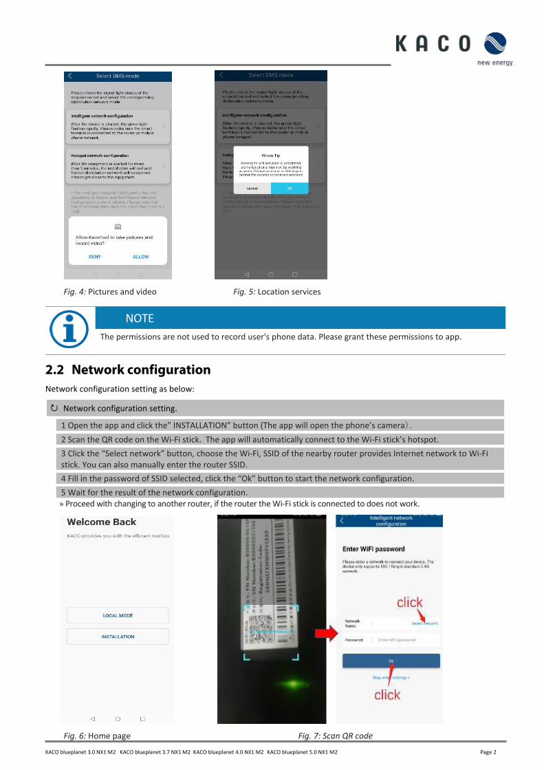
2.1 Authorization
The app will automatically connect to the Wi-Fi Stick hotspot via SSID and password in QR code, so the app needs certain
permissions to access the device of smart phone (Android and iOS) as below:
Access the device of smart phone.
1 Photo and media permission.
2 Location permission.
3 Device information permission.
4 Picture and video permission
5 Location service.
» Proceed with network configuration
Fig. 1: Photo and media permission Fig. 2: Device information permission Fig. 3: Location permission
KACO blueplanet 3.0 NX1 M2 KACO blueplanet 3.7 NX1 M2 KACO blueplanet 4.0 NX1 M2 KACO blueplanet 5.0 NX1 M2 Page 2
Fig. 4: Pictures and video Fig. 5: Location services
NOTE
The permissions are not used to record user's phone data. Please grant these permissions to app.
2.2 Network configuration
Network configuration setting as below:
Network configuration setting.
1 Open the app and click the” INSTALLATION” button (The app will open the phone’s camera).
2 Scan the QR code on the Wi-Fi stick. The app will automatically connect to the Wi-Fi stick’s hotspot.
3 Click the “Select network” button, choose the Wi-Fi, SSID of the nearby router provides Internet network to Wi-Fi
stick. You can also manually enter the router SSID.
4 Fill in the password of SSID selected, click the “Ok” button to start the network configuration.
5 Wait for the result of the network configuration.
» Proceed with changing to another router, if the router the Wi-Fi stick is connected to does not work.
Fig. 6: Home page Fig. 7: Scan QR code

Page 3 KACO blueplanet 3.0 NX1 M2 KACO blueplanet 3.7 NX1 M2 KACO blueplanet 4.0 NX1 M2 KACO blueplanet 5.0 NX1 M2
Fig. 8: Network configuration Fig. 9: Successful configuration
NOTE
Frequency band
Before the Network configuration, please prepare a WLAN router that supports 2.4G frequency band. Wi-Fi stick only supports 2.4G frequency band.
Installation position
Please keep the Wi-Fi stick within 10 meters of the router.
SSID and password of router availability
Wi-Fi stick only supports 32 characters SSID and password.
Connection to a different router
If you want the Wi-Fi stick to connect to another router:
Connect to another router.
1 Connect the smart phone to the router via Wi-Fi and open the app, click the “LOCAL MODE” button.
2 Enter the “Monitor Device Details” page and click the “WLAN” option which shows the router connected now.
3 Select the new router within the list and enter the password, click the “Confirm Settings” button in the “Router”
page.
» Proceed with inverter parameter settings.
If the Wi-Fi stick cannot connect to the router the blue LED light doesn’t work. You can find the SSID of the Wi-Fi stick’s
hotspot named as the Wi-Fi stick’s serial number in your WLAN list. You can connect to the Wi-Fi stick hotspot using the
registration code on the label as the password.

KACO blueplanet 3.0 NX1 M2 KACO blueplanet 3.7 NX1 M2 KACO blueplanet 4.0 NX1 M2 KACO blueplanet 5.0 NX1 M2 Page 4
Fig. 10: Changing Wi-Fi network
3 Inverter Parameters Settings
3.1 Connect to Wi-Fi stick
3.1.1 Connect Wi-Fi stick directly through the Wi-Fi stick’s hotspot
If you haven’t configurated the WLAN network to the Wi-Fi stick yet, you can find the Wi-Fi stick’s SSID in the WLAN
network list of your smart device. If you have configurated the WLAN network to the Wi-Fi stick, but the blue LED light of
the Wi-Fi stick doesn’t work, you can find the Wi-Fi stick’s SSID also in the WLAN list of your smart device. The password of
the Wi-Fi stick’s hotspot is the resist code on the Wi-Fi stick.
Connect Wi-Fi stick directly through the Wi-Fi stick’s hotspot.
1 Open the app and click on “LOCAL MODE”.
2 Click the “Scan device“ button.
3 Select inverter from list
» Proceed with inverter parameter settings.

Page 5 KACO blueplanet 3.0 NX1 M2 KACO blueplanet 3.7 NX1 M2 KACO blueplanet 4.0 NX1 M2 KACO blueplanet 5.0 NX1 M2
.
Fig. 11: Connect to Wi-Fi stick
3.1.2 Connect Wi-Fi stick through the router
If you have configurated the WLAN network to the Wi-Fi stick and the blue LED light of the Wi-Fi stick works, you need to
connect your smart phone to the router.
Connect Wi-Fi stick through the router.
1 Open the app and click on “LOCAL MODE”.
2 Click the “Scan device“ button.
3 Select inverter from list
» Proceed with inverter parameter setting.
Fig. 12: Connect to Wi-Fi stick
KACO blueplanet 3.0 NX1 M2 KACO blueplanet 3.7 NX1 M2 KACO blueplanet 4.0 NX1 M2 KACO blueplanet 5.0 NX1 M2 Page 6
NOTE
Can’t find the smart Wi-Fi dongle in your WLAN list?
Sometimes you can’t find the smart Wi-Fi dongle in your WLAN list:
› Check the blue LED light: Blue light indicates a successful connection to the router › If the blue LED is not on try to scan again.
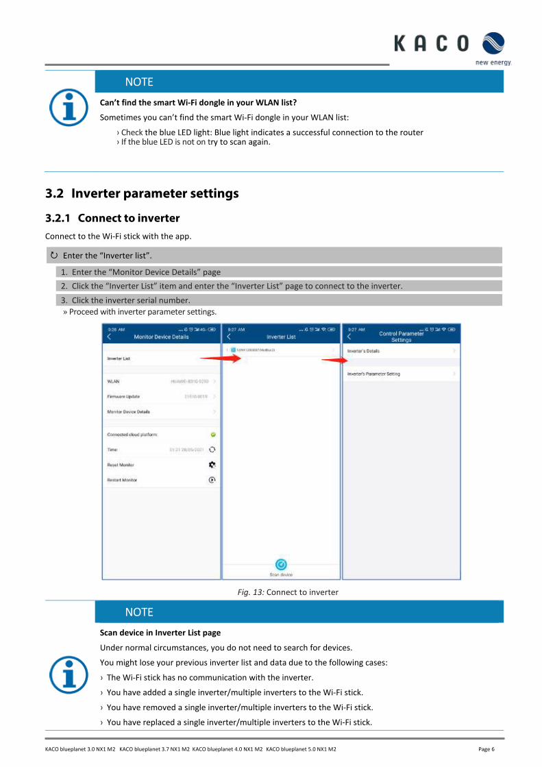
3.2 Inverter parameter settings
3.2.1 Connect to inverter
Connect to the Wi-Fi stick with the app.
Enter the “Inverter list”.
1. Enter the “Monitor Device Details” page
2. Click the “Inverter List” item and enter the “Inverter List” page to connect to the inverter.
3. Click the inverter serial number.
» Proceed with inverter parameter settings.
Fig. 13: Connect to inverter
NOTE
Scan device in Inverter List page
Under normal circumstances, you do not need to search for devices.
You might lose your previous inverter list and data due to the following cases:
› The Wi-Fi stick has no communication with the inverter.
› You have added a single inverter/multiple inverters to the Wi-Fi stick.
› You have removed a single inverter/multiple inverters to the Wi-Fi stick.
› You have replaced a single inverter/multiple inverters to the Wi-Fi stick.

Page 7 KACO blueplanet 3.0 NX1 M2 KACO blueplanet 3.7 NX1 M2 KACO blueplanet 4.0 NX1 M2 KACO blueplanet 5.0 NX1 M2
By clicking on “Inverter’s Parameter Setting”, you can set the inverter parameters. No passcode is required for the first use of these parameter settings during the initial inverter commissioning. If the inverter parameters need to be changed after the initial commissioning a passcode will be required. The inverter specific passcode can be obtained from KACO Service.
Fig. 14: Inverter passcode
3.2.2 Enabling Inverter functions
All required inverter functions can be activated by enabling them as shown below.
Fig. 16: Inverter function enable/disable

KACO blueplanet 3.0 NX1 M2 KACO blueplanet 3.7 NX1 M2 KACO blueplanet 4.0 NX1 M2 KACO blueplanet 5.0 NX1 M2 Page 8
3.2.3 Inverter grid parameter setting: grid standards
The currently selected country standard is displayed on the right side of ‘Country standard’.
To select the required local grid code please click on ‘Grid Standard Settings’. The next page will display the country
standard list. Here you can choose the right grid standard.
Fig. 17: Grid Standard
3.2.4 Inverter grid parameter setting: power up
Tap ‘Parameter Settings For Starting’, the next page will display the parameters.
The appropriate voltage range and frequency range for starting can be set according to the requirements of the local grid
company.
Fig. 18: Parameter settings for starting

Page 9 KACO blueplanet 3.0 NX1 M2 KACO blueplanet 3.7 NX1 M2 KACO blueplanet 4.0 NX1 M2 KACO blueplanet 5.0 NX1 M2
3.2.5 Inverter grid parameter setting: voltage protection
Tap ‘Grid Voltage Protection’, the next page will display the parameters.
There are three threshold levels for the overvoltage and undervoltage protection. The first threshold means the smallest
range, and the third threshold means the largest range.
All thresholds need to follow the principles as below:
1. The first maximum threshold ≤ The second maximum threshold ≤ The third maximum threshold
2. The first minimum threshold ≥ The second minimum threshold ≥ The third minimum threshold 3. The first threshold tripping time ≤ The second threshold tripping time ≤ The third threshold tripping time
Fig. 19: Grid voltage protection
KACO blueplanet 3.0 NX1 M2 KACO blueplanet 3.7 NX1 M2 KACO blueplanet 4.0 NX1 M2 KACO blueplanet 5.0 NX1 M2 Page 10
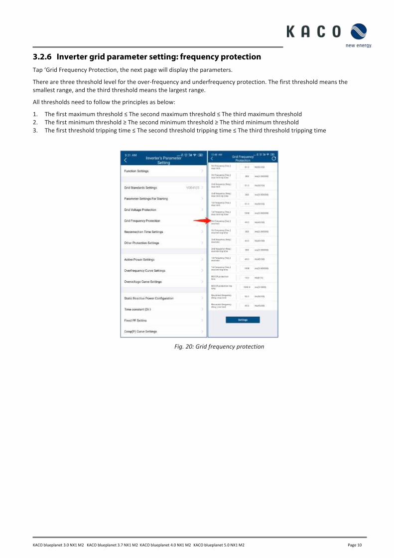
3.2.6 Inverter grid parameter setting: frequency protection
Tap ‘Grid Frequency Protection, the next page will display the parameters.
There are three threshold level for the over-frequency and underfrequency protection. The first threshold means the
smallest range, and the third threshold means the largest range.
All thresholds need to follow the principles as below:
1. The first maximum threshold ≤ The second maximum threshold ≤ The third maximum threshold
2. The first minimum threshold ≥ The second minimum threshold ≥ The third minimum threshold
3. The first threshold tripping time ≤ The second threshold tripping time ≤ The third threshold tripping time
Fig. 20: Grid frequency protection

Page 11 KACO blueplanet 3.0 NX1 M2 KACO blueplanet 3.7 NX1 M2 KACO blueplanet 4.0 NX1 M2 KACO blueplanet 5.0 NX1 M2
3.2.7 Inverter grid parameter setting: reconnection time
Tap ‘Reconnection Time Settings’, the next page will display the parameters.
The observation time during which all the voltage and the frequency values are observed to be within a specified range
prior to the inverter connection or reconnection to the grid can be set in this page.
Fig. 21: Reconnection time

KACO blueplanet 3.0 NX1 M2 KACO blueplanet 3.7 NX1 M2 KACO blueplanet 4.0 NX1 M2 KACO blueplanet 5.0 NX1 M2 Page 12
3.2.8 Inverter active power setting: power limit
During changing in AC operation and control or changing in energy source operation, the active power generated by the
inverter shall not exceed a specified gradient expressed as a percentage of the active nominal power of the inverter per
minute. You can set ‘Active power gradient for increasing’ and ‘Active power gradient for reducing’ according to the
requirement.
The grid company maybe requires reduction of active power on set point. You can set ‘Active power limit’ according to the
requirement.
Fig. 22: Power limit

Page 13 KACO blueplanet 3.0 NX1 M2 KACO blueplanet 3.7 NX1 M2 KACO blueplanet 4.0 NX1 M2 KACO blueplanet 5.0 NX1 M2
3.2.9 Inverter active power setting: overfrequency curve
The inverter may be capable of activating active power response to overfrequency at a programmable frequency threshold
with a programmable droop. There are four available modes.
Fix gradient and non-hysteresis: ∆P is the active power as a percentage of Pn, the inverter provide non-hysteresis in the
control of active power response to over-frequency.
Fix gradient and hysteresis: ∆P is the active power as a percentage of Pn, the inverter provide hysteresis in the control of
active power response to over-frequency.
Variable gradient and non-hysteresis: ∆P is the active power as a percentage of PM, the inverter provide non-hysteresis in
the control of active power response to over-frequency.
Variable gradient and hysteresis: ∆P is the active power as a percentage of PM, the inverter provide hysteresis in the control of active power response to over-frequency.
The below figure descripts the difference between hysteresis and non-hysteresis control
Here,
fn: Rated frequency
freset: Reset frequency
fstart: Starting frequency
fstop: Stopping frequency
∆P : Active power in percentage during reducing
Intentional delay time for P(f) is only active for the activation of the function, once the frequency rises above fstart and the
intentional delay time plus inherent dead time is less than 2s. Once the function is operating, the established control loop is
not intentionally delayed.
Min. delay time for active power release is the delay time that the active power can increase after the frequency below
freset.

KACO blueplanet 3.0 NX1 M2 KACO blueplanet 3.7 NX1 M2 KACO blueplanet 4.0 NX1 M2 KACO blueplanet 5.0 NX1 M2 Page 14
Fig. 23: Overfrequency curve

Page 15 KACO blueplanet 3.0 NX1 M2 KACO blueplanet 3.7 NX1 M2 KACO blueplanet 4.0 NX1 M2 KACO blueplanet 5.0 NX1 M2
3.2.10 Inverter active power setting: overvoltage curve
The inverter may be capable of activating active power response to overvoltage at a programmable voltage threshold with
a programmable droop. There are five available modes
Fix gradient and non-hysteresis: ∆P is the active power as a percentage of Pn, the inverter provide non-hysteresis in the
control of active power response to overvoltage.
Fix gradient and hysteresis: ∆P is the active power as a percentage of Pn, the inverter provide hysteresis in the control of
active power response to overvoltage.
Variable gradient and non-hysteresis: ∆P is the active power as a percentage of PM, the inverter provide non-hysteresis in
the control of active power response to overvoltage.
Variable gradient and hysteresis: ∆P is the active power as a percentage of PM, the inverter provide hysteresis in the control
of active power response to overvoltage.
The below figure descripts the difference between hysteresis and non-hysteresis control.
Here,
fn: Rated voltage
freset: Reset voltage
fstart: Starting voltage
fstop: Stopping voltage
∆P : Active power in percentage during reducing
Intentional delay time for P(f) is only active for the activation of the function after the voltage over Ustart, and the
intentional delay time plus inherent dead time shall be less than 2s
Min. delay time for active power release is the delay time that the active power can increase after the voltage below Ureset.

KACO blueplanet 3.0 NX1 M2 KACO blueplanet 3.7 NX1 M2 KACO blueplanet 4.0 NX1 M2 KACO blueplanet 5.0 NX1 M2 Page 16
Fig. 24: Over-voltage curve

Page 17 KACO blueplanet 3.0 NX1 M2 KACO blueplanet 3.7 NX1 M2 KACO blueplanet 4.0 NX1 M2 KACO blueplanet 5.0 NX1 M2
3.2.11 Inverter reactive power setting: running mode
The inverter may be required to participate to voltage control by means of production and absorption of reactive power.
There are seven reactive power control modes. Only one mode may be active at a time.
The inverter acts as a load from the perspective of the grid according to the country standard. This means the inverter
operation in Quadrant II (under-excited) or III (over-excited) as below.
Over-excited reactive power also known as Capacitive reactive power or Leading power factor.
Under-excited reactive power also known as Inductive reactive power or Lagging power factor.
Tap ‘Reactive power control mode’ to choose the mode. The ‘Time constant 3(τ)’ should be set first. The reactive power
change maybe required to correspond with a first order filter. The ‘Time constant 3(τ)’ is three time constant of the filter
and is the time until 95% of the nominal value is reached.
Fig. 25: Reactive running mode

KACO blueplanet 3.0 NX1 M2 KACO blueplanet 3.7 NX1 M2 KACO blueplanet 4.0 NX1 M2 KACO blueplanet 5.0 NX1 M2 Page 18
3.2.12 Inverter reactive power setting: fixed power factor
The fixed displacement factor cosφ can be set.
Fig. 26: Fixed power factor
3.2.13 Inverter reactive power setting: Cos(Φ) – P curve
The power related control mode cosφ(P) controls the cosφ of the output as a function of the active power output.
There are four coordinate points that are adjustable in the curve as shown in the figure below.
The coordinate points are the active power as a percentage of Pn and the displacement factor cosφ.
Some grid companies may require two voltage thresholds as a percentage of Un to activate or deactivate this function.
These voltage thresholds are referred to as the ‘lock-in’ and ‘lock-out ’voltage.
Activation threshold as a percentage of Un corresponds to ‘lock-in’ voltage
Deactivation threshold as a percentage of Un corresponds to ‘lock-out’ voltage

Page 19 KACO blueplanet 3.0 NX1 M2 KACO blueplanet 3.7 NX1 M2 KACO blueplanet 4.0 NX1 M2 KACO blueplanet 5.0 NX1 M2
Fig. 27: Cos Φ curve
3.2.14 Inverter reactive power setting: fixed Q
The fixed reactive power as a percentage of Pn can be set.
Fig. 28: Fixed Q

KACO blueplanet 3.0 NX1 M2 KACO blueplanet 3.7 NX1 M2 KACO blueplanet 4.0 NX1 M2 KACO blueplanet 5.0 NX1 M2 Page 20
3.2.15 Inverter reactive power setting: Q-U curve
The voltage related control mode Q(U) controls the reactive power output as a function of the voltage.
There are four coordinate points that are adjustable in the curve and the difference between non-hysteresis and hysteresis
control shown in the figure below.
The coordinate points are the voltage as a percentage of Un and the reactive power as a percentage of Pn.
Some grid companies may require two active power thresholds as a percentage of Pn to activate or deactivate this function.
These active power thresholds are referred to as‘lock-in’ and ‘lock-out’ active power.
Activation threshold as a percentage of Pn corresponds to ‘lock-in’ active power.
Deactivation threshold as a percentage of Pn corresponds to ‘lock-out’ active power.
Fig. 29: Q-U curve

Page 21 KACO blueplanet 3.0 NX1 M2 KACO blueplanet 3.7 NX1 M2 KACO blueplanet 4.0 NX1 M2 KACO blueplanet 5.0 NX1 M2
3.2.16 Inverter parameter report
Tap ‘Inverter Parameter Report’, the next page will display the parameter.
Export inverter parameter in file
1 After grid parameter setting, press “Inverter Parameter Report”, and the grid parameters will be shown on the page.
2 Press “Export PDF”, the export file is located as a pdf file in “kaco.report” folder on your smart device.
Fig. 30: Parameter report
NOTE
Passcode
Parameter export without the inverter specific passcode is only possible during the first commissioning. If an export is required after the initial commissioning a passcode will be required. The inverter specific passcode can be obtained from KACO Service.

KACO blueplanet 3.0 NX1 M2 KACO blueplanet 3.7 NX1 M2 KACO blueplanet 4.0 NX1 M2 KACO blueplanet 5.0 NX1 M2 Page 22
3.3 Inverter real time data
3.3.1 Connect to inverter
Connect to the Wi-Fi stick with the app.
Enter the “Inverter list”.
1. Enter the “Monitor Device Details” page
2. Click the “Inverter List” item and enter the “Inverter List” page to connect to the inverter.
3. Click the inverter serial number.
» Proceed with inverter real time data.
Fig. 13: Connect to inverter
NOTE
Scan device in Inverter List page
Under normal circumstances, you do not need to search for devices.
You might lose your previous inverter list and data due to the following cases:
› The Wi-Fi stick has no communication with the inverter.
› You have added a single inverter/multiple inverters to the Wi-Fi stick.
› You have removed a single inverter/multiple inverters to the Wi-Fi stick.
› You have replaced a single inverter/multiple inverters to the Wi-Fi stick.

Page 23 KACO blueplanet 3.0 NX1 M2 KACO blueplanet 3.7 NX1 M2 KACO blueplanet 4.0 NX1 M2 KACO blueplanet 5.0 NX1 M2
3.3.2 Inverter’s details
Click the “Inverter’s Details”, you can view the real time data from the inverter. The parameters shown on the page are as
follows:
Parameter Description
PV1 Voltage and current of MPPT 1 at DC side
PV2 Voltage and current of MPPT 2 at DC side
U1 Voltage and current at AC side
E-Today Generation today
E-Total Cumulative power generation after installation
H-Total Cumulative running hour after installation
Power Current power at AC side
Power Factor Power factor at AC side
Data update time The sampling time.
Error code
Displays the current error code, if one is present.
Fig. 15: Inverter real time data

KACO blueplanet 3.0 NX1 M2 KACO blueplanet 3.7 NX1 M2 KACO blueplanet 4.0 NX1 M2 KACO blueplanet 5.0 NX1 M2 Page 24
4 Firmware Update
4.1 Wi-Fi stick firmware update
Wi-Fi stick firmware update.
1. Find Wi-Fi stick in network.
2. Click the “Firmware Update” and Click the “Local upgrade” to find the firmware file (WIFI_STK.bin).
» The whole process takes approximately 5 minutes.
Fig. 31: Wi-Fi stick firmware
4.2 Inverter firmware update
Inverter firmware update.
1. Connect to the Wi-Fi stick and enter the “Monitor Device Details” page.
2. Click “Firmware Update” and choose the “Inverter” label page.
3. Choose the inverter and choose the firmware path in your smart device.
» The whole process takes about 10 minutes.

Page 25 KACO blueplanet 3.0 NX1 M2 KACO blueplanet 3.7 NX1 M2 KACO blueplanet 4.0 NX1 M2 KACO blueplanet 5.0 NX1 M2
Fig. 32: Inverter firmware
NOTE
The DC power supply must be guaranteed during the upgrade process.
The whole process will take approximately 10 minutes. After 10 minutes, you can check the firmware with the app.

Werner-von-Siemens-Allee 1 · 74172 Neckarsulm · Germany · Phone +49 7132 3818-0 · Fax +49 7132 3818-703 · [email protected] · www.kaco-
newenergy.de