Operating Instructions BA-1281 - Sauter Feinmechanik
31
15-02-18 Sauter: The world turns with us! … for more information, please consult www.sauter-feinmechanik.com, and for the complete standard tooling programme, please visit www.sauter-tools.com 2019-12-10 Operating Instructions BA-1281
-
Upload
khangminh22 -
Category
Documents
-
view
2 -
download
0
Transcript of Operating Instructions BA-1281 - Sauter Feinmechanik
15-02-18
Sauter: The world turns with us!
… for more information, please consult www.sauter-feinmechanik.com, and for the complete standard tooling programme, please visit www.sauter-tools.com
2019-12-10
Operating Instructions BA-1281

Page 1 of 30
sauter-feinmechanik.com
Table of contents:
(1) General information ................................................................................................ 2
(2) Warranty / guarantee ............................................................................................. 3
(3) Definition of terms ................................................................................................... 4
(4) Safety guidelines ..................................................................................................... 5
4.1 Intended use ................................................................................................................... 5
4.2 Unauthorised modifications ............................................................................................ 6
4.3 Observance of the driven tools ....................................................................................... 6
4.4 Duties of the operator .................................................................................................... 7
4.5 Special sources of danger / handling of driven tools ........................................................ 7
(5) Installation and function ......................................................................................... 8
5.1 Installation, initial operation and use .............................................................................. 8 5.1.1 Sauter aligning unit ....................................................................................................................... 12 5.1.2 Trifix ® ............................................................................................................................................ 14 5.1.3 Turret edge (System EMCO®) ........................................................................................................ 15 5.1.4 Sauter precision alignment (SPA) .................................................................................................. 16 5.1.5 BMT tooling (Base Mounted Tooling) ........................................................................................... 16 5.1.6 Tools .............................................................................................................................................. 17
5.2 Tool change .................................................................................................................. 17 5.2.1 Safety guidelines ........................................................................................................................... 17 5.2.2 Collet chuck / milling arbour holder .............................................................................................. 18 5.2.3 Solidfix® (modular interface, compact, high rigidity, high precision)............................................ 20 5.2.4 HSK tool holder (modular interface, compact, high rigidity, high precision) ................................ 22 5.2.5 Sauter Capto® (modular interface, compact, high rigidity, high precision) .................................. 24
5.3 Sealing air ..................................................................................................................... 25
5.4 Cooling supply / dry machining ..................................................................................... 26
5.5 Demounting of the driven tool ...................................................................................... 26
(6) Defects and defect corrections ............................................................................... 27
(7) Procuration of additional parts / Ordering of spare parts ...................................... 29
(8) Servicing and storage ............................................................................................ 29
(9) Disposal ................................................................................................................. 30

Page 2 of 30
sauter-feinmechanik.com
(1) General information These operating instructions are part of our driven tools and have to be handed over to a new user, if the driven tools are passed on. If additional copies of these operating instructions are required, they can be downloaded at http://www.sauter-feinmechanik.com/en/tooling.html Read these operating instructions prior to installation / initial operation, and observe the directions and instructions contained. Please also observe the data on the type plate of the driven tool and the possibly provided specification sheet. This document partly contains symbolic representations. The accessory shown is not necessarily contained in the scope of supply. Please also observe the accessory and spare parts programme offered by Sauter. If and when required, our service team will be pleased to assist you: Tel.: +49 (0) 7123 926 – 0 Fax.: +49 (0) 7123 926 – 193 Mail: [email protected] The information contained in these operating instructions is based on the knowledge available at the point of going to press. We explicitly reserve the right to carry out modifications, which occur as part of constant further development, even without advance notice.

Page 3 of 30
sauter-feinmechanik.com
(2) Warranty / guarantee Any warranty as well as guarantee and/or liability claims in case of personal injuries and material damage shall be excluded, if these can be traced back to one or several causes listed herein below:
Usage of the driven tools not according to the intended purpose.
Improper installation, initial operation, operation and maintenance of the driven tools.
Damage caused through external force, for example, as a consequence of collision in the machine or dropping of the driven tools during mounting / demounting.
Operation or continuation of operation of the driven tools with defective and/or non-functional safety and protective devices.
Non-observation of the notes in the operating instructions with respect to storage, installation, initial operation, tool assembly, operation and maintenance of the driven tools.
Unauthorised constructional alterations of the driven tools.
Unauthorised modifications of the drive conditions of the driven tools (such as power consumption and/or torque exceeding the actual permissible values).
Inadequate monitoring of the machine parts.
Incorrect and/or unapproved repairs.
Influence caused by force majeure which Sauter Feinmechanik GmbH has no influence on.
Use of unsuitable, such as improperly sharpened, blunt, defective or unpermitted, machining tools.

Page 4 of 30
sauter-feinmechanik.com
(3) Definition of terms The following illustrations of typical driven tools explain terms which are helpful for use and for the understanding of these operating instructions.
Spindle
Bore for transferof cooling lubricant
Safety pin (sealing air)
Coupling (for tool drive)
Sauter spindle orientation detent (pat.)
Shank Mounting screw for holder
O-ring on shank
O-ring for sealing air
Tirifx® alignment bar
Leakage bore(in case of internal cooling)
Housing
Bevel gears (in housing)
Leakage bore(in case of internal cooling)
Specifications field
Serration of the shank
External cooling supply
Holder
External cooling supplyadditionally mounted by user)
Page 5 of 30
sauter-feinmechanik.com
(4) Safety guidelines The operating instructions and any other documents belonging to the driven tools shall be kept within reach at the place of operation at all times. In addition to these operating instructions, the general and locally applicable regulations for the prevention of accidents and for environmental protection have to be observed.
4.1 Intended use
The exclusive intended purpose of driven tools is the application in processing machines used for machining operations of work pieces made of the following materials:
steel aluminium non-ferrous and precious metals synthetic materials wood
using usual machining operations, such as:
drilling milling thread-cutting sawing
A use of the driven tool deviating from and/or beyond this permission shall be considered unintended. The manufacturer shall not be held liable for any resulting consequences / damage or injuries, et cetera. The intended use shall also comprise:
the observation of these operating instructions the observation of the setting routines as well as the guidelines concerning care and
storage the observation of the limits of performance given by the technical data the observation of the restrictions caused by the accessories mounted
All applications not listed shall be considered inappropriate, unintended applications. In case of doubt, please get in touch with the manufacturer. For more detailed information on the performance data of your driven tools, please refer to the specifications field lasered on or the specifications sheet which will be sent to you upon request or which can be downloaded from our tool finder at www.sauter-tools.com.

Page 6 of 30
sauter-feinmechanik.com
4.2 Unauthorised modifications
Without previous written approval by the manufacturer, no structural modifications, extensions or conversions may be carried out on the driven tools. The manufacturer shall not be liable for any injury or damage that may result. The risk shall be borne by the operator only. The installation of an additional cooling supply, which is possible with almost all driven tools, shall be explicitly excluded. The manufacturer shall not be liable for any consequences / injuries and damage which may occur due to incorrect fitting / installation of this additional cooling supply. Spare and / or wearing parts have to meet the specifications defined by the manufacturer which can be ensured only by original spare parts.
4.3 Observance of the driven tools
Intense warming and/or excessive noise development of the driven tools may be caused by a potentially looming bearing failure, gear damage or a faulty installation of the driven tools on the tool carrier. Check the driven tools as indicated in chapter (6) and inform Sauter Feinmechanik GmbH immediately. If the problem should persist, the driven tool must not be used any longer.

Page 7 of 30
sauter-feinmechanik.com
4.4 Duties of the operator
The operator obligates himself to carry out the following points:
The operator shall regularly verify the safety-conscious working of the staff. The operator shall familiarise the staff in handling driven tools. The operator shall assure that the staff is familiar with the regulations on occupational
safety and the currently applicable regulations for the prevention of accidents. The operator shall verify that the driven tools are used on machine tools only which
are in conformity with the currently applicable safety regulations. The operator shall assure that all safety equipment is activated and operational when
work is carried out with the driven tools. The operator shall ensure that all regulations of the occupational safety act are
observed. Trained and familiarised staff only shall work with / on the driven tools. Competences for all tasks of the staff during installation, initial operation, operation and servicing shall be defined. Staff being trained shall work only under the supervision of a trained person with / on the driven tools; the same shall apply for all apprentices.
4.5 Special sources of danger / handling of driven tools
Observe the correct tension of the machining tool as described in chapter 5.2 on tool
change.
In case of especially heavy driven tools, use suitable lifting gear and initiate suitable measures for the exchange into the tool turret.
In case of repair and maintenance work, please use a suitable support and secure the driven tool against unintentional movements. Use suitable safety devices.
In case of improper use or mounting / demounting, danger to life and limb of the operator or a third party and/or damage to the driven tools or other material assets (work pieces to be machined, et cetera) may arise. Defects, which may affect safety, have to be corrected immediately.
Depending on the type of operation (load, runtime) higher temperatures may occur during the operation of the driven tools. For this reason always wear protective gloves when replacing the driven tool or changing the machining tool.

Page 8 of 30
sauter-feinmechanik.com
(5) Installation and function
5.1 Installation, initial operation and use
Prior to installation, the driven tool has to be examined for potential damage. In case of obvious damage, the driven tool must not be used. In case of damage during shipment, please inform us immediately. Prior to operation of the driven tool, please check for any interfering contours – be sure to consider the planned machining tool – and the permissible overall weight of the tool turret assembly in accordance with the operating instructions of the turret or the machine manufacturer. CAUTION IMPORTANT TO AVOID DAMAGE OR MALFUNCTIONS AT THE TOOL TURRET:
Check the shank of the driven tool and / or the potentially fitted O rings for existence, correct fit and damage.
It has to be ensured that the contact surfaces of the driven tool and of the tool holder
are free of chips and coolant remnants. Compressed air must not be used for cleaning.
Push the straight shank into the mounting hole of the tool holder. In case of VDI tools,
the serrated side of the shank of the driven tool has to point towards the serrated thrust piece of the tool holder in the process.
It has to be made sure that the drive of the driven tool matches the coupling of the
tool holder system so that the torque can be transmitted faultlessly. If these instructions are not followed the manufacturer resumes no responsibility for possible damage to the tool turret! Subsequently the driven tool has to be pressed on to the flat contact surface. By means of the clamping device provided on the tool holder system or by means of the fastening screws the driven tool can be attached permanently. Be sure to observe the permissible torque in the process; always use a torque wrench! In the process, the data of the machine manufacturer have to be generally observed as well as the torque data possibly lasered on the driven tool. In case of non-observation, damage may occur.

Page 9 of 30
sauter-feinmechanik.com
It has to be observed that the permissible technical parameters are not exceeded in operation. Influencing factors in this respect are primarily the type and condition of the machining tools used, the material to be machined as well as the selected machining parameters, such as cutting speed, feed, et cetera. These factors are the responsibility of the operator. The maximum values indicated on the driven tool refer to impact-free machining and to short-time operation. In case of severe impact-loaded machining, the parameters have to be reduced partly by 50 per cent and more. The respectively permissible operating time depends:
On the type of the driven tool (with or without gear, et cetera). On the presence of a cooling or dry machining system. On the type of the cooling system (external or internal by tool spindle). On the machining torque.
At a load of approx. 60 per cent of the maximum values, a calculated life time of approx. 2,000 h is achieved. Permissible relative duty cycle – Guide values –
Driven tools with gearing inevitably have an increased noise development in case of higher speeds. If the permissible parameters are not observed, this will lead as a rule to excessive heating and to unavoidable damages to the driven tools subsequently, such as premature bearing failure, et cetera. Following are two diagrams indicating exemplary the coolant pressures or the volume flow respectively existing at the tool with the respective inlet pressures in the system.

Page 10 of 30
sauter-feinmechanik.com
Diagrams proportion coolant pressure – volume flow
Please observe: The driven tool can only be as good as permitted by the general conditions. It depends on how it has been mounted and aligned. The characteristic machining values should be suitable and adapted. Ultimately it always depends on the clamping units, tools and the achievable system accuracies how precise and accurate the machining result is.

Page 11 of 30
sauter-feinmechanik.com
CAUTION:
Close all unequipped tool holders with sealing plugs fitted with O rings in keeping with German standard DIN ISO 10889 (formerly German standard DIN 69880). This applies for tools with VDI shank.
For BMT tooling, use the respectively required closure plates of the respective
manufacturer. In case of non-observation of these instructions, the manufacturer shall not assume any guarantee for potential damage to the tool turret.

Page 12 of 30
sauter-feinmechanik.com
5.1.1 Sauter aligning unit
Alignment bar
Adjusting screw
Adjusting pin
The Sauter aligning unit is used to precisely set the angular position of the driven tools relative to the turret rotation axis. CAUTION: Never turn the adjusting screw when the thrust piece is fully tightened (see chapter below).

Page 13 of 30
sauter-feinmechanik.com
Tighten the thrust piece with approx. 25 per cent of the torque TA of the table values of the thrust piece.
Shank diameter (ISO 10 889)
[mm] Torque TA
[Nm] 16 6 20 10 25 10 30 25 40 50 50 50 60 86
Use the adjusting screw to align the driven tool centrically by means of the control surface.
Tighten the thrust piece. Observe the torque TA in the table in the process.

Page 14 of 30
sauter-feinmechanik.com
5.1.2 Trifix ®
Trifix® alignment bar
Trifix® alignment groove
In case of driven tools, which have been fitted with Trifix®, a high-precision alignment unit, the driven tool only has to be put on and has to be tightened according to the torque in the table of chapter 5.1.1 (see p. 13). Other alignment can be omitted completely. If a re-adjustment is required after a collision, please get in touch with the tooling manufacturer. CAUTION: When Trifix® is combined with an additional flange mounting for high loads the thrust piece on the tool turret imperatively has to be tightened first according to the torque in the table of chapter 5.1.1 (see p. 13), only then the screws of the flange mounting have to be fastened with the torque specified in the table of chapter 5.1.5 (see page 16). If this is not observed, the high-precision alignment cannot be ensured.
Page 15 of 30
sauter-feinmechanik.com
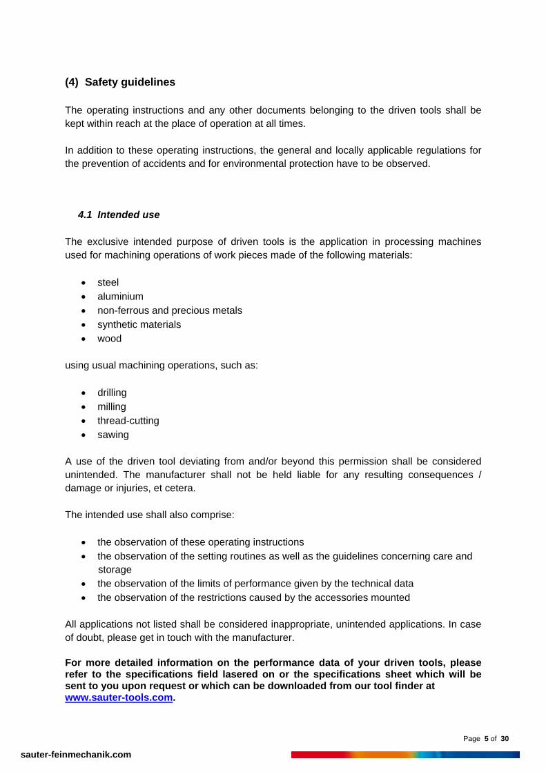
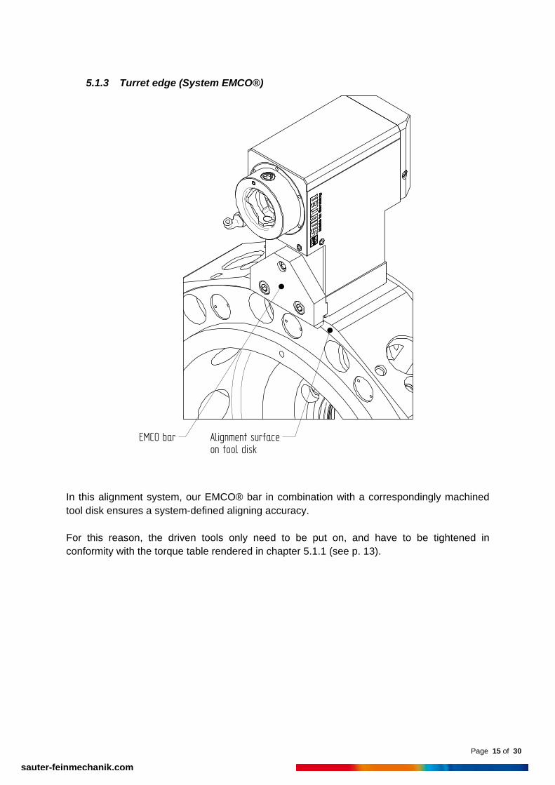
5.1.3 Turret edge (System EMCO®)
EMCO bar Alignment surfaceon tool disk
In this alignment system, our EMCO® bar in combination with a correspondingly machined tool disk ensures a system-defined aligning accuracy. For this reason, the driven tools only need to be put on, and have to be tightened in conformity with the torque table rendered in chapter 5.1.1 (see p. 13).

Page 16 of 30
sauter-feinmechanik.com
5.1.4 Sauter precision alignment (SPA)
Alignment bar
It is sufficient to screw the driven tools on to the turret to ensure a highly precise alignment. In the process, please observe the permissible torque of the respective fastening screws.
Screw size Torque TA [Nm]
M10 49 M12 86
5.1.5 BMT tooling (Base Mounted Tooling)
In this system, the driven tool with its straight shanks is inserted and attached with four socket head screws. In this case the alignment accuracy is ensured by keyways or other comparable systems. In the process, please observe the permissible torque of the respective fastening screws.
Screw size Torque TA [Nm]
M6 10 M8 25
M10 49 M12 86

Page 17 of 30
sauter-feinmechanik.com
5.1.6 Tools
Depending on the diameter very high centrifugal forces develop at the maximum
speed of the tool.
Only correspondingly balanced machining tools may be used, the maximum permissible torque and/or circumferential speed of which is above the maximum spindle speed of the driven tool.
Standards to be observed: VDI guideline 2056 E DIN EN ISO 15641
In case of tools with a large mass and/or a large cantilever length it is possible that the spindle / machining tool system reaches its resonant frequency, thus causing damage to the bearing. The machining tool and/or parts thereof could be hurled away with a high kinetic energy.
Generally, tools should be clamped as short as possible.
5.2 Tool change
5.2.1 Safety guidelines
Remove any chips, lubricant residues, et cetera from all surfaces at the spindle in
order to ensure correct operation of the tool clamping (minimisation of slipping risk).
Collet chuck / milling arbour spindle The suitable key always has to be used to hold against (see illustration in chapter 5.3.2). Non-observation may lead to damage of the gear on the driven tool and/or of the tool drive of the turret.
Incorrect clamping may lead to rejects and damage to the driven tool. Please always
observe the installation instructions of the respective manufacturer.
Avoid cut injuries caused by tools. Always wear protective gloves when handling tools. Always wear safety boots and protective goggles.
Exclusively use clamping products and tools which have been approved for the maximum speed of the driven tool.

Page 18 of 30
sauter-feinmechanik.com
Remove all auxiliary means used for the installation (such as chuck keys, et cetera) of the driven tool as well as those used in the working space of the machine before you start operating the driven tools and the processing machine.
5.2.2 Collet chuck / milling arbour holder
An external clamping nut for larger shank diameters is shown in the illustration.
wrong right

Page 19 of 30
sauter-feinmechanik.com
Zollmann ® Zeta nut (especially non-slip easy handling ensured by the dovetail grooves in the nut)
A nut with the side chuck key is shown in the illustration. A complete accessory programme is available (product information PI 29.3) as download at www.sauter-feinmechanik.com/en/tooling.html
Type Torque [Nm] ER 11 40 ER 16 60 ER 20 75 ER 25 100 ER 32 130 ER 40 150 ER 50 170
CAUTION: The listed values are maximum values which are based on the respective female thread. The secure clamping of the respective machining tool in a collet chuck is the sole responsibility of the user / operator. The manufacturer resumes no liability for improper clamping!

Page 20 of 30
sauter-feinmechanik.com
5.2.3 Solidfix® (modular interface, compact, high rigidity, high precision)
This clamping system stands out for its one-hand operation without special tools. The actuator is tightened and/or loosened by means of a suitable Allen key. The loosening and/or tightening position is reached at a fixed stop in both directions, a torque wrench is not necessary. In opened state – adaptor can be fitted – the check mark of the actuator points towards the opened lock (lasered on the spindle).
In closed state – adaptor then clamped – the check mark of the actuator points towards the closed lock (lasered on the spindle).
Clamping 180°
Releasing 180°

Page 21 of 30
sauter-feinmechanik.com
Insert tool adaptor and clamping: Set adaptor in the spindle – check mark points towards opened lock – and turn through 90° until adaptor catches. This is a security function towards losing the adaptor (integrated safety bayonet) so the adaptor cannot fall out in an overhead position as may be the case. The actuator is turned through 180°. The check mark now points towards closed lock.
Loosen adaptor The actuator is loosened – check mark turned towards opened lock – and the adaptor can be removed after slightly lifting and turning through 90°. Due to an eject function the adaptor cannot get stuck in the spindle.
A detailed description of the construction as well as the complete Solidfix® tooling program is available (product information PI 58) as a download at www.sauter-feinmechanik.com/en/solidfix.html

Page 22 of 30
sauter-feinmechanik.com
5.2.4 HSK tool holder (modular interface, compact, high rigidity, high precision)
MAPAL® collet Clamping screw
Cover ring
Through hole
The locking ring is turned until the through hole in the ring coincides with the through hole of the spindle. When this position is reached, a normal Allen key can be used to undo the tool by turning the clamping bolt on the clamping unit to the left or can be used to tighten the tool by turning the bolt on the clamping unit to the right. A torque wrench is not required. ATTENTION IMPORTANT: Unfavorable position of torque wrench leads to a premature wear of the toothed hub.
Position 1:
No force component FZ on spindle and therefore on toothed hub. This position is to be preferred under all circumstances! The locking position of the indexing must be checked after a tool has been replaced and clamped in the HSK respectively.
The indexing is correctly locked when the working spindle can no longer be manually turned.

Page 23 of 30
sauter-feinmechanik.com
Position 2:
Considerable force component on spindle and toothed hub. This position is to be avoided.
HSK-Size 32 40 50 63 80 100 fastening torque [Nm]
6 7 15 20 30 50
wrench size [mm]
3 3 4 5 6 8
clamping force [kN]
11 14 21 30 40 50
ATTENTION IMPORTANT: The clamping force must be measured approximately every 500 operating hours by means of a clamping force testing device, which is available from specialized suppliers. If the value given for the respective HSK-Size (see table) is no longer reached, there is the risk of:
lower machining quality breakage of the tool rotating tool coming loose, with all consequences
Replacement or maintenance respectively of the HSK-collet is required. For inspection and maintenance, please send driven tool to SAUTER.

Page 24 of 30
sauter-feinmechanik.com
5.2.5 Sauter Capto® (modular interface, compact, high rigidity, high precision)
This clamping system stands out for its one-hand operation without special tools. The actuator is tightened and/or loosened (with machining tool mounted) by means of a suitable Allen key. The loosening and/or tightening position is reached at a fixed stop each so that no torque has to be taken into consideration. The following table shows the maximum permissible torque for each respective polygon size (not to be confused with the maximum permissible torque for the driven tool) and the appropriate wrench size.
Size polygon T max. polygon [Nm] Wrench size [mm] C3 320 6 C4 580 8 C5 1000 10 C6 2000 12
A detailed description of the construction and the mode of action is available (operating instructions BA 1202) as a download at www.sauter-feinmechanik.com/en/capto.html.

Page 25 of 30
sauter-feinmechanik.com
5.3 Sealing air
Especially fast running driven tools are frequently fitted with sealing air.
It is essential to observe the pressure of the sealing air in order to achieve a good sealing action.
If no sealing air is available, no cooling lubricant must wet the driven tool.
Correspondingly treated compressed air as described below has to be used
exclusively.
Driven tools with sealing air seals may be used only on the turrets intended for the purpose.
If the above is not observed, the driven tool may be severely damaged.
The sealing air (compressed air) has to provide a quality in keeping with ISO 8573-1: Filtered Class 3 5µm Dried Class 4 +3 deg. Celsius Oiled Class 4 3…5mg/m³ (recommended) The pressure has to be between 0.4 and 0.8 bar.

Page 26 of 30
sauter-feinmechanik.com
5.4 Cooling supply / dry machining
Cooling lubricant purity
Disregard may lead to material damage. Observe filter fineness (lasered on to the internally cooled driven tool) – if in doubt,
please consult the manufacturer. Observe the permissible purity class in accordance with ISO 4406.
Leakage outlet (in internally cooled driven tool)
Check leakage boring(s) for potential clogging in regular intervals.
Small amounts (drops) of leakage are functional and are no defect, and thus permissible.
The leakage of larger amounts (continuous squirt from the leakage boring(s))
indicates a defective seal. The driven tool has to be sent in for repair immediately. Further operation will inevitably lead to damage of the bearing.
Cooling lubricant pressure and dry running
Please observe the specific data on cooling lubricant pressure, primarily the maximum permissible and/or minimum pressure required (in case of internally cooled driven tools). In case of non-observation, the driven tools may be damaged.
Basically, driven tools with internal cooling lubricant feed can run dry, however for
maximum 10 per cent duration in cycle (100 per cent are 5 min.).
CAUTION:
Exclusive dry run is permissible only with driven tools with external cooling, whereby the exit opening for the external cooling lubricant feed of the driven tool has to be closed so that no dirt can enter.
5.5 Demounting of the driven tool
For disassembly, proceed in reverse order to the assembly (see chapter 5.1). If the position remains free on the tool holder system, the opening has to be closed properly with a plate fitted with an O ring intended for the purpose. This closure has been described in chapter 5.1. In case of non-observation of these instructions, the manufacturer shall not assume any guarantee for potential damage to the tool turret.

Page 27 of 30
sauter-feinmechanik.com
(6) Defects and defect corrections Defects of the driven tools may lead to severe consequential damage in parts which reduce the service life of the driven tools and/or may lead to production stoppages, et cetera. For this reason always seek advice from the manufacturer. If in doubt, send the driven tool to the manufacturer. In order to ensure a quicker handling in case of a return, please supply the following data for our customer service department:
Type of driven tool and/or identification number (lasered on to the driven tool) and approximate date of purchase.
Sauter Feinmechanik GmbH commission number (lasered on to the driven tool).
Short information on the reason for return and / or assumed or existing damage.
Our customer service department can be reached via: Tel.: +49 (0) 7123 926 - 0 Fax: +49 (0) 7123 926 - 193 Mail: [email protected]

Page 28 of 30
sauter-feinmechanik.com
Defect Check Correction Driven tool does not perfectly contact the turret head.
Check the length of the pin of the turret head. Are the contact surfaces clean?
In case of a deviation from standard, please talk to the machine manufacturer. Clean the surfaces (chapter 5.2).
Excessive warming. Check the limits of performance, such as run time, speed, torque, et cetera.
Correct the values correspondingly.
Excessive warming of driven tool with internal cooling lubricant feed.
Check the through-hole of the cooling lubricant boreholes. Is the cooling lubricant fed correctly? Check the driven tool for leakage.
Flush the cooling lubricant feed. Switch on the cooling lubricant feed. Send the driven tool to the manufacturer.
Dimensional and shape error of the work piece.
Has the machining method been chosen correctly for the precision required? Excessive wear of the machining tool? Machining tool deflected by excessive cutting forces? Excessive radial run-out. Alignment error of driven tool?
If and when necessary change method, change machining tool. Change machining tool, and adapt machining data, if and when necessary. Adapt machining parameters; use another machining tool, if and when necessary; check tool tightening pressure. Change tool; check tightening pressure. Measure the angle setting and (re-)align the driven tool.
High cooling lubricant exit at the leakage boring(s) of internally cooled driven tool.
Inform the manufacturer immediately for repair of the driven tool; in case of non-observation this will lead inevitably to bearing failure.

Page 29 of 30
sauter-feinmechanik.com
(7) Procuration of additional parts / Ordering of spare parts Should you require additional parts like other coolant supply tubes, further wrenches or possible spare parts, please contact our customer service department: Tel.: +49 (0) 7123 926 – 0 Fax.: +49 (0) 7123 926 – 193 Mail: [email protected]
(8) Servicing and storage If the driven tool shall be stored for several days, please observe the following notes:
Carefully clean the driven tool prior to warehousing for example remove chips, coolant residues et cetera, whereby the use of compressed air is not permissible.
Ground surfaces have to be conserved (for example using WD40).
The driven tool has to be stored in a dry environment at temperatures of between 5°C
and 40°C. (min. 41°F / max. 104°F)
Protect the driven tool against dust, dirt and other deposits.
Should the driven tool be stored for several weeks, a simplified grease distribution run according to the bearing manufacturer’s specified running-in cycle has to be done before bringing into service again. This complete running-in cycle (grease distribution run) has been done in our factory prior to dispatch but the homogenous distribution of the grease which is important for the functioning of the bearings, cannot be guaranteed any more after prolonged storage. Depending on the operating condition lubricant can be washed out by coolant. Noticeable through sluggish clamping procedure. In that case a re-lubrication proceed as follows. Lubrication recommendation: Metaflux 70-82 Anti-Seize-Spray Loctite 8154 No copper paste!

Page 30 of 30
sauter-feinmechanik.com
For re-lubrication proceed as follows:
1. Remove set screw (3) and eccentric (1) 2. Use the set screw(3) hole to spray in the lubricant. 3. Mount eccentric (1) and set screw (3) again. Please pay attention to the torque shown
in the table below. Size S1 S2 S3 S4 S5 Max. clamping torque [Nm] for the set screw 1 2 3 4 5 This renewed (simplified) running-in cycle has to be carried out as following:
Use half of the maximum rpm of the driven tool for 20 seconds then 2 minutes pause. This has to be done altogether 5 times.
Three quarters of the maximum rpm of the driven tool for 20 seconds then 2 minutes
pause. This has to be done altogether 5 times. If this grease distribution run is not carried out, the manufacturer cannot guarantee a flawless function of the driven tool especially with high rpm.
(9) Disposal In case of disposal, the operator has to observe the respectively applicable regulations of the environmental protection act.