operating and safety manual - Academy Sports + Outdoors
35
“The Quality Goes In Before The Rifle Goes Out” operating and safety manual For AR15 Type Semi-Automac Models Windham Weaponry Part No: MAN-OP-AR Made in the U.S.A.
-
Upload
khangminh22 -
Category
Documents
-
view
1 -
download
0
Transcript of operating and safety manual - Academy Sports + Outdoors

“The Quality Goes In Before The Rifle Goes Out”
operating
and
safety
manual
ForAR15 Type
Semi-Automa,cModels
Windham Weaponry Part No: MAN-OP-AR Made in the U.S.A.

WARNING! IF THIS FIREARM IS CARELESSLY OR IMPROPERLY HANDLED, UNINTENTIONAL DISCHARGE COULD RESULT AND COULD
CAUSE INJURY, DEATH, OR DAMAGE TO PROPERTY.
WARNING! THIS WEAPON COULD CHAMBER A ROUND IF IT IS DROPPED OR JARRED WITH A LOADED MAGAZINE IN PLACE AND
WITH THE BOLT CARRIER ASSEMBLY LOCKED TO THE REAR.
WARNING! BE SURE CAM PIN IS INSTALLED IN THE BOLT GROUP. IF IT ISN’T, THE RIFLE CAN STILL FIRE AND WILL EXPLODE!
WARNING! IF THERE IS WATER IN THE BARREL, DO NOT FIRE THE RIFLE. IT COULD EXPLODE!
CAUTION! USE ONLY CLEAN, DRY, HIGH QUALITY COMMERCIALLY MANUFACTURED AMMUNITION WHICH IS APPROPRIATE TO THE 5.56MM NATO / .223 REM. CALIBER OF YOUR FIREARM. WINDHAM WEAPONRY DOES NOT RECOMMEND THE USE OF REMANUFAC-TURED OR HAND LOADED AMMUNITION BECAUSE IT MAY DAMAGE YOUR RIFLE.
CAUTION! IF THE RIFLE STOPS FIRING (A MISFIRE) WITH A LIVE ROUND IN THE CHAMBER OF A HOT BARREL, REMOVE THE ROUND FAST! HOWEVER, IF YOU CANNOT REMOVE IT WITHIN 10 SECONDS, REMOVE MAGAZINE AND WAIT 15 MINUTES WITH THE RIFLE POINT-ING IN A SAFE DIRECTION SO YOU WON’T BE HURT BY A POSSIBLE ROUND “COOKING-OFF” (I.E. THE ROUND DETONATING FROM THE HEAT OF THE BARREL). ALWAYS KEEP YOUR FACE AWAY FROM THE EJECTION PORT WHILE CLEARING A HOT CHAMBER.
CAUTION! IF RIFLE’S BOLT FAILS TO UNLOCK, AND YOU TRY TO FREE IT BY TAPPING THE BUTTSTOCK ON THE GROUND WHILE PULLING ON THE CHARGING HANDLE, KEEP YOURSELF CLEAR OF THE MUZZLE! PLACE THE SAFETY SELECTOR LEVER ON SAFE.
CAUTION! IF YOU HEAR A NOTICEABLE DIFFERENCE IN SOUND OR RECOIL DURING FIRING, STOP FIRING! EITHER CONDITION COULD INDICATE AN INCOMPLETE POWDER BURN AND/OR A BULLET STUCK IN THE BORE.
BEWARE OF DANGEROUS PROCEDURES
CAREFULLY READ THIS INSTRUCTION MANUAL PRIOR TO LOADING
AND FIRING THIS FIREARM. FOLLOW ALL INSTRUCTIONS ON THE
PROPER HANDLING AND SAFE USE OF THIS FIREARM!

Pg. 1
TABLE OF CONTENTS
This manual is based upon the U.S. Gov’t. Issue Manual for M16 A2 Rifles, and will be included with all semi-automa/c Windham Weaponry Firearms.
Windham Weaponry is steadfast in its goal to produce the finest AR15 type rifle and carbine possible, and we encourage our customers to follow further devel-opments on our website.
www.windhamweaponry.com
In the mean/me, we encourage you to shoot safely, to enjoy the great outdoors, and to provide us feedback in our quest to produce the finest rifles in the world.
Thanks, from your
Windham Weaponry Team
YOUR WARRANTYYour Transferable Life/me
Warrany is printed in full on the back cover of this manual. As soon as possible upon receipt of your Windham Weaponry firearm, go online, or call, to ac/vate your warranty. See:
www.windhamweaponry.com
or call Toll-Free: 855-808 1888
Follow the Instruc/ons on the website warranty page. Your firearm’s warranty will be in effect upon comple/on of these steps.
The Windham Weaponry Team thanks you for your purchase of this fine rifle, and we hope you will enjoy it safely for many years. If you need parts, service or advice concerning your rifle, we are never more than a phone call away, and will be pleased to help you.
CAREFULLY READ THIS INSTRUCTION MANUAL PRIOR TO LOADING AND FIRING THIS FIREARM. FOLLOW ALL INSTRUCTIONS ON THE PROPER HANDLING AND SAFE USE OF THIS FIREARM!
About Your Windham Weaponry Rifle 2
Rifle Features & Controls - Loca/on 2
Familiarize Yourself With Your Rifle 3
Range Safety Checks - Before You Fire! 6
Loading A Magazine 6
Preparing To Fire 7
Chambering A Round From An Open Bolt 7
Chambering A Round From A Closed Bolt 8
Firing The Rifle 8
If The Rifle Stops Firing - Immediate Ac/ons 9
If The Rifle Stops Firing - Remedial Ac/ons 9
Understanding Your Sight Adjustments 10
The Dual Aperture Rear Sight 11
25 Meter Zeroing Procedures 11
Rifle Disassembly, Cleaning & Maintenance 13
A Visual Guide To The WW-15 Rifle 16
Cleaning Bolt, Bolt Carrier & Components 18
Inspec/on, Cleaning & Lubrica/on 22
Cleaning The Bore 22
Magazine Disassembly & Cleaning 27
Troubleshoo/ng Problems / Solu/ons 28
Shipping Rifles For Service 31
Maintence Log / Zeroing-In Records / Notes 32

Pg. 2
• This opera$ng manual covers Windham Weaponry models chambered for .223 Rem. / 5.56mm NATO ammuni$on. They are lightweight, gas operated, air-cooled, magazine fed rifles that operate in semi-automa$c mode. This means that each $me the trigger is pulled, a single round will fire un$l the magazine is empty.
• On all models, the upper and lower receivers are easily opened for cleaning and inspec$on. Upper and lower receivers are machined from forged 7075 T6 aircra9 aluminum.
• Most Windham Weaponry models feature fully adjustable rear sights and eleva$on adjustable front sights. Some models are designed to allow the owner to add their own choice of front and rear sights (e.g. Windham Weaponry SRC & Varmint Exterminator models).
• Barrels on Windham Weaponry models are chrome lined 4150 chrome moly vanadium 11595E steel or 416R grade stainless steel. They are 100% air gauged, bore scoped, head spaced and buGon rifled - right hand twist with 6 lands and grooves. Refer to barrel markings for twist rate and caliber.
• Windham Weaponry models are supplied with 6 posi$on telescoping buGstocks or fixed style buGstocks.
• Most forends are ribbed and vented to allow heat dissipa$on. Carbines feature M4 double heat shield design forends.
• All models feature ver$cal pistol grips and detachable magazines. Standard magazine capacity is 30 rounds (depending on State regula$ons), but all AR-15/M-16 type magazines of capaci$es from 5 to 40 rounds as well as c-drum magazines will fit and func$on in Windham Weaponry models.
RIFLE FEATURES & CONTROLS
ABOUT YOUR WINDHAM WEAPONRY RIFLE
Rear Sight Windage Knob
Rear Sling Loop
M4 Profile Barrel
A2 Flash Hider
Spent Brass Deflector
M4 Double Heat Shield Handguards
Bayonet Lug
Front Sling Swivel
A4 Removable Carry Handle
A4 Removable Carry Handle
Carry Handle Locking Knobs
Charging Handle
Charging
Handle
Pistol Grip
Safety Selector Lever
6 Posi$on Telestock
6 Posi$on
Telestock
Telestock Latch
Rear Sight Eleva$on Wheel
Dual Aperture Rear Sight
Flat Top Upper Receiver
30 Rd. Magazine
Magazine Release
BuGon
Forward Assist Knob
Trigger
Receiver
Safety
Indicator
Ejec$on Port Cover
A2 Front Sight Assembly
Takedown
Pin
Pivot Pin
Bolt Catch
Magazine
Catch

Pg. 3
ALWAYS FOLLOW THE RULES OF SAFE GUN HANDLING!
FAMILIARIZE YOURSELF WITH YOUR NEW WINDHAM WEAPONRY RIFLE.THEN FOLLOW THESE STEPS TO PREPARE TO USE THE RIFLE.
ALWAYS ASSUME THE GUN YOU ARE HANDLING IS LOADED.
POINT THE RIFLE IN A SAFE DIRECTION!
Place safety selector lever on SAFE. NOTE: If the rifle is not cocked, the safety selector lever cannot be pointed toward SAFE.
A
Fig. 1
Fig. 2
Fig. 3
Fig. 4
B
Note: Safety markings enhanced in photo for inden+fica+on.
1. To lock bolt open, pull charging handle rearward (A - Fig. 2). Press bo6om of bolt catch and allow bolt to move forward un+l it engages bolt catch (B - Fig. 2). Return charging handle to its forward posi+on.
If you haven’t done so before, now
place safety selector lever on SAFE (as shown in Fig.1)
2. Remove chamber plug/tool (Fig. 3).
Note: The chamber plug/tool should remain in the chamber when the rifle is not in use, or in storage.
Look into the upper receiver and firing chamber to ensure there is no ammuni+on in the rifle (Fig. 4).
Note: Be sure a magazine is not inserted in the rifle.
3. Once you are sure the firing chamber is empty, and the safety selector lever is on SAFE, you can press the upper por+on of the bolt catch, or pull the charging handle all the way to the rear and release to allow the bolt to move forward.
THE RIFLE IS NOW “CLEAR”.

Pg. 4
4. Using your chamber plug/tool (or a punch) push the takedown pin in as far as it will go. Then pull on the head of the pin (from the right side of the rifle) un0l it stops (Fig. 5).
5. Push the front pivot pin in as far as it will go (Fig. 6) - then separate the upper and lower receivers (Fig. 7).
6. Pull the charging handle back un0l it stops. The bolt carrier assembly will come out with it (Fig. 8).
Li7 the bolt carrier back and up un0l it is clear of the upper receiver.
NOTE: Observe how the carrier key
fits within the slot in the bo9om of the charging handle.
7. To remove the charging handle, pull it to the rear un0l it stops. Then li7 the charging handle up, allowing the side tabs to clear the cutouts in the upper receiver (Fig. 9).
Fig. 5
Fig. 6
Fig. 7
Fig. 8
Fig. 9
Side tabs on charging handle must clear the cutouts in the upper receiver for removal and reinser0on.

Pg. 5
Tabs
8. Run a cleaning patch with oil through the barrel. Always pull your cleaning rod from chamber to muzzle (Fig. 10).
9. Run a dry patch through the barrel (again, always from chamber to muzzle).
10. Visually inspect the barrel to make sure it is free of any debris or obstruc3ons.
11. To reassemble your rifle, follow the preceding steps (1 thru 7) in reverse order.
NOTE: When installing the charging handle, remember that the tabs on the side of the handle need to drop into corresponding cutouts in the channel within the upper receiver (Fig. 11).
NOTE: When installing the bolt carrier assembly, the bolt must be pulled all the way forward before being inserted in the upper receiver (Fig. 12).
The bolt carrier can then be reinserted in the upper receiver. the gas key must fit into the channel in the charging handle. then, both charging handle and carrier can slide into receiver (Fig. 13).
With the upper receiver reassembled, it can then be joined to the lower receiver.
NOTE: When pivo3ng the rifle closed, the hammer should be in the cocked (down) posi3on (Fig. 14). The safety can then be moved to the SAFE posi3on.
12. Pull the charging handle to the rear and insert the chamber plug/tool into the chamber. Then ease the charging handle and bolt carrier forward, and latch the charging handle in place.
Pg. 5
YOUR RIFLE IS NOW READY
TO TAKE TO THE RANGE.
Fig. 10
Fig. 11
Fig. 12
Fig. 13
Fig. 14
Hammer
Safety

Pg. 6
1. Pull charging handle to the rear, remove chamber plug, and release charging handle. Place selector lever on SAFE. Pull trigger. HAMMER SHOULD NOT FALL.
2. Place selector lever in FIRE posi(on, point rifle in a safe direc(on, and pull trigger. HAMMER SHOULD FALL.
3. Hold trigger to the rear, pull charging handle to the rear and release charging handle. Then release pressure on the trigger with a slow, smooth mo(on, without hesita(ons or stops, un(l the trigger is fully forward. YOU SHOULD HEAR A CLICK AND THE HAMMER SHOULD NOT FALL.
4. Repeat the FIRE posi(on test FIVE TIMES (Step 2 above). The rifle must not malfunc(on during any of these five tests.
WARNING: IF THE RIFLE MALFUNCTIONS DURING ANY OF THESE FIVE TESTS,
CONTACT THE FACTORY FOR TECHNICAL SUPPORT. Call Toll Free: 1-855-808-1888
RANGE SAFETY CHECKS - BEFORE YOU FIRE!
1. Use only quality 5.56mm NATO or .223 Rem. caliber ammuni(on! Brass cased ammuni(on is recommended.
CAUTION! DO NOT USE AMMUNITION THAT IS DENTED, SCRATCHED, CORRODED,
OR DAMAGED.
2. Insert a cartridge between the feed lips of the magazine with the bullet (p forward. Push the cartridge down un(l it is held by the magazine feed lips (as shown Arrow A - Fig. 15).
3. Then slide the cartridge backward to seat it against the inside back of the magazine (Arrow B - Fig. 15). Place the next cartridge on top of the previous one and repeat steps 2 & 3 un(l desired number of cartridges are loaded into the magazine (Fig. 16).
CAUTION! DO NOT LOAD LIVE AMMUNITION INTO YOUR MAGAZINE UNTIL YOU
ARE READY TO SHOOT.
NOTE: AR15 / M16 magazines are manufactured to hold various capaci(es of ammuni(on - anywhere from 5 to 100 cartridges - but all func(on in the same manner. Do not try to force more cartridges into a magazine than it was designed to hold.
ALWAYS ASSUME THE RIFLE YOU ARE HANDLING IS LOADED, AND POINT IT IN A SAFE
DIRECTION! WHEN PERFORMING THIS SAFETY CHECK, MAKE SURE THERE IS NO MAGAZINE
IN THE RIFLE.
SAFETY SELECTOR FUNCTION CHECK: Perform this safety func(on check to ensure that the safety selector lever works properly.
LOADING A MAGAZINE
MagazineFollower
FeedLips
A
B
Fig. 15 Fig. 16

Pull charging handle to the rear and
lock bolt carrier back by depressing the
bo(om of the bolt catch. Slide the
charging handle forward un+l it latches
onto the upper receiver. Move the safety
selector to the SAFE posi+on (Fig. 17).
Push a magazine up into the magazine
well un+l the magazine catch engages
and holds the magazine in place (Fig. 18).
PREPARING TO FIREALWAYS PRACTICE SAFE FIREARMS HANDLING! ASSUME THE RIFLE YOU ARE
HANDLING IS LOADED!
ALWAYS USE EYE AND EAR PROTECTION FOR SAFETY WHEN SHOOTING!
CHAMBERING A ROUND FROM AN OPEN BOLT
INSERTING A MAGAZINE
With a magazine inserted, press upper por+on of the bolt catch (Fig. 19). Bolt should spring
forward - chambering a round. Or, you can pull back on the charging handle and release.
Then tap the forward assist to ensure bolt is fully forward and locked (Fig. 20).
Fig. 17
Fig. 18
Fig. 19 Fig. 20
Pg. 6 Pg. 7

Pg. 8
KEEP YOUR FINGER OFF THE TRIGGER UNTIL YOU ARE READY TO FIRE THE
RIFLE.
CHAMBERING A ROUND FROM A CLOSED BOLT
CAUTION! ALWAYS POINT THE MUZZLE IN A SAFE DIRECTION!
FIRING THE RIFLEThe rifle is now loaded, a round is chambered, the safety selector lever should be in
the safe posi4on.
Fig. 21 Fig. 22 Fig.23
Insert a loaded magazine into the magazine well un(l the magazine catch engages and holds the magazine. Slap up on the bo+om of the magazine to ensure it is seated correctly.
Pull charging handle fully to the rear (Fig. 21).
Release charging handle. Never “ride” the charging handle forward. The charging handle and bolt assembly should slide forward from the pressure of the ac(on spring to chamber a round (Fig. 22).
Then tap the forward assist to ensure bolt is fully forward and locked (Fig. 23). Now move the safety selector to the SAFE posi(on.
1. Aim at your target.
2. Move safety selector lever from SAFE to FIRE (Fig. 24).
3. Squeeze the trigger – release trigger pressure.
4. The rifle will eject the spent cartridge and chamber another in prepara(on for the next shot. This is called firing in “semi-automa(c mode”. One round will be fired with each pull of the trigger, and the rifle will automa(cally reload, un(l the magazine is empty.
NOTE: A?er the last round is fired, the bolt carrier will lock in the rear posi(on. You can then push the magazine release bu+on to drop out the empty magazine*, insert a fresh magazine, release the bolt catch, and a new round will automa(cally be chambered in prepara(on for the next shot.
If you stop firing the rifle before the magazine is empty:
1. Move safety to SAFE posi(on.
2. Remove magazine.
3. Lock bolt to the rear (to remove live round from the chamber).
4. Visually inspect the chamber to ensure that it is empty.
*For California approved models, use the chamber plug/tool to depress the bullet bu+on to drop out the empty magazine (Fig. 25).
Fig. 24
Fig. 25
To fire the rifle:

Pg. 9
IF THE RIFLE STOPS FIRING - IMMEDIATE ACTIONS
IF THE RIFLE STOPS FIRING - REMEDIAL ACTIONS
IF THE RIFLE FAILS TO FIRE WHEN THE TRIGGER IS SQUEEZED...
1. Keep the rifle safely pointed downrange for 30 seconds.
2. Remove the magazine.
3. Lock the bolt to the rear (take note if a live round is ejected).
4. Place safety selector in safe posi7on.
5. Visually inspect the chamber to ensure that the chamber is empty!
A. If a live round was ejected when clearing the rifle, inspect the round for evidence of
possible ammo failure.
B. If a live round was not ejected, reinsert the magazine in the magazine well un7l the
magazine catch engages and holds the magazine securely in place. Press bolt catch to chamber a
round and resume firing.
1. Remove the magazine.
2. Lock the bolt to the rear.
3. Place safety selector in safe posi7on and visually check that the chamber is empty.
4. Visually inspect the bore or insert a cleaning rod in the bore to ensure there is not a bullet
stuck in the bore.
*If a bullet is stuck in the barrel, do not a=empt to remove it. Contact Windham Weaponry
for Technical Support. Call: 1-855-808-1888
WARNING! If your rifle stops firing with a live round in the chamber of a hot barrel,
remove the round FAST! However, if you cannot remove it within 10 seconds, remove
the magazine and wait 15 minutes with the rifle poin7ng in a safe direc7on! This way
you won’t get hurt by a possible round “cooking off” (meaning a round may detonate
unexpectedly from being exposed to the heat of the rifle’s firing chamber). Always be sure to
keep your face away from the ejec7on port while clearing a hot chamber.
If your rifle s7ll fails to fire, check the troubleshoo7ng sec7on of this manual.
IF YOU HEAR A NOTICEABLE DIFFERENCE IN SOUND OR RECOIL DURING
FIRING, STOP FIRING! EITHER CONDITION COULD INDICATE AN
INCOMPLETE POWDER BURN AND/OR A STUCK BULLET IN THE BORE.*

Pg. 10
THE FRONT SIGHT IS ADJUSTABLE FOR ELEVATION
THE REAR SIGHT IS ADJUSTABLE FOR WINDAGE AND ELEVATION
IMPACT1.2 cm (1/2”)4.8 cm (1 7/8”)9.6 cm (3 3/4”)14.4 cm (5 3/4”)
DISTANCE25 meters
100 meters200 meters300 meters
FRONT SIGHT ADJUSTMENT: To adjust eleva4on, depress detent and rotate post using a firing pin, punch or the specifically designed front sight adjustment tool. To raise strike of bullet, rotate post in the direc4on of arrow marked up (clockwise) (Fig. 26).
Reverse the direc4on of rota4on to lower strike of bullet. Each of the 4 gradua4ons (notches) moves the point of impact of bullet as indicated below.
Eleva4on adjustments at front sight post (A2 four posi4on) - one “click” equals:
Fig. 26
Fig. 27
For Carbine Sight Radius*:
IMPACT0.83 cm (3/8”)3.5 cm (1 3/8”)6.5 cm (2 5/8”)10.0 cm (4”)
DISTANCE25 meters
100 meters200 meters300 meters
For Rifle Sight Radius*:
IMPACT0.5 cm (1/4”)2.75 cm (1”)5.5 cm (2 1/4”)8.5 cm (3 1/4”)
DISTANCE25 meters
100 meters200 meters300 meters
Turning the windage knob clockwise will move bullet impact to the right. Turning the windage knob counter-clockwise will move bullet impact to the le@ (Fig. 27).
Once the rifle is zeroed, the rear sight is adjustable for eleva4on when firing at distances of 300 - 600 meters (A4 sights) or 300 - 800 meters (A2 sights).
Windage adjustments - one “click” equals:
For Carbine Sight Radius*:
IMPACT0.33 cm (1/8”)1.5 cm (1/2”)2.5 cm (1”)4.0 cm (1 1/2”)
DISTANCE25 meters
100 meters200 meters300 meters
For Rifle Sight Radius*:
Front Sight Detent
Windage Knob
Sigh4ng Data from Army Marksmanship manual.
25 meters = 27 yards + 1 @. (82 @.) 100 meters = 109 yards + 1 @. (328 @.)
*AII the above values have been rounded off. To remember your correct zero windage, note loca4on of windage scale and windage knob pointer (heavy mark on outside of knob). Once you have established your correct zero windage leave your windage scale and windage knob pointer on these seQngs at all 4mes.
WindageScale Windage
KnobPointer
UNDERSTANDING YOUR SIGHT ADJUSTMENTS

Pg. 11
THE DUAL APERTURE REAR SIGHT
25 METER ZEROING PROCEDURES
ADJUSTABLE FOR ELEVATION & WINDAGE
By following the steps below and establishing a zero at 25 meters, your rifle sights will be set with a 300-meter ba+lesight.
1. Do not move front sight post at this /me. It was set at the factory and should be very close to your zero.
2. Center the rear sight aperture by turning the windage knob le7 or right (this is called mechanical zero windage.)
3. The unmarked (smaller) aperture should be up.
4. Rotate eleva/on knob in the down direc/on (counter-clockwise - Fig. 30). To bo+om out the rear sight, line up the 6/3 (A4 sights) or the 8/3 (A2 sights) with the corresponding index mark above the eleva/on wheel. This is called “mechanical zero eleva/on” for the rear sight.
5. Now rotate the eleva/on knob up (clockwise) one click past the 300-meter mark for A2 sights or 2 clicks for A4 sights. From this point on, the rear sight eleva/on knob should not be moved. Any changes in eleva/on required in the following zeroing steps are made to the front sight post only.
6. Carefully aim and fire at the center of the target bulls-eye.
7. If your shot group is not in the center of the bulls-eye, calculate the required “clicks” necessary to move your next shot group into the bulls-eye using the eleva/on and windage values in the “Understanding Your Sight Adjustment” sec/on on the previous page. Remember that any changes in eleva/on are made by moving the front sight post only.
A. In order to raise your next shot group, rotate the front sight post clockwise. In order to lower your next shot group, rotate the front sight post counterclockwise.
B. Changes in windage are made with the windage knob. To move the shot group to the le7, turn the windage knob counterclockwise. To move the shot group to the right, turn the windage knob clockwise.
Short Range (0-200 meters) Normal Range - A2 Sights: 300-800 metersA4 Sights: 300-600 meters
SHORT RANGE - The “02” (larger) aperture is used for 0-200 meters range. As shown below, the sight is set for 0 - 200 meters. This larger aperture is only used when the rear sight is all the way down. In other words, the 300-meter mark is aligned with the mark on the le7 side of the receiver (Fig. 28).
NORMAL RANGE - The aperture is unmarked and used for most firing situa/ons. It is used in conjunc/on with the eleva/on knob for 300, 400, 500, 600, 700, and 800 meter targets with A2 sights (Fig. 29).
With A4 carry handle sights, ranges are 300, 400, 500, 600 meters.
A2 sights -
A4 sights -
1 min. eleva/on1/2 min. windage
1/2 min. eleva/on1/2 min. windage
A2 eleva/on wheelsare marked 8/3
A4 eleva/on wheelsare marked 6/3
Fig. 28 Fig. 29
Fig. 30

Pg. 12
25 METER ZEROING PROCEDURES (con#nued)
THE RIFLE IS NOW SAFE TO
TRANSPORT FROM THE RANGE.
8. Carefully aim and fire another group at the center of the target bulls-eye.
9. Repeat steps 7 and 8, if required.
10. When your group is on target, your sight is now “calibrated” for ba7lesight zero. To place your actual 300-meter zero on the rifle, rotate the eleva#on knob down two clicks for A4 sights or one click for A2 sights. The range scale’s 300-meter mark should now be aligned with the corresponding index above the eleva#on wheel.
1. Clear the rifle to ensure the chamber is empty (Fig. 31).
2. Place safety in the safe posi#on.
3. Pull the charging handle to the rear and insert the chamber plug/tool into the chamber. Then ease the charging handle and bolt forward and latch in place (Fig. 32).
Fig. 31ONCE YOU
ARE FINISHED
AT THE RANGE...
Fig. 32

Pg. 13
RIFLE DISASSEMBLY, CLEANING & MAINTENANCEALWAYS FOLLOW THE RULES OF SAFE GUN HANDLING!
ALWAYS ASSUME THE GUN YOU ARE HANDLING IS LOADED.
Fig. 33
A
Fig. 34
Fig. 35
Fig. 36
B
1. To lock the bolt open, pull the charging handle rearward (A - Fig. 34). Press the bo/om of the bolt catch and allow the bolt to move forward un4l it engages the bolt catch (B - Fig. 34). Return the charging handle to its forward posi4on.
If you haven’t done so before, place the safety selector lever on SAFE.
2. Remove the chamber plug/tool (Fig. 35).
Look into the upper receiver and firing chamber to ensure there is no ammuni4on in the rifle (Fig. 36).
NOTE: Be sure a magazine is not inserted in the rifle.
3. Once you are sure the firing chamber is empty, and the safety selector lever is on SAFE, you can press the upper por4on of the bolt catch, or pull the charging handle all the way to the rear and release to allow the bolt to move forward (Fig 37).
THE RIFLE IS NOW “CLEAR”.
POINT THE RIFLE IN A SAFE DIRECTION!
Place the safety selector lever on SAFE (Fig.33). NOTE: If the rifle is not cocked, the safety selector lever cannot be pointed toward SAFE.
Fig. 37

Pg. 14
RIFLE DISASSEMBLY, CLEANING & MAINTENANCE (Con#nued)
Fig. 38
Fig. 39
Fig. 40
Fig. 41
Fig. 43
Side tabs on charging handle must clear the cutouts in the upper receiver for removal and reinser#on.
4. Using your chamber plug/tool (or a punch) push the takedown pin in as far as it will go. Then pull on the head of the pin (from the right side of the rifle) un#l it stops (Fig. 38).
5. Push the pivot pin in as far as it will go (Fig. 39) - then separate the upper and lower receivers (Fig. 40).
6. Pull the charging handle back. The bolt carrier assembly will come out with it (Fig. 41).
Li: the bolt carrier back and up un#l it is clear of the upper receiver.
NOTE: Observe how the carrier key
fits within the slot in the bo=om of the charging handle (Fig. 42).
7. To remove the charging handle, pull it to the rear un#l its side tabs clear the cutouts in the upper receiver (Fig. 43).
Fig. 42

RIFLE DISASSEMBLY, CLEANING & MAINTENANCE (Con nued)
Fig. 44
Fig. 46
Fig. 47
Fig. 45
8. Remove the firing pin retaining pin (Fig. 44) NOTE: Do not open or close the split end of the firing pin retaining pin, and NEVER subs tute a common co1er pin on reassembly.
9. Push the bolt in to locked posi on within the bolt carrier (Fig. 45).
10. Drop the firing pin out of rear of the bolt carrier (Fig. 46).
11. With the bolt pushed into the locked posi on, remove the cam pin by rota ng 1/4 turn and li:ing out (Fig. 47).
12. Remove the bolt assembly from the bolt carrier by pulling it straight out (Fig. 48).
Fig. 48
Pg. 15

a visual guide
to the ww-15 rifle
“The Quality Goes InBefore The Rifle Goes Out”
For Parts Call Toll Free: 1-855-808-1888 - or Order Online: www.windhamweaponry.com
Complete AR Rifles...and Everything to Keep Them Complete.
a visual guide
to the ww-15 rifleALUMINUM
TRIGGERGUARD ASSY. P/N: 8448587
TRIGGERGUARD
SPRING PINP/N: MS16562-129
TRIGGER SPRINGP/N: 8448593
HAMMER/TRIGGER PINP/N: 8448609
HAMMER/TRIGGER PINP/N: 8448609
HAMMER SPRINGP/N: 8448611
DISCONNECTOR ARP/N: 8448635-AR
DISCONNECTORSPRING
P/N: 8448594
PISTOL GRIPP/N: 9349127
PISTOL GRIP SCREWP/N: AN501D416-18
PISTOL GRIP WASHERP/N: MS35335-61
SAFETY DETENTP/N: 8448631
SAFETY DETENT SPRINGP/N: 8448516
© Windham Weaponry, Inc. 2012
TRIGGER ARP/N: 8448592-AR
HAMMER W. J PIN ARP/N: 9349110-AR
TAKEDOWN PINP/N: 8448584
TAKEDOWNPIN DETENT
P/N: 8448585
TAKEDOWN PINDETENT SPRING
P/N: 8448586
PIVOT PINDETENT SPRING
P/N: 8448586
PIVOT PINDETENT
P/N: 8448585
PIVOT PINP/N: 8448621
CHARGINGHANDLE
LATCHP/N: 8448519
CHARGING HANDLESPRING PINP/N: 8448521
CHARGING HANDLE SPRINGP/N: 8448520
CHARGING HANDLE ASSY.P/N: 8448517
BUFFER RETAINERP/N: 8448582
BUFFER RETAINERSPRINGP/N: 8448583
A4 CARRY HANDLE GROUPWITH 300-600 M REAR SIGHT
P/N: 12951011
TELESTOCKPLATE
P/N: 9390021
TELESTOCKLOCKING RINGP/N: 9390020
TELESTOCK KITP/N: KIT-TELESTK
BUFFER SPRING P/N: 9390022
CARBINE BUFFERP/N: 1005-914-4578
DELTA RINGP/N: 8448712
WELD SPRINGP/N: 8448555
SNAP RINGP/N: MS16626-1137
EJECTION PORT COVERP/N: 8448525
EJCT. PORTCOVER ROD C-CLIPP/N: MS16632-3012
EJCT. PORT COVER SPRINGP/N: 8448532
EJCT. PORT COVER RODP/N: 8448533
BARREL NUTP/N: 9349054BBLN
BARREL EXTENTIONP/N: 9349054-W2BE
HANDGUARD CAPP/N: HCAP-RDHVYM4
MAGAZINE CATCHP/N: 8448638
MAGAZINE CATCHSPRING
P/N: 8448637
MAGAZINE CATCH BUTTONP/N: 8448636
BOLT ASSY. COMPLETEP/N: 8448509
EXTRACTOR CARTRIDGEP/N: 8448512
BOLTGASRINGS (3)
P/N: KIT-GASRINGS
MAGAZINES30 / 20 / 10 / 5 ROUND
BOLT CARRIERWITH KEY
P/N: 8448505
M16 BOLT CARRIER ASSEMBLYP/N: 8448501
BOLT CARRIER KEYP/N: 8448506
BOLT CAM PINP/N: 8448502
BOLT CATCHPLUNGERP/N: 8448634
BOLT CATCH SPRING PINP/N: MS16562-119
BOLT CATCHP/N: 8448628
BOLT CATCH PLUNGERSPRING P/N: 8448633
FIRING PIN-M16P/N: 8448503
FIRING PINRETAINING PINP/N: 8448504
GAS KEY SCREWS (2)P/N: 8448508
FRONT SIGHT POSTP/N: 9349056
FRONT SIGHT POST DETENTP/N: 8448573
FRONT SIGHT POST DETENT SPRINGP/N: 8448574
SLING SWIVELP/N: 8448571
FRONT SIGHT TAPER PIN (2)P/N: 8448575
SLING SWIVEL RIVETP/N: 8448697
FRONTSIGHTBASE
A2 FLASHSUPPRESSORP/N: 9349051
CRUSH WASHER FOR A2 FLASH
SUPPRESSORP/N: 12991533
BARREL ASSEMBLY W. M4 CUTAWAY
CARBINE GAS TUBE P/N: 1005-914-3504
GAS TUBE SPRING PIN P/N: MS16562-106
FORWARD ASSIST ASSY. ROUND P/N: 9349086
FORWARD ASSISTSPRING
P/N: 8448540
FORWARD ASSISTSPRING PIN
P/N: MS16562-121
DUAL HEATSHIELD HANDGUARDSP/N: DS4-HANDGUARD
M4 PROFILE CHROME LINED 16” BARREL4150 CHROME MOLY VANADIUM 11595E STEEL
SAFETY SELECTOR ARP/N: 9381367-AR
EJECTOR SPRINGP/N: 8448516
EJECTOR CARTRIDGEP/N: 8448515
EJECTOR SPRING PINP/N: MS16562-98
EXTRACTOR PINP/N: 8448513
EXTRACTOR SPRING INSERTP/N: 8448755-INSERT
EXTRACTOR SPRINGP/N: 8448755
EXTRACTOR “O”RINGP/N: 8448755-ORING
The U.S.A.
Made in
RIFLE DISASSEMBLY, CLEANING & MAINTENANCE will con4nue on Page 18
Pg. 16 Pg. 17

RIFLE DISASSEMBLY, CLEANING & MAINTENANCE (Con nued)
CLEANING THE BOLT, BOLT CARRIER & COMPONENTS
Fig. 49 Fig. 50
Fig. 51
13. Once the bolt carrier has been disassembled...
A. Clean the gas key on top of the bolt carrier with a pipe cleaner or Q- p (Fig. 49). Lightly oil
the gas key (Fig. 50). Clean carbon and powder residue from vent holes and outer and inner
surfaces of the bolt carrier. Use a bore brush - wet with CLP - to clean carbon and powder
residue from around the gas tube.
B. Clean and inspect the bolt, cam pin, firing pin and firing pin retaining pin thoroughly. Clean
the bolt locking lugs, bolt rings, firing pin, firing pin hole and cam pin (Fig. 51).
Fig. 52 Fig. 53
14. Remove extractor pin by pushing it out with the p of the firing pin or a punch. Take care
not to damage the firing pin, or lose the extractor pin (Fig. 52).
15. Remove the extractor with its spring, insert and o-ring (Fig. 53).
CAUTION: It is unlikely, but if the extractor spring should pop out of its recess, reset the
spring by pressing it back in its recess with a punch as shown in Fig. 55 (on next page).
Pg. 18

Fig. 57
RIFLE DISASSEMBLY, CLEANING & MAINTENANCE (Con nued)CLEANING THE BOLT, BOLT CARRIER & COMPONENTS (con nued)
Fig. 55
17. Reinsert extractor in bolt (Fig. 56). Press extractor down to reinsert extractor pin (Fig. 57).
16. Check the extractor, extractor spring, insert and o-ring. If the extractor is chipped, or if the lip that engages the cartridge rim has broken edges, the extractor should be replaced. Check that the rubber insert is inside the extractor spring. Clean off any carbon buildup or powder residue (Fig. 54). Use CLP to clean any carbon buildup or powder residue in the extractor pocket/channel of the bolt. Use a pipe cleaner and CLP to clean the firing pin channel of carbon buildup and powder residue.
NOTE: Extractor assembly has a rubber insert within the spring. Be sure not to lose it. If the spring comes loose, put the large end of spring in the extractor and seat it with a punch (Fig.55).
Rubber InsertO-ring
Fig. 54
Look for chips/broken edges
Fig. 56
Extractor Spring
NOTE: Windham Weaponry does not recommend disassembly of the ejector for cleaning. You can ensure that your rifle ejects empty cases efficiently by following these lubrica on steps on a regular basis.
17. With the bolt removed from the bolt carrier, hold it in your hand as shown with bolt face and ejector up. Lubricate the ejector with a few drops of CLP (Fig. 58).
LUBRICATING THE EJECTORFig. 58
Pg. 19

RIFLE DISASSEMBLY, CLEANING & MAINTENANCE (Con nued)
18. Place an empty .223 case, or a dummy
round, under the lip of the extractor. With a
rocking mo on, press the case down against the
ejector. The ejector is spring loaded, so you will
feel some resistance. Press on the case un l it
stops against the bolt face. Rock the case back
and forth several mes to work the CLP
lubricant into the ejector and its spring.
Relubricate the ejector, and repeat the rocking
mo on several mes. Once the spring ac on of
the ejector is smooth and strong, dry off any
excess lubricant (Fig. 59).
LUBRICATING THE EJECTOR (con nued):
INSPECTIONS BEFORE REASSEMBLY:
Fig. 59
CAUTION: The bolt should not have any cracks or fractures - especially in the cam pin hole
area. The bolt face should not have any pi:ng - especially around the firing pin hole. If this
pi:ng is found, the bolt must be replaced.
• The cam pin should not be worn or cracked. If so, replace it.
LUBRICATION BEFORE REASSEMBLY:
Fig. 60
Pi$ng?
Worn?
Bent?
Too Blunt?
Too Sharp?
Cracks?
Fractures?Wear?
Cracks?
Do not spread.
BOLT CARRIER GROUP: Apply a LIGHT COATING OF CLP to firing pin and firing pin recess
(hole) in bolt, the extractor and its pin, and inner surfaces of the bolt carrier. GENEROUSLY
LUBRICATE the outside areas of the bolt body and cam pin, and the slide and cam pin areas of
the bolt carrier.
STAGGER GAS RINGS: Gaps in
the 3 gas rings should be evenly
spaced around the bolt body
(120° apart) to stop gas loss (Fig.
61).
Fig. 61
Gas Ring Gap
WARNING: If the cam pin is missing,
DO NOT FIRE THE RIFLE - it will have a catastrophic failure!
• The firing pin should not be worn, bent, or too blunt or too sharp.
If the firing pin retaining pin is bent or worn, replace it. NEVER spread the legs of the firing pin
retaining pin apart, and never use a common coDer pin as a subs tute (Fig. 60).
Pg. 20

RIFLE DISASSEMBLY, CLEANING & MAINTENANCE (Con nued)NOW INSERT BOLT INTO CARRIER:
Fig. 62
WARNING: Regarding swapping bolts between rifles, while Windham Weaponry rifles and bolts are machined with great care, and are interchangeable with other Windham Weaponry bolts, we do not recommend exchanging bolts - par cularly those from other manufacturers, without first checking for proper headspacing with a Field Gauge or Go/No-Go Gauge for .223 Rem./5.56mm NATO.
Fig. 63
Fig. 65
Fig. 66
Fig. 64
INSERT CAM PIN:
Insert cam pin into carrier and hole in bolt body (Fig. 63).
NOTE: The cam pin should only fit into the bolt from one side. If it doesn’t slip in easily, turn bolt body 180° within the carrier and try again. A=er cam pin is inserted, turn it 90°. This allows for the inser on of the firing pin.
INSERT FIRING PIN:
Drop firing pin into back end of bolt carrier (Fig. 64) and seat by pushing in all the way (Fig. 65).
INSERT FIRING PIN RETAINING PIN:
Insert firing pin retaining pin into the firing pin retaining pin hole in the side of the carrier as shown (Fig.66).
NOTE: In the cutaway drawing, the firing pin retaining pin sits behind the large shoulder of the firing pin. The test for correct posi oning is that the firing pin should not fall out when bolt carrier group is turned upside down.
Now that the bolt carrier is fully reassembled, move the bolt in and out of the carrier to ensure that the cam pin retains the bolt in the carrier and that the cam pin moves freely in the cam pin track.
Tap the rear of the bolt carrier on a solid surface to ensure that the firing pin and its retaining is installed properly.
Now lightly lubricate the bolt carrier assembly and charging handle assembly.
Pg. 21

INSPECTION, CLEANING & LUBRICATION OF YOUR RIFLEThese steps have been adapted from the US Gov’t. Manual and involve
the use of the standard issue M16 cleaning kit. You can achieve comparable results with any high quality rifle cleaning kit. Be sure your kit includes a quality cleaning rod; patch holder; co/on flannel bore patches; pipe cleaners; a small toothbrush; brass wire bristle bore and chamber brushes; and a Cleaner/Lubricant/Preserva2ve (CLP). If you use an ammonia based solvent while cleaning a chrome lined barrel, do not let it sit in the bore for more than 10 minutes. This will cause premature deteriora2on of the chrome lining. The toothbrush is for cleaning parts and dislodging dirt. Pipe cleaners or Q-2ps are for cleaning the gas key, gas tube and other hard to reach areas.
CLEANING THE BORE:
ALWAYS CLEAN FROM CHAMBER TOWARDS THE MUZZLE AND ALWAYS PULL THE BORE BRUSH THROUGH THE BORE
The bore of your Windham Weaponry rifle has lands and grooves called rifling. Rifling makes the bullet spin very fast as it moves down the bore and down range. Because it twists so quickly, it is difficult to push a new, s2ff bore brush through the bore. You will find it much easier to pull your bore brush through the bore. Also, because the brush will clean be/er if the bristles follow the grooves (called tracking), you want the bore brush to be allowed to turn as you pull it through.
1. Swab out the bore with a patch moistened with CLP.
2. If using a mul2-piece military cleaning rod, a/ach three rod sec2ons together but leave each one about two turns short of being 2ght (Fig. 67).
3. A/ach the bore brush. The rod and bore brush will twist as you pull it through - following the path of the rifling. NEVER reverse the direc2on of the bore brush while it is in the bore.
4. Point the muzzle down. Hold the upper receiver in one hand while inser2ng the end of the rod without the brush into the firing chamber. Let the rod fall straight through the bore. About 2-3 inches will be s2cking out of the muzzle at this point.
5. A/ach the handle sec2on of the cleaning rod to the end of the rod s2cking out of the muzzle (Fig. 68).
6. Pull the brush through the bore and out the muzzle.
7. A[er one pull, take off the handle sec2on and repeat the process.
8. Send a patch through the bore once in a while to help clean out the crud that the brush is ge\ng loose. You can use the same technique as described above to save 2me. Just replace the bore brush with the rod 2p (patch holder) and a wet patch. Drop it through. You won’t need to a/ach the handle to pull only a patch through. If you leave the rods loose again, the patch will “track” in the rifling as before. Remember - always have the bore wet with cleaner before trying to pull a brush through.
Fig. 68
Fig. 67
A#ach
Handle
- Pull
Through
Bore
Brush,
or Patch
&
Three
Rod
Sec3ons
Drop
Through
Pg. 22
REMOVING THE HANDGUARDS
LUBRICATION OF UPPER RECEIVER & BARREL
CLEANING THE UPPER RECEIVER
Fig. 70
Fig. 69
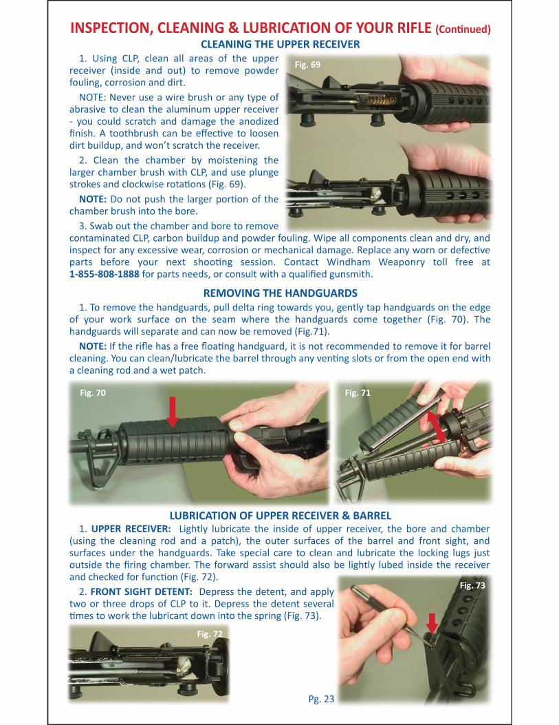
1. To remove the handguards, pull delta ring towards you, gently tap handguards on the edge of your work surface on the seam where the handguards come together (Fig. 70). The handguards will separate and can now be removed (Fig.71).
NOTE: If the rifle has a free floa3ng handguard, it is not recommended to remove it for barrel cleaning. You can clean/lubricate the barrel through any ven3ng slots or from the open end with a cleaning rod and a wet patch.
1. Using CLP, clean all areas of the upper receiver (inside and out) to remove powder fouling, corrosion and dirt.
NOTE: Never use a wire brush or any type of abrasive to clean the aluminum upper receiver - you could scratch and damage the anodized finish. A toothbrush can be effec3ve to loosen dirt buildup, and won’t scratch the receiver.
2. Clean the chamber by moistening the larger chamber brush with CLP, and use plunge strokes and clockwise rota3ons (Fig. 69).
NOTE: Do not push the larger por3on of the chamber brush into the bore.
3. Swab out the chamber and bore to remove contaminated CLP, carbon buildup and powder fouling. Wipe all components clean and dry, and inspect for any excessive wear, corrosion or mechanical damage. Replace any worn or defec3ve parts before your next shoo3ng session. Contact Windham Weaponry toll free at 1-855-808-1888 for parts needs, or consult with a qualified gunsmith.
INSPECTION, CLEANING & LUBRICATION OF YOUR RIFLE (Con)nued)
1. UPPER RECEIVER: Lightly lubricate the inside of upper receiver, the bore and chamber (using the cleaning rod and a patch), the outer surfaces of the barrel and front sight, and surfaces under the handguards. Take special care to clean and lubricate the locking lugs just outside the firing chamber. The forward assist should also be lightly lubed inside the receiver and checked for func3on (Fig. 72).
2. FRONT SIGHT DETENT: Depress the detent, and apply two or three drops of CLP to it. Depress the detent several 3mes to work the lubricant down into the spring (Fig. 73).
Fig. 72
Fig. 71
Fig. 73
Pg. 23

LUBRICATION OF UPPER RECEIVER & BARREL (con#nued)
INSPECTION, CLEANING & LUBRICATION OF YOUR RIFLE (Con#nued)
Fig. 74
WindageKnob
Adjustable Rear Sight on A4 Removable Carry Handle
Eleva#onDial
WindageScrew
Bo:om of Eleva#on ScrewSha; & Detent Spring Hole
(remove carry handle for access)
DetentSpringHole
3. ADJUSTABLE REAR SIGHT: NOTE: Make a note of how far you move the sights so they can be returned to their original posi#on a/er comple#ng this lubrica#on procedure (Fig. 74).
MOVING PARTS: Use one or two drops of CLP. Rotate these parts to ensure lubricant is spread evenly above and below the eleva#on knob / eleva#on screw sha/ / windage knob (maximum five clicks le/ or right) / windage screw / detent holes.
ELEVATION SCREW SHAFT: Remove A4 carry handle to lubricate the eleva#on screw (or, if you have an A2 fixed carry handle upper receiver, look inside the upper). Put two or three drops of CLP on bo8om of eleva#on screw sha/ and in eleva#on detent spring hole. Rotate the eleva#on dial back and forth a few #mes while keeping upper receiver upside down.
AFTER LUBING REAR SIGHT: Reset your correct zero windage and your ba8lesight zero. Refer to the sec#on within this manual about se:ng ba8lesight zero. No#ce the rear sight comes down when the “6/3 or 8/3” is aligned with the mark on the le/ side of the receiver. You will feel a “click" when the “6/3 or 8/3” first lines up with the mark. Carry your rifle with the “6/3 or 8/3” aligned with the mark. Keep the sight on 300 meters to keep dirt and water out of sight mechanism and protect the sight from damage.
IF YOU GET THE REAR SIGHT WET: Clean it as soon as possible to avoid the onset of rust and corrosion.
REINSTALLING THE HANDGUARDS
1. Insert the first half of the handguard into the handguard cap. Then pull the delta ring back and insert rear part of the handguard onto the delta ring as shown (Fig. 75).
2. Now insert the second half of the handguard into the handguard cap and pull back the delta ring and slide the rear of the handguard onto the delta ring as shown (Fig. 76).
3. Then squeeze the rear of the handguard halves as shown un#l they snap into the delta ring. (Fig.77).
NOTE: The two halves of standard issue rifle and carbine length handguards are iden#cal, and so can be installed either on top or bo8om.
Fig. 75
Fig. 76
Fig. 77Pg. 24

INSTALLING THE CHARGING HANDLE
LOWER RECEIVER DISASSEMBLY
INSPECTION, CLEANING & LUBRICATION OF YOUR RIFLE (Con#nued)
Fig. 78
Fig. 79
1. INSTALL THE CHARGING HANDLE: Insert
the charging handle into the upper receiver and
align the tabs on the charging handle with the
corresponding slots in the upper receiver. Then
push the charging handle down into the
charging handle groove and slide it part way
forward (Fig. 78).
2. INSTALL THE BOLT CARRIER: Pull the bolt to
the “out” posi/on in the carrier. As
you install the bolt carrier, align the
gas key with the channel in the
charging handle. Then push the bolt
carrier and charging handle all the
way forward un/l the bolt carrier is
flush with the back of the upper
receiver and the charging handle
latches in place (Fig. 79).
1. With the hammer cocked,
depress buffer retainer with chamber
plug tool or punch to release buffer
and spring (Fig. 80).
NOTE: Hammer must be cocked to
allow clearance for removal of buffer
and spring.
CAUTION: The buffer is under
tension from the ac/on spring.
2. Pull buffer and ac/on spring out
for cleaning (Fig. 81).
NOTE: Windham Weaponry does
not recommend any further
disassembly of rifle components or
subsystems. If you need further
service or parts, consult the factory
or a qualified gunsmith.
Fig. 80
Fig. 82
Fig. 81
Pg. 25

LOWER RECEIVER GROUP: lightly lubricate inside the lower receiver extension (buffer tube),
as well as the buffer and ac.on spring.
Generously lubricate the takedown and pivot pins and their detents, all moving parts inside
the lower receiver and their pins.
1. Using CLP, or a quality gun cleaner, clean all areas on the lower receiver of any powder
fouling, corrosion and dirt. Use of a toothbrush will avoid scratching the finish - never use a wire
brush.
2. Clean any dirt from the trigger mechanism. Carefully clean the magazine release bu8on
and the cavity for the magazine catch on the le9 side of the receiver. Inspect and clean the bolt
catch mechanism and lower receiver’s takedown and pivot pins. Clean the buffer, ac.on spring,
and inside the lower receiver extension (also called the buffer tube). A cloth a8ached to the
cleaning rod and patch holder can be used to wipe inside the buffer tube.
3. If the rifle has been used in dirty or muddy condi.ons, clean out the vent hole in the
telestock receiver extension (or the vent screw in the A2 solid bu8stock) with a pipe cleaner or
piece of wire to ensure that the vent hole is clear.
4. Clean telestock or bu8stock as necessary. The telestock latch can be pulled down to
remove the stock (as shown in Figures 83 & 84). Clean the 6 posi.on lock holes, and lightly lube
the receiver extension and latch mechanism to ensure proper telescoping ac.on. A2 solid
bu8stocks may require cleaning and lubrica.on of storage compartment door latch and hinge.
CLEANING THE LOWER RECEIVER
REASSEMBLY OF THE LOWER RECEIVER
REASSEMBLY OF THE RIFLE
LUBRICATION OF THE LOWER RECEIVER ASSEMBLY
INSPECTION, CLEANING & LUBRICATION OF YOUR RIFLE (Con#nued)
Fig. 83
Fig. 84
Fig. 85
Fig. 86JOIN UPPER & LOWER RECEIVERS:
1. Posi.on upper receiver so that receiver
pivot pin can slide into forward lug of upper
receiver.
2. Push pivot pin in, close upper receiver
completely onto lower (with hammer cocked).
3. Push in rear takedown pin (Fig. 86).
LOWER RECEIVER: Insert ac.on spring and
buffer. You may have to “wiggle” the ac.on
spring past the buffer detent as you insert it
(Fig. 85).
2
31
Pg. 26
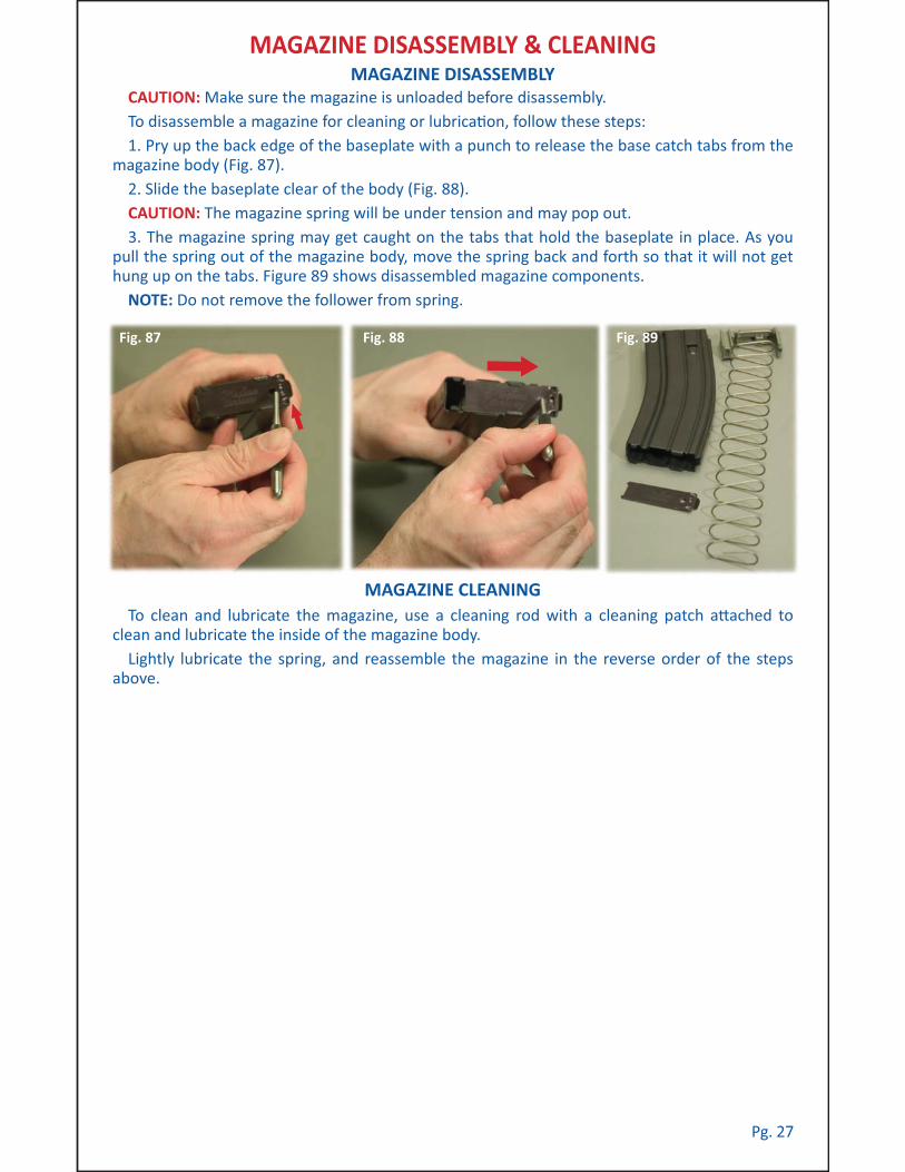
To clean and lubricate the magazine, use a cleaning rod with a cleaning patch a)ached to
clean and lubricate the inside of the magazine body.
Lightly lubricate the spring, and reassemble the magazine in the reverse order of the steps
above.
CAUTION: Make sure the magazine is unloaded before disassembly.
To disassemble a magazine for cleaning or lubrica/on, follow these steps:
1. Pry up the back edge of the baseplate with a punch to release the base catch tabs from the
magazine body (Fig. 87).
2. Slide the baseplate clear of the body (Fig. 88).
CAUTION: The magazine spring will be under tension and may pop out.
3. The magazine spring may get caught on the tabs that hold the baseplate in place. As you
pull the spring out of the magazine body, move the spring back and forth so that it will not get
hung up on the tabs. Figure 89 shows disassembled magazine components.
NOTE: Do not remove the follower from spring.
MAGAZINE DISASSEMBLY
MAGAZINE CLEANING
MAGAZINE DISASSEMBLY & CLEANING
Fig. 87 Fig. 88 Fig. 89
Pg. 27

TROUBLESHOOTING - PROBLEMS & SOLUTIONS
Fig. 90
Move selector lever to fire.
Assemble correctly - retaining pin must be
posi+oned behind large shoulder on firing pin.
Remove bolt & firing pin. With pipe cleaner,
clean out hole in bolt face. Clean firing pin.
Lubricate & reassemble.
Remove & discard. Use only fresh, clean .223
Rem. or 5.56mm NATO caliber ammuni+on.
Clean bolt & locking lugs in firing chamber.
Replace bolt if necessary, or consult with the
factory or a qualified gunsmith.
Replace the extractor spring and insert.
Possible stuck round. If possible, remove the
upper receiver from the lower. Clear the
weapon. Push out round with cleaning rod from
muzzle end.
Clean firing chamber & bolt locking lugs.
Remove bolt, disassemble extractor.
Clean extractor, lip, & related
Areas of bolt.
Remove bolt, disassemble extractor. Clean &
lubricate.
Remove & replace extractor.
Disassemble & clean magazine box, follower &
spring.
Replace defec+ve magazine.
Remove excess ammuni+on.
Remove buffer & spring. Clean, lubricate &
reinstall.
PROBLEM: CHECK FOR: WHAT TO DO:
Rifle will not
fire...
Bolt will not
easily unlock...
Bolt will not
extract...
Rifle will
not feed
ammuni+on...
Selector lever on safe.
Improper assembly of
firing pin.
Too much oil, or fouling in
firing pin recess.
Defec+ve ammuni+on.
Dirty or burred bolt.
Weak or broken extractor
spring.
Dirty or corroded
ammuni+on.
Carbon in firing chamber.
Fouling or carbon in
extractor recess or lip.
Frozen extractor.
Broken extractor.
Dirty magazine.
Defec+ve magazine.
Too many rounds in
magazine.
Ac+on of buffer assembly
is restricted.
Fig. 91
Pg. 28

Fig. 92
PROBLEM: CHECK FOR: WHAT TO DO:
Rifle will
not feed
ammuni'on...
Double feed...
Rifle will not
chamber a
round...
Short recoil...
Magazine not fully seated.
Defec've magazine.
Dirty or corroded
ammuni'on.
Damaged ammuni'on.
Carbon or fouling in
chamber area or in barrel
locking lugs.
Restricted movement of
bolt carrier group.
Gaps in bolt gas rings
aligned correctly.
Carbon or dirt in carrier
key or on outside of gas
tube.
Underpowered
ammuni'on.
Loose gas key.
TROUBLESHOOTING - PROBLEMS & SOLUTIONS (con%nued)
Slap up on the bo/om of the magazine to
ensure it is seated correctly in the magazine
well. Then pull
down on the
magazine to
ensure the
magazine catch
is properly
engaged with
the magazine.
Replace defec've magazine.
Clean the ammuni'on, or remove & discard.
Use only fresh, clean .223 Rem. or 5.56mm
NATO caliber ammuni'on.
Replace damaged ammuni'on.
Clean firing chamber area & bolt locking lugs.
Remove bolt carrier. Clean & lubricate all
components. Before pu7ng bolt back in, make
sure gas tube fits into carrier key, and that the
carrier moves freely.
Gaps in the 3 gas rings should be staggered 120°
around the bolt body to ensure proper gas
pressure.
Clean these areas.
Use newly manufactured, quality ammuni'on.
Contact Customer Service toll free at:
1-855-808-1888
Fig. 93
Fig. 94
Fig. 95
Pg. 29

Pg. 30
PROBLEM: CHECK FOR: WHAT TO DO:
Bolt fails to
lock a'er last
round...
Selector lever
binds...
Failure to
eject...
Bolt carrier
“hang up”...
Dirty or corroded bolt
catch.
Faulty magazine.
Needs oil.
Obstruc-on under trigger.
Hammer posi-on.
Frozen or s-ff ejector.
Round jammed between
bolt and charging handle.
TROUBLESHOOTING - PROBLEMS & SOLUTIONS (con#nued)
Clean bolt catch.
Replace defec-ve magazine.
Lubricate with CLP.
Clean or flush out lower receiver & lubricate.
The safety selector will only rotate when the
hammer is in the cocked posi-on.
Lubricate ejector with CLP and use a punch to
work ejector in and out of bolt face.
With rifle pointed in a safe direc-on...
1. Remove magazine.
2. Push in on bo7om of the bolt catch.
3. Pull charging handle to the rear. If the bolt
carrier does not lock to the rear, while pulling
the charging handle rearward, bang the
bu7stock on a solid surface (Fig. 96).
4. Once the bolt is locked to the rear, place the
safety selector in the safe posi-on.
5. Push the charging handle forward and the
round should become dislodged (Fig. 97).
Inspect that round, and discard if damaged.
CAUTION: A'er round is removed, bolt is under
tension.
NOTE: If this procedure fails, use a sec-on of
cleaning rod to push bolt fully to rear through
the ejec-on port.
Fig. 96 Fig. 97
NOTE: If the problem s-ll persists, see the short recoil solu-ons.
NOTE: If the problem s-ll persists, call Customer Service toll free at: 1-855-808-1888
WARNING: Keep clear of muzzle.

Pg. 31
PROBLEM: CHECK FOR: WHAT TO DO:
Double feed...
TROUBLESHOOTING - PROBLEMS & SOLUTIONS (con#nued)
SHIPPING RIFLES FOR SERVICE
With rifle pointed in a safe direc-on...
1. Remove magazine.
2. Push in on bo)om of the bolt catch.
3. Pull charging handle to the rear and lock the
bolt carrier in place.
4. Place the safety selector in the SAFE posi-on.
5. Rounds should fall out of the rifle through the
magazine well.
6. Visually inspect to ensure that all rounds are
clear from the rifle.
Inspect and discard any damaged ammuni-on.
For Owners Within The United States... CONTACT CUSTOMER SERVICE:Tel: 207 893 2223 • Sales Line: 855 808 1888 • E-mail: [email protected]
RETURNS FOR SERVICE: Should your Windham Weaponry Firearm require service, it should be
returned to the Windham Weaponry factory.
• Call or E-mail the Customer Service Dept. for authoriza-on and shipping instruc-ons.
• ENSURE THAT THE FIREARM IS UNLOADED.
• DO NOT SHIP ANY AMMUNITION.
• Do not a)empt to ship a Firearm via US Postal Service (only Federally Licensed Dealers may
ship Firearms by Postal Service).
• Enclose a le)er which includes your full name and street address (no P.O. Boxes), day-me
telephone number, e-mail address, the serial number of the firearm, and details of problem expe-
rienced (sta-ng the brand and type of ammuni-on used when the problem occurred), or work
desired. We recommended that you insure your shipment.
• Record the serial number before shipping, in case you wish to check on the repair status of
your Firearm.
• Please remove all custom parts and accessories, such as stocks, special sights and scopes, or
slings from your firearm before returning.
• Place the Firearm in its original case or in a similar secure container, and pack it snugly.
• The package must NOT bear any markings which indicate the iden-ty of the contents.
Windham Weaponry • Windham Business Park
999 Roosevelt Trail • P.O. Box 1900 • Windham, ME 04062
Telephone: 207 893 2223 • Fax: 207 893 1623 • Sales Line: 855 808 1888
E-mail: [email protected] www.windhamweaponry.com

Pg. 32
MAINTENANCE LOG / ZEROING-IN RECORDS / NOTES
Windham Weaponry • Windham Business Park
999 Roosevelt Trail • P.O. Box 1900 • Windham, ME 04062
Telephone: 207 893 2223 • Fax: 207 893 1623 • Sales Line: 855 808 1888
E-mail: [email protected] www.windhamweaponry.com
This Opera-ng and Safety Instruc-on Manual should
always be kept with your Windham Weaponry firearm. If
the rifle is sold, it should be transferred to the new owner.
Model:
__________________________________________________
Serial Number:
__________________________________________________
Sold To:
__________________________________________________
Date Sold:
__________________________________________________

SAFE HANDLING!
ALWAYS HANDLE your firearm as if it were loaded.
NEVER POINT your firearm at anything you do not intend to shoot.
KNOW YOUR TARGET and beyond.
USE EYE & EAR PROTECTION when shoo*ng.
DO NOT TOUCH the trigger unless you are ready to fire.
DO NOT RELY on the firearm’s safety - it should only be considered a supplement to safe firearm handling.
NEVER LEAVE a loaded firearm una/ended.
ONLY USE AMMUNITION designed for your firearm. Failure to use the proper caliber ammu-ni*on can damage your firearm and may result in injury or death.
ONLY USE QUALITY commercial ammuni*on that is in good condi*on. Using corroded, lacquer coated, damaged, hand loaded, steel or aluminum cased ammuni*on may void the warranty and may cause injury or death.
BE SURE YOUR FIREARM is unloaded and the bolt is open before handing it to others.
DO NOT HANDLE firearms while impaired or the influence of alcohol or drugs.
DO NOT ALLOW others to handle or shoot your rifle if they have not read the safety guide-lines in this manual.
DO TAKE a firearms safety course!
RIFLE SPECIFIC WARNINGS:
BOLT CAM PIN must be installed or rifle will suffer catastrophic failure when fired. Injury or death may result.
IF THERE IS WATER, too much oil, or an obstruc*on in the barrel, do not fire. It may explode and cause injury or death to you or those around you.
DO NOT DROP your firearm, it may discharge. A firearm dropped on its bu/ may chamber a round.
DO NOT EXCHANGE bolt assemblies from one rifle to another. While Windham Weaponry rifles and bolts are machined with great care, and are interchangeable with other Windham Weaponry bolts, we do not recommend exchanging bolts - par*cularly those from other manu-facturers, without first checking for proper headspacing with a Field Gauge or Go/No-Go Gauge for .223 Rem. /5.56mm NATO.
BE SAFE WORKING WITH YOUR FIREARM!
BEFORE INSPECTION OR MAINTENANCE, be sure to clear the rifle. Do not pull the trigger un*l the rifle has been cleared. Inspect the firing chamber to ensure that it is empty and the magazine has been removed.
DO NOT KEEP ammuni*on near your work area.
ONLY THE FACTORY or a qualified gunsmith should service, repair or modify your firearm in any way.
CAUTIONS REGARDING TOXICS & PARTS:
CLEANING, DISCHARGING, HANDLING of your firearm and ammuni*on may result in expo-sure to lead - a toxic and hazardous substance. Wash hands thoroughly a?er exposure.
TO AVOID INJURY to your eyes, use care when removing and installing spring-loaded parts of your firearm.
ALWAYS FOLLOW THE RULES OF SAFE GUN HANDLING!
FOLLOW ALL INSTRUCTIONS ON THE
PROPER HANDLING AND SAFE USE OF THIS FIREARM!

Windham Weaponry, Inc. (WWI) will warranty all firearms manufactured by WWI against any and all manufacturer’s defects in material and workmanship which affect reasonable opera1on for the life-me of the firearm to the purchaser. This warranty is transferable from the original purchaser to a subse-quent buyer.
Warranty is established by registering online at:
h&p://www.windhamweaponry.com or by phone with our Customer Service department at 855-808-1888.
Warranty claims may be made by contac1ng Customer Service, either in wri1ng or by phone for a Return Authoriza1on number prior to delivering the unloaded firearm to Windham Weaponry, Inc., 999 Roosevelt Trail, Windham, Maine 04062, freight prepaid by the purchaser. Firearms and ammuni1on must be shipped separately. No COD shipments will be accepted.
WWI will repair or replace only those parts determined to be defec1ve by the factory. This warranty does not apply to normal wear and tear of any parts or protec1ve finishes.
The following are specifically excluded from coverage under this warranty and will cause said warranty to become null and void:
Damage or malfunc1on resul1ng from accident, negligence, misuse or unauthorized repair or altera1on; barrel obstruc1on; use of ammuni1on other than NATO and/or SAAMI specifica1on new produc1on ammuni1on; use of any hand loaded, reloaded, imported or factory re-manufactured ammuni1on; failure to provide reasonable and necessary maintenance as described in the Operator’s Manual accompanying the firearm; rust or corrosion; use of replace-ment parts other than parts authorized by WWI for use in WWI firearms; any unauthorized repair or any altera1on, including of a cosme1c nature, performed on the firearm by an individual, organiza1on, company or en1ty other than WWI; unreasonable or excessive use of the firearm.
Any finished products that are not assembled at our facili1es, or are assembled using imported or used parts. This includes complete rifle kits, upper receivers, lower receivers, barrel assemblies, etc.
No implied warran1es of any kind are made herein. Limited Life1me Warranty does not apply to any accessory items.
WWI assumes no liability for accidental or consequen1al damages. Some states do not allow the exclusion or limita1on of accidental or consequen1al damages and therefore this limita1on may not apply to you.
TRANSFERABLE LIMITED LIFETIME WARRANTY
Windham Weaponry • 999 Roosevelt Trail • P.O. Box 1900 • Windham, ME 04062
Telephone: 207 893 2223 • Fax: 207 893 1623 • Sales Line: 855 808 1888
E-mail: [email protected] www.windhamweaponry.com
ACTIVATING YOUR WARRANTYAs soon as possible upon receipt of your Windham Weaponry Firearm, go online, or call, to
ac1vate the Warranty. See: www.windhamweaponry.com / or call Toll-Free: 855-808 1888
Follow the Instruc1ons on the Website Warranty Page. Your Windham Weaponry Firearm’s Warranty will be in effect upon comple1on of these steps.
The Windham Weaponry Team thanks you for your purchase of this fine rifle, and we hope you will enjoy it safely for many years. If you need parts, service or advice concerning your rifle, we are never more than a phone call away, and will be pleased to help you.
© Feb.. 2012 Windham Weaponry Inc., Windham, Maine USA Windham Weaponry Part No: MAN-OP-AR