OpenFlow-based segment protection in Ethernet networks
10
OpenFlow-Based Segment Protection in Ethernet Networks Andrea Sgambelluri, Alessio Giorgetti, Filippo Cugini, Francesco Paolucci, and Piero Castoldi Abstract—Metro and carrier-grade Ethernet networks, as well as industrial area networks and specific local area networks (LANs), have to guarantee fast resiliency upon network failure. However, the current OpenFlow architec- ture, originally designed for LANs, does not include effec- tive mechanisms for fast resiliency. In this paper, the OpenFlow architecture is enhanced to support segment protection in Ethernet-based networks. Novel mechanisms have been specifically introduced to maintain working and backup flows at different priorities and to guarantee effec- tive network resource utilization when the failed link is recovered. Emulation and experimental demonstration im- plementation results show that the proposed architecture avoids both the utilization of a full-state controller and the intervention of the controller upon failure, thus guarantee- ing a recovery time only due to the failure detection time, i.e., a few tens of milliseconds within the considered scenario. Index Terms—Ethernet; OpenFlow; Recovery; Segment protection; Software-defined networking (SDN). I. INTRODUCTION S oftware-defined networks are emerging as an attrac- tive solution to permit effective separation of data and control planes while guaranteeing a centralized network intelligence to control the network (i.e., the controller). OpenFlow is an example of a software-defined network in which the controller manages the switching elements (e.g., Ethernet switches) by installing flow entries within their flow table [ 1]. Communications between the control- ler and the switches use the OpenFlow protocol through a secure channel. Each flow entry consists of a flow-match composed of a set of fields to match the incoming packets, an action to define how to process matching packets (e.g., forwarding on a specific output port), and several counters used for collecting flow statistics. Other information can also be associated with each entry, such as priority level and the two timers hard timeout and idle timeout. When a switch receives a packet not matching any of the installed entries, that packet is sent to the controller using the se- cure channel. Upon reception, the controller decides how to handle the received packets, e.g., it computes a path and installs a flow entry in each traversed switch to deliver the matching packets to the proper destination. OpenFlow was originally designed at Stanford Univer- sity to be used in local and campus area networks [ 1, 2]. However, because of its centralized control approach it is currently also under consideration in other scenarios such as carrier-grade networks [ 3], optical transport networks [ 4– 8], and industrial area networks [ 9]. Specifically, trans- port network carriers tend to prefer centralized control be- cause it is simpler, more manageable, and easier to migrate from the current network management system architec- ture with respect to the current standard distributed con- trol plane of transport networks [ 10], i.e., generalized multi-protocol label switching (GMPLS). In all the aforementioned scenarios, network reliability is a fundamental feature. Indeed, in carrier-grade and op- tical transport networks, a single failure can disrupt a huge amount of traffic, implying a service degradation to a great number of users. In these networks the target recovery time is 50 ms as guaranteed by the legacy SONET/SDH networks [ 11, 12]. Similarly, in industrial area networks the recovery time cannot exceed the typical grace time of industrial plants (e.g., 20 ms for time critical automation systems, 200 ms for general automation systems) [ 13, 14]. Therefore, in all of these cases, fast recovery of net- work failures is strictly required. However, fast recovery is not a key feature in local area networks (LANs), and the current OpenFlow architecture needs several seconds to re- cover from a network failure [ 15]. In order to achieve lower recovery times, this paper pro- poses an OpenFlow-based segment protection (OSP) scheme enabling fast recovery in case of single link or inter- face failure in Ethernet-based networks. The concepts behind the OSP scheme can be applied, with slight modi- fications, in OpenFlow-based optical transport networks [ 4– 8]. Therefore, this work also represents a first step to- ward the introduction of OpenFlow-based fast recovery in optical transport networks. The proposed architecture relies on preplanned backup paths guaranteeing that, upon failure occurrence, recovery is locally performed by the switch attached to the failed link, thus minimizing the recovery time. To support backup paths, several enhancements to the OpenFlow architecture are proposed. Indeed, in addition to the auto-reject mecha- nism, the configuration of alternative flow entries with http://dx.doi.org/10.1364/JOCN.5.001066 Manuscript received March 29, 2013; revised July 12, 2013; accepted July 18, 2013; published August 26, 2013 (Doc. ID 187905). A. Sgambelluri (e-mail: [email protected]), A. Giorgetti, F. Paolucci, and P. Castoldi are with the Scuola Superiore Sant’Anna, Pisa, Italy. F. Cugini is with CNIT, Pisa, Italy. 1066 J. OPT. COMMUN. NETW./VOL. 5, NO. 9/SEPTEMBER 2013 Sgambelluri et al. 1943-0620/13/091066-10$15.00/0 © 2013 Optical Society of America
Transcript of OpenFlow-based segment protection in Ethernet networks

OpenFlow-Based Segment Protection inEthernet Networks
Andrea Sgambelluri, Alessio Giorgetti, Filippo Cugini,Francesco Paolucci, and Piero Castoldi
Abstract—Metro and carrier-grade Ethernet networks,as well as industrial area networks and specific local areanetworks (LANs), have to guarantee fast resiliency uponnetwork failure. However, the current OpenFlow architec-ture, originally designed for LANs, does not include effec-tive mechanisms for fast resiliency. In this paper, theOpenFlow architecture is enhanced to support segmentprotection in Ethernet-based networks. Novel mechanismshave been specifically introduced to maintain working andbackup flows at different priorities and to guarantee effec-tive network resource utilization when the failed link isrecovered. Emulation and experimental demonstration im-plementation results show that the proposed architectureavoids both the utilization of a full-state controller and theintervention of the controller upon failure, thus guarantee-ing a recovery time only due to the failure detection time,i.e., a few tens of milliseconds within the consideredscenario.
Index Terms—Ethernet; OpenFlow; Recovery; Segmentprotection; Software-defined networking (SDN).
I. INTRODUCTION
S oftware-defined networks are emerging as an attrac-tive solution to permit effective separation of data and
control planes while guaranteeing a centralized networkintelligence to control the network (i.e., the controller).OpenFlow is an example of a software-defined networkin which the controller manages the switching elements(e.g., Ethernet switches) by installing flow entries withintheir flow table [1]. Communications between the control-ler and the switches use the OpenFlow protocol through asecure channel. Each flow entry consists of a flow-matchcomposed of a set of fields to match the incoming packets,an action to define how to process matching packets (e.g.,forwarding on a specific output port), and several countersused for collecting flow statistics. Other information canalso be associated with each entry, such as priority leveland the two timers hard timeout and idle timeout. Whena switch receives a packet not matching any of the installedentries, that packet is sent to the controller using the se-cure channel. Upon reception, the controller decides how
to handle the received packets, e.g., it computes a pathand installs a flow entry in each traversed switch to deliverthe matching packets to the proper destination.
OpenFlow was originally designed at Stanford Univer-sity to be used in local and campus area networks [1,2].However, because of its centralized control approach it iscurrently also under consideration in other scenarios suchas carrier-grade networks [3], optical transport networks[4–8], and industrial area networks [9]. Specifically, trans-port network carriers tend to prefer centralized control be-cause it is simpler, more manageable, and easier to migratefrom the current network management system architec-ture with respect to the current standard distributed con-trol plane of transport networks [10], i.e., generalizedmulti-protocol label switching (GMPLS).
In all the aforementioned scenarios, network reliabilityis a fundamental feature. Indeed, in carrier-grade and op-tical transport networks, a single failure can disrupt a hugeamount of traffic, implying a service degradation to a greatnumber of users. In these networks the target recoverytime is 50 ms as guaranteed by the legacy SONET/SDHnetworks [11,12]. Similarly, in industrial area networksthe recovery time cannot exceed the typical grace time ofindustrial plants (e.g., 20 ms for time critical automationsystems, 200 ms for general automation systems)[13,14]. Therefore, in all of these cases, fast recovery of net-work failures is strictly required. However, fast recovery isnot a key feature in local area networks (LANs), and thecurrent OpenFlow architecture needs several seconds to re-cover from a network failure [15].
In order to achieve lower recovery times, this paper pro-poses an OpenFlow-based segment protection (OSP)scheme enabling fast recovery in case of single link or inter-face failure in Ethernet-based networks. The conceptsbehind the OSP scheme can be applied, with slight modi-fications, in OpenFlow-based optical transport networks[4–8]. Therefore, this work also represents a first step to-ward the introduction of OpenFlow-based fast recovery inoptical transport networks.
The proposed architecture relies on preplanned backuppaths guaranteeing that, upon failure occurrence, recoveryis locally performed by the switch attached to the failedlink, thus minimizing the recovery time. To support backuppaths, several enhancements to the OpenFlow architectureare proposed. Indeed, in addition to the auto-reject mecha-nism, the configuration of alternative flow entries withhttp://dx.doi.org/10.1364/JOCN.5.001066
Manuscript received March 29, 2013; revised July 12, 2013; acceptedJuly 18, 2013; published August 26, 2013 (Doc. ID 187905).
A. Sgambelluri (e-mail: [email protected]), A. Giorgetti, F.Paolucci, and P. Castoldi are with the Scuola Superiore Sant’Anna, Pisa,Italy.
F. Cugini is with CNIT, Pisa, Italy.
1066 J. OPT. COMMUN. NETW./VOL. 5, NO. 9/SEPTEMBER 2013 Sgambelluri et al.
1943-0620/13/091066-10$15.00/0 © 2013 Optical Society of America

different priority levels, a renewal mechanism, relying on anovel renew packet, is introduced to avoid the expiration ofthe entries required to support the backup paths. In addi-tion, a novel mechanism is provided for reverting activeflows to the original working path once the failure has beenphysically repaired, thus guaranteeing efficient networkresource utilization.
The proposed OSP scheme has been validated on ringtopologies through emulation and experimental demon-stration of real implementation, both achieved by extend-ing OpenFlow version 1.0 [16]. The obtained results showthat the proposed scheme avoids controller scalability is-sues upon failure occurrence and guarantees a recoverytime only dependent on the failure detection time (i.e., afew tens of milliseconds in the considered testbed).
II. PREVIOUS WORK
The authors of [15] and [17] designed a restorationscheme for OpenFlow carrier-grade Ethernet networks. Inthe proposed scheme, the switch connected to the disruptedlink directly notifies the controller about the topologychange.Uponnotification, a full-state controller (i.e., storingthe complete path of all the flows established in the net-work) identifies the disrupted flows, computes the backuppaths, and updates the data plane flow tables consideringthe failure. Obtained results show recovery times around200 ms. However, the authors recognize that, in big net-works, the full-state controller could be overloaded by recov-ery requests the full-state architecture of the controllermayintroduce, thus introducing significant scalability issues.
In [18] two different recovery mechanisms are pre-sented, i.e., restoration and path protection. In the caseof restoration, similarly to in [15,17], the controller reactsto the failure notification by deleting affected flow entries,computing backup paths, and installing the new requiredentries. In the case of path protection, backup paths areprecomputed and installed using the fast-failover groupsfunctionality of OpenFlow specification 1.1, and workingpath liveness is monitored by the ingress switch with amechanism similar to the one proposed in [7]. In the caseof failure, emulation results show that the protection sol-ution achieves the recovery process in around 50 ms.
The work in [19] considers OpenFlow in IP networks.The proposed scheme is similar to that of [15,17], consid-ering a full-state controller that is notified by the switchupon link failure occurrence. In this case emulation resultsprovide a failure recovery time in the range of 200–300 ms.
The work in [7] proposes a monitoring mechanism ena-bling fast failure discovery in transport networks based onOpenFlow. In the proposed mechanism, each establishedflow is monitored by sending frequent probe messages.Failures are quickly discovered; however, the controlleris then involved for the computation of the backup paths.Thus, the overall recovery time may still suffer from longdelays and relevant scalability issues.
In [20], a data plane mechanism is proposed to notify,upon failure, all the switches that are sending traffic
through the disrupted link. Upon notification the switchesstop these traffic flows to avoid waste of bandwidth. Theactual recovery is then performed by the controller relyingon the standard OpenFlow mechanism.
The authors of [21] propose a mechanism enabling theutilization of a backup controller in an OpenFlow-basednetwork to avoid the problem of having a single pointof failure, which is a typical weak point of centralizedapproaches.
With respect to the restoration schemes proposed in[15,17–19], the OSP scheme does not involve the controllerupon failure occurrence and does not require a full-statecontroller. Moreover, with respect to the path protectionscheme proposed in [18], OSP implements segment protec-tion; thus it locally switches the traffic on the backup pathand does not require a per-flowmonitoring mechanism. Forthe aforementioned reasons the OSP scheme is expected tobe more scalable and to achieve lower recovery time withrespect to existing schemes.
III. OPENFLOW-BASED ARCHITECTURE ENABLING
SEGMENT PROTECTION
In OpenFlow switches each flow entry is installed withtwo associated timers, i.e., hard timeout and idle timeout.The entry is deleted by the switch upon expiration of one ofthe two timers. The hard timeout is never refreshed andis used to set the maximum duration of each entry.Conversely, the idle timeout is refreshed every time apacket matches the associated entry; it expires owing tolack of activity.
Referring to OpenFlow Switch Specification 1.0 [16], fail-ure recovery operates as follows. When the switch detects afailure, it notifies the controller with a port status message.Thus, the controller updates the network topology and thesuccessive path computations are performed using the up-dated topology. However, the switch does not delete the en-tries using the failed link. Therefore, established flows arenot actually recovered till one of the aforementioned timersexpires. Since these timers are usually set to several sec-onds, current OpenFlow implementations do not guaranteefast recovery [15].
Therefore, as a first step, an auto-reject mechanismshould be implemented to promptly delete the entries us-ing the failed link. Specifically, with the auto-reject mecha-nism, upon failure occurrence, the two switches connectedto the failed link delete all their flow entries having the in-put or output port on the failed link. Moreover, upon recep-tion of a new entry to be installed, an auto-reject-enabledswitch checks the status of the ports used by the entry;when one of the ports uses a failed link, the entry is notinstalled.
However, extending OpenFlow with only the auto-rejectmechanism does not guarantee fast recovery; indeed, fail-ures would be handled as follows. Switches apply auto-reject and send port status to the controller. Because ofauto-reject, subsequent packets of disrupted flows do notmatch any entry and are sent to the controller. While
Sgambelluri et al. VOL. 5, NO. 9/SEPTEMBER 2013/J. OPT. COMMUN. NETW. 1067

the controller is updating the topology, it keeps replyingwith flow entries using the disrupted link, which are re-fused by auto-reject. Only after topology update is a fea-sible path computed and proper entries installed in allthe involved switches. This procedure requires several sec-onds. Thus, besides auto-reject, a set of backup entries haveto be preconfigured for enabling fast recovery.
The rest of this section describes the architectureenabling the proposed OSP scheme. The flow entries
required for each protected data flow are detailed inSubsection III.A; the mechanism needed for avoidingthe expiration of the installed entries is described inSubsection III.B. Finally, Subsection III.C summarizesthe actions taken in case of link failure and recovery.
A. Flow Entries Installation
Figure 1 shows the flowchart of the Recovery modulethat we have implemented at the controller, for the caseof a flow request protected against single link and interfacefailures. Specifically, upon request of a protected data flowbetween the hosts (Src-Dst), the controller computes andinstalls the entries for supporting the working path (i.e.,working entries). Then, for providing protection againstlink and interface failures only, a backup path is computedconsidering a failure in each link traversed by the workingpath. Conversely, if protection is also required against sin-gle node failures, a backup path is computed considering afailure in each intermediate node traversed by the workingpath. After backup path computation the required backupentries are installed to enable the switching of packetsalong the backup paths. During failure-free operation, dataare routed along the working path. If a failure disrupts theworking path, the flow is deviated by the switch attached tothe failed link so that it will reach Dst along the backuppath (see Figs. 2–4).
Working and backup entries are installed with differentpriorities. High-priority levels are used for working entries:Hi in the ingress switch, Ht in transit switches, and He inthe egress switch. Low-priority levels are used for backupentries: Li in the ingress switch and in switches where abackup path diverges from the working path (e.g., switchB in Fig. 2), Lt in transit switches, and Le in the egressswitch). Each received packet is forwarded consideringthe currently installed matching entry with the highestpriority.
Figure 2 summarizes the flow entries required in theillustratedmesh topology when a single protected data flowis configured between the host pair (Src-Dst). For the sake
Working pathcomputation
Install working entries in the traversed switches
H = working path hopsi = 1
Reply withOFPT_PACKET_OUTBackup path i-th
computation
Working pathComputed?
i H
Install broadcast flowentries in the requesting
switch
Protected flow request(OFPT_PACKET_IN)
NO
YES
Install backup entries in the traversed switches
i++Backup path i-th
computed? End
YES
NO
YES
NO
Fig. 1. Flowchart of the Recovery module at the controller. Thisflowchart refers to the case of a flow request protected against linkand interface failures.
Src Dst2
13
A
23 I
12
3D
2
3
H2
3
G
23 F
4 23 E
4
23B
42
3C4
Fig. 2. Protected traffic flow in a mesh network. Only the flow entries related to host pair (Src-Dst) are shown.
1068 J. OPT. COMMUN. NETW./VOL. 5, NO. 9/SEPTEMBER 2013 Sgambelluri et al.

of clarity, the flow entries are shown in Fig. 2, just includingthe triplet composed of the input port (IN), outport port(OUT), and priority level (Pri). However, other parameters[i.e., Src and Dst media access control (MAC) addresses]are used for flow matching.
Specifically, in Fig. 2 the working path is A–B–C–D.Backup paths are configured for multiple points of failurealong the working path. At ingress switch A, the flow tableis configured with one working entry �1;2; Hi� and onebackup entry �1; 3; Li�. The working path entry enablesthe packet switching from the host Src toward switch B.The backup path entry is configured for the case of failureof the adjacent linkA–B to enable the forwarding of packetstoward switch F.
The transit switchesB andC are configured with a work-ing entry �2;3; Ht� and a backup entry �2; 4; Li�. The backupentry is configured for a case of a failure of the adjacent link(B–C for switch B, C–D for switch C). For switch B, thiscauses traffic to be sent to switch G, and for switch C thiscauses traffic to be sent to switchH. Egress switchD is con-figured as a working and a backup entry in the sameway aspreviously described. The other transit switches along thebackup paths are configured with one or more backup en-tries, e.g., �2; 3; Lt� in the switches G and H.
Figures 3 and 4 show the backup paths used in the caseof a failure occurring in the working path along link A–Band linkC–D, respectively. Referring to Fig. 4, the failure oflink C–D is detected by switches C and D; at switchC the auto-reject mechanism removes the flow entry�2;3; Ht�. This leaves a flow entry for the configuredbackup path �2; 4; Li�. The resulting backup pathis A–B–C–H–E–D.
B. Backup Flow Entries Renewal
Since, in the proposed architecture, no packets arerouted along the backup paths during failure-free opera-tion, the expiration of the idle timeout may determinethe deletion of backup entries. Therefore, a mechanismis used to avoid the deletion of backup entries related to
active working flows, without involving either the control-ler or the hosts Src and Dst.
First, for each flow, the refresh of working entries auto-matically determines the refresh of all the backup entriesassociated with the same flow. With reference to Fig. 2, thiswill guarantee the liveness of all backup entries in switchesA, B, C, and D.
Second, a specifically designed renew packet is built andperiodically sent by each switch on the output port ofentries with Li priority (e.g., switch B in Fig. 2). The renewpacket fields are set to match the considered flow. More-over, a specific field is included so that the egress switchcan distinguish renew packets from data packets. Sincethe generation rate of renew packets depends on the con-sidered idle timeout, they use a negligible amount of band-width. In Fig. 2, the ingress switch A periodically sendsrenew packets along the backup path A–F–I–E–D, theseframes do not reach the host Dst, as they are dropped bythe egress switch C. In this way, the backup entries inswitches F, I, and E are preserved. Finally, switches Band C periodically send renew packets on port 4 so thatbackup entries in switches G and H are also preserved.
C. Failure Recovery and Reversion
If the failure affects a working path, auto-reject is trig-gered at the switches attached to the failed link. After auto-reject of the working entry, the related backup flow entry isautomatically used for switching the packets along thebackup path. Data packets are lost only in the periodof time between the failure and the auto-reject (i.e., switch-over time). Indeed, during this period packets are for-warded on the failed link. In a similar way, if the failureaffects a backup path, the auto-reject deletes the relatedbackup entry. In this case, data packets are not affected;however, renew packets periodically sent along the backuppath arrive at the switch attached to the failed link. Theserenew packets do not match any entries and are thereforeforwarded to the controller using OFP_PACKET_IN packets.To limit requests to the controller, these packets arehandled as described in Subsection IV.C.
Src Dst2
13
A
23 I
12
3D
2
3
H2
3
G
23 F
4 23 E
4
23B
42
3C4
Fig. 3. Actual backup path used upon failure of link A–B.
Sgambelluri et al. VOL. 5, NO. 9/SEPTEMBER 2013/J. OPT. COMMUN. NETW. 1069

When the link failure is physically repaired, the at-tached switches notify the controller about the topologychange, sending a port status message. Then, for revertingthe routing of the active flows to the original working pathas before the failure, a OFP_FLOW_RESTORE packet is sent,for each installed flow match, to the controller and handledas described in Subsection IV.C. For instance, working en-tries in the switches downstream to a failure occurredalong the working path may expire after the failure.This rerouting procedure involves the controller and cantherefore require several seconds; however, this is not anissue because, in the case of link recovery, data traffic isnot disrupted.
IV. IMPLEMENTATION
The proposed OSP scheme has been implemented by ex-tending the OpenFlow Switch Specification 1.0 [16,22].More recent specifications include additional features(i.e., fast-failover groups) that could further facilitate theOSP implementation. However, stable implementationsof these specifications were not available at the time ofarchitecture design. This section describes the extensionsto the OpenFlow protocol, to the OpenFlow switch, and tothe OpenFlow controller, which have been implemented toenable the OSP scheme.
A. OpenFlow Protocol
The standard OpenFlow version 1.0 protocol has beenextended with the novel OFPT_FLOW_RESTORE packet.Its fields include the standard OpenFlow header object,the match object specifying the flow-match, the cookieobject, and the priority object as depicted in Fig. 5.
B. OpenFlow Switch
The OpenFlow switch implementation is based on OpenvSwitch version 1.1.1, which is compliant with OpenFlow
Switch Specification 1.0 [16,22]. Moreover, the followingnovel features have been implemented.
1) Flow Auto-Reject: As described in Section III, aswitch detecting a failure on a local interface deletes allthe flow entries having the failed interface as an input oroutput port. Moreover, a new flow entry is installed only ifthe output port is working correctly.
2) Flow Renewal: With reference to Subsection III.B, re-new packets have been implemented using a specificallydesigned Ethernet frame (i.e., ETH_RENEW). In particular,ETH_RENEW frames are of 64 byte size, source and destina-tion MAC addresses are set to match the considered flow,and the EtherType field is set to the specific value 0 × 88dd.For each flow, one ETH_RENEW frame is sent every 20 s bybackup path ingress switches. A switch is recognized to be abackup path ingress of a particular flow if its flow table in-cludes an entry with priority Li. A switch is recognized to bethe egress of a particular flow if its flow table includes anentry with priority He and Le; see Fig. 2.
3) Flow Restore: As mentioned in Subsection III.C, theOFPT_FLOW_RESTORE packet is sent 20 s after a link recov-ery has been detected on a local interface. This 20 s delay isempirically estimated so that, upon failure, the controllerreceives the port status messages from the switches
Src Dst2
13
A
23 I
12
3D
2
3
H2
3
G
23F4 2
3 E4
23B
42
3C4
Fig. 4. Actual backup path used upon failure of link C–D. Traffic is wrapped at node C.
0 1 2 3
0 1 2 3 4 5 6 7 8 9 0 1 2 3 4 5 6 7 8 9 0 0 1 2 3 4 5 6 7 8 9 0 1
+-+-+-+-+-+-+-+-+-+-+-+-+-+-+-+-+-+-+-+-+-+-+-+-+-+-+-+-+-+-+-+-+-+| |+ Header +| |+-+-+-+-+-+-+-+-+-+-+-+-+-+-+-+-+-+-+-+-+-+-+-+-+-+-+-+-+-+-+-+-+-+| |+ Match +| |+-+-+-+-+-+-+-+-+-+-+-+-+-+-+-+-+-+-+-+-+-+-+-+-+-+-+-+-+-+-+-+-+-+| |+ Cookie +| |+-+-+-+-+-+-+-+-+-+-+-+-+-+-+-+-+-+-+-+-+-+-+-+-+-+-+-+-+-+-+-+-+-+| Priority | (pad) |+-+-+-+-+-+-+-+-+-+-+-+-+-+-+-+-+-+-+-+-+-+-+-+-+-+-+-+-+-+-+-+-+-+
Fig. 5. OFPT_FLOW_RESTORE packet format.
1070 J. OPT. COMMUN. NETW./VOL. 5, NO. 9/SEPTEMBER 2013 Sgambelluri et al.

attached to the recovered link; then it has time to updatethe network topology before the reception of theOFPT_FLOW_RESTORE.
C. OpenFlow Controller
The OpenFlow controller implementation is based on theNOX controller version 0.9.1-full-beta [23]. The novelRecovery module has been implemented to process thepackets arriving from the switches and to install the re-quired working and backup entries with the proper prior-ities, according to the flowchart of Fig. 1. Moreover, theexisting Routing module has been slightly extended to en-able the computation of backup paths. In the consideredscenario, both working and backup entries are installedusing a MAC layer flow-match: input port, sourceMAC addresses, and destination MAC address; seeSubsection III.A. Idle timeout of 120 s, and hard timeout0 s are used; i.e., entries are deleted only upon idle timeoutexpiration.
The OFP_PACKET_IN packets are handled depending onthe EtherType field:
1) Packet With EtherType 0 × 800 (IPv4): This is the re-quest for a new data flow. All data flows are currentlyinstalled with protection; however, hosts can be allowedto require protected and unprotected data flows, e.g.,setting specific flags in the IP header.
2) Packet With EtherType 0 × 88dd: This is a renew packetsent to the controller due to a failure occurring alongthe backup path (see Subsection III.C). If the failurehas been recovered, the backup paths are recomputedand the related entries are reinstalled in the traversedswitches; otherwise a permanent null entry is installedwith a low-priority value (i.e., both hard timeout andidle timeout set to 0). In such a way the next renewpackets are dropped at the switch to avoid the unnec-essary overhead of the controller; when the failure isrecovered, the null flow entry is replaced with a newvalid backup flow entry.
The OFP_FLOW_RESTORE packets are handled as follows.The controller extracts the match, computes working andbackup paths, and installs the proper working and backupentries in the involved switches.
V. PERFORMANCE EVALUATION
The proposed OSP scheme has been tested through bothemulation and experimental demonstration of real imple-mentation. In both cases, a ring topology composed ofN � 5 switches has been considered. Indeed, the ring top-ology is the most common in industrial area networks[14,24], and it represents the worst case for segment pro-tection schemes in terms of both recovery time and networkresource utilization. The ring topology is a critical case forthe proposed OSP scheme because backup paths typicallycan partially overlap the working path. Specifically, Fig. 6
illustrates the flow entries required in the considered ringtopology when a single protected data flow is configured be-tween the host pair (Src-Dst). In the case of the failure oflink B–C the traffic is wrapped back to port 2 by switch B;thus the backup path is A–B–A–E–D–C, where link A–B istraversed twice.
In the emulation environment, two servers have beenemployed. The first server (i.e., Intel Pentium 4 CPU3.00 GHz, 1 GB RAM, Ubuntu 11.10 kernel 3.0.0-16-generic) acts as the OpenFlow controller, running theNOX version 0.9.1-full-beta, extended with the describedrecovery functionalities. The second server (i.e., Intel Corei5-2400 CPU 3.10 GHz, 4 GB RAM, Ubuntu 11.04 kernel2.6.38-8-generic) emulates the network. In particular, theMininet tool is used for emulating rings composed of NOpenFlow-enabled Ethernet switches, extended with thenew recovery functionalities, and M hosts connected toeach switch [25]. Each emulated OpenFlow switch is con-figured with two interfaces for the ring links; one interfaceis for the connection to the controller, and the other inter-faces are used for connecting the hosts.
In the experimental demonstration of real implementa-tion, the server hosting the emulating network was re-placed with a real OpenFlow-based Ethernet ringnetwork composed of N � 5 switches. The five switcheswere implemented in five personal computers (i.e., IntelCore 4 CPU 2.40 GHz, 2 GB RAM, Ubuntu 10.04 kernel2.6.32-25-generic) using an extended release of OpenvSwitch version 1.1.1 to support the proposed recoverymechanism. Each computer was equipped with a networkinterface card (Intel Quad Port server adapter PCI-Express) providing four Ethernet interfaces, i.e., two forthe ring links, one for the controller, and one for the con-nection to an end host (M � 1).
Subsections V.A and V.B report the results obtained inthe system performance tests, considering the requirednumber of flow entries and the time needed to performthe recovery of the active traffic in ring topologies withdifferent N and M values.
213
A 12
3
C
23 D2
3E
2 3B
Src Dst
Fig. 6. Protected traffic flow in the test ring network. Only theflow entries related to host pair (Src-Dst) are shown.
Sgambelluri et al. VOL. 5, NO. 9/SEPTEMBER 2013/J. OPT. COMMUN. NETW. 1071

A. Number of Entries
The emulated environment has been used to assess therequired number of per-switch flow entries. Indeed, as de-scribed above, to speed up the switchover time, the OSPscheme performs local traffic protection without involvingthe controller in the recovery process. However, consideringworking and backup paths, a significant number of flow en-tries have to be installed in each network switch to supportthe OSP scheme.
Figure 7 illustrates the required entries per switch, con-sidering the worst case in which a protected flow is activebetween each couple of hosts connected on differentswitches (i.e., any-to-any communication). N values higherthan 13 are not supported by the server running Mininet.Equations (1) and (2), in accordance with Fig. 7, respec-tively detail the amount of working entries W and backupentriesB in each switch of a ring network as a function ofNand M, in the any-to-any communication worst case:
W � 2M2�N − 1� � 2M2XN�12 −2
i�0
i; (1)
B � M2
24N2 �N − 4� 2u�N − 5�
XN−12 −2
i�0
i
35: (2)
Since in the current field programmable gate-array im-plementation of OpenFlow switches, up to 64,000 contem-porarily active entries can be easily supported [2]; theresults illustrated in Fig. 7 show that the OSP schemecan scale up to rings composed of several tens of switchesand hosts.
Figure 8 details the trend of working, backup, and totalentries in each switch for M � 1. The number of requiredbackup entries grows faster than the number of requiredworking entries with the number of network switches N.
B. Switchover Time
As described in Subsection III.C, upon failure occur-rence, data packets can be lost during the switchover time,Tf . This section evaluates Tf guaranteed by the OSPscheme in both emulated and implemented environments.
1) Emulation Environment: In the emulated environ-ment tests, only one host is connected to each switch,M � 1. Conversely, two ring topologies have been consid-ered with N � 5 and N � 13, respectively. With referenceto Fig. 6, the flow between the host Src, attached to theswitch A, and the host Dst, attached to the switch C (seeFig. 6), uses a ping application to generate a packet every2 ms so that Tf can be estimated with a precision of�2 ms.The working path is A–B–C. Data packets are captured atthe Dst host (using the TShark network protocol analyzer[26]). Upon failure on link B–C, data are wrapped back onport 2 at nodeB, and the backup path is A–B–A–E–D–C. Tf
is estimated as the time between the reception of the lastpacket before the failure and the reception of the firstpacket after the failure at the host Dst. The failure on linkB–C is repeated 200 times.
Figure 9 illustrates the obtained Tf distribution with theonly active flow between Src and Dst. Its average value is79.4 ms. In particular, Tf distribution presents one peak inthe interval 20–30 ms, and most of the samples are distrib-uted in the range 20–180 ms. Figure 9 shows the obtainedTf distribution, considering N � 5, M � 1, and any-to-anycommunication. In this case the ping application is alsoused so that each host generates one packet every 1 s to-ward all other hosts (i.e., in each switch there are W � 10and B � 26 active entries). The obtained average of Tf is79.44 ms with most of the samples concentrated in therange 20–120 ms. Figure 10 shows the obtained Tf distri-bution, considering N � 13, M � 1, and any-to-any com-munication. The obtained result is similar to Fig. 9, withan average value of 80.96 ms, with most of the samples con-centrated in the range 20–160 ms. However, in both cases,some Tf samples higher than 180 ms have been measured.
0
500
1000
1500
2000
2500
3000
3500
4000
4500
3 5 7 9 11 13
Num
ber
of e
ntrie
s
Number of switches (N)
M = 1 M = 2 M = 4
Fig. 7. Flow entries per switch with M ∈ f1;2;4g hosts, andN ∈ f3; 5;7; 9; 11; 13g switches.
0
50
100
150
200
250
3 5 7 9 11 13
Num
ber
of e
ntrie
s pe
r sw
itch
Number of switches (N)
Total entriesBackup entries
Working entries
Fig. 8. Working, backup, and total number of entries in eachswitch with M � 1.
1072 J. OPT. COMMUN. NETW./VOL. 5, NO. 9/SEPTEMBER 2013 Sgambelluri et al.
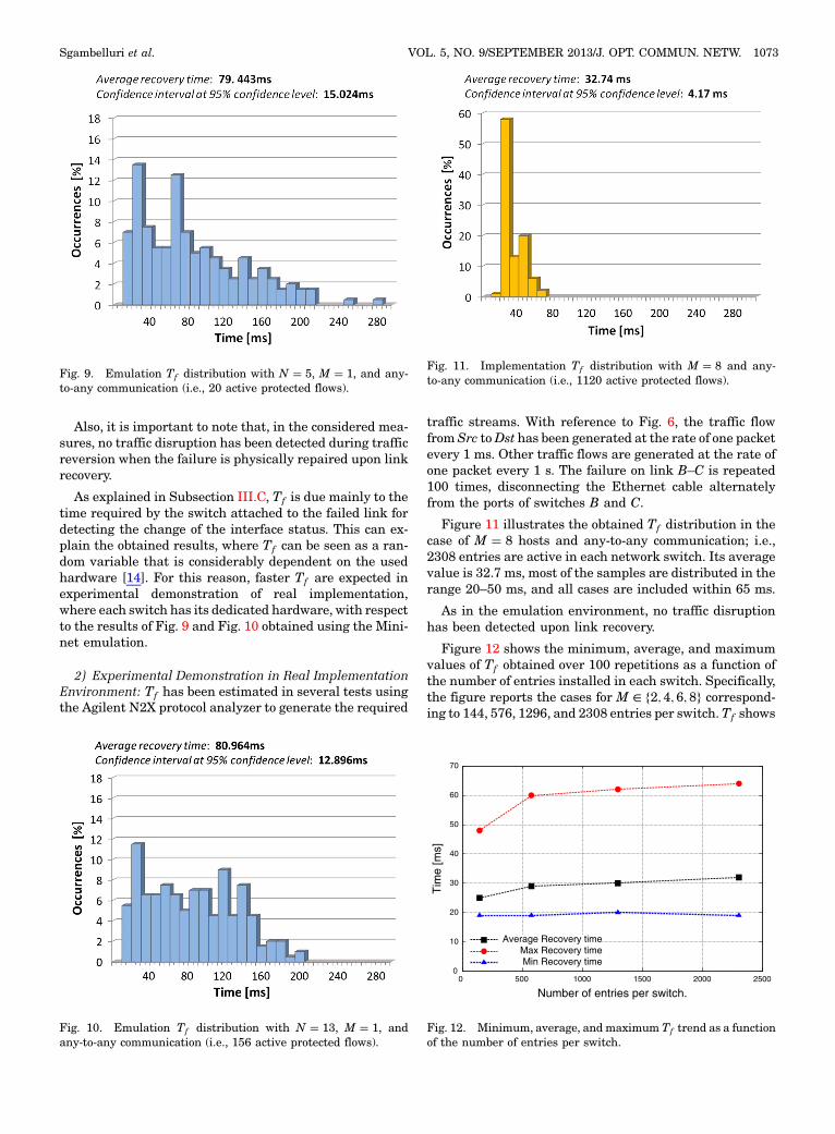
Also, it is important to note that, in the considered mea-sures, no traffic disruption has been detected during trafficreversion when the failure is physically repaired upon linkrecovery.
As explained in Subsection III.C, Tf is due mainly to thetime required by the switch attached to the failed link fordetecting the change of the interface status. This can ex-plain the obtained results, where Tf can be seen as a ran-dom variable that is considerably dependent on the usedhardware [14]. For this reason, faster Tf are expected inexperimental demonstration of real implementation,where each switch has its dedicated hardware, with respectto the results of Fig. 9 and Fig. 10 obtained using the Mini-net emulation.
2) Experimental Demonstration in Real ImplementationEnvironment: Tf has been estimated in several tests usingthe Agilent N2X protocol analyzer to generate the required
traffic streams. With reference to Fig. 6, the traffic flowfrom Src toDst has been generated at the rate of one packetevery 1 ms. Other traffic flows are generated at the rate ofone packet every 1 s. The failure on link B–C is repeated100 times, disconnecting the Ethernet cable alternatelyfrom the ports of switches B and C.
Figure 11 illustrates the obtained Tf distribution in thecase of M � 8 hosts and any-to-any communication; i.e.,2308 entries are active in each network switch. Its averagevalue is 32.7 ms, most of the samples are distributed in therange 20–50 ms, and all cases are included within 65 ms.
As in the emulation environment, no traffic disruptionhas been detected upon link recovery.
Figure 12 shows the minimum, average, and maximumvalues of Tf obtained over 100 repetitions as a function ofthe number of entries installed in each switch. Specifically,the figure reports the cases for M ∈ f2; 4; 6; 8g correspond-ing to 144, 576, 1296, and 2308 entries per switch.Tf shows
Fig. 9. Emulation Tf distribution with N � 5, M � 1, and any-to-any communication (i.e., 20 active protected flows).
Fig. 10. Emulation Tf distribution with N � 13, M � 1, andany-to-any communication (i.e., 156 active protected flows).
Fig. 11. Implementation Tf distribution with M � 8 and any-to-any communication (i.e., 1120 active protected flows).
0
10
20
30
40
50
60
70
0 500 1000 1500 2000 2500
Tim
e [m
s]
Number of entries per switch.
Average Recovery timeMax Recovery timeMin Recovery time
Fig. 12. Minimum, average, and maximum Tf trend as a functionof the number of entries per switch.
Sgambelluri et al. VOL. 5, NO. 9/SEPTEMBER 2013/J. OPT. COMMUN. NETW. 1073

a very limited increase with the number of entries, thusproving the scalability of the OSP scheme.
VI. CONCLUSION
This work proposed and implemented the OSP scheme,enabling fast recovery in networks composed of OpenFlow-based Ethernet switches. The OSP scheme does not requirea full-state controller and, upon failure, it does not involvethe controller in the recovery process. Specifically, The OSPscheme relies on working and backup entries that are con-figured in the network switches with different priorities, onthe renewal mechanism to avoid backup flow expiration,on the auto-reject mechanism deleting the entries involvedin the failure, and on a novel message to enable flow revert-ing on the working path.
Experimental demonstration implementation resultsshowed that the OSP scheme also guarantees recoverybelow 64 ms with a high number of installed entries, thuspreserving network scalability. Indeed, the achieved recov-ery time is determined only by the failure detection time.The emulation environment showed larger variance in therecovery time. Finally, no traffic disruption has beendetected during reversion of flows when the failure isphysically repaired or resolved.
ACKNOWLEDGMENTS
This work has been partially supported by the projectEMOTICON (Extending OpenFlow for Unified Manage-ment and Control of Cloud Data Center Resources)approved within the 2nd Call for additional beneficiariesof the OFELIA project. Part of this work was presentedin [27].
REFERENCES
[1] N. McKeown, T. Anderson, H. Balakrishnan, G. Parulkar, L.Peterson, J. Rexford, S. Shenker, and J. Turner, “OpenFlow:Enabling innovation in campus networks,” Comput. Com-mun. Rev., vol. 38, no. 2, pp. 69–74, Aug. 2008.
[2] J. Naous, D. Erickson, G. A. Covington, G. Appenzeller, and N.McKeown, “Implementing an OpenFlow switch on theNetFPGA platform,” in Proc. of the 4th ACM/IEEE Symp.on Architectures for Networking and CommunicationsSystems, 2008, pp. 1–9.
[3] SPARC, http://www.fp7‑sparc.eu/.[4] S. Das, G. Parulkar, N. McKeown, P. Singh, D. Getachew, and
L. Ong, “Packet and circuit network convergence withOpenFlow,” in Optical Fiber Communication Conf. andthe Nat. Fiber Optic Engineers Conf. 2010, Mar. 2010,paper OTuG1.
[5] A. Giorgetti, F. Cugini, F. Paolucci, and P. Castoldi, “Open-Flow and PCE architectures in wavelength switched opticalnetworks,” in 16th Int. Conf. on Optical Network Design andModeling (ONDM), Apr. 2012, pp. 1–6.
[6] S. Azodolmolky, R. Nejabati, E. Escalona, R. Jayakumar, N.Efstathiou, and D. Simeonidou, “Integrated OpenFlow-GMPLS control plane: An overlay model for software definedpacket over optical networks,” in 37th European Conf. andExpo. onOptical Communications, Sept. 2011, paperTu.5.K.5.
[7] J. Kempf, E. Bellagamba, A. Kern, D. Jocha, A. Takacs, and P.Skoldstrom, “Scalable fault management for OpenFlow,” inIEEE Int. Conf. on Communications (ICC), June 2011,pp. 6606–6610.
[8] F. Paolucci, F. Cugini, N. Hussain, F. Fresi, and L. Poti, “Open-Flow-based flexible optical networks with enhanced monitor-ing functionalities,” in European Conf. and Exhibition onOptical Communication, Sept. 2012, paper Tu.1.D.5.
[9] J. D. Decotignie, “The many faces of Industrial Ethernet[past and present],” IEEE Ind. Electron. Mag., vol. 3, no. 1,pp. 8–19, Mar. 2009.
[10] L. Liu, T. Tsuritani, I. Morita, H. Guo, and J. Wu, “OpenFlow-based wavelength path control in transparent optical net-works: A proof-of-concept demonstration,” in 37th EuropeanConf. and Expo. on Optical Communications, Sept. 2011,paper Tu.5.K.2.
[11] Metro Ethernet Forum (MEF), “Requirements and frame-work for Ethernet service protection in metro Ethernet net-works,” Technical Specification MEF 2, Feb. 2004.
[12] B. Niven-Jenkins, D. Brungard, M. Betts, N.Sprecher, and S. Ueno, “MPLS-TP requirements,” IETFMPLS Working Group Internet Draft draft-ietf-mpls-tp-requirement-10, Aug. 2009.
[13] M. Huynh, P. Mohapatra, S. Goose, and R. Liao, “RRR: Rapidring recovery sub-millisecond decentralized recovery forEthernet rings,” IEEE Trans. Comput., vol. 60, no. 11,pp. 1561–1570, Nov. 2011.
[14] A. Giorgetti, F. Cugini, F. Paolucci, L. Valcarenghi, A. Pistone,and P. Castoldi, “Performance analysis of media redundancyprotocol (MRP),” IEEE Trans. Ind. Inform., vol. 9, no. 1,pp. 218–227, 2013.
[15] S. Sharma, D. Staessens, D. Colle, M. Pickavet, and P.Demeester, “Enabling fast failure recovery in OpenFlow net-works,” in 8th Int. Workshop on the Design of Reliable Com-munication Networks (DRCN), Oct. 2011, pp. 164–171.
[16] OpenFlow Switch Specification 1.0.0, June 2012 [Online].Available: http://www.openflow.org/.
[17] D. Staessens, S. Sharma, D. Colle, M. Pickavet, and P.Demeester, “Software defined networking: Meeting carriergrade requirements,” in 18th IEEE Workshop on Local Met-ropolitan Area Networks (LANMAN), Oct. 2011, pp. 1–6.
[18] S. Sharma, D. Staessens, D. Colle, M. Pickavet, and P.Demeester, “OpenFlow: Meeting carrier-grade recoveryrequirements,”Comput. Commun., vol. 36, no. 6, pp. 656–665,Mar. 2013.
[19] Y. Yu, L. Xin, C. Shanzhi, and W. Yan, “A framework of usingOpenFlow to handle transient link failure,” in Int. Conf. onTransportation, Mechanical, and Electrical Engineering(TMEE), Dec. 2011, pp. 2050–2053.
[20] M. Desai and T. Nandagopal, “Coping with link failuresin centralized control plane architectures,” in 2nd Int. Conf.on Communication Systems and Networks (COMSNETS),Jan. 2010, pp. 1–10.
[21] P. Fonseca, R. Bennesby, E. Mota, and A. Passito, “A replica-tion component for resilient OpenFlow-based networking,” inIEEE Network Operations and Management Symp. (NOMS),Apr. 2010, pp. 933–939.
[22] Open vSwitch documentation [Online]. Available: http://openvswitch.org/support/.
[23] N. Gude, T. Koponen, J. Pettit, B. Pfaff, M. Casado, N.McKeown, and S. Shenker, “NOX: Towards an operating sys-tem for networks,” Comput. Commun. Rev., vol. 38, no 3,pp. 105–110, July 2008.
1074 J. OPT. COMMUN. NETW./VOL. 5, NO. 9/SEPTEMBER 2013 Sgambelluri et al.

[24] G. Yoon, D. H. Kwon, S. C. Kwon, Y. O. Park, and Y. J. Lee,“Ring topology-based redundancy Ethernet for industrialnetwork,” in SICE-ICASE Int. Joint Conf., Oct. 2006,pp. 1404–1407.
[25] Mininet, http://mininet.org/.
[26] Tshark, http://www.wireshark.org/docs/man‑pages/tshark.html.[27] A. Sgambelluri, A. Giorgetti, F. Cugini, F. Paolucci, and P.
Castoldi, “Effective flow protection in OpenFlow rings,” inOptical Fiber Communication Conf. and the Nat. Fiber OpticEngineers Conf., Mar. 2013, paper JTh2A.01.
Sgambelluri et al. VOL. 5, NO. 9/SEPTEMBER 2013/J. OPT. COMMUN. NETW. 1075