Open Secure Office Project - DiVA Portal
61
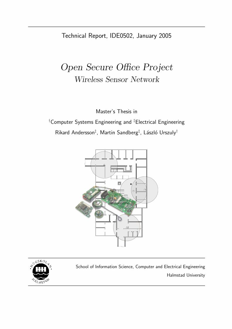
Technical Report, IDE0502, January 2005 Open Secure Office Project Wireless Sensor Network Master’s Thesis in † Computer Systems Engineering and ‡ Electrical Engineering Rikard Andersson ‡ , Martin Sandberg ‡ , L´ aszl´ o Urszuly † School of Information Science, Computer and Electrical Engineering Halmstad University
-
Upload
khangminh22 -
Category
Documents
-
view
0 -
download
0
Transcript of Open Secure Office Project - DiVA Portal
Technical Report, IDE0502, January 2005
Open Secure Office ProjectWireless Sensor Network
Master’s Thesis in
†Computer Systems Engineering and ‡Electrical Engineering
Rikard Andersson‡, Martin Sandberg‡, Laszlo Urszuly†
School of Information Science, Computer and Electrical Engineering
Halmstad University

Open Secure Office ProjectWireless Sensor Network
Master’s Thesis inComputer Systems Engineering and Electrical Engineering
School of Information Science, Computer and Electrical EngineeringHalmstad University
Box 823, S-301 18 Halmstad, Sweden
January 2005
c©2005Rikard Andersson, Martin Sandberg, Laszlo Urszuly
All Rights Reserved
OPEN SECURE OFFICE PROJECT
Description of cover page picture: Motekit 5040 from Crossbow [1] and a intendedfloor plan at Halmstad university.
ii
Preface
The document in your hand is a master’s thesis entitled Open Secure Office Project -Wireless Sensor Network. It is one part of the project Open Secure Office initiated byProf. Tony Larsson at the Computing and Communication laboratory at the school ofInformation Science, Computer an Electrical Engineering at Halmstad University, in thespring of 2004.
We would like to thank our supervisor Tony Larsson for his guidance throughout theproject. We would also like to thank Latef Berzenji for his comments on the language ofthe work.
This document has been formatted using LATEX.
Rikard Andersson, Martin Sandberg, Laszlo UrszulyHalmstad University, 20th January 2005
iii

OPEN SECURE OFFICE PROJECT
iv
Abstract
In recent years, the development of wireless sensor networks has made a great progress.Early projects focused on replacement of existing systems equipped with wires. Thesesystems started out as simple static data collection networks with one smart central nodethat could decide further actions based on the content of the collected data. Throughtime, the intelligence has become more decentralized, which means the nodes now cancooperate in a more efficient and dynamic manner.
The task given is to evaluate TinyOS and NesC on specific hardware from CrossbowTechnology Inc, applied on an application called the Open Secure Office Project. Thisapplication is designed to enhance the security without negative effects on comfort in afrequently visited open-plan office. Finally, a real world system demonstration should beperformed.
We propose a solution where there is no urgent need to cover the entire office area withradio signals to maintain a secure sensor system. This is true as long as all entries andexits to the office area are “guarded” by some base station which has as main task to keeptrack of people and equipment entering or leaving the office.
Small scale tests have been performed which show that it is possible to easily developand maintain a wireless sensor network security system, that could be coordinated byalternative systems.
KEYWORDS: Wireless sensor network, Open secure office, TinyOS, NesC.
v

OPEN SECURE OFFICE PROJECT
vi
CONTENTS
Contents
Preface iii
Abstract v
1 Introduction 1
1.1 General Concept . . . . . . . . . . . . . . . . . . . . . . . . . . . . . . . . 1
1.2 Related Work . . . . . . . . . . . . . . . . . . . . . . . . . . . . . . . . . . 2
1.2.1 CodeBlue . . . . . . . . . . . . . . . . . . . . . . . . . . . . . . . . 2
1.2.2 Wisenet . . . . . . . . . . . . . . . . . . . . . . . . . . . . . . . . . 2
1.2.3 Comparison . . . . . . . . . . . . . . . . . . . . . . . . . . . . . . . 3
2 Theoretical Background 5
2.1 Wireless Sensor Networks . . . . . . . . . . . . . . . . . . . . . . . . . . . 5
2.2 NesC . . . . . . . . . . . . . . . . . . . . . . . . . . . . . . . . . . . . . . . 6
2.3 TinyOS . . . . . . . . . . . . . . . . . . . . . . . . . . . . . . . . . . . . . 8
2.4 Power Management . . . . . . . . . . . . . . . . . . . . . . . . . . . . . . . 9
2.4.1 HPLPowerManagement . . . . . . . . . . . . . . . . . . . . . . . . . 10
2.4.2 Power Generation . . . . . . . . . . . . . . . . . . . . . . . . . . . . 12
2.5 Network Design . . . . . . . . . . . . . . . . . . . . . . . . . . . . . . . . . 12
2.5.1 Single-hop Communication . . . . . . . . . . . . . . . . . . . . . . . 12
2.5.2 Multi-hop Communication . . . . . . . . . . . . . . . . . . . . . . . 13
3 Method 17
3.1 Problem Definition . . . . . . . . . . . . . . . . . . . . . . . . . . . . . . . 17
3.1.1 Project Frames . . . . . . . . . . . . . . . . . . . . . . . . . . . . . 17
3.2 Approach . . . . . . . . . . . . . . . . . . . . . . . . . . . . . . . . . . . . 18
3.2.1 Investigation . . . . . . . . . . . . . . . . . . . . . . . . . . . . . . 18
3.2.2 Implementation . . . . . . . . . . . . . . . . . . . . . . . . . . . . . 18
3.2.3 Evaluation . . . . . . . . . . . . . . . . . . . . . . . . . . . . . . . . 19
3.2.4 Summarization . . . . . . . . . . . . . . . . . . . . . . . . . . . . . 19
vii
OPEN SECURE OFFICE PROJECT
4 Results and Discussion 21
4.1 System Architecture . . . . . . . . . . . . . . . . . . . . . . . . . . . . . . 21
4.2 Sensor Network Components . . . . . . . . . . . . . . . . . . . . . . . . . . 24
4.2.1 Mica2 Processing Element . . . . . . . . . . . . . . . . . . . . . . . 25
4.2.2 Mica2 Sensor Board . . . . . . . . . . . . . . . . . . . . . . . . . . 26
4.2.3 Mica2dot Processing Element . . . . . . . . . . . . . . . . . . . . . 26
4.2.4 Mica2dot Sensor Board . . . . . . . . . . . . . . . . . . . . . . . . . 28
4.3 Hardware Specific Software . . . . . . . . . . . . . . . . . . . . . . . . . . . 28
4.3.1 Mica2RadioM . . . . . . . . . . . . . . . . . . . . . . . . . . . . . . 29
4.3.2 Mica2UartM . . . . . . . . . . . . . . . . . . . . . . . . . . . . . . . 29
4.3.3 Mica2AccM . . . . . . . . . . . . . . . . . . . . . . . . . . . . . . . 30
4.3.4 Base Stations . . . . . . . . . . . . . . . . . . . . . . . . . . . . . . 31
4.3.5 Identification Tags . . . . . . . . . . . . . . . . . . . . . . . . . . . 31
4.3.6 Accelerometer Nodes . . . . . . . . . . . . . . . . . . . . . . . . . . 32
4.4 Software Development Environment and Debugging . . . . . . . . . . . . . 33
4.4.1 The Source Code Editor . . . . . . . . . . . . . . . . . . . . . . . . 33
4.4.2 The Mote Communicator . . . . . . . . . . . . . . . . . . . . . . . . 33
5 Conclusions 35
5.1 System Architecture . . . . . . . . . . . . . . . . . . . . . . . . . . . . . . 35
5.2 Debug Application . . . . . . . . . . . . . . . . . . . . . . . . . . . . . . . 35
5.3 NesC and TinyOS . . . . . . . . . . . . . . . . . . . . . . . . . . . . . . . . 35
5.4 Power Management . . . . . . . . . . . . . . . . . . . . . . . . . . . . . . . 36
5.5 Alternative Solutions . . . . . . . . . . . . . . . . . . . . . . . . . . . . . . 36
5.6 Future Work . . . . . . . . . . . . . . . . . . . . . . . . . . . . . . . . . . . 37
Bibliography 39
A The combined project goal 41
A.1 Introduction . . . . . . . . . . . . . . . . . . . . . . . . . . . . . . . . . . . 41
A.2 Proposed Solution . . . . . . . . . . . . . . . . . . . . . . . . . . . . . . . . 41
A.2.1 The Sensor Network . . . . . . . . . . . . . . . . . . . . . . . . . . 41
A.2.2 Coordination . . . . . . . . . . . . . . . . . . . . . . . . . . . . . . 42
B NesC Programs Structure 45
viii
LIST OF FIGURES
List of Figures
1.1 A mote compared with a coin, Ø = 25mm [1] . . . . . . . . . . . . . . . . . 1
1.2 WISENET system block diagram. . . . . . . . . . . . . . . . . . . . . . . . . 3
2.1 Code example: Mica2dotPersonal.nc . . . . . . . . . . . . . . . . . . . . . . 7
2.2 Code example: Mica2dotPersonalM.nc . . . . . . . . . . . . . . . . . . . . . 8
2.3 Single-hop communication, connections between CN and AP are wireless.The client (CN) only needs one hop to reach the access-point (AP). . . . . . 13
2.4 Multi-hop communication, all connections are wireless. The sensor node Ahave to use 3 hops over B and C to reach the base-mote D . . . . . . . . . . 14
2.5 Data centric: Trying to find routes from several sources to a single sink. AtB data from Source 1 & 2 are aggregated. . . . . . . . . . . . . . . . . . . . 14
2.6 Address centric: Finds the shortest path between pairs of addressable end-nodes. . . . . . . . . . . . . . . . . . . . . . . . . . . . . . . . . . . . . . . . 14
3.1 Planning (organization) of the work . . . . . . . . . . . . . . . . . . . . . . . 18
4.1 The thief (filled circle) is trying to escape with the prey (outlined square) andhe is detected by the general system only when positioned within the rangeof a base station (outlined white triangle), but before that, a picture mighthave been taken of him, and doors could have been locked or other actionstaken within the particular office due to the settings of the local controlstation (outlined gray triangle), which also registers the alarm signals sentby the stolen but protected equipment. . . . . . . . . . . . . . . . . . . . . . 22
4.2 The thief (filled circle) is trying to escape with the prey (outlined square)and is detected only when approaching a base station (outlined triangle)guarding an exit. . . . . . . . . . . . . . . . . . . . . . . . . . . . . . . . . . 23
4.3 Alternative alarming method is an epidemic multi-hop protocol where eachnode (outlined circles and squares) forwards the alarm once. . . . . . . . . . 23
4.4 The main components of the hardware platform for the Open Secure OfficeEnvironment. Top left: Mica2 processing element. Top right: Program-ming/docking board. Bottom left: Mica2 sensor board. Center: Mica2dotprocessing element. Bottom right: Mica2dot sensor board. . . . . . . . . . . 24
4.5 The Mica2 processing element attached to the programming/docking board. 25
4.6 The Mica2 sensor board attached to the programming/docking board. . . . 27
4.7 The Mica2dot processing element attached to the programming/docking board. 28
4.8 The Mica2dot sensor board attached to the programming/docking board. . . 29
4.9 Mica2RadioM module with interfaces. . . . . . . . . . . . . . . . . . . . . . 29
4.10 Mica2UartM module connected via interfaces. . . . . . . . . . . . . . . . . . 30
4.11 Mica2AccM module with interfaces . . . . . . . . . . . . . . . . . . . . . . . 31
ix
OPEN SECURE OFFICE PROJECT
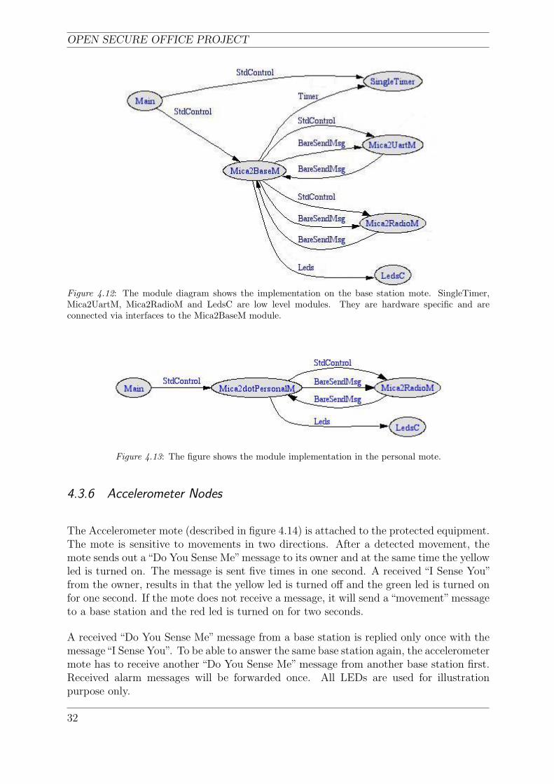
4.12 The module diagram shows the implementation on the base station mote.SingleTimer, Mica2UartM, Mica2RadioM and LedsC are low level mod-ules. They are hardware specific and are connected via interfaces to theMica2BaseM module. . . . . . . . . . . . . . . . . . . . . . . . . . . . . . . . 32
4.13 The figure shows the module implementation in the personal mote. . . . . . 32
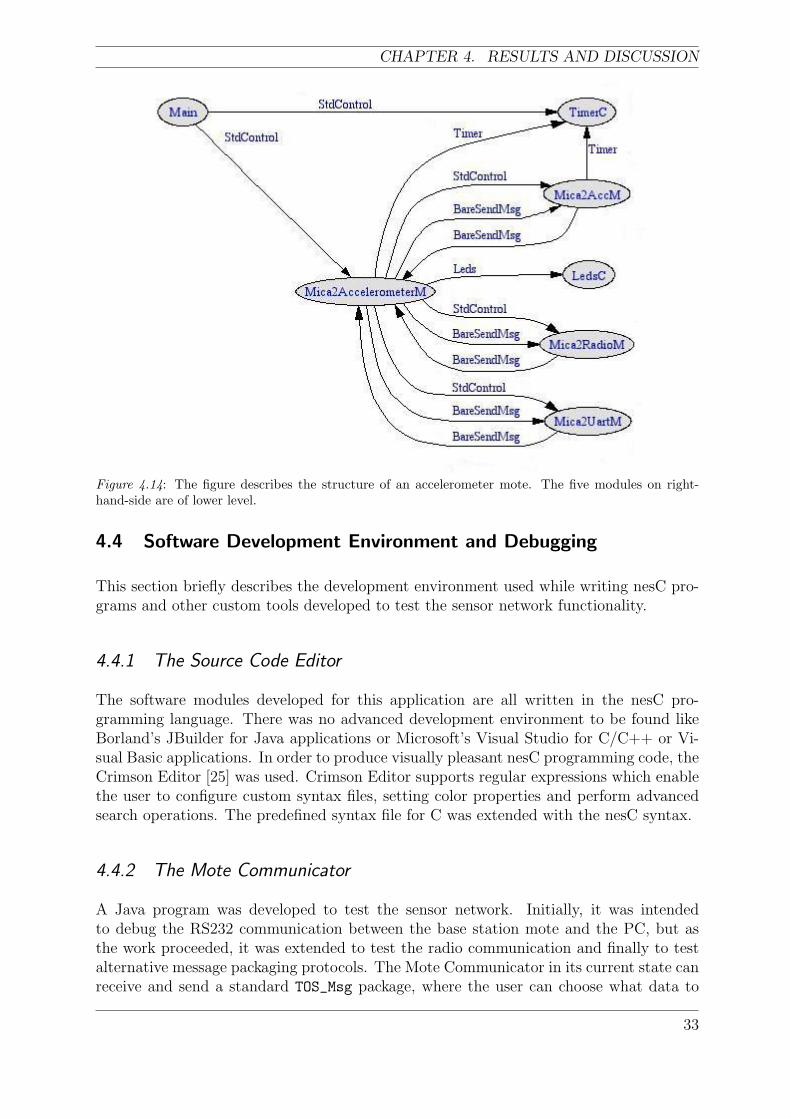
4.14 The figure describes the structure of an accelerometer mote. The five mod-ules on right-hand-side are of lower level. . . . . . . . . . . . . . . . . . . . . 33
B.1 NesC programming code for the BlinkM module. . . . . . . . . . . . . . . . 46
B.2 NesC programming code for the Blink configuration file. . . . . . . . . . . . 47
B.3 Graphical view of the Blink configuration file. . . . . . . . . . . . . . . . . . 47
x

LIST OF TABLES
List of Tables
2.1 Different kinds of motes . . . . . . . . . . . . . . . . . . . . . . . . . . . . . 6
2.2 Sleep Mode select . . . . . . . . . . . . . . . . . . . . . . . . . . . . . . . . . 11
xi

OPEN SECURE OFFICE PROJECT
xii
CHAPTER 1. INTRODUCTION
1 Introduction
1.1 General Concept
Modern offices are nothing like they used to be twenty or thirty years ago. They areno longer closed environments for corporate employees while the ever growing need forpersonal contact with customers, business associates and suppliers has transformed theminto something that sometimes could look like market places. This – of course – raisesseveral security issues which as of today have been dealt with by using passwords anddifferent kinds of identification methods like id-cards.
Too poorly designed security systems are (for reasons not needed to state) not desirable,while too rigorous systems are annoying when accessing frequently used resources. Thisdilemma creates a need for equipment which themselves can identify a foe and prevent in-trusion by locking doors and drawers, turning of monitors or locking computer keyboards.
The idea is to develop the next generation of surveillance systems which can adapt them-selves to different scenarios and dynamically make correct decisions for that particularevent, i.e. equipment that function more like people than static machinery.
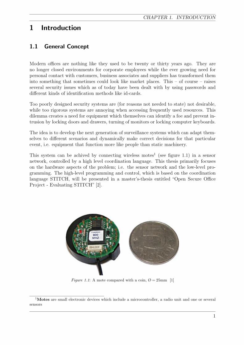
This system can be achived by connecting wireless motes1 (see figure 1.1) in a sensornetwork, controlled by a high level coordination language. This thesis primarily focuseson the hardware aspects of the problem; i.e. the sensor network and the low-level pro-gramming. The high-level programming and control, which is based on the coordinationlanguage STITCH, will be presented in a master’s-thesis entitled “Open Secure OfficeProject - Evaluating STITCH” [2].
Figure 1.1: A mote compared with a coin, Ø = 25mm [1]
1Motes are small electronic devices which include a microcontroller, a radio unit and one or severalsensors
1
OPEN SECURE OFFICE PROJECT
1.2 Related Work
This section describes a couple of projects associated with the Open secure office andpoints out the main differences between them.
1.2.1 CodeBlue
CodeBlue is a wireless infrastructure under development at Harvard University, USA [3]that is intended for critical health care environments both inside a hospital and on thefield. CodeBlue is designed to work with several different types of devices containing PCsat a central level, iPAQ PDAs at a user interface level and low-power motes at the sensorlevel. The system architecture attaches great importance to the particular sturdiness andsecurity demands of medical care settings.
CodeBlue has the capability to determine patients on the scene of the accident and guar-antee a data transfer from the victims to the paramedics without any loss of data. Italso makes assignment of hospital resources more effective. The intention is that the sys-tem should be scalable from small static systems to very dense networks containing maybethousands of devices and where the network conditions are very harsh. In order to achievethis, the infrastructure will support reliable, ad hoc data delivery, a flexible naming anddiscovery scheme, and a decentralized security model. Using an ad hoc network will givethe possibility to extend the system over a building or between several different buildingsclose to each other. For increased coverage, if needed, extra fixed nodes could be placedin hallways or other areas. The network is self-organizing, which entail that data could bere-routed in a quick way, if a node is lost or a link is broken, independent of the networktopology.
The system is built upon use of the Berkeley motes, Mica2 and Mica2dot series, which areavailable at Crossbow Technology Inc [1]. The motes are equipped with sensor boards thatperiodically transmit packets containing heart rate, SpO2 (blood oxygen saturation), andplethysmogram waveform data. Several patients could be monitored at the same timeusing a flexible, multi-hop routing strategy. The vital signs could be directed to thePDAs carried by personnel or to a base station (PC). As the network expands, the chancefor information overload increases which may result in a network bottleneck. Therefore,CodeBlue supports filtration and aggregation of events continuously. For example, para-medics want to receive continuous data from one patient but only crucial data changesfrom other patients when they are on duty.
The project homepage is located at [4].
1.2.2 Wisenet
WISENET (WIreless SEnsor NETwork) is a wireless sensor network at Bradley University,Department of ECE [5]. The system monitors the environmental conditions of the labsand offices of the department. Things measured are for example, light, humidity andtemperature.
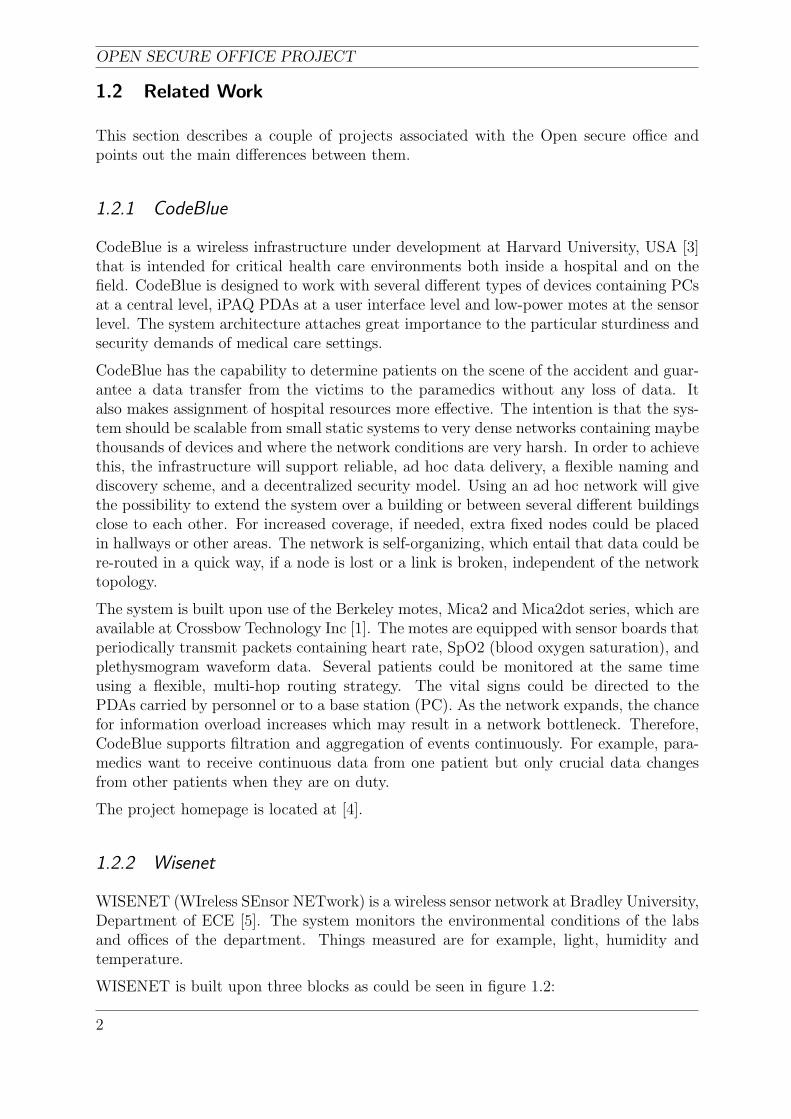
WISENET is built upon three blocks as could be seen in figure 1.2:
2
CHAPTER 1. INTRODUCTION
• The SENSOR MOTE NETWORK block contains several static sensor motes, whichare equipped with sensor boards. Raw sensor data are transmitted from the sensormotes to a gateway mote, which is connected via RS232 to the SERVER block.When a sensor mote does not transmit any data, it enters a sleep mode in order tosave energy but the gateway mote is always awake.
• The SERVER block contains a HTTP server and a mySQL database.
• The CLIENT block contains a computer with connection to Internet (HTTP) anda web browser user interface, which involves that a person can access the collecteddata via the Internet. The CLIENT could be developed outside of WISENET,however it is essential for the overall function.
Figure 1.2: WISENET system block diagram.
The connections between the SENSOR NET and the SERVER is a RS232 serial interface,and between the SERVER and the CLIENT is a regular TCP/IP.
Data Acquisition subsystem
This subsystem collects and stores data from the motes for later processing by the DataAnalysis subsystem. This subsystem is the system part that contains all the hardware, i.e.the motes. It also includes TinyOS and WiseDB. WiseDB, which is a software componentespecially made for WISENET, is located on the server (see figure 1.2). This componentis an interface that connects the hardware with the database.
Data Analysis subsystem
This subsystem could stand alone from WISENET, since it relies only on existing in-frastructures. It is built upon software only. The main issue of this subsystem is topresent the collected data in an appropriate graphical way on a website.
1.2.3 Comparison
CodeBlue differs from WISENET in several ways. First of all CodeBlue is intended towork for much larger networks, and it is partially dynamic. WISENET, on the otherhand, since its network is static, does not need to deal with the problem that is causedby the dynamic environment. Small static systems are also much easier to maintain.
3
OPEN SECURE OFFICE PROJECT
When comparing The Open Secure Office with the projects above, some main differencesand similarities could be identified.
In comparison to CodeBlue, both systems must be robust (no data could be lost). Thesystems also focus on a dynamic approach, which is not commonly the case in wirelesssensor networks. CodeBlue supports a much more dense network, which entails morecomplex routing. It is; therefore larger compared to The Open Secure Office, which couldbe expanded in the future.
In comparison to WISENET, both systems are developed for indoor office environment,but WISENET focuses on many-to-one2 communication instead of many-to-many. WISENETis fully static, that is, all motes are non-movable. Both systems are rather similar in sizebut the routing in WISENET is much easier.
Compared both to CodeBlue and WISENET the Open Secure Office solution is moreevent oriented.
2The many-to-one communication is done in a push manner from the motes to the server
4
CHAPTER 2. THEORETICAL BACKGROUND
2 Theoretical Background
This chapter presents a brief description of the theory which forms the basis of this thesis.
2.1 Wireless Sensor Networks
Since the late nineties, the interest in various kinds of wireless electronic equipment hasemerged. In the commercial market, this has been seen particularly in wireless datanetworks such as Wireless Local Area Networks (WLAN: 802.11) and Bluetooth whichare mostly known in connection with mobile telephones. Another part of the wireless areais wireless sensor networks which will be described briefly in this section.
Wireless sensor networks can be used to monitor temperature and humidity [5], industrialcontrol [6] and intelligent agriculture and environmental sensing [6]. To be able to meetthe requirements of these applications, some aspects of the sensor-networks are to bespecified.
• Less maintenance than wired networks, for the simple reason that large systemsinclude a large amount of wires which entail many possible sources of errors.
• Easy to install and change the configuration. The comparison with a painting canbe done. One just attaches the sensor to a wall or an object, and it is ready to beused.
• Very small size (sometimes called smart dust[7]). There are sizes from a few squaremillimeters to the size of a coin (couple of centimeters).
• A sensor node is energy critical due to the battery power; therefore, one needs tosave energy by turning off the unit to sleep mode when it is not needed. It also hasa limited peak power.
• The sensor networks have low data throughputs compared to other wireless net-works. This implies that the overhead from addressing will be significant; thereforethe communication effectiveness of the network will be very low.
• Security is an important issue in all kinds of wireless communication, where it iseasier to intercept a message than with wired communication. The security couldbe obtained by message encryption, which, however, is not often the primary goalin a sensor network. The more important part to be seen is that the message hasnot been modified when it reaches the receiver.
Several sensors integrated into a mote have an event driven operational mode, that is, theyreact to changes in the environment and are not controlled by interaction with a user oranother application in the same sense as an ordinary desktop computer is controlled. Thefact that the motes get smaller and smaller makes it, however, harder to program theirfunctionality. Increasing functional complexity and lower power consumption constraintsdue to market development add new dimensions to the programming intelligence.
5
OPEN SECURE OFFICE PROJECT
Connecting several motes to a network of some kind introduces a new set of constraintsto the application in terms of concurrency and real time requirements. A wireless net-work requires, besides the general considerations presented in the previous paragraph, anextensive survey in data encryption and secure wireless transmission. Additional con-straints to keep in mind, while implementing data integrity mechanisms, are the poorsystem hardware resources on motes, such as limited RAM and Flash memory.
A dynamic application also has heavy demands on power consumption and power man-agement to take into consideration. A static sensor network, which is only time triggered,like a humidity controlling system, which only measures some values at a given time inter-val and reports them back to a base station, can be tuned in for optimal signal strengthin case of wireless data transmission. It can also use well defined sleeping modes to savebattery power and make it last for months or even years. A dynamic application, suchas an active security system, has to react on non-periodical events and send data andalarm signals at different signal strengths depending on present conditions. Planningand implementing an “intelligent” sleeping behavior on such systems are therefore muchharder.
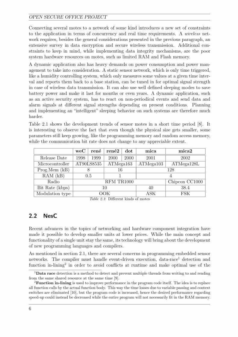
Table 2.1 shows the development trends of sensor motes in a short time period [8]. Itis interesting to observe the fact that even though the physical size gets smaller, someparameters still keep growing, like the programming memory and random access memory,while the communication bit rate does not change to any appreciable extent.
weC rene rene2 dot mica mica2
Release Date 1998 1999 2000 2000 2001 2002Microcontroller AT90LS8535 ATMega163 ATMega103 ATMega128LProg.Mem (kB) 8 16 128
RAM (kB) 0.5 1 4Radio RFM TR1000 Chipcon CC1000
Bit Rate (kbps) 10 40 38.4Modulation type OOK ASK FSK
Table 2.1: Different kinds of motes
2.2 NesC
Recent advances in the topics of networking and hardware component integration havemade it possible to develop smaller units at lower prices. While the main concept andfunctionality of a single unit stay the same, its technology will bring about the developmentof new programming languages and compilers.
As mentioned in section 2.1, there are several concerns in programming embedded sensornetworks. The compiler must handle event-driven execution, data-race1 detection andfunction in-lining2 in order to avoid conflicts at runtime and make optimal use of the
1Data race detection is a method to detect and prevent multiple threads from writing to and readingfrom the same shared resource at the same time [9].
2Function in-lining is used to improve performance in the program code itself. The idea is to replaceall function calls by the actual function body. This way the time losses due to variable passing and contextswitches are eliminated [10], but the program code is increased, hence the desired performance regardingspeed-up could instead be decreased while the entire program will not necessarily fit in the RAM memory.
6
CHAPTER 2. THEORETICAL BACKGROUND
relatively poor hardware resources.
NesC is a static language, which means there is no possibility to dynamically allocatememory or in any other way alter the memory- or resource map during runtime. Thismakes the entire program definite at compile-time and the debugging processes are per-formed easily. The compiled software is thereby, theoretically at least, more reliable. Asfar as the lack of dynamic properties are concerned, there is no urgent need for them whilethe language itself is based on components that perform tasks rather than generate newdata and the motes are seldom targets of data storage [8]. NesC is also the programminglanguage used to develop TinyOS, see section 2.3.
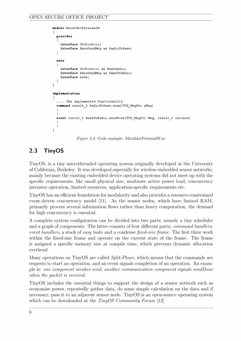
A program in nesC is built out of Components, which can be divided into two parts,Modules and Configurations. Modules contain the code for the implementation and theconfigurations “wire” several components together.
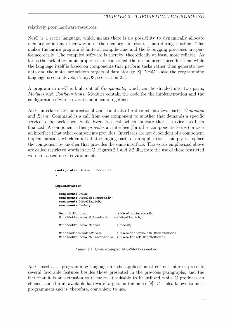
NesC interfaces are bidirectional and could also be divided into two parts, Commandand Event. Command is a call from one component to another that demands a specificservice to be performed, while Event is a call which indicate that a service has beenfinalized. A component either provides an interface (for other components to use) or usesan interface (that other components provide). Interfaces are not dependent of a componentimplementation, which entails that changing parts of an application is simply to replacethe component by another that provides the same interface. The words emphasized aboveare called restricted words in nesC. Figures 2.1 and 2.2 illustrate the use of these restrictedwords in a real nesC environment.
Figure 2.1: Code example: Mica2dotPersonal.nc
NesC used as a programming language for the application of current interest presentsseveral favorable features besides those presented in the previous paragraphs, and thefact that it is an extension to C makes it suitable to be utilized while C produces anefficient code for all available hardware targets on the motes [8]. C is also known to mostprogrammers and is, therefore, convenient to use.
7
OPEN SECURE OFFICE PROJECT
Figure 2.2: Code example: Mica2dotPersonalM.nc
2.3 TinyOS
TinyOS, is a tiny microthreaded operating system originally developed at the Universityof California, Berkeley. It was developed especially for wireless embedded sensor networks,mainly because the existing embedded device operating systems did not meet up with thespecific requirements, like small physical size, moderate active power load, concurrencyintensive operation, limited resources, application-specific requirements etc.
TinyOS has an efficient foundation for modularity and also provides a resource-constrainedevent-driven concurrency model [11]. As the sensor nodes, which have limited RAM,primarily process several information flows rather than heavy computation, the demandfor high concurrency is essential.
A complete system configuration can be divided into two parts; namely a tiny schedulerand a graph of components. The latter consists of four different parts: command handlers,event handlers, a stack of easy tasks and a condense fixed-size frame. The first three workwithin the fixed-size frame and operate on the current state of the frame. The frameis assigned a specific memory size at compile time, which prevents dynamic allocationoverhead.
Many operations on TinyOS are called Split-Phase, which means that the commands arerequests to start an operation, and an event signals completion of an operation. An exam-ple is: one component invokes send, another communication component signals sendDonewhen the packet is received.
TinyOS includes the essential things to support the design of a sensor network such aseconomize power, repeatedly gather data, do some simple calculation on the data and ifnecessary, pass it to an adjacent sensor node. TinyOS is an open-source operating systemwhich can be downloaded at the TinyOS Community Forum [12]
8
CHAPTER 2. THEORETICAL BACKGROUND
2.4 Power Management
General wireless networks, like WLAN (802.11a-g), require high bandwidth which con-sumes a lot of power. This is, however, not a big problem because most devices that usethese systems are either connected to power mains or use batteries with good capacities,for example portable computers. Portable devices with good battery capacity such ascellphones have an average energy consumption of tens to hundreds of milliamps whichwill give them a lifetime of approximately a couple of days. These lifetimes are acceptedsince it is easy to charge such systems.
Wireless sensor networks, on the other hand, require longer lifetimes, which demandcomponents with very low average energy consumption (µA), because the majority of all“motes” used in wireless sensor networks are battery powered. Another reason is thatthese systems should be suited for the company’s or product’s maintenance period. Theenergy available normally has to last for years or at least months to be useful, whichentails that the average power requirements need to be approximately 3 volts times acouple of hundred microamps (AA batteries, Mica2 mote) to last a year, and even less forcell batteries used at for example the Mica2dot mote.
Based on power supply and power consumption, the power management problem in wire-less sensor network nodes seems to be easy, since the battery delivers a specified amountof energy, and the node has to consume it during as long time as possible to maintain along lifetime. However, since the energy form provided by the source is seldom optimalfor the load, the problem becomes aggravated. One thing to consider is how to solve theproblem with high power-peaks. Wireless sensor networks often have low average energyconsumption but need to be able to handle high power-peaks every now and then duringoperation. For best performance, the hardware should be customized for the specific ap-plication. Off the shelf products, designed for multiple purposes, do not often completelyreach the power requirements.
In order to save energy, one has to specify sources for energy consumption. The list belowstates a few examples to be considered:
• Radio transmission.
• Transmission rate.
• Time constraints.
• Network topologies.
• Routing protocols.
• Operating system.
The major energy consumer in a wireless sensor network is the radio, which mainly hasthree states; idle listening, transmit and receive. Therefore, one needs to use the radio ina controlled way, to minimize the time the radio is active, which can be done in variousways. In this thesis, the approach is to use HPLPowerManagement, which is described indetail in section 2.4.1. Transmission rate, and time constraints are two sections in radio
9
OPEN SECURE OFFICE PROJECT
communication which could be considered since they effect energy consumption. Highertransmission rate and wide time constraints result in higher energy consumption.
Being an essential part in wireless sensor networks and highly dependent of the appli-cation, network topologies are used to save energy. In the dissertation entitled “SystemArchitecture for Wireless Sensor Networks” [13], Jason Hill states three classes of appli-cations:
Environmental data collection when one wants to assemble data from a great numberof nodes (magnitude >100) and evaluate the data afterward.
Security monitoring differs from the former class in that no data are gathered forstorage or further transmission. This forces the nodes to be awake more frequently (toread sensor values) but the radio is less active.
Sensor node tracking is a class often considered when one wants to track a movingobject by the use of a sensor network. This scenario differs from the above two in severalways. First of all, this class exploits both dynamic and static nodes compared with onlystatic ones. Secondly, these systems are designed to intercept radio messages from movingobject rather than sensor reading.
The Open Secure Office does not fit into any of the classes mentioned above, because it ismore or less a junction of security monitoring and sensor node tracking. The Open SecureOffice, which uses, both dynamic and static nodes, focuses on sensor readings and triesto minimize radio traffic in order to save energy.
The network topologies suggested to save energy for each class are: Short and wide treefor Environmental data collection, linear topology for Security monitoring. The last classtopology will change as the nodes advance in the network due to the dynamics.
As mentioned above, the radio use and network topology are essential in wireless sensornetworks. However, in order to achieve a good performance of the network, one needs toconsider routing protocols. One kind of the routing protocol is multi-hop communication,which gives the opportunity to reduce the transmission power of the radio (see section 2.5.2for details).
A lot of power could be saved with an operating system that supports power management.TinyOS which is used in this project fits well this description. Section 2.4.1 presents themanagement of power in TinyOS.
2.4.1 HPLPowerManagement
By using Mica2 motes (containing the CC1000M radio), TinyOS provides 6 different powersaving modes.
1. Idle mode basically halts the CPU- and FLASH clocks. Interrupt handlers, watch-dog and other clocks etc will be active. The start-up time is fast, but power reductionis not considerable.
10

CHAPTER 2. THEORETICAL BACKGROUND
2. ADC Noise Reduction mode differs essentially in one manner compared with the Idlemode, namely the I/O clock is disabled. This modification will make measurementsmore accurate since the noise level for the A/D converter is reduced. Power reductionin this mode is not considerable.
3. Power-down mode disables the external oscillator and the generated clocks but keepsthe possibility for external interrupts to occur. Synchronous modules are not sup-ported due to the lack of clocks, which will save energy, but result in a delay, relatedto wake-up conditions.
4. Power-save mode differs from power-down mode in one aspect, namely it is possibleto have Timer/Counter0 active during sleep. This requires that the AS0 bit in theAsynchronous Status Register (ASSR) is set (i.e. the Timer0 is clocked asynchro-nous). Compared to Power-down, this will give other possibilities for wake-up, asTimer overflow. Power-save mode is not recommended in favor of Power-down modewhen the asynchronous timer is not clocked asynchronously.
5. Standby mode is identical to Power-down mode, with one modification, namely theoscillator is active. The wake-up time is 6 clock cycles.
6. Extended Standby mode is identical to Power-save mode, with one modification,namely the oscillator is active. The wake-up time is 6 clock cycles.
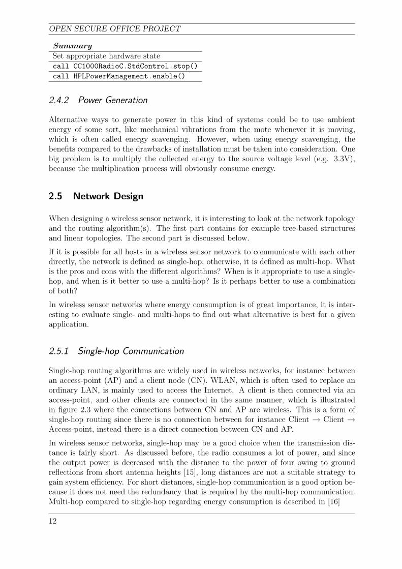
For even more detailed information regarding sleep-modes with the ATmega128(L) fromthe Atmel corporation, the reader is referred to Atmels website [14]. The sleep modeactivation process in TinyOS includes 2 steps. First the hardware must be put in thedesired state, which is done by:
1. Writing logic one to bit 5 in MCU Control Register (MCUCR) i.e. Sleep Enable.
2. Setting the appropriate mode according to table 2.2.
SM1 SM2 SM3 Sleep Mode
0 0 0 Idle0 0 1 ADC Noise Reduction0 1 0 Power-down0 1 1 Power-save1 1 0 Standby1 1 1 Extended Standby
Table 2.2: Sleep Mode select
Second, when the hardware is set, the application has to shut down the radio in orderfor HPLPowerManagement to work. Then the HPLPowerManagement must be enabled,which will lead to that the mote automatically sleeps when the radio is off, all high speedinterrupts and Serial Peripheral Interface interrupts (SPI) are disabled and the task queueis empty.
11
OPEN SECURE OFFICE PROJECT
SummarySet appropriate hardware statecall CC1000RadioC.StdControl.stop()
call HPLPowerManagement.enable()
2.4.2 Power Generation
Alternative ways to generate power in this kind of systems could be to use ambientenergy of some sort, like mechanical vibrations from the mote whenever it is moving,which is often called energy scavenging. However, when using energy scavenging, thebenefits compared to the drawbacks of installation must be taken into consideration. Onebig problem is to multiply the collected energy to the source voltage level (e.g. 3.3V),because the multiplication process will obviously consume energy.
2.5 Network Design
When designing a wireless sensor network, it is interesting to look at the network topologyand the routing algorithm(s). The first part contains for example tree-based structuresand linear topologies. The second part is discussed below.
If it is possible for all hosts in a wireless sensor network to communicate with each otherdirectly, the network is defined as single-hop; otherwise, it is defined as multi-hop. Whatis the pros and cons with the different algorithms? When is it appropriate to use a single-hop, and when is it better to use a multi-hop? Is it perhaps better to use a combinationof both?
In wireless sensor networks where energy consumption is of great importance, it is inter-esting to evaluate single- and multi-hops to find out what alternative is best for a givenapplication.
2.5.1 Single-hop Communication
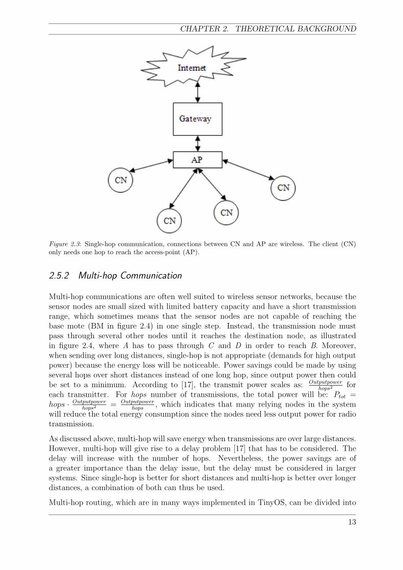
Single-hop routing algorithms are widely used in wireless networks, for instance betweenan access-point (AP) and a client node (CN). WLAN, which is often used to replace anordinary LAN, is mainly used to access the Internet. A client is then connected via anaccess-point, and other clients are connected in the same manner, which is illustratedin figure 2.3 where the connections between CN and AP are wireless. This is a form ofsingle-hop routing since there is no connection between for instance Client → Client →Access-point, instead there is a direct connection between CN and AP.
In wireless sensor networks, single-hop may be a good choice when the transmission dis-tance is fairly short. As discussed before, the radio consumes a lot of power, and sincethe output power is decreased with the distance to the power of four owing to groundreflections from short antenna heights [15], long distances are not a suitable strategy togain system efficiency. For short distances, single-hop communication is a good option be-cause it does not need the redundancy that is required by the multi-hop communication.Multi-hop compared to single-hop regarding energy consumption is described in [16]
12
CHAPTER 2. THEORETICAL BACKGROUND
Figure 2.3: Single-hop communication, connections between CN and AP are wireless. The client (CN)only needs one hop to reach the access-point (AP).
2.5.2 Multi-hop Communication
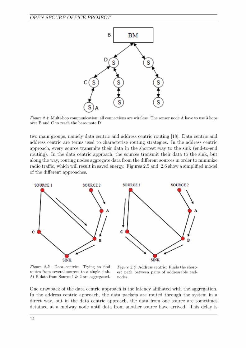
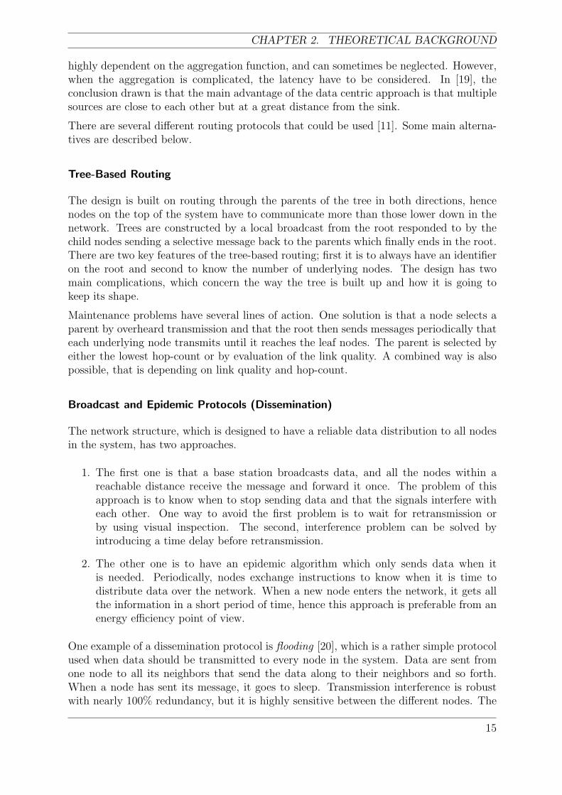
Multi-hop communications are often well suited to wireless sensor networks, because thesensor nodes are small sized with limited battery capacity and have a short transmissionrange, which sometimes means that the sensor nodes are not capable of reaching thebase mote (BM in figure 2.4) in one single step. Instead, the transmission node mustpass through several other nodes until it reaches the destination node, as illustratedin figure 2.4, where A has to pass through C and D in order to reach B. Moreover,when sending over long distances, single-hop is not appropriate (demands for high outputpower) because the energy loss will be noticeable. Power savings could be made by usingseveral hops over short distances instead of one long hop, since output power then couldbe set to a minimum. According to [17], the transmit power scales as: Outputpower
hops2 foreach transmitter. For hops number of transmissions, the total power will be: Ptot =hops · Outputpower
hops2 = Outputpowerhops
, which indicates that many relying nodes in the systemwill reduce the total energy consumption since the nodes need less output power for radiotransmission.
As discussed above, multi-hop will save energy when transmissions are over large distances.However, multi-hop will give rise to a delay problem [17] that has to be considered. Thedelay will increase with the number of hops. Nevertheless, the power savings are ofa greater importance than the delay issue, but the delay must be considered in largersystems. Since single-hop is better for short distances and multi-hop is better over longerdistances, a combination of both can thus be used.
Multi-hop routing, which are in many ways implemented in TinyOS, can be divided into
13
OPEN SECURE OFFICE PROJECT
Figure 2.4: Multi-hop communication, all connections are wireless. The sensor node A have to use 3 hopsover B and C to reach the base-mote D
two main groups, namely data centric and address centric routing [18]. Data centric andaddress centric are terms used to characterize routing strategies. In the address centricapproach, every source transmits their data in the shortest way to the sink (end-to-endrouting). In the data centric approach, the sources transmit their data to the sink, butalong the way, routing nodes aggregate data from the different sources in order to minimizeradio traffic, which will result in saved energy. Figures 2.5 and 2.6 show a simplified modelof the different approaches.
Figure 2.5: Data centric: Trying to findroutes from several sources to a single sink.At B data from Source 1 & 2 are aggregated.
Figure 2.6: Address centric: Finds the short-est path between pairs of addressable end-nodes.
One drawback of the data centric approach is the latency affiliated with the aggregation.In the address centric approach, the data packets are routed through the system in adirect way, but in the data centric approach, the data from one source are sometimesdetained at a midway node until data from another source have arrived. This delay is
14
CHAPTER 2. THEORETICAL BACKGROUND
highly dependent on the aggregation function, and can sometimes be neglected. However,when the aggregation is complicated, the latency have to be considered. In [19], theconclusion drawn is that the main advantage of the data centric approach is that multiplesources are close to each other but at a great distance from the sink.
There are several different routing protocols that could be used [11]. Some main alterna-tives are described below.
Tree-Based Routing
The design is built on routing through the parents of the tree in both directions, hencenodes on the top of the system have to communicate more than those lower down in thenetwork. Trees are constructed by a local broadcast from the root responded to by thechild nodes sending a selective message back to the parents which finally ends in the root.There are two key features of the tree-based routing; first it is to always have an identifieron the root and second to know the number of underlying nodes. The design has twomain complications, which concern the way the tree is built up and how it is going tokeep its shape.
Maintenance problems have several lines of action. One solution is that a node selects aparent by overheard transmission and that the root then sends messages periodically thateach underlying node transmits until it reaches the leaf nodes. The parent is selected byeither the lowest hop-count or by evaluation of the link quality. A combined way is alsopossible, that is depending on link quality and hop-count.
Broadcast and Epidemic Protocols (Dissemination)
The network structure, which is designed to have a reliable data distribution to all nodesin the system, has two approaches.
1. The first one is that a base station broadcasts data, and all the nodes within areachable distance receive the message and forward it once. The problem of thisapproach is to know when to stop sending data and that the signals interfere witheach other. One way to avoid the first problem is to wait for retransmission orby using visual inspection. The second, interference problem can be solved byintroducing a time delay before retransmission.
2. The other one is to have an epidemic algorithm which only sends data when itis needed. Periodically, nodes exchange instructions to know when it is time todistribute data over the network. When a new node enters the network, it gets allthe information in a short period of time, hence this approach is preferable from anenergy efficiency point of view.
One example of a dissemination protocol is flooding [20], which is a rather simple protocolused when data should be transmitted to every node in the system. Data are sent fromone node to all its neighbors that send the data along to their neighbors and so forth.When a node has sent its message, it goes to sleep. Transmission interference is robustwith nearly 100% redundancy, but it is highly sensitive between the different nodes. The
15
OPEN SECURE OFFICE PROJECT
main drawback of flooding is its inefficiency, since nodes commonly recieve the samemessage several times. This problem is known as The broadcast storm problem, which iswidely known and has resulted in several variations from the basic protocol to improvethe efficiency of the system.
16
CHAPTER 3. METHOD
3 Method
In this chapter, the solution path of this project is discussed and the related problems aredefined. Moreover, the operating circumstances and methods used to obtain the resultsare presented.
3.1 Problem Definition
For the achieving of the main goals, the obstacles defined below should be overcome;
• Build up and maintain communication in a dependable way. The first step in settingup the network is to send information between motes. A message can be consideredas successfully sent when it has also successfully been received by the other partywithout information losses.
• Expand the network. The expansion must under no circumstances cause perfor-mance degradation in terms of data losses during send/receive operations, i.e. thecommunication must work properly also with the new motes.
• Implement some kind of multi-hop functionality. If one node physically can notreach the receiving node, the message should be sent either through other motes orthrough the base station. The main goal remains that the message must arrive atall costs.
• Data transmission security. This point has to be closely examined before it is statedfully, but it is conceivable to wish for some kind of data encryption or anothermethod to protect the data that are sent, or at least detect if any changes have beenmade according to the parity model used in some early modems.
• Fault tolerance. The system must work as good as possible even if a hardware re-source is down or missing. This opens doors for the concept of graceful degradationand even though it falls a bit outside the frames of this thesis, the system soft-ware must be prepared for future upgrades and implementation of additional faulttolerance functionality.
3.1.1 Project Frames
The operational environment of the network system is only defined indoors. This meansthat tests on the network are made in a protected and controlled environment but thereare no theoretical facts which indicate that this system will not work in an outdoorenvironment.
This project does neither include development of the rules by which the sensor networkwill work nor will the signals produced be used for further computation.
17
OPEN SECURE OFFICE PROJECT
3.2 Approach
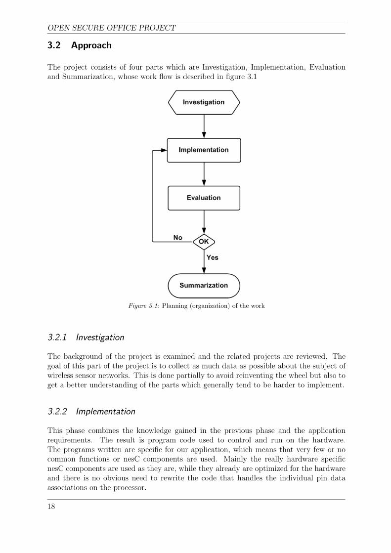
The project consists of four parts which are Investigation, Implementation, Evaluationand Summarization, whose work flow is described in figure 3.1
Figure 3.1: Planning (organization) of the work
3.2.1 Investigation
The background of the project is examined and the related projects are reviewed. Thegoal of this part of the project is to collect as much data as possible about the subject ofwireless sensor networks. This is done partially to avoid reinventing the wheel but also toget a better understanding of the parts which generally tend to be harder to implement.
3.2.2 Implementation
This phase combines the knowledge gained in the previous phase and the applicationrequirements. The result is program code used to control and run on the hardware.The programs written are specific for our application, which means that very few or nocommon functions or nesC components are used. Mainly the really hardware specificnesC components are used as they are, while they already are optimized for the hardwareand there is no obvious need to rewrite the code that handles the individual pin dataassociations on the processor.
18
CHAPTER 3. METHOD
3.2.3 Evaluation
The implementation is evaluated and notes are made to be used in the final documentation.The complete functionality requirements are broken down to smaller parts which areimplemented, tested and evaluated one by one. This reduces the complexity in getting itall working while there are fewer possible errors to commit with smaller modules. Whena module is successfully implemented, it is easier to implement the rest knowing that thepreviously completed work is free from flaws and errors. A custom debugging program isalso developed on the computer-side. This program is written in Java and is solely usedto debug and verify the communication up to the PC. This program is also importantbecause it contains the data transmission protocol between the standard TinyOS messagesand the STITCH coordination language.
3.2.4 Summarization
The documentation phase comes into action when the Implementation/Evaluation loopreaches a final state. Then the results are analyzed, summarized and discussed.
19

OPEN SECURE OFFICE PROJECT
20
CHAPTER 4. RESULTS AND DISCUSSION
4 Results and Discussion
In this chapter, the proposed sensor network architecture and the obtained results arepresented and alternative additions, the tools and test environments used to obtain theseresults are discussed.
4.1 System Architecture
The functionality of the sensor network heavily depends on the overall system architecture.Not placing the base nodes strategically correct may influence the system stability or evenreduce it completely.
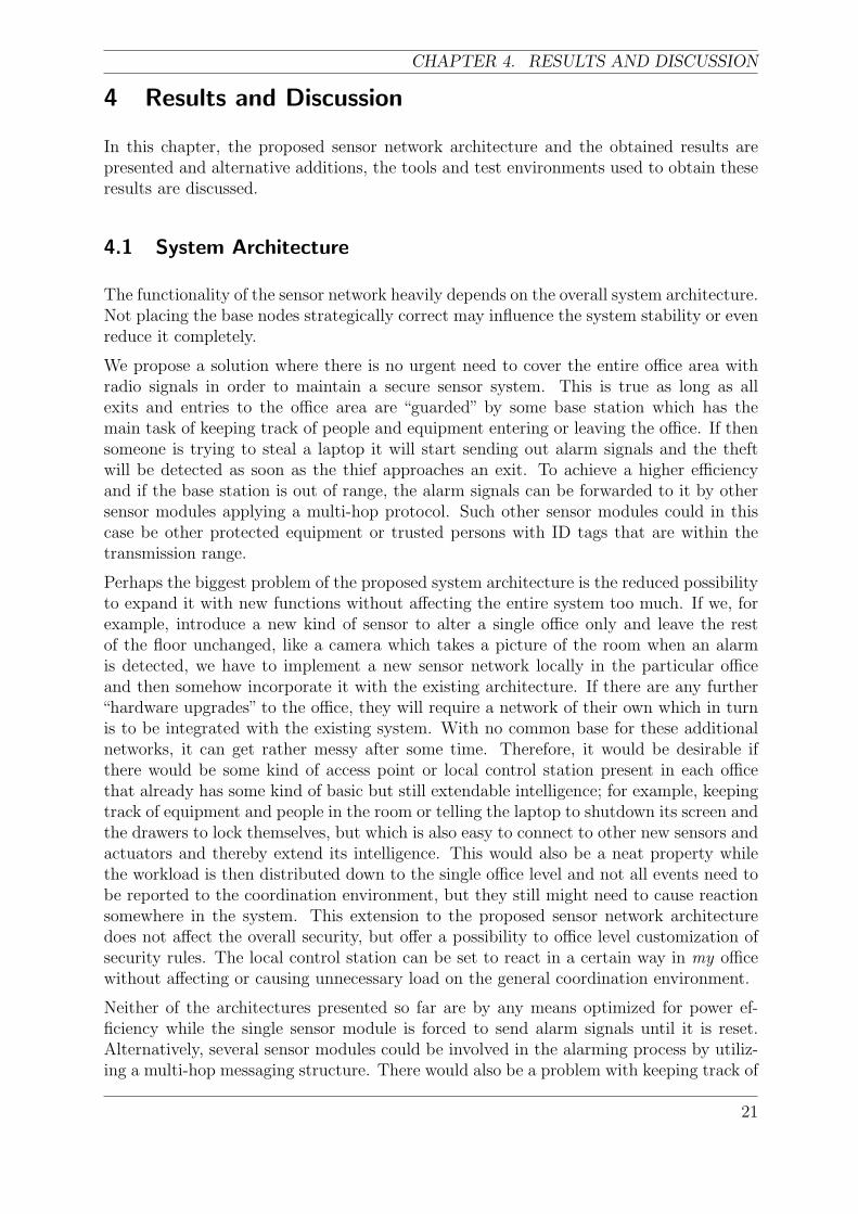
We propose a solution where there is no urgent need to cover the entire office area withradio signals in order to maintain a secure sensor system. This is true as long as allexits and entries to the office area are “guarded” by some base station which has themain task of keeping track of people and equipment entering or leaving the office. If thensomeone is trying to steal a laptop it will start sending out alarm signals and the theftwill be detected as soon as the thief approaches an exit. To achieve a higher efficiencyand if the base station is out of range, the alarm signals can be forwarded to it by othersensor modules applying a multi-hop protocol. Such other sensor modules could in thiscase be other protected equipment or trusted persons with ID tags that are within thetransmission range.
Perhaps the biggest problem of the proposed system architecture is the reduced possibilityto expand it with new functions without affecting the entire system too much. If we, forexample, introduce a new kind of sensor to alter a single office only and leave the restof the floor unchanged, like a camera which takes a picture of the room when an alarmis detected, we have to implement a new sensor network locally in the particular officeand then somehow incorporate it with the existing architecture. If there are any further“hardware upgrades” to the office, they will require a network of their own which in turnis to be integrated with the existing system. With no common base for these additionalnetworks, it can get rather messy after some time. Therefore, it would be desirable ifthere would be some kind of access point or local control station present in each officethat already has some kind of basic but still extendable intelligence; for example, keepingtrack of equipment and people in the room or telling the laptop to shutdown its screen andthe drawers to lock themselves, but which is also easy to connect to other new sensors andactuators and thereby extend its intelligence. This would also be a neat property whilethe workload is then distributed down to the single office level and not all events need tobe reported to the coordination environment, but they still might need to cause reactionsomewhere in the system. This extension to the proposed sensor network architecturedoes not affect the overall security, but offer a possibility to office level customization ofsecurity rules. The local control station can be set to react in a certain way in my officewithout affecting or causing unnecessary load on the general coordination environment.
Neither of the architectures presented so far are by any means optimized for power ef-ficiency while the single sensor module is forced to send alarm signals until it is reset.Alternatively, several sensor modules could be involved in the alarming process by utiliz-ing a multi-hop messaging structure. There would also be a problem with keeping track of
21
OPEN SECURE OFFICE PROJECT
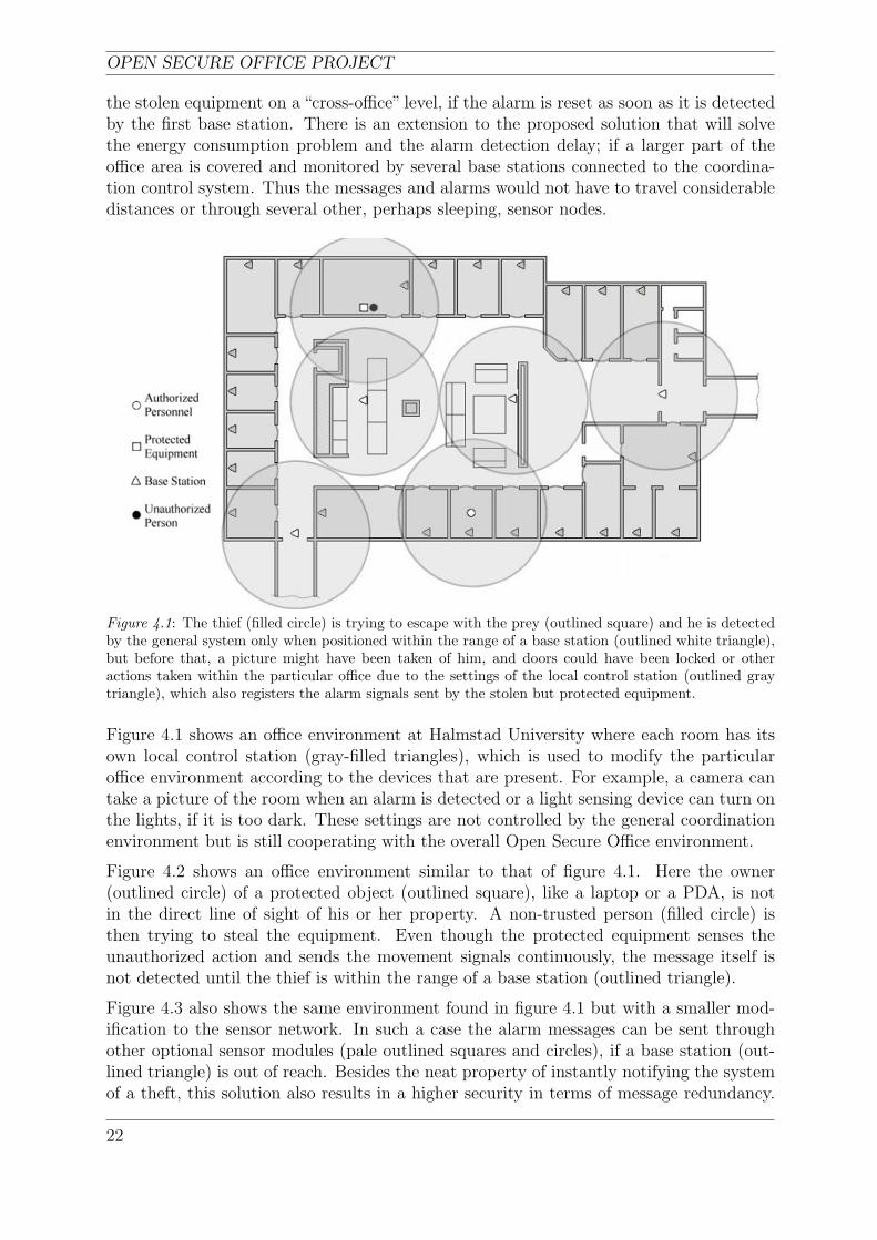
the stolen equipment on a “cross-office” level, if the alarm is reset as soon as it is detectedby the first base station. There is an extension to the proposed solution that will solvethe energy consumption problem and the alarm detection delay; if a larger part of theoffice area is covered and monitored by several base stations connected to the coordina-tion control system. Thus the messages and alarms would not have to travel considerabledistances or through several other, perhaps sleeping, sensor nodes.
Figure 4.1: The thief (filled circle) is trying to escape with the prey (outlined square) and he is detectedby the general system only when positioned within the range of a base station (outlined white triangle),but before that, a picture might have been taken of him, and doors could have been locked or otheractions taken within the particular office due to the settings of the local control station (outlined graytriangle), which also registers the alarm signals sent by the stolen but protected equipment.
Figure 4.1 shows an office environment at Halmstad University where each room has itsown local control station (gray-filled triangles), which is used to modify the particularoffice environment according to the devices that are present. For example, a camera cantake a picture of the room when an alarm is detected or a light sensing device can turn onthe lights, if it is too dark. These settings are not controlled by the general coordinationenvironment but is still cooperating with the overall Open Secure Office environment.
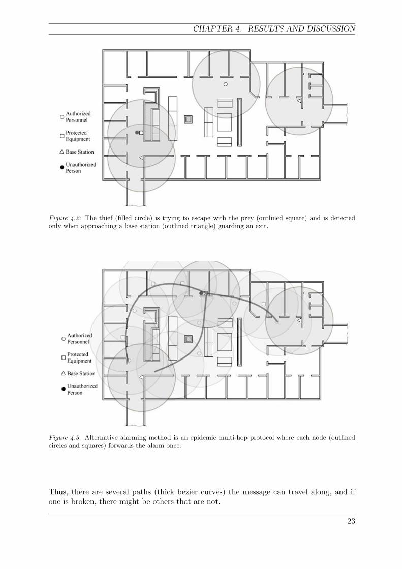
Figure 4.2 shows an office environment similar to that of figure 4.1. Here the owner(outlined circle) of a protected object (outlined square), like a laptop or a PDA, is notin the direct line of sight of his or her property. A non-trusted person (filled circle) isthen trying to steal the equipment. Even though the protected equipment senses theunauthorized action and sends the movement signals continuously, the message itself isnot detected until the thief is within the range of a base station (outlined triangle).
Figure 4.3 also shows the same environment found in figure 4.1 but with a smaller mod-ification to the sensor network. In such a case the alarm messages can be sent throughother optional sensor modules (pale outlined squares and circles), if a base station (out-lined triangle) is out of reach. Besides the neat property of instantly notifying the systemof a theft, this solution also results in a higher security in terms of message redundancy.
22
CHAPTER 4. RESULTS AND DISCUSSION
Figure 4.2: The thief (filled circle) is trying to escape with the prey (outlined square) and is detectedonly when approaching a base station (outlined triangle) guarding an exit.
Figure 4.3: Alternative alarming method is an epidemic multi-hop protocol where each node (outlinedcircles and squares) forwards the alarm once.
Thus, there are several paths (thick bezier curves) the message can travel along, and ifone is broken, there might be others that are not.
23
OPEN SECURE OFFICE PROJECT
4.2 Sensor Network Components
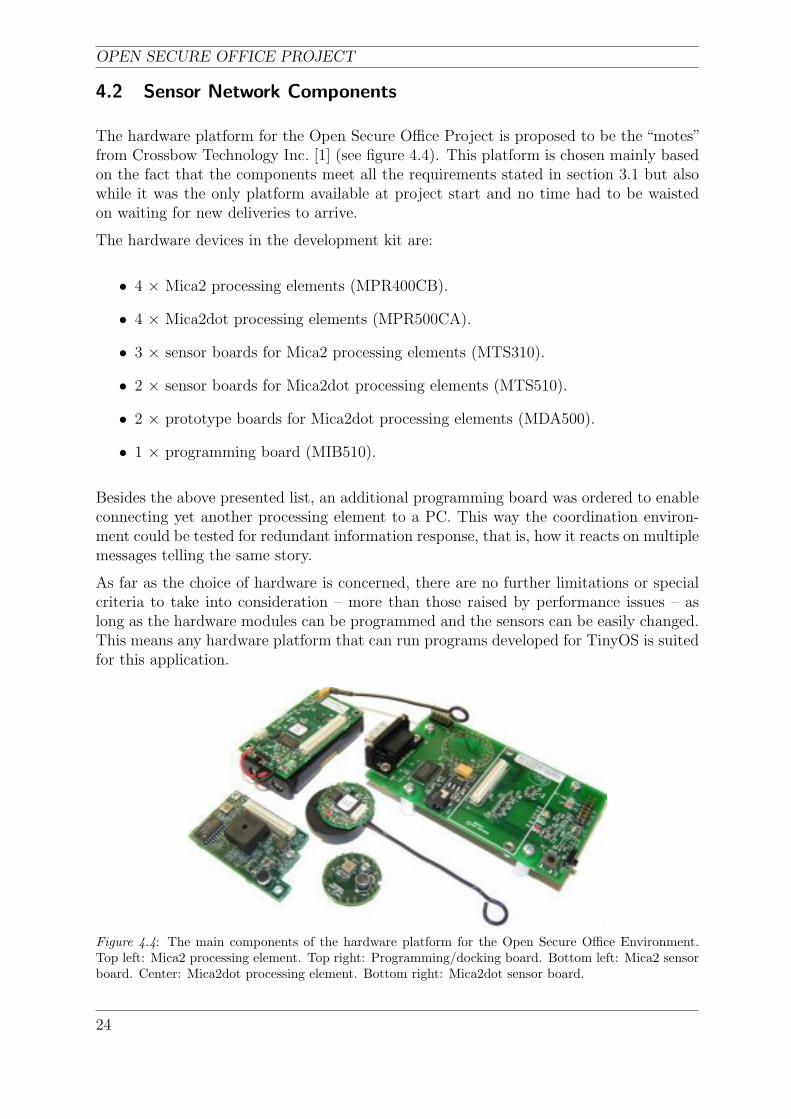
The hardware platform for the Open Secure Office Project is proposed to be the “motes”from Crossbow Technology Inc. [1] (see figure 4.4). This platform is chosen mainly basedon the fact that the components meet all the requirements stated in section 3.1 but alsowhile it was the only platform available at project start and no time had to be waistedon waiting for new deliveries to arrive.
The hardware devices in the development kit are:
• 4 × Mica2 processing elements (MPR400CB).
• 4 × Mica2dot processing elements (MPR500CA).
• 3 × sensor boards for Mica2 processing elements (MTS310).
• 2 × sensor boards for Mica2dot processing elements (MTS510).
• 2 × prototype boards for Mica2dot processing elements (MDA500).
• 1 × programming board (MIB510).
Besides the above presented list, an additional programming board was ordered to enableconnecting yet another processing element to a PC. This way the coordination environ-ment could be tested for redundant information response, that is, how it reacts on multiplemessages telling the same story.
As far as the choice of hardware is concerned, there are no further limitations or specialcriteria to take into consideration – more than those raised by performance issues – aslong as the hardware modules can be programmed and the sensors can be easily changed.This means any hardware platform that can run programs developed for TinyOS is suitedfor this application.
Figure 4.4: The main components of the hardware platform for the Open Secure Office Environment.Top left: Mica2 processing element. Top right: Programming/docking board. Bottom left: Mica2 sensorboard. Center: Mica2dot processing element. Bottom right: Mica2dot sensor board.
24
CHAPTER 4. RESULTS AND DISCUSSION
4.2.1 Mica2 Processing Element
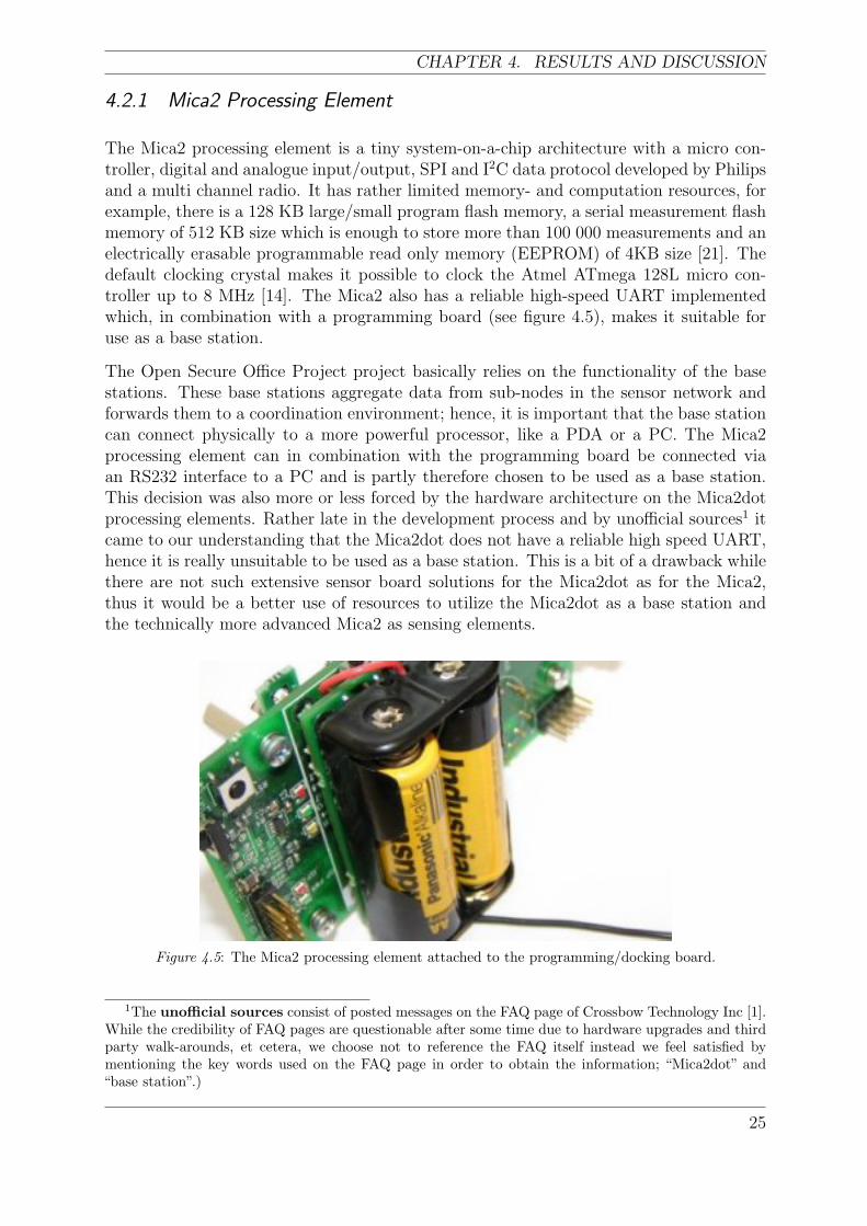
The Mica2 processing element is a tiny system-on-a-chip architecture with a micro con-troller, digital and analogue input/output, SPI and I2C data protocol developed by Philipsand a multi channel radio. It has rather limited memory- and computation resources, forexample, there is a 128 KB large/small program flash memory, a serial measurement flashmemory of 512 KB size which is enough to store more than 100 000 measurements and anelectrically erasable programmable read only memory (EEPROM) of 4KB size [21]. Thedefault clocking crystal makes it possible to clock the Atmel ATmega 128L micro con-troller up to 8 MHz [14]. The Mica2 also has a reliable high-speed UART implementedwhich, in combination with a programming board (see figure 4.5), makes it suitable foruse as a base station.
The Open Secure Office Project project basically relies on the functionality of the basestations. These base stations aggregate data from sub-nodes in the sensor network andforwards them to a coordination environment; hence, it is important that the base stationcan connect physically to a more powerful processor, like a PDA or a PC. The Mica2processing element can in combination with the programming board be connected viaan RS232 interface to a PC and is partly therefore chosen to be used as a base station.This decision was also more or less forced by the hardware architecture on the Mica2dotprocessing elements. Rather late in the development process and by unofficial sources1 itcame to our understanding that the Mica2dot does not have a reliable high speed UART,hence it is really unsuitable to be used as a base station. This is a bit of a drawback whilethere are not such extensive sensor board solutions for the Mica2dot as for the Mica2,thus it would be a better use of resources to utilize the Mica2dot as a base station andthe technically more advanced Mica2 as sensing elements.
Figure 4.5: The Mica2 processing element attached to the programming/docking board.
1The unofficial sources consist of posted messages on the FAQ page of Crossbow Technology Inc [1].While the credibility of FAQ pages are questionable after some time due to hardware upgrades and thirdparty walk-arounds, et cetera, we choose not to reference the FAQ itself instead we feel satisfied bymentioning the key words used on the FAQ page in order to obtain the information; “Mica2dot” and“base station”.)
25

OPEN SECURE OFFICE PROJECT
4.2.2 Mica2 Sensor Board
The Mica2 sensor board, which is a collection of sensors, is attachable to to the Mica2processing element. The Mica2 operates independently of the sensor board, that is, itcan send and receive messages via radio or to the on-board UART or light its LEDs eventhough there is not any sensor board attached to it. The sensor board on the other handdoes not make any sense without the Mica2, while sensor readings are not useful unlessoperated on or in some other way worked upon. Each and every sensor has individualpower control [22] which means they can be turned on and off independently of each other.This is really a smart design from an energy saving point of view while only those sensorsin use consume battery power.
The sensor boards for the Mica2 in the development kit have a set of five sensors, whichare [22]:
• Accelerometer.
• Acoustic sensor.
• Light sensor.
• Magnetometer.
• Thermistor.
In the Open Secure Office Project, the accelerometer, which is the dominant sensor of use,can be used to detect when protected equipment is moved or perhaps a door is opened.The buzzer and microphone can be involved in the distance determination process betweensensor nodes. This can be done by sending a high-frequency sound pulse just beforesending a radio message. When a node receives the radio message, which travels muchfaster than sound, it activates its microphone and a timer. After some time, when thesound pulse is registered, the timer is stopped and by knowing the speed of sound inair, the time of flight of the sound pulse can be used to calculate the distance betweenthe sending node and the receiving node. This feature has not been implemented in thisapplication.
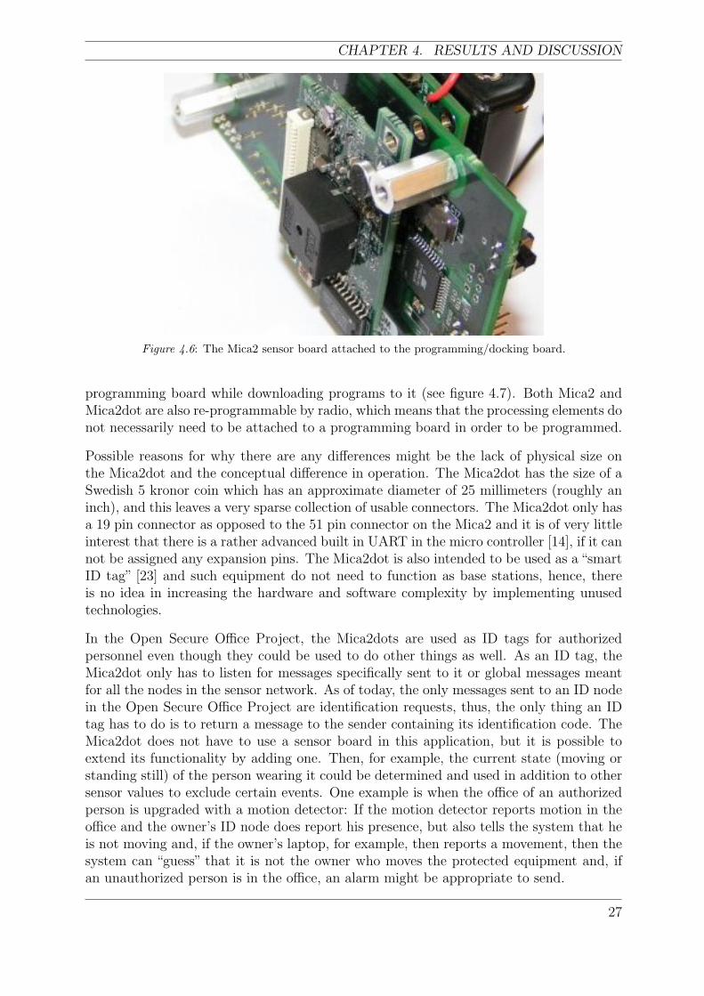
The sensor board is not only physically attachable to the Mica2 processing element but alsoto the programming board to be used in combination with a base station (see figure 4.6).Crossbow also grants an opportunity to order custom sensor boards for all processingelements they supply, if the standard equipment is not satisfactory for certain projects.
4.2.3 Mica2dot Processing Element
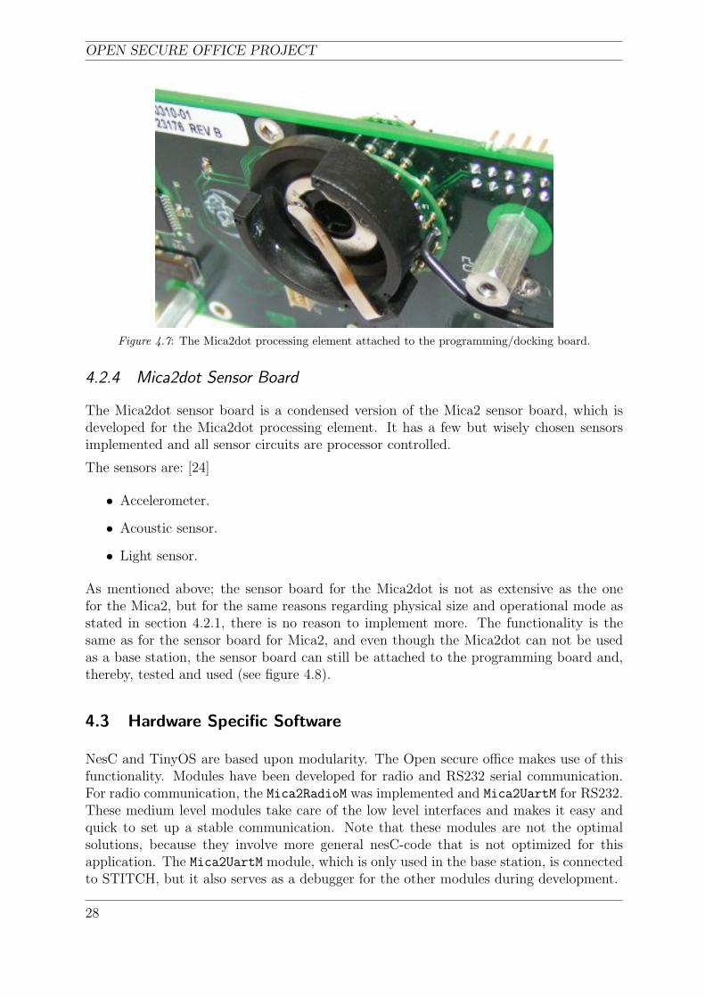
The Mica2dot processing element, which has mainly the same functionality as the Mica2,has the same hardware specification except for the data interfaces. The Mica2dot has onlydigital and analogue input/output, no SPI or I2C protocols are implemented [23]. Thelack of a reliable high speed UART also differentiates the two platforms (see section 4.2.1).Even though there is a UART on the Mica2dot, it is not to be used to extract data directlyfrom the Mica2dot as if it was a base station. Still the Mica2dot can be attached to the
26
CHAPTER 4. RESULTS AND DISCUSSION
Figure 4.6: The Mica2 sensor board attached to the programming/docking board.
programming board while downloading programs to it (see figure 4.7). Both Mica2 andMica2dot are also re-programmable by radio, which means that the processing elements donot necessarily need to be attached to a programming board in order to be programmed.
Possible reasons for why there are any differences might be the lack of physical size onthe Mica2dot and the conceptual difference in operation. The Mica2dot has the size of aSwedish 5 kronor coin which has an approximate diameter of 25 millimeters (roughly aninch), and this leaves a very sparse collection of usable connectors. The Mica2dot only hasa 19 pin connector as opposed to the 51 pin connector on the Mica2 and it is of very littleinterest that there is a rather advanced built in UART in the micro controller [14], if it cannot be assigned any expansion pins. The Mica2dot is also intended to be used as a “smartID tag” [23] and such equipment do not need to function as base stations, hence, thereis no idea in increasing the hardware and software complexity by implementing unusedtechnologies.
In the Open Secure Office Project, the Mica2dots are used as ID tags for authorizedpersonnel even though they could be used to do other things as well. As an ID tag, theMica2dot only has to listen for messages specifically sent to it or global messages meantfor all the nodes in the sensor network. As of today, the only messages sent to an ID nodein the Open Secure Office Project are identification requests, thus, the only thing an IDtag has to do is to return a message to the sender containing its identification code. TheMica2dot does not have to use a sensor board in this application, but it is possible toextend its functionality by adding one. Then, for example, the current state (moving orstanding still) of the person wearing it could be determined and used in addition to othersensor values to exclude certain events. One example is when the office of an authorizedperson is upgraded with a motion detector: If the motion detector reports motion in theoffice and the owner’s ID node does report his presence, but also tells the system that heis not moving and, if the owner’s laptop, for example, then reports a movement, then thesystem can “guess” that it is not the owner who moves the protected equipment and, ifan unauthorized person is in the office, an alarm might be appropriate to send.
27
OPEN SECURE OFFICE PROJECT
Figure 4.7: The Mica2dot processing element attached to the programming/docking board.
4.2.4 Mica2dot Sensor Board
The Mica2dot sensor board is a condensed version of the Mica2 sensor board, which isdeveloped for the Mica2dot processing element. It has a few but wisely chosen sensorsimplemented and all sensor circuits are processor controlled.
The sensors are: [24]
• Accelerometer.
• Acoustic sensor.
• Light sensor.
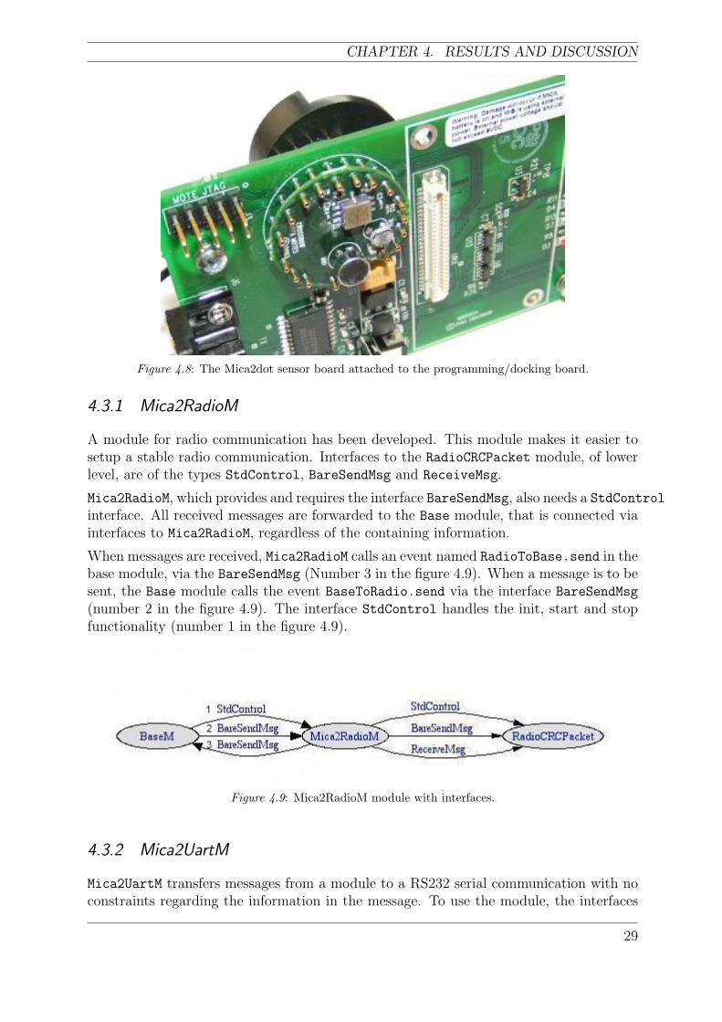
As mentioned above; the sensor board for the Mica2dot is not as extensive as the onefor the Mica2, but for the same reasons regarding physical size and operational mode asstated in section 4.2.1, there is no reason to implement more. The functionality is thesame as for the sensor board for Mica2, and even though the Mica2dot can not be usedas a base station, the sensor board can still be attached to the programming board and,thereby, tested and used (see figure 4.8).
4.3 Hardware Specific Software
NesC and TinyOS are based upon modularity. The Open secure office makes use of thisfunctionality. Modules have been developed for radio and RS232 serial communication.For radio communication, the Mica2RadioM was implemented and Mica2UartM for RS232.These medium level modules take care of the low level interfaces and makes it easy andquick to set up a stable communication. Note that these modules are not the optimalsolutions, because they involve more general nesC-code that is not optimized for thisapplication. The Mica2UartM module, which is only used in the base station, is connectedto STITCH, but it also serves as a debugger for the other modules during development.
28
CHAPTER 4. RESULTS AND DISCUSSION
Figure 4.8: The Mica2dot sensor board attached to the programming/docking board.
4.3.1 Mica2RadioM
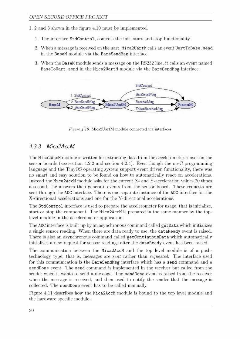
A module for radio communication has been developed. This module makes it easier tosetup a stable radio communication. Interfaces to the RadioCRCPacket module, of lowerlevel, are of the types StdControl, BareSendMsg and ReceiveMsg.
Mica2RadioM, which provides and requires the interface BareSendMsg, also needs a StdControlinterface. All received messages are forwarded to the Base module, that is connected viainterfaces to Mica2RadioM, regardless of the containing information.
When messages are received, Mica2RadioM calls an event named RadioToBase.send in thebase module, via the BareSendMsg (Number 3 in the figure 4.9). When a message is to besent, the Base module calls the event BaseToRadio.send via the interface BareSendMsg
(number 2 in the figure 4.9). The interface StdControl handles the init, start and stopfunctionality (number 1 in the figure 4.9).
Figure 4.9: Mica2RadioM module with interfaces.
4.3.2 Mica2UartM
Mica2UartM transfers messages from a module to a RS232 serial communication with noconstraints regarding the information in the message. To use the module, the interfaces
29
OPEN SECURE OFFICE PROJECT
1, 2 and 3 shown in the figure 4.10 must be implemented.
1. The interface StdControl, controls the init, start and stop functionality.
2. When a message is received on the uart, Mica2UartM calls an event UartToBase.sendin the BaseM module via the BareSendMsg interface.
3. When the BaseM module sends a message on the RS232 line, it calls an event namedBaseToUart.send in the Mica2UartM module via the BareSendMsg interface.
Figure 4.10: Mica2UartM module connected via interfaces.
4.3.3 Mica2AccM
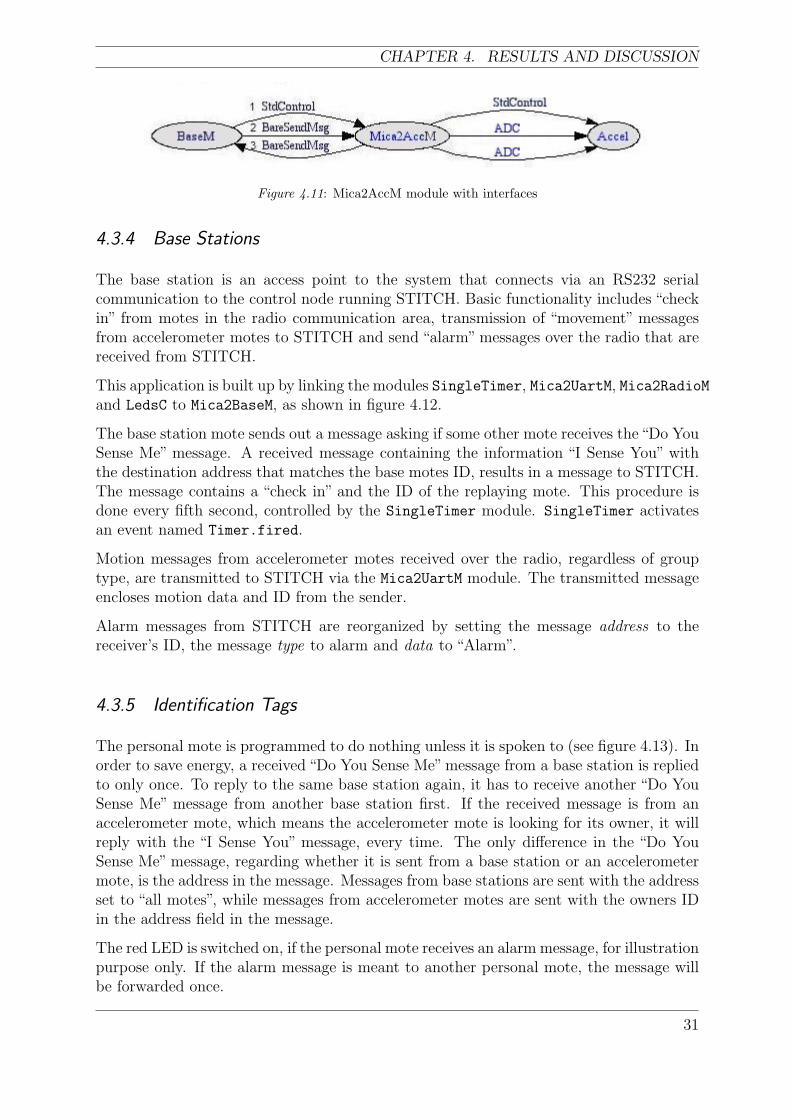
The Mica2AccM module is written for extracting data from the accelerometer sensor on thesensor boards (see section 4.2.2 and section 4.2.4). Even though the nesC programminglanguage and the TinyOS operating system support event driven functionality, there wasno smart and easy solution to be found on how to automatically react on accelerations.Instead the Mica2AccM module asks for the current X- and Y-acceleration values 20 timesa second, the answers then generate events from the sensor board. These requests aresent through the ADC interface. There is one separate instance of the ADC interface for theX-directional accelerations and one for the Y-directional accelerations.
The StdControl interface is used to prepare the accelerometer for usage, that is initialize,start or stop the component. The Mica2AccM is prepared in the same manner by the top-level module in the accelerometer application.
The ADC interface is built up by an asynchronous command called getData which initializesa single sensor reading. When there are data ready to use, the dataReady event is raised.There is also an asynchronous command called getContinuousData which automaticallyinitializes a new request for sensor readings after the dataReady event has been raised.
The communication between the Mica2AccM and the top level module is of a push-technology type, that is, messages are sent rather than requested. The interface usedfor this communication is the BareSendMsg interface which has a send command and asendDone event. The send command is implemented in the receiver but called from thesender when it wants to send a message. The sendDone event is raised from the receiverwhen the message is received, and then used to notify the sender that the message iscollected. The sendDone event has to be called manually.
Figure 4.11 describes how the Mica2AccM module is bound to the top level module andthe hardware specific module.
30
CHAPTER 4. RESULTS AND DISCUSSION
Figure 4.11: Mica2AccM module with interfaces
4.3.4 Base Stations
The base station is an access point to the system that connects via an RS232 serialcommunication to the control node running STITCH. Basic functionality includes “checkin” from motes in the radio communication area, transmission of “movement” messagesfrom accelerometer motes to STITCH and send “alarm” messages over the radio that arereceived from STITCH.
This application is built up by linking the modules SingleTimer, Mica2UartM, Mica2RadioMand LedsC to Mica2BaseM, as shown in figure 4.12.
The base station mote sends out a message asking if some other mote receives the“Do YouSense Me” message. A received message containing the information “I Sense You” withthe destination address that matches the base motes ID, results in a message to STITCH.The message contains a “check in” and the ID of the replaying mote. This procedure isdone every fifth second, controlled by the SingleTimer module. SingleTimer activatesan event named Timer.fired.
Motion messages from accelerometer motes received over the radio, regardless of grouptype, are transmitted to STITCH via the Mica2UartM module. The transmitted messageencloses motion data and ID from the sender.
Alarm messages from STITCH are reorganized by setting the message address to thereceiver’s ID, the message type to alarm and data to “Alarm”.
4.3.5 Identification Tags
The personal mote is programmed to do nothing unless it is spoken to (see figure 4.13). Inorder to save energy, a received “Do You Sense Me”message from a base station is repliedto only once. To reply to the same base station again, it has to receive another “Do YouSense Me” message from another base station first. If the received message is from anaccelerometer mote, which means the accelerometer mote is looking for its owner, it willreply with the “I Sense You” message, every time. The only difference in the “Do YouSense Me” message, regarding whether it is sent from a base station or an accelerometermote, is the address in the message. Messages from base stations are sent with the addressset to “all motes”, while messages from accelerometer motes are sent with the owners IDin the address field in the message.
The red LED is switched on, if the personal mote receives an alarm message, for illustrationpurpose only. If the alarm message is meant to another personal mote, the message willbe forwarded once.
31
OPEN SECURE OFFICE PROJECT
Figure 4.12: The module diagram shows the implementation on the base station mote. SingleTimer,Mica2UartM, Mica2RadioM and LedsC are low level modules. They are hardware specific and areconnected via interfaces to the Mica2BaseM module.
Figure 4.13: The figure shows the module implementation in the personal mote.
4.3.6 Accelerometer Nodes
The Accelerometer mote (described in figure 4.14) is attached to the protected equipment.The mote is sensitive to movements in two directions. After a detected movement, themote sends out a“Do You Sense Me”message to its owner and at the same time the yellowled is turned on. The message is sent five times in one second. A received “I Sense You”from the owner, results in that the yellow led is turned off and the green led is turned onfor one second. If the mote does not receive a message, it will send a “movement”messageto a base station and the red led is turned on for two seconds.
A received “Do You Sense Me” message from a base station is replied only once with themessage“I Sense You”. To be able to answer the same base station again, the accelerometermote has to receive another “Do You Sense Me” message from another base station first.Received alarm messages will be forwarded once. All LEDs are used for illustrationpurpose only.
32
CHAPTER 4. RESULTS AND DISCUSSION
Figure 4.14: The figure describes the structure of an accelerometer mote. The five modules on right-hand-side are of lower level.
4.4 Software Development Environment and Debugging
This section briefly describes the development environment used while writing nesC pro-grams and other custom tools developed to test the sensor network functionality.
4.4.1 The Source Code Editor
The software modules developed for this application are all written in the nesC pro-gramming language. There was no advanced development environment to be found likeBorland’s JBuilder for Java applications or Microsoft’s Visual Studio for C/C++ or Vi-sual Basic applications. In order to produce visually pleasant nesC programming code, theCrimson Editor [25] was used. Crimson Editor supports regular expressions which enablethe user to configure custom syntax files, setting color properties and perform advancedsearch operations. The predefined syntax file for C was extended with the nesC syntax.
4.4.2 The Mote Communicator
A Java program was developed to test the sensor network. Initially, it was intendedto debug the RS232 communication between the base station mote and the PC, but asthe work proceeded, it was extended to test the radio communication and finally to testalternative message packaging protocols. The Mote Communicator in its current state canreceive and send a standard TOS_Msg package, where the user can choose what data to
33

OPEN SECURE OFFICE PROJECT
send and which COM port settings to use. All received messages are printed on an outputscreen, where each fragment is individually extracted and presented. These fragments are:
• address (2 bytes)
• type (1 byte)
• group (1 byte)
• length (1 byte)
• data (max 29 bytes)
• crc (2 bytes)
These fields have to be set manually, if not a predefined packetizer provided in the TinyOSinstallation package is used.
There are some general debugging and simulation environments available for nesC appli-cations, like TOSSIM, but there were major difficulties starting these up. This problemjustified the development of custom debug software.
34
CHAPTER 5. CONCLUSIONS
5 Conclusions
The principal task was to evaluate TinyOS and nesC on specific hardware from CrossbowTechnology Inc, applied on an application called the Open Secure Office Project.
The implemented system was designed with the following requirements:
• Build up and maintain a reliable communication.
• Expand the network.
• Implement multi-hop functionality.
The things listed above have successfully been implemented. Communication via the radioand on the RS232 serial line were initialized and have never failed to function during ourtests.
The expansion of the network works without problems, and new motes that enter thesystem simply check in, in an ad-hoc manner, and are thereby known to the coordinationenvironment.
Important messages like alarms are forwarded once by each node epidemically throughthe network until the receiver gets them.
5.1 System Architecture
We have experienced that relatively small modifications to the network architecture mayinfluence the system stability or even cause system failure. For example, it is not necessaryto cover the entire office with radio signals, if the entries and exits are covered. Usingmore base stations in the network will increase the precision of the alarm detection.
The topic of data transmission security has not been investigated at all, since the maininterest is to deliver the message by all means, rather than protect it from interception.How the system handles unexpected events like an empty battery or node failure have notbeen implemented.
5.2 Debug Application
Although there are several debugging applications and simulators available, a propertest environment was not successfully set up. To solve this problem a custom debuggingsoftware built in Java with predefined classes was developed. This software was specificallydesigned for this application.
5.3 NesC and TinyOS
Software modules were created for each functionality of the sensor nodes, like commu-nication or sensor readings. These modules make it easy to set up an application in a
35
OPEN SECURE OFFICE PROJECT
short time. The TinyOS operating environment makes our nesC-code standardized andoperable also on other hardware that are TinyOS compatible.
The TinyOS and nesC are perfect combinations for module based and resource limitedprogramming. The code can be compiled to a graphical flowchart, which makes the entireprogram overview very clear. There are however some disadvantages using TinyOS andnesC; the documentation of the modules and interfaces are not satisfactory, which makesit time consuming to learn new functionality. We propose a publicly available source codedocumentation, which explains how the predefined modules and interfaces are to be used.
5.4 Power Management
Power management has been investigated, which shows that it is rather easy to implement.However, due to time constraints, power management has not been implemented. Theproblem would be to determine the real gain in our application, but the results producedby other researchers show that it would be 100 times or more.
5.5 Alternative Solutions
Instead of using mote based wireless sensor networks to establish the open secure office,alternative hardware could have been used like:
Bluetooth
Bluetooth is mainly used to connect peripheral equipment in an office environment such asmobile phones, printers, keyboards etc. The drawbacks of using Bluetooth are its complexprotocol stack, which demands large memory capacity. The power saving modes are alsoless sophisticated than those in wireless sensor motes. One idea could be to use mobilephones in a wireless sensor network with Bluetooth connection, since they are consideredevery man’s property these days.
RFID
RFID could be either active or passive. Active RFID tags are battery powered and havethe ability to contact its reader. Passive RFID tags are not battery powered and cannot contact its reader by itself because it does not have any energy source of its own.Active tags could be joined together with other electronic devices, such as sensors, ona single PCB, which is very similar to, and could replace the accelerometer mote in theopen secure office environment. A passive tag only includes an ID-number and could forinstance replace the personal mote in the open secure office environment. Passive tagsare, on the other hand, very easy to copy, which would not be appropriate in a securitysystem.
36
CHAPTER 5. CONCLUSIONS
Regular surveillance system
Surveillance systems of today could be remote accessed, which means the alarm systemcould be monitored for instance over the Internet. Alarm sensors, like motion detectors,are often not wireless connected. Some systems use the IEEE standard 802.11, but theydo not focus on energy savings, limited resources etc.
5.6 Future Work
The approach used in this thesis can be extended and developed in many ways. Themost important question is how the Open Secure Office network structure will work ina real environment. Another aspect of the question is to try to implement some kind ofencryption algorithms and evaluate their pros and cons.
The developed software could be rewritten, so that it become closer to optimal for thissolution. All the modules of lower level could be removed and placed together with theconfiguration specific software, in one single module instead, and in this way improve thetotal performance.
Another implementation that would be interesting on this system is graceful degradation.How does the system handle unexpected events like an empty battery or when a nodefails to work properly?
The most interesting point is to implement HPLPowermanagement, which follows in theTinyOS environment, on the personal mote. Can a mote operate in the Open SecureOffice network structure for a month or a year?
37

OPEN SECURE OFFICE PROJECT
38
BIBLIOGRAPHY
Bibliography
[1] Crossbow. (2004, May) Crossbow technology inc. Crossbow. [Online]. Available:http://www.xbow.com/
[2] E. Nilsson, J. Olsson, and A. Stahl, “Open secure office project - evaluating stitch,”Master’s thesis, School of Information Science, Computer and Electrical Engineering,Halmstad University, Halmstad, January 2005.
[3] D. Malan, T. Fulford-Jones, M. Welsh, and S. Moulton, “Codeblue: An ad hocsensor network infrastructure for emergency medical care,” in WAMES: Mobisys2004 Workshop on Applications of Mobile Embedded Systems(In conjunction withACM/USENIX Mobisys 2004), Boston, MA, June 2004.
[4] M.Welsh. (2004) Codeblue project page. Harvard University. [Online]. Available:http://www.eecs.harvard.edu/˜mdw/proj/codeblue/
[5] D. Patnode, J. Dunne, A. Malinowski, and D. Schertz, “Wisenet - tinyos based wire-less network of sensors,” vol. 3, November 2003, pp. 2363–2368.
[6] E. H. Callaway Jr., Wireless Sensor Networks: Architectures and Protocols, 1st ed.New York: CRC Press LLC., 2004, ch. 1, pp. 1–20.
[7] Berkeley. (2004, May) Smartdust. Berkeley. [Online]. Available: http://www-bsac.eecs.berkeley.edu/archive/users/warneke-brett/SmartDust/
[8] D. Gay, P. Levis, R. von Behren, M. Welsh, E. Brewer, and D. Culler, “The nesclanguage: A holistic approach to networked embedded systems,” in Proceedings ofProgramming Language Design and Implementation (PLDI), San Diego, California,June 2003.
[9] B. Mandelovich. (2004, May) A review on high level data races. University of Haifa.[Online]. Available: http://study.haifa.ac.il/˜mbarak07/hldr.zip/
[10] The Portland Group. (2004, May) Pgi workstation user´s guide. The PortlandGroup Compiler Technology, ST Microelectronics. [Online]. Available: http://www.pgroup.com/ppro docs/pgiws ug/pgiug 05.htm
[11] P. Levis and S. Madden et al., “The emergence of networking abstractions andtechniques in tinyos,” in Proceedings of the First USENIX/ACM Symposium onNetworked Systems Design and Implementation (NSDI), San Francisco, California,March 2004.
[12] Berkeley WEBS. (2004, May) Tinyos community forum. Berkeley WEBS. [Online].Available: http://www.tinyos.net/
[13] Jason Lester Hill. (2003) System architecture for wireless sensor networks. Universityof California, Berkeley. [Online]. Available: http://www.jlhlabs.com/jhill cs/
[14] Atmel Corporation. (2004) Atmega128(l) complete users manual. Atmel. [Online].Available: http://www.atmel.com/dyn/resources/prod documents/doc2467.pdf
39
OPEN SECURE OFFICE PROJECT
[15] G.Pottie and W.Kaiser, “Wireless integrated network sensors,” Communications ofthe ACM, vol. 43, no. 5, pp. 51–58, May 2000.
[16] U. Bilstrup and P. A. Wiberg, “An architecture comparison between a wireless sen-sor network and an active rfid system,” in The First IEEE Workshop on EmbeddedNetworked Sensors, Tampa, Florida, November 2004.
[17] U. Bilstrup, K. Sjoberg, B. Svensson, and P. A. Wiberg, “Capacity limitations inwireless sensor networks,” in The 9th IEEE International Conference on EmergingTechnologies and Factory Automation, Lisbon, Portugal, September 2003.
[18] Ravi Kumar Dasari. (2003) Wireless sensor networks, eece 505 term project.University of New Mexico. [Online]. Available: www.eece.unm.edu/˜wu/course/505f03/WSN.ppt
[19] B.Krishnamachari, D.Estrin, and S.Wicker, “Modelling data-centric routing in wire-less sensor networks,”Department of Computer Engineering, USC, Tech. Rep. CENG02-14, 2002.
[20] R. Cardell-Oliver, “Why flooding is unreliable,” School of Computer Science & Soft-ware Engineering, The University of Western Australia, Tech. Rep. UWA-CSSE-04-001, February 2004.
[21] Crossbow. (2004, December) Crossbow technology inc. Crossbow. [On-line]. Available: http://www.xbow.com/Products/Product pdf files/Wireless pdf/6020-0042-06 A MICA2.pdf
[22] ——. (2004, December) Crossbow technology inc. Crossbow. [On-line]. Available: http://www.xbow.com/Products/Product pdf files/Wireless pdf/6020-0047-01 B MTS.pdf
[23] ——. (2004, December) Crossbow technology inc. Crossbow. [On-line]. Available: http://www.xbow.com/Products/Product pdf files/Wireless pdf/6020-0043-04 B MICA2DOT.pdf
[24] ——. (2004, December) Crossbow technology inc. Crossbow. [On-line]. Available: http://www.xbow.com/Products/Product pdf files/Wireless pdf/6020-0058-02 A MTS510CA.pdf
[25] I. Kang. (2004, December) Crimson editor home page. Ingyu Kang. [Online].Available: http://www.crimsoneditor.com
40

APPENDIX A. THE COMBINED PROJECT GOAL
A The combined project goal
The project Open Secure Office Project is divided into three parts.
1. The first handle the rules of the system, which will be established in the program-ming language STITCH.
2. The second handle the sensor network related hardware decisions, including thelow-level programming. This part is presented in this thesis.
3. The last handle the concept of graceful degradation, applied to this project.
A.1 Introduction
The office of the future should have an open feeling where security is not an obstacle toefficient work. Personnel do not want to constantly push in codes to get access to newareas while moving around. It should be possible for the employees to keep the doorsto their offices unlocked without endangering the security. The Xerox machine should ofcourse not be usable by guests and visitors, however the employees do not want to carryaround a key all the time in order to gain access to the equipment.
To make this scenario possible, a transparent, easy to use system is needed. The employeesshould hardly notice that it is there. A solution to this problem is proposed in thefollowing chapter. With the aid of a sensor network consisting of motes, ID tags andreaders controlled by the STITCH language we believe this can all be possible.
A.2 Proposed Solution
As a result of definitions and requests made by higher authorities of this project, there isalready a proposed solution path to the project; the application should implement a sensornetwork of some kind and a high-level coordination language is to control the resourcesand rules.
A.2.1 The Sensor Network
It is desirable to implement a distributed sensor network in order to keep the applicationindependent of its size and the eventual limitations which might follow as a result of thegrowth. On the other hand, it is advantageous to keep the network compact and somehowregulate the number of nodes within the system, while the number of signals to processgrows as the number of sensors grows.
Grouping several kinds of sensors like motion detectors and identification sensors (RFID)and treating them as one node adds intelligence to the application, while one node then canscan several different kinds of events. This has also advantages from an energy-efficiencypoint-of-view, while data can be packed together and hence fewer actual signals are sent.
41

OPEN SECURE OFFICE PROJECT
Fortunately, this concept of grouping sensors is not a new idea. There are several of-the-shelf sensor platforms available, which allow the development of custom applications.There are also several standardized programming languages and software environmentssuch as nesC and TinyOS which are developed for programming small networked devices.
One type of device that will be used in this project is the motes from Crossbow TechnologyInc [1]. A mote is a wireless transceiver that is equipped with sensors.
The system consists of several sensors such as motion detectors, accelerometer sensors,identification readers and light sensors. Accelerometers and light sensors are part of thementioned motes. Motion sensors and identification readers, however, are not availableon the motes’, therefore, they have to be added. The motes are all connected to eachother by wireless connections. All the sensors are connected to something which will becalled a base station. This device will, in the first phase of development, be a standardPC, where STITCH is running but in a real application small, embedded systems arepreferable. A PDA with a user interface will also be connected to the system in order tomake it possible for employees to change personal security settings.
The system is going to be event-based, which means several events (configured in STITCH)have to occur in order take some action. The reason for using this approach is to minimizethe radio traffic to the base station, which entails lower power consumption.
One example is:If a person enters a room, he or she is sensed by a motion detector or RFID recognition(Event A), which is probably not enough (naturally depending on the STITCH rules) foran alert. Event B should be that the person then seizes a portable computer, equippedwith an accelerometer. This action combined with Event A will raise a third event (EventC).
A ∧B ⇒ C ⇒ Action decision by STITCH
This event will make STITCH signal alert (in this case).
A.2.2 Coordination
The implementation of security rules and coordination will be performed in the STITCHlanguage which is a distributed language written in Python and C. STITCH should be agood programming language for these types of applications because it has built-in transac-tion management. This helps during the software-development because the programmercan concentrate on the application-specific problems instead of worrying about concurrentuse of resources in the distributed environment.
Only two base stations will initially be used in this application, but it should be possibleto connect more base stations if needed.
To get new information into the STITCH environment, the sensor network and its softwaredrivers will use a push approach. This will be useful both in an energy-efficient way and toprevent overloading the STITCH environment, which does not work well with too manyconcurrent events.
As this application is a high-security system, there is also a need for some kind of gracefuldegradation routines in case of hardware failure. If a mote does not respond as expected,
42

APPENDIX A. THE COMBINED PROJECT GOAL
then the system must work around the problem and still maintain the overall security,which can be very complicated to implement but some basic functionality and compati-bility for future developments must be taken into consideration.
If a mote has not shown activity for a while, an “are-you-alive” query can be sent. Ifthe mote does not respond to that signal in a given time, it is considered faulty and thegraceful degradation routines will take over.
43

OPEN SECURE OFFICE PROJECT
44
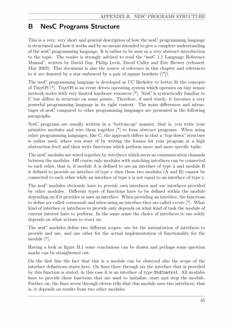
APPENDIX B. NESC PROGRAMS STRUCTURE
B NesC Programs Structure
This is a very, very short and general description of how the nesC programming languageis structured and how it works and by no means intended to give a complete understandingof the nesC programming language. It is rather to be seen as a very abstract introductionto the topic. The reader is strongly advised to read the “nesC 1.1 Language ReferenceManual”, written by David Gay, Philip Levis, David Culler and Eric Brewer (released:May 2003). This document is also the source of reference in this chapter and referencesto it are denoted by a star embraced by a pair of square brackets ([*]).
The nesC programming language is developed at UC Berkeley to better fit the conceptsof TinyOS [*]. TinyOS is an event driven operating system which operates on tiny sensornetwork nodes with very limited hardware resources [*]. NesC is syntactically familiar toC but differs in structure on some points. Therefore, if used wisely, it becomes a verypowerful programming language in its right context. The main differences and advan-tages of nesC compared to other programming languages are presented in the followingparagraphs.
NesC programs are usually written in a “bottom-up” manner, that is, you write yourprimitive modules and wire them together [*] to form abstract programs. When usingother programming languages, like C, the approach differs in that a “top-down” structureis rather used, where you start of by writing the frames for your program at a highabstraction level and then write functions which perform more and more specific tasks.
The nesC modules are wired together by interfaces which serve as communication channelsbetween the modules. Off course only modules with matching interfaces can be connectedto each other, that is, if module A is defined to use an interface of type x and module Bis defined to provide an interface of type y then these two modules (A and B) cannot beconnected to each other while an interface of type x is not equal to an interface of type y.
The nesC modules obviously have to provide own interfaces and use interfaces providedby other modules. Different types of functions have to be defined within the moduledepending on if it provides or uses an interface. When providing an interface, the functionsto define are called commands and when using an interface they are called events [*]. Whatkind of interface or interfaces to provide only depends on what kind of task the module ofcurrent interest have to perform. In the same sense the choice of interfaces to use solelydepends on what actions to react on.
The nesC modules define two different scopes; one for the instantiation of interfaces toprovide and use, and one other for the actual implementation of functionality for themodule [*].
Having a look at figure B.1 some conclusions can be drawn and perhaps some questionmarks can be straightened out.
On the first line the fact that this is a module can be observed also the scope of theinterface definitions starts here. On lines three through six the interface that is providedby this function is stated, in this case it is an interface of type StdControl. All moduleshave to provide these functions that are used to initialize, start and stop the module.Further on, the lines seven through eleven tells that this module uses two interfaces, thatis, it depends on results from two other modules.
45
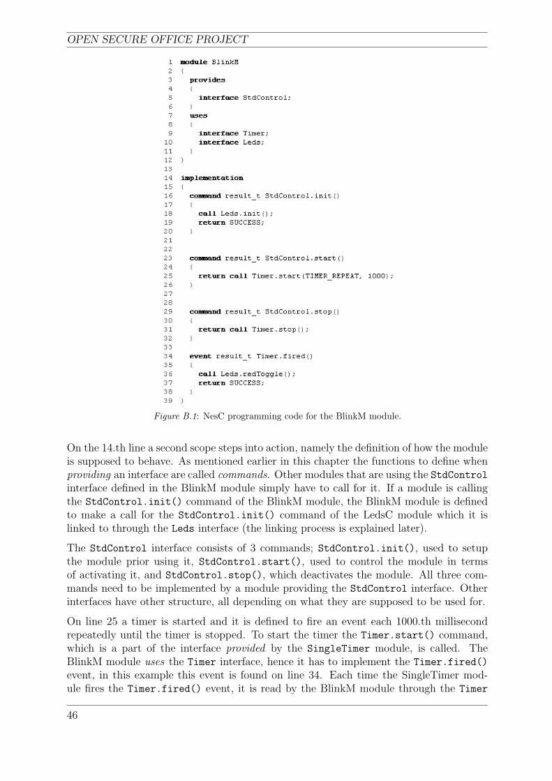
OPEN SECURE OFFICE PROJECT
Figure B.1: NesC programming code for the BlinkM module.
On the 14.th line a second scope steps into action, namely the definition of how the moduleis supposed to behave. As mentioned earlier in this chapter the functions to define whenproviding an interface are called commands. Other modules that are using the StdControlinterface defined in the BlinkM module simply have to call for it. If a module is callingthe StdControl.init() command of the BlinkM module, the BlinkM module is definedto make a call for the StdControl.init() command of the LedsC module which it islinked to through the Leds interface (the linking process is explained later).
The StdControl interface consists of 3 commands; StdControl.init(), used to setupthe module prior using it, StdControl.start(), used to control the module in termsof activating it, and StdControl.stop(), which deactivates the module. All three com-mands need to be implemented by a module providing the StdControl interface. Otherinterfaces have other structure, all depending on what they are supposed to be used for.
On line 25 a timer is started and it is defined to fire an event each 1000.th millisecondrepeatedly until the timer is stopped. To start the timer the Timer.start() command,which is a part of the interface provided by the SingleTimer module, is called. TheBlinkM module uses the Timer interface, hence it has to implement the Timer.fired()
event, in this example this event is found on line 34. Each time the SingleTimer mod-ule fires the Timer.fired() event, it is read by the BlinkM module through the Timer
46
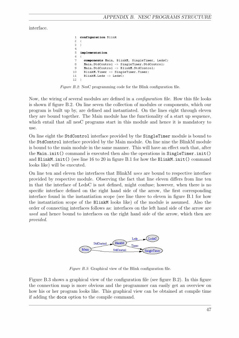
APPENDIX B. NESC PROGRAMS STRUCTURE
interface.
Figure B.2: NesC programming code for the Blink configuration file.
Now, the wiring of several modules are defined in a configuration file. How this file looksis shown if figure B.2. On line seven the collection of modules or components, which ourprogram is built up by, are defined and instantiated. On the lines eight through eleventhey are bound together. The Main module has the functionality of a start up sequence,which entail that all nesC programs start in this module and hence it is mandatory touse.
On line eight the StdControl interface provided by the SingleTimer module is bound tothe StdControl interface provided by the Main module. On line nine the BlinkM moduleis bound to the main module in the same manner. This will have an effect such that, afterthe Main.init() command is executed then also the operations in SingleTimer.init()
and BlinkM.init() (see line 16 to 20 in figure B.1 for how the BlinkM.init() commandlooks like) will be executed.
On line ten and eleven the interfaces that BlinkM uses are bound to respective interfaceprovided by respective module. Observing the fact that line eleven differs from line tenin that the interface of LedsC is not defined, might confuse; however, when there is nospecific interface defined on the right hand side of the arrow, the first correspondinginterface found in the instantiation scope (see line three to eleven in figure B.1 for howthe instantiation scope of the BlinkM looks like) of the module is assumed. Also theorder of connecting interfaces follows as: interfaces on the left hand side of the arrow areused and hence bound to interfaces on the right hand side of the arrow, which then areprovided.
Figure B.3: Graphical view of the Blink configuration file.
Figure B.3 shows a graphical view of the configuration file (see figure B.2). In this figurethe connection map is more obvious and the programmer can easily get an overview onhow his or her program looks like. This graphical view can be obtained at compile timeif adding the docs option to the compile command.
47