Porous Alginate Hydrogels: Synthetic Methods for Tailoring the Porous Texture
Upload
uni-bremenCategory
view
1download
0
1 Copyright © 2010 by ASME
Proceedings of ASME Turbo Expo 2010: Power for Land, Sea and Air GT2010
June 14-18, 2010, Glasgow, UK
GT2010-22331
DRAFT: ON THE PERFORMANCE OF POROUS SOUND ABSORBENT MATERIAL IN HIGH TEMPERATURE APPLICATIONS
Frank Giese* Department of Propulsion- and Power Systems
Bremen, 28359 Bremen, Germany
Hans-Christoph Ries Department of Propulsion- and Power Systems
Bremen, 28359 Bremen, Germany
Christian Eigenbrod Department of Propulsion- and Power Systems
ZARM University of Bremen
Bremen, 28359 Bremen, Germany
ABSTRACT This paper discusses the use of novel porous sound
absorbent ceramic tiles as heat shields in combustion chambers with respect to their sound absorption. For this purpose a theory describing the bulk properties of a homogeneous porous absorber layer was combined with a transfer matrix approach to account for the temperature gradient within the absorber. By means of a high temperature scenario, the maximum absorption performance and the required microscale properties of the absorber are presented. 1 INTRODUCTION
To achieve high power density and low emissions, modern gas turbine burners are operated in the lean-premixed regime with a swirl-stabilized flame. Under certain conditions however, these tend to self induced combustion instabilities, which can lead to an increase of emissions, extinction of the flame or degradation of system components. For this reason many investigations were done during the last decades to suppress these thermo acoustic oscillations. A good overview of the basic feedback mechanism, its mathematical description and experiments can be found in “Combustion Instabilities in Gas Turbine Engines” [1]. Among the active stabilization of the combustion process [2], also passive strategies, e.g. by the use
of Helmholtz resonators [3] or perforates [4] attached to combustion chamber or the premix-section, were studied. Up to now, the lining of combustion chambers mainly serves the purpose of thermal insulation. Due to the development of ceramic lining, the need of cooling air was reduced significantly in comparison to metallic lining and consequently led to an enhancement of the efficiency of the combustor. With the development of novel ceramic tiles as lining, having sound absorbent properties, the tendency of self-induced combustion instabilities might be reduced. This would result in an extension of the stability range of combustors. Beside traditional requirements such as high temperature, thermal shock and corrosion resistance amongst others, these ceramic tiles must have an adequate macroporous inner structure. This structure must be open-pored to enable the permeation of incident acoustic waves, so that the sound wave can be dissipated by interaction with the frame. The acoustic losses are mainly caused by viscous friction of the gas. Hence, the airflow resistance of the material is the most important parameter with respect to sound absorption. It is obvious that these requirements on the microstructure are in conflict with some of the above-mentioned needs like high mechanical stability or thermal insulation. However, traditional sound absorbent materials like fibers are, with respect to their
2 Copyright © 2010 by ASME
structural stability and/-or maximum operation temperature, unsuitable. By contrast, porous ceramics match most closely the demands. For the production of macroporous ceramics many processing routes like replica of a sacrificial foam template, direct foaming and burn-out off fugitive pore formers have been established for a wide range of applications. A good overview of macroporous ceramics can be found in papers by Studart et al. [5] or Colombo [6]. Nonetheless, in the domain of porous ceramics, the investigation of sound absorbing properties and the development of absorbent structures are underrepresented in literature.
The topic of this work is the investigation of the performance of novel porous ceramic, used as sound absorber in a high temperature environment. To accomplish this, a mathematical model, which relates the properties of the microstructure to the absorption, is used to demonstrate the limitations and detect the ideal microscale properties of the absorber.
2 ACOUSTIC THEORIES AND METHODS
2.1 Acoustic power balance We define the sound power P as P:=p·v·A. In case of plain
sound waves the sound power can be written as: P=p2·A/Z0, where Z0=ρ0·c0.
Falling on an absorption layer, the incoming sound power Pe is divided in three parts. The sound power of the reflected wave Pr, the sound power of the transmitted wave Pt and the dissipated sound power Pd. It is obvious, that Pe = Pr + Pt + Pd and therefore 1=r+t+d as well. We denote the absorption factor a:=t+d=1-r.
With
0
2
0
w
w
Z Z
Z Zρ −=
+ (1)
, we have
0
2
0
1 w
w
Z Z
Z Zα −= −
+ (2)
The normal impedance of the lining depends on its
properties e.g. the surface, thickness or structure of the lining. In particular even complex arrangements of absorbers consisting of multiple layers or having an air gap between absorber and rigid wall, can be described by an appropriate Zw.
Obviously, the absorptions reaches a maximum of one for Zw=Z0 and a minimum of zero for Zw=0 and Zw ö ∞ as well.
2.2 Bulk properties of porous absorbers A general definition of Zw is given in [7] as the ratio of the
sound pressure and sound particle velocity at the wall (e.g. x=0) Zw=p(0)/v(0).
There are various ways to determine the surface impedance via the bulk properties Za and Ga in regard to the observed problem. For example, Zw differs, if there is an air gap behind the absorber, or not.
There are different approaches to measure or approximate the bulk properties, e.g. the two-load method [8] or the two-source method [9]. These methods establish the demanded parameters by measuring acoustic transfer functions in front of and behind the sample.
A possibility to determine the bulk properties is described by Zwicker and Kosten [10]; the theory of homogenous medium (THM). This theory follows a phenomenological approach and originates from the theory of lossy electrical conductors. It is based on semi-heuristic differential equations namely continuity equation, equation of momentum and adiabatic equation of state. It further assumes that the frame of the absorber is rigid and the ratio of inner dimensions of the microstructure to the wavelength of sound is smaller than 1 to exclude diffraction phenomena. Thereby, the absorber is considered as quasihomogeneous, isotropic medium with friction losses.
This method allows the calculation of Za and Ga using measurable microstructure properties of the observed material such as porosity σ, flow resistance X or structure factor χ. From the above, σ and X can be obtained easily by measurements, while χ is an approximation on the inner absorber structure, that can’t be measured directly. This originates from the use of the structure factor as cumulative factor for several small influences not implemented in the model. In the THM, these influences include damping effects of dead - end pores, convective acceleration in constrictions and the effect of pores perpendicular to the sound induced mass flow. Fibrous absorbers have none of these, so that χ is usually set close to one. As shown in [7], foams tend to have dead-end pores as well as constrictions and cross pores. Therefore they develop a structure factor up to around 10.
The THM can be used for a wide field of absorbent material, such as traditional used fibers [11], metallic fibers [12] and porous ceramic structures [13], as shown in figure 3. According to Mechel [11], the bulk properties are given by
0
0
0
1
1
a
a
Z jZ
jk j
χσ κ
κ χ
ω ρχσ
= ⋅ ⋅ − Ω
Γ = ⋅ ⋅ ⋅ − Ω
⋅Ω = ⋅⋅Ξ
(3)
Obviously, the surface impedance depends not only on the microstructure properties but on the frequency as well. Because of the complex combination of the bulk properties equations,
3 Copyright © 2010 by ASME
there are no other general statements about the influence of microstructure properties to be made.
Implementing the equations in numerical software allows the optimization of the absorption coefficient with respect to the microstructure properties, considering their boundary conditions. Some basic observations can be made: The porosity σ has a minor linear influence on the sound absorption. The structure factor slightly modifies the shape of the absorption coefficient graph. In general the flow resistance X has the biggest influence on the absorption coefficient.
2.3 The effect of temperature and pressure on the acoustic properties
Many of the above specified values highly depend on temperature and a single one also on ambient pressure of the sound propagation media. For ideal gases density and speed of sound show the well-known relations
0 0( , ) and ( )p M R T
p T c TR T M
κρ ⋅ ⋅ ⋅= =⋅
(4)
Where p and T stand for absolute pressure and temperature, M for the molar mass, κ for the ratio of specific heat and R is the universal gas constant. The viscosity of dilute gases is not affected by pressure in the observed pressure range of 1-20 bars and can be written as
2
5 /( )
16A BM N k T
Tπ
ηπ δ
⋅ ⋅ ⋅ ⋅=
⋅ ⋅ (5)
Here, NA is the Avogadro constant, kB the Boltzmann constant and δ the Lennard-Jones-diameter. Hence, the effect of temperature on the flow resistance Ξ being a function of viscosity is given by
( ) ( )0 0
0 0
T T TT
ηηΞ ΞΞ = ⋅ = ⋅ (6)
where only the measured flow resistance X0 at a specific temperature T0 is required. Porosity and structure factor are purely material properties, describing the inner structure and are consequently not affected by temperature.
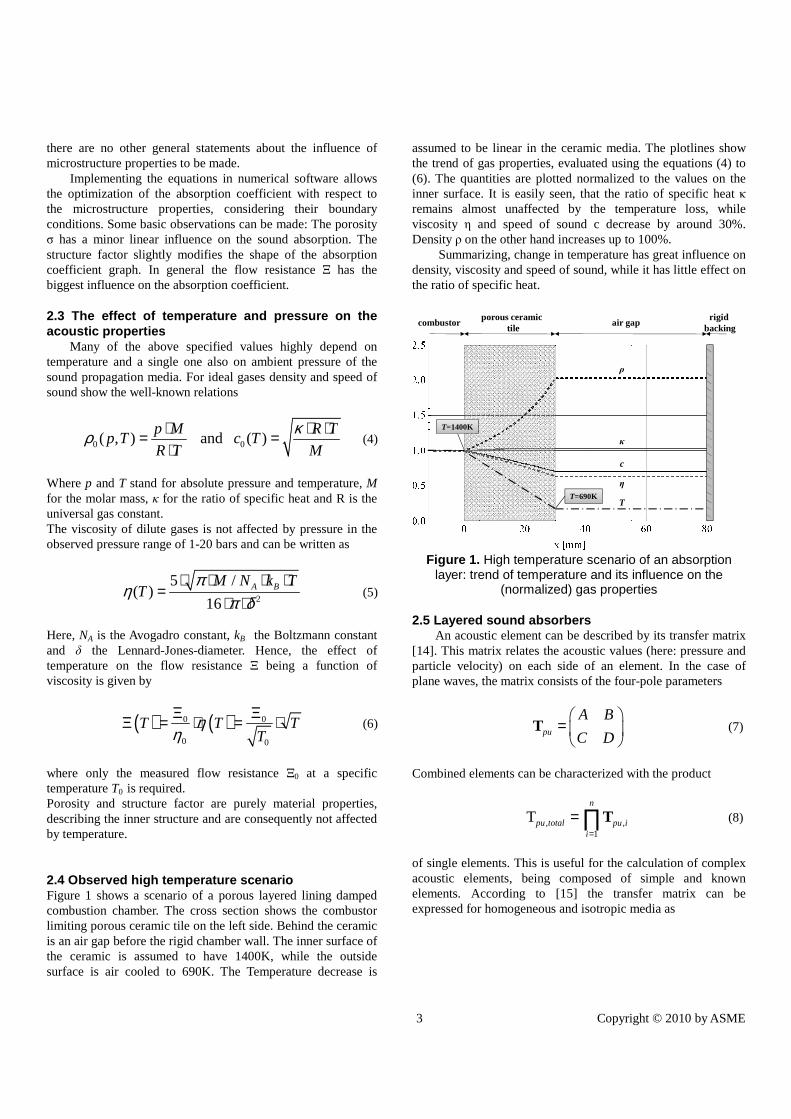
2.4 Observed high temperature scenario Figure 1 shows a scenario of a porous layered lining damped combustion chamber. The cross section shows the combustor limiting porous ceramic tile on the left side. Behind the ceramic is an air gap before the rigid chamber wall. The inner surface of the ceramic is assumed to have 1400K, while the outside surface is air cooled to 690K. The Temperature decrease is
assumed to be linear in the ceramic media. The plotlines show the trend of gas properties, evaluated using the equations (4) to (6). The quantities are plotted normalized to the values on the inner surface. It is easily seen, that the ratio of specific heat κ remains almost unaffected by the temperature loss, while viscosity η and speed of sound c decrease by around 30%. Density ρ on the other hand increases up to 100%.
Summarizing, change in temperature has great influence on density, viscosity and speed of sound, while it has little effect on the ratio of specific heat.
porous ceramictile
combustor air gaprigid
backing
T=690K
T=1400K
ρ
c
T
η
κ
Figure 1. High temperature scenario of an absorption
layer: trend of temperature and its influence on the (normalized) gas properties
2.5 Layered sound absorbers An acoustic element can be described by its transfer matrix
[14]. This matrix relates the acoustic values (here: pressure and particle velocity) on each side of an element. In the case of plane waves, the matrix consists of the four-pole parameters
pu
A B
C D
=
T (7)
Combined elements can be characterized with the product
, ,1
Tn
pu total pu ii =
= ∏T (8)
of single elements. This is useful for the calculation of complex acoustic elements, being composed of simple and known elements. According to [15] the transfer matrix can be expressed for homogeneous and isotropic media as
4 Copyright © 2010 by ASME
( ) ( )( ) ( )
cos sin
sin cosa a a
pua a a
l j l Z
j l Z l
Γ ⋅ ⋅ Γ ⋅ ⋅ = ⋅ Γ ⋅ Γ ⋅
T (9)
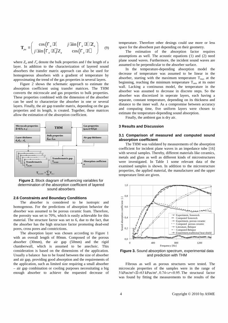
where Za and Ga denote the bulk properties and l the length of a layer. In addition to the characterization of layered sound absorbers the transfer matrix approach can also be used for homogeneous absorbers with a gradient of temperature by approximating the trend of the gas properties in several layers.
Figure 2 shows the schematic approach to estimate the absorption coefficient using transfer matrices. The THM converts the microscale and gas properties to bulk properties. These properties combined with the dimension of the absorber can be used to characterize the absorber in one or several layers. Finally, the air gap transfer matrix, depending on the gas properties and its length, is created. Together, these matrices allow the estimation of the absorption coefficient.
Microscale propertiesΞ=f(T), σ, χ THM
Bulk propertiesZabs, Γabs
TransfermatrixTpu,abs
Layer thicknessd1,d2,…dn
Gas properties(ρ,κ,c)=f(T,p)
Absorption coefficientα
TransfermatrixTpu,abs
TransfermatrixTpu,abs
TransfermatrixTpu,abs
Transfermatrix Tpu,abs
1
n
23
… Transfermatrix gapTpu,gap
Air gap thicknesst
, ,1
n
pu total pu ii=
=∑T T
Figure 2. Block diagram of influencing variables for determination of the absorption coefficient of layered
sound absorbers
2.6 Constraints and Boundary Conditions The absorber is considered to be isotropic and
homogenous. For the predictions of absorption behavior the absorber was assumed to be porous ceramic foam. Therefore, the porosity was set to 70%, which is easily achievable for this material. The structure factor was set to 6, due to the fact, that the absorber has the high structure factor promoting dead-end pores, cross pores and constrictions.
The absorption layer was chosen according to Figure 1 with an overall length of 80mm. Composed of the porous absorber (30mm), the air gap (50mm) and the rigid chamberwall, which is assumed to be anechoic. This consideration is based on the dimensions of the application. Usually a balance has to be found between the size of absorber and air gap, providing good absorption and the requirements of the application, such as limited size requiring a small absorber – air gap combination or cooling purposes necessitating a big enough absorber to achieve the requested decrease of
temperature. Therefore other desings could use more or less space for the absorbent part depending on their geometry.
The estimation of the absorption factor requires assumptions as well. The acoustic equations (1) and (2) need plane sound waves. Furthermore, the incident sound waves are assumed to be perpendicular to the absorber surface.
In the temperature-depending absorption model the decrease of temperature was assumed to be linear in the absorber, starting with the maximum temperature Tmax at the beginning, reaching the minimum temperature Tmin at its outer wall. Lacking a continuous model, the temperature in the absorber was assumed to decrease in discrete steps. So the absorber was discretized in seperate layers, each having a separate, constant temperature, depending on its thickness and distance to the inner wall. As a compromise between accuracy and computing time, five uniform layers were chosen to estimate the temperature-depending sound absorption.
Finally, the ambient gas is dry air.
3 Results and Discussion
3.1 Comparison of measured and computed sound absorption coefficient
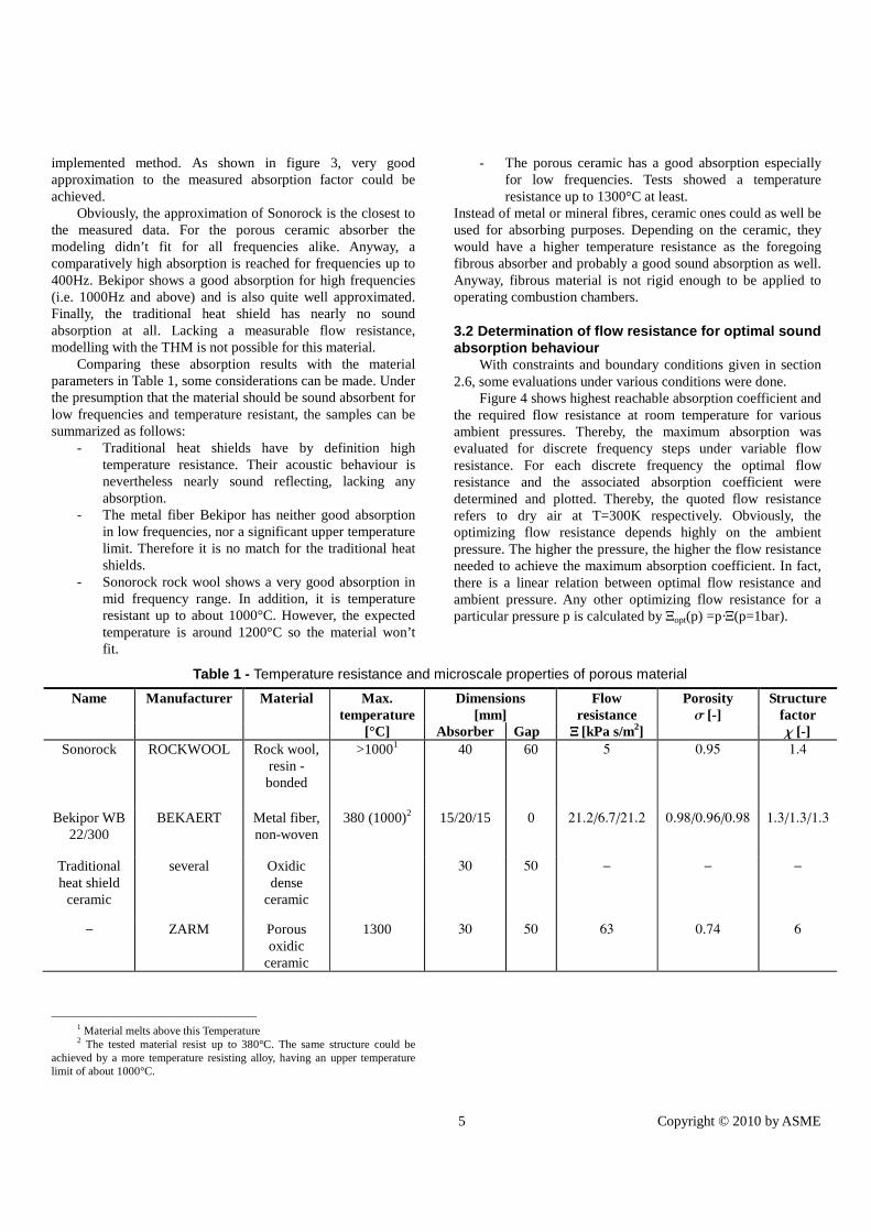
The THM was validated by measurements of the absorption coefficient for incident plane waves in an impedance tube [16] with several samples. Thereby, different materials like ceramics, metals and glass as well as different kinds of microstructures were investigated. In Table 1 some relevant data of the examined samples is shown. In addition to the microstructure properties, the applied material, the manufacturer and the upper temperature limit are given.
0,0
0,2
0,4
0,6
0,8
1,0
0 400 800 1200Frequency [Hz]
So
und
abso
rptio
n co
effic
ient
[-
]
Experiment, SonorockComputed SonorockExperiment, porous ceramicComputed porous ceramicLiterature, BekiporComputed BekiporExperiment,traditional heat shield
Figure 3. Sound absorption spectrum, experimental data
and prediction with THM Fibrous as well as porous structures were tested. The
microscale properties of the samples were in the range of 5 kPas/m²<X<63 kPas/m² , 0.74<s<0.95. The structural factor was found by fitting the measurements to the results of the
5 Copyright © 2010 by ASME
implemented method. As shown in figure 3, very good approximation to the measured absorption factor could be achieved.
Obviously, the approximation of Sonorock is the closest to the measured data. For the porous ceramic absorber the modeling didn’t fit for all frequencies alike. Anyway, a comparatively high absorption is reached for frequencies up to 400Hz. Bekipor shows a good absorption for high frequencies (i.e. 1000Hz and above) and is also quite well approximated. Finally, the traditional heat shield has nearly no sound absorption at all. Lacking a measurable flow resistance, modelling with the THM is not possible for this material.
Comparing these absorption results with the material parameters in Table 1, some considerations can be made. Under the presumption that the material should be sound absorbent for low frequencies and temperature resistant, the samples can be summarized as follows:
- Traditional heat shields have by definition high temperature resistance. Their acoustic behaviour is nevertheless nearly sound reflecting, lacking any absorption.
- The metal fiber Bekipor has neither good absorption in low frequencies, nor a significant upper temperature limit. Therefore it is no match for the traditional heat shields.
- Sonorock rock wool shows a very good absorption in mid frequency range. In addition, it is temperature resistant up to about 1000°C. However, the expected temperature is around 1200°C so the material won’t fit.
1 Material melts above this Temperature 2 The tested material resist up to 380°C. The same structure could be
achieved by a more temperature resisting alloy, having an upper temperature limit of about 1000°C.
- The porous ceramic has a good absorption especially for low frequencies. Tests showed a temperature resistance up to 1300°C at least.
Instead of metal or mineral fibres, ceramic ones could as well be used for absorbing purposes. Depending on the ceramic, they would have a higher temperature resistance as the foregoing fibrous absorber and probably a good sound absorption as well. Anyway, fibrous material is not rigid enough to be applied to operating combustion chambers.
3.2 Determination of flow resistance for optimal sound absorption behaviour
With constraints and boundary conditions given in section 2.6, some evaluations under various conditions were done.
Figure 4 shows highest reachable absorption coefficient and the required flow resistance at room temperature for various ambient pressures. Thereby, the maximum absorption was evaluated for discrete frequency steps under variable flow resistance. For each discrete frequency the optimal flow resistance and the associated absorption coefficient were determined and plotted. Thereby, the quoted flow resistance refers to dry air at T=300K respectively. Obviously, the optimizing flow resistance depends highly on the ambient pressure. The higher the pressure, the higher the flow resistance needed to achieve the maximum absorption coefficient. In fact, there is a linear relation between optimal flow resistance and ambient pressure. Any other optimizing flow resistance for a particular pressure p is calculated by Xopt(p) =p·X(p=1bar).
Table 1 - Temperature resistance and microscale properties of porous material Name Manufacturer Material Max.
temperature [°C]
Dimensions [mm]
Flow resistance X [kPa s/m2]
Porosity s [-]
Structure factor c [-] Absorber Gap
Sonorock ROCKWOOL Rock wool, resin - bonded
>10001 40 60 5 0.95 1.4
Bekipor WB 22/300
BEKAERT Metal fiber, non-woven
380 (1000)2 15/20/15 0 21.2/6.7/21.2 0.98/0.96/0.98 1.3/1.3/1.3
Traditional heat shield
ceramic
several Oxidic dense
ceramic
30 50 - - -
- ZARM Porous oxidic
ceramic
1300 30 50 63 0.74 6
6 Copyright © 2010 by ASME
00,10,20,30,40,50,60,70,80,91
050
100150200250300350400450500
0 200 400 600 800 1000 1200 1400
soun
d ab
sorp
tion
coef
fiice
nt α
[-]
flow
res
ista
nce Ξ
[kP
as/m
²]
Frequency [Hz]
Ξ, p=1bar Ξ, p=5bar Ξ, p=10bar Ξ, p=15bar α
Figure 4. Prediction of the maximum reachable
absorption coefficient and corresponding flow resistance for different pressures at T=300K, σ=0.7 and χ=6
For this reason, the maximum reachable absorption
coefficient is identical for all pressures alike. This relation is the result of the bulk property formulas (3), where the flow resistance is linked with the density, the only factor affected by pressure changes as seen in the gas property equations (4).
Figure 5 shows the optimized flow resistance with respect to the absorption coefficient for a various range of ambient temperatures.
0
0,2
0,4
0,6
0,8
1
0
20
40
60
80
100
120
0 200 400 600 800 1000 1200 1400
soun
d ab
sorp
tion
coef
fiice
nt α
[-]
flow
resi
stan
ce Ξ
[kP
as/m
²]
Frequency [Hz]
Ξ, T=300K Ξ, T=690K Ξ, T=1000K Ξ, T=1400K
α, T=300K α, T=690K α, T=1000K α, T=1400K
Figure 5. Prediction of the maximum reachable
absorption coefficient and corresponding flow resistance for different Temperatures, σ=0.7 and χ=6
As in figure 4, the optimization was done for discrete
frequency steps and the given flow resistance refers also to T=300K. While the dashed lines show the flow resistance, the solid line shows the corresponding absorption coefficient. Thereby, the absorption coefficient achieves its maximum when the flow resistance has its minimum. Obviously, the sound absorption maximum shifts for higher temperatures to higher frequencies. Therefore, achieving high sound absorption in low frequencies at high temperatures is challenging and requires comparatively low flow resistances.
0 500 1000 1500 2000-0.01
0.00
0.01
0.02
0.03
0.04
0.05
f @HzD
Abs
olut
edev
iatio
nofa@-
D
Ò layer=4
Ò layer=3
Ò layer=2
Ò layer=1
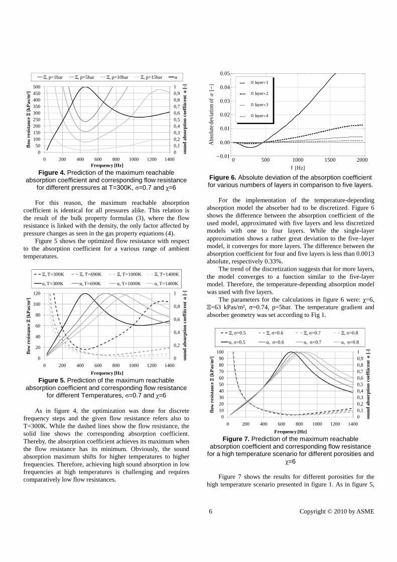
Figure 6. Absolute deviation of the absorption coefficient for various numbers of layers in comparison to five layers.
For the implementation of the temperature-depending absorption model the absorber had to be discretized. Figure 6 shows the difference between the absorption coefficient of the used model, approximated with five layers and less discretized models with one to four layers. While the single-layer approximation shows a rather great deviation to the five–layer model, it converges for more layers. The difference between the absorption coefficient for four and five layers is less than 0.0013 absolute, respectively 0.33%.
The trend of the discretization suggests that for more layers, the model converges to a function similar to the five-layer model. Therefore, the temperature-depending absorption model was used with five layers.
The parameters for the calculations in figure 6 were: χ=6, X=63 kPas/m², σ=0.74, p=5bar. The temperature gradient and absorber geometry was set according to Fig 1.
00,10,20,30,40,50,60,70,80,91
0102030405060708090
100
0 200 400 600 800 1000 1200 1400
soun
d ab
sorp
tion
coef
fiice
nt α
[-]
flow
res
ista
nce Ξ
[kP
as/m
²]
Frequency [Hz]
Ξ, σ=0.5 Ξ, σ=0.6 Ξ, σ=0.7 Ξ, σ=0.8
α, σ=0.5 α, σ=0.6 α, σ=0.7 α, σ=0.8
Figure 7. Prediction of the maximum reachable
absorption coefficient and corresponding flow resistance for a high temperature scenario for different porosities and
χ=6 Figure 7 shows the results for different porosities for the
high temperature scenario presented in figure 1. As in figure 5,
7 Copyright © 2010 by ASME
the solid lines show the maximum reachable sound absorption coefficient while the dashed lines denote the corresponding flow resistance. Obviously, there’s not much variation in the required flow resistance for different porosities. Especially for low frequencies up to 400Hz the differences are marginal. Anyway, the effect on the maximum reachable absorption coefficient α is noticeable, at least for frequencies above 400Hz. For these frequencies, low porosities achieve a maximum for lower frequencies as higher porosities. But, higher porosities achieve a higher α after reaching their maximum. However, porosity and flow resistance are not completely independent. Usually, a high porosity tends to result in a low flow resistance and vice versa. There are approaches for fibrous material, where the correlation between X and σ is suggested as X~(1-σ)1.5. Unfortunately, there are no such approaches for porous ceramics yet.
4. CONCLUSION This study discusses the use of novel sound absorbent
porous ceramic heat shields in the combustion chamber of gas turbine engines. It focuses on the sound absorption in the lower frequency range at high temperature. For this investigation the theory of homogeneous media was used for the estimation of the bulk properties of an absorber. It is shown, that this theory is well-qualified for the description of acoustic absorption for many different materials. A combination of this theory with a transfer matrix approach allows the description of multi-layered sound absorbers as well as temperature gradients across the absorber.
The investigations were executed with ceramic foams, having an open porosity between 50-80%, a structure factor of 6 and a variable flow resistance. By means of fixed absorber dimensions, the prediction of maximum reachable sound absorption and the corresponding flow resistance for different ambient pressures, temperatures and a high temperature scenario exhibiting a temperature gradient across the absorber are presented. Thereby, the prediction of the maximum reachable absorption was executed for discrete frequencies.
It was shown that the ambient pressure doesn`t affect the maximum reachable absorption. However, the corresponding flow resistance is highly affected by ambient pressure. By contrast, the reachable absorption coefficients for different temperatures vary and can’t be compensated with a variation of the flow resistance. In general, the absorption capability at low frequencies decreases with higher temperatures.
Finally, the reachable absorption coefficient for a high temperature scenario using the transfer matrix method to fulfill a temperature gradient across the absorber is presented.
NOMENCLATURE
Symbol Name Unit A Affected area [m2] c0 Speed of sound [m·s-1]
k0 Ambient wave number [m-1] kB Boltzmann constant kg·m2·s-2] l Length [m] M Molar mass [kg] NA Avogadro constant [mol−1] p Sound pressure [kg·m-1·s-2] P Sound power [kg·m2·s-3] R Universal gas constant [kg·m2·s-2·mol-1] T Absolute temperature [K] Z0 Acoustic impedance [kg·m-2·s-1] Za Specific impedance [kg·m-2·s-1] Zw Normal impedance [kg·m-2·s-1] α Absorption coefficient [-] Ga Propagation constant [m-1] δ Dissipation coefficient [-] X Flow resistance [kg·m -3·s-1] χ Structure factor [-] κ Heat capacity ratio [-] v Particle velocity [m·s-1] ω Angular frequency [s−1] p Absolute ambient pressure [kg·m-1·s-2] ρ0 Ambient density [kg·m -3] σ Volume porosity [-] ρ Reflection coefficient [-] τ Transmission coefficient [-]
ACKNOWLEDGMENTS This work was supported by the German Research
Foundation (DFG) within the Research Training Group 1375 “Non-metallic Porous Structures for Physical-Chemical Functions - PoreNet”.
REFERENCES [1] Lu, F. K., ed., 2005, Combustion Instabilities in Gas Turbine Engines - Operational Experience, Fundamental Mechanisms, and Modeling, American Institute of Aeronautics and Astronautics, Inc. , Arlington, Texas. [2] Candel, S. M., 1992, "Combustion Instabilities Coupled by Pressure Waves and Their Active Control," 24th Symposium on Combustion, pp. 1277-1296. [3] Zhao, D., and Morgans, A. S., 2009, "Tuned passive control of combustion instabilities using multiple Helmholtz resonators," Journal of Sound and Vibration, 320(4-5), pp. 744-757. [4] Tran, N., Ducruix, S., and Schuller, T., 2009, "Damping combustion instabilities with perforates at the premixer inlet of a swirled burner," Proceedings of the Combustion Institute, 32, pp. 2917-2924. [5] Studart, A. R., Gonzenbach, U. T., Tervoort, E., and Gauckler, L. J., 2006, "Processing routes to macroporous ceramics: A review," Journal of the American Ceramic Society, 89(6), pp. 1771-1789.
8 Copyright © 2010 by ASME
[6] Colombo, P., 2006, "Conventional and novel processing methods for cellular ceramics," Philosophical Transactions of the Royal Society a-Mathematical Physical and Engineering Sciences, 364(1838), pp. 109-124. [7] Cremer, L., and Müller, H. A., 1976, Die wissenschaftlichen Grundlagen der Raumakustik, Wellentheoretische Raumakustik, Hirzel Verlag, Stuttgart. [8] Cox, T. J., and D'Antonio, P., 2004, Acoustic absorbers and diffusers : theory, design, and application, Spon Press, London ; New York, NY. [9] Song, B. H., and Bolton, J. S., 2000, "A Transfer-Matrix Approach For Estimating the Characteristic Impedance and Wave Numbers of Linp and Rigid Porous Material," Journal of the Acoustic Society of America, 107(3), pp. 1131,1151. [10] Zwicker, C., and Kosten, C. W., 1949, Sound absorbing materials, Elsevier Amsterdam. [11] Mechel, F. P., 1995, Schallabsorber, Band II - Innere Schallfelder, Strukturen, S. Hirzel Verlag, Stuttgart.
[12] Albracht, F., 2004, "Metallfasern als schallabsorbierende Strukturen und als leitfähige Komponenten in Verbundwerkstoffen," Technische Universität Dresden, Dresden. [13] Giese, F., Eigenbrod, C., and Koch, D., 2010, "A Novel Production Method for Porous Sound Absorbing Ceramic," International Journal of Applied Ceramic Technology. [14] Munjal, M. L., 1987, Acoustic of Ducts and Mufflers, Wiley-Interscience, New York. [15] Tao, Z., Herrin, D. W., and Seybert, A. F., 2003, "Measuring Bulk Properties of Sound-Absorbing Materials using the Two-Source Method," SAE Noise and Vibration Conference and ExpositionTraverse City. [16] ASTM, 1998, "Standard Test Method for Impedance and Absorption of Acoustical Materials Using Tube, Two Microphones and A Digital Frequency Analysis System," E 1050-98, American Society for Testing and Materials.
Copyright © 2022 FDOKUMEN


![Index Abbreviations, 1.4.2.1.[A] Absorbent materials ...](https://static.fdokumen.com/doc/165x107/632130edaa6c954bc707258c/index-abbreviations-1421a-absorbent-materials-.jpg)