On the generation of aerosol for diesel particulate filtration studies
15
Separation and Purification Technology 27 (2002) 195 – 209 On the generation of aerosol for diesel particulate filtration studies Michele Ambrogio a , Guido Saracco a, *, Vito Specchia a , Coen van Gulijk b , Michiel Makkee b , J.A. Moulijn b a Dipartimento di Scienza dei Materiali ed Ingegneria Chimica, Politecnico di Torino, Corso Duca degli Abruzzi 24, 10129 Turin, Italy b Section of Industrial Catalysis, Uniersity of Technology Delft, Julianalaan 136, Delft, Netherlands Received 21 June 2001; received in revised form 2 August 2001; accepted 5 August 2001 Abstract The three different ways for the generation of carbon particulate aerosols were considered to simulate the exhaust gases of the latest-generation Common-Rail Diesel engines for vehicle application: a small Diesel engine for electric power generation modules, an acetylene burner, and an ad hoc designed ‘fluidised bed’ pilot plant. The final goal of this work is to develop a simple and reliable apparatus to improve the knowledge of the filtration mechanisms for different particulate traps, avoiding the need to build-up large and expensive Diesel engine benches. The particles shape, their composition and size distribution have been assessed to compare the aerosols generated by the three pilot plants with those typical of the modern Common-Rail Diesel engines for passenger cars. Ceramic foam filters are finally employed as a common reference to check whether the filtration results obtained with the particles produced by such pilot plants are representative of those determined with their large-scale counterpart or not. © 2002 Elsevier Science B.V. All rights reserved. Keywords: Diesel soot; Aerosol generation; Acetylene flame; Filter; Size distribution www.elsevier.com/locate/seppur 1. Contents of the paper This paper concerns with the comparison be- tween different pilot plants for the generation of soot-based aerosols. The aim of this work is to show how different set-ups like a small Diesel engine for power applications, an acetylene burner and a small fluidised bed pilot plant can be used to feed benches for the particulate filtration study purposes. The evaluation of the characteris- tics necessary to develop a suitable pilot plant was performed by analysing the soot concentration, the soot chemical composition and its size distribution. 2. Introduction The continuous penetration of Diesel engines in the passenger-cars market is mainly due to their * Corresponding author. Tel.: +39-11-564-4654; fax: +39- 11-564-4699. E-mail address: [email protected] (G. Saracco). 1383-5866/02/$ - see front matter © 2002 Elsevier Science B.V. All rights reserved. PII: S1383-5866(01)00182-4
-
Upload
independent -
Category
Documents
-
view
2 -
download
0
Transcript of On the generation of aerosol for diesel particulate filtration studies
Separation and Purification Technology 27 (2002) 195–209
On the generation of aerosol for diesel particulate filtrationstudies
Michele Ambrogio a, Guido Saracco a,*, Vito Specchia a, Coen van Gulijk b,Michiel Makkee b, J.A. Moulijn b
a Dipartimento di Scienza dei Materiali ed Ingegneria Chimica, Politecnico di Torino, Corso Duca degli Abruzzi 24,10129 Turin, Italy
b Section of Industrial Catalysis, Uni�ersity of Technology Delft, Julianalaan 136, Delft, Netherlands
Received 21 June 2001; received in revised form 2 August 2001; accepted 5 August 2001
Abstract
The three different ways for the generation of carbon particulate aerosols were considered to simulate the exhaustgases of the latest-generation Common-Rail Diesel engines for vehicle application: a small Diesel engine for electricpower generation modules, an acetylene burner, and an ad hoc designed ‘fluidised bed’ pilot plant. The final goal ofthis work is to develop a simple and reliable apparatus to improve the knowledge of the filtration mechanisms fordifferent particulate traps, avoiding the need to build-up large and expensive Diesel engine benches. The particlesshape, their composition and size distribution have been assessed to compare the aerosols generated by the three pilotplants with those typical of the modern Common-Rail Diesel engines for passenger cars. Ceramic foam filters arefinally employed as a common reference to check whether the filtration results obtained with the particles producedby such pilot plants are representative of those determined with their large-scale counterpart or not. © 2002 ElsevierScience B.V. All rights reserved.
Keywords: Diesel soot; Aerosol generation; Acetylene flame; Filter; Size distribution
www.elsevier.com/locate/seppur
1. Contents of the paper
This paper concerns with the comparison be-tween different pilot plants for the generation ofsoot-based aerosols. The aim of this work is toshow how different set-ups like a small Dieselengine for power applications, an acetyleneburner and a small fluidised bed pilot plant can be
used to feed benches for the particulate filtrationstudy purposes. The evaluation of the characteris-tics necessary to develop a suitable pilot plant wasperformed by analysing the soot concentration,the soot chemical composition and its sizedistribution.
2. Introduction
The continuous penetration of Diesel engines inthe passenger-cars market is mainly due to their
* Corresponding author. Tel.: +39-11-564-4654; fax: +39-11-564-4699.
E-mail address: [email protected] (G. Saracco).
1383-5866/02/$ - see front matter © 2002 Elsevier Science B.V. All rights reserved.
PII: S1383-5866(01)00182-4
M. Ambrogio et al. / Separation and Purification Technology 27 (2002) 195–209196
good efficiency (higher than 30% for the lastgeneration, direct-injection, turbocharged,Common-Rail version) and to their low fuel cost.Further, the noise, typical of such engines, hasbeen markedly reduced during the recent years,thereby achieving a good comfort level. Thiscontinuous market growth has entailed adverseeffects on the public health and environment ofhighly populated areas. In this last context, howthe small carbonaceous particles (PM 10) andNOx concentrations have reached higher andhigher levels mainly because of Diesel enginesemissions has been observed.
Soot generation is related to incomplete fueloxidation, due to local substoichiometric condit-ions in the combustion chamber. Particulateemissions are made up of a mixture of carbonnuclei carrying sulphates, heavy metal oxides andadsorbed hydrocarbons. Some of suchhydrocarbons, belonging to the polyaromaticclass, possess the well-known mutagenic effects[1]. The governments of many Countries arelowering their emission standards for the vehiclesand the power plants equipped with such engines.Particularly 2005 US and European legislationwill be very stringent [2] and will require serioustechnological breakthroughs to meet the fixed
NOx and particulate outlet concentrations.Although some automotive manufacturers haveannounced that it will be possible to achieve theimposed emissions levels [3] with a furtherdevelopment of the Common-Rail injectionsystem, it looks like that this will likely occur onlywith the engines characterised by the smallestdisplacement. As admitted by many enginemanufacturers, further improvements in thecombustion chamber design and in thefuel-injection system management will not becompletely sufficient to allow every class of theseengines to respect the 2005 emission standards. Asa consequence, an innovative exhaust-gasafter-treatment system will be needed.
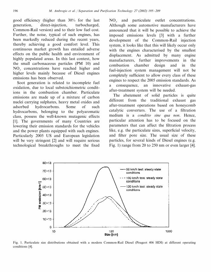
The abatement of solid particles is quitedifferent from the traditional exhaust gasafter-treatment operations based on honeycombcatalytic converters. The use of a filtrationmedium is a conditio sine qua non. Hence,particular attention has to be focused on theparameters that can affect the filtration processlike, e.g. the particulate sizes, superficial velocity,and filter pore size. The usual size of theseparticles, for several kinds of Diesel engines (e.g.Fig. 1) range from 20 to 250 nm or even larger [4].
Fig. 1. Particulate size distributions obtained with a modern Common-Rail Diesel (Peugeot 406 HDI) at different operatingconditions [4].
M. Ambrogio et al. / Separation and Purification Technology 27 (2002) 195–209 197
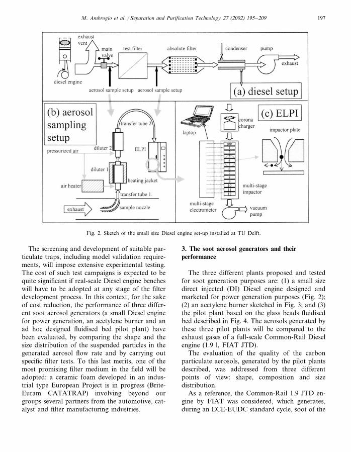
Fig. 2. Sketch of the small size Diesel engine set-up installed at TU Delft.
The screening and development of suitable par-ticulate traps, including model validation require-ments, will impose extensive experimental testing.The cost of such test campaigns is expected to bequite significant if real-scale Diesel engine bencheswill have to be adopted at any stage of the filterdevelopment process. In this context, for the sakeof cost reduction, the performance of three differ-ent soot aerosol generators (a small Diesel enginefor power generation, an acetylene burner and anad hoc designed fluidised bed pilot plant) havebeen evaluated, by comparing the shape and thesize distribution of the suspended particles in thegenerated aerosol flow rate and by carrying outspecific filter tests. To this last merits, one of themost promising filter medium in the field will beadopted: a ceramic foam developed in an indus-trial type European Project is in progress (Brite-Euram CATATRAP) involving beyond ourgroups several partners from the automotive, cat-alyst and filter manufacturing industries.
3. The soot aerosol generators and theirperformance
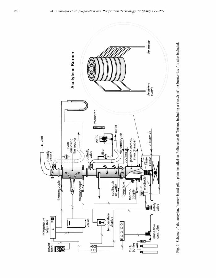
The three different plants proposed and testedfor soot generation purposes are: (1) a small sizedirect injected (DI) Diesel engine designed andmarketed for power generation purposes (Fig. 2);(2) an acetylene burner sketched in Fig. 3; and (3)the pilot plant based on the glass beads fluidisedbed described in Fig. 4. The aerosols generated bythese three pilot plants will be compared to theexhaust gases of a full-scale Common-Rail Dieselengine (1.9 l, FIAT JTD).
The evaluation of the quality of the carbonparticulate aerosols, generated by the pilot plantsdescribed, was addressed from three differentpoints of view: shape, composition and sizedistribution.
As a reference, the Common-Rail 1.9 JTD en-gine by FIAT was considered, which generates,during an ECE-EUDC standard cycle, soot of the
M. Ambrogio et al. / Separation and Purification Technology 27 (2002) 195–209198
Fig
.3.
Sche
me
ofth
eac
etyl
ene-
burn
er-b
ased
pilo
tpl
ant
inst
alle
dat
Pol
itec
nico
diT
orin
o,in
clud
ing
ask
etch
ofth
ebu
rner
itse
lfis
also
incl
uded
.
M. Ambrogio et al. / Separation and Purification Technology 27 (2002) 195–209 199
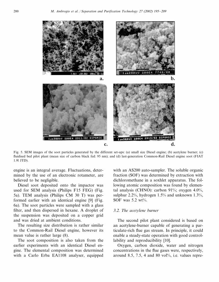
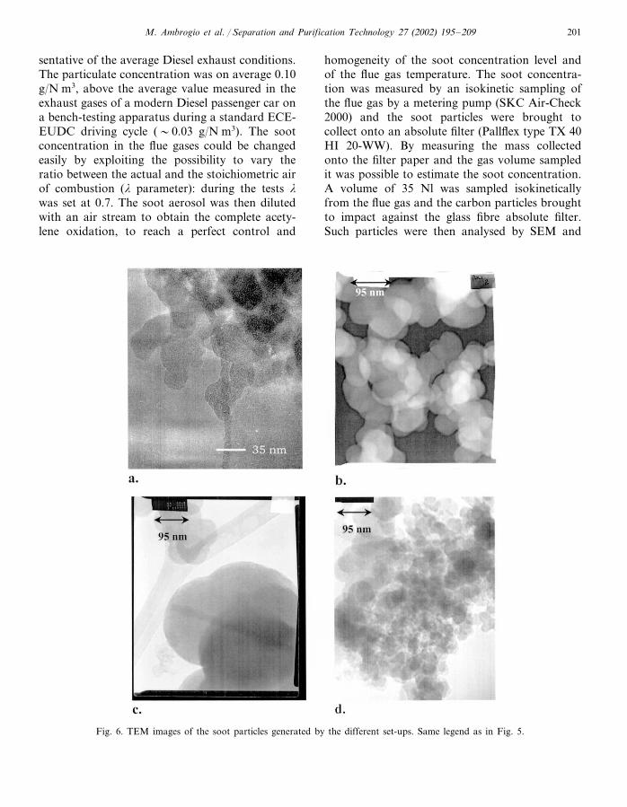
following composition: 1.3% lube oil metals, 7.8%adsorbed and condensed unburned hydrocarbons,0.5% sulphates and 90.4% carbon. As for theparticulate shape and size distribution see theelectron microscope micrographs in Figs. 5d, 6d,and 1, respectively. It is worth emphasising thatthe basic soot particles are rather small (20 nm onaverage, Fig. 6d) with a remarkable tendency toagglomeration (Figs. 1 and 5d).
3.1. The small Diesel engine for power generation
The first experimental set-up is shown in Fig. 2.Its three major components are: DI Diesel bench,the aerosol sampling apparatus and the electricallow-pressure impactor or ELPI (Dekati Ltd). Theset-up is used for filter efficiency measurementsbut it can also be used for the characterisation ofcatalytic filters [5].
The Diesel bench consists of four major parts.The first part is the Diesel engine, a 900 ccLyster–Petter LPW-2 (5.7 kW) operating at 50%load. It is installed as a reproducible Diesel sootgenerator. The second part is the test filter sectionwhere the trap can be placed for filtration effi-ciency measurements. The third part is the abso-lute filter: a Corning EX-80 wall-flow monolithinstalled to protect the downstream equipmentfrom soot penetration. The amount of soot in thispart can be determined by controlled regenera-tion, combustion and measuring the CO and CO2
content of the outlet gas with a non-dispersiveinfrared analyser (NDIR, Uras 10 E by Hart-mann and Braun). The fourth part is the pump(NKF-Verder membrane vacuum pump) used todraw a constant flow of exhaust gas through thetest filter. The pump flow is regulated with anelectronic rotameter (Brooks MT-3809), an elec-tronic gas-valve (Kammer 20037-I/P-PN400), anda PID controller (West 6100).
The aerosol sampling set-up concept is basedon an earlier paper by Joutsensaari et al. [6], whoused it for the aerosol measurement of stackgases. It is a two-step dilution system where thefirst diluter is operated at sample gas temperature,to avoid the condensation of water, and the sec-ond diluter is at ambient temperature. The di-luters (Dekati diluters, Dekati Ltd) are of theejector type diluters [7]. Both have a dilutionfactor of 7 so the total dilution factor is about 50.The entire aerosol-sampling set-up is made ofstainless steel and grounded. Table 1 shows moredetails on the aerosol sampling set-up.
The ELPI (Dekati Ltd) is the last major com-ponent. It is a sensitive instrument for measuringthe concentration of the aerosol particles, sizesand size distributions. When the particles enterthe ELPI they get charged by a positive coronaeffect. Subsequently, they are classified in 12 sizeranges by 12 impactor stages of low-pressure im-paction. The current through the impactor stagesis measured with sensitive electrometers. A cali-bration curve is used to calculate the concentra-tions of the aerosol that enters the ELPI. Adetailed description is given by Keskinen et al. [8].Owing the particulate sampling method, the parti-cle size distribution obtained for the small Diesel
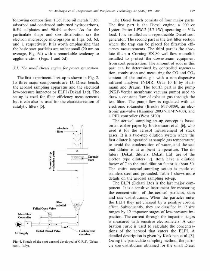
Fig. 4. Sketch of the soot aerosol developed at C.R.F. (Orbas-sano, Italy).
M. Ambrogio et al. / Separation and Purification Technology 27 (2002) 195–209200
Fig. 5. SEM images of the soot particles generated by the different set-ups: (a) small size Diesel engine; (b) acetylene burner; (c)fluidised bed pilot plant (mean size of carbon black fed: 95 nm); and (d) last-generation Common-Rail Diesel engine soot (FIAT1.9l JTD).
engine is an integral average. Fluctuations, deter-mined by the use of an electronic rotameter, arebelieved to be negligible.
Diesel soot deposited onto the impactor wasused for SEM analysis (Philips F15 FEG) (Fig.5a). TEM analysis (Philips CM 30 T) was per-formed earlier with an identical engine [9] (Fig.6a). The soot particles were sampled with a glassfilter, and then dispersed in hexane. A droplet ofthe suspension was deposited on a copper gridand was dried at ambient conditions.
The resulting size distribution is rather similarto the Common-Rail Diesel engine, however itsmean value is rather large (8).
The soot composition is also taken from theearlier experiments with an identical Diesel en-gine. The elemental composition was determinedwith a Carlo Erba EA1108 analyser, equipped
with an AS200 auto-sampler. The soluble organicfraction (SOF) was determined by extraction withdichloromethane in a soxhlet apparatus. The fol-lowing atomic composition was found by elemen-tal analysis (CHNO): carbon 91%; oxygen 4.0%,sulphur 2.2%, hydrogen 1.5% and unknown 1.3%,SOF was 5.2 wt%.
3.2. The acetylene burner
The second pilot plant considered is based onan acetylene-burner capable of generating a par-ticulate-rich flue gas stream. In principle, it couldenable a steady-state operation with good control-lability and reproducibility [10].
Oxygen, carbon dioxide, water and nitrogenconcentrations in the flue gases were, respectively,around 8.5, 7.5, 4 and 80 vol%, i.e. values repre-
M. Ambrogio et al. / Separation and Purification Technology 27 (2002) 195–209 201
sentative of the average Diesel exhaust conditions.The particulate concentration was on average 0.10g/N m3, above the average value measured in theexhaust gases of a modern Diesel passenger car ona bench-testing apparatus during a standard ECE-EUDC driving cycle (�0.03 g/N m3). The sootconcentration in the flue gases could be changedeasily by exploiting the possibility to vary theratio between the actual and the stoichiometric airof combustion (� parameter): during the tests �
was set at 0.7. The soot aerosol was then dilutedwith an air stream to obtain the complete acety-lene oxidation, to reach a perfect control and
homogeneity of the soot concentration level andof the flue gas temperature. The soot concentra-tion was measured by an isokinetic sampling ofthe flue gas by a metering pump (SKC Air-Check2000) and the soot particles were brought tocollect onto an absolute filter (Pallflex type TX 40HI 20-WW). By measuring the mass collectedonto the filter paper and the gas volume sampledit was possible to estimate the soot concentration.A volume of 35 Nl was sampled isokineticallyfrom the flue gas and the carbon particles broughtto impact against the glass fibre absolute filter.Such particles were then analysed by SEM and
Fig. 6. TEM images of the soot particles generated by the different set-ups. Same legend as in Fig. 5.
M. Ambrogio et al. / Separation and Purification Technology 27 (2002) 195–209202
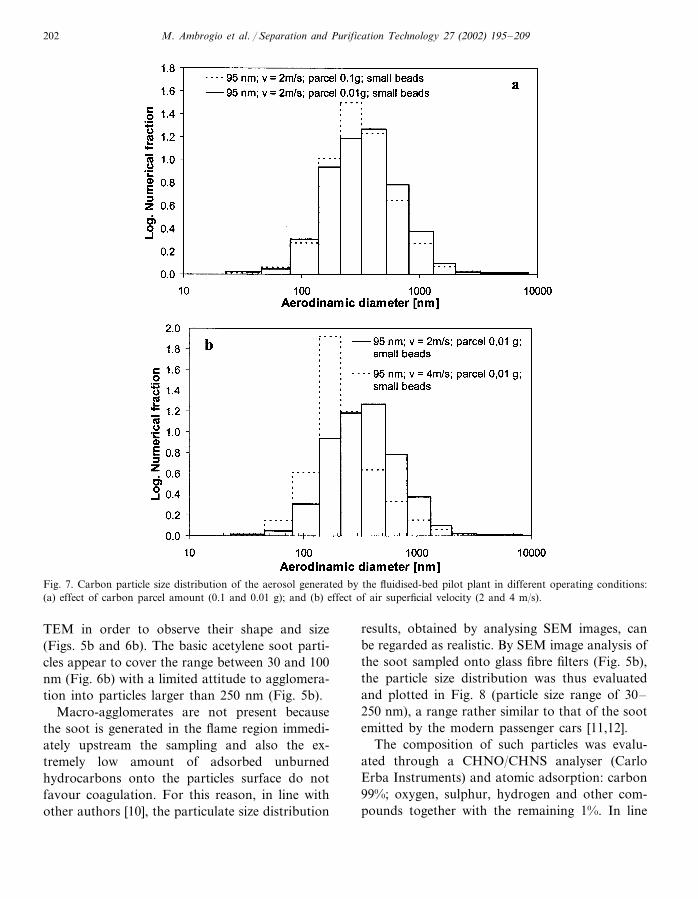
Fig. 7. Carbon particle size distribution of the aerosol generated by the fluidised-bed pilot plant in different operating conditions:(a) effect of carbon parcel amount (0.1 and 0.01 g); and (b) effect of air superficial velocity (2 and 4 m/s).
TEM in order to observe their shape and size(Figs. 5b and 6b). The basic acetylene soot parti-cles appear to cover the range between 30 and 100nm (Fig. 6b) with a limited attitude to agglomera-tion into particles larger than 250 nm (Fig. 5b).
Macro-agglomerates are not present becausethe soot is generated in the flame region immedi-ately upstream the sampling and also the ex-tremely low amount of adsorbed unburnedhydrocarbons onto the particles surface do notfavour coagulation. For this reason, in line withother authors [10], the particulate size distribution
results, obtained by analysing SEM images, canbe regarded as realistic. By SEM image analysis ofthe soot sampled onto glass fibre filters (Fig. 5b),the particle size distribution was thus evaluatedand plotted in Fig. 8 (particle size range of 30–250 nm), a range rather similar to that of the sootemitted by the modern passenger cars [11,12].
The composition of such particles was evalu-ated through a CHNO/CHNS analyser (CarloErba Instruments) and atomic adsorption: carbon99%; oxygen, sulphur, hydrogen and other com-pounds together with the remaining 1%. In line
M. Ambrogio et al. / Separation and Purification Technology 27 (2002) 195–209 203
with Ref. [10], this corresponds to an almost ‘dry’soot, i.e. with a negligible amount of SOF.
3.3. The fluidised bed pilot plant
The fluidised bed pilot plant is described in Fig.4. With this apparatus, it is easily possible, inprinciple, to control many parameters that couldinfluence the filtration performance of the filtermedium, e.g. the nature of the carbon particles,superficial velocity, carbon particles concentra-tion, and their size distribution.
Downstream the soot feed chamber, in accor-dance with the recent studies [13], a divergentcone, hosting a fluidised bed of glass beads, wasplaced with the aim of obtaining a homogeneousdispersion of the carbon particles into the air flowand avoid the occurrence of air jets localisedalong the axis. The presence of the divergent coneand the possibility to change the amount and thesize of the glass beads enabled the possibility tomaintain easily a steady fluidisation at differentair flow rates.
The carbon-black particles are fed to the sootfeed chamber and hereafter entrained by an airstream. The dispersion of such particles is inducedwhen the normally closed valve is opened andsimultaneously the other valve, normally open, isclosed. By these means, the soot concentrationand the particle size could be tentatively con-trolled by using different carbon weight parcelsand particle sizes. The air flow rate could also beset at different values by means of a mass flow
controller located upstream the carbon feedchamber. It was thus possible to study the trapcollecting properties with different superficial ve-locities thereby assessing the role of this parame-ter on the filtration efficiency.
The filter seat was located between the twoports to which the pressure sensors were con-nected. The upstream port has also been used tomeasure the size distribution of the generatedaerosol using the ELPI analyser (see Section 3.1).
Downstream the filter seat an absolute filterpaper was placed to collect all the particles notblocked by the tested trap. The filtration efficiencycould be evaluated by comparing the mass ofcarbon black deposited onto the filter trap withthat collected in the absolute filter paper. Themass of carbon particles that reached the firstfilter was lower than that of the parcel carried inthe carbon feed chamber. This is due to electro-static phenomena that could bring a fraction ofparticles (near 30% by mass) to deposit along theplastic pilot plant inside walls.
The carbon black particles of 95 nm averagediameter (Degussa O) are considered rather repre-sentative of the mean size of the Diesel sootparticulate; so most investigations are focusedusing this kind of carbon black (Fig. 6c). Theshape of all these particles is rather similar to asphere (Fig. 6c) with an undoubted tendency toagglomerate into particle aggregates (Fig. 5c). Thepresence of large agglomerates at the filter inletlocation is in fact expected to unrealistically en-hance the measured filtration efficiency.
Table 1Diesel engine for power generation: characteristics of the sample set-up
Length (cm) NotesFunction Temperature(°C)
To sample raw exhaustSample tube 150–2005 Ratio of curvature �710 150–200Transport to 1st diluter1st Transfer Heated by sample air
tubeDilution air at 200 °C20030To lower vapour pressure and aerosol1st Diluter
concentration30Same as 1st, including cooling Dilution air at ambient2nd Diluter Ambient
temperature150Transport to ELPI2nd Transfer Ratio of curvature �100Ambient
tube

M. Ambrogio et al. / Separation and Purification Technology 27 (2002) 195–209204
Fig. 8. Comparison of the particulate size distribution of Common-Rail Diesel engine and those obtained with the three pilot plants:small Diesel engine (superficial velocity 2 m/s); acetylene burner (superficial velocity: 2 m/s) and fluidised bed pilot plant(carbon-black size: 95 nm; superficial velocity: 2 m/s; 0.01 g parcel; small beads).
The resulting size distribution, measured byELPI in the standard operating conditions (car-bon black parcel 0.01 g, average particle size 95nm, superficial velocity over the filter surface 2m/s), is enlightened in Fig. 8. Further, whether thecarbon particle agglomerates fed to the system insuch conditions could be broken to obtain aparticle size distribution comparable to the Com-mon-Rail engines ones by (i) the interaction be-tween the aerosol particles themselves and/or by(ii) the drag forces generated by the shear stressdue to the air turbulence it had to be checked.With the aim to check if the particles agglomer-ates are broken by the above-mentioned twomechanisms, different tests have been carried outwith different carbon parcels (0.01 and 0.1 g), anddifferent air velocities (2 and 4 m/s). The results ofthese tests are shown in Fig. 8a and b,respectively.
The last parameter analysed was the composi-tion of the carbon particles used with this appara-tus. As indicated by the manufacturer (Degussa)the composition of the carbon particles was: car-bon 97.5%, hydrogen 0.75%, oxygen 0.35%, nitro-
gen 0.35%, sulphur 0.55% and ashes 0.5%. TheSOF was rather limited. However, a qualifyingfeature of the plant lies in the possibility tochange the type of carbon employed.
4. Filtration test procedure and results
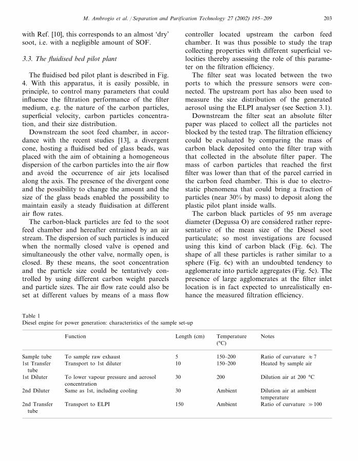
In order to evaluate the filtration behaviour ofthese aerosols some tests have been carried outwith a ceramic foam filter in comparable operat-ing conditions for each set-up. The foam filter wasrealised at Centro Ricerche Fiat (Orbassano,Italy) by the impregnation of polyurethane foamwith ceramic slurry. After impregnation, thepolyurethane foam is burned bringing the struc-ture at 400 °C and then heating it up to thesintering temperature (�1600 °C) with a rate of5 °C/min. This way, it is possible to obtain agood control on the structural filter propertiesconcerning the porosity, the pore density, etc. Themicrostructure of a ceramic foam filter is shownin Fig. 9. The foam filters were realised in cylin-drical shape (diameter 50 mm; thickness 17 mm)
M. Ambrogio et al. / Separation and Purification Technology 27 (2002) 195–209 205
and with a pore density of 50 p.p.i. (pores perinch) by using Zirconia-Toughened-Alumina(ZTA) powder precursors. The pore size distribu-tion of the foam cannot be measured by conven-tional Hg porosimetry since the pore size is toolarge. An idea of such a distribution was obtainedfrom the direct observation of the microstructure(Fig. 9).
The filtration tests were performed in compara-ble operating conditions. The superficial velocityfor each apparatus (the large-scale Common-RailDiesel engine, the small DI Diesel engine bench,the acetylene burner and the fluidised bed pilotplant) was kept at about 4 m/s.
The filtration efficiency for the large-scale Com-mon-Rail Diesel engine and for the acetyleneburner was measured by the weighting methodusing absolute filters. The sampling procedure wascarried out upstream and downstream the ceramicfoam filter; hence, by comparing the two collectedsoot masses, the filtration efficiency was calcu-lated. As for the power generator set-up, the sootmass was determined by a slow oxidation of thesoot in the absolute filter, and simultaneouslymeasuring the CO and CO2 content in the outletgas with the NDIR. The gas flux in these lastmeasurements was kept equal to 1.25 l/min, en-abling an easy calculation of the collected mass ofthe soot particles. The filtration efficiency is deter-mined by considering the measured soot amountwith and without the ceramic foam filter.
The evaluation of the fluidised bed pilot plantfiltration efficiency was conversely measured ac-cording the following expression:
The results obtained for each set-up are listed inTable 2.
Fig. 9. SEM image of a ceramic foam microstructure (courtesyof C.R.F., Orbassano, Italy).
5. Discussion
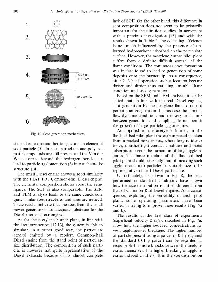
As a common reference for the discussion ofthe results presented, it seems convenient to recallthe typical Diesel particle formation mechanisms[14]. Such mechanisms, enlightened in Fig. 10, canbe divided into six steps. According to step (1),the fuel is reformed into aromatic compounds; asa consequence the fuel hydrogen content becomespoorer and poorer. These aromatic compounds(2) can react together to form some polyaromaticsubstances: the carbon–hydrogen ratio becomeshigher and higher. The polyaromatic compounds(3) then generate some flat micro-cells in whichhydrogen is almost absent. Hence, such carbon
flat structures (4) bond themselves in a graphite-like lattice. These micro-structures are then
Filtration efficiency=Mass collected into foam filter
Mass collected into foam filter+Mass collected into absolute filter
Table 2Filtration results obtained with the same foam filter installed in different pilot plants
Fluidised pilot plantAcetylene burnerSmall diesel Common-Rail Diesel engineengine
Gravimetric filtration efficiency (%) 80�10 38�1037.5�1.5 45�5
Superficial velocity 4 m/s.
M. Ambrogio et al. / Separation and Purification Technology 27 (2002) 195–209206
Fig. 10. Soot generation mechanisms.
lack of SOF. On the other hand, this difference insoot composition does not seem to be primarilyimportant for the filtration studies. In agreementwith a previous investigation [15] and with theresults shown in Table 2, the collecting efficiencyis not much influenced by the presence of un-burned hydrocarbons adsorbed on the particulatesurface. However, the acetylene burner pilot plantsuffers from a definite difficult control of theflame conditions. The continuous soot formationwas in fact found to lead to generation of somedeposits onto the burner tip. As a consequence,after 2–3 h of operation such a location becamedirtier and dirtier thus entailing unstable flamecondition and soot generation.
Based on the SEM and TEM analysis, it can bestated that, in line with the real Diesel engines,soot generation by the acetylene flame does notpermit soot coagulation. In this case the laminarflow dynamic conditions and the very small timebetween generation and sampling, do not permitthe growth of large particle agglomerates.
As opposed to the acetylene burner, in thefluidised bed pilot plant the carbon parcel is takenfrom a packed powder box, where long residencetimes, a rather tight contact condition and moistadsorption favour the formation of large agglom-erates. The basic mandate of the fluidised bedpilot plant should be exactly that of breaking suchagglomerates into particles of suitable size to berepresentative of real Diesel particulate.
Unfortunately, as shown in Fig. 8, the testsperformed in standard conditions have shownhow the size distribution is rather different fromthat of Common-Rail Diesel engines. As a conse-quence, exploiting the versatility of such pilotplant, some operating parameters have beenvaried in trying to improve these results (Fig. 7aand b).
The results of the first class of experiments(superficial velocity 2 m/s), sketched in Fig. 7a,show how the higher soot-fed concentrations fa-vour agglomerates breakage. The higher numberof particle present using a parcel of 0.1 g (againstthe standard 0.01 g parcel) can be regarded asresponsible for more knocks between the agglom-erates themselves. The higher breaking of agglom-erates induced a little shift in the size distribution
stacked onto one another to generate an elementalsoot particle (5). In such particles some polyaro-matic compounds are still present and the Van derWaals forces, beyond the hydrogen bonds, canlead to particle agglomeration (6) into a chain-likestructure [14].
The small Diesel engine shows a good similaritywith the FIAT 1.9 l Common-Rail Diesel engine.The elemental composition shows about the samefigures. The SOF is also comparable. The SEMand TEM analysis leads to the same conclusion:quite similar soot structures and sizes are noticed.These results indicate that the soot from the smallpower generator is an adequate substitute for theDiesel soot of a car engine.
As for the acetylene burner plant, in line withthe literature source [12,13], the system is able tosimulate, in a rather good way, the particulateaerosol emitted by a modern Common-RailDiesel engine from the stand point of particulatesize distribution. The composition of such parti-cles is however not quite representative of theDiesel exhausts because of its almost complete

M. Ambrogio et al. / Separation and Purification Technology 27 (2002) 195–209 207
towards the smaller particle size classes. Unfortu-nately, by using the described experimental set-up,it was not possible to enhance the carbon particlesconcentration further for measuring reasons. Theuse of higher carbon parcels leads in part to aneasy overloading of the ELPI analyser as well asto quite unrealistic particle concentration per unitgas volume.
Conversely, the effect of air velocity (Fig. 7b) issurely higher than that of the carbon fed amountdiscussed before in approaching the size distribu-tion typical of a Common-Rail Diesel engine.This occurrence can perhaps be attributed to thecombined effect of:� drag forces generated by the air flow eddies [16];� increased frequency of inter particle collisions
due to the enhancement of the velocity field.However, this combined phenomenon could not
allow reducing the average particle size of thegenerated aerosol below 200–250 nm, which re-mains markedly higher than that of Common-RailDiesel engine.
The filtration test results, reported in Table 2
show that the filtration efficiency of the singlefoam filter employed is not excellent, but, proba-bly, by assembling a modular filter, composed ofseveral foam disks in series, more satisfying resultscould be achieved. The higher filtration efficiencyvalues measured using the fluidised bed pilot plantcan be explained easily by analysing the size distri-bution of the aerosol in which the presence oflarger particles is much more evident. In this case,because of the agglomerates present, the meandiameter and the size dispersion values are higherthan those of the other pilot plants. As a conse-quence the higher filtration efficiency is due to thelarger dimension of the agglomerates that impactonto the foam. These particles, in fact, are respon-sible for higher filtration efficiency due tothe inertial impaction mechanism and, becauseof their high weight, contribute to the totalmass collected. Therefore, in the actual set up,the fluidised bed pilot plant does not appear tobe very useful in simulating the aerosol generatedby the last generation Common-Rail Dieselengine. Conversely, the other set-ups are able to
Table 3Pilot plant characteristics: −, bad; −/+, sufficient; +/−, average; +, good; ++, excellent
System Cost Possibility to performRepresenting the diesel RepresentativeEasy variation ofparameters affecting long-term runs particulate compositionsoot size of the modernfiltrationengine
++++ ++− ++Common-RailDiesel engine
++ + c−/+Small DI + a + b
Diesel enginebench
+ + a −/+ d − e +/− cAcetyleneburner
− a + f‘Fluidised’ bed −/+ g++ ++ h
pilot plant
a See Fig. 8.b Superficial velocity can be easily varied, temperature and soot concentration range is limited and these parameters can hardly
be varied independently.c See Section 3.d Superficial velocity, temperature and soot concentration can be varied only in the limited range and not independently.e Burner tip gets dirty in 2–3 h.f Superficial velocity and soot concentration can be varied independently. Temperature is not representative of Diesel exhausts’
conditions.g Large amounts of particulate can be fed to simulate long-term runs but not in a continuous way, by discrete steps only.h Real Common-Rail Diesel engine soot can be employed.

M. Ambrogio et al. / Separation and Purification Technology 27 (2002) 195–209208
generate particle-rich gas streams, quite similarto the full-scale Common-Rail Diesel engines.
The prevalent results of this investigation arequalitatively summarised in Table 3.
The small Diesel engine shows a good similar-ity with the Common-Rail Diesel engine. Theelemental composition, the SOF, the particle sizeand structure were found to be indeed rathersimilar. These results indicate that the soot fromthe small power generator is an adequate substi-tute for the Diesel soot of a car-engine. Further,by using a side stream of the exhaust system incombination with a pump, controlling the su-perficial velocity, one of the affecting filtrationparameters, seems to be easy. However, usingsuch device, it is not easy to control the sootconcentration and the flue gas temperature.Moreover, non-steady-state operating conditions,representative of the frequent load/rpm changestypical of on-road driving can be easily accom-plished with this apparatus by means of an ade-quate control strategy.
An acetylene burner has been assembled toavoid the troubles concerning the possible con-densation of non-carbonaceous particles. Thewater and unburned hydrocarbons fractions arein fact lower than a real Diesel engine; as aconsequence their condensation and sulphatesformation did not affect the measurements much.However, the necessity of dilution to keep thetemperature under tolerable levels cannot be ne-glected. The air–acetylene flame conditions, us-ing such apparatus, could change during the testsbringing the soot concentration at non-stable val-ues in the long term. This is due to the continu-ous deposit of some carbonaceous particles onthe burner surface. In any case, the soot sizedistribution is quite similar to the Common-RailDiesel engine case and also their particle shapeand the size distribution are not very different.This pilot plant shows a good level of reproduci-bility in the short-term tests.
Finally, a fluidised pilot plant has been re-alised with the aim of simulating the Diesel en-gine exhaust flue gas. The shape and compositionof the carbon could be quite similar to the Dieselsoot (the same Common-Rail Diesel soot can befed into the plant); the size distribution is rather
different and, therefore, not completely suitableto generate an aerosol for Diesel particulatefiltration studies. If, with some modifications, itwill be possible to restore the particle size distri-bution until the advent of the modern Dieselengines then this device could be useful for thepurpose of filtration studies because it allows usto control all the parameters affecting the filtra-tion mechanisms. However the temperature influ-ence cannot be observed using this apparatus.
6. Conclusions
Three different pilot plants for simulating thesoot aerosol of a Common-Rail car engine weretested and compared in order to study filtrationefficiencies. The three apparatuses were: a realsmall DI Diesel engine in a power generator, anacetylene burner, and an ad hoc designedfluidised bed pilot plant in which the aerosol isgenerated by the dispersion of a carbon parcelinto the air stream. The aim of this work was tofind a cost-effective pilot plant suitable for Dieselparticulate filtration studies. Particle shape, com-position and size distribution were considered asthe main characterising parameters.
By analysing the performance offered by eachplant it seems that the results that can beachieved are strictly linked to the cost of theaerosol generator. However, perhaps the bestcompromise between the cost and the technicalperformance is offered by the small DI Dieselengine bench.
References
[1] E.S. Lox, B.H. Engler, E. Koberstein, in: A. Crucq (Ed.),Diesel Emission Control in Catalysis and AutomotivePollution Control II, Elsevier, Amsterdam, 1991, p. 291.
[2] www.dieselnet.com (web site).[3] O. Salvat, P. Marez, G. Belot, Passenger Car Serial
Application of a Particulate Filter System on a Common-Rail Direct Injection Diesel Engine, SAE Paper 2000-01-0437, 2000.
[4] Ch. Rigaudeau, G. Belot, Influence of fuel sulphur on theformation of ultrafine particulates in diesel, Third Inter-national ETH-Workshop on Nanoparticle Measurement,Zurich, August 1999.
M. Ambrogio et al. / Separation and Purification Technology 27 (2002) 195–209 209
[5] B.A.A.L. van Setten, M. Makkee, J.A. Moulijn, MoltenSalts supported on Ceramic Foam in the Potential Appli-cation of a Diesel Soot Abatement Technology, SAE2001-01-0905, 2001.
[6] J. Joutsensaari, E.I. Kauppinen, P. Ahonen, T.M. Lind,S.I. Yalatalo, J.K. Joneniemi, J. Hautanen, M. Kilpel-lainen, J. Aerosol. Sci. 23 (Suppl. 1) (1992) S241.
[7] W. Koch, H. Lodding W, Molter and Munzinger Staub-Reinhaltung der Luft 48 (1988) 341.
[8] J. Keskinnen, K. Pietarinen, M. Lehtmaki, J. Aerosol.Sci. 234 (1992) 353.
[9] W.C. Hinds, Aerosol Technology, Wiley, New York,1992.
[10] K.H. Homan, H.G. Wagner, Ber. Bunsen. 69 (1965) 20.[11] D.P. Moon, J.R. Donald, UK Research Programme on
the Characterisation of Vehicle Particulate Emissions,September 1997 Report, 90pp.
[12] W. Koch, G. Pohlmann, Characterization of nanoparti-cles from different sources: Diesel engines, welding fumes,environment, chemical reactions, Third InternationalETH-Workshop on Nanoparticles measurement, Zurich,August 1999.
[13] M. Olazar, M.J. San Jose, E. Cepeda, R. Ortiz de laTierro, J. Bilbao, Hydrodinamics of Fine Solids in Coni-cal Spouted Beds, Fluidization VIII, 1995, p. 197.
[14] G. Panciroli, Il nero di carbonio, Cabot Italiana InternalReport, 1989.
[15] M. Ambrogio, G. Saracco, V. Specchia, Chem. Eng. Sci.56 (2001) 1613.
[16] J.O. Hinze, Turbulence, McGraw-Hill, New York, 1975.