On the design of power gear trains: Insight regarding number ...
13
RESEARCH ARTICLE On the design of power gear trains: Insight regarding number of stages and their respective ratios Harrison L. Bartlett*, Brian E. Lawson, Michael Goldfarb Department of Mechanical Engineering, Vanderbilt University, Nashville, TN, United States of America * [email protected] Abstract This paper presents a formulation for selecting the stage ratios and number of stages in a multistage transmission with a given desired total transmission ratio in a manner that maxi- mizes efficiency, maximizes acceleration, or minimizes the mass of the transmission. The formulation is used to highlight several implications for gear train design, including the fact that minimizing rotational inertia and mass are competing objectives with respect to optimal selection of stage ratios, and that both rotational inertia and mass can often be minimized by increasing the total number of stages beyond a minimum realizable number. Additionally, a multistage transmission will generally provide maximum acceleration when the stage ratios increase monotonically from the motor to the load. The transmission will have minimum mass when the stage ratios decrease monotonically. The transmission will also provide maximum efficiency when the corresponding stages employ constant stage ratios. This paper aims to use this optimization formulation to elucidate tradeoffs between various com- mon objectives in gear train design (efficiency, acceleration, and mass). Introduction Electric motors are commonly employed to actuate drive systems, but generally provide power in a high speed, low torque power regime relative to the drive applications they are intended to actuate. In order to address this disparity, gear transmissions are commonly employed to transform the high speed, low torque output power of the motor to the requisite higher torque, lower speed power regime of the drive system. Such gear transmissions are commonly of the multistage [1, 2] or planetary types [3, 4]. This paper describes methods of optimally selecting gear trains of the multistage type. Drive systems with large transmission ratios (e.g., on the order of 100:1) are common in modern electric motor-driven machines. Such transmissions are typically split into multiple stages for the purposes of efficient packaging and practical con- straints on transmission size. When considering the design of a multistage transmission of a given overall transmission ratio, a designer must determine the most appropriate number of stages, and the stage ratio associated with each. This paper considers the problem of selecting number of stages, and stage ratios, from the perspective of either maximizing transmission effi- ciency, maximizing rotational acceleration capabilities, or minimizing mass. PLOS ONE | https://doi.org/10.1371/journal.pone.0198048 June 1, 2018 1 / 13 a1111111111 a1111111111 a1111111111 a1111111111 a1111111111 OPEN ACCESS Citation: Bartlett HL, Lawson BE, Goldfarb M (2018) On the design of power gear trains: Insight regarding number of stages and their respective ratios. PLoS ONE 13(6): e0198048. https://doi.org/ 10.1371/journal.pone.0198048 Editor: Xiaosong Hu, Chongqing University, CHINA Received: March 14, 2018 Accepted: May 12, 2018 Published: June 1, 2018 Copyright: © 2018 Bartlett et al. This is an open access article distributed under the terms of the Creative Commons Attribution License, which permits unrestricted use, distribution, and reproduction in any medium, provided the original author and source are credited. Data Availability Statement: All relevant data are within the paper and its Supporting Information files. Funding: This material is based upon work supported by the National Science Foundation Graduate Research Fellowship Program under Grant Number 1445197. The funders had no role in study design, data collection and analysis, decision to publish, or preparation of the manuscript. Competing interests: The authors have declared that no competing interests exist.
-
Upload
khangminh22 -
Category
Documents
-
view
0 -
download
0
Transcript of On the design of power gear trains: Insight regarding number ...
RESEARCH ARTICLE
On the design of power gear trains: Insight
regarding number of stages and their
respective ratios
Harrison L. Bartlett*, Brian E. Lawson, Michael Goldfarb
Department of Mechanical Engineering, Vanderbilt University, Nashville, TN, United States of America
Abstract
This paper presents a formulation for selecting the stage ratios and number of stages in a
multistage transmission with a given desired total transmission ratio in a manner that maxi-
mizes efficiency, maximizes acceleration, or minimizes the mass of the transmission. The
formulation is used to highlight several implications for gear train design, including the fact
that minimizing rotational inertia and mass are competing objectives with respect to optimal
selection of stage ratios, and that both rotational inertia and mass can often be minimized by
increasing the total number of stages beyond a minimum realizable number. Additionally, a
multistage transmission will generally provide maximum acceleration when the stage ratios
increase monotonically from the motor to the load. The transmission will have minimum
mass when the stage ratios decrease monotonically. The transmission will also provide
maximum efficiency when the corresponding stages employ constant stage ratios. This
paper aims to use this optimization formulation to elucidate tradeoffs between various com-
mon objectives in gear train design (efficiency, acceleration, and mass).
Introduction
Electric motors are commonly employed to actuate drive systems, but generally provide power
in a high speed, low torque power regime relative to the drive applications they are intended to
actuate. In order to address this disparity, gear transmissions are commonly employed to
transform the high speed, low torque output power of the motor to the requisite higher torque,
lower speed power regime of the drive system. Such gear transmissions are commonly of the
multistage [1, 2] or planetary types [3, 4]. This paper describes methods of optimally selecting
gear trains of the multistage type. Drive systems with large transmission ratios (e.g., on the
order of 100:1) are common in modern electric motor-driven machines. Such transmissions
are typically split into multiple stages for the purposes of efficient packaging and practical con-
straints on transmission size. When considering the design of a multistage transmission of a
given overall transmission ratio, a designer must determine the most appropriate number of
stages, and the stage ratio associated with each. This paper considers the problem of selecting
number of stages, and stage ratios, from the perspective of either maximizing transmission effi-
ciency, maximizing rotational acceleration capabilities, or minimizing mass.
PLOS ONE | https://doi.org/10.1371/journal.pone.0198048 June 1, 2018 1 / 13
a1111111111
a1111111111
a1111111111
a1111111111
a1111111111
OPENACCESS
Citation: Bartlett HL, Lawson BE, Goldfarb M
(2018) On the design of power gear trains: Insight
regarding number of stages and their respective
ratios. PLoS ONE 13(6): e0198048. https://doi.org/
10.1371/journal.pone.0198048
Editor: Xiaosong Hu, Chongqing University, CHINA
Received: March 14, 2018
Accepted: May 12, 2018
Published: June 1, 2018
Copyright: © 2018 Bartlett et al. This is an open
access article distributed under the terms of the
Creative Commons Attribution License, which
permits unrestricted use, distribution, and
reproduction in any medium, provided the original
author and source are credited.
Data Availability Statement: All relevant data are
within the paper and its Supporting Information
files.
Funding: This material is based upon work
supported by the National Science Foundation
Graduate Research Fellowship Program under
Grant Number 1445197. The funders had no role in
study design, data collection and analysis, decision
to publish, or preparation of the manuscript.
Competing interests: The authors have declared
that no competing interests exist.
The general objective of optimal gear transmission design is not new–various approaches
have been presented by others previously, such as those described in [1, 2, 5–25]. Of the works
most relevant to this paper, among the earliest is [1], in which the authors minimized the rota-
tional inertia reflected onto the motor shaft of a two-stage transmission with a pre-specified
total transmission ratio, using the assumption of size-invariant pinions for each stage. The
optimal stage ratios for multistage transmissions with more than two stages was also presented
in that paper, although in a graphical manner. An iterative, numerical method for optimizing
multistage transmissions with respect to minimizing transmission rotational inertia was pre-
sented in [2, 6, 8]. Numerical multi-criterion optimization methods for transmissions were
also presented in [9–16], which consider objective functions such as gear train volume and effi-
ciency. Various optimization algorithms have also been described for the problem of choosing
stage ratios of a gear train in which each gear is constrained to have a predetermined number
of teeth [17, 18]. In terms of selecting the number of stages in a gear train, [2] provides an ana-
lytical solution for the number of stages that should be chosen to minimize the reflected inertia
of a transmission.
This paper presents a formulation for the design of a multistage gear train that selects stage
ratios in a manner that maximizes transmission efficiency, maximizes rotational acceleration,
or minimizes mass for a given desired total transmission ratio. The problem is formulated as a
constrained multivariate optimization problem for any number of stages n, and can be used
with a wide variety of stage scaling criteria. The scaling criterion employed in this manuscript
is intended for power gear trains, and, as a result, is derived to provide constant tooth stress
across the stages. In addition to presenting optimal stage ratio formulations, the paper de-
scribes some implications of these formulations with respect to gear train design, specifically
with respect to how these performance characteristics relate to number of stages and variation
in stage ratios.
Unlike prior related works [1–23], this paper provides formulations for the optimal effi-
ciency, acceleration, and mass, respectively, as a function of number of stages and stage ratios,
for a given total transmission ratio. The authors note that, this paper also provides a topologi-
cal context for the solution presented in [2]. Specifically, [2] does not provide information
regarding the local curvature around the optimal solution, and thus does not provide informa-
tion regarding the sensitivity of the optimal solution as a function of the number of stages.
Without this information, a designer is unable to assess the trade-offs entailed in a sub-optimal
solution, which is of fundamental importance in the design process. In fact, the relevant objec-
tive function, as constructed herein, is quite flat around the optimal solution for most applica-
tions, and as such, employing the solution presented in [2], although mathematically correct,
would often result in an infeasibly large number of stages. By examining the topology of the
objective function, the (maximum rotational acceleration) solution presented here enables a
more knowledgeable selection of stages, which can provide near-optimal performance in a fea-
sible transmission configuration. This paper additionally examines the optimal design of gear
trains with respect to multiple different objective functions, and subsequently illustrates the
inherent tradeoff between mass and inertia in the gear train design process. This work allows a
designer to select gear train parameters with knowledge of how design decisions might affect
multiple design objectives.
Formulation
Let n be the number of stages in a transmission with a total transmission ratio (i.e., reduction
ratio) of N:1, and let the respective stage ratio, si, be the transmission ratio corresponding to
the ith stage of the transmission (where the stage index i increases from the motor to the load).
Multistage gear train optimization
PLOS ONE | https://doi.org/10.1371/journal.pone.0198048 June 1, 2018 2 / 13
The n stage ratios must multiply to equal the total desired transmission ratio N, as expressed
by the following constraint equation:
Yn
i¼1
si
!
� N ¼ 0 ð1Þ
In the following sections, expressions for the transmission efficiency, maximum achievable
acceleration, and transmission mass are developed as functions of the stage ratios. A represen-
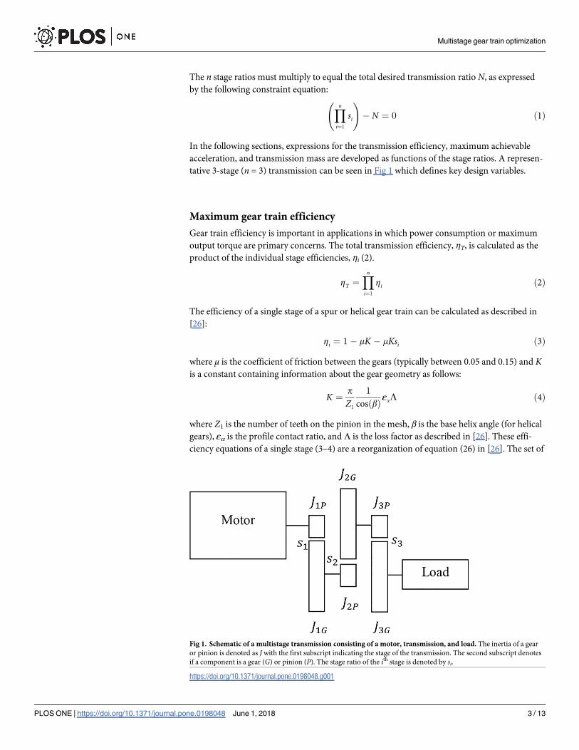
tative 3-stage (n = 3) transmission can be seen in Fig 1 which defines key design variables.
Maximum gear train efficiency
Gear train efficiency is important in applications in which power consumption or maximum
output torque are primary concerns. The total transmission efficiency, ηT, is calculated as the
product of the individual stage efficiencies, ηi (2).
ZT ¼Yn
i¼1
Zi ð2Þ
The efficiency of a single stage of a spur or helical gear train can be calculated as described in
[26]:
Zi ¼ 1 � mK � mKsi ð3Þ
where μ is the coefficient of friction between the gears (typically between 0.05 and 0.15) and Kis a constant containing information about the gear geometry as follows:
K ¼p
Z1
1
cosðbÞεaL ð4Þ
where Z1 is the number of teeth on the pinion in the mesh, β is the base helix angle (for helical
gears), εα is the profile contact ratio, and Λ is the loss factor as described in [26]. These effi-
ciency equations of a single stage (3–4) are a reorganization of equation (26) in [26]. The set of
Fig 1. Schematic of a multistage transmission consisting of a motor, transmission, and load. The inertia of a gear
or pinion is denoted as J with the first subscript indicating the stage of the transmission. The second subscript denotes
if a component is a gear (G) or pinion (P). The stage ratio of the ith stage is denoted by si.
https://doi.org/10.1371/journal.pone.0198048.g001
Multistage gear train optimization
PLOS ONE | https://doi.org/10.1371/journal.pone.0198048 June 1, 2018 3 / 13
si that maximizes (2), subject to the constraint (1), will provide the maximum possible effi-
ciency for the multistage transmission.
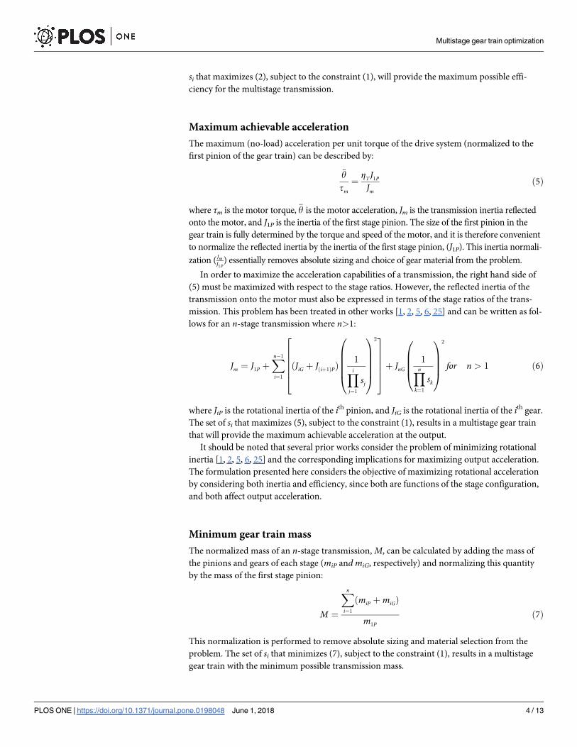
Maximum achievable acceleration
The maximum (no-load) acceleration per unit torque of the drive system (normalized to the
first pinion of the gear train) can be described by:
€y
tm¼
ZTJ1P
Jmð5Þ
where τm is the motor torque, €y is the motor acceleration, Jm is the transmission inertia reflected
onto the motor, and J1P is the inertia of the first stage pinion. The size of the first pinion in the
gear train is fully determined by the torque and speed of the motor, and it is therefore convenient
to normalize the reflected inertia by the inertia of the first stage pinion, (J1P). This inertia normali-
zation (JmJ1P
) essentially removes absolute sizing and choice of gear material from the problem.
In order to maximize the acceleration capabilities of a transmission, the right hand side of
(5) must be maximized with respect to the stage ratios. However, the reflected inertia of the
transmission onto the motor must also be expressed in terms of the stage ratios of the trans-
mission. This problem has been treated in other works [1, 2, 5, 6, 25] and can be written as fol-
lows for an n-stage transmission where n>1:
Jm ¼ J1P þXn� 1
i¼1
ðJiG þ Jðiþ1ÞPÞ1
Yi
j¼1
sj
0
BBBB@
1
CCCCA
22
66664
3
77775þ JnG
1
Yn
k¼1
sk
0
BBB@
1
CCCA
2
for n > 1 ð6Þ
where JiP is the rotational inertia of the ith pinion, and JiG is the rotational inertia of the ith gear.
The set of si that maximizes (5), subject to the constraint (1), results in a multistage gear train
that will provide the maximum achievable acceleration at the output.
It should be noted that several prior works consider the problem of minimizing rotational
inertia [1, 2, 5, 6, 25] and the corresponding implications for maximizing output acceleration.
The formulation presented here considers the objective of maximizing rotational acceleration
by considering both inertia and efficiency, since both are functions of the stage configuration,
and both affect output acceleration.
Minimum gear train mass
The normalized mass of an n-stage transmission, M, can be calculated by adding the mass of
the pinions and gears of each stage (miP and miG, respectively) and normalizing this quantity
by the mass of the first stage pinion:
M ¼
Xn
i¼1
ðmiP þmiGÞ
m1Pð7Þ
This normalization is performed to remove absolute sizing and material selection from the
problem. The set of si that minimizes (7), subject to the constraint (1), results in a multistage
gear train with the minimum possible transmission mass.
Multistage gear train optimization
PLOS ONE | https://doi.org/10.1371/journal.pone.0198048 June 1, 2018 4 / 13
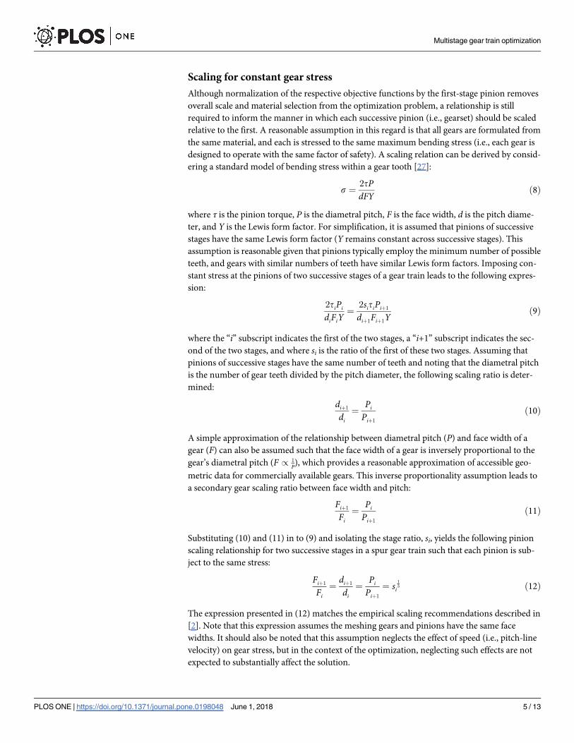
Scaling for constant gear stress
Although normalization of the respective objective functions by the first-stage pinion removes
overall scale and material selection from the optimization problem, a relationship is still
required to inform the manner in which each successive pinion (i.e., gearset) should be scaled
relative to the first. A reasonable assumption in this regard is that all gears are formulated from
the same material, and each is stressed to the same maximum bending stress (i.e., each gear is
designed to operate with the same factor of safety). A scaling relation can be derived by consid-
ering a standard model of bending stress within a gear tooth [27]:
s ¼2tPdFY
ð8Þ
where τ is the pinion torque, P is the diametral pitch, F is the face width, d is the pitch diame-
ter, and Y is the Lewis form factor. For simplification, it is assumed that pinions of successive
stages have the same Lewis form factor (Y remains constant across successive stages). This
assumption is reasonable given that pinions typically employ the minimum number of possible
teeth, and gears with similar numbers of teeth have similar Lewis form factors. Imposing con-
stant stress at the pinions of two successive stages of a gear train leads to the following expres-
sion:
2tiPi
diFiY¼
2sitiPiþ1
diþ1Fiþ1Yð9Þ
where the “i” subscript indicates the first of the two stages, a “i+1” subscript indicates the sec-
ond of the two stages, and where si is the ratio of the first of these two stages. Assuming that
pinions of successive stages have the same number of teeth and noting that the diametral pitch
is the number of gear teeth divided by the pitch diameter, the following scaling ratio is deter-
mined:
diþ1
di¼
Pi
Piþ1
ð10Þ
A simple approximation of the relationship between diametral pitch (P) and face width of a
gear (F) can also be assumed such that the face width of a gear is inversely proportional to the
gear’s diametral pitch (F / 1
P), which provides a reasonable approximation of accessible geo-
metric data for commercially available gears. This inverse proportionality assumption leads to
a secondary gear scaling ratio between face width and pitch:
Fiþ1
Fi¼
Pi
Piþ1
ð11Þ
Substituting (10) and (11) in to (9) and isolating the stage ratio, si, yields the following pinion
scaling relationship for two successive stages in a spur gear train such that each pinion is sub-
ject to the same stress:
Fiþ1
Fi¼
diþ1
di¼
Pi
Piþ1
¼ si13 ð12Þ
The expression presented in (12) matches the empirical scaling recommendations described in
[2]. Note that this expression assumes the meshing gears and pinions have the same face
widths. It should also be noted that this assumption neglects the effect of speed (i.e., pitch-line
velocity) on gear stress, but in the context of the optimization, neglecting such effects are not
expected to substantially affect the solution.
Multistage gear train optimization
PLOS ONE | https://doi.org/10.1371/journal.pone.0198048 June 1, 2018 5 / 13
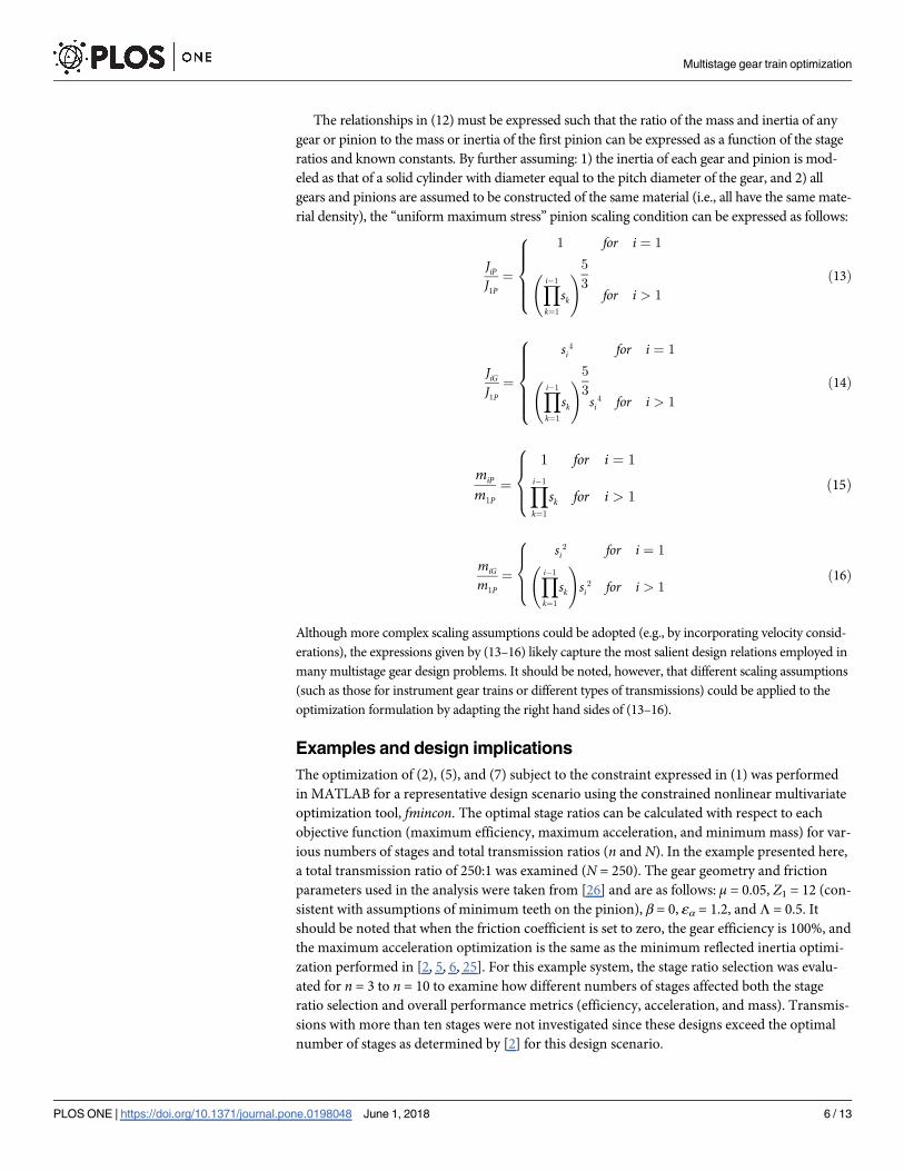
The relationships in (12) must be expressed such that the ratio of the mass and inertia of any
gear or pinion to the mass or inertia of the first pinion can be expressed as a function of the stage
ratios and known constants. By further assuming: 1) the inertia of each gear and pinion is mod-
eled as that of a solid cylinder with diameter equal to the pitch diameter of the gear, and 2) all
gears and pinions are assumed to be constructed of the same material (i.e., all have the same mate-
rial density), the “uniform maximum stress” pinion scaling condition can be expressed as follows:
JiP
J1P¼
1 for i ¼ 1
Yi� 1
k¼1
sk
!5
3for i > 1
ð13Þ
8>>><
>>>:
JiG
J1P¼
si4 for i ¼ 1
Yi� 1
k¼1
sk
!5
3si
4 for i > 1
ð14Þ
8>>>><
>>>>:
miP
m1P¼
(1 for i ¼ 1
Yi� 1
k¼1
sk for i > 1ð15Þ
miG
m1P¼
(si
2 for i ¼ 1
Yi� 1
k¼1
sk
!
si2 for i > 1
ð16Þ
Although more complex scaling assumptions could be adopted (e.g., by incorporating velocity consid-
erations), the expressions given by (13–16) likely capture the most salient design relations employed in
many multistage gear design problems. It should be noted, however, that different scaling assumptions
(such as those for instrument gear trains or different types of transmissions) could be applied to the
optimization formulation by adapting the right hand sides of (13–16).
Examples and design implications
The optimization of (2), (5), and (7) subject to the constraint expressed in (1) was performed
in MATLAB for a representative design scenario using the constrained nonlinear multivariate
optimization tool, fmincon. The optimal stage ratios can be calculated with respect to each
objective function (maximum efficiency, maximum acceleration, and minimum mass) for var-
ious numbers of stages and total transmission ratios (n and N). In the example presented here,
a total transmission ratio of 250:1 was examined (N = 250). The gear geometry and friction
parameters used in the analysis were taken from [26] and are as follows: μ = 0.05, Z1 = 12 (con-
sistent with assumptions of minimum teeth on the pinion), β = 0, εα = 1.2, and Λ = 0.5. It
should be noted that when the friction coefficient is set to zero, the gear efficiency is 100%, and
the maximum acceleration optimization is the same as the minimum reflected inertia optimi-
zation performed in [2, 5, 6, 25]. For this example system, the stage ratio selection was evalu-
ated for n = 3 to n = 10 to examine how different numbers of stages affected both the stage
ratio selection and overall performance metrics (efficiency, acceleration, and mass). Transmis-
sions with more than ten stages were not investigated since these designs exceed the optimal
number of stages as determined by [2] for this design scenario.
Multistage gear train optimization
PLOS ONE | https://doi.org/10.1371/journal.pone.0198048 June 1, 2018 6 / 13
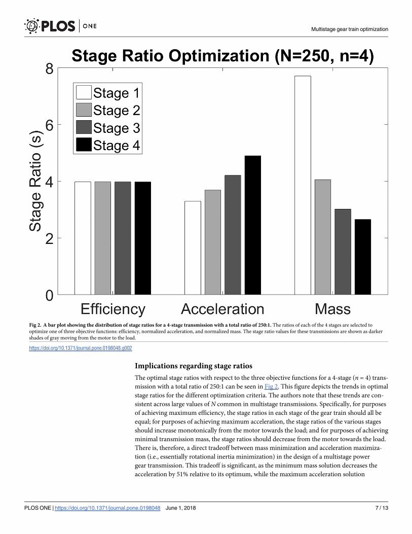
Implications regarding stage ratios
The optimal stage ratios with respect to the three objective functions for a 4-stage (n = 4) trans-
mission with a total ratio of 250:1 can be seen in Fig 2. This figure depicts the trends in optimal
stage ratios for the different optimization criteria. The authors note that these trends are con-
sistent across large values of N common in multistage transmissions. Specifically, for purposes
of achieving maximum efficiency, the stage ratios in each stage of the gear train should all be
equal; for purposes of achieving maximum acceleration, the stage ratios of the various stages
should increase monotonically from the motor towards the load; and for purposes of achieving
minimal transmission mass, the stage ratios should decrease from the motor towards the load.
There is, therefore, a direct tradeoff between mass minimization and acceleration maximiza-
tion (i.e., essentially rotational inertia minimization) in the design of a multistage power
gear transmission. This tradeoff is significant, as the minimum mass solution decreases the
acceleration by 51% relative to its optimum, while the maximum acceleration solution
Fig 2. A bar plot showing the distribution of stage ratios for a 4-stage transmission with a total ratio of 250:1. The ratios of each of the 4 stages are selected to
optimize one of three objective functions: efficiency, normalized acceleration, and normalized mass. The stage ratio values for these transmissions are shown as darker
shades of gray moving from the motor to the load.
https://doi.org/10.1371/journal.pone.0198048.g002
Multistage gear train optimization
PLOS ONE | https://doi.org/10.1371/journal.pone.0198048 June 1, 2018 7 / 13
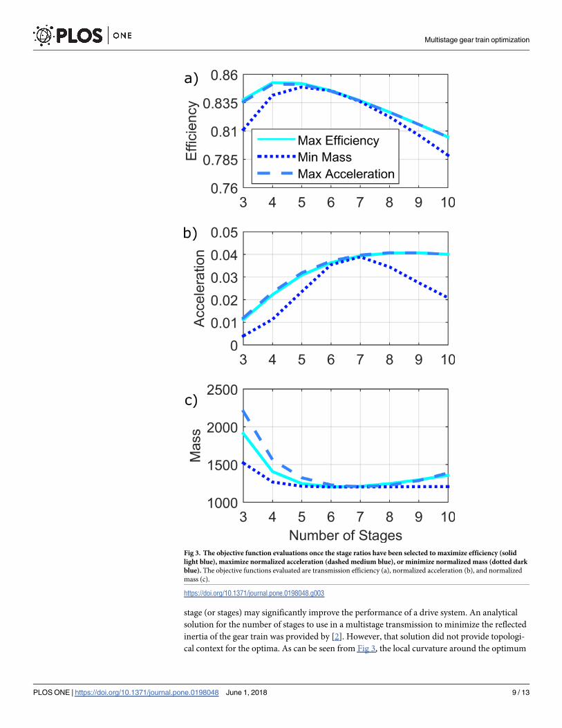
increases the mass by 19% relative to its optimum, for the case (n = 4, N = 250) considered
here.
Implications regarding number of stages
For a desired total ratio of 250:1, stage ratios were optimized with respect to the three objective
functions (efficiency, acceleration, and mass) for various values of n (3�n�10), and the effi-
ciency, normalized acceleration capability, and normalized mass of the resulting transmissions
were then calculated using (2), (5), and (7), respectively. The results of this analysis can be seen
plotted against the number of stages in Fig 3. The transmissions optimized for efficiency, accel-
eration, and mass are plotted in solid light blue, dashed medium blue, and dotted dark blue
respectively. This analysis lends insight into the selection of the number of stages in a transmis-
sion. Specifically, as can be seen in Fig 3A, the efficiency of the various transmissions peak at
approximately 4–5 stages. The transmissions designed to maximize efficiency obtain higher
efficiencies than the ones optimized for acceleration and mass, but the difference between the
overall efficiency values is not substantial. In fact, the range of transmission efficiency obtain-
able by varying the number of stages in the transmission is also very small (approximately 6%
change in efficiency from n = 3 to n = 10).
Fig 3B shows how the normalized acceleration properties vary with the number of stages in
the transmission. As can be seen, adding additional stages to the transmission significantly
increases the acceleration capabilities of the system up to a point, but an upper limit exists in
all cases. In this example, the acceleration capabilities increase rapidly from 3 to 4 stages, but
the performance increases become less significant as more stages are added. In fact, the local
curvature of this objective function around the maxima (n = 8) is relatively flat, indicating that
a designer could choose significantly fewer than the optimal number of stages without substan-
tially compromising maximum acceleration.
Fig 3C shows that adding additional stages to a transmission can significantly decrease its
mass, up to a point. It should be noted that the local curvature of Fig 3C is relatively flat around
its minima (n = 6), but relatively steep between 3 and 5 stages indicating that the most of the
improvements that can be made in terms of minimizing mass can be done with fewer than 6
stages. It should also be noted that when the stage ratios are selected to minimize mass, the
transmission mass is significantly less than if the stage ratios are selected to maximize either of
the other two objective functions, particularly for 3 or 4 stage transmissions.
It is important to note that when optimizing the stage ratios for efficiency, acceleration, or mass,
the same general trends hold with respect to the number of stages in Fig 3A–3C. This indicates
that the selection of the number of stages of a transmission has a larger effect on the performance
metrics treated here than does the selection of the individual stage ratios of the transmission.
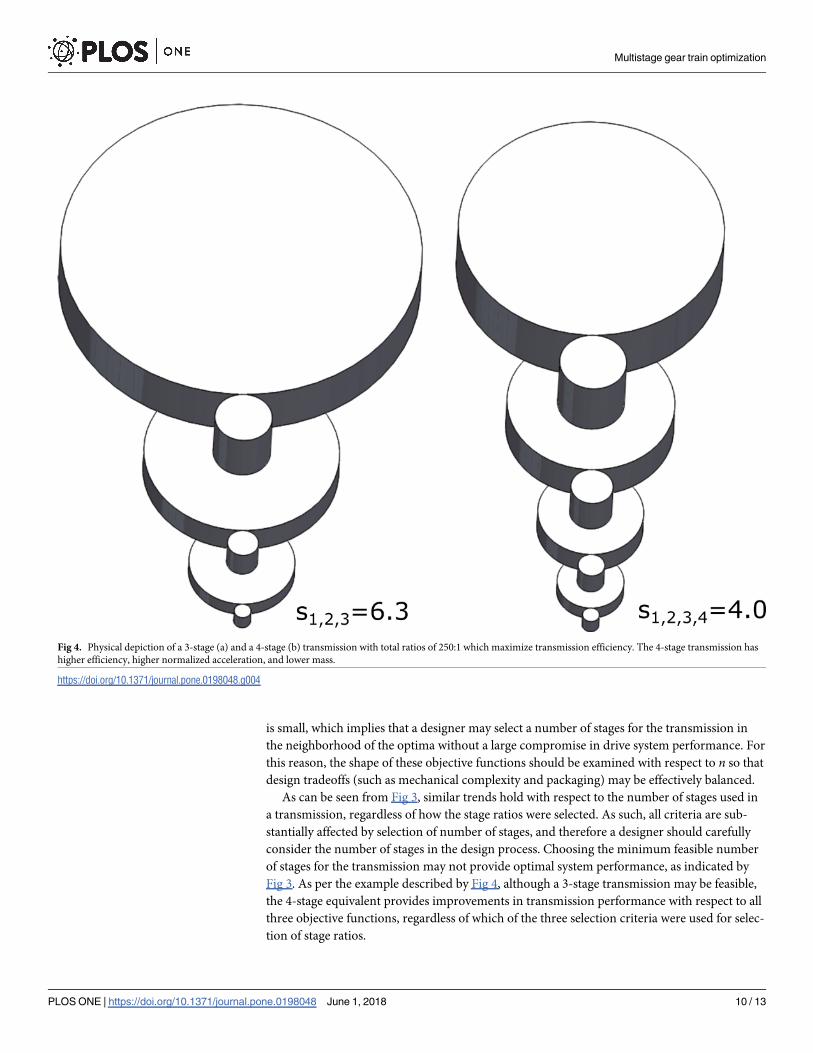
For the case of N = 250, a 3-stage and a 4-stage transmission, both optimized for maximum
efficiency, are shown to scale in Fig 4A and 4B, respectively. The 3-stage transmission employs
three equal stages of 6.3:1, while the 4-stage transmission employs four equal stages of 4.0:1
each. As indicated by the optimization, the 4-stage transmission reduces the overall mass by
26% relative to the 3-stage equivalent, and additionally increases the acceleration capabilities
of the gear train by 50%. The 4-stage transmission also increases overall efficiency by 1%,
which is obviously modest relative to the mass and acceleration advantages. Note that, since
these gear trains are scaled by (12), the stress experienced by both gear trains is the same.
Discussion
It is common for designers to use the minimum feasible number of stages when designing a
multistage gear train. The analysis presented here, however, indicates that adding an additional
Multistage gear train optimization
PLOS ONE | https://doi.org/10.1371/journal.pone.0198048 June 1, 2018 8 / 13
stage (or stages) may significantly improve the performance of a drive system. An analytical
solution for the number of stages to use in a multistage transmission to minimize the reflected
inertia of the gear train was provided by [2]. However, that solution did not provide topologi-
cal context for the optima. As can be seen from Fig 3, the local curvature around the optimum
Fig 3. The objective function evaluations once the stage ratios have been selected to maximize efficiency (solid
light blue), maximize normalized acceleration (dashed medium blue), or minimize normalized mass (dotted dark
blue). The objective functions evaluated are transmission efficiency (a), normalized acceleration (b), and normalized
mass (c).
https://doi.org/10.1371/journal.pone.0198048.g003
Multistage gear train optimization
PLOS ONE | https://doi.org/10.1371/journal.pone.0198048 June 1, 2018 9 / 13
is small, which implies that a designer may select a number of stages for the transmission in
the neighborhood of the optima without a large compromise in drive system performance. For
this reason, the shape of these objective functions should be examined with respect to n so that
design tradeoffs (such as mechanical complexity and packaging) may be effectively balanced.
As can be seen from Fig 3, similar trends hold with respect to the number of stages used in
a transmission, regardless of how the stage ratios were selected. As such, all criteria are sub-
stantially affected by selection of number of stages, and therefore a designer should carefully
consider the number of stages in the design process. Choosing the minimum feasible number
of stages for the transmission may not provide optimal system performance, as indicated by
Fig 3. As per the example described by Fig 4, although a 3-stage transmission may be feasible,
the 4-stage equivalent provides improvements in transmission performance with respect to all
three objective functions, regardless of which of the three selection criteria were used for selec-
tion of stage ratios.
Fig 4. Physical depiction of a 3-stage (a) and a 4-stage (b) transmission with total ratios of 250:1 which maximize transmission efficiency. The 4-stage transmission has
higher efficiency, higher normalized acceleration, and lower mass.
https://doi.org/10.1371/journal.pone.0198048.g004
Multistage gear train optimization
PLOS ONE | https://doi.org/10.1371/journal.pone.0198048 June 1, 2018 10 / 13
With respect to selecting the individual stage ratios of a gear train, Fig 3 also indicates that
stage ratio selection has a more significant impact on efficiency, acceleration, and mass when
the number of stages in the transmission is low. This can be seen by the divergence of the three
curves in Fig 3A–3C in the region of low number of stages. It is also interesting to note that the
stage ratios show opposite trends when selected to minimize the mass of the transmission or to
maximize the acceleration properties of a transmission, as shown in Fig 2. The divergence of
optimal solutions highlights the value of considering the relative importance of minimal rota-
tional inertia, versus minimum mass, when selecting the stage ratios for a given gear train and
design application.
Considering multiple objective functions simultaneously, as is done in this work, allows a
designer to assess which design objectives are sensitive to particular design parameters. For
example, Fig 3 shows that the selection of number of stages has a significant effect on the accel-
eration capabilities of the drive system, but has a relatively small effect on the overall efficiency
of the transmission. If maximizing efficiency were the only objective function considered, a
designer may have overlooked the possibility of designing a transmission with maximum
acceleration (with almost no cost in efficiency).
It should be noted that this optimization does not consider some aspects of transmission
design that may affect the objective functions considered. For example, the mass of the shafts
and bearings necessary to construct a transmission have not been considered, and the efficiency
losses associated with bearings are not considered. The formulation presented here also does not
include the effects of speed (i.e., pitch-line velocity) on gear stress. The volumetric packaging of
the optimization’s resulting transmissions is also not considered, although this is expected to
scale closely with transmission mass. Despite these limitations, the analyses presented here are
believed to capture salient features of gear-based transmission design, and the formulation and
implications of it should offer useful and accurate insights with respect to selecting the number
of stages and stage ratios of gear trains for achieving desired performance characteristics.
Conclusions
This paper describes a formulation that provides the optimal stage ratios for a n-stage multi-
stage gear train with a desired overall transmission ratio that maximizes efficiency, maximizes
transmission acceleration, or minimizes transmission mass, respectively. In addition to pro-
viding a formulation from which a designer can obtain the optimal number of stages and stage
ratios, the authors highlight several related implications regarding gear train design, including
the following two seemingly counterintuitive results. First, for a gear train that provides a
given total gear reduction ratio, the respective objectives of minimizing rotational inertia (i.e.,
maximizing acceleration) and minimizing gear train mass are competing objectives with
respect to selection of stage ratios. In particular, optimal stage ratio selection for a minimal
rotational inertia solution entails successively increasing stage ratios, while optimal stage ratio
selection a minimal mass solution entails successively decreasing stage ratios. Second, increas-
ing the total number of stages can substantially decrease both mass and rotational inertia of a
gear train. As such, substantially improved overall performance may be achieved by employing
a number of stages that may be greater than the minimum feasible number of stages.
Supporting information
S1 File. MultistageOptimizationData. Matlab data file containing the output of the optimiza-
tion run in this study.
(MAT)
Multistage gear train optimization
PLOS ONE | https://doi.org/10.1371/journal.pone.0198048 June 1, 2018 11 / 13

S2 File. Data Description. File explaining the data contained in MultistageOptimizationData.
mat as well as the naming conventions used in this data set.
(PDF)
Author Contributions
Conceptualization: Harrison L. Bartlett.
Formal analysis: Harrison L. Bartlett.
Funding acquisition: Michael Goldfarb.
Methodology: Harrison L. Bartlett, Brian E. Lawson, Michael Goldfarb.
Writing – original draft: Harrison L. Bartlett.
Writing – review & editing: Harrison L. Bartlett, Brian E. Lawson, Michael Goldfarb.
References1. Gibson JE, Tuteur FB. Control system components: McGraw-Hill; 1958.
2. Peterson DP. Power Gear Trains. Machine Design. 1954; 26(6):161.
3. Tang X, Hu X, Yang W, Yu H. Novel Torsional Vibration Modeling and Assessment of a Power-Split
Hybrid Electric Vehicle Equipped with a Dual Mass Flywheel. IEEE Transactions on Vehicular Technol-
ogy. 2017.
4. Tang X, Yang W, Hu X, Zhang D. A novel simplified model for torsional vibration analysis of a series-
parallel hybrid electric vehicle. Mechanical Systems and Signal Processing. 2017; 85:329–38.
5. Burgess E Jr. Minimization of gear-train inertia. Trans of the ASME. 1954; 76:493–6.
6. Freudenstein FaM, M. On the algorithms for the minimization of gear trains. ASME Computers in Engi-
neering. 1982:199–202.
7. Kron M. Minimum Inertia Design for Gear Trains. JPL Technical Report 32-1256.XV:102–8.
8. Selfridge R. Compound gear trains of minimum equivalent inertia. Mechanism and Machine Theory.
1980; 15(4):287–94.
9. Rosic B. Multicriterion optimization of multistage gear train transmission. Facta Universitatis, series:
Mechanical Engineering. 2001; 1(8):1107–15.
10. Stefanović-Marinović J, PetkovićM, Stanimirović I, MilovančevićM. A model of planetary gear multicri-
teria optimization. Transactions of FAMENA. 2011; 35(4).
11. Swantner A, Campbell MI. Topological and parametric optimization of gear trains. Engineering Optimi-
zation. 2012; 44(11):1351–68.
12. Savsani V, Rao RV, Vakharia DP. Optimal weight design of a gear train using particle swarm optimiza-
tion and simulated annealing algorithms. Mechanism and Machine Theory. 2010; 45(3):531–41.
13. Si Golabi, Fesharaki JJ, Yazdipoor M. Gear train optimization based on minimum volume/weight
design. Mechanism and Machine Theory. 2014; 73:197–217.
14. Yokota T, Taguchi T, Gen M. Selected Papers from the 22nd ICC and IE ConferenceA solution method
for optimal weight design problem of the gear using genetic algorithms. Computers & Industrial Engi-
neering. 1998; 35(3):523–6.
15. Gologlu C, Zeyveli M. A genetic approach to automate preliminary design of gear drives. Computers &
Industrial Engineering. 2009; 57(3):1043–51.
16. Thompson DF, Gupta S, Shukla A. Tradeoff analysis in minimum volume design of multi-stage spur
gear reduction units. Mechanism and Machine Theory. 2000; 35(5):609–27.
17. Gandomi AH, Yun GJ, Yang X-S, Talatahari S. Chaos-enhanced accelerated particle swarm optimiza-
tion. Communications in Nonlinear Science and Numerical Simulation. 2013; 18(2):327–40.
18. Deb K, Goyal M, editors. Optimizing Engineering Designs Using a Combined Genetic Search. ICGA;
1997: Citeseer.
19. Roos F. Towards a methodology for integrated design of mechatronic servo systems. 2007.
20. Pettersson M, Olvander J. Drive Train Optimization for Industrial Robots. Robotics, IEEE Transactions
on. 2009; 25(6):1419–24.
Multistage gear train optimization
PLOS ONE | https://doi.org/10.1371/journal.pone.0198048 June 1, 2018 12 / 13
21. Chong TH, Bae I, Park G-J. A new and generalized methodology to design multi-stage gear drives by
integrating the dimensional and the configuration design process. Mechanism and Machine Theory.
2002; 37(3):295–310.
22. Prayoonrat S, Walton D. Practical approach to optimum gear train design. Computer-Aided Design.
1988; 20(2):83–92.
23. Wang H, Wang H-P. Optimal engineering design of spur gear sets. Mechanism and Machine Theory.
1994; 29(7):1071–80.
24. Huang H-Z, Tian Z-G, Zuo MJ. Multiobjective optimization of three-stage spur gear reduction units
using interactive physical programming. Journal of Mechanical Science and Technology. 2005; 19
(5):1080–6.
25. Black T. Designing low-inertia instrument drives. Product Engineering. 1979; 50(12):31–3.
26. Velex P, Ville F. An analytical approach to tooth friction losses in spur and helical gears—influence of
profile modifications. Journal of Mechanical Design. 2009; 131(10):101008.
27. Shigley JE, Mischke CR. Standard handbook of machine design. 1986.
Multistage gear train optimization
PLOS ONE | https://doi.org/10.1371/journal.pone.0198048 June 1, 2018 13 / 13