OH1A/4 Relating to Overhead Line Clearances to Ground and ...
58
ST: OH1A/4 October 2019 - 1 of 58 - Company Directive STANDARD TECHNIQUE: OH1A/4 Relating to Overhead Line Clearances to Ground and Objects for Reasons of Safety Summary This document provides supplementary information to ENATS 43-08 issue 5, 2019, which is also reproduced as an Appendix. It gives WPD-specific safety clearances to ground, objects and other plant, from overhead lines, at all voltage levels maintained in WPD. Note that greater clearances are sought for network resilience reasons on some EHV and HV circuits – see POL OH1 and ST OH1B for further details. When constructing new overhead lines, or altering, refurbishing or deviating existing lines, the increased clearances given in this Standard Technique shall be complied with. Trees in proximity to any overhead line shall be cleared to the distances in this document. Target Group Applicable Staff include Safety & Training, OH Line Trainers, Network Service Teams, DM’s responsible for OH working groups, DMs, TM,s OH teams Impact of Changes Amber - The changes have an impact of current working practices that are not safety critical, these changes will improve the way that clearance defects are assigned – Communication at next team meeting and within one month of the issue date of this document. Planned Assurance Checks Approvers Shall undertake ongoing checks to ensure policy is being written and disseminated in compliance with this POL: GE1 Compliance Checks associated with carrying out measured span checks will be carried out in accordance with ST: GE1E. NOTE: The current version of this document is stored in the WPD Corporate Information Database. Any other copy in electronic or printed format may be out of date. Copyright 2019 Western Power Distribution
-
Upload
khangminh22 -
Category
Documents
-
view
0 -
download
0
Transcript of OH1A/4 Relating to Overhead Line Clearances to Ground and ...

ST: OH1A/4 October 2019 - 1 of 58 -
Company Directive
STANDARD TECHNIQUE: OH1A/4
Relating to Overhead Line Clearances to Ground and Objects for Reasons of Safety
Summary This document provides supplementary information to ENATS 43-08 issue 5, 2019, which is also reproduced as an Appendix. It gives WPD-specific safety clearances to ground, objects and other plant, from overhead lines, at all voltage levels maintained in WPD. Note that
greater clearances are sought for network resilience reasons on some EHV and HV circuits – see POL OH1 and ST OH1B for further details.
When constructing new overhead lines, or altering, refurbishing or deviating existing lines, the increased clearances given in this Standard Technique shall be complied with.
Trees in proximity to any overhead line shall be cleared to the distances in this document.
Target Group
Applicable Staff include Safety & Training, OH Line Trainers, Network Service Teams, DM’s responsible for OH working groups, DMs, TM,s OH teams
Impact of Changes
Amber - The changes have an impact of current working practices that are not safety critical, these changes will improve the way that clearance defects are assigned – Communication at next team meeting and within one month of
the issue date of this document.
Planned Assurance
Checks
Approvers Shall undertake ongoing checks to ensure policy is being written and disseminated in compliance with this POL: GE1 Compliance Checks associated with carrying out measured span checks will be carried out in accordance with ST: GE1E.
NOTE: The current version of this document is stored in the WPD Corporate Information Database. Any other copy in electronic or printed format may be out of date. Copyright 2019 Western Power Distribution

ST: OH1A/4 October 2019 - 2 of 58 -
IMPLEMENTATION PLAN
Introduction This document details the electrical clearance requirements applicable to WPD’s overhead lines.
Main Changes Document updated due team feedback and subsequent revision and release of ENA TS 43-08 issue 5 2019 major changes relate to
Table 3 - Reduced ground clearances for effectively insulated lines not accessible tovehicular traffic including access to property and attachments of service spans tobuildings
Clause 6.3.4 – LV systems attached to buildings
Section 3 updated to provide interpretation in relation to effectively insulated cables
Appendix B Drawing amended to reflect changes to ENA TS 43-08 i.e. Access to property & service spans attached to buildings / across gardens.
Impact of Changes
Target Group
Applicable Staff include Safety & Training, Engineer Trainers, Network Service Teams, DM’s responsible for OH working groups, DMs, TM,s OH teams i.e. All staff involved in providing guidance, carrying out measured span clearances
assigning and rectifying clearance related defects or constructing and maintaining OH lines.
Impact of Changes
Amber - The changes have an impact on current working practices that are not safety critical, these changes will improve the way that clearance defects are assigned. Communication at next team meeting and within one month of the issue date of this document.
Implementation Actions Distribution & Team Managers responsible for overhead line networks shall familiarize themselves with the changes outlined in the table below and communicate the changes of this document to all relevant staff at their next team meeting.
OH Line trainers shall review the changes to this document and amend any relevant training material / information.
All previous versions of Clearance drawing in Appendix B shall be withdrawn and replaced with the version contained in this document.
Implementation Timetable This document can be implemented with immediate effect.

ST: OH1A/4 October 2019 - 3 of 58 -
REVISION HISTORY
Document Revision & Review Table
Date Comments Author
October
2019
Document updated due to release of ENA TS 43-
08 issue 5 2019 major changes relate to Table 3
- Reduced ground clearances for effectively
insulated lines not accessible to vehicular traffic
including access to property and attachments of
service spans to buildings and Clause 6.3.4 – LV
systems attached to buildings. All other
amendments can be seen in the Table
‘Amendments since publication’ on page 2 of
ENA TS 43-08 Issue 5
Section 3 updated to provide interpretation in
relation to effectively insulated cables and the
requirements of ENA TS 43-08 Issue 5
Appendix B Drawing amended to show
effectively insulated service span attached to
building
Mike Chapman
17/03/16 Document re-written to provide separation
between WPD-specific requirements and ENATS
requirements. Only WPD-specific information is
contained in the body of this ST.
ENATS 43-08 is now fully reproduced at
Appendix C.
Section 8.0 added to highlight requirements
relating to wind turbines and solar panels.
Previously inserted definition of road largely
adopted by ENA, where distinction is now
drawn between “roads” and “laneways”.
Sven Hoffmann
24/06/14 Definition of Road added (Section 3)
Pictorial summary of key clearance values added
(appendix B)
Sven Hoffmann
28/11/13 Pages 13 and 18 revised - typing errors Sven Hoffmann
08/07/13 Document Revision & Review Table inserted on
page 3
Note 4 revised on page 10
Map inserted as Appendix A on page 27
Sven Hoffmann
ST: OH1A/4 October 2019 - 4 of 58 -
CONTENTS
1.0 INTRODUCTION 5
2.0 GENERAL REQUIREMENTS 5
3.0 TYPES OF INSULATED CONDUCTOR 6
4.0 CLEARANCE TO GROUND, ROADS AND OBJECTS 7
5.0 CLEARANCES WHERE POWER LINES CROSS OR ARE IN CLOSE PROXIMITY 9
6.0 RAILWAY CROSSINGS 10
7.0 TELECOMMUNICATION LINES 11
8.0 RENEWABLE GENERATION ASSETS 11
APPENDIX A – HEAVY & HIGH ROUTES 12
APPENDIX B – CLEARANCE DRAWING 13
APPENDIX C – ENATS 43-08 Issue 5, 2019 14
APPENDIX D - POLICY FEEDBACK COMMENTS 58
APPENDIX E - SUPERSEDED DOCUMENTATION 58
APPENDIX F - ASSOCIATED DOCUMENTATION 58
APPENDIX G - KEY WORDS 58

ST: OH1A/4 October 2019 - 5 of 58 -
1.0 SCOPE
ENATS 43-08 Issue 4, 2015, reproduced at Appendix C of this ST, is the national-level document that specifies the minimum ground clearances for overhead lines and the clearances to be maintained from objects, other power lines, roads, railways, and waterway crossings.
The minimum clearances specified in ENATS 43-08 shall be complied with in all cases.
In cases where WPD is responsible for the design and construction of overhead lines, greater, more onerous clearances shall be used. These revised clearances are given in Sections 4, 5 and 6 of this ST, and they shall over-rule any requirements set out in ENATS 43-08. These enhanced clearances shall also apply to any overhead line designed and constructed by a third party and intended for adoption by WPD.
For the purposes of ESQCR inspections, the clearances set out in ENATS 43-08 shall be used, with the exception of clearances to trees and lighting standards, where the clearances in Section 4, Table WPD 2 Shall apply.
Guidance on clearances and other safety precautions required when third parties are working near overhead lines is given in ENATS 43-08 as well as STs OH1E and OH1I for LV and HV overhead lines respectively.
Circuits which are subject to resilience tree clearances have greater risk based clearances, but must also comply with the clearances for safety in this ST.
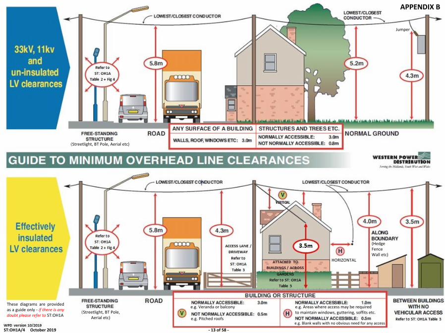
A pictorial summary of key clearance figures is given at Appendix B, or via the following
hyperlink: Appendix B.pdf
2.0 GENERAL REQUIREMENTS
The tables included in ENATS 43-08 in conjunction with the rest of this document list the minimum clearances required.
Due consideration must, however, be given to the use of land. In some cases greater clearances will be required to ensure public safety or allow for imminent changes in ground levels.
3.0 TYPES OF INSULATED CONDUCTOR
ENATS 43-08 now incorporates clearances for Effectively Insulated Conductor into its tables. The following insulated Conductors are used on overhead lines within the WPD area:-

ST: OH1A/4 October 2019 - 6 of 58 -
a) LV Conductors covered with black PVC (0.8mm thick to BS6485) or green PVC(1.6mm thick to BS6485) is classed as Effectively Insulated. If there is asignificant risk that the Conductor insulation will be damaged e.g. by abrasion /3rd party contact, the Conductor Shall be given additional Approved mechanicalprotection. Note that there is a requirement for additional protection ifattached to buildings within the stated proximity to windows etc. [ST: OH6A Fig4]
When used for LV overhead spans or service spans that are deemed accessible from ground, buildings or other objects, additional mechanical protection, such as permanent shrouding, Shall be used to prevent damage caused by third party interference.
b) LV Aerial Bundled Conductors (ABC) consisting of 2 or more XPLE insulatedcores laid up in a self-supporting bundle is Effectively Insulated. If there is asignificant risk that the Conductor insulation will be damaged e.g. by abrasion /3rd party contact, the Conductor Shall be given additional Approved mechanicalprotection. Note that there is a requirement for additional protection if ABC isattached to buildings within stated proximity to windows etc. [ST: OH6A fig 4].
When used on LV overhead spans or service spans that are normally accessible from ground, buildings or other objects additional mechanical protection, such as tree guard, Shall be used to prevent third party interference.
Where ABC is close to trees it shall be sheathed with "tree guard" or equivalent, to provide mechanical protection.
c) PVC insulated/PVC sheathed cables are Effectively Insulated and sheathed formechanical protection and can be used as LV under-eaves wiring which may beaccessible from ground or building.
Note: Existing cables when clipped to buildings below 2.4m are deemed to have sufficient mechanical protection properties to meet the requirements of 43-08 Clause 6.3.4 b) - LV systems attached to buildings.
d) Concentric service cable is Effectively Insulated when used on LV overheadspans. It is also sheathed for mechanical protection and can be used for LVunder-eaves wiring which may be accessible from ground or building.
Note: These cables when clipped to buildings below 2.4m are deemed to have sufficient mechanical protection properties to meet the requirements of 43-08 Clause 6.3.4 b) - LV systems attached to buildings.
e) Green PVC 1.6mm thick (BS6485). This Conductor is Lightly Insulated fortransient faults when used on 11kV or above. It must therefore be consideredas a bare Conductor for all clearance purposes.

ST: OH1A/4 October 2019 - 7 of 58 -
f) Covered Conductors (BLL / BLX / SAX etc.) and HV Conductors covered withApproved shrouding shall be considered as lightly insulated and must beconsidered as bare Conductor for clearance purposes.
g) LV Conductors with Approved shrouding systems are Effectively Insulatedwhen used on LV overhead spans not normally accessible from ground,buildings or other objects.
4.0 CLEARANCE TO GROUND, ROADS AND OBJECTS
Guidance is contained in Sections 6.1 and 6.2 of ENATS 43-08.
WPD overhead lines, however, Shall be designed with additional clearances and these clearances, where they differ from those given in ENATS 43-08, are shown in bold underlined in the following Tables WPD 1 and WPD 2:-
Table WPD 1 - Clearance to Ground and Roads
Item Description of Clearance
Nominal System Voltage (kV) Minimum Clearance (m)
For Bare and Lightly Insulated Conductors
LV 11 33 66 132 275
1.1 Line Conductor to ground at any point not over road. (Replaces Item 1 of Table 1 in ENATS 43-08)
5.2 6.0 6.0 6.3 7.0 7.0
1.2 Line Conductor, wire or cable to road surface other than “high load” routes, “skycradle” routes, or motorways. (Replaces Item 2 of Table 1 in ENATS 43-08)
5.8 6.0 6.0 6.3 7.3 7.4
1.3 Line Conductor, wire or cable to road surface of designated 'high load' routes (Replaces Item 3 of Table 1 in ENATS 43-08)
6.9 6.9 6.9 7.5 7.5 8.5
1.4 Line Conductor to motorway road surface - Minimum clearance (Additional requirement within Item 5 of Table 1 in ENATS 43-08)
7.6 7.6 7.6 7.6 7.6 7.6
Additional Notes:
1. ENATS 43-08 sets out the clearance requirements for effectively insulatedConductors which may be less than the 5.2m indicated in item 1.1 of Table WPD 1.

ST: OH1A/4 October 2019 - 8 of 58 -
2. 'High load' routes are roads designated by the Department of Transport for whichthe higher load clearance of 6.1m must be maintained. A map is provided atAppendix A or click on the hyperlink below:-
High_and_Heavy_Load_Grids_Map_for_Abnormal_Loads.pdf
3. Irrespective of system voltage, 7.6 metres is the minimum clearance required overmotorway carriageways for all wires including straining wires for temporary guardnetting.
Table WPD 2 - Clearance To Objects
Item Description of Clearance
Nominal System Voltage (kV) Minimum Clearance (m)
For Bare and Lightly Insulated Conductors
LV 11 33 66 132 275
2.1 Line Conductor to any object which is normally accessible (including permanently mounted ladders and access platforms) or to any surface of a building. (Replaces Item 1 of Table 2 in ENATS 43-08)
3.0 4.3 4.3 4.5 6.6 7.6
2.3 Line Conductor to that part of a tree under / adjacent to line and:
(i) Unable to support ladder / climber.
(ii) Capable of supporting ladder / climber.
(Replaces Items 3(i) and 3(ii) of Table 2 in ENATS 43-08)
0.8
3.0
0.8
3.0
0.8
3.0
4.0
4.0
4.0
4.0
4.0
4.6
2.6 Line Conductor to street lighting standard with:
(i) Standard in normal upright position
(ii) Standard falling towards line with Conductors hanging vertically.
(Replaces Items 6(i) and 6(ii) of Table 2 in ENATS 43-08)
See ENA TS 43-08 Fig 5
2.0
2.0
2.0
2.0
2.0
2.0
2.3
2.3
3.3
3.3

ST: OH1A/4 October 2019 - 9 of 58 -
Additional Notes:
1. ENATS 43-08 sets out the clearance requirements for effectively insulatedConductors which may be less than the distances indicated in this table.
2. Where Effectively Insulated LV Conductors are used in proximity to vegetation, dueregard shall be given to the risk of physical damage - insulation in contact withbranches will suffer abrasion damage. Vegetation should be cut back to allow wind-induced movement of branches (or the Conductor) etc. to occur without contactingthe Conductor insulation. Alternatively, additional mechanical protection may beapplied, such as “tree guard” for LV ABC. Bare Conductors fitted with Raychem MVLCpermanent shrouding may be treated as Effectively Insulated and protected fromabrasion. The Horizon "Insuline" lightweight shrouding should be treated asEffectively Insulated but not equivalent to having additional mechanical protection.
3. Guidance on the use of irrigators, slurry guns and high pressure hoses is contained inENA Engineering Recommendation G45/1.
4. ST: OS6C gives information on electrical safety in planning, commissioning andmaintenance of public lighting furniture.
5.0 CLEARANCES WHERE POWER LINES CROSS OR ARE IN CLOSE PROXIMITY
Guidance is contained in Section 7 of ENATS 43-08 which outlines the minimum clearances that shall be achieved when carrying out inspection of existing lines, however new / refurbished WPD lines, Shall be designed with additional clearances and these clearances, where they differ from those given in ENATS 43-08, are shown in bold underlined in the following Table WPD 5:-
Table WPD 5 - Clearance Where Power Lines Cross or are in Close Proximity
Item Description of Clearance
Nominal System Voltage (kV) Minimum Clearance (m)
For Bare and Lightly Insulated Conductors
LV 11 33 66 132 275 400
5.4 Support of upper line and any Conductor of lower line. (Replaces Item 4 of Table 5 in ENATS 43-08)
See Note
3 7.5 7.5 7.5 15.0 15.0 15.0
Additional Notes:
1. Clearances to be determined by the ultimate voltage of upper or lower overhead linewhichever is the greater.
ST: OH1A/4 October 2019 - 10 of 58 -
For 132kV; 275kV and 400kV overhead lines the minimum clearance requirement Shall be determined by option (i) described in Figure 6 of ENATS 43-08 (Upper Conductor at maximum temperature, T, and lower Conductor 25degC cooler than T).
For LV; 11kV; 33kV and 66kV lines (except 150 HDC lines) the minimum clearance requirement shall be determined by option (iii) described in Figure 6 of ENATS 43-08 (upper Conductor at maximum temperature with the lower Conductor at -5.6oC).
2. In special cases a lesser or greater distance than that quoted in item 5.4 of TableWPD 5 may be agreed to suit difficult locations or conditions, but in no instance Shallthe distance be less than 7.5m at 11kV or above. Where it is impracticable to complywith the above table, the clearance Shall be Approved by the Company orCompanies concerned.
3. LV lines and supports may be a minimum of 3.0m from any part of an 11kV lineprovided a separation of 9m is maintained between LV and HV system earths,including PME earths.
6.0 RAILWAY CROSSINGS
Guidance is contained in Section 8 of ENATS 43-08.
WPD lines, however, Shall be designed with additional clearances and these clearances, where they differ from those given in ENATS 43-08, are shown in bold underlined in the following Table WPD 6:-
Imperial values are specified in the Master Wayleave Agreement, and are shown in brackets “( )”
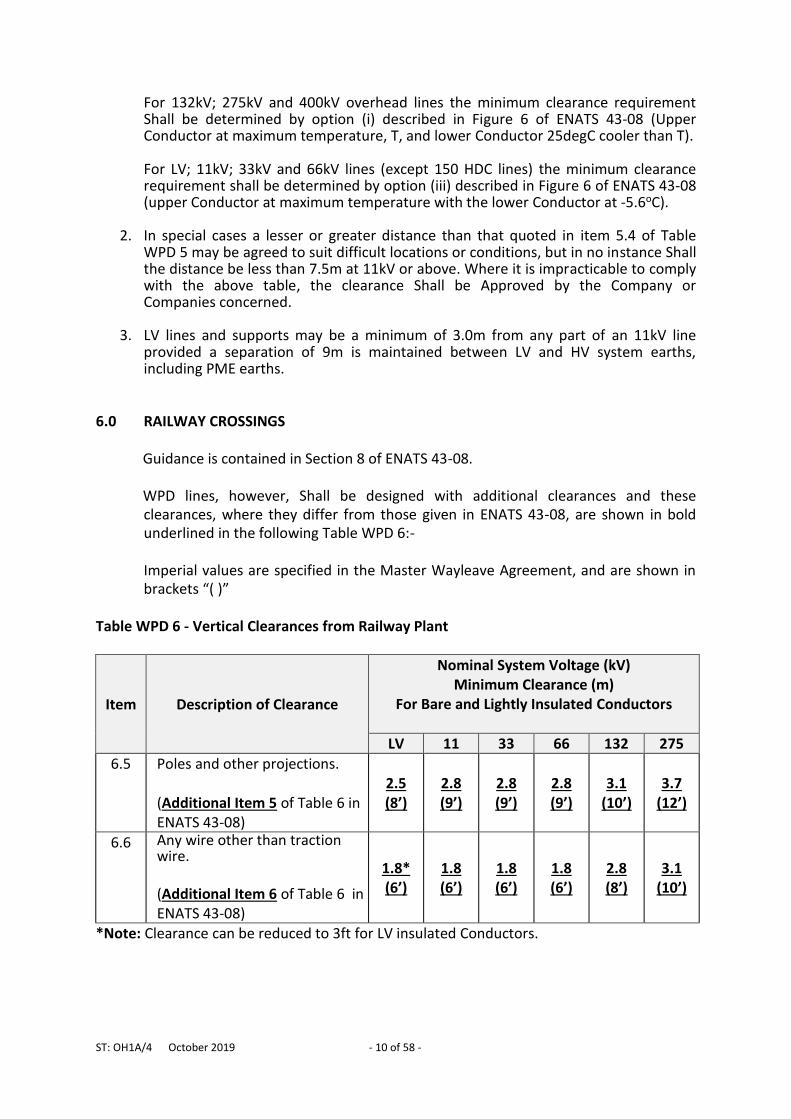
Table WPD 6 - Vertical Clearances from Railway Plant
Item Description of Clearance
Nominal System Voltage (kV) Minimum Clearance (m)
For Bare and Lightly Insulated Conductors
LV 11 33 66 132 275
6.5 Poles and other projections.
(Additional Item 5 of Table 6 in ENATS 43-08)
2.5 (8’)
2.8 (9’)
2.8 (9’)
2.8 (9’)
3.1 (10’)
3.7 (12’)
6.6 Any wire other than traction wire.
(Additional Item 6 of Table 6 in ENATS 43-08)
1.8* (6’)
1.8 (6’)
1.8 (6’)
1.8 (6’)
2.8 (8’)
3.1 (10’)
*Note: Clearance can be reduced to 3ft for LV insulated Conductors.
ST: OH1A/4 October 2019 - 11 of 58 -
7.0 TELECOMMUNICATION LINES
Vertical and lateral clearances to telecommunication lines are specified in ST:OH4O, while ST:OH4E specifies the clearance requirements for apparatus when poles are jointly used.
8.0 RENEWABLE GENERATION ASSETS
Guidance relating to clearances between wind turbines and overhead power lines is contained in ENA Engineering Recommendation L44.
Solar panels should be treated as normally accessible objects as per Item 1 of Table 2 in ENATS 43-08 or, where WPD is building or refurbishing a line over an existing solar farm, Item 2.1 of Table WPD 2 in Section 4 of this document.

ST: OH1A/4 October 2019 - 12 of 58 -
APPENDIX A
(Streetlight, BT Pole, Aerial etc)
(Streetlight, BT Pole, Aerial etc)
These diagrams are provided as a guide only - if there is any doubt please refer to ST:OH1A
Jumper
e.g. Veranda or balcony
e.g. Pitched roofs
e.g. Areas where access may be required to maintain windows, guttering, soffits etc.
e.g. Blank walls with no obvious need for any access
HORIZONTAL
(Hedge Fence Wall etc)
APPENDIX B
ST:OH1A/4 October 2019 - 13 of 58 -

ST: OH1A/4 October 2019 - 14 of 58 -
APPENDIX C
ENATS 43-08 Issue 5, 2019
This page is intentionally blank

PRODUCED BY THE OPERATIONS DIRECTORATE OF ENERGY NETWORKS ASSOCIATION
www.energynetworks.org
Technical Specification 43-8
Issue 5 2019
Overhead line clearances
Sup
plie
d by
EN
A to
: Mik
e C
hapm
an (
Wes
tern
Pow
er D
istr
ibut
ion)
. D
eliv
ered
to: m
chap
man
1@w
este
rnpo
wer
.co.
uk o
n 14
/08/
2019
at 1
1:02
. ©
EN
A 2
019
Una
utho
rised
sha
ring
or d
istr
ibut
ion
is p
rohi
bite
d.
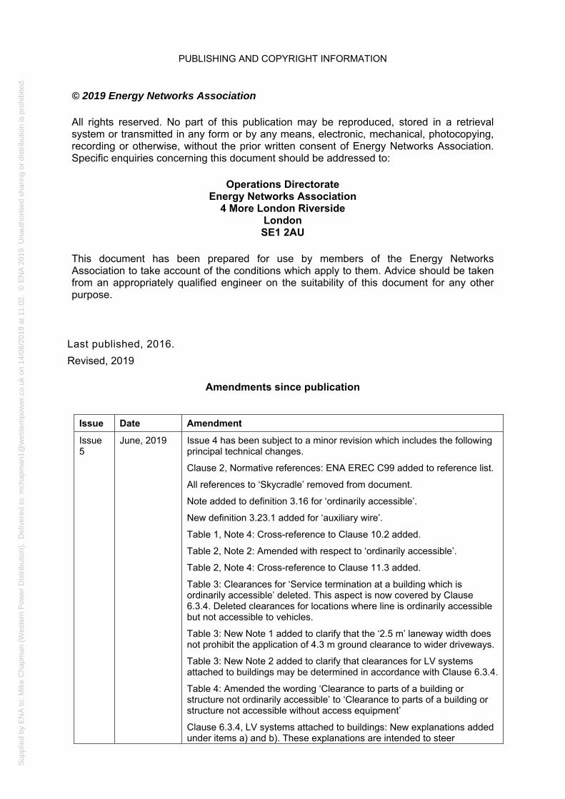
PUBLISHING AND COPYRIGHT INFORMATION
Last published, 2016.
Revised, 2019
Amendments since publication
Issue Date Amendment
Issue 5
June, 2019 Issue 4 has been subject to a minor revision which includes the following principal technical changes.
Clause 2, Normative references: ENA EREC C99 added to reference list.
All references to ‘Skycradle’ removed from document.
Note added to definition 3.16 for ‘ordinarily accessible’.
New definition 3.23.1 added for ‘auxiliary wire’.
Table 1, Note 4: Cross-reference to Clause 10.2 added.
Table 2, Note 2: Amended with respect to ‘ordinarily accessible’.
Table 2, Note 4: Cross-reference to Clause 11.3 added.
Table 3: Clearances for ‘Service termination at a building which is ordinarily accessible’ deleted. This aspect is now covered by Clause 6.3.4. Deleted clearances for locations where line is ordinarily accessible but not accessible to vehicles.
Table 3: New Note 1 added to clarify that the ‘2.5 m’ laneway width does not prohibit the application of 4.3 m ground clearance to wider driveways.
Table 3: New Note 2 added to clarify that clearances for LV systems attached to buildings may be determined in accordance with Clause 6.3.4.
Table 4: Amended the wording ‘Clearance to parts of a building or structure not ordinarily accessible’ to ‘Clearance to parts of a building or structure not accessible without access equipment’
Clause 6.3.4, LV systems attached to buildings: New explanations added under items a) and b). These explanations are intended to steer
© 2019 Energy Networks Association
All rights reserved. No part of this publication may be reproduced, stored in a retrieval system or transmitted in any form or by any means, electronic, mechanical, photocopying, recording or otherwise, without the prior written consent of Energy Networks Association. Specific enquiries concerning this document should be addressed to:
Operations Directorate Energy Networks Association
4 More London Riverside London SE1 2AU
This document has been prepared for use by members of the Energy Networks Association to take account of the conditions which apply to them. Advice should be taken from an appropriately qualified engineer on the suitability of this document for any other purpose.

Sup
plie
d by
EN
A to
: Mik
e C
hapm
an (
Wes
tern
Pow
er D
istr
ibut
ion)
. D
eliv
ered
to: m
chap
man
1@w
este
rnpo
wer
.co.
uk o
n 14
/08/
2019
at 1
1:02
. ©
EN
A 2
019
Una
utho
rised
sha
ring
or d
istr
ibut
ion
is p
rohi
bite
d.
PUBLISHING AND COPYRIGHT INFORMATION
appropriate selection for ground clearance on ‘service flights’.
New Clause 8.3, Clearances to crane jibs on railways: New Clause added to capture clearance requirements for crane jibs on railways working under overhead lines.
Clause 10.1, Telecommunications: Clarified that ENA TS PO5 applies to all voltages.
New Clause 10.2, Auxiliary wires: New Clause added to capture clearance requirements for auxiliary wires installed on overhead supports.
Clause 11.2, Horizontal clearances – working near but not underneath overhead lines: Deleted recommendation that the horizontal clearance to steel tower lines should be 15 m and replaced with a NOTE to clarify that some ENAMCs may specify a larger distance than 10 m.
Table 7: New Note 2 added to clarify that the ENAMC should be contacted to ensure distances are sufficient.
Clause 11.3, Vertical passing clearances – passing underneath overhead lines on work sites: Paragraph 3, wording related to vehicles ‘not of fixed height’ has been removed and replaced with a new ‘Item 2’ in Table 8 for ‘Passing clearance for vehicles NOT of fixed height’.
Clause 11.4, Vertical clearances – on sites where work will be undertaken beneath the line: New Commentary added to explain the intent of the minimum vertical clearance.
Figure 1 amended - the ladder against the ‘Building’ has been replaced with scaffold.
Annex B.2: Items i) and ii) clarified regarding determination of clearance to a laneway. New item iii) added.
Issue 4 + A1
2016 Figure 1 amended. Position of objects altered to improve interpretation of diagram. The ‘Structure’ has been moved and the ladder against the ‘Building’ has been repositioned. Reference to Table 2, Item 1 added.
Issue 4
2015 This issue includes the following principal technical changes.
Amendment 1 (Issue 3): This amendment is now removed and the correction incorporated to Clause 11.3.2.
Foreword: Major amendment to structure so as to align with recommendations in EREC G0. The previous references are updated. Description of ‘specified maximum conductor temperature’ has been moved to ‘Definitions’. Paragraphs moved from ‘Scope’ describing how the document can be used and who can use the document. New sentence added to introduce GS6. New reference to ENA EREC L44 added.
Scope: Major amendment to content. Requirements for effectively insulated conductors have been moved to Clause 6.3. New references for induced voltages added. Various paragraphs moved to ‘Foreword’ including the paragraph stating that ‘ENAMC shall be contacted’ for definitive clearances.
Normative References: Numerous references have been updated and those which have been withdrawn or superseded are removed. New references are now included as used in the document.
Definitions: New definitions added for ABC, BIL, Skycradle, withstand voltage, ordinarily accessible, laneway, road and vehicles. The definitions for specified maximum conductor temperature and basic electrical clearance have been amended. The reference to ENA TS 43-122 has been removed from the definition of covered conductor.
Clause 5: New requirement d) added to capture assessment of laneways.

Sup
plie
d by
EN
A to
: Mik
e C
hapm
an (
Wes
tern
Pow
er D
istr
ibut
ion)
. D
eliv
ered
to: m
chap
man
1@w
este
rnpo
wer
.co.
uk o
n 14
/08/
2019
at 1
1:02
. ©
EN
A 2
019
Una
utho
rised
sha
ring
or d
istr
ibut
ion
is p
rohi
bite
d.
PUBLISHING AND COPYRIGHT INFORMATION
Clause 6.1: Table 1 amended with new details for effectively insulated conductors. Notes 1 – 3 in Table 1 have been changed to align with these changes.
Table 1 Item 1 for 400 kV has been changed from 7.6 m to 7.3 m to align with ESQCR.
Clause 6.2: Table 2 amended with new details for effectively insulated conductors including values for clearances to these conductors. New Notes 1, 3 and 5 added. Amendments existing notes.
Clause 6.3: The scope of this clause has been amended to include all effectively insulated conductors up to and including 33 kV. Changes to the wording and some text has been moved from the ‘Scope’ and ‘Definitions’ to this clause. Table titles have been changed.
Clause 7: New Figure 6 added to replace Note 1 description in Table 5.
Clause 8: Minor amendments to terminology to reflect updates to references. Table 6 Item 2 figures have been corrected for accuracy (conversion from feet to metres). Reference added to Minor Railways.
Table 6: Note 1 has been deleted and two new paragraphs added beneath the table to describe requirements for use of scaffolds when overhead lines cross railways. Figure 7 has been added to aid the descriptions. New Note 1 added in relation to vertical clearance above minor railways.
Clause 10: Title amended and new paragraph added to include requirements for clearances to telecommunications masts. References updated.
Clause 11: Major changes to content of entire clause to reflect and align with the latest revision of HSE Guidance Note GS6. This includes incorporating the 10 m clearance from overhead lines stipulated in HSE Guidance Note GS6 and the exclusion zones identified by HSE Guidance Note GS6 when third parties are working underneath an overhead line. Terminology amended to align with HSE Guidance Note GS6. Table column headings have been updated to align with other tables in the document.
New Clause 11.4 added to include pertinent points from SHEC004, which has been withdrawn.
New Clause 11.5 added to clarify requirements for agricultural work, which is no longer covered by HSE Guidance Note GS6 but is covered by HSE Information Sheet AIS8 instead.
Annex A: Reference to BS 7354:1990 has been updated to reflect that it has been superseded and the relevant content is now included in ENA TS 41-38.
Annex B: New annex added to explain rationale for overhead line clearances for roads and laneways.
Details of all other technical, general and editorial amendments are included in the associated Document Amendment Summary for this Issue (available on request from the Operations Directorate of ENA).

Sup
plie
d by
EN
A to
: Mik
e C
hapm
an (
Wes
tern
Pow
er D
istr
ibut
ion)
. D
eliv
ered
to: m
chap
man
1@w
este
rnpo
wer
.co.
uk o
n 14
/08/
2019
at 1
1:02
. ©
EN
A 2
019
Una
utho
rised
sha
ring
or d
istr
ibut
ion
is p
rohi
bite
d.
ENA Technical Specification 43-8 Issue 5 2019
Page 5
Contents
Foreword .................................................................................................................................. 7
1 Scope ................................................................................................................................. 9
2 Normative references ......................................................................................................... 9
3 Terms and definitions....................................................................................................... 12
4 Derivation of clearances .................................................................................................. 15
5 Application of clearances ................................................................................................. 16
6 Clearance to ground, roads and objects .......................................................................... 16
6.1 Clearances to ground and roads ............................................................................ 16
6.2 Clearances to objects ............................................................................................. 18
6.3 Supplementary clearances for effectively insulated conductors attached to poles ....................................................................................................................... 20
6.3.1 General ....................................................................................................... 20
6.3.2 Supplementary ground clearances to effectively insulated conductors only .......................................................................................... 21
6.3.3 Supplementary clearances to objects for effectively insulated conductors .................................................................................................. 21
6.3.4 LV systems attached to buildings ............................................................... 22
7 Clearances where power lines cross or are in close proximity to one another ................ 23
8 Railway crossings ............................................................................................................ 23
8.1 General ................................................................................................................... 23
8.2 Use of scaffolding across railways ......................................................................... 24
8.3 Clearances to crane jibs on railways ...................................................................... 25
9 Waterway crossings ......................................................................................................... 25
10 Telecommunication lines and auxiliary wires ................................................................... 25
10.1 Telecommunications ............................................................................................... 25
10.2 Auxiliary wires ......................................................................................................... 25
11 Work in proximity to overhead lines ................................................................................. 26
11.1 General ................................................................................................................... 26
11.2 Horizontal clearances – working near but not underneath overhead lines ............. 26
11.3 Vertical passing clearances – passing underneath overhead lines on work sites ........................................................................................................................ 27
11.4 Vertical clearances – on sites where work will be undertaken beneath the line .......................................................................................................................... 28
11.4.1 Work at ground-level only ........................................................................... 28
11.4.2 Work on buildings or structures close to or underneath an overhead line .............................................................................................................. 28
11.5 Safe working of third parties carrying out work in close proximity to live LV overhead conductors which are not effectively insulated ....................................... 29
11.6 Agricultural work ..................................................................................................... 29
Annex A (informative) Clearances to objects – philosophy ................................................... 37
A.1 Introduction ............................................................................................................. 37
A.2 Normal clearance ................................................................................................... 38

Sup
plie
d by
EN
A to
: Mik
e C
hapm
an (
Wes
tern
Pow
er D
istr
ibut
ion)
. D
eliv
ered
to: m
chap
man
1@w
este
rnpo
wer
.co.
uk o
n 14
/08/
2019
at 1
1:02
. ©
EN
A 2
019
Una
utho
rised
sha
ring
or d
istr
ibut
ion
is p
rohi
bite
d.
ENA Technical Specification 43-8 Issue 5 2019 Page 6
A.3 Passing clearance .................................................................................................. 38
Annex B (informative) Definitions for roads and vehicles – rationale .................................... 39
B.0 Preamble ................................................................................................................ 39
B.1 Background ............................................................................................................ 39
B.2 Roads ..................................................................................................................... 39
B.3 Vehicles .................................................................................................................. 41
Bibliography ............................................................................................................................ 42
Figures
Figure 1 — Clearance to objects (on which a person can stand) ........................................... 30
Figure 2 — Examples of clearance to trees ........................................................................... 31
Figure 3 — HV conductor clearance to lighting columns ....................................................... 32
Figure 4 — LV conductor clearances from lighting columns .................................................. 33
Figure 5 — Clearance between structures and effectively insulated conductors installed on poles .......................................................................................... 34
Figure 6 — Clearance between crossing overhead lines ....................................................... 35
Figure 7 — Vertical clearances between an overhead line, scaffold structure and railway ........................................................................................................... 36
Tables
Table 1 — Clearances to ground and roads (1 of 2) .............................................................. 17
Table 1 — Clearances to ground and roads (2 of 2) .............................................................. 18
Table 2 — Clearances to objects (1 of 2) ............................................................................... 19
Table 2 — Clearances to objects (2 of 2) ............................................................................... 20
Table 3 — Reduced ground clearances for effectively insulated lines not accessible to vehicular traffic .............................................................................................. 21
Table 4 — Supplementary clearance to objects for effectively insulated conductors ............ 22
Table 5 — Minimum clearances where power lines cross or are in close proximity to one another (1 of 2) ...................................................................................... 23
Table 6 — Principal vertical clearance to railways and associated structures ....................... 24
Table 7 — Horizontal distances to safety barriers .................................................................. 27
Table 8 — Vertical passing clearances .................................................................................. 27
Table A.1 — Derivation of clearances to objects ................................................................... 37
Table A.2 — Derivation of normal and passing clearances ................................................... 38
Sup
plie
d by
EN
A to
: Mik
e C
hapm
an (
Wes
tern
Pow
er D
istr
ibut
ion)
. D
eliv
ered
to: m
chap
man
1@w
este
rnpo
wer
.co.
uk o
n 14
/08/
2019
at 1
1:02
. ©
EN
A 2
019
Una
utho
rised
sha
ring
or d
istr
ibut
ion
is p
rohi
bite
d.
ENA Technical Specification 43-8 Issue 5 2019
Page 7
Foreword
This Technical Specification (TS) is published by the Energy Networks Association (ENA) and comes into effect from date of publication. It has been prepared under the authority of the ENA Engineering Policy and Standards Manager and has been approved for publication by the ENA Electricity Networks and Futures Group (ENFG). The approved abbreviated title of this engineering document is “ENA TS 43-8”.
This Specification is intended to ensure that ENA Member Companies (ENAMC) meet their statutory obligations under the Electricity Safety, Quality and Continuity Regulations 2002 (ESQCR) [N1] with respect to minimum clearances from overhead lines, wires and cables including minimum ground clearance requirements.
This Specification supersedes the following documents, which previously specified requirements for clearances to overhead lines.
a) ENA Engineering Recommendation L11/4.
b) ENA Engineering Recommendation L40/1.
c) ENA Engineering Recommendation G35.
d) Clearances given in ENA TS 43-12 [N6].
e) Issue 4 of this Specification.
This Specification may be of use to the general public and to bodies other than the ENAMC as a general guidance document.
The overhead clearances specified in this Specification have been determined to provide safety to the general public and protection against flashover from the line. Minimum clearances for certain voltage levels are determined from the relevant tables in this document. Where a particular voltage is not listed the next higher voltage in the table will apply, e.g. for 110 kV equipment, 132 kV clearances will apply. In all cases, where definitive clearances are required, contact with the owner of the overhead line will be necessary. This is particularly important where a change in land use is envisaged. An appropriate employee of the ENAMC will then determine the clearance to be adopted for that particular situation, along with any precautions deemed necessary. Statutory clearances are denoted by being underlined in the tables.
Clearances in this Specification are specified in metres (m) and those distances which have previously been specified in feet (ft.) have been converted to metres, rounded up to two decimal places.
For work activities in vicinity to overhead lines, this Specification complements the guidance in HSE Guidance Note GS6 [N3]. It is important to note that the vertical clearances in this document are minimum clearances consistent with the requirements of ESQCR [N1] as opposed to horizontal and vertical safe working clearances described in HSE Guidance Note GS6 [N3].
This Specification can be used to specify clearances to wind turbines mounted on buildings. However, for those involved in the siting of wind farms or wind turbines in the vicinity of overhead lines, reference should be made to ENA EREC L44 [N15].

Sup
plie
d by
EN
A to
: Mik
e C
hapm
an (
Wes
tern
Pow
er D
istr
ibut
ion)
. D
eliv
ered
to: m
chap
man
1@w
este
rnpo
wer
.co.
uk o
n 14
/08/
2019
at 1
1:02
. ©
EN
A 2
019
Una
utho
rised
sha
ring
or d
istr
ibut
ion
is p
rohi
bite
d.
ENA Technical Specification 43-8 Issue 5 2019 Page 8
The wider application of effectively insulated conductors for locations that may be ordinarily accessible has been addressed in this Specification. HV effectively insulated conductors are included to cater for those small number of installations that exist. The application of HV effectively insulated conductors is not expected to be widespread but is intended to be used for a limited number of special situations.
The concept of a ‘laneway’ is covered in Annex B of this Specification. This provides guidance for ENAMC inspectors when assessing those types of accesses that could otherwise be dismissed as not being ‘roads’. In some circumstances, a minimum ground clearance of 5.2 m may not be adequate; this concept requires ENAMC inspectors to assess whether the minimum ground clearance of any overhead line crossing a laneway is adequate given the nature and extent of any vehicles that may use the laneway.

Sup
plie
d by
EN
A to
: Mik
e C
hapm
an (
Wes
tern
Pow
er D
istr
ibut
ion)
. D
eliv
ered
to: m
chap
man
1@w
este
rnpo
wer
.co.
uk o
n 14
/08/
2019
at 1
1:02
. ©
EN
A 2
019
Una
utho
rised
sha
ring
or d
istr
ibut
ion
is p
rohi
bite
d.
ENA Technical Specification 43-8 Issue 5 2019
Page 9
1 Scope
This Specification defines the minimum clearances between ENAMC overhead lines at all nominal system voltages and objects, ground, railway property and other ENAMC overhead lines. The Specification also refers to National Agreements between ENAMC and other Authorities.
The clearances specified refer to bare, lightly and effectively insulated line conductors, based on the conductor sag at the specified maximum conductor temperature. These clearances are based on normal use of any land, buildings or structures crossed by the line. Unusual situations can only be determined by local assessment and may require an increase in the clearances specified or may require other measures to be taken such as those described in ENA TS 43-90 [N7]. All clearances shall therefore be determined by the appropriate ENAMC, considering the circumstances in which the line is used and having regard to the use of the surrounding land. This Specification has been produced primarily for use by such personnel, who may find Annex A useful.
Where other considerations, e.g. induced voltages, would dictate the use of metallic screens or enhanced clearances, the owner of the overhead line will specify the requirements1,2.
2 Normative references
The following referenced documents, in whole or part, are indispensable for the application of this document. For dated references, only the edition cited applies. For undated references, the latest edition of the referenced document (including any amendments) applies.
Standards publications
BS EN 50341-1:2012, Overhead electrical lines exceeding AC 1 kV – Part 1: General Requirements – Common specifications
BS EN 61936-1:2010+A1:2014, Power installations exceeding 1 kV a.c. – Part 1: Common rules
BS EN 60071-1:2006+A1:2010, Insulation co-ordination – Part 1: Definitions, principles and rules
—————————
1 Further guidelines on the control of electric and magnetic fields (EMFs) can be found in Power Lines: Control of Microshocks and other indirect effects of public exposure to electric fields [1].
2 Guidance on the suppression of electrical interface when high voltage lines cross telecommunications power lines is provided in ENA TS PO5 Appendix H [N10].

Sup
plie
d by
EN
A to
: Mik
e C
hapm
an (
Wes
tern
Pow
er D
istr
ibut
ion)
. D
eliv
ered
to: m
chap
man
1@w
este
rnpo
wer
.co.
uk o
n 14
/08/
2019
at 1
1:02
. ©
EN
A 2
019
Una
utho
rised
sha
ring
or d
istr
ibut
ion
is p
rohi
bite
d.
ENA Technical Specification 43-8 Issue 5 2019 Page 10
The following referenced documents, in whole or in part, are generally applied by ENAMCs for the specification of effectively insulated conductors mentioned in this document. For undated references, the latest edition of the referenced document (including any amendments) applies.
Standards publications – effectively insulated conductors at LV
BS 6004, Electric cables. PVC insulated and PVC sheathed cables for voltages up to and including 300/500 V, for electric power and lighting
BS 6485, PVC-covered conductors for overhead power lines
BS 7870-3.11, LV and MV polymeric insulated cables for use by distribution and generation utilities. Specification for distribution cables of rated voltage 0.6/1 kV. XLPE insulated combined neutral and earth copper wire concentric cables with copper or aluminium conductors
NOTE: This Standard relates to single-phase and three-phase combined neutral and earth (CNE) service cables.
BS 7870-3.21, LV and MV polymeric insulated cables for use by distribution and generation utilities. Specification for distribution cables of rated voltage 0.6/1 kV. XLPE insulated split concentric cables with copper or aluminium conductors
NOTE 1: This Standard relates to single-phase and three-phase separate neutral and earth (SNE) service cables.
BS 7870-5, LV and MV polymeric insulated cables for use by distribution and generation utilities. Polymeric insulated aerial bundled conductors (ABC) of rated voltage 0.6/1 kV for overhead distribution
ENA TS 43-13, Aerial bundled conductors insulated with cross-linked polyethylene for low voltage overhead distribution
NOTE 2: ENA TS 43-13 requires conformance with BS 7870-5 subject to a number of specific amendments.
ENA TS 43-122, XLPE covered-conductors for overhead lines (having rated voltages Uo/U greater than 0.6/1 kV up to and including 19/33kV)
NOTE 3: XLPE covered-conductors that comply with ENA TS 43-122 are considered to be lightly insulated conductors when used for HV applications.
Standards publications – effectively insulated conductors at HV
There is no single Standard publication that defines requirements for aerial HV cables. Such cables are required to comply with relevant requirements of underground cable Standards, e.g. BS 7870-4.20 and IEC 60502. In general, aerial HV cables are required to be assessed as being suitable for self suspension, incorporating outer sheaths resistant to ultra-violet (UV) radiation, abrasion and the effects of external temperature variations and moisture.

Sup
plie
d by
EN
A to
: Mik
e C
hapm
an (
Wes
tern
Pow
er D
istr
ibut
ion)
. D
eliv
ered
to: m
chap
man
1@w
este
rnpo
wer
.co.
uk o
n 14
/08/
2019
at 1
1:02
. ©
EN
A 2
019
Una
utho
rised
sha
ring
or d
istr
ibut
ion
is p
rohi
bite
d.
ENA Technical Specification 43-8 Issue 5 2019
Page 11
Other publications
[N1] Statutory Instrument 2002 No. 2665, The Electricity Safety, Quality and Continuity Regulations 2002 (as amended)3
[N2] Statutory Instrument 1989 No. 635, The Electricity at Work Regulations 1989
[N3] HSE Guidance Note GS6 (rev 4), Avoiding danger from overhead power lines. ISBN 978 0 7176 1348 9
[N4] HSE Agriculture Information Sheet AIS8 (rev 3), Working safely near overhead electricity power lines. HSE books 2012
[N5] ENA TS 41-38, Power installations exceeding 1 kV a.c.: Design of high-voltage open-terminal stations
[N6] ENA TS 43-12, Insulated aerial bundled conductors erection requirements for LV overhead distribution systems
[N7] ENA TS 43-90, Anti climbing devices and safety signs for HV lines up to and including 400 kV
[N8] ENA TS 43-103, Low voltage overhead line shrouding materials
[N9] ENA TS 43-119, Design and use of temporary scaffold guards
[N10] ENA TS PO5, Protection of telecommunication lines from power lines
[N11] ENA EREC G39, Model code of practice covering electrical safety in the planning, installation, commissioning and maintenance of public lighting and other street furniture
[N12] ENA EREC G55, Safe tree working in proximity to overhead electric lines
[N13] ENA EREC G96, Use of mechanical harvesters in vegetation management
[N14] ENA EREC EB/TP, Engineering Recommendation for telecommunication providers and distribution network operators joint use of poles
[N15] ENA EREC L44, Separation between wind turbines and overhead lines: Principles of good practice
[N16] ENA EREC C99, Guidance for working on cables under induced voltage conditions
[N17] Railway Master Wayleave Agreement 1961
—————————
3 In Northern Ireland, the Electricity Safety, Quality and Continuity Regulations (Northern Ireland) 2012 apply. Some aspects of overhead line clearances in this Specification may not apply retrospectively to existing overhead lines subject to the requirements of Regulation 2(9) with regard to “material alteration”.

Sup
plie
d by
EN
A to
: Mik
e C
hapm
an (
Wes
tern
Pow
er D
istr
ibut
ion)
. D
eliv
ered
to: m
chap
man
1@w
este
rnpo
wer
.co.
uk o
n 14
/08/
2019
at 1
1:02
. ©
EN
A 2
019
Una
utho
rised
sha
ring
or d
istr
ibut
ion
is p
rohi
bite
d.
ENA Technical Specification 43-8 Issue 5 2019 Page 12
3 Terms and definitions
For the purposes of this document, the following terms and definitions apply.
3.1 aerial bundled conductor (ABC) assembly of LV effectively insulated phase and neutral conductors
NOTE: Types of ABC in general use can also include an additional earth conductor.
3.2 application factor distance (dependent upon working situation) which is added to the safety distance to determine working and access clearance
3.3 basic electrical clearance smallest permissible clearance in air between live parts or between live parts and earth
[BS EN 61936-1:2010+A1:2014, 6.52]
NOTE: Basic electrical clearances do not include any additions for constructional tolerances, wind effects, etc.
3.4 basic insulation level (BIL)
standard lightning impulse waveform withstand voltage of an insulation device under specified conditions
NOTE: The term BIL is interpreted as lightning impulse withstand voltage in BS EN 60071-1 and is specific to equipment rated above 1 kV.
3.5 cable conductor, or assembly of conductors, which are effectively insulated and incorporate an earthed metallic screen
3.6 controlled zone inside of an enclosure efficiently protected against unauthorised access by fencing not less than 2.4 m in height or other means necessary to meet the requirements of ESQCR [N1] Regulation 11 (b)
3.7 covered conductor (CC) conductor that can be lightly or effectively insulated
NOTE: In the Guidance Notes to the ESQCR [N1], the term ‘BLX conductors’ is used, which is a trade name used in Scandinavia. BLX is interpreted as lightly insulated in this document.
3.8 creep non-elastic stretch of a conductor

Sup
plie
d by
EN
A to
: Mik
e C
hapm
an (
Wes
tern
Pow
er D
istr
ibut
ion)
. D
eliv
ered
to: m
chap
man
1@w
este
rnpo
wer
.co.
uk o
n 14
/08/
2019
at 1
1:02
. ©
EN
A 2
019
Una
utho
rised
sha
ring
or d
istr
ibut
ion
is p
rohi
bite
d.
ENA Technical Specification 43-8 Issue 5 2019
Page 13
NOTE: This consists of two parts – bedding down of the strands and the long-term stretch of conductor material.
3.9 effectively insulated conductor line conductor which is insulated for continuous phase-to-phase or phase-to-earth contact and is protected, so far as is reasonably practicable, against mechanical damage or interference having regard to its accessibility
NOTE 1: The implication here is that effectively insulated conductors may be placed such that they are ordinarily accessible.
NOTE 2: For a HV conductor to be considered effectively insulated it must have an earthed metallic screen incorporated in its construction.
3.10 jumper connection connection at a support from a phase conductor to another conductor or to a terminal on transformers, switchgear, fusegear, line taps, etc.
3.11 laneway defined access between a road and a residential or business address that is suitable for vehicular traffic but which is either not of constructed material or which the public do not have unrestricted access
NOTE: See Annex B for further explanation of a laneway.
3.12 lightly insulated conductor line conductor which is insulated against momentary phase-to-phase or phase-to-earth contact and is considered as a bare conductor for clearance purposes
NOTE: This level of insulation may not be designed to support the full phase-to-earth or phase-to-phase voltage (as appropriate). For example, the covering on some types of HV or EHV CC overhead line conductors could be described as lightly insulated. Other types of CC exist that can be effectively insulated.
3.13 line conductor conductor used, or to be used, for conveying a supply of electricity
NOTE: A line conductor is deemed to include a through jumper.
3.14 normal use of land type of work or activity which is likely to occur on or over a particular piece of land or water
3.15 object building, wall, fence, structure, stationary vehicle, tree, vegetation or similar with an elevation above ground level

Sup
plie
d by
EN
A to
: Mik
e C
hapm
an (
Wes
tern
Pow
er D
istr
ibut
ion)
. D
eliv
ered
to: m
chap
man
1@w
este
rnpo
wer
.co.
uk o
n 14
/08/
2019
at 1
1:02
. ©
EN
A 2
019
Una
utho
rised
sha
ring
or d
istr
ibut
ion
is p
rohi
bite
d.
ENA Technical Specification 43-8 Issue 5 2019 Page 14
3.16 ordinarily accessible capable of being reached by hand from any scaffolding, ladder or other construction erected or placed on, in, against or near to any building or structure
NOTE: Ordinarily accessible is applicable to parts of a building or structure that are reasonably expected to be accessed by persons for the purposes of inspection, maintenance, cleaning and repairs.
[similar to ESQCR [N1] Regulation 18 (6)]
3.17 overhead line equipment in the open air and above ground level coming within the scope of the ESQCR [N1]
3.18 road constructed material suitable for vehicular traffic over which the public have access whether by permission or right
NOTE 1: The intention is that high-sided vehicles will have safe passage beneath any overhead line crossing a road.
NOTE 2: Forest roads designed and built for timber transport using road haulage vehicles are classed as roads.
3.19 safety distance distance maintained from the nearest exposed conductor or from an insulator supporting a conductor to avoid danger
3.20 specified maximum conductor temperature design maximum temperature of the conductor resulting from a combination of climatic conditions and the rated electrical load under normal operating conditions4
3.21 system voltage nominal r.m.s. phase-to-phase voltage of a three-phase a.c. system
3.22 vehicle mechanically-propelled vehicle intended or adapted for use on roads and laneways
3.22.1 high load vehicle vehicle with maximum height exceeding 5 m but not exceeding 6.1 m
—————————
4 For overhead lines which are designed using probabilistic thermal rating concepts which allows a defined conductor temperature exceedance then the ‘specified maximum conductor temperature’ shall be interpreted as the ‘maximum likely conductor temperature’ in accordance with Regulation 17 (1) of ESQCR [N1].

Sup
plie
d by
EN
A to
: Mik
e C
hapm
an (
Wes
tern
Pow
er D
istr
ibut
ion)
. D
eliv
ered
to: m
chap
man
1@w
este
rnpo
wer
.co.
uk o
n 14
/08/
2019
at 1
1:02
. ©
EN
A 2
019
Una
utho
rised
sha
ring
or d
istr
ibut
ion
is p
rohi
bite
d.
ENA Technical Specification 43-8 Issue 5 2019
Page 15
3.22.2 high-sided vehicle vehicle with maximum height exceeding 4 m but not exceeding 5 m
3.22.3 non high-sided vehicle vehicle with maximum height not exceeding 4 m
3.23 wire wire which is not designed to convey electricity but which is attached to a support carrying line conductors
3.23.1 auxiliary wire wire used for the purposes of control, protection, regulation of supply, or for communication
NOTE 1: An auxiliary wire is not a line conductor.
NOTE 2: In general, an auxiliary wire uses the same supports as intended for the line conductor.
3.24 withstand voltage value of the test voltage to be applied under specified conditions in a withstand test, during which a specified number of disruptive discharges is tolerated
[BS EN 60071-1:2006+A1:2010,3.22]
4 Derivation of clearances
In general, the clearances stated in this Specification have been derived from the summation of the following.
a) Basic electrical clearance, as specified in BS EN 50341-1, increased by 10% and rounded up, or where past practice has employed greater clearances, these have been retained.
b) An appropriate physical distance to allow for the normal use of the ground or object to which clearance is required. This is termed the application factor.
The summation method has not been applied where this conflicts with statutory requirements or where certain clearances, e.g. to railways, are the subject of agreement with the appropriate companies.
Where the clearance derived by the summation of a) and b) is greater than the statutory clearance, it is this greater clearance which is quoted in this Specification.
NOTE: Annex A clarifies the process used to determine the clearances to objects. Where overhead lines are refurbished, or constructed, so that the BIL exceeds that used in determining the clearances, then the clearances will need to be re-assessed. This is particularly pertinent in cases where a line is insulated for a higher voltage than that at which it is operated.

Sup
plie
d by
EN
A to
: Mik
e C
hapm
an (
Wes
tern
Pow
er D
istr
ibut
ion)
. D
eliv
ered
to: m
chap
man
1@w
este
rnpo
wer
.co.
uk o
n 14
/08/
2019
at 1
1:02
. ©
EN
A 2
019
Una
utho
rised
sha
ring
or d
istr
ibut
ion
is p
rohi
bite
d.
ENA Technical Specification 43-8 Issue 5 2019 Page 16
5 Application of clearances
The following factors need to be taken into consideration when providing clearances to overhead lines.
a) Allowance shall be made for the effects of creep in conductors, as the specified clearance shall be maintained for the life of the conductor.
b) In some cases, lines are operated at a lower voltage than that for which they are designed. It is important when specifying clearances to fixed objects that the clearances appropriate to the intended nominal operating voltage of the line be adopted.
c) When an overhead line is being erected in proximity to existing objects, the clearances shall allow for future maintenance of the object.
d) The adequacy of overhead line conductor clearances above laneways will be determined by the ENAMC. This may be based on an assessment/and, if necessary, discussion with the landowner/resident, to determine the nature (e.g. maximum height of vehicle) and extent of vehicular traffic requiring access to the laneway.
e) When work is to be carried out, or objects are to be erected in proximity to an existing overhead line, the clearance may need to be increased substantially to allow for the operation and movement of site traffic. Detailed guidance on safe working methods are given in HSE Guidance Note GS6 [N3]. If utilised, the clearances provided in Clause 11 will allow the site operator to comply with HSE Guidance Note GS6 [N3].
6 Clearance to ground, roads and objects
6.1 Clearances to ground and roads
The clearances specified in Table 1 shall not be infringed at the specified maximum conductor temperature with the conductor (including its suspension insulators if fitted) hanging vertically in still air or deflected at any angle up to 45° from the vertical.

Sup
plie
d by
EN
A to
: Mik
e C
hapm
an (
Wes
tern
Pow
er D
istr
ibut
ion)
. D
eliv
ered
to: m
chap
man
1@w
este
rnpo
wer
.co.
uk o
n 14
/08/
2019
at 1
1:02
. ©
EN
A 2
019
Una
utho
rised
sha
ring
or d
istr
ibut
ion
is p
rohi
bite
d.
ENA Technical Specification 43-8 Issue 5 2019
Page 17
Table 1 — Clearances to ground and roads (1 of 2)
Item Description of clearance Nominal system voltage (kV)
Minimum clearance (m)
≤ 33 (NOTE 2) 66 132 275 400
B EI
1 Line conductor at any point not over road. (NOTE 3)
5.2 5.2 6.0 6.7 7.0 7.3
2 Line conductor to road surface other than as specified in 3, 4, and 5. (NOTE 4)
5.8 5.8 6.0 6.7 7.4 8.1
3 Line conductor to road surface of designated '6.1 m high load vehicle' routes. (NOTE 5)
6.9 6.9 7.1 7.5 8.5 9.2
4 Line conductor to motorway road surface where scaffolding is to be used on:
a) Normal 3 lane motorways. 14.0 14.0 14.2 14.6 15.6 16.3
b) Elevated 2 lane motorways(NOTE 6 & 7)
11.0 11.0 11.2 11.6 12.6 13.3
5 Bare live metalwork, e.g. transformer terminals, jumper connections, etc. (NOTE 8)
4.3 NA 4.3 Controlled Zone Safety Rules Apply

Sup
plie
d by
EN
A to
: Mik
e C
hapm
an (
Wes
tern
Pow
er D
istr
ibut
ion)
. D
eliv
ered
to: m
chap
man
1@w
este
rnpo
wer
.co.
uk o
n 14
/08/
2019
at 1
1:02
. ©
EN
A 2
019
Una
utho
rised
sha
ring
or d
istr
ibut
ion
is p
rohi
bite
d.
ENA Technical Specification 43-8 Issue 5 2019 Page 18
Table 1 — Clearances to ground and roads (2 of 2)
NOTE 1: Statutory clearances are denoted by being underlined within this table.
NOTE 2: Clearances to effectively insulated conductors are detailed in this table. The column heading codes are: B = Bare conductors and EI = Effectively insulated conductors.
NOTE 3: Clearance for EI conductors could be lower in some cases if the overhead line is not ordinarily accessible. Clause 6.3.2 provides further guidance for clearances in particular situations. Annex B provides information regarding the rationale for definitions of ‘road’ and ‘laneway’.
NOTE 4: The minimum height of any wire or cable (other than a line conductor) which is attached to a support carrying a line conductor is 5.8 m above any road. The clearances specified allow for the safe passage below the line of a high-sided vehicle. These clearances are based on a vehicle height not exceeding 5 m (except for the 6.1 m high load vehicle routes). See also Clause 10.2.
NOTE 5: 'High load vehicle' routes are roads designated by the Department for Transport, for which the higher load clearance of 6.1 m shall be maintained.
NOTE 6: These clearances allow for the erection of scaffolding/guard netting with the overhead circuits live.
NOTE 7: Should the erection of temporary scaffolding in proximity to overhead lines be considered then appropriate guidance shall be sought relating to acceptable working methods and appropriate preparation prior to any work commencing. Detailed guidance on the design and construction of temporary scaffolding, including clearances to overhead lines, is contained in ENA TS 43-119 [N9].
NOTE 8: These clearances apply to supports of overhead lines that in addition support transformers, isolators, cable sealing ends, etc. These clearances do not apply to pole mounted, LV fuses as long as they are effectively insulated and the fuse carriers are in place. These clearances are not required for effectively insulated jumper connections but shall be maintained from any bare jumpers and terminals. These clearances do not apply to section jumpers.
6.2 Clearances to objects
The clearances specified in Table 2 shall not be infringed at the specified maximum conductor temperature with the conductor (including its suspension insulators if fitted) hanging vertically in still air or deflected at any angle up to 45° from the vertical towards the object unless otherwise specified. The clearances apply in any direction.

Sup
plie
d by
EN
A to
: Mik
e C
hapm
an (
Wes
tern
Pow
er D
istr
ibut
ion)
. D
eliv
ered
to: m
chap
man
1@w
este
rnpo
wer
.co.
uk o
n 14
/08/
2019
at 1
1:02
. ©
EN
A 2
019
Una
utho
rised
sha
ring
or d
istr
ibut
ion
is p
rohi
bite
d.
ENA Technical Specification 43-8 Issue 5 2019
Page 19
Table 2 — Clearances to objects (1 of 2)
Item Description of clearance Nominal system voltage (kV)
Minimum clearance (m)
≤ 33 (NOTE 1) 66 132 275 400
B EI
1 Line conductor to any object which is ordinarily accessible (including permanently mounted ladders and access platforms) or to any surface of a building. (Note 2 and Figure 1)
3.0 Note 3 3.2 3.6 4.6 5.3
2 Line conductor to any object to which access is not required AND on which a person cannot stand or lean a ladder. (Note 4)
0.8 0.5 1.0 1.4 2.4 3.1
3 Line conductors to that part of a tree under / adjacent to line and:
(i) Unable to support ladder/climber. 0.8 0.5 1.0 1.4 2.4 3.1
(ii) Capable of supporting ladder/climber. 3.0 0.5 3.2 3.6 4.6 5.3
(iii) Trees falling towards line with conductors hanging vertically only.
(Note 5, Note 6 and Figure 2(a))
0.8 0.5 1.0 1.4 2.4 3.1
4 Line conductors to trees in Orchards and Hop Gardens. (Note 7 and Figure 2(b))
3.0 3.0 3.2 3.6 4.6 5.3
5 Line conductors to irrigators, slurry guns and high pressure hoses (Note 8)
30.0 30.0 30.0 30.0 30.0 30.0
6 Line conductor to street lighting standards with:
(i) Standard in normal upright position. 1.7 1.0 1.9 2.3 3.3 4.0
(ii) Standard falling towards line with conductor hanging vertically only.
1.7 0.3 1.9 2.3 3.3 4.0
(iii) Standard falling towards line.
(Note 9, Figure 3 and 4)
0.4 0.3 0.7 0.8 1.4 1.9

Sup
plie
d by
EN
A to
: Mik
e C
hapm
an (
Wes
tern
Pow
er D
istr
ibut
ion)
. D
eliv
ered
to: m
chap
man
1@w
este
rnpo
wer
.co.
uk o
n 14
/08/
2019
at 1
1:02
. ©
EN
A 2
019
Una
utho
rised
sha
ring
or d
istr
ibut
ion
is p
rohi
bite
d.
ENA Technical Specification 43-8 Issue 5 2019 Page 20
Table 2 — Clearances to objects (2 of 2)
NOTE 1: Clearances to effectively insulated conductors are detailed in this table. The column heading codes are: B = Bare conductors and EI = Effectively insulated conductors.
NOTE 2: These are the minimum clearances that shall be maintained between an overhead line conductor and a structure or a building (walls, roof, windows etc.) that is ordinarily accessible. They permit a person to stand on or access parts of a structure or building that are ordinarily accessible but only allow for free movement of short hand held objects. Minimum clearances to installed photovoltaic panels shall satisfy these values. Detailed guidance on the avoidance of danger from electric lines on construction sites is contained in HSE Guidance Note GS6 [N3].
NOTE 3: Detailed guidance on supplementary clearances for effectively insulated conductors from objects, excluding LV conductors attached to buildings, is provided in Table 4.
NOTE 4: Account should be taken of the possible movement of the object, e.g. flagpole in the wind. These clearances also apply to moving objects to which access is precluded during passage below the line. The height or position of the object should take into account any possible undulating or rocking movement of the object, e.g. a mobile crane jib travelling over uneven ground. Detailed guidance on the avoidance of danger from electric lines on construction sites is contained in HSE Guidance Note GS6 [N3]. See also Clauses 8.3 and 11.3.
NOTE 5: Clearances to effectively insulated conductors may be lower than the value stated but the conductor must be afforded mechanical protection.
NOTE 6: Clearances quoted in 3 i) and ii) are minimum acceptable clearances but in practice, larger clearances will be necessary to take account of growth rates of trees and of the swaying of trees/branches in the wind. Clearances quoted in 3 iii) are recommended in order to protect lines from falling trees but due to wayleave considerations will not always be attainable. Detailed guidance on the avoidance of danger from electric lines during tree work is contained in ENA EREC G55 [N12] and ENA EREC G96 [N13].
NOTE 7: These clearances shall be obtained vertically when any part of a tree is within 7.5 m horizontally of a line. For hop gardens, the clearances apply to the strain wires forming the mesh supporting system.
NOTE 8: The clearance quoted is for general guidance only. Detailed guidance on the use of irrigators, slurry guns and high-pressure hoses in the vicinity of overhead lines should be obtained from the individual ENAMC.
NOTE 9: The clearances quoted in 6 i) assume that maintenance platforms will be positioned such that clearances quoted in Item 1 are maintained. Reduced clearances for LV conductors are indicated in Figure 4. Clearances to effectively insulated conductors may be reduced depending on position as detailed in Figure 4 and Clause 6.3.3. The clearances quoted in 6 iii) can be neglected if the location of the lighting column is such that impact by a vehicle is improbable. ENA EREC G39 [N11] contains guidance on maintenance of street lighting columns in proximity to overhead lines. Where for maintenance purposes the operative requires to work on the upper part of a lantern, within the clearances specified in Item 6 i), appropriate safety measures shall be taken, which shall be agreed in advance between the distribution or transmission company and the lighting maintenance company or authority. The clearances quoted in 6 ii) include additional clearance to allow for the erection of street lighting columns.
6.3 Supplementary clearances for effectively insulated conductors attached to poles
6.3.1 General
Effectively insulated conductors up to and including 33 kV, e.g. Ericsson aerial HV cable, and low voltage conductors, e.g. ABC installed in accordance with ENA TS 43-12 [N6], shall conform with the clearances in Table 3 and Table 4 in addition to those stated in Clauses 6.1 and 6.2.

Sup
plie
d by
EN
A to
: Mik
e C
hapm
an (
Wes
tern
Pow
er D
istr
ibut
ion)
. D
eliv
ered
to: m
chap
man
1@w
este
rnpo
wer
.co.
uk o
n 14
/08/
2019
at 1
1:02
. ©
EN
A 2
019
Una
utho
rised
sha
ring
or d
istr
ibut
ion
is p
rohi
bite
d.
ENA Technical Specification 43-8 Issue 5 2019
Page 21
The clearances specified in Table 3 and Table 4 are minimum clearances and the ENAMC may install HV effectively insulated conductors at a greater height, e.g. above bare LV conductors on the same route. Hence, the ENAMC may specify greater clearances than presented in this clause.
ENAMCs shall provide justification for the use of effectively insulated conductors operating at HV (≤ 33 kV), where they are installed at reduced clearance to ground or objects (see Table 3 and Table 4).
Clearances between line conductors and other power lines and above railways, as detailed in Clauses 7 and 8 and Tables 5 and 6 shall be met.
6.3.2 Supplementary ground clearances to effectively insulated conductors only
Where effectively insulated conductors are used over roads accessible to vehicular traffic, ground clearances shall still conform with Clause 6.1 and Table 1 as stated in Regulation 17 (2) (a) of ESQCR [N1].
However clearances in other locations are provided in Table 3. Such conductors shall be positioned so that they are not likely to cause injury or be damaged by persons going about normal everyday activities.
Table 3 — Reduced ground clearances for effectively insulated lines not accessible to vehicular traffic
Location Minimum clearance (m)
LV HV (≤ 33 kV)
Along the line of hedgerows, fences and boundary walls etc. 4.0 4.0
Access laneway to a property, with a width of 2.5 m or less which is defined by gateposts, hedges or other fixed features. (NOTE 1)
4.3 4.3
Between buildings, attached to buildings, or locations where the line is safe in the particular circumstance (e.g. over gardens), in addition to there being no vehicular access. (NOTE 2 & 3)
3.5 3.5
NOTE 1: A ground clearance of 4.3 m may also be applied to laneways which are wider than 2.5 m subject to there being a physical restriction(s) prohibiting a high-sided vehicle travelling down the laneway to the point where the line crosses over the laneway. Physical restrictions may include bending radius, trees etc.
NOTE 2: Where the LV system is attached to the building(s), such as for a service, then the clearances may be determined in accordance with Clause 6.3.4.
NOTE 3: “safe in the particular circumstances” means overhead lines are positioned so that they are not likely to cause injury or be damaged by persons going about normal everyday activities.
6.3.3 Supplementary clearances to objects for effectively insulated conductors
The clearances in Table 4 do not apply to LV mains or services attached to buildings. In determining clearances the following conditions should be considered as appropriate.
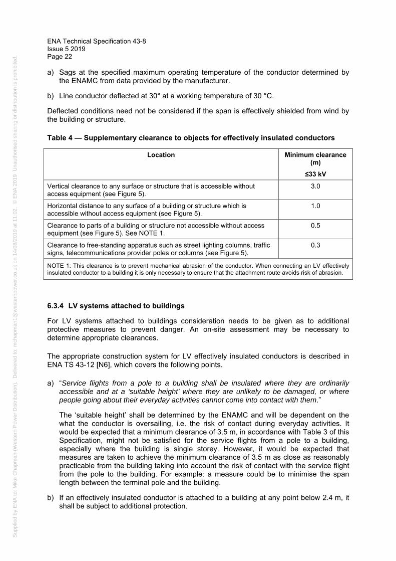
Sup
plie
d by
EN
A to
: Mik
e C
hapm
an (
Wes
tern
Pow
er D
istr
ibut
ion)
. D
eliv
ered
to: m
chap
man
1@w
este
rnpo
wer
.co.
uk o
n 14
/08/
2019
at 1
1:02
. ©
EN
A 2
019
Una
utho
rised
sha
ring
or d
istr
ibut
ion
is p
rohi
bite
d.
ENA Technical Specification 43-8 Issue 5 2019 Page 22
a) Sags at the specified maximum operating temperature of the conductor determined by the ENAMC from data provided by the manufacturer.
b) Line conductor deflected at 30° at a working temperature of 30 °C.
Deflected conditions need not be considered if the span is effectively shielded from wind by the building or structure.
Table 4 — Supplementary clearance to objects for effectively insulated conductors
Location Minimum clearance (m)
≤33 kV
Vertical clearance to any surface or structure that is accessible without access equipment (see Figure 5).
3.0
Horizontal distance to any surface of a building or structure which is accessible without access equipment (see Figure 5).
1.0
Clearance to parts of a building or structure not accessible without access equipment (see Figure 5). See NOTE 1.
0.5
Clearance to free-standing apparatus such as street lighting columns, traffic signs, telecommunications provider poles or columns (see Figure 5).
0.3
NOTE 1: This clearance is to prevent mechanical abrasion of the conductor. When connecting an LV effectively insulated conductor to a building it is only necessary to ensure that the attachment route avoids risk of abrasion.
6.3.4 LV systems attached to buildings
For LV systems attached to buildings consideration needs to be given as to additional protective measures to prevent danger. An on-site assessment may be necessary to determine appropriate clearances.
The appropriate construction system for LV effectively insulated conductors is described in ENA TS 43-12 [N6], which covers the following points.
a) “Service flights from a pole to a building shall be insulated where they are ordinarily accessible and at a ‘suitable height’ where they are unlikely to be damaged, or where people going about their everyday activities cannot come into contact with them.”
The ‘suitable height’ shall be determined by the ENAMC and will be dependent on the what the conductor is oversailing, i.e. the risk of contact during everyday activities. It would be expected that a minimum clearance of 3.5 m, in accordance with Table 3 of this Specification, might not be satisfied for the service flights from a pole to a building, especially where the building is single storey. However, it would be expected that measures are taken to achieve the minimum clearance of 3.5 m as close as reasonably practicable from the building taking into account the risk of contact with the service flight from the pole to the building. For example: a measure could be to minimise the span length between the terminal pole and the building.
b) If an effectively insulated conductor is attached to a building at any point below 2.4 m, it shall be subject to additional protection.

Sup
plie
d by
EN
A to
: Mik
e C
hapm
an (
Wes
tern
Pow
er D
istr
ibut
ion)
. D
eliv
ered
to: m
chap
man
1@w
este
rnpo
wer
.co.
uk o
n 14
/08/
2019
at 1
1:02
. ©
EN
A 2
019
Una
utho
rised
sha
ring
or d
istr
ibut
ion
is p
rohi
bite
d.
ENA Technical Specification 43-8 Issue 5 2019
Page 23
The additional protection is necessary for the risk of contact and mechanical damage to the conductor.
7 Clearances where power lines cross or are in close proximity to one another
The following minimum clearances shall apply where power lines cross or are in close proximity to one another. In all cases the clearances shall be determined with consideration of the ultimate nominal system voltage of the upper or lower line, whichever is greater.
Table 5 — Minimum clearances where power lines cross or are in close proximity to one another (1 of 2)
Item Description of clearance
conductor or earth wire to:
Nominal system voltage (kV)
Minimum clearance (m)
0.4 11 33 66 132 275 400
1 Lowest line conductor or earth wire of upper line to highest line conductor of lower line. (NOTE 1)
1.0 1.8 2.0 2.3 2.7 3.7 4.4
2 Lowest line conductor or earth wire of upper line to earth wire of lower line where erected. (NOTE 1)
0.7 1.4 1.6 2.3 2.7 3.7 4.4
3 Lowest line conductor or earth wire of upper line to any point on a support of the lower line on which a person may stand. (NOTE 2)
2.7 2.8 3.0 3.2 3.6 4.6 5.3
4 Support of upper line and any conductor of lower line. (NOTE 2)
7.5 7.5 7.5 7.5 7.5 15.0 15.0
NOTE 1: See Figure 6 for methods of determining clearances that shall be adopted.
NOTE 2: Clearance shall be obtained with the conductor/earth wire at its specified maximum conductor temperature and deflected by any angle up to 45°.
8 Railway crossings
8.1 General
Clearances to railways and their associated lines, buildings and yards are covered by the second schedule (General and Engineering Conditions) of the Railway Master Wayleave Agreement [N17].
Table 6 lists the principal vertical clearances referred to in the Master Agreement [N17]. For horizontal clearances to railway circuits (excluding traction wires) reference should be made to the Master Agreement [N17].

Sup
plie
d by
EN
A to
: Mik
e C
hapm
an (
Wes
tern
Pow
er D
istr
ibut
ion)
. D
eliv
ered
to: m
chap
man
1@w
este
rnpo
wer
.co.
uk o
n 14
/08/
2019
at 1
1:02
. ©
EN
A 2
019
Una
utho
rised
sha
ring
or d
istr
ibut
ion
is p
rohi
bite
d.
ENA Technical Specification 43-8 Issue 5 2019 Page 24
Table 6 — Principal vertical clearance to railways and associated structures
Item Description of clearance Nominal system voltage (kV)
Minimum clearance* m (ft.)
≤33 66 132 275 400
1 Ground level. 6.1 (20)
6.1 (20)
6.7 (22)
7.0 (23)
7.6 (25)
2 Ground level at roads or yards where road mobile cranes are likely to be employed.
10.7 (35)
10.7 (35)
11.3 (37)
11.6 (38)
12.2 (40)
3 Rail level. (NOTE 1)
7.3 (24)
7.3 (24)
8.0 (26)
8.2 (26)
8.8 (29)
4 Buildings, gantries or other structures on which a person might stand and to traction wires.
3.0 (10)
3.0 (10)
3.7 (12)
4.6 (15)
6.1 (20)
* The imperial values take precedence since they are specified in the Agreement.
NOTE 1: See Office of Rail Regulation, Railway Safety Publication 5, Guidance on Minor Railways [3] for minimum clearance requirements above rail level for minor railways.
8.2 Use of scaffolding across railways
The clearances specified in Table 6 items 3 and 4 do not incorporate any allowances for the use of scaffolding across railway tracks/traction wires during erection/maintenance of overhead lines. To accommodate such scaffolding, the requirements in ENA TS 43-119 [N9] are applicable. Clause 9.2 of ENA TS 43-119 [N9] stipulates a minimum clearance of 4.6 m from scaffolding/catenary wires to railway traction wires or supports. Clearances from scaffolds/catenary wire to overhead lines shall satisfy Table 2 of ENA TS 43-119 [N9]. Figure 7 depicts the clearance requirements for overhead lines, scaffolds and railways.
It is important to note that clearances between overhead lines, scaffolds/catenary wires, railway traction wires, and supports or rails represent the ‘final’ distances to be achieved.
WARNING: Additional clearances and precautions will be necessary to ensure safety during erection of temporary scaffolds.
Sup
plie
d by
EN
A to
: Mik
e C
hapm
an (
Wes
tern
Pow
er D
istr
ibut
ion)
. D
eliv
ered
to: m
chap
man
1@w
este
rnpo
wer
.co.
uk o
n 14
/08/
2019
at 1
1:02
. ©
EN
A 2
019
Una
utho
rised
sha
ring
or d
istr
ibut
ion
is p
rohi
bite
d.
ENA Technical Specification 43-8 Issue 5 2019
Page 25
8.3 Clearances to crane jibs on railways
The operation of railway borne cranes in proximity to overhead lines shall be in accordance with Clause 11, except that the minimum vertical clearance to jibs of railway borne cranes working under overhead lines shall satisfy the distances specified in Table 8 Item 2.
9 Waterway crossings
Clearances to waterways are not subject to a single national agreement but are dealt with by agreement with the appropriate Authority.
10 Telecommunication lines and auxiliary wires
10.1 Telecommunications
Vertical and lateral clearances to telecommunication lines shall comply with those clearances specified in ENA TS PO5 [N10] for all voltages.
ENA EREC EB/TP [N14] specifies the clearance requirements for apparatus when poles are jointly used between a telecommunications provider and a DNO.
Where telecommunications masts are constructed adjacent to an existing overhead line, the minimum lateral clearance between the line conductor and the nearest point on the mast shall be 1.5 times the height of the mast or 15.0 m, whichever is the greater.
10.2 Auxiliary wires
Auxiliary wires should be treated as effectively insulated, unless otherwise specified by the ENAMC.
In general, an auxiliary wire is not current carrying and the voltage level is low, i.e. LV. However, the auxiliary wire may be subject to induced voltage from adjacent live conductors – this is particularly the case during network fault events (fault current flowing in adjacent live conductor). An estimate of induced voltage in the auxiliary wire can be determined in accordance with ENA EREC C99 [N16]. Historical practice in the UK electricity industry has been to consider a maximum induced voltage of 5 kV when in proximity to 11/33 kV conductors, and a maximum induced voltage of 15 kV when in proximity to 132/275/400 kV conductors. For the purposes of induced voltage circumstances, an auxiliary wire should be treated as a line conductor ≤33 KV.
NOTE: Safe working methods for, auxiliary wires subject to induced voltage, are not covered by this document but may be as described in ENA EREC C99 [N16] and/or ENAMC specific procedures.
The minimum clearances for an overhead auxiliary wire should be in accordance with those distances in Table 1 and Table 2 of this ENA TS for an effectively insulated line conductor ≤33 kV.
NOTE: In certain situations, the consequence of damage to an auxiliary wire may be detrimental to the safe and efficient operation of the associated network. For this reason, the ENAMC may wish to maintain the same clearance to the auxiliary wire as would be required for the associated line conductor.

Sup
plie
d by
EN
A to
: Mik
e C
hapm
an (
Wes
tern
Pow
er D
istr
ibut
ion)
. D
eliv
ered
to: m
chap
man
1@w
este
rnpo
wer
.co.
uk o
n 14
/08/
2019
at 1
1:02
. ©
EN
A 2
019
Una
utho
rised
sha
ring
or d
istr
ibut
ion
is p
rohi
bite
d.
ENA Technical Specification 43-8 Issue 5 2019 Page 26
11 Work in proximity to overhead lines
11.1 General
The following clauses deal with the use of plant or vehicles in proximity to overhead lines. Where work is undertaken using ladders, scaffold, mobile platforms etc. then the clearances provided in Tables 1 and 2 shall be used unless other risk mitigation can be employed such as temporary shrouding of the overhead conductor.
Whenever work is to be carried out in proximity to overhead lines, consideration shall always be given to the possibility of making the line dead, or diverting it around the area affected. All work near live overhead power lines must be fully justifiable and satisfy all three requirements of Regulation 14 of the Electricity at Work Regulations 1989 [N2].
The HSE provides guidance for the avoidance of danger from overhead lines in their Guidance Note GS6 [N3] (subsequently referred to as GS6 [N3]). The ENAMC shall be prepared to provide, preferably in writing, safety clearances and advice on safe working methods to those working in proximity to overhead lines. Where work can only be carried out safely with the line dead, this shall be the subject of precise written agreement between the ENAMC and site operators.
The requirements and guidance provided in the following clauses of this Specification aim to complement that provided in GS6 [N3].
11.2 Horizontal clearances – working near but not underneath overhead lines
GS6 [N3] recommends that the ENAMC should be contacted for advice for any work within 10 m, measured at ground level horizontally from below the nearest overhead line.
NOTE: Some ENAMCs specify a larger horizontal clearance (up to 15 m) to cater for overhead line swing on longer span lengths.
GS6 [N3] recommends the erection of safety barriers to establish a safety zone parallel to the overhead line to maintain clearance from it. Table 7 details typical minimum values for horizontal separation of the overhead lines and safety barriers.

Sup
plie
d by
EN
A to
: Mik
e C
hapm
an (
Wes
tern
Pow
er D
istr
ibut
ion)
. D
eliv
ered
to: m
chap
man
1@w
este
rnpo
wer
.co.
uk o
n 14
/08/
2019
at 1
1:02
. ©
EN
A 2
019
Una
utho
rised
sha
ring
or d
istr
ibut
ion
is p
rohi
bite
d.
ENA Technical Specification 43-8 Issue 5 2019
Page 27
Table 7 — Horizontal distances to safety barriers
Description Clearance (m)
≤33 kV Wood pole
66 kV Wood pole
132 kV Wood pole
132 kV Tower
275 kV Tower
400 kV Tower
Minimum horizontal distances to safety barriers
6.0 6.0 6.0 9.0 12.0 14.0
NOTE 1: Site conditions will dictate whether this clearance is adequate and consideration shall be given to line parameters, e.g. span length, maximum sag etc. when calculating an actual clearance.
NOTE 2: To ensure these distances are sufficient the ENAMC should be contacted to assist with any calculations.
11.3 Vertical passing clearances – passing underneath overhead lines on work sites
GS6 [N3] specifies the use of passageways where plant or vehicles have to pass underneath the overhead line at the work sites.
Plant or vehicles passing underneath overhead lines must not breach the safety clearance distance. Table 8 details these passing clearances and Annex A provides their derivation.
The vertical clearances given in Table 8 are minimum clearances and must not be infringed under any circumstances.
Table 8 — Vertical passing clearances
Item Description Clearance (m)
≤33 kV 66 kV 132 kV 275 kV 400 kV
1 Passing clearance fixed height loads
0.8 1.0 1.4 2.4 3.1
2 Passing clearance for vehicles NOT of fixed height (NOTE 1,2)
2.0 2.2 2.6 3.6 4.3
NOTE 1: The distances stated include an allowance of 1.2 m to cater for some variation in the vehicle height e.g. crane jib bounce, abnormal load, uneven ground.
NOTE 2: Greater clearance may be required when there is a risk that the height variation may exceed 1.2 m.
The above clearances shall be used to determine the maximum distance to the underside of the passageway goalpost5 erected to prevent vehicles or plant from infringing these clearances whilst traversing the line. The maximum height to the underside of the goalpost
—————————
5 The term ‘goalpost’ is referred to in GS6 [N3].

Sup
plie
d by
EN
A to
: Mik
e C
hapm
an (
Wes
tern
Pow
er D
istr
ibut
ion)
. D
eliv
ered
to: m
chap
man
1@w
este
rnpo
wer
.co.
uk o
n 14
/08/
2019
at 1
1:02
. ©
EN
A 2
019
Una
utho
rised
sha
ring
or d
istr
ibut
ion
is p
rohi
bite
d.
ENA Technical Specification 43-8 Issue 5 2019 Page 28
shall be the minimum ground clearance of the line less the specified passing clearance from Table 8.
It is important that the minimum ground clearance of the line is determined at the specified maximum conductor temperature, when specifying the passageway height.
11.4 Vertical clearances – on sites where work will be undertaken beneath the line
Work beneath the line shall be deemed to be any work carried out within the minimum horizontal distances specified in Table 7 or the calculated distance (see NOTE 1 in Table 7) whichever is greater.
GS6 [N3] provides recommendations for working under the line and describes two general cases: ground-level work, and erection of buildings or structures close or underneath an overhead line. Exclusion zones from the overhead line are stipulated for the various voltages.
GS6 [N3] recommends that the ENAMC should be consulted when there is doubt about the use of the exclusion zones. In the cases where the exclusion zone may be breached, it is imperative that the clearances maintained shall satisfy Table 8 Item 1.
COMMENTARY ON: Minimum vertical clearance
The intent of a vertical clearance when working beneath a line is to ensure that the safety distance (see Table 8 item 1 and Table A.1) is maintained as a minimum at all times i.e. prevention of a person breaching the safety distance (see A.1). It is important that an appropriate safe system of work is employed and overseen by experienced and competent persons. The use of an ‘application factor’ is a relevant consideration, as described in A.2: an allowance of 2.2 m for a person to move their arm whilst holding a short metallic object. Another robust and industry accepted concept is a ‘working and access clearance’ which is the safety clearance + 0.3 m (as described in the Model Distribution Safety Rules [4]).
11.4.1 Work at ground-level only
Where work is carried out at ground-level the passing clearances specified in Table 8 Item 1 for fixed height loads are permissible, as GS6 [N3] requires that no vehicle, item of plant, ladders or poles shall reach beyond the safe clearance limit. Where plant such as cranes and excavators has the capability to reach into the safe clearance limit it shall be fitted with a physical restraint in order to prevent such action.
GS6 [N3] requires that all such work shall be “directly supervised by someone who is familiar with the risks”.
11.4.2 Work on buildings or structures close to or underneath an overhead line
This work includes erection of permanent and temporary structures as specified by GS6 [N3].
A horizontal physical barrier should be erected to form a roof between the area of work and the overhead line such that the safe clearance limit cannot be infringed. The distances in Table 8, Item 1 shall be treated as a minimum necessary clearance and shall be used to calculate the height of the underside of the physical barrier.
Where a conductive material is used to form the barrier this shall be earthed.
The line shall be made dead if, during the erection of the physical barrier, safety clearances would be infringed.

Sup
plie
d by
EN
A to
: Mik
e C
hapm
an (
Wes
tern
Pow
er D
istr
ibut
ion)
. D
eliv
ered
to: m
chap
man
1@w
este
rnpo
wer
.co.
uk o
n 14
/08/
2019
at 1
1:02
. ©
EN
A 2
019
Una
utho
rised
sha
ring
or d
istr
ibut
ion
is p
rohi
bite
d.
ENA Technical Specification 43-8 Issue 5 2019
Page 29
11.5 Safe working of third parties carrying out work in close proximity to live LV overhead conductors which are not effectively insulated
Where third parties, e.g. owner-occupiers or their contractors, carry out work in close proximity to live LV overhead conductors, the requirements of Clauses 11.2, 11.3 and 11.4 are applicable in the first instance.
Where these requirements are not satisfied and in order to prevent inadvertent contact with live conductors or equipment, the ENAMC shall be contacted for advice. The following precautions shall be considered for bare or lightly insulated LV overhead mains and services, excluding undereaves mains, services and all similar means of supply secured to buildings.
a) De-energise the line and take appropriate precautions in accordance with ENAMC procedures.
b) Apply temporary shrouding complying with ENA TS 43-103 [N8].
c) Erect a horizontal physical barrier as described in Clause 11.4.2.
d) Underground the mains/service.
e) Replace bare open conductor services with effectively insulated services, for example ABC, together with the requirements of Clause 6.3.
f) Divert the line.
The procedure adopted shall be recorded and communicated appropriately between the third party and ENAMC.
11.6 Agricultural work
The HSE provide information for persons in agriculture working near overhead lines in Agriculture Information Sheet No 8 [N4]. The information sheet recommends carrying out specified activities at least 10 m from overhead lines.
NOTE: Some ENAMCs specify a larger horizontal clearance (up to 15 m) to cater for overhead line swing on longer span lengths.
Where the above conditions cannot be satisfied for agricultural work, the ENAMC approach shall be adopted.

Sup
plie
d by
EN
A to
: Mik
e C
hapm
an (
Wes
tern
Pow
er D
istr
ibut
ion)
. D
eliv
ered
to: m
chap
man
1@w
este
rnpo
wer
.co.
uk o
n 14
/08/
2019
at 1
1:02
. ©
EN
A 2
019
Una
utho
rised
sha
ring
or d
istr
ibut
ion
is p
rohi
bite
d.
ENA Technical Specification 43-8 Issue 5 2019 Page 30
Figure 1 — Clearance to objects (on which a person can stand)

Sup
plie
d by
EN
A to
: Mik
e C
hapm
an (
Wes
tern
Pow
er D
istr
ibut
ion)
. D
eliv
ered
to: m
chap
man
1@w
este
rnpo
wer
.co.
uk o
n 14
/08/
2019
at 1
1:02
. ©
EN
A 2
019
Una
utho
rised
sha
ring
or d
istr
ibut
ion
is p
rohi
bite
d.
ENA Technical Specification 43-8 Issue 5 2019
Page 31
Figure 2 — Examples of clearance to trees

Sup
plie
d by
EN
A to
: Mik
e C
hapm
an (
Wes
tern
Pow
er D
istr
ibut
ion)
. D
eliv
ered
to: m
chap
man
1@w
este
rnpo
wer
.co.
uk o
n 14
/08/
2019
at 1
1:02
. ©
EN
A 2
019
Una
utho
rised
sha
ring
or d
istr
ibut
ion
is p
rohi
bite
d.
ENA Technical Specification 43-8 Issue 5 2019 Page 32
Figure 3 — HV conductor clearance to lighting columns

Sup
plie
d by
EN
A to
: Mik
e C
hapm
an (
Wes
tern
Pow
er D
istr
ibut
ion)
. D
eliv
ered
to: m
chap
man
1@w
este
rnpo
wer
.co.
uk o
n 14
/08/
2019
at 1
1:02
. ©
EN
A 2
019
Una
utho
rised
sha
ring
or d
istr
ibut
ion
is p
rohi
bite
d.
ENA Technical Specification 43-8 Issue 5 2019
Page 33
Figure 4 — LV conductor clearances from lighting columns

Sup
plie
d by
EN
A to
: Mik
e C
hapm
an (
Wes
tern
Pow
er D
istr
ibut
ion)
. D
eliv
ered
to: m
chap
man
1@w
este
rnpo
wer
.co.
uk o
n 14
/08/
2019
at 1
1:02
. ©
EN
A 2
019
Una
utho
rised
sha
ring
or d
istr
ibut
ion
is p
rohi
bite
d.
ENA Technical Specification 43-8 Issue 5 2019 Page 34
Figure 5 — Clearance between structures and effectively insulated conductors installed on poles

Sup
plie
d by
EN
A to
: Mik
e C
hapm
an (
Wes
tern
Pow
er D
istr
ibut
ion)
. D
eliv
ered
to: m
chap
man
1@w
este
rnpo
wer
.co.
uk o
n 14
/08/
2019
at 1
1:02
. ©
EN
A 2
019
Una
utho
rised
sha
ring
or d
istr
ibut
ion
is p
rohi
bite
d.
ENA Technical Specification 43-8 Issue 5 2019
Page 35
Figure 6 — Clearance between crossing overhead lines
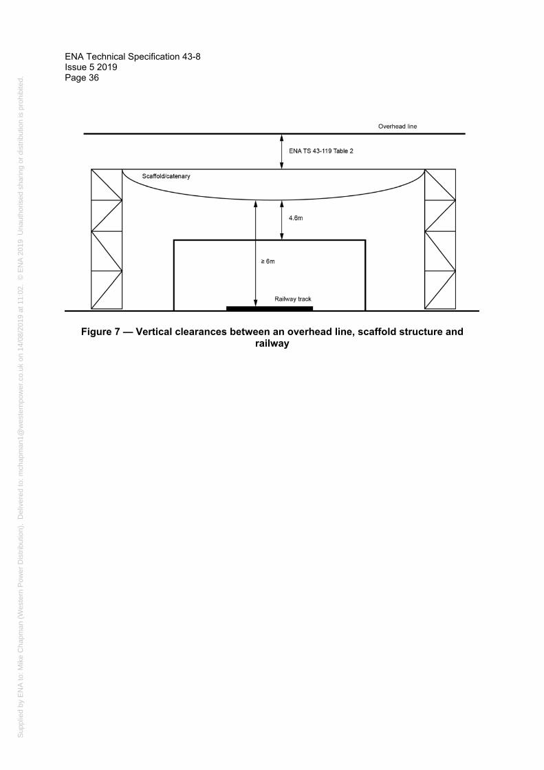
Sup
plie
d by
EN
A to
: Mik
e C
hapm
an (
Wes
tern
Pow
er D
istr
ibut
ion)
. D
eliv
ered
to: m
chap
man
1@w
este
rnpo
wer
.co.
uk o
n 14
/08/
2019
at 1
1:02
. ©
EN
A 2
019
Una
utho
rised
sha
ring
or d
istr
ibut
ion
is p
rohi
bite
d.
ENA Technical Specification 43-8 Issue 5 2019 Page 36
Figure 7 — Vertical clearances between an overhead line, scaffold structure and railway
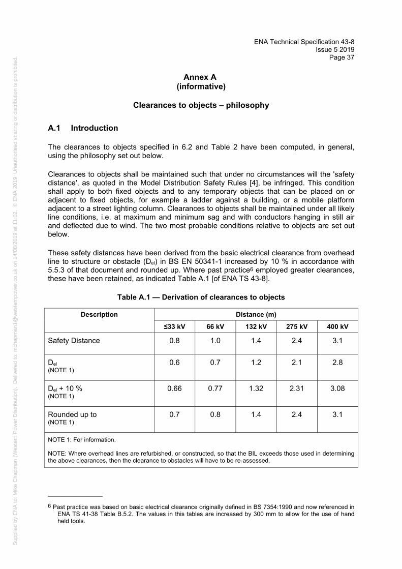
Sup
plie
d by
EN
A to
: Mik
e C
hapm
an (
Wes
tern
Pow
er D
istr
ibut
ion)
. D
eliv
ered
to: m
chap
man
1@w
este
rnpo
wer
.co.
uk o
n 14
/08/
2019
at 1
1:02
. ©
EN
A 2
019
Una
utho
rised
sha
ring
or d
istr
ibut
ion
is p
rohi
bite
d.
ENA Technical Specification 43-8 Issue 5 2019
Page 37
Annex A (informative)
Clearances to objects – philosophy
A.1 Introduction
The clearances to objects specified in 6.2 and Table 2 have been computed, in general, using the philosophy set out below.
Clearances to objects shall be maintained such that under no circumstances will the 'safety distance', as quoted in the Model Distribution Safety Rules [4], be infringed. This condition shall apply to both fixed objects and to any temporary objects that can be placed on or adjacent to fixed objects, for example a ladder against a building, or a mobile platform adjacent to a street lighting column. Clearances to objects shall be maintained under all likely line conditions, i.e. at maximum and minimum sag and with conductors hanging in still air and deflected due to wind. The two most probable conditions relative to objects are set out below.
These safety distances have been derived from the basic electrical clearance from overhead line to structure or obstacle (Del) in BS EN 50341-1 increased by 10 % in accordance with 5.5.3 of that document and rounded up. Where past practice6 employed greater clearances, these have been retained, as indicated Table A.1 [of ENA TS 43-8].
Table A.1 — Derivation of clearances to objects
Description Distance (m)
≤33 kV 66 kV 132 kV 275 kV 400 kV
Safety Distance 0.8 1.0 1.4 2.4 3.1
Del (NOTE 1)
0.6 0.7 1.2 2.1 2.8
Del + 10 %(NOTE 1)
0.66 0.77 1.32 2.31 3.08
Rounded up to (NOTE 1)
0.7 0.8 1.4 2.4 3.1
NOTE 1: For information.
NOTE: Where overhead lines are refurbished, or constructed, so that the BIL exceeds those used in determining the above clearances, then the clearance to obstacles will have to be re-assessed.
—————————
6 Past practice was based on basic electrical clearance originally defined in BS 7354:1990 and now referenced in ENA TS 41-38 Table B.5.2. The values in this tables are increased by 300 mm to allow for the use of hand held tools.

Sup
plie
d by
EN
A to
: Mik
e C
hapm
an (
Wes
tern
Pow
er D
istr
ibut
ion)
. D
eliv
ered
to: m
chap
man
1@w
este
rnpo
wer
.co.
uk o
n 14
/08/
2019
at 1
1:02
. ©
EN
A 2
019
Una
utho
rised
sha
ring
or d
istr
ibut
ion
is p
rohi
bite
d.
ENA Technical Specification 43-8 Issue 5 2019 Page 38
A.2 Normal clearance
This is the distance between the conductor at maximum sag hanging vertically or deflected by any angle up to 45° and an object. It is not normal to permit any object to be placed above an electric line. If a person can stand on the object or any temporary object adjacent to it, then the normal clearance shall include an 'application factor' of 2.2 m to allow for the person to move their arm whilst holding a short metallic object. Should it be necessary for a person to move their arm whilst holding a longer object, then this normal clearance may have to be increased by a distance of up to the length of the object.
A.3 Passing clearance
This is the minimum distance between the conductor at maximum sag hanging vertically or at an angle of up to 45° towards an object and the object itself when it is moving relative to the line. The passing clearance therefore does not normally require an 'application factor' since it is intended for objects which are moving, and on which no person may be able to stand, relative to the line. This clearance can also be applied to any object when there is no likelihood of any temporary platform being situated adjacent to it.
The normal and passing clearances, which have been derived from the 'safety distances', at the various nominal system voltages are shown in Table A.2.
Table A.2 — Derivation of normal and passing clearances
Description Clearance (m)
≤33 kV 66 kV 132 kV 275 kV 400 kV
Normal clearance 3.0 3.2 3.6 4.6 5.3
Passing clearance 0.8 1.0 1.4 2.4 3.1
Sup
plie
d by
EN
A to
: Mik
e C
hapm
an (
Wes
tern
Pow
er D
istr
ibut
ion)
. D
eliv
ered
to: m
chap
man
1@w
este
rnpo
wer
.co.
uk o
n 14
/08/
2019
at 1
1:02
. ©
EN
A 2
019
Una
utho
rised
sha
ring
or d
istr
ibut
ion
is p
rohi
bite
d.
ENA Technical Specification 43-8 Issue 5 2019
Page 39
Annex B (informative)
Definitions for roads and vehicles – rationale
B.0 Preamble
It is intended that the definitions of ‘road’ and ‘laneway’ will provide improved clarity for ENAMC inspectors, who carry out ESQCR inspections of overhead lines. In particular, these definitions are intended to reduce the number of situations, where ENAMC inspectors may otherwise dismiss some types of access as not being roads but where a minimum ground clearance of 5.2 m may not be adequate. A more detailed assessment of the minimum ground clearance of overhead line crossings is now prescribed in light of vehicles that may use laneways. Laneways are principally concerned with assessment of clearances below existing overhead line crossings, where access have been created that may be used by vehicles but may not be reasonably considered roads.
The definitions of ‘road’ and ‘laneway’ are intended to assist with interpretation of requirements in the ESQCR. Notwithstanding this, it is important to state that the ESQCR provides clear statutory requirements for line clearances above roads, and other ground; the Regulations do not make any reference to reduced clearances over laneways, nor do they make any reference to laneways. Users of this Technical Specification are reminded of the duty to comply with the ESQCR requirements for line clearances.
B.1 Background
Experience of the ENAMC has proven that it is not uncommon for confusion to arise when describing what constitutes a road and what constitutes a vehicle. Indeed, the clearances to an overhead line will depend on the nature of the road and the vehicles using it. It is imperative therefore that persons using this document understand the context for the definition of roads and vehicles when determining whether safe passing clearances for vehicles exist for any particular road in question.
B.2 Roads
The definitions in Clause 3 of the document distinguish between defined ‘roads’ and ‘laneways’, that are required to have safe passing clearance for vehicles and other routes that may be used by vehicles but where adequate safe passing clearance may not exist.
The definition of a ‘road’ is based on section 192 of the Road Traffic Act 1988, which sets down that a 'road' means 'any highway and any other road to which the public have access and includes bridges over which a road passes'. The definition of ‘road’ in this Specification has been amended from that in the Road Traffic Act to reflect roads and other accesses, which are specifically constructed from suitable materials for the purpose of carrying vehicles driven by the public. The definition of ‘road’ is distinct from that of ‘laneway’, which reflects routes principally across agricultural land, that could be inappropriately classed as ‘roads’ by virtue of vehicles, such as off-road vehicles, compacting ground by running over it and making it suitable for vehicles.

Sup
plie
d by
EN
A to
: Mik
e C
hapm
an (
Wes
tern
Pow
er D
istr
ibut
ion)
. D
eliv
ered
to: m
chap
man
1@w
este
rnpo
wer
.co.
uk o
n 14
/08/
2019
at 1
1:02
. ©
EN
A 2
019
Una
utho
rised
sha
ring
or d
istr
ibut
ion
is p
rohi
bite
d.
ENA Technical Specification 43-8 Issue 5 2019 Page 40
It is acknowledged that some accesses from roads to dwellings may not be made of constructed materials but which are the designated access for the resident and members of the public to service that dwelling. To ensure adequate ground clearance exists from overhead lines to routes constituted from stone and other tracks that are legitimately used by residents and other members of the public driving vehicles, e.g. for making deliveries, the term ‘laneway’ is defined. In essence a laneway is the principal access from a road to an addressed property which is used by vehicles visiting that property.
The intention is that the ENAMC will assess whether overhead lines crossing laneways provide adequate ground clearance given the nature and extent of vehicle usage. This will consider whether, in general, an overhead line above a laneway should:
a) provide safe passage for non high-sided vehicles, i.e. Table 1 item 1 clearances arerelevant;
b) provide safe passage for high-sided vehicles, i.e. Table 1 item 2 clearances are relevant.
In order to enable the ENAMC to adequately manage the risk moving forwards, suitable means for recording information from the assessment will need to be provided. This may include the use of risk codes and/or a specific classification for laneways. The ENAMC will consider what action is appropriate for managing the risk to the public in accordance with Regulation 3(3) of the ESQCR – in a similar manner to other specific applications and land use, where there is an increased risk of accidental contact with overhead line conductors.
The following examples are typical of the considerations for the assessment of laneways.
i. A stoned-route or other track that crosses agricultural land, that does not have publicaccess and that is not the principal access to an addressed dwelling from a ‘road’.Overhead line clearances to this laneway would not be treated as a ‘road’ according tothis Specification i.e. a minimum ground clearance of 5.2 m would be appropriate.
ii. A vehicle access constituted from stone that is the principal access from a ‘road’ to afarm, which is used by tractors towing road legal high-sided trailers. Overhead lineclearances to this laneway would be treated as a ‘road’ according to this Specificationi.e. a minimum ground clearance of 5.8 m would be appropriate.
iii. A paved drive that is the principal access from a ‘road’ to a property which has aphysical restriction(s) (width, tree, bending radius) prohibiting a high-sided vehicletravelling down it. Overhead line clearances to this laneway would not be treated as a‘road’ according to this Specification. Refer to Clause 6.3.2 when the overhead line iseffectively insulated in this situation.

Sup
plie
d by
EN
A to
: Mik
e C
hapm
an (
Wes
tern
Pow
er D
istr
ibut
ion)
. D
eliv
ered
to: m
chap
man
1@w
este
rnpo
wer
.co.
uk o
n 14
/08/
2019
at 1
1:02
. ©
EN
A 2
019
Una
utho
rised
sha
ring
or d
istr
ibut
ion
is p
rohi
bite
d.
ENA Technical Specification 43-8 Issue 5 2019
Page 41
B.3 Vehicles
The definition of a vehicle in section 185(1) of the Road Traffic Act 1988 and section 136(1) of the Road Traffic Regulation Act 1984 is "a mechanically-propelled vehicle, intended or adapted for use on roads". This definition does not distinguish between vehicles of different heights that may use roads and laneways.
The term ‘non high-sided vehicle’ in this Specification defines a vehicle of maximum fixed height not greater than 4 m. This is intended to cover vehicles up to 7.5 tonne box lorries with tail lifts, which typically have a fixed height of 3.6 m. These vehicles could be reasonably expected to use laneways for making deliveries and removals.
It is intended that vehicles greater than 4 m but not greater than 5 m (defined as high-sided vehicles in this Specification) can be expected to use all ‘roads’ and will have adequate passing clearance beneath overhead lines with a minimum ground clearance of 5.8 m. High load vehicles are defined as only being suitable for specified ‘high load vehicle routes’, where the vehicle height exceeds 5 m but not 6.1 m.

Sup
plie
d by
EN
A to
: Mik
e C
hapm
an (
Wes
tern
Pow
er D
istr
ibut
ion)
. D
eliv
ered
to: m
chap
man
1@w
este
rnpo
wer
.co.
uk o
n 14
/08/
2019
at 1
1:02
. ©
EN
A 2
019
Una
utho
rised
sha
ring
or d
istr
ibut
ion
is p
rohi
bite
d.
ENA Technical Specification 43-8 Issue 5 2019 Page 42
Bibliography
Other publications
[1] Department of Energy & Climate Change voluntary code of practice, Power line: Control of microshocks and other indirect effects of public exposure to electric fields. URN 13D/204.
[2] Department of Trade and Industry Guidance on Regulations, Guidance on the Electricity Safety, Quality and Continuity Regulations 2002. URN 02/1544
[3] Office of Rail Regulation, Railway Safety Publication 5, Guidance on Minor Railways
[4] ENA SHE Standard 07, Model Distribution Safety Rules

Sup
plie
d by
EN
A to
: Mik
e C
hapm
an (
Wes
tern
Pow
er D
istr
ibut
ion)
. D
eliv
ered
to: m
chap
man
1@w
este
rnpo
wer
.co.
uk o
n 14
/08/
2019
at 1
1:02
. ©
EN
A 2
019
Una
utho
rised
sha
ring
or d
istr
ibut
ion
is p
rohi
bite
d.
ENA Technical Specification 43-8 Issue 5 2019
Page 43
This page deliberately left blank

ST: OH1A/34 October 2019 - 58 of 58 -
APPENDIX D
SUPERSEDED DOCUMENTATION
This document supersedes ST: OH1A/3 dated March 2016 which has now been withdrawn.
APPENDIX E
RECORD OF COMMENT DURING CONSULTATION
Policy Feedback Comments
APPENDIX F
ASSOCIATED DOCUMENTATION
ENA Technical Specification 43-8 Issue 5, 2019 POL OH1 - Overhead Line Clearances ST OH1B - Maintaining tree clearances to overhead Conductors ST OH1C - Safety precautions for tree cutting near live overhead lines ST OH1I - Relating to Precautions for Third Party Work near High Voltage Overhead
Lines on Wood Poles or Steel Towers
APPENDIX G
KEY WORDS
Overhead, Clearance, Ground, Tree, Object, Crossings, Resilience, Railway, Conductor, Proximity.