Nuts and Volts - December 2011
84
Vol. 32 No. 12 NUTS & VOLTS PILL TIMERS • WEARABLE ELECTRONICS • CCTV TIME STAMP • LI-FI December 2011 U.S. $6.50 CANADA $7.50
-
Upload
khangminh22 -
Category
Documents
-
view
3 -
download
0
Transcript of Nuts and Volts - December 2011

Vo
l.32 No.12
NU
TS
& V
OLT
SP
ILL TIM
ER
S •
WE
AR
AB
LE E
LEC
TR
ON
ICS
•C
CTV
TIM
E S
TAM
P •
LI-FID
ecemb
er 2011
0 71486 02421 7
1 2
$6.50US $7.50CANU.S. $6.50 CANADA $7.50
Cover.qxd 11/2/2011 10:37 AM Page 1

Information and Sales | [email protected] Web | www.netburner.com Telephone | 1-800-695-6828
Start with the PK70 EX
Design your own, or use a
NetBurner Personality Blade
Add your label to get a
fi nished product
The easiest fi nished product you will ever create
Personality Blades
Prototype Blade (P/N NBPKBP-100CR) ................................ $25 ea.
Create your own Personality Blade
CPLD Digital I/O Blade (P/N NBPKD-100CR)....................... $59 ea.
Programmable Xilinx CPLD32 digital I/O
Multi-I/O Blade (P/N NBPKM-100CR) .................................. $99 ea.
Eight 12-bit analog-to-digital inputsTwo 16-bit digital-to-analog outputs16 digital I/O
FPGA Digital I/O Blade (P/N NBPKX500-100CR) ................ $169 ea.
Programmable Xilinx Spartan 3E FPGA High-density 62-pin connector
NTP Server with GPS Blade (P/N NBPKX500-100CR) ........... $99 ea.
Network Time Protocol (NTP) serverPrecision GPS time reference
Quad UART Blade: RS-232 Version(P/N NBPKBU-232CR) ............................................................ $99 ea.
Network enable up to 4 RS-232 serial devices
Quad UART Blade: RS-422/485 Version(P/N NBPKBU-485CR) .......................................................... $119 ea.
Network enable up to 4 RS-422/485 serial devices
Quad UART Blade: RS-232/422/485 Version(P/N NBPKBU-MMSCR) ........................................................ $245 ea.
Network enable up to 4 RS-232/422/485 serial devices
PK70 EX & Development Kit
PK70 EX (P/N PK70EX-100IR) ............................................. $199 ea.32-Bit Freescale ColdFire 147 MHz CPU
PK70 EX Development Kit(P/N NNDK-PK70EX-KIT) ...................................................... $299 ea.The Development Kit features NetBurner’s Eclipse, an enterprise level professional IDE that provides editing, downloading and debugging in one environment.
Full Page.qxd 8/30/2011 2:19 PM Page 2

Pocket Analyzer
Protocol Analyzer
Digital Oscilloscope
Spectrum Analyzer
bitscope.com/nv
Mixed Signal Oscilloscopes
Digital + AnalogBitScope
Full Page.qxd 7/29/2011 10:23 AM Page 4


6 December 2011
Departments0088 DEVELOPING
PERSPECTIVES0099 READER FEEDBACK2266 NEW PRODUCTS2299 SHOWCASE
6633 ELECTRO-NET6644 NV WEBSTORE7766 CLASSIFIEDS7788 TECH FORUM8811 AD INDEX
Nuts & Volts (ISSN 1528-9885/CDN Pub Agree #40702530) is published monthly for $26.95 peryear by T & L Publications, Inc., 430 Princeland Court, Corona, CA 92879.PERIODICALS POSTAGE PAID AT CORONA, CA AND AT ADDITIONAL MAILING OFFICES.POSTMASTER: Send address changes to Nuts & Volts, P.O. Box 15277, North Hollywood, CA91615 or Station A, P.O. Box 54,Windsor ON N9A 6J5; [email protected].
FUNdamentals For Beginners5588 Build an English Police Siren
Columns10 TechKnowledgey 2011
EEvveennttss,, AAddvvaanncceess,, aanndd NNeewwssThe most complex ground-based observatory comes to life, a CPU sets a world clock record, and using an iPhone for medical imaging are just some of the current topics covered this time.
14 PICAXE PrimerSShhaarrppeenniinngg YYoouurr TToooollss ooff CCrreeaattiivviittyyUpgrading the recent serial LCD project.
22 Q & ARReeaaddeerr QQuueessttiioonnss AAnnsswweerreedd HHeerreeLearn about a deer repellant circuit, a sine wave modulator, IR remote control, plus a lot of other stuff people have questions about.
60 Open CommunicationTThhee LLaatteesstt iinn NNeettwwoorrkkiinngg aanndd WWiirreelleessss TTeecchhnnoollooggiieessBuilding a crystal radio — is it a sane thing to do?
68 Smiley’s WorkshopPPrrooggrraammmmiinngg •• HHaarrddwwaarree •• PPrroojjeeccttssDigital I/O — Part 3: Bitwise Operations.
2011Nuts & VoltsDecemberwww.nutsvolts.com
32 Light Up Your ClothesWith Wearable ElectronicsAdd a special kind of bling to your outfits with electroluminescent (EL) wire.■ By Pres Tuesley
38 Build the RTC OSD for CCTV RecordingAdd a date/time stamp to your closed circuit television camera system with this real time clock-based on-screen display.■ By Kelly Lewis
46 Pill Timers — Big Medicine for Your Little ProjectsOne of the neatest things about pill timers is their size, so you can easily add them to any of your projects, curing the headache of space issues.■ By James Lyman
54 REVIEWThe SparkFun ProtoSnapPro MiniWhether you’re new to the Arduino or an old fan, the Pro Mini development platform — which is made up of pre-wired boards and a small pile of components — is worth exploring.■ By Bryan Bergeron
Projects & Features
PPaaggee 6600
PPaaggee 3322
TOC Dec11.qxd 11/1/2011 7:53 PM Page 6

www.Globalspecialties.comPhone: 1-800-572-1028
introduces concepts of sequential logic design, which is the final basic elements to understanding microprocessor and microcontroller logic.
The DL-020 Sequential Logic Trainer
Our courseware offers many options to aid in electronics training and lab instruction.
RDB-10 Resistance Decade BoxA compact, convenient tool for aiding in engineering design and testing as well as calibration of test equipment.
8-Pin SOP to Through -
Hole Prototyping Adapter
44-Pin PLCC to Through -
Hole Prototyping Adapter
GSPA-K1
GSPASOP-8B
Offer Selection of Over 18 DIY Educational Kits
GSPAPLCC-44
GSPATSOP-48S48-Pin TSOP to Through -
Hole Prototyping Adapter
5-pin DIN connector
housed on a PC board
PB-503 Analog & Digital Design Workstation
Courseware
A robust electronics trainer suitable for all levels of electronics instruction and design.
PRO-S LabBreadboard with External Power & Jumper Wires
The set includes 11 tools commonly used for working with surface mount components
Surface Mount Device Soldering & Re-Work Tool Kit
Basic Fixed Test Leadsmodel# CT3737
Provides users with the basic connection leads to begin using one’s digital multimeter (DMM)
December 2011 7
Full Page.qxd 11/1/2011 3:37 PM Page 7

by Bryan Bergeron, Editorby Bryan Bergeron, Editor
DEVELOPINGLLII--FFII
The US energy efficiency legislation for light bulbs hasbeen a boon for alternatives to the traditional
incandescent bulb, including the LED. Energy issues aside,I use LED lamps for my desk and workbench becausethey’re small, unobtrusive, and give off little heat.
Still, there’s a lot of energy being wasted by LED-based lighting — especially if you think of the light theygenerate as unused bandwidth. Making use of thisbandwidth is the basis of LI-FI (Light Fidelity) which hasmany parallels with WI-FI.
Proponents of LI-FI contend that room light,automobile lights, interior aircraft lights, and street lights allrepresent under-utilized bandwidth that can carryeverything from voice communications and HDTV tointelligent navigation signaling between cars. If you want agreat vision of what’s possible with the technology, checkout the free TEDtalks podcast, “Wireless Data From EveryLightbulb,” available on iTunes.
Communications with light is nothing new. Romansoldiers used polished shields to reflect sunlight whensignaling during battle. Commercial, secure, line-of-sightlaser communications systems have been around fordecades. I’ve used a DIY He-Ne gas laser and telescopesystem to communicate over five miles, but at modestbandwidth. And, of course, much of the phone system isbased on optical transmission and switching.
IR light signaling has been around for some time. Youprobably own at least one IR remote. However, as withUV light, you wouldn’t want to bathe a room with IR lightbecause it can damage your vision. The real R&D activityis around visible light. There’s plenty of bandwidthavailable, and it’s not likely that you’ll inadvertently stareinto a bright light and burn your retinas.
As with RF communications, the transmission processis straightforward and doesn’t take much in terms ofhardware. Reception is the sticking point. There are issuesof inadequate signal strength, how to handle multipathsignals formed by light reflecting off of different objectsand arriving at the receiver out of time, and interferencefrom other light sources, just to name a few.
So, assuming I’ve piqued your interest, where do youbegin? Start simple. Get an ordinary red LED andphototransistor — each coupled to your favoritemicrocontroller — to communicate with each other. Onceyou’ve managed a simple simplex serial connection, go forfull duplex (two-way) communications.
To give you an example of what’s involved, I’ve been
experimenting with parallel data streams using red, green,and blue LEDs. Driving low power red, green, and blueLEDs with an Arduino is trivial. I use external switchingtransistors with each LED so that I can handle high powerLEDs.
On the receiver end, I’m working with two differentapproaches. The first uses separate phototransistors forred, green, and blue light. I use standard photographicacetate as a filter for each phototransistor. Red, green, andblue transparent film from acetate report covers works justabout as well.
I’m also working with color-sensitive light sensors,including the TCS3200-DB color sensor from Parallax. Atalmost $60, it’s expensive, but it has a built-in array ofphotodetectors with red, green, and blue filters. It’s worthlooking at the spec sheet (downloadable fromParallax.com) to get an idea of how they’re using thechip. Parallax also sells the TSL230R light-to-frequencyconverter. As with the TCS3200-DB, the $6 chip isn’tdesigned for color light communications, but it haspotential that’s worth exploring.
SparkFun electronics sells an inexpensive TEMT600($1.50) light sensor that can be put behind a color acetatefilter. As with standard phototransistors, these devices aremore sensitive to certain portions of the visible spectrumthan others. SparkFun also sells the Avago ADJD-S311-CR999 that has built-in red-green-blue filters ($5).Unfortunately, you’ll have to be skilled at SMT mountingto get at the input and output leads.
Of course, the real work for harnessing broadbandlight communications is in the software. Checksums andother error-detection mechanisms provision forinterference from other visible light transmitters. There’sthe approach used by most IR remote controllers — that ofmodulating the bean at about 38 kHz. Take a look at thespec sheet on the IR receiver TSOP85 — available fromSparkFun — to get an idea of what’s typically involved inlight receivers.
Of course, if you’re on an unlimited budget, then youcould start considering diffraction gratings, prisms, andother commercial-grade tools developed for the fiberoptics community. Edmund Scientifics is a good place tolook for information and products.
There are obvious technical and behavioral issues thatmust be addressed before LI-FI becomes ubiquitous. Forexample, there will be no more tucking your phone inyour pocket or purse. You’ll have to expose at least part ofthe phone to light — perhaps as Bluetooth chest-pincommunicators akin to those on Star Trek. Then, there are
PERSPECTIVES
8 December 2011
DevPerspec - Dec 11.qxd 11/1/2011 5:42 PM Page 8

Published Monthly ByTT && LL PPuubblliiccaattiioonnss,, IInncc..
430 Princeland Ct.Corona, CA 92879-1300
((995511)) 337711--88449977FAX ((995511)) 337711--33005522
Webstore orders only 11--880000--778833--44662244wwwwww..nnuuttssvvoollttss..ccoomm
SubscriptionsToll Free 11--887777--552255--22553399
Outside US 11--881188--448877--44554455P.O. Box 15277
North Hollywood, CA 91615
FOUNDER/ASSOCIATE PUBLISHERJack Lemieux
PUBLISHERLarry Lemieux
ppuubblliisshheerr@@nnuuttssvvoollttss..ccoomm
ASSOCIATE PUBLISHER/VP OF SALES/MARKETING
Robin Lemieuxddiissppllaayy@@nnuuttssvvoollttss..ccoomm
EDITORBryan Bergeron
tteecchheeddiitt--nnuuttssvvoollttss@@yyaahhoooo..ccoomm
CONTRIBUTING EDITORSJeff Eckert Russ KincaidJoe Pardue Ron HackettLouis Frenzel Kelly LewisJames Lyman Pres Tuesley
CIRCULATION DIRECTORTracy Kerley
ssuubbssccrriibbee@@nnuuttssvvoollttss..ccoomm
SHOW COORDINATORAudrey Lemieux
MARKETING COORDINATORWEBSTORE
Brian Kirkpatrickssaalleess@@nnuuttssvvoollttss..ccoomm
WEB CONTENTMichael Kaudze
wweebbssiittee@@nnuuttssvvoollttss..ccoomm
ADMINISTRATIVE ASSISTANTDebbie Stauffacher
PRODUCTION/GRAPHICSShannon Christensen
Copyright © 2011 by T & L Publications, Inc.All Rights Reserved
All advertising is subject to publisher’s approval. Weare not responsible for mistakes, misprints, or typographical errors. Nuts & Volts Magazine assumesno responsibility for the availability or condition of advertised items or for the honesty of the advertiser.The publisher makes no claims for the legality of any item advertised in Nuts & Volts. This is the soleresponsibility of the advertiser. Advertisers and theiragencies agree to indemnify and protect the publisherfrom any and all claims, action, or expense arising fromadvertising placed in Nuts & Volts. Please send all editorial correspondence, UPS, overnight mail, and artwork to: 443300 PPrriinncceellaanndd CCoouurrtt,, CCoorroonnaa,, CCAA 9922887799.
Printed in the USA on SFI & FSC stock.
EVERYTHING FOR ELECTRONICS
December 2011 9
times when lights are normally out — when you’re sleeping at home or in aplane. There are places and times — the beach or on your bike, for example —where there isn’t normally artificial light.
Clearly Li-Fi isn’t ready to displace the current WI-FI infrastructure. Perhapsyou’ll be the experimenter-entrepreneur that works out the kinks and brings LI-FI to market. NV
READER FEEDBACKAPOLOGIES TO NUTS & VOLTSREADERS
In the November ‘11 edition ofNuts & Volts, we were advertising thenew EasyPIC v7 board, and as it wasfound out, the designers of the adaccidentally placed an incorrect pricefor the board. Instead of $139 — asstated in the ad — the price of theboard is actually $149.
We are deeply sorry for thisunpleasant mistake, and we want toapologize to everyone who wasaffected by this.
We will continue to provide onlythe highest quality products andservices with the correct informationas we always have.
Sincerely,mikroElektronika
DEVELOPING OPINIONSRegarding Bryan Bergeron’s
November ’11 DevelopingPerspectives column ... I may be techsavy but I'm cooking retarded. Iassumed it was an anti-stick mat, but
there was some confusion (as usual)about whether it was silicon orsilicone. Silicone gets more hits onGoogle.
I really like Bergeron’s column.His and Fred Eady are the only "mustread" articles for me, though I readalmost everything — even the ads.Excellent "out of the box" ideas. I'mheaded to Goodwill to see if I canfind a toaster oven, more forconstruction than destruction. I've justbeen wondering how to deal with thecollection of boards from old drives,power supplies, and motherboards I have accumulated. Bergeron’ssuggestion about reusing wholepieces of boards got me thinking.
The floppys and the powersupplies look promising as they don'tuse surface-mount and the traces arebig enough to see without amicroscope. Reverse-engineering anewer board is a much biggerchallenge because the multi-layerPCB's traces are next to impossible tofollow. Firing them up and spending afew hours with a good scope mighthelp, but it sounds like too muchwork for the return.
Keep up the good work.Steve McChrystal
GREAGREATT
GIFTGIFT
IDEA!IDEA!
DevPerspec - Dec 11.qxd 11/1/2011 5:43 PM Page 9

MOST COMPLEX GROUND-BASED OBSERVATORYCOMES TO LIFE
Last fall, on a 16,000 ft site in northern Chile, the National Radio AstronomyObservatory's Atacama Large Millimeter/Submillimeter Array (ALMA) opened its
first set of "eyes" (i.e., millimeter/submillimeter telescopes), and its first glimpse ofthe universe was AU Microscopii — a star located 33 light years away and only onepercent of the age of our Sun. This was done at the behest of ALMA's firstcustomers — Dr. David Wilner of the Harvard-Smithsonian Center for Astrophysics.He noted, "We will use ALMA to image the 'birth ring' of planetesimals that we believeorbits this young star. Only with ALMA can we hope to discover clumps in these dustyasteroid belts, which can be the markers of unseen planets."
Apparently, ALMA is particularly well-suited to locating forming stars which areconcealed by dark clouds that are impenetrable by optical telescopes. Shown in the photo (white-blue area) is thegeneration of super-bright hot stars that formed when the denser centers of the two spirals first collided. The latest stars tolight up are ionizing their gas shrouds, making the hydrogen glow bright pink around them. The gas ripped off during thegalaxies’ first close encounter are shown by the array; here colored blue. ALMA's selection of current star-forming regionsin millimeter/submillimeter are shown as orange and yellow.
ALMA will be used to study many other parts of the galaxy and, in fact, the NRAO has already received 900+ requestsfrom around the world to peek at things with it — this even though only about one third of its eventual bank of 66 radiotelescopes are in place and operating. As noted by NRAO Director Dr. Fred K. Lo, "We welcome ALMA into NRAO'sworking suite of state-of-the-art engines of exploration alongside the Very Large Array, the Very Long Baseline Array, and theGreen Bank Telescope. With them, and other novel facilities around the world, the astronomical community is entering agolden age of discovery using radio techniques." For a guided tour of the facility, just log onto www.nrao.edu/explorer/alma. ▲
TECHKNOWLEDGEYEVENTS, ADVANCES, AND NEWS 20
11
■ BY JEFF ECKERT
■ Star-forming regions of AUMicroscopii as seen by the
newly operating Atacama LargeMillimeter/Submillimeter Array
(ALMA).
ADVANCED TECHNOLOGYPhoto courtesy of NRAO/AUI/NSF.
TAKE A STAB AT PRESSURE MEASUREMENT
Well, maybe it isn't advanced astrophysics, but what it lacks in technologicalawesomeness it makes up for in weirdness. Here in the USA, if we want to do away
with Uncle Fred, we tend to take the simple route: We just grab a gun and shoot the SOB Infact, in the latest federal report (2008) of 14,299 murder victims, a full 66.3 percent (9,484)took a bullet, with a mere 13.3 percent (1,897) cut or stabbed. Things are different in merryold England, however, where stabbing is the most common method of committing murder,with a glass or bottle used in an estimated 3,400 to 5,400 offenses every year. When yousmash a Guiness bottle on the bar to create a weapon, each such device is unique in shapeand sharpness, so the amount of pressure required to shove it into someone's liver can varygreatly.
Until recently, there have been no systematic studies of how much force is required, as"carrying out reconstructions of glass bottle stabbing incidents can be unreliable and maylead to a misleading approximation of force involved, as glasses and bottles fracture to leavea unique stabbing surface of sharp and blunt points," explained Gary Nolan, a Ph.D. student
at the University of Leicester. "This could have major implications for not only those in the field of forensics but also foranyone involved in a stabbing incident. This is alarming from the point of view of victims of such incidents, as suchinformation could influence the outcome of a court case."
However, Gary has tackled the problem and developed a test for classifying the force used in bottle stabbings. "Ourstudy provides the first set of penetration force data for broken glass bottles and illustrates how the consideration ofproffering an opinion on force used is different to that of knives." Mr. Nolan added, "Although some bottles have similar
10 December 2011
■Test setup forclassifying force usedin bottle stabbings.
Phot
o co
urte
sy o
f Uni
vers
ity o
f Lei
cest
er
Tech2011 - Dec 11.qxd 11/1/2011 7:36 AM Page 10

T E C H K N O W L E D G E Y 2 0 11
CPU SETS WORLD CLOCK RECORD
Let's face it. The decades-old battle for microprocessordominance has always been one sided, with Intel
(www.intel.com) and AMD (www.amd.com) beingsomething like Simon and Garfunkle. In both cases, thelatter seems to have a place, but you're not quite surewhy. But like Art coming up with "Bridge over TroubledWater," AMD recently racked up a space in the GuinessBook of World's Records by topping the "HighestFrequency of a Computer Processor" category with ahugely overclocked version of its eight-core AMD FXdesktop processor. Aided by a pair of professionaloverclockers and liquid nitrogen/liquid helium cooling,the chip reached a speed of 8.429 GHz. The feat was accomplished by virtue of AMD's new Accelerated Processing Unit(APU) technology which combines general-purpose x86 CPU cores with programmable vector processing engines on asingle silicon die. According to VP and General Manager Chris Cloran, "Along with world-record frequencies, the AMD FXprocessor will enable an unrivaled enthusiast PC experience for the money — extreme multi-display gaming, mega-taskingand HD content creation." Before you get too excited and take a whack at the record yourself, beware the fine print:"AMD's product warranty does not cover damages caused by overclocking. Extreme overclocking with liquid helium andliquid nitrogen should only be attempted by professional overclockers." ▲
COMPUTERS AND NETWORKING
BIGGER, CHEAPER HDD
Sure, it's the natural evolution of disk storage, but not only does Seagate's newGoFlex® Desk external hard drive break the 4-TB barrier, it lists at only $249.99.
This is particularly timely in the emerging age of multimedia, as 4 TB providesenough space for 2,000+ HD movies and photos of everyone's grandchildren in all50 states. The standard drive is Windows and Mac OS compatible, and it can bepaired with the GoFlex Home Adapter for use as a network drive. Included areautomatic file encryption and a USB 3.0 adapter that also works with 2.0 ports; aMac version will include FireWire 800. The adapter features an illuminatedindicator that displays available space on the drive. The drive isn't presentlycompatible with the emerging Thunderbolt standard, but future GoFlex adapteriterations are expected to handle it. You can get further details or even buy one atwww.seagate.com. ▲
www.nutsvolts.com/index.php?/magazine/article/december2011_TechKnow
■ AMD FX processor with liquid cooling.
December 2011 11
■ Seagate's latest GoFlex HDD offers4 TB storage for a paltry $250.
penetration forces to knives, due to the presenting broken glass geometry, most require a much larger amount of force,which suggests that the majority of stabbing incidents involving bottles would require greater force than those involvingknives."
Alas, this inquiry seems less aimed at reducing the number of bar fights or convicting criminals than at generatinggovernment regulations. Nolan says, "We are now working with the Materials Knowledge Transfer Network and theInstitute of Materials, Minerals, and Mining to take the insights from the research into standards for safer pint glasses, andare looking at how we can work with the glass industry to develop new approaches to design of glasses that fracture tocreate less damaging surfaces." Cheers! ▲
TAKE A STAB AT PRESSURE MEASUREMENT CONTINUED
ADVANCED TECHNOLOGY CONTINUED
Discuss this article in the Nuts & Volts forums at http://forum.nutsvolts.com.
Tech2011 - Dec 11.qxd 11/1/2011 7:36 AM Page 11

IPHONE FOR MEDICAL IMAGING?
Maybe you're dabbling in the medical field and need adecent microscope to examine things like blood cells. One
option would be to log onto Amazon.com and get yourself anLW Scientific Medical Microscope at a discount rate of about$750. If you happen to have an iPhone, however, you can justmodify it with a few cheap parts and end up with a roughequivalent, as demonstrated by some resourceful people at theUniversity of California, Davis' Center for Biophotonics Science andTechnology (cbst.ucdavis.edu). At the October annual meeting of the Optical Society of America (OSA, www.osa.org),physicist Sebastian Wachsmann-Hogiu demonstrated how enhanced iPhones might help doctors and nurses diagnose blooddiseases in developing nations and transmit real time data for further analysis and diagnosis. It's so simple, that you can probablydo it yourself. All you need is a 1 mm dia ball lens inserted into a hole in a rubber sheet and taped over the smartphone'scamera. Because the phone's semiconductor sensor includes millions of cells that are only about 1.7 microns across, themicroscope can resolve features down to about 1.5 microns. Sure, the images aren't as sharp as what you get from acommercial microscope, but they are sufficient to reveal such conditions as iron deficiency anemia and sickle cell anemia.
The team has also created an iPhone spectrometer that — essentially like a prism — smears out light from an objectfor analysis. Because atoms and molecules absorb specific wavelengths when exposed to light, one can learn a lot aboutthem by obtaining their chemical signature and studying the obtained spectra. In this case, the team just used a plastictube with black electrical tape at each end and cut slits in the tape to allow only parallel light beams to enter and exit thetape, thus spreading the light into a spectrum of colors. No word yet on when an iPhone MRI device will appear. ▲
CAN YOU HEAR ME NOW?
Billed as Japan's No. 1 shopping site, Rakuten Global Market(global.rakuten.com) claims to offer more than 17 million items from
7,600 participating stores, so you can find just about anything there. Asproof, consider the Ear Scope TV which allows you to examine your ownglobs of earwax on a TV screen — magnified up to 23 times — as youream out your audio canals. Along with the Ear Scope TV unit, you getthe probe with light guide and a protective end cap, a video cable,batteries, and a special ear-adhesive "pita vector," said to be useful forremoving "more powdery" wax. And, it's fun for the whole family. Asnoted in the advertisement, "If the parents while the child's ear to a childTV show, children should have nailed me to sit in Dzuke TV. Big game(earwax) can be viewed with breathless interest the whole family to takea moment (laughs)." It's hard to argue with that. It can be yours for only168,000 yen ($2187.77), plus tax and shipping. ▲
CIRCUITS AND DEVICES
WIRELESS RH/TEMP TRANSMITTER
If you need to monitor relative humidity and temperature in a facility orequipment, the answer may be the UWRG-2 wireless sensor/transmitter from
OMEGA (www.omega.com). It measures both conditions in a single unit and —using free software — converts your PC into a multichannel chart recorder or datalogger. Signal strength and battery status are also transmitted, and it works withany UWTC wireless receiver or transceiver. You get ±1% accuracy between -17 and 49°C (1.4 to 120°F), ±2.5% RH accuracy between 20 to 80%, and 3.5%accuracy above and below. The transceiver carrier is at ISM 2.4 GHz with 10 mWoutput power, resulting in a range of up to 120 m (outdoor line of sight) or 40 m(indoor/urban). The units are priced at $165 standard or $235 with a NEMAenclosure. ▲
■ OMEGA's UWRG-2 combines RHand temperature measurement in awireless transmitter.
■The Ear Scope TV, available fromRakuten Global Market.
12 December 2011
Phot
o co
urte
sy o
f UC
Davi
s.
■ Stained images of pollen and plant stemsobtained with (top) a commercial microscope and
(bottom) an iPhone microscope.
Tech2011 - Dec 11.qxd 11/1/2011 7:37 AM Page 12

CLOUD STORAGE UPSWING PREDICTED
If you're looking for growth areas in the IT market, it might be wise to keep an eye on cloud computing vendors.According to tech analysis firm Gartner, Inc. (www.gartner.com), external controller-based disk storage
companies should see industry revenues grow from today's $417.3 million to $1.45 billion in 2015 — a nifty 56percent increase from 2010. To be specific, Gartner defines "external cloud" as "any public, private, or hybridcloud that is offered by a third-party provider that services multiple customers." This excludes individualorganizations' internal data centers. Gartner bases its predictions on the belief that "with the exception of afew extremely large cloud providers, such as Google, Amazon, and Facebook, which have deep pockets forinternal R&D to develop their own storage infrastructure with commodity hardware, enterprise-focused externalcloud providers will prefer commercial ECB storage technologies over homegrown storage hardwareinfrastructures." NV
INDUSTRY AND THE PROFESSION
December 2011 13
Try our new compact display
Get one of three Noritake compact vacuum fluorescent displays absolutely free!Perfect for developing your compact application. Choose either module CU16024-UX3J, CU20024-UX3J, or GU144X16D-7053B. Noritake compact displays have high brightness, better readability than LCDs, and require less wires with serial interface. Hurry and get yours today! No purchase necessary.Limit one per customer. Offer available through 12/31/2011.
Limited time offer!
See here for details:
http://itron.tv/NV12FREE
A 100%
compact displayfor you!
FREE
Noritake Co., Inc. 2635 Clearbrook Drive Arlington Heights, IL 60005(847) 439-9020
T E C H K N O W L E D G E Y 2 0 11
NEW CATALOG AVAILABLE
In case you haven't noticed, All Electronics Corp. (www.allelectronics.com) — in the tradition of electronicssurplus stores of yore — offers a huge selection of electromechanical and electronic parts, largely at discount
prices. The company has released its 96 page 2011 fall catalog, available for free. (Isn't free always good?) All youhave to do is log on and sign up or — if you want to save time, trees, and postage — download the PDF version.Such a deal! ▲
CIRCUITS AND DEVICES CONTINUED
Tech2011 - Dec 11.qxd 11/1/2011 7:37 AM Page 13

The second feature we discussedis the ability to use indirect
addressing to access the new M2-classstorage variable area of memory.Indirect addressing is a very fast andpowerful approach to storing andretrieving data values, so it’s well suitedfor manipulating the data that we wantto display on an LCD. This month,we’re going to apply what we learnedin the previous installment to upgradethe LCD program that we originallydeveloped back in the June and August‘09 columns. When we’re finished,our serial LCD will be able to handlehigh speed, variable length serialinput without missing a character.
Before we get started with thismonth’s project, there are two web-related announcements I would liketo make. First, T & L Publicationsrecently unveiled a new set of forumsfor Nuts & Volts and SERVO Magazineso that readers and writers can interact,so there’s one for the PICAXE Primer.You can access all the new forums athttp://forum.nutsvolts.com. Whileyou’re there, stop by the PICAXE PrimerForum and let me know how you’redoing with your serial LCD upgrade.If you have a question about ourupgrade project (or any PICAXEproject for that matter), the PICAXEPrimer Forum will be a good place to
post it. I hope we’ll see you there!My second web-related
announcement is that RevolutionEducation recently unveiled acomplete redesign of the PICAXEwebsite, including a new URL(www.picaxe.com). If you haven’t yetvisited the new site, you may want tocheck it out. It includes a wealth ofwell-organized PICAXE-relatedinformation.
Okay, let’s get down to business!
UNDERSTANDING THE M2-CLASS MEMORY AREAS
There are three different memoryareas in all PICAXE processors. We’regoing to focus on the details for theM2 processors, but if you’re alsointerested in the memory structure ofthe X2 processors, see“Understanding the PICAXEMemory” in Section 1 of the PICAXEmanual. Figure 1 presents a summaryof the M2-class memory features;let’s review the salient points. First, allM2 processors contain 2,048 bytesof non-volatile (Flash) program
UPGRADING OUR SERIAL LCD PROJECT
■ BY RON HACKETT
SHARPENING YOUR TOOLS OF CREATIVITY
In the previous Primer installment, we took a quick look at several of the newfeatures of the recently released M2 line of PICAXE processors, and thenexplored two of those features in more depth. First, we experimented withthe new timeout option for the serrxd and serin commands which nowenables us to specify how long (in milliseconds) an M2 program should waitat a serrxd or serin command before “giving up” and moving on if no data isreceived. As a result, we no longer need to know exactly how many serialbytes will be received. As long as we provide more than enough variables inwhich to store the incoming serial data, the new timeout option will enableour program to “move on” to processing the data, no matter how manybytes are actually received.
PICAXEPRIMER
14 December 2011
08M2 14M2 18M2 20M2
Program Memory (Non-volatile) 2048 2048 2048 2048
Table Mem. (part of prog. mem.) 0 512 0 512
Data Memory (Non-volatile) 256* 256 256* 256
Total Variable Memory (RAM) 128 512 256 512
General Purpose Variables 28 28 28 28
Storage Variables 100 484 228 484
"Safe" Storage Locations (28-127) (28-511) (28-255) (28-511)
* Shared with Program Memory
■ FIGURE 1. M2-class memorysummary.
Discuss this article in the Nuts & Volts forums athttp://forum.nutsvolts.com.
PicaxePrimer - Dec 11.qxd 11/1/2011 7:23 AM Page 14

memory. That means that adownloaded program isn’t lost whenpower is removed from theprocessor; the next time power isapplied, the downloaded programwill automatically start to run.
On the 14M2 and 20M2processors, a maximum of 512 bytesof the program memory can be setaside as a lookup table. This featureis especially useful for storing stringsfor display on an LCD, so naturallywe’ll be experimenting with it thismonth. Unfortunately, there’s notable storage on the 08M2 and18M2 processors.
All M2 processors also contain256 bytes of non-volatile data storage.On the 14M2 and 20M2, this is anentirely separate area of memory; onthe 08M2 and 18M2, it’s part of theprogram memory. As a result, on the08M2 and 18M2 every data bytethat we store decreases the availableprogram memory by a byte. Similarlyto table storage, data storage can alsobe very useful with LCDs, so we’ll betaking a look at it as well this month.
The variable memory area on allPICAXE processors is located inrandom-access memory (RAM), sounlike program and data memory,variable memory is volatile. Whenyou turn off the power to a PICAXEprocessor, all the values that werestored in the variable memory areaare lost. The next time you apply power,all the variables will be re-initializedto 0. In spite of this limitation — aswe will soon see — the variablememory area can also be extremelyuseful for working with LCDs.
As shown in Figure 1, thevariable memory area can containtwo different types of variables: the28 general-purpose (GP) variables(b0 through b27) included in all M2processors, and as many as 484storage variables. As you know, theGP variables are extremely flexible;they can be renamed by using asymbol instruction, and they can beused in any command that supportsvariables — including computations.
Storage variables have neither ofthese capabilities; they can’t berenamed and they can’t be used inmathematical calculations. We can
only write a value to astorage location (e.g., thestatement poke 100, 25writes the value 25 tostorage location 100) orread its value (e.g., thestatement peek 50, b0copies the value stored atlocation 50 into the GPvariable b0).Nevertheless, the storagevariables may be the mostpowerful mechanism wehave for manipulatingstring data for use withLCDs, primarily becauseof their ability to beaddressed indirectly. (You know wewere headed there, didn’t you!)
One final point is worth makingbefore we get to our LCD upgrade.The values of the 28 GP variables arestored at locations 0 through 27 inthe variable memory. We can write avalue to any location in the variablememory, either directly or indirectly.For example, the following two codesnippets each write the value 2 tostorage location 5:
• Direct addressing:poke 5, 2
• Indirect addressing:bptr = 5
@bptr = 2
However, the problem is that inboth snippets we have changed thevalue of GP variable b5 which maynot be what we intended to do!Especially when you are firstexperimenting with using the variablememory area, I would recommendthat you avoid locations 0 through 27completely. If you want to changethe value of GP variable b5, just writeb5 = 2 or, if you have previouslywritten symbol myVar = b5, you canalso write myVar = 2.
Of course, when you feelcomfortable manipulating the valuesin the variable memory area, theremay be times when you have a goodreason to ignore the rule. For
example, if for some reason youwanted to re-initialize all 28 GPvariables to 0, you could use thefollowing code snippet:
for bptr = 0 to 27
@bptr = 0
next bptr
However, in each of theprograms we’re about to explore, I’llobey my own rule and keep our datawithin the “safe” storage locationslisted in Figure 1.
UPGRADING OURSERIAL LCD PROJECT
Before we discuss the softwarefor our LCD upgrade project, let’s setup the necessary hardware. We’ll needtwo processors for our experimentsthis month: a 14M2 to install on theserial LCD board, and anotherprocessor to send serial data to theupgraded LCD for testing. I used asecond 14M2, but you can also use a20M2 (or any X2 processor) becausethose processors all support the tablecommand that we will use in one ofour experiments.
Figure 2 presents the breadboardcircuit that I used, but feel free tomodify it to suit your needs and theprocessor you are using. As you cansee, I am using two programmingcables. A re-configured FTDI USB-to-
www.nutsvolts.com/index.php?/magazine/article/december2011_PICAXEPrimer P I C A X E P R I M E R
December 2011 15
■ FIGURE 2. Breadboardsetup, serial LCD upgrade.
PicaxePrimer - Dec 11.qxd 11/1/2011 7:23 AM Page 15

serial cable (see the June ‘10 Primer)is connected to my AxMate-FTprogramming adapter for poweringthe project and programming the14M2 that will send serial data to theLCD. An AXE027 USB-to-serial cableis connected to the LCD board viathe same adapter we used back inthe original project (see the June ‘09Primer). Of course, you can modifythis setup to suit your needs. If youdon’t have an AxMate setup, you canuse whatever 5V power supply youhave on hand. If you only have oneprogramming cable, you can justmove it back and forth between thetwo processors as necessary. As youcan also see in Figure 2, I’m usingpin B.4 as my serial output pin. If youuse a different pin, you will need tomodify our test programs accordingly.
When you have completed yourbreadboard setup, we’re ready tomove on to the software portion ofthe project. The first thing we needto do is to modify our original LCDdriver software so that it includes thetechniques we developed in theSerrxdFast14M2.bas program that wediscussed last time. The original LCDdriver program was fairly involved,mainly because of my determinationto include custom characters withtrue descenders. (Sorry about that!)Since we worked on the originalproject so long ago, you may notremember many of the details of thefinal driver program (I certainlydidn’t), so you may want to re-readthe June and August ‘09 installmentsto refresh your memory.
Fortunately, we don’t need to makemany changes to implement ourupgrade. As usual, the upgraded software(LCD16x2-CustCharDriver14M2.bas) isavailable for downloading at thearticle link. While you’re there, alsodownload the other three programswe’ll be using this month. You maywant to print out a copy of eachprogram for reference during thefollowing discussion.
When you have done that, youwill see that some of the commentsin each program end with anumbered “footnote” in brackets. Inthe discussion, I will use the samenumbering system to make it clear
which program line is currently beingreferenced.
Program 1 (LCD16x2-CustCharDriver14M2.bas): If youread through the main program loopin the upgraded driver software, youwill see that we have essentiallyreplicated the approach we used lasttime in the SerrxdFast14M2.basprogram. The following are morecomplete footnotes for the program:
1. We’re taking advantage of the14M2’s high speed capabilities, andare running the program as fast aspossible so that our LCD will be ableto keep up with any serialtransmissions it receives.
2. I included the “Ready to ReceiveData” section of the program so thatyou can see it’s running correctly.However, displaying the “ready” messagedoes take a couple of seconds everytime the LCD is powered on. So,after you’re sure everything isworking correctly, you may want todelete this entire section (as well asthe data 64 and data 80 statementsearlier in the program) and re-installthe driver on the LCD board.
3. Here, we’re following the“rule” I suggested earlier, andinitializing the byte pointer to 28 sothat we don’t overwrite any of theGP variables at locations 0 to 27.
4. This command is simpler thanthe bug fix we used in the previouscolumn because the latest version ofthe Programming Editor (version5.4.2) has corrected the bug. Thisserin command doesn’t include atimeout, so it is blocking. In otherwords, the program will wait at thisinstruction until it receives the firstserial byte. Important: Be sure toupgrade to version 5.4.2 of ProgEditbefore downloading the new driversoftware to your 14M2. Also, notethat we’re using 9600 baud for ourserial interface. This is because allcurrent PICAXE processors arecapable of at least that speed. If youwant to send data to the LCD froman older M-class processor, you canrun that processor at 8 MHz and useits serout pin and the sertxd commandwhich will give you 9600 baud.
5. As we discussed the last time,this instruction may look strange dueto its unusual length, but it’s thefastest way to receive all the data. Wehave allowed for a total of 41 bytes(one in the blocking serin statementand 40 in the non-blocking serinstatement). That should be more thanenough to fill both lines of the LCD,including a few commands mixed inwith the 32 characters, as necessary.
6. Here, we again tack on a finalvalue of “0” as an “end oftransmission” marker.
When you have studied theupdated LCD driver software andunderstand how it works, downloadit to the 14M2 processor on the LCDboard. You should see the “ready”message displayed for a couple ofseconds, and then the display willclear. If that doesn’t happen, you willneed to troubleshoot your setup. Ifyou can’t get it working properly,email me ([email protected]) andI’ll try to help.
Program 2(SeroutToLCDdemo.bas): Thisprogram — which we’re going todownload to the 14M2 on thebreadboard — is just a simpledemonstration of a few of the waysthat serial data can be sent to theLCD. The program is simple andthoroughly commented, so we don’tneed to discuss it here. Hopefully, itwill show you how flexible theupgraded LCD has become. Usingonly one serout command, we cannow accomplish the following:
• Fill one line of the display – (see program comment 1).
• Fill both lines of the display – (see program comments 3and 5).
• Update text in a single location– (see program comment 2).
• Update text in multiple,disjointed locations – (see program comment 4).
• Create special effects – (see program comment 6).
Download SeroutToLCDdemo.basto the 14M2 on your breadboard
16 December 2011
PicaxePrimer - Dec 11.qxd 11/1/2011 7:24 AM Page 16

and try it out. When you get tired ofwatching the same sequence ofdisplays, you may want to add yourown serout commands to see whatyou can accomplish with theupgraded display.
Program 3(SeroutToLCDtable.bas): When the14M2 and 20M2 processors werefirst released, I was eager toexperiment with their table andtablecopy commands. The tablecommand has been around for awhile; the X1 and X2 processors alsosupport it. Tablecopy, however, is anew command; only the 14M2 and20M2 processors support it.Tablecopy is the command that reallyinterested me. It can be used to copyall or part of the table data to thestorage variable area in the processor.For example, consider the followingcode snippet:
table 28,(“Hello world!”)
tablecopy 28,12
The table statement embeds the12-character string in the programmemory area (starting at location 28)and then the tablecopy statementautomatically copies the string to thestorage variable area. The firstparameter of the tablecopy statement(28) specifies the starting location forthe copying, and the secondparameter (12) specifies the numberof bytes that will be copied (in thiscase, the entire string). Immediatelyafter the two statements haveexecuted, “Hello world!” has beenstored at locations 28 through 39 inthe storage variable area. At thispoint, you’re probably asking yourself“Why bother?” The answer is thatnow we can use indirect addressingto access the data and send it to ourserial LCD. (Aren’t you glad youasked?)
If you read through the copy ofSeroutToLCDtable.bas that youdownloaded, you can see that it’sfairly straightforward; there are just acouple of aspects of it that I want toclarify:
1. Here, we’re again following
my “rule” by not using storagelocations 0 through 27. Each tableinstruction contains 17 bytes of data.The first byte is a command byte thatspecifies the LCD line on which thedata is to be displayed (128 = line 1,and 192 = line 2); the remaining 16data bytes are the string that is to bedisplayed on the specified line.
2. The for/next loop executesfour times with index values of 28,45, 62, and 79. Each time throughthe loop, bptr is initialized to one ofthese four locations which eachcontain the command byte for thedata that is currently being accessed.The if/then statement tests @bptr(which is the value “pointed to” bybptr). If @bptr is 128, we’re going tobe displaying the data on line 1, sothe LCD is cleared just before weactually display the line of text.
3. The print subroutine is asimple loop that sends the 17 bytesof data to the LCD.
Before you downloadSeroutToLCDtable.bas to the 14M2processor on your breadboard, Iwant to give you a “heads-up.” Thedownload is going to take muchlonger than usual. (My downloadtakes more than 50 seconds!) Afteryou have tested the program andhave a clear understanding of how itfunctions, we’ll discuss the downloadissue, and experiment with one wayof avoiding it.
The first program that I wrote toexperiment with table and tablecopywas much simpler than the finalSeroutToLCDtable.bas program, but italso took more than 50 seconds todownload to my 14M2. I tried severalmodifications to the program, but nomatter what I did, the problempersisted. Hoping that someone elsemight have encountered the sameissue, I posted the details on thePICAXE forum. It wasn’t long beforethere was a reply from “Hippy,” onemember of the RevEd’s technicalsupport team. As usual, Hippy’sresponse was very informative. Heexplained that the long downloadtimes for 14M2 (and 20M2)programs that include tablestatements are the result of the
internal memory layout of thoseprocessors.
Hippy also suggested switchingto an X2-class processor because theX2 table command doesn’t slowdown the program downloads.However, I think it’s important to beable to use any current PICAXEprocessor with our upgraded LCDdisplay, so I was determined to find away of doing what I wanted (using@bptrinc and indirect addressing)without using the table command.The solution I came up with was toreplace the table commands withdata commands. Since there is noPICAXE datacopy command, I had todo that part in software, but that’sreally easy to do.
Program 4(SeroutToLCDdata.bas): Our finalprogram this month demonstrates theuse of the data command to storeand send the same data to our LCDas we just did with the tablecommand in SeroutToLCDtable.bas.We’ll discuss the pros and cons ofthese two approaches after weexplore and understand the “data-based” alternative. Take a look atyour printout of theSeroutToLCDtable.bas program; you’llsee that it’s very similar to the “table-based” program we just discussed, solet’s just focus on the differences.
1. As you can see, the programincludes a “commented-out”#no_data directive. After the firstdownload of the program to your14M2, you can “un-comment” thisdirective so that the data statementsaren’t downloaded each time you runthe program. As you know, EEPROMstorage is non-volatile; even if youpower-down the 14M2, the correctdata values will still be retained thenext time you power-up. Includingthe #no_data directive in subsequentdownloads will also eliminate thesecond pass the compiler makesduring the download process,speeding things up a bit. Of course, ifyou need to change any of your datastatements as you are working on aproject, you would need tocomment-out the #no_data statement
P I C A X E P R I M E R
December 2011 17
PicaxePrimer - Dec 11.qxd 11/1/2011 7:24 AM Page 17

temporarily to download the newdata to your processor.
2. In the previous program, westarted the table storage at location28 to avoid any possible conflictswith the GP variables which arestored at locations 0 through 27. Thistime, however, we’re storing our databeginning at location 0 in theEEPROM memory area. As we’reabout to see in the next comment,this won’t be a problem.
3. In effect, this for/next loopaccomplishes the same thing that thetablecopy statement did for the tabledata; it copies the data into thestorage area RAM. Each time throughthe loop, the bptr variable is setequal to the current value of index,plus 28. That way, we avoid storingany data in locations 0 through 27which could create problems withthe GP variables in a program. Theread statement reads each data byteand places it in the @bptr variablewhich automatically stores the valueat the location pointed to by bptr.
4. In the second for/next loop,we’re using the same start and endparameters; the step 17 parameterresults in index being set to 0, 17, 34,and 51 for the four passes throughthe loop. However, each time throughthe loop, bptr is set equal to the valueof index plus 28, so bptr assumesvalues of 28, 45, 62, and 79. Thosefour locations are where we previouslystored the first byte (the commandbyte) of each data statement. Next,the if/then statement in the loopchecks to see if we’re about to printon line 1 of the LCD (command byte= 128). If so, the LCD screen iscleared. Finally, the 17-byte datastring is sent to the LCD for display.
When you’re ready, downloadSeroutToLCDdata.bas to the 14M2 onyour breadboard setup. Thedownload should be much fasterthan that of the SeroutToLCDtable.basprogram; mine took about 10seconds — a welcomedimprovement! The sequence of thetext on the LCD should be identicalto what you observed with theprevious program. The only purposein switching from table statements to
data statements was to make thedownload time much faster.
However, if you refer back toFigure 1, you can see that the 08M2and 18M2 processors have 256 bytesof data memory, but no tablememory. Therefore, data statementscan be used with any M2 or X2processor, while table statements areonly usable with the 14M2, 20M2, orany X2 processor, which is certainlysomething to keep in mind when youare designing a project that includesa serial LCD display. Also, the tableversion filled 185 bytes of programmemory, but the data version onlyrequires 78 bytes. I don’t know whythe difference is so big, but it’s anotherclear advantage of the data version.
That’s all for this month’s Primer,but we certainly haven’t exhausted thepossibilities for efficient and flexibleways of sending data to our upgradedserial LCD. You may want to experimentwith combining the approaches ofour demo program and either thetable (if you have the patience for thedownload times involved) or the dataapproach. Don’t forget that it’s notnecessary to send a full line everytime. You can certainly use eithertable or data statements to targetspecific locations on the LCD screenas we did in the demo program.
Also, in addition to sending textstrings, you can update variablevalues in real time just by precedingthe variable name with the “#”character, as we have done in thepast. For example, serouttxPin,N9600_8,(133,#myVar) wouldprint the current value of myVar,starting at position 6 of line 1 on theLCD. Have fun!
WHAT’S NEXT?To tell you the truth, I don’t
know! I have been so engrossed inour LCD upgrade project that Ihaven’t stopped to think about it yet.If you have any suggestions aboutwhat you would like to see coveredin this column, post them on theN&V Primer forum. In the meantime,I’ll put on my thinking cap and seewhat I can come up with.
See you next time. NV
18 December 2011
PicaxePrimer - Dec 11.qxd 11/1/2011 8:34 PM Page 18

* Quality Quick Turn Sheet Metal Products &Precision Machined Parts
* No Minimum Quantity Restrictions
* Quote in 24 Hours or Less!
* Several Metallic & Non-Metallic Materials in Stock
Visit www.iitmetalfab.comtoday for your free, noobligation quote!
December 2011 19
Page 19 Dec11.qxd 10/31/2011 8:52 AM Page 19

✔ Build It!✔ Learn It!✔ Achieve It!✔ Enjoy It!
EElleeccttrrooccaarrddiiooggrraamm EECCGG HHeeaarrtt MMoonniittoorr
Use the ECG1C to astound your physician with your knowledge of ECG/EKG systems.Enjoy learning about the inner workings of the heart while, at the same time, covering thestage-by-stage electronic circuit theory used in the kit to monitor it. The documentation withthe ECG1C covers everything from the circuit description of the kit to the circuit description ofthe heart! Multiple “beat” indicators include a bright front panel LED that flashes with theactions of the heart along with an adjustable level audio speaker output that supports bothmono and stereo hook-ups. In addition, a monitor output is provided to connect to any standard oscilloscope toview the traditional style ECG/EKG waveforms just like you see on ER... or in the ER! 10 hospital grade re-usableprobe patches are included together with the matching custom case set shown. Safe 9V battery operation.
ECG1C Electrocardiogram Heart Monitor Kit With Case & Patches $44.95ECG1WT Electrocardiogram Heart Monitor, Factory Assembled & Tested $89.95ECGP10 Electrocardiogram Re-Usable Probe Patches, 10-Pack $7.95
DDiiggiittaall VVooiiccee CChhaannggeerrThis voice changer kit is a riot! Justlike the expensive units you hear theDJ’s use, it changes your voice with a multitude ofeffects! You can sound just like a robot, you can evenad vibrato to your voice! 1.5W speaker output plus aline level output! Runs on a standard 9V battery.
MK171 Voice Changer Kit $14.95
SStteeaamm EEnnggiinnee && WWhhiissttlleeSimulates the sound of a vintage steamengine locomotive and whistle! Also pro-vides variable “engine speed” as well asvolume, and at the touch of a button thesteam whistle blows! Includes speaker.Runs on a standard 9V battery.
MK134 Steam Engine & Whistle Kit $11.95
LLEEDD TTrraaffffiicc SSiiggnnaallNot exactly a holiday theme, a real attentiongetter for this time of the season! Impress yourfriends with this neat 4-way traffic signal!Operates just like a standard signal, and featuresadjustable delay. Red, yellow, and green LEDs areused just like the real thing! Runs on 9V battery.
MK131 LED Traffic Signal Kit $7.95
LLaasseerr TTrriipp SSeennsseerr AAllaarrmm
LTS1 Laser Trip Sensor Alarm Kit $29.95
LLEEDD SSwwiittcchheerr BBlliinnkkeeyyWait, an LED that runs on 3VDC run-ning on 1.5VDC? Learn power supplyswitching and end up with a superbright Telux LED blinking at 140 kHz!Great to light up your ornaments! Runs on a singlestandard AA battery (not included).
LSW1 LED Switcher Blinkey Kit $14.95
LLiiqquuiidd LLeevveell CCoonnttrroolllleerrNot just an alarm, but gives you aLED display of low, middle, or highlevels! You can also set it to soundan alarm at the high or low condi-tion. Provides a 2A 240VAC ratedrelay output. Runs on 12-14VAC or 16-18VDC.
K2639 Liquid Level Controller Kit $21.95
SSMMTT LLEEDD SSmmiilleeyy FFaacceeThis is a great attention grabber and alsoteaches you the basics of SMT construc-tion! Perfect to wear through the holidayseason or to hang on your tree as an atten-tion getting ornament! ! Extra parts included!Runs on Li-Ion cell.
MK141 SMT LED Smiley Kit Kit $9.95
True laser protects over 500yards! At last within thereach of the hobbyist, this neat kit uses a standardlaser pointer (included) to provide both audible andvisual alert of a broken path. 5A relay makes it simpleto interface! Breakaway board to separate sections.
TThhee HHoolliiddaayySSppoottlliigghhtt!!
Follow Us and SAVE $$Follow us on your favorite network site andlook for a lot of super deals posted frequently...exclusively for our followers!
LLEEDD AAnniimmaatteedd SSaannttaaThis animated Santa and rein-deer display has been our mostpopular holiday display for years!It contains a whopping 126 daz-zling colored LEDs which make it a great holiday signthat is guaranteed to draw attention!
LED animated motion makes it come alive. Runs onstandard 9V battery or 9-12VDC external power sup-ply. Dazzle your friends this great display!
MK116 LED Animated Santa Kit $16.95
LLEEDD CChhrriissttmmaass TTrreeeeElectronic Christmas tree features 134bright colored LEDs in the shape of a gor-geous holiday Christmas tree. Includes 18random flashing blinking “candles” on thePC board! Runs on a 9V battery or external9-12VDC power supply.
MK117 LED Christmas Tree Kit $18.95
LLEEDD AAnniimmaatteedd HHoolliiddaayy BBeellllThis PC board holiday bell is animatedto simulate a bell swinging back andforth! 84 bright colored LEDs will daz-zle you with holiday cheer! Includesan on/off switch. Runs on 9V.
MK122 LED Animated Bell Kit $16.95
33DD LLEEDD CChhrriissttmmaass TTrreeeeNot your average LED display! 4 branch sec-tions give this tree a true 3D look! 16 redLEDs light it up with yellow LED’s for you tocustomize your tree! The base of the tree isactually the 9V battery acting as a self support-ing base! Now that’s pretty neat!
MK130 3D LED Christmas Tree Kit $7.95
SSMMTT LLEEDD CChhrriissttmmaass TTrreeeeBuild this subminiature Christmas tree andlearn SMT at the same time. Small enoughto wear as a badge or pendant! ExtraSMT parts are included so you can’t gowrong! Runs on Li-Ion cell.
MK142 SMT LED Christmas Tree Kit $10.95
For nearly a decade we’ve been the leader in hobbyistFM radio transmitters. We told our engineers wewanted a new technology transmitter that would provide FM100series quality without the advanced mixer features. They took it as a challenge anddesigned not one, but TWO transmitters!
The FM30 is designed using through-hole technology and components and isavailable only as a do-it-yourself kit with a 25mW output very similar to our FM25series. Then the engineers redesigned their brand-new design using surfacemount technology (SMT) for a very special factory assembled and tested FM35WTversion with 1W output for our export only market!
All settings can be changed without taking the cover off! Enter the setup modefrom the front panel and step through the menu to make all of your adjustments.A two line LCD display shows you all the settings! In addition to the LCD display,a front panel LED indicates PLL lock so you know you are transmitting.
Besides frequency selection, front panel control and display gives you 256 stepsof audio volume (left and right combined) as well as RF output power. A sepa-
rate balance setting compensates for left/right differences in audio level. In addition to set-tings, the LCD display shows you “Quality of Signal” to help you set your levels for optimumsound quality. And of course, all settings are stored in non-volatile memory for future use!Both the FM30 and FM35WT operate on 13.8 to 16VDC and include a 15VDC plug-in powersupply. The stylish black metal case measures 5.55"W x 6.45"D x 1.5"H. (Note: After assemblyof this do-it-yourself hobby kit, the user is responsible for complying with all FCC rules & regulationswithin the US, or any regulations of their respective governing body. FM35BWT is for export use andcan only be shipped to locations outside the continental US or valid APO/FPO addresses or validcustoms brokers for end delivery outside the continental US.)
✔✔ PLL synthesized for drift free operation✔✔ Front panel digital control and display of all set
tings and parameters!✔✔ Professional metal case for noise-free operation✔✔ EMI filtering on audio and power inputs✔✔ Super audio quality, rivals commercial broadcasts✔✔ Available in domestic kit or factory assembled
export versions
FM30B Digital FM Stereo Transmitter Kit, 0-25mW, Black $199.95FM35BWT Digital FM Stereo Transmitter, Assembled, 0-1W, Black (Export ONLY) $299.95
DDiiggiittaall CCoonnttrroolllleedd FFMM SStteerreeoo TTrraannssmmiitttteerrss
✔✔ Visible and audible display of your heart rhythm!✔✔ Bright LED “Beat” indicator for easy viewing!✔✔ Re-usable hospital grade sensors included!✔✔ Monitor output for professional scope display✔✔ Simple and safe 9V battery operation
Look for the QR tag like thisthroughout our catalog and printads. Use the Tag app in yoursmart phone to automatically getmore information for that specificproduct, or in this case, it will takeyou right to www.ramseykits.com!
201112.qxd 11/1/2011 7:11 AM Page 20

Get the brand new 2012 Ramsey HobbyCatalog today! Filled with some of theneatest goodies around! Order yourstoday... Or download the PDF atww.ramseykits.com/catalog!
RAMSEY ELECTRONICS®590 Fishers Station Drive
Victor, NY 14564(800) 446-2295(585) 924-4560Prices, availability, and specifications are subject to change. Not responsible for typos, mistakes, stupids, or watching too much
football on TV. Robin asked Santa for a new sailboat this year! So much for that chimney! Visit www.ramseykits.com for the latestpricing, specials, terms and conditions. Copyright 2011/2012 Ramsey Electronics®.. so there!
800-446-2295www.ramseykits.com
VViinnttaaggee BBaatttteerryy EElliimmiinnaattoorrCollectors come across some greatdeals on antique battery-poweredradios, but how to power them is areal problem. Many classic radiosoperated on batteries only, and inmany cases a series of three batteries foreach radio were required!
The new ABCE1 Battery Eliminator gives you an easyway to replace all these batteries with a simple house-hold AC power connection and resurrect your vintage
antique radios! Provides “A” filiment, “B”plate, and “C” control grid supplies,
which are all isolated fromeach other. Complete withaluminum case. Runs on
110-240VAC.ABCE1 Vintage Radio Battery Elim Kit $199.95
DDiiggiittaall MMeessssaaggee SSyysstteemmThe third generation ofRamsey digital voice storagekits! We started with the lat-est digital voice storage technol-ogy. It provides up to 8 minutes of digital storage at afrequency response up to 3.5 KHz. (Total messagetime and frequency response is dependant on selectedinternal sampling rate.) Once recorded, messages areavailable for playback on-demand or automatic contin-uous looping. Standard RCA unbalanced line leveloutput is provided for easy connection to any amplifi-er, amplified speaker, mixer, or sound system. In addi-tion, a standard 4-8 ohm speaker output is provided todirectly drive a monitor speaker. Can be remote con-trolled via 3-wire BCD with our interface options.Check www.ramseykits.com for all options!DVMS8 Digital Voice Message 8Ch Kit $99.95DVMS8WT Assembled DVMS8 $149.95
PPaassssiivvee AAiirrccrraafftt MMoonniittoorrThe hit of the decade! Our patented receiverhears the entire aircraft band without any tun-ing! Passive design has no LO, therefore canbe used on board aircraft! Perfect for air-shows, hears the active traffic as it happens!Available kit or factory assembled.
ABM1 Passive Aircraft Receiver Kit $89.95
VVooiiccee AAccttiivvaatteedd SSwwiittcchhVoice activated (VOX) provides aswitched output when it hears asound. Great for a hands free PTTswitch or to turn on a recorder or light!Directly switches relays or low voltage loads up to100mA. Runs on 6-12 VDC.
VS1 Voice Switch Kit $9.95
RRFF PPrreeaammpplliiffiieerrThe famous RF preamp that’s beenwritten up in the radio & electronicsmagazines! This super broadband preampcovers 100 KHz to 1000 MHz! Unconditionally stablegain is greater than 16dB while noise is less than 4dB!50-75 ohm input. Runs on 12-15 VDC.
SA7 RF Preamp Kit $19.95
TToouucchh SSwwiittcchhTouch on, touch off, or momentarytouch hold, it’s your choice with thislittle kit! Uses CMOS technology.Actually includes TWO totally separate touch circuitson the board! Drives any low voltage load up to100mA. Runs on 6-12 VDC.
TS1 Touch Switch Kit $9.95
MMaadd BBllaasstteerr WWaarrbbllee AAllaarrmmIf you need to simply get atten-tion, the “Mad Blaster” is theanswer, producing a LOUD earshattering raucous racket! Super forcar and home alarms as well. Drivesany speaker. Runs on 9-12VDC.
MB1 Mad Blaster Warble Alarm Kit $9.95
LLaasseerr LLiigghhtt SShhoowwJust like the big concerts, youcan impress your friends withyour own laser light show!Audio input modulates thelaser display to your favorite music!Adjustable pattern & speed. Runs on 6-12VDC.
LLS1 Laser Light Show Kit $49.95
WWaatteerr SSeennssoorr AAllaarrmmThis little $7 kit can really “bail you out”!Simply mount the alarm where you want todetect water level problems (sump pump)!When the water touches the contacts thealarm goes off! Sensor can even be remotelylocated. Runs on a standard 9V battery.
MK108 Water Sensor Alarm Kit $6.95
UUSSBB DDMMXX IInntteerrffaacceeControl DMX fixtures with your PC viaUSB! Controls up to 512 DMX channelseach with 256 different levels! Usesstandard XLR cables. Multiple fixturescan be simply daisy chained. Includes Light Playersoftware for easy control. Runs on USB or 9V power.
K8062 USB DMX Interface Controller Kit $67.95
AAiirr BBllaassttiinngg IIoonn GGeenneerraattoorrGenerates negative ions along with ahefty blast of fresh air, all without anynoise! The steady state DC voltagegenerates 7.5kV DC negative at 400uA,and that’s LOTS of ions! Includes 7 windtubes for max air! Runs on 12-15VDC.
IG7 Ion Generator Kit $64.95
TTrrii--FFiieelldd MMeetteerr KKiitt“See” electrical, magnetic, and RF fields asa graphical LED display on the front panel!Use it to detect these fields in yourhouse, find RF sources, you name it.Featured on CBS’s Ghost Whisperer todetect the presence of ghosts! Req’s 4 AAA batteries.
TFM3C Tri-Field Meter Kit $74.95
EElleeccttrroonniicc WWaattcchh DDooggA barking dog on a PC board! And you don’thave to feed it! Generates 2 different selec-table barking dog sounds. Plus a built-in micsenses noise and can be set to bark when ithears it! Adjustable sensitivity! Unlike mySaint, eats 2-8VAC or 9-12VDC, it’s not fussy!
K2655 Electronic Watch Dog Kit $39.95
TTiicckkllee--SSttiicckk SShhoocckkeerrThe kit has a pulsing 80 volt tickleoutput and a mischievous blink-ing LED. And who can resist ablinking light and an unlabeledswitch! Great fun for your desk,“Hey, I told you not to touch!” Runs on 3-6 VDC.
TS4 Tickle Stick Kit $12.95
EElleeccttrreett CCoonnddeennsseerr MMiiccThis extremely sensitive 3/8” michas a built-in FET preamplifier! It’sa great replacement mic, or a perfectanswer to add a mic to your project.Powered by 3-15VDC, and we even include couplingcap and a current limiting resistor! Extremely popular!
MC1 Mini Electret Condenser Mic Kit $3.95
SSnniiffff--IItt RRFF DDeetteeccttoorr PPrroobbeeMeasure RF with your standardDMM or VOM! This extremely sensi-tive RF detector probe connects toany voltmeter and allows you tomeasure RF from 100kHz to over 1GHz! So sensitive itcan be used as a RF field strength meter!
RF1 Sniff-It RF Detector Probe Kit $27.95
BBeeggiinnnneerrss TToo AAddvvaanncceedd...... IItt’’ss FFuunn!!
For over 3 decades we’ve become famous for makingelectronics fun, while at the same time making it agreat learning experience. As technology has changedover these years, we have continued that goal!
PL130A Gives you 130 different electronic projectstogether with a comprehensive learning manualdescribing the theory behind all the projects.
PL200 Includes 200 very creative fun projects andincludes a neat interactive front panel with 2 controls,speaker, LED display and a meter.
PL300 Jump up to 300 separate projects thatstart walking you through the learning phase of digitalelectronics.
PL500 The ultimate electronics lab that includes500 separate projects that cover it all, from the basicsall the way to digital programming.
SP3B Whether young or old, there’s always aneed to hone your soldering skills. Either learn fromscratch or consider it a refresher, and end up with aneat little project when you’re done!
SM200K Move up to Surface Mount Technology(SMT) soldering, and learn exactly how to solderthose tiny little components to a board!
AMFM108K We not only take you through AM and FMradio theory but we guide you through IC’s. Whenyou’re done you’ve built yourself an IC based AM/FMradio that works great!
KNS10 With a reversible PEM fuel cell that com-bines electrolysis and power conversion into a singledevice you end up building your own fuel cell car!Learn tomorrows technology today!
KNS11 Learn alternative fuel technology whileyou build your own H-Racer car and refueling station!
KNS13 Convert ethanol alcohol to run a PEM fuelcell and watch it all work in front of your eyes!
KNS1 A great beginner’s kit for the dinosaurenthusiast in the family, young and old! A woodenhobby kit that teaches motor and gear driven opera-tion that requires no soldering.
PL130A 130-In-One Lab Kit $39.95PL200 200-In-One Lab Kit $69.95PL300 300-In-One Lab Kit $89.95PL500 500-In-One Lab Kit $219.95SP1A Through Hole Soldering Lab $9.95SM200K SMT Practical Soldering Lab $22.95AMFM108K AM/FM IC Lab Kit & Course $34.95KNS10 Fuel Cell Car Science Kit $82.95KNS11 H-Racer & Refueling Station Kit $144.95KNS13 Bio-Energy Fuel Cell Kit $129.95KNS1 Tyrannomech Motorized Kit $17.95
✔✔ Learn and build!✔✔ 130, 200, 300, & 500 in one electronic labs!✔✔ Practical through hole and SMT soldering labs!✔✔ Integrated circuit AM/FM radio lab!✔✔ Fuel Cell, Solar Hydrogen, and Bio-Energy labs!✔✔ Beginner’s non-soldering kits!
TThhee LLeeaarrnniinnggCCeenntteerr!!
PL500
PL300
PL200
PL130A
AMFM108K
SP3B
SM200K
PATENTED!KSN10
KNS13KNS1 KNS11
201112.qxd 11/1/2011 7:15 AM Page 21

● Sine Wave Modulator
● Remote Ammeter
● Surface-Mount Adapter
✓
✓
✓
COMPUTER FAULT FINDER
QI repair computers,including laptops anddesktops. My question ison how to build a fault
finder for laptop motherboards.Instead of replacing the systemboard, I want to repair andrehabilitate the faulty componentwhether it is a capacitor, resistor, orvideo or power/charging issue. Forinstance, when you push the powerbutton, some of the LED lights mayflash but nothing powers up.
— Mike
AMany years ago, Iworked in computer repairand we used a devicemade by Huntron which
displayed a Lissajouspattern when you probeda circuit. The circuit wasnot powered; it justdepended on theimpedance at that point.By comparing the patternof a defective circuit withthat of a known goodcircuit, you could find thedefective part and didnot need to know how itworked.
The principle is quitesimple, so I built one; seeFigure 1. The signal atthe vertical input is thevoltage (always 12V), butthe signal at the
horizontal input is related to theimpedance.
If there were a sufficient numberof boards to check, you could makea “bed of nails” probe with computercontrol to quickly troubleshoot. Themanual process is too tedious for me,but it works.
DEER REPELLANT CIRCUIT
QFirst of all, thank you forthe diagram you createdcalled the PIR-controlled IRilluminator. However, I have
another request which also involvestwo PIR modules and an amplifiedbarking module that I’d like to buildin order to repel deer from mygarden.
I’d like to add (without basically
modifying) the two modules I boughtfrom QKits.com (dog barking module#FK207 and two watt amp #FK674)and two PIR modules purchased fromParallax.com (#555-28027) in orderto turn on the amplified barkingmodule for at least one minute assoon as heat/movement is detectedby either one of the two PIR modules(no precise time required), then turnthe unit off after about a minute. I’dlike the PIRs to be connected inparallel to independently turn theunit on.
I’d like to use just one powersupply (please specify the best powersupply in terms of voltage andcurrent) for the amplified barkingmodules, as well as the two PIRs.
P.S. I’ve tried the solar ultrasonic‘deer repellent’ which probablyscares only ghosts, not deer!
— Don
AI answered asimilar questionsome time ago(November
‘08, page 29), but toanswer your question,see Figure 2 for theconnections of the twoPIR modules and thebarking dog module.
The barking dogmodule works on threeto six volts so, sinceyou have to have a fivevolt regulator for thePIR modules, you mightas well run the barkingdog module at five volts
Q&A■ WITH RUSSELL KINCAID
WHAT’S UP:Join us as we delve into thebasics of electronics as appliedto every day problems, like:
In this column, I answer questions about allaspects of electronics, including computer hardware,software, circuits, electronic theory, troubleshooting,and anything else of interest to the hobbyist. Feelfree to participate with your questions, comments, or suggestions. SSeenndd aallll qquueessttiioonnss aanndd ccoommmmeennttss ttoo::Q&[email protected]
22 December 2011
■ FIGURE 1.
Q&A - Dec 11.qxd 11/1/2011 1:10 PM Page 22

also. The PIR modulesare connected to pin3 of the voice ICthrough diodes whichprovide the ORfunction. You don’tneed to install anyjumpers; the barkingwill continue as longas there are warmbodies moving. Takingthe audio outputfrom pin 5 of the voiceIC is good and you might removeTR1 — the output transistor — to savepower since you are not using thespeaker.
The 12 volt power supplyshould be rated at two amps if youare running the power amp atmaximum volume. Therecommended speaker for thepower amp is eight ohms.
TELEPHONE REMOTE CONTROL
QI want to open the door tomy work room by calling aphone number on myinternal phone system. I
bought an electronic door lock whichoperates on 12 VAC. How can I dothat circuit?
— Selahattin SADOGLU
AThe circuit in Figure 3 ispowered from the DCof the telephone linethrough R1 and D1. The
output of IC1 is normally lowbecause the bias from R5 and R6 ishigher than the voltage on thepositive input. The ring signal —which is 80 or 90 VAC — isenough to lift the positive inputhigher than the bias, causing theoutput to go high. Positivefeedback through R2 latches theoutput high, and you have to pressthe reset switch to re-lock the doorand put the phone on hook. I don’tthink the current drawn by thecircuit will be enough to keep thephone off hook, but if I am wrong,you may want to use an externalsix volt supply.
SINE WAVEMODULATOR
QCould I use yourexpertise in designing acircuit to modulate a 455kHz signal? The 455 kHz
signal is generated from a CD4093,divided by 1024 with CD4040.The CD4040 gives me a goodfrequency count with a 4-1/2 digitcounter. The resulting 444 Hz isthen fed into a CD4011 for a 0/+6and 0-6 square wave. The squarewaves are then fed through an RCnetwork for a fair sine wave. Theobjective is to modulate the 455kHz signal with the 222 Hz signal(here’s the hard part) withoutdistorting the carrier wave.Through hole devices are preferred.The power supply is +6/0/-6volts. Any ideas will be greatlyappreciated.
— Weldon Thorp
ASine wave modulation isreally easy, just use the sinewave as power for thecarrier amplifier and see
Figure 4. The resultant signal willhave a DC component which can beeliminated by a coupling capacitor.
TIMER
QI need to build a summingtimer of some sort that willtell me the time it takes tostop rotation of a shaft. I
was thinking of using a 1,200 PPR(pulses per revolution) encoder onthe end of the shaft. The timer wouldhave to measure the time betweenpulses and sum them until there areno more pulses. When power isstopped to the shaft, the timer willreceive a start signal to start timing.The distance between pulses wouldbe timed and the time addedtogether until the pulses stop; thetotal time would be displayed so that
■ FIGURE 2.
QUESTIONS & ANSWERS
December 2011 23
■ FIGURE 3.
Discuss this article in the Nuts & Volts forums at http://forum.nutsvolts.com.
Q&A - Dec 11.qxd 11/1/2011 1:10 PM Page 23

the time to stop rotationcan be determined.
I am a plant electrician;we have machines thathave light curtains to stopthe machine if somethingbreaks the curtain. There isa regulation that themachine must stop beforean object moving at avelocity of 65 in/sec breaksthe curtain and hits themachine. A typical setupwould be 15 in from thelight curtain to themachine; therefore .231sec to stop the machine.That is why I need to knowthe time it takes to stop.One sec would probably be the mosttime I would be dealing with.
I’m interested in solving thisproblem, so any help would beappreciated.
— Ken Brown
AWhat you suggest is rathercomplicated; it’s mucheasier to start a free-running timer (stop watch)
and stop it when the shaft stopsturning. The hard part is determiningthat the shaft has stopped. If thefriction is low, it will keep turningslower and slower. The timing systemwill have to measure the rate that theshaft is slowing and estimate whenthe next pulse is due. If the pulsedoes not happen in a time window,the assumption will be that it hasstopped.
IR REMOTE CONTROL
QI want to add a remotecontrol to a project I’mbuilding. I would like to usea four channel IR remote
control using 5 VDC for the powersupply.
I found the remote receiver Iwould like to use but the trouble is ituses latched TTL for the four channeloutputs.
The project I’m building usestactile switches for control, but Iwould like to control the unitremotely without using relays.
Is there a simple transistor circuitthat I can use to replace the tactileswitches?
Or, am I still better off using fivevolt relays?
— Jeff Miller
ASince you have TTL to driveit, I recommend a solid-state relay (Mouser 782-VO1400AEFTR). It handles
AC or DC, and turns on with 3 mA.TTL pulls down better than up, soconnect 1K from the LED anode to+5V and the TTL output to the LEDcathode. This relay is less than 1/4inch square and is surface-mount buteasily solderable. You can find a thruhole equivalent at Mouser; 769-AQY212GH is an example.
REMOTE AMMETER
QI’m using 100:5 ratiocurrent transformers (CT) tomonitor incoming AC utilitypower and generator load
when the power is out. The four CTsare only accurate when they arepresented with a .4 ohm load or lesson the secondary. The ammeters Iuse are .4 ohms which means if Iwant them to be at a remote locationI would have to use something likenumber 8 wire. I’m looking for acircuit that can act as a bufferamplifier for these CTs. It needs tohave in input impedance less than .4ohms, accept 0-5 amps AC 60 Hz,
and output the same signalwith the ability to drive atleast one or two ohms.
— John Spangler
AI believe back-to-backtransformers willsolve your
problem. Mouser #546-266M5 can be configuredfor 2.5 VAC to 234 VAC.It is rated six amps at2.5V, so the current at the234V secondary would be64 mA. The sametransformer at the remotesite will step the currentback up. However, you
could use a 12 VAC transformer —#546-266K12 (wiring the windings inseries), adjust the load for five voltsout with five amps in, and read thecurrent with a voltmeter. I figure theload to be 4.8 ohms, five watts. Theadvantage of using the 12Vtransformer is that the load presentedto the current transformer will be lessthan .4 ohms; you can compensatefor losses by adjusting the variableload.
BASIC COMPILERWANTED
QIn the August ‘11 issue onpage 23, there is “Basic”code for a PIC. I have beenprogramming these in
assembly language, using Microchip’sassembler.
I haven’t seen any project donein assembly, so I am looking for acheap or free Basic compiler, like theone in the August LED flasher circuitarticle.
— Gregg Reber
AA Google search for“free PIC Basic compiler”brought up GCBASICwhich you should check
out at http://gcbasic.sourceforge.net/download.html. Manycompilers have free versions whichare limited in size of program orfeatures. The program that I use has
www.nutsvolts.com/index.php?/magazine/article/december2011_QA
24 December 2011
■ FIGURE 4.
Q&A - Dec 11.qxd 11/1/2011 1:10 PM Page 24

an experimenter version for $49.95 that is limited to28-pin devices (www.csmicrosystems.com/products/270-picbasic-pro-compiler-3x-experimenter-edition.aspx).
SURFACE-MOUNT ADAPTER
QI recently obtained a few samples of an IC Iwanted to experiment with; it is so small I canhardly see the contacts without my readingglasses. It is about 1/8” square with eight
contacts. Is there any way I can use these? I couldn’tpossibly solder them. Does any business sell small printedcircuit boards to which these could be attached? Is thereany retail business that would mount these for me?
— Bill Brown
AI found a company that does exactly what youwant: www.proto-advantage.com. They have akit with wire-wrap pins for an eight-pin SOIC for$3.67. For an additional $6 plus the part, they
will order the part from Digi-Key and mount it on theboard. The wire-wrap pin is .025” square and is too largeto plug into a breadboard. For an additional $1, .018”round pins can be supplied. I suspect that you could sendthe part to be mounted instead of them ordering it fromDigi-Key. The adapter that you are interested in is atwww.proto-advantage.com/store/product_info.php?products_id=2200001.
Good luck with your project. NV
QUESTIONS & ANSWERS
MAILBAG
Dear Russell: Re: SolarController, August ‘11, page 22.
My son says we are going toget six more solar panels fromHarbor Freight and he is going totake the two off of my RV andconnect them all together. Ofcourse, he claims he knowsnothing about electricity orelectronics but that is what heplans to do.
So, what modifications can Imake to the controller you sent methe schematic for and how manyof what kind of batteries will Ineed for eight Harbor Freight solarpanels to be off the grid?
—— DDeenniiss KKeelllloogggg
Response: If the panels are all15 watt, the output can be 10amps. So, I recommend changingthe power transistor and diode;transistor 512-FQPF30N06L and
diode 511-STPS40M100CT.If you are planning to use this
for emergency power for thehouse, you should plan on at least2 KW for 10 hours (20,000 W-H). Irecommend deep cycle typebatteries which will have screwposts and wing nuts, as well asstandard automotive posts. If youbuy 100 AH batteries, you willneed 170 of them (120 watts each).I think a gasoline poweredgenerator will be moreeconomical, and you won’t haveto replace it after five to 10 years.
Dear Russell: Re: CombGenerator Request, September ‘11,page 22.
In your answer to the firstquestion [Comb Generator], theschematic refers to a UHF-Ndevice. What is the source of thisdevice?
The online datasheet catalogdoesn’t recognize it. Where else
should I look or is this sheerunobtanium?
—— RRoonnaalldd GG.. HHaanndd
Response: There wasn’t a partnumber associated with that SPICEmodel, but Mouser #771-BFR540-T/R should be applicable (9 GHz,SOT-23, $0.90).
Dear Russell: Re: DSL CarrierDetector, September ‘11, page 23.
You might have a marketableproduct with the DSL detectorcircuit. At my age (75+), I’m tooshaky to build it myself, and I’msure there are others out there thatwould buy such a device if it wasavailable at a reasonable price. Ifyou decide to build one, put meon your list.
—— DDaavviidd SScchhooeeppff
Response: With my schedule, Iam not going to have time. Ifanyone wants to make it, go for it.
December 2011 25
Q&A - Dec 11.qxd 11/2/2011 10:49 AM Page 25

P R O D U C T SNEW
■■ HHAARRDDWWAARREE■■ SSOOFFTTWWAARREE■■ GGAADDGGEETTSS■■ TTOOOOLLSS
NEW ezLCD-301SMART TOUCH LCD
EarthLCD announces theimmediate availability of their
new ezLCD-301 smart touch LCDmodule — the first of a planned seriesof improved, third generation ezLCDdevices. Helping engineers minimizedevelopment time and hardwarecosts while speeding time to marketfor products requiring a display, theezLCD-301 provides an effectivesolution as a graphical user interface(GUI). Its all-in-one modular designunites a color LCD, touch screen,control electronics, memory, and I/O,with an easy-to-use USBprogrammable firmwareenvironment.
Serial terminal software(included) and the EarthSEMPLlanguage (Simple Embedded MacroProgramming Language) allows usersto quickly customize macros,graphical objects, fonts, images, andinterfaces, shortening the designcycle.
The ezLCD-301, features a new2.6 inch diagonal color TFT LCD,providing 400 x 240 pixel resolution,
65,536 colors, 180 Nit brightness,LED back light, and an integratedfour wire resistive touch screen. Itsintelligent control module ishighlighted by a 16-bitmicrocontroller, 4 Mbytes of Flashmemory, USB 2.0, and RS232/TTLinterfaces. The ezLCD-301 operatesat a +3.3V supply voltage, draws lessthan 100 ma, and offers a 0 to 70°Coperating temperature range. It isRoHS compliant and employs amechanical outline of 2.69 x 1.61inches, addressing 1U high (1.75inch) product applications. Its lowcost makes it a viable alternative tocharacter modules, vacuumflorescent displays, STN passivematrix displays, or more complexgraphic LCD products.
The ezLCD-301-QK (Quick Kit)has also been introduced andprovides a comprehensive, easy-to-use development platform for thoseinterested in designing the ezLCD-301 into an existing or new productapplication.
The Quick Kit includes theezLCD-301 module and a USBinterface cable.
5 MHz FUNCTIONGENERATORWITH FREQUENCYCOUNTER
Global Specialties, has re-introduced the new 5 MHz
function generator. The model 4005has a number of features andfunctions not offered by other similar5 MHz function generators on themarket today. The 4005 is designedto be very vestal and can be used asa function generator, sweepgenerator, pulse generator, and afrequency counter. Cost is $320.
VCF (voltage controlledfrequency) produces precision sine,square, and triangle waves over 0.05Hz to 5 MHz for sub-audible, audio,ultrasonic, and RF applications. Acontinuously variable DC offsetallows the output to be injecteddirectly into circuits at the correctbias level.
Variable symmetry of the outputwaveforms converts the model 4005into a pulse generator capable ofgenerating rectangular waves orpulses, ramp or saw tooth waves, andskewed sine waves of variable dutycycle. The sweep generator offers alinear sweep with a variable sweeprate and sweep width up to a 100:1frequency change. The frequencyresponse of any active or passivedevice up to 5 MHz can then bedetermined. The 4005 can be used inapplications in both analog anddigital electronics such asengineering, manufacturing, servicing,education, and hobbyist.
26 December 2011
For more information, contact:EarthLCD
3184-J Airway AvenueCosta Mesa, CA 92626
Tel: 949-248-2333Web: www.earthlcd.com
For more information, contact:Global Specialties, LLC
Tel: 800-572-1028Web: www.globalspecialties.com
DEC11 - NewProducts.qxd 11/1/2011 4:26 PM Page 26

SYNAPSE AND BRUTUSBOTKITS
Familiar with XBee? Of course!How about Synapse — not so
much? The geeks at Solarbotics havebeen playing with the new Synapse802.15.4 modules and feel they’remore handy than the venerable XBee.Since Synapse modules offer moreI/O, embedded microcontrollerPython, A2D converters, and I2C, theyoffer a great way to upgrade wirelessprojects, especially withcommunication ranges up to 1,000 ftindoors and three miles outdoors (line-of-sight). To easily harness thenew features offered by the SynapseRF100, Solarbotics is now offeringtwo interfacing kits.
The Synapse-to-FTDI adapter kitinterfaces the Synapse module to a PC with an FTDI USB converter, breaksthe pins spacing out to 0.1”, andgenerates the 3.3V power necessaryto drive the module. Price is $22.95USD.
The Synapse-to-FTDI kit features: • Fuse-protected USB-TTL
interface (FT232RL chip).• 3.3V 1A onboard voltage
regulator.• Tx/Rx/Power LEDs.• Breadboard-compatible
breakout headers.• Reset switch (handy when
erasing SNAPpyscripts orupgrading firmware).
• #4-40 mounting holes.
The Synapse-to-XBee Adapter Kitconverts a Synapse module to a drop-in replacement for Xbee RF nodes.Since the Synapse has extra I/O theXBee doesn’t (and with embeddedpython), the adapter breaks out thesepoints to LEDs and header pins forincreased hacking power. Users canconvert Arduino XBee projects toSynapse with this converter. Price is$7.50 USD.
Solarbotics also introduces a new,more useful platform based on theTamiya Bulldozer technology called
■ H A R D W A R E ■ T O O L S ■ G A D G E T S
Synapse-to-FTDIadapter kit
Synapse-to-XBeeadapter kit
December 2011 27
DEC11 - NewProducts.qxd 11/1/2011 4:27 PM Page 27

UPGRADEDEASYPIC v7
mikroElektronika announces thesuccessor to their major
development board for PICmicrocontrollers: the EasyPIC v7.
For the first time in EasyPIC’salmost 10 year history, EasyPIC v7 hasgrouped PORT headers, LEDs, andbuttons into input-output groups, thusmaking them easier to use. Theboards are equipped with tri-state DIPswitches, so placing pull-up or pull-down jumpers to desired pins is nowjust a matter of pushing the switch.
Connectivity is the main focus ofEasyPIC v7 which provides threeseparate PORT headers in the input-output groups, and another one onthe opposite side of the board. Thisway, users can access those pins fromany side.
The board has a dual powersupply, supporting both 3.3V and 5Vmicrocontrollers. Another feature ofthe board is its powerful on-boardmikroProg programmer and In-Circuit
debugger, capable of programmingover 250 PIC microcontrollers.Debugging is supported with allmikroElektronika PIC compilers(mikroC, mikroBasic, and mikroPascal).
The board has three displays:GLCD 128x64, LCD 2x16 character,and four-digit seven-segment displays.
EasyPIC v7 is the first board thatsupports the mikroBUS pinoutstandard. It now has new moduleswhich include: serial EEPROM, piezobuzzer, and support for both DS1820and LM35 temperature sensors.
SHIELDED DUALWINDINGINDUCTORS
The new RLD - 7500 series ofshielded dual winding SMD
power inductors now available from
Renco can be used in parallel orseries and are excellent for powerline DC-DC conversion applicationsused in hard disk, notebookcomputers, and other electronicequipment.
Features include: • Magnetic shielded surface
mount inductor with highcurrent rating.
• Low resistance to keep powerloss at a minimum.
Environemental Data: • Storage temperature range:
-55°C to +130°C.• Operating temperature range:
-40°C to +130°C.Approximate size is 7.5 mm
square.
CEREBOT MC7DEVELOPMENTKIT
Microchip Technology Inc.,announces the availability of a
Microchip dsPIC33 Digital SignalController (DSC)-based developmentkit. The DigilentCerebot™ MC7development kit addresses thegrowing interest in embedded motorcontrol from the academic andhobbyist markets, and is ideal forlearning about microcontrollers andsolving real problems. The kit includesa demonstration board that providesfour half-bridge circuits, eight RC servo
For more information, contact:Renco Electronics, Inc.
595 International PlaceRockledge, FL 32955-4200
Tel: 800-645-5828Web: www.RENCOUSA.com
28 December 2011
■ H A R D W A R E ■ T O O L S ■ G A D G E T S
For more information, contact:mikroElektronika
Web: www.mikroe.com
Continued on Page 75
the BrutusBot Tank Platform.The BrutusBot features the Tamiya
Gearbox and Tread set, anodizedaluminum frame, and Arduino-compatible acrylic top-plate. Being justa motorized base, users can add anycontroller platform desired, fromsomething as simple as an analogmodified “Herbie” brain to as complexas a wireless Synapse networkingmodule. Price is $52 and featuresinclude:
• Rugged anodized aluminumchassis with skid plate.
• Grippy Tamiya rubber treads forexcellent traction.
• Tamiya twin motorgearbox configurable forhigh speed(indoor/smoothenvironment) or hightorque (outdoor/roughenvironments).
• Acrylic top-plate withcutouts for pass-through wiring portsand mounting asensor-sweepingservo.
• Interfaces with SolarboticsS.A.F.E. enclosures to protectelectronics in off-workbenchenvironments.
• Six-cell ‘AA’ battery pack forexcellent motor power andlifetime.
For more information, contact:Solarbotics, Ltd.
3740D 11A Street NE Suite #101Calgary, AB T2E 6M6 Canada
Tel: 866-276-2687Web: www.solarbotics.com
DEC11 - NewProducts.qxd 11/1/2011 4:30 PM Page 28

Open Source HardwareArduino UNO - MEGA 2560Arduino Duemilanove $24.95Freeduino - Seeeduino
DSO NanoArduino Shields - Ethernet
RGB LCD - XBee
Zeroplus LAP-C 16032Logic Analyzer
16-channel - 100MHz - USB 2.0SPI - i2c - UART - 7-segment2 free additional protocols
rce Hardwaree
2
2.0t
http://www.NKCelectronics.coml
Rigol DS1052E DSO50MHz - up to 1GSa/s
1 Meg mem - TFT LCD - USBAdvanced triggering: Edge,Pulse, Video, Slope, Alt
SHOWCASESHOWCASE
December 2011 29
A powerful set of components designed to
simplify your mobile project.
Makes use of a design that incorporates
two banks of batteries allowing you to
swap out batteries without losing power to
primary systems. A hot-swappable power system.
USB connection to your
onboard processor allowing
your processor full control of
the platforms power system.
DEC11 - NewProducts.qxd 11/1/2011 5:50 PM Page 29

DO YOU NEED
A GIZMO?
We sell the Gizmos that bring your dreams to life!SurplusGizmos Your Science and Hobby Electronics Superstore
Enter Code NUTSADD andget a FREE gizmo with orderg g
Tools:USB to TTL 5volt cable On Sale! $16.50 Solder stations variable temp, ESD $65.00 Clamp on desk magnifier (tired eyes?) $5.50
CNC Parts:THK Ball screw $150Vexta stepper motor and controller $99.95
KITS:2313 PWM RGB LED Kit $9.95 Blinky Gizmo Bug Kits For Kids $3.00 Arduino Compatible ATMEGA-Lite $6.75Led Chase Kits With LED’s $9.95
1000’s of LED’s available for every idea!!y1.8mm,3mm,5mm,10mm, Pirana, RGB, Stars Waterproof, Stick on Strips, and way more! RGB Blinking / Twinkling LED’s $1.25 UV LED’s $.95 Blinking single color 5mm $.50IR photodiode and LED set $.70 1 watt high power LED starting at $3.60 3 watt high power LED starting at $7.75
Power Supplies Wall Bugs:pp g9Volt 1 amp $4.00 12v 2 amp $6.12v/5v $15.00
www.SurplusGizmos.comp503-439-1249
5797 NW Cornelius Pass Road Hillsboro, Oregon 97124
☺☺☺☺☺☺☺☺☺☺☺☺☺☺☺
Perf Boards $.50 to $2.00
Blinky Gizmo Bug KitGreat Stocking Stuffer $3
USB to TTL Cable With FTDI ChipDecember Sale $16.50 each
Project Boxes $1.50 and up
USB AtmelAVR ISP
Programmer FTDI chipset
$38.00
RGB LED $1.50
Lego Flashlights Are Back $7.95
Your Inner ChildNeeds One NOW!!
Tom Tom GPS Parts Kit $25.00 Hackable 320 x 240 Display
See Web For More Details!!!
Components and Parts:pGermanium diodes $1.251N4594 High Power Diode $30.00 1000V, 150Amp
16 x 2 LCD Hitachi interface $5.50
Noritake VFD Vacuum Fluorescent Display 24 x 2 Lines ON SALE $22.50
18650 Li-Ion battery 3.7v, 2200mAH $4.75
Atmega328P-PU Atmel micro $5.00 w/ bootloader $6.00 Test Cables:DMM test probes $1.75 Mini-grabber to grabber $3.7510 pack alligator to gator $4.5060mhz scope probe $20.00
This line ententionally left blank. Honest…
5 Watt LED $17.00
FrontPanelExpress.com(206) 768-0602
Cost effective prototypes and production runsPowder-coated finish and panel thickness up to 10mm now available
Choose from aluminum, acrylic or customer provided material
1, 3 and 5-day lead times available
Custom Front Panels & Enclosures
Software
Designed by you using ourFREE software, Front Panel Designer
30 December 2011
Page 30 Dec11.qxd 11/2/2011 1:18 PM Page 30

HAPRO ElectronicsTel: +1- 516 - 794 - 4080 · Fax: +1-516 - 794 -1855 · sales @ haproelectronics.com www.hameg.us
GREAT VALUE IN TEST & MEASUREMENT
LCR - BRIDGE HM8118
Basic Accuracy 0.05 % Measurement functions L, C, R, |Z|, X, |Y|, G, B, D, , Δ, D, M, N Test frequencies 20 Hz…200 kHz Up to 12 measurements per second Parallel and Series Mode Binning Interface HO118 (optional) for automatic sorting of components Internal programmable voltage and current bias Transformer parameter measurement External capacitor bias up to 40 V Kelvin cable and 4 wire SMD Test adapter included in delivery Galvanically isolated USB / RS-232 Interface, optional IEEE-488
PROGR. 2 / 3 /4 CHANNEL HIGH-PERFORMANCE POWER SUPPLY HMP SERIES
HMP2020: 1 x 0…32 V/0…10 A 1 x 0…32 V/0…5 A, max. 188 W HMP2030: 3 x 0…32 V/0…5 A 188 W HMP4030: 3 x 0...32 V/0...10 A, max. 384 W HMP4040: 4 x 0...32 V/0...10 A, max. 384 W 188 / 384W output power realized by intelligent power management Low residual ripple: ‹ 150 μVrms due to linear post regulators High setting- and read-back resolution of up to 1 mV / 0.2 mA HMP4030/HMP4040: Keypad for direct parameter entry Galvanically isolated, earth-free and short circuit protected output channels Advanced parallel- and serial operation via V/I tracking EasyArb function for free definable V/I characteristics FuseLink: individual channel combination of electronic fuses Free adjustable overvoltage protection (OVP) for all outputs All parameters clearly displayed via LCD/glowing buttons
1 GHZ SPECTRUM ANALYZER HMS 1000 / HMS 1010
Frequency range 100 kHz…1 GHzAmplitude measurement range -114…+ 20 dBm DANL -135dBm with Preamp. Option HO3011Sweep time 20 ms…1000 sResolution bandwidth 100 Hz…1 MHz in 1–3 steps, 200 kHz (-3 dB) additional 200 Hz, 9 kHz, 120 kHz, 1 MHz (-6 dB)Spectral purity ‹ -100 dBc / Hz (@ 100 kHz)Video bandwidth 10 Hz…1 MHz in 1–3 stepsTracking Generator (HMS 1010) -20 dBm / 0 dBmIntegrated AM and FM demodulator (int. speaker)Detectors: Auto-, min-, max-peak, sample, RMS, quasi-peak
70 MHZ 2 /4 CHANNEL DIGITAL OSCILLOSCOPE HMO 722/ HMO 724
2 GSa /s Real time, low noise flash A /D converter (reference class) 2 MPts memory, memory oom up to 50,000:1 MSO (Mixed Signal Opt. HO 3508) with 8 logic channels Serial bus trigger and hardware accelerated decode, I2C, SPI, UART/RS-232
(Opt. HOO10, HOO11) Vertical sensitivity 1 mV...5 V/div. Lowest noise fan 12 div. x-axis display range
20 div. y-axis display range with VirtualScreen function Trigger modes: slope, video, pulsewidth, logic, delayed, event Component tester, 6 digit counter, Autoset, automeasurement, formula editor,
ratiocursor, FFT for spectral analysis
25 / 50 MHZ ARBITRARY FUNCTION GENERATOR HMF2525 / HMF2550
Frequency range 10 μHz...25 MHz / 50 MHz Output voltage 5 mVpp...10 Vpp (into 50 Ω) DC Offset ±5 mV...5 V Arbitrary waveform generator: 250 MSa /s, 14 Bit, 256 kPts Sine, Square, Pulse, Triangle, Ramp, Arbitrary
waveforms incl. standard curves (white, pink noise etc.) Total harmonic distortion 0.04 % (f ‹ 100 kHz) Burst, Sweep, Gating, external Trigger Rise time ‹ 8 ns, in pulse mode 8...500 ns variable-edge-time Pulse mode: Frequency range 100 μHz...12.5 MHz / 25 MHz,
pulse width 15 ns…999 s, resolution 5 ns Modulation modes AM, FM, PM, PWM, FSK (int. and ext.) 10 MHz Timebase: ± 1ppm TCXO, rear I / O BNC connector Front USB connector: save and recall of waveforms and settings 3.5” TFT: crisp representation of the waveform and all parameters
HZ188incl.
1,2 GHZ/3 GHZ RF- SYNTHESIZER HM8134-3/HM 8135
Outstanding Frequency range 1 Hz…1,2 GHz / 3 GHz Output power -127…+13 dBm / -135…+13 dBm Frequency resolution 1 Hz (accuracy 0.5 ppm) Input for external time base (10 MHz) Modulation modes: AM, FM, Pulse, , FSK, PSK Rapid pulse modulation: typ. 200 ns Internal modulator (sine, square, triangle, sawtooth) 10 Hz…150 kHz/200 kHz High spectral purity Standard: TCXO (temperature stability: ± 0.5 x 10⁻⁶)
Optional: OCXO (temperature stability: ± 1 x 10⁻⁸) Galvanically isolated USB / RS-232 Interface, optional IEEE-488 10 configuration memories including turn-on configuration
Call for educational discount
100MHz:HMO1022HMO1024
3GHz:HMS3000HMS3010
from$1,773
from$1,550
$2,115
from$3,765
from$1,756
from$4,524
Full Page.qxd 6/29/2011 3:13 PM Page 31

Putting a voltmeter on the inverter output, I foundthat it used 80 volts AC, driven at 1,600 Hz. I quicklyfigured out that it was going to take something more thana simple transistor driver to turn it on and off. I tried acouple of miniature relays with limited success, but theywere just too bulky and power-hungry for wearableelectronics. I finally found the G3 series of opto-isolatedswitches from Omron. These seemed to be the perfectanswer. Feed them a simple three volt DC signal and theycan switch up to 120 mA of 350 volts AC. Since EL wiredraws under 8 mA per meter, each switch could drive 15meters. No moving parts, either. I breadboarded a simplecircuit with a G3VM-2 and found that they would easilymake the EL wire turn on and off.
I had several goals in mind. I wanted to create a shirtwith custom blinking patterns. I wanted the shirt to be atleast hand-washable, so the electronics had to beremovable. I wanted the controller to be compact, so Iwasn’t dragging around a big box under my shirt. I didn’twant to electrocute myself. I also had to work within myown limited electronic knowledge.
I didn’t know enough about generating fairly highvoltage AC from a battery-powered source to create myown driver. So, I decided to use the simple nine voltbattery powered inverter from Live Wire and just insert myelectronics between it and the EL wire.
I’ve used PIC processors before, so I thought thiswould be a great way to expand my knowledge. They
A while back, I had purchased some electroluminescent (EL) wirefrom LiveWire (www.elbestbuy.com) and used it to decorate a shirtand a hat. The simple “on” or variable-speed flashing controllerquickly grew boring.The sequencers had up to five colors of wire,but didn’t allow me to customize the patterns. I wanted morecontrol and creativity, as any self-respecting hobbyist does.
32 December 2011
By Pres Tuesley
■■ PHOTO 1.
LIGHT UP YOUR CLOTHESWITH WEARABLE
EELLEECCTTRROONNIICCSS Discuss this article in the Nuts & Volts forums at http://forum.nutsvolts.com.
Tuesley - Bird Shirt.qxd 11/1/2011 6:47 PM Page 32

offer a huge range of devices, the programming tools arecheap, and they seem well-suited to this task. Going backto my prototype board, I programmed a PIC12F675 toswitch one of the pins on and off, fed the signal to theG3VM-2, and the EL wire blinked at my command!
Now, I had to design the controller. The shirt I hadused with the simple inverter was an Eric Clapton concertT-shirt from many years ago (see Photo 1). Even when itwas just a simple blinking guitar outline, it was popular atconcerts. What could I do to improve it?
There was just enough room on the neck of the guitarto allow four wires across. The body of the guitar wasanother circuit, for a total of five circuits. The PIC12F675has six I/O pins. If I reserved one for a switch to changethe pattern, I’d have five output pins. That left justconnecting the controller to the shirt. Looking around myparts bins, I spotted a spare Ethernet cable. Hmmm, eightwires. I checked the specs for the connectors, and theyare rated for 120 volts AC at 1.5 amps. Five control lines,two grounds, and a spare. Perfect!
I now had all of my major components selected, so I
started on the schematic (see Figure 1). I usedExpressSCH from ExpressPCB (www.expressPCB.com). Iassigned each pin on the connector to a circuit. I assignedthe spare pin to an “always on” circuit. Each of thecontrollable circuits led back to a G3 switch (U2-U7; notethat I numbered them to match the pin they are attachedto), then to the PIC pin. The pattern-changing switch isconnected to pin 4 through a 1K ohm resistor. The pin ispulled high through R9 (10K) until you press the switch.
Each G3 switch has a current-limiting resistor (R3-R7)to ground. They are also numbered to match the pin theyare connected to. The G3 datasheet shows a typicalcurrent draw of 50 mA. Since I’m driving the PIC withthree volts, the maximum I can expect on a “high” pin isabout 2.7 volts. Plugging this into Ohm’s law gives 2.7V /0.05 A = 54 ohms. A 1/8 watt 47-ohm resistor will do thejob nicely.
Printed Circuit BoardI designed the printed circuit board (PCB) to fit into a
www.nutsvolts.com/index.php?/magazine/article/december2011_Tuesley
■■ FIGURE 1.
December 2011 33
Enclosure is Jameco #189222.5 mm high-brightness LiveWire draws about 8 MA/meter at 80 volts and 1KHz
Tuesley - Bird Shirt.qxd 11/1/2011 4:20 PM Page 33

Jameco 18922 enclosure. It’s 3.1” x 2” x .9” (inside), so Imade the board 2.75” x 1.6” (see Figure 2). I ordered fourof them from Expresspcb.com for about $80. Note thatyou will have to cut off the corners of the board in orderto clear the screw mounting bosses in each corner of theenclosure.
From left to right, the PIC (U1) is at the end, thecurrent-limiting resistors come next (R2-7), then the G3switches (U2-7), the selection switch (SW1) and highvoltage input connector (CN1), and finally the RJ-45 jack(CN2). There is an activity LED (D1) and current-limitingresistor (R1) in the lower left corner of the board,connected to pin 2. This helps you determine if the boardis functioning.
AssemblyAssembly is very easy; all of the components are
through-hole. Three volt power comes in the left side ofthe board from a 2xAAA battery holder attached to theinside of the enclosure cover with double-stick foam tape.
There is a small switch glued to a1/4” hole drilled in the coverwhich allows you to turn thecontroller on and off. Measuredpower draw with all circuits on isabout 33 mA, so two AAAbatteries rated at 1,125 mAhshould last over 30 hours.
Start by soldering the shortestcomponents in place — theresistors. Next, install the tallerones: the processor socket, theLED, and the G3 switches. Isoldered the bypass cap (C1) tothe bottom of the board to keep itout of the way when I was pullingand re-installing the processorduring software development. After
those components, install the pushbutton switch and thehigh voltage input plug. Notice I used just a simple two-pin plug. I soldered a two-pin socket I had lying around tothe high voltage converter. This allows me to easily moveit to another controller.
You may want to just directly solder the driver wire tothe board. Even better, if you can find a source for theslick two-pin locking connectors on the inverters, youcould have them plug directly into your board. (If you findthem, please email me with the source and part number!)In any case, tie a knot in the wire as a stress relief andnotch the enclosure so that you can feed the wire throughbefore you attach the lid (see Figure 3).
The last component is the RJ-45 jack. Finally, connectthe wires from the battery holder/switch. It should looklike Photo 2. Notice that I put the activity LED on the topof the board. I’ve found that I tend to leave the controlleron after using it, so I recommend that you install the LEDon the bottom of the PCB and drill a hole in the bottomof the enclosure large enough for it to stick through. Thisgives you a visual indicator that the controller is on,
without having to open the enclosure.Now, program a PIC12F675 with the
program available at the article link. Iused a PICkit2, but there are many otheroptions available. Do a web search forPIC programmers; you’ll find several.After programming, plug it into the socketon the board. Install the batteries andturn it on. The activity LED should light. Ifit doesn’t, check your batteryconnections and make sure that the PICis oriented correctly. Press the patternselect button once or twice; the LEDshould start blinking.
Now, you need to prepare theenclosure. Drill a 3/16” hole in the sideof the case to accommodate thepushbutton switch. Note the dimensionsand location of the hole in Figure 3. Youmay want to make it a little oversized to
■■ FIGURE 2.
34 December 2011
■■ FIGURE 3.
Tuesley - Bird Shirt.qxd 10/31/2011 2:03 PM Page 34
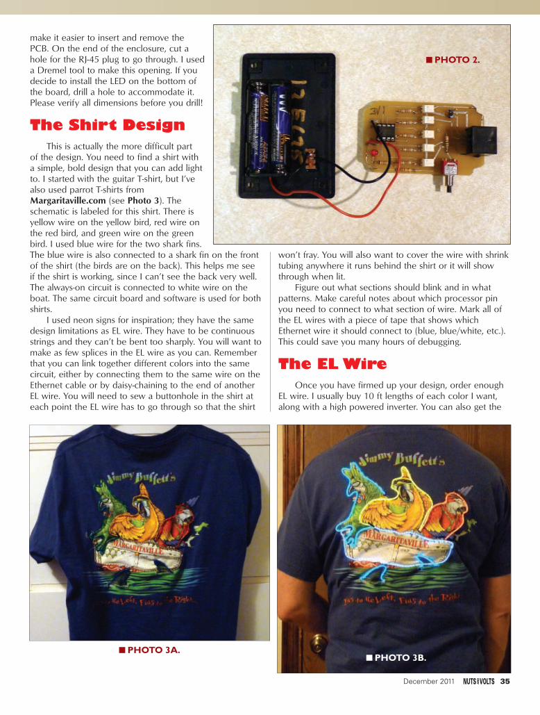
make it easier to insert and remove thePCB. On the end of the enclosure, cut ahole for the RJ-45 plug to go through. I useda Dremel tool to make this opening. If youdecide to install the LED on the bottom ofthe board, drill a hole to accommodate it.Please verify all dimensions before you drill!
The Shirt DesignThis is actually the more difficult part
of the design. You need to find a shirt witha simple, bold design that you can add lightto. I started with the guitar T-shirt, but I’vealso used parrot T-shirts fromMargaritaville.com (see Photo 3). Theschematic is labeled for this shirt. There isyellow wire on the yellow bird, red wire onthe red bird, and green wire on the greenbird. I used blue wire for the two shark fins.The blue wire is also connected to a shark fin on the frontof the shirt (the birds are on the back). This helps me seeif the shirt is working, since I can’t see the back very well.The always-on circuit is connected to white wire on theboat. The same circuit board and software is used for bothshirts.
I used neon signs for inspiration; they have the samedesign limitations as EL wire. They have to be continuousstrings and they can’t be bent too sharply. You will want tomake as few splices in the EL wire as you can. Rememberthat you can link together different colors into the samecircuit, either by connecting them to the same wire on theEthernet cable or by daisy-chaining to the end of anotherEL wire. You will need to sew a buttonhole in the shirt ateach point the EL wire has to go through so that the shirt
won’t fray. You will also want to cover the wire with shrinktubing anywhere it runs behind the shirt or it will showthrough when lit.
Figure out what sections should blink and in whatpatterns. Make careful notes about which processor pinyou need to connect to what section of wire. Mark all ofthe EL wires with a piece of tape that shows whichEthernet wire it should connect to (blue, blue/white, etc.).This could save you many hours of debugging.
The EL WireOnce you have firmed up your design, order enough
EL wire. I usually buy 10 ft lengths of each color I want,along with a high powered inverter. You can also get the
■■ PHOTO 2.
■■ PHOTO 3A.■■ PHOTO 3B.
December 2011 35
Tuesley - Bird Shirt.qxd 10/31/2011 2:00 PM Page 35

five-color CK-3 kit if you just need short pieces of severalcolors. For some designs, you may even be able to just liftthe entire pre-made wire assembly and use it directly. Ifthat’s not practical, you will have to make your own wiringharness. The chart in Table 1 will help you keep track ofeach circuit.
The extremely fine wires inside the plastic insulationcan be difficult to work with. I found a pair of highpowered reading glasses helped me locate them. Thereare a lot of tips on the EL Wire website. Click on the SiteMap link and look under the soldering tips. Make yourconnections sturdy; you may be crowd surfing with thisshirt on! Use generous lengths of shrink tubing on all ofyour connections. I used 22-gauge speaker wire toconnect the EL wire to the Ethernet cord.
First, separate the speaker wire for at least one inch.Cut one wire about 1/4” shorter than the other; strip themboth for 1/4”. Next, strip about 3/8” of the colored jacketoff the outside of the EL wire. Now, find the two very finewires that spiral around the core inside the second clearlayer. Very carefully strip off the second layer of insulation.Do not cut the wires! Fold them back out of the way.Scrape off 1/4” of the white layer covering the wire core.Put a piece of shrink tubing over the shorter speaker wire,and then solder that wire to the core of the EL wire. Once
it’s solidly connected, pull the shrink tubing over theconnection up to the two fine wires and shrink it intoplace. I used 3/32” shrink tubing for all of myconnections, but you might want to get some 1/8” tomake the outer ones slide over the inner ones easier.Solder the two fine wires to the longer speaker wire.Check that the wire lights when you apply power. Afteryou confirm that the connection is good, put some shrinktubing over the entire connection and shrink it into place.
After each EL wire had a lead wire and was attachedto the shirt, I routed them all down to the bottom edge ofthe shirt and connected them to the Ethernet cable. Sewthem all solidly in place. Make the Ethernet cable longenough to reach the pocket where you intend to keep theelectronics. Leave some slack.
Once everything is connected, plug in the controllerand turn on the EL inverter. Your always-on circuits shouldlight up. Next, power up your controller and press thepattern switch once or twice. Your EL wire should startblinking. Once you are sure everything works, wrap all ofthe wires together with larger diameter shrink tubing.
SewingYou may want to take your shirt to a local alterations
shop for the button holes. It’s not easy to sew them into T-shirts. Don’t even consider doing them yourself without asewing machine that does automatic buttonholes. If youdo them yourself, you may want to get some self-adhesiveliner material (called interfacing) at a fabric store. I’ve hadmixed success with it. Sacrifice an old T-shirt to the causeand practice both with and without the interfacing.
Carefully mark where you need the holes to be with alight pencil mark or a pin. Allow the automaticbuttonholer to do its job. Note which way the sewingmachine makes the buttonhole outline — probably AWAYfrom you. Now, apply a generous-size patch of theinterfacing behind the shirt and try again. Select themethod that works best on your fabric. You only need
about a 4 mm holefor a single wire; a6 or 7 mm holewill accommodatetwo wires. Onceyou are good atbuttonholes, goahead and sewthem in your shirt.Take a good pair ofscissors or a seamripper and carefullyopen up themiddle of eachone.
Now, threadyour first piece ofEL wire throughthe buttonhole. Layit out on the shirt
36 December 2011
EEtthheerrnneettPPiinn ##
WWiirree CCoolloorr PPIICC PPiinn BBiirrdd SShhiirrtt GGuuiittaarr
1 Orange/White Ground Ground Ground
2 Orange — Boat Body ofGuitar
3 Green/White 7 — —
4 Blue 6 Yellow Bird String #1
5 Blue/White 5 Blue Shark String #2
6 Green 3 Green Bird String #3
7 Brown/White 2 Red Bird String #48 Brown Ground Ground Ground
TTaabbllee 11..
PARTS LIST QTY DESCRIPTION ID SOURCE AND PART #5 47 ohm, 1/8 watt resistor R2-4, R5-7 Digi-Key CF18JT47R0TR-ND1 1K ohm, 1/8 watt resistor R8 Digi-Key RNF18FTD1K00CT-ND1 10K ohm, 1/8 watt resistor R4 Digi-Key RNF18FTD10K0CT-ND1 120 ohm, 1/8 watt resistor R1 Digi-Key CF18JT120RCT-ND1 Pushbutton switch, NO SW1 Jameco 71643-21 .1 µF capacitor C1 Jameco 152701 LED, any color D11 Eight-pin DIP socket Digi-Key ED2202-ND1 PIC12F675 processor U1 Digi-Key PIC12F675-I/P-ND / Jameco 2237811 RJ-45 socket CN2 Digi-Key WM5432-ND5 G3VM-2L opto-isolated relay U2-3, U4-7 Digi-Key Z2710-ND (note new “L” version)1 Enclosure Jameco 189221 Slide power switch Jameco 109171-31 Two “AAA” battery holder Jameco 616283-310 ft 3/32” shrink tubing Jameco 6448341 roll 24-gauge speaker wire Jameco 1002801 Ethernet patch cord Jameco 21156021 Two-pin .1” C-C header CN1 Jameco 1083381 Two-pin socket Taken from old computer case
Tuesley - Bird Shirt.qxd 10/31/2011 2:00 PM Page 36

exactly where it needs to go and tape or pin it down. Sewthe wire in place firmly by hand; a sewing machine can’tdo this job. Use heavy thread or a double strand of lighterthread. Be careful to not puncture the wire! Repeat foreach strand of wire.
This is where it pays to know someone who can sew.Having an experienced hand help here is worth more thanyou can imagine. Use thread the same color as the shirtso that it blends in. I found that I needed a loop over thewire about every 1/2” in order to hold it securely in place.Put the loops closer around tight curves. The specs sayyou shouldn’t bend the EL wire any tighter than the radiusof a dime, but I’ve made tightercorners and haven’t had anyproblems (yet). Tie every stitchfirmly with a square knot. Double-knot them at high stress points (likewhere they go through thebuttonholes). Don’t forget to putshrink tubing over EL wires routedbehind the shirt so that they don’tshow through.
The SoftwareIf you’ve tested everything up
to this point, all you have to do isturn it on; everything should work.However, you may want a differentpattern than I used. That’s thewhole point here. Be creative! Thesoftware is labeled for the three-birdT-shirt I made, but it will work justas well for a guitar design. Use thethree birds and the shark for theguitar strings. I used the always-oncircuit for the body of the guitar,but you could use pin 7 to blink it,too.
The code is all written in PICassembly. It’s broken up into severalsubroutines that are called from themain loop. There’s a delay loopused for blinking that also checksthe pattern selection switch. Theprocessor runs off the 4 MHzinternal clock; if you change this,you will have to adjust the delaycode.
The switch code rotates aneight-bit variable called “Direction.”Whatever bit is on selects thatpattern in the main loop. There aresubroutines to blink each of thepins. Those are, in turn, called fromsubroutines that combine them intopatterns.
Note that the one to blink pin 7is not called since neither of these
designs use it. BirdLoop2, for instance, blinks the guitarstrings (or the three birds) in one direction or the other,depending on the value in Direction. The StayOn routineturns on all of the strings and waits for you to press theselection button (this is the default pattern when you turnit on). The BlinkOne routine will blink one of the strings,again based on the value in Direction.
I’ve just scratched the surface of what can be donewith my code. You should customize it to go with the shirtdesign you come up with. There’s plenty of code spaceavailable, so if you feel like programming the cords for“Stairway to Heaven,” go for it. Have fun! NV
December 2011 37
Tuesley - Bird Shirt.qxd 10/31/2011 2:01 PM Page 37

I installed two affordable CCTV cameras withinfrared for night vision around our yard to deter anypotential troublemakers. An old Sharp VCR was put intoservice as a time-lapse VCR using a circuit that I built toswitch between the two cameras and control the VCR
using IR signals, but I had no way of knowing whenevents had happened because the VCR does not writethe date/time on the video recording. So, I built the RTCOSD (real time clock on-screen display) to provide anaccurate time-stamp for the recordings.
HOW THECIRCUITWORKS
The circuit is made quitesimple through the use offunction-specific chips and aMicrochip PIC to tie themtogether. Video display can bevery tricky to get right, but theMAX7456 makes displaying
Closed circuit television (CCTV) camera systems have been in use for yearsin commercial areas such as banks and supermarkets, but with camera pricesbeing more affordable, CCTV is now used more and more to protect homesand private property. Unfortunately, recording systems such as DVRs andtime-lapse VCRs can be expensive, so an old VCR is sometimes used instead.However, without time stamps on the recordings, it can be difficult todetermine when an event occurred.
38 December 2011
By Kelly Lewis
■■ FIGURE 1. MAX7456 mountedon a 28-pin SSOP to DIP adapter.
A real time clock-based on-screen display for closed-circuit television camera recording.
BUILD THE RTC OSD FOR
CCCCTTVVRREECCOORRDDIINNGG
Discuss this article in the Nuts & Volts forums at http://forum.nutsvolts.com.
●●●●
Lewis - RTC OSD for CCTV Recording.qxd 11/1/2011 6:48 PM Page 38
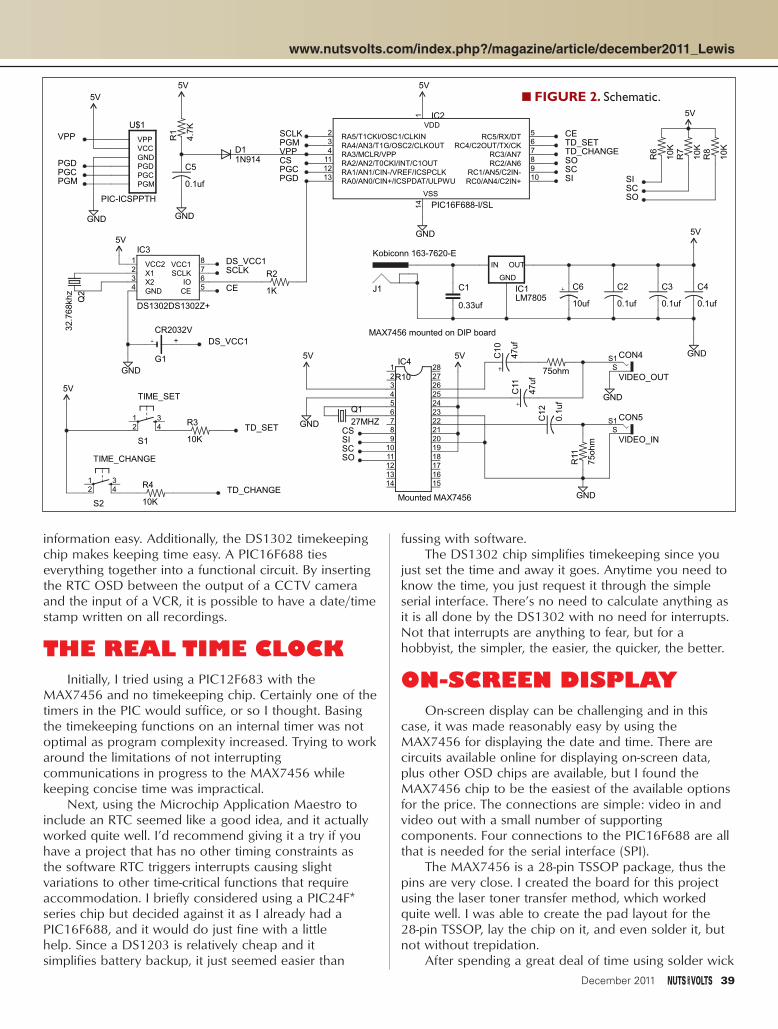
information easy. Additionally, the DS1302 timekeepingchip makes keeping time easy. A PIC16F688 tieseverything together into a functional circuit. By insertingthe RTC OSD between the output of a CCTV cameraand the input of a VCR, it is possible to have a date/timestamp written on all recordings.
THE REAL TIME CLOCKInitially, I tried using a PIC12F683 with the
MAX7456 and no timekeeping chip. Certainly one of thetimers in the PIC would suffice, or so I thought. Basingthe timekeeping functions on an internal timer was notoptimal as program complexity increased. Trying to workaround the limitations of not interruptingcommunications in progress to the MAX7456 whilekeeping concise time was impractical.
Next, using the Microchip Application Maestro toinclude an RTC seemed like a good idea, and it actuallyworked quite well. I’d recommend giving it a try if youhave a project that has no other timing constraints as the software RTC triggers interrupts causing slightvariations to other time-critical functions that requireaccommodation. I briefly considered using a PIC24F*series chip but decided against it as I already had aPIC16F688, and it would do just fine with a little help. Since a DS1203 is relatively cheap and it simplifies battery backup, it just seemed easier than
fussing with software. The DS1302 chip simplifies timekeeping since you
just set the time and away it goes. Anytime you need toknow the time, you just request it through the simpleserial interface. There’s no need to calculate anything asit is all done by the DS1302 with no need for interrupts.Not that interrupts are anything to fear, but for ahobbyist, the simpler, the easier, the quicker, the better.
ON-SCREEN DISPLAYOn-screen display can be challenging and in this
case, it was made reasonably easy by using theMAX7456 for displaying the date and time. There arecircuits available online for displaying on-screen data,plus other OSD chips are available, but I found theMAX7456 chip to be the easiest of the available optionsfor the price. The connections are simple: video in andvideo out with a small number of supportingcomponents. Four connections to the PIC16F688 are allthat is needed for the serial interface (SPI).
The MAX7456 is a 28-pin TSSOP package, thus thepins are very close. I created the board for this projectusing the laser toner transfer method, which workedquite well. I was able to create the pad layout for the 28-pin TSSOP, lay the chip on it, and even solder it, butnot without trepidation.
After spending a great deal of time using solder wick
5V
5V
10ufLM7805
0.33uf
GND
GND
5V
GND
5V
GND
32.7
68khz
CR2032V
5V
S2
S1
5V
1N914
5V
GND
10K
10K
10K
4.7
K
10K
10K
1K
0.1uf 0.1uf 0.1uf
0.1uf
PIC16F688-I/SL
Kobiconn 163-7620-E
Mounted MAX7456 GND
75ohm
47uf
47uf VIDEO_OUT
VIDEO_IN
GND
0.1
uf
75ohm
5V5V
GND 27MHZ
PIC-ICSPPTH
C6IC1
GND
IN OUT
C1
Q2
+-
G1
1 342
TIME_CHANGE
1 342
TIME_SET
IC3
DS1302DS1302Z+
VCC21
X12
X23
GND4
CE5
IO6
SCLK7
VCC18
D1
R6
R7
R8
R1
R3
R4
R2
C2 C3 C4
C5
1
RA5/T1CKI/OSC1/CLKIN2
RA4/AN3/T1G/OSC2/CLKOUT3
RA3/MCLR/VPP4
RC5/RX/DT5
RC4/C2OUT/TX/CK6
RC3/AN77
RC2/AN68
RC1/AN5/C2IN-9
RC0/AN4/C2IN+10
RA2/AN2/T0CKI/INT/C1OUT11
RA1/AN1/CIN-/VREF/ICSPCLK12
RA0/AN0/CIN+/ICSPDAT/ULPWU13
14
VDD
VSS
IC2
J1
1234
IC4
56789
1011121314 15
16171819202122232425262728
R10
C10
C11
S1S
CON4
S1S
CON5C12
R11
Q1
GND
PGCPGD
PGM
VCCVPP
U$1
CS
CS
SC
SC
SC
SO
SO
SO
SISI
SI
VPP
VPP
PGD
PGDPGC PGC
PGM
PGM
TD_SET
TD_SET
TD_CHANGE
TD_CHANGE
DS_VCC1
DS_VCC1
CE
CE
SCLK
SCLK
MAX7456 mounted on DIP board
www.nutsvolts.com/index.php?/magazine/article/december2011_Lewis
December 2011 39
■■ FIGURE 2. Schematic.
Lewis - RTC OSD for CCTV Recording.qxd 11/1/2011 6:47 AM Page 39

to clean up the solder mess, and after examining thechip pins with a magnifying glass over and over, the chipfailed when I powered up the circuit. I had overlookedthe exposed pad beneath the chip — or it may havefailed because of a hairline connection or failurebetween pins that was nearly invisible. Checkingconnections with an ohmmeter and a magnifying glassrevealed no problems. There was no way of trulyknowing if every connection was dependable without amicroscope, which I do not possess.
To prevent a repeat of my last soldering mistake, Iordered a “SSOP to DIP Adapter 28-Pin“ (BOB-00500)from SparkFun and rerouted traces on the board for a28-pin DIP instead of a 28-pin SSOP. I do not work forSparkFun, but I can certainly recommend their breakoutboards as being easy to use and reliable. Their 28-pinSSOP adapter has more accurate spacing than possibleusing the toner transfer method and it does not havetraces beneath the SSOP chip. The adapter solved theexposed pad problem and made soldering theMAX7456 much easier.
CONSTRUCTIONI chose to use SMD parts whenever possible
because I’ve actually found it easier to use them thanthrough-hole parts. That may come as a shock to somehobbyists, but when it comes down to etching your ownboard, the fewer holes you need to drill, the better.Using the most narrow, flat, soldering tip possible withsmall diameter solder is a necessity for hand-solderingSMD parts — especially SSOP packages. Round
soldering tips tend not to hold atiny amount of solder on the tipas well as a screwdriver orflattened tip does. However, I’vealso learned to stick with 1206packages and SOIC packageswhenever possible. SSOP can bedone by hand, but it ischallenging unless you have thehands and eyes of a surgeon.
For vias, I’ve always just useda piece of wire or componentlead and soldered the lead intothe via. However, what happenswhen you need to mount a radialpackage electrolytic capacitorwith traces connecting to thethrough-hole leads on the topand bottom of the board and youdon’t have a way to do plated
vias? There’s no way to solder underneath a radialcapacitor without mounting the capacitor in an awkwardlooking way. In those cases, I usually route the traces insuch a way as to avoid the problem, but that isn’t alwayspractical and in some cases it can contribute to makingthe etched board bigger.
One solution that I came across on the DallasPersonal Robotics Group website was included in avideo by Doug Paradis wherein he described a way tocreate a plated through via without using chemicals. Hedescribes using copper foil — available from craft stores— to form a tiny tube of copper to fit into the hole onthe board that needs to be through-plated. The coppertube works well but if the board hole is too tiny, thenyou just will not be able to form a small enough tube tofit into the hole. For more information on the method,visit http://youtu.be/iU6LPvFEYeY.
THE FIRMWAREThe PIC16F688 code was written in C using the free
version of the Hi-Tech C compiler available fromMicrochip within MPLAB version 8.66. The codeinitializes I/O, initializes the RTC, initializes the OSD,checks for user input for changing the date/time, andoutputs the date/time for recording or displaying on aCCTV monitor or television screen.
Although the sample code for the DS1302 was foran 8051 chip, it was in C and I was able to extract thesections of the code that I needed and port them overto the PIC16F688. The DS1302 has the ability to providethe date/time in AM/PM format or 24-hour format, so I
40 December 2011
■■ FIGURE 3. Completed circuitboard in use.The board was etchedto accomodate RCA jacks, but Iended up using direct wiring instead.
Lewis - RTC OSD for CCTV Recording.qxd 11/1/2011 6:51 PM Page 40

chose the 24-hour format as it was a little easier to use.The DS1302 outputs data in binary coded decimal
(BCD). The DS1302.c code translates the BCD data intocharacter values the MAX7456 can use. For instance, ifthe DS1302 sends data stating the date is “04 29 2011,”then the data sent to the MAX7456 to display thisinformation would be “0x0A, 0x04, 0x47, 0x02, 0x09,0x47, 0x02, 0x0A, 0x01, 0x01” where 0x47 is a “/”character. The output on-screen would be“04/29/2011.”
Both the DS1302 and MAX7456 code use simpleserial code, or what would be “ShiftIn” or “ShiftOut” inBasic. However, the DS1302 code uses quite a lot of bitshifting after receiving data simply because of the formatthat the data is in. On the other hand, the MAX7456code is straightforward as data is either shifted in or outas listed in the shiftdata.c code. Oddly, neither code setneeded delays as is sometimes needed when doing bitshifting.
The “ShiftIn” sections for each device were justdifferent enough to prevent reuse. Besides, I had alreadycreated the shiftdata.c code for the MAX7456 basedupon sample code on the Maxim website long beforecreating the DS1302 code, and found it much moreeffective to keep the code sections separated.
When the circuit is first started, naturally the
date/time will need to be adjusted. This is accomplishedby using the two board-mounted pushbuttons in afashion similar to a digital watch. When the “TimeSet”pushbutton is pressed, the code state changes from timedisplay to time change. The first digit in the date/timewill blink on the CCTV display while pressing the “TimeChange” pushbutton increases the blinking number untilit wraps around to zero. Wrapping around does notincrement the adjacent digit.
Upon attaining the desired digit value, pressing the“Time Change” pushbutton will cause the next digit tothe right to blink as it is ready to be changed. Theblinking digit is changed using the “TimeSet” pushbuttonafter which the next digit blinks, and so on until all digitsare changed as desired. The date/time will continue tochange even if the RTC OSD is left in “TimeSet” mode.If “TimeSet” mode is not exited by setting the last digitin the date/time, then the digit being changed using thepushbuttons will continue to blink forever.
CONCLUSIONThe RTC OSD provides an easy way to add a time
stamp to a CCTV camera recording as programmed.Simply plug the CCTV camera or CCTV switcher intothe video input of the RTC OSD, and plug the video
PARTS LIST ITEM QTY DESCRIPTION SUPP. SUPP. PART# MNF. MNF. PART#
C1 1 0.33 µf 100V radial capacitor Mouser 598-M30U334M1-F Cornell-Dubilier M30U334M1-FC2-C5 4 0.1 µf 50V capacitor
SMD 1206 package Mouser 80-C1206C104M5R Kemet C1206C104M5RACTUC6 1 10 µf 25V radial electrolytic capacitor Mouser 598-SEK100M025ST Cornell-Dubilier SEK100M025STC10,C11 2 47 µf 16V radial electrolytic capacitor Mouser 598-SEK470M016ST Cornell-Dubilier SEK470M016STCON4,CON5 2 RCA connectors — panel mount Mouser 502-BPJR04X Switchcraft BPJR04XD1 1 1N914 diode Mouser 512-1N914 Fairchild 1N914G1 1 Battery holder for
battery type CR2032V Mouser 614-VBH2032-1 Renata VBH2032-1IC1 1 TO220 package five volt DC
one amp low dropout regulator Mouser 511-L4941BV ST Micro L4941BVIC2 1 SOIC package PIC16F688 Mouser 579-PIC16F688-I/SL Microchip PIC16F688-I/SLIC3 1 SOIC package DS1302
RTC timekeeping chip Mouser 700-DS1302S Maxim DS1302S+IC4a* 1 TSSOP28 package
MAX7456 OSD chip Mouser 700-MAX7456EU Maxim MAX7456EUI+IC4b* 1 SSOP to DIP adapter 28-pin SparkFun BOB-00500 Sparkfun BOB-00500J1 1 163-7620-E power jack Mouser 163-7620-E Kobiconn 163-7620-EQ1 1 27 MHz crystal Mouser 815-ABL-27-B2F Abracon ABL-27.000MHZ-B2FQ2 1 32.768 kHz crystal Mouser 815-AB38T-32.768KHZ Abracon AB38T-32.768KHZR1 1 4.7K SMD 1206 package Mouser 652-CR1206FX-4701ELF Bourns CR1206FX-4701ELFR2 1 1K SMD 1206 package Mouser 652-CR1206-JW-102ELF Bourns CR1206-JW-102ELFR3,R4,R6,R7,R8 5 10K SMD 1206 package Mouser 652-CR1206FX-1002ELF Bourns CR1206FX-1002ELFR10, R11 2 75 ohm SMD 1206 package Mouser 652-CR1206FX-75R0ELF Bourns CR1206FX-75R0ELFS1,S2 2 Mini pushbutton switch SparkFun COM-00097 Omron B3F-1060U$1 1 2.54 mm breakaway vertical header Mouser 517-929834-01-36-RK 3M 929834-01-36-RK
*Note: IC4a and IC4b are represented on the schematic as one unit being that the MAX7456 mounts to the SSOP to DIP adapter, thus creating one unit: IC4. Also, 28 of the breakaway pins of U$1 are used for mounting the adapter.
December 2011 41
Lewis - RTC OSD for CCTV Recording.qxd 11/1/2011 6:48 AM Page 41

output of the RTC OSD into a VCR or even a DVR forrecording, then apply 7 to 9 VDC power.
Of course, there is opportunity for customization.The RTC code could be changed to output in AM/PMformat and the MAX7456 could display it as such. TheMAX7456 code could be changed to alter theappearance of the characters as custom characters aresupported. Even multiple lines could be displayed, withone being the title of the camera area and the otherbeing the date/time.
Bear in mind that the MAX7456 is designed for usewith NTSC and PAL equipment. If you attempt to displaya line at the bottom of the screen — row 16, for instance— and you are using an HDTV as a monitor, the line willdisplay somewhere near the middle of the screenbecause the MAX7456 will not output past scanline 525as a 1080p HDTV has 1080 scanlines.
When dealing with high frequency signals, it is oftennecessary to include a ground plane. The board that Icreated does not have a ground plane, and it wascreated using the toner transfer method rather thanhaving it professionally etched. I found no need for theground plane as long as I did not run wires underneaththe board, in which case slight signal noise was noted. Ifyou’d prefer to have the boards etched professionally,you might want to edit the Cadsoft Eagle PCB toeliminate the SSOP to DIP adapter.
If editing is done, be careful not to run any tracesunder the MAX7456 because of the exposed pad, unlessyou intend to connect the pad. Consider ordering soldermasking and even tinning to make soldering theMAX7456 a little easier. All of these options can bequite expensive compared to a basic double-sided boardorder, hence I used the SSOP to DIP adapter and savedquite a bit of money in board etching costs. Althoughthe dat sheet for the MAX7456 indicates that theexposed pad should be connected to a similarly sizedpad on the component side of the PD board to aid inheat dissipation, I’ve had no problems with the chip forthe last several months.
If this board was going to be made into acommercial product, then a ground plane wouldcertainly be recommended. In fact, referring to theMAX7456EVKIT datasheet for a board layout examplewould be strongly recommended.
At last check, the MAX7456 was priced around $20at Mouser.com and the DS1302 was about $4. This $20may seem expensive, but it is worth it for the amount oftime that it saves and the simplicity of use. Also, the lasttime that I checked, Maxim has a special programproviding free samples for potential customers that are inschool and have an education based (.edu) emailaddress. NV
42 December 2011
Lewis - RTC OSD for CCTV Recording.qxd 11/1/2011 6:52 PM Page 42

Need high-quality audio in a miniature package? The A8520 Anaren Integrated Radio (AIR) module offers:
> Uncompressed wireless digital audio/full CD quality (44.1/48KHz/16 bits)
> Robust RF protocol – with virtually no RF engineering experience necessary
> Tiny 11 x 19 x 2.5mm form factor
> Integral antenna
> Pre-certifi ed/compliant: FCC, IC, ETSI (pending)
To learn more, write [email protected], visit www.anaren.com/air, or scan the QR code with your smart phone.
800-411-6596www.anaren.comIn Europe, call +44-2392-232392
Available from:
Lowlatency.
One, tiny wireless audio
module.
December 2011 43
Page 43 Dec11.qxd 10/31/2011 9:10 AM Page 43

Sunstone Advanced Batch Express Circuits PCB PCB
FREE STENCIL
Manual DRC included
Collision detection
Accepted file formats
Face to Face Order Tracking
Discount for feedback
Etest includedfor Multilayer
Direct orderfrom EAGLE
Watch“ur“PCB
On Time or Free
Data restoration service
Online PCB price calculation
Often copied - never equaled:
16 6 2 2 1
PCB-
POOL®
is a
reg
iste
red
trade
mar
k of
Bet
a LA
YOUT
Gm
bH
www.pcb-pool.com
The Original since 1994!
@
Call Tyler:707 447 7744
765 Eubanks DriveVacaville CA 95688
Toll FREE USA: 1 888 977 7443Email: [email protected]
Full Page.qxd 11/1/2011 7:32 AM Page 44

MANUFACTURERS - We Purchase EXCESS INVENTORIES... Call, Write, E-MAIL or Fax YOUR LIST.
NO MINIMUM ORDER • All Orders Can Be Charged to Visa, Mastercard, American Express or Discover • Checks and Money Orders Accepted by Mail • OrdersDelivered in the State of California must include California State Sales Tax • NO C.O.D • Shipping and Handling $7.00 for the 48 Continental United States - ALLOTHERS including Alaska, Hawaii, P.R. and Canada Must Pay Full Shipping • Quantities Limited • Prices Subject to change without notice.
MAIL ORDERS TO:ALL ELECTRONICS CORP.
14928 OXNARD ST., VAN NUYS, CA 91411-2610
FAX (818) 781-2653 • INFO (818) 904-0524
E-MAIL [email protected]
Shop ON-LINE www.allelectronics.comORDER TOLL FREE 1-800-826-5432
QUALITY Parts
FAST Shipping
DISCOUNT Pricing
CALL, WRITE, FAX or E-MAIL for a FREE 96 page catalog.
Outside the U.S.A. send $3.00 postage.
ALLELECTRONICS
ALLELECTRONICS
C O R P O R A T I O N
12 VDC FLASH ASSEMBLYBright xenon strobe assembly with horseshoe flash tube. Approximately 80 flashes per minute. 65 x 75mm PC board. 12 Vdc operation.
CAT# FSH-13 $700each
$100each
50mm wire leads.
CAT# PE-56
10 for 85¢ each
21MM PIEZO ELEMENT
12VDC 1A POWER SUPPLY Switching power supply. Input: 100-240V, 50-60Hz, 0.3A. Output: 12Vdc, 1Amp. Right-angle coax power plug. 5.5mm od, 2.1mm id, center+. cULus, CE.
CAT# PS-1219 $895
each
MINI-PANCAKE
VIBRATING MOTOR LG Innotek Co.# TA09-T3001459AA / SpecMVMF-A346T3. 10mm dia. x 3mm thick. Operates on 1.5 - 4 Vdc. Two 12mm wireleads. Prepped with adhesive patch on one side.
CAT# DCM-707 $100
each
50 for 80¢ each • 100 for 75¢ each
9 VDC BUZZER
18 GAUGE TEFLON TUBING,
NATURALPTFE 18 TW NATURAL. 18 Gauge, thin-wallTeflon tubing. Natural (white). TFE-TW-300.Type VW-1. Rated 200C Degrees. 300Vrated. Nominal I.D. 0.042". Wall Thickness:0.012". CSA. 5' min.
CAT# PTFE-18 $150ft. for5100’ for 25¢ per ft. • 1000’ for 18¢ per ft.
Mechanical, medium-loud buzzer. Ideal for school projects. 16.9mm x 23mm (33.38mm base mounting tabs, 1.1" centers) x 15.39mmbody. 9 Vdc, can operate @ 3 Vdc. 4.5" long leads.
CAT# BZ-90 $125each
20 for $1.15 each
Japan Servo Motor# KH42JM2-038. 6-pin connector, 1.8º / step motor attached to a gear train with eight singleand compound gears. Motor is 42mm square(1.63") x 1.57" long with a 5mm dia. shaft witha brass gear attached. The gear train is 6" x1.45" overall and is removable. Requires an11-pin socket connector, 2mm pitch for connection.
CAT# SMT-107
STEPPER MOTOR W/
GEAR
TRAIN
$1000each
20W 8 OHM HORN SPEAKER Universal# SP-20B. Horn-type communication speaker. 20 Watt 8 Ohms. 5.25" diameter x 6" long. 3-hole adjustable mounting bracket. 12" leads.
CAT# PHS-20 $995
each
BATTERY HOLDER,
4 AA CELLS Holder for 4 AA size batteries, in a 2x2 stacked format. 2.25" long x 1.20" x 1.10" high. Unbreakable
black plastic. 6" wire leads. CAT# BH-342
$110each
10 for 95¢ each100 for 80¢ each
DOOR LOCK ACTUATOR 12 Vdc motor-drive actuator for auto-motive door locks. Nylon plunger moves 0.75". Push or pull, depending on polarity. Includes mountinghardware and a 10" metal extension rod whichfits through the hole in the end of the plunger.Overall dimensions of actuator assembly (retracted): 8.42" x 2.35" x 1.15". Rubber boot protects against moisture anddust. Pigtail leads.
CAT# DLA-1 $550each
RGB COLOR-CHANGING LED 5mm (T1-3/4) led cycles through, red -green - blue and combinations of thosecolors, yielding white, purple and otherhues. Changes color every 3 or 4 seconds.Water-clear in off-state. Great for attentiongetting displays, costumes or jewelry.
CAT# LED-158
75¢each
10 for 70¢ ea. • 100 for 50¢ ea.
LIGHTWEIGHT STEREO
HEADPHONES Lightweight stereo headphones for audio and computer applications. Adjustable headband. 3.5mm phone plug with 4' shielded cord.
CAT# HP-100
$335each
100 for $2.50 each
DESKTOP COMPUTER
MICROPHONE Electret multimedia micro-phone for computer audio and telephonic applicat-ions. Omnidirect-ional mike with 100 - 10,000 Hz frequency response. Desk stand and holder with adhesive backing to attach to side of computer monitor. 8' cord with3.5mm stereo phone plug.
CAT# MIKE-90 $450each
December 2011 45
Full Page.qxd 11/1/2011 7:30 AM Page 45

Taking pen in hand, I started writing down what Iwanted in the design:
• Have the means for in-circuit programming.• Work with voltages up to 24 volts.• Use all surface-mount technology.• Have a transistor for control of devices such as
mechanical relays. • Tolerate a 10 msec dropout.• Selectable sense of output.• Use internal timer instead of stacked delay loops.
I began to realize that this little circuit — with in-circuitprogrammability — could be used for a number ofdifferent yet similar functions such as flashers or pulsegenerators. With a minimum of external components, thedevice would be all in the software, which is the waymicroprocessor designs should be. The idea began to formof making a circuit so small and universal that it would bea component on its own, which could then be wired intoa project the same as a resistor or capacitor. This could besomething really useful for doing a lot of small, quickprojects around the home and lab.
Having decided on the PIC10F200, I drew up mycircuit schematic starting with the microprocessor. Since Ihave a bunch of surface-mount 2N2222 transistors, Idecided on it for my load driver. The transistor cancontinuously carry a load of 600 mA — more than enoughto drive a number of common relays. I chose a simplezener diode voltage regulator since it would be thecheapest, and voltage regulation wasn’t critical. With anoperating voltage ranging from 2.0 to 5.5 volts, a zenerregulator would allow the circuit to operate down toabout two volts, while with a five volt regulator — such asa 78L05 (TO92 versions) — it would mandate a minimumoperating voltage of about 7.5 volts.
Doing a quick layout of the circuit board, I soon hadan elongated circuit board that was about the size of alarge pill ... hence the name, pill timer. This was becausethe circuit has so few parts. Encouraged, I began workingthe circuit over to determine the values needed for thecomponents; in particular, the zener voltage regulator. Thefive to 24 volt range is rather large, so I needed todetermine a value for R1 (see Figure 1, schematic) whichwould give me that range.
Using Mathcad and my SPICE circuit simulator, I
I recently needed to update a design for a small five-second “power on”timer, and decided to use Microchip’s PIC10F2xx series microprocessors. Inlooking at the PIC10F200, I began to get carried away with the size.Thesurface-mounted version is a six-pin SOT-23 package outline which is smallerthan some surface-mount transistors I have.That got me thinking about howelse I could make the timer circuit smaller but more versatile than my olderthru-hole design.
46 December 2011
By James Lyman
Discuss this article in the Nuts & Volts forums at http://forum.nutsvolts.com.
PILL TIMERS — BIG MEDICINE FOR YOUR
LLIITTTTLLEEPPRROOJJEECCTTSS
Lyman - Pill Timers Big Medicine.qxd 11/1/2011 6:46 PM Page 46

started doing calculations ofpower dissipation for both R1and D1. For a 4.7 volt zenerand a minimum input voltage offive volts, R1 would have avalue of just 10 ohms. The onlytrouble is — for the maximuminput voltage of 24 volts — R1would dissipate 38 watts whilethe zener diode had a loadcurrent of almost two amps.Obviously, more work wasneeded on the design. R1would need to be a much largervalue.
The maximum continuouscurrent for the surface-mountedversion of the 2N2222 is 600milliamps, and for a DC beta of150, the base current is fourmilliamps. So, working with this,I tried different values of R1 andinput (battery) voltages while monitoring the currentthrough the zener diode and output voltage. One big plusis the PIC10F200 operates from 5.5 volts down to 2.0volts, so I didn’t need good regulation; I just needed tolimit the voltage to under 5.5 volts.
One thing quickly became apparent: I wasn’t going toget my 24 maximum operating volts. It looked like 15 voltswas going to be the best I could do, which is about themaximum encountered in electronic circuits. Inautomotive systems, the voltage will reach about 16.5volts while the engine is running, so this could be aproblem. So, if a pill timer is to be used in an automotivecircuit, the value of R1 may need to be increased to give agreater voltage drop, thereby reducing the current throughzener diode Z1.
SMD and In-CircuitProgramming
The next objective of having In-Circuit Development(ICD) programming ability defeats thegoal of using surface-mount devicesbecause normally, ICD requires a headerpin set to plug the programmer in. Thetraditional SIP headers I use for ICD wouldbe bigger than the anticipated size of thepill timer’s circuit board, so somethingbetter was needed. In addition, I alsowanted to keep all the componentsmounted on one side of the board, so thecircuit would lay flat on a surface.
What I needed was something likefinger pads on the edge of the circuitboard that would allow the pill timer to beplugged into a connector with finger
contacts. The trouble is there isn’t any standard connectoravailable that would fit the bill. I would need a custom-built device using several small precision made parts.Sounds like a lot of time and effort with the lathe andmilling machine. This would be something difficult formost amateurs to reproduce. I thought about trying to usean RJ-9 jack with an insert that would force the circuitboard up and make contact with the finger pads. Thatwould make the circuit board layout larger, however, and Iwanted to keep it as small as possible.
The most difficult part of doing a custom connector isensuring all contacts make and hold electrical contact; thetolerances just become too tight. I then thought aboutimplementing thru-hole vias used to route lands from onecircuit board layer to another. The small hole would givean anchor to hold a pin in place when pressure is applied.If I took a common straight pin, bent the tip over 90degrees, then fixed it in a spring lever so the springpressure would hold the pin down in the hole, it wouldthen be easy to reprogram the timer.
www.nutsvolts.com/index.php?/magazine/article/december2011_Lyman
December 2011 47
■■ FIGURE 1.Schematic.
PARTS LIST
ITEM QTY DESCRIPTION Digi-Key PART#C1 1 0.1 µF capacitor, ceramic, 25V,
10% X&R SMD 0805 PCC1828CTC2 1 10 µF capacitor, tantalum,
10V 20% SMD 1206 718-1118-1D1 1 4.7 volt zener diode, SMD SOT-23 BZX84C4V7LT1GOSCTQ1 1 2N2222A NPN transistor,
SMD SOT-23 MMBT2222ALT1GOSCTR1 1 680 ohm, 5%, 1/8 watt, SMD 0805 P680ACTR2 1 10 Kohm, 5%, 1/8 watt, SMD 0805 P10KACTR3 1 220 ohm, 5%, 1/8 watt, SMD 0805 P220ACTU1 1 PIC10F200 microprocessor PIC10F200T-I/OTCT
Lyman - Pill Timers Big Medicine.qxd 10/31/2011 4:18 PM Page 47

Finally, it occurred to me that if the holes were largeenough and were close enough to the edge, I couldsimply use micro grabbers and hook each wire onto theboard. This would be much easier than building a springloaded clip connector. As shown in Figure 2, the threesignals used for Microchip’s ICD would be “thru holes” seton the edge of the circuit board, so the hook of a microclip could be inserted in the hole and hold when releasedas shown in Figure 3. This would mean the hook wouldneed to be straightened out — an easy job done withneedle-nose pliers.
Some of the clips were just a shade too wide, butusing a rotary power tool with a sanding cylinder, I sandedthe clip end down and also made it more pointed so itwas easier to insert the clip in the small hole. I then madean adapter for my Microchip PICkit 2® programmer (Digi-Key PG164120 @ $34.99 each) that allowed me to easilyconnect the programmer to the pill timer. Also, clips forthe power and ground allow the pill timer to beprogrammed without external power. The power (red clip)and ground (green clip) are connected to the power andground inputs of the circuit board.
The adapter is simply a six-pin single inline (0.1 inch
spacing, 0.025 inch square post) that the PICkit 2 can pluginto, and has short test leads connecting each pin to amicro grabber as shown in Figure 4. I used regular highflexible, small wire, test lead (Belden 8890, 0.088 inchdiameter) which is kind of pricey, but you can also makeall your own test leads. The small diameter of the test leadwire makes clipping several test leads to a circuit a loteasier. A different color micro grabber is used for eachsignal, with red and green used for power and ground.The /MCLR is yellow and the ICSPDAT is black; theISCPCLK is white.
The data and clock are also marked with a letter usinga small paint pen. Looking closely at the header, you cansee the top end of the header pin strip is marked withwhite paint to indicate polarity when plugging into thePICkit 2 programmer; it should be opposite the whiteindex mark on the programmer as shown in Figure 5. Thisshows the PICkit 2 programmer connected to the pilltimer, ready to download the program into thePIC10F200. So, if you have a timer programed for a 10second delay and you find that 20 seconds would bebetter, the timer can be quickly reprogrammed with thenew delay.
Note that the PIC10F200 is a Flash device, meaningnew programs can be loaded as many times as you want;the program remains in the device when the power isturned off.
Selecting Sense of Output
I wanted to select if the output was high or low onpower-up, and then after timeout, switch the sense of theoutput. This could be done in software, but that wouldmean another change in the program before assembling.
Plus if the sense wasn’t right, thenreprogramming would be required to correctit. Since the /MCLR (bit 3 on G port) is readonly and already has a pull-up resistor, Idecided to do a hardware select using asolder short jumper. This way, just a quicktouch of solder and hot iron will form asolder bridge across the pads, and just asquickly, a touch of the iron with solder wickwill remove it.
With the pads open, the pull-up resistorR2 would give a high input level when bit 3is read, while a solder short would give alow-level input. The program would checkthe input level and decide what to set theoutput level at on power-up. The onedisadvantage is the solder short can’t be inplace when the in-circuit programming isused. If you want to reprogram the devicewhen the pads are shorted, you must firstsolder-wick the short to open the jumper,then the programmer will work correctly.
Since canned programs are being used
48 December 2011
■■ FIGURE 3. Micro clip ICD connection.
■■ FIGURE 2. In-CircuitProgramming.
Lyman - Pill Timers Big Medicine.qxd 10/31/2011 4:19 PM Page 48
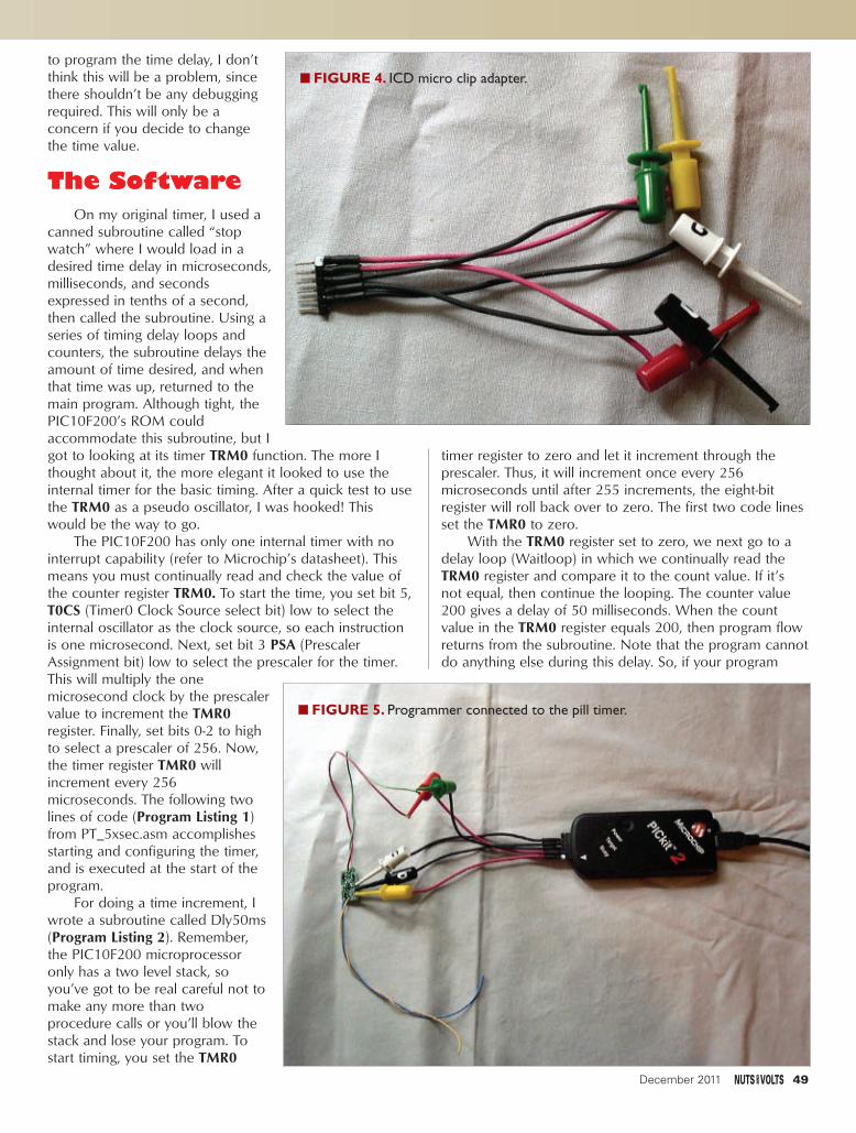
to program the time delay, I don’tthink this will be a problem, sincethere shouldn’t be any debuggingrequired. This will only be aconcern if you decide to changethe time value.
The SoftwareOn my original timer, I used a
canned subroutine called “stopwatch” where I would load in adesired time delay in microseconds,milliseconds, and secondsexpressed in tenths of a second,then called the subroutine. Using aseries of timing delay loops andcounters, the subroutine delays theamount of time desired, and whenthat time was up, returned to themain program. Although tight, thePIC10F200’s ROM couldaccommodate this subroutine, but Igot to looking at its timer TRM0 function. The more Ithought about it, the more elegant it looked to use theinternal timer for the basic timing. After a quick test to usethe TRM0 as a pseudo oscillator, I was hooked! Thiswould be the way to go.
The PIC10F200 has only one internal timer with nointerrupt capability (refer to Microchip’s datasheet). Thismeans you must continually read and check the value ofthe counter register TRM0. To start the time, you set bit 5,T0CS (Timer0 Clock Source select bit) low to select theinternal oscillator as the clock source, so each instructionis one microsecond. Next, set bit 3 PSA (PrescalerAssignment bit) low to select the prescaler for the timer.This will multiply the onemicrosecond clock by the prescalervalue to increment the TMR0register. Finally, set bits 0-2 to highto select a prescaler of 256. Now,the timer register TMR0 willincrement every 256microseconds. The following twolines of code (Program Listing 1)from PT_5xsec.asm accomplishesstarting and configuring the timer,and is executed at the start of theprogram.
For doing a time increment, Iwrote a subroutine called Dly50ms(Program Listing 2). Remember,the PIC10F200 microprocessoronly has a two level stack, soyou’ve got to be real careful not tomake any more than twoprocedure calls or you’ll blow thestack and lose your program. Tostart timing, you set the TMR0
timer register to zero and let it increment through theprescaler. Thus, it will increment once every 256microseconds until after 255 increments, the eight-bitregister will roll back over to zero. The first two code linesset the TMR0 to zero.
With the TRM0 register set to zero, we next go to adelay loop (Waitloop) in which we continually read theTRM0 register and compare it to the count value. If it’snot equal, then continue the looping. The counter value200 gives a delay of 50 milliseconds. When the countvalue in the TRM0 register equals 200, then program flowreturns from the subroutine. Note that the program cannotdo anything else during this delay. So, if your program
December 2011 49
■■ FIGURE 4. ICD micro clip adapter.
■■ FIGURE 5. Programmer connected to the pill timer.
Lyman - Pill Timers Big Medicine.qxd 10/31/2011 4:19 PM Page 49

requires other actions, then you need a smaller prescalervalue and nested counting loops integrated into the otherfunctions you need to do at the same time.
Since we are only needing to delay, then we can sit ina wait loop until we have our desired time interval. Usingthe timer makes doing exact timing very easy byeliminating multiple counting loops and the sometimestedious task of calibrating those loops. The counter valuefor the wait loop is calculated simply by:
Delay
Count = SSSSSSSSSS
256 uSec
The desired delay is divided by the timer incrementtime of 256 microseconds to give the count for the waitloop. Therefore, 50 milliseconds divided by 256microseconds gives 195.3125, so for an eight-bit value,this rounds off to 195 decimal or C3 hex. Since there issome small amount of program latency, testing gave amore accurate value of 200.
What we want are time delays in five secondincrements, so now we need another subroutine thatcounts the number of 50 millisecond delays to give a fullfive seconds. The procedure Do5sec (Program Listing 3)calls the Do50ms delay function and counts the numberof 50 milliseconds to give five seconds, which is 100times. This means a subroutine calling a secondsubroutine, which gives us our stack level of 2. This meansany more subroutine calls risk blowing the program.
We start with a counter register called Timecnt andset it to zero. Next, we set up a FOR-NEXT loop whichcalls the Do50ms subroutine. Each return increments theTimecnt register, then checks to see if it equals 100. IfTimecnt doesn’t equal 100, then the program incrementsthe Timecnt register and loops to the Elbl3 label to delayanother 50 milliseconds. The value of Timecnt iscompared by subtracting that register from 100 and thentesting if the result is zero. When Timecnt equals 100(subtraction equals 0), then the loop branches to Elbl4 toreturn to the Main program just after the subroutine call.
The main section of the program (Program Listing 4)
50 December 2011
Program Listing 1 — Set Option Register.;configure uP to use internal timer and pre scaler
MOVLW B’10000111’ ;set option bits for TMR0 with osc prescalerOPTION ;load option value into OPTION register to configure
;
Program Listing 2 — 50 Millisecond Subroutine.
Dly50ms; Time delay of 50 milli sec
; DOCODE
MOVLW 0x00 ; set W register to 0MOVWF 0x01 ; set TMR0 register to
; zero
; ENDCODE
Waitloop ;
; DOCODE
MOVF 0x01, 0 ; move value of TMR0 ; register to W reg
MOVWF Scratch ; now move TMR0 value to ; variable Scratch
; ENDCODE
; IF Scratch <> 200 THEN Waitloop ‘ loop until time is up -> Endvalue is number ‘ of counts for time
MOVLW 200SUBWF Scratch,0BTFSS 3,2GOTO Waitloop
; RETURN
Program Listing 3 — Five Second Subroutine.
Do5sec ;
; Timecnt = 0 ‘ make sure time count is ‘ set to zero
MOVLW 0MOVWF Timecnt
; FOR Timecnt = 0 TO 100
MOVLW 0MOVWF Timecnt
Elbl3
; GOSUB Dly50ms
CALL Dly50ms
; NEXT
MOVLW 100SUBWF Timecnt,0BTFSC 3,2GOTO Elbl4INCF Timecnt,1GOTO Elbl3
Elbl4
; RETURN
RETLW 0
Lyman - Pill Timers Big Medicine.qxd 10/31/2011 4:20 PM Page 50

starts after the initialization section, and after first selectingthe output state based on the solder bridge JP1 by readingport G, then testing bit 3. A FOR-NEXT loop calls theDo5sec subroutine to time a delay of five seconds, andcounts the desired number of five second intervals to givethe desired delay. At the end of that delay, the output ischanged to the state specified by JP1. After that, theprogram goes to the endless loop Asmend, which is thefinished state of the program.
Two other programs are included (PT_1xsec.asm andFLASHER.asm) for your use. The first is another timerprogram that delays in increments of one second. Thesecond is a flasher program that is a low speed oscillatorused to turn something like a light on and offcontinuously. This flasher program started as an exerciserthat I used to measure the time period duringdevelopment, then I remade it into a user program. Tochange the time interval for the PT_5xsec.asm andFLASHER.asm program, change the equate statement“TimeX5 EQU 1” from 1 to a number from 2 to 255.That means the five second timer can time up to 255 xfive seconds or 21 minutes and 15 seconds. For thePT_1xsec.asm, change the equate statement “TimeX1EQU 10” to a number from 1 to 255, to give a delay ofone to 255 seconds.
These assembly programs are compiled usingMicrochip’s MPLAB ICD program which is free and canbe downloaded from www.microchip.com. MPLAB is alsoused to download the program into the microprocessorusing the PICkit 2 programmer.
The Circuit BoardFigure 6 shows the circuit board (center left) beside
an actual pill that I take daily, so you can see that theboard actually is the size of a pill, while Figure 7 showsthe pill sitting over the circuit board. (The corners of thecircuit board are just peeking out from under it.) Acompleted pill timer — including connecting wire leads —is shown in the lower part of Figure 6. As you can see, thefull circuit uses all surface-mount components.
The single circuit board layout is shown in Figure 8,although only the silkscreen and top layer are shown forclarity. There are some lands on the bottom layer, but allcomponents are mounted on top so the completed pilltimer can lay flat as I mentioned earlier. This meansdouble-sided carpet tape can be used to mount pill timersin projects.
So that others can easily make their own circuitboards, I designed the timer using the ExpressPCB version7.0.2 CAD program for designing circuit boards (which isavailable as a free download at www.expresspcb.com).Using this program, either of the circuit boards can beloaded and then can be modified, or it can be used as-isto order circuit boards. Both boards are laid out instandard format size to allow purchasing ExpressPCB’sthree boards for $59 deal. The file1086010.pcb is thedesign for the single board while the 1086010P.pcb filehas the single board repeated 29 times. Using the single
board design means three boards for $59, so each pilltimer circuit board costs $19.66. Ordering the boards with29 circuits brings the cost down to 68¢ each.
You will need a shear to cut the individual boards out,so if you don’t have a shear, then you need to do a layoutwhere you can cut the boards out without cutting and for
Program Listing 4 — Main Part of Program.
Main ;
; Scratch = INP(PortG)
MOVF PortG,0MOVWF Scratch
; ON Scratch 3 TRUE DO SetLo
BTFSC Scratch,3CALL SetLo
; ON Scratch 3 FALSE DO SetHi
BTFSS Scratch,3CALL SetHi
; FOR Timeblk = 1 TO TimeX5 ‘ count the nubmer of desired 5 second intervals
MOVLW 1MOVWF Timeblk
Elbl1
; GOSUB Do5sec
CALL Do5sec
; NEXT
MOVLW TimeX5SUBWF Timeblk,0BTFSC 3,2GOTO Elbl2INCF Timeblk,1GOTO Elbl1
Elbl2
; Scratch = INP(PortG)
MOVF PortG,0MOVWF Scratch
; ON Scratch 3 TRUE DO SetHi
BTFSC Scratch,3CALL SetHi
; ON Scratch 3 FALSE DO SetLo
BTFSS Scratch,3CALL SetLo
; END
GOTO Asmend
December 2011 51
Lyman - Pill Timers Big Medicine.qxd 10/31/2011 4:20 PM Page 51

damaging the actual circuit board. That’s why the singleboard design is included, so you can copy and paste itinto a multi-board design with sufficient spacing to cuteverything out. That is, have the width of the cutter bladebetween each circuit board.
Note that these prices are for circuit boards withoutthe silkscreen and solder mask, and while useable, greatcare must be taken when soldering parts on. I ordered mythree boards with the silkscreen and solder mask so thecost was $86 for three boards, making the cost per boardabout a dollar each. (Not bad for high quality circuitboards, except it may take you a while to use 87 of them.)
Although I didn’t make any improvements to thecircuit board layout, there are two things that I would nowdo differently. First, I’d make the three holes forconnecting the ICD a little larger to make connectionseasier. Second, the lower pad of JP1 would be a thru-holethe same size as used to mount the lead wires. If the gap
between thesquare pad andthe thru-hole isthe same asbefore, then itshould still beeasy to solder ashort acrossthem.
A thru-holewould allow port GP3 to be used as an input for suchthings as trigger or gating signals. This port pin already hasa pull-up resistor, so connecting input signals would bereally easy. This input would allow the pill timer to be usedfor one shot applications, using the basic components inthe provided programs to write a new program. Evenwithout the thru-hole, a wire can be carefully soldered tothe present pad to give an input signal.
Building the Pill TimerThe downside to building pill timers is it’s all surface-
mount technology. However, if you haven’t done a projectwith surface-mount components, then this will be a nicelittle project to start with. Since the gap between pads forthe PIC10F200 is only about 0.024 inches; you will need aneedle-point tip for your soldering iron. This part is themost difficult to solder in-circuit because it’s easy to get asolder bridge between the microprocessor’s pins. Theremaining parts are large enough and there is sufficientspacing that soldering is easy.
When soldering surface-mount parts, I find it’s best toglue each part in place, so there isn’t any slipping aroundwhile trying to hold your soldering iron in one hand andthe solder in the other. (Commercial fabricators glue theparts down prior to soldering.) I use a two-part epoxycalled J-B Weld (part number 8265-S) found in mosthardware and auto supply stores. This stuff can be used torepair an engine block, so it doesn’t have problems withheat. To use, I mix just a dab, then use a toothpick toplace just a pin point of glue where the component goes.Then using tweezers, I place the component on the gluespot where it will be soldered. The glue needs to set
several hours before soldering; I usually waitovernight. Don’t use so much glue that itsqueezes out and covers the surfaces to besoldered, since that will prevent the solder frommaking electrical contact.
Once the parts are soldered on, connectthe programmer adapter and PICkit 2programmer to the pill timer and download theprogram to the microprocessor. Now, solder onyour lead wires and add it to your project.
Using the Pill Timers
So, what can you do with your pill timer?
52 December 2011
■■ FIGURE 7. Size reference of pill timer.
■■ FIGURE 8. Circuit board layout.
■■ FIGURE 6. Pill timers.
Lyman - Pill Timers Big Medicine.qxd 10/31/2011 4:20 PM Page 52

Well, here are some examples of how you can use them.For turning on/off a motor or light drawing more than 600mA, you will most likely need some power control devicesuch as a relay. A relay with a coil drawing less than 600mA and a drive voltage less than 15 volts can be directlyconnected to the output of the pill timer as shown inFigure 9. Don’t forget to include a diode across the relay’scoil to prevent voltage spikes when the relay is turned off.These voltage spikes can easily destroy the drive transistorQ1. The diode is placed with its cathode on the positiveoutput side of the pill timer so that it is reversed-biased. Ifyou put the diode in backwards, don’t worry. When youapply power, the diode will send you a nice little smokesignal that it’s in backwards. Start over with a new diode.
Another neat device for controlling electrical powerare AC electronic relays that use semiconductors to turnthe power on and off. Electronic relays are veryaffordable, are controlled with a DC voltage signal level,and can switch as much as 220 volts at 20 amps.Referring to Figure 10, the pill timer requires a pull-upresistor across its output (1K to 10 Kohms) to generatethe digital control signal necessary to control theelectronic relay. The relay’s positive input is connected tothe resistor on the side of transistor Q1, while thenegative input goes to ground (negative power input, or -5V on Figure 10). Remember, in this configuration,the sense of the output is reversed.
Something that many electronic hobbyists want tocontrol are LEDs. Looking at Figure 11, the LED isconnected in series with a limiting resistor to the pill timer,making sure the anode end of the LED is toward thepositive output of the timer. LEDs can be strung togetherin series using a single limiting resistor, as long as theoutput voltage is sufficient. The limiting resistor shouldlimit current to a maximum of 20 milliamps. Assume eachLED has a voltage drop of two volts. LEDs can also be inparallel, but you’ll need a limiting resistor for each LED.
One helpful fixture I made for testing the software inpill timers is shown in Figure 12. It provides easyconnections to the world. Power is provided by a nine voltbattery with an LED to show that power is on. An LEDwith a limiting resistor is connected with a jumper plug,and another jumper plug isconnected to JP1 on the pill timerto allow easy shorting of thestartup sense. Finally, a six-pinheader is installed to allow thePICkit 2 to be directly installed,making for easier softwaredevelopment.
The files for the three assembly programs and thecircuit boards are available for downloading at the articlelink. Readers can make any changes to any of these filesfor private use, but may not use any of these materials incommercial products or for resale.
From a software standpoint, what you can do with apill timer is largely limited by your imagination. Althoughthe program space of the PIC10F200 is small, there is stilla lot of capability to do many things, expanded by alsobeing able to use a control input signal. But, the neatestthing about pill timers is their size and being able to stickthem into almost any place with a piece of double-sidedtape. Making little displays for the holidays becomes asnap, so enjoy this new medicine for curing the headachesin your projects. NV
■■ FIGURE 9. Traditional relay connection.
■■ FIGURE 10. ACElectronic relay
connection.
■■ FIGURE 11. LED connection.
■■ FIGURE 12.Developmentfixture.
December 2011 53
Lyman - Pill Timers Big Medicine.qxd 10/31/2011 4:21 PM Page 53

This is a review of the ProtoSnap: an Arduino-compatible board from SparkFun Electronics(www.sparkfun.com). There’s a great tutorial on the
$45 board at the SparkFun website, complete with close-ups of the board and source code. As you can see fromFigure 1, the little board — which easily fits on the activescreen area of an iPhone — consists of a Pro-Mini 5V/16MHz microcontroller, a USB interface pad, a button pad,light sensor pad, RGB LED pad, buzzer, and prototypingpad.
Why ProtoSnap?
Of all the Arduino-compatible boards, why consider
the ProtoSnap? After all, it’s not the cheapest or fastestboard on the market, but it’s perfect for the budget-minded novice. It’s perfect for beginners because there’sno need to hook anything up, other than the USB cable toyour PC, Mac, or Linux box. You can experiment with themicroprocessor, the buzzer, LED, light sensor, and buttonwithout going for a soldering iron or solderlessbreadboard kit. The USB cable supplies power andenables you to download code to the microprocessor.
In a way, the ProtoSnap is much like a project boardwith a dedicated processor. These boards typically featurea large solderless breadboard area with microprocessor,sensors, and other devices mounted on the periphery ofthe board. You can’t do much with these boards withoutfirst connecting the pins of the microcontroller to thecomponents with jumper wires.
From a budgetary perspective, traditional projectboards are fine for prototyping, but not for deployment.You might extract the microcontroller — assuming it’s notintegrated in the board — but you’ll have to purchase anew board and sensors for actual use. With theProtoSnap, once you’ve figured out your design andprogrammed the microcontroller, you simply snap thecomponents free and use the pads you need for yourproject. Of course, the economics of this equationdepend on whether your project calls for a buzzer, LED,light sensor, and/or pushbutton.
Board Check
When you first attach a USB cable to the FTDI
“Whether you’re new to the Arduino or an old fan, the ProtoSnap Pro Mini isworth exploring.”
One of the great things about open source hardware — such as the Arduino— is competition and variety. A quick search on the Internet will revealArduino-compatible boards that are smaller, faster, cheaper, or more feature-laden than those offered by rivals. It’s the same for add-ons andbooks – there seems to be no end to inexpensive sensors and other add-onsfrom China and books from publishers in the US and EU.
The SparkFunProtoSnap Pro Mini
By Bryan Bergeronwww.nutsvolts.com/index.php?/
magazine/article/december2011_Bergeron
FIGURE 1.
Review
54 December 2011
Bergeron - Sparkfun Review.qxd 11/1/2011 7:08 AM Page 54

interface pad, you might be startled to see the RGB LEDcycle through red, green, and then blue. According to thedocumentation in the 50-line source code (also availableon the SparkFun website), the LED is intended to cyclewhen the light sensor is in the dark. I suppose myworkbench isn’t illuminated as brightly as it could be. Iverified the function of the light sensor by bringing mywork lamp closer to the board. The LED stopped cycling.
Depressing the button activates the buzzer which ispleasantly subtle, as buzzers go. Some of the buzzers thatship with evaluation boards are loud enough to causehearing loss. The demo source code is typical Arduinowhich means it’s easy to read and modify. I changed thesensitivity of the light sensor so that it triggered on lesslight. It’s a bit odd that the LED — which is surprisinglybright — is located immediately adjacent to the lightsensor.
If you work the button with the LED active, you’llrecognize one aspect of the Arduino code: the sensorhandling is sequential. If the processor is handling thebutton down and buzzer, it can’t cycle the LED. As aproject, see if you can make the buzzer sound wheneverthe button is pressed.
Note that the board setting for the ProtoSnap is“Arduino Uno.” If you set the set the board to “Mini Pro”,(as I did), you’ll find the microcontroller unresponsive.
Next Steps
Once you’ve worked through the sample source
code, you should be ready for your first real project. Takea look at the sample code available within the Arduinodevelopment environment, under ‘Examples’. Most ofthese examples don’t require sensors or pushbuttons. Agood first step would be to integrate the sensors andbuzzer with the example code. Of course, there’s nothinglike working on your pet project.
As a ‘rhythm-challenged’ student of the electric guitar,one of my long-time plans has been to construct a footpedal that sequences light to silently indicate how closelyI’m keeping time with my foot. That is, say, white on beatone, red on two, green on three, and blue on four. I’dassociate a handful of high power LEDs with each beat.
The little ProtoSnap kit was just the thing to get meworking on this project. The pushbutton is a perfectprototype for a foot button, and the RGB LED was just thething to prototype the planned array of red, green, andblue LEDs.
The code (shown in Sidebar 1) is simple enough. Startby initializing variables. Then, set up the input (button) andoutput (LED) pins. The main loop consists of reading thebutton which is LOW when depressed. A button pressincrements the beatcount variable by one, and the switchstatement illuminates the R, G, or B, or all threecomponents, depending on the value of beatcount.
The most interesting line of the code is:
Delay(250);
This line provides signal conditioning for the
December 2011 55
SIDEBAR 1./*RGB LED Sequencer for ProtoSnap ProMini Bryan Bergeron*/
int button = 7;int beatcount = 0;int red = 3;int blue = 6;int green = 5;
void setup() { Serial.begin(9600);pinMode(red, OUTPUT); pinMode(green, OUTPUT); pinMode(blue, OUTPUT);pinMode(button, INPUT);}
void loop() { if(digitalRead(button) == LOW){beatcount = beatcount + 1;if (beatcount > 3) {
beatcount = 0;}delay(250);}
switch (beatcount){case 0:
digitalWrite(red, LOW);digitalWrite(green, LOW);digitalWrite(blue, LOW);break;
case 1:digitalWrite(red, LOW);digitalWrite(green, HIGH);digitalWrite(blue, HIGH);break;
case 2:digitalWrite(red, HIGH);digitalWrite(green, LOW);digitalWrite(blue, HIGH);break;
case 3:digitalWrite(red, HIGH);digitalWrite(green, HIGH);digitalWrite(blue, LOW);break;
}
}
Discuss this article in the Nuts & Volts forums at http://forum.nutsvolts.com.
Bergeron - Sparkfun Review.qxd 11/1/2011 7:08 AM Page 55

pushbutton, in the form of a 250 ms delay following thefirst button press. Because the switch contacts bouncewhen they first make contact, the button doesn’t go fromopen to closed, but opens and closes several times afterthe initial press. Without the delay, the beatcount variablecould be incremented dozens of time by a single buttonpress. There are, of course, more sophisticated buttonsignal conditioning routines, but this one works well for asimple on-off button.
Another way to handle the contact bounce problem isto insert a low pass filter — in the form of a resistor andcapacitor — in line with the switch. The simple RC filter —while saving a line of code — is relatively expensive if youconsider the components, PC board real estate, and thetime to insert and test the components. Furthermore, ifyou change the switch to another brand or model, the RCfilter components may need to be changed to handle thebounce characteristics of the new switch. Changes insoftware, on the other hand, are trivial.
That’s it. My prototype is just about done. My nextstep is to use the prototyping area to install three smallsolid-state relays. I’ll energize the relays instead of the RGBLED, and have a way to control the much more powerfuland power-hungry banks of LEDs that I’m building for theproject. I could snap off the microcontroller, add a batterysupply, and wire in a foot pedal switch, but I think I’llleave the assembly intact for my next prototype. It’s handy
having a three-mode LED and switch to work with,without having to dig for wires or my soldering iron.
Room for Improvement
Nothing’s perfect, and every electronics product isdesigned to provide a list of features at some price point.In this case, the only real area in need of improvement isthe USB interface pad. The interface works fine, but onceyou unsnap the pad from the microcontroller, you’ll haveto take out your soldering iron to reconnect the two if youwant to reprogram the microcontroller. It’s a simpleenough task to install headers on the microcontroller andUSB pad, but you’ll need to think ahead and order theparts when you buy the ProtoSnap. Also, you’ll need tosupply a mini USB cable.
Bottom Line
Overall, this is a great product for beginners —especially beginners without an inventory of parts. I caneasily see this used in the classroom, where the teacherdoesn’t have to contend with keeping track ofcomponents, wires, and other parts. The ProtoSnap offersa lot in an affordable compact package, and the designmakes it painless to move from prototype to product.NV
56 December 2011
7540 Colbert Drive • Reno • Nevada 89511 1 (800) 759-7535 | www.PanaVise.com775757577554040404040 CCColololollbbebebebertrtrtrtr DDDDriririr vevevev •• RReReRReeennnnnonoonon ••• NNNNeveveevvvvaddadadadadaaaa 88989898989515151
Innovative Holding SolutionsVISIT US ONN
MONTHLY CONTESTVisit us on Facebook® to post a photo of your creative PanaVise project for a chance to win a PanaVise prize package.
TESTTEST
Our line of Circuit Board Holders add versatility & precision to your DIY electronics project. Solder, assemble & organize with ease.
World's Most Versatile VVeerrssaattiilllee t ld ss MMoosst
C i rc u i t Board HOLDERS
Model 201
Model 324 RS485/422/232/TTL
w w w . r s 4 8 5 . c o m
Converters / RepeatersMulti-Repeaters / HubsFiber Optics / Isolators
Extended Distance UnitsSerial to Digital I/O
Large Multi-Drop NetworksCustom Units & Smart UnitsIndustrial, 3.0 KV Isolation
Call the RS485 Wizards513-874-4796
IBS485HV5 Port Isolated RS485 Repeater
ASC24T RS232<=>RS485 ATE Converter
$45.00 board only
$349.00
Enclosures, Cables,Power Supplies
and other Accessories
RES R.E. Smith Inc.
Bergeron - Sparkfun Review.qxd 11/1/2011 7:08 AM Page 56

Order on l ine : www. jaycar.com
Post & Packing ChargesOrder Value Cost$25 - $49.99 $7.50$50 - $99.99 $20$100 - $199.99 $40$200 - $499.99 $60$500+ $75Note: Products are dispatched from Australia,so local customs duty & taxes may apply.Prices valid until 31/12/2011
Max weight 12lb (5kg).
Heavier parcels POA.
Minimum order $25.
WEB: www.jaycar.comPHONE: 1-800-784-0263*FAX: +61 2 8832 3118*EMAIL: [email protected]: P.O. Box 107, Rydalmere NSW 2116 Australia
• ALL PRICING IN US DOLLARS • MINIMUM ORDER ONLY $25
*Australian Eastern Standard Time (Monday - Friday 09.00 to 17.30 GMT + 10 hours)Note: 10-14 days for air parcel delivery
HOW TO ORDER
Build something this ChristmasDon’t just sit there -
SD/MMC Card Web Server In a Box
Voltage Monitor KitShort Circuits - Volume 1
This volume will teach you everything you need to get started in electronics andis suitable for ages 8+. We give you the option of buying the book on its own,or together with the accompanying kit that contains the components for each ofthe 20-odd projects described in the book. Some of the exciting projects includea Police Siren, Electronic Organ, Sound Effects Unit, Light Chaser and many,many more! The full color 96 page book, is lavishly illustrated with over 100drawings and diagrams. No prior knowledge of electronics is needed, projects are fun and safe to build.
Short Circuits BookBJ-8502 $7.25Short Circuits Project KitKJ-8504 $24.50Short Circuits Book and Project KitKJ-8502 $29.00
AGES12+
AGESAGES8+8+
AGES10+
AGES14+
AGES5+
AGES3+
KIT OF THE MONTH
KC-5489 $65.00 plus postage & packing
Host your own website on a commonSD/MMC card with this compactWeb server In a Box (WIB).Connecting to the Internet viayour modem/router, it featuresinbuilt HTTP server, FTP server,SMTP email client, dynamic DNSclient, RS232 serial port, four digital outputs andfour analogue inputs. Requires a SD memory card,some SMD soldering and a 6 - 9VDC adaptor.
• Kit includes PCB, case and electronic components• PCB: 123 x 74mm
Clifford The Cricket Kit
KC-5178 $12.50 plus postage & packing
Clifford hides in the dark and chirps annoyingly untila light is turned on - just like a real cricket. Clifford iscreated on a small PCB, measuring just 40 x 35mmand has cute little LED insecteyes that flash as it sings. Justlike a real cricket, it waits a fewseconds after darknessuntil it beginschirping, and stopsinstantly when a lightcomes back on.
• PCB, piezo buzzer, LDR plus all electroniccomponents supplied
• PCB: 40 x 35mm
SFX KitsStarship Enterprise Door SoundEmulator Kit KC-5423 $29.00 pluspostage & packing
This easy to build kitemulates the uniquesound of a cabin dooropening or closing onthe Starship Enterprise.The sound can betriggered by switchcontacts or evenfitted to automatic doors.
• Kit supplied with PCBwith overlay, speaker,case and all specifiedcomponents
• 9-12VDC regulated
KC-5424 $16.75 plus postage & packing
This versatile kit will allow you to monitor thebattery voltage, the airflow meter or oxygen sensorin your car. The kit features 10 LEDs that illuminatein response to the measured voltage, preset 9-16V,0.-5V or 0-1V ranges, complete with afast response time, high inputimpedance and auto dimmingfor night time driving. Kitincludes PCB with overlay,LED bar graph and allelectronic components.
• 12VDC• PCB: 74 x 47mm
DC Relay Switch KitKC-5434 $12.25 plus postage & packing
An extremely useful and versatile kit that enablesyou to use a tiny trigger current - as low as400µA at 12V to switch up to 30A at 50VDC.It has an isolated input, and is suitablefor a variety of triggering options.The kit includes PCB with overlayand all electronic components withclear instructions.
Ultrasonic Antifouling Kit for Boats
KC-5498 $179.50 plus postage & packing
Marine growthelectronicantifoulingsystems can costthousands. Thisproject uses thesame ultrasonicwaveforms andvirtually identicalultrasonic transducersmounted in sturdypolyurethane housings. Bybuilding it yourself (which includes some potting)you save a fortune! Standard unit consists ofcontrol electronic kit and case, ultrasonictransducer, potting and gluing components andhousings. The single transducer design of this kit issuitable for boats up to 10m (32ft); boats longerthan about 14m will need two transducers anddrivers. Basically all parts supplied in the project kitincluding wiring. (Price includes epoxies).
• 12VDC• Suitable for power or sail• Could be powered by a solar panel/wind generator• PCB: 78 x 104mm
Top Seller
Theremin Synthesiser Kit MkII
KC-5475 $54.00 plus postage & packing
The ever-popular Theremin is better than ever! From piercing shrieks to menacing growls, create your own eerie science fiction sound effects by simply moving your hand near the antenna. It's now easier to build with PCB-mounted switches and pots to reduce wiring to just the hand plate, speaker and antenna and has the addition of a skew control to vary the audio tone from distorted to clean.
• Complete kit contains PCB with overlay, pre-machined case and all specified components
• PCB: 85 x 145mm
Vehicle G-Force Meter Kit
KC-5504 $36.00 plus postage & packing
Measure the g-forces on yourvehicle and it’soccupants duringyour next laparound the race circuit, ormore sensibly use this kit to encouragesmoother driving to save petrol and reduce wear &tear. Based around an accelerometer IC, this kitdisplays the forces (+/- 2g) on the 4-digit LEDdisplay. It is not limited to cars either; use it tomeasure g-forces on a boat crashing over waves oron a theme park thrill ride. Kit includes PCB withpre-mounted SMD component, pre-programmedmicrocontroller and all onboard electronic components.
• Requires 2 x AA batteries• PCB: 100(L) x 44(W)mmNote: To make the kit more accessible to everyday hobbyists we are suppling the PCB with the SMD component already mounted on the board to save time and frustration.
FANTASTICStocking
Fillers
An excellentway for newcomers to diptheir toes intothe wonders ofelectronics!
Nuts & Volts DEC 11 31/10/11 1:48 PM Page 57

Build an English Police SirenFUNDDAAMMEENNTTAALLSS FOR THE
BEGINNER
This circuit lets you simulate the sounds of anEnglish police siren by creating two different toneswith a pushbutton switch.1. Build the Circuit.Using the schematic along with the pictorial diagram, placethe components on a solderless breadboard as shown.Verify that your wiring is correct.2. Do the Experiment.Theory: Here we have a 555 timer IC working as an astableor free-running multivibrator. As we change the voltageacross pins 6 and 7, we change the frequency of the outputpulses. The time it takes to charge and discharge capacitorC1 determines the output frequency from pin 3. Pressingpushbutton switch S1 causes R5, 470K ohm, to be put in parallel withresistor R2. This, in turn, changes the voltage across these two pins andthat changes the frequency of the output pulses coming from pin 3.These output pulses are then sent to transistor Q1 and amplified. Thisamplified signal is then sent to the speaker.Procedure: Connect a nine volt battery to the battery snap. You shouldhear a tone. If you press the pushbutton switch, you will hear anothertone. As you press and release the pushbutton switch, you’ll be able tocreate the sounds of a two-tone English siren.
ResistorsGK01041 100 ohmsGK01049 220 ohmsGK01065 1,000 ohmsGK01115 120,000 ohmsGK01129 470,000 ohms
GK18001 3904 NPN TransistorGK35002 Battery SnapGK14004 555 Timer ICGK02012 0.01 mfd Ceramic DiscGK25006 Pushbutton Switch N/OGK27002 8 ohm round SpeakerGK45011 Seven Wires 4” long
These experiments are provided by GSSTechEd at
www.gssteched.com
SCHEMATIC
PICTORIAL DIAGRAM
58 December 2011
You can order partsfor this experiment from their website
as follows:
Beg Experiments Dec11.qxd 11/1/2011 8:07 AM Page 58

AA kkiitt ffoorr tthheessee
eexxppeerriimmeennttss ccaann bbee
ppuurrcchhaasseedd ffrroomm tthhee
NNuuttss && VVoollttssWWeebbssttoorree aatt
wwwwww..nnuuttssvvoollttss..ccoomm
oorr ccaallll uuss aatt
880000--778833--44662244..
PICBASIC PRO™ Compiler
PBP3Experimenter - $49.95Silver Edition - $119.95Gold Edition - $269.95
Download a FREE trial version now.
www.PBP3.comwww.melabs.commicroEngineering Labs, Inc. 888-316-17533
The industry-standard BASIC compiler for Microchip PIC® microcontrollers.
PICBASIC and PICBASIC PRO are trademarks of Microchip Technology Inc. in the USA and other countries. PIC is a registered trademark of Microchip Technology Inc. in the USA and other countries.
Multi-Seat Licensingfor Educational Institutions
Upgrade fromPICBASIC™ Compiler (PBC)
December 2011 59
WIRESW1 = 7j and 30jW2 = 21i and 30iW3 = 20h and 26gW4 = 21c and 30bW5 = 9c and 30a
W6 = 19c and 20gW7 = 21d and 18g
Beg Experiments Dec11.qxd 11/1/2011 8:05 AM Page 59

60 December 2011
With a crystal diode, a tuned circuit, and anearphone, you can make a radio that receives AM(amplitude modulation) radio stations. The big questionremains, why do that? In today’s high tech world ofiPhones, satellite TV, MP3 players, and the Internet, whyrevert to such an anachronism? Who listens to AM radiotoday, anyway?
Some good reasons to build a crystal radio are, first,as a learning experience. If this is your very first electronicconstruction project, it is a good one. It uses very fewcomponents and they are very easy to connect. Second, it
is a good educational project. You learn about resonantcircuits, diode rectification, and soldering.
As for who listens to AM radio, you would besurprised. If you listen to the radio for music, then youprobably listen mostly to FM. But millions still listen to AMfor news, weather, traffic, and general talk radio shows.You can still hear lots of music on AM, as well. There areroughly 5,000 AM radio stations around the country ineven the smallest of towns. As old as it is, AM radio is notgoing away anytime soon.
I built my first AM radio decades ago. It was, in fact,my first actual electronic construction project. And it reallyworked. I credit that experience to putting me on the pathto a long career in radio and electronics. Recently, I hadthe urge to build a crystal radio again. Mainly just to see ifI could and what I could hear. This project was an attemptto recapture those simpler days of radio and electronics. Ifyou have never built a crystal radio, you may want to giveit a try.
HOW IT WORKS
Figure 1 shows the schematic diagram of a basiccrystal radio. An inductor or coil (L) is connected to avariable tuning capacitor (C), and those are connected toa diode in series with an earphone. An antenna isconnected to one end of the coil and a ground is
Who in their right mind would want to build a crystal radio (or crystal set asit is sometimes called)? A crystal radio is the absolutely simplest radio thereis and is, in fact, the very first communications receiver. It derives its namefrom the detector or diode used in detecting the radio signal.The originaldiode was a piece of crystal called galena. When you made contact with it byway of a small wire probe, you created a diode in which current would easilyflow through it in one direction and not flow in the other direction.Thiscrystal acted as a diode that performed rectification. Rectification is theprocess of converting AC to DC, and for detection or demodulating AM radiosignals.Today, the crystal is a semiconductor diode made of thesemiconductor material germanium.
BUILDING A CRYSTAL RADIOReally? Is This A Sane Thing To Do?
OPEN■ BY LOUIS E. FRENZEL W5LEF
COMMUNICATIONTHE LATEST IN NETWORKING AND WIRELESS TECHNOLOGIES
■ FIGURE 1. Schematicof the crystal radio.
OpenComm - Dec 11.qxd 10/31/2011 8:40 AM Page 60
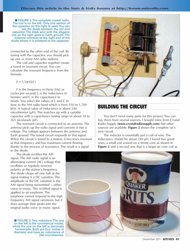
connected to the other end of the coil. Bytuning with the capacitor, you should pickup one or more AM radio stations.
The coil and capacitor together createa tuned or resonant circuit. You cancalculate the resonant frequency from theformula:
F = 1/2π√(LC)
F is the frequency in Hertz (Hz) orcycles per second; L is the inductance inhenries; and C is the capacitance infarads. You select the values of L and C to tune to the AM radio band which is from 530 to 1,700kHz. A typical value of inductance is about 240microhenries (µH). This matches up with a variablecapacitor with a capacitance tuning range of about 30 to365 picofarads (pF).
The resonant circuit is connected to an antenna. Theantenna picks up the radio signal and converts it into avoltage. The voltage appears between the antenna andEarth ground. The tuned circuit responds to that signal.When the circuit is tuned to a station, it becomes resonantat that frequency and has maximum current flowingthanks to the process of resonance. The result is a signalto the diode.
The diode rectifies the AMsignal. The AM radio signal is analternating current (AC) voltage thatoscillates or regularly reversespolarity at the station’s frequency.The diode chops off one half of thesignal making it a DC variation. Theamplitude of the DC variation is theAM signal being transmitted — eithervoice or music. This rectified signal isapplied to an earphone. Theearphone cannot respond to the highfrequency AM signal variations, but itdoes average their peaks into theoriginal audio voice or music signal.
BUILDING THE CIRCUIT
You don’t need many parts for this project. You canbuy them from several sources. I bought mine from CrystalRadio Supply (www.crystalradiosupply.com) but othersources are available. Figure 2 shows the complete rat’snest circuit.
The inductor is essentially just a coil of wire. Theinductance should be about 240 µH. I found two goodones; a small coil wound on a ferrite core as shown inFigure 2 and a second one that is a larger air core coil as
December 2011 61
■ FIGURE 2. The complete crystal radio.The coil is on the left. Only one section ofthe capacitor on the right is used. You can
see the diode between the coil andcapacitor. The black wire with the alligatorclip on the right goes to Earth ground. The
antenna connects to the right end of thediode where it is soldered to the capacitor.
■ FIGURE 3. Two inductors. The oneon the left is the commercial model,
while the one on the left is obviouslyhomemade. Both are four inches in
diameter and have an inductance of240 microhenries.
Discuss this article in the Nuts & Volts forums at http://forum.nutsvolts.com.
OpenComm - Dec 11.qxd 10/31/2011 8:41 AM Page 61

shown in Figure 3. Both work well, but the ferrite core coilhas a higher Q which provides somewhat betterperformance. Q is the quality factor of the coil which is ameasure of how efficient the coil is. The higher the Q, thebetter the results. You can also make your own coil. Imade one using plain old #22 copper wire wound on afour inch diameter form; in this case, a box of grits. Anoatmeal box is a good alternative since both are fourinches in diameter. Use 40 turns of wire closely spaced.Punch holes in the box to secure the wire at the ends. Youmay need to glue them down to hold the coil in place andkeep it from unwinding. Be sure to scrape the enamelinsulation from the wire ends before you solder it.
You are probably going to have to buy the variablecapacitor. These were once widely available in everymodel AM radio but no longer. Again, I bought mine fromCrystal Radio Supply, but I also found one atwww.stormwise.com. The capacitance is typically 365 pFwhen the plates are fully meshed, and down about 30 pFwhen the plates are fully unmeshed. The shaft is easy toturn for tuning. The one I bought is shown in Figure 2. It isactually two capacitors that are ganged together. You willonly need one section. You can also buy a one-sectioncapacitor, as well.
The crystal is a germanium diode. These are no longerwidely used but you can still buy them. Part numbers suchas 1N34, 1N34a, 1N60, or 1N270 are common. Any ofthese should work. I used a 1N60. Do NOT substitute asilicon rectifier diode like a 1N4001, 1N914, or 1N4148.It simply won’t work. The germanium diodes have a muchlower threshold of conduction of about 0.2 volts,compared to about 0.7 volts or so for the silicon diode.Radio signals are very small and if you want this to work,stick with the germanium diode. One possible substitutionI did not try was a Schottky or hot carrier diode. Thesesmall signal diodes are made for very high frequency andmicrowave signals, and should work.
Headphones are also important. The widely availableearbuds or headphones used with iPods, MP3 players, andother modern audio products have a very low impedance(32 ohms or so). These will load down the tuned circuit,reducing the Q and rendering it inoperable. You must usehigh impedance (many megohms) crystal or ceramic earphones.
BUILDING THE RADIO
I did not intend for this to be a final finished project. Ijust wanted to see if I could do it for nostalgic reasons, Iguess. So, I just soldered everything together in ahaphazard way as Figure 2 shows. The only pain in theneck connection was to the capacitor. One side of thecapacitor has a nice solder terminal for connecting thecoil and diode, but the other connection to the capacitoris the actual metal housing. I found a solder lug in my junkbox and screwed it into the capacitor housing with a short4-40 screw. It is mechanical connection details that
sometimes discourage us from building electronic circuits.
ANTENNA AND GROUND
One thing for sure is that this radio absolutely needs abig antenna to work. The bigger — or longer — the antenna,the more signal it picks up and the stronger the voltageapplied to the circuit. This, of course, translates into a loudersignal in the earphone. The antenna should be the verylongest piece of wire you can afford or place. I used 100feet of #14 copper wire which I strung on my wooden backyard fence. You may be able to get by with 50 feet but thatdepends on how strong or how close your local stations are.I tried 20 feet of wire and it did not work; 200 feet wouldbe great if you can manage it. Keep the wire off the groundand as high as possible. This radio will also not workwithout a good ground. And by ground, I mean the Earth. Iused a four foot copper rod from RadioShack. Drive it as farinto the ground as you can. I connected the antenna wire toan alligator clip that attaches to the solder connection onthe capacitor (not the solder lug). Connect the solder lug onthe capacitor to a wire that will attach to the ground rod. Iused about 15 feet of #16 speaker wire with an alligator clipto make this connection.
USING THE RADIO
Once you solder everything together, make theconnections to the antenna and ground, and you are readyto go. Tune the capacitor slowly while listening on theearphone. You should be able to hear at least one local AMstation. The strongest station will stand out. If you haveseveral stations locally, you could hear more. I heard justtwo: a local station on 590 kHz and one on 1,200 kHzabout 70 miles away. This later station is one of those clearchannel AM stations transmitting 50K watts.
Just so you won’t be disappointed, you should know inadvance that the stations you will hear will be very weak.Good hearing is an asset. Also, most AM stations transmitmore power during the day than at night, so daylight testingis a must. For greater volume, a longer antenna is theanswer. You can also experiment with different components.Try a different coil and see what works best. Try anotherdiode. That may help. If you can find a Schottky hot carriersignal diode (NOT a power supply rectifier diode), give thata try. A 0.001 µF capacitor in parallel with the earphonemay help. I did not notice much difference.
The other possible addition is an amplifier. Adding aone transistor amplifier in place of the headphone will boostsignal strength considerably. I did not do that as I wanted tosee the pure crystal set performance. It is totally self-powered by the radio signal it receives.
I was pleased with the result of this project. It seemedso silly given the state of technology today, that Iquestioned my sanity. However, for many of you it couldbe the beginning of a long hobby or career. NV
www.nutsvolts.com/index.php?/magazine/article/december2011_OpenCommunication
62 December 2011
OpenComm - Dec 11.qxd 10/31/2011 8:41 AM Page 62

WWW.POLOLU.COM
www.dlpdesign.com
Add USB to your next project--It's easier than you might think!USB
USB-FIFO USB-UART USB/Microcontroller BoardsDesign/Manufacturing Services AvailableRFID Readers
Absolutely NO driver software development required!
w w w . A t r i a T e c h n o l o g i e s . c o m
ATRIA Technologies Inc
Microcontroller Boards
GREAT for Breadboards, Home Projects, Experi-ments, Test Fixtures, Prototypes, Labs and more. Microcontrollers, Communications, Display, Power.
BASIC ON BOARD Eliminates development tools
AM/FM Broadcasters • Hobby KitsLearnng Kits • Test Equipment...AND LOTS OF NEAT STUFF!
EELLEECCTTRROONNEETT
For the ElectroNet online, go to
www.nutsvolts.comclick Electro-NetElectronic Parts & Supplies
Since 1967
December 2011 63
Electronet Dec11.qxd 11/1/2011 7:42 AM Page 63

The Nuts & Volts WEBSTORE
BOOKS UNDER $35 — GREAT GIFTS FOR DIYers!
For comple te pr oduct de t ai ls , v is i t our webs tore!!
TTEEAARRDDOOWWNNSSby Bryan Bergeron
LLeeaarrnn HHooww EElleeccttrroonniiccss WWoorrkk bbyy TTaakkiinngg TThheemm AAppaarrtt
Amp up your knowledgeof electronics by deconstructing commondevices and analyzing therevealed componentsand circuitry. Teardowns:Learn How ElectronicsWork by Taking ThemApart contains 14 projects that expose theinner workings of household appliances,workbench measuring instruments, andmusical equipment. Discover how resistors,capacitors, sensors, transducers, and transistors function in real circuitry.RReegg $$2244..9955 SSaallee PPrriiccee $$2211..9955
MMaakkiinngg TThhiinnggss MMoovvee:: DDIIYY MMeecchhaanniissmmss ffoorr IInnvveennttoorrss,,
HHoobbbbyyiissttss,, aanndd AArrttiissttssby Dustyn Roberts
In Making Things Move:DIY Mechanisms forInventors, Hobbyists, andArtists, you'll learn howto successfully buildmoving mechanismsthrough non-technicalexplanations, examples,and do-it-yourself projects — from kineticart installations to creative toys to energy-harvesting devices. Photographs,illustrations, screenshots, and images of 3D models are included for each project..$$2299..9955
PPIICCAAXXEE MMiiccrrooccoonnttrroolllleerr PPrroojjeeccttssffoorr tthhee EEvviill GGeenniiuuss
by Ron Hackett
This wickedly inventive guideshows you how toprogram, build, anddebug a variety of PICAXE microcontroller projects. PICAXEMicrocontrollerProjects for the EvilGenius gets you started with programming and I/O interfacing right away,and then shows you how to develop a master processor circuit.$$2244..9955
EElleeccttrroonniiccss EExxppllaaiinneeddby Louis Frenzel
The New Systems Approach to Learning Electronics
Don't spend time reading about theory,components, and oldham radios — that's history! Industry veteran, Louis Frenzel,gives you the realscoop on electronicproduct fundamentalsas they are today.Rather than tearingelectronics apart andlooking at every littlepiece, the author takes a systems-level view.For example, you will not learn how tomake a circuit but how a signal flows fromone integrated circuit (IC) to the next, andso on to the ultimate goal..$$2299..9955
1155 DDaannggeerroouussllyy MMaadd PPrroojjeeccttss ffoorr tthhee EEvviill GGeenniiuuss
by Simon Monk
UNLEASH YOURINNER MAD SCIENTIST!
This wickedly inventive guideexplains how todesign and build 15 fiendishly fun electronics projects.Filled with photosand illustrations,15 Dangerously MadProjects for the Evil Genius includes step-by-step directions, as well as a construction primer for those who arenew to electronics projects.$$2244..9955
EElleeccttrroonniiccss AAnn IInnttrroodduuccttiioonnby Jim Stewart
This book isdesigned as an in-depth introductionto important concepts in electronics.Whileelectronics can behighly mathematical,this text is notabout calculations.It is about howelectronic equipment is able to extract, process, and present information held in electrical signals. If you are in — or studying to be in— a profession that requires the use ofelectronic equipment, then this book willprovide the insight necessary to use suchequipment effectively.$33.95*
HHooww ttoo DDiiaaggnnoossee aanndd FFiixxEEvveerryytthhiinngg EElleeccttrroonniiccby Michael Jay Geier
Master the Art of Electronics Repair!In this hands-onguide, a lifelong electronics repairguru shares his testedtechniques andinvaluable insights.How to Diagnose andFix EverythingElectronic shows youhow to repair andextend the life of allkinds of solid-statedevices, from modern digital gadgetry tocherished analog products of yesteryear.About the Author: Michael Jay Geierbegan operating a neighborhood electronicsrepair service at age eight that was profiledin The Miami News.$$2244..9955
MMaasstteerr aanndd CCoommmmaanndd CC ffoorr PPIICC MMCCUUssby Fred Eady
Master and Command Cfor PIC MCU,Volume 1aims to help readersget the most out ofthe Custom ComputerServices (CCS) Ccompiler for PICmicrocontrollers.The author describessome basic compileroperations that will help programmers —particularly those new to the craft — create solid code that lends itself to easydebugging and testing.As Eady notes in hispreface, a single built-in CCS compiler call(output_bit) can serve as a basic aid to letprogrammers know about the "health" oftheir PIC code.$$1144..9955
BBuuiilldd YYoouurr OOwwnn EElleeccttrroonniiccss WWoorrkksshhoopp by Thomas Petruzzellis
BUILD YOUR OWN DREAM
ELECTRONICS LAB!This value-packedresource provideseverything needed toput together a fullyfunctioning home electronics workshop!From finding space tostocking it with components to putting the shop into action — building, testing, and troubleshooting systems.This great bookhas it all! And the best part is, it shows youhow to build many pieces of equipmentyourself and save money, big time! RReegg PPrriiccee $$2299..9955 SSaallee PPrriiccee $$2244..9955
64 December 2011
NV Webstore Dec 2011 working.qxd 11/1/2011 8:40 AM Page 64

CD-ROM SPECIALBOOK & KIT COMBOS
Or CALL 1-800-783-4624 today!Order online @ www.nutsvolts.com
December 2011 65
GREAGREATTGIFTGIFT
IDEA!IDEA!
GREAGREATT
STOCKINGSTOCKING
STUFFER!STUFFER!
NV Webstore Dec 2011 working.qxd 11/1/2011 8:42 AM Page 65

The Amateur Scientist 4.0 The Complete Collection
by Bright Science, LLC
There are 1,000 projects on this CD,not to mention the additional technicalinfo and bonus features. It doesn’tmatter if you’re acomplete novice looking to do theirfirst science fair project or a supertech-head gadgetfreak; there areenough projects on the single CD-ROM to keep you and 50 of your friends busy for a lifetime!RReegg $$2266..9955 SSaallee PPrriiccee $$2233..9955
Order online @ www.nutsvolts.comCALL 1-800-783-4624 today!
PROJECTS UNDER $50BBaatttteerryy MMaarrvveell KKiitt 33DD GGrreeeenn LLEEDD CCuubbee KKiitt
MMaaggiicc BBooxx KKiitt
As seen on theApril 2007
cover.
This unique DIY construction projectblends electronics technology with
carefully planned handcraftsmanship.This clever trick has the observer removeone of six pawns while you are out of theroom and upon re-entering you indicate
the missing pawn without ever opening the box.
IInncclluuddeess aann aarrttiiccllee rreepprriinntt..
Subscriber’s Price $$3399..9955Non-Subscriber’s Price $$4455..9955
The 32-Bit Micro Experimenter isthe fastest way tolearn 32-bitmicrocontrollers.
The kit includes onboard 46 programmable I/O and USB, free software,
carefully documented step-by-step experiments for USB, embedded web
server, graphics and audio, wireless, RTOS,and file I/O. User pushbuttons, LEDs, and 32kHz clock crystal. Can be used in solderless
breadboard environment or stand-alone.
Subscriber’s Price $$8899..9955Non-Subscriber’s Price $$9933..9955
As seen in the November2011 issue.Battery Marvelhelps protectcars, trucks,motorcycles,boats, and anyother 12V vehicles from sudden battery failure. Thiseasy-to-build kit features a single LED thatglows green, yellow, or red, indicating battery health at a glance. An extra-loudpiezo driver alerts you to any problems.
For more info,please visit our website.Subscriber’s Price $$1188..9955
Non-Subscriber’s Price $$1199..9955
SSoorrttiinngg CCoouunntteerr KKiitt 3322--BBiitt MMiiccrroo EExxppeerriimmeenntteerr BBooaarrdd
Sorting counters have many uses — keepingscore, counting parts, counting people — itis just a handy gadget to have around.Thisis a very simple project for those who wantto learn to solder or are interested in usingmicroprocessors and how they function.No special tools are needed, just a small tipsoldering iron. It has no box as it standsalone, therefore there is no drilling.
Subscriber’s Price $$3333..9955Non-Subscriber’s Price $$3399..9955
From the article “Buildthe 3D LEDMatrix Cube”as seen in theAugust 2011issue.
This kit shows you how to build a reallycool 3D cube with a 4 x 4 x 4 monochromatic LED matrix which has atotal of 64 LEDs. The preprogrammedmicrocontroller that includes 29 patternsthat will automatically play with a runtimeof approximately 6-1/2 minutes.Colors available: Green, Red,Yellow & Blue
Subscriber’s Price $$5577..9955Non-Subscriber’s Price $$5599..9955
As seen in theJuly 2011 issue.
NNEEW!W!
CChhrriissttmmaass TTrreeee KKiitt
This microprocessor-controlled Xmas Treecomes with eight preprogrammed light
display sequences.All you need is a solderingiron and a couple of batteries, and you’ll be
ready to show off your electronic tree!To see a demo video, please
visit www.nutsvolts.comSubscriber’s Price $$3399..4455
Non-Subscriber’s Price $$4411..9955
IInnccuuddeess aann IInnccuuddeess aann
aarrttiiccllee rreepprriinntt..
aarrttiiccllee rreepprriinntt..
66 December 2011
BEST SELLERS
This lab —from the goodpeople at GSSTech Ed — will show you 40 of the mostsimple andinterestingexperimentsand lessonsyou have ever
seen on a solderless circuit board.As you do each experiment, youlearn how basic components work in a circuit.Along with the purchaseof the lab, you will receive a special password to access the fantasticonline interactive software to help you fully understand all the electronic principles. For a complete product description and samplesoftware, please visit our webstore.
WE ACCEPT VISA, MC, AMEX, and DISCOVER. Prices do not include shipping and may be subject to change.
Reg Price $79.95 Subscriber’s Price $75.95
GIFTGIFTS S
FORFOR
GEEKSGEEKS
Don’t knowwhat to get that
experimenteron your list???
Give them aNuts & VoltsWebstore giftcertificate!!
You tell us theamount you’dlike to make itfor and we’lltake care ofthe rest! Call800-783-4624for details!!!
FOR BEGINNER GEEKS!
GREAGREATTSTOCKING
STOCKINGSTUFFER!
STUFFER!
NV Webstore Dec 2011 working.qxd 11/1/2011 6:50 PM Page 66

Subscribe online at: www.nutsvolts.com
or call:877-525-2539 (toll free)
818-487-4545 (outside US)
Go now to www.nutsvolts.com
to enter your gift order!
Be sure to use promotion codeY1WXMS when ordering.
U.S. Price:1 Yr – $26.95
Give a one year (12 issues) subscriptionto a friend and they willreceive an extra THREE
FREE ISSUES! That’sright! A total of 15 issues in all!
Not only will they get 15 great issues, but they will also receive:
• Access to the digital edition
• Discounts in the Webstore
• Online only content and
downloads
• And so much more!
Give the Gift ofNuts & Volts!
NV-GiftSubAd2011.qxd 11/1/2011 7:02 PM Page 67

68 December 2011
RecapIn Part 1 of this series, we looked at the software side
of Digital I/O (DIO) as it is done in the Arduino using thesequentially numbered pins on the Arduino board. Wewrote a library of functions like the Arduino DIO functionsbut used regular C concepts and tools (AVRStudio,WinAVR, avrdude, avrlibc, etc.). In Part 2, we saw that theArduino pins are simple abstractions of the deeper AVRmicrocontroller’s concept of ports that are eight-bit arrays
of pins, and then we wrote a library that specificallyhandles ports and their pins as they are used by raw AVRs.Now in Part 3, we will drop the abstractions and look athow DIO is really done in AVRs using the tools availablein C, without having to write special libraries tomanipulate the ports and pins for DIO.
So, Part 1 was a high level abstraction for DIO;Part 2 was a mid-level abstraction; and in Part 3, we willlook at the raw low level stuff with no abstractionsinvolved. After we see how the professionals do this (yes,it will be on the test), we will (mercifully) build a set oflow level macros that will help you do things with DIOwithout requiring that you be a certified C guru. [BTW,if you know what PORTB &= ~(1<<PB5); doesimmediately without having to think about it, then youare certifiable.] Since we are determined to get as closeto the machine as possible, we will demonstrate theDIO input with an eight-pin DIP switch and the DIOoutput with eight LEDs using an ATmega328 on abreadboard (as shown in Figure 1). We looked atthe BreadboArduino in the April ‘10 Nuts & VoltsSmiley’s Workshop 21 and the details are on my blog:http://smileymicros.com/blog/2011/06/15/arduino-
on-a-breadboard-breadboarduino. A parts kit isavailable from Nuts & Volts.
TheoryBitwise Operators
Bitwise operators arecritically important inmicrocontroller software. Theyallow us to do many things in Cthat can be directly andefficiently translated intomicrocontroller machine
OOppeerraattoorr NNaammee EExxaammppllee DDeeffiinneedd
~ Bitwisecomplement NOT ~x Changes 1 bits to 0 and
0 bits to 1
& Bitwise AND x&y Bitwise AND of x and y
| Bitwise OR x|y Bitwise OR of x and y
^ Bitwise exclusiveOR x^y Bitwise XOR of x and y
<< Left shift x<<2 Bits in x shifted left twobit positions
>> Right shift x>>3 Bits in x shifted rightthree bit positions
TTaabbllee 11.. BBiittwwiissee OOppeerraattoorrss
#41
Digital I/O —Part 3 BitwiseOperations
by Joe Pardue
Follow along with this
series! Joe’s book & kits
are available at
wwwwww..nnuuttssvvoollttss..ccoomm
■■ FFIIGGUURREE 11.. BBrreeaaddbbooAArrdduuiinnoo cchhaasseerr lliigghhttss..
Discuss this article in the Nuts & Volts forums at
http://forum.nutsvolts.com.
Smileys Workshop 41 - Dec 11.qxd 11/1/2011 1:20 PM Page 68

operations. This is a dense topic, so get out a pencil andpiece of paper and work through each of the examplesuntil you understand it.
In case you’ve ever wondered how to tell what is trueand what is false, for bitwise operators which use binarylogic (single bits), 1 is true and 0 is false.
We discussed binary vs. hexadecimal vs. decimal inWorkshop 3, but to refresh: A byte has 256 statesnumbered 0 to 255. We number the bits in a byte fromthe right to the left as lowest to highest:
bit # 76543210myByte = 01010101 binary = 0x55 hexadecimal
= 85 decimal
Look at the truth tables for AND ‘&’, OR ‘|’, XOR ‘^’,and NOT ‘~’:
AND ‘&’ OR ‘|’ XOR ‘^’ NOT ‘~’0 & 0 = 0 0 | 0 = 0 0 ^ 0 = 0 ~1 = 00 & 1 = 0 0 | 1 = 1 0 ^ 1 = 1 ~0 = 11 & 0 = 0 1 | 0 = 1 1 ^ 0 = 11 & 1 = 1 1 | 1 = 1 1 ^ 1 = 0
Now, memorize them. Ouch, but yes, I am serious.
ORingWe can set bit 3 to 1 in a variable, myByte, by using
the Bitwise OR operator ‘|:’
myByte = 0;myByte = myByte | 0x08;
To see what’s happening, look at these in binary:
bit # 76543210myByte = 00000000 = 0x00
0x08 = 00001000 = 0x08————————————————————————— OR ‘|’ = 00001000 = 0x08
We see that bit 3 is 1 in 0x08 and 1 | 0 = 1, so weset bit 3 in myByte.
Suppose myByte = 0xF7:
bit # 76543210myByte = 11110111 = 0xF7
0x08 = 00001000 = 0x08—————————————————————————OR ‘|’ = 11111111 = 0xFF
Or maybe myByte = 0x55:
bit # 76543210myByte = 01010101 = 0x55
0x08 = 00001000 = 0x08—————————————————————————OR ‘|’ = 01011101 = 0x5D
This shows that only bit # 3 of myByte is changed bythe OR operation. It is the only bit equal to 1 in 0x08 andORing 1 with anything always yields 1, so you can use itto ‘set’ a bit regardless of that bit value.
ANDingNow let’s do the same thing with the & operator.
We can clear bit 3 with:
myByte = 0xAA;myByte = myByte & 0xF7;
bit # 76543210myByte = 10101010 = 0xAA
0xF7 = 11110111 = 0xF7—————————————————————————AND ‘&’ = 10100010 = 0xA2
Or maybe myByte = 0x55:
bit # 76543210myByte = 01010101 = 0x55
0xF7 = 11110111 = 0xF7——————————————————————————AND ‘&’ = 01010101 = 0x55
From this, you see that ANDing with 1 leaves the bitvalue the same as the original bit, and ANDing with 0clears that bit regardless of its state, so you can useANDing with 0 to ‘clear’ a bit value.
Setting and clearing bits is very important in AVRmicrocontrollers since the plethora of peripherals availableare set up by either setting or clearing the hundreds of bitsin dozens of byte-sized registers.
Setting and Clearing BitsIn each of the above cases, we are only dealing
with a single bit, but we might be interested in any or allof the bits. Another important feature of using bitwiseoperators is that it allows us to set or clear a specificbit or group of bits in a byte without knowing the stateof — nor affecting — the bits we aren’t interested in.For example, suppose we are only interested in bits0, 2, and 6. Let’s set bit 6, regardless of its present value,then clear bits 0 and 2, also regardless of their presentvalue and — here’s the trick — we must leave bits 1, 2, 4,5, and 7 as they were when we began.
NOTE:
myByte = myByte | 0x08;
is the same as
myByte |= 0x08;
which we will use from now on. To set bit 6, we ORmyByte with 0100000 0x40:
myByte = 42;myByte |= 0x40;
bit # 76543210myByte = 00101010 = 0x2A
0x40 = 01000000 = 0x40—————————————————————————OR ‘|’ = 01101010 = 0x6A
www.nutsvolts.com/index.php?/magazine/article/december2011_SmileysWorkshop
December 2011 69
Smileys Workshop 41 - Dec 11.qxd 11/1/2011 1:20 PM Page 69

70 December 2011
Next, we want to clear bits 0 and 2 so we AND11111010:
myByte &= 0xFA;
bit # 76543210myByte = 01101011 = 0x6B0xFA = 11111010 = 0xFA————————————————————————
AND ‘&’ = 01101010 = 0x6A
So, in summary, we set bits with ‘|’ and clear bits with‘&.’ If you are going ‘Oh my gawd!’ at this point, I hope itis because you are surprised that you actually understandthis. If it isn’t, then get that pencil and paper, and go backtill you do.
XORingSuppose we want to flip the highest four bits in a byte
while leaving the lowest four alone. We could use a maskwith the bits you want to flip set to 1 and the bits youdon’t want to flip set to 0:
myByte = 0xAA;myMask = 0xF0;
myByte ^= myMask;
bit # 76543210myByte = 10101010 = 0xAAmyMask = 11110000 = 0xF0—————————————————————————
XOR ‘^’ = 01011010 = 0x5A
XORing is used a lot in cryptographers, but not a lotby us mortals.
NOTingUsing the above example, we could clear those bits in
myByte using the NOT on the mask, then AND it withmyByte:
myByte = 0xAA;myMask = 0xF0;
myMask = 11110000 = 0xF0~ myMask = 00001111 = 0x0F
myByte &= ~myMask;
bit # 76543210myByte = 10101010 = 0xAA
~ myMask = 00001111 = 0x0F————————————————————————
AND ‘&’ = 00001010 = 0x0A
Shift OperatorsThe shift operators can be used to radically speed
up multiplication and division IF you use numbers thatare a power of 2. You might want to do this for taskslike averaging ADC readings. When we study ADC,you’ll see that sometimes we can get more accurateresults if we take a bunch of readings and average them.My first inclination was to take 10 readings and then
divide by 10. I chose 10 because I’ve got that manyfingers, but if I had chosen eight or 16 then mydivision would be much faster using >>. If I divide by10, the compiler has to call a large and complexdivision function and floating-point data types, but if Idivide by eight it only needs to shift bits three positionsto the right. Three quick right shift operations versuslots of time and program space — the tradeoff isprecision.
Let’s say my readings were:
54, 62, 59, 57, 60, 59, 56, 63 = 470
The sum is 470 and 470 / 8 = 58.75
Remember that the largest decimal number that fits inan eight-bit byte is 256, so we must store 470 in a 16-bitinteger (0000000111010110):
myTotal = 470
bit # FEDCBA9876543210 (in Hex)myTotal 0000000111010110
If we shift this right three times, it becomes:
myAverage = (myTotal >> 3);
bit # FEDCBA9876543210 (in Hex)>> 3 0000000000111010110
The low three bits (110) fall out of the AVR and haveto be swept up later. [You didn’t believe that did you?They actually just disappear.] Anyway, the value now(ignoring the leading zeros) is 111010 which is decimal58. Note that 58 is not 58.75, but you did save both timeand program space so you have to decide which is betterto use. The binary averaging gets you closer than all buttwo of the eight readings (59) and it does it lightning fastso if you are time constrained, the tradeoff should beobvious.
The Ternary Conditional OperatorSince we are already in about as deep as it gets, let’s
look at one last dense thing: the ternary conditionaloperator. (Don’t you just love the way programmingconcepts get named? Ternary conditional operator, soundslike it means something that a programming guru mightspout out in a stream of trying to scare you out ofcompeting with him.) Unfortunately, even though thisoperator is quite useful it is not only a mouthful to say, butit’s a bit of slog trying to get your head around it. It lookslike this:
a ? b : c
It says that given the condition ‘a,’ if that condition istrue, then do ‘b,’ if it is false, do ‘c:’
[condition] ? [do this if true] : [do this if false];
Smileys Workshop 41 - Dec 11.qxd 11/1/2011 1:20 PM Page 70

A condition is any combination of variables, operators,and function calls that produce a single value. Since this isa logic condition, then any result of 0 is false and anyother result is true.
For instance, if you want to turn on a fan if thetemperature is above 150° F, or to turn off the fan if it isbelow 150° F, you could use:
temp > 150 ? Fan(ON) : Fan(OFF);
The condition: temp > 150 is evaluated to see if it istrue or false. If it’s true, then the function Fan(ON) iscalled; if it’s false, Fan(OFF) is called. At this point, youmight be yelling at the page: “Hey, I can do this with an‘if’ expression!” You actually could, as follows:
if( temp > 150)Fan(ON);
else if( temp < 100)Fan(OFF);
Since one of our goals is to learn C — whichsometimes means learning several equivalent ways to dothe same thing — you ought to get used to the ternaryconditional operator because you will see it a lot, and wewill use it in the digitalio library.
Yet Another Really Dumb ErrorI like to share my really dumb errors with folks so that
they can see that even those of us who ought to knowthis stuff by now sometimes make embarrassing mistakes.So, what is wrong with the following?
value ? (PORTD != (1<<pin)) : (PORTD &= ~(1<<pin));
Well, when you have a bit of presbyopia and aresquinting at the screen you may not see the problem.When you write this in your code, the compiler may justincorrectly assume that you know what you are doing andnot even give you a warning since what you wrote isperfectly legal in C — but not at all what you intended.The compiler didn’t give me a warning and I futzed awaya half hour before I finally saw that I’d used a ‘!’ in placeof a ‘|’. IMHO, this is yet another reason to use macros. IfI had written this with macros for the set and clearoperation, then it would be:
value ? pin_set(PORTD,pin) : pin_clear(PORTD,pin);
And I wouldn’t have made that typo. In fact, if I getthe pin_set macro correct, then I’ll never make that dumbmistake again. Which neatly brings us to ...
Macros Can HelpIf we want to clear the 0 bit in PORTB, we write:
PORTB &= ~(1<<PORTB0). I’m sorry, but this is just nastylooking. It is the C way of doing things, but listen up myfriend because now I’m going to give you some truth. If
you want to be a professional C programmer and get towag your huge wagging thing that other pros wag, thenyou not only have to memorize the bitwise operators, youhave to use them raw — and you must scoff at folks whouse simplifying macros. However, if you are moreinterested in getting the job done than in wagging your Cprogramming skills at people, then you might want to usea set of simplifying macros that encapsulate all thosemind-bending operators into something with a descriptivename attached to them. Like maybe bit_clear(PORTB,PORTB0) instead of PORTB &= ~(1<<PORTB0.
So, let’s save a few brain cells and write a smallheader file: bitwise.h. That will provide us macros withclear names for these operations. Be sure and note,however, that if you are taking a class on C programming,the teacher will quite correctly make you use the actualoperators (and it will be on the test). If you aren’t a fulltime C programmer, then these macros can help to makeyour life easier:
#define bit_get(p,m) ((p) & (m)) #define bit_set(p,m) ((p) |= (m)) #define bit_clear(p,m) ((p) &= ~(m)) #define bit_flip(p,m) ((p) ^= (m)) #define bit_write(c,p,m) (c ? bit_set(p,m) :
bit_clear(p,m))
#define bit(x) (0x01 << (x)) #define LONGBIT(x) ((unsigned long)0x00000001
<< (x))
Masks: Using Named BitsWe sometimes want to look only at a few contiguous
bits in a byte or integer. For instance, we might want toonly look at the high four bits in a byte. We use a maskwith the bits of interest set to 1: 0xF0 (0b11110000). Wethen AND ‘&’ this mask with the byte of interestremembering that the only way we can get a 1 out ofANDing is if both bits are 1. For instance, if we want toextract the number in the top four bits of myByte first weAND myByte with myMask:
bit # 76543210myByte = 10011011 = 0x9BmyMask = 11110000 = 0xF0————————————————————————
AND ‘&’ = 10010000 = 0x90
Then, we shift the results right four bits:
bit # 76543210myResult 10010000 = 0x90
(myResult >> 4);
bit # 76543210>>4 00001001 = 0x09
Lab Section: Using Bitwise OperationsChaser Lights With the BreadboArduino
All that theory makes my head hurt! To help us feelbetter, let’s make something bright and shiny! And what
December 2011 71
SMILEY’S WORKSHOP ☺
Smileys Workshop 41 - Dec 11.qxd 11/1/2011 1:20 PM Page 71

72 December 2011
is brighter and shinier than LEDs? (Okay, the sun, but whohas time to go outdoors when there is so much neat stuffto learn?). Let’s design some chaser lights with eight LEDsthat allow us to use an eight-pin DIP switch to select 16sweep patterns, eight speeds, and polarity (more on thatlater). You can see what this looks like in Figure 1, and I’msorry for the rat’s nest of wires. The ATmega328 pins in
Figure 2 and the schematic in Figure 3 will guide you increating your own rat’s nest.
Getting Bit Fields From a DIP SwitchWe will let the top four switches encode 16
patterns, the next lower three can encode eight speeds,and the lowest switch can encode the polarity. In order tolook at each of these parameters individually (whileignoring the others), we use bit masks which are sets ofbits set to 1 that we AND ‘&’ with the byte so that weexclude the other bits. This is best explained with anexample:
// DIP switch masks#define POLARITYMASK 0x01 // 00000001#define SPEEDMASK 0x0E // 00001110#define PATTERNMASK 0xF0 // 11110000
We have eight patterns and we can encode them withfour switches, as follows:
Binary Decimal Pattern Select0000 0 right_sweep1 0001 1 right_sweep20010 2 right_sweep30011 3 right_sweep40100 4 left_sweep10101 5 left_sweep20110 6 left_sweep30111 7 left_sweep41000 8 right_stack1001 9 left_stack1010 10 right_ant
■■ FFIIGGUURREE 22.. AATTmmeeggaa332288 ppoorrtt ppiinn mmaappppiinngg..
■■ FFIIGGUURREE 33.. AATTmmeeggaa332288 ppiinnss ffoorr DDIIPP sswwiittcchh aanndd LLEEDD..
Smileys Workshop 41 - Dec 11.qxd 11/1/2011 1:21 PM Page 72

1011 11 left_ant1100 12 inout1101 13 blinkin1110 14 brownian1111 15 random
[NOTE: For sweep 5, 6, and 7, just run sweep 1, 2,and 3 with the polarity reversed.]
If we AND each of these masks with the value weread on the DIP switch, we convert all the bits wearen’t interested in to 0 and leave those we areinterested in as they were in the port. Suppose, forinstance, that we set the pattern to left_stack (9), thespeed select to six, and the polarity to one, we would see10011011 (0x9B):
PORTB = 10011011 (0x9B)
bit # 76543210PORTB = 10011011 = 0x9B
POLARITYMASK = 00000001 = 0x01———————————————————————
AND = 00000001 = 0x01
bit # 76543210PORTB = 10011011 = 0x9B
SPEEDMASK = 00001110 = 0x0E————————————————————————
AND = 00001010 = 0x0A
bit # 76543210PORTB = 10011011 = 0x9B
PATTERNMASK = 11110000 = 0xF0————————————————————————
AND = 10010000 = 0x90
To get the parameters using raw C, we would write:
uint8_t pattern = 0;uint8_t speed = 0;uint8_t polarity= 0;uint8_t dip_value = 0;
dip_value = get_dip();
// Using raw C bitwise operatorspattern = ((dip_value & PATTERNMASK) >> 4 );speed = ((dip_value & SPEEDMASK) >> 1 );polarity = dip_value & POLARITYMASK;
The only problem is that we have to remember wherethe field was in the mask so that we can remember toshift it the correct number of times. Or, we can giveourselves yet another bitwise crutch and write macros toget these parameters automatically so that we don’t needto remember so much. This crutch would let use retrievethe pattern, speed, and polarity without having toremember anything about the size and position of our bitfields:
// Using a function as a crutchpattern = get_mask_field8(dip_value,PATTERNMASK);speed = get_mask_field8(dip_value,SPEEDMASK);polarity = get_mask_field8(dip_value,
POLARITYMASK);
As is often the case, I owe a debt to the folks atwww.avrfreaks.net for the macros we’ll use. I posted myconcept and immediately was given a better way:www.avrfreaks.net/index.php?name=PNphpBB2&file=viewtopic&p=877894#877894 (Michael Hennebry providedthe algorithm, and I changed the macro names to conformto my process):
#define bit_to_shift8(mask) ( \ ((mask) & 0x01) ? 0 : ( \ ((mask) & 0x02) ? 1 : ( \ ((mask) & 0x04) ? 2 : ( \ ((mask) & 0x08) ? 3 : ( \ ((mask) & 0x10) ? 4 : ( \ ((mask) & 0x20) ? 5 : ( \ ((mask) & 0x40) ? 6 : 7 )))))))
#define get_mask_field8(byte, mask) \(((byte) & (mask))>>bit_to_shift8(mask))
This method allows the compiler to do someserious optimizing and according to another AVRFreak,Cliff Lawson, this wonder uses only four opcodes onan AVR!
If there is a down side, it is that this may well beone of the most complicated looking things we haveseen so far. But if you’ll take some time with it, youshould be able to follow what it is doing. First, thebit_to_shift8 macro finds the number of 0 bits to the rightof a mask. For instance, for our PATTERNMASK 0xF0 //0b11110000 we see that after we mask the DIP switchwe need to shift the value four places to the right to getthe numeric value of the pattern field. As you rememberfrom algebra, when you work a problem with parenthesisyou evaluate the innermost one first, then sequentiallyeach next inner parenthesis until you get to the final outerparenthesis.
In the case of the bit_to_shif8 macro, the system firstevaluates the expression: ((mask) & 0x40) ? 6 : 7 ).This looks at the second highest bit position and if it is 1,then the lowest bit found — so far — is the 0x40 bit,number 6; if not, then it is 7. Next, it looks at ((mask) &0x20) ? 5 : ( X ). This looks at the third highest bitposition and if it is 1, then the lowest bit found — so far —is the 0x20 bit, number 5; if not, then it is what we foundin the previous evaluation (either bit 6 or 7). The next
December 2011 73
SMILEY’S WORKSHOP ☺
■■ FFIIGGUURREE 44.. DDIIPP sswwiittcchh uussee..
Smileys Workshop 41 - Dec 11.qxd 11/1/2011 1:22 PM Page 73

((mask) & 0x10) ? 4 : ( \ does exactly the same asbefore and determines the lowest bit so far. This continuesuntil each bit has been evaluated.
For the PATTERNMASK, the lowest bit is 0x01 and theshift is 4. For the SPEEDMASK, the lowest bit it 0x02 andthe shift is 1. For the POLARITYMASK, the lowest bit isthe lowest bit 0, so the shift is also 0. So for our patternmask, the bit_to_shift8 tells us how many bits to shift right.We just AND ‘&’ our DIP switch value with ourPATTERNMASK and shift it the four bits to get the numberfor the pattern.
I hope this is clear because if you understand it, youare getting fairly sophisticated in your understanding of Cprogramming and bitwise operations. I also recommendrereading this section each night at bedtime if you havetrouble falling to sleep (with this, you should find yourselfnodding right off).
Okay, I’ve slipped off the rails again and run out oftime and space (fortunately, gravity is still working), so ifyou want to see how this is used in a real chaser lightapplication, you can get the source code at http://code.google.com/p/avrtoolbox/ in the sources underavr_applications\simple-chaser_lights.
Next month, we will finish our study of DIO by usingit with an LCD navigator as shown in Figure 5. If you wantto get a head start on that project, you can get the
hardware from Nuts & Volts and theLCD navigator application sourcecode from the avrtoolbox repository.
Questions? Well, now we have anew option. Nuts & Volts is hostingforums for its writers and you canfind mine at http://forum.servomagazine.com. If you want a reallyquick response — especially to aquestion not directly related to anarticle — you can put on yourbiohazard suit and start a thread atwww.avrfreaks.net. (Read this blogentry first to find out why you needthe biohazard suit: http://smileymicros.com/blog/2011/01/24/using-an-internet-forum.) NV
■■ FFIIGGUURREE 55.. NNeexxtt mmoonntthh’’ss LLCCDD nnaavviiggaattoorr..
Theory is all well and good,but to really learn this stuff youhave to get your hands on sometangible items that blink, whirr,and sometimes detonate. As aservice for the readers of theSmiley’s Workshop articles, wehave simple and inexpensiveprojects kits available that canhelp you make it real. You canfind these kits (and some darngood books) at the Nuts & VoltsWebstore.
74 December 2011
Smileys Workshop 41 - Dec 11.qxd 11/1/2011 1:22 PM Page 74

motor connectors, the ability to useDigilent Pmod™ peripheral modules,and an integrated programming/debugging circuit that is compatiblewith the free MPLABIDE. Exampleapplications include universityembedded-systems andcommunications classes, seniorcapstone projects, and numerousother academic and hobbyist projects.
The Cerebot MC7 board featuresfour half-bridge circuits that are rated
for 24V at up to 5A. These halfbridges can be used to control twobrushed DC motors, two bi-polarstepper motors, one brushless DCmotor, and one uni-polar steppermotor. An onboard 5V, 4A switchingregulator with an input voltage up to24V simplifies operation of the board,enabling it to operate from a singlepower supply in embeddedapplications such as robotics. Theonboard dsPIC33 DSC features 128 KBinternal Flash program memory and16 KB internal SRAM, as well asnumerous on-chip peripherals,including an advanced eight-channelmotor-control PWM unit, an enhancedCAN controller, two Serial PeripheralInterfaces (SPIs), timer/counters, serial-interface controllers, an Analog-to-Digital Converter (ADC), and more.The Cerebot MC7 board combinestwo pushbuttons and four LEDs foruser I/O, as well as connections fortwo I2C busses — one of whichcontains an integrated serial EEPROMdevice.“The Cerebot MC7 board is an
ideal embedded motor control andgeneral-purpose microcontrollerexperimentation platform foracademics and hobbyists,” stated ClintCole, president of Digilent, Inc.
The Cerebot MC7 developmentkit is available for $119. It can bepurchased from Digilent or frommicrochipDIRECT.
BLOCKS ANDMOUNTS
ServoCity introduces their all newpatented ServoBlocks™ that
increase a servo’s load-bearingcapabilities by helping to isolate thelateral load from the servo spline andcase. The versatility of ServoBlocks
■ H A R D W A R E ■ T O O L S ■ G A D G E T S
For more information, contact:microchipDIRECT
www.microchip.com/get/DUMT
Continued from Page 28
Continued on Page 77
December 2011 75
DEC11 - NewProducts.qxd 11/1/2011 4:30 PM Page 75

www.Alan-Parekh.com/Store
DEC EQUIPMENTWANTED!!!
Digital Equipment Corp.and compatibles.Buy - Sell - Trade
CALL KEYWAYS 937-847-2300or email [email protected]
HARDWARE
WANTED
TEST
EQUIPMENT
DESIGN/ENG
SERVICES
SURPLUS
KITS/PLANS
ENERGY
SOLUTIONS
COMPONENTS
uM-FPU6464-bit Floating Point Coprocessor
www.micromegacorp.com
DIP-28, SOIC-28,TQFP-44
64-bit and 32-bit IEEE 754 compatibleSPI or I2C interface, 3.3V Supply, 5V Tolerant I/O
Extensive floating point support, FFT, matrix operationsGPS input, local device support, Flash functions, IDE
RoboticsNavigation
Sensor ModulesEmbedded Systems
Additional products... uM-FPU V3.1 32-bit FPU uM-PWM1 Servo Coprocessor
New
• Industrial packaging•Weather resistant• Standard ¾” fitting• $99.95 USD qty. 1
MaxSonarUltrasonic Ranging is EZ
www.maxbotix.com
• Beam pattern choice• Real-time calibration•High acoustic power • $39.95 USD qty. 1
• Power-up calibration• Smallest MaxSonar•Low power, 2.5V-5.5V• $29.95 USD qty. 1
XL-MaxSonar-EZ
LV-MaxSonar-EZ
MaxSonar-WR (IP67)
MaxSonar-WRC (IP67)• Compact packaging•Weather resistant• Quality narrow beam• $99.95 USD qty. 1
tix com
(IP67( ))
ROBOTICS
CLASSIFIEDS
76 December 2011
OSCILLOSCOPES
50MHz scope uses external
monitor and mouse
visit
www.screenscopetraces.comemail for special price
No computer
required
Don’t know what to get that experimenter
on your list???
Give them aNuts & Volts Webstore
gift certificate!!
You tell us the amountyou’d like to make it
for and we’ll take care of the rest!
Call 800-783-4624 for details!!!
Classifieds Dec11.qxd 11/1/2011 7:50 AM Page 76

allow users to create complex,extremely rigid structures with easeusing standard Hitec servos. The 1/2”aluminum hub shaftprovides multiplemounting optionsusing 6-32 screws.The robust 6061T-6aluminum
framework acts as a servoexoskeleton, enhancing themechanical loads the servo canwithstand. ServoCity’s new .770” hubpattern is repeated throughout theframework to allow endlessattachment options. ServoBlocks are
compatiblewith allstandard sizeHitec servos.
The kit comesunassembled; servo not included. Thefive piece kit is $24.99.
Brand new and exclusive toServoCity, these new verticalaluminum mounts work for nearly anyservo mounting application.Constructed entirely from 6061 T6aluminum, the mounts are durableand solid. The “A” frame designprovides additional strength, whilekeeping a low profile to allow formounting in tight spaces. Themounting kit includes two mountingbrackets and four 6-32 x 1/4” panhead Phillips screws. These mounts
are designed for use with standardsize Hitec and Futaba servos. A singleservo mounting kit is $6.99.
■ H A R D W A R E ■ T O O L S ■ G A D G E T S
THE OWNERSHIP, MANAGEMENT, AND CIRCULATION STATEMENT OF NUTS & VOLTS MAGAZINE, Publication Number:1528-9885 is published monthly. Subscription price is $26.95. 7. The complete mailing address of known office of Publicationis T&L Publications, Inc., 430 Princeland Ct., Corona,Riverside County, CA 92879-1300. Contact Person: Tracy Kerley.Telephone: (951) 371-8497. 8. Complete Mailing address of Headquarters or General Business Office of Publisher is T&LPublications, Inc., 430 Princeland Ct, Corona, CA 92879. 9. The names and addresses of the Publisher, and AssociatePublisher are: Publisher, Larry Lemieux, 430 Princeland Ct., Corona, CA. 92879; Associate Publisher, Robin Lemieux, 430Princeland Ct., Corona, CA 92879. 10. The names and addresses of stockholders holding one percent or more of the totalamount of stock are: Jack Lemieux, 430 Princeland Ct., Corona, CA 92879; Larry Lemieux, 430 Princeland Ct., Corona, CA92879; Audrey Lemieux, 430 Princeland Ct., Corona, CA 9287911. Known Bondholders, Morgagees, and other securityholders: None. 12. Tax Status: Has not changed during preceding 12 months. 13. Publication Title: Nuts & Volts 14. Issue Datefor Circulation Data: October 2010-September 2011. 15. The average number of copies of each issue during the proceedingtwelve months is: A) Total number of copies printed (net press run); 39,616 B) Paid/Requested Circulation (1) Mailed OutsideCounty subscriptions: 28,075 (2) Mailed In-County subscriptions: 0 (3) Paid Distribution Outside the Mail including Salesthrough dealers and carriers, street vendor, and counter sales and other paid distribution outside USPS: 6,663 (4) PaidDistribution by other classes of mail through the USPS: 0; C) Total Paid Distribution: 34,737; D) Free or Nominal RateDistribution by mail and outside the mail (1) Free or Nominal Rate Outside-County Copies: 0 (2) Free or Nominal Rate In-County Copies: 0 (3) Free or Nominal Rate Copies Mailed at other classes through the USPS: 0 (4) Free or Nominal RateDistribution Outside the mail: 413; E) Total Free or Nominal Rate Distribution: 413; F) Total Distribution: 35,150; G) Copies notdistributed: 6,206; H) Total: 39,616; Percent paid circulation: 98.83%. Actual number of copies of the single issue publishednearest the filing date is September 2011; A) Total number of copies printed (net press run) 36,110; B) Paid/RequestedCirculation (1) Mailed Outside County subscriptions: 25,751 (2) Mailed In-County subscriptions: 0 (3) Paid Distribution Outsidethe Mail including Sales through dealers and carriers, street vendor, and counter sales and other paid distribution outsideUSPS: 6,087 (4) Paid Distribution by other classes of mail through the USPS: 0; C) Total Paid Distribution: 31,838; D) Free orNominal Rate Distribution by mail and outside the mail (1) Free or Nominal Rate Outside-County Copies: 0 (2) Free or NominalRate In-County Copies: 0 (3) Free or Nominal Rate Copies Mailed at other classes through the USPS: 0 (4) Free or NominalRate Distribution Outside the mail: 0; E) Total Free or Nominal Rate Distribution: 0; F) Total Distribution: 31,838; G) Copies notdistributed: 6,099; H) Total: 36,110; Percent paid circulation: 100.0%. I certify that these statements are correct and complete.Larry Lemieux, Publisher.
December 2011 77
Continued from Page 75
For more information, contact:ServoCity
Web: www.servocity.com
POLOLUM3PI ROBOT
Pololu announces the release of them3pi robot — a high-performance,
expandable mobile platform for usewith ARM’s powerful mbeddevelopment board. When socketed inthe m3pi, the 32-bit mbed makes anextremely capable high-level robotcontroller that can be easily interfacedwith wireless serial modules, additionalsensors, and custom electronics.
The m3pi robot consists of a 3pirobot base connected to an m3piexpansion board which includessockets for an mbed developmentboard and Wixel, orXBee wireless serialmodules. The base shipspre-programmed with aserial slave program, soany microcontrollerboard capable ofsending serialcommands can be usedas the m3pi’s high levelcontroller. Or, the 3pibase can beprogrammed directly.Since the heart of them3pi is a 3pi robot, them3pi has all the featuresof the 3pi robot,including a maximumspeed of around 1 m/s,
regulated motor power that preventsbattery voltage from affectingperformance, five reflectance sensorsfor line following and maze solving, an8x2 character LCD, and a piezo buzzerfor simple sounds and music.
A fully assembled m3pi robot with3pi base included, is available for$149.95. An m3pi expansion kit,which can be used to convert a 3pirobot into an m3pi robot, is availablefor $27.95. An mbed module is notincluded.
For more information, contact:Pololu Corp.
Web: www.pololu.com
DEC11 - NewProducts.qxd 11/1/2011 4:31 PM Page 77

>>> QUESTIONSSpeed Control of a 3/4 HP 12 VDC motor
I would like to control the speedof a 3/4 HP 12 VDC motor with a 3.3VDC microcontroller. I've seen in pastissues where PWM was used tocontrol small DC motors but notfractional HP motors.
Can someone show a circuit tointerface the high power motor with alow power MCU from a 12V autobattery? Presently, I'm trying to use aFreescale MC9S08QG8 MCU.Ultimately, I would like to use themotor as a brake, and then reverserotation on a small flywheel for a fewrevolutions.
The motor goes the samedirection all the time, just the flywheelwill reverse direction. #12111 Rod
Scotts, MI
Pump Shut-off NeededThere is an electric pump on our
boat that moves diesel fuel from oneof four main fuel tanks to a day tank torun the engine. It can sometimes takeup to 20 minutes to fill the day tank.Sometimes, we forget the toggleswitch is on and the tank overflowsthrough the vent line onto the deck. Ineed to devise a way to automaticallyturn off the pump when the tank isfull, or at least after a specified intervalof 5 to 10 minutes. There is no accessfor a float switch in the tank. Maybesome sort of timer circuit? #12112 LL
Long Beach, CA
Schematics NeededConar Model 251 Oscilloscope
I need a schematic or manual forthe Conar model 251 oscilloscopewhich Conar, I understand, wasbought out by NRI/National RadioInstitute/McGraw Hill. This is an oldsingle channel 10 MHz analog scope.I need the manual to repair the scope.
I already know the power supplyworks and the cathode ray tube workssince I see a momentary dot when thescope is turned off. I am on limitedincome but will be willing to pay for acopy of the schematic or manual forthis scope.#12113 James C. New
Jacksonville, FL
Stanley Garage Door OpenerWhere can I get a schematic for
the circuit board in my Stanley model520 garage door opener? The circuitboard has a burnt capacitor and Ineed to find the value to repair it. #12114 Orlando Silveira
Toronto, Ontario
Microcontroller CardsI’m just getting started with
microcontroller cards. What is thedifference between an AVRmicrocontroller card and a PICmicrocontroller card? I am interestedin purchasing a course kit thatincludes the books and themicrocontroller card for the course. #12115 Steve Huff
Des Moines, IA
[#11111 - October 2011]
Single-Stroke AC BellWe would like to operate a single-
stroke AC bell that would ring onceevery time the phone rings in cadence.The telephone line power — 40 to 120VAC at 15 to 60 Hz — should powerthe bell. We prefer no external powersupply. A typical single-stroke bell hasa coil voltage of 24 VAC drawing 0.5
amps. Coil resistance is 10 ohms.
#1 First, let’s correct the phonecompany specs. The IDLE line voltageis 48 volts; busy voltage is six to 12(depends on the device). Ringing iszero volts to 60-100 volts (depends onthe distance from the central office) at20 Hz DC pulses.
The bell you intend to userequires 500 mA, but the phone company sends DC pulses AND is current limited to a few less than 10mA. Any current draw over the limit isconstrued as an ANSWER, and stopsringing.
Your best bet is an AC inputoptoisolator such as the H11AA1 witha 0.1, 100V disc on one input and a100K, 1/4W resistor on the otherinput. Connect the other ends of theresistor and capacitor to the phoneline. The capacitor allows the AC com-ponent of the DC pulses to passthrough while the resistor limits cur-rent through the opto LEDs. This optohas an open collector output whichcan be connected to a relay driver toring the bell. External power isrequired.
Be aware the open collector willpulse low at 20 Hz, so some signalconditioning will be needed to get asolid low during the full one secondring cycle. If you want a diagram,email me at [email protected] and I will send a typical circuit.
Dennis HewettFrontenac, KS
#2 I recomend that you abandonthis device as it cannot be used directlyon a phone line. Use a Wheelock
All questions AND answers are submittedby Nuts & Volts readers and are intendedto promote the exchange of ideas and pro-vide assistance for solving technicalproblems. Questions are subject to edit-ing and will be published on a spaceavailable basis if deemed suitable by thepublisher. Answers are submitted
by readers and NO GUARANTEES WHATSOEVER are made by the publisher.The implementation of any answer printedin this column may require varying degreesof technical experience and should only beattempted by qualified individuals.
Always use common sense and goodjudgment!
>>> ANSWERS
78 December 2011
R E A D E R - T O - R E A D E R TECHFORUM
TechForum.qxd 11/1/2011 4:42 PM Page 78

WHWR-AT-1-W or a WH-UTA-1. Bothare electronic chimes that can be driv-en directly from the ring voltage on aphone line. Suppliers such as GraybarElectric, Teledynamics (www.teledy-namics.com), or Target Distribution(www.targetd.com) carry it, as well.
Chris SnyderCosby,TN
[#11113 - November 2011]
Frequency Changes In Cold Weather
I built the "Mail DeliveredDetector" published in the June ‘06issue of N&V (http://nutsvolts.texterity.com/nutsvolts/200606/#pg44) andwas quite satisfied with the results.However, I found that the devicestopped working in the cold weather.Adjusting the 25K pot on the receiver's567 tone detector restored operationuntil the temperature changed and thedevice stopped working again. As anexample, I measured the frequency ofthe transmitter's 555 timer at 68 degreesF to be 320 Hz, and at 20 degrees F itwas 280 Hz. Can someone suggest any modification which will keep the 555 timer circuit in the transmitter on frequency as temperature variesbetween minus 10 degrees and 95 F, ora way to broaden the frequency rangeof the tone detector in the receiver?
#1 You can try to change your .22µF caps in the 555 circuit to low toler-ance devices. Mouser part number140-PEI2A224G-RC is a polyester unitwith 3% tolerance from -40C to +85C.At the receiver, you can widen thebandwidth of the 567 by changing the capacitor at pin 2. NationalSemicondutor still hosts the specsheet with the calculations at www.national.com/ds/LM/LM567.pdf.
Alanvia email
#2 The Parts List in the article thatdescribed your 555 circuit used acommercial temperature range, bipo-
lar-style 555 chip with carbon filmresistors, and the 0.22 µF capacitorswere polyester-film types. If you usedthe same component types, I thinkyour 555 circuit's poor performancewith dropping temperature is likelydue to those choices of componentsfor the critical timing components;that is, the 555 IC itself, the timingresistor R17, and the timing cap C8(the other circuit components will notbe as severely affected). Commercialtemp ICs are not intended for usebelow freezing — where your prob-lems are occurring — so the 555 maybe out of spec. You should use anindustrial temperature range IC for the555. Secondly, you probably shouldswitch from a bipolar-style 555 to aCMOS-style 555 for your purposes, asthe frequency of a CMOS-version 555oscillator will be less affected by dropsin battery voltage, and CMOS 555senable the use of higher-value timingresistors. Thru-hole versions of CMOS555 chips come from a variety of manufacturers. Their industrial temper-ature versions will have part numberssuch as TLC555IP, TS555IN,ICM7555IP, LMC555CN, etc. The tim-ing capacitor C8 is 0.22 µF in the arti-cle, and if you used the polyester(mylar) cap indicated, the tempco ofpolyester caps is the poorest for theplastic film caps, thus giving the largestchange in frequency with temperaturein an oscillator circuit. It would be better to change a polyester cap to apolystyrene or polypropylene type, ifyou wish to use a film cap. You couldalso swap the C8 timing cap for aC0G/NPO dielectric-type ceramic capinstead, as those types of ceramiccaps also have very low tempcos(other types of ceramic dielectrics areunsuitable, however). Such higher performance caps are costlier andbulkier than polyester caps of thesame capacitance value. For this reason, if you switch to one of thoseother types, you would benefit fromusing the CMOS-style 555 chip, since
the value of timing resistor R17 couldbe raised, so that a smaller value (andcheaper) timing cap C8 can be used.For example, you could use an R17 of22K value in conjunction with a 0.1 µFfilm cap for C8, or an R17 of 220Kvalue in conjunction with a 0.01 mFC0G ceramic cap for C8. Each ofthese combinations would provide thesame RC timing period as in the original circuit. Finally, whatever valuetiming resistor you use, changing thecarbon-film type R17 to a metal-film type resistor should improve itstemperature performance, as well.Some carbon-film type resistors canhave an order-of-magnitude worsetempco than good metal-film types ofthe same resistor value. In checkingthe website of parts supplier MouserElectronics, I found suitable compo-nents in stock (CMOS industrial temperature range 555 ICs, 0.01 µFC0G ceramic caps, 0.1 µF polypropy-lene film caps, metal film resistors);doubtless, other suppliers (Digi-Key,etc.) have them as well.
William Braellvia email
[#11118 - November 2011]
Long Range Wireless RS-232How can a long range wireless
RS-232 link between two computersbe built? I'd be very interested in howto get an effective range of 3-5 miles.
#1 Check out B&B electronics atwww.bb-elec.com/product_multi_family.asp?multifamilyid=78.
Chris SnyderCosby,TN
#2 I'm curious ... why RS-232? RS-232 is a standard that describes theelectrical, timing, and signal defini-tions for the transport of serial data. Itdoes not define the pin assignments of the D-subminiature connectorscommonly used for serial port connections on a computer. A fewquestions need to be addressed
>>>YOUR ELECTRONICS QUEST IONS ANSWERED HERE BY N&V READERS
Send all questions and answers by email to [email protected] at wwwwww..nnuuttssvvoollttss..ccoomm for tips and info on submitting to the forum.
December 2011 79
TechForum.qxd 11/1/2011 4:43 PM Page 79

R E A D E R - T O - R E A D E R TECHFORUM
80 December 2011
before this question can be answered. What data rate (throughput) is
required? The maximum data rate usually found with a computer serialport is 115 Kbit or 230 Kbit. Will thislink be half or full duplex? What typeof modulation scheme will be used?
The answers to these two ques-tions will be used to determine thebandwidth required for the wirelesslink. What is the purpose of this link?Is this for experimentation with radiocommunications (the same thing aswireless communications) or is there aserious application being implement-ed? If the latter, I'd seriously considerusing currently manufactured IEEE803.xx wireless Ethernet modems andhigh gain directional antennas. Threeto five miles might be achievable. I was playing with the former over 30 years ago. Thanks for bringing back memories of fun times in earlycomputer experimentation. Check outsome of the earlier Circuit Cellararticles published in Byte Magazine.
Douglas Hall, CPBEVilas, NC
CommentsWhen I saw my answer published
in September, I realized that I hadmade a big mistake. I missed two veryimportant words in the originalquestion: "inversely proportional." So,my circuit may not be the solution thatMr. Prigge is looking for.
The circuit is a form of constantcurrent source. One end of R, point A,is held at VRef while the other end isconnected to V, so there is a constantvoltage difference across a constantresistance, and thus a constant currentthrough R which must also flowthrough Rx to generate a theoreticallylinear voltage response.
My inner math geek says that a lin-ear equation takes the form of Y = M X+ B, where M is the slope of the line —(VRef - V)/R in this case (the currentthrough R) — and B is the Y intercept(where the line crosses the Y axis):VRef, in this case, and so the formulaalso shows this solution to be linear.
That's the ideal theory, but whatcan go wrong? There are a lot of mys-teries (to me) about op-amps and I'll
leave out a bunch to concentrate onjust three things that apply to all op-amp circuits and may impact this one.
1) An op-amp REALLY works bysubtracting its input voltages and multiplying by a large gain, from oneto 10 million depending on the op-amp. Thus, the assumption that Aequals VRef is only true when the output is zero, but because of the really large open-loop gain, they stayquite close to each other; most op-amp circuits ignore the difference.
2) When computing the voltagedivider of R and Rx, I assumed a per-fect situation. Alas, most op-ampshave a thing called input-bias current.When you present a voltage on theirinput pins, a small current flows and itchanges with the voltage, disruptingthe voltage divider. If we assume ahobby level precision with R at 1%,then, if we make sure the currentthrough R is several hundred times thebias current, we (probably) won'tnotice the error. This implies that thereis a practical upper limit to the value ofR, depending on the op-amp.
3) Op-amps have a limited amountof output current and so there is also apractical lower limit to the value of R,again depending on the op-amp.
So, now break out the simulator. Ihad to assume many things. A VRef of10V, a voltage of 12V, a max Rx of10K thus an R of 2K, and I used a 741model as that was one of the few thatmy simulator had built-in. I used a DCsimulation and swept Rx from 0 to10K, graphing the output.
Sure enough, it looked correct,but the eye can be fooled. The bestway to confirm the linearity is to thinkabout making a small change to Rxand observing the change in output.With a linear equation, the outputshould change by the same amountno matter what Rx we started with.Math geek calls this the first derivativeof the output with respect to the input,and it should equal M — the constantslope of the line (and the currentthrough R).
Of course, it wasn't a constanthorizontal line. I captured the mini-mum and maximum derivative valuesand subtracted them to get an idea of
how things changed overall. This cameto roughly an 80 nA differencebetween high and low. And there I'mstuck. I have no way of deciding if thatis good enough.
So now, on to Mr. Cicchinelli's circuit where I start climbing out on alimb over a pool of quicksand. Usingthe voltage comparator to shut off theoutput when out of range was a coolidea, but as my simulator gets reallyslow with complex models I onlyaddressed the U1.1 part.
It seems to me that it is based ona voltage subtraction circuit where weare subtracting 10V (the input to R1)from the voltage at the junction of R4,R5, and Rx (let's call that P). Thus, theoutput of the op-amp is always lowerthan P and so voltages are always negative. One of several ways this canbe fixed is by supplying a negativevoltage at R1 with a bi-polar supply.
Again off to the simulator, but Ineeded more information. I don't havethe Applications handbook fromNational but I did find ApplicationNote 31 by National on the web, andit had a circuit that looked like thisone. It used 2M for R1 and R2, and1M for R3 and R4, and 2K for R5.With these values in place and -1V atR1 to keep from clipping (plus a for-mula to map the output to the properrange), I ran the simulation. The bottom line is that the change in slope(current) from min to max was around6 µA. It sounds good but again, I haveno idea if it is good enough.
Jim BrannanSanta Clara, CA
Reprinted from SeptemberResistance Amplifier
I was wondering if someoneknows how to design a circuit tomeasure resistance. I would like tojumper select the input range, run itthrough a zero and span circuit, and output a 0-10 VDC signal inverslyproportional to the selected resistancerange.
As the resistance goes down to thebottom of the range, the output wouldincrease to the maximum (10 volts). As the resistance increases to the maximum of the range, the voltage on
TechForum.qxd 11/1/2011 4:43 PM Page 80

the output would go down to zero. Aswith all analog designs, linearity isimportant. I have seen circuit boardsthat do this. They have two eight-pinchips on them, two trimmers, and asmall assortment of misc. parts. Simpleis good.
Producing a suitable power supplyfor this circuit is the easy part, so I cancome up with that on my own.
Consider the non-inverting voltageamplifier of Figure 1. Normally, we construct it with V connected toground, but we don't have to. To compute the voltage at A for any output, observe that the voltage A-V isacross R while the voltage Out-V isacross X+R, and the currents are thesame through both resistors, so:
Skipping all of the tedious algebrawhile solving for Out — and realizingthat it is an op-amp's job to keep its twoinputs equal by changing its output —
thus A = VRef. We get:
So, if you want the output to be10V when X is zero, VRef must be 10V.Skipping more algebra while solving forthe ratio of X to R when Out is zero, we get:
So, with V = 12V and VRef = 10V,the multiplier N is 5, i.e., the output iszero when X is five times R. Alternately,a V of 11V gets a multiplier, N, of 10.Though some op-amps are rail-to-rail,they still have difficulty getting all theway there. It's best to use a bi-polarsupply with enough head space to letthe op-amp be comfortable and stay lin-ear. Since no negative voltages areused, the negative supply only needs tobe low enough to give clearance andcan be any voltage lower than about -1.5V. You may want to use a second op-amp from a dual package as an out-put buffer (voltage follower), dependingon the intended load. You can change
V or R or both to change the range.Changing VRef changes both the spanand the range. Use the offset adjust(R3) to make the output 10V when X iszero. Since there are tens of thousandsof op-amps to choose from, it is proba-bly best to look to your favorite store,see what they have, and consult the spec sheets. For increased accuracy,you could choose an instrumentationop-amp. The bandwidth is probablyirrelevant depending on just what theresistance source is and how fast itchanges.
>>>YOUR ELECTRONICS QUEST IONS ANSWERED HERE BY N&V READERS
Figure 1
December 2011 81
AADDvveerrttiisseerr IINNDDEEXX■ L O O K F O R ■ S E A R C H F O R ■ F I N D
Find your favorite advertisers here!
Abacom Technologies ....................75All Electronics Corp. ......................45Anaren ...........................................43AP Circuits .....................................75BaneBots .......................................37Bitscope ...........................................4Blue Wolf ........................................43Cana Kit Corp. ...............................74Chipino ...........................................29Circuit Specialists, Inc. .............82-83Command Productions ..................43Cunard Associates .........................29Dimension Engineering...................37EasyPIC7/MikroElektronika .............3Electronic Design Specialists .........59ExpressPCB ..................................27Front Panel Express LLC ..............30Fun Gizmos ...................................29Global Specialties ............................7GSS Tech Ed .................................30HAPRO Electronics ........................31I/O Bridge ......................................25Integrated Ideas & Tech. ................19Jaycar Electronics...........................57Lemos International Co., Inc. ........19Lynxmotion, Inc. .............................42Matco, Inc. ....................................29microEngineering Labs ...................59NetBurner ........................................2NKC Electronics ............................29Noritake .........................................13PanaVise .......................................56Parallax, Inc. ...................Back CoverPCB Pool .......................................44Pololu Robotics & Electronics...........5Poscope..........................................18PowerBotix .....................................29QKITS .............................................29Ramsey Electronics, Inc. ..........20-21R.E. Smith Inc. ...............................56Surplus Gizmos .............................30Swap My Rigs ................................29V-Module ........................................19Weirdstuff Warehouse ...................29
AMATEUR RADIO AND TVRamsey Electronics, Inc. ......................20-21Swap My Rigs ...........................................29V-Module ...................................................19
BATTERIES/CHARGERSCunard Associates ....................................29PowerBotix ................................................29
BUYING ELECTRONIC SURPLUSJaycar Electronics ......................................57Weirdstuff Warehouse ...............................29
CCD CAMERAS/VIDEOCircuit Specialists, Inc. .........................82-83Matco, Inc. ................................................29Ramsey Electronics, Inc. ......................20-21
CIRCUIT BOARDSAP Circuits .................................................75Cunard Associates ....................................29Dimension Engineering ..............................37ExpressPCB ..............................................27Front Panel Express LLC ..........................30PCB Pool ...................................................44R.E. Smith Inc. ..........................................56V-Module ...................................................19
COMPONENTSAnaren .......................................................43Cana Kit Corp. ...........................................74Fun Gizmos ...............................................29Noritake .....................................................13PowerBotix ................................................29V-Module ...................................................19
COMPUTERHardwareNoritake .....................................................13Weirdstuff Warehouse ...............................29
Microcontrollers / I/O BoardsAbacom Technologies ...............................75Bitscope .......................................................4Chipino ......................................................29EasyPIC7/MikroElektronika .........................3Fun Gizmos ...............................................29I/O Bridge ..................................................25microEngineering Labs...............................59Parallax, Inc. ...............................Back CoverPololu Robotics & Electronics ......................5
DESIGN/ENGINEERING/REPAIR SERVICES
Cana Kit Corp. ...........................................74ExpressPCB ..............................................27Front Panel Express LLC ..........................30PCB Pool ...................................................44
EDUCATIONBaneBots ...................................................37Bitscope .......................................................4Blue Wolf ....................................................43Command Productions ..............................43Global Specialties ........................................7GSS Tech Ed .............................................30I/O Bridge ..................................................25NKC Electronics ........................................29Poscope......................................................18
EMBEDDED TOOLSNetBurner ....................................................2
ENCLOSURESFront Panel Express LLC ..........................30Integrated Ideas & Tech. ...........................19
KITS & PLANSCana Kit Corp. ...........................................74GSS Tech Ed .............................................30Jaycar Electronics ......................................57NetBurner ....................................................2NKC Electronics ........................................29QKITS.........................................................29Ramsey Electronics, Inc. ......................20-21
MISC./SURPLUSAll Electronics Corp. ..................................45Front Panel Express LLC ..........................30Surplus Gizmos .........................................30Weirdstuff Warehouse ...............................29
MOTORSBaneBots ...................................................37
OPTICSNoritake .....................................................13
PROGRAMMERSEasyPIC7/MikroElektronika .........................3microEngineering Labs...............................59
PROTOTYPING & TRAINERSGlobal Specialties ........................................7
RF TRANSMITTERS/RECEIVERSAbacom Technologies ...............................75Anaren .......................................................43
Blue Wolf ....................................................43Matco, Inc. ................................................29Swap My Rigs ...........................................29
ROBOTICSBaneBots ...................................................37Blue Wolf ....................................................43Fun Gizmos ...............................................29GSS Tech Ed .............................................30Lemos International Co., Inc. ....................19Lynxmotion, Inc. ........................................42Pololu Robotics & Electronics ......................5PowerBotix ................................................29
SATELLITELemos International Co., Inc. ....................19
SECURITYMatco, Inc. ................................................29
TEST EQUIPMENTBitscope .......................................................4Circuit Specialists, Inc. .........................82-83Dimension Engineering ..............................37Electronic Design Specialists .....................59Global Specialties ........................................7HAPRO Electronics ....................................31Jaycar Electronics ......................................57NKC Electronics ........................................29Poscope......................................................18
TOOLSEasyPIC7/MikroElektronika .........................3NetBurner ....................................................2PanaVise ...................................................56
WEB SERVICESI/O Bridge ..................................................25
WIRE, CABLE, & CONNECTORSSwap My Rigs ...........................................29
WIRELESS PRODUCTSAnaren .......................................................43
TechForum.qxd 11/1/2011 4:44 PM Page 81

CircuitSpecialists.com
ESD Safe, CPU Controlled,
SMD Hot Air Rework Station
with Hot Air Gun & Suction.
CSI825ACSI825A
$99.00$99.00
www.circuitspecialists.com/csi825a
CircuitSpecialists carries a large
selection of Nozzles for BGC,
PLCC, QFP, SOP and single
point applications.
www.circuitspecialists.com/hot-air-nozzles
CircuitSpecialists.com
Hot Air Gun w/Digital Display for
Surface Mount Devices.
CSIHOTGUN-2CSIHOTGUN-2
$89.00$89.00
www.circuitspecialists.com/csihotgun-2
CircuitSpecialists.com
ESD Safe SMD Rework Station
with Hot Air Gun
& Soldering Iron.
CSI906CSI906
$99.00$99.00
www.circuitspecialists.com/csi906
CircuitSpecialists.com
Compact Rework Center with
Hot Air Gun and Soldering Iron.
CSI899A+CSI899A+
$99.00$99.00
www.circuitspecialists.com/csi899a+
BlackJack SolderWerks
Deluxe Rework System with
Hot Air, Soldering Iron, Suction
Gun & Mechanical Arm.
BK6000BK6000
$229.00$229.00
www.circuitspecialists.com/bk6000
BlackJack SolderWerks
Hot Air Rework Station
with Digital Display, Mechanical
Arm & 70w Soldering Iron.
BK5050BK5050
$169.00$169.00
www.circuitspecialists.com/bk5050
BlackJack SolderWerks
Hot Air System
with Suction Pen
& Mechanical Arm.
BK4050BK4050
$1$119.0019.00
www.circuitspecialists.com/bk4050
YYour our Hot Hot Air ReworkAir Rework HeadquartersHeadquartersSurface-Mount components have taken over from through-hole components in many electronic products produced
today. Circuit Specialists, Inc stocks numerous Hot Air Rework solutions to handle this trend.
Our many rework solutions offer a wide range of nozzle designs and many have built-in holders for efficient placement
of the air stream for proper application of heat/airflow over the desired component.
www.circuitspecialists.com/hot-air-rework
This is a terrific soldering station featuring a
microprocessor controlled temperature set up
system with great versatility. The unit includes 3
preset temperature settings that are user defin-
able so you can turn on the system & push one
button to go to the temperature range you desire.
Specific system temps can also be set with an
easy to use push button up/down button AND
when you turn off this station, the unit keeps the
last used temperature in memory & automaticly
returns to that setting the next time the user turns
the system on. The temperature display can be
set to display in Celsius or Fahrenheit scale.
The CSI-Station-3DLF is a powerful 60 watt sol-
dering system. The fast heat recovery provided by
a 60 watt system like this allows the user to sol-
der both traditional solder and lead free solder.
This system features a grounded tip to protect
delicate circuits from static charge. Also included
is a seperate iron holder. Circuit Specialists stocks
a large supply of tips for this station.
Features:
* 60 watt dual core ceramic heater
* 150 to 450 degree Celsius Temperature range
* Versatile easy to read liquid crystal display
* 3 preset & user definable temperature settings.
* Automaticly remembers previous temperature setting
* Display in Celsius or Fahrenheit scale
* 3 foot cord length from station to iron tip
* Broad selection of replacement tips available
CCCiiirrrcccuuuiiitttSSSpppeeeccciiiaaalll iiissstttsss...cccooommm111000000000’’’sss ooofff III ttteeemmmsss OOOnnnlll iiinnneee!!! 111--888000000--555222888--111444111777 FFFaaaxxx::: 444888000--444666444--555888222444 SSSiiinnnccceee 111999777111
CCCiii rrrcccuuuiiittt SSSpppeeeccciiiaaalll iiissstttsss,,, IIInnnccc...
PPPhhhooonnneee::: 888000000--555222888--111444111777 /// 444888000--444666444--222444888555 /// FFFaaaxxx::: 444888000--444666444--555888222444
$720.00$720.00
www.CircuitSpecialists.com/CSI-Station-3DLF
$49.00$49.00Item#
CSI-SCSI-Sttation-3DLFation-3DLF
60 W60 Watt Digitatt Digital Soldering Sal Soldering SttationationFor use with traditional or Lead Free Soldering
Circuit Specialists carries a wide selection of traditional & lead-free sol-dering equipment, including soldering irons, soldering stations, hot-airrework stations, focused infrared systems, reflow ovens, pre-heatingsystems, regular and lead-free solder, solder flux, and soldering aids forboth thru-hole and surface-mount soldering.
See our complete line of soldering equipment at:
www.CircuitSpecialists.com/soldering-equipment
Programmable DC Electronic LoadProgrammable DC Electronic Load
0~80V / 0~40A0~80V / 0~40A
The 3721A Programmable DC Electronic Load provides
excellent performance with sophisticated features found on
much more expensive units. This 400 watt, 40 Amp, 0~80
volt Programmable DC Electric Load can be used to test
all sorts of DC power sources including power supplies and
is especially helpful to battery manufacturing processes.
This DC load features constant voltage, constant resist-
ance, constant current and constant power settings. The
end user can design programs that control precisely all of
the load values and time durations for each step of a test
sequence. Up to nine 10 step programs can be internally
stored in the 3721A Programmable DC Load.
4 basic functions: CC, CV, CR & CP
8 basic test modes: CCL, CCH, CV, CRL, CRM, CRH, CPV & CPC
Minimum operating voltage is less than 0.6v at the load’s fullrated current.
High-speed sequence, high-speed transient, short circuit,battery discharge and other functions.
Programable current slew rate.
Multiple groups of parameters and lists can be saved & recalled.
Supports SCPI and LabView with included software.
Current Rating: 0~40A
Voltage Rating: 0~80V
Power Rating: 400W at 40oC
Item#
CSI3721ACSI3721A
www.CircuitSpecialists.com/CSI3721A
Programmable DC Electronic LoadsProgrammable DC Electronic Loads
Thease devices can be used with supplies up
to 360VDC and 30A. It features a rotary
selection switch and a numeric keypad used
to input the maximum voltage, current and
power settings. These electronic DC loads
are perfect for use in laboratory environments
and schools, or for testing DC power supplies
or high-capacity batteries. It also features
memory, and can also be connected to a PC,
to implement remote control and supervision.
360V/150W (CSI3710A) $349.00www.circuitspecialists.com/csi3710a
360V/300W (CSI3711A) $499.00www.circuitspecialists.com/csi3711a
Full Page.qxd 11/1/2011 7:21 AM Page 82

Aardvark IIDual Camera
Wireless Inspection Camera
With Color 3.5" LCD
Recordable Monitor
Your Extended Eyes & Hands!
See It!Clearly in narrowspots, even in totaldarkness or underwa-ter.Find It!Fast. No more strug-gling with a mirror &flash light.Solve It!Easily, speed up thesolution with extendedaccessories.Record It!With the 3.5" LCDrecordable monitor, youcan capture pictures orrecord video for docu-mentation.
The Aardvark Wireless Inspection Camera is the only dual cameravideo borescope on the market today. With both a 17mm camerahead that includes three atachable accessories and a 9mm camerahead for tighter locations. Both cameras are mounted on 3ft flexi-ble shafts. The flexible shaft makes the Aardvark great for inspect-ing hard to reach or confined areas like sink drains, AC Vents,engine compartments or anywhere space is limited. The AardvarkII comes with with a 3.5 inch color LCD monitor. The monitor iswireless and may be separated from the main unit for ease of oper-ation. Still pictures or video can also be recorded and stored on a2GB MicroSD card (included). The Aardvark’s monitor also has con-nections for composite video output for a larger monitor/recorderand USB interface for computer connection. Also included is an ACadapter/charger, video cable and USB cable. Optional 3 ft flexibleextensions are available to extend the Aardvark’s reach (Up to 5may be added for a total reach of 18 feet!).
www.CircuitSpecialists.com/aardvark-ii
Aardvark Nine9mm Wireless Inspection Camera
With Color 3.5" LCD Recordable
Monitor
Your Extended Eyes & Hands!
Same great Aardvark Wireless Inspection Camera System,
but with only the 9mm Camera for a lower cost option!
www.CircuitSpecialists.com/aardvark-nine
Aardvark Aardvark JrJr9mm Wireless Inspection Camera
With Color LCD Monitor
With its small 9mm camera head,the Aardvark Jr allows for easyvisual inspection in hard-to-reachareas. Lightweight, handheld designto easily find, diagnose and solveproblems with the flexible extendedtube and useful accessories.
www.CircuitSpecialists.com/aardvark-jr
Easily our best value in our selection of soldering stations. O.E.M.
manufactured just for Circuit Specialists Inc., so we can offer the
best price possible! The CSI-Station1A features a grounded tip &
barrel for soldering static-sensitive devices and uses a ceramic
heating element for fast heat up & stable temperature control.
The control knob is calibrated in Fahrenheit & Celsius
(392° to 896°F and 200° to 480°C). One of the nicest fea-
tures is the high quality comfort grip soldering iron. The
iron connects to the station via an easy screw-on connec-
tor making iron replacement a snap. The 1 meter length
iron cord provides plenty of length for users to set up the
station in a convenient location. Another nice feature is the
soldering iron holder. Made of rugged aluminum,it is a
seperate piece from the main station & allows the user
maximum convenience.....you don't have to reach all the
way back to the station to store the iron. Yet another fea-
ture is the stackable design of the CSI-Station1. The main
station is designed for an additional unit to be placed on
top of it allowing for space saving placement of the CSI-
Station1A. Also included at no additional charge is one
user replaceable ceramic heating element so that you will
be prepared! Large selection of soldering tips available too.
Includes1 Year USAWarranty
You get both a 200 MHzOscilloscope and a multi func-tion digital multimeter, all inone convenient lightweightrechargeable battery poweredpackage. This power packedpackage comes complete withscopemeter, test leeds, twoscope probes, charger, PC soft-ware, USB cable and a conven-ient nylon carrying case.
• 200MHz Handheld Digital Scopemeter with integrated DigitalMultimeter Support
• 200MHz Bandwidth with 2 Channels• 500MSa/s Real-Time Sampling Rate• 50Gsa/s Equivalent-Time Sampling Rate• 6,000-Count DMM resolution with AC/DC at 600V/800V, 10A• Large 5.7 inch TFT Color LCD Display• USB Host/Device 2.0 full-speed interface connectivity• Multi Language Support• Battery Power Operation (Installed)
www.circuitspecialists.com/DSO1200
60MHz Hand Held Scopemeter60MHz Hand Held Scopemeterwith Oscilloscope & DMM Functionswith Oscilloscope & DMM Functions
• 60MHz Handheld Digital Scopemeter with integrated Digital Multimeter Support
• 60MHz Bandwidth with 2 Channels• 150MSa/s Real-Time Sampling Rate• 50Gsa/s Equivalent-Time Sampling Rate• 6,000-Count DMM resolution with AC/DC
at 600V/800V, 10A• Large 5.7 inch TFT Color LCD Display• USB Host/Device 2.0 full-speed interface
connectivity• Multi Language Support• Battery Power Operation (Installed)
www.circuitspecialists.com/DSO1200
60MHz Hand Held Scopemeter60MHz Hand Held Scopemeterw/Oscilloscope, DMM Functions &w/Oscilloscope, DMM Functions &25 MHz Arbitrary Waveform Generator25 MHz Arbitrary Waveform Generator
• All the features of the DSO1060 plus a 25 MHz ArbitraryWaveform.Generator.
• Waveforms can be saved in the following formats: jpg/bmp graphic file,.MS excel/word file
• Can record and save 1000 waveforms • DC to 25 MHz Arbitrary Waveform Generator
www.circuitspecialists.com/DSO-8060
CCCiiirrrcccuuuiiitttSSSpppeeeccciiiaaalll iiissstttsss...cccooommm111000000000’’’sss ooofff III ttteeemmmsss OOOnnnlll iiinnneee!!! 111--888000000--555222888--111444111777 FFFaaaxxx::: 444888000--444666444--555888222444 SSSiiinnnccceee 111999777111
CCCiii rrrcccuuuiiittt SSSpppeeeccciiiaaalll iiissstttsss,,, IIInnnccc... 222222000 SSS... CCCooouuunnntttrrr yyy CCCllluuubbb DDDrrr... ,,, MMMeeesssaaa,,, AAAZZZ 888555222111000PPPhhhooonnneee::: 888000000--555222888--111444111777 /// 444888000--444666444--222444888555 /// FFFaaaxxx::: 444888000--444666444--555888222444
We carry a LARGE selection of Power Supplies, Soldering Equipment, Test Equipment,Oscilloscopes, Digital Multimeters, Electronic Components, Metal and Plastic Project Boxes,
Electronic Chemicals, PC Based Digital I/O Cards, Panel Meters, Breadboards, DeviceProgrammers, and many other interesting items. Check out our website at:
www.CircuitSpecialists.com
•Up to 10 settings stored in memory
•Optional RS-232, USB, RS-485 adapters
•May be used in series or parallel modes
wi th addi t ional supplies.
•Low output ripple .& noise
•LCD display with .backlight
•High resolution at .1mV
Programmable DC PowerProgrammable DC PowerSuppliesSupplies
Model CSI3644A CSI3645A CSI3646A
DC Voltage 0-18V 0-36V 0-72V
DC Current 5A 3A 1.5A
Power (max) 90W 108W 108W
Price $199.00$199.00 $199.00$199.00 $199.00$199.00
Item #DSO1200DSO1200
$589.00$589.00
Item #DSO1060DSO1060 $429.00$429.00
Item #DSO-8060DSO-8060 $519.00$519.00
200MHz Hand Held Scopemeter200MHz Hand Held Scopemeterwith Oscilloscope & DMM Functionswith Oscilloscope & DMM Functions
Best VBest Value, Low Cost Salue, Low Cost Sttationation
CSI-SCSI-Sttation1Aation1A
Item#
CSI-STCSI-STAATION1ATION1A$29.95$29.95
www.circuitspecialists.com/csi-station1a Item #AARDVAARDVARK IIARK II $199.00$199.00
Ideal for Law Enforcement,
Post Fire Inspection, Plumbing,
Facilities Maintenence,
Security Companies,
& Many Other UsesI
New Low Price!
New Low Price!
New Low Price!
3 Channel Programmable3 Channel ProgrammableRegulated DC Power SuppliesRegulated DC Power Supplies
Check out our new programmable hi preformance 3 chan-nel power supplies. Featuring both USB & RS232 inter-faces, Overload Protection, Auto Fan Control, and Seriesor Parallel Operation. Both units feature a Large LCD dis-play panel with simultaneous output and parameter viewand a keypad for control. They are ideal for applicationsrequiring high resolution, multiple output, and automatedoperation such as in production testing. There are both fineand coarse controls via the shuttle knob and 90 memorysettings. Software included.
CSIPPS33T CSIPPS33T 0~32V / 0~3A $299.00$299.00www.CircuitSpecialists.com/CSIPPS33T
CSIPPS55T CSIPPS55T 0~32V / 0~5A $379.00$379.00www.CircuitSpecialists.com/CSIPPS55T
www.CircuitSpecialists.com/inspection-cameras
Item #AARDVAARDVARK NINEARK NINE $149.00$149.00
Item #AARDVAARDVARK JRARK JR $49.95$49.95
Regular
$99.95
Full Page 2.qxd 11/1/2011 7:24 AM Page 83

backcvr.qxd 10/3/2011 4:04 PM Page 84