Numerical Calibration Of A Macro-Element For Vaulted Systems In His-toric Churches
12
SAHC2014 – 9 th International Conference on Structural Analysis of Historical Constructions F. Peña & M. Chávez (eds.) Mexico City, Mexico, 14–17 October 2014 NUMERICAL CALIBRATION OF A MACRO-ELEMENT FOR VAULTED SYSTEMS IN HISTORIC CHURCHES L. Giresini 1 , C. Butenweg 1 , M. Andreini 2 , A. De Falco 3 , M. Sassu 3 1 RWTH Aachen, Lehrstuhl für Baustatik und Baudynamik Mies-van-der-Rohe-Straße 1, 52074 Aachen {giresini,butenweg}@lbb.rwth-aachen.de 2 University of Illinois at Urbana-Champaign Department of Civil and Environmental Engineering Newmark Civil Engineering Laboratory 205 North Mathews Ave., Urbana, IL 61801-2352 - USA [email protected] 3 University of Pisa, DESTEC Largo Lucio Lazzarino, 1, 56100 Pisa {a.defalco,m.sassu}@ing.unipi.it Keywords: church, vaults, equivalent trusses, macro-element, modal analysis. Abstract. The present paper proposes to represent vaults in an extremely simplified manner, by means of equivalent trusses. In the context of seismic vulnerability of historic churches, numerical tools are required in order to easily interpret their overall dynamic behavior. In addition to kinematic analyses, global analyses may be useful to identify vulnerable macro- elements in churches characterized by the presence of vaulted systems. Vaults often play an important role by connecting colonnades and external walls in basilica-type churches. Since techniques for modeling such structural elements are generally time-consuming and it is often useful to have simple tools to take them into account, they are regarded as macro-elements by adopting the usual approach accepted for churches and masonry structures. Trusses stiffness in different directions is obtained with both linear and non-linear static analyses. Finite ele- ment models are analyzed to perform parametric analyses for different vaults typologies and values of vaults plan dimensions or ratio rise-to-width. The equivalence is validated by means of comparisons between the actual model, where vaults are fully modeled, and the simplified one, with equivalent trusses. An example is provided to show the capability of the proposed technique. A sensitivity analysis is also carried out in order to evaluate differences in the dy- namic behavior of the whole church replacing vaults with horizontal slabs of different thick- ness. Finally, time-histories analyses monitoring relative displacements are performed to observe differences in the response of the simplified and the actual model.
Transcript of Numerical Calibration Of A Macro-Element For Vaulted Systems In His-toric Churches

SAHC2014 – 9th International Conference on Structural Analysis of Historical Constructions
F. Peña & M. Chávez (eds.) Mexico City, Mexico, 14–17 October 2014
NUMERICAL CALIBRATION OF A MACRO-ELEMENT FOR VAULTED SYSTEMS IN HISTORIC CHURCHES
L. Giresini 1, C. Butenweg1, M. Andreini 2, A. De Falco3, M. Sassu3
1 RWTH Aachen, Lehrstuhl für Baustatik und Baudynamik Mies-van-der-Rohe-Straße 1, 52074 Aachen {giresini,butenweg}@lbb.rwth-aachen.de
2University of Illinois at Urbana-Champaign Department of Civil and Environmental Engineering
Newmark Civil Engineering Laboratory 205 North Mathews Ave., Urbana, IL 61801-2352 - USA
3University of Pisa, DESTEC Largo Lucio Lazzarino, 1, 56100 Pisa
{a.defalco,m.sassu}@ing.unipi.it
Keywords: church, vaults, equivalent trusses, macro-element, modal analysis.
Abstract. The present paper proposes to represent vaults in an extremely simplified manner, by means of equivalent trusses. In the context of seismic vulnerability of historic churches, numerical tools are required in order to easily interpret their overall dynamic behavior. In addition to kinematic analyses, global analyses may be useful to identify vulnerable macro-elements in churches characterized by the presence of vaulted systems. Vaults often play an important role by connecting colonnades and external walls in basilica-type churches. Since techniques for modeling such structural elements are generally time-consuming and it is often useful to have simple tools to take them into account, they are regarded as macro-elements by adopting the usual approach accepted for churches and masonry structures. Trusses stiffness in different directions is obtained with both linear and non-linear static analyses. Finite ele-ment models are analyzed to perform parametric analyses for different vaults typologies and values of vaults plan dimensions or ratio rise-to-width. The equivalence is validated by means of comparisons between the actual model, where vaults are fully modeled, and the simplified one, with equivalent trusses. An example is provided to show the capability of the proposed technique. A sensitivity analysis is also carried out in order to evaluate differences in the dy-namic behavior of the whole church replacing vaults with horizontal slabs of different thick-ness. Finally, time-histories analyses monitoring relative displacements are performed to observe differences in the response of the simplified and the actual model.

L. Giresini, C. Butenweg, M. Andreini, A. De Falco and M. Sassu
2
1 INTRODUCTION
The seismic behavior of churches may be investigated with both global analyses [1] and local analyses [2]. The second approach is supposed to be more capable to correctly interpret the churches response if compared to the first one [3]. Nevertheless, a global analysis is need-ed to collect information about the dynamic behavior of the whole building, which is justified especially in presence of a single constructive phase for the church. Therefore, global analyses can be useful to understand the role of macro-elements once their dynamic characterization has been evaluated [4]. In the very frequent case of vaulted systems, whose role might be not negligible in the overall structural response, the necessity of their modelling emerges. Often vaults are not modeled in 3D models or rigid diaphragms are considered in place of them [5]. This has been shown to produce completely different results in terms of natural frequencies, participant masses and mode shapes [6]. Nevertheless, vaults’ modeling is often time-consuming and might not be always required to just obtain the dynamical characterization of the building for the identification of macro-elements.
Thus, simplified models with equivalent trusses simulating vaulted systems are hereby pre-sented to provide an intuitive and fast tool for the global response interpretation. The proce-dure follows the meaning of simplification proposed in the macro-elements approach applied to masonry structures [7,8,9,10,11]. First, the procedure to evaluate the stiffness of the equiva-lent trusses is described and applied to the case study of St. Frediano’s church (Pisa). After-wards, modal analyses are performed comparing the actual model with vaults to simplified models with equivalent trusses and horizontal slabs of different thickness. Linear time history analyses were finally carried out to determine the correspondence between actual and simpli-fied models. The aim of the present work is to promote an intuitive and effective approach to model vaults in historic churches to help designers to easily interpret their dynamic behavior.
2 A TRUSSES MACRO-ELEMENT FOR VAULTED SYSTEMS
2.1 Aim of the procedure
The purpose of the work is to determine macro-elements equivalent to several typologies of vaults in terms of stiffness. Each vault is constituted by three couples of equivalent trusses. Two couples are referred to the longitudinal and transverse behavior, and the third one repre-sents diagonal equivalent trusses which activate for shear actions. The simplified models with equivalent trusses are compared to the full F.E. models for which vaults are modeled by shell elements and homogenized continuum material. The procedure is hereby applied to a typical Romanesque basilica church.
2.2 F.E. models for full-modelled vaults
The program used to perform numerical analyses is Abaqus CAE 6.12. Masonry is de-scribed by homogeneous thick shell elements, mainly quadrilateral S8R based on the Mindlin-Reissner theory, while for intersection curves triangular STRI6 are used [12]. The average mesh size for single-vaults models is about 10-15 cm.
2.3 The “vaults equivalent trusses” macro-element (VET)
The simplified model taken into account (Figs. 1-2-3-4) is made up by six equivalent trusses AB-BC-CD-AD-AC-BD whose stiffness is calculated imposing a displacement δ and compu-ting the sum of reaction forces �� returned by the system. Fig.1 shows the way to determine the diagonal and longitudinal/transverse stiffness for a vault having plan dimensions L1 and L2, rise f and thickness t. In the event that both the compression and the tension trusses are con-

Numerical Calibration of a Macro-Element for Vaulted Systems in Historic Churches
3
sidered, not taking into account the low tensile strength of masonry, the diagonal stiffness is thus obtained by the following expression:
�� = |�|||∙� �� � (1)
where α the angle between the horizontal direction and the diagonal (Fig. 1). It is supposed that displacements are small so that α ≅ α�. The equivalent stiffness can be translated in term of steel trusses with cross section. The equivalent area of the cross circular section ��,�� and the diameter ��,�� are obtained by:
��,�� = ������ ; ��,�� = 2!����
"�� (2)
#� is the length of the diagonal and $% the steel Young’s modulus.
Figure 1 – Macro-element for diagonal and longitudinal/transverse stiffness (compressive and tensile behavior).
Referring to vault’s transverse and longitudinal directions, the stiffness can be similarly ob-tained by imposing a displacement in the considered direction and evaluating the correspond-ing sum of reaction forces. For what concerns the longitudinal stiffness (Fig. 1), said &' the imposed displacement along L2 and �( the sum of the reaction forces in the same direction, the simple relationship holds:
)* = |�+||+| (2)
Each one of the equivalent trusses A-D and B-C is one half of )* for symmetry. Similarly the transverse stiffness and corresponding equivalent diameters are computed. It is worthy to notice how displacements are imposed; displacements for the diagonal stiffness computations are applied to a set of nodes which belongs to the lateral profile of the arch (Fig. 2d) or to supports (Fig. 2a). For plan vaults having L� ≅ L( results are not so sensitively af-fected by the extension of the profile to which displacements are applied. Boundary condi-tions must be applied depending on the real connections between vaults: for instance, in the “sliced” barrel vault (Fig. 2e,f), representing a part of the central nave vault of the example, transverse arches with lunettes are fully restrained except for translation UX in order to com-pute the transverse stiffness. Gravity loads are considered in computing the transversal or lon-gitudinal vaults stiffness, in order to consider the consequent thrust of arches. Parametric analysis can be performed by varying the ratio of rise to length f/L and plan lengths L1, L2 as well as thickness t, in order to provide quick to implement simplified models for barrel, groin, dome vaults and in general for all typologies of vaulted systems. Other pa-
L. Giresini, C. Butenweg, M. Andreini, A. De Falco and M. Sassu
4
rameters may be the thicknesses of the ribbing arches or the stabilizing backfill weight, hereby not considered. Fig. 3 shows the trend of equivalent diagonal stiffness for a square-plan groin vault modeled in Abaqus [12] and Ansys [13], for different f/L ratios and thickness.
Figure 2 – Different boundary conditions and mesh for dome vaults (a, b) and groin vaults (c, d). Sliced barrel
vault with applied displacement for the computation of transverse stiffness (e, f).
Figure 3 – Parametric analysis of a groin vault with plan dimensions 3x3 m and ratio rise-to-width equal to 0.4.
Figure 4 – Diagonal stiffness of the vaults type 1 and 2 (St. Frediano’s church) assuming nonlinear behavior.
162 121 94 76
636 498 400 331
22921845 1526 1300
0
1000
2000
3000
300 350 400 450 500 550 600
Eq
uiv
. stif
fnes
s (d
aN/c
m)
L (cm)
Diagonal equivalent stiffness – groin vault
f/L=0.4, t=3cm f/L=0.4, t=6cm f/L=0.4, t=12cm
0
5000
10000
15000
20000
0 0.01 0.02 0.03 0.04 0.05 0.06
Kd - diagonal equivalent stiffness (daN/cm) vs Ux (cm)
Dome vault 430x370x260t=6 cm
Dome vault 370x370x260t=6 cm

Numerical Calibration of a Macro-Element for Vaulted Systems in Historic Churches
5
Moreover, nonlinear static analyses allow investigating the stiffness degradation supposing compressive elasto-plastic and tensile brittle behavior. Fig. 4 depicts the trend for dome vaults with different geometric dimensions (L1xL2xf) of the example analyzed in the following. In that case a compressive strength of 3.2 MPa and a tensile strength of 0.01 MPa were consid-ered [14]. It can be noticed that the square plan dome vault (in black) has a larger diagonal stiffness for its more regular plan shape.
3 ST. FREDIANO’S CHURCH
The proposed method was applied to the St. Frediano’s church, a Romanesque church located in Pisa (Fig. 5a). The case study was chosen being a typical three naves basilica church char-acterized by the presence of different typologies of vaulted systems (Fig. 5b).
Figure 5 – Eastern main façade (a) and internal view (b) of St Frediano’s church.
That constructive solution is very widespread in Italy, and since the geometric ratio be-tween structural elements dimensions are recurring for such churches, the procedure can be easily applied to similar cases. The global dimensions are 41x15x16 m (length x width x max-imum height). The church is adjacent to masonry buildings but it will be considered structur-ally isolated for the purposes of the work. The church is made up by ashlar stone (façade and walls), granite (columns), bricks and mortar (vaults). For linear analyses the following me-chanical properties have been considered: Young modulus 50000 MPa (granite), 1500 MPa (bricks and mortar), 2800 MPa (stone); Poisson coefficient 0.15 for all materials; specific weight 27 kN/m3 (granite), 18 kN/m3 (bricks and mortar), 22 kN/m3 (stone) [14,15].
3.1 Description of the vaulted systems of St. Frediano’s church and VET identification
Five typologies of vaults –6 cm thick - are present in the St. Frediano’s church (Fig. 6): - n°14 dome vaults of dimensions 370x370x270 cm (plan longitudinal length, plan
transverse width and rise at the crown respectively) in lateral naves, called type 1. - n°4 dome vaults near to the main façade of dimensions 430x370x270 cm the lateral
naves, named type 2. - apse dome vault of dimensions 670x800x 440 cm; - central nave barrel vault, modelled as set of “sliced” barrel vaults, with and without lu-
nettes, of dimensions 430/370x800x260 cm. Geometrical dimensions for each vault are depicted in Fig. 7. Longitudinal direction is in-
tended along X-axis, transverse along Z-axis.

L. Giresini, C. Butenweg, M. Andreini, A. De Falco and M. Sassu
6
The dome vaults of lateral naves and the apse are bounded by four ribbing arches, 40 cm thick, according to the traditional construction procedure.
In Table 1 equivalent stiffness values are reported for each vault type, calculated according to the procedure illustrated in §2. For the central barrel vault two types of VET were analyzed: the first one with the length of the barrel vault equal to the lateral nave span length (in longi-tudinal direction, Fig. 8c), the second one by considering the distance between two lunettes. The latter model showed no satisfying results as the first did in terms of equivalence with the full model, thus it will be not considered in the following.
Figure 6 – Vaulted systems of the St. Frediano’s church.
The following considerations can be inferred from Table 1: 1. if the shape ratio L1/L2 is not equal to one, namely if the vault projection is not a
square, vaults are more deformable along the longest direction, because of the more pronounced bending effect. In addition, the shortest direction is also stiffer than the corresponding one for the square vault (confer type 1 and type 2, having the same value for L1). This is also valid if the nonlinear behavior is accounted (Fig.4);
2. the longitudinal stiffness of the whole barrel vault is in between that of sliced vaults having lunettes and that of sliced vaults not having them, thus the procedure is con-sistent;
3. “sliced” barrel vaults without lunettes are all stiffer than those with lunettes but the transverse stiffness, since lunettes create a stiffening effect.
Figure 7 – Vaulted systems of the St Frediano’s church.

Numerical Calibration of a Macro-Element for Vaulted Systems in Historic Churches
7
Figure 8 – FEM models: fully modeled - actual (a) and VET model (b).
Fig. 8 shows the actual model with vaults and the simplified one with VET which has been considered in the following. The actual model has 42646 shell elements, 14 beams (columns between central and lateral naves) and 118730 nodes; the VET model counts 8767 shell ele-ments, 14 beams and 26607 nodes. The reduction of computational time with the strong de-creasing of degrees of freedom is obvious. Both models have a mesh size of about 30-40 cm. Equivalent trusses are modeled as 1 axial DOF connector elements (dashed lines in Fig. 8b, c). They are tension-compression elements; in case of compression elements the buckling must be avoided, because the elements are wide spanned.
Table 1: VET for the St. Frediano’s church.
Vault Keq (daN/cm) deq (mm) Keq/2 deq (Keq/2)
Late
ral n
aves
DV
1 diag 15552 22.2 7776 15.7 long 12555 16.8 6278 11.9 transv 12555 16.8 6278 11.9
DV
2 diag 10060 18.6 5030 13.1 long 9882 14.9 4941 10.5 transv 13663 17.5 6832 12.4
Aps
e
-
diag 56445 59.7 28223 42.2 long 138719 74.8 69360 52.9 transv 54208 51.3 27104 36.3
Cen
tral
nav
e 800X
370
Barrel_lun_diag 62206 57.7 31103 40.8 Barrel_lun_long 172806 62.3 86403 44.0 Barrel_lun_transv 15240 27.2 7620 19.2 Barrel_diag 81209 65.9 40604 46.6 Barrel_long 248612 74.7 124306 52.8 Barrel_transv 9626 21.6 4813 15.3
800X
430
Barrel_lun_diag 54977 55.0 27488 38.9 Barrel_lun_long 152189 63.0 76095 44.5 Barrel_lun_transv 17441 29.1 8720 20.6 Barrel_diag 74086 63.9 37043 45.2 Barrel_long 223165 76.3 111583 53.9 Barrel_transv 12611 24.7 6306 17.5
Complete longitudinal barrel vault 21413 63.2 10707 44.7

L. Giresini, C. Butenweg, M. Andreini, A. De Falco and M. Sassu
8
4 MODAL AND SENSITIVITY ANALYSIS
A first comparison between actual (church with full modeled vaults) and simplified model was made in terms of natural frequencies and activated masses. Two VETs (Vaults Equivalent Trusses) simplified models were considered: one with additional masses representing the re-moved masses of the vaults, and a second one were the additional masses are not computed. In the first case the inertia is recreated by applying concentrated masses at the supports of the vaults; for the central nave barrel vault at the extremities of VETs. In both models material density was calibrated to keep the same rate of self-weight for structural elements, in particu-lar the same rate of vertical reactions forces at columns with respect to the total value, namely about 20%. 230 modes were necessary to reach about 85% of the total mass for the two main horizontal directions of the building.
Modal analyses showed a good correspondence for the simplified model without additional masses, having a difference lower than 8% of the first natural frequency along the transverse direction and the corresponding modal mass. In the model with additional masses the natural frequency variation is 18% and the variation of the corresponding mass 13% (Table 1). Moreover, also in the longitudinal direction the correspondence is better in case of simplified model without additional masses (Table 3). The mode shapes between actual and simplified model are quite similar, so the VET model without masses does not filter the individuation of macro-elements, especially the relative transverse deformation of the longitudinal central walls which affects the mode in the longitudinal direction (Fig. 9).
Figure 9 – Comparisons between the main mode shapes in X (longitudinal) and Z (transverse direction).
A sensitivity analysis on models with horizontal slabs was also performed to investigate the dynamic behavior in case of vaults as flat panels. The horizontal thrust is calculated for each vault and applied as distributed force; the density was calibrated not to alter the initial mass distribution. By assuming the same thickness of the vaults (6 cm), the buildings stiffness is slightly lower than the VET for transverse direction, but stiffer in the longitudinal one. Con-

Numerical Calibration of a Macro-Element for Vaulted Systems in Historic Churches
9
sequently, for transverse direction the VET model is in favor of safety. In addition, the men-tioned effect of relative displacement in the central nave for the longitudinal mode is not visi-ble in case of horizontal slabs (Fig. 10), thus they are not able to properly describe the overall behavior. Generally, the VET model is more deformable then the actual one, as expected, since this is not able to recreate totally arch stiffening effects. The thrusts are indeed idealized in concentrate points and not along the arches profiles.
Table 2: Comparisons between natural frequencies and modal masses in Z (transverse) direction.
Model fz (Hz) Mz (%tot) % Actual fz % Actual Mz
Actual 1.90 42.36 0.00 0.00
Simplified 1.82 38.86 -4.33 -8.27
Simplified + add. masses 1.56 37.63 -17.85 -11.16
Horizontal slabs 6 cm 1.76 42.90 -7.50 1.26
Horizontal slabs 60 cm 2.53 45.80 32.90 8.11
No vaults 0.56 18.53 -70.71 -56.27
Table 3: Comparisons between eigenfrequencies and modal masses in X (longitudinal) direction.
Model fx1
(Hz) Mx1
(%tot) % Actual
fx1 fx2
(Hz) Mx2
(%tot) % Actual
fx2 Sum Mx (%tot)
Actual 4.12 36.79 0.00 4.36 11.99 0 48.78
Simplified 3.87 56.06 -6.00 - - - 56.06
Simplif. + add.masses 3.75 26.25 -8.89 3.82 21.96 -12.30 48.21
Horizontal slabs 6 cm 4.88 11.25 18.54 4.96 8.12 13.80 19.36
Horiz. slabs 60 cm 6.09 26.82 48.09 7.17 34.77 64.51 61.59
No vaults 3.50 47.82 -15.08 3.51 10.60 -19.35 58.42
Figure 10 – Mode shapes in X (longitudinal) direction of horizontal slabs models.
Modes have small participant masses for each mode, and this implies the activation of local macro-elements, but masses are higher in case of simplified models. Both for X and for Z di-rection, the model without vaults has a completely different dynamic behavior from the actual one, especially in the transverse direction, with a reduction of the main frequency of 70%. Moreover, the model in which vaults are not considered has a large scattering of participating masses lower than 10%. Hence, neglecting vaults or modeling them as more or less rigid dia-phragms can bring undesired results, because vaults are deformable and not able to distribute the horizontal forces to the walls like rigid diaphragms.

L. Giresini, C. Butenweg, M. Andreini, A. De Falco and M. Sassu
10
5 TIME-HISTORY ANALYSIS
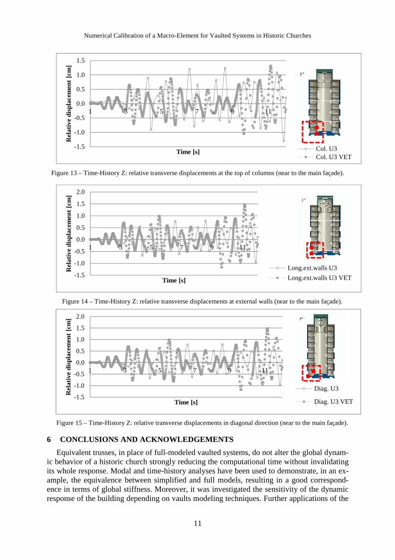
Time-history analysis based on time step integration is often the most reliable approach to evaluate the dynamic response, provided that the damping value and the stress-deformation relationship are accurately considered as material properties. Hereby spectrum-compatible accelerograms (spectra with return period 75 years and behavior factor 1.5) were considered and comparisons were performed between significant points of lateral naves, namely longitu-dinal, transverse, diagonal relative displacements along the transverse direction of the church (Fig. 11). That points are located at the ribbing arches imposts of lateral naves. They have been chosen to compare the response both in a central zone, subjected to larger transverse dis-placements, and in a zone near to the main façade. Modal analysis also allows computing rela-tive displacements, but the choice of the mode to consider would be arbitrary. Time histories outcomes are showed just in case of application along the transverse direction (Z), since along that relative displacements are larger and vaults play a more significant role in the overall seismic response.
Figure 11 – Nodes for monitoring relative displacements.
Figure 12 – Time-History Z: relative transverse displacements in diagonal direction (central part of lateral nave).
Figs 12-13-14-15 show a good correspondence between time-histories on simplified with VETs and fully modeled church. Although some peeks are filtered (Fig. 13), the trend of rela-tive transverse displacements is such that maximum displacements are those of VET model, by its nature more deformable as seen in the modal analysis, thus maximum stresses may be calculated in favor of safety in that case. It is necessary to notice that in the analysis the non-linear behavior of masonry has not been taken into account first for the arbitrary choice which it would require, and secondly for the intrinsic meaning of simplification of the proposed method, focused to recreate the dynamic global behavior in presence of vaulted systems.
-1.5
-1.0
-0.5
0.0
0.5
1.0
1.5
1 3 5 7 9 11
Rel
ativ
e di
spla
cem
ent
[cm
]
Time [s]
Diag. U3 actual
Diag. U3 VET
Numerical Calibration of a Macro-Element for Vaulted Systems in Historic Churches
11
Figure 13 – Time-History Z: relative transverse displacements at the top of columns (near to the main façade).
Figure 14 – Time-History Z: relative transverse displacements at external walls (near to the main façade).
Figure 15 – Time-History Z: relative transverse displacements in diagonal direction (near to the main façade).
6 CONCLUSIONS AND ACKNOWLEDGEMENTS
Equivalent trusses, in place of full-modeled vaulted systems, do not alter the global dynam-ic behavior of a historic church strongly reducing the computational time without invalidating its whole response. Modal and time-history analyses have been used to demonstrate, in an ex-ample, the equivalence between simplified and full models, resulting in a good correspond-ence in terms of global stiffness. Moreover, it was investigated the sensitivity of the dynamic response of the building depending on vaults modeling techniques. Further applications of the
-1.5
-1.0
-0.5
0.0
0.5
1.0
1.5
1 3 5 7 9 11
Rel
ativ
e di
spla
cem
ent
[cm
]
Time [s] Col. U3Col. U3 VET
-1.5
-1.0
-0.5
0.0
0.5
1.0
1.5
2.0
1 3 5 7 9 11
Rel
ativ
e di
spla
cem
ent
[cm
]
Time [s]
Long.ext.walls U3
Long.ext.walls U3 VET
-1.5
-1.0
-0.5
0.0
0.5
1.0
1.5
2.0
1 3 5 7 9 11
Rel
ativ
e di
spla
cem
ent
[cm
]
Time [s]
Diag. U3
Diag. U3 VET

L. Giresini, C. Butenweg, M. Andreini, A. De Falco and M. Sassu
12
illustrated procedure will be performed in nonlinear static and dynamic analyses and kinemat-ic analyses. Parametric analysis may provide diagrams of stiffness depending on vaults thick-ness, plan dimensions, boundary conditions. Such diagrams can be easily and quickly used for the definition of trusses to be implemented in simplified models. Moreover, by means of the equivalence in terms of steel diameter, the method can become a tool normally used in the de-signing of safety features such to improve the seismic response of the building.
The authors wish to thank the Consortium RELUIS – Masonry 2014 for its support.
REFERENCES
[1] P.B. Lourenço, Computations on historic masonry structures, Progress in Structural Engineering and Materials, 4, 3: 301–319. doi: 10.1002/pse.120, 2002.
[2] S. Lagomarsino, S. Brun, S. Giovinazzi, C. Idri, A. Penna, S. Podestà, S. Resemini, B. Rossi, Modelli di calcolo per il miglioramento sismico delle chiese. Proc. of the 9th Na-tional Conference "L'ingegneria sismica in Italia", Turin, 1999.
[3] P.B. Lourenço, P. Roca, Analysis of historical constructions: from thrust-lines to ad-vanced simulations, Historical Constructions, Lourenço & Roca (Eds), 91-116, 2001.
[4] F. Peña, M. Meza, M. Chavez, Macro-element identification of masonry churches by means of their dynamic properties, Structural Analysis of Historical Constructions SAHC 2012, 333–340, Wrocław, Poland, ISBN 978-83-7125-216-7, 2012.
[5] G. Brandonisio G. Lucibello, E. Mele, A. De Luca, Damage and performance evaluation of masonry churches in the 2009 L’Aquila earthquake, Engineering Failure Analysis, 34, 693–714, 2013.
[6] E. Mele, D. Gatto, A. De Luca, Structural analysis of basilica churches: a case study, Historical Constructions, P.B. Lourenço, P. Roca (Eds.), Guimarães, 729-738, 2001.
[7] B. Calderoni, P. Lenza, M. Pagano, Attuali prospettive per l’analisi sismica non lineare di edifici in muratura, Proc. of the 4th National Conf. ANIDIS, Milan, 1989.
[8] P. D’Asdia, A. Viskovic, Un modello di calcolo della resistenza ultima delle pareti in muratura, Proc. of the 6th National Conf. ANIDIS, Perugia, Oct. 13th-15th, 1993.
[9] A. Brencich and S. Lagomarsino, Un modello a macroelementi per l’analisi ciclica di pareti murarie, Proc. of the 8th National Conf. ANIDIS, Taormina, Sept. 21th-24th, 1997.
[10] L. Gambarotta, S. Lagomarsino, Damage models for the seismic response of brick masonry shear walls. Part I: The mortar joint model and its applications. Part II: The continuum model and its application, Earthquake Engineering and Structural Dy-namic, 26, 423-439, 1997.
[11] I. Caliò, F. Cannizzaro, M. Marletta, A discrete element for modeling masonry vaults, Advanced Materials Research, 133-134, 447-452, 2010.
[12] Abaqus CAE 6.12, User’s and Theory Manuals.
[13] ANSYS® Academic Research, Release 14.0.
[14] Norme Tecniche per le Costruzioni 14/01/2008. G. U. 29 del 4 febbraio 2008, S.O. n°30.
[15] M. Andreini, A. De Falco, L. Giresini, M. Sassu, Mechanical Characterization of Ma-sonry Walls with Chaotic Texture: Procedures and Results of In-Situ Tests, Int. Journal of Arch. Heritage, 8(3), 376-407, doi:10.1080/15583058.2013.826302, 2014.