Numerical analysis of candidate materials for multi-stage ...
30
Numerical analysis of candidate materials for multi-stage metal hydride hydrogen compression processes Gkanas, E. and Khzouz, M. Post-print deposited in Coventry University Repository Original citation: Gkanas, E. and Khzouz, M. (Forthcoming) Numerical analysis of candidate materials for multi-stage metal hydride hydrogen compression processes. Renewable Energy. DOI: 10.1016/j.renene.2017.04.037 http://dx.doi.org/10.1016/j.renene.2017.04.037 Elsevier Creative Commons Attribution Non-Commercial No Derivatives License Copyright © and Moral Rights are retained by the author(s) and/ or other copyright owners. A copy can be downloaded for personal non-commercial research or study, without prior permission or charge. This item cannot be reproduced or quoted extensively from without first obtaining permission in writing from the copyright holder(s). The content must not be changed in any way or sold commercially in any format or medium without the formal permission of the copyright holders.
-
Upload
khangminh22 -
Category
Documents
-
view
1 -
download
0
Transcript of Numerical analysis of candidate materials for multi-stage ...

Numerical analysis of candidate materials for multi-stage metal hydride hydrogen compression processes Gkanas, E. and Khzouz, M. Post-print deposited in Coventry University Repository Original citation: Gkanas, E. and Khzouz, M. (Forthcoming) Numerical analysis of candidate materials for multi-stage metal hydride hydrogen compression processes. Renewable Energy. DOI: 10.1016/j.renene.2017.04.037 http://dx.doi.org/10.1016/j.renene.2017.04.037 Elsevier Creative Commons Attribution Non-Commercial No Derivatives License Copyright © and Moral Rights are retained by the author(s) and/ or other copyright owners. A copy can be downloaded for personal non-commercial research or study, without prior permission or charge. This item cannot be reproduced or quoted extensively from without first obtaining permission in writing from the copyright holder(s). The content must not be changed in any way or sold commercially in any format or medium without the formal permission of the copyright holders.

Accepted Manuscript
Numerical analysis of candidate materials for multi-stage metal hydride hydrogen compression processes
Evangelos I. Gkanas, Martin Khzouz
PII: S0960-1481(17)30344-0
DOI: 10.1016/j.renene.2017.04.037
Reference: RENE 8732
To appear in: Renewable Energy
Received Date: 19 January 2017
Revised Date: 06 April 2017
Accepted Date: 19 April 2017
Please cite this article as: Evangelos I. Gkanas, Martin Khzouz, Numerical analysis of candidate materials for multi-stage metal hydride hydrogen compression processes, Renewable Energy(2017), doi: 10.1016/j.renene.2017.04.037
This is a PDF file of an unedited manuscript that has been accepted for publication. As a service to our customers we are providing this early version of the manuscript. The manuscript will undergo copyediting, typesetting, and review of the resulting proof before it is published in its final form. Please note that during the production process errors may be discovered which could affect the content, and all legal disclaimers that apply to the journal pertain.

ACCEPTED MANUSCRIPT
Highlights
Numerical Study of multistage compressors Validation with solid experimental results Four different cases for two-stage compressor Comparison between two-stage and three-stage compressor
ACCEPTED MANUSCRIPT
1
1 Numerical analysis of candidate materials for multi-stage metal hydride 2 hydrogen compression processes
3 Evangelos I. Gkanas* and Martin Khzouz
4 Hydrogen and Mobility Lab, Centre for Mobility and Transport, Coventry University, Priory Street, 5 Coventry CV1 5FB, United Kingdom.
6 * email: evangelos.gkanas.ac.uk
7
8 Abstract
9 A numerical study on multistage metal hydride hydrogen compression (MHHC)
10 systems is presented and analyzed. Multistage MHHC systems use a combination of
11 different materials to increase the final compression ratio at the end of the compression
12 process. In the current work a numerical model is proposed to describe the operation of
13 a complete three-stage MHHC cycle, which can be divided in seven steps (for a three-
14 stage compression system): first stage hydrogenation process, sensible heating of first
15 stage, coupling process between the first and the second stage, sensible heating of the
16 second stage, second coupling with the upcoming sensible heating of the third stage
17 material and finally the delivery of high pressure hydrogen to a high pressure hydrogen
18 tank. Three scenarios concerning the combination of different materials for the
19 compression stages are introduced and analyzed in terms of maximum compression
20 ratio, cycle time and energy consumption. According to the results, the combination of
21 LaNi5 (stage 1), MmNi4.6Al0.4 (stage 2) and a novel synthesized AB2-Laves phase
22 intermetallic (stage 3) present a compression ratio 22:1 while operating between 20-
23 130 oC.
24 Keywords: Metal Hydride Hydrogen Compressor; Heat and mass transfer; 25 Hydrogenation/Dehydrogenation; Metal Hydrides;
26
27
28
29
30
31
32
33
ACCEPTED MANUSCRIPT
2
1 1. Introduction23 Energy is one of the key elements for global peace and nature rescue. An increase in
4 the energy consumption of a country provides a positive impact on the economic as
5 well as social development of the country [1, 2]. Over the past decade, the investigation
6 for alternative fuels and energy technologies became important for the future energy
7 stability [3, 4]. Hydrogen is one of the most promising energy carriers for the future
8 energy needs. It is a high energy effective and low polluting fuel [5, 6]. Metal hydrides
9 have been established as excellent mediums for hydrogen storage and compression
10 applications compared to liquid and compressed hydrogen techniques due to the safest
11 and more efficient operation [7].
12 The metal hydride technology for hydrogen compression has been an alternative to the
13 use of conventional mechanical compressors. Current methods in hydrogen
14 compression typically comprise of mechanical compressors operate in electricity
15 derived from fossil fuels which poses higher energy costs. Compression of hydrogen
16 gas to higher pressure, using mechanical compressors might face many technical
17 problems related to lubrication, leakage, maintenance and compression construction. In
18 addition, the mechanical compressors consume high grade of electrical energy for their
19 operation.
20 With the implementation of metal hydrides for hydrogen compression, energy density
21 and efficiency can be increased while reducing cost [8]. Compared to the conventional
22 mechanical compressor, the hydrogen compressor based on reversible metal hydride
23 presents many merits, such as the one of being able to export hydrogen over a wide
24 range of pressure with high purity, free of mechanical movement or friction, low energy
25 consumption, noiseless operation and easy and cheap maintenance [9-12]. The
26 candidate materials for a metal hydride compressor need to present certain properties
27 such as large reversible hydrogen storage capacity, flat plateau pressure, small
28 hysteresis factor and high compression ratio [13-14]. Meanwhile, admirable reaction
29 kinetics and pulverization resistance are also necessary [15]. The metal hydride
30 hydrogen compressor is one such solution that can cover a wide range of operating
31 pressures and pressure ratios by selecting suitable metal hydride combinations [16].
32
33 A multistage hydride-based compressor consists of a series of coupled modules
34 containing metal alloys, which store and release the hydrogen gas in a cyclical manner,
ACCEPTED MANUSCRIPT
3
1 under certain conditions of temperature and pressure. The driving force exerted by a
2 variation in temperature which brings the transfer of hydrogen while increasing the exit
3 pressure from the one stage to another. Despite the advantages of using metal hydride
4 compression systems over the mechanical compressors, to become commercially
5 available several things need to be achieved: the overall general efficiency of such
6 systems needs to be improved and the capital cost to be significantly reduced [17].
7 Appropriate selection of the metal hydrides is essential to fully realize the commercial
8 potential of the metal hydride compressor [18]. The multistage operation approach
9 introduces more strict requirements to the tuneability of the Pressure-Composition-
10 Temperature P-c-T characteristics, because during the coupling of the first stage
11 (dehydrogenation) and the second stage (hydrogenation) the isotherms of both stages
12 must be synchronized [19]. Some requirements for the correct selection is that the
13 materials should present fast kinetics in order the compression cycle to be as fast as
14 possible and relatively high reversible hydrogenation/dehydrogenation capacity, so the
15 total amount for the materials needed to be lower. Low plateau slope for the isotherms
16 of the materials, low hysteresis and cycle stability are also required. Finally, the cost of
17 the compression process should be affordable.
18
19 Over the last decade, many scientists have made efforts in the subject of MHHC and
20 some promising results were found both experimentally and numerically. Wang et al.
21 [20] developed a 700-bar metal hydride compression system by using a two-stage
22 system. For both stages, AB2-type intermetallics based on Ti-Zr used. For the
23 cooling/heating system cold/hot oil used and a compression ratio of 17.5:1 achieved
24 operating between 25–150 oC. Li et al. [21] experimentally developed a two-stage metal
25 hydride compressor by operating an AB5-type intermetallic of the La-Ce-Ca-Ni family
26 for the first stage and an AB2-type of the Ti-Zr-Cr-Fe-V family and they concluded a
27 final pressure of 745 bar at 150 oC with a compression capacity of 2000 L/cycle.
28 Laurencelle et al. [22] reported a three-stage metal hydride compression system where
29 for all the three stages AB5-type intermetallics were selected based on the La-Ni-Sn,
30 La-Ni and Mm-Ni-Al families respectively. Under operation temperatures between 20–
31 80 oC a 20:1 compression ratio achieved. Popeneciu et al. [23] investigated a three-
32 stage compressor and they reported that when the compressor operated between 20–80
33 oC the compression ratio was 28:1 when operating three AB5-type intermetallics for the
34 compression stages. Koultoukis et al. [24] studied experimentally potential AB2-type
ACCEPTED MANUSCRIPT
4
1 intermetallics based on the Ti-Zr family, applicable for hydrogen compression
2 processes under several operating conditions. Furthermore, they also investigated [25]
3 another series of AB2-type intermetallics at operation range between 20–90 oC. Wang
4 et al. [26] developed two alloys for hydrogen compression, an AB5-type based on Ml-
5 Mm-Ca-Ni and an AB2-type based on Ti-Zr-Cr-Mn, where a compression ratio of
6 22.5:1 was reported. Several other works focusing on the numerical study of metal
7 hydride compression were also reported. Muthukumar et al. [27] numerically studied
8 the operation of a three-stage compression system using the AB5-type LaNi5, Mm-Ni-
9 Al and an AB2-type based on Ti-Zr-VFe-Cr-Mn as the operating metal hydrides
10 between 20 and 120 oC and they reported a compression ratio of 28:1 at the end of the
11 final stage. Gkanas et al. [28] investigated numerically the performance of a two-stage
12 compression system by using an AB5-type as the first stage material and an AB2-type
13 as the second stage material and they reported a compression ratio of 23:1 when
14 operating the system between 20-130 oC. Furthermore, they investigated [29]
15 numerically the performance of a three-stage compressor by using two AB5-type
16 intermetallics as the first and second stage materials and the commercial available
17 Hydralloy C as the final stage material. Talaganis et al. [30] suggested a simplified
18 model in order to reduce the number of the variables used during the simulation study.
19 They used the proposed numerical model to simulate the compression behavior by
20 using LaNi5 and Mm-Ni-Al as the operating materials.
21
22 According to the previous studies there is a large interest in the experimental
23 development of novel materials for effective hydrogen compression processes. The
24 potential materials for such processes are based both on the AB5-type intermetallics
25 (such as LaNi5, Mm-Ni-Al) as the materials for the first stages of the compression
26 process and AB2-type intermetallics as the materials to use for the upcoming stages and
27 the final stage of the compression. On the other hand, there are not many publications
28 focusing on the numerical analysis of the compression process and more specific on the
29 usage of several materials to achieve the maximum compression ratio under the most
30 suitable conditions of temperature and pressure for practical applications. In the current
31 work, a numerical study of three-stage MHHC systems is presented and analysed. The
32 proposed model was validated with experimental results extracted from a Sievert type
33 apparatus. Three different MHHC systems were examined by using different
34 combination of materials as the first, second and third stage in terms of maximum
ACCEPTED MANUSCRIPT
5
1 compression ratio, cycle time and energy consumption for the operation of the system
2 and the results extracted from the study are compared with previously reported results
3 [28] regarding a two-stage compression system and discussing the necessity of the
4 correct choice of materials and number of stages for the development of MHHC.
5
6 2. Model Formulation and Problem Definition
7 2.1 Introduction to a three-stage MHHC cycle
8
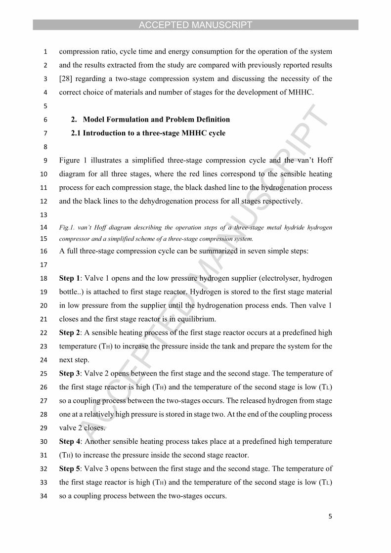
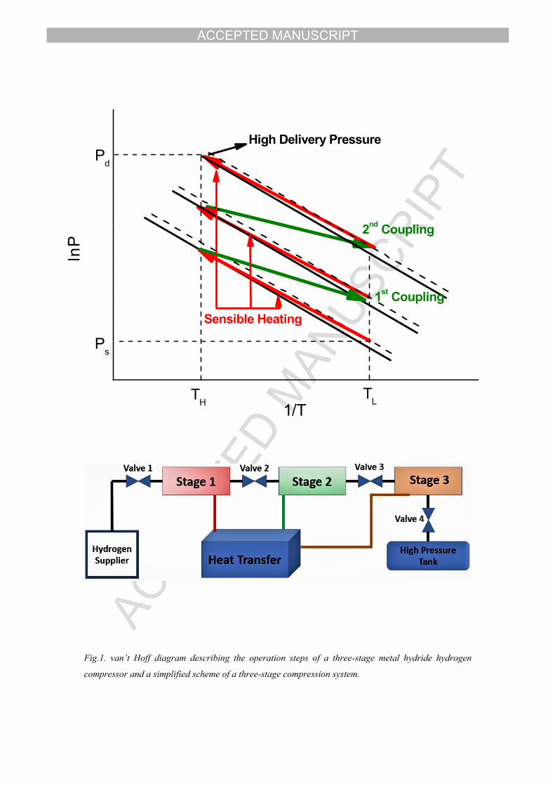
9 Figure 1 illustrates a simplified three-stage compression cycle and the van’t Hoff
10 diagram for all three stages, where the red lines correspond to the sensible heating
11 process for each compression stage, the black dashed line to the hydrogenation process
12 and the black lines to the dehydrogenation process for all stages respectively.
13
14 Fig.1. van’t Hoff diagram describing the operation steps of a three-stage metal hydride hydrogen
15 compressor and a simplified scheme of a three-stage compression system.
16 A full three-stage compression cycle can be summarized in seven simple steps:
17
18 Step 1: Valve 1 opens and the low pressure hydrogen supplier (electrolyser, hydrogen
19 bottle..) is attached to first stage reactor. Hydrogen is stored to the first stage material
20 in low pressure from the supplier until the hydrogenation process ends. Then valve 1
21 closes and the first stage reactor is in equilibrium.
22 Step 2: A sensible heating process of the first stage reactor occurs at a predefined high
23 temperature (TH) to increase the pressure inside the tank and prepare the system for the
24 next step.
25 Step 3: Valve 2 opens between the first stage and the second stage. The temperature of
26 the first stage reactor is high (TH) and the temperature of the second stage is low (TL)
27 so a coupling process between the two-stages occurs. The released hydrogen from stage
28 one at a relatively high pressure is stored in stage two. At the end of the coupling process
29 valve 2 closes.
30 Step 4: Another sensible heating process takes place at a predefined high temperature
31 (TH) to increase the pressure inside the second stage reactor.
32 Step 5: Valve 3 opens between the first stage and the second stage. The temperature of
33 the first stage reactor is high (TH) and the temperature of the second stage is low (TL)
34 so a coupling process between the two-stages occurs.

ACCEPTED MANUSCRIPT
6
1 Step 6: Sensible heating of the third reactor
2 Step 7: Valve 4 opens and high pressure hydrogen is stored in a high-pressure tank,
3 while the first reactor is prepared (cooling) for the beginning of the upcoming
4 compression cycle.
5 It is essential that the material selection should fulfil certain criteria to ensure that the
6 operation of the compression system will be efficient and safe. As explained in Figure
7 2, the plateau pressure for the hydrogenation process of the first stage material should
8 be sufficient low in order the material to be able to absorb the hydrogen from the low-
9 pressure supplier. Furthermore, it is important that the plateau pressure of the
10 dehydrogenation process for the first stage material should be higher than the plateau
11 pressure for the hydrogenation process of the second stage material to ensure the
12 presence of the pressure difference between the two reactors, which is going to act as
13 the driving force to lead hydrogen from the first tank to the other. The same behavior
14 must be presented during the second coupling process between the second and the third
15 stage of the compression. Finally, to achieve the highest compression ratio, the plateau
16 pressure of the final stage must be as high as possible.
17
18 Fig 2. P-c-T plot describing the operation steps of a three-stage metal hydride hydrogen compressor
19
20 2.2 Mathematical Model
21 To simplify the problem of hydrogen storage into the interstitial sites of the metal lattice
22 which is a complex process containing chemical reactions, diffusion and heat transfer,
23 it is essential to make some assumptions for the modeling purposes. The following
24 assumptions have been considered for the current work.
25
26 a) Initially the temperature and pressure profiles are uniform inside the reactors.
27 b) Thermal conductivity and specific heat of the hydride are assumed to be
28 constant during the compression cycle.
29 c) The medium is in local thermal equilibrium which implies that there is no heat
30 transfer between solid and gas phases
31 d) Radiative heat transfer and viscous dissipation are negligible.
32 e) Hydrogen is treated as an ideal gas from a thermodynamic point of view.
33
34
ACCEPTED MANUSCRIPT
7
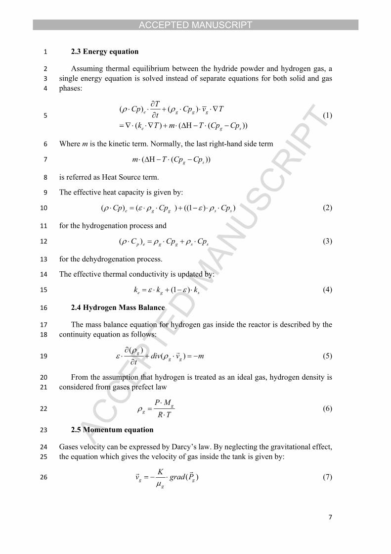
1 2.3 Energy equation
2 Assuming thermal equilibrium between the hydride powder and hydrogen gas, a 3 single energy equation is solved instead of separate equations for both solid and gas 4 phases:
5 (1)( ) ( )
( ) ( ( ))
e g g g
e g s
TCp Cp v Tt
k T m T Cp Cp
6 Where m is the kinetic term. Normally, the last right-hand side term
7 ( ( ))g sm T Cp Cp
8 is referred as Heat Source term.
9 The effective heat capacity is given by:
10 (2)( ) ( ) ((1 ) )e g g s sCp Cp Cp
11 for the hydrogenation process and
12 (3)( )p e g g s sC Cp Cp
13 for the dehydrogenation process.
14 The effective thermal conductivity is updated by:
15 (4) (1 )e g sk k k
16 2.4 Hydrogen Mass Balance
17 The mass balance equation for hydrogen gas inside the reactor is described by the 18 continuity equation as follows:
19 (5)( )
( )gg gdiv v m
t
20 From the assumption that hydrogen is treated as an ideal gas, hydrogen density is 21 considered from gases prefect law
22 (6)gg
P MR T
23 2.5 Momentum equation
24 Gases velocity can be expressed by Darcy’s law. By neglecting the gravitational effect, 25 the equation which gives the velocity of gas inside the tank is given by:
26 (7)( )g gg
Kv grad P

ACCEPTED MANUSCRIPT
8
1 Where K is the permeability of the solid and μg is the dynamic viscosity of gas. The 2 solid permeability is given by the Kozeny–Carman’s equation
3 (8)2 3
2180 (1 )dpK
4 2.6 Kinetic expression
5 In the equations (1) and (5), the m term represents the amount of hydrogen that is stored 6 and released in the materials.
7 For the hydrogenation process:
8 (9)exp[ ] ln[ ] ( )gaabs abs ss s
g eq
pEm CR T P
9 Where Ca is the pro-exponential constant, Ea is the activation energy (calculated 10 experimentally), ρss is the saturation density of the hydride (after the full completion of 11 the hydrogenation process) and ρs is the density of the hydride with time. The saturation 12 density is determined by calculating the hydride concentration (mol/m3) after the 13 storage process and the volume of the hydride after the expansion process that occurs 14 during the hydrogenation. As for the density of the hydride anytime, from the 15 ‘Transport of diluted species’ Module in COMSOL Multiphysics, the concentration of 16 the hydride anytime is calculated (mol/m3) and subsequently is substituted in Eq. (9) in 17 order to calculate the kinetic term for the hydrogenation process.
18 For the dehydrogenation process:
19 (10)exp[ ] ( )eq gddes des s
g eq
P pEm CR T P
20 Where Cd is the pro-exponential constant, Ed is the activation energy for the 21 dehydrogenation process (measured experimentally) and ρs is the density of the hydride 22 during the dehydrogenation process which is determined as for the hydrogenation 23 process by calculating the concentration of the hydride and substituting in Eq. (10)
24 2.7 Equilibrium Pressure
25 Initially, the reactors are in equilibrium with the hydrogen gas. The hydride 26 equilibrium pressure is estimated by using van’t Hoff law [31]:
27 (11) 0 0max
1ln [ ( ) tan( ( )) ]2 2eq s
g g
S XP PR T R X
28 Where σs and σ0 are factors referring to the plateau slope flatness and Y is the 29 hysteresis of the isotherm for the materials.
30
31 2.8 Coupled mass and energy balance

ACCEPTED MANUSCRIPT
9
1 The situation of the system during the coupling between the first and the second 2 stage after opening the valve between them is an important parameter that need to be 3 considered when trying to describe the compression cycle. The number of moles inside 4 the interconnector between the two reactors is updated from the following equation:
5 (12)t in des absn n n n
6 To determine the number of moles, another ‘Transport of diluted species’ Module in 7 COMSOL Multiphysics to calculate the concentration of hydrogen (mol/m3) during the 8 hydrogenation process (Reactor 1), during the dehydrogenation process (Reactor 2) and 9 at the interconnector between the two reactors.
10 The pressure of hydrogen inside the interconnector is updated by:
11 (13)1 2
t gt
n R Tp
V V
12 Where V1 and V2 are the volumes of the first and second stage tanks respectively 13 and T is the temperature of the gas inside the interconnector. Considering the pressure 14 of hydrogen in the interconnector, we can use it as the driving force to lead hydrogen 15 from the first stage to the second, therefore the kinetic equations for both hydrogenation 16 and dehydrogenation process during the coupling are provided by the following 17 equations.
18 (14)exp( ) ln( ) ( )a tabs abs ss s
g eq
E pm CR T P
19 For the hydrogenation process.
20 (15)exp( ) ( ) ( )eq tddes des s
g eq
P pEm CR T P
21 For the dehydrogenation process.
22
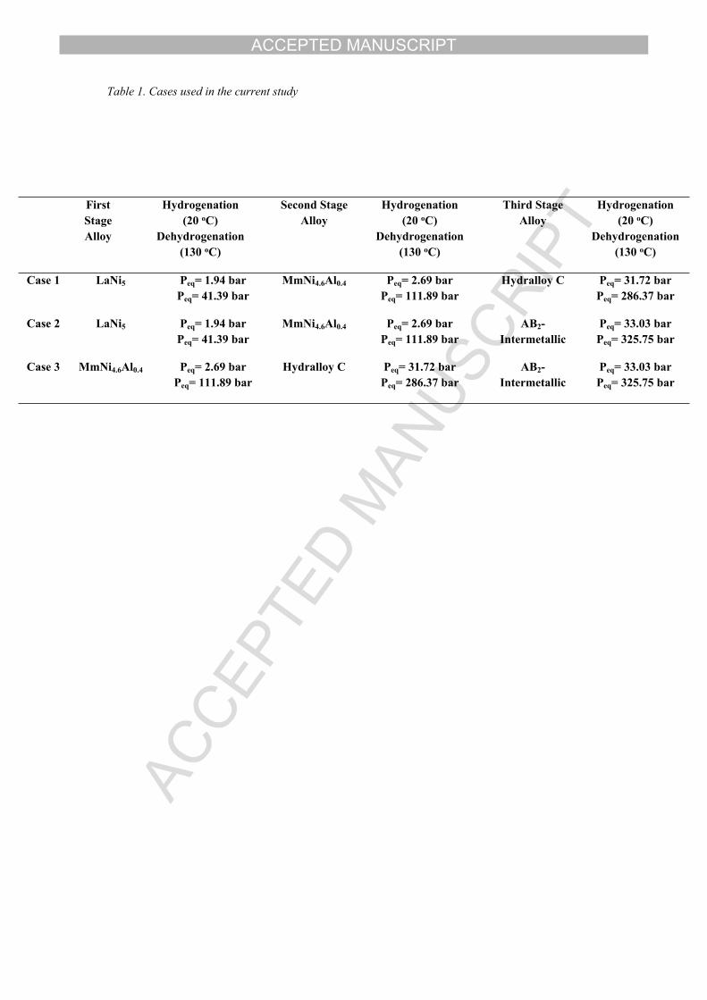
23 3 Materials and Methods24 3.1 Material Selection
25 Three different cases are studied regarding the proper material selection to build
26 a three-stage MHHC. Table 1 presents all the studied cases. The first case utilizes LaNi5
27 (AB5-type) as the first stage alloy, MmNi4.6Al0.4 (AB5-type) as the second stage alloy
28 and Hydralloy C as the third stage. The second case uses LaNi5 (AB5-type) as the first
29 stage alloy, MmNi4.6Al0.4 (AB5-type) as the second stage alloy and a novel AB2-
30 intermetallic (Laves phase) as the third stage. The final case involves MmNi4.6Al0.4
31 (AB5-type) as the first stage alloy, Hydralloy C as the second stage alloy and a novel
32 AB2-intermetallic (Laves phase) as the third stage. All the above mentioned
ACCEPTED MANUSCRIPT
10
1 intermetallics were synthesized by arc-melting techniques and characterized by means
2 of XRD (BRUKER AXS D8-Advance Diffractometer) and SEM (Zeiss NEON 40 EsB
3 Microscope), in order to identify the microstructure of these materials and the P-c-T
4 properties were measured by commercial Sievert-type apparatus (Hidden Isochema), in
5 order to be able to measure the thermodynamic properties needed for the numerical
6 calculations. For all the different cases the hydrogenation process was selected to occur
7 at 20oC and for the dehydrogenation process the temperature was selected at 130oC.
8 According to Table 1 and the analysis presented in chapter 2.1 for all the cases the
9 temperature range is eligible for the compression applications.
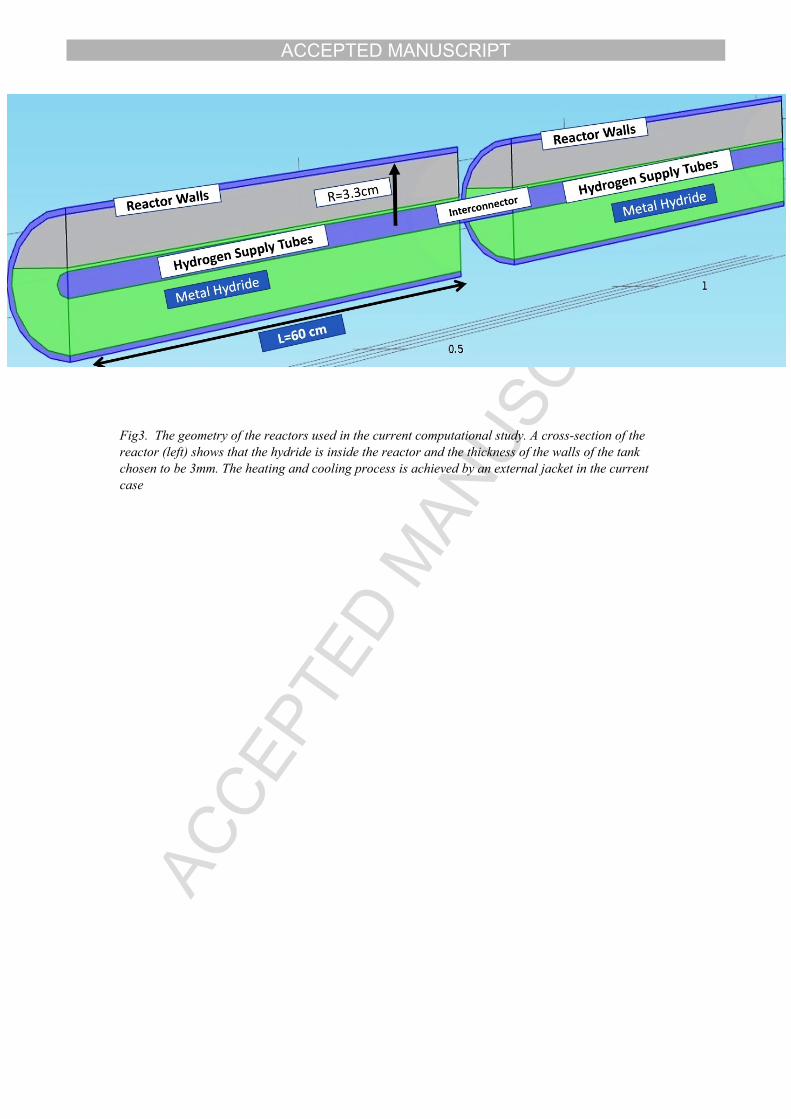
10 Table 1. Cases used in the current study1112 3.2 Geometry of the system
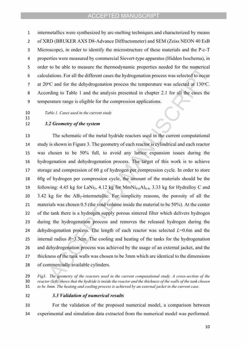
13 The schematic of the metal hydride reactors used in the current computational
14 study is shown in Figure 3. The geometry of each reactor is cylindrical and each reactor
15 was chosen to be 50% full, to avoid any lattice expansion issues during the
16 hydrogenation and dehydrogenation process. The target of this work is to achieve
17 storage and compression of 60 g of hydrogen per compression cycle. In order to store
18 60g of hydrogen per compression cycle, the amount of the materials should be the
19 following: 4.45 kg for LaNi5, 4.12 kg for MmNi4.6Al0.4, 3.33 kg for Hydralloy C and
20 3.42 kg for the AB2-intermetallic. For simplicity reasons, the porosity of all the
21 materials was chosen 0.5 (the void volume inside the material to be 50%). At the center
22 of the tank there is a hydrogen supply porous sintered filter which delivers hydrogen
23 during the hydrogenation process and removes the released hydrogen during the
24 dehydrogenation process. The length of each reactor was selected L=0.6m and the
25 internal radius R=3.3cm. The cooling and heating of the tanks for the hydrogenation
26 and dehydrogenation process was achieved by the usage of an external jacket, and the
27 thickness of the tank walls was chosen to be 3mm which are identical to the dimensions
28 of commercially available cylinders.
29 Fig3. The geometry of the reactors used in the current computational study. A cross-section of the 30 reactor (left) shows that the hydride is inside the reactor and the thickness of the walls of the tank chosen 31 to be 3mm. The heating and cooling process is achieved by an external jacket in the current case.
32 3.3 Validation of numerical results
33 For the validation of the proposed numerical model, a comparison between
34 experimental and simulation data extracted from the numerical model was performed.
ACCEPTED MANUSCRIPT
11
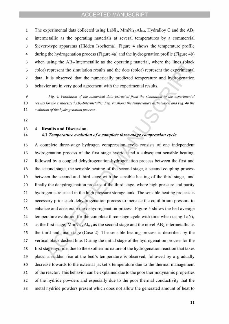
1 The experimental data collected using LaNi5, MmNi4.6Al0.4, Hydralloy C and the AB2
2 intermetallic as the operating materials at several temperatures by a commercial
3 Sievert-type apparatus (Hidden Isochema). Figure 4 shows the temperature profile
4 during the hydrogenation process (Figure 4a) and the hydrogenation profile (Figure 4b)
5 when using the AB2-Intermetallic as the operating material, where the lines (black
6 color) represent the simulation results and the dots (color) represent the experimental
7 data. It is observed that the numerically predicted temperature and hydrogenation
8 behavior are in very good agreement with the experimental results.
9 Fig. 4. Validation of the numerical data extracted from the simulation to the experimental
10 results for the synthesized AB2-Intermetallic. Fig. 4a shows the temperature distribution and Fig. 4b the
11 evolution of the hydrogenation process.
12
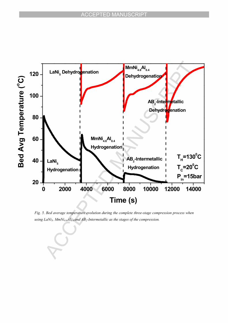
13 4 Results and Discussion.14 4.1 Temperature evolution of a complete three-stage compression cycle
15 A complete three-stage hydrogen compression cycle consists of one independent
16 hydrogenation process of the first stage hydride and a subsequent sensible heating,
17 followed by a coupled dehydrogenation-hydrogenation process between the first and
18 the second stage, the sensible heating of the second stage, a second coupling process
19 between the second and third stage with the sensible heating of the third stage, and
20 finally the dehydrogenation process of the third stage, where high pressure and purity
21 hydrogen is released in the high pressure storage tank. The sensible heating process is
22 necessary prior each dehydrogenation process to increase the equilibrium pressure to
23 enhance and accelerate the dehydrogenation process. Figure 5 shows the bed average
24 temperature evolution for the complete three-stage cycle with time when using LaNi5
25 as the first stage, MmNi4.6Al0.4 as the second stage and the novel AB2-intermetallic as
26 the third and final stage (Case 2). The sensible heating process is described by the
27 vertical black dashed line. During the initial stage of the hydrogenation process for the
28 first stage hydride, due to the exothermic nature of the hydrogenation reaction that takes
29 place, a sudden rise at the bed’s temperature is observed, followed by a gradually
30 decrease towards to the external jacket’s temperature due to the thermal management
31 of the reactor. This behavior can be explained due to the poor thermodynamic properties
32 of the hydride powders and especially due to the poor thermal conductivity that the
33 metal hydride powders present which does not allow the generated amount of heat to

ACCEPTED MANUSCRIPT
12
1 be transferred from the hydride bed to the external jacket during the first stage of the
2 hydrogenation process and the amount of heat is stored inside the metal hydride bed,
3 resulting in a sudden rise of the temperature at the first stage of the hydrogenation. After
4 the hydrogenation process, a sensible heating of the hydride bed takes place where the
5 equilibrium pressure of the material increases. During the initial stage of the
6 dehydrogenation process, the necessary amount of heat has not been transferred from
7 the external heater (130oC) to the hydride bed due to poor thermal conductivity and
8 initially the necessary amount of heat is provided by the hydride bed itself, resulting in
9 a sudden decrease of beds’ temperature as illustrated in Figure 5. Therefore, a sensible
10 heating process is essential for the dehydrogenation. Due to the increase of the heat
11 within the hydride bed, according to the vant Hoff’s law (Eq. 11), the sensible heating
12 can increase the equilibrium pressure resulting in a favorable condition for the
13 upcoming coupled dehydrogenation-hydrogenation process.
14 Fig. 5. Bed average temperature evolution during the complete three-stage compression
15 process when using LaNi5, MmNi4.6Al0.4 and AB2-Intermetallic as the stages of the compression.
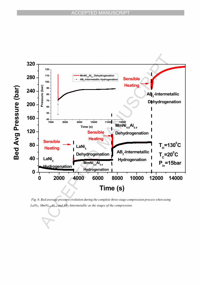
16 4.2 Pressure and storage capacity evolution during the complete three-stage
17 compression cycle
18 The average pressure of the operating metal hydride beds during the three-stage
19 compression cycle when using LaNi5 as the first stage, MmNi4.6Al0.4 as the second stage
20 and the novel AB2-intermetallic as the third and final stage is presented in Figure 6.
21 Initially, a low-pressure hydrogen supplier (e.x an electrolyser) is attached to the first
22 stage hydride and provide hydrogen at pressure 15 bar and enters the first stage hydride
23 due to the pressure difference. By maintaining the temperature of the first stage at low
24 levels, hydrogen is stored at the lattice of the material indicating a gradually reduction
25 of the hydrogen pressure within the storage bed during the first step of the pressure
26 evolution. The pressure of hydrogen inside the first stage at the end of the
27 hydrogenation process is almost 7 bar. After the hydrogenation, a sensible heating of
28 the reactor occurs. During this process, there is a sharp increase in the bed’s pressure,
29 due to the increase of the equilibrium pressure as per vant Hoff’s law. After the sensible
30 heating process, the coupled dehydrogenation-hydrogenation procedure takes place.
31 During the initial stage of this process, the equilibrium pressure of the dehydrogenating
32 reactor decreases while the equilibrium pressure for the hydrogenating reactor increases
33 sharply due to the very fast kinetics between the two reactors. After this rapid initial
ACCEPTED MANUSCRIPT
13
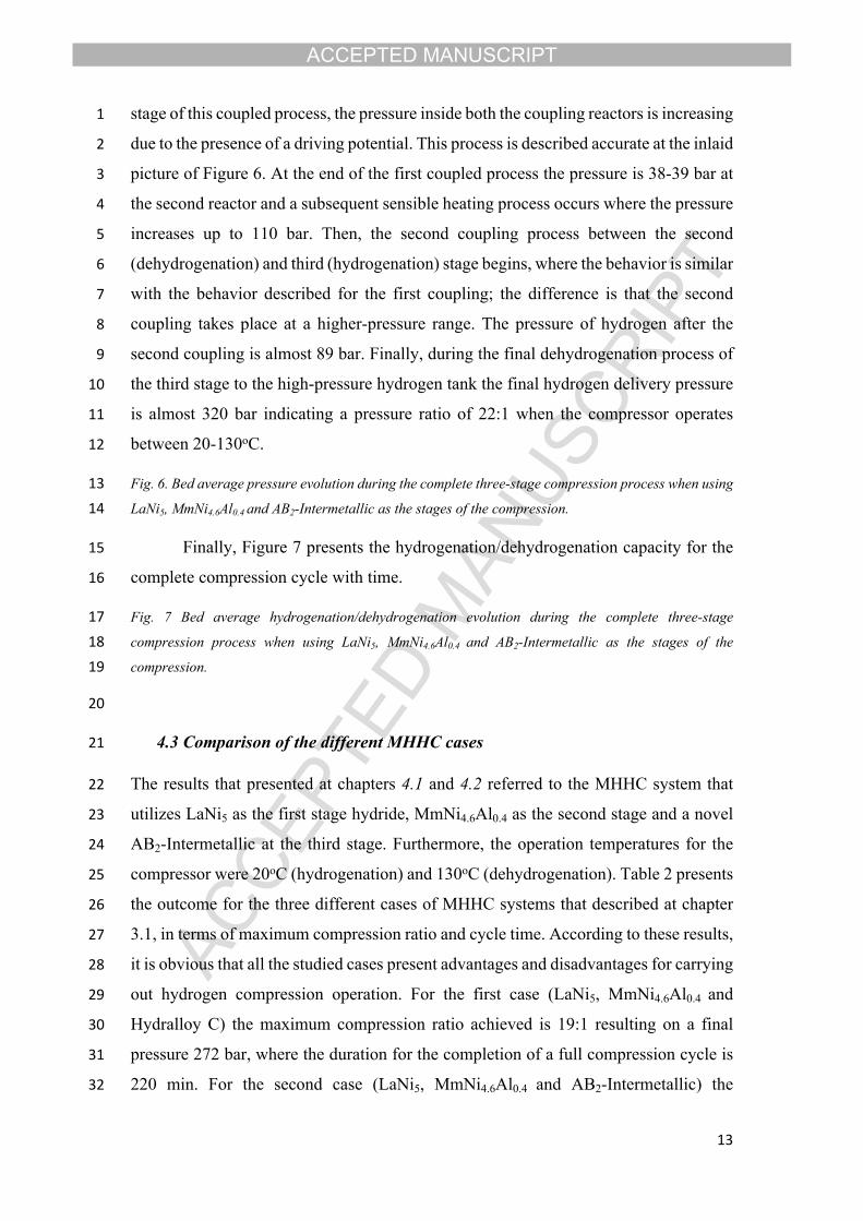
1 stage of this coupled process, the pressure inside both the coupling reactors is increasing
2 due to the presence of a driving potential. This process is described accurate at the inlaid
3 picture of Figure 6. At the end of the first coupled process the pressure is 38-39 bar at
4 the second reactor and a subsequent sensible heating process occurs where the pressure
5 increases up to 110 bar. Then, the second coupling process between the second
6 (dehydrogenation) and third (hydrogenation) stage begins, where the behavior is similar
7 with the behavior described for the first coupling; the difference is that the second
8 coupling takes place at a higher-pressure range. The pressure of hydrogen after the
9 second coupling is almost 89 bar. Finally, during the final dehydrogenation process of
10 the third stage to the high-pressure hydrogen tank the final hydrogen delivery pressure
11 is almost 320 bar indicating a pressure ratio of 22:1 when the compressor operates
12 between 20-130oC.
13 Fig. 6. Bed average pressure evolution during the complete three-stage compression process when using
14 LaNi5, MmNi4.6Al0.4 and AB2-Intermetallic as the stages of the compression.
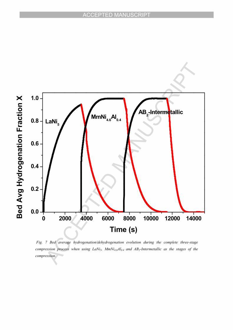
15 Finally, Figure 7 presents the hydrogenation/dehydrogenation capacity for the
16 complete compression cycle with time.
17 Fig. 7 Bed average hydrogenation/dehydrogenation evolution during the complete three-stage
18 compression process when using LaNi5, MmNi4.6Al0.4 and AB2-Intermetallic as the stages of the
19 compression.
20
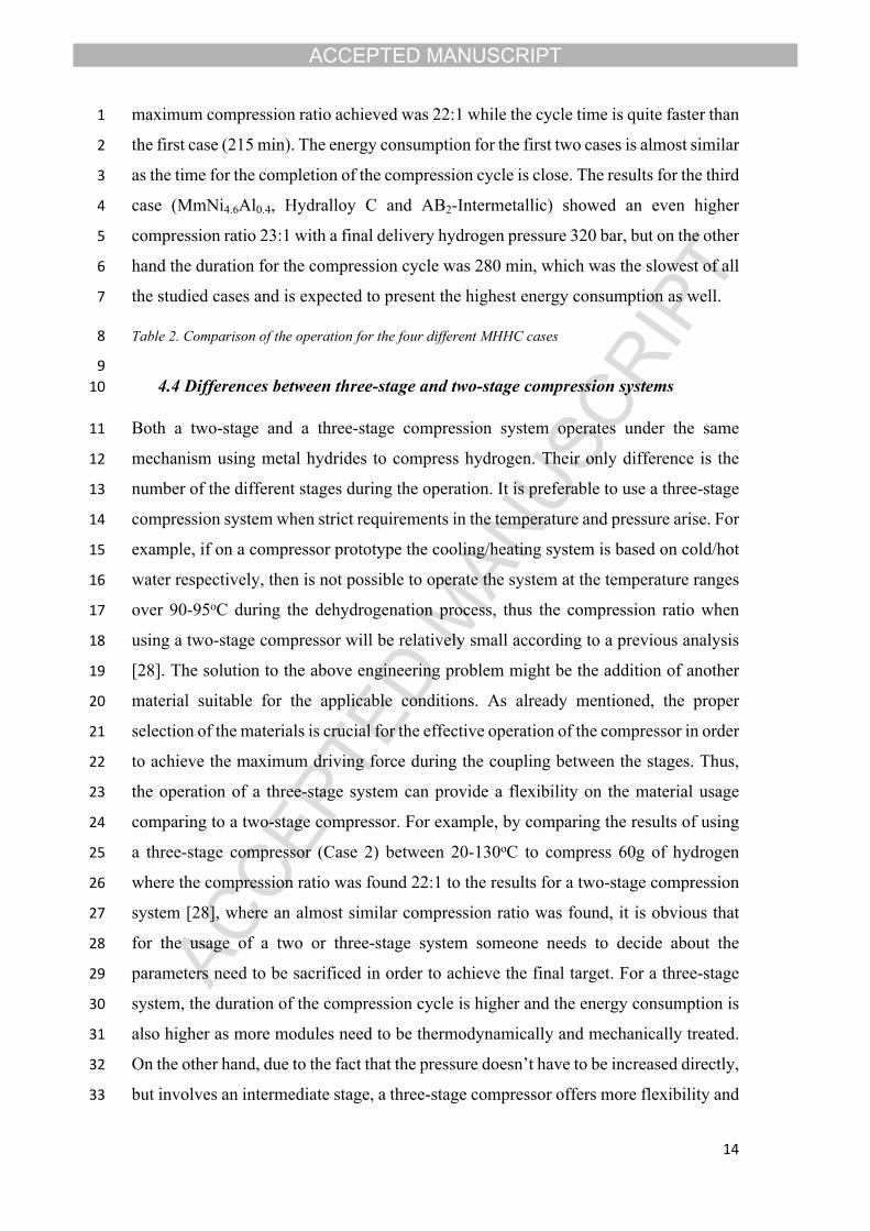
21 4.3 Comparison of the different MHHC cases
22 The results that presented at chapters 4.1 and 4.2 referred to the MHHC system that
23 utilizes LaNi5 as the first stage hydride, MmNi4.6Al0.4 as the second stage and a novel
24 AB2-Intermetallic at the third stage. Furthermore, the operation temperatures for the
25 compressor were 20oC (hydrogenation) and 130oC (dehydrogenation). Table 2 presents
26 the outcome for the three different cases of MHHC systems that described at chapter
27 3.1, in terms of maximum compression ratio and cycle time. According to these results,
28 it is obvious that all the studied cases present advantages and disadvantages for carrying
29 out hydrogen compression operation. For the first case (LaNi5, MmNi4.6Al0.4 and
30 Hydralloy C) the maximum compression ratio achieved is 19:1 resulting on a final
31 pressure 272 bar, where the duration for the completion of a full compression cycle is
32 220 min. For the second case (LaNi5, MmNi4.6Al0.4 and AB2-Intermetallic) the
ACCEPTED MANUSCRIPT
14
1 maximum compression ratio achieved was 22:1 while the cycle time is quite faster than
2 the first case (215 min). The energy consumption for the first two cases is almost similar
3 as the time for the completion of the compression cycle is close. The results for the third
4 case (MmNi4.6Al0.4, Hydralloy C and AB2-Intermetallic) showed an even higher
5 compression ratio 23:1 with a final delivery hydrogen pressure 320 bar, but on the other
6 hand the duration for the compression cycle was 280 min, which was the slowest of all
7 the studied cases and is expected to present the highest energy consumption as well.
8 Table 2. Comparison of the operation for the four different MHHC cases
910 4.4 Differences between three-stage and two-stage compression systems
11 Both a two-stage and a three-stage compression system operates under the same
12 mechanism using metal hydrides to compress hydrogen. Their only difference is the
13 number of the different stages during the operation. It is preferable to use a three-stage
14 compression system when strict requirements in the temperature and pressure arise. For
15 example, if on a compressor prototype the cooling/heating system is based on cold/hot
16 water respectively, then is not possible to operate the system at the temperature ranges
17 over 90-95oC during the dehydrogenation process, thus the compression ratio when
18 using a two-stage compressor will be relatively small according to a previous analysis
19 [28]. The solution to the above engineering problem might be the addition of another
20 material suitable for the applicable conditions. As already mentioned, the proper
21 selection of the materials is crucial for the effective operation of the compressor in order
22 to achieve the maximum driving force during the coupling between the stages. Thus,
23 the operation of a three-stage system can provide a flexibility on the material usage
24 comparing to a two-stage compressor. For example, by comparing the results of using
25 a three-stage compressor (Case 2) between 20-130oC to compress 60g of hydrogen
26 where the compression ratio was found 22:1 to the results for a two-stage compression
27 system [28], where an almost similar compression ratio was found, it is obvious that
28 for the usage of a two or three-stage system someone needs to decide about the
29 parameters need to be sacrificed in order to achieve the final target. For a three-stage
30 system, the duration of the compression cycle is higher and the energy consumption is
31 also higher as more modules need to be thermodynamically and mechanically treated.
32 On the other hand, due to the fact that the pressure doesn’t have to be increased directly,
33 but involves an intermediate stage, a three-stage compressor offers more flexibility and
ACCEPTED MANUSCRIPT
15
1 choices on the material selection, while for the two-stage compression the material
2 selection has to be very strict and the choices might not be plenty. Thus, it is obvious
3 that the selection of the proper compression system depends on a number of parameters
4 such as the compression ratio, the cycle time, the operation conditions, the size and the
5 energy consumption.
6 5 Conclusions
7 A numerical model describing the complete operation of a three-stage hydrogen
8 compression system was presented and analyzed. The numerical results were validated
9 with experimental data and very good agreement for both the temperature evolution
10 and the hydrogenation profile was obtained. Three different cases of MHHC systems
11 were studied and compared in terms of compression ratio, cycle time and energy
12 consumption and was found that the operation temperature range for the compressor
13 such as the choice of different materials as the operating hydrides can affect the
14 compression characteristics. It was also found that when operating LaNi5 as the first
15 stage hydride, MmNi4.6Al0.4 as the second stage and a novel AB2-intermetallic as the
16 third stage alloy at a temperature range 20oC (hydrogenation) and 130oC
17 (dehydrogenation) the final compression ratio could be almost 22:1 reaching at the end
18 of the final dehydrogenation process a delivery pressure of 315 bar. In order to optimize
19 the compression system and to able to achieve higher compression ratios while
20 minimize the operation temperature ranges and consequently the energy consumption
21 and to achieve faster cycle time special attention should be given to the research for
22 materials with better compression characteristics (fast kinetics, low plateau slope and
23 hysteresis, thermodynamics) and to the heat management of the metal hydride tank.
24
25
26
27
28
29
30
ACCEPTED MANUSCRIPT
16
1
2
3
4
5
6
7
8
9
10
11
12
13
14
15
16
17
18
19
20
21
22
23
24
25
26
Nomenclature Subscripts
Ca Absorption Reaction Constant, s-1 a Absorption
Cd Desorption Reaction Constant, s-1 A Reactor A
Cp Specific Heat, J/kg-K B Reactor B
Ea Activation Energy for Absorption, J/molH2 d Desorption
Ed Activation Energy for Desorption, J/molH2 e Effective
h Heat Transfer Coefficient, W/m2K eq Equilibrium
k Thermal Conductivity, W/m-K f External Heater/Cooler
K Permeability, m2 g Gas
M Molecular Weight, kg/mol i Initial
m Kinetic Expression s Solid
n Number of Hydrogen Moles ss Saturation
P Pressure, bar Greek Letters
R Gas Global Constant, J/mol-K ε Porosity
t Time (s) μ Dynamic Viscosity, kg/ms
T Temperature (K) ρ Density, kg/m3
v Gas Velocity, m/s ΔΗ Reaction Enthalpy, J/mol
V Volume, m3 ΔS Reaction Entropy, J/mol-K
ACCEPTED MANUSCRIPT
17
1
2 References
3 [1] Dincer, I. (2007). Environmental and sustainability aspects of hydrogen and fuel cell systems. International 4 Journal of Energy Research, 31, 29-55.
5 [2] Gkanas, E.I., Steriotis, T.A., Stubos, A.K., Myler, P. Makridis, S.S. (2015). A complete transport validated 6 model on a zeolite membrane for carbon dioxide permeance and capture. Applied Thermal Engineering, 74, 7 36-46.
8 [3] Midili, A., Ay, M., Dincer, I. & Rosen, M.A. (2005). On hydrogen and hydrogen energy strategies II: Future 9 projections affecting global stability and unrest. Renewable and Sustainable Energy Reviews, 9(3), 273-287.
10 [4] Midili, A. & Dincer, I. (2007). Key strategies of hydrogen energy systems for sustainability. International 11 Journal of Hydrogen Energy, 32, 511-524.
12 [5] Gkanas, E.I, Makridis, S.S. (2016). Effective thermal management of a cylindrical MgH2 tank including 13 thermal coupling with an operating SOFC and the usage of extended surfaces during the dehydrogenation 14 process. International Journal of Hydrogen Energy, 41, 5693-5708.
15 [6] Gkanas, E.I, Grant D.M., Khzouz, M., Stuart, A.D., Manickam K., Walker, G.S. (2016). Efficient hydrogen 16 storage in up-scale metal hydride tanks as possible metal hydride compression agents equipped with aluminium 17 extended surfaces. International Journal of Hydrogen Energy, 41, 10795-10810.
18 [7] Golben M. & Da Costa, D. (2002). Proceedings of the 2001 DOE hydrogen Program Review. 19 http://www1.eere.energy.gov/hydrogenandfuelcells/annual_review2001.html
20 [8] Muthukumar, P., Linder, M., Mertz, R. & Laurien, E. (2009). Measurement of thermodynamic properties 21 of some hydrogen absorbing alloys. International Journal of Hydrogen Energy, 34, 1873-1879.
22 [9] M.V. Lototskyy, V.A. Yartys, B.G. Pollet, R.C. Bowman Jr. (2014) Metal hydride hydrogen compressors: 23 A review, International Journal of Hydrogen Energy, 39, 5818-5851.
24 [10] Makridis, S.S., Gkanas, E.I., Panagakos, G., Kikkinides, E.S., Stubos, A.K., Wagener, P., Barcikowski, S. 25 (2013). Polymer-stable magnesium nanocomposites prepared by laser ablation for efficient hydrogen storage, 26 International Journal of Hydrogen Energy, 38, 11530-11535.
27 [11] Yu, S., Ivanovsky F., Lotovsky, A.I., Karnatsevich, M.V., Milenko, L.V. & Yu, Y. (1999). Cryo – Hydride 28 high pressure hydrogen compressor. International Journal of Hydrogen Energy, 24, 649-650.
29 [12] Bowman, R.C. Jr. (2003). Development of metal hydride beds for sorption cryocoolers in space 30 applications. Journal of Alloys and Compounds, 356-357, 789-793.
31 [13] Shafiee, S., McCay, M.H. (2016) Different reactor and heat exchanger configurations for metal hydride 32 hydrogen storage systems – A review. International Journal of Hydrogen Energy, 41, 9462-9470.
33 [14] Muthukumar, P., Patil, M.S., Raju, N.N., Imran, M. (2016) Parametric investigations on compressor-driven 34 metal hydride based cooling system. Applied Thermal Engineering, 97, 87-99.
35 [15] Sharma, V.K., Kumar, E.A. (2016) Thermodynamic analysis of novel multi stage multi effect metal 36 hydride based thermodynamic system for simultaneous cooling, heat pumping and heat transformation. 37 International Journal of Hydrogen Energy (2016), http://dx.doi.org/10.1016/j.ijhydene.2016.09.154.
38 [16] Bowman Jr, R.C. (2003) Development of metal hydride beds for sorption cryocoolers in space applications. 39 Journal of Alloys and Compounds 356-357, 789-793.
40 [17] Lototskyy, M.V, Klochko, Ye., Linkov, V., Lawrie P., Pollet, B.G. (2012) Thermally Driven Metal 41 Hydride Hydrogen Compressor for Medium-Scale Applications. Energy Procedia 29, 347-356.
42 [18] Lototskyy, M.V (2016) New model of phase equilibria in metal – hydrogen systems: Features and software. 43 International Journal of Hydrogen Energy 41, 2739-2761.
44 [19] Lototskyy, M.V, Yartys, V.A., Pollet, B.G., Bowman Jr, R.C. (2014) Metal hydride hydrogen compressors: 45 A review. International Journal OF Hydrogen Energy 39, 5818-5851.
ACCEPTED MANUSCRIPT
18
1 [20] Wang, X., Liu, H. & Li, H. (2011). A 70MPa hydrogen – compression system using metal hydrides. 2 International Journal of Hydrogen Energy, 36, 9079-9085.
3 [21] Li, H., Wang, X., Dong, X., Xu, L. & Chen, C. (2010). A study on 70MPa metal hydride hydrogen 4 compressor. Journal of Alloys and Compounds, 502, 503-507.
5 [22] Laurencelle, F., Dehouche, Z., Morin, F. & Goyette, J. (2009). Experimental study on a metal hydride 6 based hydrogen compressor. Journal of Alloys and Compounds, 475, 810-816.
7 [23] Popeneciu, G., Almasan, V., Coldea, I., Lupu, D., Misan, I. & Ardelean, O. (2009). Investigation on a three 8 – stage hydrogen thermal compressor based on metal hydrides. Journal of Physics, 182, 2009.
9 [24] Koultoukis, E.D., Gkanas, E.I., Makridis, S.S., Christodoulou, C.N., Fruchard, D., Stubos, A.K. (2014). 10 High Temperature Activated AB2 Nanopowders for metal Hydride Hydrogen Compression. International 11 Journal of Energy Research 38, 477-486, 2014.
12 [25] Koultoukis, D. E., Makridis, S. S., Fruchart, D., Stubos, K. A. (2013). Two stage compression using Zr-13 based metal hydrides. Solid State Phenomena, 194, 249-253.
14 [26] Wang, X., Chen, R., Zhang, Y., Changpin, C. & Wang, Q. (2006). Hydrogen storage alloys for high 15 pressure suprapure hydrogen compressor. Journal of Alloys and Compounds, 420, 322-325.
16 [27] Muthukumar, P., Patel, K.S., Pratik, S. & Singhal, N. (2012). Computational Study on metal hydride based 17 three–stage hydrogen compressor. International Journal of Hydrogen Energy, 37, 3797 – 3806.
18 [28] Gkanas, E.I., Grant, D.M., Stuart, A.D., Eastwick C.N., Book, D., Walker, G.S. (2015) Numerical study 19 on a two-stage Metal Hydride Hydrogen Compression system. Journal of Alloys and Compounds 645: S18 – 20 S22.
21 [29] Gkanas, E.I., Makridis, S.S., Stubos, A.K. (2013). Modeling and Simulation for Absorption-Desorption 22 Cyclic Process on a Three -Stage Metal Hydride Hydrogen Compressor. Computer Aided Chemical 23 Engineering, 32, 379-384.
24 [30] Talaganis, B.A., Meyer, G.O., & Aguirre, P.A. (2011). Modeling and simulation of absorption–desorption 25 cyclic processes for hydrogen storage–compression using metal hydrides. International Journal of Hydrogen 26 Energy, 36, 13621-13631.
27 [31] Nishizaki, T., Miyamoto, K., Yoshida, K. (1983). Coefficients of performance of hydride heat pumps. 28 Journal of Less Common Metals, 89, 559-566.
29
ACCEPTED MANUSCRIPT
Fig.1. van’t Hoff diagram describing the operation steps of a three-stage metal hydride hydrogen
compressor and a simplified scheme of a three-stage compression system.
2nd Coupling
lnP
1/TTH
TL
Pd
Ps
Sensible Heating1st Coupling
High Delivery Pressure

ACCEPTED MANUSCRIPT
Fig 2. P-c-T plot describing the operation steps of a three-stage metal hydride hydrogen compressor
Xmax
Stage 3 Dehydrogenation
Stage 1 Dehydrogenation
Stage 1 Dehydrogenation
Stage 3 Hydrogenation
Stage 2 Hydrogenation
H/M
Stage 1 Hydrogenation
Xmin
lnP
ACCEPTED MANUSCRIPT
Fig3. The geometry of the reactors used in the current computational study. A cross-section of the reactor (left) shows that the hydride is inside the reactor and the thickness of the walls of the tank chosen to be 3mm. The heating and cooling process is achieved by an external jacket in the current case

ACCEPTED MANUSCRIPT
0 1000 2000 3000 4000 500020
25
30
35
40 AB2 - Simulation Data AB2 - Experimental Data
Tem
pera
ture
(oC
)
Time (s)
a)
0 1000 2000 3000 4000 50000.0
0.2
0.4
0.6
0.8
1.0
Hyd
roge
natio
n Fr
actio
n X
Time (s)
AB2 - Simulation Data AB2 - Experimental Data
b)
Fig. 4. Validation of the numerical data extracted from the simulation to the experimental
results for the synthesized AB2-Intermetallic. Fig. 4a shows the temperature distribution and Fig. 4b the
evolution of the hydrogenation process.
ACCEPTED MANUSCRIPT
Fig. 5. Bed average temperature evolution during the complete three-stage compression process when
using LaNi5, MmNi4.6Al0.4 and AB2-Intermetallic as the stages of the compression.
0 2000 4000 6000 8000 10000 12000 1400020
40
60
80
100
120
MmNi4.6Al0.4
Hydrogenation
Bed
Avg
Tem
pera
ture
(o C)
TH=1300CTC=200CPin=15bar
AB2-Intermetallic
Dehydrogenation
MmNi4.6Al0.4
DehydrogenationLaNi5 Dehydrogenation
LaNi5Hydrogenation
Time (s)
AB2-Intermetallic
Hydrogenation
ACCEPTED MANUSCRIPT
Fig. 6. Bed average pressure evolution during the complete three-stage compression process when using
LaNi5, MmNi4.6Al0.4 and AB2-Intermetallic as the stages of the compression.
0 2000 4000 6000 8000 10000 12000 140000
40
80
120
160
200
240
280
320
7000 8000 9000 10000 11000 1200040
50
60
70
80
90
100
110
120
Pres
sure
(bar
)
Time (s)
MmNi4.6Al0.4 Dehydrogenation AB2-Intermetallic Hydrogenation
AB2-Intermetallic
Dehydrogenation
AB2-Intermetallic
Hydrogenation
MmNi4.6Al0.4
Dehydrogenation
MmNi4.6Al0.4
Hydrogenation
LaNi5Dehydrogenation
LaNi5Hydrogenation
Sensible Heating
Sensible HeatingSensible
Heating TH=1300CTC=200CPin=15bar
Bed
Avg
Pre
ssur
e (b
ar)
Time (s)
ACCEPTED MANUSCRIPT
Fig. 7 Bed average hydrogenation/dehydrogenation evolution during the complete three-stage
compression process when using LaNi5, MmNi4.6Al0.4 and AB2-Intermetallic as the stages of the
compression.
0 2000 4000 6000 8000 10000 12000 140000.0
0.2
0.4
0.6
0.8
1.0
MmNi4.6Al0.4LaNi5
Bed
Avg
Hyd
roge
natio
n Fr
actio
n X
Time (s)
AB2-Intermetallic
ACCEPTED MANUSCRIPT
Table 1. Cases used in the current study
First Stage Alloy
Hydrogenation (20 oC)
Dehydrogenation (130 oC)
Second Stage Alloy
Hydrogenation (20 oC)
Dehydrogenation (130 oC)
Third Stage Alloy
Hydrogenation (20 oC)
Dehydrogenation (130 oC)
Case 1 LaNi5 Peq= 1.94 barPeq= 41.39 bar
MmNi4.6Al0.4 Peq= 2.69 barPeq= 111.89 bar
Hydralloy C Peq= 31.72 barPeq= 286.37 bar
Case 2 LaNi5 Peq= 1.94 barPeq= 41.39 bar
MmNi4.6Al0.4 Peq= 2.69 barPeq= 111.89 bar
AB2-Intermetallic
Peq= 33.03 barPeq= 325.75 bar
Case 3 MmNi4.6Al0.4 Peq= 2.69 barPeq= 111.89 bar
Hydralloy C Peq= 31.72 barPeq= 286.37 bar
AB2-Intermetallic
Peq= 33.03 barPeq= 325.75 bar

ACCEPTED MANUSCRIPT
Table 2. Comparison of the operation for the four different MHHC cases
Cycle Duration (min) Compression Ratio
Case 1 220 19
Case 2 215 22
Case 3 280 23