NSC - New Steel Construction
44
Vol 21 No.4 July/August 2013 www.newsteelconstruction.com Center Parcs sports steel Moorgate’s tubular columns New energy for Exeter Steel supports supermarket site High speed steel for rail
-
Upload
khangminh22 -
Category
Documents
-
view
0 -
download
0
Transcript of NSC - New Steel Construction

Vol 2
1 No.
4
J
uly/
Aug
ust
2013www.newsteelconstruction.com Center Parcs sports steel
Moorgate’s tubular columns
New energy for Exeter
Steel supports supermarket site
High speed steel for rail
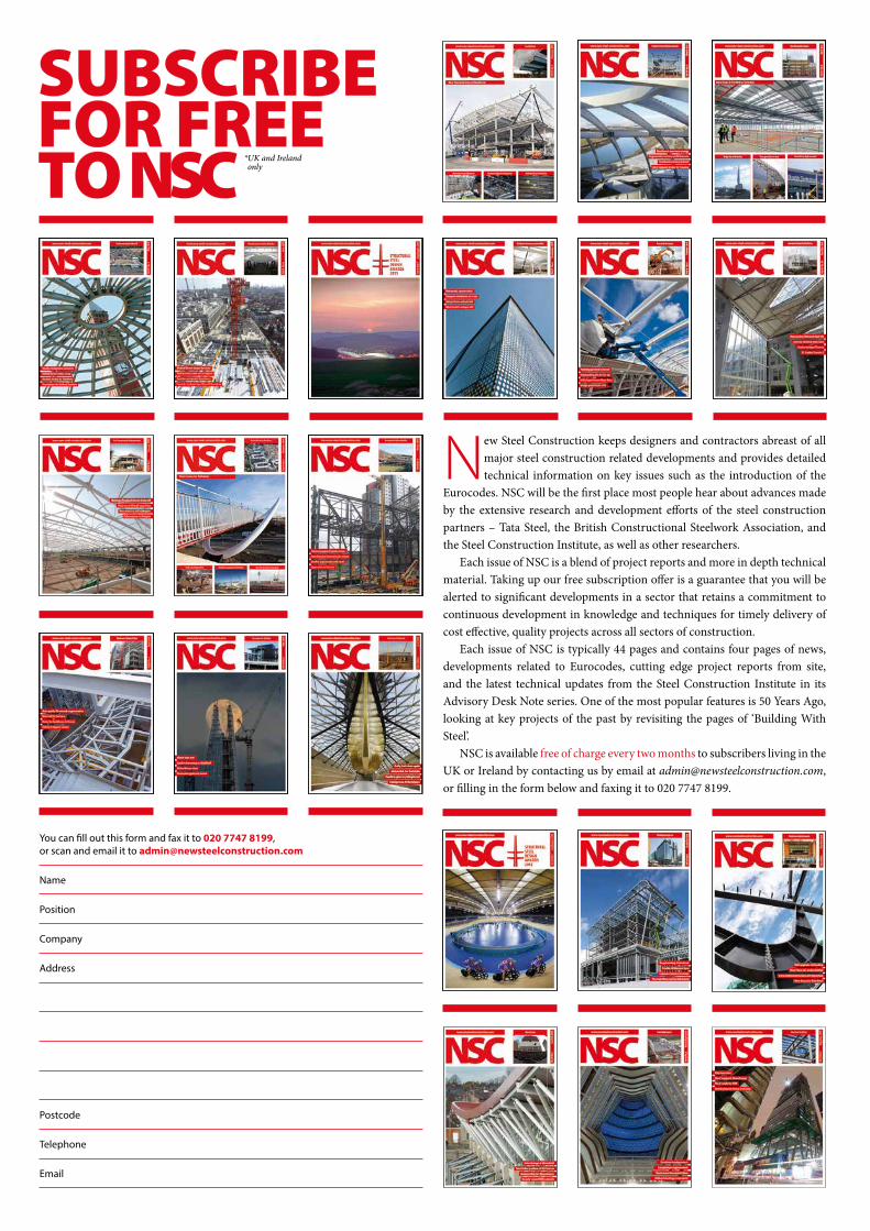
SUBSCRIBEFOR FREETO NSC
New Steel Construction keeps designers and contractors abreast of all major steel construction related developments and provides detailed technical information on key issues such as the introduction of the
Eurocodes. NSC will be the first place most people hear about advances made by the extensive research and development efforts of the steel construction partners – Tata Steel, the British Constructional Steelwork Association, and the Steel Construction Institute, as well as other researchers.
Each issue of NSC is a blend of project reports and more in depth technical material. Taking up our free subscription offer is a guarantee that you will be alerted to significant developments in a sector that retains a commitment to continuous development in knowledge and techniques for timely delivery of cost effective, quality projects across all sectors of construction.
Each issue of NSC is typically 44 pages and contains four pages of news, developments related to Eurocodes, cutting edge project reports from site, and the latest technical updates from the Steel Construction Institute in its Advisory Desk Note series. One of the most popular features is 50 Years Ago, looking at key projects of the past by revisiting the pages of ‘Building With Steel’.
NSC is available free of charge every two months to subscribers living in the UK or Ireland by contacting us by email at [email protected], or filling in the form below and faxing it to 020 7747 8199.
You can fill out this form and fax it to 020 7747 8199, or scan and email it to [email protected]
Name
Position
Company
Address
Postcode
Telephone
*UK and Ireland *only

3NSCJuly/Aug 13
In this issue
Cover ImageMoorgate Exchange, LondonClient: Telex SàrlClient monitoring architect: Pringle Brandon Perkins + WillArchitect: HKRSteelwork contractor: Severfield -Watson StructuresSteel tonnage: 2,900t
July/August 2013 Vol 21 No 4
These and other steelwork articles can be downloaded from the New Steel Construction Website at www.newsteelconstruction.com
5 Editor’s comment The 2013 Structural Steel Design Awards once again show steel construction at its dazzling best, reports Nick Barrett.
6 News Four projects achieved Awards at this year’s Structural Steel Design Awards, now in their 45th year.
10 Energy Devon’s first energy from waste facility has relied on steel construction’s speed and efficiency to remain on programme.
12 Leisure Steelwork has helped create a number of long span areas for the latest Center Parcs development.
14 Retail A complex horizontal truss forms a retail floor and supports a large retaining wall on a project in South Wales.
18 Bridge The completion of the Loughor Viaduct has reinstated a double track railway between Swansea and Llanelli.
20 Retail A petrol filling station in Corby has become a local landmark after two highly intricate steel canopies were erected.
22 Commercial The angled façade of the City’s Moorgate Exchange development ensures the rights to light entitlement of adjacent buildings.
26 Fire Engineering The latest developments in structural fire engineering have been detailed at a series of seminars.
28 Transport Off site fabrication has played a key role in the rebuilding of Wakefield Westgate Station.
30 Technical Alastair Hughes has a proposal for live load reduction to put to the responsible code committees.
34 Codes and Standards
34 Advisory Desk AD 376 Fire design of concrete filled hollow steel columns to Eurocode 4.
36 Publications
38 50 Years Ago A look back through the pages of Building with Steel features the Wheelwright arched car park design.
40 BCSA Members
42 Register of Qualified Steelwork Contractors for Bridgeworks

Westok Plate Beam can now be specifiedalong withWestok Cellular Beams + USFB’s
www.asdwestok.comklöckner & co multi metal distribution
ASDmetal services
Tel: 0113 205 5270 Fax: 0113 205 5271 Email: [email protected], Valley FarmWay, Stourton, Leeds LS10 1SE
ASDWestok Plate Beam...
AD1278 09/12
new design software, developed& supported by

5NSCJuly/Aug 13
Comment
Awards show steel quality is maintained
EDITORNick Barrett Tel: 01323 422483 [email protected] EDITORMartin Cooper Tel: 01892 [email protected] EDITORTy Byrd Tel: 01892 [email protected] EDITORAndrew Pilcher Tel: 01892 553147 [email protected] ASSISTANTAlastair Lloyd Tel: 01892 553145 [email protected] REPORTERMike WalterCOMMERCIAL MANAGERSally Devine Tel: 01474 833871 [email protected]
CHANGES TO THE MAILING LISTIf you wish to notify us of a change:Members BCSA and Non Members Telephone BCSA on 020 7747 8126Members SCI Telephone SCI on 01344 636 525
PUBLISHED BYThe British Constructional Steelwork Association Ltd4 Whitehall Court, Westminster, London SW1A 2ESTelephone 020 7839 8566 Fax 020 7976 1634Website www.steelconstruction.orgEmail [email protected]
The Steel Construction InstituteSilwood Park, Ascot, Berkshire SL5 7QNTelephone 01344 636525 Fax 01344 636570Website www.steel-sci.comEmail [email protected]
Tata Steel PO Box 1, Brigg Road, Scunthorpe, North Lincolnshire DN16 1BPTelephone 01724 405060Website www.tatasteelconstruction.comEmail [email protected]
CONTRACT PUBLISHER & ADVERTISING SALESBarrett, Byrd Associates7 Linden Close, Tunbridge Wells, Kent TN4 8HHTelephone 01892 524455Website www.barrett-byrd.com
The London Olympic year crop of entries for the Structural Steel Design Awards was always going to be a hard act to follow, after the Olympic Stadium itself and the Velodrome were winners. But the judges of this year’s awards were delighted once again with the standard of projects that they were invited to pass verdict on.
This year there were four Awards and three Commendations from a short list that included another nine strong entries. The variety of type of structure given Awards was as impressive as ever, including a high quality commercial and retail development behind a historic retained façade in London’s West End; a new home for the famous Cutty Sark that gives visitors views of its innovative hull that were not possible before; the Emirates Air Line that provides a cable car crossing of the Thames for the first time; and the strikingly iconic Twin Sails Bridge at Poole.
The Awards, Commendations and short-listed projects are all described in a special supplement from the BCSA and Tata Steel that accompanies this issue of NSC, and which will be distributed with leading construction magazines over the coming weeks. Digital versions of the supplement will be available for download on the free, online steel construction website www.steelconstruction.info, where you can also find NSC.
Sceptics would have been justified in thinking that the worst and longest recession the construction has suffered would mean a dramatic reduction in the quality and diversity of type of entry to the SSDA. The judges report no sign of that though, and the proof is in the photographs and descriptions in the supplement.
Chairman of the Judges David Lazenby CBE and his fellow judges – all eminent architects, engineers and steelwork contractors – make great efforts to ensure that all the short-listed projects, 16 of them this year, are visited. They demand a high standard, and in theory they could decide that no project is worthy of award or commendation. There was no likelihood of that with this year’s strong crop of entries though, or with any other year in the 45 years that the awards have been running.
One of the trends over the years commented on by David Lazenby this year is the closer and more cooperative relationships within project teams, a professional approach to training and qualifications, and proper tracking and certification of processes and materials.
All of these are prevalent in steel construction, where adopting Building Information Modelling for example is all the easier because of the sector’s early adoption of computing techniques for design and fabrication. The industry is also ready for the introduction of CE Marking, as detailed in the freely downloadable guide to CE Marking that can be found at www.steelconstruction.info.
The diversity and quality of this year’s entries shows why steel construction is the method of choice for the widest range of structures. As long as the flexibility, economy and sustainability of steel construction allow architects and structural engineers to express their vision and to realise the ambitions of their clients, this will surely continue.
Nick Barrett - Editor
EDITORIAL ADVISORY BOARDMs S McCann-Bartlett (Chair); Mr N Barrett; Mr D G Brown, SCI; Mr M Crosby; Mr R Dixon, BCSA; Mr R Gordon; Mrs K D Lloyd, BCSA; Mr A Palmer, Buro Happold;Mr G H Taylor, Caunton Engineering; Mr M Thompson, Mott MacDonald; Mr O Tyler, Wilkinson Eyre Architects
The role of the Editorial Advisory Board is to advise on the overall style and content of the magazine.
New Steel Construction welcomes contributions on any suitable topics relating to steel construction. Publication is at the discretion of the Editor. Views expressed in this publication are not necessarily those of the BCSA, SCI, Tata Steel or the Contract Publisher. Although care has been taken to ensure that all information contained herein is accurate with relation to either matters of fact or accepted practice at the time of publication, the BCSA, SCI, Tata Steel and the Editor assume no responsibility for any errors or misinterpretations of such information or any loss or damage arising from or related to its use. No part of this publication may be reproduced in any form without the permission of the publishers.
All rights reserved ©2013. ISSN 0968-0098
Westok Plate Beam can now be specifiedalong withWestok Cellular Beams + USFB’s
www.asdwestok.comklöckner & co multi metal distribution
ASDmetal services
Tel: 0113 205 5270 Fax: 0113 205 5271 Email: [email protected], Valley FarmWay, Stourton, Leeds LS10 1SE
ASDWestok Plate Beam...
AD1278 09/12
new design software, developed& supported by

6 NSCJuly/Aug 13
News
Four projects scooped a top prize at the 45th Structural
Steel Design Awards (SSDA), hosted by the BCSA and Tata
Steel and held at Madame Tussauds.
Air W1, London; Emirates Air Line connecting
Greenwich Peninsula to The Royal Docks; The Cutty Sark,
and the Twin Sails Bridge, Poole all won an Award.
The judges praised all 16 short-listed projects and
Judges Chairman David Lazenby CBE said he was
particularly impressed by the professionalism of the
industry and the winning teams.
Commendations were awarded to three further
structures: Brent Civic Centre, Wembley; Marlowe
Theatre, Canterbury and The Saints Stadium Bridge,
St Helens.
Television news presenter Emma Crosby gave out the
awards, including Student Awards for three categories –
Building Structures, Bridges and Architecture.
A comprehensive report on the SSDA presentation, as
well as descriptions of all 16 short-listed projects can be
found in a special supplement distributed with this issue
of New Steel Construction.
2013 SSDA winners announced
W1, London
The Cutty Sark, Greenwich
Twin Sails Bridge, Poole
Emirates Air Line connecting Greenwich Peninsula and the Royal DocksPh
oto:
© D
ave M
orris
Pho
togr
aphy

7NSCJuly/Aug 13
Steelwork has played a leading role in the
construction of a straw fired power plant
in Sleaford, Lincolnshire that is set to go
online before the end of the year.
The facility will burn bales of straw
and woodchip to produce enough
electricity for 65,000 homes. Ash from
the processes will be recycled into
agricultural fertiliser.
Caunton Engineering has erected
approximately 1,600t of steel for the
project, as well as stair towers, ladders,
platforms, metal flooring and more than
1km of handrails.
The entire facility, owned by EC02
Lincs, is based around a series of
predominantly steel framed buildings.
These include two straw barns, a turbine
hall, boiler house, flue gas area, straw
conveyor and an office unit.
News
Students page added to steel encyclopedia
The BCSA has announced that CE Marking capability is now a condition of membership for associate members, as from 1 July 2013. The requirement applies to steelwork contractor members from 1 July 2014. This means clients and main contractors can have confidence in the complete supply chain for steel construction from manufacture of the sections and other products, through distribution to fabrication and erection.
The Leadenhall Building (Cheesegrater) in the City of London has topped out after reaching its final 224m height. The building’s tapered profile, designed to protect sight lines of St Paul’s Cathedral, means the structure has already become a landmark in the square mile. The building is a joint venture between British Land and Canadian company Oxford Properties, and Severfield-Watson Structures has erected the steelwork.
Lindapter has launched its high clamping force (HCF) Hollo Bolt, an enhanced version of its original expansion bolt for structural connections. The Hollo-Bolt HCF is available as standard in sizes M16 & M20 and features Lindapter’s patented HCF mechanism that is said to produce a typical clamping force three times higher than the same sized product without the mechanism. SCI member Consteel has launched the STABLAB software package that is said to provide analysis and evaluation of the stability and buckling modes of a structural model. Basic analysis capabilities include: all types of buckling modes – flexural, torsional, lateral torsional buckling of members, buckling sensitivity analysis and complete second order analysis using buckling mode based imperfections. To register and download a free trial visit: www.stablab.net
Leach Structural Steelwork has extended its workshop and purchased a new Voortman V330C fully automatic combined drilling and plate cutting system equipped with an oxy fuel and plasma torch. Eric Leach, Leach Structural Steelwork Managing Director said: “We decided to equip the machine with both plasma and oxy fuel for the larger and thicker parts. With this machine we are better positioned for the markets we’re active in.”
NEWS IN BRIEF
To further support the education and
training for the next generation of
construction professionals, a resources
for students page has been added to
www.steelconstruction.info - the free
encyclopedia for UK steel construction
information.
The new Resources for students page
contains articles specifically prepared for
engineering and architectural students,
providing the ideal introduction to the
wealth of other material available on the
steel information website.
For engineering students there are
guides to multi-storey buildings and
single storey buildings. Both guides
contain a wealth of in depth design
information as well as articles and
video case studies on relevant UK
projects.
An architectural student resource is
coming soon, and will contain sections on
framing schematics, expressed structural
forms, connections, cladding systems and
fire protection.
There are also a number of external
links, including
Student Awards, Steel
Construction’s YouTube channel, teaching
resources from Tata Steel, SCI education
services and Steel University – a free
e-learning resource.
Lincolnshire renewable energy plant nears completion
The Falkirk skyline is about to change
dramatically as two 30m high steel
plated equine sculptures, known as The
Kelpies, take shape.
Steelwork contractor S H Structures
(SHS) is currently erecting the two giant
horses’ heads, which will be Scotland’s
tallest works of art, with completion
scheduled for end of August.
Each sculpture needs more than 150t
of structural steelwork and this will
require more than 100 component
deliveries to the site from SHS’s North
Yorkshire fabrication facility.
Off site manufacture of the Kelpie
parts is critical to ensure the highest
level of quality control as well as
enabling onsite erection to be achieved
in the shortest possible timeframe.
Main contractor Balfour Beatty Civil
Engineering previously constructed the
foundations, on which The Kelpies sit, a
job that included the installation of a
series of 32m long piles.
The Kelpies form an important part
of the overall Helix project, a £43M
scheme to transform a 350 acre site
beside the Forth and Clyde Canal.
Steelwork creates giant equine sculptures

8 NSCJuly/Aug 13
A £6bn redevelopment programme of
London Bridge Station, the country’s
fourth busiest station, is now under way.
Because of the complexity of the
work and the need to keep as much of
the station operational as possible, all
of the work is being phased with overall
completion set for 2018.
The work includes a new and bigger
concourse, which will have 66% more
space for retail and station facilities.
A reconfiguration of the tracks will
result in nine through platforms and six
terminating platforms.
Network Rail says this will mean more
trains to more destinations including a
connection to Crossrail services.
Two major steelwork packages, one
for bridge decks and another for platform
canopies and associated areas, are currently
being finalised by main contractor Costain.
News
The Structural EngineerJuly 2013 Suspension Bridges: past and presentWith a depth of only 3m, the revolutionary Severn box girder deck was an all welded construction, which further reduced the weight of steel required. In addition, the 18m long and 118t closed box girder segments were buoyant, and could therefore be floated out into the Severn Estuary without recourse for any barges.
Construction News14 June 2013Twice as high for office replacement[Bevis Marks] “An eight-storey concrete building was demolished and replaced with a 16-storey steel one using the existing foundations,” says Waterman Structures director Julian Traxler. “We couldn’t have achieved that and the net lettable areas required by the client if we hadn’t used a steel frame – it just wouldn’t have been viable.”
Construction News14 June 2013Tram plan calls for bridge variety[Nottingham tram extension] The bridges have been designed to enhance their environment. “We considered carefully the look and function of these structures as part of the design process and chose steel because we wanted to achieve something with a contemporary feel,” says Nottingham City Council project director Chris Deas.
Building Design3 May 2013They’ve got it all covered[The choice of steel for aspects of Brent Civic Centre] - “We picked the material that suited the vision,” says URS regional director Mike Pauley. “Where we were getting the 15m spans, concrete became too heavy visually to achieve that [vision].”
Building Magazine24 May 2013A lot of history[Stonehenge Visitor Centre] – The steel structure of the pods was erected in tandem with a birdcage scaffold covering the entire footprint of the visitor centre. This allowed Vinci to work on the canopy and the pods at the same time.
AROUND THE PRESS
All change at London Bridge
The Imperial War Museum (IWM),
one of London’s most popular tourist
attractions, is currently undergoing a
major refurbishment to create additional
exhibition space.
Bourne Construction Engineering,
working on behalf of Lend Lease, has
been on site at IWM since the beginning
of March, erecting staircase structures,
columns and additional floors - all inside
the existing building.
The new floors, supported by feature
columns, are being constructed to create
new exhibition spaces and terraced
galleries that will enlarge the museum’s
current facilities.
The work will also transform the
existing atrium, creating a contemporary
and easy to navigate visitor experience.
The steelwork project forms part of the
wider £35M scheme that will create new
ground breaking First World War galleries
in time to mark the centenary of the
outbreak of the conflict in 2014.
Additional galleries will also be used to
cover conflicts from the Second World War
onwards, as well as dedicated events space
for private corporate hire.
War Museum gets more exhibition space
An £89M Technology and Innovation
Centre is being built at the University of
Strathclyde in Glasgow city centre.
The facility will bring together
academics, researchers and project
managers from the university and its
leading industrial partners to find solutions
to challenges in sectors central to economic
regeneration, including power and energy,
health and advanced engineering.
In order to maximise the building’s
footprint, the steel framed structure, being
erected by Fisher Engineering, is wedge
shaped.
Michael Dyke, Executive Director of
main contractor Lend Lease said: “The
building will be a global centre for research
excellence and will bring economic,
sustainable benefits to the local community
through the involvement of small
businesses, social enterprise groups and
employment in construction.”
Technology centre for Glasgow university

9NSCJuly/Aug 13
News
Advance brochures updated and available New Advance® section brochures from Tata Steel are now available for download free of
charge at www.tatasteelconstruction.com
The Advance® section range has been developed to reflect current structural design
practice and make it easier to specify Tata Steel CE Marked sections compliant with the EU
Directive on Construction Products.
There are two brochures, one version supports designs in accordance with BS 5950, while
an EC version follows the design specification, and nomenclature laid out in the Eurocodes.
Compared to previous brochures the new versions have capacities and examples based on
S355 material, acknowledging that this is now the predominant steel grade in the UK.
Thursday 26 September Portal Frame Design Oxford
Tuesday 8 & Wednesday 9 October Essential Steelwork Design (2 day course) London
DiaryFor SCI events contact Jane Burrell, tel: 01344 636500 email: [email protected]
By opting for a steel framed
design for the new 6 Bevis
Marks development in
London, main contractors
Skanska and Waterman
Structures have been able to
reuse the foundations of an
old eight-storey structure and
replace it with a 16-storey
building.
Maximising the lettable
space is one of the project’s
main aims and using
steelwork has also allowed the
project team to create long
open floorplates throughout
the structure.
William Hare has erected
2,100t of steel for the job,
with the frame consisting of
concrete filled CHS sections
in the centre of the building
and RHS at the perimeter.
Under a separate contract
Tubecon is erecting the
tubular steelwork frame
for the project’s feature sky
garden.
Aiming for a BREEAM
‘Excellent’ rating, Bevis Marks
is due to be completed by the
end of this year.
Barnshaw Section Benders, working
in conjunction with ASD Westok, has
supplied some of the deepest cellular
beams ever requested to Fisher
Engineering for a new energy from waste
plant in Cardiff.
The largest curved cellular beams
were 23m long and 1,594mm deep,
formed from one of the biggest sections
that Tata Steel produces, a 1,016 × 305 ×
438kg UKB.
As well the curving for ASD Westok,
Barnshaws has also been bending
a number of bars direct for Fisher
Engineering, which included a variety of
sections and sizes ranging from 457mm
deep beams, to 400mm deep rectangular
hollow section (RHS).
Both cellular beams and sections
took Barnshaws three to four months
to complete and in total they weighed
approximately 500t.
Big beams create energy plant for Welsh capital
Steel ensures foundation reuse for City development

10 NSCJuly/Aug 13
Work is progressing on schedule on a new energy from waste (EfW) plant in Exeter that once operational will process
60,000t of household refuse per annum for Devon County Council. More and more of these facilities are being built throughout the UK as local authorities seek to find environmentally friendly alternatives to landfill. As well as processing approximately one third of the county’s non recyclable municipal waste, the plant will enhance its green credentials by the fact that it will also recover value from the refuse with up to 3MW of electricity generated for the National Grid. EfW facilities are invariably built with a steel frame because they are housed in large open plan structures, a form of construction
best suited to steelwork. The Exeter plant is no exception being a large beam, column and braced framed structure measuring approximately 24m wide by 80m long and with a maximum height of 35m. It is supported by piled foundations or from reinforced concrete frames forming the waste bunker, waste feed structure, offices and plant rooms. All of the project’s steelwork has been galvanized. This ensures it is safe from corrosion caused by contact with inert gases and gives the material a minimum 25 year lifespan in this harsh environment. Prior to any of the structural steelwork being erected on site by the Bourne Group, eight months of preliminary works were carried out. “The site had originally been occupied by an incinerator and transfer station, but this had already been demolished by the time we started on site in early 2012,” explains Phil Moss, Chilworth Construction Management Construction Director. “Initially we did some piling and groundwork before the concrete
superstructure was cast, this then allowed the main steelwork package to begin last January.” Before the main steel programme commenced Bourne erected approximately 50t of steel to support a mezzanine level and the facility’s silo. This was followed by the erection of the boiler support frame and access walkways a couple of weeks later. “The silo support steelwork was initially freestanding and was later connected to the main frame,” explains Rod Potts, Bourne Group Contracts Manager. “Installing this steel early in the programme allowed the fit out of the plant’s equipment to proceed on schedule.” Towards the end of last year most of the large equipment for the facility was installed. This included a 120t combustor unit that was delivered to site in one load and then lifted into place by a 1,000t capacity crawler crane. The plant’s 65m tall chimney was also delivered to site and installed during the same period. With all the major heavy lifting completed the main steel erection package was able to
Energy
A large braced steel structure will house Devon’s first energy from waste plant. Martin Cooper reports.
Waste solution with steel

11NSCJuly/Aug 13
Energy
start in January with the frame being installed around and over the facility’s installed equipment. “One of the main design challenges with the steel frame was ensuring coordination with the process equipment, while providing adequate support for elevated floors, mezzanines and platforms,” says Brian Melia, Project Engineer for Melia Smith & Jones. “The advantages of using steel are the speed of construction and its flexibility,” adds Mr Moss. “The main steelwork went up while the fit out continued inside the facility, and some cold rolled sections, which aren’t structurally integral, have been left out temporarily to allow equipment to continue to be installed.” As part of its main frame steel erection programme, Bourne is also carrying out the connection and cladding design as well as installing a series of internal crane beams. These beams, for the refuse hall, must meet BS EN 1090-2 Execution Class 3 standard (fatigue rated beams with higher levels of quality control).
Possible fatigue on the steel frame had to be taken into account during the design, as the waste crane will be in continual use for the life of the facility. “We had to liaise closely with Bourne to make sure the structural members were not affected by the connection details and vice versa,” says Mr Melia. The steel frame has also been designed to resist loading from the waste and ash cranes, product silos, wind, snow and imposed loading from operations and maintenance. Bourne’s scope of works also includes installation of 5,800m2 of cladding, 3,600m2 of roof cladding, 3,000m2 of decking, gutters, rainwater pipes, windows, louvres, mansafe roof systems in addition to the industrial and personnel doors. Great care and attention has had to be taken during all lifting operations due to the site’s location. The plant is nestled between a major power line and the main rail route between London and Cornwall. Bourne has used a variety of mobile cranes, ranging from 50 tonners up to 100t capacity units. With up to four cranes on site at any one time, the main challenge has been to erect steel without over slewing the rail lines or the power line. “We also had to position our cranes on either side of the structure as the centrally positioned chimney had to be manoeuvred around during the lifting in of the roof beams,” explains Mr Potts.
The structure’s main perimeter columns all arrived on site in three sections and the completed section has two bolted splices. These members support the roof that is formed by a series of 24m long Westok cellular beams. The rear elevation of the facility features an outward sloping façade. To achieve this architectural component Bourne has installed a series of V-shaped column bases along the elevation; these bases each support a spliced raking member and a vertical member. Overall stability of the frame, as well as for the rear elevation is achieved via horizontal roof and floor bracing, along with composite steel and concrete floors and reinforced concrete two way spanning slabs acting as diaphragms. These transfer lateral loads to vertical steel tubular bracing and reinforced shear walls. The facility is expected to be processing waste by summer 2014.
FACT FILEExeter energy from waste plantMain client: ViridorMain contractor: TIRUConstruction manager: Chilworth Construction ManagementStructural engineer: Melia Smith & JonesSteelwork contractor: The Bourne GroupSteel tonnage: 570tProject value: £2.6M
Feature V-shaped columns form the sloping rear façade
Much of the steel frame sits on top of a concrete superstructure
The project’s steel frame in its entirety
Nearby power lines have made lifting operations challenging

Center Parcs is constructing its fifth UK village at Woburn Forest near Milton Keynes, a project that is being aided by steel construction
for its leisure facility buildings. The £250M development is one of the
largest leisure projects in the UK and will eventually create 1,500 jobs. During the construction process it is providing employment for 1,200 workers. Overall the job has been divided into three main contracts, with infrastructure and civils being undertaken by Birse, the construction of 625 accommodation lodges by ISG while Bowmer & Kirkland is responsible for the £93M contract to deliver leisure buildings. The leisure facilities consist of three parts and steel tonnage wise The Plaza (next to the watersports lake) is the largest component of the contract requiring approximately 1,000t of the material. Hambleton Steel is the steelwork contractor working on behalf of Bowmer & Kirkland for this part of the project A large sports hall is one of the most
prominent parts of this area, with a series of 32m-long Westok beams forming this column free space. Weighing 6.5t each, these beams were brought to site in two pieces bolted up on the ground and then lifted into place as one section. Another feature of the sports hall is the curved shape of the structure as it follows a radial grid. Each column is set out individually as the connecting 14m-high beams are faceted to form the curving elevations. The inside elevation is formed by a series of V-shaped columns, an architectural steel feature which will remain exposed within the completed building. These columns were fabricated by Hambleton Steel in two pieces; one with a V-shaped base and the other a straight column that was connected via a bolted connection to form the final
12 NSCJuly/Aug 13
Hybrid design for leisure parkThe requirement for lightweight flexible structures has resulted in steel being used on all leisure facility buildings at the latest Center Parcs development.
Leisure
The sports hall has a curved elevation adjoining the hotel
A series of exposed V-shaped columns form one of the sports hall’s elevations
Tata Steel’s Kalzip is said to be the world’s leading
aluminium standing seam roofing and wall
cladding system. It is a precision engineered, multi
component system with proven durability, high
performance and low maintenance.
A range of materials, finishes and shapes are
available offering a multitude of designs. The
product is also said to combine functionality with
stunning aesthetics on both small uncomplicated
designs as well as world famous, award winning
projects.
Alternative products include; a full range of
fabrications, Hi-Point - Kalzip’s off site roofing
system and Falzinc, a lightweight fully supported
raised seam roofing and cladding system that
combines a pre weathered zinc layer with an
aluminium core.
For more information visit: www.kalzip.co.uk
Tailored solution for roofs and envelopes

13NSCJuly/Aug 13
double column element. Behind these feature columns the sports hall includes a two-storey zone housing a ground floor crèche and offices on the upper floor. The outer curved elevation of the sports hall adjoins the hotel which is being constructed with in-situ concrete. Following the curvature of the sports hall the hotel has three levels and will be topped with a steel framed roof. “The steel braced sports centre was first to be erected in this area,” explains Bill Poole, Bowmer & Kirkland Project Manager. “Everything else, including the hotel, followed on afterwards.” One end of the sports hall connects into a large two-level venue area which is being constructed with an in-situ concrete podium and a steel framed upper level. The podium will house a supermarket and some smaller retail units, while the above steel framed level will accommodate a conference centre. Explaining the hybrid design of the venue structure, Fergal Kelly, Peter Brett Associates Engineer says: “The conference facilities require some long spans that are more economically formed with a steel frame.” A few hundred metres away along a woodland road is the Village Square development that is divided into two sectors, north and south. The former is a two-storey retail, restaurant and bowling complex, while the latter is a large domed swimming pool structure known as the Subtropical Swimming Paradise. Steel is playing an integral role in the construction of both of these two adjacent structures. Steelwork for the Village Square north side is being fabricated, supplied and erected by Shipley Fabrications with 170t
required for this part of the project. The upper level of the Centre One North is steel framed and it is mostly founded on top of a concrete podium level. As the building incorporates the site’s sloping topography, approximately one third of the structure only has the steel framed level. The single storey element of the building will house a diner, while the two-storey part will accommodate retail outlets within the podium and a bar and a bowling alley on the upper level. Coordination was key to the construction of this structure as Glynn Shepperson, Shipley Fabrications Director says: “While we erected the diner, the podium was being poured simultaneously. We then continued erecting the steel frame for the upper level by following on behind the concreting team.” The steel frame is on a 7.8m × 7.8m grid, matching that of the concrete frame, within the podium. The only exception is the bowling alley where a series of 20m long 3t cellular beams create the necessary larger column free grid. “The cellular beams have all been fabricated with tapered end sections to suit the varying roof/ceiling profiles,” says Mr Shepperson. Meanwhile, the Village Square south side is destined to become one of the Village’s focal points. The large steel and timber clam-shaped dome Subtropical Swimming Paradise will house six pools of varying sizes. Shipley Fabrications is also responsible
for the swimming pool’s changing room facilities, a structurally independent but adjoining 90m-long building that follows the dome’s 90 degree quadrant perimeter. Similar in design to the Village Square north side, the facility has a podium housing the pool’s changing facilities, with a steel framed upper level with restaurants. The swimming pool’s large dome has been created by a series of 70m long glulam rafters, while spanning around and in between the timber is a steel hollow section ring beam and roof. “The steel is supported vertically by the glulam beams and has been designed to look like it is floating,” says Mr Kelly. The centre point of the circular roof structure, where the beams meet is supported by a series of feature 16m long pencil shaped tubular columns. The majority of the roof will be clad with Kalzip and ETFE for the roof, however the front elevation – overlooking a lake – will be fully glazed to a height of 16m. This large feature façade is formed by a series of 12 steel bowstring trusses. Excluding the changing room facility, the roof structure has been designed and constructed by B&K Structures (a wholly owned subsidiary of the Bowmer & Kirkland Group). Summing up, David Gallimore, Holder Mathias Project Architect, says the reasons for choosing a hybrid design for the leisure buildings is because Center Parcs has a similar design philosophy for all of its developments. “However, steel has been used in areas where a lightweight and flexible solution was required.” Center Parcs Woburn Forest is scheduled to open in spring 2014.
Leisure
FACT FILECenter Parcs Woburn Forest (leisure buildings) Main client: Center ParcsArchitect: Holder MathiasMain contractor: Bowmer & KirklandStructural engineer: Peter Brett AssociatesSteelwork contractors: Hambleton Steel, Shipley Fabrications, B&K StructuresSteel tonnage: 400t
The Center Parcs’ leisure facilities consist of three parts, the Village Square is a large clam shaped Subtropical Swimming Paradise, containing pools of varying sizes attached to a two-storey changing room and restaurant building. Close by is the Village Square north side, a two-storey retail, dining and bowling alley complex.
The Plaza is a stand-alone collection of facilities which includes a large indoor sports hall, conference facilities, a supermarket and a 75-bed hotel. Under a separate contract ISG is building 625 lodges for the project, while the overall civils contract will see Birse create seven miles of new roads for the new Center Parcs.
Center Parcs Woburn Forest facilities
A steel roof floats above the dome’s main rafters
The domed swimming zone will house six pools
“Steel has been used where a lightweight and flexible solution was required.”

The former South Wales mining town of Bargoed is in the midst of a £30M regeneration scheme, a programme that aims to revitalise the
community and bring new job opportunities to the area. A new relief road and connecting viaduct, as well as a bridge over the Rhymney River have recently been completed, improving transportation links and removing traffic from the previously congested main streets of Bargoed. Central to the overall plan is the rejuvenation of commerce and this will be achieved with a large scale retail development, based around a 5,200m2 Morrisons supermarket being constructed in the town centre. Known as the Retail Development Plateau, the 2.2 hectare site is situated on a 300m long × 20m high reinforced embankment, said to
be the largest of its type in the UK. The plateau over looks the Rhymney River valley and backs onto Bargoed’s main shopping street. The plateau was cut into the hillside by main contractor Simons, a job that saw 23,000m3 of spoil to be excavated and removed. The face of the cutting is formed with a contiguous piled wall, 11m at its highest and 130m long. This had to be reinforced with temporary anchors during excavation. Steelwork contractor Caunton Engineering has a design and build contract for this project and it designed the structural frame to support the piles. “The temporary anchors have to remain in place until the steel frame is complete and the concrete decking is on, then the diaphragm action will also help to support the wall,” explains David Wilson, Simons Senior Project Manager.
“Steel’s speed of construction is important as the quicker the frame is up the quicker the contiguous piled wall is permanently supported.” In order to allow the completed steel frame to resist the loads from the piles, a 24m deep horizontal truss has been installed and concealed within the project’s retail floors. The truss spans the full length of the wall and is connected into it via cast-in plates. The massive loads from the wall will be transferred through the truss via a series of large welded nodes, some of which have up to 14 incoming members. “We had to design the truss and the nodes to absorb up to 700kN/m,” explains Matthew Shimwell, Caunton Engineering Lead Designer. “The nodes also simplified the overall steel design and the fabrication detail.” The nodes also enable the truss and the
Retail banks on regeneration Situated on a large embankment, a new retail development is dependent on a large steel truss to not only provide the necessary shopping space, but also the stability to an adjacent piled wall.
Retail
A large truss forms the roof of the main retail floor and supports the piled wall
14 NSCJuly/Aug13

15NSCJuly/Aug 13
Retail
steelwork to follow the sloping topography of the external retail deck. The site has a slight slope which follows the height of the retaining wall. In order to keep the steel frame in line with the wall, each floor level is stepped and the sloping horizontal truss fits within these floors. “The nodes allow the frame to accommodate this eccentric floor design,” adds Mr Shimwell. Brought to site in individual sections, the truss was erected along with the rest of the project’s steelwork, with no steel element weighing more than 3t. For the steel frame and for the erection programme it has had two mobile cranes working on site. The cranes are also being used to install the precast floor planks and the stairs. “As we already have the craneage on site it makes sense for us to install the planks and
stairs,” comments Andrew Austen, Caunton’s Site Manager. “It also means there are less trades on site which speeds up the erection programme.” Sitting on top of the plateau and abutting the retaining wall, the steel framed retail development consists of a lower level undercroft car park for 400 vehicles, with the main Morrisons retail floor positioned above along with second car park level. Above the main Morrisons supermarket floor are a series of further decks, set back from the valley elevation, accommodating independent retail outlets and rooftop plant areas. The retail outlets will be accessed via Bargoed’s main shopping street – as they sit on the retaining wall, consequently providing a continuation to the existing shop frontage and enhancing the town centre. The majority of the frame is based on
a 9.5m × 7.5m structural grid. This was deemed suitable and large enough not only for the car park but also the retail levels above. The exception is the area where the lower level car park has the first floor level outdoor parking area above, here a large 16.5m × 7.5m grid has been accommodated. The main Morrisons retail area is topped by a series of portal roof frames situated along the elevation overlooking the valley. These feature elements provide a signature to the development, as this part of the scheme will be the most visible to people approaching the town. Helping the project to progress seamlessly, the job has been fully managed and constructed using Building Information Management (BIM). According to Andrew Watson, Caunton Engineering 3D Project Coordinator, this enabled architect’s and engineer’s models to be fully integrated with Caunton’s steel detail and design models. “This helped the development process on the project and allowed complex geometry and data to be easily transferred among the team. Design meetings were far more productive as we could take integrated models and present them on site to solve problems quickly.” Summing up the project, Welsh Government Housing, Regeneration and Heritage Minister Huw Lewis says: “Town centre renewal is a key priority and I am delighted to support this development which will help breathe new life into Bargoed, support new and existing businesses, stimulate the local economy and provide jobs in the retail sector.” The development is due to open in early 2014.
FACT FILEMorrisons supermarket, Bargoed, South WalesMain client: Simons Developments, Caerphilly County CouncilArchitect: HMAMain contractor: Simons ConstructionStructural engineer: Capita SymondsSteelwork contractor: Caunton EngineeringSteel tonnage: 1,000tProject value: £24M
“Steel’s speed of construction is important as the quicker the frame is up the quicker the contiguous piled wall is permanently supported.”
Visualisation of the completed scheme
Prefabricated nodes have allowed the project team to quickly erect the site’s main truss

16 NSCJuly/Aug 13
Retail
An early scheme for the restraint of the contiguous piled wall involved permanent rock anchors which however could not be relied on for the life of the development. Controlled transfer of load at construction stage was a more reliable option than
transfer on failure of the anchors at some unpredictable future date. The truss in the plane of the retail floor steelwork is therefore designed to support the piles in the permanent condition. The truss spans about 85m with the depth between booms of over 16m: two bays of floor beams. The bracing members are cruciform in arrangement such that some bracing members resist tension and others compression (Figure 1). The truss is designed for stiffness and the mid-span deflection is limited to about 50mm. The shear forces are transmitted to the ground at each end through vertical tension only bracing which also provides the wind restraint to the development. Piles and 15m square pile caps resist the tension forces. Two lines of retail floor beams act as the truss booms and consist of 914, 838 and 762 UKB serial sizes. The retail floor slopes slightly across the site and the slope is accommodated by stepping the beams at points away from the principal nodes in the truss. At the changes in level, the beams are designed for the bending moment due to the eccentricity in the line of the axial force. The bracing members, all set in one plane, are formed from UKC sections of 305 serial size, also with their webs vertical. The approach taken to detailing the truss was to concentrate the fabrication in the nodes and make the elements as simple as possible. This approach resulted in truss elements with extended end plates for bolted connections, detailed with shims to allow for erection tolerances. Fasteners are mostly M30 and M36 grade 8.8 bolts. The truss nodes were designed to carry the forces efficiently in direct
tension and compression and avoid bending. The truss boom forces are carried by stubs of the same shape. Horizontal stiffeners are placed in line with the flanges of the incoming diagonals. Column elements are spliced above and below the nodes and the flange forces carried through vertical stiffeners. Mating end plates and cap and base plates are provided for each incoming element (see Figure 1).
The use of fabricated nodes in the Bargoed supermarket development Dr Richard
Henderson (SCI)
Figure 1: Example of node arrangement (Figure courtesy of Caunton Engineering)
A series of portals crown the development

• Software optimises the design of
Z and C-sections to the Eurocodes
for building shell and mezzanine
fl oor applications.
• Easily select and specify the
correct purlin and side rail system
for your project in accordance
with the Eurocodes.
Metsec PLC is part of the voestalpine Group
For Purlin Eurocode Compliance,our software’s fi rst class
To order or download a FREE copy www.metsec.com/nsc1

18 NSCJuly/Aug 13
Bridge
Using steel helped the project team assemble the bridge off site and then launch and slide the structure into place
Opened in early April, the new replacement steel composite designed Loughor Viaduct has reinstated a double track
rail service across the South Wales estuary, improving travel times between Swansea and Llanelli and boosting the local economy. Originally constructed in 1852, the 236m long Viaduct was initially a wooden structure and a fine example of Isambard Kingdom Brunel’s once numerous timber viaducts. However substantial redesigns and strengthening works in subsequent years had altered the bridge and most of the recently demolished viaduct dated from around 1910. Importantly in recent times detailed site investigations had determined that the old viaduct had reached the end of its life and was no longer able to function and support the expected amount of modern rail traffic. For capacity the double track bridge had been reduced to a single track, which proved to be inconvenient as the region still required a robust rail link over the estuary. In order to improve rail services and restore the line to a double track configuration Network Rail, working with Carillion Rail, opted to replace the entire structure as part of a £48M scheme. A primary consideration was how the
new viaduct could be constructed within a limited 250-hour possession provided by Network Rail. “Before commencing the steelwork on site we had to construct our temporary works and the new bridge piers in a high flow tidal estuary working from both sides of the existing viaduct,” says Jon Kite, Carillion Rail Senior Project Manager. “Our piling rigs and cranes worked from jack up barges in the river working between trains as necessary so as not to disrupt the operational railway.” The work included the installation of twelve 1,200mm diameter permanent steel cased piles to form the foundations for the new viaduct. At the same time as this work was being undertaken steelwork contractor Mabey Bridge began a three month programme, fabricating the structural steelwork and walkways at its facility in Chepstow. Mabey Bridge was also contracted to oversee site assembly, including the temporary pier cross beams to support the launch of the new structure. These beams were installed atop six temporary piers that had been installed on the north side of the existing viaduct. The fabricated steelwork was transported to site by road in girder sections up to 24m long. The new bridge was then assembled in
four sections in a laydown area on the west side of the estuary, ready to be launched alongside the existing viaduct. To facilitate the launching process, the assembly area had previously been excavated and sheet piled, to ensure it was at the same level as the existing rail track and viaduct. Space was at a premium and each of the four viaduct sections was assembled individually. Each section was a different length and consisted of two outer plate girders connected by a series of crossbeams. Steel walkways were also attached to each side of the structure. A total of 26 girders were needed (13 on each side) to construct the entire 236m long viaduct. “Once the first section was fully assembled we launched it, using strand jacks, over the river onto temporary piers,” explains Roger Walker, Mabey Bridge Project Manager. “We then assembled the next section, bolted it onto the previous section and launched the structure a bit further over the river.” This process was repeated a further three times, to position the entire new viaduct, spanning the Loughor estuary adjacent to the old existing structure. The steelwork was then jacked down onto its permanent bearings. The deck was concreted, waterproofed, ballasted and tracks laid.
Viaduct replacement
The rail line heading west from Swansea has been significantly improved with the opening of the new steel composite Loughor Viaduct.
FACT FILELoughor Viaduct, South WalesMain client: Network RailMain contractor: Carillion RailStructural engineers: Tony Gee & PartnersSteelwork contractor: Mabey BridgeSteel tonnage: 1,200t

19NSCJuly/Aug 13
Bridge
The 250-hour rail possession was then initiated and work began to demolish the old structure. After putting protective rubber matting over the rail tracks, Carillion Rail used the new bridge as a working deck for its demolition equipment. Once the old structure had been dismantled and new abutments constructed the new viaduct was slid sideways on its bearings to its permanent location using hydraulic rams.
After the viaduct opened one of Carillion Rail’s final tasks on site was to construct a heritage monument to reflect the old structure. Positioned on the west bank of the estuary, the monument consists of two of the original spans mounted on three of the original trestles. “The monument captures an element of a unique structure in history that used early steel in its deck with support from timber trestles,” sums up Mr Kite.
Mabey Bridge held a series of planning meetings with structural
engineers Tony Gee & Partners and main contractor Carillion Rail to
establish the suitability of steelwork for the launching and sliding
process. Design discussions at these initial meetings covered
the number of launches, nose and tail design, splice design and
positioning.
Following agreement on design, Mabey Bridge began a three
month programme of fabrication of the 1,200t of structural
steelwork and walkways for the 236m long viaduct.
“The bridge has a total of seven spans, five of which are 36m
long, this design was best achieved using steelwork,” says Chris
Young, Tony Gee & Partners Regional Director. “Plus we had to
have a soffit which mimicked the existing structure’s low profile for
environmental reasons, again another reason for choosing steel.”
Design and launch
The new structure was slid sideways into the position of the old bridge
The bridge was launched in four individual sections

20 NSCJuly/Aug 13
Retail
Two steel canopies spanning a petrol filling station have provided a striking entrance feature to a new supermarket development.
Located on a site once known as Soothills and associated with the town’s once thriving steel industry, a new 7,432m2 Tesco store and
petrol filling station has opened in Corby, Northamptonshire. The store is one of the largest in Corby and boasts plenty of environmental features, but it is the adjacent petrol station that immediately captures the eye.
Two cantilevering wedge shaped canopies cover the petrol station; the larger measuring 44m × 26m spans the forecourt while a slightly smaller one measuring 41m × 24m provides shelter for a kiosk and car wash. Structurally both are independent steel structures, with the larger canopy slightly oversailing the smaller canopy and so providing the facility with a standout feature.
As the Tesco store and petrol station are positioned on a busy main road, the local council’s planning department wanted a striking entrance feature to the development. This would highlight the project and act as a monument to the site’s regeneration. Initially two locally based architectural and engineering firms developed the petrol station scheme along with the store. However, once Barr Construction was awarded the contract it decided to employ its own teams to redesign and deliver the job. “We decided we needed to deliver a safe and buildable structure based on the original design and steel was the only option that could create the required shape,” Robert Mackay, Barr Construction Engineering Design Manager. The canopies are curved in plan and wedge shaped in section, therefore every purlin cleat and soffit cleat is a different size
Filling up with steel

21NSCJuly/Aug 13
and had to be fabricated at individual angles to suit the design. “This was one of our most challenging projects, technically and erection wise, as all of the steelwork is bespoke and individual,” says Ian Elliott, Border Steelwork Structures Senior Project Engineer. The smaller canopy is supported by a series of vertical square hollow section columns, but the large canopy has four pairs of distinctive 8m raking CHS columns. The raking columns have fixed base connections for stability of the structure, resulting in larger foundations than would normally be required. The roof is wedge shaped, with a flat soffit so the heads of each of the CHS columns had to be at the same level. Keeping the steelwork level but aligning the purlins to provide the required profile achieved the shape of the roof. The steelwork for the canopy roofs includes a series of cantilevered beams. They are designed as continuous, where possible, to reduce the moment at the column connection by balancing the forces. “Trying to coordinate the design and illustrate on plans the simplest way to build the canopies was the biggest challenge,” says Mr Mackay. “This is why we kept the canopy roof steel flat across the column pairs, which gave us level setting out points along the grids.” However, the roof wedge shape was made difficult by the fact that the curved sides are different radii with differing centre points; therefore, there was no simple solution to the purlin layout but to ‘fan’ them about one
of the radii. This meant almost every purlin cleat was a different height. Limiting deflection was another challenging aspect to the project. Horizontal deflection had to be controlled with the column and foundation stiffness, as there is no bracing. At the same time vertical deflection had to be controlled at the tips of the long cantilevers, the shallowest roof depth is therefore dictated by the beam section required to limit the deflection. Border Steelwork Structures erected the small canopy first and then the larger structure, with the latter requiring temporary propping due to the large cantilevering steelwork. “The larger canopy had to be erected in a certain sequence to allow the columns to act against each other in balance,” says Stuart Airey Border Steelwork Structures Senior Contracts Manager. “Once the canopy was fully erected the frame became stable and temporary works were removed.” For aesthetic reasons both structures feature deep gutters formed within the steelwork along the edges of each canopy. This means the gutter is mostly hidden with only the edge facia visible. Drainage connections have also been coordinated to go through the steel edge beams and routed within the canopy to column positions. The only evidence of any drainage are the exposed downpipes positioned adjacent to the columns. The Tesco store and petrol filling station has been open since May and according to the local council the canopy’s design has achieved the desired landmark effect.
Retail
FACT FILETesco petrol station, CorbyMain client: TescoArchitect: Barr ConstructionMain contractor: Barr ConstructionStructural engineer: Barr ConstructionSteelwork contractor: Border Steelwork StructuresSteel tonnage: 100t
“…Steel was the only option that could create the required shape.”
The job provided a challenge to all the team as the steelwork is all bespoke
The canopies consist of two overlapping but independent structures

22 NSCJuly/Aug 13
Steel exchange
Commercial
“A major feature of the development is the central atrium, positioned midway between the structure’s two cores.”The building’s large
open plan floorplates wrap around the atrium

Some parts of the UK have seen a significant slump in the number of office developments being undertaken in recent times, but this
can’t be said of the City of London. New landmark structures seem to be continually rising up within the Square Mile and a current example is Moorgate Exchange, a 12-storey office building on the site of an old telephone exchange. MGPA, an independent private equity company, and CarVal Investors in conjuction with Quadrant Estates are speculatively developing the site. Architect HKR has designed a large rectangular block which will stand out from its more sober looking neighbours as its roof line is dominated by an angled façade
containing stepped gardens on the six upper levels. Designed to achieve a BREEAM “Excellent” rating, the 20,252m2 steel framed building will have uniform, square open plan floorplates arranged around a central atrium and two main cores. The design ensures flexibility, as all of the floors can be subdivided if necessary. Floor sizes vary from 2,229m2 to 743m2 on the topmost office level. The building will also include two rooftop plant equipment floors and a two-storey basement. Overall, the structure has been designed to achieve a BREEAM “Excellent’ rating. At ground level, the most striking visual elements of the building are two rows of V-shaped columns, positioned along the two longest elevations. The two-storey high raking columns were fabricated from square hollow sections which were encased in concrete, producing members that taper from 900mm to 600mm. These columns were initially designed into the scheme as a way of avoiding an old subterranean telecommunications chamber that intrudes into the southwest corner of the project’s footprint.
“We suggested raking columns for this one area of the building, the architect then liked these features and decided they would add symmetry to the structure by running the length of the two main elevations,” explains Iain Sproat, Ramboll Design Engineer. In total there are four pairs of V-shaped columns on each side of the building. Weighing 11t each, the columns were erected individually and are bolted to a ground level two-way node that helps form the desired V formation. The nodes weigh 3t each, and will eventually be encased within a concrete base. At the top, each raking column is connected to the underside of the second storey beam by a welded connection. Steelwork contractor Severfield-Watson Structures had to temporarily support each raking member during the erection process. “Once each pair of columns was connected top and bottom they were released from their props and we could then move onto the next pair,” says Terry Barnett, Severfield-Watson Structures’ Site Manager. Within the structure, long span open column free areas dominate the design. The client wanted to maximise the floorspace and consequently typical spans in the building are 15.5m long. The majority of the columns are 457mm diameter CHS members to maximise the available floor space. They have been in-filled to achieve the required fire rating and left exposed by the architect as part of the design. Dynamic behaviour needs to be
Large open plan floorplates and a sloping terraced façade are just two feature elements adorning the City of London’s latest Grade A office development. Martin Cooper reports from Moorgate Exchange.
23NSCJuly/Aug 13
Commercial
FACT FILEMoorgate Exchange, LondonMain Client: Telex SàrlClient monitoring architect: Pringle Brandon Perkins+Will Architect: HKRMain contractor: SkanskaStructural engineer: RambollProject manager: GVA Second London WallSteelwork contractor: Severfield-Watson StructuresSteel tonnage: 2,900t
The structure’s shape is a response to the rights to light entitlement of the adjacent Barbican Housing
The feature V-shaped columns are connected to an 11t node at ground level

24 NSCJuly/Aug 13
Commercial
A transfer system at second floor level enables the steel
frame to step back 1.5m on two elevations, meaning the
V-shaped columns are outside of the main façade line,
thereby emphasing their aesthetic appeal.
The transfer structure has also been used to create a column
free entrance area by hanging the first floor above the entrance
foyer from a series of steel hangers. This means no columns need
to be installed within the main lobby.
Designing deeper cellular floors beams for the second floor
level has helped form the transfer system. Overall the structure
has 550mm deep beams, but here the depth has been increased
to 700mm.
The building’s first floor will be used as a trading floor and
will therefore require more services than the other office floors.
Deeper beams with larger services holes were more efficient, not
only to form the transfer system, but also to accommodate the
extra services.
Step back and admire the columns
considered on such long spans and Ramboll decided to use stiffener beams to achieve the required floor response. “By inserting secondary or stiffener beams at midspan between the main beams, we stiffened the floor without adding much more mass and successfully reduced the response factor,” says Mr Sproat. Stiffener beams and the large open grid pattern remains the same all the way up to the top office level. However, above level six each floor steps back, creating a sloping façade on the northwest elevation. This creates outdoor terraces that require a deeper floor zone, due to waterproofing and drainage. The structural design however requires that the upper floors keep to the same floor to ceiling heights as the lower levels. To achieve both these aims, the Fabsec floor beams were reduced in depth on these floors, with a shallower but heavier section being used. As the useable floor plates get progressively smaller above level six, a lightweight steel frame is being added to the main frame. This light steelwork framing cantilevers out by 1.5m and extends the office floorspace. Close coordination with the cladding installation is key to this part of the project, as the light framing material has to meet the tight glazing tolerances.
A major feature of the development is the central atrium, positioned midway between the structure’s two cores. This large void penetrates the building’s heart, starting at level one and topping out with a glazed roof halfway up the sloping façade at level eight. Richard Norris, Project Director for Skanska says: “Over the years the team has built up its knowledge and expertise from working in the City of London on major commercial projects that involved complicated steel frames. We have applied this experience to the Moorgate Exchange project and worked with all stakeholders to plan for any challenges that a complicated structure like this can create, to ensure a seamless project delivery for our client. “The relationship between Skanska and Severfield-Watson has developed and strengthened over the years because employees from both companies have worked together on previous projects. “The coordination of the steel structure with the cladding interfaces was a complex and extensive job; however, due to everybody’s proactive and positive approach to the challenges involved it was completed successfully.” Severfield-Watson’s 20 week steel erection programme is due to be completed in early September. The entire Moorgate Exchange project will be completed in the first quarter of 2014.
Large open floors are a feature throughout the building
The upper floors will feature outdoor terraced areas (right) with greenery supplied by plant boxes (left) to be retrofitted to the steelwork

The Hollo-Bolt High Clamping Force (HCF) is optimised for primary SHS connections and features a patented mechanism to produce three times more clamping force for a more secure connection, as shown below:
Load
(kN
)
Displacement (mm)
321.510.5 2.5
To view the significance of increased clamping force, watch the new video at www.hollo-bolt.com
High Clamping Force for Structural Joints
The Hollo-Bolt is recognised as a structural connection
in the BCSA/SCI ‘Green Book’ Connection Manual.
20
40
60
80
100
120
140
Hollo-Bolt®
by
Connection Load vs Ply Displacement (Size M20)
Safe Working Load
HCF Mechanismbefore installation
HCF Mechanism compresses during installation to achieve
3x Clamping Force
Without HCF Mechanism With HCF Mechanism
HIGH CLAMPING
FORCE
Scan the QR code to watch the video
NSC Hollo-Bolt Advert_May 2013_FINAL.indd 1 15/05/2013 15:34
Tel: +353 45434288 Fax: +353 45434308 Email: [email protected]
www.jamestownprofiling.com
- Automated Welding of Plate Girders and Box Girders
- Fully certified to ISO 9001 standard
- Full Penetration Butt Welding
- Fillet Welding
- Proven track record with major projects
- Submerged Arc Welding
UK Mobile: +44 7432 738124
Now CE Marking: Plate Girders & Box Girders (Exec Cl. 4)

26 NSCJuly/Aug 13
At the seminar BCSA Fire and Sustainability Manager John Dowling explained the legislative background that covers the use of
fire safety engineering, and current trends in its use. He said that Building Regulations, Approved Document B for England and Wales and Technical Handbook 2 in Scotland, tell designers what to achieve, but not how to do it. Designers were not however restricted to the use of the Building Regulations – they could use BS 9999 instead, which in many cases allowed fire resistance requirements to be reduced while maintaining the safety of a building in fire. BS 9999 is based on an understanding of how different factors affect the risk of fire. It describes how fire ratings change depending on building height, the familiarity of the occupants with the building and whether
occupants sleep on the premises; and the degree of their mobility. Fire load, compartment size and whether or not sprinklers have been fitted are also taken into account. Recently a new height category of over 60 metres has been introduced. A point well made by several speakers including Mr Dowling was that fire safety engineering can provide an alternative approach to the prescriptive requirements of the Building Regulations, and may in fact be the only practical way to achieve a satisfactory level of safety in some large and complex buildings. Mr Dowling quoted an Institution of Structural Engineers description of fire safety engineering, which says it supports a rational, scientific approach that ensures fire protection is provided where it is needed, rather than just applied in line with universal prescriptions that may over estimate its need in some areas while possibly under estimating it in others. The use of intumescent coatings to protect steel, now dominates the UK market with around a 70% market share, with off site applied material contributing 20%
of that figure. Board protection was still popular but historic techniques such as cementitious sprays had all but died out in the UK. “There has been a lot of research and development by a lot of companies over the past decade or so, and the resultant sharp fall in the cost of fire intumescent protection has ensured its dominance in the market,” he said. Four key issuesWilf Butcher, chief executive officer of the Association for Specialist Fire Protection, highlighted four key issues that building designers and owners had to consider in relation to fire safety. The ASFP has just published a guide called ASFP Guide to Inspecting Passive Fire Protection for the Fire Risk Assessor that explains the appropriate regulations and fire risk assessment in more detail. Third party certification is not mandatory but, said Mr Butcher, all those in the design and installation process are better protected if such product and installation certification is in place.
Fire Engineering
A rational design approach to fire safety Structural Fire Engineering, a rational and scientific approach to ensuring the safety of buildings, is increasingly popular, as delegates to a series of seminars have been hearing. Nick Barrett reports from the Fire Safety Engineering seminar in Glasgow.
“Fire engineering should be considered for all buildings, and fire should be considered at all stages of the design.”
John Dowling, BCSA Fire and Sustainability Manager
Neal Butterworth, Arup Fire

Simplified approach based on comprehensive full scale testsDave Chapman, Regional Technical Manager in Tata Steel Europe’s Structural Advisory Service, explained some of the testing, principles and practice associated with performance based structural fire engineering. He said the new approach to fire engineering meant that structures were designed to resist fire, rather than having protection added to a design afterwards. Structures were designed for wind loading, rather than having protection against wind added later, and fire should be treated in the same way. He described how the lessons of how steel framed buildings behave in fire were well established at the Broadgate fire in the City of London in 1990, and later at the Cardington tests. Richard Dixon, Manager of Tata Steel Europe’s Structural Advisory Service, outlined a simplified approach to structural fire engineering, focusing on using the TSlab design tool, which is a simple semi empirical tool, and the Vulcan Lite design software which is derived from the University of Sheffield’s fire engineering modelling software that is capable of analysing non rectangular grids and producing detailed real time outputs. Vulcan Lite provides full information about the structural response to a fire. Both consider a single structural bay and need only very simple input of data. TSlab is best suited for initial assessments while Vulcan Lite is the preferred tool for rigorous analysis, so they are ideally used in tandem.
Complex structuresThe only practical way of achieving a satisfactory level of fire safety in some large and complex structures and in buildings housing a variety of uses may be by using fire engineering. The fire engineering design of large and unusual structures was the subject of Buro Happold’s Dr Florian Block’s presentation. Dr Block took delegates through the approaches adopted on projects like the atrium steelwork assessment of
the Foster+Partners designed ME hotel in Aldwych, London, and an assessment of the D Y Patil School of Management in Mumbai, India. He said that most prescriptive approaches to fire protection guidance are for ‘normal’ structures made of beams and columns which might not be applicable for ‘unusual’ structures. To get over this issue the impact of fire on a structure should be assessed from first principles early in the design process, he argued. Mr Dowling also delivered a presentation on structural fire engineering on The Shard on behalf of Dr Mark O’Connor of WSP, structural engineers on the project. There are seven different types of occupancy in The Shard, each with its own fire protection requirements. Using the structural fire engineering approach was not about cutting costs by eliminating fire protection, he explained, but about ensuring that the appropriate, possibly enhanced, protection is applied where it best ensures the safety of a building’s occupants.
Concluding the SeminarArup Fire’s Neal Butterworth said seeing things in terms of a prescriptive versus a performance based approach leads to preconceived ideas. He emphasised that structures should be well designed, whichever approach is chosen. “Using a prescriptive approach doesn’t mean that a designer doesn’t have to think,” he said. Leeds Arena did not need fire protection on its roof trusses, according to building codes, but a performance based analysis was carried out and the roof was given fire protection as its integrity was considered key to the safe evacuation of the building. Selection of less combustible materials for use in acoustic insulation cladding was a measure also not required by codes but was done for good design reasons. “When should a fire engineering approach be adopted? We might as well ask when is a good design required. I say fire engineering should be considered for all buildings, and fire should be considered at all stages of the design.” The seminar was also repeated in Bristol on 20 June.
27NSCJuly/Aug 13
Fire Engineering
For more information about fire engineering visit www.steelconstruction.info/Fire_and_steel_construction
Dr Florian Block, Buro Happold
The Shard - a primary example of how Fire Engineering can enhance occupant safety
Phot
o: An
dy Ro
gers

28 NSCJuly/Aug 13
Transport
All change at Wakefield
Widespread changes are afoot in Wakefield as the city continues to regenerate large parts of its commercial centre.
Recent developments have included a number of steel framed projects such as a new covered market (NSC April 2008) and the large Trinity Walk shopping mall (NSC June 2010). Currently under construction is a new Westgate station, one of the city’s two railway stations. The £8M redevelopment of Wakefield Westgate is being built on a new site to the north of existing station buildings. It forms part of the much larger Merchant Gate scheme, which recently delivered a new 900 space steel framed multi storey car park for rail users. Dan Guiher, Network Rail Commercial Sponsor, says: “The new station will provide rail travellers and station staff with modern, enhanced facilities utilising a highly sustainable design.” One of the main components of this sustainable design blueprint is steel. The main station building - which will house a large open foyer, retail outlets, coffee shop and a first class lounge – a pedestrian footbridge and associated lift shaft and
staircases have all been built using structural steelwork.
“The long spans required for the retail
areas and
the foyer, as well as the speed of construction meant the project was ideal for steel,” says Anthony Hall CJCT Project Architect. Billington Structures erected all of the steelwork during a four week programme. Prefabrication helped speed up the work, but also meant the steelwork programme had to be phased, in order to accommodate erection of these elements. “We erected half of the main station building, then installed the footbridge, and then returned to completing the building,” explains Alan Dutton, Billington Structures Project Manager. “If we hadn’t scheduled our programme in this manner we wouldn’t have had enough room to position the large crane needed to lift in the bridge structure.” Site access for large vehicles and deliveries is limited to one side of the rail tracks, where the new buildings are being erected. A laydown area is located where the new taxi rank and drop off point will be positioned. The footbridge, the lift shaft and its associated lobby (shelter) were also delivered to site as prefabricated units. They were both lifted into place during an overnight rail possession that took place a week after the bridge was installed (see box). The lift shaft weighed 9t and for ease of transportation it had to be delivered to site by truck in a horizontal position. This meant two cranes were needed for the installation, one to lift the shaft into an upright position and another to then lift it across the tracks to its final location.
Two prefabricated staircases have also
been delivered to site and
FACT FILEWakefield Westgate StationMain client: Network RailArchitect: CJCTMain contractor: Buckingham ContractingStructural engineer: AmeySteelwork contractor: Billington StructuresSteel tonnage: 300t
The delivery of new station facilities at Wakefield Westgate station is reliant on steelwork’s speed of construction.
Curved rafters form the station’s feature front elevation

29NSCJuly/Aug 13
installed either end of the footbridge. One 9t staircase has been installed within the new station foyer, while on the other side of the tracks a larger 23t staircase provides access to the station and bridge. One of the main architectural features of the station building are the long uninterrupted spans in the retail areas and in the foyer. The steel frame has been erected around 7m × 15m grid pattern, which allows plenty of column free internal space. The station building is a single-storey structure, with a large double height space in the centre to accommodate access to the footbridge. A curved wave like frontage adorns the station’s main elevation. Here a series of CHS columns support curved braced box sections to form the project’s feature element. “Creating this part of the project in anything other than steel would have been difficult,” says Simon Walker, Amey Project Engineer. “Curved steel sections were simply brought to site and bolted into place.” Summing up Peter Box CBE, Wakefield Council Leader says: “The new Wakefield Westgate Station is fantastic news for the district. The rail station has always been an integral part of the master plan for the redevelopment of the area. It will be a key gateway into the city, providing improved transport facilities for residents and visitors.”
Connecting the station’s two platforms, the new footbridge was fabricated in two 14m long sections by Billington Structures. The sections were then transported to the cladding contractor’s facility, where they were clad with a
distinctive bronze sheeting, before being spliced together and trial erected. Once main contractor Buckingham had signed off the erection procedure and the bridge structure, it was dismantled back into two sections again and delivered to site.
On site it was spliced together again and lifted into place by a 500t capacity mobile crane. Such a large crane was needed to provide the necessary lifting radius as the structure had to be jibbed over the rail lines. The lifting was completed in one overnight weekend rail possession.
Footbridge
Transport
North elevationWest elevation - Entrance
Much of the work has had to be coordinated around rail services

30 NSCJuly/Aug 13
Where next?The UK committee decision to retain traditional LLR rules for the time being will, sooner or later, have to be reviewed. We have an obligation to progress in the direction of harmonization. One possibility, which can be presented both as politically correct and as a simplification, is to integrate storey-based LLR into area-based LLR for all members including columns. A slight drawback is that the reduction factor α could vary from one column to another at the same level, but that is manageable. For this course to be taken, it would be necessary for us in the UK to reconsider our approach to area-based LLR, in particular the 25% limit (αA ≥ 0.75). There is surely no argument, except perhaps locally in crowd loaded areas, against the traditional 50% as a limit to be approached as the area increases; any debate would concern the rate of approach. That rate of approach is exceedingly rapid if the recommended values are adopted: for instance, a column supporting just 50 m2 of floor at each of two qualifying levels would enjoy αA of 0.6 (40% LLR). This compares with the current 10%. To look at it another way, 40% LLR would become available just two floors down instead of the current five. Most of us would side with the UK committee and regard the European formula as sailing too close to the wind. On the other hand, current UK area-based LLR is unduly handicapped by its 25% limitation. So here is a suggestion to the Code committee(s):
α = 1 − na/1000 ≥ 0.5
in which n is the number of qualifying (‘occupied’, non-storage) levels, a is the total area supported at each, in m2, and α can be shorn of any subscript. This eliminates the artificial distinction between two kinds of LLR. Of course A, the total area supported by the member in question, could substitute for na to make it obvious that this is simply an extension of the traditional UK formula for area-based LLR beyond its traditional 25% limitation. If this suggestion were to be adopted, a column supporting 100 m2 at each of five qualifying levels could earn the maximum 50% LLR, and successive stages of the same column would get 40%, 30%, 20%, 10%, more or less as now except that the supported area per level, as well as the number of levels, would enter the calculation – which seems entirely
rational. The same formula, with n = 1, would apply to beams, and to the length of column just below the topmost qualifying level (which could be the roof if it is an occupied one, such as the top deck of a multi-storey car park).
What’s ‘A’, exactly?A point that needs clarifying in this context is whether or not it is intended that A (or na) in the formula is equal to the ‘tributary’ area customarily used to assess the load in the column (or beam). The Eurocode refers variously to ‘loaded area’ and ‘area supported’ which, taken literally, must be interpreted as the total supported area – the area whose load adds to the effect being designed against. A typical interior column is only fully loaded if all four complete panels of floor that surround it are fully loaded; that’s four times the tributary area, so the distinction is important. Which is correct? Arguably, the answer is ‘whichever the committee had in mind when formulating the rules’. We haven’t been told, and the same criticism could be levelled at BS 6399. Could lack of a common understanding have exaggerated the national differences so evident in Figure 1?
Technical
The future of live load reduction – part twoIn Part One (in the previous issue - NSC Vol 21, No 3) Alastair Hughes examined how the new regime of EN 1991-1-1:2002, together with its National Annex, makes provision for live load reduction (LLR) in UK buildings designed to the Eurocodes. Some anomalies and questions of interpretation were identified. In Part Two he proposes a way forward for the future.
Unlike Part One, Part Two is a proposal by Alastair Hughes which is aimed not at the designer but at the committee responsible for the standards.
20 30 40 50 60
αA
0.9
0.8
0.7
0.6
0.5A [m²]
CEN, DE (A, B)
FRČR (C, D)
ČR (A, B)DE (C, D)
UK
FI
Figure 1 Area-based LLR

31NSCJuly/Aug 13
For practical purposes it is simpler to base the rules on total supported area, as defined in Figure 2, opposite, which unlike tributary area is the same for the beam as for the reactions at its ends. Moreover it isn’t always possible, with complex beam arrangements and/or cantilevers in play, to outline tributary areas in the normal way. Whatever the intention, it deserves to be spelt out unambiguously in any future revision.
The harmonization challengeWe could also reflect that the scope for LLR is not unconnected with any generosity in the assessment of design imposed load. Nobody told the office floor whether it was designed for 2.5 or 5 kPa, and the load it actually experiences is, on average, rather less than 1 kPa regardless. This is no secret; every survey there has ever been has reported the same conclusion. Some examples of load intensity survey results can be found, amid much theorizing, in a recent report from which Figure 3 (over the page) is extracted. Graphs like these present the case for LLR cogently, and make the UK’s straight line formula (the green line on Figure 1) look rather conservative. However these are surveys of normal occupancies in normal use. What the occupants might occasionally get up to is another matter, not so amenable to statistics but not to be disregarded. For example, think back to the seventies, when the office party actually took place in the office. Furniture was stacked against one wall, old Rolling Stones records were played and the cleared area of floor was subjected to energetic load testing by the people whose weight had, earlier in the day, been distributed around the rest of the building. Even if Facilities Management wouldn’t allow this nowadays, it may explain and, to a considerable extent, justify the UK’s relative caution towards area-based LLR. If you prefer a more up to date example, think of the recent pop-up café-bar phenomenon. Historically, BS 6399’s approach was even more grasping; until 1996 area-based LLR began at A = 40 m2, with a straight line to αA = 0.75 at A = 240 m2. In practice, for most designers most of the time, self-denial probably extends well beyond 40 m2 to this day, as percentage reductions remain in single figures until A reaches 100 m2. In future, which occupancy categories should qualify for LLR? The current rules (discussed in Part One) are confusing. Common ground is that categories A to D should qualify and that non-occupied roofs (category H, accessible only for maintenance and repair) should not. Category E includes both storage, traditionally denied LLR for good reasons, and plant/industry, whose floor loadings are commonly project-specific. Will any of us rise in protest if this category is excluded? Category F is currently a victim of neglect, but in principle LLR seems applicable to multi-storey car parks. Seven 20 kN cars per 15.6 × 7.5 m bay equates to just 1.2 kPa, and the average car with occupants weighs less than 20 kN. Unless the client is a distributor of ‘Chelsea tractors’, why hesitate? Although category G is similarly neglected, there is little to be gained from LLR in areas frequented by vehicles heavier than 30 kN. It seems reasonable that an ‘occupied’ roof (category I) should be granted associate membership of its corresponding floor category, if that would qualify. Here is how the table in Part One might be recast:
CATEGORY OCCUPANCY QUALIFYING FOR LLR?
FLOORS A Residential
YesB Office
C Assembly
D Retail
FLOORS AND
ROOFS
E Storage, industry, plant No
F Parking (cars) Yes
G Fire appliances etc No
ROOFS H (maintenance and repair only) No
I As A, B, C or D above Yes
K Helicopters N/A (point loads)
Finally, should the 50% maximum LLR (α ≥ 0.5) be varied for some categories, as EN 1991-1-1 recommends? The categories picked out are C (areas where people may congregate) and D (retail). For these it sets a 40% limit (α ≥ 0.6). So if, for example, qk is 4 kPa for a retail floor this could not be reduced below 2.4 kPa. No reason is given for the 40% limit. We may speculate that it is to allow for some degree of occasional crowd loading, but if so is it fit for purpose? Based on the current UKNA, 0.6qk may vary between 1.2 kPa (for communal dining rooms) and 3 kPa (for bars, dance halls etc) or even 4.5 kPa (for stages), all within category C. At the lower end of this range, the safety factor would struggle to defend against overcrowding. Restricting LLR to 0.6qk does not make enough of a difference, whereas a thoughtful designer will – by anticipating the possible uses to which the area may be put. With the formula suggested here, 40% LLR corresponds to A = 400 m2, which would require 600 people (average weight 0.8 kN) at 1.2 kPa or 1500 people at 3 kPa. These are comforting figures, in view of the unlikelihood of such large crowds concentrating their action effect on any one member supporting such a large area. [By contrast, the European formula grants 40% LLR at A = 100 m2 so the same level of overloading could be generated by one quarter the number of people occupying a relatively modest area. This is much more plausible, prompting the observation that the restriction may have been a reaction (a misdirected one, arguably) to the generosity of the formula.] In practice, of course, designers of assembly buildings will commonly design against unreduced load. In most of the buildings which are
columns and girdersin the centre
columns and girderson the side
columns and girdersat the corner
beams
assumed members
Columns
Girders • Beams
Figure 2 Definition of A
Technical

32 NSCJuly/Aug 13
1960
1470
960
490
1960
1470
960
490
1960
1470
960
490
1960
1470
960
490
1960
1470
960
490
1960
1470
960
490
0 50 100 0 50 0 50 0 50 0 50 0 50
0 50
3920
2940
1960
980
6860
5880
4900
3920
2940
1960
980
2940
2450
1960
1470
980
490
100 150 200 250 300
0 50 100 150 200 250 300 350 400 450
0 50 100
load i
nten
sity (
N/m
2 )loa
d int
ensit
y (N/
m2 )
load i
nten
sity (
N/m
2 )
load i
nten
sity (
N/m
2 )
area (m2)a) dwellings
area (m2)b) residential �ats
extracted from thedata of dwellings
area (m2)c) residential
�ats - anothersurvey
area (m2)d) hotel rooms
including UB
area (m2)e) hotel rooms
excluding UB
area (m2)f) classrooms
area (m2)g) o�ces
area (m2)h) supermarkets
area (m2)i) computer rooms
candidates for LLR (and certainly those with most to gain) categories A/B will predominate, and the occasional floor of C/D could safely be allowed to participate in LLR on the same basis as all the rest. The people crowding into the 10th floor restaurant can’t be in two places at once. Whatever the original motive for the 40% limitation, it should be re-examined and, perhaps, substituted by an advisory ‘floor’ value of (say) 3 kPa where the area is all at one level and might, conceivably, be subject to serious crowd loading. More importantly, it has to be recognized that EN 1991-1-1’s ‘recommended’ αA formula, seemingly modelled on graphs like those of Figure 3, does not admit the very real possibility of exceptional local patterns of use (or abuse) which can be decidedly influential on individual members, even if unnoticed at the feet of the columns. What is called for is a drastic reduction in the rate at which LLR is
initially dispensed. The straight line labelled UK in Figure 1, whose relative conservatism was remarked upon at the start of this article, now seems to offer as good a solution as any. This article must stop short of any detailed discussion of the actual values set for qk, but readers are invited to take a glance at EN 1991-1-1 Table 6.2, with its credibility-stretching ranges for national choice. A couple of examples: office areas, 2 to 3 kPa; railway station forecourts, 3 to 5 kPa. Until a consensus is reached on what the imposed loads should be in the first place it may be unrealistic to attempt to harmonize their reduction.
TerminologyShould it be ‘variable action reduction’ from now on? Surely not. Long live LLR!
Technical
Figure 3 Load intensity surveys
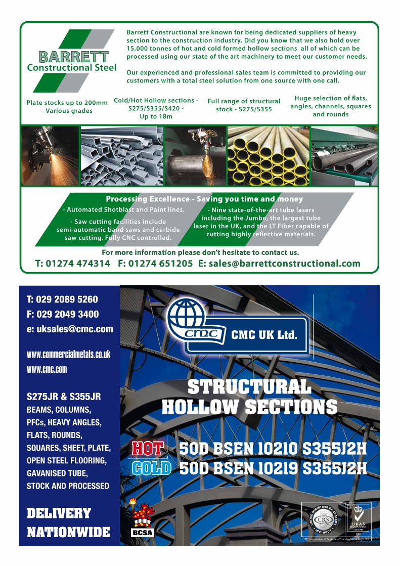
For more information please don’t hesitate to contact us.
Full range of structural
stock - S275/S355
Cold/Hot Hollow sections -
S275/S355/S420 -
Up to 18m
Huge selection of flats,
angles, channels, squares
and rounds
Plate stocks up to 200mm
- Various grades
- Automated Shotblast and Paint lines. - Nine state-of-the-art tube lasers
including the Jumbo, the largest tube
laser in the UK, and the LT Fiber capable of
cutting highly reflective materials.
Processing Excellence - Saving you time and money
- Saw cutting facilities include
semi-automatic band saws and carbide
saw cutting. Fully CNC controlled.
T: 01274 474314 F: 01274 651205 E: [email protected]
BARRETTConstructional Steel
Barrett Constructional are known for being dedicated suppliers of heavy
section to the construction industry. Did you know that we also hold over
15,000 tonnes of hot and cold formed hollow sections all of which can be
processed using our state of the art machinery to meet our customer needs.
Our experienced and professional sales team is committed to providing our
customers with a total steel solution from one source with one call.
www.commercialmetals.co.uk www.cmc.com
T: 029 2089 5260 F: 029 2049 3400 e: [email protected]
HOTCOLD
STRUCTURAL HOLLOW SECTIONS
S275JR & S355JRBEAMS, COLUMNS,
PFCs, HEAVY ANGLES,
FLATS, ROUNDS,
SQUARES, SHEET, PLATE,
OPEN STEEL FLOORING,
GAVANISED TUBE,
STOCK AND PROCESSED
DELIVERY NATIONWIDE
HOT 50D BSEN 10210 S355J2HCOLD 50D BSEN 10219 S355J2H

34 NSCJuly/Aug 13
Codes & Standards/Advisory Desk
BS EN PUBLICATIONS
BS EN 13381-4:2013 Test methods for determining the contribution to the fire resistance of structural members. Applied passive protection products to steel members Supersedes DD ENV 13381-4:2002
BS EN 13381-8:2013 Test methods for determining the contribution to the fire resistance of structural members. Applied reactive protection to steel members Supersedes BS EN 13381-8:2010
PUBLISHED DOCUMENTS
PD CEN/TR 10261:2013 Iron and steel. European standards for the determination of chemical composition. No current standard is superseded
UPDATED BRITISH STANDARDS
PD 6705-2:2010+A1:2013 Structural use of steel and aluminium. Recommendations for the execution of steel bridges to BS EN 1090-2. AMENDMENT 1
BS EN 1998-1:2004+A1:2013 Eurocode 8: Design of structures for earthquake resistance. General rules, seismic actions and rules for buildings AMENDMENT 1
CEN EUROPEAN STANDARDS
EN 13381-4:2013 Test methods for determining the contribution to the fire resistance of structural members. Applied passive protection to steel members
EN 13381-8:2013 Test methods for determining the contribution to the fire resistance of structural members. Applied reactive protection to steel members
DRAFTS FOR PUBLIC COMMENT
13/30277428 DC BS EN 14399-2 High-strength structural bolting assemblies for preloading. Suitability for preloading
13/30277431 DC BS EN 14399-3 High-strength structural bolting assemblies for preloading. System HR. Hexagon bolt and nut assemblies
13/30277434 DC BS EN 14399-4 High-strength structural bolting assemblies for preloading. System HV. Hexagon bolt and nut assemblies
13/30277437 DC BS EN 14399-5 High-strength structural bolting assemblies for preloading. Plain washers
13/30277440 DC BS EN 14399-6 High-strength structural bolting assemblies for preloading. Plain chamfered washers.
ISO PUBLICATIONS
ISO 3452-1:2013 (Edition 2) Non-destructive testing. Penetrant testing. General principles Will be implemented as an identical British Standard
ISO 5951:2013 (Edition 5) Hot-rolled steel sheet of higher yield strength with improved formability Will not be implemented as a British Standard
New and revised codes & standardsFrom BSI Updates June & July 2013
Depending on the constructional details, Section 4 of BS EN 1994-1-2 1 presents three alternative design procedures for fire design:• Tabulated data for specific types of structural
members• Simple calculation models for specific types of
structural members• Advanced calculation models.
For the fire design of concrete-filled hollow steel columns, clause 4.3.5 describes simple calculation models and clause 4.3.5.3 addresses unprotected concrete-filled hollow sections: the designer is directed to Annex H for the simple calculation model. However, the UK National Annex (NA to BS EN 1994-1-2:2005) states that Annex H of the code should not be used. This Advisory Desk note provides some background on Annex H and an update on the status of alternative guidance.
Annex H is informative and puts forward a method for calculating the design axial buckling load for concrete-filled hollow steel columns at elevated temperatures. A simple method is also given to account for the effects of eccentricity of the axial load.
Annex H follows an old method of calculating
axial resistance of composite columns at ambient temperature. For fire resistance calculations, this method is particularly difficult to implement, as the composite cross section must be divided into many blocks and the calculations involve many iterations. Each round of iteration needs to use the detailed material non-linear stress-strain relationships of steel and concrete at different temperatures, for each block in the cross section.
Annex H allows for the effect of small eccentricities in axial load by introducing two modification factors, one as a function of the reinforcement ratio and one as a function of eccentricity and column dimensions.
A CIDECT research project (15Q) assessed the Annex H calculation method and found that it can be grossly inaccurate. For this reason, the UK National Annex (published in 2008), states in clause NA.3 that Annex H should not be used.
Instead, it is recommended that the column design method for the fire limit state should be consistent with that at ambient temperature 2, but a reduction in strength and stiffness of the steel and concrete should be incorporated. Such a method has been implemented in the FIRESOFT software package developed by the University of
Manchester for Tata Steel. FIRESOFT software and an associated quality assurance document, giving details of methodology and validation testing are available free of charge from Tata Steel. The software and document have the status of Non-Contradictory Complementary Information (NCCI).
The Tata Steel design guide for concrete-filled structural hollow section columns is currently being updated and will be made available from http://www.steel-ncci.co.uk/ in due course.
Contact: Dr Richard Henderson Tel: 01344 636525Email: [email protected]
1. BS EN 1994-1-2:2005 (Incorporating corrigendum
July 2008) Eurocode 4 - Design of composite steel
and concrete structures - Part 1-2: General rules –
Structural fire design
2. Designers’ Guide to EN 1994-1-1; Eurocode 4:
Design of composite steel and concrete structures;
Part 1.1: General rules and rules for buildings;
R P Johnson and D Anderson; Thomas Telford
Publishing.
AD 376 Fire design of concrete-filled hollow steel columns to Eurocode 4

RAINHAM STEELSteel stockholders and suppliers of structural sections and structural hollow sections
We stock over 80,000 tonnes of structural steel products, servicing the UK, European and world markets. Our large modern fleet of heavy goods vehicles enables us to deliver throughout the UK normally within 24 hours. We can tailor the
configuration of your deliveries enabling various products to arrive in one vehicle.
Our sales team has years of experience in the steel industry enabling them to match your requirements with the most cost effective products available.
Call us on 01708 522311
www.rainhamsteel.co.uk
Rainham Steel Company Ltd Kathryn House, Manor Way, Rainham, Essex, RM13 8RE
RAINHAM STEEL Proud sponsors of BOXNATION Channel of Champions
Eurocode series starts in October 2013
SCI’S NEW ON-LINE WEBINAR SERIES
FREE to all SCI Members
See the full list of webinars at www.steel-sci.com/courses
SCI (the Steel Construction Institute) has been a trusted, independent source of information and engineering expertise globally for 25 years, and remains the leading independent provider of technical expertise and disseminator of best practice to the steel construction sector.
Many of our training engineers are internationally recognised experts in their fields and known for their code development and research work. Our engineers are renowned for delivering training to designers in a real world context, helping designers to solve every day problems confidently. SCI training is continuously reviewed and updated to deliver the latest Eurocode compliant and quality assured technical information.
These 1 hour webinars, presented by SCI technical experts provide an overview of the latest technical information. The new series of webinars starts with an overview of steel design to Eurocodes. The series will then cover:• Connection design• Compression members• Members in bending• Selection of steel sub-grade• Loading to BS EN 1990
e: [email protected]: +44 (0)1344 636 525w: www.steel-sci.com/courses
TM
For more information and to register:
halfpage Advert July 2013.indd 1 7/12/2013 2:33:02 PM

Advisory Desk
Interim ReportDesign of Portal Frames to Eurocode 3:An overview for UK designers
In the UK, designers of portal frame buildings have commonly used bespoke software specifically written for the analysis and member design in accordance with BS 5950.
The view has arisen that design to Eurocode 3 is not practical. This short guide was written to refute that impression. The guidance aims to show how existing analysis software (for use in design to BS 5950) may be utilised, with appropriate adjustments, and how (at least in the interim, until Eurocode-specific software is widely used) portal frame member design can be carried out manually at critical locations without undue complexity.
Full Price £30 (BCSA and SCI Member price £15.00)
To purchase copies of this publication please visit the SCI shop at:
http://shop.steel-sci.com or contact publication sales on; +44 (0)1344 636505
Catalogue number SCI P400ISBN Number 978-1-85942-206-9Authors D G Brown BEng CEng MICEPagination 48 pp Pages A4 PaperbackPublication date July 2013
A comprehensive range of SCI publications
A number of publications covering industry standards and Eurocode design
Secure online payments
Visit the SCI shop http://shop.steel-sci.com
FOR ALL YOUR TECHNICAL INFORMATION The SCI shop provides:
e: [email protected]: +44 (0)1344 636 505w: http://shop.steel-sci.com
TM
For for further details
halfpage Advert Bookshop July 2013 V1.indd 1 7/15/2013 10:50:24 AM
SteelConstruction.info is the new online encyclopaedia for UK steel design and construction information.
Developed and maintained by the British Constructional Steelwork Association, Tata Steel and the Steel Construction Institute, the site brings together a wealth of information in an easy to use, fully searchable format that is constantly updated.
At its heart lies over 100 interlinked and freely downloadable articles from industry experts, covering all the topics that civil and structural engineers need to have at their fi ngertips. These core articles then act as a roadmap with multiple links to other detailed sources of information. A number of online CPD presentations are also included, which enable the user to take a test and download a certifi cate for their records.
Whether you need information on design to the Eurocodes, fi re engineering, guidance on costs or the key issues involved in the design of schools, hospitals, commercial buildings or bridges, www.steelconstruction.info is the new go to resource.
Follow us on: Twitter @steelcoinfoLinkedIn: steelconstruction.infoFacebook: steelconstruction.info
ANY.QUESTIONS?
Multi-storey offi ce buildings 1 Attributes of steel construction 1.1 Value for money 1.2 Speed of construction 1.3 Flexibility and adaptability 1.4 Service integration 1.5 Quality and safety 1.6 Sustainability 2 Anatomy of commercial buildings 2.1 City centre commercial buildings 2.1.1 Tall commercial buildings 2.1.2 Commercial buildings with atria 2.1.3 Mixed use commercial buildings 2.2 Commercial buildings in suburban areas 3 Structural options in commercial buildings 3.1 Braced frames 3.2 Continuous frames 3.3 Composite construction 3.4 Long span systems 3.4.1 Beams with web openings 3.4.2 Cellular beams 3.4.3 Fabricated beams 3.4.4 Other types of long span beams 3.5 Shallow fl oor beams 3.6 Floor systems 4 Key issues in the design of commercial buildings 4.1 Procurement 4.2 Client requirements in multi-storey offi ce buildings 4.3 Building economics 4.4 Construction programme 4.5 Sustainability 4.5.1 Operational energy use in offi ces 4.5.2 BREEAM for offi ce buildings 4.6 Loading for offi ces 4.7 Services and service integration 4.8 Fire engineering 4.9 Floor vibrations 4.10 Acoustic performance 4.11 Health and safety 4.12 Corrosion protection 4.13 Fabrication and construction 5 Connections 5.1 Typical details 5.2 Other interfaces 5.3 Façade systems 6 Case studies 7 References 8 Further reading 9 Resources 10 See Also 11 CPD Single storey industrial buildings 1 Attributes of steel construction 1.1 Speed of construction 1.2 Flexibility and adaptability 1.3 Maintenance 1.4 Resource effi cient design 1.5 Sustainability 1.6 Value for money 2 Anatomy of typical single storey building 2.1 Framing options 2.2 Geometry and layout 2.3 Secondary steelwork 2.4 Envelope 2.5 Floor slabs 2.6 Offi ce areas 2.7 Mezzanines 3 Forms of construction 3.1 Choice of building form 3.2 Types of portal frame 3.3 Lattice structures 3.4 Suspended structures 4 Design 4.1 Design concept 4.2 Frame choice 4.3 Structural design 4.4 Interdependence of frames and envelopes 4.5 Operational energy performance 4.6 Service integration 4.7 Roof drainage systems 4.8 Floors and foundations 4.9 Connection details 4.10 Fire Safety 4.11 Sustainability 4.11.1 Operational energy use in single storey industrial buildings 4.11.2 BREEAM for industrial buildings 5 Construction 5.1 Lead-in times 5.2 Site erection periods 5.3 Safe site erection 5.4 Envelope erection 6 Procurement 6.1 Design & Build 6.2 Traditional 6.3 Project management 6.4 Early involvement of the supply chain 6.5 Selection of the supply chain 6.6 Achieving collaborative working 6.7 Achieving commitment 7 Case studies 8 References 9 Further reading 10 External links 11 Resources 12 See Also 13 CPD 1 Design drivers in the retail sector 1.1 Supermarkets 1.2 Superstores - out of town retail outlets 1.3 Distribution centres 1.4 Shopping centres 1.5 Mixed use retail and commercial or residential buildings 2 Anatomy of a typical retail building 2.1 Single storey superstore 2.2 Single storey supermarket 2.3 Distribution warehouses 2.4 Shopping centres 2.5 Mixed use retail and residential buildings 3 Attributes of steel construction 3.1 Speed of construction 3.2 Economy 3.3 Lightweight construction 3.4 Flexibility 3.5 Sustainability 3.6 Versatility 4 Forms of construction 4.1 Portal frames 4.2 Trusses 4.3 Building envelopes 4.4 Braced frames 4.5 Composite construction 4.6 Long span beams 4.7 Floor systems 5 Key issues 5.1 Procurement, cost and programme 5.2 Sustainability 5.2.1 Operational energy use in supermarkets 5.2.2 BREEAM for retail buildings 5.3 Design guidance 5.4 Service integration 5.5 Fire engineering 5.6 Acoustic performance 5.7 Floor vibrations 5.8 Car parks 5.9 Fabrication and construction 5.9.1 Single storey buildings 5.9.2 Multi-storey buildings 6 Case studies 7 References 8 Further reading 9 Resources 10 See Also 11 CPD Healthcare Buildings 1 Attributes of steel construction 1.1 Speed of construction 1.2 Flexibility and adaptability 1.3 Quality 1.4 Minimised disruption 1.5 Cleanliness 1.6 Vibration and acoustic performance 1.7 Service integration 1.8 Thermal insulation of cladding 1.9 Environmental benefi ts 2 Anatomy of a typical health sector building 3 Forms of construction 3.1 Braced frames 3.2 Rigid frames 3.3 Composite construction 3.4 Long span beams 3.5 Floor systems 3.6 Cores 3.7 Infi ll walling 3.8 Modular units 4 Procurement, cost and programme 4.1 Procurement routes 4.1.1 Framework Partnering 4.1.2 Private Finance Initiative (PFI) 4.1.3 Local Improvement Finance Trust (LIFT) 4.2 Cost 4.3 Programme 5 Sustainability aspects 5.1 Life cycle costing 5.2 BREEAM for Hospitals 5.3 Minimising operational CO2 emissions 6 Design guidance 6.1 Special requirements 6.2 Service integration 6.3 Fire engineering 6.4 Corrosion protection 6.5 Acoustic performance 6.6 Floor vibrations 6.7 Health & Safety 6.8 Fabrication and construction 7 Case studies 8 References 9 Resources 10 See Also 11 External links Education Buildings 1 Attributes of steel construction 2 Anatomy of a typical education building 3 Forms of construction 3.1 Braced frames 3.2 Composite construction 3.3 Long span beams 3.4 Floor systems 3.5 Modular construction 3.6 Light steel and infi ll wall construction 4 Procurement, cost and programme 4.1 Procurement routes 4.2 Cost 4.3 Programme 5 Sustainability aspects 5.1 BREEAM for schools 5.2 Renewable energy system 6 Design guidance 6.1 Special requirements for schools 6.2 Dimensional requirements for planning of schools 6.3 Services and service integration 6.4 Fire safety 6.5 Corrosion protection 6.6 Acoustic insulation 6.7 Health & safety 6.8 Materials and construction 7 Typical details 7.1 Connections 7.2 Facades and interfaces 8 Case studies 9 References 10 Further reading 11 Resources 12 See Also Leisure Buildings 1 Attributes of steel construction 1.1 Ease and speed of construction 1.2 Ability to span long distances 1.3 Appearance 1.4 Flexibility and adaptability 1.5 Maintenance 1.6 Cost effi cient design 1.7 Sustainability 2 Categories of leisure building 2.1 Stadia 2.2 Indoor arenas 2.3 Theatres and auditoria 3 Anatomy of a typical leisure building 3.1 Geometry and layout 3.2 Framing options 3.3 Roofi ng options in stadia 3.4 Sightlines and seating 3.5 Additional facilities in stadia 4 Forms of construction 4.1 Continuous frames 4.2 Portal frames 4.3 Braced frames 4.4 Long span beams 4.4.1 Trusses 4.4.2 Cellular beams 4.4.3 Curved beams 4.5 Composite construction 4.6 Floor systems 4.7 Envelope 4.8 Detailing and connections 5 Key issues 5.1 Procurement, cost and programme 5.2 Sustainability 5.3 Design issues 5.3.1 Venue circulation space 5.3.2 Climate control 5.3.3 Acoustics 5.3.4 Floor vibrations 5.4 Fire engineering 5.5 Corrosion protection 5.6 Health and safety 5.7 Fabrication and erection 6 Case studies 7 References 8 Further reading 9 Resources 10 See Also 11 External links Residential and Mixed Use Buildings 1 Attributes of steel construction 2 Types of residential buildings 2.1 Housing 2.2 Residential buildings in suburban areas 2.3 Residential buildings in urban areas 2.4 Mixed-use residential buildings 2.5 Student residences 2.6 Hotels 3 Forms of construction 3.1 Light steel framing 3.2 Steel frames with light steel infi ll walls 3.2.1 Composite beam and composite fl oor slabs 3.2.2 Steel beams and precast concrete slabs 3.2.3 Slim fl oor beams with precast concrete slabs 3.2.4 Slimdek with deep composite fl oor slabs 3.2.5 Infi ll walling 3.3 Modular construction 3.4 Podium structures 4 Key issues in the design of residential buildings 4.1 Procurement 4.2 Building economics 4.3 Construction programme 4.4 Sustainability 4.4.1 Code for Sustainable Homes 4.4.2 Thermal performance 4.4.3 Renewable energy systems 4.5 Floor zones 4.6 Below ground car parking 4.7 Service integration 4.8 Fire safety 4.9 Floor vibrations 4.10 Acoustic performance 4.11 Health and safety 4.12 Corrosion protection 4.13 Fabrication and construction 5 Typical details 5.1 Connections in light steel framing 5.2 Connections in steel framed buildings 5.3 Infi ll walls 5.4 Building envelopes 5.4.1 Façade systems 5.4.2 Roofi ng systems 5.4.3 Balcony systems 6 Case studies 7 References 8 Resources 9 See Also Bridges 1 Attributes 2 Forms of construction 2.1 Beam bridges 2.2 Box girder bridges 2.3 Truss bridges 2.4 Arch bridges 2.5 Cable-stayed bridges 2.6 Suspension bridges 3 Materials 4 Design 5 Construction 6 Durability 7 Case Studies 8 Resources 9 See Also 10 External links 11 CPD Cost of Structural Steelwork 1 Introduction 2 The importance of realistic steel pricing 3 Making the most of the available information 4 Key cost drivers 4.1 Function, sector and building height 4.2 Form, site conditions and complexity 4.3 Location, logistics and access 4.4 Programme, risk and procurement route 5 Current cost 5.1 Low rise and short span buildings 5.2 High rise and longer span buildings 5.3 Industrial buildings 5.4 The cost table 6 Cost planning through the design stages 7 Cost comparison study 8 Market share trend in UK multi-storey construction 9 Resources 10 See also 11 External links Sustainability 1 Sustainable construction – legislation and drivers 2 Steel and sustainable construction 2.1 Steel manufacture 2.2 Steel fabrication 2.3 The steel supply chain 2.4 Health and safety 2.5 Speed of construction 2.6 Recycling and reuse 2.7 Adaptability 3 Attributes of sustainable buildings 3.1 Location 3.2 Aesthetic appeal 3.3 Low impact materials 3.4 Flexibility and adaptability 3.5 Recyclability 3.6 Demountability and reuseability 3.7 Minimising on-site and local impacts 3.8 Operational energy effi ciency 3.9 Robustness and longevity 3.10 Low maintenance 4 Embodied carbon 4.1 Embodied carbon assessment 4.2 Life cycle assessment (LCA) 4.3 LCA system boundaries 4.4 Accounting for end-of-life and recycling 4.5 Embodied carbon comparisons 4.6 Steel embodied carbon and LCA data 5 Operational carbon 5.1 Operational carbon targets 5.2 Operational carbon assessment 5.3 Embodied versus operational carbon 5.4 Breakdown of energy use in buildings 5.5 Energy effi ciency measures 5.6 LZC technologies 5.7 Optimum solutions for low and zero carbon design 5.8 Thermal mass 6 BREEAM 6.1 Understanding BREEAM 6.2 Optimum routes to BREEAM targets 6.3 Material assessment within BREEAM 7 Sustainable procurement and responsible sourcing 7.1 Sustainable procurement 7.2 Sustainable procurement within the steel sector 7.3 Responsible sourcing standards 8 The UK steel construction sector 8.1 Sector commitments 8.2 BCSA Sustainability charter 8.3 BCSA Carbon foot-printing tool 9 References 10 Resources 11 See Also 12 CPD Design 1 Design process 1.1 Steel design 2 Concept design 3 Factors affecting choice of structural system 3.1 Stability systems 3.2 Columns 3.3 Floor systems 3.4 Foundations 3.5 Integration of building services 3.6 External envelope 4 Structural principles 4.1 Actions 4.2 Analysis 4.3 Sensitivity to second-order effects 5 Design Standards 5.1 Building Regulations 5.2 BS 5950 5.3 Eurocodes 5.3.1 National Annexes 5.3.2 NCCI 5.4 Basis of structural design 5.5 BS EN 1993-1 (Eurocode 3) 5.6 BS EN 1994 (Eurocode 4) 6 Common structural systems 6.1 Composite construction 6.2 Precast concrete units 6.3 Integrated fl oor solutions 6.4 Long-span beams 7 Trusses 8 Portal frames 9 Member design 10 Connections 10.1 Simple connections 10.2 Moment-resisting connections 11 Structural robustness 12 Specifi cation of structural steelwork 12.1 BS EN 1090 Execution of steel structures 12.2 The National Structural Steelwork Specifi cation for Building Construction (NSSS) 13 References 14 Further reading, 15 Resources 16 See Also 17 CPD 18 External links Fire and Steel Construction 1 The Building Regulations and fi re precautions in buildings 2 Steelwork fi re resistance 3 Design using structural fi re standards 4 Fire protecting structural steelwork 5 Structural fi re protection specifi cation 6 Hollow sections in fi re 7 Composite steel deck fl oors in fi re 8 External steelwork in fi re 9 Car parks in fi re 10 Single storey buildings in fi re 11 Active fi re protection 12 Structural fi re engineering 13 Structural steel after fi re 14 One stop shop 15 References 16 Resources 17 See also 18 External links Corrosion protection 1 Corrosion of structural steel 2 Infl uence of design on corrosion 3 Surface preparation 4 Paint coatings 5 Metallic coatings 5.1 Hot-dip galvanizing 5.2 Thermally sprayed metal coatings 6 Appropriate specifi cations 7 Inspection and quality control 8 References 9 Resources 10 Further reading 11 See also 12 External links 13 CPD Acoustics 1 Introduction to acoustics 1.1 Sound 1.2 Acoustic detailing 2 Regulations and requirements 2.1 Residential buildings 2.2 Schools 2.3 Hospitals 2.4 Commercial buildings 3 Walls 3.1 Wall Construction 3.2 Types of Wall 4 Floors 4.1 Floor Construction 4.2 Floor treatments 4.3 Ceilings 5 Junction details 6 Integration of elements 7 References 8 Further reading 9 Resources 10 See Also 11 CPD Floor vibration 1 Introduction to fl oor vibrations 1.1 Vibrations 1.2 Sources of vibration 1.3 Consequences of vibrations 2 Theory of vibrations 2.1 Single degree of freedom systems 2.2 Continuous systems 3 Types of response 3.1 Resonant response 3.2 Response to periodic impulses 4 Human induced vibration 5 Acceptability of vibrations 5.1 The human perception of vibration 5.2 Design criteria for vibrations 5.3 Design for rhythmic activity 5.4 Designing for dynamic loads 6 Vibration analysis 6.1 Basic principles 6.2 Finite element modelling 6.3 Simplifi ed assessment of fl oors with steel beams 7 Dynamic testing of fl oors 7.1 Modal testing 7.1.1 Modal testing without measuring the excitation force 7.1.2 Modal testing with measured excitation force 7.2 Response measurement 8 Regulations and design rules 9 Structural design considerations 9.1 Damping 9.2 Floor loading 9.3 Modelling issues 9.4 Continuity and isolation of critical areas 9.5 Precast concrete units in composite design 10 Architectural design considerations 10.1 Walking paths 10.2 Location of aerobic areas 11 References 12 Further reading 13 Resources 14 See Also 15 CPD Health and safety 1 Steel the safe solution 1.1 Pre-engineered 1.2 Pre-planned 1.3 Erected by specialists 1.4 Future-proof 2 Default solutions 2.1 Stability 2.2 Cranage 2.3 Access 3 Hazard, risk and competence 3.1 Buildings 3.2 Bridgeworks 4 Method statement development 4.1 Site conditions 4.2 Design-basis method of erection 4.3 Construction health & safety plan 5 Stability 5.1 Final condition 5.2 Part erected condition 5.3 Individual members 5.4 Temporary works 5.5 Connections 6 Site arrangements 6.1 Safe site handover certifi cate 6.2 Segregation of contractors 6.3 Cooperation between sub-contractors 7 References 8 Resources 9 Further reading 10 See also 11 External links 12 CPD Fabrication 1 Design for economic fabrication 1.1 Specifi cation 1.2 Bay size 2 Complexity 2.1 Materials 2.2 Architectural infl uence 2.3 Quality of engineering and documentation 3 Materials and components 3.1 Sections and plates 3.2 Bolts 3.3 Proprietary products 3.4 Coating systems 3.5 Cold-formed sections 4 Fabrication processes 4.1 Preparation 4.1.1 Stockyard 4.1.2 Shot blasting 4.1.3 Cutting & drilling 4.1.3.1 Circular saws 4.1.3.2 Gas or fl ame cutting 4.1.3.3 Plasma cutting 4.1.3.4 Drilling and punching 4.1.4 Bending 4.1.4.1 Section bending 4.1.4.2 Plate bending 4.1.4.3 Tube bending 4.1.4.4 Press breaking 4.1.5 Tee splitting 4.1.6 Profi ling of tubular sections 4.2 Welding 4.2.1 Manual Metal Arc welding (MMA) 4.2.2 Metal Active Gas welding (MAG) 4.2.3 Submerged Arc Welding (SAW) 4.2.4 Non Destructive Testing (NDT) 4.3 Coating 5 Accuracy 6 Handling and transportation 6.1 Normal loads 6.2 Abnormal loads 6.3 Special order 7 Specifi cation 8 Quality management 8.1 BCSA Steelwork Contractor membership 8.2 Steel Construction Certifi cation Scheme 8.2.1 Quality Management System Certifi cation (QM) 8.2.2 Environmental Management System Certifi cation (EM) 8.2.3 Occupational Health and Safety Management System Certifi cation (HSM) 8.2.4 CE Marking
requirements in multi-storey offi ce buildings 4.3 Building economics 4.4 Construction programme 4.5 Sustainability 4.5.1 Operational energy use in offi ces 4.5.2 BREEAM for offi ce buildings 4.6 Loading for offi ces 4.7 Services and service integration 4.8 Fire engineering 4.9 Floor vibrations 4.10 Acoustic performance 4.11 Health and safety 4.12 Corrosion protection 4.13 Fabrication and construction 5 Connections 5.1 Typical details 5.2 Other interfaces 5.3 Façade systems 6 Case studies 7 References 8 Further reading 9 Resources 10 See Also 11 CPD Single storey industrial buildings 1 Attributes of steel construction 1.1 Speed of construction 1.2 Flexibility and adaptability 1.3 Maintenance 1.4 Resource effi cient design 1.5 Sustainability 1.6 Value for money 2 Anatomy of typical single storey building 2.1 Framing options 2.2 Geometry and layout 2.3 Secondary steelwork 2.4 Envelope 2.5 Floor slabs 2.6 Offi ce areas 2.7 Mezzanines 3 Forms of construction 3.1 Choice of building form 3.2 Types of portal frame 3.3 Lattice structures 3.4 Suspended structures 4 Design 4.1 Design concept 4.2 Frame choice 4.3 Structural design 4.4 Interdependence of frames and envelopes 4.5 Operational energy performance 4.6 Service integration 4.7 Roof drainage systems 4.8 Floors and foundations 4.9 Connection details 4.10 Fire Safety 4.11 Sustainability 4.11.1 Operational energy use in single storey industrial buildings 4.11.2 BREEAM for industrial buildings 5 Construction 5.1 Lead-in times 5.2 Site erection periods 5.3 Safe site erection 5.4 Envelope erection 6 Procurement 6.1 Design & Build 6.2 Traditional 6.3 Project management 6.4 Early involvement of the supply chain 6.5 Selection of the supply chain 6.6 Achieving collaborative working 6.7 Achieving commitment 7 Case studies 8 References 9 Further reading 10 External links 11 Resources 12 See Also 13 CPD 1 Design drivers in the retail sector 1.1 Supermarkets 1.2 Superstores - out of town retail outlets 1.3 Distribution centres 1.4 Shopping centres 1.5 Mixed use retail and commercial or residential buildings 2 Anatomy of a typical retail building 2.1 Single storey superstore 2.2 Single storey supermarket 2.3 Distribution warehouses 2.4 Shopping centres 2.5 Mixed use retail and residential buildings 3 Attributes of steel construction 3.1 Speed of construction 3.2 Economy 3.3 Lightweight construction 3.4 Flexibility 3.5 Sustainability 3.6 Versatility 4 Forms of construction 4.1 Portal frames 4.2 Trusses 4.3 Building envelopes 4.4 Braced frames 4.5 Composite construction 4.6 Long span beams 4.7 Floor systems 5 Key issues 5.1 Procurement, cost and programme 5.2 Sustainability 5.2.1 Operational energy use in supermarkets 5.2.2 BREEAM for retail buildings 5.3 Design guidance 5.4 Service integration 5.5 Fire engineering 5.6 Acoustic performance 5.7 Floor vibrations 5.8 Car parks 5.9 Fabrication and construction 5.9.1 Single storey buildings 5.9.2 Multi-storey buildings 6 Case studies 7 References 8 Further reading 9 Resources 10 See Also 11 CPD Healthcare Buildings 1 Attributes of steel construction 1.1 Speed of construction 1.2 Flexibility and adaptability 1.3 Quality 1.4 Minimised disruption 1.5 Cleanliness 1.6 Vibration and acoustic performance 1.7 Service integration 1.8 Thermal insulation of cladding 1.9 Environmental benefi ts 2 Anatomy of a typical health sector building 3 Forms of construction 3.1 Braced frames 3.2 Rigid frames 3.3 Composite construction 3.4 Long span beams 3.5 Floor systems 3.6 Cores 3.7 Infi ll walling 3.8 Modular units 4 Procurement, cost and programme 4.1 Procurement routes 4.1.1 Framework Partnering 4.1.2 Private Finance Initiative (PFI) 4.1.3 Local Improvement Finance Trust (LIFT) 4.2 Cost 4.3 Programme 5 Sustainability aspects 5.1 Life cycle costing 5.2 BREEAM for Hospitals 5.3 Minimising operational CO2 emissions 6 Design guidance 6.1 Special requirements 6.2 Service integration 6.3 Fire engineering 6.4 Corrosion protection 6.5 Acoustic performance 6.6 Floor vibrations 6.7 Health & Safety 6.8 Fabrication and construction 7 Case studies 8 References 9 Resources 10 See Also 11 External links Education Buildings 1 Attributes of steel construction 2 Anatomy of a typical education building 3 Forms of construction 3.1 Braced frames 3.2 Composite construction 3.3 Long span beams 3.4 Floor systems 3.5 Modular construction 3.6 Light steel and infi ll wall construction 4 Procurement, cost and programme 4.1 Procurement routes 4.2 Cost 4.3 Programme 5 Sustainability aspects 5.1 BREEAM for schools 5.2 Renewable energy system 6 Design guidance 6.1 Special requirements for schools 6.2 Dimensional requirements for planning of schools 6.3 Services and service integration 6.4 Fire safety 6.5 Corrosion protection 6.6 Acoustic insulation 6.7 Health & safety 6.8 Materials and construction 7 Typical details 7.1 Connections 7.2 Facades and interfaces 8 Case studies 9 References 10 Further reading 11 Resources 12 See Also Leisure Buildings 1 Attributes of steel construction 1.1 Ease and speed of construction 1.2 Ability to span long distances 1.3 Appearance 1.4 Flexibility and adaptability 1.5 Maintenance 1.6 Cost effi cient design 1.7 Sustainability 2 Categories of leisure building 2.1 Stadia 2.2 Indoor arenas 2.3 Theatres and auditoria 3 Anatomy of a typical leisure building 3.1 Geometry and layout 3.2 Framing options 3.3 Roofi ng options in stadia 3.4 Sightlines and seating 3.5 Additional facilities in stadia 4 Forms of construction 4.1 Continuous frames 4.2 Portal frames 4.3 Braced frames 4.4 Long span beams 4.4.1 Trusses 4.4.2 Cellular beams 4.4.3 Curved beams 4.5 Composite construction 4.6 Floor systems 4.7 Envelope 4.8 Detailing and connections 5 Key issues 5.1 Procurement, cost and programme 5.2 Sustainability 5.3 Design issues 5.3.1 Venue circulation space 5.3.2 Climate control 5.3.3 Acoustics 5.3.4 Floor vibrations 5.4 Fire engineering 5.5 Corrosion protection 5.6 Health and safety 5.7 Fabrication and erection 6 Case studies 7 References 8 Further reading 9 Resources 10 See Also 11 External links Residential and Mixed Use Buildings 1 Attributes of steel construction 2 Types of residential buildings 2.1 Housing 2.2 Residential buildings in suburban areas 2.3 Residential buildings in urban areas 2.4 Mixed-use residential buildings 2.5 Student residences 2.6 Hotels 3 Forms of construction 3.1 Light steel framing 3.2 Steel frames with light steel infi ll walls 3.2.1 Composite beam and composite fl oor slabs 3.2.2 Steel beams and precast concrete slabs 3.2.3 Slim fl oor beams with precast concrete slabs 3.2.4 Slimdek with deep composite fl oor slabs 3.2.5 Infi ll walling 3.3 Modular construction 3.4 Podium structures 4 Key issues in the design of residential buildings 4.1 Procurement 4.2 Building economics 4.3 Construction programme 4.4 Sustainability 4.4.1 Code for Sustainable Homes 4.4.2 Thermal performance 4.4.3 Renewable energy systems 4.5 Floor zones 4.6 Below ground car parking 4.7 Service integration 4.8 Fire safety 4.9 Floor vibrations 4.10 Acoustic performance 4.11 Health and safety 4.12 Corrosion protection 4.13 Fabrication and construction 5 Typical details 5.1 Connections in light steel framing 5.2 Connections in steel framed buildings 5.3 Infi ll walls 5.4 Building envelopes 5.4.1 Façade systems 5.4.2 Roofi ng systems 5.4.3 Balcony systems 6 Case studies 7 References 8 Resources 9 See Also Bridges 1 Attributes 2 Forms of construction 2.1 Beam bridges 2.2 Box girder bridges 2.3 Truss bridges 2.4 Arch bridges 2.5 Cable-stayed bridges 2.6 Suspension bridges 3 Materials 4 Design 5 Construction 6 Durability 7 Case Studies 8 Resources 9 See Also 10 External links 11 CPD Cost of Structural Steelwork 1 Introduction 2 The importance of realistic steel pricing 3 Making the most of the available information 4 Key cost drivers 4.1 Function, sector and building height 4.2 Form, site conditions and complexity 4.3 Location, logistics and access 4.4 Programme, risk and procurement route 5 Current cost 5.1 Low rise and short span buildings 5.2 High rise and longer span buildings 5.3 Industrial buildings 5.4 The cost table 6 Cost planning through the design stages 7 Cost comparison study 8 Market share trend in UK multi-storey construction 9 Resources 10 See also 11 External links Sustainability 1 Sustainable construction – legislation and drivers 2 Steel and sustainable construction 2.1 Steel manufacture 2.2 Steel fabrication 2.3 The steel supply chain 2.4 Health and safety 2.5 Speed of construction 2.6 Recycling and reuse 2.7 Adaptability 3 Attributes of sustainable buildings 3.1 Location 3.2 Aesthetic appeal 3.3 Low impact materials 3.4 Flexibility and adaptability 3.5 Recyclability 3.6 Demountability and reuseability 3.7 Minimising on-site and local impacts 3.8 Operational energy effi ciency 3.9 Robustness and longevity 3.10 Low maintenance 4 Embodied carbon 4.1 Embodied carbon assessment 4.2 Life cycle assessment (LCA) 4.3 LCA system boundaries 4.4 Accounting for end-of-life and recycling 4.5 Embodied carbon comparisons 4.6 Steel embodied carbon and LCA data 5 Operational carbon 5.1 Operational carbon targets 5.2 Operational carbon assessment 5.3 Embodied versus operational carbon 5.4 Breakdown of energy use in buildings 5.5 Energy effi ciency measures 5.6 LZC technologies 5.7 Optimum solutions for low and zero carbon design 5.8 Thermal mass 6 BREEAM 6.1 Understanding BREEAM 6.2 Optimum routes to BREEAM targets 6.3 Material assessment within BREEAM 7 Sustainable procurement and responsible sourcing 7.1 Sustainable procurement 7.2 Sustainable procurement within the steel sector 7.3 Responsible sourcing standards 8 The UK steel construction sector 8.1 Sector commitments 8.2 BCSA Sustainability charter 8.3 BCSA Carbon foot-printing tool 9 References 10 Resources 11 See Also 12 CPD Design 1 Design process 1.1 Steel design 2 Concept design 3 Factors affecting choice of structural system 3.1 Stability systems 3.2 Columns 3.3 Floor systems 3.4 Foundations 3.5 Integration of building services 3.6 External envelope 4 Structural principles 4.1 Actions 4.2 Analysis 4.3 Sensitivity to second-order effects 5 Design Standards 5.1 Building Regulations 5.2 BS 5950 5.3 Eurocodes 5.3.1 National Annexes 5.3.2 NCCI 5.4 Basis of structural design 5.5 BS EN 1993-1 (Eurocode 3) 5.6 BS EN 1994 (Eurocode 4) 6 Common structural systems 6.1 Composite construction 6.2 Precast concrete units 6.3 Integrated fl oor solutions 6.4 Long-span beams 7 Trusses 8 Portal frames 9 Member design 10 Connections 10.1 Simple connections 10.2 Moment-resisting connections 11 Structural robustness 12 Specifi cation of structural steelwork 12.1 BS EN 1090 Execution of steel structures 12.2 The National Structural Steelwork Specifi cation for Building Construction (NSSS) 13 References 14 Further reading, 15 Resources 16 See Also 17 CPD 18 External links Fire and Steel Construction 1 The Building Regulations and fi re precautions in buildings 2 Steelwork fi re resistance 3 Design using structural fi re standards 4 Fire protecting structural steelwork 5 Structural fi re protection specifi cation 6 Hollow sections in fi re 7 Composite steel deck fl oors in fi re 8 External steelwork in fi re 9 Car parks in fi re 10 Single storey buildings in fi re 11 Active fi re protection 12 Structural fi re engineering 13 Structural steel after fi re 14 One stop shop 15 References 16 Resources 17 See also 18 External links Corrosion protection 1 Corrosion of structural steel 2 Infl uence of design on corrosion 3 Surface preparation 4 Paint coatings 5 Metallic coatings 5.1 Hot-dip galvanizing 5.2 Thermally sprayed metal coatings 6 Appropriate specifi cations 7 Inspection and quality control 8 References 9 Resources 10 Further reading 11 See also 12 External links 13 CPD Acoustics 1 Introduction to acoustics 1.1 Sound 1.2 Acoustic detailing 2 Regulations and requirements 2.1 Residential buildings 2.2 Schools 2.3 Hospitals 2.4 Commercial buildings 3 Walls 3.1 Wall Construction 3.2 Types of Wall 4 Floors 4.1 Floor Construction 4.2 Floor treatments 4.3 Ceilings 5 Junction
EVERYTHING YOU NEED TO KNOW ABOUT UK STEEL CONSTRUCTION
5 Acceptability of vibrations 5.1 The human perception of vibration 5.2 Design criteria for vibrations 5.3 Design for rhythmic activity 5.4 Designing for dynamic loads 6 Vibration analysis 6.1 Basic principles 6.2 Finite element modelling 6.3 Simplifi ed assessment of fl oors with steel beams 7 Dynamic testing of fl oors 7.1 Modal testing 7.1.1 Modal testing without measuring the excitation force 7.1.2 Modal testing with measured excitation force 7.2 Response measurement 8 Regulations and design rules 9 Structural design considerations 9.1 Damping 9.2 Floor loading 9.3 Modelling issues 9.4 Continuity and isolation of critical areas 9.5 Precast concrete units in composite design 10 Architectural design considerations 10.1 Walking paths 10.2 Location of aerobic areas 11 References 12 Further reading 13 Resources 14 See Also 15 CPD Health and safety 1 Steel the safe solution 1.1 Pre-engineered 1.2 Pre-planned 1.3 Erected by specialists 1.4 Future-proof 2 Default solutions 2.1 Stability 2.2 Cranage 2.3 Access 3 Hazard, risk and competence 3.1 Buildings 3.2 Bridgeworks 4 Method statement development 4.1 Site conditions 4.2 Design-basis method of erection 4.3 Construction health & safety plan 5 Stability 5.1 Final condition 5.2 Part erected condition 5.3 Individual members 5.4 Temporary works 5.5 Connections 6 Site arrangements 6.1 Safe site handover certifi cate 6.2 Segregation of contractors 6.3 Cooperation between sub-contractors 7 References 8 Resources 9 Further reading 10 See also 11 External links 12 CPD Fabrication 1 Design for economic fabrication 1.1 Specifi cation 1.2 Bay size 2 Complexity 2.1 Materials 2.2 Architectural infl uence 2.3 Quality of engineering and documentation 3 Materials and components 3.1 Sections and plates 3.2 Bolts 3.3 Proprietary products 3.4 Coating systems 3.5 Cold-formed sections 4 Fabrication processes 4.1 Preparation 4.1.1 Stockyard 4.1.2 Shot blasting 4.1.3 Cutting & drilling 4.1.3.1 Circular saws 4.1.3.2 Gas or fl ame cutting 4.1.3.3 Plasma cutting 4.1.3.4 Drilling and punching 4.1.4 Bending 4.1.4.1 Section bending 4.1.4.2 Plate bending 4.1.4.3 Tube bending 4.1.4.4 Press breaking 4.1.5 Tee splitting 4.1.6 Profi ling of tubular sections 4.2 Welding 4.2.1 Manual Metal Arc welding (MMA) 4.2.2 Metal Active Gas welding (MAG) 4.2.3 Submerged Arc Welding (SAW) 4.2.4 Non Destructive Testing (NDT) 4.3 Coating 5 Accuracy 6 Handling and transportation 6.1 Normal loads 6.2 Abnormal loads 6.3 Special order 7 Specifi cation 8 Quality management 8.1 BCSA Steelwork Contractor membership 8.2 Steel Construction Certifi cation Scheme 8.2.1 Quality Management System Certifi cation (QM) 8.2.2 Environmental Management System Certifi cation (EM) 8.2.3 Occupational Health and Safety Management System Certifi cation (HSM) 8.2.4 CE Marking
www.steelconstruction.info

38 NSCJuly/Aug 13
50 Years Ago
In an increasingly motorised civilisation finding space for the motorcar has become a major difficulty. Not only must new roads be built to carry the growing number of private automobiles but space must be found of created to park them once they reach their destination. And in an intensely built up country like Britain, parking space is a major problem – as any London car owner knows. Nor is the problem restricted to owners; the cost to local authorities can be staggering. In London, for instance, the City of Westminster’s investment in off-street parking – the Park Lane underground garage
and the multi-storey Audley Street garage – amounts to nearly £1.5 million: an average of £1,000 for each of the vehicle spaces involved. In an effort to solve the problem of providing maximum parking space at minimum cost and with minimum use of valuable urban land Birmingham has turned to a revolutionary new answer, the Wheelwright Car Park, designed by John Smith, F.R.I.B.A. The Wheelwright design makes use of simple arches; these can be stacked one above the other without the need for spiral ramps. There are no lifts and the driver will park his own car.
The wheelwright unit – up to six ramps arranged in various patterns to fit site requirements – can be built above or below ground. If required, in fact, two complete units can be built one above the other, one being below ground and one in the open. The cost of construction per car space is about £200 and ground area per car space is modest: 82.68 sq. ft for a three-arch and 50.08 sq. ft for a five arch unit. The design can be adapted to a wide variety of sites including many that would not be suitable for other use. One suggestion, for instance, calls for locating the unit along the median strip of a divided motorway.
The Birmingham installation, Britain’s first, is of the U-shaped pattern and is to be built of steel. Though the design is not necessarily restricted to steel construction, steel is preferred for several reasons. In addition to its faster erection time and the smaller space required by the supporting columns, a steel framed unit of bolted construction can – if future planning or building requirements so dictate – be easily dismantled and rebuilt at another location. The Birmingham installation is so designed, the decking being designed to lift out in sections.
From Building with Steel mAY 1963
“wheelwright” Arched Car Park design Saves Cost and Space
Above: Birmingham’s Wheelwright park, of the folded arch or ‘U’Shape, is Britain’s first.
One use visualised for the Wheelwright design is the propvision of parking space in motorway median strips

39NSCJuly/Aug 13
50 Years Ago

40 NSCJuly/Aug 13
Company name Tel C D E F G H J K L M N Q R S QM FPC SCM Guide Contract Value (1)
ListingsListings
Steelwork contractors for buildingsMembership of BCSA is open to any Steelwork Contractor who has a fabrication facility within the United Kingdom or Republic of Ireland. Details of BCSA membership and services can be obtained from Gillian Mitchell MBE, Deputy Director General, BCSA, 4 Whitehall Court, London SW1A 2ES Tel: 020 7747 8121 Email: [email protected]
Applicants may be registered in one or more Buildings category to undertake the fabrication and the responsibility for any design and erection of:
Notes (1) Contracts which are primarily steelwork but which may include associated works. The steelwork contract value for which a company is pre-qualified under the Scheme is intended to give guidance on the size of steelwork contract that can be undertaken; where a project lasts longer than a year, the value is the proportion of the steelwork contract to be undertaken within a 12 month period.
Where an asterisk (*) appears against any company’s classification number, this indicates that the assets required for this classification level are those of the parent company.
C Heavy industrial platework for plant structures, bunkers, hoppers, silos etcD High rise buildings (offices etc over 15 storeys)E Large span portals (over 30m)F Medium/small span portals (up to 30m) and low rise buildings (up to 4 storeys)G Medium rise buildings (from 5 to 15 storeys)H Large span trusswork (over 20m)J Tubular steelwork where tubular construction forms a major part of the structureK Towers and mastsL Architectural steelwork for staircases, balconies, canopies etcM Frames for machinery, supports for plant and conveyorsN Large grandstands and stadia (over 5000 persons)
Q Specialist fabrication services (eg bending, cellular/ castellated beams, plate girders)R RefurbishmentS Lighter fabrications including fire escapes, ladders and catwalks
FPC Factory Production Control certification to BS EN 1090-1 1 – Execution Class 1 2 – Execution Class 2 3 – Execution Class 3 4 – Execution Class 4QM Quality management certification to ISO 9001SCM Steel Construction Sustainability Charter (l = Gold, l = Silver, l = Member)
Company name Tel C D E F G H J K L M N Q R S QM FPC SCM Guide Contract Value (1)A C Bacon Engineering Ltd 01953 850611 l l l 2 Up to £2,000,000Adey Steel Ltd 01509 556677 l l l l l l l l ✔ l Up to £2,000,000Adstone Construction Ltd 01905 794561 l l l l ✔ 2 l Up to £3,000,000Advanced Fabrications Poyle Ltd 01753 653617 l l l l l l l l Up to £800,000AJ Engineering & Construction Services Ltd 01309 671919 l l l l l l ✔ Up to £1,400,000Angle Ring Company Ltd 0121 557 7241 l ✔ Up to £1,400,000Apex Steel Structures Ltd 01268 660828 l l l l Up to £800,000Arminhall Engineering Ltd 01799 524510 l l l l l l Up to £200,000Arromax Structures Ltd 01623 747466 l l l l l l l l l l l l 2 Up to £800,000ASA Steel Structures Ltd 01782 566366 l l l l l l l l Up to £800,000*ASD Westok Ltd 0113 205 5270 l ✔ 2 Up to £6,000,000ASME Engineering Ltd 020 8966 7150 l l l l l l Up to £800,000*Atlas Ward Structures Ltd 01944 710421 l l l l l l l l l l l l ✔ 4 l Above £6,000,000Atlasco Constructional Engineers Ltd 01782 564711 l l l l l l l Up to £1,400,000Austin-Divall Fabrications Ltd 01903 721950 l l l l l l l l Up to £400,000B D Structures Ltd 01942 817770 l l l l l l l Up to £400,000Ballykine Structural Engineers Ltd 028 9756 2560 l l l l l l ✔ Up to £1,400,000Barnshaw Section Benders Ltd 01902 880848 l ✔ Up to £800,000BHC Ltd 01555 840006 l l l l l l l l l l l ✔ 2 Above £6,000,000Billington Structures Ltd 01226 340666 l l l l l l l l l l l ✔ 4 l Above £6,000,000Border Steelwork Structures Ltd 01228 548744 l l l l l l l Up to £3,000,000Bourne Construction Engineering Ltd 01202 746666 l l l l l l l l l l l l l ✔ 4 l Above £6,000,000Briton Fabricators Ltd 0115 963 2901 l l l l l l l l l l l ✔ Up to £3,000,000Cairnhill Structures Ltd 01236 449393 l l l l l l l l l ✔ 4 l Up to £3,000,000Caunton Engineering Ltd 01773 531111 l l l l l l l l l l l l ✔ 4 l Up to £6,000,000Cleveland Bridge UK Ltd 01325 381188 l l l l l l l l l l l l ✔ 4 l Above £6,000,000CMF Ltd 020 8844 0940 l l l l l l ✔ Up to £6,000,000Cook Fabrications Ltd 01303 890040 l l l l l Up to £800,000Cordell Group Ltd 01642 452406 l l l l l l l l ✔ Up to £3,000,000Coventry Construction Ltd 024 7646 4484 l l l l l l l l l l Up to £800,000D H Structures Ltd 01785 246269 l l l l l Up to £100,000DGT Structures Ltd 01603 308200 l l l l l l ✔ Up to £2,000,000Discain Project Services Ltd 01604 787276 l l l l ✔ Up to £1,400,000Duggan Steel Ltd 00 353 29 70072 l l l l l l l Up to £4,000,000ECS Engineering Services Ltd 01773 860001 l l l l l l l l l l l ✔ 3 Up to £2,000,000Elland Steel Structures Ltd 01422 380262 l l l l l l l l l l l ✔ 4 l Up to £6,000,000EvadX Ltd 01745 336413 l l l l l l l l l ✔ l Up to £3,000,000Fisher Engineering Ltd 028 6638 8521 l l l l l l l l l l ✔ 4 l Above £6,000,000Fourbay Structures Ltd 01603 758141 l l l l l l Up to £1,400,000Fox Bros Engineering Ltd 00 353 53 942 1677 l l l l l l Up to £3,000,000Gorge Fabrications Ltd 0121 522 5770 l l l l l l Up to £800,000Graham Wood Structural Ltd 01903 755991 l l l l l l l l l l l ✔ l Up to £6,000,000Grays Engineering (Contracts) Ltd 01375 372411 l l l l l l Up to £100,000Gregg & Patterson (Engineers) Ltd 028 9061 8131 l l l l l l l ✔ Up to £3,000,000H Young Structures Ltd 01953 601881 l l l l l l ✔ l Up to £2,000,000Had Fab Ltd 01875 611711 l l l l l ✔ Up to £2,000,000

41NSCJuly/Aug 13
Company name Tel C D E F G H J K L M N Q R S QM FPC SCM Guide Contract Value (1)
ListingsListings
Company name Tel C D E F G H J K L M N Q R S QM FPC SCM Guide Contract Value (1)Hambleton Steel Ltd 01748 810598 l l l l l l l l ✔ l Up to £1,400,000Harry Marsh (Engineers) Ltd 0191 510 9797 l l l l l l l ✔ Up to £1,400,000Henry Smith (Constructional Engineers) Ltd 01606 592121 l l l l l Up to £3,000,000Hescott Engineering Company Ltd 01324 556610 l l l l l l l Up to £3,000,000Hills of Shoeburyness Ltd 01702 296321 l l l Up to £1,400,000J Robertson & Co Ltd 01255 672855 l l l Up to £200,000James Killelea & Co Ltd 01706 229411 l l l l l l l 4 Up to £6,000,000*John Reid & Sons (Strucsteel) Ltd 01202 483333 l l l l l l l l l l l Up to £6,000,000Kiernan Structural Steel Ltd 00 353 43 334 1445 l l l l l l l l l l l ✔ l Up to £4,000,000Leach Structural Steelwork Ltd 01995 640133 l l l l l l ✔ 2 l Up to £2,000,000Luxtrade Ltd 01902 353182 l l l ✔ Up to £800,000M Hasson & Sons Ltd 028 2957 1281 l l l l l l l l l ✔ Up to £3,000,000M&S Engineering Ltd 01461 40111 l l l l l l Up to £1,400,000Mabey Bridge Ltd 01291 623801 l l l l l l l l l l l l l ✔ 4 l Above £6,000,000Mackay Steelwork & Cladding Ltd 01862 843910 l l l l l l l ✔ Up to £800,000Maldon Marine Ltd 01621 859000 l l l l l l Up to £1,400,000Mifflin Construction Ltd 01568 613311 l l l l l l Up to £3,000,000Newbridge Engineering Ltd 01429 866722 l l l l l ✔ Up to £1,400,000Nusteel Structures Ltd 01303 268112 l l l l ✔ 4 Up to £4,000,000On Site Services (Gravesend) Ltd 01474 321552 l l l l l l Up to £100,000Overdale Construction Services Ltd 01656 729229 l l l l l l Up to £400,000Paddy Wall & Sons 00 353 51 420 515 l l l l l l l l Up to £6,000,000Painter Brothers Ltd 01432 374400 l l l ✔ l Up to £6,000,000Pencro Structural Engineering Ltd 028 9335 2886 l l l l l l l l l ✔ Up to £2,000,000Peter Marshall (Steel Stairs) Ltd 0113 307 6730 l l Up to £800,000PMS Fabrications Ltd 01228 599090 l l l l l l l l l Up to £1,400,000Remnant Plant Ltd 01594 841160 l l l l l l l ✔ Up to £400,000Rippin Ltd 01383 518610 l l l l l l l Up to £1,400,000S H Structures Ltd 01977 681931 l l l l l ✔ 4 l Up to £3,000,000SDM Fabrication Ltd 01354 660895 l l l l l l l Up to £200,000Severfield-Watson Structures Ltd 01845 577896 l l l l l l l l l l l l l l ✔ 4 l Above £6,000,000Shipley Fabrications Ltd 01400 251480 l l l l l l l l l Up to £1,400,000SIAC Butlers Steel Ltd 00 353 57 862 3305 l l l l l l l l l ✔ 2 l Above £6,000,000SIAC Tetbury Steel Ltd 01666 502792 l l l l l l l l Up to £400,000*Snashall Steel Fabrications Ltd 01300 345588 l l l l l l l Up to £1,400,000South Durham Structures Ltd 01388 777350 l l l l l l l Up to £800,000Temple Mill Fabrications Ltd 01623 741720 l l l l l l l Up to £200,000Traditional Structures Ltd 01922 414172 l l l l l l l l l l l ✔ l Up to £2,000,000TSI Structures Ltd 01603 720031 l l l l Up to £1,400,000Tubecon 01226 345261 l l l l l l ✔ l Above £6,000,000*W & H Steel & Roofing Systems Ltd 00 353 56 444 1855 l l l l l l l Up to £3,000,000W I G Engineering Ltd 01869 320515 l l l Up to £200,000Walter Watson Ltd 028 4377 8711 l l l l l l ✔ Up to £6,000,000Westbury Park Engineering Ltd 01373 825500 l l l l l l l l ✔ Up to £800,000William Haley Engineering Ltd 01278 760591 l l l l l l ✔ l Up to £2,000,000William Hare Ltd 0161 609 0000 l l l l l l l l l l l l ✔ 4 l Above £6,000,000
Corporate Members are clients, professional offices, educational establishments etc which support the development of national specifications, quality, fabrication and erection techniques, overall industry efficiency and good practice.
Company name TelBalfour Beatty Utility Solutions Ltd 01332 661491Griffiths & Armour 0151 236 5656Highways Agency 08457 504030Kier Construction Ltd 01767 640111
Corporate Members
Company name TelRoger Pope Associates 01752 263636Sandberg LLP 020 7565 7000SUM Ltd 0113 242 7390

42 NSCJuly/Aug 13
Listings
Company name Tel 1 2 3 4 5 6 7 8 9 CE SCMAceCad Software Ltd 01332 545800 l N/A
Albion Sections Ltd 0121 553 1877 l M
Andrews Fasteners Ltd 0113 246 9992 l M
Arcelor Mittal Distribution – Birkenhead 0151 647 4221 l D/I
Arcelor Mittal Distribution - Scunthorpe 01724 810810 l D/I
Arcelor Mittal Distribution – South Wales 01633 627890 l D/I
ASD metal services 0113 254 0711 l D/I
Ayrshire Metal Products (Daventry) Ltd 01327 300990 l M
Company name Tel 1 2 3 4 5 6 7 8 9 CE SCMBAPP Group Ltd 01226 383824 l M
Barnshaw Plate Bending Centre Ltd 0161 320 9696 l N/A
Barrett Steel Ltd 01274 682281 l D/I
BW Industries Ltd 01262 400088 l M
Cellbeam Ltd 01937 840600 l D/I
Cellshield Ltd 01937 840600 l N/A
CMC (UK) Ltd 029 2089 5260 l D/I
Composite Profiles UK Ltd 01202 659237 l D/I
Associate MembersAssociate Members are those principal companies involved in the direct supply to all or some Members of components, materials or products. Associate member companies must have a registered office within the United Kingdom or Republic of Ireland.
CE CE Marking compliant, where relevant: M manufacturer (products CE Marked) D/I distributor/importer (systems comply with the CPR) N/A CPR not applicable
SCM Steel Construction Sustainability Charter l = Gold, l = Silver, l = Member
The Register of Qualified Steelwork Contractors Scheme for Bridgeworks (RQSC) is open to any Steelwork Contractor who has a fabrication facility within the European Union.
Steelwork contractors for bridgeworks
Applicants may be registered in one or more category to undertake the fabrication and the responsibility for any design and erection of:
FG Footbridge and sign gantriesPG Bridges made principally from plate girdersTW Bridges made principally from trussworkBA Bridges with stiffened complex platework (eg in decks, box girders or arch boxes)CM Cable-supported bridges (eg cable-stayed or suspension) and other major structures (eg 100 metre span)MB Moving bridgesRF Bridge refurbishment
AS Ancilliary structures in steel associated with bridges, footbridges or sign gantries (eg grillages, purpose-made temporary works)QM Quality management certification to ISO 9001FPC Factory Production Control certification to BS EN 1090-1 1 – Execution Class 1 2 – Execution Class 2 3 – Execution Class 3 4 – Execution Class 4SCM Steel Construction Sustainability Charter (l = Gold, l = Silver, l = Member)
BCSA steelwork contractor member Tel FG PG TW BA CM MB RF AS QM FPC NHSS SCM Guide Contract Value (1)19A 20
Access Design & Engineering 01952 685162 l l l ✓ Up to £3,000,000Briton Fabricators Ltd 0115 963 2901 l l l l l l l l ✓ ✓ Up to £3,000,000Cairnhill Structures Ltd 01236 449393 l l l l l l ✓ 4 l Up to £3,000,000Cleveland Bridge UK Ltd 01325 381188 l l l l l l l l ✓ 4 ✓ ✓ l Above £6,000,000Four-Tees Engineers Ltd 01489 885899 l l l l l l l ✓ 3 ✓ l Up to £2,000,000Kiernan Structural Steel Ltd 00 353 43 334 1445 l l l l l l ✓ l Up to £800,000Mabey Bridge Ltd 01291 623801 l l l l l l l l ✓ 4 ✓ ✓ l Above £6,000,000Nusteel Structures Ltd 01303 268112 l l l l l l l l ✓ 4 ✓ ✓ Up to £4,000,000Painter Brothers Ltd 01432 374400 l l l ✓ l Up to £6,000,000Remnant Plant Ltd 01594 841160 l l l l ✓ Up to £400,000S H Structures Ltd 01977 681931 l l l l l ✓ 4 ✓ l Up to £3,000,000Severfield-Watson Structures Ltd 01204 699999 l l l l l l l l ✓ 4 ✓ l Above £6,000,000Non-BCSA memberAllerton Steel Ltd 01609 774471 l l l l l l l l ✓ Up to £1,400,000Cimolai SpA 01223 350876 l l l l l l l l ✓ Above £6,000,000Concrete & Timber Services Ltd 01484 606416 l l l l l l l ✓ l Up to £800,000Donyal Engineering Ltd 01207 270909 l l l ✓ ✓ l Up to £1,400,000Francis & Lewis International Ltd 01452 722200 l l ✓ 2 l Up to £2,000,000Harland & Wolff Heavy Industries Ltd 028 9045 8456 l l l l l l l ✓ Up to £2,000,000Hollandia BV 00 31 180 540540 l l l l l l l l ✓ Above £6,000,000Interserve Construction Ltd 0121 344 4888 l l ✓ Above £6,000,000*Interserve Construction Ltd 020 8311 5500 l l l l l l l ✓ Above £6,000,000*Lanarkshire Welding Company Ltd 01698 264271 l l l l l l l l ✓ l Up to £2,000,000Millar Callaghan Engineering Services Ltd 01294 217711 l l l ✓ Up to £800,000P C Richardson & Co (Middlesbrough) Ltd 01642 714791 l l l ✓ Up to £3,000,000Varley & Gulliver Ltd 0121 773 2441 l l l ✓ ✓ Up to £3,000,000
Notes (1) Contracts which are primarily steelwork but which may include associated works. The steelwork contract value for which a company is pre-qualified under the Scheme is intended to give guidance on the size of steelwork contract that can be undertaken; where a project lasts longer than a year, the value is the proportion of the steelwork contract to be undertaken within a 12 month period.Where an asterisk (*) appears against any company’s classification number, this indicates that the assets required for this classification level are those of the parent company.
1 Structural components2 Computer software3 Design services4 Steel producers5 Manufacturing equipment6 Protective systems7 Safety systems
8 Steel stockholders9 Structural fasteners

43NSCJuly/Aug 13
Listings
Company name Tel 1 2 3 4 5 6 7 8 9 CE SCMCooper & Turner Ltd 0114 256 0057 l M
CSC (UK) Ltd 0113 239 3000 l N/A
Cutmaster Machines (UK) Ltd 01226 707865 l N/A
Daver Steels Ltd 0114 261 1999 l M
easi-edge Ltd 01777 870901 l N/A l
Fabsec Ltd 0845 094 2530 l N/A
FabTrol Systems UK Ltd 01274 590865 l N/A
Ficep (UK) Ltd 01942 223530 l N/A
FLI Structures 01452 722200 l M l
Forward Protective Coatings Ltd 01623 748323 l N/A
Goodwin Steel Castings Ltd 01782 220000 l N/A
Graitec UK Ltd 0844 543 8888 l N/A
Hadley Group Ltd 0121 555 1342 l M l
Hempel UK Ltd 01633 874024 l N/A
Highland Metals Ltd 01343 548855 l N/A
Hilti (GB) Ltd 0800 886100 l M
Hi-Span Ltd 01953 603081 l M l
International Paint Ltd 0191 469 6111 l N/A l
Jack Tighe Ltd 01302 880360 l N/A
Jamestown Cladding & Profiling Ltd 00 353 45 434288 l M
John Parker & Sons Ltd 01227 783200 l l D/I
Jotun Paints (Europe) Ltd 01724 400000 l N/A
Kaltenbach Ltd 01234 213201 l N/A
Company name Tel 1 2 3 4 5 6 7 8 9 CE SCMKingspan Structural Products 01944 712000 l M l
Lindapter International 01274 521444 l M
Metsec Plc 0121 601 6000 l M l
MSW Structural Floor Systems 0115 946 2316 l D/I
Murray Plate Group Ltd 0161 866 0266 l D/I
National Tube Stockholders Ltd 01845 577440 l D/I
Peddinghaus Corporation UK Ltd 01952 200377 l N/A
PPG Performance Coatings UK Ltd 01773 814520 l N/A
Prodeck-Fixing Ltd 01278 780586 l D/I
Rainham Steel Co Ltd 01708 522311 l D/I
Sherwin-Williams Protective & Marine Coatings 01204 521771 l M l
Sika Ltd 01707 384444 l M
Structural Metal Decks Ltd 01202 718898 l M l
Tata Steel 01724 404040 l M
Tata Steel Distribution UK & Ireland 01902 484000 l D/I
Tata Steel Ireland Service Centre 028 9266 0747 l D/I
Tata Steel Service Centre Dublin 00 353 1 405 0300 l D/I
Tata Steel Tubes 01536 402121 l M
Tata Steel UK Panels & Profiles 0845 3088330 l M
Tekla (UK) Ltd 0113 307 1200 l N/A
Tension Control Bolts Ltd 01948 667700 l l M
Wedge Group Galvanizing Ltd 01909 486384 l N/A

SCI’s courses keep engineers up to date with the lastest developments in steel design and equip them to design competently, efficiently and safely.
SCI (the Steel Construction Institute) has been a trusted, independent source of information and engineering expertise globally for 25 years, and remains the leading independent provider of technical expertise and disseminator of best practice to the steel construction sector.
Many of our training engineers are internationally recognised experts in their fields and known for their code development and research work. Our engineers are renowned for delivering training to designers in a real world context, helping designers to solve every day problems confidently. SCI training is continuously reviewed and updated to deliver the latest Eurocode compliant and quality assured technical information.
8 & 9 October 2013
LONDON
ESSENTIAL STEELWORK DESIGN
This course introduces the concepts and principles of steel building design. It highlights the similarities and differences between the BS 5950 and Eurocode 3, without assuming prior knowledge of either code. Having attended the course you will:
• understand the principles of steel building design
• be able to confidently specify steel for building purposes
• be familiar with the key clauses in EC3 for member and frame design
Price: £320 + VAT for SCI Members £400 + VAT for Non Members Certificates issued2 days CPD
e: [email protected]: +44 (0)1344 636 525w: www.steel-sci.com\coursesTM
Advert for 2Day courseOct13.indd 1 7/4/2013 11:00:33 AM