
Nova Energy - Protecting Lake Taupo
228
Nova Energy Resource Consent Assessment of Environmental Effects Item 1 Stream Ecology Assessment Waikato Power Plant Development 2 Proposed Power Generation Plant – Access to SH31 – Transport Assessment 3 Terrestrial Ecological Values of the Proposed Waikato Power Plant Site 4 Preliminary Geotechnical Appraisal Report for Proposed Power Plant 5 Assessment of Noise Effects for Waikato Power Plant – 869 Kawhia Rd 6 Landscape and Visual Assessment June 2016 – Power Station at 869 Kawhia Rd 7 Updated Archaeology report 8 Final Golder Air discharge report – see separate document
-
Upload
khangminh22 -
Category
Documents
-
view
5 -
download
0
Transcript of Nova Energy - Protecting Lake Taupo

Nova Energy
Resource Consent
Assessment of Environmental Effects
Item
1 Stream Ecology Assessment Waikato Power Plant Development
2 Proposed Power Generation Plant – Access to SH31 – Transport Assessment
3 Terrestrial Ecological Values of the Proposed Waikato Power Plant Site
4 Preliminary Geotechnical Appraisal Report for Proposed Power Plant
5 Assessment of Noise Effects for Waikato Power Plant – 869 Kawhia Rd
6 Landscape and Visual Assessment June 2016 – Power Station at 869 Kawhia Rd
7 Updated Archaeology report
8 Final Golder Air discharge report – see separate document

tT
IIII
fresh

ECOLOGY ASSESSMENT
Table of Contents
1.0 lntroduction -.......--.-.-. ..................... 1
2.0 General Site Description and Watercourses .................... 1
3.0 Survey Methods... .........3
3.1 lntroduction ........... 3
3.2 Sampling Site Details ..............3
3.3 Water Quality....... ................... 5
3.4 General Habitat Characteristics............ ...................... 5
3.5 Periphyton ............5
3.6 Macrophytes................ ...........5
3.7 Macroinvertebrate Communities............... .................. 6
3.8 Fish Fauna ...........6
4.0 Water Quality ................7
4.1 Physicochemistry........ ............7
4.2 Nutrients and Total Suspended Solids ......7
5.0 Habitat Characteristics......... ......... 8
5.1 Ongaruhe Stream ................... 8
5.2 Tributaries ..........11
6.0 Aquatic Flora Community...... ......12
6.1 Periphyton ..........12
6.2 Macrophytes................ .........12
7.0 Macroinvertebrate Community............... .......14
7.1 Community Composition................ ......... 14
7.2 Biological lndices....... ........... 15
8.0 Fish Fauna .................. 15
8.1 New Zealand Freshwater Fish Database .................. 15
8.2 Survey Data.......... ................ 18
9.0 Assessment of Effects............... .................... 18
9.1 lntroduction ......... 18
9.2 Power Plant Site and Access Road Earthworks........ .................. 18
9.3 Stream Diversions ................21
10.0 Mitigation ....................22
11.0 References ..................23
fresh. <yater
IIT
IIIIIII
March 2016Report: Nova Energy power plant - stream ecology
fresh<vveltel'

ECOLOGY ASSESSMENT fresh.<-'w,a[er
lndex to Tables
Table 1:
Table 2:
Table 3:
Table 4:
Table 5:
Table 6:
Table 7:
Table 8:
lndex to
Figure 1:
Figure 2:
Figure 3:
Figure 4:
Figure 5:
Figure 6:
Figure 7:
Figure 8:
Figure 9:
Figure 10:
Appendices
Appendix A Water Quality Results
Appendix B Macroinvertebrate Data
Sampling site details. 3
MCI-sb and QMCI-sb quality classes (Stark and Maxted 2007). 6
Physicochemistry in watercourses within the site on 25 November 2015. 7
Water quality of watercourses within the site on 25 November 2015. 7
Key habitat features recorded at each site. 8
Macrophyte results recorded on 23 October 2015. 12
Benthic lnvertebrate lndices Scores. 15
Summary of NZFFD records for the Waipa River catchment (1990-2016). 16
Figures
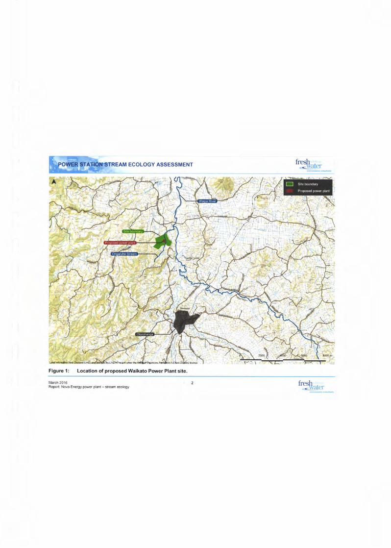
Location of proposed Waikato Power Plant site. 2
Watercourses and sampling locations within the site. 4
Habitat upstream and downstream of the proposed power plant at Sites 2 and3 on the Ongaruhe Stream.
Habitat at key locations on Ongaruhe Stream where proposed works are tocarried out and downstream.
Habitat at tributaries within the wider site and draining the proposed powerplant footprint (Tributaries 2 and 3).
Cross-sections assessed as part of macrophyte assessment.
Relative abundance of macroinvertebrate taxonomic groups.
Distribution of fish species with a threat classification in the Waipa RiverCatchment (NZFFD).
Proposed works relating to watercourses near power plant building (based onplan in Aurecon 2016). 19
Proposed culvert on upperTributary 1 fortransmission line access road (basedon plan in Aurecon 2016). 20
9
be10
11
13
14
17
March 2016Report: Nova Energy power plant - stream ecology
fresh-.dvater

fresh- <uaater
1.0 lntroduction
Nova Energy is seeking to obtain resource consents to construct and operate a 360Megawatt (MW) open cycle gas turbine power plant approximately 10 km north-east ofOtorohanga (referred to as the Waikato Power Plant). The proposed Waikato Power Plantsite is located off State Highway 31, Kawhia Road and occupies approximately five hectareswithin a 153 hectare working dairy farm. The site is located in the Ongaruhe Streamcatchment a tributary of the Waipa River and the Waikato River.
The purpose of this assessment is to assess the ecological values the Ongaruhe Streamand some unnamed tributaries and to assess the likely environmentaleffects associatedwith development of the site. The key features of the proposed Power Plant development inrelation to potential effects on the streams include:
. Earthworks and civil construction including construction of a section of erosionprotection on a portion of the eastern boundary of the site.
. Construction of a new Northern access road (including replacing and upgradingexisting farm track culverts/crossings) and the possible construction of a section oferosion protection between the Northern Access Road and the true-right bank of theOngaruhe Stream.
. Construction of the pylon access track including a crossing of Tributary 1.
. Discharge of treated site stormwater to an unnamed tributary of the OngaruheStream.
. Construction of high voltage transmission lines between the Site and the NationalGrid transmission lines approximately 500 m to the west of the Site.
. Diversion of two unnamed tributaries that are located within the footprint of the site.
This report has the following sections; general site description (Section 2), survey methods(Section 3), water quality (Section 4), instream and riparian habitat characteristics (Section5), aquatic flora (Section 6), macroinvertebrate communities (Section 7), fish fauna (Section8), assessment of effects (Section 9) and mitigation (Section 10).
2.0 General Site Description and Watercourses
The proposed power plant site is located within a 153 ha dairy farm located approximately10 km north-east of Otorohanga Township (Figure 1). The site is located within the WaipaEcological District and Waikato Ecological Region (McEwen 1987). Land cover within thesite is classed as'high producing exotic grassland' according to the New Zealand LandCover Database (LCBD v4.1) with no other categories noted (Mitchell Partnerships 2016).
The Ongaruhe Stream is the largest and only named watercourse within the site. Thecatchment area of the Ongaruhe Stream upstream of the proposed power plant site is3.2km2 (Aurecon 2016). The Ongaruhe Stream originates approximately 1.5 km south ofthe southern boundary of the farm, near Owaikura Road. The Ongaruhe Stream enters thesite at the southern boundary and flows in a northerly direction until it leaves the site at thenorth-eastern boundary. After leaving the site, the Ongaruhe Stream flows for some 280 mdownstream and under State Highway 39 via a culvert. The stream continues on in aneasterly direction for approximately 1.4 km before entering the Waipa River.
March 2016Report: Nova Energy power plant - stream ecology
resh<lvalel'
ECOLOGY ASSESSMENT
;:::]=F_-
ECOLOGY ASSESSMENT
Flgure 1: Locatlon of propooed Waikato Power Plant slte,
%;,
I
I
I
I
March 2016Report Nova Energy pffi plat - sEsm mlogy

ECOLOGY ASSESSMENT
Tributary 1 is located in the south-western portion of the farm and would have a crossingconstructed (culvert) associated with the pylon access track. lt flows in a north-easterlydirection and enters the Ongaruhe Stream approximately 300 m south of the proposedpower plant site (Figure 2).
Tributary 2 originates in a grazed pasture gully approximately 800 m south-west of thesouthern boundary of the proposed power plant site. lt flows in a northerly direction throughthe site and the lower reaches would be diverted as part of the development (Figure 2).
Tributary 3 originates in a small gully approximately 300 m west of the western boundary ofthe proposed power plant site. lt flows into Tributary 2 in the north-westem corner of thesite and the lower reaches would be diverted as part of developing the proposed powerplant (Figure 2).
Tributaries 4 and 5 are located in the eastern portion of the farm between the proposedpower plant site and Kawhia Road. They flow in an easterly direction and drain into theOngaruhe Stream downstream of the proposed power plant.
Tributary 6 originates in a gully to the east of the site and flows in a westerly direction beforeentering the Ongaruhe Stream adjacent to the proposed power plant site (Figure 2).
3.0 Survey Methods
3.1 lntroductionA stream ecological survey was carried out on 25 November 2015; it involved assessmentof aquatic and riparian habitat, water quality, aquatic flora (periphyton and macrophytes),macroinvertebrate communities and fish fauna. The following section describes the surveymethodology.
3.2 Sampling Site Details
Detailed ecological surveys were carried out at four sites as part of the assessment (Figure2 and Table 1). Site 1 was located on Tributary 1 near the southern boundary of the site.Site 2 was located on the Ongaruhe Stream upstream (south) of the proposed power plantsite. Site 3 was located on the Ongaruhe Stream downstream (north) of the proposedpower plant site. Site 4 was located on Tributary 2 within a section of the stream that isproposed to be diverted. Each site comprised a 50 m stream reach.
Table 1: Sampling site details.
Site Stream DescriptionEasting Northing
Tributary 1
Ongaruhe
3 Ongaruhe
Tributary 2
Located on the upper reaches of Tributary 1 (smallwatercourse) that drains a grazed pasture gully in the 1 791 580.89 5778239.85western area of the site
Located on the Ongaruhe Stream upstream of the 1792.101 .93 577g66g.57proposed power plant footprint
Located on the Ongaruhe Stream downstream of theproposed power plant footprint but upstream of 1791979.15 5779053.84Tributary 2 confluence
Located in the lower channelised reaches of Tributary2 and the section to be diverted as part of 1792067.09 5779097.14development of the proposed power plant
March 2016Report: Nova Energy power plant - stream ecology
fresh.<lvelter

Flgure 2: Watercourses and sampllng locatlons wlthln the site.
March 2016Report Nova Energy piler plant- stream sology
f-$ar",

EcoLoGY ASSESSMENT frohrut",<<!.:ltqlL\-r
[email protected]!orr.rnlr
3.3 Water Quality
Water physicochemical parameters measured at each site included temperature, dissolvedoxygen (percent saturation and concentration), conductivity and pH using a calibrated handheld YSI meter. The time at which measurements were made was noted. Water qualitysamples were collected from each site and analysed for:
o Totalsuspendedsolids.
. Dissolved inorganic nitrogen.
. Total nitrogen.
o Totalammoniacal-N.
. Nitrate-N + Nitrate-N.
. Total Kjeldahl nitrogen.
o Dissolved reactive phosphorus.
o Total phosphorus.
3.4 General Habitat Characteristics
General aquatic and riparian habitat characteristics along each survey reach were assessedusing the Waikato Regional Council (WRC) Field Assessment Cover Form taken fromCollier and Kelly (2005). Characteristics assessed included channel width, water depth,streambed substrate composition, organic matter (leaf litter and woody debris), channelshade, dominant riparian species, erosion and channel modification. WRC habitatassessment scores (maximum score = 180) were derived for each reach and provide anindication of habitat quality.
3.5 Periphyton
Periphyton data was collected from each site using the WRC method outlined in Collier etal. (2007). The method involves assessing periphyton cover (%) and the types presentalong five transects at each site and the calculation of the following indices:
. Periphyton Enrichment lndex (PEI) - a measure of nutrient enrichment and canrange from 0-90 with higher scores reflecting greater enrichment.
. Periphyton Proliferation lndex a measure of periphyton biomass thataccounts for the total cover of long filaments and thick mats.
. Periphyton Slimyness lndex (PSt - a measure of biomass that accounts for theweighted percent cover of each thickness category.
3.6 Macrophytes
Macrophyte (aquatic plant) data was collected from each site using the WRC methodoutlined in Collier et al. (2007). The method involves assessing submerged and emergentmacrophyte cover and species present across five transects at each site. The followingmacrophyte indices were calculated from the periphyton data collected:
o Macrophyte Total Cover (MTC) - a measure of the total cover of macrophytes overthe streambed.
fresh.<!vatel'
March 2016Report: Nova Energy power plant - stream ecology

ECOLOGY ASSESSMENT t&,,"'
. Macrophyte channet clogginess (MCC) - a measure of the total cover of
macrophytes through the water column'
o Macrophyte Native Cover (MNC) - a measure of the naturalness of the community'
3.7 Macroinvertebrate Communities
A single macroinvertebrate sample was collected from each site using a kigklne! (mesh
O.S m"nr; and followin! the semi-quantitative Protocol C2 of Stark et al' (2001)' Samples
*"r" prl""rved in 70ilo ethanol and processed by an experienced taxonomist using
Protocol P3 (full count with sub-sampling) (stark et al. 2001). The following indices were
calculated to assess macroinvertebrate community health:
. Community composition - relative abundance of the main taxonomic groups making
up the macroinvertebrate communities recorded from each watercourse. Can be
used to provide a general indication of stream health based on the relative
proportions of water and habitat sensitive and tolerant taxonomic groups'
. Taxa number -a measure of the overall health of the benthic macroinvertebrate
community and habitat and water quality. ln general, high taxa number can be an
indication of a healthy waterway. The number of taxa present at a site can be highly
variable and can fluciuate depending on many factors including habitat, water quality
and samPling effort.
. Abundance -a measure of the total number of individuals in a sample. Total
abundance tends to increase in the presence of organic/nutrient enrichment but
declines in the presence of toxic pollution'
. Macroinvertebrate community lndex (MCt-sb) - is a presence/absence based index
for measuring rii"a, health and in particular orggnlc enrichment in soft-bottomed
streams. lndividual taxa scores range from 1 (pollution tolerant) to 10 (highly
pollution sensitive). MCI-sb scores iange from <8g-(poor) to >120 (excellent) and
are interpreteJtoffowing the guidelineJpresent in Tible 2 (Stark and Maxted 2oo7)'
. EpT taxa number- a measure of the overall health of the community and of habitat
and water quality. A community that has a higher number of water and habitat
sensitive taxa from the groups Lphemeropteri (mayflies), Plecoptera (stoneflies)
and Trichoptera (caddisflies) (EPT) indicates a healthier waterway'
Tabte 2: MCI-sb and QMGt-sb quality classes (stark and Maxted 2007)'
Stream health Descriptions
Excellent
Good
Fair
Poor
Clean water
Doubtful quality/possible mild pollution
Probable moderate Pollution
Probable severe enrichment
>120
100-1 19
80-99<80
3.8 Fish Fauna
Fish data was obtained from existing sources (e.g', New Zealand Freshwater Fish
Database) and augmented with results of an eieCtric fishing survey at the four sites on 25
November 2015. The electric fishing survey was carried out along representative 50 m
reaches. Allfish captured were identified, counted and released.
March 2016Report: Nova Energy power plant - stream ecology
t$ut",.
ECOLOGY ASSESSMENT
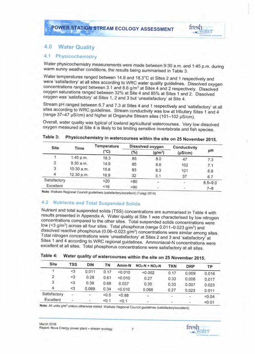
4.0 Water Quality4.1 PhysicochemistryWater physicochemistry measurements were made between 9:30 a.m. and 1:45 p.m. duringwarm sunny weather conditions, the results being summarised in Table 3.Water temperatures ranged between 14.9 and 18.3"C at Sites 2 and 1 respectively andwere 'satisfactory' at all sites according to WRC water quatity guidelines. bissolved oxygenconcentrations ranged between 3.1 and 8.6 g/m3 at Sites q iia2 respectively. Dissolvedoxygen saturations ranged between 32o/o atsite 4 and 85% at Sites i and 2.'Dissolvedoxygen was 'satisfactory' at sites 1 ,2 and 3 but ,unsatisfactory,
at site 4.S.tream pH ranged between 6.7 and 7.3 at Sites 4 and 1 respectivety and 'satisfactory,at altsites according to WRC guidelines. Stream conductivity was low atiriuuiary sii"r r and 4(range 3747 ps/cm) and higher at ongaruhe stream .it"r [ror-102 ps/cm)-overall, water quality was typical of lowland agricultural watercourses. very low dissolvedoxygen measured at Site 4 is likely to be limiting sensitive invertebrate ano?isn sfecies.
Table 3: Physicochemistry in watercourses within the site on 25 November 2015.
Site Time Temperature('c)
Dissolved oxygen Conductivity(pS/cm)(Yol (g/m3) pH
1
2
3
4
't.45 p.m.
9.30 a.m.
10:30 a.m.
12.30 p.m.
18.3
14.9
15.6
16.9
85
85
83
32
8.0
8.6
8.3
3.1
47
102
101
37
7.3
7.1
6.9
6.7Satisfactory
Excellent<20
<16>80
>906.5-9.0
74Note: waikato Regronar councir guiderines (satisfac{orylexceilent) (Turagi 2014)
4.2 Nutrients and Total Suspended SolidsNutrient and total suspended solids (TSS) concentrations are summarised in Table 4 withresults presented in Appendix A. Water quality at Site 1 was characteriseo uy tow nitrogenconcentratio^ns compared to the other sites. Total suspended solids concentrations werelow (<3 g/m3) across allfour sites. Total phosphoru* 1rrng" o.ot t-o.oza glmjj anodissolved reactive phosphorus (0.06-0.0i3 g/m3) confentiutiln. were similar among sites.Total nitrogen concentrations were 'unsatisfJctory'at Sitei i and 3 and ,satisfactory,atSites 1 and 4 according to WRC regionalguidelines. Ammoniacal-N concentrations wereexcellent at all sites. Total phosphorus concentrations were satisfactory at all sites.
Table 4: Water quality of watercourses within the site on 25 November 2015.
TN Amm-N NOg-N + NOz-N
1
2
3
4
<3
<3
<3
<3
0.0'11
0.28
0.39
0.069
0.17
0.61
0.68
0.34
<0.010
<0.010
0.037<0.010
<0.002
0.27
0.35
0.066
0.17
0.33
0.33
0.27
0.009
0.006
0.0070.023
0.0'16
0.0170.023
0.011Satisfactory
Excellent<0.5
<0.1
<0.89
<0.1<0.04
<0.01Note: All units g/m3 unless otherwise stated. waikato Regional council guidetin"" 1""fl[ilfrGffi
March 2016Report: Nova Energy power plant - stream ecology fresh
. <v/atel'

fresh.,<IMater
5.0 HabitatCharacteristics
5.1 Ongaruhe Stream
The Ongaruhe Stream has been highly modified through land use, riparian vegetationclearance or disturbance, drainage works and channelisation. Typical habitat conditionsalong the section of the Ongaruhe Stream upstream (Site 2) and downstream (Site 3) of theproposed power plant building site are shown in Figure 3. Habitat characteristics recordedat sampling sites are summarised in Table 5.
Measured channel widths ranged between 1.54.5 m and increased downstream betweenSites 2 and 3 (mean widths = 2.0 m and 2.9 m respectively). The channel has a moremeandering flow path upstream of the proposed power plant (Site 2) but has undergonesome channelisation downstream in the vicinity of Site 3. Aquatic habitat comprises uniformruns and pools and reflects the U-shaped channel, moderate water depths ranging between0.2->1.0 m (mean = 0.45-0.46 m) and sluggish flow velocities (0.3 m/s).
The streambed comprises weathered clay and silt with occasional gravels recorded at theupstream Site 2. Woody debris was common at Site 2 upstream of the proposed buildingsite and reflected the mature exotic tree (e.9., Lawson's cypress) and mixed native/exoticunderstorey and streambank riparian vegetation (e.9., privet, Carex sp., umbrella sedge,kiokio, ring fern) (Figure 3). ln contrast, woody debris was rare at Site 3 due to the modifiedstate of the riparian habitat and reduction in the number of mature trees (Figure 3).
The Ongaruhe Stream within the site is fenced along both streambanks meaning stock areexcluded however there is variability in the nature of the existing riparian habitat andchannel shade. The channel upstream of the proposed power plant is narrower and somesections (Site 2) are lined with mature exotic trees that provide moderate-good shade (50-80%). The wider channel downstream of the proposed power plant, although fenced, lacksa continuous margin of mature trees and is less well shaded (10-30%).
WRC habitat scores for sampling reaches on the Ongaruhe Stream sites ranged between108 (Site 3) and 120 (Site 2) out of a maximum of 180 and indicates the stream providesmoderate quality habitat.
Figure 4 shows habitat conditions along the Ongaruhe Stream in the vicinity of proposedworks including the areas where the proposed diversion channels (northern and southern)will flow into the mainstem, the stream length along which proposed erosion works will becarried out and the existing oxbow on the mainstem that may be reclaimed as part ofbuilding construction. Proposed works associated with the power plant will be carried outalong poorly shaded and channelised sections of the Ongaruhe Stream. Figure 4 alsoshows the Ongaruhe Stream downstream of the proposed site at the Kawhia Road culvert.
Table 5: Key habitat features recorded at each site.
ECOLOGY ASSESSMENT
StreambedWRC
habitatscore
Mean Meandepth "1"?1" vel. Habitat(m) rtot (m/s)
width(m)Site Location
0.30
0.30
0.30
0
70
30
0
1
2
3
4
Tributary 1 (upper catchment) 1-2 0.16
Ongaruhe Stream (upstream) 1.5-3 0.45
Ongaruhe Stream (downstream) 1.54.5 0.46
Tributary 2 2.0-2.5 0.19
p = BOo/o, R = 2oo/o ?[:^i3iy7;"P = 80%, R=20oh Si = 100%
R = 100%
0.00 P = 100%
Si = 100%
Si = 100%
66
120
108
47
Note: Vel. =velocity, R =run, p = pool, Si =silt, Cl =clay,61 =gravel.
March 2016Report: Nova Energy power plant - stream ecology
fresh-.<l&/at('l'

Ongaruhe Stream downitream of the
Flgure 3: Habitat upstream and downstream of the proposed power plant at Sltes 2 and 3 on the Onqaruhe Stream.
March 2016Report: Nova Energy pMr plant - stream sdogy H",",

ECOLOGY ASSESSMENT Sater
norlhgm dlveBlon coniuencs,ir.;I.ri;+'r', ' 'l
Figure 4: Habitat at key locations on Ongaruhe Stream where proposed works are to be carried out and doirnstream.
March 2016Report Nova Energy pwer plant- slream sology fresh .
. <!l,al('r
LooklnE downstream of Kawhla Road culvert (ofi-3lte)
ECOLOGY ASSESSMENT
5.2 Tributaries
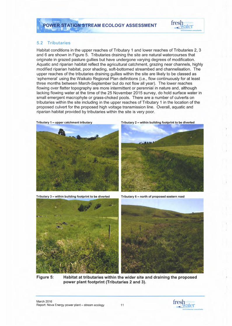
Habitat conditions in the upper reaches of Tributary 1 and lower reaches of Tributaries 2, 3and 6 are shown in Figure 5. Tributaries draining the site are naturalwatercourses thatoriginate in grazed pasture gullies but have undergone varying degrees of modification.Aquatic and riparian habitat reflect the agricultural catchment, grazing near channels, highlymodified riparian habitat, poor shading, soft-bottomed streambed and channelisation. Theupper reaches of the tributaries draining gullies within the site are likely to be classed as'ephemeral' using the Waikato Regional Plan definitions (i.e., flow continuously for at leastthree months between March-September but do not flow all year). The lower reachesflowing over flatter topography are more intermittent or perennial in nature and, althoughlacking flowing water at the time of the 25 November 2015 survey, do hold surface water insmall emergent macrophyte or grass-choked pools. There are a number of culverts ontributaries within the site including in the upper reaches of Tributary 1 in the location of theproposed culvert for the proposed high voltage transmission line. Overall, aquatic andriparian habitat provided by tributaries within the site is very poor.
Tributary 6 - north of proposed eastern road
Figure 5: Habitat at tributaries within the wider site and draining the proposedpower plant footprint (Tributaries 2 and 3).
fresh---warcr
March 2016Report: Nova Energy power plant - stream ecology 11
fresh-diatel'
onrronmdlal .siulldi
Tributary 3 - within building footprint to be diverted

EAM ECOLOGY ASSESSMENT
6.0 Aquatic Flora Community
6.1 Periphyton
Periphyton cover was sparse within all watercourses draining the site, reflecting acombination of habitat related factors including the soft-bottomed nature of the streambed,channel shade, deep water depths and moderate-high macrophyte cover.
6.2 Macrophytes
Total macrophyte cover (MTC) ranged between 45% at Site 2 on the shaded section of theOngaruhe Stream and 100% at the poorly shaded upper catchment Site 1 (Tributary 1)(Table 6). Photographs at cross-sections assessed at each site are shown in Figure 6.
Smalltributaries draining the site (e.9., Tributary 1 and 2)were poorly shaded, held limitedsurface water and were gpically choked with exotic grass (65-100% cover) and emergentmacrophytes including Nasturtium officinale (watercress; 10-100% cover) , Callitrichesfagna/rs (starwort; <1% cover) and Ludwigia palustris (water purslane; 1-10% cover).
The macrophyte community recorded from the two Ongaruhe Stream sites (Sites 2 and 3)were different and reflected the amount of channel shading present. The moderate-wellshaded upstream Site 2 supported moderate cover of the submerged charophyte N[e//a sp.(5-95% cover) and rare growths of Ludwigia palustris (water purslane; <5% cover). Thepoorly shaded downstream Site 3 was choked with Potamogeton crispus (curly pondweed;10-70% cover) and water purslane (5-70%o cover). Persicaria hydropiper (water pepper)was recorded in low cover along channel margins (<5% cover) at Site 3.
The Macrophyte channel clogginess (MCC) is a measure of the total cover of macrophytesthroughout the water column with high scores indicating a stream channel is choked withmacrophytes. The lowest MCC score of 23 was recorded for the shaded section ofOngaruhe Stream (Site 2). All other sites had high MCC scores (77-100) and reflectedpoor channel shading and high macrophyte growth or grass growing in the channel (e.9.,the smaller tributary sites 1 and 4) (Table 6).
The only native macrophyte species recorded was moderate cover of Nitella sp. along theshaded section of the Ongaruhe Stream at Site 2 hence the Macrophyte Native Cover(MNC) score of 44for this site and 0 for all other poorly shaded sites (Table 6).
Tabfe 6: Macrophyte results recorded on 23 October 2015.
MTC MCC(%l (Y.l
fresh.<lyatel'
Site Watercourse T)"i SPecies recorded
0
44
0
100
23
77
100
45
89
1
2
3
4
Tributary 1
Ongaruhe Stream
Ongaruhe Stream
Tributary 3
Nasturtium officinale, Callitriche sfagna/is,Ludwigia palustris
Nitella sp., Ludwigia palustrls
Potamogeton crlspus, Ludwigia palustris,Persicaria hydropiper
Nasturtium officinale, Callitriche stagnalis,Ludwigia palustris
March 2016Report: Nova Energy power plant - stream ecology
fresh-<lvatel'

ECOLOGY ASSESSMENT
Cross section 1 Cross section 2
ia!
IlLF
oo
Cross section 3 Cross sec{ion 4
Figure 6: Gross-sections assessed as part of macrophyte assessment.
EGotho
at,EDcoNo=o
Et!Eoo.t(s.Dtro
aY,
o=o
NBa!f!
Ito=o
Cross section 5
_--rqil
March 2016Report: Nova Energy power plant - stream ecology
fresh ,
-<u/ater13
ECOLOGY ASSESSMENT
7.0 MacroinvertebrateCommunity
7.1 Community Composition
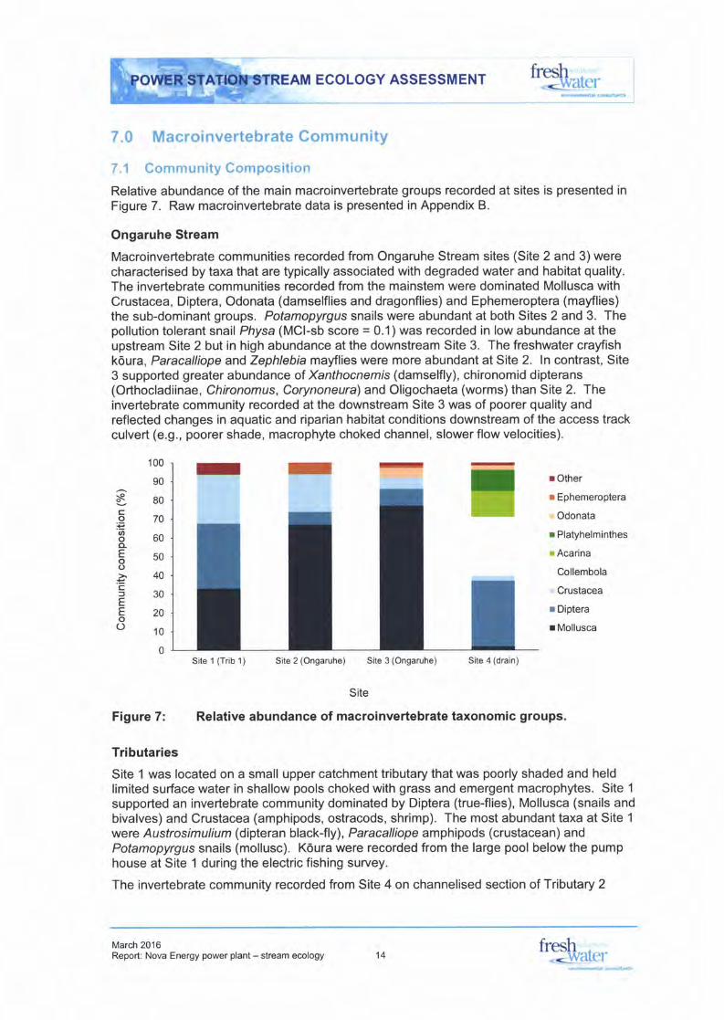
Relative abundance of the main macroinvertebrate groups recorded at sites is presented inFigure 7. Raw macroinvertebrate data is presented in Appendix B.
Ongaruhe Stream
Macroinvertebrate communities recorded from Ongaruhe Stream sites (Site 2 and 3)werecharacterised by taxa that are typically associated with degraded water and habitat quality.The invertebrate communities recorded from the mainstem were dominated Mollusca withCrustacea, Diptera, Odonata (damselflies and dragonflies) and Ephemeroptera (mayflies)the sub-dominant groups. Potamopyrgus snails were abundant at both Sites 2 and 3. Thepollution tolerant snail Physa (MCl-sb score = 0.1) was recorded in low abundance at theupstream Site 2 but in high abundance at the downstream Site 3. The freshwater crayfishk6ura, Paracalliope and Zephlebia mayflies were more abundant at Site 2. ln contrast, Site3 supported greater abundance of Xanthocnemis (damselfly), chironomid dipterans(Orthocladiinae, Chironomus, Corynoneura)and Oligochaeta (worms)than Site 2. Theinvertebrate community recorded at the downstream Site 3 was of poorer quality andreflected changes in aquatic and riparian habitat conditions downstream of the access trackculvert (e.9., poorer shade, macrophyte choked channel, slower flow velocities).
fresh<\Aratct'
sCo,6oo-Eoo
=c=EEoO
100
90
80
70
60
50
40
30
20
10
0
r Other
I Ephemeroptera
Odonata
r Platyhelminthes
. Acarina
Collembola
Crustacea
r Diptera
r Mollusca
Site 1 (Trib'1) Site 2 (Ongaruhe) Site 3 (Ongaruhe) Site 4 (drain)
Site
Figure 7: Relative abundance of macroinvertebrate taxonomic groups.
Tributaries
Site 1 was located on a small upper catchment tributary that was poorly shaded and heldlimited surface water in shallow pools choked with grass and emergent macrophytes. Site 1
supported an invertebrate community dominated by Diptera (true-flies), Mollusca (snails andbivalves) and Crustacea (amphipods, ostracods, shrimp). The most abundant taxa at Site 1
were Ausfro simulium (dipteran black-fly), Paracalliope amphipods (crustacean) andPotamopyrgus snails (mollusc). K6ura were recorded from the large pool below the pumphouse at Site 1 during the electric fishing survey.
The invertebrate community recorded from Site 4 on channelised section of Tributary 2
March 2016Report: Nova Energy power plant - stream ecology 14
fresh<wal('l'

EcoLocY ASSESSMENT tTh,nt",
draining the proposed power plant building site was the most evenly distributed bytaxonomic groups but dominated by Diptera and Collembola (spring tails)with Acari (watermites) and Platyhelminthes (flatworms) being the sub-dominant taxonomic groups. Themost abundant taxa at Site 4 were the chironomids Orthocladiinae and Corynoneura,Collembola and Acarina. The community recorded from Site 4 was of poor quality andreflected the highly modified channelised channel, limited surface water, weak flow, poorshade and high emergent macrophyte cover.
7.2 Biological lndices
A total of 30 taxa were recorded across the two tributary and two Ongaruhe Stream sites.The number of taxa recorded at each sites ranged between 17 at Sites 2 and 3 on theOngaruhe Stream and 20 taxa from Site 4 (Tributary 1) (Table 7). lnvertebrate abundanceranged between 923 individuals at Site 4 and 3,705 individuals at Site 3 (Table 7).
Water and habitat quality sensitive EPT taxa (mayflies, stoneflies and caddisflies)were rarewith only six mayfly and caddisfly taxa recorded across the four sites. The number of EPTtaxa recorded at sites was low and ranged between 1-5 at Sites 4 and 2 respectively (Table7). The low number of EPT taxa recorded reflects generally poor habitat conditions at eachsite (see Table 5). EPT abundance was similarly low with the most abundant EPT taxonrecorded being Zephlebta (MCl-sb score = 8.8), which was recorded in moderate-highabundance at Ongaruhe Stream Sites 2 and 3 (176 and 48 individuals respectively). Allother EPT taxa were recorded in low abundance (s5 individuals) but included the caddisfliesHydrobiosis, Polyplectropus, Psilochorema and Triplectides.
MCI-sb scores varied widely among sites and ranged between 60 and 96 at Sites 3 and 2respectively. MCI-sb scores were indicative of 'poor' ecological stream health at Sites 1, 3and 4 and 'fair' stream ecological health at Site 2 (Table 7). MCI-sb scores reflect therelatively high number of low scoring taxa (e.9., Diptera, Crustacea and Mollusca), acommon situation in soft-bottomed Waikato streams with modified riparian margins anddraining grazed pasture catchments
Table 7: Benthic lnvertebrate !ndices Scores.
Site Watercourse Taxa number Abundance EPT taxa MCI-sb
2,731
3,093
3,705
923
3
5
2
1
8.0 Fish Fauna
8.1 New Zealand Freshwater Fish Database
There are records for 207 surveys at 179 sites held in the NZFFD for the wider Waipa RiverCatchment between 1990 and 2016 (Table 8). Records prior to '1990 were excluded asthey may not be representative of the current fish fauna present. Most surveys since 1990have been carried out on tributaries (200) rather than the Waipa River mainstem (7).
The Waipa River Catchment supports a diverse and abundant freshwater fish faunacomprising 14 native species and 10 introduced species (Table 8). The most commonly
1 Tributary 1 (upper catchment)
2 Ongaruhe (upstream)
3 Ongaruhe(downstream)
4 Tributary 3 (drain)
20
17
17
21
78
96
60
69
March 2016Report: Nova Energy power plant - stream ecology
fresh<v/atel'15

ECOLOGY ASSESSMENT
recorded species are shortfin eel, longfin ee!, common bully and Cran's bully. otherspecies commonly recorded based on NZFFD records are torrentfish, black mudfish,common smelt and Gambusia pest fish.
Table 8: Summary of NZFFD records for the Waipa River catchment (1ggo-2oi6).
Common name Scientific name Origin Diadromous ThreaUpest status I
Waipa Rivercatchment 2
Mainstem Tribs.
Unidentifiedgalaxiid Galaxiassp.
Banded kokopu
lnanga
Shortjaw kokopu
Lamprey
Cran's bully
Common bully
Redfin bully
Unidentified bully
Grey mullet
Black mudfish
Common smelt
Shortfin eel
Longfin eel
Unidentified eel
Torrentfish
Giant kokopu
Rudd
Goldfish
Koi carp
Gambusia
Rainbow trout
Brown trout
Anguilla australis
Ang uilla dieffenbachii
Anguilla sp.
Cheimanichthys fosteri
Galaxias argenteus
Galaxias fasciatus
Galaxias maculatus
Galaxias postvectis
Geotria australis
Gobiomorphus Dasa/is
G ob i omorphu s cotidi a n u s
Gobiomorphus huttoni
Gobiomorphus sp.
Mugil cephalus
Neochanna dlyersus
Retropinna retropinna
Native
Native
Native
Native
Native
Native
Native
Native
Native
Native
Native
Native
Native
Native
Native
Native
Native
lntroduced
lntroduced
lntroduced
lntroduced
lntroduced
lntroduced
lntroduced
Yes
Yes
Yes
Yes
Yes
nla
Yes
Yes
Yes
Yes
Yes
Yes
nla
Yes
At Risk (declining)
At Risk (declining)
At Risk (declining)
At Risk (declining)
Nationally wlnerable
Nationally vulnerable
At Risk (declining)
At Risk (declining)
Pest
Pest
Pest
Pest
2
1
2
1
3
1
3
2
I
93
98
21
28
I6
13
12
8
16
43
40
6
8
20
23
I4
6
2
23
16
4
Brown bullhead catfish Ameiurus nebulosus
S card i n i u s e ryth ro phth al m u s
Crassrr.ls auratus
Cyprinus carpio
Gambusia affinis
Oncorhynchus myklss
Salmo trutta
Note: 1 Threat status obtained from Goodman et al. (2014); 2 number of NZFFD records.
Figure 8 shows the distribution of fish species in the Waipa River Catchment. Eightthreatened species have been recorded from the Waipa River Catchment since 1gg0 andincludes longfin eel, torrentfish, giant k6kopu, Inanga, shortjaw k6kopu, lamprey, redfin bullyand black mudfish. Threatened species recorded in the Waipa River Catchment upstreamof the Ongaruhe Stream confluence with the Waipa River since 1990 are longfin eel,torrentfish, lamprey and black mudfish. Although most black mudfish records occur in thelower Waipa River Catchment, there are records of this threatened species in weflands andswamps in the Tanehopuwai Stream and Mangapu Stream that drain the area to the south-west of Otorohanga.
March 2016Report: Nova Energy power plant - stream ecology fresh
*dvatel'

EcoLocY ASSESSMENT L?F*4",trvlrdmtltr
'o^t!nndi
Figure 8: Distribution of fish species with a threat classification in the Waipa RiverCatchment (NZFFD).
March 2016Report: Nova Energy power plant - stream ecology
fresh-<!vater

EAM ECOLOGY ASSESSMENT*"i1111i:r:',]:'r"
All native freshwater fish species recorded except Cran's bully and black mudfish arediadromous and require upstream and downstream passage between the freshwater andmarine environment to complete their lifecycles. The Ongaruhe Stream draining the site isapproximately 168 km upstream from the coast and there are no records for the OngaruheStream since 1990 but there is a record of unidentified eels downstream of the site in 1983.
8.2 Survey Data
The only fish species recorded from sampling sites during the electric fishing survey wereshortfin eel from the Ongaruhe Stream (Sites 2 and 3) and the pest fish Gambusra fromTributary 2 (Site 4). Between 10 and 15 shortfin eels ranging in length between 180 and500 mm were recorded from Sites 2 and 3. No other fish were recorded from the mainstem.Gambusia were common in small pools of surface water in the lower reaches of Tributary 2.Other fish species that may occur in the section of the Ongaruhe Stream within the site,based on habitat present and NZFFD records, include longfin eel, common bully and Cran'sbully in the Ongaruhe Stream. Shortfin eels may also occur in areas of stable surface waterin the smaller tributaries. Potential habitat for black mudfish does not exist in the smallertributaries within the site.
9.0 Assessment of Effects
9.1 lntroduction
The proposed development will involve the following activities with the potential to adverselyaffect the watercourses within and downstream of the site (refer Figure 9 and Figure 10):
. Earthworks including construction of a section of erosion protection on a portion ofthe eastern boundary of the site and within the Ongaruhe Stream floodplain.
. Construction of a new north access road from Kawhia Road including replacing andupgrading existing farm track culverts/crossings and construction of a section oferosion protection between the northern access road and the true-right bank of theOngaruhe Stream.
. Construction of culvert in the Ongaruhe Stream for power plant site road.
o Discharge of treated power plant site stormwater to an unnamed tributary (Tributary3) of the Ongaruhe Stream.
. Diversion of Tributary 2 and Tributary 3 around the power plant site.
. Construction of culvert in Tributary 1 for power pylon access road.
9.2 Power Plant Site and Access Road Earthworks
Construction Effects
Potential water quality effects associated with the development of the power plant site andaccess roads, including the construction of approximately 350 m of erosion protection closeto the Ongaruhe Stream and the construction of a stormwater treatment pond and outletstructure to the newly aligned Tributary 3, relate to short-term sediment mobilisation,reduced water clarity and smothering of instream substrates by sediment.
fresh. <\Yatel'
March 2016Report: Nova Energy power plant - stream ecology
fresh*<v/atet-18

Figure 9: Proposed works relating to watercourses near power plant building (based on plan in Aurecon 2016),
March 2016Report Nova Energy pMr plant - stream eology tS*",

AM ECOLOGY ASSESSMENT fresh .
< \\'itl(,1'
Figure 10: Proposed culvert on upper Tributary 1 for transmission line access road (based on plan in Aurecon 2016).
March 2016Repoft Nova Energy power plant - stream ffology frsh
- \\'llt('l'
ftesh-<\ &iler
The discharge of coarse and fine sediment during construction has the potential toadversely affect downstream ecology, despite the water and habitat tolerant nature ofbiologicalcommunities present. Mitigation to minimise potentialeffects on stream waterand habitat quality will be required. The shortterm discharge of a small amount of finesediment is unlikely to result in adverse effects due to the low sensitivity of the invertebrateand fish communities.
The construction of the northern and eastern access roads would require upgrades to theexisting farm culverts on Tributary 6 and Ongaruhe Stream (Figure 9). The construction ofan access road for the high voltage transmission line to the west of the power plant site willalso require an upgrade to an existing farm culvert on the upper reaches of Tributary 1
(Figure 10). A new culvert will be constructed on the Ongaruhe Stream for a section of theaccess road extending off the proposed northern access road (Figure 9). Culvertconstruction, which would involve works in a watercourse, willdisturb short sections ofhighly modified stream habitat that currently support limited ecological values. Withappropriate mitigations to minimise disturbance and sediment discharges and also tostabilise and rehabilitate the areas, the effects of culvert construction will be minimised.
Operational Effects
The construction of the power plant site platform will involve the construction ofapproximately 200 m of rip rap erosion protection around the north eastern portion of thepower plant platform and, depending on the route selected, a further approximately 150 mon the western side of the northern access road (see Figure 9). The location of theproposed erosion protection is highly modified by the current land use, stream managementand farming operations and is therefore insensitive to the effects of the erosion protectionstructures on stream habitat quality. With appropriate mitigation measures aimed tominimise the effects of erosion protection structures on stream habitat the effects areassessed as minor.
The approximately 5 ha power plant site will generate stormwater that will be treated via adetention pond before discharging to the lower reaches of the realigned Tributary 3 channel(Figure 9). The stormwater volumes have been assessed by Aurecon. With theappropriate level of treatment and the current moderate-poor water quality of the receivingenvironment, stormwater discharge-related effects on receiving water quality should be ableto be avoided.
The construction of the access road will involve the replacement of some existing farm trackculverts and the construction of a new culvert on the Ongaruhe Stream. There is potentialfor poorly installed culverts to act as barriers to upstream fish passage (e.9., perched, steepgradient, swift flow). With appropriate mitigation through the implementation of suitableculvert design and construction guidelines, adverse effects will be avoided.
The new culverts are likely to result in a small loss of natural stream habitat (associated withthe wider road). This effect, whilst not assessed as significant, will require some mitigationas outlined below.
9.3 Stream Diversions
Construction Effects
The construction of the power plant platform would involve diverting an approximately105 m section of Tributary 3 around the north western corner of the power plant platforminto a new stream channel of approximately 250 m in length (Figure 9). The constructionwould also involve diverting an approximately 450 m section of Tributary 2 around the south
March 2016Report: Nova Energy power plant - stream ecology
fresh-.<!vater21

ECOLOGY ASSESSMENT
eastern corner of the power plant platform into a new stream channel of approximately305 m in length. Construction of the proposed northern and southern diversion channels(Figure 9) will therefore result in no net loss of stream/drain channel.
The diversions would involve works in a watercourse and approximately 555 m of highlymodified channelised stream habitat that currently support limited ecological values. Withappropriate mitigations to minimise disturbance and sediment discharges and also tostabilise and rehabilitate the areas the effects of the effects of the diversions will beminimised. The diversions will result in 555 m of tributary I farm drain habitat beingdisturbed and resulting in potential minor adverse effects on benthic invertebrates and fish.
Diversion of the tributaries I farm drains presents an opportunity to improve aquatic habitatvalues. Actions to mitigate or offset the effects of the disturbance of a section of Tributary 2and 3 on biologicalcommunities are outlined in Section 10.0.
Operational Effects
Tributary 3 is a highly modified ephemeral watercourse that supports very limited ecologicalvalues. Tributary 2 is a highly modified watercourse that is most likely to be ephemeral inits mid-upper reaches under the Waikato Regional Plan definition. The diversion ofTributary 2 and Tributary 3 will be undertaken to avoid the loss of stream channel (habitat)and will minimise any adverse effects on stream habitat within the site.
10.0 Mitigation
Construction Effects
It is recommended that:
. ln-stream works and works close to the streams be carried out during dry weatherconditions and follow appropriate best practice guidelines recommended by WRC tocontrol sediment mobilisation and runoff.
. The contractor responsible for upgrading culverts be required to capture andrelocate any native fish and koura that are encountered during instream works.
. The new channels associated with the Tributary 2 and 3 diversions be designed toincorporate in-stream and riparian habitat features that enhance the current habitatquality including the constructing a channelwith meanders, run and pool habitat,sections of higher gradient (if possible) and riparian planting that provides 70-80%shading of the channel.
. The new channels be constructed well ahead of diverting the flow to allowstreambank and riparian vegetation to become established in order to stabilisestreambanks and improve habitat values.
o The restored stream habitat in the diversions will have higher ecologicalvalue andfunction than the existing stream habitat so there will be a net ecological benefitassociated with the development of the site, thus meeting the requirements toenhance water and habitat quality within the Waikato River Catchment.
March 2016Report: Nova Energy power plant - stream ecology
fresh-<!vater22

ECOLOGY ASSESSMENT
Stream Habitat Disturbance
It is recommended that consideration be given to:
. Designing the new channels to enhance aquatic habitat quality (as outlined above).
. Planting of 5-10 m wide riparian buffers with eco-sourced native plants on bothbanks of the Ongaruhe Stream (within the farm boundary) with the objective ofachieving 7O-80% channel shading.
o Willow removal from the northern section of the Ongaruhe Stream.
Restored riparian habitat along the Ongaruhe Stream and along the new diversion channelswill have higher ecological value and function than the existing stream habitat so there willbe a 'net ecological benefit' associated with the development of the site and will thus meetthe requirements to enhance water and habitat quality within the Waikato River catchment.
Culverts and Fish Passage
It is recommended that the design and construction of the proposed culverts be inaccordance with best practice guidelines (e.9. WRC 2006). The base of the culverts shouldbe submerged by 300 mm below the streambed and have a low gradient (<1%). Thedesign and construction of the culverts in accordance with guidelines WRC (2006) willensure passage at normal (or below normal) stream flows for eels, bully species, bandedkdkopu and other climbing biota (e.9., kdura) and ensure that there will not be any adverseeffects on fish.
Fish Transfer
It is recommended that native fish and kdura be captured and relocated from the sections ofTributary 2 and 3 that will be diverted. The requirement for and method of implementationof fish relocations will need to be confirmed following confirmation of detailed constructionmethodology and the timing of works.
11.0 References
Aurecon New Zealand Limited 2016: Flood assessment report - Waikato power plant.Report prepared for Nova Energy. February 2016.
Collier, K. and Kelly, J. 2005: Regional Guidelines for Ecological Assessments ofFreshwater Environments. Macroinvertebrate sampling in wadeable streams.Environment Waikato Technical Report TR2005/02.
Collier, K. Kelly, J. Champion, P.2007'. Regional Guidelines for Ecological Assessments ofFreshwater Environments. Aquatic plant cover in wadeable streams. EnvironmentWaikato Technical Report TR2006l 47 .
McEwen, W.M. 1987. Ecological Regions and Districts of New Zealand. Third revisededition in four 1:500 000 Maps. New Zealand Biological Resources Centre,Department of Conservation, Wellington.
Mitchell Partnerships 2015: Terrestrial ecological values of the proposed Waikato PowerPlant site. Report prepared for Nova Energy. December 2015.
Stark, J. D., Boothroyd, l. K. G., Harding, J. S., Maxted, J. R., Scarsbrook, M. R. 2001:
March 2016Report: Nova Energy power plant - stream ecology
fresh*&rer
23fresh
**-watel'

ECOLOGY ASSESSMENT
Protocols for sampling macroinvertebrates in wadeable streams. Prepared for theMinistry for the Environment. November 2001.
Stark, J., Maxted, J.2007: A user guide for the Macroinvertebrate Community lndex.Cawthron Report No 1166. April2007.
Tulagi, A.2014: Regional rivers water quality monitoring programme: Data report 2013.Waikato Regional CouncilTechnical Report 2014130. June 2014.
Waikato Regional Council 2006: Environment Waikato Best Practice Guidelines forWatenlray Crossings. Environment Waikato Technical Report 2006/25R. 3 April2006.
March 2016Report: Nova Energy power plant - stream ecology

ECOLOGY ASSESSMENT
Report Signature Page
n tl 'K i;Ll, nfq-,<txt,/
Richard Montgomerie
Director
Freshwater Solutions Ltd
trt-Nick Carter
Freshwater Ecologist
March 2016Report: Nova Energy power plant - stream ecology

ECOLOGY ASSESSMENT
APPENDIX AWater Quality Results
Appendix AReport Nova Energy power plant - stream ecology

ECOLOGY ASSESSMENT
Appendix AReport: Nova Energy power plant - stream ecology

ECOLOGY ASSESSMENT
APPENDIX BMacroinvertebrate Data
Appendix BReport: Nova Energy power plant - stream ecology

ECOLOGY ASSESSMENT
Hydrobios is
OxyethiraPolyplectropusPsilochorema
MicrowliaSigara
6.71.2
8.1
7.85.7
1
1
35
4.62.4
Dytiscidae
Ar.rstrosimuliumChironomusCorynoneuraMuscidaeOrthocladiinaeParadixaSciompidaeTanypodinaeTanytarsiniCollembola
CopepodaOstracodaParacalliopeParanephropsAcarina
3.93.41.7
1.6
3.28.53
6.54.55.3
688
48
8;128
1
4
ia576
3
128 9
3232
1
,:u
3
4817_6
iq6
1725
1
16
288
128
2.41.9
5.58.45.2
;624
1
Lymnaeidae 1.2 1
PhpaPotamopyrgusSphaeriidaeOligochaeta
Hvdra
0.1 32 1
z.',t 864 2064 2384 3
2.9-13.8 48 1
1
464
7I
PlatyhelminthesO.g6lllO4:ffi,**stt**xii+ ry#&$Y+iwll,s1.6 80 -71
Appendix BReport: Nova Energy power plant - stream ecology
fresh-<l&'ater.nr ronmolrl .on!uttrdi

I
ourecon
Leadlng. Vibrant. Global.www.aurecongroup.com
Proposed Power Generation Plant -Access to SH 31
Transport Assessment
Nova Energy
13 May 2016
Revision: 2
Reference: 241157

/// /,/,,,/,/,///,//r//././///./,,/./,/ ././,,,, ,/,/,,' /, ,,.','7,t7l,lr//l,t',t1
,a:/ ,//r'/
Document control record
Document prepared by:
Aurecon New Zealand Limited
Ground Level247 Cameron RoadTauranga 31 10
PO Box2292Tauranga 3140New Zealand
T +64 7 578 6183F +64 7 5786143E [email protected] aurecongroup.com
A person using Aurecon documents or data accepts the risk of:
a) Using the documents or data in electronic form without requesting and checking them for accuracy against the original hard
copy version.b) Using the documents or data for any purpose not agreed to in writing by Aurecon.
Report title
Document !D
File path
GIient
Rev Date
1 3 February 20'16
2 13 May 2016
Current revision
Transport Assessment
Proiect number 241157
C:\Users\Chris.Jones\AppData\Roaming\OpenText\OTEdit\EC-cs\c133442451\TransportAssessment-rev2.docx
Nova Energy
Revision details/status
Final
Final
Client contact
Author Reviewer
A Fosberry J Gottler
A Fosberry J Gottler
Verifier Approver(lt requlred)
C Walters
C Walters
Author signature
Name
Title
r1l au*Ann Fosberry
Technical Director
Approver signature
Name
Title
Chris Walters
Associate
qUleCOn Leading. Vibrant. Global. Projst 24'1157 Flle TransportAssesmonlrev2.doff 13 May 2016 Revision 2

I
2
3
Contents
Append icesAppendix A
Site Layout
Appendix B
Crash Data
Appendix C
lntersection Schematic
lntroduction
Proposal
Existing road environment
3.1 Traffic volumes
3.2 Crash data
3.3 Vulnerable road users
3.4 Public Transport
Traffic Generation
4.1 Day to day operations
4.2 Maintenance
Site access assessment
5.1 Sight distance requirements
5.2 Access offset requirement
5.3 Locations assessed
5.4 Preferred site access
5.5 Liaison with NZ Transport Agency
5.6 Access intersection form with state highway - Location 3, southern access
5.7 Access intersection form with state highway - Location 5, northern access
Construction Management
6.1 Construction Management Plan
6.2 Work phases
Assessment of effects
7.1 Traffic generation
7.2 Safety
7.3 Site access
7.4 Constructionmanagement
Conclusions and Recommendations
1
3
4
4
5
6
6
7
7
8
II9
I12
15
15
18
19
19
20
22
22
22
22
22
23
OUfeCOn Leading. Vibrant. Globat. Prqect 241157 Flle TEnsport Asssmtrt-r6v2.doo( 13 may 2016 Revision 2 Page I

Figures
Figurel-LocalityPlanFigure2-SitePlanFigure 3 - Schematic of internal site access and building site location
Figure4-Crash Diagram
Figure 5 - lnvestigated access locations I to 7Figure 6 - View north on SH 31 from Location 3, southern access
Figure 7 - View south on SH 31 from Location 3, southern access
Figure 8 - View north on SH 31 from Location 5, northern access
Figure 9 - View south on SH 3l from Location 5, northern access
Figure 10 - Transport Agency Diagram D
Figure 11 - Access schematic Location 3 southern access
Figure 12 - Transport Agency Diagram C, for temporary northern access
Tables
Table I - SH 31 average hourly traffic volumesTable 2 - Expected traffic generation from power plant
Table 3 - Expected SH 31 volumes with additional traffic
1
2
3
5
10
12
13
14
14
16
17
18
'I
4
7
8
fUfeCOn Leadlng. Vlbrant. Global. Ptq/[,ci241157 FllsTEnspofi Assessmmt-rev2.docx 13 fty 2016 Revision 2 Paga ll

Nt
I n trod u ctio n
Nova Energy proposes to establish a new power generation plant to provide power during peak loadtimes.
The site is currently operating as a dairy farm which is owned by Nova Energy.
The following report assesses the transportation effects of a new access onto State Highway 31
(Kawhia Road). This report will discuss two access options with a view to having both optionsconsented with appropriate conditions for each, following agreement with the NZ Transport Agency(as the Road Controlling Authority) and the inclusion of specific Transport Agency requirements.
The site is located on SH 31, approximately 9km north of Otorohanga - refer Figure 1 below.
,,
Figurel-LocalityPlan
Source: Auckland Motorway Alliance - lrms.aucklandmotorways.com
(NB: The above view from the Auckland Motorway Alliance website from which the above map wassourced, inconectly shows the adjacent section of state highway to be SH 39; it is however, SH 31.)
le
+
tIe
16
iUfeCOn Leading. Vibrant. Globat. Prct*t241157 FlleTransportAssessment_rev2.docx 13May2016 Revision2 Page'l
/ / ./.. /////' / //' .',/,/// / ' ,, ,/ ,/,/'./ ,/ ..'
,' ,,/ t ,/,,/.r',2/,,/7 ,/ ',, ,///. /,.'/,' ,' ,,/ ,' ./ I 2",/,/'/,/ /./.././
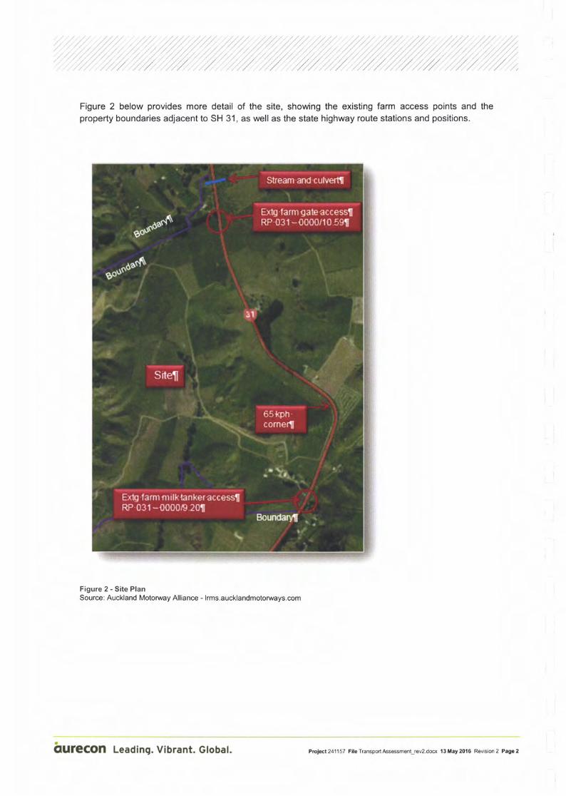
Figure 2 below provides more detail of the site, showing the existing farm access points and theproperty boundaries adjacent to SH 31, as well as the state highway route stations and positions.
Figure2-SitePlanSource: Auckland Motorway Alliance - lrms.aucklandmotoruays.com
hUfeCOn Leading. Vibrant. Global. Ptol*l 241157 Fllo Transport Asssment_rev2.dsx 13 May 2016 Revision 2 PagB 2

2 Proposal
A schematic of the intemal layout is shown in Figure 3 below and also attached in Appendix A.
- Two access options are indicated on the schematic. The site will have one permanent access for dayi to day operations at the southem end of the site and an access at the northern end of the site for
construction and maintenance vehicle access onto SH 31.
, The internal road layout and circulation design is not included within this assessment.
Figure 3 - Schematic of internal site access and building site location
i
I
rl
i1
fUfeCOn Leadlng. VIbrant. Global. Pioif,t,.241'157 Fll. TransporlAssassment_rev2.doo( 13 ll.y 2016 Revision 2 PagE 3

,i/,, ,4' I ,/rfu /Z'/77zl3 Existing road environmentSH 31 adjacent to the Nova Energy site is a rural state highway and has the following features:
r Centre line and edge lines
r Reflectorised raised pavement markers on the centreline
r Localised road widening for the existing farm dairy tanker access at RP 031 - 0000/9.2
r A farm house access immediately north of the tanker access
r Vehicle activated electronic warning signs for north and southbound traffic on the 65km/h bendnorth of the milk tanker access
r Gated permanent dynamic curve warning signs with an advisory 65 km/h speed for northboundtraffic on the above bend
r Guardrail edge protection on SH 31 at the northern extent of the site, in the vicinity of a stream andculvert under the state highway
r An open road speed limit
3.1 Traffic volumes
The closest state highway count station to the Nova Energy site is lD:03100013, which is located justsouth of the SH39/SH31 intersection.
Data from the NZ Transport Agency website provides the following information:
t 2013 Annual average daily traffic (AADT) 2755vpd - 18.8% Heavy commercial vehicles
t 2014 Annual average daily traffic (AADT) 2781vpd - 22o/o Heavy commercial vehicles
We note that between 2013 and 2014 there has been less than 1% increase in traffic volume, howeverthere has been an increase in heavy commercial vehicles from 18.8% lo 22o/o. This equates to an18% increase in the number of trucks using this section of state highway from 518 trucks per day (on
average) to 612 trucks per day (on average).
We have accessed the hourly count data from the Transport Agency TMS site which provide threeweeks of data from 2015 and have averaged the hourly volumes for the three weeks of data. ReferTable 1 below:
Table 'l - SH 31 average hourly traffic volumes
OUfeCOn Leading. Vibrant. Global. Ptol*l 2411 57 Fllo Transport Asssmst_rev2.du 1 3 tlay 2015 Revision 2 Page 4

/ / //,/ ,/ ,/ ,/,/ ,/ ,/ ,/,/
/// /,r// //,/./ /..././, /...,,././
/' .///// /// z':'//'/"////'/.,///./././,/ ,/ ,/
From the above data, this section of state highway does not experience typical commuter peak trafficflows. Volumes gradually increase through the morning and remain steady throughout the day, until
6pm when they start to reduce.
3.2 Crash data
Crash data has been sourced from the NZ Transport CAS database from 2010-2015 (6 year period).
The database contains all crashes that were attended by or reported to the NZ Police.
Figure 4 below provides a crash diagram showing the crashes on SH31 in the vicinity of the Nova site.
The northern and southern Nova Energy boundary is shown to provide clarity of the crash locations.
The two crashes in the red boxes were recorded in 2015. Only one of these is within the site area.
201201329 ) 6r
-,] ,) ,o,ur*.n a o
Figure4-CrashDiagram
20 1 230306
201201187 e
$
qUfeCOn Leading. Vibrant. Global. Prc!ec1241157 Fll6 TransportAsssmenlrev2.docx 13 May 2016 Revision 2 Page 5

,/.i / .'/ / / //'/;'/,/'|.':/,::'//,:';.'/,/.:",/
3.2.1 Data summary
From the data, three crashes have been recorded on the section of SH 31 fronting the Nova Energysite. All three of these are "loss of control on bend" and occurred on the bend that is signed with65kmh speed advisories and vehicle activated electronic curve warning signs.
Crash data is located in Appendix B and summarised below:
r Two crashes involved northbound vehicles and one crash involved a southbound vehicle
I Two of the crashes resulted in minor injuries, the third crash was non injury
I All three crashes occurred during light rain: one at night and two in the early afternoon
r Two occurred in2012 and one in 2015
r The 2015 crash is the first recorded crash on this corner, since the installation of the vehicleactivated warning signs
The crash data was sourced beyond the extent of the Nova Energy site, to determine if there were anyexisting safety issues in close proximity to potential site access locations.
To the north, the Nova Energy boundary is at approximate RP 00/10.8. The crashes to the north ofthe site boundary are summarised as follows:
r At approximately 160m north of the Nova site, a southbound truck lost control and ran off the road.The crash occurred in May 2O1O al01:53 in fog/mist and the road was wet.
r All other crashes to the north are at least 330m further north of the Nova site and occurred onbends. The crashes are predominantly loss of control in the wet. Only one crash, in 2010, occurredon a dry road.
r No crashes have been recorded during 2014 and 2015, following safety improvement works thatincluded audio tactile pavement markings, new seal and edge barrier protection.
To the south, the Nova Energy boundary is at approximate RP 00/9.1. The crashes to the south of thesite boundary are summarised as follows:
I Three crashes between 800m and 1000m south of the Nova site, all of which were non-injury
I All three crashes were southbound loss of control on bends and occurred in 2012,2013 and 2015
r Two occurred in wet conditions
It is important to note that no crashes have been recorded near either the northern access at location5 or the southern access at location 3.
3.3 Vulnerable road usersAs a rural state highway there is limited provision for walking or cycling on this route. There is also noexpectation that facilities be provided for these users.
3.4 Public TransportThere are no public transport services provided along this route. The nearest bus service is thelntercity service on SH 3 between Auckland and New Plymouth.
fUfeCOn Leading. Vibrant. Gtobat. Prclecl241157 FileTransportAssessmenl_rev2.docx'13May2016 Revision2 Page6

4 Traffic Generation
4.1 Day to day operations
The Nova development is to provide power during the peak demand periods in the morning and
evening. However the site will operate via three works shifts covering a 24 hour period, 7 days per
week.
There are three expected staff shifts for the site:
t 1 x 12 hour operation consisting of a maximum of 2 staff. This shift is likely be 06:00 - 18:00
t 1 x 12 hour operation consisting of a maximum of 2 staff. This shift is likely be 18:00 to 06:00
r 1 x day shift, 4 staff. This shift will be 08:00 - 16:00.
Operation of the plant will be continuous and based on our knowledge of similar operations and
information provided by Nova, traffic movements are assessed as follows:
Table 2 - Expected traffic generation from power plant
08:00 to 16:00(Week dayvisitors)
Parts anc
consumablesdeliveries
(1 truck per week)
16:00 to 16:30(Staff)
17:30 to 18:30
OUfeCOn Leading. Vibrant. Global. Prclecl241157 Filo TranspodAssNmenlrev2.docx 13 May 2016 Revision 2 Pago 7

'//
l
l
i
I
5.2% increase
2.97o increase07:30 to08:00
77 (06:00 to 07:00) 4 (staff)
137 (07:00 to 08:00) I 4 (staff)I
216 (16:00 to 17:00) 4 (staff)
"1,
211 (17:OO to 18:00) 4 (staff)
207 10 (visitors)
220 1.8% increase I-Lv I
r.v /q il rvr eqoe I1-
:l'l::l::: _zi-1 4s'/,'^"*; ,;;.ur". , *or.t-
i """" with all visitors arriving in a one
220 ) 1.8Yo increase16:0016:30
17:3018:30
13:00 to14:00 I case with all visitors arriving in a one
I hour oeriod
]
Visitors to the site are expected to arrive and depart at various times of the day, however they havebeen added to a period during the day (13:00 to 14:00) when flows on SH 31 are above 200 vph, todemonstrate a worst case scenario.
Flows on SH 31 are not high and this minor increase in traffic will not be noticeable to road users oradjacent land owners. ln terms of capacity effects, the impacts are considered less than minor.
4.2 MaintenanceDuring normal operations, maintenance periods may last up to 2 weeks. Additional traffic at this timemay be up to 4 trucks (8 movements) and 25 cars (50 movements) per day. Maintenance operationsare once per year per unit, with stage 1 of the plant having 2 units with the potential to increase to amaximum of 6 units.
Table 3 - Expected SH 31 volumes with additional traffic
fUfeCOn Leading. Vibrant. Gtobat. Prclecl241157 FileTransportAssessment r€v2.docx 13May2016 Revision2 PageS

5 Site access assessment
ln assessing the suitability of potential access locations, the following items have been considered:
r Sight distance requirements for an open road speed environment and whether the option can meetappropriate requirements
r Proximity of other property access locations
r Potential impact on adjacent landowners
r lntemal site considerations
r 5.1 to 5.3 have been assessed with reference to the Transit Planning Policy Manual(SP/M/001)and AUSTROADS, which are the relevant reference documents.
5.1 Sight distance requirements
The Transport Agency minimum sight distance requirement for a posted speed limit of 100km/h is
282m. This equates to an Austroads safe intersection sight distance (SISD) of 285m with a designspeed of 11Okmih and a reaction time of 2 seconds, refer Table 3.2 from the Austroads Guide to RoadDesign - Part 4A: Unsignalised and Signalised lntersections.
5.2 Access offset requirement
The Transport Agency minimum offset to other access ways for an open road speed environment is
200m.
5.3 Locations assessedAs part of the site access assessment, seven locations have been investigated.
Four of these are at the southern end of the site and include the existing farm milk tanker access.
The other three are at the northern end of the site.
The approximate locations are shown in Figure 5 below.
fufeCOn Leading. Vibrant. Global. Ptolac1241157 FileTransporlAsssssmgnlrev2.dmx 13tlay2016 Revision2 Page9

i,
Figure 5 - lnvestigated access locations 1 to 7
Source: lrms.aucklandmotorways.com
5.3.1 Location 1 - South of existing milk tanker access
Sight distance to the south is met
Sight distance to the north is not met due to crest in the road at location 3. SH 31 is on a negativegrade to the south of the tanker entry and the further south one moves, the more the sight distance tothe north is restricted.
5.3.2 Location 2 - At existing milk tanker access
Sight distance to the south is met.
The road widening that has already been undertaken for the milk tanker entry could be utilised, whichwould reduce the amount of road widening necessary to meet the Transport Agency wideningrequirements.
The existing residential access onto SH 31 from the Nova Energy site would be closed, reducing thenumber of accesses and vehicle conflict locations.
Sight distance to the north is affected by the crest in the road at location 3 and the dip in the road atlocation 4. The effect is that full visibility of vehicles in the dip at location 4 is not maintained although
vehicle roofs are visible.
AUfeCOn Leading. Vibrant. Global. P.oJ*t 2411 57 Fllo Transpon Ass€smont-rov2.du l3 ilay 20'16 Rovision 2 Pago 10

', ',', , ./,/, ,,, ..,/'/,,, . ,/ ' ,'/, :',1 ,., '
/',
',"."': :,' "/' ,/ / ' .',/" ';l'/' :.:/ .''/',/ "i ,/ // '''/,/ '','/ .',
5.3.3 Location 3 - At crest in the road, north of the tanker access and farm residence
Sight distance to the north is met'
The road widening that has already been undertaken for the milk tanker entry could be utilised, which
would reduce the amount of road widening necessary to meet the Transport Agency widening
requirements.
The existing milk tanker access and the residential access from the Nova Energy site onto SH 31
would be closed, reducing the number of accesses and vehicle conflict locations.
The offset distance between property access points on the opposite side of the road would be
increased to 90m but not to the 200m required in the Transport Agency Planning Policy Manual
(sP/M/001).
Sight distance to the south is affected by the existing farm boundary fence and power poles, which
can be relocated out of the sight line.
This location is in a cutting and will require earthworks, benching and service pole relocation to
construct a site access.
5.g.4 Location 4 - At the low point in the road between the 65km/h bend to the north and the
existing milk tanker access.
Sight distance to the north is met but the line of sight is across the Nova Energy site. lf future
development or boundary planting were to occur, the sight distance may be reduced below that
required.
sight distance to the south is not met due to the crest at location 3.
5.3.5 Location 5 - At the existing farm access on the northern boundary of the site
Sight distance is met in each direction.
Heavy commercial vehicles maintain speed through this section due to the vertical alignment of the
road either side.
Widening works do not impact the 'W' section guardrail (located immediately north on both sides of the
road). On the western side, which is the site newly acquired by Nova Energy, the trees and their
associated roots would need to be removed to ensure sight distance is unimpeded.
There is a stream on the boundary of the newly acquired property and a culvert under the state
highway. Any works should be south of this to avoid work in the stream and extension of the culvert
and related consents.
5.3.6 Location 6 ' Approximately 110m south of site 5
Sight distance is met in each direction.
This location is far enough south not to affect the 'W' section guardrail to the north of site 5.
Heavy commercial vehicles northbound are on a downhill run and looking to maintain their speed for
the uphill climb further to the north. An access in this location may require a longer left turn lane
deceleration lane to ensure that left turning vehicles are clear of the through lane so as not to impede
following trafflc.
Similarly, southbound trucks have entered the straight via a downhill grade and are maintaining speed
for the approaching climb.
:irUfeCOn Leading. Vibrant. Global. Prctecl241157 FileTransportA$essment-rev2.docx 13May2016 Revision2 Page11
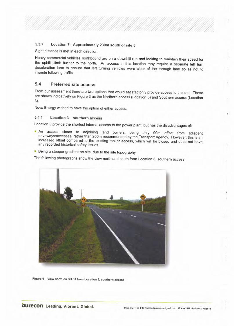
5.3.7 Location 7 - Approximately 230m south of site 5Sight distance is met in each direction.
Heavy commercial vehicles northbound are on a downhill run and looking to maintain their speed forthe uphill climb further to the north. An access in this location may require a separate left turndeceleration lane to ensure that left turning vehicles were clear of the through lane so as not toimpede following traffic.
5.4 Preferred site accessFrom our assessment there are two options that would satisfactorily provide access to the site. Theseare shown indicatively on Figure 3 as the Northern access (Location 5) and Southern access (Location3).
Nova Energy wished to have the option of either access.
5.4.1 Location 3 - southern access
Location 3 provide the shortest internal access to the power plant, but has the disadvantages of:
r An access closer to adjoining land owners, being only 90m offset from adjacentdriveways/accesses, rather than 200m recommended by thJTransport Agency. However, this is anincreased offset compared to the existing tanker acceis, which will oe Ltoseo and does not haveany recorded historical safety issues.
r Being a steeper gradient on site, due to the site topographyThe following photographs show the view north and south from Location 3, southern access.
Figure 6 - View north on SH 31 from Location 3, southern access
qUfeCOn Leading. Vibrant. Gtobat. Prct*12411 57 Fllo Transpod Aissment_rev2.docx 13 May 2016 Revision 2 pag6 i2

Figure 7 - View south on SH 31 from Location 3, southern access
Figure 7 above shows the fence and service poles that would need to be set back behind the line ofsight to achieve the required sight distance.
5.4.2 Location 5 - northern access
Location 5 is likely to be a higher cost access location due to the works required for tree removal buthas the advantages of:
r Adjacent land owners and their dwellings being further away from the proposed access point
r The 200m offset distance to adjacent accesses can be met
r Easier internal access gradients
The following photographs show the view north and south from Location 5.
qUfgCOn Leading. Vibrant. Global. PJot*l 241157 Fllo Transpon Asssment_rev2.dffx 13 May 2016 Revision 2 Page 13

,"r' /' t'' , '
'r/ , ,,1 ., ,,
Figure 8 - View north on SH 31 from Location 5, northern access
The view north from Location 5 shows the trees on the left hand side that should be removed as partof any access works. Also visible, is the existing edge guardrail with sight distance well in excess ofthe requirement.
Figure 9 - View south on SH 31 from Location 5, northern access
The view south from Location 5 shows the sight distance in excess of that required, with a clear viewof vehicles approaching from the 65km/h bend, although no vehicles are in the photograph.
fUfeCOn Leading. Vibrant. Global. Prclecl241157 FlleTransportAssessment_rev2.dofi 13Hay2016 Rovision2 Page14

/
/
,/ ,/,/ ./ ,/ ,/,/ ,/ ,/
5.5 Liaison with NZ Transport Agency
Revision 1 of the Transport Assessment outlining the two preferred options (Location 3 and Location
5) was forwarded to the NZ Transport Agency for their review and comment prior to lodging forconsent.
The Transport Agency advised that their preferred access option from a state highway perspective
was Location 3. ln order to fully understand the reasoning for their decision, representatives from
Nova Energy, Aurecon and Mitchell Partnerships met with the Transport Agency on 13 April 2016.
Transport Agency concerns with Location 5 were:
r SH 31 is generally a winding road, both vertically and horizontally, and the section of highway pastthe northern access at location 5, is in the middle, where faster vehicles currently overtake slowervehicles.
r Those vehicles being passed may not actually be travelling slowly in this section but will have toslow for the road alignment either side of this straight. So overtaking vehicles are very likely to beundertaking this manoeuvre in excess of the 100km/h speed limit, to get past a truck before itdelays the following vehicle at the next hill.
r The Transport Agency undertake regular video recordings of their highways. They advised, that onevery video run, the video vehicle was overtaken on this straight at the proposed northern access atlocation 5.
r Their safety concern is that a left turning driver may exit the access onto the highway and collidewith a southbound overtaking vehicle.
Options for using location 5 for construction access, were discussed, and there was agreement from
all parties that use of the northern access at location 5, for construction and for programmed
maintenance operations would be acceptable to the NZ Transport Agency and that at all other times itwould be closed to traffic. The southern access at location 3 would be used for the day to day low
volume staff movements, but is also acceptable for the construction period and programmed
maintenance operations.
Ben Tobias from the Transport Agency agreed to commence their internal approval process andprovide written confirmation of any required conditions of consent. A copy of Revision 2 of the
Transport Assessment will be provided to the NZ Transport Agency.
5.6 Access intersection form with state highway - Location 3, southernaccess
From the data in section 4 above, the day to day expected number of truck movements per week is 2
(1 in and 1 out) and the expected daily traffic using the site access is 26.
Heavy commercial vehicles with trailers are equivalent to 10 car movements. With 1 truck per week,
assuming they are not scheduled for weekends, 4 movements per day (average) would be added,
totalling 30 (26 + 4) movements per day.
Referencing Table App5B/4 - Accessway types, in SP/M/001, the minimum accessway type isdiagram D. (One or more trucks per week, 1-30 equivalent car movements per day).
OUfeCOn Leading. Vibrant. Global. PrcJecl 2411 57 Filo Transport Asse$ment-rev2.dofi 13 May 2016 Revision 2 Page 15
ADDOXT{AL UT,I}I T(' AIfl H€AI'Y I/Effi.B TO WAIT
iloE:
! ScalrrArir€.nd lGaEysdlng.r-9.0rr 0Ih vdlEh m @M
'f-ls'om (hquq. l.lCV s*)
G.l? to bc rtcE[s.d bd( ftqtr hlrlmy suflicir*drilo. to alqr.w vdlack usitt tlrc .rnYw to5Op dcir c, thc lxjrftsytrffic lanci xliL tic O-cis baiE FmGd adorcd
Figure 10 - Transport Agency Diagram D
As there are a high proportion of heavy commercial vehicles on SH 31, we have provided accessdimensions in accordance with the Austroads requirements for deceleration lanes and tapers for thespeed environment (rather than Diagram D in Figure 10 above). Refer Austroads Guide to RoadDesign Part 44.
A schematic for Location 3 is provided in Appendix C and is shown in Figure 11 below. Two 3.5mtraffic lanes and 3m shoulders have been provided. The tanker access and house access onto SH 31
will be closed and all access will be via the new acoess to the plant.
As traffic volumes are light, there is no requirement for a left tum acceleration facility. Exiting vehicleswill have plenty of opportunity to exit without being in conflict with other vehicles.
Similarly, for right turn entering vehicles, a right turn bay is not warranted and Austroads provisions areshown to allow for right turners to wait on the left hand side of the road for a suitable gap in which toturn. Through traffic can safely pass a stationary vehicle waiting to tum right.
iUfeCOn Leadlng. Vlbrant. Gtobet. PrM.241157 Fllo TranspodAss€ssmonlrEv2.doo( 13 ilay 2016 Revision 2 Pag3 16

Figure ll - Accss schemaiic Location 3 southem accegs
OUfgCOn Lc.dlng. Vlbr.nt. Glob.l. h4d 241157 tu Topdbt.mnt-nf .dd tl I.y 5l! Rdd6 2 Pry 17

,/,/ /,',. , i i'.,', /./ / /..,...././ 2,.r. | .t,r.,, /,,1 , ,,..1', .. ,u, ',,:. ,, / 1,. ., ,,,2: r,: /: ,z,z / /,:::',;.:: 2': ';..., . I , ,, ;. ./., /., .. , ./., .,.,,,. 1.,,., :,':; ;l ; / I I a,/,, 2, /; /;'// /"1;,1,2./ 2,: l; lZ; /';, 2 2,, a,,,,,,
5.7 Access intersection form with state highway - Location 5, northernaccess
ln agreement with the NZ Transport Agency, Location 5 at the northern end will only be used forconstruction traffic and programmed maintenance, under strict access and hazard managementcontrol during these activities. At all other times the access will be closed. During construction andmaintenance operations a temporary traffic management plan (TTMP) will be in place to managethrough traffic and the temporary traffic entering and exiting the site. As all traffic movements will bemanaged under the TTMP, we consider that NZTA diagram C (refer figure 12 below) with the followingalterations is appropriate for this access:
r Radius R is to be 15m
r Access width is to be 7.0m
r Gated access to be the same as the access width at 7.0m and to be 15m minimum from edge ofseal
r Access to be sealed a minimum of 10m from edge of seal
LEGAL BOUilDAf,Y
I ___lt,
CLI!'TRT F NT(IsSARYrmrnrnu- cfumeter - ]7lmh, ffiBll?u,u, Eoctor s€AL
Are to b. (m5tutcd and xrhd'R=9 0m llght whicles onlv)
Gate to b€ recesrd back trom highmy ruflloentdistame tc all* anv vehrcle uiing the dr,my to5toi clcar of ttE highwl raffic liles f,,hrl€ the gat€
15 bernq oparcd or closed
LEGAL BCTNDAiY
Figure 12 - Transport Agency Diagram C, for temporary northern access
iUfeCOn Leading. Vibrant. Globat. Prciecl241157 FileTransportAssessment_rev2.docx 13May2016 Revision2 PagelS

, i /ri/ z /2i7/7,/i7i/tzi z'/i t /i /i/,/ ///t6 Construction Management
6.1 Construction Management Plan
During the development of the Nova Energy generation plant, a construction management plan willneed to be implemented for the internal site development and construction activities to managearriving and departing traffic related to the works.
Preparation of the Construction Management Plan (CMP) is generally prepared by the contactorundertaking the work and is submitted for approval prior to commencement of construction which is acondition imposed by the Road Controlling Authority. As the NZ Transport Agency are the Road
Controlling Authority, their approval of the CMP will be required as well as that of the consentingauthority.
The CMP will address, but not be limited to, the following:
r Site address and consent: Specifies site address, references to consents issued and wherecopies of the consent can be found
r Contact details: Names and 24hour contact details for contractor, site manager, consultants,engineer to contract, STMS etc.
r Responsibilities: Outlines who is responsible for what during the temporary works
r Time frame: Staging, programme of construction activities,
r Description of work activities: What the project entails, methodology of activities
r Site inspections and commissioning: Sets out site meeting schedules, inspections, testing forthe programme of works, commissioning
r Noise, dust and vibration: Sets out requirements for monitoring and control
t 24 hour communication plan/complaint response system: Complaints register, how adjacentlandowners etc will be kept informed and any concerns addressed. The trucking contractor will berequired to provide notification, where necessary, to affected parties along the SH 31 transportroute and may include schools, school bus operators, rural delivery operators etc. All residentswithin the area will be provide with a 24 hours contact phone number to report any issues and willbe encouraged to make contact so that further mitigation solutions can be quickly applied.
r Site signage/notice board: Contains required relevant information for those entering the site and a24hr name and contact number
r Access to Site: Details site access provisions
r Protection of Services: To cover all underground and overhead utility services
r Site Maintenance: To cover materials storage, stockpiles, rubbish removal etc
r Contractors Facilities: Site office, temporary buildings, ablutions
r Sediment Control: Compliance with earthworks consent
r Traffic Management: Routes to be used to and from the site, times of day, days of the week, loadsizes, over dimensional permits, temporary traffic control, temporary speed limits, road controllingauthority approvals
r Health and Safety: Compliance with legislation, identify and record hazards, siterequirements/inductions, policy, manual etc to be submitted for approval prior to work commencing
fUfeCOn Leading. Vibrant. Globat, Prc1ed241157 File TransporlAsssmenlrev2.docx l3 May 2016 Revision 2 Page 19

,, f /,r.i, /: i' / ii /r:i /,/t/,// Z /rr,,i / i r,i i:, i' i i i,' 7 ;,,
r Emergency/contingency plan: Emergency protocol, actions and contingency planning
r Quality Management: May include but is not limited to; resource consents, programme of works,Traffic Management Plan, Health and Safety Plan, Quality Management Plan
6.2 Work phases
To provide an indication of the likely activities traffic movements during construction andcommissioning phases that will need to be considered in the construction management plan, thefollowing information is provided:
6.2.1 Enabling Earthworks
The enabling works will span approximately four months and utilise a team in the order of 8
staff. Traffic movements are estimated as follows:
r 16 daily car movements for site commuter traffic.
r 16 daily truck movements arriving and departing from the site (most machinery will be permanentlylocated at the site).
r 40 truck movements per day for periods when fill is being transported to the site.
6.2.2 Foundations
The preliminary plant foundation and civil works will span approximately three months and will utilise ateam in the order of 16 staff. Traffic movements are estimated as follows:
r 32 daily car movements for site commuter traffic.
r A peak of 100 truck movements for the main foundation concrete placement. There will only be twodays with traffic movements of this order and they will be separated by at least 1 week.
6.2.3 Plant construction/erection
The main plant construction works will span approximately three months per stage and will utilise ateam in the order of 40 staff. Traffic movements are estimated as follows:
r 80 daily car movements for site commuter traffic.
r An average of 12 truck movements per day.
The 12 truck movements per day to and from the site deliver the equipment, special machinery andbuilding materials. The truck movements will vary depending on construction methodology, howeverthere are a few deliveries that will require special attention and are independent of the constructionmethodology, these are:
r Large cranes for construction
r Generation Step Up Transformer x 2 (overweight heavy load)
r Gas Turbine Generators x 2, referenced here in relation to the main generator and turbine. The restof the units will come in multiple smaller deliveries.
r Gas Turbine Stack and Stack Silencer Sections. (Over dimension load).
r Precast concrete panels for building (heavy Loads - may be overweight)
r Steel framework for building (heavy Loads - may be overweight)
qUfeCOn Leading. Vibrant. Global. Prciecl241157 FileTransportAsse$m€nt_rev2.docx'13Uay2016 Revision2 Page20

6.2.4 Commissioning
The commissioning phase will span approximately three months and will utilise a team in the order of20 staff. Traffic movements are estimated as follows:
, 40 daily car movements for site commuter traffic.
OUfeCOn Leading. Vibrant. Global. Prc)ec1241157 FileTransportAssessment_rev2.docx 13May20'16 Revision2 Page21

7 Assessment of effects
7.1 Traffic generation
The day to day traffic generated from the proposed power plant is extremely low and we consider thatthe activity will have a less than minor impact on existing traffic on SH 31, based on our analysis.
7.2 Safety
There is no recorded crash data in the vicinity of either of the proposed access locations. The
accesses are to be designed in accordance with the appropriate Austroads guidelines to provide a
facility for left turning vehicles to move clear of following vehicles.
A widened shoulder is provided in which vehicles can wait to turn right to enter the site if they need to
move out of the path of a following vehicle. As through traffic volumes are low and there are
significant opportunities to exit the site with no approaching or conflicting traffic, neither a right turn bayor a left turn acceleration lane are considered to be warranted.
7.3 Site access
Two site access options have been assessed as appropriate. Following discussion with the NZ
Transport Agency Location 5 at the northern end of the Nova site, is to be used for construction andplant maintenance activities only. Location 3 to at the southern end of the site is to be used for day today operations but is not precluded from being used for construction and plant maintenance activities.
Sight distance requirements can be met at both locations.
7,4 ConstructionmanagementA full construction management plan will form part of the consenting requirements for thisdevelopment to safely and efficiently manage site access. All activities will be managed under thisplan including all temporary traffic management through the site and the access to the site.
qUfeCOn Leading. Vibrant. Global. Prclecl241157 Flle TransportAss$menlrev2.dex '13 ttay 2016 Revision 2 Page 22

,,il,/,i"ii /riri/t/r/Z1 /r/z/i i,t1 /i'r''// /i/,;,
B Conclusions and Recommendations
From a transportation perspective, we consider that the application can be supported with little to no
impact on the surrounding road network for the following reasons:
r The day to day traffic generated from the proposed power plant activity is extremely low and willhave a less than minor impact on existing traffic on SH 31
r Access locations and sight distance requirements meet or exceed the NZ Transport Agencyminimums
r Traffic generated by the Nova Energy Plant will have minimal impact on crash rates and severity
The following recommendations are made with respect to this proposal:
r That this transport assessment report be submitted to the NZ Transport Agency as an affected partyand to enable any specific conditions of consent to be set
r That the new type D access at location 3, southern access, for day to day operations, is installed tocomply with Austroads
r Site access at location 5, northern access, for construction and maintenance operations to beconstructed in accordance with NZ Transport Agency Diagram C with the following adjustments:
- Radius R is to be 15m
- Access width is to be 7.0m
- Gated access to be the same as the access width at 7.0m and to be 15m minimum from edge ofseal
- Access to be sealed a minimum of 10m from edge of seal
r That the construction management plan form part of the consenting requirements
r That the site access at location 3 be generally in accordance with Figure 12
r Detailed construction drawings of the proposed accesses at Location 3 and 5 be submitted to theNZ Transport Agency for approval prior to construction
r That approved TTMP (active and inactive - as appropriate) be in place for the use of the access atLocation 5, northern access, for maintenance operations
qUfeCOn Leading. Vibrant. Global. Prciec7241157 FileTransportAssessment_rev2.docx 13May20't6 Revision2 Page23


I
T
I

aurecon n6vam$lq|w
ffi@r
,afltt

coded crash repcrt, run on 23 11 201s, Pag€ t
Firststreet crash DavTime I ra.rorsandRoles I o J c M s rotal ! c
I Nxnber
I
I A rs for vehlcl€ t
i
AEr I I
DD/W/YYYY DDD g: T T ::I I
rr/o/11 4rr
2a1136.61 2t/at /2otr
r1lo/rr.44s 2at2att12 oltar/2at2
.ar2att31 22/a1/2a12
2at2at32e )2/a3/2ar2 rhu uloo rarsl
r1/o11r r3r 2at2a2211 13/a./2aa2
tt/o/11.44. 2at2as142 26/12/2aD {ed 1611 !FcN1.
r1l0/11 4:r 20123a434 22/a2/2av
31/0/r.66r ,o15r}333 orlorlro1s

Plain Engl ish report, run on 23-Nov-2o15 Page 1
J1 /O/8.083
)1/O/B O93
31/O/A 293
J1 /O/9.543
x1/o/9.663
)1/O/9.663
31 /O/10,963
)1/O/11.113
31/O/11.113
D Secodd street Crash Day Iime Description of Events Road Natural Ieather Junction CntrlLrgnt F5U
AE I
TRNDDIW/YWY DDD HHW IENV - Environrental factors)
suvl too far left/rroht, lostcontrol *hen turnrnq- Fatlque(drowsy. t i red. fel I as leep)
TRUC(] ioo fast enterino corner.rost contror when tur6rio ENv:road sl,pp€ry (ra,n). he;vy ra,n
CARI too fast entering corner lostcontrol when turnino.overseas/rror6nt driver far led ioadiust to N, ro6d rules and roadconditions ENv: road sl ippery(ra I n)
SUvl too fast enterlno corner, lostcootrol when turnrnq -ENV road
TRUCXI too fast enterisq corner f,etlost control then turn,ng,lnattentive TRUCX2 lost control,suddenly swerved to avoid vehrcle
TRUCKI roo far reff/rrohr. losr *ercontror when turn'ng Fatrgue(drowsv, tired, fel I asleep) E(v.road sl ipPery (rarn)TRUCkI lost conrrol ENV. fog or lel
CAR1 roo fast enlerrnq corner. losl telcontrol ahen turninq evadi.qerforcement. stolen vehic le
CAR1 lost .ontrol *hen turnrnq. wFrdriver over reacted ENV: road
CARI lost contror men turnrnq. ner Wet Wercastdrrver shoued rnexper rence EW
VAN1 too f6sr enter rnq Lornpr lost Wet Overcastcontrol 6en turnrno EW: roadslrppery (rarn)
CARI too fast enterinq corner, lo\l lel Overc6tcontrol ,hen turnrnq, new drrvershosed rnerperrence-
SUVI lost control *h.n turnrng tret
TRUCXI too fast enterrno corner f,ellost cohtrol rhen turnr;q Eflv
CAR1 too fast enterrng corne., nei orydriver shored inexperience. stolen
BUSI lost control *hen rurnrno IFI tuercast Lloht Unhnom N/Asudoenlv braked ENV' road slippery Rsin(ra i n)
vNl lost contror under heaw Wet OvFrcas! vrsl Unkrown fl/Abrakrnq ENV sl 'ppery. foq br nrstCAR1 too last enter rno corner. tost f,et Overcast Lroht Un(no{n (/A..ntrol *hEn lurnino -FNv road Ra;nslippe.y (rain)
Sright F ine unknown N/A
Dark Heavy Unknown N/A
wercGt Lignt unhNn N/a
W€r** Light Uilrcm N/A
OwrcEt Light hkmffi N/a
Dark Llgm UilmM N/A t
o8rk Mlst Unknown N/A 1
oark F ne Unknown N/A 1
L ght hhwn N/A
Heary hhom N/A
LigN khoM N/A
Fine UnknoM N/A
Dark Beavy Unknown il/A 2
Dark Aeavy Unknosn N/A
Twi I ight F ne Unknom N/A 2
l50X WAIKUM ROAD 201330311 28/01/2013 Mon 1515 SUVI SBD on SH 31 lost controlturning right, suvl hit Cl iff Bankon right hand berd
16N flAIKURA RoaD 201535439 10106/2015 f,ed 2303 TRUCK1 S8D on SB 31 lost conlrolturninq left, TRUCK1 hit Fence
36N WAIKUU RoAD 201230306 15/02/2012 Ued 1744 CARI SBD on sH 31 lost controlturniog left, CAR1 hit fence
1650N W |(URA ROAD 2012011A7 22/01/2012 Sun 1350 SUVI NBD on SH 31 lost controlwhl le overtaklng, SUV1 hit Fence
ilon 1308 TRUCN1 NBD on SH 31 lost controlturnlnq leFt, TRUC(1 hlt Fence
ory
201201329 22/03/2012 Thu 01@ TRUCKI SB0 on SH 31 lost controllurnrnq , lqht. TRUC(l hlt FenceDrtcl on r ight hand bend
201@3741 14/O5/2o1O Fri 0153 TRUC(1 SBD on SH 31 lost control;went off road to right, TRUCX] hitFence
2O12o1O15 1o/O1/?o1? Tue 0527 CAR1 SBD on SH 31 lost controlturning r rghl CARI h't Drtch onr rqht hand bend
201136557 21/07/2011 Thu 2125 CAR1 SaD on SH 31 lost controlturning right, CAR! went tuer SankTree on right hand bend
l1/o/11 1!5 5ms (A*A mAD ?01134610 25/01/2011 Moh 1425 CAR1 NBD on SH 31 lost controlturning left, CAR1 hit Guard Rai I
201231412 o3/o1/2o12 Tue 1331 VN1 NgD on SH 31 lost controlturning left, VANI hit Guard &i I
201039438 03/09/2010 Fri 1330 cARl NBo on SH 3l lost controlturning right, CAR1 hit Guard Rai I
on right hand bend
201202277 13/05/2012 Sun 1934 SUV1 sBD on sH 31 lost controlturnin9 left
201133212 O9/O3/2O11 led 2042 TRUC(1 SBD on SH 31 lost controrturning left
)1/O/11.14s
31/O/11 -363
)1/O/11.343
31/O/11.413
t1/o/11.411
31/O/11.411
tl/o/11.423
19@S T IH IROA ROAD
6@5 TIHIRU ROAD
45OS TIHIROA ROAD
45OS TIHI ROA ROAD
5@S Sf,A rcAD
2@S TIHIRG ROAD
1a0s TtHlRm RoAo
15OS TIHIRG ROAD
15OS TIHIROA ROAO
15OS IIHIROA ROAO
14OS TIHiROA ROAO
31/0/11 t17 1505 rtHlROA ROAn 201N59A2 15/12/2010 *ed 0520 CAR1 SBD on SH 31 lost controlturnrna lefr CAR1 hit Cl'rr tunkTraffia S,gn
201301059 14/01/2013 ilon 1035 BUSI SBD on SH 31 lost controlturn ing left, BUSI h it Cl iff Bank
?01115510 31/05/2011 Tue o8l5 VAN1 SBD on Sfl 31 lost controlturn ing left, VAN1 hit Cl iff a6nk
2O12XUX1 2?/O2/?o12 wed o93o CAR1 SBD on SA 31 lost controllurnrnq left. CARr hrt Cl rff 8ank.lraffra Srqn
Combined Grash List Detail report - Run on: 23 Nov 2015
lnjury and non-injury crashes
Page 1 of 2Crash List: Kawhia Rd Otorohanga
Overall Crash StatisticsCrash Severity Number Social cost ($m)
Overall Casualty Statisticslnjury Severity Number % all casualties
FatalSerious
Minor lnjuryNon-injury
Grash NumbersYear Fatal Serious Minor
DeathSerious lnjury
Minor lnjury
Casualty NumbersYear Fatal
0
1
1',!
17
0
3
3859
0
0.56
't.02
0.54
0
2
23
0
I92
10025
10029 2.12
Non-inj Serious Minor
201 02011201220132015
TOTAL
5
0
5
1
0
0
0
I0
0
00
0
0
0
2
7
42
2
't5
0
7,|
0
201020't1201220132015
TOTAL
00
0
0
0
0
0
2
0
0
1711
Percent 0
Note: Last 5 years of crashes shown38 Percent 0
Note: Last 5 years of casualties shown
Crash Type and Gause StatisticsGrash Type All crashes % All crashes
Driver and Vehicle StatisticsNote: Driver information is not computerised for non-injury crashes
Drivers at fault or part fault in injury crashesAge Male Yo Female Yo Total %
Overtaking CrashesStraight Road Lost Control/Head On
Bend - Lost Control/Head On
Rear End/ObstructionCrossing/TurningPedestrian Crashes
Miscellaneous Crashes
TOTAL
Crash factors (*)
1
1
270
0
0
0
0
0
0
0
0
0
00
0
0
0
0
0
0
0
0
0
2
1
2
2
2
0
0
18
18
I18
18
180
3
3
93
0
0
0
0
15-1920-2425-2930-39
40-4950-5960-697O+
00218218192 ',18
21821800
29
All crashes
100
% All crashes
Too fastFailed Keep Leftlncorrect Lane/posnPoor handlingPoor ObservationPoor judgementFatigueVehicle factorsRoad factorsWeatherOther
TOTALCrashes with a:
Driver factorEnvironmental factor
'16
1
2
241
63
1
15
124
553
7
833
2110
3
52
4',!
14
TOTAL 11 100 0 0
Drivers at fault or part fault in injury crashesLicence Male Female Total
100
o/o
11
Full
Learner
RestrictedNever licensedDisqualifiedOverseas
ExpiredOther/Unknown
TOTAL 120
I0
0
1
0
0
1
1
0
0
0
0
0
0
0
0
I0
0
1
0
0
1
1
75
0
0
8
0
0
8
8
(.) factors are counted once against a crash - ie two fatigueddrivers count as one fatigue crash factor.
Note: Driver/vehicle factors are not available for non-injury crashesfor Northland, Auckland, Waikato and Bay of Plenty before 2007.This will influence numbers and percentages.
Note: % represents the % of crashes in which the cause factor appears
Number of parties in crash All crashes % All crashes
100
Vehicles involved in injury crashesNo.of vehicles o/o lnjury crashes
SUVBusCarlStn WagonTruckVan Or Utility
TOTALNote: % represents the % of injury crashes in which the vehicle
appears
292
18293
125327
31
7
3
1
25I
4225
8
15
Single party
Multiple party
TOTAL
24
5
8317
100
'108

Combined Crash List Detail report - Run on: 23 Nov 2015
lnjury and non-injury crashes
Page 2 of 2
Crash List: Kawhia Rd Otorohanga
Road Environment StatisticsRoad Type Local o/o State
road highway
Total Yo
Time Period StatisticsDay/Period All crashes % All crashes
WeekdayWeekend
TOTAL
254
8614Urban
Open Road
TOTAL
Conditions
0
0
0
29
0
100
0
0
0
29
0
100 100
29 100
Conditions Injury Non-injury Total To
LighVovercast 4 11 15 52
Dark/twilight I 61448TOTAL 12 17
Dayl 0000- 0300- 0600- 0900- 1200- 1500- 1800- 2100-Period 0259 0559 0859 1159 1459 1759 2059 2400 Total
Weekday222255'l 524Weekend00002O'l 03TOTA12222752527Note: Weekend runs from 6 pm on Friday to 6 am on Monday
Dayl 0000- 0300- 0600- 0900- 1200- 1500- 1800- 2100-Period 0259 0559 085S 1159 1459 1759 2059 2400 Total
MonTueWed
ThuFri
SatSun
TOTA122227s2527
Month lnjury % Non-injury o/o Total Yo
10029
29 100
lnjury Non-injury Total Yo
Dry
Wetlce/snow
TOTAL
1
11
0
1
16
0
2
270
7
930
I ntersection/mid-block
17 100
All crashes % All crashes
12 29
lntersectionMidblock
TOTAL
Objects Struck lnjurycrashes
Yo Non-injurycrashes
029
94
Yo
't683
0
1000001220050110100030'f0102127'r0'r000013100021026000010001000010102
100
%
Crashes w/obj.struck 10
Object Struck lnjurycrashes
% Non-injurycrashes
Cliff BankOver BankFenceGuard Rail
Traffic SignTreeDitch
TOTAL
5I3
0
2
0
3
42I
250
170
25
I,|
3
421
0
40
1
0
3
0
1
1
0
0
0
2
2418
12
6
12
6
12
0
6
0
0
6
476
182412
6
0
8283 10
3 10
3340382
14 19
Note: % represents the % of crashes in which the object is struck
JanFebMarApr
MayJunJulAug
sepOctNovDec
TOTAL
13517133 10
131300003 10
0
250
8
I0
0
0
17
1
2
1
2
0,|
0
0
1
12 100 17 '100 29 100

Plaln Engl ish repoft, run on 23 Nov 2Or5 Page 2
First Street 0 Second street Crash Date Day Time Descriptlon of Events Crash Factors Rosd Natural Weath€r Junction cntrl Tot ltjI or lanha.k Nunber Lighr F S M
AE I0ist6nce R Do/m/YWY DDD HHil (ENv = Envtronrentat factors) T R N
X1/O/11.423 14oS TIHIRU ROAD 2o1o3@14 21/O5/2O1o Frl 13oo CAR1 SBD on SH 31 lost control CAR1 lost control Sen turnino f,et tuercast Heaw Unknomturnins rert, cARl hit criff tunk !i0l J,::L':::l'
sen turninq f,et werc*t Heavv u*rcm N/A
31/0/11.433 l3OS TIHIRU RO D 20123630 19/03/2012 Mon 1610 CAR1 NBD on $ 31 lost control CAR1 lost control due to vehicle Wet Wercast Heavy Uhknom N/Atur.ing right, CAR1 hit Cl ifr Bank fault. puncture or blosout EWj Rainon right hand bend heary raitr
31/0/11.413 12oS TIHIRU ROAo 2o133m45 16/01/2013 Sed 23@ CAR1 SBD on SH 31 lost control CAR1 roo fast enterrnq corner. rost Wet oark Light Unknom N/Aturni^g left, CAR1 hrt Cl rff &nk control rhen turnrng, n* dr'ver Rain
showed rnexDerlence ENV roadsl rppery Irarn)
31/0'11,445 2@S (AIA mAO ?o12o51a? 26/12/2012 f,ed 1611 CAR1 NBD on SA 31 rost contror on CAR1 too fast enterrnq corner. Iost let Wercast Heavy Unknom N?A 2 1
curve and nlr CAR2 head on. CAR1 control *hetr turnrnq -EW: heavy Rarn_hit Cliff Baf,k, Trafflc Slqn rain
3l/o/I1.445 2mS UxA mAo 20120117? o7/O1/2O12 Sat 1251 CAR1 SBD on 5H 3t swinorno srde hrr CAR1 roo fasr ente, rno corner, Wer Wercast Lroht Unknom N/A 1
CAR2 head on, CARI hit-CrTff &nk, swno irde on bend, fStroue RaTnCAR2 h,t Drtch (dro*sy. trred. fet r asraep) ENV
road sl rppery (rain)31/0/11,153 11oS TlNlRm ROAD 201139155 30/12/2011 Fri 1515 CARI NBD on SA 3l lost control CAR1 too fsst €nterlnq corner. lost Wet &erc€st Heavy Unknom N/A
turnlng rlght. CARI hrt Guard Rar I control *hen tu.nrnq EW' heavy Ralnon rtsit nEni oeno
31/0111.163 1@S TIHIROA R0A0 2o11312os 2a/O1/2O11 Frl 2130 CAR1 SBD on SH 31 lost control CAR1 lost control due to road Wet Oark Lloht Unknom N/Alurnlnq left, CARI hrt Cl rff B6nk, condrtrons ENV: road obstructed RaInlrafrrz Srgn (flood qaters)
31/0/11,463 1@S TlHlR$ RoAD 201@2A64 2O/O5/2O11 Ih! TRUCXI SB0 on SH 3! rost contror TRUCK1 roo f6st enterrnE corner, f,et Oark Uist Unknofr N/A 1rurnlng left, TRUCK1 hit CI iff Bank lost cont.ol ,hen tu.niig EW: rog
X1/O/11.1A3 1mS TlHlRm ROAD 201133365 22/O1/?O11 Sat CARr SBD on SH 31 lost cof,trol CiRl lost control due to road *et Dark Heavv Unknown N/Aturnrng le/t. CAR1 hir Cl 'ff Bank condrtrons EW: heavy ra'n Rain-
31/0/11.463 1mS TIHIROA ROAD 2Ol@4!04 OslOal2O1O Ihu 0640 SUVr SB0 on St 31 lost control SUVI $o fast enlerrnq corne., lost f,et Darkturn,ng l.fr. SUV1 spnl Over Bank control when turning -EW sl rppery
31/0/11.461 1@S TIHIRU ROAD 2O1@41O7 16/01/2010 tri 2130 CAR1 SB0 on SH 31 lost control on CAR1 lost control fren turn.no let Dark Lroht Unknoun N/A 6curve a4d h,r vat2 head on EW: road sl'ppFry (r6rn) - Rain
T
T
II

II
I
NOTE
DIWNSM AS PER AUSTROADS
MT 4A SMSEO AI,ID I
uNsrGNAlsEotNrERsEcrroNs I
reconliiulffilllfiFEliffirir.:::,.'
-8-S-lF-E-?

qurecon
Aurecon New Zealand LimitedGround Level247 Cameron RoadTauranga 31 10
POBox2292Tauranga 3140New Zealand
T +64 7 578 6183F +64 7 5786143E [email protected]
Aurecon o,ffices are located in:Angola, Australia, Botswana, Chile, China,Ethiopia, Ghana, Hong Kong, lndonesia,Lesotho, Libya, Malawi, Mozambique,Namibia, New Zealand, Nigeria,Philippines, Qatar, Singapore, South Africa,Swaziland, Tanzania, Thailand, Uganda,United Arab Emirates, Vietnam, Zimbabwe.

TERRESTRIAL ECOLOGIGAL VALUESOF THE PROPOSED WAIKATO POWER
PLANT SITE
Prepared for Nova Energy
mitchel!'irrll" r ri
December 2015

Executive Summary
Nova Energy is investigating the development of a nominal 300 Megawatt (MW) opencycle gas turbine power plant approximately 10 km north of Otorohanga to be knownas the Waikato Power Plant. The proposed Waikato Power Plant site is located offState Highway 31, Kawhia Road and occupies approximately five hectares within an 80hectare working dairy farm.
Nova Energy is in the process of gathering information to support an application forresource consents and a Notice of Requirement to allow the construction of theproposed power plant and associated transmission line. Mitchell Partnerships Limitedwas retained to undertake a site visit and review terrestrial ecology informationpertaining to both the existing environment and the conceptual project description forthe proposed construction.
The vegetation that would be affected by the proposal comprises exotic pasture.Although vegetation there includes indigenous elements as a minor component, it isnot considered predominantly indigenous.
The only species of conservation concern known to be present is the New Zealandpipit. Pipits are species of open rough pasture and the presence of power lines withinthe landscape is very unlikely to adversely affect pipit populations. There are nosignificant issues relating to terrestrial ecology that might affect the ability of the projectas proposed to achieve consent.
mitcheltoPartnershiPs

1.
2.
3.
I
TABLE OF CONTENTS
INTRODUCTION
ECOLOGICAL CONTEXT
SITE DESCRIPTION
3.1 Vegetation3.2 Fauna
3.2.1 Avifauna3.2.2 Herpetofauna
CONCLUSION
REFERENCES
LIST OF PLATES
The Site of the proposed Waikato Power Plant.
Riparian vegetation near the Site.
Small shrubland remnants near the location of the proposed WaikatoPower Plant.
Vegetation in the vicinity of the proposed transmission route.
Vegetation near the existing transmission line southwest of the Site.
mitchettopartnsships
Page
1
2
2
27
77
7
8
4.
5.
4:
5:
1:
2:
3:
3
4
5
6
6

1
1. INTRODUGTION
Nova Energy ('Nova') is investigating the development of a nominal 300 Megawatt(MW) open cycle gas turbine power plant north of Otorohanga to be known as theWaikato Power Plant. The proposed site of the Waikato Power Plant ('the Site') islocated off State Highway 31, Kawhia Road, approximately 10 km north of Otorohanga.
The Site occupies approximately five hectares within an 80 hectare working dairy farmowned by Nova Energy and accessed from State Highway 31, Kawhia Rd, either viathe existing farm entrance or via a new entrance to be established at the northern endof the farm.
The key features of the proposed development include:
o Earthworks and civil construction including site levelling and pouring ofconcrete for foundations of heavy equipment, buildings, tanks andtransformers.
o Qonstruction of new access roads.
. lnstallation of gas turbines and the associated emissions of combustionproducts and operational noise.
o Qonstruction of water treatment facilities requiring a water supply andwastewater containment facilities.
. lnstallation of fire protection systems including water storage.
o Construction of plant room, workshop, staff amenities and control roombuildings.
o provision of gas reception and pipeline facilities.
o Qonstruction of high voltage substation and transmission lines for powerexport to the national grid. The development will have a dedicated 220 kVpower transmission spur line that will allow electricity production from theSite to be exported into the National Grid. The spur line will connect to theNational Grid approximately 500 m west of the Site.
Nova is in the process of gathering information to support an application for resourceconsents and a Notice of Requirement to allow the construction of the proposed powerplant and associated transmission lines. Mitchell Partnerships Limited was retained toundertake a site visit and review terrestrial ecology information pertaining to both theexisting environment at the Site and the conceptual project description for the proposedconstruction. The aim of this task was to identify any significant consenting risks of theconceptual project design with respect to terrestrial ecological matters. A second aimwas to identify any information gaps that could be addressed prior to the application forconsents being lodged.
This report is based on a day-long visit to the site on 25 November 2015 with Mr NickCarter of Freshwater Solutions Limited, during which the Site and surrounds wasexplored by vehicle and on foot. Publically available information about the Site and asearch of the Department of Conservation's Herpetofauna Database were also used toinform this report.
mitchellopadnerships

2
This report consists of five sections as follows:
Section 1 (this lntroduction) describes the proposal and the objectives of this report.
Section 2 describes the ecological context of the site and the values of the EcologicalDistrict within which it is located.
Section 3 describes the vegetation and fauna present at the site.
Section 4 provides our conclusions with respect to any effects on terrestrial ecologicalvalues.
Section 5 provides the references used in compiling this report.
2. ECOLOGICAL CONTEXT
The Site is located within the Waipa Ecological District and Waikato Ecological Region(McEwen 1987). The Site is located near the boundary with the adjoining WaitomoEcological District, which is part of the King Country Ecological Region.
The Waipa Ecological District was defined on the basis of topography and geology andcomprises an inland basin comprising mostly Pleistocene pumiceous alluvium andconglomerate with small areas of peat. The Waipa Ecological District is approximatelytriangular in shape with the northern boundary located north of Te Awamutu extendingfrom the eastern foothills of Pirongia, to the western foothills of Maungatautari atPuahue. The eastern boundary runs south to include Te Kuiti (at the apex of thetriangle), then curves north, lying west of Otorohanga and Tihiroa, and continuingtowards Pirongia. The Waipa Ecological District is approximately 69,634 ha in size andthe district experiences warm, humid summers, relatively mild winters and an annualrainfall of 1 ,100 - 1,500 mm (McEwen 1987, Deichmann and Kessels 2013).
Most of the district has been converted to farmland or residential areas with onlyaround 1 % of indigenous forest, <1oh of shrubland and < 0.5% of wetlands remainingwithin the district (Leathwick et al., 1995). The nationally vulnerable long-tailed bat(Chalinolobus tuberculafus) has been recorded in the north of the district, near Pirongiaand in Kihikihi township (Deichmann and Kessels 2013). The goldstripe gecko(Woodworthia chrysosireflcus) and Auckland green gecko (Naultinus e/egans) havebeen recorded at Kakepuku reserve, with the Auckland green gecko also recordednear Parawera township (Deichmann and Kessels 2013). Within the district theforested peak of Kakepuku is the largest area of intact indigenous vegetation andprovides habitat for several species of conservation interest.
3. SITE DESCRIPTION
3.1 Vegetation
The farm is bisected by tributaries of the Ongaruhe Stream, a tributary of the WaipaRiver. The stream is fenced throughout most of its length through the farm and it iswithin the generally narrow riparian margin that most native species are located. The
mitchetl'partnerships

Site itself, shown in Plate 1, comprisesstream or drain drains part of the Site.
3
higher production pasture. A small unfenced
Plate 1: The Site of the proposed Waikato Power Plant.
The occasional native species present within the riparian vegetation included sedgessuch as Carex geminata, C. virgata and C. subdola and ferns such as ring fern (Paesiascaberula), kiokio (Blechnum novae-zelandiae), Diplazium australe and silver fern(Cyathea dealbata). Wiwi (Juncus edgariae) was also occasionally encountered withinthe riparian vegetation. An example of the riparian vegetation is shown in Plate 2. Alist of plant species encountered during the site visit is provided in Appendix 1.
mitchellopartnershrps

;.::lrl'[
Plate 2: Riparian vegetation near the Site.
Within the Site itself the higher producing pasture included perennial rye (Lolium
perenne) and white clover (Trifotium repens) with occasional pasture weeds, such as'broad-leaved
dock (Rumex obtusifotius), Carex divulsa, speanruort (Ranunculus
flammuta), catchfly (S/ene gatlica) creeping buttercup (Ranunculus repens) and broad-
leaved flea bane (Conyza sumatrensrs), particularly in damper or pugged areas.
There were several very small remnants of native vegetation on the steeper slopes
near the site. The canopy of these remnants was dominated by mahoe (Melicytus
ramiflorus) with occasional mamaku (Cyathea medullaris) and wheki (Dicksonia
squarrosai4, but there was no real indigenous understorey, with grazing having removed
any native species leaving grass, litter and bare earth as the predominant ground
cover. An example of such remnants is shown in Plate 3.
mitchetl'partneisf IJS

Plate 3: Small shrubland remnants near the location of the proposed WaikatoPower Plant.
The vegetation along the proposed transmission route was similar with a mixture ofexotic pasture species and occasional isolated mahoe trees and exotic trees such aswillow (Sa/x fragilis) and poplar (Poputus yunnanensis). Examples of vegetation alongthe transmission route are shown in Plates 4 and 5.
mitcheltoPartnerShrPS

Plate 4: Vegetation in the vicinity of the proposed transmission route.
Plate 5: Vegetation near the existing transmission line southwest of the Site.
mitchello

3.2 Fauna
3.2.1 Avifauna
Birds seen or heard during the site visit include exotic species and common nativespecies typical of rural areas. A list of bird species seen or heard is provided inAppendix 2.
The only species of conservation interest recorded was the New Zealand pipit (Anthusnovaeseelandiae). Pipits have a conservation threat ranking of "At Risk (Declining)"(Robertson et a\.2012). A single pipit was seen using rough pasture on a steeper partof the property near the proposed location of the transmission line.
Pipits are commonly found in farmland, coastal, wetland and forested habitats, but areabsent from much of the Auckland and Waikato Regions and are only sparsely presentwhere they do occur. Typically pipits occur in the rough pasture areas of the steeperhill country surrounding the more intensively developed parts of the Waikato Regionsuch as that found in the Hapuakohe and Raglan Ecological Districts (Robertson ef a/.
2007, G. Bramley, pers. obs.). Pipits are considerably more common along the westcoast of those regions, and are known from the areas immediately north of Auckland in
reasonable numbers (Robertson et al. 2007). They are absent from the moreintensively farmed or inhabited areas, including the Hamilton Basin and Auckland city(Robertson et al. 2007), because of a lack of suitable habitat. The Waikato is notregarded as a stronghold area for pipit populations. Nationally New Zealand pipits aremore common through the central North lsland (south of Taupo), Northland, East Capeand throughout most of the South lsland (Robertson et al. 2007) and less common orabsent from the more developed Auckland, Waikato, Manawatu, Canterbury andSouthland regions.
3.2.2 Herpetofauna
A search of the Department of Conservation's Herpetofauna Databasel revealedrecords of only Pacific gecko (Dactylocnemis pacificus) and Auckland green (orelegant) gecko within 5 km of the Site:. The Pacific gecko is nocturnal and occupiesretreats beneath loose bark or knot holes in forest, crevices in clay banks or rockyareas by day and forages in forest, shrubland or grassland at night. The elegant geckooccupies forest and most commonly manuka and kanuka shrubland. There is nosuitable habitat for either species either at the Site or along the proposed transmissionline route.
4. CONCLUSION
The Otorohanga District Plan (2014) includes Criteria for Determining the Significanceof lndigenous Vegetation as Appendix 2. The criteria are not relevant to vegetation atthe Site because although vegetation there includes indigenous elements as a minorcomponent, it is not considered predominantly indigenous. On that basis none of thevegetation at the site would be considered significant with respect to Section 6(c) of theResource Management Act (1991).
Database accessed 17 December 201 5. B Kappers, Department of Conservation, pers
comm.
mitchellopannershrps

B
The only species of conservation concern known to be present is the New Zealandpipit. As discussed above, pipits are species of open rough pasture and the presenceof power lines within the landscape is very unlikely to adversely affect pipit populations.The Power Plant itself would be located on high producing pasture which is notpreferred pipit habitat. The presence of abundant rough pasture habitats in the vicinitywhich would remain unaffected further supports the conclusion that no adverse effectson pipits should be anticipated.
There are no significant issues relating to terrestrial ecology that might affect the abilityof the project (including transmission lines) as proposed to achieve consent. Thepaucity of indigenous species and habitats in the wider area means that any effects onterrestrial ecology would be limited to provision of ecological services such as sedimentcontrol. Provided best practice is followed with respect to construction, these effectsare expected to be less than minor.
No further information is required to assess the ecological values of the Site.
5. REFERENCES
Deichmann, B. and Kessels, G.H.A. 2013. Significant natural areas of the WaipaDistrict: terrestrial and wetland systems. Waikato Regional Council TechnicalReport 2013116. Kessels and Associates Limited, Hamilton East. 48 pp +appendices.
McEwen, W.M. 1987. Ecological Regions and Districts of New Zealand. Third revisededition in four 1:500 000 Maps. New Zealand Biological Resources Centre,Department of Conservation, Wellington.
Leathwick JR, Clarkson BD, Whaley PT 1995. Vegetation of the Waikato Region:current and historical perspectives. Landcare Research contract reportLC9596/022, prepared for Waikato Regional Council. Hamilton,ManaakiWhenua - Landcare Research (DOCS# 1485592).
Robertson, C.J.R., Hyvdnen, P., Fraser, M.J. and Pickard, C.R. 2007. Atlas of BirdDistribution in New Zealand 1999-2004. The Ornithological Society of NewZealand lncorporated. Wellington, New Zealand.533 pp.
Robertson, H.A., Dowding, J.E., Elliott, G.P., Hitchmough, R.A., Miskelly, C.M.,O'Donnell, C.F.J., Powlesland, R.G., Sagar, P.M., Scofield, R.P., Taylor, G.A.2013: Conservation status of New Zealand birds, 2012. New Zealand ThreatClassification Series 4. Department of Conservation, Wellington.22 pp.
mitcheltopartnershrps

Appendix 1
Plant Species Encountered

Plant Species Encountered
Latin Name Common NameMonocots (qrasses and sedqes)Anthoxanth um odoratum* Sweet vernalBromus willdenowil Prairie orassCarex divulsa" Grev sedqeCarex qeminate RautahiCarex subdolaCarex viroate Swamo sedoeCortaderia selloana* PampasCritesion murinum* Barlev qrass
Cvnosurus crisfafus* Crested doq's tailCvoerus ustulatus Umbrella sedqeDactvlis olomerata* CocksfootHolcus lanatus* Yorkshire foo/so/epls proliferaJuncus canadensis"Juncus edoariae WiwiPoa annua* Annual ooaPhormium tenax Harakeke. flaxTvpha orientalis Raupo
Dicot herbs and lianesAchillea millefolium* YarrowApium nodiflorum* Water celeryBellis perennis* Lawn daisvBidens frondosa* Beqoars'ticksBrassica rapa var. oleifera* Wild turnioCalvsteqia silvatica* Great bindweedCarduus nutans* Noddinq thistleCirsium arvense* Californian thistleCirsium vuloare* Scotch thistleConvza sumatrensis* Broad-leaved flea baneDioitalis DurDurea* FoxoloveErichtete s val eria n ifol i a* Brazilian fireweedGalium aoarine* CleaversGeranium molle* Doves foot cranesbillHvpochoeris radicata* HawkbitJacobaea vuloaris* RaqwortLemna disperma DuckweedLudwioia oalustris* Water ourslaneMvosotis laxa* Water foroet-me-notPersicaria hvdropipef Water oeooerPlantaoo lanceolata* Na rrow-leaved planta inPlantaoo maior' Broad-leaved plantainPotamooeton crisous* Curlv oondweedPrunella vuloaris* SelfhealRanunculus flammula* SoeanruortRanunculus repens* Creepinq buttercupRanunculus sardous* Hairv buttercuoRubus fruticosus aoo. BlackberryRumex acetosella* Sheeo's sorrell

Latin Name Gommon NameRumex obtusifolius* Broad-leaved dockS/ene qallica* CatchflySoliva sess/rs* Onehunoa weedTaraxacum officinale* DandelionTrifolium repens* White cloverTrifolium pratense* Red cloverVeronica arvensis* Field soeedwell
FernsBle ch n u m novae-ze I a nd i ae KiokioCvathea dealbata Silver fernDicksonia fibrosa Wheki-oonoaDicksonia squarrosa WhekiDiplazium australPaesia scaberula Rino fernPvrrosi a el ae aq n ifol i a Leather-leaf fern
Woodv trees. shrubs and lianesAcer pseudoplanatus* SvcamoreBerberis olaucocarDa* BarberrvC h am ae cvp ari s I awso ni an a* Lawson's cvoressEucalvotus cinerea*Levcesteria formosa* Himalavan honevsuckleLiqustrum slnensls* Chinese privetMelicvtus ramiflorus MahoePopulus vunnanensis* Yunnan ooplarPrunus x domestica Plum treeRosa rubioinosa* Brier roseSalix fraqilis" Crack willowUlex europaeus* Gorse

Appendix 2
Bird Species Recorded

Bird Species Recorded
Latin name Common NameAcridotheres frisfis* MvnaAnas platvrhvnchos* MallardAnth u s novae seel and i ae New Zealand oioitCarduelis carduelis* GoldfinchCircus approximans HarrierCracticus tibicen* Australian maooieEoretta novaehol I and iae White-faced heronEmberiza citrinella* YellowhammerHirundo neoxena neoxena Welcome swallowPasser domesticus* House sparrowPhasianus colchicus* PheasantPorphvrio m el anotu s m el a notu s PukekoRhipidura fuliginosa FantailSfurnus vuloaris* StarlinoTadorna varieqata Paradise shelduck, putanoitanqiTodiramphus sancfus vaoan s Kotare, New Zealand kinqfisherTurdus merula* BlackbirdZosteroos lateralis Waxeve. silvereve

aAurecon New Zealand Limited I +64 7 834 1565Level 6 KPMG Centre F +647 834352785 Alexandra Street E [email protected] 3240 w aurecongroup.com
PO Box 487Hamilton 3240New Zealand
qurecon
13 Novembet 2015
Jeremy MillerProject ManagerNova EnergyLevel 15 95 Customhouse QuayWellington
Dear Jeremy
RE: Proposed Nova Energy Waikato 300 MW Power Plant - Preliminary GeotechnicalAppraisal Report
1 Project background
Aurecon have been engaged by Nova Energy (the Client) to provide geotechnical consultancyservices to support preliminary planning and concept design for the proposed 300 MW Waikato PowerPlant, located approximately 500m to the west of Kawhia Road, SH39, Otorohanga (the 'site').
The purpose of this report is to provide a 'high level' site-wide preliminary geotechnical appraisal tosupport master planning and conceptual design of options for the proposed development. The keyelements assessed by the preliminary geotechnical appraisal include:
. The power plant building location
r Access Roads A & B
. 220kV overhead transmission line
ln order to prepare this report a desktop study and site inspection was undertaken to collate availableand relevant information to identify and provide preliminary discussion concerning geotechnicalhazards at the site which may impact the design and construction of the proposed development.Detailed geotechnical investigation and assessment will be required to support future design andconstruction.
2 Site sefting
2.1 Site location and access
The proposed development site is located within a single legal property boundary, legally defined asSection 75 B:L XVI Pirongia SD and owned by NEL Farms Ltd. The site is addressed 869 KawhiaRoad, RD3, Te Raumoa, State Highway 39 (SH39). The land parcel covers a total area of 153hectares, of which the proposed power plant will cover an area of 2 to 3 hectares. The power plant siteis currently accessed from the south-east along farm tracks extending from Kawhia Road. The site iscurrently zoned as rural, under the Otorohanga District Plan.
The power plant footprint is located approximately 500 m to the west of SH39 within the centre of theproperty. From the building footprint, proposed Access A extends back along the existing farm accesstrack south-east towards SH39. Proposed Access B extends from the building footprint north alongexisting tracks and through paddocks towards SH39 in the northern corner of the property. Theproposed transmission line route extends roughly south-west from the power plant building footprinttowards existing transmission line which is located in the southwest corner of the site.
Ptolecl 241157 File 241 1 57_PGAR_R€v0.docx l3 November 2015 Revisim 0 Pagc 1

aqurecon
2.2 Geological setting
A review of the lnstitute of Geological and Nuclear Sciences (IGNS) geological map 1:250,000 forRotorua, Sheet 5 (Healy et al, 1964) indicates that three main geological units are mapped within theproperty boundary, as shown on Figure 1 attached.
The Aotea Formation, primarily a sandstone unit with siltstone, limestone and greenstone sub-units is
mapped in the western part of the site and corresponds with raised topography to the west of the main
building footprint. This unit is described as'massive or banded, calcareous muddy sandstone andsandy calcareous sl/fsfone, commonly glauconitic, basal, flaggy or cross bedded' . The unit isOligocene-aged (-28.5 Ma) and mapped as part of the large Te Kuiti Group of sedimentary rocks. The
southwest most part of the transmission line is shown to be underlain by Aotea Formation.
The Ongatiti Formation, a Pleistocene-aged (-1.8 Ma) ignimbrite unit, is mapped within the centraland eastern parts of the property. The ignimbrite is described as'compound, moderately to stronglywelded, vitriophyric pumice and crystal rich ignimbrite with abundant lithics'. The majority of AccessRoad A and the proposed transmission line are situated within areas of the site mapped to be
underlain by Ongatiti Formation.
The northern corner of the site, in the vicinity of site streams, is mapped as Piako Subgroup. Thisformation is described as alluvial and colluvial deposits of silt, sand, gravel and pumice. Thesematerials are described as'locally derived pumiceous clays, sandy clays and gravels' . The majority ofthe Power Plant and Access Road B are situated within areas of the site mapped to be underlain byPiako Subgroup alluvium.
Although not mapped, the geological units described above are is anticipated to be overlain by a
capping layer (typically a few metres thick) of volcanic ash originating from the Taupo Volcanic Zone.
The beds of local streams are also expected to be underlain by recent alluvial deposits associated
with migration of stream channels.
2.3 Geomorphologicalsetting
The site is located within a small valley on the boundary between two key geomorphological settings,
the West Waikato Hills and Ranges to the east and the Waipa Basin to the west, as described by
Edbrooke (2005). The Waipa Basin is described as a wide valley system formed by the Mangapu
River, Waipa River and Mangaokewa Stream (and respective tributaries). The northern part of the
basin is dominated by low rolling hills formed by volcaniclastic rich alluvium with locally higher hills
formed over weathered basement greywacke (such as Aotea Formation). Wide alluvial valleys
separate the hills.
The West Waikato Hills and Ranges is described as an area of dissected hills and ranges extending
inland from the coast towards the Waipa Basin. ln the area of the site, the dissected hills are formedover siltstone and sandstones of the Te Kuiti Group (Aotea Formation). The hills have a steppedprofile of alternating steep and gentle slope escarpments. Numerous block falls are apparent along
steeper slopes and active earth flows are common. Sinkholes and karst landscapes are common inareas underlain by limestone, although this is not anticipated to be an issue for the power plant site.
2.4 Hydrogeologicalsetting
The site area comprises a large valley setting with a number of small streams, creeks and tributariesflowing north. This network of streams drain to the Waipa River which lies approximately 1.4 km to the
north of the power plant building footprint. Of these streams, the Ongaruhe Stream flows along the
eastern periphery of the power plant, with a smaller tributary stream flowing through the centre of the
building footprint.
Prclect 241'157 Flls 241 157_PGAR_Rev0.docx l3 Novomber 2015 Revision 0 Pags 2

aqurecon
No groundwater bore information is cunently available. lt is expected that the groundwater will berelatively shallow below the valley floor, which sits at an elevation of -32 m RL. lt is expected thatsurface run-off will percolate quickly through free draining site soils and flow towards streams andcreeks at the base of gullies. ln addition to natural water courses, a series of drainage channels andditches have been constructed within the valley floor in the vicinity of the proposed power plant.
2.5 Active fault database
A review of the GNS online active fault database on 10 November 2015 indicates the nearest activefault to be in exceedance of 80 km to the south-east and east of site.
2.6 Regional hazard mapping
The site is located within an area defined as a 'Not Very Hazardous'to 'quite hazardous' earthquakezone by the Waikato Regional Council. 'Not Very Hazardous' classification is defined by the WRC asbeing underlain by materials formed between 75 and 2.5 millions years ago and which includesandstone, siltstone, mudstone, coal measures, limestone and conglomerate. These materials aredefined as being weak to moderately strong, containing volcanic rocks of various ages. Gravelmaterials are usually dense to very dense. Fine-grained rocks are prone to slumping and land sliding,especially if saturated or without vegetation.
The 'Quite Hazardous' classification is defined as materials formed less than 2.5 million years ago andare made up of ricer and marine terrace deposits, lignite, dune sand, pumice, alluvium and ignimbriteflows. These include unsaturated, slightly weathered, loose gravel ash and sand.
Areas of natural valley and lower elevation (which include the Power Plant and Access B) areidentified by Waikato Regional Council as being within zones of likely flood hazard. lt is noted that themapping prepared by WRC does not represent a design flood event.
Prolecl 241157 Flle 24'l 157_PGAR_Rev0.docx t3 November 20i5 Revision O page 3

aqurecon
n d.n
{ffi
IItl
Er0rq.f.fl* frD-LnhEdor.
C- tttry lmtfrr8-QftrhudarA-Ldlruttllocdrapttl hndrtS
AN
ffitffi\Lv/
!(.,
Waikato Regional Council Earthquake Hazard Map (source:http:/lwww,waikatoregion. govt.nzlPageFiles/2529/earthquake'pdf)
Figure 1
ProFct 241 157 Flle 241'l 57-PGAR-Rov0.docx 13 Novcmb.r 2015 Revisim 0 Pags'l

oqurecon
2.7 Site inspection
Aurecon's Senior Engineering Geologist undertook a site inspection on Tuesday 3 November 2015.The purpose of the investigation was to inspect the current status of the site, and identify any keygeotechnical constraints that will need to be addressed and/or managed through the design andconstruction process.
The inspection focussed on the four key features of the power plant concept design. As such, otherparts of the property (including the proposed gas supply route shown on Drawing L001) have not beeninspected in as much detail and may need to be revisited in the event specific structures or servicesare relocated.
A summary of the key observations made during the inspection is presented in Table 1. The locationreferences for each key feature are shown on Figure 1, attached. Site photographs relevant to theinspection are also attached at the end of this document.
Table 1 Key site observations
Location Photo Location CommentRef. Ref.
1 1 & 2 Access A Entrance to site through paddock raised approximately 1 .5 m above KawhiaRoad. Gentle slope to north-west across paddock to existing farm track. Nostructures present, other than water tanks and a corrugated tin shed. Asmall grassed drainage channel (less than 500 mm deep) runs through thecentre of the paddock along the rough alignment of Access A. Someexposed ash soils within paddock comprising stiff sandy silt. A cut wouldneed to be formed to tie in access track to main road.
3-5 AccessA Access A alignment runs along crest of sloping ground located at head oflarge gully. Slope approxlmately 15 to 20 m high and moderate to steepgradient (-"45). Small shallow failures noted to be present at top and baseof slope exposing ash soil within fresh scarp surface. A small slip scarp wasobserved at top of gully head which was circular in shape and measured 2m across and 400 mm high. Scarp at base of slope appears to be erosional.A small spring was observed at base of slope with swampy vegetation andorganic silVclay infilling the gully floor.
Pond formed by earth embankment in base of gully with small culvertdraining to stream.
Access A follows alignment of existing farm track in this locality Trackformed in cut located two thirds up the way of moderate north-facing slope.Slope ranges in height between 10 m and 20 m. Cut surface above trackapproximately 70', exposing cream and pale brown sandy silt ash soils.Some minor instability caused by weathering and erosion in face, which is
not vegetated. Slope above cut less than 30' with no instability observed.Below the track the slope steepens to between approximately 40' and 45".Slopes below the track show some minor instability and erosion (stream
located directly at toe of slope).
Power Plant building platform located in the base of an alluvial valley (PiakoSubgroup) approximately 350 m wide. The northern end of the platform
comprises level ground, but with natural undulations and hummockysurface. The site area is currently in pasture with no building structures. No
soil exposures were observed.
6 Access A
7&8 AccessA
9 PowerPlant
Proiecl 24'1157 File 241 1 57_PGAR_ReV0.docx 13 November 2015 Revision 0 Page 5
aqurecon
Comment
Southern end of the power plant building platform is located over a plunging
ridgeline (Ongatiti Formation) elevated approximately 5 to 10 m above thevalley floor. The ridgeline trends south to north and drops into the valleyfloor at a gradient of -<10'. Gentle to moderate slopes to east and westfrom crest of ridge with no observed evidence of instability.
The Ongaruhe Stream runs along the eastern boundary of the Power Plantbuilding platform. At this location the channel is approximately 1 m to 2 mwide and 3 m deep and at the time of inspection running with approximately1 m of water. Some minor erosion instability is observed at the edge of thechannel. Channel is unlined and appears to follow a natural alignment.
Stream channel located through the western side of the building platform.
Channel is 1 to 2 m wide. Channel approximately 1 m deep and half full.
Channel unlined but has been straightened for drainage purposes.
From the power plant, Access B follows the existing farm track north forapproximately 300 m. The track follows the eastern edge of the valley floorat the toe of gentle to moderately sloping ground. At location 9, the track is
formed within a small cut into a west facing slope with a gradient of -25'. No
evidence of instability observed.
Culvert beneath existing farm track for small drainage channel.
At the closest point to Access B, the Ongaruhe Stream flows through a
natural cut approximately 3 m high and with a gradient towards the channel
of approximately 40" to 60'. At the base of the cut, the channel is
approximately3to4 m wide and approximately 1 m deep.
The northern end of the Access B deviates from the existing farm track andpasses through paddock towards an entry point to be formed in the northern
corner of the property. The alignment rises up a gentle slope at a gradient ofapproximately 10'.
Where Access B meets the State Highway the elevation matches that of thevalley floor. Between Locations 10 and 12 there is a small shallow plunging
ridgeline through the alignment that could be avoided by re-routing theaccess way approximalely 20 m to the north.
The proposed route of overhead wires follows a small gully to the south ofthe power plant footprint for approximately 450 m. Through the base of thevalley the gradient to the south is gentle, with level to gently sloping
topography to the east of the line route, and moderately sloping topographyto the west of the line route. Further upgradient to the west, the slopessteepen sharply and show evidence of instability.
Due to recent rain and steep topography this area could not be accesseddirectly, however from this point the line route moves to the south-west and
traverses steep south-east facing sloping ground with evidence of instabilityvisible in aerial photography.
Location PhotoRef. Ref.
6 10 &11
Location
PowerPlant
I 14&15
PowerPlant
PowerPlant
Access B
12
13
10
11
'16
17
Access B
Access B
18 Access B
19 Access B
Proposed220kvline route
N/A Proposed220 kvline route
12
13
2014
15
2.8 Previous and current investigations
To our knowledge there has been no site specific geotechnical investigations undertaken at the site.
Aurecon are in the process of undertaking ground investigation to support a large industrial
Prcjecl 241 1 57 File 241 1 57 PGAR_Revo.docx 13 November 20 15 Revision 0 Page 6

a
aurecon
development located at the comer of Kawhia Road and Waitomo Valley Road, approximately 10 km to
the south of the site. Although the location of the investigation is of reasonable distance from the
current site, the site is located within a similar geological and geomorphological setting; within a low
lying valley floor setting at the edge of the Waipa River catchment. A geotechnical assessment reportis yet to be published by Aurecon, however the following information has been obtained which is ofrelevance to this site:
r MASW geophysics undertaken at the Kawhia Rd site confirmed a Subsoil Class C setting inaccordance with NZS1170.5. The geophysics also identifies the presence of buried palaeo-
channels within the Piako Subgroup which may result in locally deep soft sediment or greater depthto bedrock.
r lnvestigations undertaken to date confirm the presence of shallow topsoil and recent volcanictephras overlying a thick sequence of Quaternary-aged alluvium, comprising primarily cohesive (silt)material with occasional horizons of sand and organic material.
r The results of in-situ testing show an SPT N values of 0 to 10 within alluvial sequence improving to30 - 50 in within weathered bedrock (estimated to be present below the site at approximately 20 mbsl).
r The alluvial sequence was found to comprise soft and loose soils which are likely to be susceptibleto settlement, low bearing capacity, and liquefaction risks.
3 Engineering considerations
3.1 Introduction
The desktop information indicates the site is underlain by two main geological units which are likely togovern the geotechnical aspects of the development. The Power Plant and Access Road B is likely tobe underlain by a sequence of quaternary sediments overlying bedrock at depth. Access Road A andthe overhead transmission line is largely underlain by Ongatiti Formation. All of the areas are expected
to be underlain by a capping layer of topsoil and ash of variable thickness. Key geotechnical
engineering considerations for development include the following:
r Variability in ground conditions and soil flexibility (subsoil class)
r Foundation conditions - bearing capacity and settlement risk
r Seismic considerations including liquefaction and lateral spread risk
r Slope stability risk
r Earthworks and reuse of site soils
r Environmental risk
Each of the above the constraints are discussed in more detail in the following subsections. Theseconsiderations are subject to change based on the findings of any future geotechnical orenvironmental investigations.
3.2 Preliminary ground model
Based on the mapped geology and the geophysical information obtained as part of the current scope,it is considered likely that the subsurface ground profile within the Power Plant and Access Road B will
comprise a sequence of topsoil and volcanic tephras overlying alluvial material comprising sand, siltand gravel. The alluvialsequence will be underlain by the published mapped geological units (being
either ignimbrite or sandstone). The alluvial layers may be separated by horizons of soft lacustrine silt
PrcJecl 241 157 Flle 24'1 157_PGAR_Rev0.docx l3 November 2015 Revisim 0 Page 7

aqurecon
and clay and localised peat deposits. Access Road A is expected to be underlain by Ash mantlingOngatiti ignimbrite. The transmission line is expected to be largely underlain by Ash mantling OngatitiFormation, with the possibility of Aotea Formation outcropping at the southwest end of the proposed
alignment.
Based on recorded groundwater levels, topographic information and proximity to surface water bodiesit is anticipated that a permanent groundwater table will be less than 5 m below the ground surfacelevel within the area of the Power Plant and Access B. lt may be possible that a shallow or perched
water horizon exist as a result of surface run off from the adjacent hills.
There is currently no evidence of fill material within surface, or near surface soils, however this cannotbe ruled out. Any non-engineered fill is likely to be unsuitable for earthworks or bearing shallowfoundations without investigation of its properties, or information regarding fill compliance testingbecomes available.
3.3 Siteclassification
Based on the mapped geology it is considered likely that the area of the Power Plant building footprintwill meet the requirements of a Class C or D site in accordance with NZSl 170.5:2M1 Earthquakedesign actions. This will need to be confirmed by geophysical or geotechnical ground investigations.The transmission line is expected to be Class C but potentially may be Class B where shallow rock isidentified during investigations.
3.4 Foundations
3.4.1 Power Plant
There is potential for soft or organic soils to be present within alluvium near the surface within the areaof the power plant building footprint and along Access Route B. These soils may be susceptible toconsolidation settlement beneath shallow foundations supporting high building loads and where earthfillembankments are proposed. Where significant cuts are undertaken to form building platforms, therisk of settlement may be reduced through load compensation.
The presence and extent of soft soils shall be investigated by geotechnical investigation with analysesundertaken based on final landform design and expected building loads and embankment heights.The risk of consolidation settlement may be reduced or mitigated through one or a combination of thefollowing:
r Undercut and replacement (where practicable to remove shallow compressible soils near surface)
r Ground improvement (stone columns, deep soil mixing, geo-grid reinforced gravel rafts)
r Pre-loading (wick drains and surcharge filling)
r Pile or structural raft foundations
No information has been provided in respect of building foundations orfinished design levels. Thebase of the valley through which the Ongaruhe Stream flows, and the location of the power plant, maybe underlain by topsoil and soft silt or loose sand alluvial material with pockets of organics. Softcohesive material or loose granular material may result in a lower bearing capacity for shallowfoundations. Conversely, even if relatively stiff soils are present, heavy and concentrated buildingloads may exceed available bearing capacities for these soils and therefore require investigation,specific foundation design and/or ground improvement.
Prclecl 241'157 Flle 241 157_PGAR_Rev0.docx 13 November 2015 Revisim 0 Page 6

aqurecon
3.4.2 Transmission Line Pylons
Foundations for the pylons are expected to comprise either pads or piles. The foundation conditionsare expected to comprise ash overlying Ongatiti Fm. Where practicable the foundations will be
embedded into the Ongatiti Formation.
The foundations for the transmission line are likely to be situated on or near sloping ground which maybe susceptible to or situated within areas of slope instability and erosion. Based on the assumptionthat the proposed transmission line is located largely outside of the mapped alluvial basin,
consolidation settlement is unlikely to be a significant risk. The likely factors governing foundationdesign will be the site stability, and the foundation bearing capacity, and elastic settlement limitations
for the pylons.
3.5 Liquefactionhazard
Given the presence of quaternary alluvial sediments and elevated groundwater conditions, it isconsidered likely that soils underlying the Power Plant are susceptible to liquefaction-inducedsettlement in the event of a design event earthquake. lt is anticipated that the power plant, given that itis a critical lifeline or service, will be an lmportance Level 4 or 5 structure in accordance with
NZS1 170.0:201 '1. lt is very possible that liquefaction will result in unacceptable settlements across thepower plant footprint as a result of design level earthquake events. A detailed assessment ofliquefaction will need to be assessed through site specific ground investigation and subsequentgeotechnical analysis.
Options to mitigate or manage the effects of liquefaction are available and are similar in nature to
those proposed for managing settlement risk (i.e ground improvement, foundation strengthening) and
therefore is it anticipated that the foundation system for the power plant is likely to be designed tomitigate multiple geotechnical hazards including consolidation settlement, low bearing capacity and
liquefaction hazard. lt is considered that the site is at low risk from lateral spreading hazard due to the
limited depth and small size of adjacent stream channels.
3.6 Slope instability
Hills to the wesVsouthwest of the Power Plant comprise areas of steep sloping ground rising
approximately 80 m above the valley. These slopes are of moderate to steep gradient with somevegetation but evidence of instability (scarps or bluffs) is observed.
The risks associated with slope instability are best managed by relocating structures and roads awayfrom instability areas. lf however this is not practicable then options for stabilisation may include the
following:
General slope stabilisation measures:
r Slope re-profiling
r lnstallation of drainage and erosion protection (vegetation and geotextiles)
ln combination with general slope stabilisation measures, where there is a risk of debris inundation
from slips above a road or structure then the following options are available:
r Debris bunds and catch fences
r Retaining walls
r Soil and rock stabilisation - soil nailing, rock bolting
Prcject 241 157 File 241 1 57_PGAR_Rev0.docx l3 November 2015 Revision 0 Page I

aqurecon
ln combination with general slope stabilisation measures, where there is a risk of under slip below theedge of a road or foundation/structure then the following options are available:
r Construct deep (pile) foundations
r ln-ground walls and or retaining walls
The transmission line route is situated within an area of slope instability risk which may impact thelocation of and type of foundation proposed for the pylons, potentially on a foundation location specificbasis. Geomorphological mapping in the proposed alignment area will be important to identifyappropriate locations to put foundations which limit the risk posed from slope instability. This will befollowed by site specific geotechnical investigation to inform foundation and slope stability design.
The alignment along Access Area A is located near to the crest of sloping ground and formed withincuts. There is potential for slope instability to cause washouts from below the access road, or forinundation from above (Photo 7 provides an example of this situation). Ground investigation andtopographic survey of key slopes will be required to inform quantitative slope risk modelling to betterassess risk of instability along access ways.
Alternatively, if it is possible to reroute Access A away from sloping ground (recommending ahorizontal distance measured from the toe of offending slopes of three times the slope height) thismay limit need for more detailed investigation and quantitative analyses. Stability of existing tracksmay be improved through use of drainage, sealing the track surface and/or retaining walls.
3.7 Surface water and groundwater
A number of small streams are located within the valley floor that may need to be realigned and/orculverted to redirect flow away from building areas. By re-aligning Access B it may be possible tomake use of existing culverts constructed below the farm access.
It is considered likely that any excavations to form shallow foundations or basements within the powerplant building footprint will intercept the groundwater table. This may require implementation ofappropriate drainage, dewatering and/or the use of drawdown wells.
Drainage measures are likely to be required for areas of instability where this is effecting infrastructurein order to limit the risk of erosion caused by overland flow and groundwater seepage.
3.8 Earthworks
Any non-engineered fill or material with high organic content (such as peat) identified by groundinvestigations will not be suitable for re-use as engineered fill. This material may be suitable for pre-loading or landscaping. Any non-engineered fill may need to be tested from environmental perspectiveto confirm ongoing suitability for re-use on site. lt is anticipated that site won natural ash soils will besuitable for re-use as engineered fill for bulk earthworks landform modification subject to appropriatetesting. lmported granular fills are likely to be required for site drainage, roading pavements and toform building foundations.
3.9 Environmental
The site is an operational dairy farm, and is expected to have remained as such for much of itsdeveloped history. Dairy farms are not formally recognised by the Ministry for Environment (MfE) onthe Hazardous Activity and Industry List (HAIL) with potential to cause soil and groundwatercontamination. However it is recognised that dairy pasture within the Bay of Plenty and Waikatoregions have been widely sprayed with phosphate-based fertilisers that have resulted in gradual
accumulation of heavy elements such as arsenic and cadmium that often exceed the 'background'concentration set by regional councils.
?tolecl 241 157 Filo 241 1 57_PGAR-Rev0.docx l3 Novomber 2015 Revisim 0 Page 10

a
t
qurecon
These elevated concentrations are not likely to be anywhere near human health soil contaminantstandards set by the NES (for commercial/industrial land use) or relevant ecological screening criteria.As such the on-going risk associated with pasture to human health and environment is considered tobe low. Elevations above background do not meet the MfE definition of cleanfill, and as such, any off-site disposal of site soils should be undertaken in liaison with Waikato Regional Council.
The presence of additional contaminating activities beyond pastoral land use at the site has not beenassessed to date. A more detailed assessment of contamination issues may be required byOtorohanga District Council to be assessed under lhe National Environmental Standard forAssessrngand Managing Contaminanfs ln So/ to Protect Human Health Regulations (2011) as part of any futureland use or building consent application.
3.10 Further investigation
ln order to support specimen and detailed design, extensive ground investigation will be required toprovide further analysis of geotechnical hazards and provide parameters for design. We recommend aphased approach to investigation:
r Non-intrusive geophysical investigation comprising MASW across the proposed Power Plantfootprint. The purpose of this investigation would be to provide low cost non-destructiveinvestigations over a wide area to confirm likely depth of bedrock, identify any key risk areasrequiring more targeted investigation (palaeochannels, obstructions, low density ground); andprovide classification of sub-soil class (in accordance with NZSI 170) early in the design process.
This could be supplemented with some limited ground investigation to confirm interpretation ofMASW and provide more detailed observations of ground conditions to support specimen design.
r lncluded within this phase would be a geomorphological mapping exercise to identify areas of slopeinstability which will inform our recommendations for the roading alignments and foundationlocations for the transmission line pylons. The geomorphological mapping will be supported byLIDAR and detailed instrument survey of key risk areas
r Once design is further advanced, detailed geotechnical investigation at the locations of the keydesign elements will be required to support design. The following investigations could be expected:
- Power Plant building: rotary boreholes, Cone Penetration Tests (CPT)and shallow investigations(test pits or hand augers) to inform liquefaction and settlement analyses; earthworks andfoundation design.
- Access A: machine drilled boreholes and shallow investigations (test pits and hand augers) toinform earthworks, slope stability analyses and design of civil infrastructure.
- Access B: Shallow investigations (test pits and hand augers)to inform earthworks and design ofcivil infrastructure.
- 220 kV transmission line: boreholes at the location of each pylon platform to inform slope stabilityanalyses and foundation design,
Please do not hesitate to contact the undersigned should you wish to discuss any of the above further.
Yours sincerely
Prclecl 241 157 F||e 241 157_PGAR_Rev0.docx 13 November 20'15 Revision 0 Page 11

aqurecon
fu'gn r-a A-..{?-n\
Richard GriffithsSenior Engineering Geologist
Attachments
r Site Location Plan
r Drawing 241157-LOO1
r Site photographs (Aurecon, November 2015)
Limitations of this report
Aurecon has prepared this report in accordance with the brief as provided. The contents of the reportare for the sole use of the Client and no responsibility or liability will be accepted to any third party.
Data or opinions contained within the report may not be used in other contexts or for any otherpurposes without Aurecon's prior review and agreement.
Soil and rock formations are often variable, resulting in heterogeneous distribution of contaminantsacross a site. Contaminant concentrations may be estimated at chosen sample locations, however,conditions between sample sites can only be inferred on the basis of geological and hydrologicalconditions and the nature and the extent of identified contamination. Boundaries between zones ofvariable contamination are often indistinct, and therefore interpretation is based on availableinformation and the application of professional judgement.
Only a finite amount of information has been collected to meet the speciflc technical requirements ofthe Client's brief and this report does not purport to completely describe all the site characteristics andproperties. The nature and continuity of the ground between test locations has been inferred usingexperience and judgment and it must be appreciated that actual conditions could vary from theassumed model.
This report does not provide a complete assessment of the environmental status of the site, and it islimited to the scope deflned herein. Should further information become available regarding theconditions at the site, including previously unknown likely sources of contamination, Aurecon reservesthe right to review the report in the context of the additional information.
This report has been prepared for the Client for its own use and is based on information provided.
Aurecon takes no responsibility and disclaims all liability whatsoever for any loss or damage that theClient may suffer as a result of using or relying on any such information or recommendationscontained in this report, except to the extent Aurecon expressly indicates in this report that it hasverified the information to its satisfaction. This report is not to be reproduced either wholly or in part
without our prior written permission
PJolecl24l'157 Fi|s241157_PGAR_Rev0.docx 13Novembar2015 Revision0 Page12

aqurecon
Site inspection photographs
Photograph 1 Looking south at the entrance from SH39 into Access A
Looking south-west towards SH39, through entrance paddock (rdccess A)Photograph 2
Prclecl241157 Flle241157 PGAR Revo.docx 13November2015 Revisim 0 PagG13
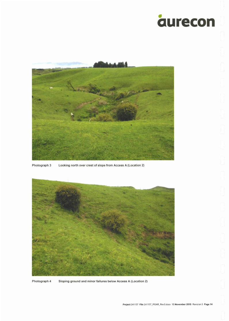
***mt
dilt
qurecon
r rdr -"
.':!*,
'+i
":u;'l*lq'l' t
'
Loclkinq north over .irest cf slope from Access A (Location 2)
. ::. ,i.
Phr:toqraph.l Sloping grourrd and rrinor failures below Access A iLocation 2)
Prcject 241 1,-1 File 2.11 1') I PGAR Rer0 occx 1 3 November 2015 Rev s on 0 Page 14

aqurecon
Photograph 5 Shallow instability at top of crest, below Access A (Location 2)
Photograph 6 Earth bund and pond (Location 3)
Ptoloct241157 File24'1157_PGAR_Rev0.docx 13Novombar2015 Revision0 Pag.'15

'r"f,
Photograph 7 Looking west along Access A (Location 4)
i -r-'I
qurecon
'Bll' r[
(6
Photograph 8 Existing farm access cut within moderate slope, with exposed ash soils (Location 4)
Prctecl 241 157 File 241 1 57 PGAR Revo docx 13 November 2015 Rev slon 0 Page'16

aqurecon
Photograph 9 Looking north over Power Plant building footprint
Photograph 10 Plunging ridgeline through centre of Power Plant building footprint
Prc!acl241157 Flle241157_PGAR-Rev0.docx 13November20'15 Revision0 PagolT

aqurecon
Photograph 11 Crest of plunging ridgeline (Location 6)
Photograph 12 Looking north at Ongaruhe Stream, with Access B to the right (Location 7)
P rclecl 241 1 57 Flle 241 1 57_PGAR_R€v0.docx 1 3 November 201 5 Revisim 0 Page 1 8

aqurecon
Photograph 13 Drainage channel running through centre of Power Plant footprint, looking north (Location 8)
Photograph 14 Looking north-west; Access B in foreground, Power Plant footprint in background
Prctacl241157 Flle241157_PGAR_Rev0.docx 13November20'15 Revision0 Page19
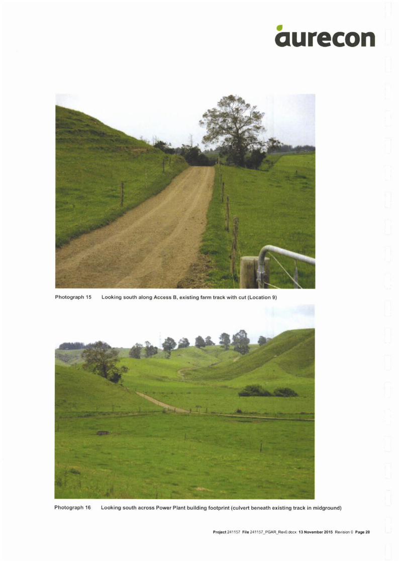
aqurecon
Photograph 15 Looking south along Access B, existing farm track with cut (Location 9)
Photograph 16 Looking south across Power Plant building footprint (culvert beneath existing track in midground)
Prolect 241 157 Fllo 241 1 57_PGAR_Rev0.docx 13 Nov6mb6r 2015 Rovisim 0 Page 20

aqurecon
Photograph 17 Ongaruhe Stream (beneath trees) (Location 11)
Photograph 18 Looking south-west across paddock, where Access B deviates from existing track (Location 12)
?rctect 24'1 157 Flle 24 l 1 57_PGAR_Rev0.docx 1 3 Novambor 2015 Revision 0 Page 21
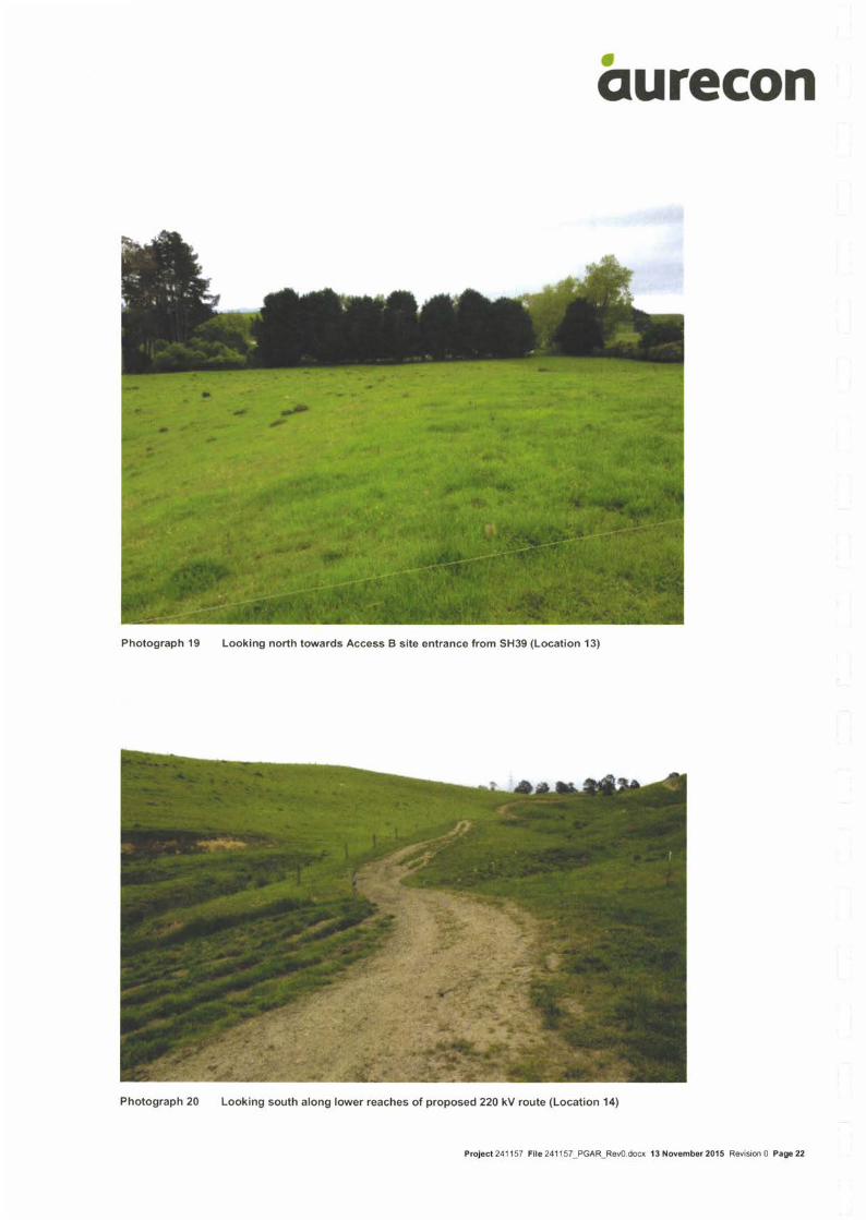
aqurecon
Photograph 19 Looking north towards Access B site entrance from SH39 (Location 13)
Photograph 20 Looking south along lower reaches of proposed 220 kV route (Location 14)
Prclecl 241 157 File 24'l 1 57_PGAR_Rev0.docx 13 November 2015 Revision 0 Page 22

turecon nova ,]' .r._ .1reill

qureconL{JPDB bn6bs&?5MrytuqaSD
v2n
tuN20Wlh.Rd
tb Sufa Ctu& r
1.@.&&ilqdhhuEmffi(@:ffi,Bn&drffi...@rrar9dl..*rmi&rmrll.@!&@oaaE
300 in y Walkato Powor Pl.nt Preliminary Geotechnical Appraisal ReportSlb Lmrdon Phn
HeGLEgRCOIJ=TICCON9ULTFlNT9
1/355 Manukau RoadEpsom, Auckland 1023PO Box 26283Epsom, Auckland 1344
T: O9 638 8414F: [email protected]
WAII(ATO POWER PLANT
sH31, KAWHIA ROAD
OTOROHANGA
ASSESSMENT OF NOISE EFFECTS
Report No 9894
Prepared for:
Nova EnergyWellingtonMarch 2O16
1
2
3
4
5
CONTENTS
Execunve SurvlunRv .................3
lrurnooucnoN... ...........4
Drsrnrcr Pmru Notsr ReournenaENTs ....... .........6
Corusrnucnoru Norse .........8
Corusrnucroru Eourpnnerur NorsE...... ............1O
Powen Srenoru Plnrur Nolse ........... 115.1 Basis of Assessment....... ...... 1 1
5.2 Noise Sources ..........11
PRrorcrrruc Norse Levels .........136. 1 lntroduction .. . ... .. . . .. . .. 1 36.2 Methodology .. .. . .. . .. . ... . . 1 36.3 Requisite Sound Reduction. ....146.4 Enclosed Noise Sources ....... 156. 5 External Noise Sources ...... 15
Predicted Construction Noise ... 16
Power Station Operation Noise ............ 1 6
Conclusions .... ....... 1 9
Appendix A............ ...2O
6
8
9

Execunve SuuuaRv
Nova Energy is proposing to develop a nominal 360 Megawatt (MW) open
cycle gas turbine (OCGT) power plant at a proposed site located off State
Highway 31, Kawhia Road, approximately 1Okm north of Otorohanga.
The noise during the construction
evaluated and will comply with the
noise criteria.
phase of the power station has been
Otorohanga District Plan construction
By implementing noise control treatment, including enclosure of most of the
plant's noise sources, the noise level from the power station will comply with
the requirements of the District Plan at all times; that is, 4OdB Ls"q. The
plant operation is steady state so by complying with the night time limit of
40dB Lngq the 50dB La"o daytime limit and 75dB Lnr* night time limit will also
be achieved with a large factor of safety.

1 lnrnoDucloN
Nova Energy is proposing to develop a nominal 360 Megawatt (MW) open
cycle gas turbine (OCGT) power plant at a proposed site located off SH31,
Kawhia Road, approximately l Okm north of Otorohanga, as shown on
Figure 1.
Figure 1. Location of Proposed Power

This report considers the noisel effects of the proposed power station and
how the site will be developed to comply with the District Plan noise
requirements to ensure the noise will be within a reasonable level for the
neighbours.
Appendix A sets out a glossary of acoustic terms used in this report.

2 DrsrRrcr Puru Norse Rroulnennerurs
The power station is located in a Rural Effects Area in the Otorohanga District
Plan. The Land Use Chapter, section 14 sets the following relevant noise
requirement for an activity in a Rural Effects Area at:
All measurements shall be taken at the boundary of the sitereceiving the noise except that in the Rural Effects Area themeasurement shall be taken at the notional boundary of any ruralsite receiving the noise.
Noise from well drilling and testing from within the RenewableElectricity Generation Policy Area is to be measured from theWaipapa Noise Control Boundary provided that the noise standardfor activities within the Renewable Electricity Generation PolicyArea are complied with (see note I above).
Noise received by any habitable buildings located within theWaipapa Core Site Noise Control Boundary will not be taken to beresidential buildings for the purpose of determining a notionalboundary for noise generated within the Renewable ElectricityGeneration Policy Area, including well drilling and testing activities.
Day shall be defined as:
o Monday to Friday 7am to I Opm.o Saturday 7am to 7pm.o Sunday and public holidays 8am to 5pm.
5. Night shall be defined as:
At all other times.
Where adjoining properties have frontage onto different orders ofroad or are located in different effects areas the most stringentnoise standard shall apply at the receiving boundary.
Sound levels will be measured in accordance with the provisions ofNew Zealand Standard NZS 6801:2O08 "Acoustics Measurementof Environmental Sound" and will be assessed in accordance withthe provisions of New Zealand Standard NZS 6802:2OO8"Acoustics Environmental Noise".
Standards
l44 Noise Measurements shall not exceed:
t.
2.
3.
6.
7.
4.

Effects Area Road Order Ln"q (Day) Ln,q(Night) Le.a, (Night)
Rural EffectsArea (excludingWaipapa NoiseControlBoundary)
1,2&3 50dB 40dB 75dB
14. 3 Any construction. maintenance or demolition activity whichcomplies with New Zealand Standard NZS68O3:1999 "AcousticsConstruction Noise" is a permitted activity.

3 CorusrRucroru Norsr
As set out above, all construction activities must comply with the requirements
of NZS68O3:1 999 The Measurement and Assessment of Noise from
Construction, Maintenance and Demolition Work. Table 2 of NZS6803:1999
sets the noise limits when measured approximately 1m from the most exposed
fagade of a dwelling for different durations of the construction noise. The actual
levels set are:
Time of week Time period Typical duration(dBA)
Short termduration
Long termduration
1"" L-"" L"" L-", L* L-..Weekdays 0630-0730 60 75 65 80 55 75
0730- 1 800 75 90 80 95 70 851 800-2000 70 85 75 90 65 802000-0630 45 75 45 75 45 75
Saturdays 0630-0730 45 75 45 75 45 750730-1 800 75 90 80 95 70 851 800-2000 45 75 45 75 45 752000-0630 45 75 45 75 45 75
Sundays andpublic holidays
0630-0730 45 75 45 75 45 750730-1 800 55 80 55 85 55 851 800-2000 45 75 45 75 45 752000-0630 45 75 45 75 45 75
Where:
(a) "Short-term" means construction work at any one location for up to 14calendar days;
(b) "Typical duration" means construction work at any one location for morethan 14 calendar days but less than 20 weeks; and
(c) "Long-term" means construction work at any one location with a durationexceeding 2O weeks.
As it will take longer than 20 weeks to construct the power station the "long
term" duration construction limits will apply to the total project. These levels are
shown shaded in the above Table.
Noise from construction equipment would depend on the emission of noise from
individual items of equipment, the distance from site boundaries and any

screening that may be present to shield the noise from the receiver position,
which for construction noise is 1m from the fagade of the dwellings. The site
preparation would include general earthworks using excavators, bulldozers and
compactors.
During the construction of the building and installation of plant the additional
equipment likely to contribute to the noise during the installation includes mobile
cranes, air compressors, mobile welding machines and miscellaneous hand held
power tools such as skill saws and grinders. Construction equipment such as
two or three 20 - 65t cranes has been included for general power station
construction with larger cranes expected to be used for specif ic items of
equipment (such as the turbine and generator). lt has been assumed that
concrete for the foundations and buildings would be imported using ready-mix
tru c ks.
Although installing the machinery would be a major part of the construction
phase it is not a noisy activity. The major source of potential noise would be
increased traffic flows delivering equipment to the site. Heavy truck traffic at
construction sites is generally evenly distributed during the working day, while
the majority of light vehicles are related to the work force arriving and leaving
the site. Although there may be major machinery deliveries at night, the noise
from traffic related to the proposed power station development is not expected
to have any adverse effects for the neighbours.

10
4 Corusrnucroru Eourpruerur Norse
A summary of the sound power levels of typical construction equipment to be
used on site, based on field measurements of plant operating, is:
Plant Sound Power (Lwe)
Caterpillar D8R bulldozer 1 12dB
Komatsu PC7 1O excavator 1 05dB
Caterpillar 825C compactor 1 07dB
Mobile crane, 1O0 - 200kW 1 07dB
Three of each of the above items of plant operating at any one time has been
assumed in the calculations. Other construction equipment, such as trucks,
portable generators, impact wrenches, saw benches, etc are quieter than the
above plant so will not have any cumulative noise events to the predicted station
plant noise.
It is expected piles will be required to support the heavy rotating gas turbine
generator and/or the GSU transformer. Assuming precast concrete pipes driven
with a drop hammer, which is noisier than bored piles, this work will have a
sound power level of 1 18dB Lwn.
The construction of the access road will be undertaken with equipment such as
scrapers, bulldozers, excavators, graders, trucks and compactors. The noise
from this work will be similar to the noise generated by the site preparation for
the power stations.
During the construction and laying of the supply gas pipelines, which are
assembled above ground, equipment will include trucks, pipes being prepared
using a portable grinder (110d8 Lwr) and welding using a portable generator
(93d8 Lwa) to provide the power for the welding and laying lengths of pipe
(stringing) in trenches using a mobile crane.

11
5 Powen Sranon Purur Norse
5.1 Basis of Assessment
This assessment has been undertaken using noise emissions data for a nominal
50MW gas turbine (LM60O0) generator package. However other gas turbine
generator packages are potentially available for the project, including turbines of
a nominal 6OMW capacity and these are being considered (hence the total
nominal capacity of 360MW). The noise emissions characteristics of these
packages, once enclosed in a building are very similar, and can be appropriately
treated in a similar manner to that described for the nominal SOMW gas turbine
package to meet the same off-site noise standards. Such equipment would
require a noise management design for the particular package and layout
selected but would still meet the required standards.
5.2 Noise Sources
To ensure the proposed power station will comply with the lower night time
noise limits, it is proposed to locate the turbines within acoustically-treated
buildings, two turbines in each building.
The following noise sources will be located in each building:
Air filter house (two intake surfaces) i 10.9
io.e
8
4.5
6
6
13 Part load andstart up only
Gas turbine room ventilation exhaust i
fan and duct i
2
---2--2 banks
i 10s.3:
f- ----96.3
1 ss.zI
l-r 99.6
; ..-I 101.6
I
106.2
I
I
I
ii
l
,,-, !
I
ll
I
i
2
r'I
I
I
Gas turbine enclosure and base beam
Auxiliary skid:
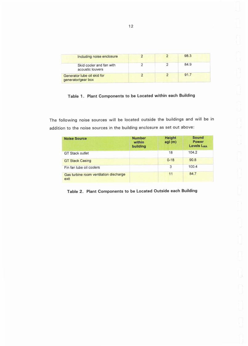
12
-lncrudingnoisJenctoiuie- i 2-i
s[iJ Coobit;d fan Gih 2acoustic louvers :
ceneraior lube oii sklo toi I 2generator/gear box
i
iz;ga.sit| *_--.L _12184.9
Tabte 1. Plant Components to be Located within each Building
The following noise sources will be located outside the buildings and will be in
addition to the noise sources in the building enclosure as set out above:
GT Stack outlet 18
o-ta
104i.,
GT Stack Casing
fin tan tirOe oit coolers- -
i
-1
3
it
90.8
ioo.A -
u.7Gis turbine roiini ventilation discharge l
exit i
Table 2. Plant Components to be Located Outside each Building

13
6 Pneprcrrruc Norse Lrvels
6.1 Introduction
It is generally recognised that the weather can have an effect on the level of
noise that we hear and this becomes noticeable where the sound transmission
path is greater than 2O0 - 3OOm. The closest house is located approximately
30Om to the east of the power station. Of the various meteorological effects on
the noise that will be received, wind and temperature inversions have the most
noticeable impact on the received noise levels.
The District Plan requires the use of NZS 6801:2008 Acoustics - Measurement
of Environmental Sound to assess noise. The meteorological conditions adopted
in clause 7.1.2 of NZSOSO|:2OO8 Acoustics - Measurement of Environmental
Sound are:
To demonstrate compliance, measurements should include or be
appropriately adjusted to slightly positive propagation conditions, whichare the upper limits of the meteorological window. Therefore whenpredicting sound levels it is recommended that slightly enhancedpropagation is assumed.
6.2 Methodology
When taking the above into account the cumulative noise levels from the
proposed power station have been predicted based on a slightly positive
meteorological effect on the transmission of noise from the proposed power
station site. This means that if there is a light wind plus a strong temperature
inversion the resulting noise may increase by as much as 2 - 3dB (Ln"q) at the
closer houses under these conditions. Should the wind strength increase to
more than approximately 4mls (8kts) the wind is expected to mask the noise
from the power station. lf the wind is blowing in the opposite direction (from
the houses towards the power station), with or without a temperature inversion,
the noise will be reduced by a minimum of 5dB (Ln"q) below the level predicted.
The cumulative noise has been predicted using the Bri.iel & Kjer Predictor
program version 1 1.OO. This is a powerful environmental noise calculation
software package that uses a digital terrain model (with the ground contour

14
interval at 2m) and considers the noise sources at the various locations on the
ground. Calculations are undertaken in accordance with the requirements of /SO
9613-1/2 Acoustics - Attenuation of Sound during Propagation Outdoors. The
analysis has adopted the ground absorption of grass land and with a slightly
positive meteorological effect to calculate the ground contours.
To determine any noise control that may be necessary to ensure the power
station complies with the District Plan limits, the noise was first predicted
without any noise control treatment. Figure 2 shows the layout for the nominal
3OOMW power station. The red shading on these figures shows the location of
the surfaces radiating noise and the points are the location of specific items of
plant on site.
6.3 Requisite Sound Reduction
From this work the minimum sound reduction required to comply with the lower
night time noise limit is 17dB Lr"q when assuming there are no special audible
characteristics to the received noise.
Figure 2. 360MW Station Layout, No Noise Control

15
6.4 Enclosed Noise Sources
To achieve the design limits the noise sources identified in Table 1 will be
enclosed. One design that will achieve the acoustic requirements (alternative
designs are also available) is to use 1OOmm precast concrete walls, a metal clad
roof with 6mm compressed fibre cement board installed on the underside ofpurlins plus a minimum of 75mm 14kg/m3 f iberglass insulation in the ceiling
cavity. To control the reverberation times within the building (echo effect) an
absorptive material will be included on the surfaces exposed to the inside of the
building, such as on walls where the material will be well clear of potential
damage from day to day activities or on the ceiling.
The ventilation may be provided via louvres and to optimise the sound reduction
the louvres will be located facing away from the closer houses. ln the event this
is not practical to achieve for all ventilation, the louvres may be replaced with
short silencers without presenting a specific design issue.
It is noted that no provisions for windows or natural light have been made to
optimise the acoustic performance.
6. 5 External Noise Sources
As part of the noise control some of the noise sources external to the buildings,
as set out in Table 2, will be located so the buildings act as a screen to the
closer dwellings. An example of where this approach has potentially significant
benefits is with the positioning of the fin fan coolers; if additional noise reduction
is needed, an engineered solution can be implemented to achieve the requisite
acoustic performance.

16
7 Pneorcreo Cousrnucrroru Norse
The proposed power station site is located approximately 350m from the closest
dwelling. At this distance the noise from the site preparation will not exceed
56dB Lr"q.
It is expected that piling will be required for the heavy rotating gas turbine
generator and/or the GSU transformer. Based on driving precast concrete piles
this work will generate a level of up to 59dB Le"q at the closest dwelling. lt has
been assumed the noise will not be screened by the existing topography.
These levels are well within the daytime TOdB Ln"q limit of NZS6803:1999
Acoustics - Construction Noise.
As all other stages of construction work will be quieter than the earthworks and
piling the noise from all aspects of the construction work will be well within the
District Plan requirements to comply with NZS68O3.
8 Powen Sranoru Oprnanoru Notse
The noise from the power station radiated into the neighbourhood from operation
of the power station (at maximum development) when assuming enclosure of the
plant components identified in Table 1, and that with a mild temperature
inversion and a positive wind blowing from the source to the receiver position,
has been predicted at 5dB Lauq intervals. The predicted noise contours are
shown on Figure 4.

\l
Figure 4. Predicted Power Station Noise, dB Lr"q

18
ln addition, the noise has been predicted at the notional boundary of each of the
closer houses as shown on Figure 5 and the results are shown in Table 3.
1 Figure 5
Table 3. Predicted Power Station Noise, dB La"q
Fiqure 5. Location of Closer Dwellinqs
Locationl Predicted Noise
1 35dB
2 35dB
3 40dB
4 33dB
5 32dB
6 30dB
7 31 dB
I 31 dB
9 29dB

19
I Cotlclustolrts
It is proposed to develop a nominal 360 Megawatt (MW) open cycle gas turbine
(OCGT) power plant at Kawhia Road located to the north of Otorohanga.
The analysis shows that any construction noise will comply with the
requirements of tr/ZS6'8O3:1999 Acoustics - Construction Noise at all times with
a large factor of safety.
To predict the noise level from the proposed power station a computer noise
prediction model has been developed and the noise predicted at 5dB (Lneq)
intervals. ln addition, the noise has been predicted at the notional boundary of
the existing dwellings in the area during the power station operation.
Based on the predicted levels at the existing houses around the power station
the noise can be controlled to within the permitted activity requirements of the
Otorohanga District Plan for the lower night time noise limits.
When taking into account the noise level from the proposed power station and
the requirements of the Otorohanga District Plan, the noise effects from the
power stations will be controlled to within a reasonable level at the notional
boundary of all dwellings in the area.
***

20
Appendix A
Guide to Noise Terms
The following sets out an explanation of the acoustic terms that will be referred
to throughout this report. The aim is not to necessarily provide technical
definitions, but to enable a basic understanding of what is meant.
The setting of specific noise levels to control any adverse effects does not
necessarily mean that noise will not be heard. Audibility depends on the level of
a sound, the loudness of the background sound and any special frequency
composition or characteristics that a sound may have.
Research suggests that a small number of people (approximately 1O%) will find
any noise not of their own making unacceptable. Conversely, there are
approximately 25o/o of the population that are essentially immune to any noise.
Neither of these two extremes is normally designed for. ln establishing the
appropriate noise levels the aim is to try and represent the typical expected
community reaction, this will generally be approximately 90% of the people.
ln order to reflect community response to noise it is necessary to establish a
measure that reflects our attitude to the sounds that we hear. Due to the
variability of many sounds (level, tone, duration, intrusiveness above the existing
sound, etc) no single descriptor will totally describe the potential community
reaction to a sound. For this reason there are a number of terms that need to be
understood.
dBA
The basic unit to quantify a sound is the decibel. The A-weighted sound level, or
dBA, is a good environmental noise descriptor because of the similarity between
A-weighting and the frequency response of the human ear at moderate sound
levels. lt can also be measured easily. However, it provides no indication of
21
tonal frequency components or unusual frequency distributions of sound that
may be the cause of annoyance. Where appropriate, this must be assessed
separately.
We can hear a change in sound pressure that varies from 1 (taken as the
threshold of hearing) through to 1,000,000,000,000 (taken as the threshold of
pain). ln order to bring these numbers to a more manageable size a logarithmic
scale is normally adopted. This reduces the above values to O and 12
respectively. The decibel is then described as 10 times the logarithm of the ratio
of the pressure level of interest, to a reference pressure level. Thus the scale
becomes O to 120dBA.
Some typical subjective changes in noise levels are:
A change of 3dBA is just perceptibleA change of SdBA is clearly perceptibleA change of IOdBA is twice (or half) as loud
Because we use a logarithmic scale care must be taken when adding sound
levels. Two equal noise sources raises the level of one source by 3dBA. lt takes
10 equal noise sources to raise the level of one source by 1OdBA. ie 60dBA +
60dBA : 63dBA and 60dBA x 10 : 7OdBA.
Maximum Sound Level (L',,".)
This unit equates to the highest (maximum) sound level for a defined
measurement period. It is adopted in NZS6802: 1 991 Assessment of
Environmental Sound, mainly as a method of protecting sleep.
Lro
The sound level which is equalled or exceeded for 1Oo/o of the measurement
time. This level is adopted in NZS6802:1991 Assessment of Environmental
Sound to measure intrusive sound. This level may be considered as the average
maximum sound level.

22
Background Sound Le5
The sound level which is equalled or exceeded for 95% of the measurement
time. This level is adopted in NZS6802:1991 Assessment of Environmental
Sound to measure the background sound. This level may be considered as the
average minimum sound level and is the component of sound that subjectively is
perceived as continuously present.
Equivalent Sound Level (Lr"q)
The La"o may be considered as the continuous steady noise level that would have
the same total A-weighted acoustic energy as a fluctuating noise over the same
time period.
Day Night Level, L6n
The day/night level (Lon) is defined as the time-average sound level in decibels (re
20pPa) over a 24 hour period from midnight to midnight) with the addition of
1OdB to nighttime levels during the period from midnight to 07.00 hours and
from 22.OO hours to midnight, to take account of the increased annoyance
caused by noise at night.
Notional Boundary
The notional boundary is defined as a line 20 metres from the facade of any rural
dwelling or the legal boundary where this is closer to the dwelling.
Figure 41 shows a noise trace with the relationship of Lr"r, Ljo, Le5 and L6q
values when including all events over the 15 minute measurement period and
Figure A2 some typical noise levels.
*+*

f;uutj60o855J
50
NG)
Lera,LroLss
Leeq
Tlme
_ Lmar _ L10 Leq _ L95
is the maximumnoise leve!is the noise level that is eggAJled or exceeded for 1 Oo/o of the measurement periodis the noise Ievel that is eggelled or exceeded for 95% of the measurement periodis the noise levelthat containsthe same eneryyas the time varying noise
Filure A{

24
,l
,1..{,,#.r,
$',= i ooo
-AW.L'tl .,l
1=
I^l'ii1-/
"i
10 000
100
140 dB
130
120
110
100
90
80
70
20
SOUNDPRESSURE LEVEL
10 000
10
SOUNDPRESSURE
p.);4.i*i "'"1)) )i*-,€ry
i ''i( I/,f- l{-- ,=
3ffi#
Z
Figure A2

WAIKATO PEAKER POWER STATION
I.ANDSCAPE AND VISUAL ASSESSMENT
JUNE 2016
isthmrs

Report Name: Waikato Peaker Power Station Landscape Assessment
Client Name: Todd Energy
Our Reference: 3593 I C2
Date: 3 June 2015
Report Status: FINAL
lsthmus Group Limited43 Sale StreetPO Box 90366Auckland
Tel: 09 309 9442Fax: 09 309 9060
Copyright. The contents of this document must not be copied or reproduced in whole without thewritten consent of the lsthmus Group Limited
i.l
1160603 3593 C2 Waikato Peaker Power Station Landscape Assessment.doc

Contents
1.0 EXECUTIVE SUMMARY ...,.,.........3
4.0 THE SrrE AND LANDSCAPE CONTEXT................... ........,,,.....5
4.7 Description of the Wider Landscape Context..,..... ...,,.,......5
4.2 Description of the Local Site Context ,...,,.......6
5.0 PLANNTNG CONTEXT ..........,,,...,.6
5.0 LANDSCAPE AND VISUAL EFFECTS ..............,..8
7.O MITIGATION PROPOSALS. ,,,,..,.21
APPEND!CES:
Graphic Attachments:
Figure One: Landscape ContextFigure Two: Site ContextFigure Three: Public Viewpoint Plan
Figure Four: Viewpoint One - Existing viewFigure Five: Viewpoint One - Proposed viewFigure Six: Viewpoint Two - Existing viewFigure Seven: Viewpoint Two - Proposed viewFigure Eight: Viewpoint Three - Existing viewFigure Nine: Viewpoint Three - Proposed viewFigure Ten: Viewpoint Four - Existing viewFigure Eleven: Viewpoint Four - Proposed viewFigure Twelve: Private Viewpoint Plan
Figure Thirteen: Viewpoint Five
Figure Fourteen: Viewpoint Six
Figure Fifteen: Viewpoint Six - Proposed ViewFigure Sixteen: Viewpoint Seven
Figure Seventeen - Viewpoint Seven - Proposed ViewFigure Eighteen: Viewpoint EightFigure Nineteen: Viewpoint NineFigure Twenty - Viewpoint Nine - Proposed ViewFigure Twenty One: Viewpoint Ten
Figure Twenty Two: Viewpoint Eleven
Figure Twenty Three: Landscape Plan
160603 3593 C2 Waikato Peaker Power Station Landscape Assessment.doc
1.0 EXECUTIVE SUMMARY
An appraisal ofthe landscape and rural character ofthe area has been undertaken ofthe site and the
surrounding area.
When assessed against the elements that make up the local rural character and amenity of the
Otorohanga District, the proposed power station can be integrated into this existing working rural
environment, largely due to the topography.
The power station will not have adverse effects on the rural character of the site or the surrounding
area.
There is a very limited public viewing audience for the site and for the proposed development. The
potential public viewing audience is generally local residents using Kawhia Road and Owaikura Road
and travellers passing the site on Kawhia Road.
Visibility of the power station will generally be restricted to within Lkm to the east and west and to
within 2km to the north and south of the site.
Views of the power station would not be out of keeping with the scale and nature of other buildings
in the area, due to the set back of the power station from the road and the scale of the buildings. lt
would be a feature along the journey, but would not change the overall character or nature of the
journey through the rural environment.
Due to the limited locations where views can be gained and the limited viewing audiences on the
adjacent roads, the overall visual effects on the public will be less than minor.
A limited number of local residents will have views of the site and proposed development from their
dwellings and properties. Due to the viewing distances and the existing landscape context, the visual
effects of the proposal on local residents will be less than minor.
160603 3593 C2 Waikato Peaker Power Station Landscape Assessment.doc

2.O INTRODUCTION
Nova Energy (Nova) is intending to apply for resource consents to develop a nominal 350 MW gas-
fired peaker power station at 869 Kawhia Road, Tihiroa, north of Otorohanga.
lsthmus has been engaged by Nova to provide advice in relation to landscape design and assessment
of the potential landscape and visual effects of the proposed power station.
2.t Methodology
The following methodology has been used to assess the landscape and visual effects of the project:
o Visits to the site and the local area to gain an appreciation of the local landscape context
including driving the main roads, walking the project site, photography and recording of the
key visual features and elements of rural character of the area;
o Assessment of the visual and rural character values of the project site and the immediately
joining land;
o Review of the relevant sections of the Otorohanga District Plan;
o Assessment of the landscape and visual effects of the proposed power station on the
immediate location and on public and private views; and
o Development of recommendations for mitigation of any adverse effects on landscape or
rural character values
3.0 THE PROPOSAL
Consent is sought for a nominal 350 MW gas-fired peaker power station at 869 Kawhia Road, Tihiroa,
north of Otorohanga. Refer to Figures One, Two and Twenty Three in the Graphic Attachments for
the location and landscape context of the site.
The features of the proposed power station development that relate to potential landscape and
visual effects include:
o Earthworks and civil construction including site levelling, concrete pours for foundations of
heavy equipment, buildings, tanks and transformers;
o Re-alignment of farm drains;
o New access roading;
o lnstallation of up to 6 gas turbines and 3 turbine enclosures (2 turbines in each);
160603 3593 C2 Waikato Peaker Power Station Landscape Assessment.doc

. Water treatment and containment facilities (tanks and ponds);
o Firefighting water storage;
r Plant room, workshop, staff amenities, and control room buildings;
r Gas reception facilities;
. A high voltage substation, transmissions lines and spur connection to the national grid (the
22OkV TMI-HLY line 1); and
o Proposed plantings to integrate into the working rural character of the farm.
4.0 THE SITE AND LANDSCAPE CONTEXT
4.t Description of the Wider Landscape Context
The site sits on the western side of the Waikato plains in the central heart of the North lsland. The
western side of the plains is punctuated by a number of local landmarks close to the site, including
Mount Kakepuku, approximately 8km to the north-east of the site and Mount Pirongia,
approximately 15 km to the northwest. Further to the north-east and north-west are Mount
Mau ngata uta ri a nd Mou nt Ka rioi, respectively.
Mounts Kakepuku and Pirongia are part of the Alexandra Volcanic Group incorporating basalt,
basaltic andesite and andesitic lavas, volcanic breccias and tuffs2. The site sits at the base of the
valley of mainly alluvial sediments of the Walton sub group, including pumiceous silt, sand and
gravel, with interbedded peat and rhyolitic pumice3.
Broad scale patterns of vegetation include remnant indigenous vegetation on Mounts Kakepupu,
Pirongia, Maungatautari and Karioi, with vegetated linkages from the high points to the wider
landscape through the stream corridors. A strong pattern of heavy indigenous and planted forestry
vegetation characterises the area to the west, towards the coast. The central Waikato Plains are
mainly used for pastoralfarming - particularly dairying. Shelter belt plantings tend to follow fences
lines and stream corridors in places, but the local rural character is generally open pastoral farming
with scattered trees and shelter belts.
Local urban centres include Otorohanga, approximately 7 km to the south, and Te Awamutu and
Kihikihi, approximately 15km to the north-east. The small crossroad of Tihiroa, with a caf6, is L.5km
to the north of the site.
I The description of the features of the project is taken from the Waikato Power Plant 350MW OCGT Project
Description by Aurecon. Revision 4. Dated 5 February 201,6.2 Geology of the Waikato Area. 1:250,000 series. lnstitute of Geological and Nuclear Sciences. Lower Hutt, New
Zealand. 2005.3 tbid.
160603 3593 C2 Waikato Peaker Power Station Landscape Assessment.doc

This wider landscape context is illustrated on Figure 1 in the Graphic Attachments.
4.2 Description of the Local Site Context
The immediate Site Context of the proposed power plant is illustrated on Figure 2.
The site of the proposed power station is a block of rural land at 869 Kawhia Road, Tihiroa,
Otorohanga.
The eastern side of the rural block of land includes the western side of a shallow ridge. Kawhia Road
generally follows the top of the ridge as it heads north towards Tihiroa, before meeting the valley
floor at the north end of the property. On the western side of the block, another ridge carries the
22OkV TMI-HLY power line (part of the National Grid), again oriented in a north-south direction.
Between the two ridges is a flat bottomed valley, with a small stream (the Ongaruhe) on the eastern
side of the valley. Either side of the valley containing the project site, the land rises over 40 metres
to the east to the Kawhia Road ridge and approximately 100 metres to the west to the Tihiroa Trig at
l-60 metres asl.
A thin strip of shelter belt vegetation, including Lawsons Cypress and Eucalypts, is planted on either
side of the stream, creating a ribbon along the stream edge. The Lawsons Cypress are approximately
20 metres tall and the tallest of the Eucalypts are approximately 30 metres talla. There are other
ribbons of planted or adventive vegetation on the edge of smaller waterways on the property,
otherwise the property is managed pasture, currently used for dairy farming.
The farm is subdivided using races and typical post and wire fencing.
On the eastern side of the property, on the edge of the Kawhia Road ridge, is the house and curtilage
area, the existing road access from Kawhia Road, internal access tracks, races, a milking shed and
other farm and implement sheds. The house and milking shed sit on a small plateau on the edge of
the ridge.
The proposed location of the power station is in the base of the valley below the existing house, and
curtilage and the access track down into the valley.
5.0 PLANN]NG CONTEXT
5.1 Otorohanga District Plan
Landuse consent is required from the Otorohanga District Council for several matters. The
application will be processed as a discretionary activity. lmportant consenting issues, in relation to
landscape and visual effects, will be effects on rural and neighbourhood character and the extent to
Measured on site using a Nikon Forestry Pro hand held laser angle, height and distance measuring device
160603 3593 C2 Waikato Peaker Power Station Landscape Assessment.doc

which views of the power station from those residences and the road can be integrated into the local
environment
5.2 Relevant Plan and Background lnformation
The relevant plan is the Otorohanga District Plan.
The proposed site is contained in the "Rural Effects Area". No outstanding natural features or
landscapes are located within or close to the site. The notable planning features identified in the
vicinity of the site on the District Plan maps that relate to landscape effects include:
o The Vector and Maui Gas Transmission Pipelines.
o The Transpower Transmission Line and associated Structures.
o Three recorded archaeological sites which are located on adjacent properties.
The site is not located within the Countryside Living Area, or any special Policy Area.
5.3 Key Assessment Criteria
The District Plan contains objectives, policies and other assessment criteria that are relevant to the
activity as set out below.
These provisions are strongly focussed on managing the scale and intensity of activities such that the
rural character, neighbourhood character and amenity values of the surrounding area are to be
retained.
Objective 3.2.3 of the District Plan identifies rural character as including the following:
(o) small scole ond low density and intensity of development;
(b) scenic vistos;
(c) high proportion of naturol open space;
(d) oreos of indigenous vegetotion ond hobitots of indigenous fauno;
(e) noturol feotures, including rolling hills, moture vegetotion and woter bodies;
ff) ogriculturol working londscopes;
@ lowfully estoblished octivities ond structures.
The rural character and amenity values of the area are dominated by pastoral farming with no
intensive industrial activities.
160603 3593 C2 Waikato Peaker Power Station Landscape Assessment.doc

The proposed activity will be a departure from what currently exists in the surrounding area.
Therefore the extent to which it can be integrated into the local environment and screened from
view is important to the consideration of landscape and visual effects.
6.0 LANDSCAPE AND VISUAL EFFECTS
The key landscape and visual issues in relation to the development of the proposed power station on
this site are:
o The loss of rural productive land;
. The effect on the local rural character and amenity; and
o The visual effects of the development on the local environment, including local roads and
local residences;
The potential landscape and visual effects of the proposal are assessed with a focus on these issues.
5.1 Loss of productive land
The loss of productive land is linked to the effect on the local rural character and amenity as the farm
is a relativelysmall rural block (153 Ha). The site of the powerstation and the switch yard willcover
an area of approximately 5ha. The overall loss of productive land would be 5 Ha within a farm of
153Ha, which will continue to be operated as a productive dairying unit. As a proportion, the loss of
5 Ha represents less lhan 4% of the farm, within a far greater area of surrounding productive rural
land.
There are two options for road access to the power station: the existing track system into and within
the farm from the access at 859 Kawhia Road, or construction of a new access road from the power
station northwards along the valley floor to join Kawhia Road at the northern boundary of the
property. The latter option would follow the base of the valley into the power station site and would
generally require the rationalisation or realignment of the existing track and race system which is an
existing part of the productive dairying unit.
The power station, in the base of the valley, will be separated from the farming activities. lt will not
remove any other land from productive rural uses.
From the site, open pastoral farming land extends some 20km to the south towards Te Kuiti, 40km to
the east towards the Waikato River, 30km to the north towards Hamilton, and 5km to the west
towards the western hill country. Overall the productive farmland on the western side of the
Waikato Plains takes in tens of thousands of hectares.
160603 3593 C2 Waikato Peaker Power Station Landscape Assessment.doc

As is visible on the site photographs, particularly those taken from Kawhia Road looking west towards
the power station location, the steep sidlings on the western side of the valley have thin soils on
slopes that are prone to localised slipping and some sheet erosion. See the photographs on Figures 4
to 9 in the Graphic Attachments. A more intensive and economically viable use of part of the site for
the power station development will allow for the rationalisation of land uses across the site,
including the planting and retirement of some of the land that is not suited for dairying or pastoral
farming. From a land use productivity point of view, this is a better result than continuing to farm
marginal slopes.
Overall and in comparison with both the size of the farm and the amount of surrounding pastoral
farming land, a very small amount of productive land will be lost to the power station development
and any access requirements.
6.2 Effects on local rural character and amenity values
The effects of the proposed power station on the rural character and amenity of the Rural
Environment is assessed below in terms of the elementsthatthe District Plan identifies as making up
"rural character" (see Objective 3.2.3 of the District Plan, section 5.3 above).
(a) The scale, density and intensity of the development of the power station and the switchyard is
relatively large, however it is not out of context with the scale of existing rural development such as
cow sheds and barns. The enclosures for the gas turbines have been designed as three separate
buildingss, with approximate dimensions of: 40 metres long, by 30 metres wide, by 20 metres tall to
the ridge of the roof line, and 25 metres to the top of the exhaust stacks. The plant building,
workshop, amenities and control room and the power control module building are all smaller at less
than 1,0 metres tall. Other than the transmission towers, the tallest components within the
switchyard are between L5 metres and 20 metres tall.
With the three gas turbine buildings separated from each other and the switchyard being some
distance from the turbines, to the west, the overall mass and scale of the power station development
is broken up into smaller components. These components are large, even in a rural context, however
they are not out of keeping with other ruralstructures and buildings within the existing ruralsetting.
Large scale glass houses, rural barns, feedlot buildings associated with feedpads and enclosed
chicken farms are all productive rural buildings that exist or could readily be anticipated in a rural
environment such as the area around Tihiroa.
One for each pair of turbines
150503 3593 C2 Waikato Peaker Power Station Landscape Assessment.doc

ln addition, power station buildings, such as the suite of geothermal power stations in the Northern
Taupo basin6, are readily accommodated within the broader rural environment, where bold
topography provides a strong context for the scale of the buildings. The Kawhia Road site itself has
bold topography which is considerably larger than the power station buildings and is therefore
capable of accommodating the power station into the local environment. Additional planting is
recommended to integrate with the existing shelter belt and streamside vegetation within the farm.
(b) Scenic vistas are generally covered in section 6.3 below on visual effects. The views of the site
and the proposal are assessed in relation to the public viewing locations on Kawhia Road and
Owaikura Road and also the private residences which are generally on elevated land to the south,
east and north of the site.
Due to the limited range of public viewing locations, the amount of screening topography
surrounding the valley floor site location and the limited number of public using the area, the
potential adverse visual effects on public viewing locations will be less than minor.
(c)The high proportion of natural open space in the local area will generally not be affected by the
proposal as the bulk of the development is located in the base of a valley, which is not readily visible.
The existing planted trees on the edge of the Ongaruhe Stream screen views into some of the valley
floor. The power station development will place additional built components into the open space of
the valley floor. ln comparison with the scale of the valley floor and the surrounding hills and ridges,
the power station buildings and structures are relatively small.
Planting is proposed to screen or soften views of the power station from particular locations (refer
attached Landscape Plan at Figure 23). The plantings will assist in reducing visual effects, but they
will also reduce the visible open space in the area. Rural scale plantings are anticipated in a
productive rural environment and are therefore a legitimate part of balance between open spaces
and the subdivision of landscape units that result from plantings. The scale of the open space of the
areas will not generally be changed as a result of the proposal, when experienced from local public or
private viewing locations.
(d) The areas of indigenous vegetation and habitats of indigenous fauna in the local area will not
be affected by the proposal. There is no indigenous vegetation within the footprint of the power
station development.
The suite of geothermal power stations in the northern Taupo basin within approximately 20 km of each other includethe historical Wairakei Power Station, Te Mihi, Nga Awa Purua, Te Huka, Nga Tamariki, Ohaaki, and the consented,but as yet unbuilt Tauhara ll station. The Mokai geothermal power station also sits approximately 10km to the northeast of that grouping of power stations.
160603 3593 C2 Waikato Peaker Power Station Landscape Assessment.doc 10

The adjacent Ongaruhe Stream is being assessed for indigenous habitat values separately by an
ecologist.
The landscape proposals for the site include additional plantings of indigenous species within the
site, including around the edges of the power station and switchyard and along the stream corridor
Refer to the attached Landscape Plan at Figure 23. This landscape and visual mitigation treatment
will improve the overall pattern of indigenous vegetation in the area and habitat values, and will
rationaliseT the current land uses across the farm.
(e) Natural features, including rolling hills, mature vegetation and water bodies are largely
unaffected by the proposal. The site that has been selected for the power station and switchyard is
relatively flat. A flat platform is required for the development, so the site will require earthworks
which will alter a small landform in the south-west corner of the development site. This 'cut' area
will generally be used to increase the levels across the balance of the development platform to get
the platform out of the flood levels of the adjacent stream. The adjacent stream and any of the large
scale topographic features in the area8 will not be affected by the earthworks or changes to the
landforms. As described above, the land climbs approximately 40 metres to the ridge to the east and
approximately 100 metres to the Tihiroa Trig to the west. The local topography is considerably larger
than the scale of the proposed development.
No mature vegetation will be affected by the proposal.
There are no notable natural features within the area that require protection underthe District Plan.
(f) As described above in relation to the loss of productive land, the agricultural working landscapes
which will be affected by the proposal are a very small proportion of the overall productive land
within the farm, throughout the local area and particularly throughout the wider area of the western
Waikato plains. The balance of the farm block will continue to be farmed as an agricultural working
landscape and the bulk of the block will not be affected by the site development or the upgrade of
the internal track access system. Proposed new plantings have been designed to soften the visual
impact of the power station development and to echo the broad pattern of functional shelter
plantings throughout the local area.
(g) The proposal would only be developed as a group of lawfully established activities and structures
if the necessary consents are granted. lf consents are granted and the project is implemented, then
the proposed power station including any proposed mitigation such as landscape planting and colour
ln this case rationalise, means organising the landuses to make the best use of access tracks, races, fences, natural
areas and the productive land within the farm.For example, the ridges and slopes within the property that are described above.
150603 3593 C2 Waikato Peaker Power Station Landscape Assessment.doc 11

treatment of buildings would become part of the lawfully established and legitimate local rural
environment.
Other lawfully established structures and activities, such as feed lot sheds and pads, large scale rural
sheds, chicken farms, glass houses could be established within the area, or within the site, and could
have a similar or greater level of visual or landscape impact, if not sited and designed sensitively.
Rural character and amenity summary
The elements set out in the District Plan that contribute to the rural character and amenity of the
Otorohanga District are a usefultouchtone forthe assessment of this proposal. As described above,
the site of the proposed power station is very contained by local topography and covers a small
footprint. The proposal will be a point feature within a much wider, more expansive landscape and
will not readily be experienced or visible from beyond the immediate environment. Any effects on
the local roads and residences will be mainly visual effects which are assessed in more detail below.
5.3 Visual Effects
5.3.1 Effects from public viewing locations
A number of publicly accessible viewpoints have been selected to present views of the proposed
power station from Kawhia Road and from Owaikura Road.
The site and the proposal will not be visible from other roads, for example, from Tihiroa Road, Te
Kawa Road, Turitea Road orfrom Kawhia Road south of the intersection with Owaikura Road, dueto
intervening topography. Similarly, due to the recessed nature of the site and the bold hills and ridges
on either side, areas to the east of Kawhia Road, to the north Te Kawa and Tihiroa Roads, to the
south of Owaikura Road and to the west of the Tihiroa Trig Ridge line will not have views of the site
or of the power station components. The surrounding landforms considerably reduce the overall
visibilityofthesiteandthisisoneofthekeyreasonsfortheselectionofthevalleyfloorlocation. As
can be seen on Figure 1, the visibility of the site and the power station will generally be confined to
within Lkm to the east and west and within 2km to the north and the south. From further afield,
some limited views of the tallest parts of the power station development, such as the exhaust stacks,
may be visible, however from the viewing distances discussed above, it would be difficult to discern
what the elements were within the view.
The existing views and visual simulations from public locations are presented as Figures 4 to 11 in the
Graphic Attachments. The locations of the public viewpoints are illustrated on Figure 3. The views
selected are typicalviews and are not intended to represent all viewing locations.
160603 3593 C2 Walkato Peaker Power Station Landscape Assessment,doc 72

ln addition to preparing visual simulations from public viewing locations, a number of private
locations were visited during sites visits. Photographs of views from private properties towards the
proposed power station are presented as Figures 13to22 and the Viewpoint locations are illustrated
on Figure 12.
The Graphic Attachments should be printed at A3, two-sided on a good quality printer and paper, or
should be viewed on a large high quality monitor screen, if being used for the purposes of assessing
potential visual effects. lf quality versions of the visual simulations are not available, then
judgements in relation to visual effects should not be made. The photographs and visual simulations
should always be used as a guide to aid field observations, which is how they are intended to be
used, that is, the viewing locations should be visited with the visual simulations and an assessment of
the level of visual effect made using the 'real life view'.
The existing views and the anticipated change to the view as a result of the proposal are described
below.
Viewpoint One
This view point is on Kawhia Road, adjacent to the
farm block), looking northwest towards the site.
from the location of the proposed power station.
entrance to 869 Kawhia Road (the Nova Energy
This view location is approximately 600 metres
The view is of the pastoral landscape, across the top of the valley (where the proposal site is located)
towards the ridge to the west, including the high point trig at Tihiroa and the TMI-HLY transmission
line. The pylons for the TMI-HLY transmission line are visible on the skyline.
The shed and curtilage development around the house site at 869 Kawhia Road are visible in the
right hand side of the photograph, along with associated shelter trees.
The visual simulation illustrates that the power station will be positioned behind the foreground
topography and will not be visible from this location. The location of the power station is outlined in
a dotted red line. This location is typical of a number of areas along Kawhia Road, where a plateau or
spur on the edge of the Kawhia Road ridge screens the valley floor and the proposed development
from view.
As a result, there will be no visual effects on this location.
Viewpoint Two
Viewpoint Two is on Kawhia Road further to the south from View Point One. This view is
approximately 750 metres away from the site of the proposed power station.
160603 3593 C2 Waikato Peaker Power Station Landscape Assessment.doc 13

The view is across a foreground paddock on the edge of Kawhia Road, across the top of the proposed
development site. The house curtilage area and the milking and farm sheds are visible on the right
hand side of the view (similar to the view point one photograph). The distant ridge line, including the
high point trig at Tihiroa and Mount Pirongia in the background are visible. From this location the
existing view is an open pastoral view, with distance landscape features which are a focus of the
scenery.
Within the simulated view, the tops of the turbine enclosure buildings are visible from the viewing
location, along with the upper parts of the exhaust stacks, above the foreground paddock. The
development would sit below the ridge in the middle ground and would not obscure the views of
Mount Pirongia in the distance. The development is visually contained within the valley. The turbine
halls and the exhaust stacks will be viewed as similar in scale to the sheds on the site to the right and
will be part of a complex rural view that includes existing working rural buildings, trees, shelter belts,
fences and layered topography. The view will be available to motorists travelling south on Kawhia
Road but only for a relatively short period of time over approximately 300 metres of the length of the
road. At 80km per hour this distance would be covered in approximately 13 seconds.
The view of the power station would not be out of keeping with the scale and nature of other
buildings in the area, due to the set back of the power station from the road. lt would be a feature
along the journey, but would not change the overall character or nature of the journey through the
rural environment.
This view is typical of the 'partial views' of the upper parts of the buildings and exhaust stacks that
are likely to be available from surrounding areas.
The proposed power station development would have no more than minor visual effects from this
location on Kawhia Road.
Viewpoint Three
This viewpoint is from Kawhia Road, looking west, through a gap in the spurs on the edge of Kawhia
Road, down into the valley floor. This is the most open public view into the site and is approximately
400 metres from the location of the proposed power station.
The view to the west, towards the Tihiroa Ridgeline is across the base of the valley. Three of the
pylons of the TMI-HLY transmission line are visible on the skyline and are prominent within this view.
Mount Pirongia is visible in the distance in the right of the view. This view is perpendicular to the
direction of travel on Kawhia Road and is only visible for a verv short time.
The three turbine enclosure buildings and the exhaust stacks of the proposed power station would
be visible, with the switchyard beyond. The power station buildings and components would be
160603 3593 CZ Waikato Peaker Power Station Landscape Assessment.doc t4

prominent within the view shaft, which is a relatively narrow part of the overall panoramic view. lf
the viewer wasn't looking directly towards the view shaft, then the view would be fleeting, if seen at
all. The line of vegetation along the stream is visible to the left of the power station buildings and this
gives an indication of the level of visual screening that could be provided by further planting. Over
time the gaps in the streamside planting would be filled with the proposed mitigation planting along
the stream edge and the lower parts of the power station would be screened from view.
Given the fleeting nature of the view and the shouldering landform on either side, the proposed
power station would have less than minor visual effects when viewed from this location.
Viewpoint Four
This view is from an elevated location on Owaikura Road looking north along the valley towards the
site. This viewing location is approximately 2km from the location of the proposed power station
site. Owaikura Road is a no exit rural road, with a limited number of residences. This view will not
be experienced by many people, mainly being limited to those living or travelling on Owaikura Road.
This is an expansive view to the north towards Mount Pirongia and Mount Kakepuku, to the far right
of the view. The focus of the view is generally of Mount Pirongia, the largest and most spectacular of
the landforms which is in the left side of the view. The open upper valley is clearly visible, with the
shouldering landforms of the Tihiroa ridge and the Kawhia Road ridge clearly visible on the left and
the right, respectively. The TMI-HLY transmission line and pylonse traverse the upper valley and
along the Tihiroa Ridge in the foreground of this view.
At a distance of approximately 2km, the power station development would be viewed as a relatively
small part of the overall view, and partially obscured by existing trees in the base of the valley. This
simulated view illustrates that the proposed power station can be effectively designed, coloured and
planted to ensure that it will not become a prominent part of the views from Owaikura Road to the
north towards Mount Pirongia.
Due to the viewing distances, the small public viewing audience, the complexity of the broader view
and the nature of the foreground of this view, the potential adverse visualeffects on this location will
be less than minor.
Public Visual Effects - Summary
The visual assessment from public viewing locations - namely locations on Kawhia Road and
Owaikura Road - illustrates that there are limited areas along these two roads where the proposed
power station could be visible from. Kawhia Road provides limited glimpses into the base of the
s Part ofthe National Grid.
150503 3593 C2 Waikato Peaker Power Station Landscape Assessment.doc 15

valley from gaps between the landforms. Views are generally perpendicular to the direction of travel
and will not be experienced for long during a journey along Kawhia Road. The views from Owaikura
Road are more open and expansive, across the valley and toward Mounts Kakepuku and Pirongia.
The views that are available of the site and the proposal are not in the direction of travel when
driving on Owaikura Road and any road users would need to be looking away from the road in order
to see the proposal. Views of the proposal from Owaikura Road are at a distance of 1..5 to 2.5km and
are of elevated skyline landscape features as described above, with the valley floor and the proposal
providing a small part of the mid ground of the view.
The upper valley includes the TMI-HLY transmission line and pylons which are prominent features of
the existing views towards the north.
As described above at Section 5.3, the visibility of the site and the power station will generally be
confined to within Lkm to the east and west and within 2km to the north and the south.
Due to the limited range of public viewing locations, the amount of screening topography
surrounding the valley floor site location and the limited number of public using the area, the
potential adverse visual effects on public viewing locations will be less than minor.
6.3.2 Effects from Private Viewing Locations
As described above, a number of local private locations have also been visited, with views from those
locations photographed. The views are all generally from private locations, such as decks or other
outdoor living areas within those private properties visited. The views generally represent the
location within that property from which the power station would be most visible.
ln addition to the public locations, visual simulations have been prepared from three private
locations - Viewpoints Six, Seven and Nine. These viewpoints have been selected as they represent
the main private residences to the south and the east where views of the site and the proposal are
available from.
Viewpoint Five
This view is from the north side of the residence and curtilage at 823 Kawhia Road looking northwest
towards the site. This viewing location is approximately 750 metres from the proposed power
station site.
From this location the tops of the marker tress immediately adjacent to the site that are a similar
height to the tallest component of the proposal are visiblelo. The tallest parts of the exhaust stacks
As described above, the eucalypts that are adjacent to the power station site are approximately 30 metres tall,
160603 3593 C2 Waikato Peaker Power Station Landscape Assessment,doc t6

will be visible above the foreground landform, however the majority of the power station, and
particularly the lower ground based elements will not be visible.
Over time the existing trees within the valley floor, which are already visible, along with the planting
proposed as part of the proposal will grow and will continue to integrate the power station into the
local landscape and screen it from view.
View Point Six
This view is from the front deck of L33 Owaikura Road, looking north up the valley towards the site,
with Mount Kakepuku on the right and Mount Pirongia on the left in the distance. This viewing
location is approximately 2.5 km from the location of the proposed power station site.
The broad expanse of the flat valley floor, with the Kawhia Road ridge to the right and the Tihiroa
Trig ridge to the left, is visible. Mount Kakepuku to the right and Mount Pirongia, to the left
(obscured by the cloud in the photograph) are visible from this location.
The relative complexity of the valley floor, will small scale landforms, trees, shelter belts,
transmission lines and poles and some dispersed rural buildings is clearly evident from this location.
The focus of the view from this location is the land and sky interface of the two higher ridges on
either side and the distant landforms of Mount Kakpuku and Mount Pirongia in the distance.
The visual simulation illustrates the proposal as a small part of the overall view to the left of the
centre of the view (marked at the top of the page with a red arrow). With the colour mitigation
applied to the main components of the proposal and the recommended site planting (not illustrated
on the visual simulation), the power station would sit 'within' the valley floor and the matrix of
planted and remnant rural vegetation. The proposed power station would be a small feature within
the mid distance of this expansive view. When viewed from this location the power station proposal
would have less than minor visual effects.
View Point Seven
This view is from the elevated lawn of 40 Owaikura Road, looking north towards the proposed power
station site. Towers and lines from the TMI-HLY transmission line are in the foreground of the view.
This viewing location is approximately 1.5km from the location of the proposed power station site.
A number of foreground spur landforms and associated tree and shelterbelt plantings break up the
upper valley into a series of smaller compartments. The pylons and lines of the TMI-HLY line in the
foreground are clearly visible and are visible from the property when looking to the east and the
north.
160603 3593 C2 Waikato Peaker Power Station Landscape Assessment.doc 77

This view is oriented towards Mount Kakepuku in the centre of the photograph and the distant view
of Maungatautari to the right, with the site occupying a lower part of the valley floor to the left. The
site and the proposal will be partially obscured by the silver birch trees in the foreground and existing
shelter belt plantings on the valley floor.
The visual simulation illustrates the proposal behind the Silver Birch trees in the far left of the view
(marked with a red arrow at the top of the page). Due to the orientation of the main view and the
partial screening provided by both foreground and mid ground vegetation, the visual effects of the
proposal on this location would be less than minor.
View Point Eight
This view is from the garden at 42 Owaikura Road looking north towards the site through the only
gaps in the foreground planting within the garden. This viewing location is approximately 1.5km
from the location of the proposed power station site.
The existing view towards the site is through a gap in the existing garden plantings which was a few
metres wide at the time of photography. The garden includes layers of planting which largely
obscure views towards the site from the area around the house. Any views from this location are
largely dependent on the ongoing management of the vegetation within the garden.
The proposal would be barely visible from this location and would require the viewer to 'find' the site
and the proposal within the view from the edge of the heavily planted garden.
View Point Nine
This view is from the deck at 958 Kawhia Road looking west towards the proposed power station site.
This viewing location is approximately 400 m from the location of the proposed power station site.
The views from this property, as with other properties described and assessed, are generally towards
thenorthtowardsMountKakepukuandMountPirongia. Thisviewisfromtheedgeofthedeckand
is in a south westerly direction, away from the main orientation of the dwelling and the views.
The views to the south west take in the Tihiroa Trig ridge on the other side of the valley, including the
TMI-HLY transmission line and pylons which are prominent on the skyline. The farm slopes make up
the majority of the mid ground of the view.
This is the residential location which will have the closest and most open views 'into' the site,
however the views are away from the main orientation of the outlook of the property.
The introduction of the proposal into this view would see the majority
platform visible on the valley floor in the left side of the view, where the
end of the Lawsons Cypress shelter belt are visible.
160603 3593 C2 Waikato Peaker Power Station Landscape Assessment.doc
of the 5 Ha development
existing Eucalypts and the
18

The foreground of the view includes some weedy vegetation along the boundary fence line between
the property and Kawhia Road (far right of the photograph). This vegetation is relatively small,
however is effective at screening views from the deck of the road, passing traffic and into the floor of
the valley. A planted hedge along this fence line would be easily capable of screening views of the
power station and the site within a short space of time. The planting would also assist in screening
the road and passing traffic from view from the deck.
The visual simulation illustrates the open view into the site and the three turbine shelters, with the
exhaust stacks. The switchyard is also partially visible behind the power station. While the
orientation and the main views from the house and the deck are to the north, this view is part of the
periphery of that view. Note that the recommended stream side planting is not illustrated in the
visual simulation. That planting will, in time, screen the lower parts of the power station from view.
With only the on-site colour and planting related mitigation measures implemented, the visual
effects of the power station on this location would be minor. With the off-site planting described
above (a hedge planted inside 958 Kawhia Road - at least to the height of the wire and batten
boundary fence), the visual effects of the power station would be less than minor.
Boundary planting should be offered as an'off-site'mitigation measure for the residents at 968
Kawhia Road.
View Point Ten
This viewpoint is from the edge of the house curtilage area of the Glenbrue Friesian Stud on the
corner of Te Kawa and Kawhia Roads looking south towards the proposed power station site. This
viewing location is approximately 1.3km from the location of the proposed power station.
This is the only elevated location where a view from the north back towards the site could be found.
At a distance of 1.3 km the proposal would be a small part of the overall view. The proposal would
be almost completely obscured by the layers of vegetation on the centre of the view, within the
valley floor. lf visible at all, the upgrade of the access road and the tops of the exhaust stacks would
be the main components that would be introduced to the view.
View Point Eleven
This view point is from the race within L025 Kawhia Road, looking south up the valley towards the
proposed power station site. This viewing location is approximately 500 m from the location of the
proposed power station.
The residence and curtilage area at 1025 Kawhia Road are heavily planted and are oriented to the
north and the north west. Given the nature and the layering of the planting around the residence,
160603 3593 C2 Waikato Peaker Power Station Landscape Assessment.doc 79

the orientation of the house does not have a bearing on the level of visibility, as no views of the site
or the proposal will be available from either the house or its' surroundings.
The photograph is a view from a race on the property near the southern boundary. This view is
available from a limited area of the property that is currently used for pastoral farming.
The lines of willows in the mid ground of the view are on the edge of the Ongaruhe Stream or on the
property boundary.
The introduction of the proposal to the view would see the north end of the station and the switch
yard visible at a similar scale to the eucalypts and shelter belt vegetation, immediately adjacent to
the site. The foreground trees and landforms frame the views towards the site and are larger
elements in the overall view from this location.
The relatively small scale willow trees in the mid ground are effective at screening views towards the
site and the proposal. A limited amount of additional shelter type rural tree planting along the edge
of the stream or along the property boundaries would be effective in screening the power station
from view within a relatively short space of time (within 3 to 5 years). This additional planting is
recommended and is illustrated on the Landscape Plan presented as Figure 23.
Private Visual Effects - Summary
A relatively small number of local residences have views towards the site and will have views of the
proposed power station. The residences can be grouped into two main areas:
o Those elevated residences on Owaikura Road, with views to the north over the valley
towards Mount Kakepuku and Mount Pirongia. These views are generally at a distance of 1.5
to 2.5km.
o Those residences on Kawhia Road, which have views to the north, with the site and the
proposal within the western periphery of the view.
Residential development in the local areas is oriented to the north, as is common to enable solar
access, however this orientation of dwellings is strengthened in this case by the open landscape
views towards Mount Kakepuku and Mount Pirongia.
Views of the site from residences on Kawhia Road or from the north of the site are either in the
periphery or are away from the main orientation of the residences and gardens, due to the
predominant northern orientation and aspect.
Views from Owaikura Road to the north towards the site are longer views at distances of 1.5 to 2.5
km and are of distant landscape features, such as the two mountains. The site and the proposal will
160603 3593 C2 Waikato Peaker Power Station Landscape Assessment.doc 20

sit in the base of the valley and will form a small part of the complex patterns of vegetation and
development in the mid ground of the view, well below the skyline.
Overall, the visual effects of the proposal on the views from residential properties will be less than
minor due to the predominant orientation of views from residences and the viewing distances from
those residences to the south.
There are a small number of locations where off-site or on-site plantings will assist in screening the
proposal from view, for example at 968 and L025 Kawhia Road.
The site wide planting proposals will also assist in softening views of the proposal from surrounding
residential locations.
7.O MITIGATIONPROPOSALS
The selection of a recessed valley floor location is the main technique that has been used to limit the
landscape and visual effects of the proposal.
ln addition to the selection of an appropriate site, the following mitigation proposals have been used
in the design of the proposal, or are recommended:
o The orientation of the power station layout to ensure that the switchyard is away from the
main viewing locations and nestled against the base of the adjacent landform;
r Colouring the main external components of turbine shelters, exhaust stacks and other
buildings Resene Rivergum and the roofs Resene lron Sand, or comparable colours to match
the colour of the surrounding landcover of grass and planted trees. lt is important that the
roofs are darker than the walls of the main buildings;
o Breaking up the turbine shelters into three separate forms;
o Planting on the stream edge and additional shelter plantings within the farm, to integrate
into the local rural landscape, as illustrated on the Landscape Plan presented as Figure 23.
8.0 coNcLustoN
When assessed against the elements that make up the local rural character and amenity of the
Otorohanga District, the proposed power station can be integrated into this existing working rural
environment.
The power station will not have adverse effects on the rural character of the site orthe surrounding
area.
160603 3593 C2 Waikato Peaker Power Station Landscape Assessment.doc 21

There is a very limited public viewing audience for the site and for the proposed development. The
potential public viewing audience is generally local residents using Kawhia Road and Owaikura Road
and travellers passing the site on Kawhia Road.
Visibility of the power station will generally be restricted to within Lkm to the east and west and to
within 2km to the north and south of the site.
Views of the power station would not be out of keeping with the scale and nature of other buildings
in the area, due to the set back of the power station from the road. lt would be a feature along the
journey, but would not change the overall character or nature of the journey through the rural
environment.
Due to the limited locations where views can be gained and the limited viewing audiences on the
adjacent roads, the overall visual effects on the public will be less than minor.
A limited number of local residents will have views of the site and proposed development from their
dwellings and properties. Due to the viewing distances and the existing landscape context, the visual
effects of the proposalon local residents will be less than minor.
lsthmusJune 2015
150503 3593 C2 Waikato Peaker Power Station Landscape Assessment.doc 22

Archaeological Assessment of Effects: Waikato Power Plant
Archaeological Assessment of Effects Waikato Power Plant 869 Kawhia Road, Otorohanga, South Waikato
Nova Energy
Archaeological Assessment of Effects: Waikato Power Plant
Archaeological
Assessment of Effects
Waikato Power Plant
869 Kawhia Road, Otorohanga, South
Waikato
Nova Energy
© Opus International Consultants Ltd 2016
Prepared By
Opus International Consultants Ltd
Gaylynne Carter Napier Office
Archaeologist Opus House, 6 Ossian Street
Private Bag 6019, Hawkes Bay Mail Centre,
Napier 4142
New Zealand
Reviewed By Telephone: +64 6 833 5100
Emma Brooks Facsimile: +64 6 835 0881
Southern Pacific Archaeological Research
Date: 01/08/ 2016
Reference: Project 3-38985.00
Status: Final

AAE Waikato Power Plant i
Project 3-38985.00 | January 2016 Opus International Consultants Ltd
Contents
1 Executive Summary ............................................................................................ 1
2 Introduction ....................................................................................................... 2 2.1 Purpose ............................................................................................................................. 2 2.2 Location ............................................................................................................................. 2 2.3 Proposed Works ................................................................................................................ 4 2.4 Background ....................................................................................................................... 4 2.5 Limitations ........................................................................................................................ 5
3 Statutory Requirements ..................................................................................... 6
3.1 Heritage New Zealand Pouhere Taonga Act 2014 (HNZPTA) .......................................... 6 3.2 The Resource Management Act 1991 ................................................................................ 6
3.3 Otorohanga District Plan .................................................................................................. 7 3.4 Waikato Regional Plan ...................................................................................................... 7
4 Methodology ...................................................................................................... 9 4.1 Desktop Research .............................................................................................................. 9
4.2 Site Visit ............................................................................................................................ 9
5 Environmental Setting ..................................................................................... 10 5.1 Natural Landscape .......................................................................................................... 10
5.2 Summary Statement ....................................................................................................... 13
6 Historical Background ......................................................................................14
6.1 Maori History of Occupation .......................................................................................... 14 6.2 European Arrival ............................................................................................................. 14
7 Previous Archaeological Work .......................................................................... 17 7.1 Overview .......................................................................................................................... 17 7.2 Previously Recorded Archaeology................................................................................... 20 7.3 Previous Archaeological Surveys .................................................................................... 21 7.4 Historic Aerial Photographs ............................................................................................ 21 7.5 Archaeological Authorities Granted in the Area ............................................................. 23
8 Research Results .............................................................................................. 24 8.1 Field Visit ........................................................................................................................ 24
8.2 Summary Statement ....................................................................................................... 30
9 Archaeological and Other Values ..................................................................... 32 9.1 Archaeological Values ..................................................................................................... 32 9.2 Other Values .................................................................................................................... 33
10 Assessment of Effects ....................................................................................... 34

AAE Waikato Power Plant ii
Project 3-38985.00 | January 2016 Opus International Consultants Ltd
10.1 Proposed Works .............................................................................................................. 34 10.2 Archaeological Effects ..................................................................................................... 35 10.3 Potential for Unrecorded Archaeological Sites ............................................................... 35 10.4 Avoidance and Mitigation of Effects ............................................................................... 36 10.5 Management of Archaeological Sites .............................................................................. 36
11 Conclusion and Recomendations ..................................................................... 37
12 References ....................................................................................................... 39
Appendices
Appendix 1: Location of proposed works and indication of proposed Access A and B alignments
Appendix 2: Otorohanga District Plan Sections 7 & 21
Appendix 3: Waikato Regional Policy (Heritage)
Appendix 4: Pylon Construction E-mail
Appendix 5: Site Record Forms
Tables of Figures
Figure 1 Map showing location of proposed WPP works at 869 Kawhia Road in relation to its wider
regional context (Source: QuickMap). ................................................................................................. 3 Figure 2 Aerial photograph showing the works footprint and access routes A and B (yellow dash)
as supplied by Nova Energy (Drawing No. L-001). The approximate locations of the four nearest
recorded archaeological sites are shown as red stars, orange centre is S15/756. ................................ 3 Figure 3 Pylon Route C and access tracks (Source: Nova Energy). ..................................................... 4 Figure 4 Track bank illustrating the typical soil profile of ca. 15cm topsoil, overlying an
orange/brown tephra subsoil (Source: G. Carter). ............................................................................ 10 Figure 5 Location of the proposed Waikato Power Plant (black outline) within its wider topographic
environment (Source: Quickmap). ..................................................................................................... 11 Figure 6 Stream that runs through the plant proposed footprint: note straight alignment and steep
(albeit overgrown) edges (looking towards northeast, SH 31 lies c. 1 km to the right) (Source: G.
Carter). ............................................................................................................................................... 12 Figure 7 Tree lined Ongaruhe Stream to the west of the proposed footprint (looking towards
northeast, SH 31 lies c. 1 km to the right) (Source: G. Carter). ......................................................... 12 Figure 8 Map showing the wider archaeological context of the proposed works (red square)
(Source: ArchSite /2/2016)................................................................................................................ 18 Figure 9 Map showing the local archaeological landscape of the proposed work (indicated in red)
(Source: ArchSite 14/12/15). .............................................................................................................. 19 Figure 10 Excerpt from SO11442.2 showing the 1899 extent of the Ongaruhe Stream. Note the
location of Tiheroa summit and the characteristics of the Waipa River course and the road that
enable the proposed works site to be approximately located onto this map (shown in red dash). ... 20 Figure 11 Excerpt from 1950 aerial photo (N74-5) indicating the stream courses and location of the
proposed works (red outline), and the three nearby archaeological record locations (blue stars);
note also the potential archaeological features to the north-west (yellow dash).
(Source:https://gdh.auckland.ac.nz/government_maps/NZMS/NZMS_003/tif/). ....................... 22

AAE Waikato Power Plant iii
Project 3-38985.00 | January 2016 Opus International Consultants Ltd
Figure 12 Possible unrecorded archaeological features in the vicinity of the proposed work (orange
outline); proposed footprint of earthworks (blue box); recorded archaeological sites (blue stars)
(Source:https://gdh.auckland.ac.nz/government_maps/NZMS/NZMS_003/tif/). ....................... 23 Figure 13 Approximate indication of the proposed footprint of works. Note that the work will
involve modification to the current small gully and the high ground in front of the trees (current
Ongaruhe Stream course). Farm buildings can be seen top centre/right. The farm tracks and the
small stream and trees locate the site in the context of Figure 2 (Source: G. Carter). ...................... 24
Figure 14 Image illustrating the extensive erosion and slumping that has occurred on the higher
slopes and gullies to the northwest and west of the proposed plant footprint (Source: G. Carter). . 25 Figure 15 Possible pit feature (S15/756) (red dash), note the change in vegetation in comparison to
surrounding area (Source: G. Carter). ............................................................................................... 26 Figure 16 Comparison of soil profiles from suspected pit (S15/756) (left) and adjacent hillside
(right). The soil profile of the suspected pit becomes darker with depth and shows no indication of
tephra subsoil; the auger sample from the hillslope is a consistent mid brown and orange tephra is
beginning to show at the tip (Source: G. Carter). .............................................................................. 26 Figure 17 Slump-terrace on which the suspected pit (S15/756) sits (view south west) (outlined in
red) (Source: G. Carter). .................................................................................................................... 27 Figure 18 General view across the area of access (ridge spur), as indicated by Mr Davenport,
looking towards the proposed work area. The existing farm track visible in the left of the photo is
the route indicated in Figure 2 (Source: G. Carter). .......................................................................... 28
Figure 19 View from the farm track at the bottom of the valley up (east) towards the road where Mr
Davenport indicated the access way to be (Source: G. Carter). ......................................................... 28 Figure 20 View south west towards the proposed work site along Access B route which will follow
the farm track visible in the centre of the photo (Source: G. Carter). ............................................... 29 Figure 21 Area of Pylon 2c, typical of the landscape and pylon sites, view northwest (Source: K.
Potts). ................................................................................................................................................. 30 Figure 22 Aerial photograph showing the route for power supply and the positions of pylons within
the designation (Source: Transpower)............................................................................................... 35

AAE Waikato Power Plant 1
Project 3-38985.00 | January 2016 Opus International Consultants Ltd
1 Executive Summary
Opus International Consultants Ltd (Opus) has been commissioned by Nova Energy to undertake
an assessment of archaeological effects in advance of a proposed power plant construction project.
This assessment is to be submitted in support of a planning application and if necessary will
support an application to Heritage New Zealand Pouhere Taonga should an archaeological
authority be sought prior to the commencement of the project.
The proposed power plant footprint work at 869 Kawhia Road, Otorohanga, Waikato is scheduled
to affect an approximately 200 m x 180 m area currently in pasture, with additional roads for
access to be developed or modified from existing farm tracks. A new power supply line is also
scheduled for installation.
There are three recorded archaeological sites within 1 km of the area of the proposed power station,
and one pending recorded archaeological site (S15/756) within 20m of the main plant footprint.
There are few recorded archaeological sites in the wider area but the majority are pā which tend to
be dominant features on the landscape. The historical record suggests that the area was densely
populated by Māori prior to the arrival of Europeans. Aerial photographs from 1950 show clear
surface features consistent with archaeological sites in the surrounding landscape.
The land on which the proposed works lies has been heavily modified at surface level by ploughing
and drainage. This is particularly important with respect to the former course of the Ongaruhe
Stream. The proposed power station lies immediately to the west of, and likely on, the former
stream banks in places. The stream itself, in 1899, was a considerably more substantial waterway
than currently exists.
Neither the desktop research nor the site visit indicated surviving archaeological features within
the confirmed development footprint, however there is a possible pit (S15/756) now recorded
within 20m of the plant footprint, and there are a number of potential archaeological sites shown
in historic (1944 & 1950) aerial photographs. The power supply line has yet to be confirmed and the
possibility of encountering archaeology along the ridgelines is cause for concern. Factors such as
surface modifications to the land; the historical evidence that the Waikato/King Country area
supported a large population; and the distribution of potential unrecorded archaeological features
showing in the historic aerial photographs all lead to the conclusion that there is reasonable cause
to suspect that archaeological sites or materials are present within the wider project footprint.
Thus it is recommended that an application for an archaeological authority be made to HNZPT.
It is recommended that:
An application be made to HNZPT for an archaeological authority prior to on-site work
commencing.
A site instruction document is prepared to accompany an application to HNZPT.
That the pylon sites are visited by a qualified archaeologist as soon as confirmed.
Consultation is undertaken with tangata whenua regarding any authority application and the
results of this assessment

AAE Waikato Power Plant 2
Project 3-38985.00 | January 2016 Opus International Consultants Ltd
2 Introduction
2.1 Purpose
Opus International Consultants Ltd (Opus) was commissioned by Nova Energy to undertake an
assessment of archaeological effects of a proposed site of work for a new Waikato Power Plant. As
part of the Resource Consent process, Nova Energy is required to submit an archaeological
assessment of effects (AAE) for the proposed site.
The purpose of this report is to review documentary evidence of archaeological sites in the vicinity
of the proposed power plant site, and to assess the risk of the project encountering archaeological
material. The report is intended to support an archaeological authority application to Heritage New
Zealand Pouhere Taonga (HNZPT) as well as to provide documentation for the resource consent
process.
This assessment considers the archaeological and other values of sites recorded within or near to
the project footprint including S15/ 756; S15/135; S15/132; S15/280; the potential for unrecorded
archaeology to be encountered during the works; and the impact on those values of the proposed
Waikato Power Plant Project. This assessment has been prepared in accordance with HNZPT
guidelines on preparing an archaeological assessment.
2.2 Location
The proposed Waikato Power Plant (WPP) has a site footprint of approximately 200 m x 180 m.
There will be additional modifications to existing farm tracks and construction of new access roads.
In addition to the plant area, Opus were later asked to include the associated pylon route. The land
on which the proposed works sits is located at 869 Kawhia Road, Otorohanga, South Waikato
(Figures 1 - 3).

AAE Waikato Power Plant 3
Project 3-38985.00 | January 2016 Opus International Consultants Ltd
Figure 1 Map showing location of proposed WPP works at 869 Kawhia Road in relation to its wider regional context (Source: QuickMap).
Figure 2 Aerial photograph showing the works footprint and access routes A and B (yellow dash) as supplied by Nova Energy (Drawing No. L-001). The approximate locations of the four nearest recorded archaeological sites are shown as red stars, orange centre is S15/756.
Access A
Access B

AAE Waikato Power Plant 4
Project 3-38985.00 | January 2016 Opus International Consultants Ltd
Figure 3 Pylon Route C and access tracks (Source: Nova Energy).
2.3 Proposed Works
The proposed WPP project has a plant footprint of approximately 200 m x 180 m, and will also
require some combination of new construction and modifications to existing farm tracks to provide
suitable road access to the site both during construction and into the operational stages (Figure 2).
Services will be required, and it is currently anticipated that trenching will follow the route of the
access roads, although this remains to be confirmed. The construction of the plant will involve
significant earthworks to level the site which straddles an area of high ground originally adjacent to
the Ongaruhe Stream, and a shallow gully through which a small (modified) stream currently runs.
This work will damage or destroy any unrecorded archaeological sites present within the
construction footprint. Whilst S15/756 appears to be outside the immediate footprint, it may be
affected by ancillary works. A power supply line is also proposed involving the installation of three
new pylons along Route C (Figure 3). Further detail is presented in Section 10.1.
2.4 Background
As part of the Resource Consent Process, Nova Energy has been asked to present an Archaeological
Assessment of Effects (AAE) in support of their planning application to Otorohanga District
Council. As part of this assessment process, a site visit was undertaken by Gaylynne Carter (Opus
Archaeologist) in December 2015, the results of which, in addition to desk-based research, has
helped inform the conclusions and recommendations presented in this AAE. A further site visit was
undertaken by Kirsty Potts (Opus Archaeologist) in June 2016 to visually assess the Route C pylon
line and associated access-ways, along with the confirmed northern access to the main site (Access
B, Figure 2).

AAE Waikato Power Plant 5
Project 3-38985.00 | January 2016 Opus International Consultants Ltd
2.5 Limitations
This report is an archaeological assessment of the impact of earthworks within the footprint of the
project and its associated infrastructure (roads and services), and pylon Route C. Full details of the
depth of earthworks and location of service trenches is currently unavailable.
Statements are made about the location and nature of archaeological sites and their archaeological
values. The archaeological information is derived from several sources (see Section 4) including the
New Zealand Archaeological Association (NZAA) ArchSite Database. The archaeological site
locations provided on the database should be regarded as a guide only. The locational accuracy of
archaeological sites recorded in ArchSite is variable. Some sites are recorded only to 100m grid
squares and many of these have been recalculated from earlier 100 yard coordinates. Sites that
have been visited since the advent of GPS may have more accurate coordinates. The full extent of
recorded archaeological sites is often not known and the single point coordinate provided by
ArchSite is often based on the visible surface expression only. This does not necessarily represent
the true subsurface extent of a site.
Every effort has been made in the preparation of this document to provide as complete an
assessment as possible, within the terms and scope of the commission and the information
provided. Any changes to the design of the project or the scope of commission will require a review
of the recommendations provided in this document to be undertaken.
There are no statements of the cultural significance of the project area nor are the views of tangata
whenua represented in this report. A statement of cultural values will need to be provided
separately to accompany an authority application to Heritage NZ.
As an authority application is recommended, appropriate mitigation strategies will need to be
detailed in a Site Instruction document (SI). The SI will accompany an application to HNZPT for an
archaeological authority.

AAE Waikato Power Plant 6
Project 3-38985.00 | January 2016 Opus International Consultants Ltd
3 Statutory Requirements
There are two main pieces of legislation in New Zealand that control work affecting archaeological
sites. These are the Heritage New Zealand Pouhere Taonga Act 2014 (HNZPTA) and the Resource
Management Act 1991 (RMA). In this assessment the legislation being considered is the HNZPTA
(2014).
3.1 Heritage New Zealand Pouhere Taonga Act 2014 (HNZPTA)
Heritage New Zealand Pouhere Taonga (HNZPT) administers the HNZPTA. It contains a consent
(authority) process for any work affecting archaeological sites, where an archaeological site is
defined as:
a. Any place in New Zealand, including any building or structure (or part of a building or
structure), that -
i. Was associated with human activity that occurred before 1900 or is the site of the wreck of
any vessel where the wreck occurred before 1900; and
ii. Provides or may provide, through investigation by archaeological methods, evidence
relating to the history of New Zealand; and
b. Includes a site for which a declaration is made under section 43(1)
Any person who intends carrying out work that may modify or destroy an archaeological site, must
first obtain an authority from HNZPT. The process applies to sites on land of all tenure including
public, private and designated land. The HNZPTA contains penalties for unauthorised site damage
or destruction.
The archaeological authority process applies to all archaeological sites, regardless of whether:
The site is recorded in the NZ Archaeological Association Site Recording Scheme or included in
the New Zealand Heritage List,
The site only becomes known about as a result of ground disturbance, and/ or
The activity is permitted under a district or regional plan, or a resource or building consent has
been granted
HNZPT also maintains the New Zealand Heritage List/ Rarangi Korero of Historic Places, Historic
Areas, Wāhi Tūpuna, Wāhi Tapu and Wāhi Tapu Areas. The List can include archaeological sites.
Its purpose is to inform members of the public about such places.
3.2 The Resource Management Act 1991
The RMA requires City, District and Regional Councils to manage the use, development, and
protection of natural and physical resources in a way that provides for the wellbeing of today’s
communities while safeguarding the options of future generations. The protection of historic
heritage from inappropriate subdivision, use, and development is identified as a matter of national
importance (section 6f).

AAE Waikato Power Plant 7
Project 3-38985.00 | January 2016 Opus International Consultants Ltd
Historic heritage is defined as those natural and physical resources that contribute to an
understanding and appreciation of New Zealand's history and cultures, derived from
archaeological, architectural, cultural, historic, scientific, or technological qualities.
Historic heritage includes:
historic sites, structures, places, and areas
archaeological sites;
sites of significance to Maori, including wahi tapu;
surroundings associated with the natural and physical resources (RMA section 2).
These categories are not mutually exclusive and some archaeological sites may include above
ground structures or may also be places that are of significance to Maori.
Where resource consent is required for any activity the assessment of effects is required to address
cultural and historic heritage matters (RMA 4th Schedule and the district plan assessment criteria).
3.3 Otorohanga District Plan
The Otorohanga District Plan1 expressly protects the heritage of the region, whilst the recorded
heritage is the focus, there is an acknowledgement within the ODP (Section 7) that with all
development comes the potential to discover previously unrecorded heritage sites, including
archaeological sites. There are no heritage items currently recorded in the ODP within the footprint
of proposed works.
The ODP includes in its items of heritage value:
Buildings
registered and recorded archaeological sites (pa, urupa, waahi tapu areas and other traces of human settlement);
registered and recorded archaeological sites (pa, urupa, waahi tapu areas and other traces of human settlement);
The ODP further notes that: “…these do not represent all sites within the district, and there is
potential with all development that previously unrecorded sites could be discovered.”
Full details of the ODP heritage policy is included as Appendix 2.
3.4 Waikato Regional Plan
The Waikato Regional Policy Statement2 expressly protects the heritage of the region, including the
cultural heritage (Section 3.15.1). Whilst there are no items of cultural heritage listed in the vicinity
1 http://www.otodc.govt.nz/assets/Uploads/PDFDocuments/Plans/ODC-Operative-District-Plan-On-Line-Version.pdf 2 http://www.waikatoregion.govt.nz/Council/Policy-and-plans/Regional-Policy-Statement/Operative-Waikato-Regional-Policy-Statement-October-2000/RPS-3151/

AAE Waikato Power Plant 8
Project 3-38985.00 | January 2016 Opus International Consultants Ltd
of the proposed works, there are several examples of cultural heritage as defined in the WRP that
are of relevance to the focal area of this assessment, such as: sites, artefacts and taonga.
The policy also acknowledges the role of Heritage New Zealand Pouhere Taonga (formerly known
as NZ Historic Places Trust) in achieving this.
The full Section 3 of the WRP is found in Appendix 3.
AAE Waikato Power Plant 9
Project 3-38985.00 | January 2016 Opus International Consultants Ltd
4 Methodology
A combination of desk-based and field-based methods were used to prepare this report.
4.1 Desktop Research
The desktop research component utilised a range of sources including:
Unpublished reports, local histories and maps,
The New Zealand Archaeological Association Site Recording Scheme (ArchSite),
The New Zealand Heritage List / Rārangi Kōrero,
Archaeological consultant reports for the wider locality
Historic aerial photographs
Published histories
4.2 Site Visit
The site visit was undertaken on 16 December 2015 by Gaylynne Carter (Opus Archaeologist) to
visually assess environmental aspects of the site and wider landscape. There were no iwi
representatives nor Nova Energy representatives present at the time, although consultation by phone
and email with Mr Bill Armstrong and Mr Jeremy Millar (Nova Energy) had been undertaken and
documents provided.
The area of proposed works was identified and walked, excluding the four potential power supply
lines, with some probing undertaken. Full details of the site visit are provided in Section 7. Location
plans are provided in Section 2 and 10. The power supply line had not been discussed prior to the
site visit.
A second site visit was undertaken by Kirsty Potts (Opus Archaeologist) on 10th June 2016,
accompanied by farm manager Tony Collinson-Smith. All proposed tracks associated with Pylon
Route C, the pylon sites and the northern access way were walked or driven. No invasive testing was
undertaken.

AAE Waikato Power Plant 10
Project 3-38985.00 | January 2016 Opus International Consultants Ltd
5 Environmental Setting
5.1 Natural Landscape
5.1.1 Geology
The proposed location of WPP lies in an area that is dominated by an underlying geology of
volcanic rock, such as ignimbrites, with pockets of sedimentary rock such as greywacke. These
basal rocks are overlaid by orange brown volcanic tephra associated with the Taupō eruptions.
Overlying this is a shallow (ca. 15 cm) layer of mid brown topsoil. The tephra and topsoil profile can
be clearly seen in the existing farm track cuts (Figure 4).
Figure 4 Track bank illustrating the typical soil profile of ca. 15cm topsoil, overlying an orange/brown tephra subsoil (Source: G. Carter).
5.1.2 Topography
The site of the proposed work is 869 Kawhia Road, Otorohanga, South Waikato. The project
footprint sits in a low-lying shallow stream gully to the west of SH31 (Kawhia Road). The site has
been chosen because it is largely hidden from view from the road. The area lies a little over 1 km
west of the Waipa River and approximately 100 m west of the Ongaruhe Stream. It is overlooked
from the west, north-west and south-west by comparatively high rising ridge lines varying from
northwest - southeast in orientation to northeast - southwest (Figure 5).
The works footprint extends across a shallow gully, bisected by a small modified stream running
approximately north-south. A second, larger stream (Ongaruhe Stream) follows a similar

AAE Waikato Power Plant 11
Project 3-38985.00 | January 2016 Opus International Consultants Ltd
alignment approximately 200 m to the east. Both streams show evidence of modification in the
form of steeply cut banks and culverts (Figures 6 & 7). The extent of modification is discussed in
Section 7. The land immediately to the north of the proposed works footprint was described by Mr
Davenport (current tenant) as flood prone, and as discussed in Section 7 represents the former
course of the Ongaruhe Stream.
At present the proposed footprint of works and the surrounding land is under pasture and in use
for dairy production. Mr Davenport concurred with the opinion that the land had likely undergone
modification through cultivation activity such as ploughing in the past. Hand-auger tests revealed
that there was approximately 15-20 cm of topsoil, overlying an orange brown tephra across the
higher ground. This stratigraphy could also be seen in several places where the extant farm access
track had been cut through hillsides (Figure 4). The lower lying areas revealed a topsoil overlying a
darker, likely alluvial, subsoil.
Figure 5 Location of the proposed Waikato Power Plant (black outline) within its wider topographic environment (Source: Quickmap).

AAE Waikato Power Plant 12
Project 3-38985.00 | January 2016 Opus International Consultants Ltd
Figure 6 Stream that runs through the plant proposed footprint: note straight alignment and steep (albeit overgrown) edges (looking towards northeast, SH 31 lies c. 1 km to the right) (Source: G. Carter).
Figure 7 Tree lined Ongaruhe Stream to the west of the proposed footprint (looking towards northeast, SH 31 lies c. 1 km to the right) (Source: G. Carter).

AAE Waikato Power Plant 13
Project 3-38985.00 | January 2016 Opus International Consultants Ltd
5.1.3 Climate
The Otorohanga District is located in NIWA’s ‘Central North Island Climate Zone’ which is
characterised by less than average wind due to the sheltering aspects of the high country to the
south and east; significant daily and seasonal temperature variance; cool and unsettled winter
weather (Ryan, 2014). The location of the proposed power station lies in a valley that is well
sheltered on all sides by higher country and likely has a microclimate favourable to vegetation
growth.
5.1.4 Vegetation
The area in which the proposed works lies is currently under pasture, as is the surrounding
landscape. The valley basin is understood to have been subject to cultivation activities in the past,
and thus the ground surface has undergone modification, likely destroying any surface evidence of
archaeological features. The depth to which ploughing has occurred in the past will determine the
likely depth at which surviving archaeological materials will occur in-situ. Figures 6 and 7 show the
surrounding vegetation and topography of the proposed works.
5.2 Summary Statement
The wider landscape in which the proposed works sits has been modified by cultivation, certainly
during the post-European contact era and likely prior. Much surface evidence will therefore have
been lost. Furthermore, tephra soils are prone to erosion, as can be seen on the hillslopes
surrounding the site at present, especially when devoid of protective vegetation. With its long
history of deforestation, and periods of drought likely weakening the vegetative cohesion of
hillslopes, much surface evidence of pits and terraces, had they been present, is likely to have been
lost.

AAE Waikato Power Plant 14
Project 3-38985.00 | January 2016 Opus International Consultants Ltd
6 Historical Background
This assessment does not provide a full historic literature review of the South Waikato/Northern
King Country region. Rather, it presents a historical background from which to understand the
archaeological landscape of the Otorohanga-Kawhia Road area specifically. Thus, the focus is on
the history and prehistory of this area, set within an overview of the history of the wider region.
6.1 Maori History of Occupation
This section relies largely upon secondary sources and is not intended to supplant any information
in the custodianship of local iwi or hapū, but is rather an overview of available sources to assist in
an understanding of archaeological formation processes affecting the landscape. The focus of this
discussion will be upon the archaeological information, discussion of Māori tradition and
whakapapa will be left to those holding this knowledge.
Māori settlement of New Zealand is thought to date from around AD 1300, based on radiocarbon
dates obtained from Wairau Bar, Marlborough (Anderson, Binney & Harris, 2015: 33). Among the
earliest settled areas in the Waikato is Kawhia (Barber, 1978) which lies 27 km east of the study
area and is the traditional landing place of Tainui, from where people spread and established in
Aotea, Raglan, Maungatautari and Mangakawa (Waikato Regional Committee of the Historic
Places Trust, 1985). Archaeological evidence for Māori settlement in these areas is readily apparent
on the NZAA ArchSite map. Otorohanga lies 8 km south of the proposed works and is considered to
have been the northern centre for Ngāti Maniapoto.
The name of the Waikato River – Waikato-taniwha-rau: the flowing river of a hundred water
monsters is indicative of the density of occupation along its banks and the symbolic importance to
tangata whenua (WRCHPT, 1985).
Pā sites dominate the landscape along the higher ground, particularly along the banks of the Waipa
River and its tributaries, and several eel weirs have been identified on the Waipa River between
Pirongia and the study area location (e.g. NZAA S15/ 312, S15 314, S15 315).
6.2 European Arrival
6.2.1 Earliest Contact
Prior to the arrival of missionaries and traders a few Pakeha-Māori, are recorded as living in the
Waipa district, lying a short distance west of the research area. Pakeha-Māori is a term applied to
individuals, usually but not exclusively men, who by choice or necessity had integrated into Māori
society, often considerably earlier than the first traders and missionaries. These individuals were
largely responsible for the initial introduction of European technologies and skills in this region;
most notably guns and horticulture (Barber, 1978). Individuals like Charles Marshall and John
Cowell are credited with introducing fruit-tree horticultural skills and the building of flour mills
during the late 1820s to early 1830s.

AAE Waikato Power Plant 15
Project 3-38985.00 | January 2016 Opus International Consultants Ltd
6.2.2 Missionaries & Traders
During the nineteenth century both missionaries and traders began to infiltrate the interior of the
Waikato, and rivers including the Waipa provided convenient access routes. The first traders are
thought to have arrived at Kawhia around 1828 and were followed by missionaries in 1834. The Te
Kupua Wesleyan mission station was established by Rev. Thomas Buddle in 1841 on the Waipa
River approximately 7 km north of the proposed works. Further north, at the confluence of the
Waipa and Puniu Rivers the first mission station in Waikato was opened by the Church of England
in 1834 by Reverends Stack and Hamlin (WRCHPT, 1985).
6.2.3 Māori King Movement
During the 1840s and 1850s a number of Māori chiefs recognised the potential advantages of a
monarchy system in terms of achieving tribal cohesion and unity. Their vision was not for a King to
rival the authority of Queen Victoria, but rather to aid by keeping order within Māori communities.
This, however, was not the way the movement was viewed by the Government. The first Māori King
was Te Wherowhero (1856), and after his endorsement at Otorohanga he was crowned at
Ngaruawahia in 1858. The ‘Kingites’ sought to prevent land sales to Europeans. Ngaruawahia
became Te Wherowhero’s capital, and despite 20 years of isolation in the King Country following
the Waikato Land Wars, it remains the seat of Māori monarchy (WRCHPT, 1985).
6.2.4 Land Wars
Between 1845 and 1872, there were 13 major conflicts in the Waikato between British colonial
forces and various North Island iwi. The conflict widely referred to as the Waikato Land War took
place between July 1863 and April 1864. The causes for the tensions between Māori and Europeans
that led to the war largely stem from the interpretations imposed on the Treaty of Waitangi.
Initially, the sole right of purchase clause worked, but as pressure on the government to provide
land for settlers increased into the 1850s, the Kingite movement and prosperity of Māori farmers
created resistance on the part of Māori to sell land at all.
Crown mistrust of the Kingite movement led to a build-up in militia presence from Auckland into
the Waikato. On July 11 1863 Governor Grey issued a notice to the effect that those who waged war
against Her Majesty would forfeit their lands, and on July 12 a small force of British troops crossed
the Mangatawhiri stream and thus the campaign began. The British line of advance came within
approximately 18 km of the proposed works, near Pirongia to the north (Ritchie, 2001). Whilst the
front line did not approach the study area, the wider impact on Ngāti Maniapoto and Ngāti
Raukawa, among others, would have been felt through the movement of warriors to support the
Kingite forces and the need for food to support the ‘rebel’ Kingites.
After the battle of Orakau (near Kihikihi), fortifications and entrenchments were constructed at
Haurua (between Otorohanga and Hangatiki). These were supported by a number of other
fortifications at Paratui and Te Roto-Marama, but Cameron’s forces moved no further south than
Kihikihi (Cowan, 1955). Ultimately over 1.2 million acres of Waikato land was confiscated as a
result of the Land War, and although over 300,000 acres were eventually returned (Sorenson,
2014), the loss of land had devastating effects on tangata whenua.

AAE Waikato Power Plant 16
Project 3-38985.00 | January 2016 Opus International Consultants Ltd
6.2.5 Late 19th Century and beyond
The Waikato is a renowned dairying region, and has been since the earliest settler farmers. By the
mid-1880s a number of dairy factories were being supported by the industry and farmers were
actively encouraged to improve their stock types (WRCHPT, 1985). The area in which the
proposed works lies has a history of dairy and agricultural use with the closest urban centre being
Otorohanga (8 km south) and the only significant infrastructure or other development in the area
was the construction of SH31 and the Maui gas pipeline.

AAE Waikato Power Plant 17
Project 3-38985.00 | January 2016 Opus International Consultants Ltd
7 Previous Archaeological Work
7.1 Overview
The NZAA record for this part of the Waikato is relatively scant, however, there are three
previously recorded archaeological sites within approximately 1 km of the proposed works (Figures
8 & 9). These are a wooden bowl discovery (S15/280) and oven/midden (S15/135), along with a
river crossing (S15/132). As a result of the site visit, a possible pit has ben added to the NZAA
database (S15/756). For the wider Otorohanga area, the majority of NZAA recorded sites are
located along roads, suggesting that the state of the record is more likely a reflection of
development driven recovery of archaeological materials than a true representation of the potential
distribution and density of surviving archaeology. That there are also a number of recorded sites
along major water ways is indicative of the importance of rivers and streams as transport and
navigation tools in the past. It is of note that the Ongaruhe Stream, whose current course takes it to
the west of the proposed works location, was in 1899, a significantly more substantive waterway
than currently (Figure 10).
The wider area features a high density of pā sites (e.g. S16/349; S15/187; S16/55) and occasional pit
and terrace records (S16/359; S15/216; S15/105) (ArchSite Records database). Unlike other
regions, the evidence of Māori cultivation is sparse, with relatively few pits, midden and terrace
sites recorded, those that are tend to be associated with pā. Whilst intense cultivation of much of
the landscape over the past 100 years will have largely destroyed surface evidence of Māori
gardening, remnants may survive subsurface.
The apparent density of pā sites in the general area certainly suggests a densely populated
landscape, or a population that was highly mobile. Without significantly more dating evidence it is
difficult to argue between density and mobility. Thus the apparent dearth of recorded
archaeological evidence in the immediate vicinity of the proposed works should not be taken to
indicate a lack of activity. Given that much of the region has been farmed since European
occupation, there has been little cause to undertake the type of intensive archaeological survey and
investigation that have been led by development for example around Tauranga, or forestry as in
Hawke’s Bay, East Coast and the lower Waikato and southern Bay of Plenty regions.

AAE Waikato Power Plant 18
Project 3-38985.00 | January 2016 Opus International Consultants Ltd
Figure 8 Map showing the wider archaeological context of the proposed works (red square) (Source: ArchSite /2/2016)
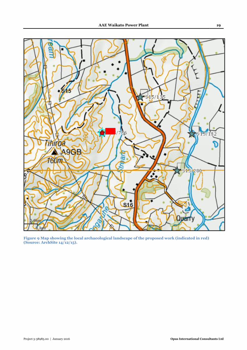
AAE Waikato Power Plant 19
Project 3-38985.00 | January 2016 Opus International Consultants Ltd
Figure 9 Map showing the local archaeological landscape of the proposed work (indicated in red) (Source: ArchSite 14/12/15).

AAE Waikato Power Plant 20
Project 3-38985.00 | January 2016 Opus International Consultants Ltd
Figure 10 Excerpt from SO11442.2 showing the 1899 extent of the Ongaruhe Stream. Note the location of Tiheroa summit and the characteristics of the Waipa River course and the road that enable the proposed works site to be approximately located onto this map (shown in red dash).
7.2 Previously Recorded Archaeology
7.2.1 S15/135
This site is recorded as midden/oven located somewhere along the Maui gas pipeline, the exact
location of which is in dispute and the aerial photograph referred to in the site records has not been
relocated. The site was described in 1974 having been plough-damaged in the past.
7.2.2 S15/ 132
Described on the NZAA site record as a river crossing said to have been used by the Maniapoto
tribes. Its location is shown on the missing aerial photograph, but a written description of its
location in relation to SH31 is provided. The site was not viewed in 1975, nor has the record since
been updated.
7.2.3 S15/280
This is the site of an artefact find, a wooden bowl (tōtara), recovered during the digging of a
drainage ditch through a small swamp at a stream head in 1977. The bowl was found in swamp peat
and was in an excellent state of preservation. It was thought to have been deliberately buried. The
NZAA site record indicates that a report was expected to follow, but this report does not appear to
have been lodged within the HNZPT reports database.

AAE Waikato Power Plant 21
Project 3-38985.00 | January 2016 Opus International Consultants Ltd
7.2.4 S16/355
This site lies approximately 12 km SE of the proposed works but is relevant to this AAE because of
the potential insight into the activities that may have been occurring near waterways such as the
Ongaruhe Stream. Originally described as an incomplete waka (canoe), there has been some
dispute as to whether this was indeed its function. It was suggested by Owen Wilkes (Site Record
files) that the artefact might instead be a large trough of likely Māori manufacture, whose possible
functions include: the preparation of hinau berries by soaking or pounding, karaka kernel steeping,
or maize storage. Wilkes indicates that the location of this artefact find, alongside a river, would
have been ideal for the two-phase maize soaking process, which also required bins (pits dug into
the stream banks) constructed in free-flowing stream water.
7.3 Previous Archaeological Surveys
A search of the HNZPT reports database produced very few archaeological reports pertinent to this
area. Similarly, broader searches for council or Department of Conservation surveys of this area
proved largely unsuccessful. In terms of archaeological features associated with gardening and
cultivation, Furey (2006:61) notes that “little is known of gardening evidence in the inland King
Country from Te Awamutu south”; this despite the presence of storage pits and the volcanic soils,
characteristics of neighbouring areas with considerable gardening evidence. Thus, whilst there is
substantial historic information on the Maori settlement of the Waikato and the King Country, in
particular around the Land War era, there is a paucity of surviving recorded archaeological features
beyond the frequent pā and their associated pits and occupation evidence.
7.4 Historic Aerial Photographs
Historic aerial photographs of the area from 1950 are publically available
(https://gdh.auckland.ac.nz/government_maps/NZMS/NZMS_003/tif/). The streams appear to
follow approximately the same alignment as in current maps and images, however they are
considerably more meandering, indicating the extent of modifications associated with the drainage
of the land for cultivation and farming since 1950 (Figure 11).
The historic aerial photographs do not show any indication of archaeological features such as pits,
either on the immediately surrounding ridges nor within the proposed footprint. There are
however, several areas of interest lying c. 1km to the northeast and c. 700m northwest of the
proposed site (Figures 11 & 12). Both these areas are situated on high ground, a ridge spur and a
high plataeu above the Waipa River. These appear to show linear features that might be associated
with field systems, circular features that might represent storage pits and transverse features that
might represent terrraces.
Aerial images from 1944 (Opus Aerial Survey Archive) have also been viewed and these features are
also present at this time. The 1944 aerial imagery also reveals a numbere of other possible pit
features , of note are those running along a north west to south east trending ridge c. 470m west of
the proposed plant site and c. 450m north east of Tihiroa point.
The original course of the Ongaruhe Stream can be seen running to the west of the current stream
cutting. The extent of drainage and modification of this valley basin is particularly apparent when
comparing the 1899 survey (Figure 10) with the 1950 aerial photograph, and the current state
(Figures 2 & 11). Thus, it is likely that any surface evidence of archaeological sites on the rolling
valley floor would have been destroyed by cultivation and other modification activity prior to 1950.

AAE Waikato Power Plant 22
Project 3-38985.00 | January 2016 Opus International Consultants Ltd
Subsurface features such as pits might show up as changes in vegetation characteristics, but that is
somewhat reliant upon seasonal conditions, angle of view and lighting conditions at the time of
photography, and the resolution of the imagery.
The aerial photograph and 1899 survey clearly show the the proposed works lies closer to a
significant water course than might be suspected based on the modern evidence, and that it
encompasses an area of high ground between the original Ongaruhe Stream and a smaller
tributary.
Figure 11 Excerpt from 1950 aerial photo (N74-5) indicating the stream courses and location of the proposed works (red outline), and the three nearby archaeological record locations (blue stars); note also the potential archaeological features to the north-west (yellow dash). (Source:https://gdh.auckland.ac.nz/government_maps/NZMS/NZMS_003/tif/).

AAE Waikato Power Plant 23
Project 3-38985.00 | January 2016 Opus International Consultants Ltd
Figure 12 Possible unrecorded archaeological features in the vicinity of the proposed work (orange outline); proposed footprint of earthworks (blue box); recorded archaeological sites (blue stars) (Source:https://gdh.auckland.ac.nz/government_maps/NZMS/NZMS_003/tif/).
7.5 Archaeological Authorities Granted in the Area
There has been very limited archaeological investigation undertaken in the local or wider area. A
partially completed waka or trough was discovered during at River Run Quarry, 8 km east of
Otorohanga (ca. 12 km south east of the proposed works) (Darmody, Jacomb & Ritchie 2002). It is
thought to only be 100 – 200 years old, based on the identification of steel tool marks. An
investigation was also undertaken on the Alexandra East Redoubt (S15/375; ARC 1997/065) (ca.
14 km north of the proposed works) (Gumbley 1997). There are no archaeological reports in the
HNZPT Digital Library that encompass the project area.
Midden
Pit?

AAE Waikato Power Plant 24
Project 3-38985.00 | January 2016 Opus International Consultants Ltd
8 Research Results
8.1 Field Visit
The site was first visited by Gaylynne Carter (Opus Archaeologist) on 16 December 2015. At the
request of Nova Energy the paddocks in which the proposed plant footprint sits were walked, as
were the proposed access routes3 (Figure 2). With Mr Davenport’s (the tenant) consent it was also
possible to walk neighbouring paddocks, including some of the higher ground and ridge spurs to
the west of the proposed site. This provided a comprehensive overview of the land. Hand-augering
was undertaken in several locations to determine the nature of the underlying soils and to check for
evidence of modified (gardening) soils. No test-pits were dug, nor was the augering systematically
implemented across the area affected.
The site visit found no surface indication of archaeological sites or materials within the proposed
works footprint nor in the location of the proposed access ways (Figure 13). The hand-auger results
did not produce any evidence of modified soils, although this was not undertaken either
systematically or intensively across the entire site. The ridges and high ground surounding the site
(north, west, south) show evidence of substantial land movement and slumpage both recently and
historically (Figure 14).
Figure 13 Approximate indication of the proposed footprint of works. Note that the work will involve modification to the current small gully and the high ground in front of the trees (current Ongaruhe Stream course). Farm buildings can be seen top centre/right. The farm tracks and the small stream and trees locate the site in the context of Figure 2 (Source: G. Carter).
3 There seemed to be some confusion between where Mr Davenport (share-milker tenant) thought the access route was to go, and where the map supplied by Nova Energy indicated that the access routes might go. To be sure of covering all the required ground, both the area indicated by Mr Davenport, and that indicated on the map were walked.

AAE Waikato Power Plant 25
Project 3-38985.00 | January 2016 Opus International Consultants Ltd
Figure 14 Image illustrating the extensive erosion and slumping that has occurred on the higher slopes and gullies to the northwest and west of the proposed plant footprint (Source: G. Carter).
A possible poorly preserved pit (S15/756) was noted on a small knoll located on an east west
trending spur, approximately 10 m from the valley floor, slightly above and to the west of the
proposed footprint. A marked difference in vegetation, of a type characteristic of a pit interior was
observed, with an apparent NNW SSE alignment (Figure 15). An auger investigation revealed a
markedly different soil profile to that a few metres to the south, and outside the possible pit
interior (Figure 16). Viewed from below, the possible pit is located upon what appears to be a
naturally formed slumped terrace (Figure 17). This might explain the diffence in the soil profile, as
the slump is an accumulation of topsoil. However, it remains possible that the slumpage event is of
considerable age, and provided a convenient location for the construction of a pit. No other such
features were found either during the site visit, nor as a result of examination of the photographic
record of the visit.

AAE Waikato Power Plant 26
Project 3-38985.00 | January 2016 Opus International Consultants Ltd
Figure 15 Possible pit feature (S15/756) (red dash), note the change in vegetation in comparison to surrounding area (Source: G. Carter).
Figure 16 Comparison of soil profiles from suspected pit (S15/756) (left) and adjacent hillside (right). The soil profile of the suspected pit becomes darker with depth and shows no indication of tephra subsoil; the auger sample from the hillslope is a consistent mid brown and orange tephra is beginning to show at the tip (Source: G. Carter).

AAE Waikato Power Plant 27
Project 3-38985.00 | January 2016 Opus International Consultants Ltd
Figure 17 Slump-terrace on which the suspected pit (S15/756) sits (view south west) (outlined in red) (Source: G. Carter).
Both the streams that are within the work footprint (plant and access) appear to have been
significantly modified through the installation of culverts and clearance of silt and vegetation, and
currently bear little resemblance to that recorded in the 1899 survey (Figure 10). The rolling
landscape lends itself to cultivation and has likely been modified through such activity. The farm
track cuts deeply into the hillsides in places, and no evidence of archaeological sites such as pits or
midden material was noted in the banks.
The ridges and spurs that are likely to be affected by Access A and Access B (Figure 2) were also
walked and their general environs observed. No surface evidence of archaeological sites was
observed (Figures 18-20).

AAE Waikato Power Plant 28
Project 3-38985.00 | January 2016 Opus International Consultants Ltd
Figure 18 General view across the area of access (ridge spur), as indicated by Mr Davenport, looking towards the proposed work area. The existing farm track visible in the left of the photo is the route indicated in Figure 2 (Source: G. Carter).
Figure 19 View from the farm track at the bottom of the valley up (east) towards the road where Mr Davenport indicated the access way to be (Source: G. Carter).
SH 31

AAE Waikato Power Plant 29
Project 3-38985.00 | January 2016 Opus International Consultants Ltd
Figure 20 View south west towards the proposed work site along Access B route which will follow the farm track visible in the centre of the photo (Source: G. Carter).
The four possible locations for the power supply were not made available at the time of the site visit
and thus were not able to be included in this field assessment.
A second site visit was undertaken by Kirsty Potts (Opus Archaeologist) on 10th June 2016. The
purpose of this visit was to assess the locations of the three pylons to be installed along Route C,
along with their associated access ways (Figure 21). Also included in this visit was a re-assessment
of the now confirmed northern Access (Access B, Figure 2). All the areas were visited by farm
vehicle or on foot, and existing track cuts were inspected for any evidence of archaeological
materials. No invasive testing was undertaken, and no archaeological features or material were
noted within the areas of proposed work.
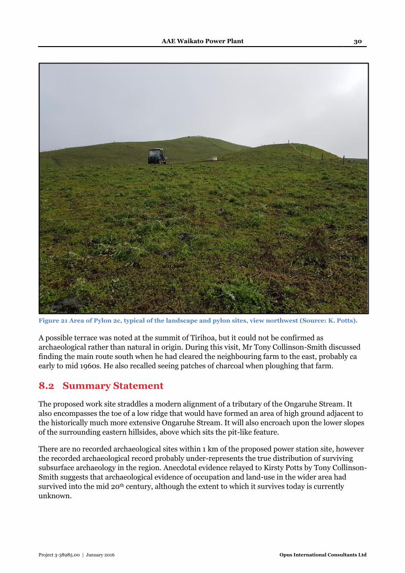
AAE Waikato Power Plant 30
Project 3-38985.00 | January 2016 Opus International Consultants Ltd
Figure 21 Area of Pylon 2c, typical of the landscape and pylon sites, view northwest (Source: K. Potts).
A possible terrace was noted at the summit of Tirihoa, but it could not be confirmed as
archaeological rather than natural in origin. During this visit, Mr Tony Collinson-Smith discussed
finding the main route south when he had cleared the neighbouring farm to the east, probably ca
early to mid 1960s. He also recalled seeing patches of charcoal when ploughing that farm.
8.2 Summary Statement
The proposed work site straddles a modern alignment of a tributary of the Ongaruhe Stream. It
also encompasses the toe of a low ridge that would have formed an area of high ground adjacent to
the historically much more extensive Ongaruhe Stream. It will also encroach upon the lower slopes
of the surrounding eastern hillsides, above which sits the pit-like feature.
There are no recorded archaeological sites within 1 km of the proposed power station site, however
the recorded archaeological record probably under-represents the true distribution of surviving
subsurface archaeology in the region. Anecdotal evidence relayed to Kirsty Potts by Tony Collinson-
Smith suggests that archaeological evidence of occupation and land-use in the wider area had
survived into the mid 20th century, although the extent to which it survives today is currently
unknown.

AAE Waikato Power Plant 31
Project 3-38985.00 | January 2016 Opus International Consultants Ltd
Although there is no surface evidence surviving to indicate archaeological potential within the
footprint of proposed works, there are several aspects to the location that would suggest a risk-
averse approach would be most appropriate in this instance. In particular the earthworks evident
in the 1950s aerial photographs suggests a landscape that may prove to be archaeologically richer
than sites records currently suggest.

AAE Waikato Power Plant 32
Project 3-38985.00 | January 2016 Opus International Consultants Ltd
9 Archaeological and Other Values
This section considers the archaeological and other relevant values, such as historical and cultural
values of the archaeological sites identified in this research. This assessment of archaeological and
other values is based on the HNZPT criteria for evaluation as per HNZPT guidelines for
archaeological assessments.
9.1 Archaeological Values
9.1.1 S15/756
Site Value Assessment
S15/756
Pit
Condition Poor – presents as vegetation anomaly and slight dip in ground,
with different auger test soil profile than surrounding area.
Rarity/
Uniqueness
Isolated pits are rare in the NZAA site record database for this
area, although they do occur in association with pā sites.
Contextual Value Has contextual value for Māori occupation and resource use in
this area.
Information Potential If the site remains outside the wider work area, not just outside
the proposed footprint its information potential is largely
contextual. Should it fall within the wider construction zone,
there is the potential to gain information relating to pit typology
and possibly its usage in this wider area.
Amenity Value The proximity to the proposed works will reduce amenity value.
Its poor preservation further reduces its amenity value.
Cultural Associations Māori
9.1.2 Wider values
There is evidence that this part of the wider Waikato - King Country was heavily utilised by Māori
prior to European contact in the form of numerous pā sites, however domestic, occupation and
horticulture activity outside of the pā environs is rare. Although none of the recorded sites fall
within the work footprint, the presence in the wider locale of a river crossing (S15/132) and a
midden (S15/135), suggests that there may have been a transport route and occupation activity
between the Waipa River crossing and the area of the Ongaruhe Stream.
Middens and ovens are not a common site type in this wider archaeological landscape. The
presence of S15/132 within approximately 1 km of the main works and 400 m of Access B indicates
a possibility that this type of site could occur. Because the main plant footprint straddles an area of
high ground adjacent to the formerly extensive Ongaruhe Stream, it is possible that temporary

AAE Waikato Power Plant 33
Project 3-38985.00 | January 2016 Opus International Consultants Ltd
encampments were located in this area and evidence in the form of midden or oven material such
as fire cracked rock may survive. Should midden be uncovered during the earthworks it has the
potential to add to both the scientific and archaeological knowledge of land and resource use in this
region.
Preserved organic artefacts are extremely rare, although this wider area has produced two
significant waterlogged preserved artefacts, a tōtara bowl (S15/280), and the tōtara waka / kumete
(S16/355) discussed below. Such artefacts offer a rare insight into lifestyle and resource use and
manufacture. The presence, and apparently deliberate deposition (see site record) of the bowl may
indicate that the area between the Waipa River and Ongaruhe Stream was of particular importance
to Māori. It also suggests that the area was being well travelled and used.
The actual function of the Otorohanga waka (S16/355) as either a waka – canoe; or kumete –
trough, has been under dispute (see SRF S16/355), however, either represents a rare and unique
find. If indeed it is an incomplete waka, this artefact is evidence of the use of the Waipa River as a
transport route and in the context of this AAE demonstrates how the nearby river crossing, midden
/ oven and bowl find spot may all form part of a wider network that radiated out from the Waipa,
possibly focussing on smaller, but still significant waterways / wetlands such as the Ongaruhe
Stream.
If the artefact is rather a kumete / trough it indicates the extent to which waterways and water
sources were integral to the preparation of a range of resources including hinau, karaka and maize
both pre and post- European contact. In the context of this AAE it serves to demonstrate the
potential for similar resource procurement and preparation along the banks of the Ongaruhe
Stream, upon which the proposed works would closely approach or encroach.
Although it is unlikely that the area of proposed work will be sufficiently waterlogged to produce
artefacts such as this, it does reinforce the possibility that wetland areas, as this likely was prior to
the modification of the Ongaruhe Stream, were important resource procurement and
manufacturing sites. Inorganic artefacts associated with such activities, e.g., stone tools, may
remain in-situ in the Ongaruhe Stream environs and the possibility of wooden artefacts being
present cannot be discounted
Thus it is apparent that there are potentially significant archaeological and scientific values that
could be derived from any currently undetected archaeology surviving within the area of proposed
works that would add significantly to the archaeological record and understanding of the wider
region.
9.2 Other Values
These sites are all associated with Māori, and have wider cultural values that need to be considered.
It is beyond the remit of the archaeologist to attempt to discuss these, rather it is left to the kaitiaki
and tangata whenua to provide statements of significance relating to these sites.

AAE Waikato Power Plant 34
Project 3-38985.00 | January 2016 Opus International Consultants Ltd
10 Assessment of Effects
The primary purpose of an archaeological assessment is to determine whether or not there are
direct impacts on archaeological sites. HNZPT provides a series of guidelines to assist in the
compilation of reports for assessments of effects on archaeological sites. In considering authority
applications to modify or damage archaeological sites, HNZPT requires statements on the
following values to assist in determining the significance of the archaeological site, the level of
impact and whether an authority can be granted or what mitigation conditions should be attached
to an authority decision.
Under RMA 1991 historic heritage is protected from inappropriate subdivision, use and
development as a matter of national importance (section 6f). The proximity of S15/756 and the
possibility that further unrecorded archaeology lies within the proposed plant footprint and
associated infrastructure requires consideration under the ODC and WRC heritage policies.
Furthermore, the wider area in which this development is situated appears to be currently under-
recorded in terms of the NZAA site records database. Furthering understanding of the
archaeological and heritage potential of this area will help to address this situation.
10.1 Proposed Works
Work for the proposed power station includes both the construction of a new power plant (WPP)
with an estimated footprint area of 200m x 180 m (3.92 ha), along with the creation of suitable
access roads which will entail the modification of existing farm tracks, possibly including
construction of new access ways and the installation of services. The main project footprint
straddles a low ridge and a shallow gully with a small modified stream running through it.
Levelling of this site will require significant earthworks and modification within the development
footprint. The access roads will encroach on areas that were likely former banks of the Ongaruhe
Stream. Although existing farm tracks, cut some time post-1950, will already have damaged any
archaeological features that may be present, upgrading these tracks to service the power plant will
likely involve earthworks to expand and improve them.
There will also be a power line installed along Route C (Figure 22). The pylon footprints potentially
involve significant earthworks depending upon the anchoring system used. An area in excess of 100
m2 could be required to accommodate both the pylon and the crane pad, and excavations could run
to tens of metres in depth (Cathcart, R. Pers comm- see email Appendix 4). Whilst there was no
surface evidence of archaeological materials noted along Pylon Route C sites and associated access-
ways it remains possible that subsurface archaeological materials do survive.
AAE Waikato Power Plant 35
Project 3-38985.00 | January 2016 Opus International Consultants Ltd
Figure 22 Aerial photograph showing the route for power supply and the positions of pylons within the designation (Source: Transpower).
10.2 Archaeological Effects
There are no recorded archaeological sites within the designated footprint of the proposed work for
the power station, however a possible pit (S15/756) was identified during the site visit, lying within
20m of the main plant footprint. This has the potential to be affected by ancillary services and
construction traffic. The ground surface has been significantly modified by farming activity,
including ploughing which will have largely destroyed any surface or shallow archaeological
evidence. None of the other four recorded archaeological sites discussed in this AAE (S15/135;
S15/132; S15/280; S15/355) will be directly affected by the proposed works.
10.3 Potential for Unrecorded Archaeological Sites
The number of recorded archaeological sites in this part of the Waikato-King Country is likely to be
an under-representation of the true number of archaeological sites in the landscape. Throughout
the surrounding area there are several pā sites recorded on ArchSite, but very few sites such as pits
are recorded outside of these pā complexes. Unlike other areas of both the Waikato and Taranaki,
recorded horticultural evidence is scant, and features like borrow pits are non-existent. This lack of
site records is likely the result of a lack of a detailed archaeological survey rather than a lack of
archaeological sites themselves. Anecdotal evidence from long-time resident Tony Collinson-Smith
does suggest that there were clear tracks and other land-use or occupation evidence (fire scoops?)
in the near vicinity (neighbouring farm to the east), that were noted during the mid 20th century.

AAE Waikato Power Plant 36
Project 3-38985.00 | January 2016 Opus International Consultants Ltd
The proposed earthworks, in particular for the power plant footprint, lie in an area that has the
potential to have been a focus for Māori resource procurement and preparation. Its proximity to
the Waipa River, the presence of a well-used river crossing nearby, several finds indicating
occupation, and the significantly more extensive Ongaruhe Stream than is curently seen, all
indicate that there is some potential for unrecorded archaeological evidence to survive.
The area has been modified by twentieth century activity, including the modification of the
Ongaruhe Stream and its tributaries, plough damage and the cutting of farm access tracks.
However, deep features such as the type of pit that might be required for maize processing could
survive below the ground surface along the former Ongaruhe Stream banks; storage pits, midden /
oven sites and other occupation evidence may survive on the higher ground including on the low
ridge straddled by the plant footprint and along the route of proposed Access B. This may be
evidenced by possible pit S15/756. The paddocks to the north of the plant footprint were described
by Mr Davenport as flood prone, and in large part comprise the former Ongaruhe Stream bed.
Should deeply cut pits be present, the watertable may be high enough to achieve some degree of
waterlogged preservation.
Any unrecorded archaeological features found during earthworks have the potential to provide
signficant information about the use of this landscape in pre-European times. Although oral
tradition contains some evidence that this was an important region in the past the archaeological
record is currently lacking in information. The area to the east of Tihiroa, in which this proposed
power plant and ancillary components lies, is currently an unknown quantity in terms of the
archaeological heritage of the region. Any unrecorded archaeology that is discovered will
substantially improve the understanding of Māori land and resource use of this inland region of the
Waikato.
10.4 Avoidance and Mitigation of Effects
There is limited scope for avoidance and mitigation of effects on archaeological material within the
proposed work footprint. There is one recorded archaeological sites within 20m of the proposed
plant footprint. It is currently believed that this site may lie within the wider construction zone of
the power plant. Given the poor state of preservation of this site, it is possible that further sites lie
undetected within the footprint. The possible pit feature ideally requires protection from accidental
damage, for example fencing off. If it cannot be protected it must be afforded mitigation through
appropriate archaeological monitoring and recording. Mitigation for the removal of other
currently unrecorded archaeological material can also be achieved through the appropriate
archaeological monitoring, investigation and recording.
10.5 Management of Archaeological Sites
There are no recorded archaeological sites within the works footprint but one newly recorded
archaeological site lies within 20m of the main plant footprint. Furthermore, Pylon Route C places
pylons along ridge knolls and spurs, locations that have some potential for subsurface archaeology
to survive. Archaeological monitoring or investigation needs to be included in the Archaeological
Management Plan for the overall project that accompanies the authority application to HNZPT.
The authority application will be accompanied by an Archaeological Management Plan document
to define where onsite monitoring by an archaeologist is required, outline on-call procedures, and
provide required contact information.

AAE Waikato Power Plant 37
Project 3-38985.00 | January 2016 Opus International Consultants Ltd
11 Conclusion and Recomendations
This assessment was undertaken to assess the effects on archaeological sites of the proposed
Waikato Power Plant project and its associated infrastructure, on land at 869 Kawhia Road,
Otorohanga. It has been prepared in support of a Resource Consent application in the first
instance, and as an assessment of archaeological effects in support of an archaeological authority
application to HNZPT.
The proposed extent of the earthworks consists of the plant footprint, measuring approximately
200 m x 180 m (3.92 ha), road access and services. The plant footprint straddles a low ridge and
shallow gully along the edge of the former extent of the Ongaruhe Stream. The access roads will in
part follow existing farm tracks, but extensions and modifications will be required to upgrade the
existing tracks for the construction and running of the site. Services will also need to be introduced
to the area. Services are expected to follow the current access roads, but power supply will need to
be provided. Pylon Route C has been selected and archaeologically assessed, with no archaeological
materials noted.
There are no recorded archaeological sites within the footprint of the proposed power plant and
ancillary services. There is a newly recorded site (S15/756) within aproximately 20m of the main
plant footprint. The next closest recorded archaeological site lies approximately 1 km from the
plant footprint, and not closer than 350 m from any access road point. Five recorded sites were
considered in this report, primarily to aid the assessment for archaeological potential as none fall
within the works footprint, although S15/756 lies within approximately 20m. These are: S15/756
(possible pit), S15/135 (midden / oven), S15/132 (traditional river crossing), S15/280 (wooden
bowl artefact findspot) and S16/355 (find spot of a waka).
The archaeological record of this part of the Waikato is poorly represented in sources such as the
NZAA site recording scheme or the HNZPT site reports database. This does not mean, however,
that the area is archaeologically poor. The apparent distribution of sites is likely to be more an
artefact of the effects of historic land use and a lack of archaeological survey and investigation than
a true representation of the archaeological potential of the area. The 1950s aerial photographs
clearly show earthwork features that are consistent with potential archaeological sites in the
surrounding area.
This assessment has found that there is a risk to S15/756, which lies within approximately 20m of
the main plant footprint. Furthermore, the proposed plant footprint does lie in an area that has
some potential for archaeological evidence to survive below the surface. This project has been
discussed between both Cathleen Haumann (HNZPT) and Gaylynne Carter and resulted in a
consensus opinion that there was sufficient grounds to recommend an archaeological authority
application. At a regular meeting between Rachel Darmody (HNZPT) and Sian Keith (Opus),
during which this project was discussed and no queries as to the recomendation were raised.
Recomendations
It should be noted that all archaeological sites are protected by the Heritage New Zealand Pouhere
Taonga Act 2014, whether recorded or not. It is illegal to modify or destroy an archaeological site
without an authority being granted under section 42 of the HNZPTA. On this basis the following
recommendations are made:

AAE Waikato Power Plant 38
Project 3-38985.00 | January 2016 Opus International Consultants Ltd
That an application to Heritage New Zealand Pouhere Taonga be made for an archaeological
authority (A General Authority).
That consultation is undertaken with Iwi to support such an application
That an Archaeological Management Plan is prepared to support such an application
It is recommended that appropriate archaeological conditions of any authority would be that
the works are monitored by an appropriately qualified archaeologist and that provision is made
to allow for the investigation and recording of both the recorded archaeological evidence
already found, and any other archaeological sites that are encountered during the course of
works.

AAE Waikato Power Plant 39
Project 3-38985.00 | January 2016 Opus International Consultants Ltd
12 References
Barber, L. H. 1978. The View from Pirongia: The history of Waipa County. Richards Publishing in
association with Waipa County Council, Te Awamutu.
Darmody, R., Jacomb, C. & Ritchie, N. 2002. Otorohanga Waka. Report to HNZ.
Cowan, J. 1955. The New Zealand Wars: A History of Maori Campaigns and the Pioneering
Period: Volume I (1845-64). RE Owen, Wellington. http://nzetc.victoria.ac.nz/tm/scholarly/tei-
Cow01NewZ-c40.html
Furey, L. 2006. Maori gardening: An archaeological perspective. Department of Conservation,
Science & Technical Publishing.
Gumbley, W. 1997. Report on Archaeological Investigations of Alexandra Eat Redoubt (1864) and
Assessment of the Archaeological Values of the Site. Unpublished Report to HPT.
Ritchie, N. 2001. The Waikato War of 1863-64: A guide to the main events and sites. Te Awamutu
and District Museum in association with the New Zealand Lotteries Commission and the
Department of Conservation.
Ryan, G. 2009. Natural Hazard Risk Assessment: Otorohanga District. Environment Waikato
Technical Report.
Waikato Regional Committee of the Historic Places Trust. 1985. Waikato-Northern King Country:
Historical Guide. Historic Places Trust.

AAE Waikato Power Plant
Project 3-38985.00 | January 2016 Opus International Consultants Ltd
APPENDICES
Appendix 1: Location of proposed works and indication of proposed Access A and B alignments
Appendix 2: Otorohanga District Plan Sections 7 & 21
Appendix 3: Waikato Regional Policy (Heritage)
Appendix 4: Pylon Construction E-mail
Appendix 5: Site Record Forms

AAE Waikato Power Plant
Project 3-38985.00 | January 2016 Opus International Consultants Ltd
Appendix 1
Location of proposed works and indication of proposed Access A and B
alignments
Access A
Access B
Main plant
footprint

AAE Waikato Power Plant
Project 3-38985.00 | January 2016 Opus International Consultants Ltd
Appendix 2
Otorohanga District Plan Sections 7 & 21

AAE Waikato Power Plant
Project 3-38985.00 | January 2016 Opus International Consultants Ltd

AAE Waikato Power Plant
Project 3-38985.00 | January 2016 Opus International Consultants Ltd

AAE Waikato Power Plant
Project 3-38985.00 | January 2016 Opus International Consultants Ltd

AAE Waikato Power Plant
Project 3-38985.00 | January 2016 Opus International Consultants Ltd

AAE Waikato Power Plant
Project 3-38985.00 | January 2016 Opus International Consultants Ltd
Appendix 3
Waikato Regional Policy (Heritage)
3.15 Heritage
Overview
Heritage is a complex resource that people perceive and value from many different perspectives.
The Waikato Region’s heritage involves aspects of the natural, physical and cultural environment,
inherited from the past, which define the present and which will be handed on to future generations.
The Region has a unique and distinctive physical setting and natural environment that has been
extensively modified by human activities. Waikato's heritage is a dynamic resource which changes
spatially over time, as natural systems evolve and humans modify the environment.
The Region’s heritage comprises:
a. Natural heritage - includes indigenous flora and fauna, terrestrial, marine, and freshwater ecosystems and habitats, landscapes, landforms, geological and geomorphic features, soils, and the natural character of the coastline.
b. Cultural heritage - includes sites, places, place names, areas, waahi tapu, taonga, structures, objects, artefacts, natural features of cultural and historical significance, historical associations, people and institutions.
There are many relationships, overlaps, and linkages between these. Therefore the natural and
cultural resources of the Region are inextricably linked.
The Waikato Region is endowed with a rich and diverse variety of natural landforms, geological
and geomorphic features and soils. In combination, these features document the unique geological
history of the Region, the development of its landforms, and the evolution of its biota. Natural
heritage is therefore an aspect of many of the resources addressed in Part 3 (i.e. coast, land, water,
flora and fauna).
In identifying cultural heritage resources local authorities take guidance from the NZ Historic
Places Trust (NZHPT), which has a statutory obligation under s22 of the Historic Places Act 1993,
to establish and maintain a register of historic places, historic areas, waahi tapu and waahi tapu
areas. Regardless of whether all archaeological sites are registered, they are afforded protection
under s10 of the Historic Places Act 1993 and an authority to modify is required from the NZHPT.
A number of agencies have responsibilities for the Region’s heritage. These include Environment
Waikato, the NZHPT, territorial authorities, tangata whenua, the Department of Conservation,
historical societies, the NZ Archaeological Association, and the Queen Elizabeth II Trust. Co-
operation among these agencies and consultation with other interested parties and the general public
is essential for the protection of the Region's heritage. A regionally consistent and integrated
approach to the protection and preservation of Region’s heritage is essential to avoid duplication
and inefficient management.
Tangata whenua have special concerns over the widespread loss of ancestral taonga e.g. waahi tapu
and other areas of cultural significance. Tangata whenua consider that the effects of subdivision,
use, development and interference with their heritage sites in the Region have been significant.
Adverse effects identified by tangata whenua include the inability to manage their taonga according

AAE Waikato Power Plant
Project 3-38985.00 | January 2016 Opus International Consultants Ltd
to tribal customs and preferences, the widespread loss of cultural and natural heritage, and the
reduction of access to remaining heritage. Through their role as kaitiaki, tangata whenua seek
greater involvement in the management of natural and cultural heritage.
Summary of Significant Resource Management Issues
The following is a summary of the significant resource management issues that have been
identified from the overview section on the Region's heritage:
1. The natural and cultural heritage resources are integral parts of the Region's heritage. Subdivision, use and development have the potential to degrade and destroy natural and cultural heritage.
2. Maori heritage resources are of significant spiritual and cultural value to tangata whenua, and are an integral part of the Region's heritage. Subdivision, use, development, and interference have the potential to degrade and destroy Maori heritage resources.
3.15.2 The Region's Heritage
Issue: Natural and cultural heritage resources are integral parts of the Region’s
heritage. Subdivision, use and development have the potential to degrade
and destroy natural and cultural heritage.
Objective: The protection of regionally significant heritage1 resources, and allowing subdivision,
use, and development of other heritage resources, while ensuring that there is no net
loss in the Region.
Principal Reasons for Adopting: The value of the Region’s cultural and historical heritage is
increasingly being recognised and appreciated. Many structures, sites and places have
historical/archaeological or cultural importance which may be adversely affected by changes in
their use or in surrounding land uses. A significant amount of Waikato’s heritage has already been
lost. It is therefore important that appropriate management practices are put in place.
The Region’s natural environment has been extensively modified. This has resulted in the loss of
particular physical features and landforms (such as limestone features and ignimbrite outcrops), and
the loss or deterioration of significant landscape qualities. Landscapes may be significant in terms
of their scientific, visual, cultural or historic values, and therefore it is appropriate to provide
guidance for heritage management from a regional perspective.
To achieve the objective, policies have been developed which will protect the significant heritage
resources of the Region while allowing the use and development of others, within a framework of
no total loss of heritage.
Policy One: Protection of Heritage Resources
Ensure the protection of significant natural and cultural heritage resources.
Implementation Methods:

AAE Waikato Power Plant
Project 3-38985.00 | January 2016 Opus International Consultants Ltd
1. Through district plans and resource consents, identify and provide for the protection of significant natural and cultural heritage resources, including the protection of views and sight-lines of outstanding natural features and landscapes.
2. Encourage territorial authorities in the Region, when they are preparing or reviewing district plans, to promote provisions such as conservation and open space covenants, economic instruments (including rates relief), heritage protection orders and designations for the protection of outstanding and significant natural and cultural heritage resources.
3. Through liaison with territorial authorities, the NZHPT, tangata whenua and other interested parties, ensure the integrated management of the Region’s natural and cultural heritage resource.
4. Provide information to the public pertaining to the Region’s significant heritage resources and their appropriate management, and support education programmes which promote the understanding and values of natural and cultural heritage.
Policy Two: Other Heritage Resources
Allow subdivision, use and development, while avoiding, remedying or mitigating any adverse
effects on other natural and cultural heritage resources.
Implementation Methods:
1. Ensure, through district plans and resource consents, the maintenance of other heritage resources in accordance with established heritage categories.
2. Through resource consents, consider methods that may be adopted to remedy and/or mitigate adverse effects of activities on the Region's heritage resources.
3. Through environmental education programmes, provide education and practical guidance on how heritage resources can be maintained and encourage land users to adopt management practices which avoid, remedy or mitigate adverse effects on natural and cultural heritage resources.
4. Through education and information, encourage an awareness of landscape values and the need for protection, by consultation with farming and forestry organisations, development and resource using enterprises and conservation organisations.
Explanation and Principal Reasons for Adopting:
Many of the significant natural and cultural heritage resources remaining in the Region occur on
private land. Policy One is concerned with protecting those natural and cultural heritage resources
that have been identified as significant. One of the most effective ways of achieving protection of
natural and cultural heritage resources is through increasing public awareness and interest in
heritage. Public education is an important role which can be undertaken by the Waikato Regional
Council (Environment Waikato) in parallel with territorial authorities and national organisations. At
the same time, it is important that regulatory tools are available to ensure protection of particularly
sensitive and significant heritage resources.
Policy Two ensures that that the other heritage resources in the Region are managed so that any
adverse effects associated with subdivision, use and development are avoided, remedied or
mitigated. This will ensure that the use and development of heritage resources is consistent with that
which it is valued for. The methods of implementation are primarily through district plans and the
processing of resource consents. Other methods include advocacy, consultation, and education of
land users.

AAE Waikato Power Plant
Project 3-38985.00 | January 2016 Opus International Consultants Ltd
Within the Region there are many places and structures with significant heritage value related to
early European settlement, such as historic mine sites and examples of early New Zealand
architecture. Appropriate planning techniques need to be in place to protect these. Areas of
particular Maori heritage value must also be protected. Significant archaeological and heritage
features and waahi tapu sites have been identified in the Region. These generally relate to items of
particular social and cultural heritage value to Maori. Where preservation of these can be ensured,
and disclosure will not put the sites at risk, it is considered that these should be scheduled for
protection.
Environmental Results Anticipated
1. Regionally significant natural and cultural heritage resources identified and protected. 2. Other natural and cultural heritage resources maintained. 3. Protection of significant landscapes from the adverse effects of subdivision, use, and
development. 4. A co-ordinated approach to the management of the Region’s heritage with territorial
authorities, affected land owners, tangata whenua and organisations specialising in the field of protecting and maintaining natural and cultural heritage resources.
<<Previous Index Next>>
Footnotes
1. See Appendix 4: Criteria for Determining Significance of Natural and Cultural Heritage Resources.
3.15.3 Maori Heritage
Issue: Maori heritage resources are of significant spiritual and cultural value to
tangata whenua, and are an integral part of the Region’s heritage.
Subdivision, use, development, and interference have the potential to
degrade and destroy Maori heritage resources.
Objective: The protection of heritage resources1 of significance to Maori.
Principal Reasons for Adopting: The relationship of Maori and their culture and traditions with
their ancestral lands, water, sites, waahi tapu and other taonga must be recognised and provided for
as a matter of national importance under the RMA. Therefore it is important that sites with heritage
value for Maori are protected from accidental or intentional damage or abuse. This is particularly
true with some waahi tapu sites where the precise locality of certain features is carefully guarded
information.
Policy One: Protection of Maori Heritage
Seek to avoid accidental or intentional damage or interference to heritage resources of significance
to Maori.
Implementation Methods:

AAE Waikato Power Plant
Project 3-38985.00 | January 2016 Opus International Consultants Ltd
1. Through district plans and resource consents and in accordance with tikanga Maori, provide for the protection of identified significant heritage resources, while recognising the right of tangata whenua not to publicly identify all significant heritage resources.
2. Provide information and practical guidance to resource users on the significance of heritage resources to tangata whenua and strongly encourage applicants to consult with the appropriate tangata whenua groups prior to submitting applications for resource consents.
3. In consultation with tangata whenua, territorial authorities, and other interested parties identify and make appropriate provision for sites and areas of Maori spiritual and cultural value where public access should be restricted.
4. Investigate delegation or transfer of functions, powers and duties to iwi for the administration of heritage resources, and where appropriate undertake such delegation or transfer.
5. Encourage territorial authorities and consent holders to notify relevant iwi authorities and cease work in areas where unidentified burial grounds or waahi tapu sites are disturbed or destroyed.
Explanation and Principal Reasons for Adopting:
Section 2.1 states the broad issues which are of resource management significance to tangata
whenua, and objectives and policies to address those issues. It is, however, considered appropriate
to include policies in relation to the protection of heritage sites of value to Maori in this section, to
provide for integrated management within the document.
The effects of the Region’s continued growth and development on the relationship of tangata
whenua to their ancestral taonga are significant. Adverse effects from this growth and development
are the inability of tangata whenua to manage their taonga according to tribal customs and
preferences, and the widespread loss of natural and cultural heritage values. Therefore it is
necessary to put in place measures to promote the protection of these heritage resources.
Policy One provides for the protection of Maori heritage resources by ensuring that accidental or
intentional damage or interference is avoided, remedied or mitigated. The means of implementing
this policy rely on methods which include the identification and protection of Maori heritage sites
of significance, consultation over resource consent sites, restriction of public access and
investigation of transfer of powers to iwi.
Identification of Maori heritage resources has, in the past, lead to accidental and intentional
interference and destruction. For these reasons iwi must be given the right not to identify sites
unless an appropriate system is put in place by regional and district councils to deal with such
sensitive information. It is also recognised that in some circumstances the protection of these
heritage values is best carried out by tangata whenua and appropriate measures should be put in
place that promote transfer of power.
Environmental Results Anticipated
1. Protection and enhancement of relationships of tangata whenua with their taonga. 2. Iwi satisfied that the heritage resources valued by Maori are protected.

AAE Waikato Power Plant
Project 3-38985.00 | January 2016 Opus International Consultants Ltd
Appendix 4
Pylon Construction E-mail
From: Russell Cathcart [mailto:[email protected]]
Sent: Tuesday, 26 January 2016 1:01 p.m.
To: Bill Armstrong; Jeremy Miller
Cc: Chris Pye
Subject: RE: WPP Archaeology
Bill
The only trenching outside of the building platform that I can think of would be related to the Gas pipeline,
water supply from the farm boar, and diverting the drains and storm water around the building platform.
There is also the potential for trenching of other services such as communication cables and a local
distribution network power cables for shut down and construction power supplies. This services are unknown
at this point in time but for now it would be best to assume that these services would run along the access
road route. If a water source is secured then this would introduce some trenching also, best to exclude as not
sure where this would be.
In terms of pylon civil earth works there are two things that need to be considered, the first being the footing
of the tower itself and the second being the crane pad of about 100m2 adjacent to the tower to allow for the
erection of the tower unless helicopters are used. For a suspension lattice tower with a mass concrete
footing you would be considering something along the lines the figure below. Mass concrete footing would
have the largest earth work volumes as opposed to piles or a rock anchor.
Hope this helps answer your questions
Russell
AAE Waikato Power Plant
Project 3-38985.00 | January 2016 Opus International Consultants Ltd
W = 4.0 – 5.5m, H=1.0 – 1.5 m, D =4m
______________________________________________________________________________
_
Russell Cathcart BE(Hons) (Elec), CPEng, IntPE(NZ), MIPENZ
Senior Electrical Engineer - Energy | Aurecon
Ph: +64 7 834 4614 | Fax: +64 7 834 3527 | Mob: +64 21 622 667
Email: [email protected]
Level 1, 286 Victoria Street | PO Box 487 | Hamilton 3240 | New Zealand
http://www.aurecongroup.com
http://www.aurecongroup.com/apac/groupentity/
AAE Waikato Power Plant
Project 3-38985.00 | January 2016 Opus International Consultants Ltd
Appendix 5 Site Record Forms
S15/756

AAE Waikato Power Plant
Project 3-38985.00 | January 2016 Opus International Consultants Ltd
AAE Waikato Power Plant
Project 3-38985.00 | January 2016 Opus International Consultants Ltd
S15/132

AAE Waikato Power Plant
Project 3-38985.00 | January 2016 Opus International Consultants Ltd

AAE Waikato Power Plant
Project 3-38985.00 | January 2016 Opus International Consultants Ltd
S15/135

AAE Waikato Power Plant
Project 3-38985.00 | January 2016 Opus International Consultants Ltd

AAE Waikato Power Plant
Project 3-38985.00 | January 2016 Opus International Consultants Ltd
S15/280

AAE Waikato Power Plant
Project 3-38985.00 | January 2016 Opus International Consultants Ltd

AAE Waikato Power Plant
Project 3-38985.00 | January 2016 Opus International Consultants Ltd

AAE Waikato Power Plant
Project 3-38985.00 | January 2016 Opus International Consultants Ltd
S16/355
There are 19 pages of supporting documents for this record, primarily a letter from Owen Wilkes
disputing the interpretation of a waka for this find. These are not reproduced here but could be
produced as a pdf attachment to the main document if required.

Opus International Consultants Ltd Opus House, 6 Ossian Street Private Bag 6019, Hawkes Bay Mail Centre, Napier 4142 New Zealand t: +64 6 833 5100 f: +64 6 835 0881 w: www.opus.co.nz