Catalogue - Nova Zeta 3
180
Catalogue WoR 1
-
Upload
khangminh22 -
Category
Documents
-
view
0 -
download
0
Transcript of Catalogue - Nova Zeta 3

CatalogueWoR 1

ComatReleco at a glance ComatReleco is one of the world’s leading suppliers of high-quality relays and contactors of all kinds. With one of the broadest product portfolios, including customized solutions, ComatReleco serves customers in the industrial automation and building installation, rail and transportation segments. Our core competencies are industrial relays, timing relays, monitoring relays and contactors. These are installed with the latest semiconductor tech-nologies or also with the traditional electromechanical design.
Designed in Switzerland, assembled in…ComatReleco continuously invests in research and development, thus ensuring a con-sistently high rate of innovation. Several international patent applications support this fact. Our research and development team is headquartered in Switzerland and has access to additional qualified employees in our subsidiaries in Germany and China. With a share of more than 20% of total research and development costs, we outperform many global players in our segment.
Customer orientation and quality managementComatReleco has a group-wide quality management system with real-time access to test and inspection protocols. Our relays and contactors are 100% tested at the end of the production line. On arrival of the goods at our central warehouse in Switzerland, another quality test is carried out.
Are you using a ComatReleco product or are you looking for a suitable solution? Our sup-port centre in Switzerland will be happy to help you find the right relay or contactor for your application. ComatReleco is known for the world’s largest number of customized solutions for industrial, time and monitoring relays and contactors.
Headquarters in Switzerland – international presenceThe warehouse and logistics are managed centrally at the headquarters in Switzerland. Production is diversified and optimized in terms of quality, costs and logistics criteria. Our production sites are located in Europe and Asia. Through our network of distribution part-ners, the Group is present on all world markets. ComatReleco has been part of the man-agement team since 2003.
Version WoR 1.1 EN
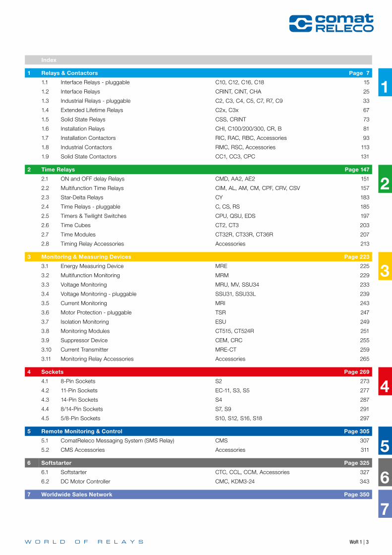
Index
1 Relays & Contactors Page 7
1.1 Interface Relays - pluggable C10, C12, C16, C18 15
1.2 Interface Relays CRINT, CINT, CHA 25
1.3 Industrial Relays - pluggable C2, C3, C4, C5, C7, R7, C9 33
1.4 Extended Lifetime Relays C2x, C3x 67
1.5 Solid State Relays CSS, CRINT 73
1.6 Installation Relays CHI, C100/200/300, CR, B 81
1.7 Installation Contactors RIC, RAC, RBC, Accessories 93
1.8 Industrial Contactors RMC, RSC, Accessories 113
1.9 Solid State Contactors CC1, CC3, CPC 131
2 Time Relays Page 147
2.1 ON and OFF delay Relays CMD, AA2, AE2 151
2.2 Multifunction Time Relays CIM, AL, AM, CM, CPF, CRV, CSV 157
2.3 Star-Delta Relays CY 183
2.4 Time Relays - pluggable C, CS, RS 185
2.5 Timers & Twilight Switches CPU, QSU, EDS 197
2.6 Time Cubes CT2, CT3 203
2.7 Time Modules CT32R, CT33R, CT36R 207
2.8 Timing Relay Accessories Accessories 213
3 Monitoring & Measuring Devices Page 223
3.1 Energy Measuring Device MRE 225
3.2 Multifunction Monitoring MRM 229
3.3 Voltage Monitoring MRU, MV, SSU34 233
3.4 Voltage Monitoring - pluggable SSU31, SSU33L 239
3.5 Current Monitoring MRI 243
3.6 Motor Protection - pluggable TSR 247
3.7 Isolation Monitoring ESU 249
3.8 Monitoring Modules CT515, CT524R 251
3.9 Suppressor Device CEM, CRC 255
3.10 Current Transmitter MRE-CT 259
3.11 Monitoring Relay Accessories Accessories 265
4 Sockets Page 269
4.1 8-Pin Sockets S2 273
4.2 11-Pin Sockets EC-11, S3, S5 277
4.3 14-Pin Sockets S4 287
4.4 8/14-Pin Sockets S7, S9 291
4.5 5/8-Pin Sockets S10, S12, S16, S18 297
5 Remote Monitoring & Control Page 305
5.1 ComatReleco Messaging System (SMS Relay) CMS 307
5.2 CMS Accessories Accessories 311
6 Softstarter Page 325
6.1 Softstarter CTC, CCL, CCM, Accessories 327
6.2 DC Motor Controller CMC, KDM3-24 343
7 Worldwide Sales Network Page 350
2
3
4
5
6
7
1
WoR 1 | 3
WoR 1 | 54 | WoR 1
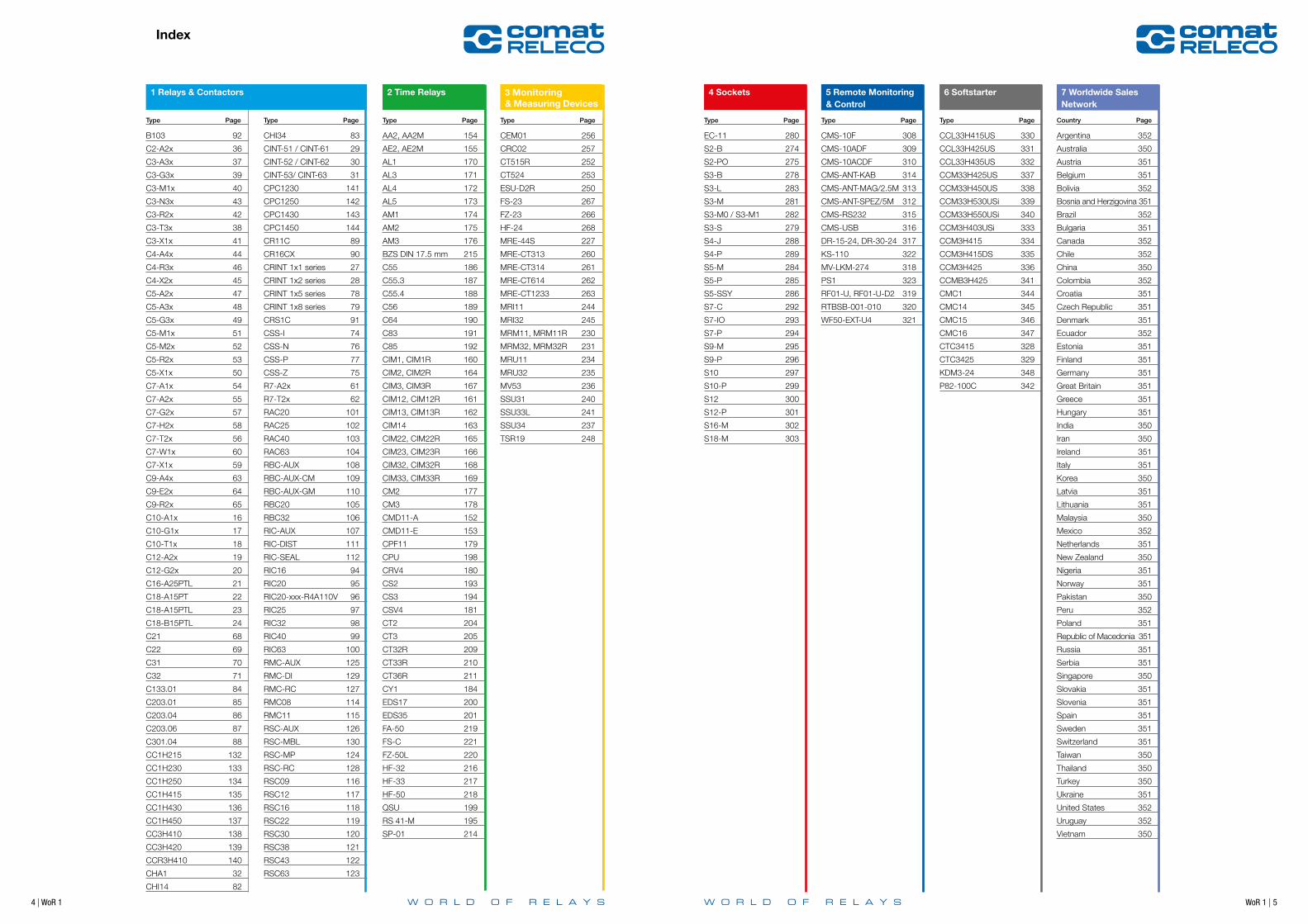
Type Page Type PageType Page Type Page Type Page Type Page Type Page Country Page
4 Sockets 5 Remote Monitoring & Control
6 Softstarter 7 Worldwide Sales Network
B103 92
C2-A2x 36
C3-A3x 37
C3-G3x 39
C3-M1x 40
C3-N3x 43
C3-R2x 42
C3-T3x 38
C3-X1x 41
C4-A4x 44
C4-R3x 46
C4-X2x 45
C5-A2x 47
C5-A3x 48
C5-G3x 49
C5-M1x 51
C5-M2x 52
C5-R2x 53
C5-X1x 50
C7-A1x 54
C7-A2x 55
C7-G2x 57
C7-H2x 58
C7-T2x 56
C7-W1x 60
C7-X1x 59
C9-A4x 63
C9-E2x 64
C9-R2x 65
C10-A1x 16
C10-G1x 17
C10-T1x 18
C12-A2x 19
C12-G2x 20
C16-A25PTL 21
C18-A15PT 22
C18-A15PTL 23
C18-B15PTL 24
C21 68
C22 69
C31 70
C32 71
C133.01 84
C203.01 85
C203.04 86
C203.06 87
C301.04 88
CC1H215 132
CC1H230 133
CC1H250 134
CC1H415 135
CC1H430 136
CC1H450 137
CC3H410 138
CC3H420 139
CCR3H410 140
CHA1 32
CHI14 82
AA2, AA2M 154
AE2, AE2M 155
AL1 170
AL3 171
AL4 172
AL5 173
AM1 174
AM2 175
AM3 176
BZS DIN 17.5 mm 215
C55 186
C55.3 187
C55.4 188
C56 189
C64 190
C83 191
C85 192
CIM1, CIM1R 160
CIM2, CIM2R 164
CIM3, CIM3R 167
CIM12, CIM12R 161
CIM13, CIM13R 162
CIM14 163
CIM22, CIM22R 165
CIM23, CIM23R 166
CIM32, CIM32R 168
CIM33, CIM33R 169
CM2 177
CM3 178
CMD11-A 152
CMD11-E 153
CPF11 179
CPU 198
CRV4 180
CS2 193
CS3 194
CSV4 181
CT2 204
CT3 205
CT32R 209
CT33R 210
CT36R 211
CY1 184
EDS17 200
EDS35 201
FA-50 219
FS-C 221
FZ-50L 220
HF-32 216
HF-33 217
HF-50 218
QSU 199
RS 41-M 195
SP-01 214
CHI34 83
CINT-51 / CINT-61 29
CINT-52 / CINT-62 30
CINT-53/ CINT-63 31
CPC1230 141
CPC1250 142
CPC1430 143
CPC1450 144
CR11C 89
CR16CX 90
CRINT 1x1 series 27
CRINT 1x2 series 28
CRINT 1x5 series 78
CRINT 1x8 series 79
CRS1C 91
CSS-I 74
CSS-N 76
CSS-P 77
CSS-Z 75
R7-A2x 61
R7-T2x 62
RAC20 101
RAC25 102
RAC40 103
RAC63 104
RBC-AUX 108
RBC-AUX-CM 109
RBC-AUX-GM 110
RBC20 105
RBC32 106
RIC-AUX 107
RIC-DIST 111
RIC-SEAL 112
RIC16 94
RIC20 95
RIC20-xxx-R4A110V 96
RIC25 97
RIC32 98
RIC40 99
RIC63 100
RMC-AUX 125
RMC-DI 129
RMC-RC 127
RMC08 114
RMC11 115
RSC-AUX 126
RSC-MBL 130
RSC-MP 124
RSC-RC 128
RSC09 116
RSC12 117
RSC16 118
RSC22 119
RSC30 120
RSC38 121
RSC43 122
RSC63 123
CEM01 256
CRC02 257
CT515R 252
CT524 253
ESU-D2R 250
FS-23 267
FZ-23 266
HF-24 268
MRE-44S 227
MRE-CT313 260
MRE-CT314 261
MRE-CT614 262
MRE-CT1233 263
MRI11 244
MRI32 245
MRM11, MRM11R 230
MRM32, MRM32R 231
MRU11 234
MRU32 235
MV53 236
SSU31 240
SSU33L 241
SSU34 237
TSR19 248
EC-11 280
S2-B 274
S2-PO 275
S3-B 278
S3-L 283
S3-M 281
S3-M0 / S3-M1 282
S3-S 279
S4-J 288
S4-P 289
S5-M 284
S5-P 285
S5-SSY 286
S7-C 292
S7-IO 293
S7-P 294
S9-M 295
S9-P 296
S10 297
S10-P 299
S12 300
S12-P 301
S16-M 302
S18-M 303
CMS-10F 308
CMS-10ADF 309
CMS-10ACDF 310
CMS-ANT-KAB 314
CMS-ANT-MAG/2.5M 313
CMS-ANT-SPEZ/5M 312
CMS-RS232 315
CMS-USB 316
DR-15-24, DR-30-24 317
KS-110 322
MV-LKM-274 318
PS1 323
RF01-U, RF01-U-D2 319
RTBSB-001-010 320
WF50-EXT-U4 321
CCL33H415US 330
CCL33H425US 331
CCL33H435US 332
CCM33H425US 337
CCM33H450US 338
CCM33H530USi 339
CCM33H550USi 340
CCM3H403USi 333
CCM3H415 334
CCM3H415DS 335
CCM3H425 336
CCMB3H425 341
CMC1 344
CMC14 345
CMC15 346
CMC16 347
CTC3415 328
CTC3425 329
KDM3-24 348
P82-100C 342
Argentina 352
Australia 350
Austria 351
Belgium 351
Bolivia 352
Bosnia and Herzigovina 351
Brazil 352
Bulgaria 351
Canada 352
Chile 352
China 350
Colombia 352
Croatia 351
Czech Republic 351
Denmark 351
Ecuador 352
Estonia 351
Finland 351
Germany 351
Great Britain 351
Greece 351
Hungary 351
India 350
Iran 350
Ireland 351
Italy 351
Korea 350
Latvia 351
Lithuania 351
Malaysia 350
Mexico 352
Netherlands 351
New Zealand 350
Nigeria 351
Norway 351
Pakistan 350
Peru 352
Poland 351
Republic of Macedonia 351
Russia 351
Serbia 351
Singapore 350
Slovakia 351
Slovenia 351
Spain 351
Sweden 351
Switzerland 351
Taiwan 350
Thailand 350
Turkey 350
Ukraine 351
United States 352
Uruguay 352
Vietnam 350
3 Monitoring & Measuring Devices
1 Relays & Contactors 2 Time Relays
Index

WoR 1 | 76 | WoR 1
Notes 1
1 Re
lays
& C
onta
ctor
s
1 Relays & Contactors
8 | WoR 1 WoR 1 | 9
1
1 Re
lays
& C
onta
ctor
s
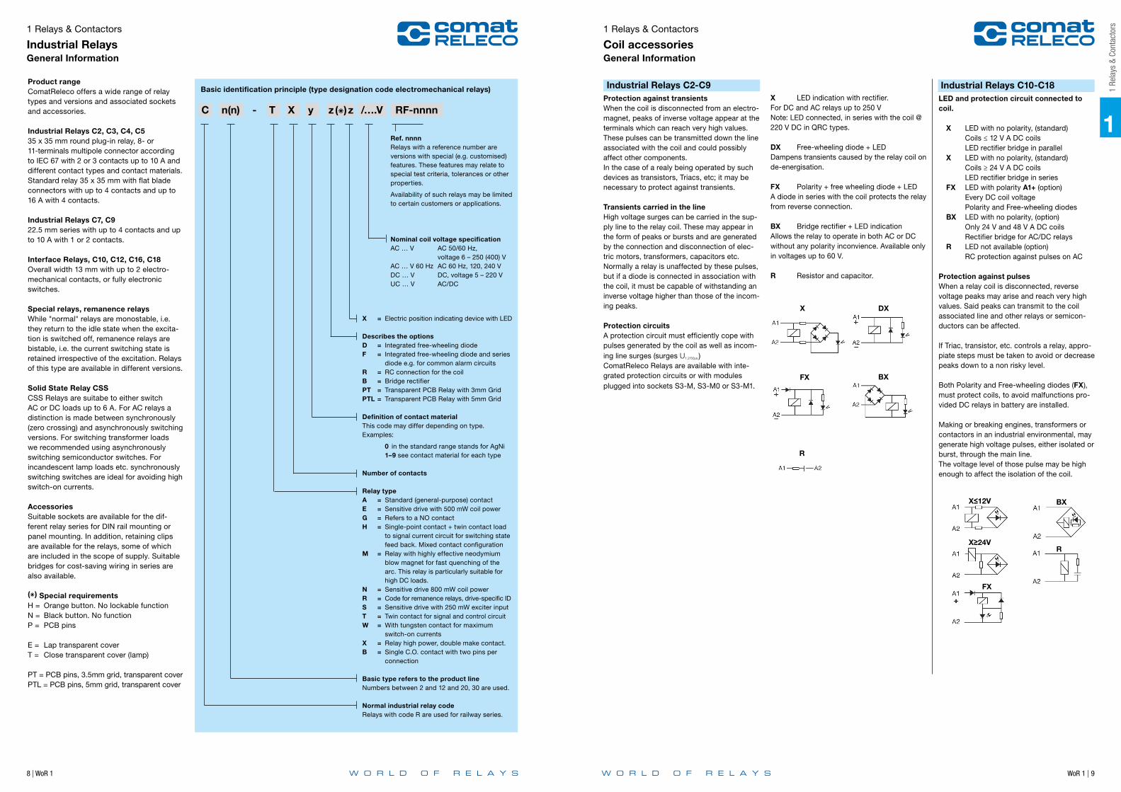
Product rangeComatReleco offers a wide range of relay types and versions and associated sockets and accessories.
Industrial Relays C2, C3, C4, C535 x 35 mm round plug-in relay, 8- or 11- terminals multipole connector according to IEC 67 with 2 or 3 contacts up to 10 A and different contact types and contact materials.Standard relay 35 x 35 mm with flat blade connectors with up to 4 contacts and up to 16 A with 4 contacts.
Industrial Relays C7, C922.5 mm series with up to 4 contacts and up to 10 A with 1 or 2 contacts.
Interface Relays, C10, C12, C16, C18Overall width 13 mm with up to 2 electro-mechanical contacts, or fully electronic switches.
Special relays, remanence relaysWhile "normal" relays are monostable, i.e. they return to the idle state when the excita-tion is switched off, remanence relays are bistable, i.e. the current switching state is retained irrespective of the excitation. Relays of this type are available in different versions.
Solid State Relay CSSCSS Relays are suitabe to either switch AC or DC loads up to 6 A. For AC relays a distinction is made between synchronously (zero crossing) and asynchronously switching versions. For switching transformer loads we recommended using asynchronously switching semiconductor switches. For incandescent lamp loads etc. synchronously switching switches are ideal for avoiding high switch-on currents.
AccessoriesSuitable sockets are available for the dif-ferent relay series for DIN rail mounting or panel mounting. In addition, retaining clips are available for the relays, some of which are included in the scope of supply. Suitable bridges for cost-saving wiring in series are also available.
() Special requirementsH = Orange button. No lockable functionN = Black button. No functionP = PCB pins
E = Lap transparent coverT = Close transparent cover (lamp)
PT = PCB pins, 3.5mm grid, transparent coverPTL = PCB pins, 5mm grid, transparent cover
Basic identification principle (type designation code electromechanical relays)
X = Electric position indicating device with LED
Describes the optionsD = Integrated free-wheeling diodeF = Integrated free-wheeling diode and series diode e.g. for common alarm circuits R = RC connection for the coilB = Bridge rectifierPT = Transparent PCB Relay with 3mm GridPTL = Transparent PCB Relay with 5mm Grid
Definition of contact material This code may differ depending on type.Examples:
0 in the standard range stands for AgNi 1–9 see contact material for each type
Number of contacts
Relay typeA = Standard (general-purpose) contactE = Sensitive drive with 500 mW coil powerG = Refers to a NO contact H = Single-point contact + twin contact load to signal current circuit for switching state feed back. Mixed contact configurationM = Relay with highly effective neodymium blow magnet for fast quenching of the arc. This relay is particularly suitable for high DC loads.N = Sensitive drive 800 mW coil powerR = Code for remanence relays, drive-specific IDS = Sensitive drive with 250 mW exciter input T = Twin contact for signal and control circuitW = With tungsten contact for maximum switch-on currentsX = Relay high power, double make contact.B = Single C.O. contact with two pins per connection
Basic type refers to the product line Numbers between 2 and 12 and 20, 30 are used.
Normal industrial relay codeRelays with code R are used for railway series.
Ref. nnnnRelays with a reference number are versions with special (e.g. customised) features. These features may relate to special test criteria, tolerances or other properties.
Availability of such relays may be limited to certain customers or applications.
Nominal coil voltage specificationAC … V AC 50/60 Hz,
voltage 6 – 250 (400) VAC … V 60 Hz AC 60 Hz, 120, 240 VDC … V DC, voltage 5 – 220 VUC … V AC/DC
C n(n) - T X y z () z /….V RF-nnnn
Industrial Relays C2-C9Protection against transientsWhen the coil is disconnected from an electro-magnet, peaks of inverse voltage appear at the terminals which can reach very high values. These pulses can be transmitted down the line associated with the coil and could possibly affect other components.In the case of a realy being operated by such devices as transistors, Triacs, etc; it may be necessary to protect against transients.
Transients carried in the lineHigh voltage surges can be carried in the sup-ply line to the relay coil. These may appear in the form of peaks or bursts and are generated by the connection and disconnection of elec-tric motors, transformers, capacitors etc.Normally a relay is unaffected by these pulses, but if a diode is connected in association with the coil, it must be capable of withstanding an inverse voltage higher than those of the incom-ing peaks.
Protection circuitsA protection circuit must efficiently cope with pulses generated by the coil as well as incom-ing line surges (surges U1.2/50µs.)ComatReleco Relays are available with inte-grated protection circuits or with modules plugged into sockets S3-M, S3-M0 or S3-M1.
X LED indication with rectifier.For DC and AC relays up to 250 VNote: LED connected, in series with the coil @ 220 V DC in QRC types.
DX Free-wheeling diode + LEDDampens transients caused by the relay coil on de-energisation.
FX Polarity + free wheeling diode + LEDA diode in series with the coil protects the relay from reverse connection.
BX Bridge rectifier + LED indicationAllows the relay to operate in both AC or DC without any polarity inconvience. Available only in voltages up to 60 V.
R Resistor and capacitor.
Industrial Relays C10-C18LED and protection circuit connected to coil. X LED with no polarity, (standard)
Coils ≤ 12 V A DC coils LED rectifier bridge in parallel
X LED with no polarity, (standard) Coils ≥ 24 V A DC coils LED rectifier bridge in series
FX LED with polarity A1+ (option) Every DC coil voltage Polarity and Free-wheeling diodes
BX LED with no polarity, (option) Only 24 V and 48 V A DC coils Rectifier bridge for AC/DC relays
R LED not available (option) RC protection against pulses on AC
Protection against pulsesWhen a relay coil is disconnected, reverse voltage peaks may arise and reach very high values. Said peaks can transmit to the coil associated line and other relays or semicon-ductors can be affected.
If Triac, transistor, etc. controls a relay, appro-piate steps must be taken to avoid or decrease peaks down to a non risky level.
Both Polarity and Free-wheeling diodes (FX), must protect coils, to avoid malfunctions pro-vided DC relays in battery are installed.
Making or breaking engines, transformers or contactors in an industrial environmental, may generate high voltage pulses, either isolated or burst, through the main line.The voltage level of those pulse may be high enough to affect the isolation of the coil.
X
F FX BXB
DX
BXX≤12V
X≥24VR
FX
D
R
1 Relays & Contactors
Industrial RelaysGeneral Information
1 Relays & Contactors
Coil accessoriesGeneral Information
X
F FX BXB
DX
BXX≤12V
X≥24VR
FX
D
R
X
F FX BXB
DX
BXX≤12V
X≥24VR
FX
D
R
X
F FX BXB
DX
BXX≤12V
X≥24VR
FX
D
R
X
F FX BXB
DX
BXX≤12V
X≥24VR
FX
D
R

10 | WoR 1 WoR 1 | 11
1
1 Re
lays
& C
onta
ctor
s
ContactsThere are different contact types. The main distinction is between single contacts and twin contacts. While single contacts are more suit-able for higher loads, twin contacts are signifi-cantly more reliable at small loads, i.e. < 24V, < 100mA.
Contact MaterialThere is no all-purpose contact!AgNi is used as standard material for a wide range of applications. AgNi contacts with hard gold plating (up to 5µm) are offered for appli-cations in aggressive atmosphere. Relays with gold contacts are approved for relatively high currents (e.g. 6A, 250V), but in practice values of 200mA, 30V should not be exceeded for operation with intact gold plat-ing.Relays with a tungsten pre-contact are avail-able for very high switch-on currents (up to 500A, 2.5ms). For some applications AgNi contacts with gold flashing (0.2µm) are availa-ble. The purpose is corrosion protection during storage. Tin oxide is specially appropiated for load with high-inrush current.
Minimum loadThe minimum load value is a recommended value under normal conditions such as regu-lar switching, no special ambient conditions, etc. Under these conditions reliable switching behaviour can be expected.
Contact resistanceInitial values of resistance of contact can vary with the use, load and others conditions.Typical values when the relay is new is about 50mΩ.
Contact spacingNormally all contacts have an air gap between 0.5 … 1.5mm when they are open. They are referred to as µ contacts. According to the Low-Voltage Directive and the associated standards these contacts are not suitable for safe disconnection.For switching of DC loads large contact clear-ances are beneficial for quenching the arc. See relays with "Cx-Gyz" naming. "G" stands for extended contact gap of 3mm.
Switching capacityThe contact switching capacity is the product of switching voltage and switching current.For AC the permitted switching capacity is generally high enough to handle the max. continuous AC-1 current over the whole volt-age range. For DC the load limit curve must never be exceeded, because this would lead to a remaining switch-off arc and immediate destruction of the relay. The order of mag-nitude of the DC switching capacity is a few 100W (DC-1).
During intermittent operation significantly higher overvoltages temporary may occur for short periods. If in doubt please consult our specialists.
General designComatReleco Relays are made from high-quality, carefully selected materials.They comply with the latest environmental regulations such as RohS. Their meticulous design makes them particularly suitable for industrial applications and installation engi-neering.They are particularly service-friendly through robust terminals, mechanical position indi-cating device a standard, manual operation, dynamic, permanent characteristics.Colour coding for manual operation as a function of the coil voltage is another useful feature. Further options such as different coil connections, free-wheeling diode, LED display, bridge rectifier for AC/DC drives etc., and short-term availability of special versions for practically any drive voltage up to DC 220V /AC 400V leave nothing to be desired.Apart from a few special versions, in general, ComatReleco industrial relays feature manual operation (push/pull) and a mechanical posi-tion indicating device. For safety reasons, manual operation may be replaced with a black button, if required.
Coil connectionsDifferent coil connections can be integrated in the relay as an option. For DC a cost-effective free-wheeling diode is available. Please note that the stated release times are generally specified without the coil connection. While an additional LED status indicator haspractically no effect, a free-wheeling diode (D)will lead to an increase in release time by afactor 2 to 5, or 10ms to 30ms. For AC VDRsor RC elements may be used. In this caseresonance effects may have to be considered.VDRs and common RC elements may increaserelease times by less than 5 ms.
2
1
Ub/UN 1.7 1.5
1.3 1.1 0.9
0.7
0.5
All -20 -5 10 25 40 55 70 T ºC
Drive (coil)The drive of a relay refers to the coil plus con-nections. The coil has special characteristics, depending on the rated voltage and the type of current.
Coil designThe coil consists of a plastic former (resist-ant up to about 130°C) and doubly insulated high-purity copper wire, temperature class F. The winding must withstand threshold voltag-es (EN 61000-4-5) of more than 2000V. This is ensured through forced separation of the start and end of the winding.
Coil resistance and other propertiesEach coil has an ohmic coil resistance that can be verified with an ohmmeter. The specified coil resistance applies to a temperature of 20°C. The tolerance is ±10%.For AC operation the coil current will not match the ohmic value, because self-in-ductance plays a dominant role. At 230V this may reach more than 90H. When a relay is switched off, self-inductance results in a self-induced voltage that may affect the switching source (destruction of transistors, EMC problems).
Drive voltagesA distinction is made between the standard-ised voltages according to EN 60947 as guar-anteed values, and typical values that can be expected with a high degree of probability.
Pick-up voltage, Release voltageThe pick-up voltage is the voltage at which the relay engages safely. For DC the typical trip voltage is approx. 65% of Unom, for AC approx. 75%. The release voltage, on the other hand, is approx. 25% or 60% respectively.For DC these voltages are strongly tempera-ture-dependent, according to the temperature coefficient of Cu. This is not the case for AC, where the inductive resistance is the con-trolling factor, which is practically constant over a wide temperature range.With AC, in a certain undervoltage range the relay may hum, and the armature may flutter. This voltage range must be avoided.
Operating voltage rangeUnless specified otherwise, the following char-acteristic curve applies for the operating volt-age range. The upper limit of the coil voltage is determined by self-heating and the ambient temperature. Self-heating through contacts under high load must not be underestimated. It may be higher than the power dissipation in the drive.
Main technical approvals and standardsStandards, conformitiesAll ComatReleco relays feature the CE mark to indicate that CE standards apply e.g. 2kV surge resistance according to EN 61000-4-5. A significant and not generally available characteristic is that the coils and in particu-lar the connections are able to withstand the voltage spikes that may occur in practice.In addition, the relays feature various tech-nical approvals depending on the respective relay code, and they comply with further standards and guidelines. The main techni-cal approvals include cURus, CCC, Lloyd‘s Register, cULus and EAC.The associated information is provided in the data sheets.
Switching classesEN 60947 defines different switching classes that specify the suitability of contacts for dif-ferent load types.
Example:AC-1 = Ohmic AC loadAC-3 = Motor loadsAC-15 = Power contactors, solenoid valves, solenoidsDC-1 = Ohmic DC loadDC-13 = DC contactors, solenoids
UL60947 contains different technical approval criteria such as general purpose, control application etc. Switching classes are defined based on the electrical switching capacity, e.g. B600 etc.
Choosing the right SocketFor plug-in industry, interface, time, and mon-itoring relays, we offer sockets with the corre-sponding pin configuration and various layouts for the terminal connectors. For easy identifi-cation, you'll find those symbol referring to the matching socket.
Utilisation categories according to EN 60947-4-1/-5-1
Pollution categoryCat. 1Dry, non-conductive contamination without further effect
Cat. 2Occasional conductive contamination, short duration due to moisture condensation
Cat. 3Dry, non-conductive and conductive con-tamination with moisture condensation
Cat. 4Contamination with persistent conductivity through conductive dust, rain
Protection class IP according to EN 60529 and other standards. Industrial relays and their sockets can be classified as follows:Socket IP20: Contact safetyRelay IP40/IP50: not watertight, but protect-ed against ingress of coarse contaminants.
Electrical Distributor DIN 45mmAll devices with a housing fitting in an elec-trical distributor with a front of 45mm are marked with the following symbol.
Further information and tipsThe main operational criteria for relays such as number of cycles, switching frequency, ambient conditions, reliability requirements, load type, switch-on current, load switch-off energy must be clarified in order to ensure reliable operation and long service life.
ExampleIf the number of cycles is expected to exceed several 100.000 operations per year (e.g. clock generators, fast running machines), an electronic solution is no doubt more appropriate, although we also offer solutions for this type of application. In AC applications crosstalk caused by long con-trol leads is often a problem and can result in constant humming of the relay or even inadvertent triggering due to interference.
Different harmless loads may lead to very high switch-on currents or switch-off energy values, resulting in an unacceptable reduc-tion in service life. Particularly tricky are DC inductive loads.
Characteristics of various loads:
Heating circuitsNo higher switch-on currents, no higher switch-off loads.
Incandescent lamps, halogen lamps Switch-on currents during a few ms in the range 10 … 18 x rated. Switch-off at rated load.
Low-energy lamps Very high, but very short switch-on currents due to built-in decoupling capacitors. Contacts have a tendency to fuse.
Transformers, AC contactorsSwitching on during zero-transition may lead to switch-on currents of 8 … 15 x rated.High inductive switch-off energy is possible. The load must be connected, not least due to EMC problems.
China
Country Technical approval
Authority: CQCSpecificationGB14048.5-2001
Russia Authority:KORPORATSIASTANDARTSpecificationTP TC 004/2011
World WideUSA / Canada
Authority: ULSpecificationC 22.2; UL 60947
United Kingdom
Authority: GBLloyd´s Register of Shipping
1 Relays & Contactors
Industrial RelaysGeneral Information
1 Relays & Contactors
Industrial RelaysGeneral Information

12 | WoR 1 WoR 1 | 13
1
1 Re
lays
& C
onta
ctor
s
If you don´t want to have the lockable function, you can use the orange button.
Orange button, no lockable function, push only
Black button, no function
Five colours for an easier identification of coil voltage
AC red: 230 V AC (North America 120 V AC)
AC dark red: others V AC
UC grey: V AC/DC
DC blue: 24 V DC
DC dark blue: others V DC
Comprehensive technical label
Symbol Voltage Current Use Type Material
Signal relays 100 mV…5 V 10 uA…1 mALow-level signals, Standard signals (0…10 V/ 4…20mA)
Gold-plateddouble contact
AgNi + Au
Gold-plated Single Contact
AgNi + Au
Control relays 5 V…30 V 1 mA…100 mA
PLC inputs, Control circuits
double contact AgNi
Gold-plated Single Contact
AgNi + Au
Frequent, rapid switching procedures
SemiconductorMosfet (DC)Triac (AC)
Power relays 30 V …400 V 100 mA…16 A
Increased AC or DC loads Single Contact AgNi
Electromagnets(utilisation cat. AC-15/DC-13)
Single Contact AgSnO2
Frequent, rapid switching proce-dures, high reliability, noiseless switching
SemiconductorMosfet (DC)Triac (AC)
High-power relays
12 V …400 V 100 mA…16 A
Capacitive loadsEarly make contact
AgNi + WAgSnO2 + W
High DC loads, inductive loads Series contactsAgNiAgSnO2
Frequent, rapid switching proce-dures, high reliability, noiseless switching
SemiconductorMosfet (DC)Triac (AC)
• Level of switching current
and voltage of the application?
• DC or AC switching?
• Inductive or
capacitive load?
• Expected number of switching
cycles?
1 Relays & Contactors
Industrial RelaysFull Features System
1 Relays & Contactors
Industrial RelaysSelect the correct Relay
Colour code = coil voltage
Time cube
Time module
Retaining clip
Manual actuator (lockable)
Coil and power bridge bus bars Type & options
X LEDDX Freewheeling diode, LEDBX Bridge rectifier, LEDFX Polarity protection, freewheeling diose, LED
Mechanical status display
Marking label
Optical status display (optional LED)
Coil voltage marking
Part number
Coil details
Maximum switching capacityaccording to EN 60947 (IEC 947)
Aditional cir-cuit diagram for coilElectric diagram showing all additions to the coil
Wiring dia-gram with sequential and DIN numbers
Approvals
Last edit:Printing color: white
Revision:
A4 1 / 1Sheet / Nb
Side print Name:
Drawing Number:
Scale
2:1Created:
Reviewed: Format
This
doc
umen
t is
our i
ntel
lect
ual p
rope
rty. W
ithou
t our
writ
ten
appr
oval
it m
ay n
eith
er c
opie
d no
r pro
vide
dto
third
par
ties.
All
right
s fo
r thi
s do
cum
ent h
ave
been
rese
rved
. Cop
yrig
ht re
serv
ed! ©
Com
atR
elec
o AG
State: Released
15001-942-37-003C3-X10 (India)
Filename: DvS_C3-X10_IND.ai Ia
01.03.2018 Mi
01.03.2018 Ld
20.05.2015
A1
A210
3 9 2
03
Made in India
10A 250 Vac10A 30 Vdc
AC 2.8 VA DC 1.3 W10 A / 250 V AC-1 | 10 A / 30V DC-1
C3-X10

WoR 1 | 1514 | WoR 1
Notes 1
1.1
Inte
rface
Rela
ys -
plug
gabl
e
Application Type Pin Page
C10 Series
1 pole | changeover contact | Faston C10-A1x 16
1 pole | normally open contact | Faston C10-G1x 17
1 pole | changeover twin contact | Faston C10-T1x 18
C12 Series
2 pole | changeover contact | Faston C12-A2x 19
2 pole | normally open contact | Faston C12-G2x 20
C16 Series
2 pole | 8-pin | changeover contact | Grid 5mm C16-A25PTL 21
C18 Series
1 pole | 5-pin | changeover contact | Grid 3.5mm C18-A15PT 22
1 pole | 5-pin | changeover contact | Grid 5mm C18-A15PTL 23
1 pole | 8-pin | changeover contact | Grid 5mm C18-B15PTL 24
1.1 Interface Relays - pluggable

16 | WoR 1 WoR 1 | 17
Connection diagram Connection diagram
fig. 1 AC voltage endurance fig. 1 AC voltage endurance
fig. 2 DC load limit curve fig. 2 DC load limit curve
Dimensions (mm) Dimensions (mm)
Technical approvals, conformities Technical approvals, conformities
1
1.1 Interface Relays - pluggable
C10-G1x1 pole | normally open contact | Faston
A2
A1
5
4
1314
1
2
6
A2A1
54
3
2
1
FASTON .187
28.8
12.5
4.75
20
35.4
switc
hing
cyc
les
x10
6
VA 500 1000 1500 2000
AC-1Cos ϕ 0.4
10
1
0.1
Gap:1 mm
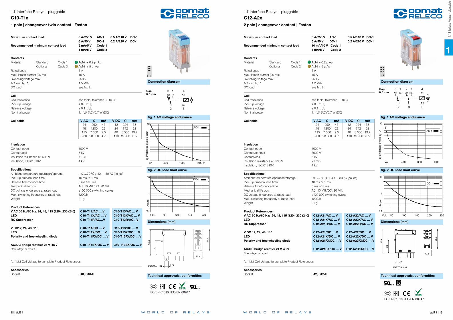
Maximum contact load 10 A/250 V AC-1 0.8 A/110 V DC-1 10 A/30 V DC-1 0.4 A/220 V DC-1Recommended minimum contact load 10 mA/10 V Code 0, 5 5 mA/5 V Code 8
ContactsMaterial Standard Code 0 AgNi Optional Code 5 AgSnO2
Rated Load 10 AMax. inrush current (20 ms) 30 A (120 A for code 5)Switching voltage max. 250 V AC load fig. 1 2.5 kVADC load see fig. 2
CoilCoil resistance see table; tolerance ± 10 %Pick-up voltage ≤ 0.8 x UN
Release voltage ≥ 0.1 x UN
Nominal power 1.1 VA (AC)/0.7 W (DC)
Coil table V AC Ω mA V DC Ω mA 24 290 45 12 224 53 48 1200 23 24 742 32 115 7.300 9.5 48 3.500 13.7 230 28.800 4.7 110 19.900 5.5
Insulation Contact open 2000 VContact/coil 5 kV Insulation resistance at 500 V ≥1 GΩ Insulation, IEC 61810-1 4 kV
SpecificationsAmbient temperature operation/storage -40 … 70 ºC /-40 … 80 °C (no ice)Pick-up time/bounce time 10 ms /≤ 1 msRelease time/bounce time 8 ms Mechanical life ops AC: 10 Mill./DC: 20 Mill. DC voltage endurance at rated load ≥ 100 000 switching cyclesMax. switching frequency at rated load 1200/hWeight 21g
Product References V AC 50 Hz/60 Hz: 24, 48, 115 (120), 230 (240) C10-G10/AC … V C10-G15/AC … V LED C10-G10X/AC … V C10-G15X/AC … VRC Suppressor C10-G10R/AC…V C10-G15R/AC…V V DC 12, 24, 48, 110 C10-G10/DC … V C10-G15/DC … VLED C10-G10X/DC … V C10-G15X/DC … VPolarity and free wheeling diode C10-G10FX/DC … V C10-G15FX/DC... V
AC/DC bridge rectifier 24 V, 48 V C10-G10BX/DC … V C10-G15BX/UC... VOther voltages on request
"..." List Coil Voltage to complete Product References
Accessories Socket S10, S10-P
Volt 75 125 175 225
Am
ps.
DC-1L/R 40 ms
0.1
1
10
1.1 Interface Relays - pluggable
C10-A1x1 pole | changeover contact | Faston
6
A2A1
54
3
2
1
FASTON .187
28.8
12.5
4.75
35.4
20
6
A2A1
54
3
2
1
FASTON .187
28.8
12.5
4.75
35.4
20
VA 500 1000 1500 2000
switc
hing
cyc
les
x10
6
AC-1 Cos ϕ 0.4
10
0.1
Gap:0.5 mm
A2
A1
5
412 14
11
13
2
Maximum contact load 10 A/250 V AC-1 0.5 A/110 V DC-1 10 A/30 V DC-1 0.2 A/220 V DC-1 Recommended minimum contact load 10 mA/10 V Code 0, 5 5 mA/5 V Code 8
ContactsMaterial Standard Code 0 AgNi Optional Code 8 AgNi + 5 µ Au Optional Code 5 AgSnO2
Rated Load 10 AMax. inrush current (20 ms) 30 A (120 A for code 5)Switching voltage max. 250 V AC load fig. 1 2.5 kVADC load see fig. 2
CoilCoil resistance see table; tolerance ± 10 %Pick-up voltage ≤ 0.8 x UN
Release voltage ≥ 0.1 x UN
Nominal power 1.1 VA (AC)/0.7 W (DC)
Coil table V AC Ω mA V DC Ω mA 24 290 45 12 224 53 48 1200 23 24 742 32 115 7.300 9.5 48 3.500 13.7 230 28.800 4.7 110 19.900 5.5
Insulation Contact open 1000 VContact/coil 5 kV Insulation resistance at 500 V ≥1 GΩInsulation, IEC 61810-1 4 kV
SpecificationsAmbient temperature operation/storage -40 … 70 ºC /-40 … 80 °C (no ice)Pick-up time/bounce time 10 ms / ≤ 1 msRelease time/bounce time 5 ms / ≤ 3 ms Mechanical life ops AC: 10 Mill./DC: 20 Mill. DC voltage endurance at rated load ≥ 100 000 switching cyclesMax. switching frequency at rated load 1200/hWeight 21g
Product References V AC 50 Hz/60 Hz: 24, 48, 115 (120), 230 (240) C10-A10/AC ... V C10-A18/AC ... V C10-A15/AC … VLED C10-A10X/AC ... V C10-A18X/AC ... V C10-A15X/AC ... VRC Suppressor C10-A10R/AC ... V C10-A18R/AC ... V C10-A15R/AC ... V V DC 12, 24, 48, 110 C10-A10/DC ... V C10-A18/DC ... V C10-A15/DC ... VLED C10-A10X/DC ... V C10-A18X/DC ... V C10-A15X/DC ... VPolarity and free wheeling diode C10-A10FX/DC ... V C10-A18FX/DC ... V C10-A15FX/DC ... V
V AC/DC bridge rectifier 24 V, 48 V C10-A10BX/UC ... V C10-A18BX/UC ... V C10-A15BX/UC ... VOther voltages on request
"..." List Coil Voltage to complete Product References
Accessories Socket S10, S10-P
Volt 50 100 150 200
Am
ps.
DC-1 L/R 40 ms
10
1
0,1
1
IEC/EN 61810; IEC/EN 60947 IEC/EN 61810; IEC/EN 60947
1.1
Inte
rface
Rela
ys -
plug
gabl
e
WoR 1 | 19
1
Connection diagram
fig. 1 AC voltage endurance fig. 1 AC voltage endurance
fig. 2 DC load limit curve fig. 2 DC load limit curve
Dimensions (mm) Dimensions (mm)
Technical approvals, conformities Technical approvals, conformities
Connection diagram
18 | WoR 1
1.1
Inte
rface
Rela
ys -
plug
gabl
e
1.1 Interface Relays - pluggable
C10-T1x1 pole | changeover twin contact | Faston
A2
A1
5
412 14
11
13
2
VA 500 1000 1500 V
switc
hing
cyc
les
x10
6
AC-110
0.1
1
Am
ps.
Volt 75 125 175 225
DC-110
0.1
1
Gap:0.5 mm
Maximum contact load 6 A/250 V AC-1 0.5 A/110 V DC-1 6 A/30 V DC-1 0.2 A/220 V DC-1Recommended minimum contact load 5 mA/5 V Code 1 1 mA/5 V Code 3
ContactsMaterial Standard Code 1 AgNi + 0.2 µ Au Optional Code 3 AgNi + 5 µ Au Rated Load 6 AMax. inrush current (20 ms) 15 A Switching voltage max 250 VAC load fig. 1 1.5 kVADC load see fig. 2
CoilCoil resistance see table; tolerance ± 10 %Pick-up voltage ≤ 0.8 x UN
Release voltage ≥ 0.1 x UN
Nominal power 1.1 VA (AC)/0.7 W (DC)
Coil table V AC Ω mA V DC Ω mA 24 290 45 12 224 53 48 1200 23 24 742 32 115 7.300 9.5 48 3.500 13.7 230 28.800 4.7 110 19.900 5.5
Insulation Contact open 1000 VContact/coil 5 kV Insulation resistance at 500 V ≥1 GΩInsulation, IEC 61810-1 4 kV
SpecificationsAmbient temperature operation/storage -40 …70 ºC /-40 … 80 °C (no ice)Pick-up time/bounce time 10 ms /≤ 1 msRelease time/bounce time 5 ms /≤ 3 ms Mechanical life ops AC: 10 Mill./DC: 20 Mill. DC voltage endurance at rated load ≥ 100 000 switching cyclesMax. switching frequency at rated load 1200/hWeight 21 g
Product References V AC 50 Hz/60 Hz: 24, 48, 115 (120), 230 (240) C10-T11/AC … V C10-T13/AC … V LED C10-T11X/AC … V C10-T13X/AC … V RC Suppressor C10-T11R/AC…V C10-T13R/AC…V
V DC12, 24, 48, 110 C10-T11/DC … V C10-T13/DC … VLED C10-T11X/DC … V C10-T13X/DC … VPolarity and free wheeling diode C10-T11FX/DC … V C10-T13FX/DC … V
AC/DC bridge rectifier 24 V, 48 V C10-T11BX/UC … V C10-T13BX/UC … VOther voltages on request
"..." List Coil Voltage to complete Product References
Accessories Socket S10, S10-P
6
A2A1
54
3
2
1
FASTON .187
28.8
12.5
4.75
35.4
20
6
A2A1
54
3
2
1
FASTON .187
28.8
12.5
4.75
35.4
20
1.1 Interface Relays - pluggable
C12-A2x2 pole | changeover contact | Faston
54
3
2
1
FASTON .098
8
7
28.8
12.5
35.4
20
9
2.5
312 22
91 7 414 24 A1
2 8 511 21 A2
Gap:0.5 mm
Maximum contact load 5 A/250 V AC-1 0.5 A/110 V DC-1 5 A/30 V DC-1 0.2 A/220 V DC-1Recommended minimum contact load 10 mA/10 V Code 1 5 mA/5 V Code 2
ContactsMaterial Standard Code 1 AgNi + 0.2 µ Au Optional Code 2 AgNi + 5 µ Au Rated Load 5 AMax. inrush current (20 ms) 15 A Switching voltage max. 250 V AC load fig. 1 1.2 kVADC load see fig. 2
CoilCoil resistance see table; tolerance ± 10 %Pick-up voltage ≤ 0.8 x UN
Release voltage ≥ 0.1 x UN
Nominal power 1.1 VA (AC)/0.7 W (DC)
Coil table V AC Ω mA V DC Ω mA 24 290 45 12 224 53 48 1200 23 24 742 32 115 7.300 9.5 48 3.500 13.7 230 28.800 4.7 110 19.900 5.5
Insulation Contact open 1000 VContact/contact 3000 VContact/coil 5 kV Insulation resistance at 500 V ≥1 GΩInsulation, IEC 61810-1 4 kV
SpecificationsAmbient temperature operation/storage -40 … 60 ºC /-40 … 80 °C (no ice)Pick-up time/bounce time 10 ms /≤ 1 msRelease time/bounce time 5 ms /≤ 3 ms Mechanical life ops AC: 10 Mill./DC: 20 Mill. DC voltage endurance at rated load ≥ 100 000 switching cyclesMax. switching frequency at rated load 1200/hWeight 21 g
Product References V AC 50 Hz/60 Hz: 24, 48, 115 (120), 230 (240) C12-A21/AC … V C12-A22/AC … VLED C12-A21X/AC … V C12-A22X/AC … VRC Suppressor C12-A21R/AC … V C12-A22R/AC … V
V DC 12, 24, 48, 110 C12-A21/DC … V C12-A22/DC … VLED C12-A21X/DC … V C12-A22X/DC … VPolarity and free wheeling diode C12-A21FX/DC … V C12-A22FX/DC … V
AC/DC bridge rectifier 24 V, 48 V C12-A21BX/UC … V C12-A22BX/UC … VOther voltages on request
"..." List Coil Voltage to complete Product References
Accessories Socket S12, S12-P
Volt 50 100 150 200 220
DC-1
Am
ps.
10
0.1
1
VA 400 800 1200
switc
hing
cyc
les
x 10
6 AC-1
10
0.1
1
IEC/EN 61810; IEC/EN 60947
IEC/EN 61810; IEC/EN 60947

20 | WoR 1 WoR 1 | 21
1
Connection diagram Connection diagram
fig. 1 AC voltage endurance
fig. 2 DC load limit curve
Dimensions (mm)
Technical approvals, conformities Technical approvals, conformities
Dimensions (mm)
fig. 1 Max. Operating Power Curve
1.1
Inte
rface
Rela
ys -
plug
gabl
e
1.1 Interface Relays - pluggable
C12-G2x2 pole | normally open contact | Faston
54
3
2
1
FASTON .098
8
7
28.8
12.5
35.4
20
9
2.5
13 23
14 24
Gap:1 mm
Maximum contact load 5 A/250 V AC-1 0.8 A/110 V DC-1 5 A/30 V DC-1 0.4 A/220 V DC-1Recommended minimum contact load 10 mA/10 V Code 1 5 mA/5 V Code 2
ContactsMaterial Standard Code 1 AgNi + 0.2 µ Au Optional Code 2 AgNi + 5 µ Au Rated Load 5 AMax. inrush current (20 ms) 15 A Switching voltage max. 250 V AC load fig. 1 1.2 kVADC load see fig. 2
CoilCoil resistance see table; tolerance ± 10 %Pick-up voltage ≥ 0.8 x UN
Release voltage ≥ 0.1 x UN
Nominal power 1.1 VA (AC)/0.7 W (DC) Coil table V AC Ω mA V DC Ω mA 24 290 45 12 224 53 48 1200 23 24 742 32 115 7.300 9.5 48 3.500 13.7 230 28.800 4.7 110 19.900 5.5
Insulation Contact open 2000 VContact/contact 3000 VContact/coil 5 kV Insulation resistance at 500 V ≥1 GΩInsulation, IEC 61810-1 4 kV
SpecificationsAmbient temperature operation/storage -40 … 60 ºC /-40 … 80 °C (no ice)Pick-up time/bounce time 10 ms /≤ 1 msRelease time/bounce time 5 ms /≤ 3 msMechanical life ops AC: 10 Mill./DC: 20 Mill. DC voltage endurance at rated load ≥ 100 000 switching cyclesMax. switching frequency at rated load 1200/hWeight 21 g
Product References V AC 50 Hz/60 Hz: 24, 48, 115, (120), 230, (240) C12-G21/AC … V C12-G22/AC … VLED C12-G21X/AC … V C12-G22X/AC … V RC Suppressor C12-G21R/AC … V C12-G22R/AC … V
V DC 12, 24, 48, 110 C12-G21/DC … V C12-G22/DC … V LED C12G21X/DC … V C12-G22X/DC … VPolarity and free wheeling diode C12-G21FX/DC … V C12-G22FX/DC … V
AC/DC bridge rectifier 24 V, 48 V C12-G21BX/UC … V C12-G22BX/UC … VOther voltages on request
"..." List Coil Voltage to complete Product References
Accessories Socket S12, S12-P
Sw
itchi
ng c
ycle
s x1
06
VA 400 800 1200
AC-1
10
0.1
1
Volt 50 100 150 200 220
Am
ps.
DC-1
10
0.1
1
IEC/EN 61810; IEC/EN 60947
1.1 Interface Relays - pluggable
C16-A25PTL2 pole | 8-pin | changeover contact | Grid 5mm
Maximum contact load 7 A/250 V AC-1 7 A/30V DC-1Recommended minimum contact load 1 mA/1 V AC/DC
ContactsMaterial AgSnO2 Rated Load 7 ASwitching voltage max. 250 V Max. inrush current (500 ms) 15 A Bounce time 2 ms
CoilCoil resistance see table; tolerance ± 10 %Pick-up voltage 75 % of UN (DC) / 80 % of UN (AC)Release voltage ≤ 0.1 UN (DC) / ≤ 0.3 UN (AC)Nominal power 1 VA (AC) / 0.53 W (DC) @ 23 °C
Coil Data (DC voltage)
Coil Voltage Code Nominal Voltage
(V DC)
Coil Resistance (Ω)
± 10 %
Must operate
voltage max. (V DC)
Must release
voltage min (V DC)
12 12 270 9.00 1.2
24 24 1080 18.00 2.4
36 36 1350 27.00 3.6
48 48 4340 36.00 4.8
110 110 22830 82.5 11
Coil Data (AC voltage 50/60 Hz)
Coil Voltage
Code
Nominal Voltage
(V AC)
Coil Resistance
(Ω) ± 10 %
Must operate
voltage max.
(V AC)
Must release
voltage min
(V AC)
Max. allowable
voltage (V AC)
24 24 253 19.2 7.2 26.4
110 110 5819 88.0 33 121
230 230 23276 184 69 253
Insulation Insulation resistance (coil to contact) ≥ 100 MΩ @ 500 V DC, 50 % RHDielectric strength 5 kV Contact/coil 5000 Vrms, 1 minContact/contact 1000 Vrms, 1 min
SpecificationsAmbient temperature operation/storage -55 …70 ºC /-55…70 °C (no ice)Pick-up time 10 msRelease time 5 ms Mechanical / electrical life ops ≥ 1 × 10 000 000 / 1 × 100 000Weight 17 gMax. switching frequency 20 HzTightness RT2
Product References V AC 50 Hz/60 Hz: 24, 110 (120), 230 (240) C16-A25PTL/AC ... V V DC 12, 24, 48 C16-A25PTL/DC ... VOther voltages on request
"..." List Coil Voltage to complete Product References
Accessories Socket S16-MRetaining clip, plastic CP-16Modules See datasheet socket S16-M
312 22
91 7 414 24 A1
2 8 511 21 A2
IEC/EN 61810; IEC/EN 60947
Max. Operating Power Curve
Contact voltage (V)
DC Resistive
AC Resistive
10
1
5
101520
20 30 40 50 100 200 380
Curr
ent o
f Loa
d (A
)

22 | WoR 1 WoR 1 | 23
Connection diagram Connection diagram
Technical approvals, conformities Technical approvals, conformities
Dimensions (mm)
fig. 1 Max. Operating Power Curve
Dimensions (mm)
fig. 1 Max. Operating Power Curve
1
1.1
Inte
rface
Rela
ys -
plug
gabl
e
1.1 Interface Relays - pluggable
C18-A15PTL1 pole | 5-pin | changeover contact | Grid 5mm
Maximum contact load 10 A/250 V AC-1 10 A/30 V DC-1Recommended minimum contact load 1 mA/1 V AC/DC
ContactsMaterial AgSnO2 Rated Load 10 ASwitching voltage max. 250 V Max. inrush current (500 ms) 25 A Bounce time 2 ms
CoilCoil resistance see table; tolerance ± 10 %Pick-up voltage 75 % of UN (DC) / 80 % of UN (AC)Release voltage ≤ 0.1 UN (DC) / ≤ 0.3 UN (AC)Nominal power 1 VA (AC) / 0.53 W (DC) @ 23 °C
Coil Data (DC voltage)
Coil Voltage Code Nominal Voltage
(V DC)
Coil Resistance (Ω)
± 10 %
Must operate
voltage max. (V DC)
Must release
voltage min (V DC)
12 12 270 9.00 1.2
24 24 1080 18.00 2.4
36 36 1350 27.00 3.6
48 48 4340 36.00 4.8
110 110 22830 82.5 11
Coil Data (AC voltage 50/60 Hz)
Coil Voltage
Code
Nominal Voltage
(V AC)
Coil Resistance
(Ω) ± 10 %
Must operate
voltage max.
(V AC)
Must release
voltage min
(V AC)
Max. allowable
voltage (V AC)
24 24 253 19.2 7.2 26.4
110 110 5819 88.0 33 121
230 230 23276 184 69 253
Insulation Insulation resistance (coil to contact) ≥ 100 MΩ @ 500 V DC, 50 % RHDielectric strength 5 kV Contact/coil 5000 Vrms, 1 minContact/contact 1000 Vrms, 1 min
SpecificationsAmbient temperature operation/storage -55 …70 ºC /-55…70 °C (no ice)Pick-up time 10 msRelease time 5 ms Mechanical / electrical life ops ≥ 1 × 10 000 000 / 1 × 100 000Weight 17 gMax. switching frequency 20 HzTightness RT2
Product References V AC 50 Hz/60 Hz: 24, 110 (120), 230 (240) C18-A15PTL/AC ... V V DC 12, 24, 36, 48, 110 C18-A15PTL/DC ... VOther voltages on request
"..." List Coil Voltage to complete Product References
Accessories Socket S16-MRetaining clip, plastic CP-16Modules See datasheet socket S16-M
A2
A1
5
412 14
11
13
2
5 5
Max. Operating Power Curve
Contact voltage (V)
DC Resistive
AC Resistive
10
1
5
101520
20 30 40 50 100 200 380
Curr
ent o
f Loa
d (A
)
IEC/EN 61810; IEC/EN 60947
1.1 Interface Relays - pluggable
C18-A15PT1 pole | 5-pin | changeover contact | Grid 3.5mm
Maximum contact load 10 A/250 V AC-1 10 A/30 V DC-1Recommended minimum contact load 1 mA/1 V AC/DC
ContactsMaterial AgSnO2 Rated Load 10 ASwitching voltage max. 250 V Max. inrush current (500 ms) 25 ABounce time 2 ms
CoilCoil resistance see table; tolerance ± 10 %Pick-up voltage 75 % of UN (DC) / 80 % of UN (AC)Release voltage ≤ 0.1 UN (DC) / ≤ 0.3 UN (AC)Nominal power 1 VA (AC) / 0.53 W (DC) @ 23 °C
Coil Data (DC voltage)
Coil Voltage Code Nominal Voltage
(V DC)
Coil Resistance (Ω)
± 10 %
Must operate
voltage max. (V DC)
Must release
voltage min (V DC)
12 12 270 9.00 1.2
24 24 1080 18.00 2.4
36 36 1350 27.00 3.6
48 48 4340 36.00 4.8
110 110 22830 82.5 11
Coil Data (AC voltage 50/60 Hz)
Coil Voltage
Code
Nominal Voltage
(V AC)
Coil Resistance
(Ω) ± 10 %
Must operate
voltage max.
(V AC)
Must release
voltage min
(V AC)
Max. allowable
voltage (V AC)
24 24 253 19.2 7.2 26.4
110 110 5819 88.0 33 121
230 230 23276 184 69 253
Insulation Insulation resistance (coil to contact) ≥ 100 MΩ @ 500 V DC, 50 % RHDielectric strength 5 kV Contact/coil 5000 Vrms, 1 minContact/contact 1000 Vrms, 1 min
SpecificationsAmbient temperature operation/storage -55 …70 ºC /-55…70 °C (no ice)Pick-up time 10 msRelease time 5 ms Mechanical / electrical life ops ≥ 1 × 10 000 000 / 1 × 100 000Weight 17 gMax. switching frequency 20 HzTightness RT2
Product References V AC 50 Hz/60 Hz: 24, 110 (120), 230 (240) C18-A15PT/AC ... V V DC 12, 24.36, 48, 110 C18-A15PT/DC ... VOther voltages on request
"..." List Coil Voltage to complete Product References
Accessories Socket S18-MRetaining clip, plastic CP-16Modules See datasheet socket S18-M
A2
A1
5
412 14
11
13
2
Max. Operating Power Curve
Contact voltage (V)
DC Resistive
AC Resistive
10
1
5
101520
20 30 40 50 100 200 380
Curr
ent o
f Loa
d (A
)
IEC/EN 61810; IEC/EN 60947
24 | WoR 1 WoR 1 | 25
Connection diagram
Technical approvals, conformities
Dimensions (mm)
fig. 1 Max. Operating Power Curve
1.1 Interface Relays - pluggable
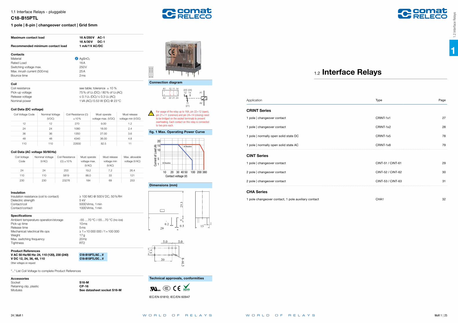
C18-B15PTL1 pole | 8-pin | changeover contact | Grid 5mm
Maximum contact load 16 A/250 V AC-1 16 A/30 V DC-1Recommended minimum contact load 1 mA/1 V AC/DC
ContactsMaterial AgSnO2 Rated Load 16 ASwitching voltage max. 250 V Max. inrush current (500 ms) 25 A Bounce time 2 ms
CoilCoil resistance see table; tolerance ± 10 %Pick-up voltage 75 % of UN (DC) / 80 % of UN (AC)Release voltage ≤ 0.1 UN (DC) / ≤ 0.3 UN (AC)Nominal power 1 VA (AC) / 0.53 W (DC) @ 23 °C
Coil Data (DC voltage)
Coil Voltage Code Nominal Voltage
(V DC)
Coil Resistance (Ω)
± 10 %
Must operate
voltage max. (V DC)
Must release
voltage min (V DC)
12 12 270 9.00 1.2
24 24 1080 18.00 2.4
36 36 1350 27.00 3.6
48 48 4340 36.00 4.8
110 110 22830 82.5 11
Coil Data (AC voltage 50/60 Hz)
Coil Voltage
Code
Nominal Voltage
(V AC)
Coil Resistance
(Ω) ± 10 %
Must operate
voltage max.
(V AC)
Must release
voltage min
(V AC)
Max. allowable
voltage (V AC)
24 24 253 19.2 7.2 26.4
110 110 5819 88.0 33 121
230 230 23276 184 69 253
Insulation Insulation resistance (coil to contact) ≥ 100 MΩ @ 500 V DC, 50 % RHDielectric strength 5 kV Contact/coil 5000 Vrms, 1 minContact/contact 1000 Vrms, 1 min
SpecificationsAmbient temperature operation/storage -55 …70 ºC /-55…70 °C (no ice)Pick-up time 10 msRelease time 5 ms Mechanical / electrical life ops ≥ 1 × 10 000 000 / 1 × 100 000Weight 17 gMax. switching frequency 20 HzTightness RT2
Product References V AC 50 Hz/60 Hz: 24, 110 (120), 230 (240) C18-B15PTL/AC ... V V DC 12, 24, 36, 48, 110 C18-B15PTL/DC ... VOther voltages on request
"..." List Coil Voltage to complete Product References
Accessories Socket S16-MRetaining clip, plastic CP-16Modules See datasheet socket S16-M
Max. Operating Power Curve
Contact voltage (V)
DC Resistive
AC Resistive
10
1
5
101520
20 30 40 50 100 200 380
Curr
ent o
f Loa
d (A
)
IEC/EN 61810; IEC/EN 60947
A1
A2
12
22
11
21
14
24
A2
A1
5
412 14
11
13
2
(22) (24)
(21)
12
11
A1
A2
14
For usage of the relay up to 16A, pin 22+12 (open), pin 21+11 (common) and pin 24+14 (closing) need to be bridged on the socket terminals to prevent overheating. Each contact on this relay is connected to two pins each.
1
1.2
Inte
rface
Rel
ays
Application Type Page
CRINT Series
1 pole | changeover contact CRINT-1x1 27
1 pole | changeover contact CRINT-1x2 28
1 pole | normally open solid state DC CRINT-1x5 78
1 pole | normally open solid state AC CRINT-1x8 79
CINT Series
1 pole | changeover contact CINT-51 / CINT-61 29
2 pole | changeover contact CINT-52 / CINT-62 30
2 pole | changeover contact CINT-53 / CINT-63 31
CHA Series
1 pole changeover contact, 1 pole auxiliary contact CHA1 32
1.2 Interface Relays

26 | WoR 1 WoR 1 | 27
Connection diagram
fig. 1 AC voltage endurance
1
fig. 2 DC load limit curve
Technical approvals, conformities
1.2
Inte
rface
Rel
ays
CRINT-C1xx & CINT-C5x/C6x Dimensions (mm)
Screw terminalsCRINT-C11x
89
4247
Cage clampCRINT-C12x
Jumper linkJumper link
LabelLabel
94
49,5
40,5
RELAY Only
1. Product family CRINT
2. TypeC = Combined version (Socket and Relay)
3. Contact1 = One change-over contact
4. Connection type1 = Screw terminal2 = Cage clamp terminal
1. Product family CRINT
2. TypeR = Relay
3. Contact11 = AgSnO212 = AgSnO2 + 3µ Au15 = NO / Solid-state DC18 = NO / Solid-state AC
4. Supply voltage DC
5. Nominal voltage 12 V, 24 V, 48 V, 60 V*
*60 V Relay used for all sockets witha nominal voltage higher or equal 60V
CRINT Product Key
1 2 3 4 5 6 7 8
CRINT - C 1 1 1 R / UC 24V1 2 3 4 5
CRINT - R 11 DC 12V
5. Output 1 = AgSnO22 = AgSnO2 + 3µ Au5 = NO / Solid-state DC8 = NO / Solid-state AC
6. Options– = Standard versionR = Railway version
7. Supply voltageUC = AC/DCDC = Only for C1x5 and C1x8
8. Nominal voltage12V, 24V, 48V, 60V, 110-125V, 220-240V
Cage clampCINT-C6xR
ELA
YS
A1
A2
220-240VU
24 14NO
21 11COM
22 12NC
TS35
14 723,4
93
4845
Screw terminalsCINT-C5x
REL
AYS
22 12NC
21 11COM
24 14NO
A1
A2
220-240VU
14 723,4
TS3591
48,5
42,5
n
Dimensions (mm)
Maximum contact load 6 A/250 V AC-1 6 A/30 V DC-1Recommended minimum contact load 100 mA / 12 V
ContactType 1 COMaterial AgSnO2
Switching current | TH 6 A 250 V ACSwitching power DC-1 30 V 180 WSwitching power AC-1 230 V 1500 VASwitching power AC-15 230 V 300 VAMax. inrush current (2.5 ms) 15 A
Coil Operation voltage AC 50/60 Hz / DC 0.8 … 1.25 UN
Nominal power DC/AC 408 / 900 mW
Insulation Test voltage I / O 6 kV rms / 1 minPollution degree 3Over voltage category IIIOpen contact 1000 Vrms dielectric strength 1 minStandard EN61810-1
SpecificationsAmbient temperature: operation / storage -40 … 70 °C / -40 … 85 °C (no ice)Typical response time @ Vn 7 msTypical release time @ Vn 15 msSwitching cycles: mech./elec. 10 x 1 000 000 / 3 x 10 000Cond. cross section screw terminal 2.5 mm2
Cond. cross section spring cage 0.75 … 2.5 mm2
Protection degree IP 20Mounting position any, TS35 or Back Panel MountingWeight 30 g
Product References
Screw terminal UC 12V, 24V, 48V, 60V, 110-125V, 220-240V
CRINT-C111/UC...V
Cage clamp terminalUC 12V, 24V, 48V, 60V, 110-125V, 220-240V
CRINT-C121/UC…V
Railway EN 50155 CRINT-C121R/UC…V„…“ List Coil Voltage to complete Product References
AccessoriesJumper link blue: CRINT-BR20-BU (BAG 5 PCS) red: CRINT-BR20-RD (BAG 5 PCS) black: CRINT-BR20-BK (BAG 5 PCS) Label plate CRINT-LAB (BAG 4x16 PCS)Spacer CRINT-SEP (BAG 5 PCS)
Replacement relays
DC 12V, 24V, 48V, 60V* CRINT-R11/DC...V„…“ List Coil Voltage to complete Product References *60V Relay used for all sockets witha nominal voltage higher or equal 60V
0.1
0.2
0.3
0.5
1
2
5 6
10
0 50 100 150 200 250 300
Cur
rent
[A]
Voltage [V]
AC-1 DC-1
104
105
0 1 2 3 4 5 6
Cyc
les
Switching current [A]
AC-1
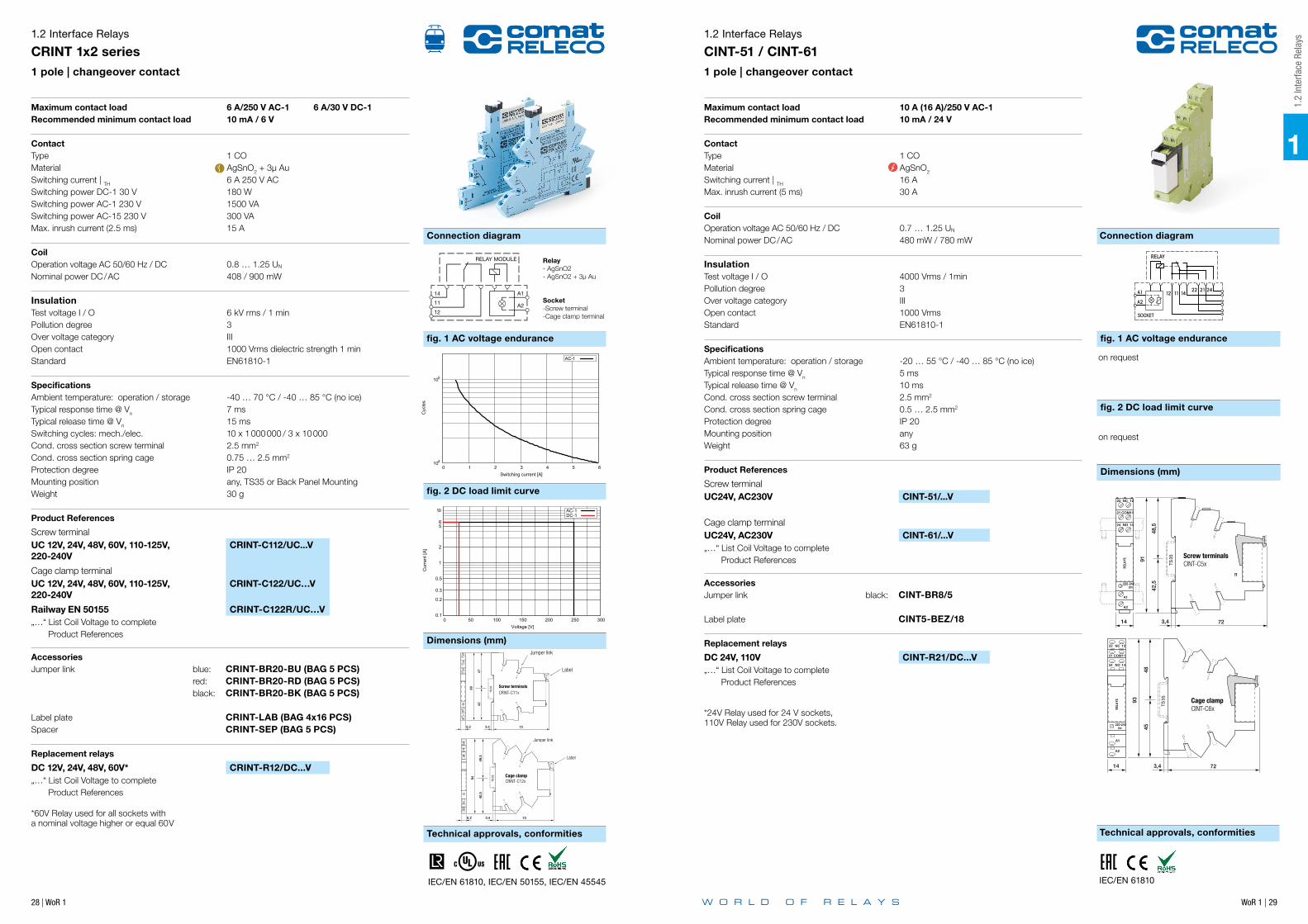
Relay- AgSnO2- AgSnO2 + 3µ Au
Socket-Screw terminal-Cage clamp terminal
RELAY MODULE
14 A1
A211
12
1.2 Interface Relays
CRINT 1x1 series1 pole | changeover contact
IEC/EN 61810, IEC/EN 50155, IEC/EN 45545
Cage clampCRINT-C12x
Jumper link
Label
94
49,5
40,5
Screw terminalsCRINT-C11x
89
4247
Jumper link
Label
28 | WoR 1 WoR 1 | 29
1
Connection diagram Connection diagram
fig. 1 AC voltage endurance
fig. 2 DC load limit curve
Dimensions (mm)
Technical approvals, conformitiesTechnical approvals, conformities
1.2
Inte
rface
Rel
ays
Dimensions (mm)
IEC/EN 61810, IEC/EN 50155, IEC/EN 45545
1.2 Interface Relays
CRINT 1x2 series1 pole | changeover contact
Maximum contact load 6 A/250 V AC-1 6 A/30 V DC-1Recommended minimum contact load 10 mA / 6 V
ContactType 1 COMaterial AgSnO2 + 3µ AuSwitching current | TH 6 A 250 V ACSwitching power DC-1 30 V 180 WSwitching power AC-1 230 V 1500 VASwitching power AC-15 230 V 300 VAMax. inrush current (2.5 ms) 15 A
Coil Operation voltage AC 50/60 Hz / DC 0.8 … 1.25 UN
Nominal power DC/AC 408 / 900 mW
Insulation Test voltage I / O 6 kV rms / 1 minPollution degree 3Over voltage category IIIOpen contact 1000 Vrms dielectric strength 1 minStandard EN61810-1
SpecificationsAmbient temperature: operation / storage -40 … 70 °C / -40 … 85 °C (no ice)Typical response time @ Vn 7 msTypical release time @ Vn 15 msSwitching cycles: mech./elec. 10 x 1 000 000 / 3 x 10 000Cond. cross section screw terminal 2.5 mm2
Cond. cross section spring cage 0.75 … 2.5 mm2
Protection degree IP 20Mounting position any, TS35 or Back Panel MountingWeight 30 g
Product References
Screw terminal UC 12V, 24V, 48V, 60V, 110-125V, 220-240V
CRINT-C112/UC...V
Cage clamp terminalUC 12V, 24V, 48V, 60V, 110-125V, 220-240V
CRINT-C122/UC…V
Railway EN 50155 CRINT-C122R/UC…V„…“ List Coil Voltage to complete Product References
AccessoriesJumper link blue: CRINT-BR20-BU (BAG 5 PCS) red: CRINT-BR20-RD (BAG 5 PCS) black: CRINT-BR20-BK (BAG 5 PCS) Label plate CRINT-LAB (BAG 4x16 PCS)Spacer CRINT-SEP (BAG 5 PCS)
Replacement relays
DC 12V, 24V, 48V, 60V* CRINT-R12/DC...V„…“ List Coil Voltage to complete Product References *60V Relay used for all sockets witha nominal voltage higher or equal 60V
104
105
0 1 2 3 4 5 6
Cyc
les
Switching current [A]
AC-1
Relay- AgSnO2- AgSnO2 + 3µ Au
Socket-Screw terminal-Cage clamp terminal
RELAY MODULE
14 A1
A211
12
0.1
0.2
0.3
0.5
1
2
5 6
10
0 50 100 150 200 250 300
Cur
rent
[A]
Voltage [V]
AC-1 DC-1
1.2 Interface Relays
CINT-51 / CINT-611 pole | changeover contact
Maximum contact load 10 A (16 A)/250 V AC-1Recommended minimum contact load 10 mA / 24 V
ContactType 1 COMaterial AgSnO2
Switching current | TH 16 AMax. inrush current (5 ms) 30 A
Coil Operation voltage AC 50/60 Hz / DC 0.7 … 1.25 UN
Nominal power DC/AC 480 mW / 780 mW
Insulation Test voltage I / O 4000 Vrms / 1minPollution degree 3Over voltage category IIIOpen contact 1000 VrmsStandard EN61810-1
SpecificationsAmbient temperature: operation / storage -20 … 55 °C / -40 … 85 °C (no ice)Typical response time @ Vn 5 msTypical release time @ Vn 10 msCond. cross section screw terminal 2.5 mm2
Cond. cross section spring cage 0.5 … 2.5 mm2
Protection degree IP 20Mounting position anyWeight 63 g
Product References
Screw terminal UC24V, AC230V CINT-51/...V
Cage clamp terminalUC24V, AC230V CINT-61/...V„…“ List Coil Voltage to complete Product References
AccessoriesJumper link black: CINT-BR8/5 Label plate CINT5-BEZ/18
Replacement relays
DC 24V, 110V CINT-R21/DC...V„…“ List Coil Voltage to complete Product References
*24V Relay used for 24 V sockets,110V Relay used for 230V sockets.
IEC/EN 61810
SOCKET
242122141112A1
A2
RELAY
RELAY
SOCKET
242122141112A1
A2
RELAY
RELAY
Cage clampCRINT-C12x
Jumper link
Label
94
49,5
40,5
Screw terminalsCRINT-C11x
89
4247
Jumper link
Label
fig. 1 AC voltage endurance
Dimensions (mm)
fig. 2 DC load limit curve
Dimensions (mm)
on request
on request
Cage clampCINT-C6xR
ELA
YS
A1
A2
220-240VU
24 14NO
21 11COM
22 12NC
TS35
14 723,4
93
4845
Screw terminalsCINT-C5x
REL
AYS
22 12NC
21 11COM
24 14NO
A1
A2
220-240VU
14 723,4
TS3591
48,5
42,5
n
30 | WoR 1 WoR 1 | 31
1
Connection diagram Connection diagram
Technical approvals, conformities Technical approvals, conformities
fig. 1 AC voltage endurance fig. 1 AC voltage endurance
Dimensions (mm) Dimensions (mm)
fig. 2 DC load limit curve fig. 2 DC load limit curve
1.2
Inte
rface
Rel
ays
Dimensions (mm) Dimensions (mm)
IEC/EN 61810
1.2 Interface Relays
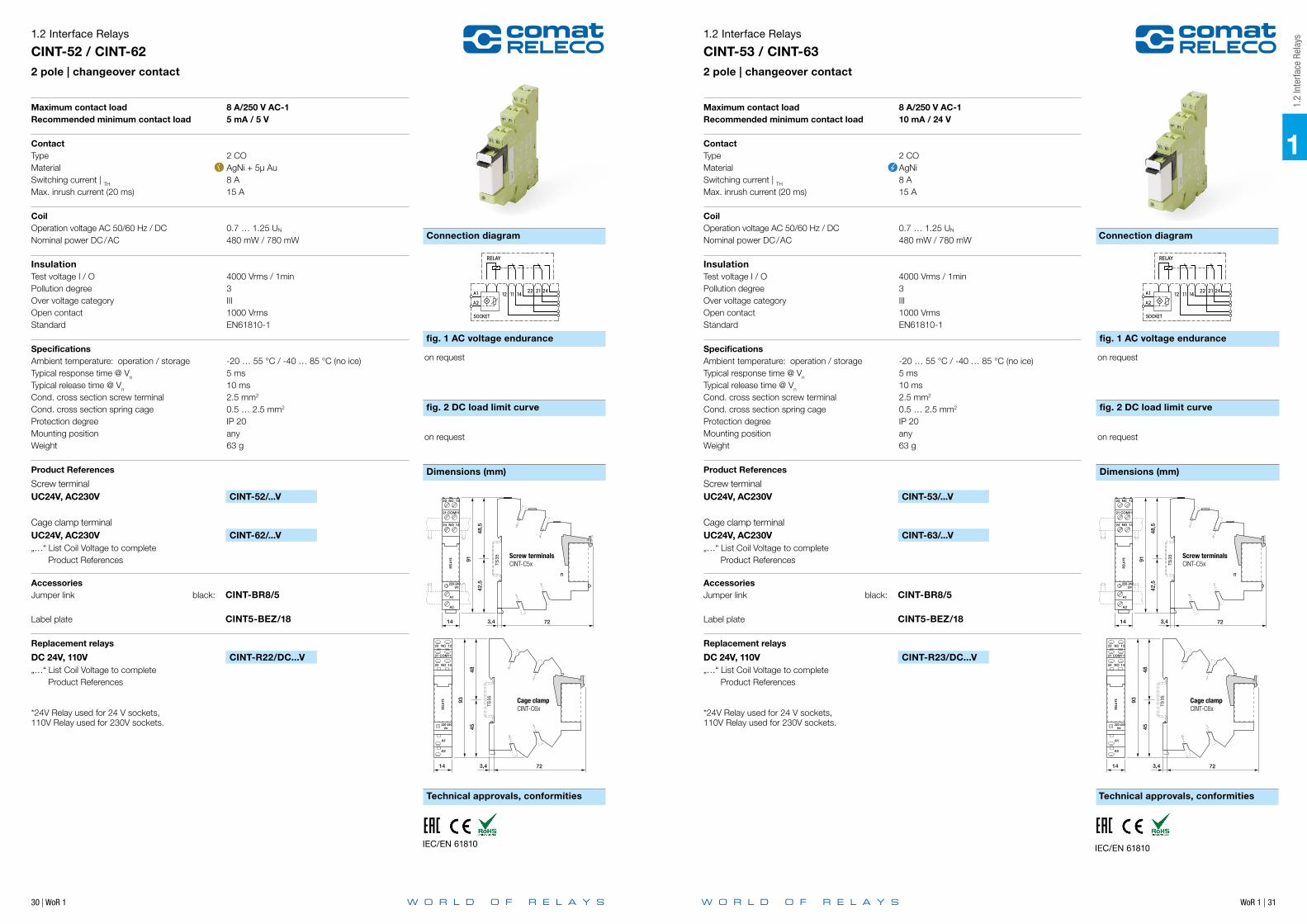
CINT-52 / CINT-622 pole | changeover contact
Maximum contact load 8 A/250 V AC-1Recommended minimum contact load 5 mA / 5 V
ContactType 2 COMaterial AgNi + 5µ AuSwitching current | TH 8 AMax. inrush current (20 ms) 15 A
Coil Operation voltage AC 50/60 Hz / DC 0.7 … 1.25 UN
Nominal power DC/AC 480 mW / 780 mW
Insulation Test voltage I / O 4000 Vrms / 1minPollution degree 3Over voltage category IIIOpen contact 1000 VrmsStandard EN61810-1
SpecificationsAmbient temperature: operation / storage -20 … 55 °C / -40 … 85 °C (no ice)Typical response time @ Vn 5 msTypical release time @ Vn 10 msCond. cross section screw terminal 2.5 mm2
Cond. cross section spring cage 0.5 … 2.5 mm2
Protection degree IP 20Mounting position anyWeight 63 g
Product References
Screw terminal UC24V, AC230V CINT-52/...V
Cage clamp terminalUC24V, AC230V CINT-62/...V„…“ List Coil Voltage to complete Product References
AccessoriesJumper link black: CINT-BR8/5 Label plate CINT5-BEZ/18
Replacement relays
DC 24V, 110V CINT-R22/DC...V„…“ List Coil Voltage to complete Product References
*24V Relay used for 24 V sockets,110V Relay used for 230V sockets.
SOCKET
242122141112A1
A2
RELAY
RELAY
SOCKET
242122141112A1
A2
RELAY
RELAY
on request on request
on request on request
1.2 Interface Relays
CINT-53 / CINT-632 pole | changeover contact
Maximum contact load 8 A/250 V AC-1Recommended minimum contact load 10 mA / 24 V
ContactType 2 COMaterial AgNi Switching current | TH 8 AMax. inrush current (20 ms) 15 A
Coil Operation voltage AC 50/60 Hz / DC 0.7 … 1.25 UN
Nominal power DC/AC 480 mW / 780 mW
Insulation Test voltage I / O 4000 Vrms / 1minPollution degree 3Over voltage category IIIOpen contact 1000 VrmsStandard EN61810-1
SpecificationsAmbient temperature: operation / storage -20 … 55 °C / -40 … 85 °C (no ice)Typical response time @ Vn 5 msTypical release time @ Vn 10 msCond. cross section screw terminal 2.5 mm2
Cond. cross section spring cage 0.5 … 2.5 mm2
Protection degree IP 20Mounting position anyWeight 63 g
Product References
Screw terminal UC24V, AC230V CINT-53/...V
Cage clamp terminalUC24V, AC230V CINT-63/...V„…“ List Coil Voltage to complete Product References
AccessoriesJumper link black: CINT-BR8/5 Label plate CINT5-BEZ/18
Replacement relays
DC 24V, 110V CINT-R23/DC...V„…“ List Coil Voltage to complete Product References
*24V Relay used for 24 V sockets,110V Relay used for 230V sockets.
IEC/EN 61810
SOCKET
242122141112A1
A2
RELAY
RELAY
SOCKET
242122141112A1
A2
RELAY
RELAY
Cage clampCINT-C6xR
ELA
YS
A1
A2
220-240VU
24 14NO
21 11COM
22 12NC
TS35
14 723,4
93
4845
Cage clampCINT-C6xR
ELA
YS
A1
A2
220-240VU
24 14NO
21 11COM
22 12NC
TS35
14 723,4
93
4845
Screw terminalsCINT-C5x
REL
AYS
22 12NC
21 11COM
24 14NO
A1
A2
220-240VU
14 723,4
TS3591
48,5
42,5
n
Screw terminalsCINT-C5x
REL
AYS
22 12NC
21 11COM
24 14NO
A1
A2
220-240VU
14 723,4
TS3591
48,5
42,5
n
32 | WoR 1
1
Connection diagram
fig. 2 DC load limit curve
Dimensions (mm)
Technical approvals, conformities
Function Table
1.2 Interface Relays
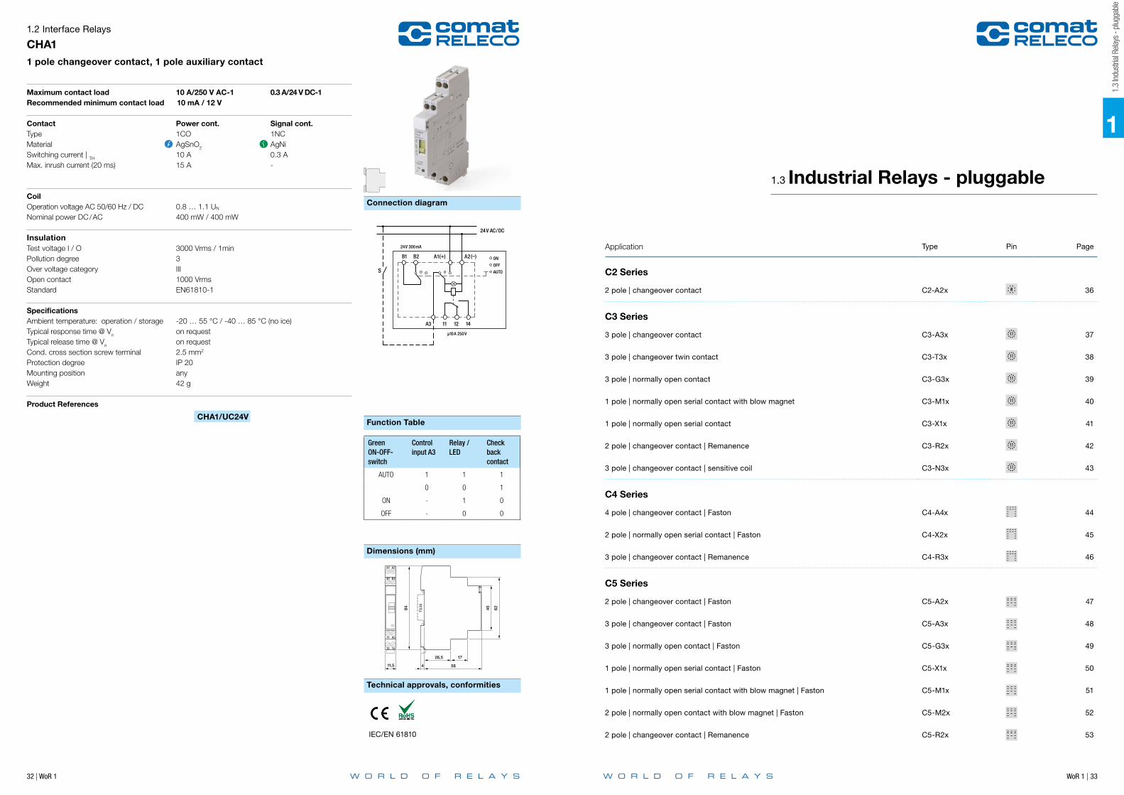
CHA11 pole changeover contact, 1 pole auxiliary contact
Maximum contact load 10 A/250 V AC-1 0.3 A/24 V DC-1Recommended minimum contact load 10 mA / 12 V
Contact Power cont. Signal cont.Type 1CO 1NCMaterial AgSnO2 AgNiSwitching current | TH 10 A 0.3 AMax. inrush current (20 ms) 15 A -
CoilOperation voltage AC 50/60 Hz / DC 0.8 … 1.1 UN
Nominal power DC/AC 400 mW / 400 mW
Insulation Test voltage I / O 3000 Vrms / 1minPollution degree 3Over voltage category IIIOpen contact 1000 VrmsStandard EN61810-1
SpecificationsAmbient temperature: operation / storage -20 … 55 °C / -40 … 85 °C (no ice)Typical response time @ Vn on requestTypical release time @ Vn on requestCond. cross section screw terminal 2.5 mm2
Protection degree IP 20Mounting position anyWeight 42 g
Product References
CHA1/UC24V
24V AC/DC
24V 300mA
S
B1 B2 A1(+) A2(–) ON
OFF
AUTO
141211A3
µ10A 250V
12 14
11 A3
B1 B2
A1 A2
11,5 58
26,5 17
84 6245
4
TS35
Green ON-OFF-switch
Control input A3
Relay /LED
Check back contact
AUTO 1 1 1
0 0 1
ON - 1 0
OFF - 0 0
IEC/EN 61810
1.3
Indu
stria
l Rela
ys -
plug
gabl
e
Application Type Pin Page
C2 Series
2 pole | changeover contact C2-A2x 36
C3 Series
3 pole | changeover contact C3-A3x 37
3 pole | changeover twin contact C3-T3x 38
3 pole | normally open contact C3-G3x 39
1 pole | normally open serial contact with blow magnet C3-M1x 40
1 pole | normally open serial contact C3-X1x 41
2 pole | changeover contact | Remanence C3-R2x 42
3 pole | changeover contact | sensitive coil C3-N3x 43
C4 Series
4 pole | changeover contact | Faston C4-A4x 44
2 pole | normally open serial contact | Faston C4-X2x 45
3 pole | changeover contact | Remanence C4-R3x 46
C5 Series
2 pole | changeover contact | Faston C5-A2x 47
3 pole | changeover contact | Faston C5-A3x 48
3 pole | normally open contact | Faston C5-G3x 49
1 pole | normally open serial contact | Faston C5-X1x 50
1 pole | normally open serial contact with blow magnet | Faston C5-M1x 51
2 pole | normally open contact with blow magnet | Faston C5-M2x 52
2 pole | changeover contact | Remanence C5-R2x 53
1.3 Industrial Relays - pluggable
WoR 1 | 33

1
34 | WoR 1
Notes
WoR 1 | 35
1.3
Indu
stria
l Rela
ys -
plug
gabl
e
Application Type Pin Page
C7 Series
1 pole | changeover contact | Faston C7-A1x 54
2 pole | changeover contact | Faston C7-A2x 55
2 pole | changeover twin contact C7-T2x 56
2 pole | normally open contact | Faston C7-G2x 57
2 pole | changeover contact | Faston C7-H2x 58
1 pole | normally open serial contact | Faston C7-X1x 59
1 pole | normally open tungsten pre-contact | Faston C7-W1x 60
R7 Series
2 pole | changeover contact | Faston R7-A2x 61
2 pole | changeover twin contact R7-T2x 62
C9 Series
4 pole | changeover contact | Faston C9-A4x 63
2 pole | changeover contact | sensitive coil | Faston C9-E2x 64
2 pole | changeover contact | Remanence | Faston C9-R2x 65

36 | WoR 1 WoR 1 | 37
1
Connection diagram Connection diagram
fig. 1 AC voltage endurance fig. 1 AC voltage endurance
fig. 2 DC load limit curve fig. 2 DC load limit curve
Dimensions (mm) Dimensions (mm)
Technical approvals, conformities Technical approvals, conformities
52
1121
A2
24
2122 12
14
A11
2
345
6
7
8
35
35
51
(+)2
7
A1
A211
12 14 22 24
21
6534
811 8
3 6 2A1(+)
A271 8
4 3 5 6
21
24221412
11
2A1(+)
A27
1.3 Industrial Relays - pluggable
C2-A2x 2 pole | changeover contact
Volt 50 100 150 200
AC15AC1
DC1DC13
DC-1L/R 40 ms
0.1
1
10
Am
ps.
kVA 0.5 1 1.5 2 2.5
AC15AC1
DC1DC13
AC-1cos ϕ 0.4
0.1
1
10
switc
hing
cyc
les
x10
6
Maximum contact load 10 A/250 V AC-1 0.5 A/110 V DC-1 10 A/30 V DC-1 0.2 A/220 V DC-1Recommended minimum contact load 10 mA/10 V Code 0 5 mA/5 V Code 8
ContactsMaterial Standard Code 0 AgNi Optional Code 8 AgNi + 5 µ AuMax. switching current 10 AMax. peak inrush current (20 ms.) 30 A Max. switching voltage 250 V Max. AC load fig. 1 2.5 kVAMax. DC load See fig. 2
Coils Coil resistance see table; tolerance ± 10 %Pick up voltage ≤ 0.8 x UN
Pick up voltage ≥ 0.1 x UN
Nominal power 2.2 VA (AC)/1.3 W (DC)
Coil Table V AC Ω mA V DC Ω mA 24 67 92 24 443 54 48 296 46 48 1K8 27 115 1K7 19 110 9K 12 230 7K1 9.5 220 36K1 6
Insulation Volt rms / 1 minOpen contact 1000 VBetween adjacent poles 2.5 kVBetween contacts and coil 2.5 kV Insulation resistance at 500 V ≥1 GΩInsulation, IEC 61810-1 2.5 kV
SpecificationsAmbient temperature operation/storage -40.…60 ºC /-40 … 80 °C (no ice)Pick-up time + bounce time 16 ms /≤ 3 msRelease time + bounce time 8 ms /≤ 1 ms Mechanical life ops AC: 10 Mill./DC: 20 Mill. DC voltage endurance at rated load ≥100 000 ops. switching cyclesMax. switching frequency at rated load 1200/h Weight 79 g
Product References V AC 50 Hz/60 Hz: 24, 48, 115 (120), 230 (240) C2-A20/AC … V C2-A28/AC … V LED C2-A20X/AC … V C2-A28X/AC … VRC Suppressor C2-A20R/AC … V C2-A28R/AC … V
V DC 24, 48, 110, 220 C2-A20/DC … V C2-A28/DC … V LED C2-A20X/DC … V C2-A28X/DC … V Free wheeling diode C2-A20DX/DC … V C2-A28DX/DC … V Polarity and free wheeling diode C2-A20FX/DC … V C2-A28FX/DC … V
AC/DC bridge rectifier 24 V, 48 V, 60 V C2-A20BX/UC … V C2-A28BX/UC … VOther voltages on request
"..." List Coil Voltage to complete Product References
Accessories (See also Section Sockets)Socket S2-B, S2-POBlanking Plug SO-NP (BAG 10 PCS)
IEC/EN 61810; IEC/EN 60947
1.3
Indu
stria
l Rela
ys -
plug
gabl
e
1.3 Industrial Relays - pluggable
C3-A3x3 pole | changeover contact
Maximum contact load 10 A/250 AC-1 0.5 A/110 V DC-1 10 A/30 DC-1 0.2 A/220 V DC-1Recommended minimum contact load 10 mA/10 V Code 0, 9 5 mA/5 V Code 8
ContactsMaterial Standard Code 0 AgNi Optional Code 8 AgNi + 5 µ Au Optional Code 9 AgNi + 0.2 µ Au Rated Load 10 AMax. inrush current (20 ms) 30 A Switching voltage max. 250 V AC load fig. 1 2.5 kVADC load see fig. 2
Coil Coil resistance see table; tolerance ± 10 %Pick-up voltage ≤ 0.8 x UN
Release voltage ≥ 0.1 x UN
Nominal power 2.2 VA (AC)/1.3 W (DC)
Coil table V AC Ω mA V DC Ω mA 24 67 92 24 480 50 48 296 46 48 1K8 26 115 1K7 19 110 9K 12 230 7K1 9.5 220 36K1 6
InsulationContact open 1000 VContact/contact 2.5 kVContact/coil 2.5 kV Insulation resistance at 500 V ≥1 GΩInsulation, IEC 61810-1 2.5 kV
SpecificationsAmbient temperature operation/storage -40.…60 ºC /-40 … 80 °C (no ice)Pick-up time/bounce time 16 ms /≤ 3 msRelease time/bounce time 8 ms /≤ 1 ms Mechanical life ops AC: 10 Mill./DC: 20 Mill. DC voltage endurance at rated load ≥ 100 000 switching cyclesMax. switching frequency at rated load 1200/hWeight 81 g
Product References V AC 50 Hz/60 Hz: 24, 48, 115 (120), 230 (240) C3-A30/AC … V C3-A38/AC … V C3-A39/AC … V
LED C3-A30X/AC … V C3-A38X/AC … V C3-A39X/AC … V
RC Suppressor C3-A30R/AC … V C3-A38R/AC … V C3-A39R/AC … V
V DC 24, 48, 110, 220 C3-A30/DC … V C3-A38/DC … V C3-A39/DC … V
LED C3-A30X/DC … V C3-A38X/DC … V C3-A39X/DC … V
Free wheeling diode C3-A30DX/DC … V C3-A38DX/DC … V C3-A39DX/DC … V
Polarity and free wheeling diode C3-A30FX/DC … V C3-A38FX/DC … V C3-A39FX/DC … V
AC/DC bridge rectifier 24 V, 48 V, 60 V C3-A30BX/UC … V C3-A38BX/UC … V C3-A39BX/UC … V
Other voltages on request
"..." List Coil Voltage to complete Product References
AccessoriesSocket S3-B, S3-S, S3-PO, S3-M, S3-M0, S3-M1Blanking Plug SO-NP (BAG 10 PCS)
11
12 14
21
22 24 32 34
31
987534
1161
2A1(+)
A210
973
1161
2A1(+)
A210
11
12 14
21
22 24 32 34
31
987534
1161
2A1(+)
A210
kVA 0.5 1 1.5 2 2.5
AC15AC1
DC1DC13
AC-1cos 0.4
0.1
1
switc
hing
cyc
les
x10
6
10
Volt 50 100 150 200
AC15AC1
DC1DC13
DC-1L/R 40 ms
0.1
1
10
Am
ps.
1
35
35
52
1131A2
34
24
32
2122
12
14
A11
23
4567
8
910
11
IEC/EN 61810; IEC/EN 60947

38 | WoR 1 WoR 1 | 39
1
Connection diagram Connection diagram
fig. 1 AC voltage endurance fig. 1 AC voltage endurance
fig. 2 DC load limit curve fig. 2 DC load limit curve
Dimensions (mm) Dimensions (mm)
Technical approvals, conformities Technical approvals, conformities
1.3 Industrial Relays - pluggable
C3-T3x3 pole | changeover twin contact
11
12 14
21
22 24 32 34
31
987534
1161
2A1(+)
A210
973
1161
2A1(+)
A210
11
12 14
21
22 24 32 34
31
987534
1161
2A1(+)
A210
Volt 50 100 150 200
DC1
AC15AC1
DC-1
0.1
1
10
Am
ps.
0.1VA 0 250 500 750 1000 1250
DC13DC1
AC1AC-1
1
switc
hing
cyc
les
x10
6
10
Maximum contact load 6 A/250 V AC-1 6 A/30 V DC-1Recommended minimum contact load 5 mA/5 V Code 1 1 mA/5 V Code 2
ContactsMaterial Standard Code 1 AgNi + 0.2 µ Au Optional Code 2 AgNi + 5 µ Au Rated Load 6 AMax. inrush current (20 ms) 15 A Switching voltage max. 250 V AC load fig. 1 1.2 kVADC load see fig. 2
CoilCoil resistance see table; tolerance ± 10 %Pick-up voltage ≤ 0.8 x UN
Release voltage ≥ 0.1 x UN
Nominal power 2.2 VA (AC)/1.3 W (DC)
Coil table V AC Ω mA V DC Ω mA 24 67 92 24 480 50 48 296 46 48 1K8 26 115 1K7 19 110 9K 12 230 7K1 9.5 220 36K1 6
InsulationContact open 1000 VContact/contact 2.5 kVContact/coil 2.5 kV Insulation resistance at 500 V ≥1 GΩInsulation, EN 61810-1 2.5 kV
SpecificationsAmbient temperature operation/storage -40 … 70 ºC /-40 … 80 °C (no ice)Pick-up time/bounce time 8 ms /≤ 3 msRelease time/bounce time 18 ms /≤ 1 ms Mechanical life ops AC: 10 Mill./DC: 20 Mill. DC voltage endurance at rated load ≥ 100 000 switching cyclesMax. switching frequency at rated load 1200/hWeight 81 g
Product References V AC 50 Hz/60 Hz: 24, 48, 115 (120), 230 (240) C3-T31/AC … V C3-T32/AC … V LED C3-T31X/AC … V C3-T32X/AC … VRC Suppressor C3-T31R/AC … V C3-T32R/AC … V
V DC 24, 48, 110, 220 C3-T31/DC … V C3-T32/DC … V LED C3-T31X/DC … V C3-T32X/DC … VFree wheeling diode C3-T31DX/DC … V C3-T32DX/DC … VPolarity and free wheeling diode C3-T31FX/DC … V C3-T32FX/DC … V
AC/DC bridge rectifier 24 V, 48 V, 60 V C3-T31BX/UC … V C3-T32BX/UC … VOther voltages on request
"..." List Coil Voltage to complete Product References
AccessoriesSocket S3-B, S3-S, S3-PO, S3-M, S3-M0, S3-M1Blanking Plug SO-NP (BAG 10 PCS)
35
35
52
1131A2
34
24
32
2122
12
14
A11
23
4567
8
910
11
IEC/EN 61810; IEC/EN 60947
1.3
Indu
stria
l Rela
ys -
plug
gabl
e
35
35
52
1131A2
34
24
32
2122
12
14
A11
23
4567
8
910
11
1.3 Industrial Relays - pluggable
C3-G3x3 pole | normally open contact
11
12 14
21
22 24 32 34
31
987534
1161
2A1(+)
A210
973
1161
2A1(+)
A210
11
12 14
21
22 24 32 34
31
987534
1161
2A1(+)
A210
Volt 50 100 150 200
DC13DC1
DC13DC1
DC13DC1
DC13DC1
DC-1L/R 40 ms
0.1
1
10
Am
ps.
kVA 0.5 1 1.5 2 2.5
AC15AC1
DC1DC13
AC-1cos ϕ 0.4
0.1
1
switc
hing
cyc
les
x10
6
10
Gap:1.7 mm
Maximum contact load 10 A/250 V AC-1 1.2 A/110 V DC-1Recommended minimum contact load 10 A/30 V DC-1 0.4 A/220 V DC-1
ContactsMaterial Standard Code 0 AgNi Rated Load 10 AMax. inrush current (20 ms) 30 A Switching voltage max. 250 V AC load fig. 1 2.5 kVADC load see fig. 2
CoilCoil resistance see table; tolerance ± 10 %Pick-up voltage ≤ 0.8 x UN
Release voltage ≥ 0.1 x UN
Nominal power 2.4 VA (AC)/1.6 W (DC)
Coil table V AC Ω mA V DC Ω mA 24 65 100 24 360 66 48 286 50 48 1K4 34 115 1K7 21 110 7K6 15 230 6K8 10 220 30K3 7.5
InsulationContact open 2000 VContact/contact 2.5 kVContact/coil 2.5 kV Insulation resistance at 500 V ≥1 GΩInsulation, IEC 61810-1 2.5 kV
SpecificationsAmbient temperature operation/storage -40.…60 ºC /-40 … 80 °C (no ice)Pick-up time/bounce time 20 ms /≤ 3 msRelease time/bounce time 8 ms /≤ 1 ms Mechanical life ops AC: 10 Mill./DC: 20 Mill. DC voltage endurance at rated load ≥ 100 000 switching cyclesMax. switching frequency at rated load 1200/hWeight 81 g
Product References V AC 50 Hz/60 Hz: 24, 48, 115 (120), 230 (240) C3-G30/AC … VLED C3-G30X/AC … VRC Suppressor C3-G30R/AC … V
V DC 24, 48, 110, 220 C3-G30/DC … V LED C3-G30X/DC … VFree wheeling diode C3-G30DX/DC... VPolarity and free wheeling diode C3-G30FX/DC … V
AC/DC bridge rectifier 24 V, 48 V, 60 V C3-G30BX/UC … VOther voltages on request
"..." List Coil Voltage to complete Product References
AccessoriesSocket S3-B, S3-S, S3-PO, S3-M, S3-M0, S3-M1Blanking Plug SO-NP (BAG 10 PCS)
IEC/EN 61810; IEC/EN 60947

40 | WoR 1 WoR 1 | 41
1
Connection diagram Connection diagram
fig. 1 AC voltage endurance
Dimensions (mm) Dimensions (mm)
Technical approvals, conformities Technical approvals, conformities
fig. 1 AC voltage endurance
fig. 2 DC voltage endurance
35
35
52
1131A2
34
24
32
2122
12
14
A11
23
4567
8
910
11
1.3 Industrial Relays - pluggable
C3-M1x1 pole | normally open serial contact with blow magnet
Maximum contact load 10 A /250 V AC-1 10 A/220 V DC-1
ContactsMaterial Standard Code 0 AgNi Rated Load 10 AMax. inrush current (20 ms) 30 ASwitching voltage max. 250 V AC load fig. 1 2.5 kVADC load see fig. 2
CoilCoil resistance see table; tolerance ± 10 %Pick-up voltage ≤ 0.8 x UN
Release voltage ≥ 0.1 x UN
Nominal power 2.4 VA (AC) / 1.3 W (DC)
Coil table V AC Ω mA V DC Ω mA 24 65 100 24 480 50 48 286 50 48 1K8 26 115 1K7 21 110 9K 12 230 6K8 10 220 29K 7.5
InsulationContact open 2500 VContact/contact 2.5 kVContact/coil 2.5 kV Insulation resistance at 500 V ≥1 GΩInsulation, IEC 61810-1: 2.5 kV
SpecificationsAmbient temperature operation/storage -40 … 70 ºC (55° C AC) /-40 … 80 °C (no ice) Pick-up time/bounce time 20 ms /≤ 3 msRelease time/bounce time 10 ms /≤ 1 ms Mechanical life ops AC: 10 Mill./DC: 20 Mill. DC voltage endurance at rated load ≥ 100 000 switching cyclesMax. switching frequency at rated load 1200/hWeight 90 g
Product ReferencesV AC 50 Hz/60 Hz: 24, 48, 115 (120), 230 (240) C3-M10/AC … V LED C3-M10X/AC … VRC Suppressor C3-M10R/AC … V
V DC 24, 48, 110, 220 C3-M10/DC … V LED C3-M10X/DC … V Free wheeling diode C3-M10DX/DC … V Polarity and free wheeling diode C3-M10FX/DC … V
AC/DC bridge rectifier 24 V, 48 V, 60 V C3-M10BX/UC … VOther voltages on request
"..." List Coil Voltage to complete Product References
AccessoriesSocket S3-B, S3-S, S3-PO, S3-M, S3-M0, S3-M1Blanking Plug SO-NP (BAG 10 PCS)
Gap:> 3 mm (1.7 + 1.7)
DC-1 110VDC-1 220V
2 4 6 8 10Amp
0.1
1
10
Ops
.
0.1
1
Op
s. x
106
Amps.
AC15AC1AC1
AC15
0.5kVA 1 1.5 2 2.50.1
1
10
switc
hing
cyc
les
x10
6
AC-1 Cos ϕ 0.4
(-)
2
10
A1
A211
12 14
21
22 249834
111
6
ON (+) OFF (+)A3
3 9 2A1(+)
A210
(+)
10A2
(+)A1293 Imánmagnet
IEC/EN 61810; IEC/EN 60947
fig. 2 DC load limit curve
1.3
Indu
stria
l Rela
ys -
plug
gabl
e
35
35
52
1131A2
34
24
32
2122
12
14
A11
23
4567
8
910
11
1.3 Industrial Relays - pluggable
C3-X1x1 pole | normally open serial contact
kVA 0.5 1 1.5 2 2.5
DC1 220VDC1 110V
AC15AC1
DC13 220VDC13 110V
AC-1 Cos ϕ 0.4
0.1
1
switc
hing
cyc
les
x10
6
10
(-)
2
10
A1
A2
9834
111
6
ON (+) OFF (+)A3
3 9 2A1(+)
A210
(+)
10A2
(+)A1293 Imán
Gap:> 3 mm (1.7 + 1.7)
Maximum contact load 10 A/250 V AC-1 7 A/110 V DC-1 10 A/30 V DC-1 1.2 A/220 V DC-1
ContactsMaterial Standard Code 0 AgNi Rated Load 10 AMax. inrush current (20 ms) 30 A Switching voltage max. 250 V AC load fig. 1 2.5 kVADC load see fig. 2
CoilCoil resistance see table; tolerance ± 10 %Pick-up voltage ≤ 0.8 x UN
Release voltage ≥ 0.1 x UN
Nominal power 2.4 VA (AC)/1.3 W (DC)
Coil table V AC Ω mA V DC Ω mA 24 65 100 24 480 54 48 286 50 48 1K8 26 115 1K7 21 110 9K 12 230 6K8 10 220 29K 7.5
InsulationContact open 2500 VContact/contact 2.5 kVContact/coil 2.5 kV Insulation resistance at 500 V ≥1 GΩInsulation, IEC 61810-1 2.5 kV
SpecificationsAmbient temperature operation/storage -40.…60 ºC /-40 … 80 °C (no ice)Pick-up time/bounce time 18 ms /≤ 3 msRelease time/bounce time 8 ms /≤ 1 ms Mechanical life ops AC: 10 Mill./DC: 20 Mill. DC voltage endurance at rated load ≥ 100 000 switching cyclesMax. switching frequency at rated load 1200/hWeight 83 g
Product References V AC 50 Hz/60 Hz: 24, 48, 115 (120), 230 (240) C3-X10/AC … V LED C3-X10X/AC … VRC Suppressor C3-X10R/AC … V
V DC 24, 48, 110, 220 C3-X10/DC … VLED C3-X10X/DC … VFree wheeling diode C3-X10DX/DC … VPolarity and free wheeling diode C3-X10FX/DC … V
AC/DC bridge rectifier 24 V, 48 V, 60 V C3-X10BX/UC … VOther voltages on request
"..." List Coil Voltage to complete Product References
AccessoriesSocket S3-B, S3-S, S3-PO, S3-M, S3-M0, S3-M1Blanking Plug SO-NP (BAG 10 PCS)
Volt 25 75 125 175 2250,1
1
10
Am
ps.
DC-1 L/R 40 ms
IEC/EN 61810; IEC/EN 60947

42 | WoR 1 WoR 1 | 43
1
Connection diagram Connection diagram
fig. 1 AC voltage endurance fig. 1 AC voltage endurance
fig. 2 DC load limit curve fig. 2 DC load limit curve
Dimensions (mm) Dimensions (mm)
Technical approvals, conformities Technical approvals, conformities
35
35
52
1131A2
34
24
32
2122
12
14
A11
23
4567
8
910
11
1.3 Industrial Relays - pluggable
C3-R2x2 pole | changeover contact | Remanence
++
A2AC
A3
A1
A2DC
A1 A3
++
A2AC
A3
A1
A2DC
A1 A3
(-)
2
10
A1
A2
9834
111
6
ON (+) OFF (+)A3
3 9 2A1(+)
A210
(+)
10A2
(+)A1293 Imán
Volt 50 100 150 200
AC15AC1
DC1DC13
DC-1 L/R 40 ms
0.1
1
10
Am
ps.
kVA 0.5 1 1.5 2 2.5
AC15AC1
DC1DC13
AC-1 Cos ϕ 0.4
0.1
1
switc
hing
cyc
les
x10
6
106
Maximum contact load 10 A/250 V AC-1 0.5 A/110 V DC-1 10 A/30 V DC-1 0.2 A/220 V DC-1Recommended minimum contact load 10 mA/10 V Code 0 5 mA/5 V Code 8
ContactsMaterial Standard Code 0 AgNi Optional Code 8 AgNi + 5 µ Au Rated Load 10 AMax. inrush current (20 ms) 30 A Switching voltage max. 250 V AC load fig. 1 2.5 kVADC load see fig. 2
CoilCoil resistance see table; tolerance ± 10 %ON pulse power 1.5 VA/W OFF pulse power 0.5 VA/WPull-in ON OFF ≤ 0.8 x UN
Internal Diagram: Coil table
V AC mA ON mA OFF V DC mA ON mA OFF 24 75 12 12 125 41 48 38 6 24 63 21 115 16 2.5 48 31 10 230 8 1.3 110 14 4.5
InsulationContact open 1000 VContact/contact 2.5 kVContact/coil 2.5 kV Insulation resistance at 500 V ≥1 GΩInsulation, IEC 61810-1 2.5 kV
SpecificationsAmbient temperature operation/storage -40.…60 ºC /-40 … 80 °C (no ice)Minimum pulse length for ON OFF 50 ms Mechanical life ops 10 Mill. DC voltage endurance at rated load ≥ 100 000 switching cyclesMax. switching frequency at rated load 1200/hWeight 81 g
Product References V AC 50 Hz/60 Hz: 24, 48, 115, 230 C3-R20N/AC … V C3-R28N/AC … V
V DC 12, 24, 48, 110 C3-R20N/DC … V C3-R28N/DC … VOther voltages on request
"..."List Coil Voltage to complete Product References
AccessoriesSocket S3-B, S3-S, S3-PO, S3-M, S3-M0, S3-M1Blanking Plug SO-NP (BAG 10 PCS)
1
IEC/EN 61810; IEC/EN 60947
1.3
Indu
stria
l Rela
ys -
plug
gabl
e
1.3 Industrial Relays - pluggable
C3-N3x3 pole | changeover contact | sensitive coil
Maximum contact load 6 A/250 V AC-1 6 A/30 V DC-1 Recommended minimum contact load 10 mA/10 V Code 4 5 mA/5 V Code 8
ContactsMaterial Standard Code 4 AgNi + 0.2 µ Au Optional Code 8 AgNi + 5 µ Au Rated Load 5 AMax. inrush current (20 ms) 30 A Switching voltage max. 250 V AC load fig. 1 1.5 kVADC load see fig. 2
Coil Coil resistance see table; tolerance ± 10 %Pick-up voltage ≤ 0.8 x UN
Release voltage ≥ 0.1 x UN
Nominal power 800 mW
Coil table V AC Ω mA V DC Ω mA 24 67 92 24 480 50 48 296 46 48 1K8 26 115 1K7 19 110 9K 12 230 7K1 9.5 220 36K1 6
InsulationContact open 1000 VContact/contact 2.5 kVContact/coil 2.5 kV Insulation resistance at 500 V ≥1 GΩInsulation, IEC 61810-1 2.5 kV
SpecificationsAmbient temperature operation/storage -40.…60 ºC /-40 … 80 °C (no ice)Pick-up time/bounce time 18 ms /≤ 3 msRelease time/bounce time 10 ms /≤ 1 ms Mechanical life ops DC: 20 Mill. DC voltage endurance at rated load ≥ 100 000 switching cyclesMax. switching frequency at rated load 1200/hWeight 90 g
Product References V DC 24, 48, 60, 110 C3-N34/DC … V C3-N38/DC … VFree wheeling diode C3-N34D/DC … V C3-N38D/DC … VPolarity and free wheeling diode C3-N34F/DC … V C3-N38F/DC … VOther voltages on request
"..." List Coil Voltage to complete Product References
AccessoriesSocket S3-B, S3-S, S3-PO, S3-M, S3-M0, S3-M1Blanking Plug SO-NP (BAG 10 PCS)
11
12 14
21
22 24 32 34
31
987534
1161
2A1(+)
A210
973
1161
2A1(+)
A210
11
12 14
21
22 24 32 34
31
987534
1161
2A1(+)
A210
35
35
52
1131A2
34
24
32
2122
12
14
A11
23
4567
8
910
11
IEC/EN 61810; IEC/EN 60947
Volt 50 100 150 200
DC1
AC15AC1
DC-1
0.1
1
10
Am
ps.
0.1VA 0 250 500 750 1000 1250
DC13DC1
AC1AC-1
1
switc
hing
cyc
les
x10
6
10

44 | WoR 1 WoR 1 | 45
1
Connection diagram Connection diagram
fig. 1 AC voltage endurance fig. 1 AC voltage endurance
fig. 2 DC load limit curve fig. 2 DC load limit curve
Dimensions (mm) Dimensions (mm)
Technical approvals, conformities Technical approvals, conformities
1.3 Industrial Relays - pluggable
C4-A4x4 pole | changeover contact | Faston
35
12 5
48
711
10
9
12
14
6
3
13
888
4.156.75
6.757.0
6.53.85
ø1.5FASTON .110
C.I.1.2
35
3
52.5
35
12 5
48
711
10
9
12
14
6
3
13
888
4.156.75
6.757.0
6.53.85
ø1.5FASTON .110
C.I.1.2
35
3
52.5
11
12 14
21
22 24 32 34
31
875421
963
ON (+)A113 12
OFF (+)
(-)A214
A3
A214
8 11(+)
13A1
2 5
1241
10 114442
11
12 14
21
22 24 32 34
31
875421
963
13A1(+)
A214
Am
ps.
Volt 50 100 150 200
AC15AC1
DC1DC13
DC-1 L/R 40 ms
0.1
1
10
kVA 0.5 1 1.5 2 2.5
AC15AC1
DC1DC13
AC-1 Cos ϕ 0.4
0.1
1
switc
hing
cyc
les
x10
6
10
Maximum contact load 10 A/250 V AC-1 0.5 A/110 V DC-1 10 A/30 V DC-1 0.2 A/220 V DC-1Recommended minimum contact load 10 mA/5 V Code 0 5 mA/5 V Code 8
ContactsMaterial Standard Code 0 AgNi Optional Code 8 AgNi + 5 µ AuRated Load 10 AMax. inrush current (20 ms) 30 A Switching voltage max. 250 V AC load fig. 1 2.5 kVADC load see fig. 2
CoilCoil resistance see table; tolerance ± 10 %Pick-up voltage ≤ 0.8 x UN
Release voltage ≥ 0.1 x UN
Nominal power 2.4 VA (AC)/1.4 W (DC)
Coil table V AC Ω mA V DC Ω mA 24 65 100 24 414 58 48 286 50 48 1K6 30 115 1K7 21 110 8K1 13 – – – 120 -125 10K 12.3 230 6K8 10 220 35K7 6.2
InsulationContact open 1000 VContact/contact 2.5 kVContact/coil 2.5 kV Insulation resistance at 500 V ≥1 GΩInsulation, IEC 61810-1 2.5 kV
SpecificationsAmbient temperature operation/storage -40.…60 ºC /-40 … 80 °C (no ice)Pick-up time/bounce time 20 ms /≤ 3 msRelease time/bounce time 8 ms /≤ 1 ms Mechanical life ops AC: 10 Mill./DC: 20 Mill. DC voltage endurance at rated load ≥ 100 000 switching cyclesMax. switching frequency at rated load 1200/hWeight 90 g
Product References V AC 50 Hz/60 Hz: 24, 48, 115, (120), 230, (240) C4-A40/AC … V C4-A48/AC … V LED C4-A40X/AC … V C4-A48X/AC … VRC Suppressor C4-A40R/AC … V C4-A48R/AC … V
V DC 24, 48, 110, 220 C4-A40/DC … V C4-A48/DC … VLED C4-A40X/DC … V C4-A48X/DC … VFree wheeling diode C4-A40DX/DC … V C4-A48DX/DC … VPolarity and free wheeling diode C4-A40FX/DC … V C4-A48FX/DC … V
AC/DC bridge rectifier 24 V, 48 V, 60 V C4-A40BX/UC … V C4-A48BX/UC … VOther voltages on request
"..." List Coil Voltage to complete Product References
AccessoriesSocket S4-J, S4-L, S4-PWall Mounting Adapter S5-R (BAG 5 PCS)Blanking Plug SO-NP (BAG 10 PCS)
IEC/EN 61810; IEC/EN 60947
1.3
Indu
stria
l Rela
ys -
plug
gabl
e
1.3 Industrial Relays - pluggable
C4-X2x2 pole | normally open serial contact | Faston
35
12 5
48
711
10
9
12
14
6
3
13
888
4.156.75
6.757.0
6.53.85
ø1.5FASTON .110
C.I.1.2
35
3
52.5
35
12 5
48
711
10
9
12
14
6
3
13
888
4.156.75
6.757.0
6.53.85
ø1.5FASTON .110
C.I.1.2
35
3
52.5
Volt 50 100 150 200
DC13DC1
DC13DC1
DC13DC1
DC13DC1
0.1
DC-1 L/R 40 ms
1
10
Am
ps.
kVA 0.5 1 1.5 2 2.5
AC15AC1
DC1DC13
AC-1 Cos ϕ 0.4
0.1
1
switc
hing
cyc
les
x10
6
10
11
12 14
21
22 24 32 34
31
875421
963
ON (+)A113 12
OFF (+)
(-)A214
A3
A214
8 11(+)
13A1
2 5
1241
10 114442
11
12 14
21
22 24 32 34
31
875421
963
13A1(+)
A214
Gap:> 3 mm (1.7 + 1.7)
Maximum contact load 10 A/250 V AC-1 7 A/110 V DC-1 10 A/30 V DC-1 1.2 A/220 V DC-1Recommended minimum contact load 10 mA/10 V Code 0
ContactsMaterial Standard Code 0 AgNiRated Load 10 AMax. inrush current (20 ms) 30 A Switching voltage max 250 V AC load fig. 1 2.5 kVADC load see fig. 2
CoilCoil resistance see table; tolerance ± 10 %Pick-up voltage ≤ 0.8 x UN
Release voltage ≥ 0.1 x UN
Nominal power 2.4 VA (AC)/1.3 W (DC)
Coil table V AC Ω mA V DC Ω mA 24 65 100 24 443 54 48 286 50 48 1K8 27 115 1K7 21 110 9K2 12 230 6k8 10 220 30K3 6
InsulationContact open 2500 VContact/contact 2.5 kVContact/coil 2.5 kV Insulation resistance at 500 V ≥1 GΩInsulation, IEC 61810-1 2.5 kV
SpecificationsAmbient temperature operation/storage -40.…60 ºC /-40 … 80 °C (no ice)Pick-up time/bounce time 20 ms /≤ 3 msRelease time/bounce time 8 ms /≤ 1 ms Mechanical life ops AC: 10 Mill./DC: 20 Mill. DC voltage endurance at rated load ≥ 100 000 switching cyclesMax. switching frequency at rated load 1200/hWeight 90 g
Product References V AC 50 Hz/60 Hz: 24, 48, 115, (120), 230, (240) C4-X20/AC … VLED C4-X20X/AC … VRC Suppressor C4-X20R/AC … V
V DC 24, 48, 110, 220 C4-X20/DC … V LED C4-X20X/DC … V Free wheeling diode C4-X20DX/DC … V Polarity and free wheeling diode C4-X20FX/DC … V
AC/DC bridge rectifier 24 V, 48 V, 60 V C4-X20BX/UC … VOther voltages on request
"..." List Coil Voltage to complete Product References
AccessoriesSocket S4-J, S4-L, S4-PWall Mounting Adapter S5-R (BAG 5 PCS)Blanking Plug SO-NP (BAG 10 PCS)
IEC/EN 61810; IEC/EN 60947
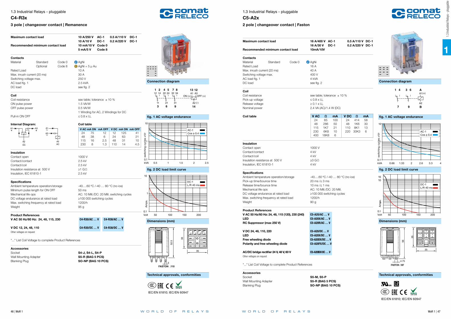
46 | WoR 1 WoR 1 | 47
1
Connection diagram Connection diagram
fig. 1 AC voltage endurance fig. 1 AC voltage endurance
fig. 2 DC load limit curve fig. 2 DC load limit curve
Dimensions (mm) Dimensions (mm)
Technical approvals, conformities Technical approvals, conformities
1.3 Industrial Relays - pluggable
C4-R3x3 pole | changeover contact | Remanence
++
A2AC
A3
A1
A2DC
A1 A3++
A2AC
A3
A1
A2DC
A1 A3
11
12 14
21
22 24 32 34
31
875421
963
ON (+)A113 12
OFF (+)
(-)A214
A3
A214
8 11(+)
13A1
2 5
1241
10 114442
11
12 14
21
22 24 32 34
31
875421
963
13A1(+)
A214
kVA 0.5 1 1.5 2 2.5
AC15AC1
DC1DC13
AC-1 Cos ϕ 0.4
0.1
1sw
itchi
ng c
ycle
s x1
06
10
Maximum contact load 10 A/250 V AC-1 0.5 A/110 V DC-1 10 A/10 V DC-1 0.2 A/220 V DC-1Recommended minimum contact load 10 mA/10 V Code 0 5 mA/5 V Code 8
ContactsMaterial Standard Code 0 AgNi Optional Code 8 AgNi + 5 µ AuRated Load 10 AMax. inrush current (20 ms) 30 A Switching voltage max. 250 VAC load fig. 1 2.5 kVADC load see fig. 2
CoilCoil resistance see table; tolerance ± 10 %ON pulse power 1.5 VA/WOFF pulse power 0.5 VA/W 1 Winding for AC, 2 Windings for DCPull-in ON OFF ≤ 0.8 x UN
Internal Diagram: Coil table
V AC mA ON mA OFF V DC mA ON mA OFF 24 75 12 12 125 41 48 38 6 24 63 21 115 16 2.5 48 31 10 230 8 1.3 110 14 4.5
InsulationContact open 1000 VContact/contact 2.5 kVContact/coil 2.5 kV Insulation resistance at 500 V ≥1 GΩInsulation, IEC 61810-1 2.5 kV
SpecificationsAmbient temperature operation/storage -40.…60 ºC /-40 … 80 °C (no ice)Minimum pulse length for ON OFF 50 msMechanical life ops AC: 10 Mill./DC: 20 Mill. switching cyclesDC voltage endurance at rated load ≥ 100 000 switching cyclesMax. switching frequency at rated load 1200/hWeight 95 g
Product References V AC 50 Hz/60 Hz: 24, 48, 115, 230 C4-R30/AC … V C4-R38/AC … V
V DC 12, 24, 48, 110 C4-R30/DC … V C4-R38/DC … VOther voltages on request
"..." List Coil Voltage to complete Product References
AccessoriesSocket S4-J, S4-L, S4-PWall Mounting Adapter S5-R (BAG 5 PCS)Blanking Plug SO-NP (BAG 10 PCS)
Volt 50 100 150 200
AC15AC1
DC1DC13
DC-1 L/R 40 ms
0.1
1
10
Am
ps.
1
IEC/EN 61810; IEC/EN 60947
35
12 5
48
711
10
9
12
14
6
3
13
888
4.156.75
6.757.0
6.53.85
ø1.5FASTON .110
C.I.1.2
35
3
52.5
35
12 5
48
711
10
9
12
14
6
3
13
888
4.156.75
6.757.0
6.53.85
ø1.5FASTON .110
C.I.1.2
35
3
52.5
1.3
Indu
stria
l Rela
ys -
plug
gabl
e
1.3 Industrial Relays - pluggable
C5-A2x2 pole | changeover contact | Faston
Maximum contact load 16 A/400 V AC-1 0.5 A/110 V DC-1 16 A/30 V DC-1 0.2 A/220 V DC-1Recommended minimum contact load 10mA/10V
ContactsMaterial Standard Code 0 AgNiRated Load 16 AMax. inrush current (20 ms) 40 A Switching voltage max. 400 VAC load fig. 1 4 kVADC load see fig. 2
CoilCoil resistance see table; tolerance ± 10 %Pick-up voltage ≤ 0.8 x UN
Release voltage ≥ 0.1 x UN
Nominal power 2.4 VA (AC)/1.4 W (DC)
Coil table V AC Ω mA V DC Ω mA 24 65 100 24 414 58 48 286 50 48 1K6 30 115 1K7 21 110 8K1 13 230 6K8 10 220 30K3 6 400 18K8 6
InsulationContact open 1000 VContact/contact 4 kVContact/coil 4 kV Insulation resistance at 500 V ≥3 GΩInsulation, IEC 61810-1 4 kV
SpecificationsAmbient temperature operation/storage -40.…60 ºC /-40 … 80 °C (no ice)Pick-up time/bounce time 20 ms /≤ 3 msRelease time/bounce time 10 ms /≤ 1 ms Mechanical life ops AC: 10 Mill./DC: 20 Mill. DC voltage endurance at rated load ≥ 100 000 switching cyclesMax. switching frequency at rated load 1200/hWeight 90 g
Product ReferencesV AC 50 Hz/60 Hz: 24, 48, 115 (120), 230 (240) C5-A20/AC … V LED C5-A20X/AC … V RC Suppressor (max 250 V) C5-A20R/AC … V
V DC 24, 48, 110, 220 C5-A20/DC … V LED C5-A20X/DC … V Free wheeling diode C5-A20DX/DC … V Polarity and free wheeling diode C5-A20FX/DC … V
AC/DC bridge rectifier 24 V, 48 V, 60 V C5-A20BX/UC … VOther voltages on request
"..." List Coil Voltage to complete Product References
AccessoriesSocket S5-M, S5-PWall Mounting Adapter S5-R (BAG 5 PCS)Blanking Plug SO-NP (BAG 10 PCS)
11
12 14
21
22 24 32 34
31
635241
987
AA1(+)
A2B
654
987
AA1(+)
A2B
AA1(+)
A2B7 9
1 4 3 6
Volt 50 100 150 200
DC-1 L/R 40 ms
0.1
1
1016
Am
ps.
AC1 ΩCos ϕ 0.4
kVA 0.66 1.33 2 2.6 3.3 4
DC13DC1
AC15AC1
0.1
1
switc
hing
cyc
les
x10
6
10
AC-1 Cos ϕ 0.4
1
IEC/EN 61810; IEC/EN 60947

48 | WoR 1 WoR 1 | 49
1
Connection diagram Connection diagram
fig. 1 AC voltage endurance fig. 1 AC voltage endurance
fig. 2 DC load limit curve fig. 2 DC load limit curve
Dimensions (mm) Dimensions (mm)
Technical approvals, conformities Technical approvals, conformities
1.3 Industrial Relays - pluggable
C5-A3x3 pole | changeover contact | Faston
11
12 14
21
22 24 32 34
31
635241
987
AA1(+)
A2B
654
987
AA1(+)
A2B
AA1(+)
A2B7 9
1 4 3 6
Volt 50 100 150 200
DC13DC1
DC13DC1
DC13DC1
DC13DC1
DC-1 L/R 40 ms
0.1
1
1016
Am
ps.
kVA 0.66 1.33 2 2.6 3.3 4
DC13DC1
AC15AC1
AC-1 Cos ϕ 0.4
0.1
1sw
itchi
ng c
ycle
s x1
06
10
Maximum contact load 16 A/400 V AC-1 0.5 A/110 V DC-1 16 A/30 V DC-1 0.2 A/220 V DC-1Recommended minimum contact load 10mA/10V
ContactsMaterial Standard Code 0 AgNi Optional Code 5 AgSnO2
Rated Load 16 AMax. inrush current (20 ms) 40 A Switching voltage max. 400 V AC load fig. 1 4 kVADC load see fig. 2
CoilCoil resistance see table; tolerance ± 10 %Pick-up voltage ≤ 0.8 x UN
Release voltage ≥ 0.1 x UN
Nominal power 2.4 VA (AC)/1.4 W (DC)
Coil table V AC Ω mA V DC Ω mA 24 65 100 24 414 58 48 286 50 48 1K6 30 115 1K7 21 110 8K1 13 230 6K8 10 220 30K3 6.2 400 18K8 6
InsulationContact open 1000 VContact/contact 4 kVContact/coil 4 kV Insulation resistance at 500 V ≥3 GΩInsulation, IEC 61810-1 4 kV
SpecificationsAmbient temperature operation/storage -40…60 ºC /-40 … 80 °C (no ice)Pick-up time/bounce time 20 ms /≤ 3 msRelease time/bounce time 10 ms /≤ 1 ms Mechanical life ops AC: 10 Mill./DC: 20 Mill. DC voltage endurance at rated load ≥ 100 000 switching cyclesMax. switching frequency at rated load 1200/hWeight 95 g
Product References V AC 50 Hz/60 Hz: 24, 48, 115, (120), 230, (240) C5-A30/AC … V C5-A35/AC … VLED C5-A30X/AC … V C5-A35X/AC … VRC Suppressor (max 250 V) C5-A30R/AC … V C5-A35R/AC … V
V DC 24, 48, 110, 220 C5-A30/DC … V C5-A35/DC … VLED C5-A30X/DC … V C5-A35X/DC … VFree wheeling diode C5-A30DX/DC … V C5-A35DX/DC … VPolarity and free wheeling diode C5-A30FX/DC … V C5-A35FX/DC … V
AC/DC bridge rectifier 24 V, 48 V, 60 V C5-A30BX/UC … V C5-A35BX/UC … VOther voltages on request
"..." List Coil Voltage to complete Product References
AccessoriesSocket S5-M, S5-PWall Mounting Adapter S5-R (BAG 5 PCS)Blanking Plug SO-NP (BAG 10 PCS)
IEC/EN 61810; IEC/EN 60947
1.3
Indu
stria
l Rela
ys -
plug
gabl
e
1.3 Industrial Relays - pluggable
C5-G3x3 pole | normally open contact | Faston
11
12 14
21
22 24 32 34
31
635241
987
AA1(+)
A2B
654
987
AA1(+)
A2B
AA1(+)
A2B7 9
1 4 3 6
kVA 0.66 1.33 2 2.6 3.3 4
DC13DC1
AC15AC1
AC-1 Cos ϕ 0.4
0.1
1
switc
hing
cyc
les
x10
6
10
Gap:1.7 mm
Maximum contact load 16 A/400 V AC-1 1.2 A/110 V DC-1 16 A/30 V DC-1 0.4 A/220 V DC-1Recommended minimum contact load 10mA/10V
ContactsMaterial Standard Code 0 AgNi Optional Code 5 AgSnO2
Rated Load 16 AMax. inrush current (20 ms) 40 A Switching voltage max. 400 VAC load fig. 1 4 kVADC load see fig. 2
CoilCoil resistance see table; tolerance ± 10 %Pick-up voltage ≤ 0.8 x UN
Release voltage ≥ 0.1 x UN
Nominal power 2.4 VA (AC)/1.6 W (DC)
Coil table V AC Ω mA V DC Ω mA 24 65 100 12 90 133 48 286 50 24 373 66 115 1K7 21 48 1K4 34 230 6K8 10 110 7K6 15 400 18K8 6 220 30K3 7.5
InsulationContact open 2000 VContact/contact 4 kVContact/coil 4 kV Insulation resistance at 500 V ≥ 3 GΩInsulation, IEC 61810-1 4 kV
SpecificationsAmbient temperature operation/storage -40.…60 ºC /-40 … 80 °C (no ice)Pick-up time/bounce time 20 ms /≤ 3 msRelease time/bounce time 10 ms /≤ 1 ms Mechanical life ops AC: 10 Mill./DC: 20 Mill. DC voltage endurance at rated load ≥ 100 000 switching cyclesMax. switching frequency at rated load 1200/hWeight 95 g
Product References V AC 50 Hz/60 Hz: 24, 48, 115, (120), 230, (240) C5-G30/AC … V C5-G35/AC … VLED C5-G30X/AC … V C5-G35X/AC … VRC Suppressor (max 250 V) C5-G30R/AC … V C5-G35R/AC … V
V DC 12, 24, 48, 110, 220 C5-G30/DC … V C5-G35/DC … VLED C5-G30X/DC … V C5-G35X/DC … VFree wheeling diode C5-G30DX/DC … V C5-G35DX/DC … VPolarity and free wheeling diode C5-G30FX/DC … V C5-G35FX/DC … V
AC/DC bridge rectifier 24 V, 48 V, 60 V C5-G30BX/UC … V C5-G35BX/UC … VOther voltages on request
"..." List Coil Voltage to complete Product References
AccessoriesSocket S5-M, S5-PWall Mounting Adapter S5-R (BAG 5 PCS)Blanking Plug SO-NP (BAG 10 PCS)
Volt 50 100 150 200
DC13DC1
DC13DC1
DC13DC1
DC13DC1
DC-1 L/R 40 ms
0.1
1
1016
Am
ps.
1
IEC/EN 61810; IEC/EN 60947

50 | WoR 1 WoR 1 | 51
1
Connection diagram Connection diagram
fig. 1 AC voltage endurance fig. 1 AC voltage endurance
fig. 2 DC load limit curve
Dimensions (mm) Dimensions (mm)
Technical approvals, conformities Technical approvals, conformities
1.3 Industrial Relays - pluggable
C5-X1x1 pole | normally open serial contact | Faston
OFF (+)ON (+)
8
7 9
1 4 3 6
A2
A1
B
A
(-)
A3
4 6(+) AA1(+)
A2B
Imán
64 AA1(+)
A2B
Volt 50 100 150 200
DC13DC1
DC13DC1
DC13DC1
DC13DC1
DC-1 L/R 40 ms
0.1
1
1016
Am
ps.
kVA 0.66 1.33 2 2.6 3.3 4
DC13DC1
AC15AC1
AC-1 Cos ϕ 0.4
0.1
1
switc
hing
cyc
les
x10
6
10
Gap:> 3 mm
Maximum contact load 16 A/400 V AC-1 7 A/110 V DC-1 16 A/30 V DC-1 1.2 A/220V DC-13Recommended minimum contact load 10mA/10V
ContactsMaterial Standard Code 0 AgNiRated Load 16 AMax. inrush current (20 ms) 40 A Switching voltage max. 400 V AC load fig. 1 4 kVADC load see fig. 2
CoilCoil resistance see table; tolerance ± 10 %Pick-up voltage ≤ 0.8 x UN
Release voltage ≥ 0.1 x UN
Nominal power 2.4 VA (AC)/1.3 W (DC)
Coil table V AC Ω mA V DC Ω mA 24 65 100 12 110 108 48 286 50 24 443 54 115 1K7 21 48 1K7 27 230 6K8 10 110 9K2 12 400 18K8 6 220 30K3 6.2
InsulationContact open 4 kVContact/contact 4 kVContact/coil 4 kV Insulation resistance at 500 V ≥ 3 GΩInsulation, IEC 61810-1 4 kV
SpecificationsAmbient temperature operation/storage -40.…60 ºC /-40 … 80 °C (no ice)Pick-up time/bounce time 20 ms /≤ 3 msRelease time/bounce time 10 ms /≤ 1 ms Mechanical life ops AC: 10 Mill./DC: 20 Mill. DC voltage endurance at rated load ≥ 100 000 switching cyclesMax. switching frequency at rated load 1200/hWeight 90 g
Product References V AC 50 Hz/60 Hz: 24, 48, 115 (120), 230 (240) C5-X10/AC … VLED C5-X10X/AC … V RC Suppressor (max 250 V) C5-X10R/AC … V
V DC 12, 24, 48, 110, 220 C5-X10/DC … V LED C5-X10X/DC … V Free wheeling diode C5-X10DX/DC … V Polarity and free wheeling diode C5-X10FX/DC … V
AC/DC bridge rectifier 24 V, 48 V, 60 V C5-X10BX/UC … VOther voltages on request
"..." List Coil Voltage to complete Product References
AccessoriesSocket S5-M, S5-PWall Mounting Adapter S5-R (BAG 5 PCS)Blanking Plug SO-NP (BAG 10 PCS)
IEC/EN 61810; IEC/EN 60947
fig. 2 DC voltage endurance
1.3
Indu
stria
l Rela
ys -
plug
gabl
e
1.3 Industrial Relays - pluggable
C5-M1x1 pole | normally open serial contact with blow magnet | Faston
kVA 0.66 1.33 2 2.6 3.3 4
DC13DC1
AC15AC1
AC-1 Cos ϕ 0.4
0.1
1
Op
erat
ions
x10
6
10
Maximum contact load 16 A/400 V AC-1 10 A/220 V DC-1 3.6 A/110 V DC-13 2 A/220 V DC-13 Recommended minimum contact load 10mA/10V
ContactsMaterial Standard Code 0 AgNiRated Load 16 AMax. inrush current (20 ms) 40 A Switching voltage max. 400 V AC load fig. 1 4 kVADC load see fig. 2
CoilCoil resistance see table; tolerance ± 10 %Pick-up voltage ≤ 0.8 x UN
Release voltage ≥ 0.1 x UN
Nominal power 2.4 VA (AC)/1.3 W (DC)
Coil table V AC Ω mA V DC Ω mA 24 65 100 12 110 108 48 286 50 24 443 54 115 1K7 21 48 1K7 27 230 6K8 10 110 9K2 12 400 18K8 6 220 30K3 6.2
InsulationContact open 4000 VContact/contact 4 kVContact/coil 4 kV Insulation resistance at 500 V ≥3 GΩInsulation, IEC 61810-1 4 kV
SpecificationsAmbient temperature operation/storage -40.…60 ºC /-40 … 80 °C (no ice)Pick-up time/bounce time 20 ms /≤ 3 msRelease time/bounce time 10 ms /≤ 1 ms Mechanical life ops AC: 10 Mill./DC: 20 Mill. DC voltage endurance see fig. 2Max. switching frequency at rated load 1200/hWeight 90 g
Product References V AC 50 Hz/60 Hz: 24, 48, 115 (120), 230 (240) C5-M10/AC … VLED C5-M10X/AC … V RC Suppressor (max 250 V) C5-M10R/AC … V
V DC 12, 24, 48, 110, 220 C5-M10/DC … V LED C5-M10X/DC … V Free wheeling diode C5-M10DX/DC … V Polarity and free wheeling diode C5-M10FX/DC … V
AC/DC bridge rectifier 24 V, 48 V, 60 V C5-M10BX/UC … VOther voltages on request
"..." List Coil Voltage to complete Product References
AccessoriesSocket S5-M, S5-PWall Mounting Adapter S5-R (BAG 5 PCS)Blanking Plug SO-NP (BAG 10 PCS)
OFF (+)ON (+)
8
7 9
1 4 3 6
A2
A1
B
A
(-)
A3
4 6(+) AA1(+)
A2B
Imán
64 AA1(+)
A2B
Gap:> 3 mm(1.7 + 1.7)
Magnet
Amp 2 4 6 8 10
DC1 220VDC1 110V
AC15AC1
DC13 220VDC13 110V
0.1
1
10
DC-1 110VDC-1 220V
Op
erat
ions
x10
6
IEC/EN 61810; IEC/EN 60947

52 | WoR 1 WoR 1 | 53
1
Connection diagram Connection diagram
fig. 1 AC voltage endurance fig. 1 AC voltage endurance
fig. 2 DC load limit curve fig. 2 DC load limit curve
Dimensions (mm) Dimensions (mm)
Technical approvals, conformities Technical approvals, conformities
1.3 Industrial Relays - pluggable
C5-M2x2 pole | normally open contact with blow magnet | Faston
4 6 AA1(+)
A2B
Magnet
7 (+) 9 (+)
IEC/EN 61810; IEC/EN 60947
Gap:1.7 mm
Maximum contact load 16 A / 250 V AC-1 7 A / 110 V DC-1 3 A / 220 V DC-1Recommended minimum contact load 10mA/10V
ContactsMaterial Standard Code 0 AgNiRated Load 16 AMax. inrush current (20 ms) 40 ASwitching voltage max. 250 VAC load fig. 1 4 kVADC load see fig. 2
CoilCoil resistance see table; tolerance ± 10 %Pick-up voltage ≥ 0.8 x UN
Release voltage ≥ 0.1 x UN
Nominal power 2.4 VA (AC) / 1.6 W (DC)
Coil table V AC Ω mA V DC Ω mA 24 65 100 12 90 133 48 286 50 24 373 66 115 1K7 21 48 1K4 33 230 6K8 10.4 110 7K6 15
InsulationContact open 2 kVContact/contact 4 kVContact/coil 3 kV Insulation resistance at 500 V ≥ 3 GΩInsulation, EN 60947/IEC 61810-1: 4 kV
SpecificationsAmbient temperature operation/storage -40.…60 ºC /-40 … 80 °C (no ice)Pick-up time/bounce time 20 ms /≤ 3 msRelease time/bounce time 10 ms /≤ 1 ms Mechanical life ops AC: 10 Mill./DC: 20 Mill. switching cyclesDC Rated load ≥ 75 000 switching cyclesMax. switching frequency at rated load 1200/hWeight 90 g
Product References V AC 50 Hz/60 Hz: 24, 48, 115 (120), 230 (240) C5-M20/AC … V LED C5-M20X/AC … V RC Suppressor C5-M20R/AC … V
V DC 12, 24, 48, 110, 220 C5-M20/DC … V LED C5-M20X/DC … V Free wheeling diode C5-M20DX/DC … V Polarity and free wheeling diode C5-M20FX/DC … V
AC/DC bridge rectifier 24 V, 48 V, 60 V C5-M20BX/UC … VOther voltages on request
"..." List Coil Voltage to complete Product References
AccessoriesSocket S5-M, S5-PWall Mounting Adapter S5-R (BAG 5 PCS)Blanking Plug SO-NP (BAG 10 PCS)
Am
ps.
Volt 50 100 150 2000.1
10
1
DC-1 L/R 40 ms
AC-1Cos ϕ 0.4
0.66 1.33 2.62 3.3KVA
0.01
0.1
1
Ops
.
4
switc
hing
cyc
les
x10
6
kVA
1.3
Indu
stria
l Rela
ys -
plug
gabl
e
1.3 Industrial Relays - pluggable
C5-R2x2 pole | changeover contact | Remanence
OFF (+)ON (+)
8
7 9
1 4 3 6
A2
A1
B
A
(-)
A3
4 6(+) AA1(+)
A2B
Imán
64 AA1(+)
A2B
AC15AC1
DC1DC13
Volt 50 100 150 200
DC-1 L/R 40 ms
0.1
1
10
Am
ps.
kVA 0.66 1.33 2 2.6 3.3 4
DC13DC1
AC15AC1
AC-1 Cos ϕ 0.4
0.1
1
switc
hing
cyc
les
x10
6
10
Maximum contact load 10 A/400 V AC-1 10 A/30 V DC-1 0.2 A/250 V DC-1 0.5 A/110 V DC-1Recommended minimum contact load 10mA/10V
ContactsMaterial Standard Code 0 AgNiRated Load 10 AMax. inrush current (20 ms) 30 A Switching voltage max. 400 V AC load fig. 1 4 kVADC load see fig. 2
CoilCoil resistance see table; tolerance ± 10 %ON pulse power 1.5 VA/WOFF pulse power 0.5 VA/W 1 winding for AC, 2 winding for DC Pull-in ON OFF < 0.8 x UN
Internal Diagram: Coil table
V AC mA ON mA OFF V DC mA ON mA OFF 24 75 12 12 125 41 48 38 6 24 63 21 115 16 2.5 48 31 10 230 8 1.3 110 14 4.5
InsulationContact open 1000 VContact/contact 4 kVContact/coil 4 kV Insulation resistance at 500 V ≥3 GΩInsulation, EN 60947/IEC 61810-1 4 kV
SpecificationsAmbient temperature operation/storage -40.…60 ºC /-40 … 80 °C (no ice)Minimum pulse ON OFF 50 msMechanical life ops AC: 10 Mill./DC: 20 Mill.DC voltage endurance at rated load ≥ 100 000 switching cyclesMax. switching frequency at rated load 1200/hWeight 95 g
Product References V AC 50 Hz/60 Hz: 24, 48, 115, 230 C5-R20/AC … V
V DC 12, 24, 48, 110, C5-R20/DC … VOther voltages on request
"..." List Coil Voltage to complete Product References
AccessoriesSocket S5-M, S5-PWall Mounting Adapter S5-R (BAG 5 PCS)Blanking Plug SO-NP (BAG 10 PCS)
++
A2AC
A3
A1
A2DC
A1 A3
++
A2AC
A3
A1
A2DC
A1 A3
IEC/EN 61810; IEC/EN 60947

54 | WoR 1 WoR 1 | 55
1
Connection diagram Connection diagram
fig. 1 AC voltage endurance fig. 1 AC voltage endurance
fig. 2 DC load limit curve fig. 2 DC load limit curve
Dimensions (mm) Dimensions (mm)
Technical approvals, conformities Technical approvals, conformities
1.3 Industrial Relays - pluggable
C7-A1x1 pole | changeover contact | Faston
5 8A2
(+)A1741
11
12 14 22 24
21
4231
65
7A1(+)
A28 5 6
1 3 2 4
21
24221412
11
7A1(+)
A28
Volt 50 100 150 200
DC13DC1
DC13DC1
DC13DC1
DC13DC1
0.1
1
1016
DC-1L/R 40 ms
Am
ps.
14.5
ø2.2
10
7.25
6.10
4.705.90
4.05
2
4
B8
6
21
A7
1
3528
4.75FASTON .187
2C.I.
37.5
14.5
ø2.2
10
7.25
6.10
4.705.90
4.05
2
4
B8
6
21
A7
1
3528
4.75FASTON .187
2C.I.
37.5
43
kVA 0.66 1.33 2 2.6 3.3 4
DC13DC1
AC15AC1
AC-1 Cos ϕ 0.4
0.1
1
switc
hing
cyc
les
x10
6
10
Maximum contact load 16 A/250 V AC-1 0.5 A/110 V DC-1 16 A/24 V DC-1 0.2 A/220 V DC-1Recommended minimum contact load 10mA/10V
ContactsMaterial Standard Code 0 AgNiRated Load 16 AMax. inrush current (20 ms) 40 A (120 A for code 5)Switching voltage max. 250 V AC load fig. 1 4 kVADC load see fig. 2
CoilCoil resistance see table; tolerance ± 10 %Pick-up voltage ≤ 0.8 x UN
Release voltage ≥ 0.1 x UN
Nominal power 1.2 VA (AC)/1.3 W (DC) Coil table V AC Ω mA V DC Ω mA 24 174 50 12 111 108 48 686 25 24 432 55 115 4K3 10.4 48 1K7 28 230 18K6 5.2 110 9K2 12
Insulation Contact open 1000 VContact/coil 2.5 kV Insulation resistance at 500 V ≥1 GΩInsulation, IEC 61810-1 2.5 kV
SpecificationsAmbient temperature operation/storage -40.…60 ºC /-40 … 80 °C (no ice)Pick-up time/bounce time 16 ms /≤ 3 msRelease time/bounce time 8 ms /≤ 1 ms Mechanical life ops AC: 10 Mill./DC: 20 Mill. AC/DC voltage endurance at rated load ≥ 100 000 switching cyclesMax. switching frequency at rated load 1200/hWeight 43 g
Product References V AC 50 Hz/60 Hz: 24, 48, 115 (120), 230 (240) LED C7-A10X/AC … V
V DC 12, 24, 48, 110 LED C7-A10X/DC … VFree wheeling diode (only 24 DC) C7-A10DX/DC 24 VPolarity and free wheeling diode C7-A10FX/DC … V
Other voltages on request
"..." List Coil Voltage to complete Product References
AccessoriesSocket S7-C, S7-IO, S7-PPush only S9-OP (BAG 10 PCS)Blanking Plug S9-NP (BAG 10 PCS)
IEC/EN 61810; IEC/EN 60947
1.3
Indu
stria
l Rela
ys -
plug
gabl
e
1.3 Industrial Relays - pluggable
C7-A2x2 pole | changeover contact | Faston
5 8A2
(+)A1741
11
12 14 22 24
21
4231
65
7A1(+)
A28 5 6
1 3 2 4
21
24221412
11
7A1(+)
A28
Volt 50 100 150 200
AC15AC1
DC1DC13
DC-1L/R 40 ms
0.1
1
10
Am
ps.
kVA 0.5 1 1.5 2 2.5
DC1
AC15AC1AC-1
Cos ϕ 0.4
0.1
1
switc
hing
cyc
les
x10
6
10
14.5
ø2.2
10
7.25
6.10
4.705.90
4.05
2
4
B8
6
21
A7
1
3528
4.75FASTON .187
2C.I.
37.5
14.5
ø2.2
10
7.25
6.10
4.705.90
4.05
2
4
B8
6
21
A7
1
3528
4.75FASTON .187
2C.I.
37.5
43
Maximum contact load 10 A/250 V AC-1 0.5 A/110 V DC-1 10 A/30 V DC-1 0.2 A/220 V DC-1Recommended minimum contact load 10 mA/10 V Code 0 5 mA/5 V Code 8
ContactsMaterial Standard Code 0 AgNi Optional Code 8 AgNi + 5 µ AuRated Load 10 AMax. inrush current (20 ms) 30 A Switching voltage max. 250 V AC load fig. 1 2.5 kVADC load see fig. 2
CoilCoil resistance see table; tolerance ± 10 %Pick-up voltage ≤ 0.8 x UN
Release voltage ≥ 0.1 x UN
Nominal power 1.2 VA (AC)/1 W (DC) Coil table V AC Ω mA V DC Ω mA 24 174 50 12 148 85 48 686 25 24 594 43 115 4K3 10.4 48 2K3 21 230 18K6 5.2 110 11K4 10
InsulationContact open 1000 VContact/contact 2.5 kVContact/coil 2.5 kV Insulation resistance at 500 V ≥1 GΩInsulation, IEC 61810-1 2.5 kV
SpecificationsAmbient temperature operation/storage -40.…60 ºC /-40 … 80 °C (no ice)Pick-up time/bounce time 16 ms /≤ 3 msRelease time/bounce time 8 ms /≤ 1 ms Mechanical life ops AC: 10 Mill./DC: 20 Mill. DC voltage endurance at rated load ≥ 100 000 switching cyclesMax. switching frequency at rated load 1200/hWeight 43 g
Product References V AC 50 Hz/60 Hz: 24, 48, 115 (120), 230 (240) LED C7-A20X/AC … V C7-A28X/AC … V
V DC 12, 24, 48, 110 LED C7-A20X/DC … V C7-A28X/DC … VFree wheeling diode (only 24 DC) C7-A20DX/DC 24 V C7-A28DX/DC 24 VPolarity and free wheeling diode C7-A20FX/DC … V C7-A28FX/DC … V
AC/DC bridge rectifier 24 V, 48 V, 60 V C7-A20BX/UC … V C7-A28BX/UC … VOther voltages on request
"..." List Coil Voltage to complete Product References
AccessoriesSocket S7-C, S7-IO, S7-P, Push only S9-OP (BAG 10 PCS)Blanking Plug S9-NP (BAG 10 PCS)
IEC/EN 61810; IEC/EN 60947

WoR 1 | 57
Connection diagram
fig. 1 AC voltage endurance
fig. 2 DC load limit curve
Dimensions (mm)
Technical approvals, conformities
56 | WoR 1
Connection diagram
fig. 1 AC voltage endurance
fig. 2 DC load limit curve
Dimensions (mm)
Technical approvals, conformities
1.3 Industrial Relays - pluggable
C7-T2x2 pole | changeover twin contact
5 8A2
(+)A1741
11
12 14 22 24
21
4231
65
7A1(+)
A28 5 6
1 3 2 4
21
24221412
11
7A1(+)
A28
Volt 50 100 150 200
DC1
AC15AC1
DC-1
0.1
1
10
Am
ps.
VA 0 250 500 750 1000 1250
DC13DC1
AC1AC-1
0.1
1
switc
hing
cyc
les
x10
6
10
Maximum contact load 6 A/250 V AC-1 6 A/30 V DC-1 Recommended minimum contact load 5 mA/5 V Code 1 1 mA/5 V Code 2
ContactsMaterial Standard Code 1 AgNi + 0.2 µ Au Optional Code 2 AgNi + 5 µ AuRated Load 6 AMax. inrush current (20 ms) 15 A Switching voltage max. 250 V AC load fig. 1 1.2 kVADC load see fig. 2
CoilCoil resistance see table; tolerance ± 10 %Pick-up voltage ≤ 0.8 x UN
Release voltage ≥ 0.1 x UN
Nominal power 1.2 VA (AC)/1 W (DC)
Coil table V AC Ω mA V DC Ω mA 24 174 50 12 148 85 48 686 25 24 594 43 115 4K3 10.4 48 2K3 21 230 18K6 5.2 110 11K4 10
InsulationContact open 1000 VContact/contact 2.5 kVContact/coil 2.5 kV Insulation resistance at 500 V ≥1 GΩInsulation, IEC 61810-1 2.5 kV
SpecificationsAmbient temperature operation/storage -40.…60 ºC /-40 … 80 °C (no ice)Pick-up time/bounce time 16 ms /≤ 3 msRelease time/bounce time 8 ms /≤ 1 ms Mechanical life ops AC: 10 Mill./DC: 20 Mill. DC voltage endurance at rated load ≥ 100 000 switching cyclesMax. switching frequency at rated load 1200/hWeight 43 g
Product References V AC 50 Hz/60 Hz: 230 (240) LED C7-T21X/AC … V C7-T22X/AC230V
V DC 12, 24, 48, 110 LED C7-T21X/DC … V Free wheeling diode (only 24 DC) C7-T21DX/DC24V Polarity and free wheeling diode C7-T21FX/DC … V C7-T22FX/DC110VAC/DC bridge rectifier 24 V, 48 V C7-T21BX/UC … V C7-T22BX/UC24VOther voltages on request C7-T22BX/UC48V
"..." List Coil Voltage to complete Product References
AccessoriesSocket S7-C, S7-IO, S7-P, Push only S9-OP (BAG 10 PCS)Blanking Plug S9-NP (BAG 10 PCS)
14.5
ø2.2
10
7.25
6.10
4.705.90
4.05
2
4
B8
6
21
A7
1
3528
4.75FASTON .187
2C.I.
37.5
14.5
ø2.2
10
7.25
6.10
4.705.90
4.05
2
4
B8
6
21
A7
1
3528
4.75FASTON .187
2C.I.
37.5
IEC/EN 61810; IEC/EN 60947
1.3
Indu
stria
l Rela
ys -
plug
gabl
e
1.3 Industrial Relays - pluggable
C7-G2x2 pole | normally open contact | Faston
14.5
ø2.2
10
7.25
6.10
4.705.90
4.05
2
4
B8
6
21
A7
1
3528
4.75FASTON .187
2C.I.
37.5
14.5
ø2.2
10
7.25
6.10
4.705.90
4.05
2
4
B8
6
21
A7
1
3528
4.75FASTON .187
2C.I.
37.5
4
5
7A1(+)
A28
43 7A1(+)
A28
43
65
7A1(+)
A28
Volt 50 100 150 200
DC13DC1
DC13DC1
DC13DC1
DC13DC1
DC-1L/R 40 ms
0.1
1
10
Am
ps.
kVA 0.5 1 1.5 2 2.5
DC1
AC15AC1AC-1
Cos ϕ 0.4
0.1
1
switc
hing
cyc
les
x10
6
10
Gap:1.5 mm
Maximum contact load 10 A/250 V AC-1 0.8 A/110 V DC-1 10 A/30 V DC-1 0.4 A/220 V DC-1Recommended minimum contact load 10mA/10V
ContactsMaterial Standard Code 0 AgNiRated Load 10 AMax. inrush current (20 ms) 30 A Switching voltage max 250 V AC load fig. 1 2.5 kVADC load see fig. 2
CoilCoil resistance see table; tolerance ± 10 %Pick-up voltage ≤ 0.8 x UN
Release voltage ≥ 0.1 x UN
Nominal power 1.5 VA (AC)/1.5 W (DC)
Coil table V AC Ω mA V DC Ω mA 24 153 62 12 99 121 48 611 31 24 388 61 115 3K6 13 48 1K5 32 230 14K6 6.5 110 8K 14
InsulationContact open 2000 VContact/contact 2.5 kVContact/coil 2.5 kV Insulation resistance at 500 V ≥1 GΩInsulation, IEC 61810-1 2.5 kV
SpecificationsAmbient temperature operation/storage -40.…60 ºC /-40 … 80 °C (no ice)Pick-up time/bounce time 20 ms /≤ 3 msRelease time/bounce time 10 ms /≤ 1 ms Mechanical life ops AC: 10 Mill./DC: 20 Mill. DC voltage endurance at rated load ≥ 100 000 switching cyclesMax. switching frequency at rated load 1200/hWeight 43 g
Product References V AC 50 Hz/60 Hz: 24, 48, 115 (120), 230 (240) LED C7-G20X/AC … V
V DC 12, 24, 48, 110 LED Polarity and free wheeling diode C7-G20FX/DC … V
AC/DC bridge rectifier 24 V, 48 V, 60 V C7-G20BX/UC … VOther voltages on request
"..." List Coil Voltage to complete Product References
AccessoriesSocket S7-C, S7-IO, S7-P, Push only S9-OP (BAG 10 PCS)Blanking Plug S9-NP (BAG 10 PCS)
IEC/EN 61810; IEC/EN 60947
1

58 | WoR 1 WoR 1 | 59
1
Connection diagram Connection diagram
fig. 1 AC voltage endurance fig. 1 AC voltage endurance
fig. 2 DC load limit curve fig. 2 DC load limit curve
Dimensions (mm) Dimensions (mm)
Technical approvals, conformities Technical approvals, conformities
1.3 Industrial Relays - pluggable
C7-H2x2 pole | changeover contact | Faston
Maximum contact load 10 A / 250 V AC-1 6 A / 250 V AC-1 10 A / 30 V DC-1 6 A / 30 V DC-1Recommended minimum contact load 10 mA/10 V (Power contacts) 5 mA/5V (twin contacts)
ContactsMaterial Standard Code 3 AgNi + 3 µ AuRated Load 10 AMax. inrush current (20 ms) 30 A Switching voltage max. 2,5 kV AC load fig. 1 2,5 VADC load see fig. 2
CoilCoil resistance see table; tolerance ± 10 %Pick-up voltage ≤ 0.8 x UN
Release voltage ≥ 0.1 x UN
Nominal power 1.2 VA (AC)/1 W (DC)
Coil table V AC Ω mA V DC Ω mA 230 18K6 5.2 24 594 43
InsulationContact open 1000 VContact/contact 2.5 kVContact/coil 2.5 kV Insulation, IEC 61810-1 2.5 kV
SpecificationsAmbient temperature operation/storage -40.…60 ºC /-40 … 80 °C (no ice)Pick-up time/bounce time 16 ms /≤ 3 msRelease time/bounce time 8 ms /≤ 1 ms Mechanical life ops AC: 10 Mill./DC: 20 Mill. DC voltage endurance at rated load ≥ 100 000 switching cyclesMax. switching frequency at rated load 1200/hWeight 43 g
Product References LED (only 230 V AC) C7-H23X/AC 230 VFree wheeling diode (only 24 DC) C7-H23X/DC 24 V
Other voltages on request
"..." List Coil Voltage to complete Product References
AccessoriesSocket S7-C, S7-IO, S7-P, Push only S9-OP (BAG 10 PCS)Blanking Plug S9-NP (BAG 10 PCS)
11
12 14 22 24
21
4231
65
7A1(+)
A28
AC1AC15
0.5 1 1.5 2 2.5KVA
0.1
1
10
Ops
.sw
itchi
ng c
ycle
s x1
06
10
kVA
AC-1Cos ϕ 0,4
Volt 50 100 150 200
AC15AC1
DC1DC13
DC-1L/R 40 ms
0,1
1
10
Am
ps.
14.5
ø2.2
10
7.25
6.10
4.705.90
4.05
2
4
B8
6
21
A7
1
3528
4.75FASTON .187
2C.I.
37.5
14.5
ø2.2
10
7.25
6.10
4.705.90
4.05
2
4
B8
6
21
A7
1
3528
4.75FASTON .187
2C.I.
37.5
IEC 61810; EN 60947
1.3 Industrial Relays - pluggable
C7-X1x1 pole | normally open serial contact | Faston
4
5
7A1(+)
A28
43 7A1(+)
A28
43
65
7A1(+)
A28
Volt 50 100 150 200
DC13DC1
DC13DC1
DC13DC1
DC13DC1DC-1
L/R 40 ms
0.1
1
10
Am
ps.
kVA 0.5 1 1.5 2 2.5
DC1
AC15AC1AC-1
Cos ϕ 0.4
0.1
1
switc
hing
cyc
les
x10
6
10
Gap:3 mm (1.5 + 1.5)
Maximum contact load 10 A/250 V AC-1 6 A/110 V DC-1 10 A/30 V DC-1 1 A/220 V DC-1Recommended minimum contact load 10mA/10V
ContactsMaterial Standard Code 0 AgNiRated Load 10 AMax. inrush current (20 ms) 30 A Switching voltage max. 250 V AC load 2.5 kVADC load see fig. 2
CoilCoil resistance see table; tolerance ± 10 %Pick-up voltage ≤ 0.8 x UN
Release voltage ≥ 0.1 x UN
Nominal power 1.5 VA (AC)/1.3 W (DC) Coil table V AC Ω mA V DC Ω mA 24 153 62 12 111 108 48 611 31 24 432 55 115 3K6 13 48 1K7 27 230 14K6 6.5 110 9K2 12
InsulationContact open 2.5 kVContact/coil 2.5 kV Insulation resistance at 500 V ≥1 GΩInsulation, IEC 61810-1 2.5 kV
SpecificationsAmbient temperature operation/storage -40.…60 ºC /-40 … 80 °C (no ice)Pick-up time/bounce time 20 ms /≤ 3 msRelease time/bounce time 10 ms /≤ 1 ms Mechanical life ops AC: 10 Mill./DC: 20 Mill. DC voltage endurance at rated load ≥ 100 000 switching cyclesMax. switching frequency at rated load 1200/hWeight 43 g
Product References V AC 50 Hz/60 Hz: 24, 48, 115 (120), 230 (240) LED C7-X10X/AC … V
V DC 12, 24, 48, 110 LED C7-X10X/DC … VFree wheeling diode (only 24 DC) C7-X10DX/DC 24 VPolarity and free wheeling diode C7-X10FX/DC … V
AC/DC bridge rectifier 24 V, 48 V, 60 V C7-X10BX/UC … VOther voltages on request
"..." List Coil Voltage to complete Product References
AccessoriesSocket S7-C, S7-IO, S7-P, Push only S9-OP (BAG 10 PCS)Blanking Plug S9-NP (BAG 10 PCS)
IEC/EN 61810; IEC/EN 60947
14.5
ø2.2
10
7.25
6.10
4.705.90
4.05
2
4
B8
6
21
A7
1
3528
4.75FASTON .187
2C.I.
37.5
14.5
ø2.2
10
7.25
6.10
4.705.90
4.05
2
4
B8
6
21
A7
1
3528
4.75FASTON .187
2C.I.
37.5
1.3
Indu
stria
l Rela
ys -
plug
gabl
e

60 | WoR 1 WoR 1 | 61
1
Connection diagram Connection diagram
fig. 1 AC voltage endurance fig. 1 AC voltage endurance
fig. 2 DC load limit curve fig. 2 DC load limit curve
Dimensions (mm) Dimensions (mm)
Technical approvals, conformities Technical approvals, conformities
1.3 Industrial Relays - pluggable
C7-W1x1 pole | normally open tungsten pre-contact | Faston
4
5
7A1(+)
A28
43 7A1(+)
A28
43
65
7A1(+)
A28
VA 250 500 750 1000
AC5 a/b
DC13DC1
DC13DC1
0.1
1
10
AC-5 a/b
Op
erat
ions
x10
6
kVA 0.5 1 1.5 2 2.5
DC1
AC15AC1AC-1
Cos ϕ 0.4
0.1
1
switc
hing
cyc
les
x10
6
10
Maximum contact load: 10 A/250 V AC-1 6 A / 250 V AC-5a/bRecommended minimum contact load: 10 mA/10 V
ContactsMaterial Standard Code 0 AgNi/WRated Load 10 AMax. inrush current (2.5 ms) 500 A Switching voltage max. 250 VAC load fig. 1 2.5 kVADC load see fig. 2
CoilCoil resistance see table; tolerance ± 10 %Pick-up voltage ≤ 0.8 x UN
Release voltage ≥ 0.1 x UN
Nominal power 1.5 VA (AC)/1.5 W (DC)
Coil table V AC Ω mA V DC Ω mA 24 153 62 12 99 121 48 611 31 24 388 61 115 3K6 13 48 1K5 32 230 14K5 6.5 110 8K 14
InsulationContact open 1000 VContact/coil 2.5 kV Insulation resistance at 500 V ≥1 GΩInsulation, IEC 61810-1 2.5 kV
SpecificationsAmbient temperature operation/storage -40.…60 ºC /-40 … 80 °C (no ice)Pick-up time/bounce time 20 ms /≤ 3 msRelease time/bounce time 10 ms /≤ 1 ms Mechanical life ops AC: 10 Mill./DC: 20 Mill. DC voltage endurance at rated load ≥ 100 000 switching cyclesMax. switching frequency at rated load 1200/hWeight 43 g
Product References V AC 50 Hz/60 Hz: 24, 48, 115 (120), 230 (240) LED C7-W10X/AC … V
V DC 12, 24, 48, 110 LED Polarity and free wheeling diode C7-W10FX/DC … V
AC/DC bridge rectifier 24 V, 48 V, 60 V C7-W10BX/UC … VOther voltages on request
"..." List Coil Voltage to complete Product References
AccessoriesSocket S7-C, S7-IO, S7-P, Push only S9-OP (BAG 10 PCS)Blanking Plug S9-NP (BAG 10 PCS)
14.5
ø2.2
10
7.25
6.10
4.705.90
4.05
2
4
B8
6
21
A7
1
3528
4.75FASTON .187
2C.I.
37.5
14.5
ø2.2
10
7.25
6.10
4.705.90
4.05
2
4
B8
6
21
A7
1
3528
4.75FASTON .187
2C.I.
37.5
IEC/EN 61810; IEC/EN 60947
1.3
Indu
stria
l Rela
ys -
plug
gabl
e
1.3 Industrial Relays - pluggable
R7-A2x2 pole | changeover contact | Faston
Maximum contact load: 10 A/250 V AC-1 10A/30V DC-1Recommended minimum contact load 10 mA/10 V Code 0 5 mA/5 V Code 8
ContactsMaterial Standard Code 0 AgNi Optional Code 8 AgNi + 5 µ AuRated Load 10 AMax. inrush current (20 ms) 30 A Switching voltage max. 250 VAC load see fig. 1DC load see fig. 2
CoilCoil resistance see table; tolerance ± 10 %Operating range 0,7 UN ... 1,25 UN
Pick-up voltage ≥ 0,1 x UN Nominal power 1,07 W
Coil table Voltage Ω ± 10% mA 24 535 45 48 2004 24 72 4750 15 110 11337 10
Insulation Contact open 1000VContact/Contact 4kV / 2200V Contact/coil 4kV / 2200V Insulation resistance at 500 V ≥1 GΩInsulation, IEC 61810-1 2,5 kV
SpecificationsAmbient temperature operation/storage -25.…70 ºC /-40 … 80 °C (no ice)Pick-up time/bounce time 16 ms /≤ 3 msRelease time/bounce time 8 ms /≤ 1 ms Mechanical life ops AC: 10 Mill./DC: 20 Mill. DC voltage endurance at rated load ≥ 100 000 switching cyclesMax. switching frequency at rated load 1200/hWeight 35 g
Product References V DC 12, 24, 48, 72, 110 LED + free wheeling diode R7-A20DX/DC ... V R7-A28DX/DC ... V
Other voltages on request
"..." List Coil Voltage to complete Product References
AccessoriesSocket S7-C, S7-I/O, S7-P
11
12 14 22 24
21
4231
65
7A1(+)
A28
Am
ps.
Volts
250,1
10
Am
ps.
1
100 175 225
DC-1L/R 40ms
0,1VA 0 250 500 750 1000 1250
DC13DC1
AC1AC-1
1
switc
hing
cyc
les
x10
6
10
14.5
ø2.2
10
7.25
6.10
4.705.90
4.05
2
4
B8
6
21
A7
1
3528
4.75FASTON .187
2C.I.
37.5
14.5
ø2.2
10
7.25
6.10
4.705.90
4.05
2
4
B8
6
21
A7
1
3528
4.75FASTON .187
2C.I.
37.5
IEC 60077; EN 60077-1-2/99; EN 61373/99

62 | WoR 1 WoR 1 | 63
1
Connection diagram Connection diagram
fig. 1 AC voltage endurance fig. 1 AC voltage endurance
fig. 2 DC load limit curve fig. 2 DC load limit curve
Dimensions (mm) Dimensions (mm)
Technical approvals, conformities Technical approvals, conformities
1.3 Industrial Relays - pluggable
R7-T2x2 pole | changeover twin contact
4231
65
7A1(+)
A28
11
12 14
21
22 24
IEC 60077; EN 60077-1-2/99; EN 61373/99
14.5
ø2.2
10
7.25
6.10
4.705.90
4.05
2
4
B8
6
21
A7
1
3528
4.75FASTON .187
2C.I.
37.5
14.5
ø2.2
10
7.25
6.10
4.705.90
4.05
2
4
B8
6
21
A7
1
3528
4.75FASTON .187
2C.I.
37.5
Am
ps.
Volts
250,1
10
Am
ps.
1
100 175 225
DC-1L/R 40ms
0,1VA 0 250 500 750 1000 1250
DC13DC1
AC1AC-1
1
switc
hing
cyc
les
x10
6
10
Maximum contact load: 10 A/250 V AC-1 10A/30V DC-1Recommended minimum contact load 10 mA/10 V Code 2
ContactsMaterial Standard Code 2 AgNi + 5 µ Au Rated Load 6 AMax. inrush current (20 ms) 30 ASwitching voltage max. 250 VAC load see fig. 1DC load see fig. 2
CoilCoil resistance see table; tolerance ± 10 %Pick-up voltage 0,7 UN … 1,25 UN
Release voltage ≥ 0,1 x UN
Nominal power 1,07 W
Coil table Voltage Ω ± 10% mA 24 535 45 48 2004 24 72 4750 15 110 11337 10
InsulationContact open 1000VContact/Contact 4kV / 2200V Contact/coil 4kV / 2200V Insulation resistance at 500 V ≥1 GΩInsulation, IEC 61810-1 2,5 kV
SpecificationsAmbient temperature operation/storage -25.…70 ºC /-40 … 80 °C (no ice)Pick-up time/bounce time 16 ms /≤ 3 msRelease time/bounce time 8 ms /≤ 1 ms Mechanical life ops AC: 10 Mill./DC: 20 Mill. DC voltage endurance at rated load ≥ 100 000 switching cyclesMax. switching frequency at rated load 1200/hWeight 35 g
Product References V DC 12, 24, 72, 110 LED + free wheeling diode R7-T22DX/DC ... V
Other voltages on request
"..." List Coil Voltage to complete Product References
AccessoriesSocket S7-C, S7-I/O, S7-P
1.3 Industrial Relays - pluggable
C9-A4x4 pole | changeover contact | Faston
Maximum contact load 5 A/250 V AC-1 5 A/30 V DC-1 Recommended minimum contact load 10 mA/10 V Code 1 1 mA/5 V Code 2
ContactsMaterial Standard Code 1 AgNi + 0.2 µ Au Optional Code 2 AgNi + 5 µ AuRated Load 5 AMax. inrush current (20 ms) 15 A Switching voltage max (same polarity) 250 V AC load fig. 1 1250 VADC load see fig. 2
CoilCoil resistance see table; tolerance ± 10 %Pick-up voltage ≤ 0.8 x UN
Release voltage ≥ 0.1 x UN
Nominal power 1.2 VA (AC)/1 W (DC) Coil table V AC Ω mA V DC Ω mA 24 174 50 12 148 81 48 686 25 24 594 40 115 4K3 10.4 48 2K3 21 230 18K6 5.2 110 11K4 11
InsulationContact open 1000 VContact/contact 2 kVContact/coil 2.5 kV Insulation resistance at 500 V ≥1 GΩInsulation, IEC 61810-1 2.5 kV
SpecificationsAmbient temperature operation/storage -40.…60 ºC /-40 … 80 °C (no ice)Pick-up time/bounce time 10 ms /≤ 3 msRelease time/bounce time 6 ms /≤ 1 ms Mechanical life ops AC: 10 Mill./DC: 20 Mill. DC voltage endurance at rated load ≥ 100 000 switching cyclesMax. switching frequency at rated load 1200/hWeight 43 g
Product References V AC 50 Hz/60 Hz: 24, 48, 115, 230 (240) LED C9-A41X/AC … V C9-A42X/AC … V
V DC 12, 24, 48, 110 LED C9-A41X/DC … V C9-A42X/DC … VFree wheeling diode (only 24 DC) C9-A41DX/DC 24 V C9-A42DX/DC 24 VPolarity and free wheeling diode C9-A41FX/DC … V C9-A42FX/DC … V
AC/DC bridge rectifier 24 V, 48 V, 60 V C9-A41BX/UC … V C9-A42BX/UC … V
Other voltages on request
"..." List Coil Voltage to complete Product References
AccessoriesSocket S9-M, S9-PPush only S9-OP (BAG 10 PCS)Blanking Plug S9-NP (BAG 10 PCS)
(-)
13
14
A1
A211
12 14
21
22 248451
129
10
ON (+) OFF (+)A3
9 12
1 5 4 8 13A1(+)
A214 9 10 11
1 5 2 6 3 7
31
34322422
21
1412
11
42 4484
4112
13A1(+)
A214
10
VA 0 400 800 1200
DC1 AC1AC-1
0.1
1
switc
hing
cyc
les
x10
6
DC-1
Am
ps.
Volts 250,1
10
1
75 125 175
IEC/EN 61810; IEC/EN 60947
37.5
ø1.5
4.44.44.4
13.2
6.95
6.35
4.054.3
6.35
951 2
610
13 14
1173
1284
21
28
2.6
FASTON .102
1.2C.I.
37.5
ø1.5
4.44.44.4
13.2
6.95
6.35
4.054.3
6.35
951 2
610
13 14
1173
1284
21
28
2.6
FASTON .102
1.2C.I.
Maximum voltage between two separate circuits on neighbouring contacts: 150 VNot permitted: 24 V DC next to 230 V AC, 230 V AC next to neutral, 230 V AC next to 230 V AC of different phases Permitted: 230 V AC next to 230 V AC same phase
1.3
Indu
stria
l Rela
ys -
plug
gabl
e

64 | WoR 1 WoR 1 | 65
1
Connection diagram Connection diagram
fig. 1 AC voltage endurance fig. 1 AC voltage endurance
fig. 2 DC load limit curve fig. 2 DC load limit curve
Dimensions (mm) Dimensions (mm)
Technical approvals, conformities Technical approvals, conformities
1.3 Industrial Relays - pluggable
C9-E2x2 pole | changeover contact | sensitive coil | Faston
(-)
13
14
A1
A211
12 14
21
22 248451
129
10
ON (+) OFF (+)A3
9 12
1 5 4 8 13A1(+)
A214 9 10 11
1 5 2 6 3 7
31
34322422
21
1412
11
42 4484
4112
13A1(+)
A214
VA 0 400 800 1200
DC1 AC1AC-1
0.1
1
switc
hing
cyc
les
x10
6
10
Maximum contact load 5 A/250 V AC-1 5 A/30 V DC-1Recommended minimum contact load 10 mA/10 V Code 1
ContactsMaterial Standard Code 1 AgNi + 0.2 µ AuRated Load 5 AMax. inrush current (20 ms) 15 A Switching voltage max. 250 V AC load fig. 1 1200 VADC load see fig. 2
CoilCoil resistance see table; tolerance ± 10 %Pick-up voltage ≤ 0.8 x UN
Release voltage ≥ 0.1 x UN
Nominal power 0.8 VA (AC)/0.5 W (DC)
Coil table V AC Ω mA V DC Ω mA 24 238 33 12 288 42 48 1K 17 24 1K1 21 115 5K9 7 48 4K6 10 230 23K9 3.5 110 24K2 4.5
InsulationContact open 1000 VContact/contact 2.5 kVContact/coil 2.5 kV Insulation resistance at 500 V ≥1 GΩInsulation, IEC 61810-1 2.5 kV
SpecificationsAmbient temperature operation/storage -40.…60 ºC /-40 … 80 °C (no ice)Pick-up time/bounce time 10 ms /≤ 3 msRelease time/bounce time 6 ms /≤ 1 ms Mechanical life AC: 10 Mill./DC: 20 Mill. DC voltage endurance at rated load ≥ 100 000 switching cyclesMax. switching frequency at rated load 1200/hWeight 40 g
Product References V AC 50 Hz/60 Hz: 24, 48, 115, 230 (240) LED C9-E21X/AC … V V DC 12, 24, 48, 110, 220 LED C9-E21X/DC … V Free wheeling diode (only 24 DC) C9-E21DX/DC 24 V Polarity and free wheeling diode C9-E21FX/DC … V
AC/DC bridge rectifier 24 V, 48 V, 60 V C9-E21BX/UC … V
Other voltages on request
"..." List Coil Voltage to complete Product References
AccessoriesSocket S9-M, S9-PPush only S9-OP (BAG 10 PCS)Blanking Plug S9-NP (BAG 10 PCS)
DC-1
Am
ps.
Volts 250,1
10
1
75 125 175
IEC/EN 61810; IEC/EN 60947
37.5
ø1.5
4.44.44.4
13.2
6.95
6.35
4.054.3
6.35
951 2
610
13 14
1173
1284
21
28
2.6
FASTON .102
1.2C.I.
37.5
ø1.5
4.44.44.4
13.2
6.95
6.35
4.054.3
6.35
951 2
610
13 14
1173
1284
21
28
2.6
FASTON .102
1.2C.I.
++
A2AC
A3
A1
A2DC
A1 A3
1.3 Industrial Relays - pluggable
C9-R2x2 pole | changeover contact | Remanence | Faston
Maximum contact load 5 A/120V AC-1 5 A/30 V DC-1Recommended minimum contact load 10 mA/10 V
ContactsMaterial Standard Code 1 AgNi + 0.2 µ AuRated Load 5 AMax. inrush current (20 ms) 15 A Switching voltage max. 120V AC load 600 VADC load see fig. 2
CoilCoil resistance see table; tolerance ± 10 %ON pulse power 1.2 VA/WOFF pulse power 0.3 VA/W1 winding for AC, 2 winding for DC Internal Diagram: Coil table
V AC mA ON mA OFF V DC mA ON mA OFF 24 50 8 12 100 25 48 25 4 24 50 12 115 10 2 48 25 6 230 5 1 60 20 5
InsulationContact open 1000 VContact/contact 2 kVContact/coil 2 kV Insulation resistance at 500 V ≥1 GΩInsulation, IEC 61810-1 2.5 kV
SpecificationsAmbient temperature operation/storage -40.…60 ºC /-40 … 80 °C (no ice)Minimum pulse ON OFF 50 msMechanical life AC: 10 Mill./DC: 20 Mill. DC voltage endurance at rated load ≥ 100 000 switching cyclesMax. switching frequency at rated load 1200/hWeight 43 g
Product ReferencesAC 50 Hz/60 Hz: 24, 48, 115, 230 C9-R21N/AC … V DC 12, 24, 48, 60 C9-R21N/DC … VOther voltages on request
"..." List Coil Voltage to complete Product References
AccessoriesSocket S9-M, S9-PPush only S9-OP (BAG 10 PCS)Blanking Plug S9-NP (BAG 10 PCS)
106
VA 0 200 400 600
DC1 AC1AC-1
0.1
1
switc
hing
cyc
les
++
A2AC
A3
A1
A2DC
A1 A3
(-)
13
14
A1
A211
12 14
21
22 248451
129
10
ON (+) OFF (+)A3
9 12
1 5 4 8 13A1(+)
A214 9 10 11
1 5 2 6 3 7
31
34322422
21
1412
11
42 4484
4112
13A1(+)
A214
Volt 50 75 125 175 200
DC-1
0.1
1
10
Am
ps.
1
IEC/EN 61810; IEC/EN 60947
37.5
ø1.5
4.44.44.4
13.2
6.95
6.35
4.054.3
6.35
951 2
610
13 14
1173
1284
21
28
2.6
FASTON .102
1.2C.I.
37.5
ø1.5
4.44.44.4
13.2
6.95
6.35
4.054.3
6.35
951 2
610
13 14
1173
1284
21
28
2.6
FASTON .102
1.2C.I.
1.3
Indu
stria
l Rela
ys -
plug
gabl
e
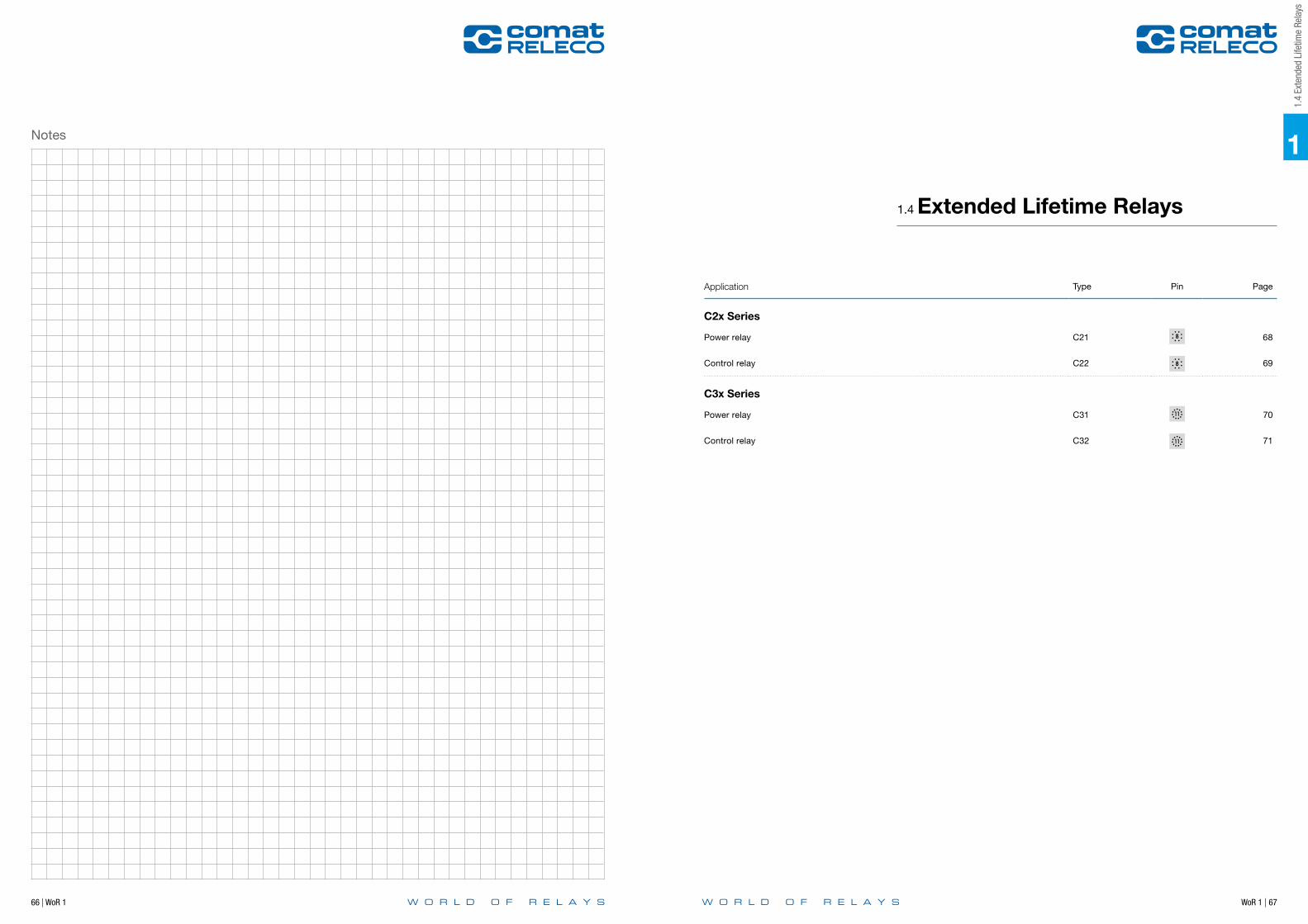
WoR 1 | 6766 | WoR 1
Notes 1
1.4
Exte
nded
Life
time
Rela
ys
Application Type Pin Page
C2x Series
Power relay C21 68
Control relay C22 69
C3x Series
Power relay C31 70
Control relay C32 71
1.4 Extended Lifetime Relays
68 | WoR 1 WoR 1 | 69
1
Connection diagram Connection diagram
fig. 1 AC voltage endurance fig. 1 AC voltage endurance
fig. 2 DC load limit curve fig. 2 DC load limit curve
Dimensions (mm) Dimensions (mm)
Technical approvals, conformities Technical approvals, conformities
1.4 Extended Lifetime Relays
C21Power relay
Maximum contact load 10 A / 250 V AC-1, 10 A / 30 V DC-1Recommended minimum contact load 50 mA / 10 V
ContactsMaterial AgCuNiRated operational current 10 AMax. inrush current (20 ms) 40 ARated switching voltage AC-1 250 VMax. AC load 2500 VA AC-1Max. DC load 30 V / 230 V DC-1 fig. 2 300 W / 90 W
CoilPick-up voltage ≤ 0.8 x UN
Release voltage AC / DC > 0.15 x UN / > 0.05 x UN
Nominal power AC / DC 2.5 VA / 1.2 W
Coil Table VN AC Ω mA VN DC Ω mA24 52 104 12 115 10448 240 55 24 480 50115 1350 23 48 1850 26230 5600 11.5 110 9000 12
220 29000 7.6
Types with LED indicator take additional 5 … 10 mA @ < 80 V
Insulation Contact Open 1.5 kV rms / 1 minContact Contact 1.5 kV rms / 1 minContact Coil 2 kV rms / 1 min
SpecificationsAmbient temperature operation, storage -40 … 70 °C (no ice)Pickup time AC / DC 3 … 10 ms / ≤ 12 msRelease time AC / DC 2 … 15 ms / ≤ 3.5 msBounce time NO contact AC / DC 3 … 6 ms / approx. 3.5 msMechanical life ≥ 100 000 000 operationsMax. switching frequency at rated load 360/hWeight 80 g
Product References
AC 50 Hz / 60 Hz: 24, 48, 115, 230 LED C21L/AC…VDC: 12, 24, 48, 110, 220LED + Free wheeling diode C21DL/DC…V
"…" List Coil Voltage to complete Product References
AccessoriesSocket S2-B, S2-PO
1121
A2
24
2122 12
14
A11
2
345
6
7
8
35
35
51
0.1
0.2
0.3
0.5
1
2
3 4
6 8
10
0 50 100 150 200 250
DC
cur
rent
[A]
DC voltage [V]
DC-1 L/R 40 ms
105
106
107
0 1 2 3 4 5 6 7 8 9 10
Cyc
les
Switching current [A]
AC-1
34
1
65
8
2A1 (+)
A27
IEC/EN 61810; IEC/EN 60947
1.4
Exte
nded
Life
time
Rela
ys
1.4 Extended Lifetime Relays
C22Control relay
Maximum contact load 6 A / 250 V AC-1 6 A / 30 V DC-1Recommended minimum contact load 10 mA / 5 V
ContactsMaterial AgCuNiRated operational current 6 AMax. inrush current (20 ms) 15 ARated switching voltage AC-1 250 VMax. AC load 1500 VA AC-1Max. DC load 30V / 230V DC-1 fig. 2 200 W / 90 W
CoilPick-up voltage ≤ 0.8 x UN
Release voltage AC / DC > 0.15 x UN / > 0.05 x UN
Nominal power AC / DC 2.5 VA / 1.2 W
Coil Table VN AC Ω mA VN DC Ω mA24 52 104 12 115 10448 240 55 24 480 50115 1350 23 48 1850 26230 5600 11.5 110 9000 12
220 29000 7.6
Types with LED indicator take additional 5 … 10 mA @ < 80 V
Insulation Contact Open 1.5 kV rms / 1 minContact Contact 1.5 kV rms / 1 minContact Coil 2 kV rms / 1 min
SpecificationsAmbient temperature operation, storage -40 … 70 °C (no ice)Pickup time AC / DC 3 … 10 ms / ≤ 12 msRelease time AC / DC 2 … 15 ms / ≤ 3.5 msBounce time NO contact AC / DC 3 … 6 ms / approx. 3.5 msMechanical life ≥ 100 000 000 operationsMax. switching frequency at rated load 360/hWeight 80 g
Product References
AC 50 Hz / 60 Hz: 24, 48, 115, 230 LED C22L/AC…VDC: 12, 24, 48, 110, 220LED + Free wheeling diode C22DL/DC…V
"…" List Coil Voltage to complete Product References
AccessoriesSocket S2-B, S2-PO
1121
A2
24
2122 12
14
A11
2
345
6
7
8
35
35
51
2A1 (+)
A27
34
1
65
8
0.1
0.2
0.3
0.5
1
2
3 4
6 8
10
0 50 100 150 200 250
DC
cur
rent
[A]
DC voltage [V]
DC-1 L/R 40 ms
106
107
0 1 2 3 4 5 6
Cyc
les
Switching current [A]
AC-1
IEC/EN 61810; IEC/EN 60947

70 | WoR 1 WoR 1 | 71
1
Connection diagram Connection diagram
fig. 1 AC voltage endurance fig. 1 AC voltage endurance
fig. 2 DC load limit curve fig. 2 DC load limit curve
Dimensions (mm) Dimensions (mm)
Technical approvals, conformities Technical approvals, conformities
1.4 Extended Lifetime Relays
C31Power relay
Maximum contact load 10 A / 250 V AC-1 10 A / 30 V DC-1 Recommended minimum contact load 50 mA / 10 V
ContactsMaterial AgCuNiRated operational current 10 AMax. inrush current (20 ms) 40 ARated switching voltage 250 VMax. AC load 2500 VA AC-1Max. DC load 30V / 230V DC-1 fig. 2 300W / 90 W
CoilPick-up voltage ≤ 0.8 x UN
Release voltage AC / DC > 0.15 x UN / > 0.05 x UN
Nominal power AC / DC 2.5 VA / 1.2 W
Coil Table VN AC Ω mA VN DC Ω mA24 52 104 12 115 10448 240 55 24 480 50115 1350 23 48 1850 26230 5600 11.5 110 9000 12
220 29000 7.6
Types with LED indicator take additional 5 … 10 mA @ < 80 V
Insulation Contact Open 1.5 kV rms / 1 minContact Contact 1.5 kV rms / 1 minContact Coil 2 kV rms / 1 min
SpecificationsAmbient temperature operation, storage -40 … 70 °C (no ice)Pickup time AC / DC 3 … 10 ms / ≤ 12 msRelease time AC / DC 2 … 15 ms / ≤ 3.5 msBounce time NO contact AC / DC 3 … 6 ms / approx. 3.5 msMechanical life ≥ 100 000 000 operationsMax. switching frequency at rated load 360/hWeight 80 g
Product References
AC 50 Hz / 60 Hz: 24, 48, 115, 230 (240)LED C31L/AC…VDC: 12, 24, 48, 110, 220 C31/DC…VLED + Free wheeling diode C31DL/DC…VRailway EN 50155 C31D/R DC…V
"…" List Coil Voltage to complete Product References
Accessories Socket S3-B, S3-S, S3-PO, S3-M0, S3-M1Blanking Plug SO-NP (BAG 10 PCS)
1131A2
34
24
32
2122
12
14
A11
23
4567
8
910
11
35
35
51
0.1
0.2
0.3
0.5
1
2
3 4
6 8
10
0 50 100 150 200 250
DC
cur
rent
[A]
DC voltage [V]
DC-1 L/R 40 ms
105
106
107
0 1 2 3 4 5 6 7 8 9 10
Cyc
les
Switching current [A]
AC-1
34
1
75
6
98
11
2A1 (+)
A210
IEC/EN 61810; IEC/EN 60947; IEC/EN 50155IEC/EN 61373; IEC/EN 45545NF F 16-101/102
1.4
Exte
nded
Life
time
Rela
ys
1.4 Extended Lifetime Relays
C32Control relay
Maximum contact load 6 A / 250 V AC-1 6 A / 30 V DC-1Recommended minimum contact load 1 mA / 5 V
ContactsMaterial AgCuNiRated operational current 6 AMax. inrush current (20 ms) 15 ARated switching voltage AC-1 250 VMax. AC load 1500 VA AC-1Max. DC load 30V / 230V DC-1 fig. 2 200 W / 90 W
CoilPick-up voltage ≤ 0.8 x UN
Release voltage AC / DC > 0.15 x UN / > 0.05 x UN
Nominal power AC / DC 2.5 VA / 1.2 W
Coil Table VN AC Ω mA VN DC Ω mA24 52 104 12 115 10448 240 55 24 480 50115 1350 23 48 1850 26230 5600 11.5 110 9000 12
220 29000 7.6
Types with LED indicator take additional 5 … 10 mA @ < 80 V
InsulationContact Open 1.5 kV rms / 1 minContact Contact 1.5 kV rms / 1 minContact Coil 2 kV rms / 1 min
SpecificationsAmbient temperature operation, storage -40 … 70 °C (no ice)Pickup time AC / DC 3 … 10 ms / ≤ 12 msRelease time AC / DC 2 … 15 ms / ≤ 3.5 msBounce time NO contact AC / DC 3 … 6 ms / approx. 3.5 msMechanical life ≥ 100 000 000 operationsMax. switching frequency at rated load 360/hWeight 80 g
Product References
AC 50 Hz / 60 Hz: 24, 48, 115, 230 (240)LED C32L/AC…VDC: 12, 24, 48, 110, 220 C32/DC…VLED + Free wheeling diode C32DL/DC…VRailway EN 50155 C32D/R DC…V
“ …” List Coil Voltage to complete Product References
Accessories Socket S3-B, S3-S, S3-PO, S3-M0, S3-M1Blanking Plug SO-NP (BAG 10 PCS)
1131A2
34
24
32
2122
12
14
A11
23
4567
8
910
11
35
35
51
2A1 (+)
A210
34
1
75
6
98
11
0.1
0.2
0.3
0.5
1
2
3 4
6 8
10
0 50 100 150 200 250
DC
cur
rent
[A]
DC voltage [V]
DC-1 L/R 40 ms
106
107
0 1 2 3 4 5 6
Cyc
les
Switching current [A]
AC-1
IEC/EN 61810; IEC/EN 60947; IEC/EN 50155IEC/EN 61373; IEC/EN 45545NF F 16-101/102

WoR 1 | 7372 | WoR 1
Notes 1
1.5
Solid
Sta
te R
elay
s
Application Type Pin Page
CSS Series
1 pole | normally open solid state AC | Faston CSS-I 74
1 pole | normally open solid state AC | Faston CSS-Z 75
1 pole | normally open solid state DC | Faston CSS-N 76
1 pole | normally open solid state DC | Faston CSS-P 77
CRINT Series
1 pole | normally open solid state DC CRINT-1x5 - 78
1 pole | normally open solid state AC CRINT-1x8 - 79
1.5 Solid State Relays

74 | WoR 1 WoR 1 | 75
1
Dimensions (mm) Dimensions (mm)
Technical approvals, conformities Technical approvals, conformities
Tab. 2 AC derating curve
fig. 1 CSS-I diagram
~
~A2
A11
2
Load
1.5 Solid State Relays
CSS-I1 pole | normally open solid state AC | Faston
Output 1 NOOperating range 3 A, 24 … 250 V AC, 50/60 HzMinimum contact load 35 mA
ContactType 1 NO (Solid state AC)Material TriacRated Load 3 A AC
Control circuitInput voltage range 5 … 48 V DCInput current 10 mA
Output circuit InstantaneousMax. output current 3 AMin. output current 35 mAOutput voltage range 24...250 V ACInrush current 150 A/10 msResidual current 1 mAI2t value 210 A2s
SpecificationsAmbient temperature operation/storage -40 … 70 ºC /-40 … 85 °C (no ice)Pick-up time 0.06 msRelease time 0.06 msWeight 28 g
Applications It is specially suitable to switch inductive loads up to 3A/250 V AC. For switching loads with a high inrush or overcurrent as transformers, motors or fluorescents, the maximum output current will limit to 2 A.
Product References
V DC 5–48 CSS-I12X/DC5–48V
Accessories Socket S10, S10-P
230 V AC
230 V AC
+(-)A15…84V DC-(+)A2
+(-)A15…48V DC-(+)A2
CSS-I
CSS-I
0
1
2
3
0 10 20 30 40°
50 60 70 80
Cur
rent
[A]
CSS-I
14
33
47
IEC/EN 60947
Tab. 2 AC derating curve
fig. 1 CSS-Z diagram
1.5
Solid
Sta
te R
elay
s1.5 Solid State Relays
CSS-Z1 pole | normally open solid state AC | Faston
~
~A2
A11
2
Load
Output 1 NOOperating range 3 A, 24 … 250 V AC, 50/60 HzMinimum contact load 35 mA
ContactType 1 NO (Solid state AC)Material TriacRated Load 3 A AC
Control circuitInput voltage range 5 … 48 V DCInput current 10 mA
Output circuit Synchronized zeroMax. output current 3 AMin. output current 35 mAOutput voltage range 24 … 250 V ACInrush current 150 A/10 msResidual current 1 mAI2t value 210 A2s
SpecificationsAmbient temperature operation/storage -40.…70 ºC /-40 … 85 °C (no ice)Pick-up time 10 msRelease time 10 ms Weight 28 g
Applications Switches ohmic AC loads up to 3 A/250 V AC in the zero-point of the tension and avoids any over-current peak in the connection. Suitable for switching resistors, incandescent lamps, signalling equipment, etc. Not suitable for inductive loads
Product References
V DC 5–48 CSS-Z12X/DC5–48V
Accessories Socket S10, S10-P
230 V AC
230 V AC+(-)A15…48V DC-(+)A2
+(-)A15…48V DC-(+)A2
CSS-Z
CSS-Z
CSS-Z
14
33
47
0
1
2
3
0 10 20 30 40°
50 60 70 80
Cur
rent
[A]
IEC/EN 60947

76 | WoR 1 WoR 1 | 77
Dimensions (mm)
Technical approvals, conformities
Dimensions (mm)
Technical approvals, conformities
Tab. 2 AC derating curve
fig. 1 CSS-N diagram
0
1
2
3
4
5
6
7
0 10 20 30 40°
50 60 70 80
Cur
rent
[A]
1.5 Solid State Relays
CSS-N1 pole | normally open solid state DC | Faston
A2
A11 (14)
2 (11)
+
–
Load
Negative common
5…48 V DC
5…48 V DC
+(-)A15…48V DC-(+)A2
+(-)A15…48V DC-(+)A2
CSS-N
CSS-N
Output 1 NOOperating range 6 A, 5 … 48 V DCMinimum contact load 1 mA
ContactType 1 NO (Solid state DC)Material MOSFETRated Load 6 A DC
Control circuitInput voltage range 5 … 48 V DCInput current 4 mA
Output circuit Type NPNMax. output current 6 AOutput voltage range 5 … 48 V DCMax. inrush current 40 A / 10 msMax. voltage drop ≤ 0.14 V DCResidual current 0.1 mA
SpecificationsAmbient temperature operation/storage -40 … 70 °C/-40 … 85 °C (no ice)Test voltage between input/output 4 kV rms /1 min.Turn-on delay 0.06 msRelease delay 0.06 msWeight 28 g
Applications For switching heating elements, electro valves, motors, PLC input/output signals, solenoids, incan-descent and fluorescent lamps, etc. (up to 48 V DC).
Inductive loads must be shunted with an antiparallel diode.
Product References
V DC 5–48 CSS-N13X/DC5–48V
Accessories Socket S10, S10-P
14
33
47
IEC/EN 60947
Tab. 2 AC derating curve
fig. 1 CSS-P diagram
1
1.5
Solid
Sta
te R
elay
s
0
1
2
3
4
5
6
7
0 10 20 30 40°
50 60 70 80
Cur
rent
[A]
1.5 Solid State Relays
CSS-P1 pole | normally open solid state DC | Faston
A2
A12 (11)
1 (14)
+
–Load
Positive common
5…48 V DC
5…48 V DC
+(-)A15…48V DC-(+)A2
+(-)A15…48V DC-(+)A2
CSS-P
CSS-P
Output 1 NOOperating range 6 A, 5 … 48 V DCMinimum contact load 1 mA
ContactType 1 NO (Solid state DC)Material MOSFETRated Load 6 A DC
Control circuitInput voltage range 5 … 48 V DCInput current 4 mA
Output circuit Type PNPMax. output current 6 AOutput voltage range 5 … 48 V DCMax. switch-on current 40 A / 10 msMax. voltage drop 0.14 V DCResidual current 0.1 mA
SpecificationsAmbient temperature operation/storage -40…70 ºC /-40 … 85 °C (no ice)Turn-on delay 0.06 msRelease delay 0.06 msWeight 28 g
Applications For switching heating elements, electro valves, motors, PLC input/output signals, solenoids, incan-descent and fluorescent lamps, etc. (up to 48 V DC).
Inductive loads must be shunted with an antiparallel diode.
Product References
V DC 5–48 CSS-P13X/DC5–48V
Accessories Socket S10, S10-P 14
33
47
IEC/EN 60947
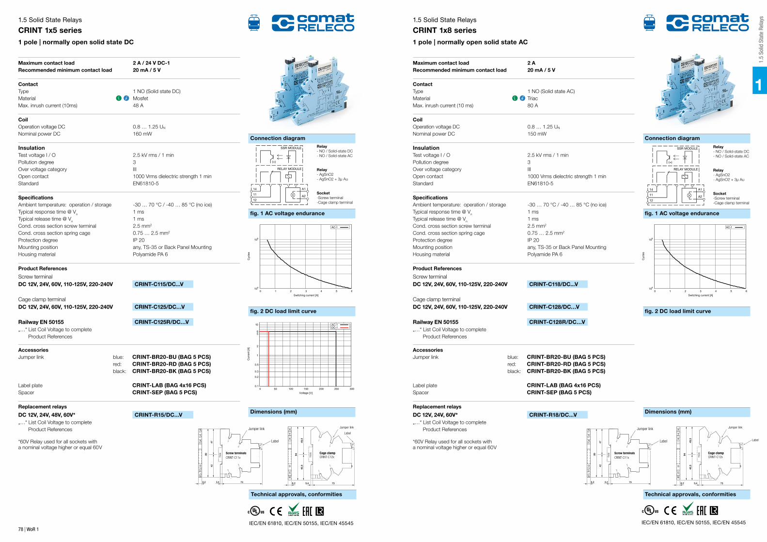
78 | WoR 1
Connection diagram
fig. 1 AC voltage endurance
1.5 Solid State Relays
CRINT 1x5 series1 pole | normally open solid state DC
Maximum contact load 2 A / 24 V DC-1Recommended minimum contact load 20 mA / 5 V
ContactType 1 NO (Solid state DC)Material MosfetMax. inrush current (10ms) 48 A
Coil Operation voltage DC 0.8 … 1.25 UN
Nominal power DC 160 mW
Insulation Test voltage I / O 2.5 kV rms / 1 minPollution degree 3Over voltage category IIIOpen contact 1000 Vrms dielectric strength 1 minStandard EN61810-5
SpecificationsAmbient temperature: operation / storage -30 … 70 °C / -40 … 85 °C (no ice)Typical response time @ Vn 1 msTypical release time @ Vn 1 msCond. cross section screw terminal 2.5 mm2
Cond. cross section spring cage 0.75 … 2.5 mm2
Protection degree IP 20Mounting position any, TS-35 or Back Panel MountingHousing material Polyamide PA 6
Product References
Screw terminal DC 12V, 24V, 60V, 110-125V, 220-240V CRINT-C115/DC...V
Cage clamp terminalDC 12V, 24V, 60V, 110-125V, 220-240V CRINT-C125/DC…V
Railway EN 50155 CRINT-C125R/DC…V„…“ List Coil Voltage to complete Product References
AccessoriesJumper link blue: CRINT-BR20-BU (BAG 5 PCS) red: CRINT-BR20-RD (BAG 5 PCS) black: CRINT-BR20-BK (BAG 5 PCS) Label plate CRINT-LAB (BAG 4x16 PCS)Spacer CRINT-SEP (BAG 5 PCS)
Replacement relays
DC 12V, 24V, 48V, 60V* CRINT-R15/DC...V„…“ List Coil Voltage to complete Product References *60V Relay used for all sockets witha nominal voltage higher or equal 60V
fig. 2 DC load limit curve
Dimensions (mm)
Technical approvals, conformities
104
105
0 1 2 3 4 5 6
Cyc
les
Switching current [A]
AC-1
Relay- NO / Solid-state DC - NO / Solid-state AC
Relay- AgSnO2- AgSnO2 + 3µ Au
Socket-Screw terminal-Cage clamp terminal
SSR MODULE
RELAY MODULE
14 A1
A211
12
(+)
0.1
0.2
0.3
0.5
1
2
5 6
10
0 50 100 150 200 250 300
Cur
rent
[A]
Voltage [V]
AC-1 DC-1
IEC/EN 61810, IEC/EN 50155, IEC/EN 45545
Connection diagram
fig. 1 AC voltage endurance
1
1.5
Solid
Sta
te R
elay
s1.5 Solid State Relays
CRINT 1x8 series1 pole | normally open solid state AC
Maximum contact load 2 ARecommended minimum contact load 20 mA / 5 V
ContactType 1 NO (Solid state AC)Material TriacMax. inrush current (10 ms) 80 A
Coil Operation voltage DC 0.8 … 1.25 UN
Nominal power DC 150 mW
Insulation Test voltage I / O 2.5 kV rms / 1 minPollution degree 3Over voltage category IIIOpen contact 1000 Vrms dielectric strength 1 minStandard EN61810-5
SpecificationsAmbient temperature: operation / storage -30 … 70 °C / -40 … 85 °C (no ice)Typical response time @ Vn 1 msTypical release time @ Vn 1 msCond. cross section screw terminal 2.5 mm2
Cond. cross section spring cage 0.75 … 2.5 mm2
Protection degree IP 20Mounting position any, TS-35 or Back Panel MountingHousing material Polyamide PA 6
Product References
Screw terminal DC 12V, 24V, 60V, 110-125V, 220-240V CRINT-C118/DC...V
Cage clamp terminalDC 12V, 24V, 60V, 110-125V, 220-240V CRINT-C128/DC…V
Railway EN 50155 CRINT-C128R/DC…V„…“ List Coil Voltage to complete Product References
AccessoriesJumper link blue: CRINT-BR20-BU (BAG 5 PCS) red: CRINT-BR20-RD (BAG 5 PCS) black: CRINT-BR20-BK (BAG 5 PCS) Label plate CRINT-LAB (BAG 4x16 PCS)Spacer CRINT-SEP (BAG 5 PCS)
Replacement relays
DC 12V, 24V, 60V* CRINT-R18/DC...V„…“ List Coil Voltage to complete Product References *60V Relay used for all sockets witha nominal voltage higher or equal 60V
fig. 2 DC load limit curve
Dimensions (mm)
Technical approvals, conformities
104
105
0 1 2 3 4 5 6
Cyc
les
Switching current [A]
AC-1
Relay- NO / Solid-state DC - NO / Solid-state AC
Relay- AgSnO2- AgSnO2 + 3µ Au
Socket-Screw terminal-Cage clamp terminal
SSR MODULE
RELAY MODULE
14 A1
A211
12
(+)
0.1
0.2
0.3
0.5
1
2
5 6
10
0 50 100 150 200 250 300
Cur
rent
[A]
Voltage [V]
AC-1 DC-1
IEC/EN 61810, IEC/EN 50155, IEC/EN 45545
Cage clampCRINT-C12x
Jumper link
Label
94
49,5
40,5
Cage clampCRINT-C12x
Jumper link
Label
94
49,5
40,5
Screw terminalsCRINT-C11x
89
4247
Jumper link
Label
Screw terminalsCRINT-C11x
89
4247
Jumper link
Label

WoR 1 | 8180 | WoR 1
Notes 1
1.6
Inst
alla
tion
Rela
ys
Application Type Page
CHI Series
1 pole | High Inrush Relay CHI14 82
3 pole | High Inrush Relay CHI34 83
C100/200/300 Series
2 pole | Power Relay C133.01 84
2 pole | 2 Coil | Control Relay C203.01 85
2 pole | 2 Coil | Control Relay C203.04 86
2 pole | 2 Coil | Signal Relay C203.06 87
3 pole | 3 Coil | Signal Relay C301.04 88
CR Series
2 pole | Signal Relay CR11C 89
1 pole | Power Relay CR16CX 90
1 pole | Power Relay | Step Switch CRS1C 91
B Series
1 pole | Power Relay B103 92
1.6 Installation Relays

82 | WoR 1 WoR 1 | 83
1
Connection diagram Connection diagram
fig. 1 AC voltage endurance fig. 1 AC voltage endurance
fig. 2 DC load limit curve fig. 2 DC load limit curve
Dimensions (mm) Dimensions (mm)
Technical approvals, conformities Technical approvals, conformities
EN 50155, EN 60730
Maximum contact load 16 A / 250 V AC-1Recommended minimum contact load 100 mA / 12 V
ContactsNumber of contacts 1Material W / AgSnO2
Max. inrush current (20 ms) 165 A (200 µs) 800 A / 200Max. switching voltage AC-1 250 V Max. AC load AC-1 fig. 1 4 kVA
Power supply- and control inputNominal voltage (A1, B1) UC 24-240 V (UC = AC / DC)Operating voltage range 16.8 … 250 VPower consumption 1.2 VA / 0.43 WFrequency range 16 … 60 Hz
InsulationTest voltage open contact 1 kV rms / 1 minTest voltage between contacts and control input 2.5 kV rms / 1 min
General SpecificationsAmbient temperature storage /operation -40 … 85 °C / -40 …60 °C (no ice)Mechanical life of contact 5 x 1 000 000 operationsConductor cross section Stranded wire 2.5 mm2, 2 x 1.5 mm2
Protection degree IP 20Nominal screw torque 0.4 NmHousing material LexanWeight 70 g
Product References
UC (AC/DC) 15…60 Hz CHI14/UC24-240V75
2,5
17,54,2
45
TS
35
5 44 20
0.1
0.2
0.5
1
2
5
10
16 20
0 50 100 150 200 250 300
Cur
rent
[A]
Voltage [V]
DC-1
105
106
107
0 2 4 6 8 10 12 14 16
Cyc
les
Switching current [A]
AC-1
1.6 Installation Relays
CHI141 pole | High Inrush Relay
1.6
Inst
alla
tion
Rela
ys1.6 Installation Relays
CHI343 pole | High Inrush Relay
EN 61000-6-3; EN 61000-6-2
Maximum contact load 16 A / 250 V AC-1Recommended minimum contact load 100 mA / 12 V
ContactsNumber of contacts 3Material W / AgSnO2
Max. inrush current (20 ms) 165 A (200 µs) 800 AMax. switching voltage AC-1 250 V Max. AC load AC-1 fig. 1 4 kVA
Auxiliary ContactsNumber of contacts 1Nominal current at 25° C / 60° C 90 mA / 60 mAInrush current 1 A / 100 μsNominal voltage AC / DC 24 VContact Material Semiconductor
Supply UB (1 – N)Nominal operating voltage (AC / DC) 110…240 VOperating voltage (AC / DC) 80…250 VFrequency range 47…63 HzPower consumption 3.45 VA
Power supply- and control inputNominal voltage (A1, A2) UC 24-240 V (UC = AC / DC)Operating voltage range 16.8 … 250 VPower consumption 30 VA / 30 mWFrequency range 47…63 Hz
InsulationTest voltage open contact 1 kV rms / 1 minTest voltage between contacts and control input 2.5 kV rms / 1 minTest voltage between contacts 2.5 kV rms / 1 min
General SpecificationsAmbient temperature storage /operation -40 … 85 °C / -25 …60 °C (no ice)Mechanical life of contact 5 x 1 000 000 operationsConductor cross section Stranded wire 2.5 mm2, 2 x 1.5 mm2
Protection degree IP 20Nominal screw torque 0.6 NmHousing material LexanWeight 125 g
Product References
UC (AC/DC) 47…63 Hz CHI34/UC24-240V
36
90
44
54.5
45
4
0.1
0.2
0.5
1
2
5
10
16 20
0 50 100 150 200 250 300
Cur
rent
[A]
Voltage [V]
DC-1
105
106
107
0 2 4 6 8 10 12 14 16
Cyc
les
Switching current [A]
AC-1
14A2
13N531
642
A1

84 | WoR 1 WoR 1 | 85
1
Connection diagram Connection diagram
fig. 1 AC voltage endurance
Technical approvals, conformities Technical approvals, conformities
Dimensions (mm)
1.6 Installation Relays
C133.012 pole | Power Relay
Maximum contact load 6 A / 250 V AC-1Recommended minimum contact load 100 mA / 12 V
ContactsType 2 COMaterial AgNiMax. inrush current (20 ms) 15 A
CoilOperation voltage AC 50/60 Hz / DC 0.85 … 1.15 UN
Nominal power DC/AC 1.1 W / 1.1 VA
InsulationTest voltage I / O 2000 Vrms / 1minPollution degree 3Over voltage category IIIOpen contact 1000 VrmsStandard EN61810-1
SpecificationsAmbient temperature: operation / storage -20 … 55 °C / -40 … 85 °C (no ice)Typical response time @ Vn 10 msTypical release time @ Vn 10 msCond. cross section screw terminal 2.5 mm2
Protection degree IP 20Mounting position anyWeight 89 g
Product References
AC220-240V, DC12V, UC24V, UC48V C133.01/...V"…" List Coil Voltage to complete Product References
EN 61810
105
106
107
0 1 2 3 4 5 6
Cyc
les
Switching current [A]
AC-1
A1 A2
22 2421
141211
TS
35
5 64
752,
5
17,54,2
LABEL
Dimensions (mm)
fig. 1 AC voltage endurance 250 V
1.6
Inst
alla
tion
Rela
ys1.6 Installation Relays
C203.012 pole | 2 Coil | Control Relay
Maximum contact load 6 A / 250 V AC-1 6 A 25 V DC-1Recommended minimum contact load 100 mA / 12 V
ContactsType 2 x 1 COMaterial AgNiMax. inrush current (20 ms) 15 A
CoilOperation voltage AC 50/60 Hz / DC 0.85 … 1.15 UN
Nominal power DC/AC 1.1 W / 1.1 VA
InsulationTest voltage I / O 2000 Vrms / 1minPollution degree 3Over voltage category IIIOpen contact 1000 VrmsStandard EN61810-1
SpecificationsAmbient temperature: operation / storage -20 … 55 °C / -40 … 85 °C (no ice)Typical response time @ Vn 10 msTypical release time @ Vn 10 msCond. cross section screw terminal 2.5 mm2
Protection degree IP 20Mounting position anyWeight 89 g
Product References
AC220-240V, UC24V C203.01/...V
"…" List Coil Voltage to complete Product References
EN 61810
105
106
107
0 1 2 3 4 5 6
Cyc
les
Switching current [A]
AC-1
21
A1 A1 A2
12 1411
2
1141211
TS
35
5 64
752,
5
17,54,2
LABEL
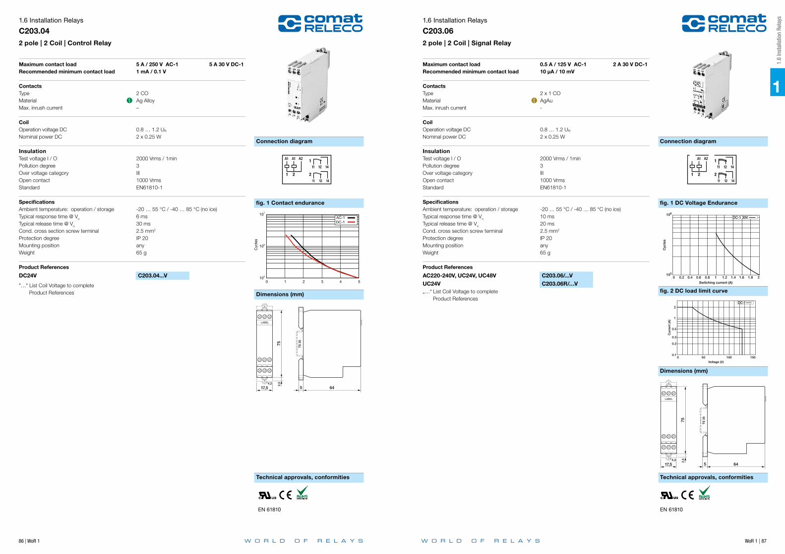
86 | WoR 1 WoR 1 | 87
1
Connection diagram Connection diagram
Technical approvals, conformities Technical approvals, conformities
Dimensions (mm)
fig. 1 Contact endurance
1.6 Installation Relays
C203.042 pole | 2 Coil | Control Relay
Maximum contact load 5 A / 250 V AC-1 5 A 30 V DC-1Recommended minimum contact load 1 mA / 0.1 V
ContactsType 2 COMaterial Ag AlloyMax. inrush current –
CoilOperation voltage DC 0.8 … 1.2 UN
Nominal power DC 2 x 0.25 W
InsulationTest voltage I / O 2000 Vrms / 1minPollution degree 3Over voltage category IIIOpen contact 1000 VrmsStandard EN61810-1
SpecificationsAmbient temperature: operation / storage -20 … 55 °C / -40 … 85 °C (no ice)Typical response time @ Vn 6 msTypical release time @ Vn 30 msCond. cross section screw terminal 2.5 mm2
Protection degree IP 20Mounting position anyWeight 65 g
Product References
DC24V C203.04...V
"…" List Coil Voltage to complete Product References
105
106
107
0 1 2 3 4 5
Cyc
les
Switching current [A]
AC-1 DC-1
21
A1 A1 A2
12 1411
2
1141211
TS
35
5 64
752,
5
17,54,2
LABEL
EN 61810
Dimensions (mm)
fig. 1 DC Voltage Endurance
fig. 2 DC load limit curve
21
A1 A1 A2
12 1411
2
1141211
TS
35
5 64
752,
5
17,54,2
LABEL
EN 61810
1.6
Inst
alla
tion
Rela
ys1.6 Installation Relays
C203.062 pole | 2 Coil | Signal Relay
Maximum contact load 0.5 A / 125 V AC-1 2 A 30 V DC-1Recommended minimum contact load 10 μA / 10 mV
ContactsType 2 x 1 COMaterial AgAuMax. inrush current -
CoilOperation voltage DC 0.8 … 1.2 UN
Nominal power DC 2 x 0.25 W
InsulationTest voltage I / O 2000 Vrms / 1minPollution degree 3Over voltage category IIIOpen contact 1000 VrmsStandard EN61810-1
SpecificationsAmbient temperature: operation / storage -20 … 55 °C / -40 … 85 °C (no ice)Typical response time @ Vn 10 msTypical release time @ Vn 20 msCond. cross section screw terminal 2.5 mm2
Protection degree IP 20Mounting position anyWeight 65 g
Product References
AC220-240V, UC24V, UC48V C203.06/...VUC24V C203.06R/…V„…“ List Coil Voltage to complete Product References
106
Cyc
les
105
Switching current (A)
0 0.2 0.4 0.6 0.8 1 1.2 1.4 1.6 1.8 2
DC-1 30V
2
1
0.5
0.3
0.2
0.10 50 100 150
Cur
rent
(A)
Voltage (V)
DC-1
106
Cyc
les
105
Switching current (A)
0 0.2 0.4 0.6 0.8 1 1.2 1.4 1.6 1.8 2
DC-1 30V
2
1
0.5
0.3
0.2
0.10 50 100 150
Cur
rent
(A)
Voltage (V)
DC-1

88 | WoR 1 WoR 1 | 89
1
Connection diagram Connection diagram
Technical approvals, conformities Technical approvals, conformities
Dimensions (mm)
fig. 1 Contact endurance
1.6 Installation Relays
C301.043 pole | 3 Coil | Signal Relay
Maximum contact load 5 A / 250 V AC-1 5 A 30 V DC-1Recommended minimum contact load 1 mA / 0.1 V
ContactsType 3 x 1 NOMaterial Ag AlloyMax. inrush current -
CoilOperation voltage DC 0.8 … 1.2 UN
Nominal power DC 3 x 0.25 W
InsulationTest voltage I / O 2000 Vrms / 1minPollution degree 3Over voltage category IIIOpen contact 1000 VrmsStandard EN61810-1
SpecificationsAmbient temperature: operation / storage -20 … 55 °C / -40 … 85 °C (no ice)Typical response time @ Vn 6 msTypical release time @ Vn 30 msCond. cross section screw terminal 2.5 mm2
Protection degree IP 20Mounting position anyWeight 65 g
Product References
DC24V C301.04...V
"…" List Coil Voltage to complete Product References
EN 61810
105
106
107
0 1 2 3 4 5
Cyc
les
Switching current [A]
AC-1 DC-1
A1 A1
A2 A2
A1
A21
14132
14133
1413
1 2 3
64
75
17,54,2
2,5
TS
35
5
LABEL
Dimension
fig. 1 Contact endurance
1.6
Inst
alla
tion
Rela
ys1.6 Installation Relays
CR11C2 pole | Signal Relay
Maximum contact load 0.5 A / 125 V AC-1 1 A 30 V DC-1Recommended minimum contact load 10 μA / 10 mV
ContactsType 2 COMaterial AgAuMax. inrush current -
CoilOperation voltage DC 0.8 … 1.2 UN
Nominal power DC 0.25 W
InsulationTest voltage I / O 2000 Vrms / 1minPollution degree 3Over voltage category IIIOpen contact 1000 VrmsStandard EN61810-1
SpecificationsAmbient temperature: operation / storage -20 … 55 °C / -40 … 85 °C (no ice)Typical response time @ Vn 3 msTypical release time @ Vn 4 msCond. cross section screw terminal 2.5 mm2
Protection degree IP 20Mounting position anyWeight 38 g
Product References
DC24V CR11C/...V
"…" List Coil Voltage to complete Product References
EN 61810
Switching current [A]
0.5 1 0105
106
107
Cyc
les
AC-1 DC-1 30 V
12 222414
11 21 A221A1
11+
TS
35 45
4 44
7 55
90
13
BS13-KBS13-G(incl.paper)

90 | WoR 1 WoR 1 | 91
Connection diagram Connection diagram
Technical approvals, conformities Technical approvals, conformities
Dimensions (mm)
fig. 1 AC voltage endurance 250 V
1.6 Installation Relays
CR16CX1 pole | Power Relay
Maximum contact load 6 A / 250 V AC-1 6 A 30 V DC-1Recommended minimum contact load 10 mA / 12 V
ContactsType 1 COMaterial AgNiMax. inrush current -
CoilOperation voltage AC / DC 0.8 … 1.1 UN / 0.85 … 1.15 UN
Nominal power AC / DC 2.5 VA / 0.25 W
InsulationTest voltage I / O 2000 Vrms / 1minPollution degree 3Over voltage category IIIOpen contact 1000 VrmsStandard EN61810-1
SpecificationsAmbient temperature: operation / storage -20 … +60 °C / -40 … 85 °C (no ice)Typical response time @ Vn 10 msTypical release time @ Vn 20 msCond. cross section screw terminal 2.5 mm2
Protection degree IP 20Mounting position anyWeight 45 g
Product References
DC24V, AC230V CR16CX/…V
"…" List Coil Voltage to complete Product References
IEC 61810
111214
12
A2 A1
+
( DC
-ver
sion
)
105
106
107
0 1 2 3 4 5 6
Cyc
les
Switching current [A]
AC-1
TS
35 45
4 44
7 55
90
13
BS13-KBS13-G(incl.paper)
fig. 1 AC voltage endurance 250 V
Dimension
1
1.6
Inst
alla
tion
Rela
ys1.6 Installation Relays
CRS1C1 pole | Power Relay | Step Switch
Maximum contact load 6 A / 250 V AC-1 6 A 30 V DC-1Recommended minimum contact load 10 mA / 12 V
ContactsType 1 COMaterial AgNiMax. inrush current -
CoilOperation voltage AC / DC 0.85 … 1.15 UN / 0.85 … 1.15 UN
Nominal power AC / DC 2 VA / 1.5 W
InsulationTest voltage I / O 2000 Vrms / 1minPollution degree 3Over voltage category IIIOpen contact 1000 VrmsStandard EN61810-1
SpecificationsAmbient temperature: operation / storage -20 … +60 °C / -40 … 85 °C (no ice)Typical response time @ Vn ≥ 50 msTypical release time @ Vn ≥ 50 msCond. cross section screw terminal 2.5 mm2
Protection degree IP 20Mounting position anyWeight 45 g
Product References
DC24V, AC230V CRS1C/…V
"…" List Coil Voltage to complete Product References
IEC 61810
A2 A1 ( DC-
vers
ion)
111214
12
0 1 2 3 4 5 6
Switching current [A]
Cyc
les
104
105
106
107
AC-1 CRS1C/DC.. AC-1 CRS1C/AC..
TS
35 45
4 44
7 55
90
13
BS13-KBS13-G(incl.paper)

92 | WoR 1 WoR 1 | 93
Connection diagram
fig. 2 DC load limit curve
Dimensions (mm)
Technical approvals, conformities
fig. 1 AC voltage endurance 250 V
1.6 Installation Relays
B1031 pole | Power Relay
Maximum contact load 10 A / 250 V AC-1 6 A 30 V DC-1Recommended minimum contact load 10 mA / 12 V
ContactsType 1 COMaterial AgSnO2
Max. inrush current (20 ms) 16 A
CoilOperation voltage AC / DC 0.85 … 1.15 UN / 0.85 … 1.15 UN
Nominal power AC / DC 0.5 … 5.5 VA / 1.2 W
InsulationTest voltage I / O 2000 Vrms / 1minPollution degree 3Over voltage category IIIOpen contact 1000 VrmsStandard EN61810-1
SpecificationsAmbient temperature: operation / storage -20 … 55 °C / -40 … 85 °C (no ice)Typical response time @ Vn 20 msTypical release time @ Vn 12 msCond. cross section screw terminal 2.5 mm2
Protection degree IP 20Mounting position anyWeight 60 g
Product References
AC220-240V, UC8-12V, UC24V B103/...V
"…" List Coil Voltage to complete Product References
IEC 61810
A2 A1 ( DC-
vers
ion)
111214
12
0 1 2 3 4 5 6
Switching current [A]
Cyc
les
104
105
106
107
AC-1 CRS1C/DC.. AC-1 CRS1C/AC..
250 0.1
0.2
0.5
1
2
5 6
0 50 100 150 200
Voltage [V]
Cur
rent
[A]
DC-1
TS
35 45
4 44
7 55
90
13
BS13-KBS13-G(incl.paper)
1
1.7
Inst
alla
tion
Cont
acto
rs
Application Type Page
RIC Series
Installation Contactor | 1, 2 or 4 pole | 16 A | 3.5 kW RIC16 94
Installation Contactor | 2 pole | 20 A | 4 kW RIC20 95
Installation Contactor | 2 pole | 20 A | 7 kW | Railway RIC20-xxx-R4A 96
Installation Contactor | 2 or 4 pole | 25 A | 5.4 kW RIC25 97
Installation Contactor | 2 or 4 pole | 32 A | 7 kW RIC32 98
Installation Contactor | 4 pole | 40 A | 8.7 kW RIC40 99
Installation Contactor | 4 pole | 63 A | 13.3 kW RIC63 100
RAC Series – manual lever Auto – 1 – Lock
Installation Contactor | 2 pole | 20 A | 4 kW RAC20 101
Installation Contactor | 2 pole | 25 A | 5.4 kW RAC25 102
Installation Contactor | 4 pole | 40 A | 8.7 kW RAC40 103
Installation Contactor | 4 pole | 63 A | 13.3 kW RAC63 104
RBC Series – Step switch – manual lever 0 – 1 – Lock
Installation Contactor | 2 or 4 pole | 20 A | 4.4 kW RBC20 105
Installation Contactor | 4 pole | 32 A | 7 kW RBC32 106
Accessories
Auxiliary module | 2 pole | 6 A RIC-AUX 107
Auxiliary module | 2 pole | 6 A RBC-AUX 108
Auxiliary centralized control | On – Off RBC-AUX-CM 109
Auxiliary group control | On – Off RBC-AUX-GM 110
Spacer RIC-DIST 111
Sealing cover RIC-SEAL 112
1.7 Installation Contactors

WoR 1 | 95
Main circuitContact materialRated voltageRated current AC-1Minimum contact loadInrush currentRated load AC-1, 230 VRated load AC-3, 230 VRated load DC-1, DC-3, DC-5Mechanical endurance (cycles)Electrical endurance at rated load AC-1 (cycles)Electrical endurance at rated load AC-3 (cycles)Electrical endurance at rated load DC-1 (cycles)Switching frequency at rated load AC-1 (cycles/h)Switching frequency at rated load AC-3 (cycles/h)Switching frequency at rated load DC-1 (cycles/h)
Control circuitNominal voltageOperating voltage rangeTyp. pick-up voltageTyp. release voltagePick-up timeRelease timePower consumption AC / DCRated frequency
InsulationRated insulation voltageRated impulse withstand voltage open contactPollution degreeOvervoltage categoryClearance of open contact
General dataAmbient temperature storageAmbient temperature operation 2 Device / 1 SpacerAmbient temperature operation 3 Device / 1 SpacerConductor cross section Control / Main CircuitNominal screw torque Control / Main CircuitModule widthWeightProtection degreeHousing material
Product references
Main circuit Product reference 230
1 NO RIC16-100/UC...V
1 NC RIC16-010/UC...V
1 NO + 1 NC RIC16-110/UC...V
2 NO RIC16-200/UC...V
2 NC RIC16-020/UC...V
2 NO + 2 NC RIC16-220/UC...V
3 NO + 1 NC RIC16-310/UC...V
4 NO RIC16-400/UC...V
4 NC RIC16-040/UC...V
“...” list control circuit voltage to complete product references.Other voltages on request. Please contact [email protected].
AccessoriesSealing cover RIC-SEAL20 / RIC-SEAL25Spacer RIC-DIST
1.7 Installation Contactors
RIC16Installation Contactor | 1, 2 or 4 pole | 16 A | 3.5kW
AgNi400 V16 A50 mA, 17 V50 A, 100 ms3.5 kW1.1 kW (NO) / 0.55 kW (NC)fig. 2≥ 1 x 10⁷
≥ 2 x 10⁵
≥ 3 x 10⁵
≥ 1 x 10⁵
≤ 600≤ 600≤ 300
230 V UC0.85 ... 1.1 UN
≤ 0.85 UN
≥ 0.1 UN
15 ... 45 ms20 ... 50 ms2.1 VA / 2.1 W40 ... 500 Hz
440 V4 kV3III3.6 mm
-30 ... 80 °C-15 ... 55 °C-15 ... 40 °C2.5 mm2 / 6 mm2
0.6 Nm / 3.5 Nmfig. 3130 g (1, 2 pole) / 170 g (4 pole)IP 20PA 6
fig. 1. Wiring diagram
fig. 2. DC load limit curve
fig. 3. Dimensions (mm)
Standards and approvals
DC-1DC-3DC-5
250
0.1
0.05
0.2
0.5
1
2
5
10
16 A
200150100Voltage [V]
500
Cur
rent
[A
]
TS35
85
17,5
45
44 (45.5*) 16.55
1.5*
*Option:Sealing coverType: RIC-SEAL20
35
85
Standards IEC/EN 60947, IEC/EN 61095
Approvals
Main circuitContact materialRated voltageRated current AC-1Minimum contact loadInrush currentRated load AC-1, 230 VRated load AC-3, 230 VRated load DC-1, DC-3, DC-5Mechanical endurance (cycles)Electrical endurance at rated load AC-1 (cycles)Electrical endurance at rated load AC-3 (cycles)Electrical endurance at rated load DC-1 (cycles)Switching frequency at rated load AC-1 (cycles/h)Switching frequency at rated load AC-3 (cycles/h)Switching frequency at rated load DC-1 (cycles/h)
Control circuitNominal voltageOperating voltage rangeTyp. pick-up voltageTyp. release voltagePick-up timeRelease timePower consumption AC / DCRated frequency
InsulationRated insulation voltageRated impulse withstand voltage open contactPollution degreeOvervoltage categoryClearance of open contact
General dataAmbient temperature storageAmbient temperature operation 2 Device / 1 SpacerAmbient temperature operation 3 Device / 1 SpacerConductor cross section Control / Main CircuitNominal screw torque Control / Main CircuitModule widthWeightProtection degreeHousing material
Product references
Main circuit Product reference 24 36 110 230
2 NO RIC20-200/UC...V
2 NC RIC20-020/UC...V
1 NO + 1 NC RIC20-110/UC...V
“...” list control circuit voltage to complete product references.Other voltages on request. Please contact [email protected].
AccessoriesSealing cover RIC-SEAL20Spacer RIC-DIST
1.7 Installation Contactors
RIC20Installation Contactor | 2 pole | 20 A | 4 kW
AgNi400 V20 A50 mA, 17 V50 A, 100 ms / 180 A, 300 µs4 kW1.3 kW (NO) / 0.75 kW (NC)fig. 2≥ 1 x 10⁷
≥ 2 x 10⁵
≥ 3 x 10⁵
≥ 1 x 10⁵
≤ 600≤ 600≤ 300
24V UC, 36 V UC, 110 V UC, 230 V UC0.85 ... 1.1 UN
≤ 0.85 UN
≥ 0.1 UN
15 ... 45 ms20 ... 50 ms2.1 VA / 2.1 W40 ... 500 Hz
440 V4 kV3III3.6 mm
-30 ... 80 °C-15 ... 55 °C-15 ... 40 °C2.5 mm2 / 6 mm2
0.6 Nm / 1.2 Nmfig. 3130 gIP 20PA 6
fig. 1. Wiring diagram
fig. 2. DC load limit curve
fig. 3. Dimensions (mm)
Standards and approvals
DC-1DC-3DC-5
250
0.1
0.05
0.2
0.5
1
2
5
10
20
200150100Voltage [V]
500
Cur
rent
[A
]
TS35
85
17,5
45
44 (45.5*) 16.55
1.5*
*Option:Sealing coverType: RIC-SEAL20
Standards IEC/EN 60947, IEC/EN 61095
Approvals
1
1.7
Inst
alla
tion
Cont
acto
rs

96 | WoR 1 WoR 1 | 97
Main circuitContact materialRated voltageRated current AC-1Minimum contact loadInrush currentRated load AC-1, 230 VRated load AC-3, 230 VRated load DC-1, DC-3, DC-5Mechanical endurance (cycles)Electrical endurance at rated load AC-1 (cycles)Electrical endurance at rated load AC-3 (cycles)Electrical endurance at rated load DC-1 (cycles)Electrical endurance at rated load DC-5 (cycles)Switching frequency at rated load AC-1 (cycles/h)Switching frequency at rated load AC-3 (cycles/h)Switching frequency at rated load DC-3 (cycles/h)Switching frequency at rated load DC-5 (cycles/h)
Control circuitNominal voltageOperating voltage rangeTyp. pick-up voltageTyp. release voltagePick-up timeRelease timePower consumption DC
InsulationRated insulation voltageRated impulse withstand voltage open contactPollution degreeOvervoltage categoryClearance of open contact
General dataAmbient temperature storageAmbient temperature operationConductor cross section Control / Main CircuitNominal screw torque Control / Main CircuitModule widthWeightProtection degreeHousing materialSpacer
Product references
Main circuit Product reference 24 36 72 110
2 NO RIC20-200-R4A110V/DC...V
2 NC RIC20-020-R4A110V/DC...V
1 NO + 1 NC RIC20-110-R4A110V/DC...V
“...” list control circuit voltage to complete product references.Other voltages on request. Please contact [email protected].
AccessoriesSealing cover RIC-SEAL20
1.7 Installation Contactors
RIC20-xxx-R4A110VInstallation Contactor | 2 pole | 20 A | 7 kW
AgNi400 V20 A50 mA, 17 V50 A, 100 ms / 180 A, 300 µs7 kW1.3 kW (NO) / 0.75 kW (NC)fig. 2≥ 1 x 10⁷
≥ 1.5 x 10⁵
≥ 2 x 10⁵
≥ 2 x 10⁵
≥ 3 x 10⁵
≤ 600≤ 600≤ 300≤ 300
24 V DC, 36 V DC, 72V DC, 110 V DC0.70 ... 1.25 UN
≤ 0.7 UN
≥ 0.1 UN
15 ... 45 ms20 ... 50 ms2.6 W
440 V4 kV3III3.6 mm
-40 ... 80 °C-40 ... 70 °C2.5 mm2 / 6 mm2
0.6 Nm / 1.2 Nmfig. 3135 gIP 20PA 6Integrated
fig. 1. Wiring diagram
fig. 2. DC load limit curve
fig. 3. Dimensions (mm)
Standards and approvals
TS35 45
44 (45.5* ) 16.55
1.5*
RIC20
17,5
85
3
*Option:Sealing coverType: RIC-SEAL20
Standards IEC/EN 50155, IEC/EN 61373, IEC/EN 45545-2, IEC/EN 60947
Approvals
Main circuitContact materialRated voltageRated current AC-1Minimum contact loadInrush currentRated load AC-1, 230 VRated load AC-3, 230 VRated load DC-1, DC-3, DC-5Mechanical endurance (cycles)Electrical endurance at rated load AC-1 (cycles)Electrical endurance at rated load AC-3 (cycles)Electrical endurance at rated load DC-1 (cycles)Switching frequency at rated load AC-1 (cycles/h)Switching frequency at rated load AC-3 (cycles/h)Switching frequency at rated load DC-1 (cycles/h)
Control circuitNominal voltageOperating voltage rangeTyp. pick-up voltageTyp. release voltagePick-up timeRelease timePower consumption AC / DCRated frequency
InsulationRated insulation voltageRated impulse withstand voltage open contactPollution degreeOvervoltage categoryClearance of open contact
General dataAmbient temperature storageAmbient temperature operation 2 Device / 1 SpacerAmbient temperature operation 3 Device / 1 SpacerConductor cross section Control / Main CircuitNominal screw torque Control / Main CircuitModule widthWeightProtection degreeHousing material
Product references
Main circuit Product reference 48 400 24 36 72 110 230
4 NO RIC25-400/AC...V
4 NC RIC25-040/AC...V
4 NO RIC25-400/UC...V
4 NC RIC25-040/UC...V
2 NO + 2 NC RIC25-220/UC...V
2 CO RIC25-002/UC...V
“...” list control circuit voltage to complete product references.Other voltages on request. Please contact [email protected].
AccessoriesAuxiliary module RIC-AUXSealing cover RIC-SEAL25Spacer RIC-DIST
1.7 Installation Contactors
RIC25Installation Contactor | 2 or 4 pole | 25 A | 5.4 kW
AgNi400 V25 A50 mA, 17 V60 A, 100 ms / 280 A, 300 µs5.4 kW1.3 kWfig. 2≥ 1 x 10⁷
≥ 2 x 10⁵
≥ 5 x 10⁷
≥ 1 x 10⁵
≤ 600≤ 600≤ 300
48 V AC, 400 V AC 24 V UC, 36 V UC, 110 V UC, 230 V UC0.85 ... 1.1 UN
≤ 0.85 UN
≥ 0.1 UN
15 ... 45 ms20 ... 70 ms2.6 VA / 2.6 W50 / 60 Hz 40 ... 500Hz
440 V4 kV3III3.6 mm
-30 ... 80 °C-15 ... 55 °C-15 ... 40 °C2.5 mm2 / 6 mm2
0.6 Nm / 1.2 Nmfig. 3250 gIP 20PA 6
fig. 1. Wiring diagram
fig. 2. DC load limit curve
fig. 3. Dimensions (mm)
Standards and approvals
DC-1DC-3DC-5
250
0.2
0.1
0.5
1
2
5
1015
25
200150100Voltage [V]
500
Cur
rent
[A
]
TS35
45
44 (45.5*) 16.55
1.5*
*Option:Sealing coverType: RIC-SEAL25
35
85
Standards IEC/EN 60947, IEC/EN 61095
Approvals
1
1.7
Inst
alla
tion
Cont
acto
rs
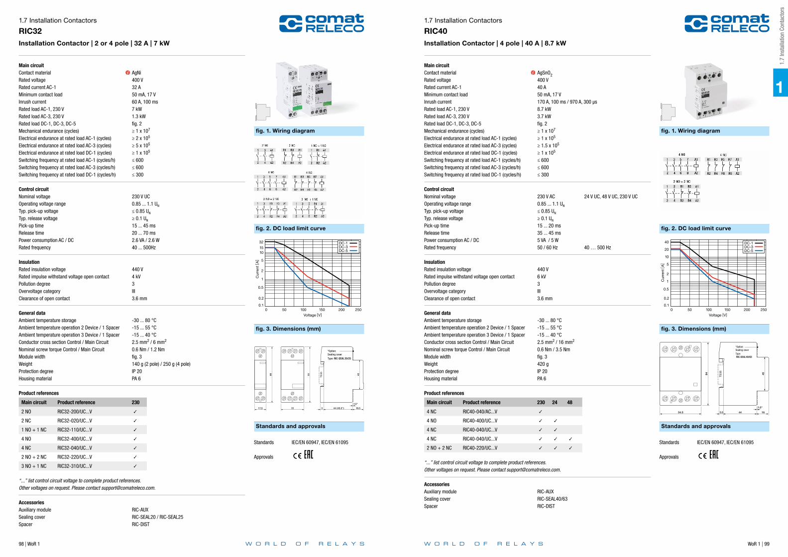
98 | WoR 1 WoR 1 | 99
Main circuitContact materialRated voltageRated current AC-1Minimum contact loadInrush currentRated load AC-1, 230 VRated load AC-3, 230 VRated load DC-1, DC-3, DC-5Mechanical endurance (cycles)Electrical endurance at rated load AC-1 (cycles)Electrical endurance at rated load AC-3 (cycles)Electrical endurance at rated load DC-1 (cycles)Switching frequency at rated load AC-1 (cycles/h)Switching frequency at rated load AC-3 (cycles/h)Switching frequency at rated load DC-1 (cycles/h)
Control circuitNominal voltageOperating voltage rangeTyp. pick-up voltageTyp. release voltagePick-up timeRelease timePower consumption AC / DCRated frequency
InsulationRated insulation voltageRated impulse withstand voltage open contactPollution degreeOvervoltage categoryClearance of open contact
General dataAmbient temperature storageAmbient temperature operation 2 Device / 1 SpacerAmbient temperature operation 3 Device / 1 SpacerConductor cross section Control / Main CircuitNominal screw torque Control / Main CircuitModule widthWeightProtection degreeHousing material
Product references
Main circuit Product reference 230
2 NO RIC32-200/UC...V
2 NC RIC32-020/UC...V
1 NO + 1 NC RIC32-110/UC...V
4 NO RIC32-400/UC...V
4 NC RIC32-040/UC...V
2 NO + 2 NC RIC32-220/UC...V
3 NO + 1 NC RIC32-310/UC...V
“...” list control circuit voltage to complete product references.Other voltages on request. Please contact [email protected].
AccessoriesAuxiliary module RIC-AUXSealing cover RIC-SEAL20 / RIC-SEAL25Spacer RIC-DIST
1.7 Installation Contactors
RIC32Installation Contactor | 2 or 4 pole | 32 A | 7 kW
AgNi400 V32 A50 mA, 17 V60 A, 100 ms7 kW1.3 kWfig. 2≥ 1 x 10⁷
≥ 2 x 10⁵
≥ 5 x 10⁵
≥ 1 x 10⁵
≤ 600≤ 600≤ 300
230 V UC0.85 ... 1.1 UN
≤ 0.85 UN
≥ 0.1 UN
15 ... 45 ms20 ... 70 ms2.6 VA / 2.6 W40 ... 500Hz
440 V4 kV3III3.6 mm
-30 ... 80 °C-15 ... 55 °C-15 ... 40 °C2.5 mm2 / 6 mm2
0.6 Nm / 1.2 Nmfig. 3140 g (2 pole) / 250 g (4 pole)IP 20PA 6
fig. 1. Wiring diagram
fig. 2. DC load limit curve
fig. 3. Dimensions (mm)
Standards and approvals
DC-1DC-3DC-5
250
0.2
0.1
0.5
1
2
5
1015
32
200150100Voltage [V]
500
Cur
rent
[A
]
TS35
85
17,5
45
44 (45.5*) 16.55
1.5*
*Option:Sealing coverType: RIC-SEAL20/25
35
85
Standards IEC/EN 60947, IEC/EN 61095
Approvals
Main circuitContact materialRated voltageRated current AC-1Minimum contact loadInrush currentRated load AC-1, 230 VRated load AC-3, 230 VRated load DC-1, DC-3, DC-5Mechanical endurance (cycles)Electrical endurance at rated load AC-1 (cycles)Electrical endurance at rated load AC-3 (cycles)Electrical endurance at rated load DC-1 (cycles)Switching frequency at rated load AC-1 (cycles/h)Switching frequency at rated load AC-3 (cycles/h)Switching frequency at rated load DC-1 (cycles/h)
Control circuitNominal voltageOperating voltage rangeTyp. pick-up voltageTyp. release voltagePick-up timeRelease timePower consumption AC / DCRated frequency
InsulationRated insulation voltageRated impulse withstand voltage open contactPollution degreeOvervoltage categoryClearance of open contact
General dataAmbient temperature storageAmbient temperature operation 2 Device / 1 SpacerAmbient temperature operation 3 Device / 1 SpacerConductor cross section Control / Main CircuitNominal screw torque Control / Main CircuitModule widthWeightProtection degreeHousing material
Product references
Main circuit Product reference 230 24 48
4 NC RIC40-040/AC...V
4 NO RIC40-400/UC...V
4 NC RIC40-040/UC...V
4 NC RIC40-040/UC...V
2 NO + 2 NC RIC40-220/UC...V
“...” list control circuit voltage to complete product references.Other voltages on request. Please contact [email protected].
AccessoriesAuxiliary module RIC-AUXSealing cover RIC-SEAL40/63Spacer RIC-DIST
1.7 Installation Contactors
RIC40Installation Contactor | 4 pole | 40 A | 8.7 kW
AgSnO2400 V40 A50 mA, 17 V170 A, 100 ms / 970 A, 300 µs8.7 kW3.7 kWfig. 2≥ 1 x 10⁷
≥ 1 x 10⁵
≥ 1.5 x 10⁵
≥ 1 x 10⁵
≤ 600≤ 600≤ 300
230 V AC 24 V UC, 48 V UC, 230 V UC0.85 ... 1.1 UN
≤ 0.85 UN
≥ 0.1 UN
15 ... 20 ms35 ... 45 ms5 VA / 5 W50 / 60 Hz 40 … 500 Hz
440 V6 kV3III3.6 mm
-30 ... 80 °C-15 ... 55 °C-15 ... 40 °C2.5 mm2 / 16 mm2
0.6 Nm / 3.5 Nmfig. 3420 gIP 20PA 6
fig. 1. Wiring diagram
fig. 2. DC load limit curve
fig. 3. Dimensions (mm)
Standards and approvals
DC-1DC-3DC-5
250
0.2
0.1
0.5
1
2
5
10
20
40
200150100Voltage [V]
500
Cur
rent
[A
]
TS35
45
44 16
84
54.5 5.5
1.5*
*Option:Sealing coverType: RIC-SEAL40/63
Standards IEC/EN 60947, IEC/EN 61095
Approvals
1
1.7
Inst
alla
tion
Cont
acto
rs
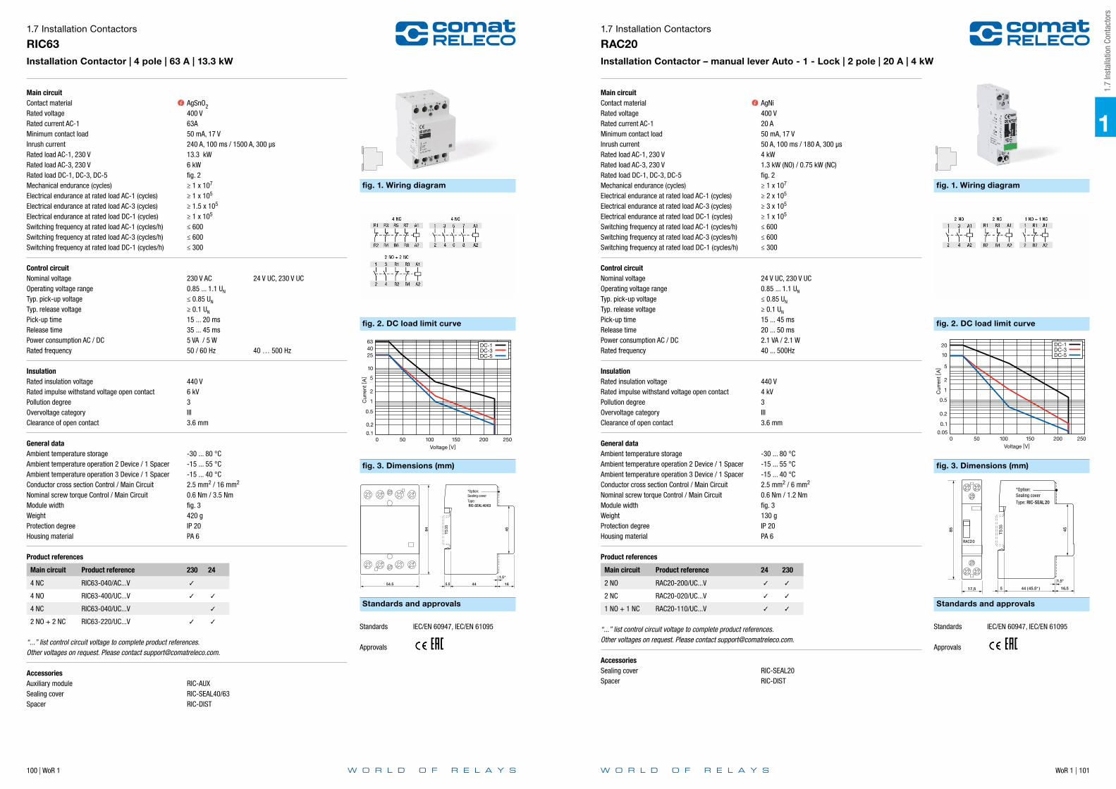
100 | WoR 1 WoR 1 | 101
Main circuitContact materialRated voltageRated current AC-1Minimum contact loadInrush currentRated load AC-1, 230 VRated load AC-3, 230 VRated load DC-1, DC-3, DC-5Mechanical endurance (cycles)Electrical endurance at rated load AC-1 (cycles)Electrical endurance at rated load AC-3 (cycles)Electrical endurance at rated load DC-1 (cycles)Switching frequency at rated load AC-1 (cycles/h)Switching frequency at rated load AC-3 (cycles/h)Switching frequency at rated load DC-1 (cycles/h)
Control circuitNominal voltageOperating voltage rangeTyp. pick-up voltageTyp. release voltagePick-up timeRelease timePower consumption AC / DCRated frequency
InsulationRated insulation voltageRated impulse withstand voltage open contactPollution degreeOvervoltage categoryClearance of open contact
General dataAmbient temperature storageAmbient temperature operation 2 Device / 1 SpacerAmbient temperature operation 3 Device / 1 SpacerConductor cross section Control / Main CircuitNominal screw torque Control / Main CircuitModule widthWeightProtection degreeHousing material
Product references
Main circuit Product reference 230 24
4 NC RIC63-040/AC...V
4 NO RIC63-400/UC...V
4 NC RIC63-040/UC...V
2 NO + 2 NC RIC63-220/UC...V
“...” list control circuit voltage to complete product references.Other voltages on request. Please contact [email protected].
AccessoriesAuxiliary module RIC-AUXSealing cover RIC-SEAL40/63Spacer RIC-DIST
1.7 Installation Contactors
RIC63Installation Contactor | 4 pole | 63 A | 13.3 kW
AgSnO2400 V63A50 mA, 17 V240 A, 100 ms / 1500 A, 300 µs13.3 kW6 kWfig. 2≥ 1 x 10⁷
≥ 1 x 10⁵
≥ 1.5 x 10⁵
≥ 1 x 10⁵
≤ 600≤ 600≤ 300
230 V AC 24 V UC, 230 V UC0.85 ... 1.1 UN
≤ 0.85 UN
≥ 0.1 UN
15 ... 20 ms35 ... 45 ms5 VA / 5 W50 / 60 Hz 40 … 500 Hz
440 V6 kV3III3.6 mm
-30 ... 80 °C-15 ... 55 °C-15 ... 40 °C2.5 mm2 / 16 mm2
0.6 Nm / 3.5 Nmfig. 3420 gIP 20PA 6
fig. 1. Wiring diagram
fig. 2. DC load limit curve
fig. 3. Dimensions (mm)
Standards and approvals
DC-1DC-3DC-5
250
0.2
0.1
0.5
1
2
5
10
254063
200150100Voltage [V]
500
Cur
rent
[A
]
TS35
45
44 16
84
54.5 5.5
1.5*
*Option:Sealing coverType: RIC-SEAL40/63
Standards IEC/EN 60947, IEC/EN 61095
Approvals
Main circuitContact materialRated voltageRated current AC-1Minimum contact loadInrush currentRated load AC-1, 230 VRated load AC-3, 230 VRated load DC-1, DC-3, DC-5Mechanical endurance (cycles)Electrical endurance at rated load AC-1 (cycles)Electrical endurance at rated load AC-3 (cycles)Electrical endurance at rated load DC-1 (cycles)Switching frequency at rated load AC-1 (cycles/h)Switching frequency at rated load AC-3 (cycles/h)Switching frequency at rated load DC-1 (cycles/h)
Control circuitNominal voltageOperating voltage rangeTyp. pick-up voltageTyp. release voltagePick-up timeRelease timePower consumption AC / DCRated frequency
InsulationRated insulation voltageRated impulse withstand voltage open contactPollution degreeOvervoltage categoryClearance of open contact
General dataAmbient temperature storageAmbient temperature operation 2 Device / 1 SpacerAmbient temperature operation 3 Device / 1 SpacerConductor cross section Control / Main CircuitNominal screw torque Control / Main CircuitModule widthWeightProtection degreeHousing material
Product references
Main circuit Product reference 24 230
2 NO RAC20-200/UC...V
2 NC RAC20-020/UC...V
1 NO + 1 NC RAC20-110/UC...V
“...” list control circuit voltage to complete product references.Other voltages on request. Please contact [email protected].
AccessoriesSealing cover RIC-SEAL20Spacer RIC-DIST
1.7 Installation Contactors
RAC20Installation Contactor – manual lever Auto - 1 - Lock | 2 pole | 20 A | 4 kW
AgNi400 V20 A50 mA, 17 V50 A, 100 ms / 180 A, 300 µs4 kW1.3 kW (NO) / 0.75 kW (NC)fig. 2≥ 1 x 10⁷
≥ 2 x 10⁵
≥ 3 x 10⁵
≥ 1 x 10⁵
≤ 600≤ 600≤ 300
24 V UC, 230 V UC0.85 ... 1.1 UN
≤ 0.85 UN
≥ 0.1 UN
15 ... 45 ms20 ... 50 ms2.1 VA / 2.1 W40 ... 500Hz
440 V4 kV3III3.6 mm
-30 ... 80 °C-15 ... 55 °C-15 ... 40 °C2.5 mm2 / 6 mm2
0.6 Nm / 1.2 Nmfig. 3130 gIP 20PA 6
fig. 1. Wiring diagram
fig. 2. DC load limit curve
fig. 3. Dimensions (mm)
Standards and approvals
DC-1DC-3DC-5
250
0.1
0.05
0.2
0.5
1
2
5
10
20
200150100Voltage [V]
500
Cur
rent
[A
]
85
RAC20
17,5
TS35 45
44 (45.5* ) 16.55
1.5*
*Option:Sealing coverType: RIC-SEAL20
Standards IEC/EN 60947, IEC/EN 61095
Approvals
1
1.7
Inst
alla
tion
Cont
acto
rs

102 | WoR 1 WoR 1 | 103
Main circuitContact materialRated voltageRated current AC-1Minimum contact loadInrush currentRated load AC-1, 230 VRated load AC-3, 230 VRated load DC-1, DC-3, DC-5Mechanical endurance (cycles)Electrical endurance at rated load AC-1 (cycles)Electrical endurance at rated load AC-3 (cycles)Electrical endurance at rated load DC-1 (cycles)Switching frequency at rated load AC-1 (cycles/h)Switching frequency at rated load AC-3 (cycles/h)Switching frequency at rated load DC-1 (cycles/h)
Control circuitNominal voltageOperating voltage rangeTyp. pick-up voltageTyp. release voltagePick-up timeRelease timePower consumption AC / DCRated frequency
InsulationRated insulation voltageRated impulse withstand voltage open contactPollution degreeOvervoltage categoryClearance of open contact
General dataAmbient temperature storageAmbient temperature operation 2 Device / 1 SpacerAmbient temperature operation 3 Device / 1 SpacerConductor cross section Control / Main CircuitNominal screw torque Control / Main CircuitModule widthWeightProtection degreeHousing material
Product references
Main circuit Product reference 24 230
4 NO RAC25-400/UC...V
2 NO + 2 NC RAC25-220/UC...V
“...” list control circuit voltage to complete product references.Other voltages on request. Please contact [email protected].
AccessoriesAuxiliary module RIC-AUXSealing cover RIC-SEAL25Spacer RIC-DIST
1.7 Installation Contactors
RAC25Installation Contactor – manual lever Auto - 1 - Lock | 2 pole | 25 A | 5.4 kW
AgNi400 V25 A50 mA, 17 V60 A, 100 ms / 280 A, 300 µs5.4 kW1.3 kWfig. 2≥ 1 x 10⁷
≥ 2 x 10⁵
≥ 5 x 10⁵
≥ 1 x 10⁵
≤ 600≤ 600≤ 300
24 V UC, 230 V UC0.85 ... 1.1 UN
≤ 0.85 UN
≥ 0.1 UN
15 ... 45 ms20 ... 70 ms2.6 VA / 2.6 W40 ... 500Hz
440 V4 kV3III3.6 mm
-30 ... 80 °C-15 ... 55 °C-15 ... 40 °C2.5 mm2 / 6 mm2
0.6 Nm / 1.2 Nmfig. 3250 gIP 20PA 6
fig. 1. Wiring diagram
fig. 2. DC load limit curve
fig. 3. Dimensions (mm)
Standards and approvals
DC-1DC-3DC-5
250
0.2
0.1
0.5
1
2
5
1015
25
200150100Voltage [V]
500
Cur
rent
[A
]
RAC25
34
TS35 45
44 (45.5* ) 16.55
1.5*
*Option:Sealing coverType: RIC-SEAL25
Standards IEC/EN 60947, IEC/EN 61095
Approvals
Main circuitContact materialRated voltageRated current AC-1Minimum contact loadInrush currentRated load AC-1, 230 VRated load AC-3, 230 VRated load DC-1, DC-3, DC-5Mechanical endurance (cycles)Electrical endurance at rated load AC-1 (cycles)Electrical endurance at rated load AC-3 (cycles)Electrical endurance at rated load DC-1 (cycles)Switching frequency at rated load AC-1 (cycles/h)Switching frequency at rated load AC-3 (cycles/h)Switching frequency at rated load DC-1 (cycles/h)
Control circuitNominal voltageOperating voltage rangeTyp. pick-up voltageTyp. release voltagePick-up timeRelease timePower consumption AC / DCRated frequency
InsulationRated insulation voltageRated impulse withstand voltage open contactPollution degreeOvervoltage categoryClearance of open contact
General dataAmbient temperature storageAmbient temperature operation 2 Device / 1 SpacerAmbient temperature operation 3 Device / 1 SpacerConductor cross section Control / Main CircuitNominal screw torque Control / Main CircuitModule widthWeightProtection degreeHousing material
Product references
Main circuit Product reference 230
4 NO RAC40-400/AC...V
3 NO + 1 NC RAC40-310/AC...V
“...” list control circuit voltage to complete product references.Other voltages on request. Please contact [email protected].
AccessoriesAuxiliary module RIC-AUXSealing cover RIC-SEAL40/63Spacer RIC-DIST
1.7 Installation Contactors
RAC40Installation Contactor – manual lever Auto - 1 - Lock | 4 pole | 40 A | 8.7 kW
AgSnO2400 V40 A50 mA, 17 V170 A, 100 ms / 970 A, 300 µs8.7 kW3.7 kWfig. 2≥ 1 x 10⁷
≥ 1 x 10⁵
≥ 1.5 x 10⁵
≥ 1 x 10⁵
≤ 600≤ 600≤ 300
230 V AC0.85 ... 1.1 UN
≤ 0.85 UN
≥ 0.1 UN
15 ... 20 ms35 ... 45 ms5 VA / 5 W50 / 60 Hz
440 V6 kV3III3.6 mm
-30 ... 80 °C-15 ... 55 °C-15 ... 40 °C2.5 mm2 / 16 mm2
0.6 Nm / 3.5 Nmfig. 3420 gIP 20PA 6
fig. 1. Wiring diagram
fig. 2. DC load limit curve
fig. 3. Dimensions (mm)
Standards and approvals
DC-1DC-3DC-5
250
0.2
0.1
0.5
1
2
5
10
20
40
200150100Voltage [V]
500
Cur
rent
[A
]
TS35
45
44 16
84
54.5 5.5
1.5*
*Option:Sealing coverType: RIC-SEAL40/63
Standards IEC/EN 60947, IEC/EN 61095
Approvals
1
1.7
Inst
alla
tion
Cont
acto
rs

104 | WoR 1 WoR 1 | 105
Main circuitContact materialRated voltageRated current AC-1Minimum contact loadInrush currentRated load AC-1, 230 VRated load AC-3, 230 VRated load DC-1, DC-3, DC-5Mechanical endurance (cycles)Electrical endurance at rated load AC-1 (cycles)Electrical endurance at rated load AC-3 (cycles)Electrical endurance at rated load DC-1 (cycles)Switching frequency at rated load AC-1 (cycles/h)Switching frequency at rated load AC-3 (cycles/h)Switching frequency at rated load DC-1 (cycles/h)
Control circuitNominal voltageOperating voltage rangeTyp. pick-up voltageTyp. release voltagePick-up timeRelease timePower consumption AC / DCRated frequency
InsulationRated insulation voltageRated impulse withstand voltage open contactPollution degreeOvervoltage categoryClearance of open contact
General dataAmbient temperature storageAmbient temperature operation 2 Device / 1 SpacerAmbient temperature operation 3 Device / 1 SpacerConductor cross section Control / Main CircuitNominal screw torque Control / Main CircuitModule widthWeightProtection degreeHousing material
Product references
Main circuit Product reference 230
4 NO RAC63-400/AC...V
3 NO + 1 NC RAC63-310/AC...V
“...” list control circuit voltage to complete product references.Other voltages on request. Please contact [email protected].
AccessoriesAuxiliary module RIC-AUXSealing cover RIC-SEAL40/63Spacer RIC-DIST
1.7 Installation Contactors
RAC63Installation Contactor – manual lever Auto - 1 - Lock | 4 pole | 63 A | 13.3 kW
AgSnO2400 V63 A50 mA, 17 V240 A, 100 ms / 1500 A, 300 µs13.3 kW6 kWfig. 2≥ 1 x 10⁷
≥ 1 x 10⁵
≥ 1.5 x 10⁵
≥ 1 x 10⁵
≤ 600≤ 600≤ 300
230 V AC0.85 ... 1.1 UN
≤ 0.85 UN
≥ 0.1 UN
15 ... 20 ms35 ... 45 ms5 VA / 5 W50 / 60 Hz
440 V6 kV3III3.6 mm
-30 ... 80 °C-15 ... 55 °C-15 ... 40 °C2.5 mm2 / 16 mm2
0.6 Nm / 3.5 Nmfig. 3420 gIP 20PA 6
fig. 1. Wiring diagram
fig. 2. DC load limit curve
fig. 3. Dimensions (mm)
Standards and approvals
DC-1DC-3DC-5
250
0.2
0.1
0.5
1
2
5
10
254063
200150100Voltage [V]
500
Cur
rent
[A
]
TS35
45
44 16
84
54.5 5.5
1.5*
*Option:Sealing coverType: RIC-SEAL40/63
Standards IEC/EN 60947, IEC/EN 61095
Approvals
Main circuitContact materialRated voltageRated current AC-1Minimum contact loadInrush currentRated load AC-1, 230 VRated load AC-3, 230 VRated load DC-1, DC-3, DC-5Mechanical endurance (cycles)Electrical endurance at rated load AC-1 (cycles)Electrical endurance at rated load AC-3 (cycles)Electrical endurance at rated load DC-1 (cycles)Switching frequency at rated load AC-1 (cycles/h)Switching frequency at rated load AC-3 (cycles/h)Switching frequency at rated load DC-1 (cycles/h)
Control circuitNominal voltageOperating voltage rangeTyp. pick-up voltageTyp. release voltageMinimal impulse duration at rated voltage UN
Minimal impulse duration at 0.9 UN
Minimal pause between two impulsesMaximal number of impulsesMaximal impulse durationPick-up timeRelease timePower consumption AC / DCRated frequency
InsulationRated insulation voltageRated impulse withstand voltage open contactPollution degreeOvervoltage categoryClearance of open contact
General dataAmbient temperature storageAmbient temperature operation 2 Device / 1 SpacerAmbient temperature operation 3 Device / 1 SpacerConductor cross section Control / Main CircuitNominal screw torque Control / Main CircuitModule widthWeightProtection degreeHousing material
Product references
Main circuit Product reference 24 230
2 NO RBC20-200/AC…V
1 NO + 1 NC RBC20-110/AC...V
4 NO RBC20-400/AC...V
“...” list control circuit voltage to complete product references.Other voltages on request. Please contact [email protected].
AccessoriesAuxiliary module RBC-AUXAuxiliary module for centralised control RBC-AUX-CMAuxiliary module for group control RBC-AUX-GMSpacer RIC-DIST
1.7 Installation Contactors
RBC20Installation Contactor – Step switch - manual lever 0 - 1 - Lock | 2 or 4 pole | 20 A | 4.4 kW
AgNi400 V20 A100 mA, 10 V50 A, 100 ms / 180 A, 300 µs4.4 kW0.55 kWfig. 2≥ 1 x 10⁶
≥ 1 x 10⁵
≥ 1 x 10⁵
≥ 1 x 10⁵
≤ 600≤ 600≤ 300
24 V AC, 230 V AC0.9 … 1.1 UN
≤ 0.75 UN
≥ 0.1 UN
50 ms100 ms150 ms≤ 15 / min≤ 60 / min5 ... 35 ms5 ... 35 ms9 VA / - W50 / 60 Hz
440 V4 kV3III> 3 mm
-30 ... 80 °C55 ° ... 70 °C40 °... 55 °C4 mm2 / 10 mm2
0.6 Nm / 1.2 Nmfig. 3132 g (2 pole) / 250 g (4 pole)IP 20PA 6
fig. 1. Wiring diagram
fig. 2. DC load limit curve
fig. 3. Dimensions (mm)
Standards and approvals
0.1
0.2
0.5
1
2
5
10
20
0.05 0 50 100 150 200 250
Cur
rent
[A]
Voltage [V]
DC-1 DC-3 DC-5
35
4460
5
4590
17.6
ON
Standards IEC/EN 60947, IEC/EN 61095
Approvals
1
1.7
Inst
alla
tion
Cont
acto
rs

106 | WoR 1 WoR 1 | 107
Main circuitContact materialRated voltageRated current AC-1Minimum contact loadInrush currentRated load AC-1, 230 VRated load AC-3, 230 VRated load DC-1, DC-3, DC-5Mechanical endurance (cycles)Electrical endurance at rated load AC-1 (cycles)Electrical endurance at rated load AC-3 (cycles)Electrical endurance at rated load DC-1 (cycles)Switching frequency at rated load AC-1 (cycles/h)Switching frequency at rated load AC-3 (cycles/h)Switching frequency at rated load DC-1 (cycles/h)
Control circuitNominal voltageOperating voltage rangeTyp. pick-up voltageTyp. release voltageMinimal impulse duration at rated voltage UN
Minimal impulse duration at 0.9 UN
Minimal pause between two impulsesMaximal number of impulsesMaximal impulse durationPick-up timeRelease timePower consumption AC / DCRated frequency
InsulationRated insulation voltageRated impulse withstand voltage open contactPollution degreeOvervoltage categoryClearance of open contact
General dataAmbient temperature storageAmbient temperature operation 2 Device / 1 SpacerAmbient temperature operation 3 Device / 1 SpacerConductor cross section Control / Main CircuitNominal screw torque Control / Main CircuitModule widthWeightProtection degreeHousing material
Product references
Main circuit Product reference 230
4 NO RBC32-400/AC...V
2 NO + 2 NC RBC32-220/AC...V
“...” list control circuit voltage to complete product references.Other voltages on request. Please contact [email protected].
AccessoriesAuxiliary module RBC-AUXAuxiliary module for centralised control RBC-AUX-CMAuxiliary module for group control RBC-AUX-GMSpacer RIC-DIST
1.7 Installation Contactors
RBC32Installation Contactor – Step switch - manual lever 0 - 1 - Lock | 4 pole | 32 A | 7 kW
AgNi440 V32 A100 mA, 10 V50 A, 100 ms / 180 A, 300 µs7 kW1.1 kWfig. 2≥ 1 x 10⁶
≥ 1 x 10⁵
≥ 1 x 10⁵
≥ 1 x 10⁵
≤ 450≤ 450≤ 300
230 V AC0.9 ... 1.1 UN
≤ 0.75 UN
≥ 0.1 UN
50 ms100 ms150 ms≤ 8 / min≤ 60 / min5 ... 35 ms5 ... 35 ms9 VA / - W50 / 60 Hz
440 V4 kV3III> 3 mm
-30 ... 80 °C55 ° ... 70 °C40 °... 55 °C4 mm2 / 10 mm2
0.6 Nm / 1.2 Nmfig. 3192 gIP 20PA 6
fig. 1. Wiring diagram
fig. 2. DC load limit curve
fig. 3. Dimensions (mm)
Standards and approvals
0.1
0.2
0.5
1
2
5
10
18
32
0 50 100 150 200 250
Cur
rent
[A]
Voltage [V]
DC-1 DC-3 DC-5
4590 35
4460
5
35.2
ON
Standards IEC/EN 60947, IEC/EN 61095
Approvals
Main circuitContact materialRated voltageRated current AC-1Minimum contact load
InsulationRated insulation voltageRated impulse withstand voltagePollution degreeOvervoltage categoryClearance of open contact
General dataAmbient temperature storageAmbient temperature operationConductor cross section main circuitNominal screw torque Control / Main CircuitModule widthWeightProtection degreeHousing material
Product references
Main circuit Product reference
2 NO RIC-AUX20
2 NC RIC-AUX02
1 NO + 1 NC RIC-AUX11
1.7 Installation Contactors
RIC-AUXAuxiliary module for RIC | RAC Installation contactors | 2 pole | 6 A
AgNi230 V / 400 V6 A / 4 A5 mA, 12 V
500 V4 kV3III3.6 mm
-30 ... 80 °C-25 ... 55 °C2.5 mm2
- Nm / 0.8 Nmfig. 230 gIP 20PA 6
fig. 1. Wiring diagram
fig. 2. Dimensions (mm)
Standards and approvals
85
8
TS35
45
44 (45.5*) 16.55
1.5*
Standards IEC/EN 60947
Approvals
1
1.7
Inst
alla
tion
Cont
acto
rs

108 | WoR 1 WoR 1 | 109
Main circuitContact materialRated voltageRated current AC-1Minimum contact load
InsulationRated insulation voltageRated impulse withstand voltage open contactRated impulse withstand voltagePollution degreeOvervoltage categoryClearance of open contact
General dataAmbient temperature storageAmbient temperature operation open contactConductor cross section main circuitNominal screw torque Control / Main CircuitModule widthWeightProtection degreeHousing material
Product references
Main circuit Product reference
2 NO RBC-AUX20
1 NO + 1 NC RBC-AUX11
1.7 Installation Contactors
RBC-AUXAuxiliary module for step switch Installation contactors | 2 pole | 6 A
AgNi250 V6 A5 mA, 12 V
440 V4 kV4 kV3III> 3 mm
-30 ... 80 °C-25 ... 70 °C2.5 mm2
- Nm / 0.8 Nmfig. 230 gIP 20PA 6
fig. 1. Wiring diagram
fig. 2. Dimensions (mm)
Standards and approvals
90 45
1618309
Standards IEC/EN 60947
Approvals
Main circuitRated voltage
InsulationRated insulation voltagePollution degree
General dataAmbient temperature storageAmbient temperature operation open contactConductor cross section main circuitNominal screw torque Control / Main CircuitModule widthWeightProtection degreeHousing material
Product references
Description Product reference
Centralized control ON – OFF RBC-AUX-CM
1.7 Installation Contactors
RBC-AUX-CMAuxiliary module for step switch Installation contactors - centralized control ON - OFF
250 V
440 V3
-30 ... 80 °C-25 ... 70 °C2.5 mm2
- Nm / 0.8 Nmfig. 230 gIP 20PA 6
fig. 1. Wiring diagram
fig. 2. Dimensions (mm)
Standards and approvals
90 45
1618309
RBC-
AUX2
0
Standards IEC/EN 60947
Approvals
1
1.7
Inst
alla
tion
Cont
acto
rs

110 | WoR 1 WoR 1 | 111
Main circuitRated voltage
InsulationRated insulation voltagePollution degree
General dataAmbient temperature storageAmbient temperature operation open contactConductor cross section main circuitNominal screw torque Control / Main CircuitModule widthWeightProtection degreeHousing material
Product references
Description Product reference
Group control ON – OFF RBC-AUX-GM
1.7 Installation Contactors
RBC-AUX-GMAuxiliary module for step switch Installation contactors - group control ON - OFF
250 V
440 V3
-30 ... 80 °C-25 ... 70 °C2.5 mm2
- Nm / 0.8 Nmfig. 230 gIP 20PA 6
fig. 1. Wiring diagram
fig. 2. Dimensions (mm)
Standards and approvals
90 45
1618309
RBC-
AUX2
0
Standards IEC/EN 60947
Approvals
General dataAmbient temperature storageModule widthWeightMaterial
Product references
Description Product reference
Spacer RIC-DIST
1.7 Installation Contactors
RIC-DISTAuxiliary spacer module for RIC / RAC installation contactors
-30 ... 80 °Cfig. 113 gPA 6
fig. 1. Dimensions (mm)
9 45
65.5
1
1.7
Inst
alla
tion
Cont
acto
rs

WoR 1 | 113112 | WoR 1
General dataAmbient temperature storageWeight RIC-SEAL20, RIC-SEAL25, RIC-SEAL 40/63Material
Product references
Description Product reference
Sealing cover RIC-SEAL20
Sealing cover RIC-SEAL25
Sealing cover RIC-SEAL40/63
1.7 Installation Contactors
RIC-SEALAuxiliary sealing cover for RIC / RAC installation contactors
-30 ... 80 °C1 g, 2 g, 3 gPA 6 1
1.8
Indu
stria
l Con
tact
ors
Application Type Page
RMC Series
Industrial Contactor | 4 pole | 8.5 A | 4 kW RMC08 114
Industrial Contactor | 4 pole | 11.3 A | 5.5 kW RMC11 115
RSC Series
Industrial Contactor | 3 or 4 pole | 9 A | 4 kW RSC09 116
Industrial Contactor | 3 or 4 pole | 12 A | 5.5 kW RSC12 117
Industrial Contactor | 3 or 4 pole | 16 A | 7.5 kW RSC16 118
Industrial Contactor | 3 pole | 22 A | 11 kW RSC22 119
Industrial Contactor | 3 pole | 30 A | 15 kW RSC30 120
Industrial Contactor | 3 pole | 38 A | 18.5 kW RSC38 121
Industrial Contactor | 5 pole | 43 A | 22 kW RSC43 122
Industrial Contactor | 5 pole | 63 A | 30 kW RSC63 123
Bimetallic thermal relay | 5 pole | 01 … 10 A RSC-MP 124
Accessories
Auxiliary module | 2 or 4 pole | 6 A RMC-AUX 125
Auxiliary module | 2 or 4 pole | 6 A RSC-AUX 126
Supressor RMC-RC 127
Supressor RSC-RC 128
Supressor RMC-DI 129
Mechanical interlock RSC-MBL 130
1.8 Industrial Contactors

114 | WoR 1 WoR 1 | 115
Main circuitContact materialRated voltageRated current AC-1Rated current AC-3Rated current DC-13Minimum contact loadRated load AC-1, 400 VRated load AC-3, 400 VMechanical endurance (cycles)Electrical endurance at rated load AC-1 (cycles)Electrical endurance at rated load AC-3 (cycles)Switching frequency at rated load AC-1 (cycles/h)Switching frequency at rated load AC-3 (cycles/h)Switching frequency at rated load DC-3
Control circuitNominal voltageOperating voltage rangeTyp. pick-up voltageTyp. release voltagePick-up timeRelease timePower consumption AC / DCRated frequency
InsulationRated insulation voltageRated impulse withstand voltagePollution degreeOvervoltage categoryClearance of open contact
General dataAmbient temperature storageAmbient temperature operation open contactAmbient temperature operation close contactConductor cross section Control / Main CircuitNominal screw torque Control / Main CircuitModule widthWeight AC / DC DeviceProtection degreeHousing material
Product references
Main circuit Product reference 24 230
3 NO + 1 NO RMC08-310/AC…V
3 NO + 1 NC RMC08-301/AC…V
3 NO + 1 NO RMC08-310/DC…V
3 NO + 1 NC RMC08-301/DC…V
“...” list control circuit voltage to complete product referencesOther voltages on request. Please contact [email protected]
AccessoriesAuxiliary module RMC-AUXRC - Suppressor RMC-RCDI - Suppressor RMC-DI
1.8 Industrial Contactors
RMC08Industrial Contactor | 4 pole | 8.5 A | 4 kW
AgNi690 V20 A8.5 A, 400 V0.25 A, 110 VDC50 mA, 17 V13 kW4 kW≥ 1 x 10⁷
≥ 2 x 10⁵
fig. 2≤ 600≤ 600≤ 300
24 V AC, 230 V AC 24 V DC0.85 ... 1.1 UN
≤ 0.85 UN
≥ 0.2 UN AC ≥ 0.1 UN DC10 ... 15 ms6 ... 15 ms8.1 VA / 4 W50 / 60 Hz
690 V6 kV3III3.6 mm
-30 ... 80 °C-20 ... 60 °C-20 ... 45 °C2.5 mm2 / 2.5 mm2
1.2 Nm / 1.2 Nmfig. 3160 g / 215 gIP 20PA 66
fig. 1. Wiring diagram
fig. 2. Electrical endurance
fig. 3. Dimensions (mm)
Standards and approvals
Ele
ctric
al e
ndur
ance
(x10
6 op
.c.)
Utilization category: AC-3
Motor rated power (kW) at 400 V, 50 HzOperation frequency: 600 op.c./h
AC-3
35
62.5
50
4.1
45
57.8
50
4.1
TS35
494.5
TS35
494.5
RMC08 (AC)
RMC08 (DC)
Standards IEC/EN 60947
Approvals
Main circuitContact materialRated voltageRated current AC-1Rated current AC-3Rated current DC-13Minimum contact loadRated load AC-1, 400 VRated load AC-3, 400 VMechanical endurance (cycles)Electrical endurance at rated load AC-1 (cycles)Electrical endurance at rated load AC-3 (cycles)Switching frequency at rated load AC-1 (cycles/h)Switching frequency at rated load AC-3 (cycles/h)Switching frequency at rated load DC-3
Control circuitNominal voltageOperating voltage rangeTyp. pick-up voltageTyp. release voltagePick-up timeRelease timePower consumption AC / DCRated frequency
InsulationRated insulation voltageRated impulse withstand voltagePollution degreeOvervoltage categoryClearance of open contact
General dataAmbient temperature storageAmbient temperature operation open contactAmbient temperature operation close contactConductor cross section Control / Main CircuitNominal screw torque Control / Main CircuitModule widthWeight AC / DC DeviceProtection degreeHousing material
Product references
Main circuit Product reference 24 230
3 NO + 1 NO RMC11-310/AC…V
3 NO + 1 NC RMC11-301/AC…V
3 NO + 1 NO RMC11-310/DC…V
3 NO + 1 NC RMC11-301/DC…V
“...” list control circuit voltage to complete product referencesOther voltages on request. Please contact [email protected]
AccessoriesAuxiliary module RMC-AUXRC - Suppressor RMC-RCDI - Suppressor RMC-DI
1.8 Industrial Contactors
RMC11Industrial Contactor | 4 pole | 11.3 A | 5.5 kW
AgNi690 V20 A11.3 A, 400 V0.25 A, 110 VDC50 mA, 17 V13 kW5.5 kW≥ 1 x 10⁷
≥ 2 x 10⁵
fig. 2≤ 600≤ 600≤ 300
24 V AC, 230 V AC 24 V DC0.85 ... 1.1 UN
≤ 0.85 UN
≥ 0.2 UN AC ≥ 0.1 UN DC10 ... 15 ms6 ... 15 ms8.1 VA / 4 W50 / 60 Hz
690 V6 kV3III3.6 mm
-30 ... 80 °C-20 ... 60 °C-20 ... 45 °C2.5 mm2 / 2.5 mm2
1.2 Nm / 1.2 Nmfig. 3170 g / 215 gIP 20PA 66
fig. 1. Wiring diagram
fig. 2. Electrical endurance
fig. 3. Dimensions (mm)
Standards and approvals
Ele
ctric
al e
ndur
ance
(x10
6 op
.c.)
Utilization category: AC-3
Motor rated power (kW) at 400 V, 50 HzOperation frequency: 600 op.c./h
AC-3
45
57.8
50
4.1
TS35
494.5
Standards IEC/EN 60947
Approvals
1
1.8
Indu
stria
l Con
tact
ors

116 | WoR 1 WoR 1 | 117
Main circuitContact materialRated voltageRated current AC-1Rated current AC-3Rated current DC-3Minimum contact loadOverload currentRated load AC-1, 400 VRated load AC-3, 400 VMechanical endurance (cycles)Electrical endurance at rated load AC-1 (cycles)Electrical endurance at rated load AC-3 (cycles)Switching frequency at rated load AC-1 (cycles/h)Switching frequency at rated load AC-3 (cycles/h)Switching frequency at rated load DC-3
Control circuitNominal voltageOperating voltage rangeTyp. pick-up voltageTyp. release voltagePick-up timeRelease timePower consumption AC / DCRated frequency
InsulationRated insulation voltageRated impulse withstand voltagePollution degreeOvervoltage categoryClearance of open contact
General dataAmbient temperature storageAmbient temperature operation open contactAmbient temperature operation close contactConductor cross section Control / Main CircuitNominal screw torque Control / Main CircuitModule widthWeightProtection degreeHousing material
Product references
Main circuit Product reference 24 230
3 NO + 1 NO RSC09-310/AC…V
3 NO + 1 NC RSC09-301/AC…V
3 NO RSC09-300/DC…V
“...” list control circuit voltage to complete product referencesOther voltages on request. Please contact [email protected]
AccessoriesAuxiliary module RSC-AUXBimetallic thermal relay RSC-MPRC - Suppressor RSC-RCDI - Suppressor RMC-DIMBL - Mechanical locking RSC-MBL1
1.8 Industrial Contactors
RSC09Industrial Contactor | 3 or 4 pole | 9 A | 4 kW
AgNi690 V25 A9 A, 400 V0.75 A, 220 V DC50 mA, 17 V72 A (10 s) / 220 A (0.001 s)16 kW4 kW≥ 1 x 10⁷
≥ 2 x 10⁵
fig. 2≤ 600≤ 600≤ 300
24 V AC, 230 V AC 24 V DC0.85 ... 1.1 UN
≤ 0.85 UN
≥ 0.2 UN AC ≥ 0.1 UN DC10 ... 25 ms5 ... 15 ms8.0 VA / 2.5 W50 / 60 Hz
690 V6 kV3III3.6 mm
-30 ... 80 °C-25 ... 55 °C-25 ... 45 °C4 mm2 / 6 mm2
1.4 Nm / 1.4 Nmfig. 3300 gIP 20PA 66
fig. 1. Wiring diagram
fig. 2. Electrical endurance
fig. 3. Dimensions (mm)
Standards and approvals
Rated motor power Pe (kW)AC-3 - 400 V
Ele
ctric
al e
ndur
ance
(x10
6 op
.c.)
76.344.7
78.5
Standards IEC/EN 60947
Approvals
Main circuitContact materialRated voltageRated current AC-1Rated current AC-3Rated current DC-3Minimum contact loadOverload currentRated load AC-1, 400 VRated load AC-3, 400 VMechanical endurance (cycles)Electrical endurance at rated load AC-1 (cycles)Electrical endurance at rated load AC-3 (cycles)Switching frequency at rated load AC-1 (cycles/h)Switching frequency at rated load AC-3 (cycles/h)Switching frequency at rated load DC-3
Control circuitNominal voltageOperating voltage rangeTyp. pick-up voltageTyp. release voltagePick-up timeRelease timePower consumption AC / DCRated frequency
InsulationRated insulation voltageRated impulse withstand voltagePollution degreeOvervoltage categoryClearance of open contact
General dataAmbient temperature storageAmbient temperature operation open contactAmbient temperature operation close contactConductor cross section Control / Main CircuitNominal screw torque Control / Main CircuitModule widthWeightProtection degreeHousing material
Product references
Main circuit Product reference 24 230
3 NO + 1 NO RSC12-310/AC…V
3 NO + 1 NC RSC12-301/AC…V
3 NO RSC12-300/DC…V
“...” list control circuit voltage to complete product referencesOther voltages on request. Please contact [email protected]
AccessoriesAuxiliary module RSC-AUXBimetallic thermal relay RSC-MPRC - Suppressor RSC-RCDI - Suppressor RMC-DIMBL - Mechanical locking RSC-MBL1
1.8 Industrial Contactors
RSC12Industrial Contactor | 3 or 4 pole | 12 A | 5.5 kW
AgNi690 V25 A12 A, 400 V0.75 A, 220 V DC50 mA, 17 V96 A (10 s) / 330 A (0.001 s)16 kW5.5 kW≥ 1 x 10⁷
≥ 2 x 10⁵
fig. 2≤ 600≤ 600≤ 300
24 V AC, 230 V AC 24 V DC0.85 ... 1.1 UN
≤ 0.85 UN
≥ 0.2 UN AC ≥ 0.1 UN DC10 ... 25 ms5 ... 15 ms8.0 VA / 2.5 W50 / 60 Hz
690 V6 kV3III3.6 mm
-30 ... 80 °C-25 ... 55 °C-25 ... 45 °C4 mm2 / 6 mm2
1.4 Nm / 1.4 Nmfig. 3300 gIP 20PA 66
fig. 1. Wiring diagram
fig. 2. Electrical endurance
fig. 3. Dimensions (mm)
Standards and approvals
Rated motor power Pe (kW)AC-3 - 400 V
Ele
ctric
al e
ndur
ance
(x10
6 op
.c.)
76.344.7
78.5
Standards IEC/EN 60947
Approvals
1
1.8
Indu
stria
l Con
tact
ors
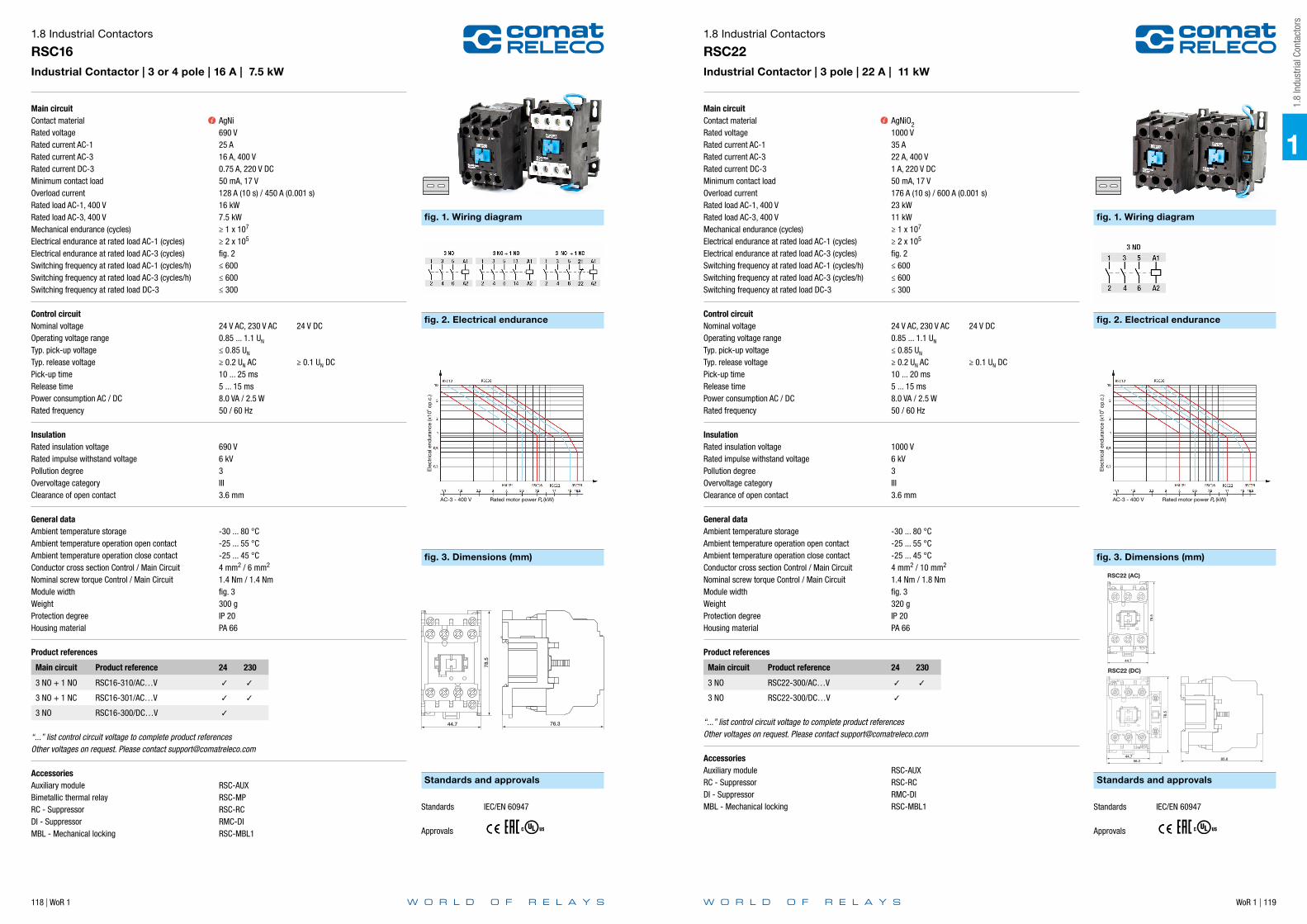
118 | WoR 1 WoR 1 | 119
Main circuitContact materialRated voltageRated current AC-1Rated current AC-3Rated current DC-3Minimum contact loadOverload currentRated load AC-1, 400 VRated load AC-3, 400 VMechanical endurance (cycles)Electrical endurance at rated load AC-1 (cycles)Electrical endurance at rated load AC-3 (cycles)Switching frequency at rated load AC-1 (cycles/h)Switching frequency at rated load AC-3 (cycles/h)Switching frequency at rated load DC-3
Control circuitNominal voltageOperating voltage rangeTyp. pick-up voltageTyp. release voltagePick-up timeRelease timePower consumption AC / DCRated frequency
InsulationRated insulation voltageRated impulse withstand voltagePollution degreeOvervoltage categoryClearance of open contact
General dataAmbient temperature storageAmbient temperature operation open contactAmbient temperature operation close contactConductor cross section Control / Main CircuitNominal screw torque Control / Main CircuitModule widthWeightProtection degreeHousing material
Product references
Main circuit Product reference 24 230
3 NO + 1 NO RSC16-310/AC…V
3 NO + 1 NC RSC16-301/AC…V
3 NO RSC16-300/DC…V
“...” list control circuit voltage to complete product referencesOther voltages on request. Please contact [email protected]
AccessoriesAuxiliary module RSC-AUXBimetallic thermal relay RSC-MPRC - Suppressor RSC-RCDI - Suppressor RMC-DIMBL - Mechanical locking RSC-MBL1
1.8 Industrial Contactors
RSC16Industrial Contactor | 3 or 4 pole | 16 A | 7.5 kW
AgNi690 V25 A16 A, 400 V0.75 A, 220 V DC50 mA, 17 V128 A (10 s) / 450 A (0.001 s)16 kW7.5 kW≥ 1 x 10⁷
≥ 2 x 10⁵
fig. 2≤ 600≤ 600≤ 300
24 V AC, 230 V AC 24 V DC0.85 ... 1.1 UN
≤ 0.85 UN
≥ 0.2 UN AC ≥ 0.1 UN DC10 ... 25 ms5 ... 15 ms8.0 VA / 2.5 W50 / 60 Hz
690 V6 kV3III3.6 mm
-30 ... 80 °C-25 ... 55 °C-25 ... 45 °C4 mm2 / 6 mm2
1.4 Nm / 1.4 Nmfig. 3300 gIP 20PA 66
fig. 1. Wiring diagram
fig. 2. Electrical endurance
fig. 3. Dimensions (mm)
Standards and approvals
Rated motor power Pe (kW)AC-3 - 400 V
Ele
ctric
al e
ndur
ance
(x10
6 op
.c.)
76.344.7
78.5
Standards IEC/EN 60947
Approvals
Main circuitContact materialRated voltageRated current AC-1Rated current AC-3Rated current DC-3Minimum contact loadOverload currentRated load AC-1, 400 VRated load AC-3, 400 VMechanical endurance (cycles)Electrical endurance at rated load AC-1 (cycles)Electrical endurance at rated load AC-3 (cycles)Switching frequency at rated load AC-1 (cycles/h)Switching frequency at rated load AC-3 (cycles/h)Switching frequency at rated load DC-3
Control circuitNominal voltageOperating voltage rangeTyp. pick-up voltageTyp. release voltagePick-up timeRelease timePower consumption AC / DCRated frequency
InsulationRated insulation voltageRated impulse withstand voltagePollution degreeOvervoltage categoryClearance of open contact
General dataAmbient temperature storageAmbient temperature operation open contactAmbient temperature operation close contactConductor cross section Control / Main CircuitNominal screw torque Control / Main CircuitModule widthWeightProtection degreeHousing material
Product references
Main circuit Product reference 24 230
3 NO RSC22-300/AC…V
3 NO RSC22-300/DC…V
“...” list control circuit voltage to complete product referencesOther voltages on request. Please contact [email protected]
AccessoriesAuxiliary module RSC-AUXRC - Suppressor RSC-RCDI - Suppressor RMC-DIMBL - Mechanical locking RSC-MBL1
1.8 Industrial Contactors
RSC22Industrial Contactor | 3 pole | 22 A | 11 kW
AgNiO21000 V35 A22 A, 400 V1 A, 220 V DC50 mA, 17 V176 A (10 s) / 600 A (0.001 s)23 kW11 kW≥ 1 x 10⁷
≥ 2 x 10⁵
fig. 2≤ 600≤ 600≤ 300
24 V AC, 230 V AC 24 V DC0.85 ... 1.1 UN
≤ 0.85 UN
≥ 0.2 UN AC ≥ 0.1 UN DC10 ... 20 ms5 ... 15 ms8.0 VA / 2.5 W50 / 60 Hz
1000 V6 kV3III3.6 mm
-30 ... 80 °C-25 ... 55 °C-25 ... 45 °C4 mm2 / 10 mm2
1.4 Nm / 1.8 Nmfig. 3320 gIP 20PA 66
fig. 1. Wiring diagram
fig. 2. Electrical endurance
fig. 3. Dimensions (mm)
Standards and approvals
Rated motor power Pe (kW)AC-3 - 400 V
Ele
ctric
al e
ndur
ance
(x10
6 op
.c.)
RSC22 (AC)
RSC22 (DC)
44.7
78.5
78.5
44.756.2 85.6
Standards IEC/EN 60947
Approvals
1
1.8
Indu
stria
l Con
tact
ors
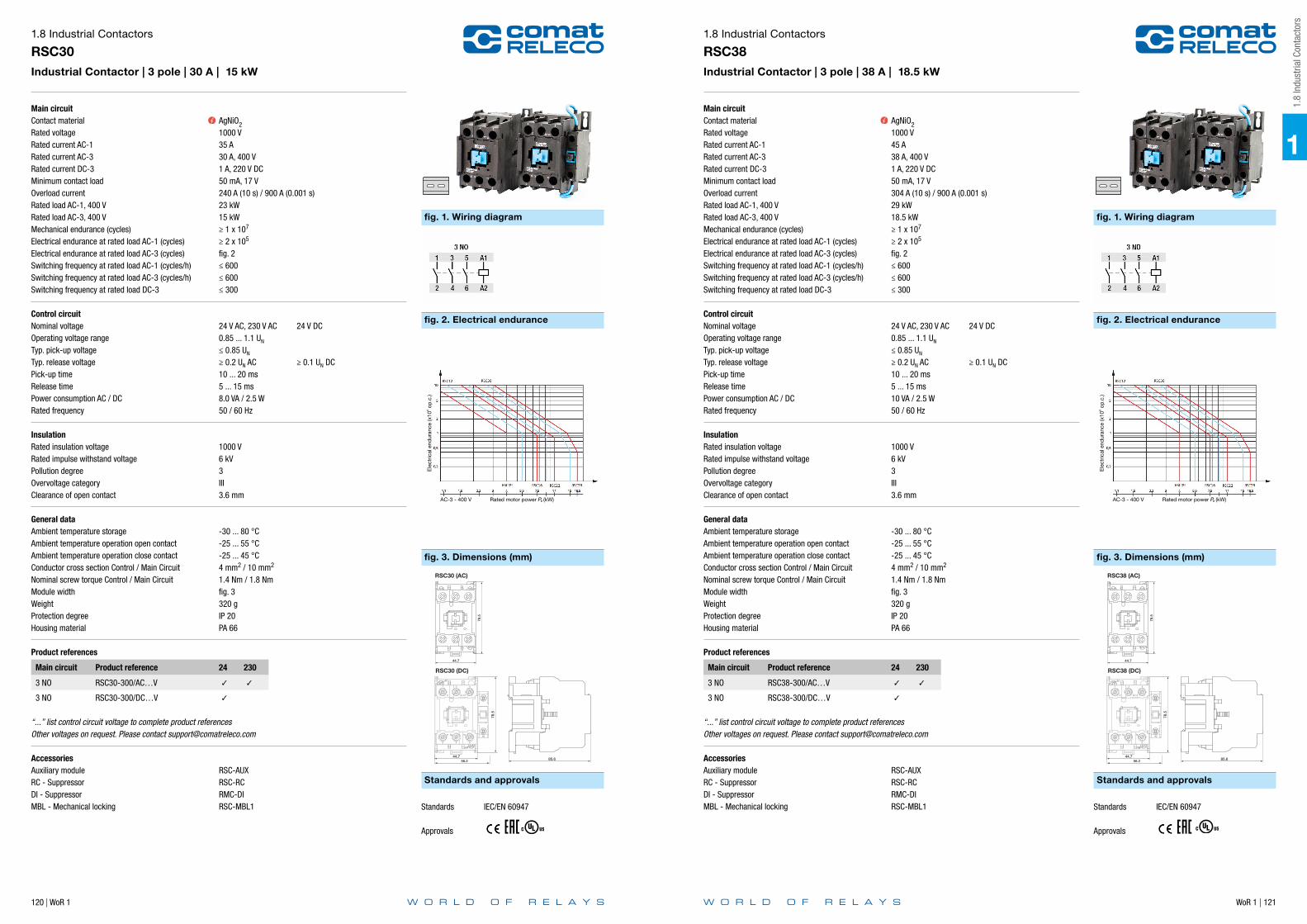
120 | WoR 1 WoR 1 | 121
Main circuitContact materialRated voltageRated current AC-1Rated current AC-3Rated current DC-3Minimum contact loadOverload currentRated load AC-1, 400 VRated load AC-3, 400 VMechanical endurance (cycles)Electrical endurance at rated load AC-1 (cycles)Electrical endurance at rated load AC-3 (cycles)Switching frequency at rated load AC-1 (cycles/h)Switching frequency at rated load AC-3 (cycles/h)Switching frequency at rated load DC-3
Control circuitNominal voltageOperating voltage rangeTyp. pick-up voltageTyp. release voltagePick-up timeRelease timePower consumption AC / DCRated frequency
InsulationRated insulation voltageRated impulse withstand voltagePollution degreeOvervoltage categoryClearance of open contact
General dataAmbient temperature storageAmbient temperature operation open contactAmbient temperature operation close contactConductor cross section Control / Main CircuitNominal screw torque Control / Main CircuitModule widthWeightProtection degreeHousing material
Product references
Main circuit Product reference 24 230
3 NO RSC30-300/AC…V
3 NO RSC30-300/DC…V
“...” list control circuit voltage to complete product referencesOther voltages on request. Please contact [email protected]
AccessoriesAuxiliary module RSC-AUXRC - Suppressor RSC-RCDI - Suppressor RMC-DIMBL - Mechanical locking RSC-MBL1
1.8 Industrial Contactors
RSC30Industrial Contactor | 3 pole | 30 A | 15 kW
AgNiO21000 V35 A30 A, 400 V1 A, 220 V DC50 mA, 17 V240 A (10 s) / 900 A (0.001 s)23 kW15 kW≥ 1 x 10⁷
≥ 2 x 10⁵
fig. 2≤ 600≤ 600≤ 300
24 V AC, 230 V AC 24 V DC0.85 ... 1.1 UN
≤ 0.85 UN
≥ 0.2 UN AC ≥ 0.1 UN DC10 ... 20 ms5 ... 15 ms8.0 VA / 2.5 W50 / 60 Hz
1000 V6 kV3III3.6 mm
-30 ... 80 °C-25 ... 55 °C-25 ... 45 °C4 mm2 / 10 mm2
1.4 Nm / 1.8 Nmfig. 3320 gIP 20PA 66
fig. 1. Wiring diagram
fig. 2. Electrical endurance
fig. 3. Dimensions (mm)
Standards and approvals
Rated motor power Pe (kW)AC-3 - 400 V
Ele
ctric
al e
ndur
ance
(x10
6 op
.c.)
RSC30 (AC)
RSC30 (DC)
44.7
78.5
78.5
44.756.2 85.6
Standards IEC/EN 60947
Approvals
Main circuitContact materialRated voltageRated current AC-1Rated current AC-3Rated current DC-3Minimum contact loadOverload currentRated load AC-1, 400 VRated load AC-3, 400 VMechanical endurance (cycles)Electrical endurance at rated load AC-1 (cycles)Electrical endurance at rated load AC-3 (cycles)Switching frequency at rated load AC-1 (cycles/h)Switching frequency at rated load AC-3 (cycles/h)Switching frequency at rated load DC-3
Control circuitNominal voltageOperating voltage rangeTyp. pick-up voltageTyp. release voltagePick-up timeRelease timePower consumption AC / DCRated frequency
InsulationRated insulation voltageRated impulse withstand voltagePollution degreeOvervoltage categoryClearance of open contact
General dataAmbient temperature storageAmbient temperature operation open contactAmbient temperature operation close contactConductor cross section Control / Main CircuitNominal screw torque Control / Main CircuitModule widthWeightProtection degreeHousing material
Product references
Main circuit Product reference 24 230
3 NO RSC38-300/AC…V
3 NO RSC38-300/DC…V
“...” list control circuit voltage to complete product referencesOther voltages on request. Please contact [email protected]
AccessoriesAuxiliary module RSC-AUXRC - Suppressor RSC-RCDI - Suppressor RMC-DIMBL - Mechanical locking RSC-MBL1
1.8 Industrial Contactors
RSC38Industrial Contactor | 3 pole | 38 A | 18.5 kW
AgNiO21000 V45 A38 A, 400 V1 A, 220 V DC50 mA, 17 V304 A (10 s) / 900 A (0.001 s)29 kW18.5 kW≥ 1 x 10⁷
≥ 2 x 10⁵
fig. 2≤ 600≤ 600≤ 300
24 V AC, 230 V AC 24 V DC0.85 ... 1.1 UN
≤ 0.85 UN
≥ 0.2 UN AC ≥ 0.1 UN DC10 ... 20 ms5 ... 15 ms10 VA / 2.5 W50 / 60 Hz
1000 V6 kV3III3.6 mm
-30 ... 80 °C-25 ... 55 °C-25 ... 45 °C4 mm2 / 10 mm2
1.4 Nm / 1.8 Nmfig. 3320 gIP 20PA 66
fig. 1. Wiring diagram
fig. 2. Electrical endurance
fig. 3. Dimensions (mm)
Standards and approvals
Rated motor power Pe (kW)AC-3 - 400 V
Ele
ctric
al e
ndur
ance
(x10
6 op
.c.)
RSC38 (AC)
RSC38 (DC)
44.7
78.5
78.5
44.756.2 85.6
Standards IEC/EN 60947
Approvals
1
1.8
Indu
stria
l Con
tact
ors
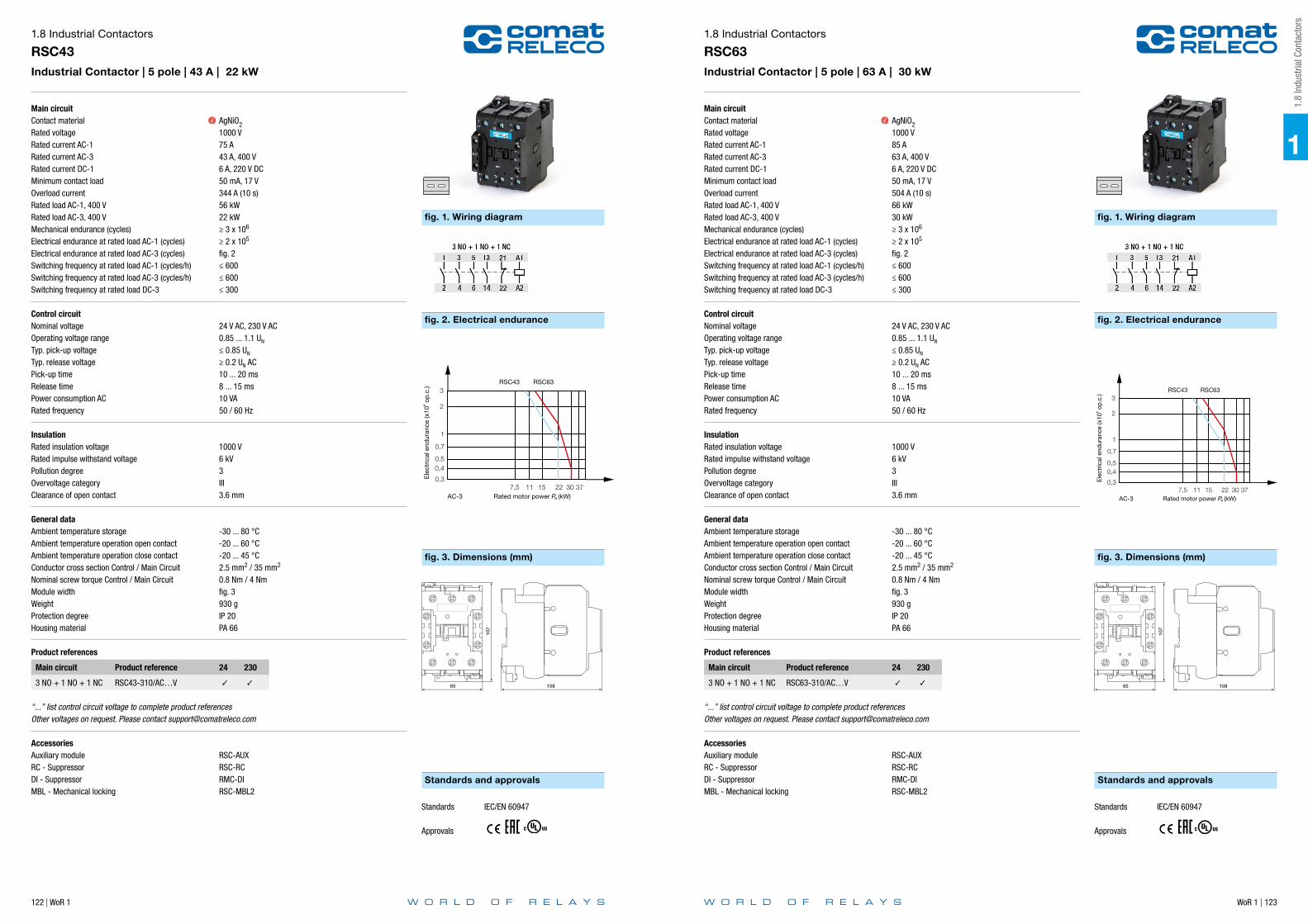
122 | WoR 1 WoR 1 | 123
Main circuitContact materialRated voltageRated current AC-1Rated current AC-3Rated current DC-1Minimum contact loadOverload currentRated load AC-1, 400 VRated load AC-3, 400 VMechanical endurance (cycles)Electrical endurance at rated load AC-1 (cycles)Electrical endurance at rated load AC-3 (cycles)Switching frequency at rated load AC-1 (cycles/h)Switching frequency at rated load AC-3 (cycles/h)Switching frequency at rated load DC-3
Control circuitNominal voltageOperating voltage rangeTyp. pick-up voltageTyp. release voltagePick-up timeRelease timePower consumption ACRated frequency
InsulationRated insulation voltageRated impulse withstand voltagePollution degreeOvervoltage categoryClearance of open contact
General dataAmbient temperature storageAmbient temperature operation open contactAmbient temperature operation close contactConductor cross section Control / Main CircuitNominal screw torque Control / Main CircuitModule widthWeightProtection degreeHousing material
Product references
Main circuit Product reference 24 230
3 NO + 1 NO + 1 NC RSC43-310/AC…V
“...” list control circuit voltage to complete product referencesOther voltages on request. Please contact [email protected]
AccessoriesAuxiliary module RSC-AUXRC - Suppressor RSC-RCDI - Suppressor RMC-DIMBL - Mechanical locking RSC-MBL2
1.8 Industrial Contactors
RSC43Industrial Contactor | 5 pole | 43 A | 22 kW
AgNiO21000 V75 A43 A, 400 V6 A, 220 V DC50 mA, 17 V344 A (10 s)56 kW22 kW≥ 3 x 10⁶
≥ 2 x 10⁵
fig. 2≤ 600≤ 600≤ 300
24 V AC, 230 V AC0.85 ... 1.1 UN
≤ 0.85 UN
≥ 0.2 UN AC10 ... 20 ms8 ... 15 ms10 VA50 / 60 Hz
1000 V6 kV3III3.6 mm
-30 ... 80 °C-20 ... 60 °C-20 ... 45 °C2.5 mm2 / 35 mm2
0.8 Nm / 4 Nmfig. 3930 gIP 20PA 66
fig. 1. Wiring diagram
fig. 2. Electrical endurance
fig. 3. Dimensions (mm)
Standards and approvals
3
2
1
0,7
0,50,4
0,37,5 11 15 22 30 37
Rated motor power Pe (kW)AC-3
RSC43 RSC63
Ele
ctric
al e
ndur
ance
(x10
6 op
.c.)
44.7 37.8
48
RSC-AUX
65 108
107
Standards IEC/EN 60947
Approvals
Main circuitContact materialRated voltageRated current AC-1Rated current AC-3Rated current DC-1Minimum contact loadOverload currentRated load AC-1, 400 VRated load AC-3, 400 VMechanical endurance (cycles)Electrical endurance at rated load AC-1 (cycles)Electrical endurance at rated load AC-3 (cycles)Switching frequency at rated load AC-1 (cycles/h)Switching frequency at rated load AC-3 (cycles/h)Switching frequency at rated load DC-3
Control circuitNominal voltageOperating voltage rangeTyp. pick-up voltageTyp. release voltagePick-up timeRelease timePower consumption ACRated frequency
InsulationRated insulation voltageRated impulse withstand voltagePollution degreeOvervoltage categoryClearance of open contact
General dataAmbient temperature storageAmbient temperature operation open contactAmbient temperature operation close contactConductor cross section Control / Main CircuitNominal screw torque Control / Main CircuitModule widthWeightProtection degreeHousing material
Product references
Main circuit Product reference 24 230
3 NO + 1 NO + 1 NC RSC63-310/AC…V
“...” list control circuit voltage to complete product referencesOther voltages on request. Please contact [email protected]
AccessoriesAuxiliary module RSC-AUXRC - Suppressor RSC-RCDI - Suppressor RMC-DIMBL - Mechanical locking RSC-MBL2
1.8 Industrial Contactors
RSC63Industrial Contactor | 5 pole | 63 A | 30 kW
AgNiO21000 V85 A63 A, 400 V6 A, 220 V DC50 mA, 17 V504 A (10 s)66 kW30 kW≥ 3 x 10⁶
≥ 2 x 10⁵
fig. 2≤ 600≤ 600≤ 300
24 V AC, 230 V AC0.85 ... 1.1 UN
≤ 0.85 UN
≥ 0.2 UN AC10 ... 20 ms8 ... 15 ms10 VA50 / 60 Hz
1000 V6 kV3III3.6 mm
-30 ... 80 °C-20 ... 60 °C-20 ... 45 °C2.5 mm2 / 35 mm2
0.8 Nm / 4 Nmfig. 3930 gIP 20PA 66
fig. 1. Wiring diagram
fig. 2. Electrical endurance
fig. 3. Dimensions (mm)
Standards and approvals
3
2
1
0,7
0,50,4
0,37,5 11 15 22 30 37
Rated motor power Pe (kW)AC-3
RSC43 RSC63
Ele
ctric
al e
ndur
ance
(x10
6 op
.c.)
44.7 37.8
48
RSC-AUX
65 108
107
Standards IEC/EN 60947
Approvals
1
1.8
Indu
stria
l Con
tact
ors

124 | WoR 1 WoR 1 | 125
Main circuitContact materialRated voltageRated current AC-1Rated current auxiliary contact AC / DCOverload currentTripping curve
Control circuitPhase loss protectionAmbient temperature compensationReset modeRated operational current auxiliary contact AC-15
InsulationRated insulation voltageRated impulse withstand voltagePollution degreeOvervoltage category
General dataAmbient temperature storageAmbient temperature operationConductor cross section Auxiliary / Main CircuitNominal screw torque Auxiliary / Main CircuitModule widthWeightProtection degreeHousing material
Product references
Description Product reference
Bimetallic thermal relay RSC-MP-0.16
Bimetallic thermal relay RSC-MP-0.25
Bimetallic thermal relay RSC-MP-0.4
Bimetallic thermal relay RSC-MP-0.5
Bimetallic thermal relay RSC-MP-0.63
Bimetallic thermal relay RSC-MP-0.8
Bimetallic thermal relay RSC-MP-1.0
Bimetallic thermal relay RSC-MP-1.3
Bimetallic thermal relay RSC-MP-1.6
Bimetallic thermal relay RSC-MP-2.0
Bimetallic thermal relay RSC-MP-2.5
Bimetallic thermal relay RSC-MP-3.2
Bimetallic thermal relay RSC-MP-4.0
Bimetallic thermal relay RSC-MP-4.8
Bimetallic thermal relay RSC-MP-6.3
Bimetallic thermal relay RSC-MP-7.5
Bimetallic thermal relay RSC-MP-10.0
1.8 Industrial Contactors
RSC-MPBimetallic thermal relay | 5 pole | 0.1 … 10 A | RSC09 … RSC16
AgNi690 V0.1 … 10 A3 A, 230 V / 0.1 A, 230 V72 A (100 ms)fig. 2
YesYesmanual / automatic3 A, 250 V
690 V6 kV3III
-25 ... 70 °C-5 ... 55 °C2.5 mm2 / 10 mm2
0.8 Nm / 1.2 Nmfig. 3115 gIP 20PA 66
fig. 1. Wiring diagram
fig. 2. Electrical endurance
fig. 3. Dimensions (mm)
Standards and approvals
Operational current x/e (A)
Standards IEC/EN 60947
Approvals
Main circuitContact materialRated voltageRated current AC-1Rated current AC-15Rated current DC-13Minimum contact loadMechanical endurance (cycles)Electrical endurance at rated load AC-15 (cycles)Electrical endurance at rated load DC-13Switching frequency at rated load AC-15 (cycles/h)Switching frequency at rated load DC-13
InsulationRated insulation voltageRated impulse withstand voltagePollution degree
General dataAmbient temperature storageConductor cross section Control / Main CircuitNominal screw torque Control / Main CircuitModule widthWeightProtection degreeHousing material
Product references
Main circuit Product reference
2 NO RMC-AUX20
2 NC RMC-AUX02
1 NO + 1 NC RMC-AUX11
4 NO RMC-AUX40
4 NC RMC-AUX04
2 NO + 2 NC RMC-AUX22
1.8 Industrial Contactors
RMC-AUXAuxiliary module for industrial contactors | 2 or 4 pole | 6 A
AgNi690 V20 A6 A, 230 V0.15 A, 110 V DC50 mA, 17 V≥ 1 x 10⁷
≥ 5 x 10⁵
≥ 5 x 10⁵
≤ 1200≤ 1200
690 V6 kV3
-30 ... 80 °C- mm2 / 2.5 mm2
- Nm / 1.2 Nmfig. 220 g (2 pole) / 36 g (4 pole)IP 20PA 66
fig. 1. Wiring diagram
fig. 2. Dimensions (mm)
Standards and approvals
2 pole
4 pole
24
26.5
RMC-
AUX2
0
51 NC 61 NC
52 NC 62 NC
IO
44
26.5
26
26
Standards IEC/EN 60947
Approvals
1
1.8
Indu
stria
l Con
tact
ors
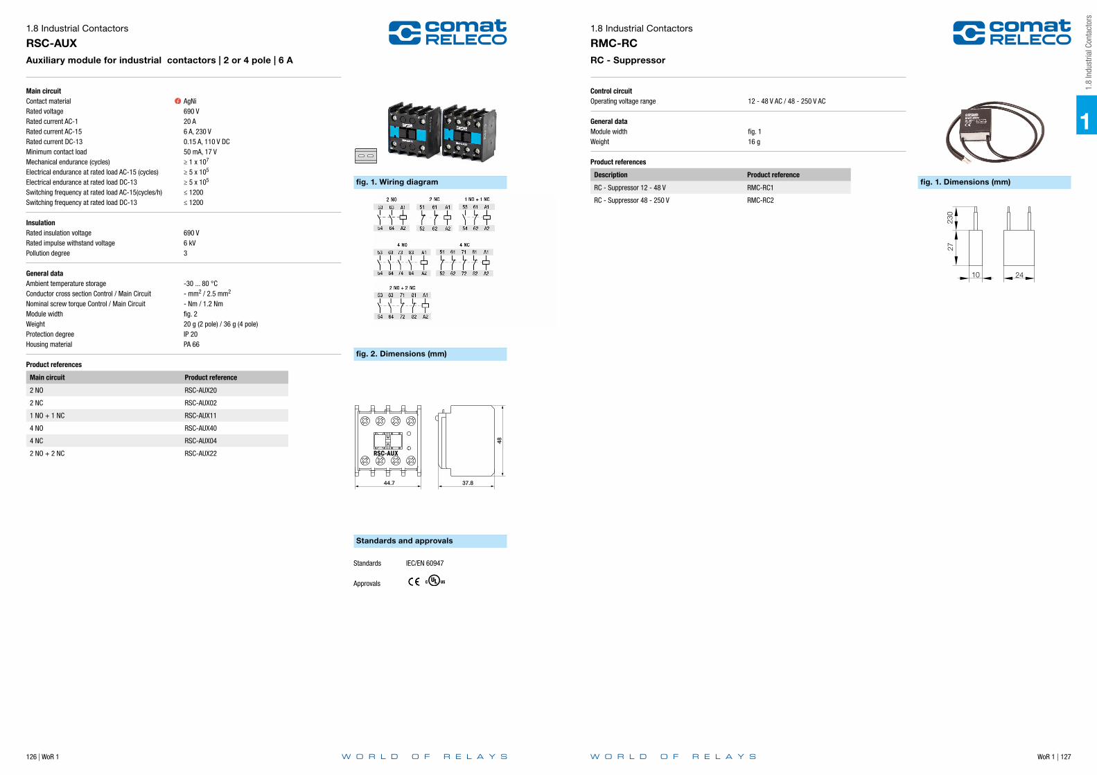
126 | WoR 1 WoR 1 | 127
Main circuitContact materialRated voltageRated current AC-1Rated current AC-15Rated current DC-13Minimum contact loadMechanical endurance (cycles)Electrical endurance at rated load AC-15 (cycles)Electrical endurance at rated load DC-13Switching frequency at rated load AC-15(cycles/h)Switching frequency at rated load DC-13
InsulationRated insulation voltageRated impulse withstand voltagePollution degree
General dataAmbient temperature storageConductor cross section Control / Main CircuitNominal screw torque Control / Main CircuitModule widthWeightProtection degreeHousing material
Product references
Main circuit Product reference
2 NO RSC-AUX20
2 NC RSC-AUX02
1 NO + 1 NC RSC-AUX11
4 NO RSC-AUX40
4 NC RSC-AUX04
2 NO + 2 NC RSC-AUX22
1.8 Industrial Contactors
RSC-AUXAuxiliary module for industrial contactors | 2 or 4 pole | 6 A
AgNi690 V20 A6 A, 230 V0.15 A, 110 V DC50 mA, 17 V≥ 1 x 10⁷
≥ 5 x 10⁵
≥ 5 x 10⁵
≤ 1200≤ 1200
690 V6 kV3
-30 ... 80 °C- mm2 / 2.5 mm2
- Nm / 1.2 Nmfig. 220 g (2 pole) / 36 g (4 pole)IP 20PA 66
fig. 1. Wiring diagram
fig. 2. Dimensions (mm)
Standards and approvals
44.7 37.8
48
RSC-AUX
Standards IEC/EN 60947
Approvals
Control circuitOperating voltage range
General dataModule widthWeight
Product references
Description Product reference
RC - Suppressor 12 - 48 V RMC-RC1
RC - Suppressor 48 - 250 V RMC-RC2
1.8 Industrial Contactors
RMC-RCRC - Suppressor
12 - 48 V AC / 48 - 250 V AC
fig. 116 g
fig. 1. Dimensions (mm)
10 24
2723
0
1
1.8
Indu
stria
l Con
tact
ors

128 | WoR 1 WoR 1 | 129
Control circuitOperating voltage range
General dataModule widthWeight
Product references
Description Product reference
RC - Suppressor 12 - 48 V RSC-RC1
RC - Suppressor 48 - 250 V RSC-RC2
1.8 Industrial Contactors
RSC-RCRC - Suppressor
12 - 48 V AC / 48 - 250 V AC
fig. 116 g
fig. 1. Dimensions (mm)
10 24
2723
0
Control circuitOperating voltage range
General dataModule widthWeight
Product references
Description Product reference
RC - Suppressor Diode 6 - 250 V RMC-DI
1.8 Industrial Contactors
RMC-DIDI - Suppressor
6 - 250 V DC
fig. 116 g
fig. 1. Dimensions (mm)
10 24
2723
0
1
1.8
Indu
stria
l Con
tact
ors

WoR 1 | 131130 | WoR 1
General dataModule widthWeight
Product references
Description Product reference
RSC - Mechanical locking RSC-MBL1
RSC - Mechanical locking RSC43 / 63 RSC-MBL2
1.8 Industrial Contactors
RSC-MBLMBL - Mechanical locking
15 mm14 g | 16 g
fig. 1. Dimensions (mm)
15 51
30
RSC-MBL1
RSC-MBL2
on request
1
1.9
Solid
Sta
te C
onta
ctor
s
Application Type Output Page
CC1 Series
Solid State Contactor | 230 V | 15 A CC1H215 1 132
Solid State Contactor | 230 V | 30 A CC1H230 1 133
Solid State Contactor | 230 V | 50 A CC1H250 1 134
Solid State Contactor | 400 V | 15 A CC1H415 1 135
Solid State Contactor | 400 V | 30 A CC1H430 1 136
Solid State Contactor | 400 V | 50 A CC1H450 1 137
CC3 Series
Solid State Contactor | 400 V | 10 A CC3H410 3 138
Solid State Contactor | 400 V | 20 A CC3H420 3 139
Solid State Contactor | 400 V | 10 A | Reversing CCR3H410 3 140
CPC Series
Solid State Power Controller | 230 V | 30 A CPC1230 1 141
Solid State Power Controller | 230 V | 50 A CPC1250 1 142
Solid State Power Controller | 400 V | 30 A CPC1430 1 143
Solid State Power Controller | 400 V | 50 A CPC1450 1 144
1.9 Solid State Contactors

132 | WoR 1 WoR 1 | 133
Main circuitOutput typeNumber of outputsRated voltageOutput voltage rangeReverse voltagePeak reverse voltageRated current AC-1Rated current AC-3Minimum loadTyp. leakage currentRated limit load
Control circuitNominal voltageOperating voltage rangeTyp. pick-up voltageTyp. release voltagePick-up timeRelease timePower consumption AC / DCRated frequency
InsulationRated insulation voltageRated impulse withstand voltagePollution degreeOvervoltage category
General dataAmbient temperature storageAmbient temperature operationAmbient temperature operation derated powerConductor cross section Control / Main CircuitNominal screw torque Control / Main CircuitModule widthWeightProtection degreeHousing materialMounting
Product references
Description Product reference
Solid State Contactor, 1 phase CC1H215
Other devices on request. Please contact [email protected].
AccessoriesThermal overload protection P82-100C
1.9 Solid State Contactors
CC1H215Solid State Contactor | 1 phase | 230 V | 15 A
Thyristor1230 V12 … 240 V AC1000 Vrrm1100 Vrrm15 A15 A10 mA1 mA1800 A2t
24 … 230 V UC0.85 ... 1.1 UN
20.4 V7.2 V20 ms20 ms1.5 VA / 150 mW50 / 60 Hz
660 V4 kV3III
-20 ... 80 °C-5 ... 40 °C-5 ... 60 °C, 0.7 IN1.5 mm2 / 10 mm2
0.5 Nm / 1.2 Nmfig. 2270 gIP 20PPETS 35 or Back Panel Mounting
fig. 1. Wiring diagram
fig. 2. Dimensions (mm)
Standards and approvals
Standards IEC/EN 60947, 50022, 60068
Approvals
11-12: Thermostat
Main circuitOutput typeNumber of outputsRated voltageOutput voltage rangeReverse voltagePeak reverse voltageRated current AC-1Rated current AC-3Minimum loadTyp. leakage currentRated limit load
Control circuitNominal voltageOperating voltage rangeTyp. pick-up voltageTyp. release voltagePick-up timeRelease timePower consumption AC / DCRated frequency
InsulationRated insulation voltageRated impulse withstand voltagePollution degreeOvervoltage category
General dataAmbient temperature storageAmbient temperature operationAmbient temperature operation derated powerConductor cross section Control / Main CircuitNominal screw torque Control / Main CircuitModule widthWeightProtection degreeHousing materialMounting
Product references
Description Product reference
Solid State Contactor, 1 phase CC1H230
Other devices on request. Please contact [email protected].
AccessoriesThermal overload protection P82-100C
1.9 Solid State Contactors
CC1H230Solid State Contactor | 1 phase | 230 V | 30 A
Thyristor1230 V12 … 240 V AC1000 Vrrm1100 Vrrm30 A15 A10 mA1 mA1800 A2t
24 … 230 V UC0.85 ... 1.1 UN
20.4 V7.2 V20 ms20 ms1.5 VA / 150 mW50 / 60 Hz
660 V4 kV3III
-20 ... 80 °C-5 ... 40 °C-5 ... 60 °C, 0.7 IN1.5 mm2 / 10 mm2
0.5 Nm / 1.2 Nmfig. 2650 gIP 20PPETS 35 or Back Panel Mounting
fig. 1. Wiring diagram
fig. 2. Dimensions (mm)
Standards and approvals
Standards IEC/EN 60947, 50022, 60068
Approvals
11-12: Thermostat
1
1.9
Solid
Sta
te C
onta
ctor
s

134 | WoR 1 WoR 1 | 135
Main circuitOutput typeNumber of outputsRated voltageOutput voltage rangeReverse voltagePeak reverse voltageRated current AC-1Rated current AC-3Minimum loadTyp. leakage currentRated limit load
Control circuitNominal voltageOperating voltage rangeTyp. pick-up voltageTyp. release voltagePick-up timeRelease timePower consumption AC / DCRated frequency
InsulationRated insulation voltageRated impulse withstand voltagePollution degreeOvervoltage category
General dataAmbient temperature storageAmbient temperature operationAmbient temperature operation derated powerConductor cross section Control / Main CircuitNominal screw torque Control / Main CircuitModule widthWeightProtection degreeHousing materialMounting
Product references
Description Product reference
Solid State Contactor, 1 phase CC1H250
Other devices on request. Please contact [email protected].
AccessoriesThermal overload protection P82-100C
1.9 Solid State Contactors
CC1H250Solid State Contactor | 1 phase | 230 V | 50 A
Thyristor1230 V12 … 240 V AC1000 Vrrm1100 Vrrm50 A15 A10 mA1 mA1800 A2t
24 … 230 V UC0.85 ... 1.1 UN
20.4 V7.2 V20 ms20 ms1.5 VA / 150 mW50 / 60 Hz
660 V4 kV3III
-20 ... 80 °C-5 ... 40 °C-5 ... 60 °C, 0.7 IN1.5 mm2 / 10 mm2
0.5 Nm / 1.2 Nmfig. 21050 gIP 20PPETS 35 or Back Panel Mounting
fig. 1. Wiring diagram
fig. 2. Dimensions (mm)
Standards and approvals
Standards IEC/EN 60947, 50022, 60068
Approvals
11-12: Thermostat
Main circuitOutput typeNumber of outputsRated voltageOutput voltage rangeReverse voltagePeak reverse voltageRated current AC-1Rated current AC-3Minimum loadTyp. leakage currentRated limit load
Control circuitNominal voltageOperating voltage rangeTyp. pick-up voltageTyp. release voltagePick-up timeRelease timePower consumption AC / DCRated frequency
InsulationRated insulation voltageRated impulse withstand voltagePollution degreeOvervoltage category
General dataAmbient temperature storageAmbient temperature operationAmbient temperature operation derated powerConductor cross section Control / Main CircuitNominal screw torque Control / Main CircuitModule widthWeightProtection degreeHousing materialMounting
Product references
Description Product reference
Solid State Contactor, 1 phase CC1H415
Other devices on request. Please contact [email protected].
AccessoriesThermal overload protection P82-100C
1.9 Solid State Contactors
CC1H415Solid State Contactor | 1 phase | 400 V | 15 A
Thyristor1400 V24 … 480 VAC1200 Vrrm1300 Vrrm15 A15 A10 mA1 mA1800 A2t
24 … 230 V UC0.85 ... 1.1 UN
20.4 V7.2 V20 ms20 ms1.5 VA / 150 mW50 / 60 Hz
660 V4 kV3III
-20 ... 80 °C-5 ... 40 °C-5 ... 60 °C, 0.7 IN1.5 mm2 / 10 mm2
0.5 Nm / 1.2 Nmfig. 2270 gIP 20PPETS 35 or Back Panel Mounting
fig. 1. Wiring diagram
fig. 2. Dimensions (mm)
Standards and approvals
Standards IEC/EN 60947, 50022, 60068
Approvals
11-12: Thermostat
1
1.9
Solid
Sta
te C
onta
ctor
s

136 | WoR 1 WoR 1 | 137
Main circuitOutput typeNumber of outputsRated voltageOutput voltage rangeReverse voltagePeak reverse voltageRated current AC-1Rated current AC-3Minimum loadTyp. leakage currentRated limit load
Control circuitNominal voltageOperating voltage rangeTyp. pick-up voltageTyp. release voltagePick-up timeRelease timePower consumption AC / DCRated frequency
InsulationRated insulation voltageRated impulse withstand voltagePollution degreeOvervoltage category
General dataAmbient temperature storageAmbient temperature operationAmbient temperature operation derated powerConductor cross section Control / Main CircuitNominal screw torque Control / Main CircuitModule widthWeightProtection degreeHousing materialMounting
Product references
Description Product reference
Solid State Contactor, 1 phase CC1H430
Other devices on request. Please contact [email protected].
AccessoriesThermal overload protection P82-100C
1.9 Solid State Contactors
CC1H430Solid State Contactor | 1 phase | 400 V | 30 A
Thyristor1400 V24 … 480 VAC1200 Vrrm1300 Vrrm30 A15 A10 mA1 mA1800 A2t
24 … 230 V UC0.85 ... 1.1 UN
20.4 V7.2 V20 ms20 ms1.5 VA / 150 mW50 / 60 Hz
660 V4 kV3III
-20 ... 80 °C-5 ... 40 °C-5 ... 60 °C, 0.7 IN1.5 mm2 / 10 mm2
0.5 Nm / 1.2 Nmfig. 2650 gIP 20PPETS 35 or Back Panel Mounting
fig. 1. Wiring diagram
fig. 2. Dimensions (mm)
Standards and approvals
Standards IEC/EN 60947, 50022, 60068
Approvals
11-12: Thermostat
Main circuitOutput typeNumber of outputsRated voltageOutput voltage rangeReverse voltagePeak reverse voltageRated current AC-1Rated current AC-3Minimum loadTyp. leakage currentRated limit load
Control circuitNominal voltageOperating voltage rangeTyp. pick-up voltageTyp. release voltagePick-up timeRelease timePower consumption AC / DCRated frequency
InsulationRated insulation voltageRated impulse withstand voltagePollution degreeOvervoltage category
General dataAmbient temperature storageAmbient temperature operationAmbient temperature operation derated powerConductor cross section Control / Main CircuitNominal screw torque Control / Main CircuitModule widthWeightProtection degreeHousing materialMounting
Product references
Description Product reference
Solid State Contactor, 1 phase CC1H450
Other devices on request. Please contact [email protected].
AccessoriesThermal overload protection P82-100C
1.9 Solid State Contactors
CC1H450Solid State Contactor | 1 phase | 400 V | 50 A
Thyristor1400 V24 … 480 VAC1200 Vrrm1300 Vrrm50 A15 A10 mA1 mA1800 A2t
24 … 230 V UC0.85 ... 1.1 UN
20.4 V7.2 V20 ms20 ms1.5 VA / 150 mW50 / 60 Hz
660 V4 kV3III
-20 ... 80 °C-5 ... 40 °C-5 ... 60 °C, 0.7 IN1.5 mm2 / 10 mm2
0.5 Nm / 1.2 Nmfig. 21050 gIP 20PPETS 35 or Back Panel Mounting
fig. 1. Wiring diagram
fig. 2. Dimensions (mm)
Standards and approvals
Standards IEC/EN 60947, 50022, 60068
Approvals
11-12: Thermostat
1
1.9
Solid
Sta
te C
onta
ctor
s
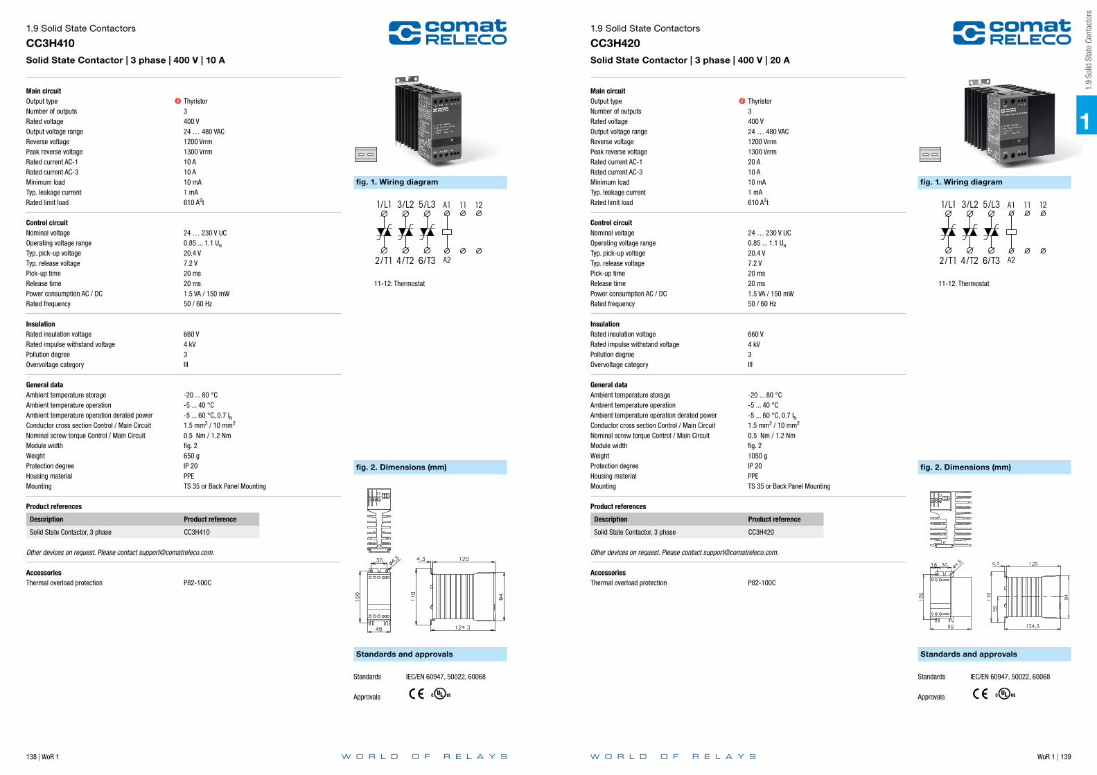
138 | WoR 1 WoR 1 | 139
Main circuitOutput typeNumber of outputsRated voltageOutput voltage rangeReverse voltagePeak reverse voltageRated current AC-1Rated current AC-3Minimum loadTyp. leakage currentRated limit load
Control circuitNominal voltageOperating voltage rangeTyp. pick-up voltageTyp. release voltagePick-up timeRelease timePower consumption AC / DCRated frequency
InsulationRated insulation voltageRated impulse withstand voltagePollution degreeOvervoltage category
General dataAmbient temperature storageAmbient temperature operationAmbient temperature operation derated powerConductor cross section Control / Main CircuitNominal screw torque Control / Main CircuitModule widthWeightProtection degreeHousing materialMounting
Product references
Description Product reference
Solid State Contactor, 3 phase CC3H410
Other devices on request. Please contact [email protected].
AccessoriesThermal overload protection P82-100C
1.9 Solid State Contactors
CC3H410Solid State Contactor | 3 phase | 400 V | 10 A
Thyristor3400 V24 … 480 VAC1200 Vrrm1300 Vrrm10 A10 A10 mA1 mA610 A2t
24 … 230 V UC0.85 ... 1.1 UN
20.4 V7.2 V20 ms20 ms1.5 VA / 150 mW50 / 60 Hz
660 V4 kV3III
-20 ... 80 °C-5 ... 40 °C-5 ... 60 °C, 0.7 IN1.5 mm2 / 10 mm2
0.5 Nm / 1.2 Nmfig. 2650 gIP 20PPETS 35 or Back Panel Mounting
fig. 1. Wiring diagram
fig. 2. Dimensions (mm)
Standards and approvals
Standards IEC/EN 60947, 50022, 60068
Approvals
11-12: Thermostat
Main circuitOutput typeNumber of outputsRated voltageOutput voltage rangeReverse voltagePeak reverse voltageRated current AC-1Rated current AC-3Minimum loadTyp. leakage currentRated limit load
Control circuitNominal voltageOperating voltage rangeTyp. pick-up voltageTyp. release voltagePick-up timeRelease timePower consumption AC / DCRated frequency
InsulationRated insulation voltageRated impulse withstand voltagePollution degreeOvervoltage category
General dataAmbient temperature storageAmbient temperature operationAmbient temperature operation derated powerConductor cross section Control / Main CircuitNominal screw torque Control / Main CircuitModule widthWeightProtection degreeHousing materialMounting
Product references
Description Product reference
Solid State Contactor, 3 phase CC3H420
Other devices on request. Please contact [email protected].
AccessoriesThermal overload protection P82-100C
1.9 Solid State Contactors
CC3H420Solid State Contactor | 3 phase | 400 V | 20 A
Thyristor3400 V24 … 480 VAC1200 Vrrm1300 Vrrm20 A10 A10 mA1 mA610 A2t
24 … 230 V UC0.85 ... 1.1 UN
20.4 V7.2 V20 ms20 ms1.5 VA / 150 mW50 / 60 Hz
660 V4 kV3III
-20 ... 80 °C-5 ... 40 °C-5 ... 60 °C, 0.7 IN1.5 mm2 / 10 mm2
0.5 Nm / 1.2 Nmfig. 21050 gIP 20PPETS 35 or Back Panel Mounting
fig. 1. Wiring diagram
fig. 2. Dimensions (mm)
Standards and approvals
Standards IEC/EN 60947, 50022, 60068
Approvals
11-12: Thermostat
1
1.9
Solid
Sta
te C
onta
ctor
s

140 | WoR 1 WoR 1 | 141
Main circuitOutput typeNumber of outputsRated voltageOutput voltage rangeReverse voltagePeak reverse voltageRated current AC-1Rated current AC-3Minimum loadTyp. leakage currentRated limit load
Control circuitNominal voltageOperating voltage rangeTyp. pick-up voltageTyp. release voltagePick-up timeRelease timeInterlock timePower consumption AC / DCRated frequency
InsulationRated insulation voltageRated impulse withstand voltagePollution degreeOvervoltage category
General dataAmbient temperature storageAmbient temperature operationAmbient temperature operation derated powerConductor cross section Control / Main CircuitNominal screw torque Control / Main CircuitModule widthWeightProtection degreeHousing materialMounting
Product references
Description Product reference
Solid State Contactor - Reversing, 3 phase CCR3H410
Other devices on request. Please contact [email protected].
AccessoriesThermal overload protection P82-100C
1.9 Solid State Contactors
CCR3H410Solid State Contactor | Reversing | 3 phase | 400 V | 10 A
Thyristor3400 V24 … 480 VAC1200 Vrrm1300 Vrrm10 A10 A10 mA1 mA610 A2t
24 … 230 V UC0.85 ... 1.1 UN
20.4 V7.2 V20 ms20 ms150 ms1.5 VA / 150 mW50 / 60 Hz
660 V4 kV3III
-20 ... 80 °C-5 ... 40 °C-5 ... 60 °C, 0.7 IN1.5 mm2 / 10 mm2
0.5 Nm / 1.2 Nmfig. 2650 gIP 20PPETS 35 or Back Panel Mounting
fig. 1. Wiring diagram
fig. 2. Dimensions (mm)
Standards and approvals
Standards IEC/EN 60947, 50022, 60068
Approvals
11-12: Thermostat
Main circuitOutput typeNumber of outputsRated voltageOutput voltage rangeReverse voltagePeak reverse voltageRated current AC-1Minimum loadTyp. leakage currentRated limit load
Control circuitNominal voltageOperating voltage rangeTyp. pick-up voltageTyp. release voltagePick-up timeRelease timeControl inputPotentiometer_input
InsulationRated insulation voltageRated impulse withstand voltagePollution degreeOvervoltage category
General dataAmbient temperature storageAmbient temperature operationAmbient temperature operation derated powerConductor cross section Control / Main CircuitNominal screw torque Control / Main CircuitModule widthWeightProtection degreeHousing materialMounting
Product references
Description Product reference
Power Controller, 1 phase CPC1230
Other devices on request. Please contact [email protected].
AccessoriesThermal overload protection P82-100C
1.9 Solid State Contactors
CPC1230Solid State Power Controller | 1 phase | 230 V | 30 A
Thyristor1230 V380 … 480 V1000 Vrrm1100 Vrrm30 A10 mA1 mA1800 A2t
24 V UC0.5 ... 1.5 UN
≤ 12 V≥ 12 V20 ms20 ms0 … 20 mA / 4 … 20 mA / 0 - 10 V0 - 10 kOhm
660 V4 kV3III
-20 ... 80 °C-5 ... 40 °C-5 ... 60 °C, 0.7 IN1.5 mm2 / 10 mm2
0.5 Nm / 1.2 Nmfig. 2650 gIP 20PPETS 35 or Back Panel Mounting
fig. 1. Wiring diagram
fig. 2. Dimensions (mm)
Standards and approvals
External power supply24VAC or
Load
24VDC / 30mA max
Standards IEC/EN 60947, 50022, 60068
Approvals
11-12: Thermostat
1
1.9
Solid
Sta
te C
onta
ctor
s

142 | WoR 1 WoR 1 | 143
Main circuitOutput typeNumber of outputsRated voltageOutput voltage rangeReverse voltagePeak reverse voltageRated current AC-1Minimum loadTyp. leakage currentRated limit load
Control circuitNominal voltageOperating voltage rangeTyp. pick-up voltageTyp. release voltagePick-up timeRelease timeControl inputPotentiometer_input
InsulationRated insulation voltageRated impulse withstand voltagePollution degreeOvervoltage category
General dataAmbient temperature storageAmbient temperature operationAmbient temperature operation derated powerConductor cross section Control / Main CircuitNominal screw torque Control / Main CircuitModule widthWeightProtection degreeHousing materialMounting
Product references
Description Product reference
Power Controller, 1 phase CPC1250
Other devices on request. Please contact [email protected].
AccessoriesThermal overload protection P82-100C
1.9 Solid State Contactors
CPC1250Solid State Power Controller | 1 phase | 230 V | 50 A
Thyristor1230 V380 … 480 V1000 Vrrm1100 Vrrm50 A10 mA1 mA1800 A2t
24 V UC0.5 ... 1.5 UN
≤ 12 V≥ 12 V20 ms20 ms0 … 20 mA / 4 … 20 mA / 0 - 10 V0 - 10 kOhm
660 V4 kV3III
-20 ... 80 °C-5 ... 40 °C-5 ... 60 °C, 0.7 IN1.5 mm2 / 10 mm2
0.5 Nm / 1.2 Nmfig. 2650 gIP 20PPETS 35 or Back Panel Mounting
fig. 1. Wiring diagram
fig. 2. Dimensions (mm)
Standards and approvals
External power supply24VAC or
Load
24VDC / 30mA max
Standards IEC/EN 60947, 50022, 60068
Approvals
11-12: Thermostat
Main circuitOutput typeNumber of outputsRated voltageOutput voltage rangeReverse voltagePeak reverse voltageRated current AC-1Minimum loadTyp. leakage currentRated limit load
Control circuitNominal voltageOperating voltage rangeTyp. pick-up voltageTyp. release voltagePick-up timeRelease timeControl inputPotentiometer_input
InsulationRated insulation voltageRated impulse withstand voltagePollution degreeOvervoltage category
General dataAmbient temperature storageAmbient temperature operationAmbient temperature operation derated powerConductor cross section Control / Main CircuitNominal screw torque Control / Main CircuitModule widthWeightProtection degreeHousing materialMounting
Product references
Description Product reference
Power Controller, 1 phase CPC1430
Other devices on request. Please contact [email protected].
AccessoriesThermal overload protection P82-100C
1.9 Solid State Contactors
CPC1430Solid State Power Controller | 1 phase | 400 V | 30 A
Thyristor1400 V380 … 480 V1200 Vrrm1300 Vrrm30 A10 mA1 mA1800 A2t
24 V UC0.5 ... 1.5 UN
≤ 12 V≥ 12 V20 ms20 ms0 … 20 mA / 4 … 20 mA / 0 - 10 V0 - 10 kOhm
660 V4 kV3III
-20 ... 80 °C-5 ... 40 °C-5 ... 60 °C, 0.7 IN1.5 mm2 / 10 mm2
0.5 Nm / 1.2 Nmfig. 2650 gIP 20PPETS 35 or Back Panel Mounting
fig. 1. Wiring diagram
fig. 2. Dimensions (mm)
Standards and approvals
External power supply24VAC or
Load
24VDC / 30mA max
Standards IEC/EN 60947, 50022, 60068
Approvals
11-12: Thermostat
1
1.9
Solid
Sta
te C
onta
ctor
s

144 | WoR 1 WoR 1 | 145
Notes
Main circuitOutput typeNumber of outputsRated voltageOutput voltage rangeReverse voltagePeak reverse voltageRated current AC-1Minimum loadTyp. leakage currentRated limit load
Control circuitNominal voltageOperating voltage rangeTyp. pick-up voltageTyp. release voltagePick-up timeRelease timeControl inputPotentiometer_input
InsulationRated insulation voltageRated impulse withstand voltagePollution degreeOvervoltage category
General dataAmbient temperature storageAmbient temperature operationAmbient temperature operation derated powerConductor cross section Control / Main CircuitNominal screw torque Control / Main CircuitModule widthWeightProtection degreeHousing materialMounting
Product references
Description Product reference
Power Controller, 1 phase CPC1450
Other devices on request. Please contact [email protected].
AccessoriesThermal overload protection P82-100C
1.9 Solid State Contactors
CPC1450Solid State Power Controller | 1 phase | 400 V | 50 A
Thyristor1400 V380 … 480 V1200 Vrrm1300 Vrrm50 A10 mA1 mA1800 A2t
24 V UC0.5 ... 1.5 UN
≤ 12 V≥ 12 V20 ms20 ms0 … 20 mA / 4 … 20 mA / 0 - 10 V0 - 10 kOhm
660 V4 kV3III
-20 ... 80 °C-5 ... 40 °C-5 ... 60 °C, 0.7 IN1.5 mm2 / 10 mm2
0.5 Nm / 1.2 Nmfig. 2650 gIP 20PPETS 35 or Back Panel Mounting
fig. 1. Wiring diagram
fig. 2. Dimensions (mm)
Standards and approvals
External power supply24VAC or
Load
24VDC / 30mA max
Standards IEC/EN 60947, 50022, 60068
Approvals
11-12: Thermostat

WoR 1 | 147146 | WoR 1
Notes
2
2 Ti
me
Rela
ys
2 Time Relays
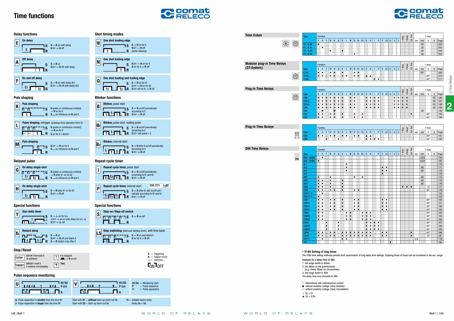
148 | WoR 1 WoR 1 | 149
W
RS
t
N
RS
t
RSO
t1 t2
Delay functions Shot timing modes
S R on for tSOFF R off(pulse clipping)
SOFF R on for tS on for t R off
S R on for t1SOFF R on for t2SOFF off for t1 R off
A
RS
t
Et R
S
Ft1 t2 R
S
S R on with delaySOFF R off
S R onSOFF R off with delay
S R on with delay (t1)SOFF R off with delay (t2)
On delay
Off delay
On and off delay
One shot leading edge
One shot trailing edge
One shot leading and trailing edge
B2
RS
t t t
K
RS
t
L
RS
t
M
RS
t
B
RS
t tt
B1
RS
t tt
Puls shaping Blinker functions
S (pulse or continuous contact) R on for t
S no influence on R and t
S R on/off periodicallyaccording to tSOFF R off
S (pulse or continuous contact) R on for t
S on for t = tRESET
S R on/off periodicallyaccording to tSOFF: last pulse = t
SOFF R on for tS no influence on R and t
S R after t on/off periodicallyaccording to tSOFF R off
Puls shaping
Pulse shaping, retrigger (subsequ.time operation from 0)
Puls shaping
Blinker, pulse start
Blinker, pulse start, trailing pulse
Blinker, interval start
G
RS
t1 t2
H
RS
t1 t2
I
RS
t1 t1t2
P
RS
t1 t1t2
C55, CT1: t2 t1
Delayed pulse Repeat cycle timer
S (pulse or continuous contact) R after t1 on for t2
S no influence on R and t
S R on/off periodicallyaccording to t1 and t2SOFF R off
S R after t1 on for t2SOFF R off
S R after t1 (t2) on/off peri- odically according to t2 and t1SOFF R off
On delay single shot
On delay single shot
Repeat cycle timer, pulse start
Repeat cycle timer, interval start
X1
RS
t t
S
RS
LS
RS
t t
Y S
tt
Special functions Special functions
S R onSOFF R off and starts tS R restart only after t
S R on and starts tS on for t R off
S R on/offS on for tOFF on with delay for t -
SOFF off
Star-delta timer
Restart delay
Step-on /Step-off switch
Step-switching (staircase lighting timer), with time lapse
t STOP T
t RESET
S = TriggeringR = Output circuit
= switches…
Stop/ResetSSTOP interrupts t(t-addition)
SRESET reset tt restarts immediately
t is stopped R on/off
TestON OFF
Pulse sequence monitoring
U
R
P (tP)S1/S2
tA tV
V
R
P (tP)S1/S2
tA
: Pulse separation is smaller than the time tP
: Pulse separation is larger than the time tP
Start with S1 = without start-up short-out tA
Start with S2 = start-up short-out tA
S1/S2 = Monitoring startP = Pulse sequencetP = Pulse separation
tV = settable alarm delay delay (tA = tV)
Time functions
DIN Time RelaysType
Function
t-St
op
t-Res
et
Ext.
Poti
t max.
E A F W N Q K L M B B1 B2 G H I P S LS Y U V sec min h d Page
AA2 - AA2M I 1,5/12 154AE2 - AE2M I 1,5/12 155AL1 I 170AL3 I I I 60 171AL4 I I I 60 172AL5 I 173AM1 I I I I 60 174AM2 I I I I 60 175AM3 1) I I I I 60 176CM2 I I I I I I I 12 177CM3 I I I I I I I 60* 178CMD11 A I 152CMD11 E I 153CIM1 I I I I I I I I I 60* 160CIM12 I I I I I I I I I 60* 161CIM13 I I I I I I I I I 60* 162CIM14 I I I I I I I I I 60* 163CIM2 I I I I I I I 60* 164CIM22 I I I I I I I 60* 165CIM23 I I I I I I I 60* 166CIM3 I I I I I I 60* 167CIM32 I I I I I I 60* 168CIM33 I I I I I I 60* 169CRV4 I I g I I g I I I I I I I I I I I 60* 180CSV4 I I g I I g I I I I I I I I I I I 10* 181CPF11 I I I 0.6 179CY1 I 184
Plug-in Time RelaysType
Function
t-St
op
t-Res
et
Ext.
Poti
t max.
E A F W N Q K L M B B1 B2 G H I P S LS X1 U V sec min h d Page
C55 I I I I I I I I I I I I I I I I I 60 186C55.3 I I I I I I I I I I I I I I I I I 60 187C55.4 I I I I I I I I I I I I I I I I I 60 188C56 I I I I I I I I I I I I I I I I I 60 189C64 20 190CS2 I I I I I I I I 60* 193CS3 I I I I I I I 60* 194
Modular plug-in Time Relays (CT-System) Type
Function
t-St
op
t-Res
et
Ext.
Poti
t max.
E A F W N Q K L M B B1 B2 G H I P S LS X1 U V sec min h d Page
CT32… I I I I I I I 60* 209CT33… I I g I I g I I I I 60* 210CT36… I I 60* 211
Time Cubes Type Function
t-St
op
t-Res
et
Ext.
Poti
t max.
E A F W N Q K L M B B1 B2 G H I P S LS X1 U V sec min h d Page
CT..-E 30 30 203CT..-A 30 I 30 203CT..-K 30 I I 30 203CT..-B 30 I 30 203
* TF-60 Setting of long timesThe TF60 time setting methode permits short examination of long delay time settings. Elapsing times of hours can be monitored in the sec. range.
Example for a delay time of 38h:1. Set range switch to 60sec2. Set 38sec on the potentiometer (e.g. check 38sec by chronometer)3. Set range switch to 60hThe delay time now amounts to 38h.
1) alternatively with instantaneous contact without auxiliary voltage (relay bistable) without auxiliary voltage (relay monostable)
g t2 = t1 t2 = 0.5s
Plug-in Time RelaysType
Function
t-St
op
t-Res
et
Ext.
Poti
t max.
E A F W N Q K L M B B1 B2 G H I P S LS X1 U V sec min h d Page
C83 I I g I I g I I I I 60* 191C85 I I I I I I 60* 192
2
2 Ti
me
Rela
ys

WoR 1 | 151
2
2.1
ON a
nd O
FF d
elay
Rel
ays
150 | WoR 1
Notes
Application Type Page
CMD Series
Off delay | single voltage | 1 CO CMD11-A 152
On delay | single voltage | 1 CO CMD11-E 153
AA2, AA2M Series
Off delay | 24 V UC | 220 … 240 V AC | 1 CO AA2, AA2M 154
AE2, AE2M Series
On delay | 24 V UC | 220 … 240 V AC | 1 CO AE2, AE2M 155
2.1 ON and OFF delay Relays
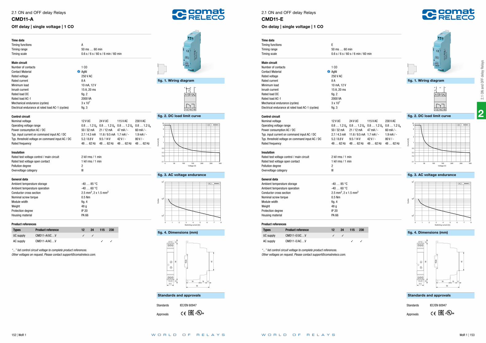
152 | WoR 1 WoR 1 | 153
2
2.1
ON a
nd O
FF d
elay
Rel
ays
Time dataTiming functionsTiming rangeTiming scale
Main circuitNumber of contactsContact MaterialRated voltageRated currentMinimum loadInrush currentRated load DCRated load AC-1Mechanical endurance (cycles)Electrical endurance at rated load AC-1 (cycles)
Control circuitNominal voltageOperating voltage rangePower consumption AC / DCTyp. input current on command input AC / DCTyp. threshold voltage on command input AC / DCRated frequency
InsulationRated test voltage control / main circuitRated test voltage open contactPollution degreeOvervoltage category
General dataAmbient temperature storageAmbient temperature operationConductor cross sectionNominal screw torqueModule widthWeightProtection degreeHousing material
Product references
Types Product reference 12 24 115 230
UC supply CMD11-A/UC…V
AC supply CMD11-A/AC…V
“...” list control circuit voltage to complete product references.Other voltages on request. Please contact [email protected].
2.1 ON and OFF delay Relays
CMD11-AOff delay | single voltage | 1 CO
A50 ms … 60 min0.6 s / 6 s / 60 s / 6 min / 60 min
1 COAgNi250 V AC8 A10 mA, 12 V15 A, 20 msfig. 22000 VA3 x 107
fig. 3
12 V UC 24 V UC 115 V AC 230 V AC0.8 … 1.2 UN 0.8 … 1.2 UN 0.8 … 1.2 UN 0.8 … 1.2 UN
50 / 32 mA 21 / 12 mA 47 mA / - 60 mA / -2.7 / 4.3 mA 11.6 / 9.5 mA 1.7 mA / - 1.9 mA / -5.2 / 8.8 V 9.5 / 14 V 42 V / - 80 V / -48 … 62 Hz 48 … 62 Hz 48 … 62 Hz 48 … 62 Hz
2 kV rms / 1 min1 kV rms / 1 min2III
-40 … 85 °C-40 … 60 °C2.5 mm2, 2 x 1.5 mm2
0.5 Nmfig. 448 gIP 20PA 66
fig. 1. Wiring diagram
fig. 3. AC voltage endurance
fig. 2. DC load limit curve
fig. 4. Dimensions (mm)
Standards and approvals
A1 B1 A2
15 16 18
~+
S
0.1
0.2
0.3
0.5
1
2
5
8 10
0 50 100 150 200 250 300
Cur
rent
[A]
Voltage [V]
DC-1
105
106
107
0 1 2 3 4 5 6 7 8
Cyc
les
Switching current [A]
AC-1
904
4
45
17.556
1634 6
TS35
Standards IEC/EN 60947
Approvals
Time dataTiming functionsTiming rangeTiming scale
Main circuitNumber of contactsContact MaterialRated voltageRated currentMinimum loadInrush currentRated load DCRated load AC-1Mechanical endurance (cycles)Electrical endurance at rated load AC-1 (cycles)
Control circuitNominal voltageOperating voltage rangePower consumption AC / DCTyp. input current on command input AC / DCTyp. threshold voltage on command input AC / DCRated frequency
InsulationRated test voltage control / main circuitRated test voltage open contactPollution degreeOvervoltage category
General dataAmbient temperature storageAmbient temperature operationConductor cross sectionNominal screw torqueModule widthWeightProtection degreeHousing material
Product references
Types Product reference 12 24 115 230
UC supply CMD11-E/UC…V
AC supply CMD11-E/AC…V
“...” list control circuit voltage to complete product references.Other voltages on request. Please contact [email protected].
2.1 ON and OFF delay Relays
CMD11-EOn delay | single voltage | 1 CO
E50 ms … 60 min0.6 s / 6 s / 60 s / 6 min / 60 min
1 COAgNi250 V AC8 A10 mA, 12 V15 A, 20 msfig. 22000 VA3 x 107
fig. 3
12 V UC 24 V UC 115 V AC 230 V AC0.8 … 1.2 UN 0.8 … 1.2 UN 0.8 … 1.2 UN 0.8 … 1.2 UN
50 / 32 mA 21 / 12 mA 47 mA / - 60 mA / -2.7 / 4.3 mA 11.6 / 9.5 mA 1.7 mA / - 1.9 mA / -5.2 / 8.8 V 9.5 / 14 V 42 V / - 80 V / -48 … 62 Hz 48 … 62 Hz 48 … 62 Hz 48 … 62 Hz
2 kV rms / 1 min1 kV rms / 1 min2III
-40 … 85 °C-40 … 60 °C2.5 mm2, 2 x 1.5 mm2
0.5 Nmfig. 448 gIP 20PA 66
fig. 1. Wiring diagram
fig. 3. AC voltage endurance
fig. 2. DC load limit curve
fig. 4. Dimensions (mm)
Standards and approvals
A1 B1 A2
15 16 18
~+
S
0.1
0.2
0.3
0.5
1
2
5
8 10
0 50 100 150 200 250 300
Cur
rent
[A]
Voltage [V]
DC-1
105
106
107
0 1 2 3 4 5 6 7 8
Cyc
les
Switching current [A]
AC-1
904
4
45
17.556
1634 6
TS35
Standards IEC/EN 60947
Approvals
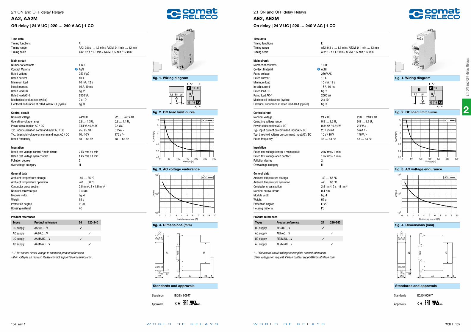
154 | WoR 1 WoR 1 | 155
2
2.1
ON a
nd O
FF d
elay
Rel
ays
Time dataTiming functionsTiming rangeTiming scale
Main circuitNumber of contactsContact MaterialRated voltageRated currentMinimum loadInrush currentRated load DCRated load AC-1Mechanical endurance (cycles)Electrical endurance at rated load AC-1 (cycles)
Control circuitNominal voltageOperating voltage rangePower consumption AC / DCTyp. input current on command input AC / DCTyp. threshold voltage on command input AC / DCRated frequency
InsulationRated test voltage control / main circuitRated test voltage open contactPollution degreeOvervoltage category
General dataAmbient temperature storageAmbient temperature operationConductor cross sectionNominal screw torqueModule widthWeightProtection degreeHousing material
Product references
Types Product reference 24 220-240
UC supply AA2/UC…V
AC supply AA2/AC…V
UC supply AA2M/UC…V
AC supply AA2M/AC…V
“...” list control circuit voltage to complete product references.Other voltages on request. Please contact [email protected].
2.1 ON and OFF delay Relays
AA2, AA2MOff delay | 24 V UC | 220 … 240 V AC | 1 CO
AAA2: 0.8 s … 1.5 min / AA2M: 0.1 min … 12 minAA2: 12 s / 1.5 min / AA2M: 1.5 min / 12 min
1 COAgNi250 V AC10 A10 mA, 12 V16 A, 10 msfig. 22500 VA2 x 107
fig. 3
24 V UC 220 … 240 V AC0.8 … 1.3 UN 0.8 … 1.1 UN
0.84 VA / 0.84 W 2.4 VA / -25 / 25 mA 5 mA / -10 / 10 V 176 V / -48 … 63 Hz 48 … 63 Hz
2 kV rms / 1 min1 kV rms / 1 min2III
-40 … 85 °C-40 … 60 °C2.5 mm2, 2 x 1.5 mm2
0.4 Nmfig. 465 gIP 20PC
fig. 1. Wiring diagram
fig. 3. AC voltage endurance
fig. 2. DC load limit curve
fig. 4. Dimensions (mm)
Standards and approvals
A2 B1 A1
S
+
0.1
0.2
0.5
1
2
5
10
0 50 100 150 200 250 300
Cur
rent
[A]
Voltage [V]
DC-1
105
106
107
0 1 2 3 4 5 6 7 8 9 10
Cyc
les
Switching current [A]
AC-1
752,
5
17,54,2
45
TS
35
5 44 20 8
Standards IEC/EN 60947
Approvals
Time dataTiming functionsTiming rangeTiming scale
Main circuitNumber of contactsContact MaterialRated voltageRated currentMinimum loadInrush currentRated load DCRated load AC-1Mechanical endurance (cycles)Electrical endurance at rated load AC-1 (cycles)
Control circuitNominal voltageOperating voltage rangePower consumption AC / DCTyp. input current on command input AC / DCTyp. threshold voltage on command input AC / DCRated frequency
InsulationRated test voltage control / main circuitRated test voltage open contactPollution degreeOvervoltage category
General dataAmbient temperature storageAmbient temperature operationConductor cross sectionNominal screw torqueModule widthWeightProtection degreeHousing material
Product references
Types Product reference 24 220-240
UC supply AE2/UC…V
AC supply AE2/AC…V
UC supply AE2M/UC…V
AC supply AE2M/AC…V
“...” list control circuit voltage to complete product references.Other voltages on request. Please contact [email protected].
2.1 ON and OFF delay Relays
AE2, AE2MOn delay | 24 V UC | 220 … 240 V AC | 1 CO
EAE2: 0.8 s … 1.5 min / AE2M: 0.1 min … 12 minAE2: 12 s / 1.5 min / AE2M: 1.5 min / 12 min
1 COAgNi250 V AC10 A10 mA, 12 V16 A, 10 msfig. 22500 VA2 x 107
fig. 3
24 V UC 220 … 240 V AC0.8 … 1.3 UN 0.8 … 1.1 UN
0.84 VA / 0.84 W 2.4 VA / -25 / 25 mA 5 mA / -10 V / 10 V 176 V / -48 … 63 Hz 48 … 63 Hz
2 kV rms / 1 min1 kV rms / 1 min2III
-40 … 85 °C-40 … 60 °C2.5 mm2, 2 x 1.5 mm2
0.4 Nmfig. 465 gIP 20PC
fig. 1. Wiring diagram
fig. 3. AC voltage endurance
fig. 2. DC load limit curve
fig. 4. Dimensions (mm)
Standards and approvals
A2 A1
S+
0.1
0.2
0.5
1
2
5
10
0 50 100 150 200 250 300
Cur
rent
[A]
Voltage [V]
DC-1
105
106
107
0 1 2 3 4 5 6 7 8 9 10
Cyc
les
Switching current [A]
AC-1
752,
5
17,54,2
45
TS
35
5 44 20 8
Standards IEC/EN 60947
Approvals

2
2.2
Mul
tifun
ctio
n Ti
me
Rela
ys
156 | WoR 1
Notes
Application Type Page
CIM Series
Multifunction | 24 … 240 V UC | 1 CO CIM1, CIM1R 160
Multifunction | 24 … 240 V UC | 1 Triac CIM12, CIM12R 161
Multifunction | 24 … 240 V UC | 1 Mosfet CIM13, CIM13R 162
Multifunction | 24 … 240 V UC | 1 NO, pre-contact CIM14 163
Multifunction | 24 … 240 V UC | 1 CO CIM2, CIM2R 164
Multifunction | 24 … 240 V UC | 1 Triac CIM22, CIM22R 165
Multifunction | 24 … 240 V UC | 1 Mosfet CIM23, CIM23R 166
Multifunction | 24 … 240 V UC | 1 CO CIM3, CIM3R 167
Multifunction | 24 … 240 V UC | 1 Triac CIM32, CIM32R 168
Multifunction | 24 … 240 V UC | 1 Mosfet CIM33, CIM33R 169
AL Series
Staircase switch | Auto - ON | 220 … 240 V AC | 1 NO AL1 170
Staircase switch | Auto - ON | 24 V UC | 220 … 240 V AC | 1 NO, pre-contact AL3 171
Staircase switch | Auto - ON | Central ON - OFF | 220 … 240 V AC | 1 NO, pre-contact AL4 172
Step switch | Auto - ON | Central ON - OFF | 230 V AC | 1 NO, pre-contact AL5 173
AM Series
Multifunction | 24 … 60 V UC | 110 … 240 V UC | 1 CO AM1 174
Multifunction | 24 … 60 V UC | 220 … 240 V AC | 1 CO AM2 175
Multifunction | 24 … 60 V UC | 110 … 240 V UC | 2 CO AM3 176
2.2 Multifunction Time Relays
WoR 1 | 157
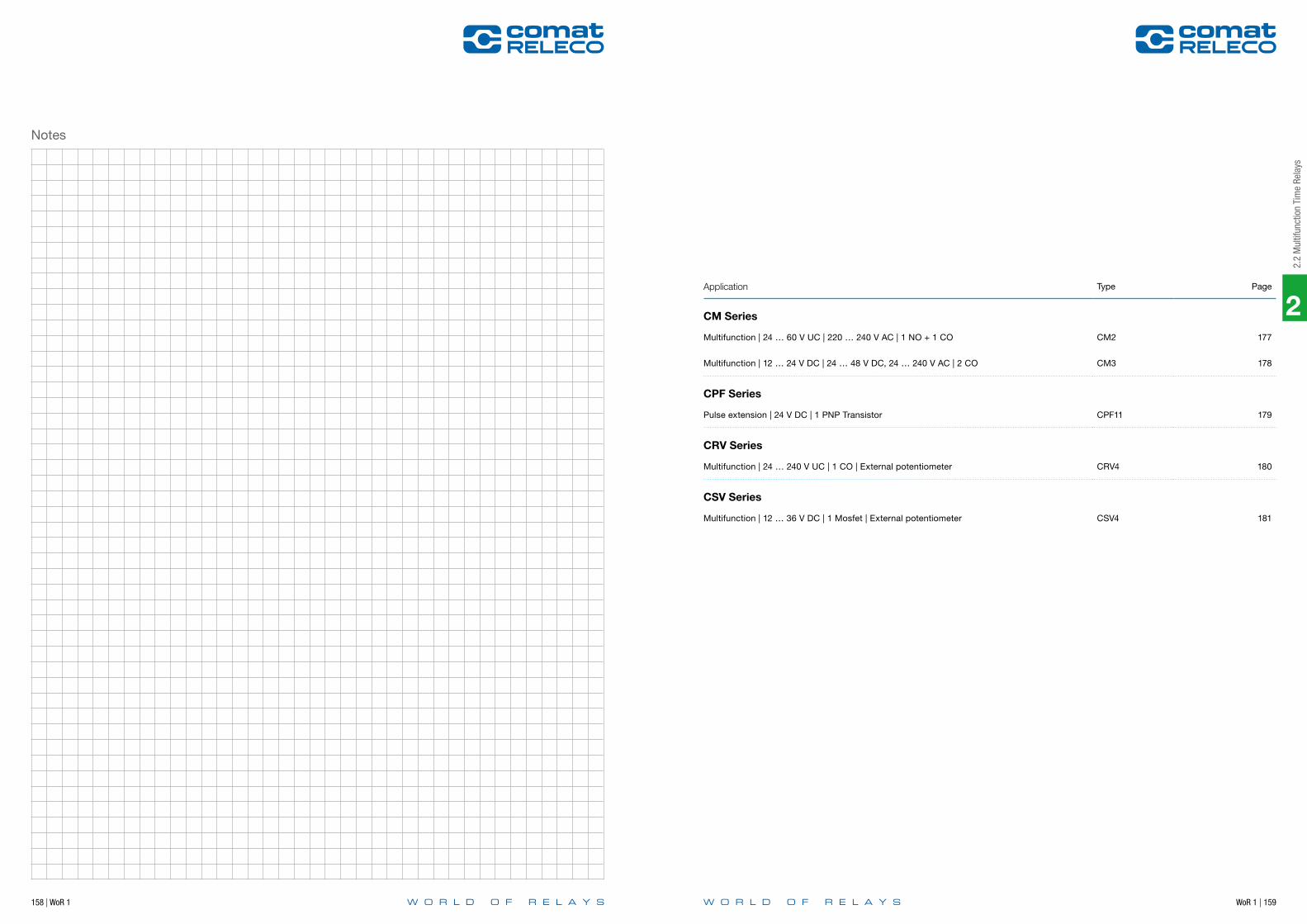
2
2.2
Mul
tifun
ctio
n Ti
me
Rela
ys
158 | WoR 1
Notes
WoR 1 | 159
Application Type Page
CM Series
Multifunction | 24 … 60 V UC | 220 … 240 V AC | 1 NO + 1 CO CM2 177
Multifunction | 12 … 24 V DC | 24 … 48 V DC, 24 … 240 V AC | 2 CO CM3 178
CPF Series
Pulse extension | 24 V DC | 1 PNP Transistor CPF11 179
CRV Series
Multifunction | 24 … 240 V UC | 1 CO | External potentiometer CRV4 180
CSV Series
Multifunction | 12 … 36 V DC | 1 Mosfet | External potentiometer CSV4 181

160 | WoR 1 WoR 1 | 161
2
2.2
Mul
tifun
ctio
n Ti
me
Rela
ys
Time dataTiming functionsTiming rangeTiming scale
Main circuitNumber of contactsContact MaterialRated voltageRated currentMinimum loadInrush currentRated load DCRated load AC-1Mechanical endurance (cycles)Electrical endurance at rated load AC-1 (cycles)
Control circuitNominal voltageOperating voltage rangePower consumption AC / DCTyp. input current on command input AC / DCTyp. threshold voltage on command input AC / DCRated frequency
InsulationRated test voltage control / main circuitRated test voltage open contactPollution degreeOvervoltage category
General dataAmbient temperature storageAmbient temperature operationAmbient temperature operation derated powerAmbient temperature operation railway versionConductor cross sectionNominal screw torqueModule widthWeightProtection degreeHousing material
Product references
Types Product reference 24-240
UC supply CIM1/UC…V
UC supply, Railway version CIM1R/UC…V
“...” list control circuit voltage to complete product references.Other voltages on request. Please contact [email protected].
2.2 Multifunction Time Relays
CIM1, CIM1RMultifunction | 24 … 240 V UC | 1 CO
fig. 1 1: E 2: A, K, N, B1, S, LS 3: B, W50 ms … 60 h0.6 s / 6 s / 60 s / 6 min / 60 min / 6 h / 60 h
1 COAgNi250 V AC16 A10 mA, 10 V30 A, 10 msfig. 24000 VA3 x 107
fig. 3
24 … 240 V UC16.8 … 250 V1.2 VA / 430 mW22 / 22 mA13 V / 15 V16 … 63 Hz
2.5 kV rms / 1 min1 kV rms / 1 min2III
-40 … 85 °C-40 … 40 °C-40 … 60 °C (IN 13 A)-40 … 70 °C2.5 mm2, 2 x 1.5 mm2
0.4 Nmfig. 470 gIP 20PC
fig. 1. Wiring diagram
fig. 3. AC voltage endurance
fig. 2. DC load limit curve
fig. 4. Dimensions (mm)
Standards and approvals
A1 B1 A2
15 16 18
~+
S
A1 B1 A2
15 16 18
~+
S
A1 B1 A2
15 16 18
~+
S
1 2 3
0.1
0.2
0.5
1
2
5
10
16 20
0 50 100 150 200 250 300
Cur
rent
[A]
Voltage [V]
DC-1
105
106
107
0 2 4 6 8 10 12 14 16
Cyc
les
Switching current [A]
AC-1
752,
5
17,54,2
45
TS
35
5 44 20
Standards IEC/EN 60947, IEC/EN 50155
Approvals
Time dataTiming functionsTiming rangeTiming scale
Main circuitNumber of outputsOutput typeRated voltageRated currentMinimum loadInrush currentRated limit loadTyp. leakage currentRated load AC-1Mechanical endurance (cycles)Electrical endurance at rated load AC-1 (cycles)
Control circuitNominal voltageOperating voltage rangePower consumption AC / DCTyp. input current on command input AC / DCTyp. threshold voltage on command input AC / DCRated frequency
InsulationRated test voltage control / main circuitRated test voltage open contactPollution degreeOvervoltage category
General dataAmbient temperature storageAmbient temperature operationAmbient temperature operation derated powerAmbient temperature operation railway versionConductor cross sectionNominal screw torqueModule widthWeightProtection degreeHousing material
Product references
Types Product reference 24-240
UC supply CIM12/UC…V
UC supply, Railway version CIM12R/UC…V
“...” list control circuit voltage to complete product references.Other voltages on request. Please contact [email protected].
2.2 Multifunction Time Relays
CIM12, CIM12RMultifunction | 24 … 240 V UC | 1 Triac
fig. 1 1: E 2: A, K, N, B1, S, LS 3: B, W50 ms … 60 h0.6 s / 6 s / 60 s / 6 min / 60 min / 6 h / 60 h
1 NOTriac, zero crossing250 V AC2 A50 mA, 12 V100 A, 10 ms78 A2s1 mA300 VA∞∞
24 … 240 V UC16.8 … 250 V1.2 VA / 430 mW22 / 22 mA13 V / 15 V16 … 63 Hz
2.5 kV rms / 1 min02III
-40 … 85 °C-40 … 40 °C-40 … 60 °C (IN 1.2 A)-40 … 70 °C2.5 mm2, 2 x 1.5 mm2
0.4 Nmfig. 270 gIP 20PC
fig. 1. Wiring diagram
fig. 2. Dimensions (mm)
Standards and approvals
A1 B1 A2
15 18
~+
S
A1 B1 A2
15 18
~+
S
A1 B1 A2
15 18
~+
S
1 2 3
752,
5
17,54,2
45
TS
35
5 44 20
Standards IEC/EN 60947, IEC/EN 50155
Approvals
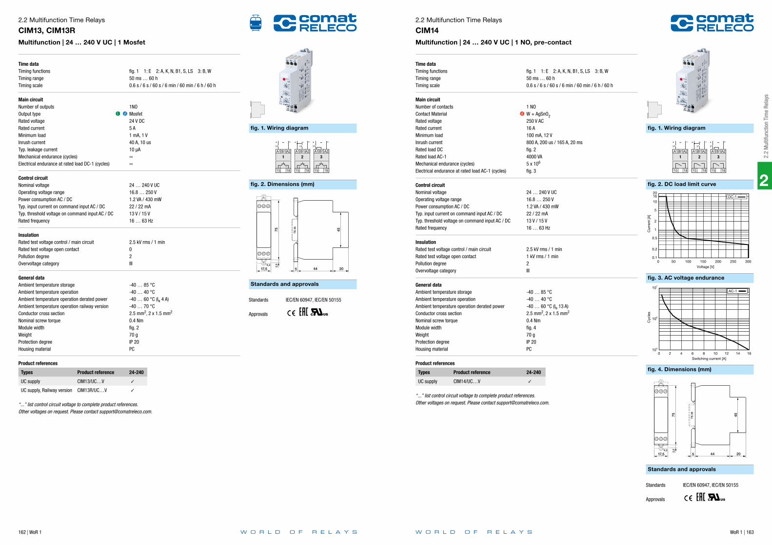
162 | WoR 1 WoR 1 | 163
2
2.2
Mul
tifun
ctio
n Ti
me
Rela
ys
Time dataTiming functionsTiming rangeTiming scale
Main circuitNumber of outputsOutput typeRated voltageRated currentMinimum loadInrush currentTyp. leakage currentMechanical endurance (cycles)Electrical endurance at rated load DC-1 (cycles)
Control circuitNominal voltageOperating voltage rangePower consumption AC / DCTyp. input current on command input AC / DCTyp. threshold voltage on command input AC / DCRated frequency
InsulationRated test voltage control / main circuitRated test voltage open contactPollution degreeOvervoltage category
General dataAmbient temperature storageAmbient temperature operationAmbient temperature operation derated powerAmbient temperature operation railway versionConductor cross sectionNominal screw torqueModule widthWeightProtection degreeHousing material
Product references
Types Product reference 24-240
UC supply CIM13/UC…V
UC supply, Railway version CIM13R/UC…V
“...” list control circuit voltage to complete product references.Other voltages on request. Please contact [email protected].
2.2 Multifunction Time Relays
CIM13, CIM13RMultifunction | 24 … 240 V UC | 1 Mosfet
fig. 1 1: E 2: A, K, N, B1, S, LS 3: B, W50 ms … 60 h0.6 s / 6 s / 60 s / 6 min / 60 min / 6 h / 60 h
1NOMosfet24 V DC5 A1 mA, 1 V40 A, 10 us10 µA∞∞
24 … 240 V UC16.8 … 250 V1.2 VA / 430 mW22 / 22 mA13 V / 15 V16 … 63 Hz
2.5 kV rms / 1 min02III
-40 … 85 °C-40 … 40 °C-40 … 60 °C (IN 4 A)-40 … 70 °C2.5 mm2, 2 x 1.5 mm2
0.4 Nmfig. 270 gIP 20PC
fig. 1. Wiring diagram
fig. 2. Dimensions (mm)
Standards and approvals
A1 B1 A2
15 18
~+
S
A1 B1 A2
15 18
~+
S
A1 B1 A2
15 18
~+
S
1 2 3
752,
5
17,54,2
45
TS
35
5 44 20
Standards IEC/EN 60947, IEC/EN 50155
Approvals
Time dataTiming functionsTiming rangeTiming scale
Main circuitNumber of contactsContact MaterialRated voltageRated currentMinimum loadInrush currentRated load DCRated load AC-1Mechanical endurance (cycles)Electrical endurance at rated load AC-1 (cycles)
Control circuitNominal voltageOperating voltage rangePower consumption AC / DCTyp. input current on command input AC / DCTyp. threshold voltage on command input AC / DCRated frequency
InsulationRated test voltage control / main circuitRated test voltage open contactPollution degreeOvervoltage category
General dataAmbient temperature storageAmbient temperature operationAmbient temperature operation derated powerConductor cross sectionNominal screw torqueModule widthWeightProtection degreeHousing material
Product references
Types Product reference 24-240
UC supply CIM14/UC…V
“...” list control circuit voltage to complete product references.Other voltages on request. Please contact [email protected].
2.2 Multifunction Time Relays
CIM14Multifunction | 24 … 240 V UC | 1 NO, pre-contact
fig. 1 1: E 2: A, K, N, B1, S, LS 3: B, W50 ms … 60 h0.6 s / 6 s / 60 s / 6 min / 60 min / 6 h / 60 h
1 NOW + AgSnO2250 V AC16 A100 mA, 12 V800 A, 200 us / 165 A, 20 msfig. 24000 VA5 x 106
fig. 3
24 … 240 V UC16.8 … 250 V1.2 VA / 430 mW22 / 22 mA13 V / 15 V16 … 63 Hz
2.5 kV rms / 1 min1 kV rms / 1 min2III
-40 … 85 °C-40 … 40 °C-40 … 60 °C (IN 13 A)2.5 mm2, 2 x 1.5 mm2
0.4 Nmfig. 470 gIP 20PC
fig. 1. Wiring diagram
fig. 3. AC voltage endurance
fig. 2. DC load limit curve
fig. 4. Dimensions (mm)
Standards and approvals
A1 B1 A2
15 18
~+
S
A1 B1 A2
15 18
~+
S
A1 B1 A2
15 18
~+
S
1 2 3
0.1
0.2
0.5
1
2
5
10
16 20
0 50 100 150 200 250 300
Cur
rent
[A]
Voltage [V]
DC-1
105
106
107
0 2 4 6 8 10 12 14 16
Cyc
les
Switching current [A]
AC-1
752,
5
17,54,2
45
TS
35
5 44 20
Standards IEC/EN 60947, IEC/EN 50155
Approvals

164 | WoR 1 WoR 1 | 165
2
2.2
Mul
tifun
ctio
n Ti
me
Rela
ys
Time dataTiming functionsTiming rangeTiming scale
Main circuitNumber of contactsContact MaterialRated voltageRated currentMinimum loadInrush currentRated load DCRated load AC-1Mechanical endurance (cycles)Electrical endurance at rated load AC-1 (cycles)
Control circuitNominal voltageOperating voltage rangePower consumption AC / DCTyp. input current on command input AC / DCTyp. threshold voltage on command input AC / DCRated frequency
InsulationRated test voltage control / main circuitRated test voltage open contactPollution degreeOvervoltage category
General dataAmbient temperature storageAmbient temperature operationAmbient temperature operation derated powerAmbient temperature operation railway versionConductor cross sectionNominal screw torqueModule widthWeightProtection degreeHousing material
Product references
Types Product reference 24-240
UC supply CIM2/UC…V
UC supply, Railway version CIM2R/UC…V
“...” list control circuit voltage to complete product references.Other voltages on request. Please contact [email protected].
2.2 Multifunction Time Relays
CIM2, CIM2RMultifunction | 24 … 240 V UC | 1 CO
fig. 1 1: E 2: A, L, M, G 3: B2, H50 ms … 60 h0.6 s / 6 s / 60 s / 6 min / 60 min / 6 h / 60 h
1 COAgNi250 V AC16 A10 mA, 10 V30 A, 10 msfig. 24000 VA3 x 107
fig. 3
24 … 240 V UC16.8 … 250 V1.2 VA / 430 mW22 / 22 mA13 V / 15 V16 … 63 Hz
2.5 kV rms / 1 min1 kV rms / 1 min2III
-40 … 85 °C-40 … 40 °C-40 … 60 °C (IN 13 A)-40 … 70 °C2.5 mm2, 2 x 1.5 mm2
0.4 Nmfig. 470 gIP 20PC
fig. 1. Wiring diagram
fig. 3. AC voltage endurance
fig. 2. DC load limit curve
fig. 4. Dimensions (mm)
Standards and approvals
A1 B1 A2
15 16 18
~+
S
A1 B1 A2
15 16 18
~+
S
A1 B1 A2
15 16 18
~+
S
1 2 3
0.1
0.2
0.5
1
2
5
10
16 20
0 50 100 150 200 250 300
Cur
rent
[A]
Voltage [V]
DC-1
105
106
107
0 2 4 6 8 10 12 14 16
Cyc
les
Switching current [A]
AC-1
752,
5
17,54,2
45
TS
35
5 44 20
Standards IEC/EN 60947, IEC/EN 50155
Approvals
Time dataTiming functionsTiming rangeTiming scale
Main circuitNumber of outputsOutput typeRated voltageRated currentMinimum loadInrush currentRated limit loadTyp. leakage currentRated load AC-1Mechanical endurance (cycles)Electrical endurance at rated load AC-1 (cycles)
Control circuitNominal voltageOperating voltage rangePower consumption AC / DCTyp. input current on command input AC / DCTyp. threshold voltage on command input AC / DCRated frequency
InsulationRated test voltage control / main circuitRated test voltage open contactPollution degreeOvervoltage category
General dataAmbient temperature storageAmbient temperature operationAmbient temperature operation derated powerAmbient temperature operation railway versionConductor cross sectionNominal screw torqueModule widthWeightProtection degreeHousing material
Product references
Types Product reference 24-240
UC supply CIM22/UC…V
UC supply, Railway version CIM22R/UC…V
“...” list control circuit voltage to complete product references.Other voltages on request. Please contact [email protected].
2.2 Multifunction Time Relays
CIM22, CIM22RMultifunction | 24 … 240 V UC | 1 Triac
fig. 1 1: E 2: A, L, M, G 3: B2, H50 ms … 60 h0.6 s / 6 s / 60 s / 6 min / 60 min / 6 h / 60 h
1 NOTriac, zero crossing250 V AC2 A50 mA, 12 V100 A, 10 ms78 A2s1 mA300 VA∞∞
24 … 240 V UC16.8 … 250 V1.2 VA / 430 mW22 / 22 mA13 V / 15 V16 … 63 Hz
2.5 kV rms / 1 min02III
-40 … 85 °C-40 … 40 °C-40 … 60 °C (IN 1.2 A)-40 … 70 °C2.5 mm2, 2 x 1.5 mm2
0.4 Nmfig. 270 gIP 20PC
fig. 1. Wiring diagram
fig. 2. Dimensions (mm)
Standards and approvals
A1 B1 A2
15 18
~+
S
A1 B1 A2
15 18
~+
S
A1 B1 A2
15 18
~+
S
1 2 3
752,
5
17,54,2
45
TS
35
5 44 20
Standards IEC/EN 60947, IEC/EN 50155
Approvals
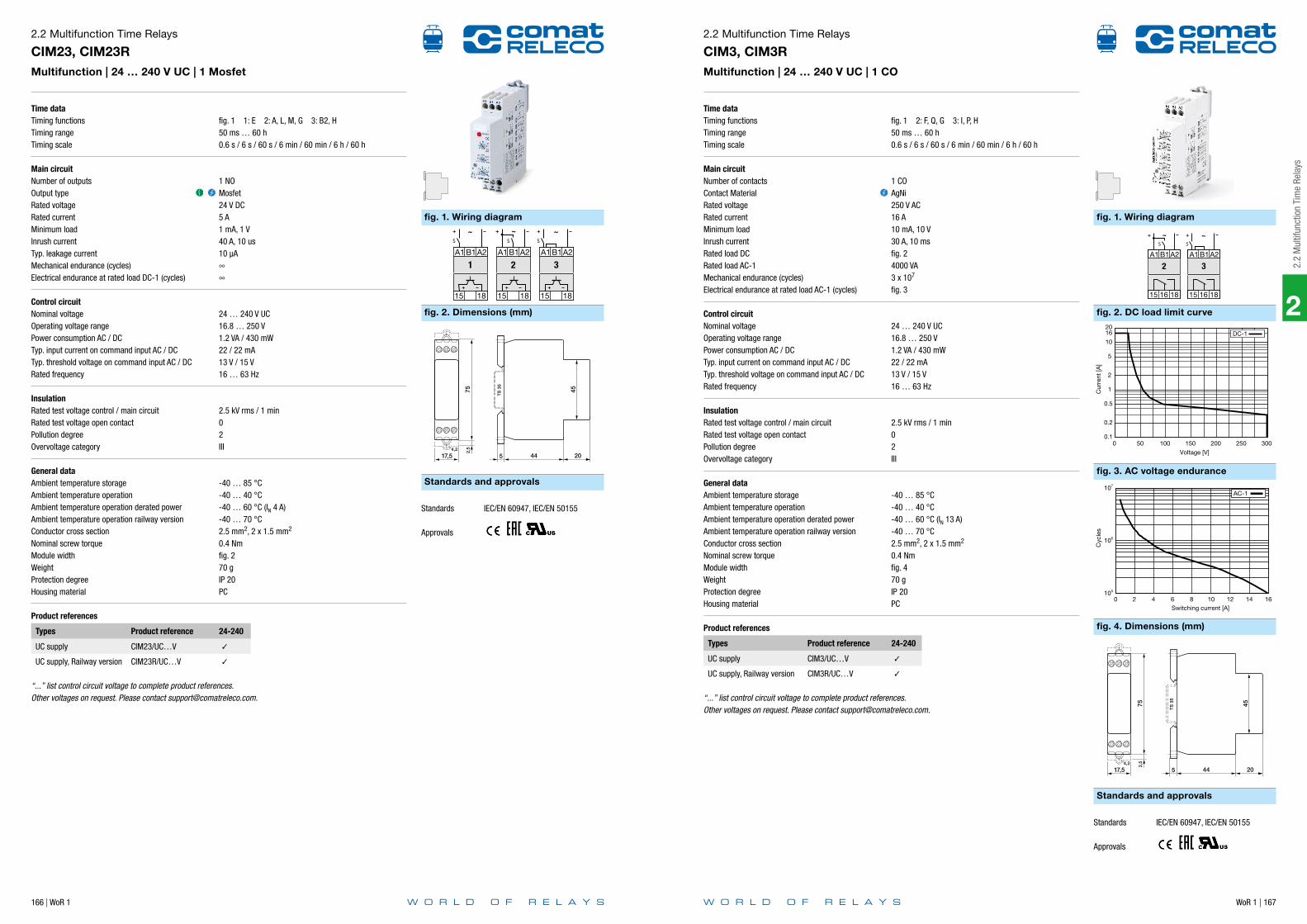
166 | WoR 1 WoR 1 | 167
2
2.2
Mul
tifun
ctio
n Ti
me
Rela
ys
Time dataTiming functionsTiming rangeTiming scale
Main circuitNumber of outputsOutput typeRated voltageRated currentMinimum loadInrush currentTyp. leakage currentMechanical endurance (cycles)Electrical endurance at rated load DC-1 (cycles)
Control circuitNominal voltageOperating voltage rangePower consumption AC / DCTyp. input current on command input AC / DCTyp. threshold voltage on command input AC / DCRated frequency
InsulationRated test voltage control / main circuitRated test voltage open contactPollution degreeOvervoltage category
General dataAmbient temperature storageAmbient temperature operationAmbient temperature operation derated powerAmbient temperature operation railway versionConductor cross sectionNominal screw torqueModule widthWeightProtection degreeHousing material
Product references
Types Product reference 24-240
UC supply CIM23/UC…V
UC supply, Railway version CIM23R/UC…V
“...” list control circuit voltage to complete product references.Other voltages on request. Please contact [email protected].
2.2 Multifunction Time Relays
CIM23, CIM23RMultifunction | 24 … 240 V UC | 1 Mosfet
fig. 1 1: E 2: A, L, M, G 3: B2, H50 ms … 60 h0.6 s / 6 s / 60 s / 6 min / 60 min / 6 h / 60 h
1 NOMosfet24 V DC5 A1 mA, 1 V40 A, 10 us10 µA∞∞
24 … 240 V UC16.8 … 250 V1.2 VA / 430 mW22 / 22 mA13 V / 15 V16 … 63 Hz
2.5 kV rms / 1 min02III
-40 … 85 °C-40 … 40 °C-40 … 60 °C (IN 4 A)-40 … 70 °C2.5 mm2, 2 x 1.5 mm2
0.4 Nmfig. 270 gIP 20PC
fig. 1. Wiring diagram
fig. 2. Dimensions (mm)
Standards and approvals
A1 B1 A2
15 18
~+
S
A1 B1 A2
15 18
~+
S
A1 B1 A2
15 18
~+
S
1 2 3
752,
5
17,54,2
45
TS
35
5 44 20
Standards IEC/EN 60947, IEC/EN 50155
Approvals
Time dataTiming functionsTiming rangeTiming scale
Main circuitNumber of contactsContact MaterialRated voltageRated currentMinimum loadInrush currentRated load DCRated load AC-1Mechanical endurance (cycles)Electrical endurance at rated load AC-1 (cycles)
Control circuitNominal voltageOperating voltage rangePower consumption AC / DCTyp. input current on command input AC / DCTyp. threshold voltage on command input AC / DCRated frequency
InsulationRated test voltage control / main circuitRated test voltage open contactPollution degreeOvervoltage category
General dataAmbient temperature storageAmbient temperature operationAmbient temperature operation derated powerAmbient temperature operation railway versionConductor cross sectionNominal screw torqueModule widthWeightProtection degreeHousing material
Product references
Types Product reference 24-240
UC supply CIM3/UC…V
UC supply, Railway version CIM3R/UC…V
“...” list control circuit voltage to complete product references.Other voltages on request. Please contact [email protected].
2.2 Multifunction Time Relays
CIM3, CIM3RMultifunction | 24 … 240 V UC | 1 CO
fig. 1 2: F, Q, G 3: I, P, H50 ms … 60 h0.6 s / 6 s / 60 s / 6 min / 60 min / 6 h / 60 h
1 COAgNi250 V AC16 A10 mA, 10 V30 A, 10 msfig. 24000 VA3 x 107
fig. 3
24 … 240 V UC16.8 … 250 V1.2 VA / 430 mW22 / 22 mA13 V / 15 V16 … 63 Hz
2.5 kV rms / 1 min02III
-40 … 85 °C-40 … 40 °C-40 … 60 °C (IN 13 A)-40 … 70 °C2.5 mm2, 2 x 1.5 mm2
0.4 Nmfig. 470 gIP 20PC
fig. 1. Wiring diagram
fig. 3. AC voltage endurance
fig. 2. DC load limit curve
fig. 4. Dimensions (mm)
Standards and approvals
A1 B1 A2
15 16 18
~+
S
A1 B1 A2
15 16 18
~+
S
2 3
0.1
0.2
0.5
1
2
5
10
16 20
0 50 100 150 200 250 300
Cur
rent
[A]
Voltage [V]
DC-1
105
106
107
0 2 4 6 8 10 12 14 16
Cyc
les
Switching current [A]
AC-1
752,
5
17,54,2
45
TS
35
5 44 20
Standards IEC/EN 60947, IEC/EN 50155
Approvals

168 | WoR 1 WoR 1 | 169
2
2.2
Mul
tifun
ctio
n Ti
me
Rela
ys
Time dataTiming functionsTiming rangeTiming scale
Main circuitNumber of outputsOutput typeRated voltageRated currentMinimum loadInrush currentRated limit loadTyp. leakage currentRated load AC-1Mechanical endurance (cycles)Electrical endurance at rated load AC-1 (cycles)
Control circuitNominal voltageOperating voltage rangePower consumption AC / DCTyp. input current on command input AC / DCTyp. threshold voltage on command input AC / DCRated frequency
InsulationRated test voltage control / main circuitRated test voltage open contactPollution degreeOvervoltage category
General dataAmbient temperature storageAmbient temperature operationAmbient temperature operation derated powerAmbient temperature operation railway versionConductor cross sectionNominal screw torqueModule widthWeightProtection degreeHousing material
Product references
Types Product reference 24-240
UC supply CIM32/UC…V
UC supply, Railway version CIM32R/UC…V
“...” list control circuit voltage to complete product references.Other voltages on request. Please contact [email protected].
2.2 Multifunction Time Relays
CIM32, CIM32RMultifunction | 24 … 240 V UC | 1 Triac
fig. 1 2: F, Q, G 3: I, P, H50 ms … 60 h0.6 s / 6 s / 60 s / 6 min / 60 min / 6 h / 60 h
1NOTriac, zero crossing250 V AC2 A50 mA, 12 V100 A, 10 ms78 A2s1 mA300 VA∞∞
24 … 240 V UC16.8 … 250 V1.2 VA / 430 mW22 / 22 mA13 V / 15 V16 … 63 Hz
2.5 kV rms / 1 min02III
-40 … 85 °C-40 … 40 °C-40 … 60 °C (IN 1.2 A)-40 … 70 °C2.5 mm2, 2 x 1.5 mm2
0.4 Nmfig. 270 gIP 20PC
fig. 1. Wiring diagram
fig. 2. Dimensions (mm)
Standards and approvals
A1 B1 A2
15 18
~+
S
A1 B1 A2
15 18
~+
S
2 3
752,
5
17,54,2
45
TS
35
5 44 20
Standards IEC/EN 60947
Approvals
Time dataTiming functionsTiming rangeTiming scale
Main circuitNumber of outputsOutput typeRated voltageRated currentMinimum loadInrush currentTyp. leakage currentMechanical endurance (cycles)Electrical endurance at rated load DC-1 (cycles)
Control circuitNominal voltageOperating voltage rangePower consumption AC / DCTyp. input current on command input AC / DCTyp. threshold voltage on command input AC / DCRated frequency
InsulationRated test voltage control / main circuitRated test voltage open contactPollution degreeOvervoltage category
General dataAmbient temperature storageAmbient temperature operationAmbient temperature operation derated powerAmbient temperature operation railway versionConductor cross sectionNominal screw torqueModule widthWeightProtection degreeHousing material
Product references
Types Product reference 24-240
UC supply CIM33/UC…V
UC supply, Railway version CIM33R/UC…V
“...” list control circuit voltage to complete product references.Other voltages on request. Please contact [email protected].
2.2 Multifunction Time Relays
CIM33, CIM33RMultifunction | 24 … 240 V UC | 1 Mosfet
fig. 1 2: F, Q, G 3: I, P, H50 ms … 60 h0.6 s / 6 s / 60 s / 6 min / 60 min / 6 h / 60 h
1 NOMosfet24 V DC5 A1 mA, 1 V40 A, 10 us10 µA∞∞
24 … 240 V UC16.8 … 250 V1.2 VA / 430 mW22 / 22 mA13 V / 15 V16 … 63 Hz
2.5 kV rms / 1 min02III
-40 … 85 °C-40 … 40 °C-40 … 60 °C (IN 4 A)-40 … 70 °C2.5 mm2, 2 x 1.5 mm2
0.4 Nmfig. 270 gIP 20PC
fig. 1. Wiring diagram
fig. 2. Dimensions (mm)
Standards and approvals
A1 B1 A2
15 18
~+
S
A1 B1 A2
15 18
~+
S
2 3
752,
5
17,54,2
45
TS
35
5 44 20
Standards IEC/EN 60947
Approvals
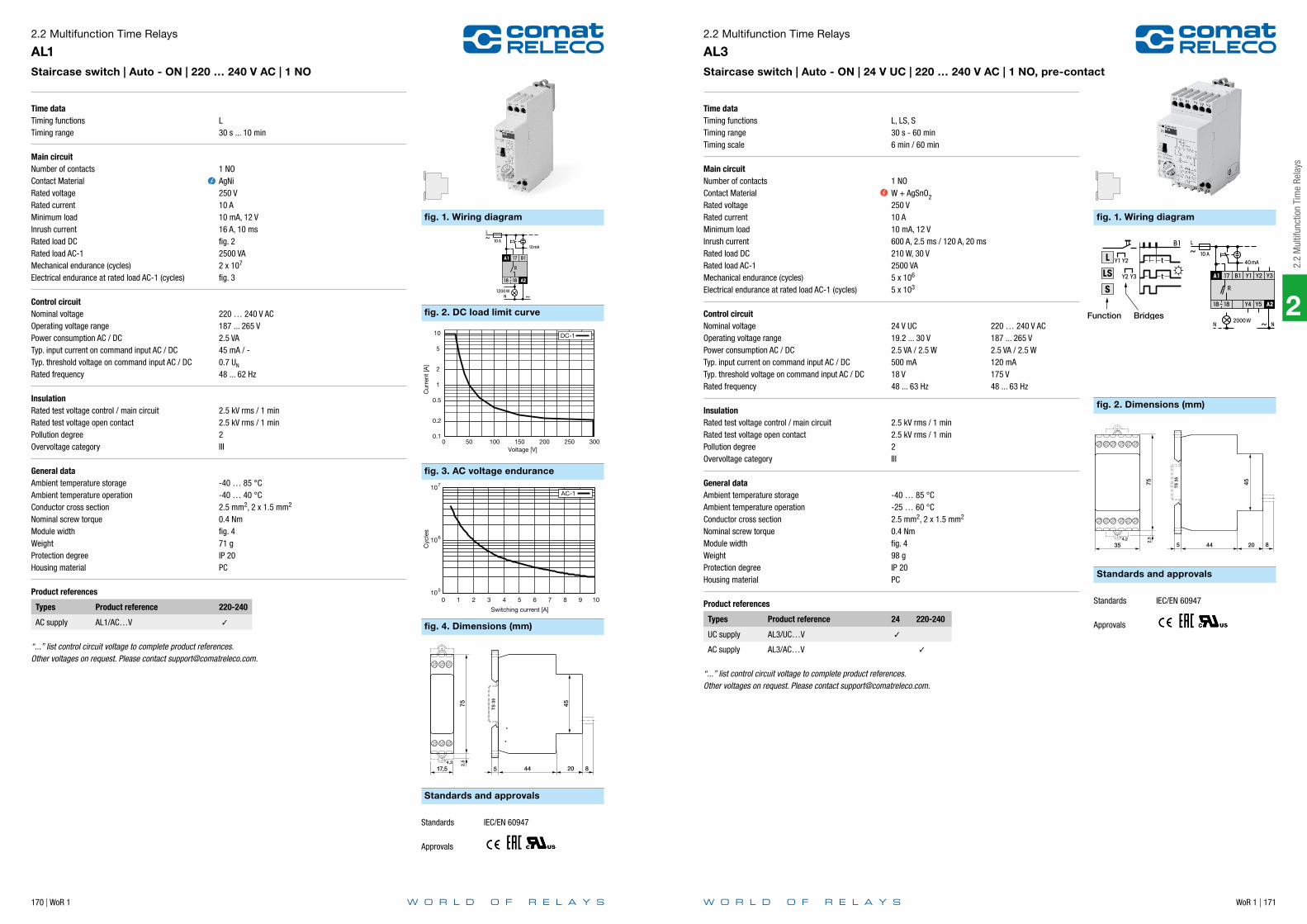
170 | WoR 1 WoR 1 | 171
2
2.2
Mul
tifun
ctio
n Ti
me
Rela
ys
Time dataTiming functionsTiming range
Main circuitNumber of contactsContact MaterialRated voltageRated currentMinimum loadInrush currentRated load DCRated load AC-1Mechanical endurance (cycles)Electrical endurance at rated load AC-1 (cycles)
Control circuitNominal voltageOperating voltage rangePower consumption AC / DCTyp. input current on command input AC / DCTyp. threshold voltage on command input AC / DCRated frequency
InsulationRated test voltage control / main circuitRated test voltage open contactPollution degreeOvervoltage category
General dataAmbient temperature storageAmbient temperature operationConductor cross sectionNominal screw torqueModule widthWeightProtection degreeHousing material
Product references
Types Product reference 220-240
AC supply AL1/AC…V
“...” list control circuit voltage to complete product references.Other voltages on request. Please contact [email protected].
2.2 Multifunction Time Relays
AL1Staircase switch | Auto - ON | 220 … 240 V AC | 1 NO
L30 s ... 10 min
1 NOAgNi250 V10 A10 mA, 12 V16 A, 10 msfig. 22500 VA2 x 107
fig. 3
220 … 240 V AC187 ... 265 V2.5 VA45 mA / -0.7 UN
48 ... 62 Hz
2.5 kV rms / 1 min2.5 kV rms / 1 min2III
-40 … 85 °C-40 … 40 °C2.5 mm2, 2 x 1.5 mm2
0.4 Nmfig. 471 gIP 20PC
fig. 1. Wiring diagram
fig. 3. AC voltage endurance
fig. 2. DC load limit curve
fig. 4. Dimensions (mm)
Standards and approvals
0.1
0.2
0.5
1
2
5
10
0 50 100 150 200 250 300
Cur
rent
[A]
Voltage [V]
DC-1
105
106
107
0 1 2 3 4 5 6 7 8 9 10
Cyc
les
Switching current [A]
AC-1
752,
5
17,54,2
45
TS
35
5 44 20 8
Standards IEC/EN 60947
Approvals
Time dataTiming functionsTiming rangeTiming scale
Main circuitNumber of contactsContact MaterialRated voltageRated currentMinimum loadInrush currentRated load DCRated load AC-1Mechanical endurance (cycles)Electrical endurance at rated load AC-1 (cycles)
Control circuitNominal voltageOperating voltage rangePower consumption AC / DCTyp. input current on command input AC / DCTyp. threshold voltage on command input AC / DCRated frequency
InsulationRated test voltage control / main circuitRated test voltage open contactPollution degreeOvervoltage category
General dataAmbient temperature storageAmbient temperature operationConductor cross sectionNominal screw torqueModule widthWeightProtection degreeHousing material
Product references
Types Product reference 24 220-240
UC supply AL3/UC…V
AC supply AL3/AC…V
“...” list control circuit voltage to complete product references.Other voltages on request. Please contact [email protected].
2.2 Multifunction Time Relays
AL3Staircase switch | Auto - ON | 24 V UC | 220 … 240 V AC | 1 NO, pre-contact
L, LS, S30 s - 60 min6 min / 60 min
1 NOW + AgSnO2250 V10 A10 mA, 12 V600 A, 2.5 ms / 120 A, 20 ms210 W, 30 V2500 VA5 x 106
5 x 10³
24 V UC 220 … 240 V AC19.2 ... 30 V 187 ... 265 V2.5 VA / 2.5 W 2.5 VA / 2.5 W500 mA 120 mA18 V 175 V48 ... 63 Hz 48 ... 63 Hz
2.5 kV rms / 1 min2.5 kV rms / 1 min2III
-40 … 85 °C-25 … 60 °C2.5 mm2, 2 x 1.5 mm2
0.4 Nmfig. 498 gIP 20PC
fig. 1. Wiring diagram
fig. 2. Dimensions (mm)
Standards and approvals
Standards IEC/EN 60947
Approvals

172 | WoR 1 WoR 1 | 173
2
2.2
Mul
tifun
ctio
n Ti
me
Rela
ys
Time dataTiming functionsTiming rangeTiming scale
Main circuitNumber of contactsContact MaterialRated voltageRated currentMinimum loadInrush currentRated load DCRated load AC-1Mechanical endurance (cycles)Electrical endurance at rated load AC-1 (cycles)
Control circuitNominal voltageOperating voltage rangePower consumption AC / DCTyp. input current on command input AC / DCTyp. threshold voltage on command input AC / DCRated frequency
InsulationRated test voltage control / main circuitRated test voltage open contactPollution degreeOvervoltage category
General dataAmbient temperature storageAmbient temperature operationConductor cross sectionNominal screw torqueModule widthWeightProtection degreeHousing material
Product references
Types Product reference 220-240
AC supply AL4/AC…V
“...” list control circuit voltage to complete product references.Other voltages on request. Please contact [email protected].
2.2 Multifunction Time Relays
AL4Staircase switch | Auto - ON | Central ON - OFF | 220 … 240 V AC | 1 NO, pre-contact
fig. 1 L, LS, S30 s - 60 min6 min / 60 min
1 NOW + AgSnO2250 V10 A10 mA, 12 V600 A, 2.5 ms / 120 A, 20 ms210 W, 30 V2500 VA5 x 106
5 x 10³
220 ... 240 V AC187 ... 265 V2.5 VA120 mA175 V48 ... 62 Hz
2.5 kV rms / 1 min2.5 kV rms / 1 min2III
-40 … 85 °C-25 … 60 °C2.5 mm2, 2 x 1.5 mm2
0.4 Nmfig. 498 gIP 20PC
fig. 1. Wiring diagram
fig. 2. Dimensions (mm)
Standards and approvals
Standards IEC/EN 60947
Approvals
Time dataTiming functions
Main circuitNumber of contactsContact MaterialRated voltageRated currentMinimum loadInrush currentRated load DCRated load AC-1Mechanical endurance (cycles)Electrical endurance at rated load AC-1 (cycles)
Control circuitNominal voltageOperating voltage rangePower consumption AC / DCTyp. input current on command input AC / DCTyp. threshold voltage on command input AC / DCRated frequency
InsulationRated test voltage control / main circuitRated test voltage open contactPollution degreeOvervoltage category
General dataAmbient temperature storageAmbient temperature operationConductor cross sectionNominal screw torqueModule widthWeightProtection degreeHousing material
Product references
Types Product reference 230
AC supply AL5/AC…V
“...” list control circuit voltage to complete product references.Other voltages on request. Please contact [email protected].
2.2 Multifunction Time Relays
AL5Step switch | Auto - ON | Central ON - OFF | 230 V AC | 1 NO, pre-contact
S
1 NOW + AgSnO2250 V10 A10 mA, 12 V600 A, 2.5 ms / 120 A, 20 ms210 W, 30 V2500 VA5 x 106
5 x 10³
230 V AC187 ... 265 V2.5 VA120 mA165 V48 ... 62 Hz
2.5 kV rms / 1 min2.5 kV rms / 1 min2III
-40 … 85 °C-25 … 60 °C2.5 mm2, 2 x 1.5 mm2
0.4 Nmfig. 498 gIP 20PC
fig. 1. Wiring diagram
fig. 2. Dimensions (mm)
Standards and approvals
Standards IEC/EN 60947
Approvals

174 | WoR 1 WoR 1 | 175
2
2.2
Mul
tifun
ctio
n Ti
me
Rela
ys
Time dataTiming functionsTiming rangeTiming scale
Main circuitNumber of contactsContact MaterialRated voltageRated currentMinimum loadInrush currentRated load DCRated load AC-1Mechanical endurance (cycles)Electrical endurance at rated load AC-1 (cycles)
Control circuitNominal voltageOperating voltage rangePower consumption AC / DCTyp. input current on command input AC / DCTyp. threshold voltage on command input AC / DCRated frequency
InsulationRated test voltage control / main circuitRated test voltage open contactPollution degreeOvervoltage category
General dataAmbient temperature storageAmbient temperature operationConductor cross sectionNominal screw torqueModule widthWeightProtection degreeHousing material
Product references
Types Product reference 24-60 220-240
UC supply AM1/UC…V
“...” list control circuit voltage to complete product references.Other voltages on request. Please contact [email protected].
2.2 Multifunction Time Relays
AM1Multifunction | 24 … 60 V UC | 110 … 240 V UC | 1 CO
E, W, B, B20.5 s … 60 min6 min / 60 min
1 COAgNi250 V10 A10 mA, 12 V16 A, 10 msfig. 22500 VA2 x 107
fig. 3
24 ... 60 V UC 220 ... 240 V AC20 - 75 V 180 - 265 V1.5 VA / 1.5 W 1.5 VA / 1.5 W40 / 40 mA 15 / 15 mA18 V / 18 V 170 V / 170 V40 ... 60 Hz 40 ... 60 Hz
2 kV rms / 1 min1 kV rms / 1 min2III
-40 … 85 °C-40 … 60 °C2.5 mm2, 2 x 1.5 mm2
0.4 Nmfig. 470 gIP 20PC
fig. 1. Wiring diagram
fig. 3. AC voltage endurance
fig. 2. DC load limit curve
fig. 4. Dimensions (mm)
Standards and approvals
0.1
0.2
0.5
1
2
5
10
0 50 100 150 200 250 300
Cur
rent
[A]
Voltage [V]
DC-1
105
106
107
0 1 2 3 4 5 6 7 8 9 10
Cyc
les
Switching current [A]
AC-1
Standards IEC/EN 60947
Approvals
Time dataTiming functionsTiming rangeTiming scale
Main circuitNumber of contactsContact MaterialRated voltageRated currentMinimum loadInrush currentRated load DCRated load AC-1Mechanical endurance (cycles)Electrical endurance at rated load AC-1 (cycles)
Control circuitNominal voltageOperating voltage rangePower consumption AC / DCTyp. input current on command input AC / DCTyp. threshold voltage on command input AC / DCRated frequency
InsulationRated test voltage control / main circuitRated test voltage open contactPollution degreeOvervoltage category
General dataAmbient temperature storageAmbient temperature operationConductor cross sectionNominal screw torqueModule widthWeightProtection degreeHousing material
Product references
Types Product reference 24-60 220-240
UC supply AM2/UC…V
AC supply AM2/AC…V
“...” list control circuit voltage to complete product references.Other voltages on request. Please contact [email protected].
2.2 Multifunction Time Relays
AM2Multifunction | 24 … 60 V UC | 220 … 240 V AC | 1 CO
fig. 1 1: E 2: A, K 3: W0.5 s … 60 min6 min / 60 min
1 COAgNi250 V10 A10 mA, 12 V16 A, 10 msfig. 22500 VA2 x 107
fig. 3
24 ... 60 V UC 220 ... 240 V AC20 - 75 V 180 - 265 V1.5 VA / 1.5 W 1.5 VA / 1.5 W40 / 40 mA 15 / 15 mA18 V / 18 V 170 V / 170 V40 ... 60 Hz 40 ... 60 Hz
2 kV rms / 1 min1 kV rms / 1 min2III
-40 … 85 °C-40 … 60 °C2.5 mm2, 2 x 1.5 mm2
0.4 Nmfig. 470 gIP 20PC
fig. 1. Wiring diagram
fig. 3. AC voltage endurance
fig. 2. DC load limit curve
fig. 4. Dimensions (mm)
Standards and approvals
0.1
0.2
0.5
1
2
5
10
0 50 100 150 200 250 300
Cur
rent
[A]
Voltage [V]
DC-1
105
106
107
0 1 2 3 4 5 6 7 8 9 10
Cyc
les
Switching current [A]
AC-1
752,
5
17,54,2
45
TS
35
5 44 20 8
Standards IEC/EN 60947
Approvals

176 | WoR 1 WoR 1 | 177
2
2.2
Mul
tifun
ctio
n Ti
me
Rela
ys
Time dataTiming functionsTiming rangeTiming scale
Main circuitNumber of contactsContact MaterialRated voltageRated currentMinimum loadInrush currentRated load DCRated load AC-1Mechanical endurance (cycles)Electrical endurance at rated load AC-1 (cycles)
Control circuitNominal voltageOperating voltage rangePower consumption AC / DCTyp. input current on command input AC / DCTyp. threshold voltage on command input AC / DCRated frequency
InsulationRated test voltage control / main circuitRated test voltage main / main circuitRated test voltage open contactPollution degreeOvervoltage category
General dataAmbient temperature storageAmbient temperature operationConductor cross sectionNominal screw torqueModule widthWeightProtection degreeHousing material
Product references
Types Product reference 24-60 220-240
UC supply AM3/UC…V
AC supply AM3/AC…V
“...” list control circuit voltage to complete product references.Other voltages on request. Please contact [email protected].
2.2 Multifunction Time Relays
AM3Multifunction | 24 … 60 V UC | 110 … 240 V UC | 2 CO
fig. 1 1: E 2: A, K 3: W0.5 s … 60 min6 min / 60 min
2 COAgNi250 V10 A (total current 12 A)10 mA, 12 V16 A, 10 msfig. 22500 VA2 x 107
fig. 3
24 ... 60 V UC 220 ... 240 V AC19 ... 75 V 195 ... 265 V1.8 VA / 1.8 W 1.8 VA / 1.8 W50 / 50 mA 15 / 15 mA19 V / 19 V 187 V / 187 V40 … 400 Hz 40 ... 60 Hz
2 kV rms / 1 min2 kV rms / 1 min1 kV rms / 1 min2III
-40 … 85 °C-40 … 50 °C2.5 mm2, 2 x 1.5 mm2
0.4 Nmfig. 4110 gIP 20PC
fig. 1. Wiring diagram
fig. 3. AC voltage endurance
fig. 2. DC load limit curve
fig. 4. Dimensions (mm)
Standards and approvals
R2=S R2=R (25-26-28)
0.1
0.2 0.3
0.5
1
2 3 4 5
10
0 50 100 150 200 250
Cur
rent
[A]
Voltage [V]
AC-1 DC-1
105
106
107
0 1 2 3 4 5 6 7 8 9 10
Cyc
les
Switching current [A]
AC-1, DC-1 30 V
752,
5
354,2
45
8
TS
35
5 44 20
Standards IEC/EN 60947
Approvals
Time dataTiming functionsTiming rangeTiming scale
Main circuitNumber of contactsContact MaterialRated voltageRated currentMinimum loadInrush currentRated load DCRated load AC-1Mechanical endurance (cycles)Electrical endurance at rated load AC-1 (cycles)Electrical endurance at rated load DC-1 (cycles)
Control circuitNominal voltageOperating voltage rangePower consumption AC / DCTyp. input current on command input AC / DCTyp. threshold voltage on command input AC / DCRated frequency
InsulationRated test voltage control / main circuitRated test voltage open contactPollution degreeOvervoltage category
General dataAmbient temperature storageAmbient temperature operationConductor cross sectionNominal screw torqueModule widthWeightProtection degreeHousing material
Product references
Types Product reference 24-60 220-240
UC supply CM2/UC…V
AC supply CM2/AC…V
“...” list control circuit voltage to complete product references.Other voltages on request. Please contact [email protected].
2.2 Multifunction Time Relays
CM2Multifunction | 24 … 60 V UC | 220 … 240 V AC | 1 NO + 1 CO
fig. 1 2: E, A, K 3: E, W0.3 s … 12 h3 s / 12 s / 1.5 min / 12 min / 1.5 h / 12 h
1 NO + 1 COAgNi250 V6 A10 mA, 12 V10 A, 10 ms100 W, 24 V1500 VA1 x 107
fig. 31 x 105
24 ... 60 V UC 220 ... 240 V AC19 ... 75 V 90 ... 265 V6 VA / 4.8 W 6 VA / 4.8 W10 / 20 mA 10 / 20 mA18 V / 18 V 70 V / 85 V40 ... 60 Hz 40 ... 60 Hz
2 kV rms / 1 min1 kV rms / 1 min2III
-40 … 85 °C-40 … 50 °C2.5 mm2, 2 x 1.5 mm2
0.4 Nmfig. 4139 gIP 20PC
fig. 1. Wiring diagram
fig. 2. Dimensions (mm)
Standards and approvals
Standards IEC/EN 60947
Approvals

178 | WoR 1 WoR 1 | 179
2
2.2
Mul
tifun
ctio
n Ti
me
Rela
ys
Time dataTiming functionsTiming rangeTiming scale
Main circuitNumber of contactsContact MaterialRated voltageRated currentMinimum loadInrush currentRated load DCRated load AC-1Mechanical endurance (cycles)Electrical endurance at rated load AC-1 (cycles)
Control circuitNominal voltageOperating voltage rangePower consumption AC / DCTyp. input current on command input AC / DCTyp. threshold voltage on command input AC / DCRated frequency
InsulationRated test voltage control / main circuitRated test voltage main / main circuitRated test voltage open contactPollution degreeOvervoltage category
General dataAmbient temperature storageAmbient temperature operationConductor cross sectionNominal screw torqueModule widthWeightProtection degreeHousing material
Product references
Types Product reference 12-24 24-48 / 24-240
DC supply CM3/DC…V
UC supply CM3/DC…V/AC…V
“...” list control circuit voltage to complete product references.Other voltages on request. Please contact [email protected].
2.2 Multifunction Time Relays
CM3Multifunction | 12 … 24 V DC | 24 … 48 V DC, 24 … 240 V AC | 2 CO
fig. 1 1: E 2: A, K, N, B1 3: B, W50 ms … 60 h0.6 s / 6 s / 60 s / 6 min / 60 min / 6 h / 60 h
2 COAgNi250 V5 A10 mA, 10 V10 A, 10 msfig. 21250 VA15 x 106
fig. 3
12 ... 24 V DC 24 ... 48 V DC / 24 ... 240 V AC9.6 ... 28.8 V 19 ... 60 V / 19 ... 250 V- / 1.2 W 15 VA / 1.2 W10 / 20 mA 10 / 20 mA5.8 ... 6.5 V 11 ... 15 V / 13 ... 18 V45 ... 63 Hz 45 ... 63 Hz
2.5 kV rms / 1 min2.5 kV rms / 1 min1 kV rms / 1 min2III
-40 … 85 °C-25 … 60 °C2.5 mm2, 2 x 1.5 mm2
0.4 Nmfig. 472 gIP 20PC
fig. 1. Wiring diagram
fig. 3. AC voltage endurance
fig. 2. DC load limit curve
fig. 4. Dimensions (mm)
Standards and approvals
0.1
0.2
0.5
1
2
3 4 5
0 50 100 150 200 250 300
Cur
rent
[A]
Voltage [V]
DC-1
105
106
107
0 1 2 3 4 5
Cyc
les
Switching current [A]
AC-1
752,
5
17,54,2
LABEL
TS
35
5 64
Standards IEC/EN 60947
Approvals
Time dataTiming functionsTiming rangeTiming scale
Main circuitNumber of outputsOutput typeOutput voltage rangeRated currentInrush currentTyp. leakage currentMechanical endurance (cycles)Electrical endurance at rated load DC-1 (cycles)
Control circuitNominal voltageOperating voltage rangePower consumption AC / DCTyp. threshold voltage on command input AC / DC
InsulationPollution degreeOvervoltage category
General dataAmbient temperature storageAmbient temperature operationAmbient temperature operation derated powerConductor cross sectionNominal screw torqueModule widthWeightProtection degreeHousing material
Product references
Types Product reference 24
DC supply CPF11/DC…V
“...” list control circuit voltage to complete product references.Other voltages on request. Please contact [email protected].
Accessories
Labels BZS DIN 17.5 mm
2.2 Multifunction Time Relays
CPF11Pulse extension | 24 V DC | 1 PNP Transistor
A, K, L5 … 600 ms60 ms / 600 ms
1 NOPNP Transistor10 … 32 V (Potential of +)0.8 A2 A, 5 s1 µA∞∞
24 V DC10 … 32 V- / 0.4 W- / E1: 10 V, E2: 15 V
2III
-40 … 85 °C-25 … 50 °C-25 … 60 °C (IN 0.7 A)2.5 mm2, 2 x 1.5 mm2
0.4 Nmfig. 460 gIP 20PC
fig. 1. Wiring diagram
fig. 2. Dimensions (mm)
Standards and approvals
Three-wire sensorNAMUR sensor
K
TS
35
5 1064
8
752,
5
17,54,2
LABEL
Standards IEC/EN 60947
Approvals

180 | WoR 1 WoR 1 | 181
2
2.2
Mul
tifun
ctio
n Ti
me
Rela
ys
Time dataTiming functions
Timing rangeTiming scale
Main circuitNumber of contactsContact MaterialRated voltageRated currentMinimum loadInrush currentRated load DCRated load AC-1Mechanical endurance (cycles)Electrical endurance at rated load AC-1 (cycles)
Control circuitNominal voltageOperating voltage rangePower consumption AC / DCTyp. input current on command input AC / DCTyp. threshold voltage on command input AC / DCRated frequency
InsulationRated test voltage control / main circuitRated test voltage open contactPollution degreeOvervoltage category
General dataAmbient temperature storageAmbient temperature operationConductor cross sectionNominal screw torqueModule widthWeightProtection degreeHousing material
Product references
Types Product reference 24-240
UC supply CRV4/UC…V
“...” list control circuit voltage to complete product references.Other voltages on request. Please contact [email protected].
Accessories
External potentiometer SP-01/100K
2.2 Multifunction Time Relays
CRV4Multifunction | 24 … 240 V UC | 1 CO | External potentiometer
fig. 1 1: E 2: E, A, K, N, M, B1, F, G, Q, L, S, LS 3: W, B, B2, H50 ms … 60 h0.6 s / 6 s / 60 s / 6 min / 60 min / 6 h / 60 h
1 COAgNi250 V6 A10 mA, 10 V15 A, 10 msfig. 21500 VA3 x 107
fig. 3
24 … 240 V UC19.2 … 250 V0.55 VA / 0.55 W4 / 7 mA14.5 V / 17.5 V48 ... 63 Hz
2 kV rms / 1 min1 kV rms / 1 min2III
-40 … 85 °C-40 … 70 °C2.5 mm2, 2 x 1 mm2
0.6 Nmfig. 450 gIP 20PC
fig. 1. Wiring diagram
fig. 3. AC voltage endurance
fig. 2. DC load limit curve
fig. 4. Dimensions (mm)
Standards and approvals
A2 A1
15 18
16 B1
+
R Z1 Z2
EXT POT
0.1
0.2
0.3
0.5
1
2
5 6
10
0 50 100 150 200 250 300
Cur
rent
[A]
Voltage [V]
DC-1
105
106
107
0 1 2 3 4 5 6
Cyc
les
Switching current [A]
AC-1
TS
35 45
4 44
7 55
90
13
BS13-KBS13-G(incl.paper)
Standards IEC/EN 60947
Approvals
Time dataTiming functions
Timing rangeTiming scale
Main circuitNumber of outputsOutput typeOutput voltage rangeRated currentMinimum loadInrush currentTyp. leakage currentMechanical endurance (cycles)Electrical endurance at rated load DC-1 (cycles)
Control circuitNominal voltageOperating voltage rangePower consumption AC / DCTyp. input current on command input AC / DCTyp. threshold voltage on command input AC / DC
InsulationRated test voltage control / main circuitPollution degreeOvervoltage category
General dataAmbient temperature storageAmbient temperature operationConductor cross sectionNominal screw torqueModule widthWeightProtection degreeHousing material
Product references
Types Product reference 12-36
DC supply CSV4/DC…V
“...” list control circuit voltage to complete product references.Other voltages on request. Please contact [email protected].
Accessories
External potentiometer SP-01/100K
2.2 Multifunction Time Relays
CSV4Multifunction | 12 … 36 V DC | 1 Mosfet | External potentiometer
fig. 1 1: E 2: E, A, K, N, M, B1, F, G, Q, L, S, LS 3: W, B, B2, H0.8 ms … 10 h0.1 s / 1 s / 10 s / 1 min / 10 min / 1 h / 10 h
1 NOMosfet10.2 ... 45 V (Potential of A1)1.5 A1 mA, 10.2 V4 A, 100 ms10 µA∞∞
12 ... 36 V DC10.2 ... 45 V- / 0.2 W- / 4 mA- / 7.3 V
2 kV rms / 1 min2III
-40 … 85 °C-40 … 70 °C2.5 mm2, 2 x 1 mm2
0.6 Nmfig. 250 gIP 20PC
fig. 1. Wiring diagram
fig. 2. Dimensions (mm)
Standards and approvals
Z1 Z2
+A2 A1
B1+
O
KR
EXT POT
TS
35 45
4 44
7 55
90
13
BS13-KBS13-G(incl.paper)
Standards IEC/EN 60947
Approvals

2
WoR 1 | 183
2.3
Star
-Del
ta R
elay
s
182 | WoR 1
Notes
Application Type Page
CY Series
Star-delta | 24 ... 60 V UC | 110 ... 240 V UC | 1 NO + 1 CO CY1 184
2.3 Star-Delta Relays
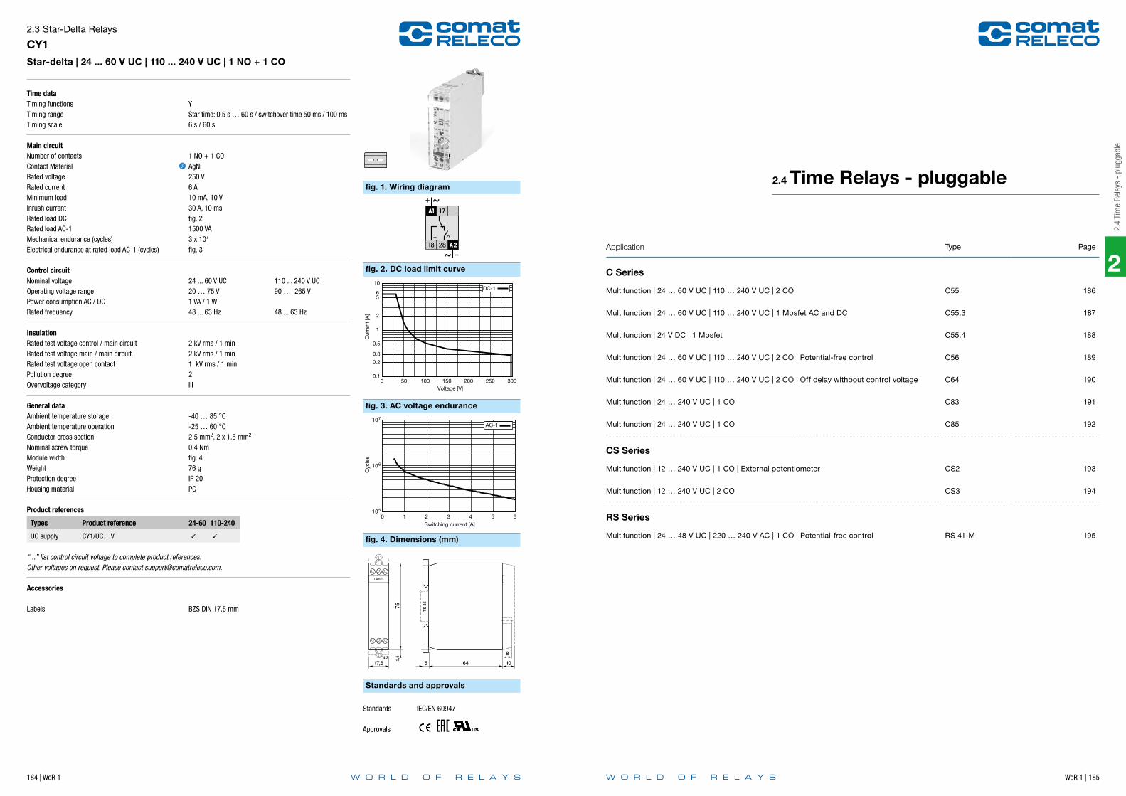
2
184 | WoR 1 WoR 1 | 185
2.4
Tim
e Re
lays
- p
lugg
able
Time dataTiming functionsTiming rangeTiming scale
Main circuitNumber of contactsContact MaterialRated voltageRated currentMinimum loadInrush currentRated load DCRated load AC-1Mechanical endurance (cycles)Electrical endurance at rated load AC-1 (cycles)
Control circuitNominal voltageOperating voltage rangePower consumption AC / DCRated frequency
InsulationRated test voltage control / main circuitRated test voltage main / main circuitRated test voltage open contactPollution degreeOvervoltage category
General dataAmbient temperature storageAmbient temperature operationConductor cross sectionNominal screw torqueModule widthWeightProtection degreeHousing material
Product references
Types Product reference 24-60 110-240
UC supply CY1/UC…V
“...” list control circuit voltage to complete product references.Other voltages on request. Please contact [email protected].
Accessories
Labels BZS DIN 17.5 mm
2.3 Star-Delta Relays
CY1Star-delta | 24 ... 60 V UC | 110 ... 240 V UC | 1 NO + 1 CO
YStar time: 0.5 s … 60 s / switchover time 50 ms / 100 ms6 s / 60 s
1 NO + 1 COAgNi250 V6 A10 mA, 10 V30 A, 10 msfig. 21500 VA3 x 107
fig. 3
24 ... 60 V UC 110 ... 240 V UC20 … 75 V 90 … 265 V1 VA / 1 W48 ... 63 Hz 48 ... 63 Hz
2 kV rms / 1 min2 kV rms / 1 min1 kV rms / 1 min2III
-40 … 85 °C-25 … 60 °C2.5 mm2, 2 x 1.5 mm2
0.4 Nmfig. 476 gIP 20PC
fig. 1. Wiring diagram
fig. 3. AC voltage endurance
fig. 2. DC load limit curve
fig. 4. Dimensions (mm)
Standards and approvals
0.1
0.2
0.3
0.5
1
2
5 6
10
0 50 100 150 200 250 300
Cur
rent
[A]
Voltage [V]
DC-1
105
106
107
0 1 2 3 4 5 6
Cyc
les
Switching current [A]
AC-1T
S 3
5
5 1064
8
752,
5
17,54,2
LABEL
Standards IEC/EN 60947
Approvals
Application Type Page
C Series
Multifunction | 24 … 60 V UC | 110 … 240 V UC | 2 CO C55 186
Multifunction | 24 … 60 V UC | 110 … 240 V UC | 1 Mosfet AC and DC C55.3 187
Multifunction | 24 V DC | 1 Mosfet C55.4 188
Multifunction | 24 … 60 V UC | 110 … 240 V UC | 2 CO | Potential-free control C56 189
Multifunction | 24 … 60 V UC | 110 … 240 V UC | 2 CO | Off delay withpout control voltage C64 190
Multifunction | 24 … 240 V UC | 1 CO C83 191
Multifunction | 24 … 240 V UC | 1 CO C85 192
CS Series
Multifunction | 12 … 240 V UC | 1 CO | External potentiometer CS2 193
Multifunction | 12 … 240 V UC | 2 CO CS3 194
RS Series
Multifunction | 24 … 48 V UC | 220 … 240 V AC | 1 CO | Potential-free control RS 41-M 195
2.4 Time Relays - pluggable

186 | WoR 1 WoR 1 | 187
2
2.4
Tim
e Re
lays
- p
lugg
able
Time dataTiming functions
Timing rangeTiming scale
Main circuitNumber of contactsContact MaterialRated voltageRated currentMinimum loadInrush currentRated load DCRated load AC-1Mechanical endurance (cycles)Electrical endurance at rated load AC-1 (cycles)
Control circuitNominal voltageOperating voltage rangePower consumption AC / DCTyp. input current on command input AC / DCTyp. threshold voltage on command input AC / DCRated frequency
InsulationRated test voltage control / main circuitRated test voltage main / main circuitRated test voltage open contactPollution degreeOvervoltage category
General dataAmbient temperature storageAmbient temperature operationModule widthWeightProtection degreeHousing material
Product references
Types Product reference 24-60 110-240
UC supply C55/UC…V
“...” list control circuit voltage to complete product references.Other voltages on request. Please contact [email protected].
Accessories
Sockets S3-MRetaining clip HF-50Transparent front cover FA-50Front panel mounting set FZ-50L
2.4 Time Relays - pluggable
C55Multifunction | 24 … 60 V UC | 110 … 240 V UC | 2 CO
fig. 1 2: E, A, K, W, H, N, M, B, G, F, Q, I, P 3: E, W, H, B, I, P 4: U, V0.01 s … 60 ddigital
2 COAgNi250 V5 A10 mA, 12 V10 A, 10 msfig. 21250 VA5 x 106
fig. 3
24 ... 60 V UC 110 ... 240 V UC19 … 75 V 88 … 265 V2 VA / 2 W6.3 / 6.3 mA 4.2 / 4.2 mA10 V / 10 V 40 V / 40 V48 ... 400 Hz 48 ... 400 Hz
2 kV rms / 1 min2 kV rms / 1 min1 kV rms / 1 min2III
-40 … 85 °C-25 … 60 °Cfig. 480 gIP 20PC
fig. 1. Wiring diagram
fig. 3. AC voltage endurance
fig. 2. DC load limit curve
fig. 4. Dimensions (mm)
Standards and approvals
RESE
T
STOP
0.1
0.2
0.5
1
2
3 4 5
0 50 100 150 200 250 300
Cur
rent
[A]
Voltage [V]
DC-1
105
106
107
0 1 2 3 4 5
Cyc
les
Switching current [A]
AC-1
32
44
LABEL
76 8
Standards IEC/EN 60947
Approvals
Time dataTiming functions
Timing rangeTiming scale
Main circuitNumber of outputsOutput typeOutput voltage rangeRated currentMinimum loadInrush currentRated load AC-1Mechanical endurance (cycles)Electrical endurance at rated load AC-1 (cycles)Electrical endurance at rated load DC-1 (cycles)
Control circuitNominal voltageOperating voltage rangePower consumption AC / DCTyp. input current on command input AC / DCTyp. threshold voltage on command input AC / DCRated frequency
InsulationRated test voltage control / main circuitPollution degreeOvervoltage category
General dataAmbient temperature storageAmbient temperature operationModule widthWeightProtection degreeHousing material
Product references
Types Product reference 24-60 110-240
UC supply C55.3/UC…V
“...” list control circuit voltage to complete product references.Other voltages on request. Please contact [email protected].
Accessories
Sockets S3-MRetaining clip HF-50Transparent front cover FA-50Front panel mounting set FZ-50L
2.4 Time Relays - pluggable
C55.3Multifunction | 24 … 60 V UC | 110 … 240 V UC | 1 Mosfet AC and DC
fig. 1 2: E, A, K, W, H, N, M, B, G, F, Q, I, P 3: E, W, H, B, I, P 4: U, V0.01 s … 60 ddigital
1 NOMosfet AC and DC10 … 265 V0.5 A1 mA, 10 V6 A, 2 us132 VA∞∞∞
24 ... 60 V UC 110 ... 240 V UC19 … 75 V 88 … 265 V2 VA / 2 W6.3 / 6.3 mA 4.2 / 4.2 mA10 V / 10 V 40 V / 40 V48 ... 400 Hz 48 ... 400 Hz
2 kV rms / 1 min2III
-40 … 85 °C-25 … 60 °Cfig. 280 gIP 20PC
fig. 1. Wiring diagram
fig. 2. Dimensions (mm)
Standards and approvals
RESE
T
STAR
T
STOP
+10
V
32
44
LABEL
76 8
Standards IEC/EN 60947
Approvals

188 | WoR 1 WoR 1 | 189
2
2.4
Tim
e Re
lays
- p
lugg
able
Time dataTiming functions
Timing rangeTiming scale
Main circuitNumber of outputsOutput typeOutput voltage rangeRated currentMinimum loadInrush currentMechanical endurance (cycles)Electrical endurance at rated load AC-1 (cycles)
Control circuitNominal voltageOperating voltage rangePower consumption AC / DCTyp. input current on command input AC / DCTyp. threshold voltage on command input AC / DC
InsulationPollution degreeOvervoltage category
General dataAmbient temperature storageAmbient temperature operationModule widthWeightProtection degreeHousing material
Product references
Types Product reference 24
DC supply C55.4/DC…V
“...” list control circuit voltage to complete product references.Other voltages on request. Please contact [email protected].
Accessories
Sockets S3-MRetaining clip HF-50Transparent front cover FA-50Front panel mounting set FZ-50L
2.4 Time Relays - pluggable
C55.4Multifunction | 24 V DC | 1 Mosfet
fig. 1 2: E, A, K, W, H, N, M, B, G, F, Q, I, P 3: E, W, H, B, I, P 4: U, V0.01 s … 60 ddigital
1 NOMosfet19 … 30 V2 A1 mA, 5 V40 A, 150 us∞∞
24 V DC19 … 30 V- / 300 mW- / 5.5 mA- / 10 V
2III
-40 … 85 °C-25 … 60 °Cfig. 280 gIP 20PC
fig. 1. Wiring diagram
fig. 2. Dimensions (mm)
Standards and approvals
RESE
T
STOP
32
44
LABEL
76 8
Standards IEC/EN 60947
Approvals
Time dataTiming functions
Timing rangeTiming scale
Main circuitNumber of contactsContact MaterialRated voltageRated currentMinimum loadInrush currentRated load DCRated load AC-1Mechanical endurance (cycles)Electrical endurance at rated load AC-1 (cycles)
Control circuitNominal voltageOperating voltage rangePower consumption AC / DCTyp. input current on command input AC / DCTyp. threshold voltage on command input AC / DCRated frequency
InsulationRated test voltage control / main circuitRated test voltage main / main circuitRated test voltage open contactPollution degreeOvervoltage category
General dataAmbient temperature storageAmbient temperature operationModule widthWeightProtection degreeHousing material
Product references
Types Product reference 24-60 110-240
UC supply C56/UC…V
“...” list control circuit voltage to complete product references.Other voltages on request. Please contact [email protected].
Accessories
Sockets S3-MRetaining clip HF-50Transparent front cover FA-50Front panel mounting set FZ-50L
2.4 Time Relays - pluggable
C56Multifunction | 24 … 60 V UC | 110 … 240 V UC | 2 CO | Potential-free control
fig. 1 6: E, A, K, W, H, N, M, B, G, F, Q, I, P 7: E, W, H, B, I, P 5: U, V0.01 s … 60 ddigital
2 COAgNi250 V5 A10 mA, 12 V10 A, 10 msfig. 21250 VA5 x 106
fig. 3
24 ... 60 V UC 110 ... 240 V UC19 … 75 V 88 … 265 V2 VA / 2 Wn.A.n.A. (10 V from COM)48 ... 400 Hz 48 ... 400 Hz
2 kV rms / 1 min2 kV rms / 1 min1 kV rms / 1 min2III
-40 … 85 °C-25 … 60 °Cfig. 480 gIP 20PC
fig. 1. Wiring diagram
fig. 3. AC voltage endurance
fig. 2. DC load limit curve
fig. 4. Dimensions (mm)
Standards and approvals
RESE
T
STAR
T
STOP
+10
V
0.1
0.2
0.5
1
2
3 4 5
0 50 100 150 200 250 300
Cur
rent
[A]
Voltage [V]
DC-1
105
106
107
0 1 2 3 4 5
Cyc
les
Switching current [A]
AC-1
32
44
LABEL
76 8
Standards IEC/EN 60947
Approvals

190 | WoR 1 WoR 1 | 191
2
2.4
Tim
e Re
lays
- p
lugg
able
Time dataTiming functionsTiming rangeTiming scale
Main circuitNumber of contactsContact MaterialRated voltageRated currentMinimum loadInrush currentRated load DCRated load AC-1Mechanical endurance (cycles)Electrical endurance at rated load AC-1 (cycles)
Control circuitNominal voltageOperating voltage rangePower consumption AC / DCRated frequency
InsulationRated test voltage control / main circuitRated test voltage main / main circuitRated test voltage open contactPollution degreeOvervoltage category
General dataAmbient temperature storageAmbient temperature operationModule widthWeightProtection degreeHousing material
Product references
Types Product reference 24-60 110-240
UC supply C64/UC…V
“...” list control circuit voltage to complete product references.Other voltages on request. Please contact [email protected].
Accessories
Sockets S3-MRetaining clip HF-50Transparent front cover FA-50Front panel mounting set FZ-50L
2.4 Time Relays - pluggable
C64Multifunction | 24 … 60 V UC | 110 … 240 V UC | 2 CO | Off delay withpout control voltage
A, N0.1 s … 20 min1.2 s / 12 s / 120 s / 20 min
2 COAgNi250 V5 A10 mA, 12 V10 A, 10 msfig. 21250 VA5 x 106
fig. 3
24 ... 60 V UC 110 ... 240 V UC20 ... 75 V 88 ... 265 V0.9 VA / 0.9 W 1.2 VA / 1.2 W48 ... 400 Hz 48 ... 400 Hz
2 kV rms / 1 min2 kV rms / 1 min1 kV rms / 1 min2III
-40 … 85 °C-25 … 60 °Cfig. 475 gIP 20PC
fig. 1. Wiring diagram
fig. 3. AC voltage endurance
fig. 2. DC load limit curve
fig. 4. Dimensions (mm)
Standards and approvals
0.1
0.2
0.5
1
2
3 4 5
0 50 100 150 200 250 300
Cur
rent
[A]
Voltage [V]
DC-1
105
106
107
0 1 2 3 4 5
Cyc
les
Switching current [A]
AC-1
32
44
LABEL
76
Standards IEC/EN 60947
Approvals
Time dataTiming functionsTiming rangeTiming scale
Main circuitNumber of contactsContact MaterialRated voltageRated currentMinimum loadInrush currentRated load DCRated load AC-1Mechanical endurance (cycles)Electrical endurance at rated load AC-1 (cycles)
Control circuitNominal voltageOperating voltage rangePower consumption AC / DCTyp. input current on command input AC / DCTyp. threshold voltage on command input AC / DCRated frequency
InsulationRated test voltage control / main circuitRated test voltage open contactPollution degreeOvervoltage category
General dataAmbient temperature storageAmbient temperature operationModule widthWeightProtection degreeHousing material
Product references
Types Product reference 24-240
UC supply C83/UC…V
“...” list control circuit voltage to complete product references.Other voltages on request. Please contact [email protected].
Accessories
Sockets S7-C
2.4 Time Relays - pluggable
C83Multifunction | 24 … 240 V UC | 1 CO
fig. 1 2: E, A, N, L, F, K, G, B1, Q 3: E, W, H, B50 ms … 60 h0.6 s / 6 s / 60 s / 6 min / 60 min / 6 h / 60 h
1 COAgNi250 V8 A10 mA, 10 V30 A, 10 msfig. 22000 VA3 x 107
fig. 3
24 ... 240 V UC20 ... 265 V9 VA / 1.6 W6.5 / 3.5 mA18 V / 18 V45 ... 63 Hz
2 kV rms / 1 min1 kV rms / 1 min2III
-40 … 85 °C-25 … 60 °Cfig. 460 gIP 20PC
fig. 1. Wiring diagram
fig. 3. AC voltage endurance
fig. 2. DC load limit curve
fig. 4. Dimensions (mm)
Standards and approvals
Voltage [V]
Cur
rent
[ A]
810
5
2
1
0.5
0.3
0.2
0.10 50 100 150 200 250 300
DC-1
105
106
107
Cyc
les
0 1 2 3 4 5 6 7 8
Switching current [A]
AC-1
6822
65
7
Standards IEC/EN 60947
Approvals

192 | WoR 1 WoR 1 | 193
2
2.4
Tim
e Re
lays
- p
lugg
able
Time dataTiming functionsTiming rangeTiming scale
Main circuitNumber of contactsContact MaterialRated voltageRated currentMinimum loadInrush currentRated load DCRated load AC-1Mechanical endurance (cycles)Electrical endurance at rated load AC-1 (cycles)
Control circuitNominal voltageOperating voltage rangePower consumption AC / DCTyp. input current on command input AC / DCTyp. threshold voltage on command input AC / DCRated frequency
InsulationRated test voltage control / main circuitRated test voltage open contactPollution degreeOvervoltage category
General dataAmbient temperature storageAmbient temperature operationModule widthWeightProtection degreeHousing material
Product references
Types Product reference 24-240
UC supply C85/UC…V
“...” list control circuit voltage to complete product references.Other voltages on request. Please contact [email protected].
Accessories
Sockets S7-C
2.4 Time Relays - pluggable
C85Multifunction | 24 … 240 V UC | 1 CO
fig. 1 2: F, G, Q, I, P 3: H, I, P50 ms … 60 h0.6 s / 6 s / 60 s / 6 min / 60 min / 6 h / 60 h
1 COAgNi250 V8 A10 mA, 10 V30 A, 10 msfig. 21250 VA3 x 107
fig. 3
24 ... 240 V UC20 ... 265 V9 VA / 1.6 W6.5 / 3 mA18 V / 18 V45 ... 63 Hz
2 kV rms / 1 min1 kV rms / 1 min2III
-40 … 85 °C-25 … 60 °Cfig. 463 gIP 20PC
fig. 1. Wiring diagram
fig. 3. AC voltage endurance
fig. 2. DC load limit curve
fig. 4. Dimensions (mm)
Standards and approvals
Voltage [V]
Cur
rent
[ A]
810
5
2
1
0.5
0.3
0.2
0.10 50 100 150 200 250 300
DC-1
105
106
107
Cyc
les
0 1 2 3 4 5 6 7 8
Switching current [A]
AC-1
6822
65
7
Standards IEC/EN 60947
Approvals
Time dataTiming functionsTiming rangeTiming scale
Main circuitNumber of contactsContact MaterialRated voltageRated currentMinimum loadInrush currentRated load DCRated load AC-1Mechanical endurance (cycles)Electrical endurance at rated load AC-1 (cycles)
Control circuitNominal voltageOperating voltage rangePower consumption AC / DCTyp. input current on command input AC / DCTyp. threshold voltage on command input AC / DCRated frequency
InsulationRated test voltage control / main circuitRated test voltage open contactPollution degreeOvervoltage category
General dataAmbient temperature storageAmbient temperature operationModule widthWeightProtection degreeHousing material
Product references
Types Product reference 12-240
UC supply CS2/UC…V
“...” list control circuit voltage to complete product references.Other voltages on request. Please contact [email protected].
Accessories
External potentiometer SP-01/1MSockets S3-MRetaining clip HF-50Transparent front cover FA-50Front panel mounting set FZ-50L
2.4 Time Relays - pluggable
CS2Multifunction | 12 … 240 V UC | 1 CO | External potentiometer
fig. 1 1: E, W, B, B2 2: A, E, K, N50 ms … 60 h0.6 s / 6 s / 60 s / 6 min / 60 min / 6 h / 60 h
1 COAgNi250 V8 A10 mA, 10 V30 A, 10 msfig. 22000 VA3 x 107
fig. 3
12 ... 240 V UC10.2 ... 265 V0.9 VA / 1.6 W6 / 2 mA6.5 V / 7 V45 ... 63 Hz
2.5 kV rms / 1 min1 kV rms / 1 min2III
-40 … 85 °C-25 … 60 °Cfig. 475 gIP 20PC
fig. 1. Wiring diagram
fig. 3. AC voltage endurance
fig. 2. DC load limit curve
fig. 4. Dimensions (mm)
Standards and approvals
EXT POT
0.1
0.2
0.5
1
2
5
8 10
0 50 100 150 200 250 300
Cur
rent
[A]
Voltage [V]
DC-1
105
106
107
0 1 2 3 4 5 6 7 8
Cyc
les
Switching current [A]
AC-1
32
44
LABEL
76 8
Standards IEC/EN 60947
Approvals

194 | WoR 1 WoR 1 | 195
2
2.4
Tim
e Re
lays
- p
lugg
able
Time dataTiming functionsTiming rangeTiming scale
Main circuitNumber of contactsContact MaterialRated voltageRated currentMinimum loadInrush currentRated load DCRated load AC-1Mechanical endurance (cycles)Electrical endurance at rated load AC-1 (cycles)
Control circuitNominal voltageOperating voltage rangePower consumption AC / DCTyp. input current on command input AC / DCTyp. threshold voltage on command input AC / DCRated frequency
InsulationRated test voltage control / main circuitRated test voltage main / main circuitRated test voltage open contactPollution degreeOvervoltage category
General dataAmbient temperature storageAmbient temperature operationModule widthWeightProtection degreeHousing material
Product references
Types Product reference 12-240
UC supply CS3/UC…V
“...” list control circuit voltage to complete product references.Other voltages on request. Please contact [email protected].
Accessories
Sockets S3-MRetaining clip HF-50Transparent front cover FA-50Front panel mounting set FZ-50L
2.4 Time Relays - pluggable
CS3Multifunction | 12 … 240 V UC | 2 CO
fig. 1 1: E, W, B, B2 2: A, E, K, N50 ms … 60 h0.6 s / 6 s / 60 s / 6 min / 60 min / 6 h / 60 h
2 COAgNi250 V6 A10 mA, 10 V10 A, 10 msfig. 21500 VA3 x 107
fig. 3
12 ... 240 V UC10.2 ... 265 V0.9 VA / 1.6 W6 / 2 mA6.5 V / 7 V45 ... 63 Hz
2.5 kV rms / 1 min2.5 kV rms / 1 min1 kV rms / 1 min2III
-40 … 85 °C-25 … 60 °Cfig. 475 gIP 20PC
fig. 1. Wiring diagram
fig. 3. AC voltage endurance
fig. 2. DC load limit curve
fig. 4. Dimensions (mm)
Standards and approvals
DC-1
0.1
0.2
0.5
1
2
3
4 5 6
Cur
rent
[A]
0 50 100 150 200 250 300
Voltage [V]
6
AC-1
105
106
107
Cyc
les
0 1 2 3 4 5
Switching current [A]
32
44
LABEL
76 8
Standards IEC/EN 60947
Approvals
Time dataTiming functionsTiming rangeTiming scale
Main circuitNumber of contactsContact MaterialRated voltageRated currentMinimum loadInrush currentRated load DCRated load AC-1Mechanical endurance (cycles)Electrical endurance at rated load AC-1 (cycles)
Control circuitNominal voltageOperating voltage rangePower consumption AC / DCTyp. input current on command input AC / DCTyp. threshold voltage on command input AC / DCRated frequency
InsulationRated test voltage control / main circuitRated test voltage open contactPollution degreeOvervoltage category
General dataAmbient temperature storageAmbient temperature operationModule widthWeightProtection degreeHousing material
Product references
Types Product reference 24-48 220-240
UC supply RS 41-M/UFK UC…V
AC supply RS 41-M/ATX AC…V
“...” list control circuit voltage to complete product references.Other voltages on request. Please contact [email protected].
Accessories
Sockets S3-MRetaining clip HF-50
2.4 Time Relays - pluggable
RS 41-MMultifunction | 24 … 48 V UC | 220 … 240 V AC | 1 CO | Potential-free control
fig. 1 4: E, 5: A, 6: K, 1: W, I0.1 s … 15 min1.5 s / 15 s / 15 min
1 COAgNi250 V6 A10 mA, 10 V10 A, 10 msfig. 21500 VA2 x 107
fig. 3
24 … 48 V UC 220 … 240 V AC19 … 53 V UC 187 … 265 V AC0.48 VA / 0.48 W 2.4 VA / 2.4 Wn.A.n.A. (8 V from Terminal 4)45 ... 63 Hz 45 ... 63 Hz
2 kV rms / 1 min1 kV rms / 1 min2III
-40 … 85 °C-25 … 60 °Cfig. 475 gIP 20PC
fig. 1. Wiring diagram
fig. 3. AC voltage endurance
fig. 2. DC load limit curve
fig. 4. Dimensions (mm)
Standards and approvals
0.1
0.2
0.3
0.5
1
2
5 6
10
0 50 100 150 200 250 300
Cur
rent
[A]
Voltage [V]
DC-1
105
106
107
0 1 2 3 4 5 6
Cyc
les
Switching current [A]
AC-1
Standards IEC/EN 60947
Approvals

WoR 1 | 197196 | WoR 1
Notes
2
2.5
Tim
ers
& Tw
iligh
t Sw
itche
s
Application Type Page
CPU Series
Digital timer | 230 V AC | 1 CO CPU 198
QSU Series
Mechanical timer | 230 V AC | 1 CO QSU 199
EDS Series
Mechanical timer | 230 V AC | 1 CO EDS17 200
Mechanical timer | 230 V AC | 1 CO EDS35 201
2.5 Timers & Twilight Switches

198 | WoR 1 WoR 1 | 199
Dimensions (mm) Dimensions (mm)
Technical approvals, conformities Technical approvals, conformities
2.5 Timers & Twilight Switches
CPUDigital Timer 16 A / 230 V AC-1
SpecificationsProtection degree IP 20Weight 163 g
Product References
AC 230 V CPU 35 WU-JS/AC230VCPU 35 W2U-JS/AC230VCPU 35 WU-LCD/AC230VCPU 35 W2U-LCD/AC230V
Type
Time program
Memory SpacesShortest switching timeSummer/winter time changeoverPower reverseNumber of con-tactsLoad AC-1Operating voltageOperating temper-ature
CPU 35WU-JS
Digital WeeklyMenu-guided timer, multilingual
64
1 min
automatic6 Years
116 A / 230 V230 V AC
0…+50 °C
CPU 35W2U-JS
Digital WeeklyTimer menu-driv-en, two-channel, multilingual
64
1 min
automatic6 Years
216 A / 230 V230 V AC
0…+50 °C
CPU 35WU-LCD
Digital Weeklytimer
Week
20
1 sec
automatic15 Days
116 A / 230 V230 V AC
-10…+50 °C (No ice)
CPU 35W2U-LCD
Digital WeeklyTimer two-channel
Week
20
1 sec
automatic15 Days
216 A / 230 V230 V AC
-10…+50 °C (No ice)
Week, cycle and random programPermanent operation and holiday program | pulse 1...99 s | Automatic leap year correction | Hour meter and maintenance program | External input for switch or button
2.5 Timers & Twilight Switches
QSUMechanical timer 16 A / 230 V AC-1
SpecificationsProtection degree IP 20Weight 134 g
Product References
AC 230 V QSU 35 U/AC230VQSU 35 WU/AC230V
Type
Time scheduleMemory SpaceShortest switching timeSummer / winter-time changeoverpower reverseNumber of con-tactsLoad AC-1Operating voltageOperating temper-ature
QSU 35UMechanical day timer
Day1
30 min
-150 h
116 A / 230 V230 V AC
0…+50 °C
QSU 35WUMechanical week timer
Week1
30 min
-150 h
116 A / 230 V230 V AC
0…+50 °C 2
2.5
Tim
ers
& Tw
iligh
t Sw
itche
s
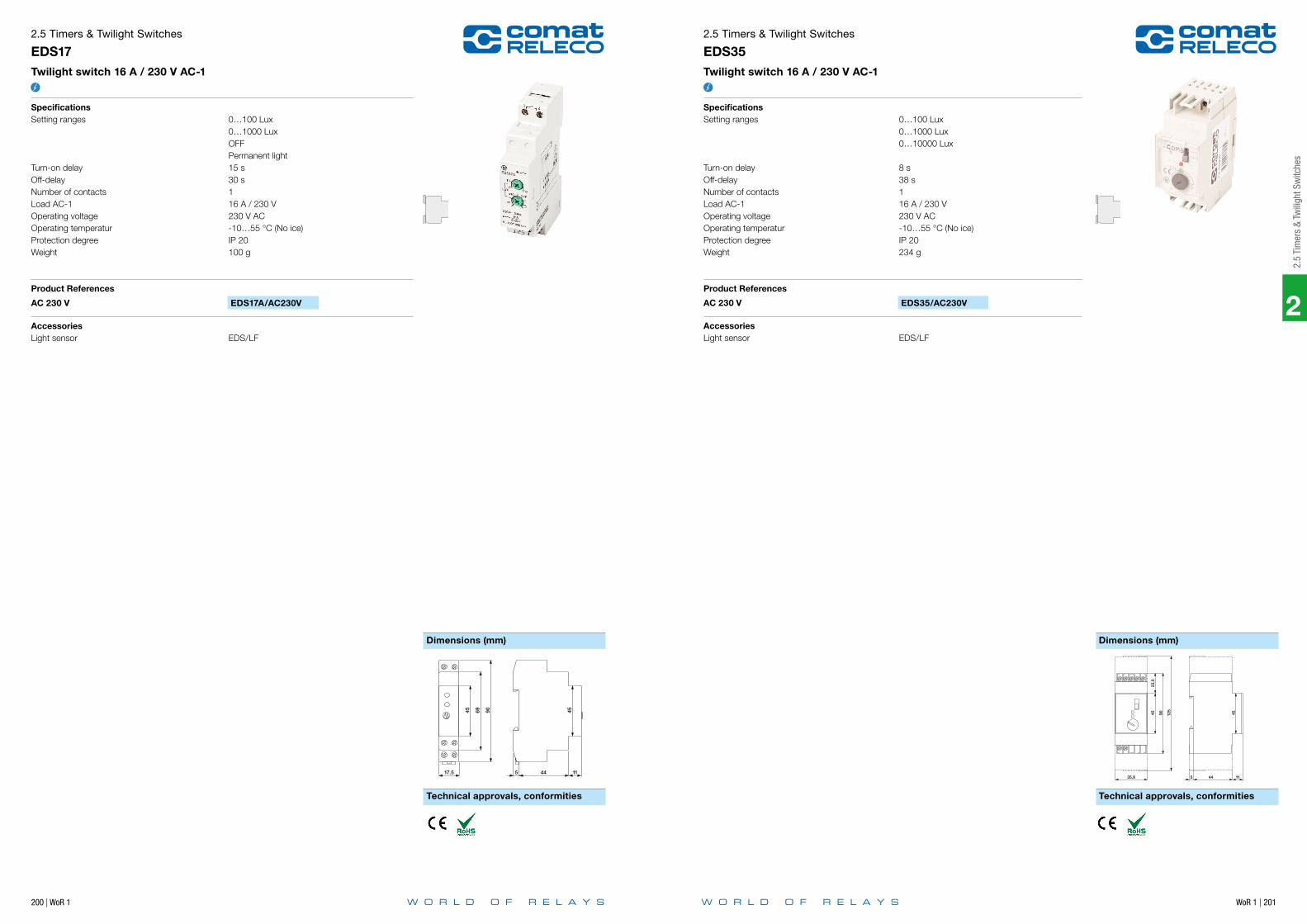
200 | WoR 1 WoR 1 | 201
Dimensions (mm) Dimensions (mm)
Technical approvals, conformities Technical approvals, conformities
2.5 Timers & Twilight Switches
EDS17Twilight switch 16 A / 230 V AC-1
SpecificationsSetting ranges 0…100 Lux 0…1000 Lux OFF Permanent lightTurn-on delay 15 sOff-delay 30 sNumber of contacts 1Load AC-1 16 A / 230 VOperating voltage 230 V ACOperating temperatur -10…55 °C (No ice)Protection degree IP 20Weight 100 g
Product References
AC 230 V EDS17A/AC230V
AccessoriesLight sensor EDS/LF
2.5 Timers & Twilight Switches
EDS35Twilight switch 16 A / 230 V AC-1
SpecificationsSetting ranges 0…100 Lux 0…1000 Lux 0…10000 Lux Turn-on delay 8 sOff-delay 38 sNumber of contacts 1Load AC-1 16 A / 230 VOperating voltage 230 V ACOperating temperatur -10…55 °C (No ice)Protection degree IP 20Weight 234 g
Product References
AC 230 V EDS35/AC230V
AccessoriesLight sensor EDS/LF
2
2.5
Tim
ers
& Tw
iligh
t Sw
itche
s
2
WoR 1 | 203
2.6
Tim
e Cu
bes
202 | WoR 1
Notes
Application Type Page
CT Series
Single function | multivoltage CT2 204
Single function | multivoltage CT3 205
2.6 Time Cubes

204 | WoR 1 WoR 1 | 205
2
2.6
Tim
e Cu
bes
Time dataTiming functionsTiming rangeTiming scale
Control circuit 1 / 2Operating voltage rangePower consumption AC / DCTyp. input current on command input AC / DCTyp. threshold voltage on command input AC / DC
Control circuit 2 / 2Operating voltage rangePower consumption AC / DCTyp. input current on command input AC / DCTyp. threshold voltage on command input AC / DC
General dataAmbient temperature storageAmbient temperature operationConductor cross sectionNominal screw torqueModule widthWeightProtection degreeHousing material
Product references
Types Product reference S DC9.5-18 L UC20-65 M 90-150 U 180-265 H 90-265
Off delay CT2-A30/…V
Blinker CT2-B30/…V
On delay CT2-E30/…V
Pulse shaping, one shot CT2-K30/…V
“...” list control circuit voltage to complete product references.Other voltages on request. Please contact [email protected].
Accessories
Sockets S2-B, S2-PORetaining clip HF-33
2.6 Time Cubes
CT2Single function | multivoltage
fig. 1 1: E, B 2: A, K 3: W0.2 s … 30 min3 s / 30 s / 3 min / 30 min
9.5 … 18 V DC 20 … 65 V UC 90 … 150 V UC0.2 VA / W 0.4 VA / W 0.3 VA / W- / 0.2 mA 0.2 / 0.2 mA 0.2 / 0.2 mA9 V 18 V 75 V
180 … 265 V UC 90 … 265 V UC0.5 VA / W 0.5 VA / W0.2 / 0.2 mA 0.2 / 0.2 mA140 V 75 V
-40 … 85 °C-25 … 60 °C2.5 mm2
0.5 Nmfig. 235 gIP 20PC
fig. 1. Wiring diagram
fig. 2. Dimensions (mm)
Standards and approvals
7
A1
RELAY4 1 3 5 8 6
4 1
3 5
8 6 CT2
7
Socket
2
+
A2
2S
12
34567
810
9
35 25
6 7
12
3
4
5
8
9
1011
50
Standards IEC/EN 60947
Approvals
Time dataTiming functionsTiming rangeTiming scale
Control circuit 1 / 2Operating voltage rangePower consumption AC / DCTyp. input current on command input AC / DCTyp. threshold voltage on command input AC / DC
Control circuit 2 / 2Operating voltage rangePower consumption AC / DCTyp. input current on command input AC / DCTyp. threshold voltage on command input AC / DC
General dataAmbient temperature storageAmbient temperature operationConductor cross sectionNominal screw torqueModule widthWeightProtection degreeHousing material
Product references
Types Product reference S DC9.5-18 L UC20-65 M 90-150 U 180-265 H 90-265
Off delay CT3-A30/…V
Blinker CT3-B30/…V
On delay CT3-E30/…V
Pulse shaping, one shot CT3-K30/…V
“...” list control circuit voltage to complete product references.Other voltages on request. Please contact [email protected].
Accessories
Sockets S3-MRetaining clip HF-33
2.6 Time Cubes
CT3Single function | multivoltage
fig. 1 1: E, B 2: A, K 3: W0.2 s … 30 min3 s / 30 s / 3 min / 30 min
9.5 … 18 V DC 20 … 65 V UC 90 … 150 V UC0.2 VA / W 0.4 VA / W 0.3 VA / W- / 0.2 mA 0.2 / 0.2 mA 0.2 / 0.2 mA9 V 18 V 75 V
180 … 265 V UC 90 … 265 V UC0.5 VA / W 0.5 VA / W0.2 / 0.2 mA 0.2 / 0.2 mA140 V 75 V
-40 … 85 °C-25 … 60 °C2.5 mm2
0.5 Nmfig. 235 gIP 20PC
fig. 1. Wiring diagram
fig. 2. Dimensions (mm)
Standards and approvals
RELAY4 1 3 5 6 7 8 11 9
4 1
3 5
6 7
8 11
9
CT3
A17
Socket
2
+
A2
10S
<
12
34567
810
9
35 25
6 7
12
3
4
5
8
9
1011
50
Standards IEC/EN 60947
Approvals

2
WoR 1 | 207
2.7
Tim
e M
odul
es
206 | WoR 1
Notes
Application Type Page
CT Series
Multifunction | 24 … 48 V UC | 110 V DC CT32R 209
Multifunction | 24 … 48 V UC | 115 V UC | 230 V UC CT33R 210
Multifunction | 24 … 48 V UC | 110 … 240 V UC CT36R 211
2.7 Time Modules

208 | WoR 1 WoR 1 | 209
2
2.7
Tim
e M
odul
es
The system sockets S3-M0 or C-155 serve as a basis for the secure reception of the electronic modules. The sockets have a 4 pole module slot in which the CT modules lock firmly and vibration proof also without the output relay. Contact is made with reliable twin knife contacts.
With the A2 connector bridge "C-A2", the neutral conductor (N/ -) can be connected from socket to socket. It reduces wiring work considerably.
Robust terminals for wires up to 4mm2 and spacious labelling are other advantages of this practical ComatReleco modular system.
Clear markings close to the terminal connections on the sockets make it easy to identify the connections for wiring and servicing.
The CT modules are proof of the practical oriented experiences of Co-matReleco in the field of industrial electronics. All control and display el-ements are arranged easy accessible at all times on the front side of the modules. The functions and settings are self-explanatory schematically illustrated on the front and allow to review the set values also during operation.
A transparent cover over the module setting components provides pro-tection from unintentional settings and additionally links the module to the output relay.
Triggering is performed with the operating voltage. (L1 or +). No poten-tial-free contacts are therefore required. The triggering complies to ma-chine standards. Parallel connection to B1 is admissible.
The wide UC voltage range (AC/DC) of the modules give a wide flexi-bility. It permits the connection to AC or DC supplies and provides a high level of reliability in triggering.
Note: In case of even wider voltage ranges, for example UC 24-240V, triggering currents on B1 are often in the range of 100µA with simul-taneous low threshold voltages of less than 20V. Due to capacitive or inductive pick-ups this may lead to unintentional triggering or switching errors caused by insufficient load on the control contacts (It is not seldom that 50V or more can be measured in open lines).
The output relays show the connection diagram and the technical val-ues on the front side, (exception C3 and C5 relays). A colour code in-dicates an AC coil with red and a DC coil with blue colour. Most of the relays have a lockable test button for manual operation.
The standard contacts have proven its reliability for high switching current applications over many years. The contact material AgNi permits a wide switching range and due to the large dimensioning they are de-signed for a high number of switching cycles. The high breaking capac-ity of up to 10A/400V and a low load switching capability of 12V/10mA makes the contact suitable for the use in main circuits as well as for low voltage applications.
The twin contacts are switching the load circuit with 2 independent contact tongues. The switching safety for low currents is therefore 100 times higher compared to a single contact relay. Despite the high switching capacity of up to 6A/250V, these contacts are very suitable to switch low currents and voltages up to 1mA /6V.
The solid-state relays are an alternative to mechanical relays. In the standard version, the relay has a potential-free universal semiconductor output for AC or DC loads. The advantage is a bouncing- and wear- free, overload resistant, short circuit protected output with a practical unlimited life cycle.
Solid-state relays are specially recommended for applications of high switching cycles, for example for repeat cycle timers, flushing lights, but also for high inductive switching loads of solenoid valves, couplings, motors, etc. The solid state relays are also suitable for capacitive loads, for example long power lines, or compensated lighting circuits.
Additional protection circuits of the output or of the load are not neces-sary in any application for this type of ComatReleco relays.
The solid-state relays are insensitive in any aggressive environment such as chemical plants, sewage plants etc. and are therefore an excellent choice for the employment in such environments.
The train symbol indicates products available in a special railway execution according EN 50155.Please refer to our special railway brochure for details.
The modular ComatReleco timer CT SystemThe time delay relays and monitoring relays consist of plug-in CT electron-ic modules and 11 pole output relays. Both system components can be combined in a variety of combinations. This allows adapting the system for the specific application.Subsequent modifications, for example a change from mechanical con-tacts to solid-state outputs, are possible at any time just by replacing the relay.This system provides the user a complete universal system with worldwide unmatched flexibility.
Time dataTiming functionsTiming rangeTiming scale
Control circuitNominal voltageOperating voltage rangePower consumption AC / DCTyp. threshold voltage on command input AC / DC
General dataAmbient temperature storageAmbient temperature operation railway versionModule widthWeightProtection degreeHousing material
Product references
Types Product reference 24-48 110
DC supply CT32R/DC…V
UC supply CT32R/UC…V
“...” list control circuit voltage to complete product references.Other voltages on request. Please contact [email protected].
Accessories
Sockets S3-M0, S5-MTransparent front cover FS-C
2.7 Time Modules
CT32RMultifunction | 24 … 48 V UC | 110 V DC
fig. 1 2: E, A, K, N, B1 3: E, W, B1.5 s / 6 s / 15 s / 60 s / 1.5 min / 6 min / 15 min / 60 min0.15 s … 60 min
24 … 48 V UC 110 V DC19 … 60 V 77 … 138 V0.3 VA / 0.3 W - / 0.3 W9 V 60 V
-40 … 85 °C-40 … 70 °Cfig. 225 gIP 20PC
fig. 1. Wiring diagram
fig. 2. Dimensions (mm)
Standards and approvals
38 4 20 54
75
16
4
Standards IEC/EN 50155
Approvals
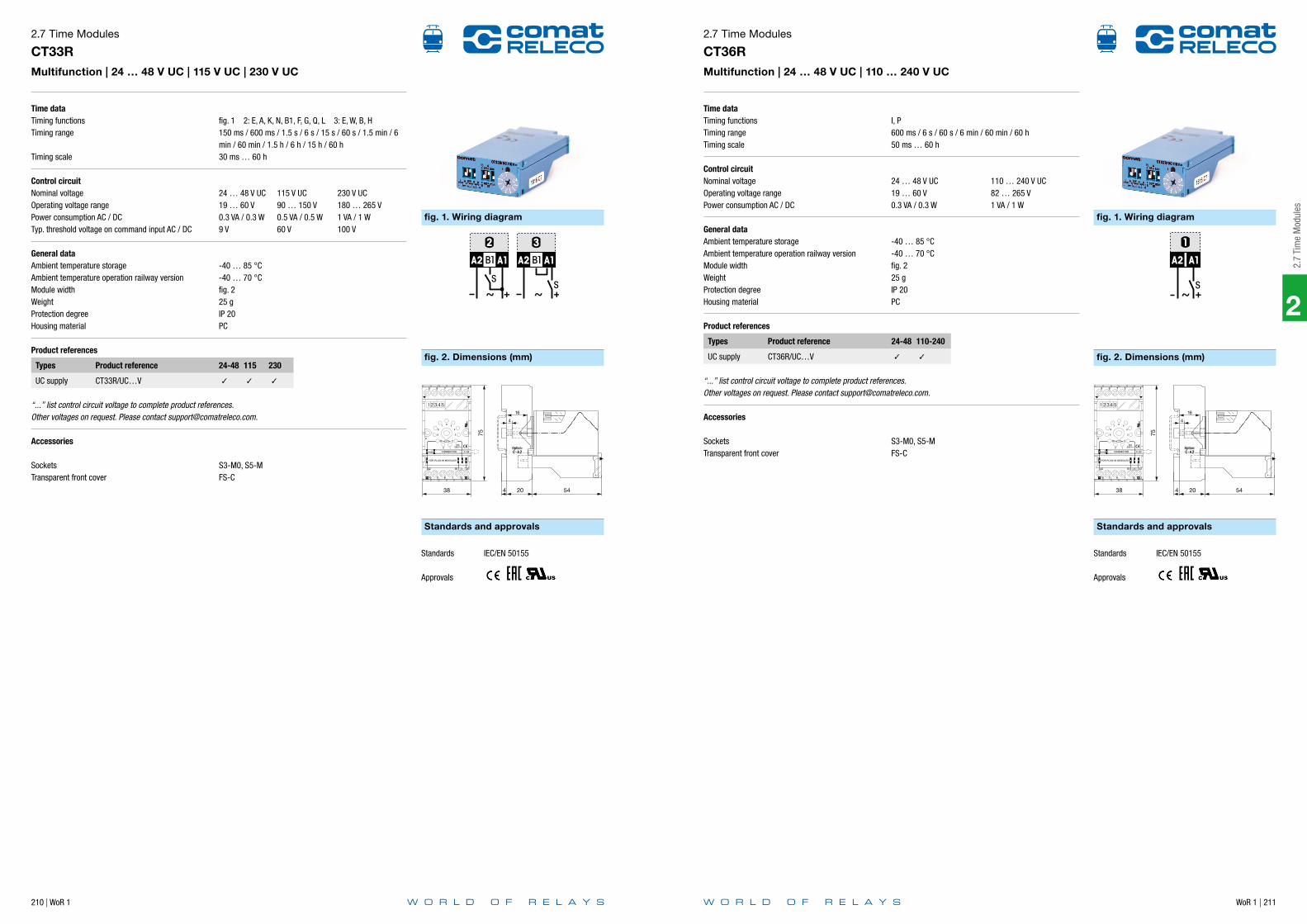
210 | WoR 1 WoR 1 | 211
2
2.7
Tim
e M
odul
es
Time dataTiming functionsTiming range
Timing scale
Control circuitNominal voltageOperating voltage rangePower consumption AC / DCTyp. threshold voltage on command input AC / DC
General dataAmbient temperature storageAmbient temperature operation railway versionModule widthWeightProtection degreeHousing material
Product references
Types Product reference 24-48 115 230
UC supply CT33R/UC…V
“...” list control circuit voltage to complete product references.Other voltages on request. Please contact [email protected].
Accessories
Sockets S3-M0, S5-MTransparent front cover FS-C
2.7 Time Modules
CT33RMultifunction | 24 … 48 V UC | 115 V UC | 230 V UC
fig. 1 2: E, A, K, N, B1, F, G, Q, L 3: E, W, B, H150 ms / 600 ms / 1.5 s / 6 s / 15 s / 60 s / 1.5 min / 6 min / 60 min / 1.5 h / 6 h / 15 h / 60 h30 ms … 60 h
24 … 48 V UC 115 V UC 230 V UC19 … 60 V 90 … 150 V 180 … 265 V0.3 VA / 0.3 W 0.5 VA / 0.5 W 1 VA / 1 W9 V 60 V 100 V
-40 … 85 °C-40 … 70 °Cfig. 225 gIP 20PC
fig. 1. Wiring diagram
fig. 2. Dimensions (mm)
Standards and approvals
38 4 20 54
75
16
4
Standards IEC/EN 50155
Approvals
Time dataTiming functionsTiming rangeTiming scale
Control circuitNominal voltageOperating voltage rangePower consumption AC / DC
General dataAmbient temperature storageAmbient temperature operation railway versionModule widthWeightProtection degreeHousing material
Product references
Types Product reference 24-48 110-240
UC supply CT36R/UC…V
“...” list control circuit voltage to complete product references.Other voltages on request. Please contact [email protected].
Accessories
Sockets S3-M0, S5-MTransparent front cover FS-C
2.7 Time Modules
CT36RMultifunction | 24 … 48 V UC | 110 … 240 V UC
I, P600 ms / 6 s / 60 s / 6 min / 60 min / 60 h50 ms … 60 h
24 … 48 V UC 110 … 240 V UC19 … 60 V 82 … 265 V0.3 VA / 0.3 W 1 VA / 1 W
-40 … 85 °C-40 … 70 °Cfig. 225 gIP 20PC
fig. 1. Wiring diagram
fig. 2. Dimensions (mm)
Standards and approvals
38 4 20 54
75
16
4
Standards IEC/EN 50155
Approvals
WoR 1 | 213
2
2.8
Tim
ing
Rela
y Ac
esso
ries
212 | WoR 1
Notes
Application Type Page
Accessories
Potentiometer | 100 kΩ | 1 MΩ | 0.2 W SP-01 214
Label BZS DIN 17.5 mm 215
Retaining clip | Steel HF-32 216
Retaining clip | Steel HF-33 217
Retaining clip | Steel HF-50 218
Transparent front cover FA-50 219
Front panel mounting set | Socket S3-L | Retaining clip FZ-50L 220
Transparent front cover FS-C 221
2.8 Timing Relay Accessories

214 | WoR 1 WoR 1 | 215
2
2.8
Tim
ing
Rela
y Ac
esso
ries
General dataAmbient temperature storageAmbient temperature operationConductor cross sectionNominal screw torqueModule widthWeightProtection degree
Product references
Types Product reference 100k 1M
Potentiometer SP-01/
“...” list resistance to complete product references.
2.8 Timing Relay Accessories
SP-01Potentiometer | 100 kΩ | 1 MΩ | 0.2 W
-40 … 85 °C-25 … 60 °C2.5 mm2
0.5 Nmfig. 185 gIP 65
fig. 1. Dimensions (mm)
1
2
3
45 6
7
8
9
10
1 2 3
1MΩ100KΩ
301...6
55 36
Ø 22…23
42,6
General dataAmbient temperature storageAmbient temperature operationHousing material
Product references
Types Product reference
Label BZS DIN 17.5 mm
2.8 Timing Relay Accessories
BZS DIN 17.5 mmLabel
-40 … 85 °C-25 … 60 °CPC

216 | WoR 1 WoR 1 | 217
2
2.8
Tim
ing
Rela
y Ac
esso
ries
General dataAmbient temperature storageAmbient temperature operationModule widthWeightHousing material
Product references
Types Product reference
Retaining clip HF-32
2.8 Timing Relay Accessories
HF-32Retaining clip | Steel
-40 … 85 °C-25 … 60 °Cfig. 12 gSteel
fig. 1. Wiring diagramfig. 1. Dimensions (mm)
PLUG-IN MODULE
INDUSTRIAL RELAY
HF-32
General dataAmbient temperature storageAmbient temperature operationModule widthWeightHousing material
Product references
Types Product reference
Retaining clip HF-33
2.8 Timing Relay Accessories
HF-33Retaining clip | Steel
-40 … 85 °C-25 … 60 °Cfig. 12 gSteel
fig. 1. Dimensions (mm)
INDUSTRIAL RELAYTIME CUBE
HF-33

218 | WoR 1 WoR 1 | 219
2
2.8
Tim
ing
Rela
y Ac
esso
ries
General dataAmbient temperature storageAmbient temperature operationModule widthWeightHousing material
Product references
Types Product reference
Retaining clip HF-50
2.8 Timing Relay Accessories
HF-50Retaining clip | Steel
-40 … 85 °C-25 … 60 °Cfig. 12 gSteel
fig. 1. Dimensions (mm)
HF-50
General dataAmbient temperature storageAmbient temperature operationModule widthWeightHousing material
Product references
Types Product reference
Transparent front cover FA-50
2.8 Timing Relay Accessories
FA-50Transparent front cover
-40 … 85 °C-25 … 60 °Cfig. 15 gPC
fig. 1. Dimensions (mm)
FA-50

220 | WoR 1 WoR 1 | 221
2
2.8
Tim
ing
Rela
y Ac
esso
ries
General dataAmbient temperature storageAmbient temperature operationModule widthWeightHousing material
Product references
Types Product reference
Front panel mounting set FZ-50L
2.8 Timing Relay Accessories
FZ-50LFront panel mounting set | Socket S3-L | Retaining clip
-40 … 85 °C-25 … 60 °Cfig. 140 gPC
fig. 1. Dimensions (mm)
45
FRONT
33 +0.6 0
36+
0.6
0
48
SET No.FZ-50L
22 68 18
1.5 .. 5
45
FRONT
33 +0.6 0
36
+0.
6
0
48
SET No.FZ-50L
22 68 18
1.5 .. 5
General dataAmbient temperature storageAmbient temperature operationModule widthWeight
Product references
Types Product reference
Transparent front cover, 5 psc FS-C/5 (BEUTEL/UNIT 5 STK/PCS)
2.8 Timing Relay Accessories
FS-CTransparent front cover
-40 … 85 °C-25 … 60 °Cfig. 15 g
fig. 1. Dimensions (mm)
PLUG-IN MODULE
FS-C
WoR 1 | 223
3
Notes
222 | WoR 1
3 M
onito
ring
& M
easu
ring
Devi
ces
3 Monitoring & Measuring Devices
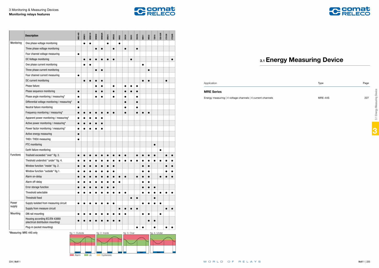
WoR 1 | 225
3
3 Monitoring & Measuring Devices Monitoring relays features
Description
MRE
-44S
MRM
11
MRM
11R
MRM
32
MRM
32R
MRU
11
MRU
32
MV5
3
SSU3
4
SSU3
1
SSU3
3L
MRI
11
MRI
32
TSR1
9
ESU-
D2R
CT51
5R
CT52
4R
Monitoring One phase voltage monitoring Three phase voltage monitoring Four channel voltage measuring DC Voltage monitoring One phase current monitoring Three phase current monitoring Four channel current measuring DC current monitoring Phase failure Phase sequence monitoring Phase angle monitoring / measuring* Differential voltage monitoring / measuring* Neutral failure monitoring Frequency monitoring / measuring* Apparent power monitoring / measuring* Active power monitoring / measuring* Power factor monitoring / measuring* Active energy measuring THDI / THDU measuring PTC monitoring Earth failure monitoring
Functions Treshold exceeded "over" fig. 3. Theshold undershot "under" fig. 4. Window function "inside" fig. 2. Window function "outside" fig.1. Alarm on-delay Alarm off-delay Error storage function Threshold selectable Threshold fixed
Power supply
Supply isolated from measuring circuit Supply from measure circuit
Mounting DIN rail mounting Housing according IEC/EN 43880 (electrical distribution mounting) Plug-in (socket mounting)
Alarm Alarm Alarm Alarm Alarm A Alarm Alarm A
fig. 1. Outside fig. 2. Inside fig. 3. Over fig. 4. Under
Alarm ok hysteresis
*Measuring: MRE-44S only
224 | WoR 1
3.1
Ener
gy M
easu
ring
Devi
ce
Application Type Page
MRE Series
Energy measuring | 4 voltage channels | 4 current channels MRE-44S 227
3.1 Energy Measuring Device
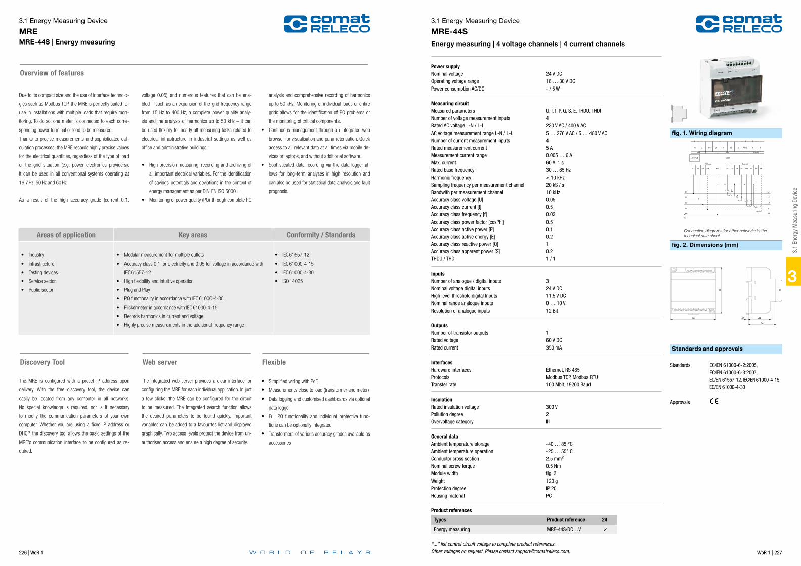
226 | WoR 1 WoR 1 | 227
3
3.1 Energy Measuring Device
MREMRE-44S | Energy measuring
Due to its compact size and the use of interface technolo-
gies such as Modbus TCP, the MRE is perfectly suited for
use in installations with multiple loads that require mon-
itoring. To do so, one meter is connected to each corre-
sponding power terminal or load to be measured.
Thanks to precise measurements and sophisticated cal-
culation processes, the MRE records highly precise values
for the electrical quantities, regardless of the type of load
or the grid situation (e.g. power electronics providers).
It can be used in all conventional systems operating at
16.7 Hz, 50 Hz and 60 Hz.
As a result of the high accuracy grade (current 0.1,
Overview of features
voltage 0.05) and numerous features that can be ena-
bled – such as an expansion of the grid frequency range
from 15 Hz to 400 Hz, a complete power quality analy-
sis and the analysis of harmonics up to 50 kHz – it can
be used flexibly for nearly all measuring tasks related to
electrical infrastructure in industrial settings as well as
office and administrative buildings.
• High-precision measuring, recording and archiving of
all important electrical variables. For the identification
of savings potentials and deviations in the context of
energy management as per DIN EN ISO 50001.
• Monitoring of power quality (PQ) through complete PQ
analysis and comprehensive recording of harmonics
up to 50 kHz. Monitoring of individual loads or entire
grids allows for the identification of PQ problems or
the monitoring of critical components.
• Continuous management through an integrated web
browser for visualisation and parameterisation. Quick
access to all relevant data at all times via mobile de-
vices or laptops, and without additional software.
• Sophisticated data recording via the data logger al-
lows for long-term analyses in high resolution and
can also be used for statistical data analysis and fault
prognosis.
Areas of application Key areas Conformity / Standards
• Industry
• Infrastructure
• Testing devices
• Service sector
• Public sector
• Modular measurement for multiple outlets
• Accuracy class 0.1 for electricity and 0.05 for voltage in accordance with
IEC 61557-12
• High flexibility and intuitive operation
• Plug and Play
• PQ functionality in accordance with IEC 61000-4-30
• Flickermeter in accordance with IEC 61000-4-15
• Records harmonics in current and voltage
• Highly precise measurements in the additional frequency range
• IEC 61557-12
• IEC 61000-4-15
• IEC 61000-4-30
• ISO 14025
Discovery Tool Web server
The MRE is configured with a preset IP address upon
delivery. With the free discovery tool, the device can
easily be located from any computer in all networks.
No special knowledge is required, nor is it necessary
to modify the communication parameters of your own
computer. Whether you are using a fixed IP address or
DHCP, the discovery tool allows the basic settings of the
MRE's communication interface to be configured as re-
quired.
The integrated web server provides a clear interface for
configuring the MRE for each individual application. In just
a few clicks, the MRE can be configured for the circuit
to be measured. The integrated search function allows
the desired parameters to be found quickly. Important
variables can be added to a favourites list and displayed
graphically. Two access levels protect the device from un-
authorised access and ensure a high degree of security.
• Simplified wiring with PoE
• Measurements close to load (transformer and meter)
• Data logging and customised dashboards via optional
data logger
• Full PQ functionality and individual protective func-
tions can be optionally integrated
• Transformers of various accuracy grades available as
accessories
Flexible
3.1
Ener
gy M
easu
ring
Devi
ce
Power supplyNominal voltageOperating voltage rangePower consumption AC/DC
Measuring circuitMeasured parametersNumber of voltage measurement inputsRated AC voltage L-N / L-LAC voltage measurement range L-N / L-LNumber of current measurement inputsRated measurement currentMeasurement current rangeMax. currentRated base frequencyHarmonic frequencySampling frequency per measurement channelBandwith per measurement channelAccuracy class voltage [U]Accuracy class current [I]Accuracy class frequency [f]Accuracy class power factor [cosPhi]Accuracy class active power [P]Accuracy class active energy [E]Accuracy class reactive power [Q]Accuracy class apparent power [S]THDU / THDI
InputsNumber of analogue / digital inputsNominal voltage digital inputsHigh level threshold digital InputsNominal range analogue inputsResolution of analogue inputs
OutputsNumber of transistor outputsRated voltageRated current
InterfacesHardware interfacesProtocolsTransfer rate
InsulationRated insulation voltagePollution degreeOvervoltage category
General dataAmbient temperature storageAmbient temperature operationConductor cross sectionNominal screw torqueModule widthWeightProtection degreeHousing material
Product references
Types Product reference 24
Energy measuring MRE-44S/DC…V
“...” list control circuit voltage to complete product references.Other voltages on request. Please contact [email protected].
3.1 Energy Measuring Device
MRE-44SEnergy measuring | 4 voltage channels | 4 current channels
24 V DC18 … 30 V DC- / 5 W
U, I, f, P, Q, S, E, THDU, THDI4230 V AC / 400 V AC5 … 276 V AC / 5 … 480 V AC45 A0.005 … 6 A60 A, 1 s30 … 65 Hz< 10 kHz20 kS / s10 kHz0.050.50.020.50.10.210.21 / 1
324 V DC11.5 V DC0 … 10 V12 Bit
160 V DC350 mA
Ethernet, RS 485Modbus TCP, Modbus RTU100 Mbit, 19200 Baud
300 V2III
-40 … 85 °C-25 … 55° C2.5 mm2
0.5 Nmfig. 2120 gIP 20PC
fig. 1. Wiring diagram
fig. 2. Dimensions (mm)
Standards and approvals
V1
L1
L2
L3
N
PE
L1
L2
L3
N
PE
V2 V3 VN PE
k l
k l
k l
I1lI1k I2k I2l I3k I3l INk INl
24V
Voltage Current
LAN/PoE MRE
I/O RS485
V-V+ 01+ 01- I1 I2 I3 GND A B
k l
Connection diagrams for other networks in the technical data sheet.
4.5 44
54
45
88
90
Standards IEC/EN 61000-6-2:2005, IEC/EN 61000-6-3:2007, IEC/EN 61557-12, IEC/EN 61000-4-15, IEC/EN 61000-4-30
Approvals
WoR 1 | 229
3
228 | WoR 1
Notes
3.2
Mul
tifun
ctio
n M
onito
ring
Application Type Page
MRM Series
Single phase multifunction monitoring | 12 … 48 V UC | 110 … 240 V UC MRM11, MRM11R 230
Three phase multifunction monitoring | 12 … 48 V UC | 110 … 240 V UC MRM32, MRM32R 231
3.2 Multifunction Monitoring

WoR 1 | 231
3
Power supplyNominal voltageOperating voltage rangePower consumption AC/DCRated frequency
Measuring circuitMeasured parametersMin. setting step, resolutionMonitoring functionsNumber of voltage measurement inputsRated AC voltage L-N / L-LAC voltage measurement range L-N / L-LRated DC voltage U+-U-DC voltage measurement range U+-U-Undervoltage setting rangeOvervoltage setting rangeNumber of current measurement inputsRated measurement currentMeasurement current rangeUndercurrent setting rangeOvercurrent setting rangeRated base frequencyAlarm delayAlarm reset delay
Main circuitNumber of contactsContact MaterialRated voltageRated currentMinimum loadInrush currentRated load DCRated load AC-1Mechanical endurance (cycles)Electrical endurance at rated load AC-1 (cycles)
InsulationRated test voltage measuring / measuring circuitRated test voltage measuring circuit / power supplyRated test voltage measuring circuit / main circuitRated test voltage main circuit / power supplyRated test voltage open contactPollution degreeOvervoltage category
General dataAmbient temperature storageAmbient temperature operationAmbient temperature operation railway versionConductor cross sectionNominal screw torqueModule widthWeightProtection degreeHousing material Product references
Types Product reference 12-48 110-240
Single phase monitoring MRM11/UC…V
Single phase monitoring, railway version MRM11R/UC…V
“...” list control circuit voltage to complete product references.Other voltages on request. Please contact [email protected].
3.2 Multifunction Monitoring
MRM11, MRM11RSingle phase multifunction monitoring | 12 … 48 V UC | 110 … 240 V UC
12 … 48 V UC 110 … 240 V UC10 … 60 V 85 … 250 V3.2 VA / 1.6 W 2.6 VA / 1.5 W16 … 63 Hz
U, I, P, S, f, Cosϕ0.1 V / 0.1 A / 1 W / 1 VA / 0.1 Hz / 0.01Under, over, inside, outside1230 V / -0.1 … 480 V300 V±0.1 … 690 V0.1 … 480 V AC / ±0.1 … 690 V DC0.1 … 480 V AC / ±0.1 … 690 V DC15 A0.1 … 6 A0.1 … 5 A0.1 … 5 A15 … 150 Hz0.5 … 999.9 s0.5 … 999.9 s
1 COAgNi250 V6 A10 mA, 10 V10 A, 10 msfig. 21500 VA3 x 107
fig. 3
1.5 kV rms / 1 min2 kV rms / 1 min2 kV rms / 1 min2 kV rms / 1 min1 kV rms / 1 min2III
-40 … 85 °C-40 … 60 °C-40 … 70 °C2.5 mm2
0.6 Nmfig. 4107 gIP 20PC
fig. 1. Wiring diagram
fig. 2. DC load limit curve
fig. 3. AC voltage endurance
fig. 4. Dimensions (mm)
Standards and approvals
A1 A2
15 16 18
U– U– I– U/I+
LOAD
AL
N L
105
106
107
0 1 2 3 4 5 6
Cyc
les
Switching current [A]
AC-1
Voltage [V]
Cur
rent
[ A]
DC-16
10
5
2
1
0.5
0.3
0.2
0.10 50 100 150 200 250 300
Standards IEC/EN 60947, IEC/EN 60730, IEC/EN 50155, IEC/EN 45545, IEC/EN 43880
Approvals
3.2
Mul
tifun
ctio
n M
onito
ring
Power supplyNominal voltageOperating voltage rangePower consumption AC/DCRated frequency
Measuring circuitMeasured parametersMin. setting step, resolutionMonitoring functionsNumber of voltage measurement inputsRated AC voltage L-N / L-LAC voltage measurement range L-N / L-LRated DC voltage U+-U-DC voltage measurement range U+-U-Undervoltage setting rangeOvervoltage setting rangeNumber of current measurement inputsRated measurement currentMeasurement current rangeUndercurrent setting rangeOvercurrent setting rangeRated base frequencyAlarm delayAlarm reset delay
Main circuitNumber of contactsContact MaterialRated voltageRated currentMinimum loadInrush currentRated load DCRated load AC-1Mechanical endurance (cycles)Electrical endurance at rated load AC-1 (cycles)
InsulationRated test voltage measuring / measuring circuitRated test voltage measuring circuit / power supplyRated test voltage measuring circuit / main circuitRated test voltage main circuit / power supplyRated test voltage main / main circuitRated test voltage open contactPollution degreeOvervoltage category
General dataAmbient temperature storageAmbient temperature operationAmbient temperature operation railway versionConductor cross sectionNominal screw torqueModule widthWeightProtection degreeHousing material
Product references
Types Product reference 12-48 110-240
Three phase monitoring MRM32/UC…V
Three phase monitoring, railway version MRM32R/UC…V
“...” list control circuit voltage to complete product references.Other voltages on request. Please contact [email protected].
3.2 Multifunction Monitoring
MRM32, MRM32RThree phase multifunction monitoring | 12 … 48 V UC | 110 … 240 V UC
12 … 48 V UC 110 … 240 V UC10 … 60 V 85 … 250 V3.2 VA / 1.6 W 2.6 VA / 1.5 W16 … 63 Hz
U, I, P, S, f, Cosϕ, ΔPhi, phase sequence0.1 V / 0.1 A / 1 W / 1 VA / 0.1 Hz / 0.01 / 1°Under, over, inside, outside, phase sequence, phase failure3230 V / 400 V0.1 … 480 V300 V±0.1 … 690 V0.1 … 480 V AC / ±0.1 … 690 V DC0.1 … 480 V AC / ±0.1 … 690 V DC35 A0.1 … 6 A0.1 … 5 A0.1 … 5 A15 … 150 Hz0.5 … 999.9 s0.5 … 999.9 s
2 COAgNi250 V6 A10 mA, 10 V10 A, 10 msfig. 21500 VA3 x 107
fig. 3
1.5 kV rms / 1 min2 kV rms / 1 min2 kV rms / 1 min2 kV rms / 1 min1.5 kV rms / 1 min1 kV rms / 1 min2III
-40 … 85 °C-40 … 60 °C-40 … 70 °C2.5 mm2
0.6 Nmfig. 4125 gIP 20PC
fig. 1. Wiring diagram
fig. 2. DC load limit curve
fig. 3. AC voltage endurance
fig. 4. Dimensions (mm)
Standards and approvals
A1 A2
15 16 18 25 26 28
I2– U/I2+ I3– U/I3+
U– U– I1– U/I1+
LOAD
LOAD
LOAD
AL1 AL2
N L1 L2 L3
105
106
107
0 1 2 3 4 5 6
Cyc
les
Switching current [A]
AC-1
Voltage [V]
Cur
rent
[ A]
DC-16
10
5
2
1
0.5
0.3
0.2
0.10 50 100 150 200 250 300
Standards IEC/EN 60947, IEC/EN 60730, IEC/EN 50155, IEC/EN 45545, IEC/EN 43880
Approvals

WoR 1 | 233
3
232 | WoR 1
Notes
3.3
Volta
ge M
onito
ring
Application Type Page
MRU Series
Single phase voltage monitoring | 12 … 48 V UC | 110 … 240 V UC MRU11 234
Three phase voltage monitoring | 12 … 48 V UC | 110 … 240 V UC MRU32 235
MV Series
Single phase voltage monitoring | 115 V AC | 230 V AC MV53 236
SSU Series
Three phase + N voltage monitoring | 400 V AC SSU34 237
3.3 Voltage Monitoring

WoR 1 | 235
3
234 | WoR 1
Power supplyNominal voltageOperating voltage rangePower consumption AC/DCRated frequency
Measuring circuitMeasured parametersMin. setting step, resolutionMonitoring functionsNumber of voltage measurement inputsRated AC voltage L-N / L-LAC voltage measurement range L-N / L-LRated DC voltage U+-U-DC voltage measurement range U+-U-Undervoltage setting rangeOvervoltage setting rangeAlarm delayAlarm reset delay
Main circuitNumber of contactsContact MaterialRated voltageRated currentMinimum loadInrush currentRated load DCRated load AC-1Mechanical endurance (cycles)Electrical endurance at rated load AC-1 (cycles)
InsulationRated test voltage measuring / measuring circuitRated test voltage measuring circuit / power supplyRated test voltage measuring circuit / main circuitRated test voltage main circuit / power supplyRated test voltage open contactPollution degreeOvervoltage category
General dataAmbient temperature storageAmbient temperature operationConductor cross sectionNominal screw torqueModule widthWeightProtection degreeHousing material
Product references
Types Product reference 12-48 110-240
Single phase monitoring MRU11/UC…V
“...” list control circuit voltage to complete product references.Other voltages on request. Please contact [email protected].
3.3 Voltage Monitoring
MRU11Single phase voltage monitoring | 12 … 48 V UC | 110 … 240 V UC
12 … 48 V UC 110 … 240 V UC10 … 60 V 85 … 250 V3.2 VA / 1.6 W 2.6 VA / 1.5 W16 … 63 Hz
U, f0.1 V / 0.1 HzUnder, over, inside, outside1230 V / -0.1 … 480 V300 V±0.1 … 690 V0.1 … 480 V AC / ±0.1 … 690 V DC0.1 … 480 V AC / ±0.1 … 690 V DC0.5 … 999.9 s0.5 … 999.9 s
1 COAgNi250 V6 A10 mA, 10 V10 A, 10 msfig. 21500 VA3 x 107
fig. 3
1.5 kV rms / 1 min2 kV rms / 1 min2 kV rms / 1 min2 kV rms / 1 min1 kV rms / 1 min2III
-40 … 85 °C-40 … 60 °C2.5 mm2
0.6 Nmfig. 4107 gIP 20PC
fig. 1. Wiring diagram
fig. 2. DC load limit curve
fig. 3. AC voltage endurance
fig. 4. Dimensions (mm)
Standards and approvals
A1 A2
15 16 18
U– U– U+
LOAD
AL
N L
105
106
107
0 1 2 3 4 5 6
Cyc
les
Switching current [A]
AC-1
Voltage [V]
Cur
rent
[ A]
DC-16
10
5
2
1
0.5
0.3
0.2
0.10 50 100 150 200 250 300
Standards IEC/EN 60947, IEC/EN 60730, IEC/EN 43880
Approvals
3.3
Volta
ge M
onito
ring
Power supplyNominal voltageOperating voltage rangePower consumption AC/DCRated frequency
Measuring circuitMeasured parametersMin. setting step, resolutionMonitoring functionsNumber of voltage measurement inputsRated AC voltage L-N / L-LAC voltage measurement range L-N / L-LRated DC voltage U+-U-DC voltage measurement range U+-U-Undervoltage setting rangeOvervoltage setting rangeAlarm delayAlarm reset delay
Main circuitNumber of contactsContact MaterialRated voltageRated currentMinimum loadInrush currentRated load DCRated load AC-1Mechanical endurance (cycles)Electrical endurance at rated load AC-1 (cycles)
InsulationRated test voltage measuring / measuring circuitRated test voltage measuring circuit / power supplyRated test voltage measuring circuit / main circuitRated test voltage main circuit / power supplyRated test voltage main / main circuitRated test voltage open contactPollution degreeOvervoltage category
General dataAmbient temperature storageAmbient temperature operationConductor cross sectionNominal screw torqueModule widthWeightProtection degreeHousing material
Product references
Types Product reference 12-48 110-240
Three phase monitoring MRU32/UC…V
“...” list control circuit voltage to complete product references.Other voltages on request. Please contact [email protected].
3.3 Voltage Monitoring
MRU32Three phase voltage monitoring | 12 … 48 V UC | 110 … 240 V UC
12 … 48 V UC 110 … 240 V UC10 … 60 V 85 … 250 V3.2 VA / 1.6 W 2.6 VA / 1.5 W16 … 63 Hz
U, f, ΔPhi, phase sequence0.1 V / 0.1 Hz / 0.01Under, over, inside, outside, phase sequence, phase failure3230 V / 400 V0.1 … 480 V300 V±0.1 … 690 V0.1 … 480 V AC / ±0.1 … 690 V DC0.1 … 480 V AC / ±0.1 … 690 V DC0.5 … 999.9 s0.5 … 999.9 s
2 COAgNi250 V6 A10 mA, 10 V10 A, 10 msfig. 21500 VA3 x 107
fig. 3
1.5 kV rms / 1 min2 kV rms / 1 min2 kV rms / 1 min2 kV rms / 1 min1.5 kV rms / 1 min1 kV rms / 1 min2III
-40 … 85 °C-40 … 60 °C2.5 mm2
0.6 Nmfig. 4125 gIP 20PC
fig. 1. Wiring diagram
fig. 2. DC load limit curve
fig. 3. AC voltage endurance
fig. 4. Dimensions (mm)
Standards and approvals
A1 A2
15 16 18 25 26 28
U2+ U3+
U– U– U1+
LOAD
LOAD
LOAD
AL1 AL2
N L1 L2 L3
105
106
107
0 1 2 3 4 5 6
Cyc
les
Switching current [A]
AC-1
Voltage [V]
Cur
rent
[ A]
DC-16
10
5
2
1
0.5
0.3
0.2
0.10 50 100 150 200 250 300
Standards IEC/EN 60947, IEC/EN 60730, IEC/EN 43880
Approvals

WoR 1 | 237
3
236 | WoR 1
Power supplyNominal voltageOperating voltage rangePower consumption AC/DCRated frequency
Measuring circuitMeasured parametersMonitoring functionsNumber of voltage measurement inputsRated AC voltage L-N / L-LAC voltage measurement range L-N / L-LUndervoltage setting rangeOvervoltage setting rangeRated base frequency
Main circuitNumber of contactsContact MaterialRated voltageRated currentMinimum loadInrush currentRated load DCRated load AC-1Mechanical endurance (cycles)Electrical endurance at rated load AC-1 (cycles)
InsulationRated test voltage main circuit / power supplyRated test voltage open contactPollution degreeOvervoltage category
General dataAmbient temperature storageAmbient temperature operationConductor cross sectionNominal screw torqueModule widthWeightProtection degreeHousing material
Product references
Types Product reference 230
Single phase monitoring MV53/AC…V
“...” list control circuit voltage to complete product references.Other voltages on request. Please contact [email protected].
3.3 Voltage Monitoring
MV53Single phase voltage monitoring | 115 V AC | 230 V AC
230 V AC149 … 270 V2.3 VA / -45 … 65 Hz
UUnder, over1 (A1 / A2)230 V / -149 … 270 V149 … 218 V236 … 270 V45 … 65 Hz
1 COAgNi250 V6 A10 mA, 5 V20 A, 20 msfig. 21500 VA2 x 107
fig. 3
2 kV rms / 1 min1 kV rms / 1 min2III
-40 … 85 °C-40 … 60 °C2.5 mm2, 2 x 1.5 mm2
0.8 Nmfig. 480 gIP 20PC
fig. 1. Wiring diagram
fig. 2. DC load limit curve
fig. 3. AC voltage endurance
fig. 4. Dimensions (mm)
Standards and approvals
Inst
alla
tion
to
be p
rote
cted
104
105
106
107
0 1 2 3 4 5 6
Cyc
les
Switching current [A]
AC-1 DC-1
0.1
0.2
0.3
0.5
1
2
5 6
0 50 100 150 200 250
Cur
rent
[A]
Voltage [V]
DC-1
1
23
45678
9
10 TS35
70
90
22,5 2
Standards IEC/EN 60065
Approvals
3.3
Volta
ge M
onito
ring
Power supplyNominal voltageOperating voltage rangePower consumption AC/DCRated frequency
Measuring circuitMeasured parametersMonitoring functionsNumber of voltage measurement inputsRated AC voltage L-N / L-LAC voltage measurement range L-N / L-LUndervoltage setting rangeOvervoltage setting rangeVoltage difference setting range L-LRated base frequencyFrequency difference setting range L-LPhase angle difference setting range L-LAlarm delay
Main circuitNumber of contactsContact MaterialRated voltageRated currentMinimum loadInrush currentRated load DCRated load AC-1Mechanical endurance (cycles)Electrical endurance at rated load AC-1 (cycles)
InsulationRated test voltage measuring / measuring circuitRated test voltage measuring circuit / main circuitRated test voltage open contactPollution degreeOvervoltage category
General dataAmbient temperature storageAmbient temperature operationConductor cross sectionNominal screw torqueModule widthWeightProtection degreeHousing material
Product references
Types Product reference 400
Three phase monitoring SSU34/AC…V
“...” list control circuit voltage to complete product references.Other voltages on request. Please contact [email protected].
3.3 Voltage Monitoring
SSU34Three phase + N voltage monitoring | 400 V AC
400 V AC240 … 495 V1.5 VA50 Hz
U, ΔPhi, ΔfUnder, over, phase failure, phase sequence4 (L1 / L2 / L3 / N)230 V / 400 V160 … 275 V / 280 … 480 V160 … 225 V / 280 … 390 V235 … 275 V / 410 … 480 V20 … 100 V 35 … 173 V50 Hz3 … 15 Hz3 … 15°0.2 … 5 s
2 COAgNi250 V5 A10 mA, 12 V15 A, 20 msfig. 21250 VA5 x 106
fig. 3
3 kV rms / 1 min3 kV rms / 1 min1 kV rms / 1 min2III
-40 … 85 °C-10 … 60 °C2.5 mm2, 2 x 1.5 mm2
0.5 Nmfig. 4350 gIP 20PC
fig. 1. Wiring diagram
fig. 2. DC load limit curve
fig. 3. AC voltage endurance
fig. 4. Dimensions (mm)
Standards and approvals
DO NOT CONNECT AT THE SAME TIME:Neutral conductor N and bridge L3-l!
105
106
107
0 1 2 3 4 5
Cyc
les
Switching current [A]
AC-1
0.1
0.2
0.5
1
2
3 4 5
0 50 100 150 200 250 300
Cur
rent
[A]
Voltage [V]
DC-1
1055
75
50
TS35
Standards IEC/EN 60947
Approvals

WoR 1 | 239
3
238 | WoR 1
Notes
3.4
Volta
ge M
onito
ring
- pl
ugga
bleApplication Type Page
SSU Series
Phase sequence monitoring | 400 V AC SSU31 240
Three phase + N voltage monitoring | 230 V AC | 400 V AC SSU33L 241
3.4 Voltage Monitoring - pluggable

WoR 1 | 241
3
240 | WoR 1
Power supplyNominal voltageOperating voltage rangePower consumption AC/DCRated frequency
Measuring circuitMeasured parametersMonitoring functionsNumber of voltage measurement inputsRated AC voltage L-N / L-LAC voltage measurement range L-N / L-LUndervoltage setting rangeRated base frequency
Main circuitNumber of contactsContact MaterialRated voltageRated currentMinimum loadInrush currentRated load DCRated load AC-1Mechanical endurance (cycles)Electrical endurance at rated load AC-1 (cycles)
InsulationRated test voltage measuring / measuring circuitRated test voltage measuring circuit / main circuitRated test voltage open contactPollution degreeOvervoltage category
General dataAmbient temperature storageAmbient temperature operationModule widthWeightProtection degreeHousing material
Product references
Types Product reference 400
Three phase monitoring SSU31/AC…V
“...” list control circuit voltage to complete product references.Other voltages on request. Please contact [email protected].
AccessoriesSocket S3-MRetaining clip HF-24Transparent front cover FS-23Front panel mounting set FZ-23
3.4 Voltage Monitoring - pluggable
SSU31Phase sequence monitoring | 400 V AC
400 V AC320 … 480 V10 VA45 … 65 Hz
UUnder, phase failure, phase sequence3 (L1 / L2 / L3)- / 400 V320 … 400 V≤ 320 V45 … 65 Hz
1 COAgNi250 V6 A10 mA, 5 V15 A, 20 msfig. 21500 VA3 x 107
fig. 3
2 kV rms / 1 min2 kV rms / 1 min1 kV rms / 1 min2III
-40 … 85 °C-25 … 60 °Cfig. 4300 gIP 20PC
fig. 1. Wiring diagram
fig. 2. DC load limit curve
fig. 3. AC voltage endurance
fig. 4. Dimensions (mm)
Standards and approvals
L1L2L3
6
AC-1
105
106
107
Cyc
les
0 1 2 3 4 5
Switching current [A]
Voltage [V]
Cur
rent
[ A]
DC-16
10
5
2
1
0.5
0.3
0.2
0.10 50 100 150 200 250 300
38
42 9
4,5
FS-23
78
75
72
FZ-23
Standards IEC/EN 60947
Approvals
3.4
Volta
ge M
onito
ring
- pl
ugga
ble
Power supplyNominal voltageOperating voltage rangePower consumption AC/DCRated frequency
Measuring circuitMeasured parametersMonitoring functionsNumber of voltage measurement inputsRated AC voltage L-N / L-LAC voltage measurement range L-N / L-LUndervoltage setting rangeOvervoltage setting rangeVoltage difference setting range L-LRated base frequencyFrequency difference setting range L-LPhase angle difference setting range L-LAlarm delay
Main circuitNumber of contactsContact MaterialRated voltageRated currentMinimum loadInrush currentRated load DCRated load AC-1Mechanical endurance (cycles)Electrical endurance at rated load AC-1 (cycles)
InsulationRated test voltage measuring / measuring circuitRated test voltage measuring circuit / main circuitRated test voltage open contactPollution degreeOvervoltage category
General dataAmbient temperature storageAmbient temperature operationModule widthWeightProtection degreeHousing material
Product references
Types Product reference 230 400
Three phase monitoring SSU33L/AC…V
Three phase monitoring + N SSU33L/AC…V
“...” list control circuit voltage to complete product references.Other voltages on request. Please contact [email protected].
AccessoriesSocket S3-MRetaining clip HF-24Transparent front cover FS-23Front panel mounting set FZ-23
3.4 Voltage Monitoring - pluggable
SSU33LThree phase + N voltage monitoring | 230 V AC | 400 V AC
230 V AC 400 V AC160 … 275 V 280 … 480 V3 VA50 Hz
U, ΔPhi, ΔfUnder, over, phase failure, phase sequence4 (L1 / L2 / L3 / N) 3 (L1 / L2 / L3)230 V / 400 V - / 400 V160 … 275 V 280 … 480 V≤ 160 V ≤ 280 V≥ 275 V ≥ 480 V20 … 100 V 35 … 173 V50 Hz3 … 15 Hz3 … 15°0.2 … 5 s
1 COAgNi250 V6 A10 mA, 5 V15 A, 20 msfig. 21500 VA3 x 107
fig. 3
2 kV rms / 1 min2 kV rms / 1 min1 kV rms / 1 min2III
-40 … 85 °C-25 … 60 °Cfig. 4300 gIP 20PC
fig. 1. Wiring diagram
fig. 2. DC load limit curve
fig. 3. AC voltage endurance
fig. 4. Dimensions (mm)
Standards and approvals
6
AC-1
105
106
107
Cyc
les
0 1 2 3 4 5
Switching current [A]
Voltage [V]
Cur
rent
[ A]
DC-16
10
5
2
1
0.5
0.3
0.2
0.10 50 100 150 200 250 300
38
42 9
4,5
FS-23
78
75
72
FZ-23
Standards IEC/EN 60947
Approvals
WoR 1 | 243
3
242 | WoR 1
Notes
3.5
Curr
ent M
onito
ring
Application Type Page
MRI Series
Single phase current monitoring | 12 … 48 V UC | 110 … 240 V UC MRI11 244
Three phase current monitoring | 12 … 48 V UC | 110 … 240 V UC MRI32 245
3.5 Current Monitoring

WoR 1 | 245
3
244 | WoR 1
Power supplyNominal voltageOperating voltage rangePower consumption AC/DCRated frequency
Measuring circuitMeasured parametersMin. setting step, resolutionMonitoring functionsNumber of current measurement inputsRated measurement currentMeasurement current rangeUndercurrent setting rangeOvercurrent setting rangeRated base frequencyAlarm delayAlarm reset delay
Main circuitNumber of contactsContact MaterialRated voltageRated currentMinimum loadInrush currentRated load DCRated load AC-1Mechanical endurance (cycles)Electrical endurance at rated load AC-1 (cycles)
InsulationRated test voltage measuring / measuring circuitRated test voltage measuring circuit / power supplyRated test voltage measuring circuit / main circuitRated test voltage main circuit / power supplyRated test voltage open contactPollution degreeOvervoltage category
General dataAmbient temperature storageAmbient temperature operationConductor cross sectionNominal screw torqueModule widthWeightProtection degreeHousing material
Product references
Types Product reference 12-48 110-240
Single phase monitoring MRI11/UC…V
“...” list control circuit voltage to complete product references.Other voltages on request. Please contact [email protected].
3.5 Current Monitoring
MRI11Single phase current monitoring | 12 … 48 V UC | 110 … 240 V UC
12 … 48 V UC 110 … 240 V UC10 … 60 V 85 … 250 V3.2 VA / 1.6 W 2.6 VA / 1.5 W16 … 63 Hz
I, f0.1 A / 0.1 HzUnder, over, inside, outside15 A0.1 … 6 A0.1 … 5 A0.1 … 5 A15 … 150 Hz0.5 … 999.9 s0.5 … 999.9 s
1 COAgNi250 V6 A10 mA, 10 V10 A, 10 msfig. 21500 VA3 x 107
fig. 3
1.5 kV rms / 1 min2 kV rms / 1 min2 kV rms / 1 min2 kV rms / 1 min1 kV rms / 1 min2III
-40 … 85 °C-40 … 60 °C2.5 mm2
0.6 Nmfig. 4107 gIP 20PC
fig. 1. Wiring diagram
fig. 2. DC load limit curve
fig. 3. AC voltage endurance
fig. 4. Dimensions (mm)
Standards and approvals
A1 A2
15 16 18
I– I+
LOAD
AL
N L
105
106
107
0 1 2 3 4 5 6
Cyc
les
Switching current [A]
AC-1
Voltage [V]
Cur
rent
[ A]
DC-16
10
5
2
1
0.5
0.3
0.2
0.10 50 100 150 200 250 300
Standards IEC/EN 60947, IEC/EN 60730, IEC/EN 43880
Approvals
3.5
Curr
ent M
onito
ring
Power supplyNominal voltageOperating voltage rangePower consumption AC/DCRated frequency
Measuring circuitMeasured parametersMin. setting step, resolutionMonitoring functionsNumber of current measurement inputsRated measurement currentMeasurement current rangeUndercurrent setting rangeOvercurrent setting rangeRated base frequencyAlarm delayAlarm reset delay
Main circuitNumber of contactsContact MaterialRated voltageRated currentMinimum loadInrush currentRated load DCRated load AC-1Mechanical endurance (cycles)Electrical endurance at rated load AC-1 (cycles)
InsulationRated test voltage measuring / measuring circuitRated test voltage measuring circuit / power supplyRated test voltage measuring circuit / main circuitRated test voltage main circuit / power supplyRated test voltage main / main circuitRated test voltage open contactPollution degreeOvervoltage category
General dataAmbient temperature storageAmbient temperature operationConductor cross sectionNominal screw torqueModule widthWeightProtection degreeHousing material
Product references
Types Product reference 12-48 110-240
Three phase monitoring MRI32/UC…V
“...” list control circuit voltage to complete product references.Other voltages on request. Please contact [email protected].
3.5 Current Monitoring
MRI32Three phase current monitoring | 12 … 48 V UC | 110 … 240 V UC
12 … 48 V UC 110 … 240 V UC10 … 60 V 85 … 250 V3.2 VA / 1.6 W 2.6 VA / 1.5 W16 … 63 Hz
I, f0.1 A / 0.1 HzUnder, over, inside, outside35 A0.1 … 6 A0.1 … 5 A0.1 … 5 A15 … 150 Hz0.5 … 999.9 s0.5 … 999.9 s
2 COAgNi250 V6 A10 mA, 10 V10 A, 10 msfig. 21500 VA3 x 107
fig. 3
1.5 kV rms / 1 min2 kV rms / 1 min2 kV rms / 1 min2 kV rms / 1 min1.5 kV rms / 1 min1 kV rms / 1 min2III
-40 … 85 °C-40 … 60 °C2.5 mm2
0.6 Nmfig. 4125 gIP 20PC
fig. 1. Wiring diagram
fig. 2. DC load limit curve
fig. 3. AC voltage endurance
fig. 4. Dimensions (mm)
Standards and approvals
A1 A2
15 16 18 25 26 28
I2– I2+ I3– I3+
I1– I1+
LOAD
LOAD
LOAD
AL1 AL2
N L1 L2 L3
105
106
107
0 1 2 3 4 5 6
Cyc
les
Switching current [A]
AC-1
Voltage [V]
Cur
rent
[ A]
DC-16
10
5
2
1
0.5
0.3
0.2
0.10 50 100 150 200 250 300
Standards IEC/EN 60947, IEC/EN 60730, IEC/EN 43880
Approvals
WoR 1 | 247
3
246 | WoR 1
Notes
3.6
Mot
or P
rote
ctio
n -
plug
gabl
e
Application Type Page
TSR Series
Motor protection | PTC | Clixon | 24 … 48 V UC | 230 V AC TSR19 248
3.6 Motor Protection - pluggable
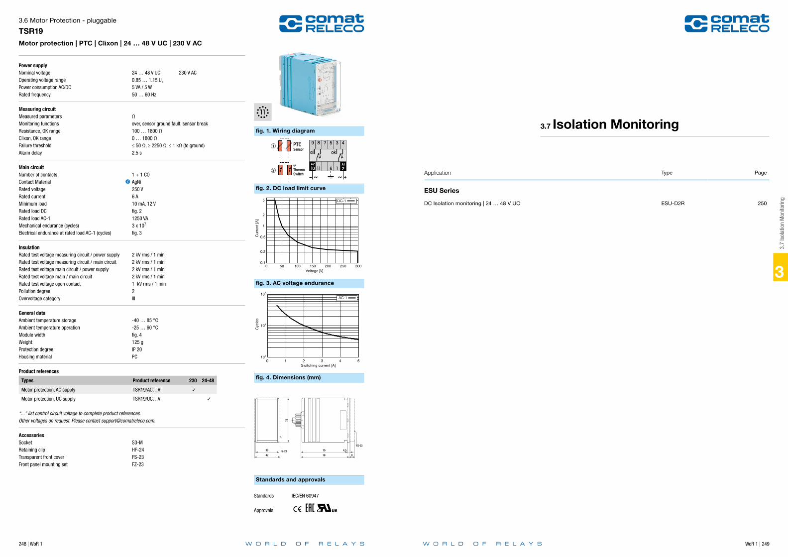
WoR 1 | 249
3
248 | WoR 1
Power supplyNominal voltageOperating voltage rangePower consumption AC/DCRated frequency
Measuring circuitMeasured parametersMonitoring functionsResistance, OK rangeClixon, OK rangeFailure thresholdAlarm delay
Main circuitNumber of contactsContact MaterialRated voltageRated currentMinimum loadRated load DCRated load AC-1Mechanical endurance (cycles)Electrical endurance at rated load AC-1 (cycles)
InsulationRated test voltage measuring circuit / power supplyRated test voltage measuring circuit / main circuitRated test voltage main circuit / power supplyRated test voltage main / main circuitRated test voltage open contactPollution degreeOvervoltage category
General dataAmbient temperature storageAmbient temperature operationModule widthWeightProtection degreeHousing material
Product references
Types Product reference 230 24-48
Motor protection, AC supply TSR19/AC…V
Motor protection, UC supply TSR19/UC…V
“...” list control circuit voltage to complete product references.Other voltages on request. Please contact [email protected].
AccessoriesSocket S3-MRetaining clip HF-24Transparent front cover FS-23Front panel mounting set FZ-23
3.6 Motor Protection - pluggable
TSR19Motor protection | PTC | Clixon | 24 … 48 V UC | 230 V AC
24 … 48 V UC 230 V AC0.85 … 1.15 UN
5 VA / 5 W50 … 60 Hz
Ωover, sensor ground fault, sensor break100 … 1800 Ω0 … 1800 Ω≤ 50 Ω, ≥ 2250 Ω, ≤ 1 kΩ (to ground)2.5 s
1 + 1 COAgNi250 V6 A10 mA, 12 Vfig. 21250 VA3 x 107
fig. 3
2 kV rms / 1 min2 kV rms / 1 min2 kV rms / 1 min2 kV rms / 1 min1 kV rms / 1 min2III
-40 … 85 °C-25 … 60 °Cfig. 4125 gIP 20PC
fig. 1. Wiring diagram
fig. 2. DC load limit curve
fig. 3. AC voltage endurance
fig. 4. Dimensions (mm)
Standards and approvals
ThermoSwitch
PTCSensor
105
106
107
0 1 2 3 4 5
Cyc
les
Switching current [A]
AC-1
0.1
0.2
0.5
1
2
5
0 50 100 150 200 250 300
Cur
rent
[A]
Voltage [V]
DC-1
38
42 9
4,5
FS-23
78
75
72
FZ-23
Standards IEC/EN 60947
Approvals
3.7
Isol
atio
n M
onito
ring
Application Type Page
ESU Series
DC Isolation monitoring | 24 … 48 V UC ESU-D2R 250
3.7 Isolation Monitoring

WoR 1 | 251
3
250 | WoR 1
Power supplyNominal voltageOperating voltage rangePower consumption AC/DCRated frequency
Measuring circuitMeasured parametersMonitoring functionsRated DC voltage U+-U-Overvoltage setting rangeCircuit / ground resistance measurement rangePre alarm setting rangeMain alarmAlarm delay
Main circuitNumber of contactsContact MaterialRated voltageRated currentMinimum loadRated load DCRated load AC-1Mechanical endurance (cycles)Electrical endurance at rated load AC-1 (cycles)
InsulationPollution degreeOvervoltage category
General dataAmbient temperature storageAmbient temperature operation railway versionConductor cross sectionNominal screw torqueModule widthWeightProtection degreeHousing material
Product references
Types Product reference 24-48
DC Isolation monitoring, railway version ESU-D2R/UC…V
“...” list control circuit voltage to complete product references.Other voltages on request. Please contact [email protected].
3.7 Isolation Monitoring
ESU-D2RDC Isolation monitoring | 24 … 48 V UC
24 … 48 V UC18 … 60 V2 VA / 2 W40 … 60 Hz
Ωunder, ground fault60 V> 60 VDC1 … 50 kΩ4 … 30 kΩ≤ 4 kΩ0.1 ... 10 s
1 NO + 2 COAgNi250 V5 A10 mA, 12 Vfig. 21250 VA5 x 106
1 x 10⁵
2III
-40 … 85 °C-40 … 70 °C2.5 mm2, 2 x 1.5 mm2
0.5 Nmfig. 4250 gIP 20PC
fig. 1. Wiring diagram
fig. 2. DC load limit curve
fig. 3. Dimensions (mm)
Standards and approvals
V
Installation to be monitored+DC 0..52V
Pre alarm
Main alarm
Connect E1, E2 separately on E.
Only one ESU-D2 per DC network!
0.1
0.2
0.5
1
2
3 4 5
0 50 100 150 200 250 300
Cur
rent
[A]
Voltage [V]
DC-1
1055
75
50
TS35
Standards IEC/EN 60947, IEC/EN 50155
Approvals
3.8
Mon
itorin
g M
odul
es
Application Type Page
CT Series
Current monitoring | 36 V DC CT515R 252
Voltage monitoring | 24 V DC CT524 253
3.8 Monitoring Modules

WoR 1 | 253
3
252 | WoR 1
Power supplyNominal voltageOperating voltage rangePower consumption AC/DC
Measuring circuitMeasured parametersMonitoring functionsRated measurement currentMeasurement current rangeUndercurrent setting rangeOvercurrent setting rangeAlarm delayAlarm reset delay
General dataAmbient temperature storageAmbient temperature operation railway versionModule widthWeightProtection degreeHousing material
Product references
Types Product reference 36
Current monitoring, railway version CT515R/…V
“...” list control circuit voltage to complete product references.Other voltages on request. Please contact [email protected].
AccessoriesSocket S3-M0, S5-M
3.8 Monitoring Modules
CT515RCurrent monitoring | 36 V DC
36 V DC18 … 45 V- / 2.3 V
IUnder, over, inside, outside2 A0 … 3 A0 … 2 A0 … 2 A100 ms / 500 ms / 2 s100 ms
-40 … 85 °C-40 … 70 °Cfig. 225 gIP 20PC
fig. 1. Wiring diagram
fig. 2. Dimensions (mm)
Standards and approvals
38 4 20 54
75
16
4
Standards IEC/EN 60947, IEC/EN 50155
Approvals
3.8
Mon
itorin
g M
odul
es
Power supplyNominal voltageOperating voltage rangePower consumption AC/DC
Measuring circuitMeasured parametersMonitoring functionsDC voltage measurement range U+-U-Undervoltage setting rangeOvervoltage setting rangeAlarm delayAlarm reset delay
General dataAmbient temperature storageAmbient temperature operation railway versionModule widthWeightProtection degreeHousing material
Product references
Types Product reference 24
Voltage monitoring, railway version CT524R/…V
“...” list control circuit voltage to complete product references.Other voltages on request. Please contact [email protected].
AccessoriesSocket S3-M0, S5-M
3.8 Monitoring Modules
CT524Voltage monitoring | 24 V DC
24 V DC18 … 30 V- / 0.4 W
UUnder, over, inside, outside0 … 30 V0 … 30 V0 … 30 V100 ms / 500 ms / 2 s100 ms
-40 … 85 °C-40 … 70 °Cfig. 225 gIP 20PC
fig. 1. Wiring diagram
fig. 2. Dimensions (mm)
Standards and approvals
38 4 20 54
75
16
4
Standards IEC/EN 60947, IEC/EN 50155
Approvals

WoR 1 | 255
3
254 | WoR 1
Notes
3.9
Supp
ress
or D
evic
e
Application Type Page
CEM Series
Suppressor device | 24 … 240 V UC CEM01 256
CRC Series
Overvoltage protection | 24 V UC CRC02 257
3.9 Suppressor Device
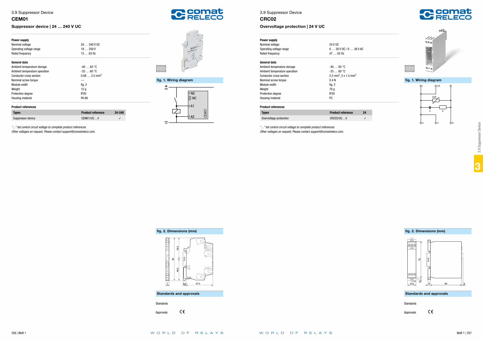
WoR 1 | 257
3
256 | WoR 1
Power supplyNominal voltageOperating voltage rangeRated frequency
General dataAmbient temperature storageAmbient temperature operationConductor cross sectionNominal screw torqueModule widthWeightProtection degreeHousing material
Product references
Types Product reference 24-240
Suppressor device CEM01/UC…V
“...” list control circuit voltage to complete product references.Other voltages on request. Please contact [email protected].
3.9 Suppressor Device
CEM01Suppressor device | 24 … 240 V UC
24 … 240 V UC19 … 250 V15 … 63 Hz
-40 … 85 °C-25 … 60 °C0.08 … 2.5 mm2
---fig. 215 gIP20PA 66
fig. 1. Wiring diagram
fig. 2. Dimensions (mm)
Standards and approvals
CEM01
NCNC
A1
A2
Standards
Approvals
3.9
Supp
ress
or D
evic
e
Power supplyNominal voltageOperating voltage rangeRated frequency
General dataAmbient temperature storageAmbient temperature operationConductor cross sectionNominal screw torqueModule widthWeightProtection degreeHousing material
Product references
Types Product reference 24
Overvoltage protection CRC02/UC…V
“...” list control circuit voltage to complete product references.Other voltages on request. Please contact [email protected].
3.9 Suppressor Device
CRC02Overvoltage protection | 24 V UC
24 V UC0 … 30 V DC / 0 … 38 V AC47 … 63 Hz
-40 … 85 °C-25 … 60 °C2.5 mm2, 2 x 1.5 mm2
0.4 Nfig. 270 gIP20PC
fig. 1. Wiring diagram
fig. 2. Dimensions (mm)
Standards and approvals
VDR
1 23
4
C
6
R
5
752,
5
17,54,2
LABEL
TS 3
5
5 64 3
Standards
Approvals
WoR 1 | 259
3
258 | WoR 1
Notes
3.10
Cur
rent
Tra
nsm
itter
Application Type Page
MRE-CT Series
Current Transmitter | 50 / 5 A … 100 / 5 A MRE-CT313 260
Current Transmitter | 100 / 5 A … 750 / 5 A MRE-CT314 261
Current Transmitter | 1000 / 5 A … 1500 / 5 A MRE-CT614 262
Current Transmitter | 2000 / 5 A MRE-CT1233 263
3.10 Current Transmitter

260 | WoR 1 WoR 1 | 261
3
Power supplyOperating voltage range
Measuring circuitPower consumption at 5 AMeasurement current rangeMax. currentRated base frequency
InsulationRated test voltage measuring / measuring circuit
General dataAmbient temperature storageAmbient temperature operationModule widthWeightProtection degree
Product references
Types Product reference 50 100
Class 1, power 1 VA MRE-CT313-…/5A/1-1
Class 1, power 2.5 VA MRE-CT313-…/5A/2.5-1
“...” list primary current to complete product references.Other transmission ratio on request. Please contact [email protected].
3.10 Current Transmitter
MRE-CT313Current Transmitter | 50 / 5 A … 100 / 5 A
< 720 V
0.36 VA/m (2.5 mm2 wire)≤ 1 x IN60 x IN, 1 s (max. 100 kA)50 … 60 Hz
3 kV rms / 1 min, Um < 720 V
-25 … 70 °C-5 … 50 °Cfig. 2120 gIP20
fig. 1. Wiring diagram
fig. 2. Dimensions (mm)
Standards and approvals
MRE
I…k
k l
PE
primary wire
I…l
Standards IEC/EN 61869
Approvals
3.10
Cur
rent
Tra
nsm
itter
Power supplyOperating voltage range
Measuring circuitPower consumption at 5 AMeasurement current rangeMax. currentRated base frequency
InsulationRated test voltage measuring / measuring circuit
General dataAmbient temperature storageAmbient temperature operationModule widthWeightProtection degree
Product references
Types Product reference 100 150 200 250 300 400 500 600 750
Class 0.2s, power 2.5 VA MRE-CT314-…/5A/2.5-0.2S
Class 0.2s, power 5 VA MRE-CT314-…/5A/5-0.2S
Class 0.5, power 2.5 VA MRE-CT314-…/5A/2.5-0.5
Class 0.5, power 5 VA MRE-CT314-…/5A/5-0.5
“...” list primary current to complete product references.Other transmission ratio on request. Please contact [email protected].
3.10 Current Transmitter
MRE-CT314Current Transmitter | 100 / 5 A … 750 / 5 A
< 720 V
0.36 VA/m (2.5 mm2 wire)≤ 1 x IN60 x IN, 1 s (max. 100 kA)50 … 60 Hz
3 kV rms / 1 min, Um < 720 V
-25 … 70 °C-5 … 50 °Cfig. 2180 gIP20
fig. 1. Wiring diagram
fig. 2. Dimensions (mm)
Standards and approvals
Standards IEC/EN 61869
Approvals
MRE
I…k
k l
PE
primary wire
I…l

262 | WoR 1 WoR 1 | 263
3
Power supplyOperating voltage range
Measuring circuitPower consumption at 5 AMeasurement current rangeMax. currentRated base frequency
InsulationRated test voltage measuring / measuring circuit
General dataAmbient temperature storageAmbient temperature operationModule widthWeightProtection degree
Product references
Types Product reference 1000 1250 1500
Class 0.2s, power 10 VA MRE-CT614-…/5A/10-0.2S
Class 0.5, power 10 VA MRE-CT614-…/5A/10-0.2S
“...” list primary current to complete product references.Other transmission ratio on request. Please contact [email protected].
3.10 Current Transmitter
MRE-CT614Current Transmitter | 1000 / 5 A … 1500 / 5 A
< 720 V
0.36 VA/m (2.5 mm2 wire)≤ 1 x IN60 x IN, 1 s (max. 100 kA)50 … 60 Hz
3 kV rms / 1 min, Um < 720 V
-25 … 70 °C-5 … 50 °Cfig. 2260 gIP20
fig. 1. Wiring diagram
fig. 2. Dimensions (mm)
Standards and approvals
Standards IEC/EN 61869
Approvals
MRE
I…k
k l
PE
primary wire
I…l
3.10
Cur
rent
Tra
nsm
itter
Power supplyOperating voltage range
Measuring circuitPower consumption at 5 AMeasurement current rangeMax. currentRated base frequency
InsulationRated test voltage measuring / measuring circuit
General dataAmbient temperature storageAmbient temperature operationModule widthWeightProtection degree
Product references
Types Product reference 2000
Class 0.2s, power 10 VA MRE-CT1233-…/5A/10-0.2S
Class 0.5, power 10 VA MRE-CT1233-…/5A/10-0.2S
“...” list primary current to complete product references.Other transmission ratio on request. Please contact [email protected].
3.10 Current Transmitter
MRE-CT1233Current Transmitter | 2000 / 5 A
< 720 V
0.36 VA/m (2.5 mm2 wire)≤ 1 x IN60 x IN, 1 s (max. 100 kA)50 … 60 Hz
3 kV rms / 1 min, Um < 720 V
-25 … 70 °C-5 … 50 °Cfig. 2340 gIP20
fig. 1. Wiring diagram
fig. 2. Dimensions (mm)
Standards and approvals
Standards IEC/EN 61869
Approvals
MRE
I…k
k l
PE
primary wire
I…l
WoR 1 | 265
3
264 | WoR 1
Notes
3.11
Mon
itorin
g Re
lay
Acce
ssor
iesApplication Type Page
Accessories
Front panel mounting set | Retaining clip FZ-23 266
Transparent front cover FS-23 267
Retaining clip | Plastic HF-24 268
3.11 Monitoring Relay Accessories
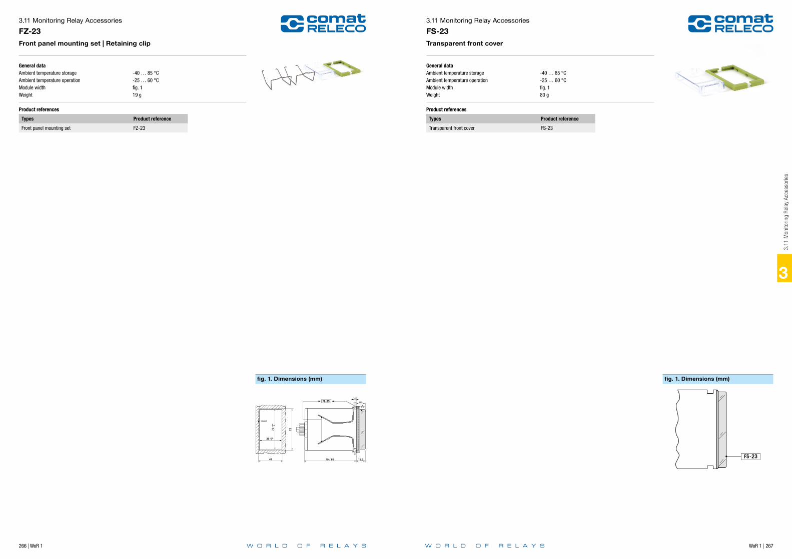
266 | WoR 1 WoR 1 | 267
General dataAmbient temperature storageAmbient temperature operationModule widthWeight
Product references
Types Product reference
Front panel mounting set FZ-23
3.11 Monitoring Relay Accessories
FZ-23Front panel mounting set | Retaining clip
-40 … 85 °C-25 … 60 °Cfig. 119 g
fig. 1. Dimensions (mm)
FRONT
+0.
6
070 72
+0.6 038
42 75 / 89 15.5
15.5
1..3
FZ-239
3
3.11
Mon
itorin
g Re
lay
Acce
ssor
ies
General dataAmbient temperature storageAmbient temperature operationModule widthWeight
Product references
Types Product reference
Transparent front cover FS-23
3.11 Monitoring Relay Accessories
FS-23Transparent front cover
-40 … 85 °C-25 … 60 °Cfig. 180 g
fig. 1. Dimensions (mm)
FS-23
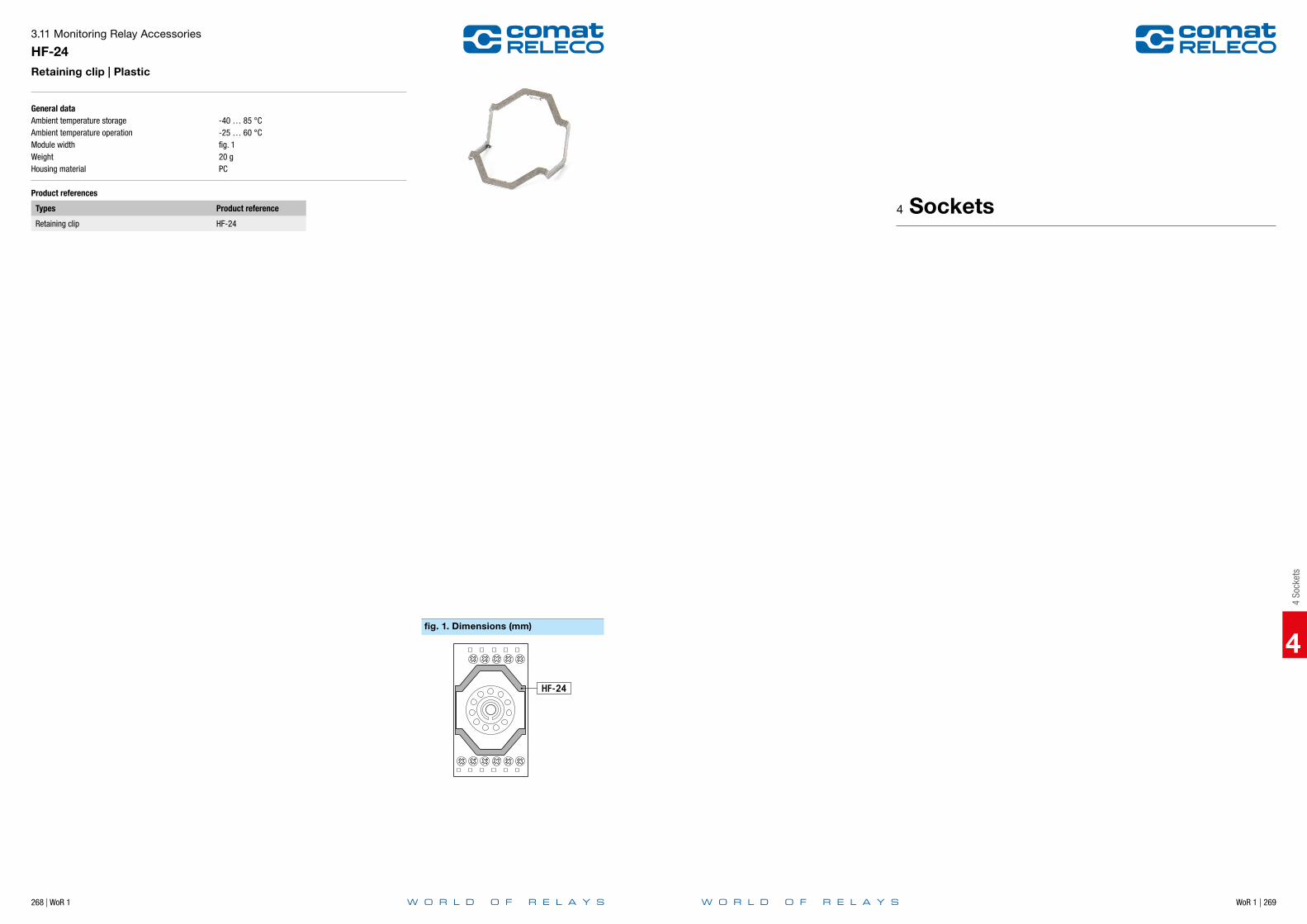
WoR 1 | 269
4
4 So
cket
s
268 | WoR 1
General dataAmbient temperature storageAmbient temperature operationModule widthWeightHousing material
Product references
Types Product reference
Retaining clip HF-24
3.11 Monitoring Relay Accessories
HF-24Retaining clip | Plastic
-40 … 85 °C-25 … 60 °Cfig. 120 gPC
fig. 1. Dimensions (mm)
HF-24
4 Sockets
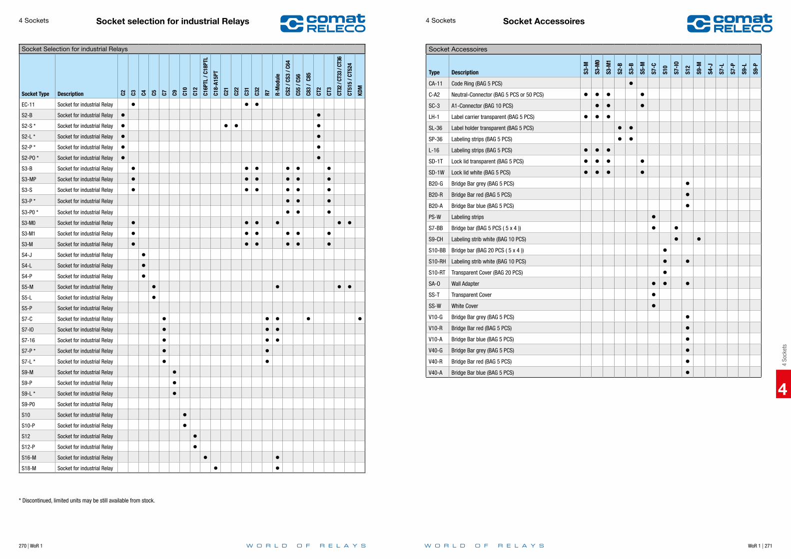
270 | WoR 1 WoR 1 | 271
4
4 So
cket
s
Socket selection for industrial Relays4 Sockets
Socket Selection for industrial Relays
Socket Type Description C2 C3 C4 C5 C7 C9 C10
C12
C16P
TL /
C18P
TL
C18-
A15P
T
C21
C22
C31
C32
R7 R-M
odul
e
CS2
/ CS3
/ C6
4
C55
/ C56
C83
/ C8
5
CT2
CT3
CT32
/ CT
33 /
CT36
CT51
5 / C
T524
KDM
EC-11 Socket for industrial Relay S2-B Socket for industrial Relay S2-S * Socket for industrial Relay S2-L * Socket for industrial Relay S2-P * Socket for industrial Relay S2-PO * Socket for industrial Relay S3-B Socket for industrial Relay S3-MP Socket for industrial Relay S3-S Socket for industrial Relay S3-P * Socket for industrial Relay S3-P0 * Socket for industrial Relay S3-M0 Socket for industrial Relay S3-M1 Socket for industrial Relay S3-M Socket for industrial Relay S4-J Socket for industrial Relay S4-L Socket for industrial Relay S4-P Socket for industrial Relay S5-M Socket for industrial Relay S5-L Socket for industrial Relay S5-P Socket for industrial Relay
S7-C Socket for industrial Relay S7-IO Socket for industrial Relay S7-16 Socket for industrial Relay S7-P * Socket for industrial Relay S7-L * Socket for industrial Relay S9-M Socket for industrial Relay S9-P Socket for industrial Relay S9-L * Socket for industrial Relay S9-P0 Socket for industrial Relay
S10 Socket for industrial Relay S10-P Socket for industrial Relay S12 Socket for industrial Relay S12-P Socket for industrial Relay S16-M Socket for industrial Relay S18-M Socket for industrial Relay
* Discontinued, limited units may be still available from stock.
4
Socket Accessoires4 Sockets
Socket Accessoires
Type Description S3-M
S3-M
0
S3-M
1
S2-B
S3-B
S5-M
S7-C
S10
S7-I
O
S12
S9-M
S4-J
S7-L
S7-P
S9-L
S9-P
CA-11 Code Ring (BAG 5 PCS) C-A2 Neutral-Connector (BAG 5 PCS or 50 PCS) SC-3 A1-Connector (BAG 10 PCS) LH-1 Label carrier transparent (BAG 5 PCS) SL-36 Label holder transparent (BAG 5 PCS) SP-36 Labeling strips (BAG 5 PCS) L-16 Labeling strips (BAG 5 PCS) SD-1T Lock lid transparent (BAG 5 PCS) SD-1W Lock lid white (BAG 5 PCS) B20-G Bridge Bar grey (BAG 5 PCS) B20-R Bridge Bar red (BAG 5 PCS) B20-A Bridge Bar blue (BAG 5 PCS) PS-W Labeling strips S7-BB Bridge bar (BAG 5 PCS ( 5 x 4 )) S9-CH Labeling strib white (BAG 10 PCS) S10-BB Bridge bar (BAG 20 PCS ( 5 x 4 )) S10-RH Labeling strib white (BAG 10 PCS) S10-RT Transparent Cover (BAG 20 PCS) SA-O Wall Adapter SS-T Transparent Cover SS-W White Cover V10-G Bridge Bar grey (BAG 5 PCS) V10-R Bridge Bar red (BAG 5 PCS) V10-A Bridge Bar blue (BAG 5 PCS) V40-G Bridge Bar grey (BAG 5 PCS) V40-R Bridge Bar red (BAG 5 PCS) V40-A Bridge Bar blue (BAG 5 PCS)

272 | WoR 1 WoR 1 | 273
Ret
aini
ng c
lip s
elec
tion
for
sock
et a
nd r
elay
Sock
et ty
pe
Made in
C2 ESP
C2 ESP + CT2 Timecube
C2 IND
CT 2 IND + CT2 Timecube
C3 ESP
C3 ESP + CT3 Timecube
C3 IND
C3 ESP + CT3 Timecube
C4 ESP
C4 CN
C5 ESP
C5 CN
C7 ESP
C7 CN
C9 ESP
C9 CN
C10 ESP
C10 CN
C10 IND
C12 ESP
C12 IND
C16PTL / C18PTL
C18-A15PT
C21
C21 + CT2 Timecube
C22
C22 + CT2 Timecube
C31
C31 + CT3 Timecube
C32
C32 + CT3 Timecube
R3 ESP
R3 IND
R7 ESP
R7 CN
EC-8
ESP
S3-C
HF-3
2S3
-CHF
-32
HF-3
2HF
-33
HF-3
2HF
-33
EC-1
1CN
HF-3
2HF
-33
HF-3
2HF
-33
S3-C
HF-3
2
S2-B
. S2-
SCN
S3-C
MCP
-15B
S3-C
S3-C
TS3
0-CM
HF-3
2HF
-33
HF-3
2HF
-33
HF-3
2HF
-33
S20-
BES
P
S3-C
MCP
-15B
S3-C
S3-C
TS3
0-CM
HF-3
2HF
-33
S2-L
, S2-
P, S2
-PO
ESP
S3-C
HF-3
2
S3-B
CN
S3-C
MCP
-15B
S3-C
S3-C
TS3
0-CM
HF-3
2HF
-33
S30-
CMHF
-32
HF-3
3S3
0-CM
HF-3
2HF
-33
S3-C
MCP
-15B
S3-C
S30-
CMHF
-32
S30-
BES
P
S3-C
MCP
-15B
S3-C
S3-C
TS3
0-CM
HF-3
2HF
-33
S30-
CMHF
-32
HF-3
3S3
0-CM
HF-3
2HF
-33
S3-C
MCP
-15B
S3-C
S30-
CMHF
-32
S3-M
PES
P
S3-C
MCP
-15B
S3-C
S3-C
TS3
0-CM
HF-3
2HF
-33
S30-
CMHF
-32
HF-3
3S3
0-CM
HF-3
2HF
-33
S3-C
MCP
-15B
S3-C
S30-
CMHF
-32
S3-S
CN
S3-C
MCP
-15B
S3-C
S3-C
TS3
0-CM
HF-3
2HF
-33
S30-
CMHF
-32
HF-3
3S3
0-CM
HF-3
2HF
-33
S3-C
MCP
-15B
S3-C
S30-
CMHF
-32
S3-L
, S3-
P, S3
-PO
ESP
S3-C
HF-3
2HF
-32
HF-3
2
S3-M
0ES
PS3
-CS3
-CT
HF-3
2HF
-33
HF-3
2HF
-33
HF-3
2HF
-33
S4-J
CN
S3-C
MCP
-15B
S3-C
S3-C
MCP
-15B
S3-C
S4-L
, S4-
P, S4
-PO
ESP
S4-C
LS4
-CL
S5-S
ESP
S3-C
MCP
-15B
S4-C
S3-C
MCP
-15B
S4-C
S5-M
CNS5
M-C
PHF
-32
S5M
-CP
HF-3
2
S7-C
CNS7
-CPO
CP-0
7BS7
-CPO
CP-0
7BS7
-CPO
CP-0
7BS7
-CPO
CP-0
7B
S7-IO
ESP
S9-C
CP-0
1BS9
-CCP
-01B
S7-C
POCP
-07B
S7-C
POCP
-07B
S7-IO
CNS9
-CCP
-01B
S9-C
CP-0
1BS7
-CPO
CP-0
7BS7
-CPO
CP-0
7B
S7-1
6ES
PS7
-CPO
CP-0
7BS7
-CPO
CP-0
7BS7
-CPO
CP-0
7BS7
-CPO
CP-0
7B
S7-P
S7-C
POCP
-07B
S7-C
POCP
-07B
S7-C
POCP
-07B
S7-C
POCP
-07B
S7-L
, S7-
POES
PS9
-CCP
-01B
S9-C
CP-0
1BS9
-CCP
-01B
S9-C
CP-0
1B
S9-M
CNS9
-CCP
-01B
S9-C
CP-0
1B
S9-P
S7-C
POCP
-07B
S7-C
POCP
-07B
S9-L
, S9-
POES
PS9
-CCP
-01B
S9-C
CP-0
1B
S10
CNS1
0-C
CP-1
7BS1
0-C
CP-1
7BS1
0-C
CP-1
7B
S10-
PCN
CP-2
4BCP
-24B
CP-2
4B
S12
CNS1
0-C
CP-1
7BS1
0-C
CP-1
7B
S12-
PES
PCP
-24B
CP-2
4B
S16-
MCN
CP-1
6
S18-
MCN
CP-1
6
4
4.1
8-Pi
n So
cket
s
Application Type Pins Page
8-Pin Series
Socket for 8-pin Relays and Time Cubes S2-B 274
Socket for 8-pin Relays and Time Cubes S2-PO 275
4.1 8-Pin Sockets

274 | WoR 1 WoR 1 | 275
4
Connection diagram Connection diagram
Dimensions (mm) Dimensions (mm)
Technical approvals, conformities Technical approvals, conformities
Dimensions (mm)
4.1 8-Pin Sockets
S2-BSocket for 8-pin Relays and Time Cubes
12
345
6
78
45°
1.3ø
17.5
5
42
7
)12(
)22((A2)
( A1) )11(1
8 ( 21)
(14 )3
( 24 )6
)A1()11()21()A2( ( 24 )
( 22 )(12 )(14 )
7812 3
456
ø8.2
ø5.3
24
6
7
A111
21A2
21
8
29.7
5
27
68
34
5
1412
2224 6
M38
38S2-B
Rated Load 10 A / 300 V
SpecificationsRated impulse withstand voltage – All terminals / DIN rail 2.5 kV rms / 1 min– Terminal / Terminal 2.5 kV rms / 1 minCross-section of connecting wire– Single-wire 4 mm2 / AWG 12 or 2 x 2.5 mm2 / AWG 14– Multi-wire 0.34 mm2 / AWG 22 - 2.5 mm2 / AWG 14 Nominal screw torque 0.7 NmScrew Dimensions (mm) M3 Pozi slotMounting TS-35 or Back Panel MountingAmbient temperature operation / storage -40.…60 ºC /-40 … 80 °C (no ice)Weight 48g
Included AccessoriesRetaining Clip, plastic S30-CM for C2 / C2x Relays Optional AccessoriesRetaining clip, steel HF-32 (BAG 10 PCS) for C2 / C2x Relays HF-33 (BAG 10 PCS) for Time Cube CTx
4.1
8-Pi
n So
cket
s
12
345
6
78
45°
1.3ø
17.5
5
42
7
)12(
)22((A2)
( A1) )11(1
8 ( 21)
(14 )3
( 24 )6
)A1()11()21()A2( ( 24 )
( 22 )(12 )(14 )
7812 3
456
Printed circuit lay-out (mm)
4.1 8-Pin Sockets
S2-POSocket for 8-pin Relays and Time Cubes
Rated Load 10 A / 300 V
SpecificationsRated impulse withstand voltage – Pin / Pin 2.5 kV rms / 1 minAmbient temperature operation/storage -40 … 60 ºC /-40 … 80 °C (no ice)Weight 17g
Optional AccessoriesRetaining clip, steel HF-32 (BAG 10 PCS) for C2 / C2x Relays HF-33 (BAG 10 PCS) for Time Cube CTx
L
PO
S2-L
S2-PO
38
3.4
39
494
1
71510
29.5
4.7
15
ø
L
PO
S2-L
S2-PO
38
3.4
39
494
1
71510
29.5
4.7
15
ø
Dimensions (mm)

WoR 1 | 277
4
276 | WoR 1
Notes
4.2
11-P
in S
ocke
ts
Application Type Pins Page
11-Pin Series
Socket for 11-pin Relays and Time Cubes S3-B 278
Socket for 11-pin standard Relays and Time Cubes S3-S 279
Socket for 11-pin standard Relays EC-11 280
Socket for 11-pin Relays and Time / Monitoring Module S3-M 281
Socket for 11-pin Relays and Time / Monitoring Module S3-M0 / S3-M1 282
PCB Socket for 11-pin Relays and Time Cubes S3-L 283
Socket for 11-pin Relays S5-M 284
PCB Socket for 11-pin Relays S5-P 285
Socket for 11-pin Relays S5-SSY 286
4.2 11-Pin Sockets

278 | WoR 1 WoR 1 | 279
4
Connection diagram Connection diagram
Dimensions (mm) Dimensions (mm)
Technical approvals, conformities Technical approvals, conformities
4.2 11-Pin Sockets
S3-BSocket for 11-pin Relays and Time Cubes
19
1.3
32°44’32°44’
12
3
4567
8
9
1011
ø
7 )24( ( 22 )56 ( 21)
8
42
10
)12(
)32((A2)
( A1) )11(1
11( 31)
(14 )3
( 34 )9
(14 ))A1()11()31()A2()34(9
( 32 )(24 )( 21)( 22 )
)12(
1011
123 4
5678
29.7
5
6838
87
6522
2124
32
102
A231
1A1
01
12
12 4
9 34143
11 7
5
1
ø8.2
ø5.3
24
6
8 M3
29.7
5
68
38
87
6522
2124
32
102
A231
1A1
01
12
12 4
9 34143
11 7
5
1
ø8.2
ø5.3
24
6
8 M3
S2-B
Rated Load 10 A / 300 V
SpecificationsRated impulse withstand voltage – All terminals / DIN rail 2.5 kV rms / 1 min– Terminal / Terminal 2.5 kV rms / 1 minCross-section of connecting wire– Single-wire 4 mm2 / AWG 12 or 2 x 2.5 mm2 / AWG 14– Multi-wire 0.34 mm2 / AWG 22 - 2.5 mm2 / AWG 14 Nominal screw torque 0.7 NmScrew Dimensions (mm) M3 Pozi slotMounting TS-35 or Back Panel MountingAmbient temperature -40 … 60 ºC /-40 … 80 °C (no ice)Weight 55g
Included AccessoriesRetaining Clip, plastic S30-CM for C3 / C3x Relays Optional AccessoriesRetaining clip, steel HF-32 (BAG 10 PCS) for C3 / C3x Relays HF-33 (BAG 10 PCS) for Time Cube CTxCoding Ring S3-BC (BAG 5 PCS) for C3 / C3x Relays
Dimensions (mm)
4.2
11-P
in S
ocke
ts
4.2 11-Pin Sockets
S3-SSocket for 11-pin standard Relays and Time Cubes
621 522724
102
75
A2 10A1 2 11 1
31 11 34 914 3 12 4
32 8
5.3
25
8.2
7.2
ø
ø
38
M3.5M3 10
30
80
621 522724
102
75
A2 10A1 2 11 1
31 11 34 914 3 12 4
32 8
5.3
25
8.2
7.2
ø
ø
38
M3.5M3 10
30
80
19
1.3
32°44’32°44’
12
3
4567
8
9
1011
ø
7 )24( ( 22 )56 ( 21)
8
42
10
)12(
)32((A2)
( A1) )11(1
11( 31)
(14 )3
( 34 )9
(14 ))A1()11()31()A2()34(9
( 32 )(24 )( 21)( 22 )
)12(
1011123 4
5678
Rated Load 10 A / 250 V
SpecificationsRated impulse withstand voltage – All terminals / DIN rail 2.5 kV rms / 1 min– Terminal / Terminal 2.5 kV rms / 1 minCross-section of connecting wire– Single-wire 4 mm2 / AWG 12 or 2 x 2.5 mm2 / AWG 14– Multi-wire 0.34 mm2 / AWG 22 - 2.5 mm2 / AWG 14 Nominal screw torque 1.2 NmScrew Dimensions (mm) M3.5 Pozi slotMounting TS-35 or Back Panel MountingAmbient temperature operation/storage -40.…60 ºC /-40 … 80 °C (no ice)Weight 69g
Included AccessoriesRetaining Clip, plastic S30-CM for C3 / C3x Relays Optional AccessoriesRetaining clip, steel HF-32 (BAG 10 PCS) for C3 / C3x Relays HF-33 (BAG 10 PCS) for Time Cube CTxCoding Ring S3-BC (BAG 5 PCS) for C3 / C3x Relays
Connection diagram
Dimensions (mm)

280 | WoR 1 WoR 1 | 281
Connection diagram Connection diagram
Dimensions (mm) Dimensions (mm)
Technical approvals, conformities
4
Dimensions (mm)
4.2 11-Pin Sockets
EC-11Socket for 11-pin standard Relays
Rated Load 10 A / 400 V
SpecificationsRated impulse withstand voltage – All terminals / DIN rail 2.5 kV rms / 1 min– Terminal / Terminal 2.5 kV rms / 1 minCross-section of connecting wire– Single-wire 4 mm2 / AWG 12 or 2 x 2.5 mm2 / AWG 14– Multi-wire 0.34 mm2 / AWG 22 - 2.5 mm2 / AWG 14 Nominal screw torque 0.7 NmScrew Dimensions (mm) M3.5 Pozi slotMounting TS-35 or Back Panel MountingAmbient temperature operation/storage -25.…60 ºC /-40 … 80 °C (no ice)Weight 56 g
6
18
22 4 38
28
10
A2 31 21 11 A1
11 6 1 1 2
62
824
.2 forM3
forM4
9
34
8 7 5 3 4
32 24 22 14 12
19
1.3
32°44’32°44’
12
3
4567
8
9
1011
ø
7 )24( ( 22 )56 ( 21)
8
42
10
)12(
)32((A2)
( A1) )11(1
11( 31)
(14 )3
( 34 )9
(14 ))A1()11()31()A2()34(9
( 32 )(24 )( 21)( 22 )
)12(
1011123 4
5678
Technical approvals, conformities
4.2
11-P
in S
ocke
ts
4.2 11-Pin Sockets
S3-MSocket for 11-pin Relays and Time / Monitoring Module
10 (A2)
6 (21)
1 (11)
2 (A1)
11 (31)
9 (34)
3 (14)
7 (24)
5 (22)
4 (12)
8 (32)
30
FOR M4
38
75
M3C-A2
FOR PLUG-INMODULES
10A
204
4
16
C-A2
FOR PLUG-INMODULES
10
A2-CONNECTOR
max 40
11 16
A2 A1
212
5789 43
10
Rated Load 10 A / 250 V
SpecificationsRated impulse withstand voltage – All terminals / DIN rail 2.5 kV rms / 1 min– Terminal / Terminal 2.5 kV rms / 1 minCross-section of connecting wire– Single-wire 1 x 6 mm2/ AWG 10, 2 x 1.5 mm2/ AWG 16 – Multi-wire 1 x 4 mm2/AWG 12, 2 x 1.5 mm2/AWG 16 Nominal screw torque 0.7 NmScrew Dimensions (mm) M3 Pozi slotMounting TS-35 or Back Panel MountingAmbient temperature operation/storage -25 … 60 ºC /-40 … 80 °C (no ice)Weight 61g
Included AccessoriesA2-Connector C-A2 Optional AccessoriesRetaining clip, steel HF-32 (BAG 10 PCS) for C3 / C3x Relays HF-33 (BAG 10 PCS) for Time Cube CTxCoding Ring S3-BC (BAG 5 PCS) for C3 / C3x RelaysA2-Connector C-A2 (BAG 5 PCS), C-A2 (BAG 50 PCS)Free-wheeling Diode Module RD1/DC12-220VRC-Suppressor Module RC1/UC110-240V
IEC/EN 50155
Dimensions (mm)

WoR 1 | 283282 | WoR 1
Technical approvals, conformities
Dimensions (mm)
Connection diagram S3-M0
4.2 11-Pin Sockets
S3-M0 / S3-M1Socket for 11-pin Relays and Time / Monitoring Module
10 (A2)
12 (B1)
6 (21)
1 (11)
2 (A1)
11 (31)
9 (34)
3 (14)
7 (24)
5 (22)
4 (12)
8 (32)
10 (A2)
12 (B1)
6 (21)
1 (11)
2 (A1)
11 (31)
9 (34)
3 (14)
7 (24)
5 (22)
4 (12)
8 (32)
30
FOR M4
38
75
M3C-A2
FOR PLUG-INMODULES
10A
204
4
16
C-A2
FOR PLUG-INMODULES
10
A2-CONNECTOR
max 40
11 16
A2 A1B1
212
5789 43
10
Rated Load 10 A / 250 V
SpecificationsRated impulse withstand voltage – All terminals / DIN rail 2.5 kV rms / 1 min– Terminal / Terminal 2.5 kV rms / 1 minCross-section of connecting wire– Single-wire 1 x 6 mm2/ AWG 10, 2 x 1.5 mm2/ AWG 16 – Multi-wire 1 x 4 mm2/AWG 12, 2 x 1.5 mm2/AWG 16 Nominal screw torque 0.7 NmScrew Dimensions (mm) M3 Pozi slotMounting TS-35 or Back Panel MountingAmbient temperature operation/storage -25 … 60 ºC /-40 … 80 °C (no ice)Weight 61g
Included AccessoriesA2-Connector C-A2 Optional AccessoriesRetaining clip, steel HF-32 (BAG 10 PCS) for C3 / C3x Relays HF-33 (BAG 10 PCS) for Time Cube CTxCoding Ring S3-BC (BAG 5 PCS) for C3 / C3x RelaysA2-Connector C-A2 (BAG 5 PCS), C-A2 (BAG 50 PCS)Free-wheeling Diode Module RD1/DC12-220VRC-Suppressor Module RC1/UC110-240V
With Bridge Connector SC-3
Connection diagram S3-M1
IEC/EN 50155
General dataRated loadRated impulse withstand voltage– Pin / pinAmbient temperature storageAmbient temperature operationWeightHousing material
Optional accessoriesRetaining clip, steel
4.2 11-Pin Sockets
S3-LPCB Socket for 11-pin Relays and Time Cubes
fig. 1. Printed circuit lay-out (mm)
19
1.3
32°44’32°44’
123
4567
8
9
1011
ø
fig. 2. Dimensions (mm)
L
10 157
ø29.54
49
39
3.4
38
Technical approvals, conformities
Approvals
10 A / 250 V
2.5 kV rms / 1 min-40 … 80 °C-40 … 60 °C17 gPA / PC
HF-32 (BAG 10 PCS) for C3 / C3x RelaysHF-33 (BAG 10 PCS) for Time Cube CTx
4
4.2
11-P
in S
ocke
ts

284 | WoR 1 WoR 1 | 285
Connection diagram Connection diagram
Dimensions (mm) Dimensions (mm)
Technical approvals, conformities Technical approvals, conformities
Printed circuit lay-out (mm)
4.2 11-Pin Sockets
S5-PPCB Socket for 11-pin Relays
Rated Load 16 A / 400 V
SpecificationsRated impulse withstand voltage – Pin / Pin 2.5 kV rms / 1 minAmbient temperature operation/storage -40 … 60 ºC / -40 … 80 °C (no ice)Weight 20g
Optional Accessories Retaining spring, steel S5-CL (BAG 10 PCS) for C5 / C5x Relays
1.8
S5-P S5-L
1.5
Dimensions (mm)Dimensions (mm)
4.2 11-Pin Sockets
S5-M Socket for 11-pin Relays
3 (32) 6 (34)9 (31)
2 (22) 5 (24)8 (21)
1 (12) 4 (14)7 (11)10 (A1)
11 (B1)
12 (A2)
Rated Load 16 A / 400 V
SpecificationsRated impulse withstand voltage – All terminals / DIN rail 4 kV rms / 1 min– Terminal / Terminal 4 kV rms / 1 minCross-section of connecting wire– Single-wire 1 x 6 mm2 / AWG 10, 2 x 2.5 mm2 / AWG 14 – Multi wire 1 x 6 mm2 / AWG 10, 2 x 1.5 mm2 / AWG 16Nominal screw torque 1 NmScrew Dimensions (mm) M3.5 Pozi slotMounting TS-35 or Back Panel MountingAmbient temperature operation / storage -40 … 60° C/-40 … 80° C (no ice)Weight 92g
Integrated Accessories A2-Connector C-A2 Retaining clip, plastic S5M-CP for C5 / C5x RelaysA1-, B1-Connector SC-3 Optional AccessoriesRetaining Clip, steel HF-32 (BAG 10 PCS) for C5 / C5x RelaysA2-Connector C-A2 (BAG 5 PCS), C-A2 (BAG 50 PCS)A1-, B1-Connector SC-3 (BAG 10 PCS)Free-wheeling Diode Module RD1/DC12-220VRC-Suppressor Module RC1/UC110-240V
CS
-155
COM
3424
14
65
4
NO
3222
12
32
1
3121
11
98
7
NC
1211
10
A2B1
A1
28.73,8
38
88
27.6
22
ø4.3
29.5
32.5C
S-155
CO
NN
EC
TO
R C
-A2
C-A
2
C-A2
SC-3
SD-1T
SD-1W
A2B1
A1
32
1110
32
1
2212
3465
4
2414
3198
7
2111
12
27.6
28.7
65
88
38
M4C-A2
29.5
4
4.2
11-P
in S
ocke
ts
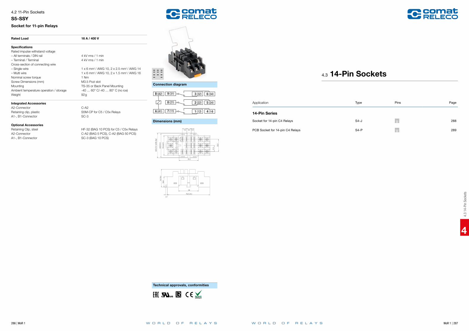
286 | WoR 1 WoR 1 | 287
4
Connection diagram
Dimensions (mm)
Technical approvals, conformities
Dimensions (mm)
4.2 11-Pin Sockets
S5-SSY Socket for 11-pin Relays
Rated Load 16 A / 400 V
SpecificationsRated impulse withstand voltage – All terminals / DIN rail 4 kV rms / 1 min– Terminal / Terminal 4 kV rms / 1 minCross-section of connecting wire– Single-wire 1 x 6 mm2 / AWG 10, 2 x 2.5 mm2 / AWG 14 – Multi wire 1 x 6 mm2 / AWG 10, 2 x 1.5 mm2 / AWG 16Nominal screw torque 1 NmScrew Dimensions (mm) M3.5 Pozi slotMounting TS-35 or Back Panel MountingAmbient temperature operation / storage -40 … 60° C/-40 … 80° C (no ice)Weight 92g
Integrated Accessories A2-Connector C-A2 Retaining clip, plastic S5M-CP for C5 / C5x RelaysA1-, B1-Connector SC-3 Optional AccessoriesRetaining Clip, steel HF-32 (BAG 10 PCS) for C5 / C5x RelaysA2-Connector C-A2 (BAG 5 PCS), C-A2 (BAG 50 PCS)A1-, B1-Connector SC-3 (BAG 10 PCS)
Technical approvals, conformities
S5-SSYSocket for square base Relay C5-…
Rated Load 16 A / 400 V
SpecificationsRated impulse withstand voltage – All terminals / DIN rail 2.5 kV rms / 1 min– Terminal / Terminal 2.5 kV rms / 1 minCross-section of connecting wire– Single-wire 4 mm2 / AWG 12 or 2 x 2.5 mm2 / AWG 14– Multi-wire 0.34mm2 / 22 - 2.5 mm2 / AWG 14Nominal screw torque 1.0 NmScrew dimensions M3.5 Pozi 1 slot 2Mounting TS-35 or Back Panel MountingAmbient temperature -25.…85 ºC /-40 ... 85 °C (no ice)Weight 81 g
Included Accessories Retaining spring, steel S5-C
Dimensions [mm]
Connection diagram
32 ±
0.1
18.8
76.5 ± 0.1
2.7
36
35.2
± 0.
1
7.6 8.3
35.3
11.1
22.2
5.3
42.6
± 0.
1
44.8
± 0.1
(with
clip
)
9 (31) 3 (32) 6 (34)B (A2)
8 (21) 2 (22) 5 (24)
7 (11) 1 (12) 4 (14)A (A1)
Maximum voltage between two separate circuits on neighbouring contacts: 250 VNot permitted: 24 V DC next to 230 V AC, 230 V AC next to neutral, 230 V AC next to 230 V AC of different phases Permitted: 230 V AC next to 230 V AC same phase
4.3
14-P
in S
ocke
ts
Application Type Pins Page
14-Pin Series
Socket for 14-pin C4 Relays S4-J 288
PCB Socket for 14-pin C4 Relays S4-P 289
4.3 14-Pin Sockets

288 | WoR 1 WoR 1 | 289
4
Connection diagram Connection diagram
Dimensions (mm) Dimensions (mm)
Technical approvals, conformities Technical approvals, conformities
4.3 14-Pin Sockets
S4-JSocket for 14-pin C4 Relays
1.58
24
6.750.2 7
6.5
6.75
ø
1 )12(13 ( A1))11( (14 )3 2
5 )24(( 22 )46 ( 21)
7 )32( (34 )8
10 )42( ( 44 )1112 ( 41) )A2(14
9 ( 31)
M4/M5
32
ø
7
ø5.5
9
3892
13
811
3 6
13
52 1
4
8 7
1412 9 11 10
3444
214
524
112
422
732
1042
36
A11121
931
1241
1421
Rated Load 10 A / 250 V
SpecificationsRated impulse withstand voltage – All terminals / DIN rail 2.5 kV rms / 1 min– Terminal / Terminal 2.5 kV rms / 1 minCross-section of connecting wire– Single-wire 1.5 mm2 / AWG 15 or 2 x 1.5 mm2 / AWG 15– Multi-wire 0,34 mm2 / AWG 22 - 1 mm2 / AWG 17 Nominal screw torque 1 NmScrew Dimensions (mm) M3.5 Philips-slot (combo)Mounting TS-35 or Back Panel MountingAmbient temperature -40 … 60 ºC /-40 … 80 °C (no ice)Weight 80g
Included AccessoriesRetaining Clip, plastic S3-CM/CP-15B (BAG 10 PCS) for C4 Relays Optional AccessoriesRetaining Clip, steel S3-C (BAG 10 PCS) for C4 Relays
Dimensions (mm)
4.3
14-P
in S
ocke
ts
Dimensions (mm)
Printed circuit lay-out (mm)
4.3 14-Pin Sockets
S4-PPCB Socket for 14-pin C4 Relays
1.58
24
6.750.2 7
6.5
6.75
ø
1 )12(13 ( A1))11( (14 )3 2
5 )24(( 22 )46 ( 21)
7 )32( (34 )8
10 )42( ( 44 )1112 ( 41) )A2(14
9 ( 31)
32
ø
7
ø5.5
9
M4/M5
38
92
13
811
3 6
13
52 1
4
8 7
1412 9 11 10
3444
214
524
112
422
732
10 42
36
A11121
931
1241
1421
S4-P 2.81.2
S4-P
S4-P S4-L
S4-LS4-PO
S4-L
35.5
36
15.5 6 7.56
35.5
M3
4757
Rated Load 10 A / 250 V
SpecificationsRated impulse withstand voltage – Pin / Pin 2.5 kV rms / 1 minAmbient temperature -30 °C … +60 °C (no ice)Weight 21g
Optional Accessories Retaining spring, steel S4-CL (BAG 10 PCS) for C4 / C4x Relays

WoR 1 | 291
4
290 | WoR 1
Notes
4.4
8/14
-Pin
Soc
kets
Application Type Pins Page
8/14-Pin Series
Socket for 8-pin Relays S7-C 292
Socket for 8-pin Relays S7-IO 293
PCB Socket for 8-pin Relays S7-P 294
Socket for 14-pin Relays S9-M 295
PCB Socket for 14-pin Relays S9-P 296
4.4 8/14-Pin Sockets

292 | WoR 1 WoR 1 | 293
4
Connection diagram Connection diagram
Dimensions (mm)
Technical approvals, conformities Technical approvals, conformities
Dimensions (mm)
4.4 8/14-Pin Sockets
S7-CSocket for 8-pin Relays
8 (A2)
5 (11)
7 (A1)
6 (21)
4 (24)
3 (14)
1 (12)
2 (22)
A1
24
75
22.5
S7-C
2214
12
42
317
56
8A2B1
1112
+ 7 5 3 1
6 4 28
26
S7-BB
Rated Load 10 A, 16 A for 1 pole / 250 V
SpecificationsRated impulse withstand voltage – All terminals / DIN rail 2.5 kV rms / 1 min– Terminal / Terminal 2.5 kV rms / 1 minCross-section of connecting wire– Single-wire 4 mm2 / AWG 12, 2 x 1.5 mm2 / AWG 16 – Multi wire 2.5 mm2 / AWG 14, 2 x 1 mm2 / AWG 18Nominal screw torque 0.7 NmScrew Dimensions (mm) M3 Pozi slotMounting TS-35 or Back Panel Mounting Ambient temperature operation/storage -40…60 °C (50 °C for 16 A) / -40…80 °C (no ice)Weight 37g
Included AccessoriesRetaining clip, plastic CP-07B for C7 / C7x Relays
Optional AccessoriesRetaining clip, plastic CP-07B (BAG 50 PCS) for C7 / C7x RelaysA2-Connector S7-BB (BAG 20 PCS)Panel Adapter S9-G (BAG 10 PCS)
Please Note:This socket replaces former socket S7-M and S7-16
4.4
8/14
-Pin
Soc
kets
Dimensions (mm)
4.4 8/14-Pin Sockets
S7-IOSocket for 8-pin Relays
(A2) 8
9
(A1)7
(24)4(22)2
(12)1(14)3
(21)6
(11)5
S9-G
S7-BB
Rated Load 10 A / 250 V
SpecificationsRated impulse withstand voltage – All terminals / DIN rail 2.5 kV rms / 1 min– Terminal / Terminal 2.5 kV rms / 1 minCross-section of connecting wire– Single-wire 4 mm2 / AWG 12, 2 x 2.5 mm2 / AWG 14– Multi wire 0.34 mm2 / AWG 22 - 2.5 mm2 / AWG 14 Nominal screw torque 0.7 NmScrew Dimensions (mm) M3 Pozi slotMounting TS-35 or Back Panel MountingAmbient temperature operation/storage -40…60 ºC / -40 … 80 °C (no ice)Weight 38g
Included Accessories Retaining clip, plastic S9-C for C7 / C7x Relays
Optional AccessoriesRetaining clip, plastic S9-C (BAG 10 PCS) for C7 / C7x RelaysA2-Connector S7-BB (BAG 20 PCS)Panel Adapter S9-G (BAG 10 PCS)

294 | WoR 1 WoR 1 | 295
4
Connection diagram
Dimensions (mm)
Technical approvals, conformities Technical approvals, conformities
Printed circuit lay-out (mm)
4.4 8/14-Pin Sockets
S7-PPCB Socket for 8-pin Relays
Rated Load 10 A / 250 V
SpecificationsRated impulse withstand voltage – Pin / Pin 2.5 kV rms / 1 minAmbient temperature operation/storage -40 … 60 ºC /-40 … 80 °C (no ice)Weight 10g
Included AccessoriesRetaining clip, plastic CP-07B for C7 / C7x Relays
Optional AccessoriesRetaining clip, plastic CP-07B (BAG 50 PCS) for C7 / C7x Relays
9 51 )12(13 ( A1))11( (14 )
6 )24(( 22 )210 ( 21)
3 )32( (34 )7
4 )42( ( 44 )812 ( 41) )A2(14
11( 31)
ø14.5
4.75.9
7.25
0.6
10
2.5
0.6
6.35
6.354.05
ø13.2
4.4
1.7
S7-P
B A
78
6 5
4 32 1
S7-P
S7-L
5.2 13.1
3.52
S7-P
S7-LS7-PO
30
124 3
56
8 7
A
36.4
46
M3
22.5
7.7 5
22.5
B
B A
78
6 5
4 32 1
S7-P
S7-L
5.2 13.1
3.52
S7-P
S7-LS7-PO
30
124 3
56
8 7
A
36.4
46
M3
22.5
7.7 5
22.5
B
B A
78
6 5
4 32 1
S7-P
S7-L
5.2 13.1
3.52
S7-P
S7-LS7-PO
30
124 3
56
8 7
A
36.4
46
M3
22.5
7.7 5
22.5
B
Dimensions (mm)
4.4
8/14
-Pin
Soc
kets
4.4 8/14-Pin Sockets
S9-MSocket for 14-pin Relays
RELECO
S9-M
1121
3141 12
1110
9A1
A2 1413 13
14 1211
109
87
65
43
21
75
43
21
4232
2212 5
67
8 4434
2414
22.5
20.5
26
46.5
S9-G
S9-M
1121
3141 12
1110
9A1
A2 1413 13
14 1211
109
87
65
43
21
43
21
4232
2212 5
67
8 4434
2414
22.5
75
A2
9 51 )12(13 ( A1))11( (14 )
6 )24(( 22 )210 ( 21)
3 )32( (34 )7
4 )42( ( 44 )812 ( 41) )A2(14
11( 31)
ø14.5
4.75.9
7.25
0.6
10
2.5
0.6
6.35
6.354.05
ø13.2
4.4
1.7
Rated Load 6 A / 250 V
SpecificationsRated impulse withstand voltage – All terminals / DIN rail 2.5 kV rms / 1 min– Terminal / Terminal 2.5 kV rms / 1 minCross-section of connecting wire– Single-wire 4 mm2 / AWG 12 or 2 x 2.5 mm2 / AWG 14 – Multi-wire 0.34mm2 / 22 - 2.5 mm2 / AWG 14 Nominal screw torque 0.7 NmScrew Dimensions (mm) M3 Pozi slotMounting TS-35 or Back Panel MountingAmbient temperature operation/storage -40 … 60 ºC /-40 … 80 °C (no ice)Weight 54g
Included AccessoriesRetaining clip, plastic S9-C for C9 / C9x Relays
Optional AccessoriesRetaining clip, plastic S9-C (BAG 10 PCS) for C9 / C9x RelaysPanel Adapter S9-G (BAG 10 PCS)Bridge Bar S9M-V1 (BAG 5 PCS)Bridge Bar S9M-V4 (BAG 5 PCS)Bridge Bar S9M-BX (BAG 5 PCS)
S9M-BX
S9M-V4
S9M-V1
Dimensions (mm)

296 | WoR 1 WoR 1 | 297
4
Technical approvals, conformities
Printed circuit lay-out (mm)
4.4 8/14-Pin Sockets
S9-PPCB Socket for 14-pin Relays
Rated Load 6 A / 150 V
SpecificationsRated impulse withstand voltage – Pin / Pin 1.5 kV rms / 1 minAmbient temperature operation/storage -40 … 60 ºC /-40 … 80 °C (no ice)Weight 12g
Included AccessoriesRetaining clip, plastic CP-07B for C9 / C9x Relays
Optional AccessoriesRetaining clip, plastic CP-07B (BAG 50 PCS) for C9 / C9x Relays
Dimensions (mm) [mm]
9 51 )12(13 ( A1))11( (14 )
6 )24(( 22 )210 ( 21)
3 )32( (34 )7
4 )42( ( 44 )812 ( 41) )A2(14
11( 31)
ø14.5
4.75.9
7.25
0.6
10
2.5
0.6
6.35
6.354.05
ø13.2
4.4
1.7
S9-P
14 13
12 11 10 9
4 3 2 1
S9-P
4636.4
M3
22.5
4 12.6 7.7 5
30
1.2 2.6
22.5
8 7 6 5
14 13
9101112
8 7 6 54 3 2 1
14 13
12 11 10 9
4 3 2 1
S9-P
4636.4
M3
22.5
4 12.6 7.7 5
30
1.2 2.6
22.5
8 7 6 5
14 13
9101112
8 7 6 54 3 2 1
14 13
12 11 10 9
4 3 2 1
S9-P
4636.4
M3
22.5
4 12.6 7.7 5
30
1.2 2.6
22.5
8 7 6 5
14 13
9101112
8 7 6 54 3 2 1
This print socket must be used in pollution degree 2 environment only, hence office, laboratory, household or similar. It is not suitable for industry environment (pollution degree 3).
Maximum voltage between two separate circuits on neighbouring contacts: 150 VNot permitted: 24 V DC next to 230 V AC, 230 V AC next to neutral, 230 V AC next to 230 V AC of different phases Permitted: 230 V AC next to 230 V AC same phase
Dimensions (mm)
4.5
5/8-
Pin
Sock
ets
Application Type Pins Page
5/8-Pin Series
Socket for 5-pin Relays S10 298
PCB Socket for 5-pin Relays S10-P 299
Socket for 8-pin Relays S12 300
PCB Socket for 8-pin Relays S12-P 301
Socket for 8-pin Relays S16-M 302
Socket for 8-pin Relays S18-M 303
4.5 5/8-Pin Sockets

298 | WoR 1 WoR 1 | 299
4
Connection diagram Connection diagram
Dimensions (mm)
Technical approvals, conformities Technical approvals, conformities
Dimensions (mm)
4.5 5/8-Pin Sockets
S10Socket for 5-pin Relays
5(A2)
4(A1)
3(12)
2(11)
1(14)
Rated Load 10 A / 250 V
SpecificationsRated impulse withstand voltage – All terminals / DIN rail 5 kV rms / 1 min– Contact / Terminals 2.5 kV rms / 1 min– Contact / Coil terminals 5 kV rms / 1 minCross-section of connecting wire– Single-wire 4 mm2 / AWG 12 or 2 x 2.5 mm2 / AWG 14 – Multi-wire 0.34mm2 / 22 - 2.5 mm2 / AWG 14 Nominal screw torque 0.7 NmScrew Dimensions (mm) M3 Pozi slotMounting TS-35 or Back Panel MountingAmbient temperature operation/storage -40.…60 ºC /-40 … 80 °C (no ice)Weight 23g
Included AccessoriesRetaining Clip, plastic S10-C for C10 / C10x Relays Optional AccessoriesRetaining clip, plastic S10-C / CP-17B (BAG 10 PCS) for C10 / C10xBridge bar S10-BB (BAG 20 PCS)
S10-BB
4.5
5/8-
Pin
Sock
ets
Dimensions (mm)
Printed circuit lay-out (mm)
4.5 5/8-Pin Sockets
S10-PPCB Socket for 5-pin Relays
Rated Load 10 A / 250 V
SpecificationsRated impulse withstand voltage – Pin / Pin 5 kV rms / 1 min Ambient temperature operation/storage -40 … 60 ºC /-40 … 80 °C (no ice)Weight 7g
Included Accessories Retaining clip, plastic

300 | WoR 1 WoR 1 | 301
4
Connection diagram Connection diagram
Dimensions (mm)
Technical approvals, conformities Technical approvals, conformities
Dimensions (mm)
4.5 5/8-Pin Sockets
S12Socket for 8-pin Relays
5(A2)6(A2)4(A1)
9(22)8(21)7(24)
3(12)2(11)1(14)
5(A2)6(A2)4(A1)
3(12)2(11)1(14)
Rated Load 5 A / 250 V
SpecificationsRated impulse withstand voltage – All terminals / DIN rail 5 kV rms / 1 min– Contact / Terminals 2.5 kV rms / 1 min– Contacts / Coil terminals 5 kV rms / 1 minCross-section of connecting wire– Single-wire 4 mm2 / AWG 12 or 2 x 2.5 mm2 / AWG 14 – Multi-wire 0.34mm2 / 22 - 2.5 mm2 / AWG 14 Nominal screw torque 0.7 NmScrew Dimensions (mm) M3 Pozi slotMounting TS-35 or Back Panel MountingAmbient temperature operation/storage -40 … 60 ºC /-40 … 80 °C (no ice)Weight 31g
Included AccessoriesRetaining Clip, plastic S10-C for C12 / C12x Relays Optional AccessoriesRetaining Clip, plastic S10-C / CP-17B (BAG 10 PCS) for C12 / C12x RelaysA2-Connector grey B20-G (BAG 5 PCS)A2-Connector red B20-R (BAG 5 PCS)A2-Connector blue B20-A (BAG 5 PCS)Bridge Bar twofold grey V10-G (BAG 5 PCS)Bridge Bar twofold red V10-RC (BAG 5 PCS)Bridge Bar twofold blue V10-AC (BAG 5 PCS)Bridge Bar fourfold grey V40-G (BAG 5 PCS)Bridge Bar fourfold red V40-R (BAG 5 PCS)Bridge Bar fourfold blue V40-AC (BAG 5 PCS)
V40-G
B20-G
V10-G
4.5
5/8-
Pin
Sock
ets
Dimensions (mm)
Printed circuit lay-out (mm)
4.5 5/8-Pin Sockets
S12-PPCB Socket for 8-pin Relays
Rated Load 5 A / 250 V
SpecificationsRated impulse withstand voltage – Pin / Pole 3 kV rms / 1 min– Coil / contact terminals 5 kV rms / 1 minWeight 7g
Included Accessories Retaining clip, plastic CP-24B (BAG 10 PCS) for C12 / C12x Relays
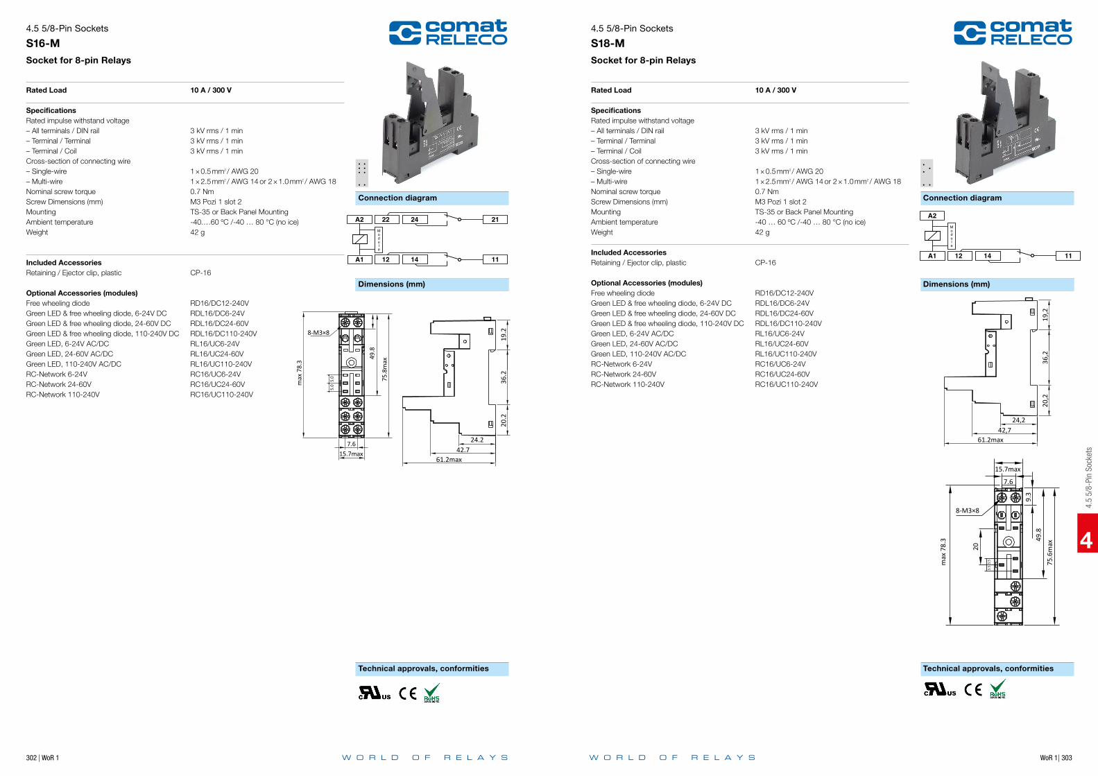
302 | WoR 1
4
Connection diagram Connection diagram
Dimensions (mm) Dimensions (mm)
Technical approvals, conformities Technical approvals, conformities
Dimensions (mm)
4.5 5/8-Pin Sockets
S16-MSocket for 8-pin Relays
Rated Load 10 A / 300 V
SpecificationsRated impulse withstand voltage – All terminals / DIN rail 3 kV rms / 1 min– Terminal / Terminal 3 kV rms / 1 min– Terminal / Coil 3 kV rms / 1 minCross-section of connecting wire– Single-wire 1 × 0.5 mm2 / AWG 20– Multi-wire 1 × 2.5 mm2 / AWG 14 or 2 × 1.0 mm2 / AWG 18Nominal screw torque 0.7 NmScrew Dimensions (mm) M3 Pozi 1 slot 2Mounting TS-35 or Back Panel MountingAmbient temperature -40.…60 ºC /-40 … 80 °C (no ice)Weight 42 g
Included Accessories Retaining / Ejector clip, plastic CP-16
Optional Accessories (modules)Free wheeling diode RD16/DC12-240VGreen LED & free wheeling diode, 6-24V DC RDL16/DC6-24VGreen LED & free wheeling diode, 24-60V DC RDL16/DC24-60VGreen LED & free wheeling diode, 110-240V DC RDL16/DC110-240VGreen LED, 6-24V AC/DC RL16/UC6-24VGreen LED, 24-60V AC/DC RL16/UC24-60VGreen LED, 110-240V AC/DC RL16/UC110-240VRC-Network 6-24V RC16/UC6-24VRC-Network 24-60V RC16/UC24-60VRC-Network 110-240V RC16/UC110-240V
A1
A2 22 24 21
1112 14
Module
8-M3×8
49.8
75.8
max
7.615.7max
5.0
5.0m
ax 7
8.3
19.2
36.2
20.2
24.242.7
61.2max
4.5
5/8-
Pin
Sock
ets
Dimensions (mm)
WoR 1| 303
4.5 5/8-Pin Sockets
S18-MSocket for 8-pin Relays
Rated Load 10 A / 300 V
SpecificationsRated impulse withstand voltage – All terminals / DIN rail 3 kV rms / 1 min– Terminal / Terminal 3 kV rms / 1 min– Terminal / Coil 3 kV rms / 1 minCross-section of connecting wire– Single-wire 1 × 0.5 mm2 / AWG 20– Multi-wire 1 × 2.5 mm2 / AWG 14 or 2 × 1.0 mm2 / AWG 18 Nominal screw torque 0.7 NmScrew Dimensions (mm) M3 Pozi 1 slot 2Mounting TS-35 or Back Panel MountingAmbient temperature -40 … 60 ºC /-40 … 80 °C (no ice)Weight 42 g
Included Accessories Retaining / Ejector clip, plastic CP-16
Optional Accessories (modules)Free wheeling diode RD16/DC12-240VGreen LED & free wheeling diode, 6-24V DC RDL16/DC6-24VGreen LED & free wheeling diode, 24-60V DC RDL16/DC24-60VGreen LED & free wheeling diode, 110-240V DC RDL16/DC110-240VGreen LED, 6-24V AC/DC RL16/UC6-24VGreen LED, 24-60V AC/DC RL16/UC24-60VGreen LED, 110-240V AC/DC RL16/UC110-240VRC-Network 6-24V RC16/UC6-24VRC-Network 24-60V RC16/UC24-60VRC-Network 110-240V RC16/UC110-240V
A1
A2
1112 14
Module
15.7max
8-M3×8
75.6
max
max
78.
3 49.8
20
3.5
3.5
9.3
7.6
19,2
36,2
20,2
24,242,7
61.2max
WoR 1 | 305
5
5 Re
mot
e M
onito
ring
& Co
ntro
l
304 | WoR 1
Notes
5 Remote Monitoring & Control

WoR 1 | 307
5
306 | WoR 1
5 Remote Monitoring & Control
CMS-10 remote monitoring and control features
Description Detail CMS-10F CMS-10ADF CMS-10ACDF
General Periodic notification daily, weekly, monthly Notification at power fail Notification at startup Status notification upon request Up to five receivers per notification selectable Notification escalation
Inputs Digital inputs Analogue (0 … 10 V) / digital inputs Analogue inputs 4 … 20 mA Notification digital input "on" Notification digital input "off" Analogue value: scaling according sensor unit
SMS notification analogue input value < lower level
SMS notification analogue input value > lower level
SMS notification analogue input value > upper level
SMS notification analogue input value < upper level Notification of analogue value in event of value change Change > x Periodic notification of analogue values Notification delay 0.1 s … 99.9 h
Outputs Relay outputs Call-in function Switch on Switch off Output on for set time 0.1 s … 99.9 h
5.1
Com
atRe
leco
Mes
sagi
ng S
yste
m (S
MS
Rela
y)
Application Type Page
CMS-Series
6 digital inputs | 4 relay outputs | 12 … 48 V DC | 110 … 240 V AC CMS-10F 308
6 analogue / digital inputs | 4 relay outputs | 12 … 48 V DC CMS-10ADF 309
4 analogue / digital inputs | 2 inputs 4 … 20 mA | 4 relay outputs | 12 … 48 V DC CMS-10ACDF 310
5.1 ComatReleco Messaging System (SMS Relay)

WoR 1 | 309
5
Power supplyNominal voltageOperating voltage rangePower consumption AC/DCRated frequency
InputsNumber of digital inputsNominal voltage digital inputsHigh level threshold digital Inputs
OutputsNumber of relay outputsContact MaterialRated voltageRated currentMinimum contact load relay outputsInrush currentRated load AC-1Mechanical enduranceElectrical endurance at rated load AC-1
CommunicationCommunication standardsFrequenciesAntenna connector
InsulationRated test voltage control / main circuitRated test voltage main / main circuitPollution degreeOvervoltage category
General dataAmbient temperature storageAmbient temperature operationConductor cross sectionNominal screw torqueWeightProtection degreeHousing material
Product references
Types Product reference 12-48 110-240
DC supply CMS-10F/DC…V
DC supply, kit (*included accessories) CMS-10FKIT/DC…V
AC supply CMS-10F/AC…V
AC supply, kit (*included accessories) CMS-10FKIT/AC…V
“...” list control circuit voltage to complete product references.
AccessoriesAntennas CMS-ANT-SPEZ/5M, CMS-ANT-MAG/2.5M*Antenna cables CMS-ANT-KAB/5M, CMS-ANT-KAB/10M, CMS-ANT-KAB/20MProgramming cable CMS-RS232*USB to serial converter CMS-USB*Power supply 15W, 24V DR-15-24Power supply 30W, 24V DR-30-24PT100 / PT1000 amplifier MV-LKM-274Indoor temperature sensor with display, 0 … 50 °C RF01-U-DIndor temperature sensor, 0 … 50 °C RF01-UExterior temperature sensor, -50 … +50 °C WF50-EXT-U4Thermostat, 5 … 30 °C RTBSB-001-010Temperature / humidity sensor KS-110Water level sensor PS1
12 ... 48 V DC 110 ... 240 V AC10 ... 60 V DC 85 ... 250 V AC8 VA / 4.2 W45 ... 63 Hz
612 ... 48 V DC 110 ... 240 V AC9.5 V DC 85 V AC
4AgNi250 V AC10 A10 mA, 12V15 A, 20 ms2500 VA3 x 107
150 000
GSM (2G)850 / 900 / 1800 / 1900 MHzSMA female
2.5 kV, 1 min2.5 kV, 1 min3II
-40 … 85 °C-25 … 55 °C2.5 mm2
0.5 Nm120 gIP20PC
fig. 1. Wiring diagram
fig. 2. Dimensions (mm)
Standards and approvals
N / –L / +
AC 110 … 240 V
CMS-10…
1114 121
L
N
CMS-10…
1114 121
L
N
Standards IEC/EN 60947, IEC/EN60730
Approvals
5.1 ComatReleco Messaging System (SMS Relay)
CMS-10F6 digital inputs | 4 relay outputs | 12 … 48 V DC | 110 … 240 V AC
5.1
Com
atRe
leco
Mes
sagi
ng S
yste
m (S
MS
Rela
y)
Power supplyNominal voltageOperating voltage rangePower consumption AC/DC
InputsNumber of analogue / digital inputsNominal voltage digital inputsHigh level threshold digital InputsNominal range analogue inputsResolution of analogue inputs
OutputsNumber of relay outputsContact MaterialRated voltageRated currentMinimum contact load relay outputsInrush currentRated load AC-1Mechanical enduranceElectrical endurance at rated load AC-1
CommunicationCommunication standardsFrequenciesAntenna connector
InsulationRated test voltage control / main circuitRated test voltage main / main circuitPollution degreeOvervoltage category
General dataAmbient temperature storageAmbient temperature operationConductor cross sectionNominal screw torqueWeightProtection degreeHousing material
Product references
Types Product reference 12-48
DC supply CMS-10ADF/DC…V
DC supply, kit (*included accessories) CMS-10ADFKIT/DC…V
“...” list control circuit voltage to complete product references.
AccessoriesAntennas CMS-ANT-SPEZ/5M, CMS-ANT-MAG/2.5M*Antenna cables CMS-ANT-KAB/5M, CMS-ANT-KAB/10M, CMS-ANT-KAB/20MProgramming cable CMS-RS232*USB to serial converter CMS-USB*Power supply 15W, 24V DR-15-24Power supply 30W, 24V DR-30-24PT100 / PT1000 amplifier MV-LKM-274Indoor temperature sensor with display, 0 … 50 °C RF01-U-DIndor temperature sensor, 0 … 50 °C RF01-UExterior temperature sensor, -50 … +50 °C WF50-EXT-U4Thermostat, 5 … 30 °C RTBSB-001-010Temperature / humidity sensor KS-110Water level sensor PS1
12 ... 48 V DC10 ... 60 V DC4.2 W
612 ... 48 V DC9.5 V DC0 ... 10 V10 Bit
4AgNi250 V AC10 A10 mA, 12V15 A, 20 ms2500 VA3 x 107
150 000
GSM (2G)850 / 900 / 1800 / 1900 MHzSMA female
2.5 kV, 1 min2.5 kV, 1 min3II
-40 … 85 °C-25 … 55 °C2.5 mm2
0.5 Nm120 gIP20PC
fig. 1. Wiring diagram
fig. 2. Dimensions (mm)
Standards and approvals
CMS-10…
1114 121
L
N
CMS-10…
1114 121
L
N
1 2 3 4 5 6DC 12 … 48V
Sig.
0…10
V
Standards IEC/EN 60947, IEC/EN60730
Approvals
5.1 ComatReleco Messaging System (SMS Relay)
CMS-10ADF6 analogue / digital inputs | 4 relay outputs | 12 … 48 V DC

WoR 1 | 311
5
Power supplyNominal voltageOperating voltage rangePower consumption AC/DC
InputsNumber of analogue inputsNumber of analogue / digital inputsNominal voltage digital inputsNominal range analogue inputsResolution of analogue inputs
OutputsNumber of relay outputsContact MaterialRated voltageRated currentMinimum contact load relay outputsInrush currentRated load AC-1Mechanical enduranceElectrical endurance at rated load AC-1
CommunicationCommunication standardsFrequenciesAntenna connector
InsulationRated test voltage control / main circuitRated test voltage main / main circuitPollution degreeOvervoltage category
General dataAmbient temperature storageAmbient temperature operationConductor cross sectionNominal screw torqueWeightProtection degreeHousing material
Product references
Types Product reference 12-48
DC supply CMS-10ACDF/DC…V
DC supply, kit (*included accessories) CMS-10ACDFKIT/DC…V
“...” list control circuit voltage to complete product references.
AccessoriesAntennas CMS-ANT-SPEZ/5M, CMS-ANT-MAG/2.5M*Antenna cables CMS-ANT-KAB/5M, CMS-ANT-KAB/10M, CMS-ANT-KAB/20MProgramming cable CMS-RS232*USB to serial converter CMS-USB*Power supply 15W, 24V DR-15-24Power supply 30W, 24V DR-30-24PT100 / PT1000 amplifier MV-LKM-274Indoor temperature sensor with display, 0 … 50 °C RF01-U-DIndor temperature sensor, 0 … 50 °C RF01-UExterior temperature sensor, -50 … +50 °C WF50-EXT-U4Thermostat, 5 … 30 °C RTBSB-001-010Temperature / humidity sensor KS-110Water level sensor PS1
5.1 ComatReleco Messaging System (SMS Relay)
CMS-10ACDF4 analogue / digital inputs | 2 inputs 4 … 20 mA | 4 relay outputs | 12 … 48 V DC
12 ... 48 V DC10 ... 60 V DC4.2 W
2412 ... 48 V DC0 ... 10 V (I1 - I4) / 4 ... 20 mA (I5 - I6)10 Bit
4AgNi250 V AC10 A10 mA, 12V15 A, 20 ms2500 VA3 x 107
150 000
GSM (2G)850 / 900 / 1800 / 1900 MHzSMA female
2.5 kV, 1 min2.5 kV, 1 min3II
-40 … 85 °C-25 … 55 °C2.5 mm2
0.5 Nm120 gIP20PC
fig. 1. Wiring diagram
fig. 2. Dimensions (mm)
Standards and approvals
CMS-10…
1114 121
L
N
CMS-10…
1114 121
L
N
1 2 3 4 5 6DC 12 … 48 V
0…10
V
4...
20 m
A
Sig. Sig.
Standards IEC/EN 60947, IEC/EN60730
Approvals
310 | WoR 1
5.2
CMS
Acce
ssor
ies
Application Type Page
Accessories
Exterior antenna | 5 m cable CMS-ANT-SPEZ/5M 312
Magnetic pod antenna | 2.5 m cable CMS-ANT-MAG/2.5M 313
Antenna cable | SMA male / female | 5 m | 10 m | 20 m CMS-ANT-KAB 314
Programming cable | Serial 1:1 | D-Sub 9 male / female | 2 m CMS-RS232 315
USB to serial converter | D-Sub 9 to USB A | FTDI FT231XS CMS-USB 316
Power supply | 24 V DC | 15 W | 30 W DR-15-24, DR-30-24 317
PT100 / PT1000 amplifier | 0 … 10 V output MV-LKM-274 318
Indoor temperature sensor | 0 … 50 °C | 0 … 10 V output RF01-U, RF01-U-D2 319
Thermostat | 5 … 30 °C | Cooling or heating | 1 CO RTBSB-001-010 320
Exterior temperature sensor | -50 … 50 °C | 0 … 10 V output WF50-EXT-U4 321
Temperature / humidity sensor | -40 … 80 °C | 0 … 100 % rH | 0 … 10 V output | Cable length 2 m KS-110 322
Water level sensor | 0 … 0.5 bar | 0 … 10 V output PS1 323
5.2 CMS Accessories

WoR 1 | 313
5
312 | WoR 1
CommunicationCommunication standardsFrequenciesAntenna connectorAntenna typeImpedanceMax. power
General dataAmbient temperature storageAmbient temperature operationWeightHousing material
Product references
Types Product reference 5
Exterior antenna CMS-ANT-SPEZ/…M
“...” list cable length to complete product references.
5.2 CMS Accessories
CMS-ANT-SPEZ/5MExterior antenna | 5 m cable
GSM824 … 960 / 1710 … 1990 MHzSMA male1/4 ʎ50 Ω20 W
-30 °C ... 70 °C-20 °C ... 60 °C360 gRW24BR
Standards and approvals
Approvals
5.2
CMS
Acce
ssor
ies
CommunicationCommunication standardsFrequenciesAntenna connectorAntenna typeImpedanceMax. power
General dataAmbient temperature storageAmbient temperature operationWeightHousing material
Product references
Types Product reference 2.5
Magnetic pod antenna CMS-ANT-MAG/…M
“...” list cable length to complete product references.
5.2 CMS Accessories
CMS-ANT-MAG/2.5MMagnetic pod antenna | 2.5 m cable
GSM / UMTS824 / 960 / 1710 / 1910 / 1990 / 2010 / 2025 / 2110 / 2170 MHzSMA male1/4 ʎ50 Ω20 W
-40 °C ... 80 °C-40 °C ... 80 °C65 gPA 6
Standards and approvals
Approvals

314 | WoR 1 WoR 1 | 315
5
CommunicationAntenna connectorImpedance
General dataAmbient temperature storageAmbient temperature operationWeightHousing material
Product references
Types Product reference 5 10 20
Extension cable SMA male / female CMS-ANT-KAB/…M
“...” list cable length to complete product references.Other cable length on request. Please contact [email protected].
5.2 CMS Accessories
CMS-ANT-KABAntenna cable | SMA male / female | 5 m | 10 m | 20 m
SMA male / female50 Ω
-35 °C ... 80 °C-35 °C ... 80 °C180 g ( 5 m) / 270 g (10 m) / 728 g (20 m)Cu / PE
Standards and approvals
Approvals
5.2
CMS
Acce
ssor
ies
General dataAmbient temperature storageAmbient temperature operationWeight
Product references
Types Product reference
Programming cable CMS-RS232
5.2 CMS Accessories
CMS-RS232Programming cable | Serial 1:1 | D-Sub 9 male / female | 2 m
-35 °C ... 80 °C-35 °C ... 80 °C126 g
Standards and approvals
Approvals

316 | WoR 1 WoR 1 | 317
5
General dataAmbient temperature storageAmbient temperature operationWeight
Product references
Types Product reference
USB to serial converter CMS-USB
5.2 CMS Accessories
CMS-USBUSB to serial converter | D-Sub 9 to USB A | FTDI FT231XS
-40 °C ... 85 °C-40 °C ... 85 °C41 g
Standards and approvals
Approvals
5.2
CMS
Acce
ssor
ies
Power supplyNominal voltageOperating voltage rangePower consumption AC/DCRated frequencyOutput voltageOutput voltage rangeOutput power
General dataAmbient temperature storageAmbient temperature operationConductor cross sectionModule widthWeightProtection degreeHousing material
Product references
Types Product reference
Power supply 15 W, 24 V DC DR-15-24
Power supply 30 W, 24 V DC DR-30-24
Other voltages on request. Please contact [email protected].
5.2 CMS Accessories
DR-15-24, DR-30-24Power supply | 24 V DC | 15 W | 30 W
230 V AC85 … 264 V AC- / 110 VA47 … 63 Hz24 V DC21.6 … 26.4 V15 W 30 W
-40 °C ... 85 °C-20 °C ... 60 °C2.5 mm2
fig. 165 gIP20PA 6
fig. 1. Dimensions (mm)
Standards and approvals
N
L
44.2
67.2
5
93
-V
+V
25
DEL
.jdaV 5
4
46.5 46.5
26
.7
47
56
93
655
55
5
34
2
37
.75
1
78
12
.2
7
8
45
68
46.5
27
.4
3
47
56
46.5
N
L
44.2
67.2
5
93
-V
+V
25
DEL
.jdaV 5
4
46.5 46.5
26
.7
47
56
93
655
55
5
34
2
37
.75
1
78
12
.2
7
8
45
68
46.5
27
.4
3
47
56
46.5
Approvals
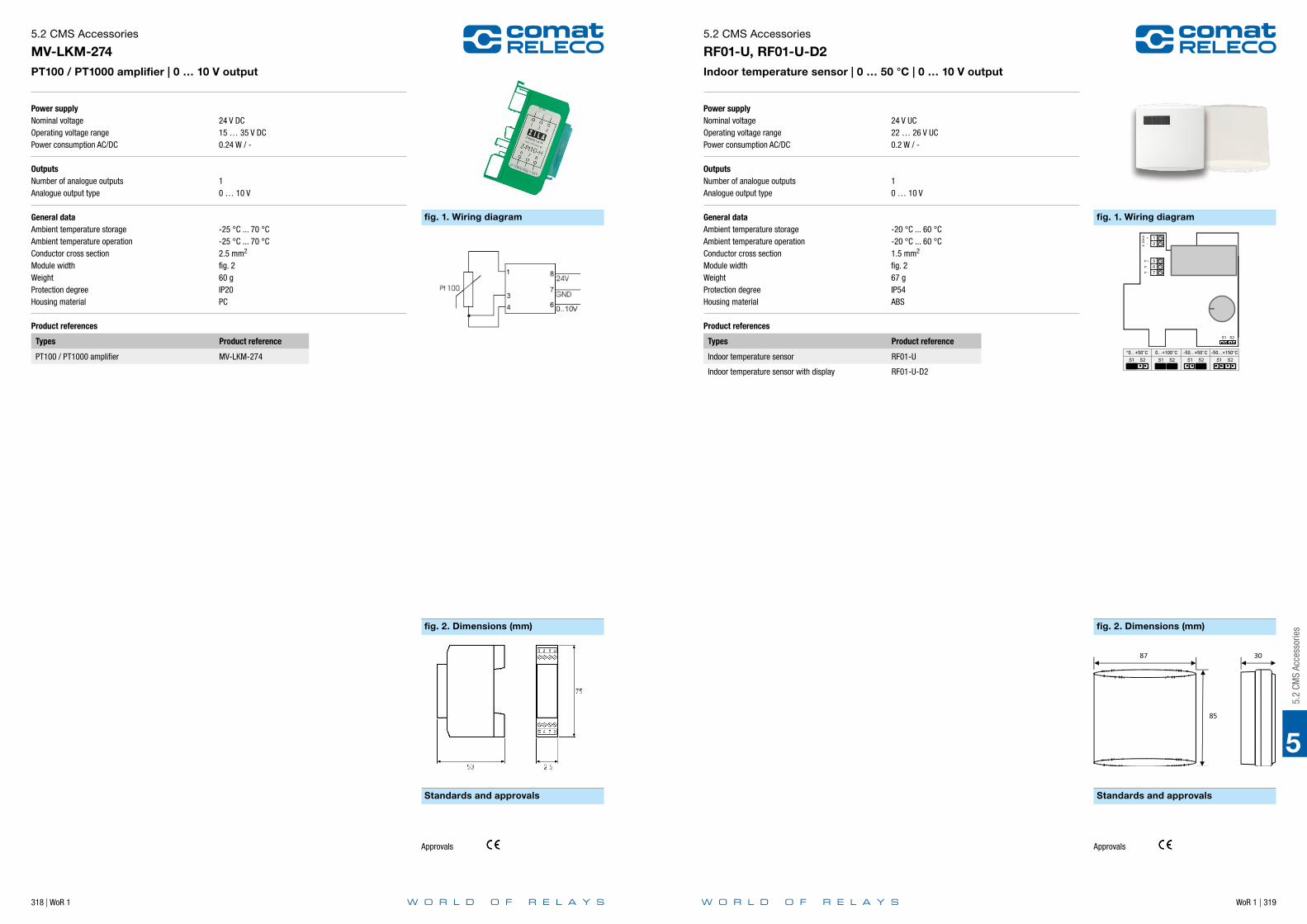
318 | WoR 1 WoR 1 | 319
5
Power supplyNominal voltageOperating voltage rangePower consumption AC/DC
OutputsNumber of analogue outputsAnalogue output type
General dataAmbient temperature storageAmbient temperature operationConductor cross sectionModule widthWeightProtection degreeHousing material
Product references
Types Product reference
PT100 / PT1000 amplifier MV-LKM-274
5.2 CMS Accessories
MV-LKM-274PT100 / PT1000 amplifier | 0 … 10 V output
24 V DC15 … 35 V DC0.24 W / -
10 … 10 V
-25 °C ... 70 °C-25 °C ... 70 °C2.5 mm2
fig. 260 gIP20PC
fig. 1. Wiring diagram
fig. 2. Dimensions (mm)
Standards and approvals
Approvals
5.2
CMS
Acce
ssor
ies
Power supplyNominal voltageOperating voltage rangePower consumption AC/DC
OutputsNumber of analogue outputsAnalogue output type
General dataAmbient temperature storageAmbient temperature operationConductor cross sectionModule widthWeightProtection degreeHousing material
Product references
Types Product reference
Indoor temperature sensor RF01-U
Indoor temperature sensor with display RF01-U-D2
5.2 CMS Accessories
RF01-U, RF01-U-D2Indoor temperature sensor | 0 … 50 °C | 0 … 10 V output
24 V UC22 … 26 V UC0.2 W / -
10 … 10 V
-20 °C ... 60 °C-20 °C ... 60 °C1.5 mm2
fig. 267 gIP54ABS
fig. 1. Wiring diagram
fig. 2. Dimensions (mm)
Standards and approvals
Approvals

320 | WoR 1 WoR 1 | 321
5
OutputsNumber of relay outputsRated voltageRated currentRated load AC-1
General dataAmbient temperature storageAmbient temperature operationConductor cross sectionWeightProtection degreeHousing material
Product references
Types Product reference
Thermostat RTBSB-001-010
5.2 CMS Accessories
RTBSB-001-010Thermostat | 5 … 30 °C | Cooling or heating | 1 CO
1 CO230 V AC10 A (Terminal 1) / 5 A (Terminal 3)2300 VA / 1150 VA
-20 °C ... 60 °C-20 °C ... 60 °C1.5 mm2
90 gIP30ABS
fig. 1. Wiring diagram
Standards and approvals
Schaltbild
Approvals
5.2
CMS
Acce
ssor
ies
Power supplyNominal voltageOperating voltage range
OutputsNumber of analogue outputsAnalogue output type
General dataAmbient temperature storageAmbient temperature operationConductor cross sectionModule widthWeightProtection degreeHousing material
Product references
Types Product reference
Exterior temperature sensor WF50-EXT-U4
5.2 CMS Accessories
WF50-EXT-U4Exterior temperature sensor | -50 … 50 °C | 0 … 10 V output
24 V DC21.6 … 26.4 V DC
10 … 10 V
-30 °C ... 70 °C-30 °C ... 70 °C1.5 mm2
fig. 2100 gIP65PA
fig. 2. Dimensions (mm)
Standards and approvals
****
Approvals

322 | WoR 1 WoR 1 | 323
5
Power supplyNominal voltageOperating voltage rangePower consumption AC/DC
OutputsNumber of analogue outputsAnalogue output type
General dataAmbient temperature storageAmbient temperature operationWeightProtection degree
Product references
Types Product reference
Temperature / humidity sensor KS-110
5.2 CMS Accessories
KS-110Temperature / humidity sensor | -40 … 80 °C | 0 … 100 % rH | 0 … 10 V output | Cable length 2 m
24 V DC12 … 27 V DC0.2 W / -
20 … 10 V
-40 °C ... 85 °C-40 °C ... 85 °C62 gIP65
Standards and approvals
Approvals
5.2
CMS
Acce
ssor
ies
Power supplyNominal voltageOperating voltage range
OutputsNumber of analogue outputsAnalogue output type
General dataAmbient temperature storageAmbient temperature operationWeightProtection degree
Product references
Types Product reference
Water level sensor PS1
Sensors for other liquids on request. Please contact [email protected].
5.2 CMS Accessories
PS1Water level sensor | 0 … 0.5 bar | 0 … 10 V output
24 V DC12 … 30 V DC
10 … 10 V
5 °C ... 70 °C5 °C ... 70 °C550 gIP68
Standards and approvals
Approvals

WoR 1 | 325
6
6.0
Softs
tarte
r
324 | WoR 1
Notes
6 Softstarter
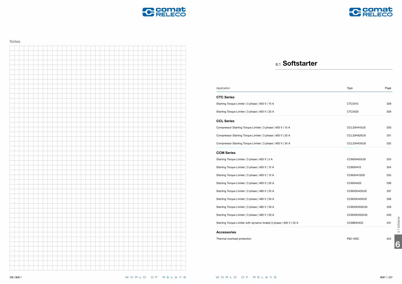
WoR 1 | 327326 | WoR 1
Notes
6
6.1
Softs
tarte
r
Application Type Page
CTC Series
Starting Torque Limiter | 3 phase | 400 V | 15 A CTC3415 328
Starting Torque Limiter | 3 phase | 400 V | 25 A CTC3425 329
CCL Series
Compressor Starting Torque Limiter | 3 phase | 400 V | 15 A CCL33H415US 330
Compressor Starting Torque Limiter | 3 phase | 400 V | 25 A CCL33H425US 331
Compressor Starting Torque Limiter | 3 phase | 400 V | 35 A CCL33H435US 332
CCM Series
Starting Torque Limiter | 3 phase | 400 V | 3 A CCM3H403USi 333
Starting Torque Limiter | 3 phase | 400 V | 15 A CCM3H415 334
Starting Torque Limiter | 3 phase | 400 V | 15 A CCM3H415DS 335
Starting Torque Limiter | 3 phase | 400 V | 25 A CCM3H425 336
Starting Torque Limiter | 3 phase | 480 V | 25 A CCM33H425US 337
Starting Torque Limiter | 3 phase | 480 V | 50 A CCM33H450US 338
Starting Torque Limiter | 3 phase | 480 V | 30 A CCM33H530USi 339
Starting Torque Limiter | 3 phase | 480 V | 50 A CCM33H550USi 340
Starting Torque Limiter with dynamic brake| 3 phase | 400 V | 25 A CCMB3H425 341
Accessories
Thermal overload protection P82-100C 342
6.1 Softstarter

328 | WoR 1 WoR 1 | 329
Main circuitNumber of outputsControlled phasesOutput typeRated voltageOutput voltage rangeReverse voltagePeak reverse voltageRated current AC-53aMinimum loadTyp. leakage currentRated limit loadSwitching cycles / h
Control circuitRelease timeRamp-up timeTorque adjustmentRated frequency
InsulationRated insulation voltageRated impulse withstand voltagePollution degreeOvervoltage category
General dataAmbient temperature storageAmbient temperature operationAmbient temperature operation derated powerConductor cross section Control / Main CircuitNominal screw torque Control / Main CircuitModule widthWeightProtection degreeHousing materialMounting
Product references
Description Product reference
Starting Torque Limiter, 3 phase CTC3415
Other devices on request. Please contact [email protected].
AccessoriesThermostat P82-100C
6.1 Softstarter
CTC3415Starting Torque Limiter | 3 phase | 400 V | 15 A
31Thyristor400 V208 … 400 V AC1200 Vrrm1300 Vrrm15 A50 mA5 mA1800 A2t3000
1 Periode0.5 … 5 s0 … 85 %50 / 60 Hz
660 V4 kV3III
-20 ... 80 °C-5 ... 40 °C-5 ... 60 °C, 0.7 IN1.5 mm2 / 4 mm2
0.5 Nm / 1.2 Nmfig. 2650 gIP 20PPOTS 35 or Back Panel Mounting
fig. 1. Wiring diagram
fig. 2. Dimensions (mm)
Standards and approvals
Standards IEC/EN 60947, 60068-2-6
Approvals
11-12: Thermostat
Main circuitNumber of outputsControlled phasesOutput typeRated voltageOutput voltage rangeReverse voltagePeak reverse voltageRated current AC-53aMinimum loadTyp. leakage currentRated limit loadSwitching cycles / h
Control circuitRelease timeRamp-up timeTorque adjustmentRated frequency
InsulationRated insulation voltageRated impulse withstand voltagePollution degreeOvervoltage category
General dataAmbient temperature storageAmbient temperature operationAmbient temperature operation derated powerConductor cross section Control / Main CircuitNominal screw torque Control / Main CircuitModule widthWeightProtection degreeHousing materialMounting
Product references
Description Product reference
Starting Torque Limiter, 3 phase CTC3425
Other devices on request. Please contact [email protected].
AccessoriesThermostat P82-100C
6.1 Softstarter
CTC3425Starting Torque Limiter | 3 phase | 400 V | 25 A
31Thyristor400 V208 … 400 V AC1200 Vrrm1300 Vrrm25 A50 mA5 mA6300 A2t3000
1 Periode0.5 … 5 s0 … 85 %50 / 60 Hz
660 V4 kV3III
-20 ... 80 °C-5 ... 40 °C-5 ... 60 °C, 0.7 IN1.5 mm2 / 4 mm2
0.5 Nm / 1.2 Nmfig. 2650 gIP 20PPOTS 35 or Back Panel Mounting
fig. 1. Wiring diagram
fig. 2. Dimensions (mm)
Standards and approvals
Standards IEC/EN 60947, 60068-2-6
Approvals
11-12: Thermostat
6
6.1
Softs
tarte
r

330 | WoR 1 WoR 1 | 331
Main circuitNumber of outputsControlled phasesOutput typeBypassRated voltageOutput voltage rangeReverse voltagePeak reverse voltageRated current AC-58Minimum loadTyp. leakage currentInrush currentRated limit loadSwitching cycles / h
Control circuitNominal voltageOperating voltage rangeTyp. release voltagePick-up timeRelease time
InsulationRated insulation voltageRated impulse withstand voltagePollution degreeOvervoltage category
General dataAmbient temperature storageAmbient temperature operationConductor cross section Control / Main CircuitModule widthWeightProtection degreeHousing materialMounting
Product references
Description Product reference
Compressor Starting Torque Limiter, 3 phase CCL33H415US
Other devices on request. Please contact [email protected].
6.1 Softstarter
CCL33H415USCompressor Starting Torque Limiter | 3 phase | 400 V | 15 A
33ThyristorIntegrated400 V230 … 400 V AC1200 Vrrm1300 Vrrm15 A1.5 A5 mA90 A, 1 s610 A2t12
230 V AC0.85 ... 1.15 UN
110 V AC500 ms500 ms
660 V4 kV3III
-20 ... 80 °C-20 ... 65 °C2.5 mm2 / 6 mm2
fig. 2470 gIP 20PPETS 35 or Back Panel Mounting
fig. 1. Wiring diagram
fig. 2. Dimensions (mm)
Standards and approvals
2/T1
34 14 C A L N
4/T2 6/T3
1/L1 3/L2 5/L3
Standards IEC/EN 60947
Approvals
Main circuitNumber of outputsControlled phasesOutput typeBypassRated voltageOutput voltage rangeReverse voltagePeak reverse voltageRated current AC-58Minimum loadTyp. leakage currentInrush currentRated limit loadSwitching cycles / h
Control circuitNominal voltageOperating voltage rangeTyp. release voltagePick-up timeRelease time
InsulationRated insulation voltageRated impulse withstand voltagePollution degreeOvervoltage category
General dataAmbient temperature storageAmbient temperature operationConductor cross section Control / Main CircuitModule widthWeightProtection degreeHousing materialMounting
Product references
Description Product reference
Compressor Starting Torque Limiter, 3 phase CCL33H425US
Other devices on request. Please contact [email protected].
6.1 Softstarter
CCL33H425USCompressor Starting Torque Limiter | 3 phase | 400 V | 25 A
33ThyristorIntegrated400 V230 … 400 V AC1200 Vrrm1300 Vrrm25 A2.5 A5 mA150 A, 1 s1800 A2t12
230 V AC0.85 ... 1.15 UN
110 V AC500 ms500 ms
660 V4 kV3III
-20 ... 80 °C-20 ... 65 °C2.5 mm2 / 6 mm2
fig. 2470 gIP 20PPETS 35 or Back Panel Mounting
fig. 1. Wiring diagram
fig. 2. Dimensions (mm)
Standards and approvals
2/T1
34 14 C A L N
4/T2 6/T3
1/L1 3/L2 5/L3
Standards IEC/EN 60947
Approvals
6
6.1
Softs
tarte
r

332 | WoR 1 WoR 1 | 333
Main circuitNumber of outputsControlled phasesOutput typeBypassRated voltageOutput voltage rangeReverse voltagePeak reverse voltageRated current AC-58Minimum loadTyp. leakage currentInrush currentRated limit loadSwitching cycles / h
Control circuitNominal voltageOperating voltage rangeTyp. release voltagePick-up timeRelease time
InsulationRated insulation voltageRated impulse withstand voltagePollution degreeOvervoltage category
General dataAmbient temperature storageAmbient temperature operationConductor cross section Control / Main CircuitModule widthWeightProtection degreeHousing materialMounting
Product references
Description Product reference
Compressor Starting Torque Limiter, 3 phase CCL33H435US
Other devices on request. Please contact [email protected].
6.1 Softstarter
CCL33H435USCompressor Starting Torque Limiter | 3 phase | 400 V | 35 A
33ThyristorIntegrated400 V230 … 400 V AC1200 Vrrm1300 Vrrm35 A3.5 A5 mA210 A, 1 s1800 A2t12
230 V AC0.85 ... 1.15 UN
110 V AC500 ms500 ms
660 V4 kV3III
-20 ... 80 °C-20 ... 65 °C2.5 mm2 / 6 mm2
fig. 2470 gIP 20PPETS 35 or Back Panel Mounting
fig. 1. Wiring diagram
fig. 2. Dimensions (mm)
Standards and approvals
2/T1
34 14 C A L N
4/T2 6/T3
1/L1 3/L2 5/L3
Standards IEC/EN 60947
Approvals
Main circuitNumber of outputsControlled phasesOutput typeBypassRated voltageOutput voltage rangeReverse voltagePeak reverse voltageRated current AC-53bMinimum loadTyp. leakage currentInrush currentRated limit loadSwitching cycles / h
Control circuitNominal voltageRamp-up timeRamp-down timeTorque adjustmentRated frequency
InsulationRated insulation voltageRated impulse withstand voltagePollution degreeOvervoltage category
General dataAmbient temperature storageAmbient temperature operationAmbient temperature operation derated powerConductor cross section Control / Main CircuitNominal screw torque Control / Main CircuitModule widthWeightProtection degreeHousing materialMounting
Product references
Description Product reference
Starting Torque Limiter, 3 phase CCM3H403USi
Other devices on request. Please contact [email protected].
6.1 Softstarter
CCM3H403USiStarting Torque Limiter | 3 phase | 400 V | 3 A
32ThyristorIntegrated400 V400 … 480 V AC1200 Vrrm1300 Vrrm3 A250 mA5 mA18 A72 A2t120
400 V AC0.5 … 10 s0.5 … 10 s0 … 85 %50 / 60 Hz
660 V4 kV3III
-20 ... 80 °C-5 ... 40 °C-5 ... 60 °C2.5 mm2 / 4 mm2
0.5 Nm / 1.2 Nmfig. 2270 gIP 20PPOTS 35 or Back Panel Mounting
fig. 1. Wiring diagram
fig. 2. Dimensions (mm)
Standards and approvals
22.5
12.42.2
08
8.5 127.3
120 3.8
90 9410
0.7
Standards IEC/EN 60947, 60068
Approvals
6
6.1
Softs
tarte
r

334 | WoR 1 WoR 1 | 335
Main circuitNumber of outputsControlled phasesOutput typeRated voltageOutput voltage rangeReverse voltagePeak reverse voltageRated current AC-53bMinimum loadTyp. leakage currentInrush currentRated limit loadSwitching cycles / h
Control circuitNominal voltageRamp-up timeRamp-down timeTorque adjustmentRated frequency
InsulationRated insulation voltageRated impulse withstand voltagePollution degreeOvervoltage category
General dataAmbient temperature storageAmbient temperature operationAmbient temperature operation derated powerConductor cross section Control / Main CircuitNominal screw torque Control / Main CircuitModule widthWeightProtection degreeHousing materialMounting
Product references
Description Product reference
Starting Torque Limiter, 3 phase CCM3H415
Other devices on request. Please contact [email protected].
AccessoriesThermal overload protection P82-100C
6.1 Softstarter
CCM3H415Starting Torque Limiter | 3 phase | 400 V | 15 A
32Thyristor400 V400 … 480 V AC1200 Vrrm1300 Vrrm15 A250 mA5 mA90 A1800 A2t3000
400 V AC0.5 … 10 s0.5 … 10 s0 … 85 %50 / 60 Hz
660 V4 kV3III
-20 ... 80 °C-5 ... 40 °C-5 ... 60 °C2.5 mm2 / 4 mm2
0.5 Nm / 1.2 Nmfig. 2650 gIP 20PPOTS 35 or Back Panel Mounting
fig. 1. Wiring diagram
fig. 2. Dimensions (mm)
Standards and approvals
Standards IEC/EN 60947, 60068
Approvals
11-12: Thermostat
Main circuitNumber of outputsControlled phasesOutput typeRated voltageOutput voltage rangeReverse voltagePeak reverse voltageRated current AC-53bMinimum loadTyp. leakage currentInrush currentRated limit loadSwitching cycles / h
Control circuitNominal voltageRamp-up timeRamp-down timeTorque adjustmentRated frequency
InsulationRated insulation voltageRated impulse withstand voltagePollution degreeOvervoltage category
General dataAmbient temperature storageAmbient temperature operationAmbient temperature operation derated powerConductor cross section Control / Main CircuitNominal screw torque Control / Main CircuitModule widthWeightProtection degreeHousing materialMounting
Product references
Description Product reference
Starting Torque Limiter, 3 phase CCM3H415DS
Other devices on request. Please contact [email protected].
AccessoriesThermal overload protection P82-100C
6.1 Softstarter
CCM3H415DSStarting Torque Limiter | 3 phase | 400 V | 15 A
32Thyristor400 V400 … 480 V AC1200 Vrrm1300 Vrrm15 A250 mA5 mA90 A1800 A2t3000
400 V AC0.5 … 10 s0.5 … 10 s0 … 85 %50 / 60 Hz
660 V4 kV3III
-20 ... 80 °C-5 ... 40 °C-5 ... 60 °C2.5 mm2 / 4 mm2
0.5 Nm / 1.2 Nmfig. 2650 gIP 20PPOTS 35 or Back Panel Mounting
fig. 1. Wiring diagram
fig. 2. Dimensions (mm)
Standards and approvals
Standards IEC/EN 60947, 60068
Approvals
11-12: Thermostat
6
6.1
Softs
tarte
r

336 | WoR 1 WoR 1 | 337
Main circuitNumber of outputsControlled phasesOutput typeRated voltageOutput voltage rangeReverse voltagePeak reverse voltageRated current AC-53bMinimum loadTyp. leakage currentInrush currentRated limit loadSwitching cycles / h
Control circuitNominal voltageRamp-up timeRamp-down timeTorque adjustmentRated frequency
InsulationRated insulation voltageRated impulse withstand voltagePollution degreeOvervoltage category
General dataAmbient temperature storageAmbient temperature operationAmbient temperature operation derated powerConductor cross section Control / Main CircuitNominal screw torque Control / Main CircuitModule widthWeightProtection degreeHousing materialMounting
Product references
Description Product reference
Starting Torque Limiter, 3 phase CCM3H425
Other devices on request. Please contact [email protected].
AccessoriesThermal overload protection P82-100C
6.1 Softstarter
CCM3H425Starting Torque Limiter | 3 phase | 400 V | 25 A
32Thyristor400 V400 … 480 V AC1200 Vrrm1300 Vrrm25 A250 mA5 mA150 A6300 A2t3000
400 V AC0.5 … 10 s0.5 … 10 s0 … 85 %50 / 60 Hz
660 V4 kV3III
-20 ... 80 °C-5 ... 40 °C-5 ... 60 °C2.5 mm2 / 6 mm2
0.5 Nm / 1.2 Nmfig. 21050 gIP 20PPOTS 35 or Back Panel Mounting
fig. 1. Wiring diagram
fig. 2. Dimensions (mm)
Standards and approvals
Standards IEC/EN 60947, 60068
Approvals
11-12: Thermostat
Main circuitNumber of outputsControlled phasesOutput typeBypassRated voltageOutput voltage rangeReverse voltagePeak reverse voltageRated current AC-53bMinimum loadTyp. leakage currentInrush currentRated limit loadSwitching cycles / h
Control circuitNominal voltageOperating voltage rangeTyp. release voltageRamp-up timeRamp-down timeTorque adjustmentRated frequency
InsulationRated insulation voltageRated impulse withstand voltagePollution degreeOvervoltage category
General dataAmbient temperature storageAmbient temperature operationAmbient temperature operation derated powerConductor cross section Control / Main CircuitNominal screw torque Control / Main CircuitModule widthWeightProtection degreeHousing materialMounting
Product references
Description Product reference
Starting Torque Limiter, 3 phase CCM33H425US
Other devices on request. Please contact [email protected].
AccessoriesThermal overload protection P82-100C
6.1 Softstarter
CCM33H425USStarting Torque Limiter | 3 phase | 480 V | 25 A
33ThyristorExternally400 V200 … 480 V AC1200 Vrrm1300 Vrrm25 A3 A5 mA150 A, 450 ms6300 A2t120
480 V AC24 - 230 V UC5 V UC0.5 … 30 s0.5 … 60 s0 … 85 %50 / 60 Hz
660 V4 kV3III
-20 ... 80 °C-5 ... 40 °C-5 ... 60 °C2.5 mm2 / 6 mm2
0.5 Nm / 1.2 Nmfig. 21050 gIP 20PPETS 35 or Back Panel Mounting
fig. 1. Wiring diagram
fig. 2. Dimensions (mm)
Standards and approvals
Standards IEC/EN 60947, 50022, 60068
Approvals
11-12: Thermostat 13-14: For control of Start/Stop function 23-24: By end of ramp up time for by-pass contactor
6
6.1
Softs
tarte
r

338 | WoR 1 WoR 1 | 339
Main circuitNumber of outputsControlled phasesOutput typeBypassRated voltageOutput voltage rangeReverse voltagePeak reverse voltageRated current AC-53bMinimum loadTyp. leakage currentInrush currentRated limit loadSwitching cycles / h
Control circuitNominal voltageOperating voltage rangeTyp. release voltageRamp-up timeRamp-down timeTorque adjustmentRated frequency
InsulationRated insulation voltageRated impulse withstand voltagePollution degreeOvervoltage category
General dataAmbient temperature storageAmbient temperature operationAmbient temperature operation derated powerConductor cross section Control / Main CircuitNominal screw torque Control / Main CircuitModule widthWeightProtection degreeHousing materialMounting
Product references
Description Product reference
Starting Torque Limiter, 3 phase CCM33H450US
Other devices on request. Please contact [email protected].
AccessoriesThermal overload protection P82-100C
6.1 Softstarter
CCM33H450USStarting Torque Limiter | 3 phase | 480 V | 50 A
33ThyristorExternally400 V200 … 480 V AC1200 Vrrm1300 Vrrm50 A3 A5 mA300 A, 450 ms25300 A2t120
480 V AC24 - 230 V UC5 V UC0.5 … 30 s0.5 … 60 s0 … 85 %50 / 60 Hz
660 V4 kV3III
-20 ... 80 °C-5 ... 40 °C-5 ... 60 °C2.5 mm2 / 6 mm2
0.5 Nm / 1.2 Nmfig. 22500 gIP 20PPETS 35 or Back Panel Mounting
fig. 1. Wiring diagram
fig. 2. Dimensions (mm)
Standards and approvals
Standards IEC/EN 60947, 50022, 60068
Approvals
11-12: Thermostat 13-14: For control of Start/Stop function 23-24: By end of ramp up time for by-pass contactor
Main circuitNumber of outputsControlled phasesOutput typeBypassRated voltageOutput voltage rangeReverse voltagePeak reverse voltageRated current AC-53bMinimum loadTyp. leakage currentInrush currentRated limit loadSwitching cycles / h
Control circuitNominal voltageOperating voltage rangeTyp. release voltageRamp-up timeRamp-down timeTorque adjustmentRated frequency
InsulationRated insulation voltageRated impulse withstand voltagePollution degreeOvervoltage category
General dataAmbient temperature storageAmbient temperature operationAmbient temperature operation derated powerConductor cross section Control / Main CircuitNominal screw torque Control / Main CircuitModule widthWeightProtection degreeHousing materialMounting
Product references
Description Product reference
Starting Torque Limiter, 3 phase CCM33H530USi
Other devices on request. Please contact [email protected].
AccessoriesThermal overload protection P82-100C
6.1 Softstarter
CCM33H530USiStarting Torque Limiter | 3 phase | 480 V | 30 A
33ThyristorExternally400 V200 … 480 V AC1200 Vrrm1300 Vrrm30 A3 A5 mA180 A, 450 ms6300 A2t120
480 V AC24 - 230 V UC5 V UC0.5 … 30 s0.5 … 60 s0 … 85 %50 / 60 Hz
660 V4 kV3III
-20 ... 80 °C-5 ... 40 °C-5 ... 60 °C2.5 mm2 / 6 mm2
0.5 Nm / 1.2 Nmfig. 21050 gIP 20PPETS 35 or Back Panel Mounting
fig. 1. Wiring diagram
fig. 2. Dimensions (mm)
Standards and approvals
Standards IEC/EN 60947, 50022, 60068
Approvals
11-12: Thermostat 13-14: For control of Start/Stop function 23-24: By end of ramp up time for by-pass contactor
6
6.1
Softs
tarte
r

340 | WoR 1 WoR 1 | 341
Main circuitNumber of outputsControlled phasesOutput typeBypassRated voltageOutput voltage rangeReverse voltagePeak reverse voltageRated current AC-53bMinimum loadTyp. leakage currentInrush currentRated limit loadSwitching cycles / h
Control circuitNominal voltageOperating voltage rangeTyp. release voltageRamp-up timeRamp-down timeTorque adjustmentRated frequency
InsulationRated insulation voltageRated impulse withstand voltagePollution degreeOvervoltage category
General dataAmbient temperature storageAmbient temperature operationAmbient temperature operation derated powerConductor cross section Control / Main CircuitNominal screw torque Control / Main CircuitModule widthWeightProtection degreeHousing materialMounting
Product references
Description Product reference
Starting Torque Limiter, 3 phase CCM33H550USi
Other devices on request. Please contact [email protected].
AccessoriesThermal overload protection P82-100C
6.1 Softstarter
CCM33H550USiStarting Torque Limiter | 3 phase | 480 V | 50 A
33ThyristorExternally400 V200 … 480 V AC1200 Vrrm1300 Vrrm50 A3 A5 mA300 A, 450 ms25300 A2t120
480 V AC24 - 230 V UC5 V UC0.5 … 30 s0.5 … 60 s0 … 85 %50 / 60 Hz
660 V4 kV3III
-20 ... 80 °C-5 ... 40 °C-5 ... 60 °C2.5 mm2 / 6 mm2
0.5 Nm / 1.2 Nmfig. 22500 gIP 20PPETS 35 or Back Panel Mounting
fig. 1. Wiring diagram
fig. 2. Dimensions (mm)
Standards and approvals
Standards IEC/EN 60947, 50022, 60068
Approvals
11-12: Thermostat 13-14: For control of Start/Stop function 23-24: By end of ramp up time for by-pass contactor
Main circuitNumber of outputsControlled phasesOutput typeBypassRated voltageOutput voltage rangeReverse voltagePeak reverse voltageRated current AC-53aMinimum loadTyp. leakage currentInrush currentRated limit load
Control circuitNominal voltageOperating voltage rangeTyp. release voltagePick-up timeRelease timeRamp-up timeBrake currentTorque adjustmentRated frequency
InsulationPollution degreeOvervoltage category
General dataAmbient temperature storageAmbient temperature operationAmbient temperature operation derated powerConductor cross section Control / Main CircuitModule widthWeightProtection degreeHousing materialMounting
Product references
Description Product reference
Starting Torque Limiter with dynamic brake, 3 phase CCMB3H425
6.1 Softstarter
CCMB3H425Starting Torque Limiter with dynamic brake| 3 phase | 400 V | 25 A
32ThyristorExternally400 V400 … 480 V AC1600 Vrrm1650 Vrrm25 A1 A5 mA200 A6300 A2t
480 V AC24 - 230 V UC5 V UC100 ms100 ms0.5 … 10 s0 … 50 A0 … 85 %50 / 60 Hz
3III
-20 ... 80 °C-5 ... 40 °C-5 ... 60 °C2.5 mm2 / 6 mm2
fig. 21050 gIP 20PPETS 35 or Back Panel Mounting
fig. 1. Wiring diagram
fig. 2. Dimensions (mm)
Common control voltage input
Run control input
Brake control inputSlow speed control input
11-12: Thermostat 13-14: For control of Start/Stop function 23-24: By end of ramp up time for by-pass contactor
6
6.1
Softs
tarte
r

6
6.2
DC M
otor
Con
trolle
r
WoR 1 | 343342 | WoR 1
General dataModule widthWeightProtection degreeMountingApplication
Product references
Description Product reference
Thermal overload protection P82-100C
6.1 Softstarter
P82-100CThermal overload protection
fig. 13 gIP 66Slot on contactorfig. 2
fig. 2. Wiring diagram
fig. 1. Dimensions (mm)
Example 2Example 1
Example 3 Example 4
Power Supply
PLC
The thermostat is connected in series with the different control circuits. When the controller heatsink temperature exceeds 90° C, the device is switched off. When the controller heatsink has dropped to approx.. 60° C, the control supply is switched On again(depending the chosen control circuit).
Optional thermal overload protection is possible by inserting a thermostat in a slot on the right hand side of the electronic contactor.
Thermostat in series with control circuit of the SSR contactor.
Thermostat in series with control circuit from main contactor.
Thermostat in series with the control supply of the controller.
Thermostat in series with PLC input.
4 8
1710
0
Application Type Page
CMC Series
DC Motor Controller | digital inputs | constant speed CMC1 344
DC Motor Controller | variable speed CMC14 345
DC Motor Controller | analogue inputs 0 … 10 V | variable speed CMC15 346
DC Motor Controller | analogue inputs 4 … 20 mA | variable speed CMC16 347
KDM Series
DC Motor Relay | 1 output for motor | 1 output for breaking resistor | Faston KDM3-24 348
6.2 DC Motor Controller

Connection diagram Connection diagram
Function diagram
Dimensions (mm)
Function diagram
Dimensions (mm)
Technical approvals, conformities Technical approvals, conformities
344 | WoR 1 WoR 1 | 345
6
6.2
DC M
otor
Con
trolle
r
6.2 DC Motor Controller
CMC1DC Motor Controller | digital inputs | constant speed
Maximum load 16 A / 24 V
Outputs DriveType Mosfet H bridgeNominal switching current 16 A Inrush current 20 A / max. 3 sNominal voltage 24 VSwitching power DC-5 384 W
Control Voltage Vn = 12-24 VNominal operating voltage range (DC) 12 – 24 VAdmissible voltage range (DC) 8 – 28 VCurrent consumption DC 12 V 3 mA 24 V 6 mA
Power supplyNominal operating voltage (DC) 12 – 24 VOperating voltage (DC) 8 – 28 VMax. current consumption without load 10 mAMax. power consumption DC 12 V 120 mW 24 V 240 mW
Time responseStart ramp 0 – 4 sBreaking ramp 0 – 4 s
SpecificationsAmbient temperature storage/operation -40 … 85°C / -25 … +60°C (no ice)Connection terminals Screw terminal 2.5 mm2
DC voltage endurance at rated load > 100 000 h (at 25 °C)Protection degree IP 20Mounting TS-35 or Back Panel MountingHousing material AluminiumWeight 80 g
Product References
DC 12-24 CMC1/DC12-24V
U
I
Q
LED IN
t t
12-2
4VD
12-2
4VD
GND
Q1
Q2
+
M1
2
12-2
4VD
12-2
4VDQ1
Q2
+
M MGND
1
2
Max. 16A
Max. 2×10A
IEC/EN 61373
6.2 DC Motor Controller
CMC14DC Motor Controller | variable speed
Maximum load 10 A / 24 V
Outputs DriveType Mosfet H bridgeNominal switching current 10 A Inrush current 20 A / max. 3 sNominal voltage 24 VSwitching power DC-5 240 W
Power supplyNominal operating voltage (DC) 12 – 24 VOperating voltage (DC) 8 – 28 VMax. current consumption without load 10 mAMax. power consumption DC 12 V ≤ 150 mW 24 V ≤ 300 mW
Time response Start ramp 0 – 4 sBreaking ramp 0 – 4 s
SpecificationsAmbient temperature storage/operation -40 … 85°C / -25 … +60°C (no ice)Connection terminals Screw terminal 2.5 mm2
DC voltage endurance at rated load > 100 000 h (at 25 °C)Protection degree IP 20Mounting TS-35 or Back Panel MountingHousing material AluminiumWeight 80 g
Product References
DC 12-24 CMC14/DC12-24V
CMC14_DB_e Motor controller CMC14 55082-101-57-001 05.09.2017 'Sc Datasheet 1/5
Motor controller CMC14
1 Features Speed adjustable via potentiometer Power supply DC 12…24 V Motor current 10 A continuously, temporary 20 A Adjustable start and break ramps Status and error displayed by LED Short-circuit-proof Wear free
2 Description The CMC14 is a control device for DC motor operation. The Motor speed is set by corresponding potentiometer on the front of the device. To adjust the acceleration and deceleration ramp another potentiometer is used. Up to two motors can be operated independently of each other. Mechanical shocks and high current peaks are prevented; the lifetime of the entire system is increased. Motor controllers of the CMC line comply to DIN standard 43880. Installation width is 14 mm.
3 Order designation Motor controller (speed adjustable) CMC14/DC12-24V
4 Connection diagram Terminal Description
I1 Input 1
I2 Input 2
GND Ground
Q1 Output 1
Q2 Output 2
+, - Power supply
The output stage is galvanically isolated.
IEC/EN 61373

Connection diagram Connection diagram
Function diagram
Dimensions (mm)
Function diagram
Dimensions (mm)
Technical approvals, conformities Technical approvals, conformities
346 | WoR 1 WoR 1 | 347
6.2 DC Motor Controller
CMC15DC Motor Controller | analogue inputs 0 … 10 V | variable speed
Maximum load 10 A / 24 V
Outputs DriveType Mosfet H bridgeNominal switching current 10 A Inrush current 20 A / max. 3 sNominal voltage 24 VSwitching power 240 W
Analogue inputsNominal operating voltage range (DC) 0 – 10 VResolution 8 BitInput impedance 55 kΩ
Power supplyNominal operating voltage (DC) 12 – 24 VOperating voltage (DC) 8 – 28 VMax. current consumption without load 10 mAMax. power consumption DC 12 V 120 mW 24 V 240 mW
Time response Start ramp 0 – 2 sBreaking ramp 0 – 2 s
SpecificationsAmbient temperature storage/operation -40 … 85°C / -25 … +60°C (no ice)Connection terminals Screw terminal 2.5 mm2
DC voltage endurance at rated load > 100 000 h (at 25 °C)Protection degree IP 20Mounting TS-35 or Back Panel MountingHousing material AluminiumWeight 80 g
Product References
DC 12-24 CMC15/DC12-24V
12-2
4VD
GND
Q1
Q2
+
M1
2
Max. 2×10A
Max. 10A
12-2
4VDQ1
Q2
+
M MGND
1
2
0-10
VD
0-10
VD
IEC/EN 61373
6
6.2
DC M
otor
Con
trolle
r
6.2 DC Motor Controller
CMC16DC Motor Controller | analogue inputs 4 … 20 mA | variable speed
Maximum load 10 A / 24 V
Outputs DriveType Mosfet H bridgeNominal switching current 10 A Inrush current 20 A / max. 3 sNominal voltage 24 VSwitching power 240 W
Analogue inputsNominal operating voltage range (DC) 4 – 20 mAResolution 8 BitInput impedance 190 Ω
Power supplyNominal operating voltage (DC) 12 – 24 VOperating voltage (DC) 8 – 28 VMax. current consumption without load 10 mAMax. power consumption DC 12 V 120 mW 24 V 240 mW
Time response Start ramp 0 – 2 sBreaking ramp 0 – 2 s
SpecificationsAmbient temperature storage/operation -40 … 85°C / -25 … +60°C (no ice)Connection terminals Screw terminal 2.5 mm2
DC voltage endurance at rated load > 100 000 h (at 25 °C)Protection degree IP 20Mounting TS-35 or Back Panel MountingHousing material AluminiumWeight 80 g
Product References
DC 12-24 CMC16/DC12-24V
Max. 10A
12-2
4VD
GND
Q1
Q2
+
M1
2
Max. 2×10A
12-2
4VDQ1
Q2
+
M MGND
1
2
4-20
mA
4-2
0 m
A
IEC/EN 61373

WoR 1 | 349
Notes
Connection diagram
Technical approvals, conformities
348 | WoR 1
Dimensions (mm)
Function diagram
Output current vs. duty cycle
6.2 DC Motor Controller
KDM3-24DC Motor Relay | 1 output for motor | 1 output for breaking resistor | Faston
Maximum load 3 A / 32 V
Outputs Drive BrakeType: Power MOS FET High side N-channel Max. switching current 3 A 3 A, 10 sec Max. continuous current 3 A (5 A) 1) 2 AMax. inrush current, 1 sec 2) 20 A 7 Switching voltage range 10 … 32 V 10 … 32 VMax. Load 100 W 65 WThermal overload protection 2) self restoring self restoringOver current limiting 2) type. 35 A 7 … 14 AClamp voltage type. 58 V 60 … 70 VMax. inductive switch-off energy 2) 1 Ws single pulse 0.4 Ws single pulseON resistance @ 25 °C ≤ 50 mΩ ≤ 100 mΩLeakage current ≤ 10 µA
1) Repetitive operation: When the ratio tpulse / tcycle is a low value then the current can be increased up to 5 A @ TA ≤ 50 °C.
2) Not for continuous repetitive operation
Control Voltage VN = DC 12-24 VOperating voltage range 9 … 28 VRelease voltage ≤ 2 VTypical input current @ 12 / 24 V 2 / 6.5 mA Power consumption @ 12 / 24 V 25 / 160 mW Polarity reversal protected
SpecificationsAmbient temperature storage/operation -40 … 85°C / -25 … +60°C (no ice)ON delay 1 ms Release time 1 msHousing material LexanWeight 27 g
Product References
DC 12-24 KDM3-24/DC12-24V R
AccessoriesSocket S7-C
Application exampleFour quadrant (forward / reversed) motor control
Operating with brake resistors (on 2–3) is not recommended in this application.
35.522
65
+E1
4
7568
132Q3+ Q2 Q1
K
K
K 3A,12-24VD
M
+
7
2 3 1
68
4
S
Adjustment braking action
0 20 40 60 80 100 0
1
2
3
4
5
Cur
rent
[A]
Duty cycle [%]
24 V supply
S
Q1
Q2
231
6/8
4
7
231
6/8
4
7KDM 2
MKDM 1
+
6
6.2
DC M
otor
Con
trolle
r

350 | WoR 1 WoR 1 | 351
ASIA
CHINAELCO (TIANJIN) ELECTRONICS CO., LTD.www.elco-holding.com
INDIACONCORD AUTOMATION & CONTROLSwww.cacindia.net
IRANDANESH ENERGY SARIR CO.www.desc-co.com
KOREAMAHANI ELECTRIC CO., LTD.www.mec.co.kr
MALAYSIAELECTRICAL MARKETING SDN. [email protected]
PAKISTANGINZA INTERNATIONAL [email protected]
SINGAPOREFUTRON ELECTRONICS PTE. LTD.www.futronelectronics.com.sg
TAIWANZ-NANOCON & AUTOMATION INT'L CORPwww.e-sensors.com.tw
THAILAND538 CO., [email protected]
SRINUTCH COMPONENTS CO., LTD.www.srinutch.com
TURKEYILERI OTOMASYON SISTEMLERI SAN. LTD. STI.www.ileriotomasyon.com
VIETNAMPLC PRODUCTION AND TRADE COMPANY [email protected]
AUSTRALIA
AUSTRALIAARLIN PTY LTD.www.arlin.com.au
NEW ZEALANDCUTHBERT STEWART LTD.www.cuthbertstewart.co.nz
Worldwide Sales Network
EUROPE
AFRICA
AUSTRIAELTAX ELEKTRO- UND KOMMUNIKATIONSTECHNIK GMBHwww.eltax.at
TURCK GmbHwww.turck.at
BELGIUMTURCK MULTIPROX N.V.www.multiprox.be
BOSNIA AND HERZEGOVINATIPTEH D.O.O.www.tipteh.ba
BULGARIASENSOMAT LTD.www.sensomat.info
CROATIATIPTEH ZAGREB D.O.O.www.tipteh.hr
VARGA ELEKTRONIK D.O.O.www.varga-elektronik.hr
CZECH REPUBLICOEM AUTOMATIC, SPOL. S.R.O.www.oem-automatic.cz
TURCK S.R.O.www.turck.cz
DENMARKOEM AUTOMATIC KLITSO A/Swww.oemklitso.dk
ESTONIAOEM EESTI OÜwww.oem.ee
FINLANDOEM FINLAND OYwww.oem.fi
GERMANYCOMAT RELECO GMBHwww.comatreleco.de
GREAT BRITAINCAMIS ELECTRONICS LTD.www.camiselectronicsuk.com
OEM AUTOMATIC LTD.www.oem.co.uk
GREECEMEGA EL (VASSILIS GETSOS A.)www.megael.gr
HUNGARYOEM AUTOMATIC KFT.www.oemautomatic.hu
IRELANDTCM CONTROLS LTD.www.tcmcontrols.com
ITALYS.P.I.I. S.P.A.www.spii.it
SOFTING ITALIA SRL.www.softingitalia.it
LITHUANIAHIDROTEKA ENGINEERING SERVICESwww.hidroteka.lt
LATVIAOEM AUTOMATIC UABwww.oem.ee
NETHERLANDSVIERPOOL BV.www.vierpool.nl
NORWAYOEM AUTOMATIC ASwww.oem.no
POLANDANIM SPÓLKA Z OGRANICZONA ODPOWIEDZIALNOSCIA SP.K.www.anim.com.pl
ASTAT LOGISTYKA SP. Z.O.O.www.astat.com.pl
OEM AUTOMATIC SP. Z O.O.www.oemautomatic.com.pl
REPUBLIC OF MACEDONIATIPTEH SKOPJE D.O.O. www.tipteh.mk
RUSSIAPOLIGON LTD.www.poligon.info
SERBIATIPTEH D.O.O. BEOGRADwww.tipteh.rs
SLOVAKIAMARPEX, S.R.O.www.marpex.sk
OEM AUTOMATIC, S R.O.www.oem.sk
SLOVENIATIPTEH D.O.O.www.tipteh.si
SPAINDISAILECO, SLwww.disaileco.com
SWEDENBEVING ELEKTRONIK ABwww.beving.se
OEM AUTOMATIC ABwww.oemautomatic.se
SWITZERLANDCOMATRELECO AGwww.comatreleco.com
UKRAINESENSORLINK UA LLCwww.sensorlink.com.ua
NIGERIAPANEK GLOBAL SERVICES LTD.www.panekglobal.com/
7
7 W
orld
wid
e Sa
les
Netw
ork
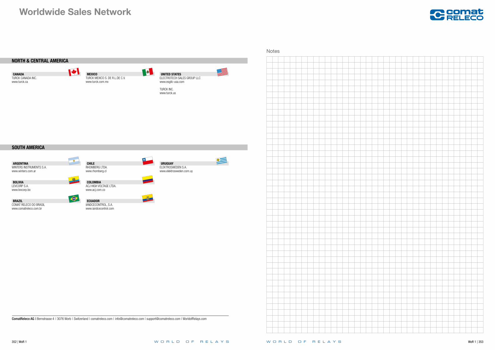
352 | WoR 1 WoR 1 | 353
Notes
NORTH & CENTRAL AMERICA
SOUTH AMERICA
CANADATURCK CANADA INC.www.turck.ca
MEXICOTURCK MEXICO S. DE R.L.DE C.V.www.turck.com.mx
UNITED STATESELECTROTECH SALES GROUP LLCwww.esgllc-usa.com
TURCK INC.www.turck.us
ARGENTINAWINTERS INSTRUMENTS S.A.www.winters.com.ar
BOLIVIALEVCORP S.A.www.levcorp.bo
BRAZILCOMAT RELECO DO BRASILwww.comatreleco.com.br
CHILERHOMBERG LTDA.www.rhomberg.cl
COLOMBIAACJ HIGH VOLTAGE LTDA.www.acj.com.co
ECUADORIANDCECONTROL, S.A.www.iandcecontrol.com
URUGUAYELEKTROSWEDEN S.A.www.elektrosweden.com.uy
Worldwide Sales Network
ComatReleco AG | Bernstrasse 4 | 3076 Worb | Switzerland | comatreleco.com | [email protected] | [email protected] | WorldofRelays.com

ComatReleco AGBernstrasse 4 | 3076 Worb | Switzerland
Tel. +41 31 838 55 77Fax +41 31 838 55 99
[email protected] | [email protected] | WorldofRelays.com
354 | WoR 1
Notes

ComatReleco AGBernstrasse 4 | 3076 Worb | Switzerland
Tel. +41 31 838 55 77Fax +41 31 838 55 99
[email protected] | [email protected] | WorldofRelays.com