NOTICE INVITING TENDER (NIT)
353
POWER SECTOR EASTERN REGION, DJ-9/1, SALT LAKE CITY, KOLKATA - 700 091 फै स/Fax: (033) 23211960 फन/Phone: बड /EPABX: 23398220 Page - 1 of 32 BHARAT HEAVY ELECTRICALS LIMITED (A Govt. Of India Undertaking) POWER SECTOR, EASTERN REGION BHEL BHAWAN, PLOT NO. DJ-9/1 , SECTOR II , SALT LAKE CITY, KOLKATA, WEST BENGAL, INDIA Phone : 033-23216130-31,033-23216130 FAX : 033-23211960 NOTICE INVITING TENDER (NIT) OFFERS are invited from REPUTED AND EXPERIENCED LOCAL BIDDERS (meeting pre-qualification criteria as mentioned) through E-PROCUREMENT PORTAL https://eprocurebhel.co.in ONLY for the subject job by the undersigned on behalf of Bharat Heavy Electricals Limited as per the tender document. Issue/ forwarding intimation regarding tender to any bidder shall not construe that the bidder is considered to be qualified. Following points relevant to the tender may please be noted and complied with. Salient Features of NIT SL NO ISSUE DESCRIPTION i E-TENDER NUMBER PSER:PUR:PMX:380(VIII):047(ENQ:22:PP:0015:PUR:64) DATE: 30/08/2022 ii Broad Scope of job SUPPLY OF FABRICATED STRUCTURAL STEEL MATERIAL (1952 MT) INCLUDING PAINTING, TRANSPORTATION TO SITE ETC FOR FGD SYSTEM PKG AT 3x 660 MW, STAGE-I & 2X660 MW, STAGE-II BARH STPP, BIHAR. iii DETAILS OF TENDER DOCUMENT a) PART – B GENERAL CONDITIONS OF CONTRACT (GCC) Applicable b) VOLUME-IC TECHNICAL CONDITIONS OF CONTRACT (SUPPLY) Applicable c) PART – F GENERAL TERMS & CONDITIONS OF REVERSE AUCTION Applicable d) VOLUME-III VOLUME-III, PRICE SCHEDULE and UNPRICE SCHEDULE Applicable e) PART – H FORMS AND PROCEDURES ETC. Applicable iv ISSUE OF TENDER DOCUMENTS a) Online through e-procurement platform at https://eprocurebhel.co.in/ b)in BHEL website (www.bhel.com, CPP Portal): For tender view purpose only. START DATE: 30/08/2022 a) Applicable b) Applicable v DUE DATE & TIME OF OFFER SUBMISSION Date: 09/09/2022, Time: 14-00 Hrs. (Offer to be submitted online only through e-procurement platform at https://eprocurebhel.co.in/ Applicable vi TECHNO-COMMERCIAL BID OPENING OF TENDER Date: 09/09/2022, Time: 16-30 Hrs. (online only through e-procurement platform at https://eprocurebhel.co.in/, participating bidders may witness the same online only) Applicable vii CURRENCY INDIAN RUPEES (INR) Applicable viii EMD AMOUNT NIL Not Applicable ix COST OF TENDER - Not Applicable x LAST DATE FOR SEEKING CLARIFICATION Date: 06/09/2022 (UP TO 12:00 Hrs.) Applicable xi SCHEDULE OF Pre Bid Discussion (PBD) Not Applicable (In case BHEL decides to conduct PBD, date, time & venue of PBD will be intimated suitably thru TCN). Not Applicable xii INTEGRITY PACT & DETAILS OF INDEPENDENT EXTERNAL MONITOR (IEM) IP SHALL BE APPLICABLE. DETAILS OF IEM: Refer Clause No 34.0 below Applicable xiii Latest updates Latest updates on the important dates, Amendments, Correspondences, Corrigenda, Clarifications, Changes, Errata, Modifications, Revisions, etc to Tender Specifications will be hosted in BHEL webpage (www.bhel.com →Tender Notifications →View Corrigendums & CPP portal →Tender Notice & E-PROCUREMENT PORTAL https://eprocurebhel.co.in) and not in the newspapers. Bidders to keep themselves updated with all such information. Shall be intimated to bidder
-
Upload
khangminh22 -
Category
Documents
-
view
1 -
download
0
Transcript of NOTICE INVITING TENDER (NIT)

POWER SECTOR EASTERN REGION, DJ-9/1, SALT LAKE CITY, KOLKATA - 700 091
फैक्स/Fax: (033) 23211960 फ़ोन/Phone: ब़ोर्ड/EPABX: 23398220
Page - 1 of 32
BHARAT HEAVY ELECTRICALS LIMITED (A Govt. Of India Undertaking) POWER SECTOR, EASTERN REGION BHEL BHAWAN, PLOT NO. DJ-9/1 , SECTOR II , SALT LAKE CITY, KOLKATA, WEST BENGAL, INDIA Phone : 033-23216130-31,033-23216130 FAX : 033-23211960
NOTICE INVITING TENDER (NIT)
OFFERS are invited from REPUTED AND EXPERIENCED LOCAL BIDDERS (meeting pre-qualification criteria as mentioned) through E-PROCUREMENT PORTAL https://eprocurebhel.co.in ONLY for the subject job by the undersigned on behalf of Bharat Heavy Electricals Limited as per the tender document. Issue/ forwarding intimation regarding tender to any bidder shall not construe that the bidder is considered to be qualified. Following points relevant to the tender may please be noted and complied with.
Salient Features of NIT
SL NO ISSUE DESCRIPTION
i E-TENDER NUMBER PSER:PUR:PMX:380(VIII):047(ENQ:22:PP:0015:PUR:64) DATE: 30/08/2022
ii Broad Scope of job
SUPPLY OF FABRICATED STRUCTURAL STEEL MATERIAL (1952 MT) INCLUDING PAINTING, TRANSPORTATION TO SITE ETC FOR FGD SYSTEM PKG AT 3x 660 MW, STAGE-I & 2X660 MW, STAGE-II BARH STPP, BIHAR.
iii DETAILS OF TENDER DOCUMENT
a) PART – B GENERAL CONDITIONS OF CONTRACT (GCC) Applicable
b) VOLUME-IC TECHNICAL CONDITIONS OF CONTRACT (SUPPLY) Applicable
c) PART – F GENERAL TERMS & CONDITIONS OF REVERSE AUCTION Applicable
d) VOLUME-III VOLUME-III, PRICE SCHEDULE and UNPRICE SCHEDULE Applicable
e) PART – H FORMS AND PROCEDURES ETC. Applicable
iv ISSUE OF TENDER DOCUMENTS
a) Online through e-procurement platform at https://eprocurebhel.co.in/
b)in BHEL website (www.bhel.com, CPP Portal): For tender view purpose only.
START DATE: 30/08/2022
a) Applicable b) Applicable
v DUE DATE & TIME OF OFFER SUBMISSION
Date: 09/09/2022, Time: 14-00 Hrs. (Offer to be submitted online only through e-procurement platform at https://eprocurebhel.co.in/
Applicable
vi TECHNO-COMMERCIAL BID OPENING OF TENDER
Date: 09/09/2022, Time: 16-30 Hrs. (online only through e-procurement platform at https://eprocurebhel.co.in/, participating bidders may witness the same online only)
Applicable
vii CURRENCY INDIAN RUPEES (INR) Applicable
viii EMD AMOUNT NIL Not Applicable
ix COST OF TENDER - Not Applicable
x LAST DATE FOR SEEKING CLARIFICATION
Date: 06/09/2022 (UP TO 12:00 Hrs.) Applicable
xi SCHEDULE OF Pre Bid Discussion (PBD)
Not Applicable (In case BHEL decides to conduct PBD, date, time & venue of PBD will be intimated suitably thru TCN).
Not Applicable
xii INTEGRITY PACT & DETAILS OF INDEPENDENT EXTERNAL MONITOR (IEM)
IP SHALL BE APPLICABLE. DETAILS OF IEM: Refer Clause No 34.0 below
Applicable
xiii Latest updates
Latest updates on the important dates, Amendments, Correspondences, Corrigenda, Clarifications, Changes, Errata, Modifications, Revisions, etc to Tender Specifications will be hosted in BHEL webpage (www.bhel.com →Tender Notifications →View Corrigendums & CPP portal →Tender Notice & E-PROCUREMENT PORTAL https://eprocurebhel.co.in) and not in the newspapers. Bidders to keep themselves updated with all such information.
Shall be intimated to
bidder

E-TENDER NUMBER - PSER:PUR:PMX:380(VIII):047(ENQ:22:PP:0015:PUR:64) DATE: 30/08/2022
POWER SECTOR EASTERN REGION, DJ-9/1, SALT LAKE CITY, KOLKATA - 700 091
फैक्स/Fax: (033) 23211960 फ़ोन/Phone: ब़ोर्ड/EPABX: 23398220
Page - 2 of 32
1. The offer shall be submitted as per the instructions of tender document. Only One set of tender document (in original, downloaded from website) signed by authorised company rep. of bidder and stamped on each page shall be submitted as detailed further, as given below. Bidders to note specifically that all pages of tender document, including these NIT pages etc. appearing in the website for this particular tender shall be submitted by them (after signing/stamping on each page) as a part of their offer. Price shall not be mentioned by them anywhere in the techno-commercial portion of offer. Price shall be mentioned in the relevant price schedule only and to be submitted in e-procurement portal/platform in the form and manner mentioned in tender.
For E-Procurement Assistance & Training, NIC PORTAL Helpdesk Contacts as per following: - For any technical related queries please call at 24x7 Help Desk Number 0120-4001 002, 0120-4200 462, 0120-4001 006, 0120-6277 787
Email Support Address: A) For any Issues or Clarifications relating to the published tenders, bidders are requested to contact the respective Tender Inviting Authority Technical - [email protected]
For any difficulty in downloading the tender from internet website, they should contact this office (Manager, Purchase or DGM, Purchase, Phone no. 033-23398222/8221). No alteration/changes by bidders is permitted in the tender/NIT appeared in the website.
2. Successful bidder shall have to submit additional set of tender/sign on tender document provided by BHEL, if so decided by BHEL.
3. This is an e-tender floated online through our E-Procurement Site https://eprocurebhel.co.in. The bidder should respond by submitting their offer online only in our e-Procurement platform at https://eprocurebhel.co.in. Offers are invited in two-parts only. No Hard copy bid or bids through email/ fax shall be accepted. Bids are invited in two parts & shall be submitted as described below:
OFFER DESCRIPTION DOCUMENTS TO BE UPLOADED & MODALITY OF UPLOADING
TECHNICAL OFFER
1. Scanned copy of Covering letter of offer (To be attached in Attachment section) 2. Scanned copy of Entire tender documents signed & stamped in each page by
authorized representative of the bidder except price bid (To be attached in Attachment section).
3. Scanned copy of Techno-Commercial Offer (To be attached in Attachment section)
4. Duly filled all annexures except price & unpriced format (To be attached in Attachment section).
5. Copy of records notes of Pre-Bid Conference, if applicable/ pre-bid MOM. (To be attached in Attachment section)
6. Copy of Tender change notice (TCN), if applicable (To be attached in Attachment section)
7. All supporting documents/ Annexures etc. as applicable (To be attached in Attachment section).
8. No deviation certificate in bidder’s letterhead as per format given in Tender (To be attached in Attachment section).
PRE-QUALIFICATION PART
9. Pre-qualifying documents with all credentials as per tender. (To be attached in PQ Attachment section)
UNPRICED PRICE BID 10. Price schedule –Unpriced but mentioning only quoted / unquoted against each item as per tender.
PRICE BID
11. Duly filled in Price Schedule as per tender. Any other document uploaded in the price bid, apart from tendered Price schedule, shall not be taken into cognizance for evaluation of offer.
4. EARNEST MONEY DEPOSIT (EMD) – Not applicable,
SPECIAL NOTE: A) Your offer & documents submitted with the offer shall be signed and stamped in each page by your authorized
representative. No overwriting/correction in tender documents by bidders shall be allowed. However if correction is unavoidable, the same may be signed by authorized signatory.
B) All documents/annexure submitted with the offer shall be properly annexed and placed in respective places of the offer as per enclosure list mentioned in the covering letter. BHEL shall not be responsible for any missing documents.
5. No deviation with respect to tender clauses and no additional clauses/ suggestions/clarification in Techno-commercial bid/Price bid shall normally be considered by BHEL. Bidders are requested to positively comply with the same. Offers with deviation are liable for rejection.
6. BHEL reserves the right to accept or reject any or all offer without assigning any reasons thereof. BHEL also

E-TENDER NUMBER - PSER:PUR:PMX:380(VIII):047(ENQ:22:PP:0015:PUR:64) DATE: 30/08/2022
POWER SECTOR EASTERN REGION, DJ-9/1, SALT LAKE CITY, KOLKATA - 700 091
फैक्स/Fax: (033) 23211960 फ़ोन/Phone: ब़ोर्ड/EPABX: 23398220
Page - 3 of 32
reserve the right to cancel the offer wholly or partly without assigning any reason thereof. BHEL also reserve the right to split/part award the job. Also BHEL shall not entertain any correspondence from bidders in this matter (except for the refund of EMD).
7. Bidders are free to visit the site and study the prevailing site condition including law & order etc. before quoting (if applicable). They may also consult this office before submitting their offers, for any clarifications regarding scope of work, facilities available at sites or on terms and conditions. No additional claim shall be entertained by BHEL in future, on account of non-acquaintance of site/machine conditions at the time of bidding.
8. For any clarification on the tender document, you may seek the same in writing or through e-procurement portal/platform as per specified format within the last date of seeking clarification as per tender. BHEL shall not be responsible for receipt of queries after due date of seeking clarification due to postal delay, and receipt of any query after due date shall not be entertained.
9. BHEL may decide holding Pre-bid Discussion [PBD] with all intending bidders. On such communication from BHEL, the bidder shall ensure participation for the same at the appointed time, date and place as may be decided by BHEL. Outcome of PBD (if any) shall also form part of tender.
10. In case of absence of any queries from bidder(s), their quoted price will be PRESUMED to be final and complete with reference to the tender documents (including Tender change notes (TCNs), clarifications, corrigendum issued by BHEL, if any). Bidders are requested to study the tender documents in detail and prepare their queries/clarifications accordingly. All such queries / clarifications shall be cleared/replied by BHEL. Such clarification letters, corrigendum and/or Tender change notes (TCNs), if issued by BHEL, shall form part of tender document.
11. In the event of any conflict between requirement of any clause of this specification/ documents /drawings /data sheets etc. or requirements of different codes/ standards specified/ contradictions between any two clauses of tender document, the same to be brought to the knowledge of BHEL by bidders in writing for clarification before due date of seeking clarification, otherwise, more stringent requirement as may be interpreted by BHEL shall prevail and shall be binding on you. Any typing error/missing pages/other clerical errors in the tender documents, noticed by you must be pointed out before submission of offer, or else, BHEL’s interpretation shall prevail & binding on you.
12. Unless specifically mentioned otherwise, bidder’s quoted price shall deemed to be in compliance with tender including PBD.
13. Tender document containing above mentioned volumes shall be signed & stamped in all pages including this covering letter. Price bid shall be furnished in the specified format enclosed with the tender. Any additional copy, if required, may be taken by photocopying from the tender document given in the web.
14. The Bidder has to satisfy the Pre-Qualifying Requirements stipulated for this Tender in order to be qualified. The Price Bids of only those bidders will be opened, who will qualify for the subject job on the basis of pre-qualification evaluation & Techno-Commercial bids etc. BHEL reserves the right to reject the bidders with unsatisfactory past performance in the execution of a contract. BHEL’s decision in this regard shall be final & binding.
15. The bidder shall submit documents in support of possession of ‘Pre-Qualifying Requirements” duly self-certified and stamped by the authorized signatory, indexed and properly linked in the format for PQR. In case BHEL requires any other documents/proofs, these shall be submitted immediately (if applicable).
16. The bidder may have to produce original document for verification if so decided by BHEL.
17. While BHEL reserves the right to open the price bid of the offers in camera, the date & time to open the tender opening shall be intimated to the bidders in case BHEL decides it to be 'Public opening' and in such a case, one authorized representative of the bidder shall be allowed to attend.
18. Validity of the offer shall be for SIX (06) MONTHS from the due date of offer submission (including extension, if any).
19. Bidders are required to submit their BEST price as per tender Price Schedule format in e-procurement portal/platform in the form & manner as mentioned in tender.
20. Price Bids shall be evaluated in the manner as prescribed in Price Schedule. However, Unit Rates shall also be furnished if applicable in the Price Schedule.
21. Bid should be free from correction, overwriting, using corrective fluid, etc. Any interlineation, cutting, erasure or overwriting shall be valid only if they are attested under full signature(s) of person(s) signing the bid else bid shall be liable for rejection.
22. Taxes and duties shall be as per TCC of the tender. Statutory variation of taxes and duties (plus or minus) in accordance with Govt. Notifications to the account of BHEL. Any imposition of new / additional Duty / Tax at the time of supply shall be borne by BHEL.
23. “BHEL shall be resorting to Reverse Auction (RA) (Guidelines as available on www.bhel.com) for this tender. RA shall be conducted among the techno-commercially qualified bidders.
Price bids of all techno-commercially qualified bidders shall be opened and same shall be considered for RA. In case any bidder(s) do(es) not participate in online Reverse Auction, their sealed envelope price bid along with applicable loading, if any, shall be considered for ranking.”

E-TENDER NUMBER - PSER:PUR:PMX:380(VIII):047(ENQ:22:PP:0015:PUR:64) DATE: 30/08/2022
POWER SECTOR EASTERN REGION, DJ-9/1, SALT LAKE CITY, KOLKATA - 700 091
फैक्स/Fax: (033) 23211960 फ़ोन/Phone: ब़ोर्ड/EPABX: 23398220
Page - 4 of 32
24. Bidders are requested to note that the accepted / agreed tender terms (technical, commercial or on Reverse Auction) in their original offer cannot be altered / withdrawn by their own during the processing of tender.
25. Unsolicited discounts received after opening of techno commercial bid shall not be considered for evaluation. However, if the party who has submitted the unsolicited discount/rebate becomes the L-1 party, then the awarded price shall be after considering the discount.
26. “The offers of the bidders who are on the banned list as also the offer of the bidders, who engage the services of the banned firms, shall be rejected. The list of banned firms is available on BHEL web site www.bhel.com”.
i. Integrity commitment, performance of the contract and punitive action thereof:
a) Commitment by BHEL:
BHEL commits to take all measures necessary to prevent corruption in connection with the tender process and execution of the contract. BHEL will during the tender process treat all Bidder(s) in a transparent and fair manner, and with equity.
b) Commitment by Bidder/ Supplier/ Contractor:
b.i) The bidder/ supplier/ contractor commit to take all measures to prevent corruption and will not directly or indirectly influence any decision or benefit which he is not legally entitled to nor will act or omit in any manner which tantamount to an offence punishable under any provision of the Indian Penal Code, 1860 or any other law in force in India.
b.ii) The bidder/ supplier/ contractor will, when presenting his bid, disclose any and all payments he has made, and is committed to or intends to make to agents, brokers or any other intermediaries in connection with the award of the contract and shall adhere to relevant guidelines issued from time to time by Govt. of India/ BHEL.
b.iii) The bidder/ supplier/ contractor will perform/ execute the contract as per the contract terms & conditions and will not default without any reasonable cause, which causes loss of business/ money/ reputation, to BHEL.
If any bidder/ supplier/ contractor during pre-tendering/ tendering/ post tendering/ award/ execution/ post-execution stage includes in mal-practices, cheating, bribery, fraud or and other misconduct or formation of cartel so as to influence the bidding process or influence the price or acts or omits in any manner which tantamount to an offence punishable under any provision of the Indian Penal code, 1860 or any other law in force in India, then, action may be taken against such bidder/ supplier/ contractor as per extant guidelines of the company available on www.bhel.com and/ or under applicable legal provisions.
27. The Bidder along with its associate/collaborators/sub-contractors/sub-vendors/consultants/service providers shall strictly adhere to BHEL Fraud Prevention Policy displayed on BHEL website http://www.bhel.com and shall immediately bring to the notice of BHEL management about any fraud or suspected fraud as soon as it comes to their notice.
28. Suspension of Business dealings: BHEL reserves the right to take action against contractors who fail to perform or indulge in malpractices, by suspending business dealings with them as detailed in Annexure-VII.
29. "MSE suppliers can avail the intended benefits in respect of the procurements related to the Goods and Services only (Definition of Goods and Services as enumerated by Govt. of India vide Office Memorandum F. No. 21(8)/2011-MA dtd. 09/11/2016 office of AS & DC, MSME) if they submit along with the offer, attested copies of either Udyam Registration Certificate or EM II certificate having deemed validity (five years from the date of issue of acknowledgement in EM II) or valid NSIC certificate or Udyog Aadhar Memorandum (UAM) & Acknowledgement or EM II certificate along with attested copy of a CA certificate (Format enclosed at Annexure – V where deemed validity of EM II certificate of five years has expired) applicable for the relevant financial year (latest audited). Date to be reckoned for determining the deemed validity will be the date of bid opening (Part 1 in case of two part bid). Non submission of such documents will lead to consideration of their bid at par with other bidders. No benefit shall be applicable for this enquiry if any deficiency in the above required documents are not submitted before price bid opening. If the tender is to be submitted through e-procurement portal, then the above required documents are to be uploaded on the portal. Documents should be notarized or attested by a Gazetted officer." Any Bidder falling under MSME category, shall furnish the following details & submit documentary evidence/Govt. Certificate etc. in support of the same along with their techno-commercial offer: -
Type under MSME SC/ST owned Others
Micro
Small
Medium
Note: - If the bidder does not furnish the above, offer shall be processed construing that the bidder is not falling under
MSME category.

E-TENDER NUMBER - PSER:PUR:PMX:380(VIII):047(ENQ:22:PP:0015:PUR:64) DATE: 30/08/2022
POWER SECTOR EASTERN REGION, DJ-9/1, SALT LAKE CITY, KOLKATA - 700 091
फैक्स/Fax: (033) 23211960 फ़ोन/Phone: ब़ोर्ड/EPABX: 23398220
Page - 5 of 32
30. Indian suppliers, falling under the purview of Public procurement (preference to make in India) order 2017 by Govt. of India, vide order no. P-45021/2/2017-B.E.-II dated 15th June, 2017 & all subsequent clarifications can avail the intended benefits, as per provisions of the order subject to minimum local content shall be 50%, margin of Purchase preference shall be 20% & modality of preference to make in India shall be as per aforesaid order.
31. “For this procurement, the local content to categorize a supplier as a Class-I local supplier/ Class-II local supplier/ Non-Local supplier and purchase preference to Class-I local supplier, is as defined in Public Procurement (Preference to Make in India), Order 2017 dated 04-06-2020 issued by DPIIT. In case of subsequent orders issued by the Nodal Ministry, changing the definition of local content for the items of the NIT, the same shall be applicable even if issued after issue of this NIT, but before opening of Part-II bids against this NIT”.
Duly filled & signed Annexure-III (Format for local content), as applicable, to be submitted by bidders along with their techno-commercial offer.
32. GeMAR and PTS Report ID: GEM/GARPTS/10082022/KI546HOK4352, Date – 10/08/2022
33. The GeM Seller ID shall be mandatory before placement of order / award of contract for goods and services to the successful bidder(s).
34. Integrity Pact (IP) –
(a) IP is a tool to ensure that activities and transactions between the Company and its Bidders/ Contractors are handled in a fair, transparent and corruption free manner. Following Independent External Monitors (IEMs) on the present panel have been appointed by BHEL with the approval of CVC to oversee implementation of IP in BHEL.
Sl IEM Email
1. Shri Otem Dai, IAS (Retd.) [email protected]
2. Shri Bishwamitra Pandey, IRAS (Retd.) [email protected]
3. Shri Mukesh Mittal, IRS (Retd.) [email protected]
(b) The IP as enclosed with the tender is to be submitted (duly signed by authorized signatory) along with techno-
commercial bid (Part-I, in case of two/three part bid). Only those bidders who have entered into such an IP with BHEL would be competent to participate in the bidding. In other words, entering into this Pact would be a preliminary qualification.
(c) Please refer Section-8 of IP for Role and Responsibilities of IEMs. In case of any complaint arising out of the tendering process, the matter may be referred to any of the above IEM(s). All correspondence with the IEMs shall be done through email only.
Note:
No routine correspondence shall be addressed to the IEM (phone/ post/ email) regarding the clarifications, time extensions or any other administrative queries, etc. on the tender issued. All such clarification/ issues shall be addressed directly to the tender issuing (procurement) department’s officials whose contact details are provided below:
Details of contact person(s):
Name Mr. Abhijit De Mr. Anuruddha Sarkar
Dept. Purchase Dept., BHEL PSER, Kolkata Purchase Dept., BHEL PSER, Kolkata
Address DJ-9/1, Sector – II, Salt Lake, Kolkata – 700091
DJ-9/1, Sector – II, Salt Lake, Kolkata –700091
Phone 033-2339 8222 033-2339 8221
Email [email protected] [email protected]
35. In the course of evaluation, if more than one bidder happens to occupy L-1 status, effective L-1 will be decided
by soliciting discounts from the respective L-1 bidders. In case more than one bidder happens to occupy the L-1 status even after soliciting discounts, the L-1 bidder shall be decided by a toss / draw of lots, in the presence of the respective L-1 bidder(s) or their representative(s). Ranking will be done accordingly. BHEL’s decision in such situations shall be final and binding

E-TENDER NUMBER - PSER:PUR:PMX:380(VIII):047(ENQ:22:PP:0015:PUR:64) DATE: 30/08/2022
POWER SECTOR EASTERN REGION, DJ-9/1, SALT LAKE CITY, KOLKATA - 700 091
फैक्स/Fax: (033) 23211960 फ़ोन/Phone: ब़ोर्ड/EPABX: 23398220
Page - 6 of 32
36. Order of Precedence
In the event of any ambiguity or conflict between the Tender Documents, the order of precedence shall be in the order below:
a) Amendments/Clarifications/Corrigenda/Errata etc issued in respect of the tender documents by BHEL
b) Notice Inviting Tender (NIT)
c) Price Bid/Schedule – Volume-III
d) TECHNICAL CONDITIONS OF CONTRACT (TCC)
e) General Conditions of Contract (GCC) - PART-B
f) Forms and Procedures – PART- H
for BHARAT HEAVY ELECTRICALS LTD.
Manager (Purchase)
Agency Contact details
BHEL, PSER, Kolkata
Address BHARAT HEAVY ELECTRICALS LIMITED, POWER SECTOR – EASTERN REGION 2ND FLOOR, BLOCK-DJ, PLOT- 9/1, SECTOR, SALT LAKE CITY, KOLKATA – 700 091
Phone no. 033-23398222, 23398221, 23211690
FAX no. 033-23211960
E-mail ID [email protected], [email protected], [email protected]
NIC E-PROCUREMENT PORTAL
For E-Procurement Assistance & Training, NIC PORTAL Helpdesk Contacts as per following: - For any technical related queries please call at 24 x 7 Help Desk Number 0120-4001 002, 0120-4200 462, 0120-4001 005, 0120-6277 787
Email Support Address: A) For any Issues or Clarifications relating to the published tenders, bidders are requested to contact the respective Tender Inviting Authority Technical - [email protected]
Enclosure:
01. ANNEXURE-I: Pre Qualifying Criteria.
02. ANNEXURE-II : No Deviation Certificate
03. ANNEXURE-III: Format for Self Certification regarding Local content (LC) for Product/ Services/ Works
04. ANNEXURE-IV: CERTIFICATE (regarding bidder from a country which shares a land border with India)
05. ANNEXURE-V: Certificate by Chartered Accountant
06. ANNEXURE-VI: Format for seeking clarification
07. ANNEXURE-VII: Suspension of business dealing with Suppliers/Contractors
08. ANNEXURE-VIII: Declaration for Relation in BHEL
09. ANNEXURE-IX: Declaration of the Bidders
10. ANNEXURE-X: Declaration regarding related firms and their area of activities
11. ANNEXURE-A: Check List
12. ANNEXURE-B: General Terms & conditions for Reverse Auction.
13. Integrity Pact Agreement Format (Separate).
14. Other Tender documents as per this NIT.

E-TENDER NUMBER - PSER:PUR:PMX:380(VIII):047(ENQ:22:PP:0015:PUR:64) DATE: 30/08/2022
POWER SECTOR EASTERN REGION, DJ-9/1, SALT LAKE CITY, KOLKATA - 700 091
फैक्स/Fax: (033) 23211960 फ़ोन/Phone: ब़ोर्ड/EPABX: 23398220
Page - 7 of 32
ANNEXURE – I
PRE QUALIFICATION CRITERIA
JOB SUPPLY OF FABRICATED STRUCTURAL STEEL MATERIAL (1952 MT) INCLUDING PAINTING,
TRANSPORTATION TO SITE ETC FOR FGD SYSTEM PKG AT 3X 660 MW, STAGE-I & 2X660 MW,
STAGE-II BARH STPP, BIHAR.
TENDER NO PSER:PUR:PMX:380(VIII):047(ENQ:22:PP:0015:PUR:64) DATE: 30/08/2022
A. FINANCIAL CRITERIA
1(a) BIDDER SHOULD HAVE AVERAGE MINIMUM ANNUAL FINANCIAL TURNOVER INR 3.0 Cr (Rs. THREE
CRORE ONLY) DURING LAST 03 (THREE) CONSECUTIVE FINANCIAL YEARS 2018-19, 2019-20 & 2020-
21 AND SHOULD SUBMIT THEIR AUDITED BALANCE SHEET AND PROFIT & LOSS ACCOUNT OF THE
COMPANY IN SUPPORT OF THE SAME.
1(b) IN CASE AUDITED BALANCE SHEET AND PROFIT & LOSS ACCOUNT HAS NOT BEEN SUBMITTED FOR
ALL THREE YEARS INDICATED ABOVE THEN THE APPLICABLE FINANCIAL AUDITED STATEMENTS
SUBMITTED BY THE BIDDERS AGAINST THE REQUISITE THREE YEARS WILL BE AVERAGED FOR
THREE YEARS.
1(c) IF FINANCIAL STATEMENTS ARE NOT REQUIRED TO BE AUDITED STATUTORILY, THEN INSTEAD OF
AUDITED FINANCIAL STATEMENTS, FINANCIAL STATEMENTS ARE REQUIRED TO BE CERTIFIED BY
CHARTERED ACCOUNTANT.
B. TECHNICAL CRITERIA
BIDDER SHOULD HAVE PREVIOUS EXPERIENCE OF SUPPLYING FABRICATED STRUCTURAL STEEL
MATERIAL OF MINIMUM QUANTITY OF 586 MT TO GOVT./PSU/REPUTED ORGANISATION IN LAST THREE
YEARS AS ON LAST DATE OF BID SUBMISSION.
BIDDER SHALL HAVE TO SUBMIT RELEVANT DOCUMENTS IN SUPPORT OF THE SAME.
C. INDIAN BIDDERS SHOULD HAVE VALID PERMANENT ACCOUNT NUMBER (PAN).
GENERAL CLAUSE:
a. CONSORTIUM BIDDING/JV BIDDING IS NOT ALLOWED.
b. IN CASE THE JOB IS UNDER EXECUTION/ ONGOING JOB, THE VALUE OF EXECUTED PORTION OF THE
JOB SHALL AT LEAST CORRESPOND TO THE RESPECTIVE VALUES SPECIFIED ABOVE EVEN IF THE
CONTRACT HAS NOT BEEN COMPLETED OR CLOSED.
c. AFTER SATISFACTORY FULFILLMENT OF ALL ABOVE CRITERIA, OFFER SHALL BE CONSIDERED FOR
FURTHER EVALUATION & PARTICIPATION AS PER NIT & ALL OTHER TERMS OF TENDER SUBJECT TO
BHEL ASSESSMENT OF VENDOR’S QUALITY MANAGEMENT SYSTEM, MANUFACTURING AND TESTING
FACILITIES.
d. THE SUPPLIED QUANTITY MAY BE CONSIDERED AGAINST SINGLE/MULTIPLE PO TO MEET THE ABOVE PQ REQUIREMENT.

E-TENDER NUMBER - PSER:PUR:PMX:380(VIII):047(ENQ:22:PP:0015:PUR:64) DATE: 30/08/2022
POWER SECTOR EASTERN REGION, DJ-9/1, SALT LAKE CITY, KOLKATA - 700 091
फैक्स/Fax: (033) 23211960 फ़ोन/Phone: ब़ोर्ड/EPABX: 23398220
Page - 8 of 32
ANNEXURE - II
FORMAT FOR NO DEVIATION CERTIFICATE
(To be submitted in the bidder's letter head)
To, BHARAT HEAVY ELECTRICALS LIMITED, Power Sector - Eastern Region, Plot no 9/1, DJ Block, Sector – II, Salt Lake City, Kolkata – 700 091
SUB NO DEVIATION CERTIFICATE.
JOB SUPPLY OF FABRICATED STRUCTURAL STEEL MATERIAL (1952 MT) INCLUDING PAINTING,
TRANSPORTATION TO SITE ETC FOR FGD SYSTEM PKG AT 3X 660 MW, STAGE-I & 2X660 MW, STAGE-
II BARH STPP, BIHAR.
REF 1.0 TENDER NO. PSER:PUR:PMX:380(VIII):047(ENQ:22:PP:0015:PUR:64) DATE: 30/08/2022
2.0 ALL OTHER PERTINENT ISSUES TILL DATE.
Dear Sir/Madam,
With reference to above tender, this is to confirm you that we have gone through each and every terms and conditions mentioned in the enquiry (Terms and Conditions) and we offer our unqualified acceptance of the same. This is also to confirm that as per tender conditions, we have visited site before submission of our offer and noted the job content & site conditions etc. We also confirm that we have not changed/modified the tender documents as appeared in the website/newspapers and in case of observance at any stage, it shall be treated as null and void. We hereby confirm that we have not taken any deviation from tender clauses together with other references as enumerated in the above referred NIT and confirm our acceptance to reverse auctioning process and we hereby convey our unqualified acceptance to all terms and conditions as stipulated in the tender and NIT. It is also confirmed that the price has been quoted in the format received with the enquiry. We confirm that, we do not have any objections to splitting the quantity among the different bidders by BHEL and price shall remain firm till the completion supply of full ordered quantity. Any deviation found subsequently at any time during execution of order shall be treated null and void.
Thanking you,
Yours faithfully,
(Signature, date & seal of authorized
representative of the bidder)

E-TENDER NUMBER - PSER:PUR:PMX:380(VIII):047(ENQ:22:PP:0015:PUR:64) DATE: 30/08/2022
POWER SECTOR EASTERN REGION, DJ-9/1, SALT LAKE CITY, KOLKATA - 700 091
फैक्स/Fax: (033) 23211960 फ़ोन/Phone: ब़ोर्ड/EPABX: 23398220
Page - 9 of 32
ANNEXURE-III
DECLARATION REGARDING MINIMUM LOCAL CONTENT IN LINE WITH
REVISED PUBLIC PROCUREMENT (PREFERENCE TO MAKE IN INDIA), ORDER 2017 DATED 04TH JUNE, 2020 AND
SUBSEQUENT ORDER(S)
(To be typed and submitted in the Letter Head of the Entity/Firm providing certificate as applicable)
-----------------------------------------------------------------------------------------------------------------------------------------------------------------------
To,
(Write Name & Address of Officer of BHEL inviting the Tender)
Dear Sir,
Sub: Declaration reg. minimum local content in line with Public Procurement (Preference to Make in India), Order 2017-Revision,
dated 04th June, 2020 and subsequent order(s).
Ref : 1) NIT/Tender Specification No: PSER:PUR:PMX:380(VIII):047(ENQ:22:PP:0015:PUR:64) DATE: 30/08/2022,
2) All other pertinent issues till date
We hereby certify that the items/works/services offered by……………………………………… (specify the name of the organization
here) has a local content of _______ % and this meets the local content requirement for ‘Class-I local supplier’ / ‘Class II local
supplier’ ** as defined in Public Procurement (Preference to Make in India), Order 2017-Revision dated 04.06.2020 issued by
DPIIT and subsequent order(s).
The details of the location(s) at which the local value addition is made are as follows:
1. _________________________________ 2. ___________________________________
3. _________________________________ 4. ___________________________________
…
…
…
Thanking you,
Yours faithfully,
(Signature, Date & Seal of Authorized Signatory of the Bidder)
** - Strike out whichever is not applicable.
Note:
1. Bidders to note that above format Duly filled & signed by authorized signatory, shall be submitted along with the techno-commercial offer.
2. In case the bidder’s quoted value is in excess of Rs.10 crores, the authorised signatory for this declaration shall necessarily be the statutory auditor or cost auditor of the company (in case of companies) or a practising cost accountant or practicing chartered accountant (in respect of suppliers other than companies)
3. In the event of false declaration, actions as per the above order and as per BHEL Guidelines shall be initiated against the bidder.

E-TENDER NUMBER - PSER:PUR:PMX:380(VIII):047(ENQ:22:PP:0015:PUR:64) DATE: 30/08/2022
POWER SECTOR EASTERN REGION, DJ-9/1, SALT LAKE CITY, KOLKATA - 700 091
फैक्स/Fax: (033) 23211960 फ़ोन/Phone: ब़ोर्ड/EPABX: 23398220
Page - 10 of 32
ANNEXURE-IV
DECLARATION REGARDING COMPLIANCE TO RESTRICTIONS UNDER RULE 144 (xi) OF GFR
2017
(To be submitted in the bidder’s letter head)
----------------------------------------------------------------------------------------------------------------------------------
To,
(Write Name & Address of Officer of BHEL inviting the Tender)
Dear Sir,
Sub: Declaration regarding compliance to Restrictions under Rule 144 (xi) of GFR 2017
Ref: 1) NIT/Tender Specification No: PSER:PUR:PMX:380(VIII):047(ENQ:22:PP:0015:PUR:64) DATE: 30/08/2022,
2) All other pertinent issues till date
“I have read the tender clauses pertaining to Department of Expenditure’s (DoE) Public Procurement Division Order (Public
procurement no 1, 2 & 3 vide ref. F.No.6/18/2019-PPD dated 23.07.2020 & 24.7.2020) regarding restrictions on procurement from
a bidder of a country which shares a land border with India. I hereby certify that _____________________________ (specify the
name of the organization here) is not from such a country or, if from such a country, has been registered with the Competent
Authority. I hereby certify that we fulfill all requirements in this regard and is eligible to be considered. [Where applicable, evidence
of valid registration by the Competent Authority shall be attached]”.
Thanking you,
Yours faithfully,
(Signature, Date & Seal of Authorized Signatory of the Bidder)
Note: Bidders to note that in case above certification given by a bidder, whose bid is accepted, is found to
be false, then this would be a ground for immediate termination and for taking further action in accordance
with law and as per BHEL guidelines.

E-TENDER NUMBER - PSER:PUR:PMX:380(VIII):047(ENQ:22:PP:0015:PUR:64) DATE: 30/08/2022
POWER SECTOR EASTERN REGION, DJ-9/1, SALT LAKE CITY, KOLKATA - 700 091
फैक्स/Fax: (033) 23211960 फ़ोन/Phone: ब़ोर्ड/EPABX: 23398220
Page - 11 of 32
ANNEXURE-V
Certificate by Chartered Accountant on letter head
This is to Certify that M/s .............................................................................................. . .. . . . . . . . . . .. . . . . . . . . . .. . . . . . . . . . .. .. . . . . . . . . . . . ., (hereinafter referred
to as 'company’) having its registered office at ..................................................................................................
is registered under MSMED Act 2006, (Entrepreneur Memorandum(Part-II) / UAM / Udyam
Registration No...................................................................................................... d td: ........................................., Category: .........................................................
(Micro/Small). (Copy enclosed).
Further verified from the Books of Accounts that the investment of the company as per the latest audited
financial year........................................................................ as per MSMED Act 2006 is as follows:
1. For Manufacturing Enterprises: Investment in plant and machinery (i.e. original cost excluding land and building and the items specified by the Ministry of Small Scale Industries vide its notification No.S.0.1722(E) dated October 5, 2006:
Rs ..............................................……….. Lacs
2. For Service Enterprises: Investment in equipment (original cost excluding land and building and
furniture, fittings and other items not directly related to the service rendered or as may be notified under the MSMED Act, 2006:
Rs ..............................................……….. Lacs 3. For Enterprises (having EM-Part-II / UAM): Investment in plant and machinery or equipment is
Rs.......................................……. Lacs and turnover is Rs. ................................……….Lacs {as notified in MSME notification no. S.O. 2119 (E) dated 26-06-2020}.
4. For Enterprises (Udyam, registered under Udyam Registration Portal): Investment in plant
and machinery or equipment is Rs...............................Lacs and turnover is Rs..........................Lacs
{as notified in MSME notification no. S.O. 2119 (E) dated 26-06-2020}.
(Strike off whichever is not applicable)
The above investment of Rs...........................Lacs is within permissible limit of Rs.............................Lacs
for ..............................Micro/Small (Strike off which is not applicable) Category under MSMED Act 2006.
Or
The company has been graduated from its original category {Micro/Small) (Strike off which is not applicable) and the date of graduation of such enterprise from its original category is .................... (dd/mm/yyyy) which is within the period of 3 years from the date of graduation of such enterprise from its original category as notified vide S.O. No. 3322(E) dated 01.11.2013 published in the gazette notification dated 04.11.2013 by Ministry of MSME.
Date: (Signature) Name- Membership number –
Seal of Chartered Accountant

E-TENDER NUMBER - PSER:PUR:PMX:380(VIII):047(ENQ:22:PP:0015:PUR:64) DATE: 30/08/2022
POWER SECTOR EASTERN REGION, DJ-9/1, SALT LAKE CITY, KOLKATA - 700 091
फैक्स/Fax: (033) 23211960 फ़ोन/Phone: ब़ोर्ड/EPABX: 23398220
Page - 12 of 32
ANNEXURE-VI
FORMAT FOR SEEKING CLARIFICATION
Job SUPPLY OF FABRICATED STRUCTURAL STEEL MATERIAL (1952 MT) INCLUDING PAINTING, TRANSPORTATION TO SITE ETC FOR FGD SYSTEM PKG AT 3x 660 MW, STAGE-I & 2X660 MW, STAGE-II BARH STPP, BIHAR.
Tender No PSER:PUR:PMX:380(VIII):047(ENQ:22:PP:0015:PUR:64) DATE: 30/08/2022
Sl. no Reference clause of tender document
Existing provision
Bidder's query BHEL’s clarification

E-TENDER NUMBER - PSER:PUR:PMX:380(VIII):047(ENQ:22:PP:0015:PUR:64) DATE: 30/08/2022
POWER SECTOR EASTERN REGION, DJ-9/1, SALT LAKE CITY, KOLKATA - 700 091
फैक्स/Fax: (033) 23211960 फ़ोन/Phone: ब़ोर्ड/EPABX: 23398220
Page - 13 of 32
ANNEXURE-VII
SUSPENSION OF BUSINESS DEALINGS WITH SUPPLIERS/ CONTRACTORS
1.0 Suspension of Business dealings with Suppliers/ Contractors
1.1 BHEL reserves the right to take action against Suppliers/ Contractors who fail to perform or indulge in malpractices, by suspending business dealings with them.
1.2
Suspension of business dealings with Suppliers/ Contractors could be in the form of following: -- a) Hold within the unit for specific item(s)/ material category(ies)/ type of work(s) for one year. b) Hold within the unit for all item(s)/ material category(ies)/ type of work(s) for two years c) Banning across BHEL for all items/ material category(ies)/ type of work(s) for three years.
The Supplier may be either put on hold or banned, as detailed hereinafter on the basis of one or more of the category wise reasons as enumerated hereunder.
1.3
Hold within the unit for a specific item(s)/ material category(ies)/ type of work(s) shall be imposed in the following cases, if
i) In the last three consecutive supplies of a specific material category, average quality rating, as provided in the supplier performance rating (SPR) as per SEARP, falls below 80% of the quality weightage. This is irrespective of supplies against PO(s) having single/ multiple delivery schedules.
Note: Not applicable in cases for erection works of Power Sector Regions, where separate guidelines for evaluation of capacity of bidders is being followed. ii) Two consecutive delays, for reasons of delay attributed to the Supplier, in execution of the contracts where delay
occurred is such that a) prescribed maximum LD time limits of the contracts is exceeded or b) delay period has equaled/ exceeded half the original delivery period specified in the contracts whichever among
the above is earlier. iii)
a) Overall SPR (Supplier Performance Rating) in that particular Unit in line with SEARP falls below 60% of the specific material category.
b) Bids of contractors (in PS-MSX portal) shall not be considered (if average score of last six months falls 60% or below as per guidelines for evaluation of capacity of bidders formula).
Note: – for (b), No specific period of hold shall be applicable. iv) Supplier works are under strike/ lockout for a period of more than three months.
Hold within the unit for all item(s)/material category(ies)/ type of work(s) shall be put in the following cases, if
i) Supplier tampers with tendering procedure affecting ordering process. ii) Supplier has misused BHEL documents/ drawings/ technical information or has breached the confidentiality
agreement with BHEL. iii) after placement of order, Supplier fails to execute the contract. iv) within warranty period as per contract, Supplier continues to supply low/ less/ non-performing equipment/ services,
repetitive failures, remains non-responsive. v) Wherever risk purchase clause (amounting to more than 5% of contract value) has been invoked. vi) After price bid opening but before placement of order, Supplier withdraws his offer or varies it in any manner within
the validity period.
1.4 Banning across BHEL shall be imposed in following cases, if
1.4.1
i) Supplier is found to be responsible for submitting fake/ false/ forged documents, certificates, or information or misrepresentation/ wilful suppression of facts, or has resorted to unethical, illegal means or has forged BHEL documents, certificates etc. for securing business, meeting PQR or for enlistment in BHEL or with customers other than BHEL.
ii) In spite of warnings, the Supplier persistently violates or circumvents the provisions of labour laws/ regulations/ rules or other statutory requirements.
iii) Supplier is found to be involved in cartel formation or in any other act so as to influence the bidding process or influence the price.
iv) The Supplier has indulged in malpractices or misconduct such as bribery, corruption and fraud, pilferage, coercion etc.
v) The Supplier is found guilty by any court of law for criminal activity/ offences involving moral turpitude in relation to business dealings.
vi) Supplier is found to have obtained any internal information/ documentation of BHEL by unauthorized means. vii) The foreign Principals along with the representing Agent shall be banned together if information submitted by them
about their precise relationship, commission/ remuneration etc. payable/ receivable and other particulars as asked by BHEL, as per the extant guidelines regarding dealing with Agents of Foreign Suppliers is found false/ incorrect, at any stage.
viii) Supplier has substituted, damaged, failed to return, or unauthorizedly disposed off free issue materials/ tools etc. of BHEL.
1.4.2
A Supplier can also be banned with the approval of Director (E, R&D) provided a direction to this effect has been received from the administrative ministry of the Government.
Note: Above shall be applicable along with Guidelines for “Suspension of Business dealings with Suppliers/ Contractors” available in BHEL website http://www.bhel.com. These shall form part of tender documents.

E-TENDER NUMBER - PSER:PUR:PMX:380(VIII):047(ENQ:22:PP:0015:PUR:64) DATE: 30/08/2022
POWER SECTOR EASTERN REGION, DJ-9/1, SALT LAKE CITY, KOLKATA - 700 091
फैक्स/Fax: (033) 23211960 फ़ोन/Phone: ब़ोर्ड/EPABX: 23398220
Page - 14 of 32
ANNEXURE-VIII
DECLARATION FOR RELATION IN BHEL (To be typed and submitted in the Letter Head of the Company/Firm of Bidder failing which the offer of Bidder is liable to be summarily rejected)
To, (Write Name & Address of Officer of BHEL inviting the Tender) Dear Sir, Sub: Declaration for relation in BHEL Ref: 1) NIT/Tender Specification No: PSER:PUR:PMX:380(VIII):047(ENQ:22:PP:0015:PUR:64) DATE: 30/08/2022, I/We hereby submit the following information pertaining to relation/relatives of Proprietor/Partner(s)/Director(s) employed in BHEL. Tick (√) any one as applicable: 1. The Proprietor, Partner(s), Director(s) of our Company/Firm DO NOT have any relation or relatives employed in BHEL OR 2. The Proprietor, Partner(s), or Director(s) of our Company/Firm HAVE relation/relatives employed in BHEL and their particulars are as below: (i) (ii) Signature of the Authorized Signatory Note:
1. Attach separate sheet, if necessary.
2. If BHEL Management comes to know at a later date that the information furnished by the Bidder is false, BHEL reserves the right to take suitable against the Bidder/Contractor.
--------------

E-TENDER NUMBER - PSER:PUR:PMX:380(VIII):047(ENQ:22:PP:0015:PUR:64) DATE: 30/08/2022
POWER SECTOR EASTERN REGION, DJ-9/1, SALT LAKE CITY, KOLKATA - 700 091
फैक्स/Fax: (033) 23211960 फ़ोन/Phone: ब़ोर्ड/EPABX: 23398220
Page - 15 of 32
ANNEXURE - IX
DECLARATION OF THE BIDDERS
Job: SUPPLY OF FABRICATED STRUCTURAL STEEL MATERIAL (1952 MT) INCLUDING PAINTING, TRANSPORTATION TO SITE ETC FOR FGD SYSTEM PKG AT 3X 660 MW, STAGE-I & 2X660 MW, STAGE-II BARH STPP, BIHAR.
01. I, …………………………………...hereby certify that all the information and date furnished by me with regard
to this Tender No. PSER:PUR:PMX:380(VIII):047(ENQ:22:PP:0015:PUR:64) DATE: 30/08/2022 are true and complete to the best of my knowledge.
02. I have gone through the tender specifications, scope of work, terms and conditions mentioned in Annexure
as well as General and Special conditions of contract and various stipulations in detail and agree to abide by them and comply with the requirements and intent of specifications.
03. I also certify that there have been no deviations from the tender requirements in the bid submitted against
this tender. 04. I further certify that I am duly authorized representative of the under mentioned tenderer and hold a valid
power of attorney to this effect, a copy of which is enclosed. Signature: Name : Date : Designation: Seal: Tenderers Name and address
Enclosed: Power of Attorney
E-TENDER NUMBER - PSER:PUR:PMX:380(VIII):047(ENQ:22:PP:0015:PUR:64) DATE: 30/08/2022
POWER SECTOR EASTERN REGION, DJ-9/1, SALT LAKE CITY, KOLKATA - 700 091
फैक्स/Fax: (033) 23211960 फ़ोन/Phone: ब़ोर्ड/EPABX: 23398220
Page - 16 of 32
ANNEXURE - X
DECLARATION
Date: ------------------
Job: SUPPLY OF FABRICATED STRUCTURAL STEEL MATERIAL (1952 MT) INCLUDING PAINTING,
TRANSPORTATION TO SITE ETC FOR FGD SYSTEM PKG AT 3x 660 MW, STAGE-I & 2X660 MW,
STAGE-II BARH STPP, BIHAR.
E-Tender No.: PSER:PUR:PMX:380(VIII):047(ENQ:22:PP:0015:PUR:64) DATE: 30/08/2022
To: ___----------------------------------------------- Address: BHEL, -------------------------------------- ------------------------------------------------ ------------------------------------------------ ------------------------------------------------ Email: ------------------------------------------------ Sub: Details of related firms and their area of activities Dear Sir/Madam, Please find below details of firms owned by our family members that are doing business/registered for same item with BHEL, ------------------------------(NA, if not applicable) 1 Material Category/ Work Description
Name of Firm
Address of Firm
Nature of Business
Name of Family Member
Relationship
2 Material Category/ Work Description
Name of Firm
Address of Firm
Nature of Business
Name of Family Member
Relationship
…
Note: I certify that the above information is true and I agree for penal action from BHEL in case any of the above information furnished is found to be false. Regards, (-------------------------------) From: M/s---------------------------- Supplier Code: --------------------------------- Address: -------------------------------- -------------------------------- --------------------------------

E-TENDER NUMBER - PSER:PUR:PMX:380(VIII):047(ENQ:22:PP:0015:PUR:64) DATE: 30/08/2022
POWER SECTOR EASTERN REGION, DJ-9/1, SALT LAKE CITY, KOLKATA - 700 091
फैक्स/Fax: (033) 23211960 फ़ोन/Phone: ब़ोर्ड/EPABX: 23398220
Page - 17 of 32
ANNEXURE - A CHECK LIST
NOTE:- Tenderers are required to fill in the following details and no column should be left blank
1 Name and Address of the Tenderer
2 Details about type of the Firm/Company
3.a Details of Contact person for this Tender Name : Mr/Ms Designation: Telephone No: Mobile No: Email ID: Fax No:
3.b Details of alternate Contact person for this Tender
Name : Mr/Ms Designation: Telephone No: Mobile No: Email ID: Fax No:
4 EMD DETAILS DD No: Date : Bank : Amount: Please tick ( √ ) whichever applicable:- ONE TIME EMD / ONLY FOR THIS TENDER
5 Validity of Offer TO BE VALID FOR 90 DAYS FROM DUE DATE
APPLICABILITY(BY BHEL) ENCLOSED BY BIDDER
6 Whether the format for compliance with PRE QUALIFICATION CRITERIA (ANNEXURE-I) is understood and filled with proper supporting documents referenced in the specified format
Applicable YES / NO
7 Audited profit and Loss Account for the last three years Applicable/Not Applicable YES/NO
8 Copy of PAN Card Applicable YES/NO
9 Whether all pages of the Tender documents including annexures, appendices etc are read understood and signed
Applicable/Not Applicable YES/NO
10 Integrity Pact Applicable YES/NO
11 Declaration of the Bidders Applicable YES/NO
12 No Deviation Certificate Applicable YES/NO
13 Declaration for relation in BHEL Applicable YES/NO
14 Declaration regarding Minimum Local Content Applicable YES/NO
15 Declaration regarding compliance to restrictions under Rule 144 (xi) of GFR 2017 (regarding bidder from a country which shares a land border with India)
Applicable YES/NO
16 Declaration regarding MSE Applicable/Not Applicable YES/NO
17 Non-Disclosure Certificate Applicable/Not Applicable YES/NO
18 Declaration regarding related firms and their area of activities Applicable YES/NO
19 Bank Account Details for E-Payment Applicable/Not Applicable YES/NO
20 Capacity Evaluation of Bidder for current Tender Applicable/Not Applicable YES/NO
21 Power of Attorney for Submission of Tender/Signing Contract Agreement
Applicable/Not Applicable YES/NO
NOTE: STRIKE OFF ‘YES’ OR ‘NO’, AS APPLICABLE. TENDER NOT ACCOMPANIED BY THE PRESCRIBED ABOVE APPLICABLE DOCUMENTS ARE LIABLE TO BE SUMMARILY REJECTED.
DATE :
AUTHORISED SIGNATORY
(With Name, Designation and Company seal)

E-TENDER NUMBER - PSER:PUR:PMX:380(VIII):047(ENQ:22:PP:0015:PUR:64) DATE: 30/08/2022
POWER SECTOR EASTERN REGION, DJ-9/1, SALT LAKE CITY, KOLKATA - 700 091
फैक्स/Fax: (033) 23211960 फ़ोन/Phone: ब़ोर्ड/EPABX: 23398220
Page - 18 of 32
PART - F
GENERAL TERMS & CONDITIONS OF REVERSE AUCTION
Against this enquiry for the subject item/ system with detailed scope of supply/service as per tender specifications, BHEL shall be resorting to “REVERSE AUCTION PROCEDURE” i.e. ON LINE BIDDING (THROUGH A SERVICE PROVIDER). The philosophy followed for reverse auction shall be English Reverse (No ties).
1. For the proposed reverse auction, technically and commercially acceptable bidders only shall be eligible to
participate.
2. Price bids of all techno-commercially qualified bidders shall be opened and same shall be considered for RA.
3. BHEL will engage the services of a service provider who will provide all necessary training and assistance
before commencement of on line bidding on internet.
4. In case of reverse auction, BHEL will inform the bidders the details of Service Provider to enable them to
contact & get trained for participation in the reverse auction.
5. Business rules like event date, time, bid decrement, extension etc. also will be communicated through service
provider for compliance.
6. Bidders have to fax /e-mail the Compliance form (annexure III) before start of Reverse auction. Without this,
the bidder will not be eligible to participate in the event.
7. In line with the NIT terms, BHEL will provide the calculation sheet (e.g., EXCEL sheet) which will help to arrive
at “Total Cost to BHEL” which is inclusive of all cost elements in line with terms & conditions of the tender for each of the bidder to enable them to fill-in the price and keep it ready for keying in during the Auction.
8. Reverse auction will be conducted on scheduled date & time.
9. At the end of Reverse Auction event, the lowest bidder value will be known on auction portal.
10. The lowest bidder has to fax/e-mail the duly signed and filled-in prescribed format for price breakup
including that of line items, if required, (Annexure VI) as provided on case-to-case basis to Service provider within two working days of Auction without fail.
11. Bidders shall be required to read the “Terms and Conditions” section of the auctions site of Serv ice provider,
using the Login IDs and passwords given to them by the service provider before reverse auction event. Bidders should acquaint themselves of the “Business Rules of Reverse Auction‟, which will be communicated before the Reverse Auction.
12. The Bidder shall not divulge either his Bids or any other exclusive details of BHEL to any other party. If the
Bidder or any of his representatives are found to be involved in Price manipulation/ cartel formation of any kind, directly or indirectly by communicating with other bidders, action as per extant BHEL guidelines for suspension of business dealings (as available on www.bhel.com), shall be initiated by BHEL and the results of the RA scrapped/ aborted.
13. Reverse Auction will be conducted if two or more bidders are techno-commercially qualified. In case of two or three qualified bidders, there shall be no elimination of H1 bidder (whose quote is highest in sealed envelope price bid). In case of four qualified bidders, the H1 bidder shall be eliminated whereas in case of five qualified bidders, H1 & H2 bidders shall be eliminated. However, in case of six or more qualified bidders are available, RA would be conducted amongst first 50% of the bidders arranged in the order of prices from lowest to highest. Number of bidders eligible for participating in RA would be rounded off to next higher integer value if number of qualified bidders is odd (e.g. if 7 bids are qualified, then RA will be conducted amongst lowest four bidders). However, there will be no elimination of qualified bidders who are MSE or qualifying under PPP-MII, Order 2017, irrespective of the number of bidders qualifying techno-commercially. In case of multiple H1 bidders, all H1 bidders (excluding MSEs and bidders qualifying under PPP-MII, Order 2017) shall be removed provided minimum two bidders remain in fray, else no H1 removal.

E-TENDER NUMBER - PSER:PUR:PMX:380(VIII):047(ENQ:22:PP:0015:PUR:64) DATE: 30/08/2022
POWER SECTOR EASTERN REGION, DJ-9/1, SALT LAKE CITY, KOLKATA - 700 091
फैक्स/Fax: (033) 23211960 फ़ोन/Phone: ब़ोर्ड/EPABX: 23398220
Page - 19 of 32
PART – B: GENERAL CONDITIONS OF CONTRACT (GCC)
SL. NO.
BHEL STANDARD TERMS Bidder’s
confirmation Remarks
1.
Our requirement will be used at BHEL-PSER’s FGD package of AT 3x 660 MW, STAGE-I & 2X660 MW, STAGE-II BARH STPP, BIHAR
Techno-commercial & Pre-Q bids shall be opened first & afterwards price
bid shall be opened for qualified bidder(s), who have qualified in Techno-
commercial & Pre-Q bids.
Tenders will be received up to 14.00 Hours on the said due date.
If the vendor submits offer i.e. Technical & Price bid together in single attachment, the offer shall be liable for rejection. Price should be submitted as per tender format only & uploaded in
the price section.
Note: In order to maintain sanctity of the tender system, it is advised that one Agent cannot represent two suppliers or quote on their behalf in a particular tender.
In the tender, either one agent on behalf of the principal/OEM or Principal/OEM itself can bid but both cannot bid simultaneously for same item/product.
2. If any vendor sought to quote through their agents "They have to inform to BHEL in advance, before opening date. Otherwise the offer will be treated as Unsolicited Offer and same will not be opened".
3.
BHEL keeps its right to reject / load any offer which is having deviations to BHEL Specifications, Standard Terms & Conditions. All the bidders shall submit their offers only by filling the original BHEL tender documents. No other offer will be entertained. In case of Technical-Cum-Commercial bid, copy of the price bid has to be used to indicate commercial terms without price.
4. The equipment offered shall be strictly conforming to the specification and for complete unit.
5. No offer for individual accessories or part machinery will be accepted.
6.
PAYMENT TERMS:
Shall be as per TCC of tender. No advance shall be paid. Payment shall be paid in INR only.
7. WARRANTY/GUARANTEE: As specified in TCC OF TENDER.
8. DELIVERY TERMS: As specified in TCC OF TENDER.
9.
DISCOUNTS: Discounts offered by the vendor in price shall not be entertained by BHEL. The vendor should factor in his discount in the price offer only. In-spite of the same, if a discount is offered by the bidder, the same shall not be considered for evaluation of the offer, but purchase order shall be issued on bidder’s final discounted price.
10. LIQUIDATED DAMAGE/PENALTY CLAUSE: As specified in TCC OF TENDER.
11. a. SECURITY DEPOSIT BANK GUARANTEE(SDBG): Not Applicable
b. PERFORMANCE BANK GUARANTEE (PBG): As per TCC
12.
The sealed tenders super scribing tender number and due date should
be addressed to:
Manager/Purchase, Bharat Heavy Electricals Limited, PSER, BHEL BHAWAN,
DJ-9/1, SALT LAKE, SECTOR-II, KOLKATA - 700 091, India.
Not Applicable
13. INSPECTION:
As specified in TCC OF TENDER.
14.
CONSIGNEE DETAILS OF THE EQUIPMENT :- As specified in TCC OF TENDER. All documents / correspondences must bear the Tender no. / Purchase Order No. & Date.
15. The manufacturing progress will have to be furnished to us periodically in the form and manner required by us.

E-TENDER NUMBER - PSER:PUR:PMX:380(VIII):047(ENQ:22:PP:0015:PUR:64) DATE: 30/08/2022
POWER SECTOR EASTERN REGION, DJ-9/1, SALT LAKE CITY, KOLKATA - 700 091
फैक्स/Fax: (033) 23211960 फ़ोन/Phone: ब़ोर्ड/EPABX: 23398220
Page - 20 of 32
16.
Supplier must submit with their offer list of customers (with their full address and their purchase reference number) to whom they have supplied similar machine in the past five years. The year of supply should also be indicated.
17.
The quotation should be valid at least for a period of SIX (06) MONTHS from the tender due date of submission (extended, if any). Price Variation Clause - applicable.
18.
FORCE MAJEURE : The vendor shall be subject to force majeure clause defined as under : This force majeure is herein defined as any cause which is beyond the control of the tenderer which they would not have foreseen or with a reasonable amount of diligence could not have foreseen and which subsequently affect the performance of the contract such as SRCC (strike riot and civil commotion), earthquake, flood, acts of god, acts of any government, domestic or foreign including but not limited to war. The tenderer shall not be liable for delay in performing his obligation resulting from any force majeure clause as referred to and/or defined above. The date of completion will be subject to hereinafter provided be extended by a reasonable time even though such cause may occur after tenderer’s performance of his obligation has been delayed for other causes.
19. ARBITRATION & CONCILIATION
19.1 ARBITRATION :
19.1.1 Except as provided elsewhere in this Contract, in case Parties are unable to reach amicable settlement (whether by Conciliation to be conducted as provided in Clause 19.2 herein below or otherwise) in respect of any dispute or difference; arising out of the formation, breach, termination, validity or execution of the Contract; or, the respective rights and liabilities of the Parties; or, in relation to interpretation of any provision of the Contract; or. in any manner touching upon the Contract (hereinafter referred to as the ‘Dispute’), then, either Party may, commence arbitration in respect of such Dispute by issuance of a notice in terms of section 21 of the Arbitration & Conciliation Act, 1996 (hereinafter referred to as the ‘Notice’). The Notice shall contain the particulars of all claims to be referred to arbitration in sufficient detail and shall also indicate the monetary amount of such claim. The arbitration shall be conducted by a sole arbitrator to be appointed by the Head of the BHEL Power Sector Region issuing the Contract within 60 days of receipt of the complete Notice. The language of arbitration shall be English.
The Arbitrator shall pass a reasoned award.
Subject as aforesaid, the provisions of Arbitration and Conciliation Act 1996 (India) or statutory modifications or re-enactments thereof and the rules made thereunder as in force from time to time shall apply to the arbitration proceedings under this clause. The seat of arbitration shall be Kolkata (the place from where the contract is Issued). The Contract shall be governed by and be construed as per provisions of the laws of India. Subject to this provision 19.1.1 regarding ARBITRATION, the principal civil court exercising ordinary civil jurisdiction over the area where the seat of arbitration is located shall have exclusive jurisdiction over any DISPUTE to the exclusion of any other court.
19.1.2 In case of Contract with Public Sector Enterprise (PSE) or a Government Department, the following shall be applicable: In the event of any dispute or difference relating to the interpretation and application of the provisions of commercial contract(s) between Central Public Sector Enterprises (CPSEs)/ Port Trusts inter se and also between CPSEs and Government Departments/Organizations (excluding disputes concerning Railways, Income Tax, Customs & Excise Departments), such dispute or difference shall be taken up by either party for resolution through AMRCD (Administrative Mechanism for Resolution of CPSEs Disputes) as mentioned in DPE OM No. 4(1)/2013-DPE(GM)/FTS-1835 dated 22-05-2018 as amended from time to time.
19.1.3 The cost of arbitration shall initially be borne equally by the Parties subject to the final allocation thereof as per the award/order passed by the

E-TENDER NUMBER - PSER:PUR:PMX:380(VIII):047(ENQ:22:PP:0015:PUR:64) DATE: 30/08/2022
POWER SECTOR EASTERN REGION, DJ-9/1, SALT LAKE CITY, KOLKATA - 700 091
फैक्स/Fax: (033) 23211960 फ़ोन/Phone: ब़ोर्ड/EPABX: 23398220
Page - 21 of 32
Arbitrator.
19.1.4 Notwithstanding the existence of any dispute or differences and/or reference for the arbitration, the Contractor shall proceed with and continue without hindrance the performance of its obligations under this Contract with due diligence and expedition in a professional manner unless the dispute inter-alia relates to cancellation, termination or short-closure of the Contract by BHEL.
19.2
CONCILIATION: If at any time (whether before, during or after the arbitral or judicial proceedings), any Disputes (which term shall mean and include any dispute, difference, question or disagreement arising in connection with construction, meaning, operation effect, interpretation or breach of the agreement, contract), which the Parties are unable to settle mutually, arise inter-se the Parties, the same may, be referred by either party to Conciliation to be conducted through Independent Experts Committee (IEC) to be appointed by competent authority of BHEL from the BHEL Panel of Conciliators. Notes: 1. No serving or a retired employee of BHEL/Administrative Ministry of
BHEL shall be included in the BHEL Panel of Conciliators. 2. Any other person(s) can be appointed as Conciliator(s) who is/are
mutually agreeable to both the parties from outside the BHEL Panel of Conciliators.
The proceedings of Conciliation shall broadly be governed by Part-III of the Arbitration and Conciliation Act 1996 or any statutory modification thereof and as provided in Procedure 2.3 to this GCC (as available in www.bhel.com)). The Procedure 2.3 together with its Formats (as available in www.bhel.com) will be treated as if the same is part and parcel hereof and shall be as effectual as if set out herein in this GCC.
The Contractor hereby agrees that BHEL may make any amendments or modifications to the provisions stipulated in the Procedure 2.3 (as available in www.bhel.com)) to this GCC from time to time and confirms that it shall be bound by such amended or modified provisions of the Procedure 2.3 (as available in www.bhel.com)) with effect from the date as intimated by BHEL to it.
19.3
No Interest payable to Contractor Notwithstanding anything to the contrary contained in any other document comprising in the Contract, no interest shall be payable by BHEL to Contractor on any moneys or balances including but not limited to the Security Deposit, EMD, Retention Money, RA Bills or the Final Bill, or any amount withheld and/or appropriated by BHEL etc., which becomes or as the case may be, is adjudged to be due from BHEL to Contractor whether under the Contract or otherwise.
20.
JURISDICTION : All disputes or differences arising out of or in connection with the Purchase Order shall be subject to the exclusive jurisdiction of Courts (pecuniary or territorial) viz Commercial Court Rajarhat/ District Court Barasat ( 24 PGN North) as the case may be and Calcutta High Court at Kolkata
21.
RIGHTS OF BHEL:
(A) To withdraw any portion of work/supply and/or to restrict / alter the quantum of work/supply as indicated in the contract during the progress of work/supply and get it done through other agency and/or to suit BHEL’s commitment to its customer or in case BHEL decides to advance the date of completion due to other emergency reasons / BHEL’s obligation to its customer.
(B)To terminate the contract or withdraw portion of work/supply and get it done
through other agency, at the risk and cost of the contractor after due notice of a period of 14 days’ by BHEL in any of the following cases:
i) Contractor/Supplier’s poor progress of the work vis-à-vis execution timeline as stipulated in the Contract, backlog attributable to contractor/supplier including unexecuted portion of work/supply does not appear to be executable within balance available (#) period considering its performance of execution.
ii) Withdrawal from or abandonment of the work by contractor before completion of the work as per contract.

E-TENDER NUMBER - PSER:PUR:PMX:380(VIII):047(ENQ:22:PP:0015:PUR:64) DATE: 30/08/2022
POWER SECTOR EASTERN REGION, DJ-9/1, SALT LAKE CITY, KOLKATA - 700 091
फैक्स/Fax: (033) 23211960 फ़ोन/Phone: ब़ोर्ड/EPABX: 23398220
Page - 22 of 32
iii) Non-completion of work/Non-supply by the Contractor / Supplier within scheduled completion/delivery period as per Contract or as extended from time to time, for the reasons attributable to the contractor/supplier.
iv) Termination of Contract on account of any other reason (s) attributable to Contractor/Supplier.
v) Assignment, transfer, subletting of Contract without BHEL’s written permission resulting in termination of contract or part thereof by BHEL.
vi) Non-compliance to any contractual condition or any other default attributable to Contractor/ Supplier.
(#) In-case inputs from BHEL/Customer are likely to be delayed or are actually delayed, this delay may also be taken into account while considering balance period available for execution of Contract.
(C) Risk & Cost Amount against Balance Work:
Risk & Cost amount against balance work shall be calculated as follows: Risk & Cost Amount= [(A-B) + (A x H/100)]
Where, A= Value of Balance scope of Work/Supply (*) as per rates of new contract B= Value of Balance scope of Work/Suppy (*) as per rates of old contract being
paid to the contractor / supplier at the time of termination of contract i.e. inclusive of PVC & ORC, if any.
H = Overhead Factor to be taken as 5 In case (A-B) is less than 0 (zero), value of (A-B) shall be taken as 0 (zero).
(*) Balance scope of work / supply (in case of termination of contract): Difference of Contract Quantities and Executed Quantities as on the date of issue of Letter for ‘Termination of Contract’, shall be taken as balance scope of Work / Supply for calculating risk & cost amount. Contract quantities are the quantities as per original contract. If, Contract has been amended, quantities as per amended Contract shall be considered as Contract Quantities. Items for which total quantities to be executed have exceeded the Contract Quantities based on drawings issued to contractor from time to time till issue of Termination letter, then for these items total Quantities as per issued drawings would be deemed to be contract quantities. Substitute / extra items whose rates have already been approved would form part of contract quantities for this purpose. Substitute / extra items which have been executed but rates have not been approved, would also form part of contract quantities for this purpose and rates of such items shall be determined in line with contractual provisions. However, increase in quantities on account of additional scope in new tender shall not be considered for this purpose. NOTE: In-case portion of work is being withdrawn, contract quantities pertaining to portion of work withdrawn shall be considered as ‘Balance scope of work / supply’ for calculating Risk & Cost amount.
(D) LD against delay in executed work/ supply in case of Termination of Contract :
LD against delay in executed be work / supply shall calculated in line with LD clause as per GCC/SCC/TCC/Special note/any other annexure of tender document (in compliance with order of precedence), for the delay attributable to contractor / supplier. For this purpose, contract value shall be taken as Executed Value of work / supply for the purpose of limiting the maximum LD value. Method for calculation of “LD against delay in executed work / supply” is given below. i) Let the time period from scheduled date of start of work till termination of contract excluding the period of Hold (if any) not attributable to contractor / supplier = T1 ii) Let the value of executed work / supply till the time of termination of contract= X iii) Let the Total Executable Value of work / supply for which inputs/fronts were made available to contractor / supplier and were planned for execution till termination of contract = Y iv) Delay in executed work / supply attributable to contractor/supplier i.e. T2=[1-(X/Y)] x T1 v) LD shall be calculated in line with LD clause [as per GCC/SCC/TCC/Special note/any other annexure of tender document (in compliance with order of precedence)] of the Contract for the delay attributable to contractor / supplier taking “X” as Contract Value and “T2” as period of delay attributable to contractor/ supplier.
(E) Recoveries arising out of Risk & Cost and LD or any other recoveries due from
Contractor. Following sequence shall be applicable for recoveries from contractor / supplier on whom risk & cost has been invoked, after informing the contractor / supplier of the total proposed recovery :

E-TENDER NUMBER - PSER:PUR:PMX:380(VIII):047(ENQ:22:PP:0015:PUR:64) DATE: 30/08/2022
POWER SECTOR EASTERN REGION, DJ-9/1, SALT LAKE CITY, KOLKATA - 700 091
फैक्स/Fax: (033) 23211960 फ़ोन/Phone: ब़ोर्ड/EPABX: 23398220
Page - 23 of 32
a) Dues available in the form of Bills payable to contractor / supplier, SD, BGs against the same contract. b) Demand notice for deposit of balance recovery amount shall be sent to contractor/ supplier, if funds are insufficient to effect complete recovery against dues indicated in (a) above. c) If contractor / supplier fails to deposit the balance amount to be recovered within the period as prescribed in demand notice, following action shall be taken for balance recovery: i) Dues payable to contractor / supplier against other contracts in the same Region / Unit shall be considered for recovery. ii) If recovery cannot be made out of dues payable to the contractor / supplier as above, balance amount to be recovered, shall be informed to other Regions/Units for making recovery from the Unpaid Bills/Running Bills/SD/BGs/Final Bills of contractor / supplier. iii) In-case recoveries are not possible with any of the above available options, Legal action shall be initiated for recovery against contractor / supplier.
22. LOADING FACTORS FOR DEVIATION TO BHEL STANDARD TERMS & CONDITIONS
i) Bank Guarantee: Non submission of 10% BG (if applicable) will attract 10% loading on the offers.
ii)
Penalty Clause: Non acceptance of penalty clause will attract maximum 10% loading on the offer and accordingly proportionate percentage will be loaded for accepting less percentage of penalty clause. Ex: If the supplier has accepted for maximum 5% penalty clause, then balance 5% will be loaded.
iii)
For all other Terms & Conditions, if the offer is not confirming to the same, BHEL at its discretion shall load the same and the loading pattern shall be intimated to the bidders before price bid opening. However BHEL reserves the right to cancel a bid in case of non-acceptance of any terms and conditions finally arrived before price bid opening.
23 Note: The offers not complying the above Terms & Conditions will not be accepted.
Note: 01. In case of any conflict / inconsistency in any clause of the tender or between various sections of the tender, bidder
should bring the same in writing to BHEL for clarification before submission of the bid, failing which the most stringent interpretation of the clause in favour of BHEL shall be adopted and the same shall be binding to the bidder.
02. Any deviation sought by the bidder should be indicated in the techno-commercial offer. 03. Bidder should write “accepted” in the column “Bidder’s confirmation” for each clause, if the conditions
are agreeable or else should write the deviations sought in “Bidder’s Deviation(if any)” column. Offers with deviation are liable for rejection.
04. If any clause left blank, shall be presumed that the clause is accepted by the bidder.
SIGNATURE OF THE BIDDER WITH SEAL AND DATE

E-TENDER NUMBER - PSER:PUR:PMX:380(VIII):047(ENQ:22:PP:0015:PUR:64) DATE: 30/08/2022
POWER SECTOR EASTERN REGION, DJ-9/1, SALT LAKE CITY, KOLKATA - 700 091
फैक्स/Fax: (033) 23211960 फ़ोन/Phone: ब़ोर्ड/EPABX: 23398220
Page - 24 of 32
PRICE SCHEDULE (UNPRICED) - VOLUME-III
PLEASE REFER
E-PROCUREMENT PORTAL https://eprocurebhel.co.in

E-TENDER NUMBER - PSER:PUR:PMX:380(VIII):047(ENQ:22:PP:0015:PUR:64) DATE: 30/08/2022
POWER SECTOR EASTERN REGION, DJ-9/1, SALT LAKE CITY, KOLKATA - 700 091
फैक्स/Fax: (033) 23211960 फ़ोन/Phone: ब़ोर्ड/EPABX: 23398220
Page - 25 of 32
PRICE SCHEDULE - VOLUME-III
PLEASE REFER
E-PROCUREMENT PORTAL https://eprocurebhel.co.in
ABOVE TO BE READ ALONG WITH SCHEDULE-2 (WEIGHTAGE) OF PRICE SCHEDULE (VOLUME-III)

E-TENDER NUMBER - PSER:PUR:PMX:380(VIII):047(ENQ:22:PP:0015:PUR:64) DATE: 30/08/2022
POWER SECTOR EASTERN REGION, DJ-9/1, SALT LAKE CITY, KOLKATA - 700 091
फैक्स/Fax: (033) 23211960 फ़ोन/Phone: ब़ोर्ड/EPABX: 23398220
Page - 26 of 32
VOLUME-III, PRICE SCHEDULE, REV-00
JOB: SUPPLY OF FABRICATED STRUCTURAL STEEL MATERIAL (1952 MT) INCLUDING PAINTING, TRANSPORTATION TO SITE ETC FOR FGD SYSTEM PKG AT 3X 660 MW, STAGE-I & 2X660 MW, STAGE-II BARH STPP, BIHAR.
E-TENDER NO.: PSER:PUR:PMX:380(VIII):047(ENQ:22:PP:0015:PUR:64) DATE: 30/08/2022
PREAMBLE
SL. NO. DESCRIPTION
1.0
This preamble forms part of tender document and schedule of items. The tenderer should read this preamble carefully before filling in rates for various items. Clauses under this preamble shall be read in conjunction with various volumes of tender and other tender sections as applicable and shall have precedence over any contrary statement mentioned anywhere in this document
2.0
The job shall be carried out strictly as per specifications, description of the items in these schedule and / or engineer’s instructions. Drawings enclosed with the tender are only preliminary and for tender purposes and giving some idea of the job involved. The job is to be executed as per drawings & documents, which shall be furnished during execution.
3.0 Items of job provided in this schedule but not covered in this specification shall be executed strictly as per instruction of the engineer.
4.0
Unless specifically mentioned otherwise in the tender document, the tenderer shall quote for the finished items and shall provide for the complete cost towards power, fuel, tools, tackles, equipment, constructional plants, temporary works, labour, dismantling of all temporary piping, structures, valves, pumps, tanks & other misc. equipment, strengthening of roads/culverts/bridges etc. including arranging all clearances etc. required for carrying out different activities & tests, materials, levies, transport, layout, repairs, rectification, maintenance till handing over, supervisions, colonies, shops, establishments, overheads, profits and all incidental items not specifically mentioned but reasonably implied and necessary to complete the job according to the complete tender document and this schedule.
5.0
The quantities of the various items mentioned in this schedule of items are approximate, based on very preliminary information and may vary to any extent or be deleted altogether. The quoted rates of each item will remain firm throughout the period of execution including extension, for reasons whatsoever, as long as variation in the total value of job executed under any part of this contract including extra items, if any, but excluding any price variation remains, within plus minus thirty percent (± 30%) of the awarded price as per LOI.
6.0 Prior written approval of BHEL shall be sought by the contractor in case quantity variation of any item crosses +50% (plus fifty percent) limit during execution, an approval to be obtained before execution of further quantity for this item.
7.0 Rates shall be quoted in figures and in words in clear legible writing. No overwriting is allowed. All scoring and cancellations should be countersigned and in case of illegibility the interpretation of engineer shall be final. All entries shall be in English language.
8.0 All jobs item wise shall be measured upon completion and paid for at the rates quoted and accepted as per BHEL approved payment schedule/billing break-up.
9.0 The tender shall be deemed to have visited site and made himself aware of all the site conditions, studied the specifications and details of job to the done within the time schedule attached and to have acquainted himself of the conditions prevailing at site.
10.0 No splitting of the job is envisaged. Decision of BHEL in this regard shall be final and binding to the bidders.
11.0
Bidders are not allowed to alter the Price Schedule format including item description, quantity etc. and the offer is liable for rejection if the bidders submit their prices in Price Schedules modified by them. BHEL reserves the right to reject the offers of bidders who submit offers in Price Formats which are modiified/altered by them. Also putting any comments instead of rates/price in the designated column of the rate schedule shall make the offer liable for rejection.
12.0 BHEL decision shall be final and binding on the contractor regarding clarification of items in the schedule with respect to the other sections/volumes of the contract.
13.0 No interest, whatsoever, shall be payable by BHEL on the security deposit, any bank guarantee submitted or any amount due to successful bidder/contractor.
14.0 Size and weights of various items are mentioned in the attached BOQ cum rate/price schedule for reference purpose only & these shall not be taken into consideration for quoting/calculating amount in the rate schedule. These shall be utilised as per relevant sections of tender.
15.0 Bidder's Total price for supply of fabricated structural steel material shall be considered for evaluation unless stated otherwise.

E-TENDER NUMBER - PSER:PUR:PMX:380(VIII):047(ENQ:22:PP:0015:PUR:64) DATE: 30/08/2022
POWER SECTOR EASTERN REGION, DJ-9/1, SALT LAKE CITY, KOLKATA - 700 091
फैक्स/Fax: (033) 23211960 फ़ोन/Phone: ब़ोर्ड/EPABX: 23398220
Page - 27 of 32
VOLUME-III, PRICE SCHEDULE, REV-00
JOB: SUPPLY OF FABRICATED STRUCTURAL STEEL MATERIAL (1952 MT) INCLUDING PAINTING, TRANSPORTATION TO SITE ETC FOR FGD SYSTEM PKG AT 3X 660 MW, STAGE-I & 2X660 MW, STAGE-II BARH STPP, BIHAR.
E-TENDER NO.: PSER:PUR:PMX:380(VIII):047(ENQ:22:PP:0015:PUR:64) DATE: 30/08/2022
SCH-1:TOTAL PRICE
SL. NO.
DESCRIPTION OF EQUIPMENT/ITEM PRICE SCHEDULE
REF TOTAL PRICE (IN INR)
1.0
TOTAL PRICE FOR “SUPPLY OF FABRICATED STRUCTURAL STEEL MATERIAL (1952 MT) INCLUDING PAINTING, TRANSPORTATION TO SITE ETC FOR FGD SYSTEM PKG AT 3X 660 MW, STAGE-I & 2X660 MW, STAGE-II BARH STPP, BIHAR”. DETAILS AS ENUMERATED IN THE TENDER.
SCH 2 - BREAK UP OF TOTAL PRICE
TO BE FILLED ONLINE ONLY
NOTE:-
1.0 Bidder shall quote Total Price for SCH-1 Part only at Sl No. 1 above. All other amounts / rates of each item of job in respective schedules / parts will be derived based on allocated percentages. As such, any uncalled figure/ amount noted at any other place / schedule of Volume-III will not be reckoned & will stand null & void.
2.0 Bidder to note that Total Price at Sl No. 1 above shall be considered for evaluation & awarding. As such, total price should be complete in all respect for the full scope defined and considering all terms and conditions.
3.0
Bidder's quoted total price of SCH-1 at Sl. No 1 above, shall be apportioned into amount of various items of job based on allocated percentages against respective item, in respective schedules / parts. As such, bidder shall not indicate / quote any amount / rate in these schedules / parts and any amount / rate quoted against any item shall not be taken into cognizance / account and offer may be liable for rejection.
4.0
Based on the itemwise percentage allocations, the amount for the individual items of the Bill of Quantity shall be arrived at. The rates of individual items shall be derived from the amount against each items and its quantity after rounding off to upto 2 decimal places. However, RA bill payment shall be done after rounding off the gross amount to two decimal points. Any adjustment, if required, due to such methodology, will be effected / adjusted in final bill.
5.0 Bidders to note that this is an item rate contract. Payment shall be made for the actual quantities of job executed at the unit rate arrived at as per Sl No.4.0 above. However, Price Variation (PVC) is applicable and shall be paid / recovered as per relevant clause.
6.0 Any item as per scope of job, if not included in the price quoted above and shown separately will not be taken cognizance of and the offer shall be liable for rejection.
7.0 Price format shall not be changed by bidder in any case and it may lead to cancellation of their offer.
8.0 The TOTAL QUOTED PRICE shall be excluding GST but including transportation charges on FOR site basis. Unloading of material at site is under the scope of BHEL.
9.0
The quantity of items may vary during execution mainly due to actual requirement etc. The unit rates work out from the overall amount quoted & accepted by BHEL shall be considered and no separate unit rates shall be allowed. Unit rates shall be valid throughout the contract period. The total quantity variation shall be limited to ± 30 % of the total contract value derived on the basis of the Order Quantities.

E-TENDER NUMBER - PSER:PUR:PMX:380(VIII):047(ENQ:22:PP:0015:PUR:64) DATE: 30/08/2022
POWER SECTOR EASTERN REGION, DJ-9/1, SALT LAKE CITY, KOLKATA - 700 091
फैक्स/Fax: (033) 23211960 फ़ोन/Phone: ब़ोर्ड/EPABX: 23398220
Page - 28 of 32
VOLUME-III, PRICE SCHEDULE, REV-00
JOB: SUPPLY OF FABRICATED STRUCTURAL STEEL MATERIAL (1952 MT) INCLUDING PAINTING, TRANSPORTATION TO SITE ETC FOR FGD SYSTEM PKG AT 3X 660 MW, STAGE-I & 2X660 MW, STAGE-II BARH STPP, BIHAR.
E-TENDER NO.: PSER:PUR:PMX:380(VIII):047(ENQ:22:PP:0015:PUR:64) DATE: 30/08/2022
SCH-2 : (WEIGHTAGE) BREAK-UP OF TOTAL PRICE
SL NO. ITEM DESCRIPTION UNIT
STAGE-I QTY
STAGE-II QTY
TOTAL QUANTITY
WEIGHTAGE
2300 STRUCTURAL STEEL
STRUCTURAL WORKS: Structural steel works including all labour, material (unless otherwise specified in BOQ/contract specification), equipments unless otherwise specified, transportation, handling etc. at all level as per specification, drawings and as directed by engineer - in - charge for the following:
B2301 Supply, fabrication (shop fabricated in customer approved shop as per specification), transportation, from work shop to site etc. of structural steel with mild steel (E250) rolled section / built up section / combination of both (shop connections (factory fabricated) will be welded type and field connections will generally be bolted type unless otherwise specified) conforming to IS:2062 and technical specification, pipes conforming to IS:1161/ IS:1239, chequered plate conforming to IS: 3052, mild steel rounds, monorails, stays, safety chains, ladders, MS grating etc. in columns, beams, gantry girders, bunkers, silos, hoppers, roof trusses, portals, laced purlins, space frames, hangers, struts, monorails, galleries, stiffeners, wall beams, sheeting runners, brackets, stub columns, bracings, cleats, trestles, base plates, splice plates, chequered plate flooring, decking and seal plates, steel frame grid over false ceiling, walkway platforms, ladders, stairs, stringers, treads, landings, hand-rails etc as applicable, including blast cleaning, application of primer, intermediate & finish paint as mentioned below and as given in specification, fabrication, straightening, cutting, bending, rolling, grinding, machining, drilling, welding, electrodes and other consumables, alignment (weight of welds not payable), assembly, edge preparation, preheating (min preheat and interpass temperature of 20o C for welding over 20 mm and upto 40 mm & 66o C for welding over 40 mm and upto 63 mm & 110o C for thickness over 63 mm & use of low hydrogen / radiogenic electrodes), post heating, testing of welders, inspection of welds, visual inspection, non-destructive and special testing, rectification and correction of defective welding works, production test plate, inspection and testing, erection scheme, protection against damage in transit, stability of structures, installation of temporary structures, setting column bases, rectification, dismantling and removal of all temporary structures (weight of temporary structures not payable), etc all complete as per technical specification. - Blast cleaning for making surface conforming to Sa 2 ½ finish of ISO 8501-1 with surface profile 40-60 Micron and providing with two component moisture curing zinc (ethyl) silicate primer coat (having minimum 80% of metallic Zinc content in dry film, solid by volume minimum 60% ±2%) of minimum 70 micron DFT, including other associate works etc all complete. The primer coat shall be applied in shop immediately after blast cleaning by airless spray technique. Zinc dust composition and properties shall be Type-II as per ASTM D520-00. -Providing and applying Intermediate coat of two component polyamide cured epoxy with MIO Content (containing lamellar MIO minimum 30% on pigment, solid by volume minimum 80% ±2%) of minimum 100-micron DFT. This coat shall be applied in shop after an interval of minimum 24 hours (from the application of primer coat) by airless spray technique including protection and cleaning, scaffolding etc. all complete as per specification. -Providing and applying Finish Coat of two pack aliphatic Isocyanate cured acrylic finish paint (solid by volume minimum 55% ±2%) with Gloss retention (SSPC Paint Spec No 36, ASTM D 4587, D 2244, D 523) of Level 2 (after minimum 1000 hours exposure, Gloss loss less than 30 and colour change less than 2.0 ∆E) and minimum 70 micron DFT including protection and cleaning, scaffolding, touchup painting etc. all complete as per specification. This coat shall be applied at shop after an interval of minimum 10 hours and within six (6) months (from the completion of Intermediate coat), Colour and shade of the coat shall be as approved by the BHEL / NTPC.
MT 268 1684 1952 0.99009899
AB2301 Preparation of detailed drawing (based on input drawing provided by BHEL), review and approval of fabrication drgs, in consultation with BHEL through Detailing Agency & Reviewing Agency, approved by BHEL.
MT 268 1684 1952 0.00990101
TOTAL PRICE 1.00000000

E-TENDER NUMBER - PSER:PUR:PMX:380(VIII):047(ENQ:22:PP:0015:PUR:64) DATE: 30/08/2022
POWER SECTOR EASTERN REGION, DJ-9/1, SALT LAKE CITY, KOLKATA - 700 091
फैक्स/Fax: (033) 23211960 फ़ोन/Phone: ब़ोर्ड/EPABX: 23398220
Page - 29 of 32
PART-H:
FORMS AND PROCEDURES
F-01
RTGS FORMAT
Form for getting payment through RTGS (Real Time Gross Settlement)
01. NAME OF VENDOR: 02. ADDRESS: 03. VENDOR’S BANK A/C NAME: 04. VENDOR’S BANK A/C NO.: 05. NAME OF BANK: 06. NAME OF BRANCH: 07. BRANCH PH. NO.: 08. CITY: 09. IFSC CODE OF THE BRANCH:
THE CHARGES IF ANY FOR PAYMENT THROUGH RTGS MAY BE RECOVERED FROM THE BILL SUBMITTED BY US. SIGNATURE OF AUTHORISED REPRESENTATIVE OF VENDOR WITH DATE & SEAL
CONFIRMATION BY BANKER WITH OFFICE SEAL
Note: Incorrect information will create accounting complications and payment will be delayed.

E-TENDER NUMBER - PSER:PUR:PMX:380(VIII):047(ENQ:22:PP:0015:PUR:64) DATE: 30/08/2022
POWER SECTOR EASTERN REGION, DJ-9/1, SALT LAKE CITY, KOLKATA - 700 091
फैक्स/Fax: (033) 23211960 फ़ोन/Phone: ब़ोर्ड/EPABX: 23398220
Page - 30 of 32
F-02
VENDOR DETAILS
1. Name & address of the vendor/company: 2. PAN No. of the vendor/company (scan copy of PAN Card): 3. Contact Person for the vendor/company: 4. Mobile number & E-mail of the contact person: 5. VAT / TIN: 5. CST:
SIGNATURE OF THE BIDDER WITH DATE & SEAL

E-TENDER NUMBER - PSER:PUR:PMX:380(VIII):047(ENQ:22:PP:0015:PUR:64) DATE: 30/08/2022
POWER SECTOR EASTERN REGION, DJ-9/1, SALT LAKE CITY, KOLKATA - 700 091
फैक्स/Fax: (033) 23211960 फ़ोन/Phone: ब़ोर्ड/EPABX: 23398220
Page - 31 of 32
F-03
FORMAT FOR DETAILS OF BIDDER
NAME OF BIDDER
FAX NO.
Registration Number*
Name of Partners / Directors
Bidder Type Indian/ Foreign*
City*
State*
Country*
Postal Code*
PAN/TAN Number*
Company's Establishment Year
Company's Nature of Business*
Company's Legal Status* {limited company/ undertaking/joint venture/partnership/other}
Company Category* {micro unit as per MSME/small unit as per MSME/medium unit as per MSME/Ancillary unit/project affected person of this company/ssi/ other}
Enter Company's Contact Person Details Title(Mr. / Mrs. / Ms. / Dr. / Shri)*
Contact Name*
Date Of Birth*
Correspondence Email* (Correspondence Email ID can be same as your Login ID. All the mail correspondence will be sent only to the Correspondence Email ID.)
Designation
Phone*
Mobile*
SIGNATURE OF THE BIDDER WITH DATE & SEAL

E-TENDER NUMBER - PSER:PUR:PMX:380(VIII):047(ENQ:22:PP:0015:PUR:64) DATE: 30/08/2022
POWER SECTOR EASTERN REGION, DJ-9/1, SALT LAKE CITY, KOLKATA - 700 091
फैक्स/Fax: (033) 23211960 फ़ोन/Phone: ब़ोर्ड/EPABX: 23398220
Page - 32 of 32
ANNEXURE-C
State wise GST Registration nos.
Sl. No. State / UT GST Reg. No.
1 Andhra Pradesh 37AAACB4146P7Z8
2 Assam 18AAACB4146P1ZE
3 Bihar 10AAACB4146P1ZU
4 Chandigarh 04AAACB4146P1ZN
5 Chattishgarh 22AAACB4146P1ZP
6 Daman & Diu 25AAACB4146P1ZJ
7 Delhi 07AAACB4146P1ZH
8 Gujarat 24AAACB4146P1ZL
9 Haryana 06AAACB4146P1ZJ
10 HP 02AAACB4146P1ZR
11 Jharkhand 20AAACB4146P5ZP
12 Karnataka 29AAACB4146P1ZB
13 Kerala 32AAACB4146P1ZO
14 Maharashtra 27AAACB4146P1ZF
15 MP 23AAACB4146P1ZN
16 Punjab 03AAACB4146P2ZO
17 Rajasthan 08AAACB4146P1ZF
18 Tamil Nadu 33AAACB4146P2ZL
19 Telangana 36AAACB4146P1ZG
20 Tripura 16AAACB4146P1ZI
21 UP 09AAACB4146P2ZC
22 Uttarakhand 05AAACB4146P1ZL
23 West Bengal 19AAACB4146P1ZC
24 Mizoram 15AAACB4146P1ZK
25 Orissa 21AAACB4146P1ZR
26 Arunachal Pradesh 12AAACB4146P1ZQ

BANK GUARANTEE FOR PERFORMANCE SECURITY
Bank Guarantee No:
Date:
To
NAME
& ADDRESSES OF THE BENEFICIARY
Dear Sirs,
In consideration of the Bharat Heavy Electricals Limited (hereinafter referred to as the 'Employer' which
expression shall unless repugnant to the context or meaning thereof, include its successors and permitted
assigns) incorporated under the Companies Act, 1956 and having its registered office at BHEL House, Siri
Fort, Asiad, New Delhi – 110049 through its Unit at Bharat Heavy Electricals Limited, Power Sector Eastern
Region, BHEL Bhawan, Plot No 9/1, DJ Block, Sector-II, Salt lake City, Kolkata – 700091 having awarded to (
Name of the Vendor / Contractor / Supplier) having its registered office at_________1 hereinafter referred to as
the 'Contractor/Supplier', which expression shall unless repugnant to the context or meaning thereof, include
its successors and permitted assigns), a contract Ref No……………………dated
………………………………….2 valued at Rs…………2 ( Rupees ------------------------)for <Nature of Work>3
(hereinafter called the 'Contract') and the Contractor having agreed to provide a Contract Performance
Guarantee, equivalent to ……% (…. Percent) of the said value of the Contract to the Employer for the faithful
performance of the Contract,
we, …………………, (hereinafter referred to as the Bank), having registered/Head office at ……………. and
inter alia a branch at ………… being the Guarantor under this Guarantee, hereby, irrevocably and
unconditionally undertake to forthwith and immediately pay to the Employer a maximum amount Rs -------------
------- ( Rupees ------------------------)4 without any demur, immediately on a demand from the Employer, .
Any such demand made on the Bank shall be conclusive as regards the amount due and payable by the Bank
under this guarantee. However, our liability under this guarantee shall be restricted to an amount not
exceeding Rs. _______________ ________________________.
We undertake to pay to the Employer any money so demanded notwithstanding any dispute or disputes raised
by the Contractor/ Supplier in any suit or proceeding pending before any Court or Tribunal relating thereto our
liability under this present being absolute and unequivocal.
E-Tender Ref. No.: PSER:PUR:PMX:380(VIII):047(ENQ:22:PP:0015:PUR:64) DATE: 30/08/2022

The payment so made by us under this Guarantee shall be a valid discharge of our liability for payment
thereunder and the contractors/supplier shall have no claim against us for making such payment.
We the ……………………bank further agree that the guarantee herein contained shall remain in full force and
effect during the period that would be taken for the performance of the said Contract and that it shall continue
to be enforceable till all the dues of the Employer under or by virtue of the said Contract have been fully paid
and its claims satisfied or discharged.
We …………….. BANK further agree with the Employer that the Employer shall have the fullest liberty without
our consent and without affecting in any manner our obligations hereunder to vary any of the terms and
conditions of the said Contract or to extend time of performance by the said Contractor/Supplier from time to
time or to postpone for any time or from time to time any of the powers exercisable by the Employer against
the said Contractor/Supplier and to forbear or enforce any of the terms and conditions relating to the said
Agreement and we shall not be relieved from our liability by reason of any such variation, or extension being
granted to the said Contractor/Supplier or for any forbearance, act or omission on the part of the Employer or
any indulgence by the Employer to the said Contractor/Supplier or by any such matter or thing whatsoever
which under the law relating to sureties would but for this provision have effect of so relieving us.
The Bank also agrees that the Employer at its option shall be entitled to enforce this Guarantee against the
Bank as a principal debtor, in the first instance without proceeding against the Contractor and notwithstanding
any security or other guarantee that the Employer may have in relation to the Contractor's liabilities.
This Guarantee shall remain in force upto and including…………………………….. 5 and shall be extended
from time to time for such period as may be desired by Employer.
This Guarantee shall not be determined or affected by liquidation or winding up, dissolution or change of
constitution or insolvency of the Contractor/Supplier but shall in all respects and for all purposes be binding
and operative until payment of all money payable to the Employer in terms thereof.
Unless a demand or claim under this guarantee is made on us in writing on or before the
……………………………….6 (3 months more than the present date of validity of Bank Guarantee) we shall be
discharged from all liabilities under this guarantee thereafter.
We, ……………… BANK lastly undertake not to revoke this guarantee during its currency except with the
previous consent of the Employer in writing.
Notwithstanding anything to the contrary contained hereinabove:
E-Tender Ref. No.: PSER:PUR:PMX:380(VIII):047(ENQ:22:PP:0015:PUR:64) DATE: 30/08/2022

a) The liability of the Bank under this Guarantee shall not exceed………………………… 7
b) This Guarantee shall be valid up to ………………8
c) Unless the Bank is served a written claim or demand on or before _____________9 (3 months more
than the present date of validity of Bank Guarantee) all rights under this guarantee shall be forfeited
and the Bank shall be relieved and discharged from all liabilities under this guarantee irrespective of
whether or not the original bank guarantee is returned to the Bank.
We, _____________ Bank, have power to issue this Guarantee under law and the undersigned as a duly
authorized person has full powers to sign this Guarantee on behalf of the Bank.
Any claim or dispute arising under the terms of this document shall only be enforced or settled in the courts of at Kolkata only.
For and on behalf of
(Name of the Bank)
Dated……………….
Place of Issue……………….
1 NAME AND ADDRESS OF THE VENDOR /CONTRACTOR / SUPPLIER. 2 DETAILS ABOUT THE NOTICE OF AWARD/CONTRACT REFERENCE 3 PROJECT/SUPPLY DETAILS 4 BG AMOUNT IN FIGURES AND WORDS 5 VALIDITY DATE 6 DATE OF EXPIRY OF CLAIM PERIOD 7 BG AMOUNT IN FIGURES AND WORDS.
8 VALIDITY DATE 9 DATE OF EXPIRY OF CLAIM PERIOD
Note:
1. Units are advised that expiry of claim period may be kept 2/3 months after validity date.
2. In Case of Bank Guarantees submitted by Foreign Vendors-
a. From Nationalized/Public Sector / Private Sector/ Foreign Banks (BG issued by Branches in India) can be accepted subject to the condition that the Bank Guarantee should be enforceable in the town/city or at nearest branch where the Unit is located i.e. Demand can be presented at the Branch located in the town/city or at nearest branch where the Unit is located.
E-Tender Ref. No.: PSER:PUR:PMX:380(VIII):047(ENQ:22:PP:0015:PUR:64) DATE: 30/08/2022

b. From Foreign Banks (wherein Foreign Vendors intend to provide BG from local branch of the Vendor country’s Bank)
b.1 In such cases, in the Tender Enquiry/ Contract itself, it may be clearly specified that Bank Guarantee issued by any of the Consortium Banks only will be accepted by BHEL. As such, Foreign Vendor needs to make necessary arrangements for issuance of Counter- Guarantee by Foreign Bank in favour of the Indian Bank (BHEL’s Consortium Bank). It is advisable that all charges for issuance of Bank Guarantee/ counter- Guarantee should be borne by the Foreign Vendor. The tender stipulation should clearly specify these requirements.
b.2 In case, Foreign Vendors intend to provide BG from Overseas Branch of our Consortium Bank
(e.g. if a BG is to be issued by SBI Frankfurt), the same is acceptable. However, the procedure at sl.no. b.1 will required to be followed.
b.3 The BG issued may preferably be subject to Uniform Rules for Demand Guarantees (URDG) 758 (as amended from time to time). In case, of Foreign Vendors, the BG Format provided to them should clearly specify the same.
b.4 The BG should clearly specify that the demand or other document can be presented in electronic form.
E-Tender Ref. No.: PSER:PUR:PMX:380(VIII):047(ENQ:22:PP:0015:PUR:64) DATE: 30/08/2022

E-Tender Ref. No.: PSER:PUR:PMX:380(VIII):047(ENQ:22:PP:0015:PUR:64) DATE: 30/08/2022

. ---
40 tie, •,0 ,. ' - "' .49'
.----------05- \ 4 ' t 4 6+ II>
COlIfilllIfili011 by liq o NT 4)1..)% )ai
r .6 E
,,.., .
v_.-......-- ,,
with office ‘eal
Form jar getting payment through 1? it ;S (Heal Time Gross Settlement)
1. (if k'citrior H PRAT- HEAVY FLECTRICALS LTD.
13HE 1 1-10us S ( R I F-CAT N.D.E LH I
2. Address
(12. Vendors Bank ,tie \ante BHARAT 1-I- EAVY
D -7 Sto0Z9
T A-TE 3 AN K OF I ND IA
CoMMER.ctAL BR, LAKE /CEcTo12-li
KLL KATA 033- 0,23S 75665
KOL KAT I
Branch s -BiN 000 1-102_89
The charges if any tor payment through HT(;S mar be ,rearmed from
the Bill submitted by to.
ot /41kiititivic. K. COSIfi
RePrr s 4 ' 1 1 ttsit(iiVis dipijitipoenersiriOn/191002 , eat 71 , 4 ,nyt *
- OM - TOO OM
WEL : PSER i Kotkata700 091 *. O. I trM. • • ' ' .
Note : Incorrect information will create Accounting complications
and payment will be delayed
bJelS
Signature
'I-
E LE.cTztc ALS LTD.
4. Vendors Bank Ah . :\ ().
5. Name of Bank
6. Name of Branch
7. Branch Phone No.
8. (...it•
9. IFS(' 'ode 0/ the
E-Tender Ref. No.: PSER:PUR:PMX:380(VIII):047(ENQ:22:PP:0015:PUR:64) DATE: 30/08/2022
biplab.pal
Typewritten Text

TENDER NO – PSER:PUR:PMX:380(VIII):047(ENQ:22:PP:0015:PUR:64) DATE: 30/08/2022
VOLUME-IC, R-0 TECHNICAL CONDITIONS OF CONTRACT (SUPPLY) PAGE 1 OF 10
These Technical conditions for SUPPLY OF FABRICATED STRUCTURAL STEEL MATERIAL (1952 MT) INCLUDING PAINTING, TRANSPORTATION TO SITE ETC FOR FGD SYSTEM PKG AT 3x 660 MW, STAGE-I & 2X660 MW, STAGE-II BARH STPP, BIHAR shall be construed as part of tender document and shall be read along with other volumes of tender, i.e. general conditions of contract (GCC), Volume-III etc and in case of any conflict or inconsistency, the provision of the TCC, “Volume- IC” shall prevail. All the tender clauses are individually applicable for respective package unless specifically mentioned separately/differently, as applicable. CLAUSE NO
DESCRIPTION
1.0
NAME OF JOB
The scope covers supply of fabricated structural steel materials including painting, transportation at BHEL Barh Site-Bihar for FGD Package etc. at 3X 660 MW STAGE 1 & 2X660 MW, STAGE-II BARH STPP, BIHAR
2.0 BROAD SCOPE OF JOB
2.1
The scope of supply job under this contract covers procurement of raw material from customer approved supplier and supply of approved shop pre-fabricated structural steel finished structures, fabrication and transportation to 2X660 MW, STAGE-II BARH STPP, BIHAR FGD Project site. Scope of supply of Pre-Fabricated Structural Steel Items includes but not limited to the following: WET BALL MILL BUILDING + MILL FOUNDATION, STAGE 1 FGD CONTROL BUILDING, STAGE 2 GYMSUM DEWATERING BUILDING, STAGE 2 WET BALL MILL BUILDING + MILL FOUNDATION, STAGE 2
2.2
While some portion of Structures, mainly auxiliary support, small beam & inserts, shear key’s etc are planned to be fabricated at site, rest of the Structures listed above are expected to be supplied as pre- fabricated product through BHEL/NTPC approved shop following the approved manufacturing quality plan and transport to site. Basic Design Drawing will be provided by BHEL Engineering group.
3.0 Supply of fabricated structures : 3.1 The job is to be carried out under the scope of these specifications is broadly as under:
3.2 Preparation of detailed drawings, bill of materials, material codification, obtaining approvals from BHEL/ NTPC. The successful bidder will tie up with a Detailing Agency with approval of BHEL / NTPC for the same.
3.3
Joint design calculations and all other general and special requirements, including appointment of a separate agency for the above job, approved by BHEL for review. The successful bidder will tie up with structural design reviewing agency with the approval of BHEL for review of the prepared drawing, BOM, calculation etc (as mentioned in clause 3.2) prior to submission to BHEL for final review and approval by BHEL/NTPC. The Reviewing Agency should not be same as Detailing Agency.
3.4 Approval of fabrication drawings from BHEL / NTPC. (Approval of fabrication drawing does not relieve the bidder from the responsibility of its correctness and accuracy).
3.5 All the steel structures (excluding auxiliary support, small beam & inserts, shear key’s) need to be fabricated in an established factory, transported to Barh site and the factory referred shall be in operation for the last two years from the date of techno-commercial bid opening.
3.6
Material required for the fabrication job (excluding auxiliary support, small beam & inserts, shear keys with allied Stainless Steel liners which are to be fabricated at site) for the scope i.e. Chq. Plates/MS plates, Flats/ beams/ channel/ angles etc. (rolled sections), etc. have to be arranged by the bidder within his quoted price.
3.7 Supply of finished materials at site to be as per BOQ of scope of supply job.
3.8 Unloading and Receipt of structural steel raw materials from vehicles of supplier using bidder's own T & P and manpower at bidder's facilities / workshop/ factory, stacking, stock keeping, watch & ward.
3.9 Fabrication, welding, destructive, non-destructive and any other tests as per approved QP /FQP/ BHEL/NTPC requirement.
3.10
Steel sections shall be blast cleaned for making surface conforming to Sa 2 ½ finish of ISO 8501-1 with surface profile 40-60 Micron and provided Primer coat on steel sections with two component moisture curing zinc (ethyl) silicate primer coat (having minimum 80% of metallic Zinc content in dry film, solid by volume minimum 60% ±2%) of minimum 70 micron DFT, including touch-up painting, etc all complete. The primer coat shall be applied in shop immediately after blast cleaning by airless spray technique. Zinc dust composition and properties shall be Type-II as per ASTM D520-00 complete as per specification, drawings and instructions of the Engineer. OR Steel sections shall be blast cleaned for making surface conforming to Sa 2 ½ finish of ISO 8501-1 and provided with epoxy resin based zinc phosphate primer in coats of minimum 50 micron (DFT) at shop and 50 micron (DFT) after erection, including touch-up painting, mist coat, additional water sprinkling etc all complete.
3.11 The primer coat shall be applied in shop / workshop/ factory immediately after shot blast cleaning using copper slag media by Airless spray technique on structural steel made from mild steel conforming to IS:2062, pipes conforming to IS:1161/IS:1239, chequered plate conforming to IS:3052

TENDER NO – PSER:PUR:PMX:380(VIII):047(ENQ:22:PP:0015:PUR:64) DATE: 30/08/2022
VOLUME-IC, R-0 TECHNICAL CONDITIONS OF CONTRACT (SUPPLY) PAGE 2 OF 10
and mild steel rounds involving rolled sections (including mild steel rounds), built up sections fabricated out of plates, rolled sections and combination of plates and rolled sections, in columns, beams, junction towers, trestles, conveyor galleries, gantry girders, bunkers, silos, hoppers, roof trusses, portals, laced purlins, space frames, shear connectors, hangers, struts, monorails, galleries, stiffeners, wall beams, sheeting runners, brackets, stub columns, bracings, cleats, trestles, base plates, splice plates, gratings, chequered plate flooring, decking and seal plates, diaphragm, steel frame grid over false ceiling, walkway platforms, ladders, stairs, stringers, treads, landings, hand-rails, toeplates, MS Rungs, insert plates, edge angles - embedments, lugs, posts, stays, louvers, lacings, gusset plates, safety chains for walkways adjacent to crane girders etc.
3.12
Straightening, making cutting plan, cutting, bending, rolling, grinding, drilling, bolting, temporary pre assembly- full length column height (Trial assembly), edge preparation, preheating (min preheat and inter-pass temperature of 20 °C for welding over 20 mm and upto 40 mm & 66 °C for welding over 40 mm and upto 63 mm & 110 °C for thickness over 63 mm & use of low hydrogen/ radiogenic electrodes), post heating, testing of welders, inspection of welds, visual inspection, non-destructive and special testing, rectification and correction of defective welding works, production test plate, inspection and testing as per erection scheme.
3.13
Intermediate coat (applying with airless spray technique) of two component polyamide cured epoxy with MIO Content (containing lamellar MIO minimum 30% on pigment, solid by volume minimum 80% ±2%) of minimum 100-micron DFT. This coat shall be applied in shop after an interval of minimum 24 hours (from the application of primer coat) by airless spray technique including protection and cleaning, scaffolding etc. all complete as per specification for all structures. Intermediate coat paints shall be from same manufacturer and the paints shall have compatibility with one another.
3.14
Finish Coat of two pack aliphatic Isocyanate cured acrylic finish paint (solid by volume minimum 55% ±2%) with Gloss retention (SSPC Paint Spec No 36, ASTM D 4587, D 2244, D 523) of Level 2 (after minimum 1000 hours’ exposure, Gloss loss less than 30 and colour change less than 2.0 ∆E) and minimum 70 micron DFT including protection and cleaning, scaffolding, touch up painting etc. all complete as per specification for all structures. This coat shall be applied at shop after an interval of minimum 10 hours and within six (6) months (from the completion of Intermediate coat), Colour and shade of the coat shall be as approved by BHEL / NTPC.
3.15 The total thickness of finished product at workshop (Primer 70 microns + Intermediate Coat 100 microns + Finish Coat 70 microns = 240 microns).
3.16 Delivering finished products from factory to NTPC Barh Project. Unloading of material at site is under the scope of BHEL.
3.17
Trial Pre assembly activity will be at bidder shop or at site as required by BHEL/NTPC by using bidders T&P in his own cost, no separate cost will be paid for Trial Pre assembly activity. Bidders may quote considering all such hidden activity as extra in their rate price. BHEL may visit for inspecting the Trial Pre assembly activity.
3.18 BHEL/NTPC may visit fabrication shop for checking eligibility/competency of shop. Approval from BHEL AND/OR NTPC is required before start the fabrication job. In any discrepancy bidder shall be complied as per BHEL/NTPC requirement at any stage of job.
3.19
Bidder/Bidder’s agency must be possessing established fabrication work shop / factory equipped with all kinds of T & P’s and other necessary requirement for supply of finished material as per specification at their own cost Tentative requirement of Factory is stipulated in Annexure -A. All other equipments and T&Ps (if required) for supply of finished material, shall be arranged by Fabricator.
3.20 Inspection of finished product will be conducted as per customer BHEL/NTPC requirement as mentioned in customer approved Quality Plan.
3.21 Detailed Technical specification for the job is attached vide NTPC “Contract Agreement Volume-D, Book 1 of 4 and Volume-D, Book 3 of 4”. Bidder is requested to refer relevant applicable portion.
4.0 Specific conditions for Supply of Fabricated Structures
4.1
After receipt of Purchase Order, Bidder shall discuss with project manager / construction manager of BHEL regarding starting of structural fabrication job. The successful bidder will tie up with approved detailers of BHEL/NTPC for preparation of detailed fabrication drawing, BOM preparation, submission of same to BHEL and getting approval from BHEL/NTPC. Appointed Detailers by the successful bidder will co-ordinate with BHEL-PSER/ISG/PEM/NTPC for approval of drawing and also interact with BHEL for day to day routine co-ordination for any clarification during fabrication. On receipt of approval of detailed drawings, successful bidder will start fabrication job in customer approved “FABRICATION WORKSHOP / FACTORY” in line with approved drawings, specifications and quality plan. Bidder shall mobilize further resources at workshop as per requirement to commence the job of fabrication, testing, shot blasting, painting etc. to match schedule of the project.
4.2
Material required for the entire job for the completion of entire scope Chq. Plates/MS plates, Flats/ beams/ channel/, angles etc. (rolled sections), Stainless steel liner, bolts, nuts, washers etc. have to be arranged by the bidder. The total quantity of steel required for the job will be calculated from the approved fabrication drawings including laps, chairs and lugs. In case any such sectional weights are

TENDER NO – PSER:PUR:PMX:380(VIII):047(ENQ:22:PP:0015:PUR:64) DATE: 30/08/2022
VOLUME-IC, R-0 TECHNICAL CONDITIONS OF CONTRACT (SUPPLY) PAGE 3 OF 10
not available in the above documents, the manufacturer recommendation / BHEL Engineer instruction/Indian Standard Code recommendation shall be binding. BHEL reserves the right to reject any material not found satisfactory.
4.3
The bidder shall procure raw material / components / sub-assemblies only from BHEL / NTPC approved vendors namely from SAIL, RINL or JINDAL or others NTPC approved list for BARH FGD Project directly and shall be backed up with required correlated test certificates. In case of procurement from Sole Selling Agents / Authorized Dealers of these suppliers, supporting correlated test certificates of manufacture shall be furnished. In the absence of such certificates, tests as per the governing specifications shall be arranged in independent test house / laboratory approved by BHEL / NTPC for Barh Project by the bidder at his own cost.
4.4 The bidder shall abide fully by all the clauses of Shop inspection and tests covered in the Technical Specification, attached with this tender. BHEL reserves the right to consider any stage of inspection / test as a “Hold Point”, beyond which job shall not proceed without acceptance of that stage.
4.5 The minimum Inspection / Testing requirements shall conform to relevant codes / standards as well as Statutory Regulations applicable, whether or not specifically mentioned in the specification, in addition to those normally carried out by the bidder.
4.6
Unless the Inspection / Test is waived, the inspection agency shall attend the Inspection / Test within 15 days of the date of receipt of notice from the bidder, failing which the bidder may proceed with the Inspection / Test and shall forward duly certified copies of the Inspection / Test Reports. After successful completion of the Inspection / Test or receipt of bidder’s Test reports mentioned above, the Inspection agency (BHEL/ NTPC/TPIA of BHEL or NTPC shall issue the acceptance certificate within 15 days. Wherever Customer / Consultant “Hold Points” are indicated in the approved Quality Plan an additional 10 days’ notice shall be given for Inspection / Testing.
4.7
Before sending written notice to the Inspection Agency, the bidder’s own inspection staff should have fully inspected / tested the item. If the visit of the Inspection Agency proves to be futile on account of the item not being ready for inspection / Testing or the same being rejected for reasons which could otherwise, have been detected during bidder’s own Inspection / Test, the cost incurred by Inspection Agency on such visits shall be borne by the bidder.
4.8
Approval or passing of Inspection / Test and thereby issue of the acceptance Certificates or waive of Inspection by the Inspection Agency shall not relieve the bidder of his responsibilities and obligations under the contract and also shall not bind BHEL to accept the item should it, on further tests after receipt at destination, erection / commissioning be found not complying with the Contract.
4.9
All necessary documents such as test reports, test certificates, test curves, stress relieving charts, radio graphic films and other non-destructive tests, copies of the welding procedure, welder qualification certificates and other documents in support of adherence to Quality plan shall be furnished to the Inspection agency. The Quality Assurance document consisting of certified copies of all of the above complied sequentially by the bidder shall be sent to BHEL prior to dispatch.
4.10 In the event of inspection revealing poor quality of goods, BHEL shall be at liberty to specify additional Inspection / Test, required ascertaining bidder’s compliance with the equipment specification.
4.11
All welding shall be carried out in accordance with applicable codes or approved equal. Welding procedure and Welder’s qualification shall be got approved. Welding consumables etc used, shall be approved by the BHEL/NTPC. Approved methods of radiographic, ultrasonic or other non-destructive testing as applicable shall be used for the welding of critical components / assembly.
4.12 None of the item shall be dispatched without the receipt of “Quality Surveillance Note” from the Inspection Agency as well as the written approval in the form of Material Dispatch Clearance Certificate (MDCC) unless specifically agreed.
4.13 All supplied fabricated structures shall be marked with clearly identifiable erection mark numbers as shown in the fabrication/ detailed drawings. This will be duly verified at site during material receipt based on which MRC shall be prepared.
4.14 To address any mismatch during erection stage, the successful bidder shall deploy a technical person on continuous basis at site for proper co-ordination with various agencies so that problem is attended / rectified without any time gap.
5.0 Material Despatch Clearance Certificate (MDCC) for Supply of Fabricated Structures to be issued by customer/BHEL before supply of finished material.
5.1
When the tests have been satisfactorily completed at the Seller/Bidder's workshop, the Inspection Agency shall issue a certificate to that effect within fifteen (15) days after completion of tests, but if the tests were not witnessed by the Inspection Agency or his representative, the certificate would be issued within fifteen (15) days of the receipt of the test certificates by the Inspection Agency. BHEL /NTPC will issue MDCC to the bidder based on the physical inspection/QS Note/Report/ Manufacturer’s Test certificate for raw materials with COC (Certificate of conformance) by the bidder.
5.2 Bidder will not dispatch any material before issue of MDCC by BHEL /NTPC.

TENDER NO – PSER:PUR:PMX:380(VIII):047(ENQ:22:PP:0015:PUR:64) DATE: 30/08/2022
VOLUME-IC, R-0 TECHNICAL CONDITIONS OF CONTRACT (SUPPLY) PAGE 4 OF 10
5.3 The satisfactory completion of these tests or the issue of MDCC, shall not bind BHEL / NTPC to accept the supply/equipment, should it, on further tests after erection, be found not to comply with the contract provisions.
5.4 For all category item (Cat –I, II & III), MDCC shall be issued by BHEL/NTPC and it is the responsibility of bidder to collect MDCC from them, and original MDCC shall be attached with Invoice by bidder for claiming payment from BHEL.
6.0
MATERIAL RECEIPT CERTIFICATE for Supply of Fabricated Structures The bidder shall arrange Material Receipt Certificate (MRC) at project site, duly signed by the BHEL/ NTPC Site Engineer, after receipt of the material at site and after it’s physical verification.
7.0
SHORTAGES/DAMAGES for Supply of Fabricated Structures
Any shortages or damages during transit, transportation shall be made good by the bidder at his risk and costs, to meet the project schedule. In case of faults/discrepancies in any material, component, sub-assembly, assembly, etc., the same shall be supplied/ replenished free of cost to enable the equipment to be put in service. Shortages in some cases shall also be replenished free of cost.
8.0 QUALITY PLAN for Supply of Fabricated Structures
8.1
The Quality Plan is a document, which presents in a tabular form the Quality control checks exercised by the bidder during the various stages of manufacture and dispatch in order to meet the requirements of this specification. This plan details, step by step, the operations, components and characteristics being controlled, method of exercising such controls, the importance (criticality) of the control (critical major or minor) with respect to the functioning of the item the extent to which the controls are exercised (100% samples, one per heat, etc.). Acceptance norms for the characteristics, method of maintaining records thereof as a proof of having exercised the control successfully, the agency responsible for performing and witnessing the checks and for verifying the records thereof.
8.2 The bidders shall furnish the Quality Plan for approval from BHEL / NTPC. In case the Standard Quality plans are included in tender specification, the bidder shall furnish his Quality Plan strictly in line with the same.
8.3 Copies of Bidder’s/Bidder’s Collaborators catalogues/drawings/ standards/ specifications/ procedures etc. as mentioned in reference document of the Quality Plan shall be furnished for approval.
8.4
In the Quality Plan, the bidder shall give in detail, the quality control checks exercised by him during the various stages of manufacture such as: a. All bought out items and incoming material checks carried out at sources and on receipt. b. Process of manufacture i.e. welding, heat treatment etc. c. Manufacture of various components, sub-assemblies and assembly. d. Final Inspection and Testing including Performance Test at shop e. Surface preparation and painting f. Packing, Marking and Despatch. g. Proper Loading on transporting vehicle to reach safely to site.
9.0
Inspection Agency for Supply of Fabricated Structures:
Inspection of packages shall be carried out by agency as per below Inspection category of packages: 1. Cat I:- Inspection shall be done jointly by NTPC, BHEL & bidder. 2. Cat-II:- Inspection shall be done by BHEL & Successful bidder. 3. Cat-III:- Certificate of Compliance shall be furnished by bidder. Please note, for Cat I & II items BHEL reserve the right to carry inspection by themselves or through nominated third party. For Inspection agency of various items, bidder may refer to Quality Plan.
Bidder to raise all inspection calls in BHEL online portal http://cqir.bhel.in only. The nominated
TPIA for subject inspection shall be intimated to successful bidder separately.
10.0
Consignee Address for Supply of Fabricated Structures:
CONSTRUCTION MANAGER, 3X660 MW STAGE-1 & 2X660 MW STAGE-2 BARH FGD SITE, GANGA BIHAR, NTPC TRANSIT CAMP, PO- BARH, PATNA, BIHAR-803213.
11.0 TERMS OF PAYMENT FOR FABRICATED STRUCTURAL STEEL SUPPLY:
11.1 90% of basic price of materials & corresponding detailing (as applicable) payment shall be released within 60 days (MSE - 45 days) against receipt of material at site on pro-rata basis as per PO. Documents (required sets) required, as applicable, for such payment are as follows.
11.2 Invoice / excisable invoice in original. 11.3 LR / RR (consignee copy).
11.4 Packing list. 11.5 BHEL / customer MDCC enclosing QS note, inspection & test certificate, wherever applicable. 11.6 Copy of letter, addressed to insurance company intimating dispatch.
11.7 Material Receipt Certificate (MRC) will be issued after receipt of materials and its physical verification at site on pro-rata basis. Collection of MRC from the site and its submission for claiming the payment shall be bidder’s responsibility.
11.8 Guarantee Certificate
11.9 BHEL Site at their discretion, may further split up the above percentages and effect payment to suit the site condition, cash flow requirement and according to the progress of job.

TENDER NO – PSER:PUR:PMX:380(VIII):047(ENQ:22:PP:0015:PUR:64) DATE: 30/08/2022
VOLUME-IC, R-0 TECHNICAL CONDITIONS OF CONTRACT (SUPPLY) PAGE 5 OF 10
11.10 5% of the basic price of material & corresponding detailing shall be released after completion of Erection and Alignment of respective supplied structures at BHEL site.
11.11
Balance 5% amount shall be retained towards ‘Performance Guarantee for Material/Workmanship’ and shall become refundable after expiry of Guarantee period, provided all the defects noticed during the guarantee period have been rectified to the satisfaction of BHEL Site Engineer/BHEL Construction Manager, and after deducting all expenses/other amounts due to BHEL under the contract/other contracts entered into by BHEL with them. This portion of the retention amount can be released on commencement of the Guarantee period, on submission of equivalent Bank Guarantee.
11.12
GST portion of invoice shall be released only upon - (i) such invoice appearing in GSTR-2A of BHEL on filing of valid returns by vendor as per GST law within timeline prescribed for availing ITC by BHEL, and (ii) Receipt of goods / services and Tax invoice by BHEL, and (iii) Confirmation of payment of GST thereon by vendor on GSTN portal.
11.13 Paying Authority shall be Construction Manager, BHEL, Barh Site. 12.0 CONTRACT EXTENSION
12.1 If the completion of job as detailed in these specification gets delayed beyond the end of contract period then depending on the balance job left out, BHEL at its discretion may / may not extend the contract.
12.2 A joint program shall be drawn for the job to be completed during the extended contract period. Review of the program and record of shortfall as described earlier shall be done during the extended period.
12.3 The part of extension attributable to the bidder, if any, in total contract extension shall be exhausted first i.e., immediately after end of contract period. This shall be followed by the extension on account of force majeure conditions, if any, and lastly on account of BHEL.
12.4 Any other service, although not specifically called for but required for a contract of the size and nature indicated in the specification.
13.0 SECURITY DEPOSIT (SD) - Not applicable
14.0 TRANSIT INSURANCE
14.1
BHEL shall arrange comprehensive MCE (marine cum erection) Insurance Policy for total project supply & services including balance of plant package covering transit risks & loss, destruction or damage during handling at site, storage, civil jobs, erection, testing and commissioning up to trial operation completion of each unit including theft, sabotage, fire, lightning and other natural calamities.
14.2 Bidder shall timely intimate despatches to the underwriter failing which the bidder shall be held responsible for the loss/damage/theft of materials during transit The name of the underwriter and Policy No. shall be intimated in due course of time.
14.3
Bidder shall report to BHEL in writing any damages to equipment/components on receipt, storing and during withdrawal of the materials from stores, in transit to site and unloading at site till trial operation completion. The above report shall be as prescribed by BHEL site management. Any consequential loss arising out of non-compliance of this stipulation will be borne by bidder.
14.4 The bidder shall be responsible for timely submission of loss/ damage/ theft to the underwriter, assistance in lodging & settlement of claim for losses/ damages/ theft/ lodging of FIR with police. Any consequential loss arising out of non-compliance of this stipulation will be borne by bidder.
14.5
The bidder will take necessary precautions/ due care to protect the material at project site, while in their custody from any damage/ loss till the same is handed over to BHEL/ owner at project site. For lodging/ processing of insurance claim, the bidder will submit necessary documents. BHEL reserve the right to decide recourse to recovery of loss from the bidder or otherwise in case the damage/ loss are due to negligence/ carelessness on the part of the bidder. Such cases will be analysed/ reviewed by a committee, comprising of members from BHEL’s different functions, for taking final course of action. In case of theft of material under bidder's custody, the same shall be reported to police by the bidder immediately and copy of FIR and subsequently police investigation report shall be submitted to BHEL/ owner for taking up with insurance. However, this will not relieve the bidder of his contractual obligation for the materials in their custody. Decision of BHEL in this regard shall be binding on bidder.
14.6
While BHEL will take up suitably with underwriter for lodging & settlement of claim for losses/ damages/ theft/ lodging, the differential amount between amount claimed & settled by underwriter will be analysed / reviewed by a committee, comprising of members from BHEL’s different functions, for taking final decision. Decision of BHEL in this regard shall be binding on bidder.
14.7 In case the claim is summarily rejected by the underwriters due to WILFUL NEGLIGENCE of the bidder and bidder’s failure to replenish the items lost/damaged, the entire cost of repair/ replacement will be recovered from bidder.

TENDER NO – PSER:PUR:PMX:380(VIII):047(ENQ:22:PP:0015:PUR:64) DATE: 30/08/2022
VOLUME-IC, R-0 TECHNICAL CONDITIONS OF CONTRACT (SUPPLY) PAGE 6 OF 10
14.8
It will be responsibility of bidder to replenish the items lost/ damaged in time without hampering the schedule of job and without waiting for settlement of insurance claim. Amount received from the underwriters on settlement of insurance claim shall be passed on to the bidder as and when available.
14.9 Other conditions of Insurance shall be as per relevant clause of GCC.
15.0 COMPLETION PERIOD
15.1 SUPPLY COMPLTION PERIOD; Total pre-fabricated structural steel Supply at Barh FGD site, as per the scope, to be completed by 08 Months (Eight Month) from Date of LOI.
15.2
The job under the scope of contract will be deemed to be completed in all respects only when all the components are erected and trial runs, testing and commissioning of all individual equipment including trial operations of each units with full load are conducted and handed over to customer. The decision of BHEL shall be final and binding on the bidder.
15.3
Fabrication schedule / sequence shall be furnished by bidder before start of fabrication job. Delivery of the fabricated structures to start within 02 months from the date of LOI. Fabrication schedule shall be submitted within 15 days from the date of LOI to BHEL for approval. BHEL has right to change this fabrication schedule at any stage as they required.
16.0 SUPPLY SCHEDULE
16.1 Bidder shall plan activities accordingly to match the completion period.
16.2 A bar chart showing of various milestones to be submitted by the bidder within 07 days from date of LOI to BHEL PMX/ Site Construction Manager, BHEL site for approval.
17.0 TAXES AND DUTIES
17.1
All taxes excluding GST & BOCW Cess (as specified elsewhere in the tender) but including, Charges, Royalties, any State or Central Levy and other taxes for materials if any obtained for the work and for execution of the contract shall be borne by successful bidder and shall not be payable extra by BHEL. Any increase of above at any stage during execution of contract, including extension of the contract, shall have to be borne by successful bidder contractor. Bidder’s quoted/ accepted rates/ price shall be inclusive of all such requirements.
17.2 GST along with Cess (as applicable) legally leviable & payable by successful bidder as per GST Law shall be paid by BHEL, extra. Hence, bidder shall not include GST along with Cess (as applicable) in their quoted rates/ price.
17.3 Successful bidder shall furnish proof of GST registration with GSTN Portal covering the services under this contract. Registration should also bear endorsement for the premises from where the billing shall be done by successful bidder on BHEL for this project / work.
17.4 Since GST on output will be paid by BHEL separately as enumerated above, bidder’s your quoted rates / price should be after considering the Input Credit under GST law at bidder’s end.
17.5 TDS under Income Tax Act shall be deducted as per prevailing IT rules from the bills.
17.6 TDS under GST shall be deducted as per prevailing GST rules from the bills.
17.7.1 You may collect TCS under section 206C(1H) of Income Tax Act, 1961 if applicable.
17.7.2 In case, you collect TCS under section 206C(1H) of Income Tax Act, 1961, following compliance is required
17.7.2.1 TAN and PAN of vendor should appear in all invoices/claims. Copy of TAN /TCS registration is to be submitted.
17.7.2.2 Amount of TCS and Assessable value on which TCS has been calculated should be specified clearly in the invoice
17.7.2.3 You shall be required to submit certificate of TCS in Form no. 27D within 15 days from the due date for furnishing the statement of tax collected at the source.
17.7.3
In case, you do not collect TCS under section 206C(1H) of Income Tax Act, 1961, following declaration is to be submitted alongwith each invoice: - “I/We hereby declare that I/We are not required to collect TCS under section 206C(1H) of Income Tax Act,1961, on this bill.
17.7.4 In event of failure to comply with the provisions of the Act, or proper certificate not issued, or if tax collected but not remitted to the Government, or for any other reason and thereby causing loss to BHEL, the same shall be recoverable from the vendor with applicable interest.
17.7.5 You shall comply with all statutory amendment/notifications in this respect.
17.8
Bidder shall note that GST Tax Invoice complying with GST Invoice Rules (Section 31 of GST Act & Rules referred thereunder) wherein the ‘Bill To’ details shall encompass following. BHEL GSTN – 10AAACB4146P1ZU. Name - BHARAT HEAVY ELECTRICALS LIMITED Address - Shall be intimated later. Specific details of BHEL GSTN, Name and Address as stated above, have been specified elsewhere in the tender.
17.9 Successful bidder to intimate immediately on the day of removal of goods (in case of any supply of goods) to BHEL along with all relevant details and send a scanned copy of Tax Invoice to BHEL through following communication mode for enabling BHEL to meet its GST related compliances.

TENDER NO – PSER:PUR:PMX:380(VIII):047(ENQ:22:PP:0015:PUR:64) DATE: 30/08/2022
VOLUME-IC, R-0 TECHNICAL CONDITIONS OF CONTRACT (SUPPLY) PAGE 7 OF 10
Portal address and Email address – Shall be intimated later. Specific details of above shall be intimated to successful bidder by BHEL at appropriate juncture.
17.10 In case of delay in submission of above mentioned documents on the date of despatch, BHEL may incur penalty/ interest for not adhering to Invoicing Rules under GST Law. The same will be liable to be recovered from successful bidder, in case such delay is not attributable to BHEL.
17.11 In case of raising any Supplementary Tax Invoice (Debit / Credit Note), successful bidder shall issue the same containing all the details as referred to in Section 34 read with Section 31 of GST Act & Rules referred there under.
17.12 Successful bidder shall comply with the Time Limit prescribed under the GST Law and rules thereof for raising of the Tax Invoice. If any supply of goods is applicable, successful bidder shall also ensure prompt delivery of goods after despatch.
17.13
Bidder shall note that in case GST credit is delayed / denied to BHEL due to delayed / non receipt of goods and / or Tax Invoice or expiry of the timeline prescribed in GST Law for availing such ITC, or any other reasons, not attributable to BHEL, GST amount shall be recoverable from successful bidder along with interest levied/ leviable on BHEL, as the case may be.
17.14
Successful bidder shall upload the invoices raised on BHEL in GSTR-1 within the prescribed time as given in the GST Act, and the same shall be available to BHEL in FORM GSTR-2A/2B electronically through the common portal. Bidder shall note that in case of delay in declaring such invoice in your return and GST credit availed by BHEL is denied or reversed subsequently as per GST Law, GST amount paid by BHEL towards such ITC reversal.
17.15
Way Bill: Successful bidder to arrange for way bill / e-waybill for any transfer of goods for the execution of the contract. Successful bidder has to make their own arrangement at their cost for completing the formalities, if required, with Issuing Authorities, for bringing materials, plants & machinery at site for execution of the works under this contract, Road Permit / Way Bill, if required, shall be arranged by successful bidder and BHEL will not supply any Road Permit/ Way Bill for this purpose.
17.16
Any new taxes & duties, if imposed subsequent to due date of offer submission as per NIT & TCN, by statutory authority during contract period (including extension, if the same is not attributable to you), shall be reimbursed by BHEL on production of relevant supporting document to the satisfaction of BHEL. However, you shall obtain prior approval from BHEL before depositing new taxes and duties.
17.17 Benefits and / or abolition of all existing taxes must be passed on to BHEL against new taxes, if any, proposed to be introduced at a later date.
17.18 Other than above, no taxes & duties are payable.
18.0 PRICE VARIATION COMPENSATION (PVC)
18.1
In order to take care of variation in cost of execution of work on either side, due to variation in the index of STEEL, Price Variation Formula as described herein shall be applicable. PVC is applicable from the date of Purchase Order and during the extension period as well (if any), subject to other conditions as described in this section. 70% component of Contract Value (Unit Rate) shall be permitted to be adjusted for variation in relevant Steel indices during execution of work. The remaining 30% shall be treated as fixed component. Payment/recovery due to variation in index shall be determined on the basis of the following notional formula without any initial absorption, in respect of the identified component i.e. STEEL
P = 0.70 x R x (XN - Xo) / Xo Where
P = Amount to be paid/recovered due to variation in the Index of Steel R = Value of Supply done for the billing month (Excluding Taxes and Duties if payable
extra) XN = Revised Index No for Steel for the billing month under consideration. This index shall
be average of indices of 03 previous consecutive months. Xo= Index no for Steel on the Base date. Base date shall be calendar month of the latest date of submission of Tender.
18.2
Indices shall be as per the ‘MONTHLY WHOLE SALE PRICE INDEX’ for the Commodity: MILD STEEL: LONG PRODUCTS Commodity Code: 1314040000, published by Office of Economic Adviser, Ministry of Commerce and Industry, Government of India. (Website: http://eaindustry.nic.in/home.asp). Revisions, if any, in the index or commodity will be re adjusted accordingly. In case, the contract gets extended beyond the contract period, for reasons attributable to the Fabricator, PVC shall not be provided for the extended period. In case, the contract gets extended beyond the contract period, for reasons not attributable to the Fabricator, PVC shall be provided as stipulated in the notional formula. In case, the contract gets extended beyond the contract period, for reasons attributable to the Fabricator and the Customer, the percentage of delay not attributable to Fabricator shall be considered for PVC derivation. PVC shall be provided as stipulated in the notional formula.

TENDER NO – PSER:PUR:PMX:380(VIII):047(ENQ:22:PP:0015:PUR:64) DATE: 30/08/2022
VOLUME-IC, R-0 TECHNICAL CONDITIONS OF CONTRACT (SUPPLY) PAGE 8 OF 10
18.2.1
a. PVC shall not be payable for the Supplementary/Additional Items, Extra works. However, PVC will be payable for items executed under quantity variation of BOQ items under originally awarded contract. b. Price Variation bills shall be claimed Monthly by the successful Fabricator c. Price Variation amount payable/recoverable shall be regulated as follows:
i. PVC shall be worked out on the basis of indices applicable for the respective month in which work is done.
ii. The total amount of PVC shall not exceed 15% of the cumulatively executed contract value. Executed contract value for this purpose is exclusive of PVC, Supplementary/ Additional Items and Extra works except extra items due to quantity variation.
19.0 ORC (OVER RUN COMPENSATION) - ORC is not applicable for this contract.
20.0 GUARANTEE PERIOD
20.1
The bidder shall warrant that the fabrications comply fully with the drawings and other technical conditions specified by BHEL. If the fabrications are found defective/mismatch owing to faulty supply/workmanship/incomplete job within a period of Twelve months from the date of dispatch of last consignment, the bidder shall do the necessary repair/rework/rectification or replace the defective items free of cost (including repair materials). In case bidder fails to repair the defective items or replace the defective items within the time specified by BHEL, BHEL may proceed to undertake the repairs of such defective jobs at bidder's risk and cost without prejudice to any other rights and recover the same from SD/ other dues.
21.0 LIQUIDATED DAMAGES (LD)
21.1
LD shall be 0.5% of basic value of undelivered portion per week of delay as per Completion Period or part thereof subject to a maximum of 10% of the total Contract value (i.e. excluding elements of taxes). In case of LD recovery, the applicable GST shall also be recovered from vendor. For this purpose, the period of delay shall be the delay attributable to the Fabricator for the completion of job as per contract. Contract value for this purpose, shall be the final executed value exclusive of Extra Works, Supplementary/Additional Items and PVC (if any).
22.0
COMMUNICATION The bidder shall be responsible for arranging all communication facilities at office. The bidder’s office/work shop must have facilities of communications like Fax, E-mail, and telephone with STD facility etc for time to time communication with BHEL/NTPC.
23.0
ENGINEERING SERVICES As part of the overall project management activity, the bidder shall be responsible for proper engineering and coordination activities during various phases of execution of the contract. The bidder shall identify one Engineering Manager with whom BHEL will interact on all matters on coordination between BHEL and the contactors. The Engineering Manager shall be the single point contact person on behalf of the bidder and shall be responsible for all engineering coordination.
24.0 EXTENSION OF TIME FOR COMPLETION
24.1 If the completion of job as detailed in the scope of job gets delayed beyond the contract/ completion period, the bidder shall request for an extension of the contract and BHEL at its discretion may extend the contract.
24.2
Based on the reviews jointly signed, the scope balance at the end of original contract period less the backlog attributable to the bidder shall be quantified, and the number of months of ‘Time extension’ required for completion of the same shall be jointly worked out. Within this period of ‘Time extension’, the bidder is bound to complete the portion of backlog attributable to the bidder. Any further ‘Time extension’ or ‘Time extensions’ at the end of the previous extension shall be worked out similarly.
24.3
However, if any ‘Time extension’ is granted to the bidder to facilitate continuation of job and completion of contract, due to backlog attributable to the bidder alone, then it shall be without prejudice to the rights of BHEL to impose penalty/ LD for the delays attributable to the bidder in addition to any other actions BHEL may wish to take at the risk and cost of bidder.
24.4 A joint programme shall be drawn for the balance amount of job to be completed during the period of ‘Time Extension’. Review of the programme and record of shortfall shall be done.
24.5
At the end of total job completion as certified by BHEL engineer, and upon analysis of the total delay, the portion of time extensions attributable to (i) bidder, (ii) Force majeure conditions, and (iii) BHEL, shall be worked out and shall be considered to be exhausted in the same order. The total period of time extensions shall be the sum of (i), (ii) and (iii) above and shall be equal to period between the scheduled date of completion and the actual date of completion of contract. LD shall be imposed/ levied for the portion of time extensions attributable to bidder and recoverable from the dues payable to the bidder.
25.0 OTHER TERMS 25.1 WELDING, RADIOGRAPHY AND OTHER NON-DESTRUCTIVE TESTING, POST WELD HEAT TREATMENT
25.1.1 THE SCOPE OF WORK INVOLVES GOOD QUALITY WELDING, NDT CHECKS, POST WELD HEAT TREATMENT ETC. CONTRACTOR’S PERSONNEL ENGAGED SHOULD HAVE ADEQUATE QUALIFICATION

TENDER NO – PSER:PUR:PMX:380(VIII):047(ENQ:22:PP:0015:PUR:64) DATE: 30/08/2022
VOLUME-IC, R-0 TECHNICAL CONDITIONS OF CONTRACT (SUPPLY) PAGE 9 OF 10
ON THE ABOVE WORKS.
25.1.2 THE METHOD OF WELDING WILL BE INDICATED IN THE DETAILED DRAWING/DOCUMENTS. BHEL ENGINEER WILL HAVE THE OPTION OF CHANGING THE METHOD OF WELDING AS PER PROJECT REQUIREMENT.
25.1.3
BEFORE ANY WELDER IS ENGAGED ON WORK, HE SHALL BE TESTED AND QUALIFIED BY BHEL/ CUSTOMER, THOUGH THEY MAY POSSESS THE PREVIOUS CERTIFICATE. BHEL RESERVES THE RIGHT TO REJECT ANY WELDER WITHOUT ASSIGNING ANY REASON. ALL THE EXPENDITURE IN TESTING/QUALIFICATION OF THE CONTRACTOR’S WELDER SHALL BE BORNE BY CONTRACTOR.
25.1.4 UNSATISFACTORY AND CONTINUOUS POOR PERFORMANCE MAY RESULT IN DISCONTINUATION OF CONCERNED WELDER.
25.1.5 THE WELDED SURFACE SHALL BE CLEANED OF SLAG AND PAINTED WITH PRIMER PAINT TO PREVENT RUSTING, CORROSION. FOR THESE CONSUMABLES LIKE PAINT /PRIMER ETC WILL BE IN THE CONTRACTOR’S SCOPE.
25.1.6 WELDING ELECTRODES HAVE TO BE STORED IN ENCLOSURES HAVING TEMPERATURE AND HUMIDITY CONTROL ARRANGEMENTS. THIS ENCLOSURE SHALL MEET BHEL SPECIFICATIONS.
25.1.7 WELDING ELECTRODES, PRIOR TO THEIR USE, CALL FOR BAKING FOR SPECIFIED PERIOD AND WILL HAVE TO BE HELD AT SPECIFIED TEMPERATURE FOR SPECIFIED PERIOD. ALSO, DURING EXECUTION, THE WELDING ELECTRODES HAVE TO BE CARRIED IN PORTABLE OVENS
24.2 HEAT TREATMENT
24.2.1
FOR THE PURPOSE OF TEMPERATURE RECORDING OF STRESS RELIEVING PROCESS, THERMOCOUPLES HAVE TO BE ATTACHED TO THE WELD JOINT. THE NUMBER OF TEMPERATURE MEASURING POINTS AND LOCATIONS SHALL BE AS PER THE STANDARDS OF BHEL. THERMOCOUPLES HAVE TO BE ATTACHED USING CAPACITOR DISCHARGE TYPE PORTABLE THERMOCOUPLE ATTACHMENT UNIT. CONTRACTOR SHALL ARRANGE SUFFICIENT NUMBER OF THERMOCOUPLE ATTACHMENT UNITS.
24.2.2
CONTRACTOR SHOULD PROVIDE TEMPERATURE INDICATOR / TEMPERATURE RECORDER FOR MEASURING TEMPERATURE DURING PRE-HEATING FOR WELDING OR FOR CONTROLLING TEMPERATURE OF METAL FOR HOT CORRECTION ETC. THE TEMPERATURE RECORDERS SHOULD BE PREFERABLY OF SOLID STATE TYPE.
24.2.3 HEAT TREATMENT MAY REQUIRE TO BE CARRIED OUT AT ANY TIME (DAY OR NIGHT) TO ENSURE THE CONTINUITY OF THE PROCESS. THE CONTRACTOR SHALL MAKE ALL NECESSARY ARRANGEMENTS INCLUDING LABOURER REQUIRED FOR THE SAME AS PER DIRECTIONS OF BHEL.
24.2.4 IN CERTAIN CASES ONLY THE PRE-HEATING OF WELD JOINTS MAY BE CALLED FOR.
24.2.5 FOR WELD JOINTS OF HEAVY STRUCTURAL SECTIONS, IF HEAT TREATMENT IS REQUIRED, THE SAME SHALL BE CARRIED OUT AS PART OF THE WORK.
24.2.6 CHECKING EFFECTIVENESS OF STRESS RELIEVING BY HARDNESS TESTS (BY DIGITAL HARDNESS TESTER OR OTHER APPROVED TEST METHODS AS PER BHEL ENGINEER’S INSTRUCTION) INCLUDING NECESSARY TESTING EQUIPMENTS IS WITHIN THE SCOPE OF THE WORK / SPECIFICATION.
24.2.7
PREHEATING, INTER-PASS HEATING, POST WELD HEATING AND STRESS RELIEVING AFTER WELDING ARE PART OF SCOPE OF WORK AND SHALL BE PERFORMED BY THE CONTRACTOR IN ACCORDANCE WITH BHEL ENGINEER’S INSTRUCTIONS. WHERE THE ELECTRIC RESISTANCE HEATING METHOD IS ADOPTED CONTRACTOR SHALL MAKE ALL ARRANGEMENT INCLUDING HEATING EQUIPMENT WITH AUTOMATIC RECORDING DEVICES, ALL HEATING ELEMENTS, THERMOCOUPLES AND ATTACHMENT UNITS, GRAPH SHEETS, THERMAL CHALKS, & INSULATING MATERIALS LIKE MINERAL WOOL, ASBESTOS CLOTH, CERAMIC BEADS, ASBESTOS ROPES ETC, REQUIRED FOR ALL HEATING AND STRESS RELIEVING WORKS.
24.2.8 ALL THE RECORDED GRAPHS FOR HEAT TREATMENT SHALL BE HANDED OVER TO BHEL/ IBR AUTHORITIES AND DUE CLEARANCES OBTAINED.
24.2.9 RESULTS OF THESE PROCESSES SHALL BE VERIFIED/ VALIDATED AS PER REQUIREMENTS OF BHEL / CLIENT.
24.3 PRESERVATION & PROTECTION OF COMPONENTS
24.3.1 AT ALL STAGES OF WORK, EQUIPMENTS / MATERIALS IN THE CUSTODY OF CONTRACTOR WILL HAVE TO BE PRESERVED AS PER RELEVANT MATERIAL IS CODES.
24.4
ALL OTHER RELEVANT TERMS & CONDITIONS OF THIS SPECIFICATION (TECHNICAL PART) INDICATED IN THE TCC SHALL BE APPLICABLE UNLESS OTHERWISE SPECIFIED IN THIS DOCUMENT. TECHNICAL SPECIFICATION OF OUR CUSTOMER (NTPC) MAY BE FOLLOWED ON ANY CASE RAISED BY CUSTOMER DURING EXECUTION. THE ISSUE TO BE COMPLIES WITH BIDDER. RECTIFICATION TO BE DONE AT SITE BY BIDDER IF IT IS FOUND ANY MISMATCH OR DEVIATE FROM APPROVED DRAWING DURING ERECTION OF STRUCTURE OTHERWISE DEBIT ACCEPTANCE SHALL BE GRANTED BY BIDDER.
24.5
THE QUOTED RATES SHALL REMAIN FIRM IRRESPECTIVE OF ANY VARIATIONS IN THE INDIVIDUAL QUANTITIES. NO COMPENSATION BECOMES PAYABLE IN CASE THE VARIATION OF THE FINAL EXECUTED CONTRACT VALUE IS WITHIN THE LIMITS OF PLUS (+) OR MINUS (-) 30% OF AWARDED CONTRACT VALUE. HOWEVER, PRICE VARIATION (PVC) SHALL BE PAID / RECOVERED AS PER RELEVANT CLAUSE.
24.6 ALL OTHER TERM & CONDITIONS OF THIS SPECIFICATION SHALL BE GOVERNED BY THE PERTINENT PROVISIONS OF GCC & OTHER VOLUMES OF THIS TENDER, AS APPLICABLE.

TENDER NO – PSER:PUR:PMX:380(VIII):047(ENQ:22:PP:0015:PUR:64) DATE: 30/08/2022
VOLUME-IC, R-0 TECHNICAL CONDITIONS OF CONTRACT (SUPPLY) PAGE 10 OF 10
ANNEXURE-A
Tentative requirement for FACTORY for Fabrication of Steel Structures
S. No Characteristic Check List
1. License A. Availability of factory registration License, GST Registration etc.
2. Quality management
A. Availability of work instruction/procedures for critical activities & its implementations.
3. Raw material control
A. Incoming raw material ac B. ceptance -MTC review records available C. Availability of material correlation/identification procedures & its implementations
by hard punching/by record keeping/painting etc D. Storage/stacking of raw material-in organized manner or elevated platform with
proper identification
4. Material handling
A. Availability of EOT crane/ Gantry Crane of required capacity to handle maximum Load required for movement.
B. Availability of gantry cranes/Hydra/other handling equipment's capable to handle proposed heaviest component(if required other than EOT crane)
5. Handling of weld consumables
A. Availability of calibrated baking oven, holding oven & portable ovens (in sufficient quantities)
B. Proper storage of weld consumables or racks & other controlled conditions C. Weld consumables handling: Issue/return of electrodes from store properly
documented/recorded.
6. Welding qualification
A. Availability of qualified WPS & PQR B. Availability of sufficient no of qualified welders C. Availability of welder performance monitoring/defect rate monitoring systems
7. Machinery
A. Availability of sufficient no of SAW welding machines B. Availability of sufficient number of GTAW welding machines C. Availability of sufficient number of welding machinery-SMAW/GTAW/FCAE etc. D. Availability of CNC plasma/torch cutting machines/profile cutting machines E. Availability of PUG/Gas cutting machines F. Availability of radial drilling machine-capacity matching to proposed thickness &
size of component G. Availability of weld edge preparation/bevel end cutting machines
8. Spare/Inspection Area
A. Availability of said levelled floor for trial assembly adequate for proposed size of components with required material handling capacity
9. NDT/HEAT treatment/hydr/leak test facility
A. Availability of sufficient size covered shed with concrete platform for fabrication activities
B. Availability of beam straightening machine C. Availability of DPT/MPI facility-in house /outsourced to other agency D. Availability of RT facility-in house/outsourced (as applicable) E. Availability of UT facility-in house/outsourced (however done inside vendors own
works) F. Availability of RT film viewer/dark room, densitometer, reference photograph etc. if
RT is done
10. Professional qualification/quality manpower
A. Availability of qualified & experience manpower for quality B. availability of qualified welding inspectors C. Availability of DP/MPT Level II qualified personal D. Availability of RT level II qualified personal if applicable E. Availability of UT level II qualified personal if required
11. Testing facility
A. Availability of in house/outsourced testing facilities for chemical testing by spectro/ PMI
B. Availability of in house/outsourced testing facilities like UTS, % elongation/bend/impact testing /hardness etc.
C. Availability of calibrated tape/laser beam instruments to measure long column length for proto /assembly/
D. Availability of calibrated weld gauge, vernier, micrometer & measuring instruments
12. Surface cleaning & painting
A. Availability of covered shot/grit blasting facility with air compressor, mechanism to segregate fine shot (sievers) shots/grits re-collection mechanism, surface compactor/surface roughness meter etc.
B. Availability of in house painting facility (separate covered area) airless gun for painting etc.
C. Availability of in house testing facility, paint thickness & paint adhesion

E-TENDER NUMBER - PSER:PUR:PMX:380(VIII):047(ENQ:22:PP:0015:PUR:64) DATE: 30/08/2022

E-TENDER NUMBER - PSER:PUR:PMX:380(VIII):047(ENQ:22:PP:0015:PUR:64) DATE: 30/08/2022

E-TENDER NUMBER - PSER:PUR:PMX:380(VIII):047(ENQ:22:PP:0015:PUR:64) DATE: 30/08/2022

E-TENDER NUMBER - PSER:PUR:PMX:380(VIII):047(ENQ:22:PP:0015:PUR:64) DATE: 30/08/2022

E-TENDER NUMBER - PSER:PUR:PMX:380(VIII):047(ENQ:22:PP:0015:PUR:64) DATE: 30/08/2022

NTPC Limited (A Government of India Enterprise)
LOT 1A PROJECTS
PART – B (DETAILED TECHNICAL SPECIFICATION)
SUB-SECTION-V-Q
(QUALITY ASSURANCE)
SECTON – VI
TECHNICAL SPECIFICATION
FOR
FLUE GAS DESULPHURISATION (FGD)
SYSTEM PACKAGE
BIDDING DOCUMENT NO. : CS-0011-109(1A)-2

LOT-IA PROJECTS FLUE GAS DESULPHURISATION (FGD) SYSTEM PACKAGE
TECHNICAL SPECIFICATION
SECTION-VI
BID DOCUMENT NO.: CS-0011-109(1A)-2
PART – B (DETAILED TECHNICAL SPECIFICATION)
SUB-SECTION- V-Q (QUALITY ASSURANCE)

LOT-IA PROJECTS FLUE GAS DESULPHURISATION (FGD) SYSTEM PACKAGE
TECHNICAL SPECIFICATION
SECTION-VI
BID DOCUMENT NO.: CS-0011-109(1A)-2
(MECHANICAL)

LOT-IA PROJECTS FLUE GAS DESULPHURISATION (FGD) SYSTEM PACKAGE
TECHNICAL SPECIFICATION
SECTION-VI
BID DOCUMENT NO.: CS-0011-109(1A)-2
SUB-SECTION-V-QM1
FLUE GAS DESULPHURISATION SYSTEM

CLAUSE NO.
QUALITY ASSURANCE
LOT-IA PROJECTS
FLUE GAS DESULPHURISATION (FGD) SYSTEM PACKAGE
TECHNICAL SPECIFICATION SECTION-VI, PART-B
BID DOC NO.:CS-0011-109(1A)-2
SUB-SECTION – V-QM1
FGD System
Page
1 of 4
FLUE GAS DESULPHURISATION SYSTEM 1.00.0 FLUE GAS DESULPHURISATION SYSTEM 1.01.0 Mills: 1.01.01 Raw material for shaft, coupling, gears and pinions, top and bottom races and
other rotating components shall be subjected to UT. MPI/LPI shall be carried out to check surface soundness.
1.01.02 Wear-resistant parts shall be UT/RT tested to check soundness after suitable
heat treatment. Check for chemical composition, hardness and microstructure shall be carried out.
1.01.03 Butt welds in the tube/separator/body casing of the mill shall be tested by RT
and MPI. All other welds in main tube/separator shall be tested by MPI/LPI for acceptance. The tube shall be statically balanced.
1.01.04 All gearboxes shall be run tested for adequate duration to check rise in oil
temperature, noise level and vibration. Check for leak tightness of gear case also shall be performed.
1.02.0 Feeders: 1.02.01 Any welds in the casing/pulley fabrication shall be checked with MPI. 1.02.02 Routine tests shall be done as per relevant Indian Standards or equivalent
International Standards. 1.02.03 All major items like plates for casing, head pulley, tail pulley, pulley shaft and
major castings shall be procured with respective material test certificates. 1.02.04 Calibration check shall be carried out on all feeders. 1.03.0 Dampers: 1.03.01 All the dampers shall be subjected to operational test/checks. 1.03.02 Gas tight Dampers shall be subjected to shop leakage test to demonstrate the
guaranteed tightness as per NTPC Tech Specification. 1.04.0 PIPING, VALVE AND SPECIALITIES: 1.04.01 All pipes and fittings shall be tested as per applicable code. 1.04.02 All valves shall be hydraulically/Air tested for body, seat and back-seat (if
applicable) as per relevant standard. 1.04.03 NDT on valves shall be as per relevant standard. 1.04.04 Valves shall be offered for hydro test in unpainted conditions.

CLAUSE NO.
QUALITY ASSURANCE
LOT-IA PROJECTS
FLUE GAS DESULPHURISATION (FGD) SYSTEM PACKAGE
TECHNICAL SPECIFICATION SECTION-VI, PART-B
BID DOC NO.:CS-0011-109(1A)-2
SUB-SECTION – V-QM1
FGD System
Page
2 of 4
1.04.05 Functional checks of the valves for smooth opening and closing shall also be
done. 1.05.00 TANKS / VESSELS: 1.05.01 Atmospheric tanks:
i) All welds joints shall be DP tested and complete tanks shall be water fill
tested. ii) All atmospheric storage tanks fabricated and erected at site shall be
subjected to tests (Hydro, NDT and Vacuum) according to design code as applicable.
iii) Rubber lining shall be tested for hardness and spark test, as applicable.
1.05.02 Pressure vessels:
1) NDT on weld joint shall be as per respective code requirements or the minimum as specified as below:
i) 100% DPT on root run of butt weld, nozzle welds and finished
fillet welds. ii) 10% DPT on all finished butt welds. iii) 10% RT (covering all ‘T’/cross joints) of butt welds.
2) Butt welds of dished ends shall be stress relieved and subjected to 100% RT.
3) Each finished vessels shall be hydraulically tested to 150% of the design pressure for a duration of 30 minutes.
1.06.0 HEAT EXCHANGER/HEATER: 1.06.01 All material shall be tested for chemical and mechanical properties and NDT as
per relevant standard. 1.06.02 NDT on welds and other checks shall be as per relevant code. 1.06.03 Air heaters shall be subjected to dimensional and clearance checks as per
standard practice 1.06.04 Lub. oil system, drive system, soot blowing system etc. of Air heaters shall be
checked suitably as per standard practice 1.07.0 PUMPS: 1.07.01 UT on shaft forgings (greater or equal to 40mm) and MPI/DPT shall be done on
shafts and impeller to ensure freedom from defects. 1.07.02 The pump casing shall be hydraulically tested at 200% of pump rated head or
at 150% of shut off head, whichever is higher. The test pressure shall be maintained for at least half an hour.

CLAUSE NO.
QUALITY ASSURANCE
LOT-IA PROJECTS
FLUE GAS DESULPHURISATION (FGD) SYSTEM PACKAGE
TECHNICAL SPECIFICATION SECTION-VI, PART-B
BID DOC NO.:CS-0011-109(1A)-2
SUB-SECTION – V-QM1
FGD System
Page
3 of 4
1.07.03 The pump rotating parts shall be subjected to static and dynamic balancing. 1.07.04 All pumps shall be tested at shop for capacity, head efficiency and brake horse
power at rated speed as per relevant/applicable standard. 1.07.05 Noise and vibration shall be measured during the performance testing at shop. 1.08.0 STRUCTURES , DUCTS, HOPPERS: 1.08.01 All materials shall be tested for chemical and mechanical properties as per
relevant standard. All plates above 40mm shall be 100% Ultrasonically tested. 1.08.02 Visual inspection of all welds shall be performed in accordance with AWSD1.1. 1.08.03 NDT requirements of structural steel welds shall be as under:
i) 100% RT/UT on butt-welds of plate thickness>= 32mm. ii) For plates of 25mm<=thickness<32mm-10% RT and 100% MPI. iii) For plates of thickness <25mm-10% MPI/LPI.
1.08.04 Edge for shop and field weld shall be examined by MPI for plate thickness >=
32mm. 1.09.0 VACUUM BELT FILTER SYSTEM: 1.09.01 Impeller, casing and shaft of vacuum pumps shall be tested for chemical and
mechanical properties as per relevant standard. All plates above 40mm shall be 100% Ultrasonically tested.
1.09.02 UT on shaft (if greater or equal to 40mm) and impeller shall be carried out. 1.09.03 All vacuum pumps shall be tested at shop for capacity, power, pressure,
efficiency, noise and vibration etc. 1.09.04 Filter cloths and belts shall be tested for physical properties as per relevant
standard 1.09.05 Hydro cyclones shall be checked by visual, dimensional etc. 1.10.0 SPRAY NOZZLES: 1.10.01 Spray nozzles shall be tested for physical properties 1.10.02 Spray nozzles also shall be subjected to performance test.

CLAUSE NO.
QUALITY ASSURANCE
LOT-IA PROJECTS
FLUE GAS DESULPHURISATION (FGD) SYSTEM PACKAGE
TECHNICAL SPECIFICATION SECTION-VI, PART-B
BID DOC NO.:CS-0011-109(1A)-2
SUB-SECTION – V-QM1
FGD System
Page
4 of 4
1.11.0 AGITATORS: 1.11.01 Rubber lining shall be tested for hardness and spark test 1.11.02 Impellers shall be tested for dimensional and balancing check 1.11.03 Gear Boxes shall be tested for run test as per standard practice 1.12.0 FANS: 1.12.01 Rotor components shall be subjected to ultrasonic test at mill and magnetic
particle inspection / liquid penetrant examination after rough machining. 1.12.02 Butt welds in rotor components shall be subjected to 100% RT and all welds
shall be magnetic particle/dye penetrant tested after stress relieving. 1.12.03 All rotating components and assemblies of fan shall be balanced dynamically 1.12.04 Performance test shall be carried out on fans as per Technical specification/
Relevant standard 1.12.05 Test for Natural Frequency and hardness of Fans blades shall be carried out as
per Technical specification/ Relevant standard
1.13.0 Thermal Insulation, Lagging & Cladding: (a) Lightly resin bonded mineral wool: LRB mattresses/sections of Rockwool/ Glasswool shall conform to & tested as per relevant clauses of Indian Standards and shall meet the requirements of NTPC data sheet. Type tests except Thermal Conductivity shall be regularly carried out once in three months, Thermal Conductivity Type Test shall be carried out minimum once in twelve months by the manufacturer. Requirements of various components like Binding wires, Lacing wires, Wire mesh, etc. shall be as per NTPC approved data sheet / as given in respective Sub-Section of Technical Requirements of Steam Generator & Auxiliaries. (b) Lagging & Cladding: All insulation shall be protected by means of an outer covering of Aluminium sheeting confirming to ASTM B-209-1060 temper H14 from reputed manufacturer meeting the requirements of NTPC data sheet.
1.14.0 OTHER CRITICAL EQUIPMENTS: 1.14.01 Checks/ NDTs shall be done as per relevant Indian Standards or equivalent
International Standards.

LOT-IA PROJECTS FLUE GAS DESULPHURISATION (FGD) SYSTEM PACKAGE
TECHNICAL SPECIFICATION
SECTION-VI
BID DOCUMENT NO.: CS-0011-109(1A)-2
SUB-SECTION-V-QM2
LIME & GYPSUM HANDLING

CLAUSE NO.
QUALITY ASSURANCE
LOT-IA PROJECTS
FLUE GAS DESULPHURISATION (FGD) SYSTEM PACKAGE
TECHNICAL SPECIFICATION SECTION-VI, PART-B
BID DOC NO.:CS-0011-109(1A)-2
SUB-SECTION –V- QM2
LIME & GYPSUM HANDLING
Page
1 of 9
Lime & Gypsum Handling 1.01.00 Brakes and Clamps : 1.01.01 Final testing of brakes shall include load, HV/IR & heat run tests. 1.02.00 Monorails and Hoists 1.02.01 All electric hoist shall be tested as per IS 3938 and chain pulley block shall be
tested as per IS 3832. 1.03.00 Hoppers & Liners 1.03.01 Rack & Pinion Gates/Flap Gates/Rod Gates a) MPI/DP test shall be conducted on rack and pinion / rod / weld joint
b) Functional checks on the gates shall be carried out along with respective actuator, if applicable.
1.04.00 Storage Silo 1.04.01 All material shall be tested for Chemical & Mechanical properties as per
relevant standard. MPI/DP test on welding shall be carried out. Fit up assembly checks shall be carried out at shop for all despatchable segments
1.04.02 Bag Filters : Leakage test shall be carried out for pressure parts. Pulsing and
sequential test on bag filter shall be done. 1.05.00 Belt Conveyor System
The details of the checks to be carried out in the various equipments are to be submitted by the Contractor for Owner’s approval. However, some indicative checks on different items are given below which should necessarily form a part of the Quality Assurance Plan to be agreed with the Owner.
1.05.01 Idlers
a) Check for run out and free movement shall be carried out on idlers. Run out shall be restricted as per IS:8598
b) Test for dust proofness, water proofness and dynamic friction factor of the Idlers shall be conducted at shop. The detailed procedures for the same shall be submitted for review and approval.
1.05.02 Belting
(a) Rubber cover of finished belt shall be checked for tensile strength and elongation at break before and after ageing. Rubber cover shall also be checked for abrasion, tear strength and hardness.
(b) For finished belts, checks for elongation at 10% nominal tensile strength, tensile and elongation at break in longitudinal (warp) direction and tensile in transverse (weft) direction shall be carried out.
(c) Adhesion test between ply to ply and cover to ply shall be carried out.

CLAUSE NO.
QUALITY ASSURANCE
LOT-IA PROJECTS
FLUE GAS DESULPHURISATION (FGD) SYSTEM PACKAGE
TECHNICAL SPECIFICATION SECTION-VI, PART-B
BID DOC NO.:CS-0011-109(1A)-2
SUB-SECTION –V- QM2
LIME & GYPSUM HANDLING
Page
2 of 9
(d) Troughability test and Test for fire resistance shall be carried out.
(e) Test for procedure qualification for belt vulcanizing joint (at site) shall be done. Procedure for belt vulcanizing joint shall be discussed and finalized during FQP finalization.
(f) There will be a limitation on the no. of repairs allowed on the belts. Following will be the acceptance norm for the cover repairs.
i) The maximum size of a repair shall be limited to a size equivalent to one fifth the belt width. No single dimension shall exceed one fifth(1/5) of belt width.
ii) Small local repair by dough filling of size 25mm x 25mm to a limited extent shall not be counted of repairs. However, in case of cluster of repairs, same shall be counted as a patch repair.
iii) The maximum number of patch repair shall not exceed 5 per 100 mts. However, the total number of patch and dough filling repairs shall not exceed 10 per 100 meters.
(g) In addition to above, Steel Cord belt shall also be tested for following.
i. Cord dia and breaking strength
ii. Finished belt shall be tested for cord pull-out strength before and after aeging, peeling resistance.
iii. Dynamic cord pull out test
iv. Cord dia, pitch and number of cords
(h) In no case shall the cover thickness or the width of belt be less than that given in specification.
(i) For testing purpose, belt sample shall be taken from anywhere of the belt roll length offered
1.05.03 Belt Vulcanizing Machine
a) Check for tensile strength shall be carried out on a sample vulcanized belt joint for each type of belt in shop. However if such test has been done earlier, the report for same shall be submitted for verification.
b) Complete assembly shall be tested at shop for temp. and pressure developed 1.05.04 Pulleys
a) In addition to chemical, mechanical, hardness, microstructure as per applicable material specification, pulleys shaft forgings shall be subjected to ultrasonic testing.

CLAUSE NO.
QUALITY ASSURANCE
LOT-IA PROJECTS
FLUE GAS DESULPHURISATION (FGD) SYSTEM PACKAGE
TECHNICAL SPECIFICATION SECTION-VI, PART-B
BID DOC NO.:CS-0011-109(1A)-2
SUB-SECTION –V- QM2
LIME & GYPSUM HANDLING
Page
3 of 9
b) 100% MPI/DPT on all welds shall be conducted and 10% RT/UT on butt welds shall be conducted.
c) Static balancing of pulleys shall be carried out after rubber lagging.
d) Checks on rubber lagging to include abrasion loss, shore hardness test, peel-off strength test and physical properties. Peel-off strength shall be 10 Kg/Cm, Abrasion loss shall be less than 250 cubic mm when tested as per DIN 53516.
1.05.05 Pull Chord & Belt Sway Switches
a. Acceptance tests
i) Over all dimension and functional test.
ii) HV & IR test
iii) Degree of protection test report.
1.05.06 Zero Speed Switch, Under Belt Switch and Chute Blockage Switch
a Acceptance test
i) Burn in test at 50 degree C for 48 hours shall be done for electronic switches.
ii) Over all dimension and functional test shall be carried out.
iii) HV & IR
iv) Degree of protection test
1.06.00 Drive Equipments 1.06.01 Gear Boxes :
(a) In addition to checks for physical, chemical, hardness,microstructure as per relevant standard, the shaft and gear/pinion forgings shall be subjected to ultrasonic testing .
(b) MPI to be carried out on Gears/Pinions after machining. Case depth, hardness and MPI after hardfacing shall be checked to ensure freedom from defects.
(c) Gear reducer shall be checked for reduction ratio, backlash and contact pattern. No load shop trial run to be conducted on gear boxes to check for oil leakage, temperature rise, noise level and vibration .
1.06.02 Flexible Coupling
(a) Ultrasonic testing shall be conducted on forgings for gear sleeve and gear hub, if gear coupling is provided.
(b) MPI shall be carried out after machining to ensure freedom from cracks.

CLAUSE NO.
QUALITY ASSURANCE
LOT-IA PROJECTS
FLUE GAS DESULPHURISATION (FGD) SYSTEM PACKAGE
TECHNICAL SPECIFICATION SECTION-VI, PART-B
BID DOC NO.:CS-0011-109(1A)-2
SUB-SECTION –V- QM2
LIME & GYPSUM HANDLING
Page
4 of 9
1.06.03 Fluid Coupling
(a) Dynamic balancing shall be carried out for the rotating parts.
(b) Check for leak tightness of the coupling shall be carried out.
(c) Functional test on fusible plug for each type of coupling shall be conducted at shop.
(d) All couplings to be run tested at shop on no load
(e) Check for temperature rise, torque-speed, torque-slip characteristics and over speed test shall be included during performance test of one coupling of each type preferably at full load.
1.07.00 Belt Scales
The details of the checks to be carried out in the various equipments are to be submitted by the Contractor for Employer’s approval. However, some indicative checks are given below which should necessarily form a part of the quality assurance plan to be agreed with the Employer.
1.07.01 Mounting arrangement/Overall dimensional check shall be carried out on the Belt Scales.
1.07.02 Belt scale shall be calibrated with test weight/test chain in static at works and with test weight for dynamic condition at site.
1.07.03 All electronic modules shall be subjected to burn in test at 50 Degree C for 48 hours.
1.07.04 General check for load cell shall be carried out.
1.07.05 Test report for degree of protection on enclosure shall be furnished.
1.07.06 Accuracy/performance check shall be demonstrated at site.
1.08.00 Dust Control & Miscellaneous Systems(Dust Suppression & Dry Fog Dust Suppression System)
The details of the checks to be carried out on the various equipments are to be submitted by the Contractor for Owners approval. However some indicative checks on different items are given below which should necessarily form a part of the Quality Assurance Plan to be agreed with by the Owner.
1.08.01 Pumps
(a) All materials should be of tested quality and test certificates to be provided.
(b) DPT of machined shaft and impeller shall be done.
(c) Shaft forgings to be also subjected to ultrasonic testing.
(d) Impellers to be dynamically balanced to ISO 1940 Gr.6.3

CLAUSE NO.
QUALITY ASSURANCE
LOT-IA PROJECTS
FLUE GAS DESULPHURISATION (FGD) SYSTEM PACKAGE
TECHNICAL SPECIFICATION SECTION-VI, PART-B
BID DOC NO.:CS-0011-109(1A)-2
SUB-SECTION –V- QM2
LIME & GYPSUM HANDLING
Page
5 of 9
(e) All pressure parts shall be hydraulically tested at 150% of the shut-off head or 200% of rated head, whichever is higher for 30 minutes. No leakage is allowed.
(f) All pumps to be performance tested as per Hydraulic Institute Standard/Indian Standard. Performance test to include check for noise, vibration level and temperature rise.
1.08.02 Valves & Specialities
(a) Valves and Specialities shall be tested as per relevant standards / codes.
(b) Seat Leakage and hydraulic test to be carried out as per relevant standards / codes.
1.08.03 Pipes and Fittings
Pipes and fittings shall be tested as per relevant standards/ codes
1.08.04 Air Compressor
a) All pressure parts shall be hydraulically tested at not less than 150% of design pressure for a duration of 30 minutes prior to painting.
b) All other parts including inter-connecting piping shall be hydraulically tested wherever possible, as per relevant codes.
c) Ultrasonic testing shall be carried out on all forgings and rotor for dia 50mm and above. MPI/DPT shall be done on machined area of the components.
d) During assembly all clearances and alignments shall also be checked and recorded
e) Rotor shall be statically and dynamically balanced
f) Performance Test(Shop Test)
i. Performance test on the compressor shall be carried out in accordance with ISO:1217/Eq. The test shall also include demonstration of loading and unloading mechanism(Capacity control) and operation of safety valve
ii. Vibration and Noise level measurement shall be done during shop performance test.
1.08.05 Air Receiver
a) Each finished vessel shall be hydraulically tested at 150% of the design pressure for a duration of 30 minutes
b) NDT on weld joints shall be as per respective code requirements or the minimum as specified below
i. 100% DPT on root run of butt welds

CLAUSE NO.
QUALITY ASSURANCE
LOT-IA PROJECTS
FLUE GAS DESULPHURISATION (FGD) SYSTEM PACKAGE
TECHNICAL SPECIFICATION SECTION-VI, PART-B
BID DOC NO.:CS-0011-109(1A)-2
SUB-SECTION –V- QM2
LIME & GYPSUM HANDLING
Page
6 of 9
ii. 100% DPT on all finished butt welds and fillet welds
iii. 10% RT on butt welds which shall include all T-Joints
1.09.00 Dust Extraction and Ventilation System
1.09.01 Fan
(a) All materials should be of tested quality and test certificates should be provided.
(b) Dynamic balancing of the fan impellers to be carried out.
(c) Shop run test shall be conducted on all centrifugal fans including check for noise and vibration level.
(d) Performance test shall be conducted on one fan of each type at shop for capacity, pressure, efficiency and power consumption.
1.09.02 Valves and Specialties
Refer 1.08.02 above
1.09.03 Pipes and Fittings
Refer 1.08.03 above
1.09.04 Package Air-Conditioner
Each Unit shall be subjected to production routine Test excluding performance test carried out as per relevant standard. Performance test of PAC shall be carried out as per relevant standard on one unit of each type and rating at site.
1.10.00 Crushers
The details of the checks to be carried out for various components are to be submitted by the Contractor for Owner’s approval. However, some indicative checks on different items are given below which should necessarily form part of the Quality Assurance Plan to be agreed with the Owner.
(a) All plates equal to or above 25mm thickness shall be ultrasonically tested.
(b) Shaft forgings and suspension bars to be checked for ultrasonic testing in addition to check for chemical, mechanical, hardness, microstructure etc. as per applicable material specification.
(c) Following minimum NDT requirements to be ensured for welds:
i) Butt welds - 10% UT/RT and 100% MPI/DPT.
ii) Fillet Welds - 10% MPI/DPT.

CLAUSE NO.
QUALITY ASSURANCE
LOT-IA PROJECTS
FLUE GAS DESULPHURISATION (FGD) SYSTEM PACKAGE
TECHNICAL SPECIFICATION SECTION-VI, PART-B
BID DOC NO.:CS-0011-109(1A)-2
SUB-SECTION –V- QM2
LIME & GYPSUM HANDLING
Page
7 of 9
(d) Crusher rotor to be dynamically balanced. Procedure to be submitted for approval.
(e) No-load trial run test to be carried out at shop to check for speed(RPM),temperature rise, noise level and vibration .
1.11.00 Mobile Trippers
(a) Shaft and wheel forgings – Ultrasonic test in addition to check for chemical, mechanical, hardness, microstructure etc. as per applicable material specification shall be conducted.
(b) Following minimum NDT requirements to be ensured for welds:
i) Butt welds - 10% UT/RT and 100% MPI/DPT.
ii) Fillet Welds - 10% MPI/DPT.
(c) Shop trial run test shall be carried out and shall include check for noise level and vibration.
1.12.00 In-Line Magnetic Separators
i) Overall Dimensional, Visual check alongwith control panel.
ii) HV & IR.
iii) Operation, temperature rise, lifting capacity, force index and gauss strength.
1.13.00 Metal Detectors
i) Functional test including sensitivity, Burn in test, operation of liquid spray marker, detection of smallest piece of different materials as specified.
ii) Test report for Degree of protection test to be furnished.
1.14.00 Sampling Units
(a) Free carriage and cutter movement, speed of cutter and dust door closing and sealing shall be tested for samplers.
(b) “No load test” shall be carried out for crushers.
1.15.00 Elevators (Passenger cum goods elevator)
Refer QA table for passenger/service elevator.

CLAUSE NO.
QUALITY ASSURANCE
LOT-IA PROJECTS
FLUE GAS DESULPHURISATION (FGD) SYSTEM PACKAGE
TECHNICAL SPECIFICATION SECTION-VI, PART-B
BID DOC NO.:CS-0011-109(1A)-2
SUB-SECTION –V- QM2
LIME & GYPSUM HANDLING
Page
8 of 9
1.16.00 Steel Structure
1.16.01 Only material which has been identified against mill sheet or test certificates shall be used for construction. Check testing shall be carried out in the absence of MTC. Correlation shall be maintained by Manufacturer. All plates above 40mm thickness shall be 100% ultrasonically tested.
1.16.02 Visual inspection of all welds shall be performed in accordance with AWS D.1.1.
1.16.03 NDT requirements of structural steel welds shall be as under:
a) 100% RT/UT on butt-welds of plate thickness >= 32 mm. Edge for field weld shall be examined by MPI for plate thickness >= 32mm.
b) For Plates of 10 mm < thickness < 32 mm - 10% RT On butt welds.
c) 10% Ultrasonic testing shall be carried out on full penetration welds (other than butt welds)
d) DP Test on Welds:
100% on Root Run & 10% on Final Welds of all butt welds
At random 5% on fillet of built-up plate girders.
1.16.04 Girders/columns/Beams etc shall be trial assembled and match marked prior to dispatch. Trial assembly procedure at shop shall be submitted for NTPC review and approval.
1.17.00 Paddle feeder
1.17.01 Shaft and wheel forgings – Chemical, Mechanical, Hardness and Ultrasonic Test shall be conducted.
1.17.02 Following minimum NDT on Weld Joint shall be carried out
(a) Butt Welds - 10% UT/RT & 100% MPI/DPT
(b) Fillet Welds - 10% MPI/DPT
1.17.03 Shop trial run shall be conducted to check for movement and RPM of Paddle wheel & Travel wheel, function of P/F in locked rotor condition, noise and vibration etc.
1.18.00 Vibrating Screen Feeders
(a) Shaft forgings to be checked for ultrasonic testing in addition to check for chemical, mechanical, hardness, microstructure etc. as per applicable material specification

CLAUSE NO.
QUALITY ASSURANCE
LOT-IA PROJECTS
FLUE GAS DESULPHURISATION (FGD) SYSTEM PACKAGE
TECHNICAL SPECIFICATION SECTION-VI, PART-B
BID DOC NO.:CS-0011-109(1A)-2
SUB-SECTION –V- QM2
LIME & GYPSUM HANDLING
Page
9 of 9
(b) Following minimum NDT requirements to be ensured for welds:
i) Butt welds - 10% UT/RT and 100% MPI/DPT.
ii) Fillet Welds - 10% MPI/DPT.
(c) Shop trial run test shall be conducted to checks for speed (RPM), amplitude (stroke), temperature rise and noise level.
1.19.00 APRON FEEDER
1.19.01 All plates equal to or above 25 mm thickness shall be ultrasonically tested.
1.19.02 Castings and forgings, forged/rolled bar/section shall be subjected to ultrasonically test in addition to check for chemical, mechanical, hardness, microstructure etc. as per applicable material specification.
1.19.03 Machined and hard faced surface of casting/forging and other hardened, stellited parts shall be subjected to DPT/MPI in addition to check for case depth, hardness as applicable for chain/sprocket/gear reducer/rollers/wheel/pan etc.
1.19.04 Suitable check for life time sealing of rollers for protection from dust and water shall be done
1.19.05 Following minimum NDT requirements shall be followed for welds:
i) Butt Welds in Tension- 100% UT/RT and 100% MPI/DPT.
ii) Butt Welds in Compression- 10% UT/RT and 10% MPI/DPT.
iii) Fillet Welds - 10% MPI/DPT.
1.19.06 For other items like drive system, motor, pulley, belt relevant portion of specification shall be applicable
1.19.07 No load trial run test shall be carried out at shop on completely assembled apron feeder to check for trouble free operation, temperature rise, Noise & vibration.

LOT-IA PROJECTS FLUE GAS DESULPHURISATION (FGD) SYSTEM PACKAGE
TECHNICAL SPECIFICATION
SECTION-VI
BID DOCUMENT NO.: CS-0011-109(1A)-2
SUB-SECTION-V-QM3
EQUIPMENT COOLING WATER SYSTEM

CLAUSE NO.
QUALITY ASSURANCE
LOT-IA PROJECTS
FLUE GAS DESULPHURISATION (FGD) SYSTEM PACKAGE
TECHNICAL SPECIFICATION SECTION-VI, PART-B
BID DOC NO.:CS-0011-109(1A)-2
SUB-SECTION –V- QM3
EQUIPMENT COOLING WATER SYSTEM
Page
1 of 1
EQUIPMENT COOLING WATER SYSTEM TEST / CHECKS
ITEM / COMPONENTS Mat
eria
l Tes
t
WP
S/P
QR
/Wel
der
Qua
lific
atio
n
DP
T/M
PI
Ass
embl
y F
it U
p
Vis
ual &
Dim
ensi
onal
Che
ck
UT
RT
Hyd
raul
ic /
Wat
er F
ill
Bal
anci
ng
Typ
e T
est
Per
form
ance
Tes
t
Oth
er T
est
A PLATE TYPE HEAT EXCHANGER
Y Y3 Y Y Y
A.1 Heat Transfer Plates Y1 Y2 Y Y7
A.2 Gaskets Y Y
A.3 Cover Plates (Front & Rear)
Y1 Y Y5
A.4 Tie Rods Y1 Y4 Y6
B HORIZONTAL CENTRIFUGAL PUMP
Y Y Y10
B.1 Casing Y1 Y4 Y Y8
B.2 Impeller Y1 Y4 Y Y9
B.3 Shaft Y1 Y Y Y6 Y9
NOTES
1 One per heat / HT batch
2 DP Test shall be conducted for 10% of the lot of HT plates. However, in case of any defect, entire lot shall be tested and only defect free plates shall be accepted.
3 100% DP Test shall be conducted on butt welds and 10% DPT on fillet weld after final run.
4 100% DPT shall be carried out on machined surfaces.
5 UT shall be done on plates with thickness 25 mm or above.
6 UT shall be done on shaft / tie rod with diameter above 40 mm.
7 After pressing each HT plate shall be subjected to either of the following tests, as per Manufacturer Practice
a) Light Box Test b) Vacuum Test c) Air Chamber Test
8 All pressure retaining parts shall be hydrostatically tested at 200% of pump rated head or 150% of shut – off head, whichever is higher, for at least 30 minutes. No leakage is allowed.
9 Static and Dynamic Balancing shall be carried out on complete rotor assembly.
10 All pumps shall be tested at rated speed, for head, flow capacity, efficiency and power consumption for the entire operating range i.e. from shut off head to maximum flow. A minimum of 7 readings shall be taken to plot the curve, with one reading at design flow. Testing standard shall be HIS (Hydraulic Institute Standard) of USA. Performance test shall be carried out with contract motor, wherever Liquidated Damages are to be ascertained based on performance test at shop.
11 For Pipes, Valves and RE Joints refer LP Piping System requirements.

LOT-IA PROJECTS FLUE GAS DESULPHURISATION (FGD) SYSTEM PACKAGE
TECHNICAL SPECIFICATION
SECTION-VI
BID DOCUMENT NO.: CS-0011-109(1A)-2
SUB-SECTION-V-QM4
AIR CONDITIONING & VENTILATION SYSTEM

CLAUSE NO.
QUALITY ASSURANCE
LOT-IA PROJECTS
FLUE GAS DESULPHURISATION (FGD) SYSTEM PACKAGE
TECHNICAL SPECIFICATION SECTION-VI, PART-B
BID DOC NO.:CS-0011-109(1A)-2
SUB-SECTION –V- QM4
AIR CONDITIONING & VENTILATION SYSTEM
Page
1 of 3
AIR CONDITIONING AND VENTILATION SYSTEM FOR FGDS
CLAUSE NO
QA MODULE FOR AIR CONDITIONING AND VENTILATION SYSTEM
1.00.00 Air cooled Condensing Unit (Outdoor unit), Evaporating unit (Indoor unit) 1.01.00 Compressor of Condensing Unit shall be tested as per relevant standard 1.01.01 Condenser (Heat Exchanger) , Evaporator coils assembly shall be subjected to
Hydraulic/Pneumatic pressure/leakage test as applicable and Electronic refrigerant leakage test along with all relevant test on tube as per applicable code..
1.01.02 Assembled Condensing unit (Outdoor Unit) shall be subjected to Leakage test,Vacuum test, Run test/Functional test as applicable
2.00.00 FANS
2.01.00 20% DPT of welding on fan hub, blades, casing and impeller as applicable shall be carried out.
2.02.00 DPT of fan shafts shall be carried out after machining. 2.03.00 UT of fan shafts (diameter equal to or above 50mm) shall be carried out.
2.04.00 Rotating components of all fans shall be dynamically balanced to ISO-1940 Gr. 6.3
2.05.00 All Fans shall be subjected to run test for 4 hrs. or till temperature stabilization is reached. Vibration, Noise level, Temp. rise and current drawn shall be measured during the run test.
2.06.00 One fan of each type and size will be performance tested as per corresponding BIS /AMCA for Air flow, Static Pressure, Speed, Efficiency, Power Consumption, Noise, Vibration and Temp. Rise.
3.00.00 AIR HANDLING UNIT 3.01.00 For Fans refer tests as mentioned at 2.00.00 3.02.00 One per type of assembled AHU (AHU casing and fan assembly) shall be
subjected to free run test. Noise, Vibration and Temp. Rise of bearing shall be measured during run test.
3.03.00 All cooling coil shall be pneumatically tested and no leakage shall be permitted. 4.00.00 CENTRIFUGAL PUMP
4.01.00 UT on pump shaft (dia equal to or above 40 mm) and MPI/DPT on pump shaft and impeller after machining shall be carried out.
4.02.00 All rotating components of the pumps shall be dynamically balanced to ISO-1940 Gr. 6.3
4.03.00 A standard hydrostatic test shall be conducted on the pump casing with water at 1.5 times the shut off pressure on the head characteristics curve or twice the rated pressure whichever is higher, for a minimum duration of 30 minutes.
4.04.00 Standard Running Test

CLAUSE NO.
QUALITY ASSURANCE
LOT-IA PROJECTS
FLUE GAS DESULPHURISATION (FGD) SYSTEM PACKAGE
TECHNICAL SPECIFICATION SECTION-VI, PART-B
BID DOC NO.:CS-0011-109(1A)-2
SUB-SECTION –V- QM4
AIR CONDITIONING & VENTILATION SYSTEM
Page
2 of 3
4.05.01 All pumps shall be tested in the manufacturer’s works preferably with contract motor for capacity, efficiency, head and brake horse power. Pump shall be given running test over the entire operating range covering from the shut-off head to the maximum flow. The duration of test shall be minimum one (1) hr. A minimum of seven readings approximately equidistant shall be taken for plotting the curves with one point at design flow. Testing of pumps shall be in accordance with stipulations of Hydraulic Institute Standard (HIS) and/or as per applicable Indian Standard or equivalent. Acceptance norms shall be as per approved datasheet & HIS standard only.
4.05.02 Noise and vibration shall be measured at shop for reference purpose only. 4.05.03 Pumps shall be subjected to strip down examination visually to check for
mechanical damages after testing at shop in case abnormal noise level and/or excessive vibration are observed during the shop test.
4.05.04 NPSH test shall be conducted with water as the medium, if required as per approved data sheets.
5.00.00 LOW PRESSURE AIR DISTRIBUTION SYSTEM
5.01.00 Functional test for fire damper along with solenoid shall be done.
5.02.00 Prototype tests report of fire damper (duly approved/accepted by ENGG) for each type and size as per UL-555 for fire rating shall be furnished.
5.03.00 Site Test- After completion, all ducting system shall be checked/tested for air leakages/tightness (smoke test) at site.
6.00.00 INSULATION 6.01.00 Insulation material shall be tested for all mandatory tests only as per relevant
code/standard. 6.02.00 Thermal conductivity tests (for thermal insulation only) shall be done as per
relevant code for the same density and thickness of material and validity of test shall be as per relevant standard.
7.00.00 AIR FILTERS 7.01.00 Pre/Fine filters shall be tested for initial and final pressure drop Vs flow and
average synthetic dust weight arrestance as per the requirement of BS 6540/ASHARE-52-76/EN779. HEPA (Absolute) filters shall be tested as per applicable code.
8.00.00 PIPES & FITTINGS 8.01.00 All pipes and fittings shall be tested as per applicable codes / standard.
8.02.00 Site test- Pipes shall be tested at site hydraulically/pneumatically as per application requirement
9.00.00 VALVES & SPECIALTIES 9.01.00 Visual and dimensional check of valves as per relevant codes and approved
drawing. 9.02.00 All the water line valves shall be hydraulically tested for body, seat and back seat
(wherever provided) as per the relevant standard to which these valves are supplied irrespective of the working pressure for which these valves are selected. Check valves shall also be tested for leak tightness test at 25% of the specified seat test pressure.

CLAUSE NO.
QUALITY ASSURANCE
LOT-IA PROJECTS
FLUE GAS DESULPHURISATION (FGD) SYSTEM PACKAGE
TECHNICAL SPECIFICATION SECTION-VI, PART-B
BID DOC NO.:CS-0011-109(1A)-2
SUB-SECTION –V- QM4
AIR CONDITIONING & VENTILATION SYSTEM
Page
3 of 3
9.03.00 Valves shall be offered for hydro test and pneumatic test in unpainted condition.
9.04.00 Functional check of the valves for smooth opening and closing shall be done.
10.00.00 SPLIT/CASSETTE / WINDOW AC/ PAC
10.01.00 Split/Cassette/ Window AC will be accepted on the basis of Manufacturer Standard Guarantee and Warrantee certificate.
10.02.00 PAC Each Unit shall be subjected to production routine Test excluding performance test carried out as per relevant standard.
10.03.00 Performance test of PAC shall be carried out as per relevant standard on one unit of each type and rating at site.
11.00.00 Unitary Air Filter (UAF) 11.01.00 Random 10% DPT on weld joints shall be carried out
11.02.00 Hydraulic test of pressure parts at 1.5 times the design. Pressure and water fill test of tanks shall be carried out
11.03.00 Trial assembly of Air washer/UAF for one of each size shall be done in shop.

LOT-IA PROJECTS FLUE GAS DESULPHURISATION (FGD) SYSTEM PACKAGE
TECHNICAL SPECIFICATION
SECTION-VI
BID DOCUMENT NO.: CS-0011-109(1A)-2
SUB-SECTION-V-QM5
ZERO LIQUID DISCHARGE SYSTEM

ZERO LIQUID DISCHARGE (ZLD) PLANT FOR FGD WASTE WATER
Test/Check
Items / Components M
ater
ial T
est
WP
S/P
QR
/Wel
der
DP
T/M
PI
Ass
embl
y F
it up
Dim
ensi
on
RT
Hyd
raul
ic t
est /
Pne
umat
ic te
st
/ Vac
uum
test
Per
form
ance
Tes
t
Tes
t as
per
rele
vant
Std
/ A
ppd.
Dat
a S
heet
s
Oth
er T
ests
Rem
arks
LOT-IA PROJECTS FLUE GAS DESULPHURISATION (FGD) SYSTEM
PACKAGE
TECHNICAL SPECIFICATION SECTION-VI, PART-B
BID DOC NO.:CS-0011-109(1A)-2
Quality Assurance SUB-SECTION – V-QM5
ZLD
PAGE 1 OF 3
COMMON ITEMS:
1. Horizontal Centrifugal Pumps
Y Y Y1 Y LEGENDS: Applicable tests are identified by ‘Y’. Ya : One per Heat / Heat Treatment batch / Lot. Yb : On machined surfaces only. Also 100% on Butt Welds & 10% on Fillet
Welds. Yc : UT shall be done for shafts with Dia 50 mm or above & Plates of
Thickness 25 mm or above. Yd :Dynamic Balancing per ISO: 1940, Grade 6.3 minimum shall be
conducted for rotating assy. Y1 : As per Pump governing standard. Tolerences as per HIS, USA. Y2 : Random 10% RT to be conducted on butt welds for Thk >10 mm. Y3 : Seat Leakage Test for actuator operated valves shall be done by
operating the valve with job actuator. Y4 : Tests on Rubber Diaphragms shall be conducted per batch of Rubber mix
for Tensile, Elongation, Hardness, Thickness, Bleed Resistance. In addition, Type Test for 50,000 cycles for each type of diaphragm shall also be conducted.
Y6 : Blue Matching, Wear Travel for Gate Valves and reduced pressure test
1.1. Casing Ya Yb Y Y 1.2. Impeller Ya Yb Y Yd 1.3. Shaft Ya Y Y Yc 2. Vertical Pumps Y Y Y1 Y 2.1. Casing Ya Yb Y Y 2.2. Impeller Ya Yb Y Yd 2.3. Shaft Ya Y Y Yc 2.4. Fabricated Parts Ya Y Yb Y Y2 Y 3. Dosing/ Metering Pumps Ya Y Y Y1 Y 4. Gate/ Globe/ Check Valves Ya Yb Y Y Y Y Y3, Y6 5. Dual Plate Check Valves Ya Yb Y Y Y Y Y6,
Y12 6. Diaphragm Valves Ya Y Y Y Y4, Y3 7. Butterfly Valves (Low Pr.) Y Y Y Y Y Y3 7.1 Body & Disc (Cast Ya Yb Y 7.2 Body and Disc (Fabricated) Ya Y Yb Y Y Y2

ZERO LIQUID DISCHARGE (ZLD) PLANT FOR FGD WASTE WATER
Test/Check
Items / Components M
ater
ial T
est
WP
S/P
QR
/Wel
der
DP
T/M
PI
Ass
embl
y F
it up
Dim
ensi
on
RT
Hyd
raul
ic t
est /
Pne
umat
ic te
st
/ Vac
uum
test
Per
form
ance
Tes
t
Tes
t as
per
rele
vant
Std
/ A
ppd.
Dat
a S
heet
s
Oth
er T
ests
Rem
arks
LOT-IA PROJECTS FLUE GAS DESULPHURISATION (FGD) SYSTEM
PACKAGE
TECHNICAL SPECIFICATION SECTION-VI, PART-B
BID DOC NO.:CS-0011-109(1A)-2
Quality Assurance SUB-SECTION – V-QM5
ZLD
PAGE 2 OF 3
7.3 Shaft Ya Yb Y Yc for check valves shall be conducted as per relevant standards. Y7 : Heat Treatment of the Tank/Vessel shall be done per fabrication code
requirement. Welded dished ends shall be stress relieved. Dished ends manufactured by cold working shall also be stress relieved as per the requirement of code.
Y8 : RT as per fabrication code requirements. However, dished ends welds, if manufactured by using welded plates shall be subjected to 100% RT.
Y9 :Rubber Lining Mix shall be subjected to Bleed Resistance Test on mould sample. Adhesion Test, Spark Test and Hardness Test for the Rubber lined jobs shall also be conducted.
Y10 :Gear Boxes shall be checked for smooth No Load Operation at shop to verify noise and vibration levels. Gear Ratio and Kerosene Leak Test shall also be conducted.
Y11 :One Fan of each type & size shall be routine performance tested as per corresponding code for air flow, static pressure, total pressure, speed, efficiency, power consumption, noise & temperature rise. Also all Fans shall be subjected to run test of 4 hours during which noise, vibration, temperature rise and current drawn shall be measured.
Y12 :Dry cycle test on valve spring for 1, 00,000 cycles shall be carried out as type test, if not carried out earlier, for the similar MOC, size and type of spring.
Y14 : Electronic leak test for condenser & evaporator unit.
8. Plug/ Ball Valves (Low Pr.) Ya Yb Y Y Y Y Y Y3 9. Blowers/ Compressors Ya Yb Y Y Y Y Yc, Yd
10. Tanks/ Pressure Vessels Ya Y Yb Y Y Y8 Y Y Y7 11. Rubber Lining Ya Y Y Y9
12. Strainers Ya Y Yb Y Y Y Y 13. Pipe & Pipe Fittings Ya Y Y Y Y8 Y Y 14. Agitators /Flash Mixer/ Flocculator
Ya Y Yb Y Y Y Y10
15. Ventilation/Exhaust Fan Ya Yb Y Y Y11 Y Yc, Yd 16. Hoists & Cranes Ya Y Yb Y Y Y8 Y Y 17. Wrapping & Coatig Material
Y Y Y
18. Package/ Split AC Y Y Y Y14 ZLD PLANT:
1. Clariflocculator / Reactor Clarifier / Plate or Tube Settler
Ya Y Yb Y Y Y Y10
2. Chlorine Tonner / Chlorine Evaporator
Ya Y Yb Y Y Y8 Y Y
3. Chlorinator / Ejector Ya Y Y Y Y Y

ZERO LIQUID DISCHARGE (ZLD) PLANT FOR FGD WASTE WATER
Test/Check
Items / Components M
ater
ial T
est
WP
S/P
QR
/Wel
der
DP
T/M
PI
Ass
embl
y F
it up
Dim
ensi
on
RT
Hyd
raul
ic t
est /
Pne
umat
ic te
st
/ Vac
uum
test
Per
form
ance
Tes
t
Tes
t as
per
rele
vant
Std
/ A
ppd.
Dat
a S
heet
s
Oth
er T
ests
Rem
arks
LOT-IA PROJECTS FLUE GAS DESULPHURISATION (FGD) SYSTEM
PACKAGE
TECHNICAL SPECIFICATION SECTION-VI, PART-B
BID DOC NO.:CS-0011-109(1A)-2
Quality Assurance SUB-SECTION – V-QM5
ZLD
PAGE 3 OF 3
4. Chlorine Gas Filter Ya Y Y Y Y Note: The complete Piping system along with valves & fittings shall be hydraulically tested at 1.5 times design pressure or 2 times working pressure whichever is higher after erection at site.
5. Heat Exchanger Ya Y Yb Y Y Y Y 6. Centrifuge Ya Y Yb Y Y Y Y Y 7. Filter Membrane Y Y 8. RO Pressure tube Ya Y Y Y 9. Pressure / Vacuum Relief valve / Pressure Regulating Valve
Ya Y Y Y Y Y

LOT-IA PROJECTS FLUE GAS DESULPHURISATION (FGD) SYSTEM PACKAGE
TECHNICAL SPECIFICATION
SECTION-VI
BID DOCUMENT NO.: CS-0011-109(1A)-2
SUB-SECTION-V-QM6
COMPRESSOR AIR SYSTEM

CLAUSE NO.
QUALITY ASSURANCE
LOT-IA PROJECTS
FLUE GAS DESULPHURISATION (FGD) SYSTEM PACKAGE
TECHNICAL SPECIFICATION SECTION-VI, PART-B
BID DOC NO.:CS-0011-109(1A)-2
SUB-SECTION –V- QM6
COMPRESSED AIR SYSTEM
Page
1 of 2
1.00.00 AIR COMPRESSOR SYSTEM
1.01.00 AIR COMPRESSORS :
a) All pressure parts shall be hydraulically tested at not less than 150% of design pressure prior to painting and lining, if applicable. The test pressure will be maintained for 30 minutes.
b) All other parts including inter-connecting piping shall be hydraulically tested wherever possible, as per relevant codes.
c) Ultrasonic testing shall be carried out on all forgings and shafts (if dia.> 40mm). MPI/DP test will be done on machined areas of the above components.
e) During assembly all clearances and alignments shall also be checked and recorded.
f) Rotor shall be statically and dynamically balanced. 1.01.01 PERFORMANCE TEST (SHOP TEST) : a) Performance test on the compressors shall be carried out in
accordance relevant standard. The test shall also include demonstration of loading and unloading mechanism (Capacity control) and operation of safety valves.
b) Power consumption at motor input terminal at rated capacity as
well as at fully unloaded condition of all the compressor shall be measured.
c) Vibration and noise level measurement will be done during shop
performance test. d) Test shall be carried out on all compressors with contract drive
motor where power consumption for compressors has been indicated as a guaranteed parameter
e) Clearance on Type test requirements from Employer’s Engg.
Shall be reviewed prior to final clearance. 1.02.00 AIR RECEIVER, HEAT EXCHANGERS, MOISTURE SEPERATORS,
AIR DRYING PLANT:
a) Each finished vessel shall be hydraulically tested to 150% of the design pressure for a duration of 30 minutes.
b) NDT on weld joints shall be as per respective code requirements or
the minimum as specified below:
(i) 100 % DPT on root run of butt welds.

CLAUSE NO.
QUALITY ASSURANCE
LOT-IA PROJECTS
FLUE GAS DESULPHURISATION (FGD) SYSTEM PACKAGE
TECHNICAL SPECIFICATION SECTION-VI, PART-B
BID DOC NO.:CS-0011-109(1A)-2
SUB-SECTION –V- QM6
COMPRESSED AIR SYSTEM
Page
2 of 2
(ii) 100% DPT on all finished butt welds and fillet welds (iii) 10% RT on butt welds which shall include all T- joints.
c) Tube to Tube sheet joint of the heat exchangers shall be subject to
Mock-up test as per the relevant standards. d) Reactivation blowers shall be tested for FAD, temp. rise,
noise & vibration. Rotating parts shall be dynamically balanced. e) Completely assembled ADP shall be pneumatically tested at
design pressure for a duration of 5 minutes. Functional and sequential operation testing of the completely assembled ADP shall be demonstrated at shop. Other accessories shall be tested as per relevant code and sections. Dew point measurement shall be done.
1.04.00 H.O.T. CRANE : a) Chain pulley Blocks shall be tested as per IS: 3832. b) Following NDT requirements shall be met :
(i) 100% RT of Butt welds in tension and 10% RT of butt welds in
compression. (ii) DP at random on all weldments.
Deflection, load, overload & travel check on HOT crane assembly shall be carried out as per IS:3177.
1.05.00 PIPINGS, VALVES, AND FITTINGS
a. All pipes and fittings shall be tested as per applicable code. b. All valves shall be hydraulically tested for body, seat and back-
seat (if applicable) as per relevant standard. Check valves shall also be tested for leak tightness test at 25% of the specified seat test pressure.
c. Valves shall be offered for hydro test in unpainted condition. d. Functional checks of the valves for smooth opening and closing
shall also be done. All forgings, dia ≥ 40 mm shall be Ultrasonic Tested irrespective of the type, size & rating of the valve.

LOT-IA PROJECTS FLUE GAS DESULPHURISATION (FGD) SYSTEM PACKAGE
TECHNICAL SPECIFICATION
SECTION-VI
BID DOCUMENT NO.: CS-0011-109(1A)-2
SUB-SECTION-V-QM7
FIRE DETECTION & PROTECTION SYSTEM

CLAUSE NO.
QUALITY ASSURANCE
LOT-IA PROJECTS FLUE GAS DESULPHURISATION
(FGD) SYSTEM PACKAGE
TECHNICAL SPECIFICATION SECTION-VI, PART-B
BID DOC NO.:CS-0011-109(1A)-2
SUB-SECTION –V- QM7 Fire Det. & Prot. System
Page 1 of 2
1.00.00 FIRE DETECTION & PROTECTION SYSTEM
1.01.00 HYDRANT SYSTEM: Shop Tests
1.01.01 Hydrant Valve:
(a.) All valves shall be hydro tested for body and seat.
(b.) Capacity test / flow test shall be done as per relevant standard.
1.01.02 Water Monitor, Hoses, Branch Pipes, Couplings and Nozzles:
(a.) All tests including hydraulic test shall be done as per relevant Indian / International standard.
1.02.00 HIGH / MEDIUM VELOCITY WATER SPRAY : Shop Tests
1.02.01 For Pipes, Fittings, Valves and specialties, requirements are indicated separately.
1.02.02 Deluge Valves and Spray Nozzles
(a.) All valves shall be hydro tested for body and seat.
(b.) Performance test / functional test of ‘Deluge Valves’ and ‘Spray Nozzles’ shall be carried out.
1.02.03 Detectors: All ‘Detectors’ shall be tested as per relevant Indian / International Standards. Detectors shall also meet the requirements of UL / FM / LPC/VDS etc.
1.03.00 PIPING, VALVE AND SPECIALITIES
1.03.01 SHOP TESTS
(a.) All pipes and fittings shall be tested as per applicable code.
(b.) DPT of pipe welds (in case of rolled and welded pipes only) shall be carried out for root and finished welds.
(c.) All strainers shall be subjected to hydraulic pressure test for leakage and Pressure drop v/s Flow for each type and size.
(d.) All valves shall be hydraulically tested for body, seat and back seat (if applicable) as per relevant standard. Check valves shall also be tested for leak tightness test at 25% of the specified seat test pressure.
(e.) Valves shall be offered for hydro test in unpainted condition.
(f.) Functional checks of the valves for smooth opening and closing shall also be done.

CLAUSE NO.
QUALITY ASSURANCE
LOT-IA PROJECTS FLUE GAS DESULPHURISATION
(FGD) SYSTEM PACKAGE
TECHNICAL SPECIFICATION SECTION-VI, PART-B
BID DOC NO.:CS-0011-109(1A)-2
SUB-SECTION –V- QM7 Fire Det. & Prot. System
Page 2 of 2
(g.) Anti-corrosive protection shall be tested as per applicable code.
1.04.00 PORTABLE & MOBILE FIRE EXTINGUISHERS
1.04.01 SHOP TEST
(a.) All fire extinguishers shall be tested as per relevant standard.
(b.) Performance / function test shall be carried out on sampling basis as per relevant code / standard.
1.05.00 SITE TESTS:
(a.) Fire Extinguishers: A performance demonstration test at site of five (5) percent or one (1) number, whichever is higher, of each type and capacity of the extinguisher shall be carried out by the contractor. All consumables and replaceable items require for the contractor without any extra cost to employer would supply this test would be supplied by the Contractor without any extra cost to employer.
(b.) Piping Protection:
(1.) Thickness, Holiday by spark test, Adhesion test shall be carried out as per relevant standard.
(2.) Complete piping shall be Hydro pressure tested, at 1.5 X DP or 2 X MWP whichever is higher, before protection.
(c.) Welding of Pipes:
(1.) ERW Black / rolled welded:
100% DPT on root of butt and finish weld of butt and fillet.
RT on 10% randomly selected joints shall be carried out (for underground piping).
(2.) GI Pipes
Welding on GI Pipes in general shall not be done. Welding of GI Pipes, if permitted by design, (butt / socket / fillet weld) shall be done strictly as per approved drawing and procedure approved by NTPC Engineering. For all such welds 100% DP test and random 1% RT shall be done.

LOT-IA PROJECTS FLUE GAS DESULPHURISATION (FGD) SYSTEM PACKAGE
TECHNICAL SPECIFICATION
SECTION-VI
BID DOCUMENT NO.: CS-0011-109(1A)-2
(ELECTRICAL)

LOT-IA PROJECTS FLUE GAS DESULPHURISATION (FGD) SYSTEM PACKAGE
TECHNICAL SPECIFICATION
SECTION-VI
BID DOCUMENT NO.: CS-0011-109(1A)-2
SUB-SECTION-V-QE1
MOTORS

CLAUSE NO. QUALITY ASSURANCE
LOT-IA PROJECTS FLUE GAS DESULPHURISATION SYSTEM PACKAGE
TECHNICAL SPECIFICATION SECTION – VI, PART-B
BID DOC. NO CS-0011-109(1A)-2
SUB-SECTION-V-QE1
MOTORS PAGE 1 OF 2
MOTOR
TESTS/CHECKS
TEMS/COMPONENTS
Vis
ual
Dim
ensi
onal
Mak
e/T
ype/
Rat
ing
/Gen
eral
P
hysi
cal I
nspe
ctio
n
Mec
h/C
hem
. Pro
pert
ies
ND
T /D
P/M
PI/U
T
Met
allo
grap
hy
Ele
ctric
al C
hara
cter
istic
s
Wel
ding
/Bra
zing
(WP
S/P
QR
)
Hea
t T
reat
men
t
Mag
netic
Cha
ract
eris
tics
Hyd
raul
ic/L
eak/
Pre
ssur
e T
est
The
rmal
Ch
arac
teris
tics
Run
out
Dyn
amic
Bal
anci
ng
Rou
tine
& A
ccep
tanc
e t
ests
as
per
IS-3
25/IS
-472
2 /
IS-
9283
/IS
2148
/IEC
6003
4\IE
C
6007
9-I/
IS-
1261
5V
ibra
tion
Ove
r sp
eed
Tan
de
lta,
shaf
t vo
ltage
&
po
lari
zatio
n in
dex
test
Pai
nt
shad
e,
thic
knes
s &
ad
hesi
on
Plates for stator frame, end shield, spider etc.
Y Y Y Y Y Y
Shaft Y Y Y Y Y Y Y Magnetic Material Y Y Y Y Y Y Y Rotor Copper/Aluminium Y Y Y Y Y Y Stator copper Y Y Y Y Y Y Y SC Ring Y Y Y Y Y Y Y Y Insulating Material Y Y Y Y Y Tubes, for Cooler Y Y Y Y Y Y Y Sleeve Bearing Y Y Y Y Y Y Y Stator/Rotor, Exciter Coils Y Y Y Y Y Castings, stator frame, terminal box and bearing housing etc.
Y Y Y Y Y Y
Fabrication & machining of stator, rotor, terminal box
Y Y Y Y Y

CLAUSE NO. QUALITY ASSURANCE
LOT-IA PROJECTS FLUE GAS DESULPHURISATION SYSTEM PACKAGE
TECHNICAL SPECIFICATION SECTION – VI, PART-B
BID DOC. NO CS-0011-109(1A)-2
SUB-SECTION-V-QE1
MOTORS PAGE 2 OF 2
Wound stator Y Y Y Y Wound Exciter Y Y Y Y Rotor complete Y Y Y Y Y Exciter, Stator, Rotor, Terminal Box assembly
Y Y Y
Accessories, RTD, BTD,CT, Space heater, antifriction bearing, gaskets etc.
Y Y Y
Complete Motor Y Y Y Y Y Y Y1 Y
Note: 1. This is an indicative list of tests/checks. The manufacture is to furnish a detailed Quality Plan indicating the practices & Procedure followed along with relevant supporting documents during QP finalization. However, No QP for LT motor upto 50KW. 2. Additional routine tests for Flame proof motors shall be applicable as per relevant standard 3. Makes of major bought out items for HT motors will be subject to NTPC approval. 4. Y1 = for HT Motor / Machines only.

LOT-IA PROJECTS FLUE GAS DESULPHURISATION (FGD) SYSTEM PACKAGE
TECHNICAL SPECIFICATION
SECTION-VI
BID DOCUMENT NO.: CS-0011-109(1A)-2
SUB-SECTION-V-QE2
MEDIUM VOLTAGE BUS DUCTS

CLAUSE NO. QUALITY ASSURANCE & INSEPCTION
LOT-IA PROJECTS FLUE GAS DESULPHURISATION SYSTEM PACKAGE
TECHNICAL SPECIFICATION SECTION – VI, PART-B
BID DOC. NO CS-0011-109(1A)-2
SUB-SECTION-V-QE2
MV BUSDUCT PAGE 1 OF 1
SQE-06 Medium Voltage BUS DUCT
Attributes / Characteristics
Items/Components Sub Systems V
isua
l & D
imen
sion
al C
heck
s
Ele
ctric
al
/ M
echa
nica
l /
Che
mic
al P
rope
rtie
s
WP
S &
PQ
R
ND
T (
RT
/ D
P /
MP
I / U
T)
Pai
ntin
g Q
ualit
y &
A
dhes
ion
Tes
t
Gal
vani
sing
T
est
as
per
IS:
2629
/ 26
33 /
674
5
Ele
ctric
al c
lear
ance
& C
reep
age
di
stan
ce
Fun
ctio
nal/O
pera
tiona
l che
ck
Mak
e /
Typ
e R
atin
g /
Mod
el /
T
C
/ E
mbo
ssin
g/P
rintin
g of
m
ake
&
ba
tch
/Gen
eral
P
hysi
cal I
nspe
ctio
n
Tria
l Ass
embl
y at
wor
ks.
Rou
tine
Tes
t as
pe
r re
leva
nt
stan
dard
/ N
TP
C S
peci
ficat
ion
Enclosure / Cubicle Y Y Y Y Y Y Bus bar Conductor / Flexible Connector & Dis-connector Link
Y Y Y
Galvanised Steel Structure & Plate (Steel as per IS:2062)
Y Y
Epoxy / Seal-off Bushing & Epoxy / Porcelain Post / Support Insulator
Y Y Y Y Y
Welding of enclosure & conductor Y Y Y
Gasket, Silica gel Breather, Elastomer Spring Head
Y
Y Y
Complete Bus Duct & Cubicles IS:8084
Y Y Y Y Y
Note: 1) This is an indicative list of tests / checks. The manufacturer is to furnish a detailed Quality Plan indicating the practice and procedure along
with relevant supporting documents. 2) All major Bought Out Items will be subject to NTPC approval.

LOT-IA PROJECTS FLUE GAS DESULPHURISATION (FGD) SYSTEM PACKAGE
TECHNICAL SPECIFICATION
SECTION-VI
BID DOCUMENT NO.: CS-0011-109(1A)-2
SUB-SECTION-V-QE3
LT POWER CABLES

CLAUSE NO. QUALITY ASSURANCE
LOT-IA PROJECTS FLUE GAS DESULPHURISATION SYSTEM PACKAGE
TECHNICAL SPECIFICATION SECTION – VI, PART-B
BID DOC. NO CS-0011-109(1A)-2
SUB-SECTION-V-QE3
LT POWER CABLES PAGE 1 OF 4
LT Power Cables
Notes: 1. This is an indicative list of tests / checks. The manufacturer is to furnish a detailed Quality Plan indicating the practice and procedure along with
relevant supporting documents. 2. Make of all major Bought out items will be subject to NTPC approval.
Attributes / Characteristics Item / Components / Sub System Assembly M
ake,
Typ
e &
T.C
as
pe
r re
leva
nt s
tand
ard
Dim
ensi
on/s
urfa
ce fi
nish
Mec
hani
cal p
rope
rtie
s
Che
mic
al C
ompo
sitio
n
Spa
rk T
est(
as a
pplic
able
)
Ele
ctric
al p
rope
rtie
s
Hot
S
et
Tes
t/ E
ccen
tric
ity
&
Ova
lity
Lay
leng
th &
Seq
uenc
e
Arm
our
cove
rage
, cro
ss o
ver,
lo
osen
ess,
ga
p be
twee
n tw
o i
Seq
uent
ial
mar
king
/ B
atch
m
arki
ng/
surf
ace
finis
h/
cabl
e le
ngth
T.S
& e
long
atio
n be
fore
& a
fter
ag
eing
on
oute
r sh
eath
&
in
sula
tion
The
rmal
sta
bilit
y
Ant
i te
rmite
coa
ting
on w
oode
n
Con
stru
ctio
nal r
equi
rem
ents
fe
atur
e as
per
NT
PC
sp
ecifi
catio
n
Rou
tine
& A
ccep
tanc
e T
ests
as
per
rel
evan
t st
anda
rd &
NT
PC
sp
ecifi
catio
n
FR
LS T
ests
Aluminum (IS-8130) Y Y Y Y Y XLPE Compound (IS-7098) Y Y Y Y Y PVC insulation Compound (IS: 5831) Y Y Y Y Y FRLS PVC Compound (IS-5831, ASTM-D2843, IS10810( Part 58), IEC-60754 Part-1)
Y Y Y Y Y
Extrusion & curing /Manufacturing of Core ( PVC / XLPE)
Y Y Y Y
Core Laying Y Armour wire/strip Y Y Y Inner sheath Y Y Armouring Y Y Outer Sheathing Y Y Power Cable (Finished) (IS-5831, ASTM-D2843, IS10810( Part 58), IEC-60754 Part-1, IEC 60332 part III cat B)
Y Y Y Y Y Y Y Y
Wooden drum(IS-10418) /Steel Drum Y Y Y

CLAUSE NO. QUALITY ASSURANCE
LOT-IA PROJECTS FLUE GAS DESULPHURISATION SYSTEM PACKAGE
TECHNICAL SPECIFICATION SECTION – VI, PART-B
BID DOC. NO CS-0011-109(1A)-2
SUB-SECTION-V-QE3
LT POWER CABLES PAGE 2 OF 4
ROUTINE TESTS Following routine tests shall be carried out on each drum of finished cables for all types
(PVC / XLPE insulated) & sizes. 1) Conductor Resistance test 2) High voltage test ACCEPTANCE TESTS
Following Acceptance tests shall be carried out on each size of each type (PVC / XLPE insulated) of cables, in the offered lot.
A) For Conductor (as per sampling plan mentioned in IS: 1554 / 7098) 1) Annealing test (Copper) 2) Tensile Test ( Aluminum)
3) Wrapping Test ( Aluminum) 4) Resistance test
B) For Armour Wires / Formed Wires ( If applicable ) (as per sampling plan mentioned in IS: 1554 / 7098) 1. Measurement of Dimensions 2. Tensile Tests 3. Elongation Test 4. Torsion Test For Round wires only 5. Wrapping Test 6. Resistance Test 7. Mass of Zinc coating test For G S wires / Formed wires only 8. Uniformity of Zinc coating For G S wires / Formed wires only 9. Adhesion test For G S wires / Formed wires only 10. Freedom from surface defects C ) For PVC / XLPE insulation & PVC Sheath (as per sampling plan mentioned in IS: 1554 / 7098) 1) Test for thickness 2) Tensile strength & Elongation before ageing (for tests after ageing see “D”) 3) Hot set test (For XLPE insulation)

CLAUSE NO. QUALITY ASSURANCE
LOT-IA PROJECTS FLUE GAS DESULPHURISATION SYSTEM PACKAGE
TECHNICAL SPECIFICATION SECTION – VI, PART-B
BID DOC. NO CS-0011-109(1A)-2
SUB-SECTION-V-QE3
LT POWER CABLES PAGE 3 OF 4
D) Ageing test:
Criteria Condition Test Requirements Remarks PVC insulation & outer sheath:
Samples as per relevant IS, from each size of cables in the offered lot, shall be tested for tensile strength & elongation (before ageing). Tensile & elongation testing shall preferably be done with a computerized machine. The values will be compared with corresponding values mentioned in the Type Test report accepted by NTPC. These values of Tensile Strength & Elongation (before ageing) should be within +/ - 15% of the corresponding values of Type Test report. (Please note that test values should be more than the minimum values indicated in relevant standard).
All sizes which meet the criteria
The size which has maximum negative deviation from type test report values will be put on accelerated ageing test. The samples shall be aged in air oven at temperature of 130ºc+/- 2ºc for 5 hours and tested for TS & elongation. Acceptance norms shall be as per IS.
In case the size does not meet the requirement in accelerated ageing test then all sizes (which had met the criteria) will be put on ageing test as per IS.
Sizes which do not meet the criteria
Every size will be put on ageing test as per IS.
----
XLPE insulation Samples as per relevant IS, from each size of cables in the offered lot,will be put on ageing test as per IS.
E) Following tests will be carried out on completed cables as per IS on each size of each type (PVC / XLPE insulated) 1) Insulation resistance test ( Volume resistivity method ) 2) High voltage test F) Following tests shall be carried out on only one size of offered lot (comprising of all sizes & types) 1) Thermal stability test on PVC insulation and outer sheath 2) Oxygen index test on outer sheath

CLAUSE NO. QUALITY ASSURANCE
LOT-IA PROJECTS FLUE GAS DESULPHURISATION SYSTEM PACKAGE
TECHNICAL SPECIFICATION SECTION – VI, PART-B
BID DOC. NO CS-0011-109(1A)-2
SUB-SECTION-V-QE3
LT POWER CABLES PAGE 4 OF 4
3) Smoke density rating test on outer sheath 4) Acid gas generation test on outer sheath G) Flammability test as per IEC 60332 - Part- 3 (Category- B) on completed cables as per following sampling plan: This test will be carried out using composite sampling i.e. irrespective of size; cables
of one particular type (i.e. armoured PVC insulated, unarmoured PVC insulated, armoured XLPE insulated, unarmoured XLPE insulated) will be bunched together, as per calculations in line with the IEC. All sizes of PVC & XLPE insulated, armoured & unarmoured cables shall be covered. For one particular type, cables with OD less than or equal to 30 mm shall be clubbed together in touching formation while cables with OD greater than 30 mm shall be clubbed together leaving a gap equal to OD of cable having least diameter. Cable OD shall be taken as nominal overall diameter as per NTPC approved datasheet.
H) Following tests shall be carried on one length of each size of each type (PVC / XLPE insulated) of offered lot: 1) Constructional / dimensional check, surface finish, length measurement, sequence
of cores, armour coverage, Gap between two consecutive armour wires / formed wires, Sequential marking, drum / Batch (outer sheath extrusion batch )number marking on sheath
2) Measurement of Eccentricity & Ovality

LOT-IA PROJECTS FLUE GAS DESULPHURISATION (FGD) SYSTEM PACKAGE
TECHNICAL SPECIFICATION
SECTION-VI
BID DOCUMENT NO.: CS-0011-109(1A)-2
SUB-SECTION-V-QE4
CONTROL CABLES

CLAUSE NO. QUALITY ASSURANCE
LOT-IA PROJECTS FLUE GAS DESULPHURISATION SYSTEM PACKAGE
TECHNICAL SPECIFICATION SECTION – VI, PART-B
BID DOC. NO CS-0011-109(1A)-2
SUB-SECTION-V-QE4
LT CONTROL CABLES PAGE 1 OF 4
Control Cables Notes: 1. This is an indicative list of tests / checks. The manufacturer is to furnish a detailed Quality Plan indicating the practice and procedure along with
relevant supporting documents. 2. Make of all major Bought out items will be subject to NTPC approval.
Attributes / Characteristics Item / Components / Sub System Assembly M
ake,
Typ
e &
T.C
as
pe
r re
leva
nt s
tand
ard
Dim
ensi
on/s
urfa
ce fi
nish
Mec
hani
cal p
rope
rtie
s
Che
mic
al C
ompo
sitio
n
Spa
rk T
est(
as a
pplic
able
)
Ele
ctric
al p
rope
rtie
s
Lay
leng
th &
Seq
uenc
e
Arm
our
cove
rage
, cro
ss o
ver,
lo
osen
ess,
ga
p be
twee
n tw
o i
Seq
uent
ial
mar
king
/ B
atch
m
arki
ng/
surf
ace
finis
h/
cabl
e le
ngth
T.S
& e
long
atio
n be
fore
& a
fter
ag
eing
on
oute
r sh
eath
&
in
sula
tion
The
rmal
sta
bilit
y
Ant
i te
rmite
coa
ting
on w
oode
n
Con
stru
ctio
nal r
equi
rem
ents
fe
atur
e as
per
NT
PC
sp
ecifi
catio
nR
outin
e &
Acc
epta
nce
Tes
ts a
s pe
r re
leva
nt s
tand
ard
& N
TP
C
spec
ifica
tion
FR
LS T
ests
Copper (IS-8130) Y Y Y Y Y PVC insulation Compound (IS: 5831) Y Y Y Y Y FRLS PVC Compound (IS-5831, ASTM-D2843, IS10810( Part 58), IEC-60754 Part-1)
Y Y Y Y Y
Extrusion & curing /Manufacturing of Core Y Y Y Core Laying Y Armour wire/strip Y Y Y Inner sheath Y Y Armouring Y Y Outer Sheathing Y Y Finished Cable (IS-5831, ASTM-D2843, IS10810( Part 58), IEC-60754 Part-1, IEC 60332 part III cat B)
Y Y Y Y Y Y Y Y
Wooden drum(IS-10418) /Steel Drum Y Y Y

CLAUSE NO. QUALITY ASSURANCE
LOT-IA PROJECTS FLUE GAS DESULPHURISATION SYSTEM PACKAGE
TECHNICAL SPECIFICATION SECTION – VI, PART-B
BID DOC. NO CS-0011-109(1A)-2
SUB-SECTION-V-QE4
LT CONTROL CABLES PAGE 2 OF 4
ROUTINE TESTS
Following routine tests shall be carried out on each drum of finished cables for all sizes.
1) Conductor Resistance test 2) High voltage test ACCEPTANCE TESTS
Following Acceptance tests shall be carried out on each size of cables, in the offered lot.
A) For Conductor (as per sampling plan mentioned in IS: 1554)
1) Annealing test (Copper) 2) Resistance test
B) For Armour Wires / Formed Wires ( If applicable ) (as per sampling plan mentioned in IS: 1554) 1. Measurement of Dimensions 2. Tensile Tests 3. Elongation Test 4. Torsion Test For Round wires only 5. Wrapping Test 6. Resistance Test 7. Mass of Zinc coating test For G S wires / Formed wires
only 8. Uniformity of Zinc coating For G S wires / Formed wires
only 9. Adhesion test For G S wires / Formed wires
only 10. Freedom from surface defects C) For PVC insulation & PVC Sheath (as per sampling plan mentioned in IS: 1554) 1) Test for thickness 2) Tensile strength & Elongation before ageing (for tests after ageing see “D”)

CLAUSE NO. QUALITY ASSURANCE
LOT-IA PROJECTS FLUE GAS DESULPHURISATION SYSTEM PACKAGE
TECHNICAL SPECIFICATION SECTION – VI, PART-B
BID DOC. NO CS-0011-109(1A)-2
SUB-SECTION-V-QE4
LT CONTROL CABLES PAGE 3 OF 4
D) Ageing test:
Criteria Condition Test Requirements Remarks
PVC insulation & outer sheath:
Samples as per relevant IS, from each size of cables in the offered lot, shall be tested for tensile strength & elongation (before ageing). Tensile & elongation testing shall preferably be done with a computerized machine. The values will be compared with corresponding values mentioned in the Type Test report accepted by NTPC. These values of Tensile Strength & Elongation (before ageing) should be within +/ - 15% of the corresponding values of Type Test report. (Please note that test values should be more than the minimum values indicated in relevant standard).
All sizes which meet the criteria
The size which has maximum negative deviation from type test report values will be put on accelerated ageing test. The samples shall be aged in air oven at temperature of 130ºc+/- 2ºc for 5 hours and tested for TS & elongation. Acceptance norms shall be as per IS.
In case the size does not meet the requirement in accelerated ageing test then all sizes (which had met the criteria) will be put on ageing test as per IS.
Sizes which do not meet the criteria
Every size will be put on ageing test as per IS.
----
E) Following tests will be carried out on completed cables as per IS on each size: 1) Insulation resistance test ( Volume resistivity method ) 2) High voltage test F) Following tests shall be carried out on only one size of offered lot (comprising of all sizes): 1) Thermal stability test on PVC insulation and outer sheath
2) Oxygen index test on outer sheath 3) Smoke density rating test on outer sheath 4) Acid gas generation test on outer sheath

CLAUSE NO. QUALITY ASSURANCE
LOT-IA PROJECTS FLUE GAS DESULPHURISATION SYSTEM PACKAGE
TECHNICAL SPECIFICATION SECTION – VI, PART-B
BID DOC. NO CS-0011-109(1A)-2
SUB-SECTION-V-QE4
LT CONTROL CABLES PAGE 4 OF 4
G) Flammability test as per IEC 60332 - Part- 3 (Category- B) on completed cable will be carried out as per following sampling plan: This test will be carried out using composite sampling i.e. irrespective of size; cables of one
particular type (i.e. armoured, unarmoured) will be bunched together, as per calculations in line with the IEC. All sizes of armoured & unarmoured cables shall be covered.
H) Following tests shall be carried on one length of each size (armoured & unarmoured) of offered lot:
1) Constructional / dimensional check, surface finish, length measurement, sequence of cores, armour coverage, Gap between two consecutive armour wires / formed wires, Sequential marking, drum / outer sheath extrusion’s batch number marking
2) Measurement of Eccentricity & Ovality

LOT-IA PROJECTS FLUE GAS DESULPHURISATION (FGD) SYSTEM PACKAGE
TECHNICAL SPECIFICATION
SECTION-VI
BID DOCUMENT NO.: CS-0011-109(1A)-2
SUB-SECTION-V-QE5
CABLING EARTHING & LIGHTNING PROTECTION

CLAUSE NO.
QUALITY ASSURANCE & INSPECTION
LOT-IA PROJECTS
FLUE GAS DESULPHURISATION SYSTEM PACKAGE
TECHNICAL SPECIFICATION SECTION – VI, PART-B
BID DOC. NO CS-0011-109(1A)-2
SUB-SECTION-V-QE5 CABLING EARTHING &
LIGHTNING PROTECTION
PAGE 1 OF 1
MODULE NO. SQE-16
CABLING, EARTHING, LIGHTNING PROTECTION ATTRIBUTES / CHARACTERISTICS
ITEMS/COMPONENTS /
SUB SYSTEMS D
imen
sio
n
Pai
nt s
had
e, p
aint
thic
knes
s, a
dhes
ion
Pre
-tre
atm
ent o
f she
et
IP p
rote
ctio
n
Pro
of lo
ad*
Sur
face
fini
sh
Def
lect
ion
test
*
HV
& I
R
Gal
van
ise
Tes
t (If
App
lica
ble)
Fun
ctio
nal
Bou
ght
out
ite
ms/
Bill
of m
ate
rial
Rou
tine
test
s as
pe
r
rele
vant
st
and
ard
&
spec
ifica
tion
Acc
epta
nce
test
s as
pe
r re
leva
nt
stan
dard
&
sp
ecifi
catio
n
Con
stru
ctio
nal f
eatu
re a
s p
er N
TP
C S
peci
ficat
ion
Wall Mounted-Lighting Panel (IS-513, IS:5, IS:2629, 2633, 6745)
Y Y Y Y Y Y Y Y Y Y Y
Switch box/junction box/ Receptacles Panel (IS-513, IS:5, IS:2629, 2633, 6745)
Y Y Y Y Y Y Y Y Y Y Y Y
Cable glands(BS-6121) Y Y Cable lug Y Y Lighting wire (IS-694) Y Y Flexible conduits Y Y Y Conduits (Galvanise & Epoxy) IS-9537 & IS-2629, 2633, 6745
Y Y Y Y Y
RCC Hume Pipe (IS-458) Y Cable termination & straight through joint (IS 13573)
Y Y Y
Cable Trays, bends, tees, crosses, Flexible supports system & accessories IS-513, 2629,2633,6745
Y Y Y Y Y Y Y Y Y
Trefoil clamp Y Y GI flats for earthing & lighting protection (IS 2062, 2629, 6745,2633)
Y Y Y Y Y
GI wire (IS-280) Y Y Fire Sealing System ( BS –476) Y Y Y .Note:1.This is an indicative list of tests /checks. The manufacturer is to furnish a detailed Quality Plan indicating the practice and procedure along with relevant supporting documents. 2.* Deflection Test on cable trays and Proof Load test on cable trays support system will be as per details given in the NTPC technical specification & approved MQP. The above acceptance tests shall be done only on one sample from each size of offered lot. This test is not applicable on bends, tees & crosses. 3. Make of all items will be subject to NTPC approval.

LOT-IA PROJECTS FLUE GAS DESULPHURISATION (FGD) SYSTEM PACKAGE
TECHNICAL SPECIFICATION
SECTION-VI
BID DOCUMENT NO.: CS-0011-109(1A)-2
SUB-SECTION-V-QE6
HT CABLES

CLAUSE NO. QUALITY ASSURANCE
LOT-IA PROJECTS FLUE GAS DESULPHURISATION SYSTEM PACKAGE
TECHNICAL SPECIFICATION SECTION – VI, PART-B
BID DOC. NO CS-0011-109(1A)-2
SUB-SECTION-V-QE6
HT CABLE PAGE 1 OF 4
MV (3.3 kV / 6.6. kV / 11 kV / 33 kV) Cables Attributes / Characteristics Item / Components / Sub System Assembly M
ake,
Typ
e &
T.C
as
pe
r re
leva
nt s
tand
ard
Dim
ensi
on/s
urfa
ce fi
nish
Mec
hani
cal p
rope
rtie
s
Che
mic
al C
ompo
sitio
n
Spa
rk T
est(
as a
pplic
able
)
Ele
ctric
al p
rope
rtie
s
Hot
S
et
Tes
t/ E
ccen
tric
ity
&
Ova
lity
Lay
leng
th &
Seq
uenc
e
Arm
our
cove
rage
, cr
oss
over
, lo
osen
ess,
ga
p be
twee
n tw
o w
ires
Seq
uent
ial
mar
king
/ B
atch
m
arki
ng/
surf
ace
finis
h/
cabl
e le
ngth
T.S
& e
long
atio
n be
fore
& a
fter
ag
eing
on
oute
r sh
eath
&
in
sula
tion
The
rmal
st
abili
ty
on
oute
r sh
eath
Met
allic
( C
u )
Scr
eeni
ng
( If
appl
icab
le)
Ant
i te
rmite
coa
ting
on w
oode
n dr
ums
Con
stru
ctio
nal r
equi
rem
ents
fe
atur
e as
per
NT
PC
sp
ecifi
catio
n
Rou
tine
& A
ccep
tanc
e T
est
as
per
rel
evan
t st
anda
rd &
NT
PC
sp
ecifi
catio
n
FR
LS T
est
Aluminum (IS-8130) Y Y Y Y Y Semiconducting Compound Y Y Y
XLPE Compound (IS-7098 Part-II) Y Y Y Y FRLS PVC Compound (IS-5831, ASTM-D2843, IS10810( Part 58) ,IEC-60754 Part-1)
Y Y Y Y Y
Triple Extrusion & curing /Manufacturing of Core
Y Y Y
Copper Tape Y Y Y Y Polyster tape Y Y Core Laying Y Armour wire/strip Y Y Y Copper tapping Y Y Y Inner sheath Y Y Armouring Y Y Outer Sheathing Y Y Power Cable (Finished) Y Y Y Y Y Y Y Y Wooden drum(IS-10418) /Steel Drum Y Y Y Notes: 1. This is an indicative list of tests / checks. The manufacturer is to furnish a detailed Quality Plan indicating the practice and procedure along with
relevant supporting documents. 2. Make of all major Bought out items will be subject to NTPC approval.

CLAUSE NO. QUALITY ASSURANCE
LOT-IA PROJECTS FLUE GAS DESULPHURISATION SYSTEM PACKAGE
TECHNICAL SPECIFICATION SECTION – VI, PART-B
BID DOC. NO CS-0011-109(1A)-2
SUB-SECTION-V-QE6
HT CABLE PAGE 2 OF 4
ROUTINE TESTS
Following routine tests shall be carried out on each drum of finished cables for all types & sizes.
1) Conductor Resistance test 2) High voltage test 3) Partial discharge test (for Screened cables only)
ACCEPTANCE TESTS
Following Acceptance tests shall be carried out on each size of each type (voltage rating) of cables, in the offered lot.
A) For Conductor (as per sampling plan mentioned in IS: 7098 Part II)
1) Annealing test (Copper) 2) Tensile Test ( Aluminum)
3) Wrapping Test ( Aluminum)
4) Resistance test B) For copper tape / Wires (as per sampling plan mentioned in IS: 7098 Part II) 1) Measurement of Dimensions 2) Conductivity check B) For Armour Wires / Formed Wires ( If applicable ) (as per sampling plan mentioned in IS: 7098 Part II) 1. Measurement of Dimensions 2. Tensile Tests 3. Elongation Test 4. Torsion Test For Round wires only 5. Wrapping Test 6. Resistance Test 7. Mass of Zinc coating test For G S wires / Formed wires only 8. Uniformity of Zinc coating For G S wires / Formed wires only 9. Adhesion test For G S wires / Formed wires only 10. Freedom from surface defects

CLAUSE NO. QUALITY ASSURANCE
LOT-IA PROJECTS FLUE GAS DESULPHURISATION SYSTEM PACKAGE
TECHNICAL SPECIFICATION SECTION – VI, PART-B
BID DOC. NO CS-0011-109(1A)-2
SUB-SECTION-V-QE6
HT CABLE PAGE 3 OF 4
C) For XLPE insulation & PVC Sheath (as per sampling plan mentioned in IS: 7098 Part II) 1) Test for thickness 2) Tensile strength & Elongation before ageing (for tests after ageing see “D”) 3) Hot set test (For XLPE insulation)
D) Ageing test:
Criteria Condition Test Requirements Remarks
PVC outer sheath :
Samples as per relevant IS, from each size of each type (voltage rating) of cables in the offered lot, shall be tested for tensile strength & elongation (before ageing). Tensile & elongation testing shall preferably be done with a computerized machine. The values will be compared with corresponding values mentioned in the Type Test report accepted by NTPC. These values of Tensile Strength & Elongation (before ageing) should be within +/ - 15% of the corresponding values of Type Test report. (Please note that test values should be more than the minimum values indicated in relevant standard).
All sizes which meet the criteria
For PVC: The size which has maximum negative deviation from type test report values will be put on accelerated ageing test. The samples shall be aged in air oven at temperature of 130ºc+/- 2ºc for 5 hours and tested for TS & elongation. Acceptance norms shall be as per IS.
In case the size does not meet the requirement in accelerated ageing test then all sizes (which had met the criteria) will be put on ageing test as per IS.
Sizes which do not meet the criteria
Every size will be put on ageing test as per IS.
----
XLPE Insulation
Samples as per relevant IS, from each size of each type (voltage rating) of cables in the offered lot, will be put on ageing test as per IS.
E) Following tests will be carried out on completed cables as per IS on each size of each type 1) Insulation resistance test ( Volume resistivity method ) 2) High voltage test 3) Partial discharge test ( for Screened cables only )

CLAUSE NO. QUALITY ASSURANCE
LOT-IA PROJECTS FLUE GAS DESULPHURISATION SYSTEM PACKAGE
TECHNICAL SPECIFICATION SECTION – VI, PART-B
BID DOC. NO CS-0011-109(1A)-2
SUB-SECTION-V-QE6
HT CABLE PAGE 4 OF 4
F) Following tests shall be carried out on only one size of offered lot (comprising of all sizes & types) 1) Thermal stability test on outer sheath
2) Oxygen index test on outer sheath 3) Smoke density rating test on outer sheath 4) Acid gas generation test on outer sheath 5) Flammability test as per IEC 60332 - Part- 3 (Category- B) on completed cable G) Following tests shall be carried on one length of each size of each type of offered lot:
1) Constructional / dimensional check, surface finish, length measurement, sequence of cores, armour coverage, Gap between two consecutive armour wires / formed wires, Sequential marking, marking of drum no. / Batch number of outer sheath extrusion
2) Measurement of Eccentricity & Ovality

LOT-IA PROJECTS FLUE GAS DESULPHURISATION (FGD) SYSTEM PACKAGE
TECHNICAL SPECIFICATION
SECTION-VI
BID DOCUMENT NO.: CS-0011-109(1A)-2
SUB-SECTION-V-QE7
ELECTRIC ACTUATORS WITH INTEGRAL STARTERS

CLAUSE NO.
QUALITY ASSURANCE & INSPECTION
LOT-IA PROJECTS
FLUE GAS DESULPHURISATION SYSTEM PACKAGE
TECHNICAL SPECIFICATION SECTION – VI, PART-B
BID DOC. NO CS-0011-109(1A)-2
SUB-SECTION-V-QE7 ELECTRICAL ACTUATORS
WITH INTEGRAL STARTERS
PAGE 1 OF 1
ELECTRICAL ACTUATOR WITH INTEGRAL STARTER
Test/Attributes Characteristics
ITEM/ COPONENT/ SUB SYSTEM ASSEMBLY/ TESTING R
PM
®
No
Load
Cur
rent
®
IR &
HV
Tes
t®
Mou
ntin
g D
imen
sion
®
All
rout
ine
Tes
t as
per
Sta
ndar
d &
Spe
cific
atio
n®
Cor
rect
Pha
se S
eque
nce®
Ope
ratio
n &
Set
ting
of li
mit
Sw
itch/
Tor
que
Sw
itch®
Sta
ll T
orqu
e/C
urre
nt (
A)
Han
d W
heel
ope
ratio
n/ A
uto
de c
lutc
h fu
nctio
n (A
)
Fun
ctio
n of
Aux
. lik
e P
oten
tiom
eter
, sp
ace
heat
er,
posi
tion
indi
cato
r ® E
PT
out
put ®
Gre
ase
leak
age
®
Loca
l/ R
emot
e (
Ope
n-S
top-
Clo
se)
Ope
ratio
n®
Saf
ety
chec
k (S
ingl
e ph
asin
g, P
hase
cor
rect
ion,
Trip
ping
etc
.) (
A)
ELECTRICAL ACTUATOR WITH INTEGRAL STARTER(IS_9334)
Motor Y Y Y Y Y Final Testing Y Y Y Y Y Y Y Y Y Y Y Y Y
Note: 1) Detailed procedure of Burn-in and Elevated Temperature test shall be as per Quality Assurance Programme in General Technical Conditions
2) This is an indicative list of tests/checks. The manufacturer is to furnish a detailed quality plan indicating the practices and procedure adopted along with relevant supporting documents.
® - Routine Test (A) - Acceptance Test Y - Test applicable

LOT-IA PROJECTS FLUE GAS DESULPHURISATION (FGD) SYSTEM PACKAGE
TECHNICAL SPECIFICATION
SECTION-VI
BID DOCUMENT NO.: CS-0011-109(1A)-2
SUB-SECTION-V-QE8
HT SWTIGCHGEAR

CLAUSE NO.
QUALITY ASSURANCE & INSPECTION
LOT-IA PROJECTS
FLUE GAS DESULPHURISATION SYSTEM PACKAGE
TECHNICAL SPECIFICATION SECTION – VI, PART-B
BID DOC. NO CS-0011-109(1A)-2
SUB-SECTION-V-QE8 HT SWITCHGEAR
PAGE 1 OF 2
QA TABLE FOR HT SWITCHGEAR ATTRIBUTES / CHARACTERISTICS
ITEMS, COMPONENTS, SUB-SYSTEM ASSEMBLY M
ake,
Typ
e, M
odel
, R
atin
g &
TC
Ele
ctric
al P
rope
rtie
s
Mec
hani
cal p
rope
rtie
s
Che
mic
al P
rope
rtie
s
Dim
ensi
ons
& F
inis
h
Con
stru
ctio
nal,
Fun
ctio
nal
&
Ope
ratio
nal
Fea
ture
s as
pe
r N
TP
C
Spe
c.
Item
to c
onfo
rm to
rel
evan
t Sta
ndar
ds
Pre
trea
tmen
t as
per
IS 6
005
Pai
nt
shad
e,
thic
knes
s,
adhe
sion
&
fin
ish
Fun
ctio
nal C
heck
s
HV
& IR
Tes
t
Deg
ree
of P
rote
ctio
n R
outin
e te
st a
s pe
r N
TP
C s
pec.
CB
Ope
ratio
n tim
ing
che
ck
All
Rou
tine
Tes
ts
as
per
re
leva
nt
stan
dard
CRCA steel sheet/ Aluzinc*/ Zincalum*/ Galvalum*
Y Y Y Y Y
Aluminum Bus bar material ( IS : 5082 )
Y Y Y Y Y Y
Copper Bus bar material ( IS : 613 )
Y Y Y Y Y Y
Bus bar Support Insulator
Y Y Y Y Y Y
HT Circuit Breaker (IEC-62271-100)
Y Y Y Y Y Y Y
HT Contactors ( IS : 9046 / IEC 60470)
Y Y Y Y Y Y
Protection & Auxilliary Relays
Y Y Y Y Y Y
HT CT’s & PT’s ( IS : 2705 / 3156 )
Y Y Y Y
HT Fuses ( IS : 9385 ) Y Y Y Y Surge Arrester ( IEC : 99 –4 ) Y Y Y Y LT Contactors ( IS : 13947) Y Y Y Y Y Control & Selector Switches ( IS : 6875 )
Y Y Y Y Y
Indicating Meters ( IS : 1248) Y Y Y Y Y Y Indicating Lamps ( IS : 13947) Y Y Y Y Y Push Buttons ( IS : 4794) Y Y Y Y Y Control Transformer ( IS : 12021 )
Y Y Y Y Y Y
LT Fuses ( IS : 13703) Y Y Y Y Energy Meters ( IS : 722 ) Y Y Y Y Y Y Transducers ( IEC : 60688) Y Y Y Y Y Y Diodes Y Y Y Y Y Terminal Blocks Y Y Y Y Synthetic Rubber Gasket ( IS : 11149 / 3400 )
Y Y Y Y
Breaker Handling Trolley Y Y Y Y Y HT Switchgear Panel IEC-62271-200)
Y Y Y Y Y Y Y Y Y Y Y

CLAUSE NO.
QUALITY ASSURANCE & INSPECTION
LOT-IA PROJECTS
FLUE GAS DESULPHURISATION SYSTEM PACKAGE
TECHNICAL SPECIFICATION SECTION – VI, PART-B
BID DOC. NO CS-0011-109(1A)-2
SUB-SECTION-V-QE8 HT SWITCHGEAR
PAGE 2 OF 2
Notes:
1. This is an indicative list of tests / checks. The manufacturer is to furnish a detailed Quality Plan indicating the practice and procedure along with relevant supporting documents.
2. Make of all major Bought Out Items will be subject to NTPC approval.
3. Temperature rise test reports for diode plates with actual heat sink will be verified.
*. CRCA Galvanized steel with metal coating composed of Al (55%), Zn (43.4%) & Si (1.6%),

LOT-IA PROJECTS FLUE GAS DESULPHURISATION (FGD) SYSTEM PACKAGE
TECHNICAL SPECIFICATION
SECTION-VI
BID DOCUMENT NO.: CS-0011-109(1A)-2
SUB-SECTION-V-QE9
LT SWTIGCHGEAR

CLAUSE NO.
QUALITY ASSURANCE & INSPECTION
LOT-IA PROJECTS
FLUE GAS DESULPHURISATION SYSTEM PACKAGE
TECHNICAL SPECIFICATION SECTION – VI, PART-B
BID DOC. NO CS-0011-109(1A)-2
SUB-SECTION-V-QE9 LT SWITCHGEAR
PAGE 1 OF 3
SQE _10
LT SWITCHGEAR
( MCC, PCC, ACDB, DCDB, FUSE BOARDS, LOCAL PUSH BUTTON STATION, LOCAL MOTOR STARTERS)
ATTRIBUTES / CHARACTERIS-TICS
ITEMS/ COMPONENTS/ SUB SYSTEM ASSEMBLIY M
ake,
Mod
el,
Typ
e, R
atin
g &
TC
Dim
ensi
ons
& F
inis
h
Ele
ctric
al p
rope
rtie
s
Mec
hani
cal P
rope
rtie
s
Che
mic
al p
rope
rtie
s
Fun
ctio
nal
& O
pera
tiona
l F
eatu
res
as p
er N
TP
C S
pec.
Item
to
co
nfor
m
to
rele
vant
S
td
dP
retr
eatm
ent a
s pe
r IS
600
5
Pai
nt S
hade
, A
dhes
ion,
Thi
ckne
ss
&F
ii
hF
unct
iona
l Che
cks
Mill
i-vol
t dr
op T
est
IR –
HV
– I
R T
est
Deg
ree
of P
rote
ctio
n R
outin
e te
st
as p
er N
TP
C s
pec
All
Rou
tine
test
s as
pe
r N
TP
C
Sheet Steel (IS : 513) Y Y Y Y Y
Aluminum Bus bar Material (IS : 5082)
Y Y Y Y Y Y
Copper Bus bar Material (IS : 613)
Y Y Y Y Y Y
Support Insulator Y Y Y Y Y Air Circuit Breaker ( IS: 13947) Y Y Y Y Y Y YEnergy Meters ( IS : 13010, 13779 )
Y Y Y Y Y Y
Power & Aux. Contactors (IS : 13947 )
Y Y Y Y Y
Protection & Aux. Relays (IS : 3231) (IEC 60255 / IEC 61850)
Y Y Y Y Y Y
Control & Selector Switches ( IS : 13947)
Y Y Y Y Y
CT’s & PT’s ( IS 2705 / 3156) Y Y Y YMCCB ( IS : 13947 ) Y Y Y Y Indicating Meters ( IS : 1248 ) Y Y Y Y Y YIndicating Lamps ( IS : 13947 ) Y Y Y Y Y Air Break Switches ( IS : 13947 )
Y Y Y Y Y
Control Terminal Blocks Y Y Y Y

CLAUSE NO.
QUALITY ASSURANCE & INSPECTION
LOT-IA PROJECTS
FLUE GAS DESULPHURISATION SYSTEM PACKAGE
TECHNICAL SPECIFICATION SECTION – VI, PART-B
BID DOC. NO CS-0011-109(1A)-2
SUB-SECTION-V-QE9 LT SWITCHGEAR
PAGE 2 OF 3
LT SWITCHGEAR
( MCC, PCC, ACDB, DCDB, FUSE BOARDS, LOCAL PUSH BUTTON STATION, LOCAL MOTOR STARTERS)
ATTRIBUTES / CHARACTERIS-TICS
ITEMS/ COMPONENTS/ SUB SYSTEM ASSEMBLIY
Mak
e, M
ode
l, T
ype,
Rat
ing
& T
C
Dim
ensi
ons
& F
inis
h
Ele
ctric
al p
rope
rtie
s
Mec
hani
cal P
rope
rtie
s
Che
mic
al p
rope
rtie
s
Fun
ctio
nal
&
Ope
ratio
nal
Fea
ture
s as
pe
r N
TP
C S
pec.
Item
to c
onfo
rm to
rel
evan
t Sta
ndar
ds
Pre
trea
tmen
t as
per
IS 6
005
Pai
nt
Sha
de,
Adh
esio
n,
Thi
ckne
ss
&
Fi
ih
Fun
ctio
nal C
heck
s
Mill
i-vol
t dr
op T
est
IR –
HV
– I
R T
est
Deg
ree
of P
rote
ctio
n R
outin
e te
st a
s pe
r N
TP
C s
pec
All
Rou
tine
test
s as
per
NT
PC
spe
c. &
IS
Fuse ( IS 13703) Y Y Y Y
Control Transformer ( IS : 12021)
Y Y Y Y Y Y
Push Buttons ( IS : 4794 ) Y Y Y Y Y
Transducer ( IEC : 60688) Y Y Y Y Y Y
MCB ( IS : 8828) Y Y Y Y Y
Breaker Handling Trolley Y Y Y Y Y Y
Synthetic Rubber Gasket (IS : 11149 )
Y Y Y Y Y
LT SWITCHGEAR ( IS : 8623 )
Y Y Y Y Y Y Y Y Y Y
Notes: 1. This is an indicative list of tests / checks. The manufacturer is to furnish a detailed Quality
Plan indicating the practice and procedure along with relevant supporting documents. 2. Makes of all major Bought Out Items will be subject to NTPC approval.

CLAUSE NO.
QUALITY ASSURANCE & INSPECTION
LOT-IA PROJECTS
FLUE GAS DESULPHURISATION SYSTEM PACKAGE
TECHNICAL SPECIFICATION SECTION – VI, PART-B
BID DOC. NO CS-0011-109(1A)-2
SUB-SECTION-V-QE9 LT SWITCHGEAR
PAGE 3 OF 3
LT BUSDUCT ATTRIBUTES ,
CHARACTERISTICS ITEM, COMPONENTS, SUB SYSTEM ASSEMBLY D
imen
sion
& S
urfa
ce F
inis
h
Mak
e, T
ype,
Rat
ing
& T
C
Ele
ctric
al P
rope
rtie
s
Mec
hani
cal P
rope
rtie
s
Che
mic
al P
rope
rtie
s
Item
to c
onfo
rm to
rel
evan
t IS
WP
S A
ppro
val,
Wel
der
Qua
lific
atio
n
Wel
d Q
ualit
y C
heck
( D
P t
est
&
x-ra
y
Pai
nt
Sha
de,
Thi
ckne
ss,
Adh
esio
n &
Ti g
htne
ss b
y T
orqu
e m
easu
rem
ent
Ele
ctric
al C
lear
ance
s
Gal
vani
zin
g T
est
as p
er I
S 2
629/
263
3/
IR –
HV
– I
R T
est
Pha
se S
eque
nce
Che
ck
Deg
ree
of P
rote
ctio
n ro
utin
e te
st a
s pe
r N
TP
C s
pec.
Aluminum Sheets / Plates / Strips / Flexibles / tubes ( IS : 5082 / 737 )
Y Y Y Y Y Y Y
CRCA Flats / ISMC ( IS 2062 ) Y Y Y Y Y Neoprene / Synthetic Rubber Gaskets ( IS 11149 / 3400 )
Y Y Y Y
Rubber Bellows (IS : 3400) Y Y Y Y Support Insulator ( BS : 2782, IEC : 660, IS : 10912 )
Y Y Y Y
Galvanized Structure & GI Earthing Flat (IS : 2629 / 2633 / 4749 )
Y Y Y Y
Space Heater & Thermostat Y Y Y LT Busduct (IS : 8623 PART 2) Y Y Y Y Y Y Y Y Y Y Y Notes: 1. This is an indicative list of tests / checks. The manufacturer is to furnish a detailed Quality
Plan indicating the practice and procedure along with relevant supporting documents.
2. Makes of all major Bought Out Items will be subject to NTPC approval.

LOT-IA PROJECTS FLUE GAS DESULPHURISATION (FGD) SYSTEM PACKAGE
TECHNICAL SPECIFICATION
SECTION-VI
BID DOCUMENT NO.: CS-0011-109(1A)-2
SUB-SECTION-V-QE10
DIESEL GENERATORS

CLAUSE NO. QUALITY ASSURANCE
LOT-IA PROJECTS FLUE GAS DESULPHURISATION SYSTEM PACKAGE
TECHNICAL SPECIFICATION SECTION – VI, PART-B
BID DOC. NO CS-0011-109(1A)-2
SUB-SECTION-V-QE10
DG SET PAGE 1 OF 4
DIESEL GENRATOR SET SQE_18 DIESEL ENGINE
TESTS/CHECKS
ITEMS/COMPONENTS
Mat
eria
l Tes
t
DP
/MP
I U
T(
On
forg
ing
and
pist
on B
ondi
ng)
Bal
anci
ng
Hyd
raul
ic/w
ater
fill
tes
t
Ass
y./f
it up
Dim
ensi
on
Fun
ctio
nal/O
pera
tion
test
Per
form
ance
te
st
as
per
BS
-551
4/or
eq
uiva
lent
IS
/IS
O-
Sta
ndar
d in
clud
ing
Gov
erni
ng T
est
for
3 ho
rs a
t fu
ll lo
ad a
nd
one
hr a
t 10
% o
verlo
ad
Fue
l co
nsum
ptio
n,
rate
d po
wer
m
easu
rem
ent
,rat
ed s
peed
All
othe
r t
ests
( if
appl
icab
le)
as p
er S
pec.
/ re
leva
nt s
tand
ard
Crank shaft Y Y Y Y
Cylinder blocks/heads Y Y
Liner/ Radiator Y Y
Rotating/moving parts other than crank shaft Y Y
Piston Y Y Y Diesel Engine Y Y Y Y Y Y Note: 1. This is an indicative list of tests / checks. The manufacturer is to furnish a detailed Quality Plan indicating the practice and
procedure along with relevant supporting documents in line in case required as per agreement with NTPC. 2. Make of all major BOIs will be subject to NTPC approval.

CLAUSE NO. QUALITY ASSURANCE
LOT-IA PROJECTS FLUE GAS DESULPHURISATION SYSTEM PACKAGE
TECHNICAL SPECIFICATION SECTION – VI, PART-B
BID DOC. NO CS-0011-109(1A)-2
SUB-SECTION-V-QE10
DG SET PAGE 2 OF 4
ALTERNATOR
TESTS/CHECKS
ITEMS/COMPONENTS
Vis
ual
Dim
ensi
onal
M
ake/
Typ
e/R
atin
g/T
C/G
ener
al
Phy
sica
l In
spec
tion
Mec
h/C
hem
. Pro
pert
ies
ND
T /D
P/M
PI/U
T
Met
allo
grap
hy
Ele
ctric
al C
hara
cter
istic
s
Wel
ding
/Bra
zing
(WP
S/P
QR
)
Hea
t Tre
atm
ent
Mag
netic
Cha
ract
eris
tics
Hyd
rual
ic/L
eak/
Pre
ssur
e T
est
The
rmal
Cha
ract
eris
tics
Run
out
Dyn
amic
Bal
anci
ng
All
test
s as
per
IS--
4722
Vib
ratio
n
Ove
r sp
eed
Tan
del
ta,
shaf
t vo
ltage
& p
olar
isat
ion
inde
x te
st
Plates for stator frame,end shield, spider etc.
Y Y Y Y Y
Shaft Y Y Y Y Y Y Y Magnetic Material Y Y Y Y Y Y Y Y Rotor Copper/Aluminium Y Y Y Y Y Y Y Stator copper Y Y Y Y Y Y Y SC Ring Y Y Y Y Y Y Y Y Y Insulating Material Y Y Y Y Y Tubes for Cooler Y Y Y Y Y Y Y Sleeve Bearing Y Y Y Y Y Y Y Stator/Rotor, Exciter Coils Y Y Y Y Y Castings, stator frame,terminal box and bearing housing etc.
Y Y Y Y Y Y
Fabrication & machining of stator, rotor, terminal box
Y Y Y Y

CLAUSE NO. QUALITY ASSURANCE
LOT-IA PROJECTS FLUE GAS DESULPHURISATION SYSTEM PACKAGE
TECHNICAL SPECIFICATION SECTION – VI, PART-B
BID DOC. NO CS-0011-109(1A)-2
SUB-SECTION-V-QE10
DG SET PAGE 3 OF 4
ALTERNATOR
TESTS/CHECKS
ITEMS/COMPONENTS
Vis
ual
Dim
ensi
onal
Mak
e/T
ype/
Rat
ing/
TC
/Ge
nera
l Phy
sica
l Ins
pect
ion
Mec
h/C
hem
. Pro
pert
ies
ND
T /D
P/M
PI/U
T
Met
allo
grap
hy
Ele
ctric
al C
hara
cter
istic
s
Wel
ding
/Bra
zing
(WP
S/P
QR
)
Hea
t Tre
atm
ent
Mag
netic
Cha
ract
eris
tics
Hyd
rual
ic/L
eak/
Pre
ssur
e T
est
The
rmal
Ch
arac
teris
tics
Run
out
Dyn
amic
Bal
anci
ng
All
Rou
tine
test
s as
per
IS
-/IS
-472
2
Vib
ratio
n
Ove
r sp
eed
Tan
del
ta,
shaf
t vo
ltage
&
pola
risat
ion
inde
x te
st
Wound stator Y Y Y Y
Wound Exciter Y Y Y Y
Rotor complete Y Y Y Y Y
Exciter, Stator, Rotor, Terminal Box assembly
Y Y Y
Accessories, RTD, BTD,CT,AVR. Brushes, Diodes,Space heater, antifriction bearing, cable glands, lugs, gaskets etc.
Y Y Y
Alternator ( IS 4722) Y Y Y Y Y Y Y1
Note: 1. This is an indicative list of tests / checks. The manufacturer is to furnish a detailed Quality Plan indicating the practice and Procedure along with relevant supporting documents during QP finalisation.
2. Make of all major BOIs will be subject to NTPC approval. Y1= for HT Machines only.

CLAUSE NO. QUALITY ASSURANCE
LOT-IA PROJECTS FLUE GAS DESULPHURISATION SYSTEM PACKAGE
TECHNICAL SPECIFICATION SECTION – VI, PART-B
BID DOC. NO CS-0011-109(1A)-2
SUB-SECTION-V-QE10
DG SET PAGE 4 OF 4
FINAL ASSEMBLY TESTS/CHECKS
ITEMS/COMPONENTS
Mat
eria
l Tes
t
Dim
ensi
on
WP
S/P
QR
/Wel
ding
ND
T/D
P/M
PI/U
T
Che
ck c
ompl
eten
ess
Hyd
raul
ic/L
eak/
Pre
ssur
e te
st
Fun
ctio
nal T
ests
All
rout
ine
test
as
pe
r S
pec/
IS
No
load
te
st f
or 5
min
&
part
ial l
oad
for
one
hour
of
the
DG
set
ass
embl
y
Cle
aran
ces
& A
lignm
ent
Base frame Y Y Y Y Y
Fuel Tank Y Y Y Y Y Y
Battery Y
Battery Charger Y
Control Panel Y
Assembled DG Set
Y Y Y
Y Y
NOTES: 1. This is an indicative list of tests / checks. The manufacturer is to furnish a detailed Quality Plan indicating the practice and
procedure along with relevant supporting documents during finalisation of QP. 2. Make of all major Bought Out Items will be subject to NTPC approval.

LOT-IA PROJECTS FLUE GAS DESULPHURISATION (FGD) SYSTEM PACKAGE
TECHNICAL SPECIFICATION
SECTION-VI
BID DOCUMENT NO.: CS-0011-109(1A)-2
SUB-SECTION-V-QE11
AUXILIARY TRANSFORMERS

CLAUSE NO. QUALITY ASSURANCE
LOT-IA PROJECTS FLUE GAS DESULPHURISATION SYSTEM PACKAGE
TECHNICAL SPECIFICATION SECTION – VI, PART-B
BID DOC. NO CS-0011-109(1A)-2
SUB-SECTION-V-QE11
AUXILIARY TRANSFORMERS PAGE 1 OF 1
AUXILIARY / LT TRANSFORMER Attributes / Characteristics
Items/Components Sub Systems
Vis
ual &
Dim
ensi
onal
Che
cks
Mec
hani
cal p
rope
rtie
s
Ele
ctric
al s
tren
gth
The
rmal
pro
pert
ies
Che
mic
al C
ompo
sitio
n
Com
patib
ility
with
oil
ND
T /
DP
T /
MP
I / U
T
Age
ing
Tes
t.
Vol
tage
Rat
io,
Vec
tor
Gro
up &
P
olar
ity, M
agne
tic B
alan
ce T
est
Mak
e /
Typ
e /
Rat
ing
/ M
odel
/
TC
/
Gen
eral
P
hysi
cal
Insp
ectio
n.
Fun
ctio
nal c
heck
WP
S &
PQ
R
Rou
tine
Tes
t as
pe
r re
leva
nt
stan
dard
/ N
TP
C S
peci
ficat
ion
Tank, H.V. & L.V. Cable Box / Flange throat
Y Y Y
Y
Conservator / Radiator / Cooler / Pipes Y Y Y Copper Conductor (IS:191) Y Y Y Y Insulating Material Y Y Y Y Y Y CRGO Lamination & Built Core Y Y Y Y Y Y Bushing / Insulator (IS:2544 / 5621) Y Y Y Y
Gasket Y Y Y Y Y Y Y Transformer Oil (IEC296) Y Y OLTC / Off-Circuit Tap Changer Y Y Y Core Coil Assembly & Pre-tanking Y Y Y Marshalling Box Y Y Y Y WTI, OTI, MOG, PRD, Breather, Terminal Connector, Bucholz Relay, Valves
Y Y Y
Welding (ASME Sect-IX) Y Y Y Complete Transformer (IS:2026/ IEC-60076)
Y
Y
Note: 1) This is an indicative list of tests / checks. The manufacturer is to furnish a detailed Quality Plan indicating the practice and procedure along with relevant supporting documents.
2) All major Bought Out Items will be subject to NTPC approval.

LOT-IA PROJECTS FLUE GAS DESULPHURISATION (FGD) SYSTEM PACKAGE
TECHNICAL SPECIFICATION
SECTION-VI
BID DOCUMENT NO.: CS-0011-109(1A)-2
SUB-SECTION-V-QE12
ELEVATOR

CLAUSE NO.
QUALITY ASSURANCE & INSPECTION
LOT-IA PROJECTS
FLUE GAS DESULPHURISATION SYSTEM PACKAGE
TECHNICAL SPECIFICATION SECTION – VI, PART-B
BID DOC. NO CS-0011-109(1A)-2
SUB-SECTION-V-QE12 ELEVATOR
PAGE 1 OF 1
Passenger/ Service Elevators
TEST /CHECK ITEM M
ater
ial T
est
DP
I/MP
I
Ultr
ason
ic T
est
Dim
ensi
ons/
Phy
sica
l
Fun
ctio
nal/
Ope
ratio
nal
Tes
t/
Run
Tes
t
Per
form
ance
Tes
t
Oth
er T
ests
All
rout
ine
test
s
as
pe
r ap
plic
able
sta
ndar
d
Pla
in
shad
e,
thic
knes
s &
ad
hesi
on
Ass
embl
y/fit
up
Shaft/ /Gears/Pinion/Pulley/Sheave
Y Y Y Y
Spring Y Y Y Y Y Plates Y Y Wire rope Y Y5 Safety device Y Geared Machine Y
VVVF Drive Y Y Power, Control & Trailing Cables
Y4
Control Panel Y Y ARD System Y Y Electrical motor Y Controller assembly with VVVF drive
Y Y3
Complete Elevator
Y Y1 Y1 Y2 Y
Y1 –Test to Be Done At Site
Y2 - Load/Overload Test to Be Done At Site as Applicable.
Y3 – Burn in test on electronic card
Y4 – Routine tests including FRLS tests as per Tech. Spec.
Y5- Test report as per relevant std.
NOTE: 1. This is an indicative list of tests/checks. The manufacturer is to furnish a detailed quality plan indicating the applicable practices and procedures followed along with relevant supporting documents during QAP finalization. 2. Makes of all bought out items shall be subject to NTPC approval

LOT-IA PROJECTS FLUE GAS DESULPHURISATION (FGD) SYSTEM PACKAGE
TECHNICAL SPECIFICATION
SECTION-VI
BID DOCUMENT NO.: CS-0011-109(1A)-2
SUB-SECTION-V-QE13
VFD MODULE

CLAUSE NO. QUALITY ASSURANCE & INSPECTION
LOT-IA PROJECTS
FLUE GAS DESULPHURISATION SYSTEM PACKAGE
TECHNICAL SPECIFICATION SECTION – VI, PART-B
BID DOC. NO CS-0011-109(1A)-2
SUB-SECTION-V-QE13 VFD MODULE
PAGE 1 OF 5
VFD MODULE SQE_28
ATTRIBUTES / CHARACTERISTICS ITEMS/COMPONENTS, SUB SYSTEM ASSEMBLY
Visual & Dimensional checks
Make / Type / Rating etc.
Final Inspection as ISS / IEC
Remarks
HT Breaker (IEC 56) Y Y Y
DC Reactor Y Y For details refer table for DC Reactor
Transformer Y Y For details refer table for Transformer
Motor Y Y For details refer separate table for Motor
VFD Panel Y Y For details refer table for VFD
Note : 1) This is an indicative list of tests/checks. The manufacture is to furnish a detailed Quality Plan indicating the practices & Procedure followed alongwith relevant supporting documents during QP finalisation. 2) Make of all major Bought Out Items will be subject to NTPC approval.

CLAUSE NO. QUALITY ASSURANCE & INSPECTION
LOT-IA PROJECTS
FLUE GAS DESULPHURISATION SYSTEM PACKAGE
TECHNICAL SPECIFICATION SECTION – VI, PART-B
BID DOC. NO CS-0011-109(1A)-2
SUB-SECTION-V-QE13 VFD MODULE
PAGE 2 OF 5
DC REACTOR
ATTRIBUTES / CHARACTERISTICS ITEMS/COMPONENTS, SUB SYSTEM ASSEMBLY V
isua
l
Dim
ensi
onal
Mec
h. &
Ch
em. P
rope
rty
Ele
ctric
al C
hara
cter
istic
s
Pre
trea
tmen
t by
Sev
en T
ank
Pai
ntin
g by
Sto
ve E
nam
elin
g
Fin
al I
nspe
ctio
n as
per
IS-2
026
Wel
ding
/ND
T
Winding Material (Aluminium) Y Y Y Y
Insulation Material Y Y Y
Sheet Steel Y Y Y
Winding Y Y Y
Fabrication of Enclosures Y Y Y Y Y
Assembly Y Y
Routine Tests Y Y Y
Note : 1) This is an indicative list of tests/checks. The manufacturer to furnish a
detailed Quality Plan indicating their practice & procedure along with relevant supporting documents during QP finalisation for all items.
2) All major Bought Out Items will be subject to NTPC approval.

CLAUSE NO. QUALITY ASSURANCE & INSPECTION
LOT-IA PROJECTS
FLUE GAS DESULPHURISATION SYSTEM PACKAGE
TECHNICAL SPECIFICATION SECTION – VI, PART-B
BID DOC. NO CS-0011-109(1A)-2
SUB-SECTION-V-QE13 VFD MODULE
PAGE 3 OF 5
TRANSFORMER (OIL FILLED) Attributes / Characteristics Items/Components Sub Systems V
isua
l & D
imen
sion
al C
heck
s
Mec
hani
cal p
rope
rtie
s
Ele
ctric
al s
tren
gth
The
rmal
pro
pert
ies
Che
mic
al C
ompo
sitio
n
Com
patib
ility
with
oil
ND
T /
DP
T /
MP
I / U
T
Age
ing
Tes
t.
Vol
tage
Rat
io, V
ecto
r G
roup
&
Pol
arity
, Mag
netic
Bal
ance
Tes
t
Mak
e / T
ype
/ Rat
ing
/ Mod
el /
TC
/
Gen
eral
Phy
sica
l Ins
pect
ion.
WP
S &
PQ
R
Rou
tine
Tes
t as
per
rele
vant
test
Rou
tine
Tes
t
Tank, H.V. & L.V. Cable Box / Flange throat
Y Y Y
Conservator / Radiator / Cooler / Pipes
Y Y Y
Copper Conductor (IS:191)
Y Y Y Y
Insulating Material Y Y Y Y Y Y CRGO Lamination & Built Core
Y Y Y Y Y
Bushing / Insulator ( IS:2544 / 5621)
Y Y Y Y
Gasket Y Y Y Y Y Transformer Oil ( IS:335 / IEC296)
Y
Off-Circuit Tap Changer Y Y Core Coil Assembly & Pre-tanking
Y Y
Marshalling Box Y Y Y Y WTI, OTI, MOG, PRD, Breather, Terminal Connector, Bucholz Relay, Globe & Gate Valve,
Y Y
Welding (ASME Sect-IX) Y Y
Complete Transformer (IS:2026/ IEC-60076)
Y Y
Note: 1) This is an indicative list of tests / checks. The manufacturer is to furnish a detailed Quality Plan indicating the practice and procedure along with relevant supporting documents. 2) All major Bought Out Items will be subject to NTPC approval.

CLAUSE NO. QUALITY ASSURANCE & INSPECTION
LOT-IA PROJECTS
FLUE GAS DESULPHURISATION SYSTEM PACKAGE
TECHNICAL SPECIFICATION SECTION – VI, PART-B
BID DOC. NO CS-0011-109(1A)-2
SUB-SECTION-V-QE13 VFD MODULE
PAGE 4 OF 5
DRY TYPE TRANSFORMER Attributes / Characteristics Items/Components Sub Systems V
isua
l & D
imen
sion
al c
heck
Mec
hani
cal p
rope
rtie
s
Ele
ctric
al s
tren
gth
The
rmal
Pro
pert
ies
Che
mic
al P
rope
rtie
s
ND
T /
DP
/ M
PI
Vol
tage
Rat
io, V
ecto
r G
roup
& P
olar
ity
Mak
e / T
ype
/ Rat
ing
/ Mod
el /T
C /
Gen
eral
Phy
sica
l Ins
pect
ion
WP
S &
PQ
R
Rou
tine
Tes
t as
per
rele
vant
sta
ndar
d
Mea
sure
me
nt o
f cap
acita
nce
& ta
n de
lta
betw
een
win
ding
Rou
tine
Tes
t
Enclosure door, H.V. & L.V. Cable Box / Flange Throat
Y Y Y
Copper Conductor Y Y Y Y Insulating Material Y Y Y CRGO Lamination & Built Core
Y
Bushing /Insulator ( IS:2544 / 5621)
Y Y Y
Gasket Y Y Y Off-Circuit Tap Changer Y Y Core Coil Assembly Y Y Marshalling Box Y Y WTI, Thermister, Terminal Connector
Y Y
Welding Y Complete Transformer (IS:11171 / IEC 60076)
Y Y Y
Notes: 1) This is an indicative List of test/checks. The manufacturer is to furnish a detailed Quality Plan indicating his practice and procedure along with relevant supporting documents during QP finalization for all item.
2. All major Bought out Items will be subject to NTPC approval.

CLAUSE NO. QUALITY ASSURANCE & INSPECTION
LOT-IA PROJECTS
FLUE GAS DESULPHURISATION SYSTEM PACKAGE
TECHNICAL SPECIFICATION SECTION – VI, PART-B
BID DOC. NO CS-0011-109(1A)-2
SUB-SECTION-V-QE13 VFD MODULE
PAGE 5 OF 5
VFD PANEL
Attributes Characteristics Item Components Sub System Assembly
Ele
ctric
al P
rope
rtie
s
Mec
hani
cal P
rope
rtie
s
Che
mic
al P
rope
rtie
s
Dim
ensi
ons
/ F
inis
h
Typ
e/ R
atin
g/F
unct
iona
l che
ck
H
V/IR
Rou
tine
test
as
per
rele
vant
st
d.
Con
stru
ctio
nal F
eatu
res
IS:6
005
,Sev
en ta
nk p
roce
ss
Pai
nt f
inis
h/ s
hade
/thi
ckne
ss
M
ount
ings
/ B
OM
/ M
ake
, C
ompl
eten
ess
Inte
rlock
Fun
ctio
nal &
Ope
ratio
n T
estin
g / S
imul
atio
n ch
eck
Deg
ree
of P
rote
ctio
n T
est
Fin
al te
stin
g as
per
Rel
evan
t
Sheet Steel (IS-513) Y Y
Y
Aluminum / Copper Bus-bar(IS-5082/IS-613/IS-1987)
Y Y Y Y
Support Insulator (BS-2782/IEC-660/IS-10912)
Y Y Y Y
Control / Selector Switch(IS-6875)
Y Y Y
Contactor/ MCB(IS-13947) Y Y Y O/L Protection relays(IS-3231) Y Y C.T /V.T/ Indicating Meter(IS-2705/3156/1248)
Y Y Y
Fuse/ Fuse carrier(IS-13703) Y Y Y Terminals/lugs/pvc wires(IS-13947//IS-694)
Y Y Y Y Y
Timers(IS-3231) Y Y Y Push Button/ Lamp/ (IS-6875) Y Y Y Control Transformer (IS-12021)
Y Y Y
Mimic, Annunciater Y Y GASKET(IS-11149) Y Y Y Y Y Fabrication Y Pretreatment & Painting Y Y VFD panel Y Y Y Y Y NOTE: 1. This is an indicative list of Test/ Checks. The manufacturer to furnish a detailed
Quality Plan indicating the practice and procedure along with relevant supporting documents.
2. All major Bought Out Items will be subject to NTPC approval.

LOT-IA PROJECTS FLUE GAS DESULPHURISATION (FGD) SYSTEM PACKAGE
TECHNICAL SPECIFICATION
SECTION-VI
BID DOCUMENT NO.: CS-0011-109(1A)-2
SUB-SECTION-V-QE14
STATION LIGHTING

CLAUSE NO.
QUALITY ASSURANCE & INSPECTION
LOT-IA PROJECTS
FLUE GAS DESULPHURISATION SYSTEM PACKAGE
TECHNICAL SPECIFICATION SECTION – VI, PART-B
BID DOC. NO CS-0011-109(1A)-2
SUB-SECTION-V-QE14 STATION LIGHTING
PAGE 1 OF 2
STATION LIGHTING SQE_17
Item Components Sub System Assembly Attributes Characteristics M
ake,
Typ
e , R
atin
g/ T
C
Dim
ensi
on
Pre
-Tre
atm
ent o
f she
at
Pai
nt S
hade
Thi
ckne
ss A
dhes
ion
& F
inis
h
Gal
vani
zatio
n T
ests
IP T
est
Bou
ght O
ut It
ems/
Bill
of M
ater
ial
HV
& IR
Fun
ctio
nal C
heck
as
per
spec
.
Con
stru
ctio
nal F
eatu
re a
s pe
r N
TP
C s
pec.
Rou
tine
Tes
t as
per
rele
vant
std
and
spe
c
Acc
epta
nce
Tes
t as
per
rel
evan
t st
d an
d sp
ec
Item
to c
onfo
rm to
rel
evan
t sta
ndar
d
Luminaries (IS-10322 Part-5 Sec.1 ( non –LED type)
Y Y Y Y
Y Y
Electronic Ballast Y Y
Y Y
Lighting Wire (IS-694) Y Y
Fans (IS-374) Y Y
Pole (IS-2713) Y Y Y Y
Y
Lamps (IS-9800, IS-9974) Y Y Y Lighting Mast (with raise & lower lantern type)
Y Y Y Y Y
Y
Wall Mounted Lighting Panel (IS-513, IS-5)
Y Y Y Y Y Y Y Y Y Y Y Y
Switch Box/ Junction Box/Receptacles/ Local Push Button Station / Lighting Panel (IS-513, 2629, 2633, 4759, 6745)
Y Y Y Y Y Y Y Y Y Y Y Y
Cable Gland (BS-6121) Y Y Y
Cable Lug (IS-8309) Y Y Y
Flexible Conduit Y Y
Lighting Transformer (IS-11171)
Y Y Y
Epoxy & Galvanised Conduit (IS-9537, 2629, 2633, 4759, 6745)
Y Y Y
Y

CLAUSE NO.
QUALITY ASSURANCE & INSPECTION
LOT-IA PROJECTS
FLUE GAS DESULPHURISATION SYSTEM PACKAGE
TECHNICAL SPECIFICATION SECTION – VI, PART-B
BID DOC. NO CS-0011-109(1A)-2
SUB-SECTION-V-QE14 STATION LIGHTING
PAGE 2 OF 2
LED Luminaire quality requirements:
1) LED modules to conform to IS: 16103 part 2. Manufacturer to issue a certificate of compliance for the same.
2) Control gear to conform to IS 15885 part 2 section 13. Manufacturer to issue a certificate of compliance for the same.
3) LED luminaire to conform to IS 16107 part 2 section 1. Manufacturer to issue a certificate of compliance for the same.
4) LED luminaire marking to be as per IS 16107 part 2 section 1. Manufacturer to issue a certificate of compliance for the same.
5) Acceptance tests as per IS 16107 part 2 section 1 to be carried out on LED luminaire except long duration tests i.e. a) Chromaticity coordinates & correlated color temperature (CCT); b) Color rendering index (CRI). Manufacturer will submit a COC for above tests i.e. CCT & CRI
6) LED driver make, model, type & rating may be as per recommendations of LED module manufacturer.
Notes: 1. This is an indicative list of tests / checks. The manufacturer is to furnish a detailed Quality
Plan indicating the practice and procedure along with relevant supporting documents. 2. Make of all major Bought Out Items will be subject to NTPC approval.

LOT-IA PROJECTS FLUE GAS DESULPHURISATION (FGD) SYSTEM PACKAGE
TECHNICAL SPECIFICATION
SECTION-VI
BID DOCUMENT NO.: CS-0011-109(1A)-2
(CONTROL & INSTRUMENTATION SYSTEM)

LOT-IA PROJECTS FLUE GAS DESULPHURISATION (FGD) SYSTEM PACKAGE
TECHNICAL SPECIFICATION
SECTION-VI
BID DOCUMENT NO.: CS-0011-109(1A)-2
SUB-SECTION-V-QC1
MEASURING INSTRUMENTS (PRIMARY & SECONDARY

CLAUSE NO.
QUALITY ASSURANCE & INSPECTION
LOT-IA PROJECTS
FLUE GAS DESULPHURISATION SYSTEM PACKAGE
TECHNICAL SPECIFICATION SECTION – VI, PART-B
BID DOC. NO CS-0011-109(1A)-2
SUB-SECTION-V-QC1 MEASURING INSTRUMENTS (PRIMARY & SECONDARY)
PAGE 1 OF 2
MEASURING INSTRUMENTS (PRIMARY AND SECONDARY)
TESTS ITEMS D
imen
sion
s (R
)
Mak
e, M
ode
l, T
ype,
Rat
ing
(R)
Pro
cess
/ E
lect
rical
con
nect
ion
(R)
Cal
ibra
tion
(R)
Tes
t as
per
stan
dard
(R)
Insu
latio
n R
esis
tanc
e (R
)
IBR
Cer
tific
atio
n (if
app
licab
le )
(R)
Hyd
ro T
est(
R)
Mat
eria
l Tes
t cer
tific
ate
®
1. PR Gauge (IS-3624) Y Y Y Y Y 2. Temp. Gauge (BS-5235) Y Y Y Y Y 3. Pr./D.P.Switch(BS-6134) Y Y Y Y Y Y 4. Electronic Transmitter(IEC-60770)
Y Y Y Y Y Y
5. Temp. Switch Y Y Y Y Y Y 6. Recorder(IS-9319/ANSI C-39.4) Y Y Y Y Y Y 7. Vertical indicators Y Y Y Y Y 8. Digital Indicators Y Y Y Y Y 9. Integrators Y Y Y Y 10. Electrical Metering Instrument (IS-1248)
Y Y Y Y Y Y
11. Transducer (IEC-688) Y Y Y Y Y Y 12. Thermocouples (IEC – 754 / ANSI-MC-96.1)
Y Y Y Y Y Y
13. RTD(IEC-751) Y Y Y Y Y Y 14. Thermowell Y Y Y Y Y R-Routine Test A- Acceptance Test Y – Test applicable : Note: 1) Detailed procedure of Environmental Stress Screening shall be
as per Quality Assurance Programme in General Technical Conditions. Requirement of test and procedure (if required) finalized during QP finalization
2) This is an indicative list of tests/checks. The manufacturer is to furnish a detailed quality plan indicating the Practices and Procedure adopted along with relevant supporting documents.

CLAUSE NO.
QUALITY ASSURANCE & INSPECTION
LOT-IA PROJECTS
FLUE GAS DESULPHURISATION SYSTEM PACKAGE
TECHNICAL SPECIFICATION SECTION – VI, PART-B
BID DOC. NO CS-0011-109(1A)-2
SUB-SECTION-V-QC1 MEASURING INSTRUMENTS (PRIMARY & SECONDARY)
PAGE 2 OF 2
MEASURING INSTRUMENTS (PRIMARY AND SECONDARY)
TESTS ITEMS D
imen
sion
s (R
)
Mak
e, M
ode
l, T
ype,
Rat
ing
(R)
Pro
cess
/ E
lect
rical
con
nect
ion
(R)
Cal
ibra
tion
(R)
Req
uire
men
t as
per
stan
dard
(R
)
WP
S a
ppro
val (
A)
Non
-des
truc
tive
test
ing
(R)
Cal
cula
tion
for
accu
racy
(R
)
Insu
latio
n R
esis
tanc
e (R
)
IBR
Cer
tific
atio
n as
app
licab
le (
R)
Hyd
ro te
st (
R)
Mat
eria
l tes
t cer
tific
ate
(A)
15. Cold junction compensation box
Y Y Y Y Y
16. Orifice plate(BS-1042) Y Y Y Y*
Y Y**
Y**
Y Y**
Y
17. Flow nozzle(BS-1042) Y Y Y Y*
Y Y Y Y Y Y
18. Impact head type element Y Y Y Y Y19. Level transmitter/float type switch
Y Y Y Y Y Y Y Y
20. Analysers Y Y Y Y 21. Dust emission monitors Y Y Y Y *Calibration to be carried out on one flow element of each type and size if calibration carried out as type test same shall not be repeated.
** If applicable R-Routine Test A- Acceptance Test Y – Test applicable Note: 1) Detailed procedure of Environmental Stress screening test shall be as per
Quality Assurance Programme in General Technical Conditions. Requirement of test and procedure (if required) finalized during QP finalization
2) This is an indicative list of tests/checks. The manufacturer is to furnish a detailed quality plan indicating the Practices and Procedure adopted along with relevant supporting documents.

LOT-IA PROJECTS FLUE GAS DESULPHURISATION (FGD) SYSTEM PACKAGE
TECHNICAL SPECIFICATION
SECTION-VI
BID DOCUMENT NO.: CS-0011-109(1A)-2
SUB-SECTION-V-QC2
PROCESS CONNECTION & PIPING

CLAUSE NO.
QUALITY ASSURANCE & INSPECTION
LOT-IA PROJECTS
FLUE GAS DESULPHURISATION SYSTEM PACKAGE
TECHNICAL SPECIFICATION SECTION – VI, PART-B
BID DOC. NO CS-0011-109(1A)-2
SUB-SECTION-V-QC2 PROCESS CONNECTION
PIPING
PAGE 1 OF 1
Process, Connection & piping FOR C&I SYSTEMS
TESTS ITEMS V
isua
l ®
GA
, BO
M, L
ayou
t of
co
mpo
nent
& c
onst
ruct
ion
feat
ure®
Dim
ensi
on
®
Pai
nt S
hade
/thic
knes
s ®
Fla
tteni
ng,
fla
ring
, hy
drot
est,
hard
ness
ch
eck
as p
er A
ST
M s
tand
ard
Com
pone
nt R
atin
gs ®
Wiri
ng ®
Mak
e, M
ode
l, T
ype,
Rat
ing®
IR &
HV
®
Rev
iew
of T
C fo
r in
stru
me
nt/d
evic
es (
R)
Acc
essa
bili
ty o
f T
Bs/
Dev
ices
®
Illu
min
atio
n,gr
oun
din
g ®
Tub
ing
®
Leak
/Hyd
ro te
st(A
)
Che
mic
al/p
hysi
cal p
rope
rtie
s of
mat
eria
l (A
)
Pro
of
pres
sure
te
st,D
ism
ant
ling
&
re
asse
mbl
y te
st,H
ydru
lic
imp
ulse
an
d vi
brat
ion
test
(R
)
Tes
ts a
s pe
r st
and
ards
& s
peci
ficat
ion
Local Instrument enclosure Y Y Y Y Y Y Y Y Y Y Y Y Y
Local instruments racks Y Y Y Y Y Y Y Y Y Y Y Y Y Junction Box Y Y Y Y
* Y Y Y
Gauge Board Y Y Y Y Y Y Y Y Y Impulse pipes and tubes Y Y Y Y Y
Socket weld fittings ANSI B-16.11
Y Y Y Y Y
Compression fittings Y Y Y Y Y Y Instrument valves & Valve manifolds
Y Y Y Y Y
Copper tubings ASTM B75 Y Y Y *-applicable for painted junction boxes. Note: R-Routine Test A- Acceptance Test Y – Test applicable Note: This is an indicative list of tests/checks. The manufacturer is to furnish a detailed quality plan indicating the Practices and Procedure adopted alongwith relevant supporting documents.

LOT-IA PROJECTS FLUE GAS DESULPHURISATION (FGD) SYSTEM PACKAGE
TECHNICAL SPECIFICATION
SECTION-VI
BID DOCUMENT NO.: CS-0011-109(1A)-2
SUB-SECTION-V-QC3
INSTRUMENTATION CABLES

CLAUSE NO.
QUALITY ASSURANCE & INSPECTION
LOT-IA PROJECTS
FLUE GAS DESULPHURISATION SYSTEM PACKAGE
TECHNICAL SPECIFICATION SECTION – VI, PART-B
BID DOC. NO CS-0011-109(1A)-2
SUB-SECTION-V-QC3 INSTRUMENTATION
CABLES
PAGE 1 OF 1
INSTRUMENTATION CABLE
TESTS ITEMS
Con
duct
or R
esis
tanc
e ®
& (
A)
Hig
h V
olta
ge ®
& (
A)
Insu
latio
n R
esis
tanc
e ®
& (
A)
Con
stru
ctio
nal d
etai
l, di
men
sion
s (A
)
Out
er-S
heat
he/c
ore
mar
king
, en
d se
alin
g (A
)
The
rmal
Sta
bilit
y (A
) +
Vis
ual,
Sur
face
fini
sh (
A)
+
Ele
ctric
al P
aram
eter
s *
* (A
) +
Per
sulp
hate
Tes
t (A
) +
Ove
rall/
Cov
erag
e/C
ontin
uity
(A
)
Sw
ides
h ch
imne
y T
est (
SS
-424
1475
) (A
) +
+
FR
LS T
est *
(A
) +
+
Ten
sile
& E
long
atio
n be
fore
& a
fter
agin
g (A
) +
+
Vol
. Res
istiv
ity. a
t roo
m &
Ele
vate
d T
emp.
(A
) +
+
Spa
rk t
est r
epor
t rev
iew
®
1. Instrument cable twisted and shielded
Conductor(IS-8130) Y Y Y Insulation(VDE-207) Y Y Y Y Y Y Pairing/Twisting Y Y Y
Shielding Y Y Y Drain wire Y Y Y Y Y Inner Sheath Y Y Y Y Y Y Outer Sheath Y Y Y Y Y Y Over all cable Y Y Y Y Y Y Y Y Y Cable Drums(IS-10418) Y Y
Note : High Temp. cables shall be subjected to tests as per VDE-207(Part-6) Compensating cables shall be checked for Thermal EMF/Endurance test as per IS 8784. Note : This is an indicative list of tests/checks. The manufacture is to furnish a detailed Quality Plan indicating his practice & Procedure along with relevant supporting documents during QP finalization for all items. Note : ® - Routine Test A - Acceptance Test Y - Test Applicable Note : Sampling Plan for Acceptance test shall be as per IS 8784 (As applicable) * FRLS Tests: Oxygen / Temp Index ( ASTM D-2863), Smoke Density Rating ( ASTM
– D 2843), HCL Emission ( IEC-754-1) ** Characteristic Impedance, Attenuation, Mutual Capacitance, Cross Talk ( As
applicable) + Sample size will be One No. of each size/type per lot. ++ Sample size will be One No. sample for complete lot offered irrespective of size/type.

LOT-IA PROJECTS FLUE GAS DESULPHURISATION (FGD) SYSTEM PACKAGE
TECHNICAL SPECIFICATION
SECTION-VI
BID DOCUMENT NO.: CS-0011-109(1A)-2
SUB-SECTION-V-QC4
CONTROL DESK PLC PANEL SMOKE DETECTOR FIRE ALARM & CONTROL SYSTEM

CLAUSE NO.
QUALITY ASSURANCE & INSPECTION
LOT-IA PROJECTS
FLUE GAS DESULPHURISATION SYSTEM PACKAGE
TECHNICAL SPECIFICATION SECTION – VI, PART-B
BID DOC. NO CS-0011-109(1A)-2
SUB-SECTION-V-QC4 CONTROL DESK, PLC
PANEL, SMOKE DETECTOR, FIRE ALARM & CONTROL
SYSTEM
PAGE 1 OF 1
CONTROL DESK, PLC PANEL, SMOKE DETECTOR, FIRE ALARM & CONTROL SYSTEM
TESTS
ITEMS V
isua
l ®
GA
, BO
M ,L
ay O
ut o
f com
pone
nts
®
Dim
ensi
ons
®
Pai
nt S
hade
/Thi
ckne
ss/A
dhes
ion
®
Alig
nmen
t of S
ectio
n ®
Com
pone
nt R
atin
g/ M
ake
/ Typ
e ®
Wiri
ng ®
IR &
HV
®
Rev
iew
of
TC
for
ins
trum
ents
/ D
evic
es/
Rec
orde
rs,
Indi
cato
rs/ o
saic
Item
s/ T
rans
duce
rs ®
Acc
essi
bilit
y of
TB
S/
Dev
ices
®
Illum
inat
ion
®
Fun
ctio
nal
Che
ck
for
Con
trol
E
lem
ent
,
Mim
ic ®
Tes
t as
per
IEC
113
1 ®
*
Tes
t as
per
Std
® &
( A
)
1. Control Desk Y Y Y Y Y Y Y Y Y Y Y Y Y
2. Annunciation/ Control/ PLC Panel
Y Y Y Y Y Y Y Y Y Y Y Y
3.Smoke Detectors ( UL-268,EN-54 PT-7), Heat Detectors( UL-521/EN 54 PT-5 ) Annunciation/ Control Panel ( UL -864, EN-54, PT-2)
Y
Note: 1) Detailed procedure of Environmental Stress Screening test shall be as per Quality Assurance Programme in General Technical Conditions
2) This is an indicative list of test/ checks. The manufacturer is to furnish a detailed quality plan indicating the Practice and Procedure alongwith relevant supporting documents.
*Applicable for PLC Y - Test Applicable , ® - Routine Test (A) - Acceptance Test

LOT-IA PROJECTS FLUE GAS DESULPHURISATION (FGD) SYSTEM PACKAGE
TECHNICAL SPECIFICATION
SECTION-VI
BID DOCUMENT NO.: CS-0011-109(1A)-2
SUB-SECTION-V-QC5
POWER SUPPLY SYSTEM

CLAUSE NO.
QUALITY ASSURANCE & INSPECTION
LOT-IA PROJECTS
FLUE GAS DESULPHURISATION SYSTEM PACKAGE
TECHNICAL SPECIFICATION SECTION – VI, PART-B
BID DOC. NO CS-0011-109(1A)-2
SUB-SECTION-V-QC5 POWER SUPPLY FOR C&I
PAGE 1 OF 1
POWER SUPPLY FOR C&I SYSTEMS (UPS/BATTERY/BATTERY CHARGER/ACDB/DCDB)
TESTS ITEMS V
isua
l/dim
ensi
on/r
atin
g/
Pai
nt
Adh
esio
n/
Thi
ckne
ss
(R)
Gen
eral
ar
rang
emen
t/BO
M/m
ake
of
co
mp
onen
ts
/Mim
ic ®
Effi
cien
cy ,r
egul
atio
n(R
)
Inpu
t vo
ltage
var
iatio
n (
A)
Out
put
vol
tage
and
fre
quen
cy a
dj.r
ange
(A)
Pre
mili
nary
ligh
t loa
d te
st(R
)
Load
tran
sfer
ret
rans
fer
test
(R
) *
AC
inpu
t fal
iure
and
ret
urn
test
(R
)
Par
rale
l ope
ratio
n an
d cu
rren
t div
ison
(R)
Rel
ativ
e ha
rmon
ic c
onte
nt(R
)
Res
tart
with
PR
I A.C
and
bat
tery
(se
para
tely
)(R
)
Sys
tem
tran
sfer
and
ret
rans
fer
(R)*
Asy
nchr
onou
s tr
ansf
er(R
)
Rip
ple
cont
ent(
R)
Load
lim
iter
oper
atio
n (R
)
IR/H
V(R
)
Tes
ts a
s pe
r st
anda
rd &
spec
ifica
tion
(R)&
(A)
UPS/CONVERTER (IEC-146 PT-4)
Y Y Y Y Y Y Y Y Y Y Y Y Y Y Y Y Y
VOLTAGE STABILISER
Y Y Y Y Y Y Y Y
LEAD ACID BATTERY(TUBLAR)-IS-1651
Y
LEAD ACID BATTERY (PLANTE)-IS-1652
Y
NICKEL CADMIUM BATTERY(IS-10918/IEC-623)
Y
SMF BATTERY YACDB/DCDB Y Y Y YBATTERY CHARGER
Y Y Y Y Y Y Y Y Y Y
R-Routine Test A- Acceptance Test Y – Test applicable * Transfer time and Over shoot /under shoot during load & system transfer shall be recorded .
Note: 1) Detailed procedure of Environmental Stress Screening test shall be as per Quality Assurance Programme in General Technical Conditions
2) This is an indicative list of tests/checks. The manufacturer is to furnish a detailed quality plan indicating the Practices and Procedure adopted alongwith relevant supporting documents.

LOT-IA PROJECTS FLUE GAS DESULPHURISATION (FGD) SYSTEM PACKAGE
TECHNICAL SPECIFICATION
SECTION-VI
BID DOCUMENT NO.: CS-0011-109(1A)-2
SUB-SECTION-V-QC6
CONTROL VALVE ACTUATORS AND ACCESSORIES

CLAUSE NO.
QUALITY ASSURANCE & INSPECTION
LOT-IA PROJECTS
FLUE GAS DESULPHURISATION SYSTEM PACKAGE
TECHNICAL SPECIFICATION SECTION – VI, PART-B
BID DOC. NO CS-0011-109(1A)-2
SUB-SECTION-V-QC6 CONTROL VALVE ACTUATORS AND
ACCESSORIES
PAGE 1 OF 1
CONTROL VALVE ACTUATORS AND ACCESSORIES. TESTS ITEMS
M
ake,
mod
el, t
ag (
r)
Dim
ensi
on®
Sur
face
fini
sh®
Hea
t tre
atm
ent®
Mat
eria
l tes
t cer
tific
ates
®
Ibr
cert
ifica
tes®
Hyd
raul
ic te
st®
Ut/r
adio
grap
hy fo
r >
900
lb r
atin
g®
Mpi
/dp®
Pre
ssur
e r
esis
tanc
e®
Sea
t lea
kage
®
Tim
ing
open
/clo
se®
Line
arity
/hys
teris
is®
Fun
ctio
nal t
est,
revi
ew fo
r m
ake
and
tc o
f ac
cess
orie
s®
CONTROL VALVE AND ACTUATOR
Overall Y Y Y Y Y Y Y Y Y
Body Y Y Y Y Y Y Y Bonnet Y Y Y Y Trim Y Y Y* Pneumatic actuator Y Y Y Electro pneumatic positioner
Y Y
R- ROUTINE TEST A - ACCEPTANCE TEST Y - TEST APPLICABLE
Y* - UT ON SPINDLE DIA >= 40 MM. NOTE : 1) Detailed procedure of environmental stress screening test shall be as per quality
assurance programme general technical conditions 2) This is an indicative list of tests/checks. the manufacture is to furnish a detailed
quality plan indicating his practice & procedure along with relevant supporting documents during QP finalisation for all item.

LOT-IA PROJECTS FLUE GAS DESULPHURISATION (FGD) SYSTEM PACKAGE
TECHNICAL SPECIFICATION
SECTION-VI
BID DOCUMENT NO.: CS-0011-109(1A)-2
SUB-SECTION-V-QC7
ELECTRICAL ACTUATOR WITH INTEGRAL STARTERS

CLAUSE NO.
QUALITY ASSURANCE & INSPECTION
LOT-IA PROJECTS
FLUE GAS DESULPHURISATION SYSTEM PACKAGE
TECHNICAL SPECIFICATION SECTION – VI, PART-B
BID DOC. NO CS-0011-109(1A)-2
SUB-SECTION-V-QC7 ELECTRICAL ACTUATOR
WITH INTEGRAL STARTERS
PAGE 1 OF 1
ELECTRICAL ACTUATOR WITH INTEGRAL STARTER
Test/Attributes Characteristics ITEM/ COPONENT/ SUB SYSTEM ASSEMBLY/ TESTING R
PM
®
No
Load
Cur
rent
®
IR &
HV
Tes
t®
Mou
ntin
g D
imen
sion
®
All
rout
ine
Tes
t as
per
Sta
ndar
d &
Spe
cific
atio
n®
Cor
rect
Pha
se S
eque
nce®
Ope
ratio
n &
Set
ting
of li
mit
Sw
itch/
Tor
que
Sw
itch®
Sta
ll T
orqu
e/C
urre
nt (
A)
Han
d W
heel
ope
ratio
n/ A
uto
de c
lutc
h fu
nctio
n (A
)
Fun
ctio
n of
Aux
. lik
e P
oten
tiom
eter
, sp
ace
heat
er,
posi
tion
indi
cato
r ® E
PT
out
put ®
Gre
ase
leak
age
®
Loca
l/ R
emot
e (
Ope
n-S
top-
Clo
se)
Ope
ratio
n®
Saf
ety
chec
k (S
ingl
e ph
asin
g, P
hase
cor
rect
ion,
Trip
ping
etc
.) (
A)
ELECTRICAL ACTUATOR WITH INTEGRAL STARTER(IS_9334)
Motor Y Y Y Y Y Final Testing Y Y Y Y Y Y Y Y Y Y Y Y Y Note: 1) Detailed procedure of Environmental Stress Screening test shall be as per
Quality Assurance Programme in General Technical Conditions. Requirement of test and procedure finalized during QP finalization
2) This is an indicative list of tests/checks. The manufacturer is to furnish a detailed quality plan indicating the practices and procedure adopted along with relevant supporting documents.
® - Routine Test (A) - Acceptance Test Y - Test applicable

LOT-IA PROJECTS FLUE GAS DESULPHURISATION (FGD) SYSTEM PACKAGE
TECHNICAL SPECIFICATION
SECTION-VI
BID DOCUMENT NO.: CS-0011-109(1A)-2
(CIVIL WORKS)
SUB-SECTION-V-QD1

Clause No QUALITY ASSURANCE PROGRAMME
LOT-1A PROJECTS
FLUE GAS DESULPHURISATION SYSTEM PACKAGE
TECHNICAL SPECIFICATIONS SECTION VI, PART-B
BID DOC. NO.:CS-0011-109(1A)-2
SUB-SECTION-V-QD1
QA CIVIL WORKS
Page 1 of 37
SAMPLING, TESTING AND QUALITY ASSURANCE FOR CIVIL WORKS
1.0.0 INTRODUCTION
1.1.0 This part of the specification covers the sampling, testing and quality assurance requirement (including construction tolerances and acceptance criteria) for all civil and structural works covered in this specification including excavation and filling, cast in situ concrete and allied works, fabrication and erection of structural steel works, masonry / sheeting and allied works, finishing items etc.
1.2.0 This part of the technical specification shall be read in conjunction with other Parts of the technical specifications, general technical requirements & erection conditions of the contract. Wherever IS code or standards have been referred they shall be the latest revisions.
1.3.0 All tests required for all materials (bought by Contractor) and workmanship shall be done / got done by the contractor at his own cost. The rate for respective items of work or price shall include the cost for all works, activities, equipment, instrument, personnel, material etc. whatsoever associated to comply with sampling, testing and quality assurance requirement including construction tolerances and acceptance criteria and as specified in subsequent clauses of this part.
1.4.0 The Contractor shall provide the facilities whatsoever required and also bear the cost for all sampling, testing and quality assurance in the field and in the laboratory. The Contractor shall carry out all sampling and testing in accordance with the relevant Indian standards and / or international standards and this technical specification. Where no specific testing procedure is mentioned, the tests shall be carried out as per the best prevalent engineering practices and to the directions of the Engineer. All sampling shall be done in the presence of the Engineer or his authorised representative. The Contractor shall establish the QA&QC laboratory at site and all field tests shall be done in the presence of the Engineer and / or his authorised representative. The tests which cannot be carried out in the field laboratory shall be done at a laboratory of repute such as CSMRS, NCBM, IITs, National Test House, Kolkata etc. as agreed by the Engineer. The test samples for such test shall be jointly selected and sealed by the engineer and thereafter these shall be sent to the concerned laboratory through the covering letter signed by FQA representative of the engineer. The cost of transportation and other associative cost including the test charges shall be borne by the contractor. These cost shall deemed to be included in the respective item of work in the contract. If the Engineer desires to witness such tests at laboratory, Contractor shall arrange to conduct the test in his presence.
1.5.0 The recommendations and suitability of material for concreting and other building materials like brick, cement, aggregates etc., shall be ascertained by contractor prior to start of work.
Preliminary evaluation of aggregate and its evaluation for potential alkali-aggregate reactivity as per following scope of work shall be done:-
A. Evaluation of Aggregates:
I. To carry out different tests on coarse aggregate sample i.e. specific gravity,

Clause No QUALITY ASSURANCE PROGRAMME
LOT-1A PROJECTS
FLUE GAS DESULPHURISATION SYSTEM PACKAGE
TECHNICAL SPECIFICATIONS SECTION VI, PART-B
BID DOC. NO.:CS-0011-109(1A)-2
SUB-SECTION-V-QD1
QA CIVIL WORKS
Page 2 of 37
water absorption, sieve analysis, deleterious material; soundness, crushing value, impact value, abrasion value, elongation index and flakiness index, as per IS: 2386.
II. To carry out different tests on fine aggregate sample i.e. specific gravity, water absorption, sieve analysis soundness, deleterious material, silt content, clay content and organic impurities as per IS: 2386.
III. To prepare evaluation report based on test results of I) and ii) above and to advise regarding suitability of fine and coarse aggregates.
B. Evaluation of Aggregates for Potential Alkali-Aggregate Reactivity:
Evaluation for Potential Alkali-Aggregate reactivity as per following scope of work:
I. To carry out petrographic analysis and accelerated Mortar bar Test on aggregate samples (1N NaOH at 80 deg. Centigrade for 14 days as per ASTM 1260, or the method established/ developed by CSMRS for 22days test.
II. To prepare a report based on test results of I) above and to advise regarding suitability of aggregates and further testing required if any.
The contractor shall initiate the action with regard to the above mentioned evaluation of aggregates and other building material, so as to ensure timely completion of these tests thereby not affecting any project work. All records shall be submitted, unless specified otherwise, as per the format developed by the Contractor and approved by the Engineer.
1.6.0 The Contractor shall enclose a comprehensive list of bought out items (BOIs) envisaged in the contract for carrying out fabrication/ manufacturing/ erection/ construction/ commissioning activities, procurement of forged, cast, semi-finished and finished components/equipment etc and shall indicate the names of reputed manufacturers for each of them in their bid proposal. The items envisaged by the Contractor to be procured from these manufacturers shall meet the specification requirement. An indicative list of major bought out items (not exhaustive) for civil works is enclosed at Annexure-I, for which the contractor shall submit the requisite details / lists of manufacturer’s in their bid proposal.
1.7.0 The list of manufacturers / sub-vendors of each of the BOIs identified / indicated by the Contractor shall be discussed / reviewed by the NTPC during post bid discussions and the list of proposed manufacturers / sub-vendors for each of the BOI shall be agreed/ approved. The list of manufacturers for all the BOIs envisaged in contract shall be included in the bid proposal and the same shall be discussed for finalization during the post bid discussions before placement of award. Where the manufacturers are placed in “DR” (Details required) category, the details of the manufacturers / sub-vendors placed in the “DR” category shall be submitted to the NTPC for approval within the period agreed at the time of post bid discussions. The Contractor’s proposal shall include vendor’s site facilities, expertise, facilities established at the respective works, the process capability, process stabilization, QC systems followed, experience list, etc. along with his own technical evaluation for identified sub-Contractors proposed. The formats for furnishing above details shall be given to the Contractor at post bid discussion stage. Monthly progress reports on sub-Contractor detail submission / approval shall be furnished on format no. QS-01-QAI-P-02/F1. The NTPC shall furnish other relevant formats for information/ clarification for manufacturers / sub-vendors approval to the Contractor at the time of post bid discussions (Main supplier’s evaluation report Format No:

Clause No QUALITY ASSURANCE PROGRAMME
LOT-1A PROJECTS
FLUE GAS DESULPHURISATION SYSTEM PACKAGE
TECHNICAL SPECIFICATIONS SECTION VI, PART-B
BID DOC. NO.:CS-0011-109(1A)-2
SUB-SECTION-V-QD1
QA CIVIL WORKS
Page 3 of 37
QA-01-QAI-P-04/F1-R0 and Sub supplier questionnaire Format no: QA-01-QAI-P-04/F2-R0). Such manufacturers / sub-vendors approval shall not relieve the Contractor from any obligation, duty or responsibility under the contract.
1.8.0 Structural steel and Reinforcement steel supply if in the scope of the contractor shall be procured from Main Steel Producers enlisted by NTPC from time to time. Currently, Main Steel Producers enlisted by NTPC are SAIL, JSW Steel Ltd, Jindal Steel & Power, Tata steel Ltd. (for Reinforcement steel/TMT bars), RINL (for long products/Rolled sections and Reinforcement steel/TMT bars), Essar Steel India Ltd. (for Flat products/ Steel Plates), Electosteel steel Ltd. (for Reinforcement steel/TMT bars) and Monnet Ispat and Energy Ltd. (for long products/Rolled sections and Reinforcement steel/TMT bars). Subsequent, if any new Main Steel Producer/s are enlisted, they may also be considered for procurement during execution of the contract if proposed by the Contractor.
1.9.0 The Field Quality Plans shall detail out all the equipment, the quality practices and procedures etc. to be followed by the Contractor’s "Site Quality Control Organisation", during various stages of site activities starting from receipt of materials/equipment at site.
The contractor shall furnish complete QA & QC programme (QAP) for the work envisaged which may include the following:-
The organisation structure for the management and implementation of the proposed Quality Assurance Programme.
Documentation Control System
The procedure for procurement of materials and source inspection.
System for site controls including process controls.
Control of non-conforming items and systems for corrective action
Inspection and test procedures for site activities
System for indication and appraisal of inspection status
System for maintenance of records
System for handling, storage and delivery.
Quality Plan detailing out quality practices and procedures, relevant standards and acceptance levels for all types of work under the scope of this contract.
The Contractor shall appoint a dedicated, experienced and competent quality management representative on site, preferably directly reporting to the Project Manager, supported by experienced personnel, to ensure the effective implementation of the approved quality assurance programme.
The onsite quality management representative shall have the organisational freedom and authority to implement the requirements of these quality assurance arrangements, free from commercial and programme restraints.
The QA & QC setup of the contractor shall consist of qualified and experienced engineers, with their supporting staff. The QA&QC set up in addition to requisite mechanical & electrical engineers shall consist sufficient graduate civil engineers & supervisors to take care of quality assurance activities of both site & laboratory. An

Clause No QUALITY ASSURANCE PROGRAMME
LOT-1A PROJECTS
FLUE GAS DESULPHURISATION SYSTEM PACKAGE
TECHNICAL SPECIFICATIONS SECTION VI, PART-B
BID DOC. NO.:CS-0011-109(1A)-2
SUB-SECTION-V-QD1
QA CIVIL WORKS
Page 4 of 37
indicative QA & QC organization chart is attached at Annexure-III. The deployment of man power for QA & QC set up shall be affected on the basis of agreed manpower deployment schedule, which shall be prepared by the contractor based on the L-2 network and the same shall be submitted to the Engineer-in-charge for acceptance.
Based on the schedule of work agreed with the Engineer-in-charge and the approved FQP, the Contractor shall prepare a schedule of tests and submit them to the Engineer-in-charge and organise to carry out the tests as scheduled/ agreed.
The QA&QC laboratory shall have all necessary equipment, instruments and shall be managed by a qualified / experienced person. An indicative list of test equipment is attached at Annexure-II. All these testing equipment shall be provided by the contractor at his own cost. The contractor shall maintain the equipment in good working condition along with valid calibration certificates, for the duration of the contract. Any other equipment though required for testing but not listed in the equipment list shall be provided / arranged by the contractor at his own cost.
QA&QC laboratory building shall be constructed by the Contractor at their own cost. The laboratory building shall be constructed and installed with the appropriate facilities. Temperature and humidity controls shall be available wherever necessary during testing of samples.
1.10.0 The contractor shall prepare and obtain approval of the Owner of the Field Quality Plan (FQP) well before the start of the work. This FQP shall cover for all the items / activities covered in the contract/schedule of items and required for completion of the work.
1.11.0 All materials / components and equipment covered under the scope of work which are to be manufactured at shop/ factory of the vendor/subvendor shall be covered under a comprehensive quality assurance programme. The detailed quality plan for manufacturing shall be drawn up by the contractor and will be submitted to the owner for approval in the prescribed format for manufacturing quality plan.
Manufacturing Quality Plan (MQP) shall detail out all the components and equipment, various test/inspection, to be carried out as per the requirements of this specification and standards mentioned therein. The quality practices and procedures followed by Bidder’s/Sub-Bidder’s/ sub-supplier’s Quality Control Organization shall include , the relevant reference documents and standards, acceptance norms, inspection documents raised etc., during all stages of material procurement, manufacture, assembly and final testing / performance testing . The quality plan shall be submitted in electronic media e.g. CD or E-mail in addition to hard copy, for review and approval. After approval the same shall be finally submitted in compiled form on CD.
1.12.0 The contractor shall store and handle the materials as per the requirements of the relevant standards at his own cost.
1.13.0 All the equipment shall be duly calibrated by NABL/ NPL accredited laboratories/accreditation agencies.
1.14.0 The Contractor shall submit to the NTPC Field Welding Schedule for field welding activities in the format No.: QS-01-CQA-W11/F1, this format shall be furnished to the Contractor at pre-award stage. The field-welding schedule shall be submitted

Clause No QUALITY ASSURANCE PROGRAMME
LOT-1A PROJECTS
FLUE GAS DESULPHURISATION SYSTEM PACKAGE
TECHNICAL SPECIFICATIONS SECTION VI, PART-B
BID DOC. NO.:CS-0011-109(1A)-2
SUB-SECTION-V-QD1
QA CIVIL WORKS
Page 5 of 37
to the NTPC along with all supporting documents, like welding procedures, heat treatment procedures, NDT procedures etc. at least ninety days before schedule start of erection work at site. The Contractor shall submit Welding Procedure Specification (WPS) in the format No: QS-01-QAI-W-06/F1 for NTPC approval/ acceptance, this format shall be furnished to the Contractor during post bid discussion stage.
All welding and brazing shall be carried out as per procedure drawn and qualified in accordance with requirements of ASME Section IX/BS-4870 or other International equivalent standard acceptable to the NTPC.
All welding/brazing procedures shall be submitted to the NTPC or its authorized representative for approval prior to carrying out the welding/brazing.
All brazers, welders and welding operators employed on any part of the contract either in the Contractor’s/ sub-Contractor’s works or at site or elsewhere shall be qualified as per AWSD1.1/ASME Section-IX or BS-4871 or other equivalent International Standards acceptable to the NTPC.
Welding procedure qualification and Welder qualification test results shall be furnished to the NTPC for approval. However, where required by the NTPC, tests shall be conducted in presence of NTPC/authorized representative.
No welding shall be carried out on cast iron components for repair.
All the heat treatment results shall be recorded on time temperature charts and verified with recommended regimes.
All Non-destructive examination shall be performed in accordance with written procedures as per International Standards and as mentioned elsewhere in the technical specification; The NDT operator shall be qualified as per SNT-TC-IA (of the American Society of non-destructive examination). NDT shall be recorded in a report, which includes details of methods and equipment used, result/evaluation, job data and identification of personnel employed and details of co-relation of the test report with the job. The records of RT (Films) and UT (inspection records or printed reports if possible) shall be documented and produced to NTPC.
1.15.0 The Contractor shall associate themselves with the reputed specialized blasting agency such as CMRI, NIRM for trials blasts, design blasts, blasting pattern, monitoring of blast during the blasting operations at site. The blasting operation shall remain in charge of a responsible, competent, authorized and experienced supervisor (Man-In-Charge) and thoroughly acquainted workmen. All blasting work shall be done as per approved blasting scheme/ design/ pattern in line with the technical specification requirements and all statutory laws, rules, regulations, relevant standards pertaining to the acquisition, transport, storage, handling along with use of explosives shall be strictly followed by the Contractor.
The Contractor shall install and operate equipments (such as tri-axial seismograph) for continuous monitoring and control of blast induced vibrations, noise level/ air pressure, dust, silica and noxious gases during all blasting operations in line with

Clause No QUALITY ASSURANCE PROGRAMME
LOT-1A PROJECTS
FLUE GAS DESULPHURISATION SYSTEM PACKAGE
TECHNICAL SPECIFICATIONS SECTION VI, PART-B
BID DOC. NO.:CS-0011-109(1A)-2
SUB-SECTION-V-QD1
QA CIVIL WORKS
Page 6 of 37
the Technical Specification requirements in association with the specialized blasting agency. The contractor shall submit the un-priced copy of the award on the specialized blasting agencies to NTPC, highlighting the scope of services/ work awarded to them by contractor. The services of such specialized blasting agency shall be available through out the period in which the blasting work is undertaken at site.
1.16.0 ASSOCIATED DOCUMENT FOR QUALITY ASSURANCE PROGRAMME:
i. Field Quality Plan Format No.: QS-01-QAI-P-09/F2-R1 ii. Indicative list of Field Quality Laboratory and Survey equipment list (Annexure-
II) iii. Indicative QA&QC Manpower requirements (Annexure-III) iv. Indicative Field Quality Plan for Civil Works (Annexure-IV) v. Indicative Field Quality Plan for Structural Steel Works (Annexure-V) vi. Manufacturing Quality Plan Format No.: QS-01-QAI-P-09/F1-R1 vii. Status of items requiring Quality Plan and sub supplier approval. Format No.:
QS-01-QAI-P-02/F1-R0 viii. List of items requiring quality plan and sub supplier approval. Format No.: QS-
01-QAI-P-01/F3-R0 ix. Field Welding Schedule Format No.: QS-01-CQA-W-11/F1-R0 x. Welding Procedure Specification (WPS) Format No.: QS-01-QAI-W-06/F1-R0 xi. Main supplier’s evaluation report Format No: QA-01-QAI-P-04/F1-R2 xii. Sub supplier questionnaire Format no: QA-01-QAI-P-04/F2-R1
(Note: The field quality plan attached is indicative and the contractor shall prepare the field Quality plan covering the entire scope of work in the contract and submit the same to corporate QA for acceptance/approval. However any addition or deletion in the scope of work, during detailed engineering shall be accordingly added/ deducted from the Field Quality Plan)
2.0.0 GENERAL QA REQUIREMENTS
2.1.0 STORAGE AND HANDLING OF COMMON BUILDING MATERIALS
All materials shall be stacked and stored by the Contractor as per IS-4082 and as per the requirements specified in NTPC Technical Specification.
2.2.0 EXCAVATION AND FILLING WORKS
The contractor shall submit a work methodology covering various items of works for all stages of excavation and filling works. This methodology shall broadly include the quantity wise and classification wise identification of source of excavation and filling, suitability tests as per specification requirements, method of stockpiling, transportation, placement, spreading , compaction, equipment, list of protocols, in-situ tests, third party lab test if required, acceptance checks for final clearance.
For blasting work at site if required, the contractor shall associate themselves with the reputed specialized blasting agency such as CMRI, NIRM for trials blasts, design blasts, blasting pattern, monitoring of blast during the blasting operations at

Clause No QUALITY ASSURANCE PROGRAMME
LOT-1A PROJECTS
FLUE GAS DESULPHURISATION SYSTEM PACKAGE
TECHNICAL SPECIFICATIONS SECTION VI, PART-B
BID DOC. NO.:CS-0011-109(1A)-2
SUB-SECTION-V-QD1
QA CIVIL WORKS
Page 7 of 37
site. The contractor shall install and operate equipment (such as tri-axial seismograph) for continuous monitoring and control of blast induced vibrations, noise level/ air pressure, dust, silica and noxious gases during all blasting operations in line with the technical specification requirements in association with the specialized blasting agency. The contractor shall submit the un-priced copy of the award on the specialized blasting agencies to NTPC, highlighting the scope of services / work awarded to them by contractor. The services of such specialized blasting agency shall be available through out the period in which the blasting work is undertaken at site. The blasting operation shall remain in charge of a responsible, competent, authorized and experienced supervisor (man-in-charge) and thoroughly acquainted workmen. All blasting work shall be done as per approved blasting scheme/ design/ pattern in line with the technical specification requirements and all statutory laws, rules, regulations, relevant standards pertaining to the acquisition, transport, storage, handling along with use of explosives shall be strictly followed by the contractor.
Tolerance for finished surface level shall be within 20 mm of the level shown in the drawing. For an unimportant area, tolerance up to +75mm shall be acceptable at the discretion of the engineer. However, these tolerances shall be applicable for localized areas only.
Acceptance criteria shall be
a) When only one set of sample is tested, then all individual samples collected and tested should pass without any deviation
b) For retest of any sample two additional samples shall be collected and tested, and both should pass without any deviation.
c) Where a large number of samples are tested for a particular test then 9 samples out of every 10 consecutive samples tested shall meet the specification requirement.
2.3.0 MASONRY AND ALLIED WORKS
The execution, finishing, testing and acceptance of masonry related works shall be as per the provisions of technical specifications / relevant practices IS code. Local depressions on account of faulty workmanship, broken / chipped edges shall not be acceptable.
All masonry shall be built true and plumb within the tolerances prescribed as below. Care shall be taken to keep the perpends properly aligned. Unless specified otherwise the tolerances in construction of masonry works shall be as below:
Sl. No. Type of Check Tolerance
Deviation in verticality in total height of any wall of a building
Shall not exceed 12.5mm (more than one storey)
6mm per 3m height (within a storey)
Deviation from the position shown on the plan of any brickwork
Shall not exceed 12.5mm (more than one storey)

Clause No QUALITY ASSURANCE PROGRAMME
LOT-1A PROJECTS
FLUE GAS DESULPHURISATION SYSTEM PACKAGE
TECHNICAL SPECIFICATIONS SECTION VI, PART-B
BID DOC. NO.:CS-0011-109(1A)-2
SUB-SECTION-V-QD1
QA CIVIL WORKS
Page 8 of 37
Relative displacement between load bearing walls in adjacent storeys intended to be in vertical alignment
Shall not exceed 6mm
Deviation of bed joint from horizontal in any length, and it
Shall not exceed 6mm (upto 12m)
Shall not exceed 12.5mm total (in any length over 12m)
Deviation from the specified thickness of bed-joints, cross-joints or perpends
Shall not exceed 3mm
Finished plastered surface Deviation not more than 4 mm when checked with a straight edge of 2 m length placed against the surface
The average thickness of plaster Not be less than the specified thickness
The minimum thickness over any portion of the surface
Not less than the specified thickness by more than 3 mm for plaster thickness above 12mm and 1 mm for ceiling plaster
2.4.0 CONCRETE WORKS
For concreting works provisions of technical specifications and IS: 456 shall apply. A detailed methodology for concrete works shall be submitted by the contractor to NTPC for approval. The methodology may require change / modification based on the site conditions, for which suitable revisions shall be submitted.
The methodology for concrete works shall broadly contain the suitability of source of aggregates, cement, admixture, water and reinforcement steel, etc. The available concrete mix design recommended from a specialist institute, results of trial mix carried out at site, method / control of batching, mixing, transportation, layer wise placement, compaction, fixing / removal of form work, staging, fixing of water stops at appropriate locations along with specials, expansion joints, contraction joints and construction joints, cover blocks and method of curing, methodology of repair of newly placed hardened concrete, testing and sampling of concrete during production and placement and acceptance checks for final clearance.
The equipment, deployment of manpower and machinery shall arranged by the contractor to ensure the continuous rate of placement of specified grade of concrete so as to prevent segregation, bleeding, formation of cold joints, temperature control for concreting in extreme weather conditions and for mass concreting works.
Exposed surfaces of concrete shall be kept continuously in a damp or wet condition for at least seven days from the date of placing concrete in case of ordinary Portland cement, not be less than 10 days for concrete exposed to dry and hot weather conditions, at least 10 days or period may be extended to 14 days where mineral admixtures or blended cements are used. Approved curing compounds may be used in lieu of moist curing with the permission of engineer-in-charge.

Clause No QUALITY ASSURANCE PROGRAMME
LOT-1A PROJECTS
FLUE GAS DESULPHURISATION SYSTEM PACKAGE
TECHNICAL SPECIFICATIONS SECTION VI, PART-B
BID DOC. NO.:CS-0011-109(1A)-2
SUB-SECTION-V-QD1
QA CIVIL WORKS
Page 9 of 37
Reinforcement steel shall conform to relevant IS codes. Lapping / spacing of reinforcement shall be so staggered that under no circumstances more than 50% of bars at any cross section shall be lapped. Corrosion resistance Steel shall be used for the foundations wherever specified in the technical specification. Sample test for 3% of the number of mechanical bars grips subject to a minimum of three, shall be carried out up to the yield strength of reinforcement of bars.
Test shall be conducted for the water tightness of the liquid retaining structures as per technical specifications, IS 3370 and IS 6494.
All the materials, equipments, processes used in pre cast concrete work shall conform to the requirements for the cast-in-situ concrete.
If fly ash is used in concrete, source of supply shall be checked for suitability as per IS 3812 (Part-I). Routine tests for retention of particles on 45μ sieve and loss on ignition shall be carried out on each lot of fly ash before its use. The storage of fly ash shall be similar to that of cement. Separate Silo for fly ash shall be provided in the batching plant. Validation of Mix design using fly ash shall be carried out by an approved specialist agency, before start of concrete production.
The acceptance criteria of concrete shall be in accordance with clause no.16 of IS 456. However in exceptional circumstances and that too in non-critical areas, the engineer may accept concrete work which is marginally unacceptable as per the criteria laid down in IS 456. For such accepted work, payment shall be made at a reduced rate pro rata to the concrete cube strength obtained, against that stipulated.
All records of concreting, reinforcement, testing of materials, as-built dimensions, the details of the rectification, etc, shall be maintained as given below. Four copies of such record in a bound form shall be submitted to owner for their record and future reference.
i. Testing data / report of aggregates including petrographic examination & potential reactivity of aggregate and repeated temperature cycle tests wherever specified
ii. Mix design details and record of trial mixes carried out at site
iii. Testing records of admixture as per IS-9103 / ASTM C494 including third party test reports.
iv. Approved scheme for concreting
v. Hourly records of concreting including pour card
vi. Protocol indicating the dimensional tolerance and details of inserts
vii. Records giving the details of rectification giving the location of grouting, the quantity of grout used at each location, type of grout used
viii. Bar bending schedule
ix. Location and details of mechanical anchoring used for reinforcement
x. Protocol giving the details of checking of reinforcements before concreting and conformance to the reinforcement details as shown in the construction drawings
xi. Photographs showing the areas where rectification works have been carried out. Photographs should be taken before and after rectification
xii. Temperature control record of concrete at the time of placement if applicable.

Clause No QUALITY ASSURANCE PROGRAMME
LOT-1A PROJECTS
FLUE GAS DESULPHURISATION SYSTEM PACKAGE
TECHNICAL SPECIFICATIONS SECTION VI, PART-B
BID DOC. NO.:CS-0011-109(1A)-2
SUB-SECTION-V-QD1
QA CIVIL WORKS
Page 10 of 37
xiii. Details of curing, staging and fixing / removal of formwork, checklist for formwork as per Clause 9.9 and Annexure-C of IS 14687 including all machine foundations
xiv. Batching Plant shall be calibrated regularly at least once in a 3 months. Computerized output shall be taken for each batch of production of concrete. For concreting works of ash pipe pedestals, mixer with weight batcher may be used. Production and supply of concrete from batching plant shall conform to the provisions of IS 4926
xv. Dimensions (length, cross sectional dimensions, straightness, squareness, and flatness) and tolerances for pre cast members as per NTPC Technical Specification. Load test on Pre cast members (except pre- cast tiles to be laid in the reservoir) shall be carried out @ 1% up to 1000 nos., @0.5% from more than 1000 nos. precast members of one type. The load test shall be carried out as per the provisions of IS-456 and relevant IS code.
TOLERANCES Description of Item/ Structural Element Max
(mm) Min (mm)
Cast In Situ Concrete 1. Faces of concrete in foundations and structural members
against which back fill is placed +25 -10
2. Eccentricity of footing as percentage of footing width in the direction of placement
2% but limited to 50mm
3. Top surfaces of slabs and of concrete to receive base plates to be grouted
+5 -5
4. Alignment of beams, lintels, columns, walls, slabs and similar structural elements
+5 -5
5. Cross sectional dimensions of walls, slabs and similar structural elements
+5 -5
6. Deviation from specified dimensions of cross-section of columns and beams
+12 -6
7. Alignment of holding down bolts without sleeves +1.5 -1.58. Alignment of holding down bolts with sleeves +5 -59. Level of holding down bolt assemblies +10 -1010. Embedded Parts (in any direction). +5 -511. Level of embedment for equipment support +1.5 012. Level of embedment for other embedded parts +5 -513. Centers of pockets or holes with greatest lateral dimension
not exceeding 150mm +10 -10
14. Variation in steps Riser Tread
+1.5+3.0
-1.5-3.0
Pre- Cast Concrete 15. Length: +/- 0.1 percent +/- 5 + 10 16. Straightness or Bow 1/750 of the length +/- 5 +/- 10 17. Cross-sectional
dimensions +/- 3 mm or +/- 0.1 percent whichever is greater
18. Squareness: When considering the squareness of the corner the length of the two adjacent sides being checked shall be

Clause No QUALITY ASSURANCE PROGRAMME
LOT-1A PROJECTS
FLUE GAS DESULPHURISATION SYSTEM PACKAGE
TECHNICAL SPECIFICATIONS SECTION VI, PART-B
BID DOC. NO.:CS-0011-109(1A)-2
SUB-SECTION-V-QD1
QA CIVIL WORKS
Page 11 of 37
TOLERANCES Description of Item/ Structural Element Max
(mm) Min (mm)
taken as the base line. The shorter side shall not vary in length from the perpendicular by more than 5 mm.
19. Flatness: The maximum deviation from a 1.5m straight edge placed in any position on a nominal plant surface shall not exceed 5 mm.
Placing of reinforcement and for cover (Cover blocks shall be of same grade of concrete in which these would be embedded)
Clause 12.3.1 and 12.3.2 of IS 456
Formwork Clause 9.6 of IS 14687 and 11.1 of IS 456
Batching Clause 10.2.2 of IS 456
2.5.0 STRUCTURAL STEEL WORK For structural steel works provisions of technical specifications and IS: 800 shall apply. A detailed methodology for structural steel works shall be submitted by the contractor to NTPC for approval. The methodology may require change / modification based on the site conditions, for which suitable revisions shall be submitted.
The contractor shall submit the welding procedures specification (WPS), heat treatment procedures, NDT procedures etc. at least ninety days before scheduled start of erection work at site. All welding and brazing shall be submitted to the NTPC and carried out as per procedure drawn and qualified in accordance with requirements of ASME Section IX/BS-4870 or other International equivalent standard acceptable to the NTPC.
All brazers, welders and welding operators employed on any part of the contract either in the contractor’s / sub-contractor’s works or at site or elsewhere shall be qualified as per AWSD1.1/ASME Section-IX or BS-4871 or other equivalent International Standards acceptable to the NTPC.
The records of welding procedure qualification and welder qualification test results shall be furnished to the NTPC for approval. However, where required by the NTPC, the tests shall be conducted in presence of NTPC / authorized representative.
No welding shall be carried out on cast iron components for repair. All the heat treatment results shall be recorded on time temperature charts and verified with recommended regimes.
All Non-destructive examination shall be performed in accordance with written procedures as per International Standards and as mentioned elsewhere in the technical specification. The NDT operator shall be qualified as per SNT-TC-IA (of the American Society of non-destructive examination). NDT shall be recorded in a report, which includes details of methods and equipment used, result/evaluation, job data and identification of personnel employed and details of co-relation of the test

Clause No QUALITY ASSURANCE PROGRAMME
LOT-1A PROJECTS
FLUE GAS DESULPHURISATION SYSTEM PACKAGE
TECHNICAL SPECIFICATIONS SECTION VI, PART-B
BID DOC. NO.:CS-0011-109(1A)-2
SUB-SECTION-V-QD1
QA CIVIL WORKS
Page 12 of 37
report with the job. The records of RT (Films) and UT (inspection records or printed reports if possible) shall be documented and produced to NTPC.
Low hydrogen electrode (AWS E-7018) for welding of High/Medium tensile steel, for M.S (IS 2062 Gr. A/Gr. B, IS 8500) sections thickness above 20mm shall be used. Preheating and Post weld heat treatment requirements shall be complied as specified in the technical specification / approved WPS.
The requirements of pre-heating shall be
Thickness of thickest part at the area of welding / heat affected zone
Welding using other than low hydrogen welding electrodes IS 2062
Welding using low hydrogen welding electrodes or submerged arc welding IS 2062
Upto 20 mm (including) None None Over 20 mm to 40 mm (including)
Not allowed 200 C
Over 40 mm to 63 mm (including)
Not allowed 660 C
Over 63 mm Not allowed 1100 C
The following tests / checks shall be carried out for structural steel works SL. NO.
TESTS / CHECKS QUANTUM / STANDARD
Physical and chemical properties of material if supply in the scope of contractor
As per relevant codes, review of correlated mill test certificates or check testing in absence of MTC
Ultrasonic test on plates above 40mm As per ASTM A435 Welding procedure & welders
qualification test
AWSD1.1/ASME Section-IX or BS-4871 or other equivalent International Standards
Fillet Weld Macro-etch examination on production
test coupons for main fillet welds Minimum one joint per built up beams, columns and crane girder etc.
Tension member of crane girder Dye penetration test on 25% weld length
All other fillet welds DPT on 5% of weld length with minimum 300mm at each location
Butt Weld DPT 100% after back gouging on all
butt welds Mechanical testing of production test
coupons Minimum one joint per built up beam, column and crane girder.
Radiography test on butt welds (In case of failure of any welds in SPOT/RT or UT the % of retesting shall be doubled at that particular location. Acceptance criteria of NDT on welds shall be as per AWS D1.1. Wherever RT is not feasible UT to be carried out with the approval of the
100% RT on butt welds of tension flange (bottom flange) of crane girders 10% RT weld length of each welder on butt welds,

Clause No QUALITY ASSURANCE PROGRAMME
LOT-1A PROJECTS
FLUE GAS DESULPHURISATION SYSTEM PACKAGE
TECHNICAL SPECIFICATIONS SECTION VI, PART-B
BID DOC. NO.:CS-0011-109(1A)-2
SUB-SECTION-V-QD1
QA CIVIL WORKS
Page 13 of 37
SL. NO.
TESTS / CHECKS QUANTUM / STANDARD
engineer)
Ultrasonic testing on full penetration welds (other than butt welds)
100% UT on the web to flange joint of crane girder 10% UT on other full penetration joints
Control assembly check in shop before erection
1st and further every 10th set of identical structure
Dimensional tolerances during fabrication and erection
as per IS-7215 and IS-12843
Surface Preparation and Paint thickness
SA 2 1/2 , By elcometer random after each coat, each member
2.6.0 PAINTING WORKS
Painting works shall be carried out as per the provisions of technical specifications. A detailed methodology for painting works shall be submitted by the contractor to NTPC for approval. The methodology may require change / modification based on the site conditions, for which suitable revisions shall be submitted.
The methodology for painting works shall broadly contain the source of approved brand of paints, shot / sand blasting as specified, minimum acceptable size of shot used for blasting, application of primer, intermediate coat and final coat, experience of applicator, etc. testing of painting work and acceptance checks for final clearance.
2.7.0 SHEETING WORKS
All bought out items shall be procured from the manufacturer’s approved by engineer and tested as per relevant IS Codes/ Specification. Raw material of colour coated sheets shall meet the chemical & physical properties as per relevant standards / codes referred in the approved data sheet. It shall be tested for colour match, bare metal thickness, weight of Z/AZ coating, thickness of painting system, reverse impact, T-Bend adhesion, scratch resistance, salt spray test for 1000 Hrs and any other test / properties as specified in the technical specifications. Colour coated sheets shall be marked with video jet printing at the interval not more than 2m bearing manufacturer’s name, date and time of manufacturing. Fasteners shall also be tested for 1000 hrs salt spray test as per the requirement of technical specifications.
Bonded Mineral Wool Insulation shall meet the requirements of thickness, density, thermal Conductivity, all other tests as per the technical specifications and IS-8183.
For sheet installation no gas cut opening shall be allowed at the site, whenever opening is specified these shall be properly cut in the factory and shall be filled with lipping / flashing for true shape / dimension etc. The sheets/ packets shall be stacked neatly clear off the ground at an angle to the ground, over a base pallet to provide drainage. Water / moisture should not be allowed to stagnate on surface, or in between layers. This can damage the coating, and cause corrosion.

Clause No QUALITY ASSURANCE PROGRAMME
LOT-1A PROJECTS
FLUE GAS DESULPHURISATION SYSTEM PACKAGE
TECHNICAL SPECIFICATIONS SECTION VI, PART-B
BID DOC. NO.:CS-0011-109(1A)-2
SUB-SECTION-V-QD1
QA CIVIL WORKS
Page 14 of 37
2.8.0 TILE WORKS The contractor shall submit the work methodology which shall include the type, grade and make of materials along with their technical data sheets, details, etc, clearance from E-I-C regarding leak proofness and damp proofness of parent concrete surface, surface preparation, the procedure of application, curing, testing and acceptance.
The agencies having adequate experience to execute the acid / alkali resistant lining works shall be engaged for executing the acid / alkali resistant lining works after obtaining the approval from the E-I-C.
The execution, finishing, testing and acceptance of tile works shall be as per the provisions of technical specifications. The material for tile works shall be procured from the NTPC approved brand / source. Local depressions on account of faulty workmanship, tiles / natural stones with cracked or broken / chipped edges shall not be acceptable.
The tests shall be carried out on acid resistant bricks / tile- water absorption, compressive strength, resistance to acid, flexural strength, dimensions and all other tests as per IS 4860 and IS 4457, bitumastic ready mixed paint as per IS 158, bitumastic as per IS 9510, potassium silicate, resin type and sulphur type mortars as per IS 4832, part I, II and III, surface preparation for painting as per IS 2395, epoxy painting shall be carried for required coating thickness and dry film thickness.
2.9.0 FIRE PROOF DOORS
Fire Proof doors shall be tested for the requirements mentioned in the Technical Specification. The type test of the doors shall be carried out at CBRI Roorkee for minimum 2 hours fire rating and its Fabrication drawing shall also be approved by CBRI, Roorkee. DFT of paint of Fire Proof Doors and its fittings and fixtures as per BOQ shall be checked. The doors shall be finished with suitable fire retardant painting system
2.10.0 WATER PROOFING The execution, finishing, testing and acceptance of water proofing works shall be as per the provisions of technical specifications. The material for the works shall be procured from the NTPC approved brand / source and the works shall be executed by the authorized applicator of the supplier. Water proofing shall be tested for water tightness by creating a pond of water minimum 25 mm height on area of 6 m x 6 m, for the period of 48 hrs on fully dried elastomeric membrane surfaces. Minimum 5% area of the roof shall be subjected to water tightness test. Such test necessarily be conducted on vulnerable areas like drain channel / drain head. No dampness shall be visible on the underneath side of roof (i.e. ceiling), parapet and well junctions etc. which have been subjected for testing. The above testing shall be carried out prior to application of wearing course.
2.11.0 PILING WORK (If Applicable)
For piling works provisions of technical specifications, approved drawings, BOQs and relevant IS codes / standards shall apply. The piling works shall be executed by the agency meeting the qualifying requirements as specified. A detailed

Clause No QUALITY ASSURANCE PROGRAMME
LOT-1A PROJECTS
FLUE GAS DESULPHURISATION SYSTEM PACKAGE
TECHNICAL SPECIFICATIONS SECTION VI, PART-B
BID DOC. NO.:CS-0011-109(1A)-2
SUB-SECTION-V-QD1
QA CIVIL WORKS
Page 15 of 37
methodology for piling works shall be submitted by the contractor to NTPC for approval. The methodology may require change / modification based on the site conditions, for which suitable revisions shall be submitted.
The methodology for piling works shall broadly contain the method of boring, stability of bore hole, termination criteria, tests / checks for termination level, fabrication of cage, cage lowering, concrete batching / mixing, transportation, placing, recording of the time of construction operations, method of conducting initial and routine load tests, testing and sampling of concrete during production and placement and acceptance checks on piles for final clearance.
The equipment, deployment of manpower and machinery shall be arranged by the contractor to prevent the collapse of bore hole and to ensure continuous rate of placement of specified grade of concrete.
The piling works shall be executed as per the technical specifications, approved drawings, relevant codes / standards, FQP and BOQ. In addition to the requirements of technical specifications, the following shall also be ensured while execution of piling works:
a) Time gap between completion of pile boring and start of concreting should be kept to the minimum. However the maximum time gap shall not be more than 6 hours.
b) Muck Debris should be removed from the pile bore by air lift technique(by keeping the tremie & air pipe as close as to bottom of pile bore) i.e. after completion of boring, after completion of SPT(wherever applicable), after lowering reinforcement cage, but before start of concreting.
c) Density of bentonite slurry shall be checked from the sample taken from the bottom of pile bore( not at 1.0 m above the bottom of the pile bore)
d) Minimum two welding sets shall be kept ready to join the two cages of reinforcement by engaging 3 or more welders. This will ensure the lowering of R/F cage in minimum time.
e) While lowering the R/F cage into the pile bore, two hooks shall always be used to ensure balanced/symmetrical insertion of cage into the pile bore.
f) Concrete cover blocks at the junction of two R/F cage shall be ensured before lowering the second segment.
g) Surge concreting of about 1.0 cum shall be ensured at the start of concreting (i.e. in the first pour), by suddenly allowing to fall through the tremie pipe from the funnel. This will help in displacing left out muck/debris in the pile bore (by the impact).
h) Continuous feeding of concrete shall be ensured by deploying at least two transit concrete mixers (if required to be deployed) and mixing done through concrete batching plant (if deployed). Cold joints in the pile shall be avoided.
i) In a pile group, SPT shall be carried out at termination level in the pile, taken up first.
j) Bentonite slurry circulation to be ensured from start of boring to start of concreting. Flushing of bentonite slurry will only ensure maintaining of density of bentonite slurry uniformly and will not allow bentonite jelly to settle at the bottom, whereas air lift technique with bentonite circulation will ensure removal of muck debris from the bottom of pile bore.

Clause No QUALITY ASSURANCE PROGRAMME
LOT-1A PROJECTS
FLUE GAS DESULPHURISATION SYSTEM PACKAGE
TECHNICAL SPECIFICATIONS SECTION VI, PART-B
BID DOC. NO.:CS-0011-109(1A)-2
SUB-SECTION-V-QD1
QA CIVIL WORKS
Page 16 of 37
k) Properties of drilling mud shall be checked prior to commencement of the piling work and thereafter, minimum once per week or as found necessary by the engineer. One sample consisting of 3 specimens shall be tested for the above.
l) Low strain pile integrity test on all job piles and test piles shall be conducted as specified in the Technical Specification. This test shall be suitably used to identify the piles for routine tests. High Strain dynamic test shall be done as per the technical specification. The frequency of the test shall be as per the BOQ
m) For Working Piles: Minimum one sample consisting of 6 test cubes shall be made for first ten piles. Out of these 3 shall be tested for 7 days cube strength and 3 for 28 days cube strength. Minimum one sample of 6 test cubes for every 25 nos. of piles shall be tested, out of these 3 shall be tested for 7 days cube strength and 3 for 28 days cube strength
PILE LOAD TEST
Pile load testing shall conform to the requirements of IS-2911 (Part IV) and the technical specification. Initial load tests as specified in the contract documents shall be conducted to assess the safe load carrying capacity of pile before start of work. To verify the load carrying capacity of the working piles, routine load test shall be conducted.
Pile load-testing procedure and the test setup / scheme shall be submitted for approval of NTPC. The contractor shall use the test setup having arrangement for anchor piles / rock anchors alone or combination of anchor piles / rock anchors and kentledge for both vertical compression and uplift (tension) Load test (initial) on piles. The cost of reaction system / piles shall deem to be included in the cost of test piles
All the gauges and instruments shall be calibrated before the start of the tests on test piles and working piles and the calibration record shall be verified before start of execution of the test.
2.12.0 WATER SUPPLY, DRAINAGE & SANITATION
Material used for sanitary and plumbing fittings and fixtures shall conform to and be tested as per the requirements of relevant IS Codes specified in NTPC technical specification.
The obstructions in sewer lines shall be checked by inserting a smooth ball, of diameter 13 mm less than the pipe bore at the high end of the sewer or drain. If absence of any obstructions, such as yarn or mortar projecting through the joints, ball shall roll down the invert of the pipe and emerge at the lower end. The straightness shall be checked by means of a mirror at one end of the line and lamp at the other. If the pipeline is straight, the full circle of the light may be observed. The mirror will also indicate obstruction in the barrel, if the pipeline is not straight.
The service pipes shall be slowly and carefully charged with water, allowing all air to escape avoiding all shock or water hammer. The service pipe shall then be inspected under test / working condition of pressure and flow, when all draw-off taps

Clause No QUALITY ASSURANCE PROGRAMME
LOT-1A PROJECTS
FLUE GAS DESULPHURISATION SYSTEM PACKAGE
TECHNICAL SPECIFICATIONS SECTION VI, PART-B
BID DOC. NO.:CS-0011-109(1A)-2
SUB-SECTION-V-QD1
QA CIVIL WORKS
Page 17 of 37
are closed. The service pipes shall be checked for satisfactory support and protection from damage, corrosion and frost.
2.13.0 ARCHITECTURAL & MISC. WORKS
Material used for sanitary and plumbing fittings and fixtures, floor finishes and allied work shall conform and tested as per the requirements of relevant IS Codes specified in NTPC technical specification.
Fabricated item like metal doors, windows, ventilators, louvers, rolling shutters and grills etc. shall be checked for correctness of locations and smoothness of operation and fixtures. All controls and locking devices shall give fault free performance. Door and window shutters shall operate without jamming. The clearance at head and jamb for door shutters shall not exceed 1.5 mm. For double leaf doors, the gap at the meeting stiles shall not be more than 2.5 mm.
Materials used in glass and glazing shall be procured from source approved by NTPC and shall conform to the requirements of the Technical Specification and IS Codes.
False ceiling panels shall be best quality material in thickness and properties called for in the specification / schedule of items. Material Test Certificate to be submitted before bulk supply.
All bought items covered in the scope of contract shall be procured from sources approved by NTPC and shall conform to the requirements of the technical specifications and referred standards /codes.
2.14.0 PRE CAST CONCRETE WORKS
1. All the materials used in Pre cast Concrete work shall be tested and conform to
the requirements of IS codes and NTPC Tech. Specification. 2. Concrete mix for Pre cast members shall conform to IS-456-2000. 3. All relevant QA requirements pertaining to cast insitu concrete shall be applicable. 4. Pre Cast Concrete member shall be checked for dimensions (length, cross
sectional dimensions, straightness, squareness, and flatness) and tolerances shall be as per NTPC Technical Specification.
2.15.0 FABRIC EXPANSION COMPENSATOR:
Each layer of fabric Compensator shall be checked for thickness, unit weight, tensile strength & elongation, composite layer of the expansion joint shall be tested for temperature withstandability test.
Thermal Insulation shall be checked for thickness, density, thermal conductivity test and all other tests as per IS:8183.
Tests and checks on all other items shall be carried out as per relevant codes.

Clause No QUALITY ASSURANCE PROGRAMME
LOT-1A PROJECTS
FLUE GAS DESULPHURISATION SYSTEM PACKAGE
TECHNICAL SPECIFICATIONS SECTION VI, PART-B
BID DOC. NO.:CS-0011-109(1A)-2
SUB-SECTION-V-QD1
QA CIVIL WORKS
Page 18 of 37
2.16.0 SLIPFORM SHUTTERING
1. The monitoring of the leveling of the yoke and the platform of the slip form
shuttering to be done in each shift to avoid tilt during the casting of the chimney shell.
2. Manning of each shift shall be done by at least two experienced operators and a
foreman particularly in night shift. 3. Suitable removal/ reduction of overhung / excess yoke beam length shall be
affected with the decrease in the diameter of Chimney shell, as per the approved plan.
4. The laser centering method to be deployed for chimney alignment and Monitoring
of chimney centre should be done by laser instruments at least two points. Monitoring/Recording of the same shall be done in each shift of 8 hours
5. Shuttering plates to be used for slip form shall be new and the grade of steel shall
conform to the specification requirements. 6. The outage of the alignment of chimney centre shall be prevented by creating a
counterbalance for alignment purpose to avoid differential loading, arising out of placement of reinforcement bars at one side or unloading of concrete in a hopper at one side of the platform for slip form shuttering.

ANNEXURE -I
PROJECT: NTPC DOC NO
PACKAGE: FLUE GAS DESULPHURISATION SYSTEM PACKAGE REV. NO. 0
MAIN SUPPLIER: DATECONTRACT NO.:
SR. NO. ITEM QAP / INSP. CAT
QAP NO. PROPOSED SUB SUPPLIER PLACE OF MANUFACTURING
APPROVAL STATUS
REMARKS
1 CEMENT2 CONSTRUCTION CHEMICALS - ADMIXTURES,
PLASTISIZERS, RETARDERS, WATER PROOFING COMPOUNDS, GROUTS, RESINS, EPOXY ETC.
3 COLOUR COATED SHEET(FOR COIL)
4 PROFILERS FOR DECKING/CLADDING SHEETS
5 ELECTROFORGED GRATING
6 PAINT AND PAINTING SYSTEM
7 GI PIPES
8 INSULATION WOOL10 PVC WATER STOP11 PLASTIC/ PVC PIPES12 FLOOR TILES13 FIRE PROOF DOORS14 PARTICLE BOARDS, PLYWOOD, MDF15 ROOF WATER PROOFING
LIST AND STATUS OF ITEM REQUIRING QP AND SUB‐SUPPLIER APPROVAL
15 ROOF WATER PROOFING16 RCC PIPES17 FALSE CEILING - GLASS REINFORCED GYPSUM 18 BITUMEN ASPHALT19 BITUMEN IMPREGNATED FIBER BOARD JOINT 20 SANITARY ITEMS21 CP BRASS TAP AND OTHER SANITARY FITTINGS
22 POLYTHENE WATER STORAGE TANKS - IS 12701
23 CHIMNEY ELEVATOR
24 PTFE BEARING / ELASTOMERIC BEARING25 FOUNDATION BOLTS
NOTE: For the items placed in CAT-III for Civil Works, the review and final acceptance shall be done by NTPC-EIC/ FQA on the basis of certificate of conformance submitted by the main supplier/ main contractor.
LEGENDS:1. SYSTEM SUPPLIER/SUB-SUPPLIER APPROVAL STATUS CATEGORY (SHALL BE FILLED BY NTPC)A – For these items proposed vendor is acceptable to NTPC. To be indicated with letter “A” in the list along with the condition of approval, if any.DR – For these items “Details required” for NTPC review. To be identified with letter “DR” in the list.'N' NOTED – For these items vendors are approved by Main Supplier and accepted by NTPC without specific vendor approval from NTPC. To be identified with ‘NOTED.’
2. QP/INSPN CATEGORY:CAT-I : For these items the Quality Plans are approved by NTPC and the final acceptance will be on physical inspection witness by NTPC.CAT-II : For these items the Quality Plans approved by NTPC. However no physical inspection shall be done by NTPC. The final acceptance by NTPC shall be on the basis review of documents as per approvedCAT-III : For these items Main Supplier approves the Quality Plans. The final acceptance by NTPC shall be on the basis certificate of conformance by the main supplier.UNITS/ WORKS : Place of manufacturing Place of Main Supplier of multi units/works.
LOT-1A PROJECTSFLUE GAS DESULPHURISATION SYSTEM PACKAGE
TECHNICAL SPECIFICATIONSSECTION VI, PART-B
BID DOC. NO.:CS-0011-109(1A)-2PAGE 19 OF 37

Clause No QUALITY ASSURANCE PROGRAMME
LOT-1A PROJECTS
FLUE GAS DESULPHURISATION SYSTEM PACKAGE
TECHNICAL SPECIFICATIONS SECTION VI, PART-B
BID DOC. NO.:CS-0011-109(1A)-2
SUB-SECTION-V-QD1
QA CIVIL WORKS
Page 20 of 37
Annexure – II
INDICATIVE FIELD QA&QC LABORATORY SET-UP
S.No Equipment Nos.
1 Vicat Apparatus with deskpot 2 2 Le Chatelier flask 2 3 Le Chatelier Mould 2 4 Cube Moulds for cement testing 12 5 Vibration Machine 1 6 Length comparator 2 7 Shrinkage Bar mould 2 8 Sieve shaker 1 9 Sieves for sand, coarse & fine aggregate 1 set for each
10 Sieves for coarse aggregate for Road 1 set 11 Proctor testing equipment 2 sets + 18 cores 12 Slump testing equipment 6 sets 13 Oven 2 14 Physical balance 1 15 Rapid moisture meter 2 16 Thermometer 4 17 Burret 2 18 Measuring cylinders 9 19 Measuring flasks 3 20 Compression testing machine 2 sets 21 Cube moulds 30 22 Electronic balance 2 (12 kg capacity),
2 ( 200 mg capacity) 23 pH balance As per requirement 24 Radiographic facilities As per requirement, Party
should deploy BARC approved agency for carrying out RT
25 Mechanical weighing machine 1 (100 kg capacity) 26 Ultrasonic testing machine As per requirement 27 D.P. Test kit 10 28 Vernier 300 mm, 600 mm 2 29 Micrometer (0.25 mm) out side (25.00) 2 30 Radiography film viewer 2 31 Inside Micrometer 25-750 dia 2 32 Digital elcometer for paint thickness 2 33 Baking oven for electrode 3 34 Portable ovens 2 35 Rebar detector to locate the reinforcement
before core cutting operation 1
36 Concrete coring machine (55mm, 60mm upto 150 mm dia core bit)
1
37 Rebound hammer 1 38 Ultrasonic pulse velocity tester May be arranged from
specialist laboratory.

Clause No QUALITY ASSURANCE PROGRAMME
LOT-1A PROJECTS
FLUE GAS DESULPHURISATION SYSTEM PACKAGE
TECHNICAL SPECIFICATIONS SECTION VI, PART-B
BID DOC. NO.:CS-0011-109(1A)-2
SUB-SECTION-V-QD1
QA CIVIL WORKS
Page 21 of 37
Note :
1. The equipments listed above are indicative and required to be mobilised as minimum requirement. additional equipment if any ,required for successful completion of work shall be provided /arranged by the contractor.
2. All test reports/ inspection reports have to be computerized and maintained on LAN with an access to the owner
3. Computers - 2 Nos shall be deployed with Windows operating system and connected to the NTPC server
4. Based on the schedule (L2/L3 Network), Quality control & Quality Assurance work plan shall be finalized by the contractor and the same shall be submitted to the engineer-in-charge for acceptance/approval. The Finalized work plan shall be maintained on the computer to be accessed by the owner for database and day to day monitoring.

LOT-1A PROJECTS FLUE GAS DESULPHURISATION SYSTEM
PACKAGE
TECHNICAL SPECIFICATIONSSECTION-VI, PART-B
BID DOC NO: CS-0011-109(1A)-2
SUB-SECTION- V-QD1 QA Civil Works
PAGE 22 of 37
Annexure – III INDICATIVE FIELD QA & QC MANPOWER STRUCTURE
NOTE:
1. The above organization setup is minimum, however their deployment shall be as per the agreed deployment schedule. The contractor shall prepare a manpower deployment schedule in line with the finalized work plan and the same shall be submitted to the engineer-in charge for acceptance/ approval.
2. The contractor shall mobilize the QA& QC manpower in line with the finalized manpower deployment schedule and shall ensure their availability well in advance (15 days approx.) of the beginning of the concerned activity/ work.
3. The contractor shall further mobilize required number of skilled & supporting staff and additional resources, if any to meet the work schedule.
PROJECT MANAGER
QA & QC MANAGER
QC ENGINEER-IN-CHARGE QA&QC LABORATORY IN-CHARGE
CONCRETE & BUILDING MATERIALS EVALUATION/ TESTING, CONCRETE MIX DESIGN, PRODUCTION, AND
PLACING- CIVIL ENGINEERS
NDT ENGINEERS FOR STRUCTURAL STEEL WORK – R.T. LEVEL- II, UT LEVEL-II – NDT ENGINEERS
QUALITY ASSURANCE DOCUMENTATION- QAP,
FQP, MQP, MONTHLY/ QUARTERLY REPORTS ETC.
CO-ORDINATION AND INTERACTION WITH NTPC AND SUB-CONTRACTORS
TEST ON BOUGHT OUT ITEMS
THIRD PARTY LABORATORY TESTING
SUPPROTING FIELD AND LABORATORY STAFF
SUPPROTING STAFF
EXCAVATION, FILLLING, FOUNDATIONS, PILING - GEOTECHNICAL ENGINEERS

1 PROJECT:0 PACKAGE:
CONTRACT NO.MAIN CONTRACTOR
1 2 4 5 6 7 8 9 D* 101.00
A Setting up of Field QA&QC laboratory As agreed / required
A Physical Once prior to start of work SR Functioning of laboratory equipment in proper working condition to be verified on monthly basis
B Avialablility of requisite laboratory set up and equipment in good working condition well before commencement of concerned activity
As agreed / required
A Physical Once prior to start of work and thereof monthly
SR
C Submission of QA & QC manpower deployment schedule based on agreed L-2 network .
- A Physical Once prior to start of work
D Availability of QA& QC manpower based on deployment schedule .
- A Physical Once prior to start of work and thereof monthly
SR
E Sampling for testing of buliding materials, concrete mix design etc.
As agreed / required
A Physical Once per each source prior to start of concern work
SR Test report along with the recommendations from specialist agency to be submitted to NTPC.
F Submission of schedule of tests to be done monthly / quaterly and maintenace of the same on a computer connected to LAN of NTPC for monitoring
- A Physical Once prior to start of work and thereof monthly
SR
2.00
1 Check for the Nature, type of soil/rock before andduring excavations
As agreed / required
B Visual Random in eah shift SR
2 Check for the Initial ground level before start ofexcavations
As agreed / required
B Measurement 100% SR
3 Check for the final shape and Dimensions ofexcavations.
As agreed / required
B Measurement 100% SR
4 Check for the Final excavation lelvels As agreed / required
B Measuement 100% SR
5 Check for the Side slope of final excavation As agreed / required
B Measurement Random in eah shift SR
6 Excavation in Hard Rock.i Receipt, Storage, accountability of Explosive As agreed /
requiredB Physical Random in each week SR
ii Execution of Blasting Operation As agreed / required
B Physical Random in eah shift SR
iii Submission of Blasting report to EIC As agreed / required
C Physical Each blast
7 Excavation in Hard Rock (Blasting Prohibited) As agreed / required
B Physical 100% SR
8i Grain size analysis As required/
agreedB Physical One in every 2000 cum for each
type and source of fill materials subject to a min. of 2 samples
SR/TR
ii Liquid & plastic limit As required/ agreed
B Physical One in every 2000 cum for each type and source of fill materials subject to a min. of 2 samples
SR/TR
iii Shrinkage limit As required/ agreed
B Physical One in every 5000 cum for each type and source of fill materials subject to a min. of 2 samples
SR/TR
iv Free Swell Index As required/ agreed
B Physical One in every 5000 cum for each type and source of fill materials
SR/TR
9 Standard proctor Test Optimum moisture content and max. dry densitybefore fill
As required/ agreed
A Physical One in every 2000 cum for each type and source of fill materials
SR/TR
10 Moisture content Moisture content of fill before compaction As required/ agreed
A Physical One in every 2000 cum for each type and source of fill materials
SR/TR
11i) For foundation fill/ backfill one for
every 10 foundations for each compacted layer.
SR/TR
ii) For area filling, one every 1000 SQM area for each compacted
layer.
SR/TR
ii Relative density (Density Index) As required/ agreed
A Physical ----do----- (i) & (ii) above SR/TR
EXCAVATION AND FILLING IN FOUNDATION WORKS
Degree Of Compaction Of Fill / Backfill
Excavations-
Fill/ Backfill -
As required/ agreed
IS 2720 (Pt. XXIX), Tech Specs and Const. Drawings
Indian Explosive Act 1940/all statutory norms, Tech Specs and Const. Drawings IS:4081, Tech Specs and Const. Drawings
Tech Specs and Const. Drawings
IS:2720 (Pt.IV), Tech Specs and Const. Drawings
IS:2720 (Pt.XI), Tech Specs and Const. Drawings
Tech Specs and Const. Drawings
Tech Specs and Const. Drawings
Tech Specs and Const. Drawings
Tech Specs and Const. Drawings
Tech Specs and Const. Drawings
Tech Specs and Const. Drawings
Tech Specs and Const. Drawings
Tech Specs and Const. Drawings
Activity and operation Type of Check Quantum Of check Reference Document RemarksAcceptance Norms
Format of Record
3
GENERAL REQUIREMENTS
i Dry density by core cutter method
---- OR----
Dry density in place by sand displacement method
Tech Specs and Const. Drawings
Tech Specs and Const. Drawings
Tech Specs and Const. Drawings
Sl. No Characteristics / instruments Class# of check
A Physical
As per approved drawing/ scheme, Tech Specs and Const. Drawings
IS:2720 (Pt.IV), Tech Specs and Const. Drawings
IS 2720 (Pt. XIV), Tech Specs and Const. Drawings
NTPC approved specialist blasting agency such as CMRI, NIRM shall be deployed at site for trial blasts, design blasts, blast vibration monitoring etc. Seismographs shall be deployed at site for monitoring of blast operation vibrations.
IS 2720 (Pt.II), Tech Specs and Const. Drawings
SUPPLIERS NAME AND ADDRESS: ANNEXURE- IV
IS:2720 (Pt.IV) , Tech Specs and Const. Drawings
IS 2720 (Pt.VII), Tech Specs and Const. Drawings
IS 2720 (Pt. XXVIII), Tech Specs and Const. Drawings
SUB-SYSTEM : Foundations, Excavation & Fill, Concrete, Building, Masonry Etc.
LOGO
QP NO. :
REV. NO .: DATE :PAGE :
INDICATIVE FIELD QUALITY PLANITEM : CIVIL WORK
FLUE GAS DESULPHURISATION SYSTEM PACKAGE
Suitability of fill material
LOT-1A PROJECTSFLUE GAS DESULPHURISATION SYSTEM PACKAGE
TECHNICAL SPECIFICATIONSSECTION VI, PART-B
BID DOC. NO.:CS-0011-109(1A)-2Page 23 of 37

1 PROJECT:0 PACKAGE:
CONTRACT NO.MAIN CONTRACTOR
1 2 4 5 6 7 8 9 D* 10
Activity and operation Type of Check Quantum Of check Reference Document RemarksAcceptance Norms
Format of Record
3
Sl. No Characteristics / instruments Class# of check
SUPPLIERS NAME AND ADDRESS: ANNEXURE- IV
SUB-SYSTEM : Foundations, Excavation & Fill, Concrete, Building, Masonry Etc.
LOGO
QP NO. :
REV. NO .: DATE :PAGE :
INDICATIVE FIELD QUALITY PLANITEM : CIVIL WORK
FLUE GAS DESULPHURISATION SYSTEM PACKAGE
iii Dry Density by proctor needle penetration As required/ agreed
B Physical Random checks to be carried out for each compacted layer
SR/TR
3.00
MATERIALS1 Cement
i Initial & Final Setting Time as per IS:4031 A Physical Each Lot IS:4031 As per relevant ISCodes
SR/LB/ Test
Report
ii Compressive strength @ 3, 7 & 28 days as per IS:4031 A Physical Each Lot IS:4031 As per relevant ISCodes
SR/LB/ Test
Report
2 Coarse Aggregatei Moisture content . B Physical Once for each stack of 100 Cum. or
part there of Except during monsoon when this has to be done every day
before start of concreting
SR/LB Accordingly water content of the concrete will be adjusted
ii Specific gravity, bulk density, voids, waterabsorption,
As required/ agreed
B Physical Once for each source & for every change of source
SR/TR These tests will be carried out white establishing design mix and the results to be intimated to NTPC.
iii Particle, size & Shape-(Sieve analysis,determination of material finer than 75 micron,flakiness index, elongation index, angularity number)
As required/ agreed
B Physical One per 100 cum., or part thereof/change of source whichever
is earlier
SR/LB -do-
iv Deleterious materials & organic impurities(determination of clay lumps, fine silt, fine dust , lightweight pieces , soft particle & estimation of organicimpurities.)
As required/ agreed
B Physical Once per source/ on every change of source
SR/TR Experts opinion regarding suitability of the aggregates shall be obtained from the specialist agency such as NCB BallbhGarh etc. finalised during preaward. Results will be reported nearest to 0.1% of clay lumps.
v Soundness As required/ agreed
B Physical Once per source/ on every change of source
SR/TR Experts opinion regarding suitability of the aggregates shall be obtained from the specialist agency such as NCB BallbhGarh etc. finalised during preaward.
vi Alkali aggregate reactivity As required/ agreed
A Physical Once per source/ on every change of source
SR/TR the quantity of dissolved silica , and reduction in alkalinity to be reported and hence the aggregate type (deleterious /innocuous)result should be supported by petrographic examination
vii Petrographic examination As required/ agreed
A Physical Once per source/ on every change of source
SR/TR Reporting of petrographic examination shall be done as illustrated in IS 2386 ( part-VIII)-1963. petrographic report shall be supported by the analysis and recommendation by a specialist instute.
viii Crushing value abrasion value and impact value As required/ agreed
A Physical Once per source/ on every change of source
SR/TR -do-
3 Fine Aggregatei Moisture content As agreed /
requiredB Physical To be done every day before start
of workSR/TR Weight of sand and weight of water shall be
adjusted as per moisture content.ii Silt, Clay content and organic impurities As agreed /
requiredB Physical Once per source& for on every
change of sourceSR/TR Acceptance limit as per relevant IS code
iii All other tests similar to coarse aggregates asmentioned above.
As agreed / required
B As above Refer S.No. 2.01.02 SR/TR
4 Wateri Test for sulphates and chlorides As required/
agreedB Testing Once per each source thereof
yearly.SR/TR
ii Tests for ascertaining limit of solids As required/ agreed
B Physical Once per each source thereof yearly.
SR/TR
iii Tests for pH Value As required/ agreed
B Testing Once per each source thereof yearly.
SR/TR
iv Check for initial set time for used water and distilled water
vicat appratus A Physical See Remarks See Remarks
Initial set time with used water should not be less than that with distilled water. This check is to be carried out only if the results of the tests mentioned at sl. no. 3.00, .4 i),ii)& iii) mentioned above
IS: 2386 Part-II, IS:383 , Tech Specs and Const. Drawings
IS:3025 part 22 and 23 (for test procedure ), IS:456(for acceptance criteria ) , Tech Specs and
CAST-IN-SITU CONCRETE
IS-2386, IS-383, Tech Specs and Const. Drawings
IS:3025, IS:456, Tech Specs and Const. Drawings
Each consignment of cement shall be duly correlated with manufactureres TC, If cement is stored more than 90 days in godown of contractor same shall be retested for comp. Strength & setting time.
IS: 2386 Part-V, IS:383 , Tech Specs and Const. Drawings
IS: 2386 Part-III IS:383 , Tech Specs and Const. Drawings
IS: 2386 Part-VIII, IS:383 , Tech Specs and Const. Drawings
IS:383, IS-2386 Part IV/, Tech Specs and Const. Drawings
IS:2386 Part-III, IS : 456, IS : 383/Tech Spec, Tech Specs and Const. Drawings
IS:2386 Part-III, IS : 456, IS : 383/Tech Spec, Tech Specs and Const. Drawings
IS:2386 Part-I, IS : 456, IS : 383/Tech Spec, Tech Specs and Const. Drawings
IS:3025 part 18 (organic),IS:456 , Tech Specs and Const. Drawings
IS:2386 Part-II, IS : 456, IS : 383/Tech Spec, Tech Specs and Const. Drawings
ASTM C 1260 , Tech Specs and Const. Drawings
See Remarks, Tech Specs and Const. Drawings
Tech Specs and Const. Drawings
LOT-1A PROJECTSFLUE GAS DESULPHURISATION SYSTEM PACKAGE
TECHNICAL SPECIFICATIONSSECTION VI, PART-B
BID DOC. NO.:CS-0011-109(1A)-2Page 24 of 37

1 PROJECT:0 PACKAGE:
CONTRACT NO.MAIN CONTRACTOR
1 2 4 5 6 7 8 9 D* 10
Activity and operation Type of Check Quantum Of check Reference Document RemarksAcceptance Norms
Format of Record
3
Sl. No Characteristics / instruments Class# of check
SUPPLIERS NAME AND ADDRESS: ANNEXURE- IV
SUB-SYSTEM : Foundations, Excavation & Fill, Concrete, Building, Masonry Etc.
LOGO
QP NO. :
REV. NO .: DATE :PAGE :
INDICATIVE FIELD QUALITY PLANITEM : CIVIL WORK
FLUE GAS DESULPHURISATION SYSTEM PACKAGE
v Check for Concrete compressive strength with used water and distilled water
standard sand and compression testing machine As agreed / required
A Physical See Remarks See Remarks
This check is to be carried out only if the results of the tests mentioned at sl. no. 3.00, .4 i),ii)& iii) mentioned above
5 CONCRETE PRODUCTIONi Check for the proportaions of materials for nominal
mix concrete as per Table-9 of IS 456As agreed /
requiredB Physical Random in each shift SR/TR
ii Trial mix (Cubes compressive strength) as per MixDesign
As agreed / required
A Physical Min. 4 Trial Mixes with admixtures and Without admixtures With fly
ash.
SR/TR For trial mix min. of 6 cubes for each mix, 3 specimen shall be tested at 7 days remaining 3 shall be for 28 days comp. Strength. Mix design shall carried out at agency finalised during pre award )
iii Crushing strength (works Tests cubes) As agreed / required
A Physical One set of 6 cubes per 50 M3 or part thereof for each grade of concrete per shift whichever is
earlier.
SR/TR Min. of 6 cubes for each mix, 3 specimen shall be tested at 7 days remaining 3 shall be for 28 days comp. Strength.
iv Workability - slump test As required/ agreed
B Physical One sample every 2 hrs. from every mixing plant
SR/TR Slump test for medium and high workability, Compaction factor test for medium and low workability, V.B. test for low to Very low workability
v Cement content As agreed / required
B Physical At random at the time of batching. SR/TR
vi Admixtures for Concrete from approved sources As agreed / required
A Review of MTC Random in each shift SR/TR Admixture of appd. Brand and tested quality shall be used.
vii Water Tightness Test for Water Retaining Structures As agreed / required
B Physical 100% SR
viii Dimensions and visual exa-mination of finishedstructure
As agreed / required
B Physical/ visual 100% SR
6 CONCRETE CONVEYING, PLACING& COMPACTIONi Mixing of concrete mixing of concrete shall be done in a approved mixer
such as to produce a homogenous mixAs required/
agreedTo be calibrated at the time of
starting and subsequently once in three months, and shall confirm to
IS:4925
time of mixing will be as given in IS 457
ii Calibration of Batching Plant As required/ agreed
A Physical To be calibrated at the time of starting and subsequently once in three months, and shall confirm to
IS:4925
SR/TR Cement consumption at batching plant shall also be obtained through comp. Output.Provision of online printer is manadatory
iii Handling and Transportation of concrete As required/ agreed
B Physical Random in each shift SR Free fall or drop shall be limited to 150 cm unless permitted concrete should be placed within 30 min of its removal from mixure . Construction methodology to be approved one week prior to start of work.
iv Placement of concrete As required/ agreed
B Physical Random in each shift SR No concrete shall be placed until the place of deposit has been throughly inspected and approved, the concrete shall be deposited in such a manner to maintain, until completion of unit, a plastic horizontal surface throughout
v Check for compaction and Curing As required/ agreed
B Physical Random in each shift SR Exposed concrete surface shall be protected against heating and drying for atleast 72 hrs after placement, curing compound may be used
vi Cleanliness, provision of chute and arrangement fortransportation & placement of concrete.
As agreed / required
C Visual 100% SR
x check for segregation As agreed / required
C Visual 100%
7 TEST/CHECK ON RCC STRUCTURE IN HARDENDED CONDITIONSi Core Test As agreed /
requiredA Physical As required by NTPC Engineer. SR/LB/
Test Report
Acceptable if average equivalent cube strength of the cores is equal to at least 85% of the cube strength of the grade of concrete specified for the corresponding age and no indivisual conc has result less than 75%`
ii Dimensional check on finished structures &Dimensional tolerances
As agreed / required
B Measurement Approved Drawing SR/LB
iii Rebound Hammer test As agreed / required
A physical As required by the NTPC engineer SR/LB
8 REINFORCEMENT STEELi Physical and Chemical Properties for each lot as per
relevant IS codesAs required/
agreedA Review of MTC Each batch of delivery MTC Applicable if steel is procured by Contractor
ii Cutting tolerance As agreed / required
B Measurement Random in each shift SR/LB Tolerance as per specifications
IS:456, Tech Specs and Const. Drawings
See Remarks, Tech Specs and Const. Drawings
IS:516, IS:456, Tech Specs and Const. Drawings
IS:456, Tech Specs and Const. Drawings
As per IS:456, IS 516, Tech Specs and Const. Drawings
Review of calibration chart/ Certificate, IS 457, Tech Specs and Const. Drawings
As per Tech. Specification./Appd. Drg./IS-456
IS:1199 , Tech Specs and Const. Drawings
IS:456, Tech Specs and Const. Drawings
IS:456, Tech Specs and Const. Drawings
IS:3370 (Tanks and Revision) , Tech Specs and Const. Drawings
IS: 516 & IS:456, IS:10262, Tech Specs and Const. Drawings
IS:456, Tech Specs and Const. Drawings
Review of calibration chart/ Certificate, Tech Specs and Const. Drawings
IS:456, Tech Specs and Const. Drawings
Check for period of curing as per IS 456 , Tech Specs and Const. Drawings
As per IS:456, Tech Specs and Const. Drawings
IS : 1786, IS:432, IS:1566, Tech Specs and Const. Drawings
Tech Specs and Const. Drawings
IS : 1852, IS: 432, IS:1786, Tech Specs and Const. Drawings
IS:456 , Tech Specs and Const. Drawings
LOT-1A PROJECTSFLUE GAS DESULPHURISATION SYSTEM PACKAGE
TECHNICAL SPECIFICATIONSSECTION VI, PART-B
BID DOC. NO.:CS-0011-109(1A)-2Page 25 of 37

1 PROJECT:0 PACKAGE:
CONTRACT NO.MAIN CONTRACTOR
1 2 4 5 6 7 8 9 D* 10
Activity and operation Type of Check Quantum Of check Reference Document RemarksAcceptance Norms
Format of Record
3
Sl. No Characteristics / instruments Class# of check
SUPPLIERS NAME AND ADDRESS: ANNEXURE- IV
SUB-SYSTEM : Foundations, Excavation & Fill, Concrete, Building, Masonry Etc.
LOGO
QP NO. :
REV. NO .: DATE :PAGE :
INDICATIVE FIELD QUALITY PLANITEM : CIVIL WORK
FLUE GAS DESULPHURISATION SYSTEM PACKAGE
iii Freedom form cracks surface flaws, Lamination. As agreed / required
B Visual Random in each shift SR/LB To be checked at site. Steel collected from source should be free from excessive rust. To be stored as per Technical Specs.
9I Check for bar bending schedule with necessary laps.
Spacers & ChairsAs agreed /
requiredB Visual &
MeasurementRandom in each shift SR
ii Check for cover, spacing of bars As agreed / required
B Visual & Measurement
Random in each shift SR
iii Check for bending of bars As agreed / required
B Visual & Measurement
Random in each shift SR
iv Check for spacers and chairs after the reinforcementcage is put inside the formwork
As agreed / required
B Visual & Measurement
Random in each shift SR
v Acceptance of placement od reinforcement beforestart of concreting
As agreed / required
B Visual & Measurement
beofre start of each concreting SR
10 STAGING AND FORMSi Materials and accessories As agreed /
requiredB Visual Once before start of work SR Proper care should be taken in order to combat
corrosion. Proper care should be taken while cleaning, moving and stacking the scaffolds
ii Soundness of staging, shuttering and scaffolding As agreed / required
B Visual Once before start of work SR
iii Acceptance of formwork before start concreting B Physical / visual beofre start of each concreting SR11
i Position and levels of embedded parts As agreed / required
B Physical/ measurement
100% SR Exposed surfsce of the embeded parts other than holding down bolts are to be painted with primer ,chlorinated , rubber baed zinc phosphate
ii Position depth and size of bolt hole As agreed / required
B Physical/ measurement
Random in each shift SR
iii Location verticality of pipe sleeve/opening of bolthold
As agreed / required
B Physical/ measurement
Random in each shift SR
iv Laying of rails under supervision of NTPCsspecilised agency.
As agreed / required
B Physical/ measurement
Random in each shift SR
v Welding / tieing of embeddment to reinforce-ment As agreed / required
B Physical/ measurement
Random in each shift SR
12 PRE-CAST CONCRETEi Crushing strength As required/
agreedA Physical one sample of six cubes per 50 cum
or part thereof SR/LB a minimum of three specimen shall be tested for
28 days comp. strengthii Workmanship free from visual defects As required/
agreedB Physical 100% SR The precast units shall be free from defects like
honeycombing, reinforcement exposure and should have good finish. All relevant tests like workability, cube test shall be carried out as per IS 456-2000 Same as applicable to cast in situ concrete.
iii Dimension of finish structure As required/ agreed
B Measurement 100% SR If the material already tested of the cast-in-situ concrete and part of the same is used for precast concrete, further testing is not required, otherwise testing is required for every 50 Cum. Of Concrete.
iv Workability slump test apparatus
B Physical one sample every two hrs from mixing plant
SR/LB According to the mix design
v Water cement ratio As agreed / required
B Physical At random at the time of batching SR/LB According to the mix design
vi Cement content As agreed / required
B Physical At random at the time of batching SR According to the mix design
vii Load Test As agreed / required
A Physical 5% or as desired by EIC SR These tests shall also be carried out, in case of doubt regarding grade of concrete and poor quality.
13 JOINTS IN CONCRETEi Check for the joint material - bitumen impregnated
fibre board, PVC water stops, Sealing compound,Expanded polystyrene board, Hydrophillic strip,Acrylic polymer etc.
As permanufacturer Standards
A Review of MTC Each batch of delivery MTC
ii Acceptance of installation of materials for Joints inconcrete
As agreed / required
B Acceptance Each installation randomly
14 DAMP PROOF COURSEi Check for the material - Hot bitumen and water
proffing materials etcAs agreed /
requiredA Review of MTC Each batch of delivery at site SR
ii Acceptance of damp proof course As agreed / required
B Acceptance 100% SR
As per drawing, Tech Specs and Const. Drawings
Approved Drawings, Tech Specs and Const. Drawings
As per provisions and tolerances, Tech Specs
Tech Specs and Const. Drawings
As per drawing, Tech Specs and Const. Drawings
IS : 456/ Drawings & approved bar bending, Tech Specs and Const. Drawings schedule
As per manufacturer's spec.and as per 3696,4014, 4990, Tech Specs and Const.
As per drawing, Tech Specs and Const. Drawings
As per relevant IS, Tech Specs and Const. Drawings
Approved Drawings, Tech Specs and Const. Drawings
As per drawing, Tech Specs and Const. Drawings
PLACEMENT OF REINFORCEMENT STEEL
EMBEDDED PART(INCLUDING LAYING OF RAILS & ANCHOR FASTENERS)
As per technical specifications and construction drawings
As per technical specifications and construction drawings
Tech Specs and Const. Drawings, IS 1838, IS 1834, IS12200
As per IS:456, Tech Specs and Const. Drawings
As per drawing, Tech Specs and Const. Drawings
IS:456/ As decided by NTPC Site Engr. Incharge., Tech Specs and Const. Drawings
IS:1199 , Tech Specs and Const. Drawings
IS:1199 /tech spec, Tech Specs and Const. Drawings
IS: 1852, IS:432, IS:1786, Tech Specs and Const. Drawings
Tech Specs and Const. Drawings, IS 702
IS:1199 &IS:456, Tech Specs and Const. Drawings
Approved Drawings, Tech Specs and Const. DrawingsApproved Drawings, Tech Specs and Const. Drawings
IS:516&IS; 456, Tech Specs and Const. Drawings
LOT-1A PROJECTSFLUE GAS DESULPHURISATION SYSTEM PACKAGE
TECHNICAL SPECIFICATIONSSECTION VI, PART-B
BID DOC. NO.:CS-0011-109(1A)-2Page 26 of 37

1 PROJECT:0 PACKAGE:
CONTRACT NO.MAIN CONTRACTOR
1 2 4 5 6 7 8 9 D* 10
Activity and operation Type of Check Quantum Of check Reference Document RemarksAcceptance Norms
Format of Record
3
Sl. No Characteristics / instruments Class# of check
SUPPLIERS NAME AND ADDRESS: ANNEXURE- IV
SUB-SYSTEM : Foundations, Excavation & Fill, Concrete, Building, Masonry Etc.
LOGO
QP NO. :
REV. NO .: DATE :PAGE :
INDICATIVE FIELD QUALITY PLANITEM : CIVIL WORK
FLUE GAS DESULPHURISATION SYSTEM PACKAGE
15 GROUTINGi Check for the material As agreed /
requiredA Review of MTC Each batch of delivery SR Check for chemical, epoxy, resin grouts etc
ii Check for the type of mix - fluid mix, plastic mix, stiffmix etc.
As agreed / required
B Physical Prior to start of work
iii Check for the mixing, placement, application andgrout pressure
As agreed / required
B Physical Random in each shift SR
iv Check for the compressive strength As agreed / required
A Physical Each batch of delivery SR
v Acceptance of the grouts As agreed / required
B Physical Each grout section SR
16 SLIPFORM SHUTTERING
i Submission of Slipform Work system to be used - B Submission Before Comencement of work SR
ii Check for the Slipform shutters As required B Physical Before Comencement of work SR Check for water level system, Controls, Walkways etc.
iii Details Positions and arrangement of Jack rods - B Approval Before Comencement of work SR Submitted to Engineer for approvaliv Details of Proposed arrangement for continuous
readings- B Approval Before Comencement of work SR
Submitted to Engineer for approvalv Check for All type of openings, Chases, Fixing of
Blocks and similar built-up featuresAs required B Physical 100% during execution SR
No any type of openings ,chases , blocks other than shown in the construction drawings or approved by Engineer shall be executed in the concrete.
vi Details of proposed method for concrete curing andprotection
- B Approval Before Comencement of work SRSubmitted to Engineer for approval
vii Check of Concrete Curing and Protection As required B Physical At Random SR Concrete shall not remain uncured for period longer than 12 hours
viii Check for Sliding Operation As required B Physical Each Sliding SR Rate of Sliding, Delays in sliding, Discontunity or stop strat sliding to be checked
Monitoring of Sliding Portionix Progress Height As required B Physical Six hourly intervals SR To be recorded in tabular form and on graphs
immediately after each monitoringx Centre line in relation to the centers at the base As required A Physical Six hourly intervals SR To be recorded in tabular form and on graphs
immediately after each monitoringxi Internal wall faces in relation to the concrete at the
baseAs required B Physical Six hourly intervals SR To be recorded in tabular form and on graphs
immediately after each monitoringxii Wall thickness As required B Physical Six hourly intervals SR To be recorded in tabular form and on graphs
immediately after each monitoringxiii Twist As required B Physical Six hourly intervals SR To be recorded in tabular form and on graphs
immediately after each monitoringxiv Verticality of the structure Optical
TheodolightB Physical Every day in morning SR To be recorded in tabular form and on graphs
immediately after each monitoringxv Check for Tolerances for chimney construction As required B Physical For every day monitoring SR
4.00 BRICK MASONARY1 Test on Bricks
i Check for Dimensions , shape As required/ agreed
A Measurement/ Physical Test
As per relevant IS Code/ One Sample for 30,000 Nos. or part
thereof
Inspection Report
Efflorescence shall be checked at each source.
ii compressive strength, water absorption, warpage efflorescence.
As required/ agreed
B Measurement/ Physical Test
As per relevant IS Code/ One Sample for 30,000 Nos. or part
thereof
Preconditioning of brick shall be done as per IS. For comperssive strength, warpage and water absorbtion
2 Test on Mortar Compressive strength, consistency and waterretentivity for each portion of walls, plasters andceilings.
As required/ agreed
B Test At random LB Cement used in mortar shall confirm to either IS 269: 1976 or IS 455- 1976 sand shall confirm to IS 2116 -1980
3 Masonry construction Acceptance of Workmanship, verticality andalignment
As agreed / required
B Visual/ Physical 100% SR/LB
5.00 .
1 MATERIALS- FINE SAND, SAND FOR PLASTERING
i Deleterious Material As agreed / required
B Physical Once per source SR
ii Grading As agreed / required
B Physical 50 Cum./or part thereof SR Table –I of IS:2116
FINISHING AND ALLIED WORKS
As per technical specifications and construction drawings
IS: 1077, Tech Specs and Const. Drawings
IS : 2386 (Part-I &II) & IS :2116, Tech Specs and Const. DrawingsIS:3150,1542& Apprd. drgs, Tech Specs and Const. Drawings
IS 2250-1981, Tech Specs and Const. Drawings
IS 2212, IS 1905 , Tech Specs and Const. Drawings
As per technical specifications and construction drawings
As per technical specifications and construction drawings
As per technical specifications and construction drawings
As per technical specifications and construction drawings
Construction Drawings and specifications
As per specifications
As per specifications
As per specificationsAs per specifications
Construction Drawings and specifications
Construction Drawings and specifications
As per specifications
As per specifications
As per specifications
As per specifications
As per specifications
As per specifications
As per specifications
As per specifications
IS: 1077, IS:3495 part I ( Compressive Strength) Part II ( Water Absorbtion) Part III( Efflorescence) Part IV ( War page), Tech Specs and Const.
LOT-1A PROJECTSFLUE GAS DESULPHURISATION SYSTEM PACKAGE
TECHNICAL SPECIFICATIONSSECTION VI, PART-B
BID DOC. NO.:CS-0011-109(1A)-2Page 27 of 37

1 PROJECT:0 PACKAGE:
CONTRACT NO.MAIN CONTRACTOR
1 2 4 5 6 7 8 9 D* 10
Activity and operation Type of Check Quantum Of check Reference Document RemarksAcceptance Norms
Format of Record
3
Sl. No Characteristics / instruments Class# of check
SUPPLIERS NAME AND ADDRESS: ANNEXURE- IV
SUB-SYSTEM : Foundations, Excavation & Fill, Concrete, Building, Masonry Etc.
LOGO
QP NO. :
REV. NO .: DATE :PAGE :
INDICATIVE FIELD QUALITY PLANITEM : CIVIL WORK
FLUE GAS DESULPHURISATION SYSTEM PACKAGE
iii Galvanized hexagonal wire netting for lath plastering As agreed / required
B Review of MTC Each batch of delivery SR
iv Check for the thickness and finishing of plaster As agreed / required
B Visual/ Measurement Random in each shift SR/LB
2 PLASTERINGi Check for defects and the remedial measure for
bond filler , blistering , cracking and crazing , efflorescence and irregularity of surface texture
As agreed / required
B Visual/ Physical Random in each shift SR
ii Truness of plastering system As agreed / required
B Visual/ Physical Random in each shift SR finished plaster surface shall not show any deviation more than 4 mm when checked with straight edge of 2 m length
iii Acceptance of Grooves and finishing As agreed / required
B Acceptance 100% SR
3i Check for Preparation of surface As agreed /
requiredB Physical Random in each shift SR
ii Check for material - Size of chips As agreed / required
B Physical Random in each shift SR
iii Acceptance of Grooves and finishing As agreed / required
B Acceptance 100% SR
4 WATER PROOFING SYSTEMi Check for the material As agreed /
requiredA Physical and Review
of MTC Each lot of delivery SR/ MTC
ii Acceptance of water proofing system - Application, fixing, laying
As agreed / required
B Physical 100% SR Water pounding test shall be done
5 FALSE CEILINGi) Check for the Materials - Glass Reinforced Gypsum
(GRG), Pre-painted coil coated steel false ceiling system etc.
As agreed / required
A Physical and MTC Review
Each batch of delivery -do-
ii) Acceptance of installation As agreed / required
B Physical / measurements
Each installation -do- All supports , hangers , accessories shall be as per Tech. Specifications/ approved manufacturer's recommendations
6.00
1 Check for the Materials and accessories White wash, Distemper and all types of Primer and Paints - Check for Shade, type from brand and manufacturer as approved by NTPC EIC
As agreed / required
A Review of MTC Each batch of delivery SR/MTC Mfr.’s T.C. shall be correlated with the consignment received.
2 Check for Surface prepration As agreed / required
B Physical /visual Random in each shift SR
3 Check for DFT of painted surfaces As agreed / required
B Physical Each surface at random SR
4 Acceptance of painted surfaces As agreed / required
B Physical Each surface at random SR
6.10i Requirements for Steel Surfaces As Required B Physical Randomly Tech Specs and Const.
DrawingsSR No of Coats applied and DFT/WFT to be checked
as per specified
ii Requirements for Cast Iron Surfaces As Required B Physical Randomly Tech Specs and Const. Drawings
SR No of Coats applied and DFT/WFT to be checked as per specified
iii Requirements for Concrete Surfaces As Required B Physical Randomly Tech Specs and Const. Drawings
SR No of Coats applied and DFT/WFT to be checked as per specified
iv Material Requirements As Required B Physical Randomly Tech Specs and Const. Drawings
SR Requirement of DFT to be checked as per Specifications. Procurement to be done from approved/acceptable manufacturer/source
v Preparation of Surfaces As Required B Physical Randomly Tech Specs and Const. SR
vi Application of Paint As Required B Physical Randomly Tech Specs and Const. Drawings
SR AS per recommendations by Manufacturer along with Relevant IS Codes and Specification requirements
7.00
PAINTING SYSTEM - All surfaces
STONE GRIT PLASTER/ GRANULAR TEXTURED COAT FINISH
DOORS , WINDOWS VENTILATORS & GRILL
Tech Specs and Const. Drawings,
, Tech Specs and Const. Drawings
Tech Specs and Const. Drawings
Tech Specs and Const. Drawings
As per relevant IS and Tech. Specs / Manufacturer's TC
Tech Specs and Const. Drawings
Tech Specs and Const. Drawings
Tech Specs and Const. Drawings, IS: 1661
Tech Specs and Const. Drawings
Tech Specs and Const. Drawings
-do-
Tech Specs and Const. Drawings
As per IS 1661 , Tech Specs and Const. Drawings
CHIMNEY PAINTING
Tech Specs and Const. Drawings
Tech Specs and Const. Drawings
Tech Specs and Const. Drawings
LOT-1A PROJECTSFLUE GAS DESULPHURISATION SYSTEM PACKAGE
TECHNICAL SPECIFICATIONSSECTION VI, PART-B
BID DOC. NO.:CS-0011-109(1A)-2Page 28 of 37

1 PROJECT:0 PACKAGE:
CONTRACT NO.MAIN CONTRACTOR
1 2 4 5 6 7 8 9 D* 10
Activity and operation Type of Check Quantum Of check Reference Document RemarksAcceptance Norms
Format of Record
3
Sl. No Characteristics / instruments Class# of check
SUPPLIERS NAME AND ADDRESS: ANNEXURE- IV
SUB-SYSTEM : Foundations, Excavation & Fill, Concrete, Building, Masonry Etc.
LOGO
QP NO. :
REV. NO .: DATE :PAGE :
INDICATIVE FIELD QUALITY PLANITEM : CIVIL WORK
FLUE GAS DESULPHURISATION SYSTEM PACKAGE
1 Check for the material/ items for all type of timber, flush doors, Particle doors, wire guage, Aluminium doors, Fire proof doors, windows fittings, Anodized aluminium works, Mortice locks, Automatic operating system etc received at site
Review of MTC / make or/and Physical checks, tests report ( if MTC is not available)
As agreed / required
A Review of MTC/ Physical
for each batch of delivery SR
2 Wood work in frames Wood work in frames - Check for dimensions, surface finish and rebating etc.
As agreed / required
B Physical Random for each installation SR
3 Wardrobe shutter and show cases
i Check for material as per IS 3087 and 3097 - from NTPC approved source
As agreed / required
B Physical one sample for each section for each lot of delivery
SR
ii Acceptance of fixing after completion As agreed / required
B Acceptance 100% SR
4 Pelmetsi Check for material as per IS 3087/ 3097 - from
NTPC approved sourceAs agreed /
requiredB Physical one sample for each section for
each lot of deliverySR
ii Acceptance of fixing after completion As agreed / required
B Acceptance 100% SR
5 MS Grillsi Check for the material for section and weight from
NTPC approved sourceAs agreed /
requiredA Physical one sample for each section for
each lot of deliverySR
ii Check for fabrication done at approved workshop As agreed / required
B Physical Random SR
Acceptance of fixing of MS Grills As agreed / required
B Acceptance Random SR
6 Fitting and fixtures - MS sliding door bolts, tower bolts, pull bolt lock, MS handles, Safety Chains, brass locks, brass latch, hydraulic floor springs & door closers, etc
Check for fitting items as per relavent IS codes, tech specifications and BOQ- from NTPC approved source
As agreed / required
B Physical and acceptance
Five samples for each item for each lot of delivery
SR
7 Fitting and fixtures - Aluminium sliding door bolts, tower bolts, pull bolt locks, handles, door stoppers etc.
Check for fitting items as per relavent IS codes, tech specifications and BOQ- from NTPC approved source
As agreed / required
B Physical and acceptance
Five samples for each item for each lot of delivery
SR
8 Fire proof doorsi a) Check for the Fire Proof Doors As required/
agreedA Review of MTC Each lot MTC
ii b) Check for DFT and Fire Retardency of Paint As required/ agreed
B Physical Each Door SR/LB
9 Acceptance of all type fittings after fixing
Acceptance of fittings after completion As agreed / required
B Physical and acceptance
Random for each type of fitting SR
8.00
1 Check for Material Review of MTC/ make / Physical checks, tests ( if MTC is not available)
As agreed / required
A Review of MTC for each delivery
For each batch of delivery SR
2 Rolling shuttersi Check for surface finish and thickness of plate of
rolling shutters of approved make and DFTAs agreed /
requiredB Physical Random for each batch of delivery SR
ii Acceptance of rolling shutters after fixing As agreed / required
B Physical and acceptance
Random SR
3 Steel Glazed doors and T-iron frames sections
i Check for shape, tolerances, thickness, welding and finishing of sections (Check MTC whereever applicable)
As agreed / required
A Review of MTC for each delivery
Random for each delivery SR
ii Acceptance of Steel Glazed doors and T-iron frames sections after fixing
As agreed / required
B Physical and acceptance
Random for each installation SR
4 Pressed steel pressed frames/ doors
i Check for shape, tolerances, thickness, welding and finishing (Check MTC whereever applicable)
As agreed / required
A Review of MTC for each delivery
Random for each delivery SR
ii Acceptance of Pressed steel pressed doors after fixing
As agreed / required
B Physical and acceptance
Random for each installation SR
5 Fencing and Gates
Tech Specs and Const. Drawings
Tech Specs and Const. Drawings, IS 3087 and 3098
Tech Specs and Const. Drawings, IS 3087/ 3097
GENERAL STEEL WORK
Tech Specs and Const. Drawings
Tech Specs and Const. Drawings
Tech Specs and Const. Drawings
Tech Specs and Const. Drawings, IS 3087 and 3097
Tech Specs and Const. Drawings, IS 3087/ 3098
Tech Specs and Const. Drawings
Tech Specs and Const. Drawings
Tech Specs and Const. Drawings
Tech Specs and Const. Drawings
Tech Specs and Const. Drawings
Tech Specs and Const. Drawings
Tech Specs and Const. Drawings
Tech Specs and Const. Drawings
As per Technical Specifications and approved drawings, IS 3614 Part (I &II)
Tech Specs and Const. Drawings
As per Technical Specifications and approved drawings, IS 3614 Part (I &II), TAC
Tech Specs and Const. Drawings
Tech Specs and Const. Drawings, IS4351, IS2202
LOT-1A PROJECTSFLUE GAS DESULPHURISATION SYSTEM PACKAGE
TECHNICAL SPECIFICATIONSSECTION VI, PART-B
BID DOC. NO.:CS-0011-109(1A)-2Page 29 of 37

1 PROJECT:0 PACKAGE:
CONTRACT NO.MAIN CONTRACTOR
1 2 4 5 6 7 8 9 D* 10
Activity and operation Type of Check Quantum Of check Reference Document RemarksAcceptance Norms
Format of Record
3
Sl. No Characteristics / instruments Class# of check
SUPPLIERS NAME AND ADDRESS: ANNEXURE- IV
SUB-SYSTEM : Foundations, Excavation & Fill, Concrete, Building, Masonry Etc.
LOGO
QP NO. :
REV. NO .: DATE :PAGE :
INDICATIVE FIELD QUALITY PLANITEM : CIVIL WORK
FLUE GAS DESULPHURISATION SYSTEM PACKAGE
i) Check for Materials for fencing and gates
PVC coated chain link fencing (IS 2720), Welded wire mesh (IS 1566), Reinforced barbed tape galvanised (IS 2629) etc.
As agreed / required
A Review of MTC Each batch of delivery SR/MTC Mfr.’s T.C. shall be correlated with the consignment received.
ii) Check for alignments, erection painting, DFT etc.
As agreed / required
B Physical / measurements
Each installation SR Erection shall be as per NTPC Tech. Specs.
ii) Acceptance of the installation and working
As agreed / required
B Physical / measurements
Each installation SR Erection shall be as per NTPC Tech. Specs.
6 Galvanised Chicken Wire Mesh Check for Guage and Dimensions from NTPC approved Source
As agreed / required
B Acceptance Random for each delivery SR
9.001 Cement Concrete Flooring
i Check for execution of concreting As agreed / required
B Physical Random in each shift SR
ii Check for providing and fixing glass/ PVC strips in joints
As agreed / required
B Physical Random in each shift SR
iii Check for laying, polishing, curing, finishing for terrazzo, marble chip flooring
As agreed / required
B Physical Random in each shift SR
iv Acceptance of lines, levels and finishing As agreed / required
B Acceptance 100% SR
10.00
1 Check for size and surface finish of all sanitory items and fixtures from NTPC approved sources, (Check MTC whereever applicable)
As agreed / required
A Physical / review of MTC
Each lot of delivery as per Specifications
SR To be procured from NTPC approved source
2 Acceptance of installations of all sanitory items and fixtures
As agreed / required
B Acceptance 100% SR
3 SCI, CI, S&S Pipes & Fittings etci Check for Work man ship and finish As agreed /
requiredB Visual Random SR
ii Check for Unit weight and Dimensions As agreed / required
B Physical Random SR
iii Hydrostatic test As agreed / required
A Review of MTC for each delivery
Each lot of delivery as per Specifications
SR
11.001 Check for size and surface finish of all water supply,
GI/ MS pipes and fittings, Photo Voltaic Control System etc from NTPC approved sources (Check MTC whereever applicable)
As agreed / required
A Physical / review of MTC
each delivery as per Specifications SR To be procured from NTPC approved source
2 Acceptance of installations of all water supply, GI pipes and fittings
As agreed / required
B Acceptance 100% SR
3 CI, S&S Pipes & Fittingsi Check for Work man ship and finish As agreed /
requiredB Visual Random as per Specifications SR
ii Check for Unit weight and Dimensions As agreed / required
B Physical Random SR
iii Hydrostatic test As agreed / required
A Physical / review of MTC
Each lot of delivery as per Specifications
SR
4 Polyethylene Water Storage Tanks
i Check for material of tanks from NTPC approved sources
As agreed / required
A Physical / review of MTC
Each lot of delivery as per Specifications
SR
ii Aceptance for instllation and fitting (IS 12701) As agreed / required
B Acceptance 100% SR
12.00
1 Sanitary appliancesi Check for Viterous China, Glazed, ceramic sanitary
appliances (Water closets, Wash basins, urinals) etc.As agreed /
requiredA Physical / review of
MTCeach delivery as per Specifications SR To be procured from NTPC approved source
ii Acceptance of installation of Viterous China, Glazed, ceramic sanitary appliances (Water closets, Wash basins, urinals) etc.
As agreed / required
B Acceptance 100% SR
2 SW Pipes and RCC Pipesi Check for size and surface finish of Pipes from
NTPC approved sourcesAs agreed /
requiredA Physical 100% after delivery SR
ii Testing of Joints As agreed / required
B Physical 100% SR
DRAINAGE AND SANITATION
FLOOR FINISHES AND ALIED WORKS
Tech Specs and Const. Drawings
Tech Specs and Const. Drawings
Tech Specs and Const. Drawings
Tech Specs and Const. Drawings
Tech Specs and Const. Drawings
Tech Specs and Const. Drawings
Tech Specs and Const. Drawings
WATER SUPPLY AND ALL TYPES OF FITTINGS
SANITORY INSTALLATIONS
Tech Specs and Const. Drawings
Tech Specs and Const. Drawings
Tech Specs and Const. Drawings
Tech Specs and Const. Drawings, IS458, IS 1536
Tech Specs and Const. Drawings
Tech Specs and Const. Drawings
Tech Specs and Const. Drawings
Tech Specs and Const. Drawings
Tech Specs and Const. Drawings
Tech Specs and Const. Drawings
Tech Specs and Const. Drawings
Tech Specs and Const. Drawings
Tech Specs and Const. Drawings
Tech Specs and Const. Drawings
Tech Specs and Const. Drawings
Tech Specs and Const. Drawings
Tech Specs and Const. Drawings
LOT-1A PROJECTSFLUE GAS DESULPHURISATION SYSTEM PACKAGE
TECHNICAL SPECIFICATIONSSECTION VI, PART-B
BID DOC. NO.:CS-0011-109(1A)-2Page 30 of 37

1 PROJECT:0 PACKAGE:
CONTRACT NO.MAIN CONTRACTOR
1 2 4 5 6 7 8 9 D* 10
Activity and operation Type of Check Quantum Of check Reference Document RemarksAcceptance Norms
Format of Record
3
Sl. No Characteristics / instruments Class# of check
SUPPLIERS NAME AND ADDRESS: ANNEXURE- IV
SUB-SYSTEM : Foundations, Excavation & Fill, Concrete, Building, Masonry Etc.
LOGO
QP NO. :
REV. NO .: DATE :PAGE :
INDICATIVE FIELD QUALITY PLANITEM : CIVIL WORK
FLUE GAS DESULPHURISATION SYSTEM PACKAGE
i Acceptance of installations of Pipes As agreed / required
B Acceptance 100% SR Acceptance tests shall be done as per specifications
3 CI Pipes, Covers and Framesi Check for CI and SFRC covers and frames as per
IS 1726 and IS 12592 from NTPC approved sources (Check MTC whereever applicable)
As agreed / required
A Physical / review of MTC
Each lot of delivery SR
ii Acceptance of installations of CI Pipes, Covers and Frames
As agreed / required
B Acceptance 1 SR
4 RCC manholes Acceptance of RCC manholes after completion As agreed / required
B Acceptance 1 SR
13.00
1 SHALLOW FOUNDATIONSi Check for the foundation excavation - Location,
Layout, size, depth etcAs required /
agreedB Physical Each location SR lines and levels to be checked
ii Check for the foundation casting - Layout, Shape, dimensitions, Reinforcement, concreting, curing etc
As required / agreed
B Physical Each foundation SR lines and levels to be checked. Concrete Grade to be checked as per Mix Design
14.00
1 Check for Material like modular areated panel,permanently colour coated sheets , metal decking ,pre-engineered buildings, AC sheeting, Fire proofdoors and insulations (all tests as per tehcnicalSpecifications)
As permanufacturer Standards
A Review of MTC Each batch of delivery MTC 1)FQP for structural steel shall also be applicable.2) For aluminium door/windows, check for anodisation as per Tech. Spec. 3) Fire proof doors shall be procured from TAC Approved parties as per relevant IS/Tech. 4) For aluminium cladding grade of alminium to be checked.
2 Check for Storage at Site As agreed / required
B Visual Random in each shift SR
3 Installation, lap alignment & workmanship. As agreed / required
B Visual/ Physical Random in each shift SR
4 Installation of lining &insulation &check thermalinsulationfor wall clading for thickness , density ,thermal conductivityn at 50 deg c and all other testsas per IS:8183
As agreed / required
B Testing 100% SR
5 Check for the installation, alignments, finishing etc As agreed / required
B Visual/ Physical Random in each shift SR/LB
6 Fasteners for sheeting work As agreed / required
B Review of TC including 1000 hrs salt
spray test
100% SR/LB
7 Acceptance of each type of installation As agreed / required
B Visual/ Physical Each installation SR/LB
15.0 PILING WORK (IF APPLICABLE)15.1 Execution
i 100 mm Dia Borehole As required A Physical 100% SR/LB If carried out by the contractorii Pile layout Total station B Measurement 100% SR/LB iii Recording ground level As required B Measurement Random SR/LB iv Cleaning/Flushing of pile bore As required B Visual Random SR/LB v Size of bore and During boring of pile record
commencement of SPT/ core recovery to ensuresocketing length equivalent in terms of the Diameterof the pile below the socketing horizon.
As required B Measurement 100% SR/LB
vi Trial mix to ascertain the workability and cubestrength
After receiving therecommended mix design fromspecialist agency,
B Physical One for each mix proportion SR/LB Necessary correction for moisture content and water absorption according to mix design recommendation may be carried out during the trial mix
vii Cement content As required B Physical Once per shift SR/LB At batching plantviii Pouring of concrete to project above cutoff level. As required B Measurement 100% SR/LB
ix Pile termination level SPT & corerecovery
A Soil data As per NTPC specifications SR
15.2 Testingi Bentonite IS:2720 A Physical / testing Once per source SR/LB Review of test reportii Density check on sample of mud collected from pile
bore bottomSample collection A Physical As per Tech. Spec. SR/LB Tests to be done before placing concrete.
Samples to be collected from pile bore bottom.
As per IS:2720 / tech. Specs.As per NTPC Tech Spec.
As per appd. Drawings and technical specification
NTPC tech specification
As per approved design mix.As per appd. Drawings and technical specification
As per appd. Drawings and technical specification
NTPC Tech. SpecsAs per appd. Drawings and technical specification
IS:2911, as per appd. Drawings and technical As per appd. Drawings and technical specification
FOUNDATION SYSTEM
Tech Specs and Const. Drawings
Tech Specs and Const. Drawings , IS 4111
Tech Specs and Const. Drawings, IS 1536, IS 12592
Tech Specs and Const. Drawings
No gas cutting of sheets acceptable . Profile sheets will be kept covered in weather proof storage &stored at accurate height to avoid any exposure of actual water. Principle of first in and first out shall be apply for erecting the sheets.
Tech Specs and Const. Drawings
Tech Specs and Const. Drawings
Tech Specs and Const. Drawings
Tech Specs and Const. Drawings
SHEETING AND OTHER WORKS
As per technical specifications and construction drawings
As per technical specifications and construction drawings
Tech Specs and Const. Drawings
Tech Specs and Const. Drawings
Tech Specs and Const. Drawings
LOT-1A PROJECTSFLUE GAS DESULPHURISATION SYSTEM PACKAGE
TECHNICAL SPECIFICATIONSSECTION VI, PART-B
BID DOC. NO.:CS-0011-109(1A)-2Page 31 of 37

1 PROJECT:0 PACKAGE:
CONTRACT NO.MAIN CONTRACTOR
1 2 4 5 6 7 8 9 D* 10
Activity and operation Type of Check Quantum Of check Reference Document RemarksAcceptance Norms
Format of Record
3
Sl. No Characteristics / instruments Class# of check
SUPPLIERS NAME AND ADDRESS: ANNEXURE- IV
SUB-SYSTEM : Foundations, Excavation & Fill, Concrete, Building, Masonry Etc.
LOGO
QP NO. :
REV. NO .: DATE :PAGE :
INDICATIVE FIELD QUALITY PLANITEM : CIVIL WORK
FLUE GAS DESULPHURISATION SYSTEM PACKAGE
iii Slump test of concrete IS:1199 B Physical Every 2 hrs at pouring point ofconcrete
SR/LB
iv Cube sampling for works cube test IS:456 B Physical One set of 6 cubes per 50 CuM orpart thereof for each grade ofconcrete per shift whichever isearlier.
SR/LB
v Initial pile load test, Vertical (Compression), Lateral(horizontal) and pullout (tension).
IS:2911 / asrequired
A Testing 100% for 3 nos. for each type or asspecified in BOQ / Tech. Spec.
SR/LB In case of compression test method the loadingshall be cyclic.
vi Routine pile tests, compression and horizontal Calibrated dialgauges etc. asrequired.
A Testing 100% for 0.5% of the total numberof piles provided for each type oftest/Tech. Spec.
SR/LB Routine Test shall be conducted by direct loadingmethod.
vii Integrity Tests PEM A Testing 100% Test Report
CHP
16.016.1
i Material Earthing mat As agreed /
required
A EIC Approved sourceand review of MTC/test reports
Each lot of delivery as perSpecifications
SR/MTC
ii Weld sizes & length Visual/Tape B Visual/ Measurement 1 NTPC approved electrodes shall be used
iii D P test DP test Kit A Physical 10% at random of the offered lot TR iv Earth test Earthing test kit A Physical 1 SR
16.2
i Material Grade of bitumenAs agreed /
required
A EIC Approved sourceand review of MTC/test reports
Each lot of delivery as perSpecifications
SR/MTC
ii Acceptance and workmanship Application / workmanshipAs agreed /
requiredB
Physical Random SR
16.3
i MaterialType of aluminium panels / structural glazing / fasteners and fixtures / silicon sealant
As agreed / required
AEIC Approved sourceand review of MTC/test reports
Each lot of delivery as perSpecifications
SR/MTC
MTC shall cover all the properties / parameters as per technical specifications
ii Acceptance and workmanship Installation / workmanshipAs agreed /
requiredB
Physical Random SR
Manufacturer/ Sub-supplier
Main-supplier For NTPC USE
REVIEWED BY APPROVAL SEAL
Technical specifications / drawings
Technical specifications / drawings
As per relevant IS and Tech. Specs /MTC
Tech Specs and Const. Drawings
Tech Specs and Const. Drawings
Composite Aluminium Panels and structural glazing
Tech Specs and Const. Drawings Tech Specs and Const. Drawings,
Bitumen layer for tank foundation
IS:2911, As per appd. Drawings and technical specification and suppliers manual
SPECIAL ITEMSEarthing Mat (Grounding System)
As per relevant IS and Tech. Specs / Manufacturer's, IS 3043
IS:2911, As per appd. Drawings and technical specification
IS:2911, As per appd. Drawings and technical specification
IS:2911, As per appd. Drawings and technical specification
IS:2911, As per appd. Drawings and technical specification
LEGEND: D * Records, indentified with “Tick” () shall be essentially included by supplier in QA documentation.
Signature This document shall be read in conjunction with NTPC Tech. Specifications, BOQ, Drawings
Legend to be used: Class # : A = Critical, B=Major, C=Minor; SR, TR, MTC, LB Categorization Witnessing & Accepting (As per NTPC QA&I System)Category ‘A’ FQA Engineer in association with Executing Engineer, Category ‘B’ Executing Engineer, Category ‘C’ Executing Engineer ;SR = Site Register , TR= Test Report, MTC = Manufacturer's Test Certificate
DOC. NO.: CS-4140-109-2 REV:
APPROVED BY
LOT-1A PROJECTSFLUE GAS DESULPHURISATION SYSTEM PACKAGE
TECHNICAL SPECIFICATIONSSECTION VI, PART-B
BID DOC. NO.:CS-0011-109(1A)-2Page 32 of 37

2 PROJECT:
0 PACKAGE:CONTRACT NO.MAIN CONTRACTOR
1 2 4 5 6 7 8 9 D* 10
1.00 MATERIALSi Structural steel procured from
NTPC approved sources-Mechanical (YS, UTS, Elg, UT ifspecified),,and Chemicalproperties (CE as per IS)
A Review For each batch of each section delivered at
site
SR
Correlated MTC shall be verified. Inthe event of non submission ofMTC , sample shall be selected byFQA for testing
2.00 FIT-UP2.01 Marking and Cutting As agreed /
requiredB Visual &
MeasurementEach plate/ Section SR
2.02 Match markings for trial assembled components
As agreed / required
B Physical Each fit-up SR
2.03 Weld Fit Up As agreed / required
B Physical Each fit-up SR
Edge Preparation/ Gap/ Alignment
3.00 PRE HEATING (wherever applicable)3.01 Pre-Heating Temperature As agreed /
requiredB Measurement Each pre-heating SR
3.02 Post Weld Heat Treatment (PWHT), if required
As agreed / required
A Time & Temperature
Each PWHT SR
Sl. No Characteristics / instruments Class# of check
LOGO
SUPPLIERS NAME AND ADDRESS:
ITEM : STRUCTURAL STEEL WORK
DATE :
3
Technical Specification and Construction Drawings, IS 2062
Tech Specs and Const. Drawings, Approved WPS
Tech Specs and Const. Drawings, Approved WPS
INDICATIVE FIELD QUALITY PLAN ANNEXURE- VQP NO. : REV. NO .: FLUE GAS DESULPHURISATION SYSTEM PACKAGE
SUB-SYSTEM : FABRICATION & ERECTIONPAGE :
Activity and operation Type of Check Quantum Of check Reference Document Acceptance Norms
Format of Record
Remarks
Tech Specs and Const. Drawings/ Approved cutting plan
Tech Specs and Const. Drawings
Tech Specs and Const. Drawings
4.00 WELDING REQUIREMENTS4.01 PQR and Welder's Qualification As agreed /
requiredA Physical Each welder Test
Report
4.02 Welding consumables As agreed / required
B Physical Random in each shift SR
4.03 Sequence of welding As agreed / required
B Physical Random in each shift SR
4.04 Removal/ grinding of temporary attachments
As agreed / required
B Measurement All cleats/ attachments SR
4.05 Completeness after welding- Dimensions/ distortion
As agreed / required
B Visual Each structure component
SR
5.00 NON DESTRUCTIVE AND DESTRUCTIVE TESTING 5.01 Fillet Welds
5.01.01 Visual As required/ agreed
B Visual/ Measurement
Each welded joint SR As per requirement of OwnerEngineer
5.01.02 Macro-Etch Examination
As required/ agreed
B Physical Main fillet weld with min one joint per built
up beam, columns and crane girders
SR
Tech Specs and Const. Drawings
Tech Specs and Const. Drawings, Agreed scheme
As per technical specifications and construction drawings
As per technical specifications and construction drawings
Tech Specs and Const. Drawings, IS-7215/Approved Drg.
Approved WPS/ PQR, AWS-D1.1/ASME-IX, Tech Specs and Const. DrawingsApproved WPS/ Owner Rationalized listof Electrodes.
LOT-1A PROJECTSFLUE GAS DESULPHURISATION SYSTEM PACKAGE
TECHNICAL SPECIFICATIONSSECTION VI, PART-B
BID DOC. NO.:CS-0011-109(1A)-2PAGE 33 OF 37

2 PROJECT:
0 PACKAGE:CONTRACT NO.MAIN CONTRACTOR
1 2 4 5 6 7 8 9 D* 10
Sl. No Characteristics / instruments Class# of check
LOGO
SUPPLIERS NAME AND ADDRESS:
ITEM : STRUCTURAL STEEL WORK
DATE :
3
INDICATIVE FIELD QUALITY PLAN ANNEXURE- VQP NO. : REV. NO .: FLUE GAS DESULPHURISATION SYSTEM PACKAGE
SUB-SYSTEM : FABRICATION & ERECTIONPAGE :
Activity and operation Type of Check Quantum Of check Reference Document Acceptance Norms
Format of Record
Remarks
5.01.03 Dye Penetration Test (DPT)
As required/ agreed
B Physical 25% weld length of tension member of crane girder- For crane girder
5% of Weld length with min. 300mm at each location - Except Crane Girder, for all other Fillet Welds
SR
5.02 Butt Welds5.02.01 Visual As required/
agreedB Visual Random in each shift SR
5.02.02 Dye Penetration Test
As required/ agreed
B Physical 100% DPT after back gouging on all butt welds except for coal bunker bins
10% DPT after back
SR All butt welds to be back gougedbefore DPT
As per technical specifications and construction drawings
As per technical specifications and construction drawings
As per technical specifications and construction drawings
10% DPT after back gouging-For coal bunker bins
5.02.03 Mechanical testing on production test coupons As required/
agreed
A Physical Min. one joint per built up beams, coloums and crane girder.
SR
Test on production test coupons
5.02.04 Radiography Test (RT)
As required/ agreed
A Physical 100% RT on butt welds of tension flange (bottom flange) of crane girders
5% spot RT on butt welds / at inaccessible locations UT on butt welds- For coal bunker bins
10% RT weld length of each welder on butt welds, except for crane girders and coal bunk
SR
In case of failure of any welds inSPOT/RT or UT the % of retestingshall be doubled at that particularlocation. Acceptance criteria ofNDT on welds shall be as per AWSD1.1.
Wherever RT is not feasible UT tobe carried out with the approval ofthe Engineer
5.03 Full Penetration Welds (Other than butt welds)5.03.01 Ultrasonic Testing (UT)
As required/ agreed
A Physical 100% UT on the web to flange joint of crane girder
10% UT on other full penetration joints
IR
In case of failure of any welds inSPOT/RT or UT the % of retestingshall be doubled at that particularloaction. Acceptance criteria ofNDT on welds shall be as per AWSD1.1.
As per technical specifications and construction drawings
As per technical specifications and construction drawings
As per technical specifications and construction drawings
LOT-1A PROJECTSFLUE GAS DESULPHURISATION SYSTEM PACKAGE
TECHNICAL SPECIFICATIONSSECTION VI, PART-B
BID DOC. NO.:CS-0011-109(1A)-2PAGE 34 OF 37

2 PROJECT:
0 PACKAGE:CONTRACT NO.MAIN CONTRACTOR
1 2 4 5 6 7 8 9 D* 10
Sl. No Characteristics / instruments Class# of check
LOGO
SUPPLIERS NAME AND ADDRESS:
ITEM : STRUCTURAL STEEL WORK
DATE :
3
INDICATIVE FIELD QUALITY PLAN ANNEXURE- VQP NO. : REV. NO .: FLUE GAS DESULPHURISATION SYSTEM PACKAGE
SUB-SYSTEM : FABRICATION & ERECTIONPAGE :
Activity and operation Type of Check Quantum Of check Reference Document Acceptance Norms
Format of Record
Remarks
5.04 NON DESTRUCTIVE AND DESTRUCTIVE TESTING FOR CHIMNEY STEEL LINER
i Visual examination
As required/ agreed
B Visual 100% SR
As per requirement of NTPC Engineer
ii DPTAs required/ agreed
B Physical 100% IR
iii RT
As required/ agreed
A Physical 10% FOR SHOP BUTT WELD AND 15% FOR SITE BUTT WELDS
6.00 FOUNDATION CHECKS
6.01 Dimensions and levels As agreed / required
B Physical/ Measurement
Each Foundation SR
Shape, lines (including diagonalchecks)
6.02 Foundation Bolts and Embedments
As agreed / required
B Physical/ Measurement
Each Foundation SR
Measurement of Verticality, Levels,pitch distance
7.00 PRE-ASSEMBLY CHECKS7 01 Punch Erection marks and B Visual/ Physical Each structural Markings for -
Tech Specs and Const. Drawings
Tech Specs and Const. Drawings
As per technical specifications and construction drawings, IS 822, AWS D 1.1
As per technical specifications and construction drawings, IS 822, AWS D 1.1
As per technical specifications and construction drawings, IS 822, AWS D 1.1
7.01 Punch Erection marks and match marks on members As agreed /
required
B Visual/ Physical Each structural member
Markings for -Assembly designation, Part number, Weight, Any other important identifications.
7.02 Pre-assembly as per match mark As agreed / required
B Visual/ Physical Each structural member
7.03 Camber, sweep and total length after trial assembly of structure.
As agreed / required
B Visual/ Physical Each structural member
SR
7.04 Control assembly check at shopAs agreed /
required
B Visual/ Physical Every first and tenth set of identical
structure
8.008.01 Alignment, slopes, level,
tolerances of erected memberAs agreed /
requiredB Measurement Each structural
memberSR
8.02 Tightening of bolts including foundation bolts with lock nuts
As agreed / required
B Visual/ Physical Each structural member
SR
8.03 Acceptance of erected structure As agreed / required
B Visual/ Physical Each erected structure SR
9.00 INSTALLATION AND ALIGNMENT OF STEEL LINERi Submission of Installation/ Erection
Scheme/ methodology for allstructures
-B Approval Once prior to erection of
each structureSR √
ii Check for Erection Marks - B Visual 100% SRiii Check for Installation of Steel Liners
As requiredB Visual/
Acceptance100% SR
iv Check for Site JointsAs required
B Visual/ Acceptance
100% SR
v Check for Installation of InletTransition Ducts
As requiredB Visual/
Acceptance100% SR
Approved drawings and TechnicalSpecifications
Approved drawings and TechnicalApproved drawings and TechnicalSpecifications Approved drawings and TechnicalSpecifications Approved drawings and TechnicalSpecifications
Tech Specs and Const. Drawings
Tech Specs and Const. Drawings
Tech Specs and Const. Drawings, IS 7215 and IS 12843
Tech Specs and Const. Drawings
Tech Specs and Const. Drawings
Tech Specs and Const. Drawings
Tech Specs and Const. Drawings
ERECTION CHECKS
LOT-1A PROJECTSFLUE GAS DESULPHURISATION SYSTEM PACKAGE
TECHNICAL SPECIFICATIONSSECTION VI, PART-B
BID DOC. NO.:CS-0011-109(1A)-2PAGE 35 OF 37

2 PROJECT:
0 PACKAGE:CONTRACT NO.MAIN CONTRACTOR
1 2 4 5 6 7 8 9 D* 10
Sl. No Characteristics / instruments Class# of check
LOGO
SUPPLIERS NAME AND ADDRESS:
ITEM : STRUCTURAL STEEL WORK
DATE :
3
INDICATIVE FIELD QUALITY PLAN ANNEXURE- VQP NO. : REV. NO .: FLUE GAS DESULPHURISATION SYSTEM PACKAGE
SUB-SYSTEM : FABRICATION & ERECTIONPAGE :
Activity and operation Type of Check Quantum Of check Reference Document Acceptance Norms
Format of Record
Remarks
vi Check for Installation of Insulationsand Expansion Compensators
As required
B Visual, Physical, Acceptance
100% SR Each layer of expansion Compensatortobe checked at shop for thickness, unitweight, tensile strength & elongationalong with temp. withstandability forcomposite joints
vii Ensure the Erection of all steelstructures along with permissibletolerances and their acceptance
As requiredB Visual/
Acceptance100% SR
viii Check and approval for Dismantling,Modification and Re-erection, ifrequired for any reason
As required
B Visual/ Acceptance
100% SR
10.00 PAINTING SYSTEM10.01 Paining Materials and
accessoriesAs agreed /
requiredA Review of MTC Each batch of delivery SR/MTC
Mfr.’s T.C. shall be correlated with the consignment received.
10.02 Surface prepration As agreed / required
B Physical /visual Random in each shift SR
10.03 DFT of paint - Over steel surface As agreed / required
B Physical Each surface at random
SR
Approved drawings and TechnicalSpecifications
Approved drawings and TechnicalSpecifications
Approved drawings and TechnicalSpecifications
Tech Specs and Const. Drawings
Tech Specs and Const. Drawings, Relevant code/ standards
Tech Specs and Const. Drawings q
10.04 Acceptance of painted surfaces As agreed / required
B Physical Each surface at random
SR
11.0011.01 Material
As agreed / required
A Physical and MTC Review
Once for each lot of delivery
SR/MTC
Permanent mild steel Bolts, mildsteel Nuts, Mild steel Washers,High strength structural Bolts,Washers-Dimensions, properties,storage along with MTC
11.02 Contact surfaces before bolting As agreed / required
B Physical Random before asembly for bolting
SR
11.03 Inspection of the assembled bolts
As agreed / required
B Physical Randomly in each shift for assembeled bolts
SR
11.04 Tensioning As agreed /
required
B Physical Randomly during snug tight test and after full
tensinoning
SR
11.05 Acceptance of installed bolts As agreed / required
B Physical Each bolt SR
12.0012.01 Material
As agreed / required
A Physical/MTC Review(In case
procured by contractor)
Once for each lot of delivery
SR/MTC
Also check grade of steel
12.02 DPT for weldingAs agreed /
required
A Physical Random for each fabrication
SR/LB
WPS shall be submited for Ownerapproval , electrodes used shall beas specified in WPS
Tech Specs and Const. Drawings
Tech Specs and Const. Drawings, IS 4000
Tech Specs and Const. Drawings
Tech Specs and Const. Drawings, IS 4000
Tech Specs and Const. Drawings, IS 4000
Tech Specs and Const. Drawings
PERMANENT BOLTS AND NUTS AND WASHERS
STAINLESS STEEL HAND RAILS
Tech Specs and Const. Drawings
AWS D1.1 / 'Tech Specs and Const. Drawings
LOT-1A PROJECTSFLUE GAS DESULPHURISATION SYSTEM PACKAGE
TECHNICAL SPECIFICATIONSSECTION VI, PART-B
BID DOC. NO.:CS-0011-109(1A)-2PAGE 36 OF 37

2 PROJECT:
0 PACKAGE:CONTRACT NO.MAIN CONTRACTOR
1 2 4 5 6 7 8 9 D* 10
Sl. No Characteristics / instruments Class# of check
LOGO
SUPPLIERS NAME AND ADDRESS:
ITEM : STRUCTURAL STEEL WORK
DATE :
3
INDICATIVE FIELD QUALITY PLAN ANNEXURE- VQP NO. : REV. NO .: FLUE GAS DESULPHURISATION SYSTEM PACKAGE
SUB-SYSTEM : FABRICATION & ERECTIONPAGE :
Activity and operation Type of Check Quantum Of check Reference Document Acceptance Norms
Format of Record
Remarks
12.03 Acceptance of stainless steel hand rails
As agreed / required
B Physical Each installation SR
13.00 PTFE SLIDING BEARINGS AND ELASTOMERIC BEARINGS13.01 Material from approved source As agreed /
requiredA Physical and
MTC ReviewOnce for each lot of
deliverySR/MTC
13.02 Acceptance of installation of bearings
As agreed / required
B Physical Each installation SR
Manufacturer/ Sub-supplier
Main-supplier For Owner USE
REVIEWED BY APPROVAL SEALAPPROVED BY
Categorization Witnessing & Accepting (As per Owner QA&I System)Category ‘A’ FQA Engineer in association with Executing Engineer, Category ‘B’ Executing Engineer, Category ‘C’ Executing Engineer ;SR = Site Register , TR= Test Report,MfrTC = Manufacturer's Test Certificate
LEGEND: D * Records, indentified with “Tick” () shall be essentially included by supplier in QA DOC. NO.: REV: 0
Signature This document shall be read in conjunction with Owner Tech. Specifications, BOQ, Drawings
Legend to be used: Class # : A = Critical, B=Major, C=Minor; SR, TR, MTC, LB
Tech Specs and Const. Drawings
Tech Specs and Const. Drawings
Tech Specs and Const. Drawings
LOT-1A PROJECTSFLUE GAS DESULPHURISATION SYSTEM PACKAGE
TECHNICAL SPECIFICATIONSSECTION VI, PART-B
BID DOC. NO.:CS-0011-109(1A)-2PAGE 37 OF 37

HEALTH, SAFETY and
ENVIRONMENT PLAN
For
SITE OPERATIONS SUB-CONTRACTORS
POWER SECTOR- EASTERN REGION
By

PS-ER
HEALTH, SAFETY AND ENVIRONMENT PLAN
FOR SUB-CONTRACTORS
(GENERAL)
Doc. No.: HSEP:14-ER Rev.: 00 Date: 25.04.19
Page 2 of 162
DOCUMENT ISSUE SHEET
PREPARED BY APPROVED BY
NAME
Saswajeet Rout
DESIGNATION
SIGNATURE
ISSUED BY:
ISSUED TO:
COPY NO:
DATE OF ISSUE:
THIS PLAN SUPERSEDES THE STANDARD HSE PLAN
Pradip Ghosh
Digitally signed by Pradip Ghosh DN: cn=Pradip Ghosh, o=BHEL, ou=HSE-PSER, [email protected], c=IN Date: 2019.06.15 13:02:14 +05'30'

PS-ER
HEALTH, SAFETY AND ENVIRONMENT PLAN
FOR SUB-CONTRACTORS
(GENERAL)
Doc. No.: HSEP:14-ER Rev.: 00 Date: 25.04.19
Page 3 of 162
HSE PLAN FOR SITE OPRATIONS BY BHEL’S SUBCONTRACTORS AT A GLANCE
SIGNING OF MOU Agree to comply to HSE Agree to accept BHEL’s decision on release of requirement- Statutory 1.5% (as specified in the contract) of Gross bill
and BHEL’s Amount or part thereof or otherwise (non- release), based on our HSE performance as evaluated by BHEL during the execution period
HSE ORGANISATION Manpower
1 (one) safety officer for every 300 workers or part thereof
1(one) safety-supervisor for every 150 workers 1(one) safety-steward/ supervisor for every 50
workers As per Cl. 7.1
HSE Roles and responsibilities All employees as per 7.2.1 Site In-charge & Package In-
charges- As per clause 7.2.2 Safety officer- As per clause 7.2.3
HSE INFRASTUCTURE PPEs Drinking Water Washing Facilities Latrines and Urinals Provision of shelter for rest Medical facilities
Canteen facilities Labor Colony Emergency Vehicle Pest Control Scrapyard Illumination Crèches (if required)
HSE TRAINING , AWARENESS & PROMOTION Training
Induction training Height work and other critical areas Tool Box talk & Pep Talk Job Specific Training
Awareness & Promotion Posters & Signage Emergency Contact/Information Display Banner Competition & Awards
HSE COMMUNICATION Incident Reporting
Accident- Fatal, Major & Minor Property damage Near Miss
Safety Performance Reporting
Event Reporting Celebrations Training Medical camp Motivational Activities
HSE Planning for Man, Machinery / Equipment/ Tools & Tackles
BEFO
RE S
TART
PR
OVI
DE
TRAI
N PL
AN
COM
MUN
ICAT
E

PS-ER
HEALTH, SAFETY AND ENVIRONMENT PLAN
FOR SUB-CONTRACTORS
(GENERAL)
Doc. No.: HSEP:14-ER Rev.: 00 Date: 25.04.19
Page 4 of 162
OPERATIONAL CONTROL Welding, Gas Cutting Grinding Rigging, Signaling Cylinder- Storage & Movement Demolition work T&Ps Chemical Handling Electrical works Painting
Fire Scaffolding Height work Working Platform Excavation / Civil Work Ladder Lifting Hoisting appliance Hard Barricading
HOUSE KEEPING WASTE MANGEMENT
TRAFFIC MANAGEMENT ENVIRONMENTAL CONTROL
EMERGENCY PREPAREDNESS AND RESPONSE PLANNING
HSE AUDITS & INSPECTION Daily Checks Inspection of Height work Inspection of PPEs Inspection of T & Ps
Inspection of Cranes & Winches Inspection of Welding and Gas
cutting Inspection of elevators etc.
PERMIT TO WORK Height work (above 2 meters), Hot Work, Heavy Lifting, Confined Space,
Radiography, Excavation (More than 1.22 meters), Lockout / Tag out
HSE PERFORMANCE EVALUATION PARAMETERS
PENALTY for NON CONFORMANCE Refer Clause 16 Incremental
penalty For repeated violation by the same person, the penalty would be double of the previous penalty For repeated fatal incident in the same contract / package, incremental penalty to be imposed. The subcontractor will pay 2 times the penalty compared to the previously paid in case there are repeated cases of fatal incidents under the same subcontractor for the same package in the same unit.
CHEC
KS
NON
CONF
ORM
ANCE
EX
ECUT
E SA
FELY
SAFETY DURING WORK EXECUTION
COMPENSATION TO ACCIDENT VICTIMS Refer Clause 17
Employee Compensation Act, 1922 Other Acts and Guidelines relevant to employee compensation

PS-ER
HEALTH, SAFETY AND ENVIRONMENT PLAN
FOR SUB-CONTRACTORS
(GENERAL)
Doc. No.: HSEP:14-ER Rev.: 00 Date: 25.04.19
Page 5 of 162
ORGANIZATION OF THIS DOCUMENT
GENERAL SECTION
SECTION A:
MAIN REQUIREMENTS APPLICABLE IN FULL
SECTION B:
SPECIAL REQUIREMENTS
ANNEXES

PS-ER
HEALTH, SAFETY AND ENVIRONMENT PLAN
FOR SUB-CONTRACTORS
(GENERAL)
Doc. No.: HSEP:14-ER Rev.: 00 Date: 25.04.19
Page 6 of 162
CONTENTS
S. No. Description Page No.
GENERAL 1 PURPOSE 9
2 SCOPE 9
3 OBJECTIVES AND TARGETS 10
4 REFERENCES 11
5 HEALTH, SAFETY & ENVIRONMENT POLICY 12
MEMORANDUM OF UNDERSTANDING 13
6 TERMS & DEFINITIONS 14
SECTION-A 7 HSE ORGANIZATION 17
7.1 DEPLOYMENT (NUMBERS, QUALIFICATIONS & EXPERIENCE) 17
7.2 HSE RESPONSIBILITIES 19
8 PLANNING BY SUBCONTRACTOR 23
8.1 MOBILISATIONOF MACHINERY/EQUIPMENT/TOOLS 23
8.2 MOBILISATION OF MANPOWER BY SUBCONTRACTOR 24
8.3 PROVISION OF PPEs 25
8.4 ARRANGEMENT OF INFRASTRUCTURE 26
9 HSE TRAINING & AWARENESS 32
10 HSE PROMOTION – SIGNAGE,POSTERS, COMPETITIONS, AWARDS
ETC 34
11 HSE COMMUNICATION & PARTICIPATION 35
12 INCIDENT INVESTIGATION & CORRECTIVE ACTION 36
13 SAFETY DURING WORK EXECUTION 37
13.1 HSE SYSTEMS & PROCEDURES 37
13.2 WORK PERMIT SYSTEM 39
13.3 ACTIVITY SPECIFIC SAFETY REQUIREMENTS 40
13.4 ENVIRONMENTAL CONTROL 46
13.5 HOUSEKEEPING 47

PS-ER
HEALTH, SAFETY AND ENVIRONMENT PLAN
FOR SUB-CONTRACTORS
(GENERAL)
Doc. No.: HSEP:14-ER Rev.: 00 Date: 25.04.19
Page 7 of 162
S. No.
Description
Page No.
13.6 WASTE MANAGEMENT 47
13.7 TRAFFIC MANAGEMENT 48
13.8 EMERGENCY PREPAREDNESS & RESPONSE 50
13.9 CONTROL OF DOCUMENTS 50
13.10 CONTROL OF RECORDS 50
14 HSE INSPECTION 51
15 HSE PERFORMANCE 54
16 HSE PENALTIES FOR NON-COMPLIANCE 55
17 OTHER REQUIREMENTS 56
18 INTERNAL & EXTERNAL HSE AUDITS 56
19 HSE REVIEW 57
20 FORMATS USE 58
FORMATS
SECTION B
ESTABLISHMENT OF COMMON FACILITIES / INFRASTRUCTURE
SHARED FACILITIES
ANNEXES ANNEXURE-1
ANNEXURE-2
ANNEXURE-3
ANNEXURE-A: ACTIVITY SPECIFIC REQUIREMENTS FOR SAFETY
ANNEXURE-B: HSE PRECAUTIONS FOR ADVERSE CLIMATES &
WEATHER CONDITIONS
ANNEXURE-C: FIRE EXTINGUISHER REQUIREMENTS
ANNEXURE-D: SPECIFICATIONS
RECORD OF REVISIONS

GENERAL

POWER SECTOR
HEALTH, SAFETY AND ENVIRONMENT PLAN FOR
SUB-CONTRACTORS (GENERAL)
Doc. No.: HSEP:14-ER Rev.: 00 Date: 25.04.19
Page 9 of 162
1. PURPOSE
1.0 The purpose of this HSE Plan is to provide for the systematic identification, evaluation, prevention and control of general workplace hazards, specific job hazards, potential hazards and environmental impacts that may arise from foreseeable conditions during installation and servicing of industrial projects and power plants.
1.1 This document shall be followed by BHEL’s Sub-Contractors at all installation and servicing sites. In case BHEL has contractual HSE obligations towards customer, this document will be followed in conjunction with (BHEL’s) customer specific requirements, ensuring that applicable systems, controls and checks of both are implemented in letter and spirit.
1.2 In case the customer has any specific requirement, the same is to be fulfilled but may not include
financial inclusion.
1.3 This document shall be followed unless otherwise mentioned in TCC (technical condition of contract) or elsewhere in NIT or contract documents. This supersedes all HSE clauses in GCC.
1.4 Although every effort has been made to make the procedures and guidelines in line with statutory requirements, in case of any discrepancy relevant statutory guidelines must be followed.
2. SCOPE
The document is applicable on all activities and assets including managerial, supervisory, professional, technical, clerical and other workers including contract laborers; and equipment operating under the control of BHEL’s Subcontractors at all installation / servicing activities of BHEL Power Sector as per the relevant contractual obligations.

POWER SECTOR
HEALTH, SAFETY AND ENVIRONMENT PLAN FOR
SUB-CONTRACTORS (GENERAL)
Doc. No.: HSEP:14-ER Rev.: 00 Date: 25.04.19
Page 10 of 162
3. OBJECTIVES
The HSE Plan reflects that BHEL places high priority upon the Occupational Health, Safety and Environment at workplaces. The Sub-contractor shall:
Health & Safety Prevent injury and ill health of all persons at site (‘Persons’ refers to all personnel
including managerial, supervisory, professional, technical, clerical and other workers including contract laborers)
Environment Prevent pollution to environment and ensure protection of environment taking into
account interested party concern and conservation of resources and reduction of wastage
Legal Requirements Comply at all times with the relevant statutory and contractual HSE requirements.
Planning & Resources Ensure that all work planning takes into account all persons that may be affected by
the work. Ensure timely provision of resources to facilitate effective implementation of HSE
requirements. Competency, Training & Awareness
Provide trained, experienced and competent personnel. Ensure medically fit personnel only are engaged at work.
Provide all personnel with adequate information, instruction, training and supervision on the safety aspect of their work.
Maintenance of Equipment Ensure fitness testing of all T&Ps. Lifting appliances like cranes, chain pulley blocks
etc. are certified by competent authority. Safety during Operations
Provide and maintain plant, places and systems of work that are safe and without risk to health and the environment.
Effectively control, co-ordinate and monitor the activities of all personnel on the Project sites including subcontractors in respects of HSE.
Establish effective communication on HSE matters with all relevant parties involved in the Project works.
HSE Improvement Capture the data of all incidents including near misses, process deviation etc.
Investigate and analyze the same to find out the root cause Ensure timely implementation of correction, corrective action. Ensure continual improvement in HSE performance

POWER SECTOR
HEALTH, SAFETY AND ENVIRONMENT PLAN FOR
SUB-CONTRACTORS (GENERAL)
Doc. No.: HSEP:14-ER Rev.: 00 Date: 25.04.19
Page 11 of 162
GOALS AND TARGETS
4. REFERENCES
1. ALL CONTRACTUAL HSE REQUIREMENTS INCLUDING THIS DOCUMENT 2. ALL APPLICABLE ACTS, RULES & REGULATIONS 3. BHEL POWER SECTOR HSE MANAGEMENT SYSTEM
I. HSE PROCEDURES (13.1.1) II. WORK PERMITS (See Clause 13.1.2) III. OPERATIONAL CONTROL PROCEDURES (See Clause 13.1.3) IV. FORMATS (See Clause 21)
4. BHEL CORPORATE STANDARD PPE GUIDELINES
5. RELEVANT INDIAN STANDARDS FOR SAFETY (See Annexure 02)
(Note: Wherever, the date or revision number of a document is not mentioned, latest revision is implied)
To achieve “Zero Incident at Site” (LTI) 100% compliance of all legal/statutory requirements related to HSE. 100% Health, Safety and Environmental Induction training attendance
for all workers. 100% High Risk activities to be carried out only after approved
Method Statement, HIRA / Aspect-Impact / JSA / OCP and Permit to Work are implemented.
100% PPEs compliance in high and medium risk activities. 100% monitoring of all Work Areas 100% detection of non-conformities in work area and 100% closure
within specified time 100% incident (near miss, minor, major, other) reporting, recording
and reviewing for corrective actions. Regular Safety Reviews to assess HSE program compliance and
100% closure of any recognized gaps to continually improve safety management and incident prevention.

POWER SECTOR
HEALTH, SAFETY AND ENVIRONMENT PLAN FOR
SUB-CONTRACTORS (GENERAL)
Doc. No.: HSEP:14-ER Rev.: 00Date: 25.04.19
Page 12 of 162
5. BHEL HEALTH, SAFETY & ENVIRONMENT POLICY:

POWER SECTOR
HEALTH, SAFETY AND ENVIRONMENT PLAN FOR
SUB-CONTRACTORS (GENERAL)
Doc. No.: HSEP:14-ER Rev.: 00Date: 25.04.19
Page 13 of 162
6. TERMS AND DEFINITIONS
6.0 INCIDENT
Work- related or natural event(s) in which an injury or ill health (regardless of severity) or fatality, damage to property/environment occurred, or could have occurred.
6.1 NEAR MISS
An incident where no ill health, injury, damage or other loss occurs, but it had a potential to cause, is referred to as “Near-Miss incident”.
6.2 MAN-HOURS WORKED
The total number of employee hours worked by all employees including subcontractors working in the premises. It includes managerial, supervisory, professional, technical, clerical and other workers including contract laborers. Man-hours worked shall be calculated from the payroll or time clock recorded including overtime. When this is not feasible, the same shall be estimated by multiplying the total man-days worked for the period covered by the number of hours worked per day. The total number of workday for a period is the sum of the number of men at work on each day of period. If the daily hours vary from department to department separate estimate shall be made for each department and the result added together.
6.3 FIRST AID CASES (FAC)
First aid cases include:
1. Visit to a physician or a licensed health care professional solely for observation or counselling
2. Conduct of diagnostic procedures like X rays, blood test including the prescription medications used solely for diagnostic purposes (e.g. eye drops to dilate eyes)
3. Using a non-prescription medicine at non-prescription strength (for medication available in both prescription and non-prescription form as recommendation by a physician or other licensed health care professional to use a non-prescription medication at prescription strength is considered medical treatment for record keeping purposes};
4. Administering tetanus immunizations (other immunizations, such as Hepatitis B vaccine or rabies vaccine, are considered medical treatment);
5. Cleaning, flushing or soaking wounds on the surface of the skin; 6. Using wound coverings such as bandages, Band-Aids TM, gauze pads, etc.; or using
butterfly bandages or Steri-Strips TM (other wound closing devices such as sutures, staples, etc., are considered medical treatment);
7. Using hot or cold therapy; 8. Using any non-rigid means of support, such as elastic bandages, wraps, non-rigid back
belts, etc. (devices with rigid stays or other systems designed to immobilize parts of the body are considered medical treatment for record-keeping purposes);

POWER SECTOR
HEALTH, SAFETY AND ENVIRONMENT PLAN FOR
SUB-CONTRACTORS (GENERAL)
Doc. No.: HSEP:14-ER Rev.: 00Date: 25.04.19
Page 14 of 162
9. Using temporary immobilization devices while transporting an accident victim (e.g., splints,
slings, neck collars, back boards, etc.). 10. Drilling of a fingernail or toenail to relieve pressure, or draining fluid from a blister; 11. Using eye patches; 12. Removing foreign bodies from the eye using only irrigation or a cotton swab; 13. Removing splinters or foreign material from areas other than the eye by irrigation, tweezers,
cotton swabs or other simple means; 14. Using finger guards; 15. Using massages (physical therapy or chiropractic treatment are considered medical
treatment for recordkeeping purposes); or 16. Drinking fluids for relief of heat stress. No other treatments are considered first aid.
6.4 MEDICAL TREATMENT CASES (MTC)
An incident involved with an injury or illness that needs medical attention beyond First-aid as per 6.3 above.
6.5 Dangerous Occurrence is defined as: (1) Collapse or failure of lifting appliances or hoist or conveyors or other similar equipment/machine; (2) Collapse or failure of a crane, derrick, winch, hoist or other appliance used in raising or lowering persons or goods or any part thereof, or the overturning of a crane; (3) Explosion or fire causing damage to the structure of any room or place in which persons are employed, or to any machine or plant, resulting in the complete suspension of ordinary work; (4) Electrical short circuit or failure of electrical machinery, plant or apparatus, attended by explosion or fire, causing structural damage involving its stoppage or disuse; (5) Explosion of a receiver or container used for the storage at a pressure greater than atmospheric pressure of any gas or gases (including air) or any liquid or solid resulting from the compression of gas; (6) Collapse in whole or part from any cause whatsoever of any roof, wall, floor, Structure or foundation forming part of the construction site in which persons are employed; (7) Total or partial collapse of any overburden, face, tip or embankment on the Construction site; (8) The overturning of, or collision with any object by any bulldozer, dumper, excavator, grader, lorry or shovel loader, or any mobile machine used for the handling of any substance on the construction site.
6.6 Fire: Except Dangerous occurrence, any incident involving fire. 6.7 Property Damage: Except Dangerous Occurrences and Fire, any incident of property (materials,
building, equipment etc) getting damaged.
6.8 TYPE OF INCIDENT / ACCIDENT & THEIR REPORTING:
The categories of Incident / accident are as follows:
Non-Reportable Cases or NON-LTI: (Including First-aid cases as per 6.3 and MTC as per 6.4 ) Minor: In this case the injured person resumes duty within 48 hours of incident.

POWER SECTOR
HEALTH, SAFETY AND ENVIRONMENT PLAN FOR
SUB-CONTRACTORS (GENERAL)
Doc. No.: HSEP:14-ER Rev.: 00Date: 25.04.19
Page 15 of 162
Reportable Cases (LTI or Loss Time Injury Cases): Major: In this case the injured person is disable for 48 hours or more and is not able to perform his duty. (as per IS 3786). It includes fatality.
All incidents must be reported orally immediately and in writing within 24 hours of time of incident. However, in case of fatality, it shall be reported to the statutory authority within prescribed timeline through proper channel. Internal reporting shall be done within 6 hours of time of the incident
6.9 TOTAL REPORTABLE FREQUENCY RATE
Frequency rate is the number of Reportable Lost Time Injury (LTI) per one Million Man hours worked. Mathematically, the formula read as: Number of Reportable LTI x 1,000,000 Total Man Hours Worked
6.10 SEVERITY RATE
Severity rate is the Number of days lost due to Lost Time Injury (LTI) per one Million Man hours worked. Mathematically, the formula reads as: Days lost due to LTI x 1,000,000 Total Man Hours Worked
6.11 FREQUENCY SEVERITY INDEX (FSI)
Frequency Severity Index, FSI =√ FR*SR/1000
6.12 INCIDENCE RATE
Incidence Rate is the Number of LTI per one thousand manpower deployed. Mathematically, the formula reads as: Number of LTIx1000 Average number of manpower deployed
6.13 JOB SAFETY ANALYSIS
A job safety analysis (JSA) is a procedure which helps integrate accepted safety and health principles and practices into a particular task or job operation. In a JSA, each basic step of the job is to identify potential hazards and to recommend the safest way to do the job. Other terms used to describe this procedure are job hazard analysis (JHA) and job hazard breakdown.

POWER SECTOR
HEALTH, SAFETY AND ENVIRONMENT PLAN FOR
SUB-CONTRACTORS (GENERAL)
Doc. No.: HSEP:14-ER Rev.: 00Date: 25.04.19
Page 16 of 162
6.14 SAFETY WALK
It’s a walk (conducted periodically) by an official through a portion or whole of a site as an HSE officer, noting down HSE observations, speaking to concerned workmen and supervisor on observation, recording and reporting to in charges of agencies, getting the same rectified with personal follow up - to send out a strong message on Management’s commitment to safety.
6.15 HEAVY & COMPLEX LIFTING
A heavy and complex lifting activity includes: 1. Lifting above 50 Tons 2. Tandem Lifting using multiple cranes 3. Total load exceeding 75% of capacity of crane 4. Lift of unusual difficulty or geometry or rigging 5. Lift over operating units 6. Any other lift as decided by site HSE / Erection
In any case, Job Safety Analysis to be carried out for any lift above 5 Tons.
6.16 SAFETY COMMITTEE
As per the BOCW, Safety Committee shall be constituted if there are more than five hundred or more construction workers are employed at any site. As per the Factories Act, 1948 it is for 250 workers. It shall be represented by equal number of representatives of employer and construction workers.
6.17 NIGHT WORK
Work conducted after sunset when only a fraction of total manpower is available

Section-A
Main Requirements
(Applicable in Full)

POWER SECTOR
HEALTH, SAFETY AND ENVIRONMENT PLAN
FOR SITE OPERATIONS
(SECTION-A)
Doc. No.: HSEP:14- ER Rev.: 00 Date: 25.04.19
Page 18 of 58
7. HSE ORGANISATION
7.1 DEPLOYMENT
7.1.1 Minimum Number (Availability per contract / package per Working Shift)
7.1.1.4 The safety officers shall be engaged directly by the sub-contractor, whereas safety supervisors and safety stewards may be from the agencies engaged by the sub-contractor.
7.1.1.5 Deployment Plan:
7.1.1.5.1 These shall be minimum one HSE officer along with HSE supervisor and HSE steward in the aforesaid ratio for every shift for each unit of Boiler/ESP/Power House & TG/ Chimney/ Whole of Cooling Tower.
7.1.1.5.2 For Civil works and other BOP items, deployment shall be broadly as specified in the above table. But BHEL shall finally approve the deployment based on nature and volume of jobs, Risks and hazards associated etc.
7.1.1.5.3 The deployment plan of Safety manpower at various locations shall be submitted to BHEL for approval by subcontractor
BHEL reserves the right to demand more safety personnel than what is stipulated here and change the deployment pattern
7.1.1.1 HSE Officer 7.1.1.2 HSE Supervisor 7.1.1.3 HSE Steward / Observer
1 per 300 workers or part thereof as a minimum or as mandated by applicable legal requirements, whichever more stringent
1 per 150 workers or part thereof
1 per 50 workers or part thereof

P
OW
ER
S
EC
TO
R
H
EA
LTH
, SA
FE
TY
AN
D E
NV
IRO
NM
EN
T P
LAN
F
OR
S
ITE
OP
ER
AT
ION
S
(SE
CT
ION
-A)
Doc
. N
o.:
HS
EP
:14-
ER
R
ev.:
00
Dat
e:
Pag
e 19
of 58
7.1.
2 Q
UA
LIF
ICA
TIO
N &
EX
PE
RIE
NC
E
All
Deg
rees
/ D
iplo
mas
sh
all
be
reco
gn
ized
by
Sta
te C
ou
nci
l fo
r T
ech
nic
al E
du
cati
on
& V
oca
tio
nal
Tra
inin
g (
SC
TE
& V
T)
/ A
ll I
nd
ia
Co
un
cil f
or
Tec
hn
ical
Ed
uca
tio
n (
AIC
TE
) /
Un
iver
sity
7.1.
3 H
SE
IN
-CH
AR
GE
In
cas
e th
ere
are
mor
e th
an o
ne H
SE
Off
icer
s w
ith a
ny s
ubco
ntra
ctor
, on
e of
the
m,
who
is s
enio
r m
ost
by e
xper
ienc
e (in
HS
E d
isci
plin
e),
may
be
des
igna
ted
a s
HS
E In
-Cha
rge.
Dut
ies
& r
espo
nsib
ilitie
s of
suc
h p
erso
n sh
all b
e co
mm
ensu
rate
with
tha
t of
rel
evan
t st
atut
e a
nd p
rimar
ily t
o co
ordi
nate
with
top
man
agem
ent o
f C
lient
and
sub
cont
ract
ors.
7.1.
2.1
HS
E O
ffic
er
7.1.
2.2
HS
E S
up
ervi
sor
7.1.
2.3
HS
E S
tew
ard
/ O
bse
rver
i. R
ecog
nize
d de
gree
in a
ny b
ranc
h of
Eng
g. o
r T
ech.
or
Arc
hite
ctur
e w
ith
prac
tical
exp
erie
nce
of w
orki
ng in
a b
uild
ing
or
oth
er c
ons
truc
tion
wor
k in
sup
ervi
sory
cap
acity
for
a pe
riod
of n
ot le
ss t
han
two
yea
rs,
or
R
ecog
nize
d di
plom
a in
any
bra
nch
of E
ngg
. or
Tec
h w
ith p
ract
ical
ex
perie
nce
of w
orki
ng in
a b
uild
ing
or
othe
r co
nstr
uctio
n w
ork
in
supe
rvis
ory
capa
city
for
a p
erio
d of
not
less
tha
n fiv
e ye
ars.
ii.
R
ecog
nize
d de
gree
or
dipl
oma
in In
dust
rial s
afet
y iii
. (P
refe
rabl
y) h
ave
adeq
uate
kno
wle
dge
of th
e la
ngua
ge
spok
en b
y m
ajor
ity o
f th
e w
orke
rs a
t the
con
stru
ctio
n si
te.
Alte
rnat
ivel
y:
Gra
duat
ion
Deg
ree
in S
cien
ce w
ith P
hysi
cs &
Che
mis
try
and
deg
ree
or
dipl
oma
in I
ndus
tria
l Saf
ety
(fro
m a
ny I
ndia
n in
stitu
tes
reco
gni
zed
by
AIC
TE
or
Sta
te C
ounc
il of
Tec
h. E
duca
tion
of a
ny I
ndia
n S
tate
) w
ith
prac
tical
exp
erie
nce
of w
orki
ng in
a b
uild
ing
, pla
nt o
r ot
her
cons
truc
tion
wor
ks (
as S
afet
y O
ffic
er, i
n lin
e w
ith I
ndia
n F
acto
ries
Act
, 195
8) fo
r a
perio
d of
not
less
than
five
yea
rs.
As
a m
inim
um, (
s)he
sha
ll po
sses
s:
A r
ecog
nize
d gr
adua
tion
Deg
ree
in
Sci
ence
(w
ith P
hysi
cs &
Che
mis
try)
or
a r
ecog
nize
d di
plom
a in
Eng
g. o
r T
ech
. w
ith:
a.
Min
imum
Tw
o ye
ars
of p
ract
ical
ex
perie
nce
in c
onst
ruct
ion
wor
k en
viro
nmen
t an
d
b.
Sho
uld
poss
ess
req
uisi
te s
kills
to
dea
l with
con
stru
ctio
n sa
fety
&
fire
rel
ated
day
-to-
day
issu
es.
As
a m
inim
um, (
s)he
sha
ll po
sses
s:
1. C
lass
XII
pass
cer
tific
ate
and
2.
Tra
ined
in f
ire-f
ight
ing
as
we
ll as
in s
afet
y /
occu
patio
nal h
ealth
rel
ated
su
bjec
ts, w
ith:
a.
Min
imum
tw
o ye
ar o
f pr
actic
al e
xper
ienc
e in
co
nstr
uctio
n w
ork
envi
ronm
ent
and
b.
Sho
uld
have
ade
qua
te
know
ledg
e of
the
loca
l la
ngua
ge
spok
en b
y m
ajo
rity
of t
he
wor
kers
at
the
cons
truc
tion
site
.

POWER SECTOR
HEALTH, SAFETY AND ENVIRONMENT PLAN
FOR SITE OPERATIONS
(SECTION-A)
Doc. No.: HSEP:14- ER Rev.: 00 Date:25.04.19
Page 20 of 162
7.1.4 AVAILABILITY AND PENALTY FOR NON-DEPLOYMENT:
Subcontractor shall ensure physical availability of safety personnel at the place of specific work location including where Height Work Permit is required/granted. No work shall be started in any area until above safety personnel & concerned Site Engineer of subcontractor are physically deployed at site. The Subcontractor shall prepare an organization chart identifying the areas of operations, responsibilities and reporting structure of all safety personnel and submit the same to BHEL. The subcontractor shall deploy sufficient safety officers, supervisors and safety-stewards, as per numbers & qualifications mandated in this Section since mobilization of first batch of manpower and add more in proportion to the added strength in work force. Any delay in deployment will attract a penalty at following rates:
Non-deployment of HSE Officer – Rs 50000 per man-month Non-deployment of HSE Supervisor – Rs 30000 per man-month Non-deployment of HSE Steward – Rs 20000 per man-month
Penalty shall be collected for the period of non-availability of safety personnel after allowing a grace period of 15 days for finding a replacement.
7.1.5 QUALIFICATION OF CRANE & WINCH OPERATORS, DRIVERS etc.:
The Crane and Winch Operators, Drivers, Riggers and other professionals deployed shall be qualified and experienced, and have valid license for the class of vehicle / machinery as applicable. The sub-contractor shall certify competence of these persons.in writing as and when they join. Crane/Winch operator should have certificate on subject course or owner experience certificate in letterhead.
7.1.6 In case the statutory requirements i.e. State or Central Acts and / or Rules as applicable like the Building and Other Construction Workers’ Regulation of Employment and Conditions of Service- Act,1996 or State Rules (wherever notified), the Factories Act, 1948 or Rules (wherever notified), etc. are more stringent than above clarifications, the same shall be followed.
7.1.7 BILLING: Deployment of Safety manpower as per this clause shall be a billable item.
7.1.8 The Subcontractor shall verify & authenticate credentials of the HSE personnel detailed in this Section and furnish Bio-Data/Resume / Curriculum Vitae of the safety personnel as above for BHEL / Owner’s approval, at least 1 month before the mobilization. The Subcontractor, whenever required, shall arrange submission of original testimonials / certificates of their Safety personnel, to BHEL / Owner (for verification/scrutiny, etc.)
7.1.9 Prior approval of CVs by BHEL for Safety Officer and Safety Supervisor is mandatory, however BHEL has right to check suitability of Safety Stewards as well.

POWER SECTOR
HEALTH, SAFETY AND ENVIRONMENT PLAN
FOR SITE OPERATIONS
(SECTION-A)
Doc. No.: HSEP:14- ER Rev.: 00 Date:25.04.19
Page 21 of 162
7.2 HSE RESPONSIBILITIES
The subcontractors shall communicate the HSE responsibilities as indicated in this section to relevant employees in written Form and ensure awareness of the same
7.2.1 ALL EMPLOYEES
1. To be aware of, get involved in and ensure implementation of all HSE related Systems and Procedures including but not limited to:
a) BHEL HSE Management System including HSE Procedures and OCPs b) Work Permit System c) Emergency Preparedness Response Plans d) Contractual HSE requirements e) Legal Requirements f) Penalty System g) Training requirements
2. To ensure that the persons engaged in respective area follow the safety rules like using appropriate PPEs.
3. To keep track of repetitive minor or major incident observation/ report and submit to BHEL.
4. To prepare HIRA / JSA as required and submit to BHEL for verification. 5. To record all incidents including near miss and report to BHEL. 6. To adopt safe working practices at all times and act as role model for Safety
7. To take immediate corrective action actions in case any non-conformity is observed on
product / process / system with respect to Occupational Health, Safety and
Environment.
8. In case any particular activity / work has extremely high consequential risk or high
environmental impact, same shall be brought to the notice of BHEL Package In-charge
before starting the work.
9. To interfere/ stop work as & when identified unsafe.
10. To maintain & promote improved level of house-keeping all the time at site.
11. To support/co-operate with audit team members as & when safety audits are carried out.
12. To involve in investigation, if any incident occurs in his work area.
13. To participate in safety promotional programmes.
14. To attend the safety committee meeting, if member/ invitee
15. To ensure that only fit T&Ps and qualified persons are engaged for all activities. 16. Shall ensure that person working above 2.0 meter should use Safety Harness tied to a
life line/stable structure. 17. Shall ensure that materials are not thrown from height. Cautions to be exercised to

POWER SECTOR
HEALTH, SAFETY AND ENVIRONMENT PLAN
FOR SITE OPERATIONS
(SECTION-A)
Doc. No.: HSEP:14- ER Rev.: 00 Date:25.04.19
Page 22 of 162
prevent fall of material from height.
18. Shall ensure that all T&Ps engaged are tested for fitness and have valid certificates from competent authorities.
7.2.2 SITE IN –CHARGE & PACKAGE IN-CHARGES OF SUBCONTRACTOR
1. All requirements as per 7.2.1 2. Shall ensure fulfillment of HSE requirements of BHEL contract as given in this
document. 3. Shall engage qualified safety manpower as per this document at all times. 4. Shall adhere to the rules and regulations mentioned in this document, practice very strictly
in his area of work in consultation with his concerned engineer and the safety coordinator. 5. Shall screen all workmen for health and competence requirement before engaging for the
job and periodically thereafter as required. 6. Shall ensure that all the workers are engaged after undergoing induction training. 7. Shall arrange for all necessary PPEs like safety helmets, belts, full body harness, shoes,
face shield, hand gloves etc. before starting the job. Shall ensure that no working men /women carry excessive weight more than stipulated in Factory Rule Regulation R57.
8. Shall ensure that provisions stipulated in contract Labor Regulation Act 1970, Chapter V C.9, canteen, rest rooms/washing facilities to contracted employees at site.
9. Shall report all incidents (Fatal/Major/Minor/Near Miss) to the Site engineer /HSE officer of BHEL.
10. Shall conduct Safety Walks and safety inspections, and act as a role model for Safety. 11. Shall ensure that Horseplay is strictly forbidden. 12. Shall ensure that adequate illumination is arranged during night work. 13. Shall ensure that all personnel working under subcontractor are working safely and do not
create any Hazard to self and to others. 14. Shall ensure display of adequate signage/posters on HSE. 15. Shall ensure that mobile phone is not used by workers while working. 16. Shall ensure conductance of HSE audit, mock drill, medical camps, induction training and
training on HSE at site. 17. Shall ensure full co-operation during Client/External /Customer HSE audits. 18. Shall ensure submission of look-ahead plan for procurement of HSE equipment’s and PPEs
as per work schedule. 19. Shall ensure adequate valid fire extinguishers are provided at the work site. 20. Shall ensure availability of sufficient number of toilets /restrooms and adequate drinking
water at work site and labor colony. 21. Shall ensure adequate emergency preparedness 22. Site In-charge also involve in the induction training so as to share knowledge of some
incident and guide the worker to perform work safely. 23. Shall ensure power source for hand lamps shall be maximum of 24 v. 24. Shall ensure temporary fencing should be done for open edges if Hand – railings and Toe-

POWER SECTOR
HEALTH, SAFETY AND ENVIRONMENT PLAN
FOR SITE OPERATIONS
(SECTION-A)
Doc. No.: HSEP:14- ER Rev.: 00 Date:25.04.19
Page 23 of 162
guards are not available.
25. Shall be responsible for the periodic testing of T&Ps (winches / crane /hydra/tools/equipment so on.) and Pressure Vessels as per applicable codes and submit report to BHEL
26. Shall be member of site HSE committee and attend all meetings of the committee
7.2.3 HSE OFFICER OF SUBCONTRACTOR
1. All requirements as per 7.2.1 2. Carry out safety inspection of Work Area, Work Method, Men, Machine & Material, P&M and
other tools and tackles. 3. Facilitate HIRA and Aspect/Impact Study in the area and ensure control measures. 4. Highlight the requirements of safety through Tool-box / other meetings. 5. Help concerned HOS to prepare Job Specific instructions for critical jobs. 6. Maintain record and conduct investigation of all incident/dangerous occurrences & recommend
appropriate safety measures. 7. Advice & co-ordinate for implementation of HSE permit systems, OCPs & MPs. 8. Convene HSE meeting & minute the proceeding for circulation & follow-up action. 9. Plan procurement of PPE & Safety devices and inspect their healthiness. 10. Report to BHEL on all matters pertaining to status of safety and promotional programmes at site
level. 11. Encourage raising Near Miss Report on safety along with, improvement initiatives on safety. 12. Facilitate administration of First Aid 13. Facilitate screening of workmen and safety induction. 14. Conduct fire Drill and facilitate emergency preparedness 15. Design campaigns, competitions & other special programs to promote safety in the workplace. 16. Notify non-conformance to safety norms observed during site visits / site inspections. 17. Recommend to Site In-charge, immediate discontinuance of work until rectification, of such
situations warranting immediate action in view of imminent danger to life or property or environment.
18. To decline acceptance of such PPE / safety equipment that do not conform to specified requirements.
7.2.4 HSE SUPERVISOR OF SUBCONTRACTOR
1. All requirements as per 7.2.1 2. To assist Safety officer
7.2.5 HSE STEWARD / OBSERVER OF SUBCONTRACTOR
1. All requirements as per 7.2.1 2. To monitor allotted area for Safety violations, take required action and inform the
concerned Safety Supervisor / Officer

POWER SECTOR
HEALTH, SAFETY AND ENVIRONMENT PLAN
FOR SITE OPERATIONS
(SECTION-A)
Doc. No.: HSEP:14- ER Rev.: 00 Date:25.04.19
Page 24 of 162
3. To assist Safety Officer and Safety Supervisor
7.2.6 HSE DOCUMENTS, SYSTEMS & PROCEDURES:
BHEL shall provide the subcontractor soft copies of all applicable HSE Procedures, Work Permits, Operational Control Procedures, Formats and any other instructions required for the implementation of HSE Management System before commencing operations at site. Subcontractor shall ensure the availability of the same.
7.2.7 IMPORTANT SITE EHS RULES RESULTING IN POSSIBLE EXPULSION FROM SITE
Pre-employment Medical fitness is compulsory for all workers. EHS induction in mandatory for all new workers, supervisor and engineers, subcontractor
managers etc. No visitors are allowed for site visit without safety induction. Mandatory PPEs are
Safety helmet, Hard toe safety shoes, Safety glasses Reflective vest Full/half sleeve (at least 4-inch-long) shirt Full length pant/trousers for male and preferably Salwar Kameez for female
Zero Tolerance Safety Rules
Violation of Fall protection / not anchoring & wearing safety harness above 6 feet, Work without PTW Child labor at site
Restricted Use of cell phone in the working zone, operating vehicle/crane and at height. Encourage the people not to bring mobile phones inside the project premises.
All vehicle being used at site to be in good condition in all respect. All electrical installations should have individual 30 mA ELCBs Fighting: Fighting anywhere on the Project site, including in parking areas, is strictly forbidden;
violators will be barred from site and possibly subjected to legal action by local authorities. Horseplay: Running, pushing, practical jokes, and other horseplay are forbidden on the project
site, including in parking areas. Gambling: Gambling on the Project site is not permitted Alcohol & Drugs: Intoxication or possession of alcohol or illegal drugs is strictly forbidden. Weapons: Possession of weapons on the Project site is strictly prohibited Asbestos Material: No asbestos material is allowed to use in Project Site Hair: Anyone working on site property with scalp hair longer than the top of his/her shoulders
must tie-up and restrains the hair within the hard hat or coveralls, shirt or jacket collar. Jewelry: Loose necklaces, dangling earrings and bracelets shall not be worn when working on
the Project site.

POWER SECTOR
HEALTH, SAFETY AND ENVIRONMENT PLAN
FOR SITE OPERATIONS
(SECTION-A)
Doc. No.: HSEP:14- ER Rev.: 00 Date:25.04.19
Page 25 of 162
Contact Lens: While the site does not prohibit the wearing of contact lens, BHEL Project does
not recommend their use.
Use of Empty Drums: Use of empty drums to climb up and work is banned. Proper stool/ ladder/ stage required to be used if intended to work at height.
Projects must comply in full with all applicable EHS local and national legislation. In circumstances where there is a conflict between local or national legislation and client requirements, the higher (more protective) requirement must prevail.
All persons working on suspended scaffolds/cradles/gondolas must wear and use appropriate fall prevention equipment so as to protect them effectively at all times when they are at risk from any failure of any part of the scaffold/cradle/gondola, including its suspension system
Construction Trucks/Vehicles
Vehicles must be equipped with proper seat belts for driver and passengers. All persons riding in vehicles must be advised of the requirement that seat belts are to be used whenever the vehicles are being operated.
The subcontractor is responsible for assuring the overall safe condition of vehicles assigned to its projects.
The speed limit on the project site is a maximum of 20 Km/hr. Any person found operating or driving in a reckless or careless manner without regard for
the safety of other employees or the general public will be immediately removed for the equipment they were operating and permanently prohibited from operating or driving any equipment on the project.
Any mobile equipment found to be unsafe or defective must be immediately removed from service and sent for repair or replacement. The subcontractor must ensure that the proper repairs have been made prior to putting the equipment back into service.
Construction Material Handling Heavy Equipment
No equipment may be modified without equipment manufacturer’s authorization. Rollover Protective Structures must be provided for all equipment as required. Seat belts must be provided and used by operators of all equipment that has a Rollover
Protective Structure. All bi-directional equipment must be equipped with an operable horn that must be used as
needed when the machinery is moving in either direction. All bi-directional equipment must also have an operable alarm in addition to the horn. All equipment must be provided with a multi-purpose (class A, B, and C) fire extinguisher
mounted in an easily accessible location. Braking systems, controls, safety devices must be maintained in effective operating
condition. The operator must inspect the equipment at the beginning of the shift and test for
acceptable

POWER SECTOR
HEALTH, SAFETY AND ENVIRONMENT PLAN
FOR SITE OPERATIONS
(SECTION-A)
Doc. No.: HSEP:14- ER Rev.: 00 Date:25.04.19
Page 26 of 162
operation as per the equipment’s manufacturer’s instructions. Inspections must be
documented and filed. Only qualified personnel must be allowed to operate equipment. Qualification must be
documented and filed.
In case any worker violates any of the EHS rules identified by BHEL as above, following punitive action shall be taken:
First Offence Second Offence Third Offence Fourth Offence
Oral warning Gate Pass Punched Gate pass punched (second)
Gate Pass Punched(third) and person sent out of the gate Photo of concerned worker to be displayed on Notice boards and prominent locations.
BHEL has the right to send out such person even earlier than fourth offence after considering the severity of the offence and/or the persons track record related to following general/EHS rules.
BHEL reserves right to expel even concerned supervisor or engineer as well in case of repeat of such cases of indiscipline.
Note: The appellate authority in this case shall be the BHEL Site In-charge whose decision shall be final on the matter and binding on all parties.
8. PLANNING FOR HSE
A. Identifying Hazards / Risks & Aspects / Impacts and implementing control measures
1. Subcontractor shall identify all OHS Hazards and Risks applicable to all activities in scope as per HSEP01: HSE Procedure for OHS Hazards and Risks, and plan & implement the required control measures.
2. Subcontractor shall identify all Environmental Aspects and Impacts applicable to all activities in scope as per HSEP02: HSE Procedure for Environmental Aspects and Impacts, and plan & implement the control measures.
B. Register of Regulations:
Subcontractor shall prepare a register of applicable rules and regulations in the scope as per

POWER SECTOR
HEALTH, SAFETY AND ENVIRONMENT PLAN
FOR SITE OPERATIONS
(SECTION-A)
Doc. No.: HSEP:14- ER Rev.: 00 Date:25.04.19
Page 27 of 162
HSEP03: HSE Procedure for Register of Regulations and plan to ensure compliance.
The detailed plans and registers in A and B to be submitted to BHEL for review and approval within 60 days of start of work at site.
Note: The plans above are dynamic and shall be periodically reviewed as per BHEL requirement.
8.1 MOBILISATION OF MACHINERY / EQUIPMENT / TOOLS
1. Subcontractor shall furnish to BHEL, the Test Certificates issued by the jurisdictional competent persons of machinery, equipment and other T&Ps to be deployed at site, before deployment. BHEL reserves the right to disallow the same if found non-conforming to HSE / legal requirements
2. As a further measure to ensure that machinery, equipment and tools being mobilized to the construction site are fit for purpose and are maintained in safe operating condition and comply with legislative and owner requirement, inspection shall be arranged by in-house expert / competent authority (preferable) for acceptance. (Report Format: HSEP:14-F15)
3. The equipment considered for this purpose shall include all those in the T&P list in the tender document. Conventional Hydra crane with carriage in front shall not be permitted. Other models like FX or TRX series of Escorts or equivalent shall be permitted.
4. In the course of work, the subcontractor shall notify the BHEL Engineer, of his intention to bring on to site any equipment or any container, with liquid or gaseous fuel or other substance which may create a hazard.
5. The Engineer shall have the right to prescribe the condition under which such equipment or container may be handled and used during the performance of the works and the subcontractor shall strictly adhere to such instructions.
6. The Engineer shall have the right to inspect any construction tool and to forbid its use, if in his opinion it is unsafe. No claim due to such prohibition will be entertained.
7. Following items should be only ISO certified and not more than 2 yr. of purchase i. Chain pulley block ii. Wire rope slings iii. Grinding machine and wheel and buffing wheel iv. Gas cutting equipment
8. Following equipment should not be more than 5 Yr. old 1. Welding machine 2. Vibrator Machine 3. Concrete cutter 4. DB/Electrical panel
9. Office Infrastructure - subcontractor shall arrange a computer / Laptop with Network

POWER SECTOR
HEALTH, SAFETY AND ENVIRONMENT PLAN
FOR SITE OPERATIONS
(SECTION-A)
Doc. No.: HSEP:14- ER Rev.: 00 Date:25.04.19
Page 28 of 162
connection, chair and table for HSE Staff to facilitate HSE reporting and recordkeeping.
8.2 MOBILISATION OF MANPOWER
1. As a measure to ensure that manpower being mobilized to the construction site is fit and competent for safe working, screening arrangement shall be made by the sub-contractor to ensure fulfillment of contractual as well as legislative requirement by:
i. Ensuring the required qualification/ training/ certification/ license and experience for the job as per Section 7 of this document & applicable legal requirements
ii. Medical Checkup: Examination of medical fitness shall be conducted through qualified medical professional for all workers to be deployed. (Record: Format No. HSEP14:F02). For height workers, height phobia test to be carried out as qualification criteria.
iii. Induction Training: Induction training of all workers to be ensured as per clause 9.1 and HSEP04: HSE Procedure for Training & Awareness (Record: Format No. HSEP14:F03)
Only on successfully meeting above criteria, permanent gate passes to be issued.
2. The subcontractor shall strictly adhere to the maximum daily working hours and other requirements as per applicable laws and shall not engage any employee below 18 years of age.
3. The subcontractor shall take special care of the employees affected with occupational diseases under rule 230 and schedule II of BOCW Rules. The employees not meeting the fitness requirement should not be engaged for such job.
4. Ensure that the regulatory requirements of excessive weight limit (to carry / lift / move weights beyond prescribed limits) for male and female workers are complied with.
5. System for Issue of Gate Passes to authorized personnel only shall be ensured at site 6. The subcontractor shall keep accurate and updated records of all manpower preferably in
soft form 7. The subcontractor shall ensure appropriate infrastructure for workers as per Clause 8.4.
8.3 PROVISION OF PPEs
1. Adequate numbers of Personnel Protective Equipment (PPEs), will be made available at site & their effectiveness and regular use by all will be ensured
2. The PPEs shall conform to the relevant standards as listed in Annexure 02, and bear ISI mark.
3. The following matrix recommends usage of minimum PPEs against the respective job. For details, the respective OCPs to be referred.

POWER SECTOR
HEALTH, SAFETY AND ENVIRONMENT PLAN
FOR SITE OPERATIONS
(SECTION-A)
Doc. No.: HSEP:14- ER Rev.: 00 Date:25.04.19
Page 29 of 162
4. The exact PPEs required for a particular task shall be chosen to ensure there are
multiple lines of defense against accident or injury. All applicable safety precautions for a job shall be ensured notwithstanding the duration or perceived importance of the task.
5. Additionally, the BHEL safety officer may demand additional PPEs based on specific requirement
6. The applicability of PPEs shall be as per the concept of Hierarchy of controls, i.e.: Elimination->Substitution->EngineeringControls->AdministrativeControls-PPEs
7. Relying solely on PPEs without other applicable controls to be strictly avoided. 8. The issuing agency shall maintain register for issue and receipt of PPEs (Format No.
HSEP: 14-F06A). All the PPEs shall be checked for quality before issue and the shall be periodically re-checked. The users shall be advised to check the PPEs themselves for any defect before putting on. The defective ones shall be replaced.
9. The body harnesses shall be serial numbered. 10. All worker should wear reflecting Jacket during both shift Day/Night. 11. Where workers are employed in sewers and manholes, which are in use, the
subcontractor shall ensure that the manhole covers are opened and ventilated at least for an hour before the workers are allowed to get into manhole, and the manholes so opened shall be cordoned off with suitable railing and provided with warning signals or boards to prevent incident to the public
12. Besides the PPEs mentioned above, the persons shall use helmet, safety shoe and reflective vest at all times. The visitors shall use Helmet and any other PPEs as
Sl. No
Type of work Suggested PPEs
1 Work at height Double lanyard full body harness with rope grab (as applicable), retractable Fall arrestor (specific cases), Safety nets (single / double)
2 Concrete and asphalt mixing
Nose mask, hand glove, apron, gum boot, goggles
3 Welders/ Grinders/ Gas cutters
Welding/face screen, apron, hand gloves, nose mask and ear muffs if noise level exceeds 90dB. Helmet fitted with welding shield is preferred for welders, safety goggles
4 Stone/ concrete breakers
Ear muffs, safety goggles, hand gloves
5 Electrical Work Rubber hand glove, Electrical Resistance shoes, Arc-flash resistant suit.
6 Insulation Work Respiratory mask, Hand gloves, safety goggles
7 Grit/Sand blasting Blast suit, blast helmet, respirator, leather gloves, safety goggles
8 Painting Plastic gloves, Respirators (particularly for Spray painting)
9 Radiography As per BARC guidelines
10 General Helmets, Safety Shoes Reflective vests, ear plugs, nose masks, safety goggles

POWER SECTOR
HEALTH, SAFETY AND ENVIRONMENT PLAN
FOR SITE OPERATIONS
(SECTION-A)
Doc. No.: HSEP:14- ER Rev.: 00 Date:25.04.19
Page 30 of 162
deemed appropriate for the area of work.
13. Following color scheme for Helmets to be maintained: a. Workmen: Yellow b. Safety staff: Green or white with green band c. Electrician: Red d. Others including visitors: White
14. The Helmets shall have logo or name (abbreviation of agency name permitted) affixed or printed on the front along with the person’s gate pass no. & blood group. An awarded worker shall have reflective logo
8.4 ARRANGEMENT OF INFRASTRUCTURE
The subcontractor is responsible for ensuring and maintaining the required HSE infrastructure at site as described in this Section
8.4.1 DRINKING WATER
1. Drinking Water Storage Tanks shall be provided and maintained at suitable places at different elevations / locations to ensure easy accessibility. The tank/container shall be kept on a platform at an elevation of at least 2 feet and should be covered:
2. Construction and Quantity: The design of Drinking Water Storage Tank (DWST) shall be submitted to BHEL for approval prior to initiating construction. Provision of 5 liter water daily for each worker to be maintained.
3. Labelling: DWST should be labeled as “Drinking Water”. Date of last cleaning, next due date shall be indicated on the container besides Date of source testing as per IS 10500.
4. Cleaning of the DWST shall be ensured at least once in a week. Mild cleaning detergents as used for cleaning vessels shall be applied and scrubbers (3M or equivalent) shall be used for removing scales and deposits on the inside surface. The tank shall be thoroughly cleaned with potable water only before it is refilled.
5. Suitability of the water source should be tested as per IS10500. 6. For all tanks containing water unsuitable for drinking, prominent “Do Not Drink” signage shall
be pasted in English, Hindi and local language. 7. In Hot Work and other critical areas, drinking water shall be made available near the activity 8. Provision of supplying drinking water to height workers and those working in difficult to reach

POWER SECTOR
HEALTH, SAFETY AND ENVIRONMENT PLAN
FOR SITE OPERATIONS
(SECTION-A)
Doc. No.: HSEP:14- ER Rev.: 00 Date:25.04.19
Page 31 of 162
areas shall be made available through dedicated personnel.
8.4.2 PROVISION OF LATRINES AND URINALS AT SITE (Ref: Interstate Migrant Workmen (Regulation & Employment and Act, 1979) read with The Inter-State Migrant Workmen (Regulation of employment and conditions of service) central rules, 1980 (PI refer rule no. 42)
LATRINES
1. Latrines shall be provided in every establishment on the following scale, namely: -
a. Where females are employed, there shall be at least one latrine for every 25 females; b. Where males are employed, there shall be at least one latrine for every 25 males:
Provided that where the number of males or females exceeds 190, it shall be sufficient if there is one latrine for 25 males or females, as the case may be, up to the first 100, and one for every 30 thereafter
2. Every latrine shall be under cover and so partitioned off as to secure privacy, and shall have a proper door and fastenings.
3. Where workers of both sexes are employed there shall be displayed outside each block of latrine and urinal a notice in the language understood by the majority of the workers 'For Men Only', or For Women Ónly', as the case may be.
4. The notice shall also bear the figure of a man or of a woman, as the case may be.
URINALS
5. There shall be at least one urinal for male workers up to fifty and one for female up to fifty employed at a time:
6. Provided that where the number of male or female workmen, as the case may be, exceeds 500 it shall be sufficient if there is one urinal for every fifty females up to the first 500 and one for every 100 or part thereof thereafter.
7. The urinals shall be designed and located so as to ensure privacy. 8. In case a structure encompasses multiple floors, urinals shall be provided suitably for quick
access 9. The latrines and urinals shall be conveniently situated and accessible to workers at all times
at the establishment. 10. The latrines and urinals shall be adequately lighted and shall be maintained in a clean and
sanitary condition at all times. 11. Latrines and urinals other than those connected with a flush sewage system shall comply with
the requirements of the public health authorities. 12. Water shall be provided by the means of tap or otherwise so as to be conveniently accessible
in or near the latrines and urinals.
8.4.3 WASHING FACILITIES
1. In every workplace, adequate and suitable facilities for washing shall be provided and maintained.
2. Separate and adequate cleaning facilities shall be provided for the use of male and female workers. Such facilities shall be conveniently accessible and shall be kept in clean and hygienic

POWER SECTOR
HEALTH, SAFETY AND ENVIRONMENT PLAN
FOR SITE OPERATIONS
(SECTION-A)
Doc. No.: HSEP:14- ER Rev.: 00 Date:25.04.19
Page 32 of 162
condition and dully illuminated for night use.
3. Overalls shall be supplied by the subcontractor to the workmen and adequate facilities shall be provided to enable the painters and other workers to wash during the cessation of work.
8.4.4 PROVISION OF REST SHELTER FOR WOKERS
Proper Sheds & Shelters big enough to accommodate all possible workers shall be provided for workers to rest during break. Taking rest at height, in activity area and other hazardous locations shall not be allowed. The drawing of such sheds shall be submitted to BHEL for approval before construction.
8.4.5 MEDICAL FACILITIES
Refer Section B for applicability of requirements pertaining to Clause 8.4.5.1
8.4.5.1 MEDICAL CUM FIRST-AID CENTER
a) A medical center shall be setup at site with basic facilities for handling medical emergencies. The medical center shall be developed independently by BHEL/an agency as specified in the contract and run jointly by all agencies on proportionate sharing basis as stipulated in the contract.
b) A qualified medical professional, not less than MBBS, shall be deployed at medical center as stipulated in the contract.(Part-time or full time as decided at the site).
c) There shall be a full-time trained first aider and a nurse. Depending upon the working hours at the site, First-aider shall be deployed accordingly.
d) The center shall have all articles as per Schedule IV of BOCW(Central) Rules’1998. In addition,, one Stokes basket stretcher shall be available.
e) An ambulance shall be deployed for every 1000 persons along with trained driver and accessories as per schedule V of Central BOCW Rules’1998. Depending upon the working hours at the site, First-aider shall be deployed accordingly.
f) The center shall be adequately equipped for Resuscitation, Immobilisation, Dressing, dealing with poisoning cases including snake and insect-bites and sufficient stock of emergency medicines as prescribed by the qualified medical professional as per point (b)
8.4.5.2 IMPORTANT
g) If there is no specific mention of responsibility of deployment or setting up of any of the above facilities and operating expenses thereof, BHEL site management shall have the liberty to give this responsibility to any of the contractors on cost sharing basis.
h) Medical waste shall be disposed as per prevailing legislation (Bio-Medical Waste –Management and Handling Rules, 1998)
i) Every injury shall be treated, recorded and reported. j) All First Aid injuries shall be recorded as per Format No. HSEP:14-F17 k) List of qualified first aiders and their contact numbers to be displayed at conspicuous places.

POWER SECTOR
HEALTH, SAFETY AND ENVIRONMENT PLAN
FOR SITE OPERATIONS
(SECTION-A)
Doc. No.: HSEP:14- ER Rev.: 00 Date:25.04.19
Page 33 of 162
8.4.5.3 FIRST AID
A. In addition to 8.4.5.1 &2, The subcontractor with Boiler&ESP, TG, Civil shall: 1. Provide necessary first aid facilities for every work place. 2. Ensure availability of qualified First-aider throughout the working hours. 3. Every injury shall be treated, recorded and reported. 4. Refresher course on first aid shall be conducted as necessary. 5. List of qualified first aiders and their contact numbers to be displayed at conspicuous places. 6. All First Aid injuries shall be recorded as per Format No. HSEP:14-F17
B. FIRST AID BOX 1. The first aid box shall be maintained by first aider who shall always be readily available
during the working hours of the work place. 2. Details of First Aid Box:
a) Details of contents of first aid box is given in Annexure 03. A slip of contents shall be pasted on the First Aid Box with following details: Name, Quantity, Expiry Date, Checked by…
b) First Aider’s name and contact no to be displayed on the box. c) The first aid box shall be distinctly marked with a Green Cross on white background. d) The box shall be properly secured with lock & key to avoid misuse
7. The first aid boxes should be placed at various locations so as to make them available within easy reach of hazardous activities and at the quickest possible time.
8. The subcontractor shall ensure that the Supervisors and Engineers are adequately trained for attending to any emergency.
9. Monthly inspection of First Aid Box to be conducted by the subcontractor as per Format no. HSEP:14-F01
8.4.5.4 HEALTH CHECK UP
The persons engaged at the site shall undergo health checkup as per the Format no. HSEP:14-F02 before induction. The persons engaged in the following works shall additionally undergo regular health checkup using same Format at least once in a year: Height workers Drivers/crane operators/riggers Confined space workers
Shot/sand blaster Welding and NDE personnel Any person referred by BHEL
8.4.5.4.1 HEIGHT PHOBIA TEST
1. The persons engaged in working at heights (above 2 meters) to be assessed for Height Phobia and associated conditions.
2. Such workers are to be allowed only on successful completion of this test, otherwise they shall be allocated ground based jobs. IDs / Height passes shall be issued to such workers.
8.4.6 PROVISION OF CANTEEN FACILITY

POWER SECTOR
HEALTH, SAFETY AND ENVIRONMENT PLAN
FOR SITE OPERATIONS
(SECTION-A)
Doc. No.: HSEP:14- ER Rev.: 00 Date:25.04.19
Page 34 of 162
Minimum or better facilities to be ensured as per BOCW (Rule 244) / Factories Act, specially taking care of the following:
1. Canteen facilities shall be provided for the workmen of the subcontractor inside the project
site.
2. Proper cleaning and hygienic condition shall be maintained.
3. Proper care should be taken to prevent biological contamination.
4. Adequate drinking water should be available at canteen.
5. Fire extinguisher shall be provided inside canteen.
6. Regular health check-up and medication to the canteen workers shall be ensured.
7. Canteen waste to be disposed of in compliance with law
8. Domestic LPG cylinder shall not be used
9. Canteen should be periodically inspected using standard checklist finalized along with
BHEL
8.4.7 PROVISION OF ACCOMMODATION / LABOR COLONY
1. The subcontractor shall provide to every workman (within fifteen days of the commencement of the employment of migrant workmen):
a) In case he is accompanied by any other member of his family, a suitable barrack so as to accommodate one room having at least a floor area of 10 square meters, a verandah and adequate additional covered space for cooking food as well as one common sanitary latrine, one common bathroom for every three such quarters; and
b) In case he is unaccompanied by any other member of his family, a suitable barrack so as to accommodate not more than ten such migrant workmen, having at least a floor area of not less than 6.5 square meters for each such migrant workman making use of the barrack, a verandah and adequate additional covered space for cooking food as well as one common sanitary latrine and one common bathroom for every ten such migrant workmen
2. Every quarter and the barrack shall be so constructed as to afford adequate ventilation, protection
against heat, wind, rain and shall have smooth, hard and impervious floor surface.
3. The quarters or the barracks, as the case may be, shall be at a convenient distance from the
establishment and shall have adequate supply of wholesome drinking water.
4. The area in which the quarters and/or barracks are located as well as the latrines and bathrooms
provided therein shall be kept in a clean and sanitary condition at all times.
5. Regular housekeeping of the labor colony shall be ensured.
6. Availability of Bathing/ washing bay to be ensured

POWER SECTOR
HEALTH, SAFETY AND ENVIRONMENT PLAN
FOR SITE OPERATIONS
(SECTION-A)
Doc. No.: HSEP:14- ER Rev.: 00 Date:25.04.19
Page 35 of 162
7. Room ventilation and safe electrification to be ensured
8. MSDS of LPG shall be put up prominently and shall be included in the induction training also.
9. The labor colony shall be secure so that only authorized persons have access to it.
10. Availability of local market to be ensured by the Sub-contractor
11. A “Suggestion Register” shall be made available at the labor colony for workers. The feedback
shall be reviewed on weekly basis and acted upon.
12. Labor colony shall be inspected fortnightly by Subcontractor Safety Officer & HR executive, and report submitted to BHEL as per Format No. HSEP:4-F16
13. Facility of Crèches – to be provided wherein more than fifty female workers are deployed 14. Provisions of Clause 8.4.1, 8.4.2 and 8.4.3 shall be applicable on labor colony as well
8.4.8 PROVISION OF EMERGENCY VEHICLE
Dedicated emergency vehicle shall be made available at workplace by subcontractor for evacuation of victim from site. However, Ambulance shall be used exclusively for transporting victim to hospital
8.4.9 PEST CONTROL
Regular pest control should be carried out at all offices, mainly laboratories, canteen, labor colony and stores by the subcontractor.
8.4.10 SCRAPYARD
1. Scrapyard shall be developed by subcontractor to store metal scrap, wooden scrap, waste,
hazardous waste.
2. Scrap/Waste shall be segregated as Bio-degradable and non-bio-degradable and stored separately.
8.4.11 ILLUMINATION
1. The subcontractor shall provide adequate lighting facilities e.g. flood lighting, hand lamps, area lights etc. to ensure adequate lighting at all work places & their approaches including passage ways as per IS: 3646 (Part-II) at all times. Indicative recommended values are given below:
S. No. Location Lux Level A. Construction Site 1 Outdoor areas like store yards, entrance and exit roads 20 2 Platforms 50 3 Entrances, corridors and stairs 100
4 General illumination of work area 150
5 Rough work like fabrication, assembly of major items 150

POWER SECTOR
HEALTH, SAFETY AND ENVIRONMENT PLAN
FOR SITE OPERATIONS
(SECTION-A)
Doc. No.: HSEP:14- ER Rev.: 00 Date:25.04.19
Page 36 of 162
6 Medium work like assembly of small machined parts 300
7 Fine work like precision assembly, precision measurements etc. 700 8 Sheet metal works 200 9 Electrical and instrument labs
450
B. Office 1 Outdoor area like entrance and exit roads 20
2 Entrance halls 150 3 Corridors and lift cars 70 4 Lift landing 150 5 Stairs 100 6 Office rooms, conference rooms, library reading tables 300 7 Drawing table 450 8 Manual telephone exchange 200
In case any area is not mentioned above, the applicable illumination for the same shall be specified by BHEL based on applicable standards and international norms
1. Level of illumination shall be checked periodically using a calibrated lux meter and recorded for each work area on minimum weekly basis as per Format No. HSEP:14-F21
2. Lamp (hand held) shall not be powered by mains supply but either by 24V or dry cells. 3. Lamps shall be protected by suitable guards where necessary to prevent danger, in case
of breakage of lamp. 4. Emergency lighting provision for night work shall be made to minimize danger in case of
main supply failure.
9. HSE TRAINING & AWARENESS
9.1 HSE INDUCTION TRAINING
1. All persons entering into project site shall be given HSE induction training before being assigned to work, which shall be imparted through audio-visual medium and shall be of minimum 2-hour duration.
2. Any single trainee batch size should not exceed 40.
3. Proper safety wear & gear must be issued to all the workers being registered for the induction (i.e., Shoes/Helmets/Goggles/Leg guard/Apron etc.)
i. They must arrive fully dressed in safety wear & gear to attend the induction. ii. Any one failing to conform to this safety wear& gear requirement shall not qualify to attend.
4. In-house induction training subjects shall include but not limited to:

POWER SECTOR
HEALTH, SAFETY AND ENVIRONMENT PLAN
FOR SITE OPERATIONS
(SECTION-A)
Doc. No.: HSEP:14- ER Rev.: 00 Date:25.04.19
Page 37 of 162
i. Briefing of the Project details and importance of employee for the project and for the nation. ii. Safety related cardinal rules, objectives and targets. iii. Site HSE rules. iv. Site HSE hazards and aspects. v. First aid facility. vi. Emergency Contact No. and procedures vii. Details of Fire prevention and emergency response systems & procedures at site. viii. Requirement of incident / near miss reporting by all. ix. Accident case studies x. Rules to be followed in the labor colony (if applicable)
5. Evaluation to be carried out after training and induction training to be repeated in case of failure of participant in evaluation
6. On completing subcontractor’s in-house HSE induction, each employee shall sign an induction training form (format no. HSEP: 14-F03) to declare that he had understood the content and shall abide to follow and comply with safe work practices. They may only then be qualified to be issued with a personal I.D. card, for access to the work site (provided Health Checkup is over).
9.2 HSE TOOLBOX TALK
1. HSE Tool Box talk shall be conducted by frontline foreman/supervisor of subcontractor to specific work groups daily prior to the start of work. The agenda shall consist of the following:
i. Visual checkup of workers regarding health, any signs of fatigue, intoxication etc. ii. Details of the job being intended for immediate execution. iii. The relevant hazards and risks involved in executing the job and their control measures. iv. Specific site condition to be considered while executing the job like high temperature,
humidity, unfavorable weather etc. v. Recent non-compliances observed. vi. Appreciation of good work and warning for any unsafe acts done by any person. vii. Any doubt clearing session at the end
2. Record of Tool box talk shall be maintained as per Format no. HSEP:14-F04
9.3 TRAINING ON HEIGHT WORK
Due to the large percentage of fall from height in incidents, training of minimum 2-hour duration on height work shall be imparted to all height workers by in- house / external faculty for every batch of new inductees. The training shall include following topics:
1. Inspection of work area, access and egress w.r.t height hazards 2. Use of PPEs; use of fall arrester, retractable fall arrester, life line, safety nets etc. 3. Safe climbing through monkey ladders. 4. Inspection of PPEs. 5. Medical fitness requirements. 6. Mock drill on rescue at height. 7. Dos & Don’ts during height work.

POWER SECTOR
HEALTH, SAFETY AND ENVIRONMENT PLAN
FOR SITE OPERATIONS
(SECTION-A)
Doc. No.: HSEP:14- ER Rev.: 00 Date:25.04.19
Page 38 of 162
8. Accident case studies In case, above is organized by BHEL, proportionate cost shall be borne by subcontractors
9.4 HSE TRAINING DURING PROJECT EXECUTION
1. HSE training shall be arranged by subcontractor as per the need of the project execution and recommendation of BHEL.
2. The topics of the HSE training shall be as follows but not limited to:
i. Hazards identification and risk analysis & Identification of Environmental Aspects / Impacts
ii. Work Permit System iii. Learning from past incidents iv. First aid, Firefighting & Fire-warden training v. EMS and OHSMS vi. T & Ps fitness and operation vii. Electrical & Chemical safety viii. Welding, NDE & Radiological safety ix. Material handling.
3. Safety awareness and on-the-job training programmes shall be carried out at site for all workers periodically. Periodicity to be decided by BHEL but shall be minimum once in six months
4. Penalty Training – In case of any incident, the involved person, group or agency shall undergo a penalty HSE training for a minimum period of 2 hrs or as decided by BHEL.
5. In case it is not possible to provide training to all workers at once, same shall be imparted in Batch-wise manner so as to cover all workers with specified periodicity.
6. An up-to-date record to be maintained with attendance of participants and trainers preferably in soft copy as per Format No. HSEP:14-F03.
7. Every employee of agency should be provided at least 2 hr. safety training in every month.
In case, above is organized by BHEL, proportionate cost shall be borne by subcontractors
10. HSE PROMOTION: SIGNAGE, POSTERS, COMPETITION, AWARDS ETC
10.1 DISPLAY OF HSE POSTERS AND BANNERS
Site shall arrange appropriate posters, banners, slogans in local/Hindi/English languages at work place.
10.2 DISPLAY OF HSE SIGNAGE
Appropriate HSE signage shall be displayed at the work area to enhance awareness of HSE workmen and passersby about the work going on and do’s and don’ts to be followed.
10.3 COMPETITIONS ON HSE, AWARDS & REWARDS

POWER SECTOR
HEALTH, SAFETY AND ENVIRONMENT PLAN
FOR SITE OPERATIONS
(SECTION-A)
Doc. No.: HSEP:14- ER Rev.: 00 Date:25.04.19
Page 39 of 162
1. Subcontractor shall arrange competitions (slogan, poster, essay etc.) on HSE for workers and
employees from time to time (Safety day, World Environment Day etc. minimum one such function each month) and winners will be suitably awarded during the functions.
2. Subcontractor shall identify workers following good HSE practices and reward them from time to time as encouragement to follow good HSE practices.
3. Alternatively, if a common monthly function is organized at site, subcontractor shall participate in the same so that a minimum frequency of one such function per month is maintained.
10.4 HSE AWARENESS PROGRAMMES
Subcontractor shall arrange HSE awareness programmes periodically on different topics including medical awareness for all personnel working at site from time to time including officials involved in execution.
11. HSE COMMUNICATION AND PARTICIPATION
11.1 MONTHLY HSE REPORTING
1. HSE activities shall be reported to BHEL monthly as per Format no. HSEP: 14-F05. The reporting medium can be hard/soft as per BHEL requirement.
2. The period of reporting shall be 25th of the preceding month to 24th of the present month and report shall be submitted by the end of the calendar month or as conveyed by BHEL.
3. BHEL can modify the reporting requirements as per requirement
11.2 HSE EVENT REPORTING
1. Important HSE events like HSE Training, Mock / Fire/Rescue Drills, Medical camp etc. organized by subcontractor shall be reported to BHEL in detail with photographs
2. Celebration of important days like National Safety Day, World Environment Day etc. shall also be reported likewise.
11.3 HSE INCIDENT REPORTING
All incidents (near misses, property damage, first-aid cases, minor, major and fatal incidents) shall be reported to BHEL as they happen through SMS and Hard/Soft copy as per Format No. HSEP: 14-F22
11.4 HSE SUGGESTIONS
All workers and employees to be encouraged to provide suggestions for improvement in

POWER SECTOR
HEALTH, SAFETY AND ENVIRONMENT PLAN
FOR SITE OPERATIONS
(SECTION-A)
Doc. No.: HSEP:14- ER Rev.: 00 Date:25.04.19
Page 40 of 162
Health, Safety & Environment at site. The suggestions to be recorded in a “Suggestions Register”. Suggestions to be reviewed and those having potential of significant beneficial effects are to be implemented, and recognition / award to be given to the individual.
11.5 CLIENT COMMUNICATON
All HSE related communication from BHEL, customer / external statutory and regulatory agencies to be handled on priority. The relevant issues to be resolved in expeditious manner
11.6 RECORDS OF COMMUNICATON
Records of all communication and their responses as detailed above shall be maintained by subcontractor in hard / soft copy and produced when required.
12. INCIDENT REPORTING, INVESTIGATION & CORRECTIVE ACTION
1. A conducive environment for reporting of near misses and other incidents shall be developed at
site through system of rewards etc.
2. Priority to be given to ensure medical treatment of the victim. Victim to be given immediate First
Aid and transported to Medical Facility in a well-equipped Ambulance
3. All incidents, as they happen, shall be reported to BHEL immediately over
phone/SMS/Whatsapp/mail and then in Format No. HSEP:14-F22 within 24 hrs. of occurrence.
Immediate SMS shall be sent to concerned Package In-charge with following Details:
a. Project & Customer Name: b. Subcontractor Name & Scope: c. Incident Area: d. Number of Injured / Fatalities: e. Date & Time of Accident: f. Incident Description in few lines:
No incident shall be hidden
4. Records of all incidents shall be maintained in hard / soft copy as per Format No. HSEP:14-F23.
5. For all incidents:
a. The incident area, equipment / tools involved, documents & records etc. shall be maintained as-it-is pending investigation
b. Root Cause Analysis (RCA) to be conducted and corresponding Corrective / Preventive Action (CAPA) ensured
c. Responsibility shall be assigned and action to be taken against the erring individual d. In case presence of manufacturer of the equipment involved is required, subcontractor will
arrange the same

POWER SECTOR
HEALTH, SAFETY AND ENVIRONMENT PLAN
FOR SITE OPERATIONS
(SECTION-A)
Doc. No.: HSEP:14- ER Rev.: 00 Date:25.04.19
Page 41 of 162
e. All expenses pertaining to the RCA / CAPA shall be borne by the subcontractor
6. RCA and CAPA reports of all near misses and minor injuries shall be identified and report submitted
to BHEL within 7 days of occurrence.
7. For incidents, where worker does not resume duty within 48 hours of occurrence, Joint investigation
along with BHEL shall be conducted within 7 days, and CAPA ensured.
8. Corrective action shall be immediately implemented at the work place. Work shall be put on hold in
the area till corrective actions are verified by BHEL
9. All incidents, their Root Cause Analyses and Corrective actions shall be recorded, and analyzed
so as to identify weak areas and actions to be taken to reduce the incident trend.
13. SAFETY DURING WORK EXECUTION
13.1 HSE SYSTEMS AND PROCEDURES
BHEL Power Sector HSE Management System (HSEMS) shall be referred for controlling hazards, aspects, and carrying out HSE activities at site. Subcontractor shall get familiar with and follow the HSEMS documents provided by BHEL which include the follows:
13.1.1 HSE PROCEDURES:
All HSE Procedures defined in HSEMS, as referred in various sub-clauses of this Section as given in Annexure 01
13.1.2 PERMIT TO WORK (PTW) SYSTEM
1. The following activities shall be carried out by the subcontractor strictly after obtaining Permit to Work (PTW) from BHEL
i. General Work Permit (Format No. HSEP14-FP01) ii. Height working (Format No. HSEP14-FP02) iii. Hot working (Format No. HSEP14-FP03) iv. Confined space Work (Format No. HSEP14-FP04) v. Excavation more than 2-meter depth (Format No. HSEP14-FP05) vi. Radiography / Radiation Work (Format No. HSEP14-FP06) vii. Heavy / Complex / Critical Lifting Activity (Format No. HSEP14-FP07) viii. Night / Holiday Work (Format No. HSEP14-FP08) ix. Material Loading / Unloading Permit (Format No. HSEP14-FP09) x. Grating / Safety Net / Safety Facility Removal Permit (Format No. HSEP14-
FP10) xi. Live Electrical Maintenance etc. - Lockout / Tag (Format No. HSEP14-FP07)

POWER SECTOR
HEALTH, SAFETY AND ENVIRONMENT PLAN
FOR SITE OPERATIONS
(SECTION-A)
Doc. No.: HSEP:14- ER Rev.: 00 Date:25.04.19
Page 42 of 162
2. The above list is not exhaustive. BHEL reserves right to introduce additional Permits or
modify requirements for usage of existing Permits. The conditions for using the Permit are specified in the Format (General Requirements).
3. Where customer is having separate Work Permit System the same shall be followed in conjunction to ensure all activities and checks are covered in all systems.
4. Permit applicant shall apply for work permit of particular work activity at particular location before starting of the work along with Job Hazard Analysis.
5. All Permit signatories shall physically visit the work area and check that all the safety control measures necessary for the activity are in place. Only then the permit shall be issued. a. Signatory shall physically visit the area of work and ensure all required safeguards
before signing the Permit b. Signatory shall periodically visit the area to confirm the availability of required
safeguards throughout the currency of the permit c. In case any Permit requirement is not available, work will be stopped till it is made
available
6. Permit holder shall implement and maintain all control measures during the period of permit. The permit will be closed after completion of the work and submitted to BHEL.
13.1.3 Operational Control Procedures
1. All applicable OCPs (Operational Control Procedures) as identified from outcomes of HIRA, Aspect / Impact studies and BHEL inputs will be followed by subcontractor. This will be done as part of normal scope of work.
2. Illustrative list of such OCPs is given in Table 13.1 and same will be made available to subcontractor by BHEL during work execution at site.
3. In case any other OCPs are required or existing ones need to be modified in order to control the risks / impacts associated with any activity during the execution of work subcontractor shall prepare / update and follow the same with information to BHEL.
Table 13.1 - LIST of Reference OCPs No. Topic No. Topic No. Topic 0 General Safety 20 Oil flushing 40 Gas distribution test 1 Handling of chemicals 21 Alkali boil out 41 Cleaning of Hotwell /
Deaerator 2 Electrical safety 22 Steam blowing 42 Electrical maintenance 3 Energy conservation 23 Working in confined area 43 O&M of control of AC
plant & system 4 Welding and gas cutting
operation 24 Operation of passenger lift,
material hoists & cages 44 Material preservation
5 Fire safety 25 Vehicle/ Crane maintenance 45 Electro-resistance heating 6 Use of hand tools 26 Radiography 46 Blasting 7 First aid 27 Waste disposal 47 Transformer charging

POWER SECTOR
HEALTH, SAFETY AND ENVIRONMENT PLAN
FOR SITE OPERATIONS
(SECTION-A)
Doc. No.: HSEP:14- ER Rev.: 00 Date:25.04.19
Page 43 of 162
8 Food safety at canteen 28 Handling & storage of
mineral wool 48 Handling of battery system
9 Use of cranes 29 Working at night 49 DG set 10 Storage and handling of
gas cylinders 30 Computer operation 50 Sanitary maintenance
11 Manual arc welding 31 Storage in open yard 51 Piling rig operation 12 Use of helmets 32 Drilling, reaming and
grinding(machining) 52 Passivation
13 Good house keeping 33 Stress relieving 53 EDTA Cleaning 14 Safe excavation 34 Hydraulic test 54 Chemical cleaning of Pre
boiler system 15 Working at height 35 Trial run of rotary equipment 55 Boiler Light up 16 Filling of hydrogen in
cylinder 36 Batching 56 Rolling and
Synchronization 17 Illumination 37 Cable laying/tray work 57 Loading of Unit
18 Handling and erection of heavy metals
38 Spray insulation 58 Air compressor
19 Acid cleaning 39 Compressor operation 59 Hydra Operation
13.2 ACTIVITY SPECIFIC REQUIREMENTS FOR SAFETY:
All Work shall be commenced only after taking the respective Work Permits (as applicable) and precautions as per relevant codes, systems and OCPs in order to ensure safe conditions throughout the duration of work. Additionally, activity specific safeguards as per this section shall be followed.
13.2.1 WORK AT HEIGHT:
1. All work at height above 2 meter above ground level without complete platforms, handrails and other related fall protection shall require a work permit in the prescribed form. This shall require approval by the competent authority. The HSE officer of sub-contractors shall follow the checklist religiously by physically verifying the condition of the work area before recommending for approval.
2. Prior to the start of work at elevation, the HSE Officer involved with the work must meet the work supervisor to review the scope of work, and must review all the possible fall hazards and effective safety responses. The evaluation / analysis must be documented and kept on file and on site by the HSE Officer.
3. Whenever a fall hazard or other exposure exists for working at heights more than 2.0m/6ft, the nature and scope of work will be evaluated for conditions and environmental factors before selecting the appropriate fall protection system (active, passive or a combination of measures, as appropriate).

POWER SECTOR
HEALTH, SAFETY AND ENVIRONMENT PLAN
FOR SITE OPERATIONS
(SECTION-A)
Doc. No.: HSEP:14- ER Rev.: 00 Date:25.04.19
Page 44 of 162
4. All Engineering and Administrative Controls including barricading, safe platform, Safety Nets
etc. shall be made available at work location. Under no circumstances, there shall be total reliance on PPEs only
5. Safety Nets
a. Contractor shall maintain sufficient stock of Safety Nets for deployment
b. Safety Nets as per IS: 11057:1984 should be used extensively for prevention / arrest men
and materials falling from height.
c. The safety nets shall be fire resistant, duly tested and shall be of ISI marked. d. Safety Nets shall be deployed below all platforms where height work is envisaged.
Duration of work, delay shall be no excuses for non-installation of Safety Net 6. Reaching beyond barricaded area without lifeline support, moving with support of bracings,
walking on beams without support, jumping from one level to another, throwing objects and
taking shortcut must be discouraged.
7. Monkey Ladder shall be fitted with cages. Rope ladder should be discouraged.
8. In case of pipe-rack, persons should not walk on pipes and walk on platforms only.
9. In case of roof work, walking ladder/ platform should be provided along with lifeline and/ or fall
arrestor.
10. For chimney or structure painting, both hanging platform and men should be anchored
separately to a firm structure along with separate fall arrestor.
11. The procedures for the safety response to identified fall hazards developed and rescue plans
must be reviewed with all individuals exposed to the hazards.
12. The HSE Officer must establish an inspection process of fall protection systems. Some
equipment requires documented inspections by its manufacture on a regular schedule. Such
equipment must have evidence of the inspection and re-certification process on it. This
information must be reviewed before the equipment is actually used. Individuals must visually
inspect the fall protection equipment before each use. Failure to complete this inspection
process could result in serious injury or death.
13. Immediately remove from service any fall protection equipment that is identified as defective,
damaged, or has been subjected to an impact. Damaged fall protective equipment must be
destroyed to prevent re-use and not be discarded into trash containers, as the worn or
damaged equipment could be unintentionally re-used.
14. Aerial lifting devices, excluding scissor lifts require the use of full body harnesses and lanyards
in any elevated position.

POWER SECTOR
HEALTH, SAFETY AND ENVIRONMENT PLAN
FOR SITE OPERATIONS
(SECTION-A)
Doc. No.: HSEP:14- ER Rev.: 00 Date:25.04.19
Page 45 of 162
13.2.1.1 Personnel fall protection system must include:
a. Safety Harness All height workers must use Safety harness with double lanyards. The primary lanyard is never unhooked until the secondary lanyard is secure. The design of the working platform should be such that under no circumstances, worker should have both lanyards unhooked while at height.
b. Lanyard
i. The type of work and the environment conditions determine lanyard and lifeline selection. If
welding, chemical cleaning that may damage lanyards, connectors or lifelines, sandblasting,
etc., either protect the components or use more appropriate type of system.
ii. Lanyards and lifelines must incorporate, or be used with, an appropriate deceleration (shock
absorbing) device. Deceleration devices include rope grabs, rip-stitch lanyards, specially
woven lanyards, tearing, or deforming lanyards, automatic self-retracting lifelines and lanyards
which dissipate or limit the energy imposed on the employee during fall arrest.
iii. Once in use, the system's effectiveness is to be monitored. In some cases, a program for
cleaning and maintaining the system may be necessary. Lanyard and lifelines must use locking
snap hooks only and under no circumstances must two lanyard snap hooks be connected.
c. Lifeline
All lifelines in general are to be made of min 8mm dia steel rope (plastic coated) and tied to columns with 3 clamps at each end. Wherever columns are not available to tie the lifelines, the vertical posts as per the design below are to be provided after carrying out drop load test initially. A load of 240kg to be dropped off the mid-point of lifeline in this test.
d. Lifeline Post

POWER SECTOR
HEALTH, SAFETY AND ENVIRONMENT PLAN
FOR SITE OPERATIONS
(SECTION-A)
Doc. No.: HSEP:14- ER Rev.: 00 Date:25.04.19
Page 46 of 162
Fig. 13.2.1.1 Lifeline Post
i. The support at vertical post shall be fixed at end-to-end. The maximum length of one end to
another end shall be 18 meters ii. If the length of a lifeline is more than 18 meters, then intermediate vertical post(s) are to be
used. Such intermediate post(s) will act as supports and the lifeline rope should simply pass through the eyelets (holes) of such supports without being anchored
iii. The lifeline need not be wrapped / clamped to any intermediate post iv. Such intermediate posts must be used at an interval of every 18 meters v. The post(s) in which the original lifeline is to be installed should be capable of sustaining a
tensile stress of 2268 Kgs vi. In a horizontal lifeline installation, maximum allowable sagging is 500-600 mm vii. For a single spun lifeline, no more than 2 persons are allowed to work; for more than two
workers, another lifeline should be installed viii. Horizontal lifeline should be so installed that it does not impede safe movement of workers ix. All the installation work must be carried out by competent person with adequate knowledge
13.2.1.2 Working Platform
1. Working platforms, gangways and stairways shall be so constructed that they do not sag unduly or unequally and if the height of the platform gangways provided is more than 3.6 m above ground level or floor level, they shall be closely boarded and shall have adequate width, which shall not be less than 750 mm and be suitably fenced.
2. Precautions against the fall of Materials, Persons and Collapse of Structures

POWER SECTOR
HEALTH, SAFETY AND ENVIRONMENT PLAN
FOR SITE OPERATIONS
(SECTION-A)
Doc. No.: HSEP:14- ER Rev.: 00 Date:25.04.19
Page 47 of 162
i. Every opening in the floor or a building or in a working platform shall be suitably barricaded to
prevent the fall of persons by providing suitable fencing or railing whose minimum height shall be 90 cm.
ii. Adequate precautions should be taken such as the provision of fencing, or barriers to protect any person who might be injured by the fall of materials, or tools or equipment being raised or lowered. Cradle may be used for lifting materials - however this shall be made of MS angles and flats only and duly certified by the HSE officer. Operators may also use designed containers for lifting small tools.
iii. Guardrails (including scaffolding) erected over/adjacent working areas must have the guardrails screened (opening < 0.5), to prevent material from falling outside the platform/decking.
iv. Guardrails must be able to withstand a 200-pound force exerted in any one direction. v. Where necessary to prevent danger, guys, stays or supports should be used or other effective
precautions should be taken to prevent the collapse of structures or parts of structures that are being erected, maintained, repaired, dismantled or demolished.
vi. All openings through which workers are liable to fall should be kept effectively covered or fenced and indicated in the most appropriate manner.
vii. Guardrails and toe-board/barricades and sound platform conforming to IS: 4912-1978 and other Indian laws and regulations as depicted below should be provided.
Guardrail system
Fig. 13.2.1.2 Guard Rail System
viii.Guardrails shall be provided to protect workers from falling from elevated work places. The rails are generally made of MS pipes of suitable dia. Rebar shall not be used for any handrails, ladder or cover purpose. Wherever the guard-rails and toe-boards cannot be provided:
a. adequate safety nets or safety sheets shall be erected and maintained; or b. adequate safety harnesses shall be provided and used and / or c. adequate fall arrestor shall be provided and used.
As mentioned under PPE clause, all these PPEs shall be defect free and regularly inspected for any defect. The full body safety harness shall have double lanyard only with max 1.8m length.
ix. The monkey ladders shall have sufficient fall arrestors. Adequate lifelines of 8mm steel wire

POWER SECTOR
HEALTH, SAFETY AND ENVIRONMENT PLAN
FOR SITE OPERATIONS
(SECTION-A)
Doc. No.: HSEP:14- ER Rev.: 00 Date:25.04.19
Page 48 of 162
rope shall be provided across the work area.
x. The HSE officer shall recommend appropriate PPEs after analyzing hazards and risks involved.
13.2.1.3 Scaffolding
All scaffolds shall be conformant to the relevant standards including IS 3696 and IS 4014 as applicable. A sketch of the scaffolds proposed to be used shall be prepared and approval of the BHEL Engineer obtained prior to construction / use.
General 1. The scaffolding work must be carried out by a competent person, who shall train the scaffold
users on safety aspects 2. All scaffolds shall be erected / dismantled by scaffolding crew under direct supervision of
competent scaffolding supervisors. 3. All scaffolds shall be capable of supporting 4 times maximum intended load and erected on
sound, rigid footing, capable of carrying the maximum intended load without settling or displacement. Bamboo scaffolding is not permitted for use on site.
4. Each employee on the scaffold shall use an approved safety harness attached to an independent lifeline. The lifeline is to be securely attached to substantial members of the structure (not the scaffold itself) or to securely rigged lines, which shall safely suspend a worker in event of a fall.
5. Guard rails and toe boards shall be installed on all open sides and ends of platforms more than (2) meters above ground or floor
6. Scaffold planks must be at least 5 cm x 25 cm (2” x 10”) full thickness lumber scaffold grade or better.
7. Scaffold planks shall not span distances greater than 2.5 meters (8 feet). 8. Scaffold planks shall extend over end supports not less than 6 inches nor more than 12 inches
and be secured to the scaffold. Scaffolding and accessories with defective parts shall be immediately repaired or replaced.
9. All scaffolding must be a minimum of two planks wide. No one may work from a single plank. 10. Scaffold planks must be inspected before use. Planks that have been damaged must be
removed from the site. 11. Access ladders must be provided for each scaffold. Climbing the end frames is prohibited unless
the design incorporates an approved ladder. 12. Adequate mudsills or other rigid footing capable of withstanding the maximum intended load must
be provided. 13. Scaffolds more the 6 meters (20 feet) in height must be tied to the building or structure at intervals
which do not exceed 4 meters (13 feet) vertically and 6 meters (20 feet) horizontally. 14. Do not overload scaffolds. Material should be brought up as needed. Scaffolding must not be
loaded in excess of its rated capacity. 15. Barrels, boxes, kegs, blocks or similar unstable object must never be used as work platforms or
to support scaffold. 16. Where persons must work under or pass under a scaffold then a 18 gauge wire mesh screen
must be installed between the toe board and guard rail. 17. Employees exposed to overhead hazards while working on a scaffold will be protected by 5 cm
(2”) thick planks. 18. Wooden/bamboo ladders shall not be allowed at any cost. Ladder’s rungs shall be fitted /welded
properly. Before every use the rungs should be checked for safe use.

POWER SECTOR
HEALTH, SAFETY AND ENVIRONMENT PLAN
FOR SITE OPERATIONS
(SECTION-A)
Doc. No.: HSEP:14- ER Rev.: 00 Date:25.04.19
Page 49 of 162
19. Wooden scaffolds shall not be used in areas where fire / fire products are expected 20. Ropes made of jute / Plastic and other fire prone material shall not be used to tie up scaffolding
components together 21. The platform should have permanent hand rail and mid rail with Toe board without fail. 22. All platforms are to be tightly planked for the full width of the scaffold, except as may be necessary
for entrance openings. Platforms shall be secured in place. 23. On suspension scaffolds designed for a working load of 500 pounds, no more than two workers
are permitted to work on the scaffold simultaneously. On suspension scaffolds with a working load of 750 pounds, no more than three workers are permitted on the scaffold simultaneously.
24. Requirements for different types of Scaffolds:
A. Suspended Scaffold i. Suspended scaffolds are platforms suspended by ropes, or other non-rigid means, from an
overhead structure. ii. Requirements for use are to be preapproved by HSE Head, under a specific Permit to Work.
B. Rolling Scaffolds
i. The height of rolling scaffolds shall not exceed three times the minimum base dimension. ii. The minimum base dimension of rolling scaffold will be 1.25 meters (4 feet). iii. Adequate help must be provided when moving a rolling scaffold. iv. Secure or remove all loose materials, equipment and tools before moving a rolling scaffold. v. No one is permitted to ride a rolling scaffold when it is being moved. Castor brakes must be
locked-on when the scaffold is not being moved.
Fig. 13.2.1.3 Types of Scaffolds
25. Scaffold Tagging Scaffolds being erected, modified or dismantled must be tagged as suitable for use. The scaffolds can only be accessed by those involved with the process. GREEN scaffold tag- shall be fixed when scaffold is complete and safe for use, signed and dated by
Rolling Scaffold

POWER SECTOR
HEALTH, SAFETY AND ENVIRONMENT PLAN
FOR SITE OPERATIONS
(SECTION-A)
Doc. No.: HSEP:14- ER Rev.: 00 Date:25.04.19
Page 50 of 162
the scaffolding competent person daily. RED scaffold tag – to be fixed if scaffold is in some way defective and cannot be used or is still under erection.
Examples of scaffold tags:
Fig. 13.2.1.4 Scaffold Tagging
13.2.1.4 Ladder Safety
A sketch of the ladders proposed to be used shall be prepared and approval of the BHEL Engineer obtained prior to construction / use
Safe Use of Ladders: 1. Fall protection is required when working on a ladder above 2 meters and when climbing above
nearby guardrails. 2. Ladders must be inspected prior to use and by a competent person quarterly, with
documentation. 3. Use portable ladders for height up to 4 M only 4. Provide fixed ladders for height above 4 M 5. Place the ladder at an angle of 75 degrees (approx.) from the horizontal (1:4) 6. Extend ladder at least 1 M above the top landing 7. Secure top and bottom of the ladder firmly to prevent displacement- anti skid lining at the
bottom 8. Ensure that the width of the ladder is not less than 300 mm and distance between rungs is not
more than 300 mm 9. Provide landings of minimum size 600 x 600 mm at intervals not more than 6 M for fixed
ladders. Check the ladders daily for any defects 10. Ensure that the areas around base and top of the ladder are clear. Getting on and off the
ladder is more hazardous than using it. Use a mudsill if the ladder is to rest on soft, lose or rough soil
11. Do not use ladders of conducting material near power lines, and only use ladders near power line or other energize system with exposed parts if they are confirmed locked-out and de-

POWER SECTOR
HEALTH, SAFETY AND ENVIRONMENT PLAN
FOR SITE OPERATIONS
(SECTION-A)
Doc. No.: HSEP:14- ER Rev.: 00 Date:25.04.19
Page 51 of 162
energized.
12. Stand no higher than the fourth rung from the top for carrying out any job standing on a ladder. 13. Never reach out from a ladder to perform work where your belt buckle protrudes past the
ladder rung. 14. Always face the ladder while climbing up or down
15. Maintain three-point contact while climbing up or down a ladder i.e. two hands and one foot
or two feet and one hand on the ladder at all the times.
16. Avoid climbing up or down a ladder while carrying anything in hands. Lift tools, equipment and
materials with a rope.
17. Work from portable and extension ladders near guardrail where fall expose exists over the
guardrail regardless of height, and above 2.0 mtr. heights from the working/walking surface
will require the use of personal fall arrest equipment
13.2.2 EXCAVATION & CIVIL WORKS
All safety precautions shall be taken for foundation and other excavation marks as per IS-3764.
13.2.2.1 Excavation
The following safety measures are to be ensured before and during excavation:
1. All Excavation activities more than with depth of 1.22 meter or more shall require and
Excavation Work Permit
2. Check for underground utilities like electrical / telephone cables, sewage, water lines and proper
care has to be exercised to protect and prevent damage to it
3. Proper and adequate slope is maintained while excavating
4. Adequate shoring or sheeting is done wherever require to prevent soil sliding
5. Safe access through ladder or steps for exit & entry to excavation
6. No material /excavated soil is kept within one meter from the edge
7. Safe way is planned and provided for movement of HEM /transport equipment near excavation
8. Safety helmet and shoes/gum boots are provided and worn by the workmen at excavation works
9. Dewatering arrangement is made where water seepage is prevailed.
10. Stop blocks are provided to avoid vehicles reversing into the excavated trenches
11. Danger signs /Caution boards are displayed at work spot
12. Barricading is provided at excavated pits

POWER SECTOR
HEALTH, SAFETY AND ENVIRONMENT PLAN
FOR SITE OPERATIONS
(SECTION-A)
Doc. No.: HSEP:14- ER Rev.: 00 Date:25.04.19
Page 52 of 162
Fig. 13.2.2.1 Excavation Reference
13.2.2.2 Piling
Ensure the following precautionary measures before starting piling works:
1. Inspection of piling equipment by responsible person for its condition before initiating piling operation.
2. Checklist and OCP for piling to be prepared using manufacturer’s instructions and used 3. Testing and its certification wire ropes, slings, D shackles, chain pulley blocks using in the
process of piling work by competent person 4. Adequate support and secured foundation of the piling equipment to avoid toppling 5. Hoses should be lashed and adequately secured 6. Proper work platform is to be provided on piling frame 7. Safe work procedures and close supervision to prevent unsafe acts of operators/any unsafe
conditions that may arise 8. Only experienced and trained operators are engaged for the piling operation 9. Provision of Personal Protective Equipment (PPE) like safety shoes/gumshoes/safety
helmet/safety belt etc. and its use by their workmen. 10. Special care and precautions If work is near electrical live cables/ electrical equipment 11. Cordoning of work area to prevent un authorized entry 12. Guarding of revolving parts 13. Specific measures to prevent over turning of pile driver/missing of hammer/ hammer movement
out of range
13.2.2.3 Batching
Following Safety considerations for batching plant are to be ensured:
1. Modern type batching plant should be used in which all the moving parts are protected and

POWER SECTOR
HEALTH, SAFETY AND ENVIRONMENT PLAN
FOR SITE OPERATIONS
(SECTION-A)
Doc. No.: HSEP:14- ER Rev.: 00 Date:25.04.19
Page 53 of 162
emergency and safety features are incorporated.
2. Installation of external Electric moto-vibrators in the feeding hopper of all batching plants to reduce human intervention.
3. Installation of safety devices like pull-chord on both the sides of conveyor for stopping the conveyor in emergency
4. Workers carrying cement / sand to be given appropriate PPEs like respiratory masks & gloves. 5. Conveyor belt/rotating parts must be guarded properly. 6. Safety awareness shall be inculcated in workmen about the risk involved in rotating parts. 7. The agency shall ensure to erect the batching plant as per drawing including installation of all
safety devices as provided by manufacturer and witnessed by BHEL Engineer in charge before starting of machine in future.
8. Safety audit to also focus on Batching plant. 9. The site shall impose penalty on the agency who has violated the safety norms as per contract.
13.2.2.4 Mobile Plant
Mobile plant includes tractors, trailers, dumpers, excavators, bulldozers, road rollers etc. for earthmoving purpose and concrete mixers, concrete transit mixtures, concrete pumps etc for concreting purpose. Due to the very nature of their function and movement in difficult terrains, congested areas, working in tandem with manual work and other operations the danger is inherent. Reverse horn is compulsory for all earth moving machineries.
Following Safety measures to be ensured for Mobile Plant: 1. Where movement around site is involved, routes should be planned, obstruction free and well
maintained 2. Observe specified speed limits 3. Operating personnel should be aware of associated risks and its preventive measures 4. Only experienced, trained and authorized persons with valid license (wherever applicable) should
operate the mobile equipment/vehicles 5. Provide and use Warning lights and reverse horn for cautioning the people around 6. Operation should be on level and stable ground with adequate working clearance. 7. Loading of out riggers/stabilizers should be well within safe ground bearing capacity 8. No person should be on equipment or vehicle during loading and unloading of material 9. Operators should be protected by warning barriers or switching off power when working in close
proximity of overhead power lines 10. The equipment /vehicles should be well maintained and provided with effective brake system and
other safety devices (wherever require) 11. Rotating parts of equipment should be adequately guarded 12. Provide necessary personal protective appliances and ensure its use by the operating personnel
Ensure effective measures at source to control harmful emissions, dust, fumes contaminating atmosphere and cause health hazards to the operators and people in the vicinity.
13. No overloading/over stressing of vehicles/plant is allowed 14. Hoses, pipes, receivers, gauges and valves involved in carrying out hydraulic fluid/ compressed
air should be checked for leaks and tested prior to operation. 15. Adequate safe clearance for swing and movement is to be judged during operation of Concrete
mixer

POWER SECTOR
HEALTH, SAFETY AND ENVIRONMENT PLAN
FOR SITE OPERATIONS
(SECTION-A)
Doc. No.: HSEP:14- ER Rev.: 00 Date:25.04.19
Page 54 of 162
16. Setting of machine on firm and level ground with wheel locked to prevent movement of machine 17. Proper instructions and Special precautions are to be ensured to prevent entry in to the danger
zone of projectile of bucket while dropping bucket 18. Operator leaving work spot should ensure that the equipment/vehicle is kept in neutral position
and place on firm and level ground. 19. The hand brake should be kept in position and block road wheels as additional safety measure 20. Blades/buckets should be kept low while moving 21. The dozer blades should not be used as brakes except in emergency 22. The ground should be examined for its bearing capacity and general safety especially when
operating road roller at the edges of slopes, embankments. 23. The roller should not be moved downhill with the engine out of gear 24. If operating near excavations the following precautionary measures are to be ensured 25. Barricading, edge protection to prevent fall of persons/vehicles over running while reversing etc. 26. Suitable support system and adequate allowance to avoid the danger of side collapsing 27. Experienced signaler /attendant should be always accompanied with operator/driver for proper
direction /signal and also to caution others in the working Zone during operation of mobile plant
13.2.2.5 Concrete Vibrators
1. Revolving parts/belt drives should be adequately guarded and Vibrating unit shall be completely enclosed and have suitable overload relays and effectively earthed
2. Ensure sufficient length of cable to the Vibrator. 3. Ensure electric starters and other accessories are firmly fixed adequately supported 4. Ensure locking of needle load while inserting needle in to the vibrator, 5. Ensure periodical lubrication and maintenance
13.2.2.6 Concrete Mixers
1. Setting of machine on firm and level ground with wheel locked to prevent movement of machine 2. Proper instructions and Special precautions are to be ensured to prevent entry in to the danger
zone of projectile of bucket while dropping bucket
13.2.3 WELDING & GAS CUTTING SAFETY (HOT WORK)
1. All Hot Work shall require a Hot Work Permit 2. There shall be flash-back arrestors conforming to IS-11006 at both cylinder and burner ends.
Damaged tube and regulators must be immediately replaced. 3. All safety precautions shall be taken for welding and cutting operations as per IS-818. 4. When possible, items to be welded, cut, heated, etc. shall be moved to a safe location free of
combustible or flammable material. If this is not possible, then all combustibles/ flammables that can be removed from the area shall be removed within a 35-foot circumference and a positive means of confining arcs and sparks generated by the process shall be ensured and additional person(s) shall be stationed as fire-watch for the area(s)still exposed, along with obtaining the Hot Work Permit as applicable.
5. Appropriate fire-fighting equipment is to be available in close proximity of any welding and gas cutting operations at all times suitable for the type of Fire.
6. Drums, tanks, and similar containers that have contained flammable or toxic material shall not be welded, cut, or heated until they have been made safe by water filling, thorough cleansing or similar accepted practices. The container shall also be ventilated during the welding, cutting, or heating process.

POWER SECTOR
HEALTH, SAFETY AND ENVIRONMENT PLAN
FOR SITE OPERATIONS
(SECTION-A)
Doc. No.: HSEP:14- ER Rev.: 00 Date:25.04.19
Page 55 of 162
7. Proper ventilation is required for any welding or torch operations performed in a confined space. 8. Any welding or gas cutting operations performed on metals of toxic compounds or coating such
as zinc, stainless steel, lead, cadmium, chromium, and beryllium shall be properly ventilated and/or proper respiratory protection shall be worn by any person that could be exposed to fumes, vapors, and gasses created by the welding and gas cutting processes.
9. Wherever it is practical, all arc welding operations shall be shielded to prevent direct light rays or sparks from contacting persons in the vicinity or from reaching areas normally used to travel through or into the vicinity. Where this is not practical, persons who shall be in the area are to use proper eye and skin protection. Other persons who are not participating in the welding or gas cutting operations are not to be allowed into the hazard zone.
10. Welders and other employees who are exposed to arc welding radiation shall wear suitable clothing and protective apparel to prevent burns and other types of ultraviolet radiation damage to the skin.
11. Arc welding machines shall be shut down when being moved or when they are not in continuous use. Electrode holders left unattended shall have electrodes removed and shall not be left where they might contact employees or conducting objects.
12. Arc welding power supply cable shall be of proper rating and material, e.g. copper. 13. Welders shall guard against allowing materials adjacent to or behind them to reflect radiation
back toward them or towards others in the area. Reflected radiation can cause skin burns and eye flash burns.
14. Valve caps shall be in place when cylinders are not in use. Valve caps shall never be used for lifting the cylinder vertically.
15. Torches shall only be lit by approved strikers; never with matches, cigarette lighters, or hot-work. 16. Splatter / Slag Collector
Fig. 13.2.3.1 Splatter / Slag Collector
While carrying out job at height, the sparks or molten slag shall be prevented from falling down by putting a fire-resistant (non-asbestos) sheet or patter/ slag collector or even MS Sheet. The passage of falling sparks or molten slag shall be barricaded till ground floor and any cable/ tubes/ any other objects interfering in the passages hall either be removed or covered with Fire-resistant sheet or MS Sheet.
Welders using spatter collector system

POWER SECTOR
HEALTH, SAFETY AND ENVIRONMENT PLAN
FOR SITE OPERATIONS
(SECTION-A)
Doc. No.: HSEP:14- ER Rev.: 00 Date:25.04.19
Page 56 of 162
13.2.3.1 COMPRESSED GAS
1. All cylinder valves shall be closed when any work is finished and when any Cylinders are empty or being moved. Valve protection caps shall be placed and secured properly before gas cylinders are transported, moved or stored.
1. Compressed gas cylinders shall be secured in an upright position with chain or appropriate means during storage & use. However, a trolley shall be used for transportation.
2. Compressed gas cylinders shall always be secured from tipping or falling, whether in use, in storage or in transit. The cylinders shall always be secured upright, except during times when actually being hoisted or carried.
3. When cylinders are transported by powered vehicle they shall be secured in a vertical position. 4. Regulators shall be removed when cylinders are not in use or are in transit, unless the cylinder
is firmly secured on a special carrier designed for this purpose. 5. Gas cylinders are not allowed to be used in man-basket when occupied. 6. Cylinders containing oxygen or fuel gasses shall not be taken into confined spaces. 7. Oxygen cylinders shall be stored a minimum of 6 meters from fuel gas cylinders or shall have
an approved firewall between them. 2. All cylinders shall be kept at a safe distance from welding or cutting operations or shielded from
arc/ sparks / slag. 3. All cylinders shall be placed where they cannot become part of the electrical circuit. 4. Oxygen and acetylene shall not be stored together. Oxygen must be separated from acetylene
(or ANY fuel gas) or combustible material by at least 20ft or a barrier with a 30 minute fire resistance rating.
5. All Cylinders should be stored upright in a designated area with labels for the type of gas. All applicable precautions to be ensured during storage
6. Oxygen and fuel gas regulators, hoses and associated equipment shall not be altered and shall be in proper working order while in use.
7. Compressed air can be extremely dangerous if allowed to penetrate the skin. As such, the use of compressed air to clean off yourself or other workers shall be strictly prohibited.
8. All gas cylinders shall be stored in upright position. Suitable trolley shall be used for cylinder movement, the design of which shall be submitted to BHEL Engineer for approval.
9. No of cylinders shall not exceed the specified quantity as per OCP 10. Cylinders shall be moved by tilting and rolling them on their bottom edges. They shall not be
intentionally dragged, struck or permitted to strike each other violently. 11. All cylinder should be kept only in cylinder trolley. 12. Cylinder shall be transported in upright vertical position by suitable mean.
13.2.4 LIFTING & RIGGING SAFETY
1. All Heavy / Complex Lifting operations as defined in Clause 6.12 shall require a Lifting Work Permit.
2. All the cranes and lifting tools & tackles shall be inspected on daily / weekly basis as well as

POWER SECTOR
HEALTH, SAFETY AND ENVIRONMENT PLAN
FOR SITE OPERATIONS
(SECTION-A)
Doc. No.: HSEP:14- ER Rev.: 00 Date:25.04.19
Page 57 of 162
monthly by expert as per applicable formats.
3. In addition, inspection / certification as mandated by law shall be carried out wherein these shall be tested and certificates of fitness shall be obtained from 3rd party State Govt. approved competent agency before deploying at site and later periodically. BHEL shall be given advance intimation of any such inspections
4. The last date of Third Party Inspection and the next Due date shall be conspicuously displayed on all cranes. A copy of certificate shall be pasted on operator’s cabin of all the lifting equipment.
5. Following requirements shall be mandatorily followed, wherever applicable: a. The manufacturer’s instruction for maintenance shall also be followed. All safety measures
shall be followed. b. All tools tackles, lifting appliances; material-handling equipment etc. used by the
subcontractor shall be of safe design and construction. c. The operators, slingers and signalers shall be qualified as per IS 13367 (part-1):2003 “Safe
use of cranes- code of practices”. d. There shall be a person responsible for co-ordination among cranes where multiple cranes
are used, and lifting over 75% of the crane capacity to be avoided. e. Mobile phone should be banned for crane operator and lifting operation. Only walki talki
shall be allowed in rigging/Lifting purpose.
13.2.4.1 Personnel Lifts (Man-Basket / Jhoola):
The design of personnel man basket shall be submitted to BHEL Engineer for approval before use. Relevant permit (Height work & others as applicable) shall be completed prior to lifting any people, along with a rigging plan.
a. A separate Lifeline / Fall arrestor anchored to a fixed structure outside of Jhoola shall be provided for the workers inside the basket. All occupants of the basket shall have Safety Harnesses equipped with rope grabs, which are to be hooked to the vertical lifeline.
b. Man-basket shall be used where access through ladders or scaffolding is not feasible. c. Man-baskets shall be designed and engineered by a manufacturer (job made man-baskets are
not allowed, unless designed and tested by a certified engineer), and built robust with MS Angles and flats or plates or channels only.
d. Guard rails top and mid, must be in place and screened-in to avoid material from falling out of basket. The factor of safety shall be 200%. e. It shall have a door with double latches and shall open inside. Anchor points shall be identified within the man-basket.
f. The man-basket shall be thoroughly inspected and load tested and a trial run performed without personnel before being put to job.
g. It shall be treated as a lifting tool (T&P Item) and shall undergo same certification cycle and inspection as other lifting equipment.
h. An additional sling of required lifting capacity shall be fixed the man-basket main lifting point and attached to the crane above the ball or block.

POWER SECTOR
HEALTH, SAFETY AND ENVIRONMENT PLAN
FOR SITE OPERATIONS
(SECTION-A)
Doc. No.: HSEP:14- ER Rev.: 00 Date:25.04.19
Page 58 of 162
i. While lifting man-basket, the crane shall maintain a uniform speed of lift without any swing. j. Once man-basket reaches the destination, the lift brakes shall be locked as long as the basket
remains at that point. The same care shall be taken in its descent. k. As for hanging man-basket, the same shall be hung off a rigid structure with help U-shaped
handle welded to man-basket. This shall be tested once in a year by a competent person. l. Use of Rebar steel for making and monkey-ladder must be avoided.
Fig. 13.2.4.1 Man Basket for Welding Erection Joint
13.2.4.2 Cranes & Hoisting Equipment: This section provides the guidelines to ensure proper rigging and lifting activities are accomplished safely and in accordance with applicable specifications, codes, and regulations.

POWER SECTOR
HEALTH, SAFETY AND ENVIRONMENT PLAN
FOR SITE OPERATIONS
(SECTION-A)
Doc. No.: HSEP:14- ER Rev.: 00 Date:25.04.19
Page 59 of 162
Fig. 13.2.4.2 Proper Crane Setup
a. On every crane or piece of hoisting equipment notices of all rated load capacities, recommended operating speeds, and any hazard warnings or special instructions shall be conspicuously posted. All instructions and warning shall be visible from the equipment operator ‘s station.
b. Cranes shall have an Anti-Two-block safety device installed c. All mobile cranes shall have overload and backup alarms, load angle indicators and limit
switches d. All areas within swing radius of cranes that are potentially accessible by pedestrian, vehicular,
or equipment movement shall be barricaded to prevent anyone or any vehicle or equipment from being struck by the crane or hoisting equipment, or its load(s).
e. No part of the lifting equipment or its load shall be within the distance as specified in the Indian Electricity Act from an energized power line
f. Cranes shall have annual certified third party inspection and be inspected before use by the operator. Any defects shall be corrected before use. Logs of crane inspection shall be kept with the crane.
g. Make certain that the rigging personnel, material, and equipment have the necessary capabilities for the job and are in safe condition.
h. Communicate with person(s) directly responsible for accomplishing the work and / or work area to establish requirements/responsibilities and make certain that all preparatory work is complete.
i. Mats/Pads must be used on all lifting equipment, equipped with out riggers. j. Pick and carry must have the load secured to the rig in front. k. Only BHEL Approved Plate Lifting Spreader Beam configuration shall be used (Sample in Fig.
13.2.4.2)

POWER SECTOR
HEALTH, SAFETY AND ENVIRONMENT PLAN
FOR SITE OPERATIONS
(SECTION-A)
Doc. No.: HSEP:14- ER Rev.: 00 Date:25.04.19
Page 60 of 162
Fig. 13.2.4.3 Typical Plate Lifting Spreader Beam Configuration for 7.5 MT and 15 MT Loads
l. Crane operators must follow the following:
1. Pass an annual Operator’s Physical examination 2. Carry a valid training certification card at all time while operating issued by the Govt. or other
recognized institute.

POWER SECTOR
HEALTH, SAFETY AND ENVIRONMENT PLAN
FOR SITE OPERATIONS
(SECTION-A)
Doc. No.: HSEP:14- ER Rev.: 00 Date:25.04.19
Page 61 of 162
13.2.4.3 SAFE RIGGING PRACTICES
13.2.4.4
a. Review the planned operation and requirements with the operator and rigging crew. b. Ensure a pre-lift meeting is conducted with crane operator, tagline operator, signal personnel,
and Safety Manager. c. Designate a qualified person from the rigging crew to observe clearance of the equipment and
give timely warning for all operations where it is difficult for the operator to maintain the desire clearance by visual means.
d. Clear the lift area of all unnecessary personnel. e. Hydras shall only be allowed for loading & unloading works & shall not be allowed to move
with load
13.2.4.4.1 RULES FOR SAFE RIGGING
1. Use loops, thimbles and corner pads to prevent damage to slings when used around corners
or on cutting edges.
2. Never allow wire rope to lie on the ground for any length of time or on rusty steel or near
solvents, chemicals or corrosive substances.
3. Slings must not be pulled from between or under loads with load resting on the sling. 4. Keep all rope away from flame cutting or welding operations. 5. Never use rope as sling material. 6. Never wrap a wire rope completely around a hook. 7. Do not bend wire rope near any attached fitting. 8. The sling must be selected to suite the most heavily loaded leg rather than the total weight
when using multi-legged sling to lift loads in which one end is heavier than the other. 9. When using 3 and 4 legged sling configurations, any two legs must be capable of supporting
the entire load. 10. Where possible, wire rope choker hitches must include a shackle with the eye around the
shackle pin to prevent breaking wires of the choke. The choker hitch must be “snugged down” prior to lifting, not after tension is applied.
11. Unless authorized by the hook manufacturer when more than two rope eyes are placed over a hook, install a shackle, pin resting in the hook, and place the rope eyes in the bowl of the shackle.
12. Properly rig all loads to prevent dislodgment of any part. 13. Use guide ropes or tag lines to prevent the rotation or uncontrolled motion of the load when
necessary. 14. Loads must be safely landed and properly blocked before being unhooked and unslung. Tag
lines must not be used in situations that jeopardize the safety of the lift. 15. Lifting beams must be plainly marked with their weight and designed working load and must
only be used in the manner for which they were designed.

POWER SECTOR
HEALTH, SAFETY AND ENVIRONMENT PLAN
FOR SITE OPERATIONS
(SECTION-A)
Doc. No.: HSEP:14- ER Rev.: 00 Date:25.04.19
Page 62 of 162
16. The hoist rope or chain must never be wrapped around the load. The load must be attached to
the hook by slings or other rigging devices that are adequate for the load being lifted. 17. Multiple part lines must not be twisted around each other. 18. The hook must be brought over the center of gravity of load before the lift is started. 19. If there has been a slack rope condition, determine that the rope is properly seated on the drum
and in the sheaves prior to lifting. 20. Keep hands away from pinch points as the slack is being taken up. 21. Leather gloves are recommended when handling wire rope. 22. Avoid impact loading caused by sudden jerking when lifting or lowering. Lift the load gradually
until the slack is eliminated. 23. Never ride on a load that is suspended. 24. Avoid allowing the load to be carried over the heads of any personnel. 25. Never work under a suspended load until the load has been adequately supported from the
floor and all conditions have been approved by the supervisor in charge of the operation. 26. Never leave a load suspended unless emergency evacuation is required. 27. Never make temporary repairs to sling. 28. The capacity of a sling is determined by its angle, construction, type of hitch and size. 29. Never lift loads with one leg of a multi-leg sling until the unused legs are made secure. 30. Never point load a hook unless it is especially designed and rated for such use. 31. Make certain that the load is broken free before lifting and that all legs are taking the load. 32. When using two or more slings on a load make certain all slings are made from the same
materials. 33. Lower the loads on to adequate blocking to prevent damage to the slings. 34. Materials and equipment being hoisted must be loaded and secured to prevent any movement
which could create a hazard in transit. 35. The weight of the hook, load block and any material handling devices must be included when
determining crane capacity. 36. Calculated weights cannot exceed 75% of the chart without written approval. 37. Personnel must be completely clear of loads being picked up or set down by crane. Tag lines
will be used to control the loads. Loads must not be touched by hand while placing/ moving.
13.2.4.4.2 SLINGS
a. Synthetic Slings
The following are rules for safe use of synthetic slings:
i. Synthetic slings must be marked to show the rated capacity for each type of hitch and type of web material.
ii. Nylon web slings must not be used where fumes, vapors, sprays or mists or liquids of acids or phenolic are present. Web slings with aluminum fittings must apply in this category.
iii. Synthetic web slings must be removed from service and destroyed if any of the following conditions are present:

POWER SECTOR
HEALTH, SAFETY AND ENVIRONMENT PLAN
FOR SITE OPERATIONS
(SECTION-A)
Doc. No.: HSEP:14- ER Rev.: 00 Date:25.04.19
Page 63 of 162
a. Acid or caustic burns b. Melting or charring of any part of the sling surface c. Snags, punctures, tears or cuts d. Broken stitches e. Distortion of fittings f. Synthetic web slings of polyester or nylon must not be used at or come in contact with
temperatures in excess of 82°C g. Polypropylene web slings must not be used at or come in contact with temperatures in
excess of 93°C h. Insulated hooks must be tested yearly to insure insulation integrity to at least
manufacturer’s specifications.
iv. Wire Rope Slings must be removed from service and destroyed if any of the following conditions are present:
a. In (10) randomly distributed wires broken in one (1) rope lay, or five (5) broken wires in one (1) strand in one (1) rope lay.
b. Wear or scraping of one-third the original diameter of outside wires. c. Kinking, crushing, bird caging or any other damage resulting in distortion of the wire
rope structure such as: d. Evidence of heat damage. e. End attachments that are cracked, deformed worn. f. Corrosion of the rope or end attachments.
v. Metal mesh slings must be immediately removed from service if any of the following
conditions are present: a. A broken weld or broken brazed joint along the sling edge. b. Reduction in wire diameter of 25 percent due to abrasion or 15 percent due to corrosion. c. Lack of flexibility due to distortion or corrosion.
vi. Synthetic web slings must be removed from service and destroyed if any of the following conditions are present:
a. Acid or caustic burns b. Melting or charring of any part of the sling service c. Snags, punctures, tears or cuts d. Broken stitches e. Distortion of fittings
vii. Requirements of Plate Clamps:
1. The rated load of the plate clamp must be marked on the main structure. 2. Care must be taken to make certain the load is correctly distributed for the plate clamp
being used. 3. Do not allow load or plate clamp to come into contact with any obstruction. 4. The plate clamp must not be used for side pulls or sliding the load. 5. When lifting stainless steel or special alloys, ensure plate clamp is designed for use on

POWER SECTOR
HEALTH, SAFETY AND ENVIRONMENT PLAN
FOR SITE OPERATIONS
(SECTION-A)
Doc. No.: HSEP:14- ER Rev.: 00 Date:25.04.19
Page 64 of 162
the specific metal.
13.2.4.4.3 SIGNALING PRACTICES:
Fig. 13.2.4.4 Recommended Signalling Practices

POWER SECTOR
HEALTH, SAFETY AND ENVIRONMENT PLAN
FOR SITE OPERATIONS
(SECTION-A)
Doc. No.: HSEP:14- ER Rev.: 00 Date:25.04.19
Page 65 of 162
13.2.5 DEMOLITION WORK
Before any demolition work is commenced and also during the process of the work the following shall be ensured, besides using the Work Permit:
1. All roads and open areas adjacent to the work site shall either be closed, suitably protected or restricted for movement
2. No electric cable or apparatus which is liable to be a source of danger nor a cable or an apparatus used by the operator shall remain electrically charged.
3. All practical steps shall be taken to prevent danger to persons employed from the risks of fire or explosion or flooding. No floor, roof or other part of the building shall be so overloaded with debris or materials as to render them unsafe.
13.2.6 T&Ps General
1. All T&Ps/ MMEs should be of reputed brand/appropriate quality & must have valid test /calibration certificates bearing endorsement from competent authority of BHEL.
2. Subcontractor to also submit monthly reports of T&Ps deployed and validity test certificates to BHEL safety Officer as per the format/procedure of BHEL.
3. Tagging and punching in all lifting tool is compulsory with SWL, sr. no. and due date.
4. All T&Ps shall be inspected by authorized Third Party agency as per applicable frequency. BHEL shall be kept informed of any such scheduled inspection
5. All T&Ps shall be internally inspected in each quarter and colour coded as below.
13.2.6.1 T&P Color Coding Procedure:
Inspections and tests shall be documented by means of color coding which shall verify that inspections or testing are current and that all receptacles, portable Power tools, Lifting Tools & Tackles have been inspected and tested as required. The color codes used on the project shall be:
GREEN BLUE YELLOW RED
January February March
April May June
July August September
October November December
Table. 13.2.6.1 T&P Color Coding Procedure
i. The cycle of colors shall be Quarterly as a minimum or as decided by BHEL. The color code
tape / Sticker shall be clearly visible to designate the period for which the inspections and tests
were conducted.

POWER SECTOR
HEALTH, SAFETY AND ENVIRONMENT PLAN
FOR SITE OPERATIONS
(SECTION-A)
Doc. No.: HSEP:14- ER Rev.: 00 Date:25.04.19
Page 66 of 162
ii. Following the initial inspection, the equipment must be color-coded quarterly as per color-coding
instructions that will be issued by the subcontractor.
iii. Fire extinguisher with the current month color-coding inspection sticker must be provided and
secured in the platform.
iv. All slings shall be regularly inspected in accordance with the requirement of the project for
frequent and periodic inspections and discard immediately if they fail to meet the minimum
requirements of the project.
v. The Subcontractor’s Safety Officer shall ensure that all PPE is inspected prior to its issue. He
is to ensure all subcontractor personnel are using safe and proper PPE equipment. Regular
inspections on the PPE shall be carried out and personnel not adhering to those inspections
shall be removed immediately from the site.
vi. A five (10) day interval period shall be given into each monthly color code change. During this
five (10) day period either color shall be acceptable.
13.2.7 CHEMICAL HANDLING
1. Displaying safe handling procedures & MSDS for all chemicals such as lube oil, acid, alkali,
sealing compounds etc, at work place.
2. Where it is necessary to provide and/or store petroleum products or petroleum mixture &
explosives, the subcontractor shall be responsible for carrying out such provision / storage in
accordance with the rules & regulations laid down in the relevant petroleum act, explosive act
and petroleum and carbide of calcium manual, published by the chief inspector of explosives of
India. All such storage shall have prior approval if necessary from the chief inspector of
explosives or any other statutory authority. The subcontractor shall be responsible for obtaining
the same.
3. The used containers of chemicals shall be segregated and disposed off suitably
4. In case the used containers need to be re-used, all traces of the chemical to be removed by
thorough cleaning with detergents etc. under trained supervision
13.2.8 ELECTRICAL SAFETY
1. Only electricians licensed by appropriate statutory authority shall be employed by the subcontractor to carry out all types of electrical works. The subcontractor shall maintain adequate number of qualified electricians to maintain his temporary electrical installations.
2. Power supply to all equipment at site to be routed through MCBs of appropriate rating. A ‘Power Supply Distribution Plan’ shall be prepared and submitted to BHEL Engineer for approval

POWER SECTOR
HEALTH, SAFETY AND ENVIRONMENT PLAN
FOR SITE OPERATIONS
(SECTION-A)
Doc. No.: HSEP:14- ER Rev.: 00 Date:25.04.19
Page 67 of 162
3. All power supplies through cables shall be underground or overhead with height > 3mtrs. 4. All distribution boxes shall be locked and the key controlled by site management of concerned
subcontractor. 5. All individual equipment & tools at site shall be powered through Earth Leakage Circuit Breakers
of 30 mA sensitivity. 6. These MCBs and ELCBs shall be regularly tested as per Clause 14 7. All fuses and fuse wires shall be of standard size and rating. 8. All electrical appliances used in the work shall be in good working condition and shall be properly
double earthed other that armour earthling. 9. All extension boards shall have separate switches for all sockets / connections 10. All portable electric tools used by the subcontractor shall have safe plugging system to source
of power and be appropriately earthed. 11. Providing adequate no. of 24 V sources and ensure that no hand lamps are operating at voltage
level above 24 Volts especially in confined spaces like inside water boxes, turbine casings, condensers etc.
12. Electrical appliance shall have proper earthing and for appliances equal to & more than 415V shall have two separate earthing (as per IS-3043-1987)
13. Details of earth resource ad their test date to be given to BHEL safety officer as per the prescribed formats of BHEL
14. The subcontractor shall use only properly insulated and armoured cables and conform to the requirement of Indian Electricity Act and Rules for all wiring, electrical applications at site.
15. BHEL reserves the right to replace any unsafe electrical installations, wiring, cabling etc. at the risk & cost of the subcontractor.
16. No maintenance work shall be carried out on live equipment 17. Adequate precautions shall be taken to prevent danger for electrical equipment. No materials on
any of the sites of work shall be so stacked or placed as to cause danger or inconvenience to any person or the public
18. The subcontractor shall carefully follow the safety requirement of BHEL/ the purchaser with the regard to voltages used in critical areas.
19. Wiring and Branch Circuits Must be protected by a proper amperage over-current device such as a HRC fuse or circuit breaker. Such installations must be located so as to prevent physical damage to the wire conductors & panels.
20. Portable Electric Lights
a. Portable electric lights used in wet or potentially wet locations must be either low voltage type (24 volts or less) or protected by a GFI (ground fault interrupter).
b. They must be visually checked before each use and periodically while in use to assure their original integrity is maintained.
c. Cords with cuts, breaks, deep abrasions, etc. shall be taken out of service immediately. d. Repairs to extension cords shall only be performed by qualified/ licensed electricians. e. Must not be allowed to lie in wet or potentially wet areas.

POWER SECTOR
HEALTH, SAFETY AND ENVIRONMENT PLAN
FOR SITE OPERATIONS
(SECTION-A)
Doc. No.: HSEP:14- ER Rev.: 00 Date:25.04.19
Page 68 of 162
21. Underground Cables:
a. Every electric line or cable of unknown origin that is discovered or exposed during a digging, drilling, probing, or similar operation is to be considered as energized and life threatening.
b. The senior company employee on the site will ensure that all necessary safety precautions are taken in order to isolate the line from all workers and the public.
c. Such precautions may include halting the operation if appropriate. d. The senior company employee on the site is to then contact the proper authorities to have
the line identified and either confirmed to be abandoned and/or made safe for continuing the work.
e. Any and all underground lines that are discovered or become severed must be considered energized on both sides, and be treated accordingly.
22. In general, equipment or machinery being moved or transported must maintain minimum clearances of 25 ft. to all power lines.
23. TAG IN/ TAG OUT must be in force in Switch Room and all Distribution Boxes for live power line. The authorized person’s name and contact no shall be displayed
24. Ensure “double insulated” three - core cables and three pin connectors are used and are properly ground “all insulated” types, all electrical tools and appliances must be manufactured for industrial use.
25. All connections shall be electrically and mechanically sound and properly insulated. Taped joints are not permitted. Connections to socket outlets must be made with proper plugs.
26. Splices in electrical cords are not permitted. Repairs must be made at the socket connection and retain the same mechanical and dielectric condition of the original connection.
27. Damaged or defective electric tools, equipment and extension cords, etc. must not be used and shall be tagged out of service, removed from the work area and taken back to stores.
28. Only licensed electricians are authorized to repair and work on electrical equipment. Tampering with electric tools or equipment by others could result in termination.
29. Temporary electric cabling should be elevated 2.2 meters above the floor/ground or covered for protection. It must be kept clear of walkways and other locations where it may be exposed to damage or create a tripping hazard.
30. Energized wiring in junction boxes, circuit breaker panels and similar places must be covered and locked at all times.
31. Areas with live high voltage wires or terminals must be barricaded against entry and warning signs posted Danger – High Voltage and Authorized Personnel Only.
32. Personnel should never work on energized equipment, de-energizing (lockout/tag out) the equipment is always the first requirement.
33. The lockout and tag out procedure will be used when testing or working on, or around, energized installation.
34. Working around energized equipment should never be done alone. A second electrician must always be available for assistance.

POWER SECTOR
HEALTH, SAFETY AND ENVIRONMENT PLAN
FOR SITE OPERATIONS
(SECTION-A)
Doc. No.: HSEP:14- ER Rev.: 00 Date:25.04.19
Page 69 of 162
35. If lockout/tag out of the work is infeasible (must be demonstrated), work on energized electrical
circuits must be approved by the Site In-charge. All safety precautions necessary must be taken, PPE use must be evaluated per the exposure and used, i.e high/low voltage gloves, insulated shoes, overcoats/aprons, face shields, and other protective equipment like insulated tools, blankets, mats, etc. must be used.
36. The welding machines earth leads shall be properly fixed without loose contacts. The earth cable only has to be used. No steel members shall be used as earth leads.
37. Electrical crews must be qualified for the equipment and tools they work on, including being trained in Cardio-Pulmonary Resuscitation (CPR) methods and First Aid for rendering help in the event of electric shock.
38. Qualified Persons for Electrical Works
One who is trained and wiremen licensed to Govt of State and familiar with the construction, operation and safety hazards of the equipment upon which they are permitted to work.
i. Qualified persons are intended to be only those who are well acquainted/experienced with and thoroughly conversant in the electric equipment and electrical hazards involved with work being performed.
ii. Only qualified persons may be permitted to work on or near exposed energized parts. Such persons are required to have been trained in three specific areas:
iii. Qualified persons must be capable of working safely on energized circuits; iv. Must be familiar with the proper use of special precautionary techniques and procedures
bases on equipment and exposure; and v. Must be familiar with required personal protective equipment, insulating and shielding
materials, and insulated tools. vi. Qualified persons are expected to be able to evaluate unknown situations and adjust their
activities in such a way that only safe work practices are used. Such behavior is the responsibility of the qualified person.
vii. It is possible and likely for an individual to be ‘qualified’ with regard to certain equipment in the work place, and unqualified on other equipment they must know their limitation and stop work if not qualified on what equipment they were to work on.
viii. An employee who is undergoing on-the-job training, who, in the course of such training, has demonstrated an ability to perform duties safely at his or her level of training, and who is under the direct supervision of a qualified person is considered to be a qualified person for the performance of those duties. The process must be documented as proof.
13.2.9 USE OF HAND TOOLS AND POWER-OPERATED TOOLS
13.2.9.1 General Provisions
a. All hands and power tools and similar equipment, shall be maintained in safe condition. b. When power operated tools are designed to accommodate guards, they shall be equipped c. with such guards, when in use; d. Belts, gears, shafts, pulleys, sprockets, spindles, drums, fly wheels, chains and other
reciprocating, rotating or moving parts of the equipment shall be similarly guarded; e. Personnel using hand and power tools and exposed to the hazard of falling, flying, abrasive,
and splashing objects, or exposed to harmful dusts, fumes, mists, vapors, or gases shall be

POWER SECTOR
HEALTH, SAFETY AND ENVIRONMENT PLAN
FOR SITE OPERATIONS
(SECTION-A)
Doc. No.: HSEP:14- ER Rev.: 00 Date:25.04.19
Page 70 of 162
provided with the particular personal protective equipment necessary to protect them from the hazards;
f. All hand-held powered platen sanders, grinders, grinders with wheels of 5 cm or less, routers, planers, laminate trimmers, nibblers, shears, scroll saws and jigsaws with blade shanks of 0.5 cm wide or less shall be equipped with only a positive on-off control.
g. All hand-held powered drills, tappers, fastener drivers, horizontal, vertical or angle grinders with wheels greater than 5 cm in diameter, disc sanders, belt sanders, reciprocating saws, saber saws and other operating powered tools shall be equipped with a momentary contact on control provided that turnoff can be accomplished by a single motion of the same finger or fingers that turn it on.
13.2.9.2 Hand Tools
a. The subcontractor shall not issue or permit the use of unsafe hand tools; b. Wrenches including adjustable pipe end and socket wrenches shall not be used when saws
are sprung to the point that slippage occurs; c. Impact tools such as drift pins, wedges and chisels shall be kept free of mushroomed heads; d. The wooden handles of tools shall be kept free of splinters or cracks and shall be kept tight
on the tools.
13.2.9.3 Power Operated Tools
a. Electric power operated tools shall be either of the approved double-insulated type or shall
be grounded; b. The use of electric cords for hoisting or lowering loads shall not be permitted; c. Pneumatic power tools shall be secured to the hose or whip by some positive means to
prevent the tool from becoming incidentally disconnected; d. Safety clips or retainers shall be securely installed or maintained on pneumatic impact
(percussion) tools to prevent attachments from being incidentally expelled; e. All pneumatically riveting machine staplers and other similar equipment provided with
automatic fastener feed, which operate at more than 7 kg/cm2 pressure at the tool a safety device on the muzzle to prevent the tool from ejecting the fasteners unless the muzzle is in contact with the work surface;
f. Compressed air shall not be used for cleaning purposes except when the pressure is reduced to less than 2 kg/cm2 and that too with effective chip guarding. The 2 kg/cm2 pressure requirement does not apply to concrete form, mill scale and similar cleaning purposes;
g. The manufacturer’s safe operating for hoses, pipes, valves, filters and other fittings shall not be exceeded;
h. Only personnel who has been trained in the operation of the particular tool shall be allowed to operate power-actuated tools;
i. The tool shall be tested each day before loading to see that the safety devices are in proper working condition. The method of testing shall be accordance with the manufacturer’s

POWER SECTOR
HEALTH, SAFETY AND ENVIRONMENT PLAN
FOR SITE OPERATIONS
(SECTION-A)
Doc. No.: HSEP:14- ER Rev.: 00 Date:25.04.19
Page 71 of 162
recommended procedure;
j. Any tool found not in proper working order, or that which develops a defect during use, shall be immediately removed from service and not used until properly repaired;
k. Tools shall not be loaded until just prior to the intended firing time. Neither loaded nor empty tools are to be pointed at any other person. Hands shall be kept clear of the open barrel end;
l. Loaded tools shall not be left unattended; m. Fasteners shall not be driven into very hard or brittle materials including, but not limited to,
cast iron, glazed tiles, surface hardened steel, glass block, live rock, face brick or hollow tiles;
n. Driving into materials that can be easily penetrated shall be avoided unless backed by a o. substance that will prevent the pin or fastener from passing completely through and creating
a flying missile hazard on the other side; p. No fastener shall be driven into a palled area caused by an unsatisfactory fastening; q. Only non-sparking tools shall be used in an explosive or flammable atmosphere; r. All tools shall be used with the correct shield, guard or attachment as recommended by the
manufacturer.
13.2.9.4 Abrasive Wheels and Tools
a. All grinding wheel must be ISO certified only. b. All grinding machines shall be supplied with sufficient power to maintain the spindle speed
at safe levels under all conditions of normal operation; c. Grinding machines shall be equipped with suitable safety guards; d. The maximum angular exposure of the grinding wheel periphery and sides shall not be more
than 900, except that when the work requires contact with the wheel below the horizontal plane of the spindle, the angular exposure shall not exceed 1200. In either case, the exposure shall begin not more than 8.650 above the horizontal plane of the spindle. Safety guards shall be strong enough to withstand the bursting of the wheel;
e. Floor and bench-mounted grinders shall be work-rests, which shall be rigidly supported and readily adjustable. Such work-rests shall be kept at a distance not to exceed 5 mm from the surface of the wheel;
f. Cup type wheels used for external grinding shall be protected by either revolving cup guard or a band type guard;
g. When safety guards are required, they shall be mounted as to maintain proper alignment with the wheel and the guard and the guard and its fastening shall be adequate strength to retain the fragments of the wheel in case of incidental breakage. The maximum angular exposure of the grinding wheel periphery and sides shall not exceed 1800;
h. Portable abrasive wheel used for internal grinding shall be provided with suitable safety flanges;
i. When safety flanges are required, they shall be used only with wheels designed to fit the flanges. Only safety flanges, of a type and design and properly assembled so as to ensure that the pieces of the wheel will be retained in case of incidental breakage, shall be used;
j. All abrasive wheels shall be closely inspected and ring tested before mounting to ensure that

POWER SECTOR
HEALTH, SAFETY AND ENVIRONMENT PLAN
FOR SITE OPERATIONS
(SECTION-A)
Doc. No.: HSEP:14- ER Rev.: 00 Date:25.04.19
Page 72 of 162
they are free from cracks or defects;
k. Grinding wheels shall fit freely on the spindle and shall not be forced on. The spindle nut shall be tightened only enough to hold the wheel in place;
l. All employees using abrasive wheels shall be protected by suitable eye protection equipment.
13.2.9.5 Wood Working Tools
a. All fixed power driven woodworking tools shall be provided with a disconnect switch that can either be locked or tagged in the off-position;
b. The operating speed shall be attached or otherwise permanently marked on all circular saws over 0.5 m in diameter or operating at over 3000 peripheral rpm. Any saw so marked shall not be operated at a speed other than that marked on the blade. When a marked saw is re-tensioned for a different speed, the marking shall be corrected to show the new speed;
c. Automatic feeding devices shall be installed on machines wherever the nature of the work will permit. Feeder attachments shall have the feed rolls or other moving parts covered or guarded so as to protect the operator from hazardous points;
d. All portable power driven circular saws shall be equipped with guards above and below the base plate or shoe. The upper guard shall cover the saw to the depth of the teeth, except for the minimum arc required to permit the base to be tilted for bevel cuts. The lower guard shall cover the saw to the depth of the teeth, except for the minimum arc required to allow proper retraction and contact with the work. When the tool is withdrawn from the work, the lower guard shall automatically and instantly return to the covering position.
13.2.10 START UP, COMMISSIONING AND TESTING:
There are various activities involved prior to commissioning- the major ones are -Hydraulic Test, Steam Blowing, Transformers Charging, Boiler Light Up, Rolling and Synchronisation and Full loading of unit. a. These activities shall be personally supervised by the site executive along with the
commissioning engineer. b. Appropriate Work Permits shall be taken as applicable c. The readiness of upstream and downstream system shall be ensured before taking up. d. These shall be handled strictly by the authorized persons only and the team shall be suitably
briefed about the activity including hazards & risks involved and control plan by the concerned executive-in-charge before start.
e. Entry of persons to the area of activity shall be suitably restricted and the emergency functions like Ambulance, first aid center and Fire station shall be intimated about the plan well in advance.
f. Tag-in/ Tag-out shall be in place while charging transformer and whenever necessary. g. Electricians with valid wiremen license only shall be permitted to work on power lines. h. The area and the passage shall be adequately illuminated.

POWER SECTOR
HEALTH, SAFETY AND ENVIRONMENT PLAN
FOR SITE OPERATIONS
(SECTION-A)
Doc. No.: HSEP:14- ER Rev.: 00 Date:25.04.19
Page 73 of 162
13.2.11 FIRE SAFETY
Numbers and types of Fire Extinguishers shall be ensured as follows:
SI. No
Type of Fire Risk (Class of Fire)
Extinguishing Medium & Relevant Indian Standard
Scale of Equipment (Minimum recommended)
1. CLASS 'A' Fires involving ordinary combustible materials like wood, paper, textiles, rubber etc. (Ordinary hazard or low fire load)
WATER Soda acid type, water type (gas pressure) and water type (constant air pressure) IS: 934 -1976; IS: 940 -1976; IS: 6234 -1971
For every 600 square meter floor area or part, one 9-litre capacity. Minimum 4 numbers per floor or room; should not be required to travel more than 15 meter to reach any extinguisher.
2. CLASS 'A' (Extra hazard & high fire load)
-do -do – (Also, consult local fire authority).
3. CLASS 'A' (Special hazards)
-do -do – Extra provision For every 100 square meter floor area or part, one 4.5 Kg. CO2; minimum 2 numbers per room; should not be required to travel more than 10 meter to reach any extinguisher.
4. CLASS 'B' (Fires in flammable liquids like oils, solvents, petroleum, products, varnishes, paints, etc. where blanketing effect is essential) (Storage and handling in small quantities)
FOAM / CARBON DIOXIDE / DRY CHEMICAL POWDER IS: 933 -1976; IS: 2878 1976; IS: 2171 1976; IS: 4308 -1982
For every 50 square meter floor area or part, 2 numbers 9 -liters foam or 5 kg dry powder; should not be required to travel more than 10 m in the area of storage to reach any extinguisher.
5. CLASS 'B' (Bulk storage other than in tank form)
-do - -do- (but minimum 3 numbers per room)
6. CLASS 'C' (Fires involving gaseous substances under pressure where it is necessary to dilute the burning gas at a very fast rate with an inert gas or powder) (locations of storage and handling of gas cylinders)
CARBON DIOXIDE / DRY CHEM. POWDER. The best way to extinguish such fire is by stopping the flow of fuel gas to the fire. Container is kept cool with water spray. IS: 2878 1976; IS: 2171 -1976; IS: 4308 -1982
For every 100 square meter floor area or part; 2 numbers, 10 kg powder extinguisher or 6 kg C02; minimum 3 nos. per room; should not be required to travel more than 10 meter to reach any extinguisher.
7. CLASS 'D' Fires involving metals like magnesium, aluminum, zinc, potassium etc. where the burning metal is reactive to water and which require special extinguishing media or technique
SPECIAL DAY POWDER IS: 2171 -1976 IS: 4861 -1968
For every 50 square meter floor area or part, 2 nos. 5 kg special dry powder; minimum 3 nos. per room; should not be required to travel more than 10 meter to reach any extinguisher.
8. MIXED OCCUPANCY (electrical); Generators; Transformers; etc.
CARBON DIOXIDE DRY POWDER, IS: 2878 -1976; IS: 2171 -1976
For every 100 square meter floor area or part one 10 kg C02. Minimum 2 numbers for every location should not be required to travel more than 10 meter to reach an extinguisher.
Note: Due to peculiarities of the power plant construction sites, there would be locations in the construction areas of Boiler, Turbine, Generator, Transformer, etc. where different types of fire risk (classes of fire) may co-exist. Special

POWER SECTOR
HEALTH, SAFETY AND ENVIRONMENT PLAN
FOR SITE OPERATIONS
(SECTION-A)
Doc. No.: HSEP:14- ER Rev.: 00 Date:25.04.19
Page 74 of 162
care shall be taken while selecting and installing portable fire extinguishers for such locations so that all types of fire risk that may co-exist, are adequately covered. Similar special care shall be taken for storage areas.
1. All Electrical welding booths shall be equipped with appropriate Fire Extinguisher 2. Appropriate Fire Extinguishers shall be made within easy reach of all welding operations 3. Fire extinguishers shall be regularly tested and last checked date to be indicated on each. 4. Providing appropriate firefighting equipment at designated work place and nominate a fire
officer/warden adequately trained for his job. 5. Subcontractor shall provide enough fire protecting equipment of the types and numbers at his
office, stores, temporary structure in labour colony etc. Such fire protection equipment shall be easy and kept open at all times.
6. The fire extinguishers shall be properly refilled and kept ready which should be certified at periodic intervals. The date of changing should be marked on the Cylinders.
7. All other fire safety measures as laid down in the “codes for fire safety at construction site” issued by safety coordinator of BHEL shall be followed.
8. Non-compliance of the above requirement under fire protection shall in no way relieve the subcontractor of any of his responsibility and liabilities to fire incident occurring either to his materials or equipment or those of others.
9. Emergency contacts nos. must be displayed at prominent locations 10. Tarpaulin being inflammable should not be used (instead, only non-infusible covering materials
shall be used) as protective cover while preheating, welding, stress relieving etc. at site.
13.2.12 HSE PREPAREDNESS FOR ADVERSE CLIMATES AND WEATHER
Subcontractor to remain updated on possible adverse weather conditions through reliable sources and all precautions taken accordingly.
13.2.12.1 SUMMER
1. The Working Time and Lunch Hour will be as per instruction of Statutory Authorities (no work between 11am to 3:30pm). However, in case temp comes down due to rain/cloudy weather work will continue as per normal routine.
2. During long lunch break, worker will be allowed to go back home for rest. Those who will like to stay back will avail at the facility of rest shed or other designed area.
3. They will be allowed to take small break during work as per their need. 4. Water sprinkling will be done on roads to reduce dust concentration. 5. Workers will be provided with adequate cool drinking water and Butter milk/Lemon water etc. 6. Adequate ORS stock will be made available at the work location in the First-Aid Box for use as
needed and at First-aid Center for emergency need. 7. Fire prevention shall be on high alert, with removal of dry grass and bushes, etc, inside and
outside the surrounding work areas. No smoking, and control of open flame/sparks shall be maintained and monitored.
8. Worker will be informed about the Do’s and Don’ts to be followed during summer in the Pre Job Brief.

POWER SECTOR
HEALTH, SAFETY AND ENVIRONMENT PLAN
FOR SITE OPERATIONS
(SECTION-A)
Doc. No.: HSEP:14- ER Rev.: 00 Date:25.04.19
Page 75 of 162
Do’s & Don’ts 9. Drink plenty of cool water and other non-alcoholic fluid and keep body well hydrated. 10. Eat salt in food to replenish loss of salt through sweating. 11. Avoid over physical exercise. 12. Have adequate sleep at night. 13. Eat light and less spicy food 14. Avoid eating food which was cooked long time ago. 15. Nobody should use small water bodies such as pits, running rain water through crevices etc.
for drinking and cleaning purpose as it may be unhygienic.
Emergency Handling
In case of emergency due to heat disorder:
16. Rescue the victim from workplace and place under shed. 17. If to be rescued from height, use stoke basket or rescue kit. 18. Inform Ambulance immediately. 19. If nearby any air conditioned room/shed is available, place him inside the room/shed. 20. Administer First aid by trained First aider for Heat Disorder 21. If conscious, give him ORS solution to drink. 22. If required send the victim hospital immediately.
13.2.12.2 Monsoon
A. Height Work & Structural Safety:
1. Ensure that all height work platforms are barricaded and avoid any highly hazardous 2. height work. 3. Ensure that all personnel have good quality and intact safety shoes 4. Stop all dangerous height work during rain 5. Explain Do’s and Don’ts to workers during Tool Box Meetings 6. Ensure that there are no weak structures, boards etc. that can fall during high winds 7. Do not allow any loose material (e.g. GI sheet, Ply board, empty cement bag, aluminum foil,
foam sheets etc.) on roof sheds or top of structures. 8. Do not permit any one to ride up or come down scaffolds frame work during heavy wind or rain. 9. Provide “anchor” of adequate strength to scaffolds and other high-rise structures. 10. All rest sheds and GI sheds will be anchored into the round and wall and roof panels will be
secured with J hook to prevent shed from blowing over or parts/pieces becoming airborne. Proper earthing per IS standard is also to be installed.
11. Do not go alone nor permit anyone to stay at tower-tops, roof-tops, high structures or on electrical poles during the course of stormy weather or heavy rain.
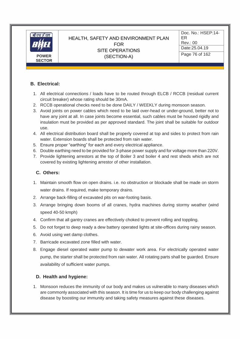
POWER SECTOR
HEALTH, SAFETY AND ENVIRONMENT PLAN
FOR SITE OPERATIONS
(SECTION-A)
Doc. No.: HSEP:14- ER Rev.: 00 Date:25.04.19
Page 76 of 162
B. Electrical:
1. All electrical connections / loads have to be routed through ELCB / RCCB (residual current circuit breaker) whose rating should be 30mA.
2. RCCB operational checks need to be done DAILY / WEEKLY during monsoon season. 3. Avoid joints on power cables which need to be laid over-head or under-ground, better not to
have any joint at all. In case joints become essential, such cables must be housed rigidly and insulation must be provided as per approved standard. The joint shall be suitable for outdoor use.
4. All electrical distribution board shall be properly covered at top and sides to protect from rain water. Extension boards shall be protected from rain water.
5. Ensure proper “earthing” for each and every electrical appliance. 6. Double earthing need to be provided for 3-phase power supply and for voltage more than 220V. 7. Provide lightening arrestors at the top of Boiler 3 and boiler 4 and rest sheds which are not
covered by existing lightening arrestor of other installation.
C. Others:
1. Maintain smooth flow on open drains. i.e. no obstruction or blockade shall be made on storm
water drains. If required, make temporary drains.
2. Arrange back-filling of excavated pits on war-footing basis.
3. Arrange bringing down booms of all cranes, hydra machines during stormy weather (wind
speed 40-50 kmph)
4. Confirm that all gantry cranes are effectively choked to prevent rolling and toppling.
5. Do not forget to deep ready a dew battery operated lights at site-offices during rainy season.
6. Avoid using wet damp clothes.
7. Barricade excavated zone filled with water.
8. Engage diesel operated water pump to dewater work area. For electrically operated water
pump, the starter shall be protected from rain water. All rotating parts shall be guarded. Ensure
availability of sufficient water pumps.
D. Health and hygiene:
1. Monsoon reduces the immunity of our body and makes us vulnerable to many diseases which are commonly associated with this season. It is time for us to keep our body challenging against disease by boosting our immunity and taking safety measures against these diseases.

POWER SECTOR
HEALTH, SAFETY AND ENVIRONMENT PLAN
FOR SITE OPERATIONS
(SECTION-A)
Doc. No.: HSEP:14- ER Rev.: 00 Date:25.04.19
Page 77 of 162
2. The diseases associated with monsoon are Malaria, Jaundice, Gastro-intestinal infections, like
typhoid, cholera etc. apart from these viral infections like cold and cough also make their presence felt. Majority of above said diseases are on account of:
3. Puddle of water formed due to rain become breeding grounds for mosquitoes which spread disease like, malaria and dengue fever. As a precautionary measure against mosquito-bite disease one can use mosquito net around the end which is better choice to mosquito repellants like mats and coils.
4. Pollution of drinking water during monsoon is very common. It is very necessary to drink clean and pure water when water-borne monsoon diseases like diarrhea and gastro-intestinal infections threaten us.
5. Walking in dirty water during rainy season leads of numerous fungal infection which affect toes and nails. Diabetic patients have to take a special care about their feet. Keeping feet always dry and clean is very necessary. Avoid walking in dirty water. Keep shoes socks and raincoats dry and clean.
E. Workmen will be made aware of following Do’s and Don’ts:
1. Do not sleep in daytime. 2. Avoid over physical exertion. 3. During lightning and thunder storm, do not take shelter under tree. Take shelter inside rest
shed or store room. 4. Wash vegetables with clean water and steam them well to kill germs. 5. Avoid eating un-cooked foods and salads should be washed properly before consumption. 6. Drink plenty of water and keep body well-hydrated. 7. Always keep the surrounding area dry and clean. Don’t allow to get water accumulated around. 8. Keep body warm as viruses attack immediately when body temperature goes down. 9. Do not enter air conditioned room with wet hair and damp cloths. 10. Dry your feet and webs with soft dry cloth whenever they are wet. 11. Eat light and less spicy food. 12. Avoid eating food which was cooked long time ago. 13. Eat salt in food to replenish loss of salt through sweating.
13.2.12.3 Emergency Weather Conditions
A. Cyclone/Severe thunder storm
In the event of Cyclone/Severe thunder storm, alert will be issued by subcontractor on notification received by Govt. authorities/Metrological departments Customer or BHEL. The actions required during cyclone/rough weather:
1. Check and advice subcontractors to cleanup work area. Pick up all loose and unused material of respective supervisor’s area.
2. Tie to secure all gas cylinders to avoid displacement and unsafe conditions which could be due to wind pressure.

POWER SECTOR
HEALTH, SAFETY AND ENVIRONMENT PLAN
FOR SITE OPERATIONS
(SECTION-A)
Doc. No.: HSEP:14- ER Rev.: 00 Date:25.04.19
Page 78 of 162
3. Secure portable electricity generating sets and other equipment, pumps, hoses etc. 4. Make preparation for removal of water logging. 5. Take review of work activity and make preparation for removal of equipment and material from
vulnerable areas. 6. Isolate/turn off all electrical power form the main panel/switches. Secure and anchor panels
properly. 7. Recheck anchorage/tie of all temporary structures/sheds, tall objects, cranes, rigs, scaffolds
etc. to avoid toppling due to wind force. 8. Cranes boom shall be secured, either locked or lowered the booms as reasonably and
practicably possible and rigs to safe position for the safety point of view. 9. Group up all trash barrels, wooden pallets, forms; wooden decks etc. and anchor properly. 10. Welding machines, air compressors and such equipment are to be grouped together and
secured to the stable objects. Welding leads, electrical cables, hoses are to be rolled up and secured properly.
11. Set on site vehicles on high ground in the site area with brakes set firmly. 12. Anchor all tanks, vessels, gas cylinders that may be moved by high wind and water. 13. Evacuate job site. Personnel Evacuation: 14. Personnel Evacuation will be required if predicted wind speed and storm surge heights are
beyond acceptable limits as per the instructions from Govt. Authorities/ Metrological departments or Customer.
15. Once the warning is received for personnel evacuation, an emergency response team shall be formed. The team will work with local authorities and other agencies formed/deployed to evacuate and transport all personnel involved in the project to the cyclone shelter.
16. Cyclone may be followed by the calm “EYE”, be aware of it. If the wind suddenly drops, don’t assume the cyclone is over. Violent wind may resume from the opposite side direction. Wait for the official “All clear Signal”.
17. After the cyclone, do not go outside until officially communicated about safe situation outside. Use recommended routes for returning. Do not panic or rush while returning.
18. Checking of gas leaks and well being of electrical appliances is essential before leaving the site.
19. Follow local communications for official warning and advice. The construction Manager shall also obtain updates from customer/metrological departments and communicate to the personnel on project site.
13.2.12.4 Preparedness for Other Adverse Climates and Weather Conditions
All Preventive and Precautionary measures to ensure Health & Safety of workers in all possible adverse weather conditions based on the analysis of the local area conditions to be taken by the subcontractor
13.3 ENVIRONMENTAL CONTROL
1. Environment protection has always been given prime importance by BHEL. Environmental

POWER SECTOR
HEALTH, SAFETY AND ENVIRONMENT PLAN
FOR SITE OPERATIONS
(SECTION-A)
Doc. No.: HSEP:14- ER Rev.: 00 Date:25.04.19
Page 79 of 162
damage is a major concern of the principal subcontractor and every effort shall be made, to have effective control measures in place to avoid pollution of Air, Water and Land and associated life.
2. Subcontractor shall list out all applicable environmental aspects and impacts, and ensure control measures to manage the same.
3. Chlorofluorocarbons such as carbon tetrachloride and trichloroethylene shall not be used.
4. Waste disposal shall be done in accordance with the guidelines laid down in the project specification.
5. Any chemical including solvents and paints, required for construction shall be stored in designated bonded areas around the site as per MSDS.
6. In the event of any spillage, the principle is to recover as much material as possible before it enters drainage system and to take all possible action to prevent spilled materials from running off the site. Subcontractor shall use appropriate MSDS for clean-up technique. Subcontractor shall be responsible for the cleanliness of their own areas.
7. Subcontractor shall ensure that noise levels generated by plant or machinery are as low as reasonably practicable. Where the subcontractor anticipates the generation of excessive noise levels from his operations the subcontractor shall inform BHEL accordingly so that reasonable & practicable precautions can be taken to protect other persons who may be affected.
8. It is imperative on the part of the subcontractor to join and effectively contribute to environmental protection measures such as tree plantation and towards social causes and maintaining good relations with local populace.
9. The subcontractor shall carry out periodic air and water quality check and illumination level checking in respective area of work place and take suitable control measure to maintain the same as per applicable laws / standards
13.3.1 WASTE MANAGEMENT
1. Subcontractor shall take suitable measures for waste management and fulfilling requirements of environment related laws/legislation as a part of normal construction activities.
2. Compliance with the legal requirements on storage/ disposal of paint drums (including the empty ones), Lubricant containers, Chemical Containers, and transportation and storage of hazardous chemicals will be strictly maintained.
3. Details of E-Waste, Hazardous Waste, shall be submitted to BHEL as per Format No. HSEP: 14-F18 and HSEP: 14-F19 respectively
13.3.1.1 BINS AT WORK PLACE
1. Sufficient rubbish bins shall be provided close to workplaces. 2. Bins should be painted yellow and numbered. 3. Sufficient nos. of drip trays shall be provided to collect oil and grease. 4. Sufficient qty. of broomsticks with handle shall be provided. 5. Adequate strength of employees should be deployed to ensure daily monitoring and service for
waste management.
13.3.1.2 STORAGE AND COLLECTION
1. Different types of rubbish/waste should be collected and stored separately.

POWER SECTOR
HEALTH, SAFETY AND ENVIRONMENT PLAN
FOR SITE OPERATIONS
(SECTION-A)
Doc. No.: HSEP:14- ER Rev.: 00 Date:25.04.19
Page 80 of 162
2. Paper, oily rags, smoking material, flammable, metal pieces should be collected in separate bins
with close fitting lids. 3. Rubbish should not be left or allowed to accumulate on construction and other work places. 4. Do not burn construction rubbish near working site.
13.3.1.3 SEGREGATION
1. Earmark the scrap area for different types of waste. 2. Store wastes away from building. 3. Oil spill absorbed by non-combustible absorbent should be kept in separate bin. 4. Clinical and first aid waste stored and incinerated separately.
13.3.1.4 DISPOSAL
1. Sufficient containers and scrap disposal area should be allocated. 2. All scrap bin and containers should be conveniently located. 3. Provide self-closing containers for flammable/spontaneously combustible material. 4. Keep drainage channels free from choking. 5. Make schedule for collection and disposal of waste.
13.3.1.5 WARNING AND SIGNS
1. Appropriate signage to be displayed at scrap storage area 2. No toxic, corrosive or flammable substance to be discarded into public sewage system. 3. Waste disposal shall be in accordance with best practice. 4. Comply with all the requirements of Pollution Control Board (PCB) for storage and disposal of
hazardous waste.
13.4 HOUSEKEEPING
1. Keeping the work area clean/ free from debris, removing unused scaffoldings, scraps, insulation/ sheeting wastage /cut pieces temporary structures, packing woods etc. will be in the scope of the subcontractor.
2. Such cleaning has to be done by subcontractor within quoted rate, on daily basis by dedicated identified groups equipped with all require PPEs and training. The details of housekeeping group shall be provided to BHEL.
3. If such activity is not carried out by subcontractor / BHEL is not satisfied, then BHEL may get it done by other agency and actual cost along with BHEL overheads will be deducted from subcontractor's bill. Such decisions of BHEL shall be binding on the subcontractor.
4. Pests, such as beehives etc. shall be periodically removed in a humane fashion 5. Following are to be taken care of on daily basis.
i. All surplus earth and debris are removed/disposed of from the working areas to identified locations.
ii. Unused/Surplus cables, steel items and steel scrap lying scattered at different places /elevation within the working areas are removed to identify locations.
iii. All wooden scrap, empty wooden cable drums and other combustible packing materials, shall

POWER SECTOR
HEALTH, SAFETY AND ENVIRONMENT PLAN
FOR SITE OPERATIONS
(SECTION-A)
Doc. No.: HSEP:14- ER Rev.: 00 Date:25.04.19
Page 81 of 162
be removed from workplace to identified locations. Sufficient waste bins shall be provided at different work places for easy collection of scrap/waste. Scrap chute shall be installed to remove scrap from high locations
iv. Access and egress (stair case, gangways, ladders etc.) path should be free from all scrap and other hindrances.
v. Workmen shall be educated through tool box talk about the importance of housekeeping and encourage not to litter.
vi. Labor camp area shall be kept clear and materials like pipes, steel, sand, concrete, chips and bricks, etc. shall not be allowed in the camp to obstruct free movement of men and machineries.
vii. Fabricated steel structures, pipes & piping materials shall be stacked properly. viii. No parking of trucks/trolleys, cranes and trailers etc. shall be allowed in the camp, which may
obstruct the traffic movement as well as below LT/HT power line. ix. Utmost care shall be taken to ensure over all cleanliness and proper upkeep of the working
areas
13.5 TRAFFIC MANAGEMENT
13.5.1 SAFE WORKPLACE TRANSPORT SYSTEM
1. Traffic routes in a work place shall be suitable for the persons or vehicles using them. 2. Traffic routes for pedestrians and vehicles shall be clearly demarcated and indicated 3. Traffic routes shall never intersect the area of work and shall not endanger the site personnel 4. For internal traffic, lines marked on roads / access routes and between buildings shall clearly
indicate where vehicles are to pass. 5. Temporary obstacles shall be brought to the attention of drivers by warning signs / hazard cones. 6. Power cables shall be maintained at a minimum height above ground as specified in Indian
Electricity Act & Rules. 7. Sensible speed limits shall set and clearly displayed. Painted Speed ramps preceded by a
warning signs or marker are necessary for stretches of roads exceeding 50 meters. 8. The traffic route should be wide enough to allow vehicles to pass and re-pass oncoming or
parked traffic and it may be advisable to introduce on-way system or parking restrictions. 9. Safest route shall be provided between places where vehicles have to call or deliver. 10. Avoid vulnerable areas/items such as fuel or chemicals tanks or pipes, open or unprotected
edges and structures likely to collapse 11. Safe areas shall be provided for loading and unloading of material. Loading / Unloading Permit
shall be taken from BHEL prior to any significant loading / unloading activity
12. Avoid sharp or blind bends. If this is not possible hazards should be indicated e.g. blind corner. 13. Ensure road crossings are minimum and clearly signed.
14. Entrance and gateways shall be wide enough to accommodate a second vehicle without causing obstruction.
15. Forklift trucks shall not pass over road hump unless of a type capable of doing so.

POWER SECTOR
HEALTH, SAFETY AND ENVIRONMENT PLAN
FOR SITE OPERATIONS
(SECTION-A)
Doc. No.: HSEP:14- ER Rev.: 00 Date:25.04.19
Page 82 of 162
16. Overhead electric cable, pipes containing flammable hazardous chemical shall be shielded by
using goal posts height gauge posts or barriers.
17. The height of Power cables above areas of movement shall conform to Indian Electricity Rules
18. Road traffic signs shall be provided on prominent locations for prevention of accidents and hazards and for quick guidance and warning to employees and public.
19. Safety signs shall be displayed as per the project working requirement and guideline of the state in which project is done.
20. Vehicles hired or used shall not be parked within the 15m radius of any working area. Any vehicle, that is required to be at the immediate/near the vicinity, shall be approved by the person in-charge of the site.
13.5.2 TRAFFIC ROUTE FOR PEDESTRIANS
1. Where traffic routes are used by both pedestrians and vehicles road shall be wide enough to allow vehicles and pedestrians safely.
2. Separate routes shall be provided for pedestrians to keep them away from vehicles. Provide suitable barriers/guard at entrances/exit and the corners or buildings.
3. Where pedestrian and vehicle routes cross, appropriate crossing shall be provided.
4. Where crowd is likely to use roadway e.g. at the end of shift, stop vehicles from using them at such times.
5. Provide high visibility clothing for people permitted in delivery area.
13.5.3 WORK VEHICLES
Work vehicles shall be as safe stable efficient and roadworthy as private vehicles on public roads. Subcontractors shall ensure that drivers are suitably trained and have valid license and experience for the designated class of vehicle. All vehicle e.g. heavy motor vehicle forklift trucks dump trucks mobile cranes shall ensure that the work equipment conforms to the following:
1. A high level of stability.
2. A safe means of access/egress.
3. Suitable and effective service and parking brakes.
4. Windscreens with wipers and external mirrors giving optimum all round visibility.
5. Provision of horn, vehicle lights, reflectors, reversing lights, reversing alarms.
6. Provision of seat belts.
7. Guards on dangerous parts.
8. Driver protection - to prevent injury from overturning and from falling objects/materials.
9. Driver protection from adverse weather.
10. No vehicle shall be parked below HT/LT power lines in conformance to Indian Electricity Act & Rules.
11. Valid Pollution Under Control certification for all vehicles

POWER SECTOR
HEALTH, SAFETY AND ENVIRONMENT PLAN
FOR SITE OPERATIONS
(SECTION-A)
Doc. No.: HSEP:14- ER Rev.: 00 Date:25.04.19
Page 83 of 162
13.5.4 DAILY CHECKS BY DRIVER
There should also be daily safety checks containing below mentioned points by the driver before the vehicle is used. Subcontractors should ensure that drivers carry out these checks as a minimum. Brakes Mirrors Warning signals Tires Windscreen waters Specific safety system i.e. control interlocks Steering Wipers
13.5.5 TRANSPORTATION OF PERSONNEL AND MATERIALS BY VEHICLES
1. All drivers shall hold a valid driving License for the class of vehicle to be driven and be registered as an authorized BHEL driver with the Administration Department.
2. Securing of the load shall be by established and approved methods, i.e. chains with patented tightening equipment for steel/heavy loads. Sharp corners on loads shall be avoided when employing ropes for securing.
3. All overhangs shall be made clearly visible and restricted to acceptable limits
4. Load shall be checked before moving off and after traveling a suitable distance.
5. On no account is construction site to be blocked by parked vehicles Drivers of vehicles shall only stop or park in the areas designate by the stringing foreman.
6. Warning signs shall be displayed during transportation of material.
7. All vehicles used by Subcontractor shall be in worthy condition and in conformance to the Land Transport requirement
13.5.6 MAINTENANCE
All Vehicles used for transportation of man and material shall undergo scheduled inspections on frequent intervals to secure safe operation. Such inspections shall be conducted in particular for steering, brakes, lights, horn, doors etc. Site management shall ensure that work equipment is maintained in an efficient, working order and in good repair. Inspections and services carried out at regular intervals of time and or mileage. No maintenance shall be carried below HT/LT power lines.
13.6 EMERGENCY PREPAREDNESS AND RESPONSE
1. Subcontractor shall develop Emergency preparedness and response capability and Emergency Response Team as per HSEP06: HSE Procedure for Emergency Preparedness and Response
2. Availability of adequate number of first aiders and fire warden shall be ensured 3. All the subcontractor’s supervisory personnel and sufficient number of workers shall be trained
for fire protection systems. Enough number of such trained personnel must be available during the tenure of contract. Subcontractor should nominate his supervisor to coordinate and implement the safety measures and communicate the same to BHEL.
4. Assembly point shall be earmarked and access to the same from different location shall be shown 5. Fire exit shall be identified and pathway shall be clear for emergency escape.
6. Appropriate type and number of fire extinguisher shall be deployed as per Clause No. 13.2.11 and validity shall be ensured periodically through inspection
7. Adequate number of first aid boxes shall be strategically placed at different work places to cater

POWER SECTOR
HEALTH, SAFETY AND ENVIRONMENT PLAN
FOR SITE OPERATIONS
(SECTION-A)
Doc. No.: HSEP:14- ER Rev.: 00 Date:25.04.19
Page 84 of 162
to all emergency needs. Holder of the first aid box shall be identified on the box itself who will have the responsibility to maintain the same.
8. First aid center shall be developed at site with trained medical personnel and ambulance
9. Emergency contact numbers of the site shall be displayed at prominent locations.
10. Tie up with fire brigade shall be done in case customer is not having fire station.
11. Tie up with hospital shall be ensured in order to ensure the availability of following services to victims quickly without wasting precious time:
a. Intensive Care Unit with Ventilator and other necessary life support systems
b. Facility of specialized Orthopedic Surgery – in case of fracture / amputation
c. Facility of specialized brain / neuro surgery – in case of head trauma
d. Facility of specialized burn unit / ward – in case of Fire / burn injury
e. and other facilities as per requirement at site location
In case tie up with multiple hospitals is required to cover all possible accidents, same shall be done. The list of facilities to be regularly checked and updated.
12. A detailed emergency services (Fire / Medical etc.) tie up plan shall be submitted to BHEL in monthly report Format No. HSEP:14-F05
13. Mock drill shall be conducted on different emergencies periodically to find out gaps in emergency preparedness and taking necessary corrective action
14 HSE INSPECTION
Inspection on HSE for different activities being carried out at site shall be done to ensure compliance to HSEMS requirements. The subcontractor shall maintain necessary safety equipment as applicable, to enable inspection personnel/agency perform Inspection. If any test equipment is found not complying with proper safety requirements then the Inspection Agency may withhold inspection, till such time the desired safety requirements are met.
The requirements of respective work permits are to be ensured by respective supervisors, safety personnel and area in-charges. In addition, the formats & checklists as per Clause 21 of this document provided by BHEL shall be used for inspection by Safety personnel (as a minimum), and records of inspection to be maintained. BHEL shall reserve the right to modify any Format in this document or introduce additional checklists / formats to ensure regular inspection of all equipment as per requirement.
14.1 DAILY HSE CHECKS
Both the Site Supervisors and HSE Supervisors are to conduct daily site Safety inspection around work activities and premises to ensure that work methods and the sites are maintained to an acceptable standard. The following are to form the common subjects of a daily safety inspection:

POWER SECTOR
HEALTH, SAFETY AND ENVIRONMENT PLAN
FOR SITE OPERATIONS
(SECTION-A)
Doc. No.: HSEP:14- ER Rev.: 00 Date:25.04.19
Page 85 of 162
1. Height Work:
a. Safe, barricaded platform b. PPEs c. Proper method d. Awareness
2. Personal Safety wears & gear compliance. 3. Complying with site safety rules and permit-to-work (PTW). 4. Positions and postures of workers. 5. Use of tools and equipment etc. by the workers. 6. The inspection shall be carried out just when work starts in beginning of the day, during peak activities
period of the day and just before the day’s work ends.
14.2 INSPECTION OF HEIGHT WORKING
1. Any kind of height work (above 2 meters) shall not be carried out without active physical supervision by concerned supervisor or safety personnel. All non-conformances related to height work shall be handled on priority and closed immediately after halting the work.
2. A roster of personnel deployed for inspection of height work and other critical activities shall be prepared and submitted to BHEL in monthly report Format No. HSEP:14-F05, in order to ensure effective supervision at all times
3. Inspection on height working shall be conducted daily by supervisors before start of work to ensure safe working condition including provision of:
a. Fall arrestor b. Lifelines c. Safety nets
d. Fencing and barricading e. Warning signage f. Covering of opening
g. Proper scaffolding with valid Tags, access and egress.
h. Illumination
4. Inspection on height working shall be conducted once in a week by HSE officer as per 5. Format no. HSEP: 14-F10. 6. Medical fitness, including vertigo test of height worker shall be ensured. 7. Height working shall not be allowed during adverse weather.
14.3 INSPECTION OF PPE
PPEs shall be inspected by HSE officer at random once in a week as per Format no. HSEP: 14-F06 for compliance to standard and provisions and any adverse observation shall be recorded in the PPE register.
14.4 INSPECTION OF T&Ps
1. All T& Ps being used at site shall be inspected by HSE officer once in a month as per specific Formats in this document, or (if not available) general Format no. HSEP: 14-F07 for its healthiness and maintenance.
2. A master list of T&Ps and validity of their inspection certificates shall be maintained by each agency and details shall be submitted to BHEL in monthly format no. HSEP:14-F05.
3. The T&Ps which require third party inspection shall be checked for its validity during inspection.

POWER SECTOR
HEALTH, SAFETY AND ENVIRONMENT PLAN
FOR SITE OPERATIONS
(SECTION-A)
Doc. No.: HSEP:14- ER Rev.: 00 Date:25.04.19
Page 86 of 162
The third party test certificate should be accompanied with a copy of the concerned competent person’s valid qualification record. BHEL shall be given advance intimation of Third Party Inspection. BHEL shall associate with Inspection as per discretion.
14.5 INSPECTION OF CRANES AND WINCHES
1. Cranes and winches shall be inspected by the operator through a daily checklist for its safe condition (as provided by the equipment manufacturer) before first use of the day.
2. Cranes and Winches shall be inspected by HSE officer once in a month as per Format no. HSEP: 14-F08 & F09 for healthiness, maintenance and validity of third party inspection.
3. The date of third party inspection and next due date shall be painted on cranes and winches. 4. The operators/drivers shall be authorized by sub-contractor based on their competency and
experience and shall carry the I-card. 5. The operator should be above 18 years of age and should be in possession of driving license
of HMV man & goods), vision test certificate and should have minimum qualification so that he can read the instructions and check list.
14.6 INSPECTION ON WELDING AND GAS CUTTING OPERATION
1. Supervisor shall ensure that no flammable items are available in near vicinity during welding and gas cutting activity.
2. Gas cylinders shall be kept upright. 3. Use of Flash back arrestor shall be ensured at both ends. 4. Inspection during welding and gas cutting operations shall be carried out by HSE officer once a
month as per Format no. HSEP: 14-F11. 5. Use of fire blanket to be ensured to avoid falling of splatters during welding or gas cutting
operation at height. 6. Availability of fire extinguisher in vicinity shall be ensured.
14.7 INSPECTION ON ELECTRICAL INSTALLATION / APPLIANCES
1. Ensure proper earthing in electrical installation 2. Use of ELCB at electrical booth 3. Electrical installation shall be properly covered at top where required 4. Use appropriate PPEs while working 5. Use portable electrical light < 24 V in confined space and potentially wet area. 6. Monthly inspection shall be carried out as per Format no. HSEP: 14-F12.
14.8 INSPECTION OF ELEVATOR
1. Elevators shall be inspected by concerned supervisors once in a week as per Format no. HSEP: 14-F13.
2. All elevators shall be inspected by competent person and validity shall be ensured. 3. The date of third party inspection and next due date shall be painted on elevator.

POWER SECTOR
HEALTH, SAFETY AND ENVIRONMENT PLAN
FOR SITE OPERATIONS
(SECTION-A)
Doc. No.: HSEP:14- ER Rev.: 00 Date:25.04.19
Page 87 of 162
14.9 MONTHLY SITE INSPECTION
Subcontractor shall carry out monthly HSE inspection of all work areas as per Format No. HSEP:14-F20 and submit to BHEL
14.10 NON-CONFORMITY HANDLING:
Any serious non-conformances identified during inspection observed shall be addressed immediately.
In case immediate closure of non-conformities is not possible:
a. work to be halted in the area b. Non-conformance to be generated and submitted to responsible person and BHEL c. non-conformance to be resolved through responsible agency / person
Only after closure of serious non-conformances, work to be allowed to resume. All non-conformances & safety violations to be recorded and closed in a time bound manner.
15 HSE PERFORMANCE
HSE performance of subcontractor shall be monitored as per BHEL criteria, based on which, marks will be awarded. Marks can be used to evaluate and rate the contractor as per BHEL internal systems
HSE performance of the subcontractor shall be monitored as per the following parameters: (For each contract-wise package). Periodicity: RA Bill period Sl. No.
Parameters of measurement Ref Clauses Weightage Actual
1 Availability of safety officers at site – absence up to 15% permissible. Score proportionately gets reduced with higher rate of absence. Availability to be reckoned from start date of manpower mobilization
7.1 10
2 Attendance by the safety officer and site CM (as applicable) in the meeting convened by BHEL
20 5
3 Level of compliance w.r.t decisions taken in previous meetings/audit/inspection/as reported.
-do- 5
4 Timely submission of monthly report on safety in the prescribed format
11 3
5 Timely reporting any incident including near–miss to BHEL /Customer/statutory authority (if required) and submission of investigation report of all LTIs/
12 10

POWER SECTOR
HEALTH, SAFETY AND ENVIRONMENT PLAN
FOR SITE OPERATIONS
(SECTION-A)
Doc. No.: HSEP:14- ER Rev.: 00 Date:25.04.19
Page 88 of 162
Major Property Loss incident and HSE events
6 Degree of PPE compliance, Fall protection arrangements and safety net coverage
8.3, 14 15
7 Level of compliance w.r.t safety rules 13,14 25 8 Availability of proper first-aid facility , ambulance,
hygienic labor colony and other adequate labor welfare initiatives, conducting of health check-up as per BOCW requirements
8 6
9 Conducting induction training, skill training, tool box meeting, mock-drills, HSE Promotion, Emergency Preparedness and Response. Participation in BHEL training also counted
9.0 6
10 Level of House-keeping, Environmental Control 13.3, 13.5 10 11 Level of general illumination 8.4.11 5 A TOTAL Obtained 100
Penalty score:
i. For each fatality: -10 ii. For each Major Incident: -07
NET TOTAL score will be arrived after deducting penalty score from Total score.
Subcontractor shall make available all data required for evaluation to BHEL as and when demanded.
1. If safety record of the subcontractor in execution of the awarded job is to the satisfaction of safety department of BHEL, issue of an appropriate certificate to recognize the safety performance of the subcontractor may be considered by BHEL after completion of the job.
2. 1.5% of running bill shall be cleared subject to certification of desired safety performance by BHEL
16 HSE PENALTIES FOR NON-COMPLIANCE
1. Nonconformity of safety rules and safety appliances will be viewed seriously and BHEL has right to impose fines on the subcontractor for every instance of violation noticed.
2. The applicable penalties for HSE violations are given in Format No. HSEP14-F14 of this document

POWER SECTOR
HEALTH, SAFETY AND ENVIRONMENT PLAN
FOR SITE OPERATIONS
(SECTION-A)
Doc. No.: HSEP:14- ER Rev.: 00 Date:25.04.19
Page 89 of 162
3. The list of non-compliances given in above format is not exhaustive. The BHEL site in-charge
has liberty to impose a penalty for any other non-compliance and incidents of any nature.
4. If principal customer or statutory and regulatory bodies impose penalty on ground of statutory non-compliance or non-compliance of HSE rules by the subcontractor or any incident of any nature including fatality or permanent disability, the same shall be passed on to the subcontractor with appropriate overhead
5. The penalty amount shall be recovered from subcontractors from the RA Bill, otherwise Final bill.
17 COMPENSATION TO ACCIDENT VICTIMS
1. BHEL shall recover the amount of compensation paid to victim(s) by BHEL towards loss of life / permanent disability due to an accident which is attributable to the negligence of contractor, agency or firm or any of its employees as detailed below.
b. Victim: Any person who suffers permanent disablement or dies in an accident as defined
below.
c. Accident: Any death or permanent disability resulting solely and directly from any unintended and unforeseen injurious occurrence caused during the manufacturing/ operation and works incidental thereto at BHEL factories/ offices and precincts thereof, project execution, erection and commissioning, services, repairs and maintenance, trouble shooting, serving, overhaul, renovation and retrofitting, trial operation, performance guarantee testing undertaken by the company or during any works / during working at BHEL Units/ Offices/ townships and premises! Project Sites.
d. Compensation in respect of each of the victims:
i. In the event of death or permanent disability resulting from Loss of both limbs: Rs. 10,00,000/- (Rs. Ten Lakh)
ii. (ii) In the event of other permanent disability: Rs. 7,00,0001- (Rs. Seven Lakh)
e. Permanent Disability: A disablement that is classified as a permanent total disablement under the proviso to Section 2 (I) of the Employee's Compensation Act, 1923. "
2. In addition to above, contractor shall provide appropriate compensation to victims of major and fatal incidents as per Employee Compensation Act, 1923, ESIC Act, 1948 or as per any existing Acts and guidelines

POWER SECTOR
HEALTH, SAFETY AND ENVIRONMENT PLAN
FOR SITE OPERATIONS
(SECTION-A)
Doc. No.: HSEP:14- ER Rev.: 00 Date:25.04.19
Page 90 of 162
18 INTERNAL & EXTERNAL HSE AUDITS
1. Subcontractor shall extend full co-operation and maintain necessary documents & records as
required by Internal & External HSE Audit carried out by BHEL. / Third Party
2. All non-conformities and observations on HSE shall be disposed of-by subcontractor in a time
bound manner as detailed in Audit Report.
3. All required corrective actions shall be taken by the subcontractor in order to avoid recurrence
19 OTHER REQUIREMENTS
1. In case of any delay in completion of a job due to mishaps attributable to lapses by the
subcontractor, BHEL shall have the right to recover cost of such delay from the payments due
to the subcontractor, after holding an appropriate enquiry and notifying the subcontractor
suitably.
2. RISK & COST:
If the subcontractor fails to improve the standards of safety in its operation to the satisfaction
of BHEL after being given reasonable opportunity to do so and/or if the subcontractor fails to
take appropriate safety precautions or to provide necessary safety devices and equipment or
to carry out instruction regarding safety as per contractual requirements, BHEL shall have the
right to take corrective steps at the risk and cost of the subcontractor after giving a notice of
not less than 7 days indicating the steps that would be taken by BHEL.
3. If the subcontractor succeeds in carrying out its job in time without any fatal or disabling injury
incident and without any damage to property BHEL may, at its sole discretion, favourably
consider to reward the subcontractor suitably for the performance.
4. The subcontractor shall take all measures at all the sites of work to protect all persons from
incidents and shall be bound to bear the expenses of every suit, action or other proceeding of
law that may be brought by any persons for injury sustained, death or damage to environment

POWER SECTOR
HEALTH, SAFETY AND ENVIRONMENT PLAN
FOR SITE OPERATIONS
(SECTION-A)
Doc. No.: HSEP:14- ER Rev.: 00 Date:25.04.19
Page 91 of 162
owing to neglect of the HSE precautions by the subcontractor; and shall be liable to pay any
such persons such compensation, should such claim proceeding be filed against BHEL.
The subcontractor hereby agrees to indemnify BHEL against the same.
20 HSE REVIEW
BHEL shall hold HSE review meeting every month or as per requirement in order to discuss
and resolve HSE issues of site and improve HSE performance. It will also discuss the incidents
occurred since previous meeting, its root cause and Corrective action. The indicative agenda
is given below:
1. Implementation of earlier MOM
2. HSE performance review
3. HSE inspection review w.r.t non-conformances observed and their status
4. HSE audit and CAPA
5. HSE training conducted and requirement
6. Health check-up camp
7. HSE planning for the erection and commissioning and installation activities in the coming
month
8. HSE reward and promotional activities
9. HSE data analysis and improvement – Data analyzed will include non-conformances closed and
pending, incident data, training data etc.
Subcontractor shall ensure presence of site in-charge, all package in-charges and safety
officers, as communicated by BHEL in the meeting.
Subcontractor shall take requisite actions as per record notes and as decided in the meeting,
in a time bound manner and submit compliance report to BHEL.

POWER SECTOR
HEALTH, SAFETY AND ENVIRONMENT PLAN
FOR SITE OPERATIONS
(SECTION-A)
Doc. No.: HSEP:14- ER Rev.: 00 Date:25.04.19
Page 92 of 162
21 FORMATS USED
This is minimum list of Formats to be used for reporting by the subcontractor. Other Formats are indicated in respective HSE Procedures, Work Permits, OCPs or as specified by BHEL. The medium of reporting can be hard / soft as indicated by BHEL. BHEL can modify these Formats or introduce new Formats to the extent necessary to get the desired performance data of all HSE activities.
SN Format Name Format No. Frequency of check Rev
1 Work at Height Permit HSEP:14-FP01 Before start of work and regularly thereafter as per Permit conditions
00
2 Hot Work Permit HSEP:14-FP02 00
3 Confined Space Work Permit HSEP:14-FP03 00
4 Excavation Work Permit HSEP:14-FP04 00
5 Radiation Work Permit HSEP:14-FP05 00
6 Lifting Activity Work Permit HSEP:14-FP06 00
7 Lockout-Tagout Work Permit HSEP:14-FP07 00
8 Inspection of First Aid Box HSEP:14-F01 Weekly 00
9 Health Check Up HSEP:14-F02 With new Induction & as per requirement thereafter
00
10 HSE Induction / Regular / On-the-Job Training
HSEP:14-F03 With new Induction & as per requirement thereafter
00
11 Tool Box Talk HSEP:14-F04 Daily before job start 00
12 Site HSE Report HSEP:14-F05 Monthly 00
13 PPE Inspection HSEP:14-F06 Weekly 00
14 PPE Issue and Receipt HSEP:14-F06A With new Induction
15 Inspection of T&Ps (General) HSEP:14-F07 Monthly / As per requirement 00
16 Inspection of Cranes HSEP:14-F08 Monthly / As per requirement 00
17 Inspection of Winches HSEP:14-F09 Monthly / As per requirement 00
18 Inspection of Height Working HSEP:14-F10 Daily / As per requirement 00
19 Inspection on Welding & Gas Cutting HSEP:14-F11 Weekly / As per requirement 00
20 Inspection on Electrical Installation HSEP:14-F12 Weekly / As per requirement 00
21 Inspection on Elevator HSEP:14-F13 Weekly / As per requirement 00 22 HSE Penalty HSEP:14-F14 - 00 23 Initial Verification of PPE’s & Lifting Tools
& Tackles HSEP:14-F15 As and when new PPEs and
T&Ps are received 00
24 Inspection of Labor Colony HSEP:14-F16 Monthly / as per requirement 00 25 Recording of First Aid Injuries HSEP:14-F17 As and when such injuries occur 00
26 E-waste Handled / Generated HSEP:14-F18 Half Yearly 00
27 Hazardous Waste at the Facility HSEP:14-F19 Half Yearly 00
28 HSE Checklist-cum-Compliance Report HSEP:14-F20 As per Audit Calendar 00
29 Illumination Levels HSEP:14-F21 Weekly / As per requirement 00 30 Incident Reporting HSEP:14-F22 - 00
31 Incident Recording HSEP:14-F23 - 00

HSEP:14-FP01
Exact Location of Work: _
Nature / Description of Work:
Duration of Work Execution *: From Date: to Date: Daily from _______ hrs. to ________hrs.
Name of Sub-Contractor Performing the Work:
Name of Sub-Contractor’s Site Engineer (Permit Requesting Authority): Sign:
Name of Sub-Contractor’s Package In-charge: Sign: Date:
The above described work will be done under all the safety precautions mentioned as under during the currency of the Permit .
No. Item Yes Not required
/ Remarks 1 All workers on job are competent and medically fit (No Height Phobia) for working at height 2 Hazards in the vicinity are identified, controlled and communicated to the worker. 3 Scaffolding soundness inspected is available for use with valid tag 4 Work platform is not made of bamboo or weak material. Barricading is available with Top,
Mid Rails and Toe Guard.
5 Working platform is clean without any unwanted material. Floor openings are covered.
6 Access and exit to workplace are safe, marked and without obstruction.
7 Adequate lighting provided (for dark hours) as per applicable lux standards (Refer HSEP:13)
8 Safety nets are provided below working area.
9 Area below the working platform has been cleared of all activity
10 Ladders have been secured, inspected and provided as per BHEL standard/contract.
11 Horizontal life lines are provided to cater to design specification of 2300 kg per person.
12 Safety harness with life line support/ fall arrester are checked and available in working condition
13 Safety shoes (non-slip), Helmet with chin strip available with employees 14 Visible Signboards provided on working platforms in workers’ understandable language
15 All lifting / tightening tools, hand tools/equipment checked and in good condition 16 ELCB provided for Electrical connections individually. Electrical cable, welding
Hose/Compressed air hose properly secured and laid down without obstruction. Earth resistance is OK.
17 Crane / Winch / Hydra operator is qualified and experienced 18 Emergency response team & Medical Facilities available. Work area is cordoned off. 19 Job Safety Analysis Submitted 20 Additional Permits to be taken (Please specify & attach):
Declaration: All the points mentioned in the above checklist have been checked and found OK
Permit Receiver: Site Engineer (Sub- Contractor): Site Safety Officer (Sub-Contractor): Signature: Signature: Name: Designation: Name: Designation:
Permit Issuer: Engineer of Concerned Execution Department (BHEL): Site Safety Officer (BHEL): Signature: Signature: Name: Designation: Name: Designation:
Package-in-charge (BHEL): Signature: Name: Designation:
(* Permit valid for 7 days, subject to daily renewal, and extension as per overleaf instructions / record formats)
WORK AT HEIGHT PERMIT Permit No. & Date
Project & Unit: Emergency Contact Nos: BHEL Sub-contractor:
To be printed on both sides of an A4 Sheet Page 1 of 2 P.T.O.
Verified by Customer Representative (if applicable), Name: _______________Sign: ____________Date: _________Time: ________

Permit Extension Beyond Initially Requested Hours Sl. No.
Extension Period Remarks
Signature with Date & Time From…….
(Date & Time) To……
(Date &Time) Agency Site
Engineer
Agency Safety Officer
BHEL Site Engineer (PIA)
BHEL Safety Officer
1.
2.
3.
4.
5.
6
TO BE SIGNED BY THE BHEL HSE & EXECUTION AFTER THE WORK IS OVER
Permit is here by returned after completing the job & ensuring safe removal of men and material.
Site Engineer, BHEL Site HSE Engineer, BHEL Signature: Signature:
Name: Name:
General Instructions: 1 This Permit is required for working at height of 2 mtr. and above or above excavation of 2 mtr or deeper. 2 This permit must be available at the work site all the times of the work. 3 Location and description of the work must be clearly indicated by the permittee. 4 Terms applicable must be clearly indicated by the permittee. 5 This permit shall be endorsed each day only after checking all the compliance jointly by the contractor and BHEL
safety. 6 Permit shall be issued for not more than 7 days including the issue date. 7 Permit shall be returned to the HSE Department of BHEL after completion of the job. 8 Before engaging anybody to work at height, height phobia needs to be ascertained and proper fitness certificate
to be ensured. 9 All safety precautions to be taken as per work site HSE plan. 10 Distribution of copy:
Original- Permittee, Duplicate –Department HOS, Contractor, Triplicate - Site HSE Dept.,
Sl. No.
Date
Signature with Date & Time Remarks Agency Safety BHEL Safety
Day 2
Day 3
Day 4
Day 5
Day 6
Day 7
Page 2 of 2
Work at Height Permit No. & Date: ___________________________
Daily Work Area Condition Endorsement
To be printed on both sides of an A4 Sheet

HSEP:14-FP02
Exact Location of Work: _
Nature / Description of Work:
Duration of Work Execution *: From Date: to Date: Daily from _______ hrs. to ________hrs.
Name of Sub-Contractor Performing the Work:
Name of Sub-Contractor’s Site Engineer (Permit Requesting Authority): Sign:
Name of Sub-Contractor’s Package In-charge: Sign: Date:
The above described work will be done under all the safety precautions mentioned as under during the currency of the Permit.
No. Item Yes Not required
/ Remarks
1. Welder is trained and qualified with good attendance in on-the-job training
2. Area ensured safe and free from all hazards (explosives etc.) with barricading and safe inlet / exit
3. Proper ventilation and lighting provided (in case of dark hours).
4. Gas hoses are in good condition and not cut / leaking
5. Pressure gauges/Flash back arrestor (at both ends) provided and in working condition.
6. Gas pressure in cylinder is within limits and hydraulic test certificate is available
7. Gas cylinders are stacked vertically and not below the welding / cutting area. Regulator key is available with cylinder. Gas cylinders covered with shields to prevent falling splinters.
8. Power supply to welding machine is through ELCB of 30 mA rating, which is tested and found ok; Earthing is tested and found OK
9. Welding machine input/output cables, welding holder and weld return clamp (Holder) are insulated and in good condition.
10. In case of welding in enclosed / confined spaces, the integrity of the structure and supports are ensured, Gas Testing done and evacuation system ensured in place
11. Emergency STOP buttons are in working condition. Welder /Helper knows how to operate it.
12. Welder & Fitter trained to connect ground/work return clamps (Holder) to work place prior to energization of welding machine.
13. Personal Protective equipment Minimum applicable: safety helmet, safety goggles, welding helmet, safety (rubber) shoes, leather gloves, long sleeve and nose mask -provided
14. In case of pits, water removed from the pit and wood/rubber insulation provided.
15. Safety signboards / cautions are in place.
16. Adequate and Suitable nos. of applicable firefighting extinguisher provided.
17. Nearby combustible material removed. Housekeeping done.
18. All workers explained about the hazards
19. First aid in attendance.
20. Any other Precautions or Permits required (Height Work, Confined Space etc.), give details and attach
Declaration: All the points mentioned in the above checklist have been checked and found OK
Permit Receiver: Site Engineer (Sub- Contractor): Site Safety Officer (Sub-Contractor): Signature: Signature: Name: Designation: Name: Designation:
Permit Issuer: Engineer of Concerned Execution Department (BHEL): Site Safety Officer (BHEL): Signature: Signature: Name: Designation: Name: Designation:
Package-in-charge (BHEL): Signature: Name: Designation:
(* Permit valid for 7 days, subject to daily renewal, and extension as per overleaf instructions / record formats)
HOT WORK PERMIT Permit No. & Date
Project & Unit: Emergency Contact Nos: BHEL Sub-contractor:
To be printed on both sides of an A4 Sheet Page 1 of 2 P.T.O.
Verified by Customer Representative (if applicable), Name: _______________Sign: ____________Date: _________Time: ________

Permit Extension Beyond Initially Requested Hours Sl. No.
Extension Period Remarks
Signature with Date & Time From…….
(Date & Time) To……
(Date &Time) Agency Site
Engineer
Agency Safety Officer
BHEL Site Engineer (PIA)
BHEL Safety Officer
1.
2.
3.
4.
5.
6
TO BE SIGNED BY THE BHEL HSE & EXECUTION AFTER THE WORK IS OVER
Permit is here by returned after completing the job & ensuring safe removal of men and material.
Site Engineer, BHEL Site HSE Engineer, BHEL Signature: Signature:
Name: Name:
General Instructions: 1 This Permit is required for all kinds of Hot Work eg. Welding, cutting etc.. 2 This permit must be available at the work site all the times of the work. 3 Location and description of the work must be clearly indicated by the permittee. 4 Terms applicable must be clearly indicated by the permittee. 5 This permit shall be endorsed each day only after checking all the compliance jointly by the contractor and BHEL
safety. 6 Permit shall be issued for not more than 7 days including the issue date. 7 Permit shall be returned to the HSE Department of BHEL after completion of the job. 8 Before engaging anybody to work, competency and fitness to be ensured. 9 All safety precautions to be taken as per work site HSE plan. 10 Distribution of copy:
Original- Permittee, Duplicate –Department HOS, Contractor, Triplicate - Site HSE Dept.,
Sl. No.
Date
Signature with Date & Time Remarks Agency Safety BHEL Safety
Day 2
Day 3
Day 4
Day 5
Day 6
Day 7
Page 2 of 2
Hot Work Permit No. & Date: ___________________________
Daily Work Area Condition Endorsement
To be printed on both sides of an A4 Sheet

HSEP:14-FP03
Exact Location of Work: _
Nature / Description of Work:
Duration of Work Execution *: From Date: to Date: Daily from _______ hrs. to ________hrs.
Name of Sub-Contractor Performing the Work:
Name of Sub-Contractor’s Site Engineer (Permit Requesting Authority): Sign:
Name of Sub-Contractor’s Package In-charge: Sign: Date:
The above described work will be done under all the safety precautions mentioned as under during the currency of the Permit .
No. Item Yes Not required /
Remarks
1. Has the equipment been Isolated from Power/Steam/Air? 2. Has the equipment been Isolated from liquid or gases? 3. Has the equipment been de-pressurized &/or drained? 4. Has the equipment been Blanked/blinded or disconnected? 5. Has the equipment been water flushed &/or steamed? 6. Whether man ways open and ventilated? 7. Whether constant Inert gas flow arranged? 8. Whether mechanically ventilated and adequately cooled? 9. Whether 24 V lighting provided inside the confined space? 10. Whether Radiation sources removed? 11. Whether training on confined space provided to the individual / group? 12. Whether required PPEs (hand gloves, goggles, face shield, ear plug/muff, protective
clothing etc.) used?
13. Whether Safety harness and Lifeline used? 14. Whether Dust/Gas/Air Line mask used? 15. Whether attendant with SCBA/Air mask available? 16. Whether grounded air Exhaust/Blower/ AC provided? 17. Whether Personal Gas alarm provided? 18. Whether communication Equipment Provided? 19. Whether rescue equipment/team available? 20. Whether firefighting arrangement done 21. Any other Precautions or Permits required (Height Work, Confined Space etc.), give details and attach
Declaration: All the points mentioned in the above checklist have been checked and found OK
Permit Receiver: Site Engineer (Sub- Contractor): Site Safety Officer (Sub-Contractor): Signature: Signature: Name: Designation: Name: Designation:
Permit Issuer: Engineer of Concerned Execution Department (BHEL): Site Safety Officer (BHEL): Signature: Signature: Name: Designation: Name: Designation:
Package-in-charge (BHEL): Signature: Name: Designation:
(* Permit valid for 7 days, subject to daily renewal, and extension as per overleaf instructions / record formats)
CONFINED SPACE WORK PERMIT Permit No. & Date
Project & Unit: Emergency Contact Nos: BHEL Sub-contractor:
To be printed on both sides of an A4 Sheet Page 1 of 2 P.T.O.
Verified by Customer Representative (if applicable), Name: _______________Sign: ____________Date: _________Time: ________

Permit Extension Beyond Initially Requested Hours Sl. No.
Extension Period Remarks
Signature with Date & Time From…….
(Date & Time) To……
(Date &Time) Agency Site
Engineer
Agency Safety Officer
BHEL Site Engineer (PIA)
BHEL Safety Officer
1.
2.
3.
4.
5.
6
TO BE SIGNED BY THE BHEL HSE & EXECUTION AFTER THE WORK IS OVER
Permit is here by returned after completing the job & ensuring safe removal of men and material.
Site Engineer, BHEL Site HSE Engineer, BHEL Signature: Signature:
Name: Name:
General Instructions: 1 This Permit is required for all confined space tasks, where injury can happen due to lack of oxygen, or chances of
fire are there due to gas accumulation. 2 This permit must be available at the work site all the times of the work. 3 Location and description of the work must be clearly indicated by the permittee. 4 Terms applicable must be clearly indicated by the permittee. 5 This permit shall be endorsed each day after checking all the compliance jointly by the contractor and BHEL safety. 6 Permit shall be issued for not more than 7 days including the issue date. 7 Permit shall be returned to the HSE Department of BHEL after completion of the job. 8 Before engaging anybody to work, competency and fitness to be ensured. 9 All safety precautions to be taken as per work site HSE plan. 10 Distribution of copy:
Original- Permittee, Duplicate –Department HOS, Contractor, Triplicate - Site HSE Dept.,
Sl. No.
Date
Signature with Date & Time Remarks Agency Safety BHEL Safety
Day 2
Day 3
Day 4
Day 5
Day 6
Day 7
Page 2 of 2
Confined Space Work Permit No. & Date: ___________________________
Daily Work Area Condition Endorsement
To be printed on both sides of an A4 Sheet

HSEP:14-FP04
Exact Location of Work: _
Nature / Description of Work:
Duration of Work Execution *: From Date: to Date: Daily from _______ hrs. to ________hrs.
Name of Sub-Contractor Performing the Work:
Name of Sub-Contractor’s Site Engineer (Permit Requesting Authority): Sign:
Name of Sub-Contractor’s Package In-charge: Sign: Date:
The above described work will be done under all the safety precautions mentioned as under during the currency of the Permit .
No. Item Yes Not required /
Remarks
1 Precautions taken for Underground Electrical Cable 2 Precautions taken for Under / Above ground sewer/Drinking Water Line 3 Precautions taken for Underground Telecommunication Line 4 Precautions taken for Underground Product/Utility Line 5 Precautions taken for Underground Fire Water Line 6 Shoring / Shuttering / Sheet piling done to prevent collapse of excavation walls.
Strength of Excavation wall ensured at all times 7 Hard Barricading & Edge Protection provided 8 Separate Safe Access for Man and Vehicle 9 Lighting arrangement 10 Banks Man Provided 11 Required basic PPEs provided 12 Slope Cutting/Benching Maintained 13 Excavated soil / Construction Material / equipment kept away from the edge. 14 First aid in attendance. 15 Any other Precautions or Permits required (Height Work, Confined Space etc.), give details and attach
Declaration: All the points mentioned in the above checklist have been checked and found OK
Permit Receiver: Site Engineer (Sub- Contractor): Site Safety Officer (Sub-Contractor): Signature: Signature: Name: Designation: Name: Designation:
Permit Issuer: Engineer of Concerned Execution Department (BHEL): Site Safety Officer (BHEL): Signature: Signature: Name: Designation: Name: Designation:
Package-in-charge (BHEL): Signature: Name: Designation:
(* Permit valid for 7 days, subject to daily renewal, and extension as per overleaf instructions / record formats)
EXCAVATION WORK PERMIT Permit No. & Date
Project & Unit: Emergency Contact Nos: BHEL Sub-contractor:
To be printed on both sides of an A4 Sheet Page 1 of 2 P.T.O.
Verified by Customer Representative (if applicable), Name: _______________Sign: ____________Date: _________Time: ________

Permit Extension Beyond Initially Requested Hours Sl. No.
Extension Period Remarks
Signature with Date & Time From…….
(Date & Time) To……
(Date &Time) Agency Site
Engineer
Agency Safety Officer
BHEL Site Engineer (PIA)
BHEL Safety Officer
1.
2.
3.
4.
5.
6
TO BE SIGNED BY THE BHEL HSE & EXECUTION AFTER THE WORK IS OVER
Permit is here by returned after completing the job & ensuring safe removal of men and material.
Site Engineer, BHEL Site HSE Engineer, BHEL Signature: Signature:
Name: Name:
General Instructions: 1 This Permit is required for all excavation tasks 1.22 mtr or deeper 2 This permit must be available at the work site all the times of the work. 3 Location and description of the work must be clearly indicated by the permittee. 4 Terms applicable must be clearly indicated by the permittee. 5 This permit shall be endorsed each day after checking all the compliance jointly by the contractor and BHEL safety. 6 Permit shall be issued for not more than 7 days including the issue date. 7 Permit shall be returned to the HSE Department of BHEL after completion of the job. 8 Before engaging anybody to work, competency and fitness to be ensured. 9 All safety precautions to be taken as per work site HSE plan. 10 Distribution of copy:
Original- Permittee, Duplicate –Department HOS, Contractor, Triplicate - Site HSE Dept.,
Sl. No.
Date
Signature with Date & Time Remarks Agency Safety BHEL Safety
Day 2
Day 3
Day 4
Day 5
Day 6
Day 7
Page 2 of 2
Excavation Work Permit No. & Date: ___________________________
Daily Work Area Condition Endorsement
To be printed on both sides of an A4 Sheet

HSEP:14-FP05
Exact Location of Work: _
Nature / Description of Work:
Duration of Work Execution *: From Date: to Date: Daily from _______ hrs. to ________hrs.
Name of Sub-Contractor Performing the Work:
Name of Sub-Contractor’s Site Engineer (Permit Requesting Authority): Sign:
Name of Sub-Contractor’s Package In-charge: Sign: Date:
The above described work will be done under all the safety precautions mentioned as under during the currency of the Permit.
No. Item Yes Not required /
Remarks
1. All the persons at the site informed/removed from the area. 2. Area around the source of radiation cordoned off with the rope/chord. 3. Radiation warning symbol/boards displayed around radiography work on rope/chord. 4. Radiographer worn radiation badges during testing and is within safe limits. 5. Radiography camera and carrying case box having radiation symbol. 6. Radiation Survey Meter is in working condition, calibrated & within validity period. 7. Radiographer has valid certificate from BARC. 8. Blinking light provided on road during radiography (in dark hours). 9. Proper required Illumination provided 10. Safe access and working platform provided to conduct RT work 11. All the persons involved in Radiography work are aware of the hazard of radiation 12. Any other Precautions or Permits required (Height Work, Confined Space etc.), give details and attach
Declaration: All the points mentioned in the above checklist have been checked and found OK
Permit Receiver: Site Engineer (Sub- Contractor): Site Safety Officer (Sub-Contractor): Signature: Signature: Name: Designation: Name: Designation:
Permit Issuer: Engineer of Concerned Execution Department (BHEL): Site Safety Officer (BHEL): Signature: Signature: Name: Designation: Name: Designation:
Package-in-charge (BHEL): Signature: Name: Designation:
(* Permit valid for 7 days, subject to daily renewal, and extension as per overleaf instructions / record formats)
RADIATION WORK PERMIT Permit No. & Date
Project & Unit: Emergency Contact Nos: BHEL Sub-contractor:
To be printed on both sides of an A4 Sheet Page 1 of 2 P.T.O.
Verified by Customer Representative (if applicable), Name: Sign: Date: Time:

Permit Extension Beyond Initially Requested Hours Sl. No.
Extension Period Remarks
Signature with Date & Time From…….
(Date & Time) To……
(Date &Time) Agency Site
Engineer
Agency Safety Officer
BHEL Site Engineer (PIA)
BHEL Safety Officer
1.
2.
3.
4.
5.
6
TO BE SIGNED BY THE BHEL HSE & EXECUTION AFTER THE WORK IS OVER
Permit is here by returned after completing the job & ensuring safe removal of men and material.
Site Engineer, BHEL Site HSE Engineer, BHEL Signature: Signature:
Name: Name:
General Instructions: 1 This Permit is required for all activities in which there is danger of exposure to harmful radiation 2 This permit must be available at the work site all the times of the work. 3 Location and description of the work must be clearly indicated by the permittee. 4 Terms applicable must be clearly indicated by the permittee. 5 This permit shall be endorsed each day after checking all the compliance jointly by the contractor and BHEL safety. 6 Permit shall be issued for not more than 7 days including the issue date. 7 Permit shall be returned to the HSE Department of BHEL after completion of the job. 8 Before engaging anybody to work, competency and fitness to be ensured. 9 All safety precautions to be taken as per work site HSE plan. 10 Distribution of copy:
Original- Permittee, Duplicate –Department HOS, Contractor, Triplicate - Site HSE Dept.,
Sl. No.
Date
Signature with Date & Time Remarks Agency Safety BHEL Safety
Day 2
Day 3
Day 4
Day 5
Day 6
Day 7
Page 2 of 2
Radiation Work Permit No. & Date: ___________________________
Daily Work Area Condition Endorsement
To be printed on both sides of an A4 Sheet

HSEP:14-FP06
Exact Location of Work: _
Nature / Description of Work:
Duration of Work Execution *: From Date: to Date: Daily from _______ hrs. to ________hrs.
Name of Sub-Contractor Performing the Work:
Name of Sub-Contractor’s Site Engineer (Permit Requesting Authority): Sign:
Name of Sub-Contractor’s Package In-charge: Sign: Date:
The above described work will be done under all the safety precautions mentioned as under during the currency of the Permit .
No. Item Yes Not required /
Remarks
1. Crane used for lifting activity TPI tested, certified and approved for rated lifting 2. All lifting tackles, gears/appliances are tested and certified for lifting works. 3. Crane operator is trained and competent for lifting operation. 4. Lifting sling/ belt is protected against sharp edge of the jobs to be lifted. 5. Lifting hook is properly latched to prevent material falling over 6. Access and exit marked and without obstruction.
7. In case of lifting multiple materials at once, same are tied up with strong rope / material
8. Area below lifting activity barricaded to prevent movement 9. Minimum 2 guidelines have been provided for balancing and guiding jobs to be lifted.
10. Periphery area of crane booms as well as lifting job is barricaded and unauthorized/no-entry sign board posted.
11. Rigger and signal man is trained and competent for lifting work. Signal is clearly visible to the operator and understood
12. No lifting activity to be carried out during lightening, heavy wind/rain. No forecast of these conditions during work period
13. If scaffolding to be used during lift, scaffolding with valid tag available for use. 14. Add drawing /procedure etc. relevant for the lifting. 15. Any other Precautions or Permits required (Height Work, Confined Space etc.), give details and attach
Declaration: All the points mentioned in the above checklist have been checked and found OK
Permit Receiver: Site Engineer (Sub- Contractor): Site Safety Officer (Sub-Contractor): Signature: Signature: Name: Designation: Name: Designation:
Permit Issuer: Engineer of Concerned Execution Department (BHEL): Site Safety Officer (BHEL): Signature: Signature: Name: Designation: Name: Designation:
Package-in-charge (BHEL): Signature: Name: Designation:
(* Permit valid for 7 days, subject to daily renewal, and extension as per overleaf instructions / record formats)
LIFTING ACTIVITY WORK PERMIT Permit No. & Date
Project & Unit: Emergency Contact Nos: BHEL Sub-contractor:
To be printed on both sides of an A4 Sheet Page 1 of 2 P.T.O.
Verified by Customer Representative (if applicable), Name: _______________Sign: ____________Date: _________Time: ________

Permit Extension Beyond Initially Requested Hours Sl. No.
Extension Period Remarks
Signature with Date & Time From…….
(Date & Time) To……
(Date &Time) Agency Site
Engineer
Agency Safety Officer
BHEL Site Engineer (PIA)
BHEL Safety Officer
1.
2.
3.
4.
5.
6
TO BE SIGNED BY THE BHEL HSE & EXECUTION AFTER THE WORK IS OVER
Permit is here by returned after completing the job & ensuring safe removal of men and material.
Site Engineer, BHEL Site HSE Engineer, BHEL Signature: Signature:
Name: Name:
General Instructions: 1 This Permit is required for all Heavy Lifting Activities that are either / all of the following: 1. Above 50 Tons; 2.
Tandem Lifting; 3. Total Load exceeding 75%of capacity of crane; 4. Lift of unusual difficulty or geometry or rigging; 5. Lift over operating Units; 6. Any other Lift as decided by Site HSE / Erection
2 Job Safety Analysis (JSA) to be created for every Lift above 5 Tons. 3 This permit must be available at the work site all the times of the work. 4 Location and description of the work, and terms applicable must be clearly indicated by the permittee. 5 This permit shall be endorsed each day after checking all the compliance jointly by the contractor and BHEL safety. 6 Permit shall be issued for not more than 7 days including the issue date. 7 Permit shall be returned to the HSE Department of BHEL after completion of the job. 8 Before engaging anybody to work, competency and fitness to be ensured. 9 All safety precautions to be taken as per work site HSE plan. 10 Distribution of copy: Original- Permittee, Duplicate –Department HOS, Contractor, Triplicate - Site HSE Dept.
Sl. No.
Date
Signature with Date & Time Remarks Agency Safety BHEL Safety
Day 2
Day 3
Day 4
Day 5
Day 6
Day 7
Page 2 of 2
Lifting Activity Work Permit No. & Date: ___________________________
Daily Work Area Condition Endorsement
To be printed on both sides of an A4 Sheet

HSEP:14-FP07
Exact Location of Work: _
Nature / Description of Work:
Duration of Work Execution *: From Date: to Date: Daily from _______ hrs. to ________hrs.
Name of Sub-Contractor Performing the Work:
Name of Sub-Contractor’s Site Engineer (Permit Requesting Authority): Sign:
Name of Sub-Contractor’s Package In-charge: Sign: Date:
The above described work will be done under all the safety precautions mentioned as under during the currency of the Permit.
Tag
No.
Device to be
Tagged / Locked
I.D. No.
Device
Location
Device Position OPEN /
CLOSED -ON/OFF
Lock
No.
Tag Lock
Placed by Name/Sign
- Date/Time
Tag I Lock
Removed by Name/Sign
- Date/Time
Declaration: All the points mentioned in the above checklist have been checked and found OK
Permit Receiver: Site Engineer (Sub- Contractor): Site Safety Officer (Sub-Contractor): Signature: Signature: Name: Designation: Name: Designation:
Permit Issuer: Engineer of Concerned Execution Department (BHEL): Site Safety Officer (BHEL): Signature: Signature: Name: Designation: Name: Designation:
Package-in-charge (BHEL): Signature: Name: Designation:
(* Permit valid for 7 days, subject to daily renewal, and extension as per overleaf instructions / record formats)
LOCKOUT/TAGOUT (LIVE ELECTRICAL MAINTENANCE) WORK PERMIT
Permit No. & Date
Project & Unit: Emergency Contact Nos: BHEL Sub-contractor:
To be printed on both sides of an A4 Sheet Page 1 of 2 P.T.O.
Verified by Customer Representative (if applicable), Name: _______________Sign: ____________Date: _________Time: ________
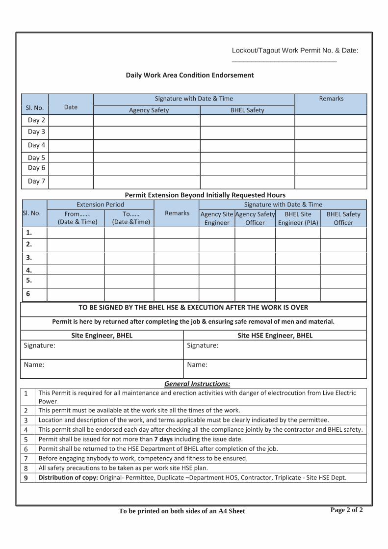
Permit Extension Beyond Initially Requested Hours Sl. No.
Extension Period Remarks
Signature with Date & Time From…….
(Date & Time) To……
(Date &Time) Agency Site
Engineer
Agency Safety Officer
BHEL Site Engineer (PIA)
BHEL Safety Officer
1.
2.
3.
4.
5.
6
TO BE SIGNED BY THE BHEL HSE & EXECUTION AFTER THE WORK IS OVER
Permit is here by returned after completing the job & ensuring safe removal of men and material.
Site Engineer, BHEL Site HSE Engineer, BHEL Signature: Signature:
Name: Name:
General Instructions: 1 This Permit is required for all maintenance and erection activities with danger of electrocution from Live Electric
Power 2 This permit must be available at the work site all the times of the work. 3 Location and description of the work, and terms applicable must be clearly indicated by the permittee. 4 This permit shall be endorsed each day after checking all the compliance jointly by the contractor and BHEL safety. 5 Permit shall be issued for not more than 7 days including the issue date. 6 Permit shall be returned to the HSE Department of BHEL after completion of the job. 7 Before engaging anybody to work, competency and fitness to be ensured. 8 All safety precautions to be taken as per work site HSE plan. 9 Distribution of copy: Original- Permittee, Duplicate –Department HOS, Contractor, Triplicate - Site HSE Dept.
Sl. No.
Date
Signature with Date & Time Remarks Agency Safety BHEL Safety
Day 2
Day 3
Day 4
Day 5
Day 6
Day 7
Page 2 of 2
Lockout/Tagout Work Permit No. & Date: ___________________________
Daily Work Area Condition Endorsement
To be printed on both sides of an A4 Sheet

POWER SECTOR FORMAT NO: HSEP:14-F01
REV NO.: 00 PAGE NO. 01 OF 02 Inspection of First Aid Box
Name of Site :
Name of Sub-Contractor:
Inspected by :
Date of Inspection:
Number of employees in the site: -
Sl. No. Item No. Available
Remarks
1 No. of small sterilized dressings
2 No of medium sized sterilized dressings
3 No of large sized sterilized dressings.
4 No of dressings
large sized sterilized burn
5 No of (15 grams) packets sterilized cotton wool
6 No of pieces of sterilized eye pads in separate sealed packets.
7 No of roller bandages 10 cm wide.
8 No of roller bandages 5 cm wide.
9 Whether tourniquet available
10 Whether supply of suitable splints available.
11 No of packets of safety pins.
12 Whether kidney tray available
13
Whether sufficient number of eye wash bottles, filled with distilled water or suitable liquid, clearly indicated by a distinctive sign which shall be visible at all times, available.
14 Whether 4%-xylocaine eye drops, and boric acid eye drops and soda by carbonate eye drops available.
15 Whether (60ml) bottle containing a two percent alcoholic solution of iodine available
16 Whether (two hundred ml) bottle of mercurochrome (2 per cent) solution in water available.
17 Whether 120ml bottle containing Sal volatile having the dose and mode of administration indicated on the label,
18 Whether roll of adhesive plaster (6 cm X 1 meter) available

POWER SECTOR FORMAT NO: HSEP:14-F01 REV NO.: 00 PAGE NO. 01 OF 02 Inspection of First Aid Box
Sl. No. Item No. Available
Remarks
19 No of rolls of adhesive plaster (2 cm X 1 meter)
20 Whether snake bite lancet available.
21 Whether (30 grams) bottle of potassium permanganate crystals available.
22 Whether a pair scissors available
23 Whether copy of the First-Aid leaflet issued by the Director-General, Factory Advice service and labor Institutes, Government of India available.
24 Whether bottle containing 100 tablets (each of 5 grains) of aspirin available
25 Whether Ointment for burns available
26 Whether bottle of a suitable surgical anti-septic solution available
27 Whether List of Contents pasted on First Aid Box along with respective expiry dates
Signature of Subcontractor’s Site I/C Date:

POWER SECTOR FORMAT NO: HSEP:14-F02 REV NO.: 00 PAGE NO. 01 OF 02 Health Check-Up
Name of Site :
Name of Sub-Contractor:
Name of Employee :
Age:
History Of Past Illness
H/O Epilepsy: H/O Drug Allergy: H/O Diabetics/ Hypertension: H/O Unconsciousness:
Personal History
EXAMINATION OBSERVATION General Physical Examination
Height
Weight
BMI
Built And nourishment
Pallor
Temperature
Chest Expansion Inspiration Expansion
Lymph Node Enlargement
Upper Limbs Strength & Function
Lower Limbs Strength & function
Spine Adequately flexible for the job concerned (Yes/No)
Mental alertness and stability with good eye, hand and foot co-ordination.
Ear, Nose, Throat
Ear / Hearing
Nose
Throat
Vision
Left Eye Right Eye

POWER SECTOR FORMAT NO: HSEP:14-F02 REV NO.: 00 PAGE NO. 02 OF 02 Health Check-Up
EXAMINATION OBSERVATION Cardiovascular System Examination
Inspection
Palpation Pulse BP
Auscultation (Heart Sounds)
Respiratory System
Inspection Respiratory Rate
Palpation:
Percussion
Auscultation (Breath Sounds)
Examination of Abdomen
Inspection
Palpation
Auscultation (Bowel Sounds)
Any Other
Clinical Impression
Signature of the examining doctor Date:

Name of Site :
Name of Sub-Contractor :
Date of Training (dd/mm/yyyy) : Duration (Hrs)
From To
Name & Details of Trainer:
Subject of Training Induction On-The-Job Training
(Give details)
Name of Training Co-ordinator:
Sl. No. Name Designation Organization Signature
I certify that Training has been carried out as per HSEP04: HSE Procedure for Training & Awareness Signature of Training Coordinator Date:
POWER SECTOR
FORMAT NO: HSEP:14-F03 REV NO.: 02 PAGE NO. 01 OF 01 HSE Induction / Regular / On-the-Job / g /
Training Records

Name of Site :
Sub-Contractors Name :
Date :
Topic Name of person delivered Tool Box Talk
No. of Participants attended
Remarks
Signature of Site I/C of Subcontractor Date:
POWER SECTOR
FORMAT NO: HSEP:14-F04 REV NO.: 00 PAGE NO. 01 OF 01Toolbox Talk

Name of subcontractor: Report Month:
A) Accidents/Incidents Details: -
a Lost time in Accidents
No. of incidents
Man Hours Lost
No. of People Involved
No. of personreported to Govt.
For the Month
Cumulative
b Minor Injuries
For the Month
Cumulative
c Fires No. of Near- Misses
No. of First- Aid cases
No. of persons injured
No. of equipment damaged
No. of Fire reported Outside
For the Month
Cumulative
d Other mishaps not covered in a, b, c.
No. of Near- Misses
No. of First- Aid cases
No. of persons injured
No. of equipment damaged
Total near misses and First-Aid
For the Month
Cumulative
B) Data for Man-hours worked:
Details Value Remarks if any No. of people
Man Hours worked
O.T. Hours
Total Man Hours
Grand Total of man hours worked during the month(A+B) Cumulative man-hours (from to ): ( Since commencing of operations)
Signature of Subcontractor Site In-charge Signature of Subcontractor HSE Officer
POWER SECTOR
FORMAT NO: HSEP:14-F05 REV NO.: 00 Page 01 of 6Monthly Site HSE Report

C) Status of Deployment of Work force, Safety Officers/Supervisors & Construction Medical Officer(s) & Electricians:
Description Name Qualification & Experience
Safety Officers
Safety Supervisors
Construction Medical Officer
Nursing Staff.
Electricians
Scaffolding Inspectors
T&P Inspectors
D) Status of deployment of manpower for critical HSE activities: (All height work and other hazardous activities to be actively supervised by trained personnel. Area to be divided in manageable sections to ensure effective supervision at all times. For example, multiple elevations in a structure can be divided among multiple supervisors)
Activity Location Shift Timings Personnel deployed Remarks Height Work Boiler Unit- (Level 1-3)
Boiler Unit- (Level 4-6)
ESP
Housekeeping Boiler Unit-
ESP Unit
Others
Signature of Subcontractor Site In-charge Signature of Subcontractor HSE Officer
POWER SECTOR
FORMAT NO: HSEP:14-F05 REV NO.: 00 Page 02 of 6Monthly Site HSE Report

E) Lifting Tools, Tackles, Equipment and Pressure Vessels:
Item Nos. Deployed
Nos. Tested by competent person
Identification Nos. (Comma separated) (A)
Validities of Test Certificates (Comma separated – corresponding to column A)
Whether internal testing using Color Coding or similar system done
Winches
Chain Blocks
Wire Rope Slings
Man Cages
D-Shackles
Air Compressors
Crawler Cranes
Mobile Cranes
Hydra Cranes
Hydraulic Jack
Others
F) Reverse Horns in Construction Vehicles:
Item Nos. Deployed with serial numbers (Comma separated) (A)
Nos. Having Functional reverse horns
Inspection Dates (Comma separated corresponding to column A)
Transit Mixers
Hydra Cranes
Dumpers/Trippers
Backhoes
Other Vehicles
G) ELCBs:
No. Of ELCBs provided with Serial Nos. (Comma separated) (A)
Nos. Functional When They were last Tested (Comma separated corresponding to column A)
H) Electrical Earthing:
No. Of Earth resources with serial numbers and locations (Comma separated) (A)
Whether Double Earthing provided to all equipment
When they were last tested (Comma separated corresponding to column A)
Signature of Subcontractor Site In-charge Signature of Subcontractor HSE Officer
POWER SECTOR
FORMAT NO: HSEP:14-F05 REV NO.: 00 Page 03 of 6Monthly Site HSE Report

I) Fire Extinguishers Name & designation of person responsible for maintenance of Extinguishers at different locations :( Individual subcontractor’s Safety Officers).
A. FIRE EXITINGUISHERS AT ERECTION SITE:
Type (Add more rows
if required)
Sizes
Qty + Serial numbers (Comma separated) (A)
Healthiness – Last checked dates (Comma separated corresponding to column A)
Locations (Comma separated corresponding to column A)
FOAM TYPE
SODA TYPE
DRY TYPE (DCP)
C02 TYPE
B. FIRE EXTINGUISHERS AT SITE OFFICES & STORES:
Type Size (Add more rows
if required)
Qty + Serial numbers (Comma separated) (A)
Healthiness – Last checked dates
(Comma separated corresponding to column
A)
Locations (Comma separated corresponding to column A)
FOAM TYPE
SODA TYPE DRY TYPE (DCP)
C02 TYPE
J) Tie-Ups with Emergency Services
Service (Add more rows if required)
Name, location & distance from site
Emergency contact details
Remarks
Hospital with ICU and facilities for orthopedic, neurological etc. trauma
Fire services Others:
Signature of Subcontractor Site In-charge Signature of Subcontractor HSE Officer
POWER SECTOR
FORMAT NO: HSEP:14-F05 REV NO.: 00 Page 04 of 6Monthly Site HSE Report

K) Implementation of Checklist, Work Permits:
Item Numbers During the Month Major Deviations
Note:- Please attach photocopies of all filled Checklists & Work permits for that month.
L) Personal Protective Equipment Issued (Extend table for each subcontractor):
Item Issued this Month Nos. Issued up to the Month
Percentage of usage at Site (as per physical verification)
Name of subcontractor: Safety Helmet
Safety Shoes
Full Body Harness
Fall Arrestor
Safety Nets
Hand Gloves
Face shield
Welder shield
Nose Mask
Reflective Jacket
Other PPEs.
M) Safety Observations by Subcontractor Executives- Observations package wise:
Topic Date Of Programme No. Of Participants Level Of Participants
• Tool-Box talks on Safety:
Date Tool Box Talk - No of Participants
Topic Remarks
• Safety Induction Trainings:
Date Safety Induction No. of Participants
Topic Remarks
Signature of Subcontractor Site In-charge Signature of Subcontractor HSE Officer
POWER SECTOR
FORMAT NO: HSEP:14-F05 REV NO.: 00 Page 05 of 6Monthly Site HSE Report

N) Progress of Management Programmes at Site
SL Description Of MPs Annual Plan Achievement In This Month
Cumulative Achievement
A. Environment Improvement Programme
1 Plantation of Trees
2 Installation of Scrap Bins
3 Chemical Storage & Handling system
B. Improvement of Working Environment
4 Increasing LTI free days
5 Air Quality Monitoring
6 Water Quality Monitoring
7 Illumination level Monitoring
O) HR Information:
Designation Total No. Inducted
Total no. of Induction Balance
Total no. of Gate Pass Issued
Total no. of Gate Pass Balance
Total no. of Gate Pass Cancelled
Medical Checkup Completed
Medical Checkup Balance
P) Rewards on Account of Good Safety Performance
Serial Number Reward Issued to Details of Reward Issued (Amount etc.)
Brief Reason
Note: Photos of Reward Functions to be attached
Q) Other Safety initiatives / Safety Activities conducted (with photos, if any):
Signature of Subcontractor Site In-charge Signature of Subcontractor HSE Officer
POWER SECTOR
FORMAT NO: HSEP:14-F05 REV NO.: 00 Page 06 of 6Monthly Site HSE Report

POWER SECTOR
FORMAT NO: HSEP:14-F06REV NO.: 00 PAGE NO. 01 OF 01 Personal Protective Equipment Inspection
Name of Site :
Name of Sub-Contractor :
Inspected by :
Date of Inspection:
Item Total Checked Numbers Found in Order Remarks
Safety Helmet
Safety Shoes
Full Body Harness
Fall Arrestor
Safety Nets
Hand Gloves
Face shield
Welder shield
Nose Mask
Reflective Jacket
Other PPEs (Specify)
Signature of Site I/C of Subcontractor: Date:

S
ite:
S
ub
con
trac
tor:
S
.N
Nam
e o
f P
erso
n
Det
ails
of
PP
E(s
) Is
sued
(w
ith
Ser
ial N
um
be
rs)
Dat
e Is
sued
R
ecei
ver’s
S
ign
atu
re
Issu
er’s
Nam
e &
Des
ign
atio
n
PP
E’s
ve
rifi
ed O
K /
Rem
arks
Is
suer
’s
Sig
nat
ure
PO
WER
SEC
TOR
FO
RMAT
NO
: HSE
P:14
-F06
RE
V NO
.: 00
PA
GE N
O. 0
1 O
F 1
Form
at fo
r Reg
ister
of I
ssue
and
Rec
eipt
of P
PEs

POWER SECTOR
FORMAT NO: HSEP:14-F07 REV NO.: 00 PAGE NO. 01 OF 01 Inspection Of T&Ps
Name of Site :
Name of Sub-Contractor :
Date of Inspection :
Sl.No. Description Remarks
1.0 Name of equipment
2.0 Basic Information of equipment
2.1 Specification
2.2 Sr. No. of equipment
2.3 Make
2.4 Year of manufacture
3.0 Major repairs / overhauls(Furnish details of work carried out) Date(s) of major repair/overhaul
3.1
3.2
3.3 Repairs carried out at site
4.0 Any performance test conducted Yes/No
5.0 Document Submitted Yes/No
6.0 Manufacturer’s test / guarantee certificate
Available/ Not available
7.0 Performance test Done/ Not Done
8.0 Acceptance Norms
9.0 Committee Observations
10.0 Date of next review (if accepted)
Signature-Subcontractor HSE Officer
Signature-Subcontractor Site In-charge

Name of Site :
Name of Sub-Contractor :
Inspected by :
Date of Inspection:
Crane Reg. No (Make/Model)
Name of Driver/Operator
Sl.no. Description Observation Measures 1 Valid Driving license
2 Hook & Hook Latch
3 Over Hoist limit switch
4 Boom limit switch
5 Boom Angle Indicator
6 Boom limit cutoff switch
7 Condition of Boom
8 Condition of ropes
9 Number of load lines
10 Size and condition of the slings
11 Stability of the cranes
12 Soil Condition
13 Swing Break And Lock
14 Proper Break And Lock
15 Hoist Break And Lock
16 Boom Break And Lock
17 Main Clutch
18 Leakage in Hydraulic Cylinders
19 Out riggers filly extendable
20 Tyre pressure
21 Condition of Battery And Lamps
22 Guards of moving and rotating parts
23 Load chart provided
24 Number and position of pedant ropes
25 Reverse Horn
26 Load Test Details
27 Operator’s fitness
28 Pollution under control certificate
29 Fire extinguisher of appropriate type.
30 Training of the operator
Signature of Site I/C of Subcontractor: Date:
POWER SECTOR
FORMAT NO: HSEP:14-F08 REV NO.: 00 PAGE NO. 01 OF 01 Inspection Of Cranes

POWER SECTOR
FORMAT NO: HSEP:14-F09 REV NO.: 00 PAGE NO. 01 OF 01 Inspection Of Winches
Name of Site :
Name of Sub-Contractor :
Inspected by :
Date of Inspection:
Winch Reg. No (Make/Model)
Name of Operator Sl. No.
Description YES NO NA Remarks
1 Has the copy of Third Party Inspection certificate been provided in winch machine shed?
2 Is safe operating instructions displayed near winch?
3 Is winch machine operator experienced enough to operate the winch machine?
4 Is the winch machine operated by someone other than the winch machine operator?
5 Is there guard provided in all moving parts like wheel and motor’s shaft?
6 Will it protect against unforeseen operational contingencies?
7 Are brakes, clutch and locking arrangement working properly?
8 Has it been ensured that the guard does not constitute a hazard by itself?
9 Are the cranks and the connecting rods protected by guardrails?
10 Is there provision for fully covered shed with wooden plank roof?
11 Is wire rope free from any kind of damage or wear and tear?
12 Is split pin provided for the protection of clutch and brake locking arrangement?
13 Is pulley inspected by competent person and certified before use?
14 Is pulley free from any wear and tear visually?
15 Is winch rope barricaded with clipsheet for the protection of rope and person?
16 Is the wire rope lubricated by cardium oil?
17 Is there any friction in wire rope which may damage the wire rope rather than the rolling parts?
18 Is there any oil leakage in the hydraulic system of the winch machine?
19 Has it been ensured that the guard will not cause discomfort orinconvenience to operator?
Total NO Total NA % Compliance
Signature of Site I/C of Subcontractor: Date:

Name of Site :
Name of Sub-Contractor :
Inspected by :
Date of Inspection:
Sl. No. Descriptions Observation (Yes/No)
Remarks
A. General
1 All the workers have been explained safe work method?
2 Adequate illumination has been ensured.
3 Work area inspected prior to the start of the work.
4 Is the work area barricaded to prevent fall and platforms are of adequate strength (bamboo, jute / plastic ropes not to be used).
5 The temporary work platforms & structures for height work including those used in Boiler structures, water walls, ESP, Powerhouse are fully barricaded with railings (as per IS 3696)
6 Fabricated makeshift arrangements are checked for quality and type of material welding, anchoring etc.
7 Are floor gaps, permanently covered and barricaded
8 Area below the work place barricaded, particularly below hot work.
9 Workers provided with bags /box to carry bolts, nuts and hand tools
10 Arrangement for fastening hand tools made.
11 All work platforms ensured to be of adequate strength and ergonomically suitable.
12 Work at more than one elevation at the same segment is restricted.
13 An established communication system has been established and explained to the workers.
B. Access/Egress
1 Walkways provided with handrail, mid-rail and toe guard?
2 All checkered plates, gratings properly welded/ bolted?
3 Are ladders inspected and they are in good condition?
4 Are ladders spliced?
5 Are ladders properly secured to prevent slipping, sliding or falling?
6 Stairs erected above and below 1 tier column for safe access?
7 Do side rails extend 36” above top landing?
POWER SECTOR
FORMAT NO: HSEP:14-F10 REV NO.: 00 PAGE NO. 01 OF 2 Inspection of Height Working

Sl. No. Descriptions Observation (Yes/No)
Remarks
8 Are built up ladders constructed of sound materials?
9 Are rugs and cleats not over 12” on center?
10 Metal ladders not used around electrical hazards.
11 Proper maintenance and storage.
12 Ladders placed at right slope.
13 Ladders / staircases welded/ bolted properly.
14 Any obstruction in the stairs.
15 Are landing provided with handrails, knee rails, toe boards etc.?
16 Whether ramp is provided with proper slope.
17 Proper hand rails / guards provided in ramps.
C. Housekeeping
1 Walkways, aisles & all overhead workplaces cleared of loose material.
2 Is any nut bolt/scrap left on beam/column?
3 Flammable materials, if any, are cleared.
4 All the de shuttering materials are removed after de shuttering is done.
5 Platforms and walkways free from oil/grease or other slippery material.
6 Collected scrap are brought down or lowered down and not dropped from height.
D. PPE And Safety Devices
1 Use of safety helmet, safety belts ensured for all workers
2 Anchoring points provided at all places of work.
3 Common lifeline provided wherever linear movement at height is required.
4 Safety nets are use wherever required.
5 Proper fall arrest system is deployed at critical workplaces.
6 Crawler boards/Safety system or works on fragile roof are used.
7 Is man-lift being used for personnel lifting?
8 Does man basket / personnel lift system has an independent lifeline and all occupants safety harnesses connected to it with rope grab?
Signature of Site I/C of Subcontractor: Date:
POWER SECTOR
FORMAT NO: HSEP:14-F10 REV NO.: 00 PAGE NO. 02 OF 2 Inspection of Height Working

POWER SECTOR
FORMAT NO: HSEP:14-F11 REV NO.: 00 PAGE NO. 01 OF 02 Inspection of Welding and Gas Cutting
Name of Site :
Name of Sub-Contractor :
Inspected by :
Date of Inspection :
Welding
Sl.no. Description Y e s
N o
Remarks
1 Is electric connection given through 30 mA ELCB/RCCB to welding m/c?
2 Is welding machine more than 10 years old?
3 Is there provision of fuse and is it bypassed?
4 Is electric cable fitted properly in junction box on m/c?
5 Is electrical cable free from joints?
6 Are the joints attached firmly & insulated with tape?
7 Is double earthing given to body of m/c?
8 Is the physical condition of the m/c good?
9 Is ON/OFF switch connected to the m/c is working and in good condition?
10 Are indication lamps on m/c working?
11 Is the electrode holder in good condition?
12 Are the cables of the welding m/c lugged & tight properly?
13 Is cable to welding machine terminal joint lose / burnt / glowing?
14 Are return lead connected properly (Rod, Angle, Channels shall not be used)
Total No of NO
Total No of YES
Signature of Site I/C of Subcontractor: Date:

POWER SECTOR FORMAT NO: HSEP:14-F11 REV NO.: 00 PAGE NO. 02 OF 02 Inspection of Welding and Gas Cutting
Gas Cutting
Sl.no Description Yes N
o Remarks
1 Are Cylinders kept on trolleys?
2 Physical condition of Gas cylinders Good?
3 Is there Oil/Grease on valve of the cylinder?
4 Are pressure regulators in good condition?
5 Condition of hose pipe OK?
6 Are hose pipe clamped with hose clip?
7
Is flash back arrestor & NRV fitted on torch both for O2 and LPG cylinder?
8 Is nozzle of the torch cleaned?
Total Number of NO
Total No of YES
% Compliance
Signature of Site I/C of Subcontractor: Date:

POWER SECTOR FORMAT NO: HSEP:14-F12 REV NO.: 00 PAGE NO. 01 OF 02
Inspection Of Electrical Installation
Name of Site :
Name of Sub-Contractor :
Inspected by :
Date of Inspection :
Sr. No.
Contents Yes/No Remarks
A Cable
1. Whether the condition of cable is checked?
2. Are cables received from other sites checked for insulation resistance before putting them into use?
3. Are all main cables taken either underground / overhead?
4. Are welding cables routed properly above the ground?
5. Are welding and electrical cables overlapping?
6. Is any improper joining of cables/wires prevailing at site?
B DBs/SDBs
1. Is earth conductor continued up to DB / SDB?
2. Whether DBs and extension boards are protected from rain / water?
3. Whether DB and extension board have separate MCB/ELCB
4. Is there any overloading of DBs / SDBs?
5. Are correct / proper fuses & CBs provided at main boards and sub-boards?
6. Is energized wiring in junction boxes, CB panels & similar places covered all times?
C ELCB
1. Whether the connections to all equipment are routed through individual ELCBs?
2. Is sensitivity of each ELCB maintained at 30 mA?

POWER SECTOR
FORMAT NO: HSEP:14-F12 REV NO.: 00 PAGE NO. 02 OF 02
INSPECTION OF ELECTRICAL INSTALLATION
Sr. No.
Contents Yes/No Remarks
3. Are the ELCB numbered and tested periodically & test results recorded in a logbook countersigned by a competent person?
D Grounding
1. Is natural earthing ensured at the source of power (main DB at Generator or Transformer)?
2. Whether the continuity and tightness of the earth conductor are checked?
3. Mention the gauge of the earth conductor used at the site.
4. Mention the value of Earth Resistance.
E Electrically operated Machines or Accessories. 1. Whether the plug top is provided everywhere.
2. Are all metal parts of electrical equipment and light fittings / accessories grounded / double earthed?
3. Is there any shed or cover for welding machines?
4. Are halogen lamps fixed at proper places?
5. Are portable power tools maintained as per norms?
6. Any other information:
Signature of Site I/C of Subcontractor: Date:

Name of Site :
Name of Sub-Contractor :
Inspected by :
Date of Inspection :
Sr. No.
Description Remarks
1.0 Name of equipment
2.0 Basic Information of equipment
2.1 Specification
2.2 Sr. No. of equipment
2.3 Make
2.4 Year of manufacture
3.0 Major repairs/overhauls(Furnish details of work carried out) Date(s) of major repair/overhaul
3.1
3.2
3.3 Repairs carried out at site
4.0 Any performance test conducted Yes/No 5.0 Document Submitted Yes/No 6.0 Manufacturer’s test / guarantee certificate Available/ Not available 7.0 Performance test Done/ Not Done 8.0 Acceptance Norms
9.0 Committee Observations
10.0 Date of next review (if accepted)
Signature-Subcontractor/ Subcontractor’s Safety Officer Signature-Site Safety Officer ( BHEL)
POWER SECTOR
FORMAT NO: HSEP:14-F13 REV NO.: 00 PAGE NO. 01 OF 01 Inspection of Elevator

Sub: MEMO for Penalty for non-compliances in Safety and Fabrication Quality requirement Following lapse (tick marked) was observed and penalty is imposed as stated at the bottom of this memo. It is requested that such occurrences may please be avoided in future. S.
No Nature of Non - Compliance Penalty
(in Rs.) Remarks
A. PPEs 1. Not wearing safety helmet / wearing without chin straps 500 Per Person/ day 2. Not Wearing safety shoes 500 Per Person/ day 3. Not wearing gloves, nose masks where required 350 Per Person/ day 4. Not using grinding goggles while doing grinding operations 500 Per Person/ day
B. Height Work 1. Not providing Lifelines for height work 1000 Per location per day 2. Not ensuring barricading of working platforms 1000 Per location per day 3. Not using temporary platform during work at height 1000 Per case per day 4. Not wearing safety belt while working at height (> 2 meters) or
not anchoring to lifeline 2000 Per Person/ day
5. Not providing proper barricades (caution tape at 2 elevations) 500 Per location per day Use of mobile phones by Height worker / Crane / Hydra Operator 1000 Per case per day
C. Electrical 1. Not using 24 V supply for lighting in confined spaces 500 Per case per day 2. Lack of Electrical Earthing 2000 Per case per day 3. Improper earthing of welding & Other electrical Machines. Earth
resistance not OK 500 Per Machine per incidence
4. Electrical plug not used for connection/ hand machines 500 Per connection per incidence 5. Unsafe electrical practice like not installing ELCB/ RCCB 500 Per case per day 6. Using frayed/ broken welding cables 500 Per machine per week
D. Lifting 1. Use of lifting equipment without having valid Third Party Test
certificate 5000 Per equipment per seven days
2. Lifting hooks without latches 500 Per hook per day 3. Using damaged slings or not slinging properly 2000 Per event Per T&P
4. Lifting cylinders without cage or rolling of cylinders 500 Per Event per incidence 5. Non removal of scrap from platforms 1000 Per Event Per location per 7 days
E. Hot Work / Cylinder Handling 20. Gas cutting without flash back arrestor 2000 Per machine per incidence 21. Gas cutting at height without sheet below 500 Per event 22. Not keeping gas cylinders vertically / in trolley on ground 500 Per event 23. Gas cutting with damaged hose pipes 500 Per event
Not covering welding cylinder with top cover 500 Per event F. Construction Vehicles
24. Not having valid driving license for the type of vehicle/ T&P 2000 Per driver per event 25. Two wheeler entry in construction area 500 Per vehicle 26. Using Hydra for material movement at site in unsafe manner 1000 Per case 27. Using Two Hydra in Tandem for material movement 2000 Per case 28. Vehicles, Hydras, Cranes, Dumpers and Earth Movers not having
automatic back horns linked to gear 1000 Per Equipment per day
29. Not using guide rope while moving material using Hydra or Crane 1000 Per event 30. Violating speed limit during vehicle movement 1000 Per event
POWER SECTOR
FORMAT NO: HSEP:14-F14 REV NO.: 00 PAGE NO. 01 OF 2 HSE Penalty Format

# or as deducted by customer, whichever is higher.
For repeated major and fatal incidents under the same subcontractor for the same package in the same Unit, the subcontractor will pay 2 times the penalty compared to previously paid
Details (if any) related to non- compliance (Name of persons, Nature of deficiency, etc.)
Penalty imposed:
1, Rate as per above chart
2. No. of Persons/ machine/ event/ labor
3. Total Penalty= 1. X 2. =
BHEL Personnel: Signatures:
Name
Attachments: Photographs & Documentary proof (if available) for violation Distribution: 1 Copy: to Sub- contractor Site In-charge,
1 Copy to Site Construction Manager (BHEL)
Nature of Non - Compliance Penalty in Rs.)
Remarks
Engineering / Administrative Controls / General 31. Major Accident – Victim not reporting for work within 48 hours –
resulting in partial loss in earning capacity & termination / demotion in employment
200000
32. Fatal Accident/Accidents Resulting in total Loss in Earning Capacity # 500000 Per victim# 33. Unsafe Act in violation of standards / clauses of this document 500-5000 Per case 34. Activity carried out without safety work permit where applicable 2000 Per person per event 35. Using untrained / unqualified personnel for hazardous work 2000 Per event 36. Not maintaining proper hygiene in canteen as per BOCW 1000 Per event
POWER SECTOR
FORMAT NO: HSEP:14-F14 REV NO.: 00 PAGE NO. 02 OF 2 HSE Penalty Format

POWER SECTOR
FORMAT NO: HSEP:14-F15 REV NO.: 00 PAGE NO. 01 OF 1 Format for Initial Verification of PPE’s & Lifting Tools & Tackles
Name of Site :
Name of Sub-Contractor :
Inspected by :
Date of Inspection :
S. No
Particulars (Serial Number, make, model of PPE, T&P)
Accepted / Rejected
Remarks
Checked
(Name & Sign. Of Subcontractor HSE Officer)
Verified (Name & Sign. Of Subcontractor Site
In-charge)

Name of Site :
Name of Sub-Contractor :
Inspected by :
Date of Inspection :
POWER SECTOR
FORMAT NO: HSEP:14-F16 REV NO.: 00 PAGE NO. 01 OF 1 Format for Inspection of Labor Colony
S. No
Particulars No Yes Comments
1 Sufficient living space ensured for each occupant with Kitchen area
2 Area cleanliness ensured through regular cleaning
3 Toilet facility sufficient for all occupants available, in order with adequate lighting, cleaned regularly and in hygienic condition
4 Washing facilities available with adequate water supply
5 Availability of sufficient drinking water in protected tanks with weekly tank cleaning and source tested annually as per IS10500 ensured
6 Adequate drainage to remove waste and rain water, no flooding
7 “Unsafe for Drinking” posted near accessible non-potable water and sources; posted in language of occupants or universal symbol
8 Prevention of mosquitoes, flies, and rodents in immediate housing area through insecticide sprays if required
9 Electricity provided & electrical connections safety ensured
10 Fans, Coolers / Quilts, Heaters provided as required to cater to weather conditions along with adequate electricity supply
11 Houses Walls and roof tight and solid; floors rigid and durable, with smooth, cleanable finish in good repair
12 Availability of nominal rate ration / common use items shop within / nearby the colony
13 Emergency medical plan developed: (A) Potential injuries determined (B) Local EMS response determined (C) Qualified first-aid person on site, if required
14 Emergency plans posted where employees gather
15 Transportation to nearest suitable facility
Any other checks:
Remarks:
Name & Sign. Of Subcontractor HSE Officer

N
ame
of S
ite:
N
ame
of S
ubco
ntra
ctor
:
PO
WER
SEC
TOR
FO
RMAT
NO
: HSE
P:14
-F17
RE
V NO
.: 00
PA
GE N
O. 0
1 O
F 1
Form
at fo
r Rec
ordi
ng o
f Firs
t Aid
Inju
ries
Date
: Ti
me:
N
ame
of p
atie
nt:
Subc
ontr
acto
r De
scrip
tion
of
inju
ry:
How
the
inju
ry
occu
rred
: Tr
eatm
ent
prov
ided
: Fi
rst A
ider
N
ame:
In
itial
s:
Rep
orta
ble:
Ye
s/N
o

(Generated Quantity in Metric Tons (MT) per year)
Signature of Subcontractor Site In-charge: Date
Site Subcontractor Date
Types & Quantity of e-waste handled/generated** Category Quantity Item Description
Types & Quantity of e-waste stored Category Quantity Item Description
Types & Quantity of e-waste sent to collection center authorized by producer/dismantler/recycler/refurbisher or authorized dismantler/ recycler or refurbisher **
Category Quantity Item Description
Types & Quantity of e-waste transported* Category Quantity Item Description
Name, address and contact details of the destination
Types & Quantity of e-waste refurbished* Category Quantity Item Description
Name, address and contact details of the destination of refurbished materials
Types & Quantity of e-waste dismantled* Category Quantity
Name, address and contact details of the destination Item Description Types & Quantity of e-waste recycled* Category Quantity Types & Quantity of materials recovered Item Description
Quantity Name, address and contact details of the destination
Types & Quantity of e-waste sent to recyclers by dismantlers
Category Quantity Item Description
Name, address and contact details of the destination Types and Quantity of other waste sent to respective recyclers by dismantlers / recyclers of e-waste
Category Quantity
Name, address and contact details of the destination Item Description Types and Quantity of e-waste treated & disposed Category Quantity
Item Description Name, address and contact details of the destination
POWER SECTOR
FORMAT NO: HSEP:14-F18 REV NO.: 00 PAGE NO. 01 OF 1 Format for Maintaining Records of E-waste
Handled / Generated

1. Name of Site: 2. Name of the Subcontractor: 3. Date: 4. Description of hazardous waste:
Physical form with description Chemical form Total volume and weight (in kg.)
5. Description of storage and treatment of hazardous waste:
Date Method of storage of hazardous wastes Date Method of treatment of hazardous wastes
6. Details of transportation of hazardous waste: Name & address of consignee of package
Mode of packing/of the waste for transportation
Mode of transportation to site of disposal
Date of transportation
7. Details of disposal of hazardous waste: Date of disposal
Concentration of hazardous material in the
final waste form
Site of disposal (identify the location on the relevant
layout drawing for reference)
Method of
disposal
Persons involved in
disposal
8. Data of environmental surveillance:
Date of measurement
Analysis of ground water Analysis of soil samples Analysis of air sampling Analysis of any other samples (give details) Location
of sampling
Depth of sampling
Data Location of sampling
Depth of sampling
Data Location of sampling
Data
9. Details of the hazardous wastes reused and recycled:
Date Total quantity of hazardous waste
generated
Details of hazardous waste minimization
activity
Material received
Final quantity of waste generated
Net reduction in waste generation quantity
and percentage
Signature of Subcontractor Site In-charge: Date:
POWER SECTOR
FORMAT NO: HSEP:14-F19 REV NO.: 00 PAGE NO. 01 OF 1
Format for Maintaining Records of Hazardous Waste at the Facility

PROJECT: CONTRACTOR:
DATE: OWNER :
INSPECTION BY:
Note : write ‘NA’ wherever the items is not applicable
Item Y e s
N o
Remarks Action
HOUSEKEEPING
Waste containers provided and used
Passageways and walkways clear
General neatness of working area
Other
PERSONNEL PROTECTIVE EQUIPTMENT
Goggles; shields
Face protection
Hearing protection
Respiratory masks etc.
Safety belts
Other
EXCAVATIONS / OPENINGS
Openings properly covered or barricaded
Excavations shored
Excavations barricaded
Overnight lighting provided
Other
WELDING, CUTTING
Gas cylinders chained upright
Cable and hoses not obstructing
Fire extinguisher (s) accessible
Others
SCAFFOLDING
Fully decked platforms
Guard and intermediate rails in place
Toe boards in place
Adequate shoring
Adequate access
Others
LADDER
Extension side rails 1 m above
Top of landing
Properly secured
Angle + 700 from horizontal
Other
POWER SECTOR
FORMAT NO: HSEP:14-F20 REV NO.: 00 PAGE NO. 01 OF 3 HSE Audit / Inspection Checklist-cum-Compliance Report

HOISTS, CRANES AND DERRICKS
Condition of cables and sheaf OK
Condition of slings, chains, hooks OK
Inspection & maintenance log maintained
Outriggers used
Signals observed and understood
Qualified operators
Others
MACHINERY, TOOLS & EQUIPMENT
Proper instruction
Safety devices
Proper cords
Inspection and maintenance
Other
VEHICLE AND TRAFFIC
Rules and regulations observed
Inspection and maintenance
Licensed drivers
Other
TEMPORARY FACILITIES
Emergency instructions posted
Fire extinguishers provided
Fire-aid equipment available
General neatness
Others
FIRE PREVENTION
Personnel instructed
Fire extinguishers checked
No smoking in prohibited areas.
Hydrants
Clearance
Others
ELECTRICAL
Proper wiring
ELCB’s provided
Ground fault circuit interrupters
Protection against damage
Prevention of tripping hazards
Other
HANDLING & STORAGE OF MATERIALS
Properly stored or stacked
Passageways clear
Other
FLAMMABLE GASES AND LIQUIDS
Containers clearly identified
Proper storage
Fire extinguisher nearby
Other
POWER SECTOR
FORMAT NO: HSEP:14-F20 REV NO.: 00 PAGE NO. 02 OF 3 HSE Checklist-cum-Compliance Report

WORKING AT HEIGHT
Safety nets
Safety belts
Safety helmets
Anchoring of safety belt to the life line rope
ENVIRONMENT
Lubricant waste/engine oils properly dispose.
Waste from Canteen, offices, sanitation etc. disposed properly.
Disposal of surplus earth, stripping materials, expired batteries, oily rags and combustible materials done properly.
HEALTH CHECKS
Hygienic conditions at labor camps O.K.
Availability of first-aid facilities
Proper sanitation at site, office & labor camps.
Arrangement of medical facilities.
Measures for dealing with illness.
Availability of potable drinking water for workmen & staff.
Provision of crèches for children.
. Signature of Subcontractor Site In-charge: Date:
POWER SECTOR
FORMAT NO: HSEP:14-F20 REV NO.: 00 PAGE NO. 03 OF 3 HSE Checklist-cum-Compliance Report

Name of Site :
Name of Sub-Contractor :
Inspected by :
Date of Inspection :
Details of Lux Meter Used for Illumination Checking
Serial Number
Last inspection Date
Inspection Due Date
POWER SECTOR
FORMAT NO: HSEP:14-F21 REV NO.: 00 PAGE NO. 01 OF 1 Format for Inspection of Illumination / Lux Levels
S. No
Location Applicable Lux Value
Measured Lux Value
Comments
1
2
3
4
5
6
7
8
9
10
11
12
13
14
15
Any other checks:
Remarks:
Name & Sign. Of Subcontractor HSE Officer

Type of incident: Fatal/Major//Fire/Property damage (Tick what is applicable)
POWER SECTOR
FORMAT NO: HSEP:14-F22 REV NO.: 00 PAGE NO. 01 OF 2 Format for Incident Reporting
1 Name Of Site 3 Activity Area
2 Scope Of Work 4 Name Of Contractor
5 NAME & DESIGNATION OF BHEL ACTIVITY I/C
6 Date & Time Of Accident
7 Date Resumed
8 No. Of Work-Days Lost by Victim (If Duty Not Resumed, Give Estimated Figure)
9 No. Of Man-hours Lost By Others 10 Personal Details Of Injured and/or Details Of Materials/Equipment/ Property Damaged
Name Name Of Material / Equipment / Property
Period Of Employment
Age Yrs. Sex Male/Female Estimated Cost
Actual Cost
Marital Status Single/ Married
Occupation Nature Of Damage
Part Of Body Injured Nature Of Injury
Agency (Object / Equipment / Substance) Most Responsible For Causing Accident / Injury / Damage
12 Person (Name & Designation) With Most Control Over Agency (Object / Equipment / Substance) Causing Accident Injury / Damage
13 Describe Clearly How the Accident Occurred (Use Additional Sheet, If Required)

Analysis 14
What Acts and/or Conditions Contributed Most Directly to This Accident
15
What Are the Basic Reason for The Existence of These Acts and/or Condition?
16
What Corrective Actions Have Been Taken to Prevent Accident Recurrence?
Date:
Signature Of Site HSE Coordinator
17 Comments of Head/Sox
Date:
Signature Of Head/SOX
POWER SECTOR
FORMAT NO: HSEP:14-F22 REV NO.: 00 PAGE NO. 02 OF 2 Format for Incident Reporting

POW
ER S
ECTO
R
FORM
AT N
O: H
SEP:
14-F
23
REV
NO.:
00
PAGE
NO
. 01
OF
1 Fo
rmat
for I
ncid
ent R
ecor
ding
Nam
e of
the
Site
Nam
e of
the
Subc
ontr
acto
r
Sl.
No.
Da
te &
Tim
e In
cide
nt T
ype
(Nea
r Miss
/M
inor
/Maj
or/F
atal
/Fire
/Pr
oper
ty D
amag
e)
Inci
dent
Loca
tion
& D
etai
ls Ba
sic
Reas
on
Num
bers
In
jure
d (T
ypes
of
Inju
ries)
Sign
RC
A Do
ne
CAPA
De
tails
Si
gn

SECTION-B
Special Requirements
(Applicable to this Contract Only)

POWER SECTOR
HEALTH, SAFETY AND ENVIRONMENT PLAN
FOR SITE OPERATIONS
(SECTION-B)
Doc. No.: HSEP:14-ER Rev.: 00 Date: 25.04.19
Page 1 of 162
1. Establishment of Common Facilities for whole Project – cost to be borne in full by subcontractor.
Table 1.1
a. MEDICAL CENTRE
i. A medical center shall be setup at site with basic facilities for handling medical emergencies
ii. Deployment of Medical Professional:
1. A qualified medical professional shall be deployed at site at all times.
2. When total employee & worker strength at site crosses 500, medical professional with MBBS Degree from recognized institute shall necessarily be deployed
iii. Ambulance shall be deployed along with a trained driver and accessories as per Schedule V of BOCW Central Rules, 1998. Ambulance shall be utilized exclusively for transporting the accident victim. Ambulance drivers shall be regularly trained in First Aid.
iv. Non deployment of Ambulance and First Aider as above shall invite a penalty of Rs. 30000 pm and Rs10000 PM respectively
v. Medical waste shall be disposed as per prevailing legislation (Bio-Medical Waste – Management and Handling Rules, 1998).
vi. Above are bare minimum requirements. Any legal requirements over and above these specifications shall supersede the above requirements
S. No.
Item Details as per Clause No. of this Section
Applicable / Not Applicable with
Remarks
Package
1 Construction of Medical Centre a Applicable Civil 2 Construction of Worker Training
Centre (A part of safety park) b Applicable Civil
3 Construction of Vertigo Test Structure (A part of safety park)
c Applicable Civil
4 Deployment of Specialists d Applicable By concerned agencies 5 HSE Equipment e Applicable By concerned agencies 6 HSE measurement devices f Applicable By concerned agencies 7 Urinals in under-construction
structures g Applicable By concerned agencies
8 Safety Park h Applicable Civil

POWER SECTOR
HEALTH, SAFETY AND ENVIRONMENT PLAN
FOR SITE OPERATIONS
(SECTION-B)
Doc. No.: HSEP:14-ER Rev.: 00 Date: 25.04.19
Page 2 of 162
b. WORKER TRAINING CENTRE
i. Indoor Worker Training Center to be developed at site with seating capacity of at least 50 trainees
ii. Projector with following minimum specifications:
iii. A Laptop or Desktop PC with following minimum specifications:
iv. Stereo speakers with minimum 50W RMS sound output v. PA system for Addressing Workers vi. Seating arrangement
c. Development of Vertigo Test Structure: Vertigo test Structure to be developed as per Annexure 04
d. Specialists:
Following specialists shall be deployed by the subcontractor, who shall cater to whole project as per BHEL requirements / instructions I. Qualified T&P Inspector: subcontractor shall engage one qualified T&P inspector having
undergone a certification course in the discipline. II. Qualified Scaffolding Erector and Inspector: Subcontractor shall deploy one qualified
Scaffolding Supervisor and Inspector having undergone a certification course in the discipline
Native Resolution XGA, 1024x768 Brightness (ANSI lumens) 3300 Contrast Ratio 13000:1 Display Color 30 Bits Aspect Ratio 4:3
Processor Intel Celeron Dual Core Memory (RAM) 2 GB Graphics Card 2GB Video Memory Hard Disk Capacity 60 GB Monitor Size 14 inches Keyboard Mouse

POWER SECTOR
HEALTH, SAFETY AND ENVIRONMENT PLAN
FOR SITE OPERATIONS
(SECTION-B)
Doc. No.: HSEP:14-ER Rev.: 00 Date: 25.04.19
Page 3 of 162
e. Tools & Equipment: Following equipment conforming to relevant IS Codes for the job shall be ensured by subcontractor:
S. No. Item 1 Lifelines
2 Retractable Fall Arrestors 3 Safety Nets (10m X 5m) 4 Sky Climbers 5 Fire Blanket 6 Honey Bee Removal Suit & Kit 7 Flashback Arrestors 8 Barricading Tape 9 Binoculars 10 Walkie-Talkies 11 LOTO kit 12 24-Volt light 13 Sand Buckets 14 Hard barricading planks 15 Standby Fire kits
S. No. Item Type of Job / Purpose Remarks
1 Lifelines (Steel Rope) and posts Height work
2 Retractable Fall Arrestors Height Work
3 Safety Nets (for fall protection; railings also to be covered)
Height Work
4 Sky Climbers Height Work
5 Fire Blanket, Spark/ slag collector Hot Work
6 Honey Bee Removal Suit & Kit General
7 Flashback Arrestors Hot work
8 Barricading –Hard ( Scaffolding Pipes & Clamps or fabricated using structural/round
Height Work, Excavation, General Barricading
9 Binoculars HSE Inspection
10 Walkie-Talkies Lifting
11 LOTO kit Working on charged line
12 24-Volt light Confined Space/ temp work
13 Sand and Water Buckets Hot work/Electrical work
15 Standby Fire kits Fire extinguisher stands Hot work/Electrical work

POWER SECTOR
HEALTH, SAFETY AND ENVIRONMENT PLAN
FOR SITE OPERATIONS
(SECTION-B)
Doc. No.: HSEP:14-ER Rev.: 00 Date: 25.04.19
Page 4 of 162
Above equipment are bare minimum to be essentially maintained at all times. Additional numbers to be deployed as and when required in order to ensure fulfillment of all Safety requirements
f. HSE Measurement Equipment & Tools S. No Device
1 ELCB Tester
2 Multi meter (Light cables)
3 Earth Resistance Meter
4 Lux Meter
5 Decibel Meter
6 Anemometer
7 Breath Analyzer (Alcohol)
8 Multi-gas analyzer
9 Gas leakage detector / alarm
10 Gas monitor (confined space)
11 Radiation meter & Badges
12 Blood pressure monitor
13 Fire detectors
14 Dust Particle Detector
g. Urinals in Under-construction structures:
Urinals for in under-construction structures for easy access eg. In case of Boiler elevations etc.
2. Shared Facilities – where part of operating cost is borne by subcontractor in proportion to contract value
The subcontractor shall bear running expenses of above facilities on a ‘proportional to contract value sharing basis as finalized by BHEL.
S. No. Facility 1. Operation of Ambulance, Nurses,
Medical Consumables 2. Construction, Maintenance &
Upkeep of Latrines and Urinals in Common spaces
3. Drinking Water Provision in Common Spaces
4. Dust Control / Water Sprinkling, Pest Control, Fumigation at Site

POWER SECTOR
HEALTH, SAFETY AND ENVIRONMENT PLAN
FOR SITE OPERATIONS
(SECTION-B)
Doc. No.: HSEP:14-ER Rev.: 00 Date: 25.04.19
Page 5 of 162
S. No Code Name Title
1 IS: 818-1888 (Reaffirmed 2003)
Code of Practice for Safety and Health requirements in Electric and Gas Welding and Cutting operations.
2 IS: 1179-1967 (Reaffirmed 2003)
Specification for Equipment for Eye & Face protection during welding.
3 IS: 1989 (Part 2):1986 (Reaffirmed 1997)
Specification for Leather Safety Boots & Shoes
4 IS:2925 – 1984 (Reaffirmed 2010)
Specification for Industrial Safety Helmets
5 IS:3521: 1999 (Reaffirmed 2002)
Industrial Safety Belts & Harnesses-Specification
6 IS:3646(Part II) – 1966(Reaffirmed 2003)
Code of Practice for Interior Illumination
7 IS:3696 (Part I) – 1987 (Reaffirmed 2002)
Safety Code for Scaffolds and Ladders
8 IS: 3696(Part 2) : 1991 (Reaffirmed 2002 )
Scaffolds and Ladders-Code of Safety
9 IS: 3764:1992 Excavation Work – Code of Safety 10 IS:3786 – 1983
(Reaffirmed 2002) Method for Computation of Frequency and Severity Rates for Industrial Injuries and Classification of Industrial Accidents
11 IS.4014.2.1967 Steel tubular Scaffolding
12 IS:4770: 1991 (Reaffirmed 2006)
Rubber Gloves Specification (Electricals Purposes)
13 IS:4912: 1978 (Reaffirmed 2002)
Safety Requirements for Floor and Wall Openings, Railings and Toe Boards
14 IS: 5557 – 1969 Industrial and Safety rubber knee boots. 15 IS: 5983 – 1980
(Reaffirmed 2002) Specification for Eye-Protectors
16 IS:6519 – 1971 (Reaffirmed 1997)
Code of Practice for Selection, Care and Repair of Safety Footwear
17 IS.6549.1972 Glossary of terms used for Lifting tackles
18 IS:6994(Part I)-1973 (Re affirmed 1996)
Specification for Industrial Safety Gloves Leather and Cotton Gloves
19 IS.7215.1974 Steel Structure Fabrication
20 IS.7969.1975 Handling and storage of building material

POWER SECTOR
HEALTH, SAFETY AND ENVIRONMENT PLAN
FOR SITE OPERATIONS
(SECTION-B)
Doc. No.: HSEP:14-ER Rev.: 00 Date: 25.04.19
Page 6 of 162
21 IS:8519 – 1977 (Reaffirmed 1983)
Guide for Selection of Industrial Safety Equipment for Body Protection.
22 IS:8520 – 1977 (Reaffirmed 2002)
Guide for Selection of Industrial Safety Equipment for Eye, Face and Ear Protection.
23 IS:9167:1979 Specification for Ear-Protectors
24 IS:9473:2002 Respiratory Protective Devices-Filtering Half Masks to protect against Particles-Specification.
25 IS: 9944:1992 (Reaffirmed 2003)
Natural and Man-made Fiber Rope Slings- Recommendations on Safe working loads.
26 IS 11006 : 2011 Flash Back(Flame) Arrestor Specification
27 IS: 11226 – 1985 Leather Safety footwear having direct molding sole. 28 IS:11057 – 1884
(Reaffirmed 2001) Specification for Industrial Safety Nets
29 IS: 12254:1993 (Reaffirmed 2002)
Polyvinyl Chloride (PVC) Industrial Boots Specification
30 IS:13367(Part 1):1992 (Reaffirmed 20030
Safe Use of Cranes-Code of Practice
31 IS: 14166:1994 (Reaffirmed 2002)
Respiratory Protective Devices-Full Face Masks Specification
32 IS:14746: 1999 (Reaffirmed 2003)
Respiratory Protective Devices-Half Masks and Quarter Masks - Specification
33 IS: 15397 :2003 (Reaffirmed 2008)
Portable Extinguisher Mechanical Foam Type(Stored Pressure)-Specification
34 IS: 19011:2002 Guidelines for Quality and/or Environmental Management Systems Auditing

POWER SECTOR
HEALTH, SAFETY AND ENVIRONMENT PLAN
FOR SITE OPERATIONS
(SECTION-B)
Doc. No.: HSEP:14 Rev.: 01 Date:
Page 1 of 162
As per Contract Labor (Regulation & Abolition Act), Central Rules, 1971,
(1) The first-aid box shall be distinctively marked with a Red Cross on a white background and shall contain the following items, namely:
(a) For establishments in which the number of contract laborers employed does not exceed fifty, each first aid box shall contain the following equipment:
(i) 6 small sterilized dressings
(ii) 3 medium size sterilized dressings
(iii) 3 large size sterilized dressings (iv) 6 pieces of sterilized eye pads in separate sealed packets. (v) 6 roller bandages 10 cm wide. (vi) 6 roller bandages 5 cm wide. (vii) One tourniquet (viii) A supply of suitable splints (ix) Three packets of safety pins. (x) Kidney tray. (xi) 3 large sterilized burn dressings. (xii) 1 (30ml) bottle containing a two percent alcoholic solution of iodine (xiii) 1 (30 ml) bottle containing Sal volatile having the dose and mode of
administration indicated on the label (xiv) 1 snake bite lancet (xv) 1 (30gms) bottle of potassium permanganate crystals. (xvi) 1 pair scissors (xvii) 1 copy of the First-Aid leaflet issued by the Director General, Factory
Advice Service and Labor Institutes, Government of India. (xviii) A bottle containing 100 tablets (each of 5 grains) of aspirin
(xix) Ointment for burns (xx) A bottle of suitable surgical anti-septic solution

Page 2 of 2
HSEP:14 - ANNEXURE 03
Details and Contents of First Aid Box
(b) For establishment in which the number of contract laborers exceeds fifty each first-aid box shall contain the following equipment:
(i) 12 small sterilized dressings (ii) 6 medium size sterilized dressings (iii) 6 large size sterilized dressings. (iv) 6 large size sterilized burn dressings (v) 6 (15 grams) packets sterilized cotton wool (vi) 12 pieces of sterilized eye pads in separate sealed packets. (vii) 12 roller bandages 10 cm wide. (viii) 12 roller bandages 5 cm wide. (ix) One tourniquet. (x) A supply of suitable splints. (xi) Three packets of safety pins. (xii) Kidney tray. (xiii) Sufficient number of eye washes bottles filled with distilled water or suitable
liquid clearly indicated by a distinctive sign which shall be visible at all times.
(xiv) 4 per cent Xylocaine eye drops, and boric acid eye drops and soda by carbonate eye drops.
(xv) 1 (60ml) bottle containing a two percent alcoholic solution of iodine (xvi) One (two hundred ml) bottle of mercurochrome (2 per cent) solution in water.
(xvii) 1 (120ml) bottle containing Sal volatile having the dose and mode of administration indicated on the label.
(xviii) 1 roll of adhesive plaster (6 cmX1 meter) (xix) 2 rolls of adhesive plaster (2 cmX1 meter) (xx) A snake bite lancet. (xxi) 1 (30 grams) bottle of potassium permanganate crystals. (xxii) 1 pair scissors (xxiii) 1 copy of the First-Aid leaflet issued by the Director-General, Factory Advice
service and labor Institutes, Government of India. (xxiv) a bottle containing 100 tablets (each of 5 grains) of aspirin (xxv) Ointment for burns (xxvi) A bottle of a suitable surgical anti septic solution.
(2) Adequate arrangement shall be made for immediate recoupment of the equipment when necessary.

POWER SECTOR
HEALTH, SAFETY AND ENVIRONMENT PLAN
FOR SITE OPERATIONS
(SECTION-B)
Doc. No.: HSEP:14 Rev.: 01 Date:
Page 1 of 162
Table 1
S. No. Topic 1 Vertigo / Height working Test Structure Layout
2, 3 Structure Layout Sketch 3 Actual Photo of a typical structure 4 Bill of Materials 5 Guidelines for Conducting the Test
Note:
All dimensions are in mm
Drawing is not to scale
Inside boundary area to be filled with sand to level with road (external)
Details of F1 and F2 are shown below
Figure 1: Vertigo / Height Work Test Structure Layout

Page 2 of 6
HSEP:14 - ANNEXURE 04
Vertigo Test Structure Specifications
F1 Footing F2 Footing
Note: Concrete Grade is M15 Drawing is not to scale TOC is at Road Level G L refers to Ground Level Figure 2

Page 3 of 6
HSEP:14 - ANNEXURE 04
Vertigo Test Structure Specifications
Mark No. LD1 Qty – 1 No.
Mark No. LD1 Qty – 1 No.
Mark No. WB1 Qty – 3 Nos.
Figure 3

Page 4 of 6
HSEP:14 - ANNEXURE 04
Vertigo Test Structure Specifications
Pic-1:Actual Photo of a Typical Vertigo Test
Mark No. RP1 Qty – 1 No.
Mark No. HP1 Qty – 1 No.
Mark No. WB1 Qty – 1 No.
ISM
C25
0
4570
Figure 4

Page 5 of 6
HSEP:14 - ANNEXURE 04
Vertigo Test Structure Specifications
Table 2: BOM FOR HEIGHT WORK INDUCTION TRAINING MODULE
Sl. No. Description Width (mm)
Length (mm)
Qty (No's) Unit Wt (Kgs) Total Wt. (Kgs)
MKD NO. WB1 1 ISMC250 609 3 34.20 62.483 2 ISMC250 914 6 34.20 187.553 3 ISMC100 3655 1 9.56 34.942 4 PL10 100 270 6 78.50 12.717
Total Weight (Kgs) 297.695 MKD NO. RP1
1 ISMC250 4570 4 34.20 625.176 2 ISMC250 3655 1 34.20 125.001 3 PL25 225 330 2 196.25 29.143 4 PL25 200 275 2 196.25 21.588
Total Weight (Kgs) 800.908 MKD NO. HP1
1 ISMC250 4570 4 34.20 625.176 2 ISMC250 3655 1 34.20 125.001 3 ISMC150 3655 1 16.80 61.404 4 PL25 300 400 2 196.25 47.100 5 PL25 240 350 2 196.25 32.970
Total Weight (Kgs) 891.651 MKD NO. LD1
1 ISA50X50X6 6070 2 4.50 54.630 2 ISA50X50X6 500 12 4.50 27.000 3 PL12 75 75 2 94.20 1.060 4 ISA50X50X6 300 6 4.50 8.100 5 ISA50X50X6 255 2 4.50 2.295 6 ISA50X50X6 1000 8 4.50 36.000 7 ISA50X50X6 910 3 4.50 12.285 8 ISA50X50X6 1100 4 4.50 19.800 9 ISA50X50X6 650 2 4.50 5.850
10 ISA50X50X6 350 2 4.50 3.150 11 PL8 75 900 1 62.80 4.239 12 PL8 75 410 2 62.80 3.862
Weight (Kgs) 178.271 Total Weight (Kgs) 2168.525

Page 6 of 6
HSEP:14 - ANNEXURE 04
Vertigo Test Structure Specifications
A. Test Procedure / Guidelines
Fear of height may be physiological or psychological. Therefore, to rule out any possibility of physiological factor, detailed medical check-up of workers is carried out before vertigo test. Medical check-up of workers includes the following: history of past illnesses (like epilepsy, drug allergy, diabetics/ hypertension, unconsciousness etc.), general physical examination (like height, weight, BMI, build and nourishment etc.), measurement of pulse rate, Blood Pressure, respiratory rate. After this check-up, those who are found suitable for height work by examining doctor, are allowed to undergo vertigo test. During this health check-up, psychology of workers is also studied. If any worker finds it extremely difficult/ frightening to climb the monkey ladder & walk on the beam, during/after performing vertigo test or even before performing, then he is treated as disqualified. As per standard, during vertigo test, worker is allowed to climb on a foundation through monkey ladder, walk on a beam, then steps down at the other end of beam, through monkey ladder. Height of the beam should be at least six feet from ground level. All necessary safety precautions are taken during this test. Worker has to wear full body harness with double lanyard. A horizontal lifeline is run parallel to the beam and worker has to put his lanyards into the lifeline. Additionally, a safety net is also put below the beam for rescue of the victim in case of a fall from beam.
Following activities are generally carried during testing:
1. Walking Bench Training: a. Person should walk over the channel. He should maintain balance & walk without much
problem. b. If the person has problem to balances himself on repeated chances, he may be having flat foot
or some other problem. So, he may not be fit for height work. 2. Rope Climb Training:
Person should be able to climb the rope up to the top channel for ensuring that in case of fall, a person hanging on the safety harness, will be able to safely climb back to the platform within minimum time period before the safety harness start breaking down under the load.
3. Height Work Training: Person should walk freely on the middle channel while holding the top channel with the help of safety harness.
4. Ladder for Vertical fall arrestor Training: Vertical fall arrestor rope is fixed from top to bottom of the ladder. It will ensure:
Usage of vertical fall arrestor. Usage of two lanyards of a safety harness. Ensure 3-point contact on the ladder while climb.
5. Chair for work at height Training: Climb though vertical ladder with two lanyard ropes. Hooking of two lanyard ropes to life line. With this safe arrangement, he can walk to chair. Sits in the chair safely, comes out & walks back to the vertical ladder & come down from
vertical ladder. After completion of vertigo test, blood pressure of worker is again measured. If it is not within acceptable limits for any worker, concerned worker is denied height pass.
Only those who pass the above training are fit for height work.

POWER SECTOR
HEALTH, SAFETY AND ENVIRONMENT PLAN
FOR SITE OPERATIONS
(SECTION-B)
Doc. No.: HSEP:14
Rev.: 01 Date:
Page 7 of 162
Safety Park Requirements
S.No Training room(capacity 40 persons) Qty. 1 Class room chair 25
2 Office Table 3
3 Rolling chair 3
4 Almirah 1
5 Visitor chair 10
6 Drawer 2
7 Single bed 1
8 Mattress 1
9 Projector 1
10 Projector screen 1
11 Sound speakers 1
12 Desktop Computer 3
13 Printer 1
14 White Board 1
15 Marker 5
16 Duster 1
17 Door Mat 9
18 Dustbin(Smaal + BIG) 7+1
19 Mannequin 1
20 Helmet 1
21 Face Shield 1
22 Safety Goggle 1
23 Welding sheild 1
24 Ear Muff 1
25 Ear Plug 1
26 Nose Mask 1
27 Breathing Apparatus 1
28 Hand Gloves(Cotton) 1
29 Hand Gloves for Electrician (Rubber) 1
30 Hand gloves Rubber 1
31 Hand Gloves Lather 1
32 Construction Safety Uniform(Boiler Suit) 1
33 Welding Apron 1
34 Safety Shoes 1
35 Leg Guard For Welder 1
36 Poster for Occupational Disease like Pneumoconosis,silicosis etc.
1
37 Gum Boot 1

38 Full Body Harness 1
39 8 MM Wire rope for life line. Length 20 Feet(FT). 1
40 Sfety Net for man & materials.Size 15 FT X 15FT. 1
41 MonkEy ladder 15 FT. 1
45 Fire Extingusher All types(DCP,CO2 & Foam) 1
46 Bed Sheet 1
47 Pillow 1
48 Curtain 12
49 curtain fittings 12
50 AC (1.5 TON) 3
51 AC (2 TON) 2
52 Rope pully. 1
53 PP Rope for pully 20 MTR.
54 Ladder Clamps 6
55 Allumuniam ladder 6 MTR. 1
56 Carry Bag
57 Scaffolding all Materilas for 5 Mtr. Height like.Sacffolding tubes,Sole plate,base plate,Right angle clamps,Swielclamps,beam clamps,Joint box/joint pin,toe guard/board,

Health, Safety & Environment, Power Sector Headquarters
Bharat Heavy Electricals Limited
Regd. Office: BHEL House, Siri Fort, New Delhi – 110049, India
Website: www.bhel.com