notice inviting tender - Amazon AWS
717
NOTICE INVITING TENDER (Document No PS:MSX:NIT) TENDER NO. BHEL/NR/SCT/PANKI/BOUNDARY WALL/1110 Rev 01 1 st Jun 2012 Bharat Heavy Electricals Limited
-
Upload
khangminh22 -
Category
Documents
-
view
1 -
download
0
Transcript of notice inviting tender - Amazon AWS

Registered Office : BHEL House, Siri Fort, New Delhi – 110 049, India
Website : www.bhel.com
NOTICE INVITING TENDER (Document No PS:MSX:NIT)
TENDER NO. BHEL/NR/SCT/PANKI/BOUNDARY WALL/1110
Rev 01 1st Jun
2012
Bharat Heavy Electricals Limited

Document No . PS:MSX:NIT, Rev 01, 1st June 2012 Page 2 of 17
Registered Office : BHEL House, Siri Fort, New Delhi – 110 049, India Website: www.bhel.com
Ref: BHEL/NR/SCT/PANKI/BOUNDARY WALL/1110 Date: 11/06/2018 ========================================================================================
NOTICE INVITING E-TENDER (NIT) BIDDER TO SUBMIT OFFERS ON PORTAL
https://bhel.abcprocure.com ========================================================================================
To Dear Sir/Madam
Sub : NOTICE INVITING E-TENDER Sealed offers in two part bid system are invited from reputed & experienced bidders (meeting PRE QUALIFICATION CRITERIA as mentioned in Annexure-I) for the subject job by the undersigned on the behalf of BHARAT HEAVY ELECTRICALS LIMITED as per the tender document. Following points relevant to the tender may please be noted and complied with.
1. Salient Features of NIT
SL NO
ISSUE DESCRIPTION
i TENDER NUMBER BHEL/NR/SCT/PANKI/BOUNDARY WALL/1110 ii Broad Scope of job BOUNDARY WALL, ASSOCIATED ROADS INSIDE AND OUTSIDE
BOUNDARY WALL, DRAIN ALONG BOUNDARY WALL, GATE COMPLEX, GATE STRUCTURES, WATCH TOWERS, WEIGH BRIDGE, CUSTOMER’S SITE OFFICE AND CONSTRUCTION OF COAL STOCK PILES AT 1 X 660 MW PANKI THERMAL POWER PLANT, PANKI, U.P.
iii DETAILS OF TENDER DOCUMENT
a Volume-IA Technical Conditions of Contract (TCC) consisting of Scope of work, Technical Specification, Drawings, Procedures, Bill of Quantities, Terms of payment, etc
Applicable
b Volume-IB Special Conditions of Contract (SCC) Applicable
c Volume-IC General Conditions of Contract (GCC) Applicable
d Volume-ID Forms and Procedures Applicable
e Volume-II Price Schedule (Absolute value). Applicable
iv Issue of Tender Documents
From BHEL website (www.bhel.com) and
https://bhel.abcprocure.com
Tender documents will be available at website till due date of submission
Applicable
v DUE DATE & TIME OF OFFER SUBMISSION
Date : 25/06/2018 , Time : 1500 HRS Place : on https://bhel.abcprocure.com
Applicable
vi OPENING OF TENDER
At due date / time
Date : 25/06/2018 , Time : 1530 HRS
Notes: (1) In case the due date of opening of tender becomes a non-working day, then the due date & time of offer submission and opening of tenders get extended to the next working day. (2) Bidder may depute representative to witness the opening of tender. However it being an e-tender it shall be opened online
Applicable

Document No . PS:MSX:NIT, Rev 01, 1st June 2012 Page 3 of 17
Registered Office : BHEL House, Siri Fort, New Delhi – 110 049, India Website: www.bhel.com
vii EMD AMOUNT Rs. 13,24,000/- Applicable for all Bidders (including MSE Bidders)
viii COST OF TENDER Rs 2,000/- Applicable for all Bidders (including MSE Bidders)
ix LAST DATE FOR SEEKING CLARIFICATION
Five days before bid submission due date. Along with soft version also, addressing to contact address given below
1) Name: SUSMITA BASU Designation: SR. DGM Deptt: SCT Address: BHEL-PSNR, PLOT NO. 25, SECTOR – 16A, NOIDA - 201301 Phone: (Landline/Mobile) 0120-2416262 Email : [email protected]
2) Name: CHITTARANJAN SWAIN
Designation: DY. MANAGER Deptt: SCT Address: BHEL-PSNR, PLOT NO. 25, SECTOR – 16A, NOIDA - 201301 Phone: (Landline/Mobile) 0120 - 2416500 Email : [email protected]
Applicable
x SCHEDULE OF Pre Bid Discussion (PBD)
Not applicable.
xi INTEGRITY PACT & DETAILS OF INDEPENDENT EXTERNAL MONITOR (IEM)
Shri D.R.S. Chaudhary E-1/164 Arera Colony Bhopal 462016 [email protected]
Applicable
xii Latest updates Latest updates on the important dates, Amendments, Correspondences, Corrigenda, Clarifications, Changes, Errata, Modifications, Revisions, etc to Tender Specifications will be hosted in BHEL webpage (www.bhel.com -->Tender Notifications View Corrigendums) & portal
https://bhel.abcprocure.com and not in the newspapers. Bidders to keep themselves
updated with all such information
xiii Tender submission On portal https://bhel.abcprocure.com
2. The offer shall be submitted as per the instructions of tender document and as detailed in this NIT. Bidders to
note specifically that all pages of tender document, including these NIT pages of this particular tender together with subsequent correspondences shall be submitted by them, Rates/Price including discounts/rebates, if any, mentioned anywhere/in any form in the techno-commercial offer other than the Price Bid, shall not be entertained.
3. Unless specifically stated otherwise, bidder shall remit cost of tender and courier charges if applicable, in the
form of Demand Draft drawn in favour of Bharat Heavy Electricals Ltd, payable at Power Sector Regional HQ at Noida issuing the Tender, along with techno-commercial offer. Bidder may also choose to deposit the Tender document cost by cash at the Cash Office as stated above against sl no iv of 1, on any working day; and in such case copy of Cash receipt is to be enclosed with the Techno Commercial offer. Sale of tender Documents shall not take place on National Holidays, holidays declared by Central or State Governments and BHEL PS HQ at Noida, Sundays and second/ last Saturdays.
As this tender is an E-Tender and no paper bids will be accepted therefore the scanned copy of the Demand Draft or the Cash Receipt issued by BHEL PSNR should be uploaded in the E procurement portal. Hard Copy

Document No . PS:MSX:NIT, Rev 01, 1st June 2012 Page 4 of 17
Registered Office : BHEL House, Siri Fort, New Delhi – 110 049, India Website: www.bhel.com
of the demand draft should reach BHEL PSNR HQ Noida before the due date and time of bid submission. BHEL shall not be responsible for postal or any other delays in this regard.
4. Unless specifically stated otherwise, bidder shall deposit EMD through Cash Deposit (as permissible under the extant Income Tax Act) (before tender opening), Electronic Fund Transfer credited in BHEL account (before Tender Opening) or Banker’s Cheque/ Demand Draft/ Pay Order in favour of Bharat Heavy Electricals Ltd, payable at Noida (along with offer). ‘One Time EMD’ will not be considered for this tender. All the bidders who have ‘One Time EMD’ with BHEL and want to participate in this tender, would also submit the requisite amount of EMD as mentioned in Clause No. 1, Salient Features of NIT, Sl. No. (vii) above. However, the One Time EMD can be adjusted against the EMD applicable against this tender on specific request of bidder. For Electronic Fund Transfer the details are as below-: a) Name of the Beneficiary -: Bharat Heavy Electricals Limited b) Bank Particulars
i). Bank Name -: STATE BANK OF INDIA ii). Bank Telephone No.(with STD code)-: 011-23352180 iii). Branch Address-: CAG BRANCH, NEW DELHI iv). Bank Fax No. (with STD code) -: 011-23353101 v). Branch Code -: SBIN0009996 vi). 9 Digit MICR Code of the Bank Branch -: 110002201 vii). Bank Account Number -: 10813608647 viii). Bank Account Type -: CASH CREDIT ix). 11 Digit IFSC Code of Beneficiary Branch-: SBIN0009996
(Note-: In case of E-Tenders, no paper bids shall be accepted, therefore, the scanned copy of the Banker’s Cheque/ Demand Draft/ Pay Order/ Details of payment made through Electronic Fund Transfer should be uploaded in the E-Procurement Portal and hard copy of the same should reach BHEL-PSNR HQ Noida before the due date and time of bid submission. BHEL shall not be responsible for postal or any other delays in this regard.) For other details please refer General Conditions of Contract.
5. Procedure for Submission of Tenders: This is an E-tender floated online through our E-Procurement Site
https://bhel.abcprocure.com. The bidder should respond by submitting their offer online only in our e-
Procurement platform at https://bhel.abcprocure.com. Offers are invited in two-parts only.
Documents Comprising the e-Tender
The tender shall be submitted online ONLY, EXCEPT TENDER FEE & EMD (in physical form), as mentioned below: a. Technical Tender (UN priced Tender)
All Technical details (e.g. Eligibility Criteria requested (as mentioned below)) should be attached in e-tendering module, failing which the tender stands invalid & may be REJECTED. Bidders shall furnish the following information along with technical tender (preferably in pdf format):
i. Tender Cost and Earnest money Deposit (EMD) furnished in accordance with NIT Clause 3.0 & 4.0. ii. Technical Bid (without indicating any prices).
b. Price Bid:
i. Prices are to be quoted in the attached Price Bid format online on e-tender portal. ii. The price should be quoted for the accounting unit indicated in the e-tender document.

Document No . PS:MSX:NIT, Rev 01, 1st June 2012 Page 5 of 17
Registered Office : BHEL House, Siri Fort, New Delhi – 110 049, India Website: www.bhel.com
iii. Note: It is the responsibility of tenderer to go through the Tender document to ensure furnishing all required documents in addition to above, if any. Any deviation would result in REJECTION of tender and would not be considered at a later stage at any cost by BHEL.
iv. A person signing (manually or digitally) the tender form or any documents forming part of the contract on behalf of another shall be deemed to warrantee that he has authority to bind such other persons and if, on enquiry, it appears that the persons so signing had no authority to do so, the purchaser may, without prejudice to other civil and criminal remedies, cancel the contract and hold the signatory liable for all cost and damages.
v. A tender, which does not fulfil any of the above requirements and/or gives evasive information/reply against any such requirement, shall be liable to be ignored and rejected.
vi. In case offer is sent through hard copy/fax/telex/cable/electronically in place of e-tender, same shall not be considered.
DO NOT‟S Bidders are requested NOT to submit the hard copy of the Bid. In case offer is sent through hard copy/fax/telex/cable/electronically in place of e-tender, the same shall not be considered. Also, uploading of the price bid in prequalification bid or technical bid may RESULT IN REJECTION of the tender.
Digital Signing of e-Tender
Tenders shall be uploaded with all relevant PDF/zip format. The relevant tender documents should be uploaded by an authorized person having Class 3- SHA2- 2048 BIT- SIGNING & ENCRYPTION digital signature certificate (DSC). .
The Requirement: 1. A PC with Internet connectivity & 2. DSC (Digital Signature Certificate)(Class 3- SHA2- 2048 BIT- SIGNING & ENCRYPTION)
BHEL has finalized the e-procurement service Provider-:
M/s AbcProcure, Ahmedabad
A-202/208, Wall Street-II, Opp. Orient Club, Nr. Gujarat College,
Ellis Bridge, Ahmedabad-380006
The contact details of the service provider are given below:
The process of utilizing e-procurement necessitates usage of DSC (Digital Signature Certificate) (Class 3- SHA2- 2048 BIT- SIGNING & ENCRYPTION) and you are requested to procure the same immediately, if not presently available with you. Please note that only with DSC, you will be able to login the e-procurement secured site and take part in the tendering process.
Name Contact Nos. e-mail ID Role Location
Swapnil
Hamilton
+91 79 40270549 [email protected] Support Executive HO – Ahmedabad
Hardik Oza +91 79 40270560 [email protected] Support Executive HO – Ahmedabad
Ankur Bhatt +91 79 40270590 [email protected] Support Executive HO – Ahmedabad
Prashant Rajyaguru
+91 79 40270545 / 9016859416
[email protected] Ast. Manager – Implementation & Support
HO – Ahmedabad
Dharam Rathod
+91 79 40270596 / 9374519754
[email protected] Manager – Implementation & Support
HO – Ahmedabad
Pradip Parmar
+91 79 40270532 / 9328657215
[email protected] Sr Manager – Implementation & Support
HO – Ahmedabad
Devang Patel +91 79 40270576 /
99983 05442
[email protected] Sr Manager –
Implementation & Support
HO – Ahmedabad

Document No . PS:MSX:NIT, Rev 01, 1st June 2012 Page 6 of 17
Registered Office : BHEL House, Siri Fort, New Delhi – 110 049, India Website: www.bhel.com
1. The contact details of the DSC Certifying Authority as given below
1 GNFC www.ncodesolutions.com
2 e-Mudhra http://www.e-Mudhra.com
3 Safescrypt www.safescrypt.com
Vendors are also requested to go through seller manual available on https://bhel.abcprocure.com.
6. Not Used
7. Deviation with respect to tender clauses and additional clauses/suggestions in Techno-commercial bid / Price bid shall NOT be considered by BHEL. Bidders are requested to positively comply with the same.
8. BHEL reserves the right to accept or reject any or all Offers without assigning any reasons thereof. BHEL also
reserves the right to cancel the Tender wholly or partly without assigning any reason thereof. Also BHEL shall not entertain any correspondence from bidders in this matter (except for the refund of EMD).
9. Assessment of Capacity of Bidders:
Bidder’s capacity for executing the job under tender shall be assessed ‘LOAD’ wise and ‘PERFORMANCE’ wise as per the following:
I. LOAD: Load takes into consideration ALL the contracts of the Bidder under execution with BHEL Regions,
irrespective of whether they are similar to the tendered scope or not. The cut off month for reckoning ‘Load’
shall be the 3rd Month preceding the month corresponding to the ‘latest date of bid submission’, in the following
manner -
(Note: For example, if latest bid submission is in Jan 2017, then the ‘load’ shall be calculated up to and inclusive of Oct
2016)
Total number of Packages in hand = Load (P)
Where ‘P’ is the sum of all unit wise identified packages (refer table-1) under execution with BHEL Regions as on the cut off month defined above, including packages yet to be commenced, excepting packages which are on Long Hold.
II. PERFORMANCE: Here ‘Monthly Performance’ of the bidder for all the packages (under execution/ executed
during the ‘Period of Assessment’ in all Power Sector Regions of BHEL) SIMILAR to the packages covered
under the tendered scope, excepting packages not commenced shall be taken into consideration. The ‘Period
of Assessment’ shall be 6 months preceding and including the cut off month. The cut off month for reckoning
‘Period of Assessment’ shall be the 3rd Month preceding the month corresponding to ‘latest date of bid
submission’, in the following manner:
(Note: For example, if ‘latest date of bid submission’ is in Jan 2017, then the ‘performance’ shall be assessed for a 6 months’ period up to and inclusive of Oct 2016 (i.e. from May 2016 to Oct 2016), for all the unit wise identified packages (refer Table -1))
i). Calculation of Overall ‘Performance Rating’ for ‘Similar Package/Packages’ for the tendered scope under
execution at Power Sector Regions for the ‘Period of Assessment’: This shall be obtained by summing up the ‘Monthly Performance Evaluation’ scores obtained by the bidder in all Regions for all the similar Package/packages’, divided by the total number of Package months for which evaluation should have been done, as per procedure below:
a) P1, P2, P3, P4, P5 , …. PN etc. be the packages (under execution/ executed during the ‘Period of Assessment’ in all Regions of BHEL) SIMILAR to the packages covered under the tendered scope, excepting packages not commenced. Total number of similar packages for all Regions = PT
(i.e. PT = P1 +P2 + P3 +P4 +…PN)

Document No . PS:MSX:NIT, Rev 01, 1st June 2012 Page 7 of 17
Registered Office : BHEL House, Siri Fort, New Delhi – 110 049, India Website: www.bhel.com
b) Number of Months ‘T1’ for which ‘Monthly Performance Evaluation’ as per relevant formats, should have been done in the ‘Period of Assessment’ for the corresponding similar package P1. Similarly T2 for package P2,T3 for package P3, etc. for the tendered scope. Now calculate cumulative total months ‘TT’ for total similar Packages ‘PT’ for all Regions (i.e. TT = T1 + T2 + T3 +T4 + ..TN )
c) Sum ‘S1 ‘of ‘Monthly Performance Evaluation’ Scores (S1-1, S1-2, S1-3, S1-4, S1-5…. S1-T1) for similar package P1, for the ‘period of assessment’ ‘T1’ (i.e. S1 = S1-1+ S1-2+ S1-3+ S1-4+ S1-5+…S1-T1). Similarly, S2 for package P2 for period T2, S3 for package P3 for period T3 etc. for the tendered scope for all Regions. Now calculate cumulative sum ‘ST’ of ‘Monthly Performance Evaluation’ Scores for total similar Packages ‘PT’ for all Regions (i.e. ‘ST ’= S1+ S2+ S3+ S4+ S5+…. SN.)
d) Overall Performance Rating ‘RBHEL’ for the Similar Package/Packages (under execution/ executed during the ‘Period of Assessment’) in all the Power Sector Regions of BHEL
Aggregate of Performance scores for all similar packages in all the Regions = ---------------------------------------------------------------------------------------------------------------------
Aggregate of months for each of the similar packages for which performance should have been evaluated in all the Regions
ST = ----- TT
e) Bidders to note that the risk of non-evaluation or non-availability of the ‘Monthly Performance Evaluation’ reports as per relevant formats is to be borne by the Bidder.
f) Table showing methodology for calculating ‘a’, ‘b’ and ‘c’ above
Sl. No.
Item Description Details for all Regions Total
(i) (ii) (iii) (iv) (v) (vi) (vii) (viii) (ix) (x)
1 Similar Packages for all Regions (under execution/ executed during period of assessment)
P1 P2 P3 P4 P5 … PN Total No. of similar packages for all Regions = PT i.e. Sum (Σ) of columns (iii) to (ix)
2 Number of Months for which ‘Monthly Performance Evaluation’ as per relevant formats should have been done in the ‘period of assessment’ for corresponding Similar Packages ( as in row 1)
T1 T2 T3 T4 T5 … TN Sum (Σ) of columns (iii) to (ix) = TT
3 Monthly performance scores for the corresponding period (as in Row 2)
S1-1, S1-2, S1-3, S1-4, … S1-T1
S2-1, S2-2, S2-3, S2-4, … S2-T2
S3-1, S3-2, S3-3, S3-4, …
S3-T3
S4-1, S4-2, S4-3, S4-4, …
S4-T4
S5-1, S5-2, S5-3, S5-4, …
S5-T5
..
…
…
…
…
SN-1, SN-2, SN-3, SN-4,
…
SN-TN
--------
4 Sum of Monthly Performance scores of the corresponding Package for the corresponding period (as in row-3)
S1 S2 S3 S4 S5 … SN Sum (Σ) of columns (iii) to (ix) = ST
ii). Calculation of Overall ‘Performance Rating’ (RBHEL) in case at least 6 evaluation scores for ‘similar Package/Packages’ for the tendered scope ARE NOT AVAILABLE, during the ‘Period of Assessment’:
This shall be obtained by summing up the ‘Monthly Performance Evaluation’ scores obtained by the bidder in all Regions for ALL the packages, divided by the total number of Package months for which

Document No . PS:MSX:NIT, Rev 01, 1st June 2012 Page 8 of 17
Registered Office : BHEL House, Siri Fort, New Delhi – 110 049, India Website: www.bhel.com
evaluation should have been done. ‘RBHEL’ shall be calculated subject to availability of ‘performance scores’ for at least 6 ‘package months’ in the order of precedence below:
a) ‘Period of Assessment’ i.e. 6 months preceding and including the cut-off month b) 12 months preceding and including the cut-off month c) 24 months preceding and including the cut-off month d) 36 months preceding and including the cut-off month
In case, RBHEL cannot be calculated as above, then Bidder shall be treated as ‘NEW VENDOR’. Further eligibility and qualification of this bidder shall be as per definition of ‘NEW VENDOR’ described in ‘Explanatory Notes’.
iii). Factor “L” assigned based on Overall Performance Rating (RBHEL) at Power Sector Regions:
Sl. no. Overall Performance Rating (RBHEL) Corresponding value of ‘L’
1 =60 NA
2 > 60 and ≤ 65 0.4
3 > 65 and ≤ 70 0.35
4 > 70 and ≤ 75 0.25
5 > 75 and < 80 0.2
6 ≥ 80 NA
III. ‘Assessment of Capacity of Bidder’:
‘Assessment of Capacity of Bidder’ is based on the Maximum number of packages for which a vendor is
eligible, considering the performance scores of similar packages, as below:
Max number of packages PMax= (RBHEL - 60) divided by corresponding value of ‘L’, i.e. (RBHEL- 60)/L Note:
i). In case the value of PMax results in a fraction, the value of PMax is to be rounded off to next whole number
ii). For RBHEL = 60, PMax = ‘1’ iii). For RBHEL ≥ 80, there will be no upper limit on PMax
The Bidder shall be considered ‘Qualified’ as per ‘Assessment of Capacity of Bidder’ for the subject Tender if P ≤ PMax (Where P is calculated as per clause ‘I’ above)
IV. Explanatory note:
i). Similar package means Boiler or ESP or Piping or Turbine or Civil or Structure or Electrical or C&I etc. at the individual level irrespective of rating of Plant and irrespective of whether the subject tender is a single package or as part of combined/composite packages. Normally Boiler, ESP, Piping, Turbine, Electrical, C&I, Civil, Structure etc. is considered individual level of package. For example, in case the tendered scope is a Boiler Vertical Package comprising of Boiler, ESP and Power Cycle Piping (i.e. the ‘identified packages as per TabIe-1 below), the ‘PERFORMANCE’ part against sl.no. II above, needs to be evaluated considering all the identified packages (i.e. Boiler, ESP and Power Cycle Piping) and finally the Bidder’s capacity to execute the tendered scope is assessed in line with III above.
ii). Identified Packages (Unit wise) Table-1
Civil Electrical and C&I Mechanical
i). Enabling works ii). Pile and Pile Caps iii). Civil Works including
foundations iv). Structural Steel Fabrication
& Erection v). Chimney vi). Cooling Tower vii). Others (Civil)
i). Electrical ii). C&I iii). Others (Elect. and C&I)
i). Boiler & Aux (All types including CW Piping if applicable)
ii). Power Cycle Piping/Critical Piping iii). ESP iv). LP Piping v). Steam Turbine Generator set & Aux vi). Gas Turbine Generator set & Aux vii). Hydro Turbine Generator set & Aux viii). Turbo Blower (including Steam Turbine) ix). Material Management x). Others (Mechanical)

Document No . PS:MSX:NIT, Rev 01, 1st June 2012 Page 9 of 17
Registered Office : BHEL House, Siri Fort, New Delhi – 110 049, India Website: www.bhel.com
iii). Bidders who have not been evaluated for at least six package months in the last 36 months preceding and including the Cut-off month in the online BHEL system for contractor performance evaluation in BHEL PS Regions, shall be considered “NEW VENDOR”.
A ‘NEW VENDOR’ shall be considered qualified subject to satisfying all other tender conditions. A ‘NEW VENDOR’ if awarded a job (of package/packages identified under this clause) shall be tagged as “FIRST TIMER” on the date of first LOI/LOA from BHEL. The “FIRST TIMER” tag shall remain till completion of all the contracts against which vendors has been tagged as First Timer or availability of 6 evaluation scores within last 36 months preceding and including the cut-off month in the online BHEL system for contractor performance evaluation in BHEL PS Regions. A Bidder shall not be eligible for the next job as long as the Bidder is tagged as “FIRST TIMER” excepting for the Tenders which have been opened on or before the date of the bidder being tagged as ‘FIRST TIMER’. After removal of ‘FIRST TIMER’ tag, the Bidder shall be considered ‘QUALIFIED’ for the future tenders subject to satisfying all other tender conditions including ‘Assessment of Capacity of Bidders’.
iv). In the unlikely event of all bidders shortlisted against Technical and Financial Qualification criteria not
meeting the criteria on ‘Assessment of Capacity of Bidders’ detailed above, OR leads to a single tender response on applying the criteria of ‘Assessment of Capacity of Bidders’ OR due to non-approval by Customer, then BHEL at its discretion reserves the right to consider the further processing of the Tender based on the Overall Performance Rating ‘RBHEL’ only, starting from the upper band.
v). ‘Under execution’ shall mean works in progress as per the following: a. Up to execution of 90% of anticipated Contract Value in case of Civil, MM, Structural and
Turbo Blower Packages
b. Up to Steam Blowing in case of Boiler/ESP/Piping Packages
c. Up to Synchronization in all Balance Packages
Note: BHEL at its discretion can extend (or reduce in exceptional cases in line with Contract conditions) the period defined against (a), (b) and (c) above, depending upon the balance scope of work to be completed.
vi). Contractor shall provide the latest contact details i.e. mail-ID and Correspondence Address to SCT
Department, so that same can be entered in the Contractor Performance Evaluation System, and in case of any change/discrepancy same shall be informed immediately. Login Details for viewing scores in Contractor Performance Evaluation System shall be provided to the Contractor by SCT Department.
vii). Performance Evaluation for Activity Month shall be completed in Evaluation Month (i.e. month next to Activity Month) or in rare cases in Post Evaluation Month (i.e. month next to Evaluation Month) after approval from Competent Authority. In case scores are not acceptable, Contractor can submit Review Request to GM Site/ GM Project latest by 25th of Evaluation Month or 3 days after approval of score, whichever is later. However, acceptance/rejection of ‘Review Request’ solely depends on the discretion of GM Site/GM Project. After acceptance of Review Request, evaluation score shall be reviewed at site and the score after completion of review process shall be acceptable and binding on the contractor.
viii). Project on Hold due to reasons not attributable to bidder -
a. Short hold: Evaluation shall not be applicable for this period, however Loading will be considered.
b. Long hold: Short hold for continuous six months and beyond or hold on account of Force Majeure shall be considered as Long Hold. Evaluation as well as Loading shall not be considered for this period.

Document No . PS:MSX:NIT, Rev 01, 1st June 2012 Page 10 of 17
Registered Office : BHEL House, Siri Fort, New Delhi – 110 049, India Website: www.bhel.com
ix). Performance evaluation in CL 9 above is applicable to prime bidder and Consortium partner (or Technical tie up partner) for their respective scope of work.
10. Since the job shall be executed at site, bidders must visit site/ work area and study the job content, facilities
available, availability of materials, prevailing site conditions including law & order situation, applicable wage structure, wage rules, etc before quoting for this tender. They may also consult this office before submitting their offers, for any clarifications regarding scope of work, facilities available at sites or on terms and conditions.
11. For any clarification on the tender document, the bidder may seek the same over e-procurement portal as per
specified format, within the scheduled date for seeking clarification, from the office of the undersigned. BHEL shall not be responsible for receipt of queries after due date of seeking clarification due to postal delay or any other delays. Any clarification / query received after last date for seeking clarification may not be normally entertained by BHEL and no time extension will be given.
12. BHEL may decide holding of pre-bid discussion [PBD] with all intending bidders as per date indicated in the
NIT. The bidder shall ensure participation for the same at the appointed time, date and place as may be decided by BHEL. Bidders shall plan their visit accordingly. The outcome of pre-bid discussion (PBD) shall also form part of tender.
13. In the event of any conflict between requirement of any clause of this specification/ documents/drawings/data sheets etc or requirements of different codes/standards specified, the same to be brought to the knowledge of BHEL in writing for clarification before due date of seeking clarification (whichever is applicable), otherwise, interpretation by BHEL shall prevail. Any typing error/missing pages/ other clerical errors in the tender documents, noticed must be pointed out before pre-bid meeting/submission of offer, else BHEL’s interpretation shall prevail.
14. Unless specifically mentioned otherwise, bidder’s quoted price shall deemed to be in compliance with tender including PBD.
15. Bidders shall submit Integrity Pact Agreement (Duly signed by authorized signatory who signs in the offer), if applicable, along with techno-commercial bid. This pact shall be considered as a preliminary qualification for further participation. The names and other details of Independent External Monitor (IEM) for the subject tender is as given at Clause No. 1, Salient Features of NIT, Sl. No. (xi) above.
15a. Integrity Pact (IP)
i) IP is a tool to ensure that activities and transactions between the Company and its Bidders / Contractors are handled in a fair, transparent and corruption free manner. A panel of Independent External Monitors (IEMs) have been appointed to oversee implementation of IP in BHEL.
The IP as enclosed with the tender is to be submitted (duly signed by authorized signatory who signs in the offer) along with techno-commercial bid. Only those bidders who have entered into such an IP with BHEL would be competent to participate in the bidding. In other words, entering into this Pact would be a preliminary qualification. Details of IEM for this tender is given at point 1 (xi) above.
ii) Please refer Section-8 of the IP for Role and Responsibilities of IEMs. In case of any complaint arising out of the tendering process, the matter may be referred to the IEM mentioned in the tender.
No routine correspondence shall be addressed to the IEM (phone / post / email) regarding the clarifications, time extensions or any other administrative queries, etc. on the tender issued. All such clarification / issues shall be addressed directly to the tender issuing (procurement) department.
For all clarifications/issues related to the tender, contact details are as per Clause No. 1, Salient Features of NIT, Sl. No. (ix) above.
16. The Bidder has to satisfy the Pre Qualifying Requirements stipulated for this Tender in order to be qualified. The Price Bids of only those bidders will be opened who will be qualified for the subject job on the basis of satisfying the Pre Qualification Criteria specified in this NIT as per Annexure-I (as applicable), past performance etc. and date of opening of price bids shall be intimated to only such bidders. BHEL reserves the right not to consider offers of parties under HOLD.

Document No . PS:MSX:NIT, Rev 01, 1st June 2012 Page 11 of 17
Registered Office : BHEL House, Siri Fort, New Delhi – 110 049, India Website: www.bhel.com
17. In case BHEL decides on a `Public Opening', the date & time of opening of the PRICE BID shall be intimated to the qualified bidders and in such a case, bidder may depute one authorised representative to witness the price bid opening. BHEL reserves the right to open ‘in-camera’ the ‘PRICE BID’ of any or all Unsuccessful/Disqualified bidders under intimation to the respective bidders.
18. Validity of the offer shall be for six months from the latest due date of offer submission (including
extension, if any) unless specified otherwise
19. (a) BHEL reserves the right to go for Reverse Auction (RA) (Guidelines as available on www.bhel.com) instead of opening the sealed envelope price bid, submitted by the bidder. This will be decided after techno-commercial evaluation. Bidders to give their acceptance with the offer for participation in RA. Non-acceptance to participate in RA may result in non-consideration of their bids, in case BHEL decides to go for RA.
(b) Those bidders who have given their acceptance to participate in Reverse Auction will have to necessarily submit ‘Process compliance form’ (to the designated service provider) as well as ‘Online sealed bid’ in the Reverse Auction. Non-submission of ‘Process compliance form’ or ‘Online sealed bid’ by the agreed bidder(s) will be considered as tampering of the tender process and will invite action by BHEL as per extant guidelines for suspension of business dealings with suppliers/ contractors (as available on www.bhel.com).
(c) The bidders have to necessarily submit online sealed bid less than or equal to their envelope sealed price bid already submitted to BHEL along with the offer. The envelope sealed price bid of successful L1 bidder in RA, if conducted, shall also be opened after RA and the order will be placed on lower of the two bids (RA closing price & envelope sealed price) thus obtained. The bidder having submitted this offer specifically agrees to this condition and undertakes to execute the contract on thus awarded rates.
(d) If it is found that L1 bidder has quoted higher in online sealed bid in comparison to envelope sealed bid for any item(s), the bidder will be issued a warning letter to this effect. However, if the same bidder again defaults on this count in any subsequent tender in the unit, it will be considered as fraud and will invite action by BHEL as per extant guidelines for suspension of business dealings with suppliers/ contractors (as available on www.bhel.com).
(e) If reverse auction process is unsuccessful, sealed envelope price bids of all the techno-commercially qualified bidders shall be opened and the tender shall be processed accordingly. However, the envelope sealed bid(s) of techno-commercially acceptable bidder(s) who had agreed to participate in the RA and had failed to submit the online sealed bid shall not be opened.
20. On submission of offer, further consideration will be subject to compliance to tender & qualifying requirement and customer’s acceptance, as applicable.
21. In case the bidder is an “Indian Agent of Foreign Principals”, ‘Agency agreement has to be submitted along with Bid, detailing the role of the agent along with the terms of payment for agency commission in INR, along with supporting documents.
22. The bidders shall not enter into any undisclosed M.O.U. or any understanding amongst themselves with respect to tender.
23. Consortium Bidding (or Technical Tie up): NOT APPLICABLE
24. The bidder shall upload documents in support of possession of ‘Qualifying Requirements’ duly self-certified and stamped by the authorized signatory, indexed and properly linked in the format for PQR. In case BHEL requires any other documents/proofs, these shall be submitted immediately.
25. The bidder may have to produce original document for verification if so decided by BHEL.
26. It may please be noted that guidelines/rules in respect of Suspension of Business dealings’, ‘Vendor evaluation format’, ‘Quality, Safety & HSE guidelines’, milestone/ completion certificate, etc may undergo change from time to time and the latest one shall be followed. The abridge version of extant ‘Guidelines for suspension of business dealings with suppliers/ contractors’ is available on www.bhel.com on “supplier registration page”.

Document No . PS:MSX:NIT, Rev 01, 1st June 2012 Page 12 of 17
Registered Office : BHEL House, Siri Fort, New Delhi – 110 049, India Website: www.bhel.com
27.0 The offers of the bidders who are on the banned/ hold list as also the offer of the bidders, who engage the services of the banned/ hold firms, shall be rejected. The list of banned/ hold firms is available on BHEL web site www.bhel.com
27.1 Integrity commitment, performance of the contract and punitive action thereof:
27.1.1 Commitment by BHEL: BHEL commits to take all measures necessary to prevent corruption in connection with the tender
Process and execution of the contract. BHEL will during the tender process treat all Bidder(s) in a transparent and fair manner, and with equity.
27.1.2 Commitment by Bidder/ Supplier/ Contractor:
(i) The bidder/ supplier/ contractor commit to take all measures to prevent corruption and will not directly or indirectly influence any decision or benefit which he is not legally entitled to nor will act or omit in any manner which tantamount to an offence punishable under any provision of the Indian Penal Code, 1860 or any other law in force in India.
(ii) The bidder/ supplier/ contractor will, when presenting his bid, disclose any and all payments he has made, and is committed to or intends to make to agents, brokers or any other intermediaries in connection with the award of the contract and shall adhere to relevant guidelines issued from time to time by Govt. of India/ BHEL.
(iii) The bidder/ supplier/ contractor will perform/ execute the contract as per the contract terms & conditions and will not default without any reasonable cause, which causes loss of business/ money/ reputation, to BHEL.
If any bidder/ supplier/ contractor during pre-tendering/ tendering/ post tendering/ award/ execution/ post-execution stage indulges in mal-practices, cheating, bribery, fraud or and other misconduct or formation of cartel so as to influence the bidding process or influence the prices or acts or omits in any manner which tantamount to an offence punishable under any provision of the Indian Penal Code, 1860 or any other law in force in India, then, action may be taken against such bidder/ supplier/ contractor as per extent guidelines of the company available on www.bhel.com and / or under applicable legal provisions.
28.0 NOT APPLICABLE
29.0 The Bidder along with its associate/ collaborators/ sub-contractors/ sub-vendors/ consultants/ service providers shall strictly adhere to BHEL Fraud Prevention Policy displayed on BHEL website http://www.bhel.com and shall immediately bring to the notice of BHEL Management about any fraud or suspected fraud as soon as it comes to their notice.
30.0 Order of Precedence:
In the event of any ambiguity or conflict between the Tender Documents, the order of precedence shall be in the order below: a. Amendments/Clarifications/Corrigenda/Errata etc issued in respect of the tender documents by BHEL b. Notice Inviting Tender (NIT) c. Price Bid d. Technical Conditions of Contract (TCC)—Volume-1A e. Special Conditions of Contract (SCC) —Volume-1B f. General Conditions of Contract (GCC) —Volume-1C g. Forms and Procedures —Volume-1D
for BHARAT HEAVY ELECTRICALS LTD (SCT) Enclosure:-
(i) Annexure-1: Pre Qualifying criteria. (ii) Annexure-2: Check List. (iii) Annexure-3: Authorization of representative who will participate in the online Reverse Auction Process (iv) Annexure-4: Feedback form (v) Annexure-5: Integrity Pact (vi) Other Tender documents as per this NIT.

Document No . PS:MSX:NIT, Rev 01, 1st June 2012 Page 13 of 17
Registered Office : BHEL House, Siri Fort, New Delhi – 110 049, India Website: www.bhel.com
ANNEXURE - 1 PRE QUALIFYING REQUIREMENTS
JOB BOUNDARY WALL, ASSOCIATED ROADS INSIDE AND OUTSIDE BOUNDARY WALL, DRAIN ALONG BOUNDARY WALL, GATE COMPLEX, GATE STRUCTURES, WATCH TOWERS, WEIGH BRIDGE, CUSTOMER’S SITE OFFICE AND CONSTRUCTION OF COAL STOCK PILES AT 1 X 660 MW PANKI THERMAL POWER PLANT, PANKI, U.P.
TENDER NO
BHEL/NR/SCT/PANKI/BOUNDARY WALL/1110
Sl. No. Name and Description of Pre-Qualification criteria Bidder’s claim in
respect of
fulfilling the PQR
Criteria
A Submission of Integrity Pact duly signed Applicable
B Assessment of Capacity of bidder to execute the work as per clause 9.0 of NIT Applicable – by
BHEL
C
C-1
C-1.1
C-1.2
C-1.3
TECHNICAL: Bidder who wish to participate should have experience as follows;
Bidder should have executed similar work for any one of the following in the last seven years from latest date of bid submission: One (1) work of value not less than Rs. 21.18 Crores. OR Two (2) works each of value not less than Rs. 13.24 Crores. OR Three (3) works each of value not less than Rs. 10.59 Crores.
Applicable
D
D-1
D-2
Financial
TURNOVER: Bidders must have achieved an average annual financial turnover
(Audited) of Rs. 7.94 Crores or more over last three Financial Years (FY) i.e.
(2014-2015, 2015-2016, 2016-2017). Bidder shall submit audited accounts
(balance sheets and profit & loss account) in support of this.
In case audited financial statements have not been submitted for all the three
years as indicated above, then the applicable audited statements submitted by
the bidders against the requisite three years, will be averaged for three years i.e.
total divided by three.
If Financial Statements are not required to be audited statutorily, then instead of
audited financial statements, financial statements are required to be certified by
Charted Accountant.
Net worth: Net worth of the Bidder based on the latest Audited Accounts as
furnished for ‘D-1’ above should be positive.
Net Worth = Paid up share capital* + Reserves.
(*: Share Capital OR Partnership Capital OR Proprietor Capital as the case may
be.)
Applicable

Document No . PS:MSX:NIT, Rev 01, 1st June 2012 Page 14 of 17
Registered Office : BHEL House, Siri Fort, New Delhi – 110 049, India Website: www.bhel.com
D-3 Profit: Bidder should have earned profit in any one of the three financial years as
applicable in the last three financial years defined in ‘D-1’ above.
PROFIT shall be PBT earned during any one year of last three financial years as
in ‘D-1’ above.
E Approval of Customer
Applicable
F Consortium Criteria
Not Applicable
BIDDER SHALL SUBMIT ABOVE PRE-QUALIFICATION CRITERIA FORMAT, DULY FILLED-IN, SPECIFYING RESPECTIVE
ANNEXURE NUMBER AGAINST EACH CRITERIA AND FURNISH RELEVANT DOCUMENT INCLUSIVE OF WORK ORDER
AND WORK COMPLETION CERTIFICATE ETC IN THE RESPECTIVE ANNEXURES IN THEIR OFFER.
Explanatory Notes:
1. Time period for achievement of the Qualification Requirements is in the last 7 years
ending on the ‘latest date of Bid Submission’ of Tender.
2. For Sl. no. ‘C-1’, ’Executed’ means the bidder should have achieved this criteria, even if
the total contract has not been completed or closed. Actual executed value shall be
considered, irrespective of completion status of contract (s) under consideration.
3. For Sl. No ‘C-1’ above the word ‘Similar Works’ means “Civil Construction Works
of Piling OR Civil OR Chimney OR Cooling Tower OR Buildings OR any
combination of them”.
4. For evaluation of PQR, the credentials of the bidder alone, and not that of the Group
Company shall be considered.
5. For sl.no. ‘C-1’ above Value of work is to be updated with indices for "All India Avg.
Consumer Price index for industrial workers" and "Monthly Whole Sale Price Index for All
Commodities" with base month as per last month of work execution and indexed up to
three (3) months prior to the month of latest due date of bid submission as per following
formula-
P = R + 0.425 x R x (X N – X 0) + 0.425 x R x (YN - Y0)
X 0 Y0
Where
P = Updated value of work
R = Value of executed work
XN = All India Avg. Consumer Price index for industrial workers for the month, three months prior
to the month of latest due date of bid submission (e.g. If latest bid submission date is 03-Apr-
17, then bid submission month shall be reckoned as April’17 and index for Jan’17 shall be
considered).
X0 = All India Avg. Consumer Price index for industrial workers for last month of work execution.
YN = Monthly Whole Sale Price Index for All Commodities for the month, three months prior to the
month of latest due date of bid submission (e.g. If latest bid submission date is 03-Apr-17,
then bid submission month shall be reckoned as April’17 and index for Jan’17 shall be
considered).
Y0 = Monthly Whole Sale Price Index for All Commodities for last month of work execution.

Document No . PS:MSX:NIT, Rev 01, 1st June 2012 Page 15 of 17
Registered Office : BHEL House, Siri Fort, New Delhi – 110 049, India Website: www.bhel.com
ANNEXURE - 2
CHECK LIST
NOTE:- Tenderers are required to fill in the following details and no column should be left blank
1 Name and Address of the Tenderer
2 Details about type of the Firm/Company
3.a Details of Contact person for this Tender Name : Mr/Ms
Designation:
Telephone No:
Mobile No:
Email ID:
Fax No:
3.b Details of alternate Contact person for this Tender Name : Mr/Ms
Designation:
Telephone No:
Mobile No:
Email ID:
Fax No:
4 EMD DETAILS DD No: Date :
Bank : Amount:
5 Validity of Offer TO BE VALID FOR SIX MONTHS FROM DUE DATE
APPLICABILITY(BY BHEL)
ENCLOSED BY BIDDER
6 Whether the format for compliance with PRE QUALIFICATION CRITERIA (ANNEXURE-I) is understood and filled with proper supporting documents referenced in the specified format
Applicable YES / NO
7 Audited profit and Loss Account for the last three years Applicable YES/NO
8 Copy of PAN Card Applicable YES/NO
9 Whether all pages of the Tender documents including annexures, appendices etc are read understood and signed Applicable YES/NO
10 Integrity Pact Applicable YES/NO
11 Declaration by Authorised Signatory Applicable YES/NO
12 No Deviation Certificate Applicable YES/NO
13 Declaration confirming knowledge about Site Conditions Applicable YES/NO
14 Declaration for relation in BHEL Applicable YES/NO
15 Non-Disclosure Certificate Applicable YES/NO
16 Bank Account Details for E-Payment Applicable YES/NO
17 Capacity Evaluation of Bidder for current Tender Applicable BY BHEL
18 Tie Ups/Consortium Agreement are submitted as per format Not Applicable YES/NO
19 Power of Attorney for Submission of Tender/Signing Contract Agreement Applicable YES/NO
20 Analysis of Unit rates Applicable YES/NO
NOTE : STRIKE OFF ‘YES’ OR ‘NO’, AS APPLICABLE. TENDER NOT ACCOMPANIED BY THE PRESCRIBED ABOVE APPLICABLE DOCUMENTS ARE LIABLE TO BE SUMMARILY REJECTED.
DATE : AUTHORISED SIGNATORY
(With Name, Designation and Company seal)

Document No . PS:MSX:NIT, Rev 01, 1st June 2012 Page 16 of 17
Registered Office : BHEL House, Siri Fort, New Delhi – 110 049, India Website: www.bhel.com
ANNEXURE - 3
Authorization of representative who will participate in the on line Reverse Auction Process;
1 NAME & DESIGNATION OF OFFICIAL
2 POSTAL ADDRESS (COMPLETE)
3 TELEPHONE NOS. (LAND LINE & MOBILE BOTH)
4 FAX NO.
5 E-MAIL ADDRESS
6 NAME OF PLACE/ STATE/ COUNTRY, WHEREFROM S/HE WILL PARTICIPATE IN THE REVERSE AUCTION

Document No . PS:MSX:NIT, Rev 01, 1st June 2012 Page 17 of 17
Registered Office : BHEL House, Siri Fort, New Delhi – 110 049, India Website: www.bhel.com
ANNEXURE – 4 Feedback Form: From where did you get information reg. this tender
1 NEWSPAPER ADVERTISEMENT (NAME)
2 BHEL WEBISTE (TENDER NOTIFICATION)
3 CENTRAL PUBLIC PROCUREMENT PORTAL OF GOVERNMENT OF INDIA (CPP PORTAL)
4 EMAIL COMMUNICATION FROM BHEL
5 ANY OTHER SOURCE

INTEGRITY PACT
Between
Bharat Heavy Electricals Ltd. (BHEL), a company registered under the Companies Act 1956 and
having its registered office at "BHEL House", Sir' Fort, New Delhi - 1 10049 (India) hereinafter
referred to as The Principal", which expression unless repugnant to the context or meaning hereof
shall include its successors or assigns of the ONE PART
and
(description of the
party along with address), hereinafter referred to as The Bidder/ Contractor" which expression
unless repugnant to the context or meaning hereof shall include its successors or assigns of the
OTHER PART'
Preamble
The Principal intends to award, under laid-down organizational procedures, contract/s for
The Principal values full compliance with
all relevant laws of the land, rules and regulations, and the principles of economic use of
resources, and of fairness and transparency in its relations with its Bidder(s)/ Contractor(s).
In order to achieve these goals, the Principal will appoint independent External Monitor(s), who
will monitor the tender process and the execution of the contract for compliance with the
principles mentioned above.
BHEL AA:MM:IP:RO1 dtd 1.4.20101 of 8

Section 1- Commitments of the Principal
1.1 The Principal commits itself to take all measures necessary to prevent corruption and to
observe the following principles:-
1.1.1 No employee of the Principal, personally or through family members, will in
connection with the tender for, or the execution of a contract, demand, take a promise
for or accept, for self or third person, any material or immaterial benefit which the
person is not legally entitled to.
1.1.2 The Principal will, during the tender process treat all Bidder(s) with equity and reason.
The Principal will in particular. before and during the tender process, provide to all
Bidder(s) the same information and will not provide to any Bidder(s) confidential /
additional information through which the Bidder(s) could obtain an advantage in
relation to the tender process or the contract execution.
1.1.3 The Principal will exclude from the process all known prejudiced persons.
1.2 If the Principal obtains information on the conduct of any of its employees which is a penal
offence under the Indian Penal Code 1860 and Prevention of Corruption Act 1988 or any
other statutory penal enactment, or if there be a substantive suspicion in this regard, the
Principal will inform its Vigilance Office and in addition can initiate disciplinary actions.
Section 2 - Commitments of the Bidder(s)/ Contractor(s)
2.1 The Bidder(s)/ Contractor(s) commit himself to take all measures necessary to prevent
corruption. He commits himself to observe the following principles during his participation
in the tender process and during the contract execution.
2.1.1 The Bidder(s)/ Contractor(s) will not, directly or through any other person or firm,
offer, promise or give to the Principal or to any of the Principal's employees involved
BHEL AA:MM:IP:R01 dtd 1.4.20102 of 8

in the tender process or the execution of the contract or to any third person any
material , immaterial or any other benefit which he / she is not legally entitled to, in
order to obtain in exchange any advantage of any kind whatsoever during the tender
process or during the execution of the contract.
2.1.2 The Bidder(s)/ Contractor(s) will not enter with other Bidder(s) into any illegal or
undisclosed agreement or understanding, whether formal or informal . This applies in
particular to prices, specifications , certifications , subsidiary contracts, submission or
non-submission of bids or any other actions to restrict competitiveness or to introduce
cartelization in the bidding process.
2.1.3 The Bidder(s)/ Contractor(s) will not commit any penal offence under the relevant IPC/
PC Act; further the Bidder(s)/ Contractor(s) will not use improperly, for purposes of
competition or personal gain, or pass on to others, any information or document
provided by the Principal as part of the business relationship , regarding plans, technical
proposals and business details, including information contained or transmitted
electronically.
2.1.4 The Bidder(s)/ Contractor( s) will, when presenting his bid , disclose any and all
payments he has made, and is committed to or intends to make to agents, brokers or any
other intermediaries in connection with the award of the contract.
2.2 The Bidder(s)/ Contractor ( s) will not instigate third persons to commit offences outlined
above or be an accessory to such offences.
BHEL AA:MM : IP:RO1 dtd 1 . 4.20103of8

Section 3 - Disqualification from tender process and exclusion from future
contracts
If the Bidder(s)/ Contractor(s), before award or during execution has committed a transgression
through a violation of Section 2 above, or acts in any other manner such as to put his reliability
or credibility in question, the Principal is entitled to disqualify the Bidder(s)/ Contractor(s) from
the tender process or take action as per the separate "Guidelines on Banning of Business dealings
with Suppliers/ Contractors". framed by the Principal.
Section 4 - Compensation for Damages
4.1 If the Principal has disqualified the Bidder from the tender process prior to the award
according to Section 3, the Principal is entitled to demand and recover the damages
equivalent Earnest Money Deposit/Bid Security.
4.2 If the Principal has terminated the contract according to Section 3, or if the Principal is
entitled to terminate the contract according to section 3, the Principal shall be entitled to
demand and recover from the Contractor liquidated damages equivalent to 5% of the
contract value or the amount equivalent to Security Deposit/Performance Bank Guarantee,
whichever is higher.
Section 5 - Previous Transgression
5.1 The Bidder declares that no previous transgressions occurred in the last 3 years with any
other company in any country conforming to the anti-corruption approach or with any other
Public Sector Enterprise in India that could justify his exclusion from the tender process.
5.2 If the Bidder makes incorrect statement on this subject, he can be disqualified from the tender
process or the contract, if already awarded, can be terminated for such reason.
BHEL AA:MM:IP:RO1 dtd 1.4.20104of8

Section 6 - Equal treatment of all Bidders/ Contractors / Sub-contractors
6.1 The Bidder(s)/ Contractor(s) undertake(s) to obtain from all subcontractors a commitment
consistent with this Integrity Pact and report Compliance to the Principal. This commitment
shall be taken only from those sub-contractors whose contract value is more than 20 % of
Bidder's/ Contractor's contract value with the Principal. The Bidder(s)/ Contractor(s) shall
continue to remain responsible for any default by his Sub-contractor(s).
6.2 The Principal will enter into agreements with identical conditions as this one with all
Bidders and Contractors.
6.3 The Principal will disqualify from the tender process all bidders who do not sign this pact
or violate its provisions.
Section 7 - Criminal Charges against violating Bidders/ Contractors /Sub-
contractors
If the Principal obtains knowledge of conduct of a Bidder, Contractor or Subcontractor, or of an
employee or a representative or an associate of a Bidder, Contractor or Subcontractor which
constitutes corruption, or if the Principal has substantive suspicion in this regard, the Principal
will inform the Vigilance Office.
Section 8 -Independent External Monitor(s)
8.1 The Principal appoints competent and credible Independent External Monitor for this Pact.
The task of the Monitor is to review independently and objectively, whether and to what
extent the parties comply with the obligations under this agreement.
BHEL AA:MM:IP:R01 dtd 1.4.20105 of 8

8.2 The Monitor is not subject to instructions by the representatives of the parties and performs
his functions neutrally and independently. He reports to the CMD, BHEL.
8.3 The Bidder(s)/ Contractor(s) accepts that the Monitor has the right to access without
restriction to all contract documentation of the Principal including that provided by the
Bidder(s)! Contractor(s). The Bidder(s)/ Contractor(s) will grant the monitor. upon his
request and demonstration of a valid interest, unrestricted and unconditional access to his
contract documentation. The same is applicable to Sub-contractor(s). The Monitor is under
contractual obligation to treat the information and documents of the Bidder(s)/
Contractor(s) / Sub-contractor(s) with confidentiality,
8.4 The Principal will provide to the Monitor sufficient information about all meetings among
the parties related to the contract provided such meetings could have an impact on the
contractual relations between the Principal and the Contractor. The parties offer to the
Monitor the option to participate in such meetings.
8.5 As soon as the Monitor notices, or believes to notice, a violation of this agreement, he will
so inform the Management of the Principal and request the Management to discontinue or
take corrective action, or heal the situation, or to take other relevant action. The Monitor
can in this regard submit non-binding recommendations. Beyond this, the Monitor has no
right to demand from the parties that they act in a specific manner, refrain from action or
tolerate action.
8.6 The Monitor will submit a written report to the CMD. BHFI_ within 8 to 10 weeks from the
date of reference or intimation to him by the Principal and, should the occasion arise,
submit proposals for correcting problematic situations.
8.7 The CMD, BHEL shall decide the compensation to be paid to the Monitor and its terms and
conditions.
8.8 If the Monitor has reported to the C: MD, BI IEL, a substantiated suspicion of an offence
under relevant IPC / PC Act , and the CMD , BI-IEL has not , within reasonable time, taken
visible action to proceed against such offence or reported it to the Vigilance Office, the
BHEL AA:MM:IP:R01 dtd 1.4.2010

Monitor may also transmit this information directly to the Central Vigilance
Commissioner, Government of India.
8.9 The number of Independent External Monitor(s) shall be decided by the CMD. BHEL.
8.10 The word `Monitor' would include both singular and plural.
Section 9 - Pact Duration
9.1 This Pact begins and shall be binding on and from the submission of bid(s) by bidder(s). It
expires for the Contractor 12 months after the last payment under the respective contract
and for all other Bidders 6 months alter the contract has been awarded.
9.2 If any claim is made / lodged during this time, the same shall be binding and continue to be
valid despite the lapse of this pact as specified as above, unless it is discharged/ determined
by the CMD, BHEL.
Section 10 - Other Provisions
10.1 This agreement is subject to Indian Laws and jurisdiction shall be registered office of the
Principal, i.e. New Delhi.
10.2 Changes and supplements as well as termination notices need to be made in writing. Side
agreements have not been made.
10.3 If the Contractor is a partnership or a consortium, this agreement must be signed by all
partners or consortium members.
10.4 Should one or several provisions of this agreement turn out to be invalid, the remainder of
this agreement remains valid. In this case, the parties will strive to come to an agreement to
their original intentions.
BHEL AA:MM:IP:RO1 dtd 1.4.2010

10.5 Only those bidders / contractors who have entered into this agreement with the Principal
would be competent to participate in the bidding. In other words, entering into this
agreement would be a preliminary qualification.
For & On behalf of the Principal For & On behalf of'the Bidder/ Contractor
(Office Seal) (Office Seal)
Place----------------------
Date-----------------------
Witness: Witness:
(Name & Address) (Name & Address)
BHEL AA:MM : IP:RO1 dtd 1.4.20108of8

Ki problems hain 00
TECHNICAL CONDITIONS OF CONTRACT (TCC)
NAME OF WORK: BOUNDARY WALL, ASSOCIATED ROADS INSIDE AND OUTSIDE BOUNDARY WALL, DRAIN ALONG BOUNDARY WALL, GATE COMPLEX, GATE STRUCTURES, WATCH TOWERS, WEIGH BRIDGE, CUSTOMER’S SITE OFFICE AND CONSTRUCTION OF COAL STOCK PILES AT 1X660 MW PANKI THERMAL POWER PLANT, PANKI U.P.
BHARAT HEAVY ELECTRICALS LIMITED

TECHNICAL CONDITIONS OF CONTRACT (TCC) CONTENTS
Technical Conditions of Contract (Document No PS:MSC:TCC, Rev 00, 6th July 2010) Page 2
Sl No DESCRIPTION Chapter PAGE NO.
Volume-IA Part-I: Contract specific details
1 Project Information Chapter-I 3-4
2 Scope of Works Chapter-II 5-7
3 Facilities in the scope of Contractor/BHEL (Scope
Matrix)
Chapter-III 8-14
4 T&Ps and MMEs to be deployed by Contractor Chapter-IV 15-17
5 T&Ps and MMEs to be deployed by BHEL on sharing
basis
Chapter-V 18
6 Time Schedule Chapter-VI 19-20
7 Terms of Payment Chapter-VII 21
8 Taxes and other Duties Chapter-VIII 22-24
9 Materials and Other Requirements Chapter-IX 25-29
10 Other Important Conditions Chapter-X 30-37
11 Annexures Chapter - XI 38
Volume-IA Part-II : Technical Specifications
1 SPECIFICATION NO PE-TS-426-600-C001 (Section C)
2 SPECIFICATION NO PE-TS-999-600-C001 (Section D,
Sub-Section D1 to D23)

TECHNICAL CONDITIONS OF CONTRACT (TCC) Chapter - I : Project Information
Technical Conditions of Contract (Document No PS: MSC: TCC, Rev 00, 6th July 2010) Page 3
PANKI THERMAL POWER STATION (1x660 MW)
INTRODUCTION
Panki (1X660 MW) is being set up by UTTAR PRADESH RAJYA VIDYUT UTPADAN NIGAM LIMITED
(UPRVUNL) at Panki. The site is located within the premises of existing Panki Thermal Power Station,
Kanpur. One (01) 660 MW supercritical unit will be installed.
The Bidder shall acquaint himself by a visit to the site, if felt necessary, with the conditions prevailing
at site before submission of the bid. The information given here in under is for general guidance and
shall not be contractually binding on BHEL/Owner. All relevant site data /information as may be
necessary shall have to be obtained /collected by the Bidder.
APPROACH TO SITE
Project Site Location: Panki, Kanpur
Latitude & Longitude of project site: North N 26028’20” East E 80014’32”
Nearest Railway Station: Panki 5 km
Nearest Town: Kanpur 16km
Nearest Highway: National Highway – N.H.25
Nearest Airport: Kanpur (25 km) & Lucknow (80 Km)
Nearest Commercial Airport: Delhi 140 km
Sl. No. Title Description
1 Owner UTTAR PRADESH RAJYA VIDYUT UTPADAN NIGAM
LIMITED (UPRVUNL), LUCKNOW
2 Project Title Panki Thermal Power Station at 1X660 MW TPS Extension
3 Project Site Location Place - Panki
District - Kanpur
State - Uttar Pradesh
Country - India
4 Land Land is in possession of UPRVUNL
5 Location Co ordinate 26.28 N, 80.14 E
6 Site Ambient Condition
I Monthly mean (DBT) : Maximum 44.4 °C : Minimum 3.8 °C
II Extreme Recorded (DBT) : Maximum 47.3 °C Minimum -0.9 °C
III Monthly mean (WBT) : Maximum – 27.3 °C, Minimum 9.2 °C

TECHNICAL CONDITIONS OF CONTRACT (TCC) Chapter - I : Project Information
Technical Conditions of Contract (Document No PS: MSC: TCC, Rev 00, 6th July 2010) Page 4
IV Relative Humidity : Maximum 84 % Minimum 28 %
V Average relative humidity
Annual
Average 65 %
VI Rainfall: Annual average 832.6 mm
VII Heaviest rainfall recorded in
24 hrs
- 247.4 mm
VIII Wind Data Basic wind speed at 10m height
47.00 m/s As per IS: 875 part – III - 1984
For wind resistance design of structure & equipment refer
relevant civil section
IX Seismic Zone Zone – III As per IS: 1893, For earthquake resistance design
of structure & equipment refer relevant civil section
INSTRUCTIONS TO TENDERERS
The Bidders are advised to physically visit and examine the site of WORKS and its surroundings and
obtain for himself on his own responsibility all information that may be necessary for preparing the
bid and entering into the Contract. All costs for and associated with site visits shall be borne by the
bidder. The Bidders shall fully acquaint themselves with site conditions, transportation routes,
various distances and the fact that other contractors would be working in this area and their
structures are to be protected. The material brought and stacked for construction should not make
hindrance to other contractors. Necessary precaution and arrangements including sprinkling
of water during work as acceptable to BHEL for safety & security for the above have to be
made by the contractor. No claim will be entertained by BHEL on ground of lack of knowledge
and the contractor's rates shall be deemed to have taken this into account.
The contractor, in the event of this work awarded to him, shall establish an office at site and keep
posted an authorized, responsible officer with valid Power of Attorney for the purpose of the
contract. Any order or instructions of the `Engineer' or his duly authorized representative,
communicated to the contractor's representative at site office will be deemed to have been
communicated to the contractor at his legal address.

TECHNICAL CONDITIONS OF CONTRACT (TCC) Chapter - II: Scope of Works
Technical Conditions of Contract (Document No PS: MSC: TCC, Rev 00, 6th July 2010) Page 5
2.0 GENERAL SCOPE OF WORK
2.1 Scope of this tender covers works for “Boundary wall, associated roads inside and
outside Boundary wall, Drain along Boundary wall, Gate Complex, Gate Structures,
Watch Towers, Weigh Bridge, Customer’s Site Office and construction of Coal Stock
Piles at 1X660 MW PANKI THERMAL POWER PLANT, PANKI U.P.”
2.2 The brief scope of work is as follows:
The bidder’s scope shall include Excavation in soil and rock (if any with/without blasting
as per the site conditions), dewatering, backfilling, disposal of surplus earth and rock,
concreting including design mix, shuttering, reinforcement work, water proofing, Joint
and Fillers, Embedment and Foundations Bolts (if required), Anchor Fasteners, Grouting,
Doors, Windows, Ventilators, Brick Works, Plastering, Finishing Works, Flooring, Roofing
/Side Cladding, False Ceiling, Rain Water Pipes, Water Supply and Sanitary Works,
Structure Steel Works, Road Works and other miscellaneous work related to this tender’s
scope and site clearance before handing over to Owner / BHEL and other auxiliary items
of work, etc. all complete including supply of all materials (except those specified in BHEL
scope), consumables, labor, Tools and plants, transportation and storage, sample testing
etc. all complete as per BOQ, specifications and drawings for proper and successful
execution of the job for 1X660 MW PANKI THERMAL POWER PLANT, PANKI U.P.
2.2.1 The scope of works covers Civil works for Panki TPS, including supply of all materials, labor, tools and plants. The scope of work is indicative but not limited to the given below:
1. Boundary Wall. 2. Road and its associated works along boundary wall. 3. Drain and its associated works along boundary wall. 4. Watch towers along boundary wall. 5. Main gate, time office and security complex. 6. Weigh Bridge and its control room. 7. Site office for customer. 8. Coal Stock Piles inside Coal Handling Stockyard.
The works to be performed under this contract consist of providing all labor,
Supervision, material, scaffolding, construction equipment, tools and plants, temporary works, supplies including POL, transportation and all incidental items not shown or specified but reasonably implied or necessary for the proper completion of work in all respects. Testing of all materials, concrete, earthwork other allied works, preparation of bar bending schedules on the basis of construction drawings, preparation of fabrication drawings etc. are included on the rates of items of work. Works shall only be carried out with approved structural fabrication drawings.
The area of work shall be cleared of all vegetation, rubbish and other objectionable matter and materials remove, shall be burnt or otherwise disposed of as directed by the Engineer-in-Charge. No separate payment for these operations shall be made. The cost of all these operations shall be deemed to have been included in the unit rates rendered for the different items under bill of quantities.

TECHNICAL CONDITIONS OF CONTRACT (TCC) Chapter - II: Scope of Works
Technical Conditions of Contract (Document No PS: MSC: TCC, Rev 00, 6th July 2010) Page 6
Any underground structure, facilities, piping etc. found in the area of work (if any) shall also be dismantled / removed and disposed off as directed by Customer / BHEL. No separate payment for these operations shall be made. The cost of all these operations shall be deemed to have been included in the unit rates rendered for the different items under bill of quantities.
All the works areas shall be adequately flood lighted to the satisfaction of the Engineer-in-Charge when the work is in progress during the night shifts.
The unit rates shall include all material equipment, fixtures, labor construction plant, temporary works and everything whether of permanent or temporary nature necessary for the completion of job in all respects.
The unit rates quoted for various items of B.O.Q shall include all the stipulations mentioned in Section C and technical specifications under Section D and nothing extra over B.O.Q rates shall be payable.
Drawings showing enough details for the construction as per the specification shall be furnished to the contractor in a phased manner as far as possible.
The bidder should fully apprise himself of the prevailing conditions at the proposed site, climatic conditions including monsoon pattern, local conditions, soil strata and site specific parameters and shall include for all such conditions and contingent measures in the bid, including those which may have not been specifically brought out in the specifications.
2.2.2 Cement and Steel Supply: Cement, Reinforcement and Structural Steel (as per BOQ cum
Rates Schedule) required for the tender scope shall be procured by BHEL and issued to
contractor as FOC (Free of Cost) Item.
2.2.3 The working area shall be separated from the existing plant area (if required) by
cordoning off the area by providing MS / GI sheets of suitable heights with appropriate
frame work as approved by BHEL/ Customer. No extra payment shall be paid to
contractor for this work.
2.2.4 The Customer Uttar Pradesh Rajya Vidyut Utpadan Nigam Ltd. (UPRVUNL) may depute
their representative for checking and supervision of important stages of work. The
contractor shall be required to provide all facilities for inspection of works at no extra
cost to BHEL. Any defect in quality of work or deviations from drawings / specifications
pointed out during such inspection shall be made good by the contractor in the same way
as if pointed out by the BHEL Engineer, without any cost implication to BHEL.
2.2.5 The work under this contract shall be carried out as per BOQ Cum Rate Schedule. In case
the description / specifications as per BOQ are found to be incomplete, Indian standard
specifications shall be followed. Quantities mentioned in the BOQ cum Rate schedules are
approximate only and liable for variation due to change of scope of work / variation in
schedule of quantities, changes in design etc. The tenderers shall undertake to execute
actual quantities as per advice of BHEL Engineer and accordingly the final contract price
shall be worked out on the basis of quantities actually executed at site and payments will
also be regulated for the same. The quantities indicated against each item may vary to
any extent and no compensation will be payable due to variation of Individual quantity.

TECHNICAL CONDITIONS OF CONTRACT (TCC) Chapter - II: Scope of Works
Technical Conditions of Contract (Document No PS: MSC: TCC, Rev 00, 6th July 2010) Page 7
2.2.6 The complete works shall be carried out as per BOQ cum Rate schedule. If any work
covered in the scope of contract cannot be executed using items available in BOQ,
additional / extra items shall be made and rates for such items shall be worked out as per
GCC clause 2.15.7. However contractor shall be bound to execute all the works under the
scope of the contract and decision whether an extra item is applicable or not, shall be
taken by BHEL Engineer which will be binding on the contractor.
2.2.7 Any activity which is necessarily required for satisfactory execution of any item of BOQ
in line with technical specifications shall be deemed to be included in BOQ item even if it
is not described in the item description and no extra payment shall be made against such
activity.
2.3 The technical requirements for work to be executed under this specification
shall be as per Specifications No PE-TS-426-600-C001 (Section C) & PE-TS-999-
600-C001 (Section D, Sub-Section D1 to D23), enclosed with this tender document.
(Part - II)
2.4 Contractor’s scope also includes following:
2.4.1 Furnishing all labor, materials (except those specified in BHEL scope), supervision,
construction plans, equipment, supplies, transport to and from the site, materials
handling, fuel, electricity, compressed air, water, transit and storage insurance and all
other incidental items and temporary works not shown or specified but reasonably
implied or necessary for the proper completion, maintenance and handing over the
works, in accordance with the stipulations laid down in the contract documents and
additional stipulations as may be provided by BHEL Engineer during the course of works.
2.4.2 Furnishing samples of all materials required by the engineers for testing / inspection and
approval for use in the works. The samples may be retained by the engineer for final
incorporation in the works.
Furnishing test reports for the products used or intended to be used, if called for the
specifications or if so desired by the engineer.
2.4.3 Giving all notices, paying all fees, taxes etc., in accordance with the general conditions of
contract, that are required for all works including temporary works.
2.4.4 Arranging manufacturer’s supervision for items of work done as per manufacturer’s
specifications when so specified.
2.4.5 The scope of work will also include such other related works although they may not be
specifically mentioned in the above paragraph and all such incidental items not specified
but reasonably implied and necessary for completion of the job as a whole all as desired
and as directed by the engineer.
2.4.6 The scope of work covered above is not a comprehensive list of items of work involved.
The detail scope of work may vary considerably depending on the actual construction
requirements.

TECHNICAL CONDITIONS OF CONTRACT (TCC) Chapter – III: Facilities in the scope of Contractor/BHEL
Technical Conditions of Contract (Document No PS:MSC:TCC, Rev 00, 6th July 2010) Page 8
Sl. No. Description Scope / to be
taken care by Remarks
BHEL Bidder
3.1.0 ESTABLISHMENT
3.1.1 FOR CONSTRUCTION PURPOSE:
A Open space for office Yes BHEL may provide free
of charge limited open
space for office and store
as and where made
available by its
customer.
Also refer clause no.
3.8.1
B Open space for storage Yes
C Construction of bidder’s office, canteen
and storage building including supply of
materials and other services
Yes
D Bidder’s all office equipment, office / store
/ canteen consumables Yes
E Canteen facilities for the bidder’s staff,
supervisors and engineers etc. Yes
F Firefighting equipment like buckets,
extinguishers etc. Yes
G Fencing of storage area, office, canteen etc.
of the bidder Yes
3.1.2 FOR LIVING PURPOSES OF THE BIDDER
A Open space Yes

TECHNICAL CONDITIONS OF CONTRACT (TCC) Chapter – III: Facilities in the scope of Contractor/BHEL
Technical Conditions of Contract (Document No PS:MSC:TCC, Rev 00, 6th July 2010) Page 9
Sl. No. Description Scope / to be
taken care by Remarks
BHEL Bidder
B Living accommodation Yes
3.2.0 ELECTRICITY
3.2.1 Electricity For construction purposes
(To be specified whether chargeable or
free)
Yes Construction Power can
be provided at single
point source at 415V (3-
phase) on chargeable
basis (as per prevalent
rates) as and where
made available by
Owner, however
contractor has to deploy
DG Sets at no extra cost
to BHEL.
3.2.1.1 Single Point source Yes
3.2.1.2 Further distribution for the work to be
done which include supply of materials
and execution
Yes
3.2.2 Electricity for the office, stores, canteen
etc. of the bidder which include: Yes
3.2.2.1 Distribution from single point including
supply of materials and service Yes
3.2.2.2 Supply, installation and connection of
material of energy meter including
operation and maintenance
Yes
3.2.2.3 Duties and deposits including statutory
clearances for the above Yes
3.2.2.4 Living facilities for office use including
charges Yes
3.2.2.5 Demobilization of the facilities after
completion of works Yes
3.2.3 Electricity for living accommodation of the
bidder’s staff, engineers, supervisors etc.
on the above lines.
Yes
3.3.0 WATER SUPPLY
3.3.1 For construction purposes:

TECHNICAL CONDITIONS OF CONTRACT (TCC) Chapter – III: Facilities in the scope of Contractor/BHEL
Technical Conditions of Contract (Document No PS:MSC:TCC, Rev 00, 6th July 2010) Page 10
Sl. No. Description Scope / to be
taken care by Remarks
BHEL Bidder
3.3.1.1 Making the water available at single point Yes Construction Water may
be made available at
single point source, as
per availability.
However Bidder has to
ensure an alternate
arrangement for
construction water at his
own cost by resorting to
the methods like bore
well, water tankers etc.
3.3.1.2 Further distribution as per the
requirement of work including supply of
materials and execution
Yes
3.3.2 Water supply for bidder’s office, stores,
canteen etc. Yes
3.3.2.1 Making the water available at single point Yes
3.3.2.2 Further distribution as per the
requirement of work including supply of
materials and execution
Yes
3.4.0 LIGHTING
3.4.1
For construction work (supply of all the
necessary materials)
1. At office storage area
2. At the preassembly area
3. At the construction site /area
Yes
3.4.2
For construction work (execution of the
lighting work/ arrangements)
1. At office storage area
2. At the preassembly area
3. At the construction site /area
Yes

TECHNICAL CONDITIONS OF CONTRACT (TCC) Chapter – III: Facilities in the scope of Contractor/BHEL
Technical Conditions of Contract (Document No PS:MSC:TCC, Rev 00, 6th July 2010) Page 11
Sl. No. Description Scope / to be
taken care by Remarks
BHEL Bidder
3.4.3 Providing the necessary consumables like
bulbs, switches, etc. during the course of
construction
Yes
3.4.4 Lighting for the living purposes of the
bidder at the colony / quarters Yes
3.5.0 COMMUNICATION FACILITIES FOR SITE
OPERATIONS OF THE BIDDER
3.5.1 Telephone, fax, internet, intranet, e-mail
etc. Yes
3.6.0 COMPRESSED AIR SUPPLY
3.6.1
Supply of Compressor and all other
equipment required for compressor and
compressed air system including pipes,
valves, storage systems etc.
Yes
3.6.2 Installation of the above system and
operation and maintenance of the same. Yes
3.6.3 Supply of the all the consumables for the
above system during the contract period Yes
3.7 CONSTRUCTION FACILITIES
3.7.0 Engineering works for construction:
3.7.1 Providing the construction drawings for all
the works covered under this scope Yes
3.7.2 Drawings for construction methods and
detailed shop drawings Yes Yes
In consultation with
BHEL. Detailed shop
drawings shall be
prepared by the
Contractor as specified
in the BOQ
3.7.3
As-built drawings – where ever deviations
observed and executed and also based on
the decisions taken at site– routing of small
bore pipes
YES In consultation with
BHEL
3.7.4 Shipping lists etc. for reference and
planning the activities Yes ”

TECHNICAL CONDITIONS OF CONTRACT (TCC) Chapter – III: Facilities in the scope of Contractor/BHEL
Technical Conditions of Contract (Document No PS:MSC:TCC, Rev 00, 6th July 2010) Page 12
Sl. No. Description Scope / to be
taken care by Remarks
BHEL Bidder
3.7.5 Preparation of site construction schedules
and other input requirements Yes ”
3.7.6 Review of performance and revision of site
construction schedules in order to achieve
the end dates and other commitments
Yes Yes ”
3.7.7 Weekly construction schedules based on Sl.
No 2.1.5 Yes ”
3.7.8 Daily construction / work plan based on Sl.
No 2.1.7 Yes ”
3.7.9
Periodic visit of the senior official of the
bidder to site to review the progress so that
works are completed as per schedule. It is
suggested this review by the senior official
of the bidder should be done once in every
two months.
Yes
3.7.10
Preparation of preassembly bay Yes
3.8 Other important Conditions regarding facilities to be provided by BHEL / Contractor
i.e. Space, Construction Power and Construction Water etc.
3.8.1 BHEL may provide free of charge limited open space, for office & storage shed, as and where
made available by Customer (UPRVUNL). It is the responsibility of the contractor to
construct sheds, provide all utilities and dismantle and clear the site after completion of
work or as and when required, as a part of his scope of work.
Note: Due to space constraint at site, contractor may have to arrange for open space for
Batching Plant, Storage Area etc. outside the plant premises. Any cost implication of the same
shall be to the account of contractor and no extra payment shall be made for any such
arrangements made by contractor (if required).
3.8.2 Contractor shall be responsible for providing all necessary facilities like residential
accommodation, transport, electricity, water, medical facilities etc. as required under
various labour laws and statutory rules and regulations framed there under to the personnel
employed by him.

TECHNICAL CONDITIONS OF CONTRACT (TCC) Chapter – III: Facilities in the scope of Contractor/BHEL
Technical Conditions of Contract (Document No PS:MSC:TCC, Rev 00, 6th July 2010) Page 13
Sl. No. Description Scope / to be
taken care by Remarks
BHEL Bidder
3.8.3 Construction power, for construction purposes will be provided on chargeable basis
at one point near erection site, from supply point AS AND WHEN IT IS MADE AVAILABLE
BY THE CUSTOMER . In the initial stages, the Contractor may have to deploy the DG sets for
carrying out the tender works. Further distribution of power (when received) shall be done
by contractor at his cost. All wiring must comply with local regulations and will be subject
to Engineer’s inspection and approval before connecting supply.
3.8.4 Provision of distribution lines of power and water from the central points to the required
place with proper distribution boards observing the safety rules laid down by the
authorities of the state shall be done by the contractor, supplying all the materials like cables,
distribution board, switch boards, TPN, CBS, ELCBS/ MCCBS / Copper / Brass clamps,
copper conductor, change over switches, pipes etc. at his own cost. If any failure is caused in
supply of the power and water, it is the responsibility of the contractor to make alternate
arrangements at his cost. The contractor shall adjust his working shift / hours accordingly
and deploy additional manpower if necessary so as to achieve the targets.
3.8.5 In case of power cuts / load shedding no compensation for idle labor or extension of time
for completion of work will be given to contractor.
3.8.6 Adequate lighting facilities such as flood lamps, hand lamps and area lighting shall be
arranged by the contractor at the site of construction, contractor's material storage area etc.
within finally accepted rates.
3.8.7 No claim for damages will be entertained by the Company on account of interruptions of
water supply or limitation of quantity of water as aforesaid or on account of the water so
taken being not fit for construction purposes or on any other account in connection with
such water supply.
3.8.8 CONTRACTOR HAS TO ARRANGE FOR CONSTRUCTION WATER BY PROVIDING
SUITABLE BORE WELL WITHIN THE QUOTED RATES. Contractor to satisfy himself that
the water drawn by him is fit for construction / consumption and adequately treat such
water at his cost when it is not found fit for the said purposes.
3.8.9 The Contractor should make arrangements for storage of sufficient quantity of water
required for work.

TECHNICAL CONDITIONS OF CONTRACT (TCC) Chapter – III: Facilities in the scope of Contractor/BHEL
Technical Conditions of Contract (Document No PS:MSC:TCC, Rev 00, 6th July 2010) Page 14
Sl. No. Description Scope / to be
taken care by Remarks
BHEL Bidder
3.8.10 The Contractor shall during the progress of the work, provide, erect and maintain at his own
expenses all necessary temporary workshops, stores, consumables, offices, etc. required for
the proper and efficient execution of the work. The planning, setting and erection of these
buildings shall have the approval of the Engineer and the Contractor shall at all times keep
them tidy and in a clean and sanitary condition to the entire satisfaction of the Engineer.
3.8.11 On completion of work or as and when required by BHEL, all the temporary buildings,
structures, pipe lines, cables etc. shall be dismantled and leveled and debris shall be removed
as per instruction of BHEL by the contractor at his cost. In the event of his failure to do so,
same will be got done by the Engineer and expenses incurred shall be recovered from the
contractor along with prevailing overhead. The decision of BHEL Engineer in this regard
shall be final.

TECHNICAL CONDITIONS OF CONTRACT (TCC) Chapter – IV: T&Ps and MMEs to be deployed by Contractor
Technical Conditions of Contract (Document No PS:MSC:TCC, Rev 00, 6th July 2010) Page 15
Sl No. EQUIPMENT INDICATIVE QUANTITY
1 TRANSIT MIXER WITH MATCHING DUMPERS 1 Nos.
2 SUBMERSIBLE PUMP (DIESEL / ELEC) 1 Nos.
3 HYDRA CRANE 9 / 14 T 1 Nos.
4 BATCHING PLANT (MIN 15 CUM PER HOUR) 1 Nos.
5 MOBILE CRANE 15/18 T 1 Nos.
6 15/20 MT TRAILORS WITH PULLING UNIT /
TRACTOR – TRAILORS 1 Nos.
7 SLUDGE / SLURRY PUMP ( DIESEL / ELEC ) 2 Nos.
8 REINFORCEMET CUTTING / BENDING MACHINE 2 Nos.
9 PORTABLE LIGHTING MAST / LIGHTING SYSTEM 2 Nos.
10 CEMENT STORAGE SHED OF APPROX. 800 MT
CAPACITY 1 Nos.
11 CONCRETE PUMPS (STATIC) APR*
12 DE WATERING PUMP – 5/10 APR*
13 CONCRETE MIXTURE M/C APR*
14 CONCRETE VIBRATORS APR*
15 POWER / HAND WINCHES APR*
16 WELDING MACHINES APR*
17 PLATE COMPACTOR APR*
18 PNEUMATIC JACK HAMMER APR*
19 ALL SCAFFOLDING MATERIALS APR*
20 PLY SHUTTERING BOARD WITH ADEQUATE
SUPPRTING STRUCTURE
APR*
22 HYD EXCAVATORS / POCLAINS / JCB APR*

TECHNICAL CONDITIONS OF CONTRACT (TCC) Chapter – IV: T&Ps and MMEs to be deployed by Contractor
Technical Conditions of Contract (Document No PS:MSC:TCC, Rev 00, 6th July 2010) Page 16
(A) - LIST OF T & Ps TO BE ARRANGED BY THE CONTRACTOR AT HIS OWN COST:
APR*: As per Requirement
NOTEs:
1. The above list – ( A ) is only indicative and these T&Ps may not be required for entire contract
period but contractor will ensure that these T & Ps are provided as per the work requirement.
T&P Deployment schedule will be finalized at site based on the work fronts and in
consultation with BHEL Engineer. Contractor have to mobilize / maintain the T& P as
per the schedule notified time to time by BHEL Engineer.
2. If any one of T&P mentioned above is not needed for proper execution of scope of work,
provided contractor has not utilized BHEL free issued T&P for completing such work, no
recovery from contractor shall be applicable.
3. Any additional item required in addition to above mentioned T&P for proper execution of
scope of work, contractor has to arrange such T&P within quoted rate on the instruction of
BHEL in writing in a reasonable period within two weeks from the written instruction from
BHEL.
4. In case deployment of T&P w.r.t requirement, is delayed or deployed for a shorter period or
abnormal down time of T&P or in case T&P w.r.t requirement was not deployed by the
contractor as per instruction of BHEL and BHEL had to deploy either its own T&P or from
outside, the recovery shall be done from the contractor as under:
a. In case BHEL had to deploy its own T&P, hire charges of T&P applicable for outside
agencies as per extant guidelines for “Hire Charges on issue of Capital Tools & Plants”
shall be recovered.
b. In case BHEL had to deploy the T&P from outside, actual hiring cost plus applicable
overheads shall be recovered.
5. All the tools and tackles/measuring instruments shall be duly tested/calibrated and valid
certificate to that effect should be submitted to BHEL site in-charge before the start of work.
23 DUMPERS APR*
24 DOZERS APR*
25 AIR COMPRESSOR APR*
26 DG SET 125 kVA APR*
27 WATER TANKER WITH SPRINKLER APR*

TECHNICAL CONDITIONS OF CONTRACT (TCC) Chapter – IV: T&Ps and MMEs to be deployed by Contractor
Technical Conditions of Contract (Document No PS:MSC:TCC, Rev 00, 6th July 2010) Page 17
6. Other terms and conditions regarding above items please also refer clause for T&P/IMTEs in
SCC.
7. All the tools and plants required for this scope of work, except the Tools & Plants provided
by BHEL are to be arranged by the contractor within the quoted rates. The list is suggestive
in nature. Any additional T & P required to meet BHEL commitments/schedule shall be
arranged without any extra cost by the contractor.
8. If the work related to T & Ps mentioned above list - (A) is completed then, Engineer I /
C can release the T & P during contract period / extended period if any. However,
written permission shall be taken by contractor from BHEL construction Manager
before releasing T&P.
B- LIST OF IMTEs/MMEs REQUIRED:
SL NO EQUIPMENT
1 TOTAL STATION
2 AUTO LEVEL AND STAFF
3 COMPRESSION STRENGTH TESTING EQUIPMENT
4 CONSTRUCTION MATERIAL TEST EQUIPMENT
5 CONCRETE CUBE MOULDS (150 X 150 X 150) mm
6 CONCRETE SLUMP CONE
7 COARSE AGGREGATE SIEVES & SAND SIEVER
8 SIEVES AND SIEVE SHAKER
9 AGGREGATE IMPACT TEST MACHINE
10 PHYSICAL BALANCE FOR LAB WORK
11 RAPID MOISTURE METER
12 VICAT APPARATUS WITH PLUNGERS FOR CEMENT TESTING
13 THEODOLITE ONE STAND ACCURACY
14 DUMPY LEVEL UP TO 350 MM
15 CORE CUTTER TEST APPARATUS
16 CUBE MOULDS (70MM SIZE)
NOTES:
1. The above list is only indicative and these IMTEs/MMEs may not be required for entire
contract period and will be provided as per need. Contractor will assess actual quantity and
period of requirement based on his experience
2. Other terms and conditions regarding above items please also refer clause for T&P/MMEs.
3. All the IMTEs /MMEs required for this scope of work, except the IMTEs / MMEs provided by
BHEL, are to be arranged by the contractor within the quoted rates. The list is suggestive
in nature. Any additional IMTEs / MMEs required to be arranged by the contractor.

TECHNICAL CONDITIONS OF CONTRACT (TCC) Chapter – V: T&Ps and MMEs to be deployed by BHEL on sharing
basis
Technical Conditions of Contract (Document No PS:MSC:TCC, Rev 00, 6th July 2010) Page 18
NOT APPLICABLE

TECHNICAL CONDITIONS OF CONTRACT (TCC) Chapter – VII: Terms of Payment
Technical Conditions of Contract (Document No PS:MSC:TCC, Rev 00, 6th July 2010) Page 19
6.0 TIME SCHEDULE (MOBILIZATION, TIME SCHEDULE, CONTRACT PERIOD)
6.1 INITIAL MOBILIZATION
After receipt of LOI, Contractor shall discuss with Project Manager / Construction Manager
regarding initial mobilization. Contractor shall mobilize necessary resources within 2
weeks of issue of letter of intent or as per the directive of Project Manager / Construction
Manager. Such resources shall be progressively augmented to match the schedule of
milestones as directed by BHEL Engineer.
6.2 START DATE / ZERO DATE
The schedule date of start of work shall be the date after 2 weeks of issue of LOI; The Actual
Date of Start of Contract Period (Zero Date) shall be date of handing over of site to contractor
for work and shall be certified by the BHEL Engineer.
6.3 COMPLETION PERIOD:
Entire work as detailed in tender specification shall be completed within 20 (Twenty)
months from the actual date of start of work as per the programs / milestones indicated
by BHEL. Contractor has to mobilize adequate resources to meet BHEL’s commitments to
their customer as indicated from time to time. In the event the contractor fails to
respond to these requirements, BHEL shall take appropriate actions to meet
customer’s commitments in line with the provisions of General Conditions of
Contract.
6.3 In case due to reasons not attributable to the contractor, the work gets delayed and
scheduled completion gets extended, time extension will be granted by BHEL as per clause
no. 2.11 of GCC.
6.4 The work under the scope of this contract is deemed to be completed in all respects, only
when all the works are carried out as per satisfaction of BHEL. The decision of BHEL on
completion date shall be final and binding on the contractor.
6.5 In order to meet above schedule in general, and any other intermediate targets set, to meet
customer/ project schedule requirements, contractor shall arrange & augment all necessary
resources from time to time on the instructions of BHEL without any extra cost to BHEL.
6.6
CONTRACT PERIOD:
The contract period for completion of entire work under scope of this contract shall be 20
(Twenty) Months from the actual / zero date of start of work.
6.7 The Milestones are as under:
Mile Stone Schedule Intermediate
Milestone(M1&M2)
Coal Stock Piles inside Coal Handling Stockyard.
Within 05 Months from Zero date
Site office for customer. Within 07 Months from Zero date M1
Main gate, time office and security complex.
Within 10 Months from Zero date

TECHNICAL CONDITIONS OF CONTRACT (TCC) Chapter – VII: Terms of Payment
Technical Conditions of Contract (Document No PS:MSC:TCC, Rev 00, 6th July 2010) Page 20
Watch towers along boundary wall.
Within 12 Months from Zero date
Complete Boundary Wall. Within 15 Months from Zero date M2
Road and its associated works along boundary wall.
Within 16 Months from Zero date
Drain and its associated works
along boundary wall.
Within 17 Months from Zero date
Weigh Bridge and its control room.
Within 18 Months from Zero
date
Finishing works/ Completion in all respect
Within 20 Months from Zero date
6.8 Provision of Penalty in case of slippage of Intermediate Milestones:
A. Two Major Intermediate Milestones are identified as M1 and M2 above.
B. In case of slippage of these identified Intermediate Milestones, Delay Analysis shall
be carried out on achievement of each of these two Intermediate Milestones.
C. In case delay in achieving M1 Milestone is solely attributable to the contractor, 0.5%
per week of executable contract value*, limited to maximum 2% of executable
contract value, will be withheld.
D. In case delay in achieving M2 Milestone is solely attributable to the contractor, 0.5%
per week of executable contract value*, limited to maximum 3% of executable
contract value , will be withheld.
E. Amount already withheld, if any against slippage of M1 milestone, shall be released
only if there is no delay attributable to contractor in achievement of M2 Milestone.
F. Amount required to be withheld on account of slippage of identified intermediate
milestone(s) shall be withheld out of respective milestone payment (corresponding
RA Bill) and balance amount (if any) shall be withheld @10% of RA Bill amount
from subsequent RA bills.
G. Final deduction towards LD (if applicable), on account of delay attributable to
contractor shall be based on final delay analysis on completion/ closure of contract.
Withheld amount, if any due to slippage of identified intermediate milestone(s)
shall be adjusted against LD or released as the case may be.
H. In case of termination of contract due to any reason attributable to contractor
before completion of work, the amount already withheld against slippage of
intermediate milestones shall not be released and be converted into recovery.
* Executable Contract Value - Value of work for which inputs/ fronts were made available to
contractor and were scheduled for execution till the date of achievement of that milestone.
6.9 CONSEQUENCE OF DELAY
It may be noted that in the event, delay in completion is attributable to the contractor; BHEL
will impose LD on the contractor as per clause no. 2.7.9 of GCC.

TECHNICAL CONDITIONS OF CONTRACT (TCC) Chapter – VII: Terms of Payment
Technical Conditions of Contract (Document No PS:MSC:TCC, Rev 00, 6th July 2010) Page 21
7.0 TERMS OF PAYMENT
7.1 The ‘Engineer’ will certify regarding the actual work executed in the measurement
books and bills, which shall be accepted by the contractor in measurement book.
7.2 The Contractor shall be paid monthly running bill as per chapter – X of SCC and
Clause Nos. 2.22 & 2.23 of GCC. The format for billing shall be approved by BHEL before
raising invoices.
7.3 The contractor on certification of the engineer at site is entitled for payments of his
running bills which shall be subject to any deduction/retention specifically under clauses
2.22 of GCC and 10.0 of SCC.

TECHNICAL CONDITIONS OF CONTRACT (TCC) Chapter – VIII: Taxes & Duties
Technical Conditions of Contract (Document No PS:MSC:TCC, Rev 00, 6th July 2010) Page 22
8.0 TAXES & DUTIES
8.1.1 Price quoted should be inclusive of all applicable Taxes/charges but Excluding GST. The
Contractor shall pay all other taxes, fees, royalty, commission etc. which may be levied on
the contractor in executing the contract. In case BHEL is forced to pay any of such taxes, it
shall be recovered from Contactor’s bills or otherwise as deemed fit.
GST Shall be payable extra as per following:
8.1.2. Contractor/Vendor has to issue invoice indicating HSN/SAC code, Description, Value, Rate,
applicable tax and other particulars in compliance with the provisions of relevant GST Act
and Rules made thereunder. With the implementation of e way bill provisions, contractor
shall comply with same as applicable.
8.1.3 Vendor has to submit GST compliant invoice within seven days from the due date of invoice
as per GST Law. In case of delay, BHEL reserves the right of denial of GST payment if there
occurs any hardship to BHEL in claiming the input thereof. In case of goods, vendor has to
provide scan copy of invoice & GR/LR/RR to BHEL before movement of goods starts. Special
care should be taken in case of month end transactions.
8.1.4. GST amount claimed in the invoice shall be released on fulfilment of all the following
conditions by the Contractor : -
a. Supply of goods and/or services have been received by BHEL.
b. Original Tax Invoice has been submitted to BHEL.
c. Respective invoice has appeared in BHEL’s GSTR - 2A for the month corresponding
to the month of invoice. Alternatively, BG of appropriate value may be furnished
which shall be valid at least one month beyond the due date of confirmation of
relevant payment of GST on GSTN portal or sufficient security is available to adjust
the financial impact in case of any default by the contractor.
8.1.5 Contractor shall be solely responsible for discharging his GST liability according to the
provisions of GST Law and BHEL will not entertain any claim of GST/interest/penalty or any
other liability on account of failure of contractor in complying the provisions of GST Law or
discharging the GST liability in a manner laid down thereunder
8.1.6 In case declaration of any invoice is delayed by the vendor in his GST return or any invoice
is subsequently amended/altered/deleted on GSTN portal which results in any adverse
financial implication on BHEL, the financial impact thereof including interest/penalty shall
be recovered from the Contactor’s due payment.
8.1.7 Any denial of input credit to BHEL or arising of any tax liability on BHEL due to non-
compliance of GST Law by the Contractor in any manner, will be recovered along with
liability on account of interest and penalty (if any) from the payments due to the Contactor.

TECHNICAL CONDITIONS OF CONTRACT (TCC) Chapter – VIII: Taxes & Duties
Technical Conditions of Contract (Document No PS:MSC:TCC, Rev 00, 6th July 2010) Page 23
8.1.8 The admissibility of GST, taxes and duties referred in this chapter or elsewhere in the
contract is limited to direct transactions between BHEL & its Contractor. BHEL is not
responsible for any liability that may arise due to any transaction beyond the direct
transaction between BHEL & its Contractor.
8.1.9 Variation in Taxes & Duties:
Any upward variation in GST shall be considered for reimbursement provided supply of
goods and services are made within schedule date stipulated in the contract or approved
extended schedule for the reason solely attributable to BHEL. However downward variation
shall be subject to adjustment as per actual GST applicability.
In case the Government imposes any new levy/tax on the output service/goods after price
bid opening, the same shall be reimbursed by BHEL at actual. The reimbursement under this
clause is restricted to the direct transaction between BHEL and its contactor only and within
the contractual delivery period only.
In case any new tax/levy/duty etc. becomes applicable after the date of Bidder’s offer but
before opening of the price Bid, the Bidder/Contractor must convey its impact on his price
duly substantiated by documentary evidence in support of the same before opening of price
bid. Claim for any such impact after opening the price bid will not be considered by BHEL for
reimbursement of tax or reassessment of offer.
8.1.10 Modalities of Tax Incidence on BHEL: Where GST law permits more than one option or
methodology for discharging liability of tax/ levy/ duty; the contractor shall approach BHEL
before choosing any option to discharge his tax liability. BHEL shall have the right to direct
the contractor to adopt the appropriate option considering the amount of tax liability on
BHEL as well as procedural simplicity with regard to assessment of the liability.
The option chosen by BHEL shall be binding on the contractor for discharging the obligation
of BHEL in respect of the tax liability to the contractor.
8.2 BUILDING & OTHER CONSTRUCTION WORKERS (REGULATION OF EMPLOYMENT AND
CONDITIONS OF SERVICE) ACT, 1996 (BOCW Act) AND RULES OF 1998 READ WITH
BUILDING & OTHER CONSTRUCTION WORKERS CESS Act, 1996 & CESS RULES, 1998.
In case any portion of work involves execution through building or construction workers,
then compliance to the above titled Acts shall be ensured by the contractor and contractor
shall obtain license and deposit the cess under the Act. In the circumstances it may be
ensured as under:-
8.2.1 It shall be the sole responsibility of the contractor in the capacity of employer to forthwith
(within a period of 15 days from the award of work) apply for a license to the Competent

TECHNICAL CONDITIONS OF CONTRACT (TCC) Chapter – VIII: Taxes & Duties
Technical Conditions of Contract (Document No PS:MSC:TCC, Rev 00, 6th July 2010) Page 24
Authority under the BOCW Act and obtain proper certificate thereof by specifying the scope
of its work. It shall also be responsibility of the contractor to furnish a copy of such certificate
of license / permission to BHEL within a period of one month from the date of award of
contract.
8.2.2 It shall be the sole responsibility of the contractor as employer to ensure compliance of all
the statutory obligations under these act and rules including that of payment / deposit of 1%
cess on gross payment made for value of work involving building or construction workers
engaged by the contractor within a period of one month from the receipt of payment.
8.2.3
It shall be the responsibility of the sub-contractor to furnish the receipts /challans towards
deposit of the cess together with the number, name and other details of beneficiaries
(building workers) engaged by the sub-contractor during the preceding month.
8.2.4 It shall be the absolute responsibility of the sub-contractor to make payment of all statutory
payments & compensations to its workers including that is provided under the Workmen’s
Compensation Act, 1923.
8.2.5 The contractor shall, however ensure before deposit of any BOCW Cess, that customer is not
depositing the same in order to avoid excess deposit of cess.
8.2.6 The contractor shall bear cost of BOCW cess either by way of deposit or through recovery by
BHEL in case the same is deposited by the customer.
8.2.7 In case of failure in above mentioned compliances, BOCW Cess @ 1% as well as applicable
penalty as specified in BOCW Act/Rules shall be deducted from the contractor.

TECHNICAL CONDITIONS OF CONTRACT (TCC) Chapter-IX: Materials and Other Requirements
Technical Conditions of Contract (Document No PS:MSC:TCC, Rev 00, 6th July 2010) Page 25
9.0 MATERIALS
9.1 The contractor shall at his own expenses provide all materials including paints, welding
electrodes etc. required for the work. However for permanent works cement &
reinforcement steel will be issued free of cost as per terms & conditions specified in clause
No. 9.14 from BHEL / Customer stores or at a point instructed by BHEL.
9.2 All materials to be provided by the Contractor shall be of the best kind in conformity with
the specifications laid down in the contract or as per relevant Indian standard and the
Contractor shall, if requested by the BHEL Engineer, furnish proof to the satisfaction of
BHEL Engineer that the materials so comply.
9.3 The Contractor shall, at his own expense and without delay, supply to the BHEL Engineer,
samples of materials proposed to be used in the works. The BHEL Engineer shall within seven
days of supply of samples or within such further period as he may require will intimate to
the Contractor in writing, whether samples are approved by him or not. If samples are not
approved, the Contractor shall forthwith arrange to supply to the BHEL Engineer for his
approval fresh samples complying with the specifications laid down in the Contract. Any delay
in approval of samples (original or fresh ones) shall not make the contractor eligible for any
compensation.
9.4 The BHEL Engineer shall have full powers for removal of any or all of the materials brought
to site by the Contractor which are not in accordance with the Contract specifications or do
not conform in character or quality to samples approved by him. In case of default on the part
of the Contractor in removing rejected materials, the BHEL Engineer shall be at liberty to
have them removed by other means. The BHEL Engineer shall have full powers to procure
other proper material to be substituted for rejected materials and in the event of the
Contractor refusing to comply; he may cause the same to be supplied by other means. All costs,
which may attend upon such removal and / or substitution, shall be borne by the Contractor.
9.5 The Contractor shall indemnify BHEL, its representatives or employees against any action,
claim or proceeding relating to infringement or use of any patent or design or any alleged
patent or design rights and shall pay any royalties or other charges which may be payable in
respect of any article or material or part thereof included in the Contract. In the event of
any claim being made or action being brought against BHEL or any agent, servant or employee
of BHEL in respect of any such matters as aforesaid, the Contractor shall immediately be
notified thereof, provided that such indemnity shall not apply when such infringement has
taken place in complying with the specific directions issued by BHEL but the Contractor shall
pay any royalties or other charges payable in respect of any such use, the amount so paid
being reimbursed to the Contractor only if the use was the result of any drawings /
specifications issued after submission of the tender.

TECHNICAL CONDITIONS OF CONTRACT (TCC) Chapter-IX: Materials and Other Requirements
Technical Conditions of Contract (Document No PS:MSC:TCC, Rev 00, 6th July 2010) Page 26
9.6 The BHEL Engineer shall be entitled to have tests carried out as specified in the Contract for
any materials supplied by the Contractor other than those for which, as stated above,
satisfactory proof has already been furnished, at the cost of the Contractor and the Contractor
shall provide at his expense all facilities which the Engineer may require for the purpose. If
no tests are specified in the Contract, and such tests are required by the Engineer, the
Contractor shall provide all facilities required for the purpose and the charges for these
tests shall be borne by the Contractor only. The cost of materials consumed in tests shall be
borne by the Contractor in all cases except when otherwise provided.
9.7 In addition, the Contractor shall perform / submit at his own cost such tests / samples as may
be required by the BHEL Engineer out of the materials used by the company except for the
costs of materials used in such tests/ samples.
9.8 After acceptance of the Contract, if Contractor desires BHEL to supply any other materials,
such material may be supplied by BHEL, if available, at rates to be fixed by the BHEL Engineer
along with prevailing departmental charges. BHEL reserve the right not to issue any material.
The non-issue of such material will not entitle the Contractor for any compensation
whatsoever either in time or in cost.
9.9 Material required for the works, whether brought by the Contractor or supplied by BHEL, shall
be stored by the Contractor only at places approved by the Engineer. Storage and safe custody
of material shall be the responsibility of the contractor.
9.10 BHEL's officials concerned with the Contract shall be entitled at any time to inspect and
examine any materials intended to be used in or on the works, either on the Site or at factory
or workshop or other place(s) where such materials are assembled, fabricated, manufactured
or at any place (s) where these are lying or from which these are being obtained and the
Contractor shall give such facilities as may be required for such inspection and examination.
9.11 All materials brought to the Site shall become and remain the property of BHEL and shall
not be removed off the Site without the prior written approval of the BHEL Engineer. But
whenever the Works are finally completed and advance, if any, in respect of any such
material is fully recovered, the Contractor shall at his own expense forthwith remove from
the Site all surplus material originally supplied by him and upon such removal, the same
shall re-vest in and become the property of the Contractor.
9.12 It shall be the responsibility of the contractor to obtain prior approval of BHEL, regarding
suppliers, type of electrodes etc. before procurement of welding electrodes / TIG wires. On
receipt of electrodes at site these shall be subjected to inspection and approval by BHEL. The
contractor shall inform BHEL details regarding type of electrodes, batch No. date of expiry etc.
and produce test certificate for each lot / batch with correlation of batch / lot no. with
respective test certificate. No electrode will be allowed to be used without valid test certificate.

TECHNICAL CONDITIONS OF CONTRACT (TCC) Chapter-IX: Materials and Other Requirements
Technical Conditions of Contract (Document No PS:MSC:TCC, Rev 00, 6th July 2010) Page 27
9.13 All charges on account of Octroi, terminal or sales tax and other duties on material obtained
for the works from any source shall be borne by the contractor.
9.14 ISSUE AND ACCOUNTING OF CEMENT, REINFORCEMENT STEEL.
9.14.1 Cement, reinforcing steel will be issued as free issue materials from BHEL / UPRVUNL
site stores or other issuing points as specified by the Engineer. Such issues would be only
for permanent works. Necessary indents shall be raised by the contractor as per procedure
laid down by the Engineer-in-Charge about 7 days in advance of the actual requirement for
incorporation in the works.
9.14.2 Materials will be issued only for permanent works and not for making templates, other
temporary works, enabling works etc. and the same shall not be taken into account for purpose
of material reconciliation.
9.14.3 The contractor shall bear all other costs including the lifting, carting from issue points to
works site / contractor’s stores, custody and handling etc. and return of surplus / serviceable
materials to Owner’s stores to be designated by the Engineer-in- charge and all expenditure
will be made by the contractor.
9.14.4 All steel shall be issued in available lengths / shapes and no claims for extra payment on
account of issue of non-standard lengths / shapes will be entertained. For the purpose of
billing and accounting only linear measurement will be taken and weight will be calculated as
per the IS Co-efficient. The different in unit weight as per IS and actual as issued, if any shall
be to the contractor’s account and contractor shall quote the rates for corresponding item to
take care of such difference.
9.14.5 Cement, as received from the Manufacturer / Stockiest will be issued to the contractor. The
theoretical weight of each bag of cement for issue purpose will be considered as 50Kgs. Per
Bag. Any type of cement and in any container as received from Manufacturer / Stockiest shall
be issued to the contractor No claim whatsoever shall be entertained on this. Cement bags
weighing up to 4% less will be accepted by the contractor and accounted for as 50Kg per bag.
9.14.6 The Contractor shall maintain good stores for storing the cement issued to him. The flooring
of the storage house, the clearance of cement bags from the side walls etc., shall be as per the
instructions of the Engineer-in-charge.
9.14.7 The cement stores shall be open for supervision and verification by the Engineer-in-charge or
his authorized representative by any time when the Engineer-in-charge feels the need to do
so.
9.14.8 In the case of steel materials, the same shall be issued generally on the basis of linear
measurement and the corresponding weight will be calculated as per Indian Standard. For the
purpose of billing & accounting, only linear measurement will be taken and any difference in
weight based on linear measurement & actual weight shall be to contractor’s account. Quoted
price shall be deemed to include the above & the permissible wastage mentioned. No claim

TECHNICAL CONDITIONS OF CONTRACT (TCC) Chapter-IX: Materials and Other Requirements
Technical Conditions of Contract (Document No PS:MSC:TCC, Rev 00, 6th July 2010) Page 28
whatsoever shall be entertained on account of wastage & difference in weight as referred to
above.
9.14.9 Issue of stores material is subject to availability and the contractor shall not be entitled to any
claim or compensation for non-supply or delay in the supply under any circumstances. The
material will be issued generally during the working hours.
9.14.10 The Contractor will have to submit their design mix for different grades of Concrete keeping
in view the requirements stipulated in IS:456, specifically regarding slump and Water Cement
ratio and Specific Gravity of Materials brought to site as analyzed in the laboratories. The
design shall be used upon absolute volume method and theoretical consumption of Cement
shall be worked out on this basis. For other than above designated mix Concrete items, the
coefficients for consumption of cement shall be adopted as per CPWD practice. The theoretical
consumption of cement thus worked out shall be binding upon the Contractor for
reconciliation of Cement issued by the Owner. For any excess /under consumption based on
these coefficients, the Contractor shall be penalized as per contract provisions. Though,
permissible wastage specified shall be considered, while effecting penal recovery, no other
allowance whatsoever shall be taken for reconciliation purposes.
9.14.11 The theoretical consumption of cement, reinforcement steel and structural steel required for
the work will be calculated on the basis of approved drawings / joint measurements. In the
case of cement, the theoretical consumption shall be decided by the Engineer as mentioned
above and his decision in this regard shall be final and binding on the Contractor.
Reinforcement and structural steel shall be measured by weight in tones. The weight will be
arrived at by multiplying the used length by the sectional weight. The sectional weight will be
same as were applied at the time of issue. Standard hooks, cranks, bends and authorized laps,
chairs, separator pieces etc. specified in drawing or instructed by engineer as required shall
be measured and paid for. No payment shall be made for binding wires, spacer block etc.
required for keeping the steel in position unless otherwise specified in the contract. No extra
payment will be made for modification of already embedded reinforcement, if required due to
faulty fabrication or placement.
9.14.12 The contractor shall submit proper account of material / material reconciliation statement for
the material drawn by him from stores once in every three months. Failing compliance of this
requirement further issue of steel to the contractor may be suspended and no claim of
compensation for delay in execution on this account shall be entertained.
9.14.13 All the cement & reinforcement steel thus issued shall be properly accounted for as per the
following permissible wastage over the theoretical quantity / consumption incorporated in
the works.
Item Area Permissible Variation
/ Wastage
Cement For All works 1.5%

TECHNICAL CONDITIONS OF CONTRACT (TCC) Chapter-IX: Materials and Other Requirements
Technical Conditions of Contract (Document No PS:MSC:TCC, Rev 00, 6th July 2010) Page 29
Reinforcement Bars & MS Earthing Rods For All works 3%
Structural Steel For All Works 4%
9.14.14 Any unused / serviceable quantity of cement, reinforcement steel & structural steel not
returned in good condition & wastages / loss / consumption beyond specified / agreed limits
shall be charged at penal rate of Rs 7000 per MT for cement, Rs 60,000 per MT for
reinforcement steel & Rs 70,000 per MT for structural steel at the time of preparing final
bill, during finalization of the contract. The decision of Engineer-in-charge with regard to
applicability of penal rates shall be final & binding upon the contractor.
9.14.15 For the materials i.e. Reinforcement (TMT), Structure Steel being issued free of cost, the scrap
generated shall belong to BHEL.
9.14.16 Empty cement bags shall be the property of contractor and recovery @ 01/- (Rs. One only)
per empty cement bag shall be made from their RA bills.
9.14.17 SCRAP & SERVICEABLE MATERIALS: All reinforcement steel / Structural steel of length
above 2 M shall be considered as serviceable materials provided the materials is in good and
acceptable condition. Structural Steel / Reinforcement steel in length less than 2 M shall be
treated as scrap.

TECHNICAL CONDITIONS OF CONTRACT (TCC) Chapter-X: Other Important Conditions
Technical Conditions of Contract (Document No PS:MSC:TCC, Rev 00, 6th July 2010) Page 30
10.1 EXECUTION OF WORK
10.1.1 The work shall be executed in a workman like manner and to the entire satisfaction of
the Engineer and as per technical specification issued with tender, IS codes, technical
specifications as applicable. In case of conflict, the decision of the Engineer I/c shall be
final & binding.
10.1.2 The Engineer I/c will communicate or confirm his instructions to the Contractor in
respect of the execution of the work in a "Work Site Order Book" maintained at his
office and the Contractor shall visit this office daily and shall confirm receipt of such
instructions by signing the relevant entries in this book or through e-mail. Such entries
/ e-mails will rank as order or notices in writing within the intent and meaning of these
conditions.
10.1.3 Only BHEL approved make of electrodes will be used. All electrodes shall be heated and
dried in the electric electrode drying oven to the required temperature for the period
specified by the Engineer before these are used in erection work. All welders shall have
electrodes drying portable oven at the work spot. The electrodes brought to site will
have valid manufacturing test certificate. The test certificate will have co-relation with
the lot no. / batch no. given on electrode packets. No electrodes will be allowed to be
used in the absence of above requirement. The thermostat and thermometer of
electrode drying oven will be also calibrated and test certificate from Govt. approved
/ accredited test house traceable to National / International standards) will be
submitted to BHEL before putting the oven in use. Periodical calibration for the same
shall also be arranged by the contractor within the finally accepted rates.
10.2 SETTING OUT
10.2.1 All the works shall be set out to the true lines, grades and elevation indicated on the
drawing. The contractor shall be responsible to locate and set out the works. Only one
grid reference line and bench mark all be made available for setting out the works
under the contract. This reference lines shall be used as datum for the works under the
contract and the contractor has to establish for his work area at available points
horizontal and vertical control points. The contractor shall inform BHEL well in
advance of the times & places at which he wishes to do work in the area allotted to him
so that suitable datum points established by him are checked by BHEL / Customer to
enable the contractor to proceed with the works. Any work done without being
properly located may be removed and / or dismantled by BHEL / Customer at
contractor’s expense.
10.2.2 The contractor shall at his own expense take all proper and responsible precautions to
preserve and maintain these datum marks to its true position. In the event of these
marks being disturbed or obliterated by accident or due to any other cause whatsoever,
the same may be deemed necessary placed by BHEL / Customer at contractor's
expenses.

TECHNICAL CONDITIONS OF CONTRACT (TCC) Chapter-X: Other Important Conditions
Technical Conditions of Contract (Document No PS:MSC:TCC, Rev 00, 6th July 2010) Page 31
10.3 SITE DRAINAGE
10.3.1 All water including sub-soil water which may accumulate on the Site during the
progress of the works or in trenches and excavations, including monsoon period shall
be removed by the contractor from the Site to the satisfaction of the Engineer. It will
also be responsibility of the contractor to de-water all the foundation pits, trenches
with suitable de-watering methods like, pumping out, well point system etc.
considering the depth of water table at plant site. All such expenditure on de-watering
shall be deemed to be included in quoted rates.
10.4 INSPECTION AND STAGE APPROVAL OF THE WORK
10.4.1 The owner or his duly authorized representative shall have at all reasonable times
access to the contractor's premises or works and shall have the power to inspect
drawings or any portion of the work, examine the materials and workmanship and shall
have the authority to reject any work. This would be implemented through joint
inspection by the representative of the owner and BHEL and in the form of joint
protocols without any extra claims and loss of time and amount.
10.4.2 All work embracing more than one process shall be subject to examination and
approval at each stage thereof and the Contractor shall give due notice in writing to the
Engineer when each stage is ready. In default of such notice being received, the
Engineer shall be entitled to approve the quality and extent thereof at any time he may
choose and in the event of any dispute, the decision of the Engineer thereon shall be
final and conclusive.
10.5 UNCOVERING AND MAKING GOOD
10.5.1 The Contractor shall uncover any part of the Works and/or make openings in or
through the same as the Engineer may from time to time direct for his verification and
shall reinstate and make good such part to the satisfaction of the Engineer. If any such
part has been covered up or put out of view after being approved by the Engineer and
is subsequently found on uncovering to be executed in accordance with the Contract,
the expenses of uncovering and / or making opening in or through, reinstating and
making good the same shall be borne by BHEL. In any other case all such expenses shall
be borne by the Contractor.
10.6 DISCREPANCIES AND ADJUSTMENT OF ERRORS
10.6.1 The several documents forming the Contract are to be taken as mutually explanatory
of one another, detailed drawings being followed in preference to small-scale drawings
and figures dimensions in preference to scale and special conditions in preference to
general conditions.
10.6.2 In case of discrepancies between schedules of quantities, the specification and / or the
drawings, the following order of preference shall be observed.

TECHNICAL CONDITIONS OF CONTRACT (TCC) Chapter-X: Other Important Conditions
Technical Conditions of Contract (Document No PS:MSC:TCC, Rev 00, 6th July 2010) Page 32
(a) Description in schedule of quantities.
(b) Technical Conditions of Contract.
(c) Drawings.
(d) Technical Specifications
(e) Special Conditions of Contract
(f) General conditions of contract
10.6.3 If there are varying or conflicting provisions made in any one document forming part
of the contract, the Engineer shall be the deciding authority with regard to the
document.
10.6.4 Any error in description, quantity in schedule of quantities or any omission there from
shall not vitiate the contract or release the contractor from the execution of the whole
or any part of the works comprised therein according to the drawings and
specifications or from any of his obligations under the contract.
10.7 MATERIAL OBTAINED FROM EXCAVATION
10.7.1 Valuable Materials / Archeologically important materials of any kind obtained from
excavation on the Site shall remain the property of BHEL / its client and shall be
disposed of as the Engineer may direct, at no extra cost.
10.8 SAFETY CODE
10.8.0 The contractor shall comply with following towards Safety and Social
Accountability.
10.8.1 Besides provision with regard to SAFETY under Clause 9.0 of SCC, the contractor will
be responsible for Health, Safety & Environment management at site for the
construction activities to be carried out by them. The contractor shall continuously
take special care to ensure the safety and prevention of human and equipment
accidents and maintain good sanitary conditions in and around the site. All the
construction work and plant operation must be carried out in the safest possible
manner. The Engineer reserves the right to stop any process which, in the Engineer’s
opinion, is being performed dangerously. In this case the contractor must immediately
adhere the requisite safety precautions and any delays attributed to the work stoppage
on this account shall not affect the agreed contractual finishing dates.
10.8.2 HSE plan for site operation by Sub Contractor (Doc No. HSEP 13 Rev 00 attached) shall
be followed.
10.9 NUISANCE
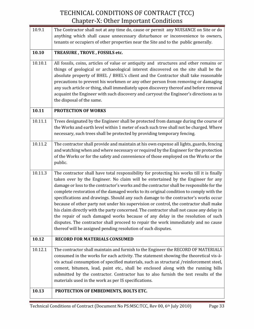
TECHNICAL CONDITIONS OF CONTRACT (TCC) Chapter-X: Other Important Conditions
Technical Conditions of Contract (Document No PS:MSC:TCC, Rev 00, 6th July 2010) Page 33
10.9.1 The Contractor shall not at any time do, cause or permit any NUISANCE on Site or do
anything which shall cause unnecessary disturbance or inconvenience to owners,
tenants or occupiers of other properties near the Site and to the public generally.
10.10 TREASURE , TROVE , FOSSILS etc.
10.10.1 All fossils, coins, articles of value or antiquity and structures and other remains or
things of geological or archaeological interest discovered on the site shall be the
absolute property of BHEL / BHEL's client and the Contractor shall take reasonable
precautions to prevent his workmen or any other person from removing or damaging
any such article or thing, shall immediately upon discovery thereof and before removal
acquaint the Engineer with such discovery and carryout the Engineer's directions as to
the disposal of the same.
10.11 PROTECTION OF WORKS
10.11.1 Trees designated by the Engineer shall be protected from damage during the course of
the Works and earth level within 1 meter of each such tree shall not be charged. Where
necessary, such trees shall be protected by providing temporary fencing.
10.11.2 The contractor shall provide and maintain at his own expense all lights, guards, fencing
and watching when and where necessary or required by the Engineer for the protection
of the Works or for the safety and convenience of those employed on the Works or the
public.
10.11.3 The contractor shall have total responsibility for protecting his works till it is finally
taken over by the Engineer. No claim will be entertained by the Engineer for any
damage or loss to the contractor's works and the contractor shall be responsible for the
complete restoration of the damaged works to its original condition to comply with the
specifications and drawings. Should any such damage to the contractor's works occur
because of other party not under his supervision or control, the contractor shall make
his claim directly with the party concerned. The contractor shall not cause any delay in
the repair of such damaged works because of any delay in the resolution of such
disputes. The contractor shall proceed to repair the work immediately and no cause
thereof will be assigned pending resolution of such disputes.
10.12 RECORD FOR MATERIALS CONSUMED
10.12.1 The contractor shall maintain and furnish to the Engineer the RECORD OF MATERIALS
consumed in the works for each activity. The statement showing the theoretical vis-à-
vis actual consumption of specified materials, such as structural /reinforcement steel,
cement, bitumen, lead, paint etc., shall be enclosed along with the running bills
submitted by the contractor. Contractor has to also furnish the test results of the
materials used in the work as per IS specifications.
10.13 PROTECTION OF EMBEDMENTS, BOLTS ETC.

TECHNICAL CONDITIONS OF CONTRACT (TCC) Chapter-X: Other Important Conditions
Technical Conditions of Contract (Document No PS:MSC:TCC, Rev 00, 6th July 2010) Page 34
10.13.1 The contractor shall ensure proper protection to the satisfaction of the Engineer, of all
bolts, inserts, embedment etc. from weather etc./ by greasing, rapping them with
gunny bags or canvas or by any other means as directed by Engineer. Cost of such
protections shall be deemed to be included in the rates quoted for the item.
10.14 COMPLETION OF WORK AND COMMENCEMENT OF GURANNTEE PERIOD
10.14.1 The works shall be completed to the entire satisfaction of the Engineer and in
accordance with the completion schedule as specified in the Contract, and all unused
stores and materials, tools, plant, equipment, temporary buildings, site office, labor
hutments and other things shall be removed and the site and work cleared of rubbish
and all waste materials and delivered up clean and tidy to the satisfaction of the
Engineer at the Contractor's expenses.
10.14.2 BHEL shall have power to take over from the Contractor from time to time such sections
of the work as have been completed to the satisfaction of the Engineer. Such work
however shall not be treated as have been completed until the extra / pending works
are executed to the satisfaction of Engineer.
10.14.3
The Engineer shall certify to the contractor the date on which the work is completed
and the date thereof for commencement of Guarantee Period. Guarantee Period shall
be as given in GCC.
10.15 CLEARANCE OF SITE AND REPAIRS.
10.15.1 Contractor has to clear the site / area where mechanical and electrical erection work is
to be commenced / or in progress. The contractor shall remove construction materials
and equipment lying in the vicinity and causing obstruction in the erection work within
24 hrs. notice. In case, he fails to clear the site, this will be done at his risk & cost by
BHEL.
10.16 QUALITY ASSURANCE
10.16.1 The contractor has to establish / arrange at site the field testing facilities for testing of
civil construction materials and concrete cubes for ensuring the proper quality, grade
and strength of the materials used in the construction in line with approved field
quality check list of BHEL/ its client. Contractor has to submit detailed report for testing
of all material used etc. All testing shall be done as per IS code specifications/ BHEL's
quality plan. If further test is required by the engineer to be carried from outside
laboratory, the cost of the same shall be borne by the contractor.
10.17 NA
10.18 METHOD OF MEASUREMENT
10.18.1 Method of measurements shall be as per standard specifications included in the tender.
For other items measurements shall be as per relevant IS Codes.
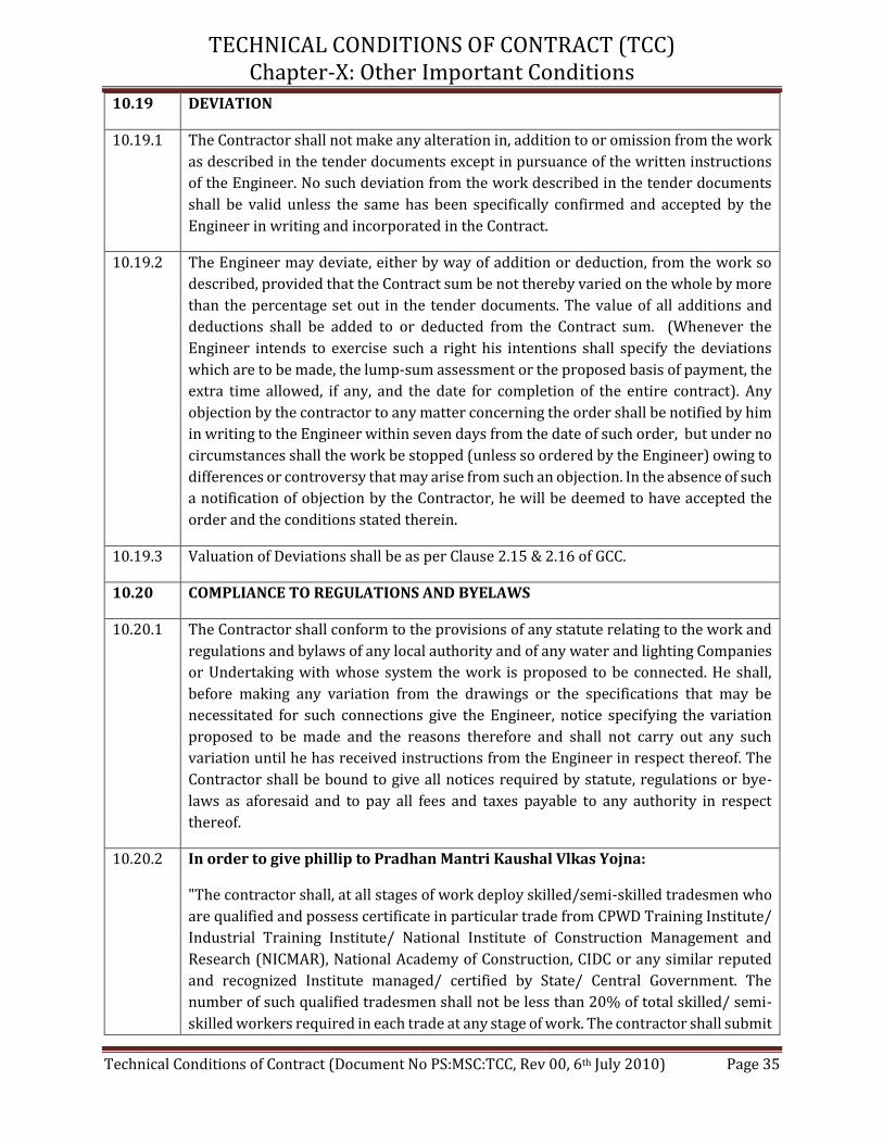
TECHNICAL CONDITIONS OF CONTRACT (TCC) Chapter-X: Other Important Conditions
Technical Conditions of Contract (Document No PS:MSC:TCC, Rev 00, 6th July 2010) Page 35
10.19 DEVIATION
10.19.1 The Contractor shall not make any alteration in, addition to or omission from the work
as described in the tender documents except in pursuance of the written instructions
of the Engineer. No such deviation from the work described in the tender documents
shall be valid unless the same has been specifically confirmed and accepted by the
Engineer in writing and incorporated in the Contract.
10.19.2 The Engineer may deviate, either by way of addition or deduction, from the work so
described, provided that the Contract sum be not thereby varied on the whole by more
than the percentage set out in the tender documents. The value of all additions and
deductions shall be added to or deducted from the Contract sum. (Whenever the
Engineer intends to exercise such a right his intentions shall specify the deviations
which are to be made, the lump-sum assessment or the proposed basis of payment, the
extra time allowed, if any, and the date for completion of the entire contract). Any
objection by the contractor to any matter concerning the order shall be notified by him
in writing to the Engineer within seven days from the date of such order, but under no
circumstances shall the work be stopped (unless so ordered by the Engineer) owing to
differences or controversy that may arise from such an objection. In the absence of such
a notification of objection by the Contractor, he will be deemed to have accepted the
order and the conditions stated therein.
10.19.3 Valuation of Deviations shall be as per Clause 2.15 & 2.16 of GCC.
10.20 COMPLIANCE TO REGULATIONS AND BYELAWS
10.20.1 The Contractor shall conform to the provisions of any statute relating to the work and
regulations and bylaws of any local authority and of any water and lighting Companies
or Undertaking with whose system the work is proposed to be connected. He shall,
before making any variation from the drawings or the specifications that may be
necessitated for such connections give the Engineer, notice specifying the variation
proposed to be made and the reasons therefore and shall not carry out any such
variation until he has received instructions from the Engineer in respect thereof. The
Contractor shall be bound to give all notices required by statute, regulations or bye-
laws as aforesaid and to pay all fees and taxes payable to any authority in respect
thereof.
10.20.2 In order to give phillip to Pradhan Mantri Kaushal Vlkas Yojna:
"The contractor shall, at all stages of work deploy skilled/semi-skilled tradesmen who
are qualified and possess certificate in particular trade from CPWD Training Institute/
Industrial Training Institute/ National Institute of Construction Management and
Research (NICMAR), National Academy of Construction, CIDC or any similar reputed
and recognized Institute managed/ certified by State/ Central Government. The
number of such qualified tradesmen shall not be less than 20% of total skilled/ semi-
skilled workers required in each trade at any stage of work. The contractor shall submit

TECHNICAL CONDITIONS OF CONTRACT (TCC) Chapter-X: Other Important Conditions
Technical Conditions of Contract (Document No PS:MSC:TCC, Rev 00, 6th July 2010) Page 36
number of man days required in respect of each trade, its scheduling and the list of
qualified tradesmen along with requisite certificate from recognized Institute to
Engineer-in-Charge for approval. Notwithstanding such approval, if the tradesmen are
found to have inadequate skill to execute the work of respective trade, the contractor
shall substitute such tradesmen within two days of written notice from Engineer-in-
Charge. Failure on the part of contractor to obtain approval of Engineer-in-Charge or
failure to deploy qualified tradesmen will attract a compensation to be paid by
contractor at the rate of Rs. 100 per such tradesman per day. Decision of Engineer-in-
Charge as to whether particular tradesman possesses requisite skill and amount of
compensation in case of default shall be final and binding.
10.21 PROGRESS REPORTING :
10.21.1 Contractor is required to draw mutually agreed monthly programme in consultation
with BHEL well in advance. Contractor shall ensure achievement of agreed programme
and shall also timely arrange additional resources considered necessary at no extra
cost to BHEL.
10.21.2 Weekly progress review meetings will be held at site during which actual progress
during the week vis-a-vis scheduled programme shall be discussed for actions to be
taken for achieving targets. The programme for subsequent week shall also be
presented by contractor for discussions. The contractor shall constantly update / revise
his work programme to meet the overall requirement. All quality problems shall be
discussed during above review meetings. Necessary preventive and corrective action,
shall be discussed and decided upon in such review meetings and shall be implemented
by the contractor in time bound manner so as to eliminate the cause of non-
conformities.
10.21.3 The contractor shall submit weekly and monthly progress reports, materials reports,
consumables (gases / electrodes) report and other reports as per proforma considered
necessary by the Engineer.
10.21.4 The progress report shall indicate the progress achieved against planned , with reasons
indicating delays , if any, and shall give the remedial actions which the contractor
intends to take to make good the slippage or lost time , so that further works again
proceed as per the original programme and the slippages do not accumulate and effect
the overall programme.
10.21.5 The daily manpower reports shall clearly indicate the manpower deployed, category
wise specifying also the activities in which they are engaged.
10.22 DRAWING AND DOCUMENTS
10.22.1 The detailed drawings, specifications available with BHEL engineers will form part of
this tender specification. These documents will be made available to the contractor

TECHNICAL CONDITIONS OF CONTRACT (TCC) Chapter-X: Other Important Conditions
Technical Conditions of Contract (Document No PS:MSC:TCC, Rev 00, 6th July 2010) Page 37
during execution of work at site. The contractor will also ensure availability of all
drawings / documents at work place.
10.22.2 Necessary drawings / documents by BHEL to carry out the construction work will be
furnished to the contractor by BHEL (except those proposed to be prepared by
contractor, as mentioned in this contract) on loan which shall be returned to BHEL
Engineer at site after completion of work. Contractor shall ensure safe storage and
quick retrieval of these documents.
10.22.3 The contractor shall maintain a record of all drawings and documents available with
him in a register as per format given by BHEL Engineer. Contractor shall ensure use of
pertinent drawings / data / documents and removal of obsolete ones from work place
and return to BHEL.
10.22.4 The data furnished in various annexures enclosed with this tender specification are
only approximate and for guidance. However, the change in the design and in the
quantity may occur as is usual in any such large scale of work.
10.22.5 Should any error or ambiguity be discovered in the specification or information the
contractor shall forthwith bring the same to the notice of BHEL before commencement
of work. BHEL's interpretation in such cases shall be final and binding on the
contractor.
10.22.6 Deviation from design dimensions should not exceed permissible limit. The contractor
shall not correct or alter any dimension / details, without specific approval of BHEL.
10.23 MODIFICATION/ DELETION OF GCC & SCC CLAUSES:
A. GCC Clauses:
i. Clause No. 2.12 of GCC (ORC) shall not be applicable.
ii. Clause No. 2.14.1: of GCC is modified as (The quantities given in the
contract are tentative and may change to any extent (both in plus side
and minus side). The quoted rates for individual items shall remain firm
irrespective of any variations in the individual quantities. No
compensation becomes payable in case the variation of the final executed
contract value is within the limits of Minus (-) 20% of awarded contract value)
B. SCC Clauses:
i. Clause No. 4.1.2, 4.1.4, 4.1.9 & 4.1.10 of SCC (Consumables & Other
Items) shall not be applicable.
ii. Clause No. 8.3.2, 8.3.3 and 8.3.4 of SCC (Statutory Inspection of Work)
shall not be applicable.

TECHNICAL CONDITIONS OF CONTRACT (TCC) Chapter-XI: Annexures
Technical Conditions of Contract (Document No PS:MSC:TCC, Rev 00, 6th July 2010) Page 38
Annexure – ‘’A’’: Price Schedule for the Work of “Boundary wall, associated roads inside and outside
Boundary wall, Drain along Boundary wall, Gate Complex, Gate Structures, Watch Towers, Weigh
Bridge, Customer’s Site Office and construction of Coal Stock Piles at 1 X 660 MW PANKI THERMAL
POWER PLANT, PANKI U.P.”
Annexure – ‘’I’’: BOQ cum Rate Schedule for the Work of “Boundary wall, associated roads inside
and outside Boundary wall, Drain along Boundary wall, Gate Complex, Gate Structures, Watch
Towers, Weigh Bridge, Customer’s Site Office and construction of Coal Stock Piles at 1 X 660 MW
PANKI THERMAL POWER PLANT, PANKI U.P.”

Annexure - "A''
Sl.
No.
TOTAL PRICE ("A") IN
RUPEES (IN FIGURES AND
WORDS)
TENDER NO. BHEL/NR/SCT/PANKI/BOUNDARY WALL/1110
Job -: “BOUNDARY WALL, ASSOCIATED ROADS INSIDE AND OUTSIDE BOUNDARY WALL,
DRAIN ALONG BOUNDARY WALL, GATE COMPLEX, GATE STRUCTURES, WATCH TOWERS,
WEIGH BRIDGE, CUSTOMER’S SITE OFFICE AND CONSTRUCTION OF COAL STOCK PILES AT
1 X 660 MW PANKI THERMAL POWER PLANT, PANKI, U.P."
• The rates of different items for the entire scope of work shall be as per BOQ Cum Rate
schedule (“Annexure-I”) of TCC of tender.
In Figures:______________
____________________
In Words:_____________
__________________________
__________________________
_________________
PRICE SCHEDULE
TOTAL PRICE ("A") FOR THE TOTAL WORK AS PER
TENDER SPECIFICATION FOR “BOUNDARY WALL,
ASSOCIATED ROADS INSIDE AND OUTSIDE
BOUNDARY WALL, DRAIN ALONG BOUNDARY
WALL, GATE COMPLEX, GATE STRUCTURES,
WATCH TOWERS, WEIGH BRIDGE, CUSTOMER’S
SITE OFFICE AND CONSTRUCTION OF COAL
STOCK PILES AT 1 X 660 MW PANKI THERMAL
POWER PLANT, PANKI, U.P."
DESCRIPTION OF WORK
1.0
Notes:-

ST.
NO.DESCRIPTION OF ITEM UNIT Total Quantity Factor (F)
RATE (Rs.) =
FACTOR (F) * A / 100000
(Rounded off to two place
after decimal)
AMOUNT (Rs.) =
RATE *QUANTITY
100 EARTH WORK
Earth work: Earth work in excavation, backfilling and disposal including
necessary men/women, materials, equipment, loading, transportation,
unloading, dewatering etc as per specification, drawing and as directed by
engineer- in-charge for the following:
101
Earth work in excavation in all types of soil including ash which can be
excavated by any means including setting out, levelling, dewatering (but excluding
special type of dewatering viz. well point method), shoring & strutting (wherever
required), dressing the sides & bottom, all lifts, ramming/compacting the excavated
bottom, stacking, disposal of surplus excavated materials within a lead upto 1Km,
spreading/levelling of disposed materials etc all complete for following depths
below ground level.
a Depth from ground level but not exceeding 2 m CUM 51635 0.0324 - -
b Depth exceeding 2 m but not exceeding 4 m CUM 25849 0.0404 - -
c Depth exceeding 4 m but not exceeding 6 m CUM 1535 0.0510 - -
d Depth exceeding 6 m but not exceeding 8 m CUM 50 0.0632 - -
107
Earthwork in Back filling upto any depth below ground level around foundations,
plinths, trenches, drains etc to proper grade and level in layers not exceeding 250
mm thickness using/with selected approved materials from compulsorily
excavated earth available within a lead upto 1 Km and compacted as specified
including re-excavation of stacked earth, sorting, spreading, watering,
ramming/compaction by manual/mechanical means, dressing etc all complete as
per specification, drawing and as directed by the engineer incharge for the
following.
- - -
aEach layer compacted so as to achieve at least 90% maximum dry density as per
IS-2720 (Part-VII)CUM 1384 0.0239 - -
bEach layer compacted so as to achieve at least 95% maximum dry density as per
IS-2720 (Part-VII)CUM 36741 0.0266 - -
108
Earthwork in Back filling upto any depth below ground level around foundations,
plinths, trenches, drains etc to proper grade and level in layers not exceeding 250
mm thickness using/with selected approved materials directly from excavation
within a lead upto 1Km and compacted as specified including re-excavation of
stacked earth, sorting, spreading, watering, ramming/compaction by
manual/mechanical means, dressing etc all complete as per specification, drawing
and as directed by the engineer incharge for the following
- - -
aEach layer compacted so as to achieve at least 90% maximum dry density as per
IS-2720 (Part-VII)CUM 2649 0.0081 - -
bEach layer compacted so as to achieve at least 95% maximum dry density as per
IS-2720 (Part-VII)CUM 15016 0.0092 - -
109Extra over ST No. 101 and 103 to 108 for carriage of material/earth for every
500m or part thereof beyond an initial lead of 1km.CUM 62615 0.0027 - -
110
Earth work in backfilling upto any depth below ground level around foundations,
plinths, trenches, drains etc to proper grade and level in layers not exceeding 250
mm thickness so as to achieve required compaction with approved borrowed soil
(borrowed soil to be arranged by the bidder) and compacted as specified including
supplying borrowed soil, royalty/seignorage fee (if any), sorting, spreading,
breaking clods, watering, ramming/compaction by manual/mechanical means,
dressing, finishing to required lines, grades and slopes, testing, all lead and lifts
etc all complete as per specification, drawing and as directed by the engineer for
the following:
- - -
aEach layer compacted so as to achieve at least 95% maximum dry density as per
IS-2720 (Part-VII)CUM 459 0.1373 - -
bEach layer compacted so as to achieve at least 90% maximum dry density as per
IS-2720 (Part-VII)CUM 1600 0.1194 - -
111
Supplying and filling sand upto any depth under floors, around foundations,
plinths etc. in layers not exceeding 250 mm thickness and compacted so as to
achieve at least 80% relative density as per IS-2720 (Part-XIV) including
spreading, watering, ramming/compaction by manual / mechanical means,
dressing, royalty (if any) etc. all complete.
CUM 2375 0.8077 - -
200 CONCRETE WORKS - - -
BOQ CUM RATE SCHEDULE- BOUNDARY WALL, PERIFERAL ROADS, DRAINS AND GATE COMPLEX PANKI
ANNEXURE - I
SCOPE OF WORK: Boundary wall, associated roads inside and outside Boundary wall, Drain along Boundary wall, Gate Complex, Gate Structures, Watch
Towers, Weigh Bridge, Customer’s Site Office and construction of Coal Stock Piles at 1X660 MW PANKI THERMAL POWER PLANT, PANKI U.P.
Project : 1X660 MW Panki thermal Power Plant, Panki U.P.
Page 1 of 18

ST.
NO.DESCRIPTION OF ITEM UNIT Total Quantity Factor (F)
RATE (Rs.) =
FACTOR (F) * A / 100000
(Rounded off to two place
after decimal)
AMOUNT (Rs.) =
RATE *QUANTITY
BOQ CUM RATE SCHEDULE- BOUNDARY WALL, PERIFERAL ROADS, DRAINS AND GATE COMPLEX PANKI
ANNEXURE - I
SCOPE OF WORK: Boundary wall, associated roads inside and outside Boundary wall, Drain along Boundary wall, Gate Complex, Gate Structures, Watch
Towers, Weigh Bridge, Customer’s Site Office and construction of Coal Stock Piles at 1X660 MW PANKI THERMAL POWER PLANT, PANKI U.P.
Project : 1X660 MW Panki thermal Power Plant, Panki U.P.
CONCRETE WORK: Providing and placing concrete work including cost of
labour, materials (unless otherwise specified in BOQ/contract specification)
and equipment for handling, transportation, batching, mixing, placing,
vibrating and curing (excluding cost of centering, shuttering and
reinforcement) with mechanised equipments like batching plant, transit
mixer, concrete pump etc. complete as per drawing, specifications and as
per direction of engineer in charge for the following:
Note: Cement will be supplied by BHEL and issued as FOC (free of Cost)
item
- - -
201
Concrete of grade M7.5 (1 part cement, 4 part sand, 8 parts of 40 mm graded
aggregate by volume) as mass filling course, lean concrete, levelling course, mud
mat under and around foundations/ floors, at any depth below finished floor level
etc.
CUM 1661 1.2738 - -
202
Concrete of grade M10 (1 part cement, 3 part sand, 6 parts of 40 mm graded
aggregate by volume) as lean concrete, levelling course, mud mat under and
around foundations/floors at any depth below finished floor level etc.
CUM 1425 1.2738 - -
203
Concrete of grade M15 (1 part cement, 2 part sand, 4 parts of 40 mm graded
aggregate by volume) as lean concrete, levelling course, mud mat under and
around foundations/floors at any depth below finished floor level etc.
CUM 36 1.2738 - -
204
Concrete of grade M20 (1 part cement, 1.5 part sand, 3 parts of 20 mm graded
aggregate by volume) under floors, paving, plinth protection, pipe encasing etc
complete.
CUM 4056 1.2753 - -
205
Providing and laying Design Mix cement concrete conforming to IS:456 & IS
10262-2009 for reinforced concrete works with coarse sand and graded hard
stone aggregate of 20mm nominal size in foundations/substructure, grade slab,
paving, drains, under floors etc at all level below finished floor level, any shape,
position or thickness etc complete including use of plasticizer/ superplasticizer
conforming to IS:9103 (latest) to achieve required slump in concrete all complete
as per specification & drawing for the following.
- - -
a M 25 Grade CUM 100 1.4175 - -
b M 30 Grade CUM 7460 1.4267 - -
206
Providing and laying Design Mix cement concrete of grade conforming to IS:456
& IS 10262-2009 for reinforced concrete works with coarse sand and graded
hard stone aggregate of 20mm nominal size in superstructure at all level above
finished floor level, any shape, position or thickness etc complete including use
of plasticizer/ superplasticizer conforming to IS:9103 (latest) to achieve required
slump in concrete all complete as per specification & drawing for the following.
- - -
a M25 Grade CUM 100 1.4321 - -
b M 30 Grade CUM 2368 1.4414 - -
212
Screed concrete conforming to IS 456 with coarse sand and graded hard stone
aggregate 12.5mm/6 mm nominal size on the roof at any level or thickness, drains
etc complete as per following.
- - -
a 1:2:4 (1 part cement, 2 part sand, 4 parts of aggregate by volume) CUM 50 1.2738 - -
A213
Providing and laying Design Mix cement concrete as per IS:456 & IS 10262-
2009 for reinforced concrete works using graded aggregate for Concrete in
precast works like roof slabs/trench covers, fins, lintels, chajas, beams,
columns, wall panels, facias, decorative copings etc.at all levels in all kinds of
work including formwork/moulds, curing, rendering the top exposed surface with
cement sand mortar (1:3), handling, storing, transpoting, all leads, erection without
damage, setting in position with cement sand mortar (1:3), filling the gaps between
adjacent preacast units with M30 grade concrete or cement sand mortar (1:3) and
including making of holes for bolts for fixing, welding etc.complete with graded
aggregate (20/12.5/10 mm) and as per specification and drawing for following
grades.
- - -
a M 25 grade CUM 69 1.9055 - -
b M 30 grade CUM 66 1.9148 - -
214
Providing and laying Design Mix cement concrete as per IS:456, IS 3370 & IS
10262-2009 for reinforced concrete works using graded aggregate for Concrete in
water retaining/conveying structures including addition of suitable plastisizer
cum waterproofing cement additives confirming to IS 9103 latest to achieve a
slump more than 125 mm in concrete as per manufacturers recommendation and
conforming to limits of permeability as per IS 2545 and specification with 20 mm
nominal size graded aggregate for following grades. Watertightness is to be
ensured including structural grouting if required.
- - -
Page 2 of 18

ST.
NO.DESCRIPTION OF ITEM UNIT Total Quantity Factor (F)
RATE (Rs.) =
FACTOR (F) * A / 100000
(Rounded off to two place
after decimal)
AMOUNT (Rs.) =
RATE *QUANTITY
BOQ CUM RATE SCHEDULE- BOUNDARY WALL, PERIFERAL ROADS, DRAINS AND GATE COMPLEX PANKI
ANNEXURE - I
SCOPE OF WORK: Boundary wall, associated roads inside and outside Boundary wall, Drain along Boundary wall, Gate Complex, Gate Structures, Watch
Towers, Weigh Bridge, Customer’s Site Office and construction of Coal Stock Piles at 1X660 MW PANKI THERMAL POWER PLANT, PANKI U.P.
Project : 1X660 MW Panki thermal Power Plant, Panki U.P.
b M 30 grade CUM 50 1.8782 - -
215
Dismantling concrete work for all types of structures at all levels including
stacking of servicable material to a lead of 500 m and disposal of unservicable
material upto a lead of 2 km, cutting of reinforcement, labour, equipment, safety
precautions etc all complete as per drawings, specification and instructions of
engineer in charge.
- - -
a Plain cement concrete of all grades CUM 4 0.2573 - -
b Reinforced cement concrete of all grades CUM 6 0.3459 - -
216
Chipping of concrete in reinforced concrete work, cutting pockets, making
openings at all levels and according to shapes, disposal of waste materials upto a
lead of 2 km as directed by engineer including equipment, safety precautions,
making good the broken surface etc all complete as per specification, drawing,
instructions of engineer in charge but excluding cutting of reinforcement .
CUDM 64 0.0119 - -
217
Extra over and above St No 216 for cutting of reinforcement, all sizes and types
including labour, equipment, return of cut reinforcement to store etc all complete
as per specification, drawings and instructions of engineer in charge.
Measurement shall be on the cross sectional area of reinforcement cut.
SQCM 36 0.0012 - -
218
Cutting Reinforced concrete with mechanised tools like Core drilling machine
etc. for cutting pockets, holes, cores in slab, beam, column or foundation as per
direction of engineer in charge.
CUDM 15 0.0612 - -
219Providing and applying curing compound (water based) of approved make
where ever required as per manufacturer's specification.SQM 185 0.0269 - -
220Providing & laying Plum cement concrete 1:3:6 with75% graded metal of
maximum size 40 mm and 25%plums of maximum size 150 mm.CUM 10 1.2673 - -
300 FORM WORKS - - -
FORMWORK: Providing, fixing and removing formwork at all elevations
for all structures, as per specifications and including all labour, material,
scaffoldings and centereing etc. complete as per drawing, specifications
and as per direction of engineer in charge for the following:
- - -
301
Fairface form work with good quality water proof ply wood of minimum 12mm
thickness and smooth surface below finished ground floor level for
foundations, footings, base of columns, walls, columns, pilasters, beams, mass
concrete, trenches etc.including chamfering of edges as per drawing,
specification and instruction of engineer in charge..
SQM 42387 0.1275 - -
302
Fairface form work with good quality water proof ply wood of minimum 12mm
thickness and smooth surface above finished ground floor level for columns,
beams, suspended floors, roofs, lintels, cantilevers, staircases, landings,
balconies, etc. including chamfering of edges as per drawing.for all heights as per
specification, drawing and instruction of engineer in charge.
SQM 20729 0.1529 - -
304
Providing, fixing and removing formwork in block-outs/pockets and openings
(below 0.1 sqm plan area) at all elevations including cutting, formation of all
shapes and all other operations required for making the required shape and size
all complete as per specification, drawing and instruction of engineer in charge.
- - -
a Upto 150 mm depth EACH 85 0.0666 - -
b Pockets of depths more than 150mm and upto 300 mm depth EACH 65 0.1206 - -
c Pockets of depths more than 300mm and upto 600 mm depth EACH 10 0.2269 - -
d Pockets of depths more than 600mm and upto 1000 mm depth EACH 5 0.3659 - -
305Extra over item no.301 and 302 for curved form work for foundations, footings,
beams, walls, trenches, domes, arches etc as per specification.- - -
a Extra for Curve Shuttering for Item No. 301 SQM 1802 0.0254 - -
b Extra for Curve Shuttering for Item No. 302 SQM 884 0.0304 - -
400 REINFORCEMENT 0 - - -
REINFORCEMENT WORK : Reinforcement work including all labour, material
(unless otherwise specified in BOQ/contract specification), equipment,
transportation, handling etc at all level as per specification, drawings and as
directed by engineer - in - charge for the following:.
- - -
401
Providing, straightening, cutting, bending, placing in position at all level, binding of
mild steel reinforcements conforming to grade 1 of IS:432 part 1 in concrete
including cost of reinforcement steel, binding wire, labour, scaffolding,
transportation to & from stores etc. all complete as per specifications & drawings.
MT 3 23.9477 - -
403
Transportation, straightening, cutting, bending, placing in position at all level,
binding in position of steel reinforcements of TMT steel of grade Fe-500D or
500EQR confirming to IS:1786 including cost of binding wire, labour, scaffolding,
transportation to & from stores etc complete all as per specifications, drawings and
as directed by Engineer. (BHEL to supply steel free of cost)
MT 165 2.5653 - -
Page 3 of 18

ST.
NO.DESCRIPTION OF ITEM UNIT Total Quantity Factor (F)
RATE (Rs.) =
FACTOR (F) * A / 100000
(Rounded off to two place
after decimal)
AMOUNT (Rs.) =
RATE *QUANTITY
BOQ CUM RATE SCHEDULE- BOUNDARY WALL, PERIFERAL ROADS, DRAINS AND GATE COMPLEX PANKI
ANNEXURE - I
SCOPE OF WORK: Boundary wall, associated roads inside and outside Boundary wall, Drain along Boundary wall, Gate Complex, Gate Structures, Watch
Towers, Weigh Bridge, Customer’s Site Office and construction of Coal Stock Piles at 1X660 MW PANKI THERMAL POWER PLANT, PANKI U.P.
Project : 1X660 MW Panki thermal Power Plant, Panki U.P.
A403
Transportation, straightening, cutting, bending, placing in position at all level,
binding in position of steel reinforcements of TMT steel of grade Fe-500
confirming to IS:1786 including cost of binding wire, labour, scaffolding,
transportation to & from stores etc complete all as per specifications, drawings and
as directed by Engineer. (BHEL to supply steel free of cost)
MT 842 2.5653 - -
405
Providing & fixing of Rebar in existing concrete surface by inserting
reinforcemnet bar with Epoxy based suitable bonding compound of Hilti or
equivalent make (HIT-RE-500 of Hilti or equivalent make) for interconnection of
new R.C. structure with existing R.C. structure. Depth of drilled hole should be
suitable to develop maximum recommended strength as per approved
manufacturer's recommendation. This item includes supply of all materials
including bonding chemicals, T&P required to execute the work, cost of all labour,
transportation of chemical, staging to reach work place etc. all complete as
directed by Engineer - in - Charge. Random Pull out non destructive test as
directed by engineer shall be conducted to ensure strength of bond and same is
included in this item. Reinforcement bar shall be paid separately under item no.
402, 403, 405 as applicable.
- - -
a 12mm Reinforcement bar EACH 23 0.1136 - -
b 16mm Reinforcement bar EACH 23 0.1799 - -
c 20mm Reinforcement bar EACH 20 0.2550 - -
500 WATER PROOOFING WORKS - - -
Roof Treatment works: Roof treatment works including all labour, material
(unless otherwise specified in BOQ/contract specification), equipment,
transportation, handling, curing, sampling, testing etc at all level as per
specification, drawings and as directed by engineer - in - charge for the
following:
Note: Cement will be supplied by BHEL and issued as FOC (free of Cost)
item
- - -
501
Providing and laying underbed grading plaster with cement mortar 1:4 (1 cement
: 4 sand) and average thickness of 25 mm including preparation of surface,
batching, mixing, leveling etc. all complete.
SQM 450 0.0385 - -
A502
Providing and laying underbed P.C.C layer of grade M15 with 10 mm nominal
size coarse aggregates and average thickness of 50 mm including preparation of
surface, batching, mixing, leveling etc. all complete.
SQM 1000 0.0847 - -
506
Providing and applying PU based water proofing treatment with one coat of
polyurethane or any other equivalent material based primer with an application
rate of minimum 6 sq.m per litre and two successive liquid coatings of high solids
content urethane pre-polymers or equivalent material based finish coats as per
relevant IS/ASTM standards to form an elastomeric membrane with overall dry film
thickness 1.5 mm subject to minimum 500 gm/sqm/coat application rate. Item
includes surface preparation, polyscrim cloth /fabric, polymerised mortar base
preparation, etc all complete as per specifications and directions of engineer in
charge.
SQM 950 0.2508 - -
507
Providing and laying wearing course consisting of 25mm thick plain cement
concrete of grade M15 (1:2:4) with graded aggregate of 12.5mm size cast in
panels of maximum size 1.2mx1.2m and reinforced with 0.56 mm dia. galvanised
chicken wire mesh and sealing of joints (in grooves of 6mm X 6mm) using silicon
/elastomeric compound etc all complete.
SQM 500 0.1113 - -
509
Providing and laying wearing course consisting of 25mm thick plain cement
concrete of grade M20 (1:1.5:3) with graded aggregate of 12.5mm size cast in
panels of maximum size 1.5mx1.5m and reinforced with 0.56 mm dia. galvanised
chicken wire mesh and sealing of joints (in grooves of 6mm X 6mm) using silicon
/elastomeric compound etc all complete.
SQM 450 0.1113 - -
510
Providing and laying cement concrete chequered flooring tiles of 22 mm
thickness and size 300x300 mm conforming to IS 13801 with 8 mm thick 1:4
cement mortar over the top most layer of roofing treatment in pathway or entire
area with fine joints including sealing of joints (silicon/elastomeric sealant) and
providing expansion gap in both directions including underbeds (as per drawing)
filled up with (silicon/elastomeric) joint sealant, etc all complete. (Water proofing
paid elsewhere)
SQM 140 0.1660 - -
511
Providing and applying two coats of bitumen grade 85/25 as per IS 702 ( @
1.7kg/sqm)with 1% antistripping compound conforming to IS 6241 in foundation,
wall, column etc on concrete surfaces exposed to soil / ash including surface
preparation etc. all complete.
SQM 43502 0.0401 - -
600 JOINTS AND FILLERS: - - -
Joints & fillers including all labour, material, equipment, transportation,
handling etc at all level as per specification, drawings and as directed by
engineer - in - charge.
- - -
601
Supplying & installation of bitumen impregnated fibre board confirming to IS
1838 as joint filler at joints in concrete including nailing, coating of both faces with
coal tar pitch/bitumin etc. all complete.
- - - Page 4 of 18

ST.
NO.DESCRIPTION OF ITEM UNIT Total Quantity Factor (F)
RATE (Rs.) =
FACTOR (F) * A / 100000
(Rounded off to two place
after decimal)
AMOUNT (Rs.) =
RATE *QUANTITY
BOQ CUM RATE SCHEDULE- BOUNDARY WALL, PERIFERAL ROADS, DRAINS AND GATE COMPLEX PANKI
ANNEXURE - I
SCOPE OF WORK: Boundary wall, associated roads inside and outside Boundary wall, Drain along Boundary wall, Gate Complex, Gate Structures, Watch
Towers, Weigh Bridge, Customer’s Site Office and construction of Coal Stock Piles at 1X660 MW PANKI THERMAL POWER PLANT, PANKI U.P.
Project : 1X660 MW Panki thermal Power Plant, Panki U.P.
a 12 mm wide joints. SQM 2024 0.1521 - -
b 20 mm wide joints. SQM 24 0.2427 - -
c 25 mm wide joints SQM 69 0.2993 - -
d 50 mm wide joints SQM 19 0.5812 - -
602
Supplying and installation of Dura board HD100 or its equivalent as approved by
the Engineer, as filler material in joints including nailing, installation as per
manufacturer's recommendation etc. all complete.
- - -
a 12 mm wide joints. SQM 120 0.1884 - -
b 20 mm wide joints. SQM 20 0.3028 - -
c 25 mm wide joints SQM 55 0.3744 - -
d 50 mm wide joints SQM 5 0.7322 - -
603
Providing and applying polysulphide based sealant conforming to IS:12118 in
joints in concrete including cleaning of joints, raking out groove, application of
primer, scaffolding etc. all complete for following size grooves:
- - -
a 25mmX25mm RM 5 0.2041 - -
b 50mmX25mm RM 5 0.3971 - -
610Providing and fixing PVC water stops in joints conforming to IS 12200 & IS
15058 all complete for the following: (Bulb or Kicker type)- - -
a 150 mm wide and 8 mm thick RM 44 0.1086 - -
b 230 mm wide and 8 mm thick RM 44 0.0820 - -
c 150 mm wide and 6 mm thick RM 25 0.0820 - -
d 230 mm wide and 6 mm thick RM 48 0.1248 - -
700 MS EMBEDMENTS - - -
Embedments including all labour, material (unless otherwise specified in
BOQ/contract specification), equipment, transportation, handling etc. at all level as
per specification, drawings and as directed by engineer - in - charge.
- - -
703
Same as above items 701 & 702 with BHEL supplied material free of cost
including loading, transportation, unloading etc. all complete from BHEL store to
plant site.
- - -
aMild steel embedments, inserts, pipe sleeves, angle pieces, rungs of various
diameters, plates of dimensions as required etc.MT 6 4.9311 - -
b
Mild steel foundation bolt assembly conforming to IS:2062 and grade 1 of IS:432
in concrete along with nuts, lock nuts (as per IS:1363, 1364 and IS:3138),
washers, anchor plates, stiffner plates, protective tape, pipe sleeves, templates
etc.
MT 2 4.3410 - -
704
Supplying, fabricating, erecting and installing following items in
concrete/brickwall for all kind of works, including setting material in concrete,
layout, scaffoling, cutting, forming, grinding, drilling, bolting, welding, jointing,
testing etc. all complete.
- - -
a MS pipes of all diameters Kg 350 0.0223 - -
b PVC pipes / conduits of all diameters Kg 350 0.1198 - -
c UPVC pipes / conduits of all diameters Kg 200 0.1252 - -
d
Expansion anchor fasteners (galvanised) of HILTI make(HUD-1 Universal
Fastners) or equivalent of safe tensile capacity as specified below for brick work
with expansion sleeve of A6 polyamide:
- - -
i 8mm Dia EACH 10 0.0150 - -
ii 10mm Dia EACH 21 0.0185 - -
iii 12mm Dia EACH 21 0.0212 - -
iv 14mm Dia EACH 14 0.0289 - -
e
Expansion fasteners (mechanical galvanised) of HILTI make or equivalent of
safe tensile capacity as specified below for concrete work with expansion sleeve
of stainless steel:
- - -
i HST M8 EACH 10 0.0377 - -
ii HST M10 EACH 16 0.0535 - -
iii HST M12 EACH 23 0.0790 - -
iv HST M16 EACH 15 0.1537 - -
v HST M20 EACH 14 0.2997 - -
f
Chemical Epoxy fasteners (galvanised)of HILTI make or equivalent of safe
tensile capacity as specified below for concrete work with anchoring
rod,nuts,washers,chemicals all complete,etc:
- - -
i HAS-E5.8 M8 EACH 10 0.0847 - -
ii HAS-E5.8 M10 EACH 10 0.1048 - -
iii HAS-E5.8 M12 EACH 10 0.1348 - -
iv HAS-E5.8 M16 EACH 10 0.2045 - -
800 GROUTING: - - -
Grouting including all labour, material (unless otherwise specified in BOQ/contract
specification), equipment, roughening surface, cleaning, ramming, curing etc. at all
level , drawings and as directed by engineer - in - charge.
- - -
Page 5 of 18

ST.
NO.DESCRIPTION OF ITEM UNIT Total Quantity Factor (F)
RATE (Rs.) =
FACTOR (F) * A / 100000
(Rounded off to two place
after decimal)
AMOUNT (Rs.) =
RATE *QUANTITY
BOQ CUM RATE SCHEDULE- BOUNDARY WALL, PERIFERAL ROADS, DRAINS AND GATE COMPLEX PANKI
ANNEXURE - I
SCOPE OF WORK: Boundary wall, associated roads inside and outside Boundary wall, Drain along Boundary wall, Gate Complex, Gate Structures, Watch
Towers, Weigh Bridge, Customer’s Site Office and construction of Coal Stock Piles at 1X660 MW PANKI THERMAL POWER PLANT, PANKI U.P.
Project : 1X660 MW Panki thermal Power Plant, Panki U.P.
804
Providing & grouting of pocket holes, pipe sleeves and under base plates of
structural steel work/ machinery/ pipe supporting structures including roughening
of surface, cleaning, ramming, curing etc. all complete with ConbextraGP-1 or
equivalent as per specification, drawing and direction of engineer-in-charge. (Cost
of all material and cleaning of the pockets by compressed air shall be in the scope
of the contractor).
CUM 2 15.0969 - -
805
Providing & grouting of pocket holes, pipe sleeves and under base plates of
structural steel work/ machinery/ pipe supporting structures including roughening
of surface, cleaning, ramming, curing, etc. all complete with Conbextra GP-2 or
equivalent as per specification, drawing and direction of engineer-in-charge.(Cost
of all material and cleaning of the pockets by compressed air shall be in the scope
of the contractor).
CUM 5 26.2330 - -
806
Providing Chemical (epoxy) injection grouting with pressure pump for water
retaining concrete structures conforming to IS:6494, including fixing nozzles,
cost of approved chemical, admixture, curing etc. all complete . Payment shall be
made as per the consumption of chemical grout.
Kg 58 0.5539 - -
900 DOORS, WINDOWS, VENTILATORS, LOUVERS - - -
DOORS & WINDOWS: Doors, windows, ventilators, louvers, roof ventilators,
rolling shutters, partitions including all labour, material (unless otherwise
specified in BOQ/contract specification), equipments, transportation,
handling, preparation of working drawings etc. at all level as per
specification, drawings and as directed by engineer - in - charge for the
following:
- - -
901
Providing and fixing wooden frame conforming to IS 4021 made of best quality
seasoned CP teakwood free from large or loose knots, cracks or other defects
including sand paper smoothening, hold fasts, beading, primer and finish painting /
polishing etc. all complete with proper wood joinery, accurately set to required
lines or levels and rigidly secured in place. (Finish painting / polishing paid
separately)
CUM 1 41.6339 - -
904
Providing and fixing single or double steel door shutters with 45mm thk flush
design shutter comprising of two outer sheets of 18 gauge steel sheets rigidly
connected and reinforced inside with continuous vertical 20 gauge stiffeners,
spot welded in position at not more than 150mm on centres including void filled
with mineral wool (density as per specification), all fittings, Godrej or equivalent
make mortice lock with handle on both sides, shop and final painting etc all
complete.
SQM 57 1.6236 - -
906
Providing and fixing anodized extruded aluminium doors (single or double
shutter) conforming to IS:1948, IS:1949 fabricated from extruded sections of
HINDALCO/JINDAL or equivalent make having minimum 3mm wall thickness as
per IS:1285, IS:733 and anodized and electro color coating of required shade as
per IS 1868 ( minimum anodized coating of grade AC15 ). fixed with rawl plugs,
expansion fasteners,SS screws / fixing clips necessary filling of gaps at Junctions,
at top, bottom & sides with required PVC / neoprene felt for bi-metallic protection
etc. Glazing shall be clear float glass of 6mm thickness including snap fit type
beading, concealed screws, fixtures, Godrej or equivalent make Mortice lock with
handle on both sides, etc all complete. Aluminium section shall be smooth, free of
stains, straight, mitred & jointed mechanically wherever required. (Glazing shall be
paid separately)
SQM 200 0.1599 - -
907
Providing and fixing fire proof steel doors (single or double shutter) with
panic devices shall be 45mm thk flush design comprising of two outer sheets of
18 gauge steel sheets rigidly connected and reinforced inside with continuous
vertical 20 gauge stiffeners, spot welded in position at not more than 150mm
on centers including all fittings, shop painting with approved post office/signal red
color fire resistant paint and mineral wool insulation (64 kg/cum density) complete
and shall be fire proof as per IS:3614, TAC requirements and as per
specification. Minimum ratings shall be 2 Hrs.
SQM 10 2.4983 - -
908
Providing and fixing steel windows/ventilator with steel sections as per
IS:1038, IS:1361 & IS:7452 latest revision including all fittings, metal beadings,
hold fasts, shop and final painting ,glazing etc. all complete. (Glazing shall be paid
separately)
0 - - -
a Openable type SQM 90 0.6436 - -
b fixed type SQM 90 0.4249 - -
A908
Providing and fixing M.S. grills in windows/ventilator as per approved design for
security purpose made of 25 mm X 6mm M.S. Flats / 12mm – 20mm M.S. square
bar of approved design shall be provided to suit security requirements.Kg 325 0.0277 - -
2675 0.1356 - -
KgA909
Providing and fixing anodised aluminium work of Jindal, Hindalco or other
equivalent approved make for door frames, windows, ventillators, partitions,
railing, grills etc with extruded standard tubular and other sections including all
fittings & fixtures and accessories of approved make conforming to IS733 and
IS1285, anodised and electro color dyed to required shade according to IS 1868
(minimum anodic coating of grade AC15), fixed with rawl plugs, expansion
fasteners, SS screws or with fixing clips, including necessary filling of gaps at
junctions, at top, bottom and sides with required PVC/neoprene felt for bi-metalic
protection etc. including preperation of working drawings, aluminium cleat angle,
aluminium snap-on-beading for glazing/panelling, stair case tread nosing, with all
fittings and fixtures (like tower bolts, handles, door stopper with rubber shoes, 'L'
drops, stays, etc.), CP brass/stailess steel screws, providing and fixing
hinges/pivots, and making provision for fixing of fitting wherever required including
cost of PVC/neoprene gasket, all complete as per drawing, specification and
instructions of engineer in charge (Glazing and panelling shall be paid
seperately).Weight of aluminium section only shall be measured.
Page 6 of 18

ST.
NO.DESCRIPTION OF ITEM UNIT Total Quantity Factor (F)
RATE (Rs.) =
FACTOR (F) * A / 100000
(Rounded off to two place
after decimal)
AMOUNT (Rs.) =
RATE *QUANTITY
BOQ CUM RATE SCHEDULE- BOUNDARY WALL, PERIFERAL ROADS, DRAINS AND GATE COMPLEX PANKI
ANNEXURE - I
SCOPE OF WORK: Boundary wall, associated roads inside and outside Boundary wall, Drain along Boundary wall, Gate Complex, Gate Structures, Watch
Towers, Weigh Bridge, Customer’s Site Office and construction of Coal Stock Piles at 1X660 MW PANKI THERMAL POWER PLANT, PANKI U.P.
Project : 1X660 MW Panki thermal Power Plant, Panki U.P.
0 - - -
B910
Providing and fixing full ht. double skin compact laminated Partitions at any levels,
finished with 12mm thick compact laminates on both sides of Greenlam or
equivalent as per approved shade and colour up-to false ceiling height. Main
frame shall be of 50x50mm Aluminium section of min. 16 Gauge verticals at
minimum 450-600mm C/C spacing approx. and 50X25mm size Aluminium
sections horizontal at 450-600mm C/C spacing approx. Additional frame shall be
provided below slab soffit for conduit to run above. Main frame shall be erected up-
to RCC ceiling/beam. Finish of Partition shall be complete as per technical
specification & as approved by engineer In-charge.
SQM 50 1.3778 - -
911Providing and fixing of door closers as per specification, of approved make & quality
all complete of following type :0 - - -
a Over head hydraulic door closures as per IS 3564 EACH 20 0.3802 - -
b Floor mounted Hydraulic door closers as per IS 6315 EACH 20 0.7534 - -
912
Providing and fixing pressed steel frames fabricated from 16 gauge M.S sheet
mortised, reinforced drilled and tapped for hinges and locks bolts strikes, hold
fasts adjustable floor anchors, floor tiles/weather bars ,paintings etc all complete
as per specifications.
Kg 1000 0.0358 - -
914
Providing and fixing PVC doors (25 thk double skin) of sintex or equivalent make
including all fitting & fixtures as per specification, drawing and instructions of
engineer in charge.
SQM 14 0.8882 - -
915
Providing, fixing and fitting of glazing of first grade class in
steel/aluminium/wooden frames, where ever required, cleaning after fixing
including hardware, gaskets, clips, beadings etc. all complete.
- - -
a 4 mm thick clear sheet glass SQM 54 0.2993 - -
b 4 mm thick clear float glass SQM 165 0.3043 - -
c 6 mm thick wired glass SQM 100 0.3836 - -
d 4 mm thick ground glass SQM 3 0.4006 - -
e 6 mm thick clear toughened safety glass SQM 8 0.5708 - -
f
Two nos. 6 mm thick tinted toughened float glass hermetically sealed and
separated by 12 mm thick air gap for thermal insulation (only single elevation area
to be measured)
SQM 5 1.0801 - -
g 6 mm thick laminated glass SQM 100 0.3836 - -
916Supplying and fixing weather stripping of approved make and quality to doors as
per instructions of engineer in charge and specification complete.RM 110 0.0628 - -
918
Providing and fixing steel louvered window with ISMC 100 frame all round
including verticals with 18G pressed steel louvers, painting etc. all complete.
SQM 25 0.8582 - -
A921
Supplying, installing and commissioning of self sliding mechanism for
aluminum door (double shutter) including photo operated sensors, fittings,
motors, mechnical systems, electrical systems, warranty all inclusive in working
condition as per specifications
(Aluminum and glazing to be paid seperately)
NOS 2 1.7584 - -
1000 BRICKWORK - - -
BRICKWORK: Brickwork masonry including all labour, material (unless
otherwise specified in BOQ/contract specification), equipment,
transportation, handling, scaffolding etc. at all levels as per specification,
drawings and as directed by engineer - in - charge for the following:
Note: Cement will be supplied by BHEL and issued as FOC (free of Cost)
item
- - -
1001
Providing brick work in cement mortar 1:6 (1 part cement 6 parts coarse
sand) in walls, chambers etc. in thickness varying from 230mm to 460mm at
all depths, places and positions below plinth including raking out joints,
curing, scaffolding etc. complete excluding plastering and painting.
- - -
KgA909
Providing and fixing anodised aluminium work of Jindal, Hindalco or other
equivalent approved make for door frames, windows, ventillators, partitions,
railing, grills etc with extruded standard tubular and other sections including all
fittings & fixtures and accessories of approved make conforming to IS733 and
IS1285, anodised and electro color dyed to required shade according to IS 1868
(minimum anodic coating of grade AC15), fixed with rawl plugs, expansion
fasteners, SS screws or with fixing clips, including necessary filling of gaps at
junctions, at top, bottom and sides with required PVC/neoprene felt for bi-metalic
protection etc. including preperation of working drawings, aluminium cleat angle,
aluminium snap-on-beading for glazing/panelling, stair case tread nosing, with all
fittings and fixtures (like tower bolts, handles, door stopper with rubber shoes, 'L'
drops, stays, etc.), CP brass/stailess steel screws, providing and fixing
hinges/pivots, and making provision for fixing of fitting wherever required including
cost of PVC/neoprene gasket, all complete as per drawing, specification and
instructions of engineer in charge (Glazing and panelling shall be paid
seperately).Weight of aluminium section only shall be measured.
Page 7 of 18

ST.
NO.DESCRIPTION OF ITEM UNIT Total Quantity Factor (F)
RATE (Rs.) =
FACTOR (F) * A / 100000
(Rounded off to two place
after decimal)
AMOUNT (Rs.) =
RATE *QUANTITY
BOQ CUM RATE SCHEDULE- BOUNDARY WALL, PERIFERAL ROADS, DRAINS AND GATE COMPLEX PANKI
ANNEXURE - I
SCOPE OF WORK: Boundary wall, associated roads inside and outside Boundary wall, Drain along Boundary wall, Gate Complex, Gate Structures, Watch
Towers, Weigh Bridge, Customer’s Site Office and construction of Coal Stock Piles at 1X660 MW PANKI THERMAL POWER PLANT, PANKI U.P.
Project : 1X660 MW Panki thermal Power Plant, Panki U.P.
aUsing fly ash lime bricks confirming to IS 12894 with crushing strength of 75
kg/cm2(including cost of cement for brick making)CUM 895 1.8735 - -
A1001
Providing and Laying Face brick work conforming to IS 2691 in cement sand
mortar 1:5 (1 cement 5 coarse sand) in exterior walls, etc. at all heights, places
and position above plinth superstructure including raking out joints, pointing,
curing, scaffolding etc complete excluding plastering and painting and as directed
by engineer incharge. The face brick shall be of superior quality bricks to suit the
exposed brick work, standard shape and size with finished edges with crushing
strength of 75 kg/cm2.
CUM 25 3.4262 - -
1002
Providing brick work in cement mortar 1:6 (1 cement 6 coarse sand) in walls,
chambers etc. in thickness 230mm at all heights, places and position above plinth
including raking out joints, curing, scaffolding etc complete excluding plastering
and painting.
- - -
aUsing fly ash lime bricks confirming to IS 12894 with crushing strength of 75
kg/cm2(including cost of cement for brick making)CUM 115 2.0985 - -
A1002
Providing brick work in cement mortar 1:5 (1 cement 5 coarse sand) in walls,
chambers etc. at all heights, places and position above plinth including raking out joints,
curing, scaffolding etc complete excluding plastering and painting.
- - -
aUsing fly ash bricks confirming to IS 12894 with crushing strength of 75 kg/cm2 (including
cost of cement for brick making)CUM 5190 2.0985 - -
1003
Providing brick work in cement mortar 1:4 (1 cement 4 coarse sand) in
partition walls, chambers etc. in thickness 115mm at all heights, places and
position above or below plinth/graded level including providing two nos. 6 mm
diameter MS bars at every third layer, raking out joints, curing, scaffolding etc
complete excluding plastering and painting as per specification.
- - -
aUsing fly ash lime bricks confirming to IS 12894 with crushing strength of 75
kg/cm2(including cost of cement for brick making)SQM 120 0.2538 - -
1004
Providing brick soling including spreading of earth, ramming, watering including
25mm thick cushion of sand complete but excluding excavation and disposal of
surplus earth (excavation and disposal of surplus earth shall be measured under
applicable item). Using brick on edge.
- - -
aUsing fly ash lime bricks confirming to IS 12894 with crushing strength of 75
kg/cm2(including cost of cement for brick making)SQM 75 0.2065 - -
1005
Breaking of existing brick work at all levels including plastering, removing the
rubbish up to a distance of 500 m including transportation, loading, unloading etc.
all complete as directed by the engineer.
CUM 10 0.3116 - -
1007
Providing and laying 75 mm thick bed of dry brick aggregate including of
excavation, disposal of surplus earth spreading of earth, ramming, watering etc.
complete in all respects as directed by the engineer.
SQM 5 0.0485 - -
1008
Making openings in existing brick wall or partition wall including making
good the broken edges/surface with cement mortar 1:6 etc. complete.
CUM 5 0.3621 - -
1009
Supply and placing in position mild steel wire fabric of square mesh 25 mm size
and wire diameter of 2 mm for encasing of steel sections in concrete including
cutting, bending, fixing etc. complete.
SQM 5 0.0239 - -
1010
Filling existing brick wall/ partition wall opening at all level including making
good the broken edges/surface with cement mortar 1:6, painting, finishing to
match with existing finishing, scaffolding/supporting at all level, removal of debris
upto a lead of 1 km including loading, unloading, transportation etc. all complete.
SQM 2 0.2280 - -
1100 DAMP PROOF COURSE - - -
DAMP PROOF COURSE: Damp proof course including all labour, material
(unless otherwise specified in BOQ/contract specification), equipment,
transportation, handling, shuttering, centering, curing etc at all level as per
specification, drawings and as directed by engineer - in - charge for the
following:
Note: Cement will be supplied by BHEL and issued as FOC (free of Cost)
item
- - -
1101
Providing Damp Proof Course of following thickness with 1:1.5:3 concrete (10mm
and down graded aggregate) with 2% of approved admixture of water proofing
compound all complete. Two layers of hot bitumen coating 85/25 grade as per
IS:702 @ 1.7Kg./sqm shall be applied one before & one after the DPC.
- - -
a 50mm thick SQM 111 0.1075 - -
1200 CEMENT MORTAR PLASTER - - -
Page 8 of 18

ST.
NO.DESCRIPTION OF ITEM UNIT Total Quantity Factor (F)
RATE (Rs.) =
FACTOR (F) * A / 100000
(Rounded off to two place
after decimal)
AMOUNT (Rs.) =
RATE *QUANTITY
BOQ CUM RATE SCHEDULE- BOUNDARY WALL, PERIFERAL ROADS, DRAINS AND GATE COMPLEX PANKI
ANNEXURE - I
SCOPE OF WORK: Boundary wall, associated roads inside and outside Boundary wall, Drain along Boundary wall, Gate Complex, Gate Structures, Watch
Towers, Weigh Bridge, Customer’s Site Office and construction of Coal Stock Piles at 1X660 MW PANKI THERMAL POWER PLANT, PANKI U.P.
Project : 1X660 MW Panki thermal Power Plant, Panki U.P.
PLASTERING: Cement mortar plaster including making grooves wherever
required including all labour, material (unless otherwise specified in
BOQ/contract specification), scaffolding, curing etc at all level as per
specification, drawings and as directed by engineer - in - charge for the
following:
Note: Cement will be supplied by BHEL and issued as FOC (free of Cost)
item
- - -
1201
Providing 18mm thick plaster in two layers outside the building/boundary wall
in cement mortar 1:6 on walls, finished to a smooth finish including providing
3mmx3mm size grooves at junctions of two dissimilar materials all complete
SQM 19023 0.0851 - -
1202
Providing 12mm thick plaster inside the building/boundary wall in cement
mortar 1:6 on walls finished to a smooth finish as per specification all complete.
SQM 18603 0.0666 - -
1203Providing 12mm thick plaster in cement mortar 1:6 on walls with rough finish all
complete.SQM 4363 0.0651 - -
1204Providing 6mm thick plaster on ceiling in cement mortar 1:4 finished to a
smooth all complete.SQM 900 0.0620 - -
1300 FINISHES TO CONCRETE / PLASTERED SURFACES - - -
1304
Two or more coats of acrylic distemper of approved brand and manufacture to
give an even shade including a priming coat with distemper primer complete.
SQM 2485 0.0175 - -
1305
Providing and applying two or more coats of acrylic emulsion paint as per IS
5411 of approved brand, shade and manufacture to give smooth, hard, durable &
glossy finish over a coat of primer over prepared plaster surface as per
manufacturers guideline.
SQM 2175 0.0265 - -
A1312
Providing and applying 02 or more coats of water proof cement paint of
approved make and color on brick/concrete surface at all heights and painting
Project Logo of different colour shade in each panel in between concrete columns
of boundary wall including material, labour, scaffolding, curing etc including primer
coat complete as per specification and direction of engineer incharge.
SQM 46100 0.0240 - -
1315
Providing and applying resin bonded granular textured finish, for internal
applications shall consist of crushed stone/quartz chips of .5 mm to 1.2 mm size
and of approved natural color/shade and bonded with synthetic resins, adhesives
and additives altogether in a single pack mix, applied on cured and dried plaster
surface with a dry film nominal thickness of 1.2 mm. The final finish shall have UV
resistance, fungus, bacterial resistance properties all complete with grooves filled
with poly sulfide sealant of matching color and shade as per
specification/drawing/approval of engineer in charge.
SQM 450 0.0825 - -
A1319
Providing and applying Silicon coating of approved make to exposed brick
surfaces/exposed concrete surfaces and wherever instructed by Engineer-In-
Charge. The treatment shall be in 2 coats or as recommended by approved
manufacturer including preparation of surfaces by cleaning, curing, protecting,
complete at all heights.
SQM 800 0.0468 - -
1400 FLOORING AND SKIRTING - - -
FLOORING AND SKIRTING: Flooring and skirting at all level including base
layer, labour, material (unless otherwise specified in BOQ/contract
specification), equipments, transportation, handling, curing, polishing etc. at
all level as per specification, drawings and as directed by engineer - in -
charge for the following:
Note: Cement will be supplied by BHEL and issued as FOC (free of Cost)
item
- - -
A1401
Providing and laying 50 mm thick heavy duty cement concrete in flooring with
non-metallic hardener pigmented topping 12mm thick flooring. Under layer of
38mm thick cement concrete mix 1:1:2 (1 cement: 1 sand : 2 stone aggregates
12.5 mm well graded) and top layer of 12mm thick non-metallic concrete of mix
1:2 (1 cement hardner mix with approved quality non-metallic hardening
compound :2 stone aggregate 6mm nominal size) by volume including cement
slurry, rounding off edges, aluminium strips etc. all complete for following (Quoted
item rate shall be inclusive of providing glass joint strips):
SQM 550 0.1298 - -
B1401
Providing and laying 50 mm thick heavy duty cement concrete in flooring with
cement concrete mix 1:1:2 (1 cement: 1 sand: 2 stone aggregate 12.5 mm well
graded) including cement slurry, rounding off edges, aluminium strips etc all
complete (Quoted item rate shall be inclusive of providing glass joint strips)
SQM 40 0.1298 - -
Page 9 of 18

ST.
NO.DESCRIPTION OF ITEM UNIT Total Quantity Factor (F)
RATE (Rs.) =
FACTOR (F) * A / 100000
(Rounded off to two place
after decimal)
AMOUNT (Rs.) =
RATE *QUANTITY
BOQ CUM RATE SCHEDULE- BOUNDARY WALL, PERIFERAL ROADS, DRAINS AND GATE COMPLEX PANKI
ANNEXURE - I
SCOPE OF WORK: Boundary wall, associated roads inside and outside Boundary wall, Drain along Boundary wall, Gate Complex, Gate Structures, Watch
Towers, Weigh Bridge, Customer’s Site Office and construction of Coal Stock Piles at 1X660 MW PANKI THERMAL POWER PLANT, PANKI U.P.
Project : 1X660 MW Panki thermal Power Plant, Panki U.P.
A1404
Providing and laying interlocking M35 Grade concrete blocks in paving with
approved colour and pattern and should be laid on subbase of 63 mm down
aggregate with sand mix bedding of minimum 200 mm thickness as per
specifications and recommendations of manufacturer.(inclusive of cost of cement
for paver manufacturing)
- - -
a 75mm SQM 40 0.3713 - -
b 80mm SQM 200 0.3821 - -
1416
Providing and laying vitrified ceramic tiles of polished variety of size 600x600
from reputed / approved manufacturer, complete including underbed of cement
mortar 1:3 minimum 20mm thick underbed for flooring and 12mm thick underbed
for dado/skirting with neat cement slurry @3.3Kg/sqm etc. all complete for
following
- - -
a 7mm thick tiles In flooring SQM 67 0.3521 - -
b 10mm thick tiles In flooring SQM 863 0.4156 - -
1417
Providing and laying vitrified ceramic tiles of matt finish of size 600x600mm
from reputed / approved manufacturercomplete including underbed of cement
mortar 1:3 minimum 20mm thick underbed for flooring and 12mm thick underbed
for dado/skirting with neat cement slurry @3.3Kg/sqm etc. all complete for
following
- - -
a 10mm thick tiles In flooring SQM 159 0.4156 - -
1418
Providing and laying 10 mm thk non-skid fully vitrified tiles of make
'MARBONITE' or 'FERRASTONE of BOSS Profile limited' or equivalent in flooring
and skirting over 30 mm thick underbed of 1 part cement and 3 parts coarse sand
by weight mixed with sufficient water, cement slurry 3.3kg/sqm complete as per
specification laid in pattern of following sizes:
- - -
a 400X400 mm SQM 100 0.4749 - -
b 600X600 mm SQM 500 0.4792 - -
1420
Providing and laying Heavy Duty dust pressed Ceramic Tiles of 7mm thick of
reputed manufacturer of approved finish shade and colour including 20mm
underbed of cement mortar 1:3 with neat cement slurry @3.3kg/sqm etc. all
complete.
- - -
a 600X600 mm SQM 112 0.2142 - -
1427
Providing and fixing glazed ceramic tiles of approved color and design of size
200x300mm / 300x300mm in dado of approved size, projecting 6mm uniformly
from adjacent plaster or wall finish. The mix for 20mm thick underbed plaster shall
consist of 1part cement and 3 parts sand by weight. fairly moist but firm, tiles shall
be pressed over under bed by applying cement slurry @ 3.3kg/sqm including
pigments, curing etc all complete for following thicknesses:
- - -
a 5mm thick SQM 752 0.2812 - -
1431
Providing and laying wodden panel flooring and skirting of PERGO or equivalent
of approved color,shade all complete as per manufacturer specification.
SQM 110 0.7068 - -
1500 ROOFING / SIDE CLADDING - - -
ROOFING / SIDE CLADDING: Roofing / side cladding work including all
labour, material (unless otherwise specified in BOQ/contract specification),
equipment, transportation, handling, scaffolding, laps, hooks, washers,
corner pieces etc. at all level as per specification, drawings and as directed
by engineer - in - charge for the following:
- - -
- - -
- - -
a Span Upto 1800mm SQM 700 0.4942 - -
1502
Designing, providing, erection and fixing permanently color coated galvanised
MS troughed metal sheet decking plate of approved colour and conforming to
class3 of IS 14246 over roof purlins for cast-in-situ roof slab as per relevant IS
code and specification. Bare metal thickness of deck plate shall be minimum
0.8mm with minimum trough depth of 44 mm having minimum yield strength of 250
MPa and shall serve as permanent shuttering to the roof slab 100mm thick
measured over crest of metal decking & shall have adequate strength to support
weight of green concrete and imposed loads of min 150 kg/sqm during
construction between purlins as per manufacturer's recommendations/
calculations/ test certificates for approval including fixing of plates to purlins, side
lapping, end lapping etc. all complete for below mentioned spans. The sheet shall
be permanently coated with silicon modified polyster paint of minimum 20 micron
DFT on exposed surface (facing operating floor) and minimum 7 micron on other
face over epoxy primer applied over hot dipped galvanising @ 275 gm/sqm
including fixing of sheet to purlin with self drilling white zinc plated heat treated
carbon steel screws of minimum 5.6 mm dia @ 260mm c/c in the trough and stich
screws between two adjacent sheets and sealing with epoxy sealant.
Measurement of profile sheeting shall be of the plan area of roof covered by MS
trough metal decking.
Page 10 of 18

ST.
NO.DESCRIPTION OF ITEM UNIT Total Quantity Factor (F)
RATE (Rs.) =
FACTOR (F) * A / 100000
(Rounded off to two place
after decimal)
AMOUNT (Rs.) =
RATE *QUANTITY
BOQ CUM RATE SCHEDULE- BOUNDARY WALL, PERIFERAL ROADS, DRAINS AND GATE COMPLEX PANKI
ANNEXURE - I
SCOPE OF WORK: Boundary wall, associated roads inside and outside Boundary wall, Drain along Boundary wall, Gate Complex, Gate Structures, Watch
Towers, Weigh Bridge, Customer’s Site Office and construction of Coal Stock Piles at 1X660 MW PANKI THERMAL POWER PLANT, PANKI U.P.
Project : 1X660 MW Panki thermal Power Plant, Panki U.P.
1507
Designing, providing and fixing External sheet of Permanent colour coated
metal cladding with high strength tensile steel sheet 0.5mm bare metal thickness
having minimum yield strength 350 MPa and zinc-aluminium alloy coating not less
than 275 gm/sqm total on both sides including fixing to supports / rails by
concealed fixing system, corrosion resistant self tapping / self drilling type
fasteners with suitable cap, flashing etc. all complete. The exposed face of the
sheet shall be permanently colour coated with Polyfluro Vinyl Coating (PVF2) of
minimum dry film thickness (DFT) 20 microns over suitable primer. Inner face of
the sheet shall be provided with suitable pre-coating of minimum DFT 7 microns
over suitable primer. The permanent colour coated sheet shall meet the general
requirements of IS : 14246 and shall conform to class 3 for the durability.
SQM 500 0.3147 - -
A1511
Providing and installing under deck insulation below RCC slabs with PUF
material of 50 mm nominal thickness conforming to relevant IS/ASTM standard
having a density of 36kg/cum including application of glue and tying with lacing
wire as per manufacturer's recommendations.
SQM 250 0.2357 - -
A1514
Providing and installing under deck insulation with PUF material of 50 mm
nominal thickness conforming to relevant IS/ASTM standard having a density of
36kg/cum using minimum 0.05 mm thick aluminium foil on exposed surface
followed by 24G and 25 mm mesh GI wire netting, fixed at various elevations with
100X50X6 slotted mild steel plate welded to MS plate inserts at the soffit of slab
@600 mm c/c including clips etc. (But excluding cost of insulation)
SQM 250 0.2357 - -
1600 FALSE CEILING - - -
FALSE CEILING: False ceiling including all labour, material (unless
otherwise specified in BOQ/contract specification), equipment,
transportation, handling, suspension system etc at all level as per
specification, drawings and as directed by engineer - in - charge for the
following:
- - -
1603
Providing and fixing permanently colour coated aluminium false ceiling of
approved colour and Luxalon 84 C or approved equivalent with corrosion
resistant aluminium alloy panels of minimum thickness 0.5mm including 50mm
thick mineral wool insulation(density 48 kg/cum) conforming to IS:8183 bound in
polythene bags on top of panels. Additional hangers and height adjustment clips
shall be provided for return air grills, light fixtures, A.C. ducts etc all complete.
Suitable M.S. channel grid with minimum MC 75 shall also be provided above the
false ceiling level for movement of personnel to facilitate maintenance of lighting
fixtures, AC ducts etc. ( Materials for structural platform grid made up of MS
Channels/ Beams / Angles shall be supplied by BHEL and shall be paid under ST
No 2301)
SQM 820 0.6849 - -
0.4653 - -
- - -
1700 RAIN WATER DOWN TAKE PIPES - - -
RAIN WATER DOWN TAKE PIPES: Rain water down take pipes at all level
including all labour, material (unless otherwise specified in BOQ/contract
specification), transportation, 2 coats of approved paint over one primary
coat, fixtures, accessories etc as per specification, drawings and as directed
by engineer - in - charge for the following:
- - -
1701Providing and fixing HCI down take pipes of 100 mm dia. with water tight lead
joint, fixing clamps etc. all complete.RM 90 0.3609 - -
1702Providing and fixing HCI down take pipes of 150mm dia with water tight lead joint
etc. all complete.RM 210 0.6128 - -
1703Providing and fixing galvanised MS down take pipes of 100 mm dia- Medium
quality as per IS:1239(part-I) / IS:3589 all complete.RM 70 0.4314 - -
1607
Providing and Fixing 12mm thick Gypsum board plain/ mineral fibre based
acoustic ceiling board in plan or elevation with aluminium grid, metal
suspension system, anchor fastener adjustable hangers etc. including two or more
coats of acrylic emulsion paint of approved colour to give an even shade with
smooth finish all complete as per architectural design and detail. Metal suspension
system as per ASTM C-635 shall be hot dipped M.S.galvanized (grade 180 as per
is :277) and nominal size of T-section shall be 24 x 38 mm or 24 x 25 mm cross
runners. 24mm wide exposed flange surface shall be permanently color coated.
Suspension system shall be as per manufaturer's specification. Movement
platform of structural steel shall be provided if required for the movement of
personnel to facilitate maintenance of lighting fixtures, AC ducts etc. (Structural
steel works for platform for movement is separately payable under relevant items
of BOQ). Work shall include 25mm thick resin bonded mineral wool insulation (as
per IS:8183) bound in polythene bags on top of ceiling. The work to be complete
as per specifications, drawings and direction of engineer. Payment terms - a) On
receipt of Gypsum board false ceiling at site - 50%;
b) On completion of erection & fixing - 50%.
SQM 500
Page 11 of 18

ST.
NO.DESCRIPTION OF ITEM UNIT Total Quantity Factor (F)
RATE (Rs.) =
FACTOR (F) * A / 100000
(Rounded off to two place
after decimal)
AMOUNT (Rs.) =
RATE *QUANTITY
BOQ CUM RATE SCHEDULE- BOUNDARY WALL, PERIFERAL ROADS, DRAINS AND GATE COMPLEX PANKI
ANNEXURE - I
SCOPE OF WORK: Boundary wall, associated roads inside and outside Boundary wall, Drain along Boundary wall, Gate Complex, Gate Structures, Watch
Towers, Weigh Bridge, Customer’s Site Office and construction of Coal Stock Piles at 1X660 MW PANKI THERMAL POWER PLANT, PANKI U.P.
Project : 1X660 MW Panki thermal Power Plant, Panki U.P.
1704Providing and fixing galvanised MS down take pipes of 150 mm dia- Medium
quality as per IS:1239(part-I) all complete.RM 96 0.5655 - -
1709Providing and fixing HDPE down take pipes conforming to IS:4984 as per
specification of following diameters.- - -
a 110 mm Dia RM 30 0.1367 - -
b 160 mm Dia RM 30 0.2061 - -
1800 MISCELLANEOUS WORKS - - -
MISCELLANEOUS: Miscellaneous works including all labour, material
(unless otherwise specified in BOQ/contract specification), equipment etc. at
all level unless otherwise specified as per specification, drawings and as
directed by engineer - in - charge for the following:
Note: Cement will be supplied by BHEL and issued as FOC (free of Cost)
item
- - -
1801
Providing and Filling in trenches, plinths, area paving and other underground
structures with graded stone aggregate of size range 63 mm to 45 mm in
layers not exceeding 230 mm in thickness including breaking of stone boulders to
required sizes, filling the interstices with selected sand and compacting to 85 % of
original volume of stone stack for all lifts etc. all complete. Payment shall be made
for the measurement of the volume of the compacted fill.
CUM 3740 0.8070 - -
1804
Providing and fixing weep holes in Retaining wall, drains, etc consisting of 100
mm dia HDPE pipe sleeves with single side covering for the pipe mouth with
galvanised welded wire fabric of 20 mm sq. opening all complete.
EACH 1159 0.0562 - -
1807
Anti termite chemical treatment of soil with Chlorpyriphos/Lindane E.C. 20%
with 1% concentration conforming to IS:8944 and as per IS 6313 all complete.
(Plinth area of building at ground floor only shall be measured for payment).
SQM 820 0.0428 - -
1808
Laying of earthing mats/rods including risers, transportation from yard stores,
loading, unloading, cutting to length, welding, protective painting of joints etc. all
complete. (Excavation & Back filling shall be paid separately under respective item
of earth work. Earthing mats/rods shall be supplied by BHEL free of cost)
MT 5 2.7614 - -
1815Providing and fixing GI rungs in concrete/brick walls having zinc coating of
minimum 900 g/sqm etc. all complete. Kg - - -
A1815Providing and fixing GI rungs in concrete/brick walls having zinc coating of
minimum 610 g/sqm etc. all complete. Kg 652 0.0235 - -
1817
Providing and laying dry stone pitching of 230 mm thickness for slope
protection in cement mortar 1:6 including hammer dressing, raking of joints,
pointing, preparing the bedding surface and voids filling with stone aggregate etc.
all complete.
SQM 950 0.9248 - -
1821
Sprinkling of water by water tanker fitted with perforated GI pipe (portable tanker
minimum 3000 litre capacity) for roads and miscellaneous area within plant
boundary, for dust supression and reduction of suspended material at site for day
to day work, as directed by BHEL site engineer (water for this purpose shall be
provided by BHEL free of cost and utilisation of machine will be in terms of Tank-
hour put in actual use for water sprinkling).
TANK-HR 5 0.1645 - -
2100 WATER SUPPLY - - -
WATER SUPPLY: Water supply work including men, material (unless
otherwise specified in BOQ/contract specification), equipment etc. at all level
as per specification, drawings and as directed by engineer - in - charge for
the following:
- - -
2101
Providing and fixing in position tested heavy duty type chromium plated (CP)
brass long neck bib cocks including sockets, union, nuts etc all complete - 15mm
nominal bore.
EACH 12 0.2669 - -
2102Providing and fixing in position heavy duty brass stop cock of approved quality
including all specials etc all complete - 15mm nominal bore.EACH 5 0.0851 - -
2103Providing and fixing in position heavy duty brass full way valve with wheel of
approved quality including all specials etc all complete for following sizes:- - -
a 25mm nominal bore. EACH 5 0.1421 - -
b 50mm nominal bore. EACH 5 0.2515 - -
2104
Providing and fixing GI pipes class B medium class conforming to IS:1239
pipes shall be concealed and painted with anticorrsive paint, complete for internal
works with GI sockets, unions, elbows, tees, nipples etc and clamps including
cutting and making good the walls etc all complete for following sizes:
- - -
a 15 mm nominal bore. RM 25 0.0971 - -
b 20 mm nominal bore. RM 25 0.1121 - -
c 25 mm nominal bore. RM 25 0.1398 - -
d 50 mm nominal bore. RM 50 0.2334 - - Page 12 of 18

ST.
NO.DESCRIPTION OF ITEM UNIT Total Quantity Factor (F)
RATE (Rs.) =
FACTOR (F) * A / 100000
(Rounded off to two place
after decimal)
AMOUNT (Rs.) =
RATE *QUANTITY
BOQ CUM RATE SCHEDULE- BOUNDARY WALL, PERIFERAL ROADS, DRAINS AND GATE COMPLEX PANKI
ANNEXURE - I
SCOPE OF WORK: Boundary wall, associated roads inside and outside Boundary wall, Drain along Boundary wall, Gate Complex, Gate Structures, Watch
Towers, Weigh Bridge, Customer’s Site Office and construction of Coal Stock Piles at 1X660 MW PANKI THERMAL POWER PLANT, PANKI U.P.
Project : 1X660 MW Panki thermal Power Plant, Panki U.P.
2105
Providing and fixing GI pipes class B complete for external work with GI
sockets, unions, elbows, tees, nipples etc including trenching & refilling, anti-
corrosive paint etc all complete for following sizes:
- - -
a 15 mm nominal bore. RM 65 0.0797 - -
b 20 mm nominal bore. RM 70 0.0948 - -
c 25 mm nominal bore. RM 25 0.1225 - -
d 50 mm nominal bore. RM 50 0.2157 - -
2106
Providing and fixing 610mmx453mmx6mm thk mirror from reputed mirror
manufacturer. Mirror shall be mounted with glass adjustable revolving CP
brackets with CP screws etc all complete.
EACH - - -
A2106
Providing and fixing 600mmx900mmx6mm thk mirror from reputed mirror
manufacturer. Mirror shall be mounted with glass adjustable revolving CP brackets
with CP screws, edge mounted with teak beading and minimum 12 mm thick
plywood backing etc all complete.
EACH 10 0.4668 - -
2107Providing and fixing 610mmx127mmx6mm thk clear glass with C.P Guard rails
and mounted on C.P. brackets etc all complete.EACH 6 0.1691 - -
A2108Providing and fixing 20 mm diameter stainless steel towel rails (600mm X
20mm) with C.P. mounting brackets all complete.EACH 10 0.1507 - -
2109Providing and fixing 20mm dia chromium plated M.S. pipes wall mounted towel
rod with C.P. Brackets etc all complete.EACH 6 0.1498 - -
2110Providing and fixing C.P. Soap holder mounted with C.P. screws etc all complete.
EACH 10 0.1167 - -
2111
Providing and fixing stainless steel / C.P. liquid soap dispenser. Dispenser
shall be round and easily revolving with removable threaded nozzle and
mounted on C.P. brackets etc all complete.
EACH 6 0.2115 - -
2112Providing and fixing glazed vitreous wall mounted paper holder with suitable
cover cum cutter fitted with CP screws etc. sll complete.EACH 16 0.0967 - -
2113Providing and fixing chromium plated brass shower rose 100mm dia with 15 or
20 mm inlet dia all complete.EACH 7 0.0162 - -
2114
Providing & fixing in position P.V.C. water tank of Syntex or approved equivalent
including making all necessary inlet & outlet pipes, fixture, ball cocks, valves etc all
complete for following capacities. GI pipes shall be paid separately under ST No.
2105.
- - -
a 500 litres capacity EACH 7 1.0951 - -
b 1000 litres capacity EACH 2 2.1902 - -
A2114
Providing and fixing in position HDPE water tank including making all necessary
inlet and outlet pipes, fixtures, ball cocks, valves etc. all complete as per
specification for following capacities. GI pipes shall be paid seperately under ST
no. 2105
- - -
a 500 litres capacity EACH 2 1.4236 - -
A2115Providing and fixing approved Geyser of 25 Litres capacity with inlet and outlet
connections and all other fittings etc. all complete.EACH 3 5.7778 - -
2200 SANITARY WORKS - - -
SANITARY: Sanitary work including all labour, material (unless otherwise
specified in BOQ/contract specification), equipment etc. at all level as per
specification, drawings and as directed by engineer - in - charge for the
following:
Note: Cement will be supplied by BHEL and issued as FOC (free of Cost)
item
- - -
2201
Supply and fixing glazed vitreous china Wash Basin of approved make
conforming to IS:2556 part 4 of oval shape with R.S. or C.I. brackets painted
white, 15mm chromium plated brass hot & cold faucets with nylon washers,
chromium plated brass chain with rubber plug, 32mm chromium plated brass
bottle trap and waste of standard pattern, 32mm dia chromium plated brass trap
unions, plastic connection pipe with chromium plated nuts, fittings, cutting and
making good the walls where required etc all complete.
- - -
a White EACH 16 1.0046 - -
b Colored EACH 5 1.0797 - -
2202
Providing and fixing approved vitreous china laboratory sink of size
600x400x200mm conforming to IS:2556 (part-5) with R.S. or C.I. brackets,
chromium plated brass chain with rubber plug 40mm, 40mm CP brass waste and
40mm CP brass trap with necessaary union complete including painting the
fittings, cutting and making good the wall where required etc. all complete.
EACH 1 0.7688 - -
2203Providing and fixing stainless steel kitchen sink of size 610x510x200mm
conforming to IS: 13983 including all fittings etc. all complete.EACH 4 1.4429 - -
2204
Providing and fixing colour glazed vitreous china European type water closet
conforming to IS:2556 with siphon, open front solid plastic seat and plastic cover,
low level 12.5 litre PVC flushing cistern (same colour as WC) with valveless
fittings, necessary C.P connections etc all complete.
- - -
a Floor mounted EACH 13 1.3385 - -
Page 13 of 18
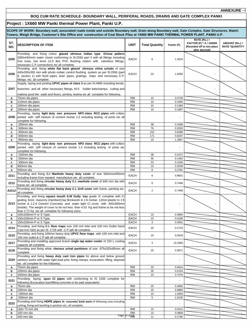
ST.
NO.DESCRIPTION OF ITEM UNIT Total Quantity Factor (F)
RATE (Rs.) =
FACTOR (F) * A / 100000
(Rounded off to two place
after decimal)
AMOUNT (Rs.) =
RATE *QUANTITY
BOQ CUM RATE SCHEDULE- BOUNDARY WALL, PERIFERAL ROADS, DRAINS AND GATE COMPLEX PANKI
ANNEXURE - I
SCOPE OF WORK: Boundary wall, associated roads inside and outside Boundary wall, Drain along Boundary wall, Gate Complex, Gate Structures, Watch
Towers, Weigh Bridge, Customer’s Site Office and construction of Coal Stock Piles at 1X660 MW PANKI THERMAL POWER PLANT, PANKI U.P.
Project : 1X660 MW Panki thermal Power Plant, Panki U.P.
2205
Providing and fixing colour glazed vitreous indian type Orissa pattern
(580x440mm) water closet conforming to IS:2556 part 3 with all fittings including
foot rests, low level 12.5 litre PVC flushing cistern with valveless fittings,
necessary C.P connections etc all complete.
EACH 6 1.3524 - -
2206
Providing and fixing white flat back glazed vitreous china urinals of size
440x265x355 mm with photo voltaic control flushing system as per IS:2556 (part
6, section 1) with flush pipes, lead pipes, gratings, traps and necessary C.P.
fittings etc. all complete.
EACH 23 1.6282 - -
2207
Supply, laying and jointing UPVC pipes of class 3 as per IS:4985 including bends,
branches and all other necessary fittings, M.S holder bats/clamps, cutting and
making good the walls and floors, jointing, testing etc all complete for following.
- - -
a 75mm dia pipes RM 10 0.0728 - -
b 110mm dia pipes RM 10 0.1055 - -
c 160mm dia pipes RM 10 0.1383 - -
d 200mm dia pipes RM 10 0.1687 - -
2208
Providing, laying light duty non pressure NP3 class RCC pipes with collars
jointed with stiff mixture of cement mortar 1:2 including testing of joints etc all
complete for following.
- - -
a 200mm dia RM 38 0.1606 - -
b 300mm dia RM 76 0.2003 - -
c 450mm dia RM 152 0.6286 - -
d 600mm dia RM 171 0.8197 - -
e 900mm dia RM 19 1.2857 - -
2209
Providing, laying light duty non pressure NP2 class RCC pipes with collars
jointed with stiff mixture of cement mortar 1:2 including testing of joints etc
complete for following.
- - -
a 150mm dia RM 38 0.1071 - -
b 250mm dia RM 30 0.1402 - -
c 300mm dia RM 23 0.1545 - -
d 450mm dia RM 15 0.2049 - -
e 500mm dia RM 8 0.2781 - -
2211Providing and fixing C.I Manhole heavy duty cover of size 600mmx450mm
including frame from reputed manufacture etc. all complete.EACH 6 0.8601 - -
2212Providing and fixing circular heavy duty C.I. manhole cover of 600 mm dia with
frame etc. all complete.EACH 6 0.7446 - -
A2212Providing and fixing circular heavy duty C.I. Grill cover with frame, painting etc.
all complete.EACH 2 0.7446 - -
2213
Providing and fixing square mouth S.W Gully trap grade 'A' complete with CI
grating, brick masonry chamber(Clay Brickwork in 1:6 mortar, 12mm plaster in 1:6
mortar & 1:2:4 Cement Concrete) and water tight CI cover with 300x300mm
(inside). The weight of cover to be not less than 4.53 Kg and frame to be not less
than 2.72 Kg etc all complete for following sizes:
- - -
a 100x100mm P or S Type. EACH 15 0.3994 - -
b 150x100mm P or S Type. EACH 10 0.4195 - -
c 150x150mm P or S Type. EACH 3 0.4561 - -
2214Providing and fixing C.I. floor traps size 100 mm Inlet and 100 mm Outlet Sand
Cast Iron S&S as per IS: 1729 with C.P jalli all complete.EACH 20 0.2723 - -
2215Providing and fixing 100mm heavy duty UPVC floor traps with 100 mm inlet and
100 mm outlet & C.P jalli all complete.EACH 10 0.2619 - -
2217Providing and installing approved brand single tap water cooler of 150 L cooling
capacity all complete.EACH 3 13.1583 - -
2218Providing and fixing white viterous urinal partitions of size 675x325x85mm all
complete.EACH 25 0.3671 - -
2220
Providing and fixing heavy duty cast iron pipes for above and below ground
sanitory works with water tight lead joint, fixing clamps, excavation, filling, disposal
etc. all complete for the following.
- - -
a 75mm dia pipes RM 25 0.4014 - -
b 100mm dia pipes RM 35 0.5154 - -
c 150mm dia pipes RM 10 0.7276 - -
2221Providing, laying spun CI pipes with conforming to IS 1536 complete for
following.(Excavation,backfilling,concrete to be paid seperately)- - -
a 75mm dia RM 25 0.4692 - -
b 100mm dia RM 25 0.6883 - -
c 150mm dia RM 10 1.0454 - -
d 200mm dia RM 5 1.6135 - -
2222Providing and fixing HDPE pipes in concrete/ brick work of following sizes including
cutting, fixing and levelling in position etc. all complete.- - -
a Upto 75 mm dia RM 15 0.0412 - -
b 100 mm dia RM 15 0.0859 - -
c 150 mm dia RM 11 0.1760 - - Page 14 of 18

ST.
NO.DESCRIPTION OF ITEM UNIT Total Quantity Factor (F)
RATE (Rs.) =
FACTOR (F) * A / 100000
(Rounded off to two place
after decimal)
AMOUNT (Rs.) =
RATE *QUANTITY
BOQ CUM RATE SCHEDULE- BOUNDARY WALL, PERIFERAL ROADS, DRAINS AND GATE COMPLEX PANKI
ANNEXURE - I
SCOPE OF WORK: Boundary wall, associated roads inside and outside Boundary wall, Drain along Boundary wall, Gate Complex, Gate Structures, Watch
Towers, Weigh Bridge, Customer’s Site Office and construction of Coal Stock Piles at 1X660 MW PANKI THERMAL POWER PLANT, PANKI U.P.
Project : 1X660 MW Panki thermal Power Plant, Panki U.P.
d 200 mm dia RM 8 0.2727 - -
2300 STRUCTURAL STEEL 0 - - -
STRUCTURAL WORKS: Structural steel works including all labour, material
(unless otherwise specified in BOQ/contract specification), equipments
unless otherwise specified, transportation, handling etc. at all level as per
specification, drawings and as directed by engineer - in - charge for the
following:
Note: Structure Steel will be supplied by BHEL and issued as FOC (free of
Cost) item
- - -
2301
A2301
Supply & Fabrication of Hollow steel sections (square & rectangular) of
minimim grade Yst 240 conforming to IS:4923, in columns, beams, ties,
struts, bracings, roof truss,connections to other members(tubular/non-
tubular), special connections if required etc. including straightening, cutting,
bending, rolling, grinding, machining, drilling, welding, electrodes and other
consumables, assembly, edge preparation, preheating / post heating (if required),
inspection of welds, visual inspection, non destructive and special testing,
rectification and correction of defective welding works, production test plate,
protection against damage in transit etc all complete. Hollow section to section
connection shall be direct as per cut profile of sections and field
conenctions/splicing shall be bolted with gusset/splice plates. Payment shall be
made for net weight of finished structure along with gussets, stiffeners but not for
Nuts & Bolts/washers. Nuts & Bolts/washers shall be paid under separate item.
MT 20 8.8747 - -
2302
Extra over ST NO. 2301 for blast cleaning of steel structures to near white metal
surface(Sa 2 1/2 ) and applying epoxy based zinc phosphate primer in coats of
minimum 25 micron (DFT) at shop and 25 micron (DFT) after erection, instead of
primer coat of red oxide zinc-chromate, including touch-up painting etc all
complete.
MT 0 - - -
A2302
Extra over ST NO. 2301 for blast cleaning of steel structures to near white metal
surface(Sa 2 1/2 ) and applying zinc silicate primer in coats of minimum 25
micron (DFT) at shop and 25 micron (DFT) after erection, instead of primer coat of
red oxide zinc-chromate, including touch-up painting etc all complete.
MT 45 1.4460 - -
2304
Extra over ST No. 2301 for providing and applying two coats of synthetic enamel
paint with minimum 50 micron total dry film thickness (DFT) of approved make
and shade to achieve an even shade over steel sections already having primer
coats and keeping overall DFT with primer not less than 110 microns including
protection and cleaning, scoffolding etc. all complete.
MT - - -
Supply, Fabrication,erection and alignment of structural steel with mild steel
rolled section / built up section / combination of both conforming to IS:2062, pipes
conforming to IS:1161/ IS:1239, chequered plate conforming to IS: 3052, mild steel
rounds, monorails, stays, safety chains, ladders, MS grating etc. in columns,
beams, gantry girders, bunkers, silos, hoppers, roof trusses, portals, laced purlins,
space frames, hangers, struts, monorails, galleries, stiffeners, wall beams,
sheeting runners, brackets, stub columns, bracings, cleats, trestles, base plates,
splice plates, chequered plate flooring, decking and seal plates, steel frame grid
over false ceiling, walkway platforms, ladders, stairs, stringers, treads, landings,
hand-rails etc including 2 coats of red oxide zinc-chromate primer (one coat at
shop and one coat after erection), connection design & preparation of fabrication
drgs, collection of steel from stores, fabrication, straightening, cutting, bending,
rolling, grinding, machining, drilling, welding, electrodes and other consumables,
alignment, erection bolts & nuts (weight of erection bolts, nuts and welds not
payable), assembly, edge preparation, preheating (min preheat and interpass
temperature of 20o C for welding over 20 mm and upto 40 mm & 66
o C for welding
over 40 mm and upto 63 mm & 110o C for thickness over 63 mm & use of low
hydrogen/ radiogenic electrodes), post heating, testing of welders, inspection of
welds, visual inspection, non destructive and special testing, rectification and
correction of defective welding works, production test plate, inspection and testing,
erection scheme, protection against damage in transit, stability of structures,
installation of temporary structures, setting column bases, surface preparation by
means of manual or mechanical power tools as per IS:1477 part 1, touch-up
painting, rectification, dismantling and removal of all temporary structures (weight
of temporary structures not payable), return of surplus / waste steel materials to
store etc all complete. Including appointment of a seperate agency, approved by
BHEL, for review and approval of fabrication drgs, in consultation with BHEL
(BHEL to supply steel free of cost).
MT 25 8.8747 - -
Page 15 of 18

ST.
NO.DESCRIPTION OF ITEM UNIT Total Quantity Factor (F)
RATE (Rs.) =
FACTOR (F) * A / 100000
(Rounded off to two place
after decimal)
AMOUNT (Rs.) =
RATE *QUANTITY
BOQ CUM RATE SCHEDULE- BOUNDARY WALL, PERIFERAL ROADS, DRAINS AND GATE COMPLEX PANKI
ANNEXURE - I
SCOPE OF WORK: Boundary wall, associated roads inside and outside Boundary wall, Drain along Boundary wall, Gate Complex, Gate Structures, Watch
Towers, Weigh Bridge, Customer’s Site Office and construction of Coal Stock Piles at 1X660 MW PANKI THERMAL POWER PLANT, PANKI U.P.
Project : 1X660 MW Panki thermal Power Plant, Panki U.P.
A2304
Extra over ST No. 2301 for providing and applying two coats of synthetic enamel
paint with minimum 50 micron total dry film thickness (DFT) of approved make
and shade to achieve an even shade over steel sections already having primer
coats of different tint to distinguish the same and keeping overall DFT with primer
not less than 100 microns including protection and cleaning, scoffolding etc. all
complete.
MT 45 0.5855 - -
2307
Supplying, fabrication, erection and alignment of factory made electroforged
galvanised grating units with mild steel having minimum galvanisation
conforming to IS:2062 in flooring, platforms, drain and trench covers, walk-ways,
passages, staircases with edge binding strips and anti-skid nosing in treads etc.
including fixing clamps, fittings, fixtures, all taxes, duties, packing, grinding, drilling,
welding, edge preparation, etc. all complete. (Supply of galvanised grating is in
contractor scope)
- - -
a Minimum galvanisation of 610 g/sqm MT 2 37.7293 - -
2311
Providing and fixing in position of permanent mild steel bolts (class 4.6 as per IS
: 1367 and grade `C' as per IS: 1363) and nuts, washers etc. up to and inclusive of
39 mm diameter and upto 300mm long for structural steel work etc all complete.
(Supply of permanent mild steel bolts is in contractor scope)
KG 500 0.0289 - -
2312
Providing and fixing in positing of high strength structural bolts (of property
class 8.8 and product grade `C' as per IS: 1367) and conforming to IS: 3757 and
high strength structural hardened and tempered nuts (of property class `8' as per
IS:1367) conforming to IS:6623 with hardened and tempered washers as per
IS:6649 etc. up to and inclusive of 39 mm diameter and upto 300 mm long for
structural steel work etc all complete. (Supply of high strength structural bolts
is in contractor scope)
KG 1400 0.0320 - -
2322
Supply, fabrication and fixing of GI pipe hand railing (900 mm high) of 32 mm/40
mm dia (Medium Grade) including transportation, loading/unloading, painting etc.
all complete. (Supply of GI pipe Hand Rails is in Contractor Scope)
MT 4 42.8530 - -
2400 ROAD WORKS - - -
Page 16 of 18

ST.
NO.DESCRIPTION OF ITEM UNIT Total Quantity Factor (F)
RATE (Rs.) =
FACTOR (F) * A / 100000
(Rounded off to two place
after decimal)
AMOUNT (Rs.) =
RATE *QUANTITY
BOQ CUM RATE SCHEDULE- BOUNDARY WALL, PERIFERAL ROADS, DRAINS AND GATE COMPLEX PANKI
ANNEXURE - I
SCOPE OF WORK: Boundary wall, associated roads inside and outside Boundary wall, Drain along Boundary wall, Gate Complex, Gate Structures, Watch
Towers, Weigh Bridge, Customer’s Site Office and construction of Coal Stock Piles at 1X660 MW PANKI THERMAL POWER PLANT, PANKI U.P.
Project : 1X660 MW Panki thermal Power Plant, Panki U.P.
ROAD WORKS: Road works including all labour, material (unless otherwise
specified in BOQ/contract specification), equipment, transportation etc. as
per specification, drawing, relevant IRC & IS codes and as directed by the
Engineer-in-charge for the following:
Note: Cement will be supplied by BHEL and issued as FOC (Free of Cost)
item
- - -
2401
Preparation of sub grade by excavating earth to required depth for all types of
soil/ rock, dressing to camber and consolidating the base including making good
the undulation etc and disposal of surplus earth within a lead upto 1 km etc. all
complete.
CUM 28507 0.0173 - -
2402
Supplying and filling with selected good earth of approved quality in layers not
exceeding 300 mm loose thickness using borrowed soil (borrowed soil to be
arranged by the bidder) and compacted so as to achieve at least 95 % maximum
dry density as per IS-2720 (Part-VII) including royalty/seignorage fee (if any),
sorting, spreading, breaking clods, watering, ramming/compaction by
manual/mechanical means, dressing, finishing to required lines, grades and
slopes, tesing etc all complete.
CUM 792 0.0578 - -
2404
Providing & laying water bound macadam sub base course in layers of required
thickness with crushed stone aggregates 90 to 40 mm down size (IRC 19 - grading
-1), stone screening & blinding material including screening, sorting, spreading to
template & consolidation with road roller including carriage, spreading &
consolidation of blinding material moorum etc all complete.
CUM 7919 1.0377 - -
2413
Supplying and laying 400mmx150mmx350mm deep precast concrete kerb stone
of grade M-20 with 20 mm nominal size stone aggregate and of shape as per
detailed drawing including fixing with cement mortar (1:2) in 13mm thick joints,
finishing of joints with neat cement paste, making drainage opening where
required etc all complete. (including cost of cement for kerb stone making)
RM 2500 0.0998 - -
2415
Supply and laying 150mm dia R.C.C NP-2 type Hume pipe in raised shoulders as
rain water drains as per detailed drawing including fixing with cement mortar (1:3)
in 13mm thick joints, finishing of joints with neat cement paste etc all complete.
Payment terms - a) On receipt of materials at site - 50%; b) On completion of
erection & fixing - 50%.
RM - - -
A2415
Supply and laying 150mm dia R.C.C NP-3 type Hume pipe in raised shoulders as
rain water drains as per detailed drawing including fixing with cement mortar (1:3)
in 13mm thick joints, finishing of joints with neat cement paste etc all complete.
Payment terms - a) On receipt of materials at site - 50%; b) On completion of
erection & fixing - 50%.
RM 1839 0.2230 - -
2416
Dismantling of existing road consisting of premix carpet, kerb stone/ brick on
edge, bitumen macadem course, WBM, prepairing subgrade to receive new WBM
including camber consolidation including disposal of debris within a lead of 1 km
etc all complete.
SQM 500 0.0254 - -
2417
Providing 25 mm compacted thick premix carpet on existing/damaged road
surfaces in a single course composed of suitable small size aggregate premixed
with a bituminous binder using medium setting grade bitumen on the existing base
including tack coat, cleaning of existing surface, mixing, applying, rolling etc all
complete.
SQM 250 0.0736 - -
2419
Providing and laying cement concrete of grade M30 using 20 mm nominal size
stone aggregate with approved admixture (if required), provision for necessary
joints including compaction, finishing to lines and grades, curing and providing &
fixing forwork etc. all complete. (Excluding the cost of reinforcement and dowel
bar)
CUM 7919 1.4267 - -
2421
Providing & laying dry lean cement concrete of grade M15 with 20 mm nominal
size graded stone aggregate over a prepared sub-grade including compaction,
finishing, curing etc all complete.
CUM 5010 1.2738 - -
(Reinforcement Steel will be supplied by BHEL and issued as FOC
(Free of Cost) Item)- - -
A2422
Providing and fixing in position MS dowel bar reinforcement including
surface painted with bitumen and greasing, dowel end caps with cotton fills
etc all complete as per specification, drawing and as directed by Engineer. MT 45 2.8219 - -
A2423
Providing, straightening, cutting, bending, placing in position at any level,
binding in position of steel reinforcements of TMT steel of grade Fe-500
confirming to IS:1786 including cost of binding wire, labour, scaffolding,
transportation to & from stores etc all complete as per specification,
drawing and as directed by Engineer.
MT 187 2.5653 - -
Page 17 of 18

ST.
NO.DESCRIPTION OF ITEM UNIT Total Quantity Factor (F)
RATE (Rs.) =
FACTOR (F) * A / 100000
(Rounded off to two place
after decimal)
AMOUNT (Rs.) =
RATE *QUANTITY
BOQ CUM RATE SCHEDULE- BOUNDARY WALL, PERIFERAL ROADS, DRAINS AND GATE COMPLEX PANKI
ANNEXURE - I
SCOPE OF WORK: Boundary wall, associated roads inside and outside Boundary wall, Drain along Boundary wall, Gate Complex, Gate Structures, Watch
Towers, Weigh Bridge, Customer’s Site Office and construction of Coal Stock Piles at 1X660 MW PANKI THERMAL POWER PLANT, PANKI U.P.
Project : 1X660 MW Panki thermal Power Plant, Panki U.P.
A2424
Providing, straightening cutting, bending, placing in position at any level,
binding in position of steel reinforcement of mild steel reinforcements
including cost of binding wire, labour, scaffolding transportation to & from
stores etc all complete as per specifications, drawings and as directed by
Engineer.
MT 12 2.5653 - -
- - -
A2425
Providing & installation of bitumen impregnated fibre board of specified
thickness confirming to IS 1838 as joint filler including nailing, coating of
both faces with coal tar pitch/bitumin etc. all complete as per specification,
drawing and as directed by engineer.
RM 1056 0.0076 - -
A2426
Providing and filling in position hot applied bitumen sealing compund
(Grade A) of specified thick confirming to IS 1834 including cleaning,
mixing, heating, pouring/injecting sealing compound in gaps in joints,
sealant primer etc all complete as per specification, drawing and as
directed by Engineer.
RM 25429 0.0108 - -
A2430
Providing and laying Impermeable plastic sheeting 125 microns thick laid
flat without creases as per IRC 15-2002 etc all complete as per
specification, drawing and as directed by Engineer.
SQM 31674 0.0060 - -
A2431
Providing and laying Inverted Choke with 25 mm course of screenings
(Grading-B) over prepared subgrade including compaction etc all
complete as per specification, drawing and as directed by Engineer. CUM 792 0.5759 - -
A2433
Providing and installation of Variable message signs including Cantilever
type MS supports etc. all complete as per drawings, specifications,
manufacturer's recommendations, indian standards.
EACH 50 0.1442 - -
Total Amount (INR) -
1
2
3
4
5
6
7
In case of any mis-match in rate and amount on price discrepency, the same will be dealt as per clause no. 1.4 of GCC.
Taxes (GST) shall be payable extra as per relevant clauses in Technical Conditions of Contract.
NOTES:
Contractor shall fully understand description and Specifications of items mentioned in BOQ.
MISCELLANEOUS
Bidder's quoted price above shall be complete in all respect for the full scope defined in specification and in accordance with all terms & conditions of tender.
Conditional price bids with any deviation / clarification etc. are liable to be rejected. No cutting / erasing / over writing shall be done.
Quantities mentioned in rate schedules are approximate only and liable for variation on either side depending upon site / design requirement. The tentative contract
value (CV) of entire scope of work shall be calculated as per finally quoted / accepted rates & the Quantities indicated in BOQ cum Rate Schedule .
Contractor's total quoted price as per rate schedule will be taken as tentative only. The contractor undertakes to execute actual quantities as per advice of BHEL Engineer
and accordingly the final contract price shall be worked out on the basis of quantities actually executed at site and payments will also be regulated for the same.
Page 18 of 18

TITLE: 1X660 MW PANKI TPS
SPECIFIC TECH. REQUIREMENT
SPECIFICATION NO. PE-TS- 426-600-C001
VOLUME - II B
SECTION - C
REV.NO. 0 DATE 09 Jan, 2018
SHEET 1 OF 1
UTTAR PRADESH RAJYA VIDYUT UTPADAN NIGAM LIMITED
[UPRVUNL]
PANKI THERMAL POWER STATION [1 x 660 MW]
VOLUME – II B
CIVIL, STRUCTURAL & ARCHITECTURAL WORKS
SPECIFICATION NO. PE-TS-426-600-C001
SECTION - C
SPECIFIC TECHINCAL REQUIREMENT
Bharat Heavy Electricals Limited Project Engineering Management
PPEI Building, Power Sector,
Plot No. 25, Sector 16A,
Noida (U.P.)-201301

DCPL Volume VI
Civil, Structural & Architectural Works Content (Vol.-VI)
Sheet | 1 of 2
1 x 660 MW - Panki Thermal Power Station
Bidding Doc. No. : 14A14-SPC-G-0001
VOLUME-VI : CIVIL, STRUCTURAL & ARCHITECTURAL WORKS
CONTENTS
Chapter No. Titles
Chapter 1. CODES AND STANDARDS
Chapter 2. SCOPE OF CIVIL & STRUCTURAL WORKS
Chapter 3. INSTRUCTION TO BIDDERS
Chapter 4. SUBMISSION
Chapter 5. GEO-TECHNICAL INVESTIGATION
Chapter 6. GENERAL REQUIREMENT OF BUILDING / STRUCTURES
Chapter 7. MATERIAL
Chapter 8. LOADING
Chapter 9. STEEL STRUCTURE
Chapter 10. REINFORCED CONCRETE STRUCTURES AND FOUNDATIONS
Chapter 11. DESCRIPTION OF BUILDINGS, STRUCTURES AND OTHER FACILITIES
Chapter 12. REINFORCED CONCRETE CHIMNEY
Chapter 13. INDUCED DRAUGHT COOLING TOWER
Chapter 14. COAL HANDLING SYSTEM
Chapter 15. ASH HANDLING SYSTEM
Chapter 16. RAW WATER PRE-TREATMENT, DM PLANT SYSTEM, EFFLUENT TREATMENT SYSTEM AND SEWAGE TREATMENT SYSTEM
Chapter 17. ARCHITECTURE
Chapter 18. PILING
Chapter 19. SURVEYING WORKS
Chapter 20. EXCAVATION AND FILLING
Chapter 21. WATER SUPPLY, DRAINAGE AND SANITATION
Chapter 22. SWITCHYARD CIVIL WORKS
Chapter 23. CONCRETE ROAD AND RIGID PAVEMENT
Chapter 24. RAISING AND STRENGTHENING OF ASH DYKE.

DCPL Volume VI
Civil, Structural & Architectural Works Content (Vol.-VI)
Sheet | 2 of 2
1 x 660 MW - Panki Thermal Power Station
Bidding Doc. No. : 14A14-SPC-G-0001

DCPL Volume VI :
Civil, Structural & Architectural Works Ch 01 : Code & Standard
Sheet | 1 of 11
1 x 660 MW - Panki Thermal Power Station
Bidding Doc. No. : 14A14-SPC-G-0001
1.0 CODES AND STANDARDS
Following is a general listing of Codes and Standards to be used in the design of the Plant. However, all other codes (not mentioned herein) with latest
editions / revision and standards along with addendums / amendments, if any, shall also be followed:
1.1 General
a) Internationally accepted design Codes and Standards where Indian
Codes are not available and which are equivalent to Indian Standards.
b) National Building Code of India.
c) “Accepted Standards” and “good Practice” listed in the appendix to
National Building Code of India.
d) IS: 1200: Method of measurement of Building and Civil Engineering Works.
e) IS: 1256: Code of Practice for Building Byelaws.
1.2 Earthwork
a) IS-1498 : Classification and identification of soils for General Engineering purpose
b) IS-3764 : Safety code for excavation work c) IS:7293 : Safety code for working with construction
machinery
1.3 Concrete
IS-269 - Ordinary and low heat Portland cement
IS-383 - Coarse and fine aggregate from natural sources for
concrete
IS-432 - Mild steel and medium tensile steel bars and hard drawn
steel wire for concrete reinforcement
IS-455 - Portland slag cement
IS-456 - Code of practice for plain and reinforced concrete
IS-460 - Test Sieves (all parts)
IS-516 - Methods of test for strength of concrete
IS-1199 - Methods of sampling and analysis of concrete

DCPL Volume VI :
Civil, Structural & Architectural Works Ch 01 : Code & Standard
Sheet | 2 of 11
1 x 660 MW - Panki Thermal Power Station
Bidding Doc. No. : 14A14-SPC-G-0001
IS-1566 - Hard drawn steel wire fabric for concrete reinforcement
IS-1786 - High strength deformed steel bars and wires for
concrete reinforcement
IS-1834 - Hot applied sealing compounds for joints in concrete
IS-2386 - Methods of test for aggregates for concrete (all parts)
IS:2502 - Code of practice for bending and fixing of bars for
concrete reinforcement
IS:3370 - Code of practice for concrete structures for storage of liquids (all parts)
IS-3414 - Code of practice for design and installation of joints in
buildings
IS-4948 - Welded steel wire fabrics for general use.
IS-6452 - High alumina cement for structural use
IS-7320 - Concrete slump test apparatus
IS-7861 - Code of practice for extreme weather concreting
(all parts)
IS-8041 - Rapid hardening Portland cement
IS-8112 - High strength ordinary Portland cement
IS:13290 - Ductile detailing of RCC structure subjected to seismic
loads SP : 34 - Handbook on concrete reinforcement and detailing
IS : 216 - Indian Standard Specification for Coal Tar Pitch
IS : 226 - Indian Standard Specification for Structural Steel [Standard quality]
IS : 1139 - Indian Standard Specification for Hot Rolled Mild Steel
and Medium Tensile Steel and High Yield Strength Steel Deformed Bars for concrete Reinforcement
IS : 1200 - Indian Standard Specification for Method of measurement Cement Concrete Works. Part-II
IS : 1200 - Indian Standard Specification for Method of
Measurement of Part-V Formwork.
IS : 1609 - Code of Practice for Laying Damp proof Treatment using Bitumen felts
IS : 1791 - Indian Standard Specification for Batch Type Concrete Mixers

DCPL Volume VI :
Civil, Structural & Architectural Works Ch 01 : Code & Standard
Sheet | 3 of 11
1 x 660 MW - Panki Thermal Power Station
Bidding Doc. No. : 14A14-SPC-G-0001
IS: 2210 - Indian Standard Specification FOR Design of Reinforced
Concrete Shell Structures and Folded Plates
IS : 2505 - Indian Standard Specification for Concrete Vibrators, Immersion Type
IS: 2506 - Indian Standard Specification for Screed Board Concrete
Vibrators
IS : 2514 - Indian Standard Specification for Concrete
VibratingTables
IS : 2722 - Indian Standard Specification for Portable Swing Weigh Batchers for Concrete (Single and Double Bucket
type)
IS : 2751 - Code of Practice for Welding of Mild Steel Bars used for
reinforced concrete construction
IS : 2770 - Indian Standard Specification for Method of Testing Bond in Reinforced Concrete.
IS : 3025 - Indian Standard Specification for Methods of Sampling
and Test (Physical and Chemical) for Water used in Industry
IS : 3201 - Indian Standard Specification for Design and construction of Precast Concrete Trusses
IS : 3370 - Indian Standard Specification for Code of Practice for
Concrete Structures for Storage of Liquids
IS : 3550 - Indian Standard Specification for Method of Test for Routine Control for Water used in Industry
IS : 3558 - Code of Practice for use of Immersion Vibrators for Consolidating Concrete
IS : 3590 - Indian Standard Specification for Load Bearing Light
Weight Concrete Blocks
IS : 3696 - Safety Code for Scaffolding and Ladders
IS : 3812 - Indian Standard Specification for Fly Ash for use as
Admixture for Concrete.
IS : 4031 - Indian Standard Specification for Method of Tests for Hydraulic Cement
IS : 4082 - Indian Standard Specification for Recommendation on
Stacking and Storage of Construction Materials at site.
IS : 4634 - Indian Standard Specification for Method of Testing
Performance of Batch-type Concrete Mixes.

DCPL Volume VI :
Civil, Structural & Architectural Works Ch 01 : Code & Standard
Sheet | 4 of 11
1 x 660 MW - Panki Thermal Power Station
Bidding Doc. No. : 14A14-SPC-G-0001
IS : 4656 - Indian Standard Specification for Form Vibrators for
Concrete
IS : 4925 - Indian Standard Specification for Concrete Batching and
Mixing Plant
IS : 4926 - Indian Standard Specification for Ready Mixed Concrete
IS : 4990 - Indian Standard Specification for Plywood for Concrete
Shuttering work
IS : 4995 - Indian Standard Specification for Design of (Part-I&II) Reinforced Concrete Bins for the Storage of Granular and
Powdery Materials
IS : 5512 - Indian Standard Specification for Flow Table for use in Tests of Hydraulic Cement and Pozzolanic Materials
IS : 5513 - Indian Standard Specification for Vicat Apparatus
IS : 5515 - Indian Standard Specification for Compaction Factor Apparatus
IS : 5751 - Indian Standard Specification for Precast Concrete
Coping Blocks
IS : 5816 - Indian Standard Specification for Method of Test for
Splitting Tensile Strength of Concrete Cylinders
IS : 5891 - Indian Standard Specification for Hand Operated Concrete Mixers
IS : 6909 - Indian Standard Specification for Supersulphated
Cement
IS : 6923 - Indian Standard Specification for Method of Test for
Performance of Screed Board Concrete Vibrators
IS : 6925 - Indian Standard Specification for Method of Test for Determination of Water Soluble Chloride in Concrete
Admixtures
IS : 7242 - Indian Standard Specification for Concrete Spreaders
IS : 7246 - Indian Standard Specification for Table Vibrators for
Consolidating Concrete
IS : 7251 - Indian Standard Specification for Concrete Finishers
IS : 7969 - Safety Code for Storage and Handling of Building Materials
IS : 8142 - Indian Standard Specification for Determining Setting
time of Concrete by Penetration Resistance
IS : 8989 - Safety Code for erection of Concrete Framed Structures

DCPL Volume VI :
Civil, Structural & Architectural Works Ch 01 : Code & Standard
Sheet | 5 of 11
1 x 660 MW - Panki Thermal Power Station
Bidding Doc. No. : 14A14-SPC-G-0001
IS : 9013 - Indian Standard Specification for Method of Making,
Curing and Determining Compressive Strength of Accelerated-cured Concrete Test Specimens
IS : 9077 - Code of Practice for Corrosion Protection of Steel Rails in
RB and RCC Construction
IS : 9103 - Indian Standard Specification for Admixtures for
Concrete.
1.4 Foundations
a) IS-1904 : Code of practice for structural safety of
building - Shallow foundations
b) IS-2950 : Code of practice for design and construction
of raft foundations
IS-2974 : Code of practice for design and construction of Machine foundations (all parts)
d) IS-2911 : Code of practice for design and construction of pile foundation.
e) IS-9716 : Lateral dynamic load test on pile
f)
IS-6313
(Part-1 & Part-2)
:
Code of Practice for anti-termite measures
and treatment.
1.5 Loading
a) IS-875 : Code of practice for design loads for buildings
and structures b) IRS : Bridge Rules of Government of India, Ministry
of Railways (Railway Board)
1.6 Masonry
a) IS-712 : Building limes
b) IS-1077 : Common burnt clay building bricks
c) IS-1127 : Recommendations for dimensions and
workmanship of natural building stones for masonry work.
d) IS-1528 : Methods of sampling and physical tests for refractory materials
e) IS-1597 : Code of practice for construction of stone masonry (all parts)
f) IS-2212 : Code of practice for brickwork g) IS-2116 : Sand for masonry mortars
h) IS-2185 : Concrete masonry units. (all parts – Hollow
and Solid concrete blocks) i) IS-2250 : Code of practice for preparation and use of
masonry mortars j) IS:2572 : Code of practice for construction of hollow
concrete block masonry k) IS-2691 : Burnt clay facing bricks

DCPL Volume VI :
Civil, Structural & Architectural Works Ch 01 : Code & Standard
Sheet | 6 of 11
1 x 660 MW - Panki Thermal Power Station
Bidding Doc. No. : 14A14-SPC-G-0001
l) IS-3414 : Code of practice for design and installation of
joints in buildings
m) IS-3495 : Methods of tests of burnt clay building bricks n) IS-4441 : Code of practice for use of silicate type
chemical resistant mortars o) IS-4860 : Acid resistant bricks
1.7 Doors, Windows & Ventilators
a) IS-399 : Classification of commercial timbers and their zonal distribution
b) IS-883 : Code of practice for design of structural timber in buildings
c) IS-1003 : Timber paneled and glazed shutters (all parts)
d) IS-1038 : Steel doors, windows and ventilators e) IS-1081 : Code of practice for fixing and glazing of
metal (steel and aluminium) doors, windows and ventilators
f) IS-1361 : Steel windows for industrial buildings g) IS-2835 : Transparent sheet glass for glazing and
framing purposes h) IS-1948 : Aluminium doors, windows and ventilators
i) IS-1949 : Aluminium windows for industrial building
j) IS-2191 : Wooden flush door shutters (cellular and hollow core type)
k) IS-2202 : Wooden flush door shutters (solid core type) l) IS-3103 : Code of practice for industrial ventilation
m) IS-3548 : Code of practice for glazing in buildings n) IS-3614 : Fire check doors
o) IS-4021 : Timber door, windows and ventilator frames p) IS-4351 : Steel door frames
q) IS-6248 :
1.8 Roof & Flooring
a) IS-2204 : Code of practice for construction of reinforced concrete shell roof
b) IS-3201 : Criteria for the design and construction of precast concrete trusses
c) IS-2210 : Criteria for design of RC shell structures and folded plates
d) IS-809 : Rubber flooring materials for general purposes e) IS-1195 : Bitumen mastic for flooring
f) IS-1196 : Code of practice for laying bitumen mastic flooring
g) IS-1198 : Code of practice for laying, fixing and
maintenance of linoleum floors h) IS-1237 : Cement concrete flooring tiles
i) IS-1443 : Code of practice for laying and finishing of cement concrete flooring tiles
j) IS-2114 : Code of practice for laying in situ terrazzo floor finish
k) IS-2571 : Code of practice for laying in situ cement concrete flooring
l) IS-5491 : Code of practice for laying in situ granolithic
concrete floor topping

DCPL Volume VI :
Civil, Structural & Architectural Works Ch 01 : Code & Standard
Sheet | 7 of 11
1 x 660 MW - Panki Thermal Power Station
Bidding Doc. No. : 14A14-SPC-G-0001
m) IS-5766 : Code of practice for laying burnt clay brick
flooring
n) IS-1197 : Code of practice for laying of rubber floors o) IS:2441 : Code of practice for fixing ceiling coverings.
1.9 Waterproofing
a)
IS-1322 : Bitumen felts for waterproofing and damp
proofing
b) IS-1346 : Code of practice for waterproofing of roofs
with bitumen felts c) IS-1609 : Code of practice for laying damp proof
treatment using bituminous felts.
d) IS-3036 : Code of practice for laying lime concrete for a water proofed roof finish
e) IS-3037 : Bitumen mastic for use in waterproofing of roofs.
f) IS-3067 : Code of practice for general design, details and preparatory work for damp proofing and
water proofing of buildings g) IS-3384 : Bitumen primer for use in water proofing and
damp proofing
h) IS-4365 : Code of practice for application of bitumen mastic for waterproofing of roofs.
1.10 Soil Engineering
a)
IS-1498 : Classification and identification of soils for
general engineering purposes
b) IS-1892 : Code of practice for sub-structure investigation for foundations
c) IS-2131 : Method for standard penetration test for soils d) IS-2720 : Methods of test for soils (all parts)
1.11 Water Supply, Drainage & Sewerage
a) IS-404 : Lead pipes b) IS-458 : Concrete pipes
c) IS:651 : Salt glazed stoneware pipes and fittings d) IS-771 : Glazed fire-clay sanitary appliances (all parts)
e) IS-774 : Flushing cisterns for water closets and urinals other than plasti9c cisterns
f) IS-783 : Code of practice for laying of concrete piles g) IS-1172 : Code of basic requirements for water supply,
drainage and sanitation
h) IS-1626 : Asbestos cement building pipes, gutters and fittings (all parts)
i) IS-1742 : Code of practice for building drainage j) IS-2064 : Code of practice for selection, installation and
maintenance of sanitary appliances k) IS-2065 : Code of practice for water supply in buildings
l) IS-2470 : Code of practice for installation of septic tanks (all parts)
m) IS-3114 : Code of practice for laying of cast iron pipes
n) IS-4127 : Code of practice for laying of glazed

DCPL Volume VI :
Civil, Structural & Architectural Works Ch 01 : Code & Standard
Sheet | 8 of 11
1 x 660 MW - Panki Thermal Power Station
Bidding Doc. No. : 14A14-SPC-G-0001
stoneware pipes
o) IS-12251 : Code of practice for drainage of building
basement p) IS-1200 : Method of measurement : Laying of water and
(Part-XVI) sewer lines including appurtenant items
q) IS-1536 : Centrifugally cast (spun) iron pressure pipes for water, gas and sewage
r) IS-1537 : Vertically cast iron pressure pipe for water,
gas and sewage s) IS-3486 : Cast iron spigot and socket drain pipes
t) IS-5329 : Code of practice for sanitary pipe work above ground for buildings
u) IS-3076 : Low density polyethylene pipes for potable water supplies
v) IS-1538 : Cast iron fittings for pressure pipes for potable water supplies
w) IS-1230 : Cast iron rainwater pipes and fittings
x) IS-1729 : Sand cast iron spigot and socket soil, waste and ventilating pipes, fittings and accessories
y) IS-784 : Pre-stressed concrete pipes z) IS-1726 : Cast iron manhole covers and frames
aa) IS-5961 : Cast iron grating for drainage purposes bb) IS-5219
[Part-I]
: “P” and “S” traps
cc) IS-772 : General requirements for enameled cast iron
sanitary appliances
dd) IS-775 : Cast iron brackets and supports for wash basins and sinks
ee) IS-777 : Glazed earthenware wall tiles ff) IS-2548 : Plastic water closet seats and covers (all
parts) gg) IS-2527 : Code of practice for fixing rainwater gutters
and down pipes for roof drainage.
1.12 Paving & Road Works
a) IS-73 : Paving bitumen
b) IS-702 : Industrial bitumen c) IS:1201 : Method of testing tar and bituminous
materials thru’ 1220 d) IRC-15 : Standard Specification and code of practice
for construction of concrete roads.
e) IRC-58 : Guidelines for the design of plain jointed rigid pavement for highways
1.13 Earthquake Resistant Design
a) IS-1893 : Criteria for earthquake resistant design of structures
b) IS-4326 : Code of practice for earthquake resistant design and construction of buildings

DCPL Volume VI :
Civil, Structural & Architectural Works Ch 01 : Code & Standard
Sheet | 9 of 11
1 x 660 MW - Panki Thermal Power Station
Bidding Doc. No. : 14A14-SPC-G-0001
1.14 Chimney
a) IS-4998 : Criteria for design of R.C. Chimneys (all parts)
1.15 Induced Draft Cooling Tower
a) CTI : Cooling Tower Institute Publication
b) BS-4485 : Specification for Water Cooling Tower
1.15 Structural Steel Work
a) IS-800 : Code of practice for general construction in
steel b) IS-802 : Code of practice for use of structural steel in
overhead transmission line Part-I: Load and permissible stresses
Part-II: Fabrication, galvanizing, inspection and packing.
c) IS-806 : Code of practice for use of steel tubes in
general building construction d) IS-808 : Rolled steel beams, channels and angle
sections
e) IS-813 : Scheme for symbols for welding
f) IS-814 : Covered electrodes for manual metal arc welding for carbon and carbon manganese
steel g) IS-816 : Code of practice for use of metal arc welding
for general construction in mild steel
h) IS-817 : Code of practice for training and testing of metal arc welders
i) IS-818 : Code of practice for safety and health requirements in electric and gas welding and
cutting operation j) IS-819 : Code of practice for resistance spot welding
for light assemblies in mild steel k) IS-919 : Recommendations for limits and fits for
engineering.
l) IS-1024 : Code of practice for use of welding in bridges and structures subjected to dynamic loading
m) IS-1161 : Steel tubes for structural purposes n) IS-1182 : Recommended practice for radiographic
examination of fusion welded butt joints in steel plates
o) IS-1200 [Part-VIII]
: Method of measurement of steelwork and iron work
p) IS-1239 : Mild steel tubes, tubulars and other wrought
steel fittings (all parts) q) IS-1363 : Black hexagonal bolts, nuts and locknuts (dia.
6 to 39 mm) and black hexagon screws (dia. 6 to 24 mm) [all parts].
r) IS-1364 : Precision and semi-precision hexagon bolts, screws, nuts and locknuts (dia. range 6 to 39
mm) [all parts] s) IS-1365 : Slotted counter sunk head screws (dia range

DCPL Volume VI :
Civil, Structural & Architectural Works Ch 01 : Code & Standard
Sheet | 10 of 11
1 x 660 MW - Panki Thermal Power Station
Bidding Doc. No. : 14A14-SPC-G-0001
1.6 to 20 mm)
t) IS-1367 : Technical supply conditions for threaded steel
fasteners u) IS-1443 : Code of practice for laying and finishing of
cement concrete flooring tiles. v) IS-1608 : Methods of tensile testing of steel products
w) IS-1730 : Dimensions for steel plate, sheet and strip for structural and general engineering purpose
x) IS-1731 : Dimensions for steel flats for structural and
general engineering purposes y) IS-1852 : Rolling and cutting tolerances for hot rolled
steel products z) IS-1977 : Structural steel (ordinary quality)
aa) IS-2016 : Plain washers bb) IS-2062 : Steel for general structural purposes
cc) IS-2074 : Ready mixed paint, air drying, red oxide zinc-chrome, priming
dd) IS-2633 : Methods of testing uniformity of coating of
zinc coated articles. ee) IS-3613 : Acceptance test for wire-flux combinations for
submerged arc welding of structural steel ff) IS-3664 : Code of practice for ultrasonic pulse echo
testing by contact and immersions methods gg) IS-3757 : High strength structural bolts
hh) IS-4000 : High strength bolts in steel structures ii) IS-4759 : Hot dip zinc coatings on structural steel and
other allied products
jj) IS-5334 : Code of practice for magnetic particle flaw detection of welds
kk) IS-7215 : Tolerances for fabrication of steel structures ll) IS-7280 : Base-wire electrodes for submerged arc
welding of structural steel mm) IS-7318
[Part-I]
: Approval test for welders when welding
procedure approval is not required. nn) IS-8500 : Structural steel – micro-alloyed (medium and
high strength qualities)
oo) IS-9595 : Recommendation for metal arc welding of carbon and carbon manganese steel
pp) AWS D.1.1 : Structural welding code.
1.16 Painting
a) IS-348 : Specification for French polish b) IS-427 : Specification for distemper, dry colour as
required
c) IS-428 : Specification for distemper, oil emulsion, colour as required
d) IS-1477 (I & II)
: Code of practice for painting of ferrous metal in buildings
e) IS-2338 (I & II)
: Code of practice for finishing of wood and wood based materials
f) IS-2339 : Specification for Aluminium Paints for general purposes in dual containers
g) IS-2395 : Code of practice for painting concrete,
masonry and plaster surface h) IS-2932 : Specification for enamel, synthetic, exterior -

DCPL Volume VI :
Civil, Structural & Architectural Works Ch 01 : Code & Standard
Sheet | 11 of 11
1 x 660 MW - Panki Thermal Power Station
Bidding Doc. No. : 14A14-SPC-G-0001
(a) undercoating , (b) finishing
i) IS-2933 : Specification for enamel, exterior – (a) under-
coating, (b) finishing. j) IS-5410 : Specification for cement paint.
1.17 a) Indian Road Congress (IRC) Bridge codes
b) Indian Railways Standard Bridge Rules
1.18 Environmental Protection
Charter on Corporate Responsibility for Environmental Protection (CREP)
published in Gazette of India dated 27.08.2003.
1.19 CEA guide lines for Civil works for Power Plants of 500 MW and above shall also be followed.
DCPL Volume VI :
Civil, Structural & Architectural Works Ch 02 : Scope of Work
Sheet | 1 of 8
1 x 660 MW - Panki Thermal Power Station
Bidding Doc. No. : 14A14-SPC-G-0001
2.0 SCOPE OF CIVIL & STRUCTURAL WORKS
2.1 This specification is to cover design, preparation of general arrangement,
construction as well as fabrication drawings, supply of all labour as well as materials and construction of all civil, structural as well as architectural work
on EPC basis.
2.2 The work to be performed under this specification consist of design,
engineering as well as providing all labour, materials, consumables, equipment, temporary works, temporary labour and staff colony,
constructional plant, fuel supply, transportation and all incidental items not shown or specified but reasonably implied or necessary for the completion and
proper functioning of the plant, all in strict accordance with the specifications and including revisions and amendments thereto as may be required during
the execution of the work.
2.3 All materials including cement, reinforcement steel, structural steel etc. shall
be arranged by the Contractor.
2.4 The scope shall also include setting up by the Contractor a complete testing laboratory in the field to carry out all relevant tests as per BIS or other
international standards required for the civil works for the project.
2.5 The work shall be carried out according to the design/drawings to be developed by the Contractor and approved by the Owner / Consultant. For all
building and structures, foundations, etc. necessary layout and details are to
be developed by the Contractor keeping in view the statutory & functional requirements of the plant & facilities and providing enough space & access for
operation, use & maintenance. Certain minimum requirements are indicated in this specification for guidance purpose only. However, the Contractor’s offer
shall cover the complete requirements of the plant & facilities and providing enough space & access for operation, use & maintenance. Also the
Contractor’s offer shall cover the complete requirements as per the best prevailing practices and to the complete satisfaction of the Purchaser.
2.6 Description of various items of work under this specification and nature of work in detail are given hereinafter, but not limited to the items listed below.
The complete work under this scope is referred to as CIVIL WORKS. List of various civil works covered under the scope is given below:
1. Turbine building foundation including Turbo-generator foundation and
superstructure including service and maintenance bays.
2. Switch Gear and Control Room
3. Compressed Air Building and DG Room
4. Steam Generator Elevator supporting structure.
5. Foundation for steam generator / ESP / duct supporting structure.
6. ESP control room.
7. Mill and bunker building including bunker structures & Mill Foundations.

DCPL Volume VI :
Civil, Structural & Architectural Works Ch 02 : Scope of Work
Sheet | 2 of 8
1 x 660 MW - Panki Thermal Power Station
Bidding Doc. No. : 14A14-SPC-G-0001
8. Mill reject silo and foundations.
9. Foundations for various fans and foundation for fan handling system.
10. RCC chimney of 275m height with single flue.
11. Substructure and superstructure of Natural Draft Cooling Tower.
12. Steel Trestles for supporting Ash slurry piping within plant area and dry
fly ash transportation pipe pedestal up to silos near plant boundary. Modification (if required) of existing ash pipe rack is also in the scope of Bidder.
13. Fly ash silos & foundation.
14. Ash slurry pump house, Ash water pump house, transport air compressor house, combined slurry/high concentration slurry pump house, Ash water
recirculation pump house and vacuum pump house, decantation wel, Silo
Utility Building, Ash Water Clarifier and associated civil work, HCSD Pump House. Modification (if required) of existing return channel, existing ash
water recirculation pump house, existing ash slurry pump house and existing decantation well is also in the scope of Bidder.
15. Buffer hopper tower and collector tank tower structure & foundation.
16. Construction / modification of RCC pedestals for supporting Ash disposal
pipes, ash water recirculation pipe and bottom ash slurry pipes upto
existing ash dyke including garlanding.
17. Ash handling Electrical / Control Room
18. Switch gear/ MCC and control room for all buildings.
19. Cooling Tower Switchgear & MCC Room
20. Cooling water (CW) and Auxiliary Cooling Water (ACW) pump house,
sump including forebay.
21. RCC encased Steel CW ducts from CW pump house to Turbine building, Turbine building to cooling tower including RCC thrust block. Intake RCC
channel from cooling tower to CW pump house forebay.
22. A raw water pump house (intake structure) to be constructed inside plant boundary near the Lower Ganga Canal to pump the make-up water
through MS pipes to Raw Water reservoir. Desilting chamber adjacent to
raw water pump house to remove the silt from incoming water from Lower Ganga Canal is also in the scope of Bidder. Size of desilting
chamber and raw water pump house will be as per mechanical requirement. Diversion and reconstruction to original width and alignment
of existing road outnside plant boundary is also included in Bidder’s scope.
23. A plant water makeup pump house to be constructed near raw water
reservoir to pump the make up water through MS pipes to clarifiers
located in the PT plant.

DCPL Volume VI :
Civil, Structural & Architectural Works Ch 02 : Scope of Work
Sheet | 3 of 8
1 x 660 MW - Panki Thermal Power Station
Bidding Doc. No. : 14A14-SPC-G-0001
24. Raw water reservoir (storage capacity shall be as described elsewhere in
this specification) for running of 1x660MW unit during canal closing priod
is in the scope of bidder.
25. Switchgear and MCC Room near CW Pump House
26. Switchgear and MCC Room near Raw water Pump House
27. DM Plant Building, acid/alkali (chemical) storage area with RCC dyke wall,
neutralization pit, acid/alkali storage tank foundation.
28. Two (2) nos. RCC type clarifiers for DM system with one (1) no. Cascade Aerator, Stilling Chamber, Flash Mixer.
29. Chemical house building.
30. DM & CPU Generation building (common).
31. Filter water sump and sludge sump.
32. Clarified Water Reservoir and Pump House
33. CW Treatment & Chlorination Plant
34. Thickener
35. Centrifuge Building
36. Hydrogen Generation Building
37. Hydrogen Generation Control Room
38. Ash Water Clarifier
39. Ash Water Clarifier Control Room
40. RCC centeral monitoring basin (CMB) and effluent disposal pump house.
41. RCC coal settling pond with two compartments.
42. Unloading header trench.
43. Unloading pump house, transfer pump, HFO storage tank foundation including dyke area, oil water separator pit, fencing/gate around fuel oil
handling area as per statutory requirements, pressurizing pump house
and all associated Civil work.
44. Fire water reservoir, fire water pump house (within clarified water reservoir and pump house) and fire station.
45. Filter water reservoir & pump house.
46. Foundation of various water pumps.
47. Foundation / superstructure for wagon tippler, crusher house, reclaim hopper, pent house etc.

DCPL Volume VI :
Civil, Structural & Architectural Works Ch 02 : Scope of Work
Sheet | 4 of 8
1 x 660 MW - Panki Thermal Power Station
Bidding Doc. No. : 14A14-SPC-G-0001
48. Civil and structural work for Transfer points, conveyor tunnels, conveyor
galleries and stacker/reclaimer foundation/superstructure.
49. CHP control room, wagon tippler control room, pump house and MCC room.
50. Switchyard control building and complete civil work for 400 kV
switchyard, towers, equipments, cable trenches, fencing and gates around
Switchyard area.
51. Switchyard structures (towers, gantries, equipment structures etc.)
52. Foundation for all power transformers in Transformer yard and other associated work including paving,fire walls, cable trenches, duct-support
foundations, oil pitswith connecting drains/underground pipes, chain link fencing etc. as per statutory requirements.
53. Rail track foundation for stacker/reclaimer.
54. Paving in coal stock pile area.
55. Minor site grading and leveling upto 500mm is in the scope of bidder. Finish ground level of entire plant area will be at RL ……… m above Mean
Sea Level. Finished Floor Level (FFL) of all buildings, roads and drains will be as per CEA guide lines. It is to be noted that fairly graded land (upto
finished grade level of proposed Power Plant as decided by UPRVUNL) as
shown in Plot plan attached with this specification shall be handed over by UPRVUNL to Contractor of this package.
56. Roads (with shoulders) network within boundary of Power Plant and
connecting the same with existing road network.
57. Plant boundary. Existing plant boundary has to be demolished in designated areas and new security wall with concertina fencing at top to
be constructed as per layout of proposed 1x660 MW plant and site
requirement. Plant boundary wall shall be RCC framed structure consisting of columns and beams at plinth level and top of wall with of Fly
Ash Bricks infilled
58. Condensate Storage Tank foundation
59. Foundation of FAE Towers
60. Electrical grounding mat & earthing pits
61. Efflent Treatment Plant comprising one (1) no. sump in fuel oil area, one
(1) no. API oil-water separator, FOOWS sump, one (1) no. sump for oily waste generated from Turbine Building, one (1) no. boiler area oily waste
sump, one (1) no. treated water sump, one (1) no. sump for oily effluent from Switchyard area, one (1) no. commom oil sump, one (1) no. boiler
area sump, one (1) no. condenser waste water sump, one (1) no. TG wash water sump, one (1) no. pre-settling pit, one (1) no. ESP area wash
water pit, one (1) no. ash silo wash water sump. One (1) no. high rate
solid contact clarifier, one (1) no. clarified water sump, ETO RO Building, Degassed water storage tank foundation, DMF filter tank foundation, UF

DCPL Volume VI :
Civil, Structural & Architectural Works Ch 02 : Scope of Work
Sheet | 5 of 8
1 x 660 MW - Panki Thermal Power Station
Bidding Doc. No. : 14A14-SPC-G-0001
filter tank foundation etc. as per system design requirement described
elsewhere in this specification.
62. Civil work for Sewage Treatment Plant including equalization cum holding
tank, FAB tank, tube settler, hypo contact cum filter feed tank, sludge sump and pump house, centrifuge building etc. as per system design
requirement described elsewhere in this specification.
63. Auxiliary building
Service building.
Administrative building (Area 1500m sq. per floor, total No. of floor ground + 2 floors)
Air washer building. Workshop
Canteen building Training Centre
Dozer shed and repair shed
Dozer shed shall be steel framed structure with brickwall upto window
sill height and insulated double skin metal sheeting cladding above it. Roof of the building shall be insulated double skin metal sheeting on
steel roof truss. The building shall provide for dozer shed space, work shop space, office rooms, stores, toilet and pantry as per functional
requirements. Minimum size of dozer shed shall be 500 sqm. External finish for brick walls shall be of premimum acrylic smooth paint.
Fire station Ware House / Stores / Storage Yard
Main gate, time office and security complex – The gate complex shall comprise two (2) mild steel vehicle entry gates of minimum 8.0m width
and height 3.0m and shall be electrically operated. Minimum one room for security personnel shall be located at each end of the gates. Two
(2) separate mild steel pedestrian gates minimum 3.0m heigh and 3.0m width shall be provided at the each end. Security complex shall
be RCC framed 2 storey building. Floor area of this building shall be of
minimum 700m sq.
All other civil items not covered above but required for completion and proper functioning of plant shall form part of scope.
64. Paving, trenches, tunnels, channels, duct banks etc.
65. Fondation and superstructure of structural steel pipe rack and cable racks
for pipes and cables for clarified water, D.M. Water, steam pipes, fuel oil
pipes etc. with walkways.
66. RCC paving from power house to chimney including Boiler area.
67. RCC paving in Transformer yard 68. RCC paving in DM Plant area, around Cooling Tower (3.0 m wide), Oil
storage area, Ash silo area etc.
69. RCC track (including jacking pads) connecting transformer yard to service
bay in TG building including cross track in service bay.

DCPL Volume VI :
Civil, Structural & Architectural Works Ch 02 : Scope of Work
Sheet | 6 of 8
1 x 660 MW - Panki Thermal Power Station
Bidding Doc. No. : 14A14-SPC-G-0001
70. Parking sheds for four wheelers and two wheelers – Size of shed shall be
capable to accommodate minimum 50 No. of 4 wheelers and 2 wheelers
each.
71. RCC storm water drainage system for the entire plant.
72. Dispensary and first aid centre.
73. Service water system pipelines.
74. Miscellaneous civil work and foundation like shed for outdoor pump etc.
75. Rain Water Harvesting should be implemented as per the scheme / design
approved. Central ground water Authority / Board or State ground water authority or MoEF authorized agency shall be consulted for finalization of
appropriate rain water harvesting technology. The necessary consultancy charges for the above agency for preparing rain water Harvesting method
/ scheme for the project to be borne by the Bidder.
76. Clearing and removing the buried items if any in the whole proposed plant
area and the same is to be deposited to the Client. Any infrastructure buried underground shall be demented/relocated by bidder without any
additional cost.
77. The contractor has to fill or excavate the areas to the required formation levels as indicated in the plot plan.
78. Site illumination work including lighting towers shall be provided in Coalyard area, Switchyard area including all other plant areas.
79. Road Weigh Bridge and Control Room
These shall be RCC framed structure with RCC roof and brick cladding.
Adequate windows shall be provided for ventilation & lighting. Roof shall be given liquid membrane water proofing treatment. Flush welded steel
doors shall be provided for personnel movement. Toilet facilities shall be
provided.
80. All underground structures such as basement, sump and water retaining structures etc.
81. Architectural finishing including flooring, paving, side cladding with
sheeting of brick masonry, walls, plastering, painting, false ceiling, doors & windows, roof treatment etc. for all buildings covered under this
package.
82. The work also includes :
(i.) Site surveying.
(ii.) Soil investigation and preparation of soil investigation report and
suggestion of type of foundations including design of piles.
(iii.) Implementation of ground improvement and post improvement
evaluation of sub surface properties if required.

DCPL Volume VI :
Civil, Structural & Architectural Works Ch 02 : Scope of Work
Sheet | 7 of 8
1 x 660 MW - Panki Thermal Power Station
Bidding Doc. No. : 14A14-SPC-G-0001
(iv.) Preparation of Architectural drawings.
(v.) Design, preparation of drawings and construction of all structures.
(vi.) Preparation of as built drawings of all structures and facilities to reflect as built status of construction.
(vii.) Submission of as built drawings in Autocad in CDs.
(viii.) Plumbing & sanitary works.
(ix.) Painting.
(x.) Anti-termite and anti-weed treatment in all areas / buildings as per IS: 6313.
(xi.) All temporary roads and approach roads necessary for construction
purpose shall be of WBM for a minimum width of 4m.
(xii.) All permanent roads as stipulated in this specification.
(xiii.) Green belt development
(xiv.) Internal/External compound wall is in the scope of bidder.
(xv.) Site clearance.
(xvi.) Demolition of existing structures / facilities, if any, as identified by Owner.
(xvii.) Supply, fabrication & erection of miscellaneous fixtures, stairs, ladders,
railings, inserts, embedments etc.
(xviii.) Foundations/platforms/staging required for erection of equipments.
(xix.) Supply of cement, reinforcement steel and structural steel.
(xx.) Obtaining all necessary statutory clearances prior to execution work
from concerned Competent Authorities.
(xxi.) Making all necessary arrangements for access to the storage yard from the nearest approach road and further to the actual site of work and
maintenance of same in order to facilitate transportation of machinery and equipment such as cranes etc. assessing the suitability of existing
roads.
It is not the intent to specify herein all the works in the scope of this contract. All other buildings, structures and works necessary which are not specifically
mentioned here but required for construction, operation and maintenance of the power plant are deemed to be included in the scope of the Contractor.
In the event of conflict between requirement of any two clauses of this
specification, or different codes / standards, the more stringent requirement
as per the interpretation of Owner is to be followed by EPC contractor.
DCPL Volume VI :
Civil, Structural & Architectural Works Ch 02 : Scope of Work
Sheet | 8 of 8
1 x 660 MW - Panki Thermal Power Station
Bidding Doc. No. : 14A14-SPC-G-0001
All works shall conform to the specification. The works shall conform to high
standards of design, engineering and workmanship. Design and construction
shall conform in every respect to all local and state regulations governing such works and to stipulations of Indian Standards unless stipulated otherwise in
detail specification.
2.7 Protection of existing utilities and services
During construction, the contractor shall provide all protection for existing
utilities and services as may be required by his construction operations. Permanent protection of certain items shall be as included under other sections
or as instructed by the Owner.
In addition to the requirements as specified, herein the contractor shall comply with the following requirements:-
a) Use all necessary precautionary and protective measures required to
maintain existing utilities, services and appurtenances that must be kept in
operation. In particular, the contractor shall take adequate measures to prevent undermining of utilities and services presently in services.
b) Protect existing or new utilities and services where required by the
contractor’s operations and/or as directed by the Owner. The contractor shall be responsible for bracing and supporting utilities and services to prevent
settlement, displacement or damage.

DCPL Volume VI :
Civil, Structural & Architectural Works Ch 03 : Instruction to Bidder
Sheet | 1 of 5
1 x 660 MW - Panki Thermal Power Station
Bidding Doc. No. : 14A14-SPC-G-0001
3.0 INSTRUCTION TO BIDDERS
3.1 Data to be furnished by Bidder at the time of Bid
3.1.1 A write-up on survey to be undertaken indicating grid, intervals for taking spot
levels, contour intervals, precision of surveying instruments proposed to be used, drawings that will be prepared, details to be covered by survey etc.
3.1.2 Detail general arrangements / architectural drawings of all buildings and structures showing dimensions, levels, plans, sections, elevations, loadings,
materials proposed, types of framings, wall / cladding, floors, roofs, types of finishes etc. This can be provided at the time of detailed engineering.
3.1.3 Detail design criteria proposed to be adopted for each building, structures,
foundations, facilities etc.
3.1.4 A write-up with drawings on layout of cooling water (CW) system indicating
sizes and design loads for CW conduits, seal pit, channels and proposed method of construction etc.
3.1.5 Size, concrete grade and other design parameters and construction details etc.
for 275m high RCC chimney with steel single flue. The top most flue can shall be of stainless steel.
3.1.6 Details of thermal insulation for ceiling and detail of false ceiling assumed with
manufactures catalogue and areas where they propose.
3.1.7 All deviations from bid document shall be furnished by the Bidder.
3.1.8 List of equipment to be deployed and rates of labour assumed by the bidder
and by other sub-contractors to be associated with him is to be furnished.
3.1.9 List of softwares proposed to be used against various areas, for analysis, design, construction etc. their source & along with validation report for the
softwares.
3.1.10 The list of documents indicated elsewhere of this section to be submitted by
the contractor to the Owner for his approval and manner in which the same need to be submitted. No construction shall commence at site without
obtaining approval from the Owner on these documents. Therefore, it is necessary that bar charts for buildings / structures / area wise shall be
submitted for design / drawing activity indicating.
a) A Level-1 pert chart showing the starting and completion date of all
civil construction activities.
b) A Level-2 pert chart showing the time required for preparation of design criteria, for approval of design criteria by Owner, time required
for detailed design and drawing preparation and time required for approval of design and drawing by Owner. This part shall be taken into
account the construction schedule (Level – 1 part).
c) A Level-3 network for all civil works shall be submitted to Owner for
monitoring of progress of works at site.
DCPL Volume VI :
Civil, Structural & Architectural Works Ch 03 : Instruction to Bidder
Sheet | 2 of 5
1 x 660 MW - Panki Thermal Power Station
Bidding Doc. No. : 14A14-SPC-G-0001
3.1.11 List of all sub-contractors that the bidder proposes to employ, in case the
contract is awarded to him, indicating their addresses with telephone number, experience on similar jobs, name, qualification and experience of persons who
shall be involved in the job on behalf of the contractor etc. shall be submitted to Owner. Only the sub-contractor approved by Owner shall be engaged by
the contractor on the job.
3.1.12 Contractor has to set-up a testing laboratory equipped with the following
minimum apparatus, materials and competent trained staff required for carrying out field tests:
a) Slump cone apparatus to measure slump.
b) Concrete cube testing machine with adequate number of moulds of
(15cmx15cmx15cm) to measure compressive strength of concrete.
c) Vicat apparatus to find initial and final setting time of cement.
d) IS sieves with vibrating machine to determine fineness modulus of
coarse and fine aggregate.
e) Abrasion & impact testing equipment for testing coarse aggregate and apparatus to determine flakiness index of aggregates.
f) Complete apparatus for the test of air content of concrete by pressure
method as per IS:1199.
g) Density bottle to determine sand bulkage.
h) Hydrometer for testing pH value of water
i) Thermometer for checking temperature
j) Apparatus for measuring proctor density, water content of compacted
soil determining CBR values.
k) All apparatus for determining dry density and water content of
sand/soil and aggregates. Any other equipment felt appropriate by the Owner for measurement of paint thickness, testing of structural
members, welding etc. The testing machines shall be recalibrated periodically and as directed by Owner/manufactuer / consultant to
detect errors. The moulds for cubes shall be checked frequently and made to conform to specifications contained in IS-516.
l) The water to the main plant will be made available from Lower Ganga Canal situated just on the North side of the Power Station as shown in
the layout plan.
3.2 Inspection of Site by Bidder
3.2.1 Bidder shall inspect the site, examine and obtain all information required and satisfy himself regarding matters and things such as access to site,
communications, transport, right of way, the type and number of equipment
and facilities required for the work, availability of local labour, materials and their rates, local working conditions, weather, sub-soil conditions, natural

DCPL Volume VI :
Civil, Structural & Architectural Works Ch 03 : Instruction to Bidder
Sheet | 3 of 5
1 x 660 MW - Panki Thermal Power Station
Bidding Doc. No. : 14A14-SPC-G-0001
drainage etc. Ignorance of the site conditions shall not be accepted by the
Owner as basis for any claim for compensation or extension of time.
Map indicating all crossings like high ways / railways / nala / river and bridges
etc. may be collected from owner’s office.
3.2.2 The submission of a bid by the Bidder will be considered as an evidence that such an examination was made and any later claims / disputes in regards to
rates quoted shall not be entertained or considered by the Owner.
The contractor shall organize his own arrangement to transport his equipment,
men and materials so as to match the construction schedule.
3.2.3 Proof checking of structural design of following structures shall be got from SERC Chennai or IIT Roorkee by the Contractor at his own cost.
(a) Design of TG Foundation including Non Destructive Testing of TG column
and Deck slab after condstruction.
(b) Design and connection for Power House building main structure frame work.
(c) Design and connection of Mill Bunker building main structural frame work including design of Bunkers.
(d) Design of 275m high RCC Chimney (e) NDCT
(f) Wind Tunnel test for RCC Chimney. This shall be conducted by an independent agency which be subjected to approval of UPRVUNL.
(g) Chimney profile laser testing and Non Destructive testing of Concrete Wind
Shell.
3.2.4 This power station is to be built over the site cleared of old power station and old colony. The obstruction on account of availability of any under ground
structure, remnants may be there, for which the firm shall not be paid extra. Therefore it is advised that firm should have a detail view of the site before
coating the prices.
3.3 Construction Tools & Materials Supplied by Contractor
3.3.1 Contractor shall provide and maintain at the site necessary number and type
of machinery and equipment including survey instruments in good working condition for proper setting out and timely completion of the various works
cover under this specification. All arrangements for transporting the equipment to and from the site shall be done by the Contractor at his own
expenses. No claim shall be entertained for mobilizing additional equipment and/or personnel to complete the work within the stipulated time.
3.3.2 Contractor shall provide all fuels and lubricants required for the operation and maintenance of construction machinery and equipment as well as his transport
vehicles at his own cost.
3.3.3 The contractor shall ensure that the work shall proceed uninterrupted even in the event of power failure. As such, adequate number of diesel operated
equipment shall be provided by the contractor at his own cost as an alternative arrangement, in case electrically operated equipment are proposed
to be brought to site.

DCPL Volume VI :
Civil, Structural & Architectural Works Ch 03 : Instruction to Bidder
Sheet | 4 of 5
1 x 660 MW - Panki Thermal Power Station
Bidding Doc. No. : 14A14-SPC-G-0001
3.3.4 The contractor shall ensure continuous supply of coarse and fine aggregate
conforming to the specification for the duration of the contract period and
extended period, if any. Adequate stocks are to be ensured before the onset of monsoon, because the approaches to the queries becomes difficult during
monsoon.
3.3.5 All materials supplied by the contractor shall be original, new and of the best quality and shall conform to the given specifications. Approval in writing shall
be obtained from the Owner before any alternative or equivalent material is
used other than what is specifically mentioned in the drawings/specification.
3.3.6 Contractor shall furnish manufacturer’s test certificate for all the manufactured items supplied by him. Representative specimens of the material shall also be
submitted to the Owner and shall be tested at a recognized testing laboratory at Contractor’s cost in case Owner so desire.
3.3.7 The Owner reserves the right to test any construction material supplied by the
Contractor in an established testing laboratory at Contractor’s cost.
The Owner reserves the right to instruct the Contractor to remove all
materials, which do not meet the specification requirements.
3.4 Work Execution and Supervision
3.4.1 Contractor shall have at the site accredited and qualified engineers and foremen / supervisors with adequate number of years of experience in
execution of similar works and also operators of machinery and equipment, for
satisfactory progress and timely completion of the work.
3.4.2 Contractor’s Engineer-in-charge of the work at site shall be capable of interpreting the specification and drawings and make adequate site decisions
as and when required. He shall also take instructions from the Owner and be responsible for carrying out the instructions.
3.4.3 Contractor shall be fully responsible for the correctness and accuracy of the
tests performed, results obtained / tabulated, interpretation of test results and
recommendations made. The work shall be executed in a professional manner, with fully understanding of the importance of work for a project of
this magnitude.
3.4.4 In the event of occurrence of any accidents at / near the site of the work or in connection with execution of the work, a report shall be made immediately to
the Owner, giving full details of the accidents. He shall also report such accidents to all the competent authorities wherever such reports are required
by them.
3.4.5 All temporary electrical installation shall be supervised by a qualified electrical
supervisor of the Contractor.
3.4.6 Owner reserves the right to order in writing, from time to time, during the progress of the work, removal and re-execution of any work which in the
opinion of the Owner, is not in accordance with the specification.
3.4.7 During inclement weather, rains etc. contractor shall suspend all works for
such time as the Owner may direct and shall protect from damage all works already in progress or completed just then. All such temporary protective

DCPL Volume VI :
Civil, Structural & Architectural Works Ch 03 : Instruction to Bidder
Sheet | 5 of 5
1 x 660 MW - Panki Thermal Power Station
Bidding Doc. No. : 14A14-SPC-G-0001
measures shall be at contractor’s cost and any damage to works shall be
made good by the contractor at his own expense.
3.4.8 Should the work be suspended by reasons of strikes / riots by Contractor’s
own employees or any other causes whatsoever save and except the force majeure condition, Contractor shall take all precautions necessary for the
protection of works and make good, at his own expenses, any damage arising from any of these causes.
3.4.9 During the course of contractor’s works, other works either by the Owner or
by the Contractors or by both simultaneously will be in progress within the project area. Contractor shall make his best effort to work in harmony with
others in the best overall interest of the project and towards its speedy completion.
3.4.10 The Contractor shall be responsible for maintaining cleanliness of the site.
The site shall be free of unwanted rubbish or filth, which is hazardous & detrimental to health, and affect safety of the work place.
3.4.11 All material supplied shall conform to the specification. Entry of unwanted materials shall be prohibited.

DCPL Volume VI :
Civil, Structural & Architectural Works Ch 04 : Submissions
Sheet | 1 of 3
1 x 660 MW - Panki Thermal Power Station
Bidding Doc. No. : 14A14-SPC-G-0001
4.0 SUBMISSION
The following documents are to be submitted for the approval of the OWNER,
prior to commencement of fabrication & erection / construction. All drawings shall be of standard sizes (metric system) and shall be made on AUTOCAD.
Software used for design shall be validated and established ones like STAAD Pro, NISA, and ANSYS. Hard and soft copies of the drawings / document to be
furnished to the OWNER. The list is not exhaustive but indicative only.
1) The analysis of TG building, Mill building, ESP control room,
Chlorination building, Switchyard control building, CW pump house, Raw water pump house, Ash water pump houses, Service building and
all other buildings/structures are to be done by developing 3D mathematical model adopting response spectra method of analysis as
per IS: 1893-2002 & 2005, in addition to wind load analysis as per IS: 875 Part-3.
2) Preparation of design drawings with maximum detailing possible and developing all possible connection / joint details for all the buildings
within the scope of civil / structural works.
3) General plant layout drawing with coordinates of roads, boundary wall, and facilities, piping / cable corridors, pipe and cable trestles, provision
of landscaping and green belt development, diversion roads and drains, equipment lay down areas etc.
4) Drawing showing underground facilities with coordinates like buried pipes, buried cables, trenches, ducts, sewer, drains, sumps pits,
culverts, foundations etc.
5) Soil investigation report based on additional geo-technical investigation carried out by CONTRACTOR along with foundation recommendation for
various buildings / structures / facilities.
6) Storm water drainage study furnishing levels of various terraces
arrangement and details of drains, culverts etc for storm water drainage system.
7) Study note on disposal of sewage and other effluent from the plant to
satisfy the statutory requirement.
8) Design basis memorandum for all buildings, facilities, services and structures.
9) Drawing showing loading data at various levels for all buildings and structures.
10) Architectural floor plans, elevations, cross sections and perspective
view in colour of all buildings. For main plant building CONTRACTOR shall submit two different schemes along with a report elaborating the
underlying philosophy of the proposed architectural concepts.
11) Design calculations and drawings for foundations / substructure and
superstructure of all buildings including pump houses and other structures.

DCPL Volume VI :
Civil, Structural & Architectural Works Ch 04 : Submissions
Sheet | 2 of 3
1 x 660 MW - Panki Thermal Power Station
Bidding Doc. No. : 14A14-SPC-G-0001
12) Design calculations including dynamic analysis and drawings for all
foundations subjected to dynamic loads like foundations for TG, BFP, Mill, Fans (PA, FD, ID), Crushers etc.
13) Design calculations and drawings for all facilities and services like roads, culverts, bridges, pavings, road / rail crossings, drainage pump
house (if required), drains, sewers, sewage pump house, sewage treatment plant, water supply, water tank, sumps, tunnels, trenches,
ducts etc.
14) Drawings of all architectural works including finishing schedule, colour
schemes (both internal and external), doors & windows, flooring and false ceiling, etc.
15) Design calculations and drawings for plumbing and building drainage.
16) Design calculations and drawings for switchyard structures,
transformer yard, etc.
17) Design calculations and drawings for structures pertaining to condenser
Cooling water system.
18) Design calculations and drawings for civil structures / works associated with fuel oil handling system, ash handling system, coal handling
system, Ash disposal system, etc.
19) All other designs, details / drawings or any other submissions as
indicated elsewhere in this specification and as required by the Owner.
20) Details of corrosion protection measures for all structures.
21) Total quantity of concrete (grade wise), reinforcement steel (diameter wise) and structural steel (section wise) shall be indicated in all
construction drawings.
22) All design and drawings for the Cooling towers.
23) All design and drawings for RCC single flue chimney.
24) All design calculations and drawings for foundation of Boiler and ESP
area structures.
25) Shop fabrication drawings of all structural steel work along with design calculations
26) Construction and erection procedure for all major structure with specific reference to main plant building, bunker structures, transfer
towers, conveyor galleries, TG foundation and other machine foundations.
27) Write up on various statutory requirements and their compliance for
various buildings and facilities.
28) Quality assurance and Quality Control procedures as per attached
guide lines. (refer Vol-II of specification)
DCPL Volume VI :
Civil, Structural & Architectural Works Ch 04 : Submissions
Sheet | 3 of 3
1 x 660 MW - Panki Thermal Power Station
Bidding Doc. No. : 14A14-SPC-G-0001
29) Copies of all reports on investigation and studies carried out by the
CONTRACTOR as per the scope.
30) Soft copies of all design calculation and drawings shall be submitted for
records after approval of the OWNER.

DCPL Volume VI :
Civil, Structural & Architectural Works
Ch 05 : Geo Tech
Investigation Sheet | 1 of 4
1 x 660 MW - Panki Thermal Power Station
Bidding Doc. No. : 14A14-SPC-G-0001
5.0 GEO-TECHNICAL INVESTIGATION
5.1 Report of Preliminary soil investigation work available with UPRVUNL within
proposed Power Plant area covering major structures/facilities tentatively located shall be provided to the bidders.
5.2 The information furnished in geotechnical report is only for the guidance of the bidders. Owner does not take any responsibility for the correctness and
interpretation of the result. Any variation of the said information shall not constitute a valid reason in affecting the terms and condition of the bid. The
bidder shall fully satisfy himself about the nature of soil expected to be encountered, including the type of foundation, bearing capacity, sub-soil water
etc. prior to the submission of his bid.
5.3 Detailed geotechnical investigation shall be carried out by the Contractor on
award of work. Based on the plot plan developed, the contractor shall identify proposed locations of boreholes and other tests and obtain the approval of
Owner prior to commencing the investigation. In the power block bore holes shall be provided and spread judiciously to cover all major buildings as well as
equipment foundations. Generally, a grid of 50 metres c/c both ways is recommended from Chimney to end of Switchyard. In the offsite areas also it
shall be ensured that the bore holes are provided near all major structures. If
the final geotechnical investigation report is found to be in variance with the assumptions / preliminary investigations made during bid stage, the
contractor is not eligible for any extra claim or time extension. Bidder should note that stringent soil parameters (including pile capacities/bearing
capacities) between soil data annexed in this specification and data obtained as per soil report based on geotechnical investigation carried out by
Contractor shall be considered in final design.
5.4 Following field tests shall be conducted:
- Bore holes and standard penetration tests
- Static plate load tests - Cyclic plate load test
- Cross hole shear velocity test - Field permeability tests
- Field density tests - Vane shear tests
- Static cone and dynamic cone penetration tests
- Electric resistivity tests - Pressure meter tests
- Percolation test - California bearing ratio tests
- Seismic Refraction Tests - Block Vibration Test
5.5 Bore holes shall be located to cover the entire area. All bore holes shall be sunk up to a depth of 30.0 m (approximate) OR upto 5.0 m in rock having
RQD of 50% or more OR depth of refusal whichever is critical.
5.6 Standard penetration test (SPT) and collection of undisturbed soil samples (UDS) shall be carried out alternatively at 1.0m intervals and at significant

DCPL Volume VI :
Civil, Structural & Architectural Works
Ch 05 : Geo Tech
Investigation Sheet | 2 of 4
1 x 660 MW - Panki Thermal Power Station
Bidding Doc. No. : 14A14-SPC-G-0001
change of strata. The interval shall be increased to 1.5m below 5m depth of boring. UDS shall be replaced by SPT in cohesion less strata. Even in highly
weathered / disintegrated rock, where core recovery is poor, SPT shall be conducted. The first SPT in any borehole shall be conducted at 1m depth.
Incase, rock is met at the proposed founding level, bore hole shall be extended up to 10m depth in the rock.
5.7 Dynamic Cone Penetration Test (DCPT)
The test equipment and procedure shall meet the requirement of IS:4968
(Part II). The driving shall not be done for more than 30 cm at a time after which it shall be stopped for a minute or two. The tests shall be terminated
when the blow counts exceed 35 for 100 mm. penetration when the cone is dry and 20 for 100 mm. penetration when the cone is penetrated by
circulating slurry.
The results shall be reported in a suitable tabular form giving below counts for
every 30 cm. penetration supplemented by a graphical plot of blow count versus depth.
5.8 In rock strata, core recovery, Rock Quality Designation (RQD) and Room Mass
Rating (RMR) shall be noted carefully for each run, immediately after cores are taken out of barrel.
5.9 During boring, the level at which ground water is struck shall be carefully noted. Ground water samples shall be collected for chemical analysis. Boring
shall be carried out without the use of water or drilling mud up to the depth of ground water table.
5.10 Following laboratory tests shall be conducted: (preferably on Undisturbed soil
samples and if UDS is not possible, on remoulded soil samples)
i) Grain size analysis
a) Hydrometer analysis
b) Sieve analysis
ii) Field density and moisture content.
iii) Specific gravity.
iv) Chemical analysis of soil and ground water including sulphates, chlorides, pH value etc.
v) Chemical analysis of 2:1, water:soil extract of the samples giving SO3
content.
vi) Consistency Index: Liquid limit, plastic limit, plasticity index, shrinkage
ratio.
vii) Consolidation test giving all relevant information.
viii) Swelling pressure and free swell index for expansive soils.

DCPL Volume VI :
Civil, Structural & Architectural Works
Ch 05 : Geo Tech
Investigation Sheet | 3 of 4
1 x 660 MW - Panki Thermal Power Station
Bidding Doc. No. : 14A14-SPC-G-0001
ix) Unconfined compressive strength on undisturbed soil samples
x) Direct shear test.
xi) Triaxial compressive strength tests:
a) Unconsolidated undrained test
b) Consolidated undrained test
c) Consolidated drained test
xii) Moisture density relations for Standard Proctor and Modified Proctor
tests.
xiii) Crushing strength, specific gravity, unit weight, water absorption test
of rock specimens of NX size.
xiv) Permeability test.
5.11 The Geotechnical investigation report shall necessarily include but not be limited to the following information:
a) Recommended types of foundation.
b) Allowable safe bearing capacities and settlement values in different strata for shallow foundations indicating relevant design criteria
adopted, method of analysis adopted etc.
c) Type of piles recommended with reasons for the same, length, diameter, allowable capacity (lateral pullout and vertical) of individual
and groups of piles, negative skin friction, if any, and magnitude of estimated negative skin friction.
d) Recommendations for values for modulus of sub grade reaction for foundation design by elastic method.
e) Type of cement to be used for concrete substructures and in stone/
brick masonry foundations with reference to the chemical nature of subsoil and ground water.
f) Recommendations regarding excavations (shallow & deep),
embankment, safe sides slopes for excavation and embankment,
dewatering, site drainage etc.
g) Recommended soil properties such as density, specific gravity, cohesion, angle of internal friction etc. for design.
5.12 The Bidder shall carry out the topographical survey of the area within leveling
boundary to establish existing ground levels before commencing the detailed
design and site leveling activities. All levels shall be established with reference to the permanent bench mark existing near the plant site. Base on field
observations the bidder shall prepare detailed survey maps showing
topographical details and contour levels and submit the same to Purchaser /
consultant for approval. If any deviation in the soil parameters is found in

DCPL Volume VI :
Civil, Structural & Architectural Works
Ch 05 : Geo Tech
Investigation Sheet | 4 of 4
1 x 660 MW - Panki Thermal Power Station
Bidding Doc. No. : 14A14-SPC-G-0001
Geotechnical investigation done by the Bidder, it will not form any basis of extera claim.

DCPL Volume VI :
Civil, Structural & Architectural Works
Ch 06 : General Requirement
of Building & Structure Sheet | 1 of 11
1 x 660 MW - Panki Thermal Power Station
Bidding Doc. No. : 14A14-SPC-G-0001
6.0 GENERAL REQUIREMENT OF BUILDING / STRUCTURES
The CONTRACTOR shall obtain and be conversant with all laws, by-laws and
regulations of local and Statutory Bodies as applicable to the project. The architectural concept evolved should also take care of these requirements.
The CONTRACTOR shall provide the drawings and documents for such
statutory approvals.
6.1 Roof Access
All roofs shall be provided with access thorough a staircase / cage ladder. Minimum 1000 mm wide access path shall be provided with tiles to approach
equipment on roof.
6.2 Platform and Walkways
Platforms shall be provided to all major equipment, not directly accessible
from - the floors, for maintenance. Platforms and connecting walkway shall have a minimum width of 750 mm. However, in case of space restriction, the
minimum allowable clear width shall be 600 mm. Platforms in front of the entry shall be atleast 900 mm wide. Platforms located close to each other shall
be connected with walkways. However, actual width of platforms and walkways shall be as per approved mechanical GA drawings.
All steel platforms above grade level shall be constructed with kick plates at edge of the platform to prevent tools or materials from falling off. It shall
consists of 8 mm thick steel plate projecting 100 mm above the platform surface. Kick plate shall be painted with the same type of coating as the
material to which it is attached.
Continuous walkway at least 750 mm (Wherever occurs) wide shall be provided along the crane girder level with handrails, on both side of the
building. Approach to EOT crane shall be ensured by Cage ladder or staircase.
Finished floor level boiler area / transformer yard area shall be kept 200mm
lower than the finished floor level of power house building.
6.3 Edge Protection
Wherever possible around floor openings an RCC kerb of 100 mm wide 150 mm high shall be provided. All concrete edges, where breakage of concrete
corners expected shall be provided with angles of minimum size L 50x50x6
with lugs for edge protection e.g. alround the cut-outs / openings in floor slab, edges of drains supporting grating covers, edges of. RCC cable / pipe trenches
supporting covers, edges of manholes supporting covers and supporting edges of precast covers etc.
6.4 Anchor Bolts and Inserts Plates
Anchor bolts shall be designed for working stress, in tension only, for embedded length of the anchor bolts and pipe sleeves. Shear and crushing
strength of concrete shall also be checked.
Insert plates shall be designed / checked for shear and bending moment. All lugs shall be checked for tension. Bond strength of concrete shall also be
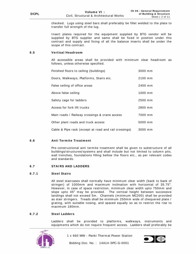
DCPL Volume VI :
Civil, Structural & Architectural Works
Ch 06 : General Requirement
of Building & Structure Sheet | 2 of 11
1 x 660 MW - Panki Thermal Power Station
Bidding Doc. No. : 14A14-SPC-G-0001
checked. Lugs using steel bars shall preferably be fillet welded to the plate to transfer full strength of the lug.
Insert plates required for the equipment supplied by BTG vendor will be
supplied by BTG supplier and same shall be fixed in position under this contract and supply and fixing of all the balance inserts shall be under the
scope of this contract.
6.5 Vertical Headroom
All accessible areas shall be provided with minimum clear headroom as
follows, unless otherwise specified.
Finished floors to ceiling (buildings) 3000 mm
Doors, Walkways, Platforms, Stairs etc. 2100 mm
False ceiling of office areas 2400 mm
Above false ceiling 1000 mm
Safety cage for ladders 2500 mm
Access for fork lift trucks 2800 mm
Main roads / Railway crossings & crane access 7000 mm
Other plant roads and truck access 5000 mm
Cable & Pipe rack (except at road and rail crossings) 3000 mm
6.6 Anti Termite Treatment
Pre-constructional anti termite treatment shall be given to substructure of all buildings/structures/systems and shall include but not limited to column pits,
wall trenches, foundations filling bellow the floors etc., as per relevant codes and standards.
6.7 STAIRS AND LADDERS
6.7.1 Steel Stairs
All steel staircases shall normally have minimum clear width (back to back of stringer) of 1000mm and maximum inclination with horizontal of 35.75o.
However, in case of space restriction, minimum clear width upto 750mm and slope upto 45o may be provided. The vertical height between successive
landings shall not exceed 5m. Channels (minimum MC200) shall be provided as stair stringers. Treads shall be minimum 250mm wide of chequered plate /
grating, with suitable nosing, and spaced equally so as to restrict the rise to
maximum 180mm.
6.7.2 Steel Ladders
Ladders shall be provided to platforms, walkways, instruments and equipments which do not require frequent access. Ladders shall preferably be

DCPL Volume VI :
Civil, Structural & Architectural Works
Ch 06 : General Requirement
of Building & Structure Sheet | 3 of 11
1 x 660 MW - Panki Thermal Power Station
Bidding Doc. No. : 14A14-SPC-G-0001
vertical and its angle with vertical shall not exceed 5o. Ladders shall be of minimum 450mm clear width with 20mm diameter MS rungs spaced at
300mm (maximum). Ladders shall be provided with a safety cage of minimum 750diameter clear when the top of ladder is more than 4.5m above the
landing level. However safety cages shall start at 2.5m above the lower landing level.
6.7.3 RCC Stairs
All stairs shall have maximum riser of 180mm and a minimum tread of 250mm. However, for Administration & Control room building riser shall be
limited to 150mm and tread width of 300mm. Minimum width of stairs shall be 1200mm generally. All stairs normally shall have not more than 15 risers
in one flight. Aluminium angle nosing with minimum 50x25x3 angle or PVC nosing shall be provided for edge protection of RCC stairs.
6.8 Handrails
Handrails shall be provided at appropriate places to ensure safety e.g. around all floors / roof openings, projections / balconies, walkways, platforms, steel
stairs etc.
All handrails shall be of 32mm nominal bore MS pipes (medium class) as per relevant codes, galvanised using 750 gm/sq. m of zinc. Handrails for
platforms, walkways and projections shall be a two-rail 450mm below the top
rails. Handrail post spacing shall be limited to 1500mm as far as possible but can be proportioned to the length of the protected horizontal opening. In such
a case spacing shall not exceed 1850mm center to center of posts. Handrails shall be shop fabricated for specific locations and field welded or bolted to the
erected structural steel. For platforms at elevation more than 30m, three rail system with top rail at 1500mm shall be adopted.
For RCC stairs, handrails with 20mm square MS bar balustrade with suitable
MS flat & aluminium / Treakwood handrail shall be provided, unless
specifically mentioned otherwise.
6.9 Expansion/Construction Joints
Expansion and construction joints shall be provided wherever required. All expansion and construction joints of water retaining structures in RCC shall be
made watertight using PVC ribbed water stops with central bulb. However, kicker type (externally placed) PVC water stops may be used for the base
slabs and in other areas where it is required to facilitate concreting. The
minimum thickness of PVC water stops shall be 6mm and minimum width 225mm. At other joints these shall be150mm wide.
Two part polysulphide sealant conforming to relevant codes shall be used for
sealing of joints in contact with water. For other cases, bitumen sealing compound conforming to relevant codes shall be used. Preformed bitumen
impregnated fibre board conforming relevant codes shall be used as joint filler.
For joint treatment of coal handling system structure, refer clause No. 14.1 of chapter 14.

DCPL Volume VI :
Civil, Structural & Architectural Works
Ch 06 : General Requirement
of Building & Structure Sheet | 4 of 11
1 x 660 MW - Panki Thermal Power Station
Bidding Doc. No. : 14A14-SPC-G-0001
6.10 Brick / Stone Masonry And Parapet Wall
All masonry works shall be designed in accordance with relevant codes as
applicable. Structural design of load bearing and non load bearing walls constructed with fly ash bricks shall be in accordance with criteria specified by
section-4 of National Building Code of India, Part-VI and codal provisions. For
thickness and details of brickwall refer Chapter-17 of this Volume.
All walls shall be non-load bearing in filled panel walls. External walls of all buildings shall be atleast one brick thick. All internal walls shall be atleast one
brick thick except for internal partition walls for office area, canteen, change room, first aid rooms and toilets, which may be half brick thick. RCC bands
(transoms and mullions) shall be provided wherever necessary to curtail the unsupported length / width of the wall.
50mm thick DPC ( 1:1.5:3) with water proofing admixture shall be provided at plinth level before starting masonry works. Water proofing compound shall be
Zydex, Sikka or similar make.
Fly Ash Bricks having minimum 75 kg/sq.cm compressive strength shall be used for non-load bearing superstructure brick work. Cement and sand mortar
1:5 for one brick thick wall and 1:4 for half brick thick wall shall be used. For half brick walls, RCC transoms and mullions shall be provided. Transoms shall
be provided at lintel / door height. The spacing of mullions shall not exceed
2000 mm centre to centre. The size of transoms / mullions shall be minimum 115mm square with four numbers, 8 mm dia bars and 6mm stirrups 150 mm
centers.
Almost all the brickwork shall be plastered with cement mortar. Brickwork in superstructures uncovered by plaster shall be executed by skilled
mason. Courses shall be truly horizontal and vertical joints truly vertical. Wooden straight edges with brick course graduations and position of window
sills and lintels shall be used to control uniformity of brick courses. Masons
should check workmanship frequently with plumb, spirit level, rule and string. All brick work shall be cleaned at the end of day’s work. In case of face bricks
involvement the brickwork shall be in composite shape with face bricks on the exposed face and balance in routine bricks, maintaining the bond fully; using
carborandum stone for rubbing down. Where face bricks are not needed, bricks for the exposed face shall be specially selected from routine bricks. All
exposed brickwork on completion of work shall be rubbed down, washed clean and pointed as specified.
For partition walls two reinforcement bars shall be placed at every fourth layer. Chicken wire mesh shall be provided at the junction of RCC & brick
work.
The masonry works shall be cured for a period of 14 days after laying and plaster shall be cured for a period of 7 days.
Type, thickness and height of external wall, facing the transformer yard to take care of fire accidents in transformer yard shall be according to the
requirements of Tariff Advisory Committee.
All upstands and parapet walls on roof shall be of RCC construction, minimum height of parapet walls shall be 750mm and thickness125 mm.

DCPL Volume VI :
Civil, Structural & Architectural Works
Ch 06 : General Requirement
of Building & Structure Sheet | 5 of 11
1 x 660 MW - Panki Thermal Power Station
Bidding Doc. No. : 14A14-SPC-G-0001
6.11 Waterproofing Of Underground Structures
Water proofing / Damp proofing of all underground structures like water
retaining structures, track hoppers, transfer house, conveyor tunnel & other deep underground structures shall be done by providing following treatments.
Chemical injection grouting for inner faces (details as specified below)
Polymer modified cementitious coating on earth side face as per the following:
1. On the outer surface of walls, frames and roof slabs coming in contact with earth, polymer modified cementitious coating in
two layers as pecificed and as per manufacturer’s specifications shall be provided directly on the concrete surface.
2. 50 mm thick P.C.C (M15 grade) with 10 mm nominal size coarse aggregates) shall be provided under the raft i.e. over the lean
concrete, followed by polymer modified cementitious coating in two layers (slurry mix application) as per manufacturer’s
specification. 50mm thick P.C.C (M15 grade) with 10 mm nominal size coarse aggretates shall then be laid over the
polymer modified cementitious coating before laying the raft. 6.11.1 Chemical Injection Grouting
Minimum, 12 mm dia ( NB ) threaded nozzle of suitable length, shall be
provided over the surface and along the construction joint line in a grid
pattern at a spacing not exceeding 1.5 m c / c before concreting operation. Adequate precaution shall be taken to keep the nozzles plugged at both ends
to prevent them from getting closed by concrete.
For fixing of any nozzle in set concrete suitable size hole shall be drilled, preferably using repercussive hammer drill electrically operated, in grid
pattern and grouting nozzle shallbe fixed in these holes.
After the nozzles are fully set, neat cement slurry admixed with water soluble
non – shrink polymer / monomer based chemical shall be injected through the net - work of nozzles with low pressure grout pumps at a pressure of about
2.0 Kgs. / cm2. Cement slurry shall be prepared by mixing cement with non-shrink polymer/monomer @ 500 gm/50 kg bag of cement and water, ensuring
that Water: Cement ratio does not exceed 2 (by weight). Wetter the structure, lesser should be the water cement ratio. The property of the
polymer/monomer should be such that when it is mixed with water @0.5% by weight of water, the viscosity of the resultant solution (water and
polymer/monomer) should not be more than 1.2 centipoises.Plasticizing agent
shall be added wherever required. The grouting shall be started at very low pressure and increased gradually to a required pressure. The grouting shall
continue, till the hole refuses to take any further grout, even at an increased pressure. Applied pressure shall not be more than the designed strength of
the concrete. After completion of grouting operation, the nozzles shall be sealed properly to the satisfaction of the Engineer.
All liquid retaining / conveying structures including sumps of pump house shall
be tested for water tighteness for as per IS-3370 and 6494 and in case of

DCPL Volume VI :
Civil, Structural & Architectural Works
Ch 06 : General Requirement
of Building & Structure Sheet | 6 of 11
1 x 660 MW - Panki Thermal Power Station
Bidding Doc. No. : 14A14-SPC-G-0001
leakage, seepage, the same shall be rectified by chemical injection grouting as specified above.
6.11.2 POLYMER MODIFIED CEMENTITIOUS COATING
6.11.2.1 Materials
Modified liquid polymer blend shall be a dispersion containing 100 % acrylic based polymer solids. Polymer shall be mixed in the ratio of 1 cement: 0.5
polymer (for minimum solid content of polymer 30%).
Portland cement based dry powder.
Clean, fine specially prepared quartz sand approximately 0.6 mm size.
6.11.2.2 Mixing
The liquid polymer shall be stirred well and cement based powder shall then be added slowly to make a Slurry Mix. For preparation of Brush Topping Mix,
quartz sand shall be added slowly and mixed well till a homogeneous mixture is obtained. The mix shall be used within half an hour of the preparation.
Addition of quartz sand may not be necessary, in case dry power contains the
same. 6.11.2.3 Properties of Coating
It must adhere to wet surface.
It should develop adequate bond strength, with the concrete surface, not less
than 2 N / Sq.mm.
Co - efficient of permeability shall be about 5x10⁻¹⁰ Cm / Sec.
Water absorption after continuous soaking shall not be more than 1 %.
The materials shall be permeable under water vapour.
The material shall be resistant to acids and alkalies present in the soil and underground water with normal pH value between 4 and 14.
The co - efficient of thermal expansion of the material shall be close to that of concrete.
6.11.2.4 Application
The concrete surface shall be cleaned and made free from grease, oils or
loosely adhered particles. The surface shall be damp without any free water. For exterior underground part, application (b) pertaining to Brush topping Mix
shall be followed.
(a) For Slurry Mix

DCPL Volume VI :
Civil, Structural & Architectural Works
Ch 06 : General Requirement
of Building & Structure Sheet | 7 of 11
1 x 660 MW - Panki Thermal Power Station
Bidding Doc. No. : 14A14-SPC-G-0001
A minimum of 2 coats shall be applied on the surface. The first coat being applied, when the surface is still damp and left to harden for 4 to 6 hours.
After 4 to 6 hours of the application of second coat, it shall be finished by rubbing down with a soft dry sponge. The coverage shall not be less than
1 : 1 Kgs. / m2 in the 2 coats. A lap of 75 mm shall be provided at the joints.
The coating shall be air dried for 4 to 6 hours and, thereafter, cured for 7 days aftern the application of last coat.
(b) For Brush Topping Mix
This shall be applied in two coats. A primary coat of slurry mix can also be
first applied on the surface as first coat. After the coating has dried up, a coat of Brush Topping Mix shall be applied over it with a push broom or
any other similar brush. It shall be left in broom finished condition. The
nominal thickness shall be 1.5 mm and minimum thickness shall be 1.0 mm. A lap of 75 mm shall be provided at the joints. It shall be ensured
that no pinhole exists and rebrushing shall be done to cover the pinholes, if any.
The Coating shall be air dried for 4 to 6 hours and thereafter cured for 7
days after the application of last coat.
Rate of application of coating shall be established to achieve the required
thickness.
6.12 Paving
Area Paving in Main Plant Block
RCC paving of minimum 150 mm thick with M25 grade concrete, over an underbed as specified herein shall be provided for areas mentioned below.
RCC paving shall be designed as rigid reinforced concrete pavement for the
crane/ vehicular/ equipment movement loads which the paving has to bear. The underbed for paving shall consist of preparation and consolidation of sub-
grade to the required level, laying of stone soling of 250mm compacted thickness for normal duty paving and 400mm compacted thickness for heavy
duty paving with 63 mm and down aggregate with interstices filled with selected moorum and sand followed by 75 mm thick PCC of M7.5 grade with
40 mm nominal size aggregate. Paving areas shall be provided with the metallic hardener floor finish as specified elsewhere in the specification. The
reinforcement shall consist of minimum 8mm diameter bars at 200 mm c/c of
grade Fe 500 at top and bottom in both directions. Actual reinforcement in paved slab shall be designed depending upon the duty and loading on the
pavement.
Entire main plant area from chimney to transformer yard as enclosed within the peripheral roads of the main plant area shall be provided with paving (on
chimney side, paving shall be upto the edge of the storm water drain by
Bidder.
Passages shall be provided inside the main plant block connecting to the outer
periphery road to have access to the various facilities/buildings. The passage
areas shall be provided with heavy duty paving for movement of heavy

DCPL Volume VI :
Civil, Structural & Architectural Works
Ch 06 : General Requirement
of Building & Structure Sheet | 8 of 11
1 x 660 MW - Panki Thermal Power Station
Bidding Doc. No. : 14A14-SPC-G-0001
vehicles. The top surface of the passages shall be finished with 50 mm thick metallic hardener topping.
Heavy duty paving shall be provided for the areas in the Mill bunker building,
equipment lay down area in the TG hall and handling areas for PA/FD fans with 50 mm thick metallic hardener topping.
The ground floor area in the boiler shall be provided with normal duty paving and shall be finished with 50 mm thick metallic hardener topping.
Lightly loaded areas such as corridors below trestle and other areas in the
main plant block where no heavy traffic movement is envisaged shall be provided with interlocking concrete block paving with PCC concrete blocks of
minimum M35 grade and minimum 80 mm thickness underlain by 200mm thick with 63 mm and down aggregate with interstices filled with selected
moorum and sand.
All other area inside the main plant block shall be provided with normal duty paving. 2.5 m wide paving around periphery of all sumps and underground
tanks without metallic hardener shall be provided.
Suitable drains shall be provided to dispose off storm water as well as floor wash of the main plant block. The paving shall be provided with slope of 1:500
to dispose the surface water/wash water to the nearest drain. Drains shall be provided to dispose the floor wash water of ESP to a sump of suitable size.
Further, the overflow from the sump shall be drained to the nearest storm
water drain.
Sewer lines interconnected by sewer manholes (RCC) at regular intervals (not exceeding 30 meter centre to centre) shall be provided to dispose off sewage
from ESP area, Main Plant Building, Control Room & transformer yard area to sewage treatment plant.
Entire switch yard shall be provided with 75mm paving of 20 to 40mm size
stone aggregate on top and 75mm paving of 20 mm stone aggregate below.
Before laying the paving, the ground surface shall be treated with antiweed chemicals as per manufacturer recommendations.
6.13 Security Gate
Emergency Gate shall be provided in addition to the main gate. Main Gate
shall have two separate entry one for project site and other for fly ash silo trucks movement. Gate latches shall be arranged for padlocking with the
padlock accessible from both sides of the gate. Padlocks shall be provided and
the key shall be in accordance with the Purchaser’s requirements.
Cantilever type motorized sliding gate shall be furnished at the main plant entrance. The gate shall be operable by push button at both the guard house
and the security office in the Administration / Plant Service area, and by card reader or key switches.
The road near the main entrance to be widened additionally by 7.5 m on either sides of the road for parking of vehicles for security check.
Suitable median arrangements to be made.
Security cabin to be provided on either sides of the road near the main gate.

DCPL Volume VI :
Civil, Structural & Architectural Works
Ch 06 : General Requirement
of Building & Structure Sheet | 9 of 11
1 x 660 MW - Panki Thermal Power Station
Bidding Doc. No. : 14A14-SPC-G-0001
Elevated platform either in steel structure / Brick work or RCC to carry out
checking on Lorries/Tippers by security personnel while the vehicles getting in or going out from the premises.
6.14 Fencing
Fencing with toe wall and steel gates shall be provided around the transformers & Switchyard. Fencing shall comprise of P.V.C coated GI
chainlink fencing of minimum 8G (including PVC coating) of mess size 75mm and of height 2.4 m above the toe wall. The diameter of steel wire for chain
link fence (excluding P.VC. coating) shall not be less than 12G. Fence post shall be of precast R.C.C. of minimum M20 grade. All corner posts will have
two stay posts and every 10th post will have tranverse stay post. Suitable R.C.C foundation for the post and stays shall be provided based on prevailing
soil condition. Gates shall be with locking provisions. The toe walls of fly ash
bricks shall be provided between fence post all along the run of the fence with suitable foundation. Toe wall shall be minimum 200mm above the formation
level with 50mm thick with PCC coping (1:1.5:3) and shall extend minimum 300mm below the formation level. The toe wall shall be plastered on both
sides and painted with two coats of cement paint of approved colour and shade. Toe walls shall be provided with weep holes at suitable spacing.
Removable type of fencing shall be provided at suitable location to permit
entry and exit of equipment.
6.15 Watch Tower
Watch Tower shall be constructed with RCC frame work. Floor of tower shall
be at least 6m above graded level.
Covered area for each tower shall be approx. 25 sqm. Number of towers shall be such that the complete periphery of the plant can be watched from the
towers but in no case the number of towers shall be less than twelve.
6.16 Plinth Protection
All buildings shall be provided with 750 mm wide plinth protection all round.
It consist of 50mm thick PCC M20 grade with 12mm maximum size aggregate over 200mm thick stone soling using 40mm nominal size ramped,
consolidated and grouted with fine sand.
6.17 Miscellaneous Requirements
Doors and windows on external walls of buildings shall be provided with RCC
sunshade over the openings with 300 mm projection on either side of the opening. Projection on sunshade from the wall shall be minimum 450 nm over
window openings and 750 mm over door openings.
Doors and windows on the external walls of buildings with metal cladding shall
be fixed by creating recesses in the cladding system.
No cable trenches shall be provided in TG hall, Boiler/ESP area, fuel oil pump
house, Ash pump houses etc.

DCPL Volume VI :
Civil, Structural & Architectural Works
Ch 06 : General Requirement
of Building & Structure Sheet | 10 of 11
1 x 660 MW - Panki Thermal Power Station
Bidding Doc. No. : 14A14-SPC-G-0001
All cables & pipes in outlying area shall run above ground over steel trestles or other supporting structures for easy inspection & maintenance except in
transformer yard area and some other localized area where the same can run in RCC trenches. However, for facilities for which buried pipe & cables are
permitted by Purchaser, the same can be provided. In case of trestles, minimum 7.0 m head clearance shall be provided for road crossings. In other
areas, the clear height shall be 3.0m minimum.
All cable and pipe trenches shall be of RCC of minimum M25 grade. Trenches
located outside buildings shall project at least 200mm above the finished formation level so that no storm water shall enter into trench. The bottom of
the trench shall be sloped suitably for draining out the collected water into sump pit. The pre-cast covers shall be of minimum M30 grade and shall not
weigh more than 65kg. Lifting hooks shall be provided in the pre-cast covers. Pre-cast covers shall have edge protection angles at top and bottom on all the
four sides along with lugs.
Duct banks consisting of MS/PVC conduits for cables shall be provided with
proper sealing arrangement consisting of fire retardant sealing compound.
All floor openings for cables below electrical panel shall be sealed with fire sealing compound after cables are laid.
Mild steel bars required for earthing / grounding mat shall also be supplied
and installed.
All cable vaults shall be located above ground level i.e. cable vaults shall not
be provided as basements in the buildings.
Connection work at terminal points is included in the scope of the Bidder.
Ground floor slab of all the buildings excluding building mentioned in Chapter 14 (Coal Handling Plant) shall be of minimum 150mm thick of M-25 grade laid
over minimum 75mm thick PCC and 230mm soling of 63mm down graded
aggregates (minimum) course unless specifically mentioned otherwise. The reinforcement shall consist of minimum 8mm diameter bars at 200 mm c/c of
grade Fe 500 at top and bottom in both directions.
All openings in external walls provided for pipes, cables, duct etc. shall be
effectively sealed to prevent water seepage, after the routing of the services are completed.
Natural lighting & Ventilation
The area of windows shall be a minimum 10 % of the floor area to ensure adequate natural lighting. Fans shall be provided in general office areas as per
standard norms. Sewerage system shall be provided with adequate ventilation for the pipe work as well as manhole.
6.18 Statutory Requirements
All the applicable statutory rules pertaining to Factories act, Factory rules of
State Government, Fire safety rules of Tariff Advisory committee, Water act of
Pollution Control boards, Explosives act etc., and stipulations of other relevant

DCPL Volume VI :
Civil, Structural & Architectural Works
Ch 06 : General Requirement
of Building & Structure Sheet | 11 of 11
1 x 660 MW - Panki Thermal Power Station
Bidding Doc. No. : 14A14-SPC-G-0001
statutory authorities shall be taken into consideration at the time of design and construction.
Provisions of safety, health and welfare according to Factories act shall be
complied with at design stage. These shall include provision of continuous walkway (minimum 600 mm wide or as per approved mechanical GA draings)
along crane-girder at crane girder level on both sides of the building,
comfortable approach to EOT crane. cabin, railings, fire escape locker room for workmen, pantry, toilets, rest rooms etc.
Adequate no. of fire escapes shall be provided in a building. Fire proof doors,
no. of staircase, fire separation walls, lath plastering on structural steel member (in fire prone areas) shall. be made according to the recommendation
of TAC.
For fire safety requirements of buildings, National Building Code of India shall
be followed in addition to TAC requirements. All masonry firewalls shall be minimum 345 thick and RCC firewall shall be minimum 200 mm thick.

DCPL Volume VI :
Civil, Structural & Architectural Works Ch 07 : Material
Sheet | 1 of 1
1 x 660 MW - Panki Thermal Power Station
Bidding Doc. No. : 14A14-SPC-G-0001
7.0 MATERIAL
7.1 Structural Steel
Steel will conform to Grade-A of IS:2062 (latest) for rolled steel members or
plates upto 20 mm thickness. For plates above 20 mm thickness and welded construction steel conforming to Grade-B (killed and normalized) of IS:
2062(latest) shall be used except for crane girders where Grade-C (IS: 2062)
steel shall be used. Steel shall be procured from SAIL or any other approved main producers.
Chequered plate shall conform to IS: 3502 (latest) and minimum thickness of
chequered plate for floorings, covers etc shall be 8 mm O/P.
Complete hopper including vertical and conical portion of bunker in mill building shall be provided with lining of atleast 6mm thick SS plate grade SS
316L .
The electrodes classification as per AWS shall be as follows:-
a) For welding of stainless steel to stainless steel : E308L
b) For welding of stainless steel to mild steel : E309
7.2 Cement
Ordinary Portland Cement (OPC) Grade 43 shall be used for all structures.
7.3 Reinforcement
The reinforcement used shall be cold worked steel high strength deformed bars of grade Fe 500 conforming to IS:1786 – latest. Reinforcement steel shall
be of either of SAIL, RINL make or equivalent as approved by UPRVUNL.
Intermixing of different grades of rebars or rebars of different material
composition in same structure shall not be allowed.
Welding of reinforcement shall not be carried out without the permission of the Owner.
Projecting reinforcement or dowel bars for future connection of the structural
works shall be protected by cement paint, if they are to be left exposed for a long time.

DCPL Volume VI :
Civil, Structural & Architectural Works Ch 08 : Loading
Sheet | 1 of 5
1 x 660 MW - Panki Thermal Power Station
Bidding Doc. No. : 14A14-SPC-G-0001
8.0 LOADING
8.1 Dead Loads
Dead loads shall include the weight of structure complete with finishes,
fixtures & partitions and shall be taken as per IS: 875 (Part-I)
8.2 Imposed Loads
Imposed loads in different areas shall include live loads, erection, operation
and maintenance loads. Equipment loads (which constitute all loads of equipment to be supported on the building frame) are not included in the
imposed loads furnished below and shall be considered in addition to imposed loads.
For consideration of imposed loads on structures, IS:875 (Part-2) “Code of
practice for design loads (other than earthquake) for buildings & structure”
shall be followed. The following minimum imposed loads as indicated for some of the important areas shall however be considered for the design. If
actual expected load is more than the specified minimum load, then actual load is to be considered
Sl.No. Location Imposed Loads
(T/Sq.m) A) Turbine Building
i) Ground floor (general) 3.00
ii) Ground floor (Heavy equipment
storage area) 5.00
iii) Mezzanine Floor 1.50
iv) Operating Floor
a) Rotor Removal area Rotor removal area beams
shall also be checked for ½
the rotor load at the center of beam
5.00
b) Equipment Laydown area
3.00
v) Gratings, chequered floors,
walkways, platforms, stairs etc.
0.50
vi) Roof (Where no equipment are
located and non-accessible)
Roof (where equipment are located and accessible)
0.15
0.50
B)
Deaerator and Heater Bay
i) HP / LP heater floor 2.0
ii) Deaerator floor 1.5
iii) Cable gallery 0.50 (In addition

DCPL Volume VI :
Civil, Structural & Architectural Works Ch 08 : Loading
Sheet | 2 of 5
1 x 660 MW - Panki Thermal Power Station
Bidding Doc. No. : 14A14-SPC-G-0001
Sl.No. Location Imposed Loads
(T/Sq.m)
to this actual cable load shall be
considered)
iv) MCC & Control Building floors
1.00
v) AHU room battery room, air
washer room 1.5
C) Mill & Bunker Bay
i) Ground Floor 2.5
ii) Feeder Floor 2.00
iii) Tripper Floor
2.00
Beams however
shall be checked for feeder/tripper
concentrated load
iv) Roof
v) Dust Load for flat roof For inclined roof
0.15 (where no equipment are
located) 0.50 (where
equipment are
located)
0.1 0.05
D) Pump Houses operating floor 1.50
E)
Underground Structures such as Channels, Sumps,
Underground Pump House, Tanks, Trenches, Reservoirs,
Cooling Water Ducts etc.
In addition to earth pressure and ground water pressure, the surcharge load of 2T/sqm. shall also be considered for design
of all underground structures.
F)
Road Culverts / Bridges and its allied structures including RCC Pipe Crossings & Road Crossing of Trenches.
Design for class ‘AA’ loading (wheeled & tracked both) and checked for class ‘A’ loading as per IRC Standard.
G) Covers for Channels / trenches
Trench cover at
entry to building and road crossings
shall be designed for live load of 100
kN at centre.
Trench cover at other location shall

DCPL Volume VI :
Civil, Structural & Architectural Works Ch 08 : Loading
Sheet | 3 of 5
1 x 660 MW - Panki Thermal Power Station
Bidding Doc. No. : 14A14-SPC-G-0001
Sl.No. Location Imposed Loads
(T/Sq.m)
be designed with a surcharge of 100
kN/m2 or a concentrated load
of 100 kN at center which is
worst.
H) Railway Supporting Structures, Rail Culverts
As per railway ‘Bridge Rules’
I)
Boiler / ESP Support Structures 0.50
J) General (Unless Specified Otherwise) i) Stairs, Landings and Balconies 0.50
ii) Toilets 0.20
iii) Chequered plates, grating floors,
etc.
0.50
iv) RCC floors (General) 0.50
v) a) Flat roofs (where no
equipment are located) 0.15
b) Flat Roofs (where
equipment are located) 0.50
vi) Inclined Roofs As per IS:875 (Part-II)
vii) Walkways (General).
0.50 T/sq.m or a
concentrated load of 0.3 T/m which
ever is greater viii) Walkways of conveyor galleries. 0.50
ix) Floor of control room of
switchyard control building 1.00
x) Cable and pipe trestles
0.20 for walkway and in addition,
friction loads as
applicable. Note:
1. Additional load for cable, piping / ducting, shall be considered as
applicable.
2. Hung load shall be based on minimum loading equivalents of 1 kN/ m2 for piping and 0.5 kN/m2 for electrical ventilation and air conditioning.
3. Loading resulting from concentrations of facilities in specific areas shall be substituted where listed base loadings are excluded
4. Cantilever loads of not less than 2000 kg/metre at a distance of
1200 mm from the external face or the columns, on both sides of the ESP, for cable trays and walkways.
5. Cantilever loads of not less than 500 kg/metre at a distance of 1200
mm from the external face or the columns, on both sides of the boiler,
for cable trays and walkways.
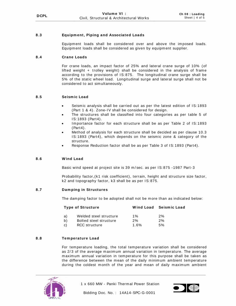
DCPL Volume VI :
Civil, Structural & Architectural Works Ch 08 : Loading
Sheet | 4 of 5
1 x 660 MW - Panki Thermal Power Station
Bidding Doc. No. : 14A14-SPC-G-0001
8.3 Equipment, Piping and Associated Loads
Equipment loads shall be considered over and above the imposed loads. Equipment loads shall be considered as given by equipment supplier.
8.4 Crane Loads
For crane loads, an impact factor of 25% and lateral crane surge of 10% (of lifted weight + trolley weight) shall be considered in the analysis of frame
according to the provisions of IS:875. The longitudinal crane surge shall be 5% of the static wheel load. Longitudinal surge and lateral surge shall not be
considered to act simultaneously.
8.5 Seismic Load
Seismic analysis shall be carried out as per the latest edition of IS:1893 (Part 1 & 4). Zone-IV shall be considered for design.
The structures shall be classified into four categories as per table 5 of IS:1893 (Part4).
Importance factor for each structure shall be as per Table 2 of IS:1893 (Part4).
Method of analysis for each structure shall be decided as per clause 10.3 IS:1893 (Part4), which depends on the seismic zone & category of the
structure.
Response Reduction factor shall be as per Table 3 of IS:1893 (Part4).
8.6 Wind Load
Basic wind speed at project site is 39 m/sec. as per IS:875 -1987 Part-3
Probability factor,(k1 risk coefficient), terrain, height and structure size factor,
k2 and topography factor, k3 shall be as per IS:875.
8.7 Damping in Structures
The damping factor to be adopted shall not be more than as indicated below:
Type of Structure Wind Load Seismic Load
a) Welded steel structure 1% 2%
b) Bolted steel structure 2% 2%
c) RCC structure 1.6% 5%
8.8 Temperature Load
For temperature loading, the total temperature variation shall be considered
as 2/3 of the average maximum annual variation in temperature. The average maximum annual variation in temperature for this purpose shall be taken as
the difference between the mean of the daily minimum ambient temperature
during the coldest month of the year and mean of daily maximum ambient

DCPL Volume VI :
Civil, Structural & Architectural Works Ch 08 : Loading
Sheet | 5 of 5
1 x 660 MW - Panki Thermal Power Station
Bidding Doc. No. : 14A14-SPC-G-0001
temperature during the hottest month of the year. The structure shall be
designed to withstand stresses due to 50% of the total temperature variation.
Suitable expansion joints shall be provided in the longitudinal direction
wherever necessary with provision of twin columns. The maximum distance of the expansion joint shall be as per the provisions of IS:800 and IS:456 for
steel and concrete structures respectively.
Following temperatures shall be considered for design of all buildings and
structures under this package :
Mean Daily minimum ambient temperature during coldest month of the year = 4° C
Mean Daily maximum ambient temperature during hottest month of the year = 50° C
8.9 The following densities shall be considered for design of coal bunkers:
(a) For volume calculations : 800 kg/cum (b) For structural design : 1200 kg/cum
The coal bunker will be designed as per criteria outlined in IS:9178 (Part I&II)
The following densities shall be considered for design of ash silos:
(a) For volume calculations : 750 kg/cum (b) For structural design : 1600 kg/cum
The coal bunker will be designed as per criteria outlined in IS:4995.

DCPL Volume VI :
Civil, Structural & Architectural Works Ch 09 : Steel Structure
Sheet | 1 of 23
1 x 660 MW - Panki Thermal Power Station
Bidding Doc. No. : 14A14-SPC-G-0001
9.0 STEEL STRUCTURE
9.1 Framing
All steel framed structures shall be either “rigid frame” or “simple space
frame” or a combination of two.
Lateral forces shall be resisted by stiff jointed moment connections in rigid
frame design. The column bases shall generally be fixed to concrete foundation pedestal by providing moment resistant base detail.
The power house building design shall be a combination of rigid frame in
transverse direction and simple frame in longitudinal direction.
If RCC floor / roof is assumed to act as diaphragm transmitting lateral loads to braced bays, it shall be provided with shear connectors. However, whenever
large / more number of cut-outs are provided in the floor slab, horizontal floor
bracings shall be provided below slab to transfer horizontal force to columns without considering diaphragm action from slab.
Minimum size and maximum spacing of shear connectors shall be ISA
75x75x6 and 500 mm respectively. A minimum height of 75 mm shall be
provided for the shear connectors.
Grating/chequered plate floor shall neither be considered to provide lateral support to the top flange of supporting beams nor to provide a shear
diaphragm.
Floors for vibrating machines of all kind together with supporting framework
shall be adequately braced in both horizontal and vertical planes. Floors or structure supporting mechanical equipment shall be designed to minimize
vibration, avoid resonance and maintain alignment and level.
9.2 Design Concepts
Individual members of the frame shall be designed for the worst combination
of forces such as bending moment, axial force, shear force, torsion, etc. Criticality of erection / maintenance loads shall also be checked separately in
combination with other simultaneously occurring loads for possible design
loadings.
The different load combinations shall be taken as per IS:875 (Part-5) and
other relevant IS Codes.
a. Wind and seismic forces shall not be considered to act simultaneously.
b. For the design of main plant structures during seismic condition, the
deaerator feed water tank shall be considered full upto operating level. However, for other load combinations, deaerator feed water tank in
flooded condition shall be considered.
c. In the analysis of main plant building & bunker building, the stresses arising due to temperature must be considered.
d. ‘Lifted load’ of crane shall not be considered during seismic condition.

DCPL Volume VI :
Civil, Structural & Architectural Works Ch 09 : Steel Structure
Sheet | 2 of 23
1 x 660 MW - Panki Thermal Power Station
Bidding Doc. No. : 14A14-SPC-G-0001
e. In case two cranes are provided and tandem operation is not
envisaged, the load shall be taken as one crane fully loaded and second crane without lifted load but standing idle adjacent to first crane.
f. In case two cranes are provided and tandem operation is envisaged for
some bays, then the load shall be taken as both the cranes fully loaded and standing side for these bays. For other bays, load shall be taken as
one crane fully loaded and second crane without lifted load but
standing idle adjacent to first crane.
g. Permissible stresses for different load combinations shall be taken as per relevant IS codes.
h. Frictional force between the pipes and supporting structure in
longitudinal direction need not be considered along with seismic or wind forces.
The design of steel structures shall be done by working stress method. Design shall be as per provision of IS:800 (latest) and other relevant IS standards.
For design of coal bins and hopper IS:9178 (Part I to III) shall be followed.
Roof decking sheets shall be designed as per IS:801 to carry the self load,
dead load due to RCC slab and finishes and imposed load. The deflection of metal deck shall be limited as per BS:5950.
Permissible stresses for different members shall be allowed to exceed upto 33.33% only under normal loads along with wind and seismic conditions. The
members which are designed primarily to resist wind load such as bracing members ,no increase in permissible stress will be permitted. However,
permissible stresses in bolts and welds shall be allowed to exceed up to 25 % only under wind and seismic conditions.
For design which requires the use of the minimum column load (such as,
uplift on anchor bolts, column axial tension, etc.) The following criteria
shall be used in determining minimum load: Use 90% of the column dead load, No live load is used, Uplift forces from vertical bracing are included
where applicable and Wind uplift on the roof is included where applicable.
Base plates shall be placed on foundation pedestal with grouting. For large base plates necessary grout holes shall be provided. All anchor bolts for
fastening steel columns on foundation shall be embedded in foundation during concreting itself. No anchor pockets in foundation shall be allowed.
Design of base plates shall be based on design pressure on foundation
which shall not exceed the following:
Pedestal in concrete grade M20 5.0 N / sq.mm Pedestal in concrete grade M25 6.25 N / sq.mm
Pedestal in concrete grade M30 7.5 N / sq.mm
The total horizontal shear force at the base of column is transferred to the
column pedestals through friction between the base plate and the grout. A
coefficient of friction of 0.30 shall be used in conjunction with the minimum column load as defined above. If the horizontal shear force exceeds the

DCPL Volume VI :
Civil, Structural & Architectural Works Ch 09 : Steel Structure
Sheet | 3 of 23
1 x 660 MW - Panki Thermal Power Station
Bidding Doc. No. : 14A14-SPC-G-0001
frictional resistance force or if the column is subjected to a net uplift load,
the total force shall then be transmitted through shear bars / shear keys
welded to the base plate. Anchor bolts are not assumed to resist any horizontal shear force. Necessary recesses shall be kept in the foundation
concrete for shear lugs.
Welding shall be used for fabrication and erection. Site connections shall generally be with welding. However, high Strength Structural (HSS) bolts shall
be used for all important connections to be decided during detail engineering
stage. In few cases, for shear connections or removable beam connections, bolted joints with MS bolts may be adopted. For HSS bolt connection,
IS:4000, IS:3757, IS:6623 and IS:6649 shall be followed. IS:814, IS:816, IS:1024, IS:4353 and IS:9595 shall be followed for welding of structures.
9.3 Permissible Deflections
The permissible deflections of various steel members under normal loading
conditions shall be as specified below. For calculation of deflections in
structures and individual members dynamic effects shall not be considered, unless specified otherwise. Also, no increase in deflection limits shall be
allowed when wind or seismic load are acting concurrent with normal loading conditions.
9.3.1 Vertical Deflection
a) For beams supporting dynamic equipment : Span / 500
b) For beams supporting floors / masonry : Span / 325
c) For beams supporting pipes : Span / 400 d) For roofing and cladding components : Span / 325
e) For gratings and chequered plates : Span / 200 subject to a maximum of 6 mm
f) Coal/ Ash conveyor gallery bridges : Span / 450
g) For beams directly supporting drive machinery : Span / 500
For crane gantries or any member subjected to working loads, the maximum
deflection under dead load and live load excluding impact shall not exceed the following values:
a) For manually operated cranes & monorails : Span / 500
b) For electric overhead cranes
i) Up to 50 t capacity : Span / 750 ii) Over 50 t capacity : Span / 1000
c) The vertical deflection of metal deck sheet for floor / roof shall be limited to : Span / 250.
9.3.2 Horizontal deflections
The permissible horizontal deflections shall be as per following unless specified
otherwise:
a) Single storey building
(without crane load ) : Height / 325 b) Multistoried building : Height / 500

DCPL Volume VI :
Civil, Structural & Architectural Works Ch 09 : Steel Structure
Sheet | 4 of 23
1 x 660 MW - Panki Thermal Power Station
Bidding Doc. No. : 14A14-SPC-G-0001
(without crane load)
c) Pipe rack columns : Height / 325
d) Crane gantry girder due to surge : Height/200 e) Building main columns at crane rail: Height / 2500 limited to
level due to action of crane surge maximum of 10 mm load only
f) Open gantry columns at crane rail level due to action of : Height/4000 limited to
crane surge load only maximum of 10 mm
h) Coal handling trestles : Height / 1000 (across conveyor) Height / 500 (along conveyor)
Provisions of IS: 800 and relevant IS Code shall be followed for limiting
deflections of structural elements not listed above.
9.4 Minimum Thickness of Structural Steel Elements
The minimum thickness of various components of a structure and hot rolled
sections shall be as follows. The minimum thickness of rolled shapes shall mean flange thickness regardless of web thickness. Structural steel members
exposed to significantly corrosive environment shall be increased suitably in thickness or suitably protected otherwise as per good practice and sound
engineering judgement in each instance.
a) Trusses, purlins, girts and
bracing 6mm
b) Columns and beams 8mm
c) Guessets 8mm
d) Stiffeners 8mm
e) Base plates 10mm & above
e) Chequered plates 8 mm o/p & above
f) Grating flats 5 mm
g) Latticed structures in switchyard : 6 mm
Minimum thickness of structural members other than gratings and chequered plate directly exposed to weather and inaccessible for painting and maintenance shall be 8 mm.
Minimum thickness of structural members other than gratings directly exposed
to weather and inaccessible for painting and maintenance shall be 8 mm.
9.5 Minimum Sizes
The flange width of purlins supporting light weight concrete slab shall not be less than 65 mm and for those supporting roof sheeting and wall cladding it
shall not be less than 50 mm. Width of steel rolled section connected to other

DCPL Volume VI :
Civil, Structural & Architectural Works Ch 09 : Steel Structure
Sheet | 5 of 23
1 x 660 MW - Panki Thermal Power Station
Bidding Doc. No. : 14A14-SPC-G-0001
member shall be at least 50 mm. The depth of beams for platform of all
structures shall not be less than 125 mm.
9.6 Slenderness and Depth Ratio
The slenderness ration of main members in tension, compression or bending
shall be in accordance with IS:800.
The following limiting ratios of depth to span shall considered as a general
guide.
a) Truss 1 / 10 b) Rolled beams and girders for ordinary floors and rafters 1 / 24
c) Supporting floor beams for vibrating machinery /equipment 1 / 15 d) Roof purlins and girts 1 / 45
e) Gable columns 1 / 30
9.7 Joints / Connections in Steel Structures:
9.7.1 Steel structures shall be detailed and connection and joints provided as per
the provisions of IS:800, IS:9595, IS:1367, IS:9178 and IS:816 and as per following requirements:
a. Connection of vertical bracings with connection members and diagonals
of truss members shall be designed for full tensile capacity of the bracings unless actual loads are indicated on the drawings.
b. Size of fillet weld for flange to web connection for built up section shall be as follows:
i) For box section weld size shall be designed for full shear
capacity. Where filet weld is not possible, full penetration but weld shall be provided.
ii) For rolled sections and built-up I sections, weld size shall be
designed for 80% of full shear capacity or actual shear, (if
indicated in drawings) whichever is more. However, weld size shall not be less 0.5 times the web thickness. Weld shall be
double fillet.
iii) All welds shall be continuous unless otherwise specifically approved. The minimum size of the fillet weld shall be 6 mm.
c. Shear connections shall be designed for 75% of section strength (shear
capacity) for rolled sections and 80% of section strength (shear
capacity) of built-up section or rolled section with cover plates. However, if actual shear load is more than above, the connection shall
be designed for actual load.
d. Moment connection between beam and column shall be designed for 100% of moment capacity of the beam section. This can be achieved
either by direct butt welding of the top and bottom flange of beam with column flange or by providing top and bottom moment plate with
suitable notch for additional weld length.

DCPL Volume VI :
Civil, Structural & Architectural Works Ch 09 : Steel Structure
Sheet | 6 of 23
1 x 660 MW - Panki Thermal Power Station
Bidding Doc. No. : 14A14-SPC-G-0001
e. All bolts and nuts shall have property class compatible to each other.
For bolts carrying dynamic or fluctuating loads and those in direct
tension shall be provided with an additional double coil helical spring washer conforming to IS:6755. The threaded portion of the bolt shall
project through the nut at least by one thread.
f. Where a steel beam or member is to be connected on RCC structure, it shall be connected using an insert plate and preferably through shear
connection.
g. All butt welds shall be full penetration butt welds.
h. The connection between top flange and web of crane girder shall be full
penetration butt weld. Bottom flange, connection with web can be fillet weld or butt weld as directed by Purchaser. Bearing edges of crane
girders shall be machine finished.
i. Connection of base plate and associated stiffeners with the columns
shall be designed considering the total load transferred through welds. However, minimum weld size (double fillet) shall not be less than 0.6
times the thickness of stiffeners.
j. Splicing: All work shall be full strength. Field splicing shall be done with web and flange cover plates for full strength. In exceptional cases, the
field splicing shall be designed for 50% of load carried by the cover plates and remaining 50% load through full penetration butt weld.
Shop splicing for all sections other than rolled shall be carried out by
full penetration butt welds with nominal cover plates. Splicing for all rolled sections shall be carried out using web and flange cover plates.
9.7.2 All bolted connections shall have bolts of minimum 16 mm dia. The
connections of stairs and handrailing shall be made with 20 mm diameter threaded fasteners conforming to IS:1363. Erection bolts shall be black
bolts of minimum 12 mm dia.
9.7.3 Efficiency of site welds (fillet/butt) to be considered shall be as
follows:
a) Weld above 20 m from ground --- 50% b) Weld below 20 m from ground --- 80%
9.8 Painting
a. All steel structures shall receive two primer coats and two finish coats of
painting. First coat of primer shall be given in shop after fabrication before dispatch to erection site after surface preparation as described
below. The second coat of primer shall be applied after erection and final alignment of the erected structures. Two finish coats shall also be
applied after erection.
b. Steel surface which is to be painted shall be cleaned of dust and grease and the heavier layers of rust shall be removed by chipping prior to
actual surface preparation. The surface shall be abrasive blasted to
Sa-2½ finish as per SIS05-5900 . Primer paint shall be zinc silicate of

DCPL Volume VI :
Civil, Structural & Architectural Works Ch 09 : Steel Structure
Sheet | 7 of 23
1 x 660 MW - Panki Thermal Power Station
Bidding Doc. No. : 14A14-SPC-G-0001
approved brand . Dry film thickness of each primer coat shall be 25
microns.
c. Finish paint shall be 2 coats of matt finish synthetic enamel paint are
equivalent with DFT of 25Micron each. The undercoat and finish coat shall be of different tint to distinguish the same from finish paint. The
total dry film thickness shall be 100 microns. All paints shall be of approved brand and shade as per the OWNER’s requirement.
d. Joints to be site welded shall have no paint applied within 100 mm of welding zone.
Similarly where Friction grip fasteners are to be used no painting shall be
provided. On completion of the joint the surfaces shall receive the paint as specified.
e. Surfaces inaccessible after assembly shall receive two coats of primer
prior to assembly.
Surfaces inaccessible after erection including top surfaces of floor beams
supporting gratings or chequered plate shall receive one additional coat of finish paint over and above number of coats specified before erection.
Portion of steel member embedded / to be encased in concrete shall not be painted.
Painting shall not be done in frosty or foggy weather or when humidity is
such as to cause condensation on the surfaces to be painted.
9.9 Fabrication of Structural Steel Work
9.9.1 The details of fabrication, shop testing and delivery to site of structural steel
work including supply of all consumable stores, bolts, nuts, washers, electrodes and other materials as required including field connections are
indicated below to be performed by the contractor:
a. Preparation & submission of complete detailed fabrication drawings and
erection marking drawings as required including design calculations.
b. Furnish all materials, labour, tools & plant and all consumables required for fabrication and supply of all necessary bolts, nuts,
washers, tie rods and welding electrodes for field connections.
c. Furnish shop painting of all fabricated steelwork as specified.
d. Suitably mark, bundle and pack for transport all fabricated materials.
e. Prepare and furnish detailed bill of materials, dispatch lists (including
bought out items) as required for fabrication of structural steelwork.
f. Load and transport all fabricated steelwork to site with field connection materials.
g. Maintain a fully equipped fabrication shop at site for modification and
repairs as required.

DCPL Volume VI :
Civil, Structural & Architectural Works Ch 09 : Steel Structure
Sheet | 8 of 23
1 x 660 MW - Panki Thermal Power Station
Bidding Doc. No. : 14A14-SPC-G-0001
No work under this specification will be provided by any agency other
than the contractor , unless specifically mentioned otherwise elsewhere
in the contract.
9.9.2 Conformity with designs
The contractor shall design all connections, supply and fabricate all steelwork and furnish all connection materials in accordance with the approved
drawings. The method of painting, marking, packing and delivery of all
fabricated materials shall be as approved by the Engineer.
9.9.3 Materials to be used
Standard structural steel sections shall be used instead of fabricated steel sections as far as possible.
a. All steel materials required for the work shall be supplied by the
contractor. All steel materials shall comply with the following IS:-
i) IS:801 - Cold formed light gauge steel structural member.
ii) IS:2062 - Grade – A, Structural Steel for plate thickness upto 20mm
iii) IS:2062 - Grade – B (Killed), Structural Steel for plate thickness above 20mm
iv) IS:2062 - Grade – C, for crane gantry girder in turbine hall. v) IS:806 - Steel tubes in general building construction.
b. Electrodes
The arc welding electrodes shall conform to the relevant IS; and shall be of heavily coated type having uniform thickness. With each container of
electrodes, the manufacturer shall furnish instructions giving recommended voltage and amperage (polarity in case of D.C. supply) for which the electrodes
are suitable. All electrodes shall comply with the following IS:
i) IS: 814 - Covered electrodes for metal arc welding structural
steel
ii) IS:815 - Classification and coding of covered electrodes for metal arc welding of mild steel and low alloy high
tensile steel. iii) IS:7280 - Base wire electrode for submerged arc welding.
c. Bolts and nuts
All bolts and nuts shall conform to the requirements of IS:1367 - Technical Supply Conditions for Threaded Fasteners. Materials for bolts and nuts shall
comply with the following IS codes. Mild steel for bolts and nuts tested to following IS shall have a tensile strength of not less than 44 Kg/mm2; and
minimum elongation of 23 per cent on a gauge length of 5.6 ÖA, where 'A' is the cross sectional area of the test specimen :
i) IS:1367 - Technical supply conditions for threaded fasteners.
ii) IS:1608 - Method for tensile testing of steel other than sheet,
strip, wire and tube.

DCPL Volume VI :
Civil, Structural & Architectural Works Ch 09 : Steel Structure
Sheet | 9 of 23
1 x 660 MW - Panki Thermal Power Station
Bidding Doc. No. : 14A14-SPC-G-0001
iii) High tensile steel material shall have the mechanical properties as per
IS:1367 or as approved by the Engineer.
d. Washers
Washers shall be made of steel conforming to the following IS:
i) IS:1977 - Structural steel (Ordinary Quality) St-39-0
ii) IS:2062 - Steel for general structural purpose
iii) IS:6623 - High Strength Structural Nuts iv) IS:6649 - Hardened and tampered washers for high strength
structural bolts & nuts.
9.10 Storage of Materials
a. All materials shall be stored to prevent deterioration ensuring the preservation of their quality and fitness for the work. Any material which
has deteriorated or has been damaged shall be removed from the
contractor's yard immediately. The contractor shall maintain upto date account in respect of receipt, use and balance of all sizes and sections of
steel and other materials. In case the fabrication is carried out in contractor's fabrication shop outside the plant site where other
fabrication works are also carried out, all materials shall be stacked separately with easily identifiable marks.
b. The steel used for fabrication shall be stored in separate stacks off the
ground section-wise and lengthwise so that they can be easily inspected,
measured and accounted for at any time. If required by the Engineer, the materials should be stored under cover and suitably painted for
protection against weather.
c. The electrodes for electric are welding shall be stored in properly designed racks, separating different types of electrodes in distinctly
marked compartments. The electrodes shall be kept in a dry and warm condition [if necessary by resorting to heating].
d. Bolts, nuts, washers and other fastening materials shall be stored on racks off the ground with a coating of suitable protective oil. These shall
be stored in separate gunny bags or compartments according to diameter, length and quality.
e. Paints shall be stored under cover in airtight containers. Paints supplied
in sealed containers shall be used up as soon as possible once the container is opened.
9.11 Inspection of Fabrication Work
As far as possible, all inspections by the Engineer shall be made at the contractor's fabrication shop. The contractor shall co-operate with the Engineer
in permitting access for inspection to all places where work is being done and in providing free of cost all necessary help in respect of tools & plant, instrument,
labour and materials required to carry out the inspection. The inspection shall be so scheduled as to provide the minimum interruption to the work of the
contractor. Materials or workmanship not in reasonable conformance with the
provisions of this specification would be rejected at any time during the progress of the work.

DCPL Volume VI :
Civil, Structural & Architectural Works Ch 09 : Steel Structure
Sheet | 10 of 23
1 x 660 MW - Panki Thermal Power Station
Bidding Doc. No. : 14A14-SPC-G-0001
The dimensions, forms, weights and tolerances of all rolled shapes,
bolts, nuts, studs, washers etc. and other members used in the fabrication shall, wherever applicable, conform to the requirements of the latest relevant
IS.
9.12 Fabrication Drawing
The sequence of submission of fabrication drawings for approval shall match
with the approved fabrication and erection schedule. It should be ensured that the correctness of general arrangement for centerline dimensions and levels,
section sizes, and adequacy of connections including splice joints as to the number of bolts, weld length, size of gusset/end plates are maintained. The
approval of the drawing however shall not relieve the contractor of his sole responsibility in carrying out the work correctly and fulfilling the complete
requirements of spec.
The fabrication drawings shall include but not be limited to the following:
i) Assembly drawings giving exact sizes of the sections to be used and
identification marks of the various sections. ii) Dimensional drawings of base plates, foundation bolt location etc.
iii) Details of all connections with supporting calculations. iv) Any other drawings or calculations that may be required for the
clarification of the works.
The fabrication drawings shall give all the necessary information for the
fabrication, erection and painting of the steelwork in accordance with the provisions of this specification. Fabrication drawings shall be made in
accordance with the best modern practice and with due regard to sequence, speed and economy in fabrication and erection. Fabrication drawings shall give
complete information necessary for fabrication of various components of the steelwork, including the location, type, size and extent of welds. These shall
also clearly distinguish between fabrication and field bolts and welds and specify the class of bolts and nuts. The drawings shall be drawn to a scale large enough
to convey all the necessary information adequately. Notes on the fabrication
drawings shall indicate those joints or groups of joints in which it is particularly important that the welding sequence; and technique of welding shall be
carefully controlled to minimize the locked -up stresses and distortion. Welding symbols used shall be in accordance with the requirements of IS:813; and shall
be consistent throughout. Weld lengths called for on the drawings shall mean the net effective length.
9.13 Workmanship
a. All workmanship shall be equal to the best practice in modern structural shops, and shall conform to the provisions of IS:800 and other relevant
Indian standards or equivalent.
b. Rolled materials before being laid off or worked, must be clean, free from sharp kinks, bends or twists and straight within the tolerances
allowed by IS:1852. If straightening is necessary, it shall be done by mechanical means or by the application of a limited amount of localized
heat. The temperature of heated areas, as measured by approved
methods, shall not exceed 600 Deg. C.

DCPL Volume VI :
Civil, Structural & Architectural Works Ch 09 : Steel Structure
Sheet | 11 of 23
1 x 660 MW - Panki Thermal Power Station
Bidding Doc. No. : 14A14-SPC-G-0001
c. Cutting shall be effected by shearing, cropping or sawing. Use of a
mechanically controlled gas cutting torch is permitted for mild steel only.
Gas cutting of high tensile steel is permitted provided special care is taken to leave sufficient metal to be removed by machining, so that all
metal that has been hardened by flame is removed. Gas cutting without a mechanically controlled torch shall be permitted if special care is taken
and done under expert hand.
To determine the effective size of members cut by gas, 3 mm shall be
deducted from each cut edge. Gas cut edges, subjected to substantial stress or which have weld metal deposited on them, shall be reasonably
free from gouges. Occasio- nal notches or gauges not more than 4 mm deep will be permitted. Gouges greater than 4 mm, that remain from
cutting, shall be removed by grinding. All re-entrant corners shall be shaped notch-free to a radius of at least 12 mm. Shearing, cropping and
gas cutting shall be clean, reasonably square and free from any distortion.
d. Finishing of sheared or cropped edges of plates or shapes of edges gas-cut with mechanically controlled torch shall not be required, unless
specifically required by design and called for on the drawings, included in a stipulation for edge preparation for welding or as may be required
after the inspection of the cut surface. Surface cut with hand-flame shall generally be ground, unless specifically instructed.
e. The erection clearance for cleated ends of members connecting steel to
steel shall preferably be not greater than 2 mm at each end. The
erection clearance at ends of beams without web cleats shall be not more than 3 mm at each end, but where, for practical reasons, greater
clearance is necessary, suitably designed cleatings shall be provided.
f. Bolted construction:
i) Holes through more than one thickness of material for members, such as compound stanchions and girder flanges, shall be drilled after the
members are assembled and tightly clamped or bolted together.
Punching shall be permitted before assembly, if the thickness of the material is not greater than the nominal diameter of bolt plus 3 mm
subject to a maximum thickness of 16 mm provided that the holes are punched 3 mm less in diameter than the required size; and reamed after
assembly to the full diameter.
Holes for black bolts shall be not more than 1.5 mm or 2 mm (depending on whether the diameter of the bolt is less or more than or
equal to 25 mm) larger in diameter than the nominal diameter of the
black bolt passing through them.
Holes for turned and fitted bolts shall be drilled to a diameter equal to the nominal diameter of the shank or barrel subject to a tolerance grade
of H8 to IS:919. Parts to be connected shall be firmly held together by tacking welds or clamps and the holes drilled through all thicknesses in
one operation and subsequently reamed to size. Holes not drilled through all thicknesses in one operation shall be drilled to a smaller size
and reamed out after assembly. Holes for bolts shall not be formed by
gas cutting process.

DCPL Volume VI :
Civil, Structural & Architectural Works Ch 09 : Steel Structure
Sheet | 12 of 23
1 x 660 MW - Panki Thermal Power Station
Bidding Doc. No. : 14A14-SPC-G-0001
ii) Drifting to enlarge unmatching holes shall not generally be permitted. In
case drifting is permitted to a slight extent during assembly, it shall not
distort the metal or enlarge the holes. Holes to be enlarged to admit the bolts shall be reamed. Poor matching of holes shall be cause for
rejection. The component parts shall be so assembled that they are neither twisted not otherwise damaged, and shall be so prepared that
the specified cambers, if any, are maintained.
Bolted construction shall be permitted only in case of field connections if
called for on the drawings and is subjected to the limitation of particular connection as may be specified.
Washers shall be tapered or otherwise suitably shaped, where
necessary, to give the heads and nuts of bolts a satisfactory bearing. The threaded portion of each bolt shall project out through the nut at
least one thread. In all cases, the bolt shall be provided with a washer of sufficient thickness under the nut to avoid any threaded portion of the
bolt being within the thickness of the parts bolted together. In addition
to the normal washer, one spring washer or lock-nut shall be provided for each bolt for connections subjected to vibrating forces or otherwise
as indicated on the drawings.
g. Welded Construction
i) Welding shall be in accordance with relevant IS. Welding shall be done by experienced and good welders qualified by tests in accordance with
IS:817. Surfaces to be welded shall be free from loose scale, slag, rust,
grease, paint and any other foreign material except that mill scale which withstands vigorous wire brushing may remain. Joint surfaces shall be
free from fins and tears. Preparation of edges by gas-cutting shall, wherever practicable, be done by a mechanically guided torch.
ii) Parts to be fillet welded shall be brought in as close contact as
practicable and in no event shall be separated by more than 4 mm. If the separation is 1.5 mm or greater, the size of the fillet welds shall be
increased by the amount of the separation. The fit of joints at contact
surfaces which are not completely sealed by welds, shall be close enough to exclude water after painting. Abutting parts to be butt-welded
shall be carefully aligned. Misalignments greater than 3 mm shall be corrected; and in making the correction, the parts shall not be drawn
into a sharper slope than two degrees (2 Deg.). The work shall be positioned for flat welding whenever practicable.
iii) In assembling and joining parts of a structure or of built-up members,
the procedure and sequence of welding shall be such as will avoid
needless distortion and minimize shrinkage stresses. Where it is impossible to avoid high residual stresses in the closing welds of a rigid
assembly, such closing welds shall be made in compression elements.
In the fabrication of cover-plated beams and built-up members, all shop splices in each component part shall be made before such component
part is welded to other parts of the member. Long girders or girder sections shall be made by shop splicing not more than 3 sub-sections,
each made in accordance with this paragraph. Welded assemblies shall
be stress relieved by heat treating in accordance with the provisions of the relevant IS.

DCPL Volume VI :
Civil, Structural & Architectural Works Ch 09 : Steel Structure
Sheet | 13 of 23
1 x 660 MW - Panki Thermal Power Station
Bidding Doc. No. : 14A14-SPC-G-0001
iv) All complete penetration groove welds made by manual welding, except
when produced with the aid of backing material not more than 8 mm thick with root opening not less than one-half the thickness of the
thinner part joined, shall have the root of the initial layer gouged out on the back side before welding is started from that side, and shall be so
welded as to secure sound metal and complete fusion throughout the entire cross- section. Groove welds made with the use of the backing of
the same material as the base metal shall have the weld metal
thoroughly fused with the backing material. Backing strips need not be removed. If required, they may be removed by gouging or gas cutting
after welding is completed, provided no injury is done to the base metal and weld metal and the weld metal surface is left flush or slightly convex
with full throat thickness.
Groove welds shall be terminated at the ends of joint in a manner ensuring soundness. Where possible, this should be done by use of
extension bars or run-off plates which need not be removed upon weld
completion. To get the best and consistent quality of welding, automatic submerged arc process shall be preferred. The technique of welding
employed, the appearance and quality of welds made, and the methods of correcting defective work shall conform to the relevant IS.
v) If welding is to be undertaken at low temperature, adequate precautions
as recommended in relevant IS shall be taken. When the parent material is more than 40 mm thick, the temperature of the area mentioned above
shall be in no case be less than 20oC, all requirements regarding
preheating of the parent material shall be in accordance with the relevant IS.
vi) Where required, intermediate layers of multiple-layer welds shall be
peened with light blows from a power hammer, using a round-nose tool. Peening shall be done after the weld is cooled to a temperature warm to
the hand. Care shall be exercised to prevent scaling or flaking of weld & base metal from over peening.
vii) The equipment shall be capable of producing proper current so that the operator may produce satisfactory welds. The welding machine shall be
of type and capacity as recommended by the electrode manufacturer.
viii) Column splices and butt joints of compression members for stress transmission shall be accurately machined and close-butted over the
whole section with a clearance not exceeding 0.2 mm locally at any place. In column caps and bases, the ends of shafts together with the
attached gussets, angles, channels etc., after welding together, should
be accurately machined so that the parts connected butt over the entire surfaces of contact. Care should be taken that those connecting angles
or channels are fixed with such accuracy that they are not reduced in thickness by machining by more than 2 mm.
ix) Bases and caps fabricated out of steel plates, except when cut from
material with true surface, shall be accurately machined over the bearing surface and shall be in effective contact with the end of the
stanchion. A bearing face which is to be grouted direct to a foundation
need not be machined if such face is true and parallel to the upper face. To facilitate grouting, holes shall be provided, where necessary, in

DCPL Volume VI :
Civil, Structural & Architectural Works Ch 09 : Steel Structure
Sheet | 14 of 23
1 x 660 MW - Panki Thermal Power Station
Bidding Doc. No. : 14A14-SPC-G-0001
stanchion bases for the escape of air. The ends of lacing bars shall
be neat and free from burrs. Rolled section or built-up steel separators
or diaphragms shall be required for all double beams except where encased in concrete, in which case, pipe separators shall be used.
Provision shall be made for all necessary steel bearing plates to take up reaction of beams & columns and the required stiffeners & gussets
whether or not specified. Bearing plates and stiffener connections shall not be permitted to encroach on the designed architectural clearances.
x) All shop connections shall be welded as specified. Certain shop connections, may be changed to field connections if desired by the
Engineer for convenience of erection; and the contractor shall make the desired changes. The steelwork shall be temporarily shop-erected
complete so that accuracy of fit may be checked before dispatch. The parts shall be shop-erected with a sufficient number of parallel drifts to
bring and keep the parts in place. In case of parts drilled or punched using steel jigs to make all similar parts interchangeable, the steelwork
shall be shop erected facilitating the check of interchangeability.
9.14 Testing, Acceptance Criteria and Delivery
a. The contractor shall carry out testing as per IS. The contractor shall get
the specimen tested in a laboratory approved by the Engineer and test
results shall be submitted to the Engineer in triplicate within 3 days after completion of the test. All electrodes shall be procured with test
certificates. The correct grade and size of electrodes not deteriorated in storage shall only be used. The testing of welding shall be performed as
under with quantum of minimum non-destructive tests to be conducted during fabrication and after erection as below:
i) Ultrasonic test should be performed on the columns, girders, Built-up
beam fabricated with plates.
ii) Fillet welds at junction of flange & web of built-up beams, columns, all
shear connections of main beams and all butt welds shall be 100% ultra sonic tested
iii) 100% radiographic test shall be performed for butt weld joints of crane
girder & its supporting columns, deaerator supporting beams and columns. The minimum percentage of Radiographic test to be carried out
at other locations shall be 25 percent.
iv) Dypenetration test, Ultrasonic test, Radiographic test shall be carried out
at any other location also, if required as per Engineer’s approval.
In cases, the test results shows deficiency, the Engineer shall have option to reject or instruct any remedial measures to be carried out by
the contractor.
b. All bolts, nuts and washers shall conform to the relevant IS. If desired
by the Engineer, representative samples of these materials should be tested in an approved laboratory and in accordance with the procedures

DCPL Volume VI :
Civil, Structural & Architectural Works Ch 09 : Steel Structure
Sheet | 15 of 23
1 x 660 MW - Panki Thermal Power Station
Bidding Doc. No. : 14A14-SPC-G-0001
described in relevant IS. All paints and primers shall be of standard
quality and shall conform to the provisions of the relevant IS. The
tolerances on the dimensions of individual rolled steel components shall be as per IS:1852. The tolerances on straightness, length etc. of various
fabricated components (such as beams and girders, columns, crane gantry girder etc.) of the steel structures subjected to dynamic loading
(like wind, seismic etc.) and thin walled construction (like box girders) shall be as per IS:7215.
c. Should any structure or part of a structure be found not to complying to the provisions of the specification, the same shall be liable to rejection.
No structure or part of the structure, once rejected, shall be offered again for test, except in cases where the Engineer considers the defects
rectifiable. The Engineer may, at his discretion, check the test results obtained at the contractor's works by independent tests at an approved
laboratory and should the items, so tested, be found to be unsatisfactory.
When all tests to be performed in the contractor's shop have been successfully carried out, the steelwork will be accepted forthwith; upon
receipt of which, the items shall be shop painted, packed and dispatched. No item should be delivered unless an acceptance certificate
for the same has been issued. The satisfactory completion of these tests or the issue of the certificates shall not bind the Purchaser to accept the
work, should it, on further tests before or after erection, be found not in compliance with spec.
d. The contractor should deliver the fabricated structural steel materials to site with all necessary field connection materials in a sequence
permitting an efficient and economical performance of the erection work. The Purchaser may prescribe or control the sequence of delivery of
materials, at his own discretion. Each separate piece of fabricated steelwork shall be distinctly marked on all surfaces before delivery in
accordance with the markings shown on approved erection drawings and shall bear such other marks as will further facilitate identification and
erection.
9.15 Rectification of Defects in Welds.
In case of detection of defects in welds, the rectification of the same shall be
done as follows:
i) All craters in the weld and breaks in the weld run shall be thoroughly filled with weld.
ii) Undercuts, beyond acceptable limits, shall be repaired with dressing so as to provide smooth transition of weld to parent metal.
Welds with cracks and also welds with incomplete penetration, porosity, slag
inclusion etc., exceeding permissible limits shall be rectified by removing the length of weld at the location of such defects plus 10 mm from both ends of
defective weld and shall be re-welded. Defective weld shall be removed by chipping hammer gouging torch wheel. Care shall be taken not to damage the
adjacent material.
9.16 Erection of Structural Steel Work

DCPL Volume VI :
Civil, Structural & Architectural Works Ch 09 : Steel Structure
Sheet | 16 of 23
1 x 660 MW - Panki Thermal Power Station
Bidding Doc. No. : 14A14-SPC-G-0001
9.16.1 The works related to the erection of structural steelwork including receiving and
taking delivery of fabricated structural steel materials arriving at site, installing the same in position, painting and grouting the stanchion bases all complete are
detailed below:
a. Providing all construction & transport equipment, tools, tackles, consumables, materials, labour and supervision as required for the
erection of the structural steelwork.
b. Receiving, unloading, checking and moving to storage yard at site
including prompt attendance to all insurance matters as necessary.
c. Transportation of all fabricated structural steel materials from site storage yard, handling, rigging, assembling, bolting, welding and satisfactory
installation in proper location as per approved erection drawings. If necessary suitable temporary approach roads should be built for
transportation.
d. Checking centerlines, levels of all foundation blocks including checking
line, level, position and plumb of all bolts and pockets. Any defect observed in the foundation shall be brought to the notice of the Engineer.
The contractor shall fully satisfy himself regarding the correctness of the foundations before installing the fabricated steel structures on the
foundation blocks.
e. Aligning, plumbing, leveling, bolting, welding and securely fixing the
fabricated steel structures as per drawings.
f. Painting of the erected steel structures.
g. Minor modifications of the fabricated steel structures as directed by the Engineer including but not limited to the following:-
i) Removal of bends, kinks, twists etc. for parts damaged during
transport and handling.
ii) Cutting, chipping, filling, grinding etc. if required for preparation and
finishing of site connections.
iii) Reaming of holes for use of higher size bolt if required.
iv) Welding of connections in place of bolting for which holes are either not drilled at all or wrongly drilled during fabrication.
v) Refabrication of parts damaged beyond repair during transport and handling or refabrication of parts which are incorrectly fabricated.
vi) Fabrication of parts omitted during fabrication by error, or
subsequently found necessary.
vii) Drilling of holes which are either not drilled at all or drilled in incorrect location during fabrication.
9.16.2 The work shall conform to the latest revisions of the following IS Codes:

DCPL Volume VI :
Civil, Structural & Architectural Works Ch 09 : Steel Structure
Sheet | 17 of 23
1 x 660 MW - Panki Thermal Power Station
Bidding Doc. No. : 14A14-SPC-G-0001
IS-800 : Code of Practice for general construction in steel
IS-456 : Code of Practice for plain or reinforced concrete IS-7205 : Safety Code for erection of Structural Steel work
IS-12840 : Tolerance for erection of Steel Structures
9.16.3 Conformity with designs:
The contractor should erect the fabricated steel structures, align all the
members, complete all field connections as per approved drawings. All works shall conform to the provisions of the relevant IS. The testing and
acceptance of the erected structures shall be in accordance with the provisions of this specification.
9.16.4 a. The contractor should take delivery of all the materials at site. He shall
unload the materials and perform all formalities such as checking of materials and attend to insurance matters as specified above.
Contractor shall make good any such deficiency, if detected later, either by repair or with fresh material as may be directed by the
Engineer at the contractor's own cost. All field connection materials such as bolts, nuts, washers and electrodes, other consumables such
as oxygen and acetylene gas, paints, fuels, lubricants, oil, grease and any other material as required for the execution of the works shall be
supplied by the contractor for erection work.
b. All materials shall be stored preventing deterioration and ensuring
the preservation of their quality and fitness for use in the works. Any material which has been deteriorated or damaged beyond repairs and
has become unfit for use shall be removed immediately from the site. The contractor should establish a suitable yard at site for storing the
fabricated steel structures and other materials. The yard shall have proper facilities such as drainage, lighting, suitable access for large
cranes, trailers and other heavy equipment. The yard shall be fenced all around with security arrangement and shall be of sufficiently large area
to permit systematic storage of the fabricated steel structures without
overcrowding. All field connection materials, paints, cement etc. shall be stored on well designed racks and platforms off the ground in a
properly covered store building.
c. The contractor shall establish and maintain quality control procedures for different items of work and materials; and shall submit the records of
the same to the Engineer. The quality control operation shall include but not be limited to the following:
i) Erection : Lines, levels, grades, plumbs, joint characteristics including tightness of bolts.
ii) Painting : Preparation of surface for painting, quality of primers and paints, thinners, application and uniformity of coats.
9.17 Workmanship
a. The suitability and adequacy of all erection tools and plant and
equipment proposed to be used shall be efficient, dependable, in
good working condition. The method and sequence of erection shall have the prior approval of the Engineer. The Erection shall arrange in

DCPL Volume VI :
Civil, Structural & Architectural Works Ch 09 : Steel Structure
Sheet | 18 of 23
1 x 660 MW - Panki Thermal Power Station
Bidding Doc. No. : 14A14-SPC-G-0001
most economical method; and sequence available to him consistent with
the drawings.
b. Unless adequate bracing is included as a part of the permanent framing,
the erector during erection shall install, temporary guys and bracings where needed to secure the framing against loads such as wind or
seismic forces comparable in intensity to that for which the structure has been designed, acting upon exposed framing as well as loads due
to erection equipment and erection operations.
If additional temporary guys are required to resist wind or seismic forces
acting upon components of the finished structure during the course of the erection of the steel framing, arrangement for installation by the
erector shall be made.
The responsibility of the contractor in respect of temporary bracings and guys shall cease when the structural steel is once located, plumbed,
leveled, aligned and grouted within the tolerances permitted under the
specification and guyed and braced to the satisfaction of the Engineer. The temporary guys, braces, false work and cribbing shall be removed
immediately upon completion of the erection
c. Positioning and leveling of all steelwork, plumbing of stanchions and placing of every part of the structure with accuracy shall be as per
approved drawings. Anchor bolts and other anchor steel shall be embedded. The contractor shall check the positions and levels of the
anchor bolts, etc. before concreting and get them properly secured
against disturbance during pouring operations. He shall remain responsible for correct positioning. For heavy columns, the
contractor shall set proper screed bars to maintain proper level. Each tier of column shall be plumbed and maintained in a true vertical
position subject to the limits of tolerance allowable. No permanent field connections by bolting or welding shall be carried out until proper
alignment and plumbing has been attained.
d. All relevant portions in respect of bolted construction for
fabrication of structural steelwork shall also be applicable for field bolting as below:
Bolts shall be inserted in such a way so that they may remain in position
under gravity even before fixing the nut. Bolted parts shall fit solidly together when assembled; and shall not be separated by gaskets or
any other interposed compressible materials. When assembled, all joint surfaces, including those adjacent to the washers shall be free of scales
except light mill scales. They shall be free of dirt, loose scales, burns,
and other defects that would prevent solid seating of the parts. Contact surfaces within friction-type joints shall be free of oil, paint, lacquer, or
galvanizing. High tensile bolts shall be tightened to provide the required minimum bolt tension by any of the following methods:-
Turn-of-nut method: When the turn-of-nut method is used to provide
the bolt tension, there shall first be enough bolts brought to a "Snug tight" condition to ensure that the parts of the joint are brought into
good contact with each other. "Snug tight" is defined as the tightness
attained by a few impacts of an impact wrench or the full effort of a man using an ordinary spud wrench. Following this initial operation, bolts

DCPL Volume VI :
Civil, Structural & Architectural Works Ch 09 : Steel Structure
Sheet | 19 of 23
1 x 660 MW - Panki Thermal Power Station
Bidding Doc. No. : 14A14-SPC-G-0001
shall be placed in any remaining holes in the connection and
brought to snug tightness. All bolts in the joint shall then be tightened
additionally by the applicable amount of nut rotation as below with tightening progressing systematically from the most rigid part of the
joint to its free edges. During this operation, there shall be no rotation of the part not turned by the wrench.
Bolts shall be installed without hardened washers when tightening is
done by the turn-of-nut method. However, normal washers shall be
used.
Bolts tightened by the turn-of-nut method may have the outer face of the nut match-marked with the protruding bolt point before final
tightening, thus affording the inspector visual means of noting the actual nut rotation. Such marks shall be made by the wrench operator by
suitable means after the bolts have been brought up snug tight.
Torque Wrench tightening: When torque wrenches are used to provide
the bolt tensions, the bolts shall be tightened to the torques as below. Nuts shall be in tightening motion when torque is measured. When using
torque wrenches to install several bolts in a single joint, the wrench shall be returned to touch up bolts previously tightened, which may have
been loosened by the tightening of subsequent bolts, until all are tightened to the required tension.
Nominal bolt diameter
(mm)
Torque to be applied for bolt class 8.8 of
IS:1367 (Kgm)
20 59.94
22 81.63
24 103.73
The above torque values are approximate for providing tensions of 14.7
MT for 20 mm dia; 18.2 MT for 22 mm dia; and 21.2 MT for 24 mm dia. bolts
under moderately lubricated condition. The torque wrench shall be calibrated at least
once daily to find out the actual torque required to produce the above required
tension in the bolt by placing it in a tension indicating device. These
torques shall be applied for tightening the bolts on that day with the particular torque
wrench.
In either of the above two methods, if required, for bolt entering and wrench operation clearances, tightening shall be done by turning the bolt
while the nut is prevented from rotating.
Impact wrenches if used shall be of adequate capacity and sufficiently
supplied with air to perform the required tightening of each bolt in approximately ten seconds.
Holes for turned bolts to be inserted in the field shall be reamed in the
field. All drilling and reaming for turned bolts shall be done only after the

DCPL Volume VI :
Civil, Structural & Architectural Works Ch 09 : Steel Structure
Sheet | 20 of 23
1 x 660 MW - Panki Thermal Power Station
Bidding Doc. No. : 14A14-SPC-G-0001
parts to be connected are assembled. Tolerances applicable in the fit of
the bolts shall be as per IS.
e. Field Welding: All field assembly and welding shall be carried out
as specified for fabrication work, excepting such provisions therein which manifestly apply to shop conditions only. Where the fabricated
structural steel members have been delivered painted, the paint shall be removed before field welding for a distance of at least 50 mm on either
side of the joints.
f. Holes, cutting and fitting: No cutting of sections, flanges, webs, cleats,
bolts, welds etc. shall be done. The erector shall not cut, drill or otherwise alter the work of other trades, or his own work to
accommodate other trades, unless such work is clearly specified. Wherever such work is specified the contractor shall obtain complete
information as to size, location and number of alterations prior to carrying out any work.
9.18 Drifting
Correction of minor misfits and reasonable amount of reaming and cutting of excess stock shall be considered as permissible. For this, light drifting shall be
used to draw holes together; and drills shall be used to enlarge holes as necessary to make connections. Reaming, that weakens the member or
makes it impossible to fill the holes properly or to adjust accurately after reaming shall not be allowed.
Any shop work error which prevents the proper assembling and fitting of parts by moderate use of drift pins and reamers shall immediately be called to the
attention of the Engineer and approval of the method of correction obtained. The use of gas cutting torches at erection site is prohibited.
9.19 Load Test and Acceptance Criteria
a.) Loading tests shall be carried out on erected structures to check
adequacy of fabrication and/or erection. Any structure or a part
thereof found to be unsuitable for acceptance as a result of the test shall be dismantled and replaced with suitable member. On the
basis of the tests, the Engineer will decide and his decision will be final. In course of dismantling, if any damage is done to any other parts of the
structure or to any fixtures, the same shall be made good
The structure or structural member under consideration shall be loaded with its actual dead load for as long a time as possible before testing;
and the tests shall be conducted as indicated below:-
i) Stiffness Test: In this test, the structure or member shall be subjected,
in addition to its actual dead load, to a test load equal to 1.5 times the specified superimposed load, and this loading shall be maintained for 24
hours. The maximum deflection attained during the test shall be within the permissible limit. If, after removal of the test load, the member or
structure does not show a recovery of at least 80 per cent of the maximum strain or deflection shown during 24 hours under load, the
test shall be repeated. The structure or member shall be considered to
have sufficient stiffness, provided that the recovery after this second test

DCPL Volume VI :
Civil, Structural & Architectural Works Ch 09 : Steel Structure
Sheet | 21 of 23
1 x 660 MW - Panki Thermal Power Station
Bidding Doc. No. : 14A14-SPC-G-0001
is not less than 90 per cent of the maximum increase in strain or
deflection recorded during the second test.
ii) Strength Test: The structure or structural member under consideration
shall be subjected, in addition to its actual dead load, to a test load equal to the sum of the dead load and twice the specified superimposed
load, and this load shall be maintained for 24 hours.
In the case of wind load, a load corresponding to twice the specified
wind load shall be applied and maintained for 24 hours, either with or without the vertical test load for more severe condition in the member
under consideration or the structure as a whole. Complete tests under both conditions may be necessary to verify the strength of the
structure. The structure shall be deemed to have adequate strength if, during the test, no part fails and if on removal of the test load, the
structure shows a recovery of at least 20 per cent of the maximum deflection or strain recorded during the 24 hours under load.
b.) Structure of same design:
Where several identical same design structures exists as a prototype, one structure shall be fully tested, but in addition, during the
first application of the test load, particular note shall be taken of the strain or deflection when the test load 1.5 times the specified
superimposed load has been maintained for 24 hours.
When a structure of the same type is selected for a check test, it shall be
subjected, in addition to its actual dead load, to a superimposed test load, equal to 1.5 time the specified live load, in a manner prescribed
by the Engineer. This load shall be maintained for 24 hours, during which time, the maximum deflection shall be recorded. The check test
shall be considered satisfactory, provided that the maximum strain or deflection recorded in the check test does not exceed by more than 20%
of the maximum strain or deflection recorded at similar load in the test on the prototype.
c.) Repair for subsequent test and use after strength tests: The structure passed the "Strength Test" as above and is subsequently to be erected
for use, shall be considered satisfactory for use after it has been strengthened by replacing any distorted members and has
subsequently satisfied the 'Stiffness Test' as specified in above.
9.20 Tolerances
Considering expected variation in the finished dimensions of structural steel
frames, these shall be within the limits of good practice when they are not in excess of the cumulative effect of detailed erection clearances, fabrication
tolerances for the finished parts; and the rolling tolerances for the profile dimensions permitted under the specification for fabrication of structural
steelwork shall be as indicated below:
Component Description Variation Allowed
a For Buildings Containing Cranes
i) Main Colomn
a) Shifting of column axis at foundation level

DCPL Volume VI :
Civil, Structural & Architectural Works Ch 09 : Steel Structure
Sheet | 22 of 23
1 x 660 MW - Panki Thermal Power Station
Bidding Doc. No. : 14A14-SPC-G-0001
Component Description Variation Allowed
withrespect to building line
i) In longitudinal direction (+/-) 3.0mm
ii) In lateral direction (+/-) 3.0mm
b) Deviation of both major
column axis from vertical between foundation and
other member connection levels :
i) For a column upto including
10M
(+/-) 3.5 mm and
from true height vertical
ii) For a column greater than
10M but less than 40M
height
(+/-) 3.5 mm from
true vertical for
length measured
between conne- ction levels, but not
more than (+/-) 7.0
mm per 30 m length
c) For adjacent pairs of
columns across the width
of the building prior to placing of truss.
(+/-) 9 mm on true
span.
d) For any individual column
deviation of any bearing or resting level from levels
shown on drawings.
(+/-) 3 mm
e) For adjacent pairs of
columns either across the width of building or
longitudinally level difference allowed between
bearing or seating level supposed to be at the same
level.
3 mm
ii) Trusses a) Deviation at centre of span of upper chord member
from vertical plane running through centre of bottom
chord
1/1500 of the span or not greater than
10 mm which ever is the least
b) Lateral displacement of top
chord at centre of span from vertical plane running
through centre of supports.
1/250 of depth of
truss or 20 mm whichever is the
least.
iii) Cranes Girders &
Tracks
a) Difference in levels of crane rail measured between
adjacent columns.
2.0 mm
b) Deviation to crane rail gauge
(+/-) 3 mm

DCPL Volume VI :
Civil, Structural & Architectural Works Ch 09 : Steel Structure
Sheet | 23 of 23
1 x 660 MW - Panki Thermal Power Station
Bidding Doc. No. : 14A14-SPC-G-0001
Component Description Variation Allowed
c) Relative shifting of ends of
adjacent crane rail in plan and elevation after thermit
welding.
1.0 mm
d) Deviation of crane rail axis
from centre line ofweb.
(+/-) 3.5 mm
iv) Setting of expansion
gaps
At the time of setting of the expansion gaps, due regard
shall be taken of the ambient temperature above or below
30°C.
The coefficient of expansion or
contraction shall be taken as 0.000012 per Deg.C per unit
length.
b For Buildings without Cranes
The maximum tolerances for line and level of the steel work shall be ±3mm on any part of the structure. The structure shall not be out of
plumb more than 3.5 mm on each 10 m section of height and not more than 7 mm per 30 m section. These tolerances shall apply to all
parts of the structure unless the drawings issued for erection purposes state otherwise.
9.21 Quality Control Procedure.
The contractor shall establish & maintain quality control procedure for different
items of works and material to ensure that all works are performed as per
specification.
Contractor shall got approved field quality plan for all the works to be executed
Quality plan shall be prepared based on guide lines furnished in Volume-II of the specification.

DCPL Volume VI :
Civil, Structural & Architectural Works
Ch 10 : RCC Strucure &
Foundation Sheet | 1 of 43
1 x 660 MW - Panki Thermal Power Station
Bidding Doc. No. : 14A14-SPC-G-0001
10.0 REINFORCED CONCRETE STRUCTURES AND FOUNDATIONS
10.1 General
All structures, building foundation, machines / equipment foundation, water
retaining structure, trenches, pits, etc., shall be designed as per relevet IS
codes in general. Construction in general shall follow provisions of IS: 456 and IS: 3370 for normal and water retaining structures respectively
10.2 Design Methodolgy
a) The design and construction of RCC structures shall be carried out as
per IS: 456-2000. Working stress method shall be adopted for the design wherever specifically mentioned in this specification.
b) For all concrete structures, ductile detailing has to be done as per IS: 13920 and IS: 4326.
c) For reinforcement detailing, IS: 5525 and SP34 shall be followed.
d) Two layers of reinforcement (on both inner and outer faces) shall be
provided for RCC wall sections having thickness 150mm or more.
10.3 Foundation and Underground structures
a) Foundation system to be adopted for structures shall be based on
loading arrangement, load intensity and soil strata.
b) All RCC liquid retaining shall be designed as uncracked section for water face and cracked section with crack width limited to 0.1mm for
earth face in accordance with IS:3370 (Part 1 to 4) by working stress method, using limited steel stress. For all other underground structures
such as conveying structures / slurry pump house/ pump houses /
under ground structures such as tunnels, reclaim hopper pit, not in contact with liquid on inside face may be designed as cracked sections
with crack width limited to 0.1mm for both faces.
c) All liquid retaining / carrying structures shall be tested for water tightness as per the provisions of IS:3370 and IS:6494 and in case of
leakage, the same shall be rectified by chemical injection grouting through nozzles.
d)
Earth pressure for all underground structures shall be calculated using coefficient of earth pressure at rest. Co-efficient of passive earth
pressure shall be used only in design of shear keys for stability against sliding.
e) In all liquid retaining structures, pvc water bar shall be provided at
each construction / expansion joint. No pressure releaving devices shall be permitted in underground structures except forebay.
f) For design of all underground structures, including CW ducts, pump
house and forebay etc. ground water table shall be assumed at the
finished ground level unless specified otherwise. In addition to ground

DCPL Volume VI :
Civil, Structural & Architectural Works
Ch 10 : RCC Strucure &
Foundation Sheet | 2 of 43
1 x 660 MW - Panki Thermal Power Station
Bidding Doc. No. : 14A14-SPC-G-0001
water pressure, minimum surcharge load of 2 T/M2 shall also be considered for design of all underground structures.
g) All building sub-structures including pump houses shall be checked for
sliding and overturning stability during both construction and operating conditions for various combinations of loads. Factor of safety for these
cases shall be as per IS:456 and other relevant IS codes. However,
following minimum factor of safety shall be followed,
a) Factor of safety against overturning due to wind , seismic or other lateral load shall be 1.5 minimum.
b) Factor of safety against sliding shall be 1.5 minimum.
c) Factor of safety against uplift due to hydrostatic forces shall be 1.2
and due to any other loads shall be 1.5.
h) In cases where dead load provides the restoring forces, only 0.9 times
characteristic dead load shall be considerd. Imposed loads shall not be considerd as restoring force.
i) In case of open foundations, loss of contact of foundations (including
machine foundations) at founding level shall not be allowed for any combination of loads in the design of any foundation under the scope of
this package.
10.4 Grouting
i) Non-shrink flowable grout shall be used for under pinning work below
base plate of columns. Non-shrink cum plasticiser admixture shall be added in the grout. For grouting of base of machine foundation high
strength flowable ready mixed non-shrink grout shall be used.
ii) Type and grade of grouting for structural columns and equipment
bases shall be indicated. Crushing strength of the grout shall generally be one grade higher than the base concrete. Minimum grade of grout
shall be M30.
iii) Nominal thickness of grouting shall be atleast 50 mm for building columns and pedestals of major equipment. For secondary posts, stair
and ladder base, etc. grouting shall not be less than 25 mm thick.
10.5 Edge Distance For Bolts
Minimum distance from the center line of foundation / anchor bolt to edge of
pedestal shall be the maximum of the following:
i) Clear distance from the edge of base plate / base frames to the outer edge of the pedestal shall be minimum 100 mm.
ii) Clear distance from the face of pocket to the outer edge of pedestal shall be 100 mm.
iii) Clear distance from the edge of the embedded part of the bolt assembly
to the outer edge of pedestal shall be 100 mm.

DCPL Volume VI :
Civil, Structural & Architectural Works
Ch 10 : RCC Strucure &
Foundation Sheet | 3 of 43
1 x 660 MW - Panki Thermal Power Station
Bidding Doc. No. : 14A14-SPC-G-0001
10.6 Loading conditions for underground structures
Following loading conditions shall be considered in addition to the loading from super structure for the design of substructure of pump house, channels,
sumps, tanks, trenches and other underground structures containing liquid.
a. Water pressure from inside and no outside pressure, like earth
pressure, ground water & surcharge pressure (applicable only to structures which are liable to be filled up with water or any other
liquid.)
b. Earth pressure, surcharge pressure and ground water pressure from outside and no water pressure from inside.
c. Design shall also be checked against buoyancy due to the ground
water during construction as well as after construction stages.
Minimum factor of safety against buoyancy shall be ensured considering empty condition inside and ignoring the superimposed
loadings. Provision of pressure relief valves / flap valves, etc. may be considered only in forebay of CW Pump House to counter the
buoyancy. When pressure relief valves are used, 50% of the hydrostatic pressure shall be considered for design of the base slab.
d. Base slab of the pump houses shall also be designed for the
condition of different combination of pump sump being empty
during maintenance stages with maximum ground water level.
e. Intermediate dividing pier of pump sumps and partition wall (if applicable) in channel shall be designed considering water on one
side only and other side being empty for maintenance.
f. All pump houses and other substructures (wherever applicable) shall be checked for stability against sliding and overturning during
construction as well as operating conditions for various
combinations of loads.
10.7 Machine Foundations
Turbo- Generator (TG) foundation:
The TG foundation shall be conventional machine foundations comprising of RCC top deck directly supported on substructure comprising of columns and
beams without any steel helical springs and viscous dampers. The columns
shall be rigidly connected to the RCC deck at top and shall rest on open / pile supported foundation at bottom. The entire foundation system (including
deck, columns and raft) shall be isolated from the main plant building structural system and no connection between the main plant structure and TG
foundation is permitted.
Bidder has to furnish extended warranty of five years for satisfactory static
and dynamic performance of the foundation system.
TDBFP & MDBFP foundations:
Alternative-1

DCPL Volume VI :
Civil, Structural & Architectural Works
Ch 10 : RCC Strucure &
Foundation Sheet | 4 of 43
1 x 660 MW - Panki Thermal Power Station
Bidding Doc. No. : 14A14-SPC-G-0001
TDBFP&MDBFP foundations shall consist of RCC top deck supported on steel helical springs & viscous dampers inside Main Power House. In case the top
deck is located at operating floor/mezzanine floor level, the springs/ viscous dampers shall be supported on a group of structural steel columns-beam grid
which shall be rigidly integrated with the Main Power House Structural frame.
Alternative-2
TDBFP&MDBFP foundations shall consist of RCC top deck directly supported on
structural beams and columns without any steel helical springs & viscous dampers inside Main Power House. The structural columns and beams
supporting the TDBFP / MDBFP shall be independent of the Main Power House Structural frame and shall also have independent foundation without any
connection to other nearby foundations. Further each TDBFP / MDBFP shall have independent supporting structural arrangement without any
interconnection among themselves.
Bidder has the option to choose either Alternative-1 or Alternative-2 based on
his design philosophy and practice. However in case Alternative-2 is adopted by bidder, then the bidder has to furnish extended warranty of five years for
satisfactory static and dynamic performance of the foundation system.
BFPs in ground floor
In case the MDBFP/TDBFP foundation is envisaged to be located at ground
floor of Main Power House, then these shall be designed as block foundations directly resting on soil / pile. Vertical facing of this block foundation shall be
isolated from adjacent footings by providing minimum 100mm thick polystyrene board of type-1 conforming to IS:4671 with density 20 Kg/Cum
sandwiched between the vertical face of block foundation and 230 thick brick wall all round.
PA/ FD/ID Fan foundations:
Alternative-1
These fan foundations shall consist of RCC top deck supported on steel helical
springs & viscous dampers. The springs & viscous dampers shall be in turn supported on RCC sub-structure which shall be supported below Ground level
either with open or pile foundation.
Alternative-2
These fan foundations shall consist of RCC top deck supported on RCC sub-
structure which shall be supported below Ground level either with open or pile foundation.
Bidder has the option to choose either Alternative -1 or Alternative-2 based on
his design philosophy and practice. However in case Alternative-2 is adopted
by bidder, then the bidder has to furnish extended warranty of five years for satisfactory static and dynamic performance of the foundation system.
Coal Mill foundation:

DCPL Volume VI :
Civil, Structural & Architectural Works
Ch 10 : RCC Strucure &
Foundation Sheet | 5 of 43
1 x 660 MW - Panki Thermal Power Station
Bidding Doc. No. : 14A14-SPC-G-0001
Coal Mill foundation shall be RCC block foundation directly resting on virgin soil below Ground level either with open or pile foundation. The vertical faces
of this block foundation shall be isolated from adjacent footings by providing minimum 100mm thick polystyrene board of type-1 conforming to IS: 4671
with density 20 Kg/cum sandwiched between the vertical face of block foundation and 230 thick brick wall all round.
General requirement for machine foundations:
• The vibration isolation system (where ever applicable) supplied shall be
of proven make and shall be in successful operation supporting machines like steam turbogenerators,
• Springs and dampers of the vibration isolation system shall be located
minimum 300 mm above the finished floor level for ID/PA/FD fans.
Basements/pits/trenches shall not be provided for these machine foundations.
• Wherever alternative-2 is adopted by the bidder for TG or BFPs or FAN
foundations, suitable provisions to be ensured by the bidder in their General Arrangement and design to prevent transmission of vibration
from these machine foundations to other near by structures / foundations.
• The bidder or his consultant should have adequate prior experience in design of machine foundations for the respective alternative to be
adopted by the bidder and the machines should be in successful operation for al least one year prior to the date of submission of bid.
10.7.1 a) Design of Foundation for TG, TDBFP, MDBFP & Fan foundations
(i) Scope of Work for Bidder
The scope of work for the design shall consist of the following:
• Finalization of the general arrangement layout and levels of the foundation for
TG, TDBFP, MDBFP & FAN foundations based on the equipment layout keeping in view the layout constraint and limitations of
available space.
• Submission of design criteria and loading data of the equipment
foundations.
• Analysis of the top deck, design and detailing of the reinforcement and finalization of the spring arrangement.
• Submission of all design calculation, all loading drawings, general
arrangement drawings, embedment drawings, spring arrangement drawings and reinforcement drawings for the foundations under the
scope for the approval of the Owner and carrying out revisions /
alterations based on the comments of the Owner. In addition to hard copies, the final soft copy of all drawings (in Autocad and pdf
format) and documents shall also to be submitted.
DCPL Volume VI :
Civil, Structural & Architectural Works
Ch 10 : RCC Strucure &
Foundation Sheet | 6 of 43
1 x 660 MW - Panki Thermal Power Station
Bidding Doc. No. : 14A14-SPC-G-0001
• Submission of construction methodology / casting sequence and
special requirements (if any) for the top of deck.
Structural Arrangement of foundations for various machine foundations like TG, TDBFP & MDBFP & FAN and Coal Mills and Crushers shall be as
specified elsewhere in this specification.
(ii) Analysis for the foundation
For the foundations of the all equipments, details static and dynamic
analysis shall be done. The static analysis shall include all operating condition, load cases and abnormal loads like short circuit, loss of
blades & unbalance and seismic forces as per IS:1893.
The dynamic analysis shall consist of free vibration analysis and forced
vibration analysis. A minimum fatigue factor of 2.0 shall be considered
for dynamic forces. The vibration amplitudes shall be calculated at the machine bearing locations and at any other points of interest by a
forced response analysis. The unbalance forces used for this analysis shall correspond to the balance quality grade of the machine as per
VDI 2060 or the unbalance forces as provided by the machine manufacturer which ever is higher. It shall be ensured that the
calculated amplitudes do not exceed the limits specified by the machine manufacturer and relevant Standards such as VDI 2056.
Natural frequencies of structures and components shall be away from the running speed of equipment by at least 20% generally but for
important ones it shall be away by at least 30%. However, frequency separation criteria and amplitude criteria as laid down in IS:2974
and/or DIN 4024 and/or VDI 2056 and/or as required by the machine manufacturer, whichever is more stringent shall also be satisfied.
For all equipment foundations supported on VIS system, the stiffness
of the supporting substructure shall be at least ten (10) times that of
spring elements as per DIN 4024. Bidder to consider the acceleration at the top of the deck for the design
of supporting / fixing arrangement of machine.
(iii) Design criteria for steel helical springs and viscous dampers
The isolation efficiency for steel helical springs and viscous dampers shall be at least 90%. The ratio of actual spring supported weight to
the nominal spring capacity shall not exceed 0.80. At least 3% to 5%
of critical damping shall be provided in the form of viscous dampers. (iv) Grade of Concrete and reinforcement
Grade of concrete for Top deck shall be minimum M35 conforming to
IS:456-2000. The grade of reinforcement for Top deck shall be Fe500 (TMT) conforming to IS:1786.
(v) Reinforcement Design
Working stress method as per IS: 456-2000 shall be used for reinforcement design. The design shall be done for the worst load

DCPL Volume VI :
Civil, Structural & Architectural Works
Ch 10 : RCC Strucure &
Foundation Sheet | 7 of 43
1 x 660 MW - Panki Thermal Power Station
Bidding Doc. No. : 14A14-SPC-G-0001
combination. Minimum reinforcement shall be provided as per IS:456-2000 and IS:2974 (Part-III), if the calculated reinforcement is less
than the minimum.
Block Foundations:
a) Block foundation resting on soil shall be analyzed using elastic half
space theory. In case the foundation is supported over piles, Novak’s
approximation shall be used for determining the spring constant and damping ratio of pile groups. The mass of the RCC block shall be at
least three times the mass of machine and the CG of the combined mass of foundation and equipment should pass through the CG of the
base area with tolerance not more than 5%. Free vibration analysis of
the foundation shall be carried out to evaluate the natural frequencies.
The fundamental natural frequency shall be kept at least 20% away from the operating frequency (speed). Forced vibration analysis shall
be carried out if the dynamic forces are made available by the machine
supplier in which case the amplitude limits stipulated by the machine supplier and VDI 2056, whichever is lower, shall be satisfied.
Reinforcement design shall be done by working stress method as per
IS:456-2000 and IS:2974 (Part-IV).
b) For the foundations supporting minor rotating equipment weighing less than one ton or if the mass of the rotating parts is less than one
hundredth of the mass of the foundation, no dynamic analysis is
necessary. However, if such minor equipment is to be supported on building structure, floors, etc., suitable vibration isolation shall be
provided by means of springs, neoprene pads, etc., and such vibration isolation system shall be designed suitably.
Steel Helical Springs And Viscous Dampers
General Requirement
This part of the specification covers the requirement for the manufacturing, testing, supply, transport to site, pre-stressing erection, supervision of
erection by the vendor, release of prestress, alignment, commissioning, etc. of Steel helical springs and viscous dampers.
The Steel helical springs and viscous dampers supplied should be of proven
make.
Codes and Standards
Some of the relevant applicable Indian standards and codes, etc, applicable to
this section of the specification are listed below:
DIN : 4024 Machine foundations; Flexible supporting structures for machine with rotating masses.
DIN : 2089 Helical compression springs out of round wire and rod : calculation & design.
DIN : 2096 Helical compression springs out of round wire and rod; Quality requirements for hot formed compression springs.

DCPL Volume VI :
Civil, Structural & Architectural Works
Ch 10 : RCC Strucure &
Foundation Sheet | 8 of 43
1 x 660 MW - Panki Thermal Power Station
Bidding Doc. No. : 14A14-SPC-G-0001
VDI : 2056 Criteria for assessing mechanical vibrations of machine. VDI : 2060 Criteria for assessing the state of balance of rotating
rigid bodies.
Design & Supply of Material
j) Supply
Steel helical springs and viscous dampers and associated auxiliaries shall
consist of:
(a) Steel helical spring units and viscous dampers along with viscous liquid including associated auxiliaries for installation of
the spring units and dampers like steel shims, adhesive pads, etc.
(b) Frames for pre-stressing of spring elements.
(c) Suitable hydraulic jack system including electric pumps, high
pressure tubes etc. required for the erection, alignment etc., of the spring units. One set of extra hydraulic jacks, and hand
operated pumps shall also be provided.
(d) Any other items which may be required for the pre-stressing, erection, release of pre-stress, alignment, and commissioning of
the Steel helical springs and viscous dampers.
ii) Design
The spring units should have stiffness in both vertical and horizontal directions with the horizontal stiffness not less than 50% of vertical
stiffness. The stiffness should be such that the vertical natural frequency of any spring unit at its rated load carrying capacity is not
more than 3 Hz. The damper units or spring-cum-damper units should be of viscous type offering velocity proportional damping. The damper
units should be suitable for temperatures ranging from 0 to 50°C. The
damping resistance of individual damper units should be such that the designed damping can be provided using reasonable number of Units.
The Steel helical springs and viscous dampers shall be designed for a
minimum operating life of 30 years.
Manufacturing & Testing
Complete manufacturing and testing of the Steel helical springs and viscous
dampers shall be done at the manufacturing shop of the approved sub vendor / supplier. For this purpose the contractor / sub vendor shall submit the
detailed quality plan for approval of engineer and take up the manufacturing / testing after approval of such quality plan. The quality plan shall include
(a) Manufacturing schedule and quality check exercised during
manufacturing.
(b) Detail of test to be carried out at the manufacturing shop with their schedule.
(c) Special requirements, if any, regarding concreting of top deck.
(d) Complete step-by-step procedure covering the installation and
commissioning of the spring system.

DCPL Volume VI :
Civil, Structural & Architectural Works
Ch 10 : RCC Strucure &
Foundation Sheet | 9 of 43
1 x 660 MW - Panki Thermal Power Station
Bidding Doc. No. : 14A14-SPC-G-0001
(e) Manuals for erection, commissioning, testing and maintenance of the Steel helical springs and viscous dampers.
(f) A checklist for confirming the readiness of the civil fronts for erection of Steel helical springs and viscous dampers.
(g) Checklist for equipment required at each stage of erection. (h) Bill of materials and data sheet of various elements such as spring
units, viscous dampers, with their rating, stiffness etc. included in the
supply. (i) Bill of material and data sheet for frames for pre stressing, hydraulic
jack including electric pump, high pressure tubes, hand operated pump etc., with their rating and umbers.
(j) Any other details which may be necessary to facilitate design and
construction of the foundations / structures.
The Springs shall conform to codes DIN 2089 and DIN 2096. The quality assurance and inspection procedure shall be finalised on the basis of the
above codes and the quality plans be drawn accordingly.
Transportation
Steel helical springs and viscous dampers shall be suitably protected, coated,
covered, boxed and crated to prevent damage or deterioration during transit,
handling and storage at site till the time of erection.
Erection and Commissioning
Complete erection and commissioning of the Steel helical springs and viscous
dampers including pre-stressing of elements, placing of elements in position, checking clearances on the shuttering of the RCC top deck, releasing of pre-
stress in spring elements, making final adjustments and alignments etc. shall be carried out by a specialist supervisor of vendor.
The contractor shall guarantee the performance of the Steel helical springs
and viscous dampers for 24 months from the date of commissioning of each
machine which shall be termed as Guarantee Period”. Supervision
The supervision of installation of Steel helical springs and viscous dampers
including prestressing, placing, releasing and alignment of spring units shall be done by a specialist supervisor of sub vendor / supplier, trained for this
purpose.
Realignment of Spring System
If any realignment of the Steel helical springs and viscous dampers is required
to be done for aligning the shaft or for any other reasons during the first one year of operation from the date of commissioning of the machine, the same
shall be done by the contractor. Acceptance Criteria
Stiffness values shall be checked. The permissible deviations shall be as per DIN 2096.

DCPL Volume VI :
Civil, Structural & Architectural Works
Ch 10 : RCC Strucure &
Foundation Sheet | 10 of 43
1 x 660 MW - Panki Thermal Power Station
Bidding Doc. No. : 14A14-SPC-G-0001
Following acceptance criteria shall be followed:
General workmanship is being good as recommended by the manufacturer and approved by the Engineer.
Tolerances are within the specified limit.
Material test certificate ( MTC ) is in compliance with the applicable codes / standards.
Bought out material is from the approved manufacturer / vendor.
Bought out material is matching with the approved sample.
10.8 Increase in Stresses
10.8.1 Where stresses due to wind (or seismic) and temperature are combined with those due to other loads, the allowable stresses in concrete and
reinforcement steel shall be increased by 33.33% in case of working stress design.
10.8.2 Bearing capacity of the soil / pile capacity shall be allowed to increase by 25%
under seismic / wind load condition except for chimney where increase in bearing capacity/pile capacity is not considered.
10.9 Minimum thickness of structural elements:
The following minimum thickness shall be followed:
Flat roof slab : 125 mm
Suspended floor / slab / walkways / : 150 mm canopy slabs etc.
Ground floor slab (non-suspended) : 150 mm
Water retaining slabs / walls : 200 mm
Cable / pipe trenches / underground pits / : 125 mm Launder walls and base slab
All footings (including raft foundations) : 300 mm
Parapets : 125 mm
Sunshades at edge : 75 mm
Pre-cast louvers / fins : 50 mm
Pre-cast trench cover slabs / floor slabs / louvers : 75 mm
Paving : 150 mm
Basement walls and base slab : 200 mm
Silo / bin walls : 150 mm

DCPL Volume VI :
Civil, Structural & Architectural Works
Ch 10 : RCC Strucure &
Foundation Sheet | 11 of 43
1 x 660 MW - Panki Thermal Power Station
Bidding Doc. No. : 14A14-SPC-G-0001
Underground reservoir :
Below ground : 200 mm
Above ground : 150 mm
From fire resistance point of view minimum thickness of reinforced concrete members shall be as per fig. 1 or table 16a of IS:456.
10.10 Minimum Concrete Clear Cover and Minimum Diameter of Reinforcement :
10.10.1 The minimum concrete clear cover to Reinforcement bars in all RCC structures shall be as per Fig 1 of Table 16 & 16 A of IS 456.
However in no case the clear cover shall be less than that stipulated below:
Top Bottom Side Ends
Sub Structure Works:
i) Foundation 50 50 50 -
ii) Columns, Pedestals 50 50/75*
iii) Grade Beam/Tie Beam 40 40 40 -
iv) Trenches & pits
etc. in contact with
earth or/and water 30 30 30 -
v) Slab-on-Grade 30 30 50 -
vi) Base Raft 50 75 50 -
vii) Others 30 30 40 -
viii) Pile Cap 50 100 50 -
Super Structure Works:
i) Columns - - 40 50
ii) Beams 25 25 25 50
iii) Slabs 20 20 30 -
iv) Lintel, Bands etc. 25 25 25 -
v) Precast Concrete 20 25 25 -
vi) Others 25 25 25 -
10.10.2 Minimum diameter of main and distribution Reinforcement bars in different
structural elements shall be as follows::

DCPL Volume VI :
Civil, Structural & Architectural Works
Ch 10 : RCC Strucure &
Foundation Sheet | 12 of 43
1 x 660 MW - Panki Thermal Power Station
Bidding Doc. No. : 14A14-SPC-G-0001
Structural Main Distribution Reinforcement/
Sl. no. Element Reinforcement Anchor Bars
a) Foundation 16 mm 12 mm
b) Pile Cap 16 mm 12 mm
c) Beams 12 mm 10 mm
d) Columns 12 mm --
e) Pits/Trenches 12 mm 10 mm
Suitable shrinkage reinforcement shall be provided at top face of foundations. Minimum shrinkage reinforcement shall be 10 mm dia. @ 200mm c/c.
10.11 Minimum Height for Pedestals / Encasement of Steel Columns/Wall Beams
10.11.1 Pedestals to steel columns for building structures
In case the top of pedestal is kept at a lower level so that the column base plate together with gussets and stiffeners remain below finished floor level
(FFL) the column bases as well as the column sections shall be encased in concrete above FFL as per following:
a. Open area : 300 mm above paved level
b. Covered area : 300 mm above FFL
Stair and ladder pedestal shall be kept 200 mm above the finished floor level.
All wall beams shall be provided with gunniting of 50 mm thick alround with nominal reinforcement and chicken mesh.
10.11.2 Pedestals to steel columns for equipment structure:
a. Equipment in open area : As required (300 mm min.)
b. Equipment in covered area : As required (150 mm min.)
c. Structures and equipment : As per vendor’s data subject to supplied by vendor minimum as specified above.
10.12 The number of construction joints in the columns of steam turbine
foundation shall be restricted.
Construction joints at the following two (2) locations shall be provided:
a) At the meeting points of the columns and the raft.
DCPL Volume VI :
Civil, Structural & Architectural Works
Ch 10 : RCC Strucure &
Foundation Sheet | 13 of 43
1 x 660 MW - Panki Thermal Power Station
Bidding Doc. No. : 14A14-SPC-G-0001
b) At the meeting points of the column and the top deck.
Additional reinforcement and shear keys shall be provided at the construction joints.
The base raft for steam turbine and GT foundation and table top for steam
turbine shall be cast in single pour.
10.13 Concrete Mix
The following minimum grades of concrete as per IS:456 shall generally be
used for the type of structures noted against each grade.
a. Grade M15 : Fill concrete
b. Grade M10 : Foundation below brick wall, blinding layer
below foundations, trenches and underground structures, minimum
thickness of the layer shall be 75 mm.
c. Grade M25 : Base plate encasement, pavement around building including plinth protection work,
encasement of structural steel work, grade slab & grade beams etc.
d. Grade M25 : All RCC members, e.g. foundation and superstructure of all plant and non-plant
buildings, pedestals, roof slabs, cable and pipe trenches,
e. Grade M30 : TG foundation, Chimney raft, Shell &
Superstructure, Pre-cast plank, RCC road, Natural Draft Cooling Tower, Ash silo including foundation, Crusher foundation including top deck, all fan foundations, Mill foundations, all water / liquid retaining structures / pits / sumps / basins including Pump Houses, cooling water channel,
CWPH forebay, raft & sump etc..
f. Grade M35 : TG top deck
For superstructure of RCC chimney and induced draft cooling towers richer mix may be used as per design requirement. However, requirement of Table-4
& 5 of IS: 456 shall be satisfied as per the exposure condition. As per IS:456, exposure condition will be “severe” for all structures under the civil scope of
work.
10.14 Allowable Settlement
The total permissible settlement and differential settlement of the foundations
will be governed by IS: 1904, IS: 13063 and from functional requirements whichever is more stringent.
Maximum allowable total settlement should be restricted to 25 mm for
foundations of all plant structures like cooling towers, CW pump house, DM

DCPL Volume VI :
Civil, Structural & Architectural Works
Ch 10 : RCC Strucure &
Foundation Sheet | 14 of 43
1 x 660 MW - Panki Thermal Power Station
Bidding Doc. No. : 14A14-SPC-G-0001
plant, crusher house, transfer house, Power House, TG foundation, Mill foundations, Fan foundations, Crusher foundation etc,.
Maximum allowable total settlement should be restricted to 40 mm for all
other foundations.
All foundations shall be so designed that the settlements are within
permissible limits as per relevant Indian Standard or from consideration of safe equipment / machine operation whichever is critical. In case of open
foundations without piles, Ground improvement methods opted by contractor, like sand drains / stone columns etc. to reduce settlement and increase the
rate of settlement, detail methodology of such installation supported by calculation based on relevant field data shall be furnished for approval of
Owner / Consultants before execution. However, type of foundations (open type or pile) shall be as per approved soil investigation report and the specific
requirements mentioned Chapter-5 of this Specification. Similarly, ground
improvement shall also be as per recommendation of approved soil investigation report. In the event, the contractor adopts any patented method
of ground improvement or retain any specialized agency for such purpose, the same can be done subject to prior approval of owner.
Boiler and ESP support structures shall be checked for differential settlement
of foundations which shall be restricted to 1 in 1000 of span or 8 mm whichever is less.
10.15 AFTER AWARD OF WORK ACTIVITIES
a) This part covers the requirements for general use of Plain and Reinforced Cement Concrete work in structures at all locations, cast-in-
situ or precast , including all incidental items of work not shown or specified but reasonably implied or necessary for the completion of the
work. The special requirements of structures covered in latest IS:456 should also be complied with.
b) The works to be provided by Contractor :
i) Furnish all labour, supervision services including facilities as required under statutory labour regulations, materials, forms,
templates, supports, scaffolds, approaches, aids,construction equipment, tools and plant, transportation etc. required for the
work.
ii) Prepare progressively detailed drawings and bar bending schedules
for reinforcement bars showing the positions and details of spacers, supports, chairs, hangers etc.
iii) Submit shop drawings for various inserts, anchors, anchor bolts,
pipe sleeves, embedment, hangers, openings, frames etc.
iv) Submit detailed drawings of supports, templates, hangers etc.
required for installation of various embedment like inserts, anchor bolts, pipe sleeves, joint seals, hangers, openings, frames etc.
v) Submit detailed schemes of all operations required for executing
the work e.g. material handling, concrete mixing, placement of concrete, compaction, curing, services, approaches etc.

DCPL Volume VI :
Civil, Structural & Architectural Works
Ch 10 : RCC Strucure &
Foundation Sheet | 15 of 43
1 x 660 MW - Panki Thermal Power Station
Bidding Doc. No. : 14A14-SPC-G-0001
vi) Design and submit concrete mix designs required to be adopted on
the job.
vii) Provide all incidental items necessary for successful completion of the work in accordance with the drawings, specifications and
schedule of Items.
ix) Supply of specialized materials as directed by the Engineer with a
guarantee in approved performa for satisfactory performance.
x) Furnish samples and submit for approval the results of various properties of the following materials :
a. The various ingredients of concrete including concrete
b. Embedments.
c. Joint seals.
The following information and data including samples where necessary shall be submitted by the bidder progressively during the execution of contract
a) Programme of execution and Requirement of Materials
Within 15 days of the award of contract ,the Contractor will submit a Master
Programme for completion of the work giving month wise requirements of
materials , particularly mentioning in details the materials which are to be supplied by the Owner and for the procurement of which the help of the
Owner is required as per the terms and conditions of the contract.
The master Programme may have to be reviewed and updated by the Contractor quarterly or at more frequent intervals as may be directed by the
engineer depending on the emergency of the work.
b) Samples
Materials supplied by the Contractor have to be tested for physical, chemical
and other properties in the reputed labs at their cost. If found unsuitable, the same shall be removed from the site. Samples of the following materials & any
other materials proposed to be used, shall be submitted as directed by the Engineer in Charge, in sufficient quantities free of cost for approval. Approved
samples will be preserved by the Engineer in Charge for future reference. The approval of the Engineer in Charge shall not, in any way, relieve the
Contractor of his responsibility of supplying materials of specified qualities :-
i) Coarse and fine aggregates.
ii) Cement
iii) Reinforcement
iv) Admixtures
v) Plywood for formwork
vi) Embedded & anchorage materials as may be desired by the Engineer in Charge.

DCPL Volume VI :
Civil, Structural & Architectural Works
Ch 10 : RCC Strucure &
Foundation Sheet | 16 of 43
1 x 660 MW - Panki Thermal Power Station
Bidding Doc. No. : 14A14-SPC-G-0001
vii) Joint sealing strips and other waterproofing materials.
viii) Joint filling compounds
ix) Foundation quality Rubber Pads.
c) Design Mix
Design mix as per the specification giving proportions of the ingredients,
sources of aggregates & cement, along with test results of trial mixes as per relevant I.S. is to be submitted to the Engineer in Charge for his approval
before it can be used on the works.
a. Detailed drawings & designs of formworks to be used.
b. Detailed drawings for templates & temporary supports for
embedments.
c. Test reports for cement, reinforcement steel and formwork including inspection reports.
d. Any other data as per specification.
d) Test Reports
Following reports are to be submitted by Contractor :
i) Mill Test Reports for Cement and Reinforcing Steel in case these materials are supplied by the Contractor.
ii) Inspection Reports in respect of Formwork and Reinforcement and any other item of work as may be desired by the Engineer
iii) Reports of tests of various materials and concrete.
e) Conformity with Design
The contractor should prepare check lists in approved performa which will be known as “Pour Cards” listing out all items of work involved. The contractor
should inform the Engineer, sufficiently in advance, whenever any particular pour is ready for concreting. He shall accord all necessary help & assistance to
the Engineer for checking required in the pour. On satisfying himself that all details are in accordance to the drawings & specifications, the Engineer will
give written permission allowing the contractor to commence placement of
concrete. Details of all instructions issued by the Engineer and the records of compliance by the contractor; deviations allowed by the Engineer and any
other relevant information should be written on accompanying sheets attached to the Pour Cards. These sheets, termed as “Progress Cards” shall be prepared
by the contractor on approved performa. The Pour Cards alongwith accompaniments shall be handed over to the Engineer before starting
placement of concrete. One of mix designs developed by the contractor as per
the I.S. specifications and established to the satisfaction of the Engineer by trial mixes shall be permitted to be used by the Engineer, the choice being
dictated by the requirements of designs and workability. The methods of
mixing, conveyance, placement, vibration, finishing, curing, protection and
testing of concrete shall be to Engineer’s approval.

DCPL Volume VI :
Civil, Structural & Architectural Works
Ch 10 : RCC Strucure &
Foundation Sheet | 17 of 43
1 x 660 MW - Panki Thermal Power Station
Bidding Doc. No. : 14A14-SPC-G-0001
10.16 Materials to be Used / Supplied by Contractor
All materials whether to be incorporated in the work or used temporarily for the construction shall conform to the relevant IS Specifications unless stated
otherwise and be of best approved quality.
a. Cement
Ordinary Portland Cement (OPC) Grade 43 shall be used for all structures.
For mix design, water cement ratio would not exceed 0.45. Chloride free
sulphonated melamine based super plasticizer conforming to IS:9103 shall be added as per mix design and manufacturer’s instructions to improve
workability.
b. Coarse Aggregate
Aggregate of sizes ranging between 4.75 mm & 150 mm shall be termed as Coarse Aggregate. Only Coarse Aggregate from approved quarries &
conforming to IS: 383 shall be allowed to be used on the works. Aggregates shall be washed to make it free from deleterious materials, if necessary.
c. Fine Aggregate
Aggregate smaller than 4.75 mm and within the grading limits and other requirements set in IS: 383 is termed as Fine Aggregate or Sand. Only Fine
Aggregate from approved sources and conforming to the above IS Specification shall be allowed to be used on works.
In certain cases crushed stone sand may be added to natural sand in order to
achieve the required grading with prior approval of the Owner.
Crushed stone sand alone may be used only with the prior approval of the
Engineer for filling and PCC works only.
d. Water
Water for use in Concrete shall be clear and free from injurious oils, acids, alkalis, organic matter, salt, silts and other impurities. Normally potable water
is found to be suitable. Generally, IS: 3550 shall be followed for routine tests. In case of doubt, the acceptance test for water shall be as per IS: 3025 and
Table-I of IS: 456.
f. Admixture
Only admixtures of approved quality shall be used when directed or permitted
by the Engineer in Charge. The admixture shall conform to IS: 9103.
g. Reinforcement
The reinforcement used shall be cold worked steel high strength deformed
bars of grade Fe 500 conforming to IS:1786- latest.
10.17 Storage of Materials
DCPL Volume VI :
Civil, Structural & Architectural Works
Ch 10 : RCC Strucure &
Foundation Sheet | 18 of 43
1 x 660 MW - Panki Thermal Power Station
Bidding Doc. No. : 14A14-SPC-G-0001
a. All materials shall be so stored as to prevent deterioration or intrusion of foreign matter and to ensure the preservation of their quality and
fitness for the work. Any material, which has deteriorated or has been damaged or its otherwise considered defective by the Engineer, shall
not be used for concrete and shall be removed from site immediately. The contractor shall maintain up-to-date accounts of receipt, issue and
balance (stack wise) of all materials. Storage of materials shall conform
to IS: 4082.
b. Cement shall be stored off the ground in dry, leak proof, well-ventilated ware-house at the works in such a manner as to prevent
deterioration due to moisture or intrusion of foreign matter. Sufficient space of storage with open passages should be arranged between
stacks. Cement shall be stored in easily countable stacks with consignment identification marks arranged in the order of their receipts
at site. Sub standards or partly set cement shall not be used; and shall
be removed from the site, as soon as it is detected.
c. Aggregates shall be stored on planks or on steel plates or on concrete or masonry surface. Each size shall be kept separated with wooden or
steel or concrete or masonry bulk-heads or in stockpiles stacks and sufficient care shall be taken to prevent the material at the edges of
the stockpiles from getting intermixed. Stacks of fine & coarse aggregate shall be kept sufficiently apart with proper arrangement of
drainage. The aggregates shall be stored in easily measurable stacks of
suitable depths.
d. Reinforcing shall be stored consignment –wise and size wise off the ground & under cover. It shall be protected from rusting, oil, grease
and distortions. The stacks shall be easily measurable. Steel needed for immediate use shall only be removed from storage.
10.18 Concrete Mix Requirements
Concrete mix requirements shall be in accordance with IS:456 and as supplemented and modified herein or by other best possible standards.
a. Washing & Screening of coarse and fine aggregates shall be carried out
to remove fines, dirt and other deleterious material.
b. Admixture: All concrete shall be designed for normal rate of setting and hardening at normal temperature and humidity under different climatic
conditions. Admixtures shall be used in accordance with IS:456 to
modify the rate of hardening, to improve workability or an and aid to control quality. The Engineer reserves the right to order for laboratory
test or use test data or other satisfactory reference before granting approval. The admixture shall be used strictly in accordance with the
manufacturer’s directions and/or as desired by the Engineer.
c. Concrete grades to be used in different parts of work shall be as shown
on the drawings or as per the Engineer’s instructions. In case of liquid retaining structures, IS:3370 shall be followed.
d. Proportioning of ingredients of concrete shall be made either with
preliminary test by designing the concrete mix [“Design Mix Concrete“] or without preliminary test adopting nominal concrete mix. Design mix

DCPL Volume VI :
Civil, Structural & Architectural Works
Ch 10 : RCC Strucure &
Foundation Sheet | 19 of 43
1 x 660 MW - Panki Thermal Power Station
Bidding Doc. No. : 14A14-SPC-G-0001
concrete shall be used on all concrete works while nominal mix concrete, as per IS:456, may be used as shown on drawings and
approved by the Engineer. In all cases, the proportioning of ingredients and works control shall be in accordance with IS:456 and its adequacy
after obtaining Engineer’s approval.
e. Mix Design Concrete
Concrete mixes shall be designed by the contractor to achieve the strength,
durability and workability economically with various ingredients. In general the design will keep in view the following considerations :
i) Consistent with the various other requirements of the mix, the quantity
of water should be kept at the lowest possible level.
ii) The nominal maximum size of coarse aggregate shall be as large as
possible within the limits specified.
iii) The various fractions of coarse and fine aggregates should be mixed in such a proportion as to produce the best possible combined internal
grading giving the densest and most workable mix.
iv) Chemical admixtures may be used to modify the rate of hardening and improve workability.
v) The finished concrete should have adequate durability in all conditions, to withstand satisfactorily the weather and other destructive agencies
which it is expected to be subjected to in actual service.
vi) Concrete Mix Design and Strength requirements
Concrete mix design shall be as per IS: 10262 and SP: 23. The strength requirements of both design mix and nominal mix concrete where ordinary
Portland cement or Portland slag cement is used shall be as per Table-2 of IS:
456. All other relevant clauses of IS: 456 shall also apply.
f. Minimum cement content
The minimum cement content for each grade of concrete shall be as per Table 1.
TAB L E - I MINIMUM CEMENT CONTENT & MAX. W / C RATIO SPECIFIED
FOR DIFFERENT GRADES OF CONCRETE
Sl. no
Conc Grade
Min cement
content (kg/cum)
Water, Cement ratio
Slump (mm)
1 M 10 - - -
2 M 15 250 0.5 -
3 M 20 320 0.55 80+/-20
4 M 25 365 0.50 Do
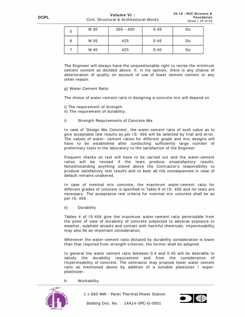
DCPL Volume VI :
Civil, Structural & Architectural Works
Ch 10 : RCC Strucure &
Foundation Sheet | 20 of 43
1 x 660 MW - Panki Thermal Power Station
Bidding Doc. No. : 14A14-SPC-G-0001
5 M 30
365 - 400
0.45
Do
6 M 35 425 0.45 Do
7 M 40 425 0.40 Do
The Engineer will always have the unquestionable right to revise the minimum cement content as decided above, if, in his opinion, there is any chance of
deterioration of quality on account of use of lower cement content or any
other reason.
g) Water-Cement Ratio
The choice of water-cement ratio in designing a concrete mix will depend on
i) The requirement of strength. ii) The requirement of durability.
i) Strength Requirements of Concrete Mix
In case of 'Design Mix Concrete', the water-cement ratio of such value as to give acceptable test results as per IS: 456 will be selected by trial and error.
The values of water- cement ratios for different grade and mix designs will have to be established after conducting sufficiently large number of
preliminary tests in the laboratory to the satisfaction of the Engineer.
Frequent checks on test will have to be carried out and the water-cement
ratios will be revised if the tests produce unsatisfactory results. Notwithstanding anything stated above the Contractor's responsibility to
produce satisfactory test results and to bear all the consequences in case of default remains unaltered.
In case of nominal mix concrete, the maximum water-cement ratio for
different grades of concrete is specified in Table-9 of IS: 456 and no tests are necessary. The acceptance test criteria for nominal mix concrete shall be as
per IS: 456.
ii) Durability
Tables 4 of IS:456 give the maximum water-cement ratio permissible from
the point of view of durability of concrete subjected to adverse exposure to weather, sulphate attacks and contact with harmful chemicals. Impermeability
may also be an important consideration.
Whenever the water-cement ratio dictated by durability consideration is lower
than that required from strength criterion, the former shall be adopted.
In general the water cement ratio between 0.4 and 0.45 will be desirable to satisfy the durability requirement and from the consideration of
Impermeability of concrete. The contractor may propose lower water cement ratio as mentioned above by addition of a suitable plasticizer / super-
plasticizer.
h. Workability

DCPL Volume VI :
Civil, Structural & Architectural Works
Ch 10 : RCC Strucure &
Foundation Sheet | 21 of 43
1 x 660 MW - Panki Thermal Power Station
Bidding Doc. No. : 14A14-SPC-G-0001
The degree of workability necessary to allow the concrete to be well
consolidated and to be worked into the corners of formwork and around the reinforcement and embedment’s and to give the required surface finish shall
depend on the type and nature of structure and shall be based on experience and tests. The limits of consistency for various types of structures as per Table
– I
With the permission of the Engineer. For any grade of concrete, if the water
has to be increased in special cases, cement shall also be increased proportionately to keep the ratio of water to cement same as adopted in trial
mix design for each grade of concrete. No extra payment will be made for this additional cement.
The workability of concrete shall be checked at frequent intervals by slump
tests. Alternatively where facilities exist or if required by the Engineer, the
compacting factor test in accordance with IS: 1199 and Clause 7 of IS: 456 shall be carried out.
i. Size of Coarse Aggregates
The maximum size of coarse aggregates for different locations shall be as
follows unless otherwise directed by the Engineer:
Very narrow space - 12 mm
Reinforced concrete except foundation - 20 mm
Ordinary Plain concrete and RCC foundations - 40 mm
Mass concrete - 80 mm
Mass concrete in very large structure - 150 mm
Grading of coarse aggregates for a particular size shall conform to relevant I.S. Codes and shall also be such as to produce a dense concrete of the
specified proportions, strength and consistency that will work readily into position without segregation.
Coarse aggregate will normally be separated into the following sizes and
stacked separately in properly designed stockpiles 40 mm to 20 mm and 20 mm to 5 mm.
In certain cases it may be necessary to further split the 20 mm to 5 mm fraction into20 mm to 10 mm and 10 mm to 5 mm fractions.
This separation of aggregates in different size fractions is necessary so that
they may be remixed in the desired proportion to arrive at a correct internal
j Mixing of Concrete
Controlled concrete only in batching plant shall be used for all major and
minor works including power house column foundation, TG, boiler foundation,
ID, FD, PA, BFP foundations, chimney cooling tower & other important structure.

DCPL Volume VI :
Civil, Structural & Architectural Works
Ch 10 : RCC Strucure &
Foundation Sheet | 22 of 43
1 x 660 MW - Panki Thermal Power Station
Bidding Doc. No. : 14A14-SPC-G-0001
The entire contents of the drum shall be discharged before the ingredients for
the next batch are fed into the drum. No partly set or remixed or excessively wet concrete shall be used. Such concrete shall be immediately removed from
site. Each time, the work stops, the mixer shall be thoroughly cleaned & when the next mixing commences, the first batch shall have 10% additional cement
at no extra cost to the Purchaser to allow for loss in the drum.
Regular checks on mixer efficiency shall be carried out as per IS: 4634 on all
mixers employed at site. Only those mixers whose efficiencies are within the tolerances specified in IS: 1791 should be allowed to be employed. Batching
Plant where used shall conform to IS: 4925.
Hand mixing if permitted shall be carried out on a water-tight platform and care shall be taken to ensure that mixing is continued until the mass is
uniform in colour and consistency. In case of hand-mixing, 10% extra cement
shall be added to each batch at no extra cost to the Purchaser.
Crushed ice shall be used in concrete mixing water so as to maintain temperature in the concrete in the top decks of the machine foundations.
Arrangements for standby weight batching plant and equipment shall also be made available by the contractor for continuous pour of conctete.
k. Conveying Concrete
Concrete shall be handled and conveyed from the place of mixing to the place of laying as rapidly as practicable by approved means, concrete shall by
placed and compacted in the final position before the initial setting of the cement starts. Concrete should be conveyed in such a way preventing
segregation or loss of any of the ingredients. For long distance haulage, agitator cars of approved design should be used. If, inspite of all precautions,
segregation does occur during transport, the concrete shall be properly remixed before placement. During very hot weather, concrete shall be
transported in deep container to reduce the rate of loss of water by
evaporation or loss of heat. If necessary, the container should be covered. Conveying equipment for concrete shall be well maintained and thoroughly
cleaned before commencement of concrete mixing. Such equipment shall be kept free from set concrete.
l. Placing and Compacting of Concrete
i) Relevant I.S. Code should be followed for the procedure of surface
preparation, placement, consolidation, curing, finishes, repairs and
maintenance of concrete. Concrete shall be placed against the surfaces of formwork or construction joint in concrete or masonry. The surface
against which concrete is placed shall be cleaned thoroughly. Old construction joint has to be roughened by wire brushing, chipping sand
blasting or any other approved means for proper bond. All cuttings, dirt, oil, foreign and deleterious material, laitance, etc. shall be
removed by air water jetting or water at high pressure.
Concrete shall be placed in the formwork by approved means, and shall
not be dropped from a height or handled in a manner which may cause
segregation.

DCPL Volume VI :
Civil, Structural & Architectural Works
Ch 10 : RCC Strucure &
Foundation Sheet | 23 of 43
1 x 660 MW - Panki Thermal Power Station
Bidding Doc. No. : 14A14-SPC-G-0001
ii) Construction joint shall be kept moist for atleast 72 hours prior to placement.
Concrete shall be placed always against moist surface but never on
pools of water. In case the foundation cannot be dewatered completely, special procedure and precaution shall be adopted.
Formwork shall be cleaned thoroughly and smeared lightly with form oil
or grease of approved quality just prior to placement.
iii) 12 mm thick mortar with less w/c ratio as that of the concrete being placed and cement slurry shall be spread thoroughly on the
construction joint just prior to placement of concrete. The concrete shall be spread, and thoroughly compacted without segregation and
thoroughly worked around shape. Vibrators shall not be used for pushing concrete into adjoining areas. Vibrators must be operated by
experienced workmen and the work carried out as per relevant IS. In
thin members with heavy congestion of reinforcement of other embedments, where effective use of internal vibrator is, doubtful, in
addition to immersion vibrators, the contractor should employ form vibrators conforming to IS: 4656. For slabs and other similar
structures, the contractor should employ screed vibrator as per IS: 2506. Care must be taken to ensure that the inserts, fixtures,
reinforcement and formwork are not displaced or distorted during placing and consolidation of concrete.
iv) The rate of placement of concrete shall be such that no cold joint is formed; and fresh concrete is placed always against green, plastic and
workable concrete. No concrete shall be placed in open during rains. During rainy season, no placement in the open should be attempted
unless sufficient tarpaulins or other similar protective arrangement for completely covering the still green concrete from rain is kept at site of
placement. If there has been any sign of washing of cement and sand, the entire affected concrete shall be removed immediately. Suitable
precautions shall be taken in advance to guard against rains before
leaving the fresh concrete unattended. No accumulation of water shall be permitted on or around freshly laid concrete.
v) Slabs, beams and similar members shall be poured in one operation.
Moulding, throating, drip course, etc., shall be poured as per the drawings. Holes shall be provided and bolts, sleeves, anchors,
fastenings or other fixtures shall be embedded in concrete as per drawings. In case the forms or supports get displaced during or
immediately after the placement and bring the concrete surface out of
alignment beyond tolerance limits, the Engineer may direct to remove the portion and reconstruct or repair the same.
The Engineer shall decide upon the time interval between two
placements of concrete of different ages coming in contact with each other, taking in consideration the degree of maturity of the older
concrete, shrinkage, heat dissipation and the ability of the older
concrete to withstand the load imposed upon it by the fresh placement. Once the concrete is deposited, consolidated and finished in its final
position, it shall not be disturbed.
10.19 a) Construction Joints

DCPL Volume VI :
Civil, Structural & Architectural Works
Ch 10 : RCC Strucure &
Foundation Sheet | 24 of 43
1 x 660 MW - Panki Thermal Power Station
Bidding Doc. No. : 14A14-SPC-G-0001
Concrete structure shall be completed by continuous pouring in one operation. However, due to practical limitation of methods and equipment and certain
design considerations, construction joints are formed by discontinuing concrete at certain predetermined stages. These joints shall be formed as per
drawings. Vertical construction joints shall be made with rigid stop-board forms having slots for allowing passage of reinforcement rods and any other
embedments and fixtures that may be shown. For water retaining structures
and leak proof buildings suitable and approved water stops shall be installed at the construction joints as per clause 12.4 of IS:456. Where the location of
the joints are not specified, it shall be in accordance with the following :-
i) In a column, the joint shall be formed 75 mm below the lowest soffit of the beam framing into it.
ii) Concrete in a beam shall preferably be placed without a joint, but if
provision of a joint is unavoidable, the joint shall be vertical and at the
middle of the span.
iii) A joint in a suspended floor slab shall be vertical and at the middle of the span and at right angles to the principal reinforcement.
iv) Feather-edges in concrete shall be avoided while forming a joint.
v) A construction joint should preferably be placed in a low stress zone
and at right angles to the direction of the principal stress.
vi) In case the Contractor proposes to have a construction joint anywhere to facilitate his work, the proposal should be submitted well in advance
to the Engineer for study and approval without which no construction joint will be allowed.
b. Cold Joint
An advancing face of a concrete pour, which could not be covered by fresh
concrete before expiry of initial setting time (due to an unscheduled stoppage
or delay on account of breakdown in plant, inclement weather, low rate of placement or any other reason), is called a cold joint. The contractor should
always remain vigilant to avoid cold joints. If however, a cold joint is formed due to unavoidable reasons, the following procedure shall be adopted for
treating it :-
i) If the concrete is so green that it can be removed manually and if vibrators can penetrate the surface without much effort, fresh concrete
should be placed directly against the old surface. The old concrete
should be covered by fresh concrete as quickly as possible, and the joint thoroughly and systematically vibrated.
ii) In case concrete has hardened a bit more than (a) but can still be
easily removed by a light hand pick, the surface shall be raked thoroughly and the loose concrete removed completely without
disturbing the rest of the concrete in depth. A rich mortar layer 12 mm
in thickness, shall be placed on the cold joint, fresh concrete shall be placed on the mortar layer and the joint shall be thoroughly and
systematically vibrated penetrating the vibrator deep into the old layer
of concrete.

DCPL Volume VI :
Civil, Structural & Architectural Works
Ch 10 : RCC Strucure &
Foundation Sheet | 25 of 43
1 x 660 MW - Panki Thermal Power Station
Bidding Doc. No. : 14A14-SPC-G-0001
iii) In case the concrete at the joint has become so stiff that it cannot be remolded and mortar or slurry does not rise inspite of extensive
vibration, the joint shall be left to harden for atleast 12 to 24 hrs. It shall then be treated as a regular construction joint, after cutting the
concrete to required shape and preparing the surface as indicated above.
c. Expansion And Isolation Joints
i) Expansion and isolation joints in concrete structures shall be provided at specific places as shown on the drawings with materials and types of
joints as specified. In case of liquid retaining structures, additional precautions shall be taken to prevent leakage of liquids as specified on
the drawings. All materials should be procured from reliable manufacturers to the approval of the Engineer. Test certificates for the
materials should be furnished. Joints shall be formed true to line, level,
shape, dimension and quality as per drawings and specifications. Prior approval from concerned engineer of the method of forming the joints
should be obtained.
ii) Duraboard HD or its equivalent of approved manufacturer shall be used as filler for expansion joints. It must be durable and waterproof. It
shall be compressible and possess a high degree of rebound. The dimensions of the board should be equal to that of the joint being
formed. It should, preferably be manufactured in one piece, matching
the dimension of the joint and not prepared by cutting to size smaller pieces from larger boards at site. At the exposed end, the joint shall be
sealed with approved sealing compound to a depth of at least 25 mm after application of an approved primer. The sealing compound and the
primer shall be applied as recommended by the manufacturer.
Commercial quality of expanded polystyrene products commonly used for thermal insulation can also be used as filler material in expansion
joints. The thickness may vary from 12 mm to 50 mm. The material
should procured from reliable manufacturers as approved by the Engineer. The method of installation shall be similar to that
recommended by the manufacturer for fixing on walls. A coat of bitumen paint shall be applied on the board against which concrete is
placed.
iii) Joint sealing strips shall be provided at the construction, expansion and isolation joints as a continuous diaphragm to contain the filler material
and/ or to exclude passage of water or any other material into or out of
the structure. General strips shall be of PVC or otherwise as specified. Sealing strips shall not have any longitudinal joint; and shall be
procured and installed in largest practicable lengths having a minimum number of transverse joints. The material shall be procured from
reputed manufacturers having proven records of satisfactory supply of joint strips of similar make and shape for other jobs. The jointing
procedure shall be as per the manufacturer’s recommendations. The
contractor should supply all labour and materials for installation including the material and tools required for jointing, testing,
protection, etc. The joints in rubber seals shall be vulcanished as
needed.

DCPL Volume VI :
Civil, Structural & Architectural Works
Ch 10 : RCC Strucure &
Foundation Sheet | 26 of 43
1 x 660 MW - Panki Thermal Power Station
Bidding Doc. No. : 14A14-SPC-G-0001
iv) The minimum thickness of P.V.C. sealing strips shall be 3 mm and the minimum width 100mm. The actual size and shape shall be as shown
in drawings. The material should be of good quality Polyvinyl Chloride highly resistant to tarring, abrasion and corrosion as well as to
chemicals likely to come in contact with during use. The physical properties shall generally be as follows:
i) Specific Gravity : 1.3 to 1.35
ii) Shore Hardness : 60A to 80A
iii) Tensile Strength : 10 to 15 N/Sq.mm
iv) Maximum Safe Continuous Temperature : 70 Deg.C
v) Ultimate Elongation : Not less than 275%
v) Bitumen Compound: When directed, the gap in expansion joints shall be thoroughly cleaned and bitumen compound Manufacturer’s
recommendation. The compound to be used shall be of approved manufacture and shall conform to the requirements of IS: 1834.
vi) Isolation Joints: Strong and tough alkathene sheet or equivalent, about
1 mm in thickness shall be used in isolation joints. It shall be fixed by
an approved adhesive compound on the cleaned surface of the already set concrete, to cover it fully. Fresh concrete shall be laid against the
sheet, care being taken not to damage the sheet in any way.
vii) Rubber Pad: Hard foundation quality rubber pads of required thickness and shapes shall be put below machine or other foundations as shown
on the drawings. The rubber shall have a unit weight of 1500 kg/cum, shore hardness – 65A to 70A and be of best quality of approved
manufacture, durable, capable of absorbing vibration and must be
chemically inert in contact with moist or dry earth or any other deleterious material expected under normal conditions.
viii) All foundation structures in contact with soil shall be coated with two
coats of Bituminous coating.
10.20 Repairs, Finishes and Treatment of Concrete Surfaces
a. Adequate and sound concrete surfaces, whether formed or unformed,
should be obtained by employing a concrete mix of proper design, competent formwork, appropriate methods of handling, placing and
consolidation by experienced workmen.
b. Unsound concrete resulting from improper mix design, incompetent methods, equipment and form work, poor workmanship and protection
shall not be accepted and shall be dismantled, removed and replaced
by sound concrete at the contractor’s cost. All concrete work shall be inspected by the contractor immediately after the forms are removed
and he should promptly report of occurrence of any defects to the
Engineer. All repair works should be carried out as per the instructions
and in the presence of the Engineer. Generally, repair work shall consist of any or all of the following operations :

DCPL Volume VI :
Civil, Structural & Architectural Works
Ch 10 : RCC Strucure &
Foundation Sheet | 27 of 43
1 x 660 MW - Panki Thermal Power Station
Bidding Doc. No. : 14A14-SPC-G-0001
i) Sack rubbing with mortar and stoning with carborundum stone.
ii) Cutting away the defective concrete to the required depth and shape.
iii) Cleaning of reinforcement and embedments. iv) Roughening by sand blasting or chipping.
v) Installing additional reinforcement/ welded mesh fabric.
vi) Dry packing with stiff mortar. vii) Plastering, guniting, hotcreting etc.
viii) Placing and compacting concrete in the void left by cutting out defective concrete.
ix) Grouting with cement sand slurry of 1:1 mix.
c. Finishing Unformed Surface
The requirement of finishes of formed surfaces are specified hereunder
separately. The contractor should include for concrete, the provision of normal finishes in unformed surfaces which can be achieved by
screeding, floating, trowelling etc. A few typical and common cases of treatment of concrete surface are cited below :
i) Floor: For non-integral floor finish, the surface of reinforcement
concrete slab shall be struck off at the specified levels and slopes and finished with a wooden float fairly smooth removing all laitance. No
over trowelling, to obtain a very smooth surface, shall be done as it will
prevent adequate bond with the subsequent finish. The surface shall be scored and marked to provide better bond.
For monolithic finish, concrete shall be compacted and struck off at the
specified levels and slopes with a screed, preferably a vibrating type; and then floated with a wooden float. Steel trowelling should then
started after the moisture film & shine disappeared from the surface; and after the concrete has hardened enough to prevent excess of fines
and water to rise to the surface but not hard enough to prevent proper
finishing of aberrations. Steel trowelling properly done should flatten and smoothen sandy surface left by wooden floats and produce a dense
surface free from blemishes, ripples and trowel marks. A fine textured surface that is not slick and can be used where there is likelihood of
spillage of oil or water should be obtained by trowelling the surface lightly with a circular motion after initial trowelling keeping the steel
trowel flat on the surface. To provide a better grip, the floor should be marked in a regular geometric pattern after initial trowelling.
ii) Beams, Columns & Walls: If on any other concrete structure, it is intended to apply plaster or such concrete surfaces against which
brick- work or other allied works are to be built, the contractor shall hack the surface adequately as soon as the form is stripped off so that
proper bond can develop.
d. Protection and Curing of concrete: Newly placed concrete shall be
protected from rain, sun and wind. Concrete placed below the ground level shall be protected against contamination from falling earth during
and after placing. Concrete placed in ground containing deleterious
substances, shall be protected from contact with such ground, or with
water draining from such ground, during placing of concrete and for a period of at least three days. Steps shall be taken to protect immature
DCPL Volume VI :
Civil, Structural & Architectural Works
Ch 10 : RCC Strucure &
Foundation Sheet | 28 of 43
1 x 660 MW - Panki Thermal Power Station
Bidding Doc. No. : 14A14-SPC-G-0001
concrete from damage by debris, excessive loadings, vibration, abrasion, mixing with earth or other deleterious materials, etc. that
may impair the strength and durability of the concrete. As soon as the concrete has hardened sufficiently, it shall be covered either with sand,
hessian, canvas or similar materials and kept continuously wet for at least 14 (fourteen) days after final setting. Curing by continuous
sprinkling of water shall be allowed if the Engineer is satisfied with the
adequacy of the arrangements made by the contractor.
The contractor shall remain extremely vigilant and employ proper equipment and workmen under able supervision for curing. In case any
lapse on the part of the contractor is noticed, the Engineer will inform the contractor verbally or in writing to correct the deficiency in curing.
If no satisfactory action is taken by the contractor within 3 hours of issuance of such instruction, the Engineer will be at liberty either to
employ sufficient means through any agency to make good the
deficiency and recover the cost thereof from the contractor.
10.21 Reinforcement
The reinforcement used shall be cold worked steel high strength deformed bars of grade Fe 500 conforming to IS:1786 – latest.
a.) All steel for reinforcement shall be free from loose scales, oil, grease,
paint or other harmful matters immediately before placing the
concrete.
b.) Bar Bending Schedules
The contractor shall submit to the Engineer bar bending schedules with working drawings showing clearly the arrangements proposed by the
contractor. Upon receipt of the Engineer’s final approval of the bar bending schedule and drawings, the contractor shall submit the final
drawings with one reproducible print after incorporating necessary
modifications or corrections, for final record and distribution. Approval of such detailed drawings shall not relieve the contractor of his
responsibility for correctness nor of any of his obligations to meet the other requirements of the contractor.
c.) Bending
Reinforcing steel shall be bent in accordance with the procedure
specified in IS:2502. Bends and shapes shall comply strictly with the
dimensions corresponding to the approved bar bending schedules which shall be rechecked by the contractor before any bending is done.
No reinforcement shall be bent when already in position in the work,
without approval of the Engineer, whether or not it is partially embedded in concrete. Bars shall not be straightened in a manner that
will injure the material. Re- bending can be done only if approved by
the Engineer. Reinforcing bars shall be bent by machine or other approved means producing a gradual and even motion. All the bars
shall be cold bent.
d.) Placing in position
DCPL Volume VI :
Civil, Structural & Architectural Works
Ch 10 : RCC Strucure &
Foundation Sheet | 29 of 43
1 x 660 MW - Panki Thermal Power Station
Bidding Doc. No. : 14A14-SPC-G-0001
All reinforcements shall be accurately fixed and maintained in position as shown on the drawings. Bars at crossing points, shall be securely
tied togetherby # 20G annealed soft iron PVC coated wire or by tack welding in case of bar larger than 25 mm dia. binders shall tightly
embrace the bars with which they are intended to be in contact and shall be securely held. The vertical distance between successive layers
of bars shall be maintained with FBEC spacer bars. They should be
spaced such that the main bars do not sag perceptibly between adjacent spacers. Before actual placing, the contractor shall study the
drawings thoroughly and inform the Engineer in case he feels that placement of certain bars is not possible due to congestion. In such
cases, he should not start placing any bar before obtaining clearance from the Engineer.
e.) Welding
Normal bond laps in reinforcement should be placed by lap or butt welding reinforcement bars. The work should be done with suitable
safe guards as per IS for welding of mild steel bars used in reinforced concrete construction as per IS: 2751 and IS: 456. Welded mesh
fabrics to IS:566 shall also be as per drawings.
f.) Control
The placing of reinforcements shall be completed well in advance of
concrete pouring. Immediately before pouring, the reinforcement shall be examined by the Engineer for accuracy of placement and
cleanliness. Necessary corrections as directed by him shall be carried out. Laps and anchorage lengths of reinforcing bars shall be as per IS:
456. If the bars in a lap are not of the same diameter, the smaller will guide the lap length. The laps shall be staggered as far as practicable.
Arrangements for placing concrete shall be such that reinforcement in position do not have to bear extra load and get disturbed.
The cover for concrete over the reinforcements shall be as shown on the approved drawings. Where concrete blocks are used for ensuring
the cover and positioning reinforcement, they shall be made of mortar not leaner than 1part cement to 2 parts sand by volume and cured in a
pond for at least 14 days. The type, shape, size and location of the concrete blocks shall be as approved by the Engineer.
g.) Cold Weather Concreting
When conditions are such that the ambient temperature may be expected to be 4.5 Deg.C or below during the placing and curing
period, the work shall conform to the requirements of clause 13 of IS: 456 and IS: 7861.
h.) Hot Weather Concreting
When depositing concrete in very hot weather, the contractor shall take all precautions as per IS: 7861 and stagger the work to the cooler
parts of the day to ensure that the temperature of wet concrete used in
massive structures does not exceed 38oC while placing.
10.22 Form Work

DCPL Volume VI :
Civil, Structural & Architectural Works
Ch 10 : RCC Strucure &
Foundation Sheet | 30 of 43
1 x 660 MW - Panki Thermal Power Station
Bidding Doc. No. : 14A14-SPC-G-0001
a. The contractor shall prepare, before commencement of actual work,
designs and working drawings for formwork and centering. The formwork shall conform to the shape, grade, lines, levels and
dimensions as shown on the drawings. Materials used for the formwork inclusive of the supports and centering shall be capable of withstanding
the working load and remain undistorted throughout the period it is left
in service. All supports and scaffolds should be manufactured from structural or tubular steel.
b. The centering shall be true to vertical, rigid and thoroughly braced both
horizontally and diagonally. Rakes shall be used where forms are to support inclined members. The forms shall be sufficiently strong to
carry without undue deformation, the dead weight of the concrete as a liquid as well as the working load. Where the concrete is vibrated, the
formwork shall be strong enough to withstand the effects of vibration
without appreciable deflection, bulging, distortion or loosening of its components. The joints in the formwork shall be sufficiently tight to
prevent any leakage of slurry or mortar.
To achieve the desired rigidity, tie bolts, spacer blocks, tie wires and clamps shall be used but they must in no way impair the strength of
concrete or cause stains or marks on the finished surface. Where there are chances of these fixtures being embedded, only mild steel or
concrete of adequate strength shall be used. Bolts passing completely
through liquid retaining walls/ slabs for the purpose of securing and aligning the formwork shall not be used.
c. The formwork shall be such as to ensure a smooth uniform surface free
from honeycombs, air bubbles, bulges, fins and other blemishes. Any blemish or defect found on the surface of the concrete must be brought
to the notice of the Engineer immediately and rectified as directed by him.
For exposed interior and exterior concrete surfaces of beams, columns and wall, plywood or other approved form shall be thoroughly cleaned
and tied together with approved corrosion-resistant devices. Rigid care shall be exercised in ensuring that all column forms are plumb and true
and thoroughly cross braced to keep them so. All floor and beam centering shall be crowned not less than 8 mm in all directions for
every 5 meters span. Bevelled forms 25 mm x 25 mm shall be fixed in the form-work at all corners to provide chambering of the finished
concrete edges. The formwork should lap and be secured sufficiently at
the lift joints to prevent bulges and offsets.
Temporary openings for cleaning, inspection and for pouring concrete shall be provided at the base of vertical forms and at other places as
necessary. The temporary openings shall be so formed that they can be conveniently closed when required, during pouring operations
without leaving any mark on the concrete.
d. Cleaning and Treatment of Forms
All parts of the forms shall be thoroughly cleaned of old concrete, wood
shavings, saw dust, dirt and dust sticking to them before they are fixed in position. All rubbish, loose concrete, chippings, shavings, saw dust

DCPL Volume VI :
Civil, Structural & Architectural Works
Ch 10 : RCC Strucure &
Foundation Sheet | 31 of 43
1 x 660 MW - Panki Thermal Power Station
Bidding Doc. No. : 14A14-SPC-G-0001
etc. shall be scrupulously removed from the interior of the forms before concrete is poured. Compressed air jet and/ or water jet along with
wire brushes, brooms etc. shall be used for cleaning. The inside surface of the formwork shall be treated with approved non-staining oil or
other compound before it is placed in position. Care shall be taken that oil or other compound does not come in contact with reinforcing steel
or construction joint surfaces. They shall not be allowed to accumulate
at the bottom of the formwork.
e. Design
The formwork shall be so designed and erected that the forms for slabs and the sides of beams, columns and walls are independent of the
soffits of beams and can be removed without any strain to the concrete already placed or affecting the remaining formwork. Removing any
props or repropping shall not be done except with the specific approval
of the Engineer. If formwork for column is erected for the full height of the column, one side shall be left open and built up in sections, as
placing of concrete progress. Wedges, spacer bolts, clamps or other suitable means shall be provided to allow accurate adjustment and
alignment of the formwork and to allow it to be removed gradually without jarring the concrete.
f. Inspection of Forms
Casting of concrete shall start only after the formwork inspection and approval by the Engineer. The concreting shall start as early as
possible within 3 days after the approval of the formwork; and during this period, the formwork shall be kept under constant vigilance against
any interference. In case of delay beyond three days, a fresh approval from the Engineer shall be obtained.
g. Removal of Forms
Before removing any formwork, the contractor must notify the Engineer well in advance to enable him to inspect the concrete if he so
desires. The contractor shall record the date on which concrete is placed in each part of the work; and the date on which the formwork is
removed there from. The contractor shall be responsible for the safe removal of the formwork; and any work showing signs of damage
through premature removal of formwork or loading shall be rejected and entirely reconstructed by him. Forms for various types of structural
components shall not be removed before the minimum periods as
detailed below:-
Schedule of Removal of Form Work
Part of
Structure
Ordinary Portland Cement
Concrete
Rapid Hardening Portland
Cement
Temperature (°C) Temperature (°C)
Above
40oC
40o-C
to
20oC
20o
to
5oC
Below 5oC Above
40oC
40o-C
to
20oC
20o
to
5oC
Below
5oC
Days Days Days Days Days Days Days Days

DCPL Volume VI :
Civil, Structural & Architectural Works
Ch 10 : RCC Strucure &
Foundation Sheet | 32 of 43
1 x 660 MW - Panki Thermal Power Station
Bidding Doc. No. : 14A14-SPC-G-0001
a) Columns
& Walls
2 1 1 Do not
remove forms
until site
cured test
specimen
1 1 1 Do not
remove
b) Beam sides
3 2 3 2 1 1
c) Slabs,
125
mm
10 7 8 7 4 5
d) Slabs
125 mm
18 14 16 12 8 9
e) Soffit of
main beams
24 21 22 14 10 12
Wherever exposed surfaces of concrete can be effectively sealed to prevent
loss of water, the periods specified for temperature above 40oC can be reduced to those of the temperature range of 20oC to 40oC.
ints in beams shall be located at the middle of span. In such cases, however,
entire span of beam shall have to be kept supported by formwork till its removal for the portion of beam, cast at a later date.
h. Tolerance
The formwork shall be so made as to produce a finished concrete, true to shape, lines, levels, plumb and dimensions as shown on the
drawings subject to the following tolerances :-
i) Sectional dimension - +/- 5 mm
ii) Plumb - 1 in 1000 of height
iii) Levels - +/- 3 mm before any deflection has taken place
The above tolerance shall be for local aberrations in the finished concrete surface, and should not be taken as tolerances for the entire
structure taken as a whole or for the setting and alignment of formwork, which should be as accurate as possible. Any error, within
the above tolerance limits if noticed in any lift of the structure after stripping of forms, shall be corrected in the subsequent work to bring
back the surface of the structure to its true alignment.
i. Re-use of Forms
Before re-use, all forms shall be thoroughly scraped, cleaned, joints
and planes examined and when necessary repaired and inside surface treated as specified hereinbefore. Formwork shall not be used / re-used
if declared unfit or unserviceable by the Engineer.

DCPL Volume VI :
Civil, Structural & Architectural Works
Ch 10 : RCC Strucure &
Foundation Sheet | 33 of 43
1 x 660 MW - Panki Thermal Power Station
Bidding Doc. No. : 14A14-SPC-G-0001
j. Generally, the “ordinary” class formwork shall be used in places where ordinary surface finish is required and shall be composed of steel and/
or approved good quality partially seasoned timber. Plywood formwork shall be used in exposed surfaces, where a specially good finish is
required and shall be made of approved brand of heavy quality plywood to produce a perfectly uniform and smooth surface conforming
to the shape described in the drawing with required grain texture on
the concrete. Re-use may only be permitted after special inspection and approval by the Engineer. He may also permit utilization of used
plywood for the “ordinary” class, if it is still in good condition. Ornamental formwork shall be used where ornamental and curved
surfaces are required and shall be made of selected best quality well seasoned timber or plywood, which can be shaped correctly. The
contractor shall leave all openings, grooves, chases, etc. in concrete work as shown on the drawings.
10.23 Anchor Bolts, Anchors, Sleeves, Inserts, Hangers / Conduits / Pipe and Other Misc.Embedded Fixtures
The contractor shall build into concrete work all the items as noted below; and
shall embed them partly or fully as directed and secure the same as may be required. The materials shall be as specified and be of best quality available
according to relevant IS and of approved manufacture to the satisfaction of the Engineer. Exposed surfaces of embedded materials shall be painted with
one coat of approved anti-corrosive paint and/or bituminous paint. If welding
is to be done subsequently on the exposed surfaces of embedded material, the paint shall be cleaned off the member to a minimum length of 50 mm
beyond each side of the weld line. Necessary templates, jigs, fixtures, supports etc. shall be used as required items to be embedded shall be as
follows:
i) Inserts, hangers, anchors, frames around openings, manhole covers, Frames, floor clips, sleeves conduits and pipes.
ii) Anchor bolts and plates for machinery, equipment and for structural steel work.
iii) Dowel bars, etc. for concrete work
iv) Lugs or plugs for door and window frames occurring in concrete work.
v) Flashing and jointing in concrete work.
vi) Any misc. embedments and fixture as may be required.
vii) Convextra-GP2, SIKA grout or equivalent grouting material shall be used as per manufacturer’s specification.
Correct location and alignment, as per drawings/instructions of all these
embedded items shall be entirely the responsibility of the contractor.
10.24 Precast Concrete
The precast concrete shall be similar as for the cast-in-place concrete
described herein. All precast work shall be carried out in a yard which shall be dry, properly levelled and having a hard and even surface. It shall be paved

DCPL Volume VI :
Civil, Structural & Architectural Works
Ch 10 : RCC Strucure &
Foundation Sheet | 34 of 43
1 x 660 MW - Panki Thermal Power Station
Bidding Doc. No. : 14A14-SPC-G-0001
with concrete or masonry as needed; and provided with a layer of plaster (1:2 proportion) with smooth neat cement finish or a layer of M.S. sheeting. Casing
shall be done on suitable vibrating table. The yard, lifting equipment, curing tank, finished material storage space etc. shall be designed such that the units
are not lifted from the mould before 7 days of curing and can be removed for erection after 28 days of curing. The moulds shall be of steel or of timber lined
with G.I. sheet metal.
Lifting hooks as necessary shall be embedded in correct position of the units
to facilitate erection, even though they may not be shown on the drawings, and shall be burnt off and finished after erection. Precast concrete units, when
ready, shall be transported to site by suitable means. Care shall be taken to ensure that no damage occurs during transportation. All adjustments, levelling
and plumbing shall be done as per instructions of the Engineer. The contractor shall render all help with instruments, materials and men to the Engineer for
checking the proper erection of the precast units.
10.25 Grouting under Machinery or Structural Steel Bases
If required, grouting under base plates of machines or structural steel etc.
shall be carried out by the Contractor. In general, the mix shall be 1 (one) part cement and 1 (one) part sand and just enough water to make it flow as
required. The areas to be grouted shall be cleaned thoroughly with compressed air jet and/or with water in locations where accumulated surplus
water can be removed. Where directed by the Engineer, 6 mm down stone
chips may have to be used in the mix. Surface to be grouted shall be kept moist for at least 24 hours in advance. The grout shall be placed under expert
supervision, so that there is no locked up air. Edges shall be finished properly. Finished grout shall be cured to ensure proper strength. If desired
by the Engineer, admixtures like Aluminium powder, ‘Ironite’ etc. may have to be added with the grout in proportions to be decided by the Engineer.
Admixture, if directed to be added, without any extra cost to the owner.
Alternatively non-shink , free flow, cementious grout like “Sikagrout 214 /
Ankor NSG” / Masterflow 918 or approved equivalent specifically selected for the type of equipment to be located (vibrating , static etc. ) may also be
used for grouting as per manufacturer’s specification with necessary approval of the Engineer.
10.26 Waterproofing of Concrete Structure
a) General
Waterproofing of concrete structures shall be done by either suitable extraneous treatments like applying waterproofing paints like “Sikatop Seal”
or approved equivalent, fixing bitumen felts etc. or internally by suitable design of the concrete mix, addition of suitable admixtures conforming to IS:
2645 and equivalent American or British codes in the concrete or mortar at
the time of mixing and/or installing water bars at the joints.
The design, material and workmanship shall conform to the relevant I.S. Codes where applicable. The Engineer’s approval of the materials shall be
obtained by the Contractor before procurement. If desired by the Engineer, test certificates for the materials and samples shall be submitted by the
Contractor free of charge. The materials shall be of best quality available indigenously, fresh clean and suitable for the duties called upon.

DCPL Volume VI :
Civil, Structural & Architectural Works
Ch 10 : RCC Strucure &
Foundation Sheet | 35 of 43
1 x 660 MW - Panki Thermal Power Station
Bidding Doc. No. : 14A14-SPC-G-0001
b) Water Bar/Seal/Special Treatment of Construction Joint
Water bearing structures and underground structures may have water
bar/seals installed at the joints. They may be rubber or P.V.C. The materials and installation will be as described under Clause 3.23.3. Construction joint
should be provided as per clause 3.13.1 with or without water bar / Seal as
shown on the drawing. In case of water bars being used at the construction Joint, fixing of the same has to be done carefully so that the water bar is not
disturbed during concreting. The construction joint shall also be treated by any one of the following methods:
Method 1: A surface retarder in the form of a thixotropic gel shall be applied on the joint surface of the previous pour in case of joint on the wall and in
case of floor the same shall be applied on the formwork against which
previous pour of concreting shall be done. The retarder may be liquid or paste form depending on the type of formwork. The formwork shall be removed
within 24 hours after concreting. Within 2 hours of striking of the formwork the retarder shall be washed off with strong water jet to make surface rough
and clean. Then a rich cement mortar using cement, sand and aggregates (maximum size 8 mm) along with synthetic rubber emulsion type water
resistant bonding agent shall be applied for a depth of 50 mm just before pouring the next stage of concreting in case of walls. The above bonding agent
will be mixed with water which will be used for making the cement mortar.
The proportion of mixing of this bonding agent with water shall be as per manufacturer’s specification. In case of floor joint, however, after washing of
retarder a solvent free two component epoxy resin bonding agent will be used at the joint before the next pour of concrete. The above bonding agent shall
have the following properties after 28 days:
Compressive strength - 55 to 60 N / Sq. mm Flexural Strength - 25 to 30 N / Sq. mm
Tensile strength - 15 N / Sq. mm (approx)
Bonding strength to concrete - 3 N / Sq. mm (approx) Bonding strength to steel - 20 N / Sq. mm (approx)
The whole operation shall be done as per manufacturer’s specification. The
contractor shall provide manufacturer’s supervision at no extra cost to owner.
Method 2 : One row of threaded nozzles at regular intervals not exceeding 1.5 m centre to centre shall be placed in concrete along the construction joint
during casting. Injection of cement water together with a suitable waterproof
expanding grouting admixture of approved quality shall be done through the nozzles after the construction joint in walls and slabs. The injection shall be
done under pressure of approximately 2 to 4 Kg/Sq cm. The nozzles shall be sealed off with suitable admixture after the injection is over. The whole
operation shall be carried out as per manufacturer’s specification and supervision. The cost of such manufacturer’s supervision shall be borne by the
contractor.
c) Waterproofing Admixtures
The waterproofing admixture for concrete and cement mortar / plaster shall
conform to relevant IS code. The admixture shall not cause decrease of

DCPL Volume VI :
Civil, Structural & Architectural Works
Ch 10 : RCC Strucure &
Foundation Sheet | 36 of 43
1 x 660 MW - Panki Thermal Power Station
Bidding Doc. No. : 14A14-SPC-G-0001
strength of concrete / plaster at any stage and it is free from chlorides and sulphates. The admixture shall not affect the setting time by more than 5 %.
The maximum permissible dosage of admixture will be 3 % (three percent) by
weight of cement but a lower dosage will always be preferred.
The product shall be stored in strong moisture proof packings.
However, in case of important structures where M25 or higher grade concrete
is specified, the use of melamine based, high range water resistant concrete admixture shall be used as per manufacturer’s specification to provide a
waterproof concrete.
i) In concrete : The approved admixture shall be based on modified lignosulphonate like “Plastocrete –
N/Super” or approved equivalent. The method of
application and other details shall conform to the manufacturer’s specification and/or as instructed
by the Engineer. The Contractor shall have the services of the manufacturer’s supervisor at no
extra cost to the Owner to supervise the work, if desired by the Engineer.
ii) In Plaster : The concrete surface, to be plastered, shall be
hacked to Engineer’s satisfaction, cleaned
thoroughly and kept wetted for 24 hours. The plaster shall be in cement sand mortar mixed in
proportion varying from 1:1 to 1:4 by volume along with the approved waterproofing admixture
like “No leek CP/ Sika Latex” or approved equivalent and laid in appropriate thickness and
in layers not exceeding 15 mm/layer or as per manufacturer’s specification. The additive shall be
of quality and type approved by Engineer. If
desired by the Engineer, the Contractor shall have the work supervised by the manufacturer’s
supervisor at no extra cost to the Owner. On completion, the plastered surface shall be cured
continuously for a minimum period of 14 days like concrete.
d) Bituminous or Tar Coating on External Surface
The surface to be waterproofed shall be rendered absolutely dry, clean and dust free. The surface shall be sand papered, cleaned and completely coated
with hot coal tar pitch of approved manufacturer and quality as per IS: 216 (not heated above 375 Deg.F) using not less than 2 Kg. per Sq.M. or with hot
asphalt i.e., bitumen according to IS:73 (not heated above 400 Deg.F) using not less than 1.5 kg. per Sq.M. When the first coat has completely dried up
and approved by the Engineer, the second coat shall be applied in the same
manner using not less than 1.25 Kg. per Sq.M. in case of coal tar and 1 Kg. per Sq.M. in case of asphalt. Immediately after application of the second coat
and before it is dried up, sand shall be spread on the surface to cover it
completely. Sufficient time shall be allowed after spreading of sand before
backfilling is done in order to allow the final coat to dry up completely. In place of hot application by coal tar / asphalt the coating of the outside

DCPL Volume VI :
Civil, Structural & Architectural Works
Ch 10 : RCC Strucure &
Foundation Sheet | 37 of 43
1 x 660 MW - Panki Thermal Power Station
Bidding Doc. No. : 14A14-SPC-G-0001
surfaces of walls may be carried out using a ready to use liquid, bituminous emulsion/ rubber protective coating of approved manufacturer.
e) Protective Coating on Inside Surface
Two coats of cement based two-components polymer modified flexible
protective and waterproofing slurry having 1 mm thickness for each coat
shall be applied on the walls/ floor after proper surface preparation as per manufacturer’s specification. The slurry shall be applied by brush.
f) Bitumen Felt : Application for Tanking
This specification shall cover laying the waterproof course on the outside and
inside of the walls and bases of structures.
The materials shall conform to IS: 1322, and the workmanship to IS: 1609.
The bitumen felt shall be hessian base and/or fibre base as specified in Drawing/Schedule of Items. If required by the Engineer, tests as specified in
relevant IS Codes shall be arranged by the Contractor without charging any extra to the Owner.
The Contractor shall execute this work in direct collaboration with one of the
well known �pecialized firm approved by the Engineer.
Cleaning the surface, keeping it dry, providing necessary corner fillets and
cement rendering and cutting chases, etc. shall be included in the rate for this item. If any protective brickwork on/against concrete sub-bases or walls is
required, these will be paid extra under suitable items in the contract. A 10 (ten) years’ guarantee for satisfactory performances shall be given by the
Contractor as well as his specialist sub-contractor jointly and severally, for this item of work. Free rectification of any defects noted in the work within this
guarantee period will be carried out by the Contractor even if it is beyond the specified maintenance period of the contract as a whole.
g) Polyethylene Films : Application in Walls or Base of Structures
Waterproof treatment shall be applied as outlined and as per sequence given hereunder:
i) the concrete surface shall be made smooth with 12 mm cement plaster
1:6
ii) apply hot bitumen 80/100 grade (IS:73-1961) @ of 1.0 Kg/Sq.m
minimum
iii) lay black polyethylene film 250 micron (IS:2508-1977) with cut back bitumen adhesive in overlaps over hot bitumen surface, gently pressed,
taking care not to puncture the film.
Alternatively, the overlaps shall be heat sealed by an electric iron
having three parallel sealing bars. A long piece of plywood is to be placed below the polyethylene film to be heat sealed. On the plywood a
rubber gasket is to be laid to provide a cushion for better welding of
the film. On the rubber padding, a cellophane tape is to be spread and
on this the LDPE film, with 100 mm overlap, is to be stretched. On the overlapped film another cellophane tape is to be placed to prevent the

DCPL Volume VI :
Civil, Structural & Architectural Works
Ch 10 : RCC Strucure &
Foundation Sheet | 38 of 43
1 x 660 MW - Panki Thermal Power Station
Bidding Doc. No. : 14A14-SPC-G-0001
heat sealer from sticking to the LDPE film. After this, the electric iron is to be pressed on the overlap joint for sufficient time so as to allow
perfect welding. The operation is to be repeated for subsequent lengths of joints. After heat sealing, the cellophane tape is to be
removed and the joints are to be tested for leaks.
iv) Lay 100 gm brown craft paper laminated with a layer of straight run
bitumen
v) Lay hot bitumen 80/100 grade (IS:73-1961) at 1.0 Kg/Sq.m minimum.
vi) Lay 250 micron polyethylene film as second layer similar to (iii) above.
vii) Lay second layer of 100 gm. Brown craft paper laminated as (iv) above.
viii) Apply hot bitumen (straight run grade) to IS:73-1961 at 1.0 Kg/Sq.m dusted with fine sand.
ix) Protecting with a layer of 75 mm plain cement concrete M10 or a layer
of brick laid in cement mortar 1:6. In case of wall apply a 12 mm thick plaster as shown on the drawing or a protective brick wall in 1:6
cement mortar as shown on the drawing.
10.27 Protective coating on Concrete Surface
3.27.01 On Foundation
The outside faces of foundation of important structures will be protected from
adverse effect of soil/ underground water, if shown on drawing or instructed by the Engineer, by using rubber / bitumen emulsion protective coating of
approved manufacturer.
10.28 Waterproofing by Pressure / Chemical Grouting
Where required, waterproofing for underground concrete structure shall be
done by injecting high polymer based non- shrink waterproof grouting compound through nozzle under pressure as per manufacturer’s
recommendation. The pressure during injection shall not be less than 2.5 kg/Sq.m and the thickness of epoxy resinous emulsion �aterproof paint (to
be applied on the external surface of walls/ slabs) shall not be less than 700 microns.
10.29 Sampling and Testing
The contractor shall carry out all sampling and testing as per IS for the
following items:
a. Cement
Representative samples shall be taken from each consignment of
cement received from the manufacturer / supplier for carrying out the
tests for fineness (by hand sieving), setting time and compressive strengths as per IS:269. Soundness Tests shall also be carried out as

DCPL Volume VI :
Civil, Structural & Architectural Works
Ch 10 : RCC Strucure &
Foundation Sheet | 39 of 43
1 x 660 MW - Panki Thermal Power Station
Bidding Doc. No. : 14A14-SPC-G-0001
required. No cement from a particular consignment / batch shall be used on the works unless satisfactory 3 days and 7 days test results for
compressive strength are known. These tests shall be of great importance as their results shall have bearing on the acceptance of
concrete or otherwise.
b. Aggregates
The contractor shall carry out any or all the tests of aggregates as
required as per IS:2386 Parts-I to VIII. The acceptance criteria of the samples tested shall be as per the relevant IS.
c. Water
Water for concrete works shall be tested as per IS: 3550 by the
contractor at regular intervals and whenever directed by the Engineer.
The final acceptance criteria in case of doubt shall be as per IS: 3025 & IS: 456.
d. Admixture
Air Entraining Agents (AEA): Initially, before starting to use A.E.A.,
relationship between the percentage of air entrained and the cylinder cube crushing strength vis-à-vis quantity of A.E.A. used for all types of
concrete shall be established by the contractor by carrying out
sufficiently large number of tests. After than, at regular intervals and whenever directed by the Engineer, the contractor should check up, the
actual percentages of air entrained and corresponding crushing strengths to correlate with the earlier test results. Tests for
establishing the various properties of any other admixtures which may be required to be added shall be carried out by the contractor.
e Concrete
The sampling of concrete, making the test specimens, curing and testing procedure etc. shall be as per IS:516 and IS:1199 with the size
of specimen being 15 cm cubes. Normally, only compression tests shall be performed apart from other tests as per IS:516. Sampling
procedure, frequency of sampling and test specimen shall conform to clause 15 of IS: 456. To control the consistency of concrete from every
mixing plant, slump tests and / or compacting factor tests in accordance with IS:1199 and as per clause 7.3.7(f) above shall be
carried out by the contractor every 2 hours. Slumps corresponding to
the test specimens shall be recorded for reference. The acceptance criteria of concrete shall be in accordance with clause 16 of IS:456.
Concrete work found unsuitable for acceptance shall have to be dismantled and replacement shall be done as per specification by the
contractor. In the course of dismantling, if any damage is done to the embedded items or adjacent structures, the same shall be made good
by the contractor to the satisfaction of the Engineer.
f. Concrete for Equipment or Steel Structures Foundations
Concrete for equipment foundation, whether principal or auxiliary, shall
be poured continuously so that the structure becomes monolithic, particular care being exercised to see that the base slabs, if any, are of

DCPL Volume VI :
Civil, Structural & Architectural Works
Ch 10 : RCC Strucure &
Foundation Sheet | 40 of 43
1 x 660 MW - Panki Thermal Power Station
Bidding Doc. No. : 14A14-SPC-G-0001
compact impervious construction. Tunnels, passages apertures and so forth shall be provided in accordance with the drawings for the
installation of mechanical and electrical equipment, pipes or cables. The top elevation of the equipment foundations or parts shall be
accurately cast to 20/50 mm (or more as may be specified on the drawings) above the level required for grouting and it shall be
pneumatically chiseled of and well roughened just prior to the erection
of the equipment concerned. All embedded anchor bolts or bolt sleeves shall be accurately and firmly set with the aid of approved templates,
steel supports and / or other accessories. For holding the embedded bolts or sleeves in the correct position during concreting, template shall
have to be of steel of suitable section approved by the Engineer in Charge. Two (2) sets of templates shall have to be provided, one
to hold the bottom and the other the top of the bolts or sleeves. The bottom template shall be securely and rigidly fixed by providing
anchorage arrangement and by welding to the lowest part of the steel
reinforcement and other structural supports. The top templates shall be securely fixed by tying with guy wires and turn buckle arrangement to
firm and rigid adjoining structures and stagings.
Bolt pockets, where required, shall be cast with wooden taper wedges. These shall be withdrawn at an appropriate time when the concrete has
set, the pockets cleaned roughened and then covered or blocked thoroughly to prevent debris getting into these. The exposed portions
of bolts and embedded parts shall be kept well greased and adequately
protected from damage throughout construction. Any damages found shall have to be corrected at the contractor cost. The Purchaser shall
have the right to use the foundations, pads, piers, slabs, floors and all concrete work as needed for other works or
equipment erected prior to its “Taking over”
10.26 Special Conditions For Construction of TG Foundation
a) Scope
i) The work to be performed under this contract consists of providing all materials except those supplied by the Purchaser, shuttering, staging,
inserts,construction equipment, labour and all incidental items not shown or specified but reasonably implied or necessary for the proper
completion of the work, all in the strict accordance with the drawings, schedules and specifications and including revisions and amendments
thereto and such detailed drawings as may be provided by the
Consultant, during the execution of the work.
ii) It is not the intent to specify completely herein all the details of designs and construction of the structure. However, the structure shall conform
in all respects to high standards of Engineering, design and workmanship and be capable of performing in continuous commercial
operation upto contractors guarantee in the manner acceptable to the
Purchaser / Consultant who will interpret the meaning of drawings and specifications and shall have the power to reject any work or materials
which in his judgment are not in full accordance therewith.
b) Form Work

DCPL Volume VI :
Civil, Structural & Architectural Works
Ch 10 : RCC Strucure &
Foundation Sheet | 41 of 43
1 x 660 MW - Panki Thermal Power Station
Bidding Doc. No. : 14A14-SPC-G-0001
i) All forms shall be abundantly wetted on both sides before concrete in poured. The date of removing forms for each individual stage of
construction shall be fixed by the Purchaser / Consultant.
ii) The minimum period for striking of formwork shall be as follows:- - Vertical sides of beams and pedestals - 7 days
- Bottom of beams / slabs - 28 days
However, the vertical faces shall be loosened after 24 hours of
completion of concreting the supports.
iii) Concrete surface shall not normally be patched or otherwise treated after the removal of forms. Where the surfaces exposed on stripping is
not of a satisfactory nature, owing to the contractors failure to take necessary precaution before, during or after the concrete placing, such
surfaces shall be worked and finished in accordance with the
instructions of the Purchaser / Consultant at the cost of the contractor. The pores shall be filled in with a neat solution of cement and water
applied by brush and when dry the surface shall be rubbed down with carborundum stone. The cost of the above treatment shall be deemed
to be included in the unit rate entered by Contractor. The top surface of the T.G. deck shall be float-finished, unless otherwise specified to
the required levels. There must be no surface grouting are treating which might draw the “fines” to the top. All shuttered surfaces shall be
left as they strip without removing boards or panel markings.
Any serious honey combing will render the concrete work liable to
rejection and cutting out and re-concreting wholly or party as the Engineer in Charge directs. All costs involved in repairing defect shall
be borne by the Contractor.
iv) The arrangement and method for movement of workers during TG construction to various levels of the TG foundations shall be submitted
well in the advance to the Engineer- in – Charge for his approval far
taking up the work.
v) In addition to the above paras the contractor shall also satisfy all other requirements for formwork mentioned in elsewhere in the
specification.
c. Staging
i) The entire staging for supporting the formwork, walkways and
platforms for placing concreting equipments such as vibrators, etc., shall be of structural steel. The staging shall be designed for the worst
combination of loading as specified hereinafter.
ii) The Contractor shall submit 6 copies of design calculations and drawing to prove adequacy of the staging for approval of the consultant. On
receipt of final approval, the contractor shall supply 20 copies of
approved drawings for distribution.
iii) The staging shall be so designed that no load from platforms are
passed on to the formwork at the top.

DCPL Volume VI :
Civil, Structural & Architectural Works
Ch 10 : RCC Strucure &
Foundation Sheet | 42 of 43
1 x 660 MW - Panki Thermal Power Station
Bidding Doc. No. : 14A14-SPC-G-0001
iv) All platforms, walkways etc. shall be clear of the formwork and at least 200 mm above it. The width of platforms and walkways shall be at
least 1.2 metres for easy movement of labour both ways.
v) The platforms shall be of planks or bamboo mats (clamped with steel strips suitably stiffened to avoid springing).
vi) The form work and staging shall be designed for a live load of 1000 Kg/m2.
vii) Unit weight of green concrete shall be considered as 2500kg/m3 for
design of form work and staging.
viii) The staging shall be braced in both the directions.
ix) The staging shall be supported on rigid surfaces at ground level.
x) The staging shall be sufficiently rigid to prevent any distortion in the
form work.
d. Special Precautions
i) The contractor shall take all precautions to ensure concreting of TG Raft, columns and TG Deck in one pour each. Concreting shall be
continuous and no break in concreting shall be permitted.
ii) The Contractor shall prepare a scheme for concreting giving
details of number of mixers, labour, vibrators, pouring schedule and obtain prior approval of the same from the Engineer-in-
Charge before starting of concreting.
iii) The Contractor shall ensure that at no time the temperature of the green concrete exceeds 38 degree C by taking proper precautions. If
required, ice shall be added to control the temperature at no
additional cost to the Purchaser.
iv) Approved “Retarders” shall be used by the contractor in the
proportions specified by the manufacturer for total concreting work of the TG foundation. The cost of the admixture shall be included in
unit rates quoted by the Bidders.
e. Test for Soundness of Concrete
i) After completion of the construction of TG foundations, the contractor
shall get the Deck and column tested for soundness of concrete by “ultrasonic wave – non – destructive test method” from reputed
research institutions as mentioned in Chapter-3.
ii) If the test report calls for any rectification in the concrete works by way
of pressure grouting or otherwise, the same shall be carried out by the contractor at no additional cost to the Purchaser to the satisfaction of
the Purchaser / Consultant.

DCPL Volume VI :
Civil, Structural & Architectural Works
Ch 10 : RCC Strucure &
Foundation Sheet | 43 of 43
1 x 660 MW - Panki Thermal Power Station
Bidding Doc. No. : 14A14-SPC-G-0001
iii) If require, any additional test to establish the adequacy of the rectification works carried out shall be done by the contractor at no
extra cost to the Purchaser.
Quality Control Procedure.
The contractor shall establish & maintain quality control procedure for different items of works and material to ensure that all works are performed as per
specification.
Contractor shall got approved field quality plan for all the works to be executed
Quality plan shall be prepared based on guide lines furnished in Volume-II of the specification.

DCPL Volume VI :
Civil, Structural & Architectural Works
Ch 11 : Building
Description Sheet | 1 of 19
1 x 660 MW - Panki Thermal Power Station
Bidding Doc. No. : 14A14-SPC-G-0001
11.0 DESCRIPTION OF BUILDINGS, STRUCTURES AND OTHER FACILITIES
11.1 TEMPORARY STRUCTURES FOR EXECUTION
11.1.1 Construction water:
The Contractor will make his own arrangement (boring, pumping etc.) for withdrawing under ground water for construction purpose without any cost
implication to the owner. Location of bore hole shall be got approved from the owner / consultant before execution.
11.1.2 Temporary site building
The CONTRACTOR shall provide for at his cost the following building facilities
for proper execution and quality control of the job, while meeting the provision
stipulated by Factory Rules regarding staff welfare facilities. All these building shall have brick cladding, Steel / AC sheet roofing over steel roof truss with
cement concrete flooring and false ceiling with A/C as required.
11.1.3 Site office
Contractor shall provide about 5 00 sqm of office area with A/C and false ceiling for the use of Owner / Owner’s representative in addition to t h e
Contractor’s requirement. Additionally an A/C Conference room to
accommodate about 70 people shall also be provided in the site office complex for the Owner’s use. In addition to these, basic facilities like toilet
for gents and ladies, potable water tanks, soak pit and septic tank for sewage disposal shall also be provided. Covered parking area for parking 10 cars
shall also be provided for Owner’s use.
11.1.4 Stores
A covered store shall be provided with brick cladding and G.I/colour coated
sheeting to store at least one month requirement of cement. Cement in bags shall be stored on a raised floor well away from outer walls and insulated
from the floor to avoid moisture. Not more than 15 bags shall be stacked in any tier. Each consignment of cement shall be stored separately and
consumed in its order of receipt.
Covered storage area may also be provided to store other construction material which will be affected on exposure to wind, sun and rain.
Reinforcement shall be stacked on top of timber sleepers to avoid contact with ground / water.
Storage yard paved or unpaved shall be provided with in the stores complex
for storage of other material.
Proper fencing and security arrangement shall be provided for the stores
complex.
Contractor may consider using the existing building in the site with necessary
repairs and restoration for use of this facility, provided the same does not
interfere with construction of Permanent works.

DCPL Volume VI :
Civil, Structural & Architectural Works
Ch 11 : Building
Description Sheet | 2 of 19
1 x 660 MW - Panki Thermal Power Station
Bidding Doc. No. : 14A14-SPC-G-0001
11.1.5 Temporary Workshop and Garage
The CONTRACTOR shall provide for a temporary workshop and garage to attend to routine maintenance and repair of the construction equipments as
well as his fleet of vehicles used for construction activities.
11.1.6 Fabrication yard
Depending on the extent of fabrication envisaged at site, the CONTRACTOR
shall establish a full fledged structural fabrication yard with adequate handling facility during and after the fabrication. A fully equipped testing
laboratory providing radiography, ultrasonic, dye penetration, magnetic particle test facilities shall be ensured adjacent to the fabrication yard to
enforce strict quality control. Portion of the yard shall have covered shed with H.O.T / E.O.T cranes so that fabrication work can proceed even during
inclement weather.
11.1.7 Quality control laboratory
A fully equipped quality control laboratory shall be established at site with
qualified personnel to conduct acceptance test on all construction material,
weldments, concrete cubes etc. This laboratory shall be housed in a
covered building with A/C facility as required by the testing facility. All testing equipment shall be periodically calibrated to the satisfaction of the OWNER. All testing shall be carried out in presence of OWNER. Finally the
laboratory shall be handed over to OWNER in good condition after completion of project.
11.1.8 Fuel storage area
CONTRACTOR shall obtain necessary permission from competent authorities and establish and operate a POL outlet with proper storage, dispensing and
adequate fire fighting facility.
11.1.9 Staff Welfare facility
CONTRACTOR shall provide adequate facility for his staff inside the plant
boundary such as Toilets for both gents and ladies, Canteens, drinking water facility, rest places, creches etc.
Necessary approach roads to the construction facility complex and internal
roads within the complex as well as proper drainage of the area shall be the CONTRACTOR’s responsibility.
CONTRACTOR shall also provide for proper disposal of sewage and other wastewater to meet with the requirement of Pollution Board.
Construction and maintenance of the staff and labour colony to satisfy all statutory requirement is the sole responsibility of CONTRACTOR. Land
required to construct staff & labour colony will be made available by the
Owner to the Contractor within or close to plant boundary.
Contractor to establish a Fly Ash Brick Plant at site to fullfil the requirement of
Fly Ash Bricks for the project.

DCPL Volume VI :
Civil, Structural & Architectural Works
Ch 11 : Building
Description Sheet | 3 of 19
1 x 660 MW - Panki Thermal Power Station
Bidding Doc. No. : 14A14-SPC-G-0001
11.2 TURBINE GENERATOR BUILDING
Turbine building (TG bay and heater bay) framing shall be of structural steel
with moment connected framing in the transverse direction and bracing in the longitudinal direction.
Service and maintenance bays shall not have any intermediate floors, however a 1500 mm wide observation gallery with handrails shall be given along the
wall at the operating floor level to observe the TG erection operation. Mezzanine floor, operating floor and deaerator floor shall be RCC floors over
steel framing, where as the floors at any other levels may either be of RCC floors or may have chequered plate / gratings supported on structural steel
frame work.
Crane capacity and crane rail level shall be fixed on the basis of the equipment
to be lifted and the method of lifting generator stator. At crane girder top flange level continuous walkways shall be provided on both sides of Turbine
hall. Access shall be provided to crane walkway through staircase from operating floor in addition to cage ladder at two ends. Bottom level of roof
framing shall be decided by the crane clearance requirement duly taking into account clearance required for mounting light fixtures. Roofing shall consist of
in-situ RCC slab of minimum 150 mm thickness laid to a slope of 1 in 100 towards transformer yard, constructed over permanently colour coated
galvanized MS troughed metal sheet of approved profile supported on steel
purlins and trusses. TG bay roof shall be provided with exhaust system. Access to roof shall be provided with structural steel staircase from Deaerator floor and the same stair shall have provision for access to crane maintence walkways provided at crane girder level.
Within the building, the concrete pedestal for supporting the turbine
generators and Boiler Feed Pumps/motors will be completely isolated from the building floors for vibration control. The foundation for Turbogenerator and
Boiler Feed Pumps/motors will be completely isolated from the building floors
for vibration control. The concrete operating floor will be designed for construction and maintenance loadings of Turbogenerator. Hatchways with
removable chequered plates or grating floor covers will provide access to equipment on lower floor and will be within turbine hall crane access.
Permanent colour coated sandwiched insulated metal cladding system from
3m (approx) above ground floor up to roof shall be provided on gable ends and A row. Brickwork shall generally be provided from ground floor to 3m
(approx) height. On other rows brickwork shall be provided upto roof level.
Wall in front of transformers shall be of adequate thickness to satisfy “fire rating” as per TAC regulations. On the heater bay side the brick wall shall be
provided upto 1m above deaerator floor level. Cladding beyond the above level shall of permanent colour coated sandwiched insulated metal cladding
system. Permanently colour coated single metal cladding sheet (non-insulated) shall be provided over brickwork above 3M (approx) from ground
floor only when brickwork is technically required and provided as mentioned
above. All internal walls shall be of brickwork.
Roof over heater bay shall consist of in-situ RCC slab of minimum 150 mm
thickness laid to a slope of 1 in 100 towards boiler side, constructed over
permanently colour coated galvanized MS troughed metal sheet of approved profile supported on steel beams.

DCPL Volume VI :
Civil, Structural & Architectural Works
Ch 11 : Building
Description Sheet | 4 of 19
1 x 660 MW - Panki Thermal Power Station
Bidding Doc. No. : 14A14-SPC-G-0001
All floors in Turbine Hall and Heater/Deaerator bay shall preferably be
constructed over permanently colour coated galvanized MS troughed metal sheet of approved profile supported on steel beams otherwise removable type
shuttering shall be used except chequered plate/grating floors.
Metal decking sheet for roof shall consist of permanently colour coated
galvanized M.S. sheet and silicon modified polyester paint shall be used for permanent coating on exposed surface. The galvanization shall be 275gm/sqm
and DFT of permanent colour coating shall be 20 micron (approx). Primer coat shall be provided on inner side. Minimum thickness of metal deck sheet shall
be 0.8 mm. Profile and trough depth of metal deck sheet shall be decided by Contractor as per design requirement.
Elevator block shall be placed in the Heater bay. Necessary provisions shall be
kept as per crane manufacturer’s requirement.
Stairs and platforms shall be provided as required for maximum utility and
safety. Stairs shall have to be provided as per TAC regulations and any other statutory requirements.
Supporting structure for power cycle piping shall be provided as necessary.
Minimum 1.0 m high RCC parapet shall be provided on each roof.
Windows shall be side-hung steel glazed using 6mm thick wired glass generally. However in areas where cladding is of sheeting fixed glazing in
anodized aluminium framework and in accessible areas sliding windows in anodized aluminium framework using 6mm thick wired glass shall be
provided. All the doors on external walls shall be of double plate flush steel doors. For equipment entry into the service bay specially designed steel sliding
cum / folding / rolling shutters shall be provided with appropriate operating mechanism. Rolling shutter shall also be provided in front of condenser to
facilitate tube removal.
Staircase protected on all sides with fireproof enclosure shall be provided to
satisfy TAC regulations. All the doors leading to the inside of the power house from staircase shall be automatically closing fire proof door satisfying TAC
regulations. Access cage ladders shall be given to TG building roof.
A roof shall be provided with roof water proofing treatment using high solid content liquid applied elastomeric water proofing membrane with separate
wearing course as per ASTM-C-836 & 898. Thickness of the membrane shall
be 1.5mm (min.). This treatment shall include application of polymerized mastic over the roof to achieve smooth surface and primer coat. Wearing
course on the top of membrane shall consist of 25 mm thick PCC (1:2:4) cast in panels of maximum 1.2x1.2m size and reinforced with 0.56mm dia
galvanized chicken wire mesh and sealing of joints using sealing compound/ elastomeric water proofing membrane. However, chequered concrete tile
flooring 22mm (min.) thick of approved colour and shade conforming to
IS:13801 shall be provided for path way of 1m width for access of personnel and handling of equipment and for the entire area of the roof where
equipment like A/C ventilation plant, cooling towers, etc. are provided in place
of PCC wearing course. Equipment shall be installed on raised pedestal of
minimum 30 cm height from the finished roof to facilitate maintenance of roof treatment in future. MS rain water pipe of min. 150 mm OD conforming to

DCPL Volume VI :
Civil, Structural & Architectural Works
Ch 11 : Building
Description Sheet | 5 of 19
1 x 660 MW - Panki Thermal Power Station
Bidding Doc. No. : 14A14-SPC-G-0001
IS:1239 shall be provided to drain off the rainwater from roof. They shall be suitably concealed from the façade.
All the suspended floors in Main Plant Building are elsewhere in the BOP Area
(having steel structure construction) should be supported on colour coated trough shaped permanent decking on beams.
All the intermediate floors shall be provided with proper drainage. Catch pit with CI grills shall be provided near the internal column in a regular pattern
and the floor shall be sloped towards the catch pit by varying the thickness of the bedding concrete for the floor finish. Catch pits shall be at the same co-
ordinate for all floor levels. 100 NB galvanized MS pipes conforming to IS:1239 shall be provided to carry the drainage down. The pipes shall be
clamped on to the intermediate column. Sumps shall be provided in ground floor to receive the water. Proper drainage arrangement shall be provided in
the ground floor by means of RCC gravity channels with MS grills on top. The
drainage shall be led to sumps from where the water shall be pumped to plant drainage, concrete kerb shall be provided to isolate the area and water shall
be led through sump and channels to the floor drainage system. Oil water separator should be provided as required to isolate oil from the drainage water
where the water is mixed with oil.
In operating floor the design live load shall be painted on the floors prominently showing the extent of the area where such loading is permitted.
Wherever openings are provided in the floor for handling of equipment using EOT cranes such openings shall be covered with gratings provided over
removable steel beams.
Expansion joint shall be provided in the building, if required, to satisfy the requirements of IS:800 and IS:3414.
Suitable provision for future expansion shall be made by BIDDER while
designing / executing the foundation system for last grid of main plant
building.
In any case auxiliary columns shall not be supported on TG foundation. Preferably auxiliary columns shall be fabricated box section.
A minimum headroom of 2200 mm below beam bottom shall be given in the
cable vaults. In control room false ceiling level shall be kept 3500 mm above floor level
Portion of the structural steel column projecting into the room shall be encased with brick masonry to shield it from fire hazards.
Cable vault in ground and second floor shall be provided with minimum 2
doors per unit. The doors shall be flush steel doors. No windows shall be provided on the turbine bay side
Switchgear room shall be provided with minimum two steel doors to satisfy statutory requirement. In addition a two leaf sliding doors of slush welded
steel construction shall be provided to move the switchgears into the room
making use of equipment lifting hatch provided in turbine building.

DCPL Volume VI :
Civil, Structural & Architectural Works
Ch 11 : Building
Description Sheet | 6 of 19
1 x 660 MW - Panki Thermal Power Station
Bidding Doc. No. : 14A14-SPC-G-0001
Main entrance to control room shall be provided with air locked lobby with automatic closing sliding glass doors. Lobby shall be formed of anodized
aluminium framing with toughened sheet glass 6 mm thick. Partition between control room and adjoining rooms shall be of glazed aluminium partition with
300 mm high brick wall at bottom for toe protection. All the doors shall be single leaf glazed aluminium doors for all cabins. For movements of panels
suitably sized double leaf aluminium glazed doors shall be provided. Control
room wall upto the false ceiling level shall be of aluminium glazed partition on either side of air lock. In other area cladding shall be of brick wall. UPS room
shall be provided with brick cladding all-round to reduce sound nuisance.
Battery room shall be provided with PVC doors in PVC framing. For Air washer room steel doors shall be used which shall be airtight. No window shall be
provided in air washer room.
Control room and electronic cubicle room is to be provided with false ceiling.
False ceiling shall be designed aesthetically properly arranging, supply air diffuser, return air grill, fire protection sprinklers and light fittings. Aluminium
ceiling system shall be provided. Under deck insulation shall be provided on the ceiling, on the walls and beams above false ceiling. Under deck insulation
shall be provided for air washer room also.
Floor above control room where APRDS and other pipes are located as well as floor below the deaerator area shall be provided with proper drains to prevent
any accumulation of water. This is very important to prevent seepage of water
into the control room.
All openings in floor for switchgear and other panels shall be sealed with fireproof material after cables are connected.
11.3 MILL AND BUNKER BAY BUILDING
The framing shall be of structural steel. This shall be designed as a moment
connected framing in the transverse direction and braced in the longitudinal
direction. These structures primarily support coalbunkers, coal feeders and tripper arrangement to feed the coal into coal bunker.
The bunker shall be circular in plan and shall have the capacity as per the
requirement of steam generator.
A mill maintenance platform shall be provided at appropriate elevation to attend to routine maintenance. This platform shall be of chequered plate or
gratings over steel framing with handrail all around. Above this floor a framing
shall be provided to support under slung crane used for handling mill maintenance work. The crane runway girders shall extend to the full length of
mill bay to enable approach to the service bay also.
Framework for supporting the circular bunker are provided above the feeder floor based on geometry of the hopper. Preferably each bunker shall be
supported on minimum eight (8) numbers supports spaced equally.
Bunker shall be provided with a top steel cover with slit openings for entry of
coal. On sides of the bunker necessary openings shall have to be provided for
bunker ventilation / dust extraction.

DCPL Volume VI :
Civil, Structural & Architectural Works
Ch 11 : Building
Description Sheet | 7 of 19
1 x 660 MW - Panki Thermal Power Station
Bidding Doc. No. : 14A14-SPC-G-0001
Tripper floor is immediately above the bunker. This floor is of RCC supported on structural steel framework.
Tripper roof shall be of RCC supported on structural steel framework. A fall of
about 300 mm is given for the roof framing to effect proper drainage. Tripper roof supports bunker ventilation / dust supporting structure. An RCC parapet
shall be provided for the tripper roof. Access stair/ladder shall be provided
from tripper floor to roof in each unit.
Metal deck sheet shall be used as a shuttering material for all RCC floors. Specification of metal deck sheet shall be same as 11.2 above.
In addition to the above, framing arrangement for structural steel platform at
various levels around the bunker shall be provided with proper access ladder, for poking, striking and attending to air canons
Tripper floor and roof shall be given access through boiler staircase / elevators.
Bunker supporting structure is normally left uncladded up to the bottom of
tripper floor. For tripper floor upto 3000 mm above finished tripper floor level, brick wall shall be provided. Above this level permanent colour coated
galvanized trough sheet cladding shall be provided. Fixed steel windows with 6mm thick wired glass shall be provided in the tripper house as per
requirements for conveyor gallery
Roof slab will be sloped to one side to permit easy drainage. Liquid membrane
water proofing treatment is to be provided. As the roof is accessible and maintenance crew is likely to work on this floor, the entire roof shall be
provided with min. 50 thick screed over the water proofing treatment.
Rainwater down take pipes shall be of MS.
One number goods cum passenger elevator and two nos. of staircase shall
provide access to all floor/platforms extending upto the roof level. Requisite nos. of corridor as per operational requirements shall be provided to access
steam generator building from Mill building. The Mill building and steam generator building shall have expansion gap and corridor shall be connected
with sliding supports.
Stainless steel liners shall be provided in bunkers for the conical / hyperbolic as well as vertical portion of Bunker. The grade of SS liner shall be SS316L.
Metal deck sheet used below RCC floors shall be treated as shuttering material only. Uniform thickness of slab, excluding corrugations shall be min. 150mm.
In this case, top of steel of beam shall be decided carefully.
11.4 STEAM GENERATOR AREA PAVING
For paving in steam generator area, refer clause No. 6.12 of chapter 6 of this specification.
11.5 TRANSFORMER YARD

DCPL Volume VI :
Civil, Structural & Architectural Works
Ch 11 : Building
Description Sheet | 8 of 19
1 x 660 MW - Panki Thermal Power Station
Bidding Doc. No. : 14A14-SPC-G-0001
Generator transformer, station transformer, unit auxiliary transformer and service transformer are located in front of the turbine building. Transformers
shall be installed on RCC foundations with rails on the top and oil soak pits filled with hard stone aggregate. Burnt oil pits are provided to collect leaked
oil from the soak pit through salt glazed pipes laid to slope. RCC blast wall / RCC frame with brick wall of adequate thickness and height to satisfy TAC
regulations shall be provided in between transformers as fire barrier wall.
RCC foundations shall be provided with rail to transport transformers out of
transformer yard during maintenance. Entire area shall be surrounded with 3m high chain link fencing with gates. Where rails cross the fencing, fencing
shall be made of removable type to facilitate transport of transformer refer clause 17.6 also. Floors shall be paved with plain cement concrete and shall be
sloped towards peripheral drains, which shall lead to a sump from which the drainage is led through an oil water separator. The clear water shall be led to
plant drainage.
11.6 ESP Control Room
ESP panel control room buildings shall be RCC framed building with brick walls
plastered on both faces, complete with drains, space conditioning, and building lighting. The building shall have a separate air-conditioned area; and
a separate non air-conditioned area except as required for the contained equipment. The contractor shall ascertain the building size according to the
design requirements.
11.7 SWITCHYARD STRUCTURES & CONTROL BUILDING
Extent of switchyard and number of towers and gantries and the size of
switchyard control room will be as per the layout of the switchyard which has been outlined in Vol. IV of the specification. For rest of the detail, refer
chapter 22 of this specification.
11.8 CIRCULATING WATER SYSTEM
The circulating water system envisaged for the plant is by using clarified
water. RCC cooling water channel shall be of rectangular in shape and is to be designed as uncracked section for water face and cracked section with crack
width of 0.1mm for earth face as water retaining structures as per IS:3370 Part-I to Part-IV. Depth of channel and width of channel shall match with the
width and depth of the cooling water channel from cooling tower. These branch channels shall join together and form common channel leading to the
forebay of the CW pump house.
Expansion joints shall be given at spacing of about 30m. Pedestrian crossover
shall be given across the channel at approx. 300m centers. The channel shall smoothly diverge and form the forebay in front of the pump house.
11.9 CW PUMP HOUSE & FOREBAY
The pump house and forebay structures shall be of RCC frame. Cladding shall
be of brick work. Crane girder shall be of steel. Cage ladder shall be provided
for access to crane platform. Side of the pump house up to motor floor level
on the pump discharge side shall be of RCC. Maintenance bay of the pump

DCPL Volume VI :
Civil, Structural & Architectural Works
Ch 11 : Building
Description Sheet | 9 of 19
1 x 660 MW - Panki Thermal Power Station
Bidding Doc. No. : 14A14-SPC-G-0001
house shall have RCC grade slab with granolithic finish and non-metallic floor hardener. Motor floor shall also have similar finish.
Pump sump, CW channel and forebay structure shall be designed as
uncracked section for water face and cracked section with crack width limited to 0.1mm for earth face. Each sump shall be provided with stainless steel (SS
316L) groove for inserting coarse screen, fine screen and stop logs. Grooves
for stop log shall be provided before and after the screens. The stop log shall be epoxy painted and coarse / fine screens shall have stainless steel mesh
over galvanized MS frame. Number of pump sump and stop log shall be as per the requirement of mechanical design. This floor shall have openings for
lowering the lifting of stop logs and screens. These openings shall be covered with epoxy coated mild steel gratings when the screens are placed in position.
Provision for handling of the screens and stoplogs shall be made. Sufficient paved space shall be provided to keep the stop log when not in use and also
for maintenance of screens. Galvanized MS handrails shall be provided on 3
sides of the pump floor (sump roof). Each individual pump sump shall also be provided with a drain sump to empty the sump for attending to maintenance
of pump.
Vertical turbine pumps are envisaged in the Plant. Number of CW & ACW pumps shall be as per mechanical requirements and described in relevant
sections of this specification.
An annex to the CW pump house shall be provided in RCC framed structure to
accommodate switchgear and control room with cable vault below, chlorinator room and toilet block. Side cladding shall be of brickwork. All floor and roof
shall be of RCC. Roof shall be given proper slope and heavy duty water proofing. Rain water down comers shall be of MS pipe conforming to IS:1239
with primer & paint of thickness 350 microns. Roofs shall be made accessible by MS cage ladder.
All doors shall be of flush welded steel construction. For switch gear room, the
main entrance door shall be of adequate size to transport the panels. All
windows shall be steel glazed side hung. Wall in front of transformer yard shall be designed to satisfy fire rating as per TAC regulations.
An auxiliary transformer yard may be required in front of the switchgear
room. Civil work similar to the transformer yard in front of MCC room shall be included in the scope of work.
In the pump house support blocks for butterfly valves and pipes along with
proper handling facility shall be provided.
Foundation system for CW pump House shall be designed carefully keeping in
view the nature of soil. For CW forebay structure (only) PRV can be used to relieve uplift water pressure on the base slab. In this case, base slab of the
CW forebay shall be designed for 50% of water uplift pressure. CW forebay shall be open at top and galvanized MS handrails shall be provided all round
the CW forebay.
Suitable thrust block to hold CW pipe line at various locations as per
mechanical requirement is also in the scope of BIDDER.
11.10 CW Inlet and Outlet conduits

DCPL Volume VI :
Civil, Structural & Architectural Works
Ch 11 : Building
Description Sheet | 10 of 19
1 x 660 MW - Panki Thermal Power Station
Bidding Doc. No. : 14A14-SPC-G-0001
Cooling water conduits of adequate size shall be provided from C.W pumps to condenser and hot water conduits from condenser to cooling tower. These
conduits shall be formed of structural steel conforming to IS: 2062.The pipes shall be encased in R.C.C with a minimum thickness of 500 mm as
external protection. However, the actual encasement thickness shall be based on stability against uplift with highest possible ground water level.
Further it has to be designed for traffic load at road crossing. Outside RCC
encasing, pipe shall be provided with 3 coats of epoxy paint of minimum DFT of 350 microns over two coats of compatible primer after sand blasting.
Painting of overground piping (external surfaces) shall be as per relevant clause of Volume-III of this specification. The pipes shall be
tested before commissioning of the system. Following design requirements shall be met:
a) Provide a minimum clear distance of 1.0 m between ground level
and the top of RC encasement.
b) The design pressure shall be the highest of the following:
(i) Pump shut off head + Static head difference between normal water level at CW sump and the lowest invert
elevation of the CW conduit.
(ii) Maximum pressure due to surges.
c) The conduit shall also be designed for vacuum pressure inside and
overburden pressure outside. The Vacuum pressure shall be based on the surge analysis but in no case less than 0.9 Kg/sq cm for the
inlet and outlet pipes from the condenser and the delivery pipes from pump discharge up to the header and 0.5 kg /sq cm for the
main inlet and discharge pipes. Suitable protection devices such as air release valves shall be provided to ensure that design vacuum
pressures are not exceeded.
d) The conduit shall be designed for surcharge of 2 t/m2.
e) The design shall be checked for other loading combinations of
surcharge, transformer load, ground water pressure etc.,
f) Manholes shall be provided at a maximum spacing of 150 m in straight reach of conduit. One manhole shall be provided at all
horizontal bends and one at the lowest stretch between two vertical
bends.
g) Thrust block / anchor blocks shall be provided at bends.
11.11 CLARIFIED WATER CUM FIRE WATER PUMP HOUSE AND PUMPS/ TANK & EQUIPMENT FOUNDATIONS
Clarified/ Fire Water sump shall be water tight RCC construction with covered RCC roof. Vent pipes shall be provided at the roof. The pump house shall be
single storeyed flat roofed RCC / steel framed building with brick / colour
coated metal sheeting as side cladding. Monorail & gantry shall be provided
for handling pumps.

DCPL Volume VI :
Civil, Structural & Architectural Works
Ch 11 : Building
Description Sheet | 11 of 19
1 x 660 MW - Panki Thermal Power Station
Bidding Doc. No. : 14A14-SPC-G-0001
The building shall be complete with doors, windows and rolling shutter. Capacity shall be as per Vol. III and Composite Water Scheme.
11.12 NON PLANT BUILDING
11.12.1 Service building
The service building shall be a reinforced concrete framed building. The building shall generally not exceed four storeys and shall be directly connected
to the main plant building at operating floor. The floor area shall not be less than 1000 sqm for each floor. The building shall generally be air conditioned
with false ceiling. Elevators as indicated in Vol III shall be provided. A grid of concrete beams and columns shall support the reinforced concrete roof
(minimum 3% slope) and the floor slabs. The walls shall be of masonry construction, plastered internally and rendered externally. The service building
shall have the following provisions:
a. Seating accommodation for senior O&M executive along with
supporting staff including furnitures of latest style. For the accommodation of all Executives permanent brick wall not to be
provided, instead wooden partition wall of cubicle type is to be provided.
b. Safety and Welfare Cell, First aid room
c. Reception, drawing hall, library, print rooms and records room/
archives. d. Conference hall with all amenities like latest style furnitures, loud
speaker systems, LCD display equipments, service room etc.
e. Mini conference hall with furnitures near UCB. f. Relay testing lab, electrical lab, C&I repair lab and transmitter lab.
g. Pantry h. Toilets – Ladies & Gents in each floor as per specification.
i. Telephone Exchange of 500 lines
j. Electrical and LAN points at each seat in the cubicle, cabins & conference rooms with wiring and fittings.
The bidder has to furnish the three dimensional architectural plans along with
the colour codes for the above buildings for approval of the Purchaser for adopting one among the alternatives proposed.
11.12.2 Storage Yard
A storage yard of 25,000sq-m shall be provided with a provision of 5000m.sq. covered area. The storage yard shall have compound wall of 3m height with
anti-climbing devise. Covered area shall be of RC construction with RCC roof and brick wall for side cladding. Office space and toilets shall also be provided.
Entry & exit of trucks shall be through rolling shutters of adequate size. In addition, a double-leaf steel flush door shall be provided for entry of the staff.
Adequate windows shall be provided. The covered sheds shall be connected
with bituminous roads in side storage yards. The storage yard shall be provided with 150mm thick gravel paving along with suitable drainage
arrangement connected to plant drainage system. Location of storage yard will
be decided during detail engineering as per availability of space at site.

DCPL Volume VI :
Civil, Structural & Architectural Works
Ch 11 : Building
Description Sheet | 12 of 19
1 x 660 MW - Panki Thermal Power Station
Bidding Doc. No. : 14A14-SPC-G-0001
11.12.3 Parking Sheds
Parking sheds (for both four wheelers and two wheelers) shall be provided at service building, security complex, at CW pump house area etc., at all
locations for operating staff. The parking sheds shall be of RCC.
11.12.4 Workshop
The building shall house electrical, mechanical workshops and shall comprise
the following facilities as a minimum requirement.
a) Mechanical workshop – consisting of carpentry, Machine shop (for lathes, drilling machines, grinding machines etc.) ,Fabrication /
welding and store. b) Electrical room
c) Offices, rest room and toilet
d) Heavy vehicle shed
The workshop building area shall be based on the equipment layout during detail engineering. The building must have provision of EOT crane for
handling. The building shall be of RCC/ steel framed structures with brick masonry side cladding. For other detail and finishes refer to Architectural
specification.
11.12.5 Fire Station
Fire station shall be single storey RCC framed building with brick walls in office
area. Provision for parking of 2 fire tenders including 1 bay for maintenance with pit, office, duty room, stores, recreating room, record room and toilet
blocks shall also be made. In addition adequate space shall be provided for hose drying and drill ground. The arrangement shall satisfy the requirement of
local fire brigade. Minimum area for this facility shall be 150sq.m.
11.12.6 Canteen
A canteen building shall be provided for all personnel working in the power
plant area. The Canteen Building will be able to cater for minimum 300 persons with staggered meal times in four group with an interval of 30
minutes. Seating arrangement of at least 100 persons shall be made. The following facilities shall be provided in the Canteen as a minimum
requirement.
a) Kitchen
b) Pantry c) Stores
d) Space for Plate and pot wash e) Area for freezer / refrigerators
f) Staff rooms and toilets g) General gents and ladies toilets
h) Administrator / caretaker room
i) Dining Hall and service counter j) Parking area.
An Air-conditioned VIP Dining room shall be provided for 15 people. General
Dining room shall be with Desert Coolers

DCPL Volume VI :
Civil, Structural & Architectural Works
Ch 11 : Building
Description Sheet | 13 of 19
1 x 660 MW - Panki Thermal Power Station
Bidding Doc. No. : 14A14-SPC-G-0001
The building shall be of RCC framed structure and flat roof with brick masonry as side cladding. Architectural details shall be as per specification.
11.13 MISCELLANEOUS PLANT BUILDING
11.13.1 Air Washer Room
This shall be a single/double storied steel framed building adjoining to the Turbo generator bay. Roof shall be of RCC supported on colour coated trough
shaped permanent decking supported on steel beams. Side cladding shall be by brick supported on concrete encased steel beams. Internal wall surfaces
shall receive cement mortar plastering mixed with water proofing compound. Water tank and RCC supporting structures for louvers, filter and foundation for
equipment such as fans and pumps are also included in the scope. Proper drainage of the floor has to be provided for. Doors shall be of flush welded
steel and they shall be made airtight. Rolling shutter of adequate size should
be provided for taking the equipment inside and truck with compressor. The roof framing shall support an underslung crane of adequate capacity.
Compressor foundation shall be isolated from the grade slab. Air receiver and Air drier can be supported from RCC grade slab. All trenches shall be sloped
towards drain sumps. Trenches shall be provided with chequered plate cover. Steel glazed windows shall be provided for ventilation and natural lighting. A
minimum of 2 flush type steel door shall be provided for movement of personnel. Dimension of the building shall be decided by the CONTRACTOR to
suit the dimension of the equipment he is supplying duly taking into account
maintenance requirements.
11.13.2 Diesel Generator Cum Compressor House
This shall be a single storied RCC framed structure with electric hoist. The dimension of the building shall be decided by the CONTRACTOR to suit
equipment supplied. D.G set foundation shall be isolated from the floor.
All trenches shall be of RCC and shall be designed as water retaining
structure. There shall be no entry of cables / pipes to these trenches below grade level from outside. All these trenches shall be covered with chequered
plate over steel framing. Adequate number of sumps shall be provided to drain these trenches.
11.13.3 Pipe racks and cable racks
All cable and pipe routing in outlying area shall be clubbed and shall run over
ground on structural steel ‘pipe / cable’ racks at a height not less than 3000
mm clear above grade level. Where the pipes cross roads / railway clear headroom shall be 8000 mm. The racks can be multi-tiered. Cable shall
normally be laid above the pipes.
Pipe racks/cable racks shall be of structural steel frame and longitudinally braced and shall be designed for worst combination of loadings. Expansion
provision shall be provided wherever there is a change in direction or where
length of the rack exceeds 100 metres.
Pipe racks for all connections from the existing station, existing pipe racks is
to be used with necessary modification (or) new rack is to be erected.

DCPL Volume VI :
Civil, Structural & Architectural Works
Ch 11 : Building
Description Sheet | 14 of 19
1 x 660 MW - Panki Thermal Power Station
Bidding Doc. No. : 14A14-SPC-G-0001
Necessary access ladders and platforms to be provided for maintenance. Where so required chequered plate platforms shall be provided for
maintenance purpose. Pipe rack columns shall be supported on RCC foundation with bottom of base plate 300mm above adjoining ground level.
11.14 FUEL OIL HANDLING SYSTEM
Unloading pump houses to unload oil from road tankers or rail wagons shall be of single storey structural steel frame structure with GI sheet
roofing and Brick walls. A paved platform shall be provided between the pump house and the rail wagon / road tanker parking area with plain
cement concrete over rubble soling, sloped towards a peripheral drain. The drain will be led to a sump with oil water separator. No cable trenches will
be permitted in the pump house.
Fuel oil pressurisation pump house will house fuel oil pumps, heaters and
MCC’s. This is also single storeyed structural steel framed structure with GI sheet roofing. The pumps will be located in an R.C.C basement. Protective
hand rail shall be provided all round the basement. MCC shall be located at plinth level. Proper access shall be given to the basement. Basement shall be
given proper drainage facility. The oil / water mixture collected in the sump will be led to an oil water separator. The basement shall be designed as a
water retaining structure. Electric hoist crane or monorail facilities will have to be provided in all the pump houses as specified in the Mechanical section
of the specification.
Fuel oil tanks shall be of structural steel designed as per IS:803.
Foundation of the fuel oil storage tank shall be provided with bitumen
sand mixture laid over confined river sand bedding formed with RCC ring beam. The type of foundation to be adopted will depend on the soil
condition. Where soil is very poor, tank may have to be founded on concrete pad resting on piles or the bearing capacity will be improved
using ground improvement technique.
The storage tanks shall be surrounded by RCC wall to prevent the spread of
fire or leakage of oil from a leaking tank to other areas. Minimum 750 mm wide walkway shall be provided on the dyke wall all-round. The height
of the wall, c/c spacing of tanks as well as area provided within the concrete wall are to be decided based on the statutory requirements for the
type of oil stored and the quantity of oil stored. The entire area outside the tank foundation and within the tank farm shall be paved with concrete. The
paving shall slope towards RCC peripheral drains which shall lead to an oil
water separator. RCC crossovers shall be provided at appropriate locations for entry of personal to the tank farm. Fuel oil storage area shall be
protected by chain link fencing as in the case of Transformer yard. Extent of fencing shall be to satisfy statutory requirement. Foundations for
trestles and pedestals for supporting the pipes, anchor blocks etc shall be provided in RCC at appropriate locations.
11.15 RAW WATER RESERVOIR
11.15.1 Arrangement of the Reservoir
The raw water reservoir shall be partially below ground and partially above ground. The Raw Water Reservoir shall have minimum live storage capacity as
DCPL Volume VI :
Civil, Structural & Architectural Works
Ch 11 : Building
Description Sheet | 15 of 19
1 x 660 MW - Panki Thermal Power Station
Bidding Doc. No. : 14A14-SPC-G-0001
per requirements mentioned in relevant section/volume of the specification for running excluding a margin of 300 mm for silting on bed.
On the basis of area available for development of the reservoir and the
required capacity of raw water storage, the storage depth shall be worked out. Minimum free board of 500 mm shall be maintained from the top and the
working storage capacity of the reservoir shall be worked out leaving 300 mm
clearance for deposition of silt from the highest bottom level of the reservoir and free board of 500 mm from the reservoir top.
The reservoir shall be divided in two equal compartments by means of central
divide wall. Arrangement to feed each compartment of the Reservoir separately with change-over facility with the provision of adequate
gates/valves for water inlet of 100% capacity for each compartment shall be made with valve chamber. The inlet for the raw water reservoir should have
arrangement for reducing the inlet velocity of water in order to avoid erosion
of reservoir bottom or side walls in long run. Providing stilling chamber near inlet with weir for discharge of water to the reservoir separately for each
compartment shall be preferred.
Proper arrangement for isolation of the compartments during maintenance and/or sludge removal of the reservoir shall be made. While one compartment
is under maintenance and empty for repairing/cleaning of accumulated silt, the other compartment shall remain in operation.
The compartments shall be interconnected with adequate capacity/size of sluice valve with extended shaft spindle.
An overflow arrangement by means of M.S. pipes of adequate diameter and
thickness or overflow spillway with other necessary arrangements shall be made separately for each compartment. The capacity of overflow arrangement
shall be equal to the inflow in reservoir. The overflowing water shall be connected to the nearby storm water drain and/or plant water recovery
schemes by suitable means.
The overflow arrangement shall be located near the pump house so that, if
any overflow takes place, it will come to the notice of the operator working at the pump house.
One meter wide walk way and working platform of adequate area for
operation of isolation valve with extended shaft spindle with hand railing of 1.00 Meter height on both the side of walkway shall be provided on the central
divide wall. Similarly, to facilitate inspection, a concrete pathway of 2.00
Meter wide all around the reservoir shall also be provided at reservoir wall.
Pressure relief valves of adequate capacity and in sufficient number shall be provided at the bottom raft to release uplift pressure whenever there is a
difference in water levels inside and outside of the reservoir. The pressure relief valve shall be provided and installed in position as per manufacturer’s
recommendations with graded filter materials below the bottom slab. The joint
at the junction of HDPE lining and the valve throat shall be so finished that there is no leakage of water from the joint.
The design of the pressure relief valve shall be such that it should not allow
the water to leak out from the reservoir in normal working condition even without any pressure and shall remain watertight.

DCPL Volume VI :
Civil, Structural & Architectural Works
Ch 11 : Building
Description Sheet | 16 of 19
1 x 660 MW - Panki Thermal Power Station
Bidding Doc. No. : 14A14-SPC-G-0001
The pressure relief valve shall start operating even with a pressure difference
of 15 cm in water level outside and inside of the reservoir.
The pressure relief valves shall have necessary arrangement for water tightness with HDPE lining and for fixing in R.C.C. panels.
11.15.2 Peripheral walls:
The peripheral walls shall be of R.C.C. construction in M30 grade concrete satisfying all checks for loading and water tightness for water retaining
structures. The base slab shall have rectangular cross section. The stem may be stepped or tapered with vertical face on water side. The walls shall be
designed as un-cracked sections. If the height of the reservoir above finished ground level happens to be less than 1.00 Meter then the reservoir peripheral
walls shall be provided with hand railing of 1.00 Meter height.
11.15.3 Bottom of Reservoir
The bottom of the reservoir shall be of cast in situ R.C.C. panels in concrete
Grade M: 20 having minimum thickness of 200 mm & with 8 mm diameter HYSD reinforcement both ways in two layers laid on 75 mm thick PCC. Below
the RCC bed HDPE lining work shall be provided. HDPE lining work shall comprise of 75 thick sand bedding below lining, 75 thick sand layer on top of
lining and 25 thick cement mortar (1:4) layer provided on sand layer.
The bottom raft shall be laid in alternate panels of suitable dimensions with
proper water tight construction joints. The panels in the bottom flooring shall be laid at adequate slope towards the de-silting chambers.
Suitable and adequate leak proof & water tight expansion and contraction
joints shall also be provided at appropriate intervals for bottom raft of the reservoir as well as for side & central R.C.C. retaining walls. The junctions of
raft/foundation for peripheral wall/central divide wall with the raft shall also be
rendered watertight.
11.15.4 Central Divide Wall
The R.C.C. central divide wall shall be constructed in M-30 grade concrete. The R.C.C. divide wall shall satisfy all necessary checks for loading and water
tightness for water retaining structures as well as sliding and overturning criteria. The central divide wall shall also be checked for sliding when one
compartment is full and other is emptied for maintenance.
The bidder shall conduct all necessary soil explorations of the reservoir area
for ascertaining the characteristics of soil strata and ground water table. While designing the reservoir walls, the ground water table shall be considered at
developed ground level.
11.15.5 Drainage/De-silting of the reservoir
The drain/de-silting chambers for de-silting of the reservoir during the
cleaning operation and with suitable inlet and outlet arrangement shall be
provided in each compartment of the reservoir. The arrangement for draining
the reservoir shall lead to nearby storm water drain/plant water recovery

DCPL Volume VI :
Civil, Structural & Architectural Works
Ch 11 : Building
Description Sheet | 17 of 19
1 x 660 MW - Panki Thermal Power Station
Bidding Doc. No. : 14A14-SPC-G-0001
schemes preferably by gravity with manually operated valves, drain chambers outside the reservoir and pipeline up to storm water drain.
In case, if gravity drainage arrangement is not possible, the arrangement shall
be with portable de-sludging pumps. Necessary space provision/ pump platforms and power supply arrangement near the drain chambers shall be
provided to facilitate operation of de-slugging pumps.
Two numbers adequate capacity of de-sludging pumps shall be supplied and
provided by the Agency.
The base raft of the reservoir shall have slope towards the inlet of the reservoir and drain chamber shall be provided on that side.
11.15.6 Outlet from the Reservoir and inlet to the Pump House
The arrangement of outlet of water from the reservoir to the inlet of sump for the raw water pump house shall be provided in such a manner that all pumps
in raw water pump house will be put to work even when either of the compartments is closed for maintenance.
Similarly, the fire water pumps installed in the pump house shall always have
positive suction. The reservoir shall have arrangement to provide positive suction to the fire water pumps all the time even if either of the compartments
is closed for maintenance.
11.15.7 Hydro-static Effect on Lining
The HDPE lining is intended to stop loss of water from reservoir into the
ground. The ground water in the adjoining area may increase due to leakages from reservoir. In such an event, the reservoir shall be subjected to buoyant
forces. Similarly, whenever the inside water level in the reservoir falls below the outside water table an uplift pressure will be exerted on the bottom raft.
In the system design, rate of filling the reservoir will match the rate of withdrawal with provision of occasional increased pumping at the intake to
create storage. Ideally, the water level in the reservoir will gradually fall due to other losses which will be periodically made up by increased pumping at
source.
11.15.8 Pressure Relief Valves
The uplift pressure is generated only when outside water level rises higher
than water level inside the reservoir and/or the reservoir is at minimum water level. The Pressure release valves should start operating as
soon as the differential head becomes 15 cm.
Considering the highest water level in the area and as per specifications under IS: 4558 and manufacturer’s recommendations the size, spacing and pattern
of providing the valves shall be decided.
The pressure relief valves shall be tested at the manufacturer’s installation as
well as at site.
11.15.9 H. D. P. E. Lining

DCPL Volume VI :
Civil, Structural & Architectural Works
Ch 11 : Building
Description Sheet | 18 of 19
1 x 660 MW - Panki Thermal Power Station
Bidding Doc. No. : 14A14-SPC-G-0001
The thickness of the HDPE lining is to be provided considering its durability
and strength against forces during installation etc. General Specifications for the HDPE lining shall be as below:
1. Minimum thickness 1 mm
2. Density 0.954 gm/cc
3. Yield strength 28 N/mm and
4. Supply width of sheet 6-7 M.
Installation of H.D.P.E film shall be as per specification/Guidelines of approved applicator. Field test procedure and Manufacturer’s test results shall be
produced for verification of materials.
The contractor shall supply all the necessary information pertaining to the
manufacturer of the H. D. P. E. Lining, material and characteristics of the lining
The lining material shall be got approved by the owner / consultant before placement of order to the supplier and shall be brought to site only after the
inspection by the owner at factory. The contractor shall submit FQP for laying of HDPE and placement of pressure
relief valves. 11.16 RAW WATER PUMP HOUSE (INTAKE STRUCTURE) AND MAKE-UP
WATER PUMP HOUSE :
11.16.1 A raw water pump house (intake structure) shall be constructed inside plant boundary near the Lower Ganga Canal to pump the Raw water through MS
pipes to Raw Water reservoir. Desilting chamber adjacent to raw water pump house to remove the silt from incoming water from Lower Ganga Canal shall
be provided. Size of desilting chamber and raw water pump house will be as
per mechanical requirement. The Raw Water Pump House shall be made of RCC construction with RCC roof slab and brick cladding alround. MCC and
switchgear room and transformer foundations for this system shall be provided at suitable location as per requirement and approved layout. The
substructure of pump house shall be designed as uncracked section with ground water table at finished grade level.
11.16.2 A plant water makeup pump house shall be constructed near raw water
reservoir to pump the make up water through MS pipes to clarifiers located in
the PT plant. Size, lyout and details shall be as per functional and system design requirements described in relevant sections/volumes of this
specification. This pump house shall be placed adjacent to raw water reservoir. The Plant Water Make-up Pump House shall be made of RCC
construction with RCC roof slab and brick cladding alround. MCC and switchgear room and transformer foundations for this system shall be
provided at suitable location as per requirement and approved layout. The
substructure of pump house shall be designed as uncracked section with ground water table at finished grade level.
11.17 OTHER PLANT AND NON-PLANT BUILDINGS :

DCPL Volume VI :
Civil, Structural & Architectural Works
Ch 11 : Building
Description Sheet | 19 of 19
1 x 660 MW - Panki Thermal Power Station
Bidding Doc. No. : 14A14-SPC-G-0001
All other plant and non-plant buildings except those already mentioned in this Chapter shall be made of RCC construction with RCC roof slab and brick
cladding alround. Type of foundation (open/pile) shall be as per approved geotechnical investigation report. Cable trenches, equipment foundations,
pipe trenches, drains, pits, duct-banks, transformer foundations, fire walls etc. shall be provided as per requirements.
11.18 CONDENSATE STORAGE TANK FOUNDATION :
Foundation of the condensate storage tank shall be provided with bitumen sand mixture laid over confined river sand bedding formed with RCC
ring beam. The type of foundation to be adopted will depend on the soil condition. Where soil is very poor, tank may have to be founded on
concrete pad resting on piles or the bearing capacity will be improved using ground improvement technique.

DCPL Volume VI :
Civil, Structural & Architectural Works
Ch 16 :Raw Water , PT,
DM Plant Sheet | 1 of 2
1 x 660 MW - Panki Thermal Power Station
Bidding Doc. No. : 14A14-SPC-G-0001
16.0 RAW WATER PRE-TREATMENT, DM PLANT SYSTEM, EFFLUENT
TREATMENT SYSTEM AND SEWAGE TREATMENT SYSTEM
16.1 Raw water pre-treatment plant, DM Plant, ETP & STP will generally consist of
the facilities / buildings already mentioned in Chapter 2 of this Volume.
However, the bidder may add / delete / club facilities as per approved system.
The stilling chamber, flash mixer and cascade aerator shall be of RCC
structure. The chambers and water channels shall be watertight structures.
The clarifier shall be of RCC construction. The watertight circular RCC structures shall have continuous platform with handrail along periphery at the
top. At least 3 nos. ladder shall be provided at the outside and vertical rungs
shall be provided inside for maintenance.
The sludge sump (reject sump) shall be an underground RCC pit, part of the pit shall be cover with RCC slab for supporting the vertical sludge pumps. The
sludge pumps shall be housed in a pump house with RCC roof supported on RCC columns and beams. There will be hoist and monorail of required
capacity for handling of pumps. Capacity of reject sump is indicated in Vol. III & Composite Water Scheme.
Clarified water reservoir shall be of water tight RCC construction having two compartments covered with RCC roof. Vent pipes shall be provided at roof.
Clarified water reservoir including RCC roof shall be designed as uncracked structure as per IS:3370. The clarified water pump house structure shall be of
RCC / steel framed construction with RCC flat roof. Side cladding shall be of brick masonry/ colour coated metal sheeting. Monorail or gantry shall be
provided for handling pumps. The building shall be complete with doors, windows and rolling shutter. Floor and other finishes shall comply with
architectural specification. Capacity of the clarified water reservoir is indicated
in Vol. III & Composite Water Scheme.
Thickener shall be of RCC construction designed as uncracked section.
Pretreatment chemical house shall be a two storied concrete RCC framed
building. Clear height of 5.5m (minimum) shall be provided in each floor. The building shall be complete with brick work, plastering, doors, windows, rolling
shutters, flooring, plaster, painting, roofing etc. and all other items necessary
for satisfactory performance of the building. The building shall have toilets and the scope shall include supply and fixing W.C.’s urinals, showers and all
plumbing sanitary and other work required for satisfactory completion of the above building. The tanks and parts of floor slabs shall be lined with acid /
alkali proof tile lining. Monorails of adequate capacities shall be provided as per functional requirements. The building shall be provided with adequate
toilet facilities.
Near the chemical house there will be a single storeyed RCC framed building
housing the chlorination plant. Hoists with monorail shall be provided for
normal plant operation and for handling of equipment during erection /
maintenance. The building shall be complete with brick work, plastering, doors, windows, rolling shutters, flooring and painting, roofing etc. and all

DCPL Volume VI :
Civil, Structural & Architectural Works
Ch 16 :Raw Water , PT,
DM Plant Sheet | 2 of 2
1 x 660 MW - Panki Thermal Power Station
Bidding Doc. No. : 14A14-SPC-G-0001
other items necessary for safety and satisfactory performance of the building. Brick masonry wall with suitable windows and doors will be provided in
accordance with architectural specification.
The DM plant building will be RCC framed building having brickwork cladding on all four sides. Ground floor shall house MCC and control room. Control
Room which shall have false ceiling and shall be air-conditioned. Central
chemical laboratory and office rooms etc. shall be at first floor level, which will also have false ceiling and air condition provision. Equipment foundations &
trenches in ground floor slab shall be of reinforced cement concrete. Ground floor shall have ironite flooring except at locations, which may come in contact
with acid/ alkali where acid / alkali resistant tile lining with epoxy mortar shall be provided. Effluent drain trenches shall also have acid proof lining at inside
surfaces of drain as well as soffit of pre-cast removable covers. The building shall be provided with adequate toilet facilities.
Floor where acid / alkali spillage are expected shall be isolated with RCC kerb. Neutralizing pit shall be of watertight RCC construction. Internal surfaces
shall be lined with acid / alkali proof lining with matching epoxy mortar. Neutralization pit shall be designed as uncracked section. Ceiling as well as
floor, supporting pumps shall be given epoxy lining.
Acid / alkali storage tanks shall be resting on RCC saddles on elevated RCC platform. The platform shall be supported on RCC beams, columns with RCC
foundations. The saddles along with platforms shall be lined with acid/alkali
proof tiles.
Acid / alkali storage and handling area shall also be lined with acid / alkali resistant tiles.
The DM storage tanks shall rest on thoroughly compacted fill of gravel, coarse
sand or other stable material topped with minimum 75 mm thick compacted crushed stone, screenings, fine gravel, clean sand or similar material mixed in
hot asphalt (8 to 10 percent by volume) and rolled or compacted. This filling
shall be confined within a RCC ring wall with foundation. The tank shall have complete bearing with the foundation fill. Where soil is very poor, tank may
have to be founded on concrete pad resting on piles or the bearing capacity will be improved using ground improvement technique. All
backfilling within tank foundation shall be done by compacted sand. Degasser shall be supported on RCC framed structure. Minimum 2.5m wide RCC
pavements shall be provided around each outdoor equipment.
All water/effluent retaining structures in Effluent Traetment and Sewage
Treatment Plants shall be of RCC construction and designed as water-tight as per IS:3370.

DCPL Volume VI :
Civil, Structural & Architectural Works
Ch 17 : Architectural
Works Sheet | 1 of 21
1 x 660 MW - Panki Thermal Power Station
Bidding Doc. No. : 14A14-SPC-G-0001
17.0 ARCHITECTURE
17.1 Architectural Concepts
a) Layout of the plant area shall have definite hierarchy of road network
depending upon its usage, aesthetic, visual sensibilities for creating
road vistas, focal points, building back drops, building frames. General layout shall be evolved taking over the basis of landform & local
climate & due consideration shall be given to orientation & wind direction. The resulting built mass shall present a definite image width
in distinct vocabulary in the form of landmarks, nodes & skyline.
b) Main Plant Building shall be architecturally treated in such a way that it retains a monumental scale, yet presents a pleasing composition of
mass and void with suitable and functionally designed projections and
recesses. The overall impact of the building shall be one of aesthetically unified architectural composition having a comprehendible
scale, blending tonal values with the surroundings and taking full consideration of the climatic conditions, the building orientation and the
existing structures nearby.
c) All other buildings and structures shall be architecturally treated in such a way so as to be in complete harmony with the main plant,
surrounding structures and environment. Local architectural characters
and materials may be judiciously imbibed. The building shall be designed initiating an architectural control common to all buildings.
The architectural control shall be clearly spelt out in terms of scale, man & form.
d) Overall colour scheme and finish schedule of the plant and other
buildings shall be designed judiciously and in a comprehensive manner taking into a account the mass and void of buildings, its façade,
equipments, exposed structural elements, piping, trestles, bus ducts
and other service elements.
e) Overall emphasis shall be on developing an eco-friendly architecture, merging with the nature with its own sustainable energy management
systems.
The scheme shall be conceptually finalized in totality including that of equipments so that the proper coordination with other agencies can be
taken up at appropriate time.
17.2 Architectural Design
i) Natural light shall be used to the maximum extent specially in the form
of north light / sky light. For adequate light & ventilation, National Building code recommendations shall be followed.
ii) Entrance canopies, chajjas (projections, recesses) over openable windows and door openings on exterior facades shall be provided.
iii) All the buildings shall be architecturally designed to meet the National
Building Code (SP:7) norms and local building bye laws, wherever applicable.

DCPL Volume VI :
Civil, Structural & Architectural Works
Ch 17 : Architectural
Works Sheet | 2 of 21
1 x 660 MW - Panki Thermal Power Station
Bidding Doc. No. : 14A14-SPC-G-0001
iv) Architectural design and detailing aspects of all the buildings shall be
rendered through professional services of an Architect. Statutory requirements and any clearances from local authority may be required
to be met with, wherever essential. The Architect Consultant shall be of National / International repute having experience in similar kind of
works. The consultant shall evolve the design philosophy based on
Employer’s guidelines and shall present it in the form of presentation drawings, Prospective views, 3-D Models & detail drawings.
v) Minimum 1000mm high (from floor / roof level) hand railing shall be
provided around all floor / roof openings, projections / balconies, walkways, platforms, steel stairs, etc., All handrails and ladder pipes
(except at operating floors) shall be 50mm nominal bore MS pipes (medium class) conforming to IS:1161 and shall be galvanized as per
IS:4736 treated with primer and finished with suitable paint. All rungs
and ladders shall also be galvanized. Minimum weight of galvanizing shall be 610 g/sqm.
All stairs and around all floor openings at operating floors, 1000mm
high hand railing with 32 NB (polished) stainless steel pipe shall be provided.
vi) All stairs shall have a maximum riser height of 180mm and a minimum
tread width of 250mm. Minimum clear width of stair shall be 1200mm
unless specified otherwise.
vii) All buildings having metal cladding shall be provided with a 150mm high RCC toe curb at the edge of the floor along the metal cladding.
900mm high hand railing shall be provided on this RCC curb, wherever required from the safety point of view.
viii) In all buildings, structures, suitable arrangement for draining out water
collected from equipment blow downs, leakages, floor washings, fire
fighting, etc., shall be provided for each floor. All the drains shall be suitably covered with grating or pre-cast RCC panels.
ix) RCC staircase shall be provided for all RCC construction buildings and
structural steel staircase for all structural steel buildings.
x) Parapet, Chajjas over window and door heads, architectural facias, projections, etc., shall be provided with drip course in cement sand
mortar 1:3.
xi) All fire exits shall be painted with P.O red/signal red colour shade which
shall not be used anywhere except to indicate emergency or safety measure. Fire safety norms shall be followed as per National Building
Codes and fire safety requirements for providing fire exits, escape stairs and firefighting equipment. In detailing of all buildings, fire
safety requirements conforming to IS:1641 and IS:1642 shall be
followed.
17.3 Interior Design
A comprehensive interior design scheme shall be conceived with the intention of projecting a definite theme and aesthetic appearance to inside working

DCPL Volume VI :
Civil, Structural & Architectural Works
Ch 17 : Architectural
Works Sheet | 3 of 21
1 x 660 MW - Panki Thermal Power Station
Bidding Doc. No. : 14A14-SPC-G-0001
environment. It shall take into account the multidisciplinary engineering activities involving power plant technology, and architectural and civil
engineering for a smooth control hierarchy and man machine inter face. All the design aspects such as flooring, false ceiling, furniture, colour scheme,
equipment design and layout, illumination, fire fighting, acoustics and ergonomics requirements shall be detailed out so as to present an overall
unified aesthetic spatial appearance. The areas to be undertaken for this
interior design process shall be control room complex including common control room, computer room, conference rooms and office areas in the main
plant building and the following aspects shall be reviewed and evaluated for design. Furniture to be supplied by Bidder for the control room complex shall
be as specified under C&I specification.
a) Layout, keeping in view the main-machine interface and suitable ergonomic practices.
b) Integration of civil engineering with architecture and interior design.
c) Illumination levels, noise levels, electromagnetic interference levels,
taking into account the equipment and furniture.
d) Comfort and safety requirements such as air conditioning, fire fighting, fire escapes etc.
e) Microprocessors based control system to control the functional
requirements.
The above design philosophy put into practice shall be detailed out through
presentation drawings, perspective views, scale models, detail drawing etc.
17.4 Roof Drainage and Water Proofing
a) Roof drainage system shall be provided for quick and efficient draining of
rainwater from roof to avoid seepage and damage to roof. The runoff
gradient for the roof shall not be less than 1 in 100. Roof drainange system shall consist of roof drain heads, rain water down corners and
fixtures. System shall be designed to handle design rainfall for the specific site and shall be in accordance to stipulations of IS: 1742 and IS: 2527.
The down comer pipes shall be suitably concealed with masonry work, cement concrete or sheeting to match with the exterior finish.
b) Multiple drains (minimum 2) shall be provided for all roof areas. Any roof
more than 8 m above grade shall have access from within the building for
cleaning of roof drains.
c) Rain water down comers shall be of M.S pipe conforming to IS: 1239.
d) All roofs shall be provided with water proofing treatment using high solid content liquid applied elastomeric water proofing membrane with separate
wearing course as per ASTM C-898. Thickness of the membrane shall be a
minimum of 1.5mm. The treatment includes application of polymerized mortar over sloped roof to achieve a smooth surface and a primer coat.
Wearing course shall be 40mm screed of 1:2:4 concrete as above cast in
panels of 1.2m x 1.2m and reinforced with 0.56mm dia galvanised chicken
wire mesh and joints sealed using sealing compound. Accessible roof shall be provided with chequered tiles as above.

DCPL Volume VI :
Civil, Structural & Architectural Works
Ch 17 : Architectural
Works Sheet | 4 of 21
1 x 660 MW - Panki Thermal Power Station
Bidding Doc. No. : 14A14-SPC-G-0001
17.5 Master Key System
An appropriate serviceable and functional master key system for the whole plant
shall be installed. The elaboration of the system itself shall be made in close co-ordination with the Purchaser / Consultant and only after obtaining the
Purchaser’s / Consultant’s approval in writing shall the order of production be
placed.
The following requirements shall be met: The general master key shall operate all locks
The main key shall open all locks of one building The single key shall open the lock of a single room.
Necessary attention shall be paid to later extensions of the master key system,
which shall be suitable for the entire plant including all final stages.
The keys shall be made of material approved by the Purchaser / Consultant and
shall have an engraved indication of the applicable key system and the building or door number.
Keys shall be supplied in the following numbers:
General Master Key 10 nos
Main keys 10 nos. per each building
Single keys 3 nos. per each door
17.6 Land Scaping
17.6.1 General
This specification covers broadly the requirements for Landscaping within the Plant Area. Landscaping shall be carried out after all the underground utilities
and drainage systems are in place. The entire work of Landscaping shall be
carried out to the satisfaction of the Engineer / Consultant and in a manner to have a beautiful appearance after completion of the work.
The Landscaping plan should be prepared by the Contractor with the help of
an expert Horticulturist with due considerations for Fauna & Flora grown in the adjacent area and which can sustain in the saline climate.
The area to be landscaped shall be clearly demarcated at site and got approved by the Engineer and the work shall be divided into following sub-
items.
17.6.2 Preparing Lawn
For this purpose, within the area where lawn is to be grown, about 0.3 metres
of earth shall be removed. This shall be replaced by fresh garden soil and manure in 2:1 proportions spread evenly. Fresh garden soil & manure shall be
mixed thoroughly, well watered and left overnight. The next morning, the
variety of lawn, as per approved plan and as directed by the Engineer, shall be planted. This grass shall be maintained till well established by watering,
weeding, clipping, rolling etc.

DCPL Volume VI :
Civil, Structural & Architectural Works
Ch 17 : Architectural
Works Sheet | 5 of 21
1 x 660 MW - Panki Thermal Power Station
Bidding Doc. No. : 14A14-SPC-G-0001
17.6.3 Preparing Clipped Hedges
Hedges made of Casuarinas or other shrubs as directed by the Engineer shall form borders between footpath and the Lawns. The shrubs shall be planted at
spacing not more than 25 cms.
17.6.4 Planting Shrubs
Shrubs with coloured leaves like Crotons, Acalyphia, Oleander and
Bougainvillea, Hibiscus etc. which are perennial shall be planted in clusters or over a large area at locations and in the manner as per approved layout.
These shrubs shall be planted at spacing of not more than 25 cms.
17.6.4.1 Planting Trees
Trees of different category and height shall be planted as per prior approval
from Owner.
17.6.5 Installation of Watering System
Contractor shall prepare and submit watering System for the Plants. Drip Irrigation and Spray System consisting of complete PVC pipe with all
necessary bends, Tees, Elbows etc., valves, stop cocks, Spray nozzles, sufficient lengths of Flexible PVC pipes to reach all area of Landscaping shall
be included in the watering system. Only after approval of the Engineer, the
Contractor shall commence the work.
17.7 Architectural Finishes
17.7.1 Plastering
a.) The plastering work including the application of cement punning (Neru) or plaster of Paris treatment on brick or concrete faces with
architectural features shall be executed as per in accordance with the
following latest IS codes: POP shall be used only on inside surfaces of ceiling and walls for aesthetic and architectural requirement.
IS:1542 : Sand for plastering
IS:1661 : Code of practice for application of cement and cement lime plaster finishes.
IS:2333 : Plaster of Paris IS:2402 : Code of practice for external rendered finishes
IS:2394 : Code of practice for application of lime plaster
finishes.
b.) Mortar for plastering shall be mixed in the proportion in a dry state and then wetted and mixed thoroughly to obtain the required consistency.
The mortar shall be mixed in an approved manner including machine mixing in batches for its consumption within half an hour of mixing.
Any mortar for partially set plaster shall be rejected and removed from
site. The mix for plastering shall be as follows:
i) Outside plaster on masonary wall: no plastering is required on outside of masonary wall. Since outside surface of brick wall will be exposed,
contrctor to manufacture good shape bricks to suit the exposed brick work. Silicone coating shall be provided on outside exposed face of
brick wall.

DCPL Volume VI :
Civil, Structural & Architectural Works
Ch 17 : Architectural
Works Sheet | 6 of 21
1 x 660 MW - Panki Thermal Power Station
Bidding Doc. No. : 14A14-SPC-G-0001
ii) Inside plaster on masonary wall: 12 mm thick (1 cement : 3 sand)
iii) Concrete ceiling: Plaster : 6 mm thick (1 cement : 3 sand)
c.) Before application of plaster, the surface shall be prepared as per IS:1661. In all plaster work, mortar shall be applied in an uniform layer
slightly more than the required thickness and well pressed into the
joint and in the surface and rubbed & levelled with a flat wooden rule to give required thickness.
Plaster, when more than 15 mm thick, shall be applied in two coats,
base coat followed by the finishing coat. Thickness of base coat shall be just sufficient to fillup all unevenness in the surface; no single coat,
however, shall exceed 12 mm in thickness. The under-coat shall be thicker than the upper coat. The overall thickness of the plaster shall
not be less than the minimum thickness shown on the drawings.
The undercoat shall be allowed to dry and shrink before applying the
second coat of plaster.
The undercoat shall be scratched or roughened before it is fully hardened to form a mechanical key. The method of application shall
be” thrown on” rather than “applied by trowel�. The finished surface shall be true to line & plumb; and the contractor shall make up any
irregularity in the masonry/concrete work with plaster. The mortar
shall adhere to the surface intimately when set; and there should be no hollow sound when struck.
All vertical edges of pillars, door jambs etc. shall be chamfered or rounded off. All corners must be finished to their true angles or
rounded. Any plastering damaged shall be repaired and left in good condition at the completion of the job.
d.) All plastered surfaces after laying and sufficiently hardened shall be cured for a minimum period of seven days and shall be protected from
excessive heat and sunlight by suitable approved means.
e.) Plaster of Paris Finish: The plaster of Paris shall be calcium sulphate hemi-hydrate variety. Its initial setting shall be less than 13 minutes.
The material shall be mixed with water to workable consistency. Plaster of Paris shall be applied to the surface in the uniform layer slightly
more than 2 mm thick and shall be finished to an even and smooth
surface with a steel trowel. Thickness of finish shall not be less than 2 mm. All corners, arises, angle and junctions shall be carefully and
neatly finished.
17.7.2 Wall Cladding
Permanent colour coated sandwiched insulated metal cladding system
a.) Permanent colour coated sandwiched (insulated) M.S. / High tensile steel
metal cladding of approved colour combination shall be provided for
main plant building and any other building with metal cladding where
thermal insulation is required as per thermal requirements.

DCPL Volume VI :
Civil, Structural & Architectural Works
Ch 17 : Architectural
Works Sheet | 7 of 21
1 x 660 MW - Panki Thermal Power Station
Bidding Doc. No. : 14A14-SPC-G-0001
b.) Troughed zinc-aluminum alloy coated (both sides) M.S. sheet having 0.6mm minimum thickness (or high tensile steel sheet of 0.5 mm
minimum thickness) shall be used on external face (outer face) of cladding system. Weight of coating shall not be less than 150mm /sq.m.
The outer side ((exposed face) shall be permanently colour coated with Polyfluro Vinyl Coating (PVF2) of Dry Film Thickness (DFT) 20 microns
(min) over primer. Inner side of external sheet shall be provided with
suitable pre-coating of minimum 7 microns.
c.) Galvanised M.S. sheets of minimum 0.6 mm thickness shall be used as inner liner (internal face) of cladding system. The exposed face shall be
permanently colour coated with silicon modified polyester paint of DFT microns (min) over primer. Inner face of external sheet shall be provided
with suitable pre-coating of minimum 7 microns. The rate of galvanization shall not be less than 180 gm/sq.m.
d.) The permanent colour coated sheet shall meet the general requirements of IS:14246 and shall conform to class 3 for the durability.
e.) Inner sheet shall fixed directly to side runner and Z spacers made of at
least 2 mm thick galvanized sheet of grade 375 as per IS:277. Inner sheet shall be fixed at the rate not more than 1.50m centre top centre to
hold the insulation and external sheeting.
17.7.3 Permanent colour coated non-insulated metal cladding system
a.) Permanent colur coated (non-insulated) M.S / High tensile steel metal
cladding of approved colour combination shall be provided for bunker building and cladding over parapet walls of buildings where metal
cladding is specified.
b.) Troughed zinc-aluminum alloy coated not less than 150 gm/sqm M.S.
sheet having 0.6mm minimum thickness (or high tensile steel sheet of 0.5 mm minimum thickness) shall be used for cladding system. The
outer side (exposed face) shall be permanently colour coated with with PVF2 paint of minimum DFT 20 microns over primer and the inner side
(internal face shall be coated with same paint of minimum DFT 12 microns over primer. These shall be fixed directly to runners. The sheets
shall meet the general requirements of IS: 14246 and shall conform to class 3 for the durability. For roof sheeting the specification remains
same as that of side cladding except the thickness and galvanization.
The minimum thickness of roof sheeting shall be 0.8mm with galvanization rate of 275 gm/sqm.
17.7.4 Roof Decking And Suspended Ceiling
a.) The roof decking includes furnishing of cold rolled formed troughed
profile sheets manufactured from tested quality CR rolls conforming to IS:513 including fixing. The profile sheet section shall be obtained from
feeding strips of uniform coil thickness through successive pairs of
shaped rollers, each pair of rollers progressively forming the sheet until
finished section is obtained

DCPL Volume VI :
Civil, Structural & Architectural Works
Ch 17 : Architectural
Works Sheet | 8 of 21
1 x 660 MW - Panki Thermal Power Station
Bidding Doc. No. : 14A14-SPC-G-0001
In general the troughed profile shall have minimum depth of valley 44mm and center to center of valley about 130mm. The thickness of
sheet shall be 0.8 mm (minimum). To suit the spacing of purlin, the length of sheet may vary between 1.50 to 2.00 m. The overall minimum
width of sheet shall be 824.20mm and covering width as 780mm i.e. side overlap shall be 22.10 mm.
b.) Pre-Treatment & Phosphating: The pre-treatment process shall conform to medium class–B conforming to IS:3618. Next operation of rust
removal shall be done by dipping in a tank containing highly diluted hydrochloric acid (HCL); and traces of HCL shall be removed by double
rinsing in a water tank for about 5 minutes each. Subsequently sufficient conditioning shall be done by dipping in the next tank containing surface
conditioner. Hot phosphating shall be accomplished in the next tank followed by water rinsing and finally passivated by heat process in the
passivation tank. Thereafter traces of moisture shall be removed by hot
compressed air before application of primer and final paint coating as required. In general the pre- treatment stages shall be as under:
Sl. No.
Stages Chemicals Processing Temp.
Processing Time
1. Degreasing Cleaner 55 to 75° C 3 to 10 minutes
2. Water Rinsing - Room Temp -
3. Derusting Rust remover
R. Temp to 60Oc
1 to 10 Mts
4. Water Rinsing - Room Temp -
5. Surface
conditioning
Surface
conditioner
Room Temp 15to 30 sec.
6. Phosphating Solution
Phosphating 50 to 55° C 3 to 5 Minutes
7. Water Rinsing - Room Temp -
8. Passivation
Solution
Passivation Room Temp. 15 to 30 sec
9. Water Rinsing - Room Temp -
10. Defonised water - Room Temp -
11. Drying
After pre-treatment, the sheet shall be painted with a coat of zinc
chromate red oxide primer on both faces.
17.7.5 Flooring
The nominal total thickness of floor finish shall be 50 mm including under bed
and topping. The flooring shall be laid on already matured concrete base. The
under bed for floors shall consist of cement concrete 1:2:4 with stone chips 12.5 mm down graded as coarse aggregates. The under bed shall be provided
with appropriate slope towards catch pit for floor drainage.
a) False Flooring System
Removable type false flooring system shall be provided in computer rooms and control rooms as required. RCC floor slab shall be sunk to a

DCPL Volume VI :
Civil, Structural & Architectural Works
Ch 17 : Architectural
Works Sheet | 9 of 21
1 x 660 MW - Panki Thermal Power Station
Bidding Doc. No. : 14A14-SPC-G-0001
depth 800 mm which shall be height of the false floor system. The flooring shall consist of fire resistant phenol formaldehyde bonded
particle board panels 600x600x35mm size, mounted on steel pedestals of adjustable height and supporting steel grid system to provide under
floor space. 2 mm thick flexible anti-static pvc topping on top and pvc strip edging on sides of each panel shall be provided.
b) PVC Floor Finish
Two mm thick PVC as per IS:3462 laid as per IS:5318 over concrete under bed of 48 mm .
c) Carborandum Tiles
Polished heavy duty cement concrete tiles (carborandum) of
300x300x22 mm thick manufactured as per IS:1237 using colouring
pigment and hard chips like carborandum, quartz etc shall be laid as per IS:1443 over concrete under bed to result in overall thickness of
50 mm.
d) Terrazzo Tiles
Tiles shall generally be of size 250 x 250 x 20 mm laid over concrete bedding to result in an overall thickness of 50 mm.
e) Granolithic flooring
i. Granolithic flooring ( cement concrete flooring in 1:1:2 ) with non metallic floor hardener topping 12 mm thick with a total
thickness of 50 mm shall be provided in maintenance and unloading area of Station building, Mill and bunker bay,
Workshop floors, operating floor of pump house, permanent stores and other plant building areas where heavy duty flooring
is required.
ii. Granolithic flooring without floor hardener shall be provided in
all MCC and switch gear rooms which are not air-conditioned.
iii. Granolithic flooring shall also be provided in areas which are not provided with any special finish. Areas which are likely to be
subjected to oil spillage shall be provided with two coats of oil resistant painting over Granolithic flooring.
f) Ceramic Tiles
Heavy duty anti skid ceramic tiles with matt finish shall be used in toilets, pantry, dining hall of canteen, locker rooms etc. The tiles shall
be 300 x 300 x 10 mm of approved colour / shade and brand. Dado in toilets and pantry, locker rooms etc shall also be of similar finish
g) Acid / Alkali resisting Tiles
Battery rooms, and other areas coming into contact with acid / alkali
vapors or fumes shall be given acid / alkali resistant tiles 25 mm thick,
jointed with acid / alkali resistant cement slurry. Bedding shall comprise of potassium silicate mortar conforming to IS:4832 (Part-I)

DCPL Volume VI :
Civil, Structural & Architectural Works
Ch 17 : Architectural
Works Sheet | 10 of 21
1 x 660 MW - Panki Thermal Power Station
Bidding Doc. No. : 14A14-SPC-G-0001
and resin based mortar like epoxy for jointing. Total thickness of flooring shall be 50 mm. Ceramic unglazed vitreous tiles conforming to
IS:4457 with minimum thickness of 20 mm may also be used as acid / alkali resistant tile. The above specification do not apply to D.M. Plant.
h) Integral floor finish
For cable vaults room, floors of wagon tripler shed, reclaim hopper shed, crusher house, junction towers, pent house shall be provided
with floor finish integral to the concrete base shall be provided as per IS:2571.
i) Cast-in-situ Terrazzo
Cast in situ terrazzo flooring shall be laid as per IS:2114, using white
cement or cement with colouring pigment. Chequered finish shall be
provided for treads. Total thickness of the finish shall be 25 mm.
j) Glazed vitrified tiles
Polished vitrified tiles shall be of 600 mm x 600 mm x 10 mm in size and shall be approved shade , brand and colour and shall be laid with
CM 1:3. These are proposed in the following areas:
Operating floor, Control room area including control room ,computer
room, control equipment room, SWAS Room and Conference room, senior executive room – The floor shall has vitrified tiles of size 2 feet X
2 feet applicable for industrial use.
17.7.6 Acid / Alkali resistant Tiling / Brick lining in D.M Plant
a Bitumen primer followed by 12 mm thick bitumastic layer, 6 mm thick
potassium silicate mortar bedding and 38 mm thick alkali / acid
resistant bricks as per IS:4860 shall be provided for CPU regeneration area, Chemical house floor, effluent drains, floors around equipment &
chemical handling vessels, chemical storage area for the floor, curbs andsumps, all as per the acid / alkali proofing specialist Contractor’s
requirement.
b For floor of neutralizing pit the finish shall be as follows. Bitumen primer followed by 18 mm thick bitumastic layer, 6 mm thick
potassium silicate mortar bedding and 75 mm thick acid / alkali
resistant brick as per IS:4860.
c For walls of neutralizing pit, the same specification as 1.10.2 shall apply except that thickness of the brickwork shall be 115 mm with
suitable pilasters at 2000 mm c/c.
d Special instruction to be followed for acid resistant lining in neutralizing
pit shall be as follows.
i) The structures shall be tested for water t ightness.
ii) Surface on which lining is to be applied shall be prepared as per IS:2395.

DCPL Volume VI :
Civil, Structural & Architectural Works
Ch 17 : Architectural
Works Sheet | 11 of 21
1 x 660 MW - Panki Thermal Power Station
Bidding Doc. No. : 14A14-SPC-G-0001
iii) Joints between acid resistant bricks / tiles shall be filled with resin
type mortar conforming to IS:4832 ( Part II ). Seal coat of ready made epoxy paint shall be provided at the joints to cover up any
porosity.
iv) Acid resistant bricks shall be laid with 6 mm wide and 20 mm deep
pointing. Pointing shall be with epoxy / furane / CNSL as per the requirement of the agency guaranteeing the performance of lining.
v) Under side of all precast slabs / steel covers over effluent drains
shall be given two coats of epoxy coating, 150 microns thick.
vi) Acid / alkali resistant treatment shall extend at least 1 meter on all sides from the outermost periphery of pedestals / saddles for
indoor installations and 2 meters all round for outdoor installations.
17.7.7 Skirting / Dado
a 150 mm skirting matching with floor finish shall be provided in all areas unless specified otherwise elsewhere.
b Toilets & locker rooms shall be provided with dado of 2100 mm high .
c For main Control room and control equipment room minimum 5 mm thick decorative coloured ceramic tiles shall be provided upto false
ceiling level.
d For battery room and other areas coming in contact with acid / alkali spillage/ fume, dado of acid / alkali resistant tiling as per IS:4457 shall
be provided to a height of 2100 mm set in potassium silicate mortar
and joints pointed with resin bonded mortar. e Staircase wall shall be given dado of cast in situ terrazzo to a height of
2100mm. If Entrance lobby and lift area in Service building and Admin building shall be provided with granite tile dado to a height upto false
ceiling level.
17.7.8 Doors, Windows, Ventilators, Louvers Etc.
Unless specified all doors, windows and ventilators of air conditioned areas,
entrance lobby of all buildings and windows/ventilators provided on the outer face of all buildings shall have, electro colour coated (anodized) aluminum
framework with glazing. All doors of office areas shall be of factory made pre-laminated particle board (MDF exterior grade). All other doors (unless
otherwise specified)shall be of steel.
Main entrance of the control room and control equipment room shall be provided with air-locked lobby with provision of double doors / glazed panels
of aluminum frame work with toughened safety double glass glazing
confirming to IS 2553 hermitically sealed and separated by 12 mm thick cup for thermal insulation. Doors shall be of double swing type or sliding type.
For common control building, double glazed wall panels with aluminum frame
shall be provided between air-conditioned and non air- conditioned areas and

DCPL Volume VI :
Civil, Structural & Architectural Works
Ch 17 : Architectural
Works Sheet | 12 of 21
1 x 660 MW - Panki Thermal Power Station
Bidding Doc. No. : 14A14-SPC-G-0001
on the side of control room and control equipment room(s) facing the operating floor to have a clear view.
Single glazed panels with aluminum frame work shall be provided as partition
between two air-conditioned areas wherever clear view is necessary.
Coal conveyor galleries shall have steel windows/ventilators shall be as per
IS1038
All steel doors shall consist of double plate flush door shutters. The door shutter shall be 45 mm thick with two outer sheets of 18 G rigidly connected
with continuous vertical 20 G stiffeners at the rate of 150 mm centre to centre. Side, top and bottom edges of shutters shall be reinforced by
continuous pressed steel channel with minimum 18 G. The door shall be sound deadened by filling the inside void with mineral wool. Doors shall be complete
with all hardware and fixtures like door closer, tower bolts, handles, stoppers,
aldrops, etc.
Steel windows and ventilators for coal conveyor gallery shall be as per IS:1361 and for all other areas as per IS:1038. Windows of coal galleries shall
be provided with wire mesh.
Wherever functionally required rolling shutters with suitable operating arrangement Manual / Electric shall be provided to facilitate smooth
operations. Rolling shutters shall conform to IS:6248.
All windows and ventilators on ground floor of all buildings located in isolated
areas shall be provided with suitable anodized aluminum grill.
Fire proof doors with panic devices shall be provided at all fire exit points as per the recommendations of Tariff Advisory Committee (TAC). These doors
shall generally be as per IS:3614 (Part I and Part II). Fire rating of the doors shall be as per TAC requirements. However minimum rating shall be 2 hours.
These doors shall be double cover plated type with mineral wool insulation.
Hollow extruded section of minimum 3 mm wall thickness as manufactured by
INDAL or equivalent shall be used for all aluminum doors, windows and ventilators.
All door sizes shall be decided carefully, keeping in view the size of the
machinery/panels to be erected inside the building. In any case opening height shall not be less than maximum height of machinery/panel installed inside the
building.
IS Codes
Following are some of the important IS codes (latest edition) applicable to this section:
IS:204 (Part-II) : Tower bolts non ferrous metals IS:208 : Door handles
IS:2002 (Part-I) : Flywood face panels
IS:1341 : Steel butt hinges
IS:1868 : Anodic coatings on aluminum and its alloys IS:3564 : Door closers (hydraulically regulated)
DCPL Volume VI :
Civil, Structural & Architectural Works
Ch 17 : Architectural
Works Sheet | 13 of 21
1 x 660 MW - Panki Thermal Power Station
Bidding Doc. No. : 14A14-SPC-G-0001
IS:5187 : Flush bolts IS:6315 : Floor springs (hydraulically regulated) for heavy
doors IS:7195 : Hold fast
IS:7452 : Hot rolled steel sections for doors, windows and ventilators
IS:10019 : Mild steel stays and fasteners
IS:1038 : Steel doors, windows and ventilators IS:1361 : Steel windows for industrial ventilators
IS:1948 : Aluminum doors, windows and ventilators IS:1949 : Aluminum windows for industrial buildings
IS:4351 : Steel door frames IS:3614 (Part-I) : Fire check doors
IS:10451 : Steel sliding shutters (top hung type) IS:4021 : Timber door, window and ventilator frames
IS:1003 (Part-I) : Timber paneled and glazed shutters – door
shutters.
17.7.9 Wall paneling
All the exposed structural steel i.e. wall, columns, bracings in STG control
room and air-conditioning areas shall be provided with wooden wall paneling. The wall panel shall consist of teak wood batten grid of size 600x600 mm or as
per site requirement. The size of batten shall be 2 inch x 1 inch. BWP grade
plywood conforming to IS:710 shall be fixed on this grid. The Venner of approved quality and shade shall be fixed on the plywood as exterior finish
with suitable adhesive. The entire work shall be carried out to the satisfaction of engineer.
17.7.10 Glass and Glazing
All ventilators and windows on external face of turbine building, conveyor
gallery, pump house, compressor house, DG set building, transfer points,
workshop building, fire escape staircase and those buildings located in fire prone areas shall be provided with wired glass of minimum 6 mm thickness
conforming IS:5437.
Glazing in control room between AC and Non AC areas shall be double glazing consisting of two 6 mm thick clear toughened safety glass conforming to
IS:2553, hermetically sealed and separated by 12 mm thick gap for thermal insulation.
For single glazed aluminum partitions and doors, Float glass or flat transparent sheet glass of minimum 6 mm thickness shall be used.
Ground glass / frosted glass of minimum 4 mm thickness shall be used for all
windows / ventilators in toilets.
Unless specified otherwise in this specification minimum thickness of plain
sheet glass used for windows/ventilators shall be 4 mm.
Float glass or flat transparent sheet glass shall conform to IS:2835. All glazing
work shall conform to IS:1083 and IS:3548
17.7.11 False Ceiling and Under Deck Insulation

DCPL Volume VI :
Civil, Structural & Architectural Works
Ch 17 : Architectural
Works Sheet | 14 of 21
1 x 660 MW - Panki Thermal Power Station
Bidding Doc. No. : 14A14-SPC-G-0001
All air conditioned areas shall be provided with the suspended false ceiling
system. Under deck insulation system shall be provided on the under side of the roof / floor slab of the air conditioned areas based on the functional
requirement. Ceiling of air washer room shall also be provided with under deck insulation.
Aluminum false ceiling system shall comprise of 84 mm wide 12.5 mm deep closed type plain panels of approved colour, roll formed out of 0.5 mm thick
corrosion resistant aluminum alloy AA 5050 fixed on roll formed carriers. Additional hangers and height adjustment clips shall be provided for return air
grills, supply air diffusers, light fixtures, AC ducts etc.
Suitable M.S channel (minimum ISMC100) grid shall be provided above false ceiling for movement of personnel to facilitate maintenance of lighting fixtures,
AC ducts etc.
CONTRACTOR shall prepare a layout of the false ceiling system incorporating
light fixtures, supply air diffuser, return air grills, fire protection sprinklers etc. such that the ceiling looks aesthetically pleasing. Work shall commence only
after the OWNER approves the layout.
Under deck insulation shall comprise of 50 thick PUF material of density 36 kg/cubic meter . This mat shall be backed with 0.05 mm thick aluminum foil
and 24 Gx25 mm wire mesh netting. They shall be fixed to ceiling or wall as
the case may be with 100x50x6 slotted mild steel plate welded to M.S. plate inserts embedded at the soffit of the slab at 600 mm c/c and 14 G steel wire
drawn through slots and fixed to wire netting.
17.7.12 Painting
Details furnished here in below are the minimum acceptable standard for
painting. Superior finish if any required by CONTRACTOR to enhance overall
appearance will be permitted if such finish meet with the technical requirements.
Water proof cement based paint as per IS:5410 shall be provided on external
faces of walls, sunshades, etc.
Inside surfaces shall be provided with Acrylic washable distemper for all areas as per IS:428 except for Control room, Control equipment rooms, all air
conditioned areas for which Acrylic emulsion paint shall be provided as per
IS:5411.
Inside surfaces shall be provided with Acrylic distemper as per IS:428 for plant buildings like Workshop, Permanent stores, D.G. house, Compressor house,
pump houses, Ash handling pump house etc.
Walls in D.M.Plant shall be provided with chlorinated rubber based paint as per
IS : 9862 over walls. Walls above Dado in battery rooms shall also be provided with similar painting.
All plastered ceilings shall be provided with acryclic washable white distemper
as per IS:42.

DCPL Volume VI :
Civil, Structural & Architectural Works
Ch 17 : Architectural
Works Sheet | 15 of 21
1 x 660 MW - Panki Thermal Power Station
Bidding Doc. No. : 14A14-SPC-G-0001
Oil resistant paint as per IS:161 shall be provided for oil canal and oil equipment room.
All wood work shall be provided with fire resistant transparent paint as per
IS : 162 over french polish as per IS:348 or flat oil paint as per IS : 137.
Painting for structural steel have been specified else where in this document.
Following general instruction for painting shall be followed.
i) For painting on concrete, masonry and plastered surfaces IS:2395 parts I and II shall be followed.
ii) For painting on wood work IS:2338 part I & II shall be followed.
iii) All paints shall be of brand and make to the approval of OWNER.
iv) A minimum of two finishing coats of paint over a primer shall be provided to give a smooth uniform finish for the painted surface.
v) All painting on masonry or concrete surfaces shall preferably be applied
by rollers.
vii) Thinner shall not be used with textured paint (sandtex matt etc) finish.
viii) All fire exits shall be painted in Post office red colour shade which shall
not be used any where except to indicate emergency or safety measure.
17.7.13 Chemical Resistant Treatment Battery Room
a.) Battery room floors and other surfaces as required shall be provided
with acid/alkali resistant tiles and treated suitably as detailed below by supplying & furnishing of all labour, materials & equipment in
accordance with the following latest codes:
IS : 3384 : Specification for bitumen primer for use in water
proofing & damp proofing
IS:4443 : Code of practice for use or resin type chemical
resistant mortars
IS:4457 : Specification for ceramic unglazed vitreous acid
resistant tiles.
IS:4832 : Specification for chemical resistant mortars (Part I to III).
IS:4971 : Recommendation for selection of Industrial floor
finishes.
b.) The surfaces to be treated against acid shall be levelled smooth, dry &
clean. The entire surface shall be tapped by wooden hammer to
determine hollows if any. In case hollows are found, they shall be
suitably sealed with concrete or other approved materials.

DCPL Volume VI :
Civil, Structural & Architectural Works
Ch 17 : Architectural
Works Sheet | 16 of 21
1 x 660 MW - Panki Thermal Power Station
Bidding Doc. No. : 14A14-SPC-G-0001
c.) The unsatisfactory surfaces shall be replaced by new concrete or other suitable material after ensuring proper bond between the new and old
surface. Surface to be prepared shall be wetted for 24 hours; use of epoxy resins for bonding fresh concrete during repairs shall be
permitted with Engineer’s subject to its execution as per Manufacturer’s instructions. All patched areas shall be properly cured
by sprinkling water for a period of not less than 10 days.
17.7.14 Acid/Alkali Resistant Tiles on Floors & Walls
a.) The surface after preparation shall be applied with a coat of bitumen primer conforming to IS:3384 (latest). The primed surface shall be
subsequently applied with a uniform coat of bitumen conforming to IS:1580.
b.) For bedding of tiles, potassium silicate based cement mortar [15 mm thick] as per IS:4832 shall be used spreading on the back & two
adjacent sides of the tile. The tile shall be pressed on the floor or wall & push against floor or wall until the joint in each case of 6 mm thick &
6 mm width is maintained with spacers. Before the bedding mortar sets completely, the jointing material shall be removed to a depth of 20
mm. After the bedding mortar is properly set, the joints shall be cured with resin type mortar filling up the entire length of the joint. The
excess mortar shall be trimmed off to make the joints smooth & place.
Seal coat shall then be applied over the epoxy mortar to cover up porosity that may be left in mortar. Acid resistant tiles shall be
provided for a height of at least upto lintel level on all the walls of battery room. The rest of the battery room walls & ceiling shall be
provided with 2 coats chlorinated rubber paint. The tiles used for flooring & walls shall be 20 mm thick conforming to IS 4457. Tiles of
approved quality and shade shall be used.
Acid curing shall be carried out as per manufacturer’s directions using
the safety precautions normally used when handling acids. The mortar joints shall be cured with 20 to 25 percent hydrochloric acid or with 30
to 40 percent sulphuric acid no sooner than 2 days and not later than 6 days after the masonry units are bonded with the mortar. The curing
time shall be at least 60 minutes.
Performance guarantee: The contractor shall be responsible for the safety, suitability & efficient functioning of all the acid resistant
treatment. He should guarantee for efficient performance of the
treatment for a period of five years time from the date of the completion. During the guarantee period, if at any stage, it is found
that any of such treatments has given way or has not been functioning satisfactorily, the same shall be made good by the contractor at his
own cost.
17.7.15 Finishing Schedule

DCPL Volume VI :
Civil, Structural & Architectural Works
Ch 17 : Architectural
Works Sheet | 17 of 21
1 x 660 MW - Panki Thermal Power Station
Bidding Doc. No. : 14A14-SPC-G-0001
The minimum quality of finishes used for various building areas are furnished in Table-1 in this section. The Bidder is at liberty to use superior finishes
provided all specific requirements for the finish specified in this specification.
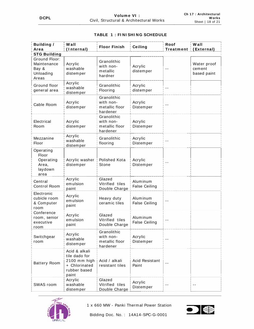
DCPL Volume VI :
Civil, Structural & Architectural Works
Ch 17 : Architectural
Works Sheet | 18 of 21
1 x 660 MW - Panki Thermal Power Station
Bidding Doc. No. : 14A14-SPC-G-0001
TABLE 1 : FINISHING SCHEDULE
Building / Area
Wall (Internal)
Floor Finish Ceiling Roof Treatment
Wall (External)
STG Building
Ground Floor:
Maintenance Bay &
Unloading Areas
Acrylic washable
distemper
Granolithic
with non-metallic
hardner
Acrylic distemper
-- Water proof cement
based paint
Ground floor
general area
Acrylic
washable distemper
Granolithic
Flooring
Acrylic
distemper --
Cable Room Acrylic
distemper
Granolithic
with non-
metallic floor hardener
Acrylic
Distemper --
Electrical
Room
Acrylic
distemper
Granolithic with non-
metallic floor hardener
Acrylic
Distemper
Mezzanine
Floor
Acrylic
washable distemper
Granolithic
flooring
Acrylic
Distemper --
Operating
Floor Operating
Area, laydown
area
Acrylic washer
distemper
Polished Kota
Stone
Acrylic
Distemper --
Central
Control Room
Acrylic emulsion
paint
Glazed Vitrified tiles
Double Charge
Aluminum
False Ceiling
Electronic cubicle room
& Computer
room
Acrylic
emulsion paint
Heavy duty
ceramic tiles
Aluminum
False Ceiling --
Conference
room, senior
executive room
Acrylic emulsion
paint
Glazed Vitrified tiles
Double Charge
Aluminum
False Ceiling --
Switchgear room
Acrylic
washable
distemper
Granolithic
with non-metallic floor
hardener
Acrylic Distemper
--
Battery Room
Acid & alkali tile dado for
2100 mm high + Chlorinated
rubber based paint
Acid / alkali resistant tiles
Acid Resistant Paint
--
SWAS room
Acrylic
washable distemper
Glazed
Vitrified tiles Double Charge
Acrylic
Distemper -- --
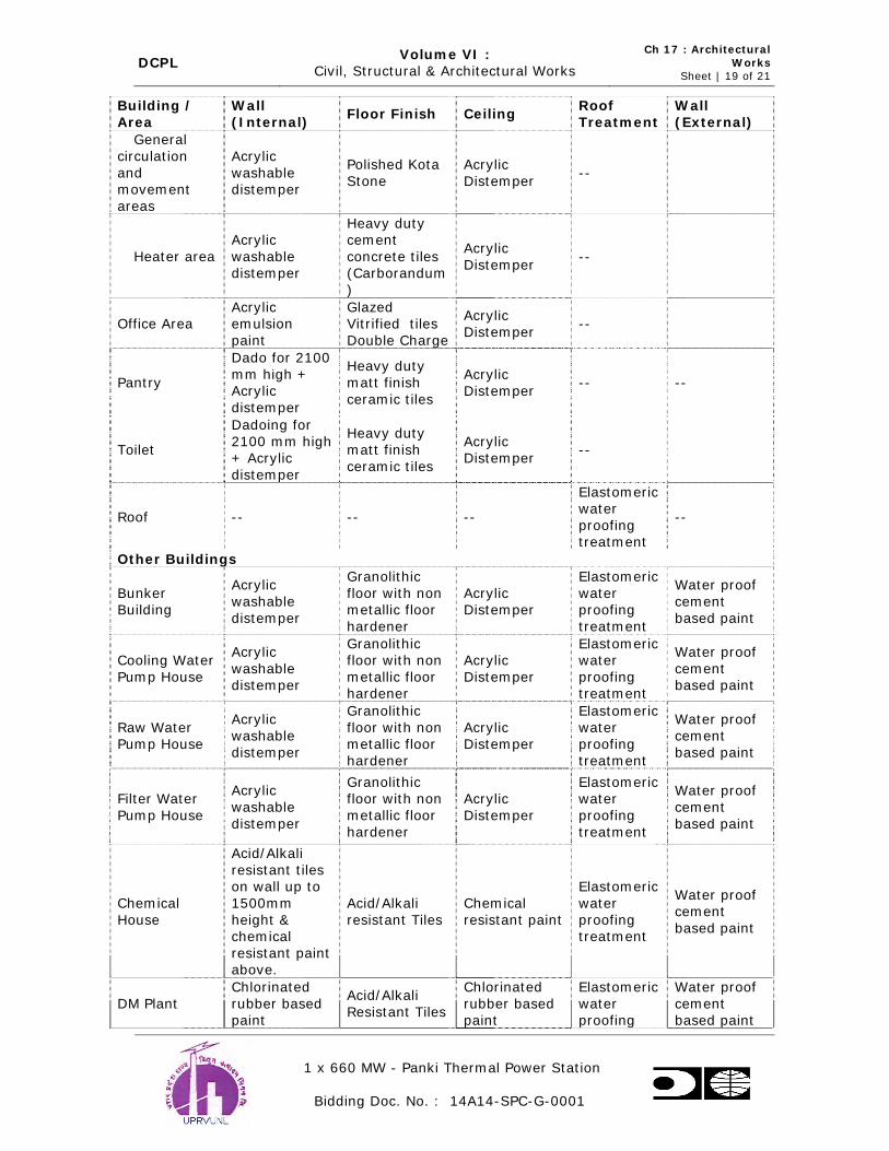
DCPL Volume VI :
Civil, Structural & Architectural Works
Ch 17 : Architectural
Works Sheet | 19 of 21
1 x 660 MW - Panki Thermal Power Station
Bidding Doc. No. : 14A14-SPC-G-0001
Building /
Area
Wall
(Internal) Floor Finish Ceiling
Roof
Treatment
Wall
(External)
General
circulation
and movement
areas
Acrylic
washable distemper
Polished Kota
Stone
Acrylic
Distemper --
Heater area
Acrylic
washable distemper
Heavy duty cement
concrete tiles (Carborandum
)
Acrylic
Distemper --
Office Area Acrylic emulsion
paint
Glazed Vitrified tiles
Double Charge
Acrylic Distemper
--
Pantry
Dado for 2100
mm high + Acrylic
distemper
Heavy duty
matt finish
ceramic tiles
Acrylic Distemper
-- --
Toilet
Dadoing for
2100 mm high + Acrylic
distemper
Heavy duty
matt finish
ceramic tiles
Acrylic Distemper
--
Roof -- -- --
Elastomeric water
proofing treatment
--
Other Buildings
Bunker Building
Acrylic
washable
distemper
Granolithic
floor with non metallic floor
hardener
Acrylic Distemper
Elastomeric
water proofing
treatment
Water proof
cement
based paint
Cooling Water
Pump House
Acrylic
washable distemper
Granolithic floor with non
metallic floor hardener
Acrylic
Distemper
Elastomeric water
proofing treatment
Water proof
cement based paint
Raw Water Pump House
Acrylic washable
distemper
Granolithic
floor with non metallic floor
hardener
Acrylic Distemper
Elastomeric
water proofing
treatment
Water proof cement
based paint
Filter Water
Pump House
Acrylic
washable
distemper
Granolithic floor with non
metallic floor
hardener
Acrylic
Distemper
Elastomeric water
proofing
treatment
Water proof
cement
based paint
Chemical
House
Acid/Alkali
resistant tiles on wall up to
1500mm
height & chemical
resistant paint above.
Acid/Alkali
resistant Tiles
Chemical
resistant paint
Elastomeric
water
proofing treatment
Water proof cement
based paint
DM Plant
Chlorinated
rubber based paint
Acid/Alkali
Resistant Tiles
Chlorinated
rubber based paint
Elastomeric
water proofing
Water proof
cement based paint

DCPL Volume VI :
Civil, Structural & Architectural Works
Ch 17 : Architectural
Works Sheet | 20 of 21
1 x 660 MW - Panki Thermal Power Station
Bidding Doc. No. : 14A14-SPC-G-0001
Building /
Area
Wall
(Internal) Floor Finish Ceiling
Roof
Treatment
Wall
(External)
treatment
Chlorination Building
Acid / Alkali resistant tiles
Acid / Alkali resistant tiles
Acrylic Distemper
Elastomeric
water proofing
treatment
Water proof cement
based paint
CPU
Regeneration Building
Acrylic
washable distemper
Granolithic Flooring
Acrylic Distemper
Elastomeric
water proofing
treatment
Water proof
cement based paint
Control
Rooms
Acrylic emulsion
paint
Glazed Vitrified tiles
Double Charge
Aluminum
False Ceiling --
Water proof cement
based paint
MCC
Switchgear Room
Acrylic
washable distemper
Granolithic floor with non
metallic floor
hardener
Acrylic
Distemper --
Water proof
cement based paint
Cable Vaults Acrylic
Distemper
Granolithic
floor with non
metallic floor
hardener
Acrylic
Distemper --
Water proof
cement based paint
Workshop
Acrylic
washable Distemper in
workshop area and
Acrylic emulsion
paint in office area
Granolithic
floor with non metallic floor
hardener in workshop area
and Vitrified
Tiles in office area
Acrylic Distemper
Elastomeric
water proofing
treatment
Water proof cement
based paint
Canteen : General Area
Kitchen
Dado for
2100mm high & Acrylic
Distemper
above. Dado for
2100mm high & Acrylic
Distemper above.
Heavy Duty
Ceramic Tiles
Heavy Duty
Ceramic Tiles
Acrylic Distemper
Acrylic
Distemper
Elastomeric
water proofing
treatment
Granular
finish
Fire Station
Building
Acrylic
washable distemper
Glazed
Vitrified tiles Double Charge
in office, dormitory
area &
granolithic flooring with
non metallic floor hardener
in parking &
equipment
store area.
Acrylic
Distemper
Elastomeric water
proofing treatment
Water proof
cement based paint
Service Acrylic 20 mm thick Aluminum Elastomeric Granular

DCPL Volume VI :
Civil, Structural & Architectural Works
Ch 17 : Architectural
Works Sheet | 21 of 21
1 x 660 MW - Panki Thermal Power Station
Bidding Doc. No. : 14A14-SPC-G-0001
Building /
Area
Wall
(Internal) Floor Finish Ceiling
Roof
Treatment
Wall
(External)
building:
Ent. Lobby,
Reception, Portico & Lift
Area Office Area
emulsion
paint
Acrylic
emulsion paint
polished
granite stone
Glazed
Vitrified tiles Double Charge
False Ceiling
Aluminum False Ceiling
water
proofing
treatment
finish
(Vineratex)

DCPL Volume VI :
Civil, Structural & Architectural Works Ch 18 : Piling Sheet | 1 of 10
1 x 660 MW - Panki Thermal Power Station
Bidding Doc. No. : 14A14-SPC-G-0001
18.0 PILING
18.1 The detailed design, preparation of construction drawings, installation and
testing of piles forming foundations to buildings and structures are detailed below conforming to the latest IS:2911 – Code of Practice for Design and
Construction of Pile Foundations : Part I Concrete Piles and IS:2911 Part : IV Load test on piles and to this Specification. The contractor shall be responsible
for all aspects of the pile performance installed including demonstration of the
adequacy of his design by testing. During detailed design the contractor shall submit the proposed firm to undertake piling work with details piling system,
method of installation, summary of design basis, number, type and size of construction plant items to be employed for the work including crane, piling
equipment, concreting equipment and proposal for installation & testing of trial piles and tests on work piles.
18.2 Prior to installation of trial piles, the contractor shall submit final details of the
trial piling installation including specifications, detailed design calculations and
construction drawings for the trial piling together with associated equipment to be provided for construction and testing of the same.Design report discussing
the overall results of the tests on trial piles and concluding with and justifying the proposed definition of reference piles; specification, with fully detailed
construction drawings, supporting calculations for the final design of the working piles, and the field control procedures the contractor intends to use to
verify that pile installation satisfies the requirements of his design should also be submitted.
18.3 Design Criteria
The following shall be the design criteria for the working piles :
a. Piles shall be designed in line with approved soil investigation report as single vertical piles acting under a design load as deemed fit.
b. Driving formula (where relevant) may be adopted interalia as a
criteria for acceptance. But the minimum founding requirements shall
be based on recognized methods of soil mechanics design, appropriate to the type of pile.
c. The piles shall be designed for a minimum factor of safety of 2.5
against failure under the design load specified.
d. Piles shall be designed for a limiting settlement of a single pile under vertical design load of 8 mm at the head.
e. Piles shall be designed to resist a maximum force due to critical load combination in any direction applied to the head of the pile at cut-off
level. For this design condition it shall be assumed that the pile head is effectively as a fixed-end by the pile-cap.
18.4 Tolerance
Setting out shall be carried out from the main grid lines of the proposed
structure. Immediately before installation of the pile, the pile position shall be
marked with suitable identifiable pins or markers. For a pile head cut-off, at or above ground level, the maximum permitted deviation of the pile head cut off

DCPL Volume VI :
Civil, Structural & Architectural Works Ch 18 : Piling Sheet | 2 of 10
1 x 660 MW - Panki Thermal Power Station
Bidding Doc. No. : 14A14-SPC-G-0001
center from the center point, shown on the setting out drawing shall be 75
mm in any direction. For a pile head cut-off below ground level, an additional
tolerance will be permitted as below on the assumption that the pile head would have been within tolerance if the cut-off
had been at ground level. The maximum permitted deviation of the finished pile from the vertical is 1 in 75. Forcible corrections to concrete piles shall not
be made.
18.5 The contractor shall carry out the work to minimize noise and disturbance.
If during the execution of the work, damage is likely to be, caused to mains, services or adjacent structures, the contractor shall submit proposal for repair
or avoidance of such damage. The contractor shall ensure that damage does not occur to completed piles.
18.6 Records
The contractor shall keep records as below of the installation of each pile and
shall submit record to the Engineer.
Table 1.0
a) Piles reference number (location) *
b) Piles cut off level *
c) Pile type *
d) Nominal cross-sectional dimensions or diameter *
e) Pile design capacity *
f) Standing groundwater level *
g) Date and time of driving, red riving or boring *
h) Date of concreting *
i) Ground level at commencement of installation of piles *
j) Working level *
k) Depth from working level to pile toe *
l) Toe level *
m) Depth from working level to pile head level *
n) Length of temporary / permanent casing *
o) Type weight, drop and mechanical condition of
hammer
*
p) Number of type of packings used and type and
condition of
*
q) Record of blows per 300 mm over complete drive *
r) Set of pile or pile tube in mm per 10 blows or number of
*
s) Temporary compression of ground and pile from time of
marked increase in driving resistance until pile reaches
*
t) Length and details of reinforcement *
u) Grade and slump of Concrete mix and control test *
v) Volume of concrete installed in pile *
w) Method of placing concrete *
x) Number of blows to form bulb where appropriate *
y) Level of water or drilling fluid at commencement of
placing concrete
*
z) All information regarding obstructions delays and other
interruptions to the sequence of work
*

DCPL Volume VI :
Civil, Structural & Architectural Works Ch 18 : Piling Sheet | 3 of 10
1 x 660 MW - Panki Thermal Power Station
Bidding Doc. No. : 14A14-SPC-G-0001
18.7 Driven Cast-in-situ Concrete Piles
a.) Installation of piles shall be carried out as per layout construction drawings in accordance with latest IS codes as below:
i.) IS:456-2000 : Code of practice for plain and Reinforced Concrete
ii.) IS:2911-Part I : Code of Practice for Design and Section-I Construction of pipe foundation
iii.) IS:2911-Part IV : Test load on piles
b.) The sequence of installation of piles shall be to the approval of the Engineer.
c.) The equipment and accessories required for the pile driving shall be standard
type. The capacity of the pile frame shall be selected after considering the size
and weight of the casing to be handled, the location of the work and the hardness of driving. The steel casing used for installing the piles shall be
straight and shall have sufficient wall thickness and strength to prevent damage, distortion etc. Detachable shoes used with the temporary steel casing
shall be fabricated steel or cast iron, double rimmed and of requisite strength, and of the standard sizes used with the respective steel casing. The shoe shall
be co-axial with the steel casing.Casings distorted from true uniform shape whether caused by driving or earth and water pressure resulting in a reduction
of the cross sectional area of the pile in excess of 10 percent shall not be used
in the works.The nominal casing size shall be 500 mm diameter.
d.) The pile shall be driven to a set proposed by the contractor. The final set values shall be repeated thrice before terminating the pile at that level. All
relevant data with back up, computations pertaining to “set” shall be submitted before commencing piling work for Purchasers approval. Any
sudden change in rate of penetration shall be brought to the notice of the Engineer.
e.) Control of Pile Driving
Protection of pile heads and selection of pile hammer shall be as per IS:2911 Part I. The pile shall be driven as accurately as possible to the vertical. Piles
shall be installed with due consideration for the safety of adjacent structures by a method leaving their strength unimpaired and which develops and retains
the required load bearing capacity. In the case of piles close to existing plant and structures, the Engineer may specify suitable precautions which may call
for additional working hours for the rig. The quipment and methods for
installing piles shall be such that the loss of energy is limited to a minimum. Should the deviation of the installed pile be greater than the specified
tolerances, the Engineer may at his discretion order the installation of additional piles after checking the design load on the pile group of which the
particular pile forms part. Care shall be taken not to damage the piles by over driving. Any sudden change in the rate of penetration shall be noted and
informed to the Engineer. Jetting of Pile by means of water shall not be permitted.
f.) After complete installation of the casing before concreting, the contractor shall inform the Engineer to inspect the casing for proper plumb location and other

DCPL Volume VI :
Civil, Structural & Architectural Works Ch 18 : Piling Sheet | 4 of 10
1 x 660 MW - Panki Thermal Power Station
Bidding Doc. No. : 14A14-SPC-G-0001
conditions. Only after approval concreting should proceed. Level readings shall
be taken on each pile after driving and again after all the piles in a group are
driven. Piles which are found to have resin shall be driven to the original depth and set.
g.) The main longitudinal reinforcing bars in piles shall be in one continuous
length. In long piles, joints shall be permitted in main longitudinal bars but these shall be kept to a minimum. Joints in adjacent bars shall be staggered at
least 1 meter part along the length of the pile. Joints in reinforcement shall be
such that the full strength of the bar is effective across the joint.
Longitudinal reinforcement shall be provided for the full length of the pile extending above pile cut off level to provide adequate bond length into the pile
cap. The minimum area of longitudinal reinforcement within the pile shaft shall be 0.4 percent of cross-sectional area of the pile on the basis of the nominal
casing diameter. Longitudinal reinforcement shall be formed into a rigid cage to resist deformation during handling and installation by the use of links or
helical reinforcement. The minimum diameter of links and helical
reinforcement shall be 6 mm spaced at 150 mm and not more than 300 mm. The longitudinal reinforcement shall project 52 times its diameter; above the
cut off level of the pile to ensure adequate bond length inside the pipe cap. Minimum 6 Nos. of longitudinal reinforcement shall be provided.
Reinforcement provided in pile shall be symmetrical about any axis on the pile cross section. The diameter of longitudinal reinforcement shall not be less than
12 mm. Lap or splice joints shall be provided with sufficient link bars to resist eccentric forces. Minimum cover to main reinforcement in the pile shall be
75mm.
h.) The method of placing and the workability of the concrete shall be such that
continuous monolithic concrete shaft of the full cross-section is formed. Mechanical vibrators shall not be used to compact concrete. Concrete in piles
shall be of design- mix with minimum grade M25 with minimum cement of 400 kg/cum water cement ratio within 0.45 to 0.55 using super plasticized
Sikament 170 or equivalent. Generally the slump of the concrete shall be within the range 100 to 150 mm. The contractor shall ensure the minimum
specified strength in accordance with IS:456, IS:10262 & SP. 23 shall be
followed as guidance for mix design. Compaction of test cubes shall be done under same condition as followed for concreting of piles.
i.) In soft clays or loose sands ,or where there is likelihood of danger to green
concrete due to driving of adjacent piles, the designed reinforcement should be provided up to the full pile depth, regardless of whether or not it is required
from uplift and lateral load considerations. Refer clause 5.11.2 of IS : 2911 ( Part I / Sec-1)
j.) Cleaning out of casing
Before placement of concrete ,it shall be ensured that the inside of the casing is free from sludge or any foreign matter. The contractor shall ensure that
water does not enter the casing tube/pile shoe at the end of driving & during the concreting operations. The existence of water inside casing tube after
driving and before executing the concrete operation, if any shall be checked by the contractor by suitable probe & concreting of pile work shall be allowed to
proceed if water level is less than 15 cm measured above the inner surface at
the top of the shoe. If the water level is more than 15 cm, contractor shall take remedial measures viz. bailing or pumping to reduce the depth of water

DCPL Volume VI :
Civil, Structural & Architectural Works Ch 18 : Piling Sheet | 5 of 10
1 x 660 MW - Panki Thermal Power Station
Bidding Doc. No. : 14A14-SPC-G-0001
before concreting & if it is not possible to do so then the contractor shall re-
drive the casing at no extra cost to the Purchaser.
k.) Concrete Level – finishing of pile head
The cut-off level shall be as shown on the construction drawings. Concrete shall be cast to minimum of 500 mm above the cut-off level, or local ground
water level, whichever is higher. Withdrawal of temporary casing shall be
carried out in stages during the concrete placing operation with utmost care maintaining an adequate head of concrete above the bottom of casing at each
stage of withdrawal so as to prevent the inflow of soil and water into the bore. Section of empty hole remaining above the head of the pile shall be
temporarily backfilled with sand or other approved material prior to excavation for pile cap construction.
l.) Trimming of pile heads
Following excavation subsequently for pile cap construction, the contractor shall carefully remove excess concrete above specified cut-off level, without
damaging the remainder of the pile including the projection reinforcement. Any cracked or defective concrete occurring below specified cut-off level shall
be cut away and made good with new concrete properly bonded to the old. Piles that are defective shall be pulled out or left in place as judged by
Engineer without affecting performance of adjacent piles. Also the contractor shall be bound to install additional piles to substitute the defective ones as per
the directions of the Engineer.
m.) The dynamic cone penetration tests shall be carried out for a depth of at least
2 meters from the termination depth. The number of such tests shall be as follows :
a. One number dynamic cone penetration test for each pile group
consisting of more than four piles.
b. For TG and Chimney pile groups the number of dynamic cone
penetration tests shall be one per cent of the total number of piles.
18.8 Load Tests on Piles
a) Load test shall be in accordance with IS:2911 Part IV (latest revision) Initial load tests on “Trial Piles” shall be executed in advance of works pile
construction and shall comprise vertical load tests at locations as directed. Load test on trial piles shall also include lateral load test and uplift load tests
as directed by the Engineer. 6 number of trial piles shall be tested from each
capacity of the pile. Out of the six (6) nos. of piles to be tested for two (2) nos. each capacity shall be tested for vertical load, two (2) nos. for lateral load
and two (2) nos. for uplift load.
Routine load tests on “Works Piles” shall be vertical load test and lateral load tests on piles as directed by the Engineer. Number of routine tests to be
conducted on work piles shall be equal to one and half (1.5) percent of the total number of piles used in the work for vertical load tests as well as lateral
load tests.

DCPL Volume VI :
Civil, Structural & Architectural Works Ch 18 : Piling Sheet | 6 of 10
1 x 660 MW - Panki Thermal Power Station
Bidding Doc. No. : 14A14-SPC-G-0001
b) Load tests shall not normally be undertaken by the contractor within 28 days
after the installation of the piles in position. However, the contractor may be
allowed by the Engineer to use rapid hardening cement or add necessary admixtures to enable him to conduct the tests within a lesser period. Before
any load test is done, the proposed arrangement for carrying out the load tests including the preparation of the structure to receive the loads and the
type of loading to be adopted shall be furnished by the contractor.
c) Vertical Load Test on Trial Piles
Load tests to verify the contractor’s design shall be carried out on piles of
different capacities proposed to be used. The contractor shall commence testing as early as possible after installing the piles. The test shall be carried
out by applying series of loads on RC cap over single pile. The load shall be applied by means of standard hydraulic jack reacting against a loaded platform
which shall be preloaded platform which shall be preloaded to three times the estimated safe load carrying capacity of the pile. Reading of settlement and
rebound shall be recorded with four dial gauges of 0.01 mm sensitively and
resting on diametrically opposite ends of the pile cap. The dial gauge shall be fixed to a datum bar whose ends rest-upon non-movable supports. The
supports for datum bar with reference to which the settlement of the pile is measured shall be at least 5 times diameter of pile away from the pile.
The test shall be conducted by the cyclic loading method. The test load shall
be applied in equal increments of about one-fifth of the estimated safe load. Each stage of loading or unloading shall be maintained till the rate of
movement of the pile cap is not more than 0.02 mm per hour. However, load
shall be maintained for longer periods at 1 to 1.5 times the assumed safe capacity, and at final loads as directed by Engineer. The safe load on pile shall
be the least of the following :
i Two third of the final load at which the total settlement attains the value of 12 mm.
ii Two third of the final load at which the net settlement attains a value of
6 mm.
iii 50 per cent of the final load at which the total settlement equals one-
tenth of the pile diameter.
d) Lateral Load Test on Trial Piles
The test pile shall be decided by the Engineer. The test pile shall be cut off at the proper level and provided with a cap with vertical plane sides having an
adequate area for proper seating of the jack and dial gauge. The lateral load
shall be applied on the pile at or approximately at cut off level and the deflection shall be measured at a point diametrically opposite to the point of
load application. The loading shall be applied by the hydraulic jack of adequate capacity, abutting the pile horizontally and reacting against a suitable system.
The reaction may be provided by the well of the excavated pit when the test is being conducted below ground level or by a neighbouring pile in which case
thrust pieces shall be inserted on either end of the jack to make up the gap. Lateral load applied on the pile shall be measured by a calibrated pressure
gauge mounted on the jack, having a least count of 500 kg. Deflection of the
pile head shall be measured by four dial gauges, fixed to datum bars & having a least count of 0.01 mm. The datum bars shall be provided with rigid

DCPL Volume VI :
Civil, Structural & Architectural Works Ch 18 : Piling Sheet | 7 of 10
1 x 660 MW - Panki Thermal Power Station
Bidding Doc. No. : 14A14-SPC-G-0001
supports. Loading shall be applied in increments of 500 kg.Each stage shall be
maintained for a period till the rate of movement of the pile head is not more
than 0.02 mm/hour or 1 hour whichever is greater . Loading shall be continued till one of the following occurs :
i. Deflection of pile head exceeds 12 mm.
ii. The applied load on the pile is three times the assumed lateral load
capacity of the pile.
The safe load shall be smaller of the following :
i. Half the final load for which the total deflection is 12 mm.
ii. Load at which the total displacement corresponds to 5 mm.
e) Pull-out Test
The test piles shall be decided by the Engineer. The test pile shall be built upto the proper length and the head provided with suitable arrangements for
anchoring the load applying system. Loads shall be applied using a approved reaction system, uplift forces on the pile shall be applied directly to the test
pile or through a lever system. The reaction shall be provided by neighbouring piles or blocks may be constructed for the purpose. Hydraulic jacks shall be
used for load application. Load applied by the hydraulic jack shall be measured by a calibrated gauge with a least count of 100 Kg. Movement of the pile shall
be measured by dial gauges, fixed to datum bar and having a least count of
0.01 mm. Four dial gauges placed diametrically opposite shall be used. Datum bars shall be provided with rigid supports. The load shall be applied along the
longitudinal axis of the pile using method approved by the Engineer. Loading shall be applied to the pile top in increment of one-fifth of the expected safe
capacity. Each stage shall be maintained for a period till the rate of movement of the pile head is not more than 0.02 mm per hour or four hours whichever is
greater. Loading shall be continued till one of the following occurs :
i. Yield of soil pile system occurs causing progressive movement of pile
exceeding 12 mm.
ii. The loading on the pile top equals three times the estimated safe load or as specified in the case of separate test pile.
The safe capacity of the pile should be least of the following :
i. Two third of the load at which the total displacement is 12 mm or the
load corresponding to a specified permissible uplift, and
ii Half of the load at which the load displacement curve shows a clear
break (downward trend)
f) Routine Test on Working Piles
Three tests shall be carried out on working piles upto one and half times the design load and the maximum settlement of test loading in position being not
exceeding 12 mm as per IS:2911 (Part IV). In case a pit foils under or during
the load test, the Engineer shall select two additional piles in lieu of each of

DCPL Volume VI :
Civil, Structural & Architectural Works Ch 18 : Piling Sheet | 8 of 10
1 x 660 MW - Panki Thermal Power Station
Bidding Doc. No. : 14A14-SPC-G-0001
such foiled pipe and the contractor shall carryout load tests on such additional
piles.
18.9 Cast-In-Situ Piling Bored
The following specification deals with the requirements of materials,
workmanship and installation of Bore Cast-in-situ reinforced concrete piles.
The materials and workmanship shall conform with the provision of the latest
IS:456, IS:2911 (Part I, Section 2) & IS:2911 (Part 4).
Care shall be taken while boring piles so that no existing foundations / sub-structures are disturbed by providing suitable arrangements like shoring etc.
a. Sequence of Piling
The sequence of piles installed shall be such that the adjacent piles already
installed are not disturbed nor their carrying capacity reduced by subsequent
boring operation. In a group the installation of the piles shall normally proceed from the center of the group towards the periphery.
b. Control of Alignment
Piles shall be installed as accurately as possible as per the designs and
drawings either vertically or to the specified batter. Great care should be exercised in respect of installation of single pile or piles in two pile group. For
vertical piles a deviation of 1.5 percent should not normally be exceeded. Piles
should not deviate more than 75 mm or D/10 whichever is more in case of piles having diameter more than 600 mm from their designed positions at the
working level of the piling rig. In the case of a single pile in a column, positional tolerance should not be more than 50 mm (100 mm in case of piles
having diameter more than 600 mm).
For piles carried to substantial depth, the design should provide for the worst combination of the above tolerance in position and inclination. In case of piles
deviating beyond these limits and to such an extent that the resulting
eccentricity cannot be taken care of by a redesign of the pile cap and ties, the piles shall be replaced or supplemented by one or more additional piles, as
directed by the Engineer, at no extra cost.
Any deviation from the designed location, alignment or load capacity of any piles shall be noted and brought to the attention of the Engineer and
rectification and supplemental works carried out to the satisfaction of the Engineer at no extra cost.
A minimum length of one meter of temporary casing shall be inserted in each bored pile unless otherwise specifically desired. Additional length of temporary
casing may be used depending on the condition of the strata etc.
Drilling mud of suitable consistency may also be used instead of temporary casings for stabilizing sides of the holes.
In case, a bored pile is stabilized by drilling mud the bottom of the hole shall
be cleaned very carefully before concreting work is taken upon. The cleaning
of the hole shall be ensured by careful operation of boring tool and / or

DCPL Volume VI :
Civil, Structural & Architectural Works Ch 18 : Piling Sheet | 9 of 10
1 x 660 MW - Panki Thermal Power Station
Bidding Doc. No. : 14A14-SPC-G-0001
flushing of the drilling mud thorugh the bottom of the hole. Flushing of bore
holes before concreting with fresh drilling fluid/ mud is preferred.
In case a holes is bored by use of drilling mud, the specific gravity of the mud
suspension near about the bottom of the hole shall, wherever practicable, be determined by suitable interval of piles and recorded. Consistency of the
drilling mus suspension shall be controlled throughout the boring as well as concreting operations in order to keep the hole stabilized as well as to avoid
concrete getting mixed up with the thicker suspension of the mud.
The concreting operatings should not be taken up when the specific gravity of
bottom slurry is more than 1.2. Concreting shall be done by tremie method in all such cases.
The top of concrete in a pile shall be brought above the cut-off level as per cl.
7.8 of IS: 2911 (Part 1/sec.2).
In case, defective piles are formed, they shall be removed or left in place, if so
directed by the Engineer, if these do not affect the performance of the adjacent piles or the cap as a whole. Additional piles shall be provided to
replace them as directed by the Engineer.
Any deviation from the designed location alignment or load capacity of any pile shall be noted and adequate measures taken well before the concreting, of the
pile cap and plinth beam if the deviations are beyond the permissible limit.
During chipping of the pile top manual chipping may be permitted after three
days of pile casting, pneumatic tools for chipping shall not be used before seven days after pile casting.
After concreting the actual quantity of concrete shall be compared with the
average obtained from observations actually made in the case of a few piles initially cast. If the actual quantity is found to be considerably less, special
investigations shall be conducted and appropriate measures taken.
The bentonite suspension used for piling work shall satisfy the following
requirements:
i. The liquid limit of bentonite when tested in accordance with IS:2720 (Part V) shall be more than 300 percent and less than 450 percent.
ii. The sand content of the bentonite powder shall not be greater than 7
percent.
iii. Bentonite solution should be made by mixing it with fresh water using
pump for circulation. The density of the freshly prepared Bentonite solution should be between 1.034 and 1.10 gm/ml depending upon
pile dimensions and type of soil in which the pile is to be installed. However, the density of bentonite solution after mixing with
deleterious materials in the pile bore may be up to 1.25 gm/ml.
iv. The marsh velocity when tested by a Marsh cone should be about 37 seconds.
v. The differential free swell shall be more than 540 percent.
DCPL Volume VI :
Civil, Structural & Architectural Works Ch 18 : Piling
Sheet | 10 of 10
1 x 660 MW - Panki Thermal Power Station
Bidding Doc. No. : 14A14-SPC-G-0001
vi. The PH value of the bentonite suspension shall be between 9 & 11.5.
18.10 Codes and Standards
The following Indian Codes and Standards (Latest) shall be used for design of the structural elements:
IS:456 : Code of Practice for plain and Reinforced concrete
IS:875 : Code of Practice for Design loads (other than earthquake) for Buildings and structures.
IS:2911: Code of Practice for Design and Construction of Pile Foundations –
Bored Cast-in-situ Piles (Part 1/sec. 2)
IS:2911 : Code of Practice for Design and Construction of Pile Foundation – Load Test on Piles (Part 4)
IS:1786 : Code of Practice for HYSD bars
IS:2751 : Code of Practice for welding of mild steel bars used for reinforced concrete construction
IS:2062 : Steel for general structural purposes
SP:16 : Design Aids for Reinforced Concrete to IS:456.

DCPL Volume VI :
Civil, Structural & Architectural Works Ch 19 : Surveying Works
Sheet | 1 of 1
1 x 660 MW - Panki Thermal Power Station
Bidding Doc. No. : 14A14-SPC-G-0001
19.0 SURVEYING WORKS
19.1 Site survey shall be carried out to establish the ground levels and to determine
any existing structures, roads etc. The site survey shall be carried out before the commencement of the work and if required during the progress of the work. The
site survey shall be carried out at a grid spacing of 5-10 meters and at every change of level of the existing ground to produce contour drawings at 0.25 meter
intervals. Scale of the contour drawings shall be as directed by the Consultant. A
specialized firm approved by the Consultant shall carry out the site survey.
A single grid pillar will be given by the client with coordinates in plant area. Necessary grids shall be made by EPC contractor including demarcating the
structures, buildings and jungle clearance including Cutting, uprooting and removing of trees and dispose the same away from the site etc.
19.2 Survey points (reference points and bench marks) : The contractor shall
construct adequate number of reference points and bench marks for marking the
setting out lines and levels. The reference points shall consist of suitable metal plates set in 400 mm x 400 mm x 500 mm precast concrete plinth (grid pillars)
and inscribed with the exact level. All levels of the benchmarks shall be related to the agreed datum. The exposed numbers, locations, co-ordinates and level of the
reference points and bench marks shall be plotted on drawings and approved by the consultant prior to the commencement of the work. Survey points in solid
walls shall be stainless steel plates or cast iron, fixed firmly and sufficiently deep in the walls.
19.3 Safeguard of survey points: The survey points shall not be removed from their position without the permission of the Consultant. If any of the survey points are
damaged or lost due to any work carried out near their location, the contractor shall be responsible for replacing such survey points.
19.4 Surveying during the progress of work : The contractor shall assist the consultant
at any time when checking survey points, setting out, checking construction items and erection parts. The contractor shall provide and arrange the following:
i.) Provision and maintenance of survey instruments and accessories.
ii.) Provision of skilled personnel, supply of all material required for the
survey exposing covered survey points.
iii.) Shifting of any machinery used for construction out of the sight lines.
iv.) Stopping all drilling, blasting, driving and any other works.
v.) Causing soil vibrations and stopping during instrument observations
vi.) Removing all obstructive accumulation of water
vii.) Taking all necessary safety precautions
viii.) Furnishing any marking material requested by the Consultant in connection with control surveys
ix.) Providing additional survey points in accordance with the consultant’s
instruction.

DCPL Volume VI :
Civil, Structural & Architectural Works Ch 20 : Excavation & Filling
Sheet | 1 of 6
1 x 660 MW - Panki Thermal Power Station
Bidding Doc. No. : 14A14-SPC-G-0001
20.0 EXCAVATION AND FILLING
20.1 The works to be provided by the bidder in respect of excavation in all types of
soils including shoring, dewatering, filling around foundations and to grade, compaction of fills and approaches, protective fencing, lighting, etc. relevant
to structures and locations shall be as detailed below:
a. Furnish all labour, supervision, services including facilities as required
under statutory labour regulations, materials, equipment, tools and plants, transportation etc. required for the work.
b. Prepare and submit working drawings showing the approaches, slopes, beams, shoring, sumps for dewatering including drains and
outfall for drainage, space for temporary stacking of spoils, disposal area, fencing etc. and all other details as may be required by the
Engineer.
c. To carryout sampling and testing and submit to the Engineer, results of soil compaction tests if required by the Engineer to assess the
degree of compaction.
20.2 All works should conform to the requirements of the latest revision of relevant
ISS. IS: 3764 : Indian Standard for Safety Code for excavation work.
IS:1200 (PartI): Indian Standard Methods of Measurement of Building and Civil Engineering work, Part-I: Earthwork.
20.3 The bidder should carryout the work as per the approved drawings. All
materials required for the work shall be of best commercial variety. Borrow
materials for back- filling shall be excavated from approved locations and
shall consist of material, free from roots, vegetation, decayed organic matter, harmful salts and chemicals free from lumps and clods. If
specified, clean graded sand free from harmful and deleterious material
from approved quarries, shall be used as fill material.
20.4 Quality Control: The bidder shall get approved the field quality plan, for maintaining the quality control for which, he shall establish and maintain
quality control lab for the various aspects of the work, method, material
and equipment used. The quality control operation shall include but not be limited to the following items of work:
a. Lines, Levels and Grades
: i. Periodic surveys. ii. Establishment of markers, boards etc.
b. Back-filling : i. Checking the quality of fill material ii. Checking moisture content of the backfill
iii. Checking the degree of compaction.
Guide lines for quality control is attached in Vol-II of the specification.
20.5 Excavation
a. Setting out : The contractor should submit to the Engineer,
detailed drawings of the excavation work to be executed by him showing the dimensions as per drawings and specification adding his

DCPL Volume VI :
Civil, Structural & Architectural Works Ch 20 : Excavation & Filling
Sheet | 2 of 6
1 x 660 MW - Panki Thermal Power Station
Bidding Doc. No. : 14A14-SPC-G-0001
proposals of slopes, shoring, approaches, dewatering sumps, beams etc.
Upon Engineer’s approval the contractor should set out the work from
the control points furnished by the Engineer and fix permanent points and markers for ease of future checking. These permanent points and
markers shall be fixed at intervals prescribed by the Engineer. The contractor should proceed with the work after Engineer’s approval. It
should be noted that this checking by the Engineer prior to start of the work shall in no way absolve the contractor of his responsibility of
carrying out the work to true lines , levels and grades as per drawing
and subsequent corrections, if necessary, should be carried out by the contractor free of cost to the Purchaser.
b. Clearing and Grubbing etc.: The area to be excavated shall be cleared
out of fences, trees, logs, stumps, bush, vegetation, rubbish, slush etc. and leveled up. Trees upto 300mm girth shall be uprooted. Trees above
300mm girth to be cut, shall be approved by the Engineer and then marked. Felling of trees shall include taking out roots upto 600mm
below ground level or 150mm below formation level whichever is lower.
After the tree is cut and roots taken out, the pit-holes formed shall be filled with good earth in 250 mm layers and consolidated. The trees shall
be cut in suitable pieces as instructed by the Engineer.
Before earthwork is started, all the spoils/ unserviceable materials and rubbish shall be burned or removed from the site to approved disposal
areas as specified. Useful materials, saleable timber, firewood etc. shall be the property of the Purchaser and shall be stacked properly at the
work site in a manner as directed by the Engineer.
c. Excavation in all kinds of soil: The excavation in all kinds of soil
including old (from demolished structures) underground RCC / CC / brick masonry shall be carried out as per the approved proposal,
modified and corrected where necessary by the Engineer. The work shall be carried out in a workman like manner without endangering the safety
of nearby structures/ services or works and without causing hindrances to other activities in the area. As the excavation reaches the required
dimensions, lines, levels and grades, the work shall be checked by the
Engineer thoroughly and the balance work shall be carried out carefully to avoid any over-excavation. On completion, the work shall be finally
checked and approved by the Engineer. In certain cases, where deterioration of the ground, upheaval, slips etc. are expected, the
Engineer may order to suspend the work at any stage and instruct the contractor to carryout the balance work just before the
foundation work of the structure can be started.
d. Disposal: The excavated soils shall be disposed of within 8 km crow fly
distance from site as directed by the Engineer-in-charge in any or all the following manners:
i) By using it for backfilling straightway.
ii) By stacking it temporarily for use in backfilling at a later date
during execution.
iii) By either spreading or spreading and compacting at
designated disposal areas.

DCPL Volume VI :
Civil, Structural & Architectural Works Ch 20 : Excavation & Filling
Sheet | 3 of 6
1 x 660 MW - Panki Thermal Power Station
Bidding Doc. No. : 14A14-SPC-G-0001
iv) By selecting the useful material and stacking it nearly in
areas designated by the Engineer for use in backfilling by
some other agency.
e. Disposal of Surplus: The surplus material from excavation shall be carried away from the excavation site to designated disposal
area selected by the Engineer. All goods excavated from the pits and all assorted materials of dismantled structures shall be
the property of the Purchaser.
f. Protection : The Engineer shall be notified by the Contractor as
soon as the excavation is expected to be completed within a day so that it may be inspected by him at the earliest. Immediately
after approval of the Engineer, the excavation must be covered up in the shortest possible time. But, in no case the excavation
shall be covered up or worked on before approval and measurement by the Engineer. Excavated material shall be
placed beyond 1.5 metres from the edge of the pit or trench or
half the depth of the pit or trench whichever is more or further away if directed by the Engineer.
Excavation shall not be carried out below the foundation level of
structure close by until required precautions have been taken.
Adequate fencing is to be made enclosing the excavation.
The Contractor shall protect all under-ground services exposed
by excavation. The Contractor shall also divert all surface drains, etc. affected by the excavation to maintain the working
area neat and clean.
g. Dealing with suface water : All working areas shall be kept free of surface water as far as reasonably praticable. Works in the
vicinity of cut areas shall be controlled to prevent the ingress of surface water.
No works shall commence until surface water streams have been properly intercepted , redirected or otherwise dealt with.
Where works are undertaken in the monsoon period, the
Contractor may need to construct temporary drainage systems at his own cost to drain surface water from working areas.
h. Dewatering : All excavations shall be kept free of water and slush. Grading in the vicinity of excavations shall be controlled
to prevent surface water running into excavated areas. The
Contractor shall remove by pumping or other means approved by the Engineer any water inclusive of rain water and subsoil
water accumulated in excavation and keep the trench dewatered until the construction of foundation structure and
backfilling are complete in all respects. (except where such dewatering would need installation of well points or deep wells
for which separate payment will be made) Sumps made for dewatering must be kept clear of the foundations. Method of
pumping shall be approved by the Engineer but in any case, the
pumping arrangement shall be such that there shall be no

DCPL Volume VI :
Civil, Structural & Architectural Works Ch 20 : Excavation & Filling
Sheet | 4 of 6
1 x 660 MW - Panki Thermal Power Station
Bidding Doc. No. : 14A14-SPC-G-0001
movement of subsoil or blowing in due to differential head of
water during pumping.
If necessary, the Engineer may direct the Contractor to continue
dewatering beyond his original or extended contract period in which case he will be paid separately for dewatering as per
terms mentioned elsewhere under payment and measurement, provided the Contractor has completed all the work
satisfactorily.
j. Timber shoring : Timber Shoring made out of approved quality
of timber shall be 'close' or 'open' type, depending on the nature of soil and the depth of pit or trench and the type of
timbering shall be determined by the Engineer. It shall be the reponsibility of the Contractor to take all necessary steps to
prevent the sides of trenches and pits from collapsing.
k. Treatment of slips : The Contractor will take all precaution to
avoid high surcharges and provide proper surface drainage to prevent flow of water over the sides. These precautions along
with proper slopes, berms, shoring and control of ground water should cause no slips to occur. If however slips do occur due to
causes beyond the control of the Contractor, the same shall be removed by him and payment shall be made to him on
appropriate item rate of earthwork. Slips caused due to negligence of the Contractor will be cleared and back-filled later
by him at his own expenses.
20.6 Back-filling
a. The backfilling material shall consist of materials, approved by the
Engineer obtained directly from nearby areas where excavation work by the same agency is in progress, from temporary stacks of excavated
spoils or from borrow pits from selected areas designated by the Engineer. The material shall be free from lumps and clods, roots and
vegetations, harmful salts and chemicals, organic materials, etc. In certain locations, the Engineer may direct sand fillings. The sand should
be clean, well graded and be of quality normally acceptable for use in
concrete.
b. Filling and compaction in pits and trenches around structures: As soon as the work in foundations has been accepted and measured, the space
around the foundation structures in pits and trenches shall be cleared of all debris, brick bats, mortar droppings etc. and filled with earth in layers
not exceeding 250 mm in loose thickness; each layer being watered, rammed and properly compacted to the satisfaction of the
Engineer. Earth shall be rammed with approved mechanized compaction
machine. Usually, no manual compaction shall be allowed unless specifically permitted by the Engineer. The final surface shall be trimmed
and leveled to proper profile as desired by the Engineer. Since the degree of compaction depends on the moisture content of the soil, a lose
watch should be kept on it and corrections done to optimize the moisture content.

DCPL Volume VI :
Civil, Structural & Architectural Works Ch 20 : Excavation & Filling
Sheet | 5 of 6
1 x 660 MW - Panki Thermal Power Station
Bidding Doc. No. : 14A14-SPC-G-0001
The backfilling shall be carried out at optimum moisture content to
achieve 95% of Proctor’s Maximum Dry Density.
c. Plinth filling: The plinth shall be filled with earth in layers not exceeding
250 mm in loose thickness, watered and compacted with approved compaction machine or manually, if specifically permitted by the
Engineer. When the filling reaches the finished level, the surface shall be flooded with water for at least 24 hours, allowed to dry and then
rammed and compacted, in order to avoid any settlement at a later
stage. The finished level of the filling shall be trimmed to the slopes intended to be given to the floor.
d. Filling in trenches for water pipes and drains: Earth used for filling shall
be free from salts, organic or other foreign matter. All clods of earth shall be broken or removed. Where excavated material is mostly rock,
the boulders shall be broken into pieces not bigger than 150 mm size in any direction, mixed with fine material consisting of disintegrated rock,
moorum or earth as available, so as to fill up the voids as far as possible
and then the mixture used for filling. Filling in trenches for pipes and drains shall be commenced as soon as the joints of pipes and drains
have been tested and passed. Where the trenches are excavated in soil, the filling shall be done with earth on the sides and top of pipes in
layers not exceeding 150 mm, watered, rammed and compacted taking care that no damage is caused to the pipe below.
e. Filling in disposal area: Surplus material from excavation which is not required for backfilling shall be disposed of in designated disposal
areas within the lead for disposal as 8 km crow fly distance from the
site. The spoils shall not be dumped haphazardly but should be spread in layers approximately 250 mm thick when loose and
compacted with the help of compacting equipment. In wide areas, rollers shall be employed and compaction done to the satisfaction of
the Engineer at the optimum moisture content which shall be checked and controlled by the contractor.
In certain cases, the Engineer may direct disposal without compaction
which can be done by tipping the spoils from a high bench neatly
maintaining always a proper level and grade of the bench.
20.7 Approaches and Fencing : The contractor should provide and maintain proper approaches for workmen and for inspection. The roads and approaches
around the excavated pits should be kept clear at all times so that there is no hindrance to the movement of men, material and equipment of various
agencies connected with the plant. Sturdy and elegant fencing shall be provided around the top edge of the excavation as well as the bottom of
the fill at the surplus disposal area where dumping from a high bench is in
progress.
20.8 Lighting : Full scale area lighting should be provided if night work is permitted or directed by the Engineer. If no night work is in progress, red
warning lights should be provided at the corners of the excavated pit and the edges of the filling.
20.9 Testing and Acceptance Criteria
a. Excavation: On completion of excavation, the dimensions of the pits shall be checked as per the drawings. After the pits are completely dewatered,

DCPL Volume VI :
Civil, Structural & Architectural Works Ch 20 : Excavation & Filling
Sheet | 6 of 6
1 x 660 MW - Panki Thermal Power Station
Bidding Doc. No. : 14A14-SPC-G-0001
the work shall be accepted after all undercuts have been set right and
all over excavations filled back to required lines, levels and grades
by placing ordinary concrete of M10 proportion and/ or richer and/ or by compacted earth, as directed by the Engineer. Over excavation of the
sides shall be made good while carrying out the back-filling. The excavation work shall be accepted after the above requirements
are fulfilled and all temporary approaches encroaching inside the required dimension of the excavation have been removed.
b. Back-filling: The degree of compaction required shall be as per IS standards and the actual method of measuring the compaction achieved
shall be as decided by the Engineer. The work of back-filling shall be accepted after the Engineer is satisfied with the degree of compaction
achieved.

DCPL Volume VI :
Civil, Structural & Architectural Works
Ch 21 : Water Supply,
Drainage & Sanitation Sheet | 1 of 12
1 x 660 MW - Panki Thermal Power Station
Bidding Doc. No. : 14A14-SPC-G-0001
21.0 WATER SUPPLY, DRAINAGE AND SANITATION
21.1 The technical details of surface drainage, storm water drainage, sewerage
disposal system, sanitary appliances and water supply required for proper supply, drainage, disposal and completion of buildings are detailed below:
21.2 Surface Drainage
a) All the paved and unpaved areas shall be adequately drained. The surface drainage system shall be designed for surface washings and / or
rain / fire water as the case may be. Unpaved open areas shall be drained through RCC drains and connected to main storm drains.
b) The paved area shall be sloped towards the drains with a minimum slope
of 1 in 100. The maximum drainage travel extent shall be limited to 10
metres.
c) The surface drainage from uncontaminated area shall be connected to nearest open storm water drains through rectangular drains.
Contaminated area surface drainage shall be collected through separate network.
d) The interconnecting pipes and rectangular drains shall be sized for
carrying the design discharge when running full.
e) The rectangular drains shall be minimum 450 mm wide of RCC
construction. For minimum width of RCC rectangular drains along major roads refer Chapter 23 of this Specification. The pipes for water drainage
system shall be of RCC class NP2 conforming to IS:458 with minimum size of 150 mm NB. However, for road crossings etc., pipe of class NP3
SHALL BE PROVIDED. For rail crossings, pipes conforming to railway loading standards shall be provided. If sufficient clearance cannot be
provided between the top of the pipe and road top, the pipes shall be
encased in RCC.
f) The maximum velocity for pipe drains and open drains shall be limited to 2.4m/sec and 1.8m/sec respectively. However, minimum velocity for self
cleansing of 0.8m/sec shall be ensured. Slope of drain shall not be milder than 1 in 1000.
g) Minimum earth cover of 450 mm shall be provided over drainage pipes in
paved areas.
h) Garland drains minimum 300mm wide shall be provided allround the
building to lead away roof drainage to plant drainage system. Plinth protection in PCC grade 1:2:4 shall be provided between brick wall and
drain with appropriate slope.
i) The drainage system shall be designed for precipitation intensity of
80mm per hour. Run-off coefficients shall be considered as 0.6 and 0.9 for unpaved and paved areas (including roof, roads etc.) respectively.
21.3 Storm Water Drainage System

DCPL Volume VI :
Civil, Structural & Architectural Works
Ch 21 : Water Supply,
Drainage & Sanitation Sheet | 2 of 12
1 x 660 MW - Panki Thermal Power Station
Bidding Doc. No. : 14A14-SPC-G-0001
a) The plant storm water drainage system shall take into account the topography of the plant area, area drainage patterns and intensity of
rainfall etc. The drainage system shall be designed for a precipitation intensity equal to hourly rainfall for a return period of 1 in 50 years.
However, storm frequency of 100 years return period shall be applied for Coal Storage area. These values shall be based on the recommendations
of Indian metrological department (IMD).
b) All storm water drainage shall preferably be through open storm water
drains. These shall be provided on both sides of the roads and shall be designed to drain the appropriate catchment area including road surface,
open and covered area etc. The drains shall be minimum 300 mm wide at the base if trapezoidal sections are adopted and minimum 450 mm wide in
case of RCC rectangular drains.
c) For open trapezoidal drains, brick masonry lining on sides and bottom shall
be provided. Bricks shall be laid in cement mortar and joints pointed flush. The thickness of lining shall be minimum 115mm. The lining shall be with
fly ash bricks of class designation 150 laid in cement sand mortar 1:4 and flush pointed with cement sand mortar 1:2. The side slopes upon which
lining has to rest shall be made such that no earth pressure is exerted upon lining in any conditions. However, the side slope shall not be steeper
than 2 vertical to 1 horizontal. Alternatively, open drains trapezoidal in cross section may be provided in PCC lining of M15 grade. The thickness
of PCC lining shall be minimum 100mm or as per design requirements
whichever is higher.
d) All open drains rectangular in cross section shall be in RCC. In the main plant block, rectangular section RCC drains in minimum M25 grade
concrete shall be provided. The thickness of side and bottom shall be minimum 125 mm or as per design considerations whichever is higher.
e) The pipes for water drainage system shall be concrete pipes of class NP2
conforming to IS:458. However, for road crossings etc. higher strength
pipe of class NP3 shall be provided. Diameter of pipes used for drainage / culverts shall be between 300 mm to 600mm. Beyond 600mm, box drains
/ culverts shall be provided.
f) Surface drains shall normally have a bed slope not milder than 1 in 1000 along longitudinal direction and RCC pipes shall have such slopes so as to
have effective discharge. The maximum velocity for pipe drains and open drains shall be limited to 2.4 m/sec and 1.8 m/sec respectively. However,
minimum velocity for self cleansing of 0.8m/sec shall be ensured at peak
flow condition (i.e. 3 times average flow) for pipes flowing at half full.
g) Suitable manholes shall be provided to piped drainage lines at every 30m intervals, at junctions and at change of gradient, alignment and diameter
of pipe and shall be of masonry or RCC construction. Minimum size of manholes shall be 1.0m x 1.0m. All manholes shall be designed
considering maintenance, inspection and cleaning of pipes. Easy
accessibility and safety shall also be given due consideration.
h) The cushion over the pipes for storm culverts shall be minimum 600mm.
Where less cushion is available, pipe shall been cased in RCC m-15.
Suitable RCC or masonry structures shall be provided at drops / falls to prevent scouring or damage to surface.

DCPL Volume VI :
Civil, Structural & Architectural Works
Ch 21 : Water Supply,
Drainage & Sanitation Sheet | 3 of 12
1 x 660 MW - Panki Thermal Power Station
Bidding Doc. No. : 14A14-SPC-G-0001
i) Invert of drainage pipe / drain shall be decided in such a way that the
water can easily be discharged above the high water level in water course outside the plant boundary to which the storm water is to be led.
The storm water drainage for the contaminated area such as coal stack pile,
fuel oil area, oil skids etc. shall be designed separately and the discharge shall
be led separately for treatment and disposal.
21.4 Waste Water Treatment and Drainage System
Waste water treatment plant will receive plant waste water and CT blow down. The treated water and the solid waste will be used within the plant.
The cooling tower blow down shall be pumped to CMB/Ash water sump.
All necessary civil / structural works for waste water treatment plant shall be under scope of contractor. The major source of plant waste water are Boiler
blow down, coal mill area drainage, PH and boiler area oily effluent drain, F.O. pump house oil drainage, boiler and ESP area floor washing drains, water pre-
treatment plant effluent, fly ash silo area effluent, transformer yard waste water etc. Civil/structural work for all other structures as per waste water system design requirement as described in relevant sections/volumes of this Specification shall also be provided by Bidder. Design and construction of all
channels / settling pits / sumps / pipe lines / separators shall be done by the
Bidder.
The description of some of the major structures / components covered under the waste water system package is given below:
Coal pile area run-off will be led to settling pond. R.C.C settling pond with two
(2) compartments will be provided. Top of pond shall be 500 mm above surrounding finished grade level to restrict ingress of storm water from
adjacent areas. Capacity of pond shall be determined on the basis of inlet
drain invert. At the downstream of pond, RCC overflow weir and sump shall be provided. Design and detailing of pond shall be as per good engineering
practice so as to satisfy functional requirement as specified in the specification. Necessary sluice gates with hoisting arrangement shall be
provided in inlet drain carrying coal pile area run-off so that one settling pond can be operative while the other one under maintenance.
The Power House and boiler area service water waste shall be collected in a
RCC underground oily waste sump pit. Necessary pumps and supporting floor
/ maintenance area shall be provided. This effluent will finally be treated in TPI (tilted plate interceptor).
Oil storage and handling area run-off will be collected to a conventional baffled
oil water separator. This oil water separator will be an underground RCC structure having RCC baffle wall and overflow sump for collecting water at
outlet end. An oil collection pit shall be provided on sidewall of oil water
separator. This structure shall be designed as un-cracked section as per IS:3370. The structure shall project at least 300 mm above finished grade
level. Handrail shall also be provided around the pit. The overflow sump shall
be covered at top over which pumps will be installed.
DCPL Volume VI :
Civil, Structural & Architectural Works
Ch 21 : Water Supply,
Drainage & Sanitation Sheet | 4 of 12
1 x 660 MW - Panki Thermal Power Station
Bidding Doc. No. : 14A14-SPC-G-0001
RCC sump for collecting boiler blow down and ESP area floor washing is included in scope of bidder. Civil work for outlet of this effluent shall also be
under scope of this package.
The Waste of DM plant and CPU will go to CMB, through neutralization pit.
All other structures not mentioned above but required as per waste water
system design requirement shall be made of RCC (minimum grade M25) construction.
21.5 Sanitary Sewerage System
Sanitary Sewerage System shall be carried out as specified in VOL – III (Mechanical Spec.).
The treated water to be provided with necessary pumps and distribution lines
for reutilization for Horticulture / Green belt development.
The sewerage system of foul water from toilet shall include layout and laying of sewers up to a sewage treatment plant together with all fittings and fixture
and inclusive of ancillary works such as connections, installation of man-hole
and inspection chambers. The construction of a sewage treatment plant of adequate capacity including settling tank, lifting stations, pump house and all
other necessary provisions shall be made for treating the sewage water by using the latest CAACO technology developed by M/s. Central Leather
Research Institute, Taramani, Chennai.
The domestic effluent from the plant shall be collected and treated in proper STP to meet the prescribed BIS standard before being discharged or reutilized
for green belt development.
21.5.1 Sanitary Sewer Drains
a) Sanitary sewers shall be designed for a minimum self cleansing velocity
of 0.75 m/sec. and the maximum velocity shall not exceed 2.5m/sec.
b) Very hot (over 600C) water shall be first cooled down to less than 600C in collecting basin by mixing with cold water before connecting to
storm drainage system.
c) The maximum temperature, quality, quantity and location of drain
water of individual equipment shall be tabulated and furnished to the Owner’s representative.
d) All underground piping below concrete slab shall be cast iron of
minimum 100mm dia and for outdoors it shall be reinforced concrete
pipe of minimum 200mm diameter. In buried piping system manholes shall be placed at every change in direction and at every 30M (max.)
interval in straight run. Suitable clean outs shall be provided for buried
piping under floor slab.
e) Following minimum drainage slope shall be provided:

DCPL Volume VI :
Civil, Structural & Architectural Works
Ch 21 : Water Supply,
Drainage & Sanitation Sheet | 5 of 12
1 x 660 MW - Panki Thermal Power Station
Bidding Doc. No. : 14A14-SPC-G-0001
Pipes of diameter less than 200mm : 1 (vertical) : 100 (horizontal) Pipes of diameter 200mm & more: 1 (vertical): 200 (horizontal).
21.6 Sewerage Pipes
a) Glazed Stoneware Pipes
Glazed stoneware pipes of diameter not exceeding 150 mm can be used in
localized areas not subjected to any traffic loads. The glazed stoneware pipes with spigot and socket ends shall conform to IS: 651 Grade “A” or “AA” as
specified. These shall be sound, free from visible defects such as fine cracks or hair cracks. The glaze of the pipe shall be free from erasing. The pipes shall
give a sharp clear note when struck with a light hammer. There shall be no broken blisters. The pipes shall be handled with sufficient care to avoid
damage to them.
b) HDPE soil, waste, vent pipes and fittings
i) HDPE soil, waste, vent pipes and fittings shall be of “Approved make”
conforming to I.S. 4984-1995. The outer and inner surfaces of the pipes and fittings shall be smooth and clean and shall in all respects be free from cracks,
pin holes, laps or other imperfections, which may impair the strength and durability of the pipes and fittings. The ends of the pipes shall be reasonably
square to their axes.
ii) The clamps for fixing the pipes to the external wall shall be of approved design
and shall fit closely round the pipe or accessory directly beneath the socket.
iii) The HDPE. soil, waste and vent pipes shall normally be fixed externally to the wall or in suitably designed shafts as per alignment shown on the drawings or
as directed by the Engineer. The pipes shall be fixed and kept in position by means of brackets or holder clamps which shall be securely embedded in the
wall. For vertical runs, each pipe shall hang freely on its own brackets fixed
just below the socket. For horizontal runs, an additional clamp shall be provided at the centre. The brackets or clamps should be of such a design so
as to maintain a minimum distance of 50 mm between the surface of the pipe and the wall.
iv) The soil, waste or vent pipes shall be carried up, above the roof by a least 1.5
m and shall have a cowl of suitable design at the upper end.
c) RCC Pipes
i) RCC pipes shall be used below ground level for sewage disposal. Pipes
connecting toilet facilities to manholes shall be minimum 100 mm diameter NB. Pipes connecting various manholes shall be minimum 150
mm diameter NB. RCC Hume pipes shall be supplied and laid as required as per latest editions of the following IS codes:
IS : 458 : Concrete pipes (with and without reinforcement)
IS : 783 : Code or practice for laying of concrete
pipes
IS : 4111(Part-1) : Code of practice for ancillary structure in sewerage system

DCPL Volume VI :
Civil, Structural & Architectural Works
Ch 21 : Water Supply,
Drainage & Sanitation Sheet | 6 of 12
1 x 660 MW - Panki Thermal Power Station
Bidding Doc. No. : 14A14-SPC-G-0001
ii) The contractor shall supply the RCC hume pipes [class NP3/NP2] of
various diameters along with fittings required for carrying out the work. The contractor should furnish manufacturer’s test certificates from
recognized authorities. PCC encasement shall also be provided whenever required as per design requirement.
iii) Alignment, Levels and Grade
The work shall be carried out in conformance to the alignments, levels and grades specified. The layout and levels shall be made by the
contractor from one reference grid and bench mark given by the Engineer with the assistance of instruments, materials and men for
checking the detailed layout and levels as and when required. Making of reference layout and level pillars along the pipeline route and
maintaining them upto completion of the work shall be the Contractor’s
responsibility.
iv) Laying of Pipes
The laying of RCC pipes shall conform to IS:783. To suit the site conditions, the pipes should be laid as per drawings and instructions of
the Engineer. Under the culvert condition, the pipe shall be laid under embankment and may project wholly or partly above the original
ground surface.
Under trench condition, the pipe shall be laid in the excavated trench
which shall be refilled with thoroughly tamped earth after laying and jointing of pipes in an approved manner. Adequate sand field
cushioning shall be provided below pipes. Minimum depth of cushion shall be 600 mm.
Under open condition, the pipe shall laid such that it projects wholly or
partly above original ground surface, there being no super imposed
over burden on the pipe.
v) Bedding and Supports
Under culvert and trench condition, the pipes shall be laid generally on “First Class bedding” as per IS:783. If shown on the drawing or so
instructed by the Engineer, the pipes can be laid on concrete cradles, conforming to IS:783. Minimum crushing strength shall be 140 Kg/sqm.
Under open condition, the pipes shall be supported over rigid C.C.
pedestals constructed at intervals not greater than the length of one individual piece of pipe, as per drawings and instructions of the
Engineer.In no case shall the joint between two pieces of pipe shall lie at center of the span between the supports. The pedestal shall be of
plain/reinforced concrete with a properly shaped out top to receive the pipe.Manholes shall be provided as per latest IS:4111 (Part-I) for pipe
drains at the change of diameter of pipe, alignment and direction at a
max. spacing of 30 m c/c upto 900 mm diameter and 45 m c/c for higher diameters of the pipe. Each manhole shall be provided with a
heavy duty C.I. cover as per IS:1726.
d) Jointing

DCPL Volume VI :
Civil, Structural & Architectural Works
Ch 21 : Water Supply,
Drainage & Sanitation Sheet | 7 of 12
1 x 660 MW - Panki Thermal Power Station
Bidding Doc. No. : 14A14-SPC-G-0001
i) Glazed Stoneware Pipes
The cement mortar for jointing shall be 1:3 (1 cement: 3 fine sand) with spun yarn in neat cement. Tarred gasket or hemp/ spun yarn
soaked in thick cement slurry shall first be placed round the spigot of each pipe and the spigot shall then be placed well into the socket of the
pipe previously laid. Then pipe shall be adjusted and fixed in the correct
position and gasket/ spun yarn caulked tightly so as to fill not more than ¼ th of the total depth of the socket.
The remainder of the socket shall be filled with stiff mixture of cement
mortar in the proportion of 1:1 (1 cement: 1 fine sand). When the socket is filled, a fillet shall be formed round the joint with a trowel
forming an angle of 45 Degree with the barrel of the pipe. After a day’s work any extraneous material shall be removed from the inside of the
pipe. The newly made joints shall be cured.
ii) Jointing of RCC pipes
IS : 783 provisions shall be followed for jointing of pipes; and every
possible care shall be taken to ensure that the joints made are leak proof. Curing of joints shall be done for a period of 10 days.
e) Testing of Joints
i) Stone Ware Pipes
Stone ware pipes used for sewers shall be subjected to test pressure of
1.5M head of water at the highest point of the section under test. The test shall be carried out by suitably plugging the low end of the drain
and the ends of the connection if any and filling the system with water. A knuckle bend shall be temporarily jointed in at the top end and a
sufficient length of vertical pipe jointed to it so as to provide the
required test head. Or this may be plugged with a connection to a hose ending in a funnel which could be raised or lowered till the required
head is obtained and fixed suitably for observation.
ii) RCC pipes
All RCC pipe joints shall be checked for water tightness as per relevant IS code.
21.7 Water Supply
a) All water supply pipes for internal plumbing of buildings shall be of GI
pipe of medium class conforming to IS : 1239 of approved make. Galvanizing of pipes shall conform to IS : 4736.
b) The pipes and sockets shall be cleanly finished, well galvanized in and out and free from cracks, surface flaws, laminations and other defects;
all screw threads shall be clean and well cut. The ends shall be cut
cleanly, and square with the axis of the tube. The thickness and weight
of pipes and sockets shall be in accordance with IS : 1239.

DCPL Volume VI :
Civil, Structural & Architectural Works
Ch 21 : Water Supply,
Drainage & Sanitation Sheet | 8 of 12
1 x 660 MW - Panki Thermal Power Station
Bidding Doc. No. : 14A14-SPC-G-0001
All screwed tubes and sockets shall have pipe threads conforming to latest IS:554. Screwed tubes shall have taper threads while the
sockets shall have parallel threads.
c) The pipe fittings shall be of malleable cast iron or mild steel tubes complying with all the appropriate requirements of clause No.3 or as
specified. The fittings shall be designated by the respective nominal
bores of the pipes for which they are intended. The fittings shall have screw threads at the ends conforming to IS: 554 (latest edition).
Female threads on fittings shall be parallel and male threads (except on running sipples and collars of unions) shall be taper.
d) Cutting, Laying and Jointing
Where the pipes have to be cut or rethreaded, the ends shall be
carefully filled out so that no obstruction to bore is offered. The ends of the pipes shall then be threaded conforming to IS: 554 (latest edition)
with pipe dies and tapes carefully in such a manner as well not result in slackness of joints when the two pieces are screwed together. The
tapes and dies shall be used only for straightening screw threads which have become bent or damaged and shall not be used for turning of the
threads so as to make them slack, as the later procedure may not
result in a water tight joints. The screw threads of pipes and fittings shall be protected from the damage until they are fitted.
The pipes shall be cleaned and cleared of all foreign matter before
being laid. In joining the pipes, the inside of the sockets and the screwed end of the pipes shall be oiled and rubbed over with white
lead; and a few turns of spun yarn wrapped round the screwed end of the pipe. The end shall then be screwed in the sockets, tee etc. with
the pipe wrench. Care should be taken that all the pipes and fittings
are properly jointed so as to make the joints completely water-tight; and pipes are kept at all times free from dust and dirt during fixing.
Bore from the joint shall be removed after screwing. After laying, the open ends of the pipes shall be temporarily plugged to prevent access
of water, soil or any other foreign matter.
Any threads exposed after joining shall be painted or in case of under-ground piping thickly coated with approved anticorrosive paint to
prevent corrosion.
e) Fitting
(i) For internal work, the galvanized pipes fittings shall be done by means
of standard pattern holder bat clamps, keeping the pipes about 1.5 cm. clear of the wall. When it is found necessary to conceal the pipes
chasing may be adopted or pipes fixed in the ducts or recesses etc.
provided there is sufficient space to work on the pipes with the usual tools. The pipes shall not be buried in walls or solid floors,where
unavoidable pipes may be buried for short distances provided adequate
protection is given against damage and where so required joints are
not buried. Where directed by the Engineer, a steel tube sleeve shall be fixed at a place a pipe is passing through a wall or floor for reception of

DCPL Volume VI :
Civil, Structural & Architectural Works
Ch 21 : Water Supply,
Drainage & Sanitation Sheet | 9 of 12
1 x 660 MW - Panki Thermal Power Station
Bidding Doc. No. : 14A14-SPC-G-0001
the pipe and to allow freedom for expansion and contraction and other movements. In case the pipe is embedded in wall or floors, it should be
painted with anticorrosive bitumastic paint of approved quality. The pipe should not come in contact with lime mortar or lime concrete as
the pipe is affected by lime. Under the floors the pipes shall be laid in layer of sand filling done under concrete floors.
ii) All pipes and fittings shall be fixed truly vertical and horizontal unless unavoidable. The pipes shall be fixed to walls with standard pattern
holder bat clamps of required shape and size so as to fit tightly on the pipes when tightened with screw bolts. The clamps shall be embedded
in brick work in cement mortar 1:3 (1 cement : 3 coarse sand) and shall be spaced at regular intervals in straight lengths as indicated
below :-
Size of pipe (mm)
L E N G T H S
Horizontal runs
(m)
Verticalruns
(m)
15 2 2.5
20 2.5 3
25 2.5 3
32 2.5 3
40 3 3.5
50 3.5 3.5
65 3.5 5
80 3.5 5
The clamps shall be fixed at shorter lengths near the fittings as
directed by the Engineer.
iii) For G.I. Pipes 15mm to 25 mm dia, the holes in the walls and floors
shall be made by drilling with chisel or jumper and not by dismantling the brick work or concrete. However, for bigger dimension pipes, the
holes shall be carefully made of the smallest size as directed by the Engineer. After fixing the pipes, the holes shall be made good with
cement mortar 1:3 (1 cement and 3 coarse sand) and properly finished to match the adjacent surface.
21.8 Trenches and Other Excavations for Pipe Laying.
Width of the trench at the bottom shall be such as to provide 200 mm
clearance on either side of the pipe for facility of laying and jointing.
Excavated material shall be stacked sufficiently away from the edge of the trench and the side of the spoil bank shall not be allowed to endanger the
stability of the excavation. Spoil may be carted away and used for filling the trench behind the work.
Turf, top soil or other surface material shall be set aside, turf being carefully
rolled and stacked for use in reinstatement.
All excavation shall be properly timbered, where necessary.
Efficient arrangements for dewatering during excavation and keeping it dry till backfilling shall be made to the satisfaction of the Engineer. Sumps for
dewatering shall be located away from the pipe layout.

DCPL Volume VI :
Civil, Structural & Architectural Works
Ch 21 : Water Supply,
Drainage & Sanitation Sheet | 10 of 12
1 x 660 MW - Panki Thermal Power Station
Bidding Doc. No. : 14A14-SPC-G-0001
Where the excavation proceeds through roads necessary permissions shall be
secured by the Contractors from the appropriate authorities.
Special care shall be taken not to damage underground services, cables etc. These when exposed shall be kept adequately supported till the trench is
backfilled.
The backfilling shall be done only after the pipeline has been tested and
approved by the Engineer. Special care shall be taken under and sides of the pipe during handpacking with selected material. At least 300 mm over the pipe
shall also be filled with soft earth or sand. Consolidation shall be done in 150 mm layers. The surface water shall be prevented from getting into the filled up
trench. Traffic shall not be inconvenienced by heaping up unduly the backfilling material to compensate future settlement. All future settlements
shall be made good regularly to minimise inconvenience of traffic where
applicable.
21.9 a.) Water Closet
(i) Minimum one number main toilet block for Gents & Ladies separately,
with required facilities shall be provided on each floor of Service building Aministration building and Canteen building. Toilets for
physically handicapped shall be provided as mentioned. All other
buildings shall have minimum one toilet block each. The facilities to be provided shall be as stipulated in subsequent clause. IS:1172 shall be followed for working out the basic requirements for water supply, drainage and sanitation. In addition, IS:2064 and IS:2065 shall also
be followed.
Each Toilet block shall have the following minimum facilties. Unless specified all the fittings shall be of Chromium plated brass (fancy type)
(ii) The water closet shall be of Orissa pan/European type of approved make, Vitreous China conforming to IS: 2556 Part- III. The closet shall
be of size as specified. The flushing rim shall be integral with the pan and shall be Self draining type. The closet shall be provided with a self
cleaning trap of the same material as the pan. The trap shall be either a “P” or “S” outlet and with a vent hole. The effective depth of the
water Seal shall not be less than 50 mm.
(iii) The pan shall be fixed in position as shown on the drawing. It shall be
embedded on a suitably prepared surface rendered smooth with neat cement or cement plaster so that uniform support is provided to the
pan. The pan shall normally be at the floor level unless otherwise specified. The WC pan shall be fixed to the trap by means of a cement
mortar joint as in the case of SW pipes; and the entire job carried out so that the effective seal is always kept maintained the vent of the trap
being connected to Anti siphonage pipe.
(iv) While laying flooring, a section about 1 x 1.5 m or less of the part of
the floor where WC is to be fixed shall be left out. This shall be finished
only after the pan has been fixed and laid in position. The pan shall be
kept suitably protected against all damages. It shall include both pan and trap, as well as fixing materials as needed.

DCPL Volume VI :
Civil, Structural & Architectural Works
Ch 21 : Water Supply,
Drainage & Sanitation Sheet | 11 of 12
1 x 660 MW - Panki Thermal Power Station
Bidding Doc. No. : 14A14-SPC-G-0001
b.) Flushing Cisterns for Water Closets
The flushing cistern for water closet shall be of PVC low level type of 10
Ltr. capacity (IS 2556 mark) with PVC bend of approved make. The cistern shall be secured on wall or supported on steel brackets which
shall be well embedded in the wall. The height of the bottom of the
cistern from the top of the pan shall be 30 cm for low level cistern. The cistern shall be provided with brass balcock with ball to IS:1703. It
shall include brackets, screw, flush pipes, brass ball cock with ball as needed.
c.) The Urinal shall be of first quality, White Glazed Vitreous china flat back
conforming to IS 2556 of size as specified and of approved make. The urinal shall be fixed in position by means of four plugs embedded in
wall and screws, the top of urinal lip being 65 cm from the floor level.
Urinal bring a soil fitment should be connected to soil pipe. Each urinal shall be provided with 25 mm dia B Class GI Waste pipe connected to
the pan by suitable joint and shall discharge in to a drain connected to a soil pipe through a trap. The flushing of urinal shall be with all fittings
including photovoltaic control flushing system as per IS:2556 (Part-6 Section-1).
d.) The wash basin (oval shape) with all fittings as per IS:2556 made of
vitreous China clay to be fixed on a concrete plat form finished with 12
mm thick polished granite stone. The basin shall be provided with single tap connection. The washbasin shall have an integral soap holder
recess or recesses which shall drain into the bowl.
Each Wash Basin shall be provided with :
i) 32 mm ø CP brass waste fitting with CP brass chain and 32 mm dia plug.
ii) 25 mm ø galvanized waste pipe “B” class discharging into a drain suitably connected to waste fitting by means of brass
check nuts.
iii) 15 mm ø CP pillar taps of superior quality to IS-8994 of approved make.
e.) All toilets shall have at least one No. of exhaust fan. The No. of exhaust
fan shall be decided as per ventilation requirements to maintain the high hygienic conditions in the toilet.
f.) One number looking mirror 600 x 900 x 6mm, edge mounted with teak
beading and minimum 12mm thick plywood backing, one number stainless towel rail 600 x 20mm, one number liquid soap dispenser.
g.) One toilet with required facilities shall be provided for physically challenged persons as per National Code requirements in GRIHA rated
buildings.
h.) In addition to the facilities stipulated elsewhere Bathroom with rotating type chromium plated shower including all fitting and fixtures shall also

DCPL Volume VI :
Civil, Structural & Architectural Works
Ch 21 : Water Supply,
Drainage & Sanitation Sheet | 12 of 12
1 x 660 MW - Panki Thermal Power Station
Bidding Doc. No. : 14A14-SPC-G-0001
be provided in toilet at ground and operating floor of main plant and any other building as per functional requirement.
i.) Janitor Space & Space for drinking water cooler.
j.) Electric operated hand dryer with photo voltaic control.
k.) The pantry shall consist of one number stainless steel pantry sink, as per IS:13983, of size 610 x 510mm, bowl depth 200mm with drain
board of at least 450mm length with trap, hot and cold water mixer, one number geyser of 25 liters capacity, with inlet and outlet
connections, one number HDPE loft type / over head water storage tank, as per IS:12701 and of 500 liters capacity, complete with float
valve, overflow drainage pipe arrangement, GI concealed water supply pipe of minimum 12mm dia of medium class, cast iron sanitary pipe
(with lead joints) of minimum 75mm diameter, floor trap with
Stainless.
Steel grating, inlet and outlet connections for supply and drainage, with all bends, tees, junctions, sockets, etc., as are necessary for the
commissioning and efficient functioning of the pantry (all sanitary fittings shall be heavy duty chrome plated brass, unless noted
otherwise)
l.) Laboratory sink shall be of white vitreous china of size
600x400x200mm conforming to IS:2556 (Part-5)
m.) In addition, adequate number of portable toilet units with adequate plumbing and sanitary arrangement, shall be provided during
construction state.

DCPL Volume VI :
Civil, Structural & Architectural Works
Ch 22 : Switchyard Civil
Works Sheet | 1 of 5
1 x 660 MW - Panki Thermal Power Station
Bidding Doc. No. : 14A14-SPC-G-0001
22.0 SWITCHYARD CIVIL WORKS
22.1 Civil works for switchyard includes:
a. Towers, girders, lightning masts and equipment supporting structures
including proto type assembly etc.,
b. Foundations and supporting pedestals for towers, lightning masts,
equipment supporting structures etc.,
c. Switchyard Control room building, foundation for AC Kiosks etc.
d. Foundations for transformers and reactors including oil pit, stone filling,
laying and fixing of rails for movement of Transformers / reactors, rail
track, jacking pad and fire walls as required, arrangement for cabling etc. all complete.
e. Earthing mat, single lane rigid pavement roads and R.C.C. drains in
switchyard area including road/drain/trench crossings etc.,
f. All necessary embedments, inserts, supporting structures & supporting members as required etc.
g. Cable trenches in switchyard and inside control room building including civil works for panel fixing etc.
h. For prevention of vegetation, the well-compacted and graded ground shall
be treated with anti-weed treatment followed by 100mm thick moorum layer and then 150 mm thick gravel layer in the switchyard area.
22.2 Design Criteria
22.2.1 Gantry structure, which consists of open web towers connected by girders,
shall be made of structural steel conforming to Grade IS:2062 or IS:8500 and duly galvanized conforming to IS: 2629 and IS: 4759. All joints shall be bolted
connections. All bolts for connections shall be of 16mm dia conforming to IS: 12427 and of property class 5.6 as per IS:1367 (Part 3). Nuts shall conform to
IS:1363 (Part 3) of property class 5. Foundation bolts shall conform to IS: 5624 and property class shall be 4.6 as per IS:1367 (Part-3). Butt splice shall
be used for splicing the main members and splice shall be located away from
the node point. IS: 802 “Code of practice for use of structural steel in overhead transmission line towers” shall be followed for design of structures.
Height & type of towers shall be established based on electrical requirements. A provision of ± 30 degree angle of deviation of line in horizontal plane and ±
20 degree deviation in vertical plane is considered and the resulting worst combination of forces shall be considered for design. For all outgoing and
incoming feeders, the conductor span shall be taken as 200m for design
purpose.
Girders shall be assumed to be simply supported on the tower at the ends.
They will be resolved into plane trusses and analysed for the design loads. The
main chords will be designed for bending moments and bracings for shear forces.

DCPL Volume VI :
Civil, Structural & Architectural Works
Ch 22 : Switchyard Civil
Works Sheet | 2 of 5
1 x 660 MW - Panki Thermal Power Station
Bidding Doc. No. : 14A14-SPC-G-0001
Towers will be analysed as self-supporting lattice structures. Bracings will be
designed for shear forces and main legs for bending moments. Due regard will be given to the relief provided to the bracing members by the horizontal
component of the inclined main leg forces. As a whole, the towers will be designed as vertical cantilever trussed-beam.
While designing towers, girders, equipment supporting structures, etc., adequate electrical clearances as stipulated in the relevant Indian
standards/codes, rules and/or regulations must be considered.
All towers including lighting towers shall be designed for diagonal wind condition. Diagonal wind shall be taken as 1.4 times the wind calculated on
Longitudinal/Transverse side.
22.2.3 Switchyard structures shall be designed for the worst combination following loads:
1) Dead loads (load of wires/conductors, insulator, electrical equipment
and structural members),
2) Live loads,
3) Wind loads
a. Switchyard gantries, towers, equipment supporting structures
and lightning mast shall be designed as per IS:802. The wind load calculations shall be made as per IS: 802 except the
parameters basic wind speed (Vb) and terrain category as stipulated in “Criteria for wind resistant design of structures and
equipment”.
b. All other structures shall be designed as per IS:456 / IS:800.
The wind load calculations to be made as per IS: 875 shall be with the parameters as stipulated in “Criteria for wind resistant
design of structures and equipment”.
4) Seismic loads,
5) Temperature load,
6) Loads due to deviation of conductor (gantries shall be checked for + 30
deg. deviation in horizontal plane and ± 20 degree deviation in vertical
plane),
7) Loads due to unbalanced tension in conductor/wire,
8) Torsional load due to unbalanced vertical and horizontal forces,
9) Erection loads,
10) Short circuit forces including snap in case of bundled conductors, etc.
Note:
i. The occurrence of earthquake and maximum wind pressure is unlikely to take place at the same time. The structure shall be designed for

DCPL Volume VI :
Civil, Structural & Architectural Works
Ch 22 : Switchyard Civil
Works Sheet | 3 of 5
1 x 660 MW - Panki Thermal Power Station
Bidding Doc. No. : 14A14-SPC-G-0001
either of the two. However, temperature stresses can be ignored, as these towers are freestanding structure in open space.
ii. Short Circuit forces and Wind pressure shall be considered to act
together for design of switchyard structures
iii. Direction of wind shall be assumed such as to produce maximum
stresses in any member for the combination of wind load with conductor tensions. The wind acting perpendicular and parallel to bus
conductor and shield wire shall be considered separately. iv. The conductor tension shall be assumed as acting on only one side of
the gantry for the analysis and design of switchyard gantries. v. The distance between terminal and dead end gantry shall be taken as
200 meters.
22.2.4 Factor of safety:
The factor of safety for the design of members shall be considered as 2.0 for
normal condition and broken wire condition, 1.5 for combined short circuit and broken wire condition. Foundation shall be designed for a factor of safety of
2.2 for normal and broken wire condition and 1.65 for combined short circuit and broken wire condition.
Design of foundation shall be carriedout as per IS Code 091.
Design consideration for switchyard equipment support:
The supporting structure for B.P.I., LA, CVT & Isolator equipment’s shall be comprised of GI (ERW) pipe of grade YST:210 or of higher grade conforming
to IS: 1161 & shall be designed as per IS:806 “Code of Practice for use of steel tubes in general building construction”.
Minimum diameter of the pipe type support for 765kV structure shall be
300NB, 400kV structure shall be 250NB, for 220kV & 132kV structures shall
be 200NB and that for 66kV & 33kV shall be 150 NB.
The supporting structure for CT, CSE & Wave Trap equipment shall be comprised of lattice structural steel conforming to IS 2026 and shall be
designed as per IS: 802. Common raft foundation shall be provided for each pole of isolator.
22.2.5 Special design consideration for lightning Mast:
Diagonal wind condition shall be considered for lightning masts. Diagonal wind shall be taken as 1.2 times the wind calculated on Longitudinal/Transverse
side. Lightning mass shall be provided with minimum two nos. of platforms as per requirement and an ladder for climbing purpose shall be provided up to
platform at top level. Top of platform shall have grating, railing and toe guard plates. The minimum width of platform shall be 900mm. Live load of
300kg/m2 above platforms shall be considered for design of Lighting Mast.
22.2.6 The Switchyard Control Room building shall have RCC framed super
structure with one brick thick wall cladding on exterior face. The Control room
building shall consist of rooms/facilities/ equipments/ monorail as per system requirement. An open space of one meter width (minimum) shall be provided

DCPL Volume VI :
Civil, Structural & Architectural Works
Ch 22 : Switchyard Civil
Works Sheet | 4 of 5
1 x 660 MW - Panki Thermal Power Station
Bidding Doc. No. : 14A14-SPC-G-0001
on the periphery of the panel rows and equipment to allow easy operator movement and access for maintenance purposes. The design of RCC
structures shall generally be carried out using limit state method of design as per IS: 456. The minimum grade of concrete shall be of RCC M25 as per IS:
456.
22.2.7 The architectural features including roof water proofing, rain water down
comers and RCC parapet walls etc. shall be as specified elsewhere in the specifications.
22.2.8 The fabrication and erection of the switchyard works shall be carried out
generally in accordance with IS: 802 and IS: 800. All materials shall be completely shop fabricated and galvanised.
22.2.9 All structural steel members including stub members, bolts, nuts, spring
washers, etc., shall be hot dip galvanized. After fabrication Minimum section
thickness should not be less than 4 mm. The Weight of zinc coating shall be at least 0.910 kg/m2. Zinc required for galvanizing shall be 99.5% as per
IS:209. All burrs and irregular edges shall be ground smooth before galvanizing.
The galvanized steel member shall withstand in copper suplphate solution as
per IS:2633. When the steel section is removed from the galvanizing kettle, excess spelter shall be removed by ‘bumpng’. The process known as ‘wiping’
or scrapping’ shall not be used for this purpose. Spring washers shall be
electro-galvanized.
The design of foundation should take care of sub soil water pressure as per relevant IS Codes.
22.2.10 Cable Trenches
Cable trenches shall be provided for routing of cables as required and shall be
of adequate size. The trenches located within switchyard shall project at least
300 mm above the finished formation level so that no storm water shall enter into the trench. The bottom of trench shall be provided with a longitudinal
slope of 1:500. The downstream end of cable trenches shall be connected to sump pits. The precast covers shall not be more than 300mm in width and
shall not be more than 65 kg. Lifting hooks shall be provided in the precast covers. Trenches shall be given a slope of 1:250 in the direction perpendicular
to the run of the trenches. Angle of size 50x50x6 mm (minimum) with lugs shall be provided in the edges of RCC cable trenches and any other place
where breakage of corners of concrete is expected. All cable trenches shall be
provided with suitable insert plates for fixing support angles of cable trays. All internal cable trenches shall have minimum 6mm thick (o / p) chequered
plate covers while external cable trenches shall have pre - cast RCC covers. However, the portion of the cable trench behind and sides of control panel /
MCC shall be provided with suitable chequered plate covers as directed by the Engineer. Cable trenches inside switchyard, having depth more than 500mm,
shall have wall thickness of minimum 150mm with two layer reinforcement.
The design of trenches to take care of sub soil water pressure as per relevant IS Codes.
22.2.11 Gravel Filling:

DCPL Volume VI :
Civil, Structural & Architectural Works
Ch 22 : Switchyard Civil
Works Sheet | 5 of 5
1 x 660 MW - Panki Thermal Power Station
Bidding Doc. No. : 14A14-SPC-G-0001
Gravel filling shall be provided as specified elsewhere in the specifications.. Each layer shall be compacted by using 1/2 tonne roller with 4-5 passes and
suitable water sprinkling. Before laying the gravel fill, the top layer of the soil shall be treated for anti-weed considering the types of weeds found in the
vicinity. The anti-weed/soil sterlization chemical shall be procured from reputed manufacturer. The Bidder shall submit necessary details pertaining to
the types of weeds found in the vicinity, anti-weed/soil sterlization such as
manufacturer's name, their specification, test certificate, etc., for Employer's approval. Any modification, if required in the proposed anti-weed treatment
chemicals, shall have to be done by the Bidder at no extra cost to the Employer. The Bidder shall be required to furnish a performance guarantee of
three years for the anti-weed treatment. This guarantee shall commence from the date of completion of work or date of handing over, whichever is later. The
gravel layer shall be placed over 100mm thick moorum layer.
22.2.12 Transformer/reactor foundations
Foundations of transformers/reactors shall be designed for seismic and wind
loads. Block foundations shall be provided for the main transformer block. The oil soak pit, if provided, shall be filled with gravel of size 40mm. The volume of
the soak pit shall be sufficient to store complete oil of the transformer/reactor along with 10 minutes of fire water considering only 40% of the volume as
available voids between gravel filling. However, in case a separate oil collection tank is provided for the transformer/reactor, oil soak pit of volume
equivalent to one-third (1/3) the oil volume of transformer/reactor shall be
provided around transformer/reactor. The oil collection tank, in such cases, shall be designed for an effective capacity of complete oil of the transformer
along with 10 minutes of fire water. The oil soak pit shall also be provided with a sump at the corner to allow drainage of water/oil from the soak pit.
Arrangement for moving the transformer into place using rail cum road, jacking pads and pulling blocks including inserts, as required, shall be
provided along with the transformer/reactor foundations. RCC Firewall shall also be provided between the transformers wherever required. 300 mm thick
PCC M20 encasement all around the Pylon supports inside soak pit for fire
fighting system shall be provided up to top of gravel filling. Coarse aggregate filling inside the transformer oil soak pit shall be carried out only after
construction/erection of Pylon supports and PCC encasement.

DCPL Volume VI :
Civil, Structural & Architectural Works
Ch 23 : Concrete Road &
Rigid Pavement Sheet | 1 of 3
1 x 660 MW - Panki Thermal Power Station
Bidding Doc. No. : 14A14-SPC-G-0001
23.0 CONCRETE ROAD AND RIGID PAVEMENT
23.1 Plant Roads
Access within the plant site shall be provided by a system of roadways.
All building shall be approached by access road, which shall either be single or double lane road depending upon the functional requirement. Access roads
shall also be provided to areas such as transformer areas, steam generator area and other equipment area shown in the plot plan, where access is
necessary for inspection, operation and maintenance.
Roads shall be three types: Type I, Type II and Type III. All the roads inside the plant area shall be of reinforced cement concrete of minimum 25 cm thick.
Type I roads shall consist of minimum 10.0 metres wide RCC paved carriageway with 2.0m wide hard shoulders. The main plant access road and
a portion of the main plant complex circumferential road shall be Type I. Final approved Plot Plan shall be followed for actual width and layout/location of
Type-I roads.
Type II roads shall consist of minimum 4.5 metre wide RCC paved carriageway with 1.5m wide hard shoulders with drains on either side. A
turning area at blind ends shall be provided. Plant areas where infrequent
access is needed shall be served by Type II roads. Examples of Type II roads are the lay-down area roads. Final approved Plot Plan shall be followed for
actual width and layout/location of Type-II roads.
Type III roads shall be of R.C.C & 3.0m wide with 1.0m wide hard shoulders on either side. Type III roads shall be provided along the plant boundary for
access for security and maintenance. Final approved Plot Plan shall be followed for actual layout of Type-III roads.
A 4.0 m wide RCC road with 1m shoulder on both sides shall be bild/constructed all along the outside of the boundary wall of the plant.
All the roads shall be constructed before start of construction activities for
power house and shall again be repaired / made good after completion of construction of activities i.e at the time of handover / project.
Road leading to main gate of power house shall be double lane road with
suitable berm. Minimum thickness of road shall be 25 cm and width of 7.5m
each.
All Type I roads shall have a minimum turning radius of 10 meters and for Type II and Type III roads shall have a minimum turning radius of 7 meter.
Boulders shall be provided along side of all type of roads near equipment
which requires protection. Spare duct bank shall be provided under all type
roads spaced at 100m intervals.
Modification / repair of existing 4.0m wide road with 1m shoulder on both
sides all along the existing ash dyke shall be in Bidder’s scope. The existing
road should be modified to RCC road.

DCPL Volume VI :
Civil, Structural & Architectural Works
Ch 23 : Concrete Road &
Rigid Pavement Sheet | 2 of 3
1 x 660 MW - Panki Thermal Power Station
Bidding Doc. No. : 14A14-SPC-G-0001
Signs shall be provided for vehicle management and shall meet the Indian standards. All signs shall be dual worded in both English and the local Indian
language. Finished top (crest) of roads shall be as per CEA guide lines. Geometric design of road shall be in accordance with IRC:73. The ruling
gradient for roads in longitudinal direction shall not exceed 1 in 25.
The shoulder shall be laid with slope of 1 in 30.
Top level of parking area shall be flushed with crown connecting roads with cross slow. Parking area shall be provided rigid pavements & shall be provided
with anti skid tiles.
On either side of type I and type II roads and on one side of type III roads, open drains shall be provided. Minimum clear width of drains shall be 600mm.
The drains shall be designed and built using RCC. Drainage lines and other
underground services shall be located at least 1m clear from the edge of the roads. All service and utility lines crossing the roads shall be taken through
NP3 class RCC pipe designed for impact loading. All culverts carrying storm water shall be cast in place RCC box culverts. No underground service
piping except for drainage and sewage system shall run directly below the road (including upto 1 m. from edge of road) along its longitudinal direction.
Surface drainage of roads shall be provided by giving proper longitudinal
slopes and cross falls.
The Roads must be designed for the heaviest equipment of the plant and
before designing the CBR test to be carried out. Road shall be designed as per IRC & MOST standards. ( MORTH)
The Cross section for road shall be as follows:
i The Sub-grade shall be 250 mm thick Granulated Sub-base
compacted to 95% dry density.
ii 250 mm thick metal finish.
iii 100mm thick dry lean concrete
iv A separation membrane shall be used between concrete slab and the
sub base. Membrane shall be impermeable plastic sheeting of 125 microns thick laid flat without creases
v Pavement 250 mm thick M30 mix, with single mat reinforcement of 12 tor @ 300 c/c both ways.
vi The drainage system shall be designed for precipitation intensity of
80mm per hour.
vii. Necessary expansion joints and contraction joints including details
shall be provided in RCC roads as per relevant IRC Codes & Standards.
The specified is minimum and indicative and the contractor has to provide
roads as per functional requirements.

DCPL Volume VI :
Civil, Structural & Architectural Works
Ch 23 : Concrete Road &
Rigid Pavement Sheet | 3 of 3
1 x 660 MW - Panki Thermal Power Station
Bidding Doc. No. : 14A14-SPC-G-0001
The detailed specification may be prepared including construction and Expansion Joint

DCPL Volume VII
Tender Drawings Content
Sheet # 1
1 x 660 MW - Panki Thermal Power Station
VOLUME VII : TENDER DRAWINGS LIST
CONTENTS
S. No. Title Drawing Number
Section : Mechanical
1. PLOT PLAN 14A14-DWG-M-001
2. LEGEND 14A14-DWG-M-002
3. GROUNG FLOOR PLAN AT E. 0.00M 14A14-DWG-M-003
4. MEZZANINE FLOOR PLAN AT E. 8.5M AND 12.0m 14A14-DWG-M-004
5. OPERATING FLOOR PLAN AT E. 17.0M 14A14-DWG-M-005
6. TG BUILDING CROSS-SECTION 14A14-DWG-M-006
7. Flow Diagram Steam & Feed Water 14A14-DWG-M-007
8. Scheme for Condensate 14A14-DWG-M-008
9. Scheme for Feed Water 14A14-DWG-M-009
10. Flow Diagram Air & Flue Gas 14A14-DWG-M-010
11. Scheme Extraction Steam for Heaters 14A14-DWG-M-011
12. Flow Diagram Aux Steam System 14A14-DWG-M-012
13. Scheme for Pulveriser 14A14-DWG-M-013
14. Composite Water Scheme 14A14-DWG-M-014
15. P&ID Pre-Treatment Plant 14A14-DWG-M-015
16. P&ID DM Plant 14A14-DWG-M-016
17. P&ID CPU 14A14-DWG-M-017
18. P&ID Service Water Distribution System 14A14-DWG-M-018
19. P&ID Potable Water Distribution System 14A14-DWG-M-019
20. P&ID Potable & Raw Water Chlorination 14A14-DWG-M-020
21. P&ID CW Chlorination System 14A14-DWG-M-021
22. CW Chemical Dosing System 14A14-DWG-M-022
23. CW Acid Dosing System 14A14-DWG-M-023
24. P&ID Effluent Treatment Plant 14A14-DWG-M-024
25. P&ID CLARIFIED WATER SYSTEM 14A14-DWG-M-025
26. P&ID Hotwell Makeup & Boiler Fill System 14A14-DWG-M-026
27. Flow Scheme Sewage Treatment Plant 14A14-DWG-M-027
28. P&ID Raw Water System 14A14-DWG-M-028
29. SITE PLAN 14A14-DWG-M-029
30. P&ID CW & ACW System 14A14-DWG-M-032

DCPL Volume VII
Tender Drawings Content
Sheet # 2
1 x 660 MW - Panki Thermal Power Station
VOLUME VII : TENDER DRAWINGS LIST
CONTENTS
S. No. Title Drawing Number
31. P&ID DMCW SYSTEM 14A14-DWG-M-033
32. P&ID For Fire Water Pump House 14A14-DWG-M-034
33. P&ID For Foam System For HFO & LDO Tank 14A14-DWG-M-035
34. P&ID For Centralized Inert Gas Flooding System 14A14-DWG-M-036
35. P&ID Compressed Air System 14A14-DWG-M-037
36. P&ID For Fuel Oil And Light Diesel Oil Unloading System 14A14-DWG-M-041
37. P&ID For Fuel Oil And Light Diesel Oil System Up To
Boiler
14A14-DWG-M-042
38. P&ID For Light Diesel Oil Supply To Boiler 14A14-DWG-M-043
39. Flow Diagram (For Coal Handling Plant) 14A14-DWG-M-044
40. Layout Plan of CHP 14A14-DWG-M-045
41. Typical Scheme for Air Washer Unit 14A14-002-DWG-VA-001
42. Typical Scheme for Unitary Air Filtration Unit 14A14-002-DWG-VA-002
43. Typical Detail of Wall Mounted Axial Flow Fan & Roof Extractor
14A14-002-DWG-VA-003
44. Typical Scheme of Air Distribution System for Power
House Building
14A14-002-DWG-VA-004
45. Schematic Drawing for Vapour Absorption Machine &
Water Cooled Screw Chiller
14A14-003-DWG-VA-001
46. Schematic Diagram of Water Cooled Precision Air-
Conditioner
14A14-003-DWG-VA-002
47. Schematic Diagram of Air Cooled Precision Air-
Conditioner
14A14-003-DWG-VA-003
48. Schematic Diagram of Air Cooled Split AC Unit 14A14-003-DWG-VA-004
49. Flow Diagram Bottom Ash Handling System 14A14-DWG-M-AHP-001
50. Flow Diagram Coarse Ash Handling System 14A14-DWG-M-AHP-002
51. Flow Diagram Fly Ash Handling System (ALTERNATIVE-1) 14A14-DWG-M-AHP-003A
52. Flow Diagram Fly Ash Handling System (ALTERNATIVE-2) 14A14-DWG-M-AHP-003B
53. Flow Diagram Ash Water Recovery System 14A14-DWG-M-AHP-004
54. Flow Diagram Ash Slurry & Water System 14A14-DWG-M-AHP-005
55. Flow Diagram HCSD System 14A14-DWG-M-AHP-006
56. Flow Diagram Mill Reject Handling System 14A14-DWG-MRHS-001

DCPL Volume VII
Tender Drawings Content
Sheet # 3
1 x 660 MW - Panki Thermal Power Station
VOLUME VII : TENDER DRAWINGS LIST
CONTENTS
S. No. Title Drawing Number
57. Conceptual Plan for Remodelling of Panki Thermal Power
Station Yard
RITES-LKO/PNK-01
Section : Electrical
1. Single line diagram 400Kv Switchyard 14A14-DWG-E-0101
2. Electrical Single line diagram for auxiliary power distribution
14A14-DWG-E-0102 (Sht 1 & 2)
Section : Control & Instrumentation
1.0 System Configuration Drawing for DDCMIS 14A14-DWG-I-0001
2.0 PLC Configuration drawings 14A14-DWG-I-0002
3.0 Station LAN 14A14-DWG-I-0003
4.0 BMS ( Burner Management system - TMR
Configuration )
14A14-DWG-I-0004
SWAS (Steam and water analysis System) 14A14-DWG-I-0008
5.0 DMS (Documentation Management system) -
Hook ups (Installation Drawings) 14A14-DWG-I-0010
6.0 PADO 14A14-DWG-I-0011
Panel (GA of Control Desk & LVS) 14A14-DWG-I-0012
24 V DC System Single Line Diagram 14A14-DWG-I-0020
UPS Single Line Diagram 14A14-DWG-I-0021
Drive Interface Scheme 14A14-DWG-I-0022
7.0 PSSS (Plant security and survillance system) 14A14-DWG-I-0031
8.0 Simulator 14A14-DWG-I-0032
9.0 Junction Box Wiring 14A14-DWG-I-0033
10.0 PA System 14A14-DWG-I-0034
Note: -
Bidder to note that equipment / valves / instruments / analysers indicated in P&ID / flow schemes is minimum. However any other additional requirements regarding quantities &
type of equipment / valves / instruments / analysers shall be finalized by Owner /
Consultant during detailed engineering as per process & redundancy requirements as stipulated in NIT/Technical specification.

Page 1 of 56
EPC Package for 1x660 MW Panki TPS Extension Project
CLARIFICATIONS TO PRE-BID QUERIES OF BHEL Annexure- 1D (PEM)
SL. NO
ENQUIRY SPECIFICATION SPECIFICATION REQUIREMENT
COMMENTS / CLARIFICATIONS
OWNER’S REPLY
VOL./ PART
SEC/ CHAPTER
PAGE NO.
CLAUSE NO.
AC & Ventilation
1. Vol III Chapter 25 3 of 40 25.3.7 The occupancy for general area shall be be minimum one person per 3 Sq. M and for conference room the same shall be one per 1.5 Sq. M. In the con- trol rooms, control equipment rooms etc, the occupancy may be one PER- SON PER
20 SQ. M rooms, control equipment rooms etc, the occupancy may be one PER- SON PER 20 SQ. M (MINIMUM).
may be one PER- SON PER 20 SQ. M
(MINIMUM).
The occupancy figures mentioned are on very higher side. As a standard practice occupancy for general area is considered as one person per 10 Sq. M, 3 Sq.M for one per- son in conference room, and one person per 25 Sq. M in control rooms, control equipment rooms etc,
We have reviewed the
requirement. However BHEL is to strictly follow the
specification as no deviation is acceptable.
2. Vol III Chapter 25 4 of 40 25.3.14 Underdeck insulation of 50 mm nominal of glass wool (32 kg/cu. M) or rock wool 8 kg/cu.m) shall be pro- vided if: i) Non A/C area is located just above the A/C area .In this case underdeck insulation shall be provided underneath the ceiling of A/C area. ii) None A/C area is located just below the A/C area. In this case, underdeck insulation shall be provided underneath of the ceiling of non A/C area.
The ceiling of A/C area. ii) None A/C area is
Customer is requested to review the requirement and confirm acceptance.
Bidder proposes to provide Underdeck insulation under- neath of the ceiling of AC areas/AHU/PAC room which are directly exposed to sun.
Please confirm acceptance.
3. Vol III Chapter 25 7 of 40 25.4.1 (vii) DG set room-45 Air Changes per hour Customer is requested to review the requirement of 45
ACH in DG set room.
As a standard practice air changes in DG set room is considered as 30 Air Changes per hour.
Please confirm acceptance.

Page 32 of 56
7. VI/ 2 Scope of Work
2 of 8 24 Raw water reservoir (storage capacity shall be as described elsewhere in this specification) for running of 1x660MW unit during canal closing period is in the scope of bidder.
Referred clauses 4.1.3 III/4 on capacity of raw water reser- voir (10 day capacity), UPRVUNL to Please confirm the same.
Confirmed.
8. VI/ 02 Scope of Work
6 of 8 2.6.75 Rain Water Harvesting should be im- plemented as per the scheme/design approved. Central ground water Au- thority/Board or State ground water authority or MOEF authorized agency shall be consulted for finalization of appropriate rain water harvesting
Rainwater Harvesting scheme shall be furnished to UPRVUNL / Consultant by bidder for approval. UPRVUNL may further get approval of scheme by any authorized agency. Please confirm
Requirement of specification shall prevail.
9. III/ 13 Rain Water Harvesting
1 of 3 13 Rain Water harvesting pond capacity shall be minimum 50,000 cum.
The capacity of rainwater harvesting pond seems to be on higher side. However if required, the location of same may please be specified.
Refer Plot Plan.
10. VI/07 Material 1 of 1 7.2 Ordinary Portland Cement (OPC) Grade 43 shall be used for all struc- tures.
Usage of Portland pozzolana cement (PPC) may also be allowed in some areas. Please confirm.
Bidder to follow specification.
11. VI/ 11 Building Description
Sheet 16 of 19
11.15.3 RAW WATER RESERVOIR….The bot- tom of the reservoir shall be of cast in situ R.C.C. panels in concrete ....... Below the RCC bed HDPE lining work shall be provided…...
HDPE lining work in RCC raw water reservoir is not required. Please confirm.
Bidder should adhere to requirement of specification.
12. VI/ 11 Building Description
15 of 19 11.15.1 RAW WATER RESER- VOIR…..Pressure relief valves of ade- quate capacity and in sufficient number shall be provided at the bottom raft…
We are considering pressure relief valves at the bottom raft of RCC raw water reservoir as per clauseno 11.15.1. Please confirm.
Pressure Relief Valve (PRV) is allowed at base raft of RCC Raw water
13. VI/ 10 RCC Struc- ture& Founda- tions
1 of 43 10.3.e In all liquid retaining structures, pvc water bar shall be provided at each construction / expansion joint. No pres- sure reliving devices shall be permitted in underground structures except fore bay.
Reservoir and CW forebay basin only. PRV not allowed in any other structure under this package as per Cl. No. 10.3 e

Page 34 of 56
19. VI/ 02 Scope of Work
4 of 8 2(55) Minor Site grading and levelling upto 500 mm is in the scope of bidder. Finish ground level of entire plant area will be RL….m above mean sea level. FFL of all other buildings, roads and drains will be as per CEA guide lines.
FGL and HFL to be confirmed by customer. The same is not mentioned in the Plot Plan. Please confirm.
Plant FGL. RL. (+) 126.0 M Ref. Vol.-II Book 1 of 2 Ch. 02; Cl No. 1.0; Page No. 1 of 7.
20.
VI/ 06
General Require- ment of Building & Structure
8 of 11
6.13
The road near the main entrance to be widened additionally by 7.5 m on either sides of the road for parking of vehicles for security check.
Please provide the length of road which has to be widened additionally by 7.5m on either side.
Please refer Plot Plan for additional information.. Bidder may visit site.
21.
VI/ 23
Concrete Road & Rigid Pavement
1 of 3
23.1
….Type III roads shall be of R.C.C & 3.0m wide with 1.0m wide hard shoul- ders on either side. Type III roads shall be provided along the plant boundary for access for security and maintenance….A 4m wide RCC road with 1m wide shoulder on both side shall be constructed all along the outside of the boundary…..
The road (Type-III) outside along the plant boundary shall be constructed as per this clause. No patrol road along inside boundary shall be constructed as the same has neither been indicated in the specification nor cleared in plot plan. Further leveling and grading for this road shall be provided by Customer.
Please confirm.
Type-III road (3.0 m wide RCC road) is the patrol road along inside of plant boundary for access for security & maintenance. 4 m wide RCC road around outside of the boundary is in addition to patrol road inside boundary.

Page 35 of 56
22. VI/ 12 Reinforced Concrete Chimney
5 of 22 &
13 of 22
12.3.10 (10) & 12.13
As per Cl. 12.3.10 (10) "Embedment to support the stair case shall be provided in the shell", it is implied that staircase is supported on shell.
However, as per Cl. 12.13 “The stair- case shall be supported by a structural steel framework supported from plat- form to platform independently of the wind shield."
The referred clauses are contradictory. Staircase provided directly on platform as per clause 12.13, would result in large platform girders, consequently large openings in windshield, which would be zone of weaknesses in the windshield. Further platforms are placed with sliding connections in windshield; placing stair- case of around 40m on platform would result in stability issues under earthquake and other dynamic conditions. Therefore the standard practice of staircase erected on brackets supported from windshield may be followed as mentioned in clause 12.3.10 (10). Please Confirm.
Stairs should be supported between plat form as per Cl. No. 12.3.10 (10). However, some minor connections may be taken wind shield if required.
23. VI/ 12 RCC Chimney
16 of 22 12.23 "The laser scanning of chimney shell after every 70 m height and on completion should be performed”. "
Kindly clarify whether this laser scanning is for verticality check only, or it is for entire shell surface profiling check.
Cl. No. 12.23 is very clear in this regard.
24.
VI/8 Loading 4 of 5 8.6 Basic wind speed at project site is 39 m/sec. as per IS:875 -1987 Part-3
There is contradictory over Basic wind speed as per clause 8.6 (39 m/s) & 12.3.7 (47m/s).Changing basic wind speed from 39m/s to 47m/s would lead to an increase of 45% pressure. Please clarify.
VI/12 RCC Chimney
3 of 22 12.3.7 Wind parameters to be considered for calculating design wind speed and pressure shall be as follows. Basic wind speed = 47 m/s (upto 10m above normal ground level) as per IS: 875 (Part-3): 1987.
Basic wind speed shall be considered as 47 m/sec.
25. VI/13 IDCT 1 of 25 - Chapter name is IDCT, but inside the details are of NDCT.
Chapter name is IDCT, but inside the details are of NDCT. Please clarify.
NDCT should be considered instead of IDCT.
26. VI/6 General require- ment of Building & Structures
8 of 11 6.12 Suitable drains shall be provided… The paving shall be provided with slope of
1:500 to dispose the surface wa- ter/wash water to the nearest drain.
Disposal point of Plant Storm water drain to be confirmed. It is understood that this storm water drain shall be con- nected to the nearest existing main drain inside plant. Please Confirm.
Disposal point shall be intimated during detail engineering. Bidder may visit site to have better idea & collecting relevant data

Page 36 of 56
27. VI/17 Architec- tural Works
2 of 21 17.2 (v) All handrails and ladder pipes (except at operating floors) shall be 50mm nominal bore MS pipes (medium class) conforming to IS: 1161 and shall be galvanized as per IS: 4736 treated with primer and finished with suitable paint.
As per mentioned clause, handrails pipe dia shall be 50mm NB (Except at operating floors) whereas as per clause Ch.06, 6.8, page 3 of 11, all handrails shall be of 32mm NB. Bidder understands that clause Ch. 06, 6.8 page 3 of 11 shall prevail i.e. all handrails shall be of 32mm NB. Please confirm.
Noted.
28. VI/17 Architec- tural Works
2 of 21 17.2 (v) All stairs and around all floor openings at operating floors, 1000mm high hand railing with 32 NB (polished) stainless steel pipe shall be provided.
All stairs and around all floor openings at operating floors, 1000mm high hand railing with 32 NB MS Galvanized pipes shall be provided.
Noted.
29. VI/17 Architec- tural Works
7 of 21 17.7.4(a) To suit the spacing of purlin, the length of sheet may vary between 1.50 to 2.00 m.
The length of sheet shall be as per manufacturer standard.
Requirement of specification prevails. However, this shall be finalized during detail engineering.
30. VI/21 Water Supply, Drainage & Sanitation
1 of 12 21.2(b) The paved area shall be sloped to- wards the drains with a minimum slope of 1 in 100. The maximum drainage travel extent shall be limited to 10 Me- ters.
For a drain slope of 1 in 1000 (min), paving slope shall befixed in detailed design as per Storm water quantity. Further, the network & spacing of drain shall be decided in detailed engg. Please confirm.
Confirmed. However, requirements of spfn. must be satisfied during detail engineering.
31. VI/2 Scope of work
4 of 8 2.6 (57) Plant boundary. Existing plant boundary has to be demolished in designated areas and new security wall with concertina fencing at top to be constructed as per layout…
The customer shall furnish to the bidder the obstacle free area which shall be suited for construction. Also the length for which security wall has to be made may please be mentioned. Height of the security wall needed may also be indicated.
Bidder may visit site to collect the data.
32. VI/2 Scope of work
2 of 8 2.6 (14) Modification (if required) of existing re- turn channel…
Owner to clarify the length and layout of return channel on Plot Plan to be modified.
During detail engineering.
33. VI/2 Scope of work
2 of 8 2.6 (22) raw water pump house (intake struc- ture) to be constructed inside plant boundary near the Lower Ganga Canal to pump the make-up water through MS pipes to Raw Water reservoir. De- silting chamber adjacent to raw water pump house to remove the silt from incoming water from Lower Ganga Canal is also in the scope of Bidder
All necessary statutory clearance required to construct raw water pump house (intake structure) near the lower ganga canal shall be in Owner scope.
Further, the removal of minimum silt size to be confirmed. The size of the desilting chamber may also be informed.
Obtaining statutory clearances under Bidder’s scope. During detail engineering.

Page 37 of 56
34. VI/17 Architec- tural Works
17 of 21 17.7.9 All the exposed structural steel i.e. wall, columns, bracings in STG control room and air-conditioning areas shall be pro- vided with wooden wall paneling.
As wood is prone to fire hazards, bidder understands that portion of the structural steel column projecting into the room in STG control room and air conditioned area shall be encased with brick masonry to shield it from fire ha- zards. Please confirm.
Bidder to follow specification. Necessary precaution for fire prevention shall be taken care by bidder.
35. VI/11 Building Description
7 of 19 11.3 Bunker supporting structure is normally left uncladded up to the bottom of trip- per floor. For tripper floor up to 3000 mm above finished tripper floor level, brick wall shall be provided. Above this level permanent color coated Galvanized trough sheet cladding shall be provided.
As per Bidder's standard practice, permanent color coated galvanized trough sheet cladding shall be provided from tripper finished floor level up to tripper roof. Please confirm.
Requirement of specification to be followed by the bidder.
36. VI/1 Code & Standard
9 of 11 1.15 IS: 800 Code of practice for use of structural steel in general building con- struction.
Design of steel structures shall be as per IS 800: 1984. Please confirm
Confirmed.
37. VI/14 CHP 18 of 25 14.2 The steel structures using tubular sec- tions shall be designed and fabricated as per IS:806-“code of practice for use of steel tubes in general building Construction.”
Bidder requests that tubular / hollow section shall be allowed in BOP buildings, Truss & Pipe racks. The minimum thickness for tubular/hollow section shall be as per IS 806 -1968. Please confirm.
Not acceptable. Tubular section should only be provided in structures as specifically mentioned in specification, if any.
38. VI/11 Building Structure
7 of 19 11.3 Roof slab will be sloped to one side to permit easy drainage. Liquid mem- brane water proofing treatment is to be provided. As the roof is accessible and maintenance crew is likely to work on this floor, the entire roof shall be pro- vided with min. 50 thick screed over the water proofing treatment.
To avoid high temperature and heat inside tripper floor, it is suggested to provide insulated cladding sheet in bunker roof instead of RCC over that sheet. Please confirm.
Bidder to follow specification.
39. VI/10 RCC Struc- ture foun- dation
26 of 43 10.19 Hard foundation quality rubber pads of required thickness and shapes shall be put below machine or other foundations as shown on the drawings
For which machine foundation Rubber pad is required to be clarified.
As per mechanical specification & approved GA drawings.

Page 38 of 56
40. - General - It may please be informed whether any existing under- ground facility is coming below the proposed location of the power plant buildings and utilities. In case same is there, details of the same may please be furnished to the bidder.
Shall be informed during execution stage. For further detail bidder may visit site.
41. VI Chapter no 12
Sheet 3 of 22
12.3.7 K2 = (TABLE 2 & TABLE 33, CATE- GORY = 1, CLASS-C)
Please note that as per IS 875 PART(iii), the subject site lies in terrain category II. Terrain category I is taken as most severe category of wind force, generally taken at open sea areas, for the subject site this would lead to significant overestimation of wind forces.
Stipulation of specification should strictly be followed by bidder.
42. VI
Chapter no 12
Sheet 3 of 22
12.3.10
The heat insulation of the liners and pressurized ventilation system shall be so designed that temperature in annu- lar space between the chimney shell and flues does not exceed 45 Deg.C in peak summers.
Pressurized ventilation system is neither possible nor required in single flue steel liner with gratings platforms. Therefore, natural ventilation shall be provided. Please confirm
Confirmed. Also refer Cl. No. 10.3.9
43. VI
Chapter no 12
Sheet 13 of 22
12.15
Lift shall be provided for the chimney inside the wind shield.
Lift shall be provided for the chimney outside the wind shield. This is already adopted as a standard practice for all single flue brick liner chimneys.
Please confirm
Steel flue to be provided as per specification. Hence, lift shall be placed inside.

Page 40 of 56
47. General
-
-
-
-
Bidder understands that the transmission line crossing the proposed BTG location and Cooling tower location shall be re-routed by owner and a free land shall be provided to contractor for construction.
Please confirm if bidder’s understanding is correct.
Confirmed.
48. General
-
-
-
-
Bidder understands that the sewer line and supply water system line shall be re-routed by owner for the existing colony (if required) during construction.
To be done by bidder.
49. Sewage Treatment Plant
Customer is requested to inform if sewage treatment Plant is to be constructed by bidder or existing Sewage Treat- ment Plant shall cater the requirement of proposed unit.
Refer Cl. 21.5 of Ch.-21
Control & Instrumentation
1. V/Part-B Ch.1 3 of 8 1.04.01 Bidder shall ensure that various C&I instruments/equipment....... are of the same make, series and family of hard- ware.
As per bidder’s policy, C&I instruments /equipments, PLC systems, UPS systems shall be provided from approved Vendor list/make & OEM recommendation for BOP pack- aged sub systems.
Same make/ type/ model/ manufacturer of C&I equip- ments/ instruments, PLC systems, UPS systems is not possible. Please confirm acceptance.
As per specification.
V/Part-B Ch.14 10 of 11 11 All the PLC control system shall be of same make/model/family.
2. V/Part-A 2 of 90 2.01.00 (viii) - 7
Automatic Unit Start-up & Shutdown Automatic unit startup & shutdown will be performed by independent startup & shutdown sequence of various plant groups/sub groups for major equipments with minimum operator intervention. Please
Noted. Exact details shall be finalized during detailed engineering.
3. V/Part-A Ch.14 35 of 90 3.0.0 24 V DC Power Supply system shall be of continuous duty as mentioned in Subsection “Uninterruptable Power Supply System & 24 V DC systems”, chapter 7, Part-B, Vol. V shall be pro- vided on as required basis meeting the specification requirements and taking care of the approved configurations
24V DC power requirement for control system shall be de- rived from 230V UPS supply using redundant 24V DC power packs in the panel. No separate 24V DC power sys- tem (employing separate battery & battery charger) is envi- saged for DCS, PLC and microprocessor based control system as per practice widely followed. Please confirm acceptance.
As per specification
6137415
Highlight
6137415
Highlight
6137415
Highlight
6137415
Highlight

Bid Document No. 14A14-SPC-G-0001 1 x 660 MW - Panki Thermal Power Station
AMENDMENT CIVIL
DEVELOPMENT CONSULTANTS (AMENDMENT (Civil)_24.07.2015)
Page 1 of 8
Sl. No. Volume / Chapter Page No. Clause No. Bid Specification AMENDMENT
1. Vol. VI
Ch. 2
2 of
8
2.6 (19) Cooling tower switchgear and MCC
Room Clause shall be read as :
19. Raising and strengthening of existing
ash dyke
2. Volume- VI
Ch. 11
2 of 19 11.1.9 Contractor to establish a Fly Ash Brick
Plant at site to fulfil the requirement of Fly Ash Bricks for the project.
Clause shall be read as :
Contractor to establish a Fly Ash Brick Plant
at site to fulfill the requirement of Fly Ash
Bricks for the project. Available Fly ash shall
be provided free of cost by UPRVUNL.
3. Volume- VI
Ch. 15
1 of 3 15.1 Works shall include bottom ash
hopper supports, dry …………… silos, development of silo area (including
paving, fencing, access roads, office block and watchman cabin), pump
……… facilities required to complete
the system.
Clause shall be read as :
Works shall include bottom ash hopper
supports, dry …………… silos, development
of silo area (including paving, 2100mm high
compound wall with 600mm high fencing at
top, access roads, office block and
watchman cabin), pump ……… facilities
required to complete the system.
4. Volume- VI
Ch. 17
2 of 21 17.2 (V) All handrails and ladder pipes (except
at operating floors) shall be 50mm
nominal bore MS pipes (medium class)
conforming to IS:1161 and shall be
galvanized as per IS:4736
Clause shall be read as :
All handrails and ladder pipes (except at
operating floors) shall be 32mm nominal
bore MS pipes (medium class) conforming
to IS:1161 and shall be galvanized as per
IS:4736 or Cl. No. 6.8 of Chapter 06
whichever is stringent.

Bid Document No. 14A14-SPC-G-0001 1 x 660 MW - Panki Thermal Power Station
AMENDMENT CIVIL
DEVELOPMENT CONSULTANTS (AMENDMENT (Civil)_24.07.2015)
Page 2 of 8
5. Volume- VI
Ch. 17
2 of 21 17.2 (V) All stairs and around all floor openings
at operating floors, 1000mm high
hand railing with 32 NB (polished)
stainless steel pipe shall be provided
Clause shall be read as :
All stairs and around all floor openings at
operating floors, 1000mm high hand railing
with 32 NB galvanized steel pipe shall be
provided. Galvanizing shall be as per
IS:4736 or Cl. No. 6.8 of Chapter 06
whichever is stringent.
6. Volume- VI
Ch. 19
1 of 1 19.1 Necessary grids shall be made by EPC
contractor including demarcating the
structures buildings and jungle
clearance including Cutting, uprooting
and removing of trees and dispose the
same away from the site etc.
Clause shall be read as :
Necessary grids shall be made by EPC contractor including demarcating the
structures/ buildings , jungle clearance, as necessary and dispose the same away
from the site etc.
7. Volume- VI
Ch. 20
1 of 4 20.3 Borrow materials for back-filling shall
be excavated from approved locations
and shall ………….. be used as fill
material.
Clause shall be read as :
Borrow materials for back-filling shall be
excavated from approved locations and
shall ………….. be used as fill material.
Identification, acquisition and right-of-way
of borrow area shall be in Bidder’s scope.
8. Vol. VI
Ch. 8
4 of 5 8.5 Seismic analysis shall be carried out as
per the latest edition of IS:1893 (Part
1 & 4). Zone-IV shall be considered for design.
Clause shall be read as :
Seismic analysis shall be carried out as per
the latest edition of IS:1893 (Part 1 & 4).
Zone-III shall be considered for design.

Bid Document No. 14A14-SPC-G-0001 1 x 660 MW - Panki Thermal Power Station
AMENDMENT CIVIL
DEVELOPMENT CONSULTANTS (AMENDMENT (Civil)_24.07.2015)
Page 3 of 8
9. Vol. VI
Ch. 8
4 of 5 8.6 Basic wind speed at project site is 39
m/sec. as per IS:875 -1987 Part-3
Clause shall be read as :
Basic wind speed at project site is 47
m/sec. as per IS:875 -1987 Part-3
10. Vol. VI
Ch. 11
1 of 19 11.1.1 The Contractor will make his own arrangement (boring, pumping etc.)
for withdrawing underground water
for construction purpose without any cost implication to the owner.
Location of bore hole shall be got
approved from the owner / consultant before execution.
Clause shall be read as :
The Contractor will make his own
arrangement (boring, pumping etc.) for withdrawing underground water for
construction purpose without any cost
implication to the owner. Location of bore hole shall be got approved from the owner /
consultant before execution. Bidder shall
obtain Statutory Clearances, as necessary to execute the work.
11. Vol. VI
Ch. 11
1 of 19 11.1.7 A fully equipped quality control laboratory shall be established
………….… carried out in presence of OWNER. Finally the laboratory shall be
handed over to OWNER in good
condition after completion of project.
Clause shall be read as :
A fully equipped quality control laboratory shall be established ………….… carried out in presence of OWNER. Finally the laboratory (fully equipped with complete set of equipment and accessories) shall be
handed over to OWNER in good condition after completion of project.

Bid Document No. 14A14-SPC-G-0001 1 x 660 MW - Panki Thermal Power Station
AMENDMENT CIVIL
DEVELOPMENT CONSULTANTS (AMENDMENT (Civil)_24.07.2015)
Page 4 of 8
12. Vol. VI
Ch. 11
5 of 19 11.2 Portion of the structural steel column
projecting into the room shall be
encased with brick masonry to shield it from fire hazards.
Clause shall be read as :
Portion of the structural steel column projecting into the room shall be encased
with brick masonry to shield it from fire
hazards. Alternatively, wooden wall paneling may also be provided for encasing
purpose with necessary protection against
fire hazard as per Cl. No. 17.7.9 of Chapter 17.
13. Vol. VI
Ch. 17
13 of 21 17.7.9 All the exposed structural steel …….
Carried out to the satisfaction of the
engineer.
Clause shall be read as :
All the exposed structural steel ……. Carried out to the satisfaction of the engineer.
Alternatively, brick enclosure may also be provided for encasing purpose (refer Cl. No.
11.2 of Chapter 11)
14. Vol. VI
Ch. 23
1 of 3 23.1 Type III roads shall be of R.C.C &
3.0m wide with 1.0m wide hard
shoulders on either side. Type III roads shall be provided along the
plant boundary for access for security and maintenance. Final approved Plot
Plan shall be followed for actual
layout of Type-III roads.
Clause shall be read as :
Type III roads shall be of R.C.C & 3.0m wide
with 1.0m wide hard shoulders on either
side. Type III roads shall be provided all along the inside of the plant boundary for
access for security and maintenance. Final
approved Plot Plan shall be followed for actual layout of Type-III roads.

Bid Document No. 14A14-SPC-G-0001 1 x 660 MW - Panki Thermal Power Station
AMENDMENT CIVIL
DEVELOPMENT CONSULTANTS (AMENDMENT (Civil)_24.07.2015)
Page 5 of 8
15. Vol. VI
Ch. 12
15 of 22 12.18 The roof slab and the inside surfaces
of the wind shield shall be lined with
20 mm thick acid proof tiles conforming to IS: 4457. Bedding
mortar (of average thickness 10 mm)
shall conform to IS: 4832 Part I and shall be of potassium silicate base.
Clause shall be read as :
The top exposed surface of roof slab and the inside surfaces of the wind shield above
roof slab shall be lined with 20 mm thick acid proof tiles conforming to IS: 4457. Bedding mortar (of average thickness 10
mm) shall conform to IS: 4832 Part I and shall be of potassium silicate base.
16. Vol. VI
Ch. 9
2 of 23 9.2 The design of steel structures shall be done by working stress method.
Design shall be as per provision of
IS:800 (latest) and other relevant IS standards. For design of coal bins and
hopper IS:9178 (Part I to III) shall be
followed.
Clause shall be read as :
The design of steel structures shall be done by working stress method. Design shall be
as per provision of IS:800-1984 and other relevant IS standards. For design of coal
bins and hopper IS:9178 (Part I to III) shall be followed.

Bid Document No. 14A14-SPC-G-0001 1 x 660 MW - Panki Thermal Power Station
AMENDMENT CIVIL
DEVELOPMENT CONSULTANTS (AMENDMENT (Civil)_24.07.2015)
Page 6 of 8
17. Vol. VI
Ch. 9
20 of 23 9.19 Loading tests shall be carried out on
erected structures to check adequacy
of fabrication and/or erection. Any structure or a part thereof found to
be unsuitable for acceptance as a
result of the test shall be dismantled and replaced with suitable
member. On the basis of the tests,
the Engineer will decide and his decision will be final. In course of
dismantling, if any damage is done to any other parts of the structure or to
any fixtures, the same shall be made
good.
Clause shall be read as :
Loading tests shall be carried out on erected structures, if required by the
Engineer, to check adequacy of fabrication and/or erection. Any structure or a part thereof found to be unsuitable for
acceptance as a result of the test shall have to be dismantled and replaced with suitable
member as per the Contract of either fabrication or erection of steelwork
whoever is responsible for it and no payment towards the cost of the dismantled portion and any connected work
shall be made to the Contractor, unless it is proved that the deficiency is due to reasons
beyond the Contractor's scope. On the basis of the tests, the Engineer will decide
whether the fabricator or the erector is responsible for the unacceptable member or structure and his decision will be final. In course of dismantling, if any damage is done to any other parts of the structure or
to any fixtures, the same shall be made good.
18. Vol. VI
Ch. 13
Header Ch 13 : IDCT
Header of the Chapter shall be read as :
Ch 13 : NDCT

Bid Document No. 14A14-SPC-G-0001 1 x 660 MW - Panki Thermal Power Station
AMENDMENT CIVIL
DEVELOPMENT CONSULTANTS (AMENDMENT (Civil)_24.07.2015)
Page 7 of 8
19. Vol. VI
Ch. 10
5 of 43 10.7.1 (a) (i) Submission of all design calculation,
all loading drawings, general
arrangement drawings, embedment drawings, spring arrangement
drawings and reinforcement drawings
for the foundations under the scope for the approval of the Owner and
carrying out revisions / alterations
based on the comments of the Owner. In addition to hard copies, the final
soft copy of all drawings (in AutoCAD and pdf format) and documents shall
also to be submitted.
Clause shall be read as :
Submission of all design calculations, all
loading drawings, general arrangement
drawings, embedment drawings, spring
arrangement drawings and reinforcement
drawings for the foundations under the
scope for the approval of the Owner and
carrying out revisions / alterations based
on the comments of the Owner. In addition
to hard copies, the final soft copy of all
drawings (in AutoCAD and pdf format) and
documents shall also to be submitted
immediately after the same being approved by Owner/Owner’s consultant.
20. Vol. VI
Ch. 11
8 of 19 11.5 RCC foundations shall be provided
with rail to transport transformers out of transformer yard during maintenance. Entire area shall be
surrounded with 3m high chain link
fencing with gates. Where rails cross the fencing, fencing shall be made of
removable type to facilitate transport
of transformer refer clause 17.6 also.
Clause shall be read as :
RCC foundations shall be provided with rail to transport transformers out of
transformer yard during maintenance. Entire area shall be surrounded with 3m high chain link fencing with gates. Where rails cross the fencing, fencing shall be made of removable type to facilitate
transport of transformer.
21. Vol. VI
Ch. 12
6 of 22 12.3.10 (10) Embedments, if required, to support
the stair-case shall be provided in the shell.
Clause shall be read as :
Embedments, if required, to connect minor
lateral supports of the stair-case shall be
provided in the shell.

Bid Document No. 14A14-SPC-G-0001 1 x 660 MW - Panki Thermal Power Station
AMENDMENT CIVIL
DEVELOPMENT CONSULTANTS (AMENDMENT (Civil)_24.07.2015)
Page 8 of 8
22. Vol. VI
Ch. 13,
7 of 25 13.7.1.4 The shell shall also be ……… solar
radiation effect. Nevertheless an
effective temperature difference of at least 250 C across the shell thickness
constant over the height ….. shall be
considered.
Clause shall be read as :
The shell shall also be ……… solar radiation effect. Nevertheless an effective
temperature difference of at least 25 Degree Celsius across the shell thickness constant over the height ….. shall be
considered.
23. Vol. VI
Ch. 24
2 of 27 24.2 (p) p) HDPE liner on the inside slope &
bottom of the existing ash dyke is in
the scope of Bidder.
p) HDPE liner on the inside slope of raised embankment & top surface of the existing
ash pond is in the scope of Bidder.
24. Vol. VI
Ch. 9,
4 of 23 9.4 (e) e) Chequered plates - 8 mm o/p &
above
Clause shall be read as :
e) Chequered plates - 6 mm o/p & above
25. Vol. VI
Ch. 2,
4 of 8 2.6 (55) Minor site grading and leveling …………..to Contractor of this package.
Fairly clear Land on as is where is basis
after demolishing existing structures above
ground and cutting trees shall be made
available to the Contractor. Further work
including area grading, Leveling, dressing
etc. shall be under scope of the Bidder.
Note: If any clarification issued earlier found contrary to the above amendments, the amendment shall supersede the clarification.

Sr. No. Section / Part /
Chapter / Volume
Clause No. Page no. Bid Specification Stipulation Statement of clarification sought Owner's Reply
1 Vol. VI / Civil / Ch. 2 2.6 2 of 8 19. Cooling tower switchgear and MCC Bidder understands that for NDCT, switchgear and
MCC room is not applicable. Please confirm.
Noted.
2 Vol. VI / Civil / Ch. 2
Vol. VI / Civil / Ch. 14
2.6
14.8
4 of 8
9 of 25
54. Paving in coal stock pile area
Coal stock yard:
Entire area shall be excavated to...Over
boulder soling, 75mm thick lean concrete
(1:4:8) shall be spread. Final layer shall be
minimum 200mm thick RCC slab of grade M20
having double layer reinforcement.
Bidder proposes to provide only 100 mm thick
river sand cushion layer over compacted sub
grade and consolidated by flooding 150 mm thick
boulder soling which shall be laid over sand
cushion, joints filled with river sand. Please
confirm.
Bidder should strictly follow the
requirements of specification
3 Vol. VI / Civil / Ch. 2 2.6 4 of 8 55. Minor site grading and leveling upto 500mm
is in the scope of bidder. Finish ground level of
entire plant area will be at RL ……… m above
Mean Sea Level.
Bidder requests owner to provide RL of the entire
plant area.
RL. of plant area shall be decided
considering existing contour and
other technical technical
requirements.
4 Vol. VI / Civil / Ch. 2 2.6 6 of 8 76. Clearing and removing the buried items if
any in the whole proposed plant area and the
same is to be deposited to the Client. Any
infrastructure buried underground shall be
demented/relocated by bidder without any
additional cost.
Clearing/removal/dismantling/relocation of any
underground/buried items is excluded from
bidder's scope. Please confirm.
Clearing/removal/dismantling/relocation
of any underground/buried items is
included in bidder's scope as per
specification
5 Vol. VI / Civil / Ch. 2 2.6 6 of 8 76. Clearing and removing the buried items if
any in the whole proposed plant area and the
same is to be deposited to the Client. Any
infrastructure buried underground shall be
demented/relocated by bidder without any
additional cost.
Bidder requests owner to provide details/drawings
of all such items. This is required to access
quantum of work
Bidder may visit site and collect
required data for assessment.
6 Vol. VI / Civil / Ch. 2 2.6 7 of 8 82. (xiv.) Internal/External compound wall is in
the scope of bidder
Bidder requests owner to provide
specifications/details/cross sectional
drawings/routing of internal/external compound
wall which is in bidder's scope.
a) For routing of wall refer Plot Plan.
Bidder may visit site to collect additional
data.
b) Details of new wall shall match with
existing walls of plant. Bidder may
collect the data, if required, by visiting
site.
7 Vol. VI / Civil / Ch. 2 2.6 7 of 8 82. (xv.) Site clearance. All site clearance is excluded in bidder's scope.
Bidder understands that site will be handed over
to bidder at FGL after all clearance.
Scope of work shall be as per
specification.
EPC PACKAGE FOR
PANKI THERMAL POWER STATION (1 X 660 MW)
BIDDING DOCUMENT NO. : 14A14-SPC-G-0001
(L&T Clarifications- Technical - Civil)
Volumne: VI: Civil
Page1 of 16 10.0_UPRRVUNL-Panki PBQ_Civil

Sr. No. Section / Part /
Chapter / Volume
Clause No. Page no. Bid Specification Stipulation Statement of clarification sought Owner's Reply
72 Vol. VI / Civil / Ch. 12 12.8 11 of 22 32mm dia G.I. drainage spouts shall be
provided in the platform for drainage of water.
As there is no drainage requirement for internal
platform, Owner to check the applicability of the
clause referred here.
Drainage spout shall be provided, if
required, as clearly mentioned in
specification.
73 Vol. VI / Civil / Ch. 12 12.18 15 of 22 The roof slab and the inside surfaces of the
wind shield shall be lined with 20mm thick acid
proof tiles conforming to IS: 4457. Bedding
mortar (of
average thickness 10 mm) shall conform to IS:
4832 Part I and shall be of potassium silicate
base
Bidder understands from referred clause that roof
slab top exposed to atmosphere & inside surface
of wind shield above roof slab will be lined with
20mm thk acid resistant tiles.
Alternatively inside surface of chimney shell above
roof slab is provided with acid & heat resistant
black bitumen paint without any tiles may also be
accepted.
Bidder's understanding is correct.
Bidder to follow specification
requirements regarding lining.
74 Vol. VI / Civil / Ch. 12 12.10 11 of 22 The CONTRACTOR shall be responsible for
furnishing, fabricating, shop painting and
delivery of ducting which shall run from the
chimney liner to the flange of the boiler
vendor’s duct including all necessary auxiliary
ducting as well as soot collecting hoppers
located outside the chimney shell. Soot
hoppers shall be lined with SS grade AISI 304.
Suitable flange connection
shall be provided at the exit of the hopper to
provide SS / CI pipe connection
to drain ash / condensed acid mixed water.
Owner to note that as per routine practice, ash
hoppers are located below flue can. Hence, Bidder
wants to proceed with same arrangement, Owner
to confirm the same.
Also, during removal of ash from hoppers, truck
entry inside chimney will be required. Hence, the
proposed access door of size 2.1x1.00m
mentioned under Cl.No. 12.17.b Of chapter 12 of
Section VI could be replaced by roll up door of
size 4x5m. Owner to confirm.
Specification Cl. No. 12.10 clearly
mentions that soot collecting hoppers
shall be located below flue can.
Specification Cl. No. 12.17(b) clearly
mentions that a rolling shutter of size
4m x 5m shall be provided near the
base of the windshield at ground level
for the purposes of flue can erection
ash removal from hoppers.
75 Vol. VI / Civil / Ch. 09 9.7.1 5 of 23 Shear connections shall be designed for 70%
of section strength for rolled sections and 80%
of section strength of built-up section or rolled
section with cover plates.
Bidder requests Owner to confirm that the section
strength mentioned in the clause is actually the
shear capacity of the section.
Confirmed.
76 Vol. VI / Civil / Ch. 09 9.2 2 of 23 The design of steel structures shall be done by
working stress method. Design shall be as per
provision of IS:800 (latest) and other relevant
IS standards.
As specification suggests working stress method
of design for steel structures, Owner may please
confirm acceptance of the provisions of IS:800 -
1984 as applicable.
Steel structures shall be designed as
per provisions of IS:800 - 1984
77 Vol. VI / Civil / Ch. 08 8.2 1 of 5 Imposed loads in different areas shall include
live loads, erection, operation and maintenance
loads.
Superimposed dead load to be considered for
plant building design per the provision 7.2.2 of IS
:1893-2004 Part-IV may please be furnished.
The loads are to considered as per
equipment specification and load data,
which shall be supplied by bidder
himself.
Page10 of 16 10.0_UPRRVUNL-Panki PBQ_Civil

Sr. No. Section / Part /
Chapter / Volume
Clause No. Page no. Bid Specification Stipulation Statement of clarification sought Owner's Reply
95 Vol. VI / Civil / Ch. 02 2.6 (57) 4 of 8 Plant boundary. Existing plant boundary has to
be demolished in designated areas and new
security wall with concertina fencing at top to
be constructed as per layout of proposed
1x660 MW plant and site requirement. Plant
boundary wall shall be RCC framed structure
consisting of columns and beams at plinth level
and top of wall with of Fly Ash Bricks infilled
Owner is requested to furnish the details
pertaining to the existing boundary wall which is
required to be demolished.
Bidder may please visit site to collect
data required for bidding purpose.
96 Vol. VI / Civil / Ch. 02 2.6 (63) 5 of 8 Main gate, time office and security complex –
The gate complex shall comprise two (2) mild
steel vehicle entry gates of minimum 8.0m
width and height 3.0m and shall be electrically
operated. Minimum one room for security
personnel shall be located at each end of the
gates. Two (2) separate mild steel pedestrian
gates minimum 3.0m height and 3.0m width
shall be provided at the each end. Security
complex shall be RCC framed 2 story building.
Floor area of this building shall be of minimum
700m sq.
Bidder understand that the floor area of security
complex mentioned in the clause is the total floor
area of two story building including the security
rooms which are required to be provided at each
end of the gates. Please confirm.
Confirmed.
97 Vol. VI / Civil / Ch. 04 10) 1 of 3 Architectural floor plans, elevations, cross
sections and perspective view in color of all
buildings. For main plant building
CONTRACTOR shall submit two different
schemes along with a report elaborating the
underlying philosophy of the proposed
architectural concepts.
Owner is requested to furnish the list of the
buildings for which the perspective view in color
are required.
As per specification.
Further details shall be discussed
during detail engineering.
98 Vol. VI / Civil / Ch. 10 10.3 (i) 2 of 43 In case of open foundations, loss of contact of
foundations (including machine foundations) at
founding level shall not be allowed for any
combination of loads in the design of any
foundation under the scope of this package.
Bidder proposes to allow 25% uplift (loss of
contact) for the foundations (excluding machine
foundations). Please confirm.
Not allowed.
Bidder must adhere to specification
requirements.
99 Vol. VI / Civil / Ch. 10 10.7.1 (a) ((i) 5 of 43 Submission of all design calculation, all loading
drawings, general arrangement drawings,
embedment drawings, spring arrangement
drawings and reinforcement drawings for the
foundations under the scope for the approval of
the Owner and carrying out revisions /
alterations based on the comments of the
Owner. In addition to hard copies, the final soft
copy of all drawings (in AutoCAD and pdf
format) and documents shall also to be
submitted.
Bidder understands that the AUTOCAD copy of
the drawings are required to be submitted as "AS
BUILT" only. Please confirm.
AUTOCAD version of all civil, structural
and architectural drawings shall be
submitted after the same being
approved by Owner/Owner's
Consultant.
Cl. No. 4.0 (30) in Chapter 04 of
specification shall also be referred in
this regard.
Page14 of 16 10.0_UPRRVUNL-Panki PBQ_Civil

Sr. No. Section / Part /
Chapter / Volume
Clause No. Page no. Bid Specification Stipulation Statement of clarification sought Owner's Reply
100 Vol. VI / Civil / Ch. 10 10.1 5 of 43 Minimum Diameter of the Reinforcement 8 mm dia. reinforcement may please be allowed
for stirrups, slab and also as main/distribution
rebar in various misc. structures like Slab,
Trenches. Please confirm.
Bidder to follow specification
requirements.
101 Vol. VI / Civil / Ch. 11 11.5 8 of 19 RCC foundations shall be provided with rail to
transport transformers out of transformer yard
during maintenance. Entire area shall be
surrounded with 3m high chain link fencing with
gates. Where rails cross the fencing, fencing
shall be made of removable type to facilitate
transport of transformer refer clause 17.6 also.
Floors shall be paved with plain cement
concrete and shall be sloped towards
peripheral drains, which shall lead to a sump
from which the drainage is led through an oil
water separator. The clear water shall be led to
plant drainage.
Bidder understands that the clause no. 17.6
(Landscaping) is not applicable along with this
clause. Please confirm.
Confirmed.
102 Vol. VI / Civil / Ch. 11 11.9 9 of 19 Foundation system for CW pump House shall
be designed carefully keeping in view the
nature of soil. For CW forebay structure (only)
PRV can be used to relieve uplift water
pressure on the base slab. In this case, base
slab of the CW forebay shall be designed for
50% of water uplift pressure. CW forebay shall
be open at top and galvanized MS handrails
shall be provided all round the CW forebay.
Bidder understands that the CW channel
connected to the CW forebay is open at top in line
with CW forebay . Please confirm.
As per specification and system design
requirement.
Further details shall be discussed
during detail engineering.
103 Vol. VI / Civil / Ch. 11 11.12.3 12 of 19 Parking sheds (for both four wheelers and two
wheelers) shall be provided at service building,
security complex, at CW pump house area etc.,
at all locations for operating staff. The parking
sheds shall be of RCC.
Owner is requested to kindly furnish the area wise
vehicle numbers (i.e. nos. of two and four
wheelers) for the parking sheds.
Bidder to consider requirement of
660 MW unit. Further detail shall be
shall be reviewed during detail
engineering.
104 Vol. VI / Civil / Ch. 11 11.12.4 12 of 19 Workshop Owner is requested to kindly furnish the minimum
floor plan area requirement to be considered for
the workshop.
Adequte information is available in
specification. Bidder to consider size as
per the requirement.
105 Vol. VI / Civil / Ch. 11 11.14 14 of 19 Fuel oil Handling System Owner is requested to furnish the bitumen grade
for the sand mixture which is required to be laid
over the confined river sand beading for the fuel
oil storage tank foundations.
During detail engineering.
Page15 of 16 10.0_UPRRVUNL-Panki PBQ_Civil

Sr. No. Section / Part /
Chapter / Volume
Clause No. Page no. Bid Specification Stipulation Statement of clarification sought Owner's Reply
15 Vol. VI / Civil / Ch. 2 2.6 2 of 8 16. Construction / modification of RCC
pedestals for supporting Ash disposal pipes,
ash water recirculation pipe and bottom ash
slurry pipes upto existing ash dyke including
garlanding.
Bidder requests owner to provide details of
existing pedestals for ash disposal pipes, ash
water recirculation pipe and bottom ash slurry
pipes upto existing ash dyke including garlanding.
Bidder may visit site to collect data
required during bidding stage.
Detail drawings shall be furnished to
successful bidder during execution of
this package.
16 Vol. VI / Civil / Ch. 24 24 1 of 27 Raising and strengthening of existing ash dyke. Specification related to raising and strengthening
of existing ash dyke is given but same is not
mentioned in scope under Vol VI, Ch. 02. Please
clarify.
Raising and strengthening of existing
ash dyke is in bidder's scope. Bidder
may refer Cl. No. 15.1 of specification
in this regard.
17 Vol. VI / Civil / Ch. 24 24 1 of 27 Raising and strengthening of existing ash dyke. If same is in bidder's scope, bidder requests
owner to provide drawings/cross section details of
existing ash dyke.
Detail shall be furnished to successful
bidder during execution stage.
18 Vol. VI / Civil / Ch. 24 24 1 of 27 Raising and strengthening of existing ash dyke. Bidder requests owner to provide Geotechnical
report, stability analysis report of existing ash
dyke.
Detail shall be furnished to successful
bidder during execution stage.
19 Vol. VI / Civil / Ch. 2 2.6 4 of 8 55. Minor site grading and leveling upto 500mm
is in the scope of bidder.
Bidder requests owner to provide topographical
survey drawing of NGL/OGL.
Available contour drawing is
attached.
20 Vol. VI / Civil / Ch. 2 5 1 of 4 Geo Technical Investigation Bidder requests owner to provide geotechnical
investigation report for the proposed site.
Shall be provided shortly.
21 Vol. VI / Civil / Ch. 2 5 1 of 4 Geo Technical Investigation Bidder requests owner to provide borehole
location report for the proposed site.
Shall be provided shortly.
22 Vol. VI / Civil / Ch. 2 2.6 4 of 8 57. Plant boundary. Existing plant boundary
has to be demolished in designated areas and
new security wall with concertina fencing at top
to be constructed as per layout of proposed
1x660 MW plant and site requirement.
Please provide details/drawings/length of existing
compound wall which is to be demolished.
Bidder may visit site to collect data
required during bidding stage.
Details shall be furnished to successful
bidder during execution of this
package.
23 Vol. VI / Civil / Ch. 2 2.6 4 of 8 57. Plant boundary. Existing plant boundary
has to be demolished in designated areas and
new security wall with concertina fencing at top
to be constructed as per layout of proposed
1x660 MW plant and site requirement.
Bidder understands that overall height of boundary
wall shall be 3mt from corresponding FGL. Please
confirm.
Detail of boundary wall shall match with
the existing one. Bidder may please
visit site to collect data.
24 Vol. VI / Civil / Ch. 11 11.1.9 2 of 19 Contractor to establish a Fly Ash Brick Plant at
site to fulfil the requirement of Fly Ash Bricks
for the project.
Bidder understands that required quantity of fly
ash shall be provided free of cost by the Owner.
Please confirm.
Fly ash as available shall be
provided.
25 Vol. VI / Civil / Ch. 11 11.9 9 of 19 For CW forebay structure (only) PRV can be
used to relieve uplift water pressure on the
base slab.
Bidder requests to allow PRV for CW forebay and
CW channel structure to relieve uplift water
pressure on the base slab. Please confirm.
Use of PRV is only allowed in CW fore-
bay basin satisfying requirements laid
down in Cl. No. 11.9 of specification.
PRV is not allowed in channel.
26 Vol. VI / Civil / Ch. 11 11.9 8 of 19 CW Forebay & Channel CW forebay and channel shall be open at top and
Galvanized MS handrails shall be provided all
around. Please confirm.
Confirmed.
Page3 of 16 10.0_UPRRVUNL-Panki PBQ_Civil
6137415
Highlight
6137415
Highlight

Sr. No. Section / Part /
Chapter / Volume
Clause No. Page no. Bid Specification Stipulation Statement of clarification sought Owner's Reply
34 Vol. VI / Civil / Ch. 16 16.1 2 of 2 The DM plant building will be RCC framed
building having brickwork cladding on all four
sides.
Bidder shall be given choice of RCC framed
building or RCC framed building with steel truss
supporting RCC roof with metal deck sheet.
Bidder should adhere to specification
requirements.
35 Vol. VI / Civil / Ch. 17 17.2 (v) 2 of 21 All handrails and ladder pipes (except at
operating floors) shall be 50mm nominal bore
MS pipes (medium class) conforming to
IS:1161 and shall be galvanized as per IS:4736
treated with primer and finished with suitable
paint.
As per mentioned clause, handrails pipe dia shall
be 50mm NB (Except at operating floors) whereas
as per clause Ch. 06, 6.8, page 3 of 11, all
handrails shall be of 32mm NB. Bidder
understands that clause Ch. 06, 6.8 page 3 of 11
shall prevail i.e. all handrails shall be of 32mm NB.
Please confirm.
32 NB.
36 Vol. VI / Civil / Ch. 17 17.2 (v) 2 of 21 All stairs and around all floor openings at
operating floors, 1000mm high hand railing with
32 NB (polished) stainless steel pipe shall be
provided.
All stairs and around all floor openings at
operating floors, 1000mm high hand railing with 32
NB MS Galvanized pipes may please be
accepted.
Ok.
37 Vol. VI / Civil / Ch. 17 17.7.1 (b) (i) 5 of 21 Outside plaster on masonry wall: no plastering
is required on outside of masonry wall. Since
outside surface of brick wall will be exposed,
contractor to manufacture good shape bricks to
suit the exposed brick work. Silicone coating
shall be provided on outside exposed face of
brick wall.
Bidder suggests to provide 18 mm thick water
proof plaster in two layers on outside surface of
masonry in cement mortar 1:6 with suitable
proportion of integral water proofing compound in
place of exposed brickwork with silicone coating.
Please confirm.
Bidder to follow specification.
38 Vol. VI / Civil / Ch. 17 17.7.1 (b) (i) 5 of 21 Outside plaster on masonry wall: no plastering
is required on outside of masonry wall. Since
outside surface of brick wall will be exposed,
contractor to manufacture good shape bricks to
suit the exposed brick work. Silicone coating
shall be provided on outside exposed face of
brick wall.
Bidder requests Owner to provide:
1. List of buildings where exposed brickwork is
required.
2. For exposed brickwork please clarify ash brick
or red brick should be considered.
Bidder to follow specification.
39 Vol. VI / Civil / Ch. 17 17.7.4 (a) 8 of 21 To suit the spacing of purlin, the length of sheet
may vary between 1.50 to 2.00 m.
Bidder requests to accept the length of sheet as
per manufacturer standard.
Bidder to follow specification.
40 Vol. VI / Civil / Ch. 19 19.1 1 of 1 Necessary grids shall be made by EPC
contractor including demarcating the structures,
buildings and jungle clearance including
Cutting, uprooting and removing of trees and
dispose the same away from the site etc.
Bidder understands that tree cutting/jungle
clearance, uprooting and disposal of the same are
not in Bidder's scope including necessary
permission from statutory authorities need to be
arranged by Owner. Please confirm.
Tree cutting/jungle clearance, uprooting
and disposal of the same are not in
Bidder's scope.
Obtaining necessary permission from
statutory authorities is in Bidder's
scope. Owner shall assist Bidder in this
regard.
41 Vol. VI / Civil / Ch. 20 20.3 1 of 4 Borrow materials for back- filling shall be
excavated from approved locations.
Identification of borrow area, acquisition & right
of way shall be in Owner's scope. The distance
from plant boundary shall not be more than 5 km.
Please confirm.
It will be in Bidder's scope. Bidder
should visit for apprisal.
Page5 of 16 10.0_UPRRVUNL-Panki PBQ_Civil

Sr. No. Section / Part /
Chapter / Volume
Clause No. Page no. Bid Specification Stipulation Statement of clarification sought Owner's Reply
50 Vol. VI / Civil / Ch. 02 2.6 2 of 6 22. A raw water pump house (intake structure)
to be constructed inside plant boundary near
the Lower Ganga Canal to pump the make-up
water through MS pipes to Raw Water
reservoir.
Bidder requests owner to provide layout of raw
water pump house intake structure to be
constructed near the lower ganga canal.
For location refer Plot plan.
Other relevant details, if any, shall be
furnished to successful bidder during
execution stage.
51 Vol. VI / Civil / Ch. 02 2.6 2 of 6 22. Diversion and reconstruction to original
width and alignment of existing road outside
plant boundary is also included in Bidder’s
scope.
Bidder requests owner to provide details of
existing road which is to be diverted and
reconstructed.
Bidder may please visit site to collect
necessary data for bidding purpose.
52 Vol. VI / Civil / Ch. 06 6.15 9 of 11 Watch Tower shall be constructed with RCC
frame work.
Bidder shall be given a choice of RCC sub
structure with Steel frame work super structure.
Bidder to follow specification
requirements.
53 Vol. VI / Civil / Ch. 08
Vol. VI / Civil / Ch. 12
8.6
12.3.7
4 of 5
3 of 22
Basic wind speed at project site is 39 m/sec. as
per IS:875 -1987 Part-3
Basic wind speed = 47 m/s (upto 10m above
normal ground level) as per IS:875 (Part-3) :
1987.
Both clauses are contradictory.
As per IS: 875 Part-3: 1987, basic wind speed at
project site is 47m/sec.
Owner is requested to clarify.
basic wind speed shall be 47 m/s as
per IS:875 (Part3)-1987.
54 Vol. VI / Civil / Ch. 10 10.11.1 12 of 43 All wall beams shall be provided with gunniting
of 50 mm thick around with
nominal reinforcement and chicken mesh.
Bidder may please be given a choice to encase all
wall beam with brickwork - anchored with MS
Bar/Flat and covered allround with chicken mesh
for plaster.
Bidder to follow specification
requirements. Deviation not allowed.
55 Vol. VI / Civil / Ch. 10 10.12 12 of 43 Construction joints at the following two (2)
locations shall be provided:
Bidder requests to finalize location and number of
construction joints during detailed engineering as
per bidder's OEM standard.
Bidder to follow specification
requirements.
56 Vol. VI / Civil / Ch. 11 11.1.1 1 of 17 Construction water:
The Contractor will make his own arrangement
(boring, pumping etc.) for withdrawing under
ground water for construction purpose without
any cost implication to the Owner. Location of
bore hole shall be got approved from the
Owner / consultant before execution.
Statutory clearance required for drawl of ground
water for purpose of construction/drinking shall be
arranged by Owner. Please confirm Bidder's
understanding.
Obtaining statutory clearance is
Bidder's scope.
57 Vol. VI / Civil / Ch. 11 11.1.7 2 of 19 Quality control laboratory:
Finally the laboratory shall be handed over to
Owner in good condition after completion of
project.
Bidder understands that quality control laboratory
shall be handed over without equipment. Please
confirm.
However, the location of the quality control
laboratory shall be decided by the Bidder.
The laboratory shall be fully
equipped.
Page7 of 16 10.0_UPRRVUNL-Panki PBQ_Civil

Sr. No. Section / Part /
Chapter / Volume
Clause No. Page no. Bid Specification Stipulation Statement of clarification sought Owner's Reply
65 Vol. VI / Civil / Ch. 23 23.1 1 of 2 Type III roads shall be provided along the plant
boundary for access for security and
maintenance.
As per plot plan, no road is shown along the plant
boundary inside the plant area. Please confirm the
requirement of Type III roads.
Type-III road shall be provided all along
the inside of the plant boundary.
A 4.0m wide road shall also be
provided all along the outside of the
boundary wall of the project as per Cl.
23.1 of specification.
66 Vol. VI / Civil / Ch. 02 2.6 7 of 8 82. (xiii.) Green belt development Bidder requests owner to provide area which is to
be developed as green belt under bidder's scope
of work.
Green belt to be developed as per
statutory requirements.
67 Vol. VI / Civil / Ch. 8 8.5 4 of 5 Seismic analysis shall be carried out as per the
latest edition of IS:1893 (Part 1 & 4). Zone-IV
shall be considered for design.
As per IS: 1893, project site falls under Zone III.
Bidder requests owner to clarify.
Seismic Zone - III shall be considered.
68 Vol. VI / Civil / Ch. 24 24 1 of 27 Raising and Strengthening of Ash Dyke Owner is requested to furnish detail design
drawings of existing ash dyke.
Bidder may visit site to collect data
required during bidding stage.
Details shall be furnished to successful
bidder during execution of this
package.
69 Vol. VI / Civil / Ch. 24 24.2.n 2 of 27 RCC collector wells with steel approach
bridges.
Owner is requested to furnish the detail drawings
of collector well system in the existing ash dyke.
Bidder may visit site to collect data
required during bidding stage.
Details shall be furnished to successful
bidder during execution of this
package.
70 Vol. VI / Civil / Ch. 24 24.18 13 of 27 Laying of jute geo-textile 500 GSM with
aperture size100mmx100mm on the
downstream slopes of ash dyke to be held in
position by wooden pegs/8mm dia MS bars at 3
meter center to center followed by providing
and spreading, seedlings of grass, watering
etc. complete till the grass establishes itself
uniformly.
Owner is requested to confirm whether it is
mandatory to provide geotextile on downstream
slope.
Bidder to follow specification
requirements.
71 Vol. VI / Civil / Ch. 12 12.6.b 9 of 22 Load Bearing & Side Restraint of Flues Bidder’s preference is to use structurally built up
flue support & lateral restraint assembly. This
being a manufacturer's standard, owner is
requested to accept it as an alternative.
Bidder to follow specification
requirements.
Page9 of 16 10.0_UPRRVUNL-Panki PBQ_Civil

Bid Document No. 14A14-SPC-G-0001 1 x 660 MW - Panki Thermal Power Station
TECHNICAL AMENDMENT NO.-2
Page 2 of 8
5. Volume-III
Ch.5
1 of 15 5.1 The source of raw water is upper Ganga Canal. The source of raw water is lower Ganga Canal.
6. Volume-III
Ch.13
1 of 3 13.1 Minimum capacity of rain water harvesting pond shall be 50,000 cum and that shall be in the construction yard area surrounded by landscaped garden.
Minimum capacity of rain water harvesting pond shall be 50,000 cum and that shall be in the construction yard area surrounded by landscaped garden. Bidder shall quote bid price considering rain water harvesting capacity of 50,000 cum as per specification. However, bidder shall quote the take out price of civil construction of (a) 50,000 cum Rain Water Harvesting Pond, (b) 20,000 cum Rain Water Harvesting Pond in Schedule-9, Section VI, Book 2 of 3, Volume.-I.
7. Volume-III
Ch.13
1 of 3 13.1 Two nos. Working and one no. Standby (2W+1S) pumps shall be considered for Rain Water Harvesting.
8. Volume-III
Ch.19
12 of 116
1.3 Sl. No. 3
Each Tippler shall operate its rated capacity of 20 tips per hour. It shall be capable of safely unloading Twenty (20) numbers of Wagons per hour on a continuous basis Including hauling, pause, decoupling and weighing time etc in conjunction with side arm charger.
Each Tippler shall operate its rated capacity of 25 tips per hour. It shall be capable of safely unloading Twenty five (25) numbers of Wagons per hour on a continuous basis Including hauling, pause, decoupling and weighing time etc in conjunction with side arm charger.
9. Volume-III
Ch.19
1 of 116
1.1.3 Conveyor stream capacity : Conveyor stream capacity : 1500 TPH rated, 1650 TPH design

Bid Document No.14A14-SPC-G-0001 1 X 660 MW Panki Extension Thermal Power Project
AMENDMENT-4 (Civil & Architectural)
Page 7 of 13
Sl.
No.
Volume / Chapter Page
No.
Clause No. Bid Specification AMENDMENT
1 VOL-VI
Ch. 02
5 of 8 2.6 (63) Training center Training centre shall be consists of minimum following requirement:
a) Total area = 250 Sqm-Single storey RCC building.
b) One AC Conference room for of size =90 Sqm.
c) One reception of = 20 Sqm (AC area) d) One Hall for library = 50 Sqm. (AC
area) e) Office Room & faculty room = 30Sqm
(AC area) f) Toilets for Ladies & Gents = 20Sqm g) Pantry = 8 sqm h) Utility area = 12 Sqm i) A Porch of size 5m x 4m will be
provided. j) 2 numbers class rooms of 30 students
each including the following details.
The finishing of walls, floor, and other specification shall be similar to Service building

Bid Document No.14A14-SPC-G-0001 1 X 660 MW Panki Extension Thermal Power Project
AMENDMENT-4 (Civil & Architectural)
Page 8 of 13
2. VOL-VI
Ch. 02
6 of 8 2.6 (72) Dispensary and first aid center Minimum size of Dispensary & first aid center shall be 14m (length) x 12m (width) x 4m (Height).
3. Vol VI Ch 2 5 of 8 63. Auxiliary
Building
…..Security complex shall be RCC framed 2 storey building. Floor area of this building shall
be of minimum 700m sq…..
….. Security complex shall be RCC framed 2 storey building. Floor area of this building
shall be of minimum 700m sq…..
● Service Building, Administration Building
& Training Centre Building shall be designed
with ECBC code and other relevant
code/standard to make it “Green Building”.
6137415
Highlight

Bid Document No. 14A14-SPC-G-0001
1 x 660 MW - Panki Thermal Power Station
AMENDMENT-5 (CIVIL, STRUCTURAL & ARCHITECTURAL)
Sl. No. Volume / Chapter Page No. Clause No. Bid Specification AMENDMENT
Page 29 of 70
1. Vol. VI, Chapter 2 4 of 8 2.6 (57) Plant boundary. Existing plant boundary has to be demolished in designated areas and new security wall with concertina fencing at top to be constructed as per layout of proposed 1x660 MW plant and site requirement. Plant boundary wall shall be RCC framed structure consisting of columns and beams at plinth level and top of wall with of Fly Ash Bricks infilled
Plant boundary : Nature and extent of work shall be as per description given in drawing no. 14A14-DWG-M-046 attached with this Amendment. The work shall include demolition of existing boundary wall including foundation and fencing as well as construction of new boundary wall and fencing in designated areas/stretches as mentioned in drawing no. 14A14-DWG-M-046. Bidder should note that tentative stretches of different types of work are furnished in the drawing mentioned above and nothing extra shall be payable in case of variation in stretch/length of any type of work w.r.t. those shown in the drawing are found during detail engineering. Bidder may pay a visit to site, if desired, to have clear understanding about the extent of work in this regard. Boundary wall shall be RCC framed structure with fly ash full brick in-fill panels. Minimum height of wall (excluding concertina) from existing ground level outside plant boundary shall be 3.0m. RCC columns with foundation at a maximum spacing of 3.0m and RCC grade beam (having top at ground level) between columns shall be provided. RCC beam at top of wall shall also be provided between columns. Debris obtained from demolition work shall be removed and stacked in designated areas identified

Bid Document No. 14A14-SPC-G-0001
1 x 660 MW - Panki Thermal Power Station
AMENDMENT-5 (CIVIL, STRUCTURAL & ARCHITECTURAL)
Sl. No. Volume / Chapter Page No. Clause No. Bid Specification AMENDMENT
Page 30 of 70
by Owner during execution. Boundary wall shall be plastered on both sides with decorative waterproof painting. The cast-in-situ RCC columns shall have decorative precast heads. Plant’s logo shall be used in each panel in between two concrete columns. Special textured paint shall be applied to a suitable location of the boundary wall to enhance the entrances. RCC columns shall have M. S. angle ‘Y’ support for 600mm high barbed wire fencing (7 strands) and 600mm diameter RBT concertina coil on top of the boundary wall. Fencing shall be provided as per the details described elsewhere in the specification and Amendments issued earlier.
2. Vol. VI, Chapter 2 7 of 8 2.6 (82) (xiv) Internal/External compound wall is in the scope of bidder.
Internal/External compound wall, as marked in drawing no. 14A14-DWG-M-046 is in the scope of bidder.
3. Vol. VI, Chapter 14 9 of 25 14.8 Entire area shall be excavated to average 300mm depth and given slope of 1 in 100 in suitable directions as approved. Entire excavated area shall be
Entire area shall be excavated to suitable depth and given slope of 1 in 100 in suitable directions as approved. Entire excavated area shall be watered

Bid Document No. 14A14-SPC-G-0001
1 x 660 MW - Panki Thermal Power Station
AMENDMENT-5 (CIVIL, STRUCTURAL & ARCHITECTURAL)
Sl. No. Volume / Chapter Page No. Clause No. Bid Specification AMENDMENT
Page 32 of 70
movement and shall be designed to sustains coal water pressure.
4. Vol. VI, Chapter 23 1 of 2 23.1 Type III roads shall be of R.C.C & 3.0m wide with 1.0m wide hard shoulders on either side. Type III roads shall be provided along the plant boundary for access for security and maintenance. Final approved Plot Plan shall be followed for actual layout of Type-III roads. A 4.0 m wide RCC road with 1m shoulder on both sides shall be build/constructed all along the outside of the boundary wall of the plant.
Type III roads shall be of R.C.C & 3.0m wide with 1.0m wide hard shoulders on either side. Type III roads shall be provided along the plant boundary for access for security and maintenance. Final approved Plot Plan shall be followed for actual layout of Type-III roads. A 4.0 m wide RCC road with 1m shoulder on both sides shall be build/constructed all along the outside of the boundary wall of the plant. For further details refer drawing no. 14A14-DWG-M-046 attached with this Amendment.
5. Vol. VI, Chapter 10 29 of 43
10.21 The reinforcement used shall be cold worked steel high strength deformed bars of grade Fe 500 conforming to IS:1786 – latest.
The reinforcement used shall be high strength deformed TMT bars of grade Fe 500 conforming to IS:1786 – latest.
6. Vol. VI, Chapter 23 1 of 3 23.1 A 4.0 m wide RCC road with 1m shoulder on both sides shall be bild/constructed all along the outside of the boundary wall of the plant.
A 4.0 m wide RCC road with 1m shoulder on both sides shall be build/constructed along the outside of the boundary wall of the plant as mentioned in drawing no. 14A14-DWG-M-046 attached with this Amendment.
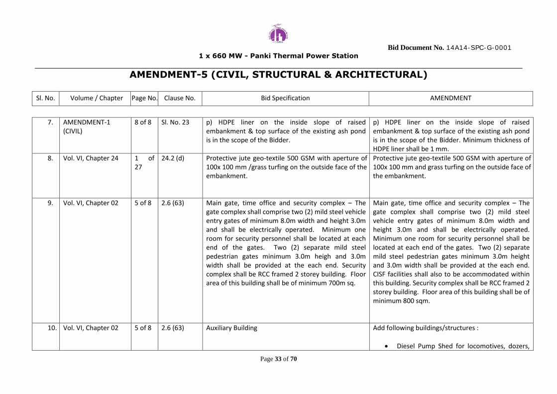
Bid Document No. 14A14-SPC-G-0001
1 x 660 MW - Panki Thermal Power Station
AMENDMENT-5 (CIVIL, STRUCTURAL & ARCHITECTURAL)
Sl. No. Volume / Chapter Page No. Clause No. Bid Specification AMENDMENT
Page 33 of 70
7. AMENDMENT-1 (CIVIL)
8 of 8 Sl. No. 23 p) HDPE liner on the inside slope of raised embankment & top surface of the existing ash pond is in the scope of the Bidder.
p) HDPE liner on the inside slope of raised embankment & top surface of the existing ash pond is in the scope of the Bidder. Minimum thickness of HDPE liner shall be 1 mm.
8. Vol. VI, Chapter 24 1 of 27
24.2 (d) Protective jute geo-textile 500 GSM with aperture of 100x 100 mm /grass turfing on the outside face of the embankment.
Protective jute geo-textile 500 GSM with aperture of 100x 100 mm and grass turfing on the outside face of the embankment.
9. Vol. VI, Chapter 02 5 of 8 2.6 (63) Main gate, time office and security complex – The gate complex shall comprise two (2) mild steel vehicle entry gates of minimum 8.0m width and height 3.0m and shall be electrically operated. Minimum one room for security personnel shall be located at each end of the gates. Two (2) separate mild steel pedestrian gates minimum 3.0m heigh and 3.0m width shall be provided at the each end. Security complex shall be RCC framed 2 storey building. Floor area of this building shall be of minimum 700m sq.
Main gate, time office and security complex – The gate complex shall comprise two (2) mild steel vehicle entry gates of minimum 8.0m width and height 3.0m and shall be electrically operated. Minimum one room for security personnel shall be located at each end of the gates. Two (2) separate mild steel pedestrian gates minimum 3.0m height and 3.0m width shall be provided at the each end. CISF facilities shall also to be accommodated within this building. Security complex shall be RCC framed 2 storey building. Floor area of this building shall be of minimum 800 sqm.
10. Vol. VI, Chapter 02 5 of 8 2.6 (63) Auxiliary Building Add following buildings/structures :
Diesel Pump Shed for locomotives, dozers,

Bid Document No. 14A14-SPC-G-0001
1 x 660 MW - Panki Thermal Power Station
AMENDMENT-5 (CIVIL, STRUCTURAL & ARCHITECTURAL)
Sl. No. Volume / Chapter Page No. Clause No. Bid Specification AMENDMENT
Page 34 of 70
cars etc.
Watch Towers
Diesel Pump Shed shall be steel framed structure with brick wall up to window sill height and insulated double skin metal sheet cladding above it. Roof of the shed shall be insulated double skin metal sheeting on steel roof truss. The building shall provide adequate space for all functional requirements including office rooms, stores, toilet and pantry etc. Minimum size of this shed shall be 500 sqm. External finish for brick walls shall be of premium acrylic smooth paint. Door window and other internal finishes shall be as per the details of other pump houses described elsewhere in the specification and Amendments issued earlier.
11. Vol. VI, Chapter 06 9 of 11
6.15 Watch Tower shall be constructed with RCC frame work. Floor of tower shall be at least 6m above graded level. Covered area for each tower shall be approx. 25 sqm. Number of towers shall be such that the complete periphery of the plant can be watched from the towers but in no case the number of towers shall be less than twelve.
Watch Tower shall be constructed with RCC frame work. Floor of tower shall be at least 6m above graded level. Covered area for each tower shall be approx. 25 sqm. Locations of towers shall be such that the complete periphery of the plant can be watched from the towers but in no case the number of towers shall be less than those shown in drawing no. 14A14-

Bid Document No. 14A14-SPC-G-0001
1 x 660 MW - Panki Thermal Power Station
AMENDMENT-5 (CIVIL, STRUCTURAL & ARCHITECTURAL)
Sl. No. Volume / Chapter Page No. Clause No. Bid Specification AMENDMENT
Page 35 of 70
DWG-M-046 attached with this Amendment.
1m wide watch balcony around the tower shall be provided at floor level. Steel stair shall be provided
to access the floor. Full length vision window on every side shall be provided. Hollow metal pressed
steel doors shall be used. Windows shall be Aluminium/steel windows with 4mm thick clear float
glass. Balcony railing height shall be 1200mm.
12. Vol. VI, Chapter 07 1 of 1 7.1 Chequered plate shall conform to IS: 3502 (latest) and minimum thickness of chequered plate for floorings, covers etc shall be 8 mm O/P.
Chequered plate shall conform to IS: 3502 (latest) and minimum thickness of chequered plate for floorings, covers etc shall be 6 mm O/P.
13. Vol. VI, Chapter 02 1 of 8 2.6 5. Foundation for steam generator / ESP / duct supporting structure.
5. Foundation for steam generator (including future installation of SCR), ESP, duct supporting structure.
14. Vol. VI, Chapter 12 3 of 22
12.3.4 Flue gas temperature at inlet / exit 1270C (approx.)
Flue gas temperature at inlet / exit without FGD in operation shall be 127oC (approx.). During operation of FGD the temperature of flue gas at chimney inlet shall be 80deg C or lower.
15. Vol. VI, Chapter 12 4 of 22
12.3.10 The heat insulation of the liners and pressurized ventilation system shall be so designed that temperature in annular space between the chimney shell and flues does not exceed 45 Deg.C in peak
The heat insulation, if required, at the outside face of the liners and ventilation system (as required) shall be so designed that temperature in annular space between the chimney shell and flues does not

Bid Document No. 14A14-SPC-G-0001
1 x 660 MW - Panki Thermal Power Station
AMENDMENT-5 (CIVIL, STRUCTURAL & ARCHITECTURAL)
Sl. No. Volume / Chapter Page No. Clause No. Bid Specification AMENDMENT
Page 36 of 70
summers. exceed 45 Deg.C in peak summers.
16. Vol. VI, Chapter 12 7 of 22
12.5.1 General Liners shall essentially be constructed from structural steel and shall be of the hung type (i.e. of tension type). The liners shall be provided with externally wrapped thermal insulation. The portion of the liners projecting above the chimney roof shall be constructed of stainless steel. Stainless steel liner shall commence immediately above the flue supporting platform but below the roof supporting structure. The liner shall be of corrosion resistant steel type “COR-TEN B” of minimum 10 mm thick. Top 10m length or length equal to 2 times flue diameter whichever is larger shall be provided using material confirming to AISI:316L or BS:1449. The liner shall be supported atleast at five different levels, and restrained laterally at several levels, with a small length at the bottom near breach elevation supported from the bottom with a suitable expansion compensator in between. The structural steel transition inlet ducting shall be bottom supported. The transition ducting shall be
General Liners shall essentially be constructed from structural steel and shall be of the hung type (i.e. of tension type). The liners shall be provided with externally wrapped thermal insulation, if required. The portion of the liners projecting above the chimney roof shall be constructed of stainless steel. Stainless steel liner shall commence immediately above the flue supporting platform but below the roof supporting structure. The liner shall be of corrosion resistant steel type “COR-TEN B” of minimum 10 mm thick. Top 10m length or length equal to 2 times flue diameter whichever is larger shall be provided using material confirming to AISI:316L or BS:1449. Acid resistant Boro Silicate brick lining shall be provided at inside face of the flue. The liner shall be supported at least at five different levels, and restrained laterally at several levels, with a small length at the bottom near breach elevation supported from the bottom with a suitable expansion compensator in between. The structural steel transition inlet ducting shall be

Bid Document No. 14A14-SPC-G-0001
1 x 660 MW - Panki Thermal Power Station
AMENDMENT-5 (CIVIL, STRUCTURAL & ARCHITECTURAL)
Sl. No. Volume / Chapter Page No. Clause No. Bid Specification AMENDMENT
Page 37 of 70
suitably profiled from a rectangular shape at the chimney inlet to a circular shape up inside the chimney where it shall be connected to the suspended circular steel liners through suitable (non-metallic) fluroelastomeric fabric expansion compensator. Clean–out door shall be provided below the flue for removal of ash.
bottom supported. The transition ducting shall be suitably profiled from a rectangular shape at the chimney inlet to a circular shape up inside the chimney where it shall be connected to the suspended circular steel liners through suitable (non-metallic) fluroelastomeric fabric expansion compensator. The transition ducting connecting the chimney inlet duct and flue shall be fabricated with steel S-TEN 1 . Clean–out door shall be provided below the flue for removal of ash.
17. Vol. VI, Chapter 12 8 of 22
12.6 Insulation
(a) On exterior surface of flue. The flue shall be insulated externally. The insulation shall be semi-rigid, resin bonded type, in the form of slabs and shall conform to IS:8183. Blanket type insulation shall not be used. The density of insulation shall not be less than 100 kg/cum for resin bonded rock wool. The coeffient thermal conductivity of insulation shall be 0.52mW / cm/o c at a mean temperature of 100oC. Insulation / wrapping over fluecan shall be done at ground level before errection. The insulation thickness shall be determined based on the maximum ambient temperature, surface air
(a) On exterior surface of flue. The flue shall be insulated externally, if required. The external insulation of the steel flue liners shall be provided, if necessary, considering the temperature profile through the wall of the flue to ensure the exposed surface temperature of boro-silicate brick lining is maintained within acceptable limits (over the full range of operating conditions including possible temperature excursions during FGD bypass operation). The insulation shall be semi-rigid, resin bonded type, in the form of slabs and shall conform to IS:8183. Blanket type insulation shall not be used. The density of insulation shall not

Bid Document No. 14A14-SPC-G-0001
1 x 660 MW - Panki Thermal Power Station
AMENDMENT-5 (CIVIL, STRUCTURAL & ARCHITECTURAL)
Sl. No. Volume / Chapter Page No. Clause No. Bid Specification AMENDMENT
Page 38 of 70
velocity worked out based on the draught of ventilation air in the annular space between the flue liner and chimney shell, insulation surface emissivity of 0.3 and the insulation cold face maximum temperature not exceeding 60oC. The draught of air in the annular space shall be the natural draught by the heating of air by the flue liner and the air being vented out through the openings in the chimney shell. The increase in the annulas air temperature due to the rising heated air shall be taken into account while calculating the insulation thickness. However, a minimum of 50 mm thick (2 layers of 25 mm) insulation shall be provided on the external face of flue. The insulation shall be tightly secured to the exterior surface of the liner by impaling them on studs welded to the surface at 450mm c/c both horizontally and vertically. The studs shall be galvanized plated and be of a minimum thickness of 10 gauge and 75 mm wide. The studs shall extend a minimum of 25 mm beyond the thickness of insulation. Circular or square metal plate speed washers of standard thickness shall be placed on the extended portion of the studs to hold the impaled insulation material well in place. Further, 20 gauge galvanized wire mesh with a 25
be less than 100 kg/cum for resin bonded rock wool. The coeffient of thermal conductivity of insulation shall be 0.52mW/cm/oC at a mean temperature of 100oC. Insulation / wrapping over flue can shall be done at ground level before erection. The insulation thickness shall be determined based on the maximum ambient temperature, surface air velocity worked out based on the draught of ventilation air in the annular space between the flue liner and chimney shell, insulation surface emissivity of 0.3 and the insulation cold face maximum temperature not exceeding 60oC. The draught of air in the annular space shall be the natural draught by the heating of air by the flue liner and the air being vented out through the openings in the chimney shell. The increase in the annulas air temperature due to the rising heated air shall be taken into account while calculating the insulation thickness. However, insulation where provided within windshield shall be in double layers as minimum. The insulation shall be tightly secured to the exterior surface of the liner by impaling them on studs welded to the surface at 450mm c/c both horizontally and vertically. The studs shall be

Bid Document No. 14A14-SPC-G-0001
1 x 660 MW - Panki Thermal Power Station
AMENDMENT-5 (CIVIL, STRUCTURAL & ARCHITECTURAL)
Sl. No. Volume / Chapter Page No. Clause No. Bid Specification AMENDMENT
Page 39 of 70
mm hexagonal pattern conforming to IS:3150 shall be wrapped around. Where the wire mesh is jointed, a minimum 150 mm overlap shall be provided. The mesh shall be bound and tied in place with a 16 gauge GI wire at 300 mm centers. Any form of lacing the mesh fibres together will not be permitted. Insulation for the exposed portion of flue at the top shall consist of 6 layers of insulation material each of a minimum thickness of 25 mm and all joints shall be staggered. The material shall have a minimum density of 200 kg/cum. This shall be protected from the elements by means of a stainless steel cladding, flashing and hood of grade 316 L stainless steel. Testing of insulation material to satisfy the specific requirements and properties as outlined in this specification IS: 8183 and in the relevant drawings by the contractor shall be carried out. Insulation materials shall be added to walls where necessary to reduce cooling loads. Also, insulation shall be used for sound absorption on walls which enclose equipment that has been determined as generating excessive noise. This sound insulation shall be provided in interior concrete block, sound
galvanized plated and be of a minimum thickness of 10 gauge and 75 mm wide. The studs shall extend a minimum of 25 mm beyond the thickness of insulation. Circular or square metal plate speed washers of standard thickness shall be placed on the extended portion of the studs to hold the impaled insulation material well in place. Further, 20 gauge galvanized wire mesh with a 25 mm hexagonal pattern conforming to IS:3150 shall be wrapped around. Where the wire mesh is jointed, a minimum 150 mm overlap shall be provided. The mesh shall be bound and tied in place with a 16 gauge GI wire at 300 mm centers. Any form of lacing the mesh fibres together will not be permitted. Insulation for the exposed portion of flue at the top shall consist of 6 layers of insulation material each of a minimum thickness of 25 mm and all joints shall be staggered. The material shall have a minimum density of 200 kg/cum. This shall be protected from the elements by means of a stainless steel cladding, flashing and hood of grade 316 L stainless steel. Testing of insulation material to satisfy the specific requirements and properties as outlined in this specification IS: 8183 and in the relevant drawings

Bid Document No. 14A14-SPC-G-0001
1 x 660 MW - Panki Thermal Power Station
AMENDMENT-5 (CIVIL, STRUCTURAL & ARCHITECTURAL)
Sl. No. Volume / Chapter Page No. Clause No. Bid Specification AMENDMENT
Page 40 of 70
block, or insulated metal wall panel liners as appropriate. The liner panels shall be as described above, except they shall include perforations and insulation enclosed in plastic bags. The overall noise Reduction Coefficient shall be 0.80 or better.
by the contractor shall be carried out. Insulation materials shall be added to walls where necessary to reduce cooling loads. Also, insulation shall be used for sound absorption on walls which enclose equipment that has been determined as generating excessive noise. This sound insulation shall be provided in interior concrete block, sound block, or insulated metal wall panel liners as appropriate. The liner panels shall be as described above, except they shall include perforations and insulation enclosed in plastic bags. The overall noise Reduction Coefficient shall be 0.80 or better.
18. Vol. VI, Chapter 12 11 of 22
12.10 Design of Transition Ducting The number, size and location of flue opening in the shell shall be as per the requirement of boiler supplier. The Contractor shall make arrangement for the proper support of ducting on the shell and provision of restraint / support arrangement as required. The CONTRACTOR shall be responsible for furnishing, fabricating, shop painting and delivery of ducting which shall run from the chimney liner to the flange of the boiler vendor’s duct including all necessary
Design of Transition Ducting The number, size and location of flue opening in the shell shall be as per the requirement of boiler supplier. The Contractor shall make arrangement for the proper support of ducting on the shell and provision of restraint / support arrangement as required. The CONTRACTOR shall be responsible for furnishing, fabricating, shop painting and delivery of ducting which shall run from the chimney liner to the flange of the boiler vendor’s duct including all

Bid Document No. 14A14-SPC-G-0001
1 x 660 MW - Panki Thermal Power Station
AMENDMENT-5 (CIVIL, STRUCTURAL & ARCHITECTURAL)
Sl. No. Volume / Chapter Page No. Clause No. Bid Specification AMENDMENT
Page 41 of 70
auxiliary ducting as well as soot collecting hoppers located below flue can. Soot hoppers shall be lined with SS grade AISI 304. Suitable flange connection shall be provided at the exit of the hopper to provide SS / CI pipe connection to drain ash / condensed acid mixed water. The duct work profile and the guide vanes shall be so configurated and sized to achieve the desired flue gas flow characteristic and to minimize flue gas pressure losses. The plate thickness of the ducts shall be arrived at from minimum (i.e. codal) requirements, structural considerations and corrosion allowances. Material of construction shall be COR-TEN steel conforming to IS:2062. Minimum thickness shall be 10 mm. The duct work shall be insulated with 75 mm thick insulation (3 layers of 25 thick sheets) as per requirements of clause 18.11 and protected with aluminium foil of minimum 1mm thickness. Access doors shall be provided for the ducting where required for inspection and cleaning. The duct work and its supporting structures shall be
necessary auxiliary ducting as well as soot collecting hoppers located below flue can. Inside face of Soot hoppers shall be lined with Acid resistant Boro Silicate brick. Suitable flange connection shall be provided at the exit of the hopper to provide SS / CI pipe connection to drain ash / condensed acid mixed water. The duct work profile and the guide vanes shall be so configurated and sized to achieve the desired flue gas flow characteristic and to minimize flue gas pressure losses. The plate thickness of the ducts and hopper shall be arrived at from minimum (i.e. codal) requirements, structural considerations and corrosion allowances. Material of construction shall be S-TEN 1 steel. Minimum thickness shall be 10 mm. The duct work shall be insulated with 75 mm thick insulation (3 layers of 25 thick sheets) and protected with aluminium foil of minimum 1mm thickness. Access doors shall be provided for the ducting where required for inspection and cleaning. The duct work and its supporting structures shall be

Bid Document No. 14A14-SPC-G-0001
1 x 660 MW - Panki Thermal Power Station
AMENDMENT-5 (CIVIL, STRUCTURAL & ARCHITECTURAL)
Sl. No. Volume / Chapter Page No. Clause No. Bid Specification AMENDMENT
Page 42 of 70
designed for the most severe of the possible combinations of gravity loading (accounting for ash accumulation), seismic loading, wind loading, flue gas pressure loading and thermal loading.
designed for the most severe of the possible combinations of gravity loading (accounting for ash accumulation), seismic loading, wind loading, flue gas pressure loading and thermal loading.
------x------

PEM
UPRVUNL, PANKI THERMAL POWER STATION (1 X 660 MW) TECHNICAL CLARIFICATIONS & DEVIATIONS
Page 40 of 56
ANNEXURE ‐ XIII
SL. NO
ENQUIRY SPECIFICATION SPECIFICATION REQUIREMENT
DEVIATION Vol / Sec
Sub Sec Page No.
Clause No.
OWNER’S REPLY
73. VOL‐VI/ CHAP‐TER 02
Scope of Civil & Struc‐tural Works
5 of 8
2.6 (63) Training center. Since the Training centres is non plant building and the layout of Training centre depends on customer requirement, customer is requested to inform the size of building to be considered by all bidders for estimation.In absence of data regarding covered area & floor details etc. in specification. Bidder con‐sidered following for Training centre.
a) Total area = 250 Sqm‐Single storey RCC building. b) One AC Conference room for of size =90 Sqm. c) One reception of = 20 Sqm (AC area) d) One Hall for library = 50 Sqm. (AC area) e) Office Room & faculty room = 30Sqm (AC area) f) Toilets for Ladies & Gents = 20Sqm
g) Pantry = 8 sqm h) Utility area = 12 Sqm i) A Porch of size 5m x 4m will be provided.
The finishing of walls, floor, and other specification shall be similar to Service building. No Furniture, furnishing, office equipment, partition/paneling for office, etc. is considered in the scope of bidder. Customer is requested to issue suitable amendment or confirm the size considered.
Additionally bidder should consider at least 2 numbers class rooms of 30 students each including the following details.

PEM
UPRVUNL, PANKI THERMAL POWER STATION (1 X 660 MW) TECHNICAL CLARIFICATIONS & DEVIATIONS
Page 43 of 56
ANNEXURE ‐ XIII
SL. NO
ENQUIRY SPECIFICATION SPECIFICATION REQUIREMENT
DEVIATION Vol / Sec
Sub Sec Page No.
Clause No.
OWNER’S REPLY
77. VOL‐III/ CHAP‐TER ‐25
Air Condi‐tioning & Venti‐lation System
4 of 40
25.3.19 Air conditioning system for Service Building, Adminis‐tration Building & Training Centre Building shall be designed with ECBC code to make it “Green Building”.
Customer is requested to clarify the follow‐ing:
A. As per tender specification Only Air conditioning system for Service Building, Administration Building & Training Centre Building shall be de‐signed with ECBC code or
B. Service Building, Administration Building & Training Centre Building shall be designed with ECBC code to make it green building. If so cus‐tomer is requested to inform the GRIHA rating or only
Customer is requested to issue suitable amendment in case B is to be followed
Bidder to follow specification.

PEM
UPRVUNL, PANKI THERMAL POWER STATION (1 X 660 MW) TECHNICAL CLARIFICATIONS & DEVIATIONS
Page 44 of 56
ANNEXURE ‐ XIII
SL. NO
ENQUIRY SPECIFICATION SPECIFICATION REQUIREMENT
DEVIATION Vol / Sec
Sub Sec Page No.
Clause No.
OWNER’S REPLY
78. VOL‐VI/ CHAP‐TER 02
Scope of Civil & Struc‐tural Works
6 of 8
72.0 Dispensary and first aid center.
Since the dispensary and first aid centres are non‐plant buildings, customer is re‐quested to inform the size of building to be considered by all bidders for estimation. In absence of size we have considered the size of Dispensary Bldg. has been consi‐dered as below 14m (length) x 12m (width) x 4m (Height). Customer is requested to issue suitable amendment or confirm the size consi‐dered..
Noted
79. VOL‐VI/ CHAP‐TER ‐07
Material 1 of 1
7.1 Complete hopper includ‐ing vertical and conical portion of the bunker in mill building shall be pro‐vided with lining of at least 6mm thick SS plate grade SS 316L
SS 304 provides better finish profile inside bunker. Bending and stitching of plate in‐side bunker with higher thickness of plate (6mm) is very difficult, and technically not required. To reduce the friction inside con‐ical hopper with SS 304 plate of thickness 3.15mm is having excellent advantage. Bidder advice to use SS plate in hopper portion only, and it is also the current prac‐tice in case of circular bunker design. Customer is requested to review the re‐quirement and confirm acceptance.
Bidder should strictly follow Specifi‐cation.

PEM
UPRVUNL, PANKI THERMAL POWER STATION (1 X 660 MW) TECHNICAL CLARIFICATIONS & DEVIATIONS
Page 48 of 56
ANNEXURE ‐ XIII
SL. NO
ENQUIRY SPECIFICATION SPECIFICATION REQUIREMENT
DEVIATION Vol / Sec
Sub Sec Page No.
Clause No.
OWNER’S REPLY
88. VOL‐VI/ CHAP‐TER ‐ 2
Scope of work
2 of 8
2.6 (14) Modification (if required) of existing return chan‐nel…
Length, location & layout of return channel is not clear as per Plot Plan. Therefore, no length has been considered for disman‐tling/construction. Kindly Accept.
Modification (if required) of existing return channel shall be under scope of this package. Bidder should assess the quantum of work and follow spe‐cification.
89. VOL‐VI/ CHAP‐TER ‐ 13
Civil De‐sign Ba‐sis
6 of 25
13.7.1.2 For coefficient `K2’, Ter‐rain category `1’ and class ‘C’ as per table 2 of IS: 875 (Part‐3) – 1987 (Latest) shall be considered.
As per site condition/location & IS: 875 (Part‐3), Terrain category `2’ shall be consi‐dered for proposed plant including cooling tower & chimney. Please accept.
Bidder should follow Specification.
90. VOL‐VI/ CHAP‐TER ‐ 21
Water closet
11 of 12
21.9 g.) One toilet with required facilities shall be provided for physically challenged persons as per National Code requirements in GRIHA rated buildings.
As per Specification there is no GRIHA rated building, however one toilet for physically challenged persons shall be provided as per this clause.
Noted. Also note that Administrative Building shall be designed as GREEN Building.
91. DWG NO.14A14‐DWG‐M‐001
PLOT PLAN
Plot Plan (Item No.‐43) In the Plot plan township has been marked. As per specification bidder understand that township construction is not in bidder’s scope. Please confirm.
Noted
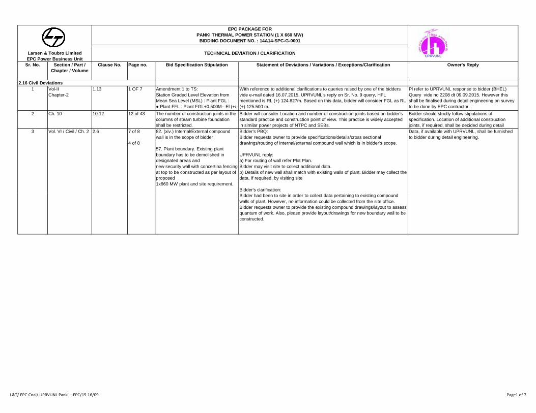
Sr. No. Section / Part /
Chapter / Volume
Clause No. Page no. Bid Specification Stipulation Statement of Deviations / Variations / Exceptions/Clarification Owner's Reply
2.16 Civil Deviations
1 Vol-II
Chapter-2
1.13 1 OF 7 Amendment 1 to TS:
Station Graded Level Elevation from
Mean Sea Level (MSL) : Plant FGL :
● Plant FFL : Plant FGL+0.500M– El (+/-
With reference to additional clarifications to queries raised by one of the bidders
vide e-mail dated 16.07.2015, UPRVUNL's reply on Sr. No. 9 query, HFL
mentioned is RL (+) 124.827m. Based on this data, bidder will consider FGL as RL
(+) 125.500 m.
Pl refer to UPRVUNL response to bidder (BHEL)
Query vide no 2208 dt 09.09.2015. However this
shall be finalised during detail engineering on survey
to be done by EPC contractor.
2 Ch. 10 10.12 12 of 43 The number of construction joints in the
columns of steam turbine foundation
shall be restricted.
Bidder will consider Location and number of construction joints based on bidder's
standard practice and construction point of view. This practice is widely accepted
in similar power projects of NTPC and SEBs.
Bidder should strictly follow stipulations of
specification. Location of additional construction
joints, if required, shall be decided during detail
3 Vol. VI / Civil / Ch. 2 2.6 7 of 8
4 of 8
82. (xiv.) Internal/External compound
wall is in the scope of bidder
57. Plant boundary. Existing plant
boundary has to be demolished in
designated areas and
new security wall with concertina fencing
at top to be constructed as per layout of
proposed
1x660 MW plant and site requirement.
Bidder's PBQ:
Bidder requests owner to provide specifications/details/cross sectional
drawings/routing of internal/external compound wall which is in bidder's scope.
UPRVUNL reply:
a) For routing of wall refer Plot Plan.
Bidder may visit site to collect additional data.
b) Details of new wall shall match with existing walls of plant. Bidder may collect the
data, if required, by visiting site
Bidder's clarification:
Data, if available with UPRVUNL, shall be furnished
to bidder during detail engineering.
EPC PACKAGE FOR
PANKI THERMAL POWER STATION (1 X 660 MW)
BIDDING DOCUMENT NO. : 14A14-SPC-G-0001
TECHNICAL DEVIATION / CLARIFICATIONLarsen & Toubro Limited
EPC Power Business Unit
Bidder had been to site in order to collect data pertaining to existing compound
walls of plant, However, no information could be collected from the site office.
Bidder requests owner to provide the existing compound drawings/layout to assess
quantum of work. Also, please provide layout/drawings for new boundary wall to be
constructed.
L&T/ EPC‐Coal/ UPRVUNL Panki – EPC/15‐16/09 Page1 of 7

Sr. No. Section / Part /
Chapter / Volume
Clause No. Page no. Bid Specification Stipulation Statement of Deviations / Variations / Exceptions/Clarification Owner's Reply
2.16 Civil Deviations
EPC PACKAGE FOR
PANKI THERMAL POWER STATION (1 X 660 MW)
BIDDING DOCUMENT NO. : 14A14-SPC-G-0001
TECHNICAL DEVIATION / CLARIFICATIONLarsen & Toubro Limited
EPC Power Business Unit
7 Vol. VI / Civil / Ch. 2 2.6 2 of 6 22. Diversion and reconstruction to
original width and alignment of existing
road outside
plant boundary is also included in
Bidder’s scope.
Bidder's PBQ:
Bidder requests owner to provide details of existing road which is to be diverted
and reconstructed.
UPRVUNL reply:
Bidder may please visit site to collect necessary data for bidding purpose.
Bidder's clarification:
Bidder had been to site in order to collect data pertaining to existing roads of plant,
however, Bidder could not obtain any necessary data/drawings pertaining to
diversion and reconstruction to original width and alignment of existing road
outside plant boundary from the site office. Hence bidder will not consider the
same in his scope.
Scope of work should strictly be as per specification.
Bidder must assess the quantum of work.
8 Volume VI
Ch 2
2 of 8 24 Raw water reservoir (storage capacity of
10 days without ash water recovery) for
running of
1x660MW unit during canal closing
Bidder understands that as per tender WBD, tentative water requirement will be
about 7,44,240 cum/day. Considering average effective depth of 5m, the area
requirement of raw water reservoir comes out to be 37 acres. However, the area
allotted to raw water reservoir as shown in plot plan is approx. 17 acres. Hence,
Tentative area for Raw Water Reservoir is already
shown in Plot Plan attached with the Tender
document. Bidder should design the structure/system
accordingly. Further discussion, if required, on this g g
period is in the scope of bidder.
p p pp ,
Bidder requests Owner to clarify on the area requirement or storage capacity.
g y , q ,
issue shall be taken up during detail engineering.
L&T/ EPC‐Coal/ UPRVUNL Panki – EPC/15‐16/09 Page4 of 7

EPC PACKAGE OF 1X660 MW PANKI THERMAL POWER EXTENSION PROJECT
ADDITIONAL CLARIFICATIONS TO QUERIES RAISED BY M/s BHEL VIDE E-MAIL DATED 16.07.2015
SL. NO.
BID DOCUMENT REFERENCE
BIDDER’S QUERRY UPRVUNL’S REPLY
1 VOL VI; CHAPTER:05; Pg. 1 OF 4
Report of Preliminary soil investigation work available with UPRVUNL within proposed Power Plant area covering major structures/facilities tentatively located shall be provided to the bidders.
Shall be provided shortly.
2 VOL VI; CHAPTER:03; Pg. 3 OF 5
Map indicating all crossings like high ways / railways / nala / river and bridges etc. may be collected from owner’s office.
Soft copy of full map of Panki TPS is attached. The information provided in the map is tentative. For detail information bidder has to visit the Panki site.
3 General AUTOCAD drawing of Plot Plan, Site Plan, E-SLD & Contour Map.
AUTOCAD drawing shall be provided to selected bidder during detail engineering.
4 Vol.-II Mandatory spares
Editable copy of Datasheets, mandatory spares and schedules.
Soft copy of Editable copy of Datasheets, mandatory spares and schedules is attached herewith.
5 General Topographical survey Drawing/ Report
Already provided with L&T queries.
6 General Area Drainage Study Report Area drainage for proposed plant is in EPC bidder’s scope. Study of drainage for overall area shall be carried out by EPC contractor only. However, full map of Panki TPS indicating drains attached.
7 General The drawing of existing transmission lines routed from proposed cooling tower area as well as ash slurry.
Soft copy of hand sketch of existing transmission lines routed from proposed cooling tower area is attached. For detail information bidder has to visit the Panki site.
8 General AWRS piping layout (which is going to existing ash pond).
Soft copy of hand sketch of AWRS piping layout (which is going to existing ash pond) marked on plot plan is attached. For detail information bidder has to visit the Panki site.
9 Vol.-III Ch. 4 page 1 of 13 cl. 4.1.1
Please clarify the ‘minimum & maximum water level’ of the Lower Ganga canal to be considered for intake system design purpose.
Details of Lower Ganga Canal:- Ground Level =124.338m Bed Level =122.727m Bed Width = 17.10m Water Depth =2.10 m HFL = 124.827 m

1x660 MW PANKI THERMAL POWER STATION EXTN.
Page 1 of 2
CLARIFICATIONS ON AMENDMENT-5 (Part-1)
Sl. No.
Volume/ Chapter
Tender Specification Clarifications/Deviations Remarks by customer
1. Amendment 5 (Site Plan)
Plot plan: 14A14-DWG-M-029,R4
Kindly note that Legend for the rail track as shown in the Site plan drawing are as follows: - proposed - existing - to be dismantled Bidder is not able to clearly identify the legends shown in the plot plan PDF Format given as per Amendment-5. Hence, request customer to furnish AUTO CAD copy of the plot plan.
Railway is not in scope of EPC contractor. However coloured PDF copy of drawing is enclosed.
2. Amendment 5 (Site Plan)
Plot plan: 14A14-DWG-M-029,R4 1. “Proposed ash silo” is shown in the plot plan on BC 5A/B,(Near JT 4)
Kindly note that “Proposed ash silo” location as shown in the plot plan is interfering with BC5A/B. We request customer to clarify that ash silo on BC-5A/B, (Near to JT 4) as shown in the latest plot plan is proposed or existing as this silo has nothing to do with this tender requirement. If it is existing silo & it is interfering with BC 5A/B. in view of this, whether bidder has to dismantle the silo or not. If it is proposed ash silo for this project, kindly specify the purpose of the same and furnish its capacity.
“Proposed ash silo” as shown is not in scope of EPC contractor nor it is existing.
3. Amendment 5 (Site Plan)
Plot plan: 14A14-DWG-M-029,R4
1. Wagon sick line and Empty Track line No.1 CSR 750M are going inside JNT 4
2. Gallery of BC 4A/B is shown above wagon sick line.
We once again request customer to review layout as railway tracks are going inside the JT 4 and interfering with trestles of BC 4A/B and its foundation. If bidder has to follow same layout, we request customer to obtain necessary approvals form railways during detailed engineering.
EPC contractor to take care in detail engineering.
4. Amendment 5 (Site Plan)
Plot plan: 14A14-DWG-M-029,R4
1. LOCO Shed (24M X 30 M)
Loco shed of 24MX30M is shown in the latest plot plan.(This Was not shown in earlier plot plan) In view of this, we request customer to confirm whether it is to be included in the bidder’s scope or not.
Loco shed is not in EPC contractor’s scope.

1x660 MW PANKI THERMAL POWER STATION EXTN.
Page 2 of 2
CLARIFICATIONS ON AMENDMENT (PEM) (Part-2)
S. No.
Vol/Sec/Cls./Sheet
Nos.
Amendment-5 Requirement
Clarification Remarks by Customer
1. Amendment 5 (Mechanical System) Sl. no. 12, page 5 of 70.
On installation of FGD the Temp of Flue Gas at chimney inlet shall be 80 degC or lower……………………….temp of flue gas
Due to Lower temperature specified for FGD, customer may inform the flue exit velocity (and the corresponding load) to be considered for chimney sizing.
The optimum range of velocity may be taken as 15 to 20 m/sec. However, velocity will not exceed, under any circumstances, 30 m/sec
2. Amendment 5 (Mechanical System) Sl. no. 15, page 7 of 70.
Temperature rise in circulation water across the condenser – Not exceeding 10 deg C against VWO , 1% makeup and 33 deg C inlet water temperature.
Customer to note that there is a contradiction in the amendments regarding DM Make up water requirement to be considered for Cycle Make up. Customer is requested to review and clarify.
1.5% shall be considered for DM water plant sizing and DM water make up system. 1% is specified for identifying the guarantee condition of turbine cycle. Amendment 5
(Mechanical System) Sl. no. 19, page 7 of 70.
DM water normal make up to thermal cycle is 1.5% of the throttle steam flow.
3. Amendement-5. DWG no-14A14-DWG-M-014 (Sht 1 of 2). Point no- 10 of NOTES.
10. Bidder will design Plant considering the above water scheme as of minimum requirement.
However, Bidder to ensure & demonstrate that plant operate at optimized condition as per latest MOEFF norms.
The minimum requirement of Raw water shown in Composite Water scheme (2484 M3/hr without Recovery, i.e 3.76 M3/Hr/MW and 2080 M3/hr with recovery i.e 3.17 m3/Hr/MW)does not meet the latest MOEF norms of 2.5 M3/Hr/MW along with ZLD (Zero Liquid Discharge).Please review the same. Customer to mention optimized condition of plant operation to demonstrate as per MOEFF norms.
For design purpose, Bidder will follow composite water scheme (14A14-DWG-M-014) as of minimum requirements. However, For MOEF compliance plant shall be considered to run with bottom ash in lean slurry with water recovery and fly ash in HCSD as being presented to MOEF.

BHARAT HEAVY ELECTRICALS LIMITED
EPC Package for 1x660 MW Panki TPS Extension Project
PRE-BID CLARIFICATIONS/ DEVIATIONS
Page 1 of 7
Annexure – 1D (PEM-ADD 03)
S. No.
ENQUIRY SPECIFICATION SPECIFICATION REQUIREMENT
BHEL’s COMMENTS / CLARIFICATIONS
UPRVUNL’s REPLY
Vol /Ch Chapter Name Sheet No.
Clause No.
CIVIL 1 III/25 Air Conditioning
& Ventilation
System
Page 4 of 40
25.3.19 Air conditioning system for
Service Building, Administra-
tion Building & Training Cen-
tre Building shall be designed
with ECBC code to make it
“Green Building”.
Customer is requested to note
that no green building require-
ment has been envisaged in the
specifications. Only AC system
for Service Building, Admin-
istration Building & Training
Centre Building has been asked
to be designed with ECBC code.
As such bidder understands that only AC system for these
buildings shall be supplied as per ECBC code.
Please confirm if bidder under-
standing is correct.
Bidder to follow
specification.
2 File name 1D_PEM_Part IV:
Customer to note that there are
contradiction in the various re-
plies of pre bid queries raised
by bidder.
As per contour map provided
by owner, Plant area is at RL
(+) 97.5m (approx.). However
All levels men-
tioned in contour
drawing may be
adjusted for +27.5
m. in respect to
MSL. However,
the FGL will be
decided during

BHARAT HEAVY ELECTRICALS LIMITED
EPC Package for 1x660 MW Panki TPS Extension Project
PRE-BID CLARIFICATIONS/ DEVIATIONS
Page 2 of 7
Annexure – 1D (PEM-ADD 03)
S. No.
ENQUIRY SPECIFICATION SPECIFICATION REQUIREMENT
BHEL’s COMMENTS / CLARIFICATIONS
UPRVUNL’s REPLY
Vol /Ch Chapter Name Sheet No.
Clause No.
File name 1D_PEM:
as per another reply to Bidder’s
query (Sl. No. 19; 1D_PEM)
FGL is at RL. (+) 126.0.
Bidder understands that FGL is
at RL (+) 97.5m (as per contour
map provided by owner) and only Minor site grading and
leveling up to 500mm is in the scope of bidder (Cl. No. 55;
Sheet no. 4 of 8; Vol VI (civ-il)).
Please confirm if bidder under-
standing is correct.
detail engineering
based on existing
contour and other
technical re-
quirement. Contour Map Provided Along with Pre bid replies


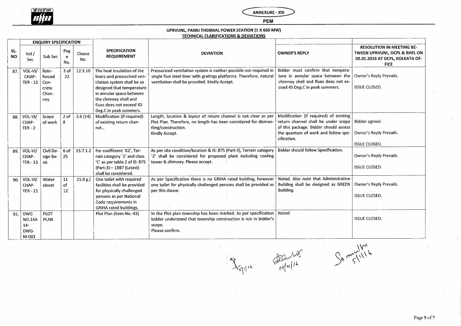


UTTAR PRADESH RAJYA VIDYUT UTPADAN NIGAM LIMITED
[UPRVUNL]
1 x 660MW PANKI TPS EXTN.
VOLUME II-B
CIVIL, STRUCTURAL AND ARCHITECTURAL WORKS
SECTION – D
GENERAL TECHNICAL SPECIFICATION
Bharat Heavy Electricals Limited Project Engineering Management
PPEI Building, Power Sector,
Plot No. 25, Sector 16A,
Noida (U.P.)-201301

SECTION – D comprises of sub-sections as mentioned below:
Sub-section D1: Earthwork in excavation and backfilling
Sub-section D2: Cement concrete (Plain and reinforced) and formwork
Sub-section D3: Carpentry and joinery
Sub-section D4: Roof and underground structures water proofing, insulation and allied works
Sub-section D5: Metal doors, windows, ventilators, louvers etc.
Sub-section D6: Glass and Glazing
Sub-section D7: Rolling Steel Shutter and Grills
Sub-section D8: Miscellaneous Metal
Sub-section D9: Masonry and allied works
Sub-section D10: Finish to masonry and concrete
Sub-section D11: Painting, Whitewashing, polishing
Sub-section D12: Floor finish and allied works
Sub-section D13: Sheet work in roof and siding
Sub-section D14: Suspended ceiling
Sub-section D15: Water supply, drainage & sanitation
Sub-section D16: Road & drainage
Sub-section D17: Fabrication of structural steelwork
Sub-section D18: Erection of structural steelwork
Sub-section D19: Roof decking
Sub-section D20: False flooring
Sub-section D21: Bored cast-in-situ RCC piles
Sub-section D22: Site levelling & grading works
Sub-section D23: Anti-termite treatment

TITLE: TECHNICAL SPECIFICATION FOR EARTHWORK IN EXCAVATION AND BACKFILLING
SPECIFICATION NO. PE-TS-999-600-C001
VOLUME - II B
SECTION - D | SUB-SECTION – D1
REV.NO. 00 DATE 09/04/2018
SHEET 1 OF 21
VOLUME: II B
SECTION - D
SUB-SECTION – D1
EARTHWORK IN EXCAVATION AND BACKFILLING
SPECIFICATION NO. PE-TS-999-600-C001
Bharat Heavy Electricals Limited Project Engineering Management
PPEI Building, Power Sector,
Plot No. 25, Sector 16A,
Noida (U.P.)-201301

TITLE: TECHNICAL SPECIFICATION FOR EARTHWORK IN EXCAVATION AND BACKFILLING
SPECIFICATION NO. PE-TS-999-600-C001
VOLUME - II B
SECTION - D | SUB-SECTION – D1
REV.NO. 00 DATE 09/04/2018
SHEET 2 OF 21
C 0 N T E N T
CLAUSE NO. DESCRIPTION SHEET NO.
1.00.0 SCOPE 3
2.00.00 GENERAL 3
3.00.00 EXECUTION 6
4.00.00 TESTING AND ACCEPTANCE CRITERIA 19
5.00.00 RATES AND MEASUREMENTS 19
6.00.00 INFORMATION TO BE SUBMITTED BY THE BIDDER 20

TITLE: TECHNICAL SPECIFICATION FOR EARTHWORK IN EXCAVATION AND BACKFILLING
SPECIFICATION NO. PE-TS-999-600-C001
VOLUME - II B
SECTION - D | SUB-SECTION – D1
REV.NO. 00 DATE 09/04/2018
SHEET 3 OF 21
STANDARD TECHNICAL SPECIFICATION FOR EARTHWORK IN EXCAVATION AND BACKFILLING
1.0.0 SCOPE
This specification covers earth work excavation in all types of soil, soft rock
and hard rock including setting out, clearing and grubbing, shoring,
dewatering, back filling around foundations/pipelines to grade, watering,
compaction of fills, testing, approaches, disposal of surplus earth, protective
fencing, lighting etc relevant to the structures and locations covered under this
contract.
2.0.0 GENERAL
2.1.0 Work to be provided for by the Contractor
The work to be provided for by the contractor unless specified otherwise shall
include but not be limited to the following.
a) Supplying and providing all labour, supervision services, earth moving
machineries, surveying instruments including facilities as required under
statutory labour regulations, materials, scaffolds, equipment, tools and plants,
transportation, etc. required for the work.
b) Preparation and submission of working drawings showing the approaches,
slopes, berms, shoring, sumps for dewatering including drainage, space for
temporary stacking of soils, disposal area, fencing etc and all other details as
may be required by the engineer.
c) To carry tests and submit to the Engineer, test results of fill materials and
degree of soil compaction of fill whenever required by the Engineer to assess
the quality of fill.
d) Design, construction and maintenance of Magazine of proper capacity for
storage of explosives for blasting work and removal of the same after
completion of the work etc. including procurement of necessary licenses from
proper authorities.
2.2.0 Work to be provided by others
No work under this specification will be provided by any agency other than
the contractor unless specifically mentioned elsewhere in the contract.

TITLE: TECHNICAL SPECIFICATION FOR EARTHWORK IN EXCAVATION AND BACKFILLING
SPECIFICATION NO. PE-TS-999-600-C001
VOLUME - II B
SECTION - D | SUB-SECTION – D1
REV.NO. 00 DATE 09/04/2018
SHEET 4 OF 21
2.3.0 Codes and Standards
All works shall be carried out as per this specification and shall conform to the
latest revision and/or replacements of the following or any other Indian
Standard (IS) Codes unless specified otherwise.
IS-1200 Method of measurement of building and civil engineering
works, Part-I: Earthwork
IS-2720 Method of test for soils (Relevant parts)
IS-3764 Excavation work - Code of safety
IS-4081 Safety code for blasting and related drilling operations
IS-4701 Indian Standard Code of Practice for earthwork on Canals
IS:6922 Criteria for safety and design of structures subject to
underground blasts
In case of conflict between this specification and those (IS Codes) referred to
herein, the former shall prevail. In case any particular aspect of work is not
covered specifically by this specification/IS Codes, any other standard practice
as may be specified by the engineer shall be followed.
2.4.0 Conformity with Designs
The contractor shall carry out the work as per the approved drawings,
specification and as directed by the engineer.
2.5.0 Materials 2.5.1 General
All materials required for the work shall be of the best commercial variety and
approved by the engineer.
2.5.2 Material for Excavation
For the purpose of identifying the various strata encountered during the course
of excavation, refer clause no. 3.4.0 for the classification of earth strata.
2.5.3 Material for Filling
Material to be used for back filling shall be free from vegetations, roots, salts,
rubbish, lumps, organic matter and any other harmful chemicals etc and shall
be got approved by the engineer. Normally excavated earth shall be used for
back filling. In case such earth contains deleterious salts, the same shall not be
used. All clods of earth shall be broken or removed. Where the excavated
material is mostly rock and if filling with the same is permitted by the
engineer in writing, then the filling with rock shall be done in the following
manner. The boulders shall be broken into pieces not exceeding 150mm size
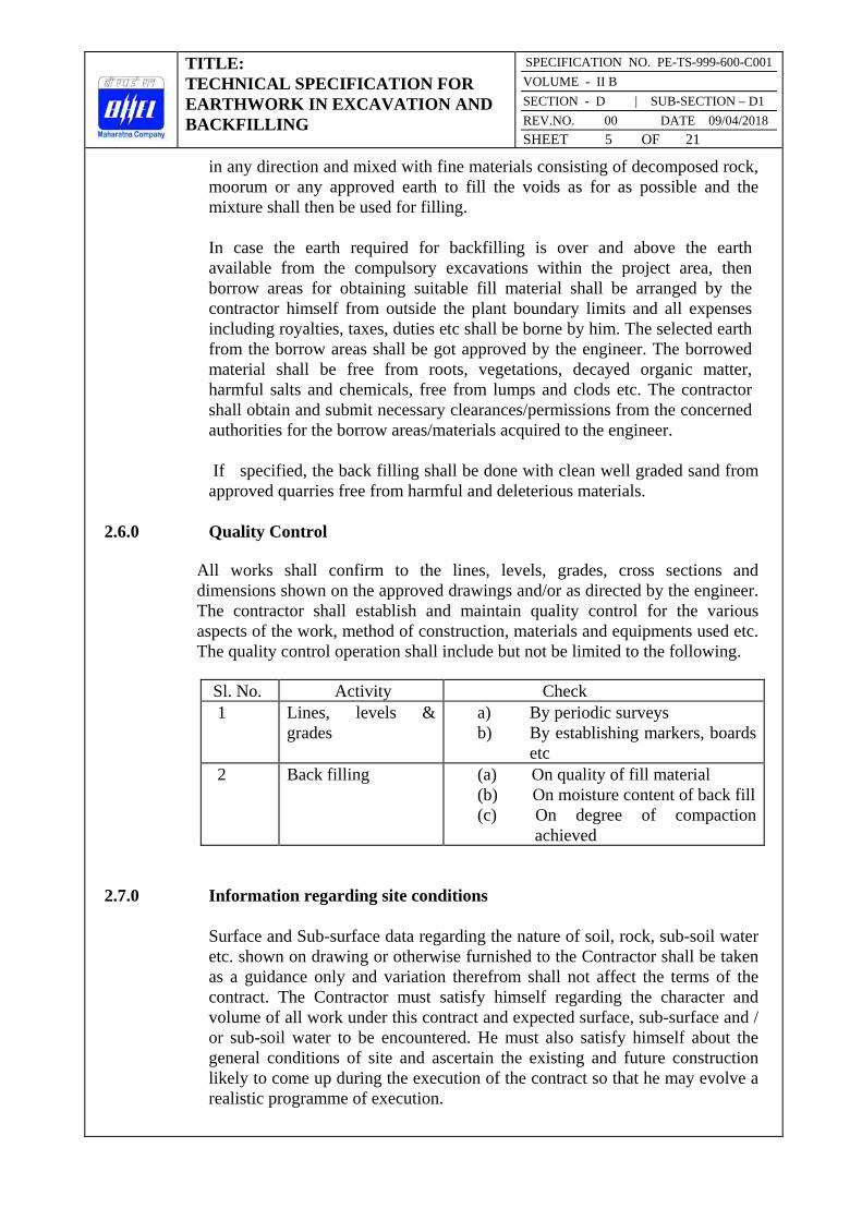
TITLE: TECHNICAL SPECIFICATION FOR EARTHWORK IN EXCAVATION AND BACKFILLING
SPECIFICATION NO. PE-TS-999-600-C001
VOLUME - II B
SECTION - D | SUB-SECTION – D1
REV.NO. 00 DATE 09/04/2018
SHEET 5 OF 21
in any direction and mixed with fine materials consisting of decomposed rock,
moorum or any approved earth to fill the voids as for as possible and the
mixture shall then be used for filling.
In case the earth required for backfilling is over and above the earth
available from the compulsory excavations within the project area, then
borrow areas for obtaining suitable fill material shall be arranged by the
contractor himself from outside the plant boundary limits and all expenses
including royalties, taxes, duties etc shall be borne by him. The selected earth
from the borrow areas shall be got approved by the engineer. The borrowed
material shall be free from roots, vegetations, decayed organic matter,
harmful salts and chemicals, free from lumps and clods etc. The contractor
shall obtain and submit necessary clearances/permissions from the concerned
authorities for the borrow areas/materials acquired to the engineer.
If specified, the back filling shall be done with clean well graded sand from
approved quarries free from harmful and deleterious materials.
2.6.0 Quality Control
All works shall confirm to the lines, levels, grades, cross sections and
dimensions shown on the approved drawings and/or as directed by the engineer.
The contractor shall establish and maintain quality control for the various
aspects of the work, method of construction, materials and equipments used etc.
The quality control operation shall include but not be limited to the following.
Sl. No. Activity Check
1 Lines, levels &
grades
a) By periodic surveys
b) By establishing markers, boards
etc
2 Back filling (a) On quality of fill material
(b) On moisture content of back fill
(c) On degree of compaction
achieved
2.7.0 Information regarding site conditions
Surface and Sub-surface data regarding the nature of soil, rock, sub-soil water
etc. shown on drawing or otherwise furnished to the Contractor shall be taken
as a guidance only and variation therefrom shall not affect the terms of the
contract. The Contractor must satisfy himself regarding the character and
volume of all work under this contract and expected surface, sub-surface and /
or sub-soil water to be encountered. He must also satisfy himself about the
general conditions of site and ascertain the existing and future construction
likely to come up during the execution of the contract so that he may evolve a
realistic programme of execution.

TITLE: TECHNICAL SPECIFICATION FOR EARTHWORK IN EXCAVATION AND BACKFILLING
SPECIFICATION NO. PE-TS-999-600-C001
VOLUME - II B
SECTION - D | SUB-SECTION – D1
REV.NO. 00 DATE 09/04/2018
SHEET 6 OF 21
3.0.0 EXECUTION
The contractor shall prepare and submit the detailed drawings/schemes for
excavation and back filling works as proposed to be executed by him showing
the dimensions as per the construction drawings and specification adding his
proposal of slopes, shoring, approaches, dewatering, drainage, berms etc. for
the approval of engineer.
3.1.0 Setting out
On receiving the approval from the engineer with modifications and
corrections if any, the contractor shall set out the work from the control points
furnished by the engineer and fix permanent points and markers for ease of
periodic checking as the work proceeds. These permanent points and markers
shall be fixed at the interval as prescribed by the engineer and shall be got
checked and certified by the engineer after whom the contractor shall proceed
with the work. It should be noted that this checking by the engineer prior to
the start of the work will in no way relieve the contractor of his responsibility
of carrying out the work to true lines, levels and grades as per the drawings
and specification. If any errors are noticed in the contractor’s work at any
stage, the same shall be rectified by the contractor at his own risk and cost.
3.2.0 Initial Levels
Initial levels of the ground either in a definite grid pattern or as directed by the
Engineer will be taken by the Contractor jointly with the Engineer over the
original ground prior to starting actual excavation work and after setting out.
These initial levels will be used for preparing cross-sections for volume
measurement or for cross-checking the depths obtained from tape
measurements. All records of levels, measurements etc. and also any drawing,
cross-section etc. made therefrom, shall be jointly signed by the authorised
representative of the contractor and the Engineer before the commencement of
work and they shall form the basis of all payments in future.
3.3.0 Clearing and Grubbing
The area to be excavated shall be cleared out of fences, trees, logs, stumps,
bushes, vegetation, rubbish, slush etc. Trees upto 300mm girth shall be
uprooted. Trees above 300mm girth to be cut shall be approved by the
engineer and marked. Cutting of trees shall include removing roots as well.
After the tree is cut and roots taken out, the pot holes formed shall be filled
with good earth in 250mm layers and compacted unless directed otherwise by
the engineer. The trees shall be cut in to suitable pieces as instructed by the
engineer. Before earthwork is started, all the spoils, unserviceable materials
and rubbish shall be burnt or removed and disposed to the approved disposal

TITLE: TECHNICAL SPECIFICATION FOR EARTHWORK IN EXCAVATION AND BACKFILLING
SPECIFICATION NO. PE-TS-999-600-C001
VOLUME - II B
SECTION - D | SUB-SECTION – D1
REV.NO. 00 DATE 09/04/2018
SHEET 7 OF 21
area(s) as specified by the engineer. Useful materials, saleable timber, fire
woods etc shall be the property of the owner and shall be stacked properly at
the worksite in a manner as directed by the engineer.
3.4.0 Classification All earthwork shall be classified under the following categories:
No distinction will be made whether the material is dry or wet.
a) Ordinary Soil
This shall comprise vegetable or organic soil, turf, sand, silt, loam, clay, mud,
peat, black cotton soil, soft shale or loose moorum, a mixture of these and
similar material which yields to the ordinary application of pick and shovel,
rake or other ordinary digging implement. Removal of gravel or any other
nodular material having diameter in any one direction not exceeding 75 mm
occurring in such strata shall be deemed to be covered under this category.
b) Hard Soil
This shall include :
i) stiff heavy clay, hard shale, or compact moorum requiring grafting tool or
pick or both and shovel, closely applied ;
ii) gravel and cobble stone having maximum diameter in any one direction
between 75 and 300 mm ;
iii) soling of roads, paths, etc., and hard core ;
iv) macadam surfaces such as water bound, and bitumen/tar bound;
v) lime concrete, stone masonry in lime mortar and brick work in lime/cement
mortar, below ground level ;
vi) soft conglomerate, where the stones may be detached from the matrix with
picks ; and
vii) generally any material which requires the close application of picks, or
scarifiers to loosen and not affording resistance to digging greater than the
hardest of any soil mentioned in (i) and (vi) above.
c) Soft and Decomposed Rock
This shall include :
i) limestone, sandstone, laterite, hard conglomerate or other soft or
disintegrated rock which may be quarried or split with crowbars ;
ii) unreinforced cement concrete which may be broken up with crowbars or
picks and stone masonry in cement mortar below ground level ;
iii) boulders which do not require blasting having maximum diameter in any
direction of more than 300 mm, found lying loose on the surface or embedded
in river bed, soil, talus, slope wash and terrace material of dissimilar origin ;
and

TITLE: TECHNICAL SPECIFICATION FOR EARTHWORK IN EXCAVATION AND BACKFILLING
SPECIFICATION NO. PE-TS-999-600-C001
VOLUME - II B
SECTION - D | SUB-SECTION – D1
REV.NO. 00 DATE 09/04/2018
SHEET 8 OF 21
iv) any rock which in dry state may be hard, requiring blasting, but which
when wet becomes soft and manageable by means other than blasting.
d) Hard Rock (requiring blasting)
This shall include :
i) any rock or cement concrete for the excavation of which the use of
mechanical plant or blasting is required ;
ii) reinforced cement concrete (reinforcement cut through but not separated
from the concrete) below ground level; and
iii) boulders requiring blasting.
e) Hard Rock (blasting prohibited)
Hard rock requiring blasting as described under (d) but where blasting is
prohibited for any reason and excavation has to be carried out by chiselling,
wedging or any other agreed method.
In case of any dispute regarding classification, the decision of the
Engineer shall be final.
3.5.0 Excavation for Foundations and Trenches
3.5.1 General
All excavation shall be done to the minimum dimensions as required for the
safety and working facility. In each individual case, the contractor shall obtain
prior approval of the engineer for the method he proposes to adopt for the
excavation including dimensions, side slopes, shoring, dewatering, drainage
and disposal etc. This approval however shall not in any way make the
engineer responsible for any consequent loss or damage. The excavation must
be carried out in the most expeditious and efficient manner. All excavation in
open cuts shall be made true to the line, slopes and grades as shown on the
drawings and/or as directed by the engineer. No material shall project within
the dimension of minimum excavation lines marked. Boulders (if any)
projecting out of the excavated surfaces shall be removed if they are likely to
be a hindrance to the work/workers in the opinion of the engineer.
Method of excavation shall in every case be subject to the approval of the
engineer. The contractor shall ensure the stability and safety of the excavation,
adjacent structures, services and works etc including the safety of the
workmen. If any slip occurs, the contractor shall remove all the slipped
materials from the excavated pit without any extra cost to the engineer/owner.
All loose boulders and semi detached rocks which are not inside but so close
to the area to be excavated and may liable to fall or otherwise endanger the
workmen, equipment of the work etc during excavation in the opinion of the
engineer shall be stripped off and removed away from the area of excavation.

TITLE: TECHNICAL SPECIFICATION FOR EARTHWORK IN EXCAVATION AND BACKFILLING
SPECIFICATION NO. PE-TS-999-600-C001
VOLUME - II B
SECTION - D | SUB-SECTION – D1
REV.NO. 00 DATE 09/04/2018
SHEET 9 OF 21
The method to be used for removal shall be such that it should not shatter or
render unstable or unsafe the portion which was originally sound and safe. In
case any material not required to be removed initially but later to become
loose or unstable in the opinion of the engineer shall also be promptly and
satisfactorily removed.
The rough excavation may be carried out upto a maximum depth of 150 mm
above the final level. The balance shall be excavated with special care. If
directed by the engineer, soft and undesirable spots shall be removed even
below the final level. The extra excavation shall be filled up as instructed by
the engineer. If the excavation (in all types of soil and rock) is done to a depth
greater than that shown on the drawing or as directed by the engineer, the
excess depth up to the required level shall be filled with cement concrete not
leaner than 1:4:8 or richer as directed by the engineer at the own risk and cost
of the contractor. In case where excavation in soil, soft rock (including
weathered rock) and hard rock are involved, the excavation in each stratum
shall be carried out separately with the approved methodology and as per the
instructions of the engineer.
All excavated materials such as rock, boulders, bricks, dismantled concrete
blocks etc shall be the property of the owner and shall be stacked separately as
directed by the engineer. All gold, silver, oil, minerals, archeological and other
findings of importance, trees cut or other materials of any description and all
precious stones, coins, treasures, relics, antiquities and other similar things
which may be found in or upon the site shall be the property of the owner and
the contractor shall duly preserve the same to the satisfaction of the
engineer/owner. The contractor shall deliver the same to such person or
persons as may be authorized or appointed from time to time by the owner to
receive the same.
Prior to starting the excavation, the ground level at the location shall be checked jointly with the engineer.
3.5.2 Excavation in All Type of Soil and in Soft Rock
The excavation in all type of soil, soft rock including decomposed rock etc
shall be carried out as per the approved proposal and as directed by the
engineer. The work shall be carried out in a workmanlike manner without
endangering the safety of nearby structures/services or works and without
causing hindrance to any other activities in the area. Foundation pits shall not
be excavated to the full depth unless construction is imminent. The last
150mm depth shall be excavated once concreting work is imminent. At the
discretion of the engineer, the full depth may be excavated and the bed be
covered with lean concrete as specified after watering and compacting the bed.
As the excavation reaches the required dimensions, lines, levels and grades
etc, the work shall be got checked and approved by the engineer. In cases
where deterioration of the ground, upheaval, slips etc are expected, the

TITLE: TECHNICAL SPECIFICATION FOR EARTHWORK IN EXCAVATION AND BACKFILLING
SPECIFICATION NO. PE-TS-999-600-C001
VOLUME - II B
SECTION - D | SUB-SECTION – D1
REV.NO. 00 DATE 09/04/2018
SHEET 10 OF 21
engineer may order to suspend the work at any stage and instruct the
contractor to carry out the protection works before the excavation will be
restarted.
3.5.3 Excavation in Hard Rock
Hard rocks shall normally be excavated by means of blasting. In case where
blasting is prohibited for any reasons, the excavation shall be carried out by
chiselling or any other approved method as directed by the engineer.
Personnel deployed for rock excavation shall be protected from all hazards
such as loose rock/boulder rolling down and from general slips of excavated
surfaces. Where the excavated surface is not stable against sliding, necessary
supports such as props, bracings or bulkheads shall be provided and
maintained during the period of construction. Where the danger of falling
loose rock/boulder from the excavated surfaces deeper than 2m exist, steel
mesh anchored to the lower edge of the excavation and extending over and
above the rock face adequate to retain the dislodged material shall be provided
and maintained.
3.5.4 Blasting
Storage, handing and use of explosives shall be governed by the current
explosive rules/regulations laid down by the Central and the State
Governments. The contractor shall ensure that these rules/regulations are
strictly adhere to. The following instructions are also to be strictly followed
and the instructions wherever found in variance with the above said
rules/regulations, the former (instructions) shall be superseded with the later
(above said rules/regulations).
No child under the age of 16 and no person who is in a state of intoxication
shall be allowed to enter the premises where explosives are stored nor they
shall be allowed to handle the explosives. The contractor shall obtain licence
from the District Authorities for undertaking the blasting work as well as for
obtaining and storing the explosives as per Explosives Rules, 1940 corrected
upto date. The contractor shall purchase the explosives, fuses, detonators etc
only from a licensed dealer and shall be responsible for the safe custody and
proper accounting of the explosive materials. The engineer or his authorized
representative shall have the access to check the contractor's store of
explosives and his accounts at any time. It is the full responsibility of the
contractor to transport the explosives as and when required for the work in a
safe manner to the work spot.
Further, the engineer may issue modifications, alterations and new instructions
to the contractor from time to time. The contractor shall comply with the
same without these being made a cause for any extra claim.

TITLE: TECHNICAL SPECIFICATION FOR EARTHWORK IN EXCAVATION AND BACKFILLING
SPECIFICATION NO. PE-TS-999-600-C001
VOLUME - II B
SECTION - D | SUB-SECTION – D1
REV.NO. 00 DATE 09/04/2018
SHEET 11 OF 21
3.5.4.1 Materials
All materials such as explosives, detonators, fuses, tamping materials etc
proposed to be used in the blasting operation shall have the prior approval of
the engineer. Only explosives of approved make and strength are to be used.
The fuses known as instantaneous fuse must not be used. The issue of fuse
with only one protective coat is prohibited. The fuse shall be sufficiently
water resistant as to be unaffected when immersed in water for 30 minutes.
The rate of burning of the fuse shall be uniform and shall be not less than 4
seconds per inch of length with 10% tolerance on either side. Before use, the
fuse shall be inspected. Moist, damaged or broken ones shall be discarded.
When the fuses are in stock for long, the rate of burning of fuses shall be
tested before use. The detonators shall be capable of giving an effective
blasting of the explosives. Moist and damaged detonators shall be discarded.
3.5.4.2 Storage of Explosives
The current Explosive Rules shall govern the storage of explosives.
Explosives shall be stored in a clean, dry and well ventilated magazine to be
specially built for the purpose. Under no circumstances should a magazine be
erected within 400m of the actual work site or any source of fire. The space
surrounding the magazine shall be fenced and the ground inside shall be kept
clear and free from trees, bushes etc. The admission to this fenced space shall
be through a single gate only and no person shall be allowed without the
permission of the officer-in-charge. The clear space between the fence and the
magazine shall not be less than 90m. The magazine shall be well drained. Two
lightning conductors, one at each end shall be provided to the magazine. The
lightning conductors shall be tested once in every year.
Explosives, fuses and detonators shall each be separately stored. Cases of
explosives must be kept clear of the walls and floors for free circulation of air
on all sides. Special care shall be taken to keep the floor free from any grains
of explosives. Cases containing explosives shall not be opened inside the magazine and the explosives in open cases shall not be received into a
magazine. Explosives which appear to be in a damaged or dangerous
condition are not to be kept in any magazine but must be removed without
delay to a safe distance and be destroyed.
Artificial light, matches, inflammable materials, oily cotton, rag waste and
articles liable to spontaneous ignition shall not be allowed inside the
magazine. Illumination shall be obtained from an electric storage battery
lantern. No smoking shall be allowed within 100m distance from any
magazine.
Magazine shoes without nails shall be used while entering the magazine. The
persons entering the magazine must put on the magazine shoes which shall be

TITLE: TECHNICAL SPECIFICATION FOR EARTHWORK IN EXCAVATION AND BACKFILLING
SPECIFICATION NO. PE-TS-999-600-C001
VOLUME - II B
SECTION - D | SUB-SECTION – D1
REV.NO. 00 DATE 09/04/2018
SHEET 12 OF 21
provided at the magazine for this purpose and should be careful
* not to put their feet on the clean floor unless the magazine shoes on.
* not to touch the magazine shoes on ground outside the clean floor.
* not to allow any dirt or grit to fall on the clean floor.
Persons with bare feet shall dip their feet in water before entering the
magazine and then step directly from the tub to the clean floor. No person
having article of steel or iron with/on him shall be allowed to enter the
magazine. Workmen shall be examined before entering the magazine to check
none of the prohibited articles are with them. A brush broom shall be kept in
the lobby of the magazine for cleaning the magazine. Cleaning shall be done
immediately after each occasion whenever the magazine is opened for receipt,
delivery or inspection of the explosives.
The mallets, levers, wedges etc for opening the barrels or cases shall be of
wood. The cases of explosives are to be carried by hand and shall not be rolled
or dragged inside the magazine. Explosives which have been issued and
returned to the magazine are to be issued first; otherwise those which have
been stored long in the store are to be issued first. Neither the magazine shall
be opened nor any person shall be allowed in the vicinity of the magazine
during any dust storm or thunderstorm. All magazines shall be officially
inspected at definite intervals and a record of such inspections shall be kept.
3.5.4.3 Carriage of Explosives
Detonators and explosives shall be transported separately to the blast site.
Explosives shall be kept dry and away from direct rays of the sun, artificial
lights, steam pipes or heated metal and other sources of heat. Before
explosives are removed, each case or package shall be carefully examined to
ascertain that it is properly closed and shows no sign of leakage.
No person except the driver shall be allowed to travel on the vehicle conveying explosives. No explosive shall be transported in a carriage or
vessel unless all iron or steel therein the carriage or vessel which are likely to
contact the package containing explosives are effectually covered with lead,
leather, wood, cloth or any other suitable material. No light shall be carried
on the vehicle carrying explosives and no operation connected with the
loading, unloading and handling of explosives shall be conducted after sunset.
3.5.4.4 Use of Explosives
The contractor shall appoint an agent who shall personally superintend the
firing and all operations connected therewith. The contractor shall satisfy
himself that the person so appointed is fully acquainted with his
TITLE: TECHNICAL SPECIFICATION FOR EARTHWORK IN EXCAVATION AND BACKFILLING
SPECIFICATION NO. PE-TS-999-600-C001
VOLUME - II B
SECTION - D | SUB-SECTION – D1
REV.NO. 00 DATE 09/04/2018
SHEET 13 OF 21
responsibilities.
Holes for charging the explosives shall be drilled with pneumatic drills and the
drilling pattern shall be so planned that the rock pieces after blasting will be
suitable for handling. The hole diameter shall be of such a size that the
cartridges can easily pass down through them and any undue force is not
required during charging. Charging operation shall be carried out by or under
the personal supervision of the shot firer. Wrappings shall never be removed
from the explosive cartridges. Only one cartridge at a time shall be inserted in
a hole and wooden rods shall only be used for loading and stemming the shot
holes. Only such quantities of explosives as are required for a particular work
shall be brought to the work site. Should any surplus remain when all the
holes have been charged shall be carefully removed to a point at least 300m
away from the firing point.
The authorized shot firer himself shall make all the connections. The shot
firing cable shall not be dragged along the ground to avoid any damage to the
insulation. The shot firing cable shall be tested each time for its continuity
and possible short circuiting. The shot firer shall always carry the exploder
handle with him until he is ready to fire shots. The number of shots fired at a
time shall not exceed the permissible limits. Before any blasting is carried out
it shall be ensured that all workmen, vehicles and equipment on the site are
cleared from an area of minimum 300m radius from the firing point or as
required by the statutory regulations at least 10 minutes before the time of
firing by sounding a warning siren and the area shall be encircled by red flags.
The explosives shall be fired by means of an electric detonator placed inside
the cartridge. For simultaneous firing of a number of charges, the electric
detonators shall be connected with the exploder through the shot firing cable
in a simple series circuit. Due precautions shall be taken to keep the firing
circuit insulated from the ground, bare wires, rails, pipes or any other path of
stray current etc and keep the lead wires short circuited until it is ready to fire.
Any kink in the detonator leading wire shall be avoided. For simultaneous
firing of a large number of shot holes, use of cordtex may be done. An
electric detonator attached to its side with adhesive tape shall initiate cordtex
connecting wire or string. Blasting shall only be carried out at certain
specified times to be agreed jointly by the contractor and the engineer.
At least five minutes after the blast has been fired in case of electric firing or
as stipulated in the regulations, the authorized shot firer shall return to the
blast area and inspect carefully the work and satisfy himself that all the
charged holes have exploded. Cases of misfired unexploded charges shall be
exploded by drilling a parallel fresh hole at a distance of not less than 600mm
from the misfired hole and by exploding a new charge. The authorized shot
firer shall be present during the removal of debris as it may contain
unexploded explosives near the misfired hole. The workmen shall not return
to the site of firing until at least half an hour after firing.

TITLE: TECHNICAL SPECIFICATION FOR EARTHWORK IN EXCAVATION AND BACKFILLING
SPECIFICATION NO. PE-TS-999-600-C001
VOLUME - II B
SECTION - D | SUB-SECTION – D1
REV.NO. 00 DATE 09/04/2018
SHEET 14 OF 21
Where blasting is to be carried out in proximity of other structures, controlled
blasting by drilling shallow shot holes and proper muffling arrangements with
steel plates loaded with sand bags etc shall be used on top of the blast holes to
prevent the rock fragments from causing any damage to the adjacent structures
and other properties. Adequate safety precautions as per building byelaws,
safety codes, statutory regulations etc shall be taken during blasting
operations.
3.5.4.5 Restrictions in Blasting
a) Blasting which may disturb or endanger the stability, safety or quality of
the adjacent structures/foundations shall not be permitted.
b) Blasting within 200m of a permanent structure or construction work in
progress shall not be permitted.
c) Progressive blasting shall be limited to two third of the total remaining
depth of excavation.
d) No large scale blasting operations will be resorted to when the excavation
reaches the last one metre and only small charge preferably black powder may
be allowed so as not to shatter the parent rock.
e) The last blast shall not be more than 0.50 m in depth.
f) In rocky formations, at locations where specifically indicated or ordered in
writing by the engineer, the use of explosives shall be discontinued and
excavation shall be completed by chiselling or any other suitable method as
approved by the engineer.
3.5.5 Disposal
The excavated spoils shall be disposed of in any (or all) of the following
manner as directed by the engineer.
a) By using it straightway for backfilling.
b) By stacking it temporarily to use for backfilling at a later date during
execution of the contract.
c) i) By either spreading
or
ii) By spreading and compacting at designated disposal areas.
a) By selecting the useful material and stacking it neatly in designated areas
as indicated by the engineer for use in backfilling by some other agency.
3.5.6 Disposal of Surplus Materials
All surplus material from excavation shall be removed and disposed of from
the excavation site to the designated disposal area indicated by the engineer.

TITLE: TECHNICAL SPECIFICATION FOR EARTHWORK IN EXCAVATION AND BACKFILLING
SPECIFICATION NO. PE-TS-999-600-C001
VOLUME - II B
SECTION - D | SUB-SECTION – D1
REV.NO. 00 DATE 09/04/2018
SHEET 15 OF 21
All good and sound rocks obtained from excavations and all assorted materials
of dismantled structures are the property of the owner and if the contractor
wants to use it, he shall have to obtain it from the engineer at a mutually
agreed rate. All sound rocks and other assorted materials like excavated bricks
etc shall be stacked separately.
3.5.7 Protection
The contractor shall notify the engineer as soon as the excavation is expected
to be completed within a day so that he shall inspect it at the earliest.
Immediately after approval of the engineer, the excavation must be covered up
in a shortest possible time. But in no case the excavation shall be covered up
or worked on before approval by the engineer. Excavated material shall be
placed 1.5m or half the depth (of excavation) whichever is more from the edge
of the excavation or further away if directed by the engineer. Excavation shall
not be carried out below the foundation level of the structure close by until the
required precautions are taken. Adequate fencing is to be made enclosing the
excavation. The contractor shall protect all the underground services exposed
during excavation. All existing surface drains in the work area shall be
suitably diverted by the contractor before taking up excavation to maintain the
working area neat and clean.
3.5.8 Dealing with Surface Water
All working areas shall be kept free of surface water as far as reasonably
praticable. Works in the vicinity of cut areas shall be controlled to prevent the
ingress of surface water.
No works shall commence until surface water streams have been properly
intercepted , redirected or otherwise dealt with.
Where works are undertaken in the monsoon period, the Contractor may need
to construct temporary drainage systems to drain surface water from working
areas.
3.5.9 Dewatering
All excavation shall be kept free of water and slush. Grading in the vicinity
shall be controlled to prevent the surface water running into the excavations.
The contractor shall remove any water inclusive of rain water and subsoil
water etc accumulated in the excavation by pumping or other means as
approved by the engineer and keep the excavations dewatered and/or lower
the subsoil water level to 300mm below the founding level until the
construction of foundation and backfilling are completed in all respects. Sumps made for dewatering must be kept clear of the foundations. The
engineer’s prior approval on the method of pumping to be adopted shall be

TITLE: TECHNICAL SPECIFICATION FOR EARTHWORK IN EXCAVATION AND BACKFILLING
SPECIFICATION NO. PE-TS-999-600-C001
VOLUME - II B
SECTION - D | SUB-SECTION – D1
REV.NO. 00 DATE 09/04/2018
SHEET 16 OF 21
taken; but in any case, the pumping arrangement shall be such that there shall
be no movement or blowing in of subsoil due to the differential head of water
during pumping.
3.5.10 Timber Shoring
Close or open type timber shoring as approved by the engineer depending on
the nature of sub-soil, depth of pit or trench and the type of timbering shall be
adopted. Timbers made out of approved quality shall only be used. It shall be
the responsibility of the contractor to take all necessary steps to prevent the
sides of trenches and pits from collapsing.
3.5.10.1 Close Timbering
Close timbering shall be done by completely covering the sides of the trenches
and pits generally with short, upright members called "polling boards". These
shall be of 250mm wide(min.) and 40mm thick(min.) sections as directed by
the engineer. The boards shall generally be placed vertically in pairs, one on
each side of the cut and shall be kept apart (maximum spacing is limited to
1.20m ) by horizontal walers of strong wood cross strutted with wooden struts
or as directed by the engineer. The length of wooden struts shall depend on
the width of the trench or pit.
In case where the soil is very soft and loose, the boards shall be placed
horizontally against the sides of excavation and supported by vertical walers
which shall be strutted to similar timber pieces on the opposite face of the
trench or pit. The lowest board supporting the sides shall be taken into the
ground. No portion of the vertical side of the trench or pit shall remain
exposed to avoid any slipping out of earth.
The withdrawal of the timber shall be done very carefully to prevent the
collapse of the pit or trench. It shall be started from one end and proceeded
systematically to the other end. Concrete or masonry shall not be damaged
during the removal of the timber. No claim shall be entertained for any timber
which cannot be withdrawn and is lost or buried.
3.5.10.2 Open Timbering
In case of open timbering, vertical board of 250mm wide(min.) and 40mm
thick(min.) shall be spaced sufficiently apart to leave unsupported strips of
maximum 500mm average width. The detailed arrangement, size of timber
and the spacing etc shall be subjected to the approval of the engineer. In all
other respects, the specification for close timbering shall apply to open
timbering as well.

TITLE: TECHNICAL SPECIFICATION FOR EARTHWORK IN EXCAVATION AND BACKFILLING
SPECIFICATION NO. PE-TS-999-600-C001
VOLUME - II B
SECTION - D | SUB-SECTION – D1
REV.NO. 00 DATE 09/04/2018
SHEET 17 OF 21
3.6.0 Treatment of Slips
The contractor shall take all precautions to avoid high surcharges and provide
proper surface drainage to prevent flow of water over the sides of the
excavations. These precautions along with proper slopes, berms, shoring and
control of ground water should cause no slips to occur. If however slips still
occur, the same shall be removed by the contractor with his own risk and cost.
3.7.0 Backfilling 3.7.1 General
The material to be used for backfilling shall be approved by the engineer
which shall be obtained directly from the excavation, from the nearby areas
where excavation work by the same agency is in progress, from the temporary
stacks of excavated spoils or from the borrow pits as directed by the engineer.
The material shall be free from lumps and clods, roots and vegetations,
harmful salts and chemicals, organic materials etc.
In locations where sand filling is required, the sand used should be clean, well
graded and be of the quality normally acceptable for use in concrete.
3.7.2 Filling and Compaction in Pits and Trenches all Around the Structures
As soon as the work in foundation has been accepted, the spaces around the
foundation in pits and trenches shall be cleared of all debris, brick bats, mortar
droppings etc and filled with approved earth in layers not exceeding 250mm
(in loose thickness). Each layer(loose) shall be watered, rammed and properly
compacted to the required degree to the satisfaction of the engineer. Earth
shall be compacted with approved mechanized compaction machine. Usually,
no manual compaction shall be allowed unless specifically permitted by the
engineer. The moisture content of the fill material during compaction shall be
controlled near to its optimum moisture content so as to obtain the required
degree of compaction. The final surface shall be trimmed and levelled to
proper profile as desired by the engineer.
3.7.3 Plinth Filling
The plinth shall be filled with earth in layers not exceeding 250mm (in loose
thickness) and each layer shall be watered and compacted to the required
degree with approved compaction machine or manually if specifically
permitted by the engineer. When the filling reaches the finished level, the
surface shall be flooded with water for at least 24 hours, allowed to dry and
then rammed and compacted in order to avoid any settlement at a later stage.
The finished surface of fill shall be trimmed to the slope intended to be
provided for the floor.
TITLE: TECHNICAL SPECIFICATION FOR EARTHWORK IN EXCAVATION AND BACKFILLING
SPECIFICATION NO. PE-TS-999-600-C001
VOLUME - II B
SECTION - D | SUB-SECTION – D1
REV.NO. 00 DATE 09/04/2018
SHEET 18 OF 21
3.7.4 Filling in Trenches for Water Pipes and Drains
Filling in trenches for pipes and drains shall be commenced as soon as the
joints of pipes and drains have been tested and passed. Where the trenches are
excavated in soil, the filling shall be done with earth on the sides and top of
pipes in layers not exceeding 150mm, watered, rammed and compacted taking
care that no damage is caused to the pipe below.
In case of trenches excavated in rock, the filling upto a height of 300mm or
the diameter of the pipe whichever is more above the crown of the pipe or
barrel shall be done with fine material such as earth, moorum, disintegrated
rock or ash as per the availability at site and shall be filled in compacted layers
not exceeding 150mm. The remaining filling shall be done in layers with the
mixture of boulders (of size not exceeding 150mm) and fine material as
specified elsewhere in the specification. Each layer shall be watered, rammed
and compacted to the required degree and to the satisfaction of the engineer. 3.7.5 Filling in Disposal Area
Surplus materials from excavation which are not required for backfilling shall
be disposed of in the designated disposal areas. The spoils shall not be
dumped haphazardly but should be spread in layers approximately 250mm
thick when loose, watered and compacted with the help of a compacting
equipment as per the directions of the engineer. In wide areas, rollers shall be
employed and compaction shall be done to the satisfaction of the engineer at
the optimum moisture content which shall be checked and controlled by the
contractor. In certain cases the engineer may direct the contractor to dispose
the surplus materials without compaction which can be done by tipping the
spoils from a high bench neatly maintaining a proper level and grade of the
bench.
3.8.0 Approaches and Fencing
The contractor should provide and maintain proper approaches for the
workmen and inspection. The roads and approaches around the excavation
should be kept clear at all times so that there is no hindrance to the movement
of men, material and equipment of various agencies connected with the
project. Sturdy and elegant fencing is to be provided around the top edge of
the excavation as well as around the bottom of the fill at the surplus disposal
area where dumping from a high bench is in progress. 3.9.0 Lighting
Full scale area lighting is to be provided if night work is permitted or directed
by the engineer. If no night work is in progress, red warning lights should be
provided at the corners of the excavated pit and the edges of the fill.

TITLE: TECHNICAL SPECIFICATION FOR EARTHWORK IN EXCAVATION AND BACKFILLING
SPECIFICATION NO. PE-TS-999-600-C001
VOLUME - II B
SECTION - D | SUB-SECTION – D1
REV.NO. 00 DATE 09/04/2018
SHEET 19 OF 21
4.0.0 TESTING AND ACCEPTANCE CRITERIA 4.1.0 Excavation
On completion of excavation, the dimension of the pits will be checked as per
the drawings after the pits are completely dewatered. The work will be
accepted after all undercuts have been set right and all over excavations are
filled back to the required lines, levels and grades by placing ordinary cement
concrete of 1:4:8 proportion and/or richer and/or by compacted earth as
directed by the engineer. The choice of the grade of concrete will be a matter
of unfettered discretion of the engineer. Over excavation of the sides shall be
made good by the contractor while carrying out the backfilling. The
excavation work will be accepted after the above requirements are fulfilled
and all the temporary approaches encroaching inside the excavation have been
removed.
4.2.0 Backfilling
The degree of compaction required will be as per the stipulation laid down in
IS:4701 and the actual method of measuring the degree of compaction will be
as decided by the engineer. The work of back filling will be accepted after the
engineer is satisfied with the degree of compaction achieved.
5.0.0 RATES AND MEASUREMENTS 5.1.0 Rates
a) The item of work in the schedule of quantities describe the work very
briefly. The various items of the schedule of quantities shall be read in
conjunction with the corresponding section in the technical specification
including amendments and additions if any. For each item in the schedule of
quantities, the bidder’s rate shall include all the activities covered in the
description of the items as well as for all necessary operations in detail as
described in the technical specification.
b) No claims shall be entertained if the details shown on the released for
construction drawings differ in any way from those shown on the tender
drawings.
c) The unit rate quoted shall include minor details which are obviously and
fairly intended and which may not have been included in these documents but
are essential for the satisfactory completion of the work.
d) The bidder’s quoted rate shall be inclusive of supplying and providing all
labour, men, materials, equipments, tools and plants, supervision, services,
approaches, schemes etc.

TITLE: TECHNICAL SPECIFICATION FOR EARTHWORK IN EXCAVATION AND BACKFILLING
SPECIFICATION NO. PE-TS-999-600-C001
VOLUME - II B
SECTION - D | SUB-SECTION – D1
REV.NO. 00 DATE 09/04/2018
SHEET 20 OF 21
e) In case blasting in hard rock is envisaged, the unit rate quoted for earth work
shall include the cost of storage and safety arrangements for the materials
required for blasting. No separate payment will be made on this account.
5.2.0 Measurements
Method of measurements are specified in the proceeding sections. Where not
so specified, the latest version of IS:1200, Part-1 shall be applicable.
a) The length, breadth and depth shall be measured correct to the nearest
centimetre if measurements are taken by tape. Rounding of numericals shall be
as per relevant IS Codes. If the measurements are taken with staff and level, the
levels shall be recorded correct to 5mm. The area and volume shall be worked
out in square meter and cubic meter respectively correct to the nearest of two
decimal places.
b) For earth work in excavation, the ground levels shall be taken before and
after completion of the work in the actually excavated area. The quantity of
earth work in excavation shall be computed from these levels in cubic meter.
c) Where soft rock and hard rock are mixed, the measurement shall be done as
follows. The two types of rock shall be stacked separately and measured in
stacks. The net quantity of each type of rock shall be so arrived by applying a
deduction of 50% for looseness/voids in the stacks. If the sum of net quantity
of the two types of rock so arrived exceeds the total quantity of excavation,
then the quantity of each type of rock shall be worked out from the total
quantity (from excavation) in the ratio of net quantities in stack measurements
of the two types of rock. If stacking is not feasible, the method as suggested by
the engineer shall be followed.
d) Where soil, soft rock and hard rock are mixed, the measurement shall be
done as follows. The soft and hard rock shall be removed from the excavated
material and stacked separately and measured in stacks. The net quantity of
each type of rock shall be so arrived by applying a deduction of 50% for
looseness/voids in stacks. The difference between the entire excavation and the
sum of the quantities of soft and hard rock so arrived shall be taken as soil. 6.0.0 INFORMATION TO BE SUBMITTED BY THE BIDDER 6.1.0 With Tender
Detail of equipments and machineries proposed to be used for excavation,
backfilling and compaction shall be submitted along with the tender.
TITLE: TECHNICAL SPECIFICATION FOR EARTHWORK IN EXCAVATION AND BACKFILLING
SPECIFICATION NO. PE-TS-999-600-C001
VOLUME - II B
SECTION - D | SUB-SECTION – D1
REV.NO. 00 DATE 09/04/2018
SHEET 21 OF 21
6.2.0 After Award
After award of the contract the successful bidder shall submit the following for
approval.
a) Within 30 days of the award of contract, the contractor shall submit a
detailed programme of the work as proposed to be executed giving completion
dates of excavation for the various foundations and the time required for
backfilling and compaction after completion of foundation for the structures.
The earthwork programme shall be planned in accordance with the foundation
programme. The programme should also show how the excavation and
backfilling quantities will be balanced minimizing the temporary stacking of
spoils. It is to be noted that the engineer even after initial approval of the
programme may instruct the contractor to enhance or to retard the progress of
work during the actual execution in order to match with the progress of
foundations. The initial programme being submitted by the contractor should
have sufficient flexibility to take care of such reasonable variations.
b) Within 15 days of the award of contract, the contractor shall submit the
drawings for earth work in excavation and backfilling showing detail of slopes,
shoring, approaches, sump pits, dewatering lines, fencing etc for the approval
of the engineer.
TECHNICAL SPECIFICATION FOR CEMENT CONCRETE (PLAIN &
REINFORCED)
SPECIFICATION NO. PE-TS-999-600-C002
VOLUME - II B
SECTION - D SUB SECTION - D2
REV.NO. 0 DATE : 30/11/2015
SHEET 1 OF 56
VOLUME – II B
CIVIL, STRUCTURAL & ARCHITECTURAL WORKS
SPECIFICATION NO. PE-TS-999-600-C002
SECTION – D
SUB SECTION – D2
GENERAL TECHNICAL SPECIFICATION
CEMENT CONCRETE (PLAIN & REINFORCED)
Bharat Heavy Electricals Limited Project Engineering Management
PPEI Building, Power Sector,
Plot No. 25, Sector 16A,
Noida (U.P.)-201301
TECHNICAL SPECIFICATION FOR CEMENT CONCRETE (PLAIN &
REINFORCED)
SPECIFICATION NO. PE-TS-999-600-C002
VOLUME - II B
SECTION - D SUB SECTION - D2
REV.NO. 0 DATE : 30/11/2015
SHEET 2 OF 56
C 0 N T E N T
CLAUSE NO. DESCRIPTION SHEET NO.
1.00.00 SCOPE 3
2.00.00 GENERAL 3
3.00.00 INSTALLATION 12
4.00.00 SAMPLING AND TESTING 41
5.00.00 ACCEPTANCE CRITERIA 43
6.00.00 RATES AND MEASUREMENTS 43
7.00.00 LIST OF I.S.: CODES AND STANDARDS 51
FOR REFERENCE

TECHNICAL SPECIFICATION FOR CEMENT CONCRETE (PLAIN &
REINFORCED)
SPECIFICATION NO. PE-TS-999-600-C002
VOLUME - II B
SECTION - D SUB SECTION - D2
REV.NO. 0 DATE : 30/11/2015
SHEET 3 OF 56
SUB-SECTION – D2
CEMENT CONCRETE (PLAIN & REINFORCED)
1.00.00 SCOPE
1.01.00 General
This specification covers all the requirements, described hereinafter for
general use of Plain and Reinforced Cement Concrete work in Structures and
locations, cast-in-situ or precast, and shall include all incidental items of work
not shown or specified but reasonably implied or necessary for the completion
of the work. Special requirements for structures such as reinforced concrete
chimney, cooling towers, etc. have been covered under the respective
specifications. Those specifications shall be used in conjunction with this
specification.
1.02.00 IS: 456 shall form a part of this specification and shall be complied with
unless permitted otherwise. For any particular aspect not covered by this
Code, appropriate Code, specifications and/or replacement by any
International code of practice as may be specified by the Engineer shall be
followed. All codes and Standards shall conform to its latest revisions. A list
of IS codes and Standards is enclosed hereinafter for reference. However,
should the list be not exhaustive and does not cover any aspect of the work,
then relevant Indian and, in its absence, relevant International code shall
apply.
2.00.00 General
2.01.00 Work to be provided for by the Contractor
The work to be provided for by the Contractor, unless otherwise specified
shall include but not be limited to the following
a) Furnish all labour, supervision, services including facilities as may be
required under statutory labour regulations, materials, forms, templates,
supports, scaffolds, approaches, aids, construction equipment, tools and
plants, transportations, etc. required for the work.
b) Prepare Bar bending Schedules for reinforcement bars showing the
positions and details of spacers, supports, chairs, hangers etc.
c) Prepare working drawings of formworks, scaffolds, supports, etc.
d) Prepare shop drawings for various inserts, anchors, anchor bolts, pipe
sleeves, embedments, hangers, openings, frames etc.
e) Prepare detailed drawings of supports, templates, hangers, etc. required for

TECHNICAL SPECIFICATION FOR CEMENT CONCRETE (PLAIN &
REINFORCED)
SPECIFICATION NO. PE-TS-999-600-C002
VOLUME - II B
SECTION - D SUB SECTION - D2
REV.NO. 0 DATE : 30/11/2015
SHEET 4 OF 56
installation of various embedments like inserts, anchor bolts, pipe sleeves,
frames, joint seals, frames, openings etc.
As decided by the Engineer some or all of the drawings & schedules prepared
under item (b) to (e) above will have to be submitted for approval.
f) Submit for approval detailed schemes of all operations required for
executing the work, e.g. material handling, Concrete mixing, Placement of
concrete, Compaction, curing, services, Approaches, etc.
g) Design and submit for approval concrete mix designs required to be
adopted on the job.
Furnish samples and submit for approval results of tests of various properties
of the following:
i) The various ingredients of concrete
ii) Concrete
iii) Embedments
iv) Joint seals
i) Provide all incidental items not shown or specified in particular but
reasonably implied or necessary for successful completion of the work in
accordance with the drawings and specifications.
j) For supply of certain materials normally manufactured by specialist firms,
the Contractor may have to produce, if directed by the Engineer, a
guarantee in approved Performa for satisfactory performance for a
reasonable period as may be specified, binding both the manufacturers and
the Contractor, jointly and severally.
2.02.00 Work by others
No work under this specification will be provided by any agency other than
the Contractor unless specifically mentioned elsewhere in the contract.
2.03.00 Information to be submitted by the Tenderer
2.03.01 With Tender
The following technical information’s are required with the tender:
a) Source and arrangement of processing of aggregates proposed to be
adopted.
TECHNICAL SPECIFICATION FOR CEMENT CONCRETE (PLAIN &
REINFORCED)
SPECIFICATION NO. PE-TS-999-600-C002
VOLUME - II B
SECTION - D SUB SECTION - D2
REV.NO. 0 DATE : 30/11/2015
SHEET 5 OF 56
b) Type of plant and equipment proposed to be used.
c) Names of firms with which association is sought for to execute the special
items of work in the contract.
d) Types of formwork proposed to be used.
2.03.02 After Award
The Contractor shall submit the following information and data including
samples where necessary, progressively during the execution of the contract.
a) Programme of Execution
Within 30 days of the award of contract, the Contractor will submit a
Master Programme for completion of the work.
This Master Programme may have to be reviewed and updated by the
Contractor, quarterly or at more frequent intervals as may be directed by
the Engineer depending on the exigencies of the work.
Detailed day-to-day Programme of every month is to be submitted by the
Contractor before the end of the previous month.
b) Samples
Samples of the following materials and any other materials proposed to be
used shall be submitted as directed by the Engineer, in sufficient quantities
free of cost, for approval. The Engineer for future reference will preserve
approved samples. The approval of the Engineer shall not, in any way,
relieve the Contractor of his responsibility of supplying materials of
specified qualities:
i) Coarse and fine aggregates.
ii) Admixtures.
iii) Plywood for Formwork.
iv) Embedded and anchorage materials as may be desired by the Engineer.
v) Joint sealing strips and other*waterproofing materials.
vi) Joint filling compounds.
vii) Foundation quality Rubber Pads.
TECHNICAL SPECIFICATION FOR CEMENT CONCRETE (PLAIN &
REINFORCED)
SPECIFICATION NO. PE-TS-999-600-C002
VOLUME - II B
SECTION - D SUB SECTION - D2
REV.NO. 0 DATE : 30/11/2015
SHEET 6 OF 56
c) Design Mix
Design mix as per specification giving proportions of the ingredients,
sources of aggregates and cement, along with test results of trial mixes as
per relevant I.S., is to be submitted to the Engineer for his approval before
it can be used on the works.
d) Bar Bending Schedules
Bar Sending Schedules in accordance with Clause 2.01.00 (b) and 3.16.01
of this specification.
e) Detailed Drawings and Designs of Formworks to be used
Detailed design data and drawings of standard formworks to be used as per
clause 2.01.00 (c).
f) Detailed Drawings for Templates & Temporary Supports for embedment
As per Clause 2.01.00 (e).
g) Mill Test Reports for Cement & Reinforcing Steel.
h) Inspection Reports
The Engineer in accordance with Clause 2.04.00 of this specification may
desire inspection Reports in respect of Formwork and Reinforcement and
any other item of work as.
i) Test Reports
Reports of tests of various materials and concrete as required under Clause
4.0: SAMPLING & TESTING of this specification or as directed by the
Engineer.
j) Any other data, which may be required as per this specification or as
directed by the Engineer.
2.04.00 Conformity with Design
The Contractor will prepare checklists in approved Performa, which will be
called "Pour Cards". These Pour Cards will list out all items of work
involved. The Contractor will inform the Engineer, sufficiently in advance,
whenever any particular pour is ready for concreting. He shall accord all
necessary help and assistance to the Engineer for all checking required in the
pour. On satisfying himself that all details are in accordance to the drawings
and specifications, the engineer will give written permission on the same Pour
TECHNICAL SPECIFICATION FOR CEMENT CONCRETE (PLAIN &
REINFORCED)
SPECIFICATION NO. PE-TS-999-600-C002
VOLUME - II B
SECTION - D SUB SECTION - D2
REV.NO. 0 DATE : 30/11/2015
SHEET 7 OF 56
Cards allowing the contractor to commence placement of concrete. Details of
all instructions issued by the Engineer and the records of compliance by the
Contractor, deviations allowed by the Engineer and any other relevant
information will be written on accompanying sheets attached to the Pour
Cards. The Pour Cards along with accompaniments will be handed over to the
Engineer before starting placement of concrete. One of the mix designs
developed by the Contractor as per the I.S. Specifications and established to
the satisfaction of the Engineer by trial mixes shall be permitted to be used by
the Engineer, the choice being dictated by the requirements of designs and
workability. The methods of mixing, conveyance, placement, vibration,
finishing, curing, protection and testing of concrete will be as approved or
directed by the Engineer.
2.05.00 Materials to be used 2.05.01 General Requirement
All materials whether to be incorporated in the work or used temporarily for
the construction shall conform to the relevant IS Specifications unless-stated
otherwise and be of best approved quality.
2.05.02 Cement
Ordinary Portland cement of grade-43 as per IS:8112/fly ash based Portland
puzzolona cement conforming to IS:1489 (Part-1) shall preferably be used in
reinforced/plain cement concrete works for all areas other than for the critical
structures identified below. However, other types of cement such as ordinary
Portland cement conforming to IS:269, Portland slag cement conforming to
IS:455 respectively can be used under special circumstances. Cement used in
all concrete mixes shall be in general of grade 33/43 unless design requires a
higher grade. Ordinary Portland cement shall be used for following structure.
a) TG foundation top deck and sub structures including raft.
b) Spring Supporting decks of all machine foundations.
c) Structures requiring grade of concrete of M30 and above.
In special cases, Rapid Hardening Portland Cement, Low Heat Cement,
Sulphate resistant cement, high strength Ordinary Portland Cement etc. may
be permitted or directed to be used by the Engineer.
For Brickwork, plaster, flooring and other finishing works, ordinary Portland
cement of 33/43 grade shall be used.
2.05.03 Coarse Aggregate
Aggregate of sizes ranging between 4.75 mm and 150 mm will be termed as

TECHNICAL SPECIFICATION FOR CEMENT CONCRETE (PLAIN &
REINFORCED)
SPECIFICATION NO. PE-TS-999-600-C002
VOLUME - II B
SECTION - D SUB SECTION - D2
REV.NO. 0 DATE : 30/11/2015
SHEET 8 OF 56
Coarse Aggregate. Coarse aggregate for concrete shall be chemically inert,
hard, strong durable against weathering, of limited porosity, and free from
deleterious materials. It shall be properly graded. Coarse aggregates shall be
either crushed gravel or stone. All aggregates shall meet the requirement of
IS:383:1970. Only Coarse Aggregate from, approved quarries and conforming
to IS-383 will be allowed to be used on the works. Petrographic test shall be
carried out by the contractor free of cost for checking the quality of rock from
quarry. This test shall be repeated by the Contractor free of cost for change in
quarry or as directed by the Engineer. The results shall be checked for
reactivity of silica in aggregate with alkalis of cement.
2.05.04 Fine Aggregate
Aggregate smaller than 4.75 mm and within the grading limits and other
requirements set in IS: 383 are termed as Fine Aggregate or Sand. Only Fine
Aggregate from approved sources and conforming to the above IS
Specification will be allowed to be used in works. Sand shall be hard, durable,
clean and free from adherent coatings or organic matter and clay balls or
pellets. Sand when used as fine aggregate in concrete shall conform to IS:383.
For plaster, it shall conform to IS:1542 and for masonry work to IS:2116.
2.05.05 Water
Water for use in Concrete shall be clear and free from injurious oils, acids,
alkalis, organic matter, salt, silts, or other impurities. Generally, IS: 3550 will
be followed for routine tests. Acceptance of water shall be as per IS: 456.
2.05.06 Admixture
Only admixtures of approved quality will be used when directed or permitted
by the Engineer. The different types of admixtures, which may be necessary
to satisfy the concrete mix and the design requirement, shall be as per IS-9103
and may be one of the followings:
a) Accelerating admixture
b) Retarding admixture
c) Water reducing admixture
d) Air entraining admixture
e) Water proofing admixture
The contractor shall inform the Engineer about the type of admixture which he
is planning to use in different areas within the scope of work for the approval

TECHNICAL SPECIFICATION FOR CEMENT CONCRETE (PLAIN &
REINFORCED)
SPECIFICATION NO. PE-TS-999-600-C002
VOLUME - II B
SECTION - D SUB SECTION - D2
REV.NO. 0 DATE : 30/11/2015
SHEET 9 OF 56
of the Engineer. The admixture shall be of proven make and from a reputed
manufacturer. It should not have any adverse effect on strength, durability of
concrete and reinforcement. Super plasticizers conforming to IS: 9103 or
ASTMC-494 shall only be used as admixture having the above properties
either individually or in a combination as per the direction of the Engineer.
2.05.07 Reinforcement
Reinforcement shall be as per relevant IS Specification as mentioned in the
Contract/Drawing/Instructions. All bars shall be of tested quality.
2.06.00 Storage of Materials
2.06.01 General
All materials shall be stored so as to prevent deterioration or intrusion of
foreign matter and to ensure the preservation of their quality and fitness for
the work. Any material, which has deteriorated or has been damaged or is
otherwise considered defective by the Engineer, shall not be used for concrete
and shall be removed from site immediately, failing which, the Engineer shall
be at liberty to get the materials removed and the cost incurred thereof shall be
realised from the Contractor's dues. The Contractor shall maintain upto-date
accounts of receipt, issue and balance (stack wise) of all materials. Storage of
materials shall conform to IS: 4082.
2.06.02 Cement
Sufficient space for storage, with open passages between stacks, shall be
arranged by the Contractor to the satisfaction of the Engineer.
Cement shall be stored off the ground in dry, leak proof, well-ventilated
warehouses at the works in such a manner as to prevent deterioration due to
moisture or intrusion of foreign matter.
Cement shall be stored in easily countable stacks with consignment
identification marks. Consignments shall be used in the order of their receipts
at site. Sub-standard or partly set cement shall not be used and shall be
removed from the site, with the knowledge of the Engineer, as soon as it is
detected.
2.06.03 Aggregates
Aggregates shall be stored on raised surface constructed by providing planks
or steel plates or on concrete or brick masonry pavement. Each size shall be
kept separated with wooden or steel or concrete or masonry bulkheads or in
separate stacks and sufficient care shall be taken to prevent the material at the

TECHNICAL SPECIFICATION FOR CEMENT CONCRETE (PLAIN &
REINFORCED)
SPECIFICATION NO. PE-TS-999-600-C002
VOLUME - II B
SECTION - D SUB SECTION - D2
REV.NO. 0 DATE : 30/11/2015
SHEET 10 OF 56
edges of the stock piles from getting intermixed. Stacks of fine and coarse
aggregates shall be kept sufficiently apart with proper arrangement of
drainage. The aggregates shall be stored in easily measurable stacks of
suitable depths as may be directed by the Engineer.
2.06.04 Reinforcement
Reinforcing steel shall be stored consignment-wise and size-wise off the
ground and under cover, if desired by the Engineer. It shall be protected from
rusting, oil, grease, and distortions.
If necessary, the reinforcing steel may be coated with cement wash before
stacking to prevent scale and rust at no extra cost to the Owner. The stacks
shall be easily measurable. Steel needed for immediate use shall only be
removed from storage.
2.07.00 Quality Control
Contractor shall establish and maintain quality control for different items of
work and materials as may be directed by the Engineer to assure compliance
with contract requirements and maintain and submit to the Engineer records of
the same. The quality control operation shall include but not be limited to the
following items of work:
a) Admixture: Type, quantity, physical, and chemical properties
that affects strength, workability, and durability of
concrete.
For air entraining admixtures, dosage to be
adjusted to maintain air contents within desirable
limits.
b) Aggregate: Physical, chemical and mineralogical qualities.
Grading, moisture content and impurities.
c) Water: Impurities tests.
d) Cement: Tests to satisfy relevant IS Specifications.
e) Formwork: Material, shapes, dimensions, lines, elevations,
surface finish, adequacy of form, ties, bracing
and shoring and coating.
f) Reinforcement: Shapes, dimensions, length of splices, clearances,
ties and supports. Quality and requirement of
welded splices.

TECHNICAL SPECIFICATION FOR CEMENT CONCRETE (PLAIN &
REINFORCED)
SPECIFICATION NO. PE-TS-999-600-C002
VOLUME - II B
SECTION - D SUB SECTION - D2
REV.NO. 0 DATE : 30/11/2015
SHEET 11 OF 56
Material tests or Certificates to satisfy relevant
IS Specification.
g) Grades of Concrete: Usage and mix design, testing of all properties.
h) Batching & Mixing: Types and capacity of plant, concrete mixers and
transportation equipment.
i) Joints: Locations of joints, water stops and filler materials.
Dimension of joints, quality, and shape of joint
material and splices.
j) Embedded and
Anchorage Items: Material, shape, location, setting.
k) Placing: Preparation, rate of pouring, weather limitations,
time intervals between mixing and placing and
between two successive lifts, covering over dry or
wet surfaces, cleaning and preparation of surfaces
on which concrete is to be placed, application of
mortar/slurry for proper bond, prevention of cold
joint, types of chutes or conveyors.
l) Compaction: Number of vibrators, their prime mover,
frequency and amplitude of vibration, diameter
and weight of vibrators, duration of vibration,
hand-spreading, rodding and tamping.
m) Setting of base &
Bearing plates: Lines, elevations, and bedding mortar.
n) Concrete Finishes: Repairs of surface defects, screening, floating,
steel trowelling and brooming, special finishes.
o) Curing: Methods and length of time.
Copies of records and tests for the items noted above, as well as, records of
corrective action taken shall be submitted to the Engineer for approval as may
be desired.
3.00.00 INSTALLATION
All installation requirements shall be in accordance with IS: 456 and as
supplemented or modified herein or by other best possible standards where the
specific requirements mentioned in this section of the specification do not
TECHNICAL SPECIFICATION FOR CEMENT CONCRETE (PLAIN &
REINFORCED)
SPECIFICATION NO. PE-TS-999-600-C002
VOLUME - II B
SECTION - D SUB SECTION - D2
REV.NO. 0 DATE : 30/11/2015
SHEET 12 OF 56
cover all the aspects to the full satisfaction of the Engineer.
3.01.00 Washing and Screening of Aggregates
Washing and screening of coarse and fine aggregates to remove fines, dirt, or
other deleterious materials shall be carried out by approved means as desired
by the Engineer.
3.02.00 Admixture
All concrete shall be designed for normal rate of setting and hardening at
normal temperature. Variations in temperature and humidity under different
climatic conditions will affect the rate of setting and hardening, which will, in
turn, affect the workability and quality of the concrete. Admixtures including
plasticisers of approved make may be used with the Engineer's approval in
accordance with IS-456 to modify the rate of hardening, to improve
workability or as an aid to control concrete quality. The Engineer reserves the
right to require laboratory test or use test data, or owner satisfactory reference
before granting approval. The admixture shall be used strictly in accordance
with the manufacturer's directions and/or as directed by the Engineer.
3.03.00 Grades of Concrete
Concrete shall be in one of the grades designated in IS: 456. Grade of
concrete to be used in different parts of work shall be as shown on the
drawing. In case of liquid retaining structures, IS: 3370 will be followed.
Minimum cement content shall be as per IS: 456. 3.04.00 Proportioning and Works Control
3.04.01 General
“Design Mix Concrete” and “Nominal Mix Design” is defined as follows for
use in this specification:
a) Proportioning of ingredients of concrete made with preliminary tests by
designing the concrete mix. Such concrete shall be called "Design Mix
Concrete".
b) Proportioning of ingredients of concrete made without preliminary tests
adopting nominal concrete mix. Such concrete shall be called "Nominal Mix
Concrete".
As far as possible, design mix concrete shall be used on all concrete works.
Nominal mix concrete, in grades M-15 or lower only may be used if shown on
drawings or approved by the Engineer. In all cases the Proportioning of
ingredients and works control shall be in accordance with IS: 456 and shall be

TECHNICAL SPECIFICATION FOR CEMENT CONCRETE (PLAIN &
REINFORCED)
SPECIFICATION NO. PE-TS-999-600-C002
VOLUME - II B
SECTION - D SUB SECTION - D2
REV.NO. 0 DATE : 30/11/2015
SHEET 13 OF 56
adopted for use after the Engineer is satisfied regarding its adequacy and after
obtaining his approval in writing.
3.04.02 Mix Design Criteria
Concrete mixes will be designed by the Contractor to achieve the strength,
durability, and workability necessary for the job, by the most economical use
of the various ingredients. In general, the design will keep in view the
following considerations
a) Consistent with the various other requirements of the mix, the quantity of
water should be kept at the lowest possible level.
b) The nominal maximum size of coarse aggregate shall be as large as
possible within the limits specified.
c) The various fractions of coarse and fine aggregates should be mixed in such
a proportion as to produce the best possible combined internal grading
giving the densest and most workable mix.
d) The finished concrete should have adequate durability in all condition, to
withstand satisfactorily the weather and other destruction agencies, which it
is expected to be subjected to in actual service.
e) The mix design shall have required workability and characteristic strength
as per IS: 456. The quantity of cement, aggregates, and admixtures shall be
determined by mass.
The requirement of adequate structural strength is catered for by the choice
of proper grade of concrete in structural design. The Contractor will strictly
abide by the same in his design of concrete mix installation. Various trials
shall be given by the contractor with specific cement content on each trial.
In some cases, plasticizers and other admixtures may be necessary to
achieve the desired results.
3.05.00 Strength Requirements
The strength requirements of both design mix and nominal mix concrete
where ordinary Portland Cement or Portland Blast furnace slag cement is
used, shall be as per IS:456. All other relevant clauses of IS:456 shall also
apply.
3.06.00 Minimum Cement Content
The minimum cement content for each grade of concrete shall be as per IS:
456. Contractor has to consider actual environmental exposure condition at

TECHNICAL SPECIFICATION FOR CEMENT CONCRETE (PLAIN &
REINFORCED)
SPECIFICATION NO. PE-TS-999-600-C002
VOLUME - II B
SECTION - D SUB SECTION - D2
REV.NO. 0 DATE : 30/11/2015
SHEET 14 OF 56
site. Based on various tests results and as per Engineer, the environment
condition shall be adopted for which minimum cement content shall be
considered. No extra payment shall be made on account of any variation in
environment condition.
a) Sufficient number of trial mixes (to be decided by the Engineer) will be
taken at the laboratory for the various designs and graphs of w/c ratio Vs
crushing strengths at various ages will be plotted.
b) All tests will be done in presence of the Engineer who shall be the final
authority to decide upon the adoption of any revised minimum cement
content. The Contractor will always be responsible to produce quality
concrete of the required grade as per the acceptance criteria of IS: 456.
c) The Engineer will always have the unquestionable right to revise the
minimum cement content as decided above, if, in his opinion, there is any
chance of deterioration of quality on account of use of lower cement
content or any other reason.
3.07.00 Water-Cement Ratio
The choice of water-cement ratio in designing a concrete mix will depend on:-
a) The requirement of strength.
b) The requirement of durability.
3.07.01 Strength Requirement
In case of "Design Mix Concrete" the water-cement ratio of such value as to
give acceptable test results as per IS: 456, will be selected by trial and error.
The values of water-cement ratios for different grade and mix designs will
have to be established after conducting sufficiently large number of
preliminary tests in the laboratory to the satisfaction of the Engineer.
Frequent checks on test will have to be carried out and the water-cement ratios
will be revised if the tests produce unsatisfactory results. Notwithstanding
anything stated above the Contractor's responsibility to produce satisfactory
test results and to bear all the consequences in case of default remains
unaltered.
In case of nominal mix concrete, the maximum water-cement ratio for
different grades of concrete is specified in Table-5 of IS: 456 and no tests are
necessary. The acceptance test criterion for nominal mix concrete shall be as
per IS: 456.

TECHNICAL SPECIFICATION FOR CEMENT CONCRETE (PLAIN &
REINFORCED)
SPECIFICATION NO. PE-TS-999-600-C002
VOLUME - II B
SECTION - D SUB SECTION - D2
REV.NO. 0 DATE : 30/11/2015
SHEET 15 OF 56
3.07.02 Durability Requirement
Tables 4 & 5 of IS: 456 give the maximum water-cement ratio permissible
from the point of view of durability of concrete subjected to adverse exposure
to weather, sulphate attacks, and contact with harmful chemicals.
Impermeability may also be an important consideration.
Whenever the water-cement ratio dictated by Durability consideration is lower
than that required from strength criteria, the former should be adopted.
In general the water cement ratio between 0.4 and 0.45 will be desirable to
satisfy the durability requirement and from the consideration of
impermeability of concrete. The contractor may propose lower water cement
ratio as mentioned above by addition of a suitable plasticizer/super-plasticizer.
Trial mix shall be carried out accordingly. However, the contractor has to
propose specifically along with field trials in the event of lower cement
content if found suitable along with a plasticizer.
3.08.00 Workability
The degree of workability necessary to allow the concrete to be well
consolidated and to be worked into the corners of formwork and around the
reinforcement and embedments and to give the required surface finish shall
depend*on the type and nature of structure and shall be based on experience
and tests. The usual limits of consistency for various types of structures are
given below:

TECHNICAL SPECIFICATION FOR CEMENT CONCRETE (PLAIN &
REINFORCED)
SPECIFICATION NO. PE-TS-999-600-C002
VOLUME - II B
SECTION - D SUB SECTION - D2
REV.NO. 0 DATE : 30/11/2015
SHEET 16 OF 56
TABLE-V
LIMITS OF CONSISTENCY
Slump in mm with
Degree of Standard Cone as Use for which concrete is suitable
workability per IS: 1199
Min. Max.
Very low 0 25 Large Mass concrete structure with
heavy compaction equipments, roads
Low 25 50 Uncongested wide and shallow
R.C.C. structures
Medium 50 100 Deep but wide R.C.C. structures with
congestion of reinforcement and
inserts
High 100 150 Very narrow and deep R.C.C.
structures with congestion due to
reinforcement and inserts.
Note: Notwithstanding anything mentioned above, the slump to be obtained for work
in progress shall be as per direction of the Engineer.
With the permission of the Engineer, for any grade of concrete, if the water
has to be increased in special cases, cement shall also be increased
proportionately to keep the ratio of water to cement same as adopted in trial
mix design for each grade of concrete. No extra payment will be made for this
additional cement.
The workability of concrete shall be checked at frequent intervals by slump
tests.
3.09.00 Size of coarse Aggregates
The maximum size of coarse aggregates for different locations shall be as
follows unless otherwise directed by the Engineer
Very narrow space - 12 mm
Reinforced concrete
Except foundation - 20 mm

TECHNICAL SPECIFICATION FOR CEMENT CONCRETE (PLAIN &
REINFORCED)
SPECIFICATION NO. PE-TS-999-600-C002
VOLUME - II B
SECTION - D SUB SECTION - D2
REV.NO. 0 DATE : 30/11/2015
SHEET 17 OF 56
Ordinary Plain concrete and Reinforced
concrete foundations - 40 mm
Mass concrete - 80 mm
Lean concrete - 40 mm
Grading of coarse aggregates for a particular size shall conform to relevant
I.S. Codes and shall also be such as to produce a dense concrete of the
specified proportions, strength and consistency that will work readily into
position without segregation.
Coarse aggregate will normally be separated into the following sizes and
stacked separately in properly designed stockpiles
80 mm to 40 mm, 40 mm to 20 mm and 20 mm to 5 mm. In certain cases it
may be necessary to further split the 20 mm to 5 mm fraction into 20 mm to
10 mm and 10 mm to 5 mm fractions.
This separation of aggregates in different size fractions is necessary so that
they may be remixed in the desired proportion to arrive at a correct internal
grading to produce the best mix.
3.09.01 Temperature control of concrete in top decks of machine foundations (i.e. of
TGs, BFPs, Fans and Mills) as extra payable over RCC item of BOQ:
The temperature of fresh concrete shall not exceed 23°C when placed. A
suitable measuring device for measuring the temperature of concrete as
approved by the Engineer shall be used. For maintaining the limiting
temperature of the 23°C, crushed ice shall be used as mixing water. The ice
shall be formed of water conforming IS: 456. The Contractor shall establish
the quantity of crushed ice to be mixed in order to achieve the limiting
temperature of 23°C.
3.09.02 Base raft of Turbo Generator foundations and top decks of all machine
foundations shall be cast in a continuous operation without any construction
joint.
3.10.00 Mixing of Concrete
Ingredients of the concrete mix shall be measured by weight. Concrete shall
always be mixed in mechanical mixer. Water shall not normally be charged
into the drum of the mixer until all the cement and aggregates constituting the
batch are already in the drum and mixed for at least one minute. Mixing of
each batch shall be continued until there is a uniform distribution of the
materials and the mass is uniform in colour and consistency, but in no case

TECHNICAL SPECIFICATION FOR CEMENT CONCRETE (PLAIN &
REINFORCED)
SPECIFICATION NO. PE-TS-999-600-C002
VOLUME - II B
SECTION - D SUB SECTION - D2
REV.NO. 0 DATE : 30/11/2015
SHEET 18 OF 56
shall mixing be done for less than 2 (two) minutes and at least 40 (forty)
revolutions after all the materials and water are in the drum. When absorbent
Aggregates are used or when the mix is very dry, the mixing time shall be
extended as may be directed by the Engineer. Mixers shall not be loaded
above their rated capacity as this prevents thorough mixing.
The entire contents of the drum shall be discharged before the ingredients for
the next batch are fed into the drum. No partly set or remixed or excessively
wet concrete shall be used. Such concrete shall be immediately removed from
site. Each time the work stops, the mixer shall be thoroughly cleaned & when
the next mixing commences, the first batch shall have 10% additional cement
at no extra cost to the Owner to allow for loss in the drum.
Regular checks on mixer efficiency shall be carried out as directed by the
Engineer as per IS: 4634 on all mixers employed at site only those mixers
whose efficiencies are within the tolerances specified in IS: 1791 will be
allowed to be employed.
Batching Plant shall conform to IS: 4925. The measuring gauges of batching
plant shall be periodically calibrated for which the contractor shall provide
standard weights. The accuracy of all gauges shall be within limits prescribed
by the Engineer.
When hand mixing is permitted by the Engineer, for unimportant out of the
way locations in small quantities, it shall be carried out on a water-tight
platform and care shall be taken to ensure that mixing is continued until the
mass is uniform in colour and consistency. In case of hand-mixing, 10% extra
cement shall be added to each batch at no extra cost to the owner.
3.11.00 Conveying Concrete
Concrete shall be handled and conveyed from the place of mixing to the place
of laying as rapidly as practicable by approved means and placed and
compacted in the final position before the initial setting of the cement starts.
Concrete should be conveyed in such a way as will prevent segregation or loss
of any of the ingredients. For long distance haulage, agitator cars of approved
design will be used. If, in-spite of all precautions, segregations does occur
during transport, the concrete shall be properly re-mixed before placement.
During very hot or cold weather, if directed by the Engineer, concrete shall be
transported in deep containers, which will reduce the rate of loss of water, by
evaporation or loss of heat. If necessary, the container may have to be
covered and insulated. Conveying equipments for concrete shall be well
maintained and thoroughly cleaned before, commencement of concrete
mixing. Such equipments shall be kept free from set concrete.

TECHNICAL SPECIFICATION FOR CEMENT CONCRETE (PLAIN &
REINFORCED)
SPECIFICATION NO. PE-TS-999-600-C002
VOLUME - II B
SECTION - D SUB SECTION - D2
REV.NO. 0 DATE : 30/11/2015
SHEET 19 OF 56
3.12.00 Placing and Compacting Concrete
Where specifically covered, the relevant I.S. Code will be followed for the
procedure of surface preparation, placement, consolidation, curing, finishes,
repairs and maintenance of concrete. If, however, there is no specific
provision in relevant I.S. code for any particular aspect of work, any other
standard code of practice, as may be specified by the Engineer, will be
adopted. Concrete may have to be placed against the following types of
surfaces:
a) Earth foundation
b) Rock foundation
c) Formwork
d) Construction joint in concrete or masonry
The surface on or against which concrete is to be placed has to be cleaned
thoroughly. Rock or old construction joint has to be roughened by wire
brushing, chipping, sand blasting or any other approved means for proper
bond. All cuttings, dirt, oil, foreign and deleterious material, laitance, etc. are
to be removed by air water jetting or water at high pressure. Earth foundation
on which direct placement of concrete is allowed, will be consolidated as
directed by the Engineer such that it does not crumble and get mixed up with
the concrete during or after placement, before it has sufficiently set and
hardened.
Formwork, reinforcement, preparation of surface, embedments, joint seals
etc., shall be approved in writing by the Engineer before concrete is placed. As
far as possible, concrete shall be placed in the formwork by means approved
by the Engineer and shall not be dropped from a height or handled in a manner
which may cause segregation. Any drop over 1500 mm shall have to be
approved by the Engineer.
Rock foundation or construction joint will be kept moist for at least 72 hours
prior to placement. Concrete will be placed always against moist surface but
never on pools of water. In case the foundation cannot be dewatered
completely, special procedure and precaution, as directed by the Engineer will
have to be adopted.
Formwork will be cleaned thoroughly and smeared lightly with form oil or
grease of approved quality just prior to placement.
A layer of mortar of thickness 12 mm of the same or less w/c ratio and the
same proportion as that of the concrete being placed or cement slurry will be
spread thoroughly on the rock Foundation or construction joint just prior to

TECHNICAL SPECIFICATION FOR CEMENT CONCRETE (PLAIN &
REINFORCED)
SPECIFICATION NO. PE-TS-999-600-C002
VOLUME - II B
SECTION - D SUB SECTION - D2
REV.NO. 0 DATE : 30/11/2015
SHEET 20 OF 56
placement of concrete.
After concrete has been placed, it shall be spread, if necessary & thoroughly
compacted by approved mechanical vibration to maximum, subsidence
without segregation and thoroughly worked around shape. Vibrators shall not
be used for pushing concrete into adjoining areas. Vibrators must be operated
by experienced workmen and the work carried out as per relevant IS Code of
Practice: In thin members with heavy congestion of reinforcement or other
embedments, where effective use of internal vibrator is, in the opinion of
the Engineer, doubtful, in addition to immersion vibrators the contractor may
have to employ form vibrators conforming to IS: 4656. For slabs and other
similar structures, the contractor will additionally employ screed vibrator as
per IS: 2506. Hand tamping may be allowed in rare cases, subject to the
approval of the Engineer. Care must be taken to ensure that the inserts,
fixtures, reinforcement, and formwork are not displaced or distorted during
placing & consolidation of concrete.
The rate of placement of concrete shall be such that no cold joint is formed
and fresh concrete is placed always against green Concrete, which is still
plastic and workable. No concrete shall be placed in open, during rains.
During rainy season, no placement in the open is to be attempted unless
sufficient tarpaulins or other similar protective arrangement for completely
covering the still green concrete from rain is kept at the site of placement. If
there has been any sign of washing of cement and sand, the entire affected
concrete shall be removed immediately. Suitable precautions shall be taken in
advance to guard against rains before leaving the fresh concrete unattended.
No accumulation of water shall be permitted on or around freshly laid
concrete.
Slabs, beams, and similar members shall be poured in one operation, unless
otherwise instructed by the Engineer. Mouldings, throating, drip course, etc.,
shall be poured as shown on the drawings or as directed by the Engineer.
Holes shall be provided and bolts, sleeves, anchors, fastenings, or other
fixtures shall be embedded in concrete as shown on the drawings or as
directed by the Engineer. Any deviation there from shall be set right by the
Contractor at his own expense as instructed by the Engineer.
In case the forms or supports get displaced during or immediately after the
placement and bring the concrete surface out of alignment beyond tolerance
limits, the Engineer may direct to remove the portion and reconstruct or repair
the same -at the Contractor's expense.
The Engineer shall decide upon the time interval between two placements of
concrete of different ages coming in contact with each other, taking in
consideration the degree of maturity of the older concrete, shrinkage, heat
dissipation and the ability of the older concrete to withstand the load imposed
upon it by the fresh placement.

TECHNICAL SPECIFICATION FOR CEMENT CONCRETE (PLAIN &
REINFORCED)
SPECIFICATION NO. PE-TS-999-600-C002
VOLUME - II B
SECTION - D SUB SECTION - D2
REV.NO. 0 DATE : 30/11/2015
SHEET 21 OF 56
Once the concrete is deposited, consolidated and finished in its final position,
it shall not be distributed.
3.13.00 Construction Joints and Cold Joints
3.13.01 Construction Joints
It is always desirable to complete any concrete structure by continuous
pouring in one operation. However, due to practical limitation of methods
and equipment and certain design considerations, construction joints are
formed by discontinuing concrete certain predetermined stages. These joints
will be formed in a manner specified in the drawings/Instruction.
Vertical construction joints will be made with rigid stop-board forms having
slots for allowing passage of reinforcement rods and any other embedments
and fixtures that may be shown. Next stage concrete shall be placed against
construction joint as per clause 3.12.
Where the location of the joints are not specified, it will be in accordance with
the following:
a) In a column, the joint shall be formed 75 mm below the lowest soffit of the
beam framing into it.
b) Concrete in a beam shall preferably be placed without a joint, but if
Provision of a joint is unavoidable, the joint shall be vertical and at the
middle of the span.
c) A joint in a suspended floor slab shall be vertical and at the middle of the
span and at right angles to the principal reinforcement.
d) Feather-edges in concrete shall be avoided while forming a joint.
e) A construction joint should preferably be placed in a low-stress zone and
at right angles to the direction of the principal stress.
f) In case the Contractor proposes to have a construction joint anywhere to
facilitate his work, the proposal should be submitted well in advance to the
Engineer for study and approval without which no construction joint will
be allowed.
3.13.02 Cold Joint
An advancing face of a concrete pour, which could not be covered by fresh
concrete before expiry of initial setting time (due to an unscheduled stoppage
or delay on account of breakdown in plant, inclement weather, low rate of

TECHNICAL SPECIFICATION FOR CEMENT CONCRETE (PLAIN &
REINFORCED)
SPECIFICATION NO. PE-TS-999-600-C002
VOLUME - II B
SECTION - D SUB SECTION - D2
REV.NO. 0 DATE : 30/11/2015
SHEET 22 OF 56
placement or any other reason), is called a cold joint. The Contractor should
always remain vigilant to avoid cold joints.
If, however, a cold joint is formed due to unavoidable reasons, the following
procedure shall be adopted for treating it:
a) If the concrete is so green that it can be removed manually and if vibrators
can penetrate the surface without much effort, fresh concrete can be placed
directly against the old surface. The old concrete should be covered by
fresh concrete as quickly as possible and the joint thoroughly and
systematically vibrated.
b) In case concrete has hardened a bit more than (a) but can still be easily
removed by a light hand pick, the surface will be raked thoroughly and the
loose concrete removed completely without disturbing the rest of the
concrete in depth. A rich mortar layer 12 mm in thickness, will be placed
on the cold joint fresh concrete shall be placed on the mortar layer and the
joint will be thoroughly and systematically vibrated penetrating the
vibrator deep into the old layer of concrete.
c) In case the concrete at the joint has become so stiff that it cannot be
remoulded and mortar or slurry does not raise inspite of extensive
vibration, the joint, will be left to harden for at least 12 - 24 hrs. It Will
then be treated as a regular construction joint, after cutting the concrete to
required shape and preparing the surface as described under clause 3.12.
3.14.00 Repairs, Finishes, and Treatment of Concrete surfaces
3.14.01 Adequate and sound concrete surfaces, whether formed or unformed, can be
obtained by employing a concrete mix of proper design, competent formwork,
appropriate methods of handling, placing, and consolidation by experienced
workmen.
Unsound concrete resulting from improper mix design, incompetent methods,
equipment and formwork, poor workmanship and protection will not be
accepted and will have to be dismantled, removed and replaced by sound
concrete at the Contractor's cost. The Engineer may, at his sole discretion,
allow to retain concrete with minor defects provided the Contractor is able to
repair it by approved methods at no extra cost to the Owner, All concrete work
shall be inspected by the Contractor immediately after the forms are removed
& he will promptly report occurrence of any defects to the Engineer. All repair
works will be carried out as per the instructions and in the presence of the
Engineer or his representative. Generally, repair work will consist of any or all
of the following operations:
a) Sack rubbing with mortar and stoning with carborundum stone.

TECHNICAL SPECIFICATION FOR CEMENT CONCRETE (PLAIN &
REINFORCED)
SPECIFICATION NO. PE-TS-999-600-C002
VOLUME - II B
SECTION - D SUB SECTION - D2
REV.NO. 0 DATE : 30/11/2015
SHEET 23 OF 56
b) Cutting away the defective concrete to the required depth shape.
c) Cleaning of reinforcement & embedments. It may be necessary to
provide an anti-corrosive coating on the reinforcement.
d) Roughening by sand blasting or chipping.
e) Installing additional reinforcement/welded mesh fabric.
f) Dry packing with stiff mortar.
g) Plastering, guniting, shotcreting etc.
h) Placing and compacting concrete in the void left by cutting out
defective concrete.
i) Grouting with cement sand slurry of 1:1 mix.
j) Repairing with a suitable mortar either cement or resin modified
mortars.
k) Polymer modified patching and adhesive repair& mortar for beams &
columns.
3.14.02 Finishing unformed Surface
The contractor shall provide normal finishes in unformed surfaces which can
be achieved by screeding, floating, trowelling etc. A few typical and common
cases of treatment of concrete surface are cited below
a) Floor
Whenever a non-integral floor finish is indicated, the surface of reinforced
concrete slab shall be struck off at the specified levels and slopes and shall be
finished with a wooden float fairly smooth removing all laitance. No over
trowelling, to obtain a very smooth surface, shall be done, as it will prevent
adequate bond with the subsequent finish. If desired by the Engineer, the
surface shall be scored and marked to provide better bond.
Where monolithic finish is specified or required, concrete shall be compacted
and struck off at the specified levels and slopes with a screed, preferably a
vibrating type and then floated with a wooden float. Steel trowelling is then started after the moisture film and shine have disappeared from the surface and
after the concrete has hardened enough to prevent excess of fines and water to
rise to the surface but not hard enough to prevent proper finishing of aberrations. Steel trowelling properly done will flatten and smoothen sandy
surface left by wooden floats and produce a dense surface free from blemishes,

TECHNICAL SPECIFICATION FOR CEMENT CONCRETE (PLAIN &
REINFORCED)
SPECIFICATION NO. PE-TS-999-600-C002
VOLUME - II B
SECTION - D SUB SECTION - D2
REV.NO. 0 DATE : 30/11/2015
SHEET 24 OF 56
ripples, and trowel marks.
A fine textured surface that is not slick and can be used where there is
likelihood of spillage of oil or water can be obtained by trowelling the surface
lightly with a circular motion after initial trowelling keeping the steel trowel
flat on the surface.
To provide a better grip the Engineer may instruct marking the floor in a
regular geometric pattern after initial trowelling.
b) Beans, Columns & Walls
If on such or any other concrete structure it is intended to apply plaster or such
concrete surfaces against which brickwork or other allied works are to be built,
the Contractor shall hack the surface adequately as soon as the form is stripped
off so that proper bond can develop. Pattern, adequacy, and details of such
hacking shall meet with the approval of the Engineer, who shall be informed to
inspect such surfaces before they are covered up.
3.15.00 Protection and Curing of concrete
Newly placed concrete shall be protected by approved means from rain, sun,
and wind. Concrete placed below the ground level shall be protected against
contamination from falling earth during and after placing. Concrete placed in
ground containing deleterious substances, shall be protected from contact with
such ground, or with water draining from such ground, during placing of
concrete and for a period of at least three days, or as otherwise instructed by
the Engineer. The ground water around newly poured concrete shall be kept to
an approved level by pumping out or other adequate means of drainage to
prevent floatation or flooding. Steps, as approved by the Engineer, shall be
taken to protect immature concrete from damage by debris, excessive
'Loadings, vibration, abrasion, mixing with earth or other deleterious
materials, etc. that may impair the strength and durability of the concrete.
As soon as the concrete has hardened sufficiently, it shall be covered either
with sand, hessian, canvas, or similar materials and kept continuously wet for
at least 14 (fourteen) days after final setting. Curing by continuous sprinkling
of water will be allowed if the Engineer is satisfied with the adequacy of the
arrangements made by the Contractor. Quality of water for curing shall be as
per IS: 456.
If permitted by the Engineer, liquid curing compound may be used for
prevention of premature water loss in concrete and thereby effecting curing of
concrete. This type of curing compound shall be sprayed on newly laid
concrete surfaces to form a thin film barrier against premature water loss
without disturbances to normal setting action. The curing compound shall be
emulsified paraffin based and shall comply with ASTM requirements for

TECHNICAL SPECIFICATION FOR CEMENT CONCRETE (PLAIN &
REINFORCED)
SPECIFICATION NO. PE-TS-999-600-C002
VOLUME - II B
SECTION - D SUB SECTION - D2
REV.NO. 0 DATE : 30/11/2015
SHEET 25 OF 56
acceptance.
The curing compound shall be applied following the final finishing operation
and immediately after disappearance of water from concrete surface. It is
important not to apply the curing compound when standing water is still
present on concrete.
The contractor shall arrange for the manufacturer's supervision at no extra
cost.
The Contractor shall remain extremely vigilant and employ proper equipment
and workmen under able supervision for curing. The Engineer's decision
regarding the adequacy of curing is final. In case the Engineer notices any
lapse on the part of the Contractor, he will inform the Contractor or his
supervisor verbally or in writing to correct the deficiency in curing. If no
satisfactory action is taken by the Contractor within 3 (three) hours of issuance
of such instruction, the Engineer will be at liberty either to employ sufficient
means through any agency to make good the deficiency and recover the cost
thereof from the Contractor, or deduct certain amount from contractor's
payment for the part where inadequate curing was noticed entirely at the
discretion of the Engineer.
3.16.00 Reinforcement
Mild steel round bars, TMT bars, Hot rolled deformed bars or cold twisted
deformed bars as medium tensile or high yield strength steel, plain hard drawn
steel wire fabric etc, will be used as reinforcement as per drawings and
directions. In an aggressive environment an anti-corrosive coating on the
reinforcement may be provided as per IS: 9077, as shown on the drawing or as
directed by the Engineer.
3.16.01 Bar Bending Schedules
The Contractor shall prepare Bar Bending Schedules showing clearly the
arrangements proposed by the Contractor to match available stock of
reinforcing steel, progressively, starting within one week of receipt of
approval on corresponding design of RCC structure. As decided by the
Engineer, some or all the detailed drawings and schedules will have to be
submitted for approval. Approval of such detailed drawings by the Engineer
shall not relieve the Contractor of his responsibility for correctness nor of any
of his obligations to meet the other requirements of the contract. The
contractor for record and distribution shall submit six prints of the final
drawings & schedules with one reproducible print.
3.16.02 Cleaning
All steel for reinforcement shall be free from loose scales, oil, grease, paint or

TECHNICAL SPECIFICATION FOR CEMENT CONCRETE (PLAIN &
REINFORCED)
SPECIFICATION NO. PE-TS-999-600-C002
VOLUME - II B
SECTION - D SUB SECTION - D2
REV.NO. 0 DATE : 30/11/2015
SHEET 26 OF 56
other harmful matters immediately before placing the concrete.
3.16.03 Bending
Unless otherwise specified, reinforcing steel shall be bent in accordance with
the procedure specified in IS: 2502 or as approved by the Engineer. Bends
and shapes shall comply strictly with the dimensions corresponding with the
final Bar Bending Schedules. Bar Bending Schedules shall be rechecked by
the Contractor before any cutting, bending is done.
No reinforcement shall be bent when already in position in the work, without
approval of the Engineer, whether or not it is partially embedded in concrete.
Bars shall not be straightened in a manner that will injure the material.
Rebending can be done only if approved by the Engineer. Reinforcing bars
shall be bent by machine or other approved means producing a gradual and
even motion. All the bars shall be cold bent unless otherwise approved.
Bending hot at a cherry-red heat (not exceeding 845°C) may be allowed under
very exceptional circumstances except for bars whose strength depends on
cold working. Bars bent hot shall not be cooled by quenching.
3.16.04 Placing in Position
All reinforcements shall be accurately fixed and maintained in position as
shown on the drawings by such approved and adequate means like mild steel
chairs and/or concrete spacer blocks. Bars intended to be in contact at crossing
points, shall be securely tied together at all such points by No. 20 G annealed
soft iron wire or by tack welding in case of Bar larger than 25 mm dia., as may
be directed by the Engineer. Binders shall tightly embrace the bars with which
they are intended to be in contact and shall be securely held. The vertical
distance between successive layers of bars shall be maintained by provision of
mild steel spacer bars. They should be spaced such that the main bars do not
sag perceptibly between adjacent spacers. Before actual placing, the
Contractor shall study the drawings thoroughly and inform the Engineer in
case he feels that placement of certain bars is not possible due to congestion.
In such cases he should not start placing any bar before obtaining clearance
from the Engineer.
3.16.05 Welding / Coupler for Splicing
Lapping shall normally do splicing of reinforcement. For M.S. reinforcement
bars, butt-welding may be done, if permitted by the Engineer, under certain
conditions. The work should be done with suitable safeguards in accordance
with relevant Indian Standards for welding of mild steel bars used in
reinforced concrete construction as per IS: 2751 and IS: 456. For High yield
strength deformed bars, lap welding may be done, if permitted by the
Engineer, under certain conditions. The work should be done with suitable
safeguards in accordance with relevant Indian Standards as per IS: 9417.

TECHNICAL SPECIFICATION FOR CEMENT CONCRETE (PLAIN &
REINFORCED)
SPECIFICATION NO. PE-TS-999-600-C002
VOLUME - II B
SECTION - D SUB SECTION - D2
REV.NO. 0 DATE : 30/11/2015
SHEET 27 OF 56
Welding of High yield strength deformed bar shall not be allowed.
Splicing of reinforcement using mechanical coupler may be done, if permitted
by the Engineer, under certain conditions. The work should be done with
suitable safeguards in accordance with relevant Indian standards for
“Reinforcement couplers for mechanical splices of bars in concrete” as per IS:
16172. Corrosion test in the coupler-bar connections exposed to marine or
severe environmental conditions to rule out any risk of galvanic corrosion will
be done by the contractor at no extra cost. Proper fitting & fixing of
mechanical coupler to rebar shall be ensured at site for each coupled joint as
per inspection testing plan developed at site in consultation with manufacturer
of coupler. If so required at site, coupler/ threading on rebar shall be such that
two bars can be coupled by moving couplers not rebar (as being heavy
reinforcement weight and L shaped, it is not feasible to rotate the rebar for
fixing up the coupler) at no extra cost.
3.16.06 Control
The placing of reinforcements shall be completed well in advance of concrete
pouring. Immediately before pouring, the reinforcement shall be examined by
the Engineer for accuracy of placement and cleanliness. Necessary corrections
as directed by him shall be carried out. Laps and anchorage lengths of
reinforcing bars shall be in accordance with IS: 456, unless otherwise
specified. The laps shall be staggered as far as practicable and as directed by
the Engineer. Arrangements for placing concrete shall be such that
reinforcement in position does not have to bear extra load and get disturbed.
The cover for concrete over the reinforcements shall be as shown on the
approved drawings unless otherwise directed by the Engineer. Where concrete
blocks are used for ensuring the cover and positioning reinforcement, they
shall be made of mortar not leaner than 1 (one) part cement to 2 (two) parts
sand by –volume and cured in a pond for at least 14 (fourteen) days. The type,
shape, size and location of the concrete blocks shall be as approved by the
Engineer.
3.17.00 Cold Weather Concreting
When conditions are such that the ambient temperature may be expected to be
5°C or below during the placing and curing period, the work shall conform to
the requirement of IS: 456 and IS: 7861.
3.18.00 Hot Weather Concreting
When depositing concrete in very hot weather, the Contractor shall take all
precautions as per IS: 7861 and stagger the work to the cooler parts of the day
to ensure that the temperature of wet concrete used in massive structures does
not exceed 38°C while placing. Positive temperature control by precooling,
post cooling or any other method, if required, will have to be done by the

TECHNICAL SPECIFICATION FOR CEMENT CONCRETE (PLAIN &
REINFORCED)
SPECIFICATION NO. PE-TS-999-600-C002
VOLUME - II B
SECTION - D SUB SECTION - D2
REV.NO. 0 DATE : 30/11/2015
SHEET 28 OF 56
contractor at no extra cost.
3.19.00 Concreting under water
When it is necessary to deposit concrete under water it shall be done in
accordance with the requirements of IS: 456.
3.20.00 Form Work
3.20.01 General
If it is so desired by the Engineer, the contractor shall prepare, before
commencement of actual work, designs and working drawings for formwork
and centring and get them approved by the Engineer. The formwork shall
conform to the shape, grade, lines, levels and dimensions as shown on the
drawings.
Materials used for the formwork inclusive of the supports and centring shall
be capable of withstanding the working load and remain undistorted
throughout the period it is left in service. All supports and scaffolds should be
manufactured from structural or tubular steel except when specifically
permitted otherwise by the Engineer.
The centring shall be true to vertical, rigid and thoroughly braced both
horizontally and diagonally. Rakers are to be used where forms are to support
inclined members. The forms shall be sufficiently strong to carry without
undue deformation, the dead weight and horizontal pressure of the concrete as
a liquid as well as the working load. In case the contractor wishes to adopt
any other design criteria, he has to convince the Engineer about its
acceptability before adopting it. Where the concrete is vibrated, the formwork
shall be strong enough to withstand the effects of vibration without
appreciable deflection, bulging, distortion or loosening of its components.
The joints in the formwork shall be sufficiently tight to prevent any leakage of
slurry or mortar.
To achieve the desired rigidity, tie bolts, spacer blocks, tie wires and clamps
as approved by the Engineer shall be used but they must in no way impair the
strength of concrete or cause stains or marks on the finished surface. Where
there are chances of these fixtures being embedded, only mild steel and
concrete of adequate strength shall be used. Bolts passing completely through
liquid retaining walls/slabs for the purpose of securing and aligning the
formwork shall not be used.
The formwork shall be such as to ensure a smooth uniform surface free from
honeycombs, air bubbles, bulges, fins and other blemishes. Any blemish or
defect found on the surface of the concrete must be brought to the notice of the
Engineer immediately and rectified as directed by him.

TECHNICAL SPECIFICATION FOR CEMENT CONCRETE (PLAIN &
REINFORCED)
SPECIFICATION NO. PE-TS-999-600-C002
VOLUME - II B
SECTION - D SUB SECTION - D2
REV.NO. 0 DATE : 30/11/2015
SHEET 29 OF 56
For exposed interior and exterior concrete surfaces of beams, columns and
wall, plywood or other approved form shall be thoroughly cleaned and tied
together with approved corrosion-resistant devices. Rigid care shall be
exercised in ensuring that all column forms are in true plumb and thoroughly
cross-braced to keep them so. All floor and beam centring shall be crowned
not less than 8 mm in all directions for every 5 metres span. The formwork
should lap and be secured sufficiently at the lift joints to prevent bulges and
offsets.
Temporary openings for cleaning, inspection and for pouring concrete shall be
provided at the base vertical forms and at other places, where they are
necessary and as may be directed by the Engineer. The temporary openings
shall be so formed that they can be conveniently closed when required, during
pouring operations without leaving any mark on the concrete.
3.20.02 Cleaning and Treatment of Forms
All parts of the forms shall be thoroughly cleaned of old concrete, wood
shavings, saw dust, dirt and dust sticking to them before they are fixed in
position. All rubbish, loose concrete, chippings, shavings, sawdust etc. shall
be scrupulously removed from the interior of the forms before concrete is
poured. Compressed air jet and/or water jet along with wire brushes brooms
etc. shall be used for cleaning. The inside surface of the formwork shall be
treated with approved non-staining oil or other compound before it is placed in
position. Care shall be taken that oil or other compound does not come in
contact with reinforcing steel or construction joint surfaces. They shall not be
allowed to accumulate at the bottom of the formwork. The oiling of the
formwork will be inspected just prior to placement of concrete and redone
wherever necessary.
3.20.03 Design
The formwork shall be so designed and erected that the forms for slabs and the
sides of beams, columns, and walls are independent of the soffits of beams and
can be removed without any strain to the concrete already placed or affecting
the remaining formwork.
Removing any props or repropping shall not be done except with the specific
approval of the Engineer. If formwork for column is erected for the full height
of the column, one side shall be left open and built up in sections, as placing
of concrete progress. Wedges, spacer bolts, clamps or other suitable means
shall be provided to allow accurate adjustment and alignment of the formwork
and to allow it to be removed gradually without jarring the concrete.

TECHNICAL SPECIFICATION FOR CEMENT CONCRETE (PLAIN &
REINFORCED)
SPECIFICATION NO. PE-TS-999-600-C002
VOLUME - II B
SECTION - D SUB SECTION - D2
REV.NO. 0 DATE : 30/11/2015
SHEET 30 OF 56
3.20.04 Inspection of Forms
Casting of' Concrete shall start only after the formwork has been inspected and
approved by the Engineer. The concreting shall start as early as possible
within 3 (three) days after the approval of the formwork and during this period
the formwork shall be kept under constant vigilance against any interference.
In case of delay beyond three days, a fresh approval from the Engineer shall
be obtained.
3.20.05 Removal of Forms
Formwork shall be kept in position after casting of concrete for a minimum
period as mentioned in IS: 456, however the period of retaining form in
position can be extended as per drawing, instruction of Engineer or as required
for satisfactory completion of work without any extra cost. Before removing
any formwork, the Contractor must notify the Engineer well in advance to
enable him to inspect the concrete if the Engineer so desires.
The Contractor shall record on the drawing or in any other approved manner,
the date on which concrete is placed in each part of the work and the date on
which the formwork is removed there from and have this record checked and
countersigned by the Engineer regularly. The Contractor shall be responsible
for the safe removal of the formwork and any work showing signs of damage
through premature removal of formwork or loading shall be rejected and
entirely reconstructed by him without any extra cost to the Owner, The
Engineer may, however, instruct to postpone the removal of formwork if he
considers it necessary.
If any other type of cement other than ordinary Portland cement and Rapid
hardening cement is used, the time of removal of forms shall be revised such
that the strength of this cement at the time of removal of forms match with
strength of Portland cement at the time of removal of form.
3.20.06 Tolerance
The formwork shall be so made as to produce a finished concrete, true to
shape, lines, levels, plumb and dimensions as shown on the drawings subject
to the following tolerances unless otherwise specified in this specification or
drawings or directed by the Engineer:-
For - a) Sectional dimension - ± 5 mm
b) Plumb - 1 in 1000 of height
c) Levels - ± 3 mm before any deflection has
taken place
The tolerance given above are specified for local aberrations in .the finished
concrete surface & should not be taken as tolerances for the entire structure

TECHNICAL SPECIFICATION FOR CEMENT CONCRETE (PLAIN &
REINFORCED)
SPECIFICATION NO. PE-TS-999-600-C002
VOLUME - II B
SECTION - D SUB SECTION - D2
REV.NO. 0 DATE : 30/11/2015
SHEET 31 OF 56
taken as a whole or for the setting and alignment of formwork, which should
be as accurate as possible to the entire satisfaction of the Engineer. Any error,
within the above tolerance limits or any other as may be specially set up by
the Engineer, if noticed in any lift of the structure after stripping of forms,
shall be corrected in the subsequent work to bring back the surface of the
structure to its true alignment.
3.20.07 Re-use of Forms
Before re-use, all forms shall be thoroughly scraped, cleaned, joints and planes
examined and when necessary repaired, and inside surface treated as specified
hereinbefore. Formwork shall not be used/re-used if declared unfit or
unserviceable by the Engineer.
3.20.08 Classification
Generally, the "ordinary" class formwork shall be used unless otherwise
specified.
a) Ordinary: These shall be used in places where ordinary surface finish is
required and shall be composed of steel and/or approved good quality
partially seasoned timber.
b) Plywood: These shall be used in exposed surfaces, where specially good
finish is required and shall be made of approved brand of heavy quality
plywood to produce a perfectly uniform and smooth surface conforming to
the shape described in the drawing with required grain texture on the
concrete. Re-use may only be permitted after special inspection and
approval by the Engineer. He may also permit utilization of used plywood
for the "ordinary" class, if it is still in good condition.
c) Ornamental: These shall be used where ornamental and curved surface
are required and shall be made of selected best quality well seasoned
timbers or of plywood, which can be shaped correctly.
3.21.00 Opening, Chases, Grooves, Rebates, Blockouts etc. The Contractor shall leave all openings, grooves, chases, etc. in concrete work
as shown on the drawings or as specified by the Engineer.
3.22.00 Anchor Bolts, Anchors, Sleeves, Inserts, Hangers/Conduits/Pipe and other misc. Embedded Fixtures
The Contractor shall build into concrete work all the items noted below and
shall embed them partly or fully as shown on drawings and secure the same as
may be required. The materials shall be as specified and be of best quality
available according to relevant Indian Standards of approved manufacture and

TECHNICAL SPECIFICATION FOR CEMENT CONCRETE (PLAIN &
REINFORCED)
SPECIFICATION NO. PE-TS-999-600-C002
VOLUME - II B
SECTION - D SUB SECTION - D2
REV.NO. 0 DATE : 30/11/2015
SHEET 32 OF 56
to the satisfaction of the Engineer. Exposed surfaces of embedded materials
are to paint with one coat of approved anti- corrosive paint and/or bituminous
paint without any extra cost to the Owner. If welding is to be done
subsequently on the exposed surface of embedded material, the paint shall be
cleaned off the member to a minimum length of 50 mm beyond each side of
the weld line.
Necessary templates, jigs, fixtures, supports etc. shall be used as may be
required or directed by the Engineer.
Items to be embedded
a) Inserts, hangers, anchors, frame around openings, manhole covers, frames,
floor clips, sleeves conduits and pipes.
b) Anchor bolts and plates for machinery, equipment and for structural steel
work.
c) Steel structurals to be left embedded for future extension, special
connection etc.
d) Dowel bars, etc. for concrete work falling under the scope of other
contractors.
e) Lugs or plugs for door and window frames occurring in concrete work.
f) Flashing and jointing in concrete work.
g) Any misc. embedments and fixture as may be required.
Correct location and alignment, as per drawings/instruction of all these
embedded items shall be entirely the responsibility of the Contractor.
3.23.00 Expansion and Isolation Joints
3.23.01 General
Expansion and isolation joints in concrete structures shall be provided at
specific places as per details indicated on the drawings. The materials and
types of joints shall be as specified hereinafter. In case of liquid retaining
structures, additional precautions shall be taken to prevent leakage of liquids
as may be specified on the drawings or as directed by the Engineer. All
materials are to be procured from reliable manufacturers and must have the
approval of the Engineer. Where it is the responsibility of the Contractor to
supply the material, the Engineer may demand test certificates for the
materials and/or instruct the Contractor to get them tested in an approved

TECHNICAL SPECIFICATION FOR CEMENT CONCRETE (PLAIN &
REINFORCED)
SPECIFICATION NO. PE-TS-999-600-C002
VOLUME - II B
SECTION - D SUB SECTION - D2
REV.NO. 0 DATE : 30/11/2015
SHEET 33 OF 56
laboratory free of cost to the Owner. Joints shall be formed true to line, level,
shape, dimension, and quality as per drawings and specifications. Prior
approval of the method of forming the joints should be obtained from the
Engineer before starting the work.
3.23.02 Bitumen Board/ Expanded Polystyrene Board
a) Bitumen Board
Bitumen impregnated fibreboard of approved manufacturer as per IS: 1838
may be used as fillers for expansion joints. It must be durable and
waterproof. It shall be compressible and possess a high degree of rebound.
The dimensions of the board should be equal to that of the joint being
formed. It should, preferably be manufactured in one piece, matching the
dimension of the joint and not prepared by cutting to size smaller pieces
from larger boards at site. At the exposed end, the joint shall be sealed
with approved sealing compound to a depth of at least 25 mm after
application of an approved primer. The sealing compound and the primer
shall be applied as specified by the manufacturer.
b) Expanded Polystyrene Boards
If required, commercial quality of expanded polystyrene products
commonly used for thermal insulations may also be used as filler material
in expansion joints. The thickness may vary from 12 mm to 50 mm. The
material will have to be procured from reliable manufacturers as approved
by the Engineer. The method of installations will be similar to that recommended by the manufacturers for fixing on cold storage walls. A coat of Bitumen paint may have to be applied on the board against which
concrete will be placed.
3.23.03 Joint sealing strips
Joint sealing strips may be provided at the construction, expansion, and
isolation joints as a continuous diaphragm to contain the filler material and/or
to exclude passage of water or any other material into or out of the structure.
The sealing strips will be either metallic like G.I., Aluminums, or Copper, or
non-metallic like rubber or P.V.C.
Sealing strips will not have any longitudinal joint and will be procured and
installed in largest practicable lengths having a minimum number of
transverse joints. The material is to be procured from reputed manufacturers
having proven records of satisfactory supply of joint strips of similar make
and shape for other jobs. The jointing procedure shall be as per the
manufacturer's recommendations, revised if necessary, by the Engineer. The
Contractor is to supply all labour and material for installation -including the
material and tools required for jointing, testing, protection, etc. If desired by

TECHNICAL SPECIFICATION FOR CEMENT CONCRETE (PLAIN &
REINFORCED)
SPECIFICATION NO. PE-TS-999-600-C002
VOLUME - II B
SECTION - D SUB SECTION - D2
REV.NO. 0 DATE : 30/11/2015
SHEET 34 OF 56
the Engineer, joints in rubber seals may have to be vulcanized.
a) Metal Sealing Strips
Metal sealing strips shall be either G.I., Aluminium or Copper and formed
straight, U shaped, Z shaped or any other shape and of thickness as
indicated in the drawing. The transverse joints will be gas welded using
brass rods and approved flux and will be tested by an approved method to
establish that it is leak proof. If required, longer lap lengths and different
method of brazing which will render it leak proof, will be adopted by the
Contractor. The edges shall be neatly crimped and bent to ensure proper
bond with the concrete.
i) G.I. Strips
G.I. strips shall be minimum 1.5 mm thick and 150 mm in width unless
specified otherwise. The standard of Galvanizing shall be as per
relevant Indian Standards for heavy-duty work. At the joints, the
overlapping should be for a minimum length of 50 mm.
ii) Aluminium Strips
Aluminium strips shall be minimum 18 SWG thick and 300 mm wide
unless specified otherwise and shall conform to IS: 737 of 19000
grades or 31000 grade (Designation as per IS: 6051). A minimum lap
of 50 mm length is required at the joints.
iii) Copper Strips
The Copper strips shall be minimum 18 SWC in thickness and 300 mm
width unless specified otherwise and shall conform to the relevant
Indian Standards. It should be cleaned thoroughly before use to expose
fresh surface, without any reduction in gauge. A minimum lap of 50
mm in length is required at the joints.
b) Non-metallic Sealing Strips
These will be normally in Rubber or P.V.C. Rubber or P.V.C. joint seals
can be of shape having any combination of the following features:
i) Plain
ii) Central bulb
iii) Dumb-bell or flattened ends
iv) Ribbed and Corrugated Wings

TECHNICAL SPECIFICATION FOR CEMENT CONCRETE (PLAIN &
REINFORCED)
SPECIFICATION NO. PE-TS-999-600-C002
VOLUME - II B
SECTION - D SUB SECTION - D2
REV.NO. 0 DATE : 30/11/2015
SHEET 35 OF 56
v) V shaped
As these types of seals can be easily handled in very large lengths unlike
metal strips, transverse joints will be allowed only under unavoidable
circumstances and with the specific approval of the Engineer. The method
of forming these joints, laps etc. shall be as specified by the Manufacturer
and/or as approved by the Engineer taking particular care to match the
central bulbs & the edges accurately.
c) Rubber Sealing Strips
The minimum thickness of Rubber sealing strips shall be 3 mm and the
minimum width 100 mm. The actual size and shape will be as shown in
drawings or as directed by the Engineer. The material will be natural
rubber and be resistant to corrosion, abrasion, and tear and also to attacks
from the acids, alkalis and chemicals normally encountered in service.
The physical properties will be generally as follows. The actual
requirements may be slightly different as decided by the Engineer:
Specific Gravity : 1.1 to 1.15
Shore Hardness : 65A to 75A
Tensile Strength : 25 - 30 N/Sq.mm
Maximum Safe Continuous
Temperature : 75°C
Ultimate Elongation : Not less than 350%
b) P.V.C., Sealing Strips
The minimum thickness of P.V.C. sealing strips will be 3 mm and the
minimum width 100 mm. The actual size and shape will be as shown in
drawings or as directed by the Engineer. The material should be of good
quality Polyvinyl Chloride highly resistant to tearing, abrasion, and
corrosion as well as to chemicals likely to come in contact with during use.
The physical properties will generally be as follows. The actual
requirements, which will be directed by the Engineer, may vary slightly
Specific Gravity : 1.3 to 1.35
Shore Hardness : 60A to SOA
Tensile Strength : 10 - 15 N/Sq.mm

TECHNICAL SPECIFICATION FOR CEMENT CONCRETE (PLAIN &
REINFORCED)
SPECIFICATION NO. PE-TS-999-600-C002
VOLUME - II B
SECTION - D SUB SECTION - D2
REV.NO. 0 DATE : 30/11/2015
SHEET 36 OF 56
Maximum Safe Continuous
Temperature : 70 Deg.C
Ultimate Elongation : Not less than 275%
3.23.04 Bitumen Compound
When shown in drawing or directed, the gap in expansion joints shall be
thoroughly cleaned and bitumen compound laid as per manufacturer's
specifications. The compound to be used shall be of approved manufacture
and shall conform to the requirements of IS: 1834.
3.23.05 Isolation Joints
Strong and tough alkathene sheet or equivalent, about 1 mm in thickness and
as approved by the Engineer shall be used in isolation joints. It shall be fixed
by an approved adhesive compound on the cleaned surface of the already set
concrete to cover it fully. Fresh concrete shall be laid against the sheet, care
being taken not to damage the sheet in any way.
3.23.06 Pad
Hard foundation quality rubber pads of required thickness and shapes shall be
put below machine or other foundations as shown on the drawings. The
rubber shall have a unit weight of 1500 Kg/Cu.m, a shore hardness - 65A to
70A and be of best quality of approved manufacture, durable, capable of
absorbing vibration and must be chemically inert in contact with moist or dry
earth or any other deleterious material expected under normal conditions.
3.24.00 Grouting under Machinery or Structural Steel Bases
If required, grouting under base plates of machines or structural steel etc. shall
be carried out by the Contractor. In general, the mix shall be 1 (one) part
cement and 1 (one) part sand and just enough water to make it flow as
required. The areas to be grouted shall be cleaned thoroughly with compressed
air jet and/or with water in locations where accumulated surplus water can be
removed. Where directed by the Engineer, 6 mm down stone chips may have
to be used in the mix. Surface to be grouted shall be kept moist for at least 24
hours in advance. The grout shall be placed under expert supervision, so that
there is no locked up air. Edges shall be finished properly. If specified on
drawings, admixtures like Aluminium powder, "Ironite” etc. may have to be
added with the grout in required proportions. Premixed non-shrink grout of
approved manufacture having proper strength shall be used with Engineer's
approval for important machineries.

TECHNICAL SPECIFICATION FOR CEMENT CONCRETE (PLAIN &
REINFORCED)
SPECIFICATION NO. PE-TS-999-600-C002
VOLUME - II B
SECTION - D SUB SECTION - D2
REV.NO. 0 DATE : 30/11/2015
SHEET 37 OF 56
3.25.00 Precast Concrete
The Specification for precast concrete will be similar as for the cast-in-place
concrete described herein and as supplemented in this section. All precast
work shall be carried out in a yard made for the purpose. This yard shall be
dry, properly levelled and having a hard and even surface. If the ground is to
be used as a soffit former of the units, it shall be paved with concrete or
masonry and provided with a layer of plaster (1:2 proportion) with smooth
neat cement finish or a layer of M.S. sheeting. Where directed by the
Engineer, casting will have to be done on suitable vibrating table. The yard,
lifting equipment, curing tank, finished material storage space etc. shall be
designed such that the units are not lifted from the mould before 7 (seven)
days of curing and can be removed for erection after 28 (twenty-eight) days of
curing. The moulds shall preferably be of steel or of timber lined with G.I.
sheet metal. The yard shall preferably be fenced.
Lifting hooks, where necessary or as directed by the Engineer, shall be
embedded in correct position of the units to facilitate erection, even though
they may not be shown on the drawings, and shall be burnt off and finished
after erection.
Precast concrete units, when ready, shall be transported to site by suitable
means approved by the Engineer. Care shall be taken to ensure that no damage
occurs during transportation. All adjustments, levelling, and plumbing shall be
done as per instructions of the Engineer. The Contractor shall render all help
with instruments, materials, and men to the Engineer for checking the proper
erection of the precast units.
After erection and alignment, the joints shall be filled with grout or concrete
as per drawings. If centrings have to be used for supporting the precast units,
they shall not be removed until the joints have attained sufficient strength and
in no case before 14 (fourteen) days. The joint between precast roof planks
shall be pointed with 1:2 cement: sand mortar where called for in the
drawings.
3.26.00 Waterproofing of Concrete Structure 3.26.01 General
Where required, waterproofing of concrete structures shall be ensured
internally by suitable design of the concrete mix, addition of suitable
admixtures in the concrete or mortar at the time of mixing and/or installing
water bars at the joints. In addition to the above measures, the structures shall
be made watertight by adopting "structural waterproofing" as per
specification. The design, material, and workmanship shall conform to the
relevant I.S. Codes where applicable. The Engineer's approval of the materials
shall be obtained by the Contractor before procurement. If desired by the

TECHNICAL SPECIFICATION FOR CEMENT CONCRETE (PLAIN &
REINFORCED)
SPECIFICATION NO. PE-TS-999-600-C002
VOLUME - II B
SECTION - D SUB SECTION - D2
REV.NO. 0 DATE : 30/11/2015
SHEET 38 OF 56
Engineer, test certificates for the materials and samples shall be submitted by
the Contractor free of charge. The materials shall be of best quality available
indigenously, fresh clean and suitable for the duties called upon.
3.26.02 Water Bar/Seal/Special Treatment of Construction Joint
Water bearing structures and underground structures may have water bar/seals
installed at the joints. They may be metallic, rubber, or P.V.C. The materials
and installation will be as described under Clause 3.23.3. Construction joint
shall be provided as per clause 3.13.1 with or without water bar/seal as shown
on the drawing. In case of water bars being used at the construction joint,
fixing of the same has to be done carefully, so that the water bar is not
disturbed during concreting. The construction joint shall also be treated by any
one of the following methods.
Method 1: A surface retarder in the form of a thixotropic gel shall be applied
on the joint surface of the previous pour in case of joint on the wall and in
case of floor the same shall be applied on the formwork against which
previous pour of concreting shall be done. The retarder may be liquid or paste
form depending on the type of formwork. The formwork shall be removed
within 24 hours after concreting. Within 2 hours of striking of the formwork
the retarder shall be washed off with strong water jet to make surface rough
and clean. Then a rich cement mortar using cement, sand and aggregates
(maximum size 8 mm) along with synthetic rubber emulsion type water
resistant bonding agent shall be applied for a depth of 50 mm just before
pouring the next stage of concreting. In case of walls, the above bonding
agent will be mixed with water, which will be used for making the cement
mortar. The proportion of mixing of this bonding agent with water shall be as
per manufacturer's specification. In case of floor joint, however, after washing
of retarder a solvent free two-component epoxy resin-bonding agent will be
used at the joint before the next pour of concrete. The above bonding agent
shall have the following properties after 28 days
Compressive strength - 55 to 60 N/Sq.mm
Flexural strength - 5 to 30 N/sq.mm
Tensile strength - 15 N/Sq.mm (approx.)
Bonding strength to concrete - 3 N/Sq.mm (approx.)
Bonding strength to steel - 20 N/Sq.m (approx.)
The whole operation shall be done as per manufacturers specification. The
contractor shall provide manufacturer's supervision at no extra cost to the
owner.

TECHNICAL SPECIFICATION FOR CEMENT CONCRETE (PLAIN &
REINFORCED)
SPECIFICATION NO. PE-TS-999-600-C002
VOLUME - II B
SECTION - D SUB SECTION - D2
REV.NO. 0 DATE : 30/11/2015
SHEET 39 OF 56
Method 2: One row of threaded nozzles at regular intervals not exceeding l.5
m centre to centre shall be placed in concrete along the construction joint
during casting. Injection of cement water together with a suitable waterproof
expanding grouting admixture of approved quality shall be done through the
nozzles after the concrete has set to seal the voids in concrete near the
construction joint in walls and slabs. The injection shall be done under
pressure of approximately 2 to 4 kg/sq.cm. The nozzles shall be sealed off
with suitable admixture after the injection is over. The whole operation shall
be carried out as per manufacturer's specification and supervision. The cost of
such manufacturer's supervision shall be borne by the contractor.
3.26.03 Waterproofing Admixtures
The waterproofing admixture for concrete and cement mortar/plaster shall
conform to IS: 2645. The admixture shall not cause decrease of strength of
concrete/plaster at any stage and it shall be free from chlorides and sulphates.
The admixture shall not affect the setting time by more than 5%. The
maximum permissible dosage of admixture will be 3% (three percent) by
weight of cement, but a lower dosage will always be preferred. The product
shall be stored in strong moisture proof packings. However, in case of
important structures where M25 or higher grade concrete is specified, the use
of melamine based, high range water reducing concrete admixture shall be
used to provide a waterproof concrete, For achieving high strength concrete
having cement content around 400 kg/cu.m. a melamine based super
plasiticizer will be preferable.
a) In concrete: The admixtures shall be procured from reliable and reputed
manufacturers and approved by the Engineer. The method of application
and other details shall conform to the manufacturer's specification and/or
as instructed by the Engineer. The Contractor shall have the services of
the manufacturer's supervisor at no extra cost to supervise the work, if
desired by the Engineer.
b) In Plaster: The concrete surface, to be plastered, shall be hacked to
Engineer’s satisfaction, cleaned thoroughly and kept wetted for 24 hours.
The plaster shall be in cement sand mortar mixed in proportion varying
from 1:1 to 1:4 by volume along with the approved waterproofing
admixture and laid in appropriate thickness and in layers not exceeding 15
mm/layer or as per manufacturer's specification. The additive shall be of
quality and type approved by the Engineer. If desired by the Engineer, the
Contractor shall have the work supervised by the manufacturer's
supervisor at no extra cost. On completion, the Plastered surface shall be
cured continuously for a minimum period of 14 days like concrete.
3.26.04 Structural waterproofing
a) Nozzles spaced as required after the concrete is completed shall be drilled

TECHNICAL SPECIFICATION FOR CEMENT CONCRETE (PLAIN &
REINFORCED)
SPECIFICATION NO. PE-TS-999-600-C002
VOLUME - II B
SECTION - D SUB SECTION - D2
REV.NO. 0 DATE : 30/11/2015
SHEET 40 OF 56
into surfaces to be rendered watertight. Non-shrink cement grout with
waterproofing compound as per manufacturers specifications shall be
injected under pressure to seal all voids. Special care shall be taken at
joints by providing additional nozzles. The pressure grouting shall be
done on the internal surface.
b) External Treatment
Two layers of (1:4) plaster of 12 mm thick each with waterproofing
compound as per manufacturer's specification shall be provided on outer
surface of concrete underground structures.
3.26.05 Protective coating on Inside Surface.
Two coats of cement based two components polymer modified flexible
protective and waterproofing slurry having 1 mm thick for each coat shall be
applied on the walls/floor after proper surface preparation as mentioned
above. The slurry shall be applied by brush.
3.26.06 Bitumen Felt: Application for Tanking
This specification shall cover laying the waterproof course on the outside and
inside of the walls and bases of structures.
The materials shall conform to IS: 1322, and the workmanship to IS: 1609.
The bitumen felt should be hessian base and/or fibre base as specified in
Drawing. If required by the Engineer, tests as specified in relevant IS Codes
shall be arranged by the Contractor without charging any extra to the Owner.
The Contractor shall execute this work in direct collaboration with one of the
well-known specialized firm approved by the Engineer.
Cleaning the surface, keeping it dry, providing, necessary corner fillets and
cement rendering and cutting chases, etc. shall be done as per drawings and/or
instructions. If any protective brickwork on/against concrete sub-bases or
walls are required, the same shall be provided. A twenty (20) years guarantee
for satisfactory performances shall be given by the Contractor as well as his
specialist sub-contractor jointly and severally, for this work. Free rectification
of any defects noted in the work within this guarantee period will be carried
out by the Contractor even if it is beyond the specified maintenance period of
the contract as a whole.
3.26.07 Polyethylene Films: Application in Walls or base of structures
Waterproof treatment shall be applied as outlined and as per sequence given
hereunder

TECHNICAL SPECIFICATION FOR CEMENT CONCRETE (PLAIN &
REINFORCED)
SPECIFICATION NO. PE-TS-999-600-C002
VOLUME - II B
SECTION - D SUB SECTION - D2
REV.NO. 0 DATE : 30/11/2015
SHEET 41 OF 56
i) the concrete surface shall be made smooth with 12 mm cement plaster 1:6.
ii) apply hot bitumen 80/100 grade (IS: 73-1961) at the rate of 1.0 Kg/Sq.m
minimum
iii) lay black polyethylene film 250-micron (IS: 2508-1977) with cut back
bitumen adhesive in overlaps over hot bitumen surface, gently pressed,
taking care not to puncture the film.
Alternatively, the overlaps shall be heat sealed by an electric iron having
three parallel sealing bars. A long piece of plywood is to be placed below
the polyethylene film to be heat-sealed. On the plywood a rubber gasket is
to be laid to provide a cushion for better welding of the film. On the rubber
padding, a cellophane tape is to be spread and on this the LDPE film, with
100 mm overlap, is to be stretched. On the overlapped film another
cellophane tape is to be placed to prevent the heat sealer from sticking to
the LDPE film. After this, the electric iron is to be pressed on the overlap
joint for sufficient time so as to allow perfect welding. The operation is to
be repeated for subsequent lengths of joints. After heat-sealing, the
cellophane tape is to be removed and the joints are to be tested for leaks.
iv) Lay 100 gm brown craft paper laminated with a layer of straight run
bitumen,
v) Lay hot bitumen 80/100 grade (IS: 73-1961) at 1.0 Kg/Sq.m minimum.
vi) Lay 250-micron polyethylene film as second layer similar to (iii)above.
viii) Lay second layer of 100 gm. brown craft paper laminated similar to (iv)
above.
ix) Apply hot bitumen (straight run grade) to IS: 73-1961 at 1.0 Kg/Sq.m
dusted with fine sand.
x) Protecting with a layer of 75 mm plain cement concrete M-10, or a layer of
brick laid in cement mortar 1:6 in case of wall apply a 12 mm thick plaster
as shown on the drawing or a protective brick wall in 1:6 cement mortar as
shown on the drawing.
3.27.00 Protective Coating on Concrete Surface
3.27.01 On Foundation
The outside faces of foundation of important structures will be protected from
adverse effect of soil/underground water, if shown on drawing by using
rubber/bitumen emulsion protective coating of approved manufacturer.

TECHNICAL SPECIFICATION FOR CEMENT CONCRETE (PLAIN &
REINFORCED)
SPECIFICATION NO. PE-TS-999-600-C002
VOLUME - II B
SECTION - D SUB SECTION - D2
REV.NO. 0 DATE : 30/11/2015
SHEET 42 OF 56
4.00.00 SAMPLING AND TESTING
4.01.00 General
The Contractor shall carry out all sampling and testing in accordance with the
relevant Indian Standards and as supplemented herein for the following items
at his own cost unless otherwise specified in this specification. The Contractor
shall get the specimens tested in a laboratory approved by the Engineer and
submit to the Engineer the teat results in triplicate within 3 (three) days after
completion of the test.
4.02.00 Cement
Representative samples will be taken from each consignment of cement
received from the manufacturer/supplier for carrying out the tests for fineness
(by hand sieving), setting time and compressive strengths as per guidelines of
IS: 269. Soundness Tests may also be required to be carried out if required by
the Engineer. The Contractor shall carry out the tests without any expense to
BHEL. No cement from a particular consignment/batch will be used on the
works unless satisfactory 3 (three) days and 7 (seven) days test results for
compressive strength are known. The Engineer and Contractor will jointly
associate themselves with the tests irrespective of whether they are carried out
by the BHEL or the Contractor. These tests are of great importance, as their
results will have a bearing on the acceptance of concrete or otherwise as per
the terms and conditions of the Contract.
4.03.00 Aggregates
The contractor shall carry out any or all the tests on aggregates as may be
required by the Engineer in accordance with IS: 2386 PARTS-I to VIII. The
acceptance criteria of the samples tested shall be in accordance with the
requirements of the relevant Indian Standards.
4.04.00 Water
Sampling and Testing of water being used for concrete works as per IS: 3550
will be carried out by the Contractor at regular intervals and whenever
directed by the Engineer. The acceptance criteria will be as per IS: 456.
4.05.00 Admixture
4.05.01 Air Entraining Agents
Initially, before starting to use A.E.A., relationship between the percentage of
air entrained and the cylinder cube crushing strength vis-a-vis quantity of
A.E.A. used for all types of concrete will be established by the Contractor by
carrying out sufficiently large number of tests. After that, at regular intervals

TECHNICAL SPECIFICATION FOR CEMENT CONCRETE (PLAIN &
REINFORCED)
SPECIFICATION NO. PE-TS-999-600-C002
VOLUME - II B
SECTION - D SUB SECTION - D2
REV.NO. 0 DATE : 30/11/2015
SHEET 43 OF 56
and whenever directed by the Engineer, the Contractor will check up the
actual percentages of air entrained and corresponding crushing strengths to
correlate with the earlier test results.
4.05.02 Other Admixtures
Tests for establishing the various properties of any other admixtures, which
may be required to be added, shall be carried out by the Contractor.
4.06.00 Concrete
The sampling of concrete, making the test specimens, curing and testing
procedure etc. shall be in accordance with IS: 516 and IS: 1199, the size of
specimen being 15 cm cubes. Normally, only compression tests shall be
performed but under special circumstances the Engineer may require other
tests to be performed in accordance with IS: 516. Sampling procedure,
frequency of sampling and test specimen shall conform to IS: 456. To control
the consistency of concrete from every mixing plant, slump tests shall be
carried out by the Contractor every two hours or as directed by the Engineer.
Slumps corresponding to the test specimens shall be recorded for reference.
The acceptance criteria of concrete shall be in accordance with IS: 456.
Concrete work found unsuitable for acceptance shall have to be dismantled
and replacement is to be done as per specification by the Contractor at his own
cost. In the course of dismantling, if any damage is done to the embedded
items or adjacent structures, the same shall be made good, free of charge by
the Contractor, to the satisfaction of the Engineer.
5.00.00 ACCEPTANCE CRITERIA
5.01.00 Standard Deviation
Standard deviation shall be based on test results and determination of Standard
deviation shall conform to IS: 456.
5.02.00 Acceptance Criteria
The strength requirements and acceptance criteria shall conform to IS: 456.
5.03.00 Inspection and Core Tests
Inspection of concrete work immediately after stripping the formwork and
core test of structures shall conform to IS: 456.
5.04.00 Load Test
Load tests of structural members as per IS:456 may be required by the
Engineer, when the strength of test specimen results falls below the required

TECHNICAL SPECIFICATION FOR CEMENT CONCRETE (PLAIN &
REINFORCED)
SPECIFICATION NO. PE-TS-999-600-C002
VOLUME - II B
SECTION - D SUB SECTION - D2
REV.NO. 0 DATE : 30/11/2015
SHEET 44 OF 56
strength.
If the member shows evident failure, the Contractor shall make the structure
adequately strong free of cost to BHEL.
The entire cost of load testing shall be borne by the Contractor. If a portion of
the structure is found to be unacceptable, it shall be dismantled and replaced
by a new structure as per specification. The entire cost of dismantling and
replacement and restoration of the site being borne by the Contractor.
If, in the course of dismantling, any damage is done to the embedded items
and or other adjacent structures, the same will be made good, free of charge by
the Contractor to the satisfaction of the Engineer.
6.00.00 RATES AND MEASUREMENTS
6.01.00 Cast-in-situ Concrete
6.01.01 Rates
a) The unit rates shall include the cost of labour, materials, equipment,
handling, transporting, botching, mixing, placing in position, vibrating,
compacting, finishing, curing, testing, etc. at all elevations. This shall
include the cost of curing by regular wetting or by using curing compound.
b) The unit rates shall include for all working conditions including at
locations under water, liquid, mud, in or under foul positions and extreme
weather conditions.
c) The unit rates for exposed concrete works (including machine foundations)
shall include all incidentals, rendering, smoothening with carborandum
stone, finishing with a paste of cement sand mortar, curing, etc.
d) The unit rates shall include all arrangement for maintaining stability of
structure during execution.
e) Nothing extra shall be payable for the handling/mixing of extra cement on
account of any reason or pouring of second stage concrete.
f) Nothing shall be payable to the Contractor on account of facilities and
arrangement provided by him for conducting ultrasonic pulse velocity
(UPV) tests or other relevant tests to ascertain grade and quality, etc. of the
concrete in case the concrete quality is in doubt and contractor has to
establish the quality by further tests. In case of any defects, the Contractor
shall rectify the same by cement/epoxy grout at his own cost.
However, mandatory UPV test as specified in the drawings shall be carried
out including arrangement of all its facilities, staging, etc. and shall be

TECHNICAL SPECIFICATION FOR CEMENT CONCRETE (PLAIN &
REINFORCED)
SPECIFICATION NO. PE-TS-999-600-C002
VOLUME - II B
SECTION - D SUB SECTION - D2
REV.NO. 0 DATE : 30/11/2015
SHEET 45 OF 56
payable to the contractor as per BOQ item.
g) The unit rates for controlling of the temperature of concrete shall include
storing and mixing of ice, water, cooling of aggregate etc.
h) The quoted rate shall include the cost of MIX design, making of all trial
mixes using admixtures and mixing in concrete etc. complete.
6.01.02 Measurements
a) Actual volume of concrete work as executed or as per drawings issued,
whichever is less shall be measured in cubic metres to the nearest two
decimals.
b) No deductions shall be made for the following:
i) Ends of dissimilar materials embedded inside for example, beams,
posts, girders, rafters, purlins, trusses, corbels and steps upto 500 sqcm
in cross section;
ii) Opening upto 0.1 sq.m.
iii) Volume occupied by reinforcement, sleeves, anchor bolts, and similar
items.
iv) Volume occupied by pipes, conduits, sheathing, etc. not exceeding 100
sq.cm. each in cross sectional area.
c) The concrete works of different grades; below and above ground floor
finished level shall be measured separately, unless otherwise specified in
the schedule of items. Accordingly rates shall be applied for concrete in
foundation for concrete below ground floor finished level and concrete in
superstructure for concrete above ground floor finished level.
d) For temperature control measures, measurement shall be done in terms of
quantity of concrete in cum. in concreting of which the ice have been used
or cooling of aggregates has been done to keep the temperature of freshly
laid concrete to less than 230C.
6.02.00 Reinforcement
6.02.01 Rates
a) The unit rates shall include for cover block, providing binding wire,
welding, separator pieces between two or more layers of reinforcement
required for keeping the steel in position, etc. at all elevations.

TECHNICAL SPECIFICATION FOR CEMENT CONCRETE (PLAIN &
REINFORCED)
SPECIFICATION NO. PE-TS-999-600-C002
VOLUME - II B
SECTION - D SUB SECTION - D2
REV.NO. 0 DATE : 30/11/2015
SHEET 46 OF 56
b) No extra will be paid for transportation from stores, cleaning, straightening
of steel, cutting, bending, binding with annealed wire, welding, tack
welding, placing the reinforcement modification of already embedded
reinforcement, if required, due to faulty fabrication or placement and other
cost of tools and plants, materials, labours, return of unused steel to the
store, etc.
c) However, lap welding of reinforcement steel if permitted shall be paid
under separate item as provided in the BOQ and no deduction for labour
and binding wire saved for not providing lap length shall be made.
Similarly, splicing of reinforcement bars using mechanical couplers if
permitted shall be paid under separate item as provided in the BOQ and
no deduction for labour and binding wire saved for not providing lap
length shall be made.
d) No extra shall be paid for preparing and getting approved bar bending
schedules (including all revisions).
e) Generally members are straight and have straight edges. However, for
bending, binding, placing of reinforcement in any curved member in
length or cross section or both, no extra payment shall be made.
6.02.02 Measurements
a) Bar or any other type of reinforcement used like hard drawn steel wire
fabric etc. for reinforced concrete shall be measured by weight in tonnes.
The weight shall be arrived at by multiplying the actual or theoretical
length measured alongwith standard hooks, cranks, bends, authorized laps,
etc. whichever is less by the sectional weights. Claims for payment for
this item shall be submitted with supporting documents giving the
schedule of bars with sketches. The sectional weight to be adopted shall
be IS Section weight. Nothing extra will be payable to the Contractor on
account of, difference in weight, if any, due to different methods adopted
for issue and measurement.
b) Standard hooks, cranks, bends, authorised laps, supports, hangers and
chairs which are covered in approved bar bending schedule shall be
measured in tonnes.
6.03.00 Formwork and Staging
6.03.01 Rates
a) The unit rates shall be inclusive of all staging, scaffolding, making the
formwork watertight, etc. for all elevations and in all types of works.

TECHNICAL SPECIFICATION FOR CEMENT CONCRETE (PLAIN &
REINFORCED)
SPECIFICATION NO. PE-TS-999-600-C002
VOLUME - II B
SECTION - D SUB SECTION - D2
REV.NO. 0 DATE : 30/11/2015
SHEET 47 OF 56
b) No separate payment shall be made for providing fillets, for rounding or
chamfering at junctions, comers, etc.
c) The unit rates shall include the cost of labour, materials etc. and the extra
time, which shall be required for the removal of shuttering/ support for
satisfactory completion of work.
d) No extra payment shall be made on account of difficulty, wastage etc. for
placement/removal of formwork between the network of closely placed
steel beams or for the lacing/bracing portions and ribbed slab constructions.
e) Payment for curved shuttering shall be made for curved members/wall
whose centerline radius in plan is less than 6m.
f) If the contact surface area in pockets is less than or equal to 0.1 sq.m. in
each case, payment shall be done under item for providing formwork in
pockets.
6.03.02 Measurements
a) Formwork for different classes (types) shall be measured separately as the
actual surface in contact with the concrete and paid on area basis unless
included in the rate for concrete. The unit of measurement shall be in sq.m.
b) Openings upto 0.1 sq.m or boxing left for inserts etc. for facility of
Contractor’s work, shall be neglected as if nonexistent for the purpose of
formwork measurement of surface in which the openings occur.
For suspended floor, no deduction shall be made for flange area of
secondary steel beams.
d) No measurement shall be taken for the formwork in pockets, openings,
chases, blockouts, etc. in concrete, the contact surface area is less than or
equal to 0.1 sq.m. in each case.
e) For pockets, if the contact surface area is less than or equal to 0.1 sq.m. in
each case, measurement shall be done under item for providing formwork
in pockets.
e) Formwork, if required, for joints shown on drawing or instructed by the
Engineer, shall be paid for the 'leading side' only.
6.04.00 Embedded Parts
6.04.01 Rates
a) The unit rate for erection of embedded steel parts, supplied by Engineer
TECHNICAL SPECIFICATION FOR CEMENT CONCRETE (PLAIN &
REINFORCED)
SPECIFICATION NO. PE-TS-999-600-C002
VOLUME - II B
SECTION - D SUB SECTION - D2
REV.NO. 0 DATE : 30/11/2015
SHEET 48 OF 56
shall include transportation from Owner's store to the place of work,
erection & installation including setting material in concrete, etc.
complete.
b) The unit rate for MS pipe embedments and PVC pipe embedments shall
include cutting, welding, fabrication, erection, embedding, and
transportation to site. Unit rate shall also include the cost of the pipes.
c) Rate for expansion fasteners shall include cost of fasteners, installation,
and fixing including cost of washers and nuts and site testing if required.
6.04.02 Measurements
a) The measurement of the embedded steel parts fabricated and installed by
the Contractor shall be based on the calculated weight of steel sections in
tonne corrected to second place of decimal.
b) Embedded steel parts supplied by Owner and installed by Contractor
Measurement shall be done for the net weight of the embedments installed
in tonnes correct to second place of decimal.
c) For PVC pipes/conduits, measurements shall be in quintals correct to
second place of decimal for the net weight.
d) For mild steel pipes, measurement shall be in quintals, correct to second
place of decimal, for the net weight of the steel pipe supplied, fabricated,
and installed.
e) The lugs shall be measured in Kg. correct to second place decimal for the
net weight.
f) The expansion fasteners shall be measured in number according to tension
capacity.
g) The rails shall not be treated as embedded steel part and the track shall be
measured in running metres along the centre line and paid for under
separate item of work as specified in schedule of items. Other related civil
items associated with the laying of track shall be measured separately and
paid under respective items of works.
6.05.00 Groutings
6.05.01 Rates
Rate shall include the cost of surface preparation, admixtures, and curing.
6.05.02 Measurements:

TECHNICAL SPECIFICATION FOR CEMENT CONCRETE (PLAIN &
REINFORCED)
SPECIFICATION NO. PE-TS-999-600-C002
VOLUME - II B
SECTION - D SUB SECTION - D2
REV.NO. 0 DATE : 30/11/2015
SHEET 49 OF 56
a) Measurement shall be in cubic decimeters.
b) Measurement for grouting shall be by volume of the block out, pockets or
bolt hole upto the top surface of foundation concrete and shall be
calculated from the dimensions shown on the drawings.
c) Measurement for underpinning shall be by volume between the top surface
of the foundation concrete and the underside of the base plate, the plan
dimensions being as indicated on the drawings.
d) No deduction shall be made for shims, bolts, shear keys and such other
embedments.
f) Pressure injection grouting with cement based grout if required as per
drawing shall be applied at appropriate spacing to cover the desired
surface area and measurement shall be made for the surface area grouted
in sqm as per BOQ item. However in water retaining structures, the
structural grouting if required to ensure water tightens shall not be payable
separately as deemed to be covered in water retaining concrete item of
BOQ.
6.06.00 Joints
6.06.01 Rates
The unit rate shall include all the activities described in the schedule of items.
6.06.02 Measurements
a) Bitumen Board/Expanded polystyrene.
The measurement for bitumen board shall be based on actual finished
surface area in square meters nearest to second decimal, for the specified
thickness.
b) Water Stops
The measurement for water stops shall be in running metres of actual
length of the joint covered, for specified thickness, width, and shapes. No
separate measurement shall be made for laps/splices for cross-joints and
mitered joints.
c) Metal Cover Strips
The measurement for Metal Cover Strips shall be based on actual finished
surface area in square metres for the specified thickness.

TECHNICAL SPECIFICATION FOR CEMENT CONCRETE (PLAIN &
REINFORCED)
SPECIFICATION NO. PE-TS-999-600-C002
VOLUME - II B
SECTION - D SUB SECTION - D2
REV.NO. 0 DATE : 30/11/2015
SHEET 50 OF 56
d) Vibration Damping Resilient Pads
The measurement for this item shall be in square metres for the specified
thickness, measured correct to the second place of decimal, of the actual
finished surface area.
6.07.00 Dismantling/Demolishing Work – RCC and PCC and Chipping of Concrete
6.07.01 Rates
The unit rates shall include the cost of all necessary propping, shoring,
underpinning scaffolding, safety measures, temporary enclosures, disposal/
stacking of serviceable/unserviceable materials, etc. for all types of work and
for all grades of concrete.
In the case of dismantling/demolishing work, the cutting of reinforcement
shall also be included in the rate.
In the case of chipping work, the cutting of reinforcement shall be paid
separately.
If the serviceable material including reinforcement steel from dismantled
structure is allowed to be used/taken out by bidder, suitable rebate shall be
given by bidder.
6.07.02 Measurements
a) Dismantling of PCC and RCC work shall be measured in cu.m separately.
Measurement of all work, except hidden work shall be taken before
execution of work and no allowance for increase in bulk shall be allowed.
Specifications for deductions of voids, openings etc, shall be done on the
same basis as that applied for construction work.
b) Chipping of concrete, making holes/pockets etc. shall be measured in cubic
decimeters (i.e. 0.001 cu.m.).
c) Cutting of reinforcement in chipping work for making of pockets and
openings shall be measured in sq. cm. of cross-sectional area.
6.08.00 Precast Concrete
This clause shall be read in conjunction with relevant provisions specified
elsewhere for cast in-situ Concrete.
6.08.01 Rates

TECHNICAL SPECIFICATION FOR CEMENT CONCRETE (PLAIN &
REINFORCED)
SPECIFICATION NO. PE-TS-999-600-C002
VOLUME - II B
SECTION - D SUB SECTION - D2
REV.NO. 0 DATE : 30/11/2015
SHEET 51 OF 56
a) The unit rate shall include cost of preparation of casting yard, formwork,
concrete and its casting, finishing as specified, setting filling of gaps
between adjacent pre-cast concrete units with concrete, or cement mortar,
curing, handling, erection, grouting, welding, preparation of supporting
surface, etc.
6.08.02 Measurements
The measurement of pre-cast concrete members shall be on the basis of
volume of concrete in cubic metres nearest to second place of decimal. No
deduction shall be made for volume occupied by reinforcement/inserts/sleeves
and for openings up to 0.1 sq.m. The setting of element with cement mortar
shall not be measured separately The filling of concrete cement mortar
between the gaps of adjacent precast units shall be considered while
computing the volume of pre-cast concrete work and shall be paid for under
this item itself.
7.00.00 LIST OF IS CODES AND STANDARDS FOR REFERENCE
All work under this specification shall, unless specified otherwise, conform to
the latest revisions and/or replacements of the following or any other Indian
Standard Specifications and Codes of Practice. In case any particular aspect
of work is not specifically covered by Indian standard Specifications, any
other standard practice, as may be specified by the Engineer, shall be
followed:-
IS: 73 - Indian Standard Specification for Paving Bitumen
IS: 216 - Indian Standard Specification for Coal Tar Pitch
IS: 383 - Indian Standard Specification for Coarse and Fine Aggregates
from Natural Sources for Concrete
IS: 432 - Indian Standard Specification for Mild Steel and Medium
Tensile Steel Bars and Hard Drawn Steel Wire for concrete
Reinforcement
IS: 455 - Indian Standard Specification for Slag Cement
IS: 456 - Indian Standard Code of Practice for Plain and Reinforced
Concrete
IS: 457 - Indian Standard Code of Practice for General Construction of
Plain and Reinforced Concrete for Dams and other Massive
TECHNICAL SPECIFICATION FOR CEMENT CONCRETE (PLAIN &
REINFORCED)
SPECIFICATION NO. PE-TS-999-600-C002
VOLUME - II B
SECTION - D SUB SECTION - D2
REV.NO. 0 DATE : 30/11/2015
SHEET 52 OF 56
Structures
IS: 516 - Indian Standard Specification for Methods of Test for Strength
of Concrete
IS: 702 - Indian Standard specification for industrial bitumen.
IS: 1199 - Indian Standard Specification for Methods of Sampling and
Analysis of Concrete
IS: 1322 - Indian Standard Specification for Bitumen Felts for
Waterproofing and Damp-proofing
IS: 1489 - Indian Standard Specification for Portland Pozzolona Cement
IS: 1566 - Indian Standard Specification for hard drawn steel wire fabric
for concrete reinforcement.
IS: 1609 - Code of Practice for Laying Damp-proof Treatment using
Bitumen Felts
IS: 1786 - Indian Standard Specification for High Strength Deformed
Steel Bars and Wires for Concrete Reinforcement.
IS: 1791 - Indian Standard Specification for Batch Type Concrete Mixers.
IS: 1838 - Indian Standard Specification for preformed fillers for
expansion joints in concrete pavements and structures (non-
extruding and resilient type.
IS: 2185 - Indian Standard Specification for Hollow Cement Concrete
Blocks
IS: 2210 - Indian Standard Specification for Design of Reinforced
Concrete shell Structures and Folded Plates
IS: 2386 - Indian Standard Specification for Methods of Test for
Aggregates for Concrete - Part-I to VIII
IS: 2502 - Indian Standard Code of Practice for Bending and Fixing of
Bars for Concrete Reinforcement
IS: 2505 - Indian Standard Specification for Concrete Vibrators,
Immersion Type
IS: 2506 - Indian Standard Specification for Screed Board Concrete
Vibrators

TECHNICAL SPECIFICATION FOR CEMENT CONCRETE (PLAIN &
REINFORCED)
SPECIFICATION NO. PE-TS-999-600-C002
VOLUME - II B
SECTION - D SUB SECTION - D2
REV.NO. 0 DATE : 30/11/2015
SHEET 53 OF 56
IS: 2514 - Indian Standard Specification for Concrete Vibrating Tables
IS: 2571 - Code of practice for laying in-situ cement concrete floors.
IS: 2645 - Integral cement water proofing compound
IS: 2722 - Indian Standard Specification for Portable Swing Weigh
Batchers for Concrete (Single and Double Bucket type)
IS: 2750 - Indian Standard Specification for steel scaffoldings.
IS: 2751 - Code of Practice for Welding of Mild Steel Bars used for
Reinforced Concrete Construction
IS: 2770 - Indian Standard Specification for Method of Testing Bond in
Reinforced Concrete
IS: 3025 - Indian Standard specification for Methods of Sampling and
Test (Physical and Chemical) for Water used in Industry
IS: 3067 - Code of practice for general design details and preparatory
work for damp proofing and water proofing of building.
IS: 3201 - Indian Standard Specification for Design and Construction of
Precast Concrete Trusses
IS: 3370 - Indian Standard Specification for Code of Practice for Concrete
Structures for Storage of Liquids
IS: 3414 - Code of practice for design and installation of joints in
buildings.
IS: 3550 - Indian Standard Specification for Method of Test for Routine
Control for Water used in Industry
IS: 3558 - Code of Practice for use of Immersion vibrators for
Consolidating Concrete
IS: 3696 - Safety Code for Scaffolding and Ladders
IS: 3812 - Indian Standard Specification for Fly Ash for Use as
Admixture for Concrete
IS: 4014 - Code of practice for steel tubular scaffolding.
IS: 4031 - Indian Standard Specification for Method of Tests for

TECHNICAL SPECIFICATION FOR CEMENT CONCRETE (PLAIN &
REINFORCED)
SPECIFICATION NO. PE-TS-999-600-C002
VOLUME - II B
SECTION - D SUB SECTION - D2
REV.NO. 0 DATE : 30/11/2015
SHEET 54 OF 56
Hydraulic Cement
IS: 4082 - Indian Standard Specification for Recommendation on
Stacking and Storage of Construction Materials at site
IS: 4090 - Indian Standard Specification for Design of Reinforced
Concrete Arches
IS: 4634 - Indian Standard Specification for Method of Testing
Performance of Batch-type Concrete Mixes
IS: 4656 - Indian Standard Specification for Form Vibrators for Concrete
IS: 4925 - Indian Standard Specification for Concrete Batching and
Mixing Plant
IS: 4926 - Indian Standard Specification for Ready Mixed Concrete
IS: 4990 - Indian Standard Specification for Plywood for Concrete
Shuttering work
IS: 4991 - Indian Standard Specification for Blast Resistant Design of
structure for Explosion above ground
IS: 4995 - Indian Standard Specification for Design of Reinforced Part-I
& II Reinforced Concrete Bins for the Storage of Granular and
Powdery Materials
IS: 4998 - Indian Standard Specification for Design of Reinforced
Concrete Chimneys.
IS: 5256 - Code of practice for sealing joints in concrete lining on canals.
IS: 5512 - Indian Standard Specification for Flow Table for use in Tests
of Cement and Pozzolanic materials
IS: 5513 - Indian Standard Specification for vacate Apparatus.
IS: 5515 - Indian Standard Specification for Compaction Factor
Apparatus.
IS: 5525 - Recommendation for detailing of reinforcement in reinforced
concrete works.
IS: 5624 - Indian Standard Specification for foundation bolts.
IS: 5751 - Indian Standard Specification for Precast Concrete Coping

TECHNICAL SPECIFICATION FOR CEMENT CONCRETE (PLAIN &
REINFORCED)
SPECIFICATION NO. PE-TS-999-600-C002
VOLUME - II B
SECTION - D SUB SECTION - D2
REV.NO. 0 DATE : 30/11/2015
SHEET 55 OF 56
Blocks.
IS: 5816 - Indian Standard Specification for Method of Test for Splitting
Tensile strength of Concrete Cylinders.
IS: 5891 - Indian Standard Specification for Hand operated Concrete
Mixers.
IS: 5892 - Indian Standard Specification for transit mixer and agitators.
IS: 6452 - Indian Standard Specification for High Alumina Cement for
Structural Use
IS: 6909 - Indian Standard Specification for Super sulphated Cement
IS: 6923 - Indian Standard Specification for Method of Test for
Performance of Screed Board Concrete Vibrators.
IS: 6925 - Indian Standard Specification for Method of Test for
Determination of Water Soluble Chloride in Concrete
Admixtures.
IS: 7242 - Indian Standard Specification for Concrete Spreaders.
IS: 7246 - Indian Standard Specification for Table Vibrators for
Consolidating Concrete.
IS: 7251 - Indian Standard Specification for Concrete Finishers.
IS: 7293 - Safety code for working with construction machinery.
IS: 7320 - Indian Standard Specification for Concrete Slump Test
Apparatus.
IS: 7861 - Indian Standard Specification for Recommended Practice Part-
I&II for Extreme Weather Concreting.
IS: 7969 - Safety Code for Storage and Handling of Building Materials.
IS: 8041 - Indian Standard Specification for Rapid Hardening Portland
cement.
IS: 8112 - Indian Standard Specification for high strength Ordinary
Portland Cement.
IS: 8142 - Indian Standard Specification for Determining Setting time of
concrete by Penetration Resistance.

TECHNICAL SPECIFICATION FOR CEMENT CONCRETE (PLAIN &
REINFORCED)
SPECIFICATION NO. PE-TS-999-600-C002
VOLUME - II B
SECTION - D SUB SECTION - D2
REV.NO. 0 DATE : 30/11/2015
SHEET 56 OF 56
IS: 8989 - Safety Code for Erection of Concrete Framed Structures.
IS: 9012 - Recommended method for shortcreting.
IS: 9013 - Indian Standard Specification for Method of Making, Curing,
and determining compressive Strength of Accelerated-cured
Concrete Test Specimens.
IS: 9077 - Code of Practice for Corrosion Protection of Steel
Reinforcement in RB and RCC Construction.
IS: 9103 - Indian Standard Specification for Admixtures for Concrete.
IS: 10262 - Recommended Guidelines for Concrete Mix Design.
IS: 13311 - Non-destructive testing of concrete.
SP: 34 - Handbook of concrete, reinforcement and detailing.

TECHNICAL SPECIFICATION FOR CARPENTRY AND
JOINERY
SPECIFICATION NO. PE-TS-999-600-C003
VOLUME - II B
SECTION - D SUB SECTION - D3
REV.NO. 0 DATE : 30/11/2015
SHEET 1 OF 7
VOLUME: II B
SECTION - D
SUB-SECTION – D3
CARPENTRY AND JOINERY
SPECIFICATION NO. PE-TS-999-600-C003
Bharat Heavy Electricals Limited Project Engineering Management
PPEI Building, Power Sector,
Plot No. 25, Sector 16A,
Noida (U.P.)-201301

TECHNICAL SPECIFICATION FOR CARPENTRY AND
JOINERY
SPECIFICATION NO. PE-TS-999-600-C003
VOLUME - II B
SECTION - D SUB SECTION - D3
REV.NO. 0 DATE : 30/11/2015
SHEET 2 OF 7
C 0 N T E N T
CLAUSE NO. DESCRIPTION SHEET NO.
1.00.00 SCOPE 3
2.00.00 INSTALLATION 3
3.00.00 ACCEPTANCE CRITERIA 5
4.00.00 I.S. CODES 6
5.00.00 RATES AND MEASUREMENTS 6

TECHNICAL SPECIFICATION FOR CARPENTRY AND
JOINERY
SPECIFICATION NO. PE-TS-999-600-C003
VOLUME - II B
SECTION - D SUB SECTION - D3
REV.NO. 0 DATE : 30/11/2015
SHEET 3 OF 7
CARPENTRY AND JOINERY
1.00.00 SCOPE
This section covers supply, fitting and fixing of timber frames to doors and
windows with M S holdfasts, flush doors, windows, shutters, partitions, wall
panelling, pelmets, shelves, furniture, etc. as shown in drawings, including a
prime coat of approved paint, varnish, or fixing of decorative plastic laminate
where called for. This shall also include the supply and fixing of all hardware
and fixtures shown in drawing or specified.
2.00.00 INSTALLATION 2.00.01 Materials
a) Timber
Unless otherwise specified, all timber shall be best quality well seasoned
CP teakwood free from large or loose knots, cracks or any other defects.
All timber shall be treated with approved wood preservative before use,
unless specified otherwise. The rough timber shall be approved by the
Engineer before incorporating in the works and starting the carpenter’s
work.
b) Plywood
Plywood shall be of commercial quality or with decorative surface veneer.
Unless specifically permitted otherwise, the adhesive used in plywood
shall be phenol formaldehyde synthetic resin of BWP grade conforming to
IS: 848.
c) Decorative Laminated Plastic Sheets
The colour, pattern, finish and texture shall be approved by the Engineer.
The bulk supply shall be procured in full sheet sizes which will ensure the
least number or joints in one surface.
d) Flush Doors
Flush doors shall be solid core doors with commercial or decorative faces
and hardwood edges conforming to IS: 2202 (Part-1). The core for solid
core doors shall be of block board or wood particle board. Manufacturer's
literature and test certificates shall be submitted for the approval of the
Engineer. The Contractor shall give a guarantee that the adhesive used is
BWP grade phenol formaldehyde synthetic resin conforming to IS: 848.
The thickness shall be as specified.
TECHNICAL SPECIFICATION FOR CARPENTRY AND
JOINERY
SPECIFICATION NO. PE-TS-999-600-C003
VOLUME - II B
SECTION - D SUB SECTION - D3
REV.NO. 0 DATE : 30/11/2015
SHEET 4 OF 7
e) Panel Doors
Panel door shall be of teakwood shutter frame, unless otherwise noted and
panels with teakwood/commercial ply/teakwood particle board. Other
considerations shall be as mentioned in item (d) above.
f) Windows, Ventilators
Windows and ventilators shall made of teakwood shutter frame, unless
specified otherwise and glazing of specified thickness shall be fixed with
wooden beadings.
g) Fixtures
Fixtures for doors, windows, furniture etc. shall be as shown on drawing or
specified.
2.02.00 Workmanship
2.02.01 General
The work shall be done by skilled carpenters as per details shown on drawing
or instructed by the Engineer.
Framing timber and other work shall be close - fitting with proper wood
joinery, accurately set to required lines or levels and rigidly secured in place.
The surface of frames etc., which will come in contact with masonry after
fixing, shall be given two coats of approved paint before fixing. Mastic
caulking shall be done after fixing external door and window frames. Special
care shall be taken to match the grain of timber or plywood, which will be
subsequently polished. Screwing or nailing will not be permitted to the edge
of plywood and particle board. The edge of all plywood, blackboard and
particle board shall be finished with teakwood lipping unless otherwise shown
on drawings.
Fixing to frames and partitions shall generally be with 40 mm x 6 mm x 300
mm long M S holdfasts bifurcated at end and grouted with 1:2:4 cement
concrete. The gap between masonry and external door and window frame
shall be caulked with polysulphide mastic. M.S. grills or guard bars shall be
provided to windows where called for in the drawings.

TECHNICAL SPECIFICATION FOR CARPENTRY AND
JOINERY
SPECIFICATION NO. PE-TS-999-600-C003
VOLUME - II B
SECTION - D SUB SECTION - D3
REV.NO. 0 DATE : 30/11/2015
SHEET 5 OF 7
2.02.02 Finish
All carpentry work after finishing shall be sand papered smooth. A prime coat
paint shall be given after inspection of the Engineer to all surfaces other than
those, which shall be subsequently polished or covered with laminated plastic
sheet.
2.02.03 Surface Treatment
When shown on drawings or called for, decorative ply or laminated plastic
sheets shall be bonded under pressure to the surface to be finished. The
adhesive used shall be of brand and brought to site in sealed containers. The
rate of application and the length of time for which the pressure is to be
applied shall be as per the manufacturer's instructions. The edge of sheets shall
be protected by teak lipping or bevelled as shown on drawings.
3.00.00 ACCEPTANCE CRITERIA
3.00.01 Door and Window Frames
All frames shall be square and flat at the time of delivery and shall be checked
for dimensions and corner angles. After fixing they shall be on a fine vertical
plane. All external door and window frames shall be caulked with mastic.
3.02.00 Door and Window Shutters
All doors and window shutters shall be of proper size, shape, and design and
free of warp. When fixed to frames, these shall operate smoothly without
jamming and all latching or locking devices shall engage properly without
undue pressure.
3.03.00 Partitions, Paneling, Pelmets, Furniture, etc.
3.03.01 General
These shall conform to drawings in all details. No unsightly nail marks etc.
shall be permitted. Plywood grains shall be matched to give a uniform and
pleasing appearance.
3.03.02 Partition
Shall be checked for rigidity of fixing, plumb and horizontal as well as vertical
alignment.

TECHNICAL SPECIFICATION FOR CARPENTRY AND
JOINERY
SPECIFICATION NO. PE-TS-999-600-C003
VOLUME - II B
SECTION - D SUB SECTION - D3
REV.NO. 0 DATE : 30/11/2015
SHEET 6 OF 7
3.03.03 Pelmets
Shall be checked for rigidity of fixing and adequate clearance of fixture.
3.03.04 Cupboard Shutters
Shall operate smoothly without jamming and locks, bolts and double ball
catches shall engage securely. Single ball catches shall not be used.
3.03.05 Drawers
Shall operate smoothly and have backstops to prevent them from being pushed
too far. Locks shall engage securely.
3.03.06 Loose Furniture
When placed on a level surface, tables tops etc. shall be horizontal and the
pieces stand stably on legs or supports.
4.00.00 IS CODES
All work shall be carried out as per this specification and shall conform to the
latest revision and/or replacements of the following or any other Indian
Standard (IS) Codes, unless specified otherwise. In case any particular aspect
of work is not specifically covered by Indian Standard Codes, any other
standard practice, as may be specified by the Engineer, shall be followed.
IS: 848 - Synthetic resin adhesives for plywood (Phenolic and
Aminoplastic)
IS: 1003 - Timber panelled and glazed shutters.
IS: 2191 - Wooden flush door shutter (Cellular and hollow core
type).
IS: 2202 - Wooden flush door shutters (solid core type).
IS: 4021 - Timber door, window, and ventilator frames.
5.00.00 RATES AND MEASUREMENT 5.01.00 Rates
Rates shall include of all activities mentioned in “Schedule of Item” for
completion of the work. No separate payment shall be made for fixing,
caulking, application of primer coat, polishing, providing of butt hinges,

TECHNICAL SPECIFICATION FOR CARPENTRY AND
JOINERY
SPECIFICATION NO. PE-TS-999-600-C003
VOLUME - II B
SECTION - D SUB SECTION - D3
REV.NO. 0 DATE : 30/11/2015
SHEET 7 OF 7
holdfasts, sliding/tower bolts, door stoppers, door closers and other fittings
and fixtures.
5.02.00 Measurement
Measurement shall be done in Sqm for doors, windows, ventilators, shutters,
partitions etc.
Measurement for wooden frame shall be in CuM.
Pelmets shall be measured in RM.

TECHNICAL SPECIFICATION FOR ROOF AND UNDERGROUND
STRUCTURES WATER PROOFING, INSULATION AND ALLIED WORKS
SPECIFICATION NO. PE-TS-999-600-C004
VOLUME - II B
SECTION - D SUB SECTION - D4
REV.NO. 0 DATE : 30/11/2015
SHEET 1 OF 14
VOLUME: II B
SECTION – D
SUB-SECTION – D4
ROOF AND UNDERGROUND STRUCTURES WATER PROOFING, INSULATION AND ALLIED WORKS
SPECIFICATION NO. PE-TS-999-600-C004
Bharat Heavy Electricals Limited Project Engineering Management
PPEI Building, Power Sector,
Plot No. 25, Sector 16A,
Noida (U.P.)-201301

TECHNICAL SPECIFICATION FOR ROOF AND UNDERGROUND
STRUCTURES WATER PROOFING, INSULATION AND ALLIED WORKS
SPECIFICATION NO. PE-TS-999-600-C004
VOLUME - II B
SECTION - D SUB SECTION - D4
REV.NO. 0 DATE : 30/11/2015
SHEET 2 OF 14
C 0 N T E N T
CLAUSE NO. DESCRIPTION SHEET NO.
1.00.00 SCOPE 3
2.00.00 INSTALLATION 3
3.00.00 ACCEPTANCE CRITERIA AND GUARANTEE 12
4.00.00 I.S. CODES AND STANDARDS 12
5.00.00 RATES AND MEASUREMENTS 13
TECHNICAL SPECIFICATION FOR ROOF AND UNDERGROUND
STRUCTURES WATER PROOFING, INSULATION AND ALLIED WORKS
SPECIFICATION NO. PE-TS-999-600-C004
VOLUME - II B
SECTION - D SUB SECTION - D4
REV.NO. 0 DATE : 30/11/2015
SHEET 3 OF 14
ROOF AND UNDERGROUND WATER PROOFING, INSULATION AND ALLIED WORKS
1.00.00 SCOPE
This section covers furnishing, installation, repairing, finishing, curing,
testing, protection, maintenance till handing over of roof and underground
water-proofing, insulation and allied works for buildings and at locations
covered under the scope of this package.
2.00.00 INSTALLATION
2.01.00 GRADING UNDERBED
The surface to receive the underbed shall be roughened and thoroughly
cleaned with wire brush and water. Oil patches if any shall be removed with
detergent. The surface shall be soaked with water and all excess water
removed just before laying of the underbed.
The underbed shall not be laid under direct hot sun and shall be kept in shade
immediately after laying so as to avoid quick loss of water from the mix and
separation from the roof surface. The underbed shall be cured under water for
at least 7 days.
The underbed shall be laid to provide an ultimate run off gradient not less than
1 in 120 and as directed by the Engineer. Upto an average thickness of 25mm
the underbed shall usually be composed of cement and sand plaster. For higher
thickness the underbed shall be made with cement concrete. The underbed
shall be finished to receive the waterproofing treatment direct or insulation as
the case may be.
2.01.01 Cement Mortar Underbed
The underbed grading plaster shall be average 25 mm thick maximum. It shall
consist of cement and coarse sand in the ratio 1:4 nominal by volume. The
sand and cement shall be thoroughly mixed dry and then water added. Each
batch of mix shall be consumed before the initial set starts.
The plaster shall be fully compacted to the desired grade in continuous
operation. The surface shall be even and reasonably smooth.
2.01.02 Cement Concrete Underbed
The underbed cement concrete shall be used where the subgrade is more than
average 25 mm thick. It shall consist of cement concrete 1:2:4 nominal mix

TECHNICAL SPECIFICATION FOR ROOF AND UNDERGROUND
STRUCTURES WATER PROOFING, INSULATION AND ALLIED WORKS
SPECIFICATION NO. PE-TS-999-600-C004
VOLUME - II B
SECTION - D SUB SECTION - D4
REV.NO. 0 DATE : 30/11/2015
SHEET 4 OF 14
by volume with 12 mm down stone chips and coarse sand. The aggregate
shall be mixed dry and minimum quantity of water shall be added to make the
mix workable.
The mix shall be laid to proper grade, fully consolidated and surface shall be
smooth and even.
2.02.00 INSULATION
The Tenderer shall, along with the tender, send specifications of insulating
materials he proposes to use and the proposed method of laying. Before bulk
supply, the contractor shall send samples of insulating material to the
Engineer, and after approval of the samples, the Contractor shall procure and
transport the bulk material to the site. Whenever asked by the Engineer, the
Contractor shall furnish test certificates from testing laboratory on the
insulating and other properties of the materials.
After laying the insulation, the surface shall be made ready as required to
receive the waterproofing treatment. If any plastering is used it shall be not
leaner than 1:4 cement sand by volume and not thinner than 12 mm and it
shall be cured for seven days.
2.02.01 Foam Concrete
This shall be of lightweight foam concrete of average 50 mm thickness or as
specified or as shown on drawings. This may be laid in situ in suitable panels
or precast blocks. The insulating properties shall be such that the thermal
conductivity shall not exceed 0.125 Kcl/sq.m. hr degree C. Before starting the
laying of foam concrete samples shall be prepared at site and got tested for
approval of the Engineer.
The foam concrete laid shall be sufficiently strong to withstand the usual
workload and standard loads expected on the roof. Any damaged portion shall
be removed and replaced forthwith. Approval of the Engineer shall be taken
before laying the waterproofing over the insulation.
While laying the foam concrete, samples from each batch of the mix shall be
kept for test if so desired by the Engineer.
2.02.02 Expended Polystyrene Blocks
The expanded polystyrene block Insulation shall be fire retardant quality and
shall have a maximum thermal conductivity of 0.026 Kcl m/sq.m h °C. It must
be strong enough to withstand without any deformation under the workload
and standard loads expected on the roof.

TECHNICAL SPECIFICATION FOR ROOF AND UNDERGROUND
STRUCTURES WATER PROOFING, INSULATION AND ALLIED WORKS
SPECIFICATION NO. PE-TS-999-600-C004
VOLUME - II B
SECTION - D SUB SECTION - D4
REV.NO. 0 DATE : 30/11/2015
SHEET 5 OF 14
The Contractor shall lay the expanded polystyrene block as per manufacturer’s
approved specification. Only specifically experienced workers shall be used
for this work. If the Engineer is not satisfied about the efficiency of the
workers the Contractor shall secure manufacturers supervision at no extra cost
to the Owner.
2.03.00 Fillets
Fillets at Junction of roofs and vertical walls shall be provided with the same
insulating material as provided for the main roof insulation. The fillets shall
be 150 mm x 150 mm in size unless otherwise shown on drawings or
instructed by the Engineer.
Where there is no insulation over roof slab, fillets shall be cast-in-situ cement
concrete (1:2:4) nominal mix volume.
2.04.00 Waterproofing Treatment
2.04.01 Bitumen Felt Treatment
Waterproofing treatment shall be laid by a specialist firm with long experience
in the particular trade.
The waterproofing treatment for roofs with bitumen felts shall be done
following relevant IS: 1346. Bitumen felt shall conform to IS: 1322 and
Bitumen primer to IS: 3384.
The bonding materials shall consist of blown type conforming to IS: 702 or
residual bitumen conforming to IS: 73 or a mixture of the two to withstand
local conditions of prevailing temperature or gradient of roof surface. The
Contractor shall convince the Engineer that the bonding material proposed to
be used is suitable for the particular job.
The Contractor shall state the source from where he proposed to procure the
materials. Samples of the self-finished felt shall be submitted in advance to
the Engineer along with test certificates for his review. Test certificates for
the bonding materials shall also be submitted and samples, if desired by the
Engineer, shall be provided for confirmatory tests. Samples shall be submitted
if instructed by the Engineer.
Minimum overlaps of 100 and 75 mm shall be given at the end and sides of
strips of felt and properly bonded with bitumen. Joints in successive layers of
felt shall be staggered.
Normal treatment with one layer of felt, heavy treatment with two lavers of
felt or Extra Heavy treatment with three layers of felt shall be indicated. Brief
details of the various treatments shall be as follows:

TECHNICAL SPECIFICATION FOR ROOF AND UNDERGROUND
STRUCTURES WATER PROOFING, INSULATION AND ALLIED WORKS
SPECIFICATION NO. PE-TS-999-600-C004
VOLUME - II B
SECTION - D SUB SECTION - D4
REV.NO. 0 DATE : 30/11/2015
SHEET 6 OF 14
a) Normal Treatment - Five courses
1) Primer coat conforming to IS:3384 applied at the rate 0.27lits/sqm min.
2) Hot applied bitumen at the rate of 1.2 kg/sq.m. (min.)
3) Hessian base self finished felt, type 3, grade 1.
4) Hot applied bitumen at the rate of 1.2 kg/sq.m. (min.)
5) 20 mm thick pressed precast concrete tiles with 15 mm, thick 1:4
cement-sand mortar underbed.
b) Heavy Treatment - Seven Courses
With Hessian base felt
1) Primer coat conforming to IS:3384 applied at the rate 0.27lits/sqm
min.
2) Hot applied bitumen at the rate of 1.2 kg/sq.m (Min.)
3) Hessian base self-finished felt, type 3, grade 1.
4) Hot applied bitumen at the rate of 1.2 kg/sq.m (Min.)
5) Hessian base self-finished felt, type 3, grade I.
6) Hot applied bitumen at the rate of 1.2 kg/sq.m (Min.)
7) 20 mm thick pressed precast concrete tiles with 15 mm thick 1:4
cement: sand mortar underbed.
or
With fiber base felt
1) Primer coat conforming to IS:3384 applied at the rate 0.27lits/sqm
min.
2) Not applied bitumen at the rate of 1.2 kg/sq.m (Min.)
3) Fiber base self-finished felt, type 2, grade 2.
4) Hot applied bitumen at the rate of 1.2 kg/sq.m (Min.)
5) Fiber base self-finished felt, type 2, grade 2.

TECHNICAL SPECIFICATION FOR ROOF AND UNDERGROUND
STRUCTURES WATER PROOFING, INSULATION AND ALLIED WORKS
SPECIFICATION NO. PE-TS-999-600-C004
VOLUME - II B
SECTION - D SUB SECTION - D4
REV.NO. 0 DATE : 30/11/2015
SHEET 7 OF 14
6) Hot applied bitumen at the rate of 1.2 kg/sq.m (Min.)
7) 20 mm thick pressed precast concrete tiles with 15 mm thick 1:4
cement: sand mortar underbed.
c) Extra Heavy Treatment – Nine courses
With fiber based felt
1) Primer coat conforming to IS:3384 applied at the rate 0.27lits/sqm
min.
2) Hot applied bitumen at the rate of 1.2 kg/sqm. (min.)
3) Fiber-base self-finished felt type 2, grade 1.
4) Hot applied bitumen at the rate of 1.2 kg/sq.m (min.)
5) Fibre base self-finished felt type 2, grade 1.
6) Hot applied bitumen at the rate of 1.2 kg/sqm. (min.)
7) Fibre base self-finished felt type 2, grade 1.
8) Hot applied bitumen at the rate of 1.2 kg/sqm. (min.)
9) 20 mm thick pressed precast concrete tiles with 15 mm thick 1:4
cement: sand mortar underbed.
or
With Hessian base felt
1) Primer coat conforming to IS:3384 applied at the rate 0.27lits/sqm min.
2) Hot applied bitumen at the rate of 1.2 kg/sqm. (min.)
3) Hessian base self-finished felt, type 3, grade 1.
4) Hot applied bitumen at the rate of 1.2 kg/sqm. (min.)
5) Hessian base self-finished felt, type 3, grade 1.
6) Hot applied bitumen at the rate of 1.2 kg/sqm. min.
7) Hessian base self-finished felt, type 3, grade 1.
TECHNICAL SPECIFICATION FOR ROOF AND UNDERGROUND
STRUCTURES WATER PROOFING, INSULATION AND ALLIED WORKS
SPECIFICATION NO. PE-TS-999-600-C004
VOLUME - II B
SECTION - D SUB SECTION - D4
REV.NO. 0 DATE : 30/11/2015
SHEET 8 OF 14
8) Hot applied bitumen at the rate of 1.2 kg/sqm. min.
9) 20 mm thick pressed precast concrete tiles with 15 thick 1:4 cement:
sand mortar underbed.
However, in special cases, more courses, or a combination of fibre base and
hessian base felts may be asked for.
The surface to receive the waterproofing treatment must be cleaned and dried
satisfactorily and the Engineer's approval taken before starting the work. If
any existing waterproofing treatment is being augmented the existing top
course shall be completely removed and all damaged felts or other defects
repaired.
The Engineer may instruct the Contractor to lay part of the stipulated courses
at the first instant to be followed later on with the balance courses. This
interim finish shall be done with a course of hot applied bitumen. While doing
the balance again hot bitumen shall be applied to start with after repair of all
damages to the already laid course.
After completion the surface shall be cleaned taking care that felt cuttings etc.
do not find their way into rainwater down comers.
2.04.02 Elastomeric Membrane
a) Material
The material shall consist of high solid content Polyurethane based cold liquid
applied coatings as per ASTMC836-89a comprising of urethane pre-polymers
extended with flexible material, which cure by reaction with atmospheric
moisture to give a continuous film which is rubbery and elastic or any other
equivalent material permitted as per ASTM and approved by the Engineer.
The material shall consist of high solid coating designed to give a high-build
film. The material shall not be diluted. The coating shall have physical feature
like high viscosity, 90% solids, high resistance to impact, abrasion and
cracking, superior tensile strength, application limit of 700C minimum, 300%
elongation and forming a perfectly smooth permanently flexible seamless
membrane which should have good adhesion to roof substrates (RCC, tiles,
brick, and metals), having a minimum life of 10 years. It should also be
resistant to acid (mild concentrated), alkalies and have a very low water
absorption rate (0.5%) max. at ambient temp. after 7 days.
The pack shall not be older than 9 months after the date of manufacture and
packing.

TECHNICAL SPECIFICATION FOR ROOF AND UNDERGROUND
STRUCTURES WATER PROOFING, INSULATION AND ALLIED WORKS
SPECIFICATION NO. PE-TS-999-600-C004
VOLUME - II B
SECTION - D SUB SECTION - D4
REV.NO. 0 DATE : 30/11/2015
SHEET 9 OF 14
b) Primer coat
It shall consists of polyurethane (P.U.) or any other equivalent material.
Primer coat shall be a special blend of moisture curing urethane pre-polymers
in solvent. A single coat of this primer shall be applied by brush over the
prepared bed as an adhesion coat of an application rate of minimum 6 sq.m per
litre.
The primer shall be allowed to dry for minimum of 2hrs. time before the
successive finishing coats of P.U. liquid membrane are applied.
c) Finishing coats :
The finishing coats shall consist of two successive liquid coatings of high
solids content urethane pre-polymers or equivalent material to form an
elastomeric membrane. The overall dry film thickness shall be 1.5mm subject
to minimum 500 gm per sq.m per coat application rate.
Each coat shall be allowed to dry for minimum 12 hours before applying the
next coat. The surface should be dry and smooth before application.
The coating shall be continued up the parapets/walls for a minimum of 150mm
over the finished roof surface. It shall be continued into rain water pipes by
atleast 100mm.
The final coat of P.U. liquid when tacky shall be sprinkled with the sand.
For edges, expansion joints and any vulnerable points a later of polyscrim
cloth /fabric to be embedded between 2 finishing coats.
d) Surface Finish :
Areas of roof treatment which are vulnerable to accidental damage shall be
provided with wearing course consist of minimum 20 mm thick PCC of Grade
M15 (using12.5mm size aggregate) cast in panel of maximum size of 1.20m x
1.20m and reinforced with 0.56mm diameter galvanised chicken wire mesh
and sealing of joints using sealant or elastomeric compound.
When the roof surface is subjected to foot traffic or used as a working area, a
cement mortar (1:4) shall be applied over the top most layer of roofing
treatment. Over this, a layer of chequered cement concrete flooring tiles
conforming to IS:13801 shall be provided in place of stone grit and cement
painted. The tiles shall be laid as per IS:1443.

TECHNICAL SPECIFICATION FOR ROOF AND UNDERGROUND
STRUCTURES WATER PROOFING, INSULATION AND ALLIED WORKS
SPECIFICATION NO. PE-TS-999-600-C004
VOLUME - II B
SECTION - D SUB SECTION - D4
REV.NO. 0 DATE : 30/11/2015
SHEET 10 OF 14
2.04.03 Waterproofing By Epoxy Resin Based Application
Exposed surfaces of cement concrete, lime concrete or brickwork to be treated
for waterproofing by the resin-based application shall be thoroughly cleaned
and the epoxy resin based material to be applied as directed by the
manufacturer. The material shall not have any adverse effect on the surface
on which it is applied and must stick to it uniformly to make a strong durable
bond. It shall not be affected by short duration fire, sun exposure, and light
duty traffic. The application shall be resistant to growth of fungus and proof
against saltpetre action. If desired by the Engineer, a sample shall be prepared
in advance and tested for waterproofness for 48 hours under 300 mm depth of
standing water. The Contractor shall arrange the demonstration by providing
free the materials and labour for the application as free of cost to Owner. This
item shall carry a guarantee as specified.
2.04.02 Flashing
Unless otherwise stated flashing shall be done in the same way as the
waterproofing except that the last layer shall be finished with two coats of
bituminous primer. The flashing shall be extended up the vertical surfaces as
shown on drawing. The flashing shall end in grooves in vertical walls. The
grooves shall be at leas 65 mm deep and caulked with waterproof mastic
cement. The minimum overlap with horizontal roofing felt shall be 100 mm.
Where specified or directed by the Engineer, metal flashing shall be provided.
The materials shall be 18 Gage or 22 G G.I. sheets, as specified or as directed
by the Engineer.
2.05.00 WATER-PROOFING OF UNDERGROUND STRUCTURES
Basements, ducts, pits, tunnels (excluding tanks) etc below the ground water
table and in contact with soil are covered under this. Bonding material shall
be blown bitumen of 65/25 grade conforming to IS: 702.
Waterproofing shall be provided on the outside of walls and top of RCC slab
and shall be carried out upto 150mm above ground level. The number of
layers of bitumen felt to be used for walls and floor unless otherwise shown in
the drawing shall be:
a) 2 layers - for depths up to 5m below ground level
b) 3 layers - for depths beyond 5m below ground level
2.05.01 Method of laying the bitumen felts and workmanship shall be as per IS: 1609
and IS: 3067. Water proofing work shall be taken in hand only when the sub-
soil water level is at its lowest; the site shall be kept dry by adequate
arrangements for pumping out water till the work has been completed.
TECHNICAL SPECIFICATION FOR ROOF AND UNDERGROUND
STRUCTURES WATER PROOFING, INSULATION AND ALLIED WORKS
SPECIFICATION NO. PE-TS-999-600-C004
VOLUME - II B
SECTION - D SUB SECTION - D4
REV.NO. 0 DATE : 30/11/2015
SHEET 11 OF 14
For this purpose drains shall be formed along the edges of the excavation but
beyond the building line, with suitable collecting sumps.
In case of large excavation areas where it is necessary to dewater under the
floor, additional land drains shall be formed across the excavation, to
adequately drain the area.
Adequate arrangement shall be made to protect the sides of excavation from
slipping while the work is in progress.
The base concrete or mud-mat shall be rendered smooth by a 20mm thick
sand-cement plaster (6:1). Any sharp edges/corners, over which the
waterproofing course is to be laid, shall be eased out by means of cement.
The surface must be dry before the next operation is carried out.
Water proofing/damp proofing treatment:
A) Heavy Treatment (Two layers of felt)
i) Primer (For vertical faces only), as per I.S. 3384.
ii) Hot applied blown bitumen at the rate of 1.2 Kg/m2
iii) Hessian base, bitumen felt type 3 grades 2
iv) Hot applied blown bitumen @ 1.2 Kg/m2
v) Hessian base, bitumen felt type 3 grade 2
vi) Hot applied blown bitumen @ 1.2 Kg/m2
B) Extra Heavy treatment (Three layers of felt)
i) Primer (for vertical faces only) as per I.S. 3384
ii) Hot applied bitumen at the rate of 1.2 Kg/m2
iii) Hessian base bitumen felt type 3 grades 2
iv) Hot applied bitumen at the rate 1.2 Kg/m2
v) Hessian base bitumen felt type 3 grades 2
vi) Hot applied bitumen at the rate of 1.2 Kg/m2

TECHNICAL SPECIFICATION FOR ROOF AND UNDERGROUND
STRUCTURES WATER PROOFING, INSULATION AND ALLIED WORKS
SPECIFICATION NO. PE-TS-999-600-C004
VOLUME - II B
SECTION - D SUB SECTION - D4
REV.NO. 0 DATE : 30/11/2015
SHEET 12 OF 14
vii) Hessian base bitumen felt type 3 grades 2
viii) Hot applied bitumen at the rate of 1.2 Kg/m2
The surface must be dry before the next operation is carried out at each stage
said above.
The laying of felt over the bitumen so applied that it shall always commence
on the floor, and shall be carried over to the walls only after treatment of the
floor is complete. The minimum over lapping at sides and ends of strips shall
be 10cm. Point for subsequent layers completely sealed by blow lamp.
A protective flooring of either brick flat in cement mortar (1:3) or 6cm thick
cement concrete (M 15) or a coat of cement plaster (1:3) 4 cm thick shall be
constructed over the bitumen layers to prevent damage to the latter during
subsequent construction of the structural floor.
The walls shall be treated in a similar way; the bitumen felts joining at the
base with the projecting felt laid over the mud-mat. The wall surface shall be
made smooth where necessary with a coat of cement plaster (1:3), the felts
laid as for the floor, ensuring that the surface to be treated is dry and then a
protective brick wall, 12.5 cm nominal thickness shall be built in cement
mortar (1:3) over the projecting mud-mat, the space between the wall and felt
being grouted with cement.
3.00.00 ACCEPTANCE CRITERIA AND GUARANTEE
The surface level shall be such as to allow quick draining of rains without
leaving any pool anywhere. The finishing course shall be fully secured and
shall have an even density. There shall not be any bubble formation or crushed
or squeezed insulation or underbed.
The contractor shall give a guarantee in writing for all works executed under this
specification supplemented by a separate and unilateral guarantee from the specified
agency for the roof waterproofing treatment work. The guarantee shall be for
materials and workmanship as under:
For Bitumen Felt Treatment under clause no. 2.04.01: 5 years in case of normal
treatment, 10 years for heavy treatment and 20 years for extra heavy treatment.
For Elastomeric Membrane under clause no. 2.04.02: 10 (ten) years
In case guarantee is more stringent in owner specification, more stringent guarantee
shall be applicable. The mode of execution of the guarantee shall be such, which shall
be acceptable to the Owner.

TECHNICAL SPECIFICATION FOR ROOF AND UNDERGROUND
STRUCTURES WATER PROOFING, INSULATION AND ALLIED WORKS
SPECIFICATION NO. PE-TS-999-600-C004
VOLUME - II B
SECTION - D SUB SECTION - D4
REV.NO. 0 DATE : 30/11/2015
SHEET 13 OF 14
4.00.00 I.S. CODES AND STANDARDS
All work shall be carried out as per this specification and shall conform to the
latest revision and/or replacements of the following or any other Indian
Standard (IS) Codes, unless specified otherwise. In case any particular aspect
of work is not specifically covered by Indian Standard Codes, any other
standard practice, as may be specified by the Engineer, shall be followed.
a) IS: 73 - Paving Bitumen
b) IS: 702 - Industrial Bitumen
c) IS: 1203 - Methods of testing tar and bitumen
d) IS: 1322 - Bitumen felts for waterproofing and damp proofing.
e) IS: 1346 - Code of practice for waterproofing of roofs with
bitumen felts.
f) IS: 1609 - Damp-proofing Treatment using Bitumen Felts
– Code of Practice
g) IS: 3067 - Code of practice for General design details and
preparatory work for Damp-proofing and water-
proofing of buildings
h) IS: 3384 - Bitumen primer for use in waterproofing and
damp proofing.
5.00.00 RATES AND MEASUREMENT 5.01.00 Rates
Rates shall be for complete work, including the cost of all materials and
labour, as detailed in the specification unless any portion is specifically
excluded in the “Schedule of Items”.
No extra shall be paid for finishing around opening, sleeves, pipes, ducts,
inserts, etc.
No separate payments shall be made for cleaning of surface, treating of cracks
and surface preparation.
5.02.00 Measurement
The finished work shall be measured in Sqm of actual surface area for the
purpose of payment.

TECHNICAL SPECIFICATION FOR ROOF AND UNDERGROUND
STRUCTURES WATER PROOFING, INSULATION AND ALLIED WORKS
SPECIFICATION NO. PE-TS-999-600-C004
VOLUME - II B
SECTION - D SUB SECTION - D4
REV.NO. 0 DATE : 30/11/2015
SHEET 14 OF 14
No deduction shall be made and no extra shall be paid for openings upto 0.4
sqm.

TITLE:
TECHNICAL SPECIFICATION FOR METAL DOORS, WINDOWS, VENTILATORS, LOUVERS ETC.
SPECIFICATION NO. PE-TS-999-600-C005
VOLUME - II B
SECTION - D | SUB-SECTION – D5
REV.NO. 00 DATE 09/04/2018
SHEET 1 OF 15
VOLUME: II B
SECTION - D
SUB-SECTION – D5
METAL DOORS, WINDOWS, VENTILATORS, LOUVERS ETC.
SPECIFICATION NO. PE-TS-999-600-C005
Bharat Heavy Electricals Limited Project Engineering Management
PPEI Building, Power Sector,
Plot No. 25, Sector 16A,
Noida (U.P.)-201301

TITLE:
TECHNICAL SPECIFICATION FOR METAL DOORS, WINDOWS, VENTILATORS, LOUVERS ETC.
SPECIFICATION NO. PE-TS-999-600-C005
VOLUME - II B
SECTION - D | SUB-SECTION – D5
REV.NO. 00 DATE 09/04/2018
SHEET 2 OF 15
C 0 N T E N T
CLAUSE NO. DESCRIPTION SHEET NO.
1.00.00 SCOPE 3
2.00.00 INSTALLATION 3
3.00.00 ACCEPTANCE CRITERIA 8
4.00.00 INFORMATION TO BE SUBMITTED 9
5.00.00 I.S. CODES 10
6.00.00 RATES AND MEASUREMENTS 10
ATTACHMENT
ANNEXURE – A SCHEDULE OF FIXTURES 12

TITLE:
TECHNICAL SPECIFICATION FOR METAL DOORS, WINDOWS, VENTILATORS, LOUVERS ETC.
SPECIFICATION NO. PE-TS-999-600-C005
VOLUME - II B
SECTION - D | SUB-SECTION – D5
REV.NO. 00 DATE 09/04/2018
SHEET 3 OF 15
METAL DOORS, WINDOWS, VENTILATORS, LOUVERS ETC.
1.00.00 SCOPE
This section covers supplying and/or erecting and installing of all metal doors,
windows, ventilators, louvers, glazed partitions, etc. The scope of work shall
also include the assembly and erection of all doors, windows, louvers, glazed
partitions, etc. Supplying and/or fixing of all door and window accessories and
hardware are also included in the scope.
2.00.00 INSTALLATION
2.01.00 Materials
Steel sections used for fabrication of doors, windows etc. shall be standard
rolled steel sections specified in IS: 1038 and IS: 1361 or as specified.
Steel sheets for frames, shutters, louver blades etc. shall be of gauge
mentioned in drawings and schedules.
Aluminium sections for fabricating doors, windows, partitions etc. shall be
extruded sections conforming to IS:733 or IS:1285 or as manufactured by
Indian Aluminium Company Limited or approved equivalent. Aluminium
door, windows and ventilator shall be fabricated as per IS:1948 and IS:1949.
The alloy used shall conform to IS Designation HE 9-WP of IS: 733.
Hardware and fixtures shall be as specified and the best quality from approved
manufacturers shall only be used. The tenderer shall specifically state the
particular manufacturer’s materials he proposes to use. Improper alignment or
faulty operation due to inadequate strength of hardware or fixture shall
entirely be the Contractor’s responsibility.
All hardware and fixtures shall be able to withstand repeated use. Door
closures shall conform to IS: 3564 and shall be suitable for doors weighing
61-80 Kg. unless otherwise stated. Each closer shall be guaranteed against
manufacturing defect for one year and any defect found within this period
shall be rectified or shall be replaced free of charge. Concealed door closers
shall be either floor mounted or transom mounted, suitable for installation
with metal doors. It shall conform to the performance Requirements and
endurance test stated in IS: 3564 - Appendix-A. The Contractor shall submit
samples of each type of hardware to the Engineer. The approved samples shall
be retained by the Engineer for comparison of bulk supply. The samples shall
be returned to the Contractor towards end for incorporation in the job. The
mastic for caulking shall be of best quality from a manufacturer approved by,
the Engineer. In general, mastic for fixing of metals frames shall be as per IS:
1081 or as approved by the Engineer.

TITLE:
TECHNICAL SPECIFICATION FOR METAL DOORS, WINDOWS, VENTILATORS, LOUVERS ETC.
SPECIFICATION NO. PE-TS-999-600-C005
VOLUME - II B
SECTION - D | SUB-SECTION – D5
REV.NO. 00 DATE 09/04/2018
SHEET 4 OF 15
2.02.00 Fabrication 2.02.01 Steel Doors, Windows, Ventilators, louvers etc.
a) Door Frames
Frames shall be fabricated from 16 gage(G) sheets. They shall, be
mortised, reinforced, drilled, and tapped for hinge lock and bolt strikes.
Where necessary, frames shall be reinforced for door closers. Welded
construction with mitered Corners shall be used. Rubber door silencers
shall be furnished for the striking jamb. Loose “T” masonry anchors shall
be provided. Frames shall finish flush with floor and adjustable floor
anchors shall be installed. Frames shall be brought to site with floor
ties/weather bars installed in, place.
b) Double Plate Flush Door Shutters
Door shutters shall be 45 mm thick, completely flush design and shall
comprise of the outer sheets or 18 G steel sheets, rigidly connected and
reinforced inside with continuous vertical 20 G stiffeners, spot welded in
position at not more than 150 mm on centres.
Both edges of doors shall be joined and reinforced full height by steel
channels placed immediately inside and welded to the door faces. Top and
bottom of doors shall be reinforced horizontally as shown on drawing by
steel channels running full width of door. Doors shall not have more than
2.5 mm clearance at jambs and heads, shall have proper level on lock stiles
and rails to operate without binding, and shall be reinforced at corners to
prevent sagging or twisting. Pairs or double doors shall have meeting-stile
edges bevelled or rebated. Where shown on drawing, or called for in the
schedule of items, the doors shall be sound deadened by filling the inside
voids with mineral wool or other suitable approved materials.
Doors shall be mortised, reinforced, drilled, and tapped in shop for hinges,
locks, and bolts. They shall also be reinforced for closers, push-plates, and
other surface hardwares where necessary. Any drilling and tapping
required for surface hardware shall be done at site. Where shown drawing,
provision shall be made for fixing glazing, vision panels, louvers etc.
glazing mouldings shall be of 18 G steel or extruded aluminium sections
and suitable for fixing 6 mm. glass. Louvers blades shall be V or Z shaped
and made out of 16 G sheets.

TITLE:
TECHNICAL SPECIFICATION FOR METAL DOORS, WINDOWS, VENTILATORS, LOUVERS ETC.
SPECIFICATION NO. PE-TS-999-600-C005
VOLUME - II B
SECTION - D | SUB-SECTION – D5
REV.NO. 00 DATE 09/04/2018
SHEET 5 OF 15
c) Single Sheet Door Shutters
Single sheet doors shall be made from best quality 18 G mild steel sheets,
and shall present a flush surface on the outside. The inside shall be
stiffened with semi tubular edge and central stiffening rail, which shall
convey the lock and other fixture. The frames shall be made from best
quality, 16 G mild steel sheets.
Wherever required, provisions for fixing glass panes, louvers etc. shall be
made.
The manufacturing shall be done as specified in 2.02.01 (b) “Double Plate
Flush Door Shutters.”
d) Sliding Door
Sliding doors shall be either double plate or single plate Construction
made out of 18 gauge steel sheets with adequate stiffeners. The contractor
shall specify the weight of the door in his shop and submit the
manufacturer's catalogue of the sliding gear he proposes to use. Where
called for the Contractor shall make provision for openings to the door for
monorail beams. Doors shall close positively to exclude rainwater from
seeping in. When called for, sliding doors shall withstand specified wind
loads without buckling or jamming. The door shall slide freely under all
ambient conditions.
e) Door Threshold
Door threshold shall be provided. Doors without threshold shall have
bottom tie of approved type.
f) Steel Windows, Sashes, and Ventilators etc.
These shall conform in all respects to IS: 1038 and IS: 1361 latest editions.
The details as called for in the above codes shall be applicable for
coupling mullions, transoms, weather bars, and pivot arrangements for
ventilators, etc. or as called for. All welds shall be dressed flush on all
exposed and contact surfaces. Where composite unit openings are
required the individual window units shall be joined together with
requisite transoms and mullions. All windows shall be outside glazed,
fixed with putty or metal glazing beads as specified. Where aluminium
glazing beads are specified, they shall be extruded aluminium channel 9.5
mm x 9.5 mm x 1.6 mm (Indal Section No. 2209) unless otherwise shown
on drawings. Aluminium beads shall be given one coat of zinc chromate
primer before fixing to windows.

TITLE:
TECHNICAL SPECIFICATION FOR METAL DOORS, WINDOWS, VENTILATORS, LOUVERS ETC.
SPECIFICATION NO. PE-TS-999-600-C005
VOLUME - II B
SECTION - D | SUB-SECTION – D5
REV.NO. 00 DATE 09/04/2018
SHEET 6 OF 15
2.02.02 Aluminium Door, Windows, and Frames
Extruded sections shall have a minimum 3 mm wall thickness. All sections
shall be approved by the Engineer before fabrication is taken up. Doors
frames, mullions, transom etc. shall be anodized in a bath of sulphuric acid to
provide a clear coating of minimum 15 micron thickness. The anodized
materials shall then be sealed by immersing in boiling water for 15 minutes. A
protective transparent Coating shall be applied to the sections before shipment
from the factory.
All work shall be fitted and shop assembled to a first class job, and ready for
erection. Shop joints shall be made to hair lines and then welded or braced by
such method as will produce an uniform colour throughout the work. Work
on the above, other than described, shall be carefully fitted and assembled
with neat joints with concealed fasteners. Wherever possible, joints shall be
made in concealed locations and on edges of doors. Field connections of all
work may be made with concealed screws or other approved type of fasteners.
Glazing beads shall be snap fit type without visible screws and shall be of
sizes to accommodate 6 mm thick glazing. All work shall be adequately
braced and reinforced as necessary for strength and rigidity.
2.03.00 Shop Coat or Paint
The shop Paint for steel doors, windows etc. shall be best lead or zinc
chromate primer paint from, approved manufacturer. All surfaces shall be
thoroughly cleaned of rust, grease, loose mill scales etc. and given one coat of
shop paint. Portions like mullions, transoms etc. that will be inaccessible after
assembly of units shall be given an extra coat of paint before assembly.
Where called for, all steel doors, windows, etc. shall be hot dip galvanized to
give a coating weight of 1½ - 2 oz. per sqft. One coat zinc chromate primer
coat shall then be applied as shop paint.
Portions of aluminium frame, which come in contact with masonry
construction shall be (before shipment from workshop) protected with a heavy
coat of alkali resistant paint. Aluminium coming in contact with other
incompatible metals shall be coated with zinc chromate primer.
2.04.00 Handling & Storage of Fabricated Material
All metal doors, windows, etc. shall be packed and crated properly before
dispatch, to ensure that there will be no damage to the fabricated materials.
Loading into wagons and trucks shall be done with all care to ensure safe
arrival of materials at site in undamaged condition.
When taking delivery of items supplied by Owner, the Contractor shall satisfy

TITLE:
TECHNICAL SPECIFICATION FOR METAL DOORS, WINDOWS, VENTILATORS, LOUVERS ETC.
SPECIFICATION NO. PE-TS-999-600-C005
VOLUME - II B
SECTION - D | SUB-SECTION – D5
REV.NO. 00 DATE 09/04/2018
SHEET 7 OF 15
himself that the items supplied are up to the specified standard. Any defect
detected shall promptly be brought to the notice of the Engineer.
All metal doors, windows etc. shall be stored under cover in a way to prevent
damage or distortion. Special care shall be taken to prevent staining of
aluminium products by rust, mortar etc.
2.05.00 Assembly & Erection at Site
In general, the fixing of steel doors, windows, ventilators, louvers, etc. shall
conform to IS: 1081. The Contractor shall assemble and install all steel doors,
windows, sashes, fixed metal louvers, etc. including transoms and mullions for
composite units in respective places, keening proper “Lines and levels”, and in
approved workmanlike manner, to give trouble free and leak-proof
installations. Installation shall be done according to instructions of the
manufacturer, and/or as approved by the Engineer. If required by the
Engineer, the installation shall have to be carried out under the supervision of
the manufacturer's staff. The Contractor shall take all precaution against
damage of the components during installation. Necessary holes, chases, etc.
required for fixing shall be made by the Contractor and made good again as
per original, after installation, without any extra charge.
After installation of steel doors, windows, etc. all abrasions to shop-coat of
paint shall be retouched and made good the same quality of paint used in shop
coat.
All coupling mullions, transoms, frames, etc. in contact with adjacent steel and
other members, shall be well bedded in mastic. The Contractor shall bring to
the site the cement in original sealed containers of manufacturer and shall
apply it as per the instruction. For all frames supplied by either the owner or
the Contractor, mastic shall be supplied by the Contractor and caulking done
properly as per drawings, specifications and as per instructions of the
Engineer.
Door shutters, partitions hardware fixtures etc. shall be fixed only after major
equipments have been installed in rooms.
Wherever required, nylon cords of approved quality shall be supplied along
with pivoted sashes and shall be of adequate length to terminate one metres
from the floor. Loose ends of cords shall end in metal or plastic pull as
approved by the Engineer.
2.06.0 Fire proof Door
Fire proof doors shall be provided at all fire exit points as specified and also to
restrict the spread of fire within buildings whether from internal fire or from
external fire. The construction details of door shall conform to the

TITLE:
TECHNICAL SPECIFICATION FOR METAL DOORS, WINDOWS, VENTILATORS, LOUVERS ETC.
SPECIFICATION NO. PE-TS-999-600-C005
VOLUME - II B
SECTION - D | SUB-SECTION – D5
REV.NO. 00 DATE 09/04/2018
SHEET 8 OF 15
requirements stipulated in IS:3614(Part-1). Doors shall comply with the
testing requirement mentioned in IS:3614 (Part-2). The doors shall be
approved by Tariff Advisory Committee and shall have minimum 2 hrs. fire
rating.
Metal covered (on both sides) Doors having insulating core filled up with
mineral wool shall be used at all fire exit points and shall open out side.
All necessary accessories and hardware shall also be supplied along with
doors. Fire proof door shall be provided with zinc silicate primer (minimum
DFT 75 micron) after blast cleaning the surface to near white metal surface
and shall be finished painted with epoxy based painting.
3.00.00 ACCEPTANCE CRITERIA
3.01.00 For fabricated Items
a) Overall dimensions shall be within ±1.5 mm of the size shown on drawings.
b) Mullions, transoms etc. shall be in one length and permissible deviations
from straightness shall be limited to ±1.5 mm from the axis of the member.
c) Door and window shutters shall operate without jamming. The clearance at
head and jamb for door shutters shall not exceed 1.5 mm for double leaf
doors; the gap at the meeting stiles shall not be more than 1.5 mm.
d) Door leaves shall be undercut where shown on drawings.
e) Doors, windows, frames, etc. shall be on a true planes, free from warp or
buckle.
f) All welds shall be dressed flush on exposed and contact surfaces.
g) Correctness of location and smoothness of operations of all shop installed
hardware and fixtures
h) Provision for hardware and fixtures to be installed at site.
i) Glazing beads shall be cut with mitered corners.
j) Glazing clips, fixing devices etc. shall be supplied in adequate numbers.
k) Shop coats shall be properly applied.
l) Exposed aluminum surfaces shall be free from scratches, stains, and
discoloration. Anodized surfaces shall present a uniform and pleasing
look.

TITLE:
TECHNICAL SPECIFICATION FOR METAL DOORS, WINDOWS, VENTILATORS, LOUVERS ETC.
SPECIFICATION NO. PE-TS-999-600-C005
VOLUME - II B
SECTION - D | SUB-SECTION – D5
REV.NO. 00 DATE 09/04/2018
SHEET 9 OF 15
3.02.00 For installed Items
a) Installations shall be at correct location, elevation and in general, on a true
vertical plane.
b) Fixing details shall be strictly as shown on drawings.
c) Assembly of composite units shall be strictly, as per drawings with mastic
caulking of transoms and mullions, gaskets, weather strips etc. complete.
d) All frames on external walls shall be mastic caulked to prevent leakage
through joint between frames and masonry.
e) All openable section shall operate smoothly without jamming.
f) Locks, fasteners etc. shall be engage positively. Key shall, be non-
interchangeable.
g) Cutting to concrete or masonry shall be made good and all abrasions to
shop paint shall be touched up with paint of same quality as shop paint.
h) Aluminium doors, windows, etc. shall be free from scratches stain or
discoloration.
4.00.00 INFORMATION TO BE SUBMITTED
4.01.00 With Tender
a) Names of manufacturers for Doors, windows etc.
b) Manufacturer's catalogue for all hardware and fixtures proposed to be
used.
4.02.00 After Award
a) Before starting fabrication of all metal doors, windows, etc. the Contractor
shall submit detailed fabrication drawings to the Engineer for approval.
The fabrication shall be started only after approval of drawings.
b) He shall submit a programme of work to be done for the approval of the
Engineer.
c) Before bulk supply, he shall submit for the approval of the Engineer
samples of all bought out items and samples of each type of fabricated
items. The samples shall by retained by the Engineer for comparison of
bulk supply and returned to the Contractor towards the end for final
incorporation in the job.

TITLE:
TECHNICAL SPECIFICATION FOR METAL DOORS, WINDOWS, VENTILATORS, LOUVERS ETC.
SPECIFICATION NO. PE-TS-999-600-C005
VOLUME - II B
SECTION - D | SUB-SECTION – D5
REV.NO. 00 DATE 09/04/2018
SHEET 10 OF 15
5.00.00 IS CODES
All work shall be carried out as per this specification and shall conform to the
latest revision and/or replacements of the following or any other Indian
Standard (IS) Codes, unless specified otherwise. In case any particular aspect
of work is not specifically covered by Indian Standard Codes, any other
standard practice, as may be specified by the Engineer, shall be followed.
Specification for Wrought Aluminium and - IS: 733
Aluminium Alloy bars, rods and sections
(for general engineering purpose)
Specification for Wrought Aluminium and - IS: 1285
Aluminium Alloy, extruded round tube, hollow
section (for general engineering purpose)
Steel doors, windows, and ventilators - IS: 1038
Steel windows for industrial, building - IS: 1361
Aluminium doors windows, and ventilators - IS: 1948
Aluminium windows for industrial buildings - IS: 1949
Steel doorframes - IS: 4351
Code of practice for fixing and glazing of
Metal (steel and aluminium) doors, windows
and Ventilators. - IS: 1081
Specification for Fire-check Doors – Part 1:
Plate, Metal covered and Rolling type - IS: 3614
Hot Rolled Steel Sections for Doors, Windows
and Ventilators – Specification - IS: 7452
6.00.00 RATES AND MEASUREMENT 6.01.00 Rates
Rates shall be applicable of all elevation. Rates shall include preparation of
working drawings (if required), supply of material, fixtures, gaskets, erection
of unit, caulking and jamming of frames, including cutting/drilling/welding,
grouting, grinding, making good of the structure for installing the unit etc.
complete as per “Schedule of Items”.

TITLE:
TECHNICAL SPECIFICATION FOR METAL DOORS, WINDOWS, VENTILATORS, LOUVERS ETC.
SPECIFICATION NO. PE-TS-999-600-C005
VOLUME - II B
SECTION - D | SUB-SECTION – D5
REV.NO. 00 DATE 09/04/2018
SHEET 11 OF 15
Rates shall also include cost of surface preparation, application of primer,
enamel painting or anodizing as applicable.
Rate for fire proof door is inclusive of providing insulation core, primer, shop
painting (epoxy based), all hardware as specified in Schedule of items.
6.02.00 Measurement
Supply and installation of doors, windows, and ventilators shall be measured
in Sqm or Kg as per BOQ item. If measured in sqm, it shall be for net outer to
outer (excluding frame) area of doors, windows, and ventilators of each type
used as described in “Schedule of Items”. Frame for steel or aluminium shall
be measured in Kgs. Wooden frames shall be measured in Cum. Measurement
for aluminium partition frames shall be in Kg. Panelling and glazing shall be
paid separately if not covered in BOQ item description.
Measurement for fire proof door shall be in SqM in net area outer to outer of
the door.

TITLE:
TECHNICAL SPECIFICATION FOR METAL DOORS, WINDOWS, VENTILATORS, LOUVERS ETC.
SPECIFICATION NO. PE-TS-999-600-C005
VOLUME - II B
SECTION - D | SUB-SECTION – D5
REV.NO. 00 DATE 09/04/2018
SHEET 12 OF 15
ANNEXURE-A
SCHEDULE OF FIXTURES
A. TIMBER DOORS
1. For single leaf panel/flush doors
i) 100 mm brass butt hinges with screws - 3 Nos.
ii) 150 mm brass tower bolts with screws - 1 No.
iii) 100 mm x 225 mm clear plastic push
Plate with counter sunk brass screws - 1 No.
iv) 30 mm brass ring pull handle with
Plates and screws - 1 No.
v) 150 mm brass coat hook with screws - 1 No.
vi) Heavy duty, cylinder looks on active leaf - for flush door. For door-
closure, see "Door Schedule".
B. ALUMINIUM DOORS
1. For double leaf door
i) Concealed hanging arrangement for door leaves.
ii) Concealed two points bolt encasing simultaneously at head and threshold
on inactive leaf, operable from inside.
iii) Heavy duty, cylinder look on active leaf.
iv) Pull handle of approved design on both leaves.
v) Doors stops for both leaves.
vi) Overhead door closure for both leaves.

TITLE:
TECHNICAL SPECIFICATION FOR METAL DOORS, WINDOWS, VENTILATORS, LOUVERS ETC.
SPECIFICATION NO. PE-TS-999-600-C005
VOLUME - II B
SECTION - D | SUB-SECTION – D5
REV.NO. 00 DATE 09/04/2018
SHEET 13 OF 15
ANNEXURE-A
C. STEEL DOORS AND WINDOWS
1. Doors
a) Double leaf doors
i) 100 mm butt hinges - 3 Nos. on each leaf.
ii) 300 mm aluminum tower bolt - 2 Nos. (top and bottom)
On inside of inactive
Leaf. 1. No. (Top only)
On inside active leaf.
iii) 200 mm anodized aluminum - 1 No. of each leaf.
pull handle
iv) Door stop of approved design - 1 No. of each leaf.
NOTE: For locks, door closure and threshold, see "Door Schedule".
b) Single leaf doors
i) 100 mm butt hinges - 3 Nos.
ii) 300 mm aluminum tower bolt - 2 Nos. top & bottom of Inside
face
iii) 200mm anodised aluminum
Pull handle - 1 No.
iv) Door stop of approved design - 1 No.
NOTE: For locks, door closures and threshold, see "Door Schedule".
2. Windows, Ventilators, etc.
a) Side Hung Windows
i) Hinges - As per standard Practice of the
Manufacturer, but minimum two
hinges Per leaf.
ii) 12" peg stays - 1 No. per leaf

TITLE:
TECHNICAL SPECIFICATION FOR METAL DOORS, WINDOWS, VENTILATORS, LOUVERS ETC.
SPECIFICATION NO. PE-TS-999-600-C005
VOLUME - II B
SECTION - D | SUB-SECTION – D5
REV.NO. 00 DATE 09/04/2018
SHEET 14 OF 15
ANNEXURE-A
iii) 2 point handles - 1 No. per leaf
b) Top Hung Ventilators (Projecting Out)
i) Hinges - As per standard Practice of the
Manufacturer, but minimum two
hinges Per leaf.
ii) Adjustable sliding fabrication
assembles - 2 Nos. per leaf.
iii) 2 point handles - 1 No. per leaf.
c) Bottom Hung Ventilators (Projecting in)
i) Hinges - As per standard Practice of the
Manufacturer, but minimum two
hinges Per leaf.
ii) Concealed side arms for
opening adjustment. - 2 Nos. per leaf.
iii) Spring Catch - 1 No. per leaf.

TITLE:
TECHNICAL SPECIFICATION FOR METAL DOORS, WINDOWS, VENTILATORS, LOUVERS ETC.
SPECIFICATION NO. PE-TS-999-600-C005
VOLUME - II B
SECTION - D | SUB-SECTION – D5
REV.NO. 00 DATE 09/04/2018
SHEET 15 OF 15
ANNEXURE-A
D. ALUMINIUM WINDOW, VENTILATORS, ETC.
(As per IS-1948 latest editions)
a) Side Hung Windows
i) Hinges - As per standard Practice of the
Manufacturer, but minimum two
hinges Per leaf.
ii) 300 mm peg stays - 1 No per leaf
iii) 2 point handles - 1 No per leaf
b) Top Hung Ventilators (Projecting out)
i) Hinges - As per standard Practice of the
Manufacturer, but minimum two
hinges Per leaf.
ii) Adjustable sliding
fabrication assembles - 2 Nos. per leaf
iii) 2 Point handles - 1 No. per leaf
c) Bottom Hung Ventilation & (Projecting In)
i) Hinges - As per standard Practice of the
Manufacturer, but minimum two
hinges Per leaf.
ii) Concealed side arms for
opening adjustment - 2 Nos. per leaf
iii) Spring Catch - 1 No. per leaf

TITLE:
TECHNICAL SPECIFICATION FOR GLASS AND GLAZING
SPECIFICATION NO. PE-TS-999-600-C006
VOLUME - II B
SECTION - D SUB-SECTION – D6
REV.NO. 00 DATE 09/04/2018
SHEET 1 OF 5
VOLUME: II B
SECTION - D
SUB-SECTION – D6
GLASS AND GLAZING
SPECIFICATION NO. PE-TS-999-600-C006
Bharat Heavy Electricals Limited Project Engineering Management
PPEI Building, Power Sector,
Plot No. 25, Sector 16A,
Noida (U.P.)-201301

TITLE:
TECHNICAL SPECIFICATION FOR GLASS AND GLAZING
SPECIFICATION NO. PE-TS-999-600-C006
VOLUME - II B
SECTION - D SUB-SECTION – D6
REV.NO. 00 DATE 09/04/2018
SHEET 2 OF 5
C 0 N T E N T
CLAUSE NO. DESCRIPTION SHEET NO.
1.00.00 SCOPE 3
2.00.00 INSTALLATION 3
3.00.00 ACCEPTANCE CRITERIA 4
4.00.00 I.S. CODES 4
5.00.00 RATES 5

TITLE:
TECHNICAL SPECIFICATION FOR GLASS AND GLAZING
SPECIFICATION NO. PE-TS-999-600-C006
VOLUME - II B
SECTION - D SUB-SECTION – D6
REV.NO. 00 DATE 09/04/2018
SHEET 3 OF 5
GLASS AND GLAZING
1.00.00 SCOPE
This section covers supplying and fixing of all glass and glazing including all
clips, putty, mastic cement etc. wherever required as per specifications.
2.00.00 INSTALLATION 2.01.00 General
The Contractor shall supply and install all glass and glazing as required for
various doors, windows, sashes, ventilators and fixed louvers, miscellaneous
glazing and partitions, from approved manufacturer like Hindustan Pilkinton
or equivalent, having uniform refractive index and free from flaws, specks,
and bubbles. The glass shall be brought to site in the original packing from the
manufacturer and cut to size at site.
Materials
a) Glare reducing or beat absorbing glass shall be "Calorex" of Hindustan
Pilkinton or approved equivalent and special care shall be taken to grind
smooth and round off the edges before fixing.
b) Clear glass shall be flat draw sheet glass and shall be at least 4 mm thick.
Sheet glass for doors shall be minimum 5.5 mm thick.
c) Wired glass shall be thick- rolled glass with centrally embedded 42g wire
mesh of Georgian type. This may be of clear or coloured glass, as
required.
d) Obscure glasses shall have a cast surface in one side.
e) Coloured and figured glass shall be as per approved sample.
f) In general, the putty shall conform to IS: 400 and be of best quality from
approved manufacturer. It shall be brought to site in the manufacturer's
original packing.
g) Neoprene gaskets with snap-fit glazing beads shall be fixed as per
manufacturer's instructions and shall sit snugly against glass to give a leak
proof installation.
2.03.00 Glazing, Setting, and Finish
All glazing clips, bolts, nuts, putty, mastic cement etc. as required shall be
supplied by the Contractor.

TITLE:
TECHNICAL SPECIFICATION FOR GLASS AND GLAZING
SPECIFICATION NO. PE-TS-999-600-C006
VOLUME - II B
SECTION - D SUB-SECTION – D6
REV.NO. 00 DATE 09/04/2018
SHEET 4 OF 5
All glass shall be thoroughly cleaned before putting in position. Each glass
pane shall be held in place by special glazing clips of approved type. As
specified in relevant I.S. Codes, four glazing chips shall be provided per glass
pane, except for large panes were six or more clips shall be used as per
engineer's instructions. All holes that may be necessary for holding the clips
glazing heads and all other attachments shall be drilled by, the Contractor.
Glass panes shall be set without springing, and shall be bedded in putty and
back puttied, except where mouldings or gasket are specified, putty, mastic
cement etc. shall be smoothly finished to the even line and figured glass shall
be set with smooth side out.
Where owner will supply glass, the Contractor shall cut it to size and fix them
in the same as specified above.
The Contractor shall supply necessary glazing clips, putty, mastic cement etc.
After completion of glazing, the Contractor shall remove all dirt stains,
excess putty etc. clean glass panes and leave the work in perfectly acceptable
condition. All broken cracked or damaged glass shall be replaced by new ones
at the contractor’s own cost.
3.00.00 ACCEPTANCE CRITERIA
a) All installation shall be free from cracked, broken, or damaged glass.
Edges of large panes of thicker glass and heat absorbing glass shall be
inspected carefully for chipped, cracked, or underground edges.
b) Glazing shall be carefully done to avoid direct contact with metal frames.
c) All glass shall be embedded in mastic or fixed by neoprene gaskets to give
a leak proof installation.
d) At completion, the panes shall be free from dirt, stains, excess putty etc. to
the complete satisfaction of the Engineer.
4.00.00 I.S. CODES
Following are some of the important I.S.Codes relevant to this Section:
IS: 3548 - Code of practice for glazing in building.
IS: 1081 - Code of practice’ for fixing and glazing metal doors, windows
ventilators.

TITLE:
TECHNICAL SPECIFICATION FOR GLASS AND GLAZING
SPECIFICATION NO. PE-TS-999-600-C006
VOLUME - II B
SECTION - D SUB-SECTION – D6
REV.NO. 00 DATE 09/04/2018
SHEET 5 OF 5
5.00.00 RATES
Rates of glass and glazing if not included in respective items for supply and
installation of window, ventilator, and partitions shall be paid separately as per
BOQ items provided. No separate payment shall be made for glazing clips,
mastic cement, putty, screws; rails, etc. nor for drilling holes in frames for
inserting glazing clips.

TITLE:
TECHNICAL SPECIFICATION FOR ROLLING STEEL SHUTTERS AND GRILLS
SPECIFICATION NO. PE-TS-999-600-C007
VOLUME - II B
SECTION - D SUB-SECTION – D7
REV.NO. 00 DATE 30/11/2015
SHEET 1 OF 5
VOLUME: II B
SECTION - D
SUB-SECTION – D7
ROLLING STEEL SHUTTERS AND GRILLS
SPECIFICATION NO. PE-TS-999-600-C007
Bharat Heavy Electricals Limited Project Engineering Management
PPEI Building, Power Sector,
Plot No. 25, Sector 16A,
Noida (U.P.)-201301
TITLE:
TECHNICAL SPECIFICATION FOR ROLLING STEEL SHUTTERS AND GRILLS
SPECIFICATION NO. PE-TS-999-600-C007
VOLUME - II B
SECTION - D SUB-SECTION – D7
REV.NO. 00 DATE 30/11/2015
SHEET 2 OF 5
C 0 N T E N T
CLAUSE NO. DESCRIPTION SHEET NO.
1.00.00 SCOPE 3
2.00.00 INSTALLATION 3
3.00.00 ACCEPTANCE CRITERIA & GUARANTEE 5
4.00.00 I.S. CODES 5
5.00.00 RATES AND MEASUREMENTS 5

TITLE:
TECHNICAL SPECIFICATION FOR ROLLING STEEL SHUTTERS AND GRILLS
SPECIFICATION NO. PE-TS-999-600-C007
VOLUME - II B
SECTION - D SUB-SECTION – D7
REV.NO. 00 DATE 30/11/2015
SHEET 3 OF 5
ROLLING STEEL SHUTTERS AND GRILLS 1.00.00 SCOPE
This Section covers the design and supply of materials, fabrication, delivery
and erection of Rolling Shutters/Grills with motor drive and/or manual
operation including all accessories as hereinafter specified.
2.00.00 INSTALLATION
2.01.00 Components
a) Slats for rolling shutters shall be made from tested bright cold rolled,
annealed M.S. strips, not less than 0.9 mm thick for shutters upto 4.5 M
wide and not less than 1.25 mm thick for shutters having width more than
4.5 M, wide and above, machine rolled at 75 mm rolling centers,
interlocking with each other. The profile will be such as to prevent
excessive deflection under specified wind load.
b) Rolling grills shall be constructed out of 6mm rods at 35 mm on centers
running horizontally flexible connected with vertical links spaced not
more than 200 centers. Alternatively, rolling grills shall be made from
perforated slats of approved design reinforced with 6mm dia rods.
c) End locks shall be heavy type M.C.I./C.I. and shall be provided at each
end of alternate slats unless specified otherwise.
d) Bottom bars shall be finished with two angles not less than 6 mm thick for
external shutters. When shown on drawings, a flexible weather strip shall
be applied to make tight contact with the floor.
e) Guides shall be of such depth as to retain the shutter under a wind pressure
of 100 Kg/Sq.m.
f) Shafts shall be of steel pipe of sufficient size to carry the tensional load
with a maximum deflection of 1/360th of span. Grease packed ball
bearings or bushings shall be provided for smooth trouble free operation.
g) Hoods shall be formed of not less than 20 gauge steel, suitable reinforced
to prevent sag.
h) Locks shall be slide bolt and hasp, or cylinder lock operable from one or
both sides. Provision securing hand chain with pad-lock, provision for
removable handle for hand cranks etc. shall be made as prescribed by the
Engineer.

TITLE:
TECHNICAL SPECIFICATION FOR ROLLING STEEL SHUTTERS AND GRILLS
SPECIFICATION NO. PE-TS-999-600-C007
VOLUME - II B
SECTION - D SUB-SECTION – D7
REV.NO. 00 DATE 30/11/2015
SHEET 4 OF 5
i) Power unit shall be suitable for 3 phase, 50 cycles, 400-volt A.C. power
supply and be either floor or wall mounted unit. The motor shall be of
sufficient capacity, to move the shutter in either direction at a speed of 0.3
metres per second. In addition to the gear motor each standard power unit
shall include a magnetic brake, a reversing starter with built-in overload
protection, a geared limit switch and one push button station located inside
the building unless otherwise stated in drawing.
It is desirable that the bottom bar of motor operated doors shall be
provided with a sensitive edge, electrically connected to stop the travel of
the door on meeting an obstruction.
j) Operating chains shall be of tested quality, heavily galvanized and with all
ends rounded to assure smooth operation and hand protection.
k) Reduction gears shall be high strength grey cast iron, machine moulded
from machine out patterns.
2.02.00 Manually Operated Shutters/Grills
Manually operated shutters shall be easily operable by one person. The speed
of operation shall be about 1.3 metres per second. In general, manually
operated shutters shall be push pull type for opening up to 9 Sq. metre in area.
Larger shutters shall, be either chain and gear operated or crank and gear
operated. The crank handle shall be removable. All shutters shall be lockable
from one or both sides as desired by the Engineer.
2.03.00 Power operated Shutters/Grills
These shall be operable from a push button station conveniently located beside
the door. One emergency hand chain/crank operation shall also be provided
for use in case of failure of the electric system. Where called for, externally
mounted shutters shall be operated by control mechanism located inside the
building.
2.04.00 Shop Coat
Shutters shall be painted with one coat of red lead or zinc chromate primer.
Where specified, doors shall be galvanized and subsequently painted one coat
of zinc chromate for adhesion of field coat.
2.05.00 Erection
Door shall be installed by the manufacturer or his authorized representative
and all work shall be as per manufacturer’s instructions. Any drilling or
cutting to concrete, masonry etc. shall be made good after erection of shutters
and all abrasion to shop coat shall be touched up. All electrical work shall be

TITLE:
TECHNICAL SPECIFICATION FOR ROLLING STEEL SHUTTERS AND GRILLS
SPECIFICATION NO. PE-TS-999-600-C007
VOLUME - II B
SECTION - D SUB-SECTION – D7
REV.NO. 00 DATE 30/11/2015
SHEET 5 OF 5
in strict accordance with the latest Indian Electricity Rules.
3.00.00 ACCEPTANCE CRITERIA AND GUARANTEE
3.01.00 Shop Inspection
After completing the manufacture of the different components of the rolling
shutter, an arrangement for shop inspection by the Engineer shall be made to
check the conformity with approved shop drawings.
3.02.00 Field Inspection
After installing the shutters, the Contractor shall test the performance of the
shutter in the presence of the Engineer. The doors shall be smoothly operable
under all ambient conditions. All control and locking devices shall give fault
free performance.
3.03.00 Guarantee
The Contractor shall give one year's guarantee for the successful operation of
the shutters. This shall be supported by a separate and unilateral guarantee
from the manufacturer of the shutters.
4.00.00 I.S. CODE
IS: 6248 - Metal rolling shutters and rolling grills.
5.00.00 RATES AND MEASUREMENT 5.01.00 Rates
Rates for rolling shutters and grill shall include the cost of the locks, guide
channels, cost of drive as specified. In case of electrically operated rolling
shutters, the rate shall also include the mounting of controls, wire and wiring
from the nearest junction box, conduit and other electrical connections and
cost of electric motor.
5.02.00 Measurement
Supply and installation of rolling shutter and grill shall be measured in Sqm in
net outer to outer (including frame) area of each type used as described in
“Schedule of Items”.

TITLE: TECHNICAL SPECIFICATION FOR MISCELLANEOUS METAL SIDING
SPECIFICATION NO. PE-TS-999-600-C008
VOLUME - II B
SECTION - D SUB-SECTION – D8
REV.NO. 00 DATE 09/04/2018
SHEET 1 OF 9
VOLUME: II B
SECTION - D
SUB-SECTION – D8
MISCELLANEOUS METAL
SPECIFICATION NO. PE-TS-999-600-C008
Bharat Heavy Electricals Limited Project Engineering Management
PPEI Building, Power Sector,
Plot No. 25, Sector 16A,
Noida (U.P.)-201301

TITLE: TECHNICAL SPECIFICATION FOR MISCELLANEOUS METAL SIDING
SPECIFICATION NO. PE-TS-999-600-C008
VOLUME - II B
SECTION - D SUB-SECTION – D8
REV.NO. 00 DATE 09/04/2018
SHEET 2 OF 9
C 0 N T E N T
CLAUSE NO. DESCRIPTION SHEET NO.
1.00.00 SCOPE 3
2.00.00 INSTALLATION 3
3.00.00 ACCEPTANCE CRITERIA 7
4.00.00 IS CODES 8
5.00.00 RATES AND MEASUREMENTS 8

TITLE: TECHNICAL SPECIFICATION FOR MISCELLANEOUS METAL SIDING
SPECIFICATION NO. PE-TS-999-600-C008
VOLUME - II B
SECTION - D SUB-SECTION – D8
REV.NO. 00 DATE 09/04/2018
SHEET 3 OF 9
MISCELLANEOUS METAL
1.00.00 SCOPE
This section covers supply, fabrication and erection of miscellaneous metal
items of light nature in gates, balcony and stair hand rails, structural works,
ladders, hangers, masonry anchors, anchor bolts, fasteners, chain link fencing,
barbed wire fencing etc. as specified or shown on drawing or as instructed by
the Engineer. The above items shall be of fabricated or cast of mild steel,
aluminium, brass, cast iron, M.S.& galvanized M.S. sheets, aluminium sheets,
expanded metal, wire mesh as shown on drawings or specified.
2.00.00 INSTALLATION 2.01.00 Fabrication/casting 2.01.01 General
All work shall be done according to approved shop drawings. All workmanship
shall be equal to the best practice in modern structural or foundary shop.
2.01.02 Shop Connections
a) All shop connections shall be riveted or welded except when noted
otherwise on drawings.
b) Welding of steel shall be done in accordance with IS: 816.
c) Welding of aluminium shall be done accordance with IS: 2812, “Arc
welding of Aluminium and Alloys.” Special care shall be taken to grind
smooth all welded surface that shall remain exposed to view. Welds shall
be electrically continuous if so required by the Engineer.
2.01.03 Shop Coat
Before leaving the shop, all metal work shall be thoroughly cleaned by
effective means of all loose mill seals, rust and foreign matter. Except where
encased in concrete, all steelwork shall be given one coat of approved metal
protective paint, applied be brush thoroughly and evenly, well worked into
joints and other open spaces. All paint shall be applied to dry surfaces. When
specified steel work shall be galvanised or painted with a coat of zinc
chromate primer. Aluminium surfaces, which shall come in contact with
masonry, shall be given one coat of bituminous paint.

TITLE: TECHNICAL SPECIFICATION FOR MISCELLANEOUS METAL SIDING
SPECIFICATION NO. PE-TS-999-600-C008
VOLUME - II B
SECTION - D SUB-SECTION – D8
REV.NO. 00 DATE 09/04/2018
SHEET 4 OF 9
2.02.00 Erection
2.02.01 Bracing
The Contractor shall provide all necessary temporary guys and braces to
ensure alignment and stability of the members and to take care of all loads to
which the structure may be subjected, including erection of equipment and
operation of the same.
2.02.02 Temporary Bolting-Up
As erection proceeds the Contractor shall plum up and level all members and
shall securely bolt up to take care of all dead load, wind load and erection
stresses. Wherever erection equipment or other loads are carried by members
during erection, proper provision shall be made to take care of the stresses
resulting from the same.
2.02.03 Turned Bolt
For field connections where bolting is specified, holes for the turned bolts may
be reamed in the field, if required. All drilling or reaming for turned bolts
shall be done after the parts to be connected are assembled.
2.02.04 Welding
Where specified on drawings, welding shall be done in accordance with IS:
816 for steel and IS: 2812 for Aluminium & Alloys.
2.02.05 Cutting and Fitting
No cutting of sections, flanges, webs of angles shall be done without the
approval of the Engineer. Where indicated on the drawings holes, cuttings,
etc. shall be provided as required for installation, to the work by the other
Contractors. No additional holes or cuttings, than those shown on drawings,
shall be made without the approval of the Engineer.
2.02.06 Drifting
Correction minor misfits and a reasonable amount of reading and cutting of
excess stock from rivets may be permitted. For this, light drifting may be
allowed to draw holes together. Twist drills shall be used to enlarge as
necessary to make connections, reaming that weakness the members or make
it impossible to fill the holes properly or to adjust accurately after reaming
shall not be allowed.
Any error in shop work which prevents the proper assembling and fitting of
parts by moderate use of drift pins or a moderate amount or reaming and slight

TITLE: TECHNICAL SPECIFICATION FOR MISCELLANEOUS METAL SIDING
SPECIFICATION NO. PE-TS-999-600-C008
VOLUME - II B
SECTION - D SUB-SECTION – D8
REV.NO. 00 DATE 09/04/2018
SHEET 5 OF 9
chipping and cutting shall immediately be called to the attention of the
Engineer-and approval of the method of correction obtained. The use of
cutting torches to enlarge or alter rivet holes shall not be permitted.
2.02.07 Spot Painting
All field rivets and bolts and also any serious abrasion to shop paint shall be
spot painted with the same materials and used for the shop paint or equivalent.
2.02.08 Good
All cutting to concrete or masonry shall be made good to the satisfaction of
the Engineer.
2.02.09 Grouting
All bearing plates, loose, lintels and beams, etc. shall be set to proper grade
and level by the Contractor and the Engineer's approval obtained before
proceeding with the grouting. Grouting shall be done in 1:1½:3 concrete with
6 mm down stone chips or as specified in schedule of items.
2.02.10 Anchor Fasteners
The anchor fasteners shall be of two type viz. light duty for carrying tensile
load upto 0.5MT per fasteners and heavy duty for carrying tensile load of
0.5MT to 5.0MT per fasteners. These anchor fasteners shall be fixed into
concrete. The Contractor shall submit the Manufacture’s literature showing
the average pull out and average shear value for anchor of various sizes.
Anchors shall be fixed in position strictly as per the manufacturers instructions
and as approved by the Engineer.
Heavy Duty Anchor Fasteners
The safe tensile load carrying capacity of the anchors shall be arrived by
providing the minimum factor of capacity of 2.5 for the characteristic load of
the anchor. Minimum size of anchor shall be M8 (8mm). All anchors shall be
from the approved manufacturers like HILTI or equivalent.
a) Anchor fasteners shall be supplied and fixed in position by the contractor.
Anchor fasteners can be of mechanical bonding or chemical bonding.
b) Capacity of the anchor shall be established after considering the effect of
concrete grade, embedment depth, concrete thickness, anchor spacing and
edge distance from the concrete edge.
c) The selection for the particular type of bonding for the anchors shall be
made after considering the concrete grade, available embedment depth,
load to be transferred, space available for installing anchors.
d) The mechanical bonding anchor are torque controlled anchors made from
carbon steel of grade 8.8 as per IS:1367 part 3. Anchors in bolt as well as
TITLE: TECHNICAL SPECIFICATION FOR MISCELLANEOUS METAL SIDING
SPECIFICATION NO. PE-TS-999-600-C008
VOLUME - II B
SECTION - D SUB-SECTION – D8
REV.NO. 00 DATE 09/04/2018
SHEET 6 OF 9
nut version are acceptable. The bolt version anchors consists of bolt
washer, sleeves, plastic section, expansion sleeves and a cone. Nuts
version anchor consists of nuts, threaded rod, washer, sleeves, plastic
section, expansion sleeves and a cone. All steel component of anchor shall
be electro galvanised to minimum 5 micron coating thickness. The plastic
section shall be of polyacetal Derlin 100 or equivalent.
e) Chemical bonding anchor shall consist of foil capsule and threaded rod.
The foil capsule shall contain the resin and hardener. The threaded rod
shall have chiselled tip. The behaviour of anchors under fire shall conform
the heating curves as per ISO:834. Anchors of size M8 to M24 shall
conform to grade 5.8 and anchors of size M27 to M39 shall conform to
grade 8.8 as per IS:1367 part 3. All steel components of the anchors shall
be electro-galvanised to minimum 5 micron thickness.
Light Duty Anchors This anchor shall comprise of stud, nut, washers, expansion sleeve. The one
end of the stud shall have thread and the other end shall have cold formed
conical head. All steel components of the anchors shall be electro-galvanised
to minimum 5 micron thickness. The expansion sleeve shall preferably be of
stainless steel of SS316. The anchors shall conform to minimum grade 5.8 as
per IS:1367 part 3.
2.02.11 Pipe Joints
MS pipes or GI pipes shall be joined by threaded sockets or by welding. Cast
iron pipes shall be socket and spigot joined and caulked with hemp and molten
head.
2.03.0 FENCING
2.03.01 Chain Link Fencing
The material requirement shall conform to IS: 2721 latest edition. The chain
link fencing shall be woven from 3.15mm dia. wire with mesh size of 50mm.
The mesh wire shall not vary from specified dia. by more then +0.05mm. all
steel wire shall be hot dipped galvanised wire. The dia shall be measured over
the galvanised coating. The line wire shall be 4.0mm dia. mild steel. The
stirrup wire for securing the line wire to the intermediate post (RCC/structural
steel) shall be 2.5 mm diameter mild steel. The tying wire for securing the
chain link fencing to the line wire shall be 1.6mm diameter mild steel. Hair
pin chain staples for fastening down the bottom of galvanised chain line
fencing to the concrete sill shall be 3.15mm wire. The ends shall be bent
outwards for securing anchorage.
Cleat for eye bolts shall be of uniform size and shall consist of mild steel angle
of 75 x 50 x 8 mm. The eye bolts strainer shall consist of bolt with welded eye
TITLE: TECHNICAL SPECIFICATION FOR MISCELLANEOUS METAL SIDING
SPECIFICATION NO. PE-TS-999-600-C008
VOLUME - II B
SECTION - D SUB-SECTION – D8
REV.NO. 00 DATE 09/04/2018
SHEET 7 OF 9
sufficiently threaded and fitted with a nut and washer. Two-way eye bolt
strainer shall have suitable ring nuts fitted after the wires have been strained
on one side. Stretcher bar shall consist of mild steel flats 25 x 4.75 mm. They
shall be secured to the cleats by steel bolts.
The chain link fencing shall be strained between each pair of straining posts
and secured to each straining posts by means of a stretcher bar. One of top line
wire shall be threaded through appropriate adjacent row of mesh, care being
taken that no meshes in the row are bypassed by the line wire except where
deviation is necessary at the straining posts. The second top line wire shall be
strained in front of the fencing. The fencing shall be attached to the top and
bottom line wire by wire ties spaced at 150mm apart and to the other middle
line wire by wire ties spaced at 450mm apart.
The bottom of fencing shall be treated as follows:
Continuous concrete sill 125mm wide x 225mm high for full length between
posts shall be cast with the top 25mm above GL and 25mm below the chain
link fencing. Hair pin staples shall be threaded through the bottom row of
mesh at 750mm c/c and set in the sill to a depth of 150mm.
2.03.02 Barbed Wire Fencing
The barbed wire shall be conform to IS:278 latest edition. The barded wire
shall be galvanised and galvanising shall conform to the requirement laid
down for ‘light-coated wire’ of IS:4826 and it shall be smooth and relatively
free of lumps etc. Wire with excessive roughness blisters, salammoniac spots
shall be rejected. The barbed wire shall be made from two line wire and two
point wire of 2.5 mm thickness each. The barbs shall have four point and shall
be formed by twisting two point wires, each two turns, tightly around both or
one line wire ( Type A - around both line wire, Type B - around one line wire)
making altogether four complete turns. The barbs shall be so finished that four
points are set and located or locked as far as possible at right angle to each
other. The barbs shall have a length of not less then 13mm and not more than
18mm. The distance between two barbs shall be 75+12mm.
Straining posts shall be provided at all ends and corners of fences or at
changes in direction or acute variation in level and at intervals not exceeding
66 M on straight lengths of fence. Intermediate posts shall be spaced at regular
intervals not exceeding 3.0m. Struts shall be fitted to all straining posts behind
the chain link fabric in the direction of line of fence. There shall be four
evenly spaced row of line wire in all. The top line wire shall be doubled,
making five line wire in all. The bottom wire shall be closed to the ground.
Each line wire shall be strained tightly by means of eyebolts strainers or
winders at each straining points. Each line wire shall be secured to each
intermediate post by a wire stirrup passed through a hold in the post and
secured to the line wire by three complete turns on each sides of the post. The
barbed wire shall be fitted with one dropper at the centre of each bay, secured

TITLE: TECHNICAL SPECIFICATION FOR MISCELLANEOUS METAL SIDING
SPECIFICATION NO. PE-TS-999-600-C008
VOLUME - II B
SECTION - D SUB-SECTION – D8
REV.NO. 00 DATE 09/04/2018
SHEET 8 OF 9
to the wire so that they could not be bunched together. Droppers for barbed
wire shall be of mild steel of not less then 25 x 4.75 mm thick with 38 x 4.85
mm half round staples for fastening the barbed wire to them. Bracing for the
rows of barbed wire shall be approved by the Engineer.
3.00.00 ACCEPTANCE CRITERIA
a) All items shall be correct shape, size, weight etc. shown on drawings and
schedule of items.
b) For installed items, the tolerances shall be as follows
i) Permissible deviation from, straightness – 1 in 1000.
ii) Seats, stiffener connections etc. shall be as per approved drawings and
shall not interfere with architectural clearances.
c) All castings shall be free from blowholes, cracks, and other blemishes.
d) All MS wire fencing shall be in true vertical plain, and shall not bulge.
4.00.00 IS CODES
IS:278 Specification for Galvanised Steel Barbed wire for fencing.
IS:816 Code of practice for use of Metal Arc welding for general
construction in mild steel.
IS:1367 Industrial Fasteners – Threaded steel fasteners - Technical
supply condition.
IS:2721 Specification for Galvanised Steel Chain Link fence fabric.
IS:2812 Arc welding of Aluminum and Alloy
5.00.00 RATES AND MEASURMENTS 5.01.0 Rates
Rates shall include supply, fabrication and installation for misc. metals works
as required for completion of works like gates, fencing, handrails, ladders,
hangers, anchors etc., unless otherwise specified in Schedule of Items.
Rate for fencing shall also include excavation, concreting and supply, erection
& fabrication of post (post made of either structural steel or reinforced cement
concrete), unless any specific item is excluded.

TITLE: TECHNICAL SPECIFICATION FOR MISCELLANEOUS METAL SIDING
SPECIFICATION NO. PE-TS-999-600-C008
VOLUME - II B
SECTION - D SUB-SECTION – D8
REV.NO. 00 DATE 09/04/2018
SHEET 9 OF 9
5.02.0 Measurements
Measurement for MS gates shall be in MT.
Measurement for galvanised MS wire fencing shall be in Sqm.
Measurement for Anchors shall be in nos. for the type as specified in schedule
of items.
Measurement of other misc. metals shall be done in MT unless otherwise
specified in schedule of items.

TECHNICAL SPECIFICATION FOR
MASONRY AND ALLIED WORKS
SPECIFICATION NO. PE-TS-999-600-C009
VOLUME - II B
SECTION - D SUB SECTION - D9
REV.NO. 0 DATE : 30/11/2015
SHEET 1 OF 12
VOLUME: II B
SECTION - D
SUB-SECTION – D9
MASONRY AND ALLIED WORKS
SPECIFICATION NO. PE-TS-999-600-C009
Bharat Heavy Electricals Limited Project Engineering Management
PPEI Building, Power Sector,
Plot No. 25, Sector 16A,
Noida (U.P.)-201301

TECHNICAL SPECIFICATION FOR
MASONRY AND ALLIED WORKS
SPECIFICATION NO. PE-TS-999-600-C009
VOLUME - II B
SECTION - D SUB SECTION - D9
REV.NO. 0 DATE : 30/11/2015
SHEET 2 OF 12
C 0 N T E N T
CLAUSE NO. DESCRIPTION PAGE NO.
1.00.00 SCOPE 3
2.00.00 MATERIALS 3 3.00.00 INSTALLATION 6
4.00.00 I.S. CODES 10
5.00.00 RATES AND MEASUREMENTS 11

TECHNICAL SPECIFICATION FOR
MASONRY AND ALLIED WORKS
SPECIFICATION NO. PE-TS-999-600-C009
VOLUME - II B
SECTION - D SUB SECTION - D9
REV.NO. 0 DATE : 30/11/2015
SHEET 3 OF 12
MASONRY AND ALLIED WORKS
1.00.00 SCOPE
This section covers furnishing, installation including handling, transporting,
batching, mixing, laying scaffolding, centering, shuttering, finishing, curing,
protection, maintenance and repair of common building materials till handing
over of masonry and allied works for use in structures and locations covered
under the scope of this package.
2.00.00 MATERIALS
a) Brick
Bricks for general masonry work shall be of class designation 7.5 of
nominal dimensions as per standard specification under IS: 1077, well
burnt, of uniform size, shape and colour, free from cracks, flaws or
modules of free lime and emit clear ringing sound when struck. Fractured
surface shall show uniform texture free from grits, lumps holes etc. Water
absorption after 24 hours immersion shall not exceed 20% by weight for
bricks. Dimensional tolerance shall not exceed 8% of the size shown in
drawings for bricks. All bricks shall have rectangular faces and sharp
straight edges. The bricks shall show no efflorescence after soaking in
water and drying in shade.
Each brick shall have the manufacturer’s identification marks clearly
marked on the frog. Representative samples shall be submitted and
approved samples shall be retained by the Engineer for further
comparisons and reference. Any brick not found up to the specification
shall be removed immediately from site at the Contractor’s own cost.
Bricks shall not be dumped at site. They shall be stacked in regular tiers,
even as they are unloaded; to minimize breakage and defacement of
bricks. Bricks selected for different situation of use in the work shall be
stacked separately.
b) Stone
All stones shall be obtained from approved quarries, hard, tough, durable
compact grained, uniform in texture and colour and free from decay, flaws,
veins, cracks and sand holes. The surface of a freshly broken stone shall
be bright, clean, and sharp and shall show uniformity of texture, without

TECHNICAL SPECIFICATION FOR
MASONRY AND ALLIED WORKS
SPECIFICATION NO. PE-TS-999-600-C009
VOLUME - II B
SECTION - D SUB SECTION - D9
REV.NO. 0 DATE : 30/11/2015
SHEET 4 OF 12
loose grains and free from any dull, chalky, or earthly appearance. Stone
showing mottled colours shall not be used for face work. A stone shall not
absorb more than 5 per cent of its weight of water after 24 hours
immersion. The type of stone shall be as specified on drawings and/or
instructed by the Engineer. Samples shall be submitted by the Contractor
and approved samples shall be retained by the Engineer for comparison of
bulk supply.
c) Cement
Cement used shall be Ordinarily Portland Cement or Portland Slag Cement
or Portland Pozzolana Cement conforming to IS Codes and shall be fresh
when delivered. In special cases, Rapid Hardening Portland Cement, Low
Heat Cement etc. may be permitted or directed to be used by the Engineer.
The Contractor shall submit the manufacturer’s certificate for each
consignment of cement procured to the Engineer. If at any time, the
Engineer feels that the cement being used by the Contractor is not up to
specification, he may stop the work and send the samples of the cement to
a testing laboratory for standard tests and all expenses incurred thus shall
be borne by the Contractor. The Contractor shall also have no claim for
this type of suspension of work.
The cement shall be stored above the ground level in perfectly dry and
watertight sheds. The bags shall be stacked in a manner so as to facilitate
removal or first in first out basis. Any material considered defective by
the Engineer shall not be used by the Contractor and shall be removed
from the site immediately.
d) Coarse Aggregate
Coarse aggregates shall be as per IS: 383 latest editions, consisting of
hard, strong and durable pieces of crushed stone and shall be free from
organic or clay coatings and other impurities like disintegrated stones, soft
flaky particles etc. and any other material liable to affect the strength,
durability or appearance of concrete.
Aggregates other than crushed stone conforming to the provisions of
specification may be used if permitted by the Engineer.
Washing of aggregates by approved means shall be carried out, if desired
by the Engineer.
Grading of coarse aggregates shall generally conform to IS: 383 and shall
be such as to produce a dense concrete or the specified proportions and
strength and of consistence that will work readily into position without
TECHNICAL SPECIFICATION FOR
MASONRY AND ALLIED WORKS
SPECIFICATION NO. PE-TS-999-600-C009
VOLUME - II B
SECTION - D SUB SECTION - D9
REV.NO. 0 DATE : 30/11/2015
SHEET 5 OF 12
segregation.
Aggregates shall be stored on brick soling or an equivalent platform so
that they do not come in contact with dirt, clay, grass, or any other
injurious substances at any stage.
Aggregate of different size shall be kept in separate stacks. If so desired
by the Engineer aggregate from different sources shall be stacked
separately with proper care to prevent intermixing.
e) Sand
Sand shall be hard, durable, clean, and free from adherent coatings or
organic matter and shall not contain clay balls or pellets. The sand shall
be free from impurities such as iron pyrites, alkalis, salts, coal, mica, shale
or other laminated materials in such forms or quantities as to affect
adversely the hardening, strength, durability or appearance of mortar,
plaster or concrete or to cause corrosion to any metal in contact with such
mortar, plaster or concrete. All sand shall be properly graded and shall be
as per relevant IS Code. Sand for concrete shall conform to IS: 383.
f) Water
Water shall be clean, fresh and free from organic matters, acids or soluble
salts and other deleterious substances which may cause corrosion,
discoloration, efflorescence etc.
g) Reinforcement
Reinforcement steel shall be clean and free from loose mill scales, dust,
loose rust, oil and grease or other coatings, which may impair proper bond.
Structural steel shall conform to IS: 2062. Mild steel and medium tensile
steel bars and hard-drawn steel wire for concrete reinforcement shall
conform to IS: 432. Cold twisted steel bars shall conform to IS: 1786.
Hand drawn steel wire fabric shall conform to IS: 1566. Hexagonal wire
netting shall conform to IS: 3150. All steel bars including and above 10
mm diameter shall be of tested quality. All wire netting shall be galvanized.
Reinforcement bars shall be stored off the ground and under cover if so
desired by the Engineer. If necessary, a coat of cement wash shall be
given to the bars to guard against rusting.
3.00.00 INSTALLATION
3:01.00 Soling 3.01.01 Brick Soling

TECHNICAL SPECIFICATION FOR
MASONRY AND ALLIED WORKS
SPECIFICATION NO. PE-TS-999-600-C009
VOLUME - II B
SECTION - D SUB SECTION - D9
REV.NO. 0 DATE : 30/11/2015
SHEET 6 OF 12
The ground shall be dressed, consolidated by ramming, or by light rolling and
a 12 mm thick cushion of sand laid. On the sand cushion the bricks shall be
laid with fine joints and placed firmly in position by hammering with wooden
mallet. The surface shall be free from undulations. The ‘frog’ side shall be on
the underside. The joints shall be broken the in all direction and bricks cut as
required. The pattern of laying and number of layers shall be as per Schedule
of item. Orientation shall be as desired by the Engineer. After laying of each
layer of bricks sand shall be spread over and worked into the joints to pack the
bricks tight.
3.01.02 Stone Soling
The stones for soling shall be selected on the basis of thickness of soling
specified in the Schedule of Items. The larger stones shall be laid and the gaps
filled by smaller stones. The interstices shall then be firmly packed with sand
by flooding with water.
3.02.00 Brick-on-Edge
Excavation shall be done close to the brick dimensions and in perfect
alignment. Bricks shall be firmly placed by hammering with wooden mallets
and sides and joints packed firmly with earth so that the edging is not
disturbed easily. Alignment and level shall be acceptable to the Engineer.
3.03.00 Masonry
3.03.01 General
All masonry work shall be true to lines and levels as shown on drawings. All
masonry shall be tightly built against structural members and bonded with
dowels, inserts etc. as shown on drawings.
3.03.02 Cement Mortar
Cement mortar shall be prepared with materials specified in clause 2.00.00.
Sand for masonry mortar shall conform to IS: 2116. Cement and sand in the
specified proportion shall be mixed dry thoroughly and minimum water added
to attain required workability.
Surplus mortar droppings from masonry, if received on surface free from dirt
may be mixed with fresh mortar if permitted by the Engineer who may direct
addition of additional cement without any extra payment. No mortar, which
has stood for more than half an hour, shall be used.

TECHNICAL SPECIFICATION FOR
MASONRY AND ALLIED WORKS
SPECIFICATION NO. PE-TS-999-600-C009
VOLUME - II B
SECTION - D SUB SECTION - D9
REV.NO. 0 DATE : 30/11/2015
SHEET 7 OF 12
3.03.03 Brick Masonry
Bricks shall be soaked by submergence in clean water for at least two hours in
approved vats before use. Bricks shall be laid in English bond unless
specified otherwise. Broken bricks shall not be used. Cut bricks shall be used
if necessary to complete bond or as closers. Bricks shall be laid with frogs
upwards over full mortar beds. Bricks shall be pressed into mortar and tapped
into final position so as to embed fully in mortar. Inside faces shall be
buttered with mortar before the next bricks is placed and pressed against it.
Thus all joints between bricks shall be fully filled with mortar.
Mortar joints shall be kept uniformly 10 mm thick. All joints on face shall be
raked to minimum 10 mm depth using raking tool while the mortar is still
green to provide bond for plaster or pointing.
Where plaster or pointing is not provided, the joints shall be struck flush and
finished immediately. Brickworks two bricks thick or more shall have both
faces in true plane. Brickwork of lesser thickness shall have one selected face
in true plane.
3.03.04 Exposed Brickwork
Brickwork in superstructures, which is not covered by plaster, shall be as
shown on drawing and executed by specially skilled mason. Courses shall be
truly horizontal and vertical joints truly vertical. Wooden straight edges with
brick course graduations and position of window sills and lintels shall be used
to control uniformity of brick courses. Masons must check workmanship
frequently with plumb, spirit level, rule, and string. All brickwork shall be
cleaned at the end of days work. If face bricks are specified, the brickwork
shall be in composite bricks, with face bricks on the exposed face and balance
in routine bricks, but maintaining the bond fully. Where face bricks are not
specified, bricks for the exposed face shall be specially selected from routine
bricks. All exposed brickwork on completion of work shall be rubbed down,
washed clean, and pointed as specified. Where face bricks are used
carborandum stone shall be used for rubbing down.
3.03.05 Reinforced Brickworks
Reinforcements shall be as specified. All reinforcements shall be thoroughly
cleaned and fully embedded in mortar. Where M.S. bars are used as
reinforcement, these shall be lapped with dowels if left in R.C. columns or
welded to steel stanchions.
3.03.06 Stone Masonry

TECHNICAL SPECIFICATION FOR
MASONRY AND ALLIED WORKS
SPECIFICATION NO. PE-TS-999-600-C009
VOLUME - II B
SECTION - D SUB SECTION - D9
REV.NO. 0 DATE : 30/11/2015
SHEET 8 OF 12
Stones shall be thoroughly soaked before laying. Stones shall be laid on their
natural quarry beds. Individual stones shall be fitted with mallet and properly
wedged to reduce thickness of mortar joints. Thickness of joint shall be not
less than 8 mm and not greater than 25 mm. At least two stones shall run the
full width of the wall for every square meter of surface area.
3.03.07 Exposed Stone work
Stonework, which is to be kept exposed, shall be as shown on approved
drawing. It shall be executed by specially skilled mason. Stones used for
exposed face shall be specially selected. All exposed stone faces shall be kept
clean and free from mortar and pointed up neatly as the work proceeds in a
manner called for in the drawings or instructions. A sample wall, 10 Sq.M.
area shall be built and approved by the Engineer and all works shall match
with this sample.
3.03.08 Composite Masonry
Where stonework facing with brick masonry backing is specified the bond
between them shall be achieved by bond stones of dimensions and frequency
as desired by the Engineer.
3.03.09 Expansion & Separation Joints
Location of joints shall strictly be as shown on drawings or as instructed by
the Engineer. Expansion joints shall be as shown on drawings and specified.
Expansion joint filler boards and sealing strips shall have minimum transverse
joints. Transverse joints shall meet the approval of the Engineer.
Separation joints shall be with standard waterproof paper or with alkathene
sheets about 1 mm in thickness. Length and sealing of laps shall be to the
satisfaction of the Engineer.
3.03.10 Mouldings, Cornices, Drip Course
These shall be made as shown in drawings. Bricks or stone shall be cut and
dressed as required. If no subsequent finish is envisaged, these shall be rubbed
to correct profile with Carborundum stone.

TECHNICAL SPECIFICATION FOR
MASONRY AND ALLIED WORKS
SPECIFICATION NO. PE-TS-999-600-C009
VOLUME - II B
SECTION - D SUB SECTION - D9
REV.NO. 0 DATE : 30/11/2015
SHEET 9 OF 12
3.03.11 Curing
Masonry shall be cured by keeping it wet for seven days from the date of
laying. In dry weather at the end of days work top surface of masonry shall be
kept wet by ponding.
3.03.12 Embedding of fixtures
All fixtures shall generally be embedded in mortar and masonry units shall be
cut as required.
3.03.13 Encasing of Structural Steel
This shall be done by building masonry work round flanges, webs etc., and
filling the gap between steel and masonry by minimum 12 mm thick mortar.
Encased members shall be wrapped with chicken wire mesh when shown on
drawings or instructed by the Engineer. The minimum lap in chicken wire
mesh shall be 50 mm.
3.04.00 Damp Proof Course (DPC)
Unless otherwise specified Damp-proof course shall be 40 mm thick ‘artificial
stone’ in proportion 1:1½:3 cement sand stone-chips (10 mm down) with
admixture of a waterproofing compound as approved by the Engineer. The
percentage of admixture shall be as per manufacturer’s specifications but not
less than 2% by weight of cement. The top surface shall be double chequered
and cured by ponding for seven days.
3.05.00 Damp Proof Membrane
Damp proof treatment using fibre or hessian base bitumen felt shall be 6, 8 or
10 course treatment as specified in IS: 1609. The number of courses shall be
as shown as drawings or as specified. Sequence of work shall be as directed
by the Engineer. Extreme care shall be taken to prevent damage to felt during
and after laying. The Contractor shall be obliged, at his own expense, to
rectify any leakage appearing within 5 years of installation by removing and
renewing the coats at the point of leakage.
Where shown on drawing, damp proof membrane with one layer bitumen
paper or one layer alkathene sheet shall be laid with minimum 150 mm lap
under slabs on grade.
3.05.00 Plinth Protection
Plinth of buildings shall be protected with brick-on-edge paving of minimum
750mm width unless otherwise shown on the drawings. The treatment shall

TECHNICAL SPECIFICATION FOR
MASONRY AND ALLIED WORKS
SPECIFICATION NO. PE-TS-999-600-C009
VOLUME - II B
SECTION - D SUB SECTION - D9
REV.NO. 0 DATE : 30/11/2015
SHEET 10 OF 12
consist of laying bricks in cement mortar 1:6 (1 cement: 6 sand) over a 75mm
thick bed of dry graded brick aggregate, 40mm nominal size, grouted with
sand. The top shall be finished with 1:2 cement mortar pointing (1 cement: 2
sand). Plinth protection shall be laid with a minimum outward slope of 1 in 50.
The brick aggregate shall be well graded, broken from well burnt or slightly
overbumt and dense brickbats. It shall be homogeneous in texture, roughly
cubical in shape, clean and free from dirt or any other foreign matter.
The ground shall first be prepared to the required slope around the building.
The high portions of the ground should be cut down; hollows and depressions
filled up to the required level from the excavated earth and rammed so as to
give uniform outward slope. The bed shall be watered and rammed with heavy
iron square rammers. Surplus earth, if any, shall be disposed off beyond a lead
of 50m or as directed by the Engineer.
Over this, 75mm thick bed of aggregate of 40mm nominal size, shall be laid
with a minimum outward slope of 1 in 50. Aggregates shall be carefully laid
and packed, bigger sized being placed at the bottom. The brick aggregates
shall be consolidated dry with heavy iron rammers.
The aggregates shall then be grouted evenly with sand at the rate of 0.6 cubic
metre per square metre area, adequately watered to ensure filling of voids by
sand and again rammed with heavy iron rammers. The finished surface shall
give uniform appearance. After the subgrade has been compacted thoroughly,
brick flooring with bricks of specified strength in cement mortar 1:6 (1
cement: 6 sand) shall be laid.
The bricks shall be laid on edge in Diagonal/Herring Bone Bond or other
paftem as specified or as directed by the Engineer. Bricks shall be laid on
12mm thick mortar bed and each brick shall be properly bedded and set home
by gentle tapping with handle of trowel or wooden mallet. Its inside face shall
be buttered with mortar before the next brick is laid and pressed against it. On
completion of the portion of flooring, the vertical joints shall be fully filled
from the top with mortar. The surface shall present a true plain surface with
the required slope.
The pointing shall be done in cement mortar 1:2 (1 cement: 2 sand). The
mortar shall be pressed into the joints and shall be finished off flush and level
with the edges of the bricks so as give a smooth appearance. The edges shall
be neatly trimmed with a trowel and a straight edge. The mortar shall not
spread over surface of the masonry.
Brick flooring & pointing shall be kept wet for a minimum period of seven
days. These shall be protected from rain by suitable covering when the mortar
is green.

TECHNICAL SPECIFICATION FOR
MASONRY AND ALLIED WORKS
SPECIFICATION NO. PE-TS-999-600-C009
VOLUME - II B
SECTION - D SUB SECTION - D9
REV.NO. 0 DATE : 30/11/2015
SHEET 11 OF 12
4.00.00 I.S. CODES
Some of the important relevant codes for this section are:
IS: 1127: Recommendations for dimensions and workmanship of natural
building stones for masonry work.
IS: 1597: Code of Practice for Construction of stone Masonry.
IS: 1609: Code of Practice for laying Damp proof treatment using
bitumen felts.
IS: 2212: Code of Practice for Brickwork.
IS: 2250: Code of Practice for preparation and use of masonry Mortar.
IS: 5134: Bitumen Impregnated Paper & Board.
5.00.00 RATES AND MEASUREMENTS 5.01.00 Rates
Unit rate for masonry work shall include the following:
a) Raking out joints for plastering or pointing or finishing the joint flush as
the work proceeds.
b) Preparing top sand sides of existing wall for joining old with new work.
c) Providing, dismantling and removing the scaffolding.
Unit rate for DPC shall be inclusive of formwork and bitumen painting.
5.02.00 Measurement
Brickwork in wall of half brick thickness shall be measured separately in Sqm
stating the wall thickness and more than half brick thickness shall be measured
by volume. Plaster thickness shall not be considered for computation of volume.
Masonry work in sub structure and super structure shall be measured separately,
unless otherwise specified in the Schedule of items.
No deductions shall be made and no extra payment shall be made for following:
a) Opening upto 0.1 Sqm each in area. In calculating the area of the opening
lintels or sills shall be included along with the size of the opening.

TECHNICAL SPECIFICATION FOR
MASONRY AND ALLIED WORKS
SPECIFICATION NO. PE-TS-999-600-C009
VOLUME - II B
SECTION - D SUB SECTION - D9
REV.NO. 0 DATE : 30/11/2015
SHEET 12 OF 12
b) Drainage holes and recesses for cement blocks to embed holdfasts for doors,
windows etc.
c) Pipe and fixtures upto 300mm dia. and nothing extra shall be paid for the
mortar used for fixing.
d) Ends of dissimilar materials ( i.e. joists, beams, lintels, posts, girders,
rafters, purlins, trusses, corbels, steps, etc); up to 0.1 sqm in section;
e) Chases of section not exceeding 50 cm in girth;
f) Iron fixtures, such as wall ties and hold fasts for doors and windows;
g) Cement concrete blocks as fcr hold fasts and holding down bolts;
h) Wall plates, bed plaros, and bearing of slabs, CHAJJAS and the like,
where thickness does not exceed 10 cm and bearing does not extend over
the full thickness of wall;
Reinforcement in masonry work shall be paid separately under respective items.
Damp proof course shall be measured in Sqm. No deduction shall be made and
no extra shall be paid for opening upto 0.1 Sqm in area.
Plinth protection shall be measured under respective item of works executed
required for completion of the work as specified.
TECHNICAL SPECIFICATION FOR
FINISH TO MASONRY AND CONCRETE
SPECIFICATION NO. PE-TS-999-600-C010
VOLUME - II B
SECTION - D SUB SECTION - D10
REV.NO. 0 DATE : 30/11/2015
SHEET 1 OF 9
VOLUME: II B
SECTION - D
SUB-SECTION – D10
FINISH TO MASONRY AND CONCRETE
SPECIFICATION NO. PE-TS-999-600-C010
Bharat Heavy Electricals Limited Project Engineering Management
PPEI Building, Power Sector,
Plot No. 25, Sector 16A,
Noida (U.P.)-201301

TECHNICAL SPECIFICATION FOR
FINISH TO MASONRY AND CONCRETE
SPECIFICATION NO. PE-TS-999-600-C010
VOLUME - II B
SECTION - D SUB SECTION - D10
REV.NO. 0 DATE : 30/11/2015
SHEET 2 OF 9
C 0 N T E N T
CLAUSE NO. DESCRIPTION SHEET NO.
1.00.00 SCOPE 3
2.00.00 INSTALLATION 3
3.00.00 ACCEPTANCE CRITERIA 8
4.00.00 I.S. CODE 8
5.00.0 RATES AND MEASUREMENTS 9

TECHNICAL SPECIFICATION FOR
FINISH TO MASONRY AND CONCRETE
SPECIFICATION NO. PE-TS-999-600-C010
VOLUME - II B
SECTION - D SUB SECTION - D10
REV.NO. 0 DATE : 30/11/2015
SHEET 3 OF 9
FINISH TO MASONRY AND CONCRETE
1.00.00 SCOPE
This Section covers finishing, installation, repairing, finishing, curing, testing,
protection, maintenance till handing over of finishing items for masonry and
concrete. This shall also include the work to be done to make the surface
suitable for receiving the finishing treatment.
Before commencing finishing items the Contractor shall obtain the approval of
the Engineer regarding the scheduling of work to minimize damage by other
trades. He shall also undertake normal precaution to prevent damage or
disfiguration to work of other trades or other installation.
2.00.01 INSTALLATION 2.01.00 Preparation of Surface
All joints in masonry walls shall be raked out to a depth of at least 10 mm
with a hooked tool made for the purpose while the mortar is still green. Walls
shall be rushed down with stiff wire brush to remove all loose dust from joints
and thoroughly, washed with water. All laitance shall be removed from
concrete to be plastered.
For all types of flooring, skirting and dado work, the base cement concrete
slab or masonry surface shall be roughened by chipping and cleaned of all dirt,
grease or loose particles by hard brush and water. The surface shall be
thoroughly moist to prevent absorption of water from the base course. Any
excess of water shall be mopped up.
At any point, the level of base shall be lower than the theoretical finished floor
level by the thickness of floor finish. Any chipping or filling to be done to
bring the base in the required level shall be brought to the notice of the
Engineer and his approval shall be taken regarding the method and extent of
rectification work required.
Prior to commencement of actual finishing work, the approval of the Engineer
shall be taken as to the acceptability of the base.
2.02.00 PLASTERING 2.02.01 Mortar
Mortar for plastering shall be as specified.
For sand cement plaster, sand and cement in the specified proportion shall be
mixed dry, on a watertight platform and minimum water added to achieve

TECHNICAL SPECIFICATION FOR
FINISH TO MASONRY AND CONCRETE
SPECIFICATION NO. PE-TS-999-600-C010
VOLUME - II B
SECTION - D SUB SECTION - D10
REV.NO. 0 DATE : 30/11/2015
SHEET 4 OF 9
working consistency. The sand for plaster shall conform to IS: 1542.
No plaster, which has stood for more than half an hour, shall be used; plaster
that shows tendency to become dry before this time shall have water added to
it.
2.02.02 Application of Plaster
Plaster, when more than 12 mm thick, shall be applied in two coats a base coat
followed by the finishing coat. Thickness of the base coat shall be sufficient to
fill up all unevenness in the surface; no single coat, however, shall exceed 12
mm in thickness. The lower coat shall be thicker than the upper coat; the
overall thickness of the coats shall not be less than the minimum thickness
shown on the drawings. The undercoat shall be allowed to dry and shrink
before applying the second coat of plaster. The undercoat shall be scratched or
roughened before it is fully hardened to form a mechanical key. The method
of application shall be ‘thrown on’ rather than ‘applied by trowel’.
To ensure even thickness and true surface, patches of plaster about 100 mm to
150 mm square or wooden screed 75 mm wide and of the thickness of the
plaster, shall be fixed vertically about 2000 mm to 3000 mm apart, to act as
gauges. The finished wall surface shall be true to plumb, and the Contractor
shall, without any extra cost to the Owner, make up any irregularity in the
brickwork with plaster.
All vertical edges of brick pillars, doorjambs etc. shall be chamfered or
rounded off as directed by the Engineer. All drips, grooves, mouldings and
cornices as shown on drawing or instructed by the Engineer shall be done with
special care to maintain true lines, levels and profiles. After the plastering
work is completed, all debris shall be removed and the area left clean. Any
plastering that is damaged shall be repaired and left in good condition at the
completion of the job.
2.02.03 Finish
Generally, the standard finish shall be used unless otherwise Shown on
drawing or directed by the engineer. Wherever any special treatment to the
plastered surface is indicated, the work shall be done exactly as shown on the
drawings, to the entire satisfaction of the engineer regarding the texture, color
and finish.
a) Standard Finish
Wherever punning is indicated, the interior plaster shall be finished rough;
otherwise the interior plaster shall generally be finished to a smooth surface.
The exterior surface shall generally be finished with a wooden float.

TECHNICAL SPECIFICATION FOR
FINISH TO MASONRY AND CONCRETE
SPECIFICATION NO. PE-TS-999-600-C010
VOLUME - II B
SECTION - D SUB SECTION - D10
REV.NO. 0 DATE : 30/11/2015
SHEET 5 OF 9
b) Neat Cement Finish
Immediately after achieving a true plastered surface with the help of a
wooden straight edge, the entire area shall be uniformly treated with a
paste of neat cement at the rate of one (1) kg. per Sq.M. and rubbed
smooth with a trowel.
c) Coloured Plaster Finish
This shall be done in the same way as specified in Clause 2.02.02 but
using Coloured cement in place of ordinary cement. When coloured
plastering is specified in more than one coat, the topcoat only shall be
made with coloured cement.
Coloured cement shall be either ready mixed material or may be obtained
by mixing pigments and cement at site, as approved by the Engineer. The
pigments to be mixed with cement shall conform to Appendix-A of IS:
2114 latest editions.
Samples of colouring material shall be submitted to the engineer for
approval and material procured, shall conform in all respects to the
approved samples, which shall remain with the Engineer. All coloured
cement and/or pigments shall be stored in an approved manner in order to
prevent deteriorations.
d) Pebble-dash Finish
Mortar of required thickness consisting of 1 part cement and 4 parts sand
by volume shall be applied in the usual manner as described under
plastering Clause 2.02.02. While the mortar is still plastic small pebbles or
crushed stone of size generally from 10mm to 20mm as approved by the
Engineer shall be thrown on the plastered surface. The aggregate shall be
lightly tapped into the mortar with a wood float or the flat end of oil a
trowel, in order to ensure satisfactory bond between the dashing and the
mortar.
e) Rough-cast Finish
A wet plastic mix of 3 parts coloured cement 6 parts sand and 4 parts
aggregate by volume (gravel or crushed stone of size from 6 mm to 12 as
approved by the Engineer) shall be thrown on to the wall by means of a
plaster’s trowel and left in the rough condition.
f) Scraped Finish
Ordinary plaster as described under Clause 2.02.02 after being leveled and
allowed to stiffen for a few hours, shall be scraped with a steel straight
edge to remove the surface skin. The pattern shall be as approved by the

TECHNICAL SPECIFICATION FOR
FINISH TO MASONRY AND CONCRETE
SPECIFICATION NO. PE-TS-999-600-C010
VOLUME - II B
SECTION - D SUB SECTION - D10
REV.NO. 0 DATE : 30/11/2015
SHEET 6 OF 9
Engineer.
g) Textured Finish
Mortar consisting of 1 part cement and 3 parts sand by volume shall be
applied in a manner as specified under “Plastering” Clause 2.2.2
Ornamental treatments in the form of horizontal or vertical rib texture fan
texture etc. shall be applied by means of suitable tools to the freshly
applied plastered surface, as approved by the Engineer.
h) Sand Faced Plaster
The plaster shall be applied in 2 coats. The first coat or the scratch coat
should be approximately 14mm and shall be continuously carried out
without break to the full length of wall or natural breaking points such as
doors, windows, etc. The scratch coat shall be dashed on the prepared
surface with heavy pressure, brought to true and even surface and then
lightly roughened by cross scratch lines, to provide bond for the finishing
coat. The mortar proportion for this scratch coat shall be as specified in the
respective item or work. The scratch coat shall be cured for at least 7 days
& then allowed to dry. The second coat shall be 6mm thick and it shall not
be applied until at least 10 days have elapsed after the application of
scratch coat. Before application of the second coat, the scratch coat shall
be evenly damped. This coat shall be applied from top to bottom in one
operation & without joints; finish shall be straight, true, & even. The
mortar of this coat shall be as specified under the respective item of work.
White sand for finish shall be used for the second coat & for finishing
work. Sand for finish shall be of even coarse size & shall be dashed on the
surface & sponged.
2.02.04 Curing
All plastered surfaces after laying shall be watered, for a minimum period of
seven days, by an approved method, and shall be protected from excessive
heat and sunlight by suitable approved means. Moistening shall commence, as
soon as the plaster has hardened sufficiently and not susceptible to damage.
Each individual coat of plaster shall be kept damp continuously, for at least
two days, and then dried thoroughly, before applying the next coat.
2.03.00 Pointing to masonry
All Joints of brickwork shall be raked out to a depth of 10 mm with a hooked
tool made for the purpose while the mortar is still green. The brickwork shall
then be brushed down with a stiff wire brush, so as to remove all loose dust
from the joints and thoroughly washed with water. Mortar consisting of 1 part
cement and 3 parts clean, sharp, well graded sand by volume shall be pressed
carefully into the joints and finishes with suitably tools to shape as shown on

TECHNICAL SPECIFICATION FOR
FINISH TO MASONRY AND CONCRETE
SPECIFICATION NO. PE-TS-999-600-C010
VOLUME - II B
SECTION - D SUB SECTION - D10
REV.NO. 0 DATE : 30/11/2015
SHEET 7 OF 9
the drawings. Any surplus mortar shall be scalped off the wall face leaving
the surface clean.
The pointed surface shall be kept wet for at least three days for curing.
2.04.00 Plaster with Metal Lath
The supports, hangers, brackets, cleats etc. shall be as shown on drawings
and/or as approved by the Engineer. These shall have a coat of prime paint
before and another coat of approved paint after erection.
The metal lath shall be expanded metal, with 12 mm x 38 mm mesh, 16 thick
and 3 mm wide strands. Side laps shall be minimum 12 mm and end laps 25
mm minimum. The plastering shall be minimum 20 mm thick measured from
the back of lath and applied in two-layers. The mortar for plastering shall
consist of 1 part cement and 4 parts sand by volume mixed as specified in
plastering, Clause 2.02.01. The application, finish etc. shall be as specified
under relevant clause above. Where called for a 2 mm Plaster of Paris punting
shall be applied over plaster as a finishing coat to give perfectly smooth and
even finish.
2.05.00 Lime Punning
For plastered surfaces, where an even smooth surface is specified, lime
punning with 5 parts of shell lime properly slaked, strained and aged, mixed
with 1 part clean, washed, sieved, fine sand by volume shall be done. The
thickness of lime punning shall be not less than 2 mm and more than 3 mm.
The plastered surface shall be saturated with water before application of the
lime punning. The punting shall be applied by skilled workman and given a
smooth and ever finish free from undulations, cracks etc. and to the
satisfaction of the Engineer.
2.06.00 Plaster of Paris Punning
Plastered surfaces, where specified shall be finished with Plaster-of-Paris
punning. The material shall be from approved manufacturers and approved by
the Engineer. The thickness of the punning shall be 2 mm and shall be applied
by skilled workmen. The finish shall be smooth, even and free from
undulation, cracks etc.
Before bulk work is taken in hand, a sample of punning shall be done on
roughly 10 Sq.M. areas and approval of the Engineer taken. The work shall
then be taken in hand as per approved sample.
2.07.00 Stone Facing
Stone facing where specified shall be done as shown on design drawings and

TECHNICAL SPECIFICATION FOR
FINISH TO MASONRY AND CONCRETE
SPECIFICATION NO. PE-TS-999-600-C010
VOLUME - II B
SECTION - D SUB SECTION - D10
REV.NO. 0 DATE : 30/11/2015
SHEET 8 OF 9
approved shop drawings. The stone shall be as specified on drawings.
Samples of stone shall be submitted to the Engineer for approval and then bulk
purchase made. The Contractor shall submit three copies of shop drawings for
the Engineer’s approval before commencing the work.
The thickness of facing stone shall be not less than 25 mm unless otherwise
specified on drawings.
The stone slabs shall be cut and finished to sizes as per pattern shown on
drawings. They shall be fastened to wall with suitable non-corrodible
anchorage as approved by the Engineer. Where mild steel clamps, stays etc.
are used for anchorage, they shall be galvanized (weight of zinc coating shall.
not be less than 700 gms per square meter of surface) to prevent rust stains
developing on the finished surface. There shall be at least 12 mm gap
between the stone and masonry, which shall be filled up and packed by a
mortar of 1 part cement and 3 parts of sand by volume. After the mortar is set
and cured for at least four days, the exposed surface shall be rubbed and
polished as approved by the Engineer.
The completed surface shall be neat, or uniform texture and acceptable to the
Engineer.
Where pointing is specified on drawings it shall be done by mortar as
specified on drawings.
3.00.00 ACCEPTANCE CRITERIA
Finish to masonry and concrete shall fully comply with the Specifications,
approved samples and instructions of the Engineer with respect to lines,
levels, thickness, colour, texture, pattern and any other special criteria as
mentioned in the body of the specification or as shown on drawings.
4.00.00 I.S. CODE All work shall be carried out as per this specification and shall conform to the
latest revision and/or replacements of the following or any other Indian
Standard (IS) Codes, unless specified otherwise. In case any particular aspect
of work is not specifically covered by Indian Standard Codes, any other
standard practice, as may be specified by the Engineer, shall be followed.
IS: 1661: Code practice for cement and cement-lime plaster finish on
wall & ceilings.
IS: 4101: code of practice for external facings and veneers.

TECHNICAL SPECIFICATION FOR
FINISH TO MASONRY AND CONCRETE
SPECIFICATION NO. PE-TS-999-600-C010
VOLUME - II B
SECTION - D SUB SECTION - D10
REV.NO. 0 DATE : 30/11/2015
SHEET 9 OF 9
5.00.00 RATES AND MEASUREMENT 5.01.00 Rates
Rates shall also include providing, dismantling and removing of scaffolding,
surface preparation, curing and all type of surface, shapes/ profiles and at all
elevations.
5.02.00 Measurement
All plastering shall be measured net (on surface area on which it is applied) in
Sqm. Plaster work shall be classified according to the type used and shall be
measured separately. Plaster on ceiling and walls shall be measured
separately. Soffits of stairs shall measured as plastering on ceiling.
No deduction shall be made for opening not exceeding 0.5 Sqm and for ends
of beams, joints, etc. also no payment shall be made for reveals, jams, soffits,
sills of these openings.
50% deduction shall be made for opening exceeding 0.5 Sqm but not
exceeding 3.0 Sqm each and no addition shall be made for reveals, jams,
soffits, sills etc.
In case of opening exceeding 3.0 Sqm each, deduction shall be made for
opening but jams, soffits, and reveals shall be measured and paid for.

TITLE: TECHNICAL SPECIFICATION FOR
PAINTING, WHITEWASHING, POLISHING
SPECIFICATION NO. PE-TS-999-600-C011
VOLUME - II B
SECTION - D SUB-SECTION – D11
REV.NO. 00 DATE 30/11/2015
SHEET 1 OF 13
VOLUME: II B
SECTION - D
SUB-SECTION – D11
PAINTING, WHITEWASHING, POLISHING
SPECIFICATION NO. PE-TS-999-600-C011
Bharat Heavy Electricals Limited Project Engineering Management
PPEI Building, Power Sector,
Plot No. 25, Sector 16A,
Noida (U.P.)-201301

TITLE: TECHNICAL SPECIFICATION FOR
PAINTING, WHITEWASHING, POLISHING
SPECIFICATION NO. PE-TS-999-600-C011
VOLUME - II B
SECTION - D SUB-SECTION – D11
REV.NO. 00 DATE 30/11/2015
SHEET 2 OF 13
C 0 N T E N T
CLAUSE NO. DESCRIPTION SHEET NO.
1.00.00 SCOPE 3
2.00.00 INSTALLATION 3
3.00.00 ACCEPTANCE CRITERIA AND TESTING 10
4.00.00 I.S. CODES AND STANDARDS 11
5.00.00 RATES AND MEASUREMENTS 12

TITLE: TECHNICAL SPECIFICATION FOR
PAINTING, WHITEWASHING, POLISHING
SPECIFICATION NO. PE-TS-999-600-C011
VOLUME - II B
SECTION - D SUB-SECTION – D11
REV.NO. 00 DATE 30/11/2015
SHEET 3 OF 13
PAINTING, WHITE WASHING, POLISHING, ETC.
1.00.00 SCOPE
This section covers painting, white washing, varnishing, polishing etc. of both
interior and exterior surfaces of wood work, masonry, concrete plastering,
plaster of paris, false ceiling, structural and other miscellaneous steel items,
rain water down comer, floor and roof drains, soil, waste and service water
pipes, and other ferrous and non-ferrous metal items.
Copper, bronze, chromium plate, Nickel, stainless steel and aluminium shall
generally not be painted or finished except if otherwise specified.
Before commencing painting, the Contractor shall obtain the approval of the
Engineer in writing regarding the schedule of work to minimize damage;
disfiguration or staining to work of other trades or other installations.
2.00.00 INSTALLATION
2.00.01 Materials
Materials shall be highest grade products or well-known approved
manufacture and shall be delivered to the site in original sealed containers,
bearing brand name, manufacturer's name and colour shade, with labels intact
and seals unbroken. All materials shall be subject to inspection, analysis and
approved by the Engineer. It is desired that materials of one manufacturer only
shall be used as far as possible and paint of one shade is obtained from the
same manufacturing batch. Each and every supply of primer, finish paint etc.
shall be accompanied by manufacturer’s test certificate. All paint shall be
subject to analysis from random samples taken at site from painters bucket, if
so desired by the Engineer.
All prime coats shall be compatible to the material of the surface to be
finished as well as to the finished coats to be applied.
All unspecified materials such as snellac, turpentine or linseed oil shall be of
the highest quality available and shall conform to the latest IS standards. All
such materials shall be made by reputable recognized manufacturers and shall
be approved by the Engineer.
All colours shall be as per painting schedule and tinting and matching shall be
done to the satisfaction of the Engineer. In such cases, where samples are
required, they shall be executed in advance with the specified materials for the
approval of the Engineer.

TITLE: TECHNICAL SPECIFICATION FOR
PAINTING, WHITEWASHING, POLISHING
SPECIFICATION NO. PE-TS-999-600-C011
VOLUME - II B
SECTION - D SUB-SECTION – D11
REV.NO. 00 DATE 30/11/2015
SHEET 4 OF 13
a) White Wash/Colour Wash
Shall be done from pure shell lime or fat lime, or a mixture of both as
instructed by the engineer, and shall conform to IS: 712 latest editions.
Samples of lime shall be submitted to the Engineer for approval, and lime
as per approved sample shall be brought to site in unslaked condition.
After slaking, it shall be allowed to remain in a tank for two days and then
stirred up with a pole, until it attains the consistency of thin cream. 100
grams of gum to 6 liters of white wash water and a little of indigo or
synthetic ultramarine blue shall be added to the lime. Mineral colour not
affected by lime shall be added to white wash to get the required tint/shade
approved by the Engineer.
b) Dry distemper
Shall be made from suitable pigments, extenders, lime proof tinters, water-
soluble binders etc. and share conform to IS: 427. The distemper shall be
diluted with prescribed thinner in a manner recommended by the
manufacture. Only sufficient quantity of distemper required for a day’s
work shall be prepared.
c) Oil Bound Washable Distemper
Shall be of oil emulsion type containing suitable preservatives and shall
conform to IS: 428. The distemper shall be diluted with prescribed thinner
in a manner recommended by the manufacturer. Only sufficient quantity of
distemper required for a day’s work shall be prepared.
d) Waterproof Cement Paint
Shall be made from best quality white cement and lime resistant colours
with accelerators, waterproofing agents and fungicides. The paint shall
conform to IS: 5410.
e) Acrylic Emulsion Paint
Shall be water-based acrylic copolymer emulsion with rutile titanium
dioxide and other selected pigments and fungicide conforming to IS: 5411
(Part-1). It shall exhibit excellent adhesion to plaster and cement surface
and shall resist deterioration by alkali salts. The paint film shall allow the
moisture in wall to escape without peeling or blistering. The paint, after it
is dried, shall be able to withstand washing with mild soap and water
without any deterioration in colour, or without showing flaking, blistering,
or peeling.
f) Synthetic Enamel Paint

TITLE: TECHNICAL SPECIFICATION FOR
PAINTING, WHITEWASHING, POLISHING
SPECIFICATION NO. PE-TS-999-600-C011
VOLUME - II B
SECTION - D SUB-SECTION – D11
REV.NO. 00 DATE 30/11/2015
SHEET 5 OF 13
Shall be made from synthetic resins and drying oil with rutile titanium
dioxide and other selected pigments to give a smooth, hard, durable and
glossy finish to all exterior and resist interior surfaces. White and pastel
shades shall not yellowing and darkening with aging. The paint shall
conform to IS: 2932 and IS: 2933.
g) Aluminium Paint
Shall be in two pack containers and shall resist weathering. The paint shall
conform to IS: 2339.
h) Varnishing
Shall be best quality alkyd varnish suitable for brushing over the tint of
paint or light natural wood and shall not darken or yellow with age.
i) French Polish
Shall be made from best quality shellac, denatured spirit and other suitable
alcohol soluble ingredients and made by a well known approved
manufacturer. The material shall conform to IS: 348.
French polish shall not be used on bare wood it shall only be used as
finishing coat on wood after the woods pretreated with a liquid wood filler
conforming to IS: 345 is applied and rubbed out.
j) Bitumen paint (black bituminous anti-corrosive paint)
Bitumen based anti-corrosive paint conforming to IS: 158 shall be used.
2.00.02 Storage
The Contractor shall arrange for safe and proper storage of all materials and
tools. The storage space if allotted within the building shall be adequately
protected from damage, disfigurement, & stains. Paint shall be kept covered
at all times and mixing shall be done in suitable containers. All necessary
precautions shall be taken by the contractor to prevent fire.
2.01.00 Preparation of surface
Before starting the work the Contractor shall obtain the approval of the
Engineer regarding the soundness & readiness of the surface to be painted on.

TITLE: TECHNICAL SPECIFICATION FOR
PAINTING, WHITEWASHING, POLISHING
SPECIFICATION NO. PE-TS-999-600-C011
VOLUME - II B
SECTION - D SUB-SECTION – D11
REV.NO. 00 DATE 30/11/2015
SHEET 6 OF 13
2.01.02 Wood
All surfaces shall be free from, dirt and loose or peeling paints. The surface
shall be rubbed down smooth. All nails & screws shall be sunk below the
surface and filled with putty after applying an under coat. Small knots that do
not justify cutting and sap streaks shall be covered with minimum 2 coats of
pure shellace coating applied thinly & extended 25 mm beyond the area. All
large, loose, or resinous knots shall be removed and filled with sound wood.
All work shall be done as per IS: 2338.
2.01.02 Masonry, Concrete, and Plastered Surface
Surface shall be free from all oil, grease, efflorescence, mildew, loose paint, or
other foreign and loose materials. Masonry cracks shall be cleaned out and
patch filled with mortar similar to the original surface and uniformly textured.
Where this type of resurfacing may lead to the finishing paint being different
in shade from, the original surfaces, the resurfaces area shall be treated with
minimum one coat of cement primer, which should be continued to the
surrounding area for a distance of minimum 100 mm.
Surface with Mildew or Efflorescence shall be treated as below:
All mildewed surfaces shall be treated with an approved fungicide such as
ammoniacal wash consisting of 7g of copper carbonate dissolved in 80ml
liquor ammonia and diluted to water, or 2.5 percent magnesium silicofluoride
solution and allowed to dry thoroughly before paint is applied.
2.01.03 Metal
The surface preparation shall be done in accordance with IS:1477(Part-1)
‘Code of practice for painting of ferrous metals in building’ and as directed by
Engineer. All metal surfaces shall be absolutely clean, dry, and free from rust,
scales, weld slag, flux deposit, wax, grease, dried soap films, foreign matters
like cement mortar etc and free from existing loose red oxide zinc chromate
primer and should be removed by means of wire brushes, hand scrappers, sand
paper, emery cloth, emery papers, or by mechanical power tools etc. or as
directed by Engineer. For exposed chemical resistant paints, surfaces shall be
blast cleaned to near white metal. All galvanized iron surfaces shall be
pretreated with a compatible primer according to the manufacturer's direction.
Any abrasion in shop coat shall be touched up with the same quality of paint
as the original coat. The actual painting work should be commenced only after
obtaining clearance from the Engineer regarding proper cleaning of the
surface.

TITLE: TECHNICAL SPECIFICATION FOR
PAINTING, WHITEWASHING, POLISHING
SPECIFICATION NO. PE-TS-999-600-C011
VOLUME - II B
SECTION - D SUB-SECTION – D11
REV.NO. 00 DATE 30/11/2015
SHEET 7 OF 13
2.02.00 Application
2.02.01 General
The method of application shall be as recommended by the manufacturer. In
case of selection of special shades and colour (not available in standard
shades) the Contractor shall mix different shades and prepare test panels of
minimum size 1 meter square as per instruction of the Engineer and obtain his
approval prior of application of finishing paints.
Proper tools and implements shall be used. Scaffoldings used shall be
independent of the surface to be painted to avoid shade differences of the
freshly repaired anchor notes.
Painting shall be done by skilled labours in a workmanlike manner. All
materials shall be evenly applied so as to free of sags, runs, crawls, or other
defects. All coats shall be of proper consistency. In case of application by
brush, no brush marks shall be visible. The brushes shall be clean and in good
condition before application of paint.
All priming undercoat for painting shall be applied by brush only, and rollers
spray equipments etc. shall not be used.
No work shall be done under conditions that are unsuitable production of good
results. No painting shall be done when plastering is in progress or is drying.
Application of paint, which seals the surfaces to moisture shall only be done
after the moisture on and below the surface has dried out.
All coats shall be thoroughly dry before succeeding coat is applied. Coats of
painting as specified are intended to cover surfaces perfectly. In case the
surface is not covered property by applying the specified number of coats,
further coats shall be applied by the Contractor when so desired by the
Engineer.
All primers and undercoats shall be tinted to approximate the colour of the
finishing coats. Finished coats shall be of exact colour and shade as per
approved samples and all finish shall be uniform in colour and texture. All
parts of mouldings and ornaments shall be left clean and true to finish.
Painting on ferrous metal surface shall, be done as per IS: 1477 (Part I & 2).
The total dry thickness of film should not be less than 120 Micron.
2.02.02 White Washing
The surface where white washing is to be applied shall be cleared of all loose
materials and dirt. All holes and irregularities of the surface shall be filled up
with lime putty and shall be allowed to dry up before white washing.

TITLE: TECHNICAL SPECIFICATION FOR
PAINTING, WHITEWASHING, POLISHING
SPECIFICATION NO. PE-TS-999-600-C011
VOLUME - II B
SECTION - D SUB-SECTION – D11
REV.NO. 00 DATE 30/11/2015
SHEET 8 OF 13
One coat of whitewash shall consist of one stroke from top downwards,
another from bottom upwards over the first stroke and another from left to
right before the previous one dries up. Second coat shall be applied and in
case the Engineer feels that one or more coats are required the Contractor shall
do so without any extra cost to the Owner. No brush marks shall show on the
finished surface.
2.02.03 Dry Distemper
New plastered surface shall be allowed to dry for at least two months. New
lime or lime cement plastered surface shall be washed with a solution of 1 part
Vinegar to 12 parts water or 1:50 sulphuric acid solution and for 24 hours after
which the wall shall be thoroughly washed with clean water. For cement-
plastered surface, the surface shall be washed with solution of 100 gms. of
zinc sulphate to 1 litre of water and allowed to dry.
Dry distempering shall be done as per manufacturers instruction. In applying
the distempers the brush, should first be applied horizontally and immediately
crossed off perpendicularly. Brushing shall not be continued too long,
otherwise brush marks may result.
2.02.04 Oil bound washable distemper
The distemper shall be applied after surface is primed with an alkali resistant
primer, and followed by minimum two coats of oil bound washable distemper
all as per manufacturer's instruction.
2.02.05 Waterproof Cement Paint
Surface to be coated with cement paint shall be washed and brushed down. As
soon as the moisture has disappeared, the surface shall be given one coat of
paint. Care shall be taken so that the paint does not dry out too rapidly. After 4
to 6 hours, the water shall be sprinkled over the surface to assist curing and
prevent cracking. After the first coat has dried (24 to 48 hours) the second coat
shall be applied in a similar manner. The finished surface shall be kept moist
by occasional sprinkling with water for seven days after painting.
2.02.06 Acrylic Emulsion Paint
Paint shall be applied after providing one coat of cement primer solvent of
approved quality and primer shall be conform to IS: 109. Lime gauged cement
plastered surfaces shall not be painted for at least one month after plastering.
A sample patch shall be painted to check alkali reaction if so desired by the
Engineer. Painting shall be done strictly as per manufacturer's specification.

TITLE: TECHNICAL SPECIFICATION FOR
PAINTING, WHITEWASHING, POLISHING
SPECIFICATION NO. PE-TS-999-600-C011
VOLUME - II B
SECTION - D SUB-SECTION – D11
REV.NO. 00 DATE 30/11/2015
SHEET 9 OF 13
2.02.07 Synthetic Enamel Paint
Shall be applied on properly primered surface. Subsequential coat shall not be
applied till the previous coat is dry. The previous shall be lightly sand
papered for better adhesion of subsequent coats.
2.02.08 Aluminium Paint
The paint, supplied in two pack containers shall be mixed and applied strictly
as per manufacturer's direction. When more than one coat of paint is required
or indicated, the next coat shall only be applied after the previous coat become
hard dry.
2.02.09 Clear Synthetic Varnish
The Varnish shall be applied on wood surface after (a) filling, (b) staining &
(c) sealing operations are carried out. The application of a combination of
filler and stain shall not be permitted.
For the finishing coats of varnish, the surface shall be allowed to dry and be
rubbed down lightly, wiped off and allowed to dry. Careful attention to
cleanliness is required for varnishing. All dust and dirt shall be removed from
the surface as well as from the neighbourhood. Damp atmosphere and
draughts shall be avoided, and exposure to extreme heat or cold & dampness
shall not be allowed.
The varnish shall be applied liberally with a brush and spread evenly over a
portion of the surface with light strokes to avoid frothing. It shall be allowed
to flow on white the next section is being laid on excess varnish shall then be
scrapped off the brush and the first section be crossed, recrossed and then laid
off lightly. The varnish once it has begun to set shall not be retouched. In case
of any mistake in application, the varnish shall be removed and the work
started afresh.
The varnish shall be minimum of two coats, with the first coat being a flatting
varnish. This shall be allowed to dry hard and be flatted down, before
applying the next coat. Sufficient time must be allowed between coats to get a
hard dry surface before next coat is applied. All work shall be as per relevant
IS Code.
2.02.10 French polish
All unevenness of the surface shall be rubbed down to smoothness with sand
paper and the surface shall well dusted .The pores in the shall be filled up with
a paste of whitening in water or methylated spirit with a suitable pigment like
burnt siemme or umber.

TITLE: TECHNICAL SPECIFICATION FOR
PAINTING, WHITEWASHING, POLISHING
SPECIFICATION NO. PE-TS-999-600-C011
VOLUME - II B
SECTION - D SUB-SECTION – D11
REV.NO. 00 DATE 30/11/2015
SHEET 10 OF 13
After application of the filler paste, the French polish shall be applied with a
pad of woollen cloth covered by a fine cloth. The pad shall be moistened with
polish and rubbed hard on the surface in a series of overlapping circles so that
the polish is sparingly but uniformly applied over the entire area to give an
even surface. A trace of linseed oil may be used on the pad for case of
application. The surface shall be allowed to dry before further coats are
applied in the same manner. To finish off, the pad shall be covered with a
fresh piece of clean fine cloth, slightly damped with methylated spirit, and
rubbed lightly and quickly with circular motions to leave the finished surface
with a uniform texture and high gloss.
2.02.11 Chemical Resistant Paint
For chemical resistant paints, epoxy, chlorinated rubber, or vinyl butryl paint
system shall be used. Manufacturer's recommendation shall be followed
regarding the paint system, exposed to moderately to severe corrosive
condition and subject to acid/alkali spillage & fumes, shall be followed.
2.03.00 Protection
Furniture and other movable objects, equipment, fittings and accessories shall
be moved, protected and replaced upon completion of work. All stationary
equipment shall be well covered so that no paint can fall on them. Work
finished by other agencies shall be well protected. All protections shall be
done as per instructions of the Engineer.
2.04.00 Cleaning up
In addition to provisions in general conditions the Contractor shall, upon
completion of painting etc. remove all marks and make good surfaces, where
paint has been splashed or splattered, including all equipment, fixtures, glass,
furniture, fittings etc. to the satisfaction of the Engineer.
3.00.00 ACCEPTANCE CRITERIA AND TESTING
a) All painted surfaces shall be uniform and pleasing in appearance.
b) All varnished surfaces shall be of uniform texture and high glossy finish.
c) The colour, texture etc. shall match exactly with those of approved samples.
d) All stains, splashes, and splatters of paints and varnishes shall be removed
from surrounding surfaces.

TITLE: TECHNICAL SPECIFICATION FOR
PAINTING, WHITEWASHING, POLISHING
SPECIFICATION NO. PE-TS-999-600-C011
VOLUME - II B
SECTION - D SUB-SECTION – D11
REV.NO. 00 DATE 30/11/2015
SHEET 11 OF 13
Testing a) As, each part of the work is under progress, i.e. preparation of surface,
providing primer, providing different coats of finishing paints, it shall be
passed by the Engineer. Variation from the drawings or specification or
standard etc. shall not be accepted. The Contractor shall ascertain from
the Engineer as to which parts will be inspected and passed from time to
time. The Contractor shall provide all necessary arrangement for
inspection of the painting work during its different working phase. The
Contractor shall provide necessary scaffolding, approach for inspection
of the above as per direction and satisfaction of the Engineer. All the
necessary cost for scaffolding, approach, platform, lighting arrangement
testing and inspection shall be borne by the Contractor. Such inspection
and testing will not, however, exonerate the Contractor from his
responsibilities for proper workmanship, material etc.
b) The Contractor shall carry out all sampling and necessary testing in
accordance with the relevant Indian Standards and shall conduct such
tests as called for by the Engineer. Where no specific testing procedure
is mentioned in the relevant codes, the tests shall be carried out as per the
prevalent accepted Engineering practice as per the direction of the
Engineer. Tests shall be done in a laboratory, approved by the Engineer,
and cost of testing shall be borne by the contractor.
c) Material/workmanship unsuitable for acceptance shall he removed and
replaced by the Contractor. The work shall be redone as per
Specification of the contract and direction of the Engineer without extra
cost to owner.
4.00.00 I.S. CODE
All work shall be carried out as per this specification and shall conform to the
latest revision and/or replacements of the following or any other Indian
Standard (IS) Codes, unless specified otherwise. In case any particular aspect
of work is not specifically covered by Indian Standard Codes, any other
standard practice, as may be specified by the Engineer, shall be followed.
IS: 348 Specification for French polish
IS: 427 Specification for Distemper, dry colour as required.
IS: 428 Specification for Distemper oil emulsion, colour as required.
IS: 1477 Code of Practice for painting of ferrous metal in buildings.
(I & II)

TITLE: TECHNICAL SPECIFICATION FOR
PAINTING, WHITEWASHING, POLISHING
SPECIFICATION NO. PE-TS-999-600-C011
VOLUME - II B
SECTION - D SUB-SECTION – D11
REV.NO. 00 DATE 30/11/2015
SHEET 12 OF 13
IS: 2338 Code of Practice for finishing of wood and
(I & II) wood based materials.
IS: 2339 Specification for Aluminium, Paints for general purposes in
dual containers.
IS: 2395 Code of Practice for painting concrete, masonry, and Plaster
surface.
IS: 2932 Specification for enamel, exterior type-1.
IS: 5410 Specification for cement paint, colour as required.
5.00.00 RATES AND MEASUREMENT 5.01.00 Rates
Rates shall be unit rates for complete items described in the “Schedule of
Items”.
Rate shall include cleaning, preparation of surface, supply and application of
primer, painting and providing all protection and scaffolding required at site.
5.02.00 Measurements
Painting over the concrete/masonry/wooden surface shall be measured net (on
the surface area on which it is applied) in Sqm.
No deduction shall be made for opening not exceeding 0.5 Sqm and ends of
beams, joints, etc. also no payment shall be made for reveals, jams, soffits, sill
of these openings.
50% deduction shall be made for opening exceeding 0.5 Sqm but not
exceeding 3.0 Sqm each and no addition shall be made for reveals, jams,
soffits, sills etc.
In case of opening exceeding 3.0 Sqm each, deduction shall be made for
opening but jams, soffits, and reveals shall be measured and paid for.
Corrugated surfaces shall be measured flat and measured area shall be
increased by 15%.
Painting of structural steel works shall be measured in M.T. of fabricated steel
(as per section D-17 clause 6.02.00 i.e Mode of measurement of technical
specification for fabrication of structural steel works) unless specified
otherwise.

TITLE: TECHNICAL SPECIFICATION FOR
PAINTING, WHITEWASHING, POLISHING
SPECIFICATION NO. PE-TS-999-600-C011
VOLUME - II B
SECTION - D SUB-SECTION – D11
REV.NO. 00 DATE 30/11/2015
SHEET 13 OF 13

TITLE:
TECHNICAL SPECIFICATION FOR FLOOR FINISH AND ALLIED WORKS
SPECIFICATION NO. PE-TS-999-600-C012
VOLUME - II B
SECTION - D | SUB-SECTION – D12
REV.NO. 00 DATE 09/04/2018
SHEET 1 OF 22
`
VOLUME: II B
SECTION - D
SUB-SECTION – D12
FLOOR FINISH AND ALLIED WORKS
SPECIFICATION NO. PE-TS-999-600-C012
Bharat Heavy Electricals Limited Project Engineering Management
PPEI Building, Power Sector,
Plot No. 25, Sector 16A,
Noida (U.P.)-201301

TITLE:
TECHNICAL SPECIFICATION FOR FLOOR FINISH AND ALLIED WORKS
SPECIFICATION NO. PE-TS-999-600-C012
VOLUME - II B
SECTION - D | SUB-SECTION – D12
REV.NO. 00 DATE 09/04/2018
SHEET 2 OF 22
`
C 0 N T E N T
CLAUSE NO. DESCRIPTION SHEET NO.
1.00.00 SCOPE 3
2.00.00 INSTALLATION 4
3.00.00 ACCEPTANCE CRITERIA 20
4.00.00 I.S. CODES 21
5.00.00 RATES AND MEASUREMENTS 21

TITLE:
TECHNICAL SPECIFICATION FOR FLOOR FINISH AND ALLIED WORKS
SPECIFICATION NO. PE-TS-999-600-C012
VOLUME - II B
SECTION - D | SUB-SECTION – D12
REV.NO. 00 DATE 09/04/2018
SHEET 3 OF 22
`
FLOOR FINISH AND ALLIED WORKS
1.00.0 SCOPE
This section covers furnishing, installation, finishing, curing, testing,
protection, maintenance till handing over various types of floor finishes, and
allied items of work as listed below
a) In Situ Finishes
i) Integral finish to concrete base
ii) Terrazzo finish
iii) Granolithic finishes
iv) Patent Stone
v) Metallic Hardener like “Ironte”/Hardonate Finish
vi) Mastic Asphalt finishes
vii) Chemical Resistant finish
b) Tiled Finishes
i) Terrazzo tile
ii) Chequered tile
iii) Glazed tile
iv) Tesse rae (Mosaic etc.)
v) Chemical Resistant
vi) Rubber, Vinyl etc.
vii) Stone Slab including Kota Stone.
1.01.00 Base
The base to receive the finish is covered under other relevant specifications.

TITLE:
TECHNICAL SPECIFICATION FOR FLOOR FINISH AND ALLIED WORKS
SPECIFICATION NO. PE-TS-999-600-C012
VOLUME - II B
SECTION - D | SUB-SECTION – D12
REV.NO. 00 DATE 09/04/2018
SHEET 4 OF 22
`
1.01.01 Sequence
Commencement, scheduling and sequence of the finishing works shall be
planned in detail and must be specifically approved by the Engineer in view
the activities of other agencies working in that area. However, the Contractor
for the finishing items shall remain fully responsible for all normal precautions
and vigilance to prevent any damages whatsoever till handing over.
2.00.00 INSTALLATION
2.00.01 Special Materials
Basic materials are covered elsewhere under the Specification. In general, all
such materials shall be as per relevant Codes where available. In all cases
these materials shall be of the best quality available indigenously unless
specified otherwise.
The materials for finishing items must be procured from well-reputed
specialized manufacturers and on the basis of approval of samples by the
Engineer. The materials shall be ordered, procured and stored well in advance
to avoid compulsion to use substandard items to maintain in the construction
schedule.
2.00.02 Workmanship
Only workers specially experienced in particular items of finishing work shall
be engaged, where such workers are not readily available, with the Engineer’s
permission, experienced supervisors recommended by the manufacturer shall
be engaged. In particular cases where the Engineer so desires the Contractor
shall get the finishing items installed by the manufacturer.
2.00.03 Preparation of the Base Surface
The surface to be treated shall be thoroughly examined by the Contractor. Any
rectification necessary shall be brought to the notice of the Engineer and his
approval shall be taken regarding method and extent of such rectification
work.
For all types of flooring, skirting, dado and similar locations, the base to
receive the finish shall be adequately roughened by chipping, raking out joints
and cleaning thoroughly all dirts, grease etc. with water and hard brush and
detergent if required, unless otherwise directed by the manufacturer of any
special finishing materials or specifically indicated in this specification.
To prevent of water from the finishing treatment the base shall be thoroughly
soaked with water and all excess water mopped up.
The surface shall be bone dry where adhesives are used for fixing the finishes.

TITLE:
TECHNICAL SPECIFICATION FOR FLOOR FINISH AND ALLIED WORKS
SPECIFICATION NO. PE-TS-999-600-C012
VOLUME - II B
SECTION - D | SUB-SECTION – D12
REV.NO. 00 DATE 09/04/2018
SHEET 5 OF 22
`
Prior to commencement of actual finishing work the approval of the Engineer
shall be taken as per the acceptability of the surface.
2.01.00 In Situ Finishes 2.01.01 Integral Finish To Concrete Base
While the surface of the concrete laid as per specification for ‘Cement
Concrete’ has been fully compacted and levelled but the concrete is still
`green' thick slurry, made with neat cement shall be applied evenly and
worked in with iron floats. When the slurry starts to set it shall be pressed with
iron floats to have a firm compact smooth surface without trowel mark or
undulations. This finish shall be as thin as possible by using 2.2 kg. of cement
per Sq.M. of area.
The surface shall be kept in shade for 24 hours and then cured for at least 7
days continuously by flooding with water. The surface shall not be subjected
to any load or abrasion till 21 days after lying.
As desired by the Engineer the surface, while still ‘green’ shall be indented by
pressing strings, the marking shall be of even depth, in straight lines and the
panels shall be of uniform and symmetrical patterns.
2.01.02 Terrazzo Finish in Situ
It shall consist of an underbed and a topping laid over an already laid and
matured concrete base.
a) Thickness
Unless otherwise specified the total thickness of the ‘finish shall be
minimum 40 mm for horizontal and 25 mm for vertical surface of which
the topping shall be not less than 10 mm. While the topping shall be of
uniform thickness the underbed may very in thickness to provide
necessary slopes.The vertical surface shall project out 6 mm from the
adjacent plaster or other finish. Necessary cutting into the surface
receiving the finish shall be done to acc ate the specified thickness. All
junctions of vertical with horizontal shall be rounded neatly to uniform
radius of 25 mm.
b) Mix
i) Underbed
The underbed for floors and similar horizontal surfaces shall consist of
a mix of 1 parts cement, 1½ parts sand and 3 parts stone chips by
volume. For vertical surfaces the mix shall consist of 1 part cement to

TITLE:
TECHNICAL SPECIFICATION FOR FLOOR FINISH AND ALLIED WORKS
SPECIFICATION NO. PE-TS-999-600-C012
VOLUME - II B
SECTION - D | SUB-SECTION – D12
REV.NO. 00 DATE 09/04/2018
SHEET 6 OF 22
`
3 parts sand by volume. The sand shall be coarse. The stone chips
shall be 10 mm down well graded. Only sufficient water to be added to
give a workable consistency.
ii) Topping
The mix for the topping shall be composed of cement, colour Pigment,
marble dust and marble chips. Proportions of the ingredients shall be
such as to produce the terrazzo of colour texture and pattern approved
by the Engineer. The cement shall be white or gray or a mixture of the
two to which pigment shall be added to achieve the desired colour. To
3 parts of this mixture 1 part marble powder by volume shall be added
and thoroughly mixed dry. To 1 part of this mix 1 to 1½ parts of
marble chips by volume shall be added and thoroughly mixed dry
again.
The pigment must be stable and nonfading. It must be very finely
ground. The marble powder shall be from White marble and shall be
finer than IS Seive No.: 30. The size of marble chips shall be between
1 mm to 20 mm. Sufficient quantity to cover each visible area shall be
prepared in one lot to ensure uniform colour. Water to make it just
workable shall be added to a quantity that can be used up immediately
before it starts to set.
c) Laying
The underbed shall be laid in panels. The panels shall not be more than 5
Sq.M. in area of which no side shall be more than 2.5 M. long. For exposed
locations the maximum area of a panel shall be 2.0 Sq.M. The panel shall be
laid in alternate bays or chequered board pattern. No panel shall be cast in
contact with another already laid until the latter has contracted to the full
extent.
Dividing strips made of aluminium or glass shall be used for forming the
panels. The strips shall exactly match the total depth of underbeds plus
topping.
After laying, the underbed shall be levelled compacted and brought to proper
grade with a screed or float. The topping shall be laid after about 24 hours
while the underbed is still somewhat “green” but firm enough to receive the
topping. A slurry of the mixture of cement and pigment already made shall be
spread evenly and brushed in just before laying the topping. The topping shall
be rolled f or horizontal areas and thrown and pressed for vertical areas to
extract all superfluous cement and water and to achieve a compact dense mass
fully bonded with the underbed. The surface of the topping shall be trowelled
over, pressed and brought to a smooth dense surface showing a minimum 75%
area covered by marble chips in a even pattern of distribution.

TITLE:
TECHNICAL SPECIFICATION FOR FLOOR FINISH AND ALLIED WORKS
SPECIFICATION NO. PE-TS-999-600-C012
VOLUME - II B
SECTION - D | SUB-SECTION – D12
REV.NO. 00 DATE 09/04/2018
SHEET 7 OF 22
`
d) Curing
The surface shall be left for curing for about 12 to 18 hours and then cured by
allowing water to stand on the surface or by covering with wet sack for four
days.
e) Grinding and Polish
When the surface has sufficiently hardened it shall be watered and ground
evenly with rapid cutting coarse grade (no.80) grit blocks, till the marble chips
are exposed and the surface is smooth. Then the surface shall be thoroughly
washed and cleaned. A grout with already prepared mixture of cement and
pigment shall be applied to fill up all pinholes. The surface shall be cured for
7 days by keeping it moist and then ground with fine grit blocks (no.: 120). It
shall again be cleaned with water, the slurry applied again to fill up any
pinholes that might have appeared and allowed to be cured again for 5 days.
Finally, the surface is ground a third time with very fine grit blocks (no.: 320)
to get smooth surface without any pinhole. A suitable machine shall do the
grinding. Where grinding machine can not be used hand grinding may be
allowed when the first rubbing shall be with carborundum stone of coarse
grade (no.:60), second rubbing with medium grade (no.: 80) and final rubbing
and polishing with fine grade (no.: 120). The surface shall be cleaned with
water, dried, and covered with soil free, clean sawdust if directed by the
Engineer. The final polishing shall be postponed till before handing over if
desired by the Engineer. Just before handing over the surface shall be dusted
with oxalic acid at the rate of 0.33 gm. per. Sq.M., water sprinkled on to it
and finished by buffing with felt or hessian bobs. The floor shall be cleaned
with soft moist rag and dried. However, all excess wax polish to be wiped off
and the surface to be left glossy, but not slippery.
2.01.03 Granolithic Finish
Granolithic finish shall either be laid monolithically over base concrete or
separately over hardened base concrete.
a) Thickness
The finish shall be average 20 mm and minimum 12 mm thick, unless
specified otherwise.
b) Mix
The mix shall consist of 1 part cement: 1 part coarse sand 2 parts coarse
aggregate by volume. The coarse aggregate shall be very hard like granite and
well graded between 6 mm and 12 mm. Minimum quantity of water to get
workability shall be added.

TITLE:
TECHNICAL SPECIFICATION FOR FLOOR FINISH AND ALLIED WORKS
SPECIFICATION NO. PE-TS-999-600-C012
VOLUME - II B
SECTION - D | SUB-SECTION – D12
REV.NO. 00 DATE 09/04/2018
SHEET 8 OF 22
`
c) Laying of Monolithic Topping
The concrete base shall be laid as per specification “Cement Concrete” and
levelled upto the required grade. The form shall remain sufficiently
protruding to take the finish.
Within about 3 hours of laying the base while it is still fully -green- the
topping shall be laid evenly to proper thickness and grade. If considered
necessary the surface ‘ of the base shall roughened by wire brushing. Unless
manual operation is permitted by the Engineer, mechanical vibrators of
suitable design shall be used to press the topping firmly and work vigorously
and quickly secure full bond with concrete base.
The laitance brought to the surface during compression shall be removed
carefully without disturbing the stone chips. The surface shall then the lightly
trowelled to remove all, marks. When sufficiently set, hand trowelling shall
be done to secure a smooth surface without disturbing the stone chips.
For large areas the laying shall be in panels of maximum 25 Sq.M. area.
The panels shall be laid in chequered board pattern.
d) Laying of Topping Separately on Hardened Base
The base concrete shall be prepared as stated in clause 2.00.03 and a slurry of
neat cement applied just prior to laying the granolithic concrete mix (1:1:2).
The method of compaction etc. shall be same as for monolithic topping.
Curing
Immediately after laying, the finish shall be protected against rapid drying. As
soon as the surface had hardened sufficiently, it shall be kept continuously
moist for at least 10 days by means of wet gunny bags or pounding of water
on the surface. The floor shall not be exposed to heavy traffic during this
period.
f) Grinding
If grinding is specified, it shall start only after the finish has fully set. Clause
2.01.02 (e) shall be followed. However, the Engineer shall decide upon the
ultimate polish required.
g) Finishing
Where specified, sodium, silicate or magnesium or zinc silico fluoride
treatment shall be done. The number of coats to be applied shall be as per

TITLE:
TECHNICAL SPECIFICATION FOR FLOOR FINISH AND ALLIED WORKS
SPECIFICATION NO. PE-TS-999-600-C012
VOLUME - II B
SECTION - D | SUB-SECTION – D12
REV.NO. 00 DATE 09/04/2018
SHEET 9 OF 22
`
approved drawings or as instructed. The concentration and method of
application of the solutions shall be as specified in IS: 5491.
2.01.04 Patent Stone
It shall consist of an underbed and a topping laid on an already laid and
matured concrete base.
a) Thickness
The patent stone finish shall have thickness as stipulated under clause
2.01.02 (a) except that the topping shall be 12 mm thick.
b) Mix
i) Underbed
The mix shall be as stipulated under clause 2.01.02 (b).
ii) Topping
The mix for the topping shall consist of 1 part cement and 2 part stone
aggregate 6mm nominal size by volume.
c) Laying
The Patent Stone finish including the underbed shall be laid in alternate
bays or in Chequered board pattern. No panel shall be cast in contact with
another already laid till the contraction of the latter has already taken
place.
The maximum area of each panel shall be 3 Sq.M. of which no side shall
be more than 2 M. long.
A cement grout shall be applied and worked into the surface to receive the
finish; the underbed then laid, compacted, and leveled to proper grade with
a screed or float. The topping shall be applied evenly on the underbed
while it is not fully set but firm enough and rolled and pressed to get full
bond. The topping shall be trowelled to a dense finish to the satisfaction
of the Engineer. All trowel marks shall be mopped out with a soft cloth to
give a clean smooth surface.
After the surface is sufficiently set, the finished floor shall be kept moist
for 7 days for curing. If desired the finish shall be polished as directed by
the Engineer.
TITLE:
TECHNICAL SPECIFICATION FOR FLOOR FINISH AND ALLIED WORKS
SPECIFICATION NO. PE-TS-999-600-C012
VOLUME - II B
SECTION - D | SUB-SECTION – D12
REV.NO. 00 DATE 09/04/2018
SHEET 10 OF 22
`
2.01.05 Metallic Hardener Like ‘Ironite’/ `Hardonate’ Finish
This will consist of a topping (incorporating iron particles) to bond with
concrete base while the latter is `green’.
a) Thickness
Unless otherwise specified the metallic hardener finish shall be of 12 mm
depth.
b) Material
The hardening compound shall be uniformly graded iron particles free
from non-ferrous metal impurities, oil, grease, sand soluble alkaline
compounds or other injurious materials when desired by the engineer,
actual samples shall be tested.
c) Mix
Proportion of the metallic hardener shall be as specified or as indicated by
the manufacturer. However, in absence of any such direction 1 part
metallic hardener shall be mixed dry, with 4 parts cement, by weight. To
this mixture 6 mm nominal size stone chips shall be added in proportion of
1 part cement (mixed with hardener) to 2 parts of stone chips by volume
and uniformly mixed. Minimum quantity of water shall be added to make
it workable.
d) Laying
The concrete floor shall be laid as per specification ‘Cement Concrete’ and
levelled upto required grade. The forms, if any, shall remain sufficiently
projecting to make the finish. The surface shall be roughened by wire
brash as soon as possible.
The finish shall be laid while the concrete underbed is still very `green’
within about 3 hours of laying of the latter. The finish shall be of uniform
thickness and even dense surface without trowel marks, pin holes etc.
This topping layer shall be pressed firmly and worked vigoursly and
quickly to secure full bond with the concrete base. Just when the initial set
starts the surface shall be finished smoothened with steel trowel.
The finished floor shall be cured for 7 days by keeping it wet.

TITLE:
TECHNICAL SPECIFICATION FOR FLOOR FINISH AND ALLIED WORKS
SPECIFICATION NO. PE-TS-999-600-C012
VOLUME - II B
SECTION - D | SUB-SECTION – D12
REV.NO. 00 DATE 09/04/2018
SHEET 11 OF 22
`
2.01.06 Mastic Asphalt Finish
This is a one-layer treatment on concrete or brick base.
a) Thickness
The thickness shall be as specified in the drawing.
b) Materials
Bitumen shall be industrial Bitumen of the grade 90/15 and 75/15
conforming to IS: 702.
Mineral filler shall be dry stone dust passing through 75 micron IS Sieve.
Fine aggregate shall be crushed and graded natural limestone or other hard
work.
Coarse aggregate shall be crushed siliceous stone or other approved
aggregate 6 mm stone chips shall be used for finish upto 20 mm thick &
10 mm chips for thicker finish.
c) Composition
Bitumen mastic shall conform IS: 1195 and shall be either brought to site
in blocks weighing about 25 Kg or prepared at site. If brought in blocks,
these shall be remelted in mechanically agitated mastic cookers and coarse
aggregate, preferably preheated fed in successive portions until the
complete change is thoroughly, incorporated. At no stage during the
remelting and mixing process, shall the temperature exceed 205°C.
d) Laying
The hot mastic shall be laid on dry base surface cleaned thoroughly by
wire brushing and sweeping. The mastic shall be leveled and when cooled
to some extent shall be finished with a wooden float with addition of small
quantity of fine sand if required. No load shall be allowed till the finish
has cooled to normal temperature.
The mastic shall be laid in suitable panels of about 1.5 Sq.M. in area each
formed by formers. Succeeding panels shall be laid overlapping the finish
panel so as to melt its edges and form a continuous finish without joint.

TITLE:
TECHNICAL SPECIFICATION FOR FLOOR FINISH AND ALLIED WORKS
SPECIFICATION NO. PE-TS-999-600-C012
VOLUME - II B
SECTION - D | SUB-SECTION – D12
REV.NO. 00 DATE 09/04/2018
SHEET 12 OF 22
`
2.01.07 Chemical Resistant in Situ Finish
Chemical resistant in situ finish shall be as epoxy resin with suitable filler
material over a primer. The minimum thickness shall be 6 mm. About its
performance the Engineer shall have to be fully satisfied by test results and
examination of similar treatment already in existence. The contractor shall get
it done by a specialized Manufacturer and get guarantee of performance from
the organization and pass it on to the Owner in addition to his own guarantee.
2.02.00 Tiled Finish
These shall include finish tiles, stone slabs, and similar manufactured or
natural items over already laid and matured base of concrete or masonry by
means of an underbed or an adhesive layer.
2.02.01 Terrazzo Tile Finish
The finish will consist of manufacture terrazzo and an underbed.
a) Thickness
The total thickness including the underbed shall be minimum 40 mm for
floors 30 mm for walls unless otherwise specified.
The skirting, dado and similar vertical surfaces shall project out 6 mm
uniformly from the adjacent plaster or other wall finishes. The necessary
cutting into the surface receiving the tiled finish, to accommodate the
specified thickness shall be done.
b) Tiles: Terrazzo
The tiles shall, unless specifically permitted in special cases be machine
made under quality control in a shop. The tile shall be pressed
hydraulically to a minimum of 140 Kg. per Sq.cm.
Each tile shall bear on its back permanent and legible trademark of the
manufacturer. All angles of the tiles shall be right angles all arises sharp
and true, colour and texture of the wearing face uniform throughout.
Maximum tolerance allowance length and breadth shall be ± 1 mm and the
thickness ± 3 mm. Face of the tile shall be plane, free from pinholes and
other blemishes.
The tiles shall be composed of a backing and topping. The topping shall be
of uniform thickness not less than 10 mm.

TITLE:
TECHNICAL SPECIFICATION FOR FLOOR FINISH AND ALLIED WORKS
SPECIFICATION NO. PE-TS-999-600-C012
VOLUME - II B
SECTION - D | SUB-SECTION – D12
REV.NO. 00 DATE 09/04/2018
SHEET 13 OF 22
`
The total thickness including the topping shall be as specified but not less
than 20 mm in any case.
The backing shall be composed of 1 part ordinary gray cement and 3 parts
of stone chips by weight mixed with water.
The topping shall be as specified under clause 2.01.02 (b).
The tile shall be cured at the shop for at last 14 days before delivery to the
site. First grinding shall be given to the tiles at the shop before delivery.
Tiles shall be packed properly to prevent damage during transit and
storage. The tiles must be carefully stored to prevent staining by damp,
rust, oil, and grease or other chemicals.
Tiles made in each batch shall be kept and used separately so that colour
of each area of the floor may remain uniform.
The manufacturer shall supply along with the tiles the grout mix
containing cement and pigment in exact proportions as used in topping of
the tiles. The containers for the grout mix shall be suitably marked to
relate it to the particular type and batch of tiles.
c) Mix: Underbed
The underbed for floor and similar horizontal surfaces shall be 1 part lime
putty: 1 part surkhi: 2 parts coarse sand by weight mixed with sufficient
water to form a stiff workable mass. For skirting and dado and all vertical
surfaces it shall be about 12 mm thick and composed of 1 part cement and
3 parts coarse sand by weight.
d) Laying
The underbed mortar shall be evenly spread and brought to proper grade
and consolidated to a smooth surface. The surface shall be roughened for
better bond. Before the underbed had time to set and while it is still fairly
moist but firm, cement shall be hand dusted over it or a cement slurry app-
lied and the tiles shall immediately be placed upon and firmly pressed by
wooden mallet on to the underbed until it achieves the desired level. The
tiles shall be kept soaked for about 10 minutes just before laying. The
joints between tiles shall be as close as possible and not more than 1.5 mm
wide.
Special care shall be taken to check the level of the surface and the lines of
the joints frequently so that they are perfect.
When tiles are required to be cut to match the dimensions these shall be
sawn and edges rubbed smooth. The location of cut tiles shall be planned

TITLE:
TECHNICAL SPECIFICATION FOR FLOOR FINISH AND ALLIED WORKS
SPECIFICATION NO. PE-TS-999-600-C012
VOLUME - II B
SECTION - D | SUB-SECTION – D12
REV.NO. 00 DATE 09/04/2018
SHEET 14 OF 22
`
in advance and approval of the Engineer taken.
At the junction of horizontal surface with vertical surface the tiles on the
former shall enter at least 12 mm under the latter.
After fixing, the floor shall be kept moist and allowed to mature
undisturbed for 7 days. Heavy traffic shall not be allowed.
If desired dividing strips as specified under Clause 2.01.02(c) may be used
for dividing the work into suitable panels.
e) Grinding and Polishing
Procedure shall be same as Clause 2.01.02(e). Grinding shall not
commence earlier than 14 days after laying of tiles.
2.02.02 Chequered Tile Finish
The finish shall consist of manufactured gray or coloured cement tiles or
terrazzo tiles with chequered face and an underbed laid over concrete or brick
surface.
a) Thickness
Thickness shall be same as in clause 2.02.01 (a).
b) Tiles: Chequered
The tiles shall have chequers not less than 2.5 cm. c/c and not more than 5
cm. c/c. Depth of grooves shall be not less than 5 mm. The grooves shall
be uniform and straight.
The tiles shall conform to clause 2.02.01 (b) except that these may have
the topping in terrazzo or plain gray cement or colour pigment added to
cement.
c) Under-bed
As per clause 2.02.01 (c).
d) Laying
As per clause 2.02.01 (d).
e) Grinding and Polishing
As per clause 2.02.01 (e) except that the tiles shall be ground and
polished by hand and after laying taking special care in polishing the
grooves properly and uniformly.

TITLE:
TECHNICAL SPECIFICATION FOR FLOOR FINISH AND ALLIED WORKS
SPECIFICATION NO. PE-TS-999-600-C012
VOLUME - II B
SECTION - D | SUB-SECTION – D12
REV.NO. 00 DATE 09/04/2018
SHEET 15 OF 22
`
2.02.03 Glazed Tiles Finish
This finish shall be composed of glazed earthenware tiles with an underbed
laid over a concrete or masonry base.
a) Thickness
The total thickness shall be between 20mm and 25mm including the
underbed.
The tile finish on vertical surface shall project out 6 mm uniformly from
the adjacent plaster or other wall finishes. The necessary cutting into the
surface receiving the finish, to accommodate the specified thickness shall
be done.
b) Tiles: Glazed
The tiles shall be of earthenware, covered with glaze white or coloured,
plain or with designs, of 150 mm x 150 mm nominal sizes and 5.5 mm to 6
mm on thick unless otherwise specified. The tolerance shall be ± 1.5 mm
for length and breadth and ± 0.5 mm for thickness specials like internal
and external angles; beads, covers, cornices, corner pieces etc. shall match.
The top surface of the tiles shall be glazed with a gloss or matt, unfading
stable finish as desired by the Engineer. The tiles shall be flat and true to
shape. The colour shall be uniform and fractured section shall be fine
grained in textures, dense and homogeneous. The tiles shall be strong and
free from flaws like cracks, craze, specks, crawlings, etc. and other
imperfections. The edge and the underside of the tiles shall be completely
free from glaze and the underside shall have ribs or indentations for better
anchorage with the fixing mortar.
The coloured tiles, when supplied, shall preferably come from one batch to
avoid difference in colour.
c) Mix: Underbed
The mix for the underbed shall consist of 1 part cement and 3 parts coarse
sand by weight mixed with sufficient water or any other mix if specified.
c) Laying
Same as clause 2.02.01 (d).
e) Finishing
The joints shall be cleaned and flush pointed with white cement and cured
for 7 days by keeping it wet. The surface shall be cleaned with soap or

TITLE:
TECHNICAL SPECIFICATION FOR FLOOR FINISH AND ALLIED WORKS
SPECIFICATION NO. PE-TS-999-600-C012
VOLUME - II B
SECTION - D | SUB-SECTION – D12
REV.NO. 00 DATE 09/04/2018
SHEET 16 OF 22
`
suitable detergent, washed fully, and wiped with soft cloth to prevent
scratching before handing over.
2.02.04 Tesserae Finish (Mosaic etc.)
This finish consists of manufactured vitreous, glass, ceramic or similar hard
small pieces set in an underbed over a concrete or masonry surface, already
laid.
a) Thickness
The total thickness including the underbed shall be between 16 mm & 25 mm.
b) Tesserae Finish
These shall usually be 6 mm thick small piece of ceramic vitreous china,
tinted glass, or similar hard wearing, strong, and durable material in
desired shapes and sizes and patterns.
The supply shall come in the desired pattern in full or sections
conveniently for handling, stuck to pieces of strong thick paper on the
surface to be exposed. The gum used for this purpose must be water
soluble and non-staining. The sections shall be properly marked to avoid
mistakes and master drawing shall be available at the site for guidance.
c) Mix: Underbed
Same as clause 2.02.03 (c)
d) Laying
The specification for laying if given by the manufacturer of the item shall
be followed provided it is approved by the Engineer. Otherwise clause
2.02.03 (d) shall generally be followed. However, instead of gray cement
the slurry shall be made with white cement to fix the panels. The paper-
mounted patterns in sections shall be carefully placed and pressed in
position true to lines and levels. Earliest possible the paper shall be peeled
off and surface examined and cleaned, joints flush pointed with white
cement and cured for 7 days by keeping it wet.
TITLE:
TECHNICAL SPECIFICATION FOR FLOOR FINISH AND ALLIED WORKS
SPECIFICATION NO. PE-TS-999-600-C012
VOLUME - II B
SECTION - D | SUB-SECTION – D12
REV.NO. 00 DATE 09/04/2018
SHEET 17 OF 22
`
2.02.05 Chemical Resistant Tiled Finish
This shall include all verities of special tiles used for specific chemical
resistance function and an underbed over already laid concrete or masonry.
a) Tiles
The chemical resistant tiles shall be of the best indigenous Manufacture
unless otherwise specified and shall be resistant to the chemical (both acid
and alkali). The tiles shall have straight edges, uniform thickness, plain
surface, uniform nonfading colour, and textures.
Usually the chemical resistant tiles shall not absorb water more than 2%
by weight. The tiles shall have at least compression strength of 700
Kg/cm2. The surface shall be abrasion resistant and durable.
b) Laying
The mortar used for setting or for underbed these tiles shall be durable,
strong and chemical resistant epoxy mortar. The grout, which shall be to
the full depth of tile, shall have equal chemical resistant properties. Joints
shall be pointed if so desired. The setting and fixing shall be according to
the manufacturer's specification approved by the Engineer.
2.02.06 Rubber, Vinyl, or Vinyl Asbestos Tiles Finish
This shall include various types of tiles manufactured from rubber, vinyl etc.
set with an adhesive on concrete or masonry base. An underbed may be
required to secure desirable surface and grade.
a) Thickness
The thickness of the tiles shall be as incorporated in drawing.
b) Tiles
Unless otherwise desired the tiles shall be squares of approved
dimensions. The tolerance in dimensions shall be ± 1.5 mm.
The face of the tiles shall be free from porosity, blisters, cracks, embedded
foreign matters or either physical defects which affect appearance or
serviceability. All edges shall be cut true and square. The colour shall be
nonfading and uniform in appearance, insoluble in water and resistant to
alkalies, cleaning agents and usual floor polishes.
Each tile shall be marked on the back legibly and indelibly with
manufacturer’s trademark, the thickness, sizes, batch number, and date of

TITLE:
TECHNICAL SPECIFICATION FOR FLOOR FINISH AND ALLIED WORKS
SPECIFICATION NO. PE-TS-999-600-C012
VOLUME - II B
SECTION - D | SUB-SECTION – D12
REV.NO. 00 DATE 09/04/2018
SHEET 18 OF 22
`
manufacturer.
Tiles shall be delivered securely packed and stored in clean, dry well
ventilated place at a temperature near about to that the tiles shall be called
upon to stand ultimately.
Adhesive to be used for sticking the tiles shall be approved by the tile
manufacturer. The adhesive shall have a short drying time and long life in
addition to toughness.
c) Mix: Underbed
The underbed where required to make up the specified thickness or to give
the required grade or to get the right type of surface shall be composed of
1 part like putty:1 part cement: 3 parts coarse sand mixed with just
sufficient water to make it workable.
d) Laying
The tiles shall be kept in the room to be tiled for at least 24 hours to bring
them to the same temperature as the room. For air-conditioned space, the
air-conditioning shall be completed before tiling is taken up.
The surface to receive this finish shall be firm even textured but not too
smooth, without undulations and other deficiencies. If an underbed is laid
the same shall be cured for at least 7 days by keeping it moist and then
fully dried.
The surface shall be thoroughly cleaned. All loose dust particles shall be
removed. Oil and grease if any shall be completely cleaned by use of
detergent.
The adhesive shall be applied to fully dry surface in desired thickness
uniformly. The adhesive shall also be applied to the backs and edges of
the tiles and allowed to surface dry. The tiles shall be placed neatly on the
surface exactly to the approved pattern and set with a suitable tool. If the
edges tend to curl, weights are to be used to keep the edges down. Special
care shall be taken to avoid formation of air pockets under the tiles. The
joints shall be very fine. Any adhesive squeezed out through the joints
shall be removed immediately.
e) Finishing
If any adhesive mark is there on the surface a soft cloth soaked in solvent
shall be used to wipe it off. The surface shall be cleaned with soft soap,
dried, and polished with an approved type of polish just before handing
over.

TITLE:
TECHNICAL SPECIFICATION FOR FLOOR FINISH AND ALLIED WORKS
SPECIFICATION NO. PE-TS-999-600-C012
VOLUME - II B
SECTION - D | SUB-SECTION – D12
REV.NO. 00 DATE 09/04/2018
SHEET 19 OF 22
`
2.02.07 Stone Slab Finish: Marble, Stone, and Similar Fine Grained Stone including
Kota stone
a) Thickness
The underbed shall be minimum 12 mm and average 20 mm thick. The
slabs will be 20 mm thick.
b) Stone Slab
The stone slabs shall be made from selected stock, which is hard, sound,
homogeneous and dense in texture and free from flaws. Angles and edges
shall be true, square, and free from chipping and surface shall be plane. The
slabs shall preferably be machine cut to the required dimensions. Tolerance
of 5 mm in dimensions and 2 mm in thickness will be allowed. Unless
specified the slabs shall be minimum 300 mm x 300 mm.
The stone slabs shall come from specific regions and in specified quality
with top surface fine chisel dressed. All sides shall also be fine chisel
dressed to the full depth to allow finest possible joints.
The slabs shall be delivered to the site well protected against damages and
stored in dry place under cover.
c) Mix: Underbed
Same as clause 2.02.01 (c).
d) Laying
The sides and top surface of the slabs shall be machine rubbed or table
rubbed with coarse sand stone and washed before laying.
The underbed mortar shall be evenly spread and brought to proper level on
the area under each slab. The slab shall be laid over the underbed, pressed,
and tapped down with wooden mallet to the proper level. The slab shall
then be lifted and the underbed corrected as necessary and allowed to
stiffen a little. Next, thick cement slurry shall be spread over the surface.
The edges of the slab shall be buttered with slurry of cement, gray / white /
mixed with pigment matching the colour of the stone slabs. The slab shall
be gently laid and tapped with wooden mallet to bed properly to a very
fine joint and to the required level. All surplus cement slurry shall be
removed and the surface mopped clean with wet soft cloth. The laid finish
shall be cured for 7 days by keeping it wet.

TITLE:
TECHNICAL SPECIFICATION FOR FLOOR FINISH AND ALLIED WORKS
SPECIFICATION NO. PE-TS-999-600-C012
VOLUME - II B
SECTION - D | SUB-SECTION – D12
REV.NO. 00 DATE 09/04/2018
SHEET 20 OF 22
`
e) Polishing, Finishing
Fine chiselling shall be done to remove the slight undulations that usually
exist at the joints. The polishing and finishing shall be done as specified
under clause 2.02.01 (e). However, the joints shall be so fine in the case
of stone slabs that grouting shall not be called for.
2.02.08 Stone Slab Finish: Sand Stone and Similar Coarse Grained Stone Finish
Generally clause 2.02.07 shall be followed except that the workmanship and
finish shall not be fine as which are explained hereunder.
The slabs shall be rough chiselled or fine chiselled as specified. Tolerance
may be allowed upto 6 mm for rough finish, but no sharp unevenness and
shall be allowed. For fine chiselling the unevenness shall be limited to 2
mm. The sides shall be chisel dressed at least to half slab depth so that the
maximum deviation from straight line shall be within 25 mm. Beyond this
depth the edge may be slightly splayed.
The joint thickness shall be kept limited to 5 mm in case of rough finish and 3
mm in case of fine finish unless wider joints are specified. The joints shall be
grouted with white or coloured cement. If fine joints in the flooring are
specified, the edges of slabs shall be cut in such a way that it shall form a
inverted ‘Y’.
3.00.00 ACCEPTANCE CRITERIA
The finish shall be checked specially for:
a) Level, Slope, Plumb as the case may be
b) Pattern and Symmetry
c) Alignment of joints, dividing strip etc.
d) Colour, texture
e) Surface finish
f) Thickness of joints
g) Details at edges, junctions etc.
h) Performance
i) Precautions specified for durability

TITLE:
TECHNICAL SPECIFICATION FOR FLOOR FINISH AND ALLIED WORKS
SPECIFICATION NO. PE-TS-999-600-C012
VOLUME - II B
SECTION - D | SUB-SECTION – D12
REV.NO. 00 DATE 09/04/2018
SHEET 21 OF 22
`
4.00.00 I.S. CODES
All work shall be carried out as per this specification and shall conform to the
latest revision and/or replacements of the following or any other Indian
Standard (IS) Codes, unless specified otherwise. In case any particular aspect
of work is not specifically covered by Indian Standard Codes, any other
standard practice, as may be specified by the Engineer, shall be followed.
IS: 777 : Glazed earthenware tiles
IS: 1196 : Code of practice for laying bitumen mastic flooring.
IS: 1197 : Code of practice for laying of rubber floors
IS: 1237 : Cement concrete flooring tiles
IS: 1443 : Code of practice for laying and finishing of cement
concrete flooring tiles.
IS: 2114 : Code of practice for laying in situ terrazzo floor.
IS: 3461 : PVC asbestos floor tiles
IS: 4860 : Specification for acid resistant bricks
IS: 5518 : Code of practice for laying of flexible PVC Sheet and
tile flooring.
IS: 5491 : Code of practice for laying in situ granolithic floor
topping.
5.00.00 RATES AND MEASUREMENT
5.01.00 Rates
Rates shall be for the complete work (including dividing strips, ironite, metals,
tiles etc. if any) as per the schedule of items. Rates shall be applicable for
application on horizontal and vertical surfaces at all elevations and for all
types of work including stairs tread and riser, laying in desired pattern and
panels, cost of specials (if any) rounding of corners, mouldings etc.
Rates shall be including provision of side shuttering (if required) for casting of
floor in alternate panels and or without dividing strips.

TITLE:
TECHNICAL SPECIFICATION FOR FLOOR FINISH AND ALLIED WORKS
SPECIFICATION NO. PE-TS-999-600-C012
VOLUME - II B
SECTION - D | SUB-SECTION – D12
REV.NO. 00 DATE 09/04/2018
SHEET 22 OF 22
`
5.02.00 Measurement
The finished surface shall be measured in Sqm for area unless otherwise
specified. Deduction shall not be made for opening or embedded articles
having area not exceeding 0.1 Sqm.

TITLE:
TECHNICAL SPECIFICATION FOR SHEET WORK IN ROOF AND SIDING
SPECIFICATION NO. PE-TS-999-600-C013
VOLUME - II B
SECTION - D | SUB-SECTION – D13
REV.NO. 00 DATE 30/11/2015
SHEET 1 OF 6
VOLUME: II B
SECTION - D
SUB-SECTION – D13
SHEET WORK IN ROOF AND SIDING
SPECIFICATION NO. PE-TS-999-600-C013
Bharat Heavy Electricals Limited Project Engineering Management
PPEI Building, Power Sector,
Plot No. 25, Sector 16A,
Noida (U.P.)-201301

TITLE:
TECHNICAL SPECIFICATION FOR SHEET WORK IN ROOF AND SIDING
SPECIFICATION NO. PE-TS-999-600-C013
VOLUME - II B
SECTION - D | SUB-SECTION – D13
REV.NO. 00 DATE 30/11/2015
SHEET 2 OF 6
C 0 N T E N T
CLAUSE NO. DESCRIPTION SHEET NO.
1.00.00 SCOPE 3
2.00.00 INSTALLATION 3
3.00.00 ACCEPTANCE CRITERIA 5
4.00.00 I.S. CODES 5
5.00.00 RATES AND MEASUREMENTS 6
TITLE:
TECHNICAL SPECIFICATION FOR SHEET WORK IN ROOF AND SIDING
SPECIFICATION NO. PE-TS-999-600-C013
VOLUME - II B
SECTION - D | SUB-SECTION – D13
REV.NO. 00 DATE 30/11/2015
SHEET 3 OF 6
SHEET WORK IN ROOF AND SIDING
1.00.00 SCOPE
This section covers supply, cutting & fabrication and erection of
corrugated/plain asbestos, corrugated galvanized iron, aluminum, permanently
colour coated troughed zinc-aluminium alloy coated M.S. sheet or other sheet
for covering to roof and sides at various elevations as specified.
2.00.00 INSTALLATION
2.01.00 Storage of Materials
All materials shall be stored by the Contractor in proper way to prevent all
damage.
2.02.00 Workmanship
The workmanship shall be according to best construction practice to give a
watertight finish to the satisfaction of the Engineer. Fixing of gutters and
down pipes shall be according to IS: 2527.
2.02.01 Asbestos Sheeting
Asbestos sheets of profiles as specified shall be fixed with minimum 150 mm
end lap and side laps as per manufacturer's specification. Hook bolts or J-
bolts shall be 8 mm dia. at 305 mm centres. Six (6) mm dia. galvanized iron
seam bolt and nut with G.I. flat washers and bitumen washers shall be used for
stiching ridge cappings, corner pieces, ventilators, north light curves etc.
2.02.02 C.G.I. Sheeting and Aluminium Sheeting
Side laps shall be 2 corrugations for roof and one corrugation for side
sheeting. End laps shall be minimum 150 mm for roof and 100 mm for side
sheeting. In ridges and hips where plain sheets are used, the end laps shall be
minimum 100 mm. Holes in C.G.I. sheets shall preferably be made on the
ground. The sheets should be placed on purlins/trestles and holes punched in
the ridge of the corrugation from the outside inward for obtaining proper
seating of limpet washers. Sheets shall be secured to sheet framing by 8 mm
dia. galvanised iron hooks or J-bolts and maximum spacing of the bolts shall
be 305 mm. The length of the hook or J-bolts shall be to suit the sections of
the bearers. Sheets shall also be bolted at the ends at every third corrugation
with 6 mm dia. galvanized iron seam bolts and G.I. flat washers and
bituminous washers.

TITLE:
TECHNICAL SPECIFICATION FOR SHEET WORK IN ROOF AND SIDING
SPECIFICATION NO. PE-TS-999-600-C013
VOLUME - II B
SECTION - D | SUB-SECTION – D13
REV.NO. 00 DATE 30/11/2015
SHEET 4 OF 6
2.02.03 Fibre Glass Reinforced Plastic Sheeting
This shall be of thickness and profile as specified. Colour and light
transmittance shall be as mentioned. Where used in conjunction with C.G.I. or
asbestos sheeting, the end and side laps and fixing device shall be same as
used for general sheeting. Where used in lieu of glass, the fixing shall be by
means of timber or metal glazing beads. In all cases, the installation shall be
completely watertight and able to withstand the designed wind-pressure.
2.02.04 PERMANENT COLOUR COATED (SANDWICHED INSULATED) METAL CLADDING SYSTEM
i. Troughed zinc-aluminium alloy coated (both sides) M.S. sheet having 0.6mm
minimum thickness (or high tensile steel sheet having minimum yield strength
of 350 Mpa of 0.5mm minimum thickness) shall be used on external face
(outer face) of cladding system. Weight of coating shall not be less than 150
gm/sq.m. The outer side (exposed face) shall be permanently colour coated
with Polyfluro Vinyl Coating (PVF2) of Dry Film Thickness (DFT) 20
microns (minimum) over primer. Inner side of external sheet shall be
provided with suitable pre-coating of minimum 7 microns.
ii. Galvanised M.S. sheets of minimum 0.6mm thickness shall be used as inner
liner (internal face) of cladding system. The exposed face shall be
permanently colour coated with silicon modified polyester paint of DFT 20
microns (minimum) over primer. Inner face of external sheet shall be provided
with suitable pre-coating of minimum 7 microns. The rate of galvanization
shall not be less than 275 gm/sqm.
iii. The permanent colour coated sheet shall meet the general requirements of
IS:14246 and shall conform to class 3 for the durability.
iv. Inner sheet shall be fixed directly to side runners and Z spacers made out of at
least 2 mm thick galvanized steel sheet of grade 375 as per IS:277. Inner
sheet shall be fixed at the rate not more than 1.50M centre to centre to hold the
insulation and external sheeting. The fasteners shall be of high quality
corrosion resistant grade of self tapping / self drilling type provided with
suitable cap.
v. The insulation shall be of bonded mineral wool of minimum thickness 50mm
conforming to IS:8183, having a density of 32 Kg/cu.m. for glass wool & 48
Kg/cu.m. for rock wool.
2.02.05 PERMANENT COLOUR COATED (NON-INSULATED) METAL CLADDING SYSTEM
i. Troughed zinc-aluminium alloy coated not less than 150 gm/sq.m M.S. sheets
having 0.6 mm minimum thickness (or High tensile steel sheet having

TITLE:
TECHNICAL SPECIFICATION FOR SHEET WORK IN ROOF AND SIDING
SPECIFICATION NO. PE-TS-999-600-C013
VOLUME - II B
SECTION - D | SUB-SECTION – D13
REV.NO. 00 DATE 30/11/2015
SHEET 5 OF 6
minimum yield strength of 350 Mpa of 0.5mm minimum thickness) shall be
used for the cladding system. The outer side (exposed face) shall be
permanently colour coated with PVF2 paint of minimum DFT 20 microns over
primer and the inner side (internal face) shall be coated with same paint of
minimum DFT 12 microns over primer. These shall be fixed directly to
runners. The sheets shall meet the general requirement of IS:14246 and shall
conform to class 3 for the durability.
ii. FLASHING, CAPS, TRIM CLOSURES ETC.
All flashings, trim closures caps etc. required for the metal cladding system
shall be made out of plain sheets having same material and coating
specification as mentioned above for the outer face of the sandwiched metal
cladding.
3.00.00 ACCEPTANCE CRITERIA
The installations shall present a neat appearance and shall be checked for
water tightness. The following shall be checked:
a) Side and end laps
b) Absence of cracks, holes or damages in sheet
c) Spacing of bolts
d) Provision of double washers (G.I. and asbestos or bituminous washers)
e) Proper installation of flashing.
4.00.00 I.S. CODE
All work shall be carried out as per this specification and shall conform to the
latest revision and/or replacements of the following or any other Indian
Standard (IS) Codes, unless specified otherwise. In case any particular aspect
of work is not specifically covered by Indian Standard Codes, any other
standard practice, as may be specified by the Engineer, shall be followed.
IS: 3007 : Code of practice for laying of asbestos cement sheets.
IS: 2527 : Code of practice for fixing rainwater gutters and down
pipes for roof drainage.
IS: 1626 : Specification for asbestos cement building pipes, gutters
and fittings.
IS: 277 : Specification for galvanized steel sheets (plain and
corrugated).

TITLE:
TECHNICAL SPECIFICATION FOR SHEET WORK IN ROOF AND SIDING
SPECIFICATION NO. PE-TS-999-600-C013
VOLUME - II B
SECTION - D | SUB-SECTION – D13
REV.NO. 00 DATE 30/11/2015
SHEET 6 OF 6
5.00.00 RATES AND MEASUREMENT 5.01.00 Rates
Rates shall be unit rate for complete item described in “Schedule of Items”
and shall include all wastage.
5.02.00 Measurement
Sheeting work in roof & sides shall be measured in Sq.M. for net area of the
work done. Profiled sheeting shall be measured flat and not girthed. Opening
less than 0.40 Sqm shall not be deducted. No extra shall be paid for extra
labour in cutting and for wastage etc. No payment shall be made for laps,
flashings, sealing, fasteners etc. in sheeting works.
TITLE:
TECHNICAL SPECIFICATION FOR SUSPENDED CEILING
SPECIFICATION NO. PE-TS-999-600-C014
VOLUME - II B
SECTION - D | SUB-SECTION – D14
REV.NO. 00 DATE 30/11/2015
SHEET 1 OF 6
VOLUME: II B
SECTION - D
SUB-SECTION – D14
SUSPENDED CEILING
SPECIFICATION NO. PE-TS-999-600-C014
Bharat Heavy Electricals Limited Project Engineering Management
PPEI Building, Power Sector,
Plot No. 25, Sector 16A,
Noida (U.P.)-201301
TITLE:
TECHNICAL SPECIFICATION FOR SUSPENDED CEILING
SPECIFICATION NO. PE-TS-999-600-C014
VOLUME - II B
SECTION - D | SUB-SECTION – D14
REV.NO. 00 DATE 30/11/2015
SHEET 2 OF 6
C 0 N T E N T
CLAUSE NO. DESCRIPTION SHEET NO.
1.00.00 SCOPE 3
2.00.00 INSTALLATION 3
3.00.00 SAMPLES 5
4.00.00 SHOP DRAWINGS 5
5.00.00 ACCEPTANCE CRITERIA 6
6.00.00 RATES AND MEASUREMENTS 6

TITLE:
TECHNICAL SPECIFICATION FOR SUSPENDED CEILING
SPECIFICATION NO. PE-TS-999-600-C014
VOLUME - II B
SECTION - D | SUB-SECTION – D14
REV.NO. 00 DATE 30/11/2015
SHEET 3 OF 6
SUSPENDED CEILING 1.00.00 SCOPE
This section covers supply and installation of suspended ceiling together with
the suspension system as shown on drawing or specified in schedule of item
with all materials, labour and equipments. The work shall also include
providing of openings in the ceiling for lighting, air-conditioning diffusers etc.
as shown on drawings or as instructed by the Engineer.
2.00.00 INSTALLATION
2.01.00 Suspension System
2.01.01 General
Suspension system shall consist of the grid supporting the ceiling panels,
intermediate runner supports for the grid if any and hangers, wall angles etc.
required to suspend the grid or the runners from structural works, slabs and
beams.
All members of the suspension system shall be of sufficient strength and
rigidity to carry, the ceiling boards or sheets in a true and level plane without
exceeding a deflection of 1/360th of their span. All joints in ceiling panels
shall run straight and cross joint shall be at perfect right angles. Angle moulds
where shown on drawings shall be securely fixed to walls. All drillings of
structural concrete and installation of suitable anchoring device for installation
including welding of the suspension system shall be included in the rate. All
M.S. sections used for supports etc. shall be given one coat of synthetic
enamel paint over a coat of red lead primer.
2.01.02 Metal Grid Suspension System
Aluminium grid ceiling system shall be “Bead lock” as manufactured by W A
Beard shell and Co. Pvt. Ltd. or Ajit India Limited or approved equal. Steel
grid ceiling system shall be 'Jolly Snap Grid' as manufactured by Jolly Board
Limited or approved equal.
Steel tees as intermediate members and steel channels, as end pieces will be
assembled in the form of grid. Size of tees and channels shall be as required.
The cross-tees shall intersect main tee runners in pattern shown on drawing
and positively locked together with intersection members. All perimeter areas
shall have tee runners fixed to vertical wall surfaces and end channels shall be
fixed to runners leaving return air space between vertical wall and channels,
TITLE:
TECHNICAL SPECIFICATION FOR SUSPENDED CEILING
SPECIFICATION NO. PE-TS-999-600-C014
VOLUME - II B
SECTION - D | SUB-SECTION – D14
REV.NO. 00 DATE 30/11/2015
SHEET 4 OF 6
unless otherwise shown on drawings. Angle cleats or other suitable fixing
device shall be fixed to the structural beams above for fixing of hangers. Main
runners shall be hung by M.S. flats, angles, rods or 12G or heavier galvanized
tie wire hangers at maximum 1.2 metre centres. Extra hangers shall be
provided at light fixtures that are supported from the ceiling system. The
spacing of main and cross runners shall be as shown on drawings.
Turnbuckles shall be provided in M.S. rods for adjustment in levels.
2.02.00 Ceiling Panels
2.02.01 Material
Ceiling panels shall be best quality material in thickness and properties called
for in the “Schedule of items”. The Contractor shall submit test certificates to
the Engineer for approval before bulk supply. The ceiling panels may be of
following type:
a) Plaster of Paris board (decorative)
b) Expanded polystyrene insulation board with plastic fascia.
c) Fibre Insulation board.
d) Bonded wooden particle board (Plain and decorative)
e) Glass fibre reinforced polystyrene sheets.
f) Flat asbestos sheets (with plastic fascia).
2.02.02 Installation of Ceiling Panels
Installation of Ceiling panels shall be strictly as per manufacturer’s
instruction.
For concealed grid system, tiles shall be fixed to the supporting grid in manner
shown on drawing or as specified by the manufacturer. Where V joints in tiles
are called for in drawings, these shall be in true lines. Where flush surface is
required, the joints shall be filled with approved filler material and finished to
give a neat uniform surface. Special care shall be taken to neatly finish the
ceiling at junctions with walls, light fixtures, diffusers etc.
2.02.03 Aluminium Lineal Ceiling System
Aluminium lineal ceiling system shall be “Luxalon 84C ” or approved equal
and the installation shall be strictly as per manufacturer’s instruction/
specification subject to approval of the Engineer.

TITLE:
TECHNICAL SPECIFICATION FOR SUSPENDED CEILING
SPECIFICATION NO. PE-TS-999-600-C014
VOLUME - II B
SECTION - D | SUB-SECTION – D14
REV.NO. 00 DATE 30/11/2015
SHEET 5 OF 6
Aluminium lineal ceiling shall comprise of plain panels, 84 mm wide and 12.5
mm deep with a 23.9 mm recessed flange, roll formed out of 0.5 mm thick
aluminium alloy panels stove enamelled on both sides, fixed on roll-formed
carriers made of enamelled 0.95 mm thick aluminium, 32 mm wide and 39
mm deep with prongs to hold panels in the module of 100mm, at maximum
spacing 1.2 M centre to centre. The carriers shall be suspended from roof by 4
mm dia galvanised steel wire hangers with special height adjustment clips
made out of spring steel at maximum spacing of 1.2 M c/c. Hangers shall be
fixed to roof by ‘J’ hooks and nylon inserts. 25 mm thick resin bonded mineral
wool (spintex 300 or equivalent) insulation bound in polythene shall be laid on
top of panels. Lineal ceiling shall be fixed in pattern as per detailed drawings.
3.00.00 SAMPLES
Samples of Ceiling panels and metal suspension system components as noted
below shall be submitted for Engineer's approval:
Panels : 3 samples approximately 300 mm square/long each
Suspension System : 3 samples of short length : each of main and
secondary system
4.00.00 SHOP DRAWINGS
Shop drawings shall be submitted for approval as required and approval shall
be obtained prior to delivery of suspended ceiling components. Shop drawings
shall be co-coordinated with all related work and shall show the following
information:
a) A reflected ceiling plan of areas indicated to receive the ceiling showing
electrical and mechanical features.
b) Typical Intermediate framing for support where required.
c) Hanger fastening details.
d) Panels - unit support at ceiling penetrations.
e) Details of splicing method for main and cross runners.
f) A table indicating load bearing capacity of main and cross runner
g) A note stating that the suspension system member furnished will not
deflect more than 1/360 of the span under the indicated loading.

TITLE:
TECHNICAL SPECIFICATION FOR SUSPENDED CEILING
SPECIFICATION NO. PE-TS-999-600-C014
VOLUME - II B
SECTION - D | SUB-SECTION – D14
REV.NO. 00 DATE 30/11/2015
SHEET 6 OF 6
5.00.00 ACCEPTANCE CRITERIA
Finished ceiling shall be at the correct plane and present a pleasing and
uniform appearance, free from, sags, warps, disfigured, or damaged board.
Cutouts for light fixtures, diffusers etc. shall be of exact dimensions and in
exact locations.
6.00.00 RATES AND MEASUREMENT 6.01.00 Rates
Rates shall be for the complete item called for in the “Schedule of Items”. No
extra payment will be made for alignment and adjustment of lighting fixtures,
air-conditioning diffusers, access panels etc. The rate shall include all cutting
and wastage from standard size sheets, runners/carries etc.
6.02.00 Measurement
Actual area of work shall be measured in Sqm correct to second place of
decimal. However, no deduction will be made for opening upto 0.25 Sqm.
each in area.

TITLE:
TECHNICAL SPECIFICATION FOR WATER SUPPLY,
DRAINAGE AND SANITATION
SPECIFICATION NO. PE-TS-999-600-C015
VOLUME - II B
SECTION - D | SUB-SECTION – D15
REV.NO. 00 DATE 30/11/2015
SHEET 1 OF 23
VOLUME: II B
SECTION - D
SUB-SECTION – D15
WATER SUPPLY, DRAINAGE AND SANITATION
SPECIFICATION NO. PE-TS-999-600-C015
Bharat Heavy Electricals Limited Project Engineering Management
PPEI Building, Power Sector,
Plot No. 25, Sector 16A,
Noida (U.P.)-201301

TITLE:
TECHNICAL SPECIFICATION FOR WATER SUPPLY,
DRAINAGE AND SANITATION
SPECIFICATION NO. PE-TS-999-600-C015
VOLUME - II B
SECTION - D | SUB-SECTION – D15
REV.NO. 00 DATE 30/11/2015
SHEET 2 OF 23
C 0 N T E N T
CLAUSE NO. DESCRIPTION SHEET NO.
1.00.00 SCOPE 3
2.00.00 MATERIAL 3
3.00.00 INSTALLATION 6
4.00.00 TESTING AND ACCEPTANCE CRITERIA 17
5.00.00 I.S. CODES 20
6.00.00 RATE AND MEASUREMENT 21

TITLE:
TECHNICAL SPECIFICATION FOR WATER SUPPLY,
DRAINAGE AND SANITATION
SPECIFICATION NO. PE-TS-999-600-C015
VOLUME - II B
SECTION - D | SUB-SECTION – D15
REV.NO. 00 DATE 30/11/2015
SHEET 3 OF 23
WATER SUPPLY, DRAINAGE AND SANITATION
1.00.00 SCOPE
This section covers supply of all materials labour and incidentals required for
supply, laying and installation of under/over ground pipes for water supply,
drainage and sanitation with all fittings, fixtures and jointing, construction of
ancillary works like manholes, drop connections, gully chambers, septic tank,
soak pits, surface drain etc.
The supply and installation of water supply/sanitation fixtures and accessories
like water closets, urinals, wash basins, sinks, mirrors, shelves, towel rail, soap
container etc. with all fittings, fixtures, water supply/sanitation pipes and
water storage tanks etc.
2.00.00 MATERIAL
All materials, fittings, fixtures, and appliances shall be of the best quality
conforming to relevant Indian Standard and shall be procured from approved
manufacturers. Unless specifically allowed by the Engineer, the Contractor
shall submit samples of fittings and fixtures, which will be retained by him for
comparison when bulk supplies are received at the site. Ultimate choice of
type, model, and manufacturer lies completely with the Engineer.
It shall be the responsibility of the Contractor to procure the materials selected
by the Engineer. Hence orders are to be placed with the manufacturers in time,
so that the materials are available at the site well ahead of their requirement.
The materials brought to the site, shall be stored in a separate secured
enclosure away from the building materials. Pipe threads, sockets, and similar
items shall be specially protected till final installation. Brass and other
expansive items shall be kept under lock and key. Fragile items shall be
checked thoroughly when received at the site and items found damaged shall
not be retained at the site.
2.01.01 Pipes and Pipe Fittings
For water supply, galvanised mild steel pipe of medium grade confirming to
IS: 1239 shall be used. The galvanising shall not be less than 400gm/sqm of
pipe surface area. Galvanising shall be smooth and shall be subjected to
testing as per IS: 2633 for uniformity of coating. The zinc coating shall be free
from defects.
For Roof drainage and building sanitation works following type of pipe are
coved in this Section:

TITLE:
TECHNICAL SPECIFICATION FOR WATER SUPPLY,
DRAINAGE AND SANITATION
SPECIFICATION NO. PE-TS-999-600-C015
VOLUME - II B
SECTION - D | SUB-SECTION – D15
REV.NO. 00 DATE 30/11/2015
SHEET 4 OF 23
a) Cast Iron pipe
b) Steel pipe (lined, coated with bituminous composition, out coated with
cement concrete or mortar or galvanized)
c) Concrete pipe
d) Asbestos cement pipe
e) PVC pipe
f) Stoneware pipe
g) Vitrified pipe
h) Lead pipe (not to be used for portable water)
2.02.01 Fixtures
All material, fittings, fixtures, appliances, accessories shall be of approved
quality and shall be procured from reputed brands like Hindustan/Pasriware/
Cera or equivalent or as approved by Engineer. The bidder shall procure the
fixtures from the above named reputed manufacturers and shall mention in his
bid the type & make of the fixtures he intends to use.
All items brought to the site must bear the manufacturer’s identification mark.
Procurements shall be made well in advance and should get inspected &
approved immediately by the Engineer. All fixtures shall be adequately
protected, covered, and plugged till handing over.
All fittings, gratings, fasteners, unless specified otherwise, shall be chromium
plated. The chromium plating shall be of grade-2 (10micron thickness)
confirming to IS: 4827. Powder coating shall be of approved colour and shall
have minimum thickness (DFT) of 20micron. Stainless steel accessories shall
be of grade SS-304 and from reputed manufacturer (like Salem Steel) and
shall be polished bright finish.
Unless specified in the contract the fixtures shall be as specified hereinafter.
Water closet
a) European type
It shall consist of European type glazed vitreous china basin (confirming
to IS: 2556, part-II), with siphon open front solid plastic seat and plastic
cover, low level glazed stoneware flushing cistern with valve less fittings,
supply connections and necessary fittings. All fittings shall be chromium
TITLE:
TECHNICAL SPECIFICATION FOR WATER SUPPLY,
DRAINAGE AND SANITATION
SPECIFICATION NO. PE-TS-999-600-C015
VOLUME - II B
SECTION - D | SUB-SECTION – D15
REV.NO. 00 DATE 30/11/2015
SHEET 5 OF 23
plated. Colour of basin, cistern, seat and cover shall be as approved by the
Engineer.
b) Squatting type
It shall consist of Orissa pattern glazed vitreous china squatting pan with
integral foot rests (confirming to IS:2556, part-III) and high level cast iron
flushing cistern with valve less fittings, supply connections and necessary
fittings. All fittings shall be chromium plated. The flushing cistern shall
be painted as specified by the Engineer.
Urinals
It shall consist of wall type glazed vitreous china urinals (conforming to
IS:2556), cast iron automatic flushing cistern complete with supply
connections, flush pipe, lead pipes, gratings, traps and all other necessary
fittings. Frequency of automatic flushing shall be approximately once every
five minutes. For every four urinals (maximum) located together may be
served by one cistern of adequately capacity. All fittings shall be chromium
plated.
Wash Basin
It shall be made of glazed vitreous china conforming to IS:2556, part-IV. The
basin shall be flat back, wall hung by painted cast-iron brackets and complete
with hot and cold CP brass faucets with nylon washers, PVC connection pipe
with CP brass nuts, CP brass chain with rubber plug, 32mm dia. Chromium
plated brass waste of standard pattern, 32mm dia. CP brass trap union
complete with necessary fittings.
Sink
It shall be made of glazed vitreous china conforming to IS:2556, part-V. It
shall be wall hung by painted cast iron brackets and complete with one CP
brass faucet with nylon washers, PVC connection pipe with CP brass nuts, CP
brass chain with rubber plug, 40mm dia. chromium plated brass waste of
standard pattern, 40mm dia. CP brass trap union complete with necessary
fittings.
Bathroom mirror
It shall be made of the best quality 6 mm thick glass and produced by a
reputed mirror manufacturer. It shall be wall mounted with adjustable
revolving brackets. The brackets, screws, and other fittings shall be chromium
plated.

TITLE:
TECHNICAL SPECIFICATION FOR WATER SUPPLY,
DRAINAGE AND SANITATION
SPECIFICATION NO. PE-TS-999-600-C015
VOLUME - II B
SECTION - D | SUB-SECTION – D15
REV.NO. 00 DATE 30/11/2015
SHEET 6 OF 23
Glass shelves
Class shelves shall consist of 6 mm thick clear glass with guardrails and shall
be wall mounted with brackets. All brackets, guardrails, and screws shall be
chromium plated.
Towel rail
Towel rails shall be 20 mm dia chromium plated MS pipes wall mounted with
steel brackets. The brackets, screws etc. shall also be chromium plated.
Soap holder
It shall be made of chromium plated strong members. The holders shall be
wall mounted with chromium-plated screws.
Liquid Soap Dispenser
It shall be round and easily revolving with removable threaded nozzle. The
body, bracket for wall mounting and screws shall be chromium plated.
Toilet roll bolder
It shall be made of glazed vitreous china with suitable cover cum cutter. Wall
mounting screw shall be chromium plated.
Valve, cocks, Taps
All valves, stop cocks, taps etc. shall conform to relevant Indian standard
specification and shall be of best quality from approved manufacturers. These
shall be suitable for normal working pressures. Nominal size and material
shall be as required / specified.
2.03.00 Water Storage Tank
Water storage tank shall be PVC of approved brand and make (Syntex or
equivalent). Reservoirs made of concrete masonry or fabricated steel shall be
covered by respective work specifications.
3.00.00 INSTALLATION
3.01.00 General
Basic layouts may be available in the drawings provided, the details might
have to be supplemented by the Contractor and get the approval of the
Engineer before installation. Special attention shall be given to economise the
layout. Symmetry of layout is very important. Fittings meant for operation

TITLE:
TECHNICAL SPECIFICATION FOR WATER SUPPLY,
DRAINAGE AND SANITATION
SPECIFICATION NO. PE-TS-999-600-C015
VOLUME - II B
SECTION - D | SUB-SECTION – D15
REV.NO. 00 DATE 30/11/2015
SHEET 7 OF 23
shall be located and oriented to allow easy reach and operation. Maintenance,
repairs, and replacements of pipes, fittings, and fixtures must be conveniently
possible. All pipe lines, locations of fittings and fixtures, etc. shall be as per
drawings or as directed by the Engineer. Correctness of lines, plumb,
orientation, symmetry, and levels shall be strictly ensured. All items shall be
fully secured against movement in any direction and so located as to allow
easy maintenance.
All pipelines, fittings, and fixtures shall be installed leak proof. When the
works under scope of this specification linked up with works executed by
others, the connections shall be such as to prevent any splashing or spilling or
emission of foul odour and gases.
3.02.00 Portable water supply Pipe Lines
3.02.01 Laying
In addition to fulfilling the functional requirements all pipelines shall be laid
true to line, plumb and level and shall run on the surface of the walls, ceiling
or in chases. Any deviation shall need approval of the Engineer. Meticulous
care shall be taken to avoid chances of airlock and water hammer.
Pipes shall be laid on continuous unyielding surface or on reliable supports at
least one near each joint and spacing as directed by the Engineer. The support
must be strong, neat and shall have provisions for securing the pipes in every
direction and easy maintenance. All pipes used for water supply should be
thoroughly and efficiently disinfected before taken in to use.
3.02.02 Back Flow
The layout of pipe work shall be such that there is no possibility of back flow
towards the source of supply from any cistern or appliances, whether by
siphonage or otherwise. All pipe works shall be so laid or fixed and
maintained as to be and to remain completely watertight, thereby avoiding
waste of water, damage of property and the risk of contamination of the water
conveyed.
3.02.03 Contamination
There shall be no cross connection whatsoever between a pipe/fitting for
conveying or containing wholesome water and a pipe/fitting for containing
impure water or water liable to contamination or of uncertain quality of water
which has been used for any other purpose. No piping shall be laid or fixed so
as to pass into or through any sewer, scour outlet or drain or any manhole
connected therewith.

TITLE:
TECHNICAL SPECIFICATION FOR WATER SUPPLY,
DRAINAGE AND SANITATION
SPECIFICATION NO. PE-TS-999-600-C015
VOLUME - II B
SECTION - D | SUB-SECTION – D15
REV.NO. 00 DATE 30/11/2015
SHEET 8 OF 23
3.02.04 Underground Piping
Underground piping shall be laid at such a depth that it is not likely to be
damaged by traffic and other loads and frost, where applicable. The size and
depth of the trench shall be as approved by the Engineer. Back filling shall be
done with selected fine earth, unless otherwise permitted, in 150 mm layers
and carefully consolidated. Special care shall be taken while filling in the
vicinity of the pipe to avoid damage. Before backfilling, the laid pipe shall be
fully tested and approved.
Where the pipe rests on rock it may be bedded on a layer of fine selected
material or concrete to avoid local point support. The trench shall be so treated
by gradient and filling in the area that it does not act as a drainage channel.
3.02.05 Concealed Piping
Where desired by the Engineer or shown on the drawings the pipes shall be
concealed in masonry or concrete of the structure. The Contractor may co-
ordinate with the building Contractor for leaving the chases, openings, and
conduits as necessary. However, the Contractor will rectify if required the
chases, openings, and conduits, supplement and make good after laying and
testing of the concealed pipelines.
3.02.06 Jointing of Pipes
All G.I. pipes shall be properly thread/weld jointed and made completely
water tight and durable. Burr from the joints shall be removed after screwing.
Union joints shall be provided for all required location to facilitate maintance.
3.02.07 Painting
Where required, underground G.I. pipes shall be given 2 coats of bituminous
paint on the outside after laying. When painting is to be done above ground
G.I. pipes shall be given one coat of red lead or zinc chromate primer and top
coats shall be minimum 2 coats of best quality paint as specified.
3.03.00 RAINWATER DOWN COMERS
3.03.01 Pipes
Rainwater down comers shall be standard Cast Iron or Asbestos Cement
Pipes. In case where specifically desired, M.S. pipes may also be used. M.S.
pipes shall be painted outside with two coats of anticorrosive paints under a
coat of primer.
Rainwater down comers shall run along and be secured to walls, columns etc.

TITLE:
TECHNICAL SPECIFICATION FOR WATER SUPPLY,
DRAINAGE AND SANITATION
SPECIFICATION NO. PE-TS-999-600-C015
VOLUME - II B
SECTION - D | SUB-SECTION – D15
REV.NO. 00 DATE 30/11/2015
SHEET 9 OF 23
Where desired by the Engineer these may have to be installed in chases cut in
the structure. All pipes shall be well secured and supported by adequately
strong brackets. The brackets may be wrought iron clevis type, split ring type,
or perforated strap iron type as approved by the Engineer. For vertical runs
each pipe shall hang freely on its brackets fixed just below the socket. Suitable
spacer blocks shall be provided against the vertical surface to which the pipe
is fixed.
All bends and junctions shall be supplied with watertight cleanouts.
Roof and floor drains and yard gullies shall be installed, if required, by cutting
into the structure and grouted with 1:2:4 cement concrete. All gutters shall be
provided with removable gratings.
All horizontal pipes shall have a minimum fall of 1 in 100.
3.03.02 Khurras
The khurras shall be constructed before the work in parapet wall is taken up
and it shall be 45x45 cm in size, unless otherwise specified and shall be
formed of cement concrete of M-20 grade.
3.03.03 Gutters
The gutters shall be made of G.I. or A.C and procured from reputed
specialised manufacturers. Each section shall be sufficiently rigid, edges and
corners straight and the slopes perfectly uniform. G.I. gutters shall have the
edges strengthened by suitable means.
Unless noted otherwise the gutters shall have a minimum fall of 1 in 120.
Adequate number of string supports shall be provided so that there is no
sagging even when the gutter is full. Each joint must have a support. Unless
otherwise specified the supports shall be fabricated M.S. brackets. All
junctions shall be thoroughly watertight. The joints may be made by riveting,
bolting or soldering. All joints between successive lengths of gutters shall
have on overlap of at least 5 cm. The drop in the overlap shall always be in the
direction of the fall of the gutter. Ends of gutters shall be closed watertight.
Junction with rainwater down comers shall be made fully watertight and
secured.
3.04.00 SOIL AND DRAINAGE PIPES 3.04.01 Gradients
If not specified the minimum gradients of soil and drainage pipeline shall be
as follows:

TITLE:
TECHNICAL SPECIFICATION FOR WATER SUPPLY,
DRAINAGE AND SANITATION
SPECIFICATION NO. PE-TS-999-600-C015
VOLUME - II B
SECTION - D | SUB-SECTION – D15
REV.NO. 00 DATE 30/11/2015
SHEET 10 OF 23
100 mm nominal dia : 1 in 35
150 mm nominal dia : 1 in 65
230 mm nominal dia : 1 in 120
300 mm nominal dia : 1 in 200
3.04.02 Relation with water supply pipelines
Unless specifically cleared by the Engineer, under no circumstances shall
drainage and sewer pipes be allowed to come close to water supply pipelines.
3.04.03 Laying
Each separate pipe shall be individually set for line and for level. Where
lengths of sewer or drain pipes are laid in trench, properly painted sight rails
shall be fixed across the trench at a height, equal to length of the boning rod to
be used, above the required invert level of the drain or sewer at the point
where the sight is fixed. More sight rails shall be required at manholes, change
of gradient and intermediate positions if the distance for sighting is more than
50 ft. apart. The excavation shall be boned in at least once in every 6 ft. The
foot of the boning rod shall be set on a block of wood of the exact, thickness
of the wall of the pipe. Each pipe shall be separately and accurately boned
between sight rails.
3.04.04 Support and Protection of Pipelines
All pipes shall be laid with sockets leading uphill. Preferably the pipe shall
rest on solid and even foundations for the full length of the barrel. However,
the pipe manufacturer's instruction as approved by the Engineer shall be
followed in the matter of support and jointing.
To achieve full and continuous support, concrete for bedding and packing is
the best. Where pipes are not bedded on concrete, the floor shall be left
slightly high and carefully placed so that the pipe barrels rest on undisturbed
ground. If anywhere the excavation has been carried too low packing shall be
done in concrete. Where laid on rock or very hard ground which cannot be
easily excavated to a smooth surface, the pipes shall be laid on a cradle of fine
concrete floor of gravel and crushed stone over laid with concrete or on a well
consolidated gravel and crushed stone bed as desired by the Engineer. PVC or
similar pipes shall be laid directly on stable soil and packed with selected soil.
The minimum support and protection for glazed stoneware pipes shall be as
follows:
a) When cover is less than 2 metre below ground level and where pipes are
unavoidably exposed above ground surface, the pipes shall be completely
encased or surrounded with concrete.

TITLE:
TECHNICAL SPECIFICATION FOR WATER SUPPLY,
DRAINAGE AND SANITATION
SPECIFICATION NO. PE-TS-999-600-C015
VOLUME - II B
SECTION - D | SUB-SECTION – D15
REV.NO. 00 DATE 30/11/2015
SHEET 11 OF 23
b) Where pipes are laid on soft soil with the maximum water table laying at
the invert of the pipe, the sewer shall be bedded on concrete.
c) Where the pipes have to be laid on soft soil with the maximum water table
rising above the invert of the pipe, but below the top of the barrel, the pipe
sewer shall be haunched.
d) Where maximum water table is likely to rise above the top of the barrel or
wherever the pipe is laid on soft soil the pipe sewers shall be completely
encased or surrounded with concrete.
Vitrified clay pipes shall be laid on a bed of 150 mm thick cement concrete
(1:3:6) nominal mix by volume.
Cast iron pipes and concrete pipes may be supported on suitable concrete or
brick support, where specified. The supports shall be unyielding and strong
enough. At least one support shall be located close to ends. Spacing of
intermediate supports shall be as decided by the Engineer. Pipes shall be
secured to the supports by approved means.
Anchoring of pipes where necessary shall be achieved by suitable concrete
encasing designed for the expected thrust.
3.04.05 Entry into structures
For entry of the pipe lines into any building of structure suitable conduits
under the structure or sleeves shall be used. The conduits and sleeves shall be
such as to allow easy repairs and replacement of the pipes. When openings or
chases are required to be made in the structure for entry of pipelines, locations
and sizes shall be marked and checked by the Engineer. After laying of the
pipeline the openings and chases shall be mended.
3.04.06 Ducts
Where solid, waste and ventilating pipes are accommodated in ducts, access to
cleaning areas shall be provided. Connection to drain shall be through a gully
with sealed cover to guard against ingress of sewer gas, vermin, or backflow.
3.04.07 Traps and Ventilating Pipes
Pipes are carrying off the waste from water closets and waste water and
overflow water from baths, wash basins, sinks to drains shall be trapped
immediately beneath such fixtures. Traps shall have minimum water seal of
50 mm and shall be ventilated whenever such ventilation is necessary to
maintain water seal of the trap. Ventilating pipes shall be carried up vertically
from the drain to a height of at least 600 mm above the outer covering of the
roof of the building or as shown on drawings. All vertical ventilating, anti-

TITLE:
TECHNICAL SPECIFICATION FOR WATER SUPPLY,
DRAINAGE AND SANITATION
SPECIFICATION NO. PE-TS-999-600-C015
VOLUME - II B
SECTION - D | SUB-SECTION – D15
REV.NO. 00 DATE 30/11/2015
SHEET 12 OF 23
syphonage and similar pipe shall be covered on top with a cowl. The cowl
shall be made of C. I. unless desired otherwise by the Engineer.
3.04.08 Manhole & Inspection Chambers
At every change of alignment, gradient or diameter there shall be a manhole or
inspection chamber. The maximum distance between manholes shall be 30
meter unless specially permitted otherwise. However, for truck route (for
pipes above 900 mm dia.) this distance can be increased to 45 M. The distance
between manhole or inspection chamber and gully chamber shall not exceed 6
metres unless desired otherwise provision of IS: 4111 (Part-1) shall be
followed for construction of a manhole. Manhole shall be constructed so as to
be watertight under test. The change in alignment shall be carried out in such a
manner as to provide no lodgement for any splashings in case of accidental
flashing of the chamber. The channel or drain at the bottom of chamber shall
be plastered with 1:2 cement, sand mortar and finished smooth to the grade.
The channels and drains shall be shaped and laid to provide smooth flow.
Connecting to existing sewer lines shall be through a manhole.
Unless otherwise specified, 560 mm dia. circular cast iron manhole cover with
frame, heavy-duty, conforming to IS: 1726 shall be provided. The covers shall
be close fittings so as to prevent gases from coming out.
3.04.09 Cutting of Pipes
Manufacturer's instructions shall be followed for cutting of pipes where
necessary. Suitable and approved tools shall be used for the cutting so as to
leave surface clean and square to the axis of the pipe.
3.04.10 Jointing
Jointing of pipes shall be so planned as to avoid completely any movement or
strain to the joints already made. If any joint is suspected to be damaged it
shall be opened out and redone.
All joints between pipes, pipes and fittings and manholes shall be gas-tight
when above ground and watertight when underground. Method of jointing
shall be as per instructions of the pipe and fittings manufacturer and as
approved by the Engineer. However, in the absence of any instruction
available from the manufacturer the methods as detailed hereunder shall be
used.
a) Cast Iron Pipes
Socket and spigot pipes shall be jointed by the cast lead joints. The spigot
shall be centred in the socket of the pipe by tightly caulking in sufficient

TITLE:
TECHNICAL SPECIFICATION FOR WATER SUPPLY,
DRAINAGE AND SANITATION
SPECIFICATION NO. PE-TS-999-600-C015
VOLUME - II B
SECTION - D | SUB-SECTION – D15
REV.NO. 00 DATE 30/11/2015
SHEET 13 OF 23
turns of tarred gasket or hemp yarn to have unfilled half the depth of
socket. When the gasket or hemp yarn has been caulked tightly a jointing
shall be placed round the barrel and tightened against the face of the
socket to prevent airlock. Molten lead shall then be poured in to fill the
remainder of the socket and caulked with suitable tools right round the
joint to make up for shrinkage of the molten metal on cooling and shall be
finished 3 mm behind the socket face.
Joints in cast iron pipes with special jointing arrangements like 'Tyton'
Joints etc. shall follow the instructions of the manufactures.
In special cases if flanged joints are accepted by the Engineer the joints
shall be made leak proof by inserting approved type of rubber gaskets. The
bolts shall be secured in stages to avoid uneven strain.
b) Concrete Pipes
Jointing of concrete pipes shall be generally of rigid type. Unless
otherwise stated collar type joint shall be provided. IS: 783 shall be
followed for general guidance.
The two adjoining pipes shall be butted against each other and adjoined in
correct position. The collar shall then be slipped over the joint, covering
equally both the pipes. The angular space shall be filled with stiff mixture
of cement mortar 1:2 (1 cement : 2 sand) which shall be rammed with
caulking tool. After a day’s work, any extraneous material shall be
removed from the inside of the pipe and the newly made joint shall be
cured for 7 days.
c) Glazed Stoneware Pipes
Tarred gasket or hemp yarn soaked in thick cement slurry shall first be
placed round the spigot of each pipe and the spigot shall then be placed
into the socket of the pipe previously laid. The pipe shall then be adjusted
and fixed in the correct position and the gasket caulked tightly so as not to
fill more than 1/4 of the total depth of the socket. The remainder of the
socket shall be filled with a stiff mixture of cement mortar 1:1 (1 cement :
1 sand). A fillet shall be formed round the joint with a trowel, forming an
angle of 45 deg. with the barrel of the pipe. The newly made joints shall
be protected, until set and shall be cured by covering with damp cloth or
other suitable materials.
d) Vitrified clay pipes
The vitrified clay pipe shall be made from refractory clay mixed with
crushed pottery and stone and burnt at a high temperature. These shall be
hard, compact, and glazed to make them acid resistant and impervious, and

TITLE:
TECHNICAL SPECIFICATION FOR WATER SUPPLY,
DRAINAGE AND SANITATION
SPECIFICATION NO. PE-TS-999-600-C015
VOLUME - II B
SECTION - D | SUB-SECTION – D15
REV.NO. 00 DATE 30/11/2015
SHEET 14 OF 23
shall be obtained from approved manufacturer.
Special care shall be taken in handling these pipes. The pipes shall not be
jointed until the earth has been partly refilled over the portion of the pipe
between the joint holes. Before laying the second pipe, the socket of the
first pipe laid shall be thinly painted all round on the inside with cement
slurry (1 part of cement and 2 parts of clean, sharp sand). A ring of rope
yarn (closely twisted hemp or jute) dipped in neat cement paste or tar or
bitumen, shall be inserted in the socket of pipe and driven home with
caulking tools. The rope shall fully encircle the spigot with a slight
overlap and shall not occupy more than one-fourth of the total depth of the
socket. Where the spigot end of the pipe is made for receiving the gasket,
it shall be wrapped with two or three turns of tarred spun, as close to the
end as possible, before inserting into the socket. The joint shall then be
completely filled with cement mortar (1:1), which shall have very little
water. A fillet shall be formed round the joint with trowel, forming an
angle of 45 degrees with the outside pipe. Special care shall be taken so
that any excess mortar etc. left inside the pipe joints is neatly cleaned off
immediately after each joint is made. A semi-circular wooden scrapper or
a rubber disc to which a long handle is fixed could be used for this
purpose.
e) Lead Pipes
The joints in lead pipes shall be made as wiped solder joint. The minimum
and the maximum length of the wiped solder joints shall be 8 cm. and 9
cm. respectively. The solders shall generally consist of two parts of lead
and one part of tin.
f) Polyethylene Pipes
The joints shall be thermo welded or bolted as per manufacturer's
instructions.
g) Jointing Cast Iron Pipes with Stoneware Pipes
Where any cast iron drain pipe, ventilating pipe or trap is connected with a
stoneware or semi-vitrified waste pipe, the beaded spigot end of such cast
iron drain pipe, waste or ventilating pipe or trap shall be inserted into a
socket of such stoneware pipe and the joint made with mortar consisting of
one part of cement and one part of clean sand after placing a ratted gasket
or hemp yarn soaked in neat cement slurry round the joint and inserted in
it by means of a caulking tool.
h) Jointing Stoneware with Cast Iron Pipes
Where any water closet pan or earthware trap connected to such a pan is to

TITLE:
TECHNICAL SPECIFICATION FOR WATER SUPPLY,
DRAINAGE AND SANITATION
SPECIFICATION NO. PE-TS-999-600-C015
VOLUME - II B
SECTION - D | SUB-SECTION – D15
REV.NO. 00 DATE 30/11/2015
SHEET 15 OF 23
be jointed with a cast iron soil pipe, the joint between the stoneware spigot
and the cast iron socket shall always be of a flexible nature. Such joint
shall be made with a mixture of bitumen and chopped asbestos fibre.
3.04.11 Trenches and other excavations
Width of the trench at the bottom shall be such as to provide 200 mm
clearance on either side of the pipe for facility of laying and jointing.
Excavated material shall be stacked sufficiently away from the edge of the
trench and the side of the spoil bank shall not be allowed to endanger the
stability of the excavation. Spoil may be carted away and used for filling the
trench behind the work.
Turf, top soil or other surface material shall be set aside, turf being carefully
rolled and stacked for use in reinstatement.
All excavation shall be properly timbered, where necessary.
Efficient arrangements for dewatering during excavation and keeping it dry till
backfilling shall be made to the satisfaction of the Engineer. Sumps for
dewatering shall be located away from the pipe layout.
Where the excavation proceeds through roads necessary permissions shall be
secured by the Contractors from the appropriate authorities.
Special care shall be taken not to damage underground services, cables etc.
These when exposed shall be kept adequately supported till the trench is
backfilled.
The backfilling shall be done only after the pipeline has been tested and
approved by the Engineer. Special care shall be taken under and sides of the
pipe during hand packing with selected material. At least 300 mm over the
pipe shall also be filled with soft earth or sand. Consolidation shall be done in
150 mm layers. The surface water shall be prevented from getting into the
filled up trench. Traffic shall not be inconvenienced by heaping up unduly the
backfilling material to compensate future settlement. All future settlements
shall be made good regularly to minimize inconvenience of traffic where
applicable.
3.04.12 Protection
Open end of each pipe shall be protected during installation by suitable covers
or plugs so that the ends, threads, sockets, or spigot are not damaged and no
foreign material can find its way into the pipeline. Fittings and fixtures liable
to be misused or stolen during the construction phase shall be fitted only
before testing and handing over.

TITLE:
TECHNICAL SPECIFICATION FOR WATER SUPPLY,
DRAINAGE AND SANITATION
SPECIFICATION NO. PE-TS-999-600-C015
VOLUME - II B
SECTION - D | SUB-SECTION – D15
REV.NO. 00 DATE 30/11/2015
SHEET 16 OF 23
3.05.00 WATER STORAGE TANKS
Overhead/loft type water storage tank shall be made of PVC. These tanks shall
be provided for each toilet block and placed on the roof/loft of the building.
Tank shall be installed with proper supports and anchorage for applicable
wind and seismic condition. Installation of tank shall be carried out according
to the recommendation of IS: 12701. These tanks shall rest preferable on flat
surface so as to distribute the load evenly. The tank shall be leakproof and
water tight.
The outlet pipe shall be 50 mm above the bottom of the tank and provided
preferably with strainers. The wash out or draining pipe shall be connected at
the lowest point and flush with bottom of tank.
Tank shall be provided with all fittings for inlet, outlet, overflow pipes and
ball valves.
3.06.00 SEPTIC TANK AND EFFLUENT DISPOSAL 3.06.01 Septic tank
Septic tank shall consist of the tank itself with inlet and outlets there from
complete with all necessary earthwork and backfilling. The details of septic
tank shall be as shown on drawings. This item shall also include ventilating
pipe of at least 100 m dia whose top shall he provided with a suitable
mosquito proof wiremesh and cowl. Ventilating pipe shall extend to a height
of about 2 meter when the septic tank is at least 15 meter away from the
nearest building and to a height of 2 meter above the top of building when it is
located closer than 15 meter. Ventilating pipes can be connected to the normal
soil ventilating system of the building where allowed.
3.06.02 Effluent Disposal
The effluent from the septic tank shall be disposed by allowing it into an open
channel or a body of water if the concerned authority approves or into a soak
pit for absorption by soil or shall be allowed to be absorbed by soil through
open jointed SW pipes laid in a trench filled with broken bricks.
3.06.03 Soak pit
The soak pit shall be complete. It shall consist of a 900 mm dia pit 1000 mm
in depth below the invert level of the inlet pipe. The pit shall be lined with
stone; brick or concrete blocks set in cement mortar (1:6) and filled with
brickbats. Inlet pipe shall be taken down to a depth of 900 mm from the top as
an anti-mosquito measure.

TITLE:
TECHNICAL SPECIFICATION FOR WATER SUPPLY,
DRAINAGE AND SANITATION
SPECIFICATION NO. PE-TS-999-600-C015
VOLUME - II B
SECTION - D | SUB-SECTION – D15
REV.NO. 00 DATE 30/11/2015
SHEET 17 OF 23
3.06.04 Open joined SW Pipe/dispersion trenches
Minimum dia of the SW pipes shall be 150 mm nominal. The trench for laying
the pipes shall be a minimum 600 x 600 mm. The joints of the pipes shall be
left unsealed. The entire length of the pipe within the trench shall be buried in
a 250 mm layer gravel or crushed stone of uniform size. On top of
gravel/crushed stone layer is a 150 mm bed of well-graded coarse aggregate.
Ordinary soil is used for filling the top of trench.
3.06.05 Commissioning septic tank
After the septic tank has been proved watertight and the sewage system is
checked the tank shall be filled with water to its outlet level before the sewage
is let into the tank. It shall be seeded with well digested sludge obtained from
septic tank or sludge digestion tank. In the absence of digested sludge a small
quantity of decaying organic matter such as digested cow-dung may be
introduced.
3.07.00 Related Works
All works, like earthwork, masonry, concrete, steelwork, cutting holes, chases,
repairs and rectification associated directly with installation of water supply
and sanitation systems shall come under scope of the Contractor unless
specifically excluded. These works are not detailed out in this Section.
3.08.00 Regulation
The work which is required to be carried out under this section, shall be
executed by a licensed Plumber only (engaged by the Contractor) and he shall
obtain all necessary sanctions, permissions, certificates etc., from Municipal
and/or other Local Authorities and shall abide by all the rules of such
Authorities.
4.00.00 TESTING AND ACCEPTANCE CRITERIA 4.01.00 Inspection Before installation
All pipes, fittings, and appliance shall be inspected, before delivery at the site
to see whether they conform to accepted standards. The pipes and fittings shall
be inspected on site before laying and shall be sounded to disclose cracks. Any
defective items shall be clearly marked as rejected and forthwith removed
from the site.
4.02.00 Testing of Water Supply pipe line 4.02.01 Testing of Mains After Laying

TITLE:
TECHNICAL SPECIFICATION FOR WATER SUPPLY,
DRAINAGE AND SANITATION
SPECIFICATION NO. PE-TS-999-600-C015
VOLUME - II B
SECTION - D | SUB-SECTION – D15
REV.NO. 00 DATE 30/11/2015
SHEET 18 OF 23
After laying and jointing, the main shall be slowly and carefully charged with
water, so that all air is expelled from the main by providing a 25 mm inlet with
a stop-cock, allowed to stand full of water for a few days if time permits, and
then tested under pressure. The test pressure shall be 5 Kg/sq.cm or double the
maximum working pressure, whichever is greater. The pressure shall be
applied by means of a manually operated test pump, or in the case of long
mains or mains of a large diameter, by a power driven test pump, provided
that the pump is not left unattached. In either case due precaution shall be
taken to ensure that the required test pressure is not exceeded. Pressure
gauges shall be accurate and shall preferably have been recalibrated before the
test. The pump having been stopped, the test pressure shall maintain itself
without measurable less for at least five minutes. The end of the main shall be
closed by fitting a watertight expanding plug and the plug shall be secured by
struts to resist the end thrust of the water pressure in the mains.
4.02.02 Testing of Service Pipes and Fittings
The service pipes shall be slowly and carefully charged with water allowing
all air to escape avoiding all shock or water hammer. The service pipe shall
then be inspected under working conditions of pressure and flow. When all
draw-off taps are closed, the service pipes shall be absolutely watertight. All
piping, fittings, and appliances shall be checked for satisfactory support and
protection from damage, corrosion, and frost.
4.03.00 Testing of Drain and Sewerage Pipelines
All soil pipes, waste pipes, ventilating pipes and all other pipes, when above
ground, shall be gas tight. All sewers and drainpipes laid below ground shall
be tested water tight. The method of actual tests shall be decided by the
Engineer. All test data shall be recorded and submitted to the Engineer for
review and instruction. The Engineer's discretion regarding tolerance shall be
final.
General guidance for the tests are given below:

TITLE:
TECHNICAL SPECIFICATION FOR WATER SUPPLY,
DRAINAGE AND SANITATION
SPECIFICATION NO. PE-TS-999-600-C015
VOLUME - II B
SECTION - D | SUB-SECTION – D15
REV.NO. 00 DATE 30/11/2015
SHEET 19 OF 23
a) Smoke test
All soil pipes, waste pipes and vent pipes and all other pipes when above
ground shall be approved gastight by a smoke test conducted under a
pressure of 25 mm of water and maintained for 15 minutes after all trap
seals have been filled with water. The smoke is produced by burning oily
waste or tarpaper or similar material in the combustion chamber of a
smoke machine. Chemical smokes shall not be used.
b) Water test The pipes shall be subjected to a test pressure of at least 1.5 m head of
water at the highest point of the section under tests. The tolerance figure
of two litres per centimetre of diameter per kilometre may be allowed
during a period of 10 (ten) minutes. The test shall be carried out by
suitably plugging the low end of the drain and the ends of connections, if
any, and filling the system, with water. A knuckle bend shall be
temporarily jointed in at the top end and a sufficient length of the vertical
pipe jointed to it so as to provide the required test head or the top end may
be plugged with a connection to a hose ending in a funnel which could be
raised or lowered till the required head is obtained and fixed suitably for
observation.
Subsidence of test water may be due to one or more of the following cases:
a) Absorption by pipes and joints
b) Sweating of pipes or joints
c) Leakage at joints or from defective pipes
d) Trapped air.
Allowance shall be made for (a) by adding water until absorption has
ceased and after which the test proper should commence. Any leakage and
the defective part of the work shall be cut out and made good.
c) For straightness
i) By inserting at the high end of the sewer or drain a smooth ball of a
diameter 13 mm less than the pipe bore. In the absence of obstruction,
such as yarn or mortar projecting through the joints, the ball with roll
down the invert of the pipe end emerge at the lower end; and
ii) By means of a mirror at one end of the line and lamp at the other. If the
pipeline is straight, the full circle of light may be observed. The mirror
will also indicate obstruction in the barrel if the pipeline is not straight.

TITLE:
TECHNICAL SPECIFICATION FOR WATER SUPPLY,
DRAINAGE AND SANITATION
SPECIFICATION NO. PE-TS-999-600-C015
VOLUME - II B
SECTION - D | SUB-SECTION – D15
REV.NO. 00 DATE 30/11/2015
SHEET 20 OF 23
4.04.00 Fittings and Fixtures etc.
All fittings and fixtures shall be connected by water tight joints. No dripping
of water shall be acceptable.
4.05.00 Testing Septic Tank
The septic tank shall be tested for water tightness. It shall be filled up with
water and allowed to soak for 24 hours. Then, it shall be topped up and
allowed to stand again for 24 hours and loss of level recorded. The fall shall
not be more than 15 mm in 24 hrs.
5.00.00 I.S. CODES
Important relevant IS Codes for this specification are listed below:
Latest editions shall always be consulted.
IS: 404 : Lead pipes.
IS: 407 : Brass tubes for general purposes.
IS: 458 : Concrete pipes (with or without reinforcement)
IS: 783 : Code of Practice for laying of concrete pipes.
IS: 1172 : Code of basic requirements for water supply, drainage
and sanitation.
IS: 1200 : Laying of water and sewer lines, including appurtenant
(Pt.XVI) items.
IS: 1230 : Cast iron rain water pipes and fittings.
IS: 1239 : Specification for Mild Steel Tubes and Mild Steel
(Pt.I & III) Tubulars and other wrought steel pipe fittings (10 mm
to 15 mm nominal diameter).
IS: 1536 : Specification for centrifugally cast (Spun) iron pressure
pipes for water gas and sewage.
IS: 1537 : Specification for vertically cast iron pressure pipes for
water, gas and sewage.
IS: 1592 : Asbestos cement pressure pipes,

TITLE:
TECHNICAL SPECIFICATION FOR WATER SUPPLY,
DRAINAGE AND SANITATION
SPECIFICATION NO. PE-TS-999-600-C015
VOLUME - II B
SECTION - D | SUB-SECTION – D15
REV.NO. 00 DATE 30/11/2015
SHEET 21 OF 23
IS: 1626 : Asbestos cement pressure pipes, gutters and fittings
(Spigot and Socket types).
IS: 2065 : Code of Practice for Water Supply in buildings.
IS: 2501 : Copper tubes for general engineering purposes.
IS: 2556 : Specification for vitreous sanitary appliances (vitreous
china) Part – I - General requirement
IS: 2633 : Method of testing, uniformity of coating on zinc coated
articles.
IS: 3076 : Low density polyethylene pipes for portable water supplies.
IS: 3486 : Specification for Cast iron spigot and socket drain pipes
(80 mm to 250 mm nominal diameter).
IS: 3589 : Specification for Electrically welded steel pipe for
water, gas and sewage (200 mm to 2000 mm nominal
diameter).
IS: 4827 : Specification for electro plated coatings of nickel and
chromium on copper and copper alloy.
IS: 4964 : High-density polyethylene pipes for portable water
supplies.
IS: 12701 : Rotational moulded polyethylene water storage tanks
6.00.00 RATE AND MEASUREMENT 6.01.00 RATE 6.01.01 G.I. Pipes For Water Supply
Rate shall include providing and fixing of the pipes including all specials and
fittings, such as tees, bands, elbows, clamps, drain heads, cleanouts etc. with
cutting, making chases and jointing of pipes, making good the walls.
6.01.02 Rainwater Down-comers
Rate shall include providing and fixing of the pipes including all specials and
fittings, such as tees, bands, elbows, clamps, drain heads, cleanouts etc. The
rate also include cost of jointing and making good the opening in structure.

TITLE:
TECHNICAL SPECIFICATION FOR WATER SUPPLY,
DRAINAGE AND SANITATION
SPECIFICATION NO. PE-TS-999-600-C015
VOLUME - II B
SECTION - D | SUB-SECTION – D15
REV.NO. 00 DATE 30/11/2015
SHEET 22 OF 23
6.01.03 Sanitary Fixtures
Rate shall include providing and fixing of sanitary appliances & fixtures and
at all elevation, including all accessories and fittings, connections pipes, waste
trap and pipes all complete as per description of “Schedule of Items”. Rate
shall also include the jointing of waste & traps to drain pipes.
6.01.04 Drainage and Sewer Pipes
Rate shall be inclusive of providing, laying and jointing of pipes as specified.
Rate also include cost of lead joints or other joint as specified, cost for
painting and cutting and making good walls, floors etc.
6.01.05 Floor and Gully Traps
Rate of traps is inclusive of all excavation, filling, repair, making good of
opening in floor and walls, grating, painting etc. complete as described in
“Schedule of Items”.
6.01.06 Manholes, Septic Tank, Soak Pit and Cover
Rate of manholes, septic tank, soak pit shall be paid under respective items of
work executed like brick work, plastering, concrete, reinforcement steel etc.
provided for completion of the structure as per drawing and specifications.
Manhole cover shall be paid separately as per description of item.
6.01.07 Water Storage Tank
The rate for water storage tank is inclusive of supply and installation of tank
with all fittings, inlets, outlets, valves etc. complete.
6.02.00 MEASUREMENTS 6.02.01 Pipe for Water Supply and Drainage
For G.I.Pipe of water supply line, rainwater down comers, drainage and sewer
pipe, the measurements shall be in running metres and shall be taken along
centre line of pipe or specials.
The pipe shall be measured separately according to dia. and class of pipe.
Fixtures like bibcock, stopcocks, valves etc. shall be measured in numbers.
TITLE:
TECHNICAL SPECIFICATION FOR WATER SUPPLY,
DRAINAGE AND SANITATION
SPECIFICATION NO. PE-TS-999-600-C015
VOLUME - II B
SECTION - D | SUB-SECTION – D15
REV.NO. 00 DATE 30/11/2015
SHEET 23 OF 23
6.02.02 Sanitary Appliances & Fixtures and Allied Works
All sanitary appliances & fixtures like sink, washbasin, WC, shall be
measured in numbers for the complete work as described in schedule of items.
Floor and gully traps shall be measured in numbers unless otherwise specified.
Water storage tank shall be measured in numbers for the capacity as specified
in “Schedule of Items”.
The item of work executed for completion of manholes, septic tank & soak pit
shall be measured in respective items of work like brick work, RCC,
plastering etc. CI cover shall be measured in numbers as specified in
“Schedule of Items”.

TITLE:
TECHNICAL SPECIFICATION FOR ROAD AND DRAINAGE
SPECIFICATION NO. PE-TS-999-600-C016
VOLUME - II B
SECTION - D | SUB-SECTION – D16
REV.NO. 00 DATE 30/11/2015
SHEET 1 OF 36
VOLUME: II B
SECTION - D
SUB-SECTION – D16
SPECIFICATION NO. PE-TS-999-600-C016
ROAD AND DRAINAGE
Bharat Heavy Electricals Limited Project Engineering Management
PPEI Building, Power Sector,
Plot No. 25, Sector 16A,
Noida (U.P.)-201301

TITLE:
TECHNICAL SPECIFICATION FOR ROAD AND DRAINAGE
SPECIFICATION NO. PE-TS-999-600-C016
VOLUME - II B
SECTION - D | SUB-SECTION – D16
REV.NO. 00 DATE 30/11/2015
SHEET 2 OF 36
C 0 N T E N T
CLAUSE NO. DESCRIPTION SHEET NO.
1.00.00 SCOPE 3
2.00.0 CODES AND STANDARDS 4
3.00.0 EXECUTION 7
4.00.00 TESTING AND ACCEPTANCE CRITERIA 36
5.00.00 MEASUREMENT 36

TITLE:
TECHNICAL SPECIFICATION FOR ROAD AND DRAINAGE
SPECIFICATION NO. PE-TS-999-600-C016
VOLUME - II B
SECTION - D | SUB-SECTION – D16
REV.NO. 00 DATE 30/11/2015
SHEET 3 OF 36
Standard Technical Specification For Road and Drainage
1.00.00 Scope
The scope include all works required for the construction of road including
construction of embankment, sub-base course, base course, tack coat,
bituminous macadam, wearing course, liquid seal coat, shoulder and all
incidental items of work specified or not shown but reasonably implied or
necessary for the completion of the work etc.
The scope also include all works required for the construction of drainage
including construction of road side drains, RCC culverts, pipe culverts,
drainage pipes, manholes and all other incidental items necessary for the
completion of the work etc.
1.01.00 Works To Be Provided By The Contractor
The works to be provided by the contractor unless specified otherwise shall
include but not be limited to the following.
a) Construction of roads including providing all materials, labour, supervision,
services, equipments, tools and plants, transportation etc all required for the
completion of the work.
b) Submission of detailed scheme of all operations required for executing the
work (e.g. material handling, placement, services, approaches etc) to the
engineer for approval.
c) Carrying out tests whenever required by the engineer to assess the quality
of work and submission of the test results to the engineer after completion of
the same etc.
1.02.00 Work To Be Provided By Others
No work under this specification will be provided for by any agency other
than the contractor unless specifically mentioned elsewhere in the contract.
1.03.00 Conformity With Designs
The contractor shall carryout the work as per the construction drawings,
specification and as directed by the engineer.

TITLE:
TECHNICAL SPECIFICATION FOR ROAD AND DRAINAGE
SPECIFICATION NO. PE-TS-999-600-C016
VOLUME - II B
SECTION - D | SUB-SECTION – D16
REV.NO. 00 DATE 30/11/2015
SHEET 4 OF 36
1.04.00 Materials To Be Used
All materials required for the work shall be the best commercial variety and as
approved by the engineer.
2.00.00 Codes and Standards
All works under this specification shall conform to the latest revision and/or
replacement of the following or any other IRC/IS Codes and Standard
Practices unless specified otherwise.
a) Specification for road and bridge works of Ministry of Shipping &
Transport (Road Wing) Published by the IRC
b) IRC: 19 - Standard specification and code of practice for Water
bound Macadam
c) IRC :SP 11 - Hand Book of Quality Control for Construction of Roads
and Runways
d) IS:456 - Indian Standard Code of Practice for Plain and
Reinforced Concrete.
e) IS:2212 - Code of Practice for Brick work
f) IS: 783 - Code of Practice for Laying of Concrete Pipes
g) IS: 1201 - Methods of testing tar and bituminous materials
to 1220
h) IS: 73 - Specification for paving bitumen
i) IS: 215 - Specification for Road tar
j) IS: 216 - Coal tar pitch
k) IS: 217 - Specification for cut-back bitumen
l) IS: 454 - Specification for cut-back bitumen from waxy crude
m) IS: 1834 - Specification for hot applied sealing compound for joint in
concrete
n) IS: 1838 - Specification for performed fillers for expansion joints in
concrete, non extruding and resilient type
Part I Bitumen impregnated fibre

TITLE:
TECHNICAL SPECIFICATION FOR ROAD AND DRAINAGE
SPECIFICATION NO. PE-TS-999-600-C016
VOLUME - II B
SECTION - D | SUB-SECTION – D16
REV.NO. 00 DATE 30/11/2015
SHEET 5 OF 36
Part II CNSL Aldehyde resin and coconut pith
o) IS : 334 - Glossary of terms relating to bitumen and tar
p) IS: 1077 - Common burnt clay building bricks
q) IS : 3117 - Specification for bitumen emulsion roads (anionic type)
r) IS : 1200 - Method of measurement of building and civil
engineering work (Part-17)- Road work including airfield pavements
s) Other specifications mentioned elsewhere in this specification.
In case any particular aspect of work is not covered specifically by the
specification/Indian Standard Code of practices, any other standard practice as
may be specified by the engineer shall be followed.
2.01.00 Quality Control The Contractor shall establish and maintain quality control for all materials,
procedures, workmanship and equipments used. All works shall conform to
the lines, grades, cross sections and dimensions shown on the drawings,
specification and as directed by the engineer. Permitted tolerances for road
works are described hereinafter.
a) Horizontal Alignment
Horizontal alignment shall be reckoned with respect to the centre line of the
carriageway as shown on the drawings. The edges of the carriageway as
constructed shall be correct within a tolerance of ± 25mm therefrom. The
corresponding tolerance for edges of the roadway and lower layers of the
pavement shall be ± 40mm.
b) Longitudinal Profile
The finished levels of the sub-grade and different pavement courses as
constructed shall not vary from those calculated with reference to the
longitudinal and cross-profile of the road shown on the drawings or as directed
by the engineer and shall not exceed the tolerances as mentioned below.
Sub-grade ± 25 mm
Sub-base ± 20 mm
Base course ± 15 mm
Wearing course ± 10 mm
Tolerance in wearing course shall not be permitted in conjunction with the

TITLE:
TECHNICAL SPECIFICATION FOR ROAD AND DRAINAGE
SPECIFICATION NO. PE-TS-999-600-C016
VOLUME - II B
SECTION - D | SUB-SECTION – D16
REV.NO. 00 DATE 30/11/2015
SHEET 6 OF 36
positive tolerance on base course if the thickness of the wearing course is thereby
reduced by more than 6 mm.
c) Surface Regularity of Sub-grade and Pavement Courses
The surface regularity of the completed sub-base, base course and wearing
surfaces in the longitudinal and transverse directions shall be within the tolerances
indicated in Table - I. The longitudinal profile shall be checked with a 3m long
straight edge at the middle of each traffic lane along a line parallel to the centre of
the road. The transverse profile shall be checked with a set of three camber boards at
intervals of 10m.
TABLE –I
PERMITTED TOLERANCE OF SURFACE REGULARITY FOR PAVEMENT COURSES
Sl. No. Type of Construction Longitudinal profile with 3m straight
edge
Cross Profile
Maximum
permissible
Undulation
(mm)
Maximum number of
undulations permitted
in any 300m length
with undulation
exceeding (mm)
Maximum
permissible
variation from
specified profile
under camber
template (mm)
18 12 10 6
1 2 3 4 5 6 7 8
1. Earthen sub-grade 25 30 - - - 15
2. Granular sub-base 15 - 30 - - 12
3. Water Bound Macadam with
oversize metal (40-90 mm size)
15 - 30 - - 12
4. Water Bound Macadam with
normal size metal (20-50 mm and
40-63 mm size), Bituminous
Penetration Macadam
12 - - 30 - 8
5. Surface dressing** (two coat) over
WBM (20-50 mm or 40-63 mm
size metal), Bituminous
penetration macadam
12 - - 20 - 8
6. Open graded premix carpet, mix
seal Surfacing
10 - - - 30 6
7. Bituminous macadam 10 - - - 20*** 6

TITLE:
TECHNICAL SPECIFICATION FOR ROAD AND DRAINAGE
SPECIFICATION NO. PE-TS-999-600-C016
VOLUME - II B
SECTION - D | SUB-SECTION – D16
REV.NO. 00 DATE 30/11/2015
SHEET 7 OF 36
8. Semi-dense carpet 10 - - - 20*** 6
9. Asphaltic Concrete 8 - - - 10*** 4
Notes: 1. ** For surface dressing in all other cases, the standards of surface
evenness will be the same as those for the surface receiving the surface
dressing.
2. *** These are for machine laid surfaces. If laid manually due to
unavoidable reasons, tolerance upto 50 percent above these values in this
column may be permitted at the discretion of the Engineer. However this
relaxation does not apply to the values of maximum undulation for
longitudinal and cross profiles mentioned in columns 3 and 8 on the table.
3. Surface evenness requirements in respect of both the longitudinal and cross
profiles should be simultaneously satisfied.
3.00.00 Execution 3.01.00 Setting Out
Within 15 days of the award of contract, the contractor shall prepare and
submit to the Engineer detailed drawings/schemes of embankment filling and
excavation works as proposed to be executed by him showing the dimensions
as per construction drawings and specification adding his proposals of
drainage and dewatering of pits, watering and compacting the embankment fill
etc. On receiving the approval from the Engineer with modifications and
corrections if any, the contractor shall set out the work from the control points
furnished by the Engineer and fix permanent points and markers for ease of
future checking. These permanent points and markers will be checked by the
Engineer and certified by him after which the contractor shall proceed with the
work. It should be noted that this checking by the Engineer prior to the start
of the work will in no way absolve the contractor of his responsibility of
carrying out the work to true lines and levels as per the approved drawings. If
any errors are noticed in the Contractor’s work at any stage, the contractor at
his own risk and cost shall rectify the same. Profiles of the embankment made
with Bamboo, earth or other convenient materials and strings shall be set up at
suitable intervals for the guidance of the workmen.
3.02.00 Clearing and Grubbing
Before commencement of earthwork, the surface area of ground to be
occupied shall be cleared of all fences, trees, logs, stumps, bushes, vegetation,
rubbish, slush etc. Cutting of trees shall include trees having girth of any size
and removing roots upto a depth of 600mm below ground level or 300mm
below formation level whichever is deeper. After the removal of roots of

TITLE:
TECHNICAL SPECIFICATION FOR ROAD AND DRAINAGE
SPECIFICATION NO. PE-TS-999-600-C016
VOLUME - II B
SECTION - D | SUB-SECTION – D16
REV.NO. 00 DATE 30/11/2015
SHEET 8 OF 36
trees, the pot holes formed shall be filled with good earth in 250mm layers
(loose thickness) and compacted unless otherwise directed by the Engineer.
The trees shall be cut into suitable pieces as instructed by the Engineer. Before
earthwork is started, all the spoils and unserviceable materials and rubbish
shall be burnt or removed from the site to the approved disposal areas as may
be specified. Useful materials, saleable timbers, firewood etc shall be the
property of the Owner and shall be stacked properly at the work site in a
manner as directed by the Engineer.
3.03.00 Filling in Embankment 3.03.01 General
The material used for constructing the embankment shall be earth, moorum,
gravel or a mixture of the above or any other material approved by the
Engineer. The material shall be free from lumps and clods, boulders and rock
pieces, roots and vegetation, harmful salts and chemicals, organic materials,
loose silts, fine sands and expansive clays in order to provide a stable
embankment. The filling and compaction operation should be such that the
best available materials are saved for the top portion and will result in an
acceptable and uniform gradation of material and provide impermeability
and stability to the embankment when compacted. The size of the coarse
material in the mixture of earth shall ordinarily not exceed 75mm. However
the Engineer may at his discretion permit the use of material coarser than the
specified if he is satisfied that the same will not present any difficulty as
regard to the placement and compaction of the fill material are concerned.
Ordinarily, only the materials satisfying the density requirements as given
below in Table-II shall be employed for embankment construction.

TITLE:
TECHNICAL SPECIFICATION FOR ROAD AND DRAINAGE
SPECIFICATION NO. PE-TS-999-600-C016
VOLUME - II B
SECTION - D | SUB-SECTION – D16
REV.NO. 00 DATE 30/11/2015
SHEET 9 OF 36
Table - II
Density Requirements of Embankment Materials
Sl. No. Type of Work Maximum laboratory dry density
when tested as per IS: 2720 (Part -
VII)
1.
2.
3.
Embankment upto 3m height
Embankment exceeding 3m
height and embankment of
any height subject to long
period of inundation
Top 0.5m of the embankment
below sub-base and shoulders
(where earth shoulders are
specified)
Not less than 1.44 gm/cc
Not less than 1.52 gm/cc
Not less than 1.65 gm/cc
Expansive clays exhibiting marked swell and shrinkage properties shall not be
used for embankment construction.
The material for embankment construction shall be obtained from approved
sources with preference given to the materials available from nearby road
excavation or any other excavation under the same contract.
3.03.02 Setting Out After the site clearance, the work shall be set out true to lines, curves, slopes,
grades and sections as shown on the approved drawings or as directed by the
Engineer. The contractor shall provide all labour, survey instruments and
materials such as strings, pegs, nails, bamboo, stones, lime, mortar, concrete
etc required in connection with the setting out of the works and establishment
of the bench marks. The limits of the embankment shall be marked by fixing
batter pegs on both sides at regular intervals as guides before commencing the
earthwork. To ensure the safety, the pegs should normally be fixed about
500mm away from the actual limits of the fill and to be painted in a distinct
colour. The centreline of the embankment shall be pegged at regular intervals
of 25/30m and at all skews/curves. The actual profile of the embankment
shall be made at every third centre line peg with bamboo posts and strings.
Preferably prototype profiles developed with wooden planks need to be fixed
at every 200m and at the intersection points at curves. The profile shall be
about 3m long.

TITLE:
TECHNICAL SPECIFICATION FOR ROAD AND DRAINAGE
SPECIFICATION NO. PE-TS-999-600-C016
VOLUME - II B
SECTION - D | SUB-SECTION – D16
REV.NO. 00 DATE 30/11/2015
SHEET 10 OF 36
3.03.03 Stripping and Storing top soil The construction of the earthen embankment by filling shall conform to the
dimensions, slopes and other details shown in the approved drawings. Before
commencement of the embankment construction, the surface area of ground to
be occupied after clearing and grubbing shall be stripped off to a minimum
depth of 150mm or more as directed by the Engineer in order to remove all
perishable materials and any soil which may become unstable on saturation or
may interfere with the development or proper bonding between the foundation
and embankment. It is not necessary to remove all the soil containing fine hair
like roots but only the rather heavy mats are to be removed. In localities
where most of the available embankment fill materials are not conducive to
plant growth or when so directed by the Engineer, the top soil suitable for
plant growth existing over the embankment foundation areas shall be stripped
to specified depths not exceeding 150mm and stored for covering the
embankment slopes where revegetation is desired.
3.03.04 Compacting Original Ground
In all cases, the original ground after stripping shall be compacted by rolling
with a minimum six passes of 8-10 tonne roller and as directed by the
Engineer.
Where the height of the proposed embankment is less than 0.5m and the
original ground does not already have a relative compaction of atleast 95
percent of Standard Proctor density (maximum dry density), the same shall be
loosened upto a depth of 0.5m and filled in layers not exceeding 250mm in
loose thickness and each layer shall be watered and compacted to 100%
maximum dry density of the fill material determined in accordance with
IS:2720, Part-VII. However before relaying and compacting the loosened
material, the surface below this level shall be suitably compacted as directed
by the Engineer with a minimum six passes of 8 - 10 tonne roller.
Where so directed by the Engineer, any unsuitable material occurring in the
embankment foundation shall be removed and replaced with approved
materials suitably compacted. Embankment work shall not proceed until the
foundation soil of the embankment is inspected by the Engineer and approved.
3.03.05 Filling
The embankment material shall be spread uniformly over the entire width of
the embankment in layers not exceeding 250mm in loose thickness.
Successive layers of embankment shall not be placed until the layer under
construction has been thoroughly compacted to the requirements set down
hereunder. Moisture content of the fill material shall be checked at the source
of supply and if found less than that specified for compaction, the same shall

TITLE:
TECHNICAL SPECIFICATION FOR ROAD AND DRAINAGE
SPECIFICATION NO. PE-TS-999-600-C016
VOLUME - II B
SECTION - D | SUB-SECTION – D16
REV.NO. 00 DATE 30/11/2015
SHEET 11 OF 36
be made good either at the source or after spreading the soil in loose thickness
for compaction. In the latter case water shall be sprinkled directly from a hose
line or from a truck mounted water tank and flooding shall not be permitted
under any circumstances. After adding required amount of water, the soil shall
be processed by means of harrows, rotary mixers or by any other approved
method until the layer is uniformly wet.
If the material delivered to the road bed is too wet, it shall be dried by
aeration and exposure to the sun till the moisture content is acceptable for
compaction. Should circumstances arise where owing to wet weather, the
moisture content cannot be reduced to the required amount by the above
procedure, the work on compaction shall be suspended.
Moisture content of each layer shall be checked in accordance with IS:2720,
Part-II and unless otherwise specified shall be so maintained making due
allowance for evaporation losses that during compaction, the moisture content
shall be in the range of 1 percent above to 2 percent below the optimum
moisture content as determined in accordance with IS:2720, Part-VII.
Clods or hard lumps of earth shall be broken to have a maximum size of
150mm when being placed in the lower layers of the embankment and a
maximum size of 60mm when being placed in the top 0.5m portion of the
embankment below sub-base.
Hauling equipment shall be dispersed uniformly over the entire surface of the
previously constructed layer to minimise rutting or uneven compaction.
Where the embankment is to be constructed across a low swampy ground that
will not support the weight of trucks or other hauling equipments, the lower
part of the fill shall be constructed by dumping successive loads in a uniformly
distributed layer to a thickness not greater than that necessary to support the
hauling equipment while placing subsequent layers.
3.03.06 Compaction
Compaction equipment approved by the Engineer shall only be employed for
construction. If directed by the Engineer, the Contractor shall demonstrate the
efficiency of the plant he intends to use by carrying out compaction trials.
Each layer shall be thoroughly compacted to the density as specified in Table-
III. Subsequent layers shall be placed only after the finished layer has been
tested and accepted by the Engineer.

TITLE:
TECHNICAL SPECIFICATION FOR ROAD AND DRAINAGE
SPECIFICATION NO. PE-TS-999-600-C016
VOLUME - II B
SECTION - D | SUB-SECTION – D16
REV.NO. 00 DATE 30/11/2015
SHEET 12 OF 36
Table - III
Compaction Requirements For Embankment
Sl. No. Type of work/material Field dry density as a percentage of
maximum laboratory dry density as
per IS : 2720, Part-VII
1.
2.
Top 0.5m portion of embankment
below sub-base and shoulders
Other portions of embankment
Not less than 100
Not less than 95
When density measurements reveal any soft area in the embankment, further
compaction shall be carried out as directed by the Engineer. If in spite of that
the specified compaction is not achieved, the material in the soft area shall be
removed and replaced with approved material and compacted to the density
requirements and satisfaction of the Engineer.
3.03.07 Drainage
The surface of the embankment at all times during construction shall be
maintained at such a cross fall as will shed water and prevent ponding.
3.03.08 Finishing Operations
Finishing operations shall include the work of shaping and dressing the
shoulders, road bed and side slopes to conform the alignment, levels, cross
sections and dimensions as shown on the drawings or as directed by the
Engineer. Both the upper and lower ends of the side slopes shall be rounded
off to improve the appearance and merge the embankment with the adjacent
terrain.
3.04.00 Turfing With Sods 3.04.01 General
This work shall consist of furnishing and laying live sod of perennial turf
forming grass on embankment slopes, shoulders or other locations as shown
on the drawings or as directed by the Engineer. Unless otherwise specified the
work shall be taken up following the construction of embankment provided
the season is favourable for establishment of the sod. 3.04.02 Materials
The sod shall consist of dense, well rooted growth of permanent and desirable
grasses indigenous to the locality where it is to be used and shall be practically

TITLE:
TECHNICAL SPECIFICATION FOR ROAD AND DRAINAGE
SPECIFICATION NO. PE-TS-999-600-C016
VOLUME - II B
SECTION - D | SUB-SECTION – D16
REV.NO. 00 DATE 30/11/2015
SHEET 13 OF 36
free from weeds and other undesirable matters. At the time the sod is cut, the
grass shall have a length of approximately 50mm and the sod shall be free
from any debris.
Thickness of the sod shall be as uniform as possible with about 50 to 80mm of
soil covering the grass roots depending on the nature of the sod so that
practically all the dense root system of the grass are retained in the sod strip.
The sods shall be cut in rectangular strips of uniform width not less than
250mm x 300mm in size but not so large so that it is convenient to handle and
transport without damage. During wet weather the sod shall be allowed to dry
sufficiently to prevent rearing during handling and during dry weather it shall
be watered before lifting to ensure its vitality and to prevent dropping of soil
during handling.
3.04.03 Placing The Sods
The area to be sodded shall be previously constructed to the required slope
and cross section. Soil in the area shall be loosened, freed from all stones
larger than 50mm size, sticks, stumps and any other undesirable foreign
matters etc and brought to a reasonably granular texture to a depth not less
than 25mm for receiving the sod.
Where required, top soil shall be spread over the slopes. Prior to placing the
top soil, the slopes shall be roughened and wetted in order to have a
satisfactory bond. The depth of top soil (to be spread) shall be 75mm.
Following soil preparation and top soiling (if required), fertilizer and ground
limestone when specified shall be spread uniformly. After spreading, the
materials shall be incorporated in the soil by discing or other means. The
prepared sod bed shall be moistened if not already sufficiently moist and the
sod shall be placed thereon within 24 hours after the same has been cut. Each
sod strip shall be laid in close contact with each other and shall be lightly
tamped with suitable wooden or metal tampers so as to eliminate air pockets
and to press it into the underlying soil. At points where water may flow over
the sod, the upper edges of the sod strips shall be turned into the soil below the
adjacent area and a layer of earth shall be placed over it followed by thorough
compaction.
3.04.04 Staking the Sods
Where the side slope is 2 to 1 or steeper and the distance along the slope is
more than 2m, the sods shall be staked with pegs or nails spaced
approximately 500 to 1000mm along the longitudinal axis of the sod strips.
Stakes shall be driven approximately plumb through the sods and to be almost
flushed with them.

TITLE:
TECHNICAL SPECIFICATION FOR ROAD AND DRAINAGE
SPECIFICATION NO. PE-TS-999-600-C016
VOLUME - II B
SECTION - D | SUB-SECTION – D16
REV.NO. 00 DATE 30/11/2015
SHEET 14 OF 36
3.04.05 Top Dressing
After the sods have been laid in position, the surface shall be cleaned of any
loose sod, excess soil and other foreign materials. Thereafter a thin layer of
top soil shall be scattered over the top dressed surface and the area shall be
thoroughly moistened by sprinkling water.
3.04.06 Watering and Maintenance The turfing so laid shall be well watered and protected until final acceptance.
Watering shall be done in such a way that no erosion or damage to the sodded
areas/embankment occur. The Contractor shall erect necessary warning signs
and barriers, repair or replace the sods which are failing to show uniform
growth of grass or damaged by his operation and shall maintain the sod at his
own cost until final acceptance.
3.05.00 Shoulder Construction 3.05.01 Description This work shall consist of constructing shoulder on either side of the pavement
in accordance with the requirements of this specification and in conformity
with the lines, grades and cross sections shown on the approved drawings and
as directed by the Engineer.
3.05.02 Materials Shoulder shall be made of selected earth or granular material as specified
conforming to relevant IRC standards.
3.05.03 Construction Operations Except in the case of bituminous pavements, the shoulders shall be
constructed in advance to the laying of pavement courses. The compacted
thickness of each layer of shoulder shall correspond to the compacted layer of
pavement course to be laid adjacent to it. After compaction, the inside edges
of shoulders shall be trimmed vertical and the area enclosed between the
shoulders shall be cleaned of all spilled materials before proceeding with the
construction of the pavement layer.
In the case of bituminous pavements, shoulder shall be constructed only after
the pavement courses have been laid and compacted.
Regardless of the method of laying, all shoulder construction material shall be
placed directly on the shoulder. Any spilled material dragged on to the
pavement surface shall be immediately removed without any damage to the

TITLE:
TECHNICAL SPECIFICATION FOR ROAD AND DRAINAGE
SPECIFICATION NO. PE-TS-999-600-C016
VOLUME - II B
SECTION - D | SUB-SECTION – D16
REV.NO. 00 DATE 30/11/2015
SHEET 15 OF 36
pavement and the area so affected shall be thoroughly cleaned. During all
stages of shoulder construction, the required crossfall shall be maintained to
drain off surface water.
3.06.00 Kerb 3.06.01 Material Kerb if required for the construction of footpath shall consist of precast
concrete blocks with concrete grade of M-20. The blocks shall be of 100mm
thick and of suitable length. The depth of blocks unless otherwise mentioned
elsewhere shall be 375mm considering 225mm height of footpath above the
road level.
3.06.02 Laying
The kerb shall be laid by cutting trenches of 150mm deep. The width of the
trench shall be minimum and just sufficient to insert the kerbs. The inside
faces of the kerbs shall be in plumb and the gap between the block shall not be
more than 10mm.The gap shall be filled with cement mortar as specified.
The kerbs shall be thoroughly packed with a mixture of stone chips (50%) and
moorum (50%) at the outside face. The laying and packing shall be done in a
proper workmanlike manner acceptable to the Engineer.
3.07.00 Sub-base (Granular Sub-base) 3.07.01 Description This work shall consist of laying and compacting well graded material on the
prepared sub-grade in accordance with the specification. The material shall be
laid in one or more layers as shown on the drawings and shall conform to the
lines, grades and cross sections shown on the drawings and as directed by the
Engineer.
3.07.02 Materials
The materials to be used for the work shall be natural sand, moorum, gravel,
crushed stone, crushed slag, crushed concrete, brick metal, laterite, kankar etc
or combinations thereof depending upon the grading required. The mixed
materials shall be free from organic and other deleterious constituents and
conform to one of the three grading given in Table - IV below.

TITLE:
TECHNICAL SPECIFICATION FOR ROAD AND DRAINAGE
SPECIFICATION NO. PE-TS-999-600-C016
VOLUME - II B
SECTION - D | SUB-SECTION – D16
REV.NO. 00 DATE 30/11/2015
SHEET 16 OF 36
Table - IV
Grading for Granular Sub-base Material
Sieve designation
Percent by weight passing the sieve
Grading 1
G
ra
di
n
g
2
G
ra
di
n
g
3
80 mm
63 mm
4.75 mm
75 micron
100
90 - 100
35 - 70
0 - 20
100
90 - 100
40 - 90
0 - 25
100
90 - 100
50 - 100
0 - 30
Minimum CBR value for
the fraction of material
passing 20 mm sieve.
30 % 25% 20%
Note : The materials passing 425micron sieve for all the three gradings when
tested according to IS : 2720, Part V shall have liquid limit and plasticity
index not more than 25 percent and 6 percent respectively.
3.07.03 Physical Requirements
The fraction of materials passing 20mm sieve shall give a CBR value as
specified in Table – IV when tested in accordance with IS : 2720, Part XVI
after preparing the samples at maximum dry density and optimum moisture
content corresponding to IS : 2720, Part VII and soaking the same in water for
4 days.
3.07.04 Spreading and Compacting Immediately prior to laying of sub-base, the sub-grade already finished shall
be prepared by removing all vegetations and other extraneous matters, lightly
sprinkled with water if necessary and rolled with one pass of 8 - 10 tonne
smooth wheeled roller.
The sub-base material shall be spread on the sub-grade with the help of a drag
spreader, motor grader or other approved means. The thickness of loose
layers shall be so regulated that the maximum thickness of each layer after
compaction shall not exceed 150mm.

TITLE:
TECHNICAL SPECIFICATION FOR ROAD AND DRAINAGE
SPECIFICATION NO. PE-TS-999-600-C016
VOLUME - II B
SECTION - D | SUB-SECTION – D16
REV.NO. 00 DATE 30/11/2015
SHEET 17 OF 36
Moisture content of the loose material shall be checked in accordance with IS
: 2720, Part II and shall be suitably adjusted by sprinkling additional water
from a hose line, truck mounted water tank or other approved means so that at
the time of compaction it shall be from 1 percent above to 2 percent below the
optimum moisture content. While adding water, due allowance shall be made
for evaporation losses. After water has been added, the material shall be
processed by mechanical or other approved means if so directed by the
Engineer until the layer is uniformly wet.
Immediately thereafter, rolling shall be done with 8 to 10 tonne smooth
wheeled rollers or with any other approved plant. Rolling shall commence
from the edges and progress towards the centre longitudinally except on super
elevated portions where it shall progress from the lower to the upper edge
parallel to the centre line of the pavement. Each pass of the roller shall
uniformly overlap not less than one third of the track made in the preceding
pass. During rolling, the grade and camber shall be checked and any high
spots or depressions which become apparent shall be corrected by removing or
adding fresh material.
Rolling shall be continued till the density achieved is at least 100% of the
maximum dry density of the material determined as per IS : 2720, Part VII.
The surface of any layer of material on completion of compaction shall be
well closed, free from movement under compaction plant and from
compaction planes, ridges, cracks or loose materials. All loose, segregated or
otherwise defective areas shall be made good to the full thickness of layer and
recompacted.
3.08.00 Water Bound Macadam Sub-base/Base Course 3.08.01 Description
Water bound macadam shall consist of clean crushed aggregates mechanically
interlocked by rolling and bonded together with screenings, binding material
wherever necessary and water, laid on the prepared sub-grade or sub-base as
the case may be and finished in accordance with the specification and in
conformity with the lines, grades and cross-sections shown on the approved
drawings.
3.08.02 Materials
a) Coarse Aggregates - General Requirements Coarse aggregates shall be either crushed or broken stone. The aggregates
shall conform to the physical requirements set forth in Table - V.

TITLE:
TECHNICAL SPECIFICATION FOR ROAD AND DRAINAGE
SPECIFICATION NO. PE-TS-999-600-C016
VOLUME - II B
SECTION - D | SUB-SECTION – D16
REV.NO. 00 DATE 30/11/2015
SHEET 18 OF 36
Table – V
Physical Requirements of Coarse Aggregates for Water Bound Macadam Sl.No. Type of
Construction
Test Test method Requirements
1.
2.
Sub-base
Base
Los Angeles
Abrasion Value *
or
Aggregate Impact
Value
a) Loss Angeles
Abrasion value*
or
Aggregate
Impact Value
b) Flakiness
Index ***
IS : 2386
(Part IV)
IS : 2386
(Part IV)
or
IS : 5640**
IS : 2386
(Part IV)
IS : 2386
(Part IV)
or
IS : 5640 **
IS : 2386
(Part I)
50 percent
maximum
40 percent
maximum
50 percent
maximum
40 percent
maximum
15 percent
maximum
* Aggregates shall satisfy requirements of either of the two tests.
** Aggregates like brick metal, kankar and laterite which get softened in
presence of water shall be tested for impact value under conditions in
accordance with IS : 5640.
*** The requirements of Flakiness Index shall be enforced only in case of
crushed or broken stone and crushed slag.
b) Crushed or Broken Stone
Crushed or broken stone shall be hard, durable and free from excess flat,
elongated, soft and disintegrated particles, dirt and other objectionable
matters.
c) Grading Requirements of Coarse Aggregates
The coarse aggregates shall conform to one of the gradings given in Table –
VI. However the use of Grading-1 shall be restricted to sub-base courses only.

TITLE:
TECHNICAL SPECIFICATION FOR ROAD AND DRAINAGE
SPECIFICATION NO. PE-TS-999-600-C016
VOLUME - II B
SECTION - D | SUB-SECTION – D16
REV.NO. 00 DATE 30/11/2015
SHEET 19 OF 36
Table - VI
Grading Requirements of Coarse Aggregates
Grading Size range Sieve designation Percent by weight
passing the sieve
1.
90mm to 40 mm
100 mm
80 mm
63 mm
40 mm
20 mm
100
65 - 85
25 - 60
0 - 15
0 - 5
2.
63 mm to 40 mm
80 mm
63 mm
50 mm
40 mm
20 mm
100
90 - 100
35 - 70
0 - 15
0 - 5
3. 50 mm to 20 mm 63 mm
50 mm
40 mm
20 mm
10 mm
100
95 - 100
35 - 70
0 - 10
0 - 5
d) Screenings
Screenings to fill the voids in the coarse aggregate shall generally consist of
the same material as the coarse aggregates. However where permitted,
predominantly non-plastic material such as moorum or gravel (other than
rounded river borne material) may be used for this purpose provided liquid
limit and plasticity index of such material is below 20 and 6 respectively and
fraction passing 75 micron sieve does not exceed 10 percent.
As far as possible, screenings shall conform to the grading set forth in Table-
VII. Screenings of Type-A in Table-VII shall be used with coarse aggregates
of Grading-1 in Table-VI. Screenings of Type-A or B shall be used with
coarse aggregates of Grading-2. Screenings of Type-B shall be used with
coarse aggregates of Grading-3.
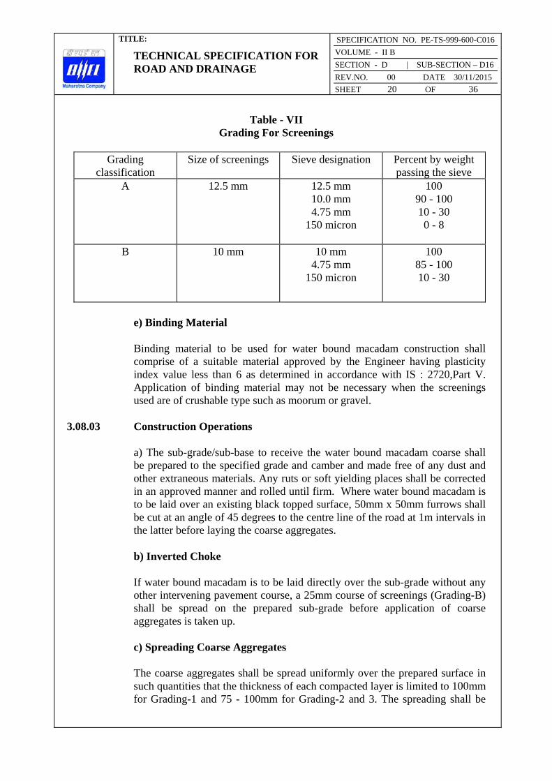
TITLE:
TECHNICAL SPECIFICATION FOR ROAD AND DRAINAGE
SPECIFICATION NO. PE-TS-999-600-C016
VOLUME - II B
SECTION - D | SUB-SECTION – D16
REV.NO. 00 DATE 30/11/2015
SHEET 20 OF 36
Table - VII Grading For Screenings
Grading
classification
Size of screenings Sieve designation Percent by weight
passing the sieve
A
12.5 mm
12.5 mm
10.0 mm
4.75 mm
150 micron
100
90 - 100
10 - 30
0 - 8
B 10 mm 10 mm
4.75 mm
150 micron
100
85 - 100
10 - 30
e) Binding Material Binding material to be used for water bound macadam construction shall
comprise of a suitable material approved by the Engineer having plasticity
index value less than 6 as determined in accordance with IS : 2720,Part V.
Application of binding material may not be necessary when the screenings
used are of crushable type such as moorum or gravel.
3.08.03 Construction Operations
a) The sub-grade/sub-base to receive the water bound macadam coarse shall
be prepared to the specified grade and camber and made free of any dust and
other extraneous materials. Any ruts or soft yielding places shall be corrected
in an approved manner and rolled until firm. Where water bound macadam is
to be laid over an existing black topped surface, 50mm x 50mm furrows shall
be cut at an angle of 45 degrees to the centre line of the road at 1m intervals in
the latter before laying the coarse aggregates.
b) Inverted Choke
If water bound macadam is to be laid directly over the sub-grade without any
other intervening pavement course, a 25mm course of screenings (Grading-B)
shall be spread on the prepared sub-grade before application of coarse
aggregates is taken up.
c) Spreading Coarse Aggregates
The coarse aggregates shall be spread uniformly over the prepared surface in
such quantities that the thickness of each compacted layer is limited to 100mm
for Grading-1 and 75 - 100mm for Grading-2 and 3. The spreading shall be

TITLE:
TECHNICAL SPECIFICATION FOR ROAD AND DRAINAGE
SPECIFICATION NO. PE-TS-999-600-C016
VOLUME - II B
SECTION - D | SUB-SECTION – D16
REV.NO. 00 DATE 30/11/2015
SHEET 21 OF 36
done from stockpiles along the side of the roadway or directly from the
vehicles. In no case shall the aggregate be dumped in heaps directly on the
surface prepared to receive the aggregates nor shall hauling over permitted.
The surface of the aggregates spread shall be carefully checked with templates
and all high or low spots remedied by removing or adding aggregates as may
be required. No segregation of large or fine particles shall be allowed and the
coarse aggregates as spread shall be of uniform gradation with no pockets of
fine material. The coarse aggregates shall not normally be spread more than 3
days in advance of the subsequent construction operation.
d) Rolling Immediately following the spreading of the coarse aggregates, rolling shall be
started with three wheeled power rollers of 8 to 10 tonne capacity or with
tandem or vibratory rollers of approved type. The weight of the roller shall
depend upon the type of the aggregate and be indicated by the Engineer.
Except on super elevated portions where the rolling shall proceed from inner
edge to the outer, rolling shall begin from the edges gradually progressing
towards the centre. First the edge/edges shall be compacted with roller
running forward and backward. The roller shall then move inwards parallel to
the centre line of the road. Each pass of the roller shall uniformly overlap not
less than one half the width of the track made in the preceding pass.
Rolling shall continue until the aggregates are thoroughly keyed and the
creeping of aggregates ahead of the roller is no longer visible. During rolling
slight sprinkling of water may be done if necessary. Rolling shall not be done
when the sub-grade is soft or yielding or when it causes a wavelike motion in
the sub-grade or sub-base course.
The rolled surface shall be checked transversely and longitudinally with
templates and any irregularities found shall be corrected by loosening the
surface, adding or removing necessary amount of aggregates and rerolled until
the entire surface conform to the desired camber and grade. In no case shall
the use of screenings be permitted to make up the depressions.
e) Application of Screenings
After the coarse aggregate has been rolled, screenings to completely fill the
interstices shall be applied gradually over the surface. These shall not be
damp or wet at the time of application. Dry rolling shall be done while the
screenings are being spread so that vibrations of the roller cause them to settle
into the voids of the coarse aggregates. The screenings shall not be dumped in
piles but be spread uniformly in successive thin layers either by the spreading
motion of hand shovels or by mechanical spreader or directly from trucks.
Trucks operating for spreading the screenings shall be so driven as not to
disturb the coarse aggregates.

TITLE:
TECHNICAL SPECIFICATION FOR ROAD AND DRAINAGE
SPECIFICATION NO. PE-TS-999-600-C016
VOLUME - II B
SECTION - D | SUB-SECTION – D16
REV.NO. 00 DATE 30/11/2015
SHEET 22 OF 36
The screenings shall be applied at a slow and uniform rate (in three or more
applications) so as to ensure filling of all voids. This shall be accompanied by
dry rolling and brooming with mechanical brooms or hand brooms or with
both. In no case shall the screenings be applied so fast and thick as to form
cakes or ridges on the surface in such a manner as would prevent filling of
voids or prevent the direct bearing of the roller on the coarse aggregate. These
operations shall continue until no more screenings can be forced into the voids
of the coarse aggregates.
The spreading, rolling and brooming of screenings shall be carried out in only
such lengths of road which could be completed within one day’s operation.
f) Sprinkling and Grouting
After the screenings have been applied, the surface shall be copiously
sprinkled with water, swept and rolled. Hand brooms shall be used to seep the
wet screenings into the voids and to distribute them evenly. The sprinkling,
sweeping and rolling operations shall be continued with additional screenings
applied as necessary until the coarse aggregates are thoroughly keyed, well
bonded and firmly set to its full depth and a grout has been formed of
screenings. Care shall be taken to see that the base or sub-grade does not get
damaged due to the addition of excess quantity of water during construction.
g) Application of Binding Material
After the application of screenings, the binding material where it is required to
be used shall be applied successively in two or more thin layers at a slow and
uniform rate. After each application, the surface shall be copiously sprinkled
with water and the resulting slurry shall be swept in with hand brooms or
mechanical brooms to fill the voids properly and rolled during which water
shall be applied to the wheels of the rollers if necessary to wash down the
binding material sticking to them. These operations shall continue until the
resulting slurry after filling the voids form a wave ahead of the wheels of the
moving roller.
h) Setting and Drying
After the final compaction of water bound macadam course, the road shall be
allowed to dry overnight. Next morning hungry spots shall be filled with
screenings or binding material as directed, lightly sprinkled with water if
necessary and rolled. No traffic shall be allowed on the road until the
macadam is set. The Engineer shall have the discretion to stop hauling traffic
from using the complete water bound macadam course if in his opinion it
would cause excessive damage to the surface.

TITLE:
TECHNICAL SPECIFICATION FOR ROAD AND DRAINAGE
SPECIFICATION NO. PE-TS-999-600-C016
VOLUME - II B
SECTION - D | SUB-SECTION – D16
REV.NO. 00 DATE 30/11/2015
SHEET 23 OF 36
3.09.00 Tack Coat 3.09.01 Description The work shall consist of application of a single coat of low viscosity liquid
bituminous material to an existing road surface preparatory to another
bituminous construction.
3.09.02 Materials The binder used for tack coat shall be bitumen of a suitable grade as approved
by the Engineer and conforming to IS-73, IS-217 or IS-454 as applicable or
any other approved cutback.
3.09.03 Construction Operations
a) Preparation of Base
The surface on which the tack coat is to be applied shall be thoroughly swept
and scraped clean of dust and any other extraneous materials before the
application of the binder.
b) Application of Binder Binder shall be heated to the temperature appropriate to the grade of bitumen
used and approved by the Engineer and sprayed on the base at the rate
specified below. The rate of spread in terms of straight run bitumen shall be 5
kg per 10 square metre area for an untreated water bound macadam surface.
The binder shall be supplied uniformly with the aid of sprayers. The tack coat
shall be applied just ahead of the oncoming bituminous construction.
3.10.00 Bituminous Macadam Binder Course 3.10.01 Description
This work shall consist of construction in a single course of 50mm/75mm
thickness of compacted crushed aggregates premixed with a bituminous binder
laid immediately after mixing on a base prepared previously in accordance
with the specification and in conformity with the lines, grades and cross
sections shown on the approved drawings.
3.10.02 Materials
a) Binder
The Binder shall be straight run bitumen of a suitable grade as directed by the
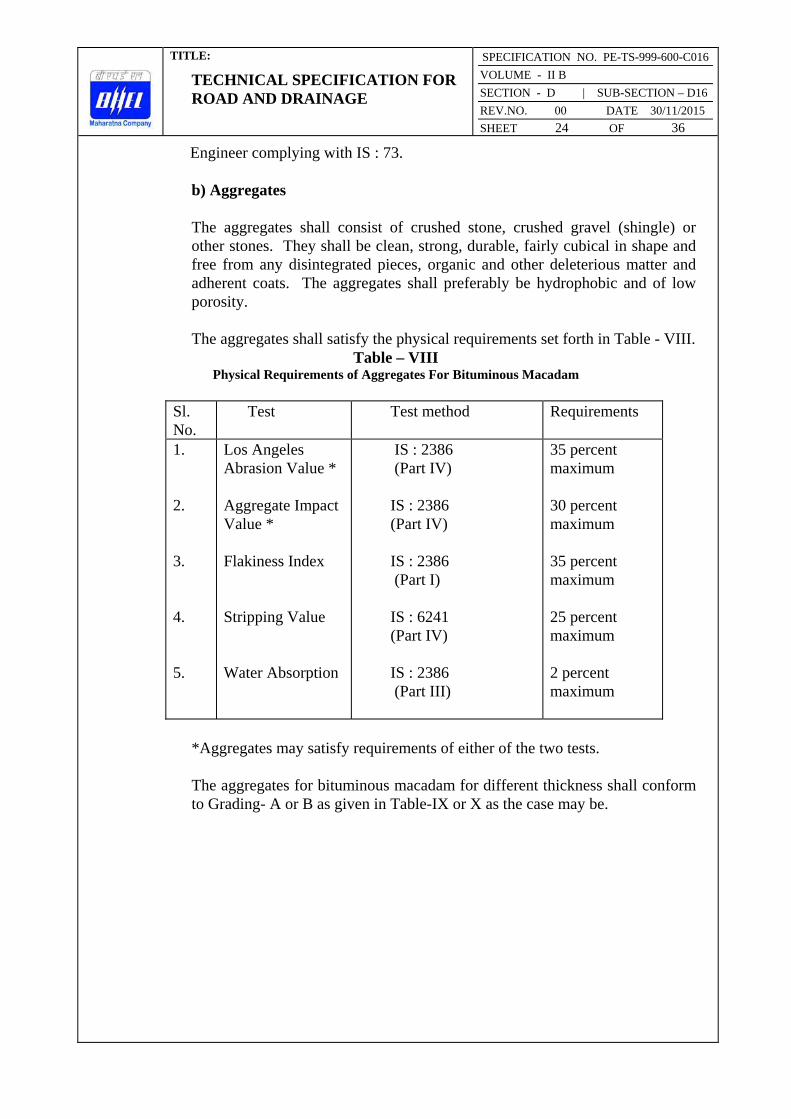
TITLE:
TECHNICAL SPECIFICATION FOR ROAD AND DRAINAGE
SPECIFICATION NO. PE-TS-999-600-C016
VOLUME - II B
SECTION - D | SUB-SECTION – D16
REV.NO. 00 DATE 30/11/2015
SHEET 24 OF 36
Engineer complying with IS : 73.
b) Aggregates The aggregates shall consist of crushed stone, crushed gravel (shingle) or
other stones. They shall be clean, strong, durable, fairly cubical in shape and
free from any disintegrated pieces, organic and other deleterious matter and
adherent coats. The aggregates shall preferably be hydrophobic and of low
porosity.
The aggregates shall satisfy the physical requirements set forth in Table - VIII.
Table – VIII Physical Requirements of Aggregates For Bituminous Macadam
Sl.
No.
Test Test method Requirements
1.
2.
3.
4.
5.
Los Angeles
Abrasion Value *
Aggregate Impact
Value *
Flakiness Index
Stripping Value
Water Absorption
IS : 2386
(Part IV)
IS : 2386
(Part IV)
IS : 2386
(Part I)
IS : 6241
(Part IV)
IS : 2386
(Part III)
35 percent
maximum
30 percent
maximum
35 percent
maximum
25 percent
maximum
2 percent
maximum
*Aggregates may satisfy requirements of either of the two tests.
The aggregates for bituminous macadam for different thickness shall conform
to Grading- A or B as given in Table-IX or X as the case may be.

TITLE:
TECHNICAL SPECIFICATION FOR ROAD AND DRAINAGE
SPECIFICATION NO. PE-TS-999-600-C016
VOLUME - II B
SECTION - D | SUB-SECTION – D16
REV.NO. 00 DATE 30/11/2015
SHEET 25 OF 36
Table-IX
Aggregates Grading For 75mm Compacted Thickness of Bituminous Macadam
Sieve Designation
Percent by weight
passing the sieve
Grading A
Grading B
63 mm
50 mm
40 mm
25 mm
20 mm
12.5 mm
4.75 mm
2.36 mm
75 micron
100
90 - 100
35 - 65
20 - 40
-
5 - 20
-
-
0 - 5
100
70 - 100
50 - 80
-
10 - 30
5 - 20
0 - 4
Table-X Aggregates Grading For 50mm Compacted Thickness of Bituminous Macadam
Sieve Designation
Percent by weight passing the sieve
Grading A
Grading B
50 mm
40 mm
25 mm
20 mm
12.5 mm
10 mm
4.75 mm
2.36 mm
75 micron
100
90 - 100
50 - 80
-
10 - 30
-
-
-
0 - 5
100
70 -100
-
35 - 60
15 - 35
5 - 20
0 - 4
c) Proportioning of Materials
The binder content for premixing shall be 3.5 and 4.0 percent by weight of the
total mix for aggregate Grading-A and B respectively unless directed
otherwise by the Engineer. The quantity of aggregates to be used shall be
sufficient to yield the specified thickness after compaction.
d) Variation in Proportioning of Materials
The Contractor shall have the responsibility for ensuring proper proportio
ning of materials and producing a uniform mix. A variation in binder content

TITLE:
TECHNICAL SPECIFICATION FOR ROAD AND DRAINAGE
SPECIFICATION NO. PE-TS-999-600-C016
VOLUME - II B
SECTION - D | SUB-SECTION – D16
REV.NO. 00 DATE 30/11/2015
SHEET 26 OF 36
upto 0.3 percent by weight of total mix shall however be permissible for
individual specimens taken for quality control tests.
3.10.03 Construction Operations a) Weather and Seasonal Limitations
Bituminous macadam shall not be laid during rainy weather or when the base
course is damp or wet.
b) Preparation of Base
The base on which the bituminous macadam is to be laid shall be prepared,
shaped and conditioned to the specified lines, grade and cross sections as
shown on the drawings and as directed by the Engineer. The surface shall be
thoroughly swept and scraped clean and free of any dust and foreign matter.
c) Tack Coat
A tack coat shall be applied over the base.
d) Preparation and Transport of Mix
Hot mix plant of adequate capacity shall be used for preparing the mix. The
temperature of binder at the time of mixing shall be in the range 150 Deg. -
165 Deg. C and to that of aggregates shall be in the range 125 Deg. - 150 Deg.
C provided the temperature difference between the binder and the aggregate at
no time exceeds 25 Deg. C. Mixing shall be thorough to ensure that a
homogenous mixture is obtained in which all particles of the aggregates are
coated uniformly. The mixture shall be transported from the mixing plant to
the point of use in a suitable vehicle. The vehicle employed for transport shall
be clean and be covered over in transit if so directed by the Engineer.
e) Spreading
After mixing, the mix shall be spread immediately by means of a self
propelled mechanical paver with suitable screeds capable of spreading,
tamping and finishing the mix to the specified lines, grade and cross sections.
However in restricted locations and in narrow widths where the available
plants cannot operate in the opinion of the Engineer may permit manual laying
of the mix. The temperature of mix at the time of laying shall be in the range
110 Deg. - 135 Deg. C.
In multilayer construction, the longitudinal joint in one layer shall offset into
the layer below by about 150mm. However, the joint in the topmost layer
shall be at the centre line of the pavement.

TITLE:
TECHNICAL SPECIFICATION FOR ROAD AND DRAINAGE
SPECIFICATION NO. PE-TS-999-600-C016
VOLUME - II B
SECTION - D | SUB-SECTION – D16
REV.NO. 00 DATE 30/11/2015
SHEET 27 OF 36
Longitudinal joints and edges shall be constructed true to the delineating lines
parallel to the centre line of the road. All joints shall be cut vertical to the full
thickness of the previously laid mix and the surface painted with hot bitumen
before placing fresh material.
f) Rolling
After spreading of mix, the rolling shall be done with 8 to 10 tonne power
roller or with any other approved plant. Rolling should start as soon as the
materials are spread. Rolling shall be done with care to avoid any undulation
in the pavement surface.
Rolling on the longitudinal joint shall be done immediately after the paving
operation. After this, the rolling shall commence at the edges and progress
towards the centre longitudinally except on superelevated portions where it
shall progress from the lower to the upper edge parallel to the centre line of
the pavement.
The initial or breakdown rolling shall be done as soon as it is possible to roll
the mixture without cracking the surface and no mix pick up on the roller
wheels. The second or intermediate rolling shall follow the break down
rolling as early as possible and be done while the paving mix is still at a
temperature that will result in maximum density. The final rolling shall be
done while the material is still workable enough for removal of roller marks.
When the roller has passed over the whole area once, any high spots or
depressions which become apparent shall be corrected by removing or adding
fresh materials. The rolling shall then be continued till the entire surface has
been rolled to compaction and there is no crushing of aggregates and till all the
roller marks are eliminated. Each pass of the roller shall uniformly overlap not
less than one third of the track made in the preceding pass. The roller wheels
shall be kept damp if necessary to avoid the bituminous material from sticking
on the wheels and being picked up. In no case shall fuel/lubricating oil be
used for this purpose.
Rolling operation shall be completed in every respect before the temperature
of the mix fall below 80 Deg. C.
Rollers shall not stand on the newly laid material as it may lead to undue
deformation. The edges along and transverse of the bituminous macadam laid
and compacted earlier shall be cut to their full depth so as to expose fresh
surface which shall be painted with a thin surface coat of appropriate binder
before the new mix is placed against it.
The bituminous macadam shall be provided with a final surfacing without any
delay. If there is to be any delay the course shall be covered by seal coat
before allowing any traffic over it.

TITLE:
TECHNICAL SPECIFICATION FOR ROAD AND DRAINAGE
SPECIFICATION NO. PE-TS-999-600-C016
VOLUME - II B
SECTION - D | SUB-SECTION – D16
REV.NO. 00 DATE 30/11/2015
SHEET 28 OF 36
3.11.00 Open Graded Premix Carpet 3.11.01 Description This work shall consist of laying and compacting open graded carpet of
specified thickness in a single course of suitable small sized aggregates
premixed with bituminous binder on a previously prepared base to form
wearing course in accordance with the specification.
3.11.02 Materials a) Binder The binder shall be bitumen of suitable grade as approved by the Engineer and
satisfying the requirements of IS: 73, 217, 454 or any other approved cutback
as applicable.
b) Aggregates The aggregates shall consist of angular fragments of clean, hard, tough and
durable rock of uniform quality throughout. They shall be obtained by
crushing rock, gravel or river shingle and be free of elongated and flaky
pieces, soft and disintegrated materials, vegetable and any other deleterious
matter etc. They shall preferably be hydrophobic type. The aggregates shall
satisfy the quality requirements set forth in Table-VIII except that the
flakiness Index shall be limited to a maximum of 30.
c) Proportioning of Materials
The materials shall be proportioned as per the quantities given in Table-XI for
20mm thick open graded premix carpet.

TITLE:
TECHNICAL SPECIFICATION FOR ROAD AND DRAINAGE
SPECIFICATION NO. PE-TS-999-600-C016
VOLUME - II B
SECTION - D | SUB-SECTION – D16
REV.NO. 00 DATE 30/11/2015
SHEET 29 OF 36
Table - XI
Quantity of Materials Required For 10 Sq. M of Road Surface For 20mm Thick Open Graded Premix Carpet
Aggregates for Carpet
i) Stone Chippings - 12mm size ; passing 0.18 Cu.m
20 mm sieve and retained on 10 mm sieve
ii) Stone Chippings - 10 mm size; passing
12.5 mm sieve and retained on 6.3 mm sieve 0.09 Cu.m
____________
Total 0. 27 Cu.m
____________
Binder for premixing (quantities in terms of straight run bitumen)
i) For 0. 18 Cu.m of 12 mm size stone 9.5 Kg
Chippings at 52 Kg per Cu.m
ii) For 0.09 Cu. M of 10mm size stone
Chippings at 56 Kg per Cu.m 5.1 Kg
Total 14.6 Kg
3.11.03 Construction Operation a) Weather and Seasonal Limitations Open graded premix carpet shall not be laid during rainy weather or when the
base course is damp or wet or when the atmospheric temperature in shade is
16 Deg. C or below.
b) Preparation of Base
The underlying base on which the bituminous carpet is to be laid shall be
prepared, shaped and conditioned to the specified lines, grade and cross
section in accordance with the drawing, specification and as directed by the
Engineer. The surface shall be well cleaned by removing caked earth and
other foreign matters with wire brushes, sweeping with brooms and finally
dusting with sacks as necessary.

TITLE:
TECHNICAL SPECIFICATION FOR ROAD AND DRAINAGE
SPECIFICATION NO. PE-TS-999-600-C016
VOLUME - II B
SECTION - D | SUB-SECTION – D16
REV.NO. 00 DATE 30/11/2015
SHEET 30 OF 36
c) Tack Coat
A tack coat complying with clause 3.09.00 shall be applied over the base
preparatory to laying of the carpet. However application of tack coat shall not
be necessary when the laying of carpet follows soon after laying the
bituminous course.
d) Preparation of Premix
Mixers of approved type shall be employed for mixing the aggregates with the
bituminous binder. The binder shall be heated to the temperature appropriate
to the grade of bitumen approved by the Engineer in boilers of suitable design
avoiding local overheating and ensuring a continuous supply. The aggregates
shall be dry and suitably heated to a temperature as directed by the Engineer
before these are placed in the mixer. After about 15 seconds of dry mixing,
the heated binder shall be distributed over the aggregates at the rate specified.
The mixing of binder with chipping shall be continued until the chippings are
thoroughly coated with the binder. The mix shall be immediately transported
from the mixer to the point of use in suitable vehicles or wheel barrows. The
vehicles employed for transport shall be clean and be covered over in transit if
so directed.
e) Spreading and Rolling
The premixed material shall be spread on the road surface with rakes to the
required thickness and camber or distributed evenly with the help of a drag
spreader without any undue loss of time. The camber shall be checked by
means of camber boards and inequalities evened out. As soon as sufficient
length of bituminous material are laid, rolling shall be commenced with 6 to 8
tonne power rollers preferably with smooth wheel tandem type or with any
other approved plant. Rolling shall begin at the edges and progress toward the
centre longitudinally except on the superelevated portions where it shall
progress from the lower to upper edge parallel to the centre line of the
pavement.
When the roller has passed over the whole area once, any high spots or
depressions which become apparent shall be corrected by removing or adding
premixed materials. Rolling shall then be continued until the entire surface
has been rolled to compaction and all the roller marks have been eliminated.
In each pass of the roller, preceding track shall be overlapped uniformly by at
least 1/3 width. The roller wheels shall be kept damp to prevent the premix
from adhering to the wheels and being picked up. In no case shall
fuel/lubricating oil be used for this purpose. Rollers shall not stand on newly
laid material as it may lead to undue deformations.
The edges along and transverse of the carpet laid and compacted earlier shall
be cut to their full depth so as to expose fresh surface which shall be painted
TITLE:
TECHNICAL SPECIFICATION FOR ROAD AND DRAINAGE
SPECIFICATION NO. PE-TS-999-600-C016
VOLUME - II B
SECTION - D | SUB-SECTION – D16
REV.NO. 00 DATE 30/11/2015
SHEET 31 OF 36
with a thin surface coat of approved binder before the new mix is placed
against it.
f) Seal Coat
A seal coat conforming to clause 3.12.00 shall be applied to the surface
immediately after laying the carpet. No traffic shall be allowed on the road till
the seal coat has been placed.
3.12.00 Seal Coat 3.12.01 Description This work shall consist of application of a seal coat as specified for sealing the
voids in the bituminous surface laid to the specified levels, grade and camber.
Type-A : Liquid seal coat comprising of an application of a layer of
bituminous binder followed by a cover of stone chippings.
Type-B : Premixed seal coat comprising of a thin application of fine
aggregate premixed with bituminous binder.
3.12.02 Materials a) Binder The binder shall be bitumen of suitable grade as directed by the Engineer and
conforming to the requirements of IS : 73, 217 or 454 as applicable or any
other approved cutback.
The quantity of binder to be adopted in terms of straight run bitumen shall be
9.8 Kg and 6.8 Kg per 10 square metre area for Type-A and Type-B seal coat
respectively.
b) Stone Chippings for Type A Seal Coat The stone chippings shall consist of angular fragments of clean, hard, tough
and durable rock of uniform quality throughout. They shall be free of
elongated or flaky pieces, soft or disintegrated stone, vegetable or other
deleterious matters etc. Stone chippings shall be of 6mm size defined as 100
percent passing through 10mm sieve and retained on 2.36mm sieve. The
quantity used for spreading shall be 0.09 cu.m per 10 sq.m area. The
chippings shall satisfy the quality requirements spelled out in Table- VIII
except that the upper limit for flakiness Index shall be 30.

TITLE:
TECHNICAL SPECIFICATION FOR ROAD AND DRAINAGE
SPECIFICATION NO. PE-TS-999-600-C016
VOLUME - II B
SECTION - D | SUB-SECTION – D16
REV.NO. 00 DATE 30/11/2015
SHEET 32 OF 36
c) Fine Aggregate for Type B Seal Coat
The fine aggregate shall be sand or fine grit and shall consist of clean, hard,
durable, uncoated dry particles and shall be free from dust, soft or flaky
material, organic matter or other deleterious substances. The aggregate shall
pass 1.7 mm sieve and be retained on 180 micron sieve. The quantity used for
premixing shall be 0.06 cubic metre per 10 square metre area.
3.12.03 Construction Operations a) Preparation of Base The seal coat shall be applied immediately after laying the bituminous course
which is required to be sealed. Before application of seal coat, the surface
shall be cleaned free of any dust or other extraneous matters.
b) Construction of Type-A Seal Coat
The binder shall be heated in boilers of suitable design to the temperature
appropriate to the grade of bitumen approved by the Engineer and sprayed on
the dry surface in a uniform manner preferably with the help of mechanical
sprayers. Excessive deposits of binder caused by stopping or starting of the
sprayer or through leakage or due to any other reason shall be suitably
corrected before the stone chippings are spread.
Immediately after the application of binder, stone chippings in a dry and clean
state shall be spread uniformly on the surface preferably by means of a
mechanical grittier or otherwise manually so as to cover the surface
completely. If necessary the surface shall be broomed to ensure uniform
spread of chippings. Immediately after the application of the cover material,
the entire surface shall be rolled with a 8 - 10 tonne smooth wheeled roller.
Rolling shall commence from the edges and progress towards the centre
except in superelevated portions where it shall proceed from the inner edge to
the outer. Each pass of the roller shall uniformly overlap not less than one
third of the track made in the preceding pass. While rolling is in progress
additional chippings shall be spread by hand in whatever quantities required to
make up the irregularities. Rolling shall continue until all aggregate particles
are firmly bedded in the binder and present an uniform closed surface.
c) Construction of Type-B Seal Coat
Mixers of approved type shall be employed for mixing the aggregates with the
bituminous binder. The binder shall be heated in boilers of suitable design to
the temperature appropriate to the grade of bitumen approved by the Engineer.
Also the aggregates shall be dry and suitably heated to a temperature as
directed by the Engineer before the same are placed in the mixer. Mixing of

TITLE:
TECHNICAL SPECIFICATION FOR ROAD AND DRAINAGE
SPECIFICATION NO. PE-TS-999-600-C016
VOLUME - II B
SECTION - D | SUB-SECTION – D16
REV.NO. 00 DATE 30/11/2015
SHEET 33 OF 36
binder with aggregates to the specified proportions shall be continued till the
latter is thoroughly coated with the former. The mix shall be immediately
transported from the mixing plant to the point of use and spread uniformly on
the bituminous surface to be sealed. As soon as sufficient length has been
covered with the premixed material, the surface shall be rolled with 6 - 8
tonne smooth wheeled power rollers. Rolling shall be continued till the
premixed material completely seals the voids in the bituminous course and a
smooth uniform surface is obtained.
3.12.04 Opening to Traffic
In case of Type-B Seal coat, traffic may be allowed soon after the final rolling
when the premixed materials are cooled down to the surrounding temperature.
However in case of Type- A seal coat, the traffic shall not be permitted until
the following day.
3.13.00 Repair of Existing Water Bound Macadam Surfaces
Pot holes or patches and ruts in the water bound macadam base or surface
course which is to be surface treated shall be repaired by removing all loose
materials by cutting in rectangular patches and replacing with suitable
materials. The repair shall be done as under.
Pot holes, patches and ruts shall be drained of any water and cut to regular
shape with vertical sides and then be filled either with i) coarse aggregates and
screenings conforming to the specification for water bound macadam and
compacted with rollers or other approved rammer etc or with ii) premixed
material conforming to the specification for open graded premix carpet and
compacted with rollers or other approved means after painting the sides and
bottom of the holes with a thin application of bitumen or a combination of
both as directed by the Engineer.
3.14.00 Road Side Drains 3.14.01 Drains The road side drains shall be made in sizes and slopes as shown on the
approved drawings. The sides and bottom shall be neatly dressed after
excavation. Proper connections shall be made to the culverts outside the plant
area as per the drawings and instructions of the Engineer.
The excavated spoils other than that required for backfilling shall be
transported and filled in low areas within the plant area or in embankments as
instructed by the Engineer. The lining for drains shall be as per the drawings.
Lining of drains may be of bricks or cement concrete blocks of specified grade
as shown on the approved drawing or as directed by the Engineer. If shown

TITLE:
TECHNICAL SPECIFICATION FOR ROAD AND DRAINAGE
SPECIFICATION NO. PE-TS-999-600-C016
VOLUME - II B
SECTION - D | SUB-SECTION – D16
REV.NO. 00 DATE 30/11/2015
SHEET 34 OF 36
on approved drawing, drains shall be of R.C.C. construction with necessary
slopes.
3.15.00 Culverts
Excavation in trenches for foundation of culverts and wing walls shall be done
with side slopes as per the drawings and instructions of the Engineer after
clearing the site etc. As described in the “Specification for Earthwork in
Excavation and Backfilling”, backfilling in layers with watering and
compaction shall be done after the construction of foundations. The
construction of culverts shall be done true to the lines and levels as shown on
the drawings. The specification for Masonry and/or Plain and Reinforced
Cement concrete shall be followed as applicable.
3.16.00 Pipe Culverts and Drainage Pipes 3.16.01 Materials The drainage pipes shall be made of R.C.C and shall be either class NP-2 or
NP-3 as shown on the approved drawings. Pipe culverts shall be made of
reinforced concrete pipe and shall be of class NP4 or RDSO class for railways
as shown in the drawing. All pipes shall meet the requirements of IS : 458 and
shall be procured from approved manufacturers with collars as per
manufacturer’s specification. The tenderer shall specifically mention the
particular manufacturer’s product he proposes to use.
Cement shall be ordinary Portland Cement as per IS:269. Coarse Aggregates
shall be as per IS:383. Maximum size shall not exceed one third the thickness
of the pipe or 20 mm whichever is smaller. Fine aggregates for concrete shall
be as per IS:383.
3.16.02 Laying of Pipes Laying of concrete pipes shall correspond to IS:783 and as per the
specification given below.
a) The foundation bed for pipe shall be excavated true to lines and grades
shown on the drawings and as directed by the Engineer. When trenching is
involved, its width on either side of the pipe shall not be less than 150mm and
not more than one third the diameter of pipe unless otherwise
instructed/permitted by the Engineer. The sides of the trench shall be as
nearly vertical as possible. Side slope, shoring, bailing out water etc as
required shall be done by the Contractor.
Side slips if there be any shall be removed by the Contractor. After laying of
the pipes are completed, backfilling of the trenches shall be done as per
“Specification for Earthwork in Excavation and Backfilling” to the

TITLE:
TECHNICAL SPECIFICATION FOR ROAD AND DRAINAGE
SPECIFICATION NO. PE-TS-999-600-C016
VOLUME - II B
SECTION - D | SUB-SECTION – D16
REV.NO. 00 DATE 30/11/2015
SHEET 35 OF 36
satisfaction of the Engineer. The surplus spoils shall be transported and filled
in low areas within the plant area as instructed by the Engineer.
When bedrock or boulder stratum is encountered during excavation, the
excavation shall be taken down to at least 200mm below the bottom of the
pipe with prior permission of the Engineer and all rock/boulders in the area
shall be removed and space filled with approved earth free from stone or
fragmented materials, shaped to the requirements and thoroughly compacted
to provide adequate support for the pipe.
Filling of trench shall be carried out simultaneously on both sides of the pipe
in such a manner that unequal pressures do not occur and shall be done as per
the “Specification for Earthwork in Excavation and Backfilling”. When two or
more pipes are to be laid adjacent to each other, they shall be separated by a
distance equal to at least half the diameter of the pipe subject to a minimum of
450 mm. Laying of pipes shall start from the outlet and proceed towards inlet.
All pipes and fittings shall be gradually lowered into the trench or placed on
the supports by approved means taking due care to avoid any damage. Under
no circumstances the pipes shall be dropped into the trench or on supports
from heights.
b) Pipe bedding shall be first class projection bedding for positive projecting
pipes as per IS : 783 having a projection ratio not greater than 0.70. The pipe
shall be carefully laid on bedding made up of fine granular materials in an
earth foundation; the bedding shall be carefully shaped to fit the lower part of
the pipe exterior for at least ten percent of its overall height and in which the
fill material is thoroughly compacted in layers not exceeding 150mm in depth
around the pipe for the remainder of the pipe laid in trench.
When indicated on the drawings or directed by the Engineer, the pipe shall be
bedded on a cradle constructed of concrete having a mix not leaner than M-15.
The shape and dimension of the cradle shall be as indicated on the drawing or
as directed by the Engineer. The pipe shall be laid on the concrete bedding
before the concrete is set.
c) The drop walls shall be made with first class brickwork in 1:4 cement
mortar.
d) The pipe culverts shall be made with proper care with respect to the invert
of the pipe, gradient if any etc as specified on the drawings and as instructed
by the Engineer.
e) Where R.C.C pipes are encased in concrete at road crossings or at other
places the pipes need be suitably supported avoiding reinforcements of
concrete blocks, joints properly done before concreting is taken up.
Concreting of total height of block may be done in a single operation or may
be done upto some height for pipes to be properly laid in position and the
balance height of the block shall be concreted subsequently.

TITLE:
TECHNICAL SPECIFICATION FOR ROAD AND DRAINAGE
SPECIFICATION NO. PE-TS-999-600-C016
VOLUME - II B
SECTION - D | SUB-SECTION – D16
REV.NO. 00 DATE 30/11/2015
SHEET 36 OF 36
f) The R.C.C. pipes shall be joined with cement mortar. Cement mortar shall
consist of 1 part of cement and 2 part of clean sand with only enough water for
workability. Procedure of jointing shall be as per IS : 783.
3.16.03 Relation With Water Supply Pipeline Unless specifically cleared by the Engineer, under no circumstances shall the
drainage pipes be allowed to come close to water supply pipelines.
3.17.00 Manholes and Inspection Chambers The maximum distance between the manholes shall be 30m unless specifically
permitted otherwise. In addition, at every change of alignment, gradient or
diameter there shall be a manhole or inspection chamber. The distance
between the manhole or inspection chamber and gully chamber shall not
exceed 6 meters unless permitted otherwise. Manhole shall be constructed so
as to be water tight under test. The channel or drain at the bottom of chamber
shall be plastered with 1:2 cement sand mortar and finished smooth to the
grade. The channels and drains shall be shaped and laid to provide a smooth
flow. Connection to the existing pipelines shall be through a manhole.
Manholes shall be provided with standard covers usually of C.I. or as directed
by the Engineer. The cover shall be closely fitted so as to prevent gases from
coming out.
4.00.00 Testing and Acceptance Criteria All testing as mentioned in the specification and as mentioned in Clause No.
900 of the “Specification for Roads and Bridge Works, 1983” published by
IRC on behalf of Ministry of Shipping and Transport (Roads Wing) shall be
carried out by the Contractor as per the direction of the Engineer.
5.00.00 MEASUREMENT
Method of measurement shall be as per the latest version of IS:1200, Part-17
and as directed by the Engineer.

TITLE:
TECHNICAL SPECIFICATION FOR FABRICATION OF STRUCTURAL STEEL WORK
SPECIFICATION NO. PE-TS-999-600-C017
VOLUME - II B
SECTION - D SUBSECTION -D17
REV.NO. 0 DATE 16/03/2016
SHEET 1 OF 40
1
VOLUME: II B
SECTION - D (PART I)
SUB-SECTION – D 17
FABRICATION OF STRUCTURAL STEEL WORK
Bharat Heavy Electricals Limited Project Engineering Management
PPEI Building, Power Sector,
Plot No. 25, Sector 16A,
Noida (U.P.)-201301

TITLE:
TECHNICAL SPECIFICATION FOR FABRICATION OF STRUCTURAL STEEL WORK
SPECIFICATION NO. PE-TS-999-600-C017
VOLUME - II B
SECTION - D SUBSECTION -D17
REV.NO. 0 DATE 16/03/2016
SHEET 2 OF 40
2
C 0 N T E N T
CLAUSE NO. DESCRIPTION SHEET NO.
1.00.00 SCOPE 3
2.00.00 GENERAL 3
3.00.00 WORKMANSHIP 19
4.00.00 INSPECTION, TESTING, ACCEPTANCE
CRITERIA AND DELIVERY 29
5.00.00 INFORMATION TO BE SUBMITTED 33
6.00.00 RATES AND MEASUREMENTS 34

TITLE:
TECHNICAL SPECIFICATION FOR FABRICATION OF STRUCTURAL STEEL WORK
SPECIFICATION NO. PE-TS-999-600-C017
VOLUME - II B
SECTION - D SUBSECTION -D17
REV.NO. 0 DATE 16/03/2016
SHEET 3 OF 40
3
SUB-SECTION – D XVII
FABRICATION OF STRUCTURAL STEEL WORK 1.00.00 SCOPE
This specification covers supply, fabrication, testing, painting and delivery to
site of structural steelwork including supply of all consumable stores and
rivets, bolts, nuts, washers, electrodes and other materials required for
fabrication and field connections of all structural steelwork covered under the
scope of the contract.
2.00.00 GENERAL
2.01.00 Work to be provided for by the Contractor The work to be provided for by the Contractor, unless otherwise specified
elsewhere in the contract, shall include, but not be limited to the following
a) Preparation of complete detailed fabrication drawings and erection
marking drawings required for all the structures covered under the scope
of the contract based on the approved design drawings. As decided by the
Engineer, some or all of these detailed drawings will have to be submitted
for approval.
b) To submit revised design with calculations and detailed fabrication
drawings in case any substitution of the designed sections are to be made.
c) To submit design calculations for joints and. connections developed by the
contractor along with detailed fabrication drawings.
d) Furnish all materials, labour, tools and plant and all consumables required
for fabrication and supply, all necessary rivets, bolts, nuts, washers, tie
rods and welding electrodes for field connections,
e) Furnish shop painting of all fabricated steelwork as per requirements of
this Specification.
f) Suitably mark, bundle, and pack for transport all fabricated materials.
g) Prepare and furnish detailed Bill of Materials, Drawing Office Dispatch
lists, Rivet and Bolt List and any other list of bought out items required in
connection with the fabrication and erection of the structural steelwork.
h) Insure, load and transport all fabricated steelwork field connection
materials to site.
i) Maintain a fully equipped workshop at site for fabrication, modification

TITLE:
TECHNICAL SPECIFICATION FOR FABRICATION OF STRUCTURAL STEEL WORK
SPECIFICATION NO. PE-TS-999-600-C017
VOLUME - II B
SECTION - D SUBSECTION -D17
REV.NO. 0 DATE 16/03/2016
SHEET 4 OF 40
4
and repairs of steelwork at site as may be required to complete the works
in accordance with the Contract.
2.02.00 Work by others
No work under this specification will be provided for by any agency other
than the contractor, unless specifically mentioned otherwise elsewhere in the
contract.
2.03.00 Codes and standards
All work under this specification shall, unless otherwise specified in the
contract, conform to the requirements of the latest revision and/or
replacements of the following or any other relevant Indian Standard
specifications and codes of practice. In case any particular aspect of the work
is not specifically covered by any Indian Standard specification, any other
standard practice, as may be specified by the Engineer shall be followed:
IS : 226 - Structural steel (Standard Quality)
IS : 800 - Code of Practice for general construction in steel.
IS : 806 - Code of practice for use of steel tubes in general building
construction.
IS : 808 - Rolled steel beams, channels, and angle sections
IS : 813 - Scheme of symbols for welding
IS : 814 - Covered electrodes for metal arc welding of structural steel
IS : 815 - Classification and coding of covered electrodes for metal arc
welding of structural steels.
IS : 816 - Code of practice for use of metal arc welding for general
construction in mild steel
IS : 817 - Code of practice for training and testing metal arc welders
IS : 818 - Code of practice for safety and health requirements in electric
and gas welding and cutting operations
IS : 822 - Code of practice for inspection of welds
IS : 919 - Recommendations for limits and fits for Engineering
IS : 961 - Structural Steel (High Tensile)

TITLE:
TECHNICAL SPECIFICATION FOR FABRICATION OF STRUCTURAL STEEL WORK
SPECIFICATION NO. PE-TS-999-600-C017
VOLUME - II B
SECTION - D SUBSECTION -D17
REV.NO. 0 DATE 16/03/2016
SHEET 5 OF 40
5
IS : 1148 - Rivet bars for structural purposes
IS : 1149 - High tensile rivet bars for structural purposes
IS : 1161 - Steel Tubes for structural purposes
IS : 1200 - Method of measurement of steelwork and ironwork (Part 8)
IS : 1239 - Mild Steel Tubes
IS : 1363 - Black hexagon bolts, nuts and lock nuts (dia. 6 to 30 mm) and
black hexagon screws (dia 6 to 24 mm)
IS : 1364 - Precision and semi-precision hexagon bolts, screws, nuts and l
locknuts (dia, range 6 to 39 mm)
IS : 1367 - Technical supply conditions for threaded fasteners
IS : 1442 - Covered electrodes for the metal are welding of high tensile
structural steel
IS : 1608 - Method for tensile testing of steel products other than sheet
strip, wire and tube
IS : 1730 - Dimensions for steel plate, sheet, and strip for structural and
general engineering purposes.
IS : 1731 - Dimensions for steel flats for structural and general engineering
purposes
IS : 1852 - Rolling and cutting tolerances for hot-rolled steel products
IS : 1977 - Structural steel (ordinary quality) St-42-0
IS : 2062 - Steel for General Structural Purposes
IS : 2074 - Ready mixed paint, red oxide Zinc chromate priming
IS : 2595 - Code of Practice for Radiographic Testing
IS : 2629 - Recommended practice for Hot-Dip Galvanizing of Iron and
Steel
IS : 2633 - Method for testing uniformity of coating on Zinc Coated Articles
IS : 3757 - High strength structural bolts

TITLE:
TECHNICAL SPECIFICATION FOR FABRICATION OF STRUCTURAL STEEL WORK
SPECIFICATION NO. PE-TS-999-600-C017
VOLUME - II B
SECTION - D SUBSECTION -D17
REV.NO. 0 DATE 16/03/2016
SHEET 6 OF 40
6
IS : 4759 - Specifications for Hot-Dip Zinc Coatings on Structural Steel
and other allied products
IS : 7205 - Safety Code for Erection of Structural Steelwork
IS : 7215 - Tolerances for fabrication of steel structures
IS : 7280 - Bare wire electrodes for submerged arc welding of structural
steels.
IS : 9595 - Recommendations for metal arc welding of carbon and carbon
manganese steels.
2.04.00 Conformity with Designs The contractor shall design all connections, supply and fabricate all steelwork
and furnish all connection materials in accordance with the approved drawings
and/or as instructed by the Engineer keeping in view the maximum Utilization
of the available sizes and sections of steel materials. The methods of painting,
marking, packing and delivery of all fabricated materials shall be in
accordance with the provisions of the contract and/or as approved by the
Engineer. Provision of all relevant Indian Standard Specifications and Codes
of Practice shall be followed unless otherwise specified in the contract.
2.05.00 Materials to be used
2.05.01 General
All steel materials required for the work will be supplied by the contractor
unless otherwise specified elsewhere in the contract. The materials shall be
free from all imperfections, mill scales, slag intrusions, laminations, fittings,
rusts etc. that may impair their strength, durability, and appearance. All
materials shall be of tested quality only unless otherwise permitted by the
Engineer and/or Consultant. If desired by the Engineer, Test Certificates in
respect of each consignment shall be submitted in triplicate. Whenever the
materials are required to be used from unidentified stocks, if permitted by the
Engineer, a random sample shall be tested at an approved laboratory from
each lot of 50 tones or less of any particular section.
The arc welding electrodes shall be of approved reputed manufacture and
conforming to the relevant Indian Standard Codes of Practice and
Specifications and shall be of heavily coated type and the thickness of the
coating shall be uniform and concentric. With each container of electrodes,
the manufacturer shall furnish instructions giving recommended voltage and
amperage (Polarity in case of D.C. supply) for which the electrodes are
suitable.

TITLE:
TECHNICAL SPECIFICATION FOR FABRICATION OF STRUCTURAL STEEL WORK
SPECIFICATION NO. PE-TS-999-600-C017
VOLUME - II B
SECTION - D SUBSECTION -D17
REV.NO. 0 DATE 16/03/2016
SHEET 7 OF 40
7
2.05.02 Steel
All steel materials to be used in construction within the purview of this
specification shall comply with any of the following Indian Standard
Specifications as may be applicable:
a) IS : 2062 - Steel for general structural purposes
b) IS : 961 - Structural steel High Tensile
c) IS : 1977 - Structural steel (Ordinary quality) St-42-0
In case of imported steel materials being used, these shall conform to
specifications equivalent to any of the above as may be applicable.
2.05.03 Rivet Steel
All rivet steel used in construction within the purview of this Specification
shall comply with one of the following Indian Standard Specifications as may
be applicable:
a) IS : 1148 - Rivet Bars for structural purpose
b) IS : 1149 - High tensile rivet bars for structural purposes. Where high
tensile steel is specified for rivets, steps shall be taken to ensure
that the rivets are so manufactured that they can be driven and
heads formed satisfactorily without the physical properties of
steel being impaired.
2.05.04 Electrodes
All electrodes to be used under the Contract shall be of approved reputed
manufacture, low hydrogen electrode and shall comply with any of the
following Indian Standard Specifications as may be applicable
a) IS : 814 - Covered electrodes for metal arc welding of structural
steel
b) IS : 815 - Classification and coding of covered electrodes for
metal arc welding of mild steel and low alloy high
tensile steel
c) IS : 1442 - Covered electrodes for the metal arc welding of high
tensile structural steel
d) IS : 7280 - Bare wire electrodes for submerged arc welding of
TITLE:
TECHNICAL SPECIFICATION FOR FABRICATION OF STRUCTURAL STEEL WORK
SPECIFICATION NO. PE-TS-999-600-C017
VOLUME - II B
SECTION - D SUBSECTION -D17
REV.NO. 0 DATE 16/03/2016
SHEET 8 OF 40
8
structural steels
2.05.05 Bolts and Nuts
All bolts and nuts shall conform to the requirements of Indian Standard
Specification IS: 1367 - Technical Supply Conditions for Threaded Fasteners.
Materials for Bolts and nuts under the purview of this contract shall comply
with any of the following Indian Standard Specifications as may be applicable.
a) Mild Steel
All mild steel for bolts and nuts when tested in accordance with the
following Indian Standard Specification shall have a tensile strength of not
less than 44 Kg/mm² and a minimum elongation of 23 per cent on a gauge
length of 5.6 _/A, where "A" is the cross sectional area of the test
specimen
i) IS: 1367: Technical supply conditions for threaded fasteners
ii) IS: 1608: Method for tensile testing of steel products other than
sheet, strip, wire and tube
b) High Tensile Steel
The material used for the manufacture of high tensile steel bolts and nuts
shall have the mechanical properties appropriate to the particular class of
steel as set out in IS: 1367 or as approved by the Engineer.
2.05.06 Washers
Washers shall be made of steel conforming to any of the following Indian
Standard Specifications as may be applicable under the provisions of the
Contract:
a) IS : 2062 - Steel for general structural purposes
b) IS : 961 - Structural Steel ( High Tensile Quality)
c) IS : 1977 - Structural steel ( Ordinary Quality ) St-42-0
d) IS : 6649 - Hardened washers
2.05.07 Paints
Paints to be used for shop coat of fabricated steel under the purview of this

TITLE:
TECHNICAL SPECIFICATION FOR FABRICATION OF STRUCTURAL STEEL WORK
SPECIFICATION NO. PE-TS-999-600-C017
VOLUME - II B
SECTION - D SUBSECTION -D17
REV.NO. 0 DATE 16/03/2016
SHEET 9 OF 40
9
contract shall conform to the Indian Standard Specification IS: 2074 - Ready
mixed Paint, Red oxide Zinc Chromate Priming.
2.06.00 Coal Bin
2.06.01 Shape of bins shall be circular, polygonal, square, or rectangular in plan.
Bottom hopper portion may have be conical-cum-hyperbolic or any other
profile shape as shown in the drawing. Bin shall be termed as bunkers or silos
according to their shape and plane of rupture of coal.
2.06.02 For general requirements, fabrication and construction details IS: 9178 (Pt.l &
11) shall be followed as general guidance. The bins shall be fabricated and
erected in segments.
2.06.03 The Coal bins shall be made of mild steel plates joined together with full
strength butt weld and provided with stiffeners at regular interval. Stiffeners
shall be provided on the external face and it may be welded with external face.
2.06.04 Bending of plates and rolled sections to the required shape for fabrication shall
be done by plate bending machine or cold bending process Without resorting
to heating, hammering, angle smithy and black smithy process.
2.06.05 Poking hole (manual or pneumatic) and striking plate shall be provided to
facilitate coal flow. Poking holes shall have circular MS pipe and cover cap
as detailed in the drawing. 2.07.00 New Erection Marks
2.07.01 Additional structures involving new erection marks may be required to be
added at any stage of work.
2.07.02 All such new erection marks shall be detailed and included in marking
schemes and fabrication carded out thereafter.
2.07.03 All such new erection marks shall be considered under item of original
fabrication work. As a result of additional structures becoming necessary if
the work is delayed beyond the time schedule stipulated, the Engineer shall
give suitable extension of time provided he is satisfied about the
reasonableness of the delay involved. However, no claim for extra payments
or revision of rates due to delay shall be entertained.

TITLE:
TECHNICAL SPECIFICATION FOR FABRICATION OF STRUCTURAL STEEL WORK
SPECIFICATION NO. PE-TS-999-600-C017
VOLUME - II B
SECTION - D SUBSECTION -D17
REV.NO. 0 DATE 16/03/2016
SHEET 10 OF 40
10
2.08.00 ELECTRO FORGED STEEL GRATINGS
2.08.01 Factory made fabricated electro forged gratings unit with steel conforming to
IS: 2062 shall be supplied, fabricated, transported, erected and aligned in
floorings, platforms, drain and trench covers, walkways, passages, staircases
with edge binding strips and anti skid nosing in treads etc.
2.08.02 All grating units shall be rectangular in pattern and electro forged. The size
and the spacing of the bearing bars and cross bars shall be as detailed in
fabrication drawings. The contractor shall submit the grating design for
different spans and load intensities along with fabrication drawings. The
depth of the grating unit shall be 40 mm, unless specified otherwise.
2.08.03 The gratings shall be made up in panel units designed to coincide with the
span of the structural steel framing or openings as indicated in the design/
scope drawings. Maximum possible standardization of the grating panel sizes
shall be tried and designed.
2.08.04 The grating unit shall be accurately fabricated and finished, free from wraps,
twists, or any defects that would impair their strength, serviceability, and
appearance.
2.08.05 Grating work shall include cut outs and clearance opening for all columns,
pipes, ducts, conduits or any other installation penetrating through the grating
work. Such cut outs and clearances shall be treated as specified in subsequent
clauses.
2.08.06 The gratings shall be notched, trimmed and neatly finished around flanges and
webs of the columns, moment connections, cap plates, and such other
components of the steel structures encountered during the placement of the
gratings. In all such cases, the trimming shall be done to follow the profile of
the components encountered. After trimming, the binding strip shall be
provided on the grating to suit the profile so obtained.
2.08.07 Opening in gratings for pipes or ducts that are 150mm in size or diameter or
larger shall be provided with steel bar toe plates of not less than 5mm
thickness and appropriate width, set flush with the bottom of the bearing bars.
2.08.08 Penetrations in gratings that are more than 50mm but less than 150mm in size
or diameter shall be welded with plates of size shown in the detailed drawings
set flush with the bottom of the grating panel.
2.08.09 Unless otherwise indicated on the drawings, grating units at all penetrations
shall be made up in split section, accurately fitted and neatly finished to
provide for proper assembly and erection at the job site.

TITLE:
TECHNICAL SPECIFICATION FOR FABRICATION OF STRUCTURAL STEEL WORK
SPECIFICATION NO. PE-TS-999-600-C017
VOLUME - II B
SECTION - D SUBSECTION -D17
REV.NO. 0 DATE 16/03/2016
SHEET 11 OF 40
11
2.08.10 Grating units shall be provided with all necessary clips, bolts, nuts and lock
washers required for proper assembly and rigid installation and fastening to
abutting units supporting structural steel framing members.
2.08.11 The gratings shall be of reputed make and manufacturer, as approved by
Engineer. The unit rate quoted by him for this item shall be inclusive of
transport of gratings to the project site, all taxes, duties etc. He shall also
provide all facilities and access to the Engineer or his representative to carry
out inspection during all stages of manufacturing of gratings.
2.08.12 Maximum deviation in linear dimension from the approved dimension shall
not exceed 12mm.
2.08.13 All fabricated grating section and accessories shall be blast cleaned to near
white metal surface (Sa 2½) followed by either of the following two:
(a) Two coats of red lead primer and two coats of black enamel finish paint.
(b) Hot dipped galvanization at 610 gm/sq.m.
in the shop prior to erection at site, as the approved drawing.
2.08.14 Prior to finishing all surfaces shall be cleaned, free from rust, mill scale,
grease, oil, or any other foreign matter by blast cleaning. BS: 4232 shall be
followed for blast cleaning.
2.08.15 Primer can be applied by spray guns or by brushes, however the finish paint
shall necessarily be applied by means of spray guns. The applied coatings
shall be uniform, free from voids and streaks; drilled or punched holes shall be
touched up prior to erection or assembly.
2.09.00 GALVANIZATION OF GRATINGS
2.09.01 Purity of Zinc to be used-for galvanizing shall be 99.5% as per IS: 2 15
2.09.02 After the shop work is complete, the structural material shall be punched with
erection mark and be hot double dip galvanized. Before galvanizing the steel
section shall be thoroughly blast cleaned to near white metal surface (Sa 2½).
2.09.03 The weight of the zinc coating shall be at least 610 gm/m² - unless noted
otherwise.
2.09.04 The galvanized surface shall consist of a continuous and uniformly thick
coating of zinc, firmly adhering to the surface of steel. The finished surface
shall be cleaned and smooth and shall be free from defects like discoloured
patches, bare spots, unevenness of coating, spelter that is loosely attached to
the steel, blistered surface, flaking or peeling off etc. The presence of any of

TITLE:
TECHNICAL SPECIFICATION FOR FABRICATION OF STRUCTURAL STEEL WORK
SPECIFICATION NO. PE-TS-999-600-C017
VOLUME - II B
SECTION - D SUBSECTION -D17
REV.NO. 0 DATE 16/03/2016
SHEET 12 OF 40
12
these defects noticed on visual or microscopic inspection shall render the
material liable to rejection.
2.09.05 There shall be no flaking or loosening when struck squarely with a chisel
faced hammer. The galvanized steel member shall withstand minimum four
one minute dips in copper sulphate solution as per IS: 2633.
2.09.06 When the steel section is removed from the galvanizing kettle, excess spelter
shall be removed by 'bumping'. The processes known as 'wiping' or
'scrapping' shall not be used for this purpose.
2.09.07 Defects in certain members indicating presence of impurities in the
galvanizing bath in quantities larger than that permitted by the specifications
or lack of quality control in any manner in the galvanizing plant, shall render
the entire, production in the relevant shift liable to rejection.
2.09.08 All structural steel shall be treated with sodium dichromate or an approved
equivalent solution after galvanizing; so as to prevent white storage stains.
2.09.09 If the galvanizing of any member is damaged, the Engineer shall be shown of
the extent of damage, if so directed the galvanizing may have to the redone in
the similar manner as stated above at no extra cost to the Owner.
2.10.00 STAINLESS STEEL HOPPERS (As per BOQ item)
2.10.01 Material
In case SS Hopper is to be fabricated & erected as per BOQ item with
SS415M, following specification shall be followed.
Stainless steel hopper of grade SS 415M as manufactured by SAIL or
equivalent shall be provided in the lower portion of bunker hopper. SS 4 15M
having the following chemical composition shall be used.
Material % Remarks
Carbon 10.03% Max.
Silicon 1.60% Max.
Manganese 0.80% to 1.50%
Phosphorous 0.03% Max.
Sulpher 0.03% Max.
Chromium 10.80% to 12.50%

TITLE:
TECHNICAL SPECIFICATION FOR FABRICATION OF STRUCTURAL STEEL WORK
SPECIFICATION NO. PE-TS-999-600-C017
VOLUME - II B
SECTION - D SUBSECTION -D17
REV.NO. 0 DATE 16/03/2016
SHEET 13 OF 40
13
Nickel 1.50% Max.
Titanium 0.75% Max.
Nitrogen 0.03% Max.
The mechanical properties shall be as follows:
Description Value Remarks
Hardness Rock Well B Scale 90 Max.
Tensile Strength 450 MPa Min.
Yield Strength 300 MPa Min.
Elongation 25% Min.
2.10.02 Fabrication
The fabrication, erection, alignment and welding shall be carried out as per the
accepted practice and in accordance with relevant I.S. and international
specification as well as stipulations contained herein. Fabrication drawings
shall be prepared by the contractor on the basis of the design / scope drawings
furnished by Engineer. The fabrication and erection works shall be done as per the approved fabrication drawings.
2.10.03 Fabrication Drawings
a) Fabrication drawing shall give the cutting plan for each hopper plate.
Such, cutting plan shall be based on the size of the Stainless Steel plate
available at store. In order to reduce the wastage and ensure the maximum
utilization of stainless steel plate, the cutting plan shall take in the
consideration of the reverse curvature and place the various elements of
hopper plate in opposite fashion to reduce the end wastage. Similarly the
hopper plate element having different radii shall be placed one inside the
other, to optimize the stainless steel plate use. Such optimization may also
required adjustment in the size of the each element of hopper plate and
also additional weld joints.
b) The bill of material of hopper plate shall indicate the inner surface area of
the hopper, weight of the hopper based on the inner surface area, weight of
each of the cut plate of hopper fabrication, weight of cut and scrap pieces
generated. Contractor shall return to the Owner’s store all unutilized
(surplus) stainless steel plates and all waste and cut pieces generated. Non
return of any part of the surplus/waste steel pieces to the Owner’s store
will call for the penal recovery at three (03) times the maximum

TITLE:
TECHNICAL SPECIFICATION FOR FABRICATION OF STRUCTURAL STEEL WORK
SPECIFICATION NO. PE-TS-999-600-C017
VOLUME - II B
SECTION - D SUBSECTION -D17
REV.NO. 0 DATE 16/03/2016
SHEET 14 OF 40
14
procurement rate for the weight of stainless steel pieces not returned to the
store.
c) In case the contractor does the cutting of the stainless steel without
approved cutting plan then all the wastage (i.e. the difference between the
weight of stainless steel plate cuts and the actual finished weight
considered for the measurement for payment) shall be subjected to the
penal recovery at the rate mentioned above.
2.10.04 Cuffing
Cutting may be affected by shearing, or by using plasma. The cut edges of all
plates shall be perfectly straight and uniform through out. Cutting shall be
done as per the cutting plan shown in the fabrication drawing. Should the
Engineer find it necessary, the edges shall be ground smooth afterwards by
contractor within the unit rates quoted by him. All the edge s shall be ground
smooth before they are welded.
2.10.05 Jointing
Welding shall join stainless steel. All weld joints (along the inclined plane)
shall be staggered. Any common welding process can weld stainless steel viz.
MIG, metal arc or plasma using the covered compatible electrodes as per IS:
5206 or by inert gas arc welding as per IS: 2811. Shielding gas shall be Argon
+ Hydrogen mixture or Argon + Oxygen mixture. However, Argon + Oxygen
mixture shall be preferred. Carbon-di-oxide mixture shall be avoided. 308L
and 315L electrodes/fillers shall be used for the welding of Stainless Steel to
Stainless Steel and Stainless Steel to Mild Steel respectively. However, the
welding process and the type of the electrodes to be used for welding shall be
as per welding procedure, as approved by the Engineer. On the basis of the
welding procedure, the Contractor shall conduct qualification test.
2.10.06 Bending
The stainless steel plates shall be subjected to cold forming and bending in
order to get the desired shape and profile.
2.10.07 Welding sequence
The type of electrodes, welding sequence, preheat and interpass temperature
and post weld heat treatment shall be as approved by the Engineer.
2.10.08 Acceptance Criteria of Fabricated Structures
The acceptance of the fabricated structure work shall depend upon correct
dimensions and alignment, absence of distortion in the structure, satisfactory
results from the inspection and testing of the welded structure joints and the

TITLE:
TECHNICAL SPECIFICATION FOR FABRICATION OF STRUCTURAL STEEL WORK
SPECIFICATION NO. PE-TS-999-600-C017
VOLUME - II B
SECTION - D SUBSECTION -D17
REV.NO. 0 DATE 16/03/2016
SHEET 15 OF 40
15
test specimens, general workmanship being good meeting the tolerance
requirements given in IS: 7215.
2.11.00 BEARINGS
2.11.01 PTFE (Poly tetra fluorethylene) slide bearing
a) General
The bearings shall consist of upper and lower units. The upper unit shall
include a sole plate with mirror finish stainless steel facing bonded to the
bottom surface of the sole plate. The lower unit shall consist of a relevant
laminated elastomers pad surfaced with PTFE. A rigid confining medium
substructure bonds the PTFE to the pad. When the upper and lower units
are mated the stainless steel slides on the PTFE surface with an extremely
low coefficient of friction. These bearings shall be designed as per the
performance requirements. The bearing shall be of reputed make and
manufacturer as approved by Engineer, for required vertical loads, as per
the construction drawings and for a maximum displacement of ± 50 mm.
b) Material
PTFE bearing shall be sliding against highly polished stainless steel and
the coefficient of friction between them shall be less than 0.06 at 55
kg/cm². In order to prevent cold flow in the PTFE surface it shall be
rigidly bonded by a special high temperature resistant adhesive to the
stainless steel sub-strata. The stainless steel surface, which slides against
the PTFE, is mirror polished. The stainless steel shall be bonded to the top
plate by special high strength adhesive. The thickness of the stainless steel
shall be between 1.0 to 1.5mm.
The resilient bearing pad shall consist of multiple layers of lightweight
fabric impregnated with a high quality elastomer compound vulcanized
into slabs of uniform standard thickness as per the requirement. This shall
withstand vertical (compressive) load not less than 500 kg/cm² and shear
loads upto 40 kg/cm².
c) Installation
The seating area for PTFE bearing shall be prepared accurately level and
furnished with a thin layer of epoxy resin mortar. The bearing will be
placed on this layer while it is still workable and the bearing is levelled.
The bearing should not be displaced as the beam is lowered into position.
When the mortar and adhesive are fully set and the beam slightly above
the top of the bearing. The upper surface of the bearing shall then be
coated with sufficient thickness of epoxy resin mortar so that when the
beam is lowered on to the temporary supports it comes into full contact

TITLE:
TECHNICAL SPECIFICATION FOR FABRICATION OF STRUCTURAL STEEL WORK
SPECIFICATION NO. PE-TS-999-600-C017
VOLUME - II B
SECTION - D SUBSECTION -D17
REV.NO. 0 DATE 16/03/2016
SHEET 16 OF 40
16
with the mortar and some is squeezed out. The surplus shall be troweled
off and after the mortar is fully set the temporary supports removed.
2.12.00 Storage of material
2.12.01 General
All materials shall be so stored as to prevent deterioration and to ensure the
preservation of their quality and fitness for the work. Any material, which has
deteriorated or has been damaged, shall be removed from the contractor's yard
immediately, failing which, the Engineer shall be at liberty to get the material
removed and the cost incurred thereof shall be realised from the Contractor.
The Contractor shall maintain upto date accounts in respect of receipt, use,
and balance of all sizes and sections of steel and other materials. In case the
fabrication is carried out in contractor's fabrication shop outside the plant site
where other fabrication works are also carried out, all materials meant for use
in this contract shall be stacked separately with easily identifiable marks.
2.12.02 Steel
The steel to be used in fabrication and the resulting cut-pieces shall be stored
in separate stacks off the ground section wise and lengthwise so that they can
be easily inspected, measured, and accounted for at any time. If required by
the Engineer, the materials may have to be stored under cover and suitably
painted for protection against weather.
2.12.03 Electrodes The electrodes for electric arc welding shall be stored in properly designed
racks, separating different types of electrodes in distinctly marked
compartments. The electrodes shall be kept in a dry and warm condition if
necessary by resorting to heating.
2.12.04 Bolts, Nuts and Washers
Bolts, nuts and washers and other fastening materials shall be stored on racks
off the ground with a coating of suitable protective oil. These shall be stored
in separate gunny bags or compartments according to diameter, length, and
quality.
2.12.05 Paints
Paints shall be stored under cover in air tight containers. Paints supplied in
sealed containers shall be used up as soon as possible once the container is
opened.

TITLE:
TECHNICAL SPECIFICATION FOR FABRICATION OF STRUCTURAL STEEL WORK
SPECIFICATION NO. PE-TS-999-600-C017
VOLUME - II B
SECTION - D SUBSECTION -D17
REV.NO. 0 DATE 16/03/2016
SHEET 17 OF 40
17
2.13.00 Quality Control
The Contractor shall establish and maintain quality control procedures for
different items of work and materials to the extent he deems necessary to
ensure that all work is performed in accordance with this specification. In
addition to the Contractor's quality control procedures, materials and
workmanship at all times shall be subjected to inspection by the Engineer or
Engineer's representative. As far as possible, all inspection by the Engineer or
Engineer’s representative shall be made at the Contractor's fabrication shop
whether located at Site or elsewhere. The Contractor shall co-operate with the
Engineer or Engineer's representative in permitting access for inspection to all
places where work is being done and in providing free of cost all necessary
help in respect of tools and plants, instrument, labour and materials required to
carry out the inspection. The inspection shall be so scheduled as to provide
the minimum interruption to the work of the Contractor.
Materials or workmanship not in reasonable conformance with the provisions
of this Specification may be rejected at any time during the progress of the
work.
The quality control procedure shall cover but not be limited to the following
items of work
a) Steel: Quality manufacturer's test certificates, test reports of representative
samples of materials from unidentified stocks if permitted to be used.
b) Rivets, Bolts, : Manufacturer's certificate, dimension checks,
Nuts & Washers material testing.
c) Electrodes : Manufacturer's certificate, thickness and quality
of flux coating.
d) Welders : Qualifying Tests
e) Welding sets : Performance Tests
f) Welds : Inspection, X-ray, Ultrasonic tests
g) Paints : Manufacturer’s certificate, physical inspection
reports
h) Galvanizing : Tests in accordance with IS 2633 - Method for
testing uniformity of coating on Zinc Coated
Articles and IS : 4759 - Specification for Hot-
Dip Zinc coatings on Structural Steel and other
allied products.

TITLE:
TECHNICAL SPECIFICATION FOR FABRICATION OF STRUCTURAL STEEL WORK
SPECIFICATION NO. PE-TS-999-600-C017
VOLUME - II B
SECTION - D SUBSECTION -D17
REV.NO. 0 DATE 16/03/2016
SHEET 18 OF 40
18
2.14.00 Standard dimensions, forms and weights
The dimensions, forms, weights and tolerances of all rolled shapes rivets,
bolts, nuts, studs, washers etc. and other members used in the fabrication of
any structure shall, wherever applicable, conform to the requirements of the
latest relevant Indian Standards, wherever they exist, or, in the absence of
Indian Standards, to other equivalent standards.
2.15.00 Fabrication Drawings
The contractor shall within thirty (30) days after the award of the Contract
submit to the Engineer the Schedule of Fabrication and erection of structural
Steelworks, for approval. Within one week after receipt of approval on design
of any steel structure (part or full) based on the approved design. As decided
by the Engineer, six (6) copies each of some or all of the detailed fabrication
drawings will have to be submitted for approval.
The sequence of preparation of fabrication drawings shall match with the
approved fabrication and erection schedule. The above-mentioned approval
for fabrication drawings will be accorded only towards the general conformity
with the design requirements as well as specifications. The approval of
drawing however shall not relieve the contractor of his sole responsibility in
carrying out the work correctly and fulfilling the complete requirements of
contract documents.
The fabrication drawings shall include but not limited to the following:
a) Assembly drawings giving exact sizes of the sections to be used and
identification marks of the various sections.
b) Dimensional drawings of base plates, foundation bolts location etc.
c) Comparison sheets to show that the proposed alternative section, if any, is
as strong as the original sections shown on the Design Drawings.
d) Complete Bill of Materials and detailed drawings of all sections as also
their billing weights.
e) Any other drawings or calculations that may be required for the
clarification of the works or substituted parts thereof.
These drawings shall give all the necessary information for the fabrication,
erection, and painting of the steelwork in accordance with the provisions of
this Specification. Fabrication drawings shall be made in accordance with the
best modern practice and with due regard to sequence, speed and economy in
fabrication and erection. Fabrication drawings shall give complete information
necessary for fabrication of the various components of the steelwork,

TITLE:
TECHNICAL SPECIFICATION FOR FABRICATION OF STRUCTURAL STEEL WORK
SPECIFICATION NO. PE-TS-999-600-C017
VOLUME - II B
SECTION - D SUBSECTION -D17
REV.NO. 0 DATE 16/03/2016
SHEET 19 OF 40
19
including the location, type, size, and extent of welds. These shall also clearly
distinguish between shop and field rivets, bolts, and welds and specify the
class of bolts and nuts. The drawings shall be drawn to a scale large enough to
convey all the necessary information adequately. Notes on the fabrication
drawings shall indicate those joints or groups of joints in which it is
particularly important that the welding sequence and technique of welding
shall be carefully controlled to minimize the locked up stresses and distortion.
Welding symbols used shall be in accordance with the requirements of the
Indian Standard Specification. IS: 813 - Scheme of symbols for Welding, and
shall be consistent throughout. Weld lengths called for on the drawings shall
mean the net effective length.
The Contractor shall be responsible for and shall carry out at his cost any
alterations of the work due to any discrepancies, errors or omissions on the
drawings or other particulars supplied by him, whether such drawings or other
particulars have been duly approved or not in accordance with the Contract.
3.00.00 WORKMANSHIP
3.01.00 Fabrication
3.01.01 General All workmanship shall be equal to the best practice in modern structural
shops, and shall conform to the provisions of the Indian Standard IS: 800 -
Code of Practice for general construction in steel and other relevant Indian
Standards or equivalent.
3.01.02 Straightening Material Rolled materials before being laid off or worked, must be clean, free from
sharp kinks, bends or twists and straight within the tolerances allowed by the
Indian Standard Specification on IS: 1552 - Specification for rolling and
cutting tolerance for hot-rolled steel products. If straightening is necessary, it
may be done by mechanical means or by the application of a limited amount
of localized heat. The temperature of heated areas, as measured by approved
methods, shall not exceed 600°C.
3.01.03 Cutting
Shearing, cropping, or sawing shall affect cutting. Use of a mechanically
controlled gas-cutting torch may be permitted for mild steel only. Gas cutting
of high tensile steel may also be permitted provided special care is taken to
leave sufficient metal to be removed by machining, so that all metal that has
been hardened by flame is removed. Gas cutting without a mechanically
controlled torch may be permitted if special care is taken and done under
expert hand, subject to the approval of the Engineer.
TITLE:
TECHNICAL SPECIFICATION FOR FABRICATION OF STRUCTURAL STEEL WORK
SPECIFICATION NO. PE-TS-999-600-C017
VOLUME - II B
SECTION - D SUBSECTION -D17
REV.NO. 0 DATE 16/03/2016
SHEET 20 OF 40
20
To determine the effective size of members cut by gas, 3 mm shall be
deducted from each cut edge. Gas cut edges, which will be subjected to
substantial stress or which are to have weld metal deposited on them, shall be
reasonably free from gouges, occasional notches or gouges not more than 4
mm deep will be permitted. Gouges greater than 4 mm that remain from
cutting shall be removed by grinding. All re-entrant corners shall be shaped
notch free to a radius of at least 12 mm. Shearing, cropping and gas cutting
shall be clean, reasonably square and free from any distortion.
3.01.04 Planning of edges Planning or finishing of sheared or cropped edges of plates or shapes or of
edges gas-cut with a mechanically controlled torch shall not be required,
unless specifically required by design and called for on the drawings, included
in a stipulation for edge preparation for welding or as may be required after
the inspection of the cut surface. Surface cut with hand-flame shall generally
be ground, unless specifically instructed otherwise by the Engineer.
3.01.05 Clearances The erection clearance for cleated ends of members connecting steel to steel
shall preferably be not greater than 2 mm at each end. The erection clearance
at ends of beams web shall be not more than 3 mm at each end, but where for
practical reasons greater clearance is necessary, suitably designed cheatings
shall be provided.
3.02.00 Riveted and bolted construction
3.02.01 Holes
Holes through more than one thickness of material for members, such as
compound stanchions and girder flanges, shall be drilled after the members are
assembled and tightly clamped or bolted together. Punching may be permitted
before assembly, if the thickness of the material is not greater than the
nominal diameter of rivet or bolt plus 3 mm subject to a maximum thickness
of 16 mm provided that the holes are punched 3 mm less in diameter than the
required size and reamed after assembly to the full diameter.
Holes for rivets or black bolts shall be not more than 1.5 mm or 2.0 mm
(depending on whether the diameter of the rivet or bolt is less or more than or
equal to 25 mm) larger in diameter than the nominal diameter of the rivet or
black bolt passing through them.
Holes for turned and fitted bolts shall be drilled to a diameter equal to the
nominal diameter of the shank or barrel subject to a tolerance grade of BS as
specified in IS: 919. Parts to be connected shall be firmly held together by

TITLE:
TECHNICAL SPECIFICATION FOR FABRICATION OF STRUCTURAL STEEL WORK
SPECIFICATION NO. PE-TS-999-600-C017
VOLUME - II B
SECTION - D SUBSECTION -D17
REV.NO. 0 DATE 16/03/2016
SHEET 21 OF 40
21
tacking welds or clamps and the holes drilled through all the thicknesses in
one operation and subsequently reamed to size. Holes not drilled through all
thickness in one operation shall be drilled to a smaller size and reamed out
after assembly.
Holes for rivets or bolts shall not be formed by gas cutting process.
3.02.02 Assembly
All parts of riveted members shall be well pinned or bolted and rigidly held
together while riveting. Drifting to enlarge unmatching holes shall not
generally be permitted. In case drifting is permitted to a slight extent during
assembly, it shall not distort the metal or enlarge the holes. Holes that must be
enlarged to admit the rivets or bolts shall be reamed. Poor matching of holes
shall be cause for rejection .The component parts shall be so assembled that
they are neither twisted not otherwise damaged, and shall be so prepared that
the specified cambers, if any, are maintained.
Rivets shall ordinarily be hot driven, in which case their finished heads shall
be approximately hemispherical in shape and shall be of uniform size
throughout the work for rivets of the same size full, neatly finished and
concentric with he holes. Rivets shall be heated uniformly to a temperature not
exceeding 1 125°C they shall not be driven after their temperature has fallen
below 540°C.
Rivets shall be driven by power riveters, of either compression or manually
operated type, employing pneumatic, hydraulic or electric power. Hand
driven rivets shall not be allowed unless in exceptional cases specifically
approved by the Engineer. After driving, rivets shall be tight, shall completely
fill the holes and their heads shall be in full contact with the surface. In case
of countersunk rivets, the countersinking shall be fully filled by the rivet, any
proudness of the countersunk head being dressed off flush, if required.
Riveted members shall have all parts firmly drawn and held together before
and during riveting and special care shall be taken in this respect for all single
riveted connections. For multiple riveted connections, a service bolt shall be
provided in every third or fourth hole.
All loose, burnt, or otherwise defective rivets shall be cut out and replaced and
special care shall be taken to inspect all single riveted connections. Special
care shall also be taken in heating and driving long rivets. The Contractor
shall prove the quality of riveting by cutting some rivets chosen at random by
the Engineer. No extra payment will be made to the Contractor for such
cutting and replacing. Riveting work, for any particular section or group, will
be considered satisfactory when at least 90% of the corresponding cut rivets is
found to be sound. If the ratio is below 75%, all the rivets in the particular
section or group shall be cut, removed and replaced and tested again at the

TITLE:
TECHNICAL SPECIFICATION FOR FABRICATION OF STRUCTURAL STEEL WORK
SPECIFICATION NO. PE-TS-999-600-C017
VOLUME - II B
SECTION - D SUBSECTION -D17
REV.NO. 0 DATE 16/03/2016
SHEET 22 OF 40
22
Contractor's expense. For cases between 75% and 90% the engineer shall have
the option to instruct cutting and replacing any number of further rivets at the
Contractor's cost as he deems necessary.
Bolted construction shall be permitted only in case of field connections if
called for on the Drawings and is subjected to the limitation of particular
connections as may be specified. In special cases, however, shop bolt
connections may be allowed if shown on drawing or directed by the Engineer.
Washers shall be tapered or otherwise suitably shaped, where necessary, to
give the heads and nuts of bolts a satisfactory bearing. The threaded portion of
each bolt shall project trough the nut at least one thread. In all cases the bolt
shall be provided with a washer of sufficient thickness under the nut to avoid
any threaded portion of the bolt being within the thickness of the parts bolted
together. In addition to the normal washer one spring washer or lock nut shall
be provided for each bolt for connections subjected to vibrating forces or
otherwise as may be specified on the Drawings.
3.03.00 Welded Construction 3.03.01 General
Welding shall be in accordance with relevant Indian Standards and as
supplemented in the Specification. Welding shall be done by experienced and
good welders who have been qualified by tests in accordance with IS: 817.
3.03.02 Preparation of material
Surface to be welded shall be free from loose scale, slag, rust, grease, paint,
and any other foreign material except that mill scale, which withstands
vigorous wire brushing, may remain. Joint surfaces shall be free from fins and
tears. Preparation of edges by gas cutting shall, wherever practicable, be done
by a mechanically guided torch.
3.03.03 Assembling
Parts to be fillet welded shall be brought in, as close contact as practicable and
in no event shall be separated by more than 4 mm. If the separation is 1.5 mm
or greater, the size of the fillet welds shall be increased by the amount of the
separation. The fit of joints at contact surfaces, which are not completely
sealed by, welds, shall be close enough to exclude water after painting.
Abutting parts to be butt-welded shall be carefully aligned. Misalignments
greater than 3 mm shall be corrected and in making the correction the parts
shall not be drawn into a sharper slope than two degrees (2°).
The work shall be positioned for flat welding whenever practicable.

TITLE:
TECHNICAL SPECIFICATION FOR FABRICATION OF STRUCTURAL STEEL WORK
SPECIFICATION NO. PE-TS-999-600-C017
VOLUME - II B
SECTION - D SUBSECTION -D17
REV.NO. 0 DATE 16/03/2016
SHEET 23 OF 40
23
3.03.04 Welding Sequence
In assembling and joining parts of a structure or of built-up members, the
procedure and sequence of welding shall be such as will avoid needless
distortion and minimize shrinkage stresses in the closing welds of a rigid
assembly, such closing welds shall be made in compression elements.
In the fabrication of cover-plated beams and built-up members, all shop
splices in each component part shall be made before such component part is
welded to other parts of the member. Long girders or girder sections may be
made by shod splicing not more than three sub-sections, each made in
accordance with this paragraph.
When required by the Engineer, welded assemblies shall be stress relieved by
heat-treating in accordance with the provisions of the relevant Indian Standard
or any other Standard approved by the Engineer.
3.03.05 Welding technique
All complete penetration groove welds made by manual welding, except when
produced with the aid of backing material not more than 8 m thick with root
opening not less than one-half the thickness of the thinner part joined, shall
have the root of the initial layer gouged out on the back side before welding is
started from that side, and shall be so welded as to secure sound metal and
complete fusion throughout the entire cross-section. Groove welds made with
the use of the backing of the same material, as the base metal shall have the
weld metal thoroughly fused with the backing material. Backing strips need
not be removed. If required, they may be removed by gouging or gas cutting
after welding is completed, provided no injury is done to the base metal and
weld metal and the weld metal surface is left flush or slightly convex with full
throat thickness.
Groove welds shall be terminated at the ends of a joint in a manner that will
ensure their soundness. Where possible, this should be done by use of
extension bars or run-off plates. Extension bars or run-off plates need not be
removed upon completion of the weld unless otherwise specified elsewhere in
the contract.
To get the best and consistent quality of welding, automatic submerged arc
process shall be preferred. The technique of welding employed, the
appearance and quality of welds made, and the methods of correcting
defective work shall all conform to the relevant Indian Standards.
3.03. 12 Temperature
No welding shall normally be done on parent material at a temperature below
(-) 5°C. However, if welding is to undertaken at low temperature, adequate
precautions as recommended in relevant Indian Standard shall be taken. When

TITLE:
TECHNICAL SPECIFICATION FOR FABRICATION OF STRUCTURAL STEEL WORK
SPECIFICATION NO. PE-TS-999-600-C017
VOLUME - II B
SECTION - D SUBSECTION -D17
REV.NO. 0 DATE 16/03/2016
SHEET 24 OF 40
24
the parent material is less than 40 mm thick and the temperature is between (-)
5°C and 0°C, the surface around the joint to a distance of 100 mm or 4 times
the thickness of the material, whichever is greater, shall be preheated till it is
hand warm. When the parent material is more than 40 mm thick, the
temperature of the area mentioned above shall be in no case be less than 20°C.
All requirements regarding preheating of the parent material shall be in
accordance with the relevant Indian Standard.
3.03. 13 Peening
Where required, intermediate layers of multiple-layer welds may be peened
with light blows from a power hammer, using a round-nose tool, peening shall
be done after the weld has cooled to a temperature warm to the hand. Care
shall be exercised to prevent scaling or flaking of weld and base metal from
over peening.
3.03. 14 Equipment
These shall be capable of producing proper current so that the operator may
produce satisfactory welds. The welding machine shall be of a type and
capacity as recommended by the manufacturers of electrodes or as may be
approved by the engineer.
3.04.00 Finish
Column splices and butt joints of compression members depending on contact
for stress transmission shall be accurately machined and close-butted over the
whole section with a clearance not exceeding 0.1 mm locally at any place. In
column caps and bases, the ends of shafts together with the attached gussets,
angles, channels etc; after welding/riveting together, should be accurately
machined so that the parts connected butt over the entire surfaces of contact.
Care should be taken that those connecting angles of channels are fixed with
such accuracy that they are not reduced in thickness by machining by more
than 1.0 mm.
3.05.00 Slab bases and caps
Bases and caps fabricated out of steel slabs, except when cut material with
true surface, shall be accurately machined over the bearing surface and shall
be in effective contact with the end of the stanchion. A bearing face, which is
to be grouted direct to a foundation, need not be machined if such face is true
and parallel to the upper face.
To facilitate grouting, holes shall be provided, where necessary, in stanchion
bases for the escape of air.

TITLE:
TECHNICAL SPECIFICATION FOR FABRICATION OF STRUCTURAL STEEL WORK
SPECIFICATION NO. PE-TS-999-600-C017
VOLUME - II B
SECTION - D SUBSECTION -D17
REV.NO. 0 DATE 16/03/2016
SHEET 25 OF 40
25
3. 12.00 Lacing bars
The ends of lacing bars shall be neat and free from burns.
3. 13.00 Separators
Rolled section or built-up steel separators or diaphragms shall be required for
all double beams except where encased in concrete, in which case, pipe
separators shall be used.
3.14.00 Bearing Plates
Provision shall be made for all necessary steel bearing plates to take up
reaction of beams and columns and the required stiffeners and gussets whether
or not specified in Drawings.
3.15.00 Floor Grating
All grating units shall be rectangular in pattern and of pressure locked
assembly. The size and spacing of bearing bars and cross bars shall be as
approved in detailed drawings. Alternatively diamond pattern grating if
approved may be used.
The grating shall be made in panel units designed to span as indicated in
structural steel framing drawing or as directed by the Engineer.
The grating units shall be finished free from warps, twists, or any other
defects. Grating work shall include cutouts and clearance openings for all
columns, pipes, ducts, conduits etc. The gratings shall be notched, trimmed,
and neatly finished around components of the steel structures encountered.
Binding strip shall be provided on the grating to suit the profile. Openings in
gratings shall be provided with steel bar toe plates of not less than 5 mm
thickness and 100 mm width.
Unless otherwise indicated on drawings, all penetrations of grating units shall
be made up in split section, accurately fitted, and neatly finished. Grating units
shall be provided with all necessary clips, bolts, lock washers etc. for proper
assembly and installation on supporting steel members. Maximum deviation in
linear dimension shall not exceed 12 mm.
3.10.00 Chequered Plates
Minimum thickness of chequered plate floorings, covers etc. shall be 6 mm
O/P. Chequered plate shall be accurately cut to the required sizes and shapes
and the cut edges properly ground. Stiffeners shall be provided wherever
required from design consideration.
TITLE:
TECHNICAL SPECIFICATION FOR FABRICATION OF STRUCTURAL STEEL WORK
SPECIFICATION NO. PE-TS-999-600-C017
VOLUME - II B
SECTION - D SUBSECTION -D17
REV.NO. 0 DATE 16/03/2016
SHEET 26 OF 40
26
3.11.00 Architectural Clearances
Bearing plates and stiffener connections shall not be permitted to encroach on
the designed architectural clearances.
3.11.00 Shop connections
a) All shop connections shall be otherwise riveted or welded as specified on
the Drawings.
b) Heads of rivets on surfaces carrying brick walls shall be flattened to 10
mm thick projection.
c) Certain connections, specified to be shop connections, may be changed to
field connections if desired by the Engineer for convenience of erection
and the contractor will have to make the desired changes at no extra cost to
the exchequer.
3.13.00 Castings
Steel castings shall be annealed.
3.14.00 Shop erection
The steelwork shall be temporarily shop-erected complete or as directed by
the Engineer so that accuracy of fit may be checked before dispatch. The parts
shall be shop-erected with a sufficient number of parallel drifts to bring and
keep the parts in place. In case of parts drilled or punched using steel jigs to
make all similar parts interchangeable, the steelwork shall be shop erected in
such a way as will facilitate the check of interchange ability.

TITLE:
TECHNICAL SPECIFICATION FOR FABRICATION OF STRUCTURAL STEEL WORK
SPECIFICATION NO. PE-TS-999-600-C017
VOLUME - II B
SECTION - D SUBSECTION -D17
REV.NO. 0 DATE 16/03/2016
SHEET 27 OF 40
27
3.15.00 Shop painting 3.15.01 General
Unless otherwise specified, steelwork, which will be concealed by interior
building finish, need not be painted; steelwork to be encased in concrete shall
not be painted. Unless specifically exempted, all other steelwork shall be
given one coat of shop paint, applied thoroughly and evenly to dry surfaces
which have been cleaned, in accordance with the following paragraph, by
brush, spray, roller coating, flow-coating or dipping as may be approved by
the Engineer.
After inspection and approval and before leaving the shop, all steelwork
specified to be painted shall be cleaned by hand-wire brushing or by other
methods of loose mill scale, loose rust, weld slag or flux deposit, dirt and
other foreign matter. Oil and grease deposits shall be removed by the solvent.
Steelwork specified to have no shop paint shall, after fabrication, be cleaned
of oil or grease by solvent cleaners and be cleaned of dirt and other foreign
material by trough sweeping with a fibre brush.
3.15.02 Inaccessible parts
Surfaces not in contact, but inaccessible after assembly, shall receive two
coats of shop paint, Positively of different colours to prove application of two
coats before assembly. This does not apply to the interior of sealed hollow
sections.
3.15.03 Contact surfaces
Contact surface shall be cleaned in accordance with sub-clause 3.13.1 before
assembly.
3.15.04 Finished surfaces
Machine finished surfaces shall be protected against corrosion by a rust
inhibiting coating that can be easily removed prior to erection or which has
characteristics that make removal unnecessary prior to erection.
3.15.05 Surfaces adjacent to field welds
Unless otherwise provided for, surfaces within 50 of any field weld location
shall be free of materials that would prevent proper welding or produce
objectionable fumes while welding is being done.

TITLE:
TECHNICAL SPECIFICATION FOR FABRICATION OF STRUCTURAL STEEL WORK
SPECIFICATION NO. PE-TS-999-600-C017
VOLUME - II B
SECTION - D SUBSECTION -D17
REV.NO. 0 DATE 16/03/2016
SHEET 28 OF 40
28
3.16.00 Galvanizing
3.16.01 General
Structural steelwork for switchyard or other structures as may be specified in
the contract shall be hot dip galvanized in accordance with the American
Society for Testing and Materials Specification ASTM-A 123 or IS: 2629 -
Recommended practice for Hot-Dip Galvanizing of Iron and steel. Where the
steel structures are required to be galvanized the field connection materials
like bolts, nuts and washers shall also be galvanized.
3.16.02 Surface Preparation
All members to be galvanized shall be cleaned, by the process of pickling of
rust, loose scale, oil, grease, slag and spatter of welded areas and other foreign
substances prior to galvanizing. Pickling shall be carried out by immersing the
steel in an acid bath containing either sulphuric or hydrochloric acid at a
suitable concentration and temperature. The concentration of the acid and the
temperature of the bath can be varied, provided that the pickling time is
adjusted accordingly.
The pickling process shall be completed by thoroughly rinsing with water,
which should preferably be warm, so as to remove the residual acid.
3.16.03 Procedure
Galvanizing shall be carried out by hot dip process in a proper and uniformly
heated bath. It shall meet all the requirements when tested in accordance with
IS: 2633 - Method for testing uniformity of coating on Zinc Coated Articles
and IS: 4759 - Specification for Hot-dip zinc coatings on Structural Steel &
other allied products.
After finishing the threads of bolts, galvanizing shall be applied over the entire
surface uniformly. The threads of bolts shall not be machined after
galvanizing and shall not be clogged with zinc. The threads of nuts may be
tapped after galvanizing but care shall be taken to use oil in the threads of nuts
during erection.
The surface preparation for galvanizing and the process of galvanizing itself,
shall not adversely affect the mechanical properties of the materials to be
galvanized. Where members are of such lengths as to prevent complete
dipping in one operation, great care shall be taken to prevent warping.
Materials on which galvanizing has been damaged shall be acid stripped and
re-galvanized unless otherwise directed, but if any member becomes damaged
after leaving been dipped twice, it shall be rejected. Special care shall be taken
not to injure the skin on galvanized surfaces during transport, handling, and

TITLE:
TECHNICAL SPECIFICATION FOR FABRICATION OF STRUCTURAL STEEL WORK
SPECIFICATION NO. PE-TS-999-600-C017
VOLUME - II B
SECTION - D SUBSECTION -D17
REV.NO. 0 DATE 16/03/2016
SHEET 29 OF 40
29
erection. Damages, if occur, shall be made good in accordance or as directed
by the Engineer.
4.00.00 INSPECTION, TESTING, ACCEPTANCE CRITERIA AND DELIVERY
4.01.00 Inspection
Unless specified otherwise, inspection to all, work shall be made by the or
Engineer's representative at the place of manufacture prior to delivery. The
Engineer or his representative shall have free access at all reasonable times to
those parts of the manufacturer’s works which are concerned with the
fabrication of the steelwork under this Contract and he shall be afforded all
reasonable facilities for satisfying himself that the fabrication is being
done in accordance with the provisions of this Specification.
The Contractor shall provide free of charge, such labour, materials, electricity,
fuel, water, stores, tools and plant, apparatus and instruments as may be
required by the Engineer to carry out inspection and/or tests in accordance
with the Contract. The Contractor shall guarantee compliance with the
provisions of this Specification.
4.02.00 Testing and Acceptance Criteria 4.02.01 General
The Contractor shall carry out sampling and testing in accordance with the
relevant Indian Standards and as supplemented herein for the following items
at his own Cost. The Contractor shall get the specimens tested in a laboratory
approved by the Engineer and submit to the Engineer the test results in
triplicate within 3 (three) days after completion of the test.
4.02.02 Steel
All steel supplied by, the Contractor shall conform, to the relevant Indian
Standards. Except otherwise mentioned in the contract, only tested quality
steel having mill test reports shall be used. In case unidentified steel materials
are permitted to be used by the Engineer, random samples of materials will be
taken from each unidentified lot of 50 M.T or less of any particular section for
tests to conform to relevant Indian Standards. Cost of all tests shall be born by
the contractor.
All material shall be free from all imperfections, mill scales, slag intrusions,
laminations, fittings, rusts etc. that may impair their strength, durability, and
appearance.

TITLE:
TECHNICAL SPECIFICATION FOR FABRICATION OF STRUCTURAL STEEL WORK
SPECIFICATION NO. PE-TS-999-600-C017
VOLUME - II B
SECTION - D SUBSECTION -D17
REV.NO. 0 DATE 16/03/2016
SHEET 30 OF 40
30
4.02.02 Welding
a) The weld surface shall be cleaned with steel wire brush to remove spatter
metal, slag etc. and 100% of welds shall be inspected visually for size,
length of weldment and external defects. Weld gauges shall be used for
checking weld sizes. The surface shall be clean with regular beads and free
from slags, cracks, blow-holes etc.
b) Non-destructive examination shall be carried out to determine soundness
of weldments as follows:
i) 10% at random on fillet-joints.
ii) 100% on all butt-joints.
c) Should the ND tests indicate defects like improper root penetration,
extensive blowholes, slag intrusion etc., such welds shall be back gauged,
joints prepared again and rewelded. All defects shall be rectified by the
Contractor at no extra costs.
d) All electrodes shall be procured from approved reputed manufacturers
with test certificates. The correct grade and size of electrode, which has
not deteriorated in storage, shall be used. The inspection and testing of
welding shall be performed in accordance with the provisions of the
relevant Indian Standards or other equivalents. For every 50 tones of
welded fabrication, the Engineer may ask for 1(one) test-destructive or
non-destructive including X -ray, ultrasonic test or similar, the cost of
which shall be borne by the Contractor.
4.02.04 Rivets, bolts, nuts and washers
All rivets, bolts, nuts, and washers shall be procured from M/s. Guest Keen
William Ltd. or equivalent and shall confirm to the relevant Indian Standards.
If desired by the Engineer, representative samples of these materials may have
to be tested in an approved laboratory and in accordance with the procedures
described in relevant Indian Standards. Cost of all such testing shall have to be
borne by the Contractor. In addition to testing the rivets by hammer, 2% (two
per cent) of the rivets done shall have to be cut off by chisels to ascertain the
fit, quality of material and workmanship. The removal of the cut rivets and re-
installing new rivets shall be done by the Contractor at his own cost.
4.02.05 Shop painting
All paints and primers shall be of standard quality and procured from
approved manufacturers and shall conform to the provisions of the relevant
Indian Standards.

TITLE:
TECHNICAL SPECIFICATION FOR FABRICATION OF STRUCTURAL STEEL WORK
SPECIFICATION NO. PE-TS-999-600-C017
VOLUME - II B
SECTION - D SUBSECTION -D17
REV.NO. 0 DATE 16/03/2016
SHEET 31 OF 40
31
4.02. 12 Galvanizing
All galvanizing shall be uniform and of standard quality when tested in
accordance with IS: 2633 - Method for testing uniformity of coating on Zinc
Coated Articles and 15: 4759 - specification for Hot-Dip Zinc Coatings on
Structural Steel & other allied products.
4.03.00 Tolerance
The tolerances on the dimensions of individual rolled steel components shall
be as specified in IS: 1852 - specification for rolling and Cutting Tolerances
for Hot-rolled Steel Products. The tolerances on straightness, length etc. of
various fabricated components (such as beams and girders, columns, crane
gantry girder etc.) of the steel structures shall be as specified in IS: 721 -
Tolerances for Fabrication of Steel Structures.
4.04.00 Acceptance
Should any structure or part of a structure be found not to comply with any of
the provisions of this specification, the same shall be liable to rejection. No
Structure or part of the structure once rejected, shall be offered again for test,
except in cases where the Engineer considers the defects rectifiable. The
Engineer may, at his discretion, check some of the tests at an appropriate
laboratory at the contractors cost.
When all tests to be performed in the Contractor’s shop under the terms of this
contract have been successfully carried out, the steelwork will be accepted
forthwith and the Engineer will issue acceptance certificate, upon receipt of
which, the items will be shop painted, packed and dispatched. No item to be
delivered unless an acceptance certificate for the same has been issued. The
satisfactory completion of these tests or the issue of the certificates shall not
bind the Owner to accept the work, should it, on further tests before or after
erection, be found not in compliance with the Contract.
4.05.00 Delivery of materials
4.05.01 General
The Contractor will deliver the fabricated structural steel materials to site with
all necessary field connection materials in such sequence as will permit the
most efficient and economical performance of the erection work. The Owner
may prescribe or control the sequence of delivery of materials, at his own
discretion.

TITLE:
TECHNICAL SPECIFICATION FOR FABRICATION OF STRUCTURAL STEEL WORK
SPECIFICATION NO. PE-TS-999-600-C017
VOLUME - II B
SECTION - D SUBSECTION -D17
REV.NO. 0 DATE 16/03/2016
SHEET 32 OF 40
32
4.05.02 Marking
Each separate piece of fabricated steelwork shall be distinctly marked on all
surfaces before delivery in accordance with the markings shown on approved
erection drawings and shall bear such other marks as will further facilitate
identification and erection.
4.05.03 Shipping
Shipping shall be strictly in accordance with the sequence stipulated in the
agreed Programme. Contractor shall dispatch the materials to the e worksite
securely protecting and packing the materials to avoid loss or damage during
transport by rail, road or water. All parts shall be adequately braced to prevent
damage in transit.
Each bundle, bale or package delivered under this contract shall be marked on
as many sides as possible and such distinct marking (all previous irrelevant
markings being carefully obliterated) shall show the following:
a) Name and address of the consignee
b) Name and address of the consignor
c) Gross weight of the package in tonnes and its dimensions
d) Identification marks and/or number of the package
e) Custom registration number, if required
All markings shall be carried out with such materials as would ensure quick
drying and indelibility.
Each component or part or piece of material when shipped, shall be indelibly
marked and/or tagged with reference to assembly drawings and corresponding
piece numbers.
Each packing case shall contain in duplicate in English a packing list pasted
on to the inside of the cover in a water-proof envelope, quoting especially -
a) Name of the Contractor
b) Number and date of the Contract
c) Name of the office placing the contract
d) Nomenclature of stores

TITLE:
TECHNICAL SPECIFICATION FOR FABRICATION OF STRUCTURAL STEEL WORK
SPECIFICATION NO. PE-TS-999-600-C017
VOLUME - II B
SECTION - D SUBSECTION -D17
REV.NO. 0 DATE 16/03/2016
SHEET 33 OF 40
33
e) A schedule of parts or pieces, giving the parts or piece number with
reference to assembly drawings and the quantity of each.
The shipping dimensions of each packing shall not exceed the maximum
dimensions permissible for transport over the Indian Railways/Roads.
After delivery of the materials at site, all packing materials shall automatically
become the property of the Owner.
Notwithstanding anything stated hereinbefore, any loss or damage resulting
from inadequate packing shall be made good by the Contractor at no
additional cost to the Owner. When facilities exist, all shipments shall be
covered by approved Insurance Policy for transit at the cost of the Contractor.
The contractor shall ship the complete materials or part on board a vessel
belonging to an agency approved by the Owner or on rail and/or road transport
as directed. The Contractor shall take all reasonable steps to ensure correct
appraisal of freight rates, weights and volumes and in no case will the Owner
be liable to pay any warehouse, wharfage, demurrage and other charges.
If, however, the Owner has to make payment of any of the above-mentioned
charges, the amount paid will be deducted from the bills of the Contractor.
Necessary advise regarding the shipment with relevant details shall reach the
Engineer at least a week in advance.
5.00.00 INFORMATION TO BE SUBMITTED
5.01.00 With Tender
The following information is required to be submitted with the Tender:
a) Progress Schedule
The Contractor shall quote in his Tender a detailed schedule of progress of
work and total time of completion, itemizing the time required for each of
the following aspects of work.
i) Preparation and approval of fabrication drawing
ii) Procurement of Materials
iii) Fabrication and shipping of all anchor bolts
iv) Fabrication and shipping of main steelwork.
v) Fabrication and shipping of steelwork for bunkers, tanks and/or silos

TITLE:
TECHNICAL SPECIFICATION FOR FABRICATION OF STRUCTURAL STEEL WORK
SPECIFICATION NO. PE-TS-999-600-C017
VOLUME - II B
SECTION - D SUBSECTION -D17
REV.NO. 0 DATE 16/03/2016
SHEET 34 OF 40
34
as applicable.
vi) Fabrication and shipping of all other remaining steelwork including
miscellaneous steelwork.
vii) Final date of completion of all shipments.
b) Shop
Location of the Tenderer's fabrication workshop giving details of
equipment, manpower, the total capacity, and the capacity that will be
available exclusively for this contract shall be submitted.
5.02.00 After Award
After award of the Contract the successful Tenderer is to submit the following:
a) Complete fabrication drawings, material lists, cutting lists, rive and bolt
lists, field welding schedules based on the approved design drawings
prepared by him in accordance with the approved schedule.
b) Monthly Progress Report with necessary photographs in six (6) copies to
reach the Engineer on or before the 7th day o. each month, giving the up-
to-date status of preparation of detailed shop drawings, bill of materials,
procurement of materials, actual fabrication done, shipping and all other
relevant information.
c) Detailed monthly material reconciliation statements relevant to the Work
done and reported in the Progress Report, giving the stock at hand of raw
steel, work in progress, finished materials.
d) Results of any test as and when conducted and as require by the engineer.
e) Manufacturer’s mill test report in respect of steel materials, rivets, bolts,
nuts, and electrodes as may be applicable.
6.00.00 RATES AND MEASUREMENT 6.01.00 Rates
6.01.01 The items of work in the Schedule of items describe the work in brief. The
various items of the Schedule of items shall be read in conjunction with these
specifications including amendments and additions, general conditions of
contract, special conditions of contracts, and other tender documents, if any.
For each item of Schedule of Items, the bidder's rates shall include the
activities covered in the description of the item as well as all necessary

TITLE:
TECHNICAL SPECIFICATION FOR FABRICATION OF STRUCTURAL STEEL WORK
SPECIFICATION NO. PE-TS-999-600-C017
VOLUME - II B
SECTION - D SUBSECTION -D17
REV.NO. 0 DATE 16/03/2016
SHEET 35 OF 40
35
operations described in the Specifications.
6.01.02 The bidder's rates shall include cost of all minor details which are obviously
and fairly intended and which may not have been included in the description
in these documents but are essential for the satisfactory completion of the
work. Rates shall also include for taking all safety measures.
6.01.03 The bidder's -rates for all items of schedule of items shall include complete
cost towards plant, equipment, erection and dismantling of scaffolding, men,
materials and consumables, skilled and unskilled labour, levies, taxes,
royalties, duties, transport, storage, repair/rectification/maintenance until
handing over, contingencies, overhead and all incidental items not specifically
mentioned but reasonably implied and necessary to complete the work.
6.01.04 No claims shall be entertained, if the details shown on the `Released for
Construction’ drawings differ from those shown on the bid/tender drawings.
6.01.05 Rates shall be inclusive of all leads and lifts/elevation.
6.01.06 The bidder's rates for Structural Steel shall include for fabrication and
erection, transportation to site, preparation checking collecting and
distributing of the fabrication drawings and design calculations, erection
scheme, alignment, welding, including preheating and post heating, testing of
welders, inspection of welds, visual inspection, non destructive and special
testing, rectification and correction of defective welding works, production
test plate, inspection and testing, erection scheme, protection against damage
in transit, stability of structures, etc. The rates shall also be inclusive of
providing and installing temporary structures, transport of Owner issue
material from store, return of surplus/waste steel materials including cut
pieces/waste steel, provision of additional butt/weld joint to reduce the
wastage and all other general, special, such requirements as may be required,
for the successful completion of the work.
The rates for fabrication are inclusive of all tests on welds and material and no extra shall be payable for quality tests specified for fabrication of structure in shop or at site.
Separate BOQ items for test on welds like radiography or Ultrasonic,
DPT, magnetic particle tests are kept for tests on material/fabrication not covered under regular fabrication item of BOQ.
6.01.07 The bidder's rates for foundation bolts assembly shall include fabrication,
threading, heat treatment, erection, installation, and alignment of complete
bolt assembly with nuts, locknuts, anchor plates, stiffener plates, protective
tape, etc. This shall also include the cost of all materials not issued by the
Owner. Material issued by Owner will be specified in GCC.

TITLE:
TECHNICAL SPECIFICATION FOR FABRICATION OF STRUCTURAL STEEL WORK
SPECIFICATION NO. PE-TS-999-600-C017
VOLUME - II B
SECTION - D SUBSECTION -D17
REV.NO. 0 DATE 16/03/2016
SHEET 36 OF 40
36
6.01.08 The bidders rates for application of inorganic primer shall include surface
preparation to near white metal surface by blast cleaning, abrasives, touch up
painting, suitable enclosure to avoid contamination and the necessary statutory
approval from the factory inspector/pollution control board etc. regarding the
method of blast cleaning and abrasives used, and getting approval of the
specialized agency supplying the primer specified.
6.01.09 The bidder's rates for application of finish painting system shall include
surface preparation, application of intermediate (under) coat, finish coat and
final finish coat, and getting approval of the specialized agency supplying the
finish paint.
6.01.10 The bidder's rates for electro-forged gratings (if specified) shall include
supply, fabrication, transportation to the site, erection and alignment of factory
made electro-forged gratings, all taxes, duties thereon etc. The rates shall also
include preparation of grating design for different spans and load intensifies,
preparation of design and fabrication drawings, edge preparation, blast
cleaning followed by finish paint.
6.01.11 The bidder's rates for galvanization of factory made electro-forged gratings (if
specified) shall include the application of hot dipped galvanization as finish
over the fabricated gratings and the treatment to be given for prevention of
white storage stains, as per the technical Aspiration.
6.01.12 The bidder’s rates for permanent mild steel bolts, nuts and washers shall
include the supply and fixing of such bolts, nuts and washers in position, for
various types of Structural Steel works, as per the technical specification.
6.01.13 The bidder’s rates for high strength structural bolts, nuts and washers shall
include the supply and fixing of such bolts, nuts and washers in position, for
various types, of Structural Steel works, as per the technical specification.
6.01.14 The bidder’s rates for dismantling, additions to, alterations in and/or
modifications shall be inclusive of all operations such as lowering of material,
carriage etc., as mentioned in the technical specification. Unutilised steel
pieces cut/removed shall be returned to the project stores free of charge. Non-
return of unublized steel pieces to the Owner's store would be considered as
wastage and recovery would be affected as per the provision of contract for
structural steel consumption. This shall not include the weight of temporarily
dismantled/supported members, connected member.
The bidder should prepare an optimised cutting plan as per fabrication drawing to utilise the steel material upto maximum extent and minimise the wastage/scrap. Quantity of wastage/scrap of material should be limited to the percentage mentioned elsewhere in the conditions of tender/ contract specifications.

TITLE:
TECHNICAL SPECIFICATION FOR FABRICATION OF STRUCTURAL STEEL WORK
SPECIFICATION NO. PE-TS-999-600-C017
VOLUME - II B
SECTION - D SUBSECTION -D17
REV.NO. 0 DATE 16/03/2016
SHEET 37 OF 40
37
6.01.15 The bidder's rates for re-erection of erection marks after additions to,
alterations in and/or modifications shall be inclusive of all operations
mentioned in technical specification for the calculated weight of the
rectified/modified erection mark rejected at site. This shall not include the
weight of temporarily dismantled/supported members, connected member. All
the operations mentioned above for restoring such members shall be carried
out at no extra cost. The work of erection of any erection mark which has not
been dismantled but have been modified/rectified before erection shall not be
paid under this item but shall be paid under relevant item of fabrication and
erection of steel work of Schedule of items for the modified weight.
6.01.16 The bidder's rates for PTFE shall include design, supply, transportation of the
complete assembly with guides and dust protection cover and installation of
bearings in position drilling, bolting, erecting aligning etc. along with any
taxes, duties thereon etc.
6.01.17 The bidder's rates for Stainless Steel hopper (if specified) shall include
fabrication and erection, transportation to site, preparation checking collecting
and distributing of the fabrication drawings and design calculations, all other
operations mentioned in the technical specification. The rates shall also
include for erection scheme, alignment, making cutting plan, cutting, jointing,
bending, rolling, grinding, drilling, bolting, assembly, edge preparation,
welding including pre-heating, post-heating, testing of welders, inspection of
welds, inspection and testing, protection against damage in transit, stability of
structures, installation of temporary structures etc. The rates shall also be
inclusive of providing and installing temporary structures, transport of Owner
issue material from store, return of surplus / waste steel materials including
cut pieces/waste steel, provision of additional butt / weld joint to reduce the
wastage and all other general, special, such requirements as may be required,
for the successful completion of the work.
6.01.18 The bidders rates for preformed flexible open ended bellow strap of neoprene
(if specified) shall include supply and transportation, installation in position,
drilling, bolting, aligning etc. complete along with any taxes, duties thereon
etc.
6.01.19 The bidder's rates for Stainless Steel Hand Rail (if specified) shall include
complete Hand Rail including, materials, fabrication, grinding & finishing,
stainless steel beading, stainless steel cleats, stainless steel fasteners, neoprene
gaskets, preparation of shop drawing but excluding the cost of glazing. The
Owner shall supply no material for this item of work.
6.02.00 MODE OF MEASUREMENT
6.02.01 The measurement for the item of foundation bolts assembly including that of
nuts; locknuts shall be based on the calculated weight of steel installed in
Metric Tonne, corrected to second place of decimal. The weight of the

TITLE:
TECHNICAL SPECIFICATION FOR FABRICATION OF STRUCTURAL STEEL WORK
SPECIFICATION NO. PE-TS-999-600-C017
VOLUME - II B
SECTION - D SUBSECTION -D17
REV.NO. 0 DATE 16/03/2016
SHEET 38 OF 40
38
foundation bolt shall be calculated in the same way as that done for the item of
fabrication, erection, alignment of structural steel. The weight of the nut /
locknut shall be taken as per actual weight supplied by the contractor and
accepted by the Engineer.
6.02.02 The measurement for the item of fabrication, erection, alignment, welding, etc.
of structural steel work shall be based on the approved weight of steel nearest
to a Kg, by applying the unit weight as adopted at the time of issue of
structural steel on the measurements worked out as given below.
6.02.03 For ISMB, ISMC, ISA, flats, round bars, square bars and pipes, length shall be
taken as per distance between planes normal to the axis of the member passing
through the extreme points of the section.
6.02.04 Gussets plates in trusses, and bracings, brackets plates, stiffeners, and skew
cuts if any in plates for butt welds, the area shall be assumed as the minimum
circumscribed rectangle. However deduction for any notch/skew cut shall be
made as mentioned in clause no-6.02.06.
6.02.05 For bunker wall plates, the minimum-circumscribing rectangle of the
individual plate/pieces out of which these wall plates are assembled by butt-
welding, shall be measured. Care shall be taken to ensure maximum utilization
of cut-pieces generated by providing extra butt joints (for which no extra
payment shall be made).
6.02.06 For all other plates, where the area of any notch/skew cut in the plate is less
than 0.05 sq.m. the area of the plate shall be assumed as that of the minimum
circumscribing rectangle for the purpose of measurement and calculation of
area for the purpose of payment. However, if the area of any notch/skew cuts
in a plate is more than 0.05 sq.m, the area of notch/skew cut shall be deducted
from assumed minimum circumscribing rectangular area for the purpose of
payment.
6.02.07 No deduction shall be made for the hole in the members, if the area of
individual hole is less than 0.05 sq.m. The weight shall be calculated by
deducting the area of holes, if area of individual hole is more than 0.05 sq.m.
6.02.08 All cut-pieces and scrap generated due to cutting of holes, skew-cuts of plates,
gussets, brackets, stiffeners, etc. shall be stacked separately and handed over
to the project stores without being considered for material accounting as the
circumscribing rectangle has been considered for payment.
6.02.09 The splice plate shown in the fabrication drawing or approved by the Engineer
shall only be measured for payment.
6.02.10 The weight of permanent bolts, washers and nuts and welds shall not be
included in the weights of the members. No extra payment shall be made for

TITLE:
TECHNICAL SPECIFICATION FOR FABRICATION OF STRUCTURAL STEEL WORK
SPECIFICATION NO. PE-TS-999-600-C017
VOLUME - II B
SECTION - D SUBSECTION -D17
REV.NO. 0 DATE 16/03/2016
SHEET 39 OF 40
39
welding/bolting.
6.02.11 The bolts and nuts required for erection purpose shall not be paid for and may
be taken away by the Contractor after final welding for members. Erection
boltholes left after removal of erection bolts shall be suitably plugged with
welds.
6.02.12 The measurement for the item of application of inorganic primer including
blast cleaning of steel surfaces shall be based on the weight on which the zinc
silicate primer is applied, after blast cleaning in Metric Tonne, corrected to
third place of decimal. The weight shall be the weight as approved, for
erection mark/element of the mark painted, for payment of the item of
fabrication and erection of structural steel works.
6.02.13 The measurement for the item of application of finish primer system shall be
based on the weight on which the epoxy based finish primer is applied in
Metric Tonne, corrected to third place of decimal. The weight shall be the
weight as approved, for erection mark/element of the mark painted, for
payment of the item of fabrication and erection of structural steel works.
6.02.14 The measurement for the item of gratings shall be based on the actual weight
in Kgs, corrected to second place of decimal, as supplied by the Contractor,
and accepted by the Engineer. Nothing extra shall be payable for making
cutouts, notches, openings of any profile, trimming profiles etc. in the grating
units.
6.02.15 The measurement for the item of hot dipped galvanization of gratings shall be
based on the actual weight in Kgs, corrected to second place of decimal of
gratings galvanized by the Contractor and accepted by the Engineer.
6.02.16 The measurement for the item of permanent bolts with nuts and washers shall
be based on the actual weight in Kgs, corrected to second place of decimal, as
supplied by the Contractor and accepted by the Engineer, and as per the
approved bolts and nuts schedules.
6.02.17 The measurement for the item of High Strength Structural bolts with nuts and
washers shall be based on the actual weight in Kgs, corrected to second place
of decimal, as supplied by the Contractor and accepted by the Engineer, and as
per the approved bolts and nuts schedules.
6.02.18 The measurement for the item of the work of dismantling, additions,
alterations, reerection etc. shall be as given below
6.02.19 For dismantling, the unmodified weight of the actually dismantled erection
marks shall only be measured.
6.02.20 For the work of addition to, alteration in and / or modification of 'erection

TITLE:
TECHNICAL SPECIFICATION FOR FABRICATION OF STRUCTURAL STEEL WORK
SPECIFICATION NO. PE-TS-999-600-C017
VOLUME - II B
SECTION - D SUBSECTION -D17
REV.NO. 0 DATE 16/03/2016
SHEET 40 OF 40
40
marks' either in erected position or in the fabrication yard, measurement of
weight for payment purpose shall be calculated as the arithmetic sum of
weight of steel cut and removed from the erection mark, weight of steel
reutilised out of such cut and removed pieces and weight of additional new
steel pieces added to the erection mark.
6.02.21 For re-erection the weight of the modified erection mark shall only be
measured.
6.02.22 The weight shall be measured nearest to kg. and shall be arrived in a manner
similar to the measurement for the item of fabrication, erection, alignment and
welding of structural steel.
6.02.23 The measurement for the item of PTFE bearings shall be based on the load
carrying capacity of PTFE in MT, corrected to third place of decimal, supplied
by the contractor and as accepted by the Engineer and as per the approved
bearing schedule, for the total vertical load carrying capacity, for all bearings.
6.02.24 The measurement for the item of stainless steel hopper shall be based on the
actual finished weight of hopper weight in Kgs, corrected to second place of
decimal. The hopper weight shall be arrived by multiplying of the inner
surface area of the hopper with the unit weight of the hopper plate.
6.02.25 The measurement for the item of flexible open-ended bellows straps of
neoprene shall be based in running meter, corrected to second place of
decimal. Bellow Straps shall be supplied as per the requirement of the
approved drawings. The measurement shall be done for the inner
circumference of the bunker on which neoprene has been fixed and for the
length supplied by the Contractor 'and as accepted by the Engineer.
6.02.26 The measurement for the item of Stainless Steel Hand Railing shall be based
on finished weight of handrail in Kgs corrected to second place of decimal.
The weight shall also include the weight of Stainless Steel fasteners, Stainless
Steel beading, Stainless Steel cleats etc. The weight shall be the finished
weight of Hand Rail, as accepted by the Engineer.

TITLE:
TECHNICAL SPECIFICATION FOR ERECTION OF STRUCTURAL STEELWORK
SPECIFICATION NO. PE-TS-999-600-C018
VOLUME - II B
SECTION - D SUBSECTION – D18
REV.NO. 0 DATE 30/11/2015
SHEET 1 OF 17
VOLUME: II B
SECTION - D (PART I)
SUB-SECTION – D 18
ERECTION OF STRUCTURAL STEELWORK
Bharat Heavy Electricals Limited Project Engineering Management
PPEI Building, Power Sector,
Plot No. 25, Sector 16A,
Noida (U.P.)-201301

TITLE:
TECHNICAL SPECIFICATION FOR ERECTION OF STRUCTURAL STEELWORK
SPECIFICATION NO. PE-TS-999-600-C018
VOLUME - II B
SECTION - D SUBSECTION – D18
REV.NO. 0 DATE 30/11/2015
SHEET 2 OF 17
C 0 N T E N T
CLAUSE NO. DESCRIPTION SHEET NO.
1.00.00 SCOPE 3
2.00.00 GENERAL 3
3.00.00 WORKMANSHIP 6
4.00.00 TESTING AND ACCEPTANCE CRITERIA 12
5.00.00 INFORMATION TO BE SUBMITTED 16

TITLE:
TECHNICAL SPECIFICATION FOR ERECTION OF STRUCTURAL STEELWORK
SPECIFICATION NO. PE-TS-999-600-C018
VOLUME - II B
SECTION - D SUBSECTION – D18
REV.NO. 0 DATE 30/11/2015
SHEET 3 OF 17
SUB-SECTION – D 18
ERECTION OF STRUCTURAL STEELWORK 1.00.00 SCOPE
This specification covers the erection of structural steelwork including
receiving and taking delivery of fabricated structural steel materials arriving at
site, installing the same in position, painting and grouting the stanchion bases
all complete as per Drawings, this Specification and other provision of the
Contract.
2.00.00 GENERAL
2.01.00 Work to be provided for by the Contractor, unless otherwise specified in the
Contract, shall include but not be limited to the following:
a) The Contractor shall provide all construction and transport equipment,
tools, tackle, consumables, materials, labour, and supervision required for
erection of the structural steelwork.
b) Receiving, unloading, checking, and moving to storage yard at Site
including prompt attendance to all insurance matters as necessary for all
fabricated steel materials arriving at Site. The Contractor shall pay all
demurrage and/or wharfage charges etc. on account of default on his part.
c) Transportation of all fabricated structural steel materials from Site storage
yard, handling, rigging, assembling, riveting, bolting, welding and
satisfactory installation of all fabricated structural steel materials in proper
location according to approved erection drawings and/or as directed by the
Engineer. If necessary suitable temporary approach roads to be built for
transportation of fabricated steel structures.
d) Checking center lines, levels of all foundation blocks including checking
line, level, position and plumb of all bolts and pockets. Any defect
observed in the foundation shall be rectified with Engineer's approval. The
Contractor shall fully satisfy himself regarding the correctness of the
foundations before installing the fabricated steel structures on the
foundation blocks.
e) Aligning, plumbing, leveling, riveting, bolting, welding and securely
fixing the fabricated steel structures including floor gratings, chequered
plates etc. in accordance with the Drawings or as directed by the Engineer.
f) Painting of the erected steel structures.
g) All minor modifications of the fabricated steel structures as directed by the

TITLE:
TECHNICAL SPECIFICATION FOR ERECTION OF STRUCTURAL STEELWORK
SPECIFICATION NO. PE-TS-999-600-C018
VOLUME - II B
SECTION - D SUBSECTION – D18
REV.NO. 0 DATE 30/11/2015
SHEET 4 OF 17
Engineer including but not limited to the following:
i) Removal of bends, kinks, twists etc. for parts damaged during transport
and handling.
ii) Cutting, chipping, filling, grinding, etc. if required for preparation and
finishing of site connections.
iii) Reaming of holes for use of higher size rivet or bolt if required.
iv) Refabrication of parts damaged beyond repair during transport and
handling or refabrication of parts, which are incorrectly fabricated.
v) Fabrication of parts omitted during fabrication by error, or
subsequently found necessary.
vi) Drilling of holes which are either not drilled at all or are drilled in
incorrect location during fabrication.
vii) Carry out tests in accordance with this specification.
2.02.00 Work by Others
No work under this Specification will be provided for by any agency other
than the Contractor unless specifically mentioned elsewhere in the contract.
2.03.00 Codes and Standards
All work under this Specification shall, unless specified otherwise, conform to
the latest revisions and/or replacements of the following or any other Indian
Standard Specification and codes of Practice of equivalent:
IS: 800 - Code of practice for general construction in steel.
IS: 456 - Code of practice for main or reinforced concrete.
2.04.00 Conformity with Designs
The Contractor will erect the entire fabricated steel structure, align all the
members, complete all field connections and grout the foundations all as per
the provisions of this specification and the sequence and the design criteria
laid down by the Engineer. All work shall conform to the provisions of this
specification and /or instructions of the engineer. The testing and acceptance
of the erected structures shall be in accordance with the provisions of this
Specifications and/or the instructions o the Engineer.

TITLE:
TECHNICAL SPECIFICATION FOR ERECTION OF STRUCTURAL STEELWORK
SPECIFICATION NO. PE-TS-999-600-C018
VOLUME - II B
SECTION - D SUBSECTION – D18
REV.NO. 0 DATE 30/11/2015
SHEET 5 OF 17
2.05.00 Material
2.05.01 General
All fabricated steel structures and connection materials shall be supplied by
the Contractor to the site. The Contractor shall take delivery from railway
wagons or trucks at site, and unload the materials and perform all formalities
like checking of materials and attend to insurance matters in accordance with
Sub-Clause 2.01.00 and as specified hereinbefore.
2.05.02 Materials to conform to Indian standards
All materials required to be supplied by the Contractor under this contract
shall conform to the relevant Indian Standard specifications.
2.06.00 Storage of Materials
2.06.01 General
All material shall be so stored as to prevent deterioration and to ensure the
preservation of their quality and fitness for use in the works. Any material
which has been deteriorated or damaged beyond repairs and has become unfit
for use shall be removed immediately from the site, failing which, the
engineer shall be at liberty to get the materials removed by agency and the
cost incurred thereof shall be realised from the Contractor's dues.
2.06.02 Yard
The Contractor will have to establish a suitable yard in an approved location at
site for storing the fabricated steel structures and other raw steel materials
such as structural sections and plates as required. The yard shall have facilities
like drainage, lighting, and suitable access for large cranes, trailers, and other
heavy equipments. The yard shall be fenced all around with security
arrangement and shall be of sufficiently large area to permit systematic storage
of the fabricated steel structures without overcrowding and with suitable
access for cranes, trailers and other equipment for use in erection work in
proper sequence in accordance with the approved Programme of work.
The Tenderer must visit the site prior to submission of his tender to acquaint
himself with the availability of land and the development necessary by way of
filling, drainage, access roads, fences, sheds etc. all of which shall be carried
out by the Contractor at his own cost as directed by the Engineer.
2.06.03 Covered Store
All field connection materials, paints, cement etc. shall be stored on well

TITLE:
TECHNICAL SPECIFICATION FOR ERECTION OF STRUCTURAL STEELWORK
SPECIFICATION NO. PE-TS-999-600-C018
VOLUME - II B
SECTION - D SUBSECTION – D18
REV.NO. 0 DATE 30/11/2015
SHEET 6 OF 17
designed racks and platforms off the ground in a properly covered store
building to be built at the cost of the Contractor.
2.07.00 Quality Control
The contractor shall establish and maintain quality control procedures for
different items of work and materials as may be directed by the Engineer to
assure compliance with the provisions of the Contract and shall submit the
records of the same to the Engineer. The quality control operation shall
include but not be limited to the Following items of work :
i) Erection: Lines, levels, grades, plumbs, joint characteristics including
tightness of bolts.
ii) Grouting: Cleaning and roughness of foundation, quality of materials used
for grouting, admixtures, consistency, and strength of grout.
iii) Painting: Preparation of surface for painting, quality of primers and paints,
thinners, application and uniformity of coats.
2.08.00 Taking Delivery
The Contractor shall take delivery of fabricated structural steel and necessary
connection materials from railhead/trucks as may be necessary and as directed
by the Engineer. He shall check, unload; transport the materials to his stores
for proper storing at his own cost. The Contractor shall submit claims to
insurance or other authorities and pursue the same in case of loss or damage
during transit and handling and all loss thereof shall be borne by him.
The Contractor shall also take all precautions against damage of the materials
in his custody after taking delivery and till the same are erected in place and
accepted. The Contractor shall salvage, collect, and deliver all the packing
materials to the Owner free of charge.
3.00.00 WORKMANSHIP
3.01.00 Erection
3.01.01 Plant and Equipment
The suitability and adequacy of all erection tools and plant and equipment
proposed to be used shall be thoroughly verified. They shall be efficient,
dependable, in good working condition and shall have the approval of the
Engineer.

TITLE:
TECHNICAL SPECIFICATION FOR ERECTION OF STRUCTURAL STEELWORK
SPECIFICATION NO. PE-TS-999-600-C018
VOLUME - II B
SECTION - D SUBSECTION – D18
REV.NO. 0 DATE 30/11/2015
SHEET 7 OF 17
3.01.02 Method and sequence of erection
The method and sequence of erection shall have the prior approval of the
Engineer. The Contractor shall arrange for most economical method and
sequence available to him consistent with the drawings and specifications and
other relevant stipulations of the contract.
3.01.03 Temporary Bracing
Unless adequate bracing is included as a part of the permanent framing, the
erector during erecrtion shall install, free of cost to the Owne, temporary guys
and bracings where needed to secure the framing against loads such as wind or
seismic forces comparable in intensity to that for which the structure has been
designed, acting upon exposed framing as well as loads due to erection
equipment and erection operations.
If additional temporary guys are required to resist wind or seismic forces
acting upon components of the finished structure installed by others during the
course of the erection of the steel framing, arrangement for their installation
by the erector shall be made free of cost to the Owner.
The requirement of temporary bracings and guys shall cease when the
structural steel is once located, plumbed, levelled, aligned, and grouted within
the tolerances permitted under the specification and guyed and braced to the
satisfaction of the Engineer.
The temporary guys, braces, false work, and cribbing shall not be the property
of the Owner and they may be removed immediately upon completion of the
steel erection.
3.01.04 Temporary Floors for Buildings
It shall be the responsibility of the Contractor to provide free of cost planking
and to cover such floors during the work in progress as may be required by
any Act of Parliament and/or bylaws of state, Municipal or other local
authorities.
3.01.05 Setting Out
Positioning and levelling of all steelwork, plumbing of stanchions and placing
of every part of the structure with accuracy shall be in accordance with the
approved Drawings and to the satisfaction of the Engineer. For heavy
columns, etc. the Contractor shall set proper screed bars to maintain proper
level. No extra payment shall be made for this.

TITLE:
TECHNICAL SPECIFICATION FOR ERECTION OF STRUCTURAL STEELWORK
SPECIFICATION NO. PE-TS-999-600-C018
VOLUME - II B
SECTION - D SUBSECTION – D18
REV.NO. 0 DATE 30/11/2015
SHEET 8 OF 17
Each tier of column shall be plumbed and maintained in a true vertical
position subject to the limits of tolerance under this Specification.
No permanent field connections by riveting, bolting or shall be carried out
until proper alignment and plumbing has been attained.
3.01.06 Field Riveting
All rivets shall be heated and driven with pneumatic tools. Hand passing or
"throwing” of rivets are desirable. Any other method of conveying hot rivets
from the furnace to the driving point must be approved by the engineer. No-
cold rivets shall be driven. All other requirements of riveting including
quality and acceptance criteria shall be in accordance with the relevant
portions of the Specification for Fabrication of Structural Steelwork of the
Project.
3.01.07 Field Bolting
All relevant Portions in respect of bolted construction of the Specification for
Fabrication of Structural Steelwork applicable to the Project shall also be
applicable for field bolting in addition to the following:
Bolts shall be inserted in such a way so that they may remain in position under
gravity even before fixing the nut. Bolted parts shall fit solidly together when
assembled and shall not be separated by gaskets or any other interposed
compressible materials. When assembled, all joint surfaces, including those
adjacent to the washers shall be free of scales except tight mill scales. They
shall be free of dirt, loose scales, burns, and other, defects that would prevent
solid seating of the parts. Contact surfaces within friction type joints shall be
free of oil, paint, lacquer, or galvanizing.
All high tensile bolts shall be tightened to provide, when all fasteners in the
joint are tight, the required minimum bolt tension by any of the following
methods.
a) Turn-of-nut Method
When the turn-of-nut method is used to provide the bolt tension, there
shall first be enough bolts brought to a "snug tight” condition to ensure
that the parts of the Joint are brought into good contact with each other.
'Snug tight" is defined as the tightness attained by a few impacts of an
impact wrench or the full effort of a man using an ordinary spud wrench.
Following this initial operation, bolts shall be placed in any remaining
holes in the connection and brought to snug tightness. All bolts in the
joint shall then be tightened additionally by the applicable amount of nut
rotation specified in Table-I with tightening progressing systematically
from the most rigid part of the joint to its free edges. During this operation
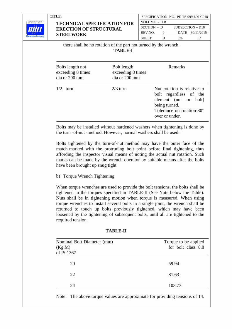
TITLE:
TECHNICAL SPECIFICATION FOR ERECTION OF STRUCTURAL STEELWORK
SPECIFICATION NO. PE-TS-999-600-C018
VOLUME - II B
SECTION - D SUBSECTION – D18
REV.NO. 0 DATE 30/11/2015
SHEET 9 OF 17
there shall be no rotation of the part not turned by the wrench.
TABLE-I
Bolts length not Bolt length Remarks
exceeding 8 times exceeding 8 times
dia or 200 mm dia or 200 mm
1/2 turn 2/3 turn Nut rotation is relative to
bolt regardless of the
element (nut or bolt)
being turned.
Tolerance on rotation-30° over or under.
Bolts may be installed without hardened washers when tightening is done by
the turn -of-nut -method. However, normal washers shall be used.
Bolts tightened by the turn-of-nut method may have the outer face of the
match-marked with the protruding bolt point before final tightening, thus
affording the inspector visual means of noting the actual nut rotation. Such
marks can be made by the wrench operator by suitable means after the bolts
have been brought up snug tight.
b) Torque Wrench Tightening
When torque wrenches are used to provide the bolt tensions, the bolts shall be
tightened to the torques specified in TABLE-II (See Note below the Table).
Nuts shall be in tightening motion when torque is measured. When using
torque wrenches to install several bolts in a single joint, the wrench shall be
returned to touch up bolts previously tightened, which may have been
loosened by the tightening of subsequent bolts, until all are tightened to the
required tension.
TABLE-II
Nominal Bolt Diameter (mm) Torque to be applied
(Kg.M) for bolt class 8.8
of IS:1367
20 59.94
22 81.63
24 103.73
Note: The above torque values are approximate for providing tensions of 14.

TITLE:
TECHNICAL SPECIFICATION FOR ERECTION OF STRUCTURAL STEELWORK
SPECIFICATION NO. PE-TS-999-600-C018
VOLUME - II B
SECTION - D SUBSECTION – D18
REV.NO. 0 DATE 30/11/2015
SHEET 10 OF 17
7 T for 20 mm dia.; and 21.2 T for 24 mm dia. bolts under moderately
lubricated condition. The torque wrench shall be calibrated at least
once daily to find out the actual torque required to produce the above
required tension in the bolt by placing it in a tension indicating device.
These torques shall be applied for tightening the bolts on that day with
the particular wrench.
In either of the above two methods, if required, for bolt entering and wrench
operation clearances, tightening may be done by turning the bolt while the nut
is prevented from rotating.
Impact wrenches if used shall be of adequate capacity and sufficiently
supplied with air to perform the required tightening of each bolt in
approximately ten seconds. Holes for turned bolts to be inserted in the field
shall be reamed in the field. All drilling and reaming for turned bolts shall be
done only after the parts to be connected are assembled. Tolerances applicable
in the fit of the bolts shall be in accordance with relevant Indian Standard
Specifications. All other requirements regarding assembly and bolt tightening
shall be in accordance with this sub clause.
3.01.08 Field Welding
All field assembly and welding shall be carried out in accordance with the
requirements of the specification for fabrication work applicable to the
project, excepting such provisions therein which manifestly apply to shop
conditions only. Where the fabricated structural steel members have been
delivered painted, the paint shall be removed before field welding for a
distance of at least 50 mm on either side of the joints.
3.01.09 Holes, Cutting and Fitting
No cutting of sections, flanges, webs, cleats, rivets, bolts, welds etc. shall be
done unless specifically approved and /or instructed by the Engineer.
The erector shall not cut, drill, or otherwise alter the work of other trades,
unless such work is clearly specified in the Contract or directed by the
Engineer. Wherever such work is obtain specified the Contractor shall obtain
complete information as to size, location and number of alterations prior to
carrying out any work. The Contractor shall not be entitled for any payment
on account of any such work.
3.02.00 Drifting
Correction of minor misfits and reasonable amount of reaming and cutting of
excess stock from rivets will be considered as permissible. For this, light
drifting may be used to draw holes together and drills shall be used to enlarge
holes as necessary to make connections. Reaming, that weakens the member

TITLE:
TECHNICAL SPECIFICATION FOR ERECTION OF STRUCTURAL STEELWORK
SPECIFICATION NO. PE-TS-999-600-C018
VOLUME - II B
SECTION - D SUBSECTION – D18
REV.NO. 0 DATE 30/11/2015
SHEET 11 OF 17
or makes it impossible to fill the holes properly or to adjust accurately after
reaming, shall not be allowed.
Any error in shop work which prevents the proper assembling and fitting of
parts by moderate use of drift pins and reamers shall immediately be called to
the attention of the Engineer and approval of the method of correction
obtained. The use of gas cutting torches at erection site is prohibited.
3.03.00 Grouting of stanchion bases and bearings of beams and girders on stone, brick or concrete (Plain or reinforced)
Grouting shall be carried out with Ordinary Cement grout as described below:
The mix shall be one (1) part cement and one (1) part sand and just enough
water to make it workable. The positions to be grouted shall be cleaned
thoroughly with compressed air jet and wetted with water and any
accumulated water shall be removed. These shall be placed under expert
supervision, taking care to avoid air locks. Edges shall be finished properly.
If the thickness of grout is 25 mm or more, two (2) parts of 6 mm down graded
stone chips may be added to the above noted cement-sand grout mix, if
required, by the Engineer or shown on the drawings.
No grouting shall be carried out until a sufficient number of bottom lengths of
stanchions have been properly lined, leveled, and plumbed and sufficient floor
beams are tied in position.
Whatever method of grouting is employed, the operation shall not be carried
out until the steelwork has been finally levelled and plumbed, the stanchion
bases being supported meanwhile by steel wedges, and immediately before
grouting, the space under steel shall be thoroughly cleaned.
If required by the Engineer, certain admixtures like aluminium powder,
“ironite” or equivalent, may be required to be added to the grout to enhance
certain desirable properties of the grout. Approved non-shrink pre-mixed grout
having required flowability and compressive strength may also be used with
Engineer's approval.
3.04.00 Painting after Erection
Field painting shall only be done after the structure is erected, levelled,
plumbed, aligned and grouted in its final position, tested and accepted by the
Engineer. Normally, final painting shall be done only after the floor slabs are
concreted and masonry walls are built. However, touch up painting, making
good any damaged shop painting and completing any unfinished portion of the
shop coat shall be carried out by the Contractor free of cost to the Owner. The
materials and specification for such painting in the field shall be in accordance
with the requirements of the specification for fabrication of structural

TITLE:
TECHNICAL SPECIFICATION FOR ERECTION OF STRUCTURAL STEELWORK
SPECIFICATION NO. PE-TS-999-600-C018
VOLUME - II B
SECTION - D SUBSECTION – D18
REV.NO. 0 DATE 30/11/2015
SHEET 12 OF 17
steelwork applicable for the project.
Painting shall not be done in frosty or foggy weather or when humidity is such
as to cause condensation on the surfaces to be painted. Before painting of
steel, which is delivered unpainted, is commenced, all surfaces to be painted
shall be dried and thoroughly cleaned from all loose scale and rust.
All field rivets, bolts, welds, and abrasions to the shop coat shall be spot
painted with the same paint used for the shop coat. Where specified,
surfaces, which will be in contact after site assembling, shall receive a coat of
paint (in addition to the shop coat, if any) and shall be brought together while
the paint is still wet.
Surface, which will be inaccessible after field assembly shall receive the full,
specified protective treatment before Bolts and fabricated steel members who
are galvanized or otherwise treated and steel members to be encased shall not
be painted.
The final painting shall be of tow coats of Synthetics Enamel painting or
Aluminium paint of approved manufacture as per the approved “Schedule of
Painting”. The shades shall also be as per the approved schedule. Synthetic
enamel paint shall conform to IS: 2932.
3.05.00 Final cleaning up
Upon completion of erection and before final acceptance of the work by the
Engineer, the contractor shall remove free of cost all false work, rubbish and
all Temporary Works resulting in connection with the performance of his
work.
4.00.00 TESTING AND ACCEPTANCE CRITERIA
4.01.00 General
Loading tests shall be carried out on erected structures, if required by the
Engineer, to check adequacy of fabrication and/or erection. Any structure or a
part thereof found to be unsuitable for acceptance as a result of the test shall
have to be dismantled and replaced with suitable member as per the Contract
and no payment towards the cost of the dismantled portion and any connected
work shall be made to the contractor. In course of dismantling, if any damage
is done to any other parts of the structure or to any fixtures, the same shall be
made good free of cost by the Contractor, to the satisfaction of the Engineer.
The Cost of the tests specified hereinafter shall be borne by the Owner; but if
the structure fails to pass the tests, the cost of the tests shall be recovered from
the Contractor. Any extra claim due to loss of time, idle labour, etc. arising out
of these testing operations shall not be entertained, however, only reasonable
and appropriate time extensions will be allowed.

TITLE:
TECHNICAL SPECIFICATION FOR ERECTION OF STRUCTURAL STEELWORK
SPECIFICATION NO. PE-TS-999-600-C018
VOLUME - II B
SECTION - D SUBSECTION – D18
REV.NO. 0 DATE 30/11/2015
SHEET 13 OF 17
The structure or structural member under consideration shall be loaded with
its actual dead load for as long a time as possible before testing and the tests
shall be conducted as indicated in the following sub-clauses 4.01.01, 4.01.02
and 4.01.03. The method of testing and application of loading shall be as
approved by the Engineer.
4.01.01 Stiffness Test
In this test, the structure or member shall be subjected, addition to its actual
dead load, to a test load equal to 1.5 times the specified superimposed load,
and this loading shall be maintained for 24 hours. The maximum deflection
attained during the test shall be within the permissible limit. If, after removal
of the test load, the member or structure does not show a recovery of at least
80 per cent of the maximum strain or deflection shown during 24 hours under
load, the test shall be repeated. The structure or member shall be considered to
have sufficient stiffness, provided that the recovery after this second test is not
less than 90 per cent of the maximum increase in strain or deflection recorded
during the second test.
4.01.02 Strength Test
The structure or structural member under consideration shall be subjected, in
addition to its actual dead load, to a test load equal to the sum of the dead load
and twice the specified superimposed load, and this load shall be maintained
for 24 hours.
In the case of wind load, a load corresponding to twice the specified wind load
shall be applied and maintained for 24 hours, either with or without the
vertical test load for more severe condition in the member under consideration
or the structure as a whole. Complete tests under both conditions may be
necessary to verify the strength of the structure. The structure shall be deemed
to have adequate strength if, during the test, no part fails and if on the removal
of the test load, the structure shows a recovery of at least 20 per cent of the
maximum deflection or strain recorded during the 24 hours under load.
4.01.03 Structure of same design
Where several structures are built to the same design and it is considered
unnecessary to test all of them, one structure, as a prototype, shall be fully
tested, as described in previous Sub-clauses, but in addition, during the first
application of the test load, particular note shall be taken of the strain or
deflection when the test load 1.5 times the specified superimposed load has
been maintained for 24 hours. This information is required as a basis of
comparison in any check test carried out on samples of the structure.

TITLE:
TECHNICAL SPECIFICATION FOR ERECTION OF STRUCTURAL STEELWORK
SPECIFICATION NO. PE-TS-999-600-C018
VOLUME - II B
SECTION - D SUBSECTION – D18
REV.NO. 0 DATE 30/11/2015
SHEET 14 OF 17
When a structure of the same type is selected for a check test, it shall be
subjected, in addition to its actual dead load, to a superimposed test load,
equal to 1.5 time the specified live load, in a manner and to an extent
prescribed by the Engineer. This load shall be maintained for 24 hours, during
which time, the maximum deflection shall be recorded. The check test shall be
considered satisfactory, provided that the maximum strain or deflection
recorded in the check test does not exceed by more than 20% of the maximum
strain or deflection recorded at similar load in the test on the prototype.
4.01.04 Repair for subsequent test and use after strength tests
An actual structure which has passed the “Strength Test” as specified in Sub-
clause 4.1.2 hereinbefore and is subsequently to be erected for use, shall be
considered satisfactory for use after it has been strengthened by replacing any
distorted members and has subsequently satisfied the 'Stiffness Test' as
specified in Sub-clause 4.01.01 hereinbefore.
4.02.00 Tolerances
Some variation is to be expected in the finished dimensions of structural steel
frames. Unless otherwise specified, such variations are deemed to be within
the limits of good practice when they are not in excess of the cumulative effect
of detailed erection clearances, fabricating tolerances for the finished parts and
the rolling tolerances for the profile dimensions permitted under the
Specifications for fabrication of structural steel work applicable to this Project
and as specified below: The specified tolerance is mainly for welded erection.
In case of bolted erection, no tolerance is desired so that all prefabricated bolt
holes are matched on erection.
I. For Buildings Containing Cranes
Component Description Variation Allowed
1. 2. 3.
Main columns a) shifting of column axis
at foundation level with
respect to building line
i) In longitudinal direction i) ± 3.0 mm
ii) In lateral direction ii) ± 3.0 mm
b) Deviation of both major
column axis from vertical
between foundation and

TITLE:
TECHNICAL SPECIFICATION FOR ERECTION OF STRUCTURAL STEELWORK
SPECIFICATION NO. PE-TS-999-600-C018
VOLUME - II B
SECTION - D SUBSECTION – D18
REV.NO. 0 DATE 30/11/2015
SHEET 15 OF 17
other member connection
levels:
i) For a column upto and i) ± 3.5 mm from true
including 10M height vertical
ii) For a column greater ii) ± 3.5 mm from
than 10M but less true vertical for any
than 40M height 10 M length measured
between connection
levels, but not more
than ±7 mm per 30m
length.
c) For adjacent pairs of columns ± 9.0 mm on true
across the width of the building span.
prior to placing of truss
d) For any individual column ± 3.0 mm
deviation of any bearing or
resting level from levels shown
on drawings.
e) For adjacent pairs of columns 3.0 mm
either across the width of building
or longitudinally level difference
allowed between bearing or seating
Trusses a) Deviation at centre of span 1/1500 of the span or
of upper chord member from greater than 10mm
vertical plane running through whichever is the
least.
centre of bottom chord.
Trusses b) Lateral displacement of 1/250 of depth
top chord at center of of truss or 20 mm
span from vertical plane which ever is the -
running through center of least.
supports.
Crane Cirders a) Difference in levels of
crane rail measured between
adjacent columns. 2.0 mm.
b) Deviation to crane rail- ± 3.0 mm
gauge

TITLE:
TECHNICAL SPECIFICATION FOR ERECTION OF STRUCTURAL STEELWORK
SPECIFICATION NO. PE-TS-999-600-C018
VOLUME - II B
SECTION - D SUBSECTION – D18
REV.NO. 0 DATE 30/11/2015
SHEET 16 OF 17
c) Relative shifting of ends 1.0 mm.
of adjacent crane rail in plan
and elevation after thermite
welding.
d) Deviation of crane rail axis ± 3.5 mm
from centre line of web.
Setting of At the time of setting of
Expansion the expansion gaps, due
gaps regard shall be taken of
the ambient temperature above
or below 30°C. The coefficient
of expansion or contraction
shall be taken as 0.000012
per °C per unit length.
iv) For Building without Cranes
The maximum tolerances for line and level of the steel work shall be ±3.0 mm
on any part of the structure. The structure shall not be Out of Plumb more
than 3.5 mm on each lox section of height and not more than 7.0 mm per 30 m
section.
These tolerances shall apply to all parts of the structure unless the drawings
issued for erection purposes state otherwise.
4.03.00 Acceptance
Structures and members have passed the tests and conform to all requirements
specified in the foregoing Sub-clause 4.01.00, 4.01.01, 4.01.02, 4.01.03 and
4.01.04 and other applicable provisions of this specification and are within the
limits of tolerances specified in Sub-clause 4.02.00 and/or otherwise approved
by the Engineer shall be treated as approved and accepted for the purpose of
fulfillment of the provisions of this contract.
5.00.00 INFORMATION TO BE SUBMITTED
5.01.00 Before Tender
5.01.01 Tentative Programme
The Tenderer shall submit a tentative programme based on the information
available in the Tender Document and visit to site indicating the structure-
wise erection schedule proposed to be maintained by the Contractor to
complete the job in time in accordance with the Contract.

TITLE:
TECHNICAL SPECIFICATION FOR ERECTION OF STRUCTURAL STEELWORK
SPECIFICATION NO. PE-TS-999-600-C018
VOLUME - II B
SECTION - D SUBSECTION – D18
REV.NO. 0 DATE 30/11/2015
SHEET 17 OF 17
5.01.02 Constructional Plant and Equipment, Tools, Temporary works & manpower A
detailed list Of all constructional plant and equipment like cranes, derricks,
winches, welding sets, erection tools etc. along with their make, model,
present condition and location available with the Tenderer which he will be
able to employ on the job to maintain the progress of work in accordance with
the Contract shall be submitted along with the Tender. The total number of
each category of experienced personnel like fitters, welders, riggers etc. that
he will be able to employ on the job shall also be indicated.
5.01.03 Erection Yard
A site plan showing the layout and location of the erection yard proposed to be
established by the tenderer shall also be attached with the tender indicating the
storage space for fabricated steel materials, site-fabrication and repair shop,
covered stores, offices, locations of erection equipments and other facilities.
The Engineer shall have the right to modify the arrangement and location of
the proposed yard to suit site conditions and the Contractor shall comply with
the same without any claim whatsoever.
5.02.00 After award of the Contract
After award of the contract, the Contractor shall submit the following:
5.02.01 Detailed Programme
The Contractor shall submit a detailed erection programme within a month of
the award of the Contract for completion of the work in time in accordance
with the Contract. This will show the target programme, with details of
erection proposed to be carried out in each fortnight, details of major
equipment required, and an assessment of required strength of various
categories of workers in a proforma approved by the Engineer.
5.02.02 Fortnightly Progress Report
The Contractor shall submit fortnightly progress reports in triplicate to the
Engineer showing along with necessary photographs, 125 mm x 90 mm size,
and all details of actual achievements against the target programme specified
in Sub-clause 5.02.01 above. Any shortfall in the achievement in a particular
fortnight must be made up within the next fortnight. Along with this report,
the Contractor shall also furnish details of fabricated materials in hand at site
and the strength of his workers.

TITLE:
TECHNICAL SPECIFICATION FOR ROOF DECKING
SPECIFICATION NO. PE-TS-999-600-C019
VOLUME - II B
SECTION - D | SUB-SECTION – D19
REV.NO. 00 DATE 30/11/2015
SHEET 1 OF 7
VOLUME: II B
SECTION - D
SUB-SECTION – D19
ROOF DECKING
SPECIFICATION NO. PE-TS-999-600-C019
Bharat Heavy Electricals Limited Project Engineering Management
PPEI Building, Power Sector,
Plot No. 25, Sector 16A,
Noida (U.P.)-201301

TITLE:
TECHNICAL SPECIFICATION FOR ROOF DECKING
SPECIFICATION NO. PE-TS-999-600-C019
VOLUME - II B
SECTION - D | SUB-SECTION – D19
REV.NO. 00 DATE 30/11/2015
SHEET 2 OF 7
C 0 N T E N T
CLAUSE NO. DESCRIPTION SHEET NO.
1.00.00 SCOPE 3
2.00.00 MATERIALS 3
3.00.00 INSTALLATION 3
4.00.00 ACCEPTANCE CRITERIA 6
5.00.00 IS CODES 6
6.00.00 RATES AND MEASUREMENTS 7

TITLE:
TECHNICAL SPECIFICATION FOR ROOF DECKING
SPECIFICATION NO. PE-TS-999-600-C019
VOLUME - II B
SECTION - D | SUB-SECTION – D19
REV.NO. 00 DATE 30/11/2015
SHEET 3 OF 7
ROOF DECKING
1.00.00 Scope
This section of the specification covers the supply, fabrication and erection of
profiled light gauge Metal Decks (coated and painted) as roof decking to the
main plant building and any other area as indicated in the drawings.
2.00.00 Material 2.01.01 Roof of main plant TG and Deareator bay and bunker building consists of
permanently colour coated (on exposed face) galvanized MS trough metal
sheet decking plate of approved colour over roof purlins for cast-in-situ roof
slab as per IS: 14246 and conform to class 3. Thickness of deck plate shall be
minimum 0.8mm and minimum trough depth of 44 mm and centre to centre of
the valley shall be 130mm with minimum yield strength of 250 Mpa. Silicon
modified polyester paint shall be used for permanent coating over galvanized
surface with minimum rate of galvanization 150 gm/sqm. DFT of permanent
colour coating shall be 20 microns. It shall serve as permanent shuttering for
cast-in-situ roof slab. It should have adequate strength to support weight of
green concrete and imposed load during construction. The thickness of the
deck plate shall however be designed suitably according to the spacing of roof
purlins.
3.00.00 INSTALLATION
The Contractor shall furnish all labour, equipment and materials as required
for the design, fabrication, coating, erection and fixing of the decking over
purlins, painting and for the complete performance of the work in accordance
with the construction drawings and as described herein.
The description, which follows, gives a general indication of the nature and
extent of the work but is not necessarily exhaustive and does not purport to
cover all the details/operations which will be necessary in order to carry out
the work.
3.01.00 Detailed Design of Roof Decking
The Contractor, in conjunction with the manufacturer, shall be responsible for
the detailing of the profiled decking, fittings and fixtures and shall submit with
his tender particulars of the proposed manufacturer and of the particular
product proposed for use. The detailing is to be based on typical details
furnished by the Engineer. The Contractor shall submit to the Engineer, two
copies of the general arrangement and detailed working drawings for the
proposed design, together with all calculations necessary to verify the
adequacy and completeness of the design & detailing of decking sheets,

TITLE:
TECHNICAL SPECIFICATION FOR ROOF DECKING
SPECIFICATION NO. PE-TS-999-600-C019
VOLUME - II B
SECTION - D | SUB-SECTION – D19
REV.NO. 00 DATE 30/11/2015
SHEET 4 OF 7
fixtures, flashings and trims. After approval he shall supply further eight
copies.
The Engineer will verify the correct interpretation of his requirements but may
not necessarily check the design and details, and the Contractor shall be
entirely responsible for the accuracy of the drawings and the correctness of the
design and the suitability of the details. Manufacture of roof decking sheets
shall not commence until the necessary approval of the Engineer has been
obtained.
3.02.00 Erection & Fixing 3.02.01 Sequence of Manufacture/Erection
Cutting Schedules, delivery to site and stacking arrangements in store shall
ensure that sheets are erected in a sequence which follows that for the
manufacture. The decking sheets shall be erected using an arrangement of
sheets and joints to conform with the requirements of this specification.
Decking erection for each elevation or feature shall commence at one end only
and proceed towards the other end, in order to ensure tight fitting laps.
3.02.02 Position and Location of Laps
Side and end laps of roof decking sheets shall be located and positioned in
such a manner as to provide the maximum weather protection taking into
account the direction of the prevailing wind.
The lines formed by horizontal laps and fixing shall where possible, be
continuous and coincide with the edges of large openings in the roof.
3.02.03 Alignment of Sheets and Fixings
All roof decking sheets shall be fixed plumb and level with all fixings evenly
spaced and accurately lined. All dirt and grease shall be removed from the
surfaces of the sheets as the work proceeds.
3.02.04 Site Cutting
Approval must be obtained before the roof decking sheets are cut at site.
Generally cutting of sheets to length will not be permitted, only special cutting
and trimming for small openings shall allowed. Where possible, site cut edges
shall be concealed at laps.
3.02.05 Damaged Sheets
Distorted, blemished or water stained sheets and any other fittings shall not be
used.

TITLE:
TECHNICAL SPECIFICATION FOR ROOF DECKING
SPECIFICATION NO. PE-TS-999-600-C019
VOLUME - II B
SECTION - D | SUB-SECTION – D19
REV.NO. 00 DATE 30/11/2015
SHEET 5 OF 7
3.02.06 Laps
End laps and side laps to roof decking sheets shall be sufficiently large to
ensure that the decking complies with the weather tightness and other
requirements of this specification. The length of each decking sheet shall be
adjusted so that the end laps shall bear on the purlins. In no case end laps
shall not be less than 150 mm and side laps shall not be less than 53 mm.
3.02.07 End Lap Fixings
End lap fixings shall be located at least 25 mm from the end of each sheet.
3.02.08 Side Lap Fixings
The spacing of side lap fixings shall ensure compliance with this specification
regarding tightness. The spacing of these fixing screws shall not exceed
500mm. The fixing shall be located in the bottom flat of the corrugation.
3.02.09 Holes
Holes in MS decking sheets shall be punched. In case holes are drilled holes,
it is to be ensured that the holes do not go oversize due to the small thickness
of the sheeting. All drilling swarf shall be removed from the surfaces of
decking, supporting steel work, purlins etc.
3.02.10 Location and Spacing of Fixings
Fixings shall be accurately located in position in the centre of the corrugations
to ensure that the heads of bolts, nuts and washers bear squarely down on the
surface of the sheeting and are not located at the edge or on the joints in
supporting purlins.
3.02.11 Fixings
The tenderer shall submit with his tender details of the proposed method for
securing the roofing sheets to the metal purlins. The roof decking sheets are to
be fixed to the roof purlins with hex washer head white zinc plated heat
treated carbon steel self drilling / self tapping screws of minimum thread
diameter of 5.6mm. These self drilling screws shall be drilled through the
roofing sheets and purlins supporting the roofing sheets. These purlins shall be
suitably spaced as per the requirement of roofing sheets and the roofing sheets
shall not sag more than span/250 for the loads likely to be imposed during
concreting and in future. The self-drilling screws are to be spaced at a
maximum distance of 390mm centre to centre along the length of the purlins
and top chord of truss. The screws are to be located preferably in the valley
only and shall be installed in accordance with the manufacturer’s

TITLE:
TECHNICAL SPECIFICATION FOR ROOF DECKING
SPECIFICATION NO. PE-TS-999-600-C019
VOLUME - II B
SECTION - D | SUB-SECTION – D19
REV.NO. 00 DATE 30/11/2015
SHEET 6 OF 7
recommendations using tools approved by the manufacturer which do not
damage the coating of the decking sheets.
3.03.00 Protection during Construction
Precautions shall be taken during the erection of the roof decking to ensure
that partially erected decking are protected during inclement weather and
damage at all times.
3.04.00 Damage
Any damage to coating & primer during transportation is to redone with the
similar type of coating as per the manufacturer’s specification at no extra cost
to the Owner.
4.00.00 Acceptance Criteria
The installation shall present a neat appearance and shall be checked for water
tightness. The following shall be checked :
a) Side and end laps
b) Absence of damage in the sheeting.
c) Conformity of fixings with the approved design.
5.00.00 IS Codes
All work shall be carried out as per this specification and shall conform to the
latest revision and/or replacements of the following or any other Indian
Standard (IS) Codes, unless specified otherwise. In case any particular aspect
of work is not specifically covered by Indian Standard Codes, any other
standard practice, as may be specified by the Engineer, shall be followed.
IS : 513 - Specification for cold rolled carbon steel sheets.
IS : 3618 - Specification for phosphate treatment of iron and steel for
protection against corrosion.
IS : 4431 - Specification for carbon & carbon manganese free cutting
steel.
IS : 1573 - Electroplated Coatings of zinc on iron and steel.
TITLE:
TECHNICAL SPECIFICATION FOR ROOF DECKING
SPECIFICATION NO. PE-TS-999-600-C019
VOLUME - II B
SECTION - D | SUB-SECTION – D19
REV.NO. 00 DATE 30/11/2015
SHEET 7 OF 7
6.00.0 RATES AND MEASUREMENTS
6.01.00 Rates
Rates shall be unit rate for complete item described in the Schedule of Items
and shall include all wastage.
6.02.00 Method of Measurement
Roofing shall be measured for net area of the work done. Profiled
sheeting (coated & painted) shall be measured in plan area of sheets and not
girthed. No deduction shall be made for openings measuring up to 0.1 sq.m. in
area. No extra shall be paid for extra labour in cutting and for wastage etc. in
making opening and cutting to size.
No payments shall be made for laps.

TITLE:
TECHNICAL SPECIFICATION FOR FALSE FLOORING
SPECIFICATION NO. PE-TS-999-600-C020
VOLUME - II B
SECTION - D | SUB-SECTION – D20
REV.NO. 00 DATE 30/11/2015
SHEET 1 OF 6
VOLUME: II B
SECTION - D
SUB-SECTION – D20
FALSE FLOORING
SPECIFICATION NO. PE-TS-999-600-C020
Bharat Heavy Electricals Limited Project Engineering Management
PPEI Building, Power Sector,
Plot No. 25, Sector 16A,
Noida (U.P.)-201301

TITLE:
TECHNICAL SPECIFICATION FOR FALSE FLOORING
SPECIFICATION NO. PE-TS-999-600-C020
VOLUME - II B
SECTION - D | SUB-SECTION – D20
REV.NO. 00 DATE 30/11/2015
SHEET 2 OF 6
C 0 N T E N T
CLAUSE NO. DESCRIPTION SHEET NO.
1.00.00 GENERAL 3
2.00.00 MATERIALS 3
3.00.00 INSTALLATION 4
4.00.00 ACCEPTANCE CRITERIA 5
5.00.00 IS CODES 6
6.00.00 RATES AND MEASUREMENTS 6

TITLE:
TECHNICAL SPECIFICATION FOR FALSE FLOORING
SPECIFICATION NO. PE-TS-999-600-C020
VOLUME - II B
SECTION - D | SUB-SECTION – D20
REV.NO. 00 DATE 30/11/2015
SHEET 3 OF 6
FALSE FLOORING
1.00.00 General
This section of the specification covers the supply, fabrication and installation
of false flooring system having PVC top finish particle board, GI supporting
system, painting etc. as per schedule of items in the main plant building and
any other area as indicated in the drawings.
The scope of contractor covers supply of all materials, fabrication &
installation works required to be carried out for completion of false flooring in
the area specified in the drawings.
2.00.00 MATERIAL
2.01.00 Supporting structure
Supporting pedestals shall be made of steel and will be of height as required.
Supporting pedestal shall be truly vertical and located at distances to conform
with size of floor panels and shall be equipped with locking devices to prevent
disturbances of finished elevation. Base of pedestal shall have integral load
dispersion plate of size 100x100x8mm to transmit the load evenly to the base
floor. Adjustment of pedestal shall be provided by threaded vertical rod of
25mm diameter and elevating nut. The pedestal head shall provide positive
interlocking of the steel grid channels supporting system and shall prevent
lateral shifting.
The grid channels shall be made of galvanised steel of 40mm x 40mm x
3.15mm thick and shall be placed at 610mm centre to centre both ways to
support floor panels in uniform levelled elevations. Nominal height of the
false flooring system shall be 600 mm unless otherwise indicated. Pedestal
head shall be equipped with conducting grounding pad if so desired by the
Engineer
2.02.00 Floor Panels
The floor panels shall be made of fire resistant particle board, phenol
formaldehyde bonded. Size of each panel shall be 610mm x 610mm with all
panel edges finished to a tolerance of + 0.2mm. Floor panel shall have 2mm
thick non-static PVC on top, 2mm thick hard PVC strip lipping on four edges
and 26 G aluminium sheet fixed with araldite at bottom. Minimum thickness
of the panel shall be 35mm, unless otherwise noted. All panels shall be
completely interchangeable and easily removable with a suction lift tool.
Panels shall be square within a tolerance of + 0.25 mm on the diagonal. The
floor panels shall be cut, wherever required for providing suitable outlets for
cables and edges shall be lipped with hard PVC sheets.

TITLE:
TECHNICAL SPECIFICATION FOR FALSE FLOORING
SPECIFICATION NO. PE-TS-999-600-C020
VOLUME - II B
SECTION - D | SUB-SECTION – D20
REV.NO. 00 DATE 30/11/2015
SHEET 4 OF 6
2.02.01 Strength
Each 610mm x 610 mm floor panel must be capable of withstanding the
designed service load. The ultimate strength shall provide a safety factor of 3.
The false flooring shall be capable of carrying a axial load of 800 kg and
uniform load of 2000 kg/sq.m with maximum deflection of 1/350. If required
by the Engineer, the samples shall be accepted only after carrying out load
tests. The Engineer may relax the test requirements with concentrated load in
case cabinets are not handled with castor fitting arrangement.
One additional pedestal shall be provided under floor stringer along front
panel area of each control board for taking possible additional load that may
occur from time to time.
2.02.02 Surface finish
All removable panels shall have the top surface finished with 2 mm thick
flexible PVC flooring conforming to IS:3462 and shall be fixed to the surface
with compatible high-creep resistant adhesive. The PVC floor tile shall be in
single piece for each floor panel. Under side of panels shall also be painted
with suitable epoxy or oil based paint.
2.02.03 Damaged Floor Panels
Distorted, blemished or stained floor panels shall not be used.
2.03.00 Skirting
Skirting shall be 150 mm high and 2 mm thick, completely matching with
false flooring surface finish materials and shall be fixed to the wall surface as
per manufacturer’s installation instructions.
3.00.00 INSTALLATION 3.01.00 Base
The system shall be placed over a base of RCC floor slab and beams. Any
grouting etc. that is necessary to fix the supporting structure shall be done.
The concrete sub floor shall be sealed with two coats of polyurethane paint to
prevent moisture from coming in contact with cables and to minimise dust
problem.
The floor panels and channels shall be completely interchangeable and remain
in position without screwing or bolting under working/imposed loadings.
Any damage to the sub floor during installation of the false flooring system

TITLE:
TECHNICAL SPECIFICATION FOR FALSE FLOORING
SPECIFICATION NO. PE-TS-999-600-C020
VOLUME - II B
SECTION - D | SUB-SECTION – D20
REV.NO. 00 DATE 30/11/2015
SHEET 5 OF 6
shall be made good by the contractor without any extra cost to the Owner. All
steel surfaces are to be protected by two coats of polyurethane paint over a
compatible primer and any damage to the paint during installation shall be
made good. In case the loads exerted by the weight of machines are above the
stated characteristics of floor finish material, the floor shall be protected by
overlaying hard board during installation of machine or equipment.
All installation work of the false flooring system shall be supervised by the
manufacturer's authorised representative.
3.03.00 Painting
After fixing the false flooring supporting system the sub floor shall be given a
coat of polyurethane paint.
3.04.00 Protection during Construction
All precautions shall be taken during the erection of the false flooring to
ensure that partially erected flooring are protected and shall not be damaged
before handing over to owner.
3.05.00 Damage
Any damage of coating to supporting system caused during transportation is to
be redone with the similar type of coating as per the manufacturer’s
specification at no extra cost to the Owner.
4.00.00 ACCEPTANCE CRITERIA
The false flooring system shall only be accepted after completion of following
checks :
a. Level
b. Alignment of joints
c. Thickness of joints
d. Surface finish
e. Colour and texture
f. Details of edges, junctions etc.
g. Performance
h. Criteria specified for strength.

TITLE:
TECHNICAL SPECIFICATION FOR FALSE FLOORING
SPECIFICATION NO. PE-TS-999-600-C020
VOLUME - II B
SECTION - D | SUB-SECTION – D20
REV.NO. 00 DATE 30/11/2015
SHEET 6 OF 6
5.00.00 IS CODES
All work shall be carried out as per this specification and shall conform to the
latest revision and/or replacements of the following or any other Indian
Standard (IS) Codes, unless specified otherwise. In case any particular aspect
of work is not specifically covered by Indian Standard Codes, any other
standard practice, as may be specified by the Engineer, shall be followed.
IS:5318 Laying of flexible sheet and flooring.
IS:3462 Flexible PVC flooring
IS:3087 Wood particle boards (medium density) for general purposes.
6.00.0 RATES AND MEASUREMENTS
6.01.00 Rates
Rates shall be unit rate for complete item described in the Schedule of Items
and shall include, but not limited to, supply & installation of floor panels,
supporting systems, paintings atc.
6.02.00 Method of Measurement
False flooring shall be measured in Sq.M for net area of the work done. No
deduction shall be made for openings measuring up to 0.4 sq.m. in area. No
extra shall be paid for extra labour in cutting and for wastage etc. in making
opening and cutting to size.

TITLE:
TECHNICAL SPECIFICATION FOR BORED CAST-IN-SITU RCC PILES
SPECIFICATION NO. PE-TS-999-600-C021
VOLUME - II B
SECTION - D | SUB-SECTION – D21
REV.NO. 00 DATE 30/11/2015
SHEET 1 OF 26
VOLUME: II B
SECTION - D
SUB-SECTION – D21
BORED CAST-IN-SITU RCC PILES
SPECIFICATION NO. PE-TS-999-600-C021
Bharat Heavy Electricals Limited Project Engineering Management
PPEI Building, Power Sector,
Plot No. 25, Sector 16A,
Noida (U.P.)-201301

TITLE:
TECHNICAL SPECIFICATION FOR BORED CAST-IN-SITU RCC PILES
SPECIFICATION NO. PE-TS-999-600-C021
VOLUME - II B
SECTION - D | SUB-SECTION – D21
REV.NO. 00 DATE 30/11/2015
SHEET 2 OF 26
CONTENTS CLAUSE NO. DESCRIPTION
1.00.00 SCOPE 3
2.00.00 GENERAL REQUIREMENTS 3
3.00.00 MATERIALS 5
4.00.00 PILE INSTALLATION 6
5.00.0 SAMPLING, TESTING, AND QUALITY ASSURANCE 12
6.00.00 PILE TESTING 15
7.00.00 CODES AND STANDARDS 16
8.00.00 RATES AND MEASUREMENT 17
ANNEXURE-A
ANNEXURE-B
ANNEXURE-C
ANNEXURE-D
TABLE - 1

TITLE:
TECHNICAL SPECIFICATION FOR BORED CAST-IN-SITU RCC PILES
SPECIFICATION NO. PE-TS-999-600-C021
VOLUME - II B
SECTION - D | SUB-SECTION – D21
REV.NO. 00 DATE 30/11/2015
SHEET 3 OF 26
TECHNICAL SPECIFICATION FOR INSTALLATION OF BORED CAST-IN-SITU PILES
1.00.00 SCOPE
This specification covers the installation of bored cast-in-situ reinforced
concrete vertical piles of specified load carrying capacity and diameter for
various structures. This specification also covers carrying out initial and routine
load tests on piles to assess their vertical, horizontal and pull out load carrying
capacities.
2.00.00 GENERAL REQUIREMENTS
2.01.00 This specification along with specific requirements under Annexure-A covers the
technical requirements for piling work.
2.02.00 The work shall include supplying and providing necessary materials, mobilization
of all necessary equipments (Annexure-B), providing necessary engineering
supervision through qualified and technical personnel, skilled and unskilled
labour, etc. as required to carryout the complete piling work, and submission of
records as per schedule.
2.03.00 The Contractor shall carryout all works as mentioned in Scope above. All works
shall be executed to the satisfaction of the Engineer.
2.04.00 Pile capacities in vertical compression, horizontal, pullout loads for various pile
diameters are given in Annexure-A.
2.05.00 The Contractor shall confirm and guarantee the "Safe Load" capacities by
conducting both initial and working load test on piles as mentioned in the specific
requirements.
2.06.00 The Contractor shall submit along with tender documents his tender design of
piles based on soil data furnished by the Owner along with this specification. The
ultimate load capacity of a pile may be estimated using suitable static formula and
the minimum factor of safety shall be 2.5. However, safe load carrying capacity
shall be conformed and guaranteed by conducting initial and routine load tests.
2.07.00 In case of initial or routine load test piles, if the Contractor fails to establish the
safe load capacity as per his design, the Owner has the right to either derate the
pile capacity on prorata basis or insist the Contractor to modify the pile design, to
achieve the desired safe load capacity at no extra cost to the Owner.
2.08.00 Derating is acceptable up to 90 percent. In such case, additional piles shall be
installed as per the design requirements.

TITLE:
TECHNICAL SPECIFICATION FOR BORED CAST-IN-SITU RCC PILES
SPECIFICATION NO. PE-TS-999-600-C021
VOLUME - II B
SECTION - D | SUB-SECTION – D21
REV.NO. 00 DATE 30/11/2015
SHEET 4 OF 26
2.09.00 The Owner shall decide whether to derate or modify the design based on the
design considerations such as providing additional piles in the designed pile cap,
provision for extending the pile cap size, etc.
2.10.00 In case the Owner decides to modify the design instead of derating the pile,
the contractor shall carry out the same and install separate test piles and test the
same to guarantee the safe load at no extra cost to the Owner. However no extra
shall be charged for the additional test piles as well as testing of these piles as per
agreed contract conditions.
2.11.00 In case of working piles, if the pile does not meet the guaranteed capacity or
rejected due to any other reason, the Contractor shall install extra piles at no
extra cost to the Owner. Further, the extra cost, due to the increase in the pile cap
size if any, on account of extra piles, shall be borne by the Contractor.
2.12.00 It is essential that all equipment and instruments are properly calibrated both at
commencement and immediately after the completion of tests so that they
represent true values. Certificates to this effect from an approved institution shall
be furnished to the Engineer. If the Engineer so desires the Contractor shall
arrange for having the instruments tested at an approved laboratory at no extra cost
to the Owner and the test report shall be submitted to the Engineer. If the
Engineer desires to witness such tests Contractor shall arrange to conduct the
test in his presence.
2.13.00 The Contractor shall make his own arrangements for locating the coordinates and
position of piles as per drawings supplied to him and for determining the
Reduced Levels (RL) of these locations with respect to the benchmark
indicated by the Engineer. Two established reference lines in mutually
perpendicular direction shall be indicated to the Contractor. The Contractor shall
provide at site all the required survey instruments to the satisfaction of the
Engineer so that the work can be carried out accurately according to
specifications and drawings.
2.14.00 The contractor shall assure the quality of piling work including cleaning of pile
bore, quality of concrete, integrity of piles, etc.
2.15.00 AVAILABLE SUB-SOIL DATA
An abstract of the sub soil data is furnished in the tender document. However, the
detailed soil investigation report shall be made available for reference of the
bidder, if so required, at the office of the Owner. The soil data furnished is in
good faith and only for the guidance of the Bidder, to arrive at design
parameters and construction methods.

TITLE:
TECHNICAL SPECIFICATION FOR BORED CAST-IN-SITU RCC PILES
SPECIFICATION NO. PE-TS-999-600-C021
VOLUME - II B
SECTION - D | SUB-SECTION – D21
REV.NO. 00 DATE 30/11/2015
SHEET 5 OF 26
3.00.00 MATERIALS 3.01.00 General
All materials viz cement, steel, aggregates, water, etc. which are to be used for pile
construction shall conform to relevant IS codes for properties, storage and
handling of common building materials. However, aggregates more than 20 mm
size shall not be used.
3.02.00 CONCRETE
Concrete shall be manufactured either by central batching plant or Ready Mix
concrete. However, for initial test piles suitable method as approved by the
Engineer may be used. Concrete shall conform to IS: 10262 & IS: 456.
3.02.01 Technical Specification for Cement Concrete (Plain and Reinforced) works
along with IS: 2911 Part I/Sec 2 shall be followed for concrete works of piles. Use
of plasticiser to control the water cement ratio shall be permitted on specific
approval from the Engineer. Water cement ratio shall not be greater than 0.5.
3.02.02 Grade and minimum cement content
Minimum grade of concrete shall be as per Annexure-A conforming to IS:
456. Minimum cement content of 400 Kg/M³ of concrete shall be used for M-20
grade concrete.
3.02.03 Slump of concrete
The slump of concrete shall vary between 150 to 180 mm.
3.03.00 REINFORCEMENT
3.03.01 Longitudinal reinforcement in pile shall be high strength deformed steel bars
conforming to IS: 1786 unless specified otherwise. Lateral reinforcement in pile
shall be of mild steel conforming to IS: 432 Part-1 or HYSD bars as per IS:
1786.
3.03.02 The longitudinal reinforcement shall be provided considering the combination of
vertical (compression and tension) and horizontal loads. However, the
minimum longitudinal reinforcement shall be 0.4 percent of the sectional area
calculated on the basis of nominal pile diameter. Minimum six numbers of bars
shall be provided for longitudinal reinforcement. The diameter of longitudinal
reinforcement bars shall not be less than 12mm. The stipulated minimum
reinforcement shall be provided for the full length of pile.
3.03.03 The longitudinal reinforcement shall project 50 times its diameter above cut off
level unless otherwise indicated.

TITLE:
TECHNICAL SPECIFICATION FOR BORED CAST-IN-SITU RCC PILES
SPECIFICATION NO. PE-TS-999-600-C021
VOLUME - II B
SECTION - D | SUB-SECTION – D21
REV.NO. 00 DATE 30/11/2015
SHEET 6 OF 26
3.03.04 The laterals shall be tied to the longitudinal reinforcement to maintain its shape
and spacing. The laterals may in the form of links or spirals. The minimum diameter
of the links or spirals shall be 6 mm and the spacing of the links or spiral shall not
be less than 150 mm and in no case more than 250 mm.
3.03.05 Reinforcement cage shall be sufficiently rigid to withstand handling and
installation without any deformation and damage. As far as possible number of
joints (laps) in longitudinal reinforcement shall be minimum. In case the
reinforcement cage is made up of more than one segment, these shall
preferably be assembled before lowering into casing tube/pilebore by providing
necessary laps as per IS: 456.
3.03.06 The minimum clear distance between the two adjacent main reinforcement bars
shall normally be 100 mm for the full depth of cage.
3.03.07 The laps in the reinforcement shall be such that the full strength of the bar is
effective across the joint and the reinforcement cage is of sound construction.
3.03.08 Laps shall be staggered as far as practicable and not more than 50% bars shall be
lapped at a 'particular section. Lap joints shall be staggered by at least 1.3 times
the lapped length (Centre to Centre).
3.03.09 Proper cover and central placement of the reinforcement cage in the pile bore
shall be ensured by use of suitable concrete spacers or rollers, cast specifically for
the purpose.
3.03.10 Minimum clear cover to the longitudinal reinforcement shall be 50 mm, unless
otherwise mentioned.
3.03.11 Bundling of bars is not permitted.
4.00.00 PILE INSTALLATION
Installation of piles shall be carried out as per pile layout drawings, installation
criteria, and the direction of the Engineer.
4.01.00 Equipment and Accessories
4.01.01 The equipment and accessories for installation of bored cast-in-situ piles shall be
selected giving due consideration to the sub soil conditions, ground water
conditions and the method of casting, etc. These shall be of standard type and
shall have the approval of the Engineer.
4.01.02 List and details of equipment and accessories proposed to be used for the job
shall be submitted along with the bid.

TITLE:
TECHNICAL SPECIFICATION FOR BORED CAST-IN-SITU RCC PILES
SPECIFICATION NO. PE-TS-999-600-C021
VOLUME - II B
SECTION - D | SUB-SECTION – D21
REV.NO. 00 DATE 30/11/2015
SHEET 7 OF 26
4.01.03 The capacity of the rig shall be adequate so as to reach the specified founding
level.
4.01.04 Provision shall be kept for chiselling within the pilebore, as specified
elsewhere in this specification. Chiselling shall be carried out only with the
approval of Engineer.
4.02.00 Installation Criteria
4.02.01 For determining the founding level of piles in soil as specified elsewhere, the
Contractor shall have to perform Standard penetration test (SPT) as per IS:
2131 in a separate bore hole. The SPT shall be conducted at 1.0 m interval
between the depths covering 5 metres each above and below the specified
founding level. The bore shall be 100 mm diameter and method of boring shall
conform to IS: 1892.
4.02.02 For determining founding level of piles in rock, as specified elsewhere
socketing horizon shall be established by the Contractor by collecting rock
cores of NX size in a separate borehole, and testing the same for uniaxial
compressive strength (UCS). Cores shall be collected by double tube core
barrel attached with diamond bit. Coring shall be done upto a depth as indicated
in the "specific requirements." Coring in rock shall conform to IS: 6926.
4.02.03 In case it is not possible to test the cores so obtained for uniaxial compressive
strength, cores shall be tested for point load strength index and correlated to
obtain uniaxial compressive strength.
4.02.04 Number of boreholes for carrying out SPT in soil or uniaxial compressive
strength in rock, shall vary from one in 100 to 150 piles or pile group of 150 Sqm
depending on the site condition and as decided by the Engineer. However, at
the location of initial load test piles, one such borehole shall be done.
4.02.05 A protocol between contractor and BHEL site shall be maintained regarding the
strata at founding level. SPT value and UCS from the nearest borehole shall be
indicated therein.
4.02.06 The founding level of the pile shall be decided based on the criteria elaborated in
the specific requirements under Annexure-A. Concreting shall not be done until
the above conditions for founding level are satisfied.
4.02.07 Approval of founding level by the Engineer shall in no way absolve the
Contractor of his responsibility to guarantee the Safe load capacity of the piles as
indicated in this document.

TITLE:
TECHNICAL SPECIFICATION FOR BORED CAST-IN-SITU RCC PILES
SPECIFICATION NO. PE-TS-999-600-C021
VOLUME - II B
SECTION - D | SUB-SECTION – D21
REV.NO. 00 DATE 30/11/2015
SHEET 8 OF 26
4.03.00 Control of position and alignment
4.03.01 Piles shall be installed as accurately vertical as possible. The permissible limits
for deviation with respect to position and (inclination) alignment shall conform
to IS: 2911 Part I/Sec. 2, which is reproduced below for ready reference.
a) The maximum deviation of vertical piles shall not exceed 1.5 per cent in
alignment.
b) Piles shall not deviate more than 75 mm or D/4 whichever is less (75mm
or D/10 whichever is more in case of piles having diameter more then
750mm) from their designed position at the working level.
4.04.00 Boring
4.04.01 Boring operations shall be done by rotary or percussion type drilling rigs using
reverse mud circulation (RMC) method. Rotary hydraulic pulley shall be
preferred.
4.04.02 The Contractor shall satisfy himself about the suitability of the method to be
adopted for site. If DMC (direct mud circulation) or RMC is used Bentonite
slurry shall be pumped through drill rods by means of high-pressure pumps. The
cutting tool shall have suitable ports for the bentonite slurry to flow out at high
pressure. If on mobilisation, the Contractor fails to make a proper bore for any
reason, the Contractor has to switchover to other boring methods as approved by
the Engineer at no extra cost to the Owner.
4.04.03 Working level shall be above the cut off level. After the initial boring of about
1.0m a temporary guide casing of suitable length shall be lowered in the pile bore.
The diameter of guide casing shall be of such diameter, so as to give the
necessary finished diameter of the concrete pile. The centre line of guide casing
shall be checked before continuing further boring. Guide casing shall be
minimum of 1.0m length. Additional length of casing may be used depending
on the condition of the strata, ground water level etc.
4.04.04 Use of drilling mud (bentonite slurry) for stabilizing the sides of the pile bore is
necessary wherever subsoil is likely to collapse in the pile bore. Drilling mud to
be used shall meet the requirement as given in Annexure-C.
4.04.05 The bentonite slurry and the cuttings, which are carried to the surface by the
rising flow of the slurry, shall pass through settling tanks of adequate size to
remove the sand and spoils from the slurry before the slurry is recirculated to the
boring. The bentonite slurry mixing and recirculation plant shall be suitably
designed and installed.

TITLE:
TECHNICAL SPECIFICATION FOR BORED CAST-IN-SITU RCC PILES
SPECIFICATION NO. PE-TS-999-600-C021
VOLUME - II B
SECTION - D | SUB-SECTION – D21
REV.NO. 00 DATE 30/11/2015
SHEET 9 OF 26
4.04.06 The bentonite slurry shall be maintained at 1.5m above the ground water level
during boring operations and till the pile is concreted. When DMC or RMC
method is used the bentonite slurry shall be under constant circulation till start of
concreting.
4.04.07 The size of cutting tools shall not be less than the diameter of the pile by more
than 75mm. However, the pile bore shall be of the specified size.
4.05.00 Chiselling
4.05.01 Chiselling may be resorted to with the permission of the Engineer below the
socketing horizon. The chiselling tool or bit shall be of adequate size and
weight so as to reach the desired depth.
4.06.00 Cleaning of Pile bore
4.06.01 On completion of the pile bore upto the required depth, the bottom of the hole
shall be cleaned very carefully before concreting work is taken up. Cleaning shall
ensure that the pile bore is completely free from sludge/bored materials, debris
of rock/boulder etc. Necessary checks shall be made as given in clause 5.0 to
confirm the thorough cleaning of the pile bore.
4.06.02 Pile bore shall be cleaned by fresh drilling mud through tremie pipe after
placing reinforcement and just before start of concreting.
4.06.03 Pile bore spoil along with used drilling mud shall be disposed off from site as
directed by the Engineer.
4.06.04 Pile bore bottom shall be thoroughly cleaned to make it free from sludge or any
foreign matter before and after placing the reinforcement cage. 4.07.00 Adjacent Structures
4.07.01 When working near existing structures care shall be taken to avoid any damage
to such structures.
4.08.00 Concreting
4.08.01 The Contractor shall carry out concrete mix design in accordance with IS:
10262 and submit mix design calculations and get them approved from the
Engineer well in advance for installation of piles. Adequate number of tests on
cubes, etc. shall be carried out as mentioned in clause 5.0 to ensure concrete of the
minimum specified strength in accordance with IS: 456 at requisite workability
(slump).

TITLE:
TECHNICAL SPECIFICATION FOR BORED CAST-IN-SITU RCC PILES
SPECIFICATION NO. PE-TS-999-600-C021
VOLUME - II B
SECTION - D | SUB-SECTION – D21
REV.NO. 00 DATE 30/11/2015
SHEET 10 OF 26
4.08.02 Concreting shall not be done until the Engineer is satisfied that the bearing
strata (soil/rock) met with at the termination level of pile.
4.08.03 The time interval between the completion of boring and placing of concrete
shall not exceed 6 hrs. In case the time interval exceeds 6 hrs the pilebore shall
be abandoned. However, the Engineer may allow concreting provided the
Contractor extends the pile bore by 0.5 m beyond the proposed depth, and clean
the pilebore. The entire cost of all operation and materials for this extra length
shall be borne by the Contractor.
4.08.04 Proper placement of the reinforcement cage to its full length shall be ensured
before concreting.
4.08.05 Concreting shall be done by tremie method as specified by IS: 2911 (Part I
/Sec.2). The level of drilling mud shall be maintained sufficiently above the
ground water level.
4.08.06 The concreting operations shall not be taken up when the specific gravity of bottom
slurry is more than 1.2 and sand content more than 7%. The drilling mud sample
shall be collected from the bottom of pilebore as mentioned in clause 5.
4.08.07 Consistency of the drilling mud suspension shall be controlled throughout the
concreting operations in order to keep the bore stabilized as well as to prevent
concrete getting mixed up with the thicker suspension of the mud.
4.08.08 It shall be ensured that volume of concrete poured is at least equal to the
theoretically computed volume of pile shaft being cast.
4.08.09 The temporary guide casing shall be withdrawn cautiously, after concreting is done
upto the required level. While withdrawing the casing concrete shall not be
disturbed.
4.09.00 Cut off level (COL)
4.09.01 Cut off level of piles shall be as indicated in drawings released for construction
or as indicated by the Engineer.
4.09.02 The top of concrete in pile shall be brought above the COL to remove all
laitance and weak concrete and to ensure good concrete at COL for proper
embedment in to pile cap.
4.09.03 When the pile cut off level is less than 1.0 metre below the working level,
concrete shall be cast to the piling platform level to permit overflow of
concrete for visual inspection. In case COL of pile is more than 1.0 metre
below working level then concrete shall be cast to a minimum of one metre
above COL.

TITLE:
TECHNICAL SPECIFICATION FOR BORED CAST-IN-SITU RCC PILES
SPECIFICATION NO. PE-TS-999-600-C021
VOLUME - II B
SECTION - D | SUB-SECTION – D21
REV.NO. 00 DATE 30/11/2015
SHEET 11 OF 26
4.10.00 Sequence of Piling
4.10.01 Each pile shall be identified with a reference number.
4.10.02 The convenience of installation may be taken into account while scheduling the
sequence of piling in a group. This scheduling shall avoid piles being bored
close to other recently constructed piles.
4.11.00 Building up of Piles
4.11.01 If any pile, already cast as per construction drawing, requires any extra casting due
to any change in cut off level or the cast pile top level is less than the specified
level or for any other reason, then the pile shall be built-up by using atleast one
grade higher concrete than that used for concreting of the same pile, ensuring
proper continuity with the existing concrete and to the satisfaction of the
Engineer. Necessary reinforcement as per design requirement and suitable
shuttering shall be provided before casting the concrete. Surrounding soil shall
also be built up to the required level by proper compaction to ensure lateral
capacity of the pile.
4.12.00 Breaking off of Piles
4.12.01 If any pile already cast, requires breaking due to lowering in cut off level or for
any other reason, then the same shall be carried out, not before seven days of
casting without affecting the quality of existing pile such as loosening,
cracking etc. and to the satisfaction of the Engineer.
4.13.00 Preparation of Pile head
4.13.01 The soil surrounding the piles shall be excavated upto the bottom of the lean
concrete below the pile cap, with provision for working space, sufficient enough to
place shuttering, reinforcement, concreting and any other related operations.
4.13.02 The exposed part of concrete above the COL shall be removed/chipped off and
made to a uniform level at COL, but not before seven days of casting of pile.
4.13.03 The projected reinforcement above COL shall be properly cleaned and bent to the
required shape and level to be anchored into the pile cap.
4.13.04 The pile top shall be embedded into the pile cap by 50mm or clear cover to
reinforcement, whichever is higher.
4.13.05 All loose material, like debris due to chipping/breaking of pile head to the
desired level, shall be removed and disposed off as directed by the Engineer.

TITLE:
TECHNICAL SPECIFICATION FOR BORED CAST-IN-SITU RCC PILES
SPECIFICATION NO. PE-TS-999-600-C021
VOLUME - II B
SECTION - D | SUB-SECTION – D21
REV.NO. 00 DATE 30/11/2015
SHEET 12 OF 26
4.14.00 Rejection and Replacement of Defective Piles
4.14.01 The Engineer reserves the right to reject any pile which in his opinion is
defective on account of load capacity, structural integrity, position, alignment,
concrete quality etc. Piles that are defective shall be pulled out or left in place as
judged convenient by the Engineer, without affecting the performance of
adjacent piles. The Contractor shall install additional piles to substitute the
defective piles as per the directions of the Engineer, at no extra cost to the
Owner.
4.15.00 Recording of Piling Data
4.15.01 The Contractor shall record all the information during installation of piles.
Typical data sheet for recording pile data shall be as shown in Appendix D of IS:
2911 Part I/Sec.2. The pile data shall also include all the details as in
Annexure-D. On completion of each pile installation, pile record in triplicate
shall be submitted to Engineer within two days of completion of concreting of the
pile.
5.00.00 SAMPLING, TESTING AND QUALITY ASSURANCE
5.01.00 Facilities required for sampling and testing of materials, concrete, etc. in field
and in laboratory should be provided by the Contractor. The Contractor shall
carry out all sampling and testing in accordance with the relevant Indian
Standards and this Specification. Where no specific testing procedure is
mentioned the tests shall be carried out as per the prevalent accepted
engineering practice and as per the directions of the Engineer. Tests shall be
done in the presence of the Engineer or his authorized representative. In case the
Engineer requires additional tests, the Contractor shall arrange to get these tests
done and submit to the Engineer the test results in triplicate within three days
after completion of any test.
5.02.00 The Contractor shall maintain records of all inspection and testing, which shall be
made available to the Engineer. The Engineer at his discretion may waive some of
the stipulations for small and unimportant concreting operations and other works.
5.03.00 Materials found unsuitable for acceptance shall be removed and replaced by the
Contractor. The work done by this unsuitable material shell be redone as per
specification requirements & and to the satisfaction of the Engineer at no extra
cost to the Owner.
5.04.00 Quality Assurance Programme
a) The Contractor shall submit and finalize a detailed Field Quality Assurance
Programme within 30 days from the date of award of the contract,
according to the requirements of this specification. This shall include setting
up of a testing laboratory, arrangement of testing apparatus/equipment,

TITLE:
TECHNICAL SPECIFICATION FOR BORED CAST-IN-SITU RCC PILES
SPECIFICATION NO. PE-TS-999-600-C021
VOLUME - II B
SECTION - D | SUB-SECTION – D21
REV.NO. 00 DATE 30/11/2015
SHEET 13 OF 26
deployment of qualified/experienced manpower, preparation of field quality
plan, etc. On finalized field quality plan, the Owner shall identify, customer
hold points, beyond which work shall not proceed without written approval
from the Engineer. The testing apparatus/equipment installed in the field
laboratory shall be calibrated/ corrected by the qualified persons as
frequently as possible to give accurate testing results.
b) Frequency of sampling and testing, etc. and Acceptance Criteria are given in
Table - 1. The testing shall be done at field laboratory or any other
laboratory approved by the Engineer. However, the testing frequencies set
forth are the desirable minimum and the Engineer shall have the full
authority to call for tests as frequently as he may deem necessary to satisfy
himself that the materials and works comply with the appropriate
specifications. The materials shall be tested to meet all the specified
requirements before acceptance at manufacturers premises or at independent
government approved laboratory. Tests indicated in the table are for cross
checking at site the conformity of the materials to some of the specifications.
5.05.00 Testing of Concrete
5.05.01 Concrete and other materials shall be tested for quality, strength and other
properties. Details of testing shall be as specified under technical specification
for Cement concrete (Plain and Reinforced).
5.05.02 One sample consisting of six test cubes shall be made from the concrete used in
each test pile, three to be tested after 7 days and three after 28 days.
5.05.03 For working piles, minimum one sample consisting of six test cubes shall be
made from the concrete for the first ten piles, three to be tested after 7 days and
three after 28 days. Thereafter, minimum one sample consisting of three test
cubes for every 10 piles shall be tested for the 7-days & 28-days cube strength.
5.05.04 In preparation of test cubes or specimens vibrators shall not be used.
5.05.05 Concrete shall be tested for slump at every 1-hour interval during concreting of
piles.
5.05.06 The frequency of sampling and testing of concrete and materials shall be done as
per technical specification for cement concrete (Plain & Reinforced).
5.05.07 The acceptance criteria shall be as mentioned in Table-1.
5.06.00 Testing for position and alignment
5.06.01 Each pile shall be checked for its position with respect to specified location. Each
pile bore shall be checked for its alignment.
5.06.02 Permissible limits for deviation shall be as specified under clause no. 4.03.

TITLE:
TECHNICAL SPECIFICATION FOR BORED CAST-IN-SITU RCC PILES
SPECIFICATION NO. PE-TS-999-600-C021
VOLUME - II B
SECTION - D | SUB-SECTION – D21
REV.NO. 00 DATE 30/11/2015
SHEET 14 OF 26
5.07.00 Properties of Drilling mud
5.07.01 Properties of drilling mud shall be checked as per requirement under Annexure C.
Prior to the commencement of piling work and thereafter minimum once in a week
or as found necessary by the Engineer, one sample consisting of 3 specimens shall
be tested. Acceptance criteria applicable are as specified else where with 5%
variation. This relaxation is not applicable for properties of drilling mud before
concreting.
5.07.02 Density of the drilling mud shall be checked in each pile before concreting.
5.08.00 Check for Pile bore
5.08.01 On completion of boring and cleaning the bottom of each pilebore shall be
checked from the sample collected from near the bottom of pile bore or by any
other methods as approved by the Engineer, to ensure that it is free from
pilebore spoil/debris and any other loose material, before concreting. Concreting
shall be done only after the approval of the Engineer.
5.08.02 For sampling of drilling mud from the pilebore the following method or any other
suitable method shall be adopted.
a) A solid cone shall be lowered by a string to the bottom of pilebore. A
sampler tube closed at top with a central hole (hollow cylinder) is lowered
over the cone, and then a top cover shall be lowered over the cylinder.
Care shall be taken for proper fittings of assembly to minimize the leakage
while lifting the cone assembly to the ground surface. The slurry collected in
the sampler tube shall be tested for density and sand content.
b) Use of borehole camera for checking the pile bore spoil and strata is
acceptable on approval of the Engineer.
5.09.00 Pile Integrity test
5.09.01 Low strain integrity test shall be conducted on 50% of the jobs piles and on all
test piles or as directed by Engineer. The system shall have the computer readout
facility and report on the findings of this shall be furnished to the Owner. This test
shall be used to identify the job piles for routine load test.
Piles shall be trimmed to cut off level or sound concrete level. No pile cap
blindage work should be undertaken prior to this test. The cast in-situ piles
should not be tested before 14 days of casting.
5.09.02 The test shall be undertaken by persons trained and experienced and capable of
interpreting the results with specific regard to piling. This test is limited to

TITLE:
TECHNICAL SPECIFICATION FOR BORED CAST-IN-SITU RCC PILES
SPECIFICATION NO. PE-TS-999-600-C021
VOLUME - II B
SECTION - D | SUB-SECTION – D21
REV.NO. 00 DATE 30/11/2015
SHEET 15 OF 26
testing the integrity of the shaft and is not intended to replace the use of static
load testing.
5.09.03 Low Strain Integrity Test Methodology:
a) In this test, a low stress wave is set up in the pile shaft and is also known as
Sonic Integrity or Sonic Echo test.
b) A small metal/hard rubber hammer is used to produce a light blow on top of
the pile. The shock wave travelling down the length of the pile is reflected
back from the toe of the pile and recorded through a suitable transducer/
accelerometer in a computer for subsequent analysis.
c) The primary shockwave, which travels down the length of the shaft, is
reflected from the toe by the change in density between the concrete and sub
strata. However, if the pile has any imperfections or discontinuities within
its length these will set up secondary reflections, which will be added to the
return signal.
d) By analysis of the captured signal and knowledge of the conditions of the
ground, age of concrete, etc. a picture of the locations of pile shaft defects can
be built up. The observed signals are amplified into digital display as
velocity versus length records providing information on structural integrity of
piles.
e) The stress wave velocity and approximate pile lengths are provided as
input for the integrity testing. The stress wave velocity is dependent on the
Young's Modulus and mass density of pile concrete.
f) More than one recording of signals shall be done until repeatability of
signals is achieved on the same pile.
g) The tests shall be conducted at 3-6 locations to cover the entire cross
section of the pile.
6.00.00 PILE TESTING
Pile load test shall be carried out as per IS:2911 Part-4 (latest edition) or as
directed by Engineer.
6.01.00 INITIAL LOAD TEST
Initial load test shall be carried out on separately cast piles for confirmation of
estimated pile capacities and to fix a more accurate driving criteria viz.
set/bow, total number of blows and approximate depth etc. of founding level.
At least 2 nos. of tests shall be conducted for each mode (vertical
compression, pull out and lateral). The maximum test load shall be as

TITLE:
TECHNICAL SPECIFICATION FOR BORED CAST-IN-SITU RCC PILES
SPECIFICATION NO. PE-TS-999-600-C021
VOLUME - II B
SECTION - D | SUB-SECTION – D21
REV.NO. 00 DATE 30/11/2015
SHEET 16 OF 26
mentioned in bill of quantities.
6.02.00 ROUTINE LOAD TEST
Routine load tests shall be carried out on job (working) piles for 0.5% of total
no. of piles (for each mode and type). Maximum test load shall be 1.5 times
the design safe load capacity. Piles showing unsatisfactory results as per load
test results shall be treated as defective piles. Defective piles shall be removed
or left in place and replaced by additional piles as directed by Engineer at no
extra cost to the owner. Any additional cost towards design implications, if
any, due to above shall be born by the contractor.
7.00.00 CODES AND STANDARDS
All work shall be carried out as per this specification and shall conform to the
latest revision and/or replacements of the following or any other Indian
Standard (IS) Codes, unless specified otherwise. In case any particular aspect
of work is not specifically covered by Indian Standard Codes, any other
standard practice, as may be specified by the Engineer, shall be followed.
IS: 432 - Specification for mild steel and medium tensile steel bars
(Part 1 & 11) and hard drawn steel wire for concrete reinforcement.
IS: 456 - Code of practice for plain and reinforced concrete.
IS: 1200 - Measurement of Building and Civil Engineering works
(Part 23) Piling.
IS: 1786 - Code of practice for twisted steel high strength
deformed bars for concrete reinforcement.
IS: 1892 - Code of practice for Subsurface Investigation for
foundation.
IS: 2131 - Method of Standard Penetration Test for Soils
IS: 2911 - Code of practice for design and construction of pile
Part I/Sec 2 foundations - Bored cast-in-situ concrete piles.
IS: 2911 - Code of practice for design and construction of pile
Part IV foundation - Load test on piles.
IS: 6926 - Code of practice for Diamond core Drilling for Site
Investigation for River Valley Projects.
IS: 10262 - Recommended guidelines for concrete mix design.

TITLE:
TECHNICAL SPECIFICATION FOR BORED CAST-IN-SITU RCC PILES
SPECIFICATION NO. PE-TS-999-600-C021
VOLUME - II B
SECTION - D | SUB-SECTION – D21
REV.NO. 00 DATE 30/11/2015
SHEET 17 OF 26
8.00.00 RATES AND MEASUREMENTS
The clauses below shall apply for item rate contracts only. They shall not be
applicable to turnkey/lump sum Contracts.
8.01.00 Rates
8.01.01 The items of work in the schedule of items, describe the work in brief. The
various items in schedule of items shall be read in conjunction with the
corresponding sections in the Technical Specifications, including amendments,
and additions, if any. For each item in schedule of items, the unit rate shall
include for the activities covered in the description of the item as well as for all
necessary operations described in the specification and specific requirements.
8.01.02 The unit rates shall include for minor details which are obviously and fairly
intended, and which may not have been included in the description in these
documents, but are essential for the satisfactory completion of the work. Unit
rates shall also include for all safety measures as required by codal provisions,
local regulations, acts, bye-laws, etc. and for execution of work to the
satisfaction of the Engineer.
8.01.03 The quoted rate for each item shall be inclusive of mobilization of all plant,
equipment, scaffolding, labour, materials, skilled and unskilled labour, and
demobilization after completion of work, supervision, establishing the level and
coordinates at each work.
8.01.04 The quoted rate for piling for a particular diameter and capacity of pile shall
remain valid for the actual lengths provided /to be provided irrespective of the
minimum length specified elsewhere in this specification.
8.01.05 The quoted rate for piling as per description of item works shall be inclusive of
providing all plant equipment, labour, materials, skilled and unskilled labour,
making observations, establishing the ground level and coordinates at each
location of pile by carrying levels from one established bench mark and
distances from one set of grid lines furnished by the owner.
8.01.06 The quoted rate for piling shall be inclusive of bailing out all the pile bore spoil
from the pilebore, keeping the borehole free from bored material/debris etc.
and disposing the bored/chiselled material along with the drilling mud upto 2
Km. beyond plant boundary or as directed by Engineer, flushing the pile bore
by fresh bentonite before concreting, collection of samples from bottom of
pilebore, transporting to laboratory, testing and reporting of results.
8.01.07 The quoted rate for piling shall include shifting of plant and equipment from one
pile location to another pile locations, providing temporary casing pipe and
removal of the same after completing, concreting, supply of necessary materials,

TITLE:
TECHNICAL SPECIFICATION FOR BORED CAST-IN-SITU RCC PILES
SPECIFICATION NO. PE-TS-999-600-C021
VOLUME - II B
SECTION - D | SUB-SECTION – D21
REV.NO. 00 DATE 30/11/2015
SHEET 18 OF 26
equipment and manpower, cost of boring by approved method as specified,
circulation of bentonite slurry and cleaning of borehole free from sludge, as
specified, etc.
8.01.08 The quoted rate for piling shall also include chiselling, if any, required for
socketing the pile in rock.
8.01.09 The quoted rate for the piling shall include concreting by termite method,
length of pile above COL, withdrawal of guide casing, cost for preparation of
pile head and disposal of debris etc., resulting from breaking off of pile upto
COL, upto a distance of 2 Km from the plant boundary or as directed by
Engineer.
8.01.10 The quoted rate for piling shall also include providing reinforcement and its
cleaning, straightening, cutting, bending, binding with annealed wire, welding,
tackwelding, providing concrete cover blocks, spacers, placing the reinforcement
cage in pile casing/bore and other cost of tools and plants, materials, labours,
carting the steel from store to piling site and return of unused steel to the
Owners storage point, etc.
8.02.11 Plasticiser/Admixture when used as directed by the Engineer shall be included
in piling rates.
8.01.12 The quoted rate for piling shall include for all quality assurance requirements, but
not limited to providing for technical inspection, transportation of samples to
laboratory, testing samples, maintaining and submitting all test records, etc.
8.01.13 The quoted rate for boring in separate borehole shall be inclusive of
performing of SPT at regular intervals as specified and collecting rock cores
from boreholes, upto the depth as specified shall be inclusive of transporting to
laboratory, testing and reporting of the results.
8.01.14 Unit rate for low integrity test shall be inclusive of mobilization of the entire set
of equipment, computer readout, printer, and equipment which may not lave
been included in the description but are essential for the satisfactory
completion of the work as per internationally accepted practice. The rate
quoted shall be inclusive of repeatability of test, preparation of pile top surface etc.
8.02.00 Measurement
8.02.01 Piling length shall be measurement by linear measurement from pile cut-off
level to the tip of pile in meters upto second place of decimal separately for
each diameter and capacity of pile. The length of pile to be cast above cut off
level, as per specification, and as approved by Engineer, shall be considered
for cement reconciliation only. Theoretical diameter of piles shall be
considered for reconciliation of cement consumption. No extra payment shall be
made for the length from existing ground to cut-off level.

TITLE:
TECHNICAL SPECIFICATION FOR BORED CAST-IN-SITU RCC PILES
SPECIFICATION NO. PE-TS-999-600-C021
VOLUME - II B
SECTION - D | SUB-SECTION – D21
REV.NO. 00 DATE 30/11/2015
SHEET 19 OF 26
8.02.02 Reinforcement steel shall be measured for reconciliation purpose only and the
measurement shall be done for providing and placing reinforcement in piles,
by weight in tones, up to third place of decimal in the following manner:
i) The weight shall be arrived at by multiplying the actual length measured
alongwith standard hooks, rings or spirals, spacers, cranks, bends, authorized
laps, etc. by sectional weight. These shall be submitted with supporting
documents giving the schedule of bars with sketches. The sectional weight
to be adopted shall be IS code’s sectional weight. Nothing extra shall be
payable to the contractor on account of difference in weight, if any, due to
different methods adopted for issue and measurement.
ii) Standard hooks, cranks, bend, authorized laps, supports, hangers and
chairs which are covered in approved bar bending schedule shall be
measured in tones.
iii) Dowels, neither shown on the drawings nor instructed by the Engineer, but
required for construction facilities shall not be measured.
8.02.03 Breaking off of piles, due to subsequent change in design cut off level, shall be
measured separately. This shall be measured in cubic metres upto second place
of decimal. This will be payable only when the pile is cast and on the basis of
written instruction of the Engineer for lowering of COL.
8.02.04 Measurements for the item of boring in a separate borehole shall be measured in
metres from ground level upto the depth as specified, upto second place of
decimal. Item of work of boring in soil and coring in rock shall be measured
separately for the actual length of boring in soil and coring in rock.
8.02.05 The item for pile integrity test shall be measured in terms of no. of piles tested.

TITLE:
TECHNICAL SPECIFICATION FOR BORED CAST-IN-SITU RCC PILES
SPECIFICATION NO. PE-TS-999-600-C021
VOLUME - II B
SECTION - D | SUB-SECTION – D21
REV.NO. 00 DATE 30/11/2015
SHEET 20 OF 26
ANNEXURE-A
Specific Requirements for Bored Cast-in-situ RCC Piles
Al.0 Minimum cement concrete grade M-25
Minimum cement content 400 Kg/M³
A1.1 Safe load
Diameter of Pile
Diameter of Pile
(mm)
Vertical/
Compression
(MT)
Horizontal/ Lateral (MX)
Pul lout/Tension (MT)
* * * * * * * *
A2. Installation criteria
The installed pile(s) shall satisfy the following criteria.
A2.1 In Soil/weathered Rock
a) Minimum length of the pile shall be ____________* m below COL.
b) The pile shall be terminated after penetrating through the strata having
SPT penetration less than __* cm for ____* blows, for a minimum length
of _________* times the diameter of the pile.
A2.2 In Rock
a) Piles shall be installed and socketed into the rocks for a length (socketing
length) equal to _____* times the pile diameter subject to a minimum of
______* meter below the socketing horizon.
b) Socketing horizon shall consist of rock strata having minimum uniaxial
compressive strength of ________* kg/sq.cm.
A3. Average cut-off level for tender design and initial load test can be assumed as
_____* m below ground level.
A4. A protocol shall be signed between BHEL site and contractor regarding,
Strata at the founding depth
Installation criteria

TITLE:
TECHNICAL SPECIFICATION FOR BORED CAST-IN-SITU RCC PILES
SPECIFICATION NO. PE-TS-999-600-C021
VOLUME - II B
SECTION - D | SUB-SECTION – D21
REV.NO. 00 DATE 30/11/2015
SHEET 21 OF 26
Socketing depth
Density of bentonite before concreting
Slump of concrete.
Time interval between end of boring and start of concreting,
* Values shall be indicated separately depending upon subsoil strata of the site.

TITLE:
TECHNICAL SPECIFICATION FOR BORED CAST-IN-SITU RCC PILES
SPECIFICATION NO. PE-TS-999-600-C021
VOLUME - II B
SECTION - D | SUB-SECTION – D21
REV.NO. 00 DATE 30/11/2015
SHEET 22 OF 26
ANNEXURE-B
List of Equipments
SI.No Description Capacity No.
1. Piling Rigs
2. Chisel 3 T min
6 T max
3. High pressure Mud Pumps 10 HP min
25 HP max
4. Bentonite mixing plants
5. Concrete batching plant
6. Soil testing equipments
Note:
1. The no. and capacity of the piling equipment varies for each work.
2. Additional equipments shall be mobilized if required as per the
directions of the Engineer to match the work schedule at no extra cost to
the Owner.

TITLE:
TECHNICAL SPECIFICATION FOR BORED CAST-IN-SITU RCC PILES
SPECIFICATION NO. PE-TS-999-600-C021
VOLUME - II B
SECTION - D | SUB-SECTION – D21
REV.NO. 00 DATE 30/11/2015
SHEET 23 OF 26
ANNEXURE-C
Bentonite suspension used for piling work shall satisfy the following requirements
a) Liquid limit of bentonite when tested in accordance with IS: 2720(Part V)
shall be more than 300 percent and less than 450 percent.
b) Sand content of the bentonite powder shall not be greater than 7 percent.
c) Bentonite solution should be made by mixing it with fresh water using
pump for circulation. The density of the freshly prepared bentonite
suspension shall be between 1.034 and 1.10 gm/ml depending upon the pile
dimensions and type of soil in which the pile is to be installed. However,
the density of bentonite suspension after mixing with deleterious materials in
the pilebore may be upto 1.25 gm/ml.
d) The Marsh viscosity when tested by a Marsh cone shall be between 30 to 60
seconds.
e) The differential free swell shall be more than 540 percent.
f) The pH value of the bentonite suspension shall be between 9 and 11.5.

TITLE:
TECHNICAL SPECIFICATION FOR BORED CAST-IN-SITU RCC PILES
SPECIFICATION NO. PE-TS-999-600-C021
VOLUME - II B
SECTION - D | SUB-SECTION – D21
REV.NO. 00 DATE 30/11/2015
SHEET 24 OF 26
ANNEXURE-D PILE DATA
1. Reference No. Location (Co-ordinates) __________________area.
2. Sequence of Piling
3. Pile diameter & Type
4. Working level (Platform level)
5. Cut off level (COL)
6. Actual length below COL
7. Pile termination level
8. Top of finished concrete level
9. Date and time of start and completion of boring.
10. Depth of Ground water table in the vicinity.
11. Type of soil at pile tip
12. Method of boring operation
13. Details of drilling mud as used:
i) Freshly supplied mud
Liquid limit -
Sand content -
Density -
Marsh viscosity -
Swelling index -
pH value -
ii) Contaminated mud
Density -
Sand content -

TITLE:
TECHNICAL SPECIFICATION FOR BORED CAST-IN-SITU RCC PILES
SPECIFICATION NO. PE-TS-999-600-C021
VOLUME - II B
SECTION - D | SUB-SECTION – D21
REV.NO. 00 DATE 30/11/2015
SHEET 25 OF 26
14. SPT* N values in soil (from the nearest bore hole).
+UCS** value in rock (from the nearest bore hole).
* Standard penetration Test
** Unconfined compression strength
15. Chiseling if any, from..….. m to …... m
16. Date and time of start and completion of concreting.
17. Method of placing concrete
18. Concrete quantity
Actual Theoretical
19. Ref. Number of test cubes
20. Grade and slump of concrete
21. Results of test cubes
22. Reinforcement details:
Main Reinforcement Stirrups: Type
No.__________ No.__________
Dia. __________ Dia.__________
Depth _________ Spacing _________
23. Any other information regarding obstructions, delay and other interruption to the
sequence of work.

TITLE:
TECHNICAL SPECIFICATION FOR BORED CAST-IN-SITU RCC PILES
SPECIFICATION NO. PE-TS-999-600-C021
VOLUME - II B
SECTION - D | SUB-SECTION – D21
REV.NO. 00 DATE 30/11/2015
SHEET 26 OF 26
TABLE -1
FREQUENCY OF SAMPLING AND TESTING
SI. Type of material Nature of Test/ Method of Test No. of test AcceptanceNo work characteristics & frequency Criteria
1. Pilebore size a) diameter Physical each pile as per b) length measurement specification
2. Founding level to establish in separate 1 borehole Annexure - B socketing horizon/ borehole meant for 100- and or founding for the purpose 150 piles level & upto depth a) SPT in soils/ or group 5m below founding weathered rock of 150 level. b) Core & UCS Sqm value of rock 3. Bentonite (Mud) Liquid Limit, Marsh properties. Viscosity, Specific a) Basic proper- gravity, sand in lab As per Cl. As per ties of bentonite content, swelling 5.7 Annexure C before use. index, pH value.
b) Contaminated
mud from pile bore
Density, sand content
in lab
Each Pile
As per annexure
C
bottom before concreting
4. Position and - Physical or any Each Pile As per Cl. 4.3 Alignment Approved method
5. Cleaning of - As per Cl. 5.8 Each Pile Pilebore be free pilebore from bored materialcuttings
debris/sludge6. Reinforcement Physical each cage As per (R/F) Spacing of inspection and approved longitudinal R/F measurement design cover laps bind- ing of laterals 7. Concrete
a) Workability Slump cone test Each pile As per Cl. As per
5.5 specification. b) Cubes Compressive As per spec. As per Cl. As per IS: 456 Strength test 5.5 8. Materials like aggregate, sand As per technical specification for concrete and relevant IS codes
etc. 9. Pile head Physical each pile
TITLE:
TECHNICAL SPECIFICATION FOR SITE LEVELLING & GRADING WORKS
SPECIFICATION NO. PE-TS-999-600-C022
VOLUME - II B
SECTION - D | SUB-SECTION – D22
REV.NO. 00 DATE 30/11/2015
SHEET 1 OF 16
VOLUME: II B
SECTION - D
SUB-SECTION – D22
SITE LEVELLING & GRADING WORKS
SPECIFICATION NO. PE-TS-999-600-C022
Bharat Heavy Electricals Limited Project Engineering Management
PPEI Building, Power Sector,
Plot No. 25, Sector 16A,
Noida (U.P.)-201301
TITLE:
TECHNICAL SPECIFICATION FOR SITE LEVELLING & GRADING WORKS
SPECIFICATION NO. PE-TS-999-600-C022
VOLUME - II B
SECTION - D | SUB-SECTION – D22
REV.NO. 00 DATE 30/11/2015
SHEET 2 OF 16
C 0 N T E N T
CLAUSE NO. DESCRIPTION SHEET NO.
1.00.00 GENERAL 3
2.00.00 SCOPE 3
3.00.00 MATERIALS 4
4.00.00 QUALITY CONTROL 6
5.00.00 EXECUTION 6
6.00.00 RATES AND MEASUREMENTS 15

TITLE:
TECHNICAL SPECIFICATION FOR SITE LEVELLING & GRADING WORKS
SPECIFICATION NO. PE-TS-999-600-C022
VOLUME - II B
SECTION - D | SUB-SECTION – D22
REV.NO. 00 DATE 30/11/2015
SHEET 3 OF 16
GENERAL TECHNICAL SPECIFICATION FOR
SITE LEVELLING AND GRADING
1.00 GENERAL
This specification cover the works to be carried out for “Site Levelling and Grading Works including Slope Protection” etc for the entire plant and
associated areas. The specified formation level(s) shall be achieved either by
excavation or by raising with controlled fill with excavated/borrowed earth as the
case may be.
2.00 SCOPE 2.01 The scope include all works involved in levelling the site to the lines, grades,
cross sections and dimensions as shown on the approved drawings and/or as
directed by the engineer including site clearance, setting out, earth work in
excavation, stacking, loading, transportation, unloading, dewatering, drainage,
filling, watering, compaction, turfing on slopes (if required), lighting, disposal of
residual/surplus earth etc. It also include supplying and providing all labour,
materials, supervision, services, equipments, tools and plants, testing and all
incidental items of work not shown or specified but reasonably implied or
necessary for the completion of the work etc.
2.02 All tools and plants, equipments and machineries to be used in this work shall be
of standard quality and manufactured by reputed concerns conforming to Indian
Standard (IS) codes or equivalent thereof.
2.03 Work to be provided by the Contractor
The works to be provided by the contractor unless specified otherwise shall
include but not be limited to the following.
a) Supplying and providing all labour, supervision, services including as
required under statutory labour regulations, materials, equipments, tools and
plants, approaches, transportation etc required for the completion of the work.
b) Preparation and submission of detailed scheme of all operations required for
executing the work (material handling, placement, services, approaches etc) to
the engineer for approval.
c) Carrying out sampling and testing on fill materials/fills to assess the
quality/moisture content/degree of compaction and submission of the test results
whenever required by the engineer.
d) Design, construction and maintenance of Magazine of proper capacity for
storage of explosives for blasting work and removal of the same after completion
of the work etc.

TITLE:
TECHNICAL SPECIFICATION FOR SITE LEVELLING & GRADING WORKS
SPECIFICATION NO. PE-TS-999-600-C022
VOLUME - II B
SECTION - D | SUB-SECTION – D22
REV.NO. 00 DATE 30/11/2015
SHEET 4 OF 16
2.04 Work to be provided by others
No work under this specification will be provided for by any agency other than
the contractor unless specifically mentioned elsewhere in the contract.
2.05 Codes and Standards
All work shall be carried out as per this specification and shall conform to the
latest revision and/or replacements of the following or any other Indian Standard
(IS) codes unless specified otherwise.
IS: 1200 Methods of measurement of building and civil engineering works,
Part-1: Earthwork
IS: 2720 Method of test for soils (Relevant parts)
IS: 3764 Excavation work- Code of safety
IS: 4081 Safety code for blasting and related drilling operations
IS: 4701 Code of practice for earthwork on canals
IS: 6922 Criteria for safety and design of structures subject to underground
Blasts
In case of conflict between this specification and those (IS codes) referred to
herein, the former shall prevail. In case any particular aspect of work is not
covered specifically by the specification or/and by the IS codes, any other
standard practice as may be specified by the engineer shall be followed.
2.06 Conformity with Designs
The contractor shall carry out the work as per the approved drawings,
specification and as directed by the engineer.
3.00 MATERIALS
All materials required for the work shall be of best variety and approved by
the engineer.
3.01 Materials for Excavation
For the purpose of identifying the various strata met during the course of
excavation, the following classification is to be followed.

TITLE:
TECHNICAL SPECIFICATION FOR SITE LEVELLING & GRADING WORKS
SPECIFICATION NO. PE-TS-999-600-C022
VOLUME - II B
SECTION - D | SUB-SECTION – D22
REV.NO. 00 DATE 30/11/2015
SHEET 5 OF 16
a) Soil
It include all type of soil including laterite, moorum etc with/without any
percentage of kankars which can be excavated by normal means such as shovel,
pick axe, crow bar, spade etc and those which do not fall under clause 3.01 (b)
and (c) etc.
b) Soft Rock
It include the rocks (including weathered rock ) which are removable by splitting
with the help of crow bar, pick axe, wedges, pavement breakers, pneumatic tools,
hammers or such implements etc and not requiring blasting (for excavation) in
the opinion of the engineer.
c) Hard Rock
It includes the rocks, which require blasting for excavation in the opinion of the
engineer. Where blasting is prohibited for any reasons, the excavation shall be
carried out by chiselling or any other method as approved by the engineer. The
mere fact that the contractor resorts to blasting shall not classify the soft rock
under hard rock.
However, the engineer’s decision on the type of strata encountered during excavation shall be the final and binding on the contractor.
3.02 Materials for Filling
Any coarse grained or fine grained low plastic soil free from vegetation, roots,
shingle, salts, organic matters, sod and any other harmful chemicals shall be used
for filling. The contractor shall test the fill material to establish its suitability and
submit the results to the engineer for approval. Fill material shall be got
approved by the engineer. The following type of materials shall not be used for
filling.
a)Materials from swamps, marshes and bogs
b)Expansive clays
c)Peat, logs, sod and perishable materials
d)Materials susceptible to combustion
e)Any material or industrial and domestic produce which will adversely affect
other materials of work
f)Materials from prohibited areas
The earth available by cutting the high grounds within the project site and the
materials (if) available from the road excavation or any other excavation under
the same contract shall be used for filling depending upon its suitability as fill
material. Filling with excavated rock (in the project site) shall be done only with

TITLE:
TECHNICAL SPECIFICATION FOR SITE LEVELLING & GRADING WORKS
SPECIFICATION NO. PE-TS-999-600-C022
VOLUME - II B
SECTION - D | SUB-SECTION – D22
REV.NO. 00 DATE 30/11/2015
SHEET 6 OF 16
the written permission of the engineer in the following manner. The boulders
shall be broken into pieces not exceeding 150mm size in any direction and
mixed with fine materials consisting of decomposed rock, moorum or any
approved earth to fill the voids as for as possible and the mixture shall then be
used for filling. In case the earth required for filling is over and above the earth
available from the compulsory excavations within the project area, then borrow
areas for obtaining suitable fill material shall be arranged by the contractor
himself from outside the plant boundary limits and all expenses including
royalties, taxes, duties etc shall be borne by him. He shall obtain and submit the
necessary clearances/permissions from the concerned authorities to the engineer
for the borrow areas/materials acquired.
4.00 QUALITY CONTROL
All works shall conform to the lines, levels, grades, cross sections and
dimensions shown on the approved drawings and/or as directed by the engineer.
The contractor shall establish and maintain quality control for the various aspects
of the work, method of construction, materials and equipments used etc. The
quality control operation shall include but not be limited to the following.
Sl.
No.
Activity Check
1 Lines, levels & grades a) By periodic surveys
b) By establishing markers, boards etc
2 Filling (a) On quality of fill material
(b) On moisture content of fill material
(c) On degree of compaction achieved
5.00 EXECUTION
The contractor shall prepare and submit the detailed drawings/schemes for
excavation and filling works as proposed to be executed by him showing the
dimensions as per the construction drawings and specification adding his
proposal of approaches, dewatering (if any), drainage and compaction etc within
15 days of award of the contract to the engineer for approval.
5.01 Site Clearance
Before the commencement of earthwork, the entire area of cutting and filling
shall be cleared of all trees, stumps, bushes, grasses, vegetation etc with their
roots, fences, logs, rubbish, water, slush etc. It is not necessary to remove all the
soil containing fine hair like roots but only the rather heavy mats are to be
removed. Cutting of trees shall include trees having girth of any size and
removing roots upto a depth of 600mm below the existing ground level or
300mm below the formation level whichever is deeper. After the removal of
roots of trees, the pot holes formed shall be filled with good earth in 250mm
layers (loose thickness) and compacted unless otherwise directed by the
engineer. The trees shall be cut in to suitable pieces as instructed by the
engineer. Before earthwork is started, all the spoils, unserviceable materials and

TITLE:
TECHNICAL SPECIFICATION FOR SITE LEVELLING & GRADING WORKS
SPECIFICATION NO. PE-TS-999-600-C022
VOLUME - II B
SECTION - D | SUB-SECTION – D22
REV.NO. 00 DATE 30/11/2015
SHEET 7 OF 16
rubbish shall be burnt or removed and disposed off to the approved disposal
area(s) as specified by the engineer. Useful materials, saleable timbers, fire
woods etc shall be the property of owner and shall be stacked properly at the
worksite in a manner as directed by the engineer.
5.02 Setting Out
On receiving the approval from the engineer with modifications and corrections
if any, the contractor shall set out the work from the control points furnished by
the engineer and fix permanent points and markers for the ease of periodic
checking as the work proceeds. These permanent points and markers shall be
fixed at the interval as prescribed by the engineer and shall be got checked and
certified by the engineer after whom the contractor shall proceed with the work.
It should be noted that this checking by the engineer prior to the start of the work
will in no way relieve the contractor of his responsibility of carrying out the
work to true lines, levels and grades as per the drawings and specification. If any
errors are noticed in the contractor’s work at any stage, the contractor at his own
risk and cost shall rectify the same. The contractor shall take spot levels of the
area (with respect to the bench mark/ available source as provided by the
engineer) to be excavated or to be filled at an interval of not more than 10m or as
directed by the engineer before starting any earth work and shall be submitted to
the engineer for prior approval.
5.03 Excavation
Levelling by excavation shall be carried out where the existing ground levels are
higher than the specified formation level. Excavation shall include removal of all
materials whatever nature as may be and whether wet or dry shall be carried out
exactly in accordance with the line, levels, grades and curves shown on the
approved drawings and/or as directed by the engineer. All excavations shall be
done to the minimum dimensions as required. The contractor shall obtain prior
approval of the engineer for the method he proposes to adopt for excavation in
different types of strata including dimensions, side slopes and dewatering if any,
stacking or disposal etc. This approval however shall not in any way make the
engineer responsible for any consequent loss or damage. The excavation must
be carried out in the most expeditious and efficient manner. The work shall be
carried out in a workmanlike manner without endangering the safety of nearby
structures/services or works and without causing hindrance to any other
activities in the area. Prior to starting the excavation, the ground level at the location shall be checked jointly with the engineer. The rough excavation may be carried up to a maximum depth of 150mm above
the final formation level. The balance shall be excavated with special care and
the final surface shall be compacted by rolling with 6 passes of 8 to 10 tonne
roller. If directed by the engineer, soft and undesirable spots shall be removed
even below the final level. The extra excavation shall be filled up with good
earth in 250mm layers (loose thickness) and compacted unless otherwise
directed by the engineer. The contractor shall be paid for the extra excavation
and filling at the appropriate items of work.

TITLE:
TECHNICAL SPECIFICATION FOR SITE LEVELLING & GRADING WORKS
SPECIFICATION NO. PE-TS-999-600-C022
VOLUME - II B
SECTION - D | SUB-SECTION – D22
REV.NO. 00 DATE 30/11/2015
SHEET 8 OF 16
If the excavation is done to a depth greater than that shown on the drawing or as
directed by the engineer due to the contractor’s fault, the excess depth shall be
filled up to the required level with good earth in 250mm layers (loose thickness)
and compacted unless otherwise directed by the engineer at the own risk and cost
of the contractor.
Suitable slope in cutting as per the requirements and as directed by the engineer
shall be adopted to withhold the face of earth. The contractor shall be held
responsible for any damage to any part of the work caused by the collapse of the
side of excavations.
5.03.01 Excavation in Hard Rock
Excavation in hard rock shall normally be done with blasting. In case where
blasting is prohibited for any reasons, the excavation shall be carried out by
chiselling or any other approved method as directed by the engineer. Personnel
deployed for rock excavation shall be protected from all hazards such as loose
rock/boulder rolling down and from general slips of excavated surfaces.
5.03.02 Blasting
a) General
Storage, handing and use of explosives shall be governed by the current
explosive rules/regulations laid down by the Central and the State Governments.
The contractor shall ensure that these rules/regulations are strictly adhere to.
The following instructions are also to be strictly followed and the instructions
wherever found in variance with the above said rules/regulations, the former
(instructions) shall be superseded with the later (above said rules/regulations).
No child under the age of 16 and no person who is in a state of intoxication
shall be allowed to enter the premises where explosives are stored nor they shall
be allowed to handle the explosives. The contractor shall obtain licence from
the District Authorities for undertaking the blasting work as well as for
obtaining and storing the explosives as per Explosives Rules, 1940 corrected
upto date. The contractor shall purchase the explosives, fuses, detonators etc
only from a licensed dealer and shall be responsible for the safe custody and
proper accounting of the explosive materials. The engineer or his authorized
representative shall have the access to check the contractor's store of explosives
and his accounts at any time. It is the full responsibility of the contractor to
transport the explosives as and when required for the work in a safe manner to
the work spot.
Further, the engineer may issue modifications, alterations and new instructions
to the contractor from time to time. The contractor shall comply with the same
without these being made a cause for any extra claim.

TITLE:
TECHNICAL SPECIFICATION FOR SITE LEVELLING & GRADING WORKS
SPECIFICATION NO. PE-TS-999-600-C022
VOLUME - II B
SECTION - D | SUB-SECTION – D22
REV.NO. 00 DATE 30/11/2015
SHEET 9 OF 16
b) Materials
All materials such as explosives, detonators, fuses, tamping materials etc
proposed to be used in the blasting operation shall have the prior approval of the
engineer. Only explosives of approved make and strength are to be used. The
fuses known as instantaneous fuse must not be used. The issue of fuse with only
one protective coat is prohibited. The fuse shall be sufficiently water resistant
as to be unaffected when immersed in water for 30 minutes. The rate of burning
of the fuse shall be uniform and shall be not less than 4 seconds per inch of
length with 10% tolerance on either side. Before use, the fuse shall be
inspected. Moist, damaged or broken ones shall be discarded. When the fuses
are in stock for long, the rate of burning of fuses shall be tested before use. The
detonators shall be capable of giving an effective blasting of the explosives.
Moist and damaged detonators shall be discarded.
c) Storage of Explosives
The current Explosive Rules shall govern the storage of explosives. Explosives
shall be stored in a clean, dry and well-ventilated magazine to be specially built
for the purpose. Under no circumstances should a magazine be erected within
400m of the actual work site or any source of fire. The space surrounding the
magazine shall be fenced and the ground inside shall be kept clear and free from
trees, bushes etc. The admission to this fenced space shall be through a single
gate only and no person shall be allowed without the permission of the officerin-
charge. The clear space between the fence and the magazine shall not be less
than 90m. The magazine shall be well drained. Two lightning conductors, one at
each end shall be provided to the magazine. The lightning conductors shall be
tested once in every year.
Explosives, fuses and detonators shall each be separately stored. Cases of
explosives must be kept clear of the walls and floors for free circulation of air
on all sides. Special care shall be taken to keep the floor free from any grains of
explosives. Cases containing explosives shall not be opened inside the
magazine and the explosives in open cases shall not be received into a
magazine. Explosives which appear to be in a damaged or dangerous condition
are not to be kept in any magazine but must be removed without delay to a safe
distance and be destroyed.
Artificial light, matches, inflammable materials, oily cotton, rag waste and
articles liable to spontaneous ignition shall not be allowed inside the magazine.
Illumination shall be obtained from an electric storage battery lantern. No
smoking shall be allowed within 100m distance from any magazine.
Magazine shoes without nails shall be used while entering the magazine. The
persons entering the magazine must put on the magazine shoes which shall be
provided at the magazine for this purpose and should be careful
* not to put their feet on the clean floor unless the magazine shoes on.

TITLE:
TECHNICAL SPECIFICATION FOR SITE LEVELLING & GRADING WORKS
SPECIFICATION NO. PE-TS-999-600-C022
VOLUME - II B
SECTION - D | SUB-SECTION – D22
REV.NO. 00 DATE 30/11/2015
SHEET 10 OF 16
* not to touch the magazine shoes on ground outside the clean floor.
* not to allow any dirt or grit to fall on the clean floor.
Persons with bare feet shall dip their feet in water before entering the magazine
and then step directly from the tub to the clean floor. No person having article
of steel or iron with/on him shall be allowed to enter the magazine. Workmen
shall be examined before entering the magazine to check none of the prohibited
articles are with them. A brush broom shall be kept in the lobby of the magazine
for cleaning the magazine. Cleaning shall be done immediately after each
occasion whenever the magazine is opened for receipt, delivery or inspection of
the explosives.
The mallets, levers, wedges etc for opening the barrels or cases shall be of
wood. The cases of explosives are to be carried by hand and shall not be rolled
or dragged inside the magazine. Explosives which have been issued and
returned to the magazine are to be issued first; otherwise those which have been
stored long in the store are to be issued first. Neither the magazine shall be
opened nor any person shall be allowed in the vicinity of the magazine during
any dust storm or thunderstorm. All magazines shall be officially inspected at
definite intervals and a record of such inspections shall be kept.
d) Carriage of Explosives
Detonators and explosives shall be transported separately to the blast site.
Explosives shall be kept dry and away from direct rays of the sun, artificial
lights, steam pipes or heated metal and other sources of heat. Before explosives
are removed, each case or package shall be carefully examined to ascertain that
it is properly closed and shows no sign of leakage.
No person except the driver shall be allowed to travel on the vehicle conveying
explosives. No explosive shall be transported in a carriage or vessel unless all
iron or steel therein the carriage or vessel which are likely to contact the
package containing explosives are effectually covered with lead, leather, wood,
cloth or any other suitable material. No light shall be carried on the vehicle
carrying explosives and no operation connected with the loading, unloading and
handling of explosives shall be conducted after sunset.
e) Use of Explosives
The contractor shall appoint an agent who shall personally superintend the
firing and all operations connected therewith. The contractor shall satisfy
himself that the person so appointed is fully acquainted with his responsibilities.
Holes for charging the explosives shall be drilled with pneumatic drills and the
drilling pattern shall be so planned that the rock pieces after blasting will be
suitable for handling. The hole diameter shall be of such a size that the
cartridges can easily pass down through them and any undue force is not
required during charging. Charging operation shall be carried out by or under
the personal supervision of the shot firer. Wrappings shall never be removed

TITLE:
TECHNICAL SPECIFICATION FOR SITE LEVELLING & GRADING WORKS
SPECIFICATION NO. PE-TS-999-600-C022
VOLUME - II B
SECTION - D | SUB-SECTION – D22
REV.NO. 00 DATE 30/11/2015
SHEET 11 OF 16
from the explosive cartridges. Only one cartridge at a time shall be inserted in a
hole and wooden rods shall only be used for loading and stemming the shot
holes. Only such quantities of explosives as are required for a particular work
shall be brought to the work site. Should any surplus remain when all the holes
have been charged shall be carefully removed to a point at least 300m away
from the firing point.
The authorized shot firer himself shall make all the connections. The shot firing
cable shall not be dragged along the ground to avoid any damage to the
insulation. The shot firing cable shall be tested each time for its continuity and
possible short circuiting. The shot firer shall always carry the exploder handle
with him until he is ready to fire shots. The number of shots fired at a time shall
not exceed the permissible limits. Before any blasting is carried out it shall be
ensured that all workmen, vehicles and equipment on the site are cleared from
an area of minimum 300m radius from the firing point or as required by the
statutory regulations at least 10 minutes before the time of firing by sounding a
warning siren and the area shall be encircled by red flags.
The explosives shall be fired by means of an electric detonator placed inside the
cartridge. For simultaneous firing of a number of charges, the electric
detonators shall be connected with the exploder through the shot firing cable in
a simple series circuit. Due precautions shall be taken to keep the firing circuit
insulated from the ground, bare wires, rails, pipes or any other path of stray
current etc and keep the lead wires short circuited until it is ready to fire. Any
kink in the detonator leading wire shall be avoided. For simultaneous firing of a
large number of shot holes, use of cordtex may be done. An electric detonator
attached to its side with adhesive tape shall initiate cordtex connecting wire or
string. Blasting shall only be carried out at certain specified times to be agreed
jointly by the contractor and the engineer.
At least five minutes after the blast has been fired in case of electric firing or as
stipulated in the regulations, the authorized shot firer shall return to the blast
area and inspect carefully the work and satisfy himself that all the charged holes
have exploded. Cases of misfired unexploded charges shall be exploded by
drilling a parallel fresh hole at a distance of not less than 600mm from the
misfired hole and by exploding a new charge. The authorized shot firer shall be
present during the removal of debris as it may contain unexploded explosives
near the misfired hole. The workmen shall not return to the site of firing until at
least half an hour after firing.
Where blasting is to be carried out in proximity of other structures, controlled
blasting by drilling shallow shot holes and proper muffling arrangements with
steel plates loaded with sand bags etc shall be used on top of the blast holes to
prevent the rock fragments from causing any damage to the adjacent structures
and other properties. Adequate safety precautions as per building byelaws,
safety codes, statutory regulations etc shall be taken during blasting operations.

TITLE:
TECHNICAL SPECIFICATION FOR SITE LEVELLING & GRADING WORKS
SPECIFICATION NO. PE-TS-999-600-C022
VOLUME - II B
SECTION - D | SUB-SECTION – D22
REV.NO. 00 DATE 30/11/2015
SHEET 12 OF 16
5.03.04 Restrictions on Blasting
a) Blasting which may disturb or endanger the stability, safety or quality of the
adjacent structures/foundations shall not be permitted.
b) Blasting within 200m of a permanent structure or construction work in
progress shall not be permitted.
c) Progressive blasting shall be limited to two third of the total remaining depth
of excavation.
d) No large scale blasting operations will be resorted to when the excavation
reaches the last one metre and only small charge preferably black powder may be
allowed so as not to shatter the parent rock.
e) The last blast shall not be more than 0.50 m in depth.
f) In rocky formations, at locations where specifically indicated or ordered in
writing by the engineer, the use of explosives shall be discontinued and
excavation shall be completed by chiselling or any other suitable method as
approved by the engineer.
5.04 Sorting of Excavated Materials
The excavated material shall be carefully sorted for use in filling the areas in the
project site by removing roots, grasses, organic matters and other objectionable
materials and be sorted out into different types of materials for use and as
directed by the engineer. The excavated material which is not considered fit for
filling purpose shall be immediately removed and disposed at such a place and in
such a manner as will be directed by the engineer. The material found unusable
should be got approved by the engineer before actually disposing it off. The
useful materials that cannot be used directly shall be heaped in separate area as
stock piles. Stockpiles shall be of regular size as for as possible for ease of
measurement. The materials heaped shall be utilised as and when required and
as directed by the engineer. The cost of complete item of earthwork includes the
cost of rehandling of the materials and temporarily heaped and reused.
5.05 Disposal of Surplus/ Waste Materials
Surplus and other waste materials shall be removed and disposed of from the
construction site to the area demarcated by the engineer. No material shall be
wasted unless approved by the engineer.
5.06 Earth Work in Filling
Levelling by raising with controlled fill of approved excavated/borrowed earth
shall be carried out where the existing ground levels are lower than the specified
formation level. After clearing site as per clause 5.01, the original ground shall
be compacted by rolling subject to a minimum 6 passes of 8 to 10 tonne roller.
The approved earth/fill material shall then be spread in horizontal layers not
exceeding 300mm in compacted thickness. Each layer shall be watered and
thoroughly compacted with proper moisture content and such equipments as may
be required to obtain a minimum of 95% of its maximum dry density as

TITLE:
TECHNICAL SPECIFICATION FOR SITE LEVELLING & GRADING WORKS
SPECIFICATION NO. PE-TS-999-600-C022
VOLUME - II B
SECTION - D | SUB-SECTION – D22
REV.NO. 00 DATE 30/11/2015
SHEET 13 OF 16
determined by standard Proctor’s test as per IS: 2720 part-VII or 85% of relative
density as per IS:2720 part-XIV as specified. Moisture content of the fill
material shall be controlled near optimum moisture content during compaction.
The fill material shall be tested for its optimum moisture content and maximum
dry density as per IS: 2720, part-VII. Moisture content shall be checked at the
source of supply in accordance with IS:2720 part- II and if found less than that
required for proper compaction, the same shall be made good either at the source
or after spreading the soil in loose thickness for compaction. In the latter case,
water shall be sprinkled directly from the hose line or from the truck-mounted
water tank etc making due allowance for evaporation losses and the fill material
be thoroughly mixed by means of harrows, rotary mixers or by any other suitable
approved method until the layer is uniformly wet. Flooding shall not be permitted for watering purpose under any circumstances. If the material
delivered is too wet, it shall then be dried by aeration and exposure to the sun till
the moisture content is suitable for compaction. Should circumstances arise
owing to wet weather the moisture content cannot be reduced to the required
amount by the above procedure, the work on compaction shall be suspended.
Clods or hard lumps of earth shall be broken to have a maximum size of 150mm
when being placed in the layers before compaction. For each of the above tests
on the fill material, one sample for every 10,000cu.m shall be tested. Additional
samples shall be tested whenever there is a change of source or type of material.
Before start of filling, the contractor shall submit the engineer his proposal for
the methodology to be adopted for compaction. The compaction equipments as
approved by the engineer shall only be employed to compact the different type
materials encountered during construction. If directed by the engineer, the
contractor shall demonstrate the efficacy of the plant he intends to use by
carrying out compaction trials. Moisture content of the fill material shall be
controlled near optimum moisture content during compaction.
The compacted layer shall be tested for its dry density as per IS:2720, part-
XXVIII or XXIX as directed by the engineer. Samples shall be taken at the rate
of one sample for every 10,000sq.m area of each compacted layer. In addition
random checks shall be carried out in compacted layers by means of Proctor
needle penetration test. Contractor shall submit all the test results to the engineer
immediately after completion of the tests. A sample shall be deemed to have
passed the test when the dry density of the compacted fill is equal to or more
than 95% of its maximum dry density. When field density measurements reveal
any soft areas in the fills, further compaction shall be carried out as directed by
the engineer. If in spite of that, the specified compaction is not achieved, the
material in the soft areas shall be replaced with approved material compacted to
the density requirements and satisfaction of the engineer.
Subsequent layers shall be placed only after the finished layer has been tested and accepted by the engineer.
Where the filling is to be done across low swampy ground that will not
support the weight of trucks or other hauling equipments, the lower part of the
fill shall be constructed by dumping successive loads in a uniformly distributed

TITLE:
TECHNICAL SPECIFICATION FOR SITE LEVELLING & GRADING WORKS
SPECIFICATION NO. PE-TS-999-600-C022
VOLUME - II B
SECTION - D | SUB-SECTION – D22
REV.NO. 00 DATE 30/11/2015
SHEET 14 OF 16
layer of a thickness not greater than that necessary to support the hauling
equipment while placing subsequent layers.
5.07 Dewatering and Drainage
It shall be ensured that the area to be excavated/filled shall be free from water.
The contractor shall remove the water (if any) by pumping or by any other
means as approved by the engineer. At all times, the surface of cutting/filling
during execution shall be maintained at such a cross fall as will shed water and
prevent ponding. All existing drains/channels (if any) in the work area shall be
suitably diverted by the contractor before taking up any excavation or filling.
These diversions shall be such that it shall ensure effective disposal of water
without any accumulation or flooding within the project site and in adjoining
areas.
5.08 Finishing Operations
Finishing operation shall include the work of shaping and dressing the
excavated/filled ground to the required grades, levels, lines, side slopes,
crosssections
and dimensions as shown on the approved drawings or as directed by
the engineer.
5.09 Turfing
Turfing shall be provided at the slopes and other locations as shown on the
drawings or as directed by the engineer. The turf shall be of approved quality of
grass. The sod shall consist of dense, well rooted growth of permanent and
desirable grasses indigenous to the locality where it is to be used and shall be
practically free from weeds or other undesirable matter. The grass on the sod
shall have a length of approximately 50mm and the sod shall be free of any
debris. Thickness of the sod shall be as uniform as possible with 50 to 80mm of
soil covering the grass roots depending on the nature of the sod so that all the
dense root system of the grasses are retained in the sod strip. The sods shall be
cut in rectangular strips of uniform width not less than about 300mm x 250mm
size but not so large so that it is convenient to handle and transport without
damage.
The area to be sodded shall be previously constructed to the required slope and
cross section. Prior to placing the sods, the slopes shall be roughned and wetted
in order to have a satisfactory bond. The strips of sod shall be laid in close
contact with each other and be tamped firmly in place so as to fill and close the
joints between them. The turfing so laid shall be well watered and protected
until final acceptance.
TITLE:
TECHNICAL SPECIFICATION FOR SITE LEVELLING & GRADING WORKS
SPECIFICATION NO. PE-TS-999-600-C022
VOLUME - II B
SECTION - D | SUB-SECTION – D22
REV.NO. 00 DATE 30/11/2015
SHEET 15 OF 16
5.10 Approaches
The contractor shall provide proper approaches for workmen and inspection.
5.11 Lighting
Full scale lighting are to be provided if night work is permitted or directed by
the engineer. If no night work is in progress, red warning lights should be
provided at the edges of excavations and fills.
6.00 RATES AND MEASUREMENTS 6.01 Rates
a) The item of work in the schedule of quantities describe the work very briefly.
The various items of the schedule of quantities shall be read in conjunction with
the corresponding sections in the technical specification including amendments
and additions if any. For each item in the schedule of quantities, the bidder’s
rate shall include all the activities covered in the description of the items as well
as for all necessary operations in detail as described in the technical
specification.
b) No claims shall be entertained if the details shown on the released for
construction drawings differ in any way from those shown on the tender
drawings.
c) The unit rate quoted shall include minor details which are obviously and fairly
intended and which may not have been included in these documents but are
essential for the satisfactory completion of the work.
d) The bidder’s quoted rate shall be inclusive of supplying and providing all
labour, men, materials, equipments, tools and plants, supervision, services,
approaches, schemes etc.
6.02 Measurements
Method of measurements are specified in the proceeding sections. Where not so
specified, the latest version of IS:1200, Part-1 shall be applicable.
a) The length, breadth and depth shall be measured correct to the nearest
centimetre if measurements are taken by tape. Rounding of numericals shall be
as per relevant IS Codes. If the measurements are taken with staff and level, the
levels shall be recorded correct to 5mm. The area and volume shall be worked
out in square meter and cubic meter correct to the nearest of two decimal places.
b) For earth work in excavation, the ground levels shall be taken before and
after completion of the work in the actually excavated area. The quantity of earth
work in cutting shall be computed from these levels in cubic meter.

TITLE:
TECHNICAL SPECIFICATION FOR SITE LEVELLING & GRADING WORKS
SPECIFICATION NO. PE-TS-999-600-C022
VOLUME - II B
SECTION - D | SUB-SECTION – D22
REV.NO. 00 DATE 30/11/2015
SHEET 16 OF 16
c) Where soft rock and hard rock are mixed, the measurement shall be done as
follows. The two types of rock shall be stacked separately and measured in
stacks. The net quantity of each type of rock shall be so arrived by applying a
deduction of 50% for looseness/voids in the stacks. If the sum of net quantity of
the two types of rock so arrived exceeds the total quantity of excavation then the
quantity of each type of rock shall be worked out from the total quantity (from
excavation) in the ratio of net quantities in stack measurements of the two types
of rock. If stacking is not feasible, the method as suggested by the engineer shall
be followed.
d) Where soil, soft rock and hard rock are mixed, the measurement shall be
done as follows. The soft and hard rock shall be removed from the excavated
material and stacked separately and measured in stacks. The net quantity of each
type of rock shall be so arrived by applying a deduction of 50% for
looseness/voids in stacks. The difference between the entire excavation and the
sum of the quantities of soft and hard rocks so arrived shall be taken as soil.
e) For earth work in filling, the actual measurements of fill shall be calculated
by taking levels of the original ground before start of the work but after site
clearance and after compaction of fills. The quantity of earth work in filling shall
be computed from these levels in cubic meter.
f) For turfing, the measurement shall be made on the finished work in square
meter.
TITLE:
TECHNICAL SPECIFICATION FOR ANTI-TERMITE
TREATMENT
SPECIFICATION NO. PE-TS-999-600-C023
VOLUME - II B
SECTION - D | SUB-SECTION – D23
REV.NO. 00 DATE 30/11/2015
SHEET 1 OF 5
VOLUME – II B
SECTION – D
SUB SECTION – D23
ANTI-TERMITE TREATMENT
SPECIFICATION NO. PE-TS-999-600-C023
Bharat Heavy Electricals Limited Project Engineering Management
PPEI Building, Power Sector,
Plot No. 25, Sector 16A,
Noida (U.P.)-201301

TITLE:
TECHNICAL SPECIFICATION FOR ANTI-TERMITE
TREATMENT
SPECIFICATION NO. PE-TS-999-600-C023
VOLUME - II B
SECTION - D | SUB-SECTION – D23
REV.NO. 00 DATE 30/11/2015
SHEET 2 OF 5
TABLE OF CONTENTS
CLAUSE NO. DESCRIPTION PAGE NO.
1.00.00 SCOPE 3 2.00.00 EXECUTION 3
3.00.00 ACCEPTANCE CRITERIA 4 4.00.00 RATES 4 5.00.00 METHOD OF MEASUREMENT 4 6.00.00 I.S. CODES 5

TITLE:
TECHNICAL SPECIFICATION FOR ANTI-TERMITE
TREATMENT
SPECIFICATION NO. PE-TS-999-600-C023
VOLUME - II B
SECTION - D | SUB-SECTION – D23
REV.NO. 00 DATE 30/11/2015
SHEET 3 OF 5
TECHNICAL SPECIFICATION FOR
ANTI-TERMITE TREATMENT
1.00.00 SCOPE
The scope of work is to set up a chemical barrier against attack by
subterranean termites while the building is under construction. 2.00.00 EXECUTION 2.01.00 General All work shall in general be executed as specified in IS: 6313 Part II-1981 and
as per approved specification of the agency having special know-how for the job.
All necessary work to ensure uniform distribution and proper penetration of treatment of treating solution shall be done according to the instruction of the Engineer.
Soil treatment shall not be done when it is raining or when the soil is wet with rain or subsoil water. Once formed, the treated soil barrier shall not be disturbed.
2.02.00 Chemicals and Rate of Application
Any of the following chemicals (conforming to relevant Indian Standards) in
water emulsion shall be applied by pressure pumps, uniformly over the area treated.
Chemicals Concentration by Weight, Percentage
Chlorpyrifos Emulsifiable (IS 8944 - 1978) : 1.0 Heptachlor Emulsifiable Concentrate (IS: 6439 - 1978) : 0.5 Chlordane Emulsifiable Concentrate (IS: 2682 - 1984) : 1.0 2.02.01 Treatment of Column Pits, Wall Trenches and Basement Excavations
Foundations, basements etc. may either be fully enveloped by the chemical
barrier or the treatment may start 500 mm below ground level. The bottom surface and sides of excavation (upto a height of about 300 mm) for column pits, walls trenches and basements shall be treated with chemicals at the rate of 5 litres / M2 of surface area. Backfills around columns, walls etc. shall be treated at the rate of 7.5 litres / M2 of the vertical surface. Chemical treatment shall be done in stages following the compaction of earth in layers. The treatment shall be carried out after the ramming operation is done by

TITLE:
TECHNICAL SPECIFICATION FOR ANTI-TERMITE
TREATMENT
SPECIFICATION NO. PE-TS-999-600-C023
VOLUME - II B
SECTION - D | SUB-SECTION – D23
REV.NO. 00 DATE 30/11/2015
SHEET 4 OF 5
rodding the earth at 150 mm centres close to the wall surface and spraying the chemicals in the specified dose.
2.02.02 Treatment of Top Surface of Plinth Filling
Holes 50 mm to 75 mm deep at 150 mm centres both ways shall be made with crowbars on the surface of compacted plinth fill. Chemical emulsion at the rate of 5 litres / M2 of surface shall be applied prior to laying soling or sub-grade. Special care shall be taken to maintain continuity of the chemical barrier at the junction of vertical and horizontal surfaces.
2.02.03 Treatment of Soil Surrounding Pipes, Wastes and Conduits
Special care shall be taken at the points where pipes and conduits enter the building and the soil shall be treated for a distance of 150 mm and a depth of 75 mm at the point where they enter the building.
2.02.04 Treatment of Expansion Joints
These shall receive special attention and shall be treated in a manner approved by the Engineer.
2.02.05 Treatment at Junction of the Wall and the Floor
Special care shall be taken to establish continuity of the vertical chemical
barrier on inner wall surfaces from ground level up to the level of the filled earth surface.
A small channel 30 x 30 mm shall be made at all the junctions of wall and columns with the floor. Rod holes made in the channel up to the ground level 150 mm apart and the chemical emulsion poured along the channel at the rate of 7.5 litres per square meter of the vertical wall or column surface. The soil should be tamped back into place after this operation.
3.00.00 ACCEPTANCE CRITERIA
The Contractor shall give a 10-year service guarantee in writing
supplemented by a separate and unilateral guarantee from the specialised agency for the job to keep the building free of termites for the specified period.
4.00.00 RATES
Rates shall be of complete work per unit area as stated in the Schedule.
5.00.00 METHOD OF MEASUREMENT
Complete work of anti-termite treatment shall be measured for plinth area
treated.

TITLE:
TECHNICAL SPECIFICATION FOR ANTI-TERMITE
TREATMENT
SPECIFICATION NO. PE-TS-999-600-C023
VOLUME - II B
SECTION - D | SUB-SECTION – D23
REV.NO. 00 DATE 30/11/2015
SHEET 5 OF 5
This includes treatment, to foundations, walls, trenches, basements, plinth, burried pipes, conduits etc. The extended portions of foundation and like beyond plinth limit shall be the part of complete work.
6.00.00 I.S. CODE
Relevant code applicable for this Specification.
IS: 6313 (Part-II) 1981 : Code of Practice of Anti-Termite Measures in
Buildings Pre-constructional chemical treatment measures.