
Not for Reproduction - Shantz Farm Equipment
48
Not for Reproduction
-
Upload
khangminh22 -
Category
Documents
-
view
1 -
download
0
Transcript of Not for Reproduction - Shantz Farm Equipment

Not for
Reprod
uctio
n

Not for
Reprod
uctio
n
2 ferrismowers.com
Table of Contents:Products Covered by This Manual......................................3Product Identification Tag................................................... 3Operator Safety..................................................................... 4
Operating Safely...............................................................4Slope Identification Guide................................................ 6Safety Rules and Information...........................................6Safety Decals................................................................... 9Safety Icons....................................................................11Safety Alert Symbol and Signal Words.......................... 11Safety Interlock System..................................................11
Features and Controls........................................................11Control Functions and Locations....................................11
Operation............................................................................. 15Before First Time Operation...........................................15Checks Before Starting.................................................. 15Starting the Engine - Briggs & Stratton Fuel InjectedModels............................................................................ 15Starting the Engine - Kawasaki Fuel InjectedModels............................................................................ 16Stopping the Unit............................................................16Driving the Zero-Turn Riding Mower.............................. 16Operating on Slopes...................................................... 18Mowing............................................................................19Mowing Recommendations............................................ 19Pushing the Unit By Hand..............................................21Storage........................................................................... 21
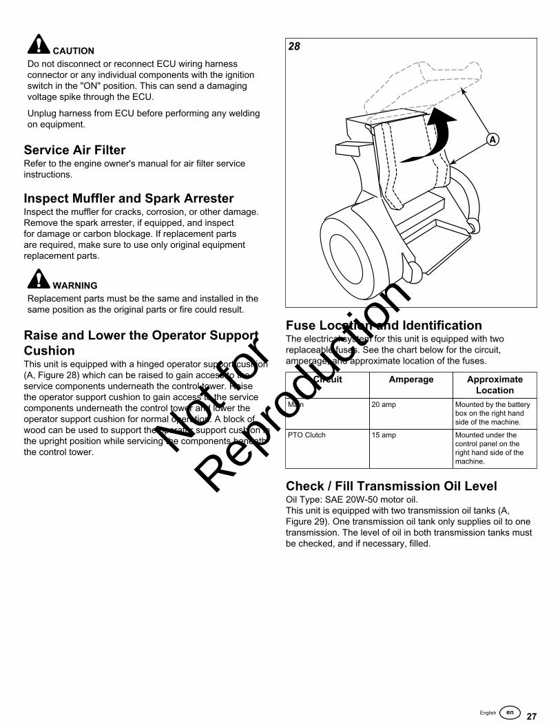
Maintenance Schedule....................................................... 22Maintenance Procedures................................................... 23
Service and Maintenance Safety................................... 23Checking / Adding Fuel.................................................. 23Replacing the Fuel Filter................................................ 24Check Engine Oil Level..................................................24Briggs & Stratton Vanguard Engines with Remote OilTank (Select Models)..................................................... 24Changing the Engine Oil and Filter (Engines with RemoteOil Tank).........................................................................24Changing the Engine Oil and Filter (All OtherModels)........................................................................... 26Engine Maintenance.......................................................26Electronic Fuel Injection (EFI) System - EFI Models ..... 26Service Air Filter.............................................................27Inspect Muffler and Spark Arrester................................ 27Raise and Lower the Operator Support Cushion........... 27Fuse Location and Identification.................................... 27Check / Fill Transmission Oil Level................................ 27Transmission Oil Filter Change......................................28Purging the Air from the Hydraulic System.................... 28Checking Tire Pressures................................................29
Lubrication...................................................................... 29Lubricate the Front Casters............................................30Servicing the Mower Blades...........................................30Cutting Height Adjustment..............................................32Neutral Adjustment......................................................... 33Neutral Lockout and Tracking Adjustment..................... 33Deck Lift Rod Timing Adjustment...................................35Mower Deck Leveling Procedure................................... 36Deck Lift Assist Springs................................................. 37Mower Deck Drive Belt Replacement - 52" & 61" MowerDecks..............................................................................37Mower Deck Drive Belt Replacement - 72" MowerDecks..............................................................................38Transaxle Drive Belt Replacement.................................39Operator Platform Suspension Adjustment.................... 40Parking Brake Adjustment..............................................40Cleaning the Battery and Cables................................... 41Battery Service............................................................... 42
Troubleshooting.................................................................. 43Troubleshooting Charts.................................................. 43Troubleshooting Common Cutting Problems..................45
Specifications...................................................................... 45Warranty...............................................................................46
Warranty Statement........................................................46
Not for
Reprod
uctio
n
3
Thank you for purchasing this quality-built Ferris Zero-Turn Stand-On Mower. We’re pleased that you’ve placedyour confidence in the Ferris brand. When operated andmaintained according to the manuals, your Ferris product willprovide many years of dependable service.
The manuals contain safety information to make you awareof the hazards and risks associated with the unit and how toavoid them. This Zero-Turn Stand-On Mower was designed tobe used as described in this operator's manual and operatedby trained professionals for finish cutting of established lawnsand is not intended for any other purpose. It is important thatyou read and understand the instructions thoroughly beforeattempting to start or operate this equipment. Save theseoriginal instructions for future reference.
Products Covered by ThisManualThe following products are covered by this manual:
5901691, 5901692, 5901693, 5901694, 5901784, 5901789, &5901809
The images in this document are representative, andare meant to complement the instructional copy theyaccompany. Your unit may vary from the imagesdisplayed. LEFT and RIGHT are as seen from the operator'sposition.
Ferris is a registered trademark of Briggs & StrattonCorporation.
The Illustrated Parts Lists for this machine can bedownloaded from ferrismowers.com. Please provide modeland serial number when ordering replacement parts.
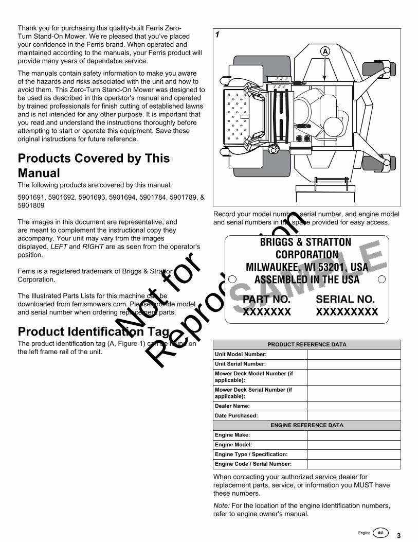
Product Identification TagThe product identification tag (A, Figure 1) can be found onthe left frame rail of the unit.
1
Record your model number, serial number, and engine modeland serial numbers in the space provided for easy access.
PRODUCT REFERENCE DATAUnit Model Number:Unit Serial Number:Mower Deck Model Number (ifapplicable):Mower Deck Serial Number (ifapplicable):Dealer Name:Date Purchased:
ENGINE REFERENCE DATAEngine Make:Engine Model:Engine Type / Specification:Engine Code / Serial Number:
When contacting your authorized service dealer forreplacement parts, service, or information you MUST havethese numbers.
Note: For the location of the engine identification numbers,refer to engine owner's manual.

Not for
Reprod
uctio
n
4 ferrismowers.com
Operator Safety WARNING
This product can expose you to chemicals includinggasoline engine exhaust, which is known to the State ofCalifornia to cause cancer, and carbon monoxide, whichis known to the State of California to cause birth defectsor other reproductive harm. For more information go towww.P65Warnings.ca.gov.
Operating SafelyRead these safety rules and follow them closely. Failure toobey these rules could result in loss of control of the unit,severe personal injury or death to you, or bystanders, ordamage to property or equipment. This mowing deck iscapable of amputating hands and feet and throwingobjects.
The safety alert triangle ( ) in text signifies importantcautions or warnings which must be followed.
Operating Safety
Congratulations on purchasing a superior-quality piece oflawn and garden equipment. Our products are designed andmanufactured to meet or exceed all industry standards forsafety.
Do not operate this machine unless you have been trained.Reading and understanding this operator’s manual is a way totrain yourself.
Keep both feet on the operator platform at all times.
Power equipment is only as safe as the operator. If it ismisused, or not properly maintained, it can be dangerous!Remember, you are responsible for your safety and that ofthose around you.
Use common sense, and think through what you are doing.If you are not sure that the task you are about to perform canbe safely done with the equipment you have chosen, ask aprofessional: contact your local authorized dealer.
Read the Manual
The operator’s manual contains important safety informationyou need to be aware of BEFORE you operate your unit aswell as DURING operation.
Safe operating techniques, an explanation of the product’sfeatures and controls, and maintenance information isincluded to help you get the most out of your equipmentinvestment.
Be sure to completely read the Safety Rules and Informationfound on the following pages. Also completely read theOperation section.
Children
Tragic accidents can occur with children. Do not allow themanywhere near the area of operation. Children are oftenattracted to the unit and mowing activity. Never assume thatchildren will remain where you last saw them. If there is a riskthat children may enter the area where you are mowing, haveanother responsible adult watch them.
Slope Operation
Operation on slopes can be dangerous. Slopes are a majorfactor related to accidents, which can result in severe injury ordeath. Using the unit on a slope that is too steep, where you

Not for
Reprod
uctio
n
5
do not have adequate wheel traction (and control) can causesliding, loss of steering, control, and possible rollover.
You should not operate on a slope greater than 20 degrees.
Always mow across slopes, not up and down (to maintaintraction on the wheels) and avoid sudden turns or rapid speedchanges. Reduce speed and use extreme caution on ALLslopes.
Also, note that the surface condition you are on can greatlyimpact your ability to safely operate this machine. Operatingon wet or slippery slopes can cause sliding and loss ofsteering and control. Do not operate on slopes that areslippery, wet, or have soft soil conditions.
If you feel unsure about operating the unit on a slope, don't doit. It's not worth the risk.
Thrown Objects
This unit has spinning mower blades. These blades can pickup and throw debris that could seriously injure a bystander.Be sure to clean up the area to be mowed and removeobjects that could be thrown by the blade BEFORE you startmowing.
Do not operate this unit without the entire grass catcher ordischarge guard (deflector) in place.
Also, do not allow anyone in the area while the unit is running!If someone does enter the area, shut the unit off immediatelyuntil they leave.
Moving Parts
This equipment has many moving parts that can injure youor someone else. However, if you stay in the operator zone(stay seated in the seat), and follow the safety rules in thisoperator’s manual, the unit is safe to operate.
The mower deck has spinning mower blades that canamputate hands and feet. Do not allow anyone near the unitwhile it is running! Keep safety devices (guards, shields, andswitches) in place and working.
To help you, the operator, use this equipment safely, it isequipped with an operator-present safety system. Do NOTattempt to alter or bypass the system. See your dealerimmediately if the system does not pass all the safetyinterlock system tests found in this manual.
Retaining Walls, Drop-Offs and Water
Retaining walls and drop-offs around steps and water area common hazard. Give yourself a minimum of two mowerwidths of clearance around these hazards and hand-trim witha walk behind mower or string trimmer. Wheels dropping overretaining walls, edges, ditches, embankments, or into watercan cause rollovers, which may result in serious injury, death,or drowning.
Fuel and Maintenance
Always disengage all drives, shutoff the engine, and removethe key before doing any cleaning, refueling, or servicing.
Gasoline and its vapors are extremely flammable. Do notsmoke while operating or refueling. Do not add fuel whileengine is hot or running. Allow engine to cool for at least 3minutes prior to adding fuel.
Do not add fuel indoors, in an enclosed trailer, garage, or anyother enclosed area that is not well ventilated. Gasoline spillsshould be cleaned up promptly and before operation begins.
Gasoline should be stored only in sealed containers approvedfor fuel.
Proper maintenance is critical to the safety and performanceof your unit. Keep the unit free of grass, leaves, and excessoil. Be sure to perform the maintenance procedures listed inthis manual, especially periodically testing the safety system.

Not for
Reprod
uctio
n
6 ferrismowers.com
Enclosed Areas
Only operate this unit outdoors and away from unventilatedareas such as inside garages or enclosed trailers. Theengine emits poisonous carbon monoxide gas and prolongedexposure in an enclosed area can result in serious injury ordeath.
Slope Identification Guide2
How to measure the slope of a lawn surface with asmartphone or an angle finder tool:
WARNINGDo not operate on slopes greater than 20 degrees.
1. Use a straight edge at least two (2) feet long (A,Figure 2). A 2x4 or a straight piece of metal works well.
2. Angle finder tools.
a. Use your smartphone: Many smartphones (B,Figure 2) have an inclinometer (angle finder) locatedunder the compass application (app). Or, search anapp store for an Inclinometer app.
b. Use angle finder tools: Angle finder tools (C andD, Figure 2) are available at local hardware storesor online (also called inclinometer, protractor, angle
meter, or angle gauge). Dial type (C) or digital type(D) work, others may not. Read and obey the userinstructions supplied with the angle finder tool.
3. Put the two (2) feet long straight edge along the steepestpart of the lawn slope. Put the board up and down theslope.
4. Lay the smartphone or angle finder tool on the straightedge and read the angle in degrees. This is the slope ofyour lawn.
Note: A paper gauge slope identification guide is includedin your product literature packet and is also available todownload from the manufacturer's website.
Safety Rules and InformationTraining
• Read, understand, and follow all instructions in themanual and on the unit before starting. If the operator(s)or mechanic(s) can not read English it is the owner’sresponsibility to explain this material to them.
• Become familiar with the safe operation of the equipment,operator controls, and safety signs.
• All operators and mechanics should be trained. Theowner is responsible for training the users.
• Only allow responsible adults, who are familiar with theinstructions, to operate the unit.
• Never let children or untrained people operate or servicethe equipment. Local regulations may restrict the age ofthe operator.
• The owner/user can prevent and is responsible foraccidents or injuries occurring to themselves, otherpeople or property.
• Data indicates that operators, age 60 years and above,are involved in a large percentage of riding mower-relatedinjuries. These operators should evaluate their abilityto operate the riding mower safely enough to protectthemselves and others from serious injury.
Preparation• Evaluate the terrain to determine what accessories and
attachments are needed to properly and safely performthe job. Use only accessories and attachments approvedby the manufacturer.
• Wear appropriate clothing including safety shoes, safetyglasses and ear protection. Long hair, loose clothing orjewelry may get tangled in moving parts.
• Inspect the area where the equipment is to be used andremove all objects such as rocks, toys and wire, whichcan be thrown by the machine.
• Use extra care when handling gasoline and other fuels.They are flammable and vapors are explosive.
• Use only an approved container.• Never remove fuel cap or add fuel with the engine
running. Allow engine to cool before refueling. Do notsmoke.
• Never refuel or drain the machine indoors.

Not for
Reprod
uctio
n
7
• Check that operator’s presence controls, safety switchesand shields are attached and functioning properly. Do notoperate unless they are functioning properly.
Operation• Keep both feet on the operator platform at all times.• Never run an engine in an enclosed area.• Mow only in the daylight or with good artificial light,
keeping away from holes and hidden hazards.• Be sure all drives are in neutral and parking brake is
engaged before starting engine. Only start engine fromthe operator’s position. Use seat belts if provided.
• Be sure of your footing while using pedestrian controlledequipment, especially when backing up. Walk, don’t run.Reduced footing could cause slipping.
• Slow down and use extra care on hillsides. Be sure totravel in the recommended direction on hillsides. Turfconditions can affect the machines stability. Use cautionwhen operating near drop-offs.
• Do not mow in reverse unless absolutely necessary.Always look down and behind before and while travelingin reverse.
• Be aware of the mower discharge direction and do notpoint it at anyone. Do not operate the mower withouteither the entire grass catcher or the deflector in place.
• Slow down and use caution when making turns and whenchanging directions on slopes.
• Never raise deck with the blades running.• Never leave a running unit unattended. Always disengage
the PTO, set parking brake, stop engine, and removekeys before dismounting. Keep hands and feet away fromthe cutting units.
• Turn off the PTO switch to disengage the blades whennot mowing.
• Never operate with guards not securely in place. Besure all interlocks are attached, adjusted properly andfunctioning properly.
• Never operate with the discharge deflector raised,removed or altered, unless using a grass catcher.
• Do not change the engine governor setting or overspeedthe engine.
• Stop on level ground, lower implements, disengagedrives, engage parking brake, shut off engine beforeleaving the operator’s position for any reason includingemptying the grass catchers or unclogging the chute.
• Stop equipment and inspect blades after striking objectsor abnormal vibration occurs. Make necessary repairsbefore resuming operations.
• Keep hands and feet away from the cutting units.• Look behind and down before backing up to be sure of a
clear path.• Never carry passengers and keep pets and bystanders
away.• Do not operate the unit while under the influence of
alcohol or drugs.• Slow down and use caution when making turns and
crossing roads and sidewalks. Stop blades if not mowing.
• Use care when loading or unloading the machine into atrailer or truck.
• Use care when approaching blind corners, shrubs, treesor other objects that may obscure vision.
• To reduce fire hazard, keep unit free of grass, leaves &excess oil. Do not stop or park over dry leaves, grass orcombustible materials.
WARNINGIt is a violation of California Public Resource Code, Section4442, to use or operate the engine on any forest-covered,brush-covered or grass-covered land unless the exhaustsystem is equipped with a spark arrester, as definedin Section 4442, maintained in effective working order.Other states or federal jurisdictions may have similar laws.Contact an Authorized Service Dealer to obtain a sparkarrester designed for the exhaust system installed on thisengine.
• OSHA regulations may require the use of hearingprotection when exposed to sound levels greater than 85dBA for an 8 hour time period.
CAUTION This machine produces sound levels in excess of 85 dBAat the operator’s ear and can cause hearing loss thoughextended periods of exposure.
Wear hearing protection when operating this machine.
Slope OperationSlopes are a major factor related to loss-of-control and tip-over accidents, which can result in severe injury or death. Allslopes require extra caution. If you cannot back up the slopeor if you feel uneasy on it, do not drive on it.
DANGER Loss of control
Operating on slopes can be hazardous and cause loss ofcontrol.
• Avoid sudden turns or rapid speed changes. • If machine stops forward motion on a slope, stop the
blades and drive slowly off the slope. • Go across slopes, NOT up and down. • Reduce speed and use extreme caution on slopes. • Do NOT operate on slopes over 20* degrees.
* This limit was determined per International Standard ISO 5395-3:2013,Section 4.6 and is based on the ISO 5395-3 Stability Test proceduredescribed in Annex A. The 20 degree “limit of stability” is equal to 60%of the angle at which machine lift-off occurred in static tests. Actualdynamic stability may vary depending on operating conditions.

Not for
Reprod
uctio
n
8 ferrismowers.com
DANGER Wet or soft slope hazard
Wet or soft slopes can cause sliding and loss of control
• Do NOT operate on slopes when grass is wet. Tiresmay lose traction and cause sliding and loss of control.
• Do NOT operate on slopes when soil is soft (such asafter heavy rains). Tires may lose traction and causesliding and loss of control.
DANGER Water, retaining walls and drop-off hazardWheels dropping over edges may result in serious injury,death and drowning.
• Do NOT operate near water, retaining walls, drop-offsor embankments. The machine could suddenly rollover if a wheel goes over the edge or the edge breaksaway.
• Give yourself a minimum of two mower widths ofclearance around these hazards.
Do:
• Mow across slopes, not up and down. • Remove obstacles such as rocks, tree limbs, etc. • Watch for holes, ruts, or bumps. Uneven terrain could
overturn the unit. Tall grass can hide obstacles. • Use slow speed. Choose a slow speed so that you will
not have to stop or change speed while on the slope. • Use extra care with grass catchers or other attachments.
These can change the stability of the unit. • Keep all movement on the slopes slow and gradual. Do
not make sudden changes in speed or direction. • See your authorized dealer for recommendations of
available weights to improve stability.
Do NOT:
• Avoid starting, stopping, or turning on a slope. If tires losetraction (i.e. machine stops forward motion on a slope),disengage the blade(s) (PTO) and drive slowly off theslope.
• Do not turn on slopes unless necessary, and then, turnslowly and gradually uphill, if possible. Never mow downslopes.
• Do not mow near drop-offs, ditches, or embankments.The operator could lose footing or balance or mowercould suddenly turn over if a wheel is over the edge of acliff or ditch, or if an edge caves in.
• Do not mow on wet grass. Reduced footing or tractioncould cause sliding.
• Do not try to stabilize the unit by putting your foot on theground (ride-on units).
• Do not mow excessively steep slopes. • Do not use grass catcher on steep slopes. • Do not mow slopes if you cannot back up them.
ChildrenTragic accidents can occur if the operator is not alert to thepresence of children. Children are often attracted to the unitand the mowing activity. Never assume that children willremain where you last saw them.
• Keep children out of the mowing area and under thewatchful care of another responsible adult.
• Be alert and turn unit off if children enter the area.• Before and during reverse operation, look behind and
down for small children.• Never carry children, even with the blade(s) off. They may
fall off and be seriously injured or interfere with safe unitoperation. Children who have been given rides in the pastmay suddenly appear in the mowing area for another rideand be run over or backed over by the machine.
• Never allow children to operate the unit.• Use extra care when approaching blind corners, shrubs,
trees, or other objects that may obscure vision.
Emissions• Engine exhaust from this product contains chemicals
known, in certain quantities, to cause cancer, birthdefects, or other reproductive harm.
• Look for the relevant Emissions Durability Period and AirIndex information on the engine emissions label.
Service and MaintenanceTo avoid personal injury or property damage, use extremecare in handling gasoline. Gasoline is extremely flammableand the vapors are explosive.
Safe Handling of Gasoline • Extinguish all cigarettes, cigars, pipes, and other sources
of ignition. • Use only approved gasoline containers. • Never remove the gas cap or add fuel with the engine
running. Allow the engine to cool before refueling. • Never fuel the machine indoors. • Never store the machine or fuel container where there is
an open flame, spark, or pilot light such as near a waterheater or other appliance.
• Never fill containers inside a vehicle or on a truck bedwith a plastic bed liner. Always place containers on theground away from your vehicle before filling.
• Remove gas-powered equipment from the truck ortrailer and refuel it on the ground. If this is not possible,then refuel such equipment on a trailer with a portablecontainer, rather than from a gasoline dispenser nozzle.
• Keep nozzle in contact with the rim of the fuel tank orcontainer opening at all times until fueling is complete. Donot use a nozzle lock-open device.
• If fuel is spilled on clothing, change clothing immediately. • Never over-fill the fuel tank. Replace gas cap and tighten
securely. • Use extra care in handling gasoline and other fuels. They
are flammable and vapors are explosive. • If fuel is spilled, do not attempt to start the engine but
move the machine away from the area of spillage and

Not for
Reprod
uctio
n
9
avoid creating any source of ignition until fuel vaporshave dissipated.
• Replace all fuel tank caps and fuel container capssecurely.
Maintenance and Storage
• Always observe safe refueling and fuel handling practiceswhen refueling the unit after transportation or storage.
• Always follow the engine manual instructions for storagepreparations before storing the unit for both short andlong term periods.
• Always follow the engine manual instructions for properstart-up procedures when returning the unit to service.
• Never store the machine or fuel container inside wherethere is an open flame, such as in a water heater. Allowunit to cool before storing.
• Shut off fuel while storing or transporting. Do not storefuel near flames or drain indoors.
• Keep all hardware, especially blade attachment bolts,tight and keep all parts in good working condition.Replace all worn or damaged decals.
• Never tamper with safety devices. Check their properoperation regularly.
• Disengage drives, lower implement, set parking brake,stop engine and remove key or disconnect spark plugwire. Wait for all movement to stop before adjusting,cleaning or repairing.
• Clean grass and debris from cutting units, drives,mufflers, and engine to prevent fires. Clean up oil or fuelspillage.
• Let engine cool before storing and do not store nearflame.
• Stop and inspect the equipment if you strike an object.Repair, if necessary, before restarting.
• Park machine on level ground. Never allow untrainedpersonnel to service machine.
• Use jack stands to support components when required. • Carefully release pressure from components with stored
energy. • Disconnect battery or remove spark plug wire before
making any repairs. Disconnect the negative terminalfirst and the positive last. Reconnect positive first andnegative last.
• Use care when checking blades. Wrap the blade(s) orwear gloves, and use caution when servicing them. Onlyreplace blades. Never straighten or weld them.
• Keep hands and feet away from moving parts. If possible,do not make adjustments with the engine running.
• Charge batteries in an open well ventilated area, awayfrom spark and flames. Unplug charger before connectingor disconnecting from battery. Wear protective clothesand use insulated tools.
• Grass catcher components are subject to wear, damage,and deterioration, which could expose moving parts orallow objects to be thrown. Frequently check componentsand replace with manufacturer’s recommended parts,when necessary.
• Check brake operation frequently. Adjust and service asrequired.
• Use only factory authorized replacement parts whenmaking repairs.
• Always comply with factory specifications on all settingsand adjustments.
• Only authorized service locations should be utilized formajor service and repair requirements.
• Never attempt to make major repairs on this unit unlessyou have been properly trained. Improper serviceprocedures can result in hazardous operation, equipmentdamage and voiding of manufacturer’s warranty.
WARNINGUnits with hydraulic pumps, hoses, or motors: Hydraulicfluid escaping under pressure may have sufficient force topenetrate skin and cause serious injury. If foreign fluid isinjected into the skin it must be surgically removed withina few hours by a doctor familiar with this form of injury organgrene may result. Keep body and hands away frompin holes or nozzles that eject hydraulic fluid under highpressure. Use paper or cardboard, and not hands, to searchfor leaks. Make sure all hydraulic fluid connections are tightand all hydraulic hoses and lines are in good conditionbefore applying pressure to the system. If leaks occur, havethe unit serviced immediately by your authorized dealer.
WARNINGStored energy device. Improper release of springs canresult in serious personal injury. Springs should be removedby an authorized technician.
WARNINGUnits equipped with an engine radiator: Stored energydevice. To prevent serious bodily injury from hot coolant orsteam blow-out, never attempt to remove the radiator capwhile the engine is running. Stop the engine and wait untilit is cool. Even then, use extreme care when removing thecap.
Safety DecalsBefore operating your unit, read the safety decals. Thecautions and warnings are for your safety. To avoid apersonal injury or damage to the unit, understand and followall safety decals.
WARNINGIf any safety decals become worn or damaged, andcannot be read, order replacement decals from yourlocal dealer.

Not for
Reprod
uctio
n
10 ferrismowers.com
3
* Located near the transmission fans.
A.) Part No.: 7101665 - Decal, Danger
B.) Part No.: 5103665 - Decal, Warning, Fire
C.) Part No.: 5105081 - Decal, Dash Panel, LH, Controls
D.) Part No.: 5105095 - Decal, Dash Panel, RH, Warning/Controls
E.) Part No.: 5104636 - Decal, Danger, Stand-On
F.) Part No.: 5061245 - Decal, Pinch Point
G.) Part No.: 5103184 - Decal, Warning, Hand in Pulley

Not for
Reprod
uctio
n
11
Safety Icons
A. AlertB. Read the manual.C. Thrown objects.D. Pinch point.E. Fire hazard.F. Amputation - hand in blade.G. Amputation - foot in blade.H. Maximum slope angle for safe operation.I. Keep children away.J. Amputation - rotating parts.
Safety Alert Symbol and Signal WordsThe safety alert symbol identifies safety informationabout hazards that can result in personal injury. A signal word(DANGER, WARNING, or CAUTION) is used with the alertsymbol to indicate the likelihood and the potential severity ofinjury. In addition, a hazard symbol may be used to representthe type of hazard.
DANGER indicates a hazard which, if notavoided, will result in death or serious injury.
WARNING indicates a hazard which, if notavoided, could result in death or serious injury.
CAUTION indicates a hazard which, if notavoided, could result in minor or moderate injury.
NOTICE indicates information considered important but nothazard-related.
Safety Interlock SystemThis unit is equipped with safety interlock switches. Thesesafety systems are present for your safety, do not attemptto bypass safety switches, and never tamper with safetydevices. Check their operation regularly.
Operational SAFETY Checks
Test 1 - Engine should NOT crank if:• The parking brake lever is in the DISENGAGED position.
Test 2 - Engine SHOULD crank if:• The parking brake lever is in the ENGAGED position.
Test 3 - Engine should SHUT OFF if:• The ignition switch is turned to the OFF position.
Test 4 - PTO Switch (blades) should SHUT OFF if:• If the PTO switch is ON and the operator steps off the
operator platform, OR• The operator presses the PTO switch down to the OFF
position.
Test 5 - PTO Switch (blades) SHOULD turn on if:• Operator stands on the operator platform and the PTO
switch is pulled up to the ON position.
Test 6 - Blade Brake Check:
Mower blades and mower drive belt should come to acomplete stop within seven (7) seconds after electric PTOswitch is turned off (or operator steps off the operatorplatform). If the mower drive belt does not stop within seven(7) seconds, see your dealer.
Note: Once the engine has been stopped, the parking brakelever must be in the ENGAGED position, the ground speedcontrol levers should be in the NEUTRAL position, theoperator should be standing on the operator platform, and thePTO switch should be in the OFF position in order to start theengine.
WARNINGIf the unit does not pass a safety test, do NOT operate it.See your authorized dealer. Under no circumstance shouldyou attempt to defeat the purpose of the safety interlocksystem.
Features and ControlsControl Functions and LocationsThe information below briefly describes the function ofindividual controls. Starting, stopping, driving, and mowingrequire the combined use of several controls applied inspecific sequences. To learn what combination and sequenceof controls to use for various tasks see the Operation section.

Not for
Reprod
uctio
n
12 ferrismowers.com
4
Callout DescriptionA Deck Lift Lever, Cutting Height Adjustment Pin, and Deck
Lift Release Button
B Maximum Forward Speed Bar
C Ground Speed Control Levers
D Parking Brake
E Transmission Oil Fill (Transmission Oil Reservoirs)
F Battery Box
G Fuel Tank Cap
H Operator Platform
I Transaxle Release Levers (Located on the rear of theengine deck)
Deck Lift Lever, Cutting Height Adjustment Pin, and DeckLift Release Button: The deck lift lever (B, Figure 5), cuttingheight adjustment pin (A), and deck lift release button (C) areused together to control the cutting height of the mower deck.See Cutting Height Adjustment for instructions on using thesecontrols.
5
Cutting Height Adjustment Pin
Storage Hole for Cutting Height Adjustment Pin
Deck Lift Lock Lever
Maximum Forward Speed Bar: This unit is equipped with anadjustable Maximum Forward Speed Bar (A, Figure 6), whichis located in front of the Ground Speed Control Levers (B &C).
6

Not for
Reprod
uctio
n
13
The Maximum Forward Speed Bar can be adjusted in fourdifferent positions to suit the desired maximum forward speedof the operator. The positioning hole closest to the groundspeed control levers (labeled as #1 in Figure 6) is the slowestsetting and the positioning hole furthest from the groundspeed control levers (labeled as #4) is the fastest.
To adjust the position of the Maximum Forward Speed Barpull the T-handle knob (D) out to release the maximumforward speed bar, position the Maximum Forward Speed Barin the desired location, and then release the T-handle knob.Make sure that the T-handle knob locks the maximum forwardspeed bar into place.
You should only adjust the position of the MaximumForward Speed Bar after you have stopped all movementof the unit.
Ground Speed Control Levers: These levers control theground speed of the unit. The left lever (B, Figure 1) controlsthe left rear drive wheel and the right lever controls (C) theright drive wheel.
FORWARD
NEUTRAL
REVERSE
Moving a lever forward increases the FORWARD speed ofthe associated wheel, and pulling back on a lever increasesthe REVERSE speed.
The ground speed control levers cannot be moved from theNEUTRAL position until the parking brake lever is moved tothe DISENGAGED position.
Note: The further a lever is moved away from the neutralposition the faster the drive wheel will turn.
See Driving the Zero-Turn Riding Mower section for steeringinstructions.
Parking Brake: Pull the parking brake lever rearwardand up to engage the parking brake. Move the lever fullyforward and down to disengage the parking brake.
Disengage Releases the parking brake.
Engage Locks the parking brake.
Operator Platform: The operator stands on the operatorplatform while driving the machine. Keep both feet on theoperator platform at all times.
The operator platform is integral to the safety interlocksystem:
• If the operator steps off the operator platform while theunit is running and the PTO switch is engaged, the PTOwill shut off.
Transmission Oil Fill: Transmission oil is added through thehydraulic oil tanks. It also serves as extra holding capacityfor oil as the transmissions heat up and the hydraulic oilexpands. See Check / Fill Transmission Oil for oil level checkand fill procedures.
Fuel Tank Cap: To remove the cap, turn counter-clockwise.
Transmission Release Levers:
Icon Control Name
Transmission Release Levers
This unit is equipped with two transmission release levers.The transmission release levers deactivate the transaxleso that the unit can be pushed by hand. Both transmissionrelease levers must be in the same position whether you aredriving the unit or pushing it by hand. See Pushing the Unit byHand for operational information.
Instrument Control Panel - Briggs & Stratton ElectronicFuel Injected (EFI) Models:
7
Instrument Control Panel - Kawasaki Electronic FuelInjected (EFI) Models:

Not for
Reprod
uctio
n
14 ferrismowers.com
8
Callout Control NameA Hour Meter
B Malfunction Indicator Lamp (M.I.L.)
C Throttle Control
D PTO (Power Take Off) Switch
E Ignition Switch
F Fuel Level Gauge
G Throttle Rocker Switch
Hour Meter: This unit is equipped with a dual function hourmeter that records the number of hours that the engine hasrun and the number of hours that the PTO switch has beenengaged.
"A" - Hour Glass Icon - The hour glass icon flashes whenthe hour meter is recording the passage of time.
"B" - Mode Icon - The mode icon will display an "E" whendisplaying engine hours, and a "P" when displaying PTOhours.
"C" - Time Display - This is the number of hours that arerecorded.
The default display of the hour meter is engine hours. Themode icon will display a "E" and the hour glass icon will notflash.
To begin recording engine hours, start the unit's engine andrelease the parking brake. The hour glass icon will flash.
To begin recording PTO hours, pull the PTO switch up toengage the PTO clutch. The unit's engine must be running.The mode icon will display a "P" and the hour glass icon willflash.
While recording PTO hours, the hour meter also recordsengine hours; however, the hour meter only displays PTOhours when recording PTO hours.
To stop recording PTO hours, push the PTO switch down todisengage the PTO clutch.
To stop recording engine hours, engage the parking brake.
The hour meter has a self contained power source so that therecorded hours are always visible even when the engine isOFF.
Malfunction Indicator Lamp (M.I.L.): The malfunctionindicator lamp detects problems with the engine. If themalfunction indicator lamp begins to flash while you areoperating the unit, see the engine operator's manual.
Throttle Control: The throttle controls engine speed. Movethe throttle forward to increase engine speed and back todecrease engine speed. Always operate at FULL throttlewhen mowing.
Fast throttle speed.
Slow throttle speed.
PTO (Power Take Off) Switch: The PTO switchengages and disengages the mower blades. Pull UP on theswitch to engage, and push DOWN to disengage.
Ignition Switch: The ignition switch starts and stops theengine, it has three positions:
OFF: Stops the engine and shuts off the electrical system.
RUN: Allows the engine to run and powers the electricalsystem.
START: Cranks the engine for starting.
Note: Never leave the ignition switch in the RUN position withthe engine stopped—this drains the battery.
Fuel Level Gauge: Displays the fuel level in the tank.The fuel level gauge is installed in the top of the fuel tank andis viewed by looking through the port hole in the instrumentcontrol panel.
Throttle Control Rocker Switch: Pressing the throttlecontrol rocker switch forward will increase the throttleposition. Pressing the throttle control rocker switch backwards

Not for
Reprod
uctio
n
15
will decrease the throttle position. Always operate at FULLthrottle when mowing.
Fast throttle speed.
Slow throttle speed.
OperationBefore First Time Operation
• Be sure to read all information in the OperatorSafety and Operation sections before attempting tooperate this unit.
• Become familiar with all of the controls and how to stopthe unit.
• Drive in an open area without mowing to becomeaccustomed to the unit.
WARNING
• Never operate on slopes greater than 20°. • Select slow ground speed before driving onto a slope.
Use extra caution when operating on slopes with anycollection accessories attached to the unit.
• Mow across the face of slopes, not up and down, usecaution when changing direction on slopes and do NOTstart or stop on a slope.
WARNING
• Never allow passengers to ride on the unit. • Before leaving the operator’s platform for any reason,
engage the parking brake, disengage the PTO, stop theengine, and remove the key.
• To reduce fire hazard, keep the engine, unit, andmower deck free of grass, leaves, and excess grease.Do NOT stop or park unit over dry leaves, grass, orcombustible materials.
• Fuel is highly flammable and must be handled withcare. Never fill the tank when the engine is still hot fromrecent operation. Do NOT allow open flame, smoking,or matches in the area. Avoid over-filling and wipe upany spills.
WARNINGDo NOT load this zero-turning mower on a trailer or truckusing two separate ramps. Only use a single ramp that is atleast one foot wider than the width of the rear wheels of thisunit. This unit has a zero turning radius and the rear wheelscould fall off the ramps, or the rider could tip over injuringthe operator or bystanders.
Checks Before Starting• Check the engine oil level using the engine oil
dipstick. If necessary, add oil through the engine oilfill. See engine operator's manual for instructions, thelocation of the engine oil fill, engine oil dipstick, and oilrecommendations.
• Make sure that all nuts, bolts, screws and pins are inplace and tight.
• Fill the fuel tank with fresh fuel. Refer to the enginemanual for fuel recommendations.
• Check the hydraulic oil level. If necessary, add oil throughthe hydraulic oil tanks.
Starting the Engine - Briggs & StrattonFuel Injected Models
WARNING Read the operator's manual before attempting tooperate this unit.
• If you do not understand how a specific controlfunctions, or have not yet thoroughly read the Featuresand Controls section, do so now.
• Do NOT attempt to operate the unit without firstbecoming familiar with the location and function of allcontrols.
Note: To prime a dry fuel system, turn key switch to ONposition for one minute. Allow fuel pump to cycle and primesystem. Turn key switch OFF.
1. While standing on the operator's platform, engagethe parking brake, make sure that the PTO switch isdisengaged, and that the ground speed control levers arein the NEUTRAL position.
2. Position the throttle control midway between SLOW andFAST positions.
3. Insert the key into the ignition switch and turn it to theSTART position. Release the switch as soon as theengine starts. If the starter does not turn the engine

Not for
Reprod
uctio
n
16 ferrismowers.com
over, shut off the key switch immediately, and consultthe engine operator's manual. Warm up the engine byrunning it for at least a minute before engaging the PTOswitch or driving the unit.
4. After warming the engine always operate the unit at FULLthrottle when mowing.
In the event of an emergency the engine can be stoppedby simply turning the ignition switch to STOP. Use thismethod only in emergency situations. For normal engine shutdown follow the procedure given in Stopping the Unit.
Starting the Engine - Kawasaki FuelInjected Models
WARNING Read the operator's manual before attempting tooperate this unit.
• If you do not understand how a specific controlfunctions, or have not yet thoroughly read the Featuresand Controls section, do so now.
• Do NOT attempt to operate the unit without firstbecoming familiar with the location and function of allcontrols.
1. While standing on the operator's platform, engagethe parking brake, make sure that the PTO switch isdisengaged, and that the ground speed control levers arein the NEUTRAL position.
2. Insert the key into the ignition switch and turn it to STARTposition.
3. The throttle will self-adjust to idle when starting. Afterthe engine starts allow the engine to warm. Warm up theengine by running it for at least a minute before engagingthe PTO switch or driving the rider.
4. After warming the engine always operate the unit at FULLthrottle when mowing.
In the event of an emergency the engine can be stoppedby simply turning the ignition switch to STOP. Use thismethod only in emergency situations. For normal engine shutdown follow the procedure given in Stopping the Unit.
Stopping the Unit1. Stop the rider movement by returning the ground speed
control levers to their NEUTRAL positions. The groundspeed control levers are spring-loaded and whenreleased they will automatically return to NEUTRAL.
2. Disengage the PTO by pushing down on the PTO switch.3. Engage the parking brake by pulling the handle up and
back until it locks into position.4. Move the throttle control to the mid-throttle position and
turn the ignition key to OFF. Remove the key.
Driving the Zero-Turn Riding MowerBefore attempting to drive the zero-turn riding mower makesure you have read the Features and Controls section and
understand the location and function of all of the unit’scontrols.
Keep both feet on the operator platform at all times.
The ground speed control levers of this zero-turn ridingmower are responsive, and learning to gain a smooth andefficient control of the unit’s forward, reverse, and turningmovements will take some practice.
Spending some time going through the maneuvers shownand becoming familiar with how the unit accelerates, travels,and steers, before you begin mowing, is absolutelyessential to getting the most out of the zero-turn ridingmower.
Locate a smooth, flat area of your lawn, one with plenty ofroom to maneuver. Clear the area of objects, people, andanimals before you begin. Operate the unit at mid-throttleduring this practice session (ALWAYS operate at full throttlewhen mowing), and turn slowly to prevent tire slippage anddamage to your lawn.
We suggest you begin with the Smooth Travel procedure,and then advance through the forward, reverse, and turningmaneuvers.
Prior to moving the ground speed control levers, the operatormust be standing on the operator platform and the parkingbrake must be disengaged.
Adjusting the Maximum Forward Speed BarThis zero-turn riding mower is equipped with an adjustablemaximum forward speed bar (A, Figure 9), which is locatedin front of the ground speed control levers (B & C). Themaximum forward speed bar can be adjusted in four differentpositions to suit the desired maximum forward speed of theoperator. The positioning hole closest to the ground speedcontrol levers (labeled as #1 in Figure 9) is the lowest settingand the positioning hole furthest from the ground speedcontrol levers (labeled as #4) is the fastest.
9

Not for
Reprod
uctio
n
17
For operator’s learning to drive the machine it isrecommended that the slowest speed setting (position # 1) beused until the operator is comfortable driving the machine.
To adjust the Maximum Forward Speed Bar to the desiredposition:
1. Bring the mower to a complete stop.2. Pull the T-handle knob (D) out, move the maximum
forward speed bar desired hole location, release the T-handle knob. Make sure that the T-handle knob locks themaximum forward speed bar into place.
Smooth TravelThe ground speed control levers of the zero-turn riding mowerare responsive.
The BEST method of handling the ground speed controllevers is in three steps — as shown in Figure 10.
10
FIRST, place your hands on the ground speed control leversand the maximum forward speed bar as shown.
SECOND, to go forward gradually push the ground speedcontrol levers with the palms of your hands evenly towardsthe maximum forward speed lever.
THIRD, to speed up squeeze the ground speed control leversto the maximum forward speed lever. To slow down smoothly,slowly move the levers evenly towards neutral.
Basic DrivingForward Travel Practice
11
Gradually move both ground speed control levers evenlyFORWARD from neutral. Slow down and repeat.
Note: Straight forward travel takes practice. If the unit veersto either direction while both ground speed controls leversare pressed against the maximum forward speed bar seeTracking Adjustment in the Maintenance Procedures section.
Reverse Travel Practice
12
LOOK DOWN & BEHIND, then gradually move both groundspeed control levers evenly BACK from neutral. Slow downand repeat.
Note: Practice backing up for several minutes beforeattempting to do so near objects. The zero-turn riding mowerturns sharply in reverse as well as forward, and backing upstraight takes practice.
Practice Turning Around a Corner

Not for
Reprod
uctio
n
18 ferrismowers.com
13
While traveling forward allow one handle to gradually returnback toward neutral. Repeat several times.
Note: To prevent pivoting directly on the tire tread, it is best tokeep both wheels going at least slightly forward.
Practice Turning In Place
14
To turn in place, “Zero-Turn,” gradually move one groundspeed control lever forward from neutral and one lever backfrom neutral simultaneously. Repeat several times.
Note: Changing the amount each lever is pulled—forward orback, changes the “pivot point” you turn on.
Advanced DrivingExecuting an End-Of-Row Zero Turn
15
Your zero-turn riding mower’s unique ability to turn in placeallows you to turn around at the end of a cutting row ratherthan having to stop and Y-turn before starting a new row.
For example, to execute a left end-of row zero turn:
1. Slow down at the end of the row.2. Move the RIGHT ground speed control lever forward
slightly while moving the LEFT ground speed control leverback to center and then slightly back from center.
3. Begin mowing forward again.
This technique turns the rider LEFT and slightly overlapsthe row just cut, eliminating the need to back up and re-cutmissed grass.
As you become more familiar and experienced with operatingthe zero-turn riding mower, you will learn more maneuversthat will make your mowing time easier and more enjoyable.
Remember, the more you practice, the better your controlof the Zero Turn will be!
Operating on SlopesLearn how to operate the stand-on mower on slopes anduse your body position to improve traction and control ofthe mower.
Operation on slopes can be dangerous. Slopes are a majorfactor related to accidents, which can result in severe injury ordeath. Using the unit on a slope that is too steep where youdo not have adequate wheel traction (and control) can causesliding, loss of steering, control, and possible rollover. If youfeel unsure about operating the unit on a slope, don’t do it. It’snot worth the risk.
Mow across slopes, NOT up and down:
• Lean your body slightly rearward and towards the uphillside drive wheel, while keeping a firm grip on the controllevers. This body position adds more weight to the uphillside drive wheel to maximize traction and control.
• Do NOT accelerate quickly, as this may cause themower’s front wheels to come off the ground.
Mow up and down slopes (only if you cannot mow acrossthe slope):

Not for
Reprod
uctio
n
19
• It is recommended to mow up and down slopes onlywhen you cannot mow across slopes.
• Mow up the slope and lean your body forward (towardsthe control panel), while keeping a firm grip on the controllevers. This body position helps keep the front wheels onthe ground.
• Mow down the slope and lean your body rearward withyour arms out-stretched, while keeping a firm grip on thehandlebar. This body position adds more weight to thedrive wheels and improves traction, downhill braking, andcontrol.
• Always be very gentle operating the controls, travel at aslower speed than normal.
• Do NOT accelerate quickly or change speed or directionsuddenly while mowing, as this may cause the mower’sfront wheels to come off the ground (up slopes) and toreduce the tendency to cause the mower to slip and slide(down slopes).
Mowing1. Engage the parking brake. Make sure that the PTO
switch is disengaged, the ground speed control levers arein the NEUTRAL position, and the operator in standing ofthe operator platform.
2. Start the engine. See Starting the Engine.3. Set the cutting height.4. Set the throttle to the 1/2 throttle position.
Note: It is best practice to engage the PTO with the throttleset at the minimum throttle position necessary to engage thedeck drive system without stalling the engine.
5. Engage the PTO by pulling up on the PTO switch.6. Move the throttle to the "FAST" position and begin
mowing.7. When finished, reduce throttle speed so that the engine
idles and push the PTO switch down to shut off the PTO.8. Stop the engine. See Stopping the Unit.
Mowing RecommendationsSeveral factors can affect how well your machine cuts grass,Following proper mowing recommendations can improve theperformance and life of your machine.
Height of GrassOften cutting height is a matter of personal preference.Typically, you should mow the grass when it is between threeand five inches high. The proper cutting height range fora specific lawn will depend upon several factors, includingthe type of grass, the amount of rainfall, the prevailingtemperature, and the lawn’s overall condition.
Cutting the grass too short causes weak, thin grass plants,which are easily damaged by dry periods and pests. Cuttingtoo short is often more damaging than allowing the grass tobe slightly higher.
Letting grass grow a bit longer—especially when it is hot anddry—reduces heat build-up, preserves needed moisture and
protects the grass from heat damage and other problems.However, allowing grass to grow too high can cause thin turfand additional problems.
Cutting off too much at one time shocks the plant’s growthsystem and weakens the grass plants. A good rule of thumbis the 1/3 rule: to cut no more than one third of the grassheight, and never more than 1 inch at a time.
16
The amount of grass you are able to cut in one pass is alsoeffected by the type of mowing system you are using (forexample, broadcasting with side discharge decks can processa much larger volume of grass than mulching does).
Tall grass requires incremental cutting. For extremely tallgrass, set the cutting height at maximum for the first pass (A,Figure 17), and then reset it to the desired height and mow asecond (B) or third time.
Don’t cover the grass surface with a heavy layer of clippings.Consider using a grass collection system and starting acompost pile.
17
When and How Often to MowThe time of day and condition of the grass greatly affect theresults you’ll get when mowing. For the best results, followthese guidelines:
• Mow when the grass is between three and five incheshigh.

Not for
Reprod
uctio
n
20 ferrismowers.com
• Mow with sharp blades. Short clippings of grass one inchor shorter decompose more quickly than longer blades.Sharp mower blades cut grass cleanly and efficiently,preventing frayed edges which harm the grass.
• Mow at time of day when the grass is cool and dry. Lateafternoon or early evening often provide these idealmowing conditions.
• Avoid mowing after rain or even heavy dew, and nevermulch when the grass is wet (moist grass does not mulchwell, and clumps beneath the mower deck).
Mowing PatternsAlways start mowing on a smooth, level area.
The size and type of area to be mowed will determine thebest mowing pattern to use. Obstructions such as trees,fences and buildings, and conditions such as slopes andgrades must also be considered.
• Cut long straight strips overlapping slightly.• Where possible, change patterns occasionally to
eliminate matting, graining or a corrugated appearance.• For a truly professional cut, mow across the lawn in one
direction, then re-cut the lawn by mowing perpendicular tothe previous cut.
Note: Always operate the engine at FULL THROTTLE whenmowing.
If you hear the engine slowing down, you are mowing toofast—using a slower ground speed will improve the cuttingefficiency of the blades and prevents many common cuttingproblems. Use an appropriate ground speed for the thicknessand height of the grass you are cutting (3rd gear or slower formanual gear models). If you hear the engine slowing downyou are mowing too fast, use a slower ground speed.
18
Where possible, make one or two passes around the outsideof the area discharging the grass INTO the lawn to keep thecut grass off fences and walks.
19
The remainder of the mowing should be done in the oppositedirection so that the clippings are dispersed OUT onto thearea of lawn previously cut.
Mowing MethodsBroadcast Mowing
Broadcasting, or side-discharging, disperses fine clippingsevenly over the entire lawn. Many golf courses use thismethod. Your mower has a deep dish deck to allow freercirculation of clippings so they are broadcast evenly over thelawn.
Engine Speed & Ground Speed for Broadcasting:
Always operate the engine at full throttle when mowing.If you hear the engine slowing down, you are mowing toofast—using a slower ground speed will improve the cuttingefficiency of the blades and prevents many common cuttingproblems.
ALWAYS use an appropriate ground speed for the thicknessand height of the grass you are cutting (3rd gear or slower formanual gear models). If you hear the engine slowing downyou are mowing too fast, use a slower ground speed.
How Much Grass to Cut Off When Broadcasting:
Mow when the grass is 3-5 inches long. Do not cut the grassshorter than 2 to 2-1/2 inches. Do not cut off more that 1 inchof grass in a single pass.
Mulching
Mulching consists of a mower deck which cuts and re-cutsclippings into tiny particles and which then blows them downINTO the lawn. These tiny particles decompose rapidlyinto by-products your lawn can use. UNDER PROPERCONDITIONS, your mulching mower will virtually eliminatenoticeable clippings on the lawn surface.
Note: When mulching under heavy cutting conditions, arumbling sound may be present and is normal.
Mulching Requires EXCELLENT Mowing Conditions:
Mulching mowers cannot function properly if the grass is wet,or if the grass is simply to high to cut. Even more than normalmowing, mulching requires that the grass be dry and theappropriate amount is cut.
Do not use the mower as a mulching mower during thefirst two or three mowings in the spring. The long grass

Not for
Reprod
uctio
n
21
blades, quick growth, and often wetter conditions are moresuitable for broadcasting (side-discharging) or grass baggingoperation.
Engine Speed & Ground Speed for Mulching:
Use full engine throttle matched with a slow ground speed sothat clippings will be finely cut. Ground speed while mulchingshould be HALF of the speed that would be used whenbroadcasting (side discharging) under similar conditions.Since mulching requires more horsepower than broadcasting,using a slower ground speed is vitally important for propermulching operation.
How Much Grass to Mulch:
The best mulching action typically results from cutting onlythe top ½ inch to 3/4 inch of grass blade. This providesshort clippings which decompose properly (much morequickly than longer clippings). The ideal cutting height willvary with climate, time of year, and quality of your lawn. Werecommend that you experiment with both the cutting heightand ground speed until you achieve the best cut. Start witha high cutting height and using progressively lower settingsuntil you find a cutting height that is matched to your mowingconditions and preferences.
Pushing the Unit By HandNOTICE Do NOT tow the zero-turn rider.Towing the units while the transmissions are engaged willcause hydraulic transmission damage. Do not use anothervehicle to push or pull this unit.
1. Disengage the PTO, engage the parking brake, turn theignition OFF, and remove the key.
2. Locate the transmission release levers (A, Figure 20) onthe back of the engine deck. There is one transmissionrelease lever on each transmission. The transmissionrelease levers open and close the transmission bypassvalves.
20
3. To open the transmission bypass valve (bypassposition) (B), take hold of the black knob and move thetransmission release lever up and pull it towards the rearof the machine. When the flanged nut (C) has passedthrough the hole, lower the rod down into the slot so it willstay in the bypass position. Repeat the process for theother side of the unit.
4. Disengage the parking brake. The unit can now bepushed by hand.
5. After moving the unit, close the bypass valve (runposition) (D) by taking hold of the black knob and raisingthe transmission release lever up so that the flanged nutclears the slot, and then push the lever towards the frontof the machine. Repeat the process for the other side ofthe unit.
Note: Both transmission release levers must be in the sameposition.
StorageTemporary Storage (30 Days or Less)
Remember, the fuel tank will still contain some gasoline, sonever store the unit indoors or in any other area where fuelvapor could travel to any ignition source. Fuel vapor is alsotoxic if inhaled, so never store the unit in any structure usedfor human or animal habitation.

Not for
Reprod
uctio
n
22 ferrismowers.com
WARNINGNever store the unit, with gasoline in engine or fuel tank,in a heated shelter or in enclosed, poorly ventilatedenclosures. Gasoline fumes may reach an open flame,spark or pilot light (such as a furnace, water heater, clothesdryer, etc.) and cause an explosion.
Handle gasoline carefully. It is highly flammable andcareless use could result in serious fire damage to yourperson or property.
Drain fuel into an approved container outdoors away fromopen flame or sparks.
Here is a checklist of things to do when storing your unittemporarily or in between uses:
• Keep the unit in an area away from where childrenmay come into contact with it. If there’s any chance ofunauthorized use, remove the spark plug (s) and put in asafe place. Be sure the spark plug opening is protectedfrom foreign objects with a suitable cover.
• If the unit can’t be stored on a reasonable level surface,chock the wheels.
• Clean all grass and dirt from the mower.
Long Term Storage (Longer Than 30 Days)
Before you store your unit for the off-season, read theMaintenance and Storage instructions in the Safety Rulessection, then perform the following steps:1. Drain crankcase oil while engine is hot and refill with a
grade of oil that will be required when unit is used again.2. Prepare the mower deck for storage as follows:
a.) Remove mower deck from the unit.
b.) Clean underside of mower deck.
c.) Coat all bare metal surfaces with paint or light coat ofoil to prevent rusting.
3. Clean external surfaces and engine.4. Prepare engine for storage. See engine owner’s manual.5. Clean any dirt or grass from cylinder head cooling fins,
engine housing and air cleaner element.6. Cover air cleaner and exhaust outlet tightly with plastic or
other waterproof material to keep out moisture, dirt andinsects.
7. Completely grease and oil unit as outlined in theLubrication section.
8. Clean up unit and apply paint or rust preventative to anyareas where paint is chipped or damaged.
9. Be sure the battery is filled to the proper level with waterand is fully charged. Battery life will be increased if it isremoved, put in a cool, dry place and fully charged aboutonce a month. If battery is left in unit, disconnect thenegative cable.
10. Drain fuel system completely or add a gasoline stabilizerto the fuel system. If you have chosen to use a fuelstabilizer and have not drained the fuel system, followall safety instructions and storage precautions in this
manual to prevent the possibility of fire from the ignitionof gasoline fumes. Remember, gasoline fumes can travelto distant sources of ignition and ignite, causing risk ofexplosion and fire.NOTE: Gasoline, if permitted to stand unused forextended periods (30 days or more), may developgummy deposits which can adversely affect the enginecarburetor and cause engine malfunction. To avoid thiscondition, add a gasoline stabilizer to the fuel tank andrun the engine a few minutes, or drain all fuel from theunit before placing it in storage.
Starting After Long Term StorageBefore starting the unit after it has been stored for a longperiod of time, perform the following steps.
1. Remove any blocks from under the unit. 2. Install the battery if it was removed. 3. Unplug the exhaust outlet and air cleaner. 4. Fill the fuel tank with fresh gasoline. See engine manual
for recommendations. 5. See engine owner’s manual and follow all instructions for
preparing engine after storage. 6. Check crankcase oil level and add proper oil if necessary.
If any condensation has developed during storage, draincrankcase oil and refill.
7. Inflate tires to proper pressure. Check fluid levels. 8. Start the engine and let it run slowly. DO NOT run at high
speed immediately after starting. Be sure to run engineonly outdoors or in well ventilated area.
Maintenance ScheduleThe following schedule should be followed for normal careof your unit. You will need to keep a record of your operatingtime. Determining operating time is easily accomplished byobserving the hour meter.
If your unit is equipped with a dual function hour meter thatdisplays both engine hours and PTO hours, the maintenanceintervals are based on the engine hours as displayed by thehour meter.
UNIT MAINTENANCEBefore each useCheck safety interlock system.
Check unit brakes.
Check unit for loose hardware.
Check hydraulic oil level.
Check tire pressures.
Every 25 HoursClean mower deck and check / Replace mower blades.*
Lubricate unit and mower deck.*
Every 100 HoursCheck mower blade stopping time.
Clean battery and cables.
Initial change of hydraulic oil.
Every 400 Hours or Yearly

Not for
Reprod
uctio
n
23
UNIT MAINTENANCEChange hydraulic oil filter.
ENGINE MAINTENANCEBefore each useCheck engine oil level.
Clean visible debris from engine compartment and mower deck.
Every 50 HoursInspect / Clean spark arrester.**
Every 100 HoursCheck fuel filter.
Refer to engine owner's manualService air filter.
Change engine oil and filter.
Check / Replace spark plugs.
* More often in hot (over 85° F; 30° C) weather or dusty operatingconditions.**If equipped. Replace if damaged.
Maintenance ProceduresService and Maintenance Safety
WARNING Amputation and crushing hazard
Specific steps must be taken in order to perform service andmaintenance procedures safely.
Read and follow all the applicable safety and instructionalmessages in this manual.
Always disengage the mower blades, set the parking brake,turn the engine OFF, remove the ignition key, and waitfor all movement to stop prior to performing service andmaintenance procedures.
Always disconnect the spark plug wire(s) and fasten it awayfrom the plug before beginning any maintenance or serviceprocedures on order to prevent accidental ignition.
Checking / Adding Fuel
WARNING Gasoline is highly flammable and must be handled withcare. Allow engine to cool for at least 3 minutes beforerefueling. Do not allow open flame, smoking or matches inthe area. Avoid over-filling and wipe up any spills.
To add fuel:
1. Remove the fuel cap (A, Figure 21).
21
2. Fill the fuel tank to the bottom of the filler neck (A, Figure22). This will allow for fuel expansion. If you are filling thetank from a fueling station make sure that the nozzle isinserted into the tank far enough that the splash guard (B)contacts the opening of the filler neck.
Note: Do not overfill. Refer to your engine owner's manual forspecific fuel recommendations.
22
3. Install and hand tighten the fuel cap.
NOTICERefer to your engine owner's manual for specific fuelrecommendations.

Not for
Reprod
uctio
n
24 ferrismowers.com
Replacing the Fuel Filter
WARNING Fuel and its vapors are extremely flammable andexplosive.
Fire or explosion can cause severe burns or death.
Do NOT remove the fuel filter when the engine is hot, asspilled gasoline may ignite. Do NOT spread hose clampsfurther than necessary. Ensure clamps grip hoses firmlyover filter after installation.
Carbureated Models: The fuel filter is located in the fuel linebetween fuel tank and carburetor, near the fuel pump.
Fuel Injected Models: The fuel filter is located in the fuel linebetween the fuel tank and fuel pump.
If filter is dirty or clogged, replace as follows:
1. Disconnect the negative battery cable.2. Place a container below the filter to catch spilled fuel.3. Using a pliers, open and slide hose clamps from fuel filter.4. Remove hoses from filter.5. Install new filter in proper flow direction in fuel line.6. Secure with hose clamps.7. Reconnect the negative battery cable when finished.
Check Engine Oil LevelInterval: Before Each Use
Refer to the engine owners manual for dipstick and oil filllocations and specific engine oil check and fill procedures.
Briggs & Stratton Vanguard Engineswith Remote Oil Tank (Select Models)Some models in this series of mower feature a remote oil tank(A, Figure 23) that supplies oil to the engine. Units equippedwith a Vanguard engine with remote oil tank are factory filledwith specially formulated Vanguard 15W-50 synthetic oil.
Note: This specific grade of oil is not required to keep enginewarranty in effect.
For more information regarding this engine and otheroperational and maintenance information, please refer to theengine operator's manual included with your unit.
23
Changing the Engine Oil and Filter(Engines with Remote Oil Tank)Engine Oil Type: 15W-50 synthetic oil. (See the engineoperator's manual for other oil recommendations.)
Engine Oil Change Amount: 5 qt (4,73 L).
Oil Change Interval: Every 500 hours.
Important: Always make sure that the mower is parked on aflat, level surface when checking the engine oil level.
1. Park the machine on a flat, level surface. Engage theparking brake and disengage the PTO. Allow the engineto run until it is warm. This will warm the oil so it willdrain better. Turn the ignition switch to OFF, remove theignition key, and wait for all moving parts to stop beforeleaving the operator's position.
2. Clean the area around the engine oil dipstick (A, Figure24) and oil fill cover (B) to remove any debris.

Not for
Reprod
uctio
n
25
24
3. Remove the engine oil dipstick and wipe with a cleancloth.
4. Cut the self-locking tie (C) that keeps the oil fill coversecurely closed. Open the oil fill cover.
5. Have a suitable container ready to capture dripping oilfrom the engine oil filter (D) after it is removed. Removethe oil filter by turning it counter-clockwise a 1/4 turn (E)and then pulling up. Dispose of the used oil filter properly.
6. This mower is equipped with an oil drain valve (A, Figure25) that is used to drain the oil from the remote oil tank.The drain is located at the end of the oil drain hose (B)which is connected to the bottom of the remote oil tank(C). There is a clamp on the left hand side of the controltower where the oil drain hose is stored when not in use.To catch the drained engine oil, place a suitable containerunderneath the oil drain valve.
25
7. Remove the oil drain hose from it's storage location.8. Remove the cap from the drain spout of the oil drain
valve.9. To operate the oil drain valve, turn counter-clockwise to
open and drain the engine oil into a suitable container.10. After the engine oil has drained, turn the oil drain valve
clockwise to close and re-install the cap on the oildrain valve. Re-install the oil drain hose into it's storagelocation.
11. Pour oil into the engine oil fill (F, Figure 24). The remoteoil tank is designed to hold 5 qt (4,73 L) of engine oil.
12. Install the engine oil dipstick (A, Figure 26) into the tankby pressing down firmly with your hand. The engine oildipstick has a detent (B) and it must snap into place onthe lip (C) of the tank housing so that the dipstick is fullyinstalled into the tank. This action requires moderateforce.

Not for
Reprod
uctio
n
26 ferrismowers.com
26
13. Remove the engine oil dipstick and check the oil level.Maximum oil level is the "FULL" line (G, Figure 24) on thedipstick. If the oil level is at or below the "ADD 1 QT." line(H), add more oil.
14. Re-install the dipstick.15. Install a new engine oil filter by lowering it into the engine
oil fill and then turning clockwise a 1/4 turn (I).16. Close the oil fill cover.17. Start and run the engine. As the engine warms up, check
for oil leaks.18. Stop the engine and check oil level. Add more if
necessary.19. If desired, a new self-locking tie can be installed to keep
the oil fill cover securely closed.
Changing the Engine Oil and Filter (AllOther Models)Some models in this series of mower feature a Kawasaki FXengine (A, Figure 27). Refer to Figure 27 for the location ofcomponents used in this procedure.
27
1. Warm engine by running for a few minutes. (Refer tothe engine operator’s manual for oil & filter replacementinstructions.)
2. The oil drain hose (B) is routed along the right side frameplate (C) of the unit underneath the hydraulic oil tanks.The hose is stored in the storage clamp (D) when it is notin use.
3. Remove the oil drain hose from the storage clamp androute the hose through the opening in the right side frameplate and into a position so that when the oil drain cap(E) is removed the oil can be drained into an adequatelysized pan.
4. Place an adequately sized pan under the oil drain hose tocatch the oil. Using the appropriate tools, remove the oildrain cap from the oil drain hose and drain the engine oil.
5. After draining, replace the cap and wipe up any spilled oil.Reinstall the oil drain hose into its storage clamp so it isretained during normal operation.
6. Place an absorbent shop cloth under the engine oil filter(F). Remove the engine oil filter and replace with a newone.
7. Add engine oil (refer to engine operator’s manual) in thefill tube (G) and check the amount of oil in the engineusing the engine oil dipstick (H).
8. Remove the shop cloth and wipe up any spilled oil.
Engine MaintenanceFor engine maintenance schedules and procedures, pleaserefer to the engine operator's manual.
Electronic Fuel Injection (EFI) System -EFI ModelsEFI is an electronically-controlled fuel management systemwhich is monitored by an Electronic Control Unit (ECU). AMalfunction Indicator Lamp (M.I.L.) will illuminate if problemsor faults are detected. Servicing by an authorized dealer isnecessary.
Not for
Reprod
uctio
n
27
CAUTIONDo not disconnect or reconnect ECU wiring harnessconnector or any individual components with the ignitionswitch in the "ON" position. This can send a damagingvoltage spike through the ECU.
Unplug harness from ECU before performing any weldingon equipment.
Service Air FilterRefer to the engine owner's manual for air filter serviceinstructions.
Inspect Muffler and Spark ArresterInspect the muffler for cracks, corrosion, or other damage.Remove the spark arrester, if equipped, and inspectfor damage or carbon blockage. If replacement partsare required, make sure to use only original equipmentreplacement parts.
WARNINGReplacement parts must be the same and installed in thesame position as the original parts or fire could result.
Raise and Lower the Operator SupportCushionThis unit is equipped with a hinged operator support cushion(A, Figure 28) which can be raised to gain access to theservice components underneath the control tower. Raisethe operator support cushion to gain access to the servicecomponents underneath the control tower and lower theoperator support cushion for normal operation. A block ofwood can be used to support the operator support cushion inthe upright position while servicing the components beneaththe control tower.
28
Fuse Location and IdentificationThe electrical system for this unit is equipped with tworeplaceable fuses. See the chart below for the circuit,amperage, and approximate location of the fuses.
Circuit Amperage ApproximateLocation
Main 20 amp Mounted by the batterybox on the right handside of the machine.
PTO Clutch 15 amp Mounted under thecontrol panel on theright hand side of themachine.
Check / Fill Transmission Oil LevelOil Type: SAE 20W-50 motor oil.This unit is equipped with two transmission oil tanks (A,Figure 29). One transmission oil tank only supplies oil to onetransmission. The level of oil in both transmission tanks mustbe checked, and if necessary, filled.

Not for
Reprod
uctio
n
28 ferrismowers.com
29
1. Locate the transmission oil tanks. The transmission oiltanks are located on the right side of the engine betweenthe engine and the battery box.
2. Check the oil level when the unit is cold. The oil should beup to the “FULL COLD” mark (B) on the transmission oiltanks. If the oil is below this level, proceed to step #3.
3. Before removing the tank cap (C), make sure that thearea around the tank caps and fill neck of the tank is freeof dust, dirt, and other debris. Remove the tank caps.
4. Add oil up to the “FULL COLD” mark.5. Re-install the tank caps.6. After adding oil to the tanks, it may be necessary to purge
air from the hydraulic system. If the unit is not drivingproperly perform the Purging the Air from the HydraulicSystem procedure.
Transmission Oil Filter ChangeChange Interval: Every 400 Hours or Yearly (Initial hydraulicoil and filter change after first 100 hours of operation).Filter Part Number: 5104385X1
Note: Removing the oil filter from the transaxle will drain theoil tank. Have a suitable container ready to catch any spilledoil. The manufacturer recommends that this be a dealer-onlyservice item.
1. Locate the hydraulic oil filter on the side of the transaxle.2. Remove the oil filter cover (A, Figure 30) from the
transaxle to drain the oil. Remove the O-ring (B) from thecover and discard the O-ring.
30
3. After the oil has drained from the transaxle, remove theoil filter (C) from the transaxle housing.
4. Install a new filter and a new O-ring onto the filter coverand install the filter cover. Torque the filter cover to480-580 in-lbs (54.2 - 65.5 Nm).
5. Remove the top oil fill vent port (D) and fill the transaxlewith new 20W50 motor oil through the expansion tankuntil the oil reaches the oil fill vent port.
6. Install the top oil fill vent port plug and continue fillingthe system with oil until the fill line is reached in theexpansion tank.
7. Repeat this process for the other side of the machine.8. Perform the Purging the Air from the Hydraulic System
procedure.
Purging the Air from the HydraulicSystemDue to the effects air has on efficiency in hydraulic drivesystems, it is critical that it be purged from the system.These purge procedures should be implemented any time ahydraulic system has been opened to facilitate maintenanceor any additional oil has been added to the system.
The resulting symptoms of air in the hydraulic system may be:• Noisy operation.• Lack of power or drive after short term operation.• High operation temperature and excessive expansion of
oil.
Before starting, make sure the transaxles/transmissions areat the proper oil levels. If it is not, fill to the specificationsoutlined in the Check / Fill Transmission Oil Level procedure.
Purging Air from the Hydraulic System:1. Chock the front wheels to prevent the machine from
rolling. Raise the rear of the machine so that the vehicle’srear tires do not contact the ground. Position jack standsunder the rear bumper of the machine to secure it.

Not for
Reprod
uctio
n
29
2. Open the transaxle’s bypass valves (see Pushing theRider by Hand for the location and function of the bypassvalves), start the engine, release the parking brake, andslowly move the zero-turn rider’s ground speed controllevers in both forward and reverse directions (5 to 6times), as air is purged from the unit, the oil level willdrop.
3. Stop the engine and engage the parking brake.4. Close the transaxle’s bypass valves, start the engine,
release the parking brake, and slowly move the zero-turnrider’s ground speed control levers in both forward andreverse directions (5 to 6 times), as air is purged from theunit, the oil level will drop.
5. Stop the engine. Remove the jack stands fromunderneath the machine.
6. Repeat the process detailed above but with the unit'sdrive wheels on the ground. The procedure should beperformed in an area free of any objects or bystanders.
It may be necessary to repeat the process detailed aboveuntil all the air is completely purged from the system. Whenthe transaxles/transmissions operate at normal noise levelsand move smoothly forward and reverse at normal speeds,then the transaxles/transmissions are considered purged.
Checking Tire PressuresTire pressure should be checked periodically, and maintainedat the levels shown in the Specifications chart. Note thatthese pressures may differ slightly from the "Max Inflation"stamped on the side-wall of the tires. The pressures shownprovide proper traction and extend tire life.
LubricationLubricate the unit at the locations shown in Figures 31, 32,33, and 34 as well as the following lubrication points:
Grease:
• Deck lift lever pivot block.• Deck lift pivot blocks.• Front caster wheel axles and yokes.• Lower parking brake shaft.• Mower deck hanger linkages.• Mower deck spindles.
Use grease fittings when present. Disassemble parts to applygrease to moving parts when grease fittings are not installed.
Not all greases are compatible. Red grease (p/n 5022285)is recommended, automotive-type, high-temperature, lithiumgrease may be used when this is not available.
The operator platform and suspension pivot bearings (A,Figure 34) are greased at the factory and do not requiremaintenance.
Oil:
• Deck lift pivots.• Discharge chute hinge.• Ground speed control and parking brake lever pivots.• Motion control shafts and linkages.• Parking brake shafts and linkages.
Generally, all moving metal parts should be oiled wherecontact is made with other parts. Keep oil and grease off beltsand pulleys. Remember to wipe fitting and surfaces cleanboth before and after lubrication.
31
32

Not for
Reprod
uctio
n
30 ferrismowers.com
33
34
Lubricate the Front Casters Interval: Annually
1. Remove the 1/4-28 bolt (A, Figure 35) screwed into thecaster and install a 1/4-28 grease fitting.
35
2. Grease the front caster. 3. Remove the 1/4-28 grease fitting and reinstall the 1/4-28
bolt. 4. Repeat the process for the other side of the machine.
Servicing the Mower BladesRemoving the Mower Blades
CAUTIONLaceration hazardMower blades are sharp.
Always wear gloves when handling, or working near, mowerblades.
1. Use a block of wood to prevent the mower blade fromturning as shown in Figure 36.
36
2. Using a wrench, remove the bolt securing the blade to thespindle.

Not for
Reprod
uctio
n
31
Inspecting the Mower Blades
DANGER Thrown objects hazard
Avoid injury: a worn or damaged mower blade can breakand a piece of the blade could be thrown into the operator'sarea or bystander's area resulting in serious personal injuryor death.
• Inspect the mower blade every 25 hours or at leastonce per year.
• If the mower blade hits a solid object, stop the engineimmediately and inspect the mower blades.
• Never weld or straighten bent mower blades.
1. Remove the mower blade from the unit. See Removingthe Mower Blades.
2. Inspect the mower blade (Figures 37 and 38). Discard themower blade if it has any of the following conditions:
• More than .5" (12,7 mm) of the mower blade metalhas been removed from previous sharpening or wear(A, Figure 37)
• The air lifts are excessively eroded (A, Figure 38) andthe notch (B) is .25" (6,35 mm) deep or greater.
• The mower blade is broken or bent.
37
38
3. If the cutting edges are not sharp or have nicks, sharpenthe blades. See Sharpening the Mower Blades.
Sharpening the Mower Blades
WARNING Thrown objects and fire hazard
Grinding mower blades throws sparks and fine metalparticles that are capable of igniting gasoline and gasolinevapors, and that can injure unprotected eyes.
Be sure all flammable materials are cleared from the areawhere grinding will occur.
Always wear safety glasses or goggles when grindingmower blades.
1. Sharpen mower blades with a grinder, hand file, orelectric blade sharpener.
2. Sharpen the blade by removing an equal amount ofmaterial from the cutting edge of each end of the blade.
3. Keep the original bevel (A, Figure 39) when grinding. DONOT change the mower blade bevel.
39
4. The mower blade should have a maximum of 1/64" (0,40mm) cutting edge (B) or less.
Balancing the Mower Blades
CAUTION Thrown objects hazard
An unbalanced mower blade can create excessive vibrationand damage the unit, or cause mower blade failure resultingin thrown debris.
Be sure blade is balanced before installing.
1. Clean the mower blade to remove any dried grass orother debris.
2. Clamp a nail in a bench vise, hang the mower bladeon the nail, and position the blade in a level horizontalposition as shown in Figure 40.

Not for
Reprod
uctio
n
32 ferrismowers.com
40
3. Check the balance of the mower blade. If either end ofthe mower blade moves downward is heavier than theother. Sharpen the heavy end until balance is achieved.See Sharpening the Mower Blades for sharpeninginstructions.
4. Repeat the process until the mower blade remains in thehorizontal, level position.
Installing the Mower Blades1. Install each mower blade with the air lifts (C, Figure 41)
pointing up towards the mower deck as shown inFigure 41 and secure with the mower blade mounting bolt(A) and flat washer (B).
41
2. Wedge a wooden block (D) between the mower bladeand the mower deck housing to keep the mower bladefrom turning and torque the blade mounting bolt to 120 ft.lbs (163 Nm).
Cutting Height AdjustmentThe cutting height is adjustable between 1-3/4" (4,5 cm) and5" (12,7 cm) in 1/4" (0,64 cm) increments. Figure 42 depictsthe cut height plate and the cut height decal for the unit. This
figure is intended to help you better understand the availablecutting heights for this unit.
42
To set the cutting height at 1-3/4” (4,5 cm):
1. Pull the deck lift lever (A, Figure 43) back towards theoperator position until it locks into the 5" (12,7 cm)TRANSPORT position.
43

Not for
Reprod
uctio
n
33
2. Remove the cutting height adjustment pin (B) from thehole that it is installed in and put it in the storage locationhole (C, Figure 43 or A, Figure 42).
3. Pull the deck lift lever back towards the operator positionand depress the deck lift release button (D, Figure 43) torelease the transport position lock.
4. Push the deck lift lever forward until it contacts thestationary pin in the 1-3/4" (4,5 cm) hole.
To set the cutting height in the range of 2” (5,08 cm) and4-3/4” (12,1 cm):
1. Pull the deck lift lever back towards the operator positionuntil it locks into the 5" (12,7 cm) TRANSPORT position.
2. Place the cutting height adjustment pin in the desiredcutting height hole.
3. Pull the deck lift lever back towards the operator positionand depress the deck lift release button to release thetransport position lock.
4. Push the deck lift lever forward until it contacts the cuttingheight adjustment pin.
To set the cutting height at 5" (12,7 cm):
1. Pull the deck lift lever back towards the operator positionuntil it locks into the 5" (12,7 cm) TRANSPORT position.
2. Place the cutting height adjustment pin in any open hole.The deck lift lock latch (E) holds the mower deck at the5" (12,7 cm) position while cutting.
Note: Make sure that the cutting height adjustment pin isinserted into the holes in both upper and lower plates of thepin box (F).
Neutral AdjustmentThe neutral system for this mower is a function of thetransaxles.1. Drive the machine to a flat, level surface. Engage the
parking brake and disengage the PTO.2. Without touching the forward speed control levers
disengage the parking brake. If the unit moves, theneutral systems on the transaxles are not correctlyadjusted. See your dealer.
Neutral Lockout and TrackingAdjustmentBefore making adjustments to the neutral lockout or theunit's tracking, be sure to check the following:
• Drive tires are properly inflated.• Caster tires are greased and turn freely.• All controls are free from damage and operate freely.• Machine is at full operating temperature.• Make sure that the machine is in NEUTRAL when
the ground speed control levers are released per theprocedure detailed in Neutral Adjustment.
Positioning the Parking Brake Handle1. Park the machine on a flat level surface such as a
concrete floor. Disengage the PTO, engage the parking
brake, turn the ignition switch to OFF, and remove theignition key.
2. Chock the front wheels of the unit to prevent movementand disengage the parking brake.
3. Engage the parking brake by pulling the parking brakelever (A, Figure 44) up and back while moving bothground speed control levers forward back and forth, sothat the neutral lockouts will engage the ground speedcontrol levers as the parking brake is being engaged.
44
4. With the parking brake engaged observe the flat edge ofthe parking brake lever (B) in relation to the front of thedash panel (C). The front edge of the parking brake levershould be parallel to the front of the dash panel.
5. To adjust the position of the parking brake lever: Locatethe threaded linkage rod (A, Figure 45) that connects theparking brake lever to the neutral lockout shaft. Loosenthe two jam nuts (B) and turn the rod (C) until the flatedge of the parking brake lever is parallel to the front ofthe dash panel.
45

Not for
Reprod
uctio
n
34 ferrismowers.com
6. Tighten the jam nuts.
Left Hand Side Lockout Bolt Adjustment
1. Observe the left hand side lockout bolt (A, Figure 46).It should be positioned so that it is in the center of thenotch of the lockout plate (B) on the ground speed controllever.
46
2. To adjust the position of the left hand side lockout bolt inthe notch of the lockout plate on the ground speed controllever, loosen the jam nut (A, Figure 47) tightened againstthe upper ball joint (B) on the left hand side motion controlrod (C) and turn the rod until the left hand side lockoutbolt is in the center of the notch of the lockout plate.
47
3. Re-tighten the jam nut.
Ground Speed Control Lever AlignmentAdjustment 1. Observe the alignment of the right side ground speed
control lever (A, Figure 48) as compared to the left sideground speed control lever (B).
48
2. If the ground speed control levers are not aligned, loosenthe right side lockout bolt (A, Figure 49) so that it canslide back and forth in the slot of the neutral lockout shaft(B).
49
3. Loosen the jam nut (A, Figure 47) on the right side motioncontrol rod (D) and turn the linkage rod until the twohandles align.
4. Tighten the jam nut. 5. Drive the unit outside to a flat, level area with plenty of
room to maneuver. 6. Safely drive the unit with the ground speeds in the
maximum forward position. 7. If the unit travels straight, tracking is adjusted correctly,
proceed to Right Side Lockout Bolt Adjustment. 8. If the unit veers to the left or the right, the tracking must
be adjusted.

Not for
Reprod
uctio
n
35
Tracking Adjustment
1. Park the machine on a flat, level surface such as aconcrete floor. Disengage the PTO, engage the parkingbrake, turn the ignition switch to OFF, and remove thekey.
2. If the unit veers to the left, loosen the jam nut (A,Figure 47) turn the right hand side linkage (D) rod 1/8 to1/4 turn counter-clockwise.
3. If the unit veers to the right, loosen the jam nut (A,Figure 47) turn the right hand side linkage rod (D) 1/8 to1/4 turn clockwise.
4. Re-tighten the jam nut. 5. Drive the machine on a flat, level surface to test and
repeat steps this process as necessary.
In some cases, the tracking adjustment may not beachievable by only adjusting the right hand side motioncontrol rod and the left hand motion control rod (C) mustbe adjusted by turning it in the opposite direction that youturned the right hand motion control rod. The left handmotion control rod has a limited amount of adjustmentavailable, and after being adjusted the left hand lockout bolt(A, Figure 46) must fall within the notch of the lockout plate(B) and not touch either side of the notch. The process mayneed to be performed several times to get the unit to trackproperly.
Right Side Lockout Bolt AdjustmentAfter the tracking of the unit has been adjusted the right handside lockout bolt (A, Figure 49) needs to be adjusted.
1. Observe the right hand side lockout bolt. It should bepositioned so that it is in the center of the notch of thelockout plate (C) on the ground speed control lever.
2. To adjust the position of the right hand side lockout bolt,move the bolt in whatever direction is necessary in theslot of the neutral lockout shaft (B) so that it is centered inthe notch of the lockout plate (C) slot of the ground speedcontrol lever and re-tighten the jam nut.
Deck Lift Rod Timing AdjustmentNote: Figures 50 and 51 depict the rods for the pivotingfront end as dashed lines to provide better visibility of thecomponents used in this procedure.
1. Park machine on a flat, level surface. Disengage thePTO, stop the engine, and engage the parking brake.
2. Verify the tires are inflated to the correct pressure.3. To check the deck lift rod timing, measure and record the
distance between the lift pivots (A, Figure 50) and the rodpivots (B). Repeat this process fo the other side of theunit.
50
4. If the measurements for the lift pivots and rod pivotsare equal, no further adjustment is required. If themeasurements are NOT equal (greater than 1/8” (3,17mm) difference), adjustment is required, continue withstep #5.
5. Pull the deck lift lever back towards the operator'sposition to raise and then lock the mower deck in the5" (12,7 cm) position.
6. Remove the deck height adjustment pin and lower themower deck to it's lowest cutting position. To ensure thatthe deck is in the lowest position, push the deck lift leveras far forward as possible.
7. Install the cutting height adjustment pin in the 3" (7,6 cm)position to hold the mower deck in place.
8. Place blocking under the mower deck until all tension isremoved from all deck hangers.
9. To adjust the length of the deck lift rod (A, Figure 51),loosen the jam nut (B) on the front ball joint (C).
51
10. Remove the 1/2” hardware (D) fastening the ball joint tothe lift pivot arm (E).

Not for
Reprod
uctio
n
36 ferrismowers.com
11. Turn the ball joint clockwise to shorten the distancebetween the rod pivots or counter-clockwise to lengthenthe distance between the rod pivots.
12. Once the measurement between the rod pivots (B, Figure50) equals the measurement between the lift pivots, re-install the ball joint on the lift pivot arm and secure withthe 1/2” hardware previously removed.
13. Tighten the jam nut against the deck lift rod.14. Repeat this process for the other side of the unit, if
necessary.15. Remove all blocking from under the mower deck.16. Remove the cutting height adjustment pin from behind
the deck lift lever. Raise the mower deck and re-install thecutting height adjustment pin in the desired height.
Mower Deck Leveling ProcedureBefore adjusting the levelness of the mower deck, the deck liftrod timing must be checked and, if necessary, adjusted.
Determining if the Mower Deck Needs to beLeveled1. Park the unit on a flat, level surface. Disengage the PTO,
engage the parking brake, turn the ignition switch to OFF,and remove the ignition key.
2. Lock the deck in the TRANSPORT position. Place thecutting height adjustment pin in the 4" position andlower the deck lift lever until it contacts the cutting heightadjustment pin.
3. Verify that the tires are inflated to the correct pressure.4. Verify that the mower blades are flat, and not bent or
broken. A bent or broken blade must be replaced.
WARNINGAvoid Injury! Mower blades are sharp.Always wear gloves when handling blades or working nearblades.
5. See Figure 52. Position the outside mower blades so theyface front-to-back.
52
6. Measure the front tip (A, Figure 52) of the blade from thecutting edge to the ground.
7. Measure the rear tip (A) of the blade from the cuttingedge to the ground.
8. Repeat the process on the other side of the machine.
• The front measurements should equal 4" (10,2 cm).• The rear measurements should equal 4-1/4" (10,8
cm).
If the measurements do not equal the measurements aslisted above, adjust the deck leveling.
Deck Leveling ProcedureNote: Figures 53 and 54 depict the rods for the pivotingfront end as dashed lines to provide better visibility of thecomponents used in this procedure.
1. Position the mower deck in the 4" (10,2 cm) cuttingposition.
2. Loosen the locking nuts (A, Figure 53) on the two (2) fronthanger chains (B) and the two (2) rear deck linkages (C).
3. Turn the adjustment nut (D) on the front hanger chainsclockwise to raise the mower deck or counter-clockwise to lower the mower deck.
53
Note: If you are lowering the mower deck and the end of theeye bolt becomes flush with the top of the adjustment nut,do not lower the mower deck by turning the adjustment nutfurther.
4. Turn the hex adjusters on the rear deck linkages(E) clockwise to raise the mower deck or counter-clockwise to lower the mower deck.
Note: If you are lowering the mower deck, measure theamount of visible threads (F) on the deck linkages. If theamount of visible threads shown reaches 1-1/2" (3,8 cm), donot lower the mower deck by adjusting the deck linkage anyfurther.
5. Re-check the measurements from the tips of the mowerblades to the ground. The front measurements shouldequal 4" (10,2 cm) and the rear measurements shouldequal 4-1/4" (10,8 cm).
• If the measurements equal 4" (10,2 cm) in the frontand 4-1/4" (10,8 cm) in the rear, tighten the lockingnuts on the front hanger chains and the rear decklinkages. The adjustment procedure is complete.

Not for
Reprod
uctio
n
37
• If the measurements do not equal 4" (10,2 cm) in thefront and 4-1/4" (10,8 cm) in the rear, the mountinghole that the front hanger chains and rear decklinkages are mounted in will have to be changed.
6. Pull the deck lift lever back towards the operator'sposition to raise and then lock the mower deck in the5" (12,7 cm) position.
7. Remove the deck height adjustment pin and lower themower deck to it's lowest cutting position. To ensure thatthe deck is in the lowest position, push the deck lift leveras far forward as possible.
8. Install the cutting height adjustment pin in the 3" (7,6 cm)position to hold the mower deck in place.
9. Place blocking underneath all four corners of the mowerdeck.
10. Re-position the hardware (A, Figure 54) that secures thefront hanger chains (B) and rear deck linkages (C) to themounts on the mower deck (D).
54
• If the mower deck was being raised when it wasunable to achieve the 4" (10,2 cm) in the front and4-1/4" (10,8 cm) in the rear measurement, positionthe hardware in the next lower hole (E) in the mowerdeck mount.
• If the mower deck was being lowered when it wasunable to achieve the 4" (10,2 cm) in the front and4-1/4" (10,8 cm) in the rear measurement, positionthe hardware in the next higher hole in the mowerdeck mount.
11. Remove the blocking from under the mower deck.12. Re-check the measurements from the tips of the mower
blades to the ground. The front measurements shouldequal 4" (10,2 cm) and the rear measurements shouldequal 4-1/4" (10,8 cm).
• If the measurements equal 4" (10,2 cm) in the frontand 4-1/4" (10,8 cm) in the rear, tighten the jamnuts on the front hanger chains and the rear decklinkages. The adjustment procedure is complete.
• If the measurements do not equal 4" (10,2 cm) inthe front and 4-1/4" (10,8 cm) in the rear, turn theadjustment nut on the front hanger chain until the
measurements equal 4" (10,2 cm) in the front andturn the hex adjusters on the rear deck linkages untilthe measurements equal 4-1/4" (10,8 cm) in the rear.
13. Tighten the jam nuts on the front hanger chains and therear deck linkages.
14. Remove the cutting height adjustment pin from behindthe deck lift lever. Raise the mower deck and re-install thecutting height adjustment pin in the desired height.
Deck Lift Assist SpringsSome models are equipped with deck lift assist springs (A,Figure 55) that assist the operator in raising the mower deckwith the deck lift lever. The deck lift assist springs are factoryset to provide optimal lifting performance.
55
Although it is fastened with an adjustable anchor, this is notan adjustment point.
Do NOT attempt to adjust the spring length or liftingperformance will be compromised.
Mower Deck Drive Belt Replacement -52" & 61" Mower DecksNOTICE To avoid damaging belt, do not pry overpulleys.
1. Park the mower on a smooth, level surface such as aconcrete floor. Disengage the PTO, engage the parkingbrake, turn the ignition switch to OFF, and remove theignition key.
2. Lower the mower deck to its lowest cutting position andremove the mower decks guards to gain access to themower deck drive belt (A, Figure 56).

Not for
Reprod
uctio
n
38 ferrismowers.com
56
WARNINGUse extreme caution when rotating the idler arm with thebreaker bar, due to the increased tension in the springas the idler arm is being rotated. Injury may result if thebreaker bar is prematurely released while the spring isunder tension.
3. Using the 1/2” breaker bar, place the square end inthe opening in the idler arm (B) and rotate the idlerarm clockwise, which will relieve the tension on the beltexerted from the idler arm.
4. Slide the drive belt over the edge of the trim side spindlepulley (C). Carefully release the tension on the breakerbar.
5. Remove the old belt and replace with a new one. 6. Install the belt onto the PTO clutch pulley (D) and the
center and discharge side spindle pulleys (C). Install thebelt on the stationary idler pulley (E) and the adjustableidler pulley (F).
7. Carefully rotate the breaker bar clockwise and install thebelt on the trim side spindle pulley, making sure that theV-side of the belt runs in the grooves of the pulley.
8. Carefully release the tension on the breaker bar. 9. Set the mower deck in the 3-1/2” (8,89 cm) cutting
position. 10. Determine the correct spring length for
your machine: For units with 52" mowerdecks: 10-1/2" (26,7 cm). For units with 61" mowerdecks: 9-3/4" (24,8 cm).
11. Measure the coil length (A, Figure 57) of the mowerbelt tensioning spring (B). The measurement should themeasurement as indicated in step #10. If not, loosen thejam nut (C) on the eye bolt (D) and turn the adjustmentnut (E) until the measurement is achieved.
57
12. Tighten the jam nut. 13. Install the mower deck guards.
Mower Deck Drive Belt Replacement -72" Mower DecksNOTICE To avoid damaging belt, do not pry overpulleys.
1. Park the mower on a smooth, level surface such as aconcrete floor. Disengage the PTO, engage the parkingbrake, turn the ignition switch to OFF, and remove theignition key.
2. Lower the mower deck to its lowest cutting position andremove the mower decks guards to gain access to themower deck drive belt (A, Figure 58).
58
WARNINGUse extreme caution when rotating the idler arm with thebreaker bar, due to the increased tension in the springas the idler arm is being rotated. Injury may result if thebreaker bar is prematurely released while the spring isunder tension.
3. Using the 1/2” breaker bar, place the square end in theopening in the idler arm (B) and rotate the idler arm

Not for
Reprod
uctio
n
39
clockwise, which will relieve the tension on the beltexerted from the idler arm.
4. Slide the drive belt over the edge of the trim side spindlepulley (C). Carefully release the tension on the breakerbar.
5. Remove the old belt and replace with a new one.6. Install the belt onto the PTO clutch pulley (D) and the
center and discharge side spindle pulleys (C). Install thebelt on the stationary idler pulleys (E) and the adjustableidler pulley (F).
7. Carefully rotate the breaker bar clockwise and install thebelt on the trim side spindle pulley, making sure that theV-side of the belt runs in the grooves of the pulley.
8. Carefully release the tension on the breaker bar.9. Set the mower deck in the 3-1/2” (8,89 cm) cutting
position.10. Measure the coil length (A, Figure 59) of the mower belt
tensioning spring (B). The measurement should equal10-1/2" (26,7 cm). If not, loosen the jam nut (C) on theeyebolt (D) and turn the adjustment nut (E) until themeasurement is achieved.
59
11. Re-tighten the jam nut.12. Re-install the mower deck guards.
Transaxle Drive Belt ReplacementFigure 60 depicts the transmission drive belt as seen fromunderneath the unit and looking up at it. The arrow (A, Figure60) indicates the front of the unit.
60
1. Park the unit on a flat, level surface such as a concretefloor. Disengage the PTO, engage the parking brake, turnoff the ignition, and remove the ignition key.
2. Remove the mower deck drive belt. See Mower DeckDrive Belt Replacement for removal instructions.
3. Disconnect the wire harness from the PTO clutch (B).4. Loosen the hardware that secures the PTO clutch anchor
(C) to the engine deck and rotate the PTO clutch anchoraway from the slot in the PTO clutch.
5. Loosen the jam nut (D) on the spring anchor eye bolt (E).6. Loosen the adjustment nut (F) on the spring anchor eye
bolt to release the majority of the belt tension.
WARNINGUse extreme caution when rotating the idler arm with thebreaker bar, due to the increased tension in the springas the idler arm is being rotated. Injury may result if thebreaker bar is prematurely released while the spring isunder tension.
7. Using a 1/2” breaker bar, place the square end in theopening in the idler arm (G) and rotate the idler armclockwise, which will relieve the tension on the beltexerted from the idler arm.
8. Slide the drive belt (H) over the edge of the stationaryidler pulley (I). Carefully release the tension on thebreaker bar.
9. Remove the old belt and replace with a new one. Makesure that the V-side of the belt runs in the grooves of thetransmission pulleys (J), PTO clutch pulley (B), and theadjustable idler pulley (K).
10. Carefully rotate the breaker bar clockwise and install thebelt on the stationary idler pulley making sure that the

Not for
Reprod
uctio
n
40 ferrismowers.com
back side of the belt contacts the face of stationary idlerpulley.
11. Carefully release the tension on the breaker bar.12. Reposition the PTO clutch anchor into the slot of the PTO
clutch and tighten it’s hardware to secure it in place.13. Turn the adjustment nut until the coil-to-coil measurement
(L) of the spring (M) equals 3-5/8" (9,2 cm).14. Tighten the jam nut.15. Reconnect the wire harness to the PTO clutch.16. Re-install the mower deck drive belt. See Mower Deck
Drive Belt for re-installation instructions.
Operator Platform SuspensionAdjustmentThe lower mounting position of the shock assembly linkage(A, Figure 61) that connects to the operator platform (B)can be positioned into one of the five available positionsto customize the ride according to the operator’s weightand/or operating conditions. The lower mounting positionclosest to the engine (labelled # 1, Figure 61) is for light-weight operators, which will provide a softer, more cushionedride. As the shock assembly linkage is moved towards thefurthest lower mounting position away from the engine deck(labelled # 5) the machine can accommodate heavier-weightoperators, and provide a stiffer more rigid ride.
61
To Adjust the Lower Mounting Position:
1. Park the machine on a flat, level surface. Disengage thePTO, engage the parking brake, turn the ignition switch toOFF, and remove the ignition key.
2. Remove the clevis pin (C, Figure 61) and hair pin (D) thatsecure the shock assembly linkage (A) to the operatorplatform (B).
3. Pivot the shock assembly linkage to the next highernumbered hole (see Figure 61) and secure to theoperator platform using the clevis pin and hair pin.
4. Continue to reposition the shock assembly linkage tothe next higher numbered hole until the desired ride isachieved.
Parking Brake AdjustmentPrior to adjusting the parking brake the neutral lockoutand tracking adjustment procedures must be checkedand adjusted correctly. See Neutral Lockout and TrackingAdjustment
1. Park the machine on a flat, level surface such as aconcrete floor. Disengage the PTO, engage the parkingbrake, turn the ignition to OFF, and remove the ignitionkey.
2. Remove the foot guard (A, Figure 62) and the hardwarethat retains it from the back of the unit.
62
3. Locate the two parking brake springs (A, Figure 63) belowthe engine deck by the unit's transaxles.

Not for
Reprod
uctio
n
41
63
4. Measure the distance from the end of the spring to thebottom face of the flat washer (B). This measurement isidentified as "C" in Figure 63. The measurement shouldequal 2-3/4" (7,0 cm). If not, position the adjustment nut(D) until the measurement equals 2-3/4" (7,0 cm).
5. Measure the distance (E) between the top of the lowerparking brake bracket (F) and the bottom edge of the setcollar (G). The measurement should be 3/16” (0,48 cm). Ifnot, position the set collar until the measurement equals3/16” (0,48 cm).
6. Repeat this process for the parking brake spring on theother transaxle.
7. Chock the front wheels of the unit to prevent the unit frommoving and then release the parking brake.
8. Inspect the control arm spring (A, Figure 64) on thetransaxles. When the parking brake is released theparking brake lever post (B) will come into alignmentwith the stationary housing post (C). The two posts (D) ofthe spring will rest on the stationary post. If the parkingbrake is correctly adjusted you should be able to movethe parking brake lever slightly with your hand.
64
9. Put the foot guard back onto the unit using the hardwarethat previously retained it.
Note: If this does not correct your braking problem, seeyour authorized dealer.
Cleaning the Battery and CablesThis unit is equipped with a maintenance-free BCIU1 battery.
WARNING Keep open flames and sparks away from the battery.
• Be careful when handling the battery. • Avoid spilling electrolyte. • Keep flames and sparks away from the battery. • When removing or installing battery cables, disconnect
the negative cable FIRST and reconnect it LAST. If notdone in this order, the positive terminal can be shortedto the frame by a tool.
1. Remove the rubber strap and battery box cover. 2. Disconnect the cables from the battery, negative [-] cable
first (A, Figure 65).

Not for
Reprod
uctio
n
42 ferrismowers.com
65
3. Clean the battery terminals and cable ends with a wirebrush until shiny.
4. Reinstall the battery and reattach the battery cables,positive [+] cable first (B).
5. Coat the cable ends and the battery terminals withpetroleum jelly or non-conducting grease.
6. Reinstall the battery box cover and rubber strap.
Battery Service
WARNINGKeep open flames and sparks away from the battery; thegasses coming from it are highly explosive. Ventilate thebattery well during charging.
Checking Battery VoltageA voltmeter can be used to determine condition of battery.When engine is off, the voltmeter shows battery voltage,which should be 12 volts. When engine is running, thevoltmeter shows voltage of charging circuit which normally is13 to 14 volts.
A dead battery or one too weak to start the engine may notmean the battery needs to be replaced. For example, it maymean that the alternator is not charging the battery properly.If there is any doubt about the cause of the problem, seeyour dealer. If you need to replace the battery, follow thesteps under Cleaning the Battery & Cables in the RegularMaintenance Section.
Charging a Completely Discharged Battery
WARNING
• Do NOT charge battery with key switch ON.• Never use a quick battery charger to start engine.• Always disconnect negative (-) battery cable before
charging battery,
1. Be aware of all the safety precautions you should observeduring the charging operation. If you are unfamiliar with
the use of a battery charger and hydrometer, have thebattery serviced by your dealer.
2. Add distilled water sufficient to cover the plate (fill to theproper level near the end of the charge). If the batteryis extremely cold, allow it to warm before adding waterbecause the water level will rise as it warms. Also, anextremely cold battery will not accept a normal chargeuntil it becomes warm.
3. Always unplug or turn the charger off before attaching orremoving the clamp connections.
4. Carefully attach the clamps to the battery in properpolarity (usually red to [+] positive and black to [-]negative).
5. While charging, periodically measure the temperature ofthe electrolyte. If the temperature exceeds 125° F (51.6°C), or if violent gassing or spewing of electrolyte occurs,the charging rate must be reduced or temporarily haltedto prevent battery damage.
6. Charge the battery until fully charged (until the specificgravity of the electrolyte is 1.250 or higher and theelectrolyte temperature is at least 60° F). The bestmethod of making certain a battery is fully charged, butnot over charged, is to measure the specific gravity of acell once per hour. The battery is fully charged when thecells are gassing freely at low charging rate and less than0.003 change in specific gravity occurs over a three hourperiod.
Jump Starting With Auxiliary (Booster) BatteryJump starting is not recommended. However, if it must bedone, follow these directions. Both booster and dis-chargedbatteries should be treated carefully when using jumpercables. Follow the steps below EXACTLY, being careful notto cause sparks. Refer to Figure 66.
WARNINGFor your personal safety, use extreme care when jumpstarting. Never expose battery to open flame or electricspark – battery action generates hydrogen gas which isflammable and explosive. Do not allow battery acid tocontact skin, eyes, fabrics, or painted surfaces. Batteriescontain a sulfuric acid solution which can cause seriouspersonal injury or property damage.
To avoid engine damage, do not disconnect battery whileengine is running. Be sure terminal connections are tightbefore starting.

Not for
Reprod
uctio
n
43
66
This hook-up is for negative grounded vehicles.Callout DescriptionA To Starter Switch
B Starting Vehicle Battery
C To Ground
D Jumper Cable
E Discharged Vehicle Battery
F Engine Block
Make sure vehicles do not touch.
1. Both batteries must be of the same voltage.2. Position the vehicle with the booster battery adjacent to
the vehicle with the discharged battery so that boostercables can be connected easily to the batteries in bothvehicles. Make certain vehicles do not touch each other.
3. Wear safety glasses and shield eyes and face frombatteries at all times. Be sure vent caps are tight. Placedamp cloth over vent caps on both batteries.
4. Connect positive (+) cable to positive post of dischargedbattery (wired to starter or solenoid).
5. Connect the other end of same cable to same postmarked positive (+) on booster battery.
6. Connect the second cable negative (-) to other post ofbooster battery.
7. Make final connection on engine block of stalled vehicleaway from battery. Do not lean over batteries.
8. Start the engine of the vehicle with the booster battery.Wait a few minutes, then attempt to start the engine of thevehicle with the discharged battery.
9. If the vehicle does not start after cranking for ten(10) seconds, STOP PROCEDURE. More than ten(10) seconds seldom starts the engine unless somemechanical adjustment is made. Allow a sixty (60) secondcool down period between starting attempts. Failure tofollow these guidelines can burn out starter motor.
10. After starting, allow the engine to return to idle speed.Remove the cable connection at the engine or frame.Then remove the other end of the same cable from thebooster battery.
11. Remove the other cable by disconnecting at thedischarged battery first and then disconnect the oppositeend from the booster battery.
12. Discard the damp cloths that were placed over the batteryvent caps.
WARNING Any procedure other than the preceding could result in:
(a) personal injury caused by electrolyte squirting out thebattery vents,
(b) personal injury or property damage due to batteryexplosion,
(c) damage to the charging system of the booster vehicle orof the immobilized vehicle.
Do not attempt to jump start a vehicle having a frozenbattery because the battery may rupture or explode. If afrozen battery is suspected, examine all fill vents on thebattery. If ice can be seen or if the electrolyte fluid cannotbe seen, do not attempt to start with jumper cables as longas the battery remains frozen.
TroubleshootingWhile normal care and regular maintenance will extendthe life of your equipment, prolonged or constant use mayeventually require that service be performed to allow it tocontinue to operating properly.
This troubleshooting guide lists the most common problems,their causes and remedies.
Refer to Maintenance Procedures for instructions on howto perform most of these minor adjustments and servicerepairs yourself. If you prefer, all of these procedures can beperformed for you by your local authorized dealer.
WARNING Remove ignition key prior to performing maintenance on theunit.To avoid serious injury, perform maintenance on the unitor mower deck only when the engine is stopped and theparking brake is engaged.
Always remove the ignition key, disconnect the spark plugwire(s) and fasten it away from the plug(s) before beginningthe maintenance, to prevent accidental starting of theengine.
Troubleshooting ChartsTroubleshooting the Unit
Problem: Engine will not turnover or start.Cause RemedyParking brake not engaged. Engage parking brake.
Out of fuel. If engine is hot, allow it to cool, thenrefill the fuel tank.

Not for
Reprod
uctio
n
44 ferrismowers.com
Problem: Engine will not turnover or start.Engine flooded. Carbureted Models: Move choke
control to the closed position. FuelInjected Models: See authorizedservice dealer.
Fuse blown. Replace fuse.
Battery terminals require cleaning. Clean the battery terminals.
Battery discharged or dead. Recharge or replace.
Wiring loose or broken. Visually check wiring & replacebroken or frayed wires. Tighten looseconnections.
Safety interlock switch faulty. Replace as needed. See authorizedservice dealer.
Spark plug(s) faulty, fouled orincorrectly gapped.
Clean and gap or replace. Seeengine manual.
Water in fuel. Drain fuel and replace with fresh fuel.
Gas is old or stale. Drain fuel and replace with fresh fuel.
Fuel Injected Models Only:Malfunction in fuel injection system.
See authorized service dealer.
Problem: Engine starts hard or runs poorly.Cause RemedyFuel mixture is too rich. 1.) Clean air filter. 2.) Carbureted
Models: Check choke adjustment.Fuel Injected Models: Seeauthorized service dealer.
Spark plug faulty, fouled, orincorrectly gapped.
Clean and gap or replace. Seeengine manual.
Problem: Engine knocks.Cause Remedy
Low oil level. Check / Add oil as required.
Using wrong grade oil. See engine manual.
Problem: Excessive oil consumption.Cause RemedyEngine running too hot. Clean engine fins, blower screen,
and air cleaner.
Using wrong weight oil. See engine manual.
Too much oil in crankcase. Drain excess oil.
Problem: Engine exhaust is black.Cause RemedyDirty air filter. Replace air filter. See engine
manual.
Carbureted Models: Engine chokecontrol is in closed position.
Open choke control.
Problem: Malfunction Indicator Lamp (M.I.L.)is flashing (Fuel Injected Models Only).
Cause RemedyProblem with the fuel injectionsystem.
See authorized service dealer.
Problem: Engine runs but mower will not drive.Cause RemedyTransmission release lever(s) in"disengaged" position.
Move transmission release lever(s)to the "engaged" position.
Transmission drive belt is broken. See "Transmission Drive BeltReplacement".
Problem: Engine runs but mower will not drive.Transmission drive belt is slipping. See problem and cause below.
Brake is not fully released. See authorized service dealer.
Problem: Transmission drive belt slips.Cause RemedyPulleys or belt is greasy or oily. Clean as required.
Tension is too loose. Adjust spring tension. See"Transmission Drive BeltReplacement".
Belt stretched or worn. Replace belt.
Problem: Parking brake will not hold.Cause RemedyBrake is incorrectly adjusted. See "Parking Brake Adjustment".
Problem: Mower steers or handles poorly.Cause RemedyGround speed control lever linkagesare loose.
Check and tighten any looseconnections.
Improper tire inflation. See "Specifications" for proper tireinflation and adjust tire pressuresaccordingly.
Tracking needs adjustment. See "Tracking Adjustment".
Troubleshooting the Mower Deck
Problem: Mower deck will not raise.Cause RemedyLift Linkage not properly attached ordamaged.
See authorized service dealer forrepair.
Problem: Engine stalls easily with mower deck engaged.Cause RemedyEngine speed too slow. Set to full throttle.
Ground speed to fast. Decrease ground speed.
Cutting height set too low. Cut tall grass at maximum cuttingheight during first pass, and thenat the desired cutting height for thesecond pass.
Discharge chute jamming with cutgrass.
Cut grass with discharge pointingtowards previously cut area.
Problem: Excessive mower deck vibration.Cause RemedyBlade mounting bolts are loose. Tighten to 120 ft. lbs. (163 N.m.).
Mower blades, arbors, or pulleys arebent.
Check and replace as necessary.
Mower blades are out of balance. Remove, sharpen, and balanceblades. See "Servicing the MowerBlades".
Belt installed incorrectly. Reinstall the belt correctly.See "Mower Deck Drive BeltReplacement".
Problem: Excessive belt wear or breakage.Cause RemedyBent or rough pulleys. Repair or replace.
Using incorrect belt. Replace with correct belt.

Not for
Reprod
uctio
n
45
Problem: Mower deck drive belt slips or fails to drive.Cause RemedyIdler pulley spring broken or notproperly attached.
Repair or replace as needed.
Mower deck drive belt is broken. Replace mower deck drive belt.
Problem: Mower (blades) does not engage.Cause RemedyElectrical wiring damage. Locate and repair damaged wire.
Operator is not standing on theoperator platform.
Operator stands on the operatorplatform and pulls up on the PTO(Power Take Off) switch.
Troubleshooting Common CuttingProblems
Problem: StreakingStreaking is when thin strips of uncut grass are left behind the mower.Streaking is usually caused by operator error or poor blade maintenance.
Cause RemedyBlades are not sharp. Sharpen your blades.
Blades are worn down too far. Replace your blades.
Engine speed is too slow. Always mow at full throttle.
Ground speed is too fast. Slow down.
Deck is plugged with grass. Clean out the mower.
Not overlapping cutting rows enough. Overlap your cutting rows
Not overlapping enough whenturning.
When turning your effective cuttingwidth decreases–overlap more whenturning.
Problem: ScalpingScalping is when the mower deck comes close to or hits the ground.Scalping can be caused by the mower deck misadjustment, unevenness inthe lawn, or by mower deck bouncing because the ground speed is too fast.
Cause RemedyLawn is uneven or bumpy. Roll or level the lawn.
Mower deck cutting height is set toolow.
Raise the cutting height.
Ground speed is too fast. Slow down.
Deck is not leveled correctly. Correctly level the deck.
Tire pressure is low or uneven. Check and inflate the tires.
Problem: Stepped CuttingStepped cutting is sharp ridges or uneven levels left in the lawnsurface. Stepped cutting is usually caused by mower deck damage ormisadjustment, or damage to the mower blades.
Problem: Stepped Cutting
Cause RemedyDeck is not leveled correctly. Level the deck correctly.
Tires are not properly inflated. Check and inflate the tires.
Blades are damaged. Replace the blades.
Deck shell is damaged. Repair or replace the deck.
Mower spindle is bent or loose. Repair or replace the spindle.
Blades are installed incorrectly. Reinstall the blades correctly.
Problem: Uneven CuttingUneven cutting is waviness or smooth troughs in the lawn surface. Unevencutting is usually caused by mower deck damage or misadjustment.
Cause RemedyDeck is not leveled correctly. Level the deck correctly.
Blades are dull or worn. Sharpen or replace the blades.
Blades are damaged. Replace the blades.
Deck is clogged with grass clippings. Clean out the deck.
Deck shell is damaged. Repair or replace the deck.
Mower spindle is bent or loose. Repair or replace the spindle.
Blades are installed incorrectly. Reinstall the blades correctly.
Tires are not properly inflated. Check and inflate the tires.
Problem: StringersStringers are sparse patches of uncut grass left behind the mower.Stringers are usually caused by operator error or poor blade maintenance.
Cause RemedyBlades are not sharp or nicked. Sharpen your blades.
Blades are worn down too far. Replace your blades.
Engine speed is too slow. Always mow at full throttle.
Ground speed is too fast. Slow down.
Deck is plugged with grass. Clean out the mower.
SpecificationsSpecifications are correct at time of printing and are subject tochange without notice.

Not for
Reprod
uctio
n
46 ferrismowers.com
ENGINE
For complete engine specifications see the enginemanufacturer's operator's manual included with your unit.
Fits models: 5901692, 5901694, & 5901809
Briggs & Stratton Vanguard EFI Make Briggs & Stratton
Model 61E877-0005-J1 / 61E877-0008-J1
Electrical System 12 volt, 20 amp alternator, Battery:340 cca
Fits models: 5901691 & 5901693
Kawasaki FX850 Electronic Fuel Injected (EFI)Make Kawasaki
Model FX850V-AS42-S
Electrical System 12 volt, 30 amp charging coil,Battery: 340 cca
Fits models: 5901784 & 5901789
Briggs & Stratton Vanguard EFIMake Briggs & Stratton
Model 54E677-0003-J1
Electrical System 12 volt, 20 amp alternator; Battery:340 cca
Fuel Tank Capacity 10.5 gallons (39,7 L) total
Rear Wheels
Tire Size (Models with 52" MowerDeck)
23 X 9.50 - 12
Tire Size (Models with 61" MowerDeck)
24 X 12.00 - 12
Tire Size (Models with 72" MowerDeck)
24 X 12.00 - 12
Inflation Pressure 18 psi (1,24 bar)
Front Wheels
Tire Size 13 X 6.5 - 6
Inflation Pressure N/A Flat free tire
LH 1710-1065L (5105286)
RH 1710-1065R (5105285)
Type ZT-4400 Transaxles
Hydraulic Fluid SAE 20W-50 motor oil
SpeedsForward 0-12 MPH (0-19,3 km/h)
Reverse 0-5 MPH (0-8,05 km/h)
Models with 52" Mower DecksOverall Length 69" (175 cm)
Overall Width (with discharge chuteup)
54-3/8" (138 cm)
Overall Width (with discharge chutedown)
65" (165 cm)
Height 48-1/2" (123 cm)
Models with 52" Mower DecksWeight (approximate): 1184 lbs (537 kg)
Models with 61" Mower Decks Overall Length 73-3/4" (187,32 cm)
Overall Width (with discharge chuteup)
67" (170,18 cm)
Overall Width (with discharge chutedown)
75-1/4" (191,14 cm)
Height 48-3/8" (122,87 cm)
Weight (approximate): 1267 lbs (874,70 kg)
Models with 72" Mower Decks Overall Length 74-1/2" (189,23 cm)
Overall Width (with discharge chuteup)
77" (195,58 cm)
Overall Width (with discharge chutedown)
85-1/4" (216,54 cm)
Height 48-3/8" (122,87 cm)
Weight (approximate): 1327 lbs (601,92 kg)
WarrantyIf your unit is equipped with a dual function hour meter thatdisplays both engine hours and PTO hours, the warranty isbased on the engine hours as displayed by the hour meter.
Warranty StatementBRIGGS & STRATTON WARRANTY POLICY (November 2018)
LIMITED WARRANTY
Briggs & Stratton warrants that, during the warranty periodspecified below, it will repair or replace, free of charge, anypart that is defective in material or workmanship or both.Transportation charges on product submitted for repair orreplacement under this warranty must be borne by purchaser.This warranty is effective for and is subject to the time periodsand conditions stated below. For warranty service, find thenearest Authorized Service Dealer in our dealer locatormap at ferrismowers.com .The purchaser must contactthe Authorized Service Dealer, and then make the productavailable to the Authorized Service Dealer for inspection andtesting.
There is no other express warranty. Implied warranties,including those of merchantability and fitness for aparticular purpose, are limited to the warranty periodlisted below, or to the extent permitted by law . Liabilityfor incidental or consequential damages are excludedto the extent exclusion is permitted by law. Some statesor countries do not allow limitations on how long an impliedwarranty lasts, and some states or countries do not allowthe exclusion or limitation of incidental or consequentialdamages, so the above limitation and exclusion may notapply to you. This warranty gives you specific legal rights andyou may also have other rights which vary from state to stateor country to country.**
WARRANTY PERIOD

Not for
Reprod
uctio
n
47
Covered Parts Standard WarrantyPeriod
Rental WarrantyPeriod
Riding mowers - exceptas noted below +
4 years (48 months) or500 hours, whicheveroccurs first.Unlimited hours duringthe first 2 years (24months)
90 days
+Coil over shocks andall suspension relatedcomponents
5 years (60 months)unlimited hours
90 days
+Transaxles 3 years (36 months)unlimited hours
90 days
+Hydro Drive Belt,Tires, Brake Pads,Hoses, Battery, Blades
90 days 90 days
+Mower Deck DriveBelt (ConventionalSingle Belt Deck DriveSystems)
1 year (12 months) or100 hours, whicheveroccurs first
90 days
+Attachments 1 year 90 days
+Engine* See Engine Operator'sManual
See Engine Operator'sManual
* Emissions-related components are covered by theEmissions Warranty Statement
** In Australia - Our goods come with guarantees that cannotbe excluded under the Australian Consumer Law. You areentitled to a replacement or refund for a major failure and forcompensation for any other reasonably foreseeable loss ordamage. You are also entitled to have the goods repairedor replaced if the goods fail to be of acceptable quality andthe failure does not amount to a major failure. For warrantyservice, find the nearest Authorized Service Dealer in ourdealer locator map at ferrismowers.com (Select region:Australia), or by calling 1300 274 447, or by emailing orwriting to [email protected], Briggs& Stratton Australia Pty Ltd, 1 Moorebank Avenue, NSW,Australia, 2170.
The warranty period begins on the date of purchase by thefirst retail or commercial customer.
To ensure prompt and complete warranty coverage,register your product at the website shown above or atwww.onlineproductregistration.com, or mail the completedregistration card (if provided), or call 1-800-743-4115 (inUSA).
Save your proof of purchase receipt. If you do not provideproof of the initial purchase date at the time warranty serviceis requested, the manufacturing date of the product will beused to determine the warranty period. Product registration isnot required to obtain warranty service on Briggs & Strattonproducts.
ABOUT YOUR WARRANTY
Warranty service is available only through Ferris AuthorizedService Dealers. This warranty only covers defects inmaterials or workmanship. It does not cover damage causedby improper use or abuse, improper maintenance or repair,normal wear and tear, or stale or unapproved fuel.
Improper Use and Abuse - The proper, intended use ofthis product is described in the Operator's Manual. Usingthe product in a way not described in the Operator's Manualor using the product after it has been damaged will not becovered under this warranty. Warranty coverage will alsonot be provided if the serial number on the product has beenremoved or the product has been altered or modified in anyway, or if the product has evidence of abuse such as impactdamage, or water/chemical corrosion damage.
Improper Maintenance or Repair - This product must bemaintained according to the procedures and schedulesprovided in the Operator's Manual, and serviced or repairedusing genuine Briggs & Stratton parts or equivalent. Damagecaused by lack of maintenance or use of non-original or non-equivalent parts is not covered by warranty.
Normal Wear and Tear - Like all mechanical devices, theunit is subject to wear even when properly maintained. Thiswarranty does not cover replacement or repairs when normaluse has exhausted the life of a part or the equipment. Exceptas noted in the warranty period, maintenance and wear itemssuch as filters, belts, cutting blades, and brake pads (exceptengine brake pads) are not covered by warranty due to wearcharacteristics alone, unless the cause is due to defects inmaterial or workmanship.
Stale or Unapproved Fuel - In order to function correctly,this product requires fresh fuel that conforms to the criteriaspecified in the Operator's Manual. Engine or equipmentdamage caused by stale fuel or the use of unapprovedfuels (such as E15 or E85 ethanol blends) is not covered bywarranty.
Other Exclusions - This warranty excludes damage dueto accident, abuse, modifications, alterations, improperservicing, freezing or chemical deterioration. Attachmentsor accessories that were not originally packaged with theproduct are also excluded. This warranty does not includeused, reconditioned, second-hand, or demonstrationequipment or engines. This warranty also excludes failuresdue to acts of God and other force majeure events beyondthe manufacturer's control. 5419127 Revision -

Not for
Reprod
uctio
n