NORMA® – Your partner for Innovative connections
204
www.normagroup.com NORMA - a NORMA Group brand Your partner for Innovative connections INCLUDING 24 NEW PRODUCTS Valid from September 2019
-
Upload
khangminh22 -
Category
Documents
-
view
3 -
download
0
Transcript of NORMA® – Your partner for Innovative connections

www.normagroup.com NORMA - a NORMA Group brand
Your partner for Innovative connections
INCLUDING 24 NEW
PRODUCTS
Valid from September 2019


3

4
Naturally – you demand the best
Wherever you are in the world, and whenever you need superior clamping
products, there is always one of our products for your first choice.
For over sixty years we have been dedicated to working closely with our
suppliers and customers to develop products that achieve outstanding
functional performance. We enjoy support from dedicated employees,
all of whom have the goal of exceeding the expectations that customers
bring us on a daily basis.
Hose clamps, pipe connections, retaining products or plastic products.
Regardless of its use, every NORMA brand product is designed, produced
and delivered within the framework of a certified quality-management
system. This development procedure is essential for achieving the
innovative yet robust designs demanded by end-users.
Our distribution partners rely on both the quality we offer and our
cooperation and support. Quality has always been and remains our
hallmark.
NORMA® – Your partner for innovative connections

5
NORMA Group is a global market and technology leader with strong
growth prospects in attractive niche markets for engineered joining
technologies.
The company manufactures and sells a wide range of high-quality eng-
ineered joining technology solutions in three product categories: clamp,
connect and fluid. These are often mission-critical for the performance,
reliability and quality of the respective customer end products.
Headquartered in Maintal, Germany, NORMA Group operates a global
network of 30 production facilities as well as numerous sales and
distribution sites across Europe, the Americas, and Asia-Pacific. The
company offers more than 40,000 high-quality products and solutions to
approximately 10,000 customers in a wide range of industries, including
agricultural machinery, commercial vehicles, construction equipment,
engines, aviation, infrastructure/construction/water management,
passenger vehicles, railway, white goods, wholesalers and technical
distributors.
NORMA Group distributes its products in more than 100 countries using
two distinct ways-to-market: Engineered Joining Technology (“EJT”) and
Distribution Services (“DS”). In the EJT way-to-market, NORMA Group
delivers customized, engineered solutions meeting the specific application
requirements of original equipment manufacturers. In the DS way-to-market,
the company sells a wide range of high-quality standardized engineered
joining technology products for a broad range of applications through
various distribution channels under its well known brands ABA®, BREEZE®,
NORMA®, R.G. RAY®, Serflex®, Serratub®, TERRY® and Torca®.
About NORMA Group

6
For NORMA Group quality is an all-embracing value, ranging from product design to delivery and beyond, to cover all aspects of the Group’s activity including its service to customers.
NORMA® Quality
Regardless of the sector in which a NORMA product is to be used, that
product will be designed, produced and delivered within the framework
of a IATF 16949 certified quality-management system developed for the
critical demands of the automotive industry. An impeccable development
procedure is essential to achieving robust designs and delivering optimal
product quality.
Within this context, Advanced Product Quality Planning (APQP) and
associated quality tools such as Failure Mode and Effect Analysis (FMEA)
are all fundamental to the development of reliable parts and error-proof
production processes. Checks carried out during production are in accor-
dance with control plans and best performed automatically, removing
operator influence. NORMA’s production lines are mostly automated, as
befits a Group in the forefront of its industrial sector.

7
A spirit of partnership
“The high quality of our products, solutions and services relies on close collaboration with our customers.”
At NORMA, teamwork is a decisive watchword, ensuring, for example,
that workshop operators and engineers combine their very specific expe-
rience and work together on product design and production practicalities.
In order to meet customer delivery schedules, Production and Logistics
work in close collaboration, ensuring on-time delivery of materials from
sub-suppliers. NORMA’s careful attention to these factors – and indeed
to all aspects of quality – contributes to the all-round excellence for
which the Group is known. In addition, NORMA’s products are nothing
less than remarkable, from a performance and reliability point of view,
offering technical solutions that are among the leaders of the industry.
Just as product development requires good dialogue between NORMA
and its’ customers, so quality performance during production and delivery
involves the closest communication. Besides the internal tracking system
with which NORMA monitors and analyzes its own performance, the Group
applies so-called “8D” methodology to production-phase problem solving,
liaising closely with customers in a spirit of transparency.
Continually striving to improve quality, delivery and service performance,
NORMA aims to remain a market leader through its solutions, maintaining a
benchmark level that customers can rely on.
Teamwork and Superior products

8
Product development – a creative partnership with customers
As the leading solution provider in its sector, the NORMA Group’s aim is to always stay a step ahead in innovation and the development of new products. NORMA’s strengths as a solution provider are considerable.
To start with, the unrivaled breadth of our product range – the result of continually developing new solutions for
our customers’ needs – puts the Group in a class of its own. Offering both plastic fluid systems and a vast range
of metal clamps and couplings, NORMA can often propose different solutions for a single application. New product
development benefits from extensive lifetime-testing and validation facilities that allow NORMA to carry out virtual-
ly all necessary tests in-house, and to analyze each and every solution and application thoroughly and effectively.

9
Developing the right products and ensuring they are ready for customers
at the right time requires thinking ahead – often as much as five years –
keeping abreast of legislation that will impact future technical specifica-
tions. In the automotive sector, for example, NORMA continually strives
to enhance its complete solutions for exhaust after-treatment, help
customers improve the efficiency of their engines and develop systems
that perform optimally at higher mechanical and thermal stresses.
Technical requirements in all NORMA’s markets are becoming more
challenging. The Group works closely with its customers’ pre-
development departments to discuss their plans and initiate and
prioritize development projects related to future applications.
“By closely following worldwide statistics concerning market growth and future mar-kets, we attempt to discern mega-trends and further anticipate tomorrow’s product requirements.”
Foresight and anticipation
A resourceful partner
In additon to responding to customer solution requests, NORMA is proactive
in proposing new solutions developed from studying current and future
market needs. The Group’s business model is based on succeeding through
creative technical leadership rather than being a “follower” in the market.
NORMA drives cutting-edge innovation for its customers.
10 www.normagroup.com
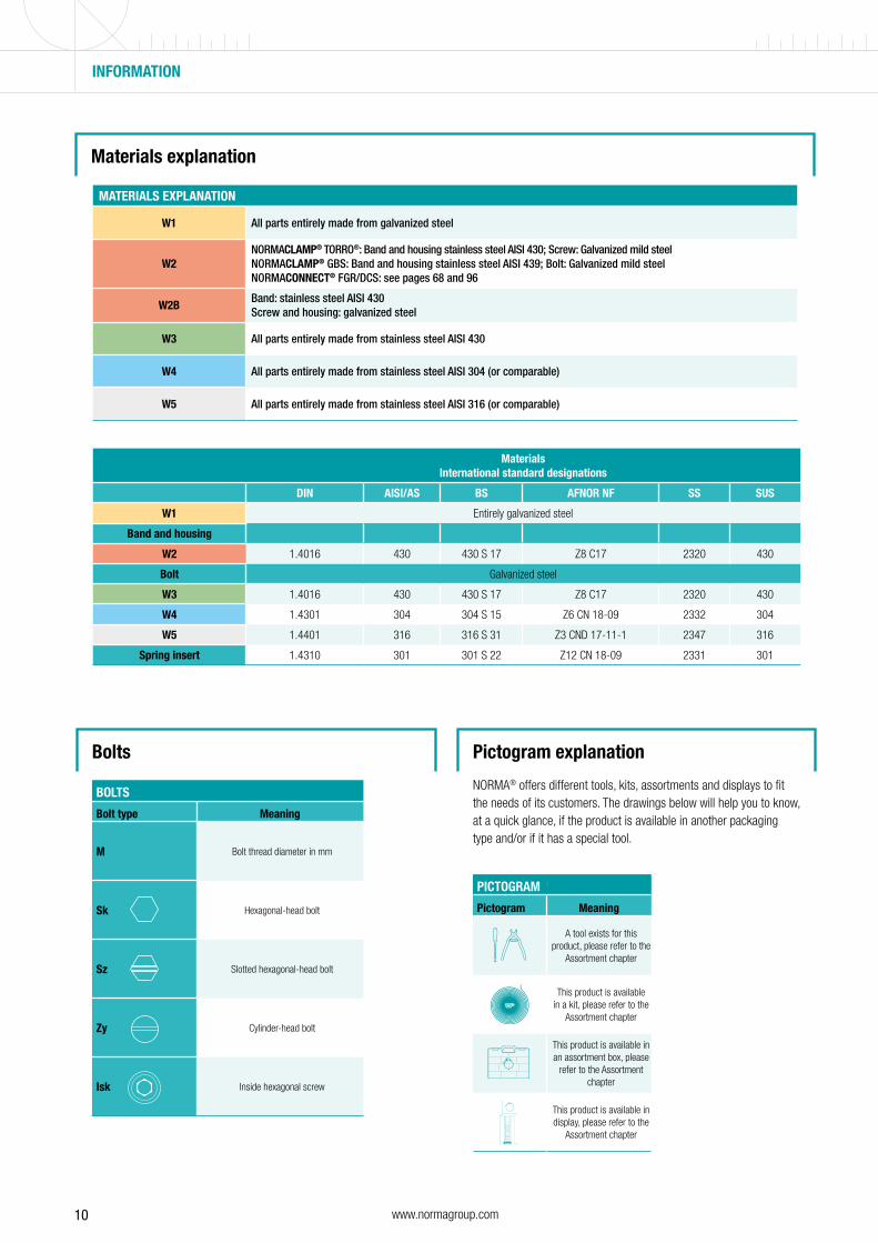
MaterialsInternational standard designations
DIN AISI/AS BS AFNOR NF SS SUS
W1 Entirely galvanized steel
Band and housing
W2 1.4016 430 430 S 17 Z8 C17 2320 430
Bolt Galvanized steel
W3 1.4016 430 430 S 17 Z8 C17 2320 430
W4 1.4301 304 304 S 15 Z6 CN 18-09 2332 304
W5 1.4401 316 316 S 31 Z3 CND 17-11-1 2347 316
Spring insert 1.4310 301 301 S 22 Z12 CN 18-09 2331 301
Bolts Pictogram explanation
INFORMATION
BOLTS
Bolt type Meaning
M Bolt thread diameter in mm
Sk Hexagonal-head bolt
Sz Slotted hexagonal-head bolt
Zy Cylinder-head bolt
Isk Inside hexagonal screw
PICTOGRAM
Pictogram Meaning
A tool exists for this product, please refer to the
Assortment chapter
This product is available in a kit, please refer to the
Assortment chapter
This product is available in an assortment box, please
refer to the Assortment chapter
This product is available in display, please refer to the
Assortment chapter
NORMA® offers different tools, kits, assortments and displays to fit the needs of its customers. The drawings below will help you to know, at a quick glance, if the product is available in another packaging type and/or if it has a special tool.
Materials explanation
MATERIALS EXPLANATION
W1 All parts entirely made from galvanized steel
W2NORMACLAMP® TORRO®: Band and housing stainless steel AISI 430; Screw: Galvanized mild steelNORMACLAMP® GBS: Band and housing stainless steel AISI 439; Bolt: Galvanized mild steel NORMACONNECT® FGR/DCS: see pages 68 and 96
W2BBand: stainless steel AISI 430Screw and housing: galvanized steel
W3 All parts entirely made from stainless steel AISI 430
W4 All parts entirely made from stainless steel AISI 304 (or comparable)
W5 All parts entirely made from stainless steel AISI 316 (or comparable)

11www.normagroup.com
PLAIN BAND
NORMACLAMP® INDEX – Clamps
PRODUCT FAMILY PRODUCT CATEGORY PRODUCT NAME PAGE
WORM DRIVE
HOSE CLAMPS
PLAIN BAND TORRO®
TORRO® WF
TORRO® TORQUE CAP
TORRO® THUMBSCREW
TORRO® TAMPERPROOF
TORRO® NOTCH
TORRO® PREFIX SYSTEM
TORRO® PREFIX SYSTEM WF
TORRO® PREFIX CLIP
NEW: TORRO® PREFIX DOUBLE CLIP
TORRO® RADIAL INSERT
TORRO® SAFETY CAP
NEW: TORRO® SAFETY COLLAR
HD
20
23
25
26
27
28
28
28
29
29
29
30
30
31
PERFORATED BAND HI-TORQUE 32
PROFILE BAND NEW: CC CLAMP 33
QUICK LOCK QUICK LOCK 9 MM
QUICK LOCK 12 MM
STRIP STEEL
QUICK LOCK HOUSING
34
36
37
38
HEAVY DUTY
CLAMPS
TRUNNION CLAMPS GBS HOLLOW TRUNNION
GBS STC
GBS QRC
GBS MULTI PART
39
41
42
43
QUICK RELEASE STANDARD SVS
SVS P
SVS EYELET BOLT
44
46
46
RETAINING CLAMPS METAL S/SP
SP SINGLE
SP DOUBLE
SPGU
HMK
HMK SINGLE-PART HEAVY DUTY
HMK TWO-PART HEAVY DUTY
HMK K1
47
49
49
49
50
52
52
52
ONE PIECE CLAMPS SCREWLESS CLAMP COBRA 53
SPRING BAND HOSE CLIPS FBS
FBS R
FBS C
FBS HC
FBS MC
55
57
57
57
57
EAR CLIPS ONE EAR CLIPS EARCLIP SINGLE
EARCLIP SAFE
NEW: CV BOOT CLAMP
58
59
60
TWO EAR CLIPS EARCLIP DOUBLE 61
PERFORATED BAND
QUICK LOCK
TRUNNION CLAMPS
QUICK RELEASE
RETAINING CLAMPS
SCREWLESS CLAMP
SPRING BAND HOSE CLIPS
EAR CLIPS
CV BOOT CLAMP
PROFILE BAND
NEWNEW
NEWNEW

12 www.normagroup.com
NORMACONNECT® INDEX – Pipe Connectors
PRODUCT FAMILY PRODUCT CATERGORY PRODUCT NAME PAGE
INFRASTRUCTURE
CONNECTORS
FGR FLEX now also available with FKM sealing sleeve
FLEX E
FLEX 3
GRIP now also available with FKM sealing sleeve
GRIP E
GRIP E-FP
RFP
PLAST GRIP
PLAST GRIP E
COMBI GRIP
COMBI GRIP E
SUPPORT SLEEVE
REP E
NEW: FIRST-AID REPAIR CLAMP
69
72
74
77
80
82
84
85
86
87
88
89
91
93
DCS RAPID
RAPID MSM
CV/CE
SVE
UNIVERSAL CLAW
RECORD CLAW
COMBI CLAW
CONFIX
98
99
100
101
102
103
104
105
COMPRESSION
FITTINGS
PLASTIC COMPRESSION FITTINGS
MALE THREADED ADAPTOR (MA)
FEMALE THREADED ADAPTOR (FA)
MALE THREADED TEE (MT)
FEMALE THREADED TEE (FT)
MALE THREADED ELBOW - MALE BEND 90 (MB)
FEMALE THREADED ELBOW - FEMALE BEND 90 (FB)
STRAIGHT COUPLER (SC)
EQUAL BEND (EB)
EQUAL TEE (ET)
END CAP (EC)
REDUCING COUPLER (RC)
REDUCING TEE (RT)
FLANGE ADAPTOR (FLA)
POP-UP EQUAL BEND (PE)
WALL PLATE ELBOW (WPE)
MALE THREADED ADAPTOR WITH BRASS INSERT (MAB)
FEMALE THREADED ADAPTOR WITH BRASS INSERT (FAB)
FEMALE THREADED BEND WITH BRASS INSERT (FBB)
108
108
109
109
110
110
111
111
111
112
112
113
113
113
114
114
114
114
PIPE CLAMPS EXHAUST PIPE CLAMP SEC
ARS
RS/DIN
ACCUSEAL
DURASEAL
ACCULOCK
NEW: EURO COUPLER
PIPE CLAMP M8/M10
EASYSEAL
NEW: TORCTITE
115
116
118
120
122
123
124
125
126
127
WIDE BAND CLAMP BRS / BRSP 128
PROFILE CLAMP V STC
V QRC
V SVS
129
133
133
FGR FLEX
FGR RFP
DCS CV/CE
DCS UNIVERSAL CLAW
PLASTIC COMPRESSION FITTINGS
EXHAUST PIPECLAMP ARS
EXHAUST PIPE CLAMP EURO COUPLER
EXHAUST PIPECLAMP M8/M10
EXHAUST PIPE CLAMP TORCTITE
PROFILE CLAMPCLAMP V
FIRST-AID REPAIR CLAMP
NEW
NEW
NEW

13www.normagroup.com
NORMAFIX® INDEX – Retaining and Mounting Products
PRODUCT FAMILY PRODUCT CATEGORY PRODUCT NAME PAGE
BANDING SYSTEMS POLYAMIDE CABLE TIES CABLE TIE WHITE
CABLE TIE BLACK
CABLE TIE COLORED
NEW: CABLE TIE WITH METAL BARB
136
136
136
138
STAINLESS STEEL CABLE TIES
NEW: STAINLESS STEEL TIE BALL LOCKING 139
ENDLESS BAND NORMETTA® SMOOTH BAND
NORMETTA® STAMPED BAND
NORMETTA® PERFORATED BAND
141
141
141
BUCKLES NB-A
NB-D
NB-G
NB-H
NB-K
142
142
142
143
143
FIXING CLIPS AND STRAPS
RUBBER CLIPS RSGU 1
RSGU 0
RSGU 2
NEW: RSGUV 1
144
146
147
148
METAL CLIPS RS 0
RS 1
RS 2
NEW: RSV 1
NEW: BSL
NEW: BSN
NEW: BSS
NEW: BS
149
150
151
152
153
157
158
159
PLASTIC CLIPS NEW: HVAC CLIP 160
MOUNTING ELEMENTS TUBE CLAMP FITTINGS SLEEVE JOINT
EXPANDING CONNECTOR
90° ELBOW
SHORT T
LONG T
WALL FLANGE
RAILING BASE FLANGE
HANDRAIL BRACKET
3 WAYS 90° ELBOW
CORNER C/W THROUGH TUBE
TWO SOCKET CROSS
SIDE OUTLET TEE
FOUR WAY CROSS AND CENTER
FIXING PAD
DOUBLE WALL COUPLER
MALE SWIVEL
FEMALE SWIVEL
GATE EYE
GATE HINGE
DOUBLE MALE SWIVEL
90° CORNER MALE SWIVEL
90° CROSSOVER
SINGLE SWIVEL COMBINATION
BASE SWIVEL COMBINATION
DOUBLE SWIVEL COMBINATION
90° CORNER SWIVEL COMBINATION
SHORT TEE SWIVEL
CLAMP ON TEE
FENCE BUILDING CLAMP
163
163
163
164
164
164
165
165
165
166
166
166
167
167
167
168
168
168
168
169
169
169
170
170
170
171
171
171
171
TRAFFIC SIGN FIXATION ALU BAND CLAMP
UNIVERSAL UCC
172
173
POLYAMIDE CABLE TIES
STAINLESS STEEL CABLE TIE
ENDLESS BAND
BUCKLES
RUBBER CLIP
METAL CLIPS
METAL CLIPS
TRAFFIC SIGN FIXATION
HVAC CLIP
TUBE CLAMP FITTINGS
NEWNEW
NEWNEW

14 www.normagroup.com
NORMAPLAST® INDEX – Hose Connectors
PRODUCT FAMILY PRODUCT CATERGORY PRODUCT NAME PAGE
PLASTIC FITTINGS HOSE CONNECTORS SV
GES
BST
TES
WES
GS
GRS
TS
KS
TRS
YRS
WS
YS
GN
TN
WN
YN
EG
EWS
ETS
ET
EW / WV
VT / VTR
VG / VGR
176
178
179
179
180
181
181
181
182
182
182
183
183
183
184
184
184
185
185
185
186
186
187
187
HOSE CONNECTORS TES
HOSE CONNECTORS WES
HOSE CONNECTORS GS
HOSE CONNECTORS KS
HOSE CONNECTORS YRS
HOSE CONNECTORS YN
HOSE CONNECTORS ET
HOSE CONNECTORS EWS
HOSE CONNECTORS EW/WV
HOSE CONNECTORS VG/VGR

15www.normagroup.com
NORMAEXTRA™ INDEX – Assortments, Displays, Tools, Accessories, User Info
KITS
ASSORTMENTS
DISPLAYS
DISPLAYS
MOUNTING TOOLS
MOUNTING TOOLS
SCREWDRIVERS
PLIERS
SCREWDRIVERS
ACCESSORIES
PRODUCT FAMILY PRODUCT CATERGORY PRODUCT NAME PAGE
NORMA®
KITSASSORTMENTSDISPLAYS TOOLS ACCESSORIES
KITS NORMAFIX® NORMETTA® Mini repair kits
NORMACLAMP® Quick lock Band-on-roll
190
190
ASSORTMENTS NORMACLAMP® TORRO® Assortment type 120 pcs
NORMACLAMP® COBRA® kit type 500k
NEW: NORMACLAMP® FBS ASSORTMENT
NORMAQUICK® PLAST® Assortment
NORMAPLAST® Assortment type 365 PA 6 and TORRO® W2
191
191
192
192
193
DISPLAYS NORMACLAMP® TORRO® Dispenser
NORMACLAMP® TORRO® Drawer Box
NORMACLAMP® TORRO® Pallet
NORMACLAMP® Quick lock Band-on-roll dispenser
194
194
194
194
NORMA® –
MOUNTING TOOLS
MOUNTING TOOLS NORMACLAMP® TORRO Prepo Assembly fixture
NORMACLAMP® COBRA® Pneumatic pliers
NORMACLAMP® FBS Pneumatic pliers version S
NORMACLAMP® FBS Pneumatic pliers version W
NORMACLAMP® FBS C Multi-release tool
NEW: NORMACONNECT® FGR Mounting aid for REP-E
NORMAFIX® Cable tie pliers for 2.2 to 4.8 mm
NORMAFIX® Cable tie pliers for 4.8 to 7.8 mm
NORMAFIX® Cable tie pliers for 3.6 to 13 mm
NEW: NORMAFIX® Cable tie pliers for 4.7 to 13 mm
NEW: NORMAFIX® Pliers for stainless steel ball locking
cable ties from 3.8 to 9 mm
NORMAFIX® NORMETTA® Clamping and cutting tool
195
195
195
195
195
196
196
196
196
196
196
196
196
NORMA® – PLIERS PLIERS NORMACLAMP® Earclip pliers
NORMACLAMP® Earclip pliers for flat mounting
NORMACLAMP® COBRA® Hand-held pliers CHT1
NORMACLAMP® COBRA® Hand-held pliers CHT2
NORMACLAMP® FBS Hand-held pliers Type 1
NORMACLAMP® FBS Hand-held pliers Type 2
NEW: NORMAFIX® RSGUV 1 / RSV 1 Handheld pliers
197
197
197
197
198
198
198
NORMA® –
SCREWDRIVERS
SCREWDRIVERS NORMACLAMP® TORRO® Screwdriver SW6, SW7, SW6/7
NORMACLAMP® Hi-torque T-screwdriver
NEW: NORMACLAMP® Tamperproof screwdriver
NORMAFIX® Tube clamp fittings Hexagonal key
199
199
199
199
NORMA® –
ACCESSORIES
ACCESSORIES NORMAFIX® Tube clamp fittings Aluminum End Cap
NORMAFIX® Tube clamp fittings Plastic End Cap
NORMAFIX® Tube clamp fittings Spare Screw
NORMAFIX® Lamppost protection tape
NORMAFIX® Cable tie Wall plug bases for cable tie
NORMAFIX® Cable tie Mounting bases for cable tie
200
200
200
200
201
201
16 www.normagroup.com
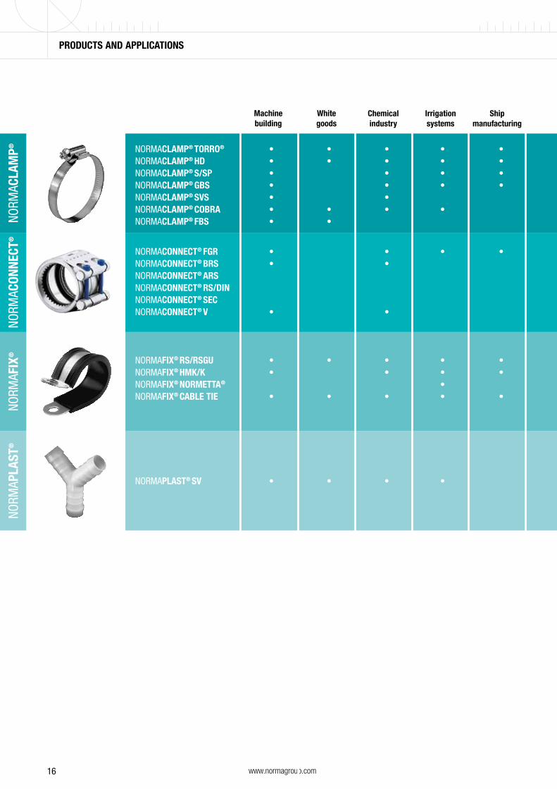
NORMACLAMP® TORRO® • • • • • • • • • • • • NORMACLAMP® HD • • • • • • • • • • • • NORMACLAMP® S/SP • • • • • • • • • NORMACLAMP® GBS • • • • • • • • • • NORMACLAMP® SVS • • • • • NORMACLAMP® COBRA • • • • • • • • NORMACLAMP® FBS • • • • •
NORMACONNECT® FGR • • • • • • • • • • NORMACONNECT® BRS • • NORMACONNECT® ARS • • • NORMACONNECT® RS/DIN • • • NORMACONNECT® SEC • • • NORMACONNECT® V • • • • • • • •
NORMAFIX® RS/RSGU • • • • • • • • • • • • NORMAFIX® HMK/K • • • • • • • • • • • NORMAFIX® NORMETTA® • • • • NORMAFIX® CABLE TIE • • • • • • • • • • • • •
NORMAPLAST® SV • • • • • • • • • •
Machinebuilding
Whitegoods
Chemical industry
Irrigationsystems
Ship manufacturing
NORM
ACLA
MP®
NO
RMAC
ONNE
CT®
NO
RMAP
LAST
®
NORM
AFIX
®
PRODUCTS AND APPLICATIONS PRODUCTS AND APPLICATIONS
17www.normagroup.com
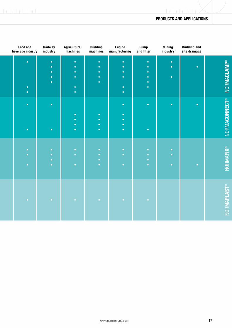
NORMACLAMP® TORRO® • • • • • • • • • • • • NORMACLAMP® HD • • • • • • • • • • • • NORMACLAMP® S/SP • • • • • • • • • NORMACLAMP® GBS • • • • • • • • • • NORMACLAMP® SVS • • • • • NORMACLAMP® COBRA • • • • • • • • NORMACLAMP® FBS • • • • •
NORMACONNECT® FGR • • • • • • • • • • NORMACONNECT® BRS • • NORMACONNECT® ARS • • • NORMACONNECT® RS/DIN • • • NORMACONNECT® SEC • • • NORMACONNECT® V • • • • • • • •
NORMAFIX® RS/RSGU • • • • • • • • • • • • NORMAFIX® HMK/K • • • • • • • • • • • NORMAFIX® NORMETTA® • • • • NORMAFIX® CABLE TIE • • • • • • • • • • • • •
NORMAPLAST® SV • • • • • • • • • •
Food and beverage industry
Railwayindustry
Agriculturalmachines
Buildingmachines
Enginemanufacturing
Pump and filter
Miningindustry
Building and site drainage
NORM
ACLA
MP®
NO
RMAC
ONNE
CT®
NO
RMAP
LAST
®
NORM
AFIX
®
PRODUCTS AND APPLICATIONS PRODUCTS AND APPLICATIONS

18 www.normagroup.com
NORMACLAMP® – Hose Clamps
* Can be designed into a complete system in conjunction with NORMAFLEX® smooth and/or corrugated tube.** Several of the NORMACLAMP products can be used.
NORMA® Product Selection Guide
Hose Pipe / Spigot
Pipe Pipe
NORMACONNECT® – Pipe Connections
Hose / Plastic*- / Metal pipe
Wall / Ceiling / Vehicle body
NORMAFIX® – Retaining Products
Hose Hose
NORMAPLAST® – Hose Connectors**

A comprehensive range to suit diverse applicationsWhether you’re looking for static hose clamps without springs or dynamic ones with springs, single-range or multi-range clamps, with NORMACLAMP® you’ll find the perfect solution for any application.
NORMACLAMP® – Hose Clamps
20 www.normagroup.com
NORM
ACLA
MP®
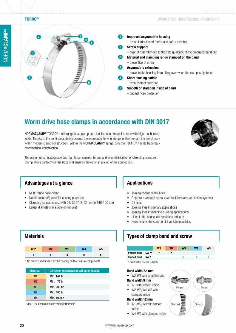
W1* W2 W3 W4 W5
x x x x x
* No chromium(VI) used for the coating on the closure components
*Max 10% base metal corrosion permissible
Material Corrosion resistance in salt spray testing
W1 Min. 144 h
W2 Min. 72 h
W3 Min. 200 h*
W4 Min. 400 h
W5 Min. 1000 h
Improved asymmetric housing – even distribution of forces and safe assembly
Screw support – ease of assembly due to the safe guidance of the emerging band end
Material and clamping range stamped on the band – prevention of errors
Asymmetric extension – prevents the housing from tilting over when the clamp is tightened
Short housing saddle – even contact pressure
Smooth or stamped inside of band – optimal hose protection
1
2
3
4
5
6
Worm drive hose clamps in accordance with DIN 3017
NORMACLAMP® TORRO® multi-range hose clamps are ideally suited to applications with high mechanical loads. Thanks to the continuous developments these products have undergone, they remain the benchmark within modern clamp construction. Within the NORMACLAMP® range, only the TORRO® has its trademark asymmetrical construction.
The asymmetric housing provides high force, superior torque and even distribution of clamping pressure. Clamp aligns perfectly on the hose and ensures the optimal sealing of the connection.
Advantages at a glance
• Multi-range hose clamp• No chromium(VI) used for coating purposes• Clamping ranges in acc. with DIN 3017: 8-12 mm to 140-160 mm• Larger diameters available on request
Applications
• Joining cooling water lines• Depressurized and pressurized fuel lines and ventilation systems• Oil lines• Joining lines in sanitary applications• Joining lines in machine building applications• Lines in the household appliance industry• Hose lines in the commercial vehicle industries
Materials
6
3
2 1
5
6
4
TORRO® Worm Drive Hose Clamps - Plain Band
SmoothStamped
Band width 7.5 mm• W2, W3 with smooth insideBand width 9 mm• W1 with smooth inside• W2, W3, W4, W5 with
stamped insideBand width 12 mm• W1, W2, W3 with smooth
inside• W4, W5 with stamped inside
Philips Slotted
W1 W2 W3 W4 W5Phillips head SW 7* • •
Slotted head SW 7 • • •
* Band width 7.5 mm = SW 6
Types of clamp band and screw
3
3
21www.normagroup.com
NORM
ACLA
MP®
NO
RMAC
LAM
P®
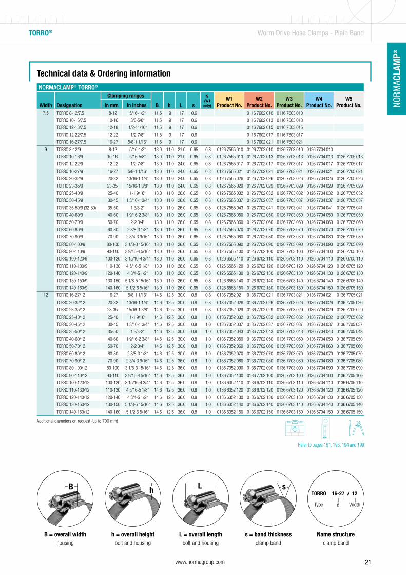
TORRO® Worm Drive Hose Clamps - Plain Band
NORMACLAMP® TORRO®
Width Designation
Clamping ranges
B h L s
s (W1 only)
W1Product No.
W2Product No.
W3Product No.
W4Product No.
W5Product No.in mm in inches
7.5 TORRO 8-12/7.5 8-12 5/16-1/2” 11.5 9 17 0.6 0116 7602 010 0116 7603 010
TORRO 10-16/7.5 10-16 3/8-5/8” 11.5 9 17 0.6 0116 7602 013 0116 7603 013
TORRO 12-18/7.5 12-18 1/2-11/16” 11.5 9 17 0.6 0116 7602 015 0116 7603 015
TORRO 12-22/7.5 12-22 1/2-7/8” 11.5 9 17 0.6 0116 7602 017 0116 7603 017
TORRO 16-27/7.5 16-27 5/8-1 1/16” 11.5 9 17 0.6 0116 7602 021 0116 7603 021
9 TORRO 8-12/9 8-12 5/16-1/2” 13.0 11.0 21.0 0.65 0.8 0126 7565 010 0126 7702 010 0126 7703 010 0126 7704 010
TORRO 10-16/9 10-16 5/16-5/8” 13.0 11.0 21.0 0.65 0.8 0126 7565 013 0126 7702 013 0126 7703 013 0126 7704 013 0126 7705 013
TORRO 12-22/9 12-22 1/2-7/8” 13.0 11.0 24.0 0.65 0.8 0126 7565 017 0126 7702 017 0126 7703 017 0126 7704 017 0126 7705 017
TORRO 16-27/9 16-27 5/8-1 1/16” 13.0 11.0 24.0 0.65 0.8 0126 7565 021 0126 7702 021 0126 7703 021 0126 7704 021 0126 7705 021
TORRO 20-32/9 20-32 13/16-1 1/4” 13.0 11.0 24.0 0.65 0.8 0126 7565 026 0126 7702 026 0126 7703 026 0126 7704 026 0126 7705 026
TORRO 23-35/9 23-35 15/16-1 3/8” 13.0 11.0 24.0 0.65 0.8 0126 7565 029 0126 7702 029 0126 7703 029 0126 7704 029 0126 7705 029
TORRO 25-40/9 25-40 1-1 9/16” 13.0 11.0 26.0 0.65 0.8 0126 7565 032 0126 7702 032 0126 7703 032 0126 7704 032 0126 7705 032
TORRO 30-45/9 30-45 1 3/16-1 3/4” 13.0 11.0 26.0 0.65 0.8 0126 7565 037 0126 7702 037 0126 7703 037 0126 7704 037 0126 7705 037
TORRO 35-50/9 (32-50) 35-50 1 3/8-2” 13.0 11.0 26.0 0.65 0.8 0126 7565 043 0126 7702 041 0126 7703 041 0126 7704 041 0126 7705 041
TORRO 40-60/9 40-60 1 9/16-2 3/8” 13.0 11.0 26.0 0.65 0.8 0126 7565 050 0126 7702 050 0126 7703 050 0126 7704 050 0126 7705 050
TORRO 50-70/9 50-70 2-2 3/4” 13.0 11.0 26.0 0.65 0.8 0126 7565 060 0126 7702 060 0126 7703 060 0126 7704 060 0126 7705 060
TORRO 60-80/9 60-80 2 3/8-3 1/8” 13.0 11.0 26.0 0.65 0.8 0126 7565 070 0126 7702 070 0126 7703 070 0126 7704 070 0126 7705 070
TORRO 70-90/9 70-90 2 3/4-3 9/16” 13.0 11.0 26.0 0.65 0.8 0126 7565 080 0126 7702 080 0126 7703 080 0126 7704 080 0126 7705 080
TORRO 80-100/9 80-100 3 1/8-3 15/16” 13.0 11.0 26.0 0.65 0.8 0126 7565 090 0126 7702 090 0126 7703 090 0126 7704 090 0126 7705 090
TORRO 90-110/9 90-110 3 9/16-4 5/16” 13.0 11.0 26.0 0.65 0.8 0126 7565 100 0126 7702 100 0126 7703 100 0126 7704 100 0126 7705 100
TORRO 100-120/9 100-120 3 15/16-4 3/4” 13.0 11.0 26.0 0.65 0.8 0126 6565 110 0126 6702 110 0126 6703 110 0126 6704 110 0126 6705 110
TORRO 110-130/9 110-130 4 5/16-5 1/8” 13.0 11.0 26.0 0.65 0.8 0126 6565 120 0126 6702 120 0126 6703 120 0126 6704 120 0126 6705 120
TORRO 120-140/9 120-140 4 3/4-5 1/2” 13.0 11.0 26.0 0.65 0.8 0126 6565 130 0126 6702 130 0126 6703 130 0126 6704 130 0126 6705 130
TORRO 130-150/9 130-150 5 1/8-5 15/16” 13.0 11.0 26.0 0.65 0.8 0126 6565 140 0126 6702 140 0126 6703 140 0126 6704 140 0126 6705 140
TORRO 140-160/9 140-160 5 1/2-6 5/16” 13.0 11.0 26.0 0.65 0.8 0126 6565 150 0126 6702 150 0126 6703 150 0126 6704 150 0126 6705 150
12 TORRO 16-27/12 16-27 5/8-1 1/16” 14.6 12.5 30.0 0.8 0.8 0136 7352 021 0136 7702 021 0136 7703 021 0136 7704 021 0136 7705 021
TORRO 20-32/12 20-32 13/16-1 1/4” 14.6 12.5 30.0 0.8 0.8 0136 7352 026 0136 7702 026 0136 7703 026 0136 7704 026 0136 7705 026
TORRO 23-35/12 23-35 15/16-1 3/8” 14.6 12.5 30.0 0.8 0.8 0136 7352 029 0136 7702 029 0136 7703 029 0136 7704 029 0136 7705 029
TORRO 25-40/12 25-40 1-1 9/16” 14.6 12.5 30.0 0.8 1.0 0136 7352 032 0136 7702 032 0136 7703 032 0136 7704 032 0136 7705 032
TORRO 30-45/12 30-45 1 3/16-1 3/4” 14.6 12.5 30.0 0.8 1.0 0136 7352 037 0136 7702 037 0136 7703 037 0136 7704 037 0136 7705 037
TORRO 35-50/12 35-50 1 3/8-2” 14.6 12.5 30.0 0.8 1.0 0136 7352 043 0136 7702 043 0136 7703 043 0136 7704 043 0136 7705 043
TORRO 40-60/12 40-60 1 9/16-2 3/8” 14.6 12.5 30.0 0.8 1.0 0136 7352 050 0136 7702 050 0136 7703 050 0136 7704 050 0136 7705 050
TORRO 50-70/12 50-70 2-2 3/4” 14.6 12.5 30.0 0.8 1.0 0136 7352 060 0136 7702 060 0136 7703 060 0136 7704 060 0136 7705 060
TORRO 60-80/12 60-80 2 3/8-3 1/8” 14.6 12.5 30.0 0.8 1.0 0136 7352 070 0136 7702 070 0136 7703 070 0136 7704 070 0136 7705 070
TORRO 70-90/12 70-90 2 3/4-3 9/16” 14.6 12.5 36.0 0.8 1.0 0136 7352 080 0136 7702 080 0136 7703 080 0136 7704 080 0136 7705 080
TORRO 80-100/12 80-100 3 1/8-3 15/16” 14.6 12.5 36.0 0.8 1.0 0136 7352 090 0136 7702 090 0136 7703 090 0136 7704 090 0136 7705 090
TORRO 90-110/12 90-110 3 9/16-4 5/16” 14.6 12.5 36.0 0.8 1.0 0136 7352 100 0136 7702 100 0136 7703 100 0136 7704 100 0136 7705 100
TORRO 100-120/12 100-120 3 15/16-4 3/4” 14.6 12.5 36.0 0.8 1.0 0136 6352 110 0136 6702 110 0136 6703 110 0136 6704 110 0136 6705 110
TORRO 110-130/12 110-130 4 5/16-5 1/8” 14.6 12.5 36.0 0.8 1.0 0136 6352 120 0136 6702 120 0136 6703 120 0136 6704 120 0136 6705 120
TORRO 120-140/12 120-140 4 3/4-5 1/2” 14.6 12.5 36.0 0.8 1.0 0136 6352 130 0136 6702 130 0136 6703 130 0136 6704 130 0136 6705 130
TORRO 130-150/12 130-150 5 1/8-5 15/16” 14.6 12.5 36.0 0.8 1.0 0136 6352 140 0136 6702 140 0136 6703 140 0136 6704 140 0136 6705 140
TORRO 140-160/12 140-160 5 1/2-6 5/16” 14.6 12.5 36.0 0.8 1.0 0136 6352 150 0136 6702 150 0136 6703 150 0136 6704 150 0136 6705 150
Technical data & Ordering information
Additional diameters on request (up to 700 mm)
TORRO 16-27 / 12
Type ø Width
B = overall widthhousing
B
h = overall heightbolt and housing
h
L = overall lengthbolt and housing
L
s = band thicknessclamp band
s
Name structureclamp band
Refer to pages 191, 193, 194 and 199

22 www.normagroup.com
NORM
ACLA
MP®
TORRO® Worm Drive Hose Clamps - Plain Band
I won’t take the page away until I have made the page changes and the adding of products.
23www.normagroup.com
NORM
ACLA
MP®
NO
RMAC
LAM
P®
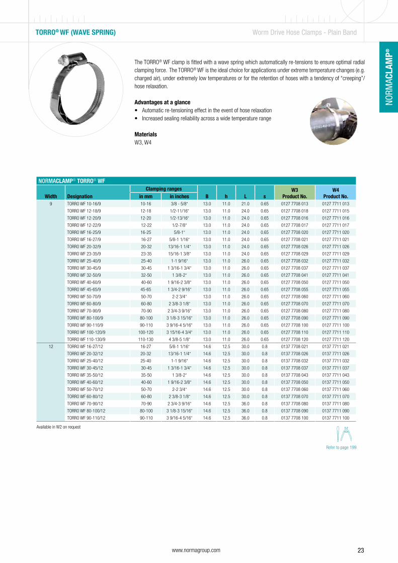
TORRO® WF (WAVE SPRING) Worm Drive Hose Clamps - Plain Band
The TORRO® WF clamp is fitted with a wave spring which automatically re-tensions to ensure optimal radial clamping force. The TORRO® WF is the ideal choice for applications under extreme temperature changes (e.g. charged air), under extremely low temperatures or for the retention of hoses with a tendency of “creeping”/hose relaxation.
Advantages at a glance• Automatic re-tensioning effect in the event of hose relaxation • Increased sealing reliability across a wide temperature range
MaterialsW3, W4
NORMACLAMP® TORRO® WF
Width DesignationClamping ranges
B h L sW3
Product No.W4
Product No.in mm in inches9 TORRO WF 10-16/9 10-16 3/8 - 5/8” 13.0 11.0 21.0 0.65 0127 7708 013 0127 7711 013
TORRO WF 12-18/9 12-18 1/2-11/16” 13.0 11.0 24.0 0.65 0127 7708 018 0127 7711 015
TORRO WF 12-20/9 12-20 1/2-13/16” 13.0 11.0 24.0 0.65 0127 7708 016 0127 7711 016
TORRO WF 12-22/9 12-22 1/2-7/8” 13.0 11.0 24.0 0.65 0127 7708 017 0127 7711 017
TORRO WF 16-25/9 16-25 5/8-1” 13.0 11.0 24.0 0.65 0127 7708 020 0127 7711 020
TORRO WF 16-27/9 16-27 5/8-1 1/16” 13.0 11.0 24.0 0.65 0127 7708 021 0127 7711 021
TORRO WF 20-32/9 20-32 13/16-1 1/4” 13.0 11.0 24.0 0.65 0127 7708 026 0127 7711 026
TORRO WF 23-35/9 23-35 15/16-1 3/8” 13.0 11.0 24.0 0.65 0127 7708 029 0127 7711 029
TORRO WF 25-40/9 25-40 1-1 9/16” 13.0 11.0 26.0 0.65 0127 7708 032 0127 7711 032
TORRO WF 30-45/9 30-45 1 3/16-1 3/4” 13.0 11.0 26.0 0.65 0127 7708 037 0127 7711 037
TORRO WF 32-50/9 32-50 1 3/8-2” 13.0 11.0 26.0 0.65 0127 7708 041 0127 7711 041
TORRO WF 40-60/9 40-60 1 9/16-2 3/8” 13.0 11.0 26.0 0.65 0127 7708 050 0127 7711 050
TORRO WF 45-65/9 45-65 1 3/4-2 9/16” 13.0 11.0 26.0 0.65 0127 7708 055 0127 7711 055
TORRO WF 50-70/9 50-70 2-2 3/4” 13.0 11.0 26.0 0.65 0127 7708 060 0127 7711 060
TORRO WF 60-80/9 60-80 2 3/8-3 1/8” 13.0 11.0 26.0 0.65 0127 7708 070 0127 7711 070
TORRO WF 70-90/9 70-90 2 3/4-3 9/16” 13.0 11.0 26.0 0.65 0127 7708 080 0127 7711 080
TORRO WF 80-100/9 80-100 3 1/8-3 15/16” 13.0 11.0 26.0 0.65 0127 7708 090 0127 7711 090
TORRO WF 90-110/9 90-110 3 9/16-4 5/16” 13.0 11.0 26.0 0.65 0127 7708 100 0127 7711 100
TORRO WF 100-120/9 100-120 3 15/16-4 3/4” 13.0 11.0 26.0 0.65 0127 7708 110 0127 7711 110
TORRO WF 110-130/9 110-130 4 3/8-5 1/8” 13.0 11.0 26.0 0.65 0127 7708 120 0127 7711 120
12 TORRO WF 16-27/12 16-27 5/8-1 1/16” 14.6 12.5 30.0 0.8 0137 7708 021 0137 7711 021
TORRO WF 20-32/12 20-32 13/16-1 1/4” 14.6 12.5 30.0 0.8 0137 7708 026 0137 7711 026
TORRO WF 25-40/12 25-40 1-1 9/16” 14.6 12.5 30.0 0.8 0137 7708 032 0137 7711 032
TORRO WF 30-45/12 30-45 1 3/16-1 3/4” 14.6 12.5 30.0 0.8 0137 7708 037 0137 7711 037
TORRO WF 35-50/12 35-50 1 3/8-2” 14.6 12.5 30.0 0.8 0137 7708 043 0137 7711 043
TORRO WF 40-60/12 40-60 1 9/16-2 3/8” 14.6 12.5 30.0 0.8 0137 7708 050 0137 7711 050
TORRO WF 50-70/12 50-70 2-2 3/4” 14.6 12.5 30.0 0.8 0137 7708 060 0137 7711 060
TORRO WF 60-80/12 60-80 2 3/8-3 1/8” 14.6 12.5 30.0 0.8 0137 7708 070 0137 7711 070
TORRO WF 70-90/12 70-90 2 3/4-3 9/16” 14.6 12.5 36.0 0.8 0137 7708 080 0137 7711 080
TORRO WF 80-100/12 80-100 3 1/8-3 15/16” 14.6 12.5 36.0 0.8 0137 7708 090 0137 7711 090
TORRO WF 90-110/12 90-110 3 9/16-4 5/16” 14.6 12.5 36.0 0.8 0137 7708 100 0137 7711 100
Refer to page 199
Available in W2 on request
24 www.normagroup.com
NORM
ACLA
MP®
TORRO® Worm Drive Hose Clamps - Plain Band
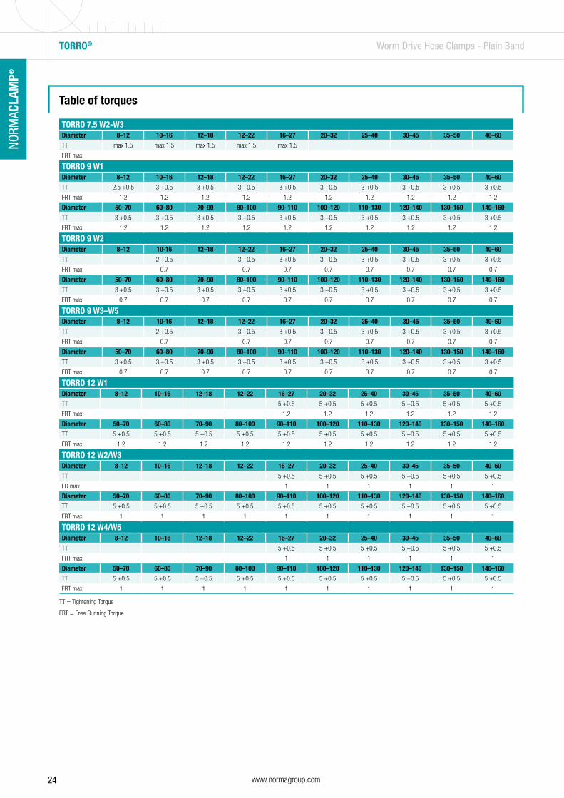
Table of torques
TORRO 7.5 W2-W3Diameter 8–12 10–16 12–18 12–22 16–27 20–32 25–40 30–45 35–50 40–60
TT max 1.5 max 1.5 max 1.5 max 1.5 max 1.5
FRT max
TORRO 9 W1Diameter 8–12 10–16 12–18 12–22 16–27 20–32 25–40 30–45 35–50 40–60
TT 2.5 +0.5 3 +0.5 3 +0.5 3 +0.5 3 +0.5 3 +0.5 3 +0.5 3 +0.5 3 +0.5 3 +0.5
FRT max 1.2 1.2 1.2 1.2 1.2 1.2 1.2 1.2 1.2 1.2
Diameter 50–70 60–80 70–90 80–100 90–110 100–120 110–130 120–140 130–150 140–160
TT 3 +0.5 3 +0.5 3 +0.5 3 +0.5 3 +0.5 3 +0.5 3 +0.5 3 +0.5 3 +0.5 3 +0.5
FRT max 1.2 1.2 1.2 1.2 1.2 1.2 1.2 1.2 1.2 1.2
TORRO 9 W2Diameter 8–12 10-16 12–18 12–22 16–27 20–32 25–40 30–45 35–50 40–60
TT 2 +0.5 3 +0.5 3 +0.5 3 +0.5 3 +0.5 3 +0.5 3 +0.5 3 +0.5
FRT max 0.7 0.7 0.7 0.7 0.7 0.7 0.7 0.7
Diameter 50–70 60–80 70–90 80–100 90–110 100–120 110–130 120–140 130–150 140–160
TT 3 +0.5 3 +0.5 3 +0.5 3 +0.5 3 +0.5 3 +0.5 3 +0.5 3 +0.5 3 +0.5 3 +0.5
FRT max 0.7 0.7 0.7 0.7 0.7 0.7 0.7 0.7 0.7 0.7
TORRO 9 W3–W5Diameter 8–12 10-16 12–18 12–22 16–27 20–32 25–40 30–45 35–50 40–60
TT 2 +0.5 3 +0.5 3 +0.5 3 +0.5 3 +0.5 3 +0.5 3 +0.5 3 +0.5
FRT max 0.7 0.7 0.7 0.7 0.7 0.7 0.7 0.7
Diameter 50–70 60–80 70–90 80–100 90–110 100–120 110–130 120–140 130–150 140–160
TT 3 +0.5 3 +0.5 3 +0.5 3 +0.5 3 +0.5 3 +0.5 3 +0.5 3 +0.5 3 +0.5 3 +0.5
FRT max 0.7 0.7 0.7 0.7 0.7 0.7 0.7 0.7 0.7 0.7
TT = Tightening Torque
FRT = Free Running Torque
TORRO 12 W1Diameter 8–12 10–16 12–18 12–22 16–27 20–32 25–40 30–45 35–50 40–60
TT 5 +0.5 5 +0.5 5 +0.5 5 +0.5 5 +0.5 5 +0.5
FRT max 1.2 1.2 1.2 1.2 1.2 1.2
Diameter 50–70 60–80 70–90 80–100 90–110 100–120 110–130 120–140 130–150 140–160
TT 5 +0.5 5 +0.5 5 +0.5 5 +0.5 5 +0.5 5 +0.5 5 +0.5 5 +0.5 5 +0.5 5 +0.5
FRT max 1.2 1.2 1.2 1.2 1.2 1.2 1.2 1.2 1.2 1.2
TORRO 12 W2/W3Diameter 8–12 10–16 12–18 12–22 16–27 20–32 25–40 30–45 35–50 40–60
TT 5 +0.5 5 +0.5 5 +0.5 5 +0.5 5 +0.5 5 +0.5
LD max 1 1 1 1 1 1
Diameter 50–70 60–80 70–90 80–100 90–110 100–120 110–130 120–140 130–150 140–160
TT 5 +0.5 5 +0.5 5 +0.5 5 +0.5 5 +0.5 5 +0.5 5 +0.5 5 +0.5 5 +0.5 5 +0.5
FRT max 1 1 1 1 1 1 1 1 1 1
TORRO 12 W4/W5Diameter 8–12 10–16 12–18 12–22 16–27 20–32 25–40 30–45 35–50 40–60
TT 5 +0.5 5 +0.5 5 +0.5 5 +0.5 5 +0.5 5 +0.5
FRT max 1 1 1 1 1 1
Diameter 50–70 60–80 70–90 80–100 90–110 100–120 110–130 120–140 130–150 140–160
TT 5 +0.5 5 +0.5 5 +0.5 5 +0.5 5 +0.5 5 +0.5 5 +0.5 5 +0.5 5 +0.5 5 +0.5
FRT max 1 1 1 1 1 1 1 1 1 1
25www.normagroup.com
NORM
ACLA
MP®
NO
RMAC
LAM
P®
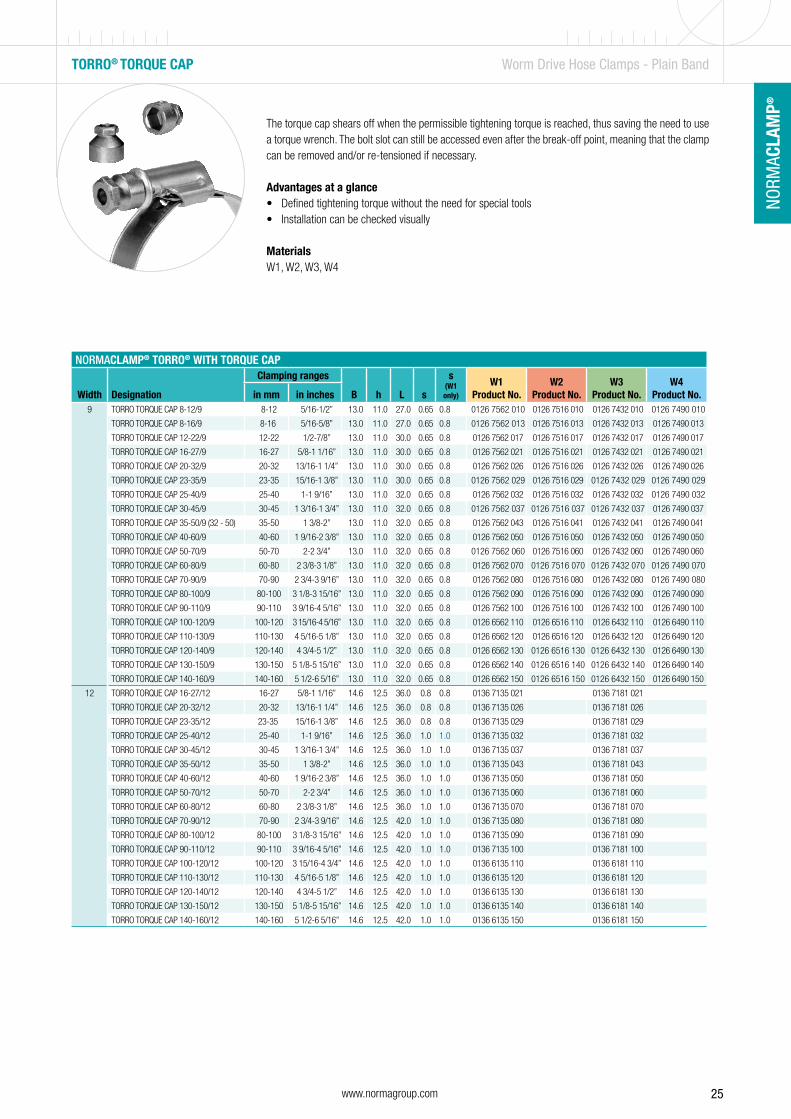
The torque cap shears off when the permissible tightening torque is reached, thus saving the need to use a torque wrench. The bolt slot can still be accessed even after the break-off point, meaning that the clamp can be removed and/or re-tensioned if necessary.
Advantages at a glance• Defined tightening torque without the need for special tools• Installation can be checked visually
MaterialsW1, W2, W3, W4
TORRO® TORQUE CAP Worm Drive Hose Clamps - Plain Band
NORMACLAMP® TORRO® WITH TORQUE CAP
Width Designation
Clamping ranges
B h L s
s (W1 only)
W1Product No.
W2Product No.
W3Product No.
W4Product No.in mm in inches
9 TORRO TORQUE CAP 8-12/9 8-12 5/16-1/2” 13.0 11.0 27.0 0.65 0.8 0126 7562 010 0126 7516 010 0126 7432 010 0126 7490 010
TORRO TORQUE CAP 8-16/9 8-16 5/16-5/8” 13.0 11.0 27.0 0.65 0.8 0126 7562 013 0126 7516 013 0126 7432 013 0126 7490 013
TORRO TORQUE CAP 12-22/9 12-22 1/2-7/8” 13.0 11.0 30.0 0.65 0.8 0126 7562 017 0126 7516 017 0126 7432 017 0126 7490 017
TORRO TORQUE CAP 16-27/9 16-27 5/8-1 1/16” 13.0 11.0 30.0 0.65 0.8 0126 7562 021 0126 7516 021 0126 7432 021 0126 7490 021
TORRO TORQUE CAP 20-32/9 20-32 13/16-1 1/4” 13.0 11.0 30.0 0.65 0.8 0126 7562 026 0126 7516 026 0126 7432 026 0126 7490 026
TORRO TORQUE CAP 23-35/9 23-35 15/16-1 3/8” 13.0 11.0 30.0 0.65 0.8 0126 7562 029 0126 7516 029 0126 7432 029 0126 7490 029
TORRO TORQUE CAP 25-40/9 25-40 1-1 9/16” 13.0 11.0 32.0 0.65 0.8 0126 7562 032 0126 7516 032 0126 7432 032 0126 7490 032
TORRO TORQUE CAP 30-45/9 30-45 1 3/16-1 3/4” 13.0 11.0 32.0 0.65 0.8 0126 7562 037 0126 7516 037 0126 7432 037 0126 7490 037
TORRO TORQUE CAP 35-50/9 (32 - 50) 35-50 1 3/8-2” 13.0 11.0 32.0 0.65 0.8 0126 7562 043 0126 7516 041 0126 7432 041 0126 7490 041
TORRO TORQUE CAP 40-60/9 40-60 1 9/16-2 3/8” 13.0 11.0 32.0 0.65 0.8 0126 7562 050 0126 7516 050 0126 7432 050 0126 7490 050
TORRO TORQUE CAP 50-70/9 50-70 2-2 3/4” 13.0 11.0 32.0 0.65 0.8 0126 7562 060 0126 7516 060 0126 7432 060 0126 7490 060
TORRO TORQUE CAP 60-80/9 60-80 2 3/8-3 1/8” 13.0 11.0 32.0 0.65 0.8 0126 7562 070 0126 7516 070 0126 7432 070 0126 7490 070
TORRO TORQUE CAP 70-90/9 70-90 2 3/4-3 9/16” 13.0 11.0 32.0 0.65 0.8 0126 7562 080 0126 7516 080 0126 7432 080 0126 7490 080
TORRO TORQUE CAP 80-100/9 80-100 3 1/8-3 15/16” 13.0 11.0 32.0 0.65 0.8 0126 7562 090 0126 7516 090 0126 7432 090 0126 7490 090
TORRO TORQUE CAP 90-110/9 90-110 3 9/16-4 5/16” 13.0 11.0 32.0 0.65 0.8 0126 7562 100 0126 7516 100 0126 7432 100 0126 7490 100
TORRO TORQUE CAP 100-120/9 100-120 3 15/16-4 5/16” 13.0 11.0 32.0 0.65 0.8 0126 6562 110 0126 6516 110 0126 6432 110 0126 6490 110
TORRO TORQUE CAP 110-130/9 110-130 4 5/16-5 1/8” 13.0 11.0 32.0 0.65 0.8 0126 6562 120 0126 6516 120 0126 6432 120 0126 6490 120
TORRO TORQUE CAP 120-140/9 120-140 4 3/4-5 1/2” 13.0 11.0 32.0 0.65 0.8 0126 6562 130 0126 6516 130 0126 6432 130 0126 6490 130
TORRO TORQUE CAP 130-150/9 130-150 5 1/8-5 15/16” 13.0 11.0 32.0 0.65 0.8 0126 6562 140 0126 6516 140 0126 6432 140 0126 6490 140
TORRO TORQUE CAP 140-160/9 140-160 5 1/2-6 5/16” 13.0 11.0 32.0 0.65 0.8 0126 6562 150 0126 6516 150 0126 6432 150 0126 6490 150
12 TORRO TORQUE CAP 16-27/12 16-27 5/8-1 1/16” 14.6 12.5 36.0 0.8 0.8 0136 7135 021 0136 7181 021
TORRO TORQUE CAP 20-32/12 20-32 13/16-1 1/4” 14.6 12.5 36.0 0.8 0.8 0136 7135 026 0136 7181 026
TORRO TORQUE CAP 23-35/12 23-35 15/16-1 3/8” 14.6 12.5 36.0 0.8 0.8 0136 7135 029 0136 7181 029
TORRO TORQUE CAP 25-40/12 25-40 1-1 9/16” 14.6 12.5 36.0 1.0 1.0 0136 7135 032 0136 7181 032
TORRO TORQUE CAP 30-45/12 30-45 1 3/16-1 3/4” 14.6 12.5 36.0 1.0 1.0 0136 7135 037 0136 7181 037
TORRO TORQUE CAP 35-50/12 35-50 1 3/8-2” 14.6 12.5 36.0 1.0 1.0 0136 7135 043 0136 7181 043
TORRO TORQUE CAP 40-60/12 40-60 1 9/16-2 3/8” 14.6 12.5 36.0 1.0 1.0 0136 7135 050 0136 7181 050
TORRO TORQUE CAP 50-70/12 50-70 2-2 3/4” 14.6 12.5 36.0 1.0 1.0 0136 7135 060 0136 7181 060
TORRO TORQUE CAP 60-80/12 60-80 2 3/8-3 1/8” 14.6 12.5 36.0 1.0 1.0 0136 7135 070 0136 7181 070
TORRO TORQUE CAP 70-90/12 70-90 2 3/4-3 9/16” 14.6 12.5 42.0 1.0 1.0 0136 7135 080 0136 7181 080
TORRO TORQUE CAP 80-100/12 80-100 3 1/8-3 15/16” 14.6 12.5 42.0 1.0 1.0 0136 7135 090 0136 7181 090
TORRO TORQUE CAP 90-110/12 90-110 3 9/16-4 5/16” 14.6 12.5 42.0 1.0 1.0 0136 7135 100 0136 7181 100
TORRO TORQUE CAP 100-120/12 100-120 3 15/16-4 3/4” 14.6 12.5 42.0 1.0 1.0 0136 6135 110 0136 6181 110
TORRO TORQUE CAP 110-130/12 110-130 4 5/16-5 1/8” 14.6 12.5 42.0 1.0 1.0 0136 6135 120 0136 6181 120
TORRO TORQUE CAP 120-140/12 120-140 4 3/4-5 1/2” 14.6 12.5 42.0 1.0 1.0 0136 6135 130 0136 6181 130
TORRO TORQUE CAP 130-150/12 130-150 5 1/8-5 15/16” 14.6 12.5 42.0 1.0 1.0 0136 6135 140 0136 6181 140
TORRO TORQUE CAP 140-160/12 140-160 5 1/2-6 5/16” 14.6 12.5 42.0 1.0 1.0 0136 6135 150 0136 6181 150
26 www.normagroup.com
NORM
ACLA
MP®
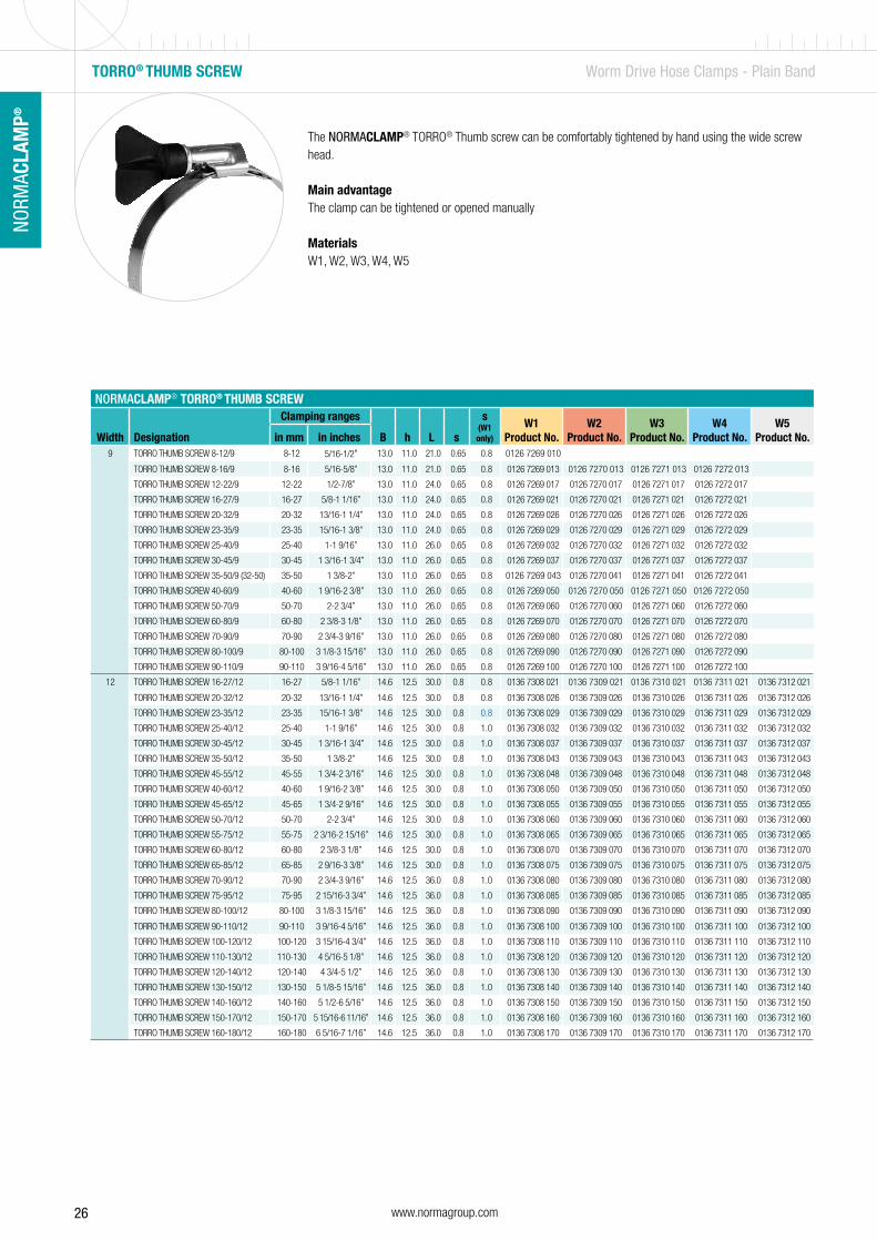
The NORMACLAMP® TORRO® Thumb screw can be comfortably tightened by hand using the wide screw head.
Main advantageThe clamp can be tightened or opened manually
MaterialsW1, W2, W3, W4, W5
NORMACLAMP® TORRO® THUMB SCREW
Width Designation
Clamping ranges
B h L s
s (W1 only)
W1Product No.
W2Product No.
W3Product No.
W4Product No.
W5Product No.in mm in inches
9 TORRO THUMB SCREW 8-12/9 8-12 5/16-1/2” 13.0 11.0 21.0 0.65 0.8 0126 7269 010
TORRO THUMB SCREW 8-16/9 8-16 5/16-5/8” 13.0 11.0 21.0 0.65 0.8 0126 7269 013 0126 7270 013 0126 7271 013 0126 7272 013
TORRO THUMB SCREW 12-22/9 12-22 1/2-7/8” 13.0 11.0 24.0 0.65 0.8 0126 7269 017 0126 7270 017 0126 7271 017 0126 7272 017
TORRO THUMB SCREW 16-27/9 16-27 5/8-1 1/16” 13.0 11.0 24.0 0.65 0.8 0126 7269 021 0126 7270 021 0126 7271 021 0126 7272 021
TORRO THUMB SCREW 20-32/9 20-32 13/16-1 1/4” 13.0 11.0 24.0 0.65 0.8 0126 7269 026 0126 7270 026 0126 7271 026 0126 7272 026
TORRO THUMB SCREW 23-35/9 23-35 15/16-1 3/8” 13.0 11.0 24.0 0.65 0.8 0126 7269 029 0126 7270 029 0126 7271 029 0126 7272 029
TORRO THUMB SCREW 25-40/9 25-40 1-1 9/16” 13.0 11.0 26.0 0.65 0.8 0126 7269 032 0126 7270 032 0126 7271 032 0126 7272 032
TORRO THUMB SCREW 30-45/9 30-45 1 3/16-1 3/4” 13.0 11.0 26.0 0.65 0.8 0126 7269 037 0126 7270 037 0126 7271 037 0126 7272 037
TORRO THUMB SCREW 35-50/9 (32-50) 35-50 1 3/8-2” 13.0 11.0 26.0 0.65 0.8 0126 7269 043 0126 7270 041 0126 7271 041 0126 7272 041
TORRO THUMB SCREW 40-60/9 40-60 1 9/16-2 3/8” 13.0 11.0 26.0 0.65 0.8 0126 7269 050 0126 7270 050 0126 7271 050 0126 7272 050
TORRO THUMB SCREW 50-70/9 50-70 2-2 3/4” 13.0 11.0 26.0 0.65 0.8 0126 7269 060 0126 7270 060 0126 7271 060 0126 7272 060
TORRO THUMB SCREW 60-80/9 60-80 2 3/8-3 1/8” 13.0 11.0 26.0 0.65 0.8 0126 7269 070 0126 7270 070 0126 7271 070 0126 7272 070
TORRO THUMB SCREW 70-90/9 70-90 2 3/4-3 9/16” 13.0 11.0 26.0 0.65 0.8 0126 7269 080 0126 7270 080 0126 7271 080 0126 7272 080
TORRO THUMB SCREW 80-100/9 80-100 3 1/8-3 15/16” 13.0 11.0 26.0 0.65 0.8 0126 7269 090 0126 7270 090 0126 7271 090 0126 7272 090
TORRO THUMB SCREW 90-110/9 90-110 3 9/16-4 5/16” 13.0 11.0 26.0 0.65 0.8 0126 7269 100 0126 7270 100 0126 7271 100 0126 7272 100
12 TORRO THUMB SCREW 16-27/12 16-27 5/8-1 1/16” 14.6 12.5 30.0 0.8 0.8 0136 7308 021 0136 7309 021 0136 7310 021 0136 7311 021 0136 7312 021
TORRO THUMB SCREW 20-32/12 20-32 13/16-1 1/4” 14.6 12.5 30.0 0.8 0.8 0136 7308 026 0136 7309 026 0136 7310 026 0136 7311 026 0136 7312 026
TORRO THUMB SCREW 23-35/12 23-35 15/16-1 3/8” 14.6 12.5 30.0 0.8 0.8 0136 7308 029 0136 7309 029 0136 7310 029 0136 7311 029 0136 7312 029
TORRO THUMB SCREW 25-40/12 25-40 1-1 9/16” 14.6 12.5 30.0 0.8 1.0 0136 7308 032 0136 7309 032 0136 7310 032 0136 7311 032 0136 7312 032
TORRO THUMB SCREW 30-45/12 30-45 1 3/16-1 3/4” 14.6 12.5 30.0 0.8 1.0 0136 7308 037 0136 7309 037 0136 7310 037 0136 7311 037 0136 7312 037
TORRO THUMB SCREW 35-50/12 35-50 1 3/8-2” 14.6 12.5 30.0 0.8 1.0 0136 7308 043 0136 7309 043 0136 7310 043 0136 7311 043 0136 7312 043
TORRO THUMB SCREW 45-55/12 45-55 1 3/4-2 3/16” 14.6 12.5 30.0 0.8 1.0 0136 7308 048 0136 7309 048 0136 7310 048 0136 7311 048 0136 7312 048
TORRO THUMB SCREW 40-60/12 40-60 1 9/16-2 3/8” 14.6 12.5 30.0 0.8 1.0 0136 7308 050 0136 7309 050 0136 7310 050 0136 7311 050 0136 7312 050
TORRO THUMB SCREW 45-65/12 45-65 1 3/4-2 9/16” 14.6 12.5 30.0 0.8 1.0 0136 7308 055 0136 7309 055 0136 7310 055 0136 7311 055 0136 7312 055
TORRO THUMB SCREW 50-70/12 50-70 2-2 3/4” 14.6 12.5 30.0 0.8 1.0 0136 7308 060 0136 7309 060 0136 7310 060 0136 7311 060 0136 7312 060
TORRO THUMB SCREW 55-75/12 55-75 2 3/16-2 15/16” 14.6 12.5 30.0 0.8 1.0 0136 7308 065 0136 7309 065 0136 7310 065 0136 7311 065 0136 7312 065
TORRO THUMB SCREW 60-80/12 60-80 2 3/8-3 1/8” 14.6 12.5 30.0 0.8 1.0 0136 7308 070 0136 7309 070 0136 7310 070 0136 7311 070 0136 7312 070
TORRO THUMB SCREW 65-85/12 65-85 2 9/16-3 3/8” 14.6 12.5 30.0 0.8 1.0 0136 7308 075 0136 7309 075 0136 7310 075 0136 7311 075 0136 7312 075
TORRO THUMB SCREW 70-90/12 70-90 2 3/4-3 9/16” 14.6 12.5 36.0 0.8 1.0 0136 7308 080 0136 7309 080 0136 7310 080 0136 7311 080 0136 7312 080
TORRO THUMB SCREW 75-95/12 75-95 2 15/16-3 3/4” 14.6 12.5 36.0 0.8 1.0 0136 7308 085 0136 7309 085 0136 7310 085 0136 7311 085 0136 7312 085
TORRO THUMB SCREW 80-100/12 80-100 3 1/8-3 15/16” 14.6 12.5 36.0 0.8 1.0 0136 7308 090 0136 7309 090 0136 7310 090 0136 7311 090 0136 7312 090
TORRO THUMB SCREW 90-110/12 90-110 3 9/16-4 5/16” 14.6 12.5 36.0 0.8 1.0 0136 7308 100 0136 7309 100 0136 7310 100 0136 7311 100 0136 7312 100
TORRO THUMB SCREW 100-120/12 100-120 3 15/16-4 3/4” 14.6 12.5 36.0 0.8 1.0 0136 7308 110 0136 7309 110 0136 7310 110 0136 7311 110 0136 7312 110
TORRO THUMB SCREW 110-130/12 110-130 4 5/16-5 1/8” 14.6 12.5 36.0 0.8 1.0 0136 7308 120 0136 7309 120 0136 7310 120 0136 7311 120 0136 7312 120
TORRO THUMB SCREW 120-140/12 120-140 4 3/4-5 1/2” 14.6 12.5 36.0 0.8 1.0 0136 7308 130 0136 7309 130 0136 7310 130 0136 7311 130 0136 7312 130
TORRO THUMB SCREW 130-150/12 130-150 5 1/8-5 15/16” 14.6 12.5 36.0 0.8 1.0 0136 7308 140 0136 7309 140 0136 7310 140 0136 7311 140 0136 7312 140
TORRO THUMB SCREW 140-160/12 140-160 5 1/2-6 5/16” 14.6 12.5 36.0 0.8 1.0 0136 7308 150 0136 7309 150 0136 7310 150 0136 7311 150 0136 7312 150
TORRO THUMB SCREW 150-170/12 150-170 5 15/16-6 11/16” 14.6 12.5 36.0 0.8 1.0 0136 7308 160 0136 7309 160 0136 7310 160 0136 7311 160 0136 7312 160
TORRO THUMB SCREW 160-180/12 160-180 6 5/16-7 1/16” 14.6 12.5 36.0 0.8 1.0 0136 7308 170 0136 7309 170 0136 7310 170 0136 7311 170 0136 7312 170
TORRO® THUMB SCREW Worm Drive Hose Clamps - Plain Band
27www.normagroup.com
NORM
ACLA
MP®
NO
RMAC
LAM
P®
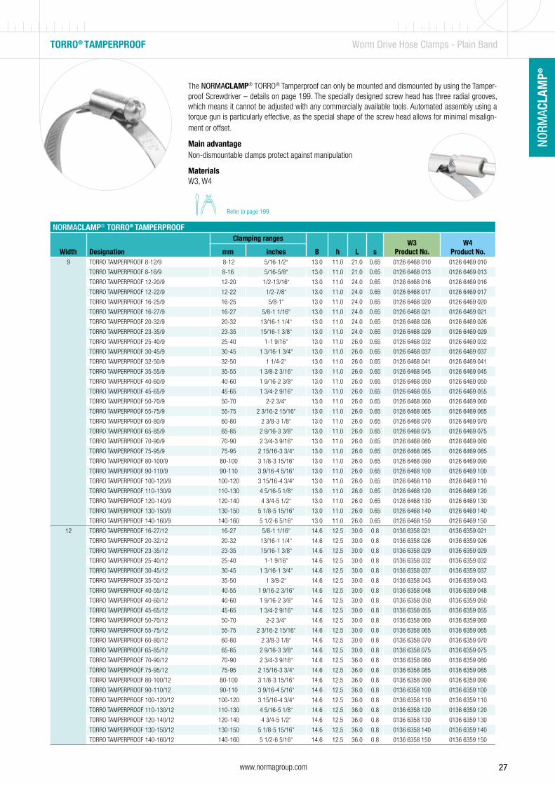
The NORMACLAMP® TORRO® Tamperproof can only be mounted and dismounted by using the Tamper-proof Screwdriver – details on page 199. The specially designed screw head has three radial grooves, which means it cannot be adjusted with any commercially available tools. Automated assembly using a torque gun is particularly effective, as the special shape of the screw head allows for minimal misalign-ment or offset.
Main advantageNon-dismountable clamps protect against manipulation
MaterialsW3, W4
NORMACLAMP® TORRO® TAMPERPROOF
Width Designation
Clamping ranges
B h L sW3
Product No.W4
Product No.mm inches9 TORRO TAMPERPROOF 8-12/9 8-12 5/16-1/2” 13.0 11.0 21.0 0.65 0126 6468 010 0126 6469 010
TORRO TAMPERPROOF 8-16/9 8-16 5/16-5/8” 13.0 11.0 21.0 0.65 0126 6468 013 0126 6469 013
TORRO TAMPERPROOF 12-20/9 12-20 1/2-13/16” 13.0 11.0 24.0 0.65 0126 6468 016 0126 6469 016
TORRO TAMPERPROOF 12-22/9 12-22 1/2-7/8” 13.0 11.0 24.0 0.65 0126 6468 017 0126 6469 017
TORRO TAMPERPROOF 16-25/9 16-25 5/8-1” 13.0 11.0 24.0 0.65 0126 6468 020 0126 6469 020
TORRO TAMPERPROOF 16-27/9 16-27 5/8-1 1/16” 13.0 11.0 24.0 0.65 0126 6468 021 0126 6469 021
TORRO TAMPERPROOF 20-32/9 20-32 13/16-1 1/4” 13.0 11.0 24.0 0.65 0126 6468 026 0126 6469 026
TORRO TAMPERPROOF 23-35/9 23-35 15/16-1 3/8” 13.0 11.0 24.0 0.65 0126 6468 029 0126 6469 029
TORRO TAMPERPROOF 25-40/9 25-40 1-1 9/16” 13.0 11.0 26.0 0.65 0126 6468 032 0126 6469 032
TORRO TAMPERPROOF 30-45/9 30-45 1 3/16-1 3/4” 13.0 11.0 26.0 0.65 0126 6468 037 0126 6469 037
TORRO TAMPERPROOF 32-50/9 32-50 1 1/4-2” 13.0 11.0 26.0 0.65 0126 6468 041 0126 6469 041
TORRO TAMPERPROOF 35-55/9 35-55 1 3/8-2 3/16” 13.0 11.0 26.0 0.65 0126 6468 045 0126 6469 045
TORRO TAMPERPROOF 40-60/9 40-60 1 9/16-2 3/8” 13.0 11.0 26.0 0.65 0126 6468 050 0126 6469 050
TORRO TAMPERPROOF 45-65/9 45-65 1 3/4-2 9/16” 13.0 11.0 26.0 0.65 0126 6468 055 0126 6469 055
TORRO TAMPERPROOF 50-70/9 50-70 2-2 3/4” 13.0 11.0 26.0 0.65 0126 6468 060 0126 6469 060
TORRO TAMPERPROOF 55-75/9 55-75 2 3/16-2 15/16” 13.0 11.0 26.0 0.65 0126 6468 065 0126 6469 065
TORRO TAMPERPROOF 60-80/9 60-80 2 3/8-3 1/8” 13.0 11.0 26.0 0.65 0126 6468 070 0126 6469 070
TORRO TAMPERPROOF 65-85/9 65-85 2 9/16-3 3/8” 13.0 11.0 26.0 0.65 0126 6468 075 0126 6469 075
TORRO TAMPERPROOF 70-90/9 70-90 2 3/4-3 9/16” 13.0 11.0 26.0 0.65 0126 6468 080 0126 6469 080
TORRO TAMPERPROOF 75-95/9 75-95 2 15/16-3 3/4” 13.0 11.0 26.0 0.65 0126 6468 085 0126 6469 085
TORRO TAMPERPROOF 80-100/9 80-100 3 1/8-3 15/16” 13.0 11.0 26.0 0.65 0126 6468 090 0126 6469 090
TORRO TAMPERPROOF 90-110/9 90-110 3 9/16-4 5/16” 13.0 11.0 26.0 0.65 0126 6468 100 0126 6469 100
TORRO TAMPERPROOF 100-120/9 100-120 3 15/16-4 3/4” 13.0 11.0 26.0 0.65 0126 6468 110 0126 6469 110
TORRO TAMPERPROOF 110-130/9 110-130 4 5/16-5 1/8” 13.0 11.0 26.0 0.65 0126 6468 120 0126 6469 120
TORRO TAMPERPROOF 120-140/9 120-140 4 3/4-5 1/2” 13.0 11.0 26.0 0.65 0126 6468 130 0126 6469 130
TORRO TAMPERPROOF 130-150/9 130-150 5 1/8-5 15/16” 13.0 11.0 26.0 0.65 0126 6468 140 0126 6469 140
TORRO TAMPERPROOF 140-160/9 140-160 5 1/2-6 5/16” 13.0 11.0 26.0 0.65 0126 6468 150 0126 6469 150
12 TORRO TAMPERPROOF 16-27/12 16-27 5/8-1 1/16” 14.6 12.5 30.0 0.8 0136 6358 021 0136 6359 021
TORRO TAMPERPROOF 20-32/12 20-32 13/16-1 1/4” 14.6 12.5 30.0 0.8 0136 6358 026 0136 6359 026
TORRO TAMPERPROOF 23-35/12 23-35 15/16-1 3/8” 14.6 12.5 30.0 0.8 0136 6358 029 0136 6359 029
TORRO TAMPERPROOF 25-40/12 25-40 1-1 9/16” 14.6 12.5 30.0 0.8 0136 6358 032 0136 6359 032
TORRO TAMPERPROOF 30-45/12 30-45 1 3/16-1 3/4” 14.6 12.5 30.0 0.8 0136 6358 037 0136 6359 037
TORRO TAMPERPROOF 35-50/12 35-50 1 3/8-2” 14.6 12.5 30.0 0.8 0136 6358 043 0136 6359 043
TORRO TAMPERPROOF 40-55/12 40-55 1 9/16-2 3/16” 14.6 12.5 30.0 0.8 0136 6358 048 0136 6359 048
TORRO TAMPERPROOF 40-60/12 40-60 1 9/16-2 3/8” 14.6 12.5 30.0 0.8 0136 6358 050 0136 6359 050
TORRO TAMPERPROOF 45-65/12 45-65 1 3/4-2 9/16” 14.6 12.5 30.0 0.8 0136 6358 055 0136 6359 055
TORRO TAMPERPROOF 50-70/12 50-70 2-2 3/4” 14.6 12.5 30.0 0.8 0136 6358 060 0136 6359 060
TORRO TAMPERPROOF 55-75/12 55-75 2 3/16-2 15/16” 14.6 12.5 30.0 0.8 0136 6358 065 0136 6359 065
TORRO TAMPERPROOF 60-80/12 60-80 2 3/8-3 1/8” 14.6 12.5 30.0 0.8 0136 6358 070 0136 6359 070
TORRO TAMPERPROOF 65-85/12 65-85 2 9/16-3 3/8” 14.6 12.5 30.0 0.8 0136 6358 075 0136 6359 075
TORRO TAMPERPROOF 70-90/12 70-90 2 3/4-3 9/16” 14.6 12.5 36.0 0.8 0136 6358 080 0136 6359 080
TORRO TAMPERPROOF 75-95/12 75-95 2 15/16-3 3/4” 14.6 12.5 36.0 0.8 0136 6358 085 0136 6359 085
TORRO TAMPERPROOF 80-100/12 80-100 3 1/8-3 15/16” 14.6 12.5 36.0 0.8 0136 6358 090 0136 6359 090
TORRO TAMPERPROOF 90-110/12 90-110 3 9/16-4 5/16” 14.6 12.5 36.0 0.8 0136 6358 100 0136 6359 100
TORRO TAMPERPROOF 100-120/12 100-120 3 15/16-4 3/4” 14.6 12.5 36.0 0.8 0136 6358 110 0136 6359 110
TORRO TAMPERPROOF 110-130/12 110-130 4 5/16-5 1/8” 14.6 12.5 36.0 0.8 0136 6358 120 0136 6359 120
TORRO TAMPERPROOF 120-140/12 120-140 4 3/4-5 1/2” 14.6 12.5 36.0 0.8 0136 6358 130 0136 6359 130
TORRO TAMPERPROOF 130-150/12 130-150 5 1/8-5 15/16” 14.6 12.5 36.0 0.8 0136 6358 140 0136 6359 140
TORRO TAMPERPROOF 140-160/12 140-160 5 1/2-6 5/16” 14.6 12.5 36.0 0.8 0136 6358 150 0136 6359 150
TORRO® TAMPERPROOF Worm Drive Hose Clamps - Plain Band
Refer to page 199
28 www.normagroup.com
NORM
ACLA
MP®
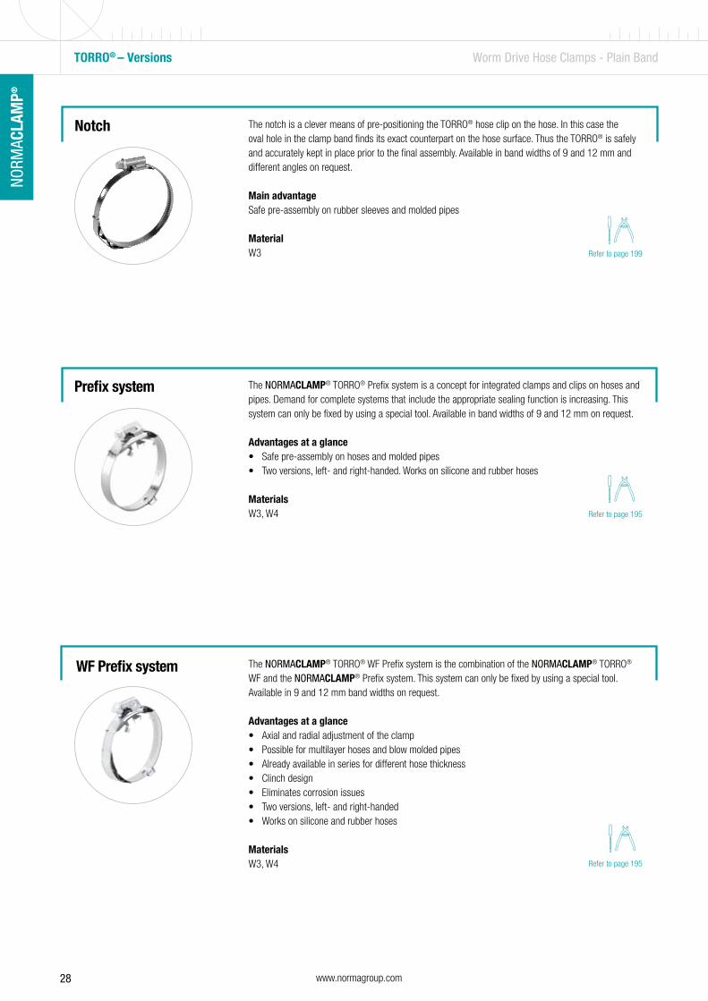
The NORMACLAMP® TORRO® Prefix system is a concept for integrated clamps and clips on hoses and pipes. Demand for complete systems that include the appropriate sealing function is increasing. This system can only be fixed by using a special tool. Available in band widths of 9 and 12 mm on request.
Advantages at a glance• Safe pre-assembly on hoses and molded pipes• Two versions, left- and right-handed. Works on silicone and rubber hoses
MaterialsW3, W4
Prefix system
The NORMACLAMP® TORRO® WF Prefix system is the combination of the NORMACLAMP® TORRO® WF and the NORMACLAMP® Prefix system. This system can only be fixed by using a special tool. Available in 9 and 12 mm band widths on request.
Advantages at a glance• Axial and radial adjustment of the clamp• Possible for multilayer hoses and blow molded pipes• Already available in series for different hose thickness• Clinch design • Eliminates corrosion issues• Two versions, left- and right-handed• Works on silicone and rubber hoses
MaterialsW3, W4
TORRO® – Versions Worm Drive Hose Clamps - Plain Band
WF Prefix system
The notch is a clever means of pre-positioning the TORRO® hose clip on the hose. In this case the oval hole in the clamp band finds its exact counterpart on the hose surface. Thus the TORRO® is safely and accurately kept in place prior to the final assembly. Available in band widths of 9 and 12 mm and different angles on request.
Main advantageSafe pre-assembly on rubber sleeves and molded pipes
MaterialW3
Notch
Refer to page 199
Refer to page 195
Refer to page 195
29www.normagroup.com
NORM
ACLA
MP®
NO
RMAC
LAM
P®
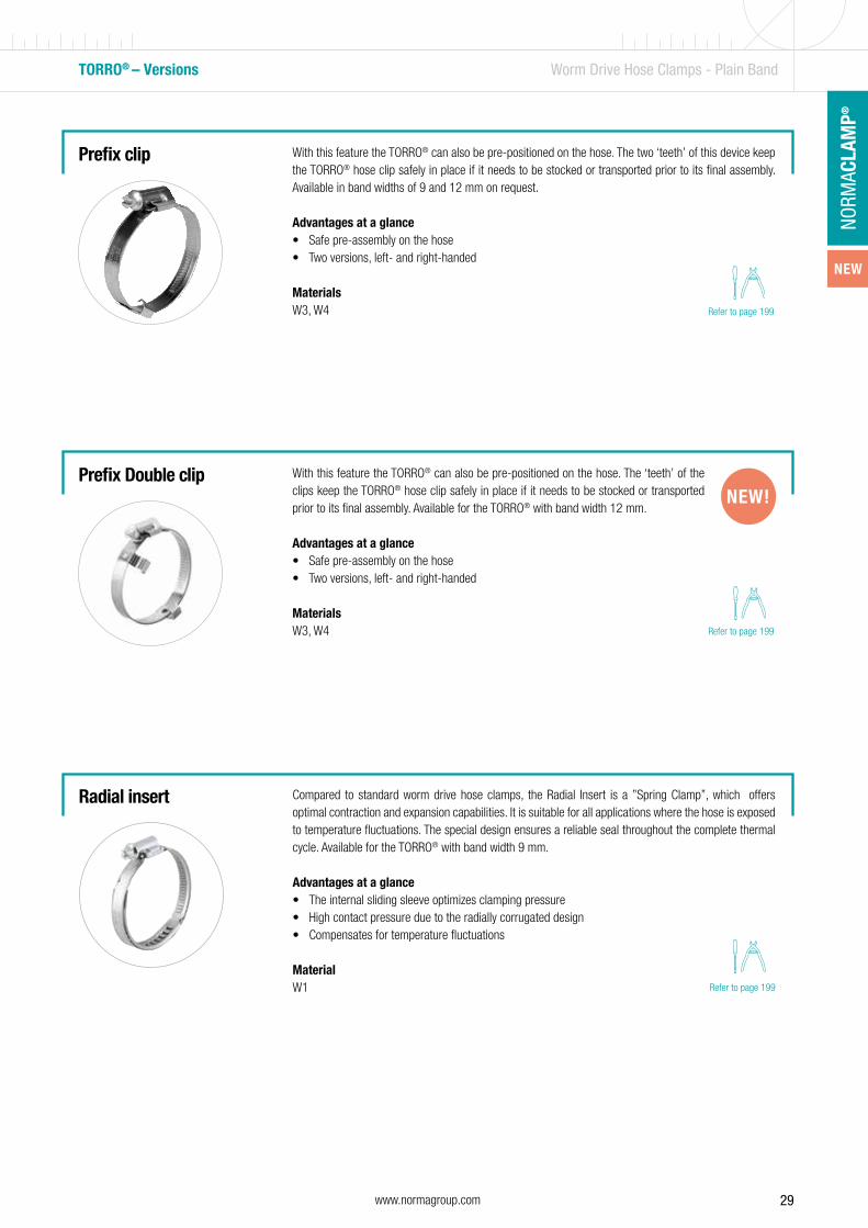
With this feature the TORRO® can also be pre-positioned on the hose. The two ‘teeth’ of this device keep the TORRO® hose clip safely in place if it needs to be stocked or transported prior to its final assembly. Available in band widths of 9 and 12 mm on request.
Advantages at a glance• Safe pre-assembly on the hose• Two versions, left- and right-handed
MaterialsW3, W4
Prefix clip
TORRO® – Versions Worm Drive Hose Clamps - Plain Band
Refer to page 199
With this feature the TORRO® can also be pre-positioned on the hose. The ‘teeth’ of the clips keep the TORRO® hose clip safely in place if it needs to be stocked or transported prior to its final assembly. Available for the TORRO® with band width 12 mm.
Advantages at a glance• Safe pre-assembly on the hose• Two versions, left- and right-handed MaterialsW3, W4
Prefix Double clipNEW!
Compared to standard worm drive hose clamps, the Radial Insert is a ”Spring Clamp”, which offers optimal contraction and expansion capabilities. It is suitable for all applications where the hose is exposed to temperature fluctuations. The special design ensures a reliable seal throughout the complete thermal cycle. Available for the TORRO® with band width 9 mm.
Advantages at a glance• The internal sliding sleeve optimizes clamping pressure• High contact pressure due to the radially corrugated design• Compensates for temperature fluctuations
MaterialW1
Radial insert
Refer to page 199
Refer to page 199
NEW

30 www.normagroup.com
NORM
ACLA
MP®
TORRO® – Versions Worm Drive Hose Clamps - Plain Band
The NORMACLAMP® TORRO® safety cap is a small plastic cap which covers the end of the clamp band, thus stopping injuries from occurring and making a significant contribution to accident prevention measures.
Main advantageAvailable for band widths 7.5 mm - 0045 8000 021, 9 mm - 0045 8000 022 and 12 mm - 0045 8000 023
MaterialPlastic
Safety cap
The NORMACLAMP® TORRO® safety collar 9/12 - 1043 0000 364 is a plastic ring that can be attached easily to the screw head of the clamp. By preventing the screwdriver from slipping off the head, it makes the installation process considerably safer. The safety collar is available for screws that correspond to wrench opening 7.
Main advantageScrewdriver prevented from slipping during installation
MaterialsFor all materials
Safety collar

31www.normagroup.com
NORM
ACLA
MP®
NO
RMAC
LAM
P®
HD Worm Drive Hose Clamps - Plain Band
Materials
Extended bridge
16 mm band width – for applications where harsh torques and contact pressures are required
Clamping range stamped on the band – prevention of errors
1
2
3
Worm drive hose clamps
NORMACLAMP® HD is suitable for special applications where harsh torques and contact pressures are required. This clamp is an add-on type to our range of worm drive hose clips and therefore only available in 16 mm band width and W4 material quality.
Technical data & Ordering information
3
2
1
NORMACLAMP® HD
Width DesignationClamping ranges
B h L sW4
Product No.in mm in inches16 HD 25-45/16 C8 25-45 1-1 3/4” 23.0 13.0 37.0 0.7 0156 7804 035
HD 32-54/16 C8 32-54 1 1/4-2 1/8” 23.0 13.0 37.0 0.7 0156 7804 043
HD 45-67/16 C8 45-67 1 3/4-2 5/8” 23.0 13.0 37.0 0.7 0156 7804 056
HD 57-79/16 C8 57-79 2 1/4-3 1/8” 23.0 13.0 37.0 0.7 0156 7804 068
HD 70-92/16 C8 70-92 2 3/4-3 5/8” 23.0 13.0 37.0 0.7 0156 7804 081
HD 83-105/16 C8 83-105 3 1/4-4 1/8” 23.0 13.0 37.0 0.7 0156 7804 094
HD 95-118/16 C8 95-118 3 3/4-4 5/8” 23.0 13.0 37.0 0.7 0156 7804 106
HD 108-130/16 C8 108-130 4 1/4-5 1/8” 23.0 13.0 37.0 0.7 0156 7804 119
HD 121-143/16 C8 121-143 4 3/4-5 5/8” 23.0 13.0 37.0 0.7 0156 7804 132
HD 133-156/16 C8 133-156 5 1/4-6 1/8” 23.0 13.0 37.0 0.7 0156 7804 144
HD 146-168/16 C8 146-168 5 3/4-6 5/8” 23.0 13.0 37.0 0.7 0156 7804 157
HD 159-181/16 C8 159-181 6 1/4-7 1/8” 23.0 13.0 37.0 0.7 0156 7804 170
HD 172-194/16 C8 172-194 6 3/4-7 5/8” 23.0 13.0 37.0 0.7 0156 7804 183
HD 184-206/16 C8 184-206 7 1/4-8 1/8” 23.0 13.0 37.0 0.7 0156 7804 195
HD 197-219/16 C8 197-219 7 3/4-8 5/8” 23.0 13.0 37.0 0.7 0156 7804 208
HD 210-232/16 C8 210-232 8 1/4-9 1/8” 23.0 13.0 37.0 0.7 0156 7804 221
Other sizes available on request
Torques
* Max 5% corrosion of the base material allowed
Material Corrosion resistance in salt spray testing
W4 Min. 240 h*
Band width Failure torque (min. value) Recommended tightening torque
16 17 Nm max. 10 Nm*
* Depending on the type of application
B = overall widthhousing
h = overall heightbolt and housing
L = overall lengthbolt and housing
s = band thicknessclamp band
Name structureclamp band
HD 16-27 / 12
Type ø Width
B
h
L
s
Main advantage
The extended bridge prevents leaks and hose being damaged
Applications
Mounting of silicone, plastic and rubber tubing with steel inserts
Refer to page 199
32 www.normagroup.com
NORM
ACLA
MP®
HI-TORQUE CLAMP Worm Drive Hose Clamps - Perforated band
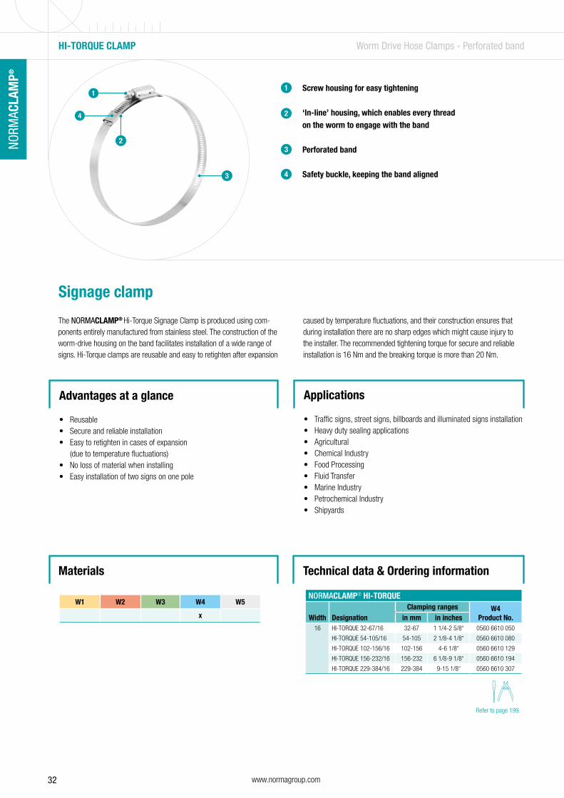
Signage clamp
The NORMACLAMP® Hi-Torque Signage Clamp is produced using com-ponents entirely manufactured from stainless steel. The construction of the worm-drive housing on the band facilitates installation of a wide range of signs. Hi-Torque clamps are reusable and easy to retighten after expansion
caused by temperature fluctuations, and their construction ensures that during installation there are no sharp edges which might cause injury to the installer. The recommended tightening torque for secure and reliable installation is 16 Nm and the breaking torque is more than 20 Nm.
Screw housing for easy tightening
‘In-line’ housing, which enables every thread on the worm to engage with the band
Perforated band
Safety buckle, keeping the band aligned
1
2
3
Advantages at a glance
• Reusable• Secure and reliable installation• Easy to retighten in cases of expansion
(due to temperature fluctuations)• No loss of material when installing• Easy installation of two signs on one pole
Applications
• Traffic signs, street signs, billboards and illuminated signs installation• Heavy duty sealing applications• Agricultural• Chemical Industry• Food Processing• Fluid Transfer• Marine Industry• Petrochemical Industry• Shipyards
Technical data & Ordering information
NORMACLAMP® HI-TORQUE
Width DesignationClamping ranges W4
Product No.in mm in inches16 HI-TORQUE 32-67/16 32-67 1 1/4-2 5/8” 0560 6610 050
HI-TORQUE 54-105/16 54-105 2 1/8-4 1/8” 0560 6610 080
HI-TORQUE 102-156/16 102-156 4-6 1/8” 0560 6610 129
HI-TORQUE 156-232/16 156-232 6 1/8-9 1/8” 0560 6610 194
HI-TORQUE 229-384/16 229-384 9-15 1/8” 0560 6610 307
3
1
2
W1 W2 W3 W4 W5
x
Materials
Refer to page 199.
4
4
33www.normagroup.com
NORM
ACLA
MP®
NO
RMAC
LAM
P®
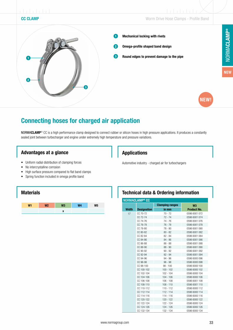
CC CLAMP Worm Drive Hose Clamps - Profile Band
Mechanical locking with rivets
Omega-profile shaped band design
Round edges to prevent damage to the pipe
1
2
3
2
Connecting hoses for charged air application
NORMACLAMP® CC is a high performance clamp designed to connect rubber or silicon hoses in high pressure applications. It produces a constantly sealed joint between turbocharger and engine under extremely high temperature and pressure variations.
Advantages at a glance
• Uniform radial distribution of clamping forces• No intercrystalline corrosion• High surface pressure compared to flat band clamps• Spring function included in omega profile band
Applications
Automotive industry - charged air for turbochargers
1
3
W1 W2 W3 W4 W5
x
Materials Technical data & Ordering information
NEW!
NORMACLAMP® CC
Width DesignationClamping ranges W3
Product No.in mm17 CC 70-72 70 - 72 0596 6001 072
CC 72-74 72 - 74 0596 6001 074CC 74-76 74 - 76 0596 6001 076CC 76-78 76 - 78 0596 6001 078CC 78-80 78 - 80 0596 6001 080CC 80-82 80 - 82 0596 6001 082CC 82-84 82 - 84 0596 6001 084CC 84-86 84 - 86 0596 6001 086CC 86-88 86 - 88 0596 6001 088CC 88-90 88 - 90 0596 6001 090CC 90-92 90 - 92 0596 6001 092CC 92-94 92 - 94 0596 6001 094CC 94-96 94 - 96 0596 6000 096CC 96-98 96 - 98 0596 6000 098CC 98-100 98 - 100 0596 6000 100CC 100-102 100 - 102 0596 6000 102CC 102-104 102 - 104 0596 6000 104CC 104-106 104 - 106 0596 6000 106CC 106-108 106 - 108 0596 6001 108CC 108-110 108 - 110 0596 6001 110CC 110-112 110 - 112 0596 6000 112CC 112-114 112 - 114 0596 6000 114CC 114-116 114 - 116 0596 6000 116CC 120-122 120 - 122 0596 6000 122CC 122-124 122 - 124 0596 6000 124CC 124-126 124 - 126 0596 6000 126CC 132-134 132 - 134 0596 6000 134
NEW!
NORMACLAMP® HI-TORQUE
Width DesignationClamping ranges W4
Product No.in mm in inches16 HI-TORQUE 32-67/16 32-67 1 1/4-2 5/8” 0560 6610 050
HI-TORQUE 54-105/16 54-105 2 1/8-4 1/8” 0560 6610 080
HI-TORQUE 102-156/16 102-156 4-6 1/8” 0560 6610 129
HI-TORQUE 156-232/16 156-232 6 1/8-9 1/8” 0560 6610 194
HI-TORQUE 229-384/16 229-384 9-15 1/8” 0560 6610 307
NEW

34 www.normagroup.com
NORM
ACLA
MP®
QUICK LOCK 9 MM Worm Drive Hose Clamps - Quick Lock
Quick Lock Housing
Smooth inner band
Smooth edges to prevent damage to the pipe
1
2
3
2
Quick locking clamp
NORMACLAMP® Quick Lock 9 mm is manufactured from a continuously threaded band with smooth edges to prevent damage to the pipe. The Quick Lock housing allows easy and quick application, as the band can
be adjusted to the right diameter of the pipe, before securing the lock with the screw. Band thickness 0.6 mm for band width 9 mm.
Advantages at a glance
• Easy and quick application• Safe joint with the hose• Flexibility• Clamping range from 25-40 up to 60-1300 mm
Applications
• Water industry• Air conditioning• Construction• Sanitary
1
3
W1 W2 (B) * W3 W4 W5
x x
Materials Torques
*W2 (B): Band in stainless steel (W3) Screw and housing in galvanized steel (W1) W2 (B) is a combination of W1 and W3 materials
Band width Tightening torque Tightening speed
9 2.5 +0.5 Nm Max. 50 RPM
35www.normagroup.com
NORM
ACLA
MP®
NO
RMAC
LAM
P®
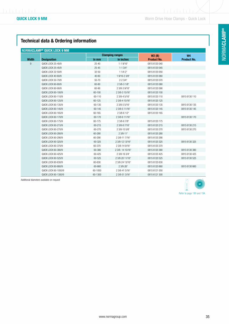
Technical data & Ordering information
NORMACLAMP® QUICK LOCK 9 MM
Width DesignationClamping ranges W2 (B)
Product No.W4
Product No.in mm in inches9 QUICK LOCK 25-40/9 25-40 1-1 9/16” 0815 6120 040
QUICK LOCK 25-45/9 25-45 1-1 3/4” 0815 6120 045
QUICK LOCK 32-50/9 32-50 1 1/4-2” 0815 6120 050
QUICK LOCK 40-60/9 40-60 1 9/16-2 3/8” 0815 6120 060
QUICK LOCK 50-70/9 50-70 2-2 3/4” 0815 6120 070
QUICK LOCK 60-80/9 60-80 2 3/8-3 1/8” 0815 6120 080
QUICK LOCK 60-90/9 60-90 2 3/8-3 9/16” 0815 6120 090
QUICK LOCK 60-100/9 60-100 2 3/8-3 15/16” 0815 6120 100
QUICK LOCK 60-110/9 60-110 2 3/8-4 5/16” 0815 6120 110 0815 6130 110
QUICK LOCK 60-125/9 60-125 2 3/8-4 15/16” 0815 6120 125
QUICK LOCK 60-135/9 60-135 2 3/8-5 5/16” 0815 6120 135 0815 6130 135
QUICK LOCK 60-145/9 60-145 2 3/8-5 11/16” 0815 6120 145 0815 6130 145
QUICK LOCK 60-165/9 60-165 2 3/8-6 1/2” 0815 6120 165
QUICK LOCK 60-170/9 60-170 2 3/8-6 11/16” 0815 6130 170
QUICK LOCK 60-175/9 60-175 2 3/8-6 7/8” 0815 6120 175
QUICK LOCK 60-215/9 60-215 2 3/8-8 7/16” 0815 6120 215 0815 6130 215
QUICK LOCK 60-270/9 60-270 2 3/8-10 5/8” 0815 6120 270 0815 6130 270
QUICK LOCK 60-280/9 60-280 2 3/8-11” 0815 6120 280
QUICK LOCK 60-290/9 60-290 2 3/8-11 7/16” 0815 6120 290
QUICK LOCK 60-325/9 60-325 2 3/8-12 13/16” 0815 6120 325 0815 6130 325
QUICK LOCK 60-370/9 60-370 2 3/8-14 9/16” 0815 6120 370
QUICK LOCK 60-380/9 60-380 2 3/8- 14 15/16” 0815 6120 380 0815 6130 380
QUICK LOCK 60-425/9 60-425 2 3/8-16 3/4” 0815 6120 425 0815 6130 425
QUICK LOCK 60-525/9 60-525 2 3/8-20 11/16” 0815 6120 525 0815 6130 525
QUICK LOCK 60-630/9 60-630 2 3/8-24 13/16” 0815 6120 630
QUICK LOCK 60-660/9 60-660 2 3/8-26” 0815 6120 660 0815 6130 660
QUICK LOCK 60-1050/9 60-1050 2 3/8-41 5/16” 0815 6121 050
QUICK LOCK 60-1300/9 60-1300 2 3/8-51 3/16” 0815 6121 300
QUICK LOCK 9 MM Worm Drive Hose Clamps - Quick Lock
Additional diameters available on request
Refer to page 190 and 194.
Band width Tightening torque Tightening speed
9 2.5 +0.5 Nm Max. 50 RPM
36 www.normagroup.com
NORM
ACLA
MP®
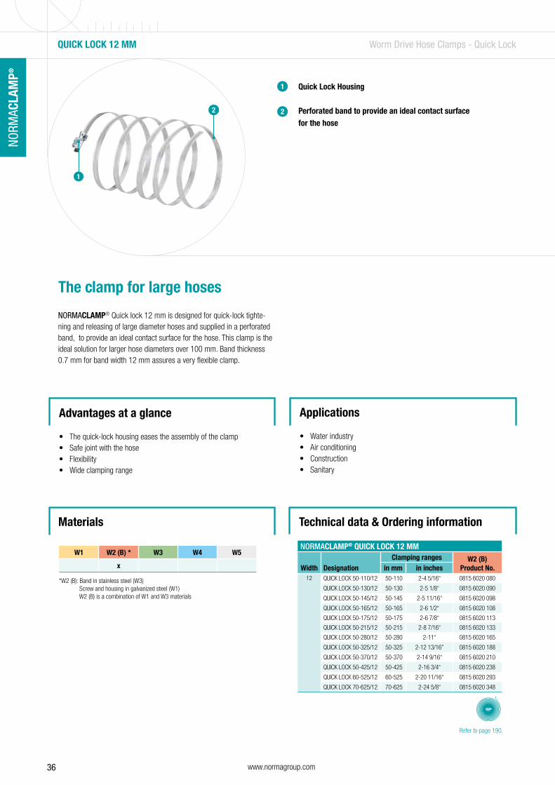
QUICK LOCK 12 MM Worm Drive Hose Clamps - Quick Lock
The clamp for large hoses
NORMACLAMP® Quick lock 12 mm is designed for quick-lock tighte-ning and releasing of large diameter hoses and supplied in a perforated band, to provide an ideal contact surface for the hose. This clamp is the ideal solution for larger hose diameters over 100 mm. Band thickness 0.7 mm for band width 12 mm assures a very flexible clamp.
Quick Lock Housing
Perforated band to provide an ideal contact surface for the hose
1
2
Advantages at a glance
• The quick-lock housing eases the assembly of the clamp• Safe joint with the hose• Flexibility• Wide clamping range
Applications
• Water industry• Air conditioning• Construction• Sanitary
Technical data & Ordering informationMaterials
W1 W2 (B) * W3 W4 W5
x
*W2 (B): Band in stainless steel (W3) Screw and housing in galvanized steel (W1) W2 (B) is a combination of W1 and W3 materials
NORMACLAMP® QUICK LOCK 12 MM
Width DesignationClamping ranges W2 (B)
Product No.in mm in inches12 QUICK LOCK 50-110/12 50-110 2-4 5/16” 0815 6020 080
QUICK LOCK 50-130/12 50-130 2-5 1/8” 0815 6020 090
QUICK LOCK 50-145/12 50-145 2-5 11/16” 0815 6020 098
QUICK LOCK 50-165/12 50-165 2-6 1/2” 0815 6020 108
QUICK LOCK 50-175/12 50-175 2-6 7/8” 0815 6020 113
QUICK LOCK 50-215/12 50-215 2-8 7/16” 0815 6020 133
QUICK LOCK 50-280/12 50-280 2-11” 0815 6020 165
QUICK LOCK 50-325/12 50-325 2-12 13/16” 0815 6020 188
QUICK LOCK 50-370/12 50-370 2-14 9/16” 0815 6020 210
QUICK LOCK 50-425/12 50-425 2-16 3/4” 0815 6020 238
QUICK LOCK 60-525/12 60-525 2-20 11/16” 0815 6020 293
QUICK LOCK 70-625/12 70-625 2-24 5/8” 0815 6020 348
2
1
Refer to page 190.

37www.normagroup.com
NORM
ACLA
MP®
NO
RMAC
LAM
P®
STRIP STEEL Worm Drive Hose Clamps - Quick Lock
Dispenser for 9 mm band width (stamped band)
Dispenser for 12 mm band width (perforated band)
1
2
Continuous band for multiple clamp diameters
The NORMACLAMP® Strip steel is a perfect solution for creating clamps with different diameters depending on a user’s needs. Strip steel is a long continuous band available in 9 or 12 mm band width. For closing the clamp use the NORMACLAMP® Quick lock housing 9 or 12 mm.
Advantages at a glance
• Variability• Flexibility• Storage and inventory benefit• Allows making up to 44 clamps
Applications
• Water industry• Air conditioning• Construction• Sanitary
Materials Technical data & Ordering information
NORMACLAMP® STRIP STEEL
Width Designation
LengthW2 (B)
Product No.W4
Product No.in m
in inch
9 STRIP STEEL 9 25 MTS 25 98 7/16 0815 7121 005 0815 7131 005
STRIP STEEL 9 30 MTS 30 118 1/8 0815 7121 008 0815 7131 008
12 STRIP STEEL 12 25 MTS 25 98 7/16 0815 0007 006
W1 W2 (B) * W3 W4 W5
x x
*W2 (B): Band in stainless steel (W3) Screw and housing in galvanized steel (W1) W2 (B) is a combination of W1 and W3 materials
12

38 www.normagroup.com
NORM
ACLA
MP®
QUICK LOCK HOUSING Worm Drive Hose Clamps - Quick Lock
Quick-Lock housing
Closed position
Open position
1
Locking system for continuous band
THE NORMACLAMP® Quick lock housing 9 and 12 mm are used to close the NORMACLAMP® Strip steel.
Advantages at a glance
• Fast, simple and safe assembly• Enables the closing of clamps of many diameters
Applications
• Water industry• Air conditioning• Construction• Sanitary
1
Materials Technical data & Ordering information
NORMACLAMP® QUICK LOCK HOUSING
Width DesignationW2 (B)
Product No.W4
Product No.9 QUICK LOCK HOUSING 9 0815 7121 007 0815 7131 007
12 QUICK LOCK HOUSING 12 0815 6007 008
2
3
3
2
W1 W2 (B) * W3 W4 W5
x x
*W2 (B): Band in stainless steel (W3) Screw and housing in galvanized steel (W1) W2 (B) is a combination of W1 and W3 materials
39www.normagroup.com
NORM
ACLA
MP®
NO
RMAC
LAM
P®
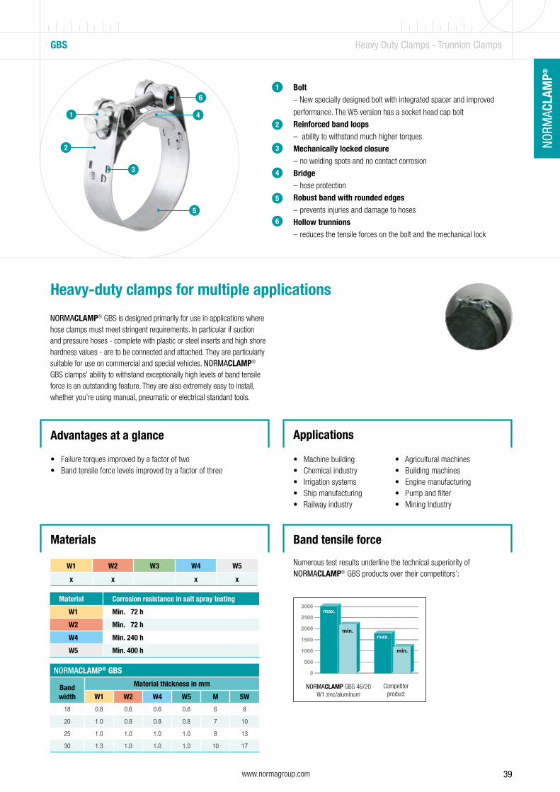
Materials
Bolt – New specially designed bolt with integrated spacer and improved
performance. The W5 version has a socket head cap bolt
Reinforced band loops – ability to withstand much higher torques
Mechanically locked closure – no welding spots and no contact corrosion
Bridge – hose protection
Robust band with rounded edges – prevents injuries and damage to hoses
Hollow trunnions – reduces the tensile forces on the bolt and the mechanical lock
1
2
3
4
5
6
Heavy-duty clamps for multiple applications
NORMACLAMP® GBS is designed primarily for use in applications where hose clamps must meet stringent requirements. In particular if suction and pressure hoses - complete with plastic or steel inserts and high shore hardness values - are to be connected and attached. They are particularly suitable for use on commercial and special vehicles. NORMACLAMP® GBS clamps’ ability to withstand exceptionally high levels of band tensile force is an outstanding feature. They are also extremely easy to install, whether you’re using manual, pneumatic or electrical standard tools.
Advantages at a glance
• Failure torques improved by a factor of two• Band tensile force levels improved by a factor of three
Applications
• Machine building • Agricultural machines• Chemical industry • Building machines• Irrigation systems • Engine manufacturing• Ship manufacturing • Pump and filter• Railway industry • Mining Industry
GBS Heavy Duty Clamps - Trunnion Clamps
2
1
3
5
6
4
W1 W2 W3 W4 W5
x x x x
Material Corrosion resistance in salt spray testing
W1 Min. 72 h
W2 Min. 72 h
W4 Min. 240 h
W5 Min. 400 h
NORMACLAMP® GBS
Band width
Material thickness in mm
W1 W2 W4 W5 M SW
18 0.8 0.6 0.6 0.6 6 8
20 1.0 0.8 0.8 0.8 7 10
25 1.0 1.0 1.0 1.0 8 13
30 1.3 1.0 1.0 1.0 10 17
NORMACLAMP GBS 46/20W1 zinc/aluminum
Competitor product
Numerous test results underline the technical superiority of NORMACLAMP® GBS products over their competitors’:
Band tensile force
40 www.normagroup.com
NORM
ACLA
MP®
GBS Heavy Duty Clamps - Trunnion Clamps
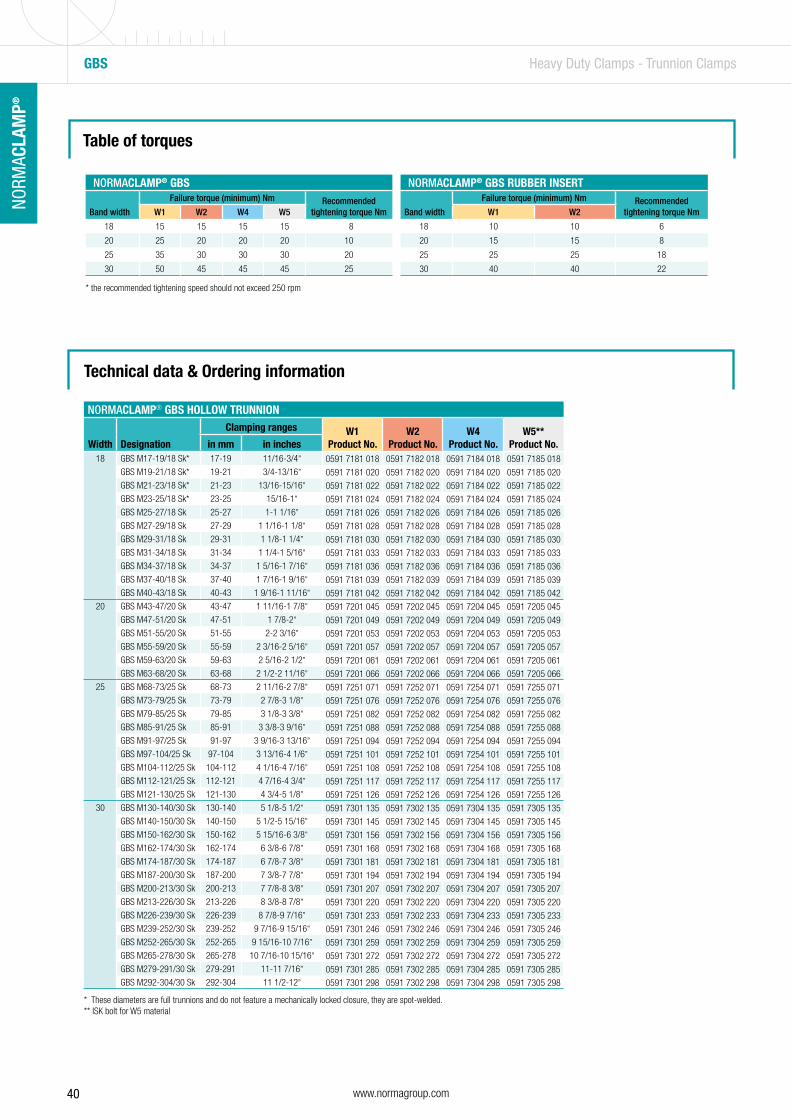
Table of torques
Technical data & Ordering information
NORMACLAMP® GBS
Band width
Failure torque (minimum) Nm Recommended tightening torque NmW1 W2 W4 W5
18 15 15 15 15 8
20 25 20 20 20 10
25 35 30 30 30 20
30 50 45 45 45 25
NORMACLAMP® GBS RUBBER INSERT
Band width
Failure torque (minimum) Nm Recommended tightening torque NmW1 W2
18 10 10 6
20 15 15 8
25 25 25 18
30 40 40 22
NORMACLAMP® GBS HOLLOW TRUNNION
Width Designation
Clamping ranges W1Product No.
W2Product No.
W4Product No.
W5**Product No.in mm in inches
18 GBS M17-19/18 Sk* 17-19 11/16-3/4” 0591 7181 018 0591 7182 018 0591 7184 018 0591 7185 018GBS M19-21/18 Sk* 19-21 3/4-13/16” 0591 7181 020 0591 7182 020 0591 7184 020 0591 7185 020GBS M21-23/18 Sk* 21-23 13/16-15/16” 0591 7181 022 0591 7182 022 0591 7184 022 0591 7185 022GBS M23-25/18 Sk* 23-25 15/16-1” 0591 7181 024 0591 7182 024 0591 7184 024 0591 7185 024GBS M25-27/18 Sk 25-27 1-1 1/16” 0591 7181 026 0591 7182 026 0591 7184 026 0591 7185 026GBS M27-29/18 Sk 27-29 1 1/16-1 1/8” 0591 7181 028 0591 7182 028 0591 7184 028 0591 7185 028GBS M29-31/18 Sk 29-31 1 1/8-1 1/4” 0591 7181 030 0591 7182 030 0591 7184 030 0591 7185 030GBS M31-34/18 Sk 31-34 1 1/4-1 5/16” 0591 7181 033 0591 7182 033 0591 7184 033 0591 7185 033GBS M34-37/18 Sk 34-37 1 5/16-1 7/16” 0591 7181 036 0591 7182 036 0591 7184 036 0591 7185 036GBS M37-40/18 Sk 37-40 1 7/16-1 9/16” 0591 7181 039 0591 7182 039 0591 7184 039 0591 7185 039GBS M40-43/18 Sk 40-43 1 9/16-1 11/16” 0591 7181 042 0591 7182 042 0591 7184 042 0591 7185 042
20 GBS M43-47/20 Sk 43-47 1 11/16-1 7/8” 0591 7201 045 0591 7202 045 0591 7204 045 0591 7205 045GBS M47-51/20 Sk 47-51 1 7/8-2” 0591 7201 049 0591 7202 049 0591 7204 049 0591 7205 049GBS M51-55/20 Sk 51-55 2-2 3/16” 0591 7201 053 0591 7202 053 0591 7204 053 0591 7205 053GBS M55-59/20 Sk 55-59 2 3/16-2 5/16” 0591 7201 057 0591 7202 057 0591 7204 057 0591 7205 057GBS M59-63/20 Sk 59-63 2 5/16-2 1/2” 0591 7201 061 0591 7202 061 0591 7204 061 0591 7205 061GBS M63-68/20 Sk 63-68 2 1/2-2 11/16” 0591 7201 066 0591 7202 066 0591 7204 066 0591 7205 066
25 GBS M68-73/25 Sk 68-73 2 11/16-2 7/8” 0591 7251 071 0591 7252 071 0591 7254 071 0591 7255 071GBS M73-79/25 Sk 73-79 2 7/8-3 1/8” 0591 7251 076 0591 7252 076 0591 7254 076 0591 7255 076GBS M79-85/25 Sk 79-85 3 1/8-3 3/8” 0591 7251 082 0591 7252 082 0591 7254 082 0591 7255 082GBS M85-91/25 Sk 85-91 3 3/8-3 9/16” 0591 7251 088 0591 7252 088 0591 7254 088 0591 7255 088GBS M91-97/25 Sk 91-97 3 9/16-3 13/16” 0591 7251 094 0591 7252 094 0591 7254 094 0591 7255 094GBS M97-104/25 Sk 97-104 3 13/16-4 1/6” 0591 7251 101 0591 7252 101 0591 7254 101 0591 7255 101GBS M104-112/25 Sk 104-112 4 1/16-4 7/16” 0591 7251 108 0591 7252 108 0591 7254 108 0591 7255 108GBS M112-121/25 Sk 112-121 4 7/16-4 3/4” 0591 7251 117 0591 7252 117 0591 7254 117 0591 7255 117GBS M121-130/25 Sk 121-130 4 3/4-5 1/8” 0591 7251 126 0591 7252 126 0591 7254 126 0591 7255 126
30 GBS M130-140/30 Sk 130-140 5 1/8-5 1/2” 0591 7301 135 0591 7302 135 0591 7304 135 0591 7305 135GBS M140-150/30 Sk 140-150 5 1/2-5 15/16” 0591 7301 145 0591 7302 145 0591 7304 145 0591 7305 145GBS M150-162/30 Sk 150-162 5 15/16-6 3/8” 0591 7301 156 0591 7302 156 0591 7304 156 0591 7305 156GBS M162-174/30 Sk 162-174 6 3/8-6 7/8” 0591 7301 168 0591 7302 168 0591 7304 168 0591 7305 168GBS M174-187/30 Sk 174-187 6 7/8-7 3/8” 0591 7301 181 0591 7302 181 0591 7304 181 0591 7305 181GBS M187-200/30 Sk 187-200 7 3/8-7 7/8” 0591 7301 194 0591 7302 194 0591 7304 194 0591 7305 194GBS M200-213/30 Sk 200-213 7 7/8-8 3/8” 0591 7301 207 0591 7302 207 0591 7304 207 0591 7305 207GBS M213-226/30 Sk 213-226 8 3/8-8 7/8” 0591 7301 220 0591 7302 220 0591 7304 220 0591 7305 220GBS M226-239/30 Sk 226-239 8 7/8-9 7/16” 0591 7301 233 0591 7302 233 0591 7304 233 0591 7305 233GBS M239-252/30 Sk 239-252 9 7/16-9 15/16” 0591 7301 246 0591 7302 246 0591 7304 246 0591 7305 246GBS M252-265/30 Sk 252-265 9 15/16-10 7/16” 0591 7301 259 0591 7302 259 0591 7304 259 0591 7305 259GBS M265-278/30 Sk 265-278 10 7/16-10 15/16” 0591 7301 272 0591 7302 272 0591 7304 272 0591 7305 272GBS M279-291/30 Sk 279-291 11-11 7/16” 0591 7301 285 0591 7302 285 0591 7304 285 0591 7305 285GBS M292-304/30 Sk 292-304 11 1/2-12” 0591 7301 298 0591 7302 298 0591 7304 298 0591 7305 298
* These diameters are full trunnions and do not feature a mechanically locked closure, they are spot-welded.** ISK bolt for W5 material
* the recommended tightening speed should not exceed 250 rpm

41www.normagroup.com
NORM
ACLA
MP®
NO
RMAC
LAM
P®
To suit the requirements of all markets, NORMACLAMP® GBS is also available with solid trunnions.
Main advantageStrong robustness
MaterialsW1, W4
GBS – Solid Trunnions - STC Heavy Duty Clamps - Trunnion Clamps
NORMACLAMP® GBS STC
Width Description
Clamping range W1Product No.
W4Product No.in mm in inches
18 GBS M17-19/18 STC 17 - 19 11/16-3/4” 0591 7001 018 0591 7009 018
GBS M19-21/18 STC 19 - 21 3/4-13/16” 0591 7001 020 0591 7009 020
GBS M21-23/18 STC 21 - 23 13/16-15/16” 0591 7001 022 0591 7009 022
GBS M23-25/18 STC 23 - 25 15/16-1” 0591 7001 024 0591 7009 024
GBS M25-27/18 STC 25 - 27 1-1 1/16” 0591 7001 026 0591 7009 026
GBS M27-29/18 STC 27 - 29 1 1/16-1 1/8” 0591 7001 028 0591 7009 028
GBS M29-31/18 STC 29 - 31 1 1/8-1 1/4” 0591 7001 030 0591 7009 030
GBS M31-34/18 STC 31 - 34 1 1/4-1 5/16” 0591 7001 033 0591 7009 033
GBS M34-37/18 STC 34 - 37 1 5/16-1 7/16” 0591 7001 036 0591 7009 036
GBS M37-40/18 STC 37 - 40 1 7/16-1 9/16” 0591 7001 039 0591 7009 039
GBS M40-43/18 STC 40 - 43 1 9/16-1 11/16” 0591 7001 042 0591 7009 042
20 GBS M43-47/20 STC 43 - 47 1 11/16-1 7/8” 0591 7002 045 0591 7010 045
GBS M47-51/20 STC 47 - 51 1 7/8-2” 0591 7002 049 0591 7010 049
GBS M51-55/20 STC 51 - 55 2-2 3/16” 0591 7002 053 0591 7010 053
GBS M55-59/20 STC 55 - 59 2 3/16-2 5/16” 0591 7002 057 0591 7010 057
GBS M59-63/20 STC 59 - 63 2 5/16-2 1/2” 0591 7002 061 0591 7010 061
GBS M63-68/20 STC 63 - 68 2 1/2-2 11/16” 0591 7002 066 0591 7010 066
25 GBS M68-73/25 STC 68 - 63 2 11/16-2 7/8” 0591 7003 071 0591 7011 071
GBS M73-79/25 STC 73 - 79 2 7/8-3 1/8” 0591 7003 076 0591 7011 076
GBS M79-85/25 STC 79 - 85 3 1/8-3 3/8” 0591 7003 082 0591 7011 082
GBS M85-91/25 STC 85 - 91 3 3/8-3 9/16” 0591 7003 088 0591 7011 088
GBS M91-97/25 STC 91 - 97 3 9/16-3 13/16” 0591 7003 094 0591 7011 094
GBS M97-104/25 STC 97 - 104 3 13/16-4 1/6” 0591 7003 101 0591 7011 101
GBS M104-112/25 STC 104 - 112 4 1/16-4 7/16” 0591 7003 108 0591 7011 108
GBS M112-121/25 STC 112 - 121 4 7/16-4 3/4” 0591 7003 117 0591 7011 117
GBS M121-130/25 STC 121 - 130 4 3/4-5 1/8” 0591 7003 126 0591 7011 126
30 GBS M130-140/30 STC 130 - 140 5 1/8-5 1/2” 0591 7004 135 0591 7012 135
GBS M140-150/30 STC 140 - 150 5 1/2-5 15/16” 0591 7004 145 0591 7012 145
GBS M150-162/30 STC 150 - 162 5 15/16-6 3/8” 0591 7004 156 0591 7012 156
GBS M162-174/30 STC 162 - 174 6 3/8-6 7/8” 0591 7004 168 0591 7012 168
GBS M174-187/30 STC 174 - 187 6 7/8-7 3/8” 0591 7004 181 0591 7012 181
GBS M187-200/30 STC 187 - 200 7 3/8-7 7/8” 0591 7004 194 0591 7012 194
GBS M200-213/30 STC 200 - 213 7 7/8-8 3/8” 0591 7004 207 0591 7012 207
GBS M213-226/30 STC 213 - 226 8 3/8-8 7/8” 0591 7004 220 0591 7012 220
GBS M226-239/30 STC 226 - 239 8 7/8-9 7/16” 0591 7004 233 0591 7012 233
GBS M239-252/30 STC 239 - 252 9 7/16-9 15/16” 0591 7004 246 0591 7012 246
GBS M252-265/30 STC 252 - 265 9 15/16-10 7/16” 0591 7004 259 0591 7012 259
GBS M265-278/30 STC 265 - 278 10 7/16-10 15/16” 0591 7004 272 0591 7012 272
GBS M278-291/30 STC 278 - 291 10 15/16-11 7/16” 0591 7004 285 0591 7012 285
GBS M291-304/30 STC 291 - 304 11 7/16-12” 0591 7004 298 0591 7012 298
GBS M304-317/30 STC 304 - 317 12-12 1/2” 0591 7004 311 0591 7012 311
GBS M317-330/30 STC 317 - 330 12 1/2-13” 0591 7004 324 0591 7012 324
NORMACLAMP® GBS RUBBER INSERT
Band width
Failure torque (minimum) Nm Recommended tightening torque NmW1 W2
18 10 10 6
20 15 15 8
25 25 25 18
30 40 40 22
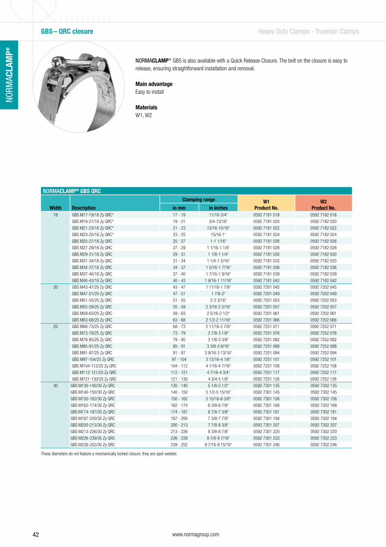
42 www.normagroup.com
NORM
ACLA
MP®
NORMACLAMP® GBS is also available with a Quick Release Closure. The bolt on the closure is easy to release, ensuring straightforward installation and removal.
Main advantageEasy to install
MaterialsW1, W2
NORMACLAMP® GBS QRC
Width Description
Clamping range W1Product No.
W2Product No.in mm in inches
18 GBS M17-19/18 Zy QRC* 17 - 19 11/16-3/4” 0592 7181 018 0592 7182 018
GBS M19-21/18 Zy QRC* 19 - 21 3/4-13/16” 0592 7181 020 0592 7182 020
GBS M21-23/18 Zy QRC* 21 - 23 13/16-15/16” 0592 7181 022 0592 7182 022
GBS M23-25/18 Zy QRC* 23 - 25 15/16-1” 0592 7181 024 0592 7182 024
GBS M25-27/18 Zy QRC 25 - 27 1-1 1/16” 0592 7181 026 0592 7182 026
GBS M27-29/18 Zy QRC 27 - 29 1 1/16-1 1/8” 0592 7181 028 0592 7182 028
GBS M29-31/18 Zy QRC 29 - 31 1 1/8-1 1/4” 0592 7181 030 0592 7182 030
GBS M31-34/18 Zy QRC 31 - 34 1 1/4-1 5/16” 0592 7181 033 0592 7182 033
GBS M34-37/18 Zy QRC 34 - 37 1 5/16-1 7/16” 0592 7181 036 0592 7182 036
GBS M37-40/18 Zy QRC 37 - 40 1 7/16-1 9/16” 0592 7181 039 0592 7182 039
GBS M40-43/18 Zy QRC 40 - 43 1 9/16-1 11/16” 0592 7181 042 0592 7182 042
20 GBS M43-47/20 Zy QRC 43 - 47 1 11/16-1 7/8” 0592 7201 045 0592 7202 045
GBS M47-51/20 Zy QRC 47 - 51 1 7/8-2” 0592 7201 049 0592 7202 049
GBS M51-55/20 Zy QRC 51 - 55 2-2 3/16” 0592 7201 053 0592 7202 053
GBS M55-59/20 Zy QRC 55 - 59 2 3/16-2 5/16” 0592 7201 057 0592 7202 057
GBS M59-63/20 Zy QRC 59 - 63 2 5/16-2 1/2” 0592 7201 061 0592 7202 061
GBS M63-68/20 Zy QRC 63 - 68 2 1/2-2 11/16” 0592 7201 066 0592 7202 066
25 GBS M68-73/25 Zy QRC 68 - 73 2 11/16-2 7/8” 0592 7251 071 0592 7252 071
GBS M73-79/25 Zy QRC 73 - 79 2 7/8-3 1/8” 0592 7251 076 0592 7252 076
GBS M79-85/25 Zy QRC 79 - 85 3 1/8-3 3/8” 0592 7251 082 0592 7252 082
GBS M85-91/25 Zy QRC 85 - 91 3 3/8-3 9/16” 0592 7251 088 0592 7252 088
GBS M91-97/25 Zy QRC 91 - 97 3 9/16-3 13/16” 0592 7251 094 0592 7252 094
GBS M97-104/25 Zy QRC 97 - 104 3 13/16-4 1/6” 0592 7251 101 0592 7252 101
GBS M104-112/25 Zy QRC 104 - 112 4 1/16-4 7/16” 0592 7251 108 0592 7252 108
GBS M112-121/25 Zy QRC 112 - 121 4 7/16-4 3/4” 0592 7251 117 0592 7252 117
GBS M121-130/25 Zy QRC 121 - 130 4 3/4-5 1/8” 0592 7251 126 0592 7252 126
30 GBS M130-140/30 Zy QRC 130 - 140 5 1/8-5 1/2” 0592 7301 135 0592 7302 135
GBS M140-150/30 Zy QRC 140 - 150 5 1/2-5 15/16” 0592 7301 145 0592 7302 145
GBS M150-162/30 Zy QRC 150 - 162 5 15/16-6 3/8” 0592 7301 156 0592 7302 156
GBS M162-174/30 Zy QRC 162 - 174 6 3/8-6 7/8” 0592 7301 168 0592 7302 168
GBS M174-187/30 Zy QRC 174 - 187 6 7/8-7 3/8” 0592 7301 181 0592 7302 181
GBS M187-200/30 Zy QRC 187 - 200 7 3/8-7 7/8” 0592 7301 194 0592 7302 194
GBS M200-213/30 Zy QRC 200 - 213 7 7/8-8 3/8” 0592 7301 207 0592 7302 207
GBS M213-226/30 Zy QRC 213 - 226 8 3/8-8 7/8” 0592 7301 220 0592 7302 220
GBS M226-239/30 Zy QRC 226 - 239 8 7/8-9 7/16” 0592 7301 233 0592 7302 233
GBS M239-252/30 Zy QRC 239 - 252 9 7/16-9 15/16” 0592 7301 246 0592 7302 246
GBS – QRC closure Heavy Duty Clamps - Trunnion Clamps
These diameters do not feature a mechanically locked closure, they are spot-welded.

43www.normagroup.com
NORM
ACLA
MP®
NO
RMAC
LAM
P®
NORMACLAMP® GBS is also available in a multi-part version for bigger diameters.
Main advantageSuitable for big diameter hoses
MaterialsW1, W2, W4, W5
GBS – Multi-parts Heavy Duty Clamps - Trunnion Clamps
NORMACLAMP® GBS MULTI-PARTS
Width Description
Clamping range W1Product No.
W2Product No.
W4Product No.
W5Product No.in mm in inches
18 GBS M59-67/18 SK 2T 59-67 2 5/16-2 5/8” 0591 7191 063 0591 7192 063 0591 7194 063 0591 7195 063
GBS M67-75/18 SK 2T 67-75 2 5/8-2 15/16” 0591 7191 071 0591 7192 071 0591 7194 071 0591 7195 071
20 GBS M67-75/20 SK 2T 67-75 2 5/8-2 15/16” 0591 7221 071 0591 7222 071 0591 7224 071 0591 7225 071
GBS M75-83/20 SK 2T 75-83 2 15/16-3 1/4” 0591 7221 079 0591 7222 079 0591 7224 079 0591 7225 079
GBS M83-91/20 SK 2T 83-91 3 1/4-3 9/16” 0591 7221 087 0591 7222 087 0591 7224 087 0591 7225 087
25 GBS M88-100/25 SK 2T 88-100 3 9/16-4” 0591 7271 094 0591 7272 094 0591 7274 094 0591 7275 094
GBS M100-116/25 SK 2T 100-116 3 7/16-4 9/16” 0591 7271 108 0591 7272 108 0591 7274 108 0591 7275 108
GBS M116-136/25 SK 2T 116-136 4 9/16-5 3/8” 0591 7271 126 0591 7272 126 0591 7274 126 0591 7275 126
GBS M136-156/25 SK 2T 136-156 5 3/8-6 1/8” 0591 7271 146 0591 7272 146 0591 7274 146 0591 7275 146
GBS M156-176/25 SK 2T 156-176 6 1/8-6 15/16” 0591 7271 168 0591 7272 168 0591 7274 168 0591 7275 168
30 GBS M125-145/30 SK 2T 125-145 4 15/16-5 11/16” 0591 7321 135 0591 7322 135 0591 7324 135 0591 7325 135
GBS M145-168/30 SK 2T 145-168 5 11/16-6 5/8” 0591 7321 156 0591 7322 156 0591 7324 156 0591 7325 156
GBS M168-193/30 SK 2T 168-193 6 5/8-7 5/8” 0591 7321 181 0591 7322 181 0591 7324 181 0591 7325 181
GBS M193-220/30 SK 2T 193-220 7 5/8-8 11/16” 0591 7321 207 0591 7322 207 0591 7324 207 0591 7325 207
GBS M220-245/30 SK 2T 220-245 8 11/16-9 5/8” 0591 7321 233 0591 7322 233 0591 7324 233 0591 7325 233
GBS M245-270/30 SK 2T 245-270 9 5/8-10 5/8” 0591 7321 258 0591 7322 258 0591 7324 258 0591 7325 258
GBS M270-295/30 SK 2T 270-295 10 5/8-11 5/8” 0591 7321 283 0591 7322 283 0591 7324 283 0591 7325 283
GBS M295-320/30 SK 2T 295-320 11 5/8-12 5/8” 0591 7321 308 0591 7322 308 0591 7324 308 0591 7325 308
GBS M320-345/30 SK 2T 320-345 12 5/8-13 9/16” 0591 7321 333 0591 7322 333 0591 7324 333 0591 7325 333

44 www.normagroup.com
NORM
ACLA
MP®
1Quick close and release
– Secure over-center lever for manual opening and
closing without the need for installation tools
Bridge – Optimum hose protection
1
2
2
Quick-release clamps
NORMACLAMP® SVS and NORMACLAMP® SVS P clamps are secure, flexible joining elements designed for applications where joints need to be closed and released frequently and quickly, such as filtering and filling systems or food industry pipeline systems that are continually being cleaned.
NORMACLAMP® SVS clamps provide optimal protection for hose applications. NORMACLAMP® SVS P clamps provide optimal protection for pipe applications. NORMACLAMP® SVS PR clamps provide optimal protection for flange applications - see our Profile section on page 129.
Main advantage
Ideal for frequent handling
Applications
• Machine building• Chemical industry• Food and beverage industry • Railway industry• Building machines• Pump and filter
Materials
W1 W2 W3 W4 W5
x
Material Corrosion resistance in salt spray testing
W4 Min. 240 h
SVS Mounting Elements - Quick Release Clamps
Technical data
Quick-release hose clamps (SVS)
Band width
Minimum ø
Maximum ø
Material Bolts Closing force
NW4 (Oe) Zy M
15 80 500 0.6 (•) • 6 80
20 80 500 0.8 (•) • 6 80
25 80 500 1.0 (•) • 6 80

45www.normagroup.com
NORM
ACLA
MP®
NO
RMAC
LAM
P®
SVS Mounting Elements - Quick Release Clamps
Technical data & Ordering information
NORMACLAMP® SVS
Diameter in mm
Material W4Product No.Band width
15 mm 20 mm 25 mm80 - 90 0565 0154 ... 0565 0204 ... 0565 0254 ...
up to 100 0565 0154 ... 0565 0204 ... 0565 0254 ...
up to 110 0565 0154 ... 0565 0204 ... 0565 0254 ...
up to 120 0565 0154 ... 0565 0204 ... 0565 0254 ...
up to 130 0565 0154 ... 0565 0204 ... 0565 0254 ...
up to 140 0565 0154 ... 0565 0204 ... 0565 0254 ...
up to 150 0565 0154 ... 0565 0204 ... 0565 0254 ...
up to 160 0565 0154 ... 0565 0204 ... 0565 0254 ...
up to 170 0565 0154 ... 0565 0204 ... 0565 0254 ...
up to 180 0565 0154 ... 0565 0204 ... 0565 0254 ...
up to 190 0565 0154 ... 0565 0204 ... 0565 0254 ...
up to 200 0565 0154 ... 0565 0204 ... 0565 0254 ...
up to 210 0565 0154 ... 0565 0204 ... 0565 0254 ...
up to 220 0565 0154 ... 0565 0204 ... 0565 0254 ...
up to 230 0565 0154 ... 0565 0204 ... 0565 0254 ...
up to 240 0565 0154 ... 0565 0204 ... 0565 0254 ...
up to 250 0565 0154 ... 0565 0204 ... 0565 0254 ...
up to 260 0565 0154 ... 0565 0204 ... 0565 0254 ...
up to 270 0565 0154 ... 0565 0204 ... 0565 0254 ...
up to 280 0565 0154 ... 0565 0204 ... 0565 0254 ...
up to 290 0565 0154 ... 0565 0204 ... 0565 0254 ...
up to 300 0565 0154 ... 0565 0204 ... 0565 0254 ...
up to 310 0565 0154 ... 0565 0204 ... 0565 0254 ...
up to 320 0565 0154 ... 0565 0204 ... 0565 0254 ...
up to 330 0565 0154 ... 0565 0204 ... 0565 0254 ...
up to 340 0565 0154 ... 0565 0204 ... 0565 0254 ...
up to 350 0565 0154 ... 0565 0204 ... 0565 0254 ...
up to 360 0565 0154 ... 0565 0204 ... 0565 0254 ...
up to 370 0565 0154 ... 0565 0204 ... 0565 0254 ...
up to 380 0565 0154 ... 0565 0204 ... 0565 0254 ...
up to 390 0565 0154 ... 0565 0204 ... 0565 0254 ...
up to 400 0565 0154 ... 0565 0204 ... 0565 0254 ...
up to 410 0565 0154 ... 0565 0204 ... 0565 0254 ...
up to 420 0565 0154 ... 0565 0204 ... 0565 0254 ...
up to 430 0565 0154 ... 0565 0204 ... 0565 0254 ...
up to 440 0565 0154 ... 0565 0204 ... 0565 0254 ...
up to 450 0565 0154 ... 0565 0204 ... 0565 0254 ...
up to 460 0565 0154 ... 0565 0204 ... 0565 0254 ...
up to 470 0565 0154 ... 0565 0204 ... 0565 0254 ...
up to 480 0565 0154 ... 0565 0204 ... 0565 0254 ...
up to 490 0565 0154 ... 0565 0204 ... 0565 0254 ...
up to 500 0565 0154 ... 0565 0204 ... 0565 0254 ...
... = Ø without decimals in mm
Quick-release hose clamps (SVS)
Band width
Minimum ø
Maximum ø
Material Bolts Closing force
NW4 (Oe) Zy M
15 80 500 0.6 (•) • 6 80
20 80 500 0.8 (•) • 6 80
25 80 500 1.0 (•) • 6 80
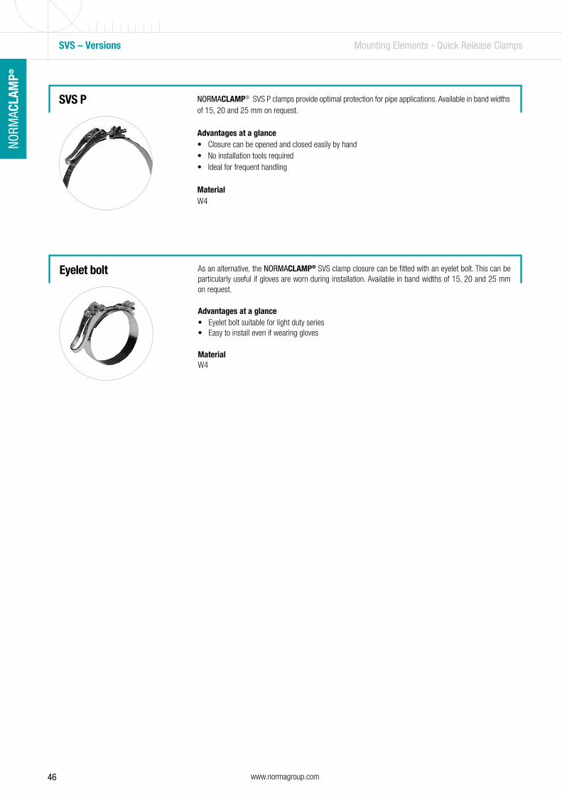
46 www.normagroup.com
NORM
ACLA
MP®
SVS – Versions Mounting Elements - Quick Release Clamps
NORMACLAMP® SVS P clamps provide optimal protection for pipe applications. Available in band widths of 15, 20 and 25 mm on request.
Advantages at a glance• Closure can be opened and closed easily by hand• No installation tools required• Ideal for frequent handling
MaterialW4
SVS P
As an alternative, the NORMACLAMP® SVS clamp closure can be fitted with an eyelet bolt. This can be particularly useful if gloves are worn during installation. Available in band widths of 15, 20 and 25 mm on request.
Advantages at a glance• Eyelet bolt suitable for light duty series• Easy to install even if wearing gloves
MaterialW4
Eyelet bolt
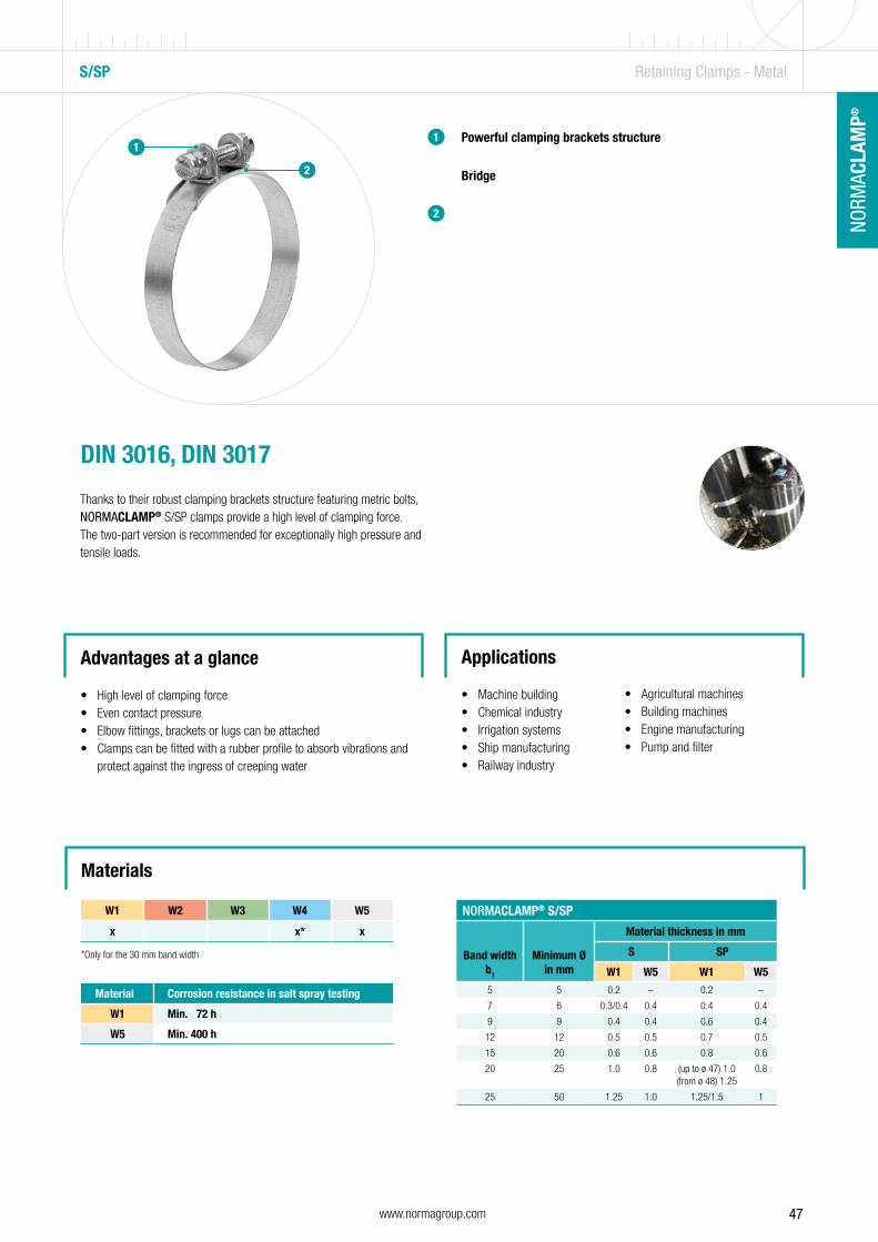
47www.normagroup.com
NORM
ACLA
MP®
NO
RMAC
LAM
P®
S/SP Retaining Clamps - Metal
1
2
Powerful clamping brackets structure
Bridge
1
2
DIN 3016, DIN 3017
Thanks to their robust clamping brackets structure featuring metric bolts, NORMACLAMP® S/SP clamps provide a high level of clamping force. The two-part version is recommended for exceptionally high pressure and tensile loads.
Advantages at a glance
• High level of clamping force • Even contact pressure• Elbow fittings, brackets or lugs can be attached• Clamps can be fitted with a rubber profile to absorb vibrations and
protect against the ingress of creeping water
Applications
• Machine building• Chemical industry• Irrigation systems• Ship manufacturing• Railway industry
• Agricultural machines• Building machines• Engine manufacturing• Pump and filter
Materials
W1 W2 W3 W4 W5
x x* x
Material Corrosion resistance in salt spray testing
W1 Min. 72 h
W5 Min. 400 h
NORMACLAMP® S/SP
Band width b1
Minimum Ø in mm
Material thickness in mm
S SP
W1 W5 W1 W55 5 0.2 – 0.2 –
7 6 0.3/0.4 0.4 0.4 0.4
9 9 0.4 0.4 0.6 0.4
12 12 0.5 0.5 0.7 0.5
15 20 0.6 0.6 0.8 0.6
20 25 1.0 0.8 (up to ø 47) 1.0(from ø 48) 1.25
0.8
25 50 1.25 1.0 1.25/1.5 1
*Only for the 30 mm band width

48 www.normagroup.com
NORM
ACLA
MP®
S Retaining Clamps - Metal
Bolts Static torques
NORMACLAMP® S/SP
Band width mm
Zy Sz Sk
5 M 2x12
7 M 3x16
9 M 4x22 M 4 x 20
12 M 5x25
15 M 6x30
20 M 8x40
25 M 10x45
NORMACLAMP® S/SP
Band width b1
mm
Static tightening torque
Nm
Static test torqueNm
max.7 0.5 0.6
9 1.2 1.5
12 1.5 1.8
15 4 4.8
20 12 14.5
25 30 36
Technical data & Ordering information
NORMACLAMP® S
Clamping diameter, mm
W1Product No.
W4Product No.
W5Product No.
Band width Band width Band width5 mm
Zy7 mm
Zy9 mm
Zy12 mm
Sz15 mm
Sz20 mm
Sz25 mm
Sz30 mm
Sz30 mm
Sz7 mm
Zy9 mm
Zy12 mm
Sz15 mm
Sz20 mm
Sz25 mm
Szup to 9 0100 8980 …
up to 10 0110 8980 ... 0120 8980 ... 0110 0700 ... 0120 0700 ...
from 15 0120 8980 ... 0130 0005 ... 0140 0000 ... 0120 0700 ... 0130 0705 ... 0140 0700 ...
up to 20 0120 8980 ... 0130 0005 ... 0140 0000 ... 0120 0700 ... 0130 0705 ... 0140 0700 ...
up to 28 0120 8980 ... 0130 0005 ... 0140 0000 ... 0120 0700 ... 0130 0705 ... 0140 0700 ...
up to 30 0120 8980 ... 0140 0000 ... 0120 0700 ... 0140 0700 ...
from 36 0120 8980 ... 0140 0000 ... 0150 000 … 0120 0700 ... 0140 0700 ... 0150 0700 ...
up to 40 0120 8980 ... 0140 0000 ... 0150 000 … 0120 0700 ... 0140 0700 ... 0150 0700 ...
up to 50 0120 8980 ... 0140 0000 ... 0150 000 … 0160 0000 ... 0120 0700 ... 0140 0700 ... 0150 0700 ... 0160 0700 ...
up to 60 0120 8980 ... 0140 0000 ... 0150 000 … 0160 0000 ... 0120 0700 ... 0140 0700 ... 0150 0700 ... 0160 0700 ...
up to 70 0120 8980 ... 0140 0000 ... 0150 000 … 0160 0000 ... 0120 0700 ... 0140 0700 ... 0150 0700 ... 0160 0700 ...
up to 75 0120 8980 ... 0140 0000 ... 0150 000 … 0160 0000 ... 0180 0000 ... 0180 0700 ... 0120 0700 ... 0140 0700 ... 0150 0700 ... 0160 0700 ...
up to 80 0140 0000 ... 0150 000 … 0160 0000 ... 0180 0000 ... 0180 0700 ... 0140 0700 ... 0150 0700 ... 0160 0700 ...
up to 90 0140 0000 ... 0150 000 … 0160 0000 ... 0180 0000 ... 0180 0700 ... 0140 0700 ... 0150 0700 ... 0160 0700 ...
up to 100 0140 0000 ... 0150 000 … 0160 0000 ... 0180 0000 ... 0180 0700 ... 0140 0700 ... 0150 0700 ... 0160 0700 ...
up to 110 0150 000 … 0160 0000 ... 0180 0000 ... 0180 0700 ... 0150 0700 ... 0160 0700 ...
up to 120 0150 000 … 0160 0000 ... 0180 0000 ... 0180 0700 ... 0150 0700 ... 0160 0700 ...
up to 130 0150 000 … 0180 0000 ... 0180 0700 ... 0150 0700 ...
up to 140 0150 000 … 0180 0000 ... 0180 0700 ... 0150 0700 ...
up to 150 0150 000 … 0180 0000 ... 0180 0700 ... 0150 0700 ...
up to 160 0150 000 … 0180 0000 ... 0180 0700 ... 0150 0700 ...
up to 170 0150 000 … 0180 0000 ... 0180 0700 ... 0150 0700 ...
up to 180 0150 000 … 0180 0000 ... 0180 0700 ... 0150 0700 ...
up to 190 0150 000 … 0180 0000 ... 0180 0700 ... 0150 0700 ...
up to 200 0150 000 … 0180 0000 ... 0180 0700 ... 0150 0700 ...
Static torques according to DIN 3017-2
... = Ø without decimals in mmAdditional diameters available on request
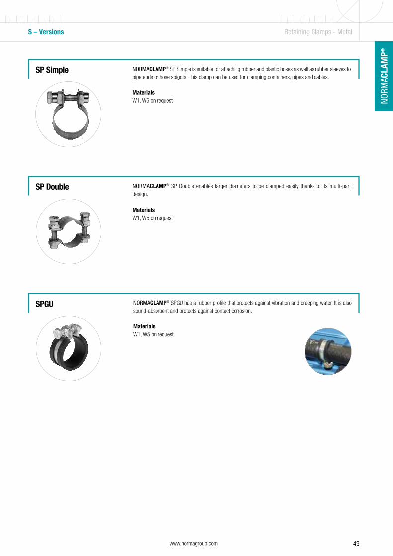
49www.normagroup.com
NORM
ACLA
MP®
NO
RMAC
LAM
P®
S – Versions Retaining Clamps - Metal
NORMACLAMP® SP Simple is suitable for attaching rubber and plastic hoses as well as rubber sleeves to pipe ends or hose spigots. This clamp can be used for clamping containers, pipes and cables.
MaterialsW1, W5 on request
SP Simple
SP Double
SPGU
NORMACLAMP® SP Double enables larger diameters to be clamped easily thanks to its multi-part design.
MaterialsW1, W5 on request
NORMACLAMP® SPGU has a rubber profile that protects against vibration and creeping water. It is also sound-absorbent and protects against contact corrosion.
MaterialsW1, W5 on request
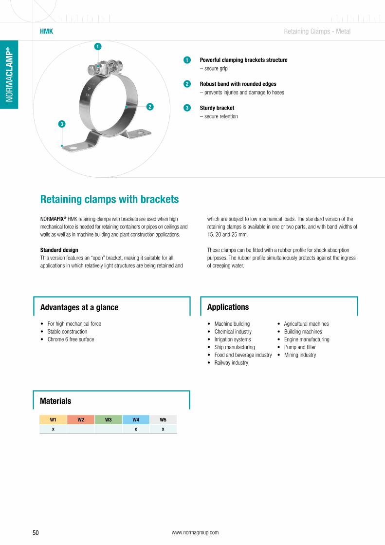
50 www.normagroup.com
NORM
ACLA
MP®
HMK Retaining Clamps - Metal
1 Powerful clamping brackets structure – secure grip
Robust band with rounded edges – prevents injuries and damage to hoses
Sturdy bracket – secure retention
1
2
2
Retaining clamps with brackets
NORMAFIX® HMK retaining clamps with brackets are used when high mechanical force is needed for retaining containers or pipes on ceilings and walls as well as in machine building and plant construction applications.
Standard design This version features an “open” bracket, making it suitable for all applications in which relatively light structures are being retained and
which are subject to low mechanical loads. The standard version of the retaining clamps is available in one or two parts, and with band widths of 15, 20 and 25 mm.
These clamps can be fitted with a rubber profile for shock absorption purposes. The rubber profile simultaneously protects against the ingress of creeping water.
Advantages at a glance
• For high mechanical force• Stable construction• Chrome 6 free surface
Applications
• Machine building • Agricultural machines• Chemical industry • Building machines• Irrigation systems • Engine manufacturing• Ship manufacturing • Pump and filter• Food and beverage industry • Mining industry• Railway industry
W1 W2 W3 W4 W5
x x x
3
3
Materials
1
2
3

51www.normagroup.com
NORM
ACLA
MP®
NO
RMAC
LAM
P®
NORMAFIX® HMK (standard design) Band widthin mm Designation
Min. øin mm
Min. øin in.
Boltsd
in mm
Rubber profile s in mmPart
GroupSz Sk Dimensions Silicone EPDM W1 W515 HMK STANDARD 25/15 25 1 X M6 x 30 6.5 X X 0.8 0.6 1416
20 HMK STANDARD 30/20 30 1 3/16 X M8 x 40 8.5 X X 1.0-1.5 0.8 1516
25 HMK STANDARD 50/25 50 2 X M10 x 45 11 X X 1.5 1.0 1616
Technical data & Ordering information
HMK Retaining Clamps - Metal
B b1≈ s2
15 18.5 1.5
20 25 2.0
25 31 3.0
30 36 3.0
The rubber profiles are available in EPDM (type a) and silicone (type b) material versions.
B = band width of clamp in mmb
1 = width in mm
s2 = material thickness in mm
All clamps with rubber profiles are pre-assembled. The complete clamps are supplied ready for use.
When submitting requests/orders for NORMAFIX® HMK retaining clamps with brackets, please specify which rubber profile you require.
Rubber profiles
When submitting requests and orders, please specify the data in the following manner:
1. Type 2. Parts 3. Diameter 4. Band width 5. Bolt 6. Material
Example HMK STANDARD 1616 80 25 SK W1
Ordering information
Silicone (b) EPDM (a)
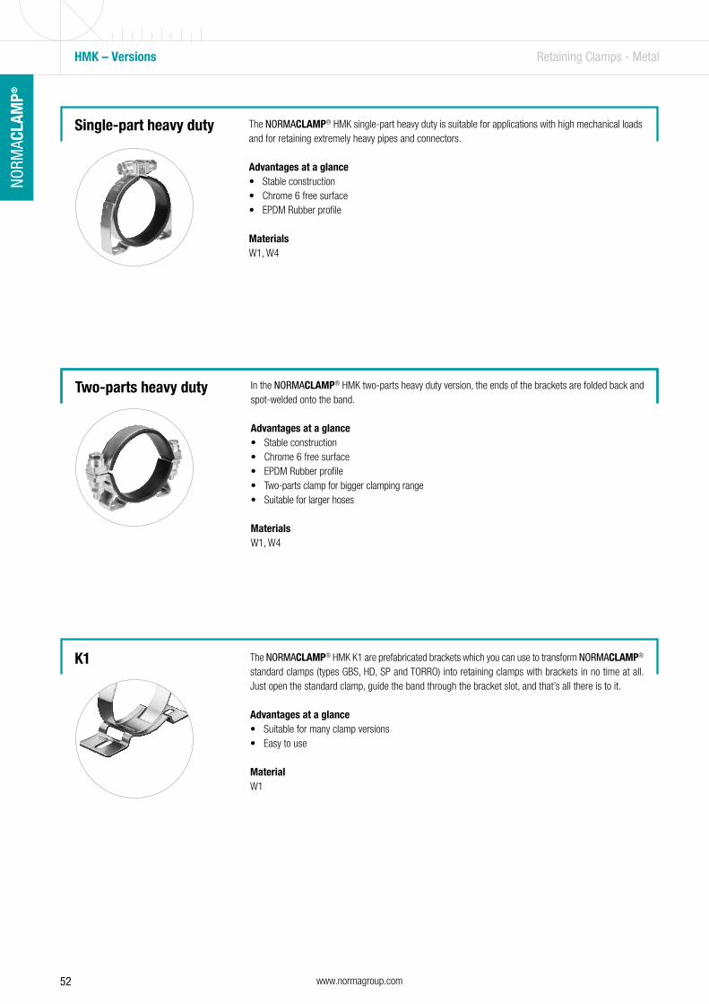
52 www.normagroup.com
NORM
ACLA
MP®
The NORMACLAMP® HMK K1 are prefabricated brackets which you can use to transform NORMACLAMP®
standard clamps (types GBS, HD, SP and TORRO) into retaining clamps with brackets in no time at all. Just open the standard clamp, guide the band through the bracket slot, and that’s all there is to it.
Advantages at a glance• Suitable for many clamp versions• Easy to use
MaterialW1
The NORMACLAMP® HMK single-part heavy duty is suitable for applications with high mechanical loads and for retaining extremely heavy pipes and connectors.
Advantages at a glance• Stable construction• Chrome 6 free surface• EPDM Rubber profile
MaterialsW1, W4
Single-part heavy duty
Two-parts heavy duty In the NORMACLAMP® HMK two-parts heavy duty version, the ends of the brackets are folded back and spot-welded onto the band.
Advantages at a glance• Stable construction• Chrome 6 free surface• EPDM Rubber profile• Two-parts clamp for bigger clamping range • Suitable for larger hoses
MaterialsW1, W4
HMK – Versions Retaining Clamps - Metal
K1
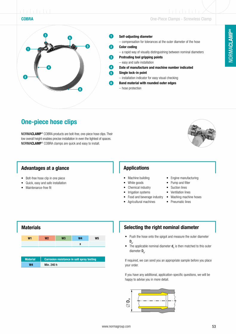
53www.normagroup.com
NORM
ACLA
MP®
NO
RMAC
LAM
P®
Self-adjusting diameter – compensation for tolerances at the outer diameter of the hose
Color coding – a rapid way of visually distinguishing between nominal diameters
Protruding tool gripping points – easy and safe installation
Date of manufacture and machine number indicatedSingle lock-in point
– installation indicator for easy visual checking
Band material with rounded outer edges – hose protection
1
2
3
4
5
6
1
2
3
4
5
6
3
COBRA One-Piece Clamps - Screwless Clamp
One-piece hose clips
NORMACLAMP® COBRA products are bolt-free, one-piece hose clips. Their low overall height enables precise installation in even the tightest of spaces.NORMACLAMP® COBRA clamps are quick and easy to install.
Advantages at a glance
• Bolt-free hose clip in one piece• Quick, easy and safe installation• Maintenance-free fit
Applications
• Machine building • Engine manufacturing• White goods • Pump and filter• Chemical industry • Suction lines• Irrigation systems • Ventilation lines• Food and beverage industry • Washing machine hoses• Agricultural machines • Pneumatic lines
Materials
W1 W2 W3 W4 W5
x
Material Corrosion resistance in salt spray testing
W4 Min. 240 h
Selecting the right nominal diameter
• Push the hose onto the spigot and measure the outer diameter Da.
• The applicable nominal diameter d1 is then matched to this outer diameter Da.
If required, we can send you an appropriate sample before you place your order.
If you have any additional, application-specific questions, we will be happy to advise you in more detail.

54 www.normagroup.com
NORM
ACLA
MP®
COBRA One-Piece Clamps - Screwless Clamp
Technical data & Ordering information
NORMACLAMP® COBRA
Width Designation
Clamping ranges Nominal diameter
W4Product No. Colorin mm in inches
7 COBRA 7.5/7 8-9 5/16-3/8” 7.5 0107 7000 075 White
COBRA 8.0/7 8.5-9.5 5/16-3/8” 8.0 0107 7000 008 Yellow
COBRA 8.5/7 9-10 3/8-3/8” 8.5 0107 7000 085 Green
COBRA 9.0/7 9.5-10.5 3/8-3/8” 9.0 0107 7000 009 Purple
COBRA 9.5/7 10-11 3/8-7/16” 9.5 0107 7000 095 Black
COBRA 10.0/7 10.5-11.5 3/8-7/16” 10 0107 7000 010 White
COBRA 10.5/7 11-12 7/16-1/2” 10.5 0107 7000 105 Yellow
COBRA 11.0/7 11.5-12.5 7/16-1/2” 11 0107 7000 011 Green
COBRA 11.5/7 12-13 1/2-1/2” 11.5 0107 7000 115 Purple
8 COBRA 12/8 12.5-14 1/2-9/16” 12 0108 7006 012 Black
COBRA 13/8 13.5-15 1/2-5/8” 13 0108 7006 013 Yellow
COBRA 14/8 14.5-16 9/16-5/8” 14 0108 7006 014 Purple
COBRA 15/8 15.5-17 5/8-11/16” 15 0108 7006 015 White
COBRA 16/8 16.5-18 5/8-3/4” 16 0108 7006 016 Green
COBRA 17/8 17.5-19 11/16-3/4” 17 0108 7006 017 Black
COBRA 18/8 18.5-20 3/4-13/16” 18 0108 7006 018 Yellow
COBRA 19/8 19.5-21 3/4-13/16” 19 0108 7006 019 Purple
COBRA 20/8 20.5-22 13/16-7/8” 20 0108 7006 020 White
COBRA 21/8 21.5-23 13/16-7/8” 21 0108 7006 021 Green
COBRA 22/8 22.5-24 7/8-15/16” 22 0108 7006 022 Black
COBRA 23/8 23.5-25 7/8-1” 23 0108 7006 023 Yellow
COBRA 24/8 24.5-26 15/16-1 1/16” 24 0108 7006 024 Purple
COBRA 25/8 25.5-27 1-1 1/16” 25 0108 7006 025 White
COBRA 26/8 26.5-28 1 1/16-1 1/8” 26 0108 7006 026 Green
COBRA 27/8 27.5-29 1 1/16-1 1/8” 27 0108 7006 027 Black
COBRA 28/8 28.5-30 1 1/8-1 3/16” 28 0108 7006 028 Yellow
COBRA 29/8 29.5-31 1 1/8-1 1/4” 29 0108 7006 029 Purple
COBRA 30/8 30.5-32 1 3/16-1 1/4” 30 0108 7006 030 White
Refer to pages 191, 195 and 197.
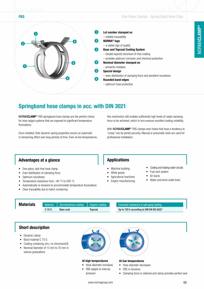
55www.normagroup.com
NORM
ACLA
MP®
NO
RMAC
LAM
P®
• Dynamic clamp• Band material C 75 S• Coating containing zinc; no chromium(VI)• Nominal diameter of 13 mm to 70 mm in
various graduations
Lot number stamped on – reliable traceability
NORMA® logo – a visible sign of quality
Base and Topcoat Coating System – Double layered chromium VI-free coating
– provides optimum corrosion and chemical protectionNominal diameter stamped on
– prevents mistakesSpecial design
– even distribution of clamping force and excellent roundnessRounded band edges
– optimum hose protection
1
2
3
4
5
6
FBS One-Piece Clamps - Spring Band Hose Clips
Springband hose clamps in acc. with DIN 3021
NORMACLAMP® FBS springband hose clamps are the perfect choice for hose spigot systems that are exposed to significant temperature fluctuations.
Once installed, their dynamic spring properties ensure an automatic re-tensioning effect over long periods of time. Even at low temperatures,
this mechanism still enables sufficiently high levels of radial clamping force to be achieved, which in turn ensures excellent sealing reliability.
With NORMACLAMP® FBS clamps even hoses that have a tendency to “creep” can be joined securely. Manual or pneumatic tools are used for professional installation.
Advantages at a glance
• One-piece, bolt-free hose clamp• Even distribution of clamping force• Optimum roundness• Temperature resistance from –40 °C to 200 °C• Automatically re-tensions to accommodate temperature fluctuations• Clear traceability due to batch numbering
Applications
• Machine building• White goods• Agricultural machines• Engine manufacturing
• Cooling and heating water circuits• Fuel vent system• Air ducts• Water and brine outlet lines
1
2
3
4
5
6
Short description
Materials Material Zinc/aluminum coating Organic coating
C 75 S Base coat Topcoat
Corrosion resistance in salt spray testing
Up to 720 h according to DIN EN ISO 9227
At high temperatures • Hose diameter increases• FBS adapts to internal
pressure
At low temperatures • Hose diameter decreases• FBS re-tensions• Clamping force is retained and clamp provides perfect seal
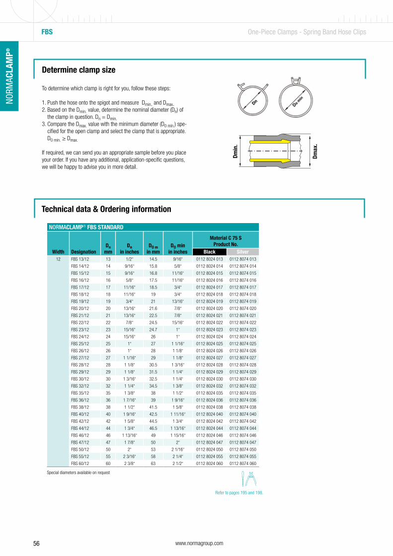
56 www.normagroup.com
NORM
ACLA
MP®
FBS One-Piece Clamps - Spring Band Hose Clips
Determine clamp size
To determine which clamp is right for you, follow these steps:
1. Push the hose onto the spigot and measure Dmin. and Dmax.2. Based on the Dmin. value, determine the nominal diameter (Dn) of
the clamp in question. Dn = Dmin.3. Compare the Dmax. value with the minimum diameter (D0 min.) spe-
cified for the open clamp and select the clamp that is appropriate. D0 min. ≥ Dmax.
If required, we can send you an appropriate sample before you place your order. If you have any additional, application-specific questions, we will be happy to advise you in more detail.
Dmax
.
Dmin
.NORMACLAMP® FBS STANDARD
Width DesignationDn
mmDn
in inchesDO m
in mmDO min
in inches
Material C 75 SProduct No.
Black Silver12 FBS 13/12 13 1/2” 14.5 9/16” 0112 8024 013 0112 8074 013
FBS 14/12 14 9/16” 15.8 5/8” 0112 8024 014 0112 8074 014
FBS 15/12 15 9/16” 16.8 11/16” 0112 8024 015 0112 8074 015
FBS 16/12 16 5/8” 17.5 11/16” 0112 8024 016 0112 8074 016
FBS 17/12 17 11/16” 18.5 3/4” 0112 8024 017 0112 8074 017
FBS 18/12 18 11/16” 19 3/4” 0112 8024 018 0112 8074 018
FBS 19/12 19 3/4” 21 13/16” 0112 8024 019 0112 8074 019
FBS 20/12 20 13/16” 21.6 7/8” 0112 8024 020 0112 8074 020
FBS 21/12 21 13/16” 22.5 7/8” 0112 8024 021 0112 8074 021
FBS 22/12 22 7/8” 24.5 15/16” 0112 8024 022 0112 8074 022
FBS 23/12 23 15/16” 24.7 1” 0112 8024 023 0112 8074 023
FBS 24/12 24 15/16” 26 1” 0112 8024 024 0112 8074 024
FBS 25/12 25 1” 27 1 1/16” 0112 8024 025 0112 8074 025
FBS 26/12 26 1” 28 1 1/8” 0112 8024 026 0112 8074 026
FBS 27/12 27 1 1/16” 29 1 1/8” 0112 8024 027 0112 8074 027
FBS 28/12 28 1 1/8” 30.5 1 3/16” 0112 8024 028 0112 8074 028
FBS 29/12 29 1 1/8” 31.5 1 1/4” 0112 8024 029 0112 8074 029
FBS 30/12 30 1 3/16” 32.5 1 1/4” 0112 8024 030 0112 8074 030
FBS 32/12 32 1 1/4” 34.5 1 3/8” 0112 8024 032 0112 8074 032
FBS 35/12 35 1 3/8” 38 1 1/2” 0112 8024 035 0112 8074 035
FBS 36/12 36 1 7/16” 39 1 9/16” 0112 8024 036 0112 8074 036
FBS 38/12 38 1 1/2” 41.5 1 5/8” 0112 8024 038 0112 8074 038
FBS 40/12 40 1 9/16” 42.5 1 11/16” 0112 8024 040 0112 8074 040
FBS 42/12 42 1 5/8” 44.5 1 3/4” 0112 8024 042 0112 8074 042
FBS 44/12 44 1 3/4” 46.5 1 13/16” 0112 8024 044 0112 8074 044
FBS 46/12 46 1 13/16” 49 1 15/16” 0112 8024 046 0112 8074 046
FBS 47/12 47 1 7/8” 50 2” 0112 8024 047 0112 8074 047
FBS 50/12 50 2” 53 2 1/16” 0112 8024 050 0112 8074 050
FBS 55/12 55 2 3/16” 58 2 1/4” 0112 8024 055 0112 8074 055
FBS 60/12 60 2 3/8” 63 2 1/2” 0112 8024 060 0112 8074 060
Technical data & Ordering information
Special diameters available on request
Refer to pages 195 and 198.

57www.normagroup.com
NORM
ACLA
MP®
NO
RMAC
LAM
P®
FBS – Versions One-Piece Clamps - Spring Band Hose Clips
FBS R The NORMACLAMP® FBS R was designed with the aim of achieving thesmallest overall height that was technically possible so that it could beused in difficult installation conditions.
Main advantageSpace-saving clamp
MaterialC75S
FBS C A pre-opened clamp that must be glued into place on the hose. Ask your sales representative for the gluing instructions. The retaining mechanism for this version is part of the band and is integrated into the clamp.
Advantages at a glance• Pre-assembled clamp• Ready to use
MaterialC75S
Refer to pages 195 and 198.
FBS HC A pre-opened version that is secured by a plastic clip and can also be glued into place on the hose. Ask your Sales Representative for gluing instructions. Once the clamp has been pushed onto the hose, this clip can be released easily by hand.
Main advantageEasy to assemble
MaterialC75S
FBS MC A pre-opened version that is secured by a metal clip and can also be glued into place on the hose. Ask your Sales Representative for gluing instructions. The retaining clip for this version is removed by using pliers.
Main advantageSecured clamp
MaterialC75S
Refer to page 195.

58 www.normagroup.com
NORM
ACLA
MP®
EARCLIP SINGLE Ear Clips - One Ear Clips
1 Ear – one tightening side
Smooth inner band
Round edges to prevent damage
1
2
One part clamp for low and medium pressure.
The NORMACLAMP® Earclip single has no screw. The assembly is fast, simple and safe thanks to the pinching of the ear.
Advantages at a glance
• Cost effective, and simple alternative to worm drive hose clips• Fast and easy to install• Ideal in narrow spaces• Suitable for definitive fixation of connecting pipes• To be assembled with simple ear clip pliers
Applications
• For hoses that convey compressed air or fluid• Original equipment manufacturing• Maintenance repair and overhaul
3
Technical data & Ordering information
NORMACLAMP® EARCLIP SINGLE
Width Description
Clamping ranges
W1Product No.
W4Product No.in mm in inches
6 EARCLIP SINGLE 8 - 10/6 8 - 10 5/16-3/8” 0110 7010 010 0110 7011 010
6.5 EARCLIP SINGLE 9 - 11/6.5 9 - 11 3/8-7/16” 0110 7010 011 0110 7011 011
EARCLIP SINGLE 10 - 12/6.5 10 - 12 3/8-1/2” 0110 7010 012 0110 7011 012
EARCLIP SINGLE 11 - 13/6.5 11 - 13 7/16-1/2” 0110 7010 013 0110 7011 013
7 EARCLIP SINGLE 12 - 14/7 12 - 14 1/2-9/16” 0110 7010 014 0110 7011 014
EARCLIP SINGLE 13 - 15/7 13 - 15 1/2-9/16” 0110 7011 015
EARCLIP SINGLE 14 - 16/7 14 - 16 9/16-5/8” 0110 7010 016 0110 7011 016
EARCLIP SINGLE 16 - 18/7 16 - 18 5/8-11/16” 0110 7010 018 0110 7011 018
3
2
W1 W2 W3 W4 W5
x x
Materials
Refer to page 197.

59www.normagroup.com
NORM
ACLA
MP®
NO
RMAC
LAM
P®
NORMACLAMP® EARCLIP SAFE
Width Description
Clamping ranges
W1Product No.
W4Product No.in mm in inches
6 EARCLIP SAFE 7.5-8.5/6 7.5-8.5 5/16-5/16” 0110 7014 008 0110 7015 008
EARCLIP SAFE 8-9.5/6 8-9.5 5/16-3/8” 0110 7014 009 0110 7015 009
6.5 EARCLIP SAFE 9-10.5/6.5 9-10.5 3/8-7/16” 0110 7014 010 0110 7015 010
EARCLIP SAFE 10-11.5/6.5 10-11.5 3/8-7/16” 0110 7014 011 0110 7015 011
EARCLIP SAFE 10.5-12.5/6.5 10.5-12.5 7/16-1/2” 0110 7014 012 0110 7015 012
7 EARCLIP SAFE 11.5-13.3/7 11.5-13.3 7/16-1/2” 0110 7014 013 0110 7015 013
EARCLIP SAFE 12.5-14.5/7 12.5-14.5 1/2-9/16” 0110 7015 014
EARCLIP SAFE 13-15.3/7 13-15.3 1/2-5/8” 0110 7014 015 0110 7015 015
EARCLIP SAFE 14-16/7 14-16 9/16-1/4” 0110 7015 016
EARCLIP SAFE 15-17.3/7 15-17.3 9/16-11/16” 0110 7014 017 0110 7015 017
7.5 EARCLIP SAFE 16-18.3/7.5 16-18.3 1/4-3/4” 0110 7015 018
EARCLIP SAFE 17-19.3/7.5 17-19.3 11-16-3/4” 0110 7015 019
EARCLIP SAFE Ear Clips - One Ear Clips
Ear – one tightening side
Smooth inner band, and inner liner for securityand roundness
Round edges to prevent damage
Inner liner – effective and powerful all-round seal
1
2
One part clamp for low and medium pressure.
The NORMACLAMP® Earclip safe has no screw. The assembly is fast, simple and safe thanks to the pinching of the ear. The inner insertallows a better distribution of the clamping force.
Advantages at a glance
• Cost effective, and simple alternative to worm drive hose clips• Fast and easy to install• Ideal in narrow spaces• Suitable for definitive fixation of connecting pipes• To be assembled with simple ear clip pliers• Inner liner for security and better distribution of the clamping force
Applications
• For hoses that convey compressed air or fluid• Original equipment manufacturing• Maintenance repair and overhaul
3
W1 W2 W3 W4 W5
x x
Materials Technical data & Ordering information
1
32
4
4
Refer to page 197.
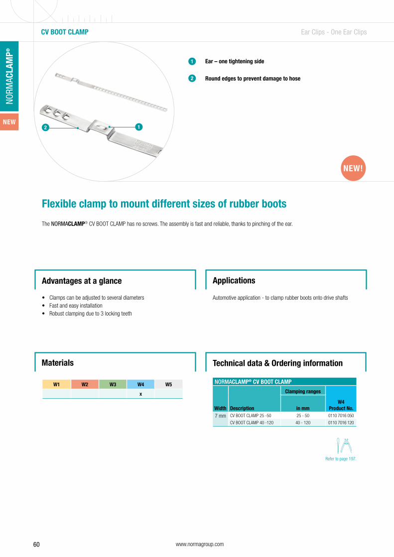
60 www.normagroup.com
NORM
ACLA
MP®
CV BOOT CLAMP Ear Clips - One Ear Clips
2
Ear – one tightening side
Round edges to prevent damage to hose
1
2
Flexible clamp to mount different sizes of rubber boots
The NORMACLAMP® CV BOOT CLAMP has no screws. The assembly is fast and reliable, thanks to pinching of the ear.
Advantages at a glance
• Clamps can be adjusted to several diameters• Fast and easy installation• Robust clamping due to 3 locking teeth
Applications
Automotive application - to clamp rubber boots onto drive shafts
Technical data & Ordering information
NORMACLAMP® CV BOOT CLAMP
Width Description
Clamping ranges
W4Product No.in mm
7 mm CV BOOT CLAMP 25 -50 25 - 50 0110 7016 050
CV BOOT CLAMP 40 -120 40 - 120 0110 7016 120
1
W1 W2 W3 W4 W5
x
Materials
NEW!NEW!
Refer to page 197.
NEW
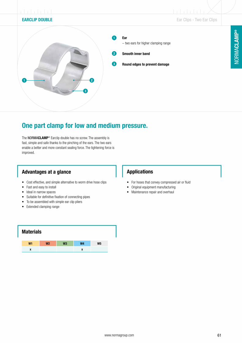
61www.normagroup.com
NORM
ACLA
MP®
NO
RMAC
LAM
P®
EARCLIP DOUBLE Ear Clips - Two Ear Clips
Ear – two ears for higher clamping range
Smooth inner band
Round edges to prevent damage
1
2
One part clamp for low and medium pressure.
The NORMACLAMP® Earclip double has no screw. The assembly is fast, simple and safe thanks to the pinching of the ears. The two ears enable a better and more constant sealing force. The tightening force is improved.
Advantages at a glance
• Cost effective, and simple alternative to worm drive hose clips• Fast and easy to install• Ideal in narrow spaces• Suitable for definitive fixation of connecting pipes• To be assembled with simple ear clip pliers• Extended clamping range
Applications
• For hoses that convey compressed air or fluid• Original equipment manufacturing• Maintenance repair and overhaul
3
1 2
3
W1 W2 W3 W4 W5
x x
Materials
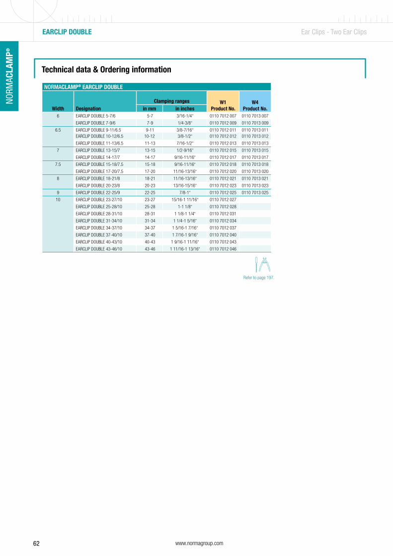
62 www.normagroup.com
NORM
ACLA
MP®
Technical data & Ordering information
EARCLIP DOUBLE Ear Clips - Two Ear Clips
Refer to page 197.
NORMACLAMP® EARCLIP DOUBLE
Width DesignationClamping ranges W1
Product No.W4
Product No.in mm in inches6 EARCLIP DOUBLE 5-7/6 5-7 3/16-1/4” 0110 7012 007 0110 7013 007
EARCLIP DOUBLE 7-9/6 7-9 1/4-3/8” 0110 7012 009 0110 7013 009
6.5 EARCLIP DOUBLE 9-11/6.5 9-11 3/8-7/16” 0110 7012 011 0110 7013 011EARCLIP DOUBLE 10-12/6.5 10-12 3/8-1/2” 0110 7012 012 0110 7013 012
EARCLIP DOUBLE 11-13/6.5 11-13 7/16-1/2” 0110 7012 013 0110 7013 013
7 EARCLIP DOUBLE 13-15/7 13-15 1/2-9/16” 0110 7012 015 0110 7013 015
EARCLIP DOUBLE 14-17/7 14-17 9/16-11/16” 0110 7012 017 0110 7013 017
7.5 EARCLIP DOUBLE 15-18/7.5 15-18 9/16-11/16” 0110 7012 018 0110 7013 018
EARCLIP DOUBLE 17-20/7.5 17-20 11/16-13/16” 0110 7012 020 0110 7013 020
8 EARCLIP DOUBLE 18-21/8 18-21 11/16-13/16” 0110 7012 021 0110 7013 021
EARCLIP DOUBLE 20-23/8 20-23 13/16-15/16” 0110 7012 023 0110 7013 023
9 EARCLIP DOUBLE 22-25/9 22-25 7/8-1” 0110 7012 025 0110 7013 025
10 EARCLIP DOUBLE 23-27/10 23-27 15/16-1 11/16” 0110 7012 027
EARCLIP DOUBLE 25-28/10 25-28 1-1 1/8” 0110 7012 028
EARCLIP DOUBLE 28-31/10 28-31 1 1/8-1 1/4” 0110 7012 031
EARCLIP DOUBLE 31-34/10 31-34 1 1/4-1 5/16” 0110 7012 034
EARCLIP DOUBLE 34-37/10 34-37 1 5/16-1 7/16” 0110 7012 037
EARCLIP DOUBLE 37-40/10 37-40 1 7/16-1 9/16” 0110 7012 040
EARCLIP DOUBLE 40-43/10 40-43 1 9/16-1 11/16” 0110 7012 043
EARCLIP DOUBLE 43-46/10 43-46 1 11/16-1 13/16” 0110 7012 046

63
The perfect method of connecting pipesWhen it comes to pipe connections, the industry and OEMs rely on NORMACONNECT® – the reliable solution that can be used with all kinds of different requirements, pipe materials and outer pipe diameters.
NORMACONNECT® – Pipe Connections
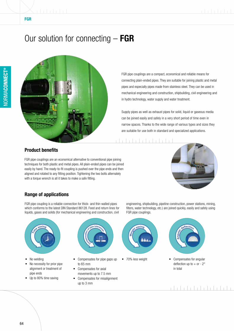
64
NORM
ACON
NECT
®
Our solution for connecting – FGR
FGR pipe couplings are an economical alternative to conventional pipe joining techniques for both plastic and metal pipes. All plain-ended pipes can be joined easily by hand. The ready-to-fit coupling is pushed over the pipe ends and then aligned and rotated to any fitting position. Tightening the two bolts alternately with a torque wrench is all it takes to make a safe fitting.
FGR
FGR pipe couplings are a compact, eco nomical and reliable means for
connecting plain-ended pipes. They are suitable for joining plastic and metal
pipes and especially pipes made from stainless steel. They can be used in
mechanical engineering and construction, shipbuilding, civil engineering and
in hydro technology, water supply and water treatment.
Supply pipes as well as exhaust pipes for solid, liquid or gaseous media
can be joined easily and safely in a very short period of time even in
narrow spaces. Thanks to the wide range of various types and sizes they
are suitable for use both in standard and specialized applications.
Product benefits
• No welding• No necessity for prior pipe
alignment or treatment of pipe ends
• Up to 80% time saving
• Compensates for pipe gaps up to 65 mm
• Compensates for axial movements up to 7.5 mm
• Compensates for misalignment up to 3 mm
• 70% less weight • Compensates for angular deflection up to + or - 2° in total
Range of applications
FGR pipe coupling is a reliable connection for thick- and thin-walled pipes which conforms to the latest DIN Standard 86128. Feed and return lines for liquids, gases and solids (for mechanical engineering and construction, civil
engineering, shipbuilding, pipe line construction, power stations, mining, filters, water technology, etc.) are joined quickly, easily and safely using FGR pipe couplings.
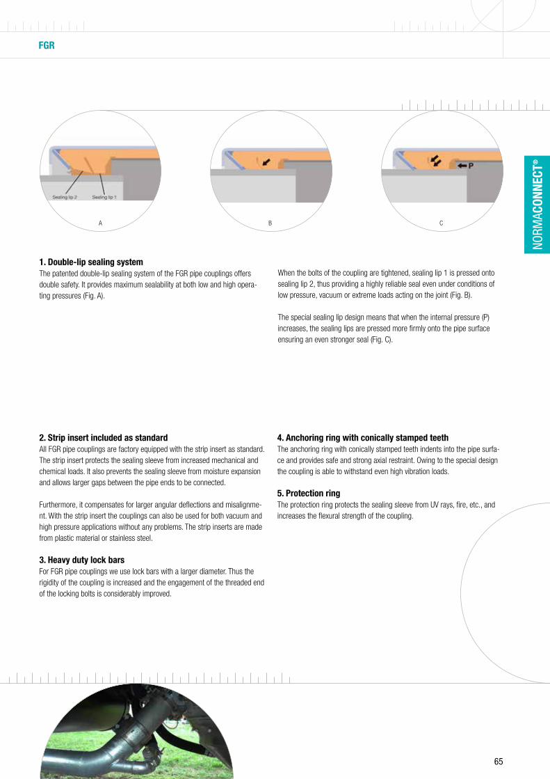
65
NORM
ACON
NECT
®
FGR
1. Double-lip sealing system The patented double-lip sealing system of the FGR pipe couplings offers double safety. It provides maximum sealability at both low and high opera-ting pressures (Fig. A).
2. Strip insert included as standard All FGR pipe couplings are factory equipped with the strip insert as standard. The strip insert protects the sealing sleeve from increased mechanical and chemical loads. It also prevents the sealing sleeve from moisture expansion and allows larger gaps between the pipe ends to be connected.
Furthermore, it compensates for larger angular deflections and misalignme-nt. With the strip insert the couplings can also be used for both vacuum and high pressure applications without any problems. The strip inserts are made from plastic material or stainless steel.
3. Heavy duty lock bars For FGR pipe couplings we use lock bars with a larger diameter. Thus the rigidity of the coupling is increased and the engagement of the threaded end of the locking bolts is considerably improved.
4. Anchoring ring with conically stamped teeth The anchoring ring with conically stamped teeth indents into the pipe surfa-ce and provides safe and strong axial restraint. Owing to the special design the coupling is able to withstand even high vibration loads.
5. Protection ring The protection ring protects the sealing sleeve from UV rays, fire, etc., and increases the flexural strength of the coupling.
When the bolts of the coupling are tightened, sealing lip 1 is pressed onto sealing lip 2, thus providing a highly reliable seal even under conditions of low pressure, vacuum or extreme loads acting on the joint (Fig. B).
The special sealing lip design means that when the internal pressure (P) increases, the sealing lips are pressed more firmly onto the pipe surface ensuring an even stronger seal (Fig. C).
A B C

66 www.normagroup.com
NORM
ACON
NECT
®
SHIPBUILDINGFLEX / FLEX E /
RFPGRIP / GRIP E / Grip E-FP / RFP
CombiGrip / CombiGrip E
PlastGrip / PlastGrip E Rep E
ABS • • • •
Bureau Veritas • • • •
DNV-GL • • • •
LRS •1 •1 • •
CLASS NK • • • •
RINA • •
RMRS • • • •
PRS •1 •1
KRS • • • •
Approvals
FGR APPROVALS
WATER SUPPLY & TREATMENT
Elastomer guidelineKTW/TZW W270
• • • • •
DVGW •2
GOST • • • • •
NSF • • • •
DQS • • • • •
GAS
DVGW / GWI •
BAM • •
SPECIAL APPROVALS
DiBT / TÜV south. Germany
•
BWB •3
FDA • • • •
¹ No approvals for RFP² From 40.0 mm up to 160 mm³ German approval for the German marine
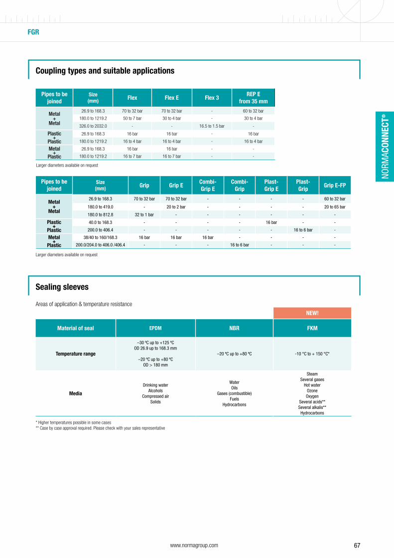
67www.normagroup.com
NORM
ACON
NECT
®
FGR
Areas of application & temperature resistance
Pipes to be joined
Size (mm) Flex Flex E Flex 3
REP E from 35 mm
Metal+
Metal
26.9 to 168.3 70 to 32 bar 70 to 32 bar - 60 to 32 bar
180.0 to 1219.2 50 to 7 bar 30 to 4 bar - 30 to 4 bar
326.0 to 2032.0 - - 16.5 to 1.5 bar -
Plastic+
Plastic
26.9 to 168.3 16 bar 16 bar - 16 bar
180.0 to 1219.2 16 to 4 bar 16 to 4 bar - 16 to 4 bar
Metal+
Plastic
26.9 to 168.3 16 bar 16 bar - -
180.0 to 1219.2 16 to 7 bar 16 to 7 bar - -
Pipes to be joined
Size (mm) Grip Grip E
Combi-Grip E
Combi-Grip
Plast-Grip E
Plast-Grip
Grip E-FP
Metal+
Metal
26.9 to 168.3 70 to 32 bar 70 to 32 bar - - - - 60 to 32 bar
180.0 to 419.0 - 20 to 2 bar - - - - 20 to 65 bar
180.0 to 812.8 32 to 1 bar - - - - - -
Plastic+
Plastic
40.0 to 168.3 - - - - 16 bar - -
200.0 to 406.4 - - - - - 16 to 6 bar -
Metal+
Plastic
38/40 to 160/168.3 16 bar 16 bar 16 bar - - - -
200.0/204.0 to 406.0 /406.4 - - - 16 to 6 bar - - -
NEW!
Material of seal EPDM NBR FKM
Temperature range
–30 ºC up to +125 ºCOD 26.9 up to 168.3 mm
–20 ºC up to +80 ºCOD > 180 mm
–20 ºC up to +80 ºC -10 °C to + 150 °C*
Media
Drinking waterAlcohols
Compressed airSolids
WaterOils
Gases (combustible)Fuels
Hydrocarbons
SteamSeveral gases
Hot waterOzoneOxygen
Several acids**Several alkalis**Hydrocarbons
Coupling types and suitable applications
Sealing sleeves
Larger diameters available on request
Larger diameters available on request
* Higher temperatures possible in some cases** Case by case approval required. Please check with your sales representative
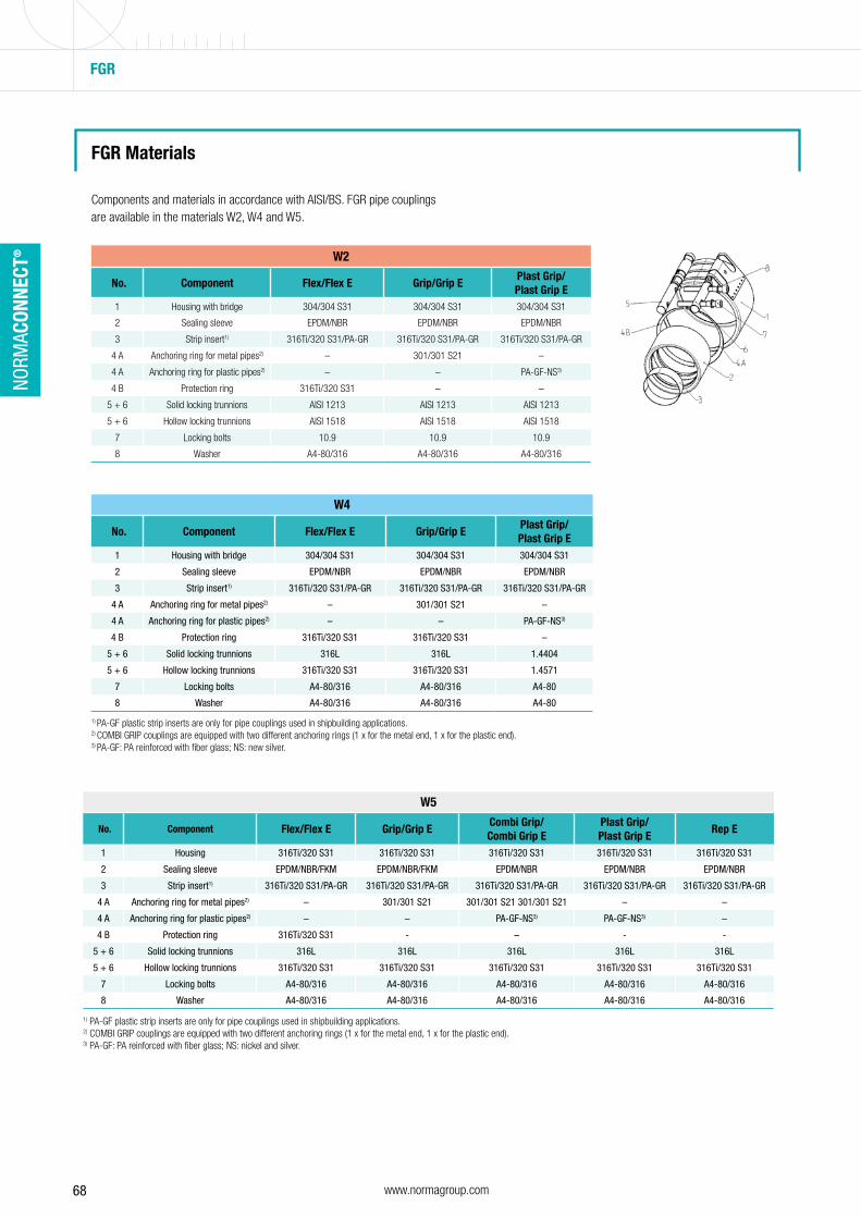
68 www.normagroup.com
NORM
ACON
NECT
®
Components and materials in accordance with AISI/BS. FGR pipe couplings are available in the materials W2, W4 and W5.
1) PA-GF plastic strip inserts are only for pipe couplings used in shipbuilding applications.2) COMBI GRIP couplings are equipped with two different anchoring rings (1 x for the metal end, 1 x for the plastic end).3) PA-GF: PA reinforced with fiber glass; NS: new silver.
1) PA-GF plastic strip inserts are only for pipe couplings used in shipbuilding applications.2) COMBI GRIP couplings are equipped with two different anchoring rings (1 x for the metal end, 1 x for the plastic end).3) PA-GF: PA reinforced with fiber glass; NS: nickel and silver.
W2
No. Component Flex/Flex E Grip/Grip EPlast Grip/ Plast Grip E
1 Housing with bridge 304/304 S31 304/304 S31 304/304 S31
2 Sealing sleeve EPDM/NBR EPDM/NBR EPDM/NBR
3 Strip insert1) 316Ti/320 S31/PA-GR 316Ti/320 S31/PA-GR 316Ti/320 S31/PA-GR
4 A Anchoring ring for metal pipes2) – 301/301 S21 –
4 A Anchoring ring for plastic pipes2) – – PA-GF-NS3)
4 B Protection ring 316Ti/320 S31 – –
5 + 6 Solid locking trunnions AISI 1213 AISI 1213 AISI 1213
5 + 6 Hollow locking trunnions AISI 1518 AISI 1518 AISI 1518
7 Locking bolts 10.9 10.9 10.9
8 Washer A4-80/316 A4-80/316 A4-80/316
W4
No. Component Flex/Flex E Grip/Grip EPlast Grip/ Plast Grip E
1 Housing with bridge 304/304 S31 304/304 S31 304/304 S31
2 Sealing sleeve EPDM/NBR EPDM/NBR EPDM/NBR
3 Strip insert1) 316Ti/320 S31/PA-GR 316Ti/320 S31/PA-GR 316Ti/320 S31/PA-GR
4 A Anchoring ring for metal pipes2) – 301/301 S21 –
4 A Anchoring ring for plastic pipes2) – – PA-GF-NS3)
4 B Protection ring 316Ti/320 S31 316Ti/320 S31 –
5 + 6 Solid locking trunnions 316L 316L 1.4404
5 + 6 Hollow locking trunnions 316Ti/320 S31 316Ti/320 S31 1.4571
7 Locking bolts A4-80/316 A4-80/316 A4-80
8 Washer A4-80/316 A4-80/316 A4-80
W5
No. Component Flex/Flex E Grip/Grip ECombi Grip/ Combi Grip E
Plast Grip/ Plast Grip E
Rep E
1 Housing 316Ti/320 S31 316Ti/320 S31 316Ti/320 S31 316Ti/320 S31 316Ti/320 S31
2 Sealing sleeve EPDM/NBR/FKM EPDM/NBR/FKM EPDM/NBR EPDM/NBR EPDM/NBR
3 Strip insert1) 316Ti/320 S31/PA-GR 316Ti/320 S31/PA-GR 316Ti/320 S31/PA-GR 316Ti/320 S31/PA-GR 316Ti/320 S31/PA-GR
4 A Anchoring ring for metal pipes2) – 301/301 S21 301/301 S21 301/301 S21 – –
4 A Anchoring ring for plastic pipes2) – – PA-GF-NS3) PA-GF-NS3) –
4 B Protection ring 316Ti/320 S31 - – - -
5 + 6 Solid locking trunnions 316L 316L 316L 316L 316L
5 + 6 Hollow locking trunnions 316Ti/320 S31 316Ti/320 S31 316Ti/320 S31 316Ti/320 S31 316Ti/320 S31
7 Locking bolts A4-80/316 A4-80/316 A4-80/316 A4-80/316 A4-80/316
8 Washer A4-80/316 A4-80/316 A4-80/316 A4-80/316 A4-80/316
FGR
FGR Materials
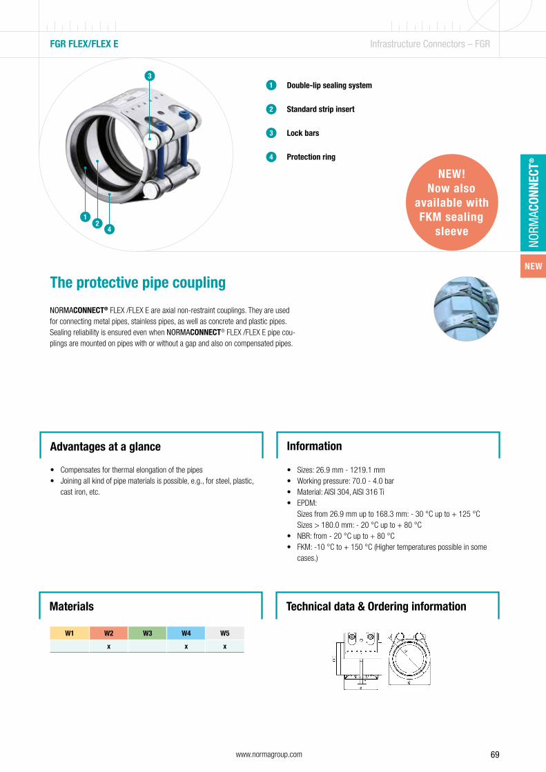
69www.normagroup.com
NORM
ACON
NECT
®
W5
No. Component Flex/Flex E Grip/Grip ECombi Grip/ Combi Grip E
Plast Grip/ Plast Grip E
Rep E
1 Housing 316Ti/320 S31 316Ti/320 S31 316Ti/320 S31 316Ti/320 S31 316Ti/320 S31
2 Sealing sleeve EPDM/NBR/FKM EPDM/NBR/FKM EPDM/NBR EPDM/NBR EPDM/NBR
3 Strip insert1) 316Ti/320 S31/PA-GR 316Ti/320 S31/PA-GR 316Ti/320 S31/PA-GR 316Ti/320 S31/PA-GR 316Ti/320 S31/PA-GR
4 A Anchoring ring for metal pipes2) – 301/301 S21 301/301 S21 301/301 S21 – –
4 A Anchoring ring for plastic pipes2) – – PA-GF-NS3) PA-GF-NS3) –
4 B Protection ring 316Ti/320 S31 - – - -
5 + 6 Solid locking trunnions 316L 316L 316L 316L 316L
5 + 6 Hollow locking trunnions 316Ti/320 S31 316Ti/320 S31 316Ti/320 S31 316Ti/320 S31 316Ti/320 S31
7 Locking bolts A4-80/316 A4-80/316 A4-80/316 A4-80/316 A4-80/316
8 Washer A4-80/316 A4-80/316 A4-80/316 A4-80/316 A4-80/316
Double-lip sealing system
Standard strip insert
Lock bars
Protection ring
1
2
3
4
The protective pipe coupling
NORMACONNECT® FLEX /FLEX E are axial non-restraint couplings. They are used for connecting metal pipes, stainless pipes, as well as concrete and plastic pipes. Sealing reliability is ensured even when NORMACONNECT® FLEX /FLEX E pipe cou-plings are mounted on pipes with or without a gap and also on compensated pipes.
Advantages at a glance
• Compensates for thermal elongation of the pipes• Joining all kind of pipe materials is possible, e.g., for steel, plastic,
cast iron, etc.
Information
• Sizes: 26.9 mm - 1219.1 mm• Working pressure: 70.0 - 4.0 bar• Material: AISI 304, AISI 316 Ti• EPDM:
Sizes from 26.9 mm up to 168.3 mm: - 30 °C up to + 125 °C Sizes > 180.0 mm: - 20 °C up to + 80 °C
• NBR: from - 20 °C up to + 80 °C• FKM: -10 °C to + 150 °C (Higher temperatures possible in some
cases.)
FGR FLEX/FLEX E Infrastructure Connectors – FGR
3
42
1
Technical data & Ordering informationMaterials
W1 W2 W3 W4 W5
x x x
NEW!Now also
available with FKM sealing
sleeve
NEW
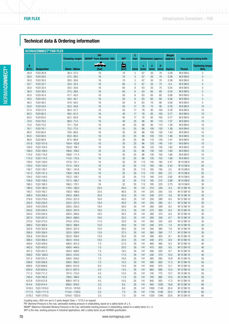
70 www.normagroup.com
NORM
ACON
NECT
®
FGR FLEX Infrastructure Connectors – FGR
Technical data & Ordering information
NORMACONNECT® FGR FLEX
Ø(O.D.) Designation
Clamping rangesPN¹
(MAWP¹ from diameter 180) WP²C
max Dimensions (approx.)Weight
(approx.) Hex socket locking bolts
Odmin - Odmax [bar] [bar] (mm)a
(mm)d
(mm)H
(mm)
(kg/pc.) ThreadTightening torque
(Nm)
26.9 FLEX 26.9 26.4 - 27.5 16 70 3 67 50 70 0.39 M 8 SW 6 528.0 FLEX 28.0 27.5 - 28.5 16 70 3 67 50 70 0.39 M 8 SW 6 530.0 FLEX 30.0 29.5 - 30.6 16 70 3 67 50 70 0.39 M 8 SW 6 533.7 FLEX 33.7 33.0 - 34.3 16 60 3 67 55 75 0.4 M 8 SW 6 535.0 FLEX 35.0 34.5 - 35.6 16 60 8 63 55 75 0.54 M 8 SW 6 538.0 FLEX 38.0 37.5 - 38.6 16 60 8 63 60 80 0.54 M 8 SW 6 542.4 FLEX 42.4 41.7 - 43.0 16 50 8 63 65 85 0.56 M 8 SW 6 544.5 FLEX 44.5 44.0 - 45.1 16 50 8 63 65 85 0.56 M 8 SW 6 548.3 FLEX 48.3 47.6 - 50.5 16 50 8 63 70 90 0.58 M 8 SW 6 554.0 FLEX 54.0 53.3 - 54.6 16 50 17 78 75 95 0.76 M 8 SW 6 1057.0 FLEX 57.0 56.3 - 57.7 16 50 17 78 80 100 0.76 M 8 SW 6 1060.3 FLEX 60.3 59.5 - 61.0 16 40 17 78 85 105 0.77 M 8 SW 6 1063.0 FLEX 63.0 62.2 - 63.9 16 40 17 78 85 105 0.77 M 8 SW 6 1070.0 FLEX 70.0 69.0 - 71.0 16 40 25 98 90 110 1.37 M 8 SW 6 1073.0 FLEX 73.0 72.1 - 73.8 16 40 25 98 95 115 1.39 M 8 SW 6 1076.1 FLEX 76.1 75.2 - 77.0 16 35 25 98 100 120 1.39 M 8 SW 6 1080.0 FLEX 80.0 79.0 - 80.8 16 35 25 98 100 120 1.43 M 8 SW 6 1084.0 FLEX 84.0 83.0 - 85.0 16 35 25 98 105 125 1.46 M 8 SW 6 1088.9 FLEX 88.9 87.0 - 89.9 16 35 25 98 110 130 1.47 M 8 SW 6 10
101.6 FLEX 101.6 100.4 - 102.8 16 35 25 98 125 145 1.61 M 8 SW 6 10104.0 FLEX 104.0 102.8 - 106.1 16 35 25 98 125 145 1.62 M 8 SW 6 10108.0 FLEX 108.0 106.8 - 109.2 16 35 25 98 130 150 1.64 M 8 SW 6 10110.0 FLEX 110.0 108.8 - 111.4 16 35 25 98 130 150 1.69 M 8 SW 6 10114.3 FLEX 114.3 113.0 - 115.5 16 35 25 98 135 155 1.69 M 8 SW 6 15129.0 FLEX 129.0 127.6 - 131.1 16 32 35 113 155 185 2.41 M 10 SW 8 20133.0 FLEX 133.0 131.5 - 134.4 16 32 35 113 160 190 2.43 M 10 SW 8 20139.7 FLEX 139.7 138.1 - 141.6 16 32 35 113 165 195 2.5 M 10 SW 8 25141.3 FLEX 141.3 139.6 - 142.8 16 32 35 113 170 200 2.5 M 10 SW 8 25154.0 FLEX 154.0 152.3 - 156.1 16 32 35 113 180 210 2.62 M 10 SW 8 30159.0 FLEX 159.0 157.3 - 160.7 16 32 35 113 185 215 2.69 M 10 SW 8 30168.3 FLEX 168.3 166.5 - 170.1 16 32 35 113 195 225 2.75 M 10 SW 8 30180.0 FLEX 180.0 178.0 - 182.0 23.5 50.0 35 141 210 240 5.4 M 12 SW 10 35193.7 FLEX 193.7 192.0 - 196.0 23.5 46.0 35 141 225 255 5.6 M 12 SW 10 35206.0 FLEX 206.0 202.0 - 208.0 20.0 43.0 35 141 240 270 5.8 M 12 SW 10 35219.0 FLEX 219.0 216.0 - 221.0 18.0 40.5 35 141 250 280 6.0 M 12 SW 10 35225.0 FLEX 225.0 222.0 - 227.0 18.0 40.0 35 141 255 285 6.1 M 12 SW 10 35229.9 FLEX 229.9 228.0 - 232.0 18.0 39.0 35 141 260 290 6.2 M 12 SW 10 35244.5 FLEX 244.5 242.0 - 247.0 18.0 37.0 35 141 275 305 6.4 M 12 SW 10 35254.0 FLEX 254.0 250.0 - 256.0 18.0 35.5 35 141 285 315 6.5 M 12 SW 10 35267.0 FLEX 267.0 264.0 - 269.0 18.0 33.5 35 141 300 330 6.7 M 12 SW 10 35273.0 FLEX 273.0 270.0 - 275.0 17.0 33.0 35 141 305 335 6.8 M 12 SW 10 35306.0 FLEX 306.0 302.0 - 308.0 15.0 29.0 35 141 340 370 7.4 M 12 SW 10 35323.9 FLEX 323.9 320.0 - 327.0 15.0 28.0 35 141 355 385 7.6 M 12 SW 10 35326.0 FLEX 326.0 322.0 - 329.0 13.0 27.5 35 141 360 390 7.7 M 12 SW 10 35355.6 FLEX 355.6 352.0 - 359.0 13.0 25.0 35 141 390 420 8.1 M 12 SW 10 35406.4 FLEX 406.4 402.0 - 410.0 10.0 22.0 35 141 440 470 8.9 M 12 SW 10 35429.0 FLEX 429.0 426.0 - 431.0 7.5 21.0 35 141 460 490 9.3 M 12 SW 10 40442.0 FLEX 442.0 439.0 - 444.0 7.5 20.0 35 141 475 505 9.5 M 12 SW 10 40457.2 FLEX 457.2 454.0 - 459.0 7.5 19.5 35 141 490 520 9.7 M 12 SW 10 40508.0 FLEX 508.0 505.0 - 510.0 7.5 17.0 35 141 540 570 10.5 M 12 SW 10 40531.0 FLEX 531.0 528,0 - 534,0 7.5 16.0 35 141 565 595 10.9 M 12 SW 10 50558.8 FLEX 558.8 556.0 - 562.0 7.5 15.5 35 141 590 620 11.3 M 12 SW 10 50609.6 FLEX 609.6 606.0 - 613.0 6.0 14.0 35 141 640 670 12.1 M 12 SW 10 50634.0 FLEX 634.0 631.0 - 637.0 5.0 13.5 35 141 665 695 12.5 M 12 SW 10 50711.2 FLEX 711.2 707.0 - 715.0 5.0 12.0 35 141 745 775 13.7 M 12 SW 10 50762.0 FLEX 762.0 758.0 - 766.0 4.5 11.0 35 141 795 885 14.5 M 12 SW 10 50812.8 FLEX 812.8 808.0 - 817.0 4.5 10.5 35 141 845 935 17.2 M 12 SW 10 50914.4 FLEX 914.4 909.0 - 919.0 3.3 9.5 35 141 945 1035 18.8 M 12 SW 10 60
1016.0 FLEX 1016.0 1013.0 - 1019.0 3.3 8.0 35 141 1050 1140 20.4 M 12 SW 10 601117.5 FLEX 1117.5 1114.0 - 1120.0 3.3 7.5 35 141 1150 1240 22.0 M 12 SW 10 601219.2 FLEX 1219.2 1216.0 - 1222.0 3.3 7.0 35 141 1250 1340 23.6 M 12 SW 10 60
Coupling sizes >800 mm are in 2-parts design! Sizes > 1219.2 on request ... = Ø without decimals in mmPN¹ (Nominal Pressure) is the max. admissible working pressure in shipbuilding, based on a safety factor of ≥ 4.MAWP¹ (Maximun Allowable Working Pressure) is the max. admissible working pressure in shipbuilding, based on a safety factor of ≥ 4.WP² is the max. working pressure in industrial applications, with a safety factor as per NORMA specification.
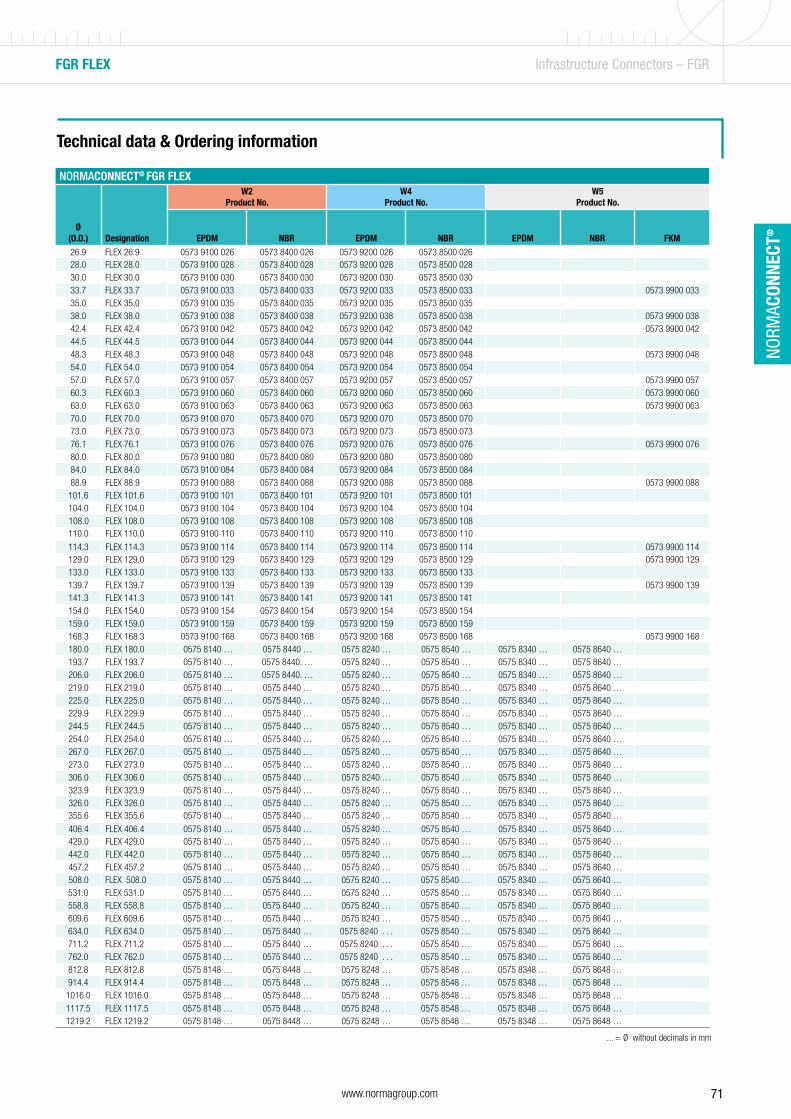
71www.normagroup.com
NORM
ACON
NECT
®
FGR FLEX Infrastructure Connectors – FGR
Technical data & Ordering information
NORMACONNECT® FGR FLEX
Ø(O.D.) Designation
W2Product No.
W4Product No.
W5Product No.
EPDM NBR EPDM NBR EPDM NBR FKM
26.9 FLEX 26.9 0573 9100 026 0573 8400 026 0573 9200 026 0573 8500 02628.0 FLEX 28.0 0573 9100 028 0573 8400 028 0573 9200 028 0573 8500 02830.0 FLEX 30.0 0573 9100 030 0573 8400 030 0573 9200 030 0573 8500 03033.7 FLEX 33.7 0573 9100 033 0573 8400 033 0573 9200 033 0573 8500 033 0573 9900 03335.0 FLEX 35.0 0573 9100 035 0573 8400 035 0573 9200 035 0573 8500 03538.0 FLEX 38.0 0573 9100 038 0573 8400 038 0573 9200 038 0573 8500 038 0573 9900 03842.4 FLEX 42.4 0573 9100 042 0573 8400 042 0573 9200 042 0573 8500 042 0573 9900 04244.5 FLEX 44.5 0573 9100 044 0573 8400 044 0573 9200 044 0573 8500 04448.3 FLEX 48.3 0573 9100 048 0573 8400 048 0573 9200 048 0573 8500 048 0573 9900 04854.0 FLEX 54.0 0573 9100 054 0573 8400 054 0573 9200 054 0573 8500 05457.0 FLEX 57.0 0573 9100 057 0573 8400 057 0573 9200 057 0573 8500 057 0573 9900 05760.3 FLEX 60.3 0573 9100 060 0573 8400 060 0573 9200 060 0573 8500 060 0573 9900 06063.0 FLEX 63.0 0573 9100 063 0573 8400 063 0573 9200 063 0573 8500 063 0573 9900 06370.0 FLEX 70.0 0573 9100 070 0573 8400 070 0573 9200 070 0573 8500 07073.0 FLEX 73.0 0573 9100 073 0573 8400 073 0573 9200 073 0573 8500 07376.1 FLEX 76.1 0573 9100 076 0573 8400 076 0573 9200 076 0573 8500 076 0573 9900 07680.0 FLEX 80.0 0573 9100 080 0573 8400 080 0573 9200 080 0573 8500 08084.0 FLEX 84.0 0573 9100 084 0573 8400 084 0573 9200 084 0573 8500 08488.9 FLEX 88.9 0573 9100 088 0573 8400 088 0573 9200 088 0573 8500 088 0573 9900 088101.6 FLEX 101.6 0573 9100 101 0573 8400 101 0573 9200 101 0573 8500 101104.0 FLEX 104.0 0573 9100 104 0573 8400 104 0573 9200 104 0573 8500 104108.0 FLEX 108.0 0573 9100 108 0573 8400 108 0573 9200 108 0573 8500 108110.0 FLEX 110.0 0573 9100 110 0573 8400 110 0573 9200 110 0573 8500 110
114.3 FLEX 114.3 0573 9100 114 0573 8400 114 0573 9200 114 0573 8500 114 0573 9900 114129.0 FLEX 129.0 0573 9100 129 0573 8400 129 0573 9200 129 0573 8500 129 0573 9900 129133.0 FLEX 133.0 0573 9100 133 0573 8400 133 0573 9200 133 0573 8500 133139.7 FLEX 139.7 0573 9100 139 0573 8400 139 0573 9200 139 0573 8500 139 0573 9900 139141.3 FLEX 141.3 0573 9100 141 0573 8400 141 0573 9200 141 0573 8500 141154.0 FLEX 154.0 0573 9100 154 0573 8400 154 0573 9200 154 0573 8500 154159.0 FLEX 159.0 0573 9100 159 0573 8400 159 0573 9200 159 0573 8500 159168.3 FLEX 168.3 0573 9100 168 0573 8400 168 0573 9200 168 0573 8500 168 0573 9900 168180.0 FLEX 180.0 0575 8140 … 0575 8440 … 0575 8240 … 0575 8540 … 0575 8340 … 0575 8640 …193.7 FLEX 193.7 0575 8140 … 0575 8440. … 0575 8240 … 0575 8540 … 0575 8340 … 0575 8640 …206.0 FLEX 206.0 0575 8140 … 0575 8440. … 0575 8240 … 0575 8540 … 0575 8340 … 0575 8640 …219.0 FLEX 219.0 0575 8140 … 0575 8440 … 0575 8240 … 0575 8540 … 0575 8340 … 0575 8640 …225.0 FLEX 225.0 0575 8140 … 0575 8440 … 0575 8240 … 0575 8540 … 0575 8340 … 0575 8640 …229.9 FLEX 229.9 0575 8140 … 0575 8440 … 0575 8240 … 0575 8540 … 0575 8340 … 0575 8640 …244.5 FLEX 244.5 0575 8140 … 0575 8440 … 0575 8240 … 0575 8540 … 0575 8340 … 0575 8640 …254.0 FLEX 254.0 0575 8140 … 0575 8440 … 0575 8240 … 0575 8540 … 0575 8340 … 0575 8640 …267.0 FLEX 267.0 0575 8140 … 0575 8440 … 0575 8240 … 0575 8540 … 0575 8340 … 0575 8640 …273.0 FLEX 273.0 0575 8140 … 0575 8440 … 0575 8240 … 0575 8540 … 0575 8340 … 0575 8640 …306.0 FLEX 306.0 0575 8140 … 0575 8440 … 0575 8240 … 0575 8540 … 0575 8340 … 0575 8640 …323.9 FLEX 323.9 0575 8140 … 0575 8440 … 0575 8240 … 0575 8540 … 0575 8340 … 0575 8640 …326.0 FLEX 326.0 0575 8140 … 0575 8440 … 0575 8240 … 0575 8540 … 0575 8340 … 0575 8640 …355.6 FLEX 355.6 0575 8140 … 0575 8440 … 0575 8240 … 0575 8540 … 0575 8340 … 0575 8640 …
406.4 FLEX 406.4 0575 8140 … 0575 8440 … 0575 8240 … 0575 8540 … 0575 8340 … 0575 8640 …429.0 FLEX 429.0 0575 8140 … 0575 8440 … 0575 8240 … 0575 8540 … 0575 8340 … 0575 8640 …442.0 FLEX 442.0 0575 8140 … 0575 8440 … 0575 8240 … 0575 8540 … 0575 8340 … 0575 8640 …457.2 FLEX 457.2 0575 8140 … 0575 8440 … 0575 8240 … 0575 8540 … 0575 8340 … 0575 8640 …508.0 FLEX 508.0 0575 8140 … 0575 8440 … 0575 8240 … 0575 8540 … 0575 8340 … 0575 8640 …531.0 FLEX 531.0 0575 8140 … 0575 8440 … 0575 8240 … 0575 8540 … 0575 8340 … 0575 8640 …558.8 FLEX 558.8 0575 8140 … 0575 8440 … 0575 8240 … 0575 8540 … 0575 8340 … 0575 8640 …609.6 FLEX 609.6 0575 8140 … 0575 8440 … 0575 8240 … 0575 8540 … 0575 8340 … 0575 8640 …634.0 FLEX 634.0 0575 8140 … 0575 8440 … 0575 8240 . . . 0575 8540 … 0575 8340 … 0575 8640 …711.2 FLEX 711.2 0575 8140 … 0575 8440 … 0575 8240 . . . 0575 8540 … 0575 8340 … 0575 8640 …762.0 FLEX 762.0 0575 8140 … 0575 8440 … 0575 8240 . . . 0575 8540 … 0575 8340 … 0575 8640 …812.8 FLEX 812.8 0575 8148 … 0575 8448 … 0575 8248 … 0575 8548 … 0575 8348 … 0575 8648 …914.4 FLEX 914.4 0575 8148 … 0575 8448 … 0575 8248 … 0575 8548 … 0575 8348 … 0575 8648 …1016.0 FLEX 1016.0 0575 8148 … 0575 8448 … 0575 8248 … 0575 8548 … 0575 8348 … 0575 8648 …1117.5 FLEX 1117.5 0575 8148 … 0575 8448 … 0575 8248 … 0575 8548 … 0575 8348 … 0575 8648 …1219.2 FLEX 1219.2 0575 8148 … 0575 8448 … 0575 8248 … 0575 8548 … 0575 8348 … 0575 8648 …
Coupling sizes >800 mm are in 2-parts design! Sizes > 1219.2 on request ... = Ø without decimals in mmPN¹ (Nominal Pressure) is the max. admissible working pressure in shipbuilding, based on a safety factor of ≥ 4.MAWP¹ (Maximun Allowable Working Pressure) is the max. admissible working pressure in shipbuilding, based on a safety factor of ≥ 4.WP² is the max. working pressure in industrial applications, with a safety factor as per NORMA specification.
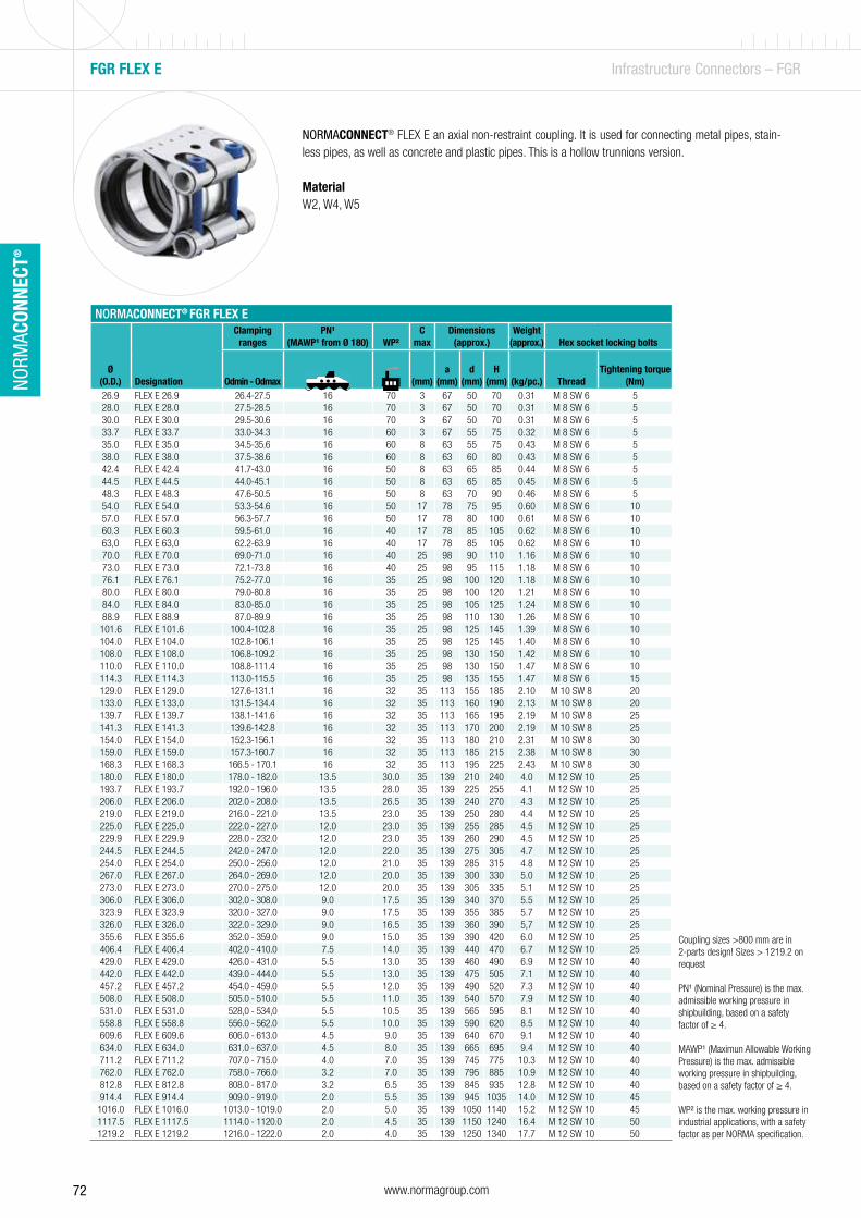
72 www.normagroup.com
NORM
ACON
NECT
®
FGR FLEX E Infrastructure Connectors – FGR
NORMACONNECT® FGR FLEX E
Ø(O.D.) Designation
Clamping ranges
PN¹ (MAWP¹ from Ø 180) WP²
C max
Dimensions(approx.)
Weight(approx.) Hex socket locking bolts
Odmin - Odmax [ bar] [bar] (mm)a
(mm)d
(mm)H
(mm)
(kg/pc.) ThreadTightening torque
(Nm)26.9 FLEX E 26.9 26.4-27.5 16 70 3 67 50 70 0.31 M 8 SW 6 528.0 FLEX E 28.0 27.5-28.5 16 70 3 67 50 70 0.31 M 8 SW 6 530.0 FLEX E 30.0 29.5-30.6 16 70 3 67 50 70 0.31 M 8 SW 6 533.7 FLEX E 33.7 33.0-34.3 16 60 3 67 55 75 0.32 M 8 SW 6 535.0 FLEX E 35.0 34.5-35.6 16 60 8 63 55 75 0.43 M 8 SW 6 538.0 FLEX E 38.0 37.5-38.6 16 60 8 63 60 80 0.43 M 8 SW 6 542.4 FLEX E 42.4 41.7-43.0 16 50 8 63 65 85 0.44 M 8 SW 6 544.5 FLEX E 44.5 44.0-45.1 16 50 8 63 65 85 0.45 M 8 SW 6 548.3 FLEX E 48.3 47.6-50.5 16 50 8 63 70 90 0.46 M 8 SW 6 554.0 FLEX E 54.0 53.3-54.6 16 50 17 78 75 95 0.60 M 8 SW 6 1057.0 FLEX E 57.0 56.3-57.7 16 50 17 78 80 100 0.61 M 8 SW 6 1060.3 FLEX E 60.3 59.5-61.0 16 40 17 78 85 105 0.62 M 8 SW 6 1063,0 FLEX E 63,0 62.2-63.9 16 40 17 78 85 105 0.62 M 8 SW 6 1070.0 FLEX E 70.0 69.0-71.0 16 40 25 98 90 110 1.16 M 8 SW 6 1073.0 FLEX E 73.0 72.1-73.8 16 40 25 98 95 115 1.18 M 8 SW 6 1076.1 FLEX E 76.1 75.2-77.0 16 35 25 98 100 120 1.18 M 8 SW 6 1080.0 FLEX E 80.0 79.0-80.8 16 35 25 98 100 120 1.21 M 8 SW 6 1084.0 FLEX E 84.0 83.0-85.0 16 35 25 98 105 125 1.24 M 8 SW 6 1088.9 FLEX E 88.9 87.0-89.9 16 35 25 98 110 130 1.26 M 8 SW 6 10101.6 FLEX E 101.6 100.4-102.8 16 35 25 98 125 145 1.39 M 8 SW 6 10104.0 FLEX E 104.0 102.8-106.1 16 35 25 98 125 145 1.40 M 8 SW 6 10108.0 FLEX E 108.0 106.8-109.2 16 35 25 98 130 150 1.42 M 8 SW 6 10110.0 FLEX E 110.0 108.8-111.4 16 35 25 98 130 150 1.47 M 8 SW 6 10114.3 FLEX E 114.3 113.0-115.5 16 35 25 98 135 155 1.47 M 8 SW 6 15129.0 FLEX E 129.0 127.6-131.1 16 32 35 113 155 185 2.10 M 10 SW 8 20133.0 FLEX E 133.0 131.5-134.4 16 32 35 113 160 190 2.13 M 10 SW 8 20139.7 FLEX E 139.7 138.1-141.6 16 32 35 113 165 195 2.19 M 10 SW 8 25141.3 FLEX E 141.3 139.6-142.8 16 32 35 113 170 200 2.19 M 10 SW 8 25154.0 FLEX E 154.0 152.3-156.1 16 32 35 113 180 210 2.31 M 10 SW 8 30159.0 FLEX E 159.0 157.3-160.7 16 32 35 113 185 215 2.38 M 10 SW 8 30168.3 FLEX E 168.3 166.5 - 170.1 16 32 35 113 195 225 2.43 M 10 SW 8 30180.0 FLEX E 180.0 178.0 - 182.0 13.5 30.0 35 139 210 240 4.0 M 12 SW 10 25193.7 FLEX E 193.7 192.0 - 196.0 13.5 28.0 35 139 225 255 4.1 M 12 SW 10 25206.0 FLEX E 206.0 202.0 - 208.0 13.5 26.5 35 139 240 270 4.3 M 12 SW 10 25219.0 FLEX E 219.0 216.0 - 221.0 13.5 23.0 35 139 250 280 4.4 M 12 SW 10 25225.0 FLEX E 225.0 222.0 - 227.0 12.0 23.0 35 139 255 285 4.5 M 12 SW 10 25229.9 FLEX E 229.9 228.0 - 232.0 12.0 23.0 35 139 260 290 4.5 M 12 SW 10 25244.5 FLEX E 244.5 242.0 - 247.0 12.0 22.0 35 139 275 305 4.7 M 12 SW 10 25254.0 FLEX E 254.0 250.0 - 256.0 12.0 21.0 35 139 285 315 4.8 M 12 SW 10 25267.0 FLEX E 267.0 264.0 - 269.0 12.0 20.0 35 139 300 330 5.0 M 12 SW 10 25273.0 FLEX E 273.0 270.0 - 275.0 12.0 20.0 35 139 305 335 5.1 M 12 SW 10 25306.0 FLEX E 306.0 302.0 - 308.0 9.0 17.5 35 139 340 370 5.5 M 12 SW 10 25323.9 FLEX E 323.9 320.0 - 327.0 9.0 17.5 35 139 355 385 5.7 M 12 SW 10 25326.0 FLEX E 326.0 322.0 - 329.0 9.0 16.5 35 139 360 390 5,7 M 12 SW 10 25355.6 FLEX E 355.6 352.0 - 359.0 9.0 15.0 35 139 390 420 6.0 M 12 SW 10 25406.4 FLEX E 406.4 402.0 - 410.0 7.5 14.0 35 139 440 470 6.7 M 12 SW 10 25429.0 FLEX E 429.0 426.0 - 431.0 5.5 13.0 35 139 460 490 6.9 M 12 SW 10 40442.0 FLEX E 442.0 439.0 - 444.0 5.5 13.0 35 139 475 505 7.1 M 12 SW 10 40457.2 FLEX E 457.2 454.0 - 459.0 5.5 12.0 35 139 490 520 7.3 M 12 SW 10 40508.0 FLEX E 508.0 505.0 - 510.0 5.5 11.0 35 139 540 570 7.9 M 12 SW 10 40531.0 FLEX E 531.0 528,0 - 534,0 5.5 10.5 35 139 565 595 8.1 M 12 SW 10 40558.8 FLEX E 558.8 556.0 - 562.0 5.5 10.0 35 139 590 620 8.5 M 12 SW 10 40609.6 FLEX E 609.6 606.0 - 613.0 4.5 9.0 35 139 640 670 9.1 M 12 SW 10 40634.0 FLEX E 634.0 631.0 - 637.0 4.5 8.0 35 139 665 695 9.4 M 12 SW 10 40711.2 FLEX E 711.2 707.0 - 715.0 4.0 7.0 35 139 745 775 10.3 M 12 SW 10 40762.0 FLEX E 762.0 758.0 - 766.0 3.2 7.0 35 139 795 885 10.9 M 12 SW 10 40812.8 FLEX E 812.8 808.0 - 817.0 3.2 6.5 35 139 845 935 12.8 M 12 SW 10 40914.4 FLEX E 914.4 909.0 - 919.0 2.0 5.5 35 139 945 1035 14.0 M 12 SW 10 451016.0 FLEX E 1016.0 1013.0 - 1019.0 2.0 5.0 35 139 1050 1140 15.2 M 12 SW 10 451117.5 FLEX E 1117.5 1114.0 - 1120.0 2.0 4.5 35 139 1150 1240 16.4 M 12 SW 10 501219.2 FLEX E 1219.2 1216.0 - 1222.0 2.0 4.0 35 139 1250 1340 17.7 M 12 SW 10 50
Coupling sizes >800 mm are in 2-parts design! Sizes > 1219.2 on request
PN¹ (Nominal Pressure) is the max. admissible working pressure in shipbuilding, based on a safety factor of ≥ 4.
MAWP¹ (Maximun Allowable Working Pressure) is the max. admissible working pressure in shipbuilding, based on a safety factor of ≥ 4.
WP² is the max. working pressure in industrial applications, with a safety factor as per NORMA specification.
NORMACONNECT® FLEX E an axial non-restraint coupling. It is used for connecting metal pipes, stain-less pipes, as well as concrete and plastic pipes. This is a hollow trunnions version.
MaterialW2, W4, W5
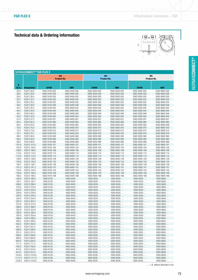
73www.normagroup.com
NORM
ACON
NECT
®
FGR FLEX E Infrastructure Connectors – FGR
NORMACONNECT® FGR FLEX E
Ø(O.D.) Designation
W2Product No.
W4Product No.
W5Product No.
EPDM NBR EPDM NBR EPDM NBR26.9 FLEX E 26.9 0582 9100 026 0582 8400 026 0582 9200 026 0582 8500 026 0582 9300 026 0582 8600 02628.0 FLEX E 28.0 0582 9100 028 0582 8400 028 0582 9200 028 0582 8500 028 0582 9300 028 0582 8600 02830.0 FLEX E 30.0 0582 9100 030 0582 8400 030 0582 9200 030 0582 8500 030 0582 9300 030 0582 8600 03033.7 FLEX E 33.7 0582 9100 033 0582 8400 033 0582 9200 033 0582 8500 033 0582 9300 033 0582 8600 03335.0 FLEX E 35.0 0582 9100 035 0582 8400 035 0582 9200 035 0582 8500 035 0582 9300 035 0582 8600 03538.0 FLEX E 38.0 0582 9100 038 0582 8400 038 0582 9200 038 0582 8500 038 0582 9300 038 0582 8600 03842.4 FLEX E 42.4 0582 9100 042 0582 8400 042 0582 9200 042 0582 8500 042 0582 9300 042 0582 8600 04244.5 FLEX E 44.5 0582 9100 044 0582 8400 044 0582 9200 044 0582 8500 044 0582 9300 044 0582 8600 04448.3 FLEX E 48.3 0582 9100 048 0582 8400 048 0582 9200 048 0582 8500 048 0582 9300 048 0582 8600 04854.0 FLEX E 54.0 0582 9100 054 0582 8400 054 0582 9200 054 0582 8500 054 0582 9300 054 0582 8600 05457.0 FLEX E 57.0 0582 9100 057 0582 8400 057 0582 9200 057 0582 8500 057 0582 9300 057 0582 8600 05760.3 FLEX E 60.3 0582 9100 060 0582 8400 060 0582 9200 060 0582 8500 060 0582 9300 060 0582 8600 06063,0 FLEX E 63,0 0582 9100 063 0582 8400 063 0582 9200 063 0582 8500 063 0582 9300 063 0582 8600 04870.0 FLEX E 70.0 0582 9100 070 0582 8400 070 0582 9200 070 0582 8500 070 0582 9300 070 0582 8600 07073.0 FLEX E 73.0 0582 9100 073 0582 8400 073 0582 9200 073 0582 8500 073 0582 9300 073 0582 8600 07376.1 FLEX E 76.1 0582 9100 076 0582 8400 076 0582 9200 076 0582 8500 076 0582 9300 076 0582 8600 07680.0 FLEX E 80.0 0582 9100 080 0582 8400 080 0582 9200 080 0582 8500 080 0582 9300 080 0582 8600 08084.0 FLEX E 84.0 0582 9100 084 0582 8400 084 0582 9200 084 0582 8500 084 0582 9300 084 0582 8600 08488.9 FLEX E 88.9 0582 9100 088 0582 8400 088 0582 9200 088 0582 8500 088 0582 9300 088 0582 8600 088101.6 FLEX E 101.6 0582 9100 101 0582 8400 101 0582 9200 101 0582 8500 101 0582 9300 101 0582 8600 101104.0 FLEX E 104.0 0582 9100 104 0582 8400 104 0582 9200 104 0582 8500 104 0582 9300 104 0582 8600 104108.0 FLEX E 108.0 0582 9100 108 0582 8400 108 0582 9200 108 0582 8500 108 0582 9300 108 0582 8600 108110.0 FLEX E 110.0 0582 9100 110 0582 8400 110 0582 9200 110 0582 8500 110 0582 9300 110 0582 8600 110114.3 FLEX E 114.3 0582 9100 114 0582 8400 114 0582 9200 114 0582 8500 114 0582 9300 114 0582 8600 114129.0 FLEX E 129.0 0582 9100 129 0582 8400 129 0582 9200 129 0582 8500 129 0582 9300 129 0582 8600 129133.0 FLEX E 133.0 0582 9100 133 0582 8400 133 0582 9200 133 0582 8500 133 0582 9300 133 0582 8600 133139.7 FLEX E 139.7 0582 9100 139 0582 8400 139 0582 9200 139 0582 8500 139 0582 9300 139 0582 8600 139141.3 FLEX E 141.3 0582 9100 141 0582 8400 141 0582 9200 141 0582 8500 141 0582 9300 141 0582 8600 141154.0 FLEX E 154.0 0582 9100 154 0582 8400 154 0582 9200 154 0582 8500 154 0582 9300 154 0582 8600 154159.0 FLEX E 159.0 0582 9100 159 0582 8400 159 0582 9200 159 0582 8500 159 0582 9300 159 0582 8600 159168.3 FLEX E 168.3 0582 9100 168 0582 8400 168 0582 9200 168 0582 8500 168 0582 9300 168 0582 8600 168180.0 FLEX E 180.0 0583 8120 … 0583 8420 … 0583 8220 … 0583 8520 … 0583 8320 … 0583 8620 …193.7 FLEX E 193.7 0583 8120 … 0583 8420 … 0583 8220 … 0583 8520 … 0583 8320 … 0583 8620 …206.0 FLEX E 206.0 0583 8120 … 0583 8420 … 0583 8220 … 0583 8520 … 0583 8320 … 0583 8620 …219.0 FLEX E 219.0 0583 8120 … 0583 8420 … 0583 8220 … 0583 8520 … 0583 8320 … 0583 8620 …225.0 FLEX E 225.0 0583 8120 … 0583 8420 … 0583 8220 … 0583 8520 … 0583 8320 … 0583 8620 …229.9 FLEX E 229.9 0583 8120 … 0583 8420 … 0583 8220 … 0583 8520 … 0583 8320 … 0583 8620 …244.5 FLEX E 244.5 0583 8120 … 0583 8420 … 0583 8220 … 0583 8520 … 0583 8320 … 0583 8620 …254.0 FLEX E 254.0 0583 8120 … 0583 8420 … 0583 8220 … 0583 8520 … 0583 8320 … 0583 8620 …267.0 FLEX E 267.0 0583 8120 … 0583 8420 … 0583 8220 … 0583 8520 … 0583 8320 … 0583 8620 …273.0 FLEX E 273.0 0583 8120 … 0583 8420 … 0583 8220 … 0583 8520 … 0583 8320 … 0583 8620 …306.0 FLEX E 306.0 0583 8120 … 0583 8420 … 0583 8220 … 0583 8520 … 0583 8320 … 0583 8620 …323.9 FLEX E 323.9 0583 8120 … 0583 8420 … 0583 8220 … 0583 8520 … 0583 8320 … 0583 8620 …326.0 FLEX E 326.0 0583 8120 … 0583 8420 … 0583 8220 … 0583 8520 … 0583 8320 … 0583 8620 …355.6 FLEX E 355.6 0583 8120 … 0583 8420 … 0583 8220 … 0583 8520 … 0583 8320 … 0583 8620 …406.4 FLEX E 406.4 0583 8120 … 0583 8420 … 0583 8220 … 0583 8520 … 0583 8320 … 0583 8620 …429.0 FLEX E 429.0 0583 8120 … 0583 8420 … 0583 8220 … 0583 8520 … 0583 8320 … 0583 8620 …442.0 FLEX E 442.0 0583 8120 … 0583 8420 … 0583 8220 … 0583 8520 … 0583 8320 … 0583 8620 …457.2 FLEX E 457.2 0583 8120 … 0583 8420 … 0583 8220 … 0583 8520 … 0583 8320 … 0583 8620 …508.0 FLEX E 508.0 0583 8120 … 0583 8420 … 0583 8220 … 0583 8520 … 0583 8320 … 0583 8620 …531.0 FLEX E 531.0 0583 8120 … 0583 8420 … 0583 8220 … 0583 8520 … 0583 8320 … 0583 8620 …558.8 FLEX E 558.8 0583 8120 … 0583 8420 … 0583 8220 … 0583 8520 … 0583 8320 … 0583 8620 …609.6 FLEX E 609.6 0583 8120 … 0583 8420 … 0583 8220 … 0583 8520 … 0583 8320 … 0583 8620 …634.0 FLEX E 634.0 0583 8120 … 0583 8420 … 0583 8220 … 0583 8520 … 0583 8320 … 0583 8620 …711.2 FLEX E 711.2 0583 8120 … 0583 8420 … 0583 8220 … 0583 8520 … 0583 8320 … 0583 8620 …762.0 FLEX E 762.0 0583 8120 … 0583 8420 … 0583 8220 … 0583 8520 … 0583 8320 … 0583 8620 …812.8 FLEX E 812.8 0583 8128 … 0583 8428 … 0583 8228. … 0583 8528 … 0583 8328. … 0583 8628 …914.4 FLEX E 914.4 0583 8128 … 0583 8428 … 0583 8228. … 0583 8528 … 0583 8328. … 0583 8628 …1016.0 FLEX E 1016.0 0583 8128 … 0583 8428 … 0583 8228. … 0583 8528 … 0583 8328. … 0583 8628 …1117.5 FLEX E 1117.5 0583 8128 … 0583 8428 … 0583 8228. … 0583 8528 … 0583 8328. … 0583 8628 …1219.2 FLEX E 1219.2 0583 8128 … 0583 8428 … 0583 8228. … 0583 8528 … 0583 8328. … 0583 8628 …
Technical data & Ordering information
. ... = Ø without decimals in mm
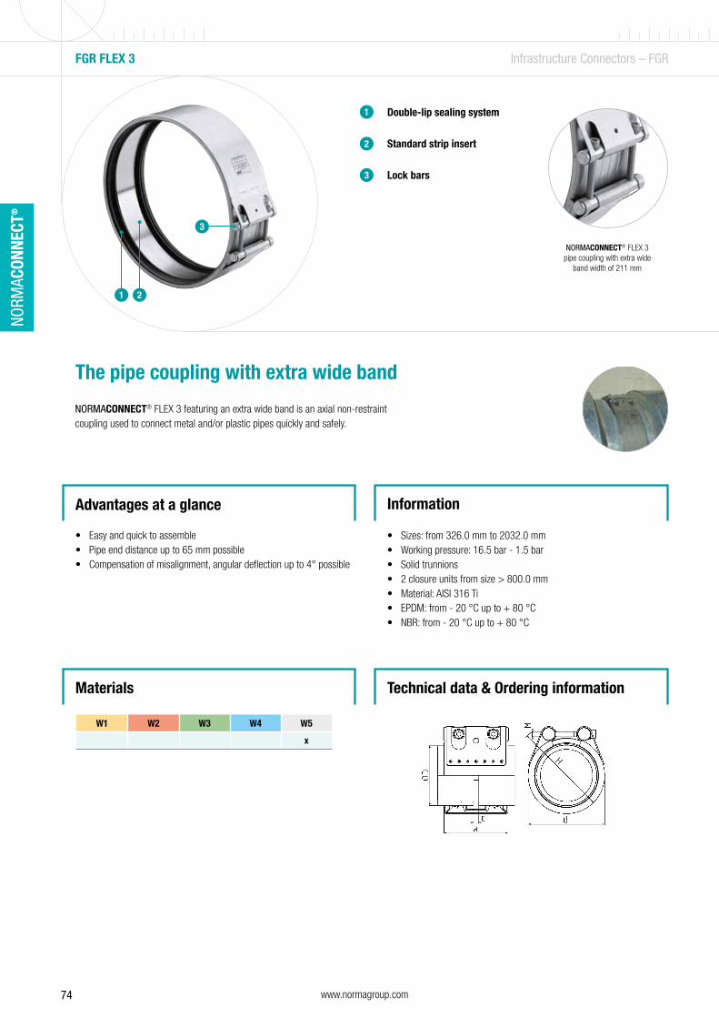
74 www.normagroup.com
NORM
ACON
NECT
®
Double-lip sealing system
Standard strip insert
Lock bars
1
2
3
The pipe coupling with extra wide band
NORMACONNECT® FLEX 3 featuring an extra wide band is an axial non-restraint coupling used to connect metal and/or plastic pipes quickly and safely.
Advantages at a glance
• Easy and quick to assemble• Pipe end distance up to 65 mm possible• Compensation of misalignment, angular deflection up to 4° possible
Information
• Sizes: from 326.0 mm to 2032.0 mm• Working pressure: 16.5 bar - 1.5 bar• Solid trunnions• 2 closure units from size > 800.0 mm• Material: AISI 316 Ti• EPDM: from - 20 °C up to + 80 °C • NBR: from - 20 °C up to + 80 °C
FGR FLEX 3 Infrastructure Connectors – FGR
1 2
3
NORMACONNECT® FLEX 3 pipe coupling with extra wide
band width of 211 mm
Materials
W1 W2 W3 W4 W5
x
Technical data & Ordering information
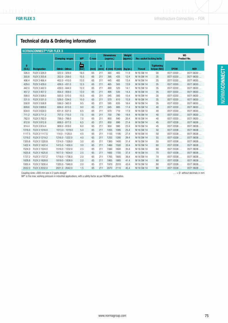
75www.normagroup.com
NORM
ACON
NECT
®
FGR FLEX 3 Infrastructure Connectors – FGR
NORMACONNECT® FGR FLEX 3
Ø(O.D.) Designation
Clamping ranges WP¹ C maxDimensions
(approx.)Weight
(approx.) Hex socket locking boltsW5
Product No.
Odmin - Odmax [bar] (mm)a
(mm) d (mm) H (mm)
(kg/pc.) ThreadTightening
torque (Nm) EPDM
NBR
326.0 FLEX 3 326.0 322.0 - 329.0 16.5 65 211 365 405 11.9 M 16 SW 14 30 0571 8330 … 0571 8630 …355.6 FLEX 3 355.6 352.0 - 259.0 15.5 65 211 395 435 12.4 M 16 SW 14 35 0571 8330 … 0571 8630 …
406.4 FLEX 3 406.4 402.0 - 410.0 13.5 65 211 445 485 13.4 M 16 SW 14 35 0571 8330 … 0571 8630 …
429.0 FLEX 3 429.0 426.0 - 431.0 12.5 65 211 465 505 13.9 M 16 SW 14 35 0571 8330 … 0571 8630 …
442.0 FLEX 3 442.0 439.0 - 444.0 12.0 65 211 480 520 14.1 M 16 SW 14 35 0571 8330 … 0571 8630 …
457.2 FLEX 3 457.2 454.0 - 459.0 12.0 65 211 495 535 14.4 M 16 SW 14 35 0571 8330 … 0571 8630 …
508.0 FLEX 3 508.0 505.0 - 510.0 10.5 65 211 545 585 15.4 M 16 SW 14 35 0571 8330 … 0571 8630 …
531.0 FLEX 3 531.0 528.0 - 534.0 10.0 65 211 570 610 15.9 M 16 SW 14 35 0571 8330 … 0571 8630 …
558.8 FLEX 3 558.8 556.0 - 562.0 9.5 65 211 595 635 16.4 M 16 SW 14 35 0571 8330 … 0571 8630 …
609.6 FLEX 3 609.6 606.0 - 613.0 9.0 65 211 645 685 17.4 M 16 SW 14 40 0571 8330 … 0571 8630 …
634.0 FLEX 3 634.0 631.0 - 637.0 8.5 65 211 670 710 17.9 M 16 SW 14 40 0571 8330 … 0571 8630 …
711.2 FLEX 3 711.2 707.0 - 715.0 7.5 65 211 750 790 19.4 M 16 SW 14 40 0571 8330 … 0571 8630 …
762.0 FLEX 3 762.0 758.0 - 766.0 7.0 65 211 800 840 20.4 M 16 SW 14 40 0571 8330 … 0571 8630 …
812.8 FLEX 3 812.8 808.0 - 817.0 6.5 65 211 850 890 21.4 M 16 SW 14 45 0571 8338 … 0571 8638 …
914.4 FLEX 3 914.4 909.0 - 919.0 6.0 65 211 950 990 23.4 M 16 SW 14 45 0571 8338 … 0571 8638 …
1016.0 FLEX 3 1016.0 1013.0 - 1019.0 5.0 65 211 1055 1095 25.4 M 16 SW 14 50 0571 8338 … 0571 8638 …
1117.5 FLEX 3 1117.5 114.0 - 1120.0 4.5 65 211 1155 1195 27.4 M 16 SW 14 50 0571 8338 … 0571 8638 …
1219.2 FLEX 3 1219.2 1216.0 - 1222.0 4.0 65 211 1255 1295 29.4 M 16 SW 14 55 0571 8338 … 0571 8638 …
1320.8 FLEX 3 1320.8 1314.0 - 1328.0 3.0 65 211 1360 1400 31.4 M 16 SW 14 55 0571 8338 … 0571 8638 …
1422.4 FLEX 3 1422.4 1415.0 - 1430.0 3.0 65 211 1460 1500 33.4 M 16 SW 14 60 0571 8338 … 0571 8638 …
1524.0 FLEX 3 1524.0 1516.0 - 1532.0 2.5 65 211 1560 1600 35.4 M 16 SW 14 60 0571 8338 … 0571 8638 …1625.6 FLEX 3 1625.6 1617.0 - 1634.0 2.5 65 211 1665 1705 37.4 M 16 SW 14 70 0571 8338 … 0571 8638 …
1727.2 FLEX 3 1727.2 1718.0 - 1736.0 2.0 65 211 1765 1805 39.4 M 16 SW 14 70 0571 8338 … 0571 8638 …1828.8 FLEX 3 1828.8 1819.0 - 1838.0 2.0 65 211 1865 1905 41.4 M 16 SW 14 80 0571 8338 … 0571 8638 …
1930.4 FLEX 3 1930.4 1320.0 - 1940.0 2.0 65 211 1970 2010 43.4 M 16 SW 14 80 0571 8338 … 0571 8638 …2032.0 FLEX 3 2032.0 2021.0 - 2042.0 1.5 65 211 2070 2110 45.4 M 16 SW 14 80 0571 8338 … 0571 8638 …
Technical data & Ordering information
Coupling sizes >800 mm are in 2-parts design! . ... = Ø without decimals in mmWP¹ is the max. working pressure in industrial applications, with a safety factor as per NORMA specification.

76 www.normagroup.com
NORM
ACON
NECT
®

77www.normagroup.com
NORM
ACON
NECT
®
Double-lip sealing system
Standard strip insert
Lock bars
Anchoring ring with conically stamped teeth
1
2
The strong pipe coupling
NORMACONNECT® GRIP/GRIP E axial restraint pipe couplings are used to connect metal pipes. The anchoring ring with conically stamped teeth indents into the pipe surface (steel, stainless steel or cast iron) and provides safe and strong axial restraint.
Advantages at a glance
• Progressive locking effect ensures a trouble- and maintenance-free connection
• Reusable • Shock resistant • Space saving connector • Withstand high vibration loads
Information
• Sizes: 26.9 mm - 812.8 mm• Working pressure: 70.0 bar - 1 bar• Material: AISI 304, AISI 316 Ti• EPDM:
Sizes from 26.9 mm up to 168.3 mm: - 30 °C up to + 125 °C Sizes > 180.0 mm: from - 20 °C up to + 80 °C
• NBR: from - 20 °C up to + 80 °C• FKM: -10 °C to + 150 °C (Higher temperatures possible in some
cases.)
Owing to the special design, the coupling can withstand even high vibration loads.
FGR GRIP/GRIP E Infrastructure Connectors – FGR
1 2 4
3
3
4
Technical data & Ordering informationMaterials
W1 W2 W3 W4 W5
x x x
NEW!Now also
available with FKM sealing
sleeve
NEW
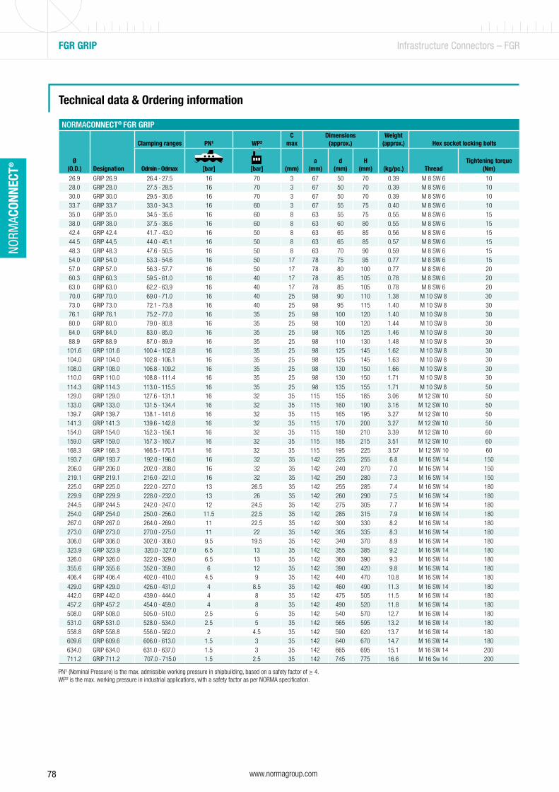
78 www.normagroup.com
NORM
ACON
NECT
®
FGR GRIP Infrastructure Connectors – FGR
Technical data & Ordering information
NORMACONNECT® FGR GRIP
Ø(O.D.) Designation
Clamping ranges PN¹ WP²C
maxDimensions
(approx.)Weight
(approx.) Hex socket locking bolts
Odmin - Odmax [bar] [bar] (mm)a
(mm)d
(mm)H
(mm)
(kg/pc.) ThreadTightening torque
(Nm)
26.9 GRIP 26.9 26.4 - 27.5 16 70 3 67 50 70 0.39 M 8 SW 6 1028.0 GRIP 28.0 27.5 - 28.5 16 70 3 67 50 70 0.39 M 8 SW 6 1030.0 GRIP 30.0 29.5 - 30.6 16 70 3 67 50 70 0.39 M 8 SW 6 1033.7 GRIP 33.7 33.0 - 34.3 16 60 3 67 55 75 0.40 M 8 SW 6 1035.0 GRIP 35.0 34.5 - 35.6 16 60 8 63 55 75 0.55 M 8 SW 6 1538.0 GRIP 38.0 37.5 - 38.6 16 60 8 63 60 80 0.55 M 8 SW 6 1542.4 GRIP 42.4 41.7 - 43.0 16 50 8 63 65 85 0.56 M 8 SW 6 1544.5 GRIP 44,5 44.0 - 45.1 16 50 8 63 65 85 0.57 M 8 SW 6 1548.3 GRIP 48.3 47.6 - 50.5 16 50 8 63 70 90 0.59 M 8 SW 6 1554.0 GRIP 54.0 53.3 - 54.6 16 50 17 78 75 95 0.77 M 8 SW 6 1557.0 GRIP 57.0 56.3 - 57.7 16 50 17 78 80 100 0.77 M 8 SW 6 2060.3 GRIP 60.3 59.5 - 61.0 16 40 17 78 85 105 0.78 M 8 SW 6 2063.0 GRIP 63.0 62,2 - 63,9 16 40 17 78 85 105 0.78 M 8 SW 6 2070.0 GRIP 70.0 69.0 - 71.0 16 40 25 98 90 110 1.38 M 10 SW 8 3073.0 GRIP 73.0 72.1 - 73.8 16 40 25 98 95 115 1.40 M 10 SW 8 3076.1 GRIP 76.1 75.2 - 77.0 16 35 25 98 100 120 1.40 M 10 SW 8 3080.0 GRIP 80.0 79.0 - 80.8 16 35 25 98 100 120 1.44 M 10 SW 8 3084.0 GRIP 84.0 83.0 - 85.0 16 35 25 98 105 125 1.46 M 10 SW 8 3088.9 GRIP 88.9 87.0 - 89.9 16 35 25 98 110 130 1.48 M 10 SW 8 30
101.6 GRIP 101.6 100.4 - 102.8 16 35 25 98 125 145 1.62 M 10 SW 8 30104.0 GRIP 104.0 102.8 - 106.1 16 35 25 98 125 145 1.63 M 10 SW 8 30108.0 GRIP 108.0 106.8 - 109.2 16 35 25 98 130 150 1.66 M 10 SW 8 30110.0 GRIP 110.0 108.8 - 111.4 16 35 25 98 130 150 1.71 M 10 SW 8 30
114.3 GRIP 114.3 113.0 - 115.5 16 35 25 98 135 155 1.71 M 10 SW 8 50129.0 GRIP 129.0 127.6 - 131.1 16 32 35 115 155 185 3.06 M 12 SW 10 50133.0 GRIP 133.0 131.5 - 134.4 16 32 35 115 160 190 3.16 M 12 SW 10 50139.7 GRIP 139.7 138.1 - 141.6 16 32 35 115 165 195 3.27 M 12 SW 10 50141.3 GRIP 141.3 139.6 - 142.8 16 32 35 115 170 200 3.27 M 12 SW 10 50154.0 GRIP 154.0 152.3 - 156.1 16 32 35 115 180 210 3.39 M 12 SW 10 60159.0 GRIP 159.0 157.3 - 160.7 16 32 35 115 185 215 3.51 M 12 SW 10 60168.3 GRIP 168.3 166.5 - 170.1 16 32 35 115 195 225 3.57 M 12 SW 10 60193.7 GRIP 193.7 192.0 - 196.0 16 32 35 142 225 255 6.8 M 16 SW 14 150206.0 GRIP 206.0 202.0 - 208.0 16 32 35 142 240 270 7.0 M 16 SW 14 150219.1 GRIP 219.1 216.0 - 221.0 16 32 35 142 250 280 7.3 M 16 SW 14 150225.0 GRIP 225.0 222.0 - 227.0 13 26.5 35 142 255 285 7.4 M 16 SW 14 180229.9 GRIP 229.9 228.0 - 232.0 13 26 35 142 260 290 7.5 M 16 SW 14 180244.5 GRIP 244.5 242.0 - 247.0 12 24.5 35 142 275 305 7.7 M 16 SW 14 180254.0 GRIP 254.0 250.0 - 256.0 11.5 22.5 35 142 285 315 7.9 M 16 SW 14 180267.0 GRIP 267.0 264.0 - 269.0 11 22.5 35 142 300 330 8.2 M 16 SW 14 180273.0 GRIP 273.0 270.0 - 275.0 11 22 35 142 305 335 8.3 M 16 SW 14 180306.0 GRIP 306.0 302.0 - 308.0 9.5 19.5 35 142 340 370 8.9 M 16 SW 14 180323.9 GRIP 323.9 320.0 - 327.0 6.5 13 35 142 355 385 9.2 M 16 SW 14 180326.0 GRIP 326.0 322.0 - 329.0 6.5 13 35 142 360 390 9.3 M 16 SW 14 180355.6 GRIP 355.6 352.0 - 359.0 6 12 35 142 390 420 9.8 M 16 SW 14 180406.4 GRIP 406.4 402.0 - 410.0 4.5 9 35 142 440 470 10.8 M 16 SW 14 180
429.0 GRIP 429.0 426.0 - 431,0 4 8.5 35 142 460 490 11.3 M 16 SW 14 180442.0 GRIP 442.0 439.0 - 444.0 4 8 35 142 475 505 11.5 M 16 SW 14 180457.2 GRIP 457.2 454.0 - 459.0 4 8 35 142 490 520 11.8 M 16 SW 14 180508.0 GRIP 508.0 505.0 - 510.0 2.5 5 35 142 540 570 12.7 M 16 SW 14 180531.0 GRIP 531.0 528.0 - 534.0 2.5 5 35 142 565 595 13.2 M 16 SW 14 180558.8 GRIP 558.8 556.0 - 562.0 2 4.5 35 142 590 620 13.7 M 16 SW 14 180609.6 GRIP 609.6 606.0 - 613.0 1.5 3 35 142 640 670 14.7 M 16 SW 14 180634.0 GRIP 634.0 631.0 - 637.0 1.5 3 35 142 665 695 15.1 M 16 SW 14 200711.2 GRIP 711.2 707.0 - 715.0 1.5 2.5 35 142 745 775 16.6 M 16 Sw 14 200
PN¹ (Nominal Pressure) is the max. admissible working pressure in shipbuilding, based on a safety factor of ≥ 4. ... = Ø without decimals in mmWP² is the max. working pressure in industrial applications, with a safety factor as per NORMA specification.
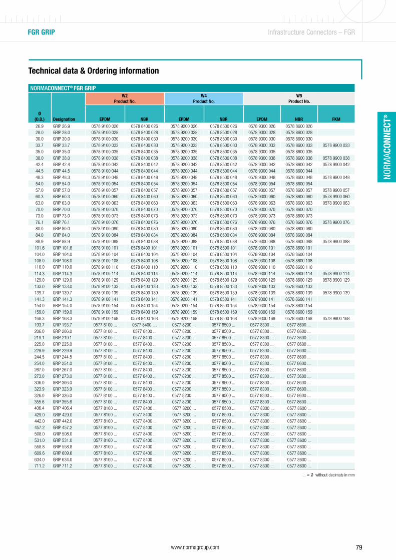
79www.normagroup.com
NORM
ACON
NECT
®
FGR GRIP Infrastructure Connectors – FGR
Technical data & Ordering information
NORMACONNECT® FGR GRIP
Ø(O.D.) Designation
W2Product No.
W4Product No.
W5Product No.
EPDM NBR EPDM NBR EPDM NBR FKM
26.9 GRIP 26.9 0578 9100 026 0578 8400 026 0578 9200 026 0578 8500 026 0578 9300 026 0578 8600 02628.0 GRIP 28.0 0578 9100 028 0578 8400 028 0578 9200 028 0578 8500 028 0578 9300 028 0578 8600 02830.0 GRIP 30.0 0578 9100 030 0578 8400 030 0578 9200 030 0578 8500 030 0578 9300 030 0578 8600 03033.7 GRIP 33.7 0578 9100 033 0578 8400 033 0578 9200 033 0578 8500 033 0578 9300 033 0578 8600 033 0578 9900 03335.0 GRIP 35.0 0578 9100 035 0578 8400 035 0578 9200 035 0578 8500 035 0578 9300 035 0578 8600 03538.0 GRIP 38.0 0578 9100 038 0578 8400 038 0578 9200 038 0578 8500 038 0578 9300 038 0578 8600 038 0578 9900 03842.4 GRIP 42.4 0578 9100 042 0578 8400 042 0578 9200 042 0578 8500 042 0578 9300 042 0578 8600 042 0578 9900 04244.5 GRIP 44,5 0578 9100 044 0578 8400 044 0578 9200 044 0578 8500 044 0578 9300 044 0578 8600 04448.3 GRIP 48.3 0578 9100 048 0578 8400 048 0578 9200 048 0578 8500 048 0578 9300 048 0578 8600 048 0578 9900 04854.0 GRIP 54.0 0578 9100 054 0578 8400 054 0578 9200 054 0578 8500 054 0578 9300 054 0578 8600 05457.0 GRIP 57.0 0578 9100 057 0578 8400 057 0578 9200 057 0578 8500 057 0578 9300 057 0578 8600 057 0578 9900 05760.3 GRIP 60.3 0578 9100 060 0578 8400 060 0578 9200 060 0578 8500 060 0578 9300 060 0578 8600 060 0578 9900 06063.0 GRIP 63.0 0578 9100 063 0578 8400 063 0578 9200 063 0578 8500 063 0578 9300 063 0578 8600 063 0578 9900 06370.0 GRIP 70.0 0578 9100 070 0578 8400 070 0578 9200 070 0578 8500 070 0578 9300 070 0578 8600 07073.0 GRIP 73.0 0578 9100 073 0578 8400 073 0578 9200 073 0578 8500 073 0578 9300 073 0578 8600 07376.1 GRIP 76.1 0578 9100 076 0578 8400 076 0578 9200 076 0578 8500 076 0578 9300 076 0578 8600 076 0578 9900 07680.0 GRIP 80.0 0578 9100 080 0578 8400 080 0578 9200 080 0578 8500 080 0578 9300 080 0578 8600 08084.0 GRIP 84.0 0578 9100 084 0578 8400 084 0578 9200 084 0578 8500 084 0578 9300 084 0578 8600 08488.9 GRIP 88.9 0578 9100 088 0578 8400 088 0578 9200 088 0578 8500 088 0578 9300 088 0578 8600 088 0578 9900 088
101.6 GRIP 101.6 0578 9100 101 0578 8400 101 0578 9200 101 0578 8500 101 0578 9300 101 0578 8600 101104.0 GRIP 104.0 0578 9100 104 0578 8400 104 0578 9200 104 0578 8500 104 0578 9300 104 0578 8600 104108.0 GRIP 108.0 0578 9100 108 0578 8400 108 0578 9200 108 0578 8500 108 0578 9300 108 0578 8600 108110.0 GRIP 110.0 0578 9100 110 0578 8400 110 0578 9200 110 0578 8500 110 0578 9300 110 0578 8600 110114.3 GRIP 114.3 0578 9100 114 0578 8400 114 0578 9200 114 0578 8500 114 0578 9300 114 0578 8600 114 0578 9900 114129.0 GRIP 129.0 0578 9100 129 0578 8400 129 0578 9200 129 0578 8500 129 0578 9300 129 0578 8600 129 0578 9900 129133.0 GRIP 133.0 0578 9100 133 0578 8400 133 0578 9200 133 0578 8500 133 0578 9300 133 0578 8600 133139.7 GRIP 139.7 0578 9100 139 0578 8400 139 0578 9200 139 0578 8500 139 0578 9300 139 0578 8600 139 0578 9900 139141.3 GRIP 141.3 0578 9100 141 0578 8400 141 0578 9200 141 0578 8500 141 0578 9300 141 0578 8600 141154.0 GRIP 154.0 0578 9100 154 0578 8400 154 0578 9200 154 0578 8500 154 0578 9300 154 0578 8600 154159.0 GRIP 159.0 0578 9100 159 0578 8400 159 0578 9200 159 0578 8500 159 0578 9300 159 0578 8600 159168.3 GRIP 168.3 0578 9100 168 0578 8400 168 0578 9200 168 0578 8500 168 0578 9300 168 0578 8600 168 0578 9900 168193.7 GRIP 193.7 0577 8100 ... 0577 8400 … 0577 8200 ... 0577 8500 ... 0577 8300 ... 0577 8600 ...206.0 GRIP 206.0 0577 8100 ... 0577 8400 ... 0577 8200 ... 0577 8500 ... 0577 8300 ... 0577 8600 ...219.1 GRIP 219.1 0577 8100 ... 0577 8400 ... 0577 8200 ... 0577 8500 ... 0577 8300 ... 0577 3600 ...225.0 GRIP 225.0 0577 8100 ... 0577 8400 ... 0577 8200 ... 0577 8500 ... 0577 8300 ... 0577 8600 ...229.9 GRIP 229.9 0577 8100 ... 0577 8400 ... 0577 8200 ... 0577 8500 ... 0577 8300 ... 0577 8600 ...244.5 GRIP 244.5 0577 8100 ... 0577 8400 ... 0577 8200 ... 0577 8500 ... 0577 8300 ... 0577 8600 ...254.0 GRIP 254.0 0577 8100 ... 0577 8400 ... 0577 8200 ... 0577 8500 ... 0577 8300 ... 0577 8600 ...267.0 GRIP 267.0 0577 8100 ... 0577 8400 ... 0577 8200 ... 0577 8500 ... 0577 8300 ... 0577 8600 ...273.0 GRIP 273.0 0577 8100 ... 0577 8400 ... 0577 8200 ... 0577 8500 ... 0577 8300 ... 0577 3600 ...306.0 GRIP 306.0 0577 8100 ... 0577 8400 ... 0577 8200 ... 0577 8500 ... 0577 8300 ... 0577 8600 ...323.9 GRIP 323.9 0577 8100 ... 0577 8400 ... 0577 8200 ... 0577 8500 ... 0577 8300 ... 0577 8600 ...326.0 GRIP 326.0 0577 8100 ... 0577 8400 ... 0577 8200 ... 0577 8500 ... 0577 8300 ... 0577 8600 ...355.6 GRIP 355.6 0577 8100 ... 0577 8400 ... 0577 8200 ... 0577 8500 ... 0577 8300 ... 0577 8600 ...406.4 GRIP 406.4 0577 8100 ... 0577 8400 ... 0577 8200 ... 0577 8500 ... 0577 8300 ... 0577 8600 ...429.0 GRIP 429.0 0577 8100 ... 0577 8400 ... 0577 8200 ... 0577 8500 ... 0577 8300 ... 0577 8600 ...442.0 GRIP 442.0 0577 8100 ... 0577 8400 ... 0577 8200 ... 0577 8500 ... 0577 8300 ... 0577 8600 ...457.2 GRIP 457.2 0577 8100 ... 0577 8400 ... 0577 8200 ... 0577 8500 ... 0577 8300 ... 0577 8600 ...508.0 GRIP 508.0 0577 8100 ... 0577 8400 ... 0577 8200 ... 0577 8500 ... 0577 8300 ... 0577 8600 ...531.0 GRIP 531.0 0577 8100 ... 0577 8400 ... 0577 8200 ... 0577 8500 ... 0577 8300 ... 0577 8600 ...558.8 GRIP 558.8 0577 8100 ... 0577 8400 ... 0577 8200 ... 0577 8500 ... 0577 8300 ... 0577 8600 ...609.6 GRIP 609.6 0577 8100 ... 0577 8400 ... 0577 8200 ... 0577 8500 ... 0577 8300 ... 0577 8600 ...634.0 GRIP 634.0 0577 8100 ... 0577 8400 ... 0577 8200 ... 0577 8500 ... 0577 8300 ... 0577 8600 ...711.2 GRIP 711.2 0577 8100 ... 0577 8400 ... 0577 8200 ... 0577 8500 ... 0577 8300 ... 0577 8600 ...
PN¹ (Nominal Pressure) is the max. admissible working pressure in shipbuilding, based on a safety factor of ≥ 4. ... = Ø without decimals in mmWP² is the max. working pressure in industrial applications, with a safety factor as per NORMA specification.

80 www.normagroup.com
NORM
ACON
NECT
®
FGR GRIP – Versions Infrastructure Connectors – FGR
NORMACONNECT® GRIP E axial restraint pipe couplings are used to connect metal pipes.
MaterialW2, W5
GRIP E
NORMACONNECT® FGR GRIP E
Ø(O.D.) Designation
Clamping ranges PN¹ WP²C
maxDimensions
(approx.)Weight
(approx.) Hex socket locking bolts
Odmin - Odmax [bar] [bar] (mm)a
(mm)d
(mm)H
(mm) (kg/pc.) ThreadTightening torque
(Nm)
26.9 GRIP E 26.9 26.4 - 27.5 16 70 3 67 50 70 0.32 M 8 SW 6 1028.0 GRIP E 28.0 27.5 - 28.5 16 70 3 67 50 70 0.32 M 8 SW 6 1030.0 GRIP E 30.0 29.5 - 30.6 16 70 3 67 50 70 0.32 M 8 SW 6 1033.7 GRIP E 33.7 33.0 - 34.3 16 60 3 67 55 75 0.33 M 8 SW 6 1035.0 GRIP E 35.0 34.5 - 35.6 16 60 8 63 55 75 0.45 M 8 SW 6 1538.0 GRIP E 38.0 37.5 - 38.6 16 60 8 63 60 80 0.45 M 8 SW 6 1542.4 GRIP E 42.4 41.7 - 43.0 16 50 8 63 65 85 0.46 M 8 SW 6 1544.5 GRIP E 44,5 44.0 - 45.1 16 50 8 63 65 85 0.47 M 8 SW 6 1548.3 GRIP E 48.3 47.6 - 50.5 16 50 8 63 70 90 0.48 M 8 SW 6 1554.0 GRIP E 54.0 53.3 - 54.6 16 50 17 78 75 95 0.62 M 8 SW 6 1557.0 GRIP E 57.0 56.3 - 57.7 16 50 17 78 80 100 0.63 M 8 SW 6 2060.3 GRIP E 60.3 59.5 - 61.0 16 40 17 78 85 105 0.64 M 8 SW 6 2070.0 GRIP E 70.0 69.0 - 71.0 16 40 25 98 90 110 1.21 M 10 SW 8 3073.0 GRIP E 73.0 72.1 - 73.8 16 40 25 98 95 115 1.23 M 10 SW 8 3076.1 GRIP E 76.1 75.2 - 77.0 16 35 25 98 100 120 1.23 M 10 SW 8 3080.0 GRIP E 80.0 79.0 - 80.8 16 35 25 98 100 120 1.27 M 10 SW 8 3084.0 GRIP E 84.0 83.0 - 85.0 16 35 25 98 105 125 1.29 M 10 SW 8 3088.9 GRIP E 88.9 87.0 - 89.9 16 35 25 98 110 130 1.31 M 10 SW 8 30
101.6 GRIP E 101.6 100.4 - 102.8 16 35 25 98 125 145 1.45 M 10 SW 8 30104.0 GRIP E 104.0 102.8 - 106.1 16 35 25 98 125 145 1.46 M 10 SW 8 30108.0 GRIP E 108.0 106.8 - 109.2 16 35 25 98 130 150 1.49 M 10 SW 8 30110.0 GRIP E 110.0 108.8 - 111.4 16 35 25 98 130 150 1.54 M 10 SW 8 30
114.3 GRIP E 114.3 113.0 - 115.5 16 35 25 98 135 155 1.54 M 10 SW 8 50129.0 GRIP E 129.0 127.6 - 131.1 16 32 35 115 155 185 2.83 M 12 SW 10 50133.0 GRIP E 133.0 131.5 - 134.4 16 32 35 115 160 190 2.93 M 12 SW 10 50139.7 GRIP E 139.7 138.1 - 141.6 16 32 35 115 165 195 3.04 M 12 SW 10 50141.3 GRIP E 141.3 139.6 - 142.8 16 32 35 115 170 200 3.04 M 12 SW 10 50154.0 GRIP E 154.0 152.3 - 156.1 16 32 35 115 180 210 3.17 M 12 SW 10 60159.0 GRIP E 159.0 157.3 - 160.7 16 32 35 115 185 215 3.28 M 12 SW 10 60168.3 GRIP E 168.3 166.5 - 170.1 16 32 35 115 195 225 3.35 M 12 SW 10 60193.7 GRIP E 193.7 192.0 - 196.0 10 20 35 141 225 255 6.2 M 16 SW 14 100206.0 GRIP E 206.0 202.0 - 208.0 10 20 35 141 240 270 6.5 M 16 SW 14 100219.1 GRIP E 219.1 216.0 - 221.0 10 20 35 141 250 280 6.7 M 16 SW 14 100225.0 GRIP E 225.0 222.0 - 227.0 10 16 35 140 255 285 6.2 M 16 SW 14 100229.9 GRIP E 229.9 228.0 - 232.0 5.5 16 35 140 260 290 6.3 M 16 SW 14 100244.5 GRIP E 244.5 242.0 - 247.0 5.5 15 35 140 275 305 6.5 M 16 SW 14 100254.0 GRIP E 254.0 250.0 - 256.0 5.5 14 35 140 285 315 6.6 M 16 SW 14 100267.0 GRIP E 267.0 264.0 - 269.0 5.5 13.5 35 140 300 330 6.8 M 16 SW 14 100273.0 GRIP E 273.0 270.0 - 275.0 5.5 13 35 140 305 335 6.9 M 16 SW 14 100306.0 GRIP E 306.0 302.0 - 308.0 5.5 10.5 35 140 340 370 7.4 M 16 SW 14 120323.9 GRIP E 323.9 320.0 - 327.0 3 9.5 35 140 355 385 7.7 M 16 SW 14 120326.0 GRIP E 326.0 322.0 - 329.0 3 9.5 35 140 360 390 7.7 M 16 SW 14 120355.6 GRIP E 355.6 352.0 - 359.0 2.7 8.5 35 140 390 420 8.2 M 16 SW 14 120406.4 GRIP E 406.4 402.0 - 410.0 2.5 7.0 35 140 440 470 8.9 M 16 SW 14 120
429.0 GRIP E 429.0 426.0 - 431,0 2.5 6.5 35 140 460 490 9.3 M 16 SW 14 120442.0 GRIP E 442.0 439.0 - 444.0 2.5 6.5 35 140 475 505 9.5 M 16 SW 14 140457.2 GRIP E 457.2 454.0 - 459.0 2.5 6.0 35 140 490 520 9.7 M 16 SW 14 140508.0 GRIP E 508.0 505.0 - 510.0 2 4.0 35 140 540 570 10.5 M 16 SW 14 140531.0 GRIP E 531.0 528.0 - 534.0 1.5 4.0 35 140 565 595 10.8 M 16 SW 14 140558.8 GRIP E 558.8 556.0 - 562.0 1.5 3.5 35 140 590 620 11.3 M 16 SW 14 140609.6 GRIP E 609.6 606.0 - 613.0 1 2.0 35 140 640 670 12.0 M 16 SW 14 140
PN¹ (Nominal Pressure) is the max. admissible working pressure in shipbuilding, based on a safety factor of ≥ 4. ... = Ø without decimals in mmWP² is the max. working pressure in industrial applications, with a safety factor as per NORMA specification.

81www.normagroup.com
NORM
ACON
NECT
®
FGR GRIP – Versions Infrastructure Connectors – FGR
Technical data & Ordering information
PN¹ (Nominal Pressure) is the max. admissible working pressure in shipbuilding, based on a safety factor of ≥ 4. ... = Ø without decimals in mmWP² is the max. working pressure in industrial applications, with a safety factor as per NORMA specification.
NORMACONNECT® FGR GRIP E
Ø(O.D.) Designation
W2Product No.
W4Product No.
W5Product No.
EPDM NBR EPDM NBR EPDM NBR
26.9 GRIP E 26.9 0579 9100 026 0579 8400 026 0579 9200 026 0579 8500 026 0579 9300 026 0579 8600 02628.0 GRIP E 28.0 0579 9100 028 0579 8400 028 0579 9200 028 0579 8500 028 0579 9300 028 0579 8600 02830.0 GRIP E 30.0 0579 9100 030 0579 8400 030 0579 9200 030 0579 8500 030 0579 9300 030 0579 8600 03033.7 GRIP E 33.7 0579 9100 033 0579 8400 033 0579 9200 033 0579 8500 033 0579 9300 033 0579 8600 03335.0 GRIP E 35.0 0579 9100 035 0579 8400 035 0579 9200 035 0579 8500 035 0579 9300 035 0579 8600 03538.0 GRIP E 38.0 0579 9100 038 0579 8400 038 0579 9200 038 0579 8500 038 0579 9300 038 0579 8600 03842.4 GRIP E 42.4 0579 9100 042 0579 8400 042 0579 9200 042 0579 8500 042 0579 9300 042 0579 8600 04244.5 GRIP E 44,5 0579 9100 044 0579 8400 044 0579 9200 044 0579 8500 044 0579 9300 044 0579 8600 04448.3 GRIP E 48.3 0579 9100 048 0579 8400 048 0579 9200 048 0579 8500 048 0579 9300 048 0579 8600 04854.0 GRIP E 54.0 0579 9100 054 0579 8400 054 0579 9200 054 0579 8500 054 0579 9300 054 0579 8600 05457.0 GRIP E 57.0 0579 9100 057 0579 8400 057 0579 9200 057 0579 8500 057 0579 9300 057 0579 8600 05760.3 GRIP E 60.3 0579 9100 060 0579 8400 060 0579 9200 060 0579 8500 060 0579 9300 060 0579 8600 06070.0 GRIP E 70.0 0579 9100 070 0579 8400 070 0579 9200 070 0579 8500 070 0579 9300 070 0579 8600 07073.0 GRIP E 73.0 0579 9100 073 0579 8400 073 0579 9200 073 0579 8500 073 0579 9300 073 0579 8600 07376.1 GRIP E 76.1 0579 9100 076 0579 8400 076 0579 9200 076 0579 8500 076 0579 9300 076 0579 8600 07680.0 GRIP E 80.0 0579 9100 080 0579 8400 080 0579 9200 080 0579 8500 080 0579 9300 080 0579 8600 08084.0 GRIP E 84.0 0579 9100 084 0579 8400 084 0579 9200 084 0579 8500 084 0579 9300 084 0579 8600 08488.9 GRIP E 88.9 0579 9100 088 0579 8400 088 0579 9200 088 0579 8500 088 0579 9300 088 0579 8600 088101.6 GRIP E 101.6 0579 9100 101 0579 8400 101 0579 9200 101 0579 8500 101 0579 9300 101 0579 8600 101104.0 GRIP E 104.0 0579 9100 104 0579 8400 104 0579 9200 104 0579 8500 104 0579 9300 104 0579 8600 104108.0 GRIP E 108.0 0579 9100 108 0579 8400 108 0579 9200 108 0579 8500 108 0579 9300 108 0579 8600 108110.0 GRIP E 110.0 0579 9100 110 0579 8400 110 0579 9200 110 0579 8500 110 0579 9300 110 0579 8600 110114.3 GRIP E 114.3 0579 9100 114 0579 8400 114 0579 9200 114 0579 8500 114 0579 9300 114 0579 8600 114129.0 GRIP E 129.0 0579 9100 129 0579 8400 129 0579 9200 129 0579 8500 129 0579 9300 129 0579 8600 129133.0 GRIP E 133.0 0579 9100 133 0579 8400 133 0579 9200 133 0579 8500 133 0579 9300 133 0579 8600 133139.7 GRIP E 139.7 0579 9100 139 0579 8400 139 0579 9200 139 0579 8500 139 0579 9300 139 0579 8600 139141.3 GRIP E 141.3 0579 9100 141 0579 8400 141 0579 9200 141 0579 8500 141 0579 9300 141 0579 8600 141154.0 GRIP E 154.0 0579 9100 154 0579 8400 154 0579 9200 154 0579 8500 154 0579 9300 154 0579 8600 154159.0 GRIP E 159.0 0579 9100 159 0579 8400 159 0579 9200 159 0579 8500 159 0579 9300 159 0579 8600 159168.3 GRIP E 168.3 0579 9100 168 0579 8400 168 0579 9200 168 0579 8500 168 0579 9300 168 0579 8600 168193.7 GRIP E 193.7 0574 8100 ... 0574 8400 ... 0574 8200 ... 0574 8500 ... 0574 8300 ... 0574 8600 ...206.0 GRIP E 206.0 0574 8100 ... 0574 8400 ... 0574 8200 ... 0574 8500 ... 0574 8300 ... 0574 8600 ...219.1 GRIP E 219.1 0574 8100 ... 0574 8400 ... 0574 8200 ... 0574 8500 ... 0574 8300 ... 0574 8600 ...225.0 GRIP E 225.0 0574 8100 ... 0574 8400 ... 0574 8200 ... 0574 8500 ... 0574 8300 ... 0574 8600 ...229.9 GRIP E 229.9 0574 8100 ... 0574 8400 ... 0574 8200 ... 0574 8500 ... 0574 8300 ... 0574 8600 ...244.5 GRIP E 244.5 0574 8100 ... 0574 8400 ... 0574 8200 ... 0574 8500 ... 0574 8300 ... 0574 8600 ...254.0 GRIP E 254.0 0574 8100 ... 0574 8400 ... 0574 8200 ... 0574 8500 ... 0574 8300 ... 0574 8600 ...267.0 GRIP E 267.0 0574 8100 ... 0574 8400 ... 0574 8200 ... 0574 8500 ... 0574 8300 ... 0574 8600 ...273.0 GRIP E 273.0 0574 8100 ... 0574 8400 ... 0574 8200 ... 0574 8500 ... 0574 8300 ... 0574 8600 ...306.0 GRIP E 306.0 0574 8100 ... 0574 8400 ... 0574 8200 ... 0574 8500 ... 0574 8300 ... 0574 8600 ...323.9 GRIP E 323.9 0574 8100 ... 0574 8400 ... 0574 8200 ... 0574 8500 ... 0574 8300 ... 0574 8600 ...326.0 GRIP E 326.0 0574 8100 ... 0574 8400 ... 0574 8200 ... 0574 8500 ... 0574 8300 ... 0574 8600 ...355.6 GRIP E 355.6 0574 8100 ... 0574 8400 ... 0574 8200 ... 0574 8500 ... 0574 8300 ... 0574 8600 ...406.4 GRIP E 406.4 0574 8100 ... 0574 8400 ... 0574 8200 ... 0574 8500 ... 0574 8300 ... 0574 8600 ...429.0 GRIP E 429.0 0574 8100 ... 0574 8400 ... 0574 8200 ... 0574 8500 ... 0574 8300 ... 0574 8600 ...442.0 GRIP E 442.0 0574 8100 ... 0574 8400 ... 0574 8200 ... 0574 8500 ... 0574 8300 ... 0574 8600 ...457.2 GRIP E 457.2 0574 8100 ... 0574 8400 ... 0574 8200 ... 0574 8500 ... 0574 8300 ... 0574 8600 ...508.0 GRIP E 508.0 0574 8100 ... 0574 8400 ... 0574 8200 ... 0574 8500 ... 0574 8300 ... 0574 8600 ...531.0 GRIP E 531.0 0574 8100 ... 0574 8400 ... 0574 8200 ... 0574 8500 ... 0574 8300 ... 0574 8600 ...558.8 GRIP E 558.8 0574 8100 ... 0574 8400 ... 0574 8200 ... 0574 8500 ... 0574 8300 ... 0574 8600 ...609.6 GRIP E 609.6 0574 8100 ... 0574 8400 ... 0574 8200 ... 0574 8500 ... 0574 8300 ... 0574 8600 ...

82 www.normagroup.com
NORM
ACON
NECT
®
FGR GRIP E-FP (Flame Protected) Infrastructure Connectors – FGR
3
Double-lip sealing system
Standard strip insert
Conically stamped anchoring ring
Flame protection housing
1
2
The fire resistant coupling
NORMACONNECT® GRIP E-FP pipe couplings with integrated flame protection are used with applications in the marine sector (civil and military) as well as in sprinkler systems. For this purpose the GRIP E type has been equipped with an additional housing made from stainless steel plus a fire-resistant lining which can resist temperatures of 850 °C and upwards.
Advantages at a glance
• Dampens absorbing vibrations, pressure surges• Weight saving • Tension free • Ready to install
Information
• Sizes: 40.0 mm - 406.0 mm• Working pressure: 16.0 - 6.0 bar• Material: AISI 304, AISI 316 Ti• EPDM:
Sizes from 26.9 mm up to 168.3 mm: - 30 °C up to + 125 °C Sizes > 180.0 mm: from - 20 °C up to + 80 °C
• NBR: from - 20 °C up to + 80 °C
1 2 3
4
3
4
Materials
W1 W2 W3 W4 W5
x
Technical data & ordering information
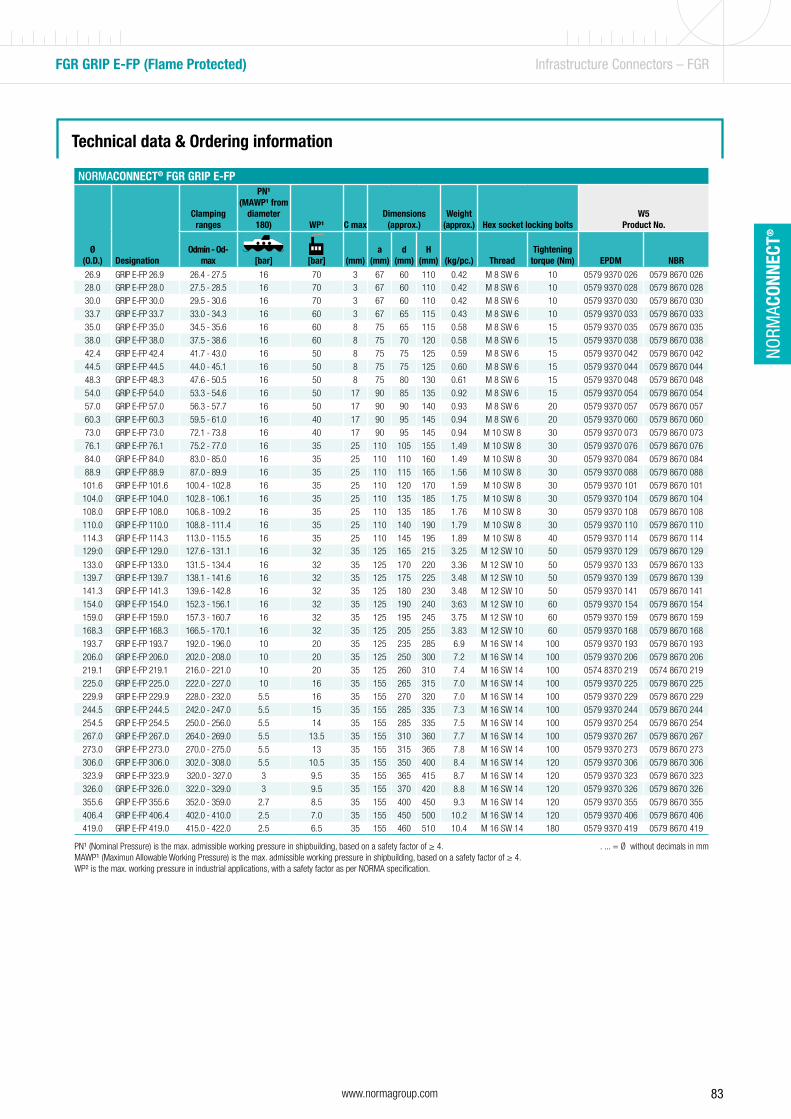
83www.normagroup.com
NORM
ACON
NECT
®
FGR GRIP E-FP (Flame Protected) Infrastructure Connectors – FGR
Technical data & Ordering information
NORMACONNECT® FGR GRIP E-FP
Ø(O.D.) Designation
Clamping ranges
PN¹ (MAWP¹ from
diameter 180) WP¹ C max
Dimensions(approx.)
Weight(approx.) Hex socket locking bolts
W5Product No.
Odmin - Od-max [bar] [bar] (mm)
a (mm)
d (mm)
H (mm)
(kg/pc.) Thread
Tightening torque (Nm) EPDM NBR
26.9 GRIP E-FP 26.9 26.4 - 27.5 16 70 3 67 60 110 0.42 M 8 SW 6 10 0579 9370 026 0579 8670 02628.0 GRIP E-FP 28.0 27.5 - 28.5 16 70 3 67 60 110 0.42 M 8 SW 6 10 0579 9370 028 0579 8670 028
30.0 GRIP E-FP 30.0 29.5 - 30.6 16 70 3 67 60 110 0.42 M 8 SW 6 10 0579 9370 030 0579 8670 030
33.7 GRIP E-FP 33.7 33.0 - 34.3 16 60 3 67 65 115 0.43 M 8 SW 6 10 0579 9370 033 0579 8670 033
35.0 GRIP E-FP 35.0 34.5 - 35.6 16 60 8 75 65 115 0.58 M 8 SW 6 15 0579 9370 035 0579 8670 035
38.0 GRIP E-FP 38.0 37.5 - 38.6 16 60 8 75 70 120 0.58 M 8 SW 6 15 0579 9370 038 0579 8670 038
42.4 GRIP E-FP 42.4 41.7 - 43.0 16 50 8 75 75 125 0.59 M 8 SW 6 15 0579 9370 042 0579 8670 042
44.5 GRIP E-FP 44.5 44.0 - 45.1 16 50 8 75 75 125 0.60 M 8 SW 6 15 0579 9370 044 0579 8670 044
48.3 GRIP E-FP 48.3 47.6 - 50.5 16 50 8 75 80 130 0.61 M 8 SW 6 15 0579 9370 048 0579 8670 048
54.0 GRIP E-FP 54.0 53.3 - 54.6 16 50 17 90 85 135 0.92 M 8 SW 6 15 0579 9370 054 0579 8670 054
57.0 GRIP E-FP 57.0 56.3 - 57.7 16 50 17 90 90 140 0.93 M 8 SW 6 20 0579 9370 057 0579 8670 057
60.3 GRIP E-FP 60.3 59.5 - 61.0 16 40 17 90 95 145 0.94 M 8 SW 6 20 0579 9370 060 0579 8670 060
73.0 GRIP E-FP 73.0 72.1 - 73.8 16 40 17 90 95 145 0.94 M 10 SW 8 30 0579 9370 073 0579 8670 073
76.1 GRIP E-FP 76.1 75.2 - 77.0 16 35 25 110 105 155 1.49 M 10 SW 8 30 0579 9370 076 0579 8670 076
84.0 GRIP E-FP 84.0 83.0 - 85.0 16 35 25 110 110 160 1.49 M 10 SW 8 30 0579 9370 084 0579 8670 084
88.9 GRIP E-FP 88.9 87.0 - 89.9 16 35 25 110 115 165 1.56 M 10 SW 8 30 0579 9370 088 0579 8670 088
101.6 GRIP E-FP 101.6 100.4 - 102.8 16 35 25 110 120 170 1.59 M 10 SW 8 30 0579 9370 101 0579 8670 101
104.0 GRIP E-FP 104.0 102.8 - 106.1 16 35 25 110 135 185 1.75 M 10 SW 8 30 0579 9370 104 0579 8670 104
108.0 GRIP E-FP 108.0 106.8 - 109.2 16 35 25 110 135 185 1.76 M 10 SW 8 30 0579 9370 108 0579 8670 108
110.0 GRIP E-FP 110.0 108.8 - 111.4 16 35 25 110 140 190 1.79 M 10 SW 8 30 0579 9370 110 0579 8670 110
114.3 GRIP E-FP 114.3 113.0 - 115.5 16 35 25 110 145 195 1.89 M 10 SW 8 40 0579 9370 114 0579 8670 114129:0 GRIP E-FP 129.0 127.6 - 131.1 16 32 35 125 165 215 3.25 M 12 SW 10 50 0579 9370 129 0579 8670 129
133.0 GRIP E-FP 133.0 131.5 - 134.4 16 32 35 125 170 220 3.36 M 12 SW 10 50 0579 9370 133 0579 8670 133139.7 GRIP E-FP 139.7 138.1 - 141.6 16 32 35 125 175 225 3.48 M 12 SW 10 50 0579 9370 139 0579 8670 139
141.3 GRIP E-FP 141.3 139.6 - 142.8 16 32 35 125 180 230 3.48 M 12 SW 10 50 0579 9370 141 0579 8670 141
154.0 GRIP E-FP 154.0 152.3 - 156.1 16 32 35 125 190 240 3:63 M 12 SW 10 60 0579 9370 154 0579 8670 154
159.0 GRIP E-FP 159.0 157.3 - 160.7 16 32 35 125 195 245 3.75 M 12 SW 10 60 0579 9370 159 0579 8670 159
168.3 GRIP E-FP 168.3 166.5 - 170.1 16 32 35 125 205 255 3.83 M 12 SW 10 60 0579 9370 168 0579 8670 168
193.7 GRIP E-FP 193.7 192.0 - 196.0 10 20 35 125 235 285 6.9 M 16 SW 14 100 0579 9370 193 0579 8670 193
206.0 GRIP E-FP 206.0 202.0 - 208.0 10 20 35 125 250 300 7.2 M 16 SW 14 100 0579 9370 206 0579 8670 206
219.1 GRIP E-FP 219.1 216.0 - 221.0 10 20 35 125 260 310 7.4 M 16 SW 14 100 0574 8370 219 0574 8670 219
225.0 GRIP E-FP 225.0 222.0 - 227.0 10 16 35 155 265 315 7.0 M 16 SW 14 100 0579 9370 225 0579 8670 225
229.9 GRIP E-FP 229.9 228.0 - 232.0 5.5 16 35 155 270 320 7.0 M 16 SW 14 100 0579 9370 229 0579 8670 229
244.5 GRIP E-FP 244.5 242.0 - 247.0 5.5 15 35 155 285 335 7.3 M 16 SW 14 100 0579 9370 244 0579 8670 244
254.5 GRIP E-FP 254.5 250.0 - 256.0 5.5 14 35 155 285 335 7.5 M 16 SW 14 100 0579 9370 254 0579 8670 254
267.0 GRIP E-FP 267.0 264.0 - 269.0 5.5 13.5 35 155 310 360 7.7 M 16 SW 14 100 0579 9370 267 0579 8670 267
273.0 GRIP E-FP 273.0 270.0 - 275.0 5.5 13 35 155 315 365 7.8 M 16 SW 14 100 0579 9370 273 0579 8670 273
306.0 GRIP E-FP 306.0 302.0 - 308.0 5.5 10.5 35 155 350 400 8.4 M 16 SW 14 120 0579 9370 306 0579 8670 306
323.9 GRIP E-FP 323.9 320.0 - 327.0 3 9.5 35 155 365 415 8.7 M 16 SW 14 120 0579 9370 323 0579 8670 323
326.0 GRIP E-FP 326.0 322.0 - 329.0 3 9.5 35 155 370 420 8.8 M 16 SW 14 120 0579 9370 326 0579 8670 326
355.6 GRIP E-FP 355.6 352.0 - 359.0 2.7 8.5 35 155 400 450 9.3 M 16 SW 14 120 0579 9370 355 0579 8670 355
406.4 GRIP E-FP 406.4 402.0 - 410.0 2.5 7.0 35 155 450 500 10.2 M 16 SW 14 120 0579 9370 406 0579 8670 406419.0 GRIP E-FP 419.0 415.0 - 422.0 2.5 6.5 35 155 460 510 10.4 M 16 SW 14 180 0579 9370 419 0579 8670 419
PN¹ (Nominal Pressure) is the max. admissible working pressure in shipbuilding, based on a safety factor of ≥ 4. . ... = Ø without decimals in mmMAWP¹ (Maximun Allowable Working Pressure) is the max. admissible working pressure in shipbuilding, based on a safety factor of ≥ 4.WP² is the max. working pressure in industrial applications, with a safety factor as per NORMA specification.
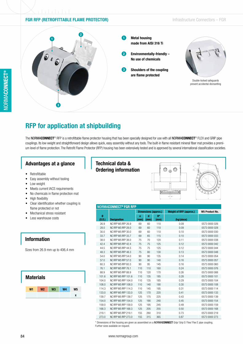
84 www.normagroup.com
NORM
ACON
NECT
®
Metal housing made from AISI 316 Ti
Environmentally-friendly –No use of chemicals
Shoulders of the coupling are flame protected
1
2
3
RFP for application at shipbuilding
The NORMACONNECT® RFP is a retrofittable flame protector housing that has been specially designed for use with all NORMACONNECT® FLEX and GRIP pipe couplings. Its low weight and straightforward design allows quick, easy assembly without any tools. The built-in flame resistant mineral fiber mat provides a premi-um level of flame protection. The Retrofit Flame Protector (RFP) housing has been extensively tested and is approved by several international classification societies.
Advantages at a glance
• Retrofittable • Easy assembly without tooling• Low weight• Meets current IACS requirements• No chemicals in flame protection mat• High flexibility• Clear identification whether coupling is
flame protected or not• Mechanical stress resistant• Less warehouse costs
Information
Sizes from 26.9 mm up to 406,4 mm
FGR RFP (RETROFITTABLE FLAME PROTECTOR) Infrastructure Connectors – FGR
12
3
NORMACONNECT® FGR RFP
Ø(O.D.) Designation
Dimensions (approx.) Weight of RFP (approx.) W5 Product No.
a(mm)
d (mm)
H*(mm) (kg/piece)
26.9 NC RFP W5 RFP 26.9 69 60 110 0.09 0573 0000 02628.0 NC RFP W5 RFP 28.0 69 60 110 0.09 0573 0000 028
30.0 NC RFP W5 RFP 30.0 69 60 110 0.10 0573 0000 030
33.7 NC RFP W5 RFP 33.7 69 65 115 0.10 0573 0000 033
38.0 NC RFP W5 RFP 38.0 75 70 120 0.11 0573 0000 038
42.4 NC RFP W5 RFP 42.4 75 75 125 0.12 0573 0000 042
44.5 NC RFP W5 RFP 44.5 75 75 125 0.12 0573 0000 044
48.3 NC RFP W5 RFP 48.3 75 80 130 0.13 0573 0000 048
54.0 NC RFP W5 RFP 54.0 90 90 135 0.14 0573 0000 054
57.0 NC RFP W5 RFP 57.0 90 90 140 0.16 0573 0000 057
60.3 NC RFP W5 RFP 60.3 90 95 145 0.16 0573 0000 060
76.1 NC RFP W5 RFP 76.1 110 110 160 0.24 0573 0000 076
88.9 NC RFP W5 RFP 88.9 110 120 170 0.26 0573 0000 088
101.6 NC RFP W5 RFP 101.6 110 135 185 0.28 0573 0000 101
104.0 NC RFP W5 RFP 104.0 110 135 185 0.29 0573 0000 104
108.0 NC RFP W5 RFP 108.0 110 140 190 0.30 0573 0000 108
114.3 NC RFP W5 RFP 114.3 110 145 195 0.31 0573 0000 114
133.0 NC RFP W5 RFP 133.0 125 170 220 0.41 0573 0000 133
139.7 NC RFP W5 RFP 139.7 125 175 225 0.43 0573 0000 139
154.0 NC RFP W5 RFP 154.0 125 190 240 0.45 0573 0000 154
159.0 NC RFP W5 RFP 159.0 125 195 245 0.49 0573 0000 159168.3 NC RFP W5 RFP 168.3 125 205 255 0.50 0573 0000 168
219.1 NC RFP W5 RFP 219.1 155 260 310 0.73 0573 0000 219273.0 NC RFP W5 RFP 273.0 155 315 365 0.87 0573 0000 273
Technical data & Ordering information
* Dimensions of the housing are given as assembled on a NORMACONNECT Grip/ Grip E/ Flex/ Flex E pipe coupling.Further sizes available on request.
Double-locked safeguards prevent accidental dismantling
Materials
W1 W2 W3 W4 W5
x
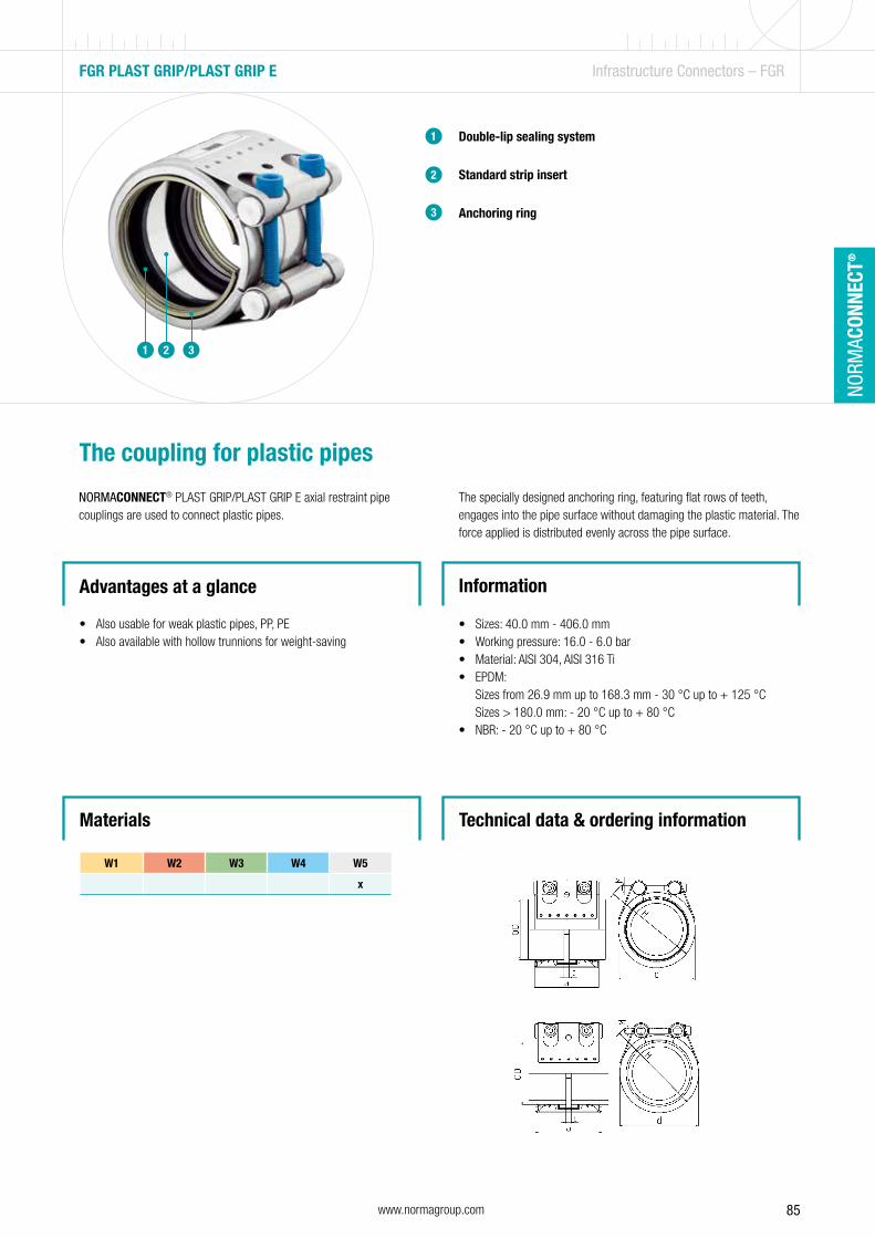
85www.normagroup.com
NORM
ACON
NECT
®
Double-lip sealing system
Standard strip insert
Anchoring ring
1
2
The coupling for plastic pipes
NORMACONNECT® PLAST GRIP/PLAST GRIP E axial restraint pipe couplings are used to connect plastic pipes.
Advantages at a glance
• Also usable for weak plastic pipes, PP, PE• Also available with hollow trunnions for weight-saving
Information
• Sizes: 40.0 mm - 406.0 mm• Working pressure: 16.0 - 6.0 bar• Material: AISI 304, AISI 316 Ti• EPDM:
Sizes from 26.9 mm up to 168.3 mm - 30 °C up to + 125 °C Sizes > 180.0 mm: - 20 °C up to + 80 °C
• NBR: - 20 °C up to + 80 °C
The specially designed anchoring ring, featuring flat rows of teeth, engages into the pipe surface without damaging the plastic material. The force applied is distributed evenly across the pipe surface.
FGR PLAST GRIP/PLAST GRIP E Infrastructure Connectors – FGR
1 2 3
3
W1 W2 W3 W4 W5
x
Materials Technical data & ordering information
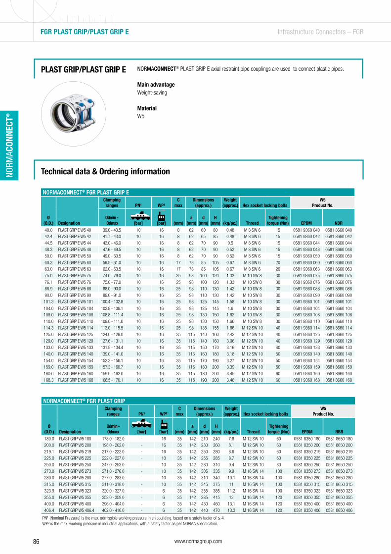
86 www.normagroup.com
NORM
ACON
NECT
®
FGR PLAST GRIP/PLAST GRIP E Infrastructure Connectors – FGR
NORMACONNECT® PLAST GRIP E axial restraint pipe couplings are used to connect plastic pipes.
Main advantageWeight-saving
MaterialW5
PLAST GRIP/PLAST GRIP E
NORMACONNECT® FGR PLAST GRIP E
Ø(O.D.) Designation
Clamping ranges PN¹ WP²
C max
Dimensions(approx.)
Weight(approx.) Hex socket locking bolts
W5Product No.
Odmin - Odmax [bar] [bar] (mm)
a (mm)
d (mm)
H (mm)
(kg/pc.) Thread
Tightening torque (Nm) EPDM NBR
40.0 PLAST GRIP E W5 40 39.0 - 40.5 10 16 8 62 60 80 0.48 M 8 SW 6 15 0581 9360 040 0581 8660 04042.4 PLAST GRIP E W5 42 41.7 - 43.0 10 16 8 62 65 85 0.48 M 8 SW 6 15 0581 9360 042 0581 8660 042
44.5 PLAST GRIP E W5 44 42.0 - 46.0 10 16 8 62 70 90 0.5 M 8 SW 6 15 0581 9360 044 0581 8660 044
48.3 PLAST GRIP E W5 48 47.6 - 49.5 10 16 8 62 70 90 0.52 M 8 SW 6 15 0581 9360 048 0581 8660 048
50.0 PLAST GRIP E W5 50 49.0 - 50.5 10 16 8 62 70 90 0.52 M 8 SW 6 15 0581 9360 050 0581 8660 050
60.3 PLAST GRIP E W5 60 59.5 - 61.0 10 16 17 78 85 105 0.67 M 8 SW 6 20 0581 9360 060 0581 8660 060
63.0 PLAST GRIP E W5 63 62.0 - 63.5 10 16 17 78 85 105 0.67 M 8 SW 6 20 0581 9360 063 0581 8660 063
75.0 PLAST GRIP E W5 75 74.0 - 76.0 10 16 25 98 100 120 1.33 M 10 SW 8 30 0581 9360 075 0581 8660 075
76.1 PLAST GRIP E W5 76 75.0 - 77.0 10 16 25 98 100 120 1.33 M 10 SW 8 30 0581 9360 076 0581 8660 076
88.9 PLAST GRIP E W5 88 88.0 - 90.0 10 16 25 98 110 130 1.42 M 10 SW 8 30 0581 9360 088 0581 8660 088
90.0 PLAST GRIP E W5 90 89.0 - 91.0 10 16 25 98 110 130 1.42 M 10 SW 8 30 0581 9360 090 0581 8660 090101.3 PLAST GRIP E W5 101 100.4 - 102.8 10 16 25 98 125 145 1.58 M 10 SW 8 30 0581 9360 101 0581 8660 101
104.0 PLAST GRIP E W5 104 102.8 - 106.1 10 16 25 98 125 145 1.6 M 10 SW 8 30 0581 9360 104 0581 8660 104108.0 PLAST GRIP E W5 108 108.8 - 111.4 10 16 25 98 130 150 1.62 M 10 SW 8 30 0581 9360 108 0581 8660 108
110.0 PLAST GRIP E W5 110 109.0 - 111.0 10 16 25 98 130 150 1.66 M 10 SW 8 30 0581 9360 110 0581 8660 110
114.3 PLAST GRIP E W5 114 113.0 - 115.5 10 16 25 98 135 155 1.66 M 12 SW 10 40 0581 9360 114 0581 8660 114
125.0 PLAST GRIP E W5 125 124.0 - 126.0 10 16 35 115 140 160 2.42 M 12 SW 10 40 0581 9360 125 0581 8660 125
129.0 PLAST GRIP E W5 129 127.6 - 131.1 10 16 35 115 140 160 3.06 M 12 SW 10 40 0581 9360 129 0581 8660 129
133.0 PLAST GRIP E W5 133 131.5 - 134.4 10 16 35 115 150 170 3.16 M 12 SW 10 40 0581 9360 133 0581 8660 133
140.0 PLAST GRIP E W5 140 139.0 - 141.0 10 16 35 115 160 180 3.18 M 12 SW 10 50 0581 9360 140 0581 8660 140
154.0 PLAST GRIP E W5 154 152.3 - 156.1 10 16 35 115 170 190 3.27 M 12 SW 10 50 0581 9360 154 0581 8660 154
159.0 PLAST GRIP E W5 159 157.3 - 160.7 10 16 35 115 180 200 3.39 M 12 SW 10 50 0581 9360 159 0581 8660 159
160:0 PLAST GRIP E W5 160 159.0 - 162.0 10 16 35 115 180 200 3.45 M 12 SW 10 60 0581 9360 160 0581 8660 160168.3 PLAST GRIP E W5 168 166.5 - 170.1 10 16 35 115 190 200 3.48 M 12 SW 10 60 0581 9360 168 0581 8660 168
Technical data & Ordering information
NORMACONNECT® FGR PLAST GRIP
Ø(O.D.) Designation
Clamping ranges PN¹ WP²
C max
Dimensions(approx.)
Weight(approx.) Hex socket locking bolts
W5Product No.
Odmin - Odmax [bar] [bar] (mm)
a (mm)
d (mm)
H (mm)
(kg/pc.) Thread
Tightening torque (Nm) EPDM NBR
180.0 PLAST GRIP W5 180 178.0 - 182.0 - 16 35 142 210 240 7.6 M 12 SW 10 60 0581 8350 180 0581 8650 180200.0 PLAST GRIP W5 200 198.0 - 202.0 - 16 35 142 230 260 8.1 M 12 SW 10 60 0581 8350 200 0581 8650 200
219.1 PLAST GRIP W5 219 217.0 - 222.0 - 16 35 142 250 280 8.6 M 12 SW 10 60 0581 8350 219 0581 8650 219
225.0 PLAST GRIP W5 225 222.0 - 227.0 - 10 35 142 255 285 8.7 M 12 SW 10 60 0581 8350 225 0581 8650 225
250.0 PLAST GRIP W5 250 247.0 - 253.0 - 10 35 142 280 310 9.4 M 12 SW 10 80 0581 8350 250 0581 8650 250
273.0 PLAST GRIP W5 273 271.0 - 276.0 - 10 35 142 305 335 9.9 M 16 SW 14 100 0581 8350 273 0581 8650 273
280.0 PLAST GRIP W5 280 277.0 - 283.0 - 10 35 142 310 340 10.1 M 16 SW 14 100 0581 8350 280 0581 8650 280
315.0 PLAST GRIP W5 315 311.0 - 318.0 - 10 35 142 345 375 11 M 16 SW 14 100 0581 8350 315 0581 8650 315
323.9 PLAST GRIP W5 323 320.0 - 327.0 - 6 35 142 355 385 11.2 M 16 SW 14 100 0581 8350 323 0581 8650 323
355.0 PLAST GRIP W5 355 352.0 - 359.0 - 6 35 142 385 415 12 M 16 SW 14 120 0581 8350 355 0581 8650 355
400.0 PLAST GRIP W5 400 396.0 - 404.0 - 6 35 142 430 460 13.1 M 16 SW 14 120 0581 8350 400 0581 8650 400406.4 PLAST GRIP W5 406.4 402.0 - 410.0 - 6 35 142 440 470 13.3 M 16 SW 14 120 0581 8350 406 0581 8650 406
PN¹ (Nominal Pressure) is the max. admissible working pressure in shipbuilding, based on a safety factor of ≥ 4.WP² is the max. working pressure in industrial applications, with a safety factor as per NORMA specification.
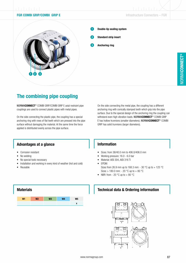
87www.normagroup.com
NORM
ACON
NECT
®
Double-lip sealing system
Standard strip insert
Anchoring ring
1
2
The combining pipe coupling
NORMACONNECT® COMBI GRIP/COMBI GRIP E axial restraint pipe couplings are used to connect plastic pipes with metal pipes.
On the side connecting the plastic pipe, the coupling has a special anchoring ring with rows of flat teeth which are pressed into the pipe surface without damaging the material. At the same time the force applied is distributed evenly across the pipe surface.
Advantages at a glance
• Corrosion resistant• No welding• No special tools necessary• Installation and working in every kind of weather (hot and cold)• Reusable
Information
• Sizes: from 38/40.0 mm to 406.0/406.0 mm• Working pressure: 16.0 - 6.0 bar• Material: AISI 304, AISI 316 Ti• EPDM:
Sizes from 26.9 mm up to 168.3 mm: - 30 °C up to + 125 °C Sizes > 180.0 mm: - 20 °C up to + 80 °C
• NBR: from - 20 °C up to + 80 °C
On the side connecting the metal pipe, the coupling has a different anchoring ring with conically stamped teeth which grip into the pipe surface. Due to the special design of the anchoring ring the coupling can withstand even high vibration loads. NORMACONNECT® COMBI GRIP E has hollow trunnions (smaller diameters). NORMACONNECT® COMBI GRIP has solid trunnions (larger diameters).
FGR COMBI GRIP/COMBI GRIP E Infrastructure Connectors – FGR
3
W1 W2 W3 W4 W5
x
Materials Technical data & Ordering information
1 2 3
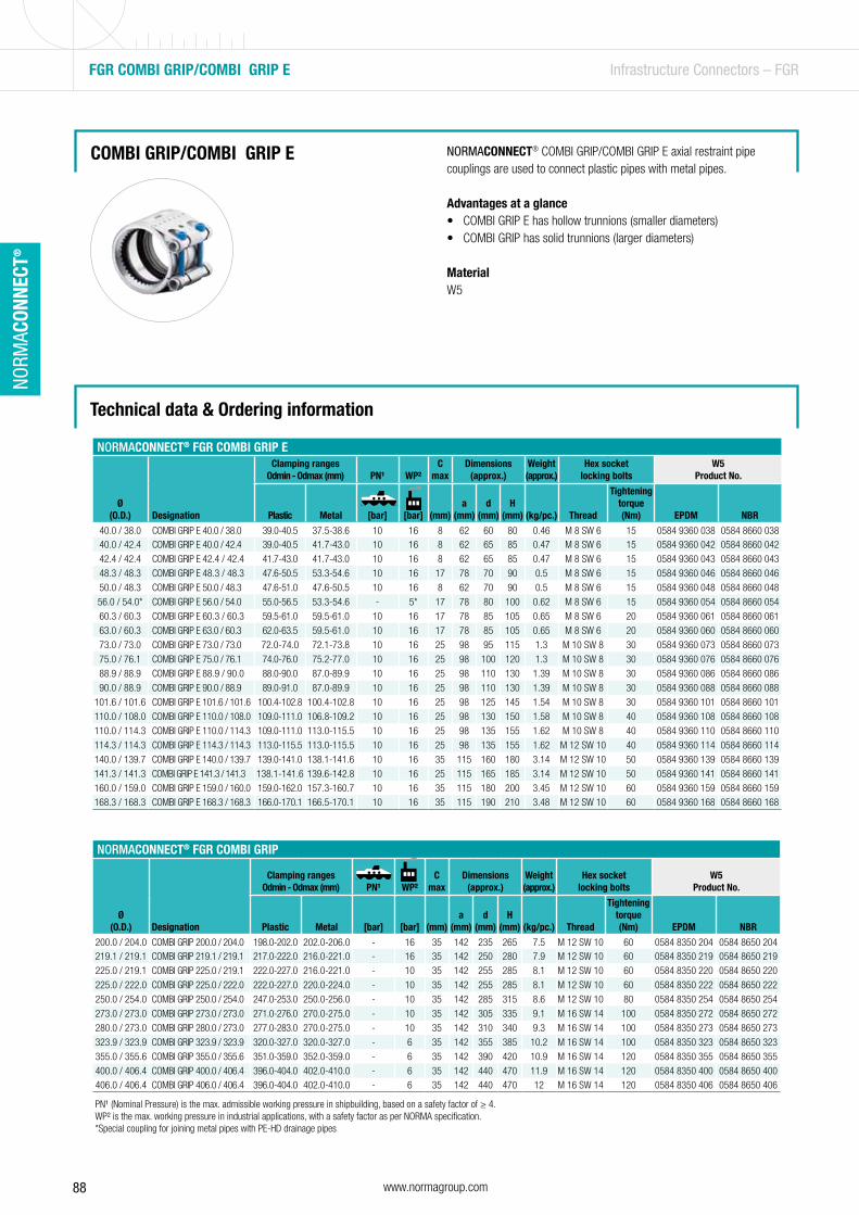
88 www.normagroup.com
NORM
ACON
NECT
®
Technical data & Ordering information
NORMACONNECT® FGR COMBI GRIP
Ø(O.D.) Designation
Clamping rangesOdmin - Odmax (mm) PN¹ WP²
C max
Dimensions(approx.)
Weight(approx.)
Hex socket locking bolts
W5Product No.
Plastic Metal [bar] [bar] (mm)a
(mm)d
(mm)H
(mm)
(kg/pc.) Thread
Tightening torque (Nm) EPDM NBR
200.0 / 204.0 COMBI GRIP 200.0 / 204.0 198.0-202.0 202.0-206.0 - 16 35 142 235 265 7.5 M 12 SW 10 60 0584 8350 204 0584 8650 204219.1 / 219.1 COMBI GRIP 219.1 / 219.1 217.0-222.0 216.0-221.0 - 16 35 142 250 280 7.9 M 12 SW 10 60 0584 8350 219 0584 8650 219
225.0 / 219.1 COMBI GRIP 225.0 / 219.1 222.0-227.0 216.0-221.0 - 10 35 142 255 285 8.1 M 12 SW 10 60 0584 8350 220 0584 8650 220
225.0 / 222.0 COMBI GRIP 225.0 / 222.0 222.0-227.0 220.0-224.0 - 10 35 142 255 285 8.1 M 12 SW 10 60 0584 8350 222 0584 8650 222
250.0 / 254.0 COMBI GRIP 250.0 / 254.0 247.0-253.0 250.0-256.0 - 10 35 142 285 315 8.6 M 12 SW 10 80 0584 8350 254 0584 8650 254
273.0 / 273.0 COMBI GRIP 273.0 / 273.0 271.0-276.0 270.0-275.0 - 10 35 142 305 335 9.1 M 16 SW 14 100 0584 8350 272 0584 8650 272
280.0 / 273.0 COMBI GRIP 280.0 / 273.0 277.0-283.0 270.0-275.0 - 10 35 142 310 340 9.3 M 16 SW 14 100 0584 8350 273 0584 8650 273
323.9 / 323.9 COMBI GRIP 323.9 / 323.9 320.0-327.0 320.0-327.0 - 6 35 142 355 385 10.2 M 16 SW 14 100 0584 8350 323 0584 8650 323
355.0 / 355.6 COMBI GRIP 355.0 / 355.6 351.0-359.0 352.0-359.0 - 6 35 142 390 420 10.9 M 16 SW 14 120 0584 8350 355 0584 8650 355
400.0 / 406.4 COMBI GRIP 400.0 / 406.4 396.0-404.0 402.0-410.0 - 6 35 142 440 470 11.9 M 16 SW 14 120 0584 8350 400 0584 8650 400406.0 / 406.4 COMBI GRIP 406.0 / 406.4 396.0-404.0 402.0-410.0 - 6 35 142 440 470 12 M 16 SW 14 120 0584 8350 406 0584 8650 406
FGR COMBI GRIP/COMBI GRIP E Infrastructure Connectors – FGR
NORMACONNECT® COMBI GRIP/COMBI GRIP E axial restraint pipe couplings are used to connect plastic pipes with metal pipes.
Advantages at a glance• COMBI GRIP E has hollow trunnions (smaller diameters)• COMBI GRIP has solid trunnions (larger diameters)
MaterialW5
COMBI GRIP/COMBI GRIP E
PN¹ (Nominal Pressure) is the max. admissible working pressure in shipbuilding, based on a safety factor of ≥ 4.WP² is the max. working pressure in industrial applications, with a safety factor as per NORMA specification.*Special coupling for joining metal pipes with PE-HD drainage pipes
NORMACONNECT® FGR COMBI GRIP E
Ø(O.D.) Designation
Clamping rangesOdmin - Odmax (mm) PN¹ WP²
C max
Dimensions(approx.)
Weight(approx.)
Hex socket locking bolts
W5Product No.
Plastic Metal [bar] [bar] (mm)a
(mm)d
(mm)H
(mm)
(kg/pc.) Thread
Tightening torque (Nm) EPDM NBR
40.0 / 38.0 COMBI GRIP E 40.0 / 38.0 39.0-40.5 37.5-38.6 10 16 8 62 60 80 0.46 M 8 SW 6 15 0584 9360 038 0584 8660 03840.0 / 42.4 COMBI GRIP E 40.0 / 42.4 39.0-40.5 41.7-43.0 10 16 8 62 65 85 0.47 M 8 SW 6 15 0584 9360 042 0584 8660 042
42.4 / 42.4 COMBI GRIP E 42.4 / 42.4 41.7-43.0 41.7-43.0 10 16 8 62 65 85 0.47 M 8 SW 6 15 0584 9360 043 0584 8660 043
48.3 / 48.3 COMBI GRIP E 48.3 / 48.3 47.6-50.5 53.3-54.6 10 16 17 78 70 90 0.5 M 8 SW 6 15 0584 9360 046 0584 8660 046
50.0 / 48.3 COMBI GRIP E 50.0 / 48.3 47.6-51.0 47.6-50.5 10 16 8 62 70 90 0.5 M 8 SW 6 15 0584 9360 048 0584 8660 048
56.0 / 54.0* COMBI GRIP E 56.0 / 54.0 55.0-56.5 53.3-54.6 - 5* 17 78 80 100 0.62 M 8 SW 6 15 0584 9360 054 0584 8660 054
60.3 / 60.3 COMBI GRIP E 60.3 / 60.3 59.5-61.0 59.5-61.0 10 16 17 78 85 105 0.65 M 8 SW 6 20 0584 9360 061 0584 8660 061
63.0 / 60.3 COMBI GRIP E 63.0 / 60.3 62.0-63.5 59.5-61.0 10 16 17 78 85 105 0.65 M 8 SW 6 20 0584 9360 060 0584 8660 060
73.0 / 73.0 COMBI GRIP E 73.0 / 73.0 72.0-74.0 72.1-73.8 10 16 25 98 95 115 1.3 M 10 SW 8 30 0584 9360 073 0584 8660 073
75.0 / 76.1 COMBI GRIP E 75.0 / 76.1 74.0-76.0 75.2-77.0 10 16 25 98 100 120 1.3 M 10 SW 8 30 0584 9360 076 0584 8660 076
88.9 / 88.9 COMBI GRIP E 88.9 / 90.0 88.0-90.0 87.0-89.9 10 16 25 98 110 130 1.39 M 10 SW 8 30 0584 9360 086 0584 8660 086
90.0 / 88.9 COMBI GRIP E 90.0 / 88.9 89.0-91.0 87.0-89.9 10 16 25 98 110 130 1.39 M 10 SW 8 30 0584 9360 088 0584 8660 088
101.6 / 101.6 COMBI GRIP E 101.6 / 101.6 100.4-102.8 100.4-102.8 10 16 25 98 125 145 1.54 M 10 SW 8 30 0584 9360 101 0584 8660 101
110.0 / 108.0 COMBI GRIP E 110.0 / 108.0 109.0-111.0 106.8-109.2 10 16 25 98 130 150 1.58 M 10 SW 8 40 0584 9360 108 0584 8660 108
110.0 / 114.3 COMBI GRIP E 110.0 / 114.3 109.0-111.0 113.0-115.5 10 16 25 98 135 155 1.62 M 10 SW 8 40 0584 9360 110 0584 8660 110
114.3 / 114.3 COMBI GRIP E 114.3 / 114.3 113.0-115.5 113.0-115.5 10 16 25 98 135 155 1.62 M 12 SW 10 40 0584 9360 114 0584 8660 114
140.0 / 139.7 COMBI GRIP E 140.0 / 139.7 139.0-141.0 138.1-141.6 10 16 35 115 160 180 3.14 M 12 SW 10 50 0584 9360 139 0584 8660 139
141.3 / 141.3 COMBI GRIP E 141.3 / 141.3 138.1-141.6 139.6-142.8 10 16 25 115 165 185 3.14 M 12 SW 10 50 0584 9360 141 0584 8660 141
160.0 / 159.0 COMBI GRIP E 159.0 / 160.0 159.0-162.0 157.3-160.7 10 16 35 115 180 200 3.45 M 12 SW 10 60 0584 9360 159 0584 8660 159168.3 / 168.3 COMBI GRIP E 168.3 / 168.3 166.0-170.1 166.5-170.1 10 16 35 115 190 210 3.48 M 12 SW 10 60 0584 9360 168 0584 8660 168
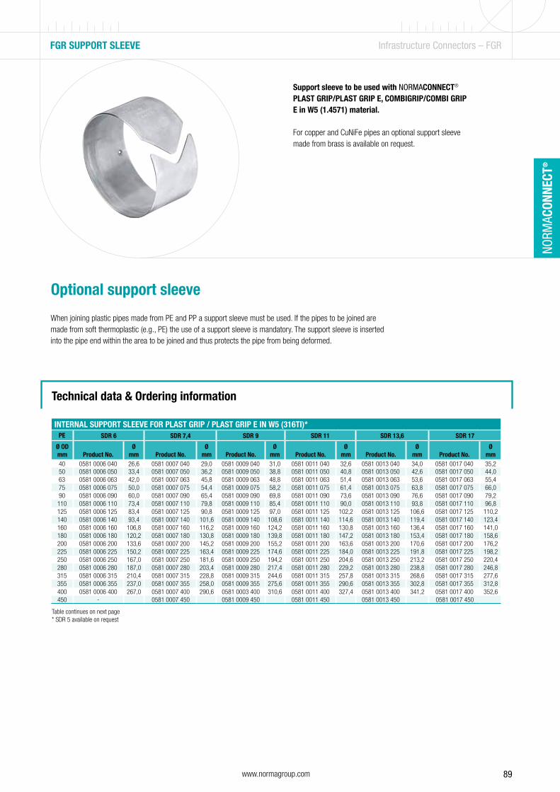
89www.normagroup.com
NORM
ACON
NECT
®
Support sleeve to be used with NORMACONNECT®
PLAST GRIP/PLAST GRIP E, COMBIGRIP/COMBI GRIP E in W5 (1.4571) material.
For copper and CuNiFe pipes an optional support sleeve made from brass is available on request.
FGR SUPPORT SLEEVE Infrastructure Connectors – FGR
Optional support sleeve
When joining plastic pipes made from PE and PP a support sleeve must be used. If the pipes to be joined are made from soft thermoplastic (e.g., PE) the use of a support sleeve is mandatory. The support sleeve is inserted into the pipe end within the area to be joined and thus protects the pipe from being deformed.
Technical data & Ordering information
INTERNAL SUPPORT SLEEVE FOR PLAST GRIP / PLAST GRIP E IN W5 (316TI)*PE SDR 6 SDR 7,4 SDR 9 SDR 11 SDR 13,6 SDR 17
Ø OD mm Product No.
Ømm Product No.
Ømm Product No.
Ømm Product No.
Ømm Product No.
Ømm Product No.
Ømm
40 0581 0006 040 26,6 0581 0007 040 29,0 0581 0009 040 31,0 0581 0011 040 32,6 0581 0013 040 34,0 0581 0017 040 35,250 0581 0006 050 33,4 0581 0007 050 36,2 0581 0009 050 38,8 0581 0011 050 40,8 0581 0013 050 42,6 0581 0017 050 44,063 0581 0006 063 42,0 0581 0007 063 45,8 0581 0009 063 48,8 0581 0011 063 51,4 0581 0013 063 53,6 0581 0017 063 55,475 0581 0006 075 50,0 0581 0007 075 54,4 0581 0009 075 58,2 0581 0011 075 61,4 0581 0013 075 63,8 0581 0017 075 66,090 0581 0006 090 60,0 0581 0007 090 65,4 0581 0009 090 69,8 0581 0011 090 73,6 0581 0013 090 76,6 0581 0017 090 79,2110 0581 0006 110 73,4 0581 0007 110 79,8 0581 0009 110 85,4 0581 0011 110 90,0 0581 0013 110 93,8 0581 0017 110 96,8125 0581 0006 125 83,4 0581 0007 125 90,8 0581 0009 125 97,0 0581 0011 125 102,2 0581 0013 125 106,6 0581 0017 125 110,2140 0581 0006 140 93,4 0581 0007 140 101,6 0581 0009 140 108,6 0581 0011 140 114,6 0581 0013 140 119,4 0581 0017 140 123,4160 0581 0006 160 106,8 0581 0007 160 116,2 0581 0009 160 124,2 0581 0011 160 130,8 0581 0013 160 136,4 0581 0017 160 141,0180 0581 0006 180 120,2 0581 0007 180 130,8 0581 0009 180 139,8 0581 0011 180 147,2 0581 0013 180 153,4 0581 0017 180 158,6200 0581 0006 200 133,6 0581 0007 200 145,2 0581 0009 200 155,2 0581 0011 200 163,6 0581 0013 200 170,6 0581 0017 200 176,2225 0581 0006 225 150,2 0581 0007 225 163,4 0581 0009 225 174,6 0581 0011 225 184,0 0581 0013 225 191,8 0581 0017 225 198,2250 0581 0006 250 167,0 0581 0007 250 181,6 0581 0009 250 194,2 0581 0011 250 204,6 0581 0013 250 213,2 0581 0017 250 220,4280 0581 0006 280 187,0 0581 0007 280 203,4 0581 0009 280 217,4 0581 0011 280 229,2 0581 0013 280 238,8 0581 0017 280 246,8315 0581 0006 315 210,4 0581 0007 315 228,8 0581 0009 315 244,6 0581 0011 315 257,8 0581 0013 315 268,6 0581 0017 315 277,6355 0581 0006 355 237,0 0581 0007 355 258,0 0581 0009 355 275,6 0581 0011 355 290,6 0581 0013 355 302,8 0581 0017 355 312,8400 0581 0006 400 267,0 0581 0007 400 290,6 0581 0003 400 310,6 0581 0011 400 327,4 0581 0013 400 341,2 0581 0017 400 352,6450 - 0581 0007 450 0581 0009 450 0581 0011 450 0581 0013 450 0581 0017 450
Table continues on next page* SDR 5 available on request

90 www.normagroup.com
NORM
ACON
NECT
®
FGR SUPPORT SLEEVE Infrastructure Connectors – FGR
Technical data & Ordering information
INTERNAL SUPPORT SLEEVE FOR PLAST GRIP / PLAST GRIP E IN W5 (316TI)PE SDR 17.6 SDR 21 SDR 22 SDR 26 SDR 33 SDR 41 SDR 51
Ø OD mm Product No.
Ømm Product No.
Ømm Product No.
Ømm Product No.
Ømm Product No.
Ømm Product No.
Ømm Product No.
Ømm
40 0581 0018 040 35,4 0581 0021 040 36,0 0581 0022 040 36,2 0581 0026 040 36,4 - - - - - -50 0581 0018 050 44,2 0581 0021 050 45,2 0581 0022 050 45,4 0581 0026 050 46 0581 0033 050 46,4 - - - -63 0581 0018 063 55,8 0581 0021 063 57,0 0581 0022 063 57,2 0581 0026 063 58 0581 0033 063 59 0581 0041 063 59,4 - -75 0581 0018 075 66,4 0581 0021 075 67,8 0581 0022 075 68,0 0581 0026 075 69,2 0581 0033 075 70,4 0581 0041 075 71,2 0581 0051 075 71,490 0581 0018 090 79,8 0581 0021 090 81,4 0581 0022 090 81,8 0581 0026 090 83,0 0581 0033 090 84,4 0581 0041 090 85,6 0581 0051 090 86,4110 0581 0018 110 97,4 0581 0021 110 99,4 0581 0022 110 100,0 0581 0026 110 101,6 0581 0033 110 103,2 0581 0041 110 104,6 0581 0051 110 105,6125 0581 0018 125 110,8 0581 0021 125 113,0 0581 0022 125 113,6 0581 0026 125 115,4 0581 0033 125 117,2 0581 0041 125 118,8 0581 0051 125 120,0140 0581 0018 140 124,0 0581 0021 140 126,6 0581 0022 140 127,2 0581 0026 140 129,2 0581 0033 140 131,4 0581 0041 140 133,0 0581 0051 140 134,4160 0581 0018 160 141,8 0581 0021 160 144,6 0581 0022 160 145,4 0581 0026 160 147,6 0581 0033 160 150,2 0581 0041 160 152,0 0581 0051 160 153,6180 0581 0018 180 159,6 0581 0021 180 162,8 0581 0022 180 163,6 0581 0026 180 166,2 0581 0033 180 169,0 0581 0041 180 171,2 0581 0051 180 172,8200 0581 0018 200 177,2 0581 0021 200 180,8 0581 0022 200 181,8 0581 0026 200 184,6 0581 0033 200 187,6 0581 0041 200 190,2 0581 0051 200 192,2225 0581 0018 225 199,4 0581 0021 225 203,4 0581 0022 225 204,4 0581 0026 225 207,8 0581 0033 225 211,2 0581 0041 225 214,0 0581 0051 225 216,2250 0581 0018 250 221,6 0581 0021 250 226,2 0581 0022 250 227,2 0581 0026 250 230,8 0581 0033 250 234,6 0581 0041 250 237,6 0581 0051 250 240,2280 0581 0018 280 248,2 0581 0021 280 253,2 0581 0022 280 254,4 0581 0026 280 258,6 0581 0033 280 262,8 0581 0041 280 266,2 0581 0051 280 269,0315 0581 0018 315 279,2 0581 0021 315 285,0 0581 0022 315 286,2 0581 0026 315 290,8 0581 0033 315 295,6 0581 0041 315 299,6 0581 0051 615 302,6355 0581 0018 355 314,8 0581 0021 355 321,2 0581 0022 350 322,6 0581 0026 355 327,8 0581 0033 355 333,2 0581 0041 355 337,6 0581 0051 355 341,0400 0581 0018 400 354,6 0581 0021 400 361,8 0581 0022 400 363,6 0581 0026 400 369,4 0581 0033 400 375,4 0581 0041 400 380,4 0581 0051 400 384,2450 0581 0018 450 399,0 0581 0021 450 407,0 0581 0022 450 409,0 0581 0026 450 415,6 0581 0033 450 422,4 0581 0041 450 428,0 0581 0051 450 432,4
INTERNAL SUPPORT SLEEVE FOR PLAST GRIP / PLAST GRIP E IN W5 (316TI)*PP SDR 6 SDR 7,4 SDR 9 SDR 11
Ø OD mm Product No.
Ømm Product No.
Ømm Product No.
Ømm Product No.
Ømm
40 0581 1006 040 26,6 0581 1007 040 29,0 0581 1009 040 31,0 0581 1011 040 32,650 0581 1006 050 33,4 0581 1007 050 36,2 0581 1009 050 38,8 0581 1011 050 40,863 0581 1006 063 42,0 0581 1007 063 45,8 0581 1009 063 48,8 0581 1011 063 51,475 0581 1006 075 50,0 0581 1007 075 54,4 0581 1009 075 58,2 0581 1011 075 61,490 0581 1006 090 60,0 0581 1007 090 65,4 0581 1009 090 69,8 0581 1011 090 73,6110 0581 1006 110 73,4 0581 1007 110 79,8 0581 1009 110 85,4 0581 1011 110 90,0125 0581 1006 125 83,4 0581 1007 125 90,8 0581 1009 125 97,0 0581 1011 125 102,2140 0581 1006 140 93,4 0581 1007 140 101,6 0581 1009 140 108,6 0581 1011 140 114,6160 0581 1006 160 106,8 0581 1007 160 116,2 0581 1009 160 124,2 0581 1011 160 130,8180 0581 1006 180 122,0 0581 1007 180 130,8 0581 1009 180 139,8 0581 1011 180 147,2200 0581 1006 200 133,6 0581 1007 200 145,2 0581 1009 200 155,2 0581 1011 200 163,6225 0581 1006 225 150,2 0581 1007 225 163,4 0581 1009 225 174,6 0581 1011 225 184,0250 - - 0581 1007 250 181,6 0581 1009 250 194,2 0581 1011 250 204,6280 - - 0581 1007 280 203,4 0581 1009 280 217,4 0581 1011 280 229,2315 - - - - 0581 1009 315 244,6 0581 1011 315 257,8355 - - - - 0581 1009 355 275,6 0581 1011 355 290,6400 - - - - - - 0581 1011 400 327,4450 - - - - - - 0581 1011 450 368,2
INTERNAL SUPPORT SLEEVE FOR PLAST GRIP / PLAST GRIP E IN W5 (316TI)PP SDR 17 SDR 17,6 SDR 26 SDR 33 SDR 41
Ø OD mm Product No.
Ømm Product No.
Ømm Product No.
Ømm Product No.
Ømm Product No.
Ømm
40 0581 1017 040 35,2 0581 1018 040 35,4 0581 1026 040 36,4 - - - -50 0581 1017 050 44,0 0581 1018 050 44,2 0581 1026 050 46,0 0581 1033 050 46,4 - -63 0581 1017 063 55,4 0581 1018 063 55,8 0581 1026 063 58,0 0581 1033 063 59,0 0581 1041 063 59,475 0581 1017 075 66,0 0581 1018 075 66,4 0581 1026 075 69,2 0581 1033 075 70,4 0581 1041 075 71,290 0581 1017 090 79,2 0581 1018 090 79,8 0581 1026 090 83,0 0581 1033 090 84,4 0581 1041 090 85,6
110 0581 1017 110 96,8 0581 1018 110 97,4 0581 1026 110 101,6 0581 1033 110 103,2 0581 1041 110 104,6125 0581 1017 125 110,2 0581 1018 125 110,8 0581 1026 125 115,4 0581 1033 125 117,2 0581 1041 125 118,8140 0581 1017 140 123,4 0581 1018 140 124,0 0581 1026 140 129,2 0581 1033 140 131,4 0581 1041 140 133,0160 0581 1017 160 141,0 0581 1018 160 141,8 0581 1026 160 147,6 0581 1033 160 150,2 0581 1041 160 152,0180 0581 1017 180 158,6 0581 1018 180 159,6 0581 1026 180 166,2 0581 1033 180 169,0 0581 1041 180 171,2200 0581 1017 200 176,2 0581 1018 200 177,2 0581 1026 200 184,6 0581 1033 200 187,6 0581 1041 200 190,2225 0581 1017 225 198,2 0581 1018 225 199,4 0581 1026 225 207,8 0581 1033 225 211,2 0581 1041 225 214,0250 0581 1017 250 220,4 0581 1018 250 221,6 0581 1026 250 230,8 0581 1033 250 234,6 0581 1041 250 237,6280 0581 1017 280 246,8 0581 1018 280 248,2 0581 1026 280 258,6 0581 1033 280 262,8 0581 1041 280 266,2315 0581 1017 315 277,6 0581 1018 315 279,2 0581 1026 315 290,8 0581 1033 315 295,6 0581 1041 315 299,6355 0581 1017 355 312,8 0581 1018 355 314,8 0581 1026 355 327,8 0581 1033 355 333,2 0581 1041 355 337,6400 0581 1017 400 352,6 0581 1018 400 354,6 0581 1026 400 369,4 0581 1033 400 375,4 0581 1041 400 380,4450 0581 1017 450 396,6 0581 1018 450 399,0 0581 1026 450 415,6 0581 1033 450 422,4 0581 1041 450 428,0
* SDR 5 available on request

91www.normagroup.com
NORM
ACON
NECT
®
Double-lip sealing system
Standard strip insert
1
2
The repair coupling
NORMACONNECT® REP E are non-restraint repair couplings. They are used to seal damaged metal and plastic pipes. They also enable repairs to be carried out easily, quickly and safely without the need to dismantle the pipes.
Advantages at a glance
• Ensures a reliable, safe, leakage-free connection• Enables easy, quick and safe repair without dismantling the pipes• Easy to install without special tools
Information
• Sizes: from 35.0 mm to 1219.1 mm• Working pressure: from 60.0 bar to 4.0 bar• Material: AISI 316 Ti• EPDM:
Sizes from 26.9 mm up to 168.3 mm: - 30 °C up to + 125 °C Sizes > 180.0 mm: - 20 °C up to + 80 °C
• NBR : from - 20 °C up to + 80 °C
FGR REP E Infrastructure Connectors – FGR
1 2
Materials
W1 W2 W3 W4 W5
x
Technical data & Ordering information

92 www.normagroup.com
NORM
ACON
NECT
®
FGR REP E Infrastructure Connectors – FGR
Technical data & Ordering information
NORMACONNECT® FGR REP E
Ø(O.D.) Designation
Clamping ranges WP¹ C maxDimensions
(approx.)Weight
(approx.) Hex socket locking boltsW5
Product No.
Odmin - Odmax [bar] (mm)a
(mm) d (mm) H (mm)
(kg/pc.) ThreadTightening
torque (Nm) EPDM NBR35.0 REP E W5 35.0 34.5 - 35.6 60 8 63 55 75 0.41 M 8 SW 6 5 0572 9360 035 0572 8660 03538.0 REP E W5 38.0 37.5 - 38.6 60 8 63 60 80 0.41 M 8 SW 6 5 0572 9360 038 0572 8660 038
42.4 REP E W5 42.4 41.7 - 43.0 50 8 63 65 85 0.42 M 8 SW 6 5 0572 9360 042 0572 8660 042
44.5 REP E W5 44.5 44.0 - 45.1 50 8 63 65 85 0.43 M 8 SW 6 5 0572 9360 044 0572 8660 044
48.3 REP E W5 48.3 47.6 - 50.5 50 8 63 70 90 0.44 M 8 SW 6 5 0572 9360 048 0572 8660 048
54.0 REP E W5 54:0 53.3 - 54.6 50 17 78 75 95 0.58 M 8 SW 6 10 0572 9360 054 0572 8660 054
57.0 REP E W5 57.0 56.3 - 57.7 50 17 78 80 100 0.58 M 8 SW 6 10 0572 9360 057 0572 8660 057
60.3 REP E W5 60.3 59.5 - 61.0 40 17 78 85 105 0.59 M 8 SW 6 10 0572 9360 060 0572 8660 060
70.0 REP E W5 70.0 69.0 - 71.0 40 25 98 90 110 0.59 M 8 SW 6 10 0572 9360 070 0572 8660 070
73.0 REP E W5 73.0 72.1 - 73.8 40 25 98 95 115 1.13 M 8 SW 6 10 0572 9360 073 0572 8660 073
76.1 REP E W5 76.1 75.2 - 77.0 35 25 98 100 120 1.13 M 8 SW 6 10 0572 9360 076 0572 8660 076
78.0 REP E W5 78.0 77.1 - 78.9 35 25 98 100 120 1.14 M 8 SW 6 15 0572 9360 078 0572 8660 078
80.0 REP E W5 80.0 79.0 - 80.8 35 25 98 100 120 1.16 M 8 SW 6 15 0572 9360 080 0572 8660 080
84.0 REP E W5 84.0 83.0 - 85.0 35 25 98 105 125 1.18 M 8 SW 6 15 0572 9360 084 0572 8660 084
88.9 REP E W5 88.9 87.0 - 89.9 35 25 98 110 130 1.20 M 8 SW 6 15 0572 9360 088 0572 8660 088
98.0 REP E W5 98.0 96.9 - 99.0 35 25 98 120 140 1.32 M 8 SW 6 15 0572 9360 098 0572 8660 098
101.6 REP E W5 101.6 100.4 - 102.8 35 25 98 125 145 1.33 M 8 SW 6 15 0572 9360 101 0572 8660 101
104.0 REP E W5 104.0 102.8 - 106.1 35 25 98 125 145 1.36 M 8 SW 6 15 0572 9360 104 0572 8660 104
108.0 REP E W5 108.0 106.8 - 109.2 35 25 98 130 150 1.40 M 8 SW 6 15 0572 9360 108 0572 8660 108
110.0 REP E W5 110.0 108.8 - 111.4 35 25 98 130 150 1.40 M 8 SW 6 20 0572 9360 110 0572 8660 110
114.3 REP E W5 114.0 113.0 - 115.5 35 25 98 135 155 1.99 M 8 SW 6 30 0572 9360 114 0572 8660 114129.0 REP E W5 129.0 127.6 - 131.1 32 35 113 155 185 2.00 M 10 SW 8 30 0572 9360 129 0572 8660 129
133.0 REP E W5 133.0 131.5 - 134.4 32 35 113 160 190 2.03 M 10 SW 8 30 0572 9360 133 0572 8660 133139.7 REP E W5 139.7 138.1 - 141.6 32 35 113 165 195 2.08 M 10 SW 8 30 0572 9360 139 0572 8660 139
141.3 REP E W5 141.3 139.6 - 142.8 32 35 113 170 200 2.09 M 10 SW 8 35 0572 9360 141 0572 8660 141
154.0 REP E W5 154.0 152.3 - 156.1 32 35 113 180 210 2.19 M 10 SW 8 50 0572 9360 154 0572 8660 154
159.0 REP E W5 159.0 157.3 - 160.7 32 35 113 185 215 2.26 M 10 SW 8 50 0572 9360 159 0572 8660 159
168.3 REP E W5 168.0 166.5 - 170.1 32 35 113 195 225 2.31 M 10 SW 8 50 0572 9360 168 0572 8660 168
180.0 REP E W5 180.0 178.0 - 182.0 30.0 35 139 210 240 4.0 M 12 SW 10 25 0576 8360 … 0576 8660 …
193.7 REP E W5 193.7 192.0 - 196.0 28.0 35 139 225 255 4.1 M 12 SW 10 25 0576 8360 … 0576 8660 …
206.0 REP E W5 206.0 202.0 - 208.0 26.5 35 139 240 270 4.3 M 12 SW 10 25 0576 8360 … 0576 8660 …
219.0 REP E W5 219.0 216.0 - 221.0 23.0 35 139 250 280 4.4 M 12 SW 10 25 0576 8360 … 0576 8660 …
225.0 REP E W5 225.0 222.0 - 227.0 23.0 35 139 255 285 4.5 M 12 SW 10 25 0576 8360 … 0576 8660 …
229.9 REP E W5 229.9 228.0 - 232.0 23.0 35 139 260 290 4.5 M 12 SW 10 25 0576 8360 … 0576 8660 …
244.5 REP E W5 244.5 242.0 - 247.0 22.0 35 139 275 305 4.7 M 12 SW 10 25 0576 8360 … 0576 8660 …
254.0 REP E W5 254.0 250.0 - 256.0 21.0 35 139 285 315 4.8 M 12 SW 10 25 0576 8360 … 0576 8660 …
267.0 REP E W5 267.0 264.0 - 269.0 20.0 35 139 300 330 5.0 M 12 SW 10 25 0576 8360 … 0576 8660 …
273.0 REP E W5 273.0 270.0 - 275.0 20.0 35 139 305 335 5.1 M 12 SW 10 25 0576 8360 … 0576 8660 …
306.0 REP E W5 306.0 302.0 - 308.0 17.5 35 139 340 370 5.5 M 12 SW 10 25 0576 8360 … 0576 8660 …
323.9 REP E W5 323.9 320.0 - 327.0 17.5 35 139 355 385 5.7 M 12 SW 10 25 0576 8360 … 0576 8660 …
326.0 REP E W5 326.0 322.0 - 329.0 16.5 35 139 360 390 5.7 M 12 SW 10 25 0576 8360 … 0576 8660 …
355.6 REP E W5 355.6 352.0 - 359.0 15.0 35 139 390 420 6.0 M 12 SW 10 25 0576 8360 … 0576 8660 …
406.4 REP E W5 406.4 402.0 - 410.0 14.0 35 139 440 470 6.6 M 12 SW 10 25 0576 8360 … 0576 8660 …
429.0 REP E W5 429.0 426.0 - 431.0 13.0 35 139 460 490 6.9 M 12 SW 10 40 0576 8360 … 0576 8660 …
442.0 REP E W5 442.0 439.0 - 444.0 13.0 35 139 475 505 7.1 M 12 SW 10 40 0576 8360 … 0576 8660 …457.2 REP E W5 457.2 454.0 - 459.0 12.0 35 139 490 520 7.3 M 12 SW 10 40 0576 8360 … 0576 8660 …
508.0 REP E W5 508.0 505.0 - 510.0 11.0 35 139 540 570 7.9 M 12 SW 10 40 0576 8360 … 0576 8660 …531.0 REP E W5 531.0 528.0 - 534.0 10.5 35 139 565 595 8.1 M 12 SW 10 40 0576 8360 … 0576 8660 …
558.8 REP E W5 558.8 556.0 - 562.0 10.0 35 139 590 620 8.5 M 12 SW 10 40 0576 8360 … 0576 8660 …
609.6 REP E W5 609.6 606.0 - 613.0 9.0 35 139 640 670 9.1 M 12 SW 10 40 0576 8360 … 0576 8660 …
634.0 REP E W5 634.0 631.0 - 637.0 8.0 35 139 665 695 9.4 M 12 SW 10 40 0576 8360 … 0576 8660 …
711.2 REP E W5 711.2 707.0 - 715.0 7.0 35 139 745 775 10.3 M 12 SW 10 40 0576 8360 … 0576 8660 …
762.0 REP E W5 762.0 758.0 - 766.0 7.0 35 139 795 825 10.9 M 12 SW 10 40 0576 8360 … 0576 8660 …
812.8 REP E W5 812.8 808.0 - 817.0 6.5 35 139 845 875 11.5 M 12 SW 10 40 0576 8360 … 0576 8660 …
914.4 REP E W5 914.4 909.0 - 919.0 5.5 35 139 945 975 12.7 M 12 SW 10 45 0576 8360 … 0576 8660 …
1016.0 REP E W5 1016.0 1013.0 - 1019.0 5.0 35 139 1050 1080 13.9 M 12 SW 10 45 0576 8360 … 0576 8660 …
1117.5 REP E W5 1117.5 1114.0 - 1120.0 4.5 35 139 1150 1180 15.1 M 12 SW 10 50 0576 8360 … 0576 8660 …1219.2 REP E W5 1219.2 1216.0 - 1222.0 4.0 35 139 1250 1280 16.3 M 12 SW 10 50 0576 8360 … 0576 8660 …
Coupling sizes >800 mm are in 2-parts design! Sizes > 1219.2 on request ... = Ø without decimals in mm
Refer to page 196.
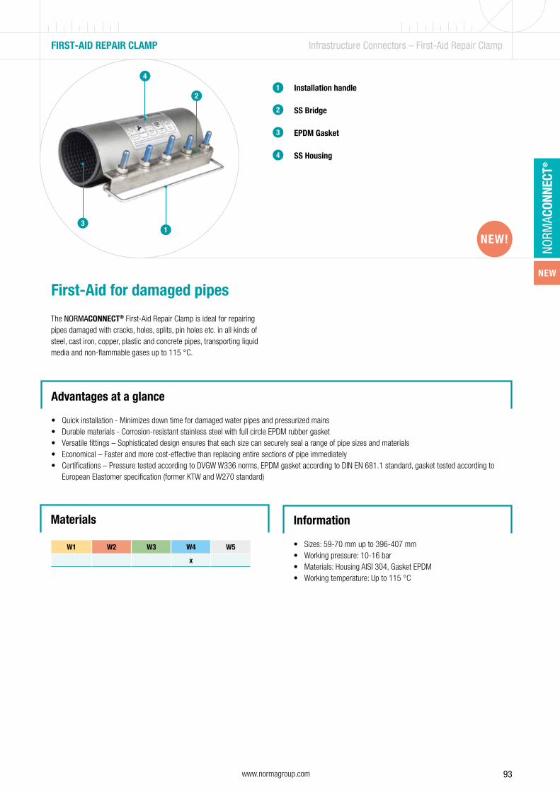
NEW
93www.normagroup.com
NORM
ACON
NECT
®
Installation handle
SS Bridge
EPDM Gasket
SS Housing
1
2
First-Aid for damaged pipes
The NORMACONNECT® First-Aid Repair Clamp is ideal for repairing pipes damaged with cracks, holes, splits, pin holes etc. in all kinds of steel, cast iron, copper, plastic and concrete pipes, transporting liquid media and non-flammable gases up to 115 °C.
Advantages at a glance
• Quick installation - Minimizes down time for damaged water pipes and pressurized mains• Durable materials - Corrosion-resistant stainless steel with full circle EPDM rubber gasket• Versatile fittings – Sophisticated design ensures that each size can securely seal a range of pipe sizes and materials• Economical – Faster and more cost-effective than replacing entire sections of pipe immediately• Certifications – Pressure tested according to DVGW W336 norms, EPDM gasket according to DIN EN 681.1 standard, gasket tested according to
European Elastomer specification (former KTW and W270 standard)
Information
• Sizes: 59-70 mm up to 396-407 mm• Working pressure: 10-16 bar• Materials: Housing AISI 304, Gasket EPDM• Working temperature: Up to 115 °C
FIRST-AID REPAIR CLAMP Infrastructure Connectors – First-Aid Repair Clamp
13
Materials
W1 W2 W3 W4 W5
x
NEW!
3
4
2
4
NEW!

94 www.normagroup.com
NORM
ACON
NECT
®
FIRST-AID CLAMP Infrastructure Connectors – First-Aid Repair Clamp
Technical data & Ordering information
NORMA® FIRST-AID REPAIR CLAMP
DesignationClamping
ranges Length (mm) PN (bar) Bolt diameterMax. tightening
torque (Nm) Weight (kg/pc.)W4
Product No.
FIRST-AID REPAIR CLAMP K-63 59-70 100 16 M12 SW19 100 0,8 0572 2211 063FIRST-AID REPAIR CLAMP M-63 59-70 200 16 M12 SW19 100 1,6 0572 2212 063
FIRST-AID REPAIR CLAMP K-68 63-72 100 16 M12 SW19 100 0,8 0572 2211 068
FIRST-AID REPAIR CLAMP M-68 63-72 200 16 M12 SW19 100 1,7 0572 2212 068
FIRST-AID REPAIR CLAMP K-75 70-81 100 16 M12 SW19 100 0,9 0572 2211 075
FIRST-AID REPAIR CLAMP M-75 70-81 200 16 M12 SW19 100 1,7 0572 2212 075
FIRST-AID REPAIR CLAMP K-82 82-91 100 16 M12 SW19 100 1,0 0572 2211 082
FIRST-AID REPAIR CLAMP M-82 82-91 200 16 M12 SW19 100 1,8 0572 2212 082
FIRST-AID REPAIR CLAMP K-104 104-114 100 16 M12 SW19 100 1,2 0572 2211 104
FIRST-AID REPAIR CLAMP M-104 104-114 210 16 M12 SW19 100 2,1 0572 2212 104
FIRST-AID REPAIR CLAMP L-104 104-114 315 16 M12 SW19 100 3,4 0572 2213 104
FIRST-AID REPAIR CLAMP K-131 128-140 200 16 M16 SW24 130 2,8 0572 2211 131
FIRST-AID REPAIR CLAMP M-131 128-140 250 16 M16 SW24 130 3,7 0572 2212 131
FIRST-AID REPAIR CLAMP L-131 128-140 315 16 M16 SW24 130 4,7 0572 2213 131
FIRST-AID REPAIR CLAMP K-140 138-150 200 16 M16 SW24 130 3,1 0572 2211 140
FIRST-AID REPAIR CLAMP M-140 138-150 250 16 M16 SW24 130 4,0 0572 2212 140
FIRST-AID REPAIR CLAMP L-140 138-150 315 16 M16 SW24 130 5,0 0572 2213 140
FIRST-AID REPAIR CLAMP K-151 150-162 200 16 M16 SW24 130 3,2 0572 2211 151
FIRST-AID REPAIR CLAMP M-151 150-162 250 16 M16 SW24 130 4,2 0572 2212 151
FIRST-AID REPAIR CLAMP L-151 150-162 315 16 M16 SW24 130 5,2 0572 2213 151
FIRST-AID REPAIR CLAMP K-166 163-175 200 16 M16 SW24 130 3,4 0572 2211 166FIRST-AID REPAIR CLAMP M-166 163-175 250 16 M16 SW24 130 4,4 0572 2212 166
FIRST-AID REPAIR CLAMP L-166 163-175 315 16 M16 SW24 130 5,4 0572 2213 166FIRST-AID REPAIR CLAMP K-178 178-192 200 16 M16 SW24 130 3,5 0572 2211 178
FIRST-AID REPAIR CLAMP M-178 178-192 250 16 M16 SW24 130 4,5 0572 2212 178
FIRST-AID REPAIR CLAMP L-178 178-192 315 16 M16 SW24 130 5,6 0572 2213 178
FIRST-AID REPAIR CLAMP K-190 191-202 200 10 M16 SW24 130 3,5 0572 2211 190
FIRST-AID REPAIR CLAMP M-190 191-202 250 10 M16 SW24 130 4,6 0572 2212 190
FIRST-AID REPAIR CLAMP L-190 191-202 315 10 M16 SW24 130 5,8 0572 2213 190
FIRST-AID REPAIR CLAMP M-215 215-226 250 10 M16 SW24 130 4,7 0572 2212 215
FIRST-AID REPAIR CLAMP L-215 215-226 315 10 M16 SW24 130 6,2 0572 2213 215
FIRST-AID REPAIR CLAMP M-225 220-230 250 10 M16 SW24 130 5,2 0572 2212 225
FIRST-AID REPAIR CLAMP L-225 220-230 315 10 M16 SW24 130 6,5 0572 2213 225
FIRST-AID REPAIR CLAMP M-260 251-261 250 10 M16 SW24 130 5,6 0572 2212 260
FIRST-AID REPAIR CLAMP L-260 251-261 315 10 M16 SW24 130 7,0 0572 2213 260
FIRST-AID REPAIR CLAMP M-269 269-281 250 10 M16 SW24 130 5,4 0572 2212 269
FIRST-AID REPAIR CLAMP M-306 306-316 315 10 M16 SW24 130 7,2 0572 2212 306
FIRST-AID REPAIR CLAMP L-306 306-316 575 10 M16 SW24 130 13,1 0572 2213 306
FIRST-AID REPAIR CLAMP M-315 314-325 315 10 M16 SW24 130 7,4 0572 2212 315
FIRST-AID REPAIR CLAMP L-315 314-325 575 10 M16 SW24 130 13,3 0572 2213 315
FIRST-AID REPAIR CLAMP M-345 345-357 315 10 M16 SW24 130 7,8 0572 2212 345
FIRST-AID REPAIR CLAMP L-345 345-357 575 10 M16 SW24 130 14,2 0572 2213 345
FIRST-AID REPAIR CLAMP M-400 396-407 315 10 M16 SW24 130 8,5 0572 2212 400FIRST-AID REPAIR CLAMP L-400 396-407 575 10 M16 SW24 130 15,5 0572 2213 400
The maximum tightening torque should not be exceeded. The bolts should be tightened until the leakage is visibly sealed.

95www.normagroup.com
NORM
ACON
NECT
®

96 www.normagroup.com
NORM
ACON
NECT
®
TYPE DN AND PRESSURE [bar]SEAL TYPE
MATE-RIAL
APPLICATION
40 50 70 75 75 S 75/80 100 125 150 200 250 300 400 500 600
STAN
DARD
Build
ings
Brid
ges
Soil
NON-PULL-OUT RESISTANT CONNECTIONS
RAPID• • • • • • • • EPDM W 2 • - -
RAPID• • • • • • • • • • EPDM W 5 • • •
MSM
RAPID • • • • • • • EPDM W 2 • - -
CV• • • • • • • • • EPDM W 2 • - -
CE• • • • • • • • EPDM W 4 • - •*
SVE• • • • • • NR-SBR PP-CO - - •
PULL-OUT RESISTANT CONNECTIONS
UNIVERSALClaw **
10 10 10 10 10 5 5 3 3 - W 2 • - -
RECORDClaw **
10 10 10 10 10 5 5 3 - W 1 • - -
COMBIClaw **
10 10 10 10 5 5 - W 1 • - -
CHANGEOVER CONNECTORS
CONFIX • • • • • EPDM - • - -
* Additional protection against corrosion * NBR on request Technical Changes reserved** The claws are only suitable for open drainage systems. It is not allowed for use in closed pressure systems.
MATERIALS FOR CONNECTORS AND CLAWSCOLLAR CLAMPING UNIT SCREWS, NUTS, BOLTS SEALING SLEEVE
W1 Steel, protected surface –
W2 AISI 430 Ti AISI 304 Steel, protected surface EPDM
W4 AISI 304 AISI 304 AISI 304 EPDM
W5 AISI 316 Ti AISI 316 Ti AISI 316 EPDM
COLLAR CLAMPING UNIT SCREWS SEALING SLEEVE
W2 AISI 304 Steel, protected surface Steel, protected surface EPDM
W5 AISI 316 Ti AISI 316 Ti AISI 316 EPDM
DCS Infrastructure Connectors – DCS
Certificates, Liability, Memberships Materials at a glance
Certificates Materialprüfungsamt Nordrhein-Westfalen (MPA NRW)
Liability Product liability: In case of bodily injury and/or material damage.
Memberships IZEG – Informationszentrum Entwässerungstechnik Guss GEG – Gütergemeinschaft Entwässerungstechnik Guss
Products and Application at a glance

97www.normagroup.com
NORM
ACON
NECT
®
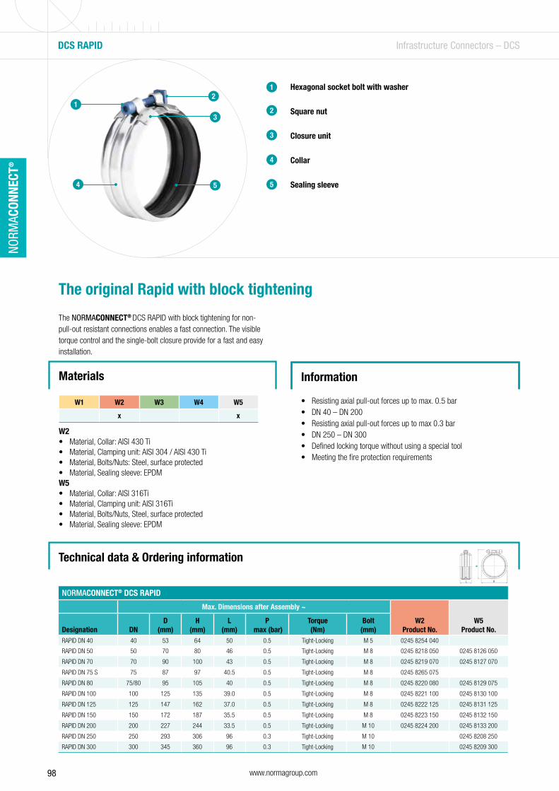
98 www.normagroup.com
NORM
ACON
NECT
®
DCS RAPID Infrastructure Connectors – DCS
Hexagonal socket bolt with washer
Square nut
Closure unit
Collar
Sealing sleeve
1
2
The original Rapid with block tightening
The NORMACONNECT® DCS RAPID with block tightening for non-pull-out resistant connections enables a fast connection. The visible torque control and the single-bolt closure provide for a fast and easy installation.
3
4
5
12
3
4 5
Technical data & Ordering information
NORMACONNECT® DCS RAPID
Max. Dimensions after Assembly ~
W2Product No.
W5Product No.Designation DN
D (mm)
H (mm)
L (mm)
P max (bar)
Torque (Nm)
Bolt (mm)
RAPID DN 40 40 53 64 50 0.5 Tight-Locking M 5 0245 8254 040
RAPID DN 50 50 70 80 46 0.5 Tight-Locking M 8 0245 8218 050 0245 8126 050
RAPID DN 70 70 90 100 43 0.5 Tight-Locking M 8 0245 8219 070 0245 8127 070
RAPID DN 75 S 75 87 97 40.5 0.5 Tight-Locking M 8 0245 8265 075
RAPID DN 80 75/80 95 105 40 0.5 Tight-Locking M 8 0245 8220 080 0245 8129 075
RAPID DN 100 100 125 135 39.0 0.5 Tight-Locking M 8 0245 8221 100 0245 8130 100
RAPID DN 125 125 147 162 37.0 0.5 Tight-Locking M 8 0245 8222 125 0245 8131 125
RAPID DN 150 150 172 187 35.5 0.5 Tight-Locking M 8 0245 8223 150 0245 8132 150
RAPID DN 200 200 227 244 33.5 0.5 Tight-Locking M 10 0245 8224 200 0245 8133 200
RAPID DN 250 250 293 306 96 0.3 Tight-Locking M 10 0245 8208 250
RAPID DN 300 300 345 360 96 0.3 Tight-Locking M 10 0245 8209 300
Materials Information
• Resisting axial pull-out forces up to max. 0.5 bar• DN 40 – DN 200• Resisting axial pull-out forces up to max 0.3 bar• DN 250 – DN 300• Defined locking torque without using a special tool• Meeting the fire protection requirements
W1 W2 W3 W4 W5
x x
W2 • Material, Collar: AISI 430 Ti• Material, Clamping unit: AISI 304 / AISI 430 Ti• Material, Bolts/Nuts: Steel, surface protected• Material, Sealing sleeve: EPDMW5• Material, Collar: AISI 316Ti• Material, Clamping unit: AISI 316Ti• Material, Bolts/Nuts, Steel, surface protected• Material, Sealing sleeve: EPDM
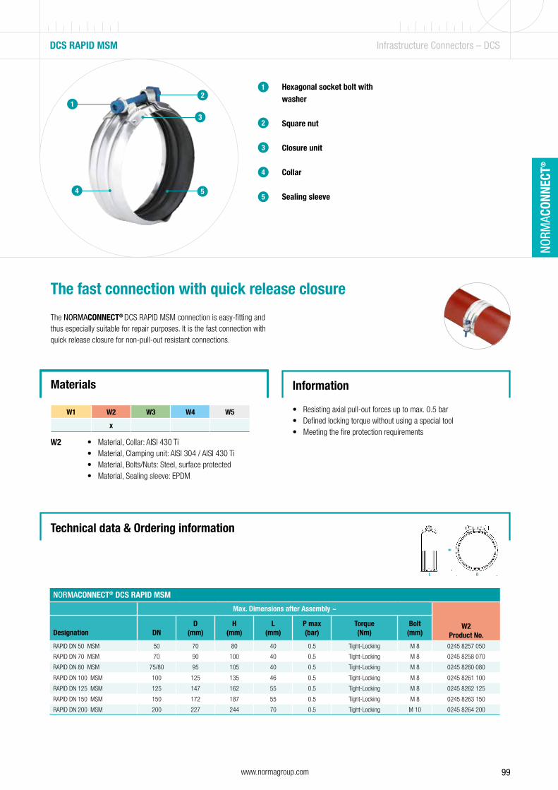
99www.normagroup.com
NORM
ACON
NECT
®
Materials
W2
DCS RAPID MSM Infrastructure Connectors – DCS
Hexagonal socket bolt with washer
Square nut
Closure unit
Collar
Sealing sleeve
1
2
The fast connection with quick release closure
The NORMACONNECT® DCS RAPID MSM connection is easy-fitting and thus especially suitable for repair purposes. It is the fast connection with quick release closure for non-pull-out resistant connections.
Information
• Resisting axial pull-out forces up to max. 0.5 bar• Defined locking torque without using a special tool• Meeting the fire protection requirements
3
4
5
Technical data & Ordering information
• Material, Collar: AISI 430 Ti• Material, Clamping unit: AISI 304 / AISI 430 Ti • Material, Bolts/Nuts: Steel, surface protected• Material, Sealing sleeve: EPDM
1
4
2
3
5
NORMACONNECT® DCS RAPID MSM
Max. Dimensions after Assembly ~
W2Product No.Designation DN
D (mm)
H(mm)
L(mm)
P max(bar)
Torque(Nm)
Bolt(mm)
RAPID DN 50 MSM 50 70 80 40 0.5 Tight-Locking M 8 0245 8257 050
RAPID DN 70 MSM 70 90 100 40 0.5 Tight-Locking M 8 0245 8258 070
RAPID DN 80 MSM 75/80 95 105 40 0.5 Tight-Locking M 8 0245 8260 080
RAPID DN 100 MSM 100 125 135 46 0.5 Tight-Locking M 8 0245 8261 100
RAPID DN 125 MSM 125 147 162 55 0.5 Tight-Locking M 8 0245 8262 125
RAPID DN 150 MSM 150 172 187 55 0.5 Tight-Locking M 8 0245 8263 150
RAPID DN 200 MSM 200 227 244 70 0.5 Tight-Locking M 10 0245 8264 200
W1 W2 W3 W4 W5
x
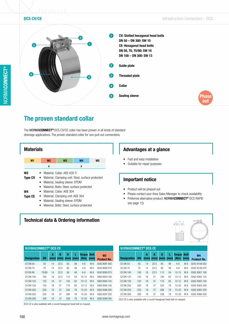
100 www.normagroup.com
NORM
ACON
NECT
®
Materials
W2Type CV
W4Type CE
DCS CV/CE Infrastructure Connectors – DCS
CV: Slotted hexagonal head boltsDN 50 – DN 300: SW 10 CE: Hexagonal head boltsDN 50, 70, 75/80: SW 10DN 100 – DN 300: SW 13
Guide plate
Threaded plate
Collar
Sealing sleeve
1
2
The proven standard collar
The NORMACONNECT® DCS CV/CE collar has been proven in all kinds of standard drainage applications. The proven standard collar for non-pull-out connections.
Advantages at a glance
• Fast and easy installation• Suitable for repair purposes
3
4
5
Technical data & Ordering information
• Material, Collar: AISI 430 Ti• Material, Clamping unit: Steel, surface protected• Material, Sealing sleeve: EPDM• Material, Bolts: Steel, surface protected• Material, Collar: AISI 304• Material, Clamping unit: AISI 304• Material, Sealing sleeve: EPDM• Material, Bolts: Steel, surface protected
12
3
45
DCS CE is also available with a round hexagonal head bolt on request.
NORMACONNECT® DCS CV
Designation DNA
(mm)B
(mm)D
(mm)L
(mm)Torque(Nm)
Bolt(mm)
W2Product No.
CV DN 50 50 14 22.5 65 48 4-6 M 6 0242 8091 050
CV DN 70 70 14 22.5 85 48 4-6 M 6 0242 8092 070
CV DN 80 75/80 14 22.5 90 48 6-8 M 6 0242 8093 075
CV DN 100 100 18 22.5 115 54 10-12 M 8 0262 8303 100
CV DN 125 125 18 31 140 65 10-12 M 8 0262 8304 125
CV DN 150 150 18 31 170 65 10-12 M 8 0262 8305 150
CV DN 200 200 18 37 220 78 15-20 M 8 0262 8306 200
CV DN 250 250 18 37 286 78 15-20 M 8 0262 8307 250
CV DN 300 300 18 37 338 78 15-20 M 8 0262 8308 300
NORMACONNECT® DCS CE
Designation DNA
(mm)B
(mm)D
(mm)L
(mm)Torque(Nm)
Bolt(mm)
W4Product No.
CE DN 50 50 14 22.5 65 48 4-6 M 6 0242 8108 050
CE DN 70 70 14 22.5 85 48 4-6 M 6 0242 8109 070
CE DN 100 100 18 22.5 115 54 10-12 M 8 0262 8361 100
CE DN 125 125 18 31 140 65 10-12 M 8 0262 8362 125
CE DN 150 150 18 31 170 65 10-12 M 8 0262 8363 150
CE DN 200 200 18 37 220 78 15-20 M 8 0262 8364 200
CE DN 250 250 18 37 286 78 15-20 M 8 0262 8365 250
CE DN 300 300 18 37 338 78 15-20 M 8 0262 8366 300
W1 W2 W3 W4 W5
x x
DCS CV is also available with a round hexagonal head bolt on request.
Important notice
• Product will be phased out• Please contact your Area Sales Manager to check availability• Preferred alternative product: NORMACONNECT® DCS RAPID
see page 15)
Phase out
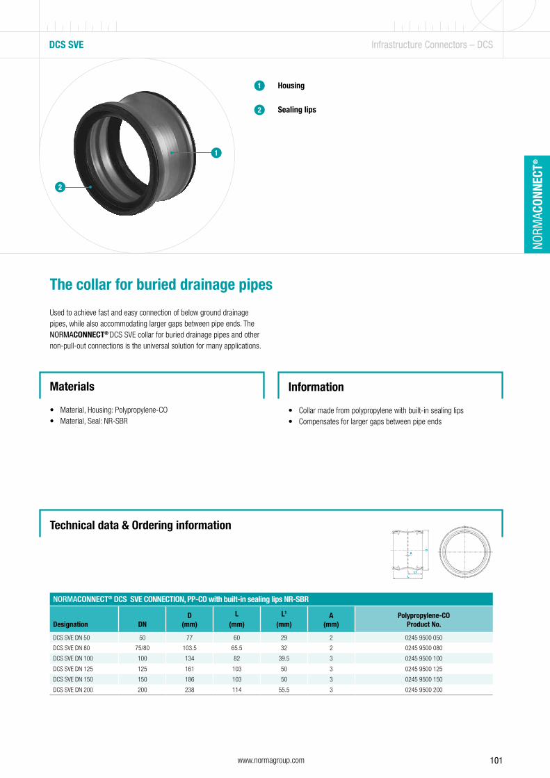
101www.normagroup.com
NORM
ACON
NECT
®
DCS SVE Infrastructure Connectors – DCS
Housing
Sealing lips
1
2
The collar for buried drainage pipes
Used to achieve fast and easy connection of below ground drainage pipes, while also accommodating larger gaps between pipe ends. The NORMACONNECT® DCS SVE collar for buried drainage pipes and other non-pull-out connections is the universal solution for many applications.
Information
• Collar made from polypropylene with built-in sealing lips• Compensates for larger gaps between pipe ends
Materials
• Material, Housing: Polypropylene-CO• Material, Seal: NR-SBR
1
2
NORMACONNECT® DCS SVE CONNECTION, PP-CO with built-in sealing lips NR-SBR
Designation DND
(mm)L
(mm)L1
(mm)A
(mm)Polypropylene-CO
Product No.
DCS SVE DN 50 50 77 60 29 2 0245 9500 050
DCS SVE DN 80 75/80 103.5 65.5 32 2 0245 9500 080
DCS SVE DN 100 100 134 82 39.5 3 0245 9500 100
DCS SVE DN 125 125 161 103 50 3 0245 9500 125
DCS SVE DN 150 150 186 103 50 3 0245 9500 150
DCS SVE DN 200 200 238 114 55.5 3 0245 9500 200
Technical data & Ordering information
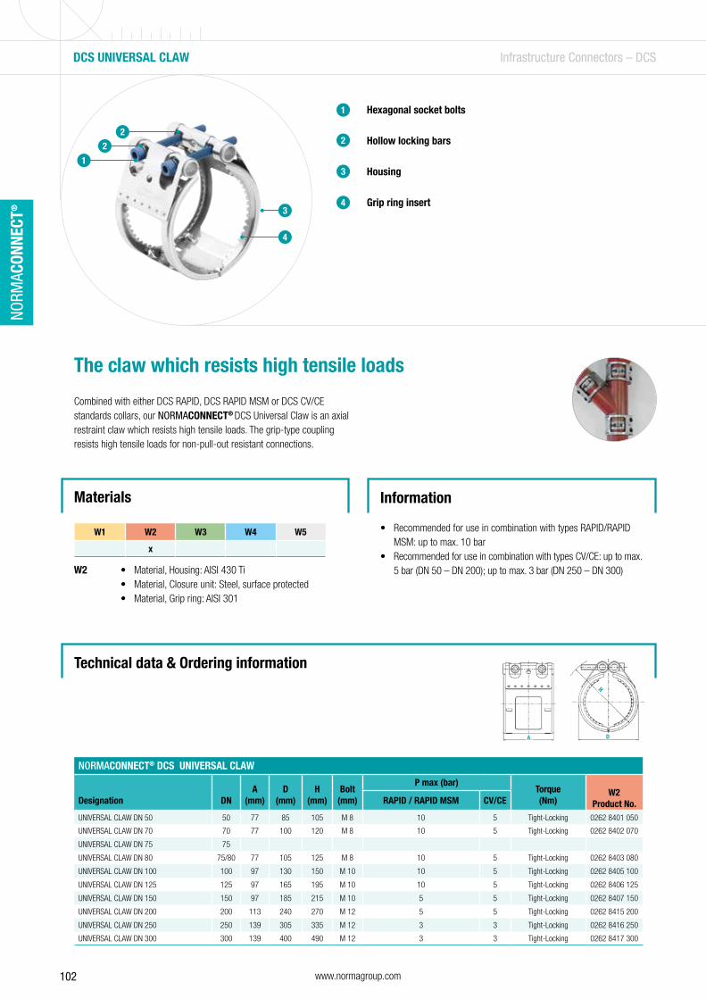
102 www.normagroup.com
NORM
ACON
NECT
®
Materials
W2
DCS UNIVERSAL CLAW Infrastructure Connectors – DCS
Hexagonal socket bolts
Hollow locking bars
Housing
Grip ring insert
1
2
The claw which resists high tensile loads
Combined with either DCS RAPID, DCS RAPID MSM or DCS CV/CE standards collars, our NORMACONNECT® DCS Universal Claw is an axial restraint claw which resists high tensile loads. The grip-type coupling resists high tensile loads for non-pull-out resistant connections.
Information
• Recommended for use in combination with types RAPID/RAPID MSM: up to max. 10 bar
• Recommended for use in combination with types CV/CE: up to max. 5 bar (DN 50 – DN 200); up to max. 3 bar (DN 250 – DN 300)
3
4
• Material, Housing: AISI 430 Ti• Material, Closure unit: Steel, surface protected• Material, Grip ring: AISI 301
1
2
2
3
4
NORMACONNECT® DCS UNIVERSAL CLAW
Designation DNA
(mm)D
(mm)H
(mm)Bolt
(mm)
P max (bar)Torque(Nm)
W2Product No.RAPID / RAPID MSM CV/CE
UNIVERSAL CLAW DN 50 50 77 85 105 M 8 10 5 Tight-Locking 0262 8401 050
UNIVERSAL CLAW DN 70 70 77 100 120 M 8 10 5 Tight-Locking 0262 8402 070
UNIVERSAL CLAW DN 75 75
UNIVERSAL CLAW DN 80 75/80 77 105 125 M 8 10 5 Tight-Locking 0262 8403 080
UNIVERSAL CLAW DN 100 100 97 130 150 M 10 10 5 Tight-Locking 0262 8405 100
UNIVERSAL CLAW DN 125 125 97 165 195 M 10 10 5 Tight-Locking 0262 8406 125
UNIVERSAL CLAW DN 150 150 97 185 215 M 10 5 5 Tight-Locking 0262 8407 150
UNIVERSAL CLAW DN 200 200 113 240 270 M 12 5 5 Tight-Locking 0262 8415 200
UNIVERSAL CLAW DN 250 250 139 305 335 M 12 3 3 Tight-Locking 0262 8416 250
UNIVERSAL CLAW DN 300 300 139 400 490 M 12 3 3 Tight-Locking 0262 8417 300
Technical data & Ordering information
W1 W2 W3 W4 W5
x
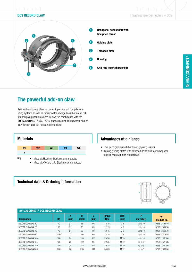
103www.normagroup.com
NORM
ACON
NECT
®
DCS RECORD CLAW Infrastructure Connectors – DCS
Hexagonal socket bolt with fine pitch thread
Guiding plate
Threaded plate
Housing
Grip ring insert (hardened)
1
2
The powerful add-on claw
Axial restraint safety claw for use with pressurized pump lines in lifting systems as well as for rainwater sewage lines that are at risk of undergoing back pressures, but only in combination with the NORMACONNECT® DCS RAPID standard collar. The powerful add-on claw for non-pull-out resistant connections.
Advantages at a glance
• Two parts (halves) with hardened grip ring inserts• Strong guiding plates with threaded holes plus four hexagonal
socket bolts with fine pitch thread
Materials
W1
3
4
5
• Material, Housing: Steel, surface protected• Material, Closure unit: Steel, surface protected
12
3
4
5
NORMACONNECT® DCS RECORD CLAW
Designation DNA
(mm)D
(mm)L
(mm)Torque(Nm)
Bolt(mm)
Pmax (bar)
W1Product No.
RECORD CLAW DN 40 40 21 65 66 12-15 M 8 up to 10 0262 1272 040
RECORD CLAW DN 50 50 21 75 69 12-15 M 8 up to 10 0262 1265 050
RECORD CLAW DN 70 70 21 95 69 12-15 M 8 up to 10 0262 1266 070
RECORD CLAW DN 80 75/80 21 100 69 12-15 M 8 up to 10 0262 1287 080
RECORD CLAW DN 100 100 25 135 87 25-30 M 10 up to 10 0262 1246 100
RECORD CLAW DN 125 125 25 160 95 30-35 M 10 up to 5 0262 1267 125
RECORD CLAW DN 150 150 25 185 95 30-35 M 10 up to 5 0262 1268 150
RECORD CLAW DN 200 200 30 235 111 60-65 M 12 up to 3 0262 1269 200
Technical data & Ordering information
W1 W2 W3 W4 W5
x

104 www.normagroup.com
NORM
ACON
NECT
®
DCS COMBI CLAW Infrastructure Connectors – DCS
Hexagonal socket bolts
Guiding side
Threaded side
Housing
Grip ring insert
1
2
The powerful add-on claw
Our NORMACONNECT® DCS Combi Claw is an axial restraint safety claw for connecting rainwater and sewage lines that are at risk of undergoing back pressures. It is used in combination with NORMACONNECT® RAPID/RAPID MSM and NORMACONNECT® CV or CE standard collars. The powerful add-on claw for non-pull-out resistant connections.
Information
• Axial restraint up to 10 bar• Diameters DN 50 up to DN 150
Materials
W1
3
4
5
• Material, Housing: Steel, surface protected• Material, Closure unit: Steel, surface protected
1
2
3
4
5
NORMACONNECT® DCS COMBI CLAW
Designation DNA
(mm)D
(mm)L
(mm)Torque(Nm)
Bolt(mm)
Pmax (bar)
W1Product No.
COMBI CLAW DN 50 50 22 81 72 18-20 M 8 up to 10 0262 8590 050
COMBI CLAW DN 70 70 22 102 72 18-20 M 8 up to 10 0262 8590 070
COMBI CLAW DN 80 80 22 110 72 18-20 M 8 up to 10 0262 8590 080
COMBI CLAW DN 100 100 22 136 82 28-30 M 10 up to 10 0262 8591 100
COMBI CLAW DN 125 125 23.5 162 93 28-30 M 10 up to 5 0262 8592 125
COMBI CLAW DN 150 150 23.5 189 93 33-35 M 10 up to 5 0262 8592 150
Technical data & Ordering information
W1 W2 W3 W4 W5
x
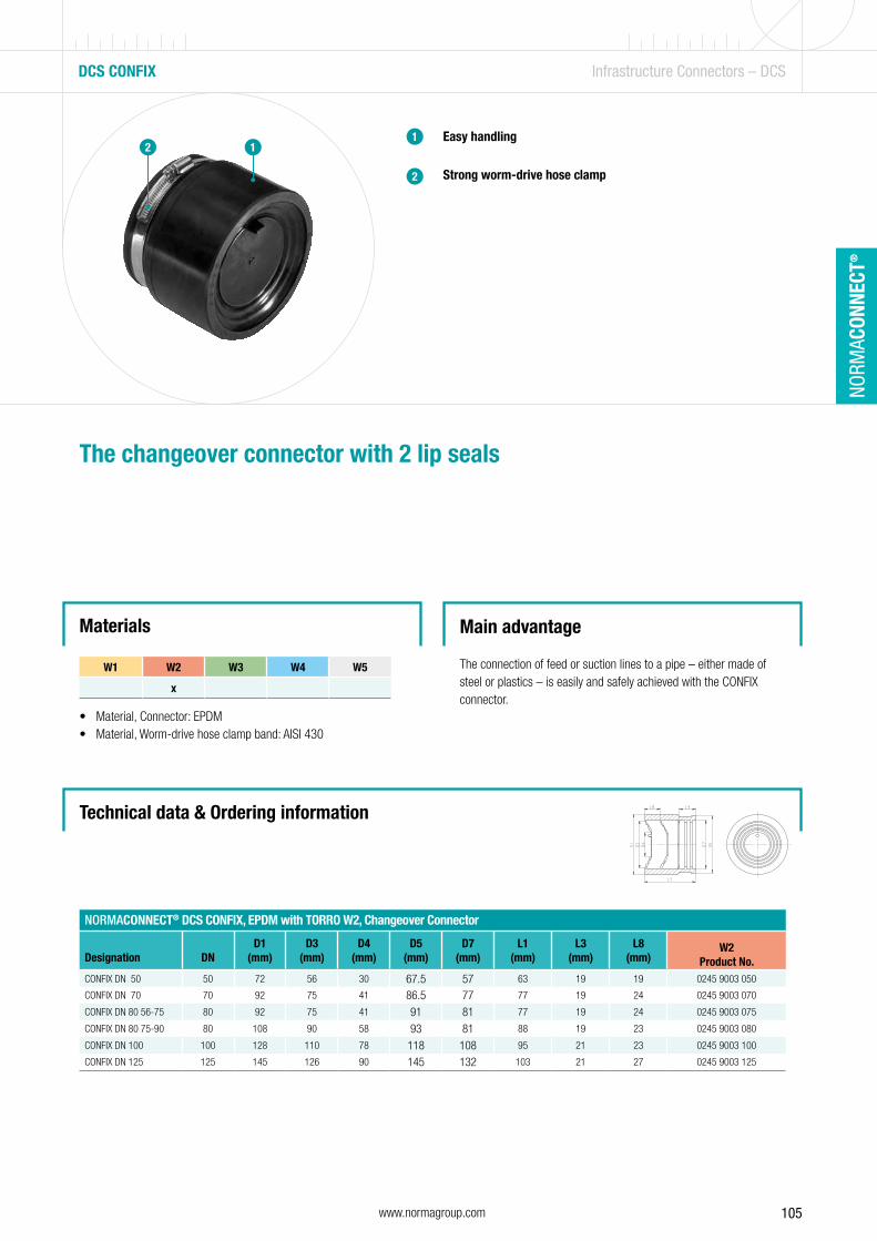
105www.normagroup.com
NORM
ACON
NECT
®
DCS CONFIX Infrastructure Connectors – DCS
Easy handling
Strong worm-drive hose clamp
The changeover connector with 2 lip seals
Main advantage
The connection of feed or suction lines to a pipe – either made of steel or plastics – is easily and safely achieved with the CONFIX connector.
Materials
• Material, Connector: EPDM• Material, Worm-drive hose clamp band: AISI 430
NORMACONNECT® DCS CONFIX, EPDM with TORRO W2, Changeover Connector
Designation DN D1
(mm)D3
(mm)D4
(mm)D5
(mm)D7
(mm)L1
(mm)L3
(mm)L8
(mm)W2
Product No.CONFIX DN 50 50 72 56 30 67.5 57 63 19 19 0245 9003 050
CONFIX DN 70 70 92 75 41 86.5 77 77 19 24 0245 9003 070
CONFIX DN 80 56-75 80 92 75 41 91 81 77 19 24 0245 9003 075
CONFIX DN 80 75-90 80 108 90 58 93 81 88 19 23 0245 9003 080
CONFIX DN 100 100 128 110 78 118 108 95 21 23 0245 9003 100
CONFIX DN 125 125 145 126 90 145 132 103 21 27 0245 9003 125
Technical data & Ordering information
1
2
12
W1 W2 W3 W4 W5
x

106 www.normagroup.com
NORM
ACON
NECT
®
DCS – SURVEY OF SIZES Infrastructure Connectors – DCS
Dimensions of pipes and fittings to EN 877
Outside Diameter (OD) Wall Thickness
DN Nominal value Tolerances Nominal value Minimum value
40 48+2-1
3.0 2.5
50 58+2-1
3.5 3.0
70 78+2-1
3.5 3.0
75/80 83+2-1
3.5 3.0
100 110+2-1
3.5 3.0
125 135+2-2
4.0 3.5
150 160+2-2
4.0 3.5
200 210+2.5-2.5
5.0 4.0
250 274+2.5-2.5
5.5 4.5
300 326+2.5-2.5
6.0 5.0
400 429+2-3
6.3 5.0
500 532+2-3,5
7.0 5.2
600 635+2-4
7.7 5.8
Dimensions of pipes and fittings to EN 877
Dimensions in mm
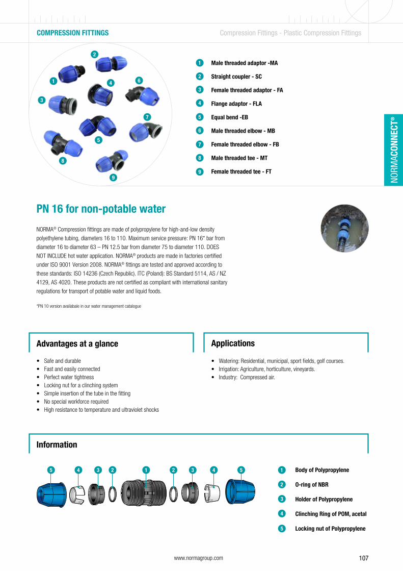
107www.normagroup.com
NORM
ACON
NECT
®
COMPRESSION FITTINGS Compression Fittings - Plastic Compression Fittings
PN 16 for non-potable water
NORMA® Compression fittings are made of polypropylene for high-and-low density
polyethylene tubing, diameters 16 to 110. Maximum service pressure: PN 16* bar from
diameter 16 to diameter 63 – PN 12.5 bar from diameter 75 to diameter 110. DOES
NOT INCLUDE hot water application. NORMA® products are made in factories certified
under ISO 9001 Version 2008. NORMA® fittings are tested and approved according to
these standards: ISO 14236 (Czech Republic). ITC (Poland): BS Standard 5114, AS / NZ
4129, AS 4020. These products are not certified as compliant with international sanitary
regulations for transport of potable water and liquid foods.
*PN 10 version availabale in our water management catalogue
Advantages at a glance
• Safe and durable• Fast and easily connected• Perfect water tightness• Locking nut for a clinching system• Simple insertion of the tube in the fitting• No special workforce required• High resistance to temperature and ultraviolet shocks
Applications
• Watering: Residential, municipal, sport fields, golf courses.• Irrigation: Agriculture, horticulture, vineyards.• Industry: Compressed air.
4
5
1
2
Body of Polypropylene
O-ring of NBR
Holder of Polypropylene
Clinching Ring of POM, acetal
Locking nut of Polypropylene
3
5 4 3 2 1 2 3 4 5
Male threaded adaptor -MA
Straight coupler - SC
Female threaded adaptor - FA
Flange adaptor - FLA
Equal bend -EB
Male threaded elbow - MB
Female threaded elbow - FB
Male threaded tee - MT
Female threaded tee - FT
1
2
3
4
5
6
7
8
9
Information
2
1
3
4
5
6
7
8
9
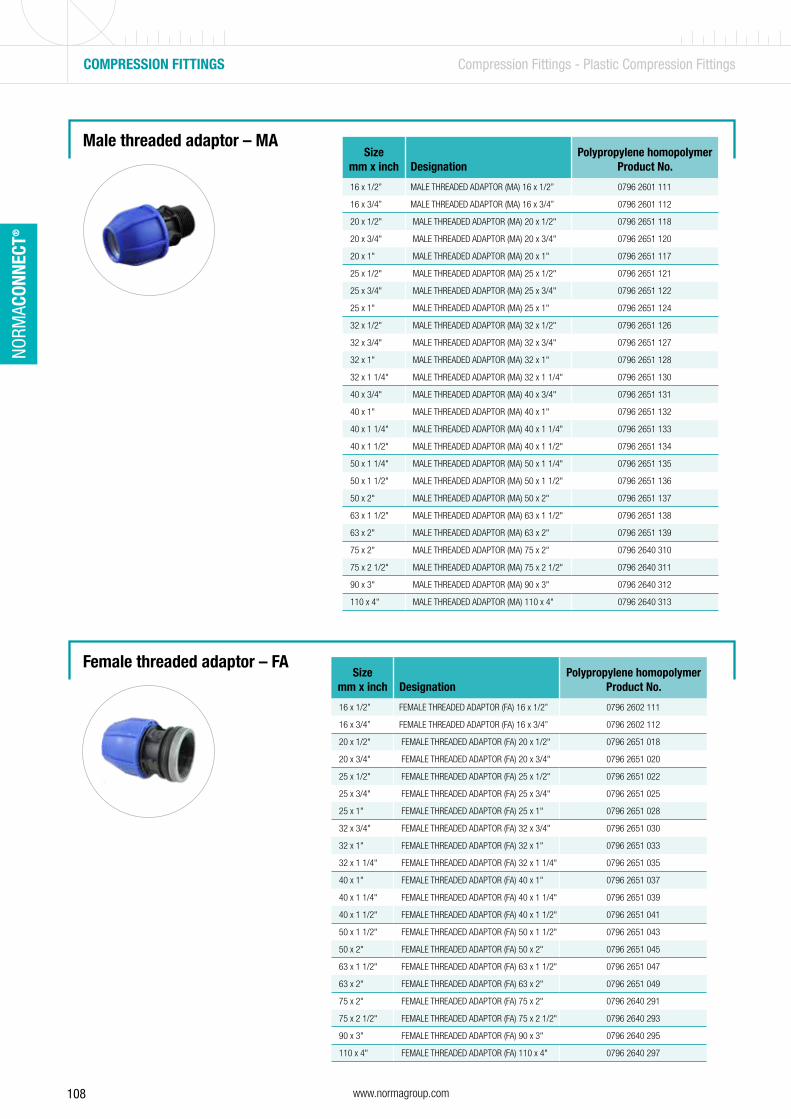
108 www.normagroup.com
NORM
ACON
NECT
®
COMPRESSION FITTINGS Compression Fittings - Plastic Compression Fittings
Male threaded adaptor – MA
Female threaded adaptor – FA
Sizemm x inch Designation
Polypropylene homopolymerProduct No.
16 x 1/2” MALE THREADED ADAPTOR (MA) 16 x 1/2” 0796 2601 111
16 x 3/4” MALE THREADED ADAPTOR (MA) 16 x 3/4” 0796 2601 112
20 x 1/2" MALE THREADED ADAPTOR (MA) 20 x 1/2" 0796 2651 118
20 x 3/4" MALE THREADED ADAPTOR (MA) 20 x 3/4" 0796 2651 120
20 x 1" MALE THREADED ADAPTOR (MA) 20 x 1" 0796 2651 117
25 x 1/2" MALE THREADED ADAPTOR (MA) 25 x 1/2" 0796 2651 121
25 x 3/4" MALE THREADED ADAPTOR (MA) 25 x 3/4" 0796 2651 122
25 x 1" MALE THREADED ADAPTOR (MA) 25 x 1" 0796 2651 124
32 x 1/2" MALE THREADED ADAPTOR (MA) 32 x 1/2" 0796 2651 126
32 x 3/4" MALE THREADED ADAPTOR (MA) 32 x 3/4" 0796 2651 127
32 x 1" MALE THREADED ADAPTOR (MA) 32 x 1" 0796 2651 128
32 x 1 1/4" MALE THREADED ADAPTOR (MA) 32 x 1 1/4" 0796 2651 130
40 x 3/4" MALE THREADED ADAPTOR (MA) 40 x 3/4" 0796 2651 131
40 x 1" MALE THREADED ADAPTOR (MA) 40 x 1" 0796 2651 132
40 x 1 1/4" MALE THREADED ADAPTOR (MA) 40 x 1 1/4" 0796 2651 133
40 x 1 1/2" MALE THREADED ADAPTOR (MA) 40 x 1 1/2" 0796 2651 134
50 x 1 1/4" MALE THREADED ADAPTOR (MA) 50 x 1 1/4" 0796 2651 135
50 x 1 1/2" MALE THREADED ADAPTOR (MA) 50 x 1 1/2" 0796 2651 136
50 x 2" MALE THREADED ADAPTOR (MA) 50 x 2" 0796 2651 137
63 x 1 1/2" MALE THREADED ADAPTOR (MA) 63 x 1 1/2" 0796 2651 138
63 x 2" MALE THREADED ADAPTOR (MA) 63 x 2" 0796 2651 139
75 x 2" MALE THREADED ADAPTOR (MA) 75 x 2" 0796 2640 310
75 x 2 1/2" MALE THREADED ADAPTOR (MA) 75 x 2 1/2" 0796 2640 311
90 x 3" MALE THREADED ADAPTOR (MA) 90 x 3" 0796 2640 312
110 x 4" MALE THREADED ADAPTOR (MA) 110 x 4" 0796 2640 313
Sizemm x inch Designation
Polypropylene homopolymerProduct No.
16 x 1/2” FEMALE THREADED ADAPTOR (FA) 16 x 1/2” 0796 2602 111
16 x 3/4” FEMALE THREADED ADAPTOR (FA) 16 x 3/4” 0796 2602 112
20 x 1/2" FEMALE THREADED ADAPTOR (FA) 20 x 1/2" 0796 2651 018
20 x 3/4" FEMALE THREADED ADAPTOR (FA) 20 x 3/4" 0796 2651 020
25 x 1/2" FEMALE THREADED ADAPTOR (FA) 25 x 1/2" 0796 2651 022
25 x 3/4" FEMALE THREADED ADAPTOR (FA) 25 x 3/4" 0796 2651 025
25 x 1" FEMALE THREADED ADAPTOR (FA) 25 x 1" 0796 2651 028
32 x 3/4" FEMALE THREADED ADAPTOR (FA) 32 x 3/4" 0796 2651 030
32 x 1" FEMALE THREADED ADAPTOR (FA) 32 x 1" 0796 2651 033
32 x 1 1/4" FEMALE THREADED ADAPTOR (FA) 32 x 1 1/4" 0796 2651 035
40 x 1" FEMALE THREADED ADAPTOR (FA) 40 x 1" 0796 2651 037
40 x 1 1/4" FEMALE THREADED ADAPTOR (FA) 40 x 1 1/4" 0796 2651 039
40 x 1 1/2" FEMALE THREADED ADAPTOR (FA) 40 x 1 1/2" 0796 2651 041
50 x 1 1/2" FEMALE THREADED ADAPTOR (FA) 50 x 1 1/2" 0796 2651 043
50 x 2" FEMALE THREADED ADAPTOR (FA) 50 x 2" 0796 2651 045
63 x 1 1/2" FEMALE THREADED ADAPTOR (FA) 63 x 1 1/2" 0796 2651 047
63 x 2" FEMALE THREADED ADAPTOR (FA) 63 x 2" 0796 2651 049
75 x 2" FEMALE THREADED ADAPTOR (FA) 75 x 2" 0796 2640 291
75 x 2 1/2" FEMALE THREADED ADAPTOR (FA) 75 x 2 1/2" 0796 2640 293
90 x 3" FEMALE THREADED ADAPTOR (FA) 90 x 3" 0796 2640 295
110 x 4" FEMALE THREADED ADAPTOR (FA) 110 x 4" 0796 2640 297

109www.normagroup.com
NORM
ACON
NECT
®
Female threaded tee – FT
COMPRESSION FITTINGS Compression Fittings - Plastic Compression Fittings
Male threaded tee – MT Sizemm x inch Designation
Polypropylene homopolymerProduct No.
16 x 1/2” MALE THREADED TEE (MT) 16 x 1/2” 0796 2603 111
16 x 3/4” MALE THREADED TEE (MT) 16 x 3/4” 0796 2603 112
20 x 1/2" MALE THREADED TEE (MT) 20 x 1/2" 0796 2651 154
20 x 3/4" MALE THREADED TEE (MT) 20 x 3/4" 0796 2651 155
25 x 1/2" MALE THREADED TEE (MT) 25 x 1/2" 0796 2651 156
25 x 3/4" MALE THREADED TEE (MT) 25 x 3/4" 0796 2651 157
25 x 1" MALE THREADED TEE (MT) 25 x 1" 0796 2651 158
32 x 3/4" MALE THREADED TEE (MT) 32 x 3/4" 0796 2651 159
32 x 1" MALE THREADED TEE (MT) 32 x 1" 0796 2651 160
40 x 1" MALE THREADED TEE (MT) 40 x 1" 0796 2651 161
40 x 1 1/4" MALE THREADED TEE (MT) 40 x 1 1/4" 0796 2651 162
50 x 1 1/4" MALE THREADED TEE (MT) 50 x 1 1/4" 0796 2651 163
50 x 1 1/2" MALE THREADED TEE (MT) 50 x 1 1/2" 0796 2651 164
63 x 2" MALE THREADED TEE (MT) 63 x 2" 0796 2651 165
75 x 2" MALE THREADED TEE (MT) 75 x 2" 0796 2640 318
75 x 2 1/2" MALE THREADED TEE (MT) 75 x 2 1/2" 0796 2640 319
90 x 3" MALE THREADED TEE (MT) 90 x 3" 0796 2640 320
110 x 4" MALE THREADED TEE (MT) 110 x 4" 0796 2640 321
Sizemm x inch Designation
Polypropylene homopolymerProduct No.
16 x 1/2” FEMALE THREADED TEE (FT) 16 x 1/2” 0796 2604 111
16 x 3/4” FEMALE THREADED TEE (FT) 16 x 3/4” 0796 2604 112
20 x 1/2" FEMALE THREADED TEE (FT) 20 x 1/2" 0796 2651 088
20 x 3/4" FEMALE THREADED TEE (FT) 20 x 3/4" 0796 2651 090
25 x 1/2" FEMALE THREADED TEE (FT) 25 x 1/2" 0796 2651 092
25 x 3/4" FEMALE THREADED TEE (FT) 25 x 3/4" 0796 2651 094
25 x 1" FEMALE THREADED TEE (FT) 25 x 1" 0796 2651 096
32 x 3/4" FEMALE THREADED TEE (FT) 32 x 3/4" 0796 2651 098
32 x 1" FEMALE THREADED TEE (FT) 32 x 1" 0796 2651 100
32 x 1 1/4" FEMALE THREADED TEE (FT) 32 x 1 1/4" 0796 2651 102
40 x 1" FEMALE THREADED TEE (FT) 40 x 1" 0796 2651 104
40 x 1 1/4" FEMALE THREADED TEE (FT) 40 x 1 1/4" 0796 2651 106
40 x 1 1/2" FEMALE THREADED TEE (FT) 40 x 1 1/2" 0796 2651 108
50 x 1 1/2" FEMALE THREADED TEE (FT) 50 x 1 1/2" 0796 2651 110
50 x 2" FEMALE THREADED TEE (FT) 50 x 2" 0796 2651 112
63 x 1 1/2" FEMALE THREADED TEE (FT) 63 x 1 1/2" 0796 2651 114
63 x 2" FEMALE THREADED TEE (FT) 63 x 2" 0796 2651 116
75 x 2 1/2" FEMALE THREADED TEE (FT) 75 x 2 1/2" 0796 2640 305
90 x 3" FEMALE THREADED TEE (FT) 90 x 3" 0796 2640 307
110 x 4" FEMALE THREADED TEE (FT) 110 x 4" 0796 2640 309
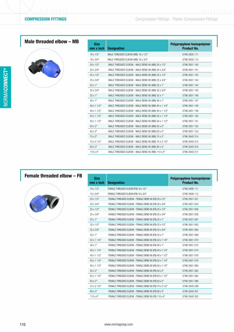
110 www.normagroup.com
NORM
ACON
NECT
®
Male threaded elbow – MB
Female threaded elbow – FB
Sizemm x inch Designation
Polypropylene homopolymerProduct No.
16 x 1/2” MALE THREADED ELBOW (MB) 16 x 1/2” 0796 2605 111
16 x 3/4” MALE THREADED ELBOW (MB) 16 x 3/4” 0796 2605 112
20 x 1/2" MALE THREADED ELBOW - MALE BEND 90 (MB) 20 x 1/2" 0796 2651 140
20 x 3/4" MALE THREADED ELBOW - MALE BEND 90 (MB) 20 x 3/4" 0796 2651 141
25 x 1/2" MALE THREADED ELBOW - MALE BEND 90 (MB) 25 x 1/2" 0796 2651 142
25 x 3/4" MALE THREADED ELBOW - MALE BEND 90 (MB) 25 x 3/4" 0796 2651 143
25 x 1" MALE THREADED ELBOW - MALE BEND 90 (MB) 25 x 1" 0796 2651 144
32 x 3/4" MALE THREADED ELBOW - MALE BEND 90 (MB) 32 x 3/4" 0796 2651 145
32 x 1" MALE THREADED ELBOW - MALE BEND 90 (MB) 32 x 1" 0796 2651 146
40 x 1" MALE THREADED ELBOW - MALE BEND 90 (MB) 40 x 1" 0796 2651 147
40 x 1 1/4" MALE THREADED ELBOW - MALE BEND 90 (MB) 40 x 1 1/4" 0796 2651 148
40 x 1 1/2" MALE THREADED ELBOW - MALE BEND 90 (MB) 40 x 1 1/2" 0796 2651 149
50 x 1 1/4" MALE THREADED ELBOW - MALE BEND 90 (MB) 50 x 1 1/4" 0796 2651 150
50 x 1 1/2" MALE THREADED ELBOW - MALE BEND 90 (MB) 50 x 1 1/2" 0796 2651 151
50 x 2" MALE THREADED ELBOW - MALE BEND 90 (MB) 63 x 2" 0796 2651 152
63 x 2" MALE THREADED ELBOW - MALE BEND 90 (MB) 63 x 2" 0796 2651 153
75 x 2" MALE THREADED ELBOW - MALE BEND 90 (MB) 75 x 2" 0796 2640 314
75 x 2 1/2" MALE THREADED ELBOW - MALE BEND 90 (MB) 75 x 2 1/2" 0796 2640 315
90 x 3" MALE THREADED ELBOW - MALE BEND 90 (MB) 90 x 3" 0796 2640 316
110 x 4" MALE THREADED ELBOW - MALE BEND 90 (MB) 110 x 4" 0796 2640 317
Sizemm x inch Designation
Polypropylene homopolymerProduct No.
16 x 1/2” FEMALE THREADED ELBOW (FB) 16 x 1/2” 0796 2606 111
16 x 3/4” FEMALE THREADED ELBOW (FB) 16 x 3/4” 0796 2606 112
20 x 1/2" FEMALE THREADED ELBOW - FEMALE BEND 90 (FB) 20 x 1/2" 0796 2651 051
20 x 3/4" FEMALE THREADED ELBOW - FEMALE BEND 90 (FB) 20 x 3/4" 0796 2651 054
25 x 1/2" FEMALE THREADED ELBOW - FEMALE BEND 90 (FB) 25 x 1/2" 0796 2651 056
25 x 3/4" FEMALE THREADED ELBOW - FEMALE BEND 90 (FB) 25 x 3/4" 0796 2651 059
25 x 1" FEMALE THREADED ELBOW - FEMALE BEND 90 (FB) 25 x 1" 0796 2651 061
32 x 1/2" FEMALE THREADED ELBOW - FEMALE BEND 90 (FB) 32 x 1/2" 0796 2651 063
32 x 3/4" FEMALE THREADED ELBOW - FEMALE BEND 90 (FB) 32 x 3/4" 0796 2651 065
32 x 1" FEMALE THREADED ELBOW - FEMALE BEND 90 (FB) 32 x 1" 0796 2651 068
32 x 1 1/4" FEMALE THREADED ELBOW - FEMALE BEND 90 (FB) 32 x 1 1/4" 0796 2651 070
40 x 1" FEMALE THREADED ELBOW - FEMALE BEND 90 (FB) 40 x 1" 0796 2651 072
40 x 1 1/4" FEMALE THREADED ELBOW - FEMALE BEND 90 (FB) 40 x 1 1/4" 0796 2651 074
40 x 1 1/2" FEMALE THREADED ELBOW - FEMALE BEND 90 (FB) 40 x 1 1/2" 0796 2651 076
50 x 1 1/4" FEMALE THREADED ELBOW - FEMALE BEND 90 (FB) 50 x 1 1/4" 0796 2651 078
50 x 1 1/2" FEMALE THREADED ELBOW - FEMALE BEND 90 (FB) 50 x 1 1/2" 0796 2651 080
50 x 2" FEMALE THREADED ELBOW - FEMALE BEND 90 (FB) 50 x 2" 0796 2651 082
63 x 1 1/2" FEMALE THREADED ELBOW - FEMALE BEND 90 (FB) 63 x 1 1/2" 0796 2651 084
63 x 2" FEMALE THREADED ELBOW - FEMALE BEND 90 (FB) 63 x 2" 0796 2651 086
75 x 2 1/2" FEMALE THREADED ELBOW - FEMALE BEND 90 (FB) 75 x 2 1/2" 0796 2640 299
90 x 3" FEMALE THREADED ELBOW - FEMALE BEND 90 (FB) 90 x 3" 0796 2640 301
110 x 4" FEMALE THREADED ELBOW - FEMALE BEND 90 (FB) 110 x 4" 0796 2640 303
COMPRESSION FITTINGS Compression Fittings - Plastic Compression Fittings
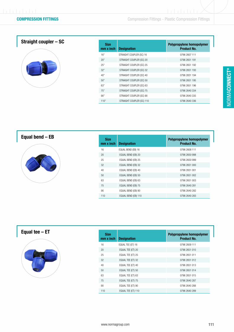
111www.normagroup.com
NORM
ACON
NECT
®
Straight coupler – SC
Equal bend – EB
Equal tee – ET
Sizemm x inch Designation
Polypropylene homopolymerProduct No.
16” STRAIGHT COUPLER (SC) 16 0796 2607 111
20” STRAIGHT COUPLER (SC) 20 0796 2651 191
25” STRAIGHT COUPLER (SC) 25 0796 2651 192
32” STRAIGHT COUPLER (SC) 32 0796 2651 193
40” STRAIGHT COUPLER (SC) 40 0796 2651 194
50” STRAIGHT COUPLER (SC) 50 0796 2651 195
63” STRAIGHT COUPLER (SC) 63 0796 2651 196
75” STRAIGHT COUPLER (SC) 75 0796 2640 334
90” STRAIGHT COUPLER (SC) 90 0796 2640 335
110” STRAIGHT COUPLER (SC) 110 0796 2640 336
Sizemm x inch Designation
Polypropylene homopolymerProduct No.
16 EQUAL BEND (EB) 16 0796 2608 111
20 EQUAL BEND (EB) 20 0796 2650 998
25 EQUAL BEND (EB) 25 0796 2650 999
32 EQUAL BEND (EB) 32 0796 2651 000
40 EQUAL BEND (EB) 40 0796 2651 001
50 EQUAL BEND (EB) 50 0796 2651 002
63 EQUAL BEND (EB) 63 0796 2651 003
75 EQUAL BEND (EB) 75 0796 2640 281
90 EQUAL BEND (EB) 90 0796 2640 282
110 EQUAL BEND (EB) 110 0796 2640 283
Sizemm x inch Designation
Polypropylene homopolymerProduct No.
16 EQUAL TEE (ET) 16 0796 2609 111
20 EQUAL TEE (ET) 20 0796 2651 010
25 EQUAL TEE (ET) 25 0796 2651 011
32 EQUAL TEE (ET) 32 0796 2651 012
40 EQUAL TEE (ET) 40 0796 2651 013
50 EQUAL TEE (ET) 50 0796 2651 014
63 EQUAL TEE (ET) 63 0796 2651 015
75 EQUAL TEE (ET) 75 0796 2640 287
90 EQUAL TEE (ET) 90 0796 2640 288
110 EQUAL TEE (ET) 110 0796 2640 289
COMPRESSION FITTINGS Compression Fittings - Plastic Compression Fittings
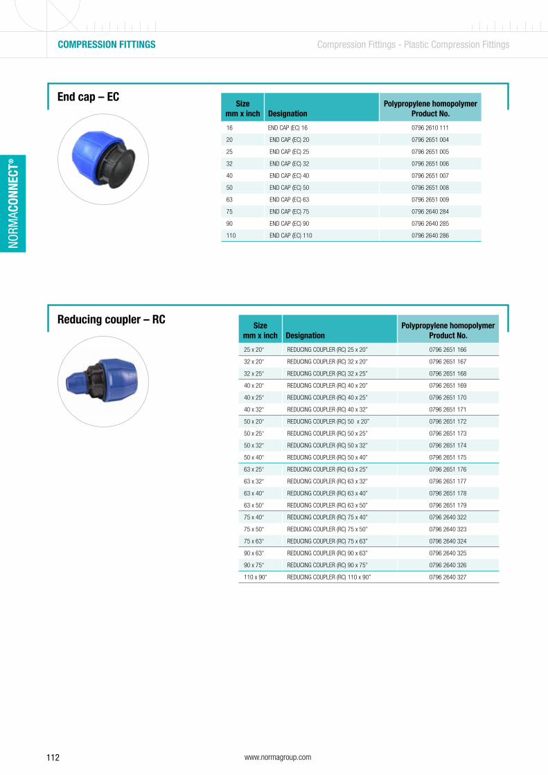
112 www.normagroup.com
NORM
ACON
NECT
®
Reducing coupler – RC
End cap – ECSize
mm x inch DesignationPolypropylene homopolymer
Product No.
16 END CAP (EC) 16 0796 2610 111
20 END CAP (EC) 20 0796 2651 004
25 END CAP (EC) 25 0796 2651 005
32 END CAP (EC) 32 0796 2651 006
40 END CAP (EC) 40 0796 2651 007
50 END CAP (EC) 50 0796 2651 008
63 END CAP (EC) 63 0796 2651 009
75 END CAP (EC) 75 0796 2640 284
90 END CAP (EC) 90 0796 2640 285
110 END CAP (EC) 110 0796 2640 286
Sizemm x inch Designation
Polypropylene homopolymerProduct No.
25 x 20” REDUCING COUPLER (RC) 25 x 20” 0796 2651 166
32 x 20” REDUCING COUPLER (RC) 32 x 20” 0796 2651 167
32 x 25” REDUCING COUPLER (RC) 32 x 25” 0796 2651 168
40 x 20” REDUCING COUPLER (RC) 40 x 20” 0796 2651 169
40 x 25” REDUCING COUPLER (RC) 40 x 25” 0796 2651 170
40 x 32” REDUCING COUPLER (RC) 40 x 32” 0796 2651 171
50 x 20” REDUCING COUPLER (RC) 50 x 20” 0796 2651 172
50 x 25” REDUCING COUPLER (RC) 50 x 25” 0796 2651 173
50 x 32” REDUCING COUPLER (RC) 50 x 32” 0796 2651 174
50 x 40” REDUCING COUPLER (RC) 50 x 40” 0796 2651 175
63 x 25” REDUCING COUPLER (RC) 63 x 25” 0796 2651 176
63 x 32” REDUCING COUPLER (RC) 63 x 32” 0796 2651 177
63 x 40” REDUCING COUPLER (RC) 63 x 40” 0796 2651 178
63 x 50” REDUCING COUPLER (RC) 63 x 50” 0796 2651 179
75 x 40” REDUCING COUPLER (RC) 75 x 40” 0796 2640 322
75 x 50” REDUCING COUPLER (RC) 75 x 50” 0796 2640 323
75 x 63” REDUCING COUPLER (RC) 75 x 63” 0796 2640 324
90 x 63” REDUCING COUPLER (RC) 90 x 63” 0796 2640 325
90 x 75” REDUCING COUPLER (RC) 90 x 75” 0796 2640 326
110 x 90” REDUCING COUPLER (RC) 110 x 90” 0796 2640 327
COMPRESSION FITTINGS Compression Fittings - Plastic Compression Fittings
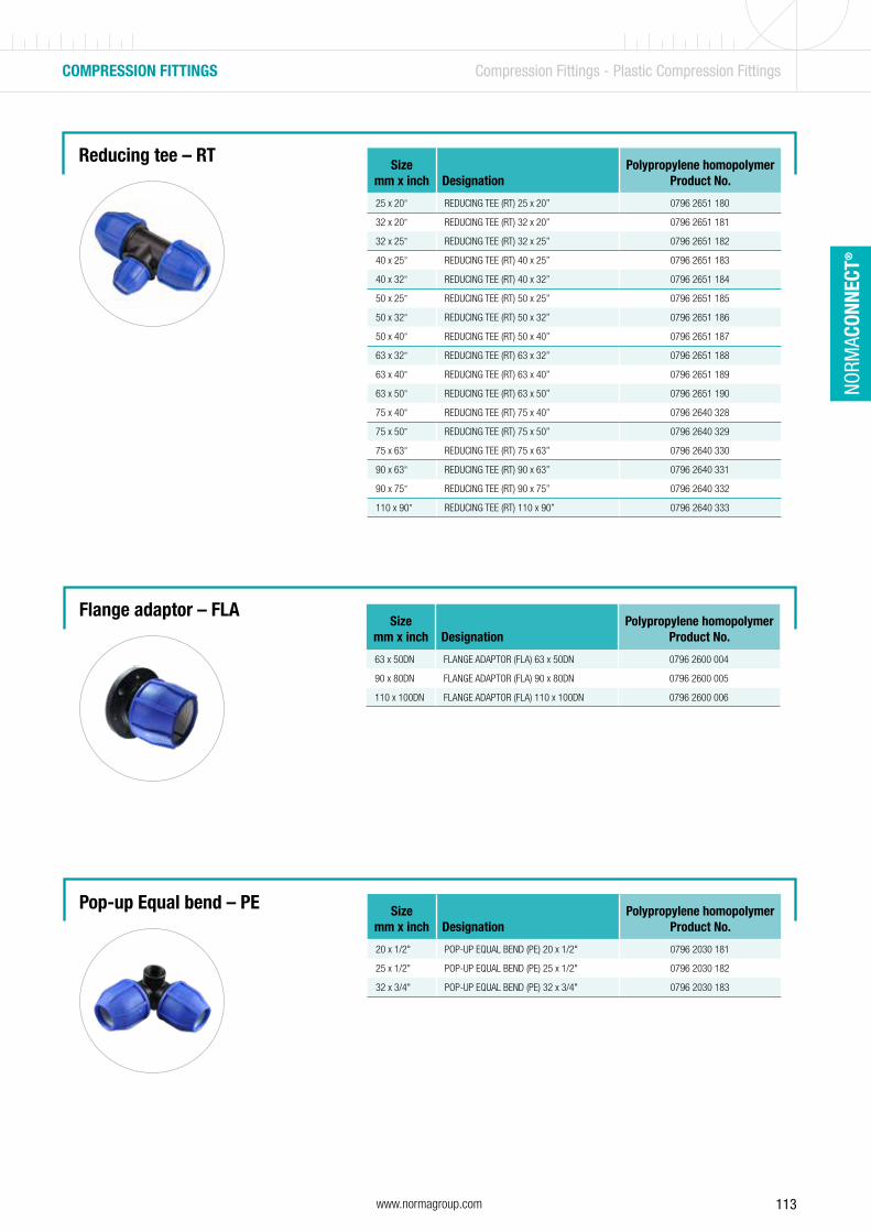
113www.normagroup.com
NORM
ACON
NECT
®
Flange adaptor – FLA
Pop-up Equal bend – PE Sizemm x inch Designation
Polypropylene homopolymerProduct No.
20 x 1/2" POP-UP EQUAL BEND (PE) 20 x 1/2" 0796 2030 181
25 x 1/2" POP-UP EQUAL BEND (PE) 25 x 1/2" 0796 2030 182
32 x 3/4" POP-UP EQUAL BEND (PE) 32 x 3/4" 0796 2030 183
Reducing tee – RTSize
mm x inch DesignationPolypropylene homopolymer
Product No.
25 x 20” REDUCING TEE (RT) 25 x 20” 0796 2651 180
32 x 20” REDUCING TEE (RT) 32 x 20” 0796 2651 181
32 x 25” REDUCING TEE (RT) 32 x 25” 0796 2651 182
40 x 25” REDUCING TEE (RT) 40 x 25” 0796 2651 183
40 x 32” REDUCING TEE (RT) 40 x 32” 0796 2651 184
50 x 25” REDUCING TEE (RT) 50 x 25” 0796 2651 185
50 x 32” REDUCING TEE (RT) 50 x 32” 0796 2651 186
50 x 40” REDUCING TEE (RT) 50 x 40” 0796 2651 187
63 x 32” REDUCING TEE (RT) 63 x 32” 0796 2651 188
63 x 40” REDUCING TEE (RT) 63 x 40” 0796 2651 189
63 x 50” REDUCING TEE (RT) 63 x 50” 0796 2651 190
75 x 40” REDUCING TEE (RT) 75 x 40” 0796 2640 328
75 x 50” REDUCING TEE (RT) 75 x 50” 0796 2640 329
75 x 63” REDUCING TEE (RT) 75 x 63” 0796 2640 330
90 x 63” REDUCING TEE (RT) 90 x 63” 0796 2640 331
90 x 75” REDUCING TEE (RT) 90 x 75” 0796 2640 332
110 x 90” REDUCING TEE (RT) 110 x 90” 0796 2640 333
Sizemm x inch Designation
Polypropylene homopolymerProduct No.
63 x 50DN FLANGE ADAPTOR (FLA) 63 x 50DN 0796 2600 004
90 x 80DN FLANGE ADAPTOR (FLA) 90 x 80DN 0796 2600 005
110 x 100DN FLANGE ADAPTOR (FLA) 110 x 100DN 0796 2600 006
COMPRESSION FITTINGS Compression Fittings - Plastic Compression Fittings

114 www.normagroup.com
NORM
ACON
NECT
®
Wall plate elbow – WPE
Male threaded adaptor with brass insert – MAB
Female threaded adaptor with brass insert – FAB
Female threaded bend with brass insert – FBB
Sizemm x inch Designation
Polypropylene homopolymerProduct No.
25 x 3/4" WALL PLATE ELBOW (WPE) 25 x 3/4" 0796 2030 360
Sizemm x inch Designation
Polypropylene homopolymerProduct No.
20 x 1/2" MALE THREADED ADAPTOR WITH BRASS INSERT (MAB) 20 x 1/2" 0796 2651 119
25 x 3/4" MALE THREADED ADAPTOR WITH BRASS INSERT (MAB) 25 x 3/4" 0796 2651 123
25 x 1" MALE THREADED ADAPTOR WITH BRASS INSERT (MAB) 25 x 1" 0796 2651 125
32 x 1" MALE THREADED ADAPTOR WITH BRASS INSERT (MAB) 32 x 1" 0796 2651 129
Sizemm x inch Designation
Polypropylene homopolymerProduct No.
20 x 1/2" FEMALE THREADED ADAPTOR WITH BRASS INSERT (FAB) 20 x 1/2" 0796 2651 017
25 x 3/4" FEMALE THREADED ADAPTOR WITH BRASS INSERT (FAB) 25 x 3/4" 0796 2651 024
25 x 1" FEMALE THREADED ADAPTOR WITH BRASS INSERT (FAB) 25 x 1" 0796 2651 027
32 x 1" FEMALE THREADED ADAPTOR WITH BRASS INSERT (FAB) 32 x 1" 0796 2651 032
Sizemm x inch Designation
Polypropylene homopolymerProduct No.
20 x 3/4" FEMALE THREADED BEND WITH BRASS INSERT (FBB) 20 x 3/4" 0796 2651 053
25 x 3/4" FEMALE THREADED BEND WITH BRASS INSERT (FBB) 25 x 3/4" 0796 2651 058
32 x 1" FEMALE THREADED BEND WITH BRASS INSERT (FBB) 32 x 1" 0796 2651 067
COMPRESSION FITTINGS Compression Fittings - Plastic Compression Fittings
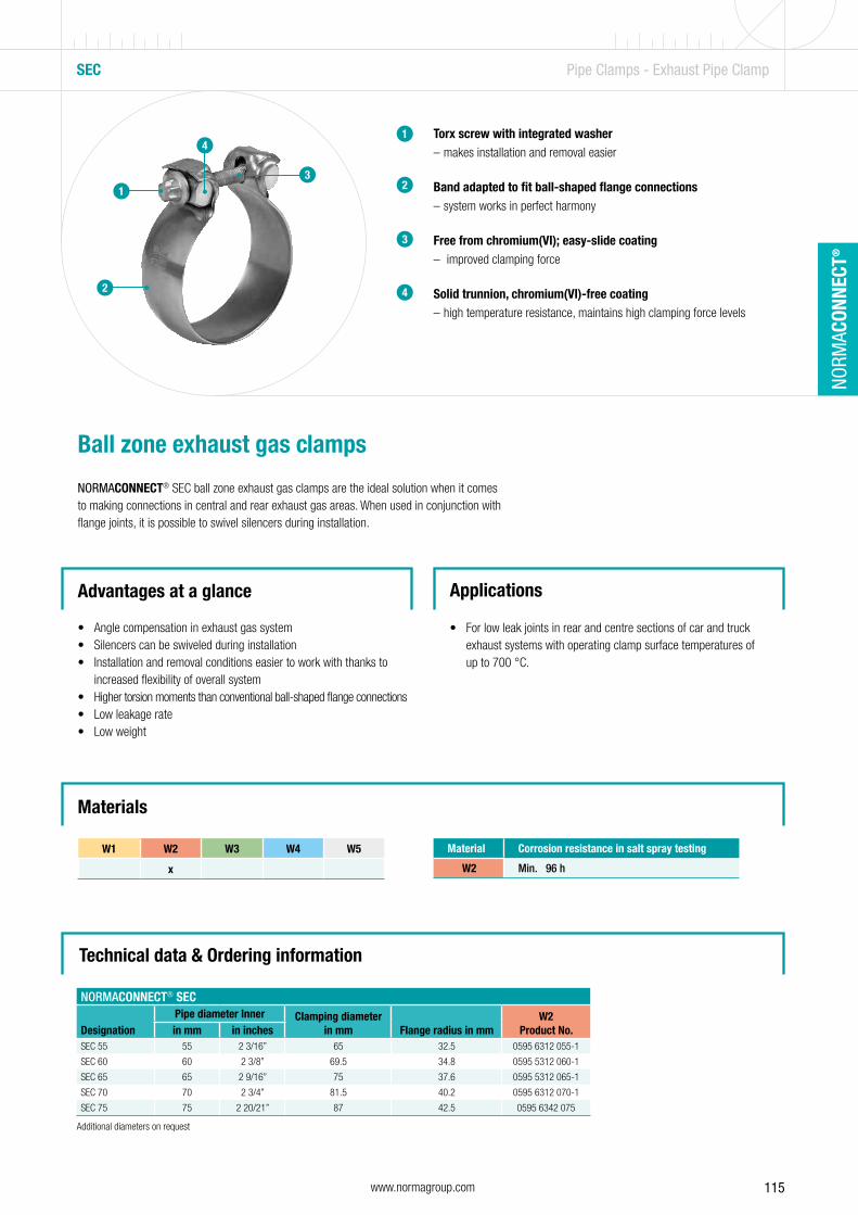
115www.normagroup.com
NORM
ACON
NECT
®
SEC Pipe Clamps - Exhaust Pipe Clamp
Torx screw with integrated washer – makes installation and removal easier
Band adapted to fit ball-shaped flange connections – system works in perfect harmony
Free from chromium(VI); easy-slide coating – improved clamping force
Solid trunnion, chromium(VI)-free coating – high temperature resistance, maintains high clamping force levels
1
2
2
Ball zone exhaust gas clamps
NORMACONNECT® SEC ball zone exhaust gas clamps are the ideal solution when it comes to making connections in central and rear exhaust gas areas. When used in conjunction with flange joints, it is possible to swivel silencers during installation.
Advantages at a glance
• Angle compensation in exhaust gas system• Silencers can be swiveled during installation• Installation and removal conditions easier to work with thanks to
increased flexibility of overall system• Higher torsion moments than conventional ball-shaped flange connections• Low leakage rate• Low weight
Applications
• For low leak joints in rear and centre sections of car and truck exhaust systems with operating clamp surface temperatures of up to 700 °C.
Materials
Material Corrosion resistance in salt spray testing
W2 Min. 96 h
13
4
W1 W2 W3 W4 W5
x
Technical data & Ordering information
NORMACONNECT® SEC
DesignationPipe diameter Inner Clamping diameter
in mm Flange radius in mmW2
Product No.in mm in inchesSEC 55 55 2 3/16” 65 32.5 0595 6312 055-1
SEC 60 60 2 3/8” 69.5 34.8 0595 5312 060-1
SEC 65 65 2 9/16” 75 37.6 0595 5312 065-1
SEC 70 70 2 3/4” 81.5 40.2 0595 6312 070-1
SEC 75 75 2 20/21” 87 42.5 0595 6342 075
3
4
Additional diameters on request
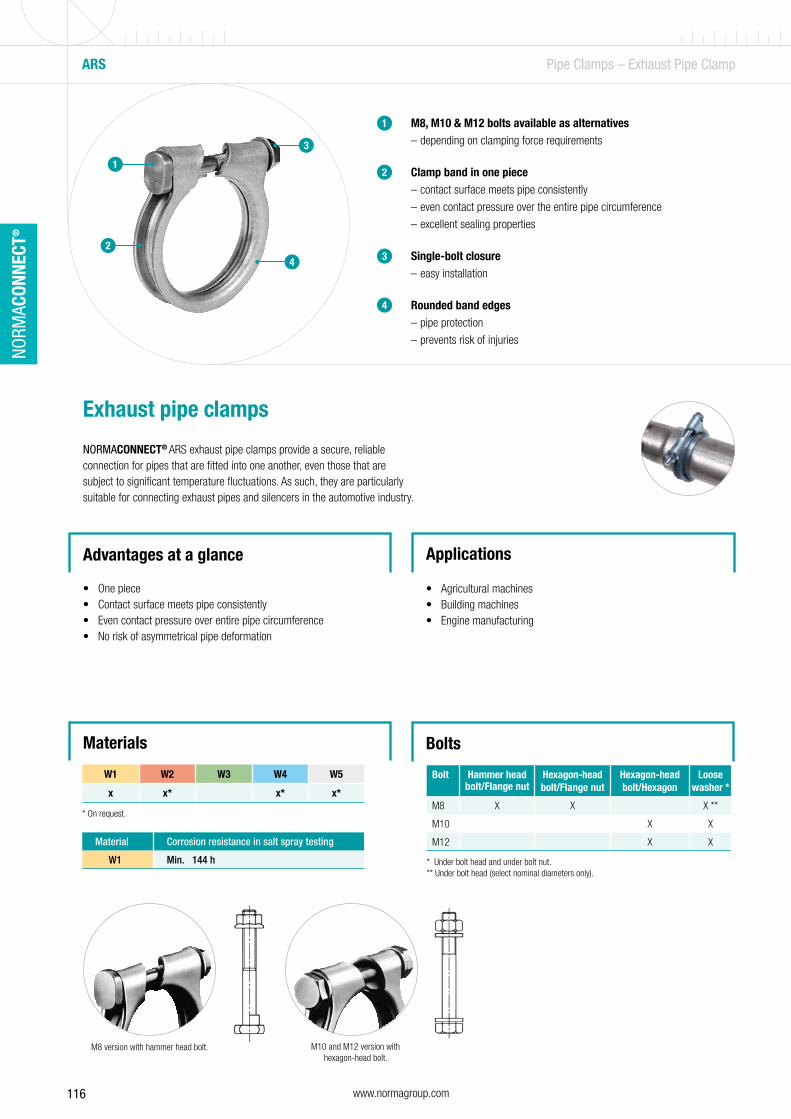
116 www.normagroup.com
NORM
ACON
NECT
®
ARS Pipe Clamps – Exhaust Pipe Clamp
4
1
2
3
M8, M10 & M12 bolts available as alternatives – depending on clamping force requirements
Clamp band in one piece – contact surface meets pipe consistently
– even contact pressure over the entire pipe circumference
– excellent sealing properties
Single-bolt closure – easy installation
Rounded band edges – pipe protection
– prevents risk of injuries
1
2
Exhaust pipe clamps
NORMACONNECT® ARS exhaust pipe clamps provide a secure, reliable connection for pipes that are fitted into one another, even those that are subject to significant temperature fluctuations. As such, they are particularly suitable for connecting exhaust pipes and silencers in the automotive industry.
Advantages at a glance
• One piece• Contact surface meets pipe consistently• Even contact pressure over entire pipe circumference• No risk of asymmetrical pipe deformation
Applications
• Agricultural machines• Building machines• Engine manufacturing
Bolts
3
Bolt Hammer head bolt/Flange nut
Hexagon-head bolt/Flange nut
Hexagon-head bolt/Hexagon
Loose washer *
M8 X X X **
M10 X X
M12 X X
M8 version with hammer head bolt. M10 and M12 version with hexagon-head bolt.
* Under bolt head and under bolt nut.** Under bolt head (select nominal diameters only).
4
Materials
W1 W2 W3 W4 W5
x x* x* x*
Material Corrosion resistance in salt spray testing
W1 Min. 144 h
* On request.
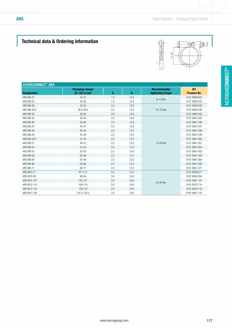
117www.normagroup.com
NORM
ACON
NECT
®
Technical data & Ordering information
NORMACONNECT® ARS
DesignationClamping ranges
D1–D2 in mm S BRecommended
tightening torqueW1
Product No.ARS-M8-27 24-27 1.5 10.4
8–10 Nm0151 8939 027
ARS-M8-33 30-33 1.5 10.4 0151 8939 033
ARS-M8-36 33-36 2.0 12.8
10–15 Nm
0151 8940 036
ARS-M8-39.5 36.5-39.5 2.0 12.0 0151 8940 040
ARS-M8-42 39-42 2.0 12.8 0151 8940 042
ARS-M8-45 42-45 2.5 13.6
15-20 Nm
0151 8941 045
ARS M8-46 43-46 2.5 12.8 0151 8941 046
ARS-M8-47 44-47 2.5 13.6 0151 8941 047
ARS-M8-48 45-49 2.5 13.2 0151 8941 048
ARS-M8-49 45-49 2.5 13.2 0151 8941 049
ARS-M8-50.5 51-54 2.5 13.2 0151 8941 505
ARS-M8-51 48-51 2.5 13.2 0151 8941 051
ARS-M8-54 51-54 2.5 13.2 0151 8941 054
ARS-M8-55 52-55 2.5 13.6 0151 8941 055
ARS-M8-58 55-58 2.5 13.2 0151 8941 058
ARS-M8-64 61-64 2.5 13.2 0151 8941 064
ARS-M8-66 63-66 2.5 13.2 0151 8941 066
ARS-M8-71 68-71 2.5 13.2 0151 8941 071
ARS-M10-71 67-71.5 3.0 13.2
35-40 Nm
0161 8939 071
ARS-M10-94 90-94 3.0 19.0 0181 8939 094
ARS-M10-107 102-107 3.0 19.0 0181 8941 107
ARS-M12-114 106-114 3.0 19.0 0181 8079 114
ARS-M12-133 129-133 3.0 19.0 0181 8079 133
ARS-M12-145 137.5-144.5 3.0 19.0 0181 8941 145
ARS Pipe Clamps – Exhaust Pipe Clamp
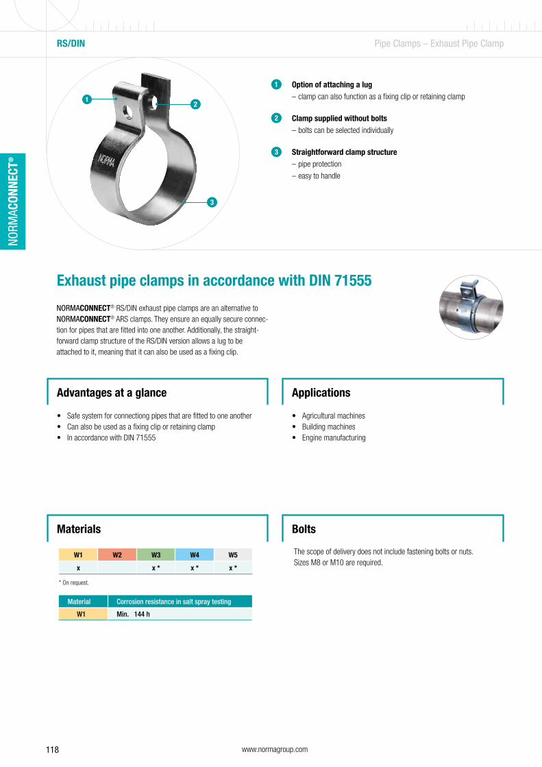
118 www.normagroup.com
NORM
ACON
NECT
®
Materials
Option of attaching a lug – clamp can also function as a fixing clip or retaining clamp
Clamp supplied without bolts – bolts can be selected individually
Straightforward clamp structure – pipe protection
– easy to handle
1
2
3
Exhaust pipe clamps in accordance with DIN 71555
NORMACONNECT® RS/DIN exhaust pipe clamps are an alternative to NORMACONNECT® ARS clamps. They ensure an equally secure connec-tion for pipes that are fitted into one another. Additionally, the straight-forward clamp structure of the RS/DIN version allows a lug to be attached to it, meaning that it can also be used as a fixing clip.
Applications
• Agricultural machines• Building machines• Engine manufacturing
3
21
RS/DIN Pipe Clamps – Exhaust Pipe Clamp
Bolts
The scope of delivery does not include fastening bolts or nuts.Sizes M8 or M10 are required.
W1 W2 W3 W4 W5
x x * x * x *
Material Corrosion resistance in salt spray testing
W1 Min. 144 h
* On request.
Advantages at a glance
• Safe system for connectiong pipes that are fitted to one another• Can also be used as a fixing clip or retaining clamp• In accordance with DIN 71555
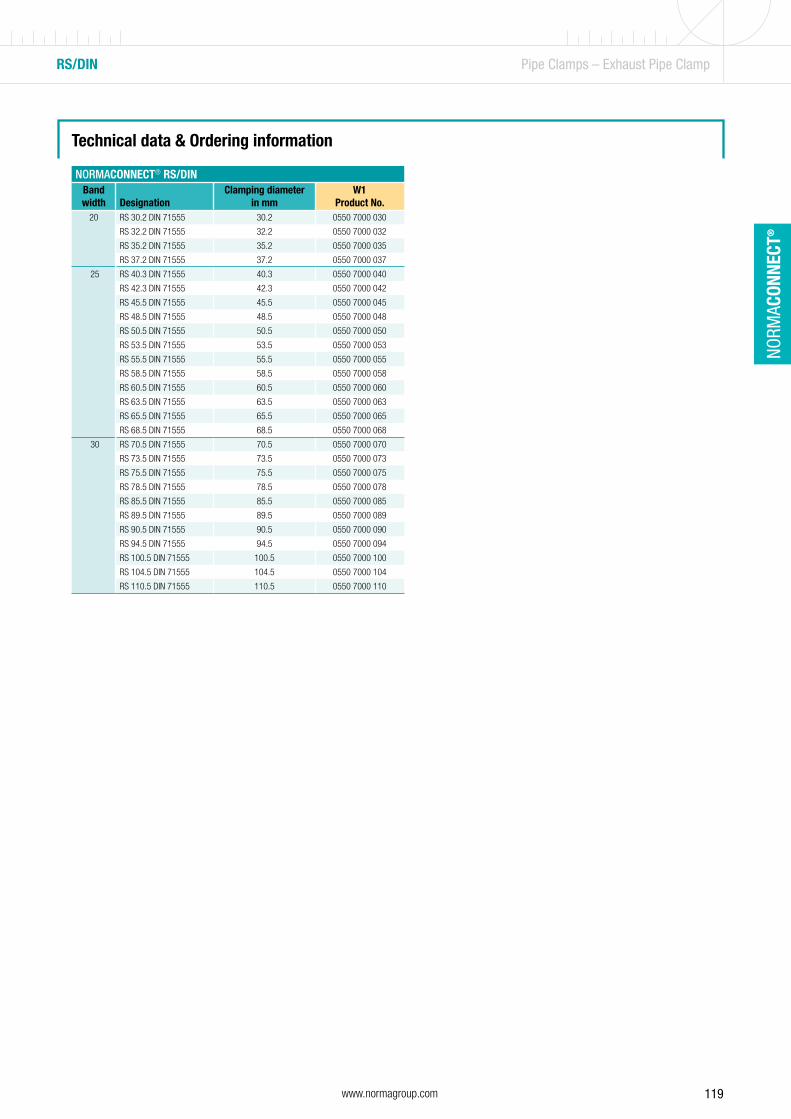
119www.normagroup.com
NORM
ACON
NECT
®
RS/DIN Pipe Clamps – Exhaust Pipe Clamp
Technical data & Ordering information
NORMACONNECT® RS/DINBand width Designation
Clamping diameter in mm
W1Product No.
20 RS 30.2 DIN 71555 30.2 0550 7000 030
RS 32.2 DIN 71555 32.2 0550 7000 032
RS 35.2 DIN 71555 35.2 0550 7000 035
RS 37.2 DIN 71555 37.2 0550 7000 037
25 RS 40.3 DIN 71555 40.3 0550 7000 040
RS 42.3 DIN 71555 42.3 0550 7000 042
RS 45.5 DIN 71555 45.5 0550 7000 045
RS 48.5 DIN 71555 48.5 0550 7000 048
RS 50.5 DIN 71555 50.5 0550 7000 050
RS 53.5 DIN 71555 53.5 0550 7000 053
RS 55.5 DIN 71555 55.5 0550 7000 055
RS 58.5 DIN 71555 58.5 0550 7000 058
RS 60.5 DIN 71555 60.5 0550 7000 060
RS 63.5 DIN 71555 63.5 0550 7000 063
RS 65.5 DIN 71555 65.5 0550 7000 065
RS 68.5 DIN 71555 68.5 0550 7000 068
30 RS 70.5 DIN 71555 70.5 0550 7000 070
RS 73.5 DIN 71555 73.5 0550 7000 073
RS 75.5 DIN 71555 75.5 0550 7000 075
RS 78.5 DIN 71555 78.5 0550 7000 078
RS 85.5 DIN 71555 85.5 0550 7000 085
RS 89.5 DIN 71555 89.5 0550 7000 089
RS 90.5 DIN 71555 90.5 0550 7000 090
RS 94.5 DIN 71555 94.5 0550 7000 094
RS 100.5 DIN 71555 100.5 0550 7000 100
RS 104.5 DIN 71555 104.5 0550 7000 104
RS 110.5 DIN 71555 110.5 0550 7000 110
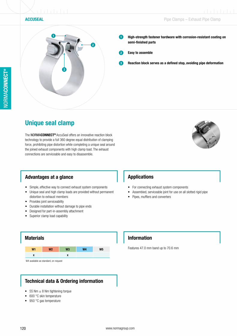
120 www.normagroup.com
NORM
ACON
NECT
®
High-strength fastener hardware with corrosion-resistant coating on semi-finished parts
Easy to assemble
Reaction block serves as a defined stop, avoiding pipe deformation
1
2
3
Unique seal clamp
The NORMACONNECT® AccuSeal offers an innovative reaction block technology to provide a full 360 degree equal distribution of clamping force, prohibiting pipe distortion while completing a unique seal around the joined exhaust components with high clamp load. The exhaust connections are serviceable and easy to disassemble.
2
1
ACCUSEAL Pipe Clamps – Exhaust Pipe Clamp
Advantages at a glance
• Simple, effective way to connect exhaust system components• Unique seal and high clamp loads are provided without permanent
distortion to exhaust members• Provides joint serviceability• Durable installation without damage to pipe ends• Designed for part-in-assembly attachment• Superior clamp load capability
Applications
• For connecting exhaust system components• Assembled, serviceable joint for use on all slotted rigid pipe• Pipes, mufflers and converters
Materials Information
Features 47.0 mm band up to 70.6 mm W1 W2 W3 W4 W5
x x
3
W4 available as standard, on request
Technical data & Ordering information
• 55 Nm ± 8 Nm tightening torque• 600 °C skin temperature• 950 °C gas temperature
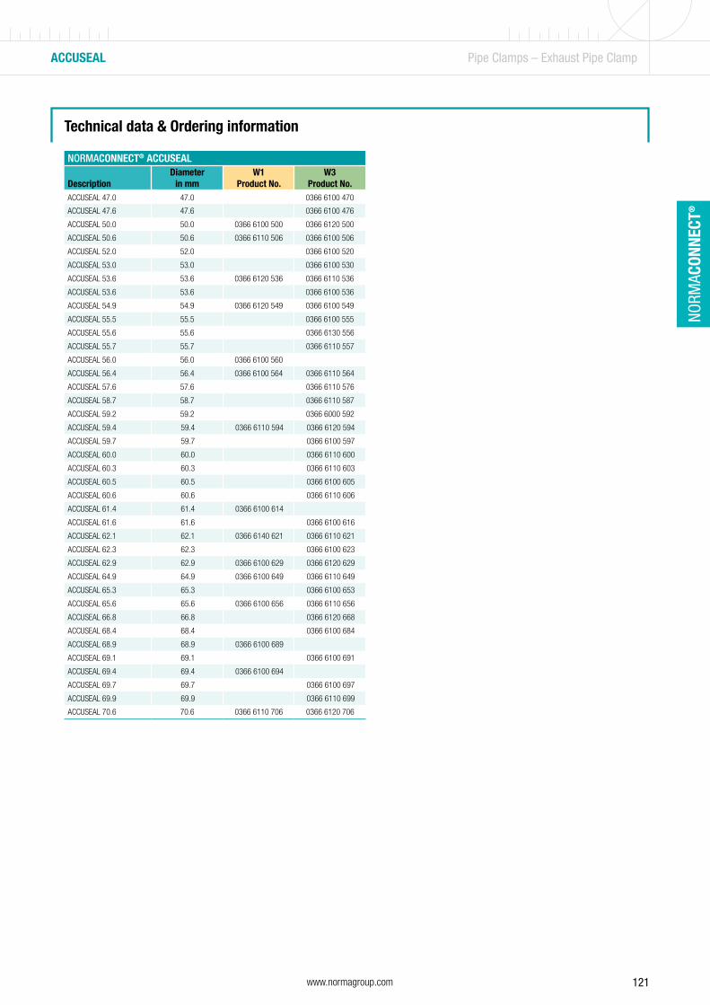
121www.normagroup.com
NORM
ACON
NECT
®
Technical data & Ordering information
NORMACONNECT® ACCUSEAL
DescriptionDiameter
in mmW1
Product No.W3
Product No.ACCUSEAL 47.0 47.0 0366 6100 470
ACCUSEAL 47.6 47.6 0366 6100 476
ACCUSEAL 50.0 50.0 0366 6100 500 0366 6120 500
ACCUSEAL 50.6 50.6 0366 6110 506 0366 6100 506
ACCUSEAL 52.0 52.0 0366 6100 520
ACCUSEAL 53.0 53.0 0366 6100 530
ACCUSEAL 53.6 53.6 0366 6120 536 0366 6110 536
ACCUSEAL 53.6 53.6 0366 6100 536
ACCUSEAL 54.9 54.9 0366 6120 549 0366 6100 549
ACCUSEAL 55.5 55.5 0366 6100 555
ACCUSEAL 55.6 55.6 0366 6130 556
ACCUSEAL 55.7 55.7 0366 6110 557
ACCUSEAL 56.0 56.0 0366 6100 560
ACCUSEAL 56.4 56.4 0366 6100 564 0366 6110 564
ACCUSEAL 57.6 57.6 0366 6110 576
ACCUSEAL 58.7 58.7 0366 6110 587
ACCUSEAL 59.2 59.2 0366 6000 592
ACCUSEAL 59.4 59.4 0366 6110 594 0366 6120 594
ACCUSEAL 59.7 59.7 0366 6100 597
ACCUSEAL 60.0 60.0 0366 6110 600
ACCUSEAL 60.3 60.3 0366 6110 603
ACCUSEAL 60.5 60.5 0366 6100 605
ACCUSEAL 60.6 60.6 0366 6110 606
ACCUSEAL 61.4 61.4 0366 6100 614
ACCUSEAL 61.6 61.6 0366 6100 616
ACCUSEAL 62.1 62.1 0366 6140 621 0366 6110 621
ACCUSEAL 62.3 62.3 0366 6100 623
ACCUSEAL 62.9 62.9 0366 6100 629 0366 6120 629
ACCUSEAL 64.9 64.9 0366 6100 649 0366 6110 649
ACCUSEAL 65.3 65.3 0366 6100 653
ACCUSEAL 65.6 65.6 0366 6100 656 0366 6110 656
ACCUSEAL 66.8 66.8 0366 6120 668
ACCUSEAL 68.4 68.4 0366 6100 684
ACCUSEAL 68.9 68.9 0366 6100 689
ACCUSEAL 69.1 69.1 0366 6100 691
ACCUSEAL 69.4 69.4 0366 6100 694
ACCUSEAL 69.7 69.7 0366 6100 697
ACCUSEAL 69.9 69.9 0366 6110 699
ACCUSEAL 70.6 70.6 0366 6110 706 0366 6120 706
ACCUSEAL Pipe Clamps – Exhaust Pipe Clamp

122 www.normagroup.com
NORM
ACON
NECT
®
DURASEAL Pipe Clamps – Exhaust Pipe Clamp
Technical data & Ordering information
High-strength fastener hardware with corrosive resistant coating
Improved clamp performance for thicker pipes on larger pipe gaps
Easy to assemble, only one assembly torque point
Reaction block serves as a defined stop, avoiding pipe deformation
1
2
3
Extra seal clamp
The NORMACONNECT® DuraSeal offers extra seal and clamp load performance to meet or exceed durability requirements without permanent distortion to exhaust members. Designed for applications with thicker pipe walls and larger pipe assembly gaps, it is ideal for applications with limited
packaging space.
Advantages at a glance
• Exclusive reaction block provides a full 360° distribution• Simple, effective way to connect exhaust system components• Designed for part-in-assembly pre-attachment• Pre-assembled for easy installation• Provides joint serviceability; no permanent distortion
Applications
• For high durability requirements• Improved clamp performance for applications with thicker pipe
walls and larger pipe assembly gaps• Ideal for applications with limited packaging space• Pipes, mufflers and converters
3
2
1
NORMACONNECT® DURASEAL
Designation
Diameters 409 Stainless SteelProduct No.in mm in inches
DURASEAL 50.8 50.8 2” 0371 0001 056
DURASEAL 57.15 57.15 2 1/4” 0371 0001 062
DURASEAL 63.5 63.5 2 1/2” 0371 0003 068
DURASEAL 69.85 69.85 2 3/4” 0371 0003 075
DURASEAL 76.2 76.2 3” 0371 0004 081
DURASEAL 88.9 88.9 3 1/2” 0371 0000 093
DURASEAL 101.6 101.6 4” 0371 0001 107
DURASEAL 114.3 114.3 5” 0371 0000 132
Materials
• 409 stainless steel• 304 stainless steel (on request)
Information
• Diameter range: 50.8 mm (2”) up to 127 mm (5”)• 7.9 mm (5/16”) slotted hex screw
44
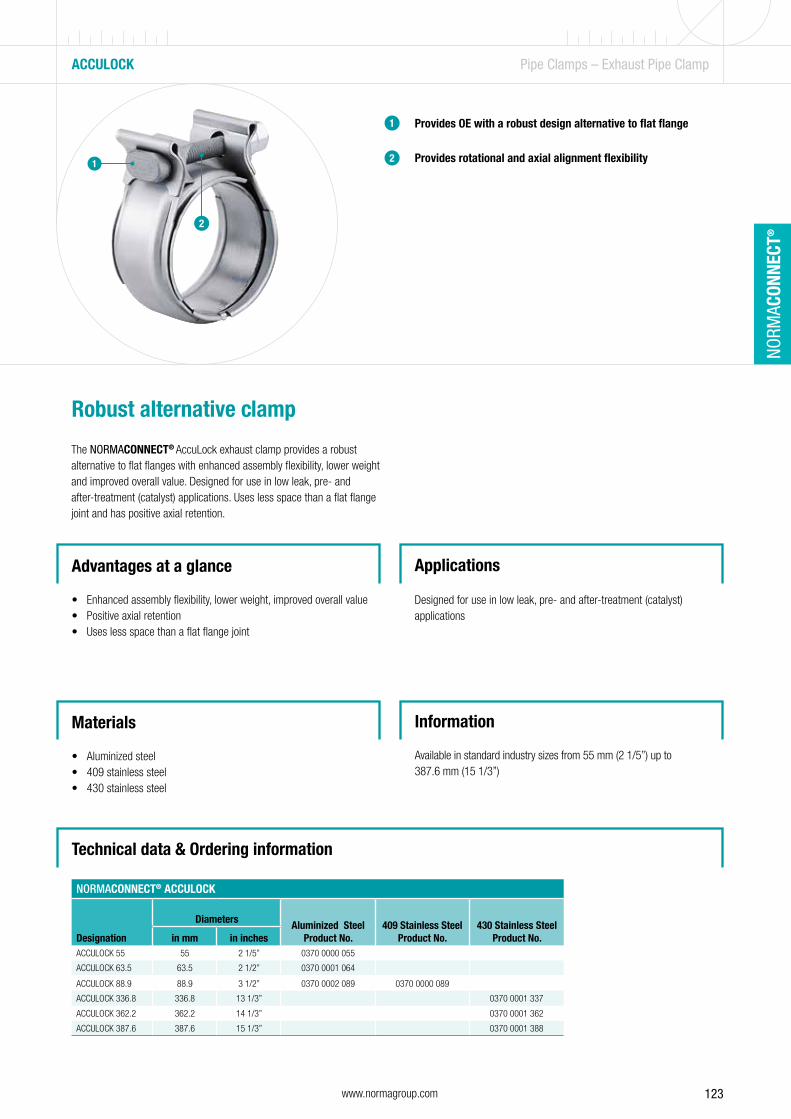
123www.normagroup.com
NORM
ACON
NECT
®
Technical data & Ordering information
Provides OE with a robust design alternative to flat flange
Provides rotational and axial alignment flexibility
1
2
Robust alternative clamp
The NORMACONNECT® AccuLock exhaust clamp provides a robust alternative to flat flanges with enhanced assembly flexibility, lower weight and improved overall value. Designed for use in low leak, pre- and after-treatment (catalyst) applications. Uses less space than a flat flange joint and has positive axial retention.
ACCULOCK Pipe Clamps – Exhaust Pipe Clamp
Advantages at a glance
• Enhanced assembly flexibility, lower weight, improved overall value• Positive axial retention• Uses less space than a flat flange joint
Applications
Designed for use in low leak, pre- and after-treatment (catalyst) applications
1
2
NORMACONNECT® ACCULOCK
Designation
Diameters Aluminized SteelProduct No.
409 Stainless SteelProduct No.
430 Stainless SteelProduct No.in mm in inches
ACCULOCK 55 55 2 1/5” 0370 0000 055
ACCULOCK 63.5 63.5 2 1/2” 0370 0001 064
ACCULOCK 88.9 88.9 3 1/2” 0370 0002 089 0370 0000 089
ACCULOCK 336.8 336.8 13 1/3” 0370 0001 337
ACCULOCK 362.2 362.2 14 1/3” 0370 0001 362
ACCULOCK 387.6 387.6 15 1/3” 0370 0001 388
Materials
• Aluminized steel• 409 stainless steel• 430 stainless steel
Information
Available in standard industry sizes from 55 mm (2 1/5”) up to 387.6 mm (15 1/3”)
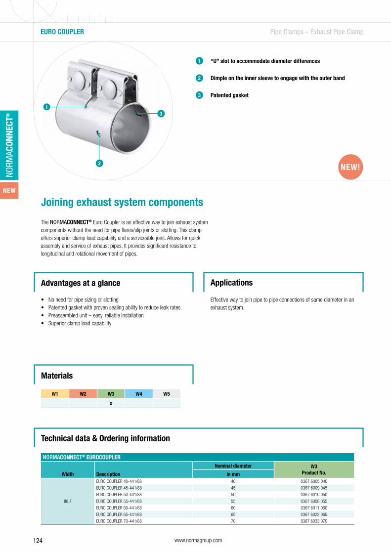
124 www.normagroup.com
NORM
ACON
NECT
®
EURO COUPLER Pipe Clamps – Exhaust Pipe Clamp
Technical data & Ordering information
“U” slot to accommodate diameter differences
Dimple on the inner sleeve to engage with the outer band
Patented gasket
1
2
3
Joining exhaust system components
The NORMACONNECT® Euro Coupler is an effective way to join exhaust system components without the need for pipe flares/slip joints or slotting. This clamp offers superior clamp load capability and a serviceable joint. Allows for quick assembly and service of exhaust pipes. It provides significant resistance to longitudinal and rotational movement of pipes.
Advantages at a glance
• No need for pipe sizing or slotting• Patented gasket with proven sealing ability to reduce leak rates• Preassembled unit – easy, reliable installation• Superior clamp load capability
Applications
Effective way to join pipe to pipe connections of same diameter in an exhaust system.
1
2
Materials
W1 W2 W3 W4 W5
x
NORMACONNECT® EUROCOUPLER
Width Description
Nominal diameter W3Product No.in mm
88,7
EURO COUPLER 40-441/88 40 0367 6005 040
EURO COUPLER 45-441/88 45 0367 6009 045
EURO COUPLER 50-441/88 50 0367 6010 050
EURO COUPLER 55-441/88 55 0367 6008 055
EURO COUPLER 60-441/88 60 0367 6011 060
EURO COUPLER 65-441/88 65 0367 6022 065
EURO COUPLER 70-441/88 70 0367 6033 070
3
NEW!
NEW

125www.normagroup.com
NORM
ACON
NECT
®
PIPE CLAMP M8/M10 Pipe Clamps – Exhaust Pipe Clamp
Technical data & Ordering information
Pre-mounted screw and nuts1
Exhaust system pipe clamp
The NORMACONNECT® Pipe clamp M8/M10 meets quality standards, which are suitable for use with a wide range of pipe diameters. Pipe clamps are not only used in exhaust systems.
Advantages at a glance
• Hexagonal wheel for better maintenance of the U• Completely assembled• Suitable for use with a wide range of pipe diameters
Applications
• Exhaust systems• Mounting of signage• TV antennas/aerials
NORMACONNECT® PIPE CLAMP M8/M10
DesignationDiameter in
mmW1
Product No.W4
Product No.PIPE CLAMP M8 32 32 08937481032 08937411032
PIPE CLAMP M8 35 35 08937481035 08937411035
PIPE CLAMP M8 38 38 08937481038 08937411038
PIPE CLAMP M8 40 40 08937481040 08937411040
PIPE CLAMP M8 42 42 08937481042 08937411042
PIPE CLAMP M8 44 44 08937481044 08937411044
PIPE CLAMP M8 45 45 08937481045 08937411045
PIPE CLAMP M8 48 48 08937481048 08937411048
PIPE CLAMP M8 52 52 08937481052 08937411052
PIPE CLAMP M8 54 54 08937481054 08937411054
PIPE CLAMP M8 57 57 08937481057 08937411057
PIPE CLAMP M8 60 60 08937481060 08937411060
PIPE CLAMP M8 65 65 08937481065 08937411065
PIPE CLAMP M8 70 70 08937481070 08937411070
PIPE CLAMP M8 76 76 08937481076 08937411076
PIPE CLAMP M10 90 90 08937481090
PIPE CLAMP M10 115 115 08937481115
PIPE CLAMP M10 127 127 08937481127
PIPE CLAMP M10 140 140 08937481140
1
W1 W2 W3 W4 W5
x X
Materials
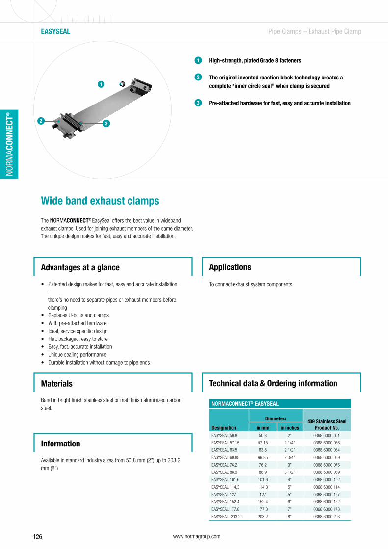
126 www.normagroup.com
NORM
ACON
NECT
®
Technical data & Ordering information
High-strength, plated Grade 8 fasteners
The original invented reaction block technology creates a complete “inner circle seal” when clamp is secured
Pre-attached hardware for fast, easy and accurate installation
1
2
3
Wide band exhaust clamps
The NORMACONNECT® EasySeal offers the best value in wideband exhaust clamps. Used for joining exhaust members of the same diameter. The unique design makes for fast, easy and accurate installation.
EASYSEAL Pipe Clamps – Exhaust Pipe Clamp
Advantages at a glance
• Patented design makes for fast, easy and accurate installation -
there’s no need to separate pipes or exhaust members before clamping• Replaces U-bolts and clamps• With pre-attached hardware• Ideal, service specific design • Flat, packaged, easy to store• Easy, fast, accurate installation• Unique sealing performance• Durable installation without damage to pipe ends
Applications
To connect exhaust system components
1
2
2 3
NORMACONNECT® EASYSEAL
Designation
Diameters 409 Stainless SteelProduct No.in mm in inches
EASYSEAL 50.8 50.8 2” 0368 6000 051
EASYSEAL 57.15 57.15 2 1/4” 0368 6000 056
EASYSEAL 63.5 63.5 2 1/2” 0368 6000 064
EASYSEAL 69.85 69.85 2 3/4” 0368 6000 069
EASYSEAL 76.2 76.2 3” 0368 6000 076
EASYSEAL 88.9 88.9 3 1/2” 0368 6000 089
EASYSEAL 101.6 101.6 4” 0368 6000 102
EASYSEAL 114.3 114.3 5” 0368 6000 114
EASYSEAL 127 127 5” 0368 6000 127
EASYSEAL 152.4 152.4 6” 0368 6000 152
EASYSEAL 177.8 177.8 7” 0368 6000 178
EASYSEAL 203.2 203.2 8” 0368 6000 203
Materials
Band in bright finish stainless steel or matt finish aluminized carbon steel.
Information
Available in standard industry sizes from 50.8 mm (2”) up to 203.2 mm (8”)
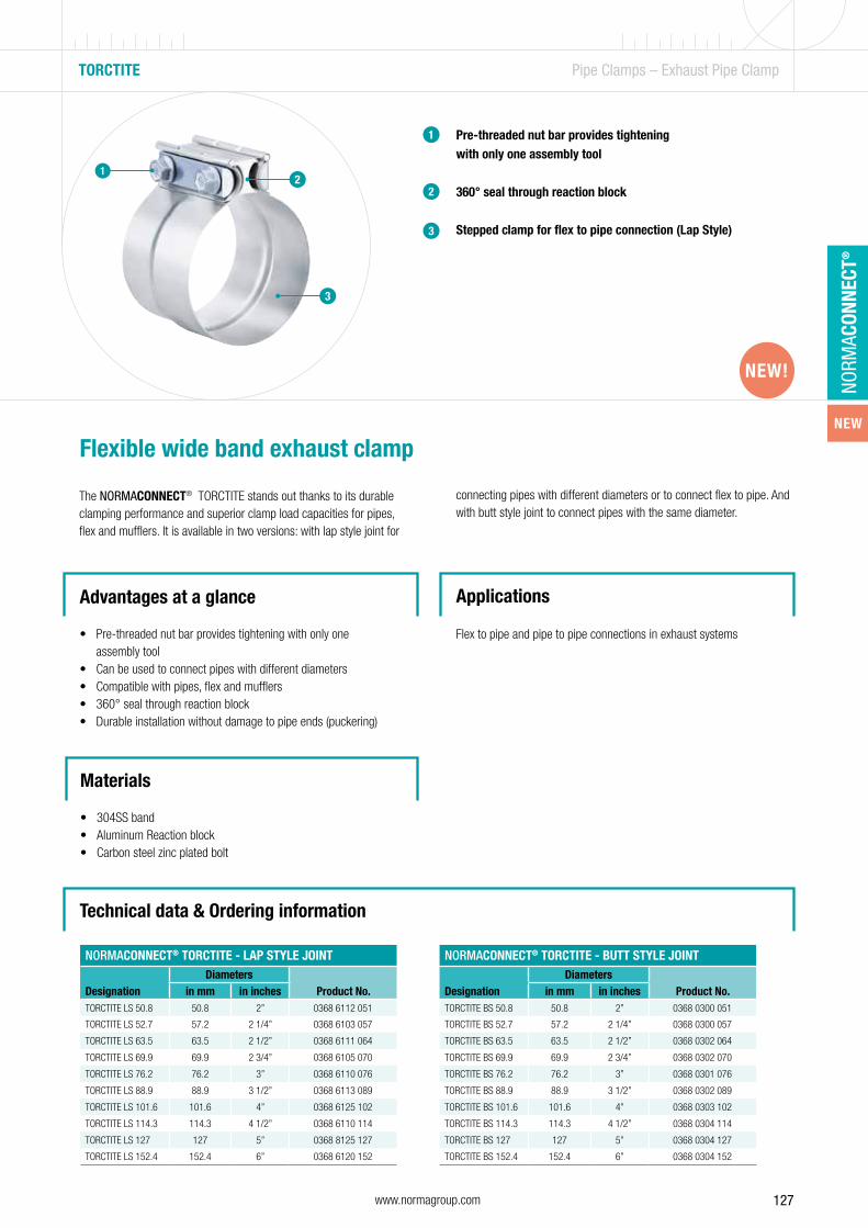
127www.normagroup.com
NORM
ACON
NECT
®
TORCTITE Pipe Clamps – Exhaust Pipe Clamp
Technical data & Ordering information
Pre-threaded nut bar provides tightening with only one assembly tool
360° seal through reaction block
Stepped clamp for flex to pipe connection (Lap Style)
1
Flexible wide band exhaust clamp
The NORMACONNECT® TORCTITE stands out thanks to its durable clamping performance and superior clamp load capacities for pipes, flex and mufflers. It is available in two versions: with lap style joint for
Advantages at a glance
• Pre-threaded nut bar provides tightening with only one assembly tool
• Can be used to connect pipes with different diameters• Compatible with pipes, flex and mufflers• 360° seal through reaction block• Durable installation without damage to pipe ends (puckering)
Applications
Flex to pipe and pipe to pipe connections in exhaust systems
Materials
• 304SS band• Aluminum Reaction block• Carbon steel zinc plated bolt
2
3
12
3
connecting pipes with different diameters or to connect flex to pipe. And with butt style joint to connect pipes with the same diameter.
NORMACONNECT® TORCTITE - LAP STYLE JOINT
DesignationDiameters
Product No.in mm in inchesTORCTITE LS 50.8 50.8 2” 0368 6112 051
TORCTITE LS 52.7 57.2 2 1/4” 0368 6103 057
TORCTITE LS 63.5 63.5 2 1/2” 0368 6111 064
TORCTITE LS 69.9 69.9 2 3/4” 0368 6105 070
TORCTITE LS 76.2 76.2 3” 0368 6110 076
TORCTITE LS 88.9 88.9 3 1/2” 0368 6113 089
TORCTITE LS 101.6 101.6 4” 0368 6125 102
TORCTITE LS 114.3 114.3 4 1/2” 0368 6110 114
TORCTITE LS 127 127 5” 0368 8125 127
TORCTITE LS 152.4 152.4 6” 0368 6120 152
NORMACONNECT® TORCTITE - BUTT STYLE JOINT
DesignationDiameters
Product No.in mm in inchesTORCTITE BS 50.8 50.8 2” 0368 0300 051
TORCTITE BS 52.7 57.2 2 1/4” 0368 0300 057
TORCTITE BS 63.5 63.5 2 1/2” 0368 0302 064
TORCTITE BS 69.9 69.9 2 3/4” 0368 0302 070
TORCTITE BS 76.2 76.2 3” 0368 0301 076
TORCTITE BS 88.9 88.9 3 1/2” 0368 0302 089
TORCTITE BS 101.6 101.6 4” 0368 0303 102
TORCTITE BS 114.3 114.3 4 1/2” 0368 0304 114
TORCTITE BS 127 127 5” 0368 0304 127
TORCTITE BS 152.4 152.4 6” 0368 0304 152
NEW!
NEW

128 www.normagroup.com
NORM
ACON
NECT
®
BRS / BRSP Pipe Clamps – Wide-Band Clamp
Wide-band hose clamps in accordance with DIN 3017-5
Used in conjunction with a rubber sleeve, NORMACONNECT® BRS wide-band hose clamps are the ideal choice for connecting pipes with smooth ends. They connect cast iron and steel pipes just as securely as plastic or glass pipes and without any welding.
NORMACONNECT® wide-band hose and retaining clamps are produced with standardized band widths and materials. The progressive ratio is 1 mm in the case of a single-part version. Up to a clamping diameter of 300 mm, the clamps are supplied in rolled-up form. With clamping diameters of 301 mm and upwards, they are supplied in stretched-out form.
Advantages at a glance
• Extremely wide band • Clamping force distributed over a large area• High level of transverse rigidity• Single-part and multi-part versions
Applications
• Machine building• White goods• Food and beverage industry• Agricultural machines• Engine manufacturing
Bolts
Bridge – good hose/sleeve coverage
Design protects hoses/sleeves – clamping force is distributed across a wide area
– prevents damage to components being clamped
– excellent transverse rigidity
1
21
NORMACONNECT® BRSBand width Sz in the case of W2 Sk in the case of W4
48 M6 x 38 Sz M6 x 45 Sk
54 M8 x 47 Sz M8 x 50 Sk
65 M8 x 47 Sz M8 x 50 Sk
Materials
W1 W2 W3 W4 W5
x x
Material Corrosion resistance in salt spray testing
W2 Min. 72 h
W4 Min. 240 h
• Exhaust air technology• Suction systems• Laboratory technology• Drainage technology
Technical data Ordering information
NORMACONNECT® BRS
Band widthin mm
Minimum diameter
in mm
Static tightening
torque in Nm
Material thickness in mm
W2 W448 50 4 0.4 0.5
54 50 12 0.4 0.5
65 50 12 0.4 0.5
1. Type 2. Clamping range 3. Band width 4. Material 5. Bolt
Example BRS 55 48 W2 Sz
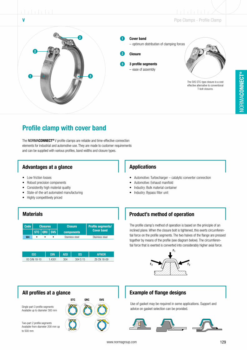
129www.normagroup.com
NORM
ACON
NECT
®
Cover band – optimum distribution of clamping forces
Closure
3 profile segments – ease of assembly
1
2
3
Profile clamp with cover band
The NORMACONNECT® V profile clamps are reliable and time-effective connection elements for industrial and automotive use. They are made to customer requirements and can be supplied with various profiles, band widths and closure types.
Advantages at a glance
• Low friction losses• Robust precision components• Consistently high material quality• State-of-the-art automated manufacturing• Highly competitively priced
Applications
• Automotive: Turbocharger – catalytic converter connection• Automotive: Exhaust manifold• Industry: Bulk material container• Industry: Bypass filter unit
Product’s method of operation
2
1
V Pipe Clamps - Profile Clamp
2
3
The profile clamp’s method of operation is based on the principle of an inclined plane. When the closure bolt is tightened, this exerts circumferen-tial force on the profile segments. The two halves of the flange are pressed together by means of the profile (see diagram below). The circumferen-tial force that is exerted is converted into considerably higher axial force.
Materials
Code Closures Closure
components
Profile segments/Cover bandSTC QRC SVS
W4 • • • Stainless steel Stainless steel
ISO DIN AISI BS AFNORX5 CrNi 18-10 1.4301 304 304 S 15 Z6 CN 18-09
NORMACONNECT® V • Flange Design Example of flange designs
Use of gasket may be required in some applications. Support and advice on gasket selection can be provided.
All profiles at a glanceSTC QRC SVS
Single-part 3 profile segmentsAvailable up to diameter 300 mm
Two-part 2 profile segments
Available from diameter 200 mm up
to 500 mm
The SVS STC-type closure is a cost effective alternative to conventional
T-bolt closures.
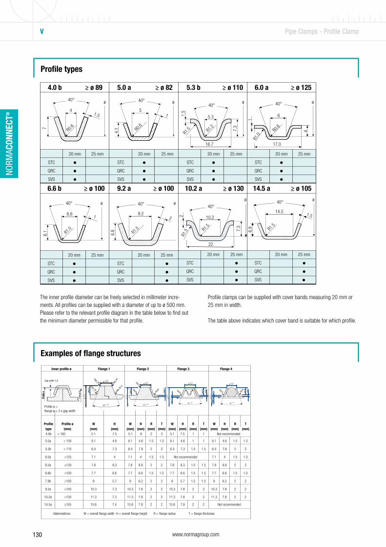
130 www.normagroup.com
NORM
ACON
NECT
®
V Pipe Clamps - Profile Clamp
Profile types
The inner profile diameter can be freely selected in millimeter incre-ments. All profiles can be supplied with a diameter of up to ø 500 mm. Please refer to the relevant profile diagram in the table below to find out the minimum diameter permissible for that profile.
4.0 b ≥ ø 89 5.0 a ≥ ø 82 5.3 b ≥ ø 110 6.0 a ≥ ø 125
ø
6
17.0
4
1
40°
R1.0
R0.6
ø
5.3
16.7
R1.2 7.
3
1.5
40°
R1.5
ø40°
5
R0.6
4.1
1
ø
41.5
R0.67
40°
ø
20 mm 25 mm
STC •QRC •
9.2 a ≥ ø 100
9.22
R1.5
6.8
40°
SVS •
20 mm 25 mm 20 mm 25 mm 20 mm 25 mm 20 mm 25 mm
STC • STC • STC • STC • QRC • QRC • QRC • QRC • SVS • SVS • SVS • SVS •
10.2 a ≥ ø 130 ø
22
10.2
R1.5
2
40°
R1.5 7.
3
20 mm 25 mm
STC • QRC • SVS •
14.5 a ≥ ø 105ø
14.51.5
R1.5
6.9
40°
20 mm 25 mm
STC •QRC •SVS •
6.6 b ≥ ø 100
ø
6.6 1
R1.0
6.1
40°
20 mm 25 mm
STC • QRC • SVS •
Examples of flange structures
Profile clamps can be supplied with cover bands measuring 20 mm or 25 mm in width. The table above indicates which cover band is suitable for which profile.
Profi
le
Inner profile ø Flange 1 Flange 2 Flange 3 Flange 4
Profile Profile ø W H W H R T W H R T W H R T type (mm) (mm) (mm) (mm) (mm) (mm) (mm) (mm) (mm) (mm) (mm) (mm) (mm) (mm) (mm) 4.0b ≥ 100 5.1 7.5 5.1 8 2 2 5.1 7.5 1 Not recommended
5.0a ≥ 100 6.1 4.6 6.1 4.6 1.5 1.5 6.1 4.6 1 1 6.1 4.6 1.5 1.5
5.3b ≥ 110 6.4 7.3 6.4 7.8 2 2 6.4 7.3 1.5 1.5 6.4 7.8 2 2
6.0a ≥125 7.1 4 7.1 4 1.5 1.5 Not recommended 7.1 4 1.5 1.5
6.5a ≥130 7.6 8.3 7.6 8.8 2 2 7.6 8.3 1.5 1.5 7.6 8.8 2 2
6.6b ≥100 7.7 6.6 7.7 6.6 1.5 1.5 7.7 6.6 1.5 1.5 7.7 6.6 1.5 1.5
7.9b ≥100 9 5.7 9 6.2 2 2 9 5.7 1.5 1.5 9 6.2 2 2
9.2a ≥100 10.3 7.3 10.3 7.8 2 2 10.3 7.8 2 2 10.3 7.8 2 2
10.2a ≥130
11.3
7.3 11.3 7.8
2 2 11.3 7.8
2 2 11.3 7.8
2 2
14.5a ≥105
15.6
7.4 15.6 7.9
2 2 15.6 7.9
2 2
Not recommended
Abbreviations:
W = overall flange width
H = overall flange height
R = flange radius
T = flange thickness
Profile ø =flange ø + 2 x gap width
1
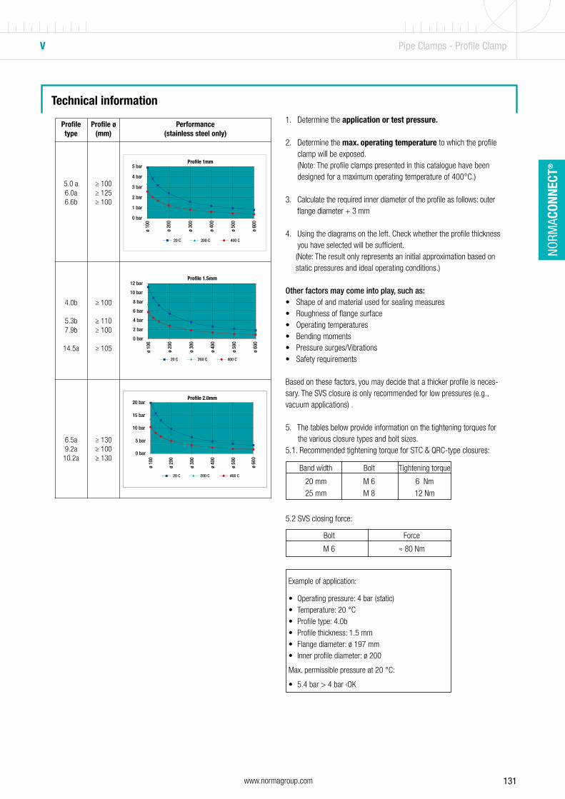
131www.normagroup.com
NORM
ACON
NECT
®
Technical information
V Pipe Clamps - Profile Clamp
1. Determine the application or test pressure.
2. Determine the max. operating temperature to which the profile clamp will be exposed. (Note: The profile clamps presented in this catalogue have been designed for a maximum operating temperature of 400°C.)
3. Calculate the required inner diameter of the profile as follows: outer flange diameter + 3 mm
4. Using the diagrams on the left. Check whether the profile thickness you have selected will be sufficient.
(Note: The result only represents an initial approximation based on static pressures and ideal operating conditions.)
Other factors may come into play, such as:• Shape of and material used for sealing measures• Roughness of flange surface• Operating temperatures• Bending moments• Pressure surges/Vibrations• Safety requirements
Based on these factors, you may decide that a thicker profile is neces-sary. The SVS closure is only recommended for low pressures (e.g., vacuum applications) .
5. The tables below provide information on the tightening torques for the various closure types and bolt sizes.5.1. Recommended tightening torque for STC & QRC-type closures:
5.2 SVS closing force:
1. Determine the application or test pressure.
2. Determine the max. operating temperature to which the profile clamp will be exposed.
(Note: The profile clamps presented in this brochure have been designed for a maximum operating temperature of 400°C.)
3. Calculate the required inner diameter of the profile as follows: outer flange diameter + 3 mm
4. Using the diagrams on the left. Check whether the profile thickness you have selected will be sufficient.
(Note: The result only represents an initial approximation based on static pressures and ideal operating conditions.)
Other factors may come into play, such as: • Shape of and material used for sealing measures • Roughness of flange surface • Operating temperatures • Bending moments • Pressure surges/Vibrations • Safety requirements
Based on these factors, you may decide that a thicker profile is necessary.
The SVS closure is only recommended for low pressures (e.g., vacuum applications) .
5. The tables below provide information on the tightening torques for the various closure types and bolt sizes.
5.1. Recommended tightening torque for STC & QRC-type closures:
5.2 SVS closing force:
Profile Profile ø Performance Technical information type (mm) (stainless steel only)
5.0 a ≥ 100 6.0a ≥ 125 6.6b ≥ 100
4.0b ≥ 100
5.3b ≥ 110 7.9b ≥ 100
14.5a ≥ 105
6.5a ≥ 130 9.2a ≥ 100 10.2a ≥ 130 11.4b ≥ 180
9.2 b ≥ 155
Example of application:
• Operating pressure: 4 bar (static)• Temperature: 20 °C• Profile type: 4.0b• Profile thickness: 1.5 mm • Flange diameter: ø 197 mm• Inner profile diameter: ø 200
Max. permissible pressure at 20 °C:
• 5.4 bar > 4 bar ‹OK
Band width Bolt Tightening torque
20 mm M 6 6 Nm
25 mm M 8 12 Nm
Bolt Force
M 6 ≈ 80 Nm
Technical information
NORMACONNECT® – Pipe Connections
NORM
ACON
NECT
®
Pipe
Con
nect
ionsProfile 1mm
Profile 1.5mm
Profile 2.0mm
Profile 3.0mm
NORMACONNECT® V profile clamps are manufactured in two different band widths and with different closures, depending on the profile type concerned:
1. Determine the application or test pressure.
2. Determine the max. operating temperature to which the profile clamp will be exposed.
(Note: The profile clamps presented in this brochure have been designed for a maximum operating temperature of 400°C.)
3. Calculate the required inner diameter of the profile as follows: outer flange diameter + 3 mm
4. Using the diagrams on the left. Check whether the profile thickness you have selected will be sufficient.
(Note: The result only represents an initial approximation based on static pressures and ideal operating conditions.)
Other factors may come into play, such as: • Shape of and material used for sealing measures • Roughness of flange surface • Operating temperatures • Bending moments • Pressure surges/Vibrations • Safety requirements
Based on these factors, you may decide that a thicker profile is necessary.
The SVS closure is only recommended for low pressures (e.g., vacuum applications) .
5. The tables below provide information on the tightening torques for the various closure types and bolt sizes.
5.1. Recommended tightening torque for STC & QRC-type closures:
5.2 SVS closing force:
Profile Profile ø Performance Technical information type (mm) (stainless steel only)
5.0 a ≥ 100 6.0a ≥ 125 6.6b ≥ 100
4.0b ≥ 100
5.3b ≥ 110 7.9b ≥ 100
14.5a ≥ 105
6.5a ≥ 130 9.2a ≥ 100 10.2a ≥ 130 11.4b ≥ 180
9.2 b ≥ 155
Example of application:
• Operating pressure: 4 bar (static)• Temperature: 20 °C• Profile type: 4.0b• Profile thickness: 1.5 mm • Flange diameter: ø 197 mm• Inner profile diameter: ø 200
Max. permissible pressure at 20 °C:
• 5.4 bar > 4 bar ‹OK
Band width Bolt Tightening torque
20 mm M 6 6 Nm
25 mm M 8 12 Nm
Bolt Force
M 6 ≈ 80 Nm
Technical information
NORMACONNECT® – Pipe Connections
NORM
ACON
NECT
®
Pipe
Con
nect
ionsProfile 1mm
Profile 1.5mm
Profile 2.0mm
Profile 3.0mmClosure type Cover band 1.0 x 20 mm Cover band 1.5 x 25 mm
STCBolt M 6 x 50 Bolt M 8 x 70
QRC
SVS Bolt M 6 x 70 Bolt M 6 x 70
1. Determine the application or test pressure.
2. Determine the max. operating temperature to which the profile clamp will be exposed.
(Note: The profile clamps presented in this brochure have been designed for a maximum operating temperature of 400°C.)
3. Calculate the required inner diameter of the profile as follows: outer flange diameter + 3 mm
4. Using the diagrams on the left. Check whether the profile thickness you have selected will be sufficient.
(Note: The result only represents an initial approximation based on static pressures and ideal operating conditions.)
Other factors may come into play, such as: • Shape of and material used for sealing measures • Roughness of flange surface • Operating temperatures • Bending moments • Pressure surges/Vibrations • Safety requirements
Based on these factors, you may decide that a thicker profile is necessary.
The SVS closure is only recommended for low pressures (e.g., vacuum applications) .
5. The tables below provide information on the tightening torques for the various closure types and bolt sizes.
5.1. Recommended tightening torque for STC & QRC-type closures:
5.2 SVS closing force:
Profile Profile ø Performance Technical information type (mm) (stainless steel only)
5.0 a ≥ 100 6.0a ≥ 125 6.6b ≥ 100
4.0b ≥ 100
5.3b ≥ 110 7.9b ≥ 100
14.5a ≥ 105
6.5a ≥ 130 9.2a ≥ 100 10.2a ≥ 130 11.4b ≥ 180
9.2 b ≥ 155
Example of application:
• Operating pressure: 4 bar (static)• Temperature: 20 °C• Profile type: 4.0b• Profile thickness: 1.5 mm • Flange diameter: ø 197 mm• Inner profile diameter: ø 200
Max. permissible pressure at 20 °C:
• 5.4 bar > 4 bar ‹OK
Band width Bolt Tightening torque
20 mm M 6 6 Nm
25 mm M 8 12 Nm
Bolt Force
M 6 ≈ 80 Nm
Technical information
NORMACONNECT® – Pipe Connections
NORM
ACON
NECT
®
Pipe
Con
nect
ionsProfile 1mm
Profile 1.5mm
Profile 2.0mm
Profile 3.0mm
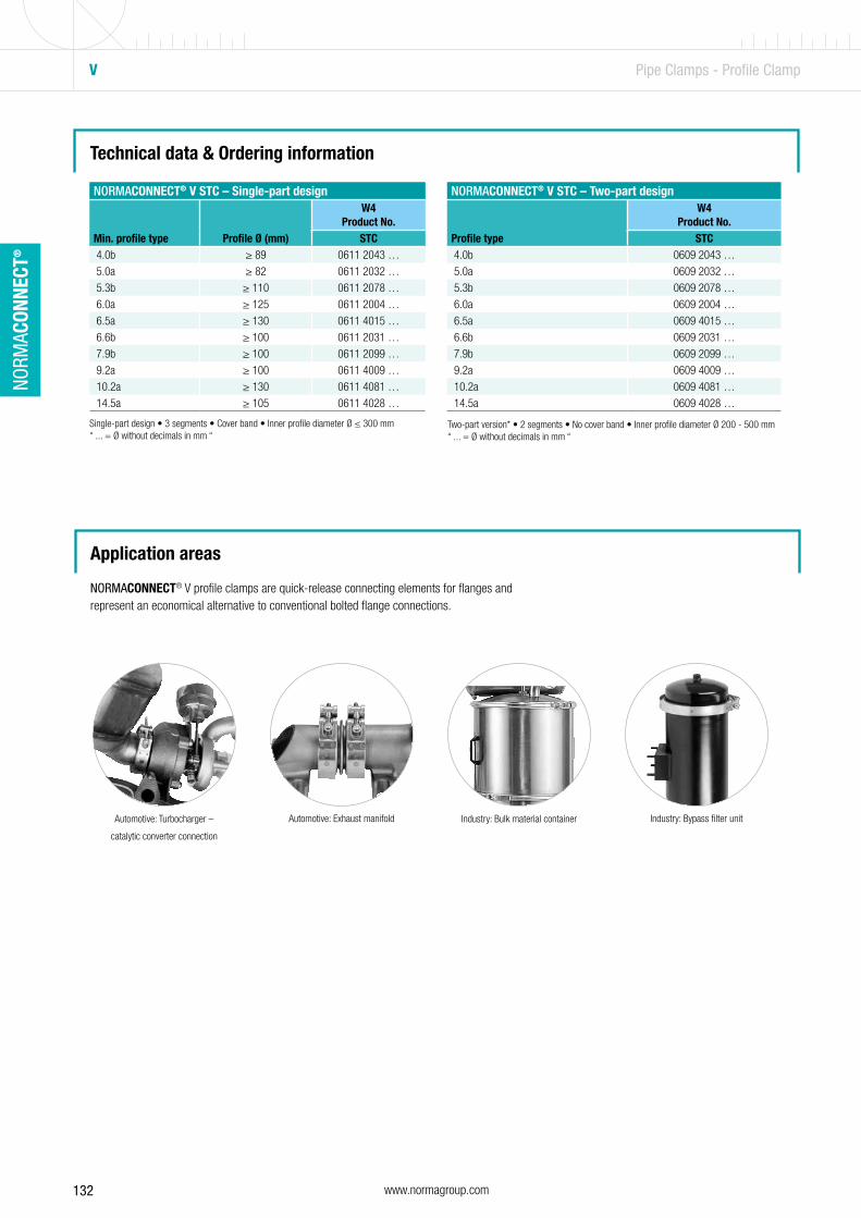
132 www.normagroup.com
NORM
ACON
NECT
®
Technical data & Ordering information
Single-part design • 3 segments • Cover band • Inner profile diameter Ø ≤ 300 mm“ ... = Ø without decimals in mm “
NORMACONNECT® V STC – Single-part design
Min. profile type Profile Ø (mm)
W4Product No.
STC 4.0b ≥ 89 0611 2043 …
5.0a ≥ 82 0611 2032 …
5.3b ≥ 110 0611 2078 …
6.0a ≥ 125 0611 2004 …
6.5a ≥ 130 0611 4015 …
6.6b ≥ 100 0611 2031 …
7.9b ≥ 100 0611 2099 …
9.2a ≥ 100 0611 4009 …
10.2a ≥ 130 0611 4081 …
14.5a ≥ 105 0611 4028 …
NORMACONNECT® V STC – Two-part design
Profile type
W4Product No.
STC 4.0b 0609 2043 …
5.0a 0609 2032 …
5.3b 0609 2078 …
6.0a 0609 2004 …
6.5a 0609 4015 …
6.6b 0609 2031 …
7.9b 0609 2099 …
9.2a 0609 4009 …
10.2a 0609 4081 …
14.5a 0609 4028 …
Two-part version* • 2 segments • No cover band • Inner profile diameter Ø 200 - 500 mm“ ... = Ø without decimals in mm “
Application areas
Automotive: Turbocharger –
catalytic converter connection
Industry: Bulk material containerAutomotive: Exhaust manifold Industry: Bypass filter unit
NORMACONNECT® V profile clamps are quick-release connecting elements for flanges and represent an economical alternative to conventional bolted flange connections.
V Pipe Clamps - Profile Clamp

133www.normagroup.com
NORM
ACON
NECT
®
QRC/ SVS Pipe Clamps - Profile Clamp
QRC The revolutionary new QRC-type closure offers significant advantages over conventional T-bolt solutions.
Advantages at a glance• Rapid closing and opening• Captive closure components• Significantly shorter installation• Closure bolt secured during tightening
MaterialW4
The SVS type includes an over-centre lever which enables manual installation.
Advantages at a glance• Installation without tools• Ideal for frequent handling
MaterialW4
SVS
NORMACONNECT® QRC – Single-part design
Min. profile type Profile Ø (mm)
W4Product No.
QRC 4.0b ≥ 89 0615 2043 … 5.0a ≥ 82 0615 2032 … 5.3b ≥ 110 0615 2078 … 6.0a ≥ 125 0615 2004 … 6.5a ≥ 130 0615 4015 … 6.6b ≥ 100 0615 2031 … 7.9b ≥ 100 0615 2099 … 9.2a ≥ 100 0615 4009 … 10.2a ≥ 130 0615 4081 … 14.5a ≥ 105 0615 4028 …
Single-part design • 3 segments • Cover band • Inner profile diameter Ø ≤ 300 mm“ ... = Ø without decimals in mm “
Single-part design • 3 segments • Cover band • Inner profile diameter Ø ≤ 300 mm“ ... = Ø without decimals in mm “
NORMACONNECT® SVS - Single-part design
Min. profile type Profile Ø (mm)
W4Product No.
SVS 4.0b ≥ 89 0607 2043 … 5.0a ≥ 82 0607 2032 … 5.3b ≥ 110 0607 2078 … 6.0a ≥ 125 0607 2004 … 6.5a ≥ 130 0607 4015 … 6.6b ≥ 100 0607 2031 … 7.9b ≥ 100 0607 2099 … 9.2a ≥ 100 0607 4009 … 10.2a ≥ 130 0607 4081 … 14.5a ≥ 105 0607 4028 …
NORMACONNECT® SVS - Two-part design
Min. profile type
W4Product No.
SVS 4.0b 0605 2043 … 5.0a 0605 2032 … 5.3b 0605 2078 … 6.0a 0605 2004 … 6.5a 0605 4015 … 6.6b 0605 2031 … 7.9b 0605 2099 … 9.2a 0605 4009 … 10.2a 0605 4081 … 14.5a 0605 4028 …
Two-part version* • 2 segments • No cover band • Inner profile diameter Ø 200 - 500 mm“ ... = Ø without decimals in mm “
134

135
Versatile products for a whole host of applicationsThe NORMAFIX® range of clamps, clips and systems for retaining pipes, cables, cable harnesses and hoses are ready for action wherever they’re needed – walls, ceilings or car bodies.
NORMAFIX® – Retaining Products
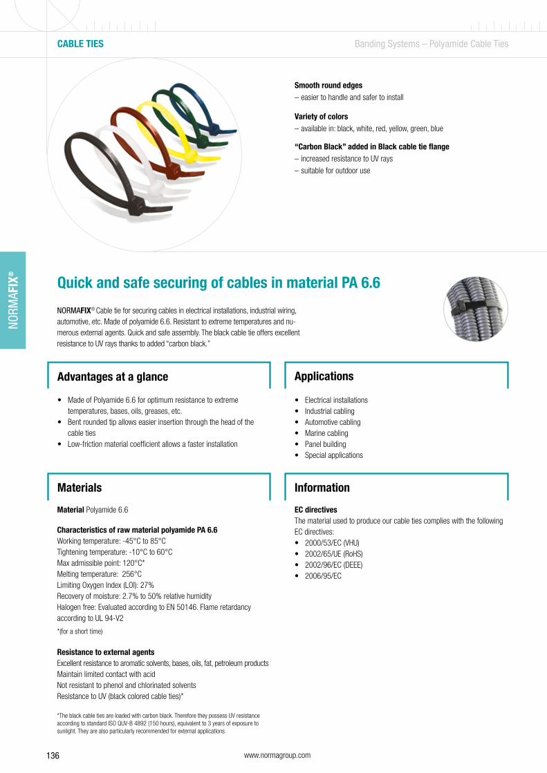
136 www.normagroup.com
NORM
AFIX
®
Materials
Smooth round edges – easier to handle and safer to install
Variety of colors – available in: black, white, red, yellow, green, blue
“Carbon Black” added in Black cable tie flange – increased resistance to UV rays
– suitable for outdoor use
Quick and safe securing of cables in material PA 6.6
NORMAFIX® Cable tie for securing cables in electrical installations, industrial wiring, automotive, etc. Made of polyamide 6.6. Resistant to extreme temperatures and nu-merous external agents. Quick and safe assembly. The black cable tie offers excellent resistance to UV rays thanks to added “carbon black.”
Advantages at a glance
• Made of Polyamide 6.6 for optimum resistance to extreme temperatures, bases, oils, greases, etc.
• Bent rounded tip allows easier insertion through the head of the cable ties
• Low-friction material coefficient allows a faster installation
Applications
• Electrical installations• Industrial cabling• Automotive cabling• Marine cabling• Panel building• Special applications
CABLE TIES Banding Systems – Polyamide Cable Ties
Material Polyamide 6.6
Characteristics of raw material polyamide PA 6.6Working temperature: -45°C to 85°CTightening temperature: -10°C to 60°CMax admissible point: 120°C*Melting temperature: 256°CLimiting Oxygen Index (LOI): 27%Recovery of moisture: 2.7% to 50% relative humidityHalogen free: Evaluated according to EN 50146. Flame retardancy according to UL 94-V2
*(for a short time)
Resistance to external agentsExcellent resistance to aromatic solvents, bases, oils, fat, petroleum productsMaintain limited contact with acidNot resistant to phenol and chlorinated solventsResistance to UV (black colored cable ties)*
*The black cable ties are loaded with carbon black. Therefore they possess UV resistance according to standard ISO QUV-B 4892 (150 hours), equivalent to 3 years of exposure to sunlight. They are also particularly recommended for external applications.
Information
EC directivesThe material used to produce our cable ties complies with the following EC directives:• 2000/53/EC (VHU)• 2002/65/UE (RoHS)• 2002/96/EC (DEEE)• 2006/95/EC
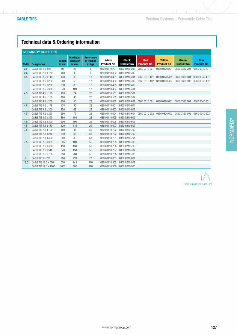
137www.normagroup.com
NORM
AFIX
®
CABLE TIES Banding Systems – Polyamide Cable Ties
Technical data & Ordering information
NORMAFIX® CABLE TIES
Width DesignationLengthin mm
Maximum diameter
in mm
Resistance to traction
in KgsWhite
Product No.Black
Product No.Red
Product No.Yellow
Product No.Green
Product No.Blue
Product No.2.5 CABLE TIE 2.5 x 98 98 21 8 0860 0110 201 0860 0210 201 0860 0310 201 0860 0320 201 0860 0330 201 0860 0340 201
2.6 CABLE TIE 2.6 x 160 160 40 8 0860 0110 302 0860 0210 302
3.5 CABLE TIE 3.5 x 140 140 35 13 0860 0110 401 0860 0210 401 0860 0310 401 0860 0320 401 0860 0330 401 0860 0340 401
CABLE TIE 3.5 x 200 200 50 13 0860 0110 402 0860 0210 402 0860 0310 402 0860 0320 402 0860 0330 402 0860 0340 402
CABLE TIE 3.5 x 290 290 80 13 0860 0110 403 0860 0210 403
CABLE TIE 3.5 x 370 370 103 13 0860 0110 404 0860 0210 404
4.5 CABLE TIE 4.5 x 120 120 24 20 0860 0110 501 0860 0210 501
CABLE TIE 4.5 x 160 160 40 20 0860 0110 502 0860 0210 502
CABLE TIE 4.5 x 200 200 50 22 0860 0110 602 0860 0210 602 0860 0310 601 0860 0320 601 0860 0330 601 0860 0340 601
4.8 CABLE TIE 4.8 x 178 178 45 22 0860 0110 601 0860 0210 601
CABLE TIE 4.8 x 250 250 68 22 0860 0110 603 0860 0210 603
4.5 CABLE TIE 4.5 x 290 290 79 22 0860 0110 604 0860 0210 604 0860 0310 602 0860 0320 602 0860 0330 602 0860 0340 602
CABLE TIE 4.5 x 360 360 103 22 0860 0110 605 0860 0210 605
4.8 CABLE TIE 4.8 x 390 390 106 22 0860 0110 606 0860 0210 606
4.5 CABLE TIE 4.5 x 430 430 115 22 0860 0110 607 0860 0210 607
7.8 CABLE TIE 7.8 x 180 180 45 55 0860 0110 702 0860 0210 702
CABLE TIE 7.8 x 240 240 63 55 0860 0110 703 0860 0210 703
CABLE TIE 7.8 x 300 300 80 55 0860 0110 704 0860 0210 704
7.5 CABLE TIE 7.5 x 365 365 100 55 0860 0110 705 0860 0210 705
CABLE TIE 7.5 x 450 450 130 55 0860 0110 706 0860 0210 706
CABLE TIE 7.5 x 540 540 158 55 0860 0110 707 0860 0210 707
CABLE TIE 7.5 x 750 750 200 55 0860 0110 708 0860 0210 708
9 CABLE TIE 9 x 780 780 233 77 0860 0110 801 0860 0210 801
12.5 CABLE TIE 12.5 x 500 500 143 110 0860 0110 902 0860 0210 902
CABLE TIE 12.5 x 1000 1000 302 110 0860 0110 905 0860 0210 905
Refer to pages 196 and 201.

138 www.normagroup.com
NORM
AFIX
®
CABLE TIE WITH METAL BARB Banding Systems – Polyamide Cable Ties
Technical data & Ordering information
Stainless steel barb – High strength and consistant performance
Curved tip – Easy to pick up from flat surface
1
2
Cable tie for high strength fixing
Made of Nylon 66 and 304 barb; this cable tie is a better choice for high strength applications
Advantages at a glance
• Stainless steel barb provides consistent performance and reliability and infinite adjustability through entire bundle range
• High strength and low thread force• Stippled strap body prevents lateral movement on the bundle• Curved tip is easy to pick up from flat surface and allows faster initial
threading to speed installation
Applications
• Electrical installations• Industrial cabling• Automotive cabling• Marine cabling • Panel building• Special applications
1
2
Materials
• Band: Nylon 66• Locking barb: SS 304 (W4)
Information
Our cable ties comply with the following directives:• ABS (Product Approval)• CE (Certificate of conformity)• UL62275 (Cable management systems)• Lloyd’s Register• DNV• DNV GL• RoHS
Characteristics
• Material-Locking Barb: Stainless Steel 304• Working Temp: -40°C to +85°C• Color: Black and White• Flammability: UL94V-2• Other Properties: Halogen Free, UV-
resistant (black cable ties)
NORMAFIX® CABLE TIE WITH METAL BARB
Width in mm Designation
Length in mm
BlackProduct No.
WhiteProduct No.
2.4 CABLE TIE WITH METAL BARB 2.4 X 10² 102 0892 7118 001 0892 7119 001CABLE TIE WITH METAL BARB 2.4 X 201 201 0892 7118 003 0892 7119 003
3.6
CABLE TIE WITH METAL BARB 3.6 X 155 155 0892 7118 006 0892 7119 006
CABLE TIE WITH METAL BARB 3.6 X 200 200 0892 7118 009 0892 7119 009
CABLE TIE WITH METAL BARB 3.6 X 284 284 0892 7118 007 0892 7119 007
4.8
CABLE TIE WITH METAL BARB 4.8 X 186 186 0892 7118 011 0892 7119 011
CABLE TIE WITH METAL BARB 4.8 X 250 250 0892 7118 010 0892 7119 010
CABLE TIE WITH METAL BARB 4.8 X 295 295 0892 7118 012 0892 7119 012
CABLE TIE WITH METAL BARB 4.8 X 361 361 0892 7118 013 0892 7119 013
7.0
CABLE TIE WITH METAL BARB 7.0 X 221 221 0892 7118 016 0892 7119 016
CABLE TIE WITH METAL BARB 7.0 X 378 378 0892 7118 018 0892 7119 018
CABLE TIE WITH METAL BARB 7.0 X 699 699 0892 7118 021 0892 7119 021
Refer to pages 196 and 201.
NEW!
NEW

139www.normagroup.com
NORM
AFIX
®
STAINLESS STEEL TIE BALL LOCKING Banding Systems – Metal Cable Ties
Technical data & Ordering information
Ball locking system for quick installation
No cutting edges: avoids damage to the cable electrical insulation
1
2
Cable tie for high strength fixing
Made of stainless steel AISI 304 or AISI 316 with ball locking system, that enables quick installation and low insertion effort. This kind of cable tie is characterized by a high resistance to high temperature, to flame and corrosion.
Advantages at a glance
• Ball-Lock type self-lock system, speeds installation
• Made entirely of high grade stainless steel, excellent corrosion and UV resistance.
Applications
• Cable and pipe fixing in shipbuilding, offshore, petrochemical plants, oil rigs, and environments with a risk of fire.
• Used as flame safety in electrical installations to fix the metal I.D. plates, which must be preserved in the event fire.
• Installations where high mechanical and UV resistance are required (photovoltaic).
2
1
Information
Our cable ties comply with the following directives:• ABS (Product Approval)• CE (Certificate of conformity)• UL62275 (Cable management systems)• Lloyd’s Register• DNV• DNV GL• RoHS
NORMAFIX® STAINLESS STEEL BALL LOCKING CABLE TIEWidth in mm Designation
Length in mm
W4Product No.
W5Product No.
4.6
STAINLESS STEEL BALL LOCKING CABLE TIE 4.6x200 200 08927012002 08927012047
STAINLESS STEEL BALL LOCKING CABLE TIE 4.6x250 250 08927012003 08927012048
STAINLESS STEEL BALL LOCKING CABLE TIE 4.6x350 350 08927012005 08927012049
STAINLESS STEEL BALL LOCKING CABLE TIE 4.6x450 450 08927012007 08927012050
STAINLESS STEEL BALL LOCKING CABLE TIE 4.6x650 650 08927012042 08927012051
STAINLESS STEEL BALL LOCKING CABLE TIE 4.6x800 800 08927012043 08927012052
7.8
STAINLESS STEEL BALL LOCKING CABLE TIE 7.6x200 200 08927012010 08927012053
STAINLESS STEEL BALL LOCKING CABLE TIE 7.6x250 250 08927012011 08927012054
STAINLESS STEEL BALL LOCKING CABLE TIE 7.6x350 350 08927012013 08927012055
STAINLESS STEEL BALL LOCKING CABLE TIE 7.6x500 500 08927012016 08927012056
STAINLESS STEEL BALL LOCKING CABLE TIE 7.6x650 650 08927012044 08927012057
STAINLESS STEEL BALL LOCKING CABLE TIE 7.6x800 800 08927012045 08927012058
STAINLESS STEEL BALL LOCKING CABLE TIE 7.6x1000 1000 08927012046 08927012059
Materials
Band: Stainless steel AISI 304 or 316
Characteristics
• Working Temp: -80°C to +300°C• Made entirely of Stainless Steel • Flammability: Fireproof• Other Properties: UV-resistant
Refer to page 196.
NEW!NEW!
NEW

140 www.normagroup.com
NORM
AFIX
®
Continuous band available in smooth version or with thread stamping throughout
5 different closure types to suit a huge variety of applications
Continuous band clamping system
Consisting of a continuous band, the NORMAFIX® NORMETTA® system is able to adapt itself to the shape and size of various objects. 5 different types of closure are available to choose from. The system is particularly suitable for carrying out retaining and repair work under difficult and extreme conditions.
Advantages at a glance
• Flexible and versatile• Can be installed under difficult conditions
Applications
• Irrigation systems• Railway industry• Building machines• Pump and filter• Retaining applications; sealing pipes during repair work• Attaching signs and containers• Binding hoses
NORMETTA® Banding Systems – Plain Band
Product and closure types
The continuous band is available in a 30 m roll and as either a smooth version with a range of band widths or a version with thread stamping throughout (with 12 mm band width only). It can also be supplied in different material grades.
Materials
W1 W2 W3 W4 W5
x x x x
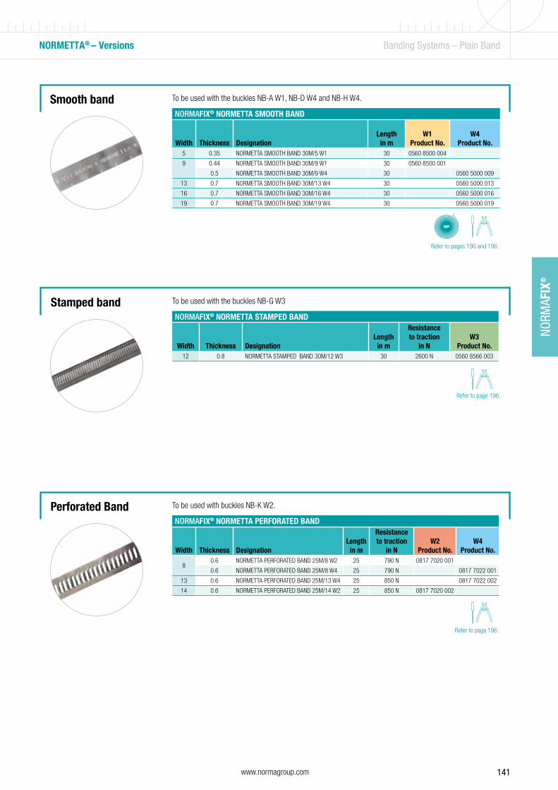
141www.normagroup.com
NORM
AFIX
®
Perforated Band
Smooth band
Stamped band
NORMETTA® – Versions Banding Systems – Plain Band
NORMAFIX® NORMETTA SMOOTH BAND
Width Thickness DesignationLength
in mW1
Product No.W4
Product No.5 0.35 NORMETTA SMOOTH BAND 30M/5 W1 30 0560 8500 004
9 0.44 NORMETTA SMOOTH BAND 30M/9 W1 30 0560 8500 001
0.5 NORMETTA SMOOTH BAND 30M/9 W4 30 0560 5000 009
13 0.7 NORMETTA SMOOTH BAND 30M/13 W4 30 0560 5000 013
16 0.7 NORMETTA SMOOTH BAND 30M/16 W4 30 0560 5000 016
19 0.7 NORMETTA SMOOTH BAND 30M/19 W4 30 0560 5000 019
NORMAFIX® NORMETTA STAMPED BAND
Width Thickness DesignationLength
in m
Resistanceto traction
in NW3
Product No.12 0.8 NORMETTA STAMPED BAND 30M/12 W3 30 2600 N 0560 8566 003
NORMAFIX® NORMETTA PERFORATED BAND
Width Thickness DesignationLength
in m
Resistanceto traction
in NW2
Product No.W4
Product No.
80.6 NORMETTA PERFORATED BAND 25M/8 W2 25 790 N 0817 7020 001
0.6 NORMETTA PERFORATED BAND 25M/8 W4 25 790 N 0817 7022 001
13 0.6 NORMETTA PERFORATED BAND 25M/13 W4 25 850 N 0817 7022 002
14 0.6 NORMETTA PERFORATED BAND 25M/14 W2 25 850 N 0817 7020 002
To be used with the buckles NB-A W1, NB-D W4 and NB-H W4.
To be used with the buckles NB-G W3
To be used with buckles NB-K W2.
Refer to pages 190 and 196.
Refer to page 196.
Refer to page 196.
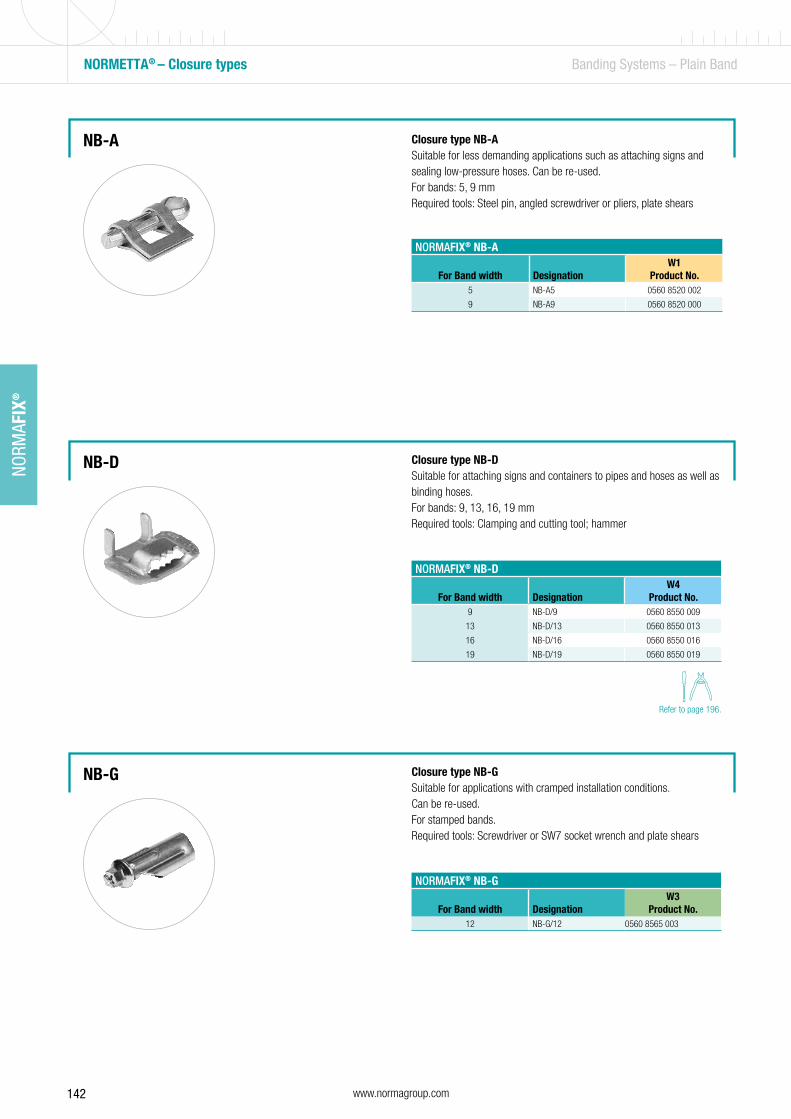
142 www.normagroup.com
NORM
AFIX
®
NORMETTA® – Closure types Banding Systems – Plain Band
NB-A
NB-D
NORMAFIX® NB-A
For Band width DesignationW1
Product No.5 NB-A5 0560 8520 002
9 NB-A9 0560 8520 000
NORMAFIX® NB-D
For Band width DesignationW4
Product No.9 NB-D/9 0560 8550 009
13 NB-D/13 0560 8550 013
16 NB-D/16 0560 8550 016
19 NB-D/19 0560 8550 019
NORMAFIX® NB-G
For Band width DesignationW3
Product No.12 NB-G/12 0560 8565 003
Closure type NB-ASuitable for less demanding applications such as attaching signs and sealing low-pressure hoses. Can be re-used. For bands: 5, 9 mmRequired tools: Steel pin, angled screwdriver or pliers, plate shears
Closure type NB-DSuitable for attaching signs and containers to pipes and hoses as well as binding hoses. For bands: 9, 13, 16, 19 mmRequired tools: Clamping and cutting tool; hammer
Closure type NB-GSuitable for applications with cramped installation conditions.Can be re-used.For stamped bands.Required tools: Screwdriver or SW7 socket wrench and plate shears
NB-G
Refer to page 196.
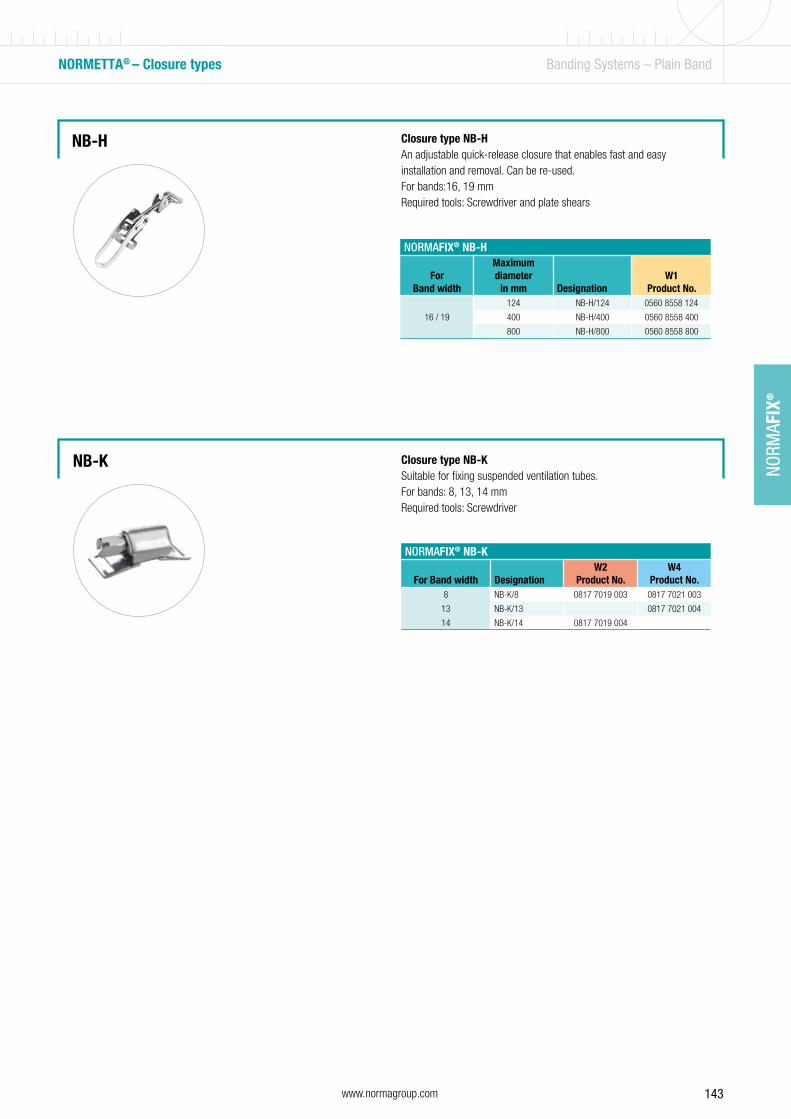
143www.normagroup.com
NORM
AFIX
®
NORMAFIX® NB-H
For Band width
Maximum diameter
in mm DesignationW1
Product No.
16 / 19
124 NB-H/124 0560 8558 124
400 NB-H/400 0560 8558 400
800 NB-H/800 0560 8558 800
Closure type NB-HAn adjustable quick-release closure that enables fast and easy installation and removal. Can be re-used.For bands:16, 19 mmRequired tools: Screwdriver and plate shears
NB-H
NORMETTA® – Closure types Banding Systems – Plain Band
NB-K
NORMAFIX® NB-K
For Band width DesignationW2
Product No.W4
Product No.8 NB-K/8 0817 7019 003 0817 7021 003
13 NB-K/13 0817 7021 004
14 NB-K/14 0817 7019 004
Closure type NB-KSuitable for fixing suspended ventilation tubes.For bands: 8, 13, 14 mmRequired tools: Screwdriver
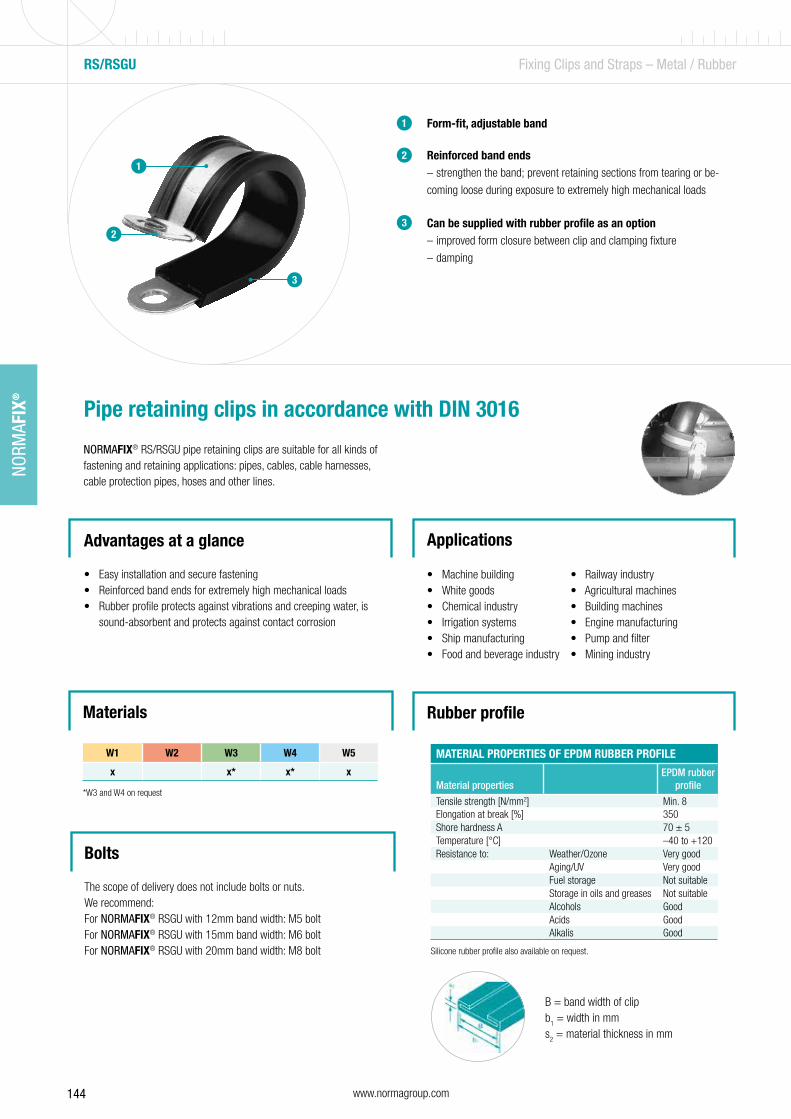
144 www.normagroup.com
NORM
AFIX
®
Rubber profile
Form-fit, adjustable band
Reinforced band ends – strengthen the band; prevent retaining sections from tearing or be-
coming loose during exposure to extremely high mechanical loads
Can be supplied with rubber profile as an option – improved form closure between clip and clamping fixture
– damping
1
2
3
Pipe retaining clips in accordance with DIN 3016
NORMAFIX® RS/RSGU pipe retaining clips are suitable for all kinds of fastening and retaining applications: pipes, cables, cable harnesses, cable protection pipes, hoses and other lines.
Advantages at a glance
• Easy installation and secure fastening• Reinforced band ends for extremely high mechanical loads• Rubber profile protects against vibrations and creeping water, is
sound-absorbent and protects against contact corrosion
Applications
• Machine building • Railway industry• White goods • Agricultural machines• Chemical industry • Building machines• Irrigation systems • Engine manufacturing• Ship manufacturing • Pump and filter• Food and beverage industry • Mining industry
RS/RSGU Fixing Clips and Straps – Metal / Rubber
1
2
3
B = band width of clipb
1 = width in mm
s2 = material thickness in mm
MATERIAL PROPERTIES OF EPDM RUBBER PROFILE
Material propertiesEPDM rubber
profile
Tensile strength [N/mm2] Min. 8Elongation at break [%] 350Shore hardness A 70 ± 5Temperature [°C] –40 to +120Resistance to: Weather/Ozone Very good
Aging/UV Very goodFuel storage Not suitableStorage in oils and greases Not suitableAlcohols GoodAcids GoodAlkalis Good
Silicone rubber profile also available on request.
Bolts
The scope of delivery does not include bolts or nuts.We recommend: For NORMAFIX® RSGU with 12mm band width: M5 bolt For NORMAFIX® RSGU with 15mm band width: M6 bolt For NORMAFIX® RSGU with 20mm band width: M8 bolt
Materials
W1 W2 W3 W4 W5
x x* x* x
*W3 and W4 on request
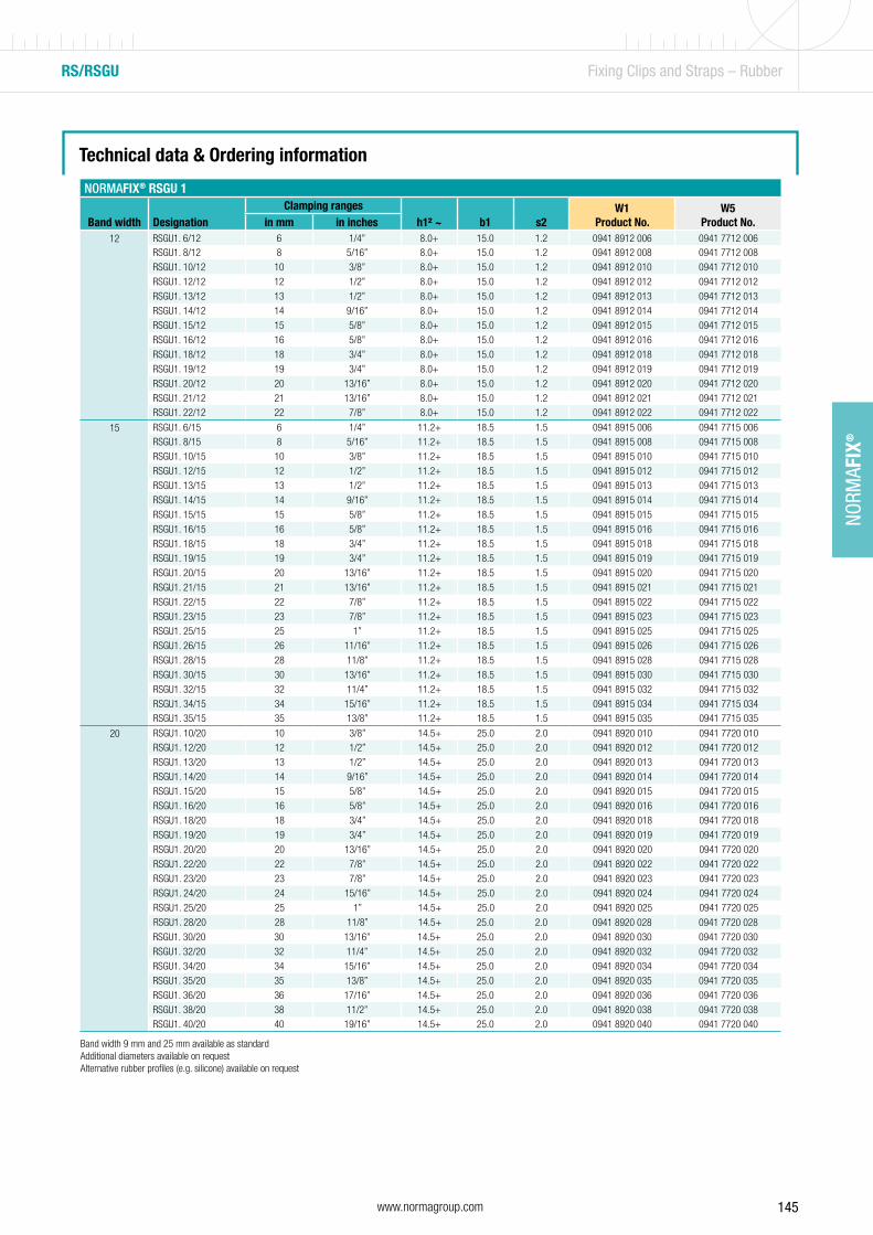
145www.normagroup.com
NORM
AFIX
®
Technical data & Ordering information
NORMAFIX® RSGU 1
Band width DesignationClamping ranges
h1² ~ b1 s2W1
Product No.W5
Product No.in mm in inches12 RSGU1. 6/12 6 1/4” 8.0+ 15.0 1.2 0941 8912 006 0941 7712 006
RSGU1. 8/12 8 5/16” 8.0+ 15.0 1.2 0941 8912 008 0941 7712 008
RSGU1. 10/12 10 3/8” 8.0+ 15.0 1.2 0941 8912 010 0941 7712 010
RSGU1. 12/12 12 1/2” 8.0+ 15.0 1.2 0941 8912 012 0941 7712 012
RSGU1. 13/12 13 1/2” 8.0+ 15.0 1.2 0941 8912 013 0941 7712 013
RSGU1. 14/12 14 9/16” 8.0+ 15.0 1.2 0941 8912 014 0941 7712 014
RSGU1. 15/12 15 5/8” 8.0+ 15.0 1.2 0941 8912 015 0941 7712 015
RSGU1. 16/12 16 5/8” 8.0+ 15.0 1.2 0941 8912 016 0941 7712 016
RSGU1. 18/12 18 3/4” 8.0+ 15.0 1.2 0941 8912 018 0941 7712 018
RSGU1. 19/12 19 3/4” 8.0+ 15.0 1.2 0941 8912 019 0941 7712 019
RSGU1. 20/12 20 13/16” 8.0+ 15.0 1.2 0941 8912 020 0941 7712 020
RSGU1. 21/12 21 13/16” 8.0+ 15.0 1.2 0941 8912 021 0941 7712 021RSGU1. 22/12 22 7/8” 8.0+ 15.0 1.2 0941 8912 022 0941 7712 022
15 RSGU1. 6/15 6 1/4” 11.2+ 18.5 1.5 0941 8915 006 0941 7715 006RSGU1. 8/15 8 5/16” 11.2+ 18.5 1.5 0941 8915 008 0941 7715 008
RSGU1. 10/15 10 3/8” 11.2+ 18.5 1.5 0941 8915 010 0941 7715 010
RSGU1. 12/15 12 1/2” 11.2+ 18.5 1.5 0941 8915 012 0941 7715 012
RSGU1. 13/15 13 1/2” 11.2+ 18.5 1.5 0941 8915 013 0941 7715 013
RSGU1. 14/15 14 9/16” 11.2+ 18.5 1.5 0941 8915 014 0941 7715 014
RSGU1. 15/15 15 5/8” 11.2+ 18.5 1.5 0941 8915 015 0941 7715 015
RSGU1. 16/15 16 5/8” 11.2+ 18.5 1.5 0941 8915 016 0941 7715 016
RSGU1. 18/15 18 3/4” 11.2+ 18.5 1.5 0941 8915 018 0941 7715 018
RSGU1. 19/15 19 3/4” 11.2+ 18.5 1.5 0941 8915 019 0941 7715 019
RSGU1. 20/15 20 13/16” 11.2+ 18.5 1.5 0941 8915 020 0941 7715 020
RSGU1. 21/15 21 13/16” 11.2+ 18.5 1.5 0941 8915 021 0941 7715 021
RSGU1. 22/15 22 7/8” 11.2+ 18.5 1.5 0941 8915 022 0941 7715 022
RSGU1. 23/15 23 7/8” 11.2+ 18.5 1.5 0941 8915 023 0941 7715 023
RSGU1. 25/15 25 1” 11.2+ 18.5 1.5 0941 8915 025 0941 7715 025
RSGU1. 26/15 26 11/16” 11.2+ 18.5 1.5 0941 8915 026 0941 7715 026
RSGU1. 28/15 28 11/8” 11.2+ 18.5 1.5 0941 8915 028 0941 7715 028
RSGU1. 30/15 30 13/16” 11.2+ 18.5 1.5 0941 8915 030 0941 7715 030
RSGU1. 32/15 32 11/4” 11.2+ 18.5 1.5 0941 8915 032 0941 7715 032
RSGU1. 34/15 34 15/16” 11.2+ 18.5 1.5 0941 8915 034 0941 7715 034RSGU1. 35/15 35 13/8” 11.2+ 18.5 1.5 0941 8915 035 0941 7715 035
20 RSGU1. 10/20 10 3/8” 14.5+ 25.0 2.0 0941 8920 010 0941 7720 010RSGU1. 12/20 12 1/2” 14.5+ 25.0 2.0 0941 8920 012 0941 7720 012
RSGU1. 13/20 13 1/2” 14.5+ 25.0 2.0 0941 8920 013 0941 7720 013
RSGU1. 14/20 14 9/16” 14.5+ 25.0 2.0 0941 8920 014 0941 7720 014
RSGU1. 15/20 15 5/8” 14.5+ 25.0 2.0 0941 8920 015 0941 7720 015
RSGU1. 16/20 16 5/8” 14.5+ 25.0 2.0 0941 8920 016 0941 7720 016
RSGU1. 18/20 18 3/4” 14.5+ 25.0 2.0 0941 8920 018 0941 7720 018
RSGU1. 19/20 19 3/4” 14.5+ 25.0 2.0 0941 8920 019 0941 7720 019
RSGU1. 20/20 20 13/16” 14.5+ 25.0 2.0 0941 8920 020 0941 7720 020
RSGU1. 22/20 22 7/8” 14.5+ 25.0 2.0 0941 8920 022 0941 7720 022
RSGU1. 23/20 23 7/8” 14.5+ 25.0 2.0 0941 8920 023 0941 7720 023
RSGU1. 24/20 24 15/16” 14.5+ 25.0 2.0 0941 8920 024 0941 7720 024
RSGU1. 25/20 25 1” 14.5+ 25.0 2.0 0941 8920 025 0941 7720 025
RSGU1. 28/20 28 11/8” 14.5+ 25.0 2.0 0941 8920 028 0941 7720 028
RSGU1. 30/20 30 13/16” 14.5+ 25.0 2.0 0941 8920 030 0941 7720 030
RSGU1. 32/20 32 11/4” 14.5+ 25.0 2.0 0941 8920 032 0941 7720 032
RSGU1. 34/20 34 15/16” 14.5+ 25.0 2.0 0941 8920 034 0941 7720 034
RSGU1. 35/20 35 13/8” 14.5+ 25.0 2.0 0941 8920 035 0941 7720 035
RSGU1. 36/20 36 17/16” 14.5+ 25.0 2.0 0941 8920 036 0941 7720 036
RSGU1. 38/20 38 11/2” 14.5+ 25.0 2.0 0941 8920 038 0941 7720 038RSGU1. 40/20 40 19/16” 14.5+ 25.0 2.0 0941 8920 040 0941 7720 040
Band width 9 mm and 25 mm available as standardAdditional diameters available on request Alternative rubber profiles (e.g. silicone) available on request
RS/RSGU Fixing Clips and Straps – Rubber

146 www.normagroup.com
NORM
AFIX
®
RS/RSGU – Versions Fixing Clips and Straps – Rubber
RSGU 0
NORMAFIX® RSGU 0Band width Designation
Clamping rangesh1² ~ b1 s2
W1Product No.
W5Product No.in mm in inches
12 RSGU0. 6/12 6 1/4” 8.0+ 15.0 1.2 0940 8912 006 0940 7712 006
RSGU0. 8/12 8 5/16” 8.0+ 15.0 1.2 0940 8912 008 0940 7712 008
RSGU0. 10/12 10 3/8” 8.0+ 15.0 1.2 0940 8912 010 0940 7712 010
RSGU0. 12/12 12 1/2” 8.0+ 15.0 1.2 0940 8912 012 0940 7712 012
RSGU0. 13/12 13 1/2” 8.0+ 15.0 1.2 0940 8912 013 0940 7712 013
RSGU0. 14/12 14 9/16” 8.0+ 15.0 1.2 0940 8912 014 0940 7712 014
RSGU0. 15/12 15 5/8” 8.0+ 15.0 1.2 0940 8912 015 0940 7712 015
RSGU0. 16/12 16 5/8” 8.0+ 15.0 1.2 0940 8912 016 0940 7712 016
RSGU0. 18/12 18 3/4” 8.0+ 15.0 1.2 0940 8912 018 0940 7712 018
RSGU0. 19/12 19 3/4” 8.0+ 15.0 1.2 0940 8912 019 0940 7712 019
RSGU0. 20/12 20 13/16” 8.0+ 15.0 1.2 0940 8912 020 0940 7712 020
RSGU0. 21/12 21 13/16” 8.0+ 15.0 1.2 0940 8912 021 0940 7712 021
RSGU0. 22/12 22 7/8” 8.0+ 15.0 1.2 0940 8912 022 0940 7712 022
15 RSGU0. 6/15 6 1/4” 11.2+ 18.5 1.5 0940 8915 006 0940 7715 006
RSGU0. 8/15 8 5/16” 11.2+ 18.5 1.5 0940 8915 008 0940 7715 008
RSGU0. 10/15 10 3/8” 11.2+ 18.5 1.5 0940 8915 010 0940 7715 010
RSGU0. 12/15 12 1/2” 11.2+ 18.5 1.5 0940 8915 012 0940 7715 012
RSGU0. 13/15 13 1/2” 11.2+ 18.5 1.5 0940 8915 013 0940 7715 013
RSGU0. 14/15 14 9/16” 11.2+ 18.5 1.5 0940 8915 014 0940 7715 014
RSGU0. 15/15 15 5/8” 11.2+ 18.5 1.5 0940 8915 015 0940 7715 015
RSGU0. 16/15 16 5/8” 11.2+ 18.5 1.5 0940 8915 016 0940 7715 016
RSGU0. 18/15 18 3/4” 11.2+ 18.5 1.5 0940 8915 018 0940 7715 018
RSGU0. 19/15 19 3/4” 11.2+ 18.5 1.5 0940 8915 019 0940 7715 019
RSGU0. 20/15 20 13/16” 11.2+ 18.5 1.5 0940 8915 020 0940 7715 020
RSGU0. 21/15 21 13/16” 11.2+ 18.5 1.5 0940 8915 021 0940 7715 021
RSGU0. 22/15 22 7/8” 11.2+ 18.5 1.5 0940 8915 022 0940 7715 022
RSGU0. 23/15 23 7/8” 11.2+ 18.5 1.5 0940 8915 023 0940 7715 023
RSGU0. 25/15 25 1” 11.2+ 18.5 1.5 0940 8915 025 0940 7715 025
RSGU0. 26/15 26 11/16” 11.2+ 18.5 1.5 0940 8915 026 0940 7715 026
RSGU0. 28/15 28 11/8” 11.2+ 18.5 1.5 0940 8915 028 0940 7715 028
RSGU0. 30/15 30 13/16” 11.2+ 18.5 1.5 0940 8915 030 0940 7715 030
RSGU0. 32/15 32 11/4” 11.2+ 18.5 1.5 0940 8915 032 0940 7715 032
RSGU0. 34/15 34 15/16” 11.2+ 18.5 1.5 0940 8915 034 0940 7715 034
RSGU0. 35/15 35 13/8” 11.2+ 18.5 1.5 0940 8915 035 0940 7715 035
20 RSGU0. 10/20 10 3/8” 14.5+ 25.0 2.0 0940 8920 010 0940 7720 010
RSGU0. 12/20 12 1/2” 14.5+ 25.0 2.0 0940 8920 012 0940 7720 012
RSGU0. 13/20 13 1/2” 14.5+ 25.0 2.0 0940 8920 013 0940 7720 013
RSGU0. 14/20 14 9/16” 14.5+ 25.0 2.0 0940 8920 014 0940 7720 014
RSGU0. 15/20 15 5/8” 14.5+ 25.0 2.0 0940 8920 015 0940 7720 015
RSGU0. 16/20 16 5/8” 14.5+ 25.0 2.0 0940 8920 016 0940 7720 016
RSGU0. 18/20 18 3/4” 14.5+ 25.0 2.0 0940 8920 018 0940 7720 018
RSGU0. 19/20 19 3/4” 14.5+ 25.0 2.0 0940 8920 019 0940 7720 019
RSGU0. 20/20 20 13/16” 14.5+ 25.0 2.0 0940 8920 020 0940 7720 020
RSGU0. 22/20 22 7/8” 14.5+ 25.0 2.0 0940 8920 022 0940 7720 022
RSGU0. 23/20 23 7/8” 14.5+ 25.0 2.0 0940 8920 023 0940 7720 023
RSGU0. 24/20 24 15/16” 14.5+ 25.0 2.0 0940 8920 024 0940 7720 024
RSGU0. 25/20 25 1” 14.5+ 25.0 2.0 0940 8920 025 0940 7720 025
RSGU0. 28/20 28 11/8” 14.5+ 25.0 2.0 0940 8920 028 0940 7720 028
RSGU0. 30/20 30 13/16” 14.5+ 25.0 2.0 0940 8920 030 0940 7720 030
RSGU0. 32/20 32 11/4” 14.5+ 25.0 2.0 0940 8920 032 0940 7720 032
RSGU0. 34/20 34 15/16” 14.5+ 25.0 2.0 0940 8920 034 0940 7720 034
RSGU0. 35/20 35 13/8” 14.5+ 25.0 2.0 0940 8920 035 0940 7720 035
RSGU0. 36/20 36 17/16” 14.5+ 25.0 2.0 0940 8920 036 0940 7720 036
RSGU0. 38/20 38 11/2” 14.5+ 25.0 2.0 0940 8920 038 0940 7720 038
RSGU0. 40/20 40 19/16” 14.5+ 25.0 2.0 0940 8920 040 0940 7720 040
Band width 9 mm and 25 mm available as standardAdditional diameters available on request Alternative rubber profiles (e.g. silicone) available on request
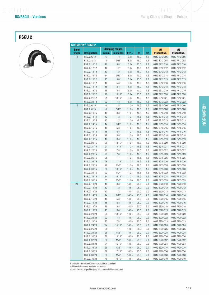
147www.normagroup.com
NORM
AFIX
®
RS/RSGU – Versions Fixing Clips and Straps – Rubber
RSGU 2
Band width 9 mm and 25 mm available as standardAdditional diameters available on request Alternative rubber profiles (e.g. silicone) available on request
NORMAFIX® RSGU 2Band width Designation
Clamping rangesh1² ~ b1 s2
W1Product No.
W5Product No.in mm in inches
12 RSGU2. 6/12 6 1/4” 8.0+ 15.0 1.2 0942 8912 006 0942 7712 006
RSGU2. 8/12 8 5/16” 8.0+ 15.0 1.2 0942 8912 008 0942 7712 008
RSGU2. 10/12 10 3/8” 8.0+ 15.0 1.2 0942 8912 010 0942 7712 010
RSGU2. 12/12 12 1/2” 8.0+ 15.0 1.2 0942 8912 012 0942 7712 012
RSGU2. 13/12 13 1/2” 8.0+ 15.0 1.2 0942 8912 013 0942 7712 013
RSGU2. 14/12 14 9/16” 8.0+ 15.0 1.2 0942 8912 014 0942 7712 014
RSGU2. 15/12 15 5/8” 8.0+ 15.0 1.2 0942 8912 015 0942 7712 015
RSGU2. 16/12 16 5/8” 8.0+ 15.0 1.2 0942 8912 016 0942 7712 016
RSGU2. 18/12 18 3/4” 8.0+ 15.0 1.2 0942 8912 018 0942 7712 018
RSGU2. 19/12 19 3/4” 8.0+ 15.0 1.2 0942 8912 019 0942 7712 019
RSGU2. 20/12 20 13/16” 8.0+ 15.0 1.2 0942 8912 020 0942 7712 020
RSGU2. 21/12 21 13/16” 8.0+ 15.0 1.2 0942 8912 021 0942 7712 021
RSGU2. 22/12 22 7/8” 8.0+ 15.0 1.2 0942 8912 022 0942 7712 022
15 RSGU2. 6/15 6 1/4” 11.2+ 18.5 1.5 0942 8915 006 0942 7715 006
RSGU2. 8/15 8 5/16” 11.2+ 18.5 1.5 0942 8915 008 0942 7715 008
RSGU2. 10/15 10 3/8” 11.2+ 18.5 1.5 0942 8915 010 0942 7715 010
RSGU2. 12/15 12 1/2” 11.2+ 18.5 1.5 0942 8915 012 0942 7715 012
RSGU2. 13/15 13 1/2” 11.2+ 18.5 1.5 0942 8915 013 0942 7715 013
RSGU2. 14/15 14 9/16” 11.2+ 18.5 1.5 0942 8915 014 0942 7715 014
RSGU2. 15/15 15 5/8” 11.2+ 18.5 1.5 0942 8915 015 0942 7715 015
RSGU2. 16/15 16 5/8” 11.2+ 18.5 1.5 0942 8915 016 0942 7715 016
RSGU2. 18/15 18 3/4” 11.2+ 18.5 1.5 0942 8915 018 0942 7715 018
RSGU2. 19/15 19 3/4” 11.2+ 18.5 1.5 0942 8915 019 0942 7715 019
RSGU2. 20/15 20 13/16” 11.2+ 18.5 1.5 0942 8915 020 0942 7715 020
RSGU2. 21/15 21 13/16” 11.2+ 18.5 1.5 0942 8915 021 0942 7715 021
RSGU2. 22/15 22 7/8” 11.2+ 18.5 1.5 0942 8915 022 0942 7715 022
RSGU2. 23/15 23 7/8” 11.2+ 18.5 1.5 0942 8915 023 0942 7715 023
RSGU2. 25/15 25 1” 11.2+ 18.5 1.5 0942 8915 025 0942 7715 025
RSGU2. 26/15 26 11/16” 11.2+ 18.5 1.5 0942 8915 026 0942 7715 026
RSGU2. 28/15 28 11/8” 11.2+ 18.5 1.5 0942 8915 028 0942 7715 028
RSGU2. 30/15 30 13/16” 11.2+ 18.5 1.5 0942 8915 030 0942 7715 030
RSGU2. 32/15 32 11/4” 11.2+ 18.5 1.5 0942 8915 032 0942 7715 032
RSGU2. 34/15 34 15/16” 11.2+ 18.5 1.5 0942 8915 034 0942 7715 034
RSGU2. 35/15 35 13/8” 11.2+ 18.5 1.5 0942 8915 035 0942 7715 035
20 RSGU2. 10/20 10 3/8” 14.5+ 25.0 2.0 0942 8920 010 0942 7720 010
RSGU2. 12/20 12 1/2” 14.5+ 25.0 2.0 0942 8920 012 0942 7720 012
RSGU2. 13/20 13 1/2” 14.5+ 25.0 2.0 0942 8920 013 0942 7720 013
RSGU2. 14/20 14 9/16” 14.5+ 25.0 2.0 0942 8920 014 0942 7720 014
RSGU2. 15/20 15 5/8” 14.5+ 25.0 2.0 0942 8920 015 0942 7720 015
RSGU2. 16/20 16 5/8” 14.5+ 25.0 2.0 0942 8920 016 0942 7720 016
RSGU2. 18/20 18 3/4” 14.5+ 25.0 2.0 0942 8920 018 0942 7720 018
RSGU2. 19/20 19 3/4” 14.5+ 25.0 2.0 0942 8920 019 0942 7720 019
RSGU2. 20/20 20 13/16” 14.5+ 25.0 2.0 0942 8920 020 0942 7720 020
RSGU2. 22/20 22 7/8” 14.5+ 25.0 2.0 0942 8920 022 0942 7720 022
RSGU2. 23/20 23 7/8” 14.5+ 25.0 2.0 0942 8920 023 0942 7720 023
RSGU2. 24/20 24 15/16” 14.5+ 25.0 2.0 0942 8920 024 0942 7720 024
RSGU2. 25/20 25 1” 14.5+ 25.0 2.0 0942 8920 025 0942 7720 025
RSGU2. 28/20 28 11/8” 14.5+ 25.0 2.0 0942 8920 028 0942 7720 028
RSGU2. 30/20 30 13/16” 14.5+ 25.0 2.0 0942 8920 030 0942 7720 030
RSGU2. 32/20 32 11/4” 14.5+ 25.0 2.0 0942 8920 032 0942 7720 032
RSGU2. 34/20 34 15/16” 14.5+ 25.0 2.0 0942 8920 034 0942 7720 034
RSGU2. 35/20 35 13/8” 14.5+ 25.0 2.0 0942 8920 035 0942 7720 035
RSGU2. 36/20 36 17/16” 14.5+ 25.0 2.0 0942 8920 036 0942 7720 036
RSGU2. 38/20 38 11/2” 14.5+ 25.0 2.0 0942 8920 038 0942 7720 038
RSGU2. 40/20 40 19/16” 14.5+ 25.0 2.0 0942 8920 040 0942 7720 040

148 www.normagroup.com
NORM
AFIX
®
RSGUV 1NEW!
The NORMAFIX® RSGUV 1 can be can be pre-positioned on the hose. The locking device keeps the RSGUV 1 safely in place if it needs to be stocked or transported prior to its final assembly.
Available in band widths of 15 and 20 mm, in the same dimensions as our RSGU 1. This system can only be fixed by using a special tool.
Advantages at a glance• Safe pre-assembly on the hose• No unintentional opening of the clamp during handling
or transportation
MaterialsW1, W3, W4, W5 Refer to page 198.
RS/RSGU - Versions Fixing Clips and Straps –Rubber
NEW
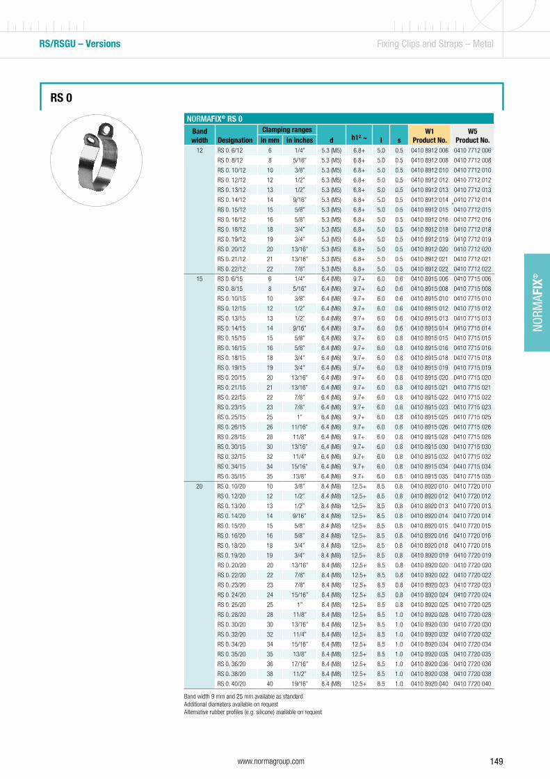
149www.normagroup.com
NORM
AFIX
®
RS/RSGU – Versions Fixing Clips and Straps – Metal
RS 0
NORMAFIX® RS 0Band width Designation
Clamping rangesd h1² ~ l s
W1Product No.
W5Product No.in mm in inches
12 RS 0. 6/12 6 1/4” 5.3 (M5) 6.8+ 5.0 0.5 0410 8912 006 0410 7712 006
RS 0. 8/12 8 5/16” 5.3 (M5) 6.8+ 5.0 0.5 0410 8912 008 0410 7712 008
RS 0. 10/12 10 3/8” 5.3 (M5) 6.8+ 5.0 0.5 0410 8912 010 0410 7712 010
RS 0. 12/12 12 1/2” 5.3 (M5) 6.8+ 5.0 0.5 0410 8912 012 0410 7712 012
RS 0. 13/12 13 1/2” 5.3 (M5) 6.8+ 5.0 0.5 0410 8912 013 0410 7712 013
RS 0. 14/12 14 9/16” 5.3 (M5) 6.8+ 5.0 0.5 0410 8912 014 0410 7712 014
RS 0. 15/12 15 5/8” 5.3 (M5) 6.8+ 5.0 0.5 0410 8912 015 0410 7712 015
RS 0. 16/12 16 5/8” 5.3 (M5) 6.8+ 5.0 0.5 0410 8912 016 0410 7712 016
RS 0. 18/12 18 3/4” 5.3 (M5) 6.8+ 5.0 0.5 0410 8912 018 0410 7712 018
RS 0. 19/12 19 3/4” 5.3 (M5) 6.8+ 5.0 0.5 0410 8912 019 0410 7712 019
RS 0. 20/12 20 13/16” 5.3 (M5) 6.8+ 5.0 0.5 0410 8912 020 0410 7712 020
RS 0. 21/12 21 13/16” 5.3 (M5) 6.8+ 5.0 0.5 0410 8912 021 0410 7712 021
RS 0. 22/12 22 7/8” 5.3 (M5) 6.8+ 5.0 0.5 0410 8912 022 0410 7712 022
15 RS 0. 6/15 6 1/4” 6.4 (M6) 9.7+ 6.0 0.6 0410 8915 006 0410 7715 006
RS 0. 8/15 8 5/16” 6.4 (M6) 9.7+ 6.0 0.6 0410 8915 008 0410 7715 008
RS 0. 10/15 10 3/8” 6.4 (M6) 9.7+ 6.0 0.6 0410 8915 010 0410 7715 010
RS 0. 12/15 12 1/2” 6.4 (M6) 9.7+ 6.0 0.6 0410 8915 012 0410 7715 012
RS 0. 13/15 13 1/2” 6.4 (M6) 9.7+ 6.0 0.6 0410 8915 013 0410 7715 013
RS 0. 14/15 14 9/16” 6.4 (M6) 9.7+ 6.0 0.6 0410 8915 014 0410 7715 014
RS 0. 15/15 15 5/8” 6.4 (M6) 9.7+ 6.0 0.8 0410 8915 015 0410 7715 015
RS 0. 16/15 16 5/8” 6.4 (M6) 9.7+ 6.0 0.8 0410 8915 016 0410 7715 016
RS 0. 18/15 18 3/4” 6.4 (M6) 9.7+ 6.0 0.8 0410 8915 018 0410 7715 018
RS 0. 19/15 19 3/4” 6.4 (M6) 9.7+ 6.0 0.8 0410 8915 019 0410 7715 019
RS 0. 20/15 20 13/16” 6.4 (M6) 9.7+ 6.0 0.8 0410 8915 020 0410 7715 020
RS 0. 21/15 21 13/16” 6.4 (M6) 9.7+ 6.0 0.8 0410 8915 021 0410 7715 021
RS 0. 22/15 22 7/8” 6.4 (M6) 9.7+ 6.0 0.8 0410 8915 022 0410 7715 022
RS 0. 23/15 23 7/8” 6.4 (M6) 9.7+ 6.0 0.8 0410 8915 023 0410 7715 023
RS 0. 25/15 25 1” 6.4 (M6) 9.7+ 6.0 0.8 0410 8915 025 0410 7715 025
RS 0. 26/15 26 11/16” 6.4 (M6) 9.7+ 6.0 0.8 0410 8915 026 0410 7715 026
RS 0. 28/15 28 11/8” 6.4 (M6) 9.7+ 6.0 0.8 0410 8915 028 0410 7715 028
RS 0. 30/15 30 13/16” 6.4 (M6) 9.7+ 6.0 0.8 0410 8915 030 0410 7715 030
RS 0. 32/15 32 11/4” 6.4 (M6) 9.7+ 6.0 0.8 0410 8915 032 0410 7715 032
RS 0. 34/15 34 15/16” 6.4 (M6) 9.7+ 6.0 0.8 0410 8915 034 0410 7715 034
RS 0. 35/15 35 13/8” 6.4 (M6) 9.7+ 6.0 0.8 0410 8915 035 0410 7715 035
20 RS 0. 10/20 10 3/8” 8.4 (M8) 12.5+ 8.5 0.8 0410 8920 010 0410 7720 010
RS 0. 12/20 12 1/2” 8.4 (M8) 12.5+ 8.5 0.8 0410 8920 012 0410 7720 012
RS 0. 13/20 13 1/2” 8.4 (M8) 12.5+ 8.5 0.8 0410 8920 013 0410 7720 013
RS 0. 14/20 14 9/16” 8.4 (M8) 12.5+ 8.5 0.8 0410 8920 014 0410 7720 014
RS 0. 15/20 15 5/8” 8.4 (M8) 12.5+ 8.5 0.8 0410 8920 015 0410 7720 015
RS 0. 16/20 16 5/8” 8.4 (M8) 12.5+ 8.5 0.8 0410 8920 016 0410 7720 016
RS 0. 18/20 18 3/4” 8.4 (M8) 12.5+ 8.5 0.8 0410 8920 018 0410 7720 018
RS 0. 19/20 19 3/4” 8.4 (M8) 12.5+ 8.5 0.8 0410 8920 019 0410 7720 019
RS 0. 20/20 20 13/16” 8.4 (M8) 12.5+ 8.5 0.8 0410 8920 020 0410 7720 020
RS 0. 22/20 22 7/8” 8.4 (M8) 12.5+ 8.5 0.8 0410 8920 022 0410 7720 022
RS 0. 23/20 23 7/8” 8.4 (M8) 12.5+ 8.5 0.8 0410 8920 023 0410 7720 023
RS 0. 24/20 24 15/16” 8.4 (M8) 12.5+ 8.5 0.8 0410 8920 024 0410 7720 024
RS 0. 25/20 25 1” 8.4 (M8) 12.5+ 8.5 0.8 0410 8920 025 0410 7720 025
RS 0. 28/20 28 11/8” 8.4 (M8) 12.5+ 8.5 1.0 0410 8920 028 0410 7720 028
RS 0. 30/20 30 13/16” 8.4 (M8) 12.5+ 8.5 1.0 0410 8920 030 0410 7720 030
RS 0. 32/20 32 11/4” 8.4 (M8) 12.5+ 8.5 1.0 0410 8920 032 0410 7720 032
RS 0. 34/20 34 15/16” 8.4 (M8) 12.5+ 8.5 1.0 0410 8920 034 0410 7720 034
RS 0. 35/20 35 13/8” 8.4 (M8) 12.5+ 8.5 1.0 0410 8920 035 0410 7720 035
RS 0. 36/20 36 17/16” 8.4 (M8) 12.5+ 8.5 1.0 0410 8920 036 0410 7720 036
RS 0. 38/20 38 11/2” 8.4 (M8) 12.5+ 8.5 1.0 0410 8920 038 0410 7720 038
RS 0. 40/20 40 19/16” 8.4 (M8) 12.5+ 8.5 1.0 0410 8920 040 0410 7720 040
Band width 9 mm and 25 mm available as standardAdditional diameters available on request Alternative rubber profiles (e.g. silicone) available on request
”
”
”
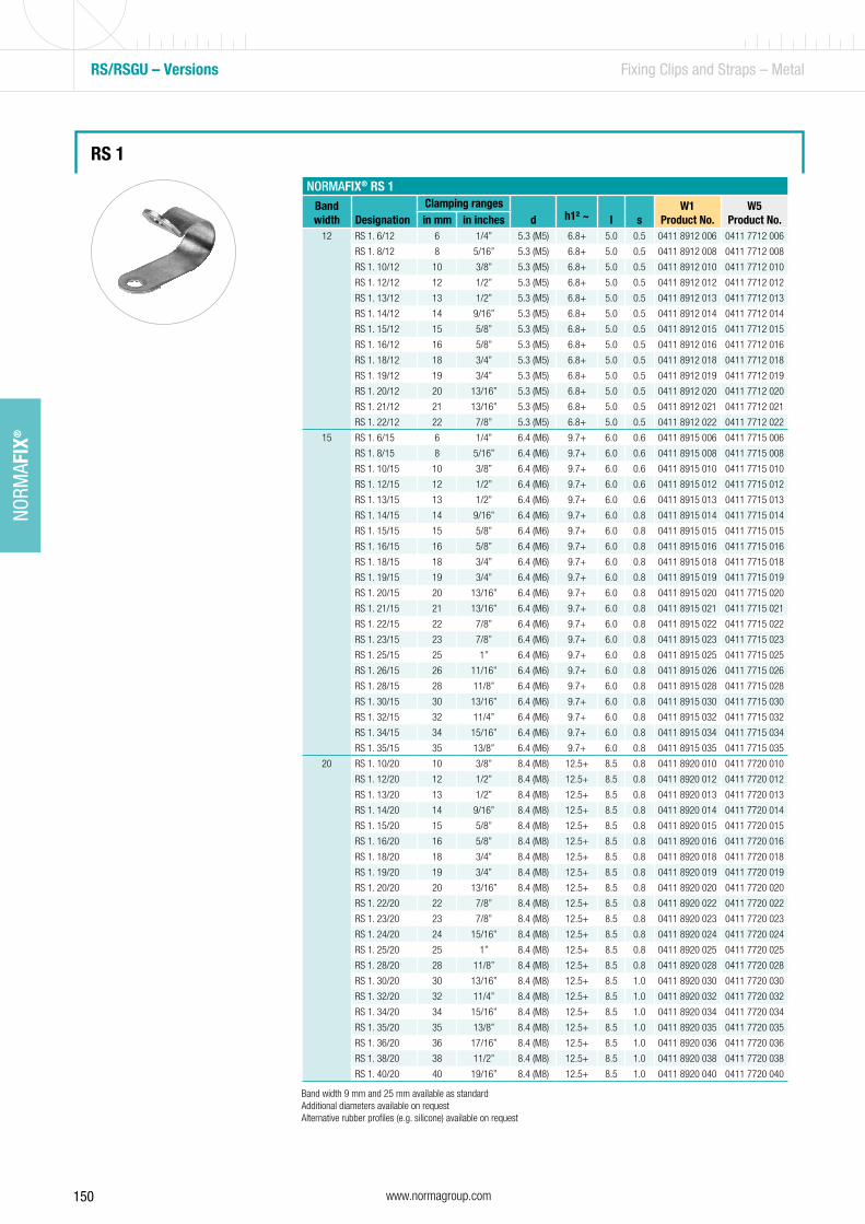
150 www.normagroup.com
NORM
AFIX
®
RS 1
RS/RSGU – Versions Fixing Clips and Straps – Metal
NORMAFIX® RS 1Band width Designation
Clamping rangesd h1² ~ l s
W1Product No.
W5Product No.in mm in inches
12 RS 1. 6/12 6 1/4” 5.3 (M5) 6.8+ 5.0 0.5 0411 8912 006 0411 7712 006
RS 1. 8/12 8 5/16” 5.3 (M5) 6.8+ 5.0 0.5 0411 8912 008 0411 7712 008
RS 1. 10/12 10 3/8” 5.3 (M5) 6.8+ 5.0 0.5 0411 8912 010 0411 7712 010
RS 1. 12/12 12 1/2” 5.3 (M5) 6.8+ 5.0 0.5 0411 8912 012 0411 7712 012
RS 1. 13/12 13 1/2” 5.3 (M5) 6.8+ 5.0 0.5 0411 8912 013 0411 7712 013
RS 1. 14/12 14 9/16” 5.3 (M5) 6.8+ 5.0 0.5 0411 8912 014 0411 7712 014
RS 1. 15/12 15 5/8” 5.3 (M5) 6.8+ 5.0 0.5 0411 8912 015 0411 7712 015
RS 1. 16/12 16 5/8” 5.3 (M5) 6.8+ 5.0 0.5 0411 8912 016 0411 7712 016
RS 1. 18/12 18 3/4” 5.3 (M5) 6.8+ 5.0 0.5 0411 8912 018 0411 7712 018
RS 1. 19/12 19 3/4” 5.3 (M5) 6.8+ 5.0 0.5 0411 8912 019 0411 7712 019
RS 1. 20/12 20 13/16” 5.3 (M5) 6.8+ 5.0 0.5 0411 8912 020 0411 7712 020
RS 1. 21/12 21 13/16” 5.3 (M5) 6.8+ 5.0 0.5 0411 8912 021 0411 7712 021
RS 1. 22/12 22 7/8” 5.3 (M5) 6.8+ 5.0 0.5 0411 8912 022 0411 7712 022
15 RS 1. 6/15 6 1/4” 6.4 (M6) 9.7+ 6.0 0.6 0411 8915 006 0411 7715 006
RS 1. 8/15 8 5/16” 6.4 (M6) 9.7+ 6.0 0.6 0411 8915 008 0411 7715 008
RS 1. 10/15 10 3/8” 6.4 (M6) 9.7+ 6.0 0.6 0411 8915 010 0411 7715 010
RS 1. 12/15 12 1/2” 6.4 (M6) 9.7+ 6.0 0.6 0411 8915 012 0411 7715 012
RS 1. 13/15 13 1/2” 6.4 (M6) 9.7+ 6.0 0.6 0411 8915 013 0411 7715 013
RS 1. 14/15 14 9/16” 6.4 (M6) 9.7+ 6.0 0.8 0411 8915 014 0411 7715 014
RS 1. 15/15 15 5/8” 6.4 (M6) 9.7+ 6.0 0.8 0411 8915 015 0411 7715 015
RS 1. 16/15 16 5/8” 6.4 (M6) 9.7+ 6.0 0.8 0411 8915 016 0411 7715 016
RS 1. 18/15 18 3/4” 6.4 (M6) 9.7+ 6.0 0.8 0411 8915 018 0411 7715 018
RS 1. 19/15 19 3/4” 6.4 (M6) 9.7+ 6.0 0.8 0411 8915 019 0411 7715 019
RS 1. 20/15 20 13/16” 6.4 (M6) 9.7+ 6.0 0.8 0411 8915 020 0411 7715 020
RS 1. 21/15 21 13/16” 6.4 (M6) 9.7+ 6.0 0.8 0411 8915 021 0411 7715 021
RS 1. 22/15 22 7/8” 6.4 (M6) 9.7+ 6.0 0.8 0411 8915 022 0411 7715 022
RS 1. 23/15 23 7/8” 6.4 (M6) 9.7+ 6.0 0.8 0411 8915 023 0411 7715 023
RS 1. 25/15 25 1” 6.4 (M6) 9.7+ 6.0 0.8 0411 8915 025 0411 7715 025
RS 1. 26/15 26 11/16” 6.4 (M6) 9.7+ 6.0 0.8 0411 8915 026 0411 7715 026
RS 1. 28/15 28 11/8” 6.4 (M6) 9.7+ 6.0 0.8 0411 8915 028 0411 7715 028
RS 1. 30/15 30 13/16” 6.4 (M6) 9.7+ 6.0 0.8 0411 8915 030 0411 7715 030
RS 1. 32/15 32 11/4” 6.4 (M6) 9.7+ 6.0 0.8 0411 8915 032 0411 7715 032
RS 1. 34/15 34 15/16” 6.4 (M6) 9.7+ 6.0 0.8 0411 8915 034 0411 7715 034
RS 1. 35/15 35 13/8” 6.4 (M6) 9.7+ 6.0 0.8 0411 8915 035 0411 7715 035
20 RS 1. 10/20 10 3/8” 8.4 (M8) 12.5+ 8.5 0.8 0411 8920 010 0411 7720 010
RS 1. 12/20 12 1/2” 8.4 (M8) 12.5+ 8.5 0.8 0411 8920 012 0411 7720 012
RS 1. 13/20 13 1/2” 8.4 (M8) 12.5+ 8.5 0.8 0411 8920 013 0411 7720 013
RS 1. 14/20 14 9/16” 8.4 (M8) 12.5+ 8.5 0.8 0411 8920 014 0411 7720 014
RS 1. 15/20 15 5/8” 8.4 (M8) 12.5+ 8.5 0.8 0411 8920 015 0411 7720 015
RS 1. 16/20 16 5/8” 8.4 (M8) 12.5+ 8.5 0.8 0411 8920 016 0411 7720 016
RS 1. 18/20 18 3/4” 8.4 (M8) 12.5+ 8.5 0.8 0411 8920 018 0411 7720 018
RS 1. 19/20 19 3/4” 8.4 (M8) 12.5+ 8.5 0.8 0411 8920 019 0411 7720 019
RS 1. 20/20 20 13/16” 8.4 (M8) 12.5+ 8.5 0.8 0411 8920 020 0411 7720 020
RS 1. 22/20 22 7/8” 8.4 (M8) 12.5+ 8.5 0.8 0411 8920 022 0411 7720 022
RS 1. 23/20 23 7/8” 8.4 (M8) 12.5+ 8.5 0.8 0411 8920 023 0411 7720 023
RS 1. 24/20 24 15/16” 8.4 (M8) 12.5+ 8.5 0.8 0411 8920 024 0411 7720 024
RS 1. 25/20 25 1” 8.4 (M8) 12.5+ 8.5 0.8 0411 8920 025 0411 7720 025
RS 1. 28/20 28 11/8” 8.4 (M8) 12.5+ 8.5 0.8 0411 8920 028 0411 7720 028
RS 1. 30/20 30 13/16” 8.4 (M8) 12.5+ 8.5 1.0 0411 8920 030 0411 7720 030
RS 1. 32/20 32 11/4” 8.4 (M8) 12.5+ 8.5 1.0 0411 8920 032 0411 7720 032
RS 1. 34/20 34 15/16” 8.4 (M8) 12.5+ 8.5 1.0 0411 8920 034 0411 7720 034
RS 1. 35/20 35 13/8” 8.4 (M8) 12.5+ 8.5 1.0 0411 8920 035 0411 7720 035
RS 1. 36/20 36 17/16” 8.4 (M8) 12.5+ 8.5 1.0 0411 8920 036 0411 7720 036
RS 1. 38/20 38 11/2” 8.4 (M8) 12.5+ 8.5 1.0 0411 8920 038 0411 7720 038
RS 1. 40/20 40 19/16” 8.4 (M8) 12.5+ 8.5 1.0 0411 8920 040 0411 7720 040
Band width 9 mm and 25 mm available as standardAdditional diameters available on request Alternative rubber profiles (e.g. silicone) available on request
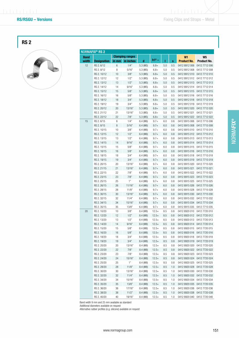
151www.normagroup.com
NORM
AFIX
®
RS/RSGU – Versions Fixing Clips and Straps – Metal
RS 2
Band width 9 mm and 25 mm available as standardAdditional diameters available on request Alternative rubber profiles (e.g. silicone) available on request
NORMAFIX® RS 2Band width Designation
Clamping rangesd h1² ~ l s
W1Product No.
W5Product No.in mm in inches
12 RS 2. 6/12 6 1/4” 5.3 (M5) 6.8+ 5.0 0.5 0412 8912 006 0412 7712 006
RS 2. 8/12 8 5/16” 5.3 (M5) 6.8+ 5.0 0.5 0412 8912 008 0412 7712 008
RS 2. 10/12 10 3/8” 5.3 (M5) 6.8+ 5.0 0.5 0412 8912 010 0412 7712 010
RS 2. 12/12 12 1/2” 5.3 (M5) 6.8+ 5.0 0.5 0412 8912 012 0412 7712 012
RS 2. 13/12 13 1/2” 5.3 (M5) 6.8+ 5.0 0.5 0412 8912 013 0412 7712 013
RS 2. 14/12 14 9/16” 5.3 (M5) 6.8+ 5.0 0.5 0412 8912 014 0412 7712 014
RS 2. 15/12 15 5/8” 5.3 (M5) 6.8+ 5.0 0.5 0412 8912 015 0412 7712 015
RS 2. 16/12 16 5/8” 5.3 (M5) 6.8+ 5.0 0.5 0412 8912 016 0412 7712 016
RS 2. 18/12 18 3/4” 5.3 (M5) 6.8+ 5.0 0.5 0412 8912 018 0412 7712 018
RS 2. 19/12 19 3/4” 5.3 (M5) 6.8+ 5.0 0.5 0412 8912 019 0412 7712 019
RS 2. 20/12 20 13/16” 5.3 (M5) 6.8+ 5.0 0.5 0412 8912 020 0412 7712 020
RS 2. 21/12 21 13/16” 5.3 (M5) 6.8+ 5.0 0.5 0412 8912 021 0412 7712 021
RS 2. 22/12 22 7/8” 5.3 (M5) 6.8+ 5.0 0.5 0412 8912 022 0412 7712 022
15 RS 2. 6/15 6 1/4” 6.4 (M6) 9.7+ 6.0 0.6 0412 8915 006 0412 7715 006
RS 2. 8/15 8 5/16” 6.4 (M6) 9.7+ 6.0 0.6 0412 8915 008 0412 7715 008
RS 2. 10/15 10 3/8” 6.4 (M6) 9.7+ 6.0 0.6 0412 8915 010 0412 7715 010
RS 2. 12/15 12 1/2” 6.4 (M6) 9.7+ 6.0 0.8 0412 8915 012 0412 7715 012
RS 2. 13/15 13 1/2” 6.4 (M6) 9.7+ 6.0 0.8 0412 8915 013 0412 7715 013
RS 2. 14/15 14 9/16” 6.4 (M6) 9.7+ 6.0 0.8 0412 8915 014 0412 7715 014
RS 2. 15/15 15 5/8” 6.4 (M6) 9.7+ 6.0 0.8 0412 8915 015 0412 7715 015
RS 2. 16/15 16 5/8” 6.4 (M6) 9.7+ 6.0 0.8 0412 8915 016 0412 7715 016
RS 2. 18/15 18 3/4” 6.4 (M6) 9.7+ 6.0 0.8 0412 8915 018 0412 7715 018
RS 2. 19/15 19 3/4” 6.4 (M6) 9.7+ 6.0 0.8 0412 8915 019 0412 7715 019
RS 2. 20/15 20 13/16” 6.4 (M6) 9.7+ 6.0 0.8 0412 8915 020 0412 7715 020
RS 2. 21/15 21 13/16” 6.4 (M6) 9.7+ 6.0 0.8 0412 8915 021 0412 7715 021
RS 2. 22/15 22 7/8” 6.4 (M6) 9.7+ 6.0 0.8 0412 8915 022 0412 7715 022
RS 2. 23/15 23 7/8” 6.4 (M6) 9.7+ 6.0 0.8 0412 8915 023 0412 7715 023
RS 2. 25/15 25 1” 6.4 (M6) 9.7+ 6.0 0.8 0412 8915 025 0412 7715 025
RS 2. 26/15 26 11/16” 6.4 (M6) 9.7+ 6.0 0.8 0412 8915 026 0412 7715 026
RS 2. 28/15 28 11/8” 6.4 (M6) 9.7+ 6.0 0.8 0412 8915 028 0412 7715 028
RS 2. 30/15 30 13/16” 6.4 (M6) 9.7+ 6.0 0.8 0412 8915 030 0412 7715 030
RS 2. 32/15 32 11/4” 6.4 (M6) 9.7+ 6.0 0.8 0412 8915 032 0412 7715 032
RS 2. 34/15 34 15/16” 6.4 (M6) 9.7+ 6.0 0.8 0412 8915 034 0412 7715 034
RS 2. 35/15 35 13/8” 6.4 (M6) 9.7+ 6.0 0.8 0412 8915 035 0412 7715 035
20 RS 2. 10/20 10 3/8” 8.4 (M8) 12.5+ 8.5 0.8 0412 8920 010 0412 7720 010
RS 2. 12/20 12 1/2” 8.4 (M8) 12.5+ 8.5 0.8 0412 8920 012 0412 7720 012
RS 2. 13/20 13 1/2” 8.4 (M8) 12.5+ 8.5 0.8 0412 8920 013 0412 7720 013
RS 2. 14/20 14 9/16” 8.4 (M8) 12.5+ 8.5 0.8 0412 8920 014 0412 7720 014
RS 2. 15/20 15 5/8” 8.4 (M8) 12.5+ 8.5 0.8 0412 8920 015 0412 7720 015
RS 2. 16/20 16 5/8” 8.4 (M8) 12.5+ 8.5 0.8 0412 8920 016 0412 7720 016
RS 2. 18/20 18 3/4” 8.4 (M8) 12.5+ 8.5 0.8 0412 8920 018 0412 7720 018
RS 2. 19/20 19 3/4” 8.4 (M8) 12.5+ 8.5 0.8 0412 8920 019 0412 7720 019
RS 2. 20/20 20 13/16” 8.4 (M8) 12.5+ 8.5 0.8 0412 8920 020 0412 7720 020
RS 2. 22/20 22 7/8” 8.4 (M8) 12.5+ 8.5 0.8 0412 8920 022 0412 7720 022
RS 2. 23/20 23 7/8” 8.4 (M8) 12.5+ 8.5 0.8 0412 8920 023 0412 7720 023
RS 2. 24/20 24 15/16” 8.4 (M8) 12.5+ 8.5 0.8 0412 8920 024 0412 7720 024
RS 2. 25/20 25 1” 8.4 (M8) 12.5+ 8.5 0.8 0412 8920 025 0412 7720 025
RS 2. 28/20 28 11/8” 8.4 (M8) 12.5+ 8.5 1.0 0412 8920 028 0412 7720 028
RS 2. 30/20 30 13/16” 8.4 (M8) 12.5+ 8.5 1.0 0412 8920 030 0412 7720 030
RS 2. 32/20 32 11/4” 8.4 (M8) 12.5+ 8.5 1.0 0412 8920 032 0412 7720 032
RS 2. 34/20 34 15/16” 8.4 (M8) 12.5+ 8.5 1.0 0412 8920 034 0412 7720 034
RS 2. 35/20 35 13/8” 8.4 (M8) 12.5+ 8.5 1.0 0412 8920 035 0412 7720 035
RS 2. 36/20 36 17/16” 8.4 (M8) 12.5+ 8.5 1.0 0412 8920 036 0412 7720 036
RS 2. 38/20 38 11/2” 8.4 (M8) 12.5+ 8.5 1.0 0412 8920 038 0412 7720 038
RS 2. 40/20 40 19/16” 8.4 (M8) 12.5+ 8.5 1.0 0412 8920 040 0412 7720 040
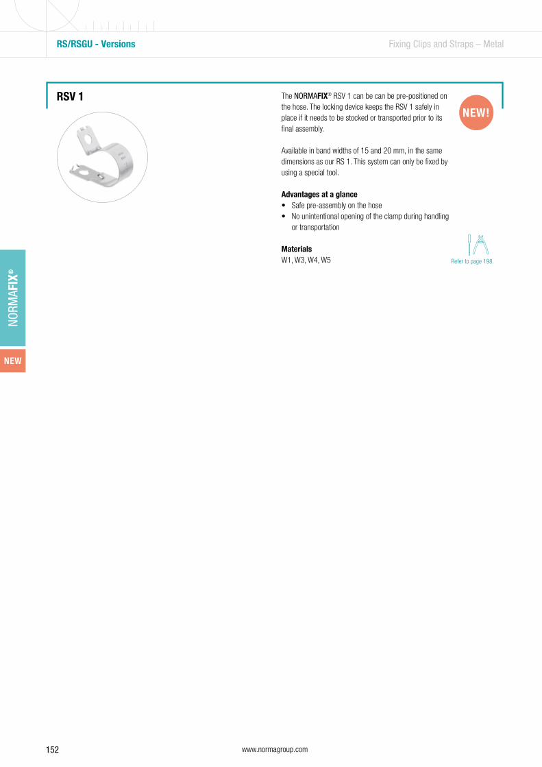
152 www.normagroup.com
NORM
AFIX
®
RS/RSGU - Versions Fixing Clips and Straps – Metal
RSV 1NEW!
The NORMAFIX® RSV 1 can be can be pre-positioned on the hose. The locking device keeps the RSV 1 safely in place if it needs to be stocked or transported prior to its final assembly.
Available in band widths of 15 and 20 mm, in the same dimensions as our RS 1. This system can only be fixed by using a special tool.
Advantages at a glance• Safe pre-assembly on the hose• No unintentional opening of the clamp during handling
or transportation
MaterialsW1, W3, W4, W5 Refer to page 198.
NEW
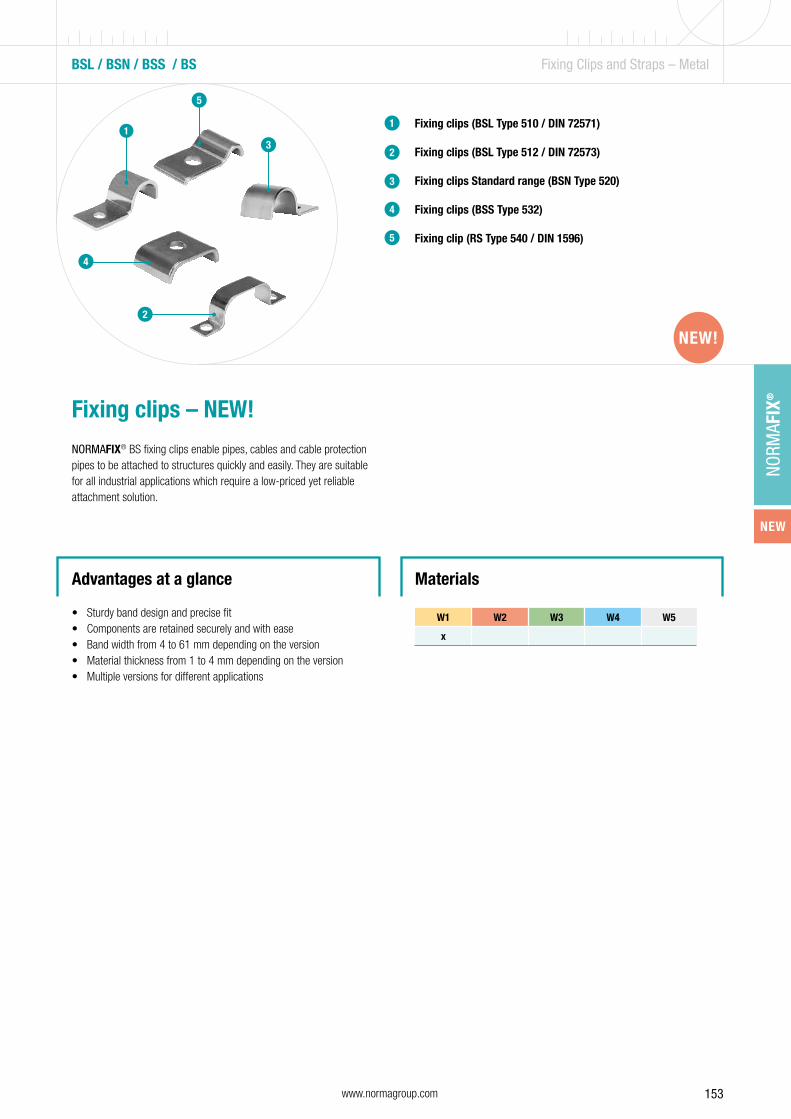
153www.normagroup.com
NORM
AFIX
®
1
BSL / BSN / BSS / BS Fixing Clips and Straps – Metal
Fixing clips (BSL Type 510 / DIN 72571)
Fixing clips (BSL Type 512 / DIN 72573)
Fixing clips Standard range (BSN Type 520)
Fixing clips (BSS Type 532)
Fixing clip (RS Type 540 / DIN 1596)
1
2
3
4
5
Fixing clips – NEW!
NORMAFIX® BS fixing clips enable pipes, cables and cable protection pipes to be attached to structures quickly and easily. They are suitable for all industrial applications which require a low-priced yet reliable attachment solution.
Advantages at a glance
• Sturdy band design and precise fit• Components are retained securely and with ease• Band width from 4 to 61 mm depending on the version• Material thickness from 1 to 4 mm depending on the version• Multiple versions for different applications
Materials
W1 W2 W3 W4 W5
x
2
4
3
5
NEW!NEW!
NEW
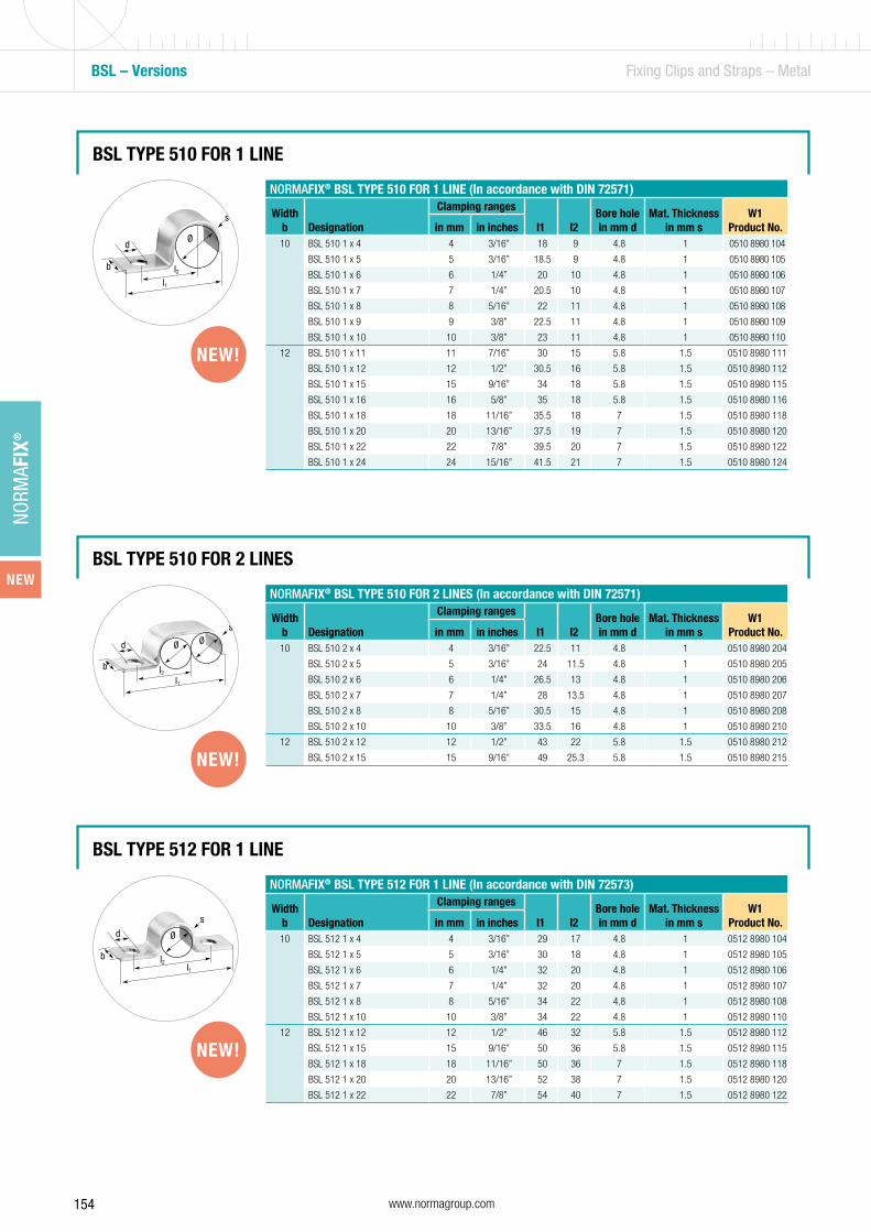
154 www.normagroup.com
NORM
AFIX
®
NORMAFIX® BSL TYPE 510 FOR 1 LINE (In accordance with DIN 72571)
Width b Designation
Clamping ranges
l1 l2Bore hole in mm d
Mat. Thickness in mm s
W1Product No.in mm in inches
10 BSL 510 1 x 4 4 3/16” 18 9 4.8 1 0510 8980 104
BSL 510 1 x 5 5 3/16” 18.5 9 4.8 1 0510 8980 105
BSL 510 1 x 6 6 1/4” 20 10 4.8 1 0510 8980 106
BSL 510 1 x 7 7 1/4” 20.5 10 4.8 1 0510 8980 107
BSL 510 1 x 8 8 5/16” 22 11 4.8 1 0510 8980 108
BSL 510 1 x 9 9 3/8” 22.5 11 4.8 1 0510 8980 109
BSL 510 1 x 10 10 3/8” 23 11 4.8 1 0510 8980 110
12 BSL 510 1 x 11 11 7/16” 30 15 5.8 1.5 0510 8980 111
BSL 510 1 x 12 12 1/2” 30.5 16 5.8 1.5 0510 8980 112
BSL 510 1 x 15 15 9/16” 34 18 5.8 1.5 0510 8980 115
BSL 510 1 x 16 16 5/8” 35 18 5.8 1.5 0510 8980 116
BSL 510 1 x 18 18 11/16” 35.5 18 7 1.5 0510 8980 118
BSL 510 1 x 20 20 13/16” 37.5 19 7 1.5 0510 8980 120
BSL 510 1 x 22 22 7/8” 39.5 20 7 1.5 0510 8980 122
BSL 510 1 x 24 24 15/16” 41.5 21 7 1.5 0510 8980 124
BSL – Versions Fixing Clips and Straps – Metal
BSL TYPE 510 FOR 1 LINE
Ø
b
d
s
l2l1
NORMAFIX® BSL TYPE 510 FOR 2 LINES (In accordance with DIN 72571)
Width b Designation
Clamping ranges
l1 l2Bore hole in mm d
Mat. Thickness in mm s
W1Product No.in mm in inches
10 BSL 510 2 x 4 4 3/16” 22.5 11 4.8 1 0510 8980 204
BSL 510 2 x 5 5 3/16” 24 11.5 4.8 1 0510 8980 205
BSL 510 2 x 6 6 1/4” 26.5 13 4.8 1 0510 8980 206
BSL 510 2 x 7 7 1/4” 28 13.5 4.8 1 0510 8980 207
BSL 510 2 x 8 8 5/16” 30.5 15 4.8 1 0510 8980 208
BSL 510 2 x 10 10 3/8” 33.5 16 4.8 1 0510 8980 210
12 BSL 510 2 x 12 12 1/2” 43 22 5.8 1.5 0510 8980 212
BSL 510 2 x 15 15 9/16” 49 25.3 5.8 1.5 0510 8980 215
BSL TYPE 510 FOR 2 LINES
b
d
s
l2l1
Ø Ø
NORMAFIX® BSL TYPE 512 FOR 1 LINE (In accordance with DIN 72573)
Width b Designation
Clamping ranges
l1 l2Bore hole in mm d
Mat. Thickness in mm s
W1Product No.in mm in inches
10 BSL 512 1 x 4 4 3/16” 29 17 4.8 1 0512 8980 104
BSL 512 1 x 5 5 3/16” 30 18 4.8 1 0512 8980 105
BSL 512 1 x 6 6 1/4” 32 20 4.8 1 0512 8980 106
BSL 512 1 x 7 7 1/4” 32 20 4.8 1 0512 8980 107
BSL 512 1 x 8 8 5/16” 34 22 4.8 1 0512 8980 108
BSL 512 1 x 10 10 3/8” 34 22 4.8 1 0512 8980 110
12 BSL 512 1 x 12 12 1/2” 46 32 5.8 1.5 0512 8980 112
BSL 512 1 x 15 15 9/16” 50 36 5.8 1.5 0512 8980 115
BSL 512 1 x 18 18 11/16” 50 36 7 1.5 0512 8980 118
BSL 512 1 x 20 20 13/16” 52 38 7 1.5 0512 8980 120
BSL 512 1 x 22 22 7/8” 54 40 7 1.5 0512 8980 122
BSL TYPE 512 FOR 1 LINE
Ø
b
d
s
l2l1
NEW!
NEW!
NEW!
NEW
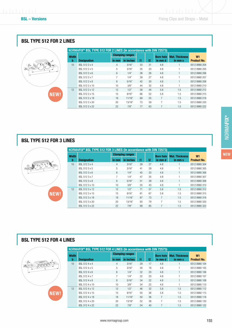
155www.normagroup.com
NORM
AFIX
®
BSL – Versions Fixing Clips and Straps – Metal
BSL TYPE 512 FOR 2 LINES
b
d
s
l2l1
Ø Ø
BSL TYPE 512 FOR 3 LINES
b
d
s
l2l1
ØØ Ø
NORMAFIX® BSL TYPE 512 FOR 4 LINES (In accordance with DIN 72573)
Width b Designation
Clamping ranges
l1 l2Bore hole in mm d
Mat. Thickness in mm s
W1Product No.in mm in inches
10 BSL 512 4 x 4 4 3/16” 29 17 4.8 1 0512 8980 104
BSL 512 4 x 5 5 3/16” 30 18 4.8 1 0512 8980 105
BSL 512 4 x 6 6 1/4” 32 20 4.8 1 0512 8980 106
BSL 512 4 x 7 7 1/4” 32 20 4.8 1 0512 8980 107
BSL 512 4 x 8 8 5/16” 34 22 4.8 1 0512 8980 108
BSL 512 4 x 10 10 3/8” 34 22 4.8 1 0512 8980 110
12 BSL 512 4 x 12 12 1/2” 46 32 5.8 1.5 0512 8980 112
BSL 512 4 x 15 15 9/16” 50 36 5.8 1.5 0512 8980 115
BSL 512 4 x 18 18 11/16” 50 36 7 1.5 0512 8980 118
BSL 512 4 x 20 20 13/16” 52 38 7 1.5 0512 8980 120
BSL 512 4 x 22 22 7/8” 54 40 7 1.5 0512 8980 122
BSL TYPE 512 FOR 4 LINES
b
d s
l2 l1
Ø Ø Ø Ø
NORMAFIX® BSL TYPE 512 FOR 2 LINES (In accordance with DIN 72573)
Width b Designation
Clamping ranges
l1 l2Bore hole in mm d
Mat. Thickness in mm s
W1Product No.in mm in inches
10 BSL 512 2 x 4 4 3/16” 33 21 4.8 1 0512 8980 204
BSL 512 2 x 5 5 3/16” 35 23 4.8 1 0512 8980 205
BSL 512 2 x 6 6 1/4” 38 26 4.8 1 0512 8980 206
BSL 512 2 x 7 7 1/4” 39 27 4.8 1 0512 8980 207
BSL 512 2 x 8 8 5/16” 42 30 4.8 1 0512 8980 208
BSL 512 2 x 10 10 3/8” 44 32 4.8 1 0512 8980 210
12 BSL 512 2 x 12 12 1/2” 58 44 5.8 1.5 0512 8980 212
BSL 512 2 x 15 15 9/16” 66 52 5.8 1.5 0512 8980 215
BSL 512 2 x 18 18 11/16” 69 55 7 1.5 0512 8980 218
BSL 512 2 x 20 20 13/16” 73 59 7 1.5 0512 8980 220
BSL 512 2 x 22 22 7/8” 77 63 7 1.5 0512 8980 222
NORMAFIX® BSL TYPE 512 FOR 3 LINES (In accordance with DIN 72573)
Width b Designation
Clamping ranges
l1 l2Bore hole in mm d
Mat. Thickness in mm s
W1Product No.in mm in inches
10 BSL 512 3 x 4 4 3/16” 39 27 4.8 1 0512 8980 304
BSL 512 3 x 5 5 3/16” 41 29 4.8 1 0512 8980 305
BSL 512 3 x 6 6 1/4” 45 33 4.8 1 0512 8980 306
BSL 512 3 x 7 7 1/4” 47 35 4.8 1 0512 8980 307
BSL 512 3 x 8 8 5/16” 51 39 4.8 1 0512 8980 308
BSL 512 3 x 10 10 3/8” 55 43 4.8 1 0512 8980 310
12 BSL 512 3 x 12 12 1/2” 71 57 5.8 1.5 0512 8980 312
BSL 512 3 x 15 15 9/16” 81 67 5.8 1.5 0512 8980 315
BSL 512 3 x 18 18 11/16” 87 73 7 1.5 0512 8980 318
BSL 512 3 x 20 20 13/16” 93 79 7 1.5 0512 8980 320
BSL 512 3 x 22 22 7/8” 99 85 7 1.5 0512 8980 322
NEW!
NEW!
NEW!
NEW

156 www.normagroup.com
NORM
AFIX
®
BSL – Versions Fixing Clips and Straps – Metal
BSL TYPE 512 FOR 5 LINES
b
d
s
l2l1
Ø Ø Ø Ø Ø
NORMAFIX® BSL TYPE 512 FOR 5 LINES (In accordance with DIN 72573)
Width b Designation
Clamping ranges
l1 l2Bore hole in mm d
Mat. Thickness in mm s
W1Product No.in mm in inches
10 BSL 512 5 x 4 4 3/16” 48 36 4.8 1 0512 8980 504
BSL 512 5 x 5 5 3/16” 53 41 4.8 1 0512 8980 505
BSL 512 5 x 6 6 1/4” 57 45 4.8 1 0512 8980 506
BSL 512 5 x 7 7 1/4” 63 51 4.8 1 0512 8980 507
BSL 512 5 x 8 8 5/16” 68 56 4.8 1 0512 8980 508
BSL 512 5 x 10 10 3/8” 77 65 4.8 1 0512 8980 510
12 BSL 512 5 x 12 12 1/2” 95 81 5.8 1.5 0512 8980 512
BSL TYPE 512 FOR 6 LINES
b
ds
l2l1
Ø Ø Ø Ø Ø Ø
NORMAFIX® BSL TYPE 512 FOR 6 LINES (In accordance with DIN 72573)
Width b Designation
Clamping ranges
l1 l2Bore hole in mm d
Mat. Thickness in mm s
W1Product No.in mm in inches
10 BSL 512 6 x 4 4 3/16” 52 40 4.8 1 0512 8980 604
BSL 512 6 x 5 5 3/16” 58 46 4.8 1 0512 8980 605
BSL 512 6 x 6 6 1/4” 64 52 4.8 1 0512 8980 606
BSL 512 6 x 7 7 1/4” 72 60 4.8 1 0512 8980 607
BSL 512 6 x 8 8 5/16” 76 64 4.8 1 0512 8980 608
BSL 512 6 x 10 10 3/8” 90 78 4.8 1 0512 8980 610
NEW!
NEW!
NEW
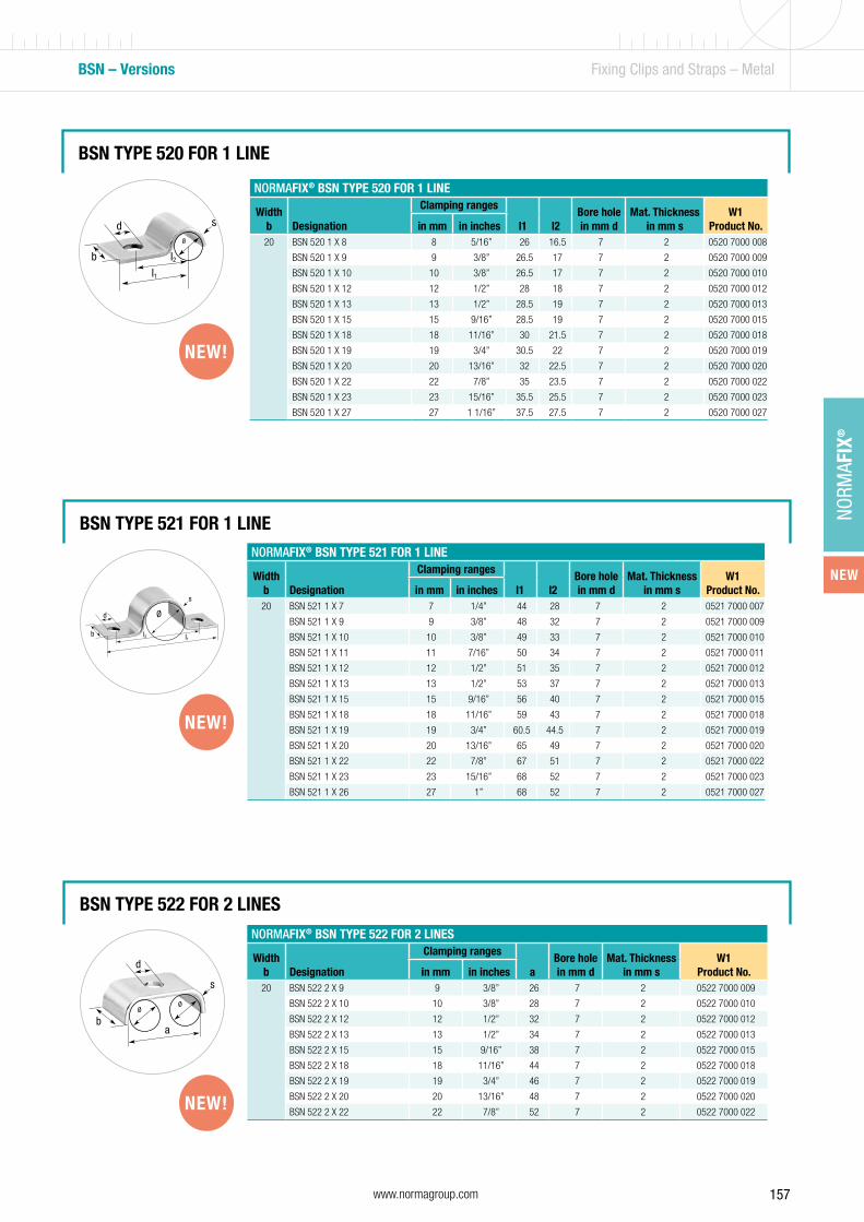
157www.normagroup.com
NORM
AFIX
®
NORMAFIX® BSN TYPE 520 FOR 1 LINE
Width b Designation
Clamping ranges
l1 l2Bore hole in mm d
Mat. Thickness in mm s
W1Product No.in mm in inches
20 BSN 520 1 X 8 8 5/16” 26 16.5 7 2 0520 7000 008
BSN 520 1 X 9 9 3/8” 26.5 17 7 2 0520 7000 009
BSN 520 1 X 10 10 3/8” 26.5 17 7 2 0520 7000 010
BSN 520 1 X 12 12 1/2” 28 18 7 2 0520 7000 012
BSN 520 1 X 13 13 1/2” 28.5 19 7 2 0520 7000 013
BSN 520 1 X 15 15 9/16” 28.5 19 7 2 0520 7000 015
BSN 520 1 X 18 18 11/16” 30 21.5 7 2 0520 7000 018
BSN 520 1 X 19 19 3/4” 30.5 22 7 2 0520 7000 019
BSN 520 1 X 20 20 13/16” 32 22.5 7 2 0520 7000 020
BSN 520 1 X 22 22 7/8” 35 23.5 7 2 0520 7000 022
BSN 520 1 X 23 23 15/16” 35.5 25.5 7 2 0520 7000 023
BSN 520 1 X 27 27 1 1/16” 37.5 27.5 7 2 0520 7000 027
BSN TYPE 520 FOR 1 LINE
Ø
b
d s
l2l1
BSN – Versions Fixing Clips and Straps – Metal
BSN TYPE 521 FOR 1 LINE
Ø
b
d
s
l2 l1
BSN TYPE 522 FOR 2 LINES
ØØ
b
d
s
a
NORMAFIX® BSN TYPE 521 FOR 1 LINE
Width b Designation
Clamping ranges
l1 l2Bore hole in mm d
Mat. Thickness in mm s
W1Product No.in mm in inches
20 BSN 521 1 X 7 7 1/4” 44 28 7 2 0521 7000 007
BSN 521 1 X 9 9 3/8” 48 32 7 2 0521 7000 009
BSN 521 1 X 10 10 3/8” 49 33 7 2 0521 7000 010
BSN 521 1 X 11 11 7/16” 50 34 7 2 0521 7000 011
BSN 521 1 X 12 12 1/2” 51 35 7 2 0521 7000 012
BSN 521 1 X 13 13 1/2” 53 37 7 2 0521 7000 013
BSN 521 1 X 15 15 9/16” 56 40 7 2 0521 7000 015
BSN 521 1 X 18 18 11/16” 59 43 7 2 0521 7000 018
BSN 521 1 X 19 19 3/4” 60.5 44.5 7 2 0521 7000 019
BSN 521 1 X 20 20 13/16” 65 49 7 2 0521 7000 020
BSN 521 1 X 22 22 7/8” 67 51 7 2 0521 7000 022
BSN 521 1 X 23 23 15/16” 68 52 7 2 0521 7000 023
BSN 521 1 X 26 27 1” 68 52 7 2 0521 7000 027
NORMAFIX® BSN TYPE 522 FOR 2 LINES
Width b Designation
Clamping ranges
aBore hole in mm d
Mat. Thickness in mm s
W1Product No.in mm in inches
20 BSN 522 2 X 9 9 3/8” 26 7 2 0522 7000 009
BSN 522 2 X 10 10 3/8” 28 7 2 0522 7000 010
BSN 522 2 X 12 12 1/2” 32 7 2 0522 7000 012
BSN 522 2 X 13 13 1/2” 34 7 2 0522 7000 013
BSN 522 2 X 15 15 9/16” 38 7 2 0522 7000 015
BSN 522 2 X 18 18 11/16” 44 7 2 0522 7000 018
BSN 522 2 X 19 19 3/4” 46 7 2 0522 7000 019
BSN 522 2 X 20 20 13/16” 48 7 2 0522 7000 020
BSN 522 2 X 22 22 7/8” 52 7 2 0522 7000 022
NEW!
NEW!
NEW!
NEW
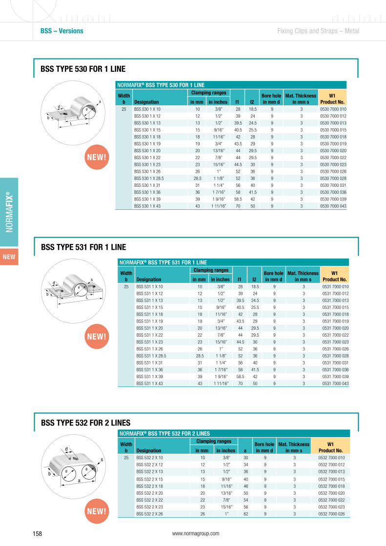
158 www.normagroup.com
NORM
AFIX
®
BSS – Versions Fixing Clips and Straps – Metal
BSS TYPE 531 FOR 1 LINE
Ø
b
ds
l2l1
BSS TYPE 532 FOR 2 LINES
ØØ
b
d
s
a
NORMAFIX® BSS TYPE 531 FOR 1 LINE
Width b Designation
Clamping ranges
l1 l2Bore hole in mm d
Mat. Thickness in mm s
W1Product No.in mm in inches
25 BSS 531 1 X 10 10 3/8” 28 18.5 9 3 0531 7000 010
BSS 531 1 X 12 12 1/2” 39 24 9 3 0531 7000 012
BSS 531 1 X 13 13 1/2” 39.5 24.5 9 3 0531 7000 013
BSS 531 1 X 15 15 9/16” 40.5 25.5 9 3 0531 7000 015
BSS 531 1 X 18 18 11/16” 42 28 9 3 0531 7000 018
BSS 531 1 X 19 19 3/4” 43.5 29 9 3 0531 7000 019
BSS 531 1 X 20 20 13/16” 44 29.5 9 3 0531 7000 020
BSS 531 1 X 22 22 7/8” 44 29.5 9 3 0531 7000 022
BSS 531 1 X 23 23 15/16” 44.5 30 9 3 0531 7000 023
BSS 531 1 X 26 26 1” 52 36 9 3 0531 7000 026
BSS 531 1 X 28.5 28.5 1 1/8” 52 36 9 3 0531 7000 028
BSS 531 1 X 31 31 1 1/4” 56 40 9 3 0531 7000 031
BSS 531 1 X 36 36 1 7/16” 58 41.5 9 3 0531 7000 036
BSS 531 1 X 39 39 1 9/16” 58.5 42 9 3 0531 7000 039
BSS 531 1 X 43 43 1 11/16” 70 50 9 3 0531 7000 043
NORMAFIX® BSS TYPE 532 FOR 2 LINES
Width b Designation
Clamping ranges
aBore hole in mm d
Mat. Thickness in mm s
W1Product No.in mm in inches
25 BSS 532 2 X 10 10 3/8” 30 9 3 0532 7000 010
BSS 532 2 X 12 12 1/2” 34 9 3 0532 7000 012
BSS 532 2 X 13 13 1/2” 36 9 3 0532 7000 013
BSS 532 2 X 15 15 9/16” 40 9 3 0532 7000 015
BSS 532 2 X 18 18 11/16” 46 9 3 0532 7000 018
BSS 532 2 X 20 20 13/16” 50 9 3 0532 7000 020
BSS 532 2 X 22 22 7/8” 54 9 3 0532 7000 022
BSS 532 2 X 23 23 15/16” 56 9 3 0532 7000 023
BSS 532 2 X 26 26 1” 62 9 3 0532 7000 026
BSS TYPE 530 FOR 1 LINE
Ø
b
ds
l2l1
NORMAFIX® BSS TYPE 530 FOR 1 LINE
Width b Designation
Clamping ranges
l1 l2Bore hole in mm d
Mat. Thickness in mm s
W1Product No.in mm in inches
25 BSS 530 1 X 10 10 3/8” 28 18.5 9 3 0530 7000 010
BSS 530 1 X 12 12 1/2” 39 24 9 3 0530 7000 012
BSS 530 1 X 13 13 1/2” 39.5 24.5 9 3 0530 7000 013
BSS 530 1 X 15 15 9/16” 40.5 25.5 9 3 0530 7000 015
BSS 530 1 X 18 18 11/16” 42 28 9 3 0530 7000 018
BSS 530 1 X 19 19 3/4” 43.5 29 9 3 0530 7000 019
BSS 530 1 X 20 20 13/16” 44 29.5 9 3 0530 7000 020
BSS 530 1 X 22 22 7/8” 44 29.5 9 3 0530 7000 022
BSS 530 1 X 23 23 15/16” 44.5 30 9 3 0530 7000 023
BSS 530 1 X 26 26 1” 52 36 9 3 0530 7000 026
BSS 530 1 X 28.5 28.5 1 1/8” 52 36 9 3 0530 7000 028
BSS 530 1 X 31 31 1 1/4” 56 40 9 3 0530 7000 031
BSS 530 1 X 36 36 1 7/16” 58 41.5 9 3 0530 7000 036
BSS 530 1 X 39 39 1 9/16” 58.5 42 9 3 0530 7000 039
BSS 530 1 X 43 43 1 11/16” 70 50 9 3 0530 7000 043
NEW!
NEW!
NEW!
NEW

159www.normagroup.com
NORM
AFIX
®
NORMAFIX® BS TYPE 540 FOR 1 LINE (In accordance with DIN 1596)
Width b Designation
Clamping ranges
l1 l2Bore hole in mm d
Mat. Thickness in mm s
W1Product No.in mm in inches
16 BS 540 1 x 7 7 1/4” 26 14 6.6 2 0540 7000 007
BS 540 1 x 9 9 3/8” 28 16 6.6 2 0540 7000 009
20 BS 540 1 x 13 13 1/2” 30 18 6.6 2 0540 7000 013
BS 540 1 x 15.5 15.5 5/8” 32 20 6.6 2 0540 7000 015
BS 540 1 x 19 19 3/4” 34 22 6.6 2 0540 7000 019
25 BS 540 1 x 23 23 15/16” 43 28 9 3 0540 7000 023
BS 540 1 x 26 26 1” 44 29 9 3 0540 7000 026
BS 540 1 x 28.5 28.5 1 1/8” 47 32 9 3 0540 7000 028
BS 540 1 x 31 31 1 1/4” 47 32 9 3 0540 7000 031
BS 540 1 x 33 33 1 5/16” 56 36 9 3 0540 7000 033
30 BS 540 1 x 36 36 1 7/16” 57 40 11 3 0540 7000 036
BS 540 1 x 39 39 1 9/16” 59 42 11 3 0540 7000 039
BS 540 1 x 43 43 1 11/16” 61 44 11 3 0540 7000 043
BS 540 1 x 46 46 1 13/16” 62 45 11 3 0540 7000 046
40 BS 540 1 x 49 49 1 15/16” 67 48 14 4 0540 7000 049
BS 540 1 x 52 52 2 1/16” 72 53 14 4 0540 7000 052
BS 540 1 x 58 58 2 1/4” 74 55 14 4 0540 7000 058
BS 540 1 x 61 61 2 3/8” 77 58 14 4 0540 7000 061
BS TYPE 540 FOR 1 LINE
Ø
b
d s
l2l1
BS – Versions Fixing Clips and Straps – Metal
BS TYPE 541 FOR 1 LINE
Ø
b
ds
l2l1
NORMAFIX® BS TYPE 541 FOR 1 LINE (In accordance with DIN 1597)
Width b Designation
Clamping ranges
l1 l2Bore hole in mm d
Mat. Thickness in mm s
W1Product No.in mm in inches
16 BS 541 1 x 7 7 1/4” 44 28 5.5 1.5 0541 7000 007
BS 541 1 x 9 9 3/8” 48 32 5.5 1.5 0541 7000 009
20 BS 541 1 x 13 13 1/2” 52 36 5.5 1.5 0541 7000 013
BS 541 1 x 15.5 15.5 5/8” 56 40 5.5 1.5 0541 7000 015
BS 541 1 x 19 19 3/4” 60 44 5.5 1.5 0541 7000 019
25 BS 541 1 x 23 23 15/16” 76 56 6.6 2 0541 7000 023
BS 541 1 x 26 26 1” 78 58 6.6 2 0541 7000 026
BS 541 1 x 28.5 28.5 1 1/8” 84 64 6.6 2 0541 7000 028
BS 541 1 x 31 31 1 1/4” 84 64 6.6 2 0541 7000 031
BS 541 1 x 33 33 1 5/16” 92 72 6.6 2 0541 7000 033
30 BS 541 1 x 36 36 1 7/16” 104 80 9 3 0541 7000 036
BS 541 1 x 39 39 1 9/16” 108 84 9 3 0541 7000 039
BS 541 1 x 43 43 1 11/16” 112 88 9 3 0541 7000 043
BS 541 1 x 46 46 1 13/16” 114 90 9 3 0541 7000 046
40 BS 541 1 x 49 49 1 15/16” 118 90 11 3 0541 7000 049
BS 541 1 x 52 52 2 1/16” 134 106 11 3 0541 7000 052
BS 541 1 x 58 58 2 1/4” 138 110 11 3 0541 7000 058
BS 541 1 x 61 61 2 3/8” 138 110 11 3 0541 7000 061
NEW!
NEW!
NEW
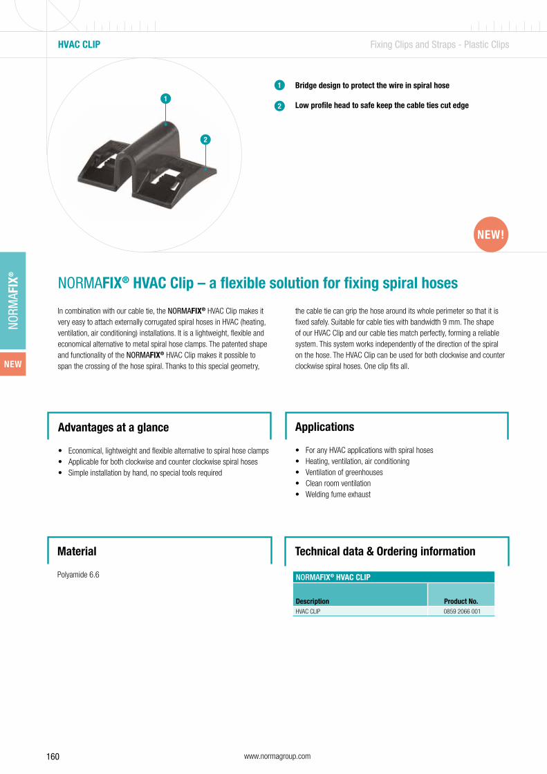
160 www.normagroup.com
NORM
AFIX
®
Bridge design to protect the wire in spiral hose
Low profile head to safe keep the cable ties cut edge
1
2
NORMAFIX® HVAC Clip – a flexible solution for fixing spiral hoses
In combination with our cable tie, the NORMAFIX® HVAC Clip makes it very easy to attach externally corrugated spiral hoses in HVAC (heating, ventilation, air conditioning) installations. It is a lightweight, flexible and economical alternative to metal spiral hose clamps. The patented shape and functionality of the NORMAFIX® HVAC Clip makes it possible to span the crossing of the hose spiral. Thanks to this special geometry,
Advantages at a glance
• Economical, lightweight and flexible alternative to spiral hose clamps• Applicable for both clockwise and counter clockwise spiral hoses• Simple installation by hand, no special tools required
Applications
• For any HVAC applications with spiral hoses• Heating, ventilation, air conditioning• Ventilation of greenhouses• Clean room ventilation • Welding fume exhaust
the cable tie can grip the hose around its whole perimeter so that it is fixed safely. Suitable for cable ties with bandwidth 9 mm. The shape of our HVAC Clip and our cable ties match perfectly, forming a reliable system. This system works independently of the direction of the spiral on the hose. The HVAC Clip can be used for both clockwise and counter clockwise spiral hoses. One clip fits all.
HVAC CLIP Fixing Clips and Straps - Plastic Clips
1
2
Material
Polyamide 6.6 NORMAFIX® HVAC CLIP
Description Product No.HVAC CLIP 0859 2066 001
NEW!
Technical data & Ordering information
NEW!
NEW

161www.normagroup.com
NORM
AFIX
®

162 www.normagroup.com
NORM
AFIX
®
TUBE CLAMP FITTINGS Mounting Elements – Tube Clamp Fittings
Material
Malleable galvanized iron
3 ways 90° elbow
Side outlet tee
90° elbow
Railing base flange
Four way cross
Double swivel combination
1
2
3
4
5
6
Tube clamp fittings for safety systems
Made of malleable galvanized iron to ensure strength, quality and conformity of production. NORMAFIX® Tube Clamp Fittings can be easily assembled on pipes in order to create safety systems.
Advantages at a glance
• Stainless steel screw• Warranty up to 1500 N/m load• No welding, so no fire permits required• No threading, no bolting• Can be assembled with a simple hexagonal key• A versatile system that allows changes on site• Can be painted
Applications
• Handrails• Safety rails/Protective barriers• Fall protections• Other applications for safety work• Fix railings• Machinery guard• Playgrounds
6
41
3
5
2
6

163www.normagroup.com
NORM
AFIX
®
Expanding connector
NORMAFIX® SLEEVE JOINT
Designation Diameter in mma
mmMalleable galvanized iron
Product No.
SLEEVE JOINT 26.9 26.9 76 0819 6301 027
SLEEVE JOINT 33.7 33.7 90 0819 6301 034
SLEEVE JOINT 42.4 42.4 100 0819 6301 042
SLEEVE JOINT 48.3 48.3 100 0819 6301 048
SLEEVE JOINT 60.3 60.3 120 0819 6301 060
Sleeve joint a
a
b
a
b
aa
a
NORMAFIX® EXPANDING CONNECTOR
DesignationDiameter in
mma
mmb
mmMalleable galvanized iron
Product No.
EXPANDING CONNECTOR 33.7 33.7 78 20 0819 6302 034
EXPANDING CONNECTOR 42.4 42.4 78 20 0819 6302 042
EXPANDING CONNECTOR 48.3 48.3 78 20 0819 6302 048
NORMAFIX® 90° ELBOW
DesignationDiameter in
mma
mmMalleable galvanized iron
Product No.
90°ELBOW 26.9 26.9 41 0819 6303 027
90° ELBOW 33.7 33.7 46 0819 6303 034
90° ELBOW 42.4 42.4 60 0819 6303 042
90° ELBOW 48.3 48.3 68 0819 6303 048
90°ELBOW 60.3 60.3 84 0819 6303 060
90° elbow
TUBE CLAMP FITTINGS Mounting Elements – Tube Clamp Fittings
Refer to page 199 and 200.
Refer to page 199 and 200.
Refer to page 199 and 200.
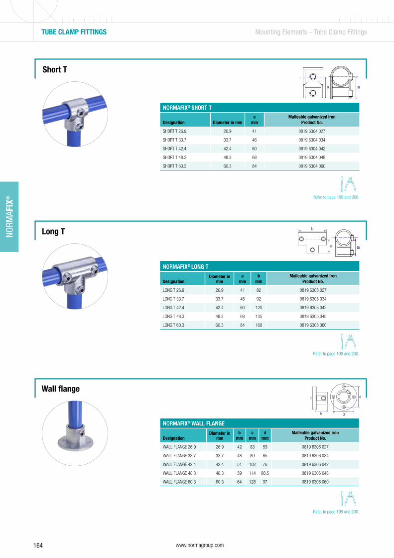
164 www.normagroup.com
NORM
AFIX
®
aa
NORMAFIX® SHORT T
Designation Diameter in mma
mmMalleable galvanized iron
Product No.
SHORT T 26.9 26.9 41 0819 6304 027
SHORT T 33.7 33.7 46 0819 6304 034
SHORT T 42.4 42.4 60 0819 6304 042
SHORT T 48.3 48.3 68 0819 6304 048
SHORT T 60.3 60.3 84 0819 6304 060
Short T
Wall flange
Long T
a
b
a
c
b d
d
NORMAFIX® LONG T
DesignationDiameter in
mma
mmb
mmMalleable galvanized iron
Product No.
LONG T 26.9 26.9 41 82 0819 6305 027
LONG T 33.7 33.7 46 92 0819 6305 034
LONG T 42.4 42.4 60 120 0819 6305 042
LONG T 48.3 48.3 68 135 0819 6305 048
LONG T 60.3 60.3 84 168 0819 6305 060
NORMAFIX® WALL FLANGE
DesignationDiameter in
mmb
mmc
mmd
mmMalleable galvanized iron
Product No.
WALL FLANGE 26.9 26.9 42 83 59 0819 6306 027
WALL FLANGE 33.7 33.7 48 89 65 0819 6306 034
WALL FLANGE 42.4 42.4 51 102 76 0819 6306 042
WALL FLANGE 48.3 48.3 59 114 88.5 0819 6306 048
WALL FLANGE 60.3 60.3 64 128 97 0819 6306 060
TUBE CLAMP FITTINGS Mounting Elements – Tube Clamp Fittings
Refer to page 199 and 200.
Refer to page 199 and 200.
Refer to page 199 and 200.

165www.normagroup.com
NORM
AFIX
®
Railing base flange
Handrail bracket
a
c d
e
a
ed
a
cb
NORMAFIX® RAILING BASE FLANGE
DesignationDiameter in
mma
mmc
mmd
mme
mmMalleable galvanized iron
Product No.
RAILING BASE FLANGE 26.9 26.9 60 105 76 52 0819 6307 027
RAILING BASE FLANGE 33.7 33.7 71 127 89 62 0819 6307 034
RAILING BASE FLANGE 42.4 42.4 84 139 101 72 0819 6307 042
RAILING BASE FLANGE 48.3 48.3 89 152 114 86 0819 6307 048
RAILING BASE FLANGE 60.3 60.3 104 165 127 96 0819 6307 060
NORMAFIX® HANDRAIL BRACKET
DesignationDiameter in
mma
mmb
mmc
mmd
mme
mmMalleable galvanized iron
Product No.
HANDRAIL BRACKET 26.9 26.9 54 77 57 44 7 0819 6308 027
HANDRAIL BRACKET 33.7 33.7 57 80 62 44 7 0819 6308 034
HANDRAIL BRACKET 42.4 42.4 62 102 82.5 45 7 0819 6308 042
HANDRAIL BRACKET 48.3 48.3 70 107 82.5 50 7 0819 6308 048
TUBE CLAMP FITTINGS Mounting Elements – Tube Clamp Fittings
a
a3 ways 90° elbow
NORMAFIX® 3 WAYS 90° ELBOW
DesignationDiameter in
mma
mmMalleable galvanized iron
Product No.
3 WAYS 90° ELBOW 26.9 26.9 41 0819 6309 027
3 WAYS 90° ELBOW 33.7 33.7 48 0819 6309 034
3 WAYS 90° ELBOW 42.4 42.4 60 0819 6309 042
3 WAYS 90° ELBOW 48.3 48.3 68 0819 6309 048
3 WAYS 90° ELBOW 60.3 60.3 84 0819 6309 060
Refer to page 199 and 200.
Refer to page 199 and 200.
Refer to page 199 and 200.
Refer to page 199 and 200.
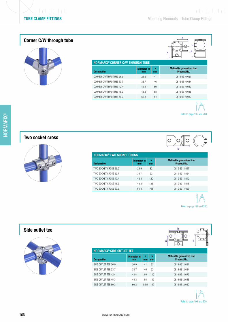
166 www.normagroup.com
NORM
AFIX
®
TUBE CLAMP FITTINGS Mounting Elements – Tube Clamp Fittings
a
b
a
b
a
a
a
NORMAFIX® CORNER C/W THROUGH TUBE
DesignationDiameter in
mma
mmMalleable galvanized iron
Product No.
CORNER C/W THRO TUBE 26.9 26.9 41 0819 6310 027
CORNER C/W THRO TUBE 33.7 33.7 46 0819 6310 034
CORNER C/W THRO TUBE 42.4 42.4 60 0819 6310 042
CORNER C/W THRO TUBE 48.3 48.3 68 0819 6310 048
CORNER C/W THRO TUBE 60.3 60.3 84 0819 6310 060
Corner C/W through tube
Two socket cross
Side outlet tee
NORMAFIX® TWO SOCKET CROSS
DesignationDiameter in
mma
mmMalleable galvanized iron
Product No.
TWO SOCKET CROSS 26.9 26.9 82 0819 6311 027
TWO SOCKET CROSS 33.7 33.7 92 0819 6311 034
TWO SOCKET CROSS 42.4 42.4 120 0819 6311 042
TWO SOCKET CROSS 48.3 48.3 135 0819 6311 048
TWO SOCKET CROSS 60.3 60.3 168 0819 6311 060
NORMAFIX® SIDE OUTLET TEE
DesignationDiameter in
mma
mmb
mmMalleable galvanized iron
Product No.
SIDE OUTLET TEE 26.9 26.9 41 82 0819 6312 027
SIDE OUTLET TEE 33.7 33.7 46 92 0819 6312 034
SIDE OUTLET TEE 42.4 42.4 60 120 0819 6312 042
SIDE OUTLET TEE 48.3 48.3 68 136 0819 6312 048
SIDE OUTLET TEE 60.3 60.3 84.5 169 0819 6312 060
Refer to page 199 and 200.
Refer to page 199 and 200.
Refer to page 199 and 200.
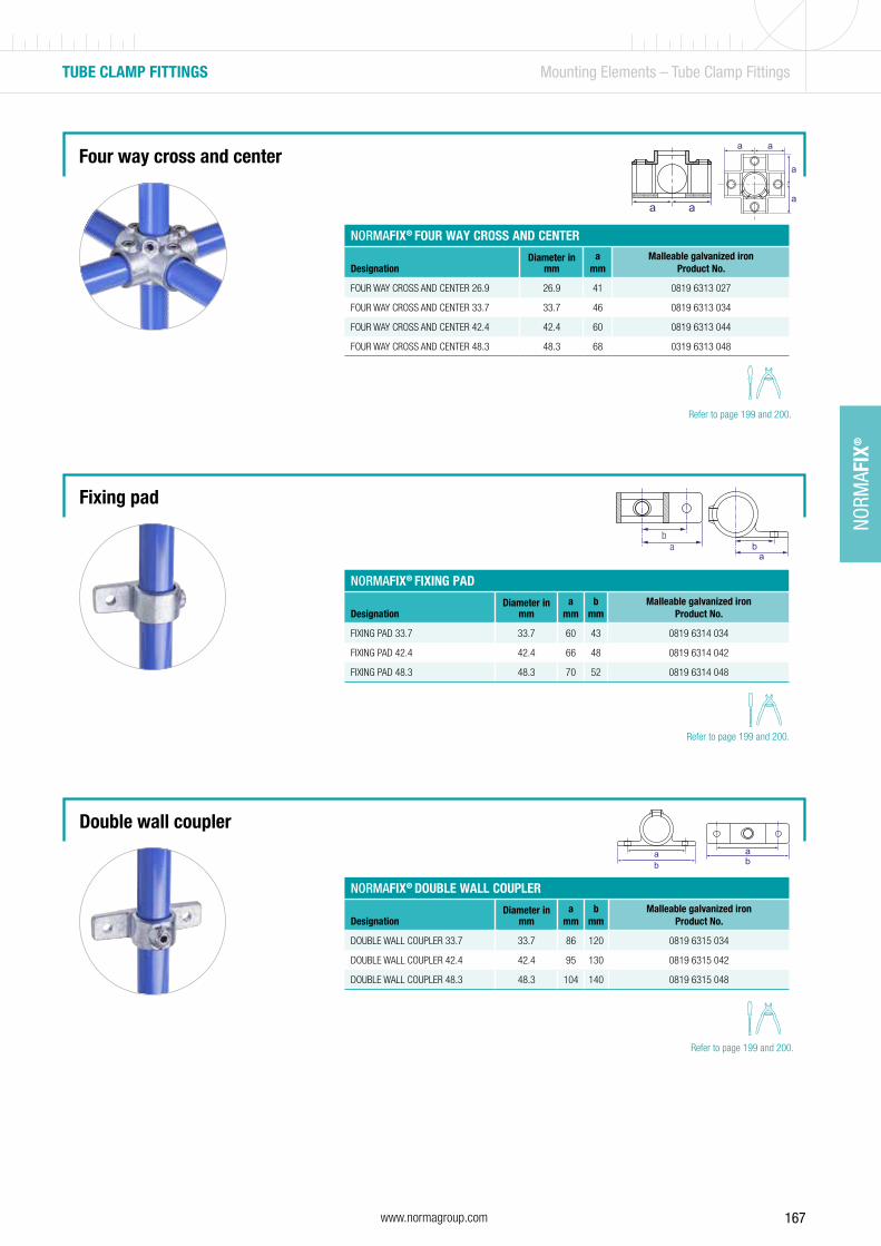
167www.normagroup.com
NORM
AFIX
®
TUBE CLAMP FITTINGS Mounting Elements – Tube Clamp Fittings
aba
b
ba
ba
NORMAFIX® FOUR WAY CROSS AND CENTER
DesignationDiameter in
mma
mmMalleable galvanized iron
Product No.
FOUR WAY CROSS AND CENTER 26.9 26.9 41 0819 6313 027
FOUR WAY CROSS AND CENTER 33.7 33.7 46 0819 6313 034
FOUR WAY CROSS AND CENTER 42.4 42.4 60 0819 6313 044
FOUR WAY CROSS AND CENTER 48.3 48.3 68 0319 6313 048
NORMAFIX® FIXING PAD
DesignationDiameter in
mma
mmb
mmMalleable galvanized iron
Product No.
FIXING PAD 33.7 33.7 60 43 0819 6314 034
FIXING PAD 42.4 42.4 66 48 0819 6314 042
FIXING PAD 48.3 48.3 70 52 0819 6314 048
NORMAFIX® DOUBLE WALL COUPLER
DesignationDiameter in
mma
mmb
mmMalleable galvanized iron
Product No.
DOUBLE WALL COUPLER 33.7 33.7 86 120 0819 6315 034
DOUBLE WALL COUPLER 42.4 42.4 95 130 0819 6315 042
DOUBLE WALL COUPLER 48.3 48.3 104 140 0819 6315 048
Fixing pad
Four way cross and center
Double wall coupler
a a
a a
a
a
Refer to page 199 and 200.
Refer to page 199 and 200.
Refer to page 199 and 200.
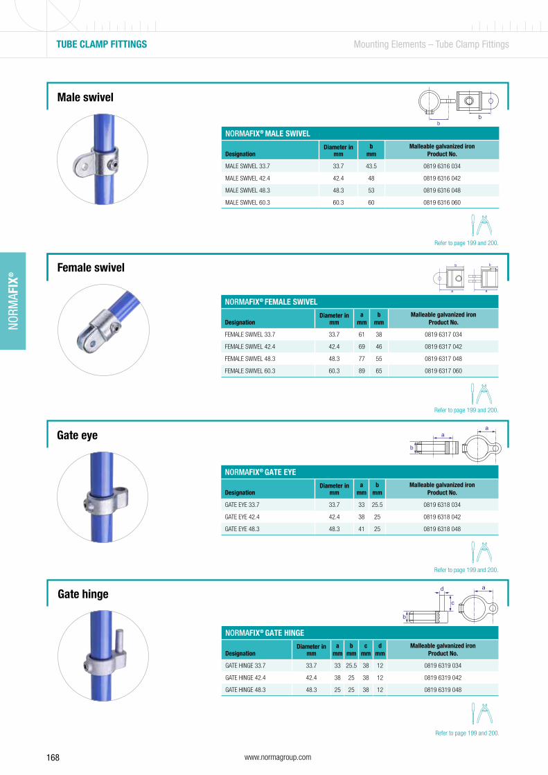
168 www.normagroup.com
NORM
AFIX
®
TUBE CLAMP FITTINGS Mounting Elements – Tube Clamp Fittings
bb
NORMAFIX® MALE SWIVEL
DesignationDiameter in
mmb
mmMalleable galvanized iron
Product No.
MALE SWIVEL 33.7 33.7 43.5 0819 6316 034
MALE SWIVEL 42.4 42.4 48 0819 6316 042
MALE SWIVEL 48.3 48.3 53 0819 6316 048
MALE SWIVEL 60.3 60.3 60 0819 6316 060
Male swivel
Gate eye
Female swivel
a
bb
a
aa
b
NORMAFIX® FEMALE SWIVEL
DesignationDiameter in
mma
mmb
mmMalleable galvanized iron
Product No.
FEMALE SWIVEL 33.7 33.7 61 38 0819 6317 034
FEMALE SWIVEL 42.4 42.4 69 46 0819 6317 042
FEMALE SWIVEL 48.3 48.3 77 55 0819 6317 048
FEMALE SWIVEL 60.3 60.3 89 65 0819 6317 060
NORMAFIX® GATE EYE
DesignationDiameter in
mma
mmb
mmMalleable galvanized iron
Product No.
GATE EYE 33.7 33.7 33 25.5 0819 6318 034
GATE EYE 42.4 42.4 38 25 0819 6318 042
GATE EYE 48.3 48.3 41 25 0819 6318 048
ad
b
c
NORMAFIX® GATE HINGE
DesignationDiameter in
mma
mmb
mmc
mmd
mmMalleable galvanized iron
Product No.
GATE HINGE 33.7 33.7 33 25.5 38 12 0819 6319 034
GATE HINGE 42.4 42.4 38 25 38 12 0819 6319 042
GATE HINGE 48.3 48.3 25 25 38 12 0819 6319 048
Gate hinge
Refer to page 199 and 200.
Refer to page 199 and 200.
Refer to page 199 and 200.
Refer to page 199 and 200.
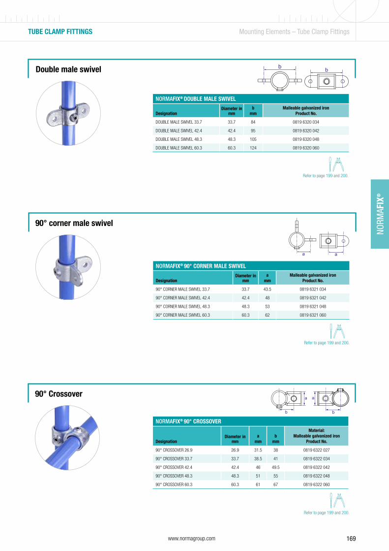
169www.normagroup.com
NORM
AFIX
®
Double male swivel b b
NORMAFIX® DOUBLE MALE SWIVEL
DesignationDiameter in
mmb
mmMalleable galvanized iron
Product No.
DOUBLE MALE SWIVEL 33.7 33.7 84 0819 6320 034
DOUBLE MALE SWIVEL 42.4 42.4 95 0819 6320 042
DOUBLE MALE SWIVEL 48.3 48.3 105 0819 6320 048
DOUBLE MALE SWIVEL 60.3 60.3 124 0819 6320 060
TUBE CLAMP FITTINGS Mounting Elements – Tube Clamp Fittings
90° Crossover
90° corner male swivel
aa
b
a
b
a
NORMAFIX® 90° CORNER MALE SWIVEL
DesignationDiameter in
mma
mmMalleable galvanized iron
Product No.
90° CORNER MALE SWIVEL 33.7 33.7 43.5 0819 6321 034
90° CORNER MALE SWIVEL 42.4 42.4 48 0819 6321 042
90° CORNER MALE SWIVEL 48.3 48.3 53 0819 6321 048
90° CORNER MALE SWIVEL 60.3 60.3 62 0819 6321 060
NORMAFIX® 90° CROSSOVER
DesignationDiameter in
mma
mmb
mm
Material: Malleable galvanized iron
Product No.
90° CROSSOVER 26.9 26.9 31.5 38 0819 6322 027
90° CROSSOVER 33.7 33.7 38.5 41 0819 6322 034
90° CROSSOVER 42.4 42.4 46 49.5 0819 6322 042
90° CROSSOVER 48.3 48.3 51 55 0819 6322 048
90° CROSSOVER 60.3 60.3 61 67 0819 6322 060
Refer to page 199 and 200.
Refer to page 199 and 200.
Refer to page 199 and 200.
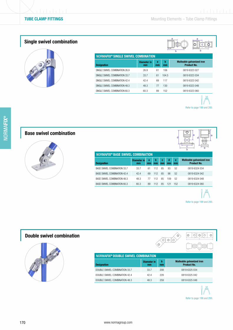
170 www.normagroup.com
NORM
AFIX
®
TUBE CLAMP FITTINGS Mounting Elements – Tube Clamp Fittings
Single swivel combination
b
a
b
a
e
ad
bc
ad
NORMAFIX® SINGLE SWIVEL COMBINATION
DesignationDiameter in
mma
mmb
mmMalleable galvanized iron
Product No.
SINGLE SWIVEL COMBINATION 26.9 26.9 61 106 0819 6323 027
SINGLE SWIVEL COMBINATION 33.7 33.7 61 104.5 0819 6323 034
SINGLE SWIVEL COMBINATION 42.4 42.4 69 117 0819 6323 042
SINGLE SWIVEL COMBINATION 48.3 48.3 77 130 0819 6323 048
SINGLE SWIVEL COMBINATION 60.3 60.3 89 152 0819 6323 060
NORMAFIX® BASE SWIVEL COMBINATION
DesignationDiameter in
mma
mmb
mmc
mmd
mme
mmMalleable galvanized iron
Product No.
BASE SWIVEL COMBINATION 33.7 33.7 61 112 85 93 52 0819 6324 034
BASE SWIVEL COMBINATION 42.4 42.4 69 112 85 98 52 0819 6324 042
BASE SWIVEL COMBINATION 48.3 48.3 77 112 85 109 52 0819 6324 048
BASE SWIVEL COMBINATION 60.3 60.3 89 112 85 121 152 0819 6324 060
Base swivel combination
Double swivel combination
NORMAFIX® DOUBLE SWIVEL COMBINATION
DesignationDiameter in
mmb
mmMalleable galvanized iron
Product No.
DOUBLE SWIVEL COMBINATION 33.7 33.7 208 0819 6325 034
DOUBLE SWIVEL COMBINATION 42.4 42.4 228 0819 6325 042
DOUBLE SWIVEL COMBINATION 48.3 48.3 259 0819 6325 048
b
b
b
b
b
b
Refer to page 199 and 200.
Refer to page 199 and 200.
Refer to page 199 and 200.
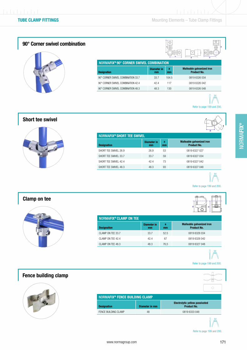
171www.normagroup.com
NORM
AFIX
®
TUBE CLAMP FITTINGS Mounting Elements – Tube Clamp Fittings
Short tee swivel
a
aa
NORMAFIX® SHORT TEE SWIVEL
DesignationDiameter in
mma
mmMalleable galvanized iron
Product No.
SHORT TEE SWIVEL 26.9 26.9 53 0819 6327 027
SHORT TEE SWIVEL 33.7 33.7 59 0819 6327 034
SHORT TEE SWIVEL 42.4 42.4 73 0819 6327 042
SHORT TEE SWIVEL 48.3 48.3 93 0819 6327 048
NORMAFIX® CLAMP ON TEE
DesignationDiameter in
mma
mmMalleable galvanized iron
Product No.
CLAMP ON TEE 33.7 33.7 52.5 0819 6328 034
CLAMP ON TEE 42.4 42.4 67 0819 6328 042
CLAMP ON TEE 48.3 48.3 76,5 0819 6327 048
Clamp on tee
Fence building clamp
NORMAFIX® FENCE BUILDING CLAMP
Designation Diameter in mmElectrolytic yellow passivated
Product No.
FENCE BUILDING CLAMP 48 0819 6333 048
Refer to page 199 and 200.
Refer to page 199 and 200.
Refer to page 199 and 200.
90° Corner swivel combination
NORMAFIX® 90° CORNER SWIVEL COMBINATION
DesignationDiameter in
mma
mmMalleable galvanized iron
Product No.
90° CORNER SWIVEL COMBINATION 33.7 33.7 104.5 0819 6326 034
90° CORNER SWIVEL COMBINATION 42.4 42.4 117 0819 6326 042
90° CORNER SWIVEL COMBINATION 48.3 48.3 130 0819 6326 048
a
a a
a
a
Refer to page 199 and 200.

172 www.normagroup.com
NORM
AFIX
®
2 bolts for fixing the clamp on the post
Round shaped to adapt to the form of the support
ALU BAND CLAMP Mounting Elements – Traffic Sign Fixation
NORMAFIX® ALU BAND CLAMP
Designation Length Number of boltsAluminum
Product No.
ALU BAND CLAMP 82 2 0560 7563 082
ALU BAND CLAMP 120 2 0560 7563 120
3
1
2
Universal traffic sign fixation
Mainly used to hold road signs on a diversity of metal posts or lamppost diameters.
1
2
Information
• Includes 2 bolts• To be used with a worm drive hose clamp
Applications
Traffic signs industry
Material
Aluminum
Technical data & Ordering information
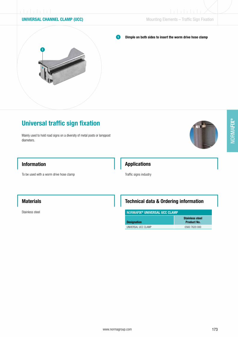
173www.normagroup.com
NORM
AFIX
®
NORMAFIX® UNIVERSAL UCC CLAMP
DesignationStainless steel
Product No.
UNIVERSAL UCC CLAMP 0560 7620 000
UNIVERSAL CHANNEL CLAMP (UCC) Mounting Elements – Traffic Sign Fixation
Materials
Dimple on both sides to insert the worm drive hose clamp
Universal traffic sign fixation
Mainly used to hold road signs on a diversity of metal posts or lamppost diameters.
Information
To be used with a worm drive hose clamp
Applications
Traffic signs industry
Stainless steel
1
Technical data & Ordering information
1

174

175
For a helping hand in industrial, commercial and private applicationsNORMAPLAST® plastic hose connectors – the NORMA® range of products for rapidly connecting hoses and pipes – are the helping hands that no one working in industrial, commercial or private applications should be without.
NORMAPLAST® - Hose Connectors
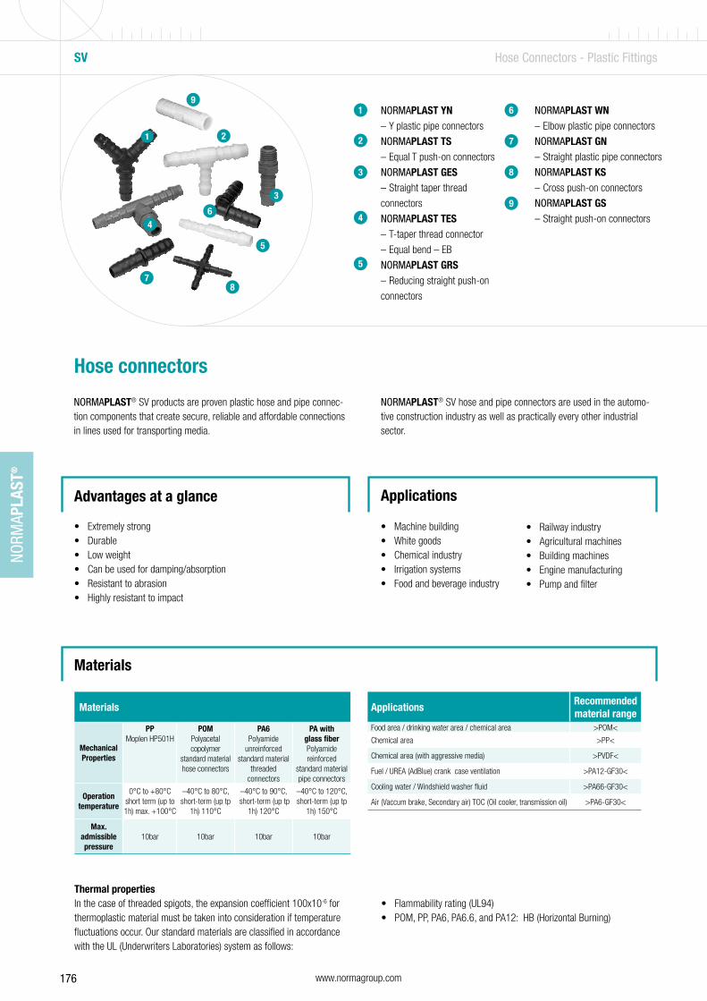
176 www.normagroup.com
NORM
APLA
ST®
ApplicationsRecommended material range
Food area / drinking water area / chemical area >POM<
Chemical area >PP<
Chemical area (with aggressive media) >PVDF<
Fuel / UREA (AdBlue) crank case ventilation >PA12-GF30<
Cooling water / Windshield washer fluid >PA66-GF30<
Air (Vaccum brake, Secondary air) TOC (Oil cooler, transmission oil) >PA6-GF30<
Materials
NORMAPLAST YN – Y plastic pipe connectors
NORMAPLAST TS – Equal T push-on connectors
NORMAPLAST GES – Straight taper thread
connectors
NORMAPLAST TES – T-taper thread connector
– Equal bend – EB
NORMAPLAST GRS – Reducing straight push-on
connectors
NORMAPLAST WN – Elbow plastic pipe connectors
NORMAPLAST GN – Straight plastic pipe connectors
NORMAPLAST KS – Cross push-on connectors
NORMAPLAST GS – Straight push-on connectors
1
2
3
4
Hose connectors
NORMAPLAST® SV products are proven plastic hose and pipe connec-tion components that create secure, reliable and affordable connections in lines used for transporting media.
Advantages at a glance
• Extremely strong• Durable• Low weight• Can be used for damping/absorption• Resistant to abrasion• Highly resistant to impact
Applications
• Machine building• White goods• Chemical industry• Irrigation systems• Food and beverage industry
• Railway industry• Agricultural machines• Building machines• Engine manufacturing• Pump and filter
NORMAPLAST® SV hose and pipe connectors are used in the automo-tive construction industry as well as practically every other industrial sector.
2
6
3
4
SV Hose Connectors - Plastic Fittings
1
78
5
6
7
8
Materials
MechanicalProperties
PP Moplen HP501H
POM Polyacetal copolymer
standard material hose connectors
PA6Polyamide
unreinforced standard material
threaded connectors
PA with glass fiberPolyamide reinforced
standard material pipe connectors
Operation temperature
0°C to +80°Cshort term (up to 1h) max. +100°C
–40°C to 80°C, short-term (up tp
1h) 110°C
–40°C to 90°C, short-term (up tp
1h) 120°C
–40°C to 120°C, short-term (up tp
1h) 150°C
Max. admissible pressure
10bar 10bar 10bar 10bar
Thermal propertiesIn the case of threaded spigots, the expansion coefficient 100x10-6 for thermoplastic material must be taken into consideration if temperature fluctuations occur. Our standard materials are classified in accordance with the UL (Underwriters Laboratories) system as follows:
• Flammability rating (UL94)• POM, PP, PA6, PA6.6, and PA12: HB (Horizontal Burning)
9
9
5
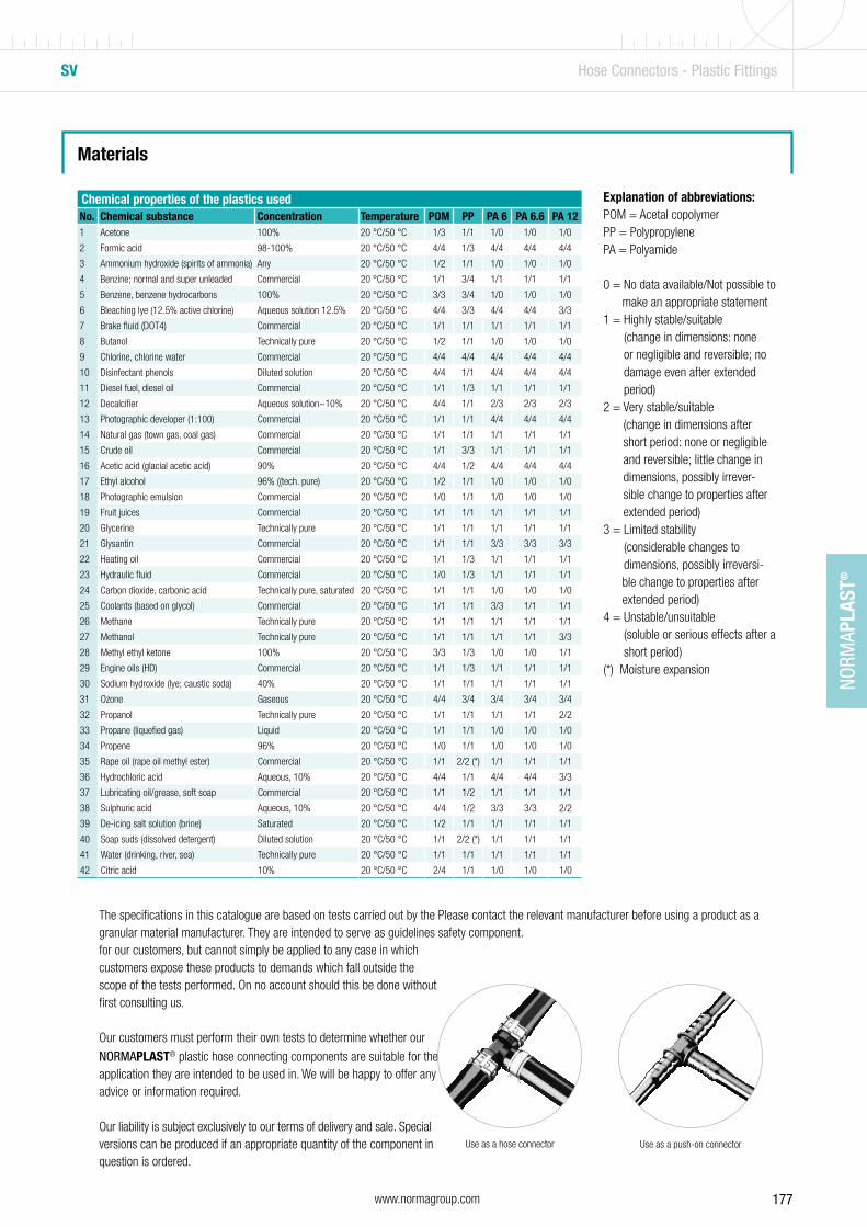
177www.normagroup.com
NORM
APLA
ST®
SV Hose Connectors - Plastic Fittings
Materials
Chemical properties of the plastics usedNo. Chemical substance Concentration Temperature POM PP PA 6 PA 6.6 PA 121 Acetone 100% 20 °C/50 °C 1/3 1/1 1/0 1/0 1/0
2 Formic acid 98-100% 20 °C/50 °C 4/4 1/3 4/4 4/4 4/4
3 Ammonium hydroxide (spirits of ammonia) Any 20 °C/50 °C 1/2 1/1 1/0 1/0 1/0
4 Benzine; normal and super unleaded Commercial 20 °C/50 °C 1/1 3/4 1/1 1/1 1/1
5 Benzene, benzene hydrocarbons 100% 20 °C/50 °C 3/3 3/4 1/0 1/0 1/0
6 Bleaching lye (12.5% active chlorine) Aqueous solution 12.5% 20 °C/50 °C 4/4 3/3 4/4 4/4 3/3
7 Brake fluid (DOT4) Commercial 20 °C/50 °C 1/1 1/1 1/1 1/1 1/1
8 Butanol Technically pure 20 °C/50 °C 1/2 1/1 1/0 1/0 1/0
9 Chlorine, chlorine water Commercial 20 °C/50 °C 4/4 4/4 4/4 4/4 4/4
10 Disinfectant phenols Diluted solution 20 °C/50 °C 4/4 1/1 4/4 4/4 4/4
11 Diesel fuel, diesel oil Commercial 20 °C/50 °C 1/1 1/3 1/1 1/1 1/1
12 Decalcifier Aqueous solution~10% 20 °C/50 °C 4/4 1/1 2/3 2/3 2/3
13 Photographic developer (1:100) Commercial 20 °C/50 °C 1/1 1/1 4/4 4/4 4/4
14 Natural gas (town gas, coal gas) Commercial 20 °C/50 °C 1/1 1/1 1/1 1/1 1/1
15 Crude oil Commercial 20 °C/50 °C 1/1 3/3 1/1 1/1 1/1
16 Acetic acid (glacial acetic acid) 90% 20 °C/50 °C 4/4 1/2 4/4 4/4 4/4
17 Ethyl alcohol 96% ((tech. pure) 20 °C/50 °C 1/2 1/1 1/0 1/0 1/0
18 Photographic emulsion Commercial 20 °C/50 °C 1/0 1/1 1/0 1/0 1/0
19 Fruit juices Commercial 20 °C/50 °C 1/1 1/1 1/1 1/1 1/1
20 Glycerine Technically pure 20 °C/50 °C 1/1 1/1 1/1 1/1 1/1
21 Glysantin Commercial 20 °C/50 °C 1/1 1/1 3/3 3/3 3/3
22 Heating oil Commercial 20 °C/50 °C 1/1 1/3 1/1 1/1 1/1
23 Hydraulic fluid Commercial 20 °C/50 °C 1/0 1/3 1/1 1/1 1/1
24 Carbon dioxide, carbonic acid Technically pure, saturated 20 °C/50 °C 1/1 1/1 1/0 1/0 1/0
25 Coolants (based on glycol) Commercial 20 °C/50 °C 1/1 1/1 3/3 1/1 1/1
26 Methane Technically pure 20 °C/50 °C 1/1 1/1 1/1 1/1 1/1
27 Methanol Technically pure 20 °C/50 °C 1/1 1/1 1/1 1/1 3/3
28 Methyl ethyl ketone 100% 20 °C/50 °C 3/3 1/3 1/0 1/0 1/1
29 Engine oils (HD) Commercial 20 °C/50 °C 1/1 1/3 1/1 1/1 1/1
30 Sodium hydroxide (lye; caustic soda) 40% 20 °C/50 °C 1/1 1/1 1/1 1/1 1/1
31 Ozone Gaseous 20 °C/50 °C 4/4 3/4 3/4 3/4 3/4
32 Propanol Technically pure 20 °C/50 °C 1/1 1/1 1/1 1/1 2/2
33 Propane (liquefied gas) Liquid 20 °C/50 °C 1/1 1/1 1/0 1/0 1/0
34 Propene 96% 20 °C/50 °C 1/0 1/1 1/0 1/0 1/0
35 Rape oil (rape oil methyl ester) Commercial 20 °C/50 °C 1/1 2/2 (*) 1/1 1/1 1/1
36 Hydrochloric acid Aqueous, 10% 20 °C/50 °C 4/4 1/1 4/4 4/4 3/3
37 Lubricating oil/grease, soft soap Commercial 20 °C/50 °C 1/1 1/2 1/1 1/1 1/1
38 Sulphuric acid Aqueous, 10% 20 °C/50 °C 4/4 1/2 3/3 3/3 2/2
39 De-icing salt solution (brine) Saturated 20 °C/50 °C 1/2 1/1 1/1 1/1 1/1
40 Soap suds (dissolved detergent) Diluted solution 20 °C/50 °C 1/1 2/2 (*) 1/1 1/1 1/1
41 Water (drinking, river, sea) Technically pure 20 °C/50 °C 1/1 1/1 1/1 1/1 1/1
42 Citric acid 10% 20 °C/50 °C 2/4 1/1 1/0 1/0 1/0
The specifications in this catalogue are based on tests carried out by the granular material manufacturer. They are intended to serve as guidelines for our customers, but cannot simply be applied to any case in which customers expose these products to demands which fall outside the scope of the tests performed. On no account should this be done without first consulting us.
Our customers must perform their own tests to determine whether our
NORMAPLAST® plastic hose connecting components are suitable for the application they are intended to be used in. We will be happy to offer any advice or information required.
Our liability is subject exclusively to our terms of delivery and sale. Special versions can be produced if an appropriate quantity of the component in question is ordered.
Please contact the relevant manufacturer before using a product as a safety component.
Explanation of abbreviations: POM = Acetal copolymerPP = PolypropylenePA = Polyamide
0 = No data available/Not possible to make an appropriate statement1 = Highly stable/suitable
(change in dimensions: none or negligible and reversible; no damage even after extended period)
2 = Very stable/suitable (change in dimensions after short period: none or negligible and reversible; little change in dimensions, possibly irrever-sible change to properties after extended period)
3 = Limited stability (considerable changes to dimensions, possibly irreversi-
ble change to properties after extended period)4 = Unstable/unsuitable
(soluble or serious effects after a short period)
(*) Moisture expansion
Use as a hose connector Use as a push-on connector
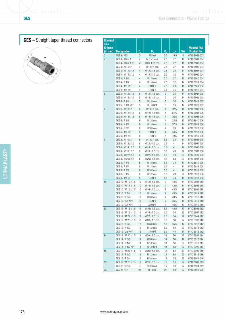
178 www.normagroup.com
NORM
APLA
ST®
GES – Straight taper thread connectors
GES Hose Connectors - Plastic Fittings
Nominal size ID hose (in mm) Designation D1 D2 D3 L1~ SW
Material PA6Product No.
3 GES 3 / M 5 3 M 5 cyl 2.5 19.5 6 0710 8952 003
4 GES 4 / M 8 x 1 4 M 8 x 1 con. 2.5 27 10 0710 8901 004
GES 4 / M 8 x 1.25 4 M 8 x 1.25 con. 2.5 27 10 0710 8902 004
GES 4 / M 10 x 1 4 M 10 x 1 con. 2.5 27 10 0710 8903 004
GES 4 / M 12 x 1.5 4 M 12 x 1.5 con. 2.5 32 14 0710 8904 004
GES 4 / M 14 x 1.5 4 M 14 x 1.5 con. 2.5 32 14 0710 8905 004
GES 4 / R 1/8 4 R 1/8 con. 2.5 27 10 0710 8910 004
GES 4 / R 1/4 4 R 1/4 con. 2.5 32 14 0710 8911 004
GES 4 / 1/8 NPT 4 1/8 NPT 2.5 29 10 0710 8917 004
GES 4 / 1/4 NPT 4 1/4 NPT 2.5 35 14 0710 8918 004
5 GES 5 / M 12 x 1.5 5 M 12 x 1.5 con. 3 36 14 0710 8904 005
GES 5 / M 14 x 1.5 5 M 14 x 1.5 con. 3 36 14 0710 8905 005
GES 5 / R 1/4 5 R 1/4 con. 3 36 14 0710 8911 005
GES 5 / R 1/4 NPT 5 R 1/4 NPT 3 39 14 0710 8918 005
6 GES 6 / M 10 x 1 6 M 10 x 1 con. 4 32.5 10 0710 8903 006
GES 6 / M 12 x 1.5 6 M 12 x 1.5 con. 4 37.5 14 0710 8904 006
GES 6 / M 14 x 1.5 6 M 14 x 1.5 con. 4 36.5 14 0710 8905 006
GES 6 / R 1/8 6 R 1/8 con. 4 32.5 10 0710 8910 006
GES 6 / R 1/4 6 R 1/4 con. 4 37.5 14 0710 8911 006
GES 6 / R 3/8 6 R 3/8 con. 4 39 17 0710 8912 006
GES 6 / 1/8 NPT 6 1/8 NPT 4 34.5 10 0710 8917 006
GES 6 / 1/4 NPT 6 1/4 NPT 4 40.5 14 0710 8918 006
8 GES 8 / M 10 x 1 8 M 10 x 1 con. 5.6 38 14 0710 8903 008
GES 8 / M 12 x 1.5 8 M 12 x 1.5 con. 5.6 41 14 0710 8904 008
GES 8 / M 14 x 1.5 8 M 14 x 1.5 con. 5.6 41 14 0710 8905 008
GES 8 / M 18 x 1.5 8 M 18 x 1.5 con. 5.6 49 22 0710 8907 008
GES 8 / M 22 x 1.5 8 M 22 x 1.5 con. 5.6 49 22 0710 8949 008
GES 8 / M 26 x 1.5 8 M 26 x 1.5 con. 5.6 58 27 0710 8908 008
GES 8 / R 1/8 8 R 1/8 con. 5.6 38 14 0710 8910 008
GES 8 / R 1/4 8 R 1/4 con. 5.6 41 14 0710 8911 008
GES 8 / R 3/8 8 R 3/8 con. 5.6 41 17 0710 8912 008
GES 8 / R 1/2 8 R 1/2 con. 5.6 49 22 0710 8913 008
GES 8 / 1/4 NPT 8 1/4 NPT 5.6 44 14 0710 8918 008
10 GES 10 / M 12 x 1.5 10 M 12 x 1.5 con. 7 43.5 14 0710 8904 010
GES 10 / M 14 x 1.5 10 M 14 x 1.5 con. 7 43.5 14 0710 8905 010
GES 10 / M 16 x 1.5 10 M 16 x 1.5 con. 7 43.5 17 0710 8906 010
GES 10 / R 1/4 10 R 1/4 con. 7 43.5 14 0710 8911 010
GES 10 / R 3/8 10 R 3/8 con. 7 43.5 17 0710 8912 010
GES 10 / 1/4 NPT 10 1/4 NPT 7 46.5 14 0710 8918 010
GES 10 / 3/8 NPT 10 3/8 NPT 7 46.5 17 0710 8919 010
12 GES 12 / M 16 x 1.5 12 M 16 x 1.5 con. 8.6 45.5 17 0710 8906 012
GES 12 / M 18 x 1.5 12 M 18 x 1.5 con. 8.6 54 22 0710 8907 012
GES 12 / M 22 x 1.5 12 M 22 x 1.5 con. 8.6 54 22 0710 8949 012
GES 12 / M 26 x 1.5 12 M 26 x 1.5 con. 8.6 58 27 0710 8909 012
GES 12 / R 3/8 12 R 3/8 con. 8.6 45.5 17 0710 8912 012
GES 12 / R 1/2 12 R 1/2 con. 8.6 54 22 0710 8913 012
GES 12 / 3/8 NPT 12 3/8 NPT 8.6 48 17 0710 8919 012
14 GES 14 / M 20 x 1.5 14 M 20 x 1.5 con. 10 56 22 0710 8908 014
GES 14 / R 3/8 14 R 3/8 con. 10 56 17 0710 8912 014
GES 14 / R 1/2 14 R 1/2 con. 10 56 22 0710 8913 014
GES 14 / R 1/2 NPT 14 R 1/2 NPT 10 58 22 0710 8920 014
16 GES 16 / M 26 x 1.5 16 M 26 x 1.5 con. 12 58 27 0710 8909 016
GES 16 / R 1/2 16 R 1/2 con. 12 58 22 0710 8913 016
GES 16 / R 3/4 16 R 3/4 con. 12 58 27 0710 8914 016
19 GES 19 / M 26 x 1.5 19 M 26 x 1.5 con. 15 58 27 0710 8909 019
GES 19 / R 3/4 19 R 3/4 con. 15 58 27 0710 8914 019
25 GES 25 / R 1 25 R 1 con. 21 69 32 0710 8915 025
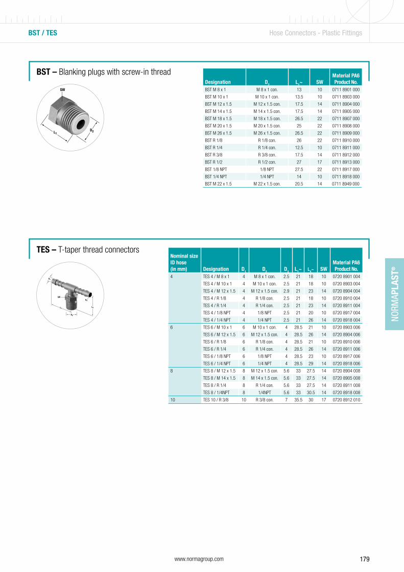
179www.normagroup.com
NORM
APLA
ST®
BST / TES Hose Connectors - Plastic Fittings
Designation D2 L1~ SWMaterial PA6Product No.
BST M 8 x 1 M 8 x 1 con. 13 10 0711 8901 000
BST M 10 x 1 M 10 x 1 con. 13.5 10 0711 8903 000
BST M 12 x 1.5 M 12 x 1.5 con. 17.5 14 0711 8904 000
BST M 14 x 1.5 M 14 x 1.5 con. 17.5 14 0711 8905 000
BST M 18 x 1.5 M 18 x 1.5 con. 26.5 22 0711 8907 000
BST M 20 x 1.5 M 20 x 1.5 con. 25 22 0711 8908 000
BST M 26 x 1.5 M 26 x 1.5 con. 26.5 22 0711 8909 000
BST R 1/8 R 1/8 con. 26 22 0711 8910 000
BST R 1/4 R 1/4 con. 12.5 10 0711 8911 000
BST R 3/8 R 3/8 con. 17.5 14 0711 8912 000
BST R 1/2 R 1/2 con. 27 17 0711 8913 000
BST 1/8 NPT 1/8 NPT 27.5 22 0711 8917 000
BST 1/4 NPT 1/4 NPT 14 10 0711 8918 000
BST M 22 x 1.5 M 22 x 1.5 con. 20.5 14 0711 8949 000
Nominal size ID hose (in mm) Designation D1 D2 D3 L1~ L4~ SW
Material PA6Product No.
4 TES 4 / M 8 x 1 4 M 8 x 1 con. 2.5 21 18 10 0720 8901 004
TES 4 / M 10 x 1 4 M 10 x 1 con. 2.5 21 18 10 0720 8903 004
TES 4 / M 12 x 1.5 4 M 12 x 1.5 con. 2.9 21 23 14 0720 8904 004
TES 4 / R 1/8 4 R 1/8 con. 2.5 21 18 10 0720 8910 004
TES 4 / R 1/4 4 R 1/4 con. 2.5 21 23 14 0720 8911 004
TES 4 / 1/8 NPT 4 1/8 NPT 2.5 21 20 10 0720 8917 004
TES 4 / 1/4 NPT 4 1/4 NPT 2.5 21 26 14 0720 8918 004
6 TES 6 / M 10 x 1 6 M 10 x 1 con. 4 28.5 21 10 0720 8903 006
TES 6 / M 12 x 1.5 6 M 12 x 1.5 con. 4 28.5 26 14 0720 8904 006
TES 6 / R 1/8 6 R 1/8 con. 4 28.5 21 10 0720 8910 006
TES 6 / R 1/4 6 R 1/4 con. 4 28.5 26 14 0720 8911 006
TES 6 / 1/8 NPT 6 1/8 NPT 4 28.5 23 10 0720 8917 006
TES 6 / 1/4 NPT 6 1/4 NPT 4 28.5 29 14 0720 8918 006
8 TES 8 / M 12 x 1.5 8 M 12 x 1.5 con. 5.6 33 27.5 14 0720 8904 008
TES 8 / M 14 x 1.5 8 M 14 x 1.5 con. 5.6 33 27.5 14 0720 8905 008
TES 8 / R 1/4 8 R 1/4 con. 5.6 33 27.5 14 0720 8911 008
TES 8 / 1/4NPT 8 1/4NPT 5.6 33 30.5 14 0720 8918 008
10 TES 10 / R 3/8 10 R 3/8 con. 7 35.5 30 17 0720 8912 010
BST – Blanking plugs with screw-in thread
TES – T-taper thread connectors
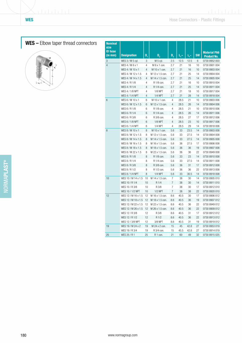
180 www.normagroup.com
NORM
APLA
ST®
WES – Elbow taper thread connectors
WES Hose Connectors - Plastic Fittings
Nominal size ID hose (in mm) Designation D1 D2 D3 L1~ L4~ SW
Material PA6Product No.
3 WES 3 / M 5 cyl. 3 M 5 cyl. 2.5 12.5 12.5 6 0730 8952 003
4 WES 4 / M 8 x 1 4 M 8 x 1 con. 2.7 21 16 10 0730 8901 004
WES 4 / M 10 x 1 4 M 10 x 1 con. 2.7 21 16 10 0730 8903 004
WES 4 / M 12 x 1.5 4 M 12 x 1.5 con. 2.7 21 25 14 0730 8904 004
WES 4 / M 14 x 1.5 4 M 14 x 1.5 con. 2.7 21 25 14 0730 8905 004
WES 4 / R 1/8 4 R 1/8 con. 2.7 21 16 10 0730 8910 004
WES 4 / R 1/4 4 R 1/4 con. 2.7 21 25 14 0730 8911 004
WES 4 / 1/8 NPT 4 1/8 NPT 2.7 21 18 10 0730 8917 004
WES 4 / 1/4 NPT 4 1/4 NPT 2.7 21 28 14 0730 8918 004
6 WES 6 / M 10 x 1 6 M 10 x 1 con. 4 28.5 21 10 0730 8903 006
WES 6 / M 12 x 1.5 6 M 12 x 1.5 con. 4 28.5 26 14 0730 8904 006
WES 6 / R 1/8 6 R 1/8 con. 4 28.5 21 10 0730 8910 006
WES 6 / R 1/4 6 R 1/4 con. 4 28.5 26 14 0730 8911 006
WES 6 / R 3/8 6 R 3/8 con. 4 28.5 27 17 0730 8912 006
WES 6 / 1/8 NPT 6 1/8 NPT 4 28.5 23 10 0730 8917 006
WES 6 / 1/4 NPT 6 1/4 NPT 4 28.5 29 14 0730 8918 006
8 WES 8 / M 10 x 1 8 M 10 x 1 con. 5.6 33 23.5 14 0730 8903 008
WES 8 / M 12 x 1.5 8 M 12 x 1.5 con. 5.6 33 27.5 14 0730 8904 008
WES 8 / M 14 x 1.5 8 M 14 x 1.5 con. 5.6 33 27.5 14 0730 8905 008
WES 8 / M 16 x 1.5 8 M 16 x 1.5 con. 5.6 36 27.5 17 0730 8906 008
WES 8 / M 18 x 1.5 8 M 18 x 1.5 con. 5.6 36 36 19 0730 8907 008
WES 8 / M 22 x 1.5 8 M 22 x 1.5 con. 5.6 36 36 22 0730 8949 008
WES 8 / R 1/8 8 R 1/8 con. 5.6 33 23 14 0730 8910 008
WES 8 / R 1/4 8 R 1/4 con. 5.6 33 27.5 14 0730 8911 008
WES 8 / R 3/8 8 R 3/8 con. 5.6 36 31 17 0730 8912 008
WES 8 / R 1/2 8 R 1/2 con. 5.6 36 36 22 0730 8913 008
WES 8 / 1/4 NPT 8 1/4 NPT 5.6 33 30.5 14 0730 8918 008
10 WES 10 / M 14 x 1.5 10 M 14 x 1.5 con. 7 38 30 14 0730 8905 010
WES 10 / R 1/4 10 R 1/4 7 38 30 14 0730 8911 010
WES 10 / R 3/8 10 R 3/8 7 38 30 17 0730 8912 010
WES 10 / 1/2 NPT 10 1/2 NPT 7 38 38 22 0730 8920 010
12 WES 12 / M 16 x 1.5 12 M 16 x 1.5 con. 8.6 40.5 30 17 0730 8906 012
WES 12 / M 18 x 1.5 12 M 18 x 1.5 con. 8.6 40.5 36 19 0730 8907 012
WES 12 / M 22 x 1.5 12 M 22 x 1.5 con. 8.6 40.5 36 22 0730 8949 012
WES 12 / M 26 x 1.5 12 M 26 x 1.5 con. 8.6 40.5 36 22 0730 8909 012
WES 12 / R 3/8 12 R 3/8 8.6 40.5 31 17 0730 8912 012
WES 12 / R 1/2 12 R 1/2 8.6 40.5 36 22 0730 8913 012
WES 12 / 3/8 NPT 12 3/8 NPT 8.6 40.5 31 19 0730 8919 012
19 WES 19 / M 24 x 2 19 M 24 x 2 con. 15 45 42.8 27 0730 8953 019
WES 19 / R 3/4 19 R 3/4 con. 15 45.5 42.8 27 0730 8914 019
25 WES 25 / R 1 25 R 1 con. 21 60 49 32 0730 8915 025

181www.normagroup.com
NORM
APLA
ST®
GS / GRS / TS Hose Connectors - Plastic Fittings
GS – Straight push-on connectors
GRS – Reducing straight push-on connectors
Nominal size ID hose (in mm) Designation D1 D2 L1~
Material POMProduct No.
3 GS 3 3 2.5 25 0750 8900 003
4 GS 4 4 2.7 35 0750 8900 004
5 GS 5 5 3 45 0750 8900 005
6 GS 6 6 4 49 0750 8900 006
8 GS 8 8 5.6 56 0750 8900 008
10 GS 10 10 7 63 0750 8900 010
12 GS 12 12 8.6 66.5 0750 8900 012
13 GS 13 13 8.6 73 0750 8900 013
14 GS 14 14 10 79 0750 8900 014
16 GS 16 16 12 75 0750 8900 016
19 GS 19 19 15 76 0750 8900 019
25 GS 25 25 21 95 0750 8900 025-
Nominal size ID hose (in mm) Designation D1 D2 D3 L1~
Material POMProduct No.
4 - 3 GRS 4 - 3 4 2.5 3 30 0751 8904 003
5 - 4 GRS 5 - 4 5 2.7 3 41 0751 8905 004
6 - 4 GRS 6 - 4 6 2.7 4 42.5 0751 8906 004
8 - 4 GRS 8 - 4 8 2.7 4 48 0751 8908 004
8 - 6 GRS 8 - 6 8 4 6 54 0751 8908 006
10 - 6 GRS 10 - 6 10 4 6 58 0751 8910 006
10 - 8 GRS 10 - 8 10 5.6 8 60.5 0751 8910 008
12 - 8 GRS 12 - 8 12 5.6 8 62.5 0751 8912 008
12 - 10 GRS 12 - 10 12 7 10 64 0751 8912 010
TS – Equal T push-on connectors Nominal size ID hose (in mm) Designation D1 D2 L1~ L3~
Material POMProduct No.
3 TS 3 3 2.5 25 12.5 0760 8900 003
4 TS 4 4 2.7 35 19.5 0760 8900 004
5 TS 5 5 3 42 22 0760 8900 005
6 TS 6 6 4 50 26 0760 8900 006
7 TS 7 7 5 50 26 0760 8900 007
8 TS 8 8 5.6 58 30 0760 8900 008
10 TS 10 10 7 62.5 33.5 0760 8900 010
12 TS 12 12 8.6 69 36 0760 8900 012
13 TS 13 13 8.6 68 36 0760 8900 013
14 TS 14 14 10 77.5 41.5 0760 8900 014
15 TS 15 15 11 79.5 43.5 0760 8900 015
16 TS 16 16 12 81 45 0760 8900 016
19 TS 19 19 15 85 45 0760 8900 019
25 TS 25 25 21 105 52.5 0760 8900 025
Refer to pages 192 and 193.
Refer to pages 192 and 193.
Additional materials available on request
Additional materials available on request
Additional materials available on request
Refer to pages 193.
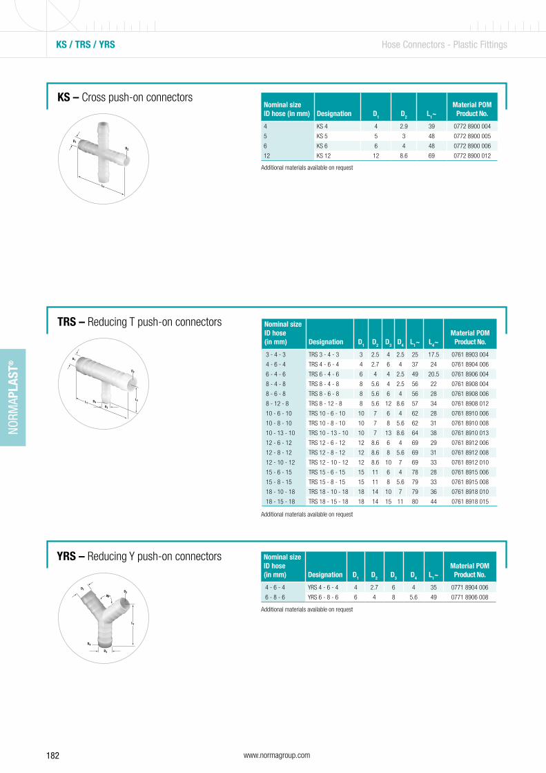
182 www.normagroup.com
NORM
APLA
ST®
KS / TRS / YRS Hose Connectors - Plastic Fittings
KS – Cross push-on connectors
TRS – Reducing T push-on connectors
YRS – Reducing Y push-on connectors
Nominal size ID hose (in mm) Designation D1 D2 L1~
Material POMProduct No.
4 KS 4 4 2.9 39 0772 8900 004
5 KS 5 5 3 48 0772 8900 005
6 KS 6 6 4 48 0772 8900 006
12 KS 12 12 8.6 69 0772 8900 012
Nominal size ID hose (in mm) Designation D1 D2 D3 D4 L1~ L4~
Material POMProduct No.
3 - 4 - 3 TRS 3 - 4 - 3 3 2.5 4 2.5 25 17.5 0761 8903 004
4 - 6 - 4 TRS 4 - 6 - 4 4 2.7 6 4 37 24 0761 8904 006
6 - 4 - 6 TRS 6 - 4 - 6 6 4 4 2.5 49 20.5 0761 8906 004
8 - 4 - 8 TRS 8 - 4 - 8 8 5.6 4 2.5 56 22 0761 8908 004
8 - 6 - 8 TRS 8 - 6 - 8 8 5.6 6 4 56 28 0761 8908 006
8 - 12 - 8 TRS 8 - 12 - 8 8 5.6 12 8.6 57 34 0761 8908 012
10 - 6 - 10 TRS 10 - 6 - 10 10 7 6 4 62 28 0761 8910 006
10 - 8 - 10 TRS 10 - 8 - 10 10 7 8 5.6 62 31 0761 8910 008
10 - 13 - 10 TRS 10 - 13 - 10 10 7 13 8.6 64 38 0761 8910 013
12 - 6 - 12 TRS 12 - 6 - 12 12 8.6 6 4 69 29 0761 8912 006
12 - 8 - 12 TRS 12 - 8 - 12 12 8.6 8 5.6 69 31 0761 8912 008
12 - 10 - 12 TRS 12 - 10 - 12 12 8.6 10 7 69 33 0761 8912 010
15 - 6 - 15 TRS 15 - 6 - 15 15 11 6 4 78 28 0761 8915 006
15 - 8 - 15 TRS 15 - 8 - 15 15 11 8 5.6 79 33 0761 8915 008
18 - 10 - 18 TRS 18 - 10 - 18 18 14 10 7 79 36 0761 8918 010
18 - 15 - 18 TRS 18 - 15 - 18 18 14 15 11 80 44 0761 8918 015
Nominal size ID hose (in mm) Designation D1 D2 D3 D4 L1~
Material POMProduct No.
4 - 6 - 4 YRS 4 - 6 - 4 4 2.7 6 4 35 0771 8904 006
6 - 8 - 6 YRS 6 - 8 - 6 6 4 8 5.6 49 0771 8906 008
Additional materials available on request
Additional materials available on request
Additional materials available on request
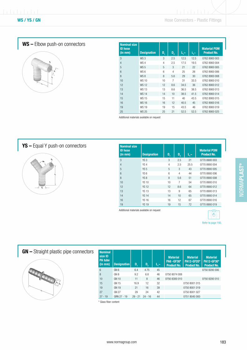
183www.normagroup.com
NORM
APLA
ST®
WS / YS / GN Hose Connectors - Plastic Fittings
WS – Elbow push-on connectors
YS – Equal Y push-on connectors
GN – Straight plastic pipe connectors
Nominal size ID hose (in mm) Designation D1 D2 L1~ L3~
Material POMProduct No.
3 WS 3 3 2.5 12.5 12.5 0762 8900 003
4 WS 4 4 2.5 17.5 19.5 0762 8900 004
5 WS 5 5 3 21 22 0762 8900 005
6 WS 6 6 4 25 26 0762 8900 006
8 WS 8 8 5.6 29 30 0762 8900 008
10 WS 10 10 7 31 33.5 0762 8900 010
12 WS 12 12 8.6 34.5 36 0762 8900 012
13 WS 13 13 8.6 36.5 38.5 0762 8900 013
14 WS 14 14 10 38.5 41.5 0762 8900 014
15 WS 15 15 11 40 43.5 0762 8900 015
16 WS 16 16 12 40.5 45 0762 8900 016
19 WS 19 19 15 43.5 46 0762 8900 019
25 WS 25 25 21 52.5 52.5 0762 8900 025
Nominal size ID hose (in mm) Designation D1 D2 L1~
Material POMProduct No.
3 YS 3 3 2.5 21 0770 8900 003
4 YS 4 4 2.5 25.5 0770 8900 004
5 YS 5 5 3 43 0770 8900 005
6 YS 6 6 4 44 0770 8900 006
8 YS 8 8 5.6 51 0770 8900 008
10 YS 10 10 7 54 0770 8900 010
12 YS 12 12 8.6 64 0770 8900 012
13 YS 13 13 9 65 0770 8900 013
14 YS 14 14 10 65 0770 8900 014
16 YS 16 16 12 67 0770 8900 016
19 YS 19 19 15 72 0770 8900 019
Nominal size ID PA tube (in mm) Designation D1 D2 L1~
MaterialPA6 -GF30*Product No.
Material PA12-GF20*Product No.
Material PA12-GF30*Product No.
6 GN 6 6.4 4.75 45 0750 8200 006
8 GN 8 9.2 6.8 46 0750 8074 008
10 GN 10 11 8 46 0750 8300 010 0750 8200 010
15 GN 15 16.9 12 32 0750 8001 015
19 GN 19 21 16 39 0750 8001 019
27 GN 27 29 24 42 0750 8001 027
27 - 19 GRN 27 - 19 29 - 21 24 - 16 44 0751 8045 000
* Glass fiber content
Additional materials available on request
Additional materials available on request
Refer to page 193.
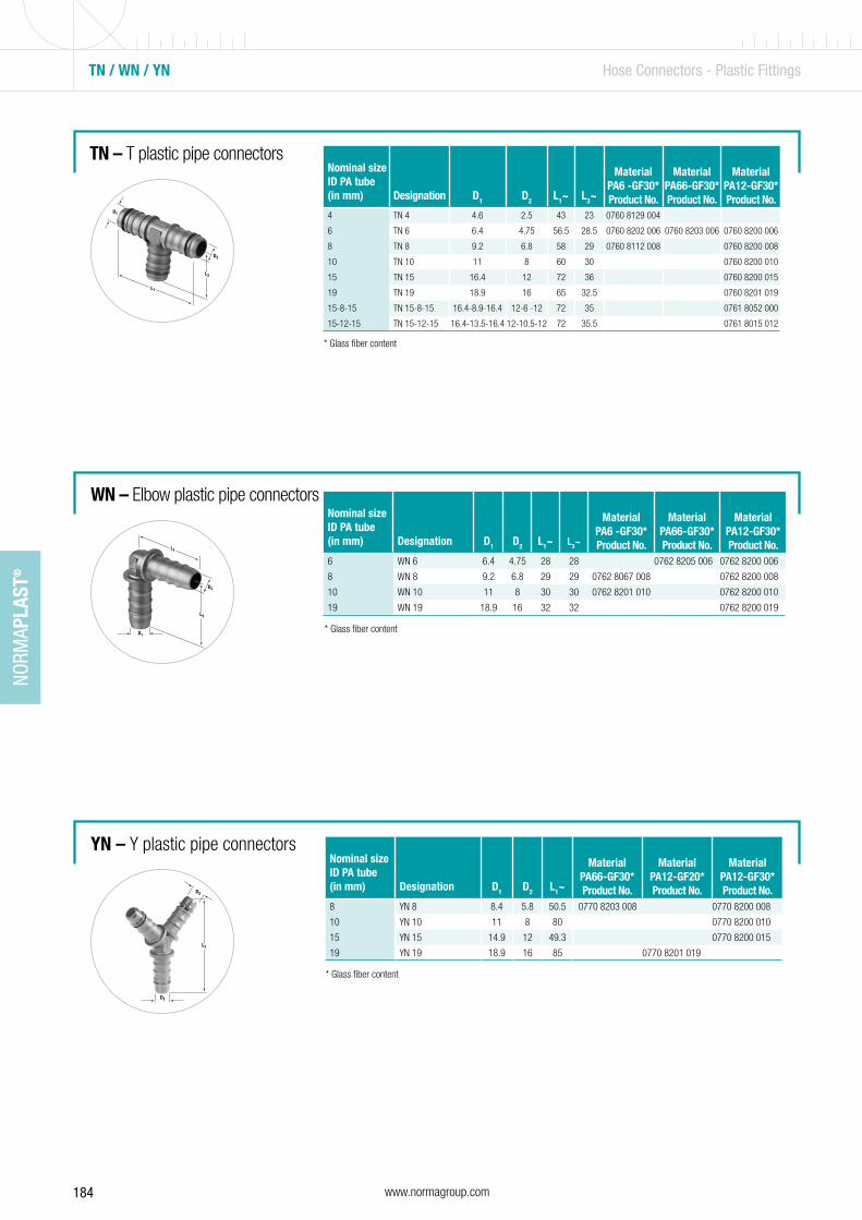
184 www.normagroup.com
NORM
APLA
ST®
TN / WN / YN Hose Connectors - Plastic Fittings
TN – T plastic pipe connectors
WN – Elbow plastic pipe connectors
YN – Y plastic pipe connectors
Nominal size ID PA tube (in mm) Designation D1 D2 L1~ L3~
MaterialPA6 -GF30*Product No.
Material PA66-GF30*Product No.
Material PA12-GF30*Product No.
4 TN 4 4.6 2.5 43 23 0760 8129 004
6 TN 6 6.4 4.75 56.5 28.5 0760 8202 006 0760 8203 006 0760 8200 006
8 TN 8 9.2 6.8 58 29 0760 8112 008 0760 8200 008
10 TN 10 11 8 60 30 0760 8200 010
15 TN 15 16.4 12 72 36 0760 8200 015
19 TN 19 18.9 16 65 32.5 0760 8201 019
15-8-15 TN 15-8-15 16.4-8.9-16.4 12-6 -12 72 35 0761 8052 000
15-12-15 TN 15-12-15 16.4-13.5-16.4 12-10.5-12 72 35.5 0761 8015 012
* Glass fiber content
Nominal size ID PA tube (in mm) Designation D1 D2 L1~ L3~
MaterialPA6 -GF30*Product No.
Material PA66-GF30*Product No.
Material PA12-GF30*Product No.
6 WN 6 6.4 4.75 28 28 0762 8205 006 0762 8200 006
8 WN 8 9.2 6.8 29 29 0762 8067 008 0762 8200 008
10 WN 10 11 8 30 30 0762 8201 010 0762 8200 010
19 WN 19 18.9 16 32 32 0762 8200 019
* Glass fiber content
* Glass fiber content
Nominal size ID PA tube (in mm) Designation D1 D2 L1~
Material PA66-GF30*Product No.
Material PA12-GF20*Product No.
Material PA12-GF30*Product No.
8 YN 8 8.4 5.8 50.5 0770 8203 008 0770 8200 008
10 YN 10 11 8 80 0770 8200 010
15 YN 15 14.9 12 49.3 0770 8200 015
19 YN 19 18.9 16 85 0770 8201 019
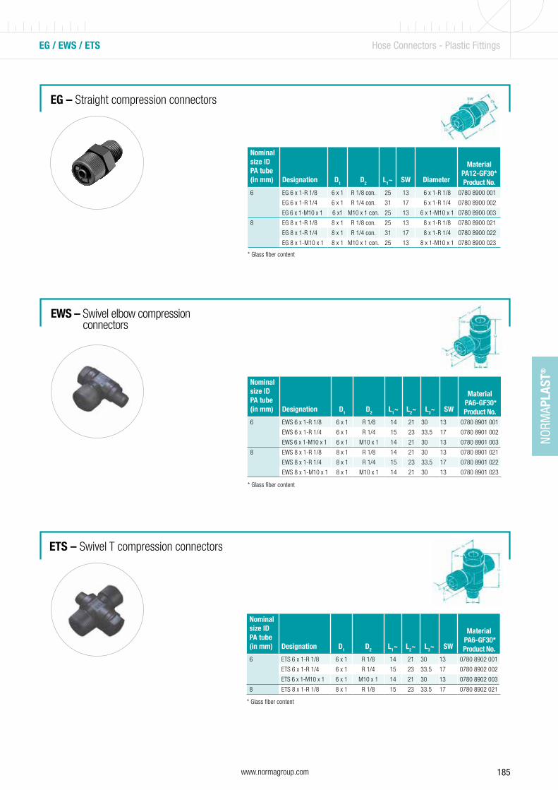
185www.normagroup.com
NORM
APLA
ST®
EG / EWS / ETS Hose Connectors - Plastic Fittings
EG – Straight compression connectors
EWS – Swivel elbow compression connectors
ETS – Swivel T compression connectors
* Glass fiber content
* Glass fiber content
Nominal size ID PA tube (in mm) Designation D1 D2 L1~ SW Diameter
Material PA12-GF30*Product No.
6 EG 6 x 1-R 1/8 6 x 1 R 1/8 con. 25 13 6 x 1-R 1/8 0780 8900 001
EG 6 x 1-R 1/4 6 x 1 R 1/4 con. 31 17 6 x 1-R 1/4 0780 8900 002
EG 6 x 1-M10 x 1 6 x1 M10 x 1 con. 25 13 6 x 1-M10 x 1 0780 8900 003
8 EG 8 x 1-R 1/8 8 x 1 R 1/8 con. 25 13 8 x 1-R 1/8 0780 8900 021
EG 8 x 1-R 1/4 8 x 1 R 1/4 con. 31 17 8 x 1-R 1/4 0780 8900 022
EG 8 x 1-M10 x 1 8 x 1 M10 x 1 con. 25 13 8 x 1-M10 x 1 0780 8900 023
Nominal size ID PA tube (in mm) Designation D1 D2 L1~ L2~ L3~ SW
Material PA6-GF30*Product No.
6 EWS 6 x 1-R 1/8 6 x 1 R 1/8 14 21 30 13 0780 8901 001
EWS 6 x 1-R 1/4 6 x 1 R 1/4 15 23 33.5 17 0780 8901 002
EWS 6 x 1-M10 x 1 6 x 1 M10 x 1 14 21 30 13 0780 8901 003
8 EWS 8 x 1-R 1/8 8 x 1 R 1/8 14 21 30 13 0780 8901 021
EWS 8 x 1-R 1/4 8 x 1 R 1/4 15 23 33.5 17 0780 8901 022
EWS 8 x 1-M10 x 1 8 x 1 M10 x 1 14 21 30 13 0780 8901 023
* Glass fiber content
Nominal size ID PA tube (in mm) Designation D1 D2 L1~ L2~ L3~ SW
Material PA6-GF30*Product No.
6 ETS 6 x 1-R 1/8 6 x 1 R 1/8 14 21 30 13 0780 8902 001
ETS 6 x 1-R 1/4 6 x 1 R 1/4 15 23 33.5 17 0780 8902 002
ETS 6 x 1-M10 x 1 6 x 1 M10 x 1 14 21 30 13 0780 8902 003
8 ETS 8 x 1-R 1/8 8 x 1 R 1/8 15 23 33.5 17 0780 8902 021

186 www.normagroup.com
NORM
APLA
ST®
Nominal size ID PA tube (in mm) Designation D1 D2 L1~ L2~
Material PA6-GF30*Product No.
6 EW 6 x 1 - R 1/8 6 x 1 R 1/8 con. 19 23 0780 8905 001
EW 6 x 1 - R 1/4 6 x 1 R 1/4 con. 23 23 0780 8905 002
EW 6 x 1 - M10 x 1 6 x 1 M10 x 1 con. 19 23 0780 8905 003
8 EW 8 x 1 - R 1/8 8 x 1 R 1/8 con. 19 23 0780 8905 021
EW 8 x 1 - R 1/4 8 x 1 R 1/4 con. 23 23 0780 8905 022
EW 8 x 1 - M10 x 1 8 x 1 M10 x 1 con. 19 23 0780 8905 023
WV 8 x 1 8 x 1 8 x 1 23 23 0781 8900 011
ET / EW / WV Hose Connectors - Plastic Fittings
ET – T compression connectors
EW/WV – Elbow compression connectors
* Glass fiber content
* Glass fiber content
Nominal size ID PA tube (in mm) Designation D1 D2 L1~ L2~
Material PA6-GF30*Product No.
6 ET 6 x 1-R 1/8 6 x 1 R 1/8 con. 19 23 0780 8904 001
ET 6 x 1-R 1/4 6 x 1 R 1/4 con. 23 23 0780 8904 002
ET 6 x 1-M10 x 1 6 x 1 M10 x 1 con. 19 23 0780 8904 003
8 ET 8 x 1-R 1/8 8 x 1 R 1/8 con. 19 23 0780 8904 021
ET 8 x 1-R 1/4 8 x 1 R 1/4 con. 23 23 0780 8904 022
ET 8 x 1-M10 x 1 8 x 1 M10 x 1 con. 19 23 0780 8904 023

187www.normagroup.com
NORM
APLA
ST®
Nominal size ID PA tube (in mm) Designation D1 L1~ SW
Material PA6-GF30*Product No.
N/A VG 6 x 1 6 x 1 31 17 0781 8901 003
VG 8 x 1 8 x 1 31 17 0781 8901 002
VGR 8 x 1 - 6 x 1 6 x 1 31 17 0781 8901 004
VT / VTR / VG / VGR Hose Connectors - Plastic Fittings
VT/VTR – Equal T and reducing T compression connectors
VG/VGR – Straight/Reducing compression connectors
* Glass fiber content
* Glass fiber content
Nominal size ID PA tube (in mm) Designation D1 D2 L1~ L2~
Material PA6-GF30*Product No.
N/A VT 6 x 1 6 x 1 6 x 1 23 23 0781 8900 001
VT 8 x 1 8 x 1 8 x 1 23 23 0781 8900 002
VTR 6 x 1-8 x 1-6 x 1 6 x 1 8 x 1 23 23 0781 8900 021
VTR 8 x 1-6 x 1-8 x 1 8 x 1 6 x 1 23 23 0781 8900 022

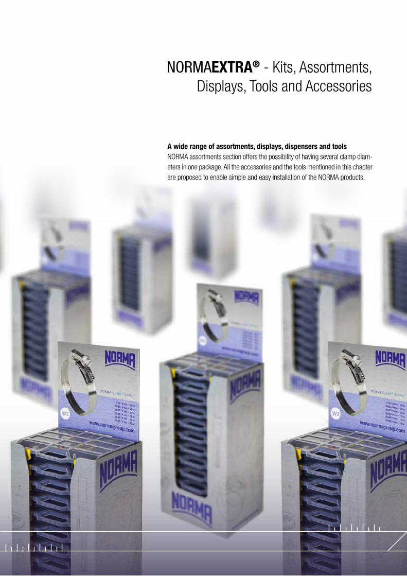
A wide range of assortments, displays, dispensers and tools NORMA assortments section offers the possibility of having several clamp diam-eters in one package. All the accessories and the tools mentioned in this chapter are proposed to enable simple and easy installation of the NORMA products.
NORMAEXTRA® - Kits, Assortments, Displays, Tools and Accessories
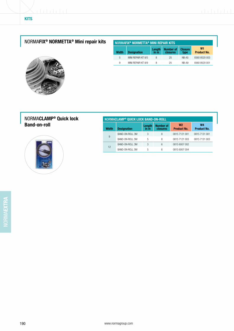
190 www.normagroup.com
NORM
AEXT
RA
KITS
NORMAFIX® NORMETTA® Mini repair kits NORMAFIX® NORMETTA® MINI REPAIR KITS
Width DesignationLength in m
Number of closures
Closure type
W1Product No.
5 MINI REPAIR KIT 8/5 8 25 NB-A5 0560 8520 003
9 MINI REPAIR KIT 8/9 8 25 NB-A9 0560 8520 001
NORMACLAMP® Quick lock Band-on-roll
NORMACLAMP® QUICK LOCK BAND-ON-ROLL
Width DesignationLengthin m
Number of closures
W2Product No.
W4Product No.
9BAND-ON-ROLL 3M 3 8 0815 7121 001 0815 7131 001
BAND-ON-ROLL 5M 5 8 0815 7121 003 0815 7131 003
12BAND-ON-ROLL 3M 3 6 0815 6007 002
BAND-ON-ROLL 5M 5 6 0815 6007 004
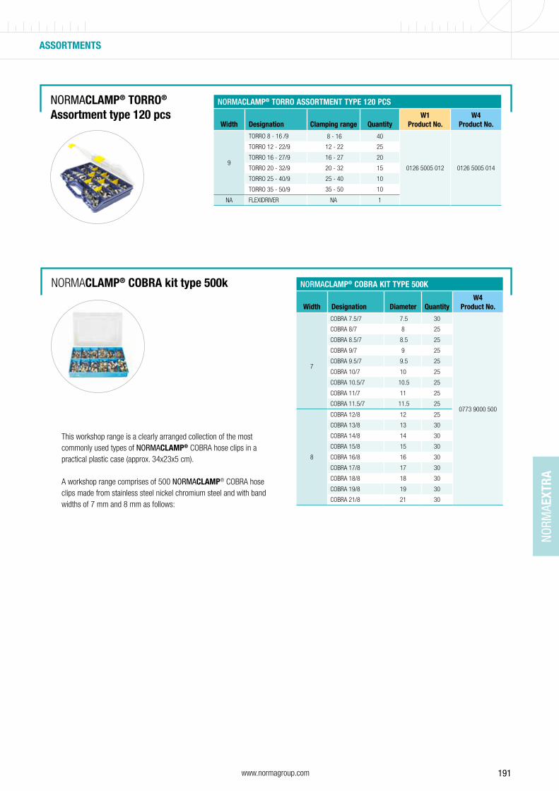
191www.normagroup.com
NORM
AEXT
RA
ASSORTMENTS
NORMACLAMP® TORRO® Assortment type 120 pcs
NORMACLAMP® TORRO ASSORTMENT TYPE 120 PCS
Width Designation Clamping range QuantityW1
Product No.W4
Product No.
9
TORRO 8 - 16 /9 8 - 16 40
0126 5005 012 0126 5005 014
TORRO 12 - 22/9 12 - 22 25
TORRO 16 - 27/9 16 - 27 20
TORRO 20 - 32/9 20 - 32 15
TORRO 25 - 40/9 25 - 40 10
TORRO 35 - 50/9 35 - 50 10
NA FLEXIDRIVER NA 1
NORMACLAMP® COBRA kit type 500k NORMACLAMP® COBRA KIT TYPE 500K
Width Designation Diameter QuantityW4
Product No.
COBRA 7.5/7 7.5 30
0773 9000 500
7
COBRA 8/7 8 25
COBRA 8.5/7 8.5 25
COBRA 9/7 9 25
COBRA 9.5/7 9.5 25
COBRA 10/7 10 25
COBRA 10.5/7 10.5 25
COBRA 11/7 11 25
COBRA 11.5/7 11.5 25
8
COBRA 12/8 12 25
COBRA 13/8 13 30
COBRA 14/8 14 30
COBRA 15/8 15 30
COBRA 16/8 16 30
COBRA 17/8 17 30
COBRA 18/8 18 30
COBRA 19/8 19 30
COBRA 21/8 21 30
This workshop range is a clearly arranged collection of the most commonly used types of NORMACLAMP® COBRA hose clips in a practical plastic case (approx. 34x23x5 cm).
A workshop range comprises of 500 NORMACLAMP® COBRA hose clips made from stainless steel nickel chromium steel and with band widths of 7 mm and 8 mm as follows:
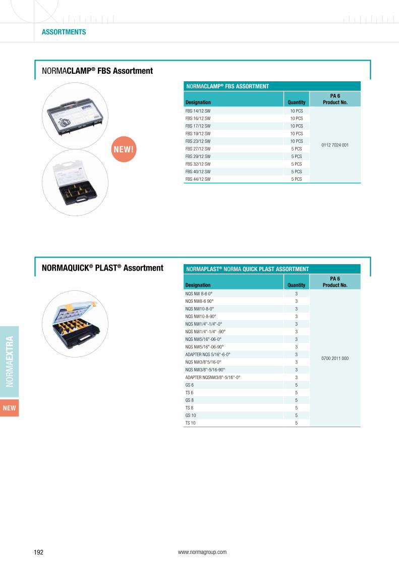
192 www.normagroup.com
NORM
AEXT
RA
NEW
ASSORTMENTS
NORMACLAMP® FBS Assortment
NORMACLAMP® FBS ASSORTMENT
Designation QuantityPA 6
Product No.
FBS 14/12 SW 10 PCS
0112 7024 001
FBS 16/12 SW 10 PCS
FBS 17/12 SW 10 PCS
FBS 19/12 SW 10 PCS
FBS 23/12 SW 10 PCS
FBS 27/12 SW 5 PCS
FBS 29/12 SW 5 PCS
FBS 32/12 SW 5 PCS
FBS 40/12 SW 5 PCS
FBS 44/12 SW 5 PCS
NEW!
NORMAQUICK® PLAST® Assortment NORMAPLAST® NORMA QUICK PLAST ASSORTMENT
Designation QuantityPA 6
Product No.
NQS NW 8-6 0° 3
0700 2011 000
NQS NW8-6 90° 3
NQS NW10-8-0° 3
NQS NW10-8-90° 3
NQS NW1/4"-1/4"-0° 3
NQS NW1/4"-1/4" -90° 3
NQS NW5/16"-06-0° 3
NQS NW5/16"-06-90° 3
ADAPTER NQS 5/16"-6-0° 3
NQS NW3/8"5/16-0° 3
NQS NW3/8"-5/16-90° 3
ADAPTER NQSNW3/8"-5/16"-0° 3
GS 6 5
TS 6 5
GS 8 5
TS 8 5
GS 10 5
TS 10 5

193www.normagroup.com
NORM
AEXT
RA
ASSORTMENTS
NORMAPLAST® Assortment type 365 PA 6 and TORRO® W2
NORMAPLAST® ASSORTMENT TYPE 365 PA 6 AND TORRO W2
Width Designation Diameter Quantity
PA 6 W2 (TORRO)Product No.
NA
GS 4 4 50
0773 9000 365
TS 4 4 50
YS 4 4 50
GS 6 6 25
TS 6 6 25
YS 6 6 25
GS 8 8 20
TS 8 8 10
YS 8 8 10
GRS 8 - 6 8 20
7.5TORRO 8 - 12/7.5 8 - 12 40
TORRO 10 - 16/7.5 10 - 16 40
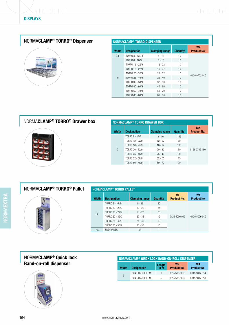
194 www.normagroup.com
NORM
AEXT
RA
NORMACLAMP® TORRO® Dispenser
NORMACLAMP® TORRO® Drawer box NORMACLAMP® TORRO DRAWER BOX
Width Designation Clamping range QuantityW2
Product No.
9
TORRO 8 - 16/9 8 - 16 155
0126 9702 450
TORRO 12 - 22/9 12 - 22 60
TORRO 16 - 27/9 16 - 27 100
TORRO 20 - 32/9 20 - 32 50
TORRO 25 - 40/9 25 - 40 50
TORRO 32 - 50/9 32 - 50 15
TORRO 50 - 70/9 50 - 70 20
NORMACLAMP® TORRO DISPENSER
Width Designation Clamping range QuantityW2
Product No.
7.5 TORRO 8 - 12/7.5 8 - 12 10
0126 9702 0109
TORRO 8 - 16/9 8 - 16 10
TORRO 12 - 22/9 12 - 22 10
TORRO 16 - 27/9 16 - 27 10
TORRO 20 - 32/9 20 - 32 10
TORRO 25 - 40/9 25 - 40 10
TORRO 32 - 50/9 32 - 50 10
TORRO 40 - 60/9 40 - 60 10
TORRO 50 - 70/9 50 - 70 10
TORRO 60 - 80/9 60 - 80 10
NORMACLAMP® TORRO® Pallet NORMACLAMP® TORRO PALLET
Width Designation Clamping range QuantityW1
Product No.W4
Product No.
9
TORRO 8 - 16 /9 8 - 16 40
0126 5006 012 0126 5006 015
TORRO 12 - 22/9 12 - 22 25
TORRO 16 - 27/9 16 - 27 20
TORRO 20 - 32/9 20 - 32 15
TORRO 25 - 40/9 25 - 40 10
TORRO 35 - 50/9 35 - 50 10
NA FLEXIDRIVER NA 1
DISPLAYS
NORMACLAMP® Quick lock Band-on-roll dispenser
NORMACLAMP® QUICK LOCK BAND-ON-ROLL DISPENSER
Width DesignationLength in m
W2Product No.
W4Product No.
9BAND-ON-ROLL 3M 3 0815 5007 015 0815 5007 014
BAND-ON-ROLL 5M 5 0815 5007 017 0815 5007 016
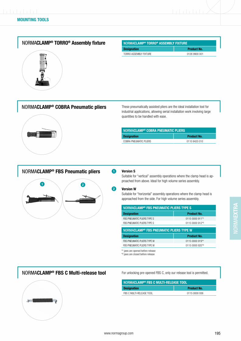
195www.normagroup.com
NORM
AEXT
RA
MOUNTING TOOLS
NORMACLAMP® FBS Pneumatic pliers Version S Suitable for “vertical” assembly operations where the clamp head is ap-proached from above. Ideal for high volume series assembly.
Version WSuitable for “horizontal” assembly operations where the clamp head is approached from the side. For high volume series assembly.
1
21 2
NORMACLAMP® TORRO® Assembly fixture NORMACLAMP® TORRO® ASSEMBLY FIXTURE
Designation Product No.
TORRO ASSEMBLY FIXTURE 0126 9900 001
NORMACLAMP® FBS C Multi-release tool
NORMACLAMP® FBS C MULTI-RELEASE TOOL
Designation Product No.
FBS C MULTI-RELEASE TOOL 0115 0000 936
For unlocking pre-opened FBS C, only our release tool is permitted.
NORMACLAMP® FBS PNEUMATIC PLIERS TYPE S
Designation Product No.
FBS PNEUMATIC PLIERS TYPE S 0115 0000 911*¹
FBS PNEUMATIC PLIERS TYPE S 0115 0000 912*²
NORMACLAMP® FBS PNEUMATIC PLIERS TYPE W
Designation Product No.
FBS PNEUMATIC PLIERS TYPE W 0115 0000 919*¹
FBS PNEUMATIC PLIERS TYPE W 0115 0000 920*²
*¹ jaws are opened before release*² jaws are closed before release
NORMACLAMP® COBRA Pneumatic pliers These pneumatically assisted pliers are the ideal installation tool for industrial applications, allowing serial installation work involving large quantities to be handled with ease.
NORMACLAMP® COBRA PNEUMATIC PLIERS
Designation Product No.
COBRA PNEUMATIC PLIERS 0110 8420 010
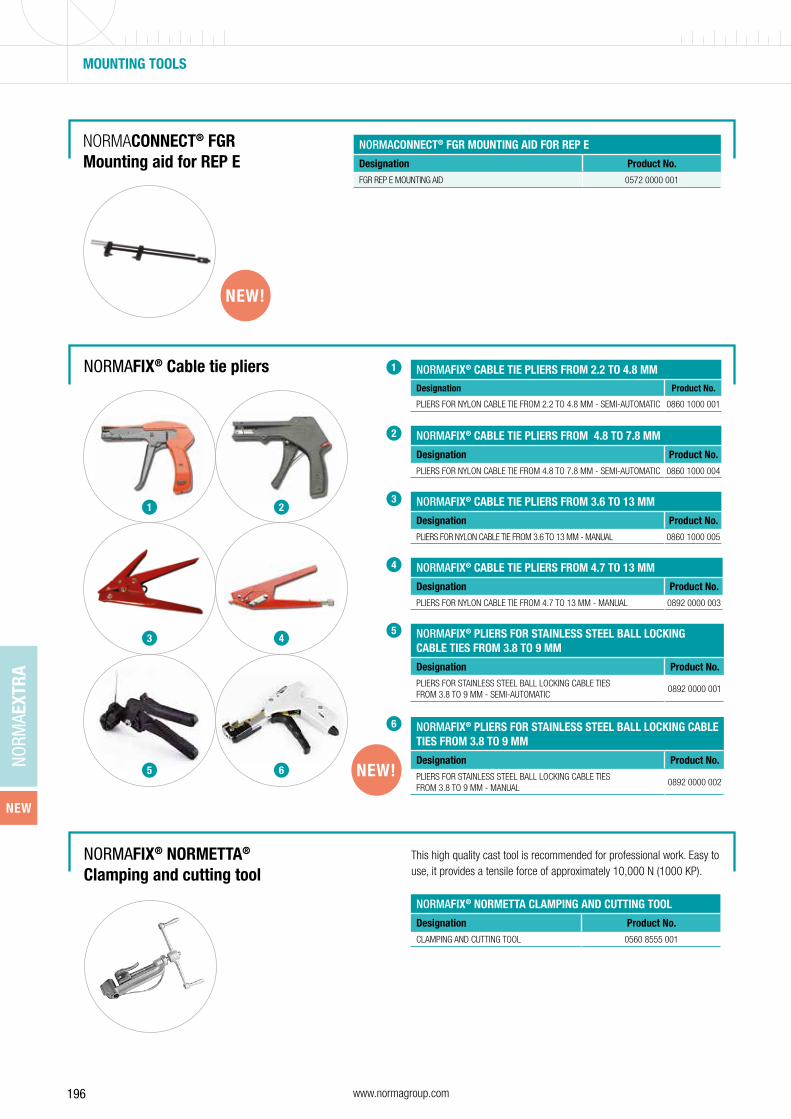
196 www.normagroup.com
NORM
AEXT
RA
NORMACONNECT® FGR Mounting aid for REP E
NORMACONNECT® FGR MOUNTING AID FOR REP E
Designation Product No.
FGR REP E MOUNTING AID 0572 0000 001
MOUNTING TOOLS
NORMAFIX® Cable tie pliers
NORMAFIX® NORMETTA®
Clamping and cutting toolThis high quality cast tool is recommended for professional work. Easy to use, it provides a tensile force of approximately 10,000 N (1000 KP).
NORMAFIX® CABLE TIE PLIERS FROM 2.2 TO 4.8 MMDesignation Product No.
PLIERS FOR NYLON CABLE TIE FROM 2.2 TO 4.8 MM - SEMI-AUTOMATIC 0860 1000 001
NORMAFIX® CABLE TIE PLIERS FROM 4.8 TO 7.8 MM
Designation Product No.
PLIERS FOR NYLON CABLE TIE FROM 4.8 TO 7.8 MM - SEMI-AUTOMATIC 0860 1000 004
NORMAFIX® CABLE TIE PLIERS FROM 3.6 TO 13 MM
Designation Product No.
PLIERS FOR NYLON CABLE TIE FROM 3.6 TO 13 MM - MANUAL 0860 1000 005
NORMAFIX® CABLE TIE PLIERS FROM 4.7 TO 13 MM
Designation Product No.
PLIERS FOR NYLON CABLE TIE FROM 4.7 TO 13 MM - MANUAL 0892 0000 003
NORMAFIX® NORMETTA CLAMPING AND CUTTING TOOL
Designation Product No.
CLAMPING AND CUTTING TOOL 0560 8555 001
NEW!
NORMAFIX® PLIERS FOR STAINLESS STEEL BALL LOCKING CABLE TIES FROM 3.8 TO 9 MM
Designation Product No.
PLIERS FOR STAINLESS STEEL BALL LOCKING CABLE TIES FROM 3.8 TO 9 MM - SEMI-AUTOMATIC
0892 0000 001
NORMAFIX® PLIERS FOR STAINLESS STEEL BALL LOCKING CABLE TIES FROM 3.8 TO 9 MM
Designation Product No.
PLIERS FOR STAINLESS STEEL BALL LOCKING CABLE TIES FROM 3.8 TO 9 MM - MANUAL
0892 0000 002NEW!
1
2
3
4
5
6
1 2
3 4
5 6
NEW
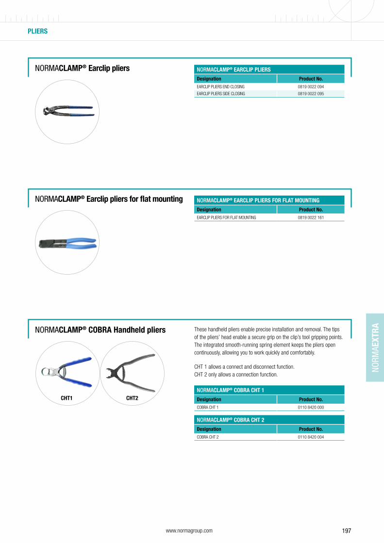
197www.normagroup.com
NORM
AEXT
RA
PLIERS
NORMACLAMP® COBRA Handheld pliers
NORMACLAMP® Earclip pliers for flat mounting
These handheld pliers enable precise installation and removal. The tips of the pliers’ head enable a secure grip on the clip’s tool gripping points. The integrated smooth-running spring element keeps the pliers open continuously, allowing you to work quickly and comfortably.
CHT 1 allows a connect and disconnect function.CHT 2 only allows a connection function.
CHT1 CHT2NORMACLAMP® COBRA CHT 1
Designation Product No.
COBRA CHT 1 0110 8420 000
NORMACLAMP® COBRA CHT 2
Designation Product No.
COBRA CHT 2 0110 8420 004
NORMACLAMP® EARCLIP PLIERS FOR FLAT MOUNTING
Designation Product No.
EARCLIP PLIERS FOR FLAT MOUNTING 0819 0022 161
NORMACLAMP® Earclip pliers NORMACLAMP® EARCLIP PLIERS
Designation Product No.
EARCLIP PLIERS END CLOSING 0819 0022 094
EARCLIP PLIERS SIDE CLOSING 0819 0022 095

198 www.normagroup.com
NORM
AEXT
RA
PLIERS
NORMACLAMP® FBS Handheld pliers For professional installation of FBS standard clamps, two types of hand-held pliers are available depending on the nominal diameter involved:
Type1: for small nominal diameters (up to 40 mm).
Type 2: for all diameters, with integrated safety lever for fixing the pliers in position.
1
2
1 2
NORMACLAMP® FBS PLIERS
Designation Product No.
FBS PLIERS 0115 0000 903
NORMACLAMP® FBS PLIERS WITH INTEGRATED SAFETY LEVER
Designation Product No.
FBS PLIERS WITH INTEGRATED SAFETY LEVER 0115 0000 904
Pliers for the FBS R are available on request
NORMAFIX® RSGUV 1 / RSV 1 Handheld pliers
For professional installation of RSGUV 1 / RSV 1 clips, two types of hand-held pliers are available depending on the band width involved.
NORMAFIX® RSGUV 1 / RSV 1 PLIERS
Designation Product No.
RSGUV 1 / RSV 1 PLIERS 15 0981 0000 151
RSGUV 1 / RSV 1 PLIERS 20 0981 0000 201
NEW!
NEW
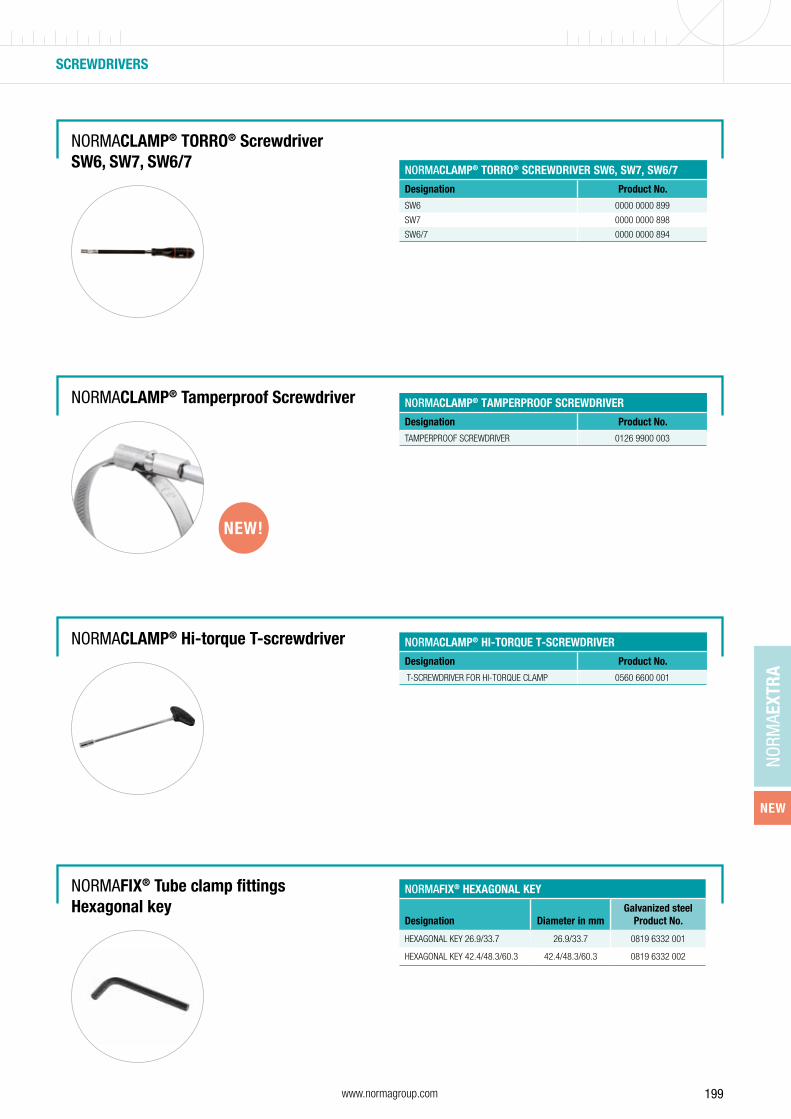
199www.normagroup.com
NORM
AEXT
RA
NORMACLAMP® Hi-torque T-screwdriver
NORMACLAMP® TORRO® Screwdriver SW6, SW7, SW6/7
NORMAFIX® Tube clamp fittingsHexagonal key
NORMAFIX® HEXAGONAL KEY
Designation Diameter in mmGalvanized steel
Product No.
HEXAGONAL KEY 26.9/33.7 26.9/33.7 0819 6332 001
HEXAGONAL KEY 42.4/48.3/60.3 42.4/48.3/60.3 0819 6332 002
NORMACLAMP® TORRO® SCREWDRIVER SW6, SW7, SW6/7
Designation Product No.
SW6 0000 0000 899
SW7 0000 0000 898
SW6/7 0000 0000 894
NORMACLAMP® HI-TORQUE T-SCREWDRIVER
Designation Product No.
T-SCREWDRIVER FOR HI-TORQUE CLAMP 0560 6600 001
NORMACLAMP® Tamperproof Screwdriver NORMACLAMP® TAMPERPROOF SCREWDRIVER
Designation Product No.
TAMPERPROOF SCREWDRIVER 0126 9900 003
SCREWDRIVERS
NEW!
NEW
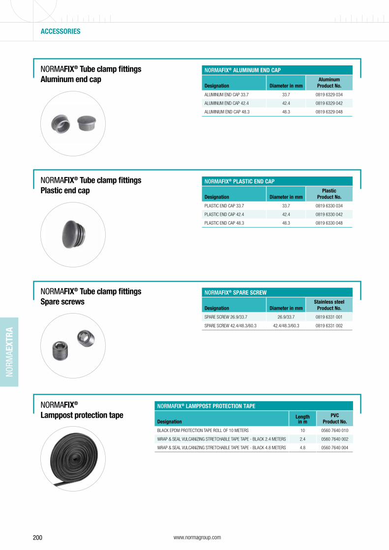
200 www.normagroup.com
NORM
AEXT
RA
ACCESSORIES
NORMAFIX® Tube clamp fittingsAluminum end cap
NORMAFIX® Lamppost protection tape
NORMAFIX® ALUMINUM END CAP
Designation Diameter in mmAluminum
Product No.
ALUMINUM END CAP 33.7 33.7 0819 6329 034
ALUMINUM END CAP 42.4 42.4 0819 6329 042
ALUMINIUM END CAP 48.3 48.3 0819 6329 048
NORMAFIX® Tube clamp fittingsPlastic end cap
NORMAFIX® PLASTIC END CAP
Designation Diameter in mmPlastic
Product No.
PLASTIC END CAP 33.7 33.7 0819 6330 034
PLASTIC END CAP 42.4 42.4 0819 6330 042
PLASTIC END CAP 48.3 48.3 0819 6330 048
NORMAFIX® Tube clamp fittingsSpare screws
NORMAFIX® SPARE SCREW
Designation Diameter in mmStainless steel
Product No.
SPARE SCREW 26.9/33.7 26.9/33.7 0819 6331 001
SPARE SCREW 42.4/48.3/60.3 42.4/48.3/60.3 0819 6331 002
NORMAFIX® LAMPPOST PROTECTION TAPE
DesignationLength in m
PVCProduct No.
BLACK EPDM PROTECTION TAPE ROLL OF 10 METERS 10 0560 7640 010
WRAP & SEAL VULCANIZING STRETCHABLE TAPE TAPE - BLACK 2.4 METERS 2.4 0560 7640 002
WRAP & SEAL VULCANIZING STRETCHABLE TAPE TAPE - BLACK 4.8 METERS 4.8 0560 7640 004
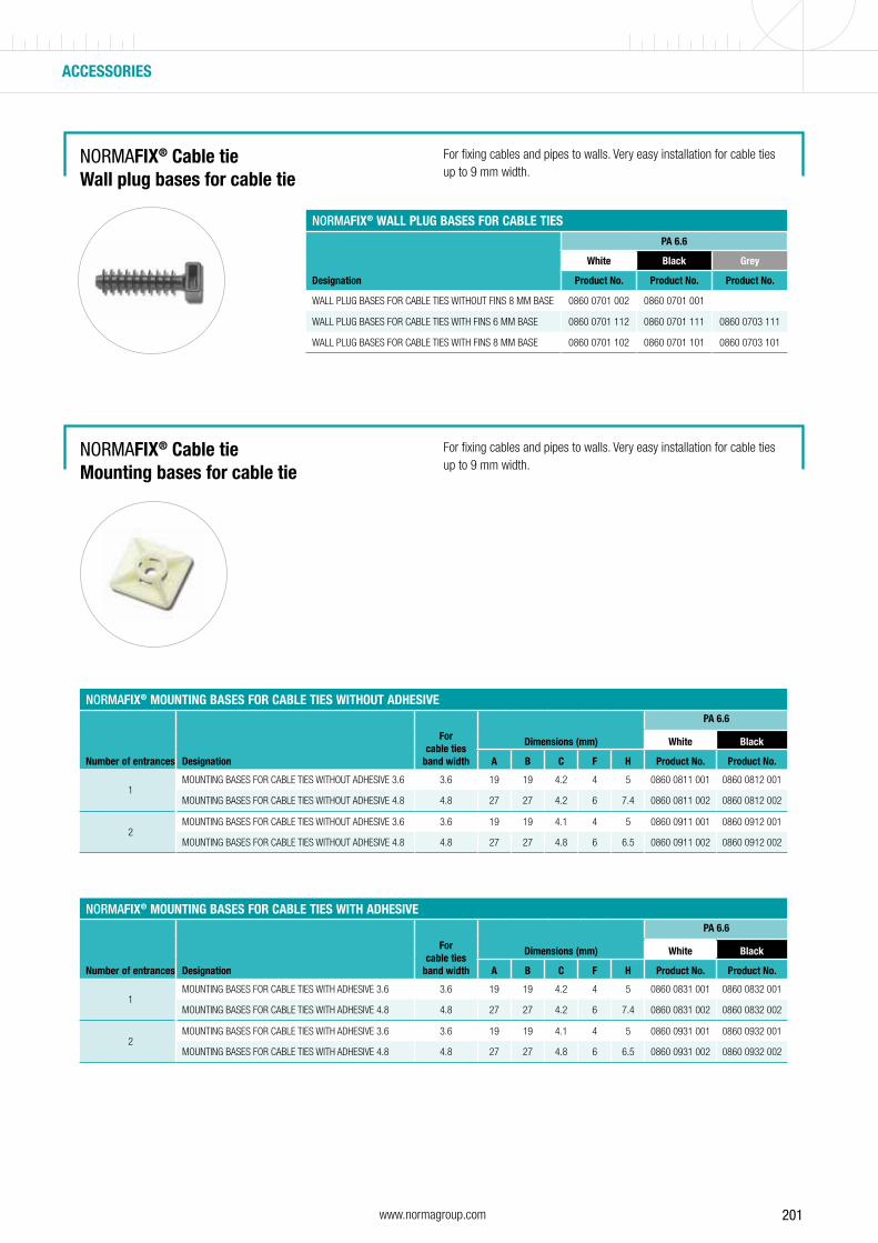
201www.normagroup.com
NORMAFIX® Cable tieWall plug bases for cable tie
For fixing cables and pipes to walls. Very easy installation for cable ties up to 9 mm width.
NORMAFIX® WALL PLUG BASES FOR CABLE TIESPA 6.6
Designation
White Black Grey
Product No. Product No. Product No.
WALL PLUG BASES FOR CABLE TIES WITHOUT FINS 8 MM BASE 0860 0701 002 0860 0701 001
WALL PLUG BASES FOR CABLE TIES WITH FINS 6 MM BASE 0860 0701 112 0860 0701 111 0860 0703 111
WALL PLUG BASES FOR CABLE TIES WITH FINS 8 MM BASE 0860 0701 102 0860 0701 101 0860 0703 101
NORMAFIX® Cable tieMounting bases for cable tie
For fixing cables and pipes to walls. Very easy installation for cable ties up to 9 mm width.
NORMAFIX® MOUNTING BASES FOR CABLE TIES WITHOUT ADHESIVE
For cable ties
band width
Dimensions (mm)
PA 6.6
Number of entrances Designation
White Black
A B C F H Product No. Product No.
1MOUNTING BASES FOR CABLE TIES WITHOUT ADHESIVE 3.6 3.6 19 19 4.2 4 5 0860 0811 001 0860 0812 001
MOUNTING BASES FOR CABLE TIES WITHOUT ADHESIVE 4.8 4.8 27 27 4.2 6 7.4 0860 0811 002 0860 0812 002
2MOUNTING BASES FOR CABLE TIES WITHOUT ADHESIVE 3.6 3.6 19 19 4.1 4 5 0860 0911 001 0860 0912 001
MOUNTING BASES FOR CABLE TIES WITHOUT ADHESIVE 4.8 4.8 27 27 4.8 6 6.5 0860 0911 002 0860 0912 002
NORMAFIX® MOUNTING BASES FOR CABLE TIES WITH ADHESIVE
For cable ties
band width
Dimensions (mm)
PA 6.6
Number of entrances Designation
White Black
A B C F H Product No. Product No.
1MOUNTING BASES FOR CABLE TIES WITH ADHESIVE 3.6 3.6 19 19 4.2 4 5 0860 0831 001 0860 0832 001
MOUNTING BASES FOR CABLE TIES WITH ADHESIVE 4.8 4.8 27 27 4.2 6 7.4 0860 0831 002 0860 0832 002
2MOUNTING BASES FOR CABLE TIES WITH ADHESIVE 3.6 3.6 19 19 4.1 4 5 0860 0931 001 0860 0932 001
MOUNTING BASES FOR CABLE TIES WITH ADHESIVE 4.8 4.8 27 27 4.8 6 6.5 0860 0931 002 0860 0932 002
ACCESSORIES

202 www.normagroup.com
NOTES

203www.normagroup.com

1-2B
-6-1
9091
2-SE
NORMA Group
Postfach 1149 · D-63461 Maintal Edisonstraße 4 · D-63477 Maintal
Tel: +49 (6181) 4 03-0
Fax: +49 (6181) 4 03-210
www.normagroup.com
NORMA®
NORMACLAMP®
NORMACONNECT®
NORMAFIX®
NORMAPLAST®
are registered trademarks of NORMA Germany GmbH.
This catalogue supersedes all previous issues. No part of this publication may be reproduced without our prior written
consent. In NORMA Group’s policy of continual product improvements to meet user needs and technological develop-
ments, all models and sets listed in this folder (photographs, specifications, sizes and weights) may be upgraded or dis-
continued without notice and without any obligation on our part to modify tools or equipment sold previously. The recom-
mendations for use and safety given in this folder do not replace accepted good practice or the safety related legal and
regulatory provisions. References to standards implemented as of September 15th, 2019 are not contractually binding.