Nonlinear feedback shift registers and generating of binary de ...
60
-
Upload
khangminh22 -
Category
Documents
-
view
0 -
download
0
Transcript of Nonlinear feedback shift registers and generating of binary de ...
Nonlinear feedback shiftregisters and generating ofbinary de Bruijn sequences
Christian Ebne Vivelid
November 21, 2016
Master's thesis
Department of Informatics
University of Bergen
1
Introduction
Cryptology is the science of hiding the meaning of a message by concealing it, sothat it is hard to �nd the meaning for others than the intended receiver. Thereare mainly two ways of doing this, one is to use di�erent words in the messageinstead of the real one. This is called using code words. The other methodis called using cipher and is performed by changing the individual charactersof the message in an orderly way. This process is called encryption, and theprocess of retrieving the original message is called decryption.
The original message is called the plaintext and the encrypted plaintext iscalled ciphertext. Ciphers can be further divided into two types of ciphers,stream ciphers and block ciphers. Block ciphers takes a number of plain textcharacters and a key to produce the cipher text. While stream ciphers a usesa key and some kind of generator to produce a pseudo random sequence ofcharacter that is uses with the plaintext, to produce the ciphertext.
Stream ciphers
A sequences is a number of consecutive characters. E.g. a number 1563 is asequences of the characters 1,5,6,3. And the word cipher is a sequence of thecharacters c,i,p,h,e, r. The simplest sequences are those that only contains onlytwo di�erent characters, we call such a sequence binary. The notation a �bit� isused to refer to either a 0 or a 1, and all binary sequences can be expressed bybits by swapping the two original characters for 1 and 0. It is a well known factthat every sequence can be represented by a sequence of bits, by having a numberof subsequent bit represent one of the characters of the original sequence.
The binary sequence generated by a generator and a key is called a key
stream, and is a pseudo binary random sequence. Then a plaintext can beencrypted be performed an operation called exclusive or between the plaintextand the key stream. This operation is that bit number i of the ciphertex t is 1,if bit number i of the plaintext and the key stream are di�erent bit (e.g. 0 and1). If they are the same (e.g. 0 and 0) then it is 0. The ciphertext can then besent through an insecure channel, and the receiver can decrypt the ciphertext
by generating the same key stream and use the exclusive or operation betweenthem to produce the plaintext. This process is illustrated in �gure 1 below.
Any cipher must have a good security, and while it is generally hard to clearlyspecify the criteria for this. There are some known ways to attack stream ciphers
based on some properties. So if the cipher does not have these properties, itshould be relatively secure. One of these properties is randomness distribution.If there is a clear and simple pattern to the sequence, it is quite easy to breakit. Or if the sequence can be found by simply guessing or using a small part ofthe sequence to �nd the rest.
2

Figure 1: Stream cipher model
In this thesis we will look at a way to construct a generator that produce a key
stream with a high period and complexity. But �rst we will have to look at atype of generators that is commonly used in stream ciphers, it is a device calleda feedback shift register (FSR).
There is two types of these, Linear feedback shift register (LFSR) is oneof them. The theory of LFSR is largely complete and it is easy to generatelong sequences with many good properties from LFSRs. But they are easilyrecognized, so they have a relatively low security. The other type is Nonlinearfeedback shift register (NLFSR) that can be very hard to recognize, but theoryof NLFSR is largely incomplete. The problem of generating a special type ofsequences from NLFSR called de Bruijn sequences be the main focus of thesethesis.
First the two things that determine the generated sequence of a FSR is thefeedback function and the initial state. The feedback function is a Booleanfunction that determine the next bit of the sequence based on some of theprevious bits of the sequence. The initial state is the �rst n bits of the sequence,that is set at the start.
Sequence have 3 important properties, which is period, complexity and dis-tribution. Period is the number of bits of the sequence before it starts to repeatitself. Complexity is a measurement on how many bit is needed to �nd thesequences from a part of the sequence and some other information. Distribu-tion is the di�erence of the number of 1's and 0's in the sequence. Ideally thedistribution should be zero and the complexity the whole of the sequence.
3
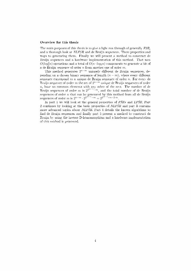
Overview for this thesis
The main purposes of this thesis is to give a light run through of generally FSR,
and a thorough look at NLFSR and de Bruijn sequences. There properties andways to generating them. Finally we will present a method to construct deBruijn sequences and a hardware implementation of this method. That usesO(log22n) operations and a total of O(n · log2n) components to generate a bit ofa de Bruijn sequence of order n from another one of order m.
This method generates 2n−m uniquely di�erent de Bruijn sequences, de-pending on a chosen binary sequence of length (n − m), where every di�erentsequence correspond to a unique de Bruijn sequence of order n. For every deBruijn sequence of order m the set of 2n−m unique de Bruijn sequences of ordern, have no common elements with any other of the sets. The number of deBruijn sequences of order m is 22
m−1−m, and the total number of de Bruijnsequences of order n that can be generated by this method from all de Bruijnsequences of order m is 2n−m · 22m−1−m = 22
m−1+n−2·m.In part 1 we will look at the general properties of FSRs and LFSR. Part
2 continues by looking at the basic properties of NLFSR and part 3 containsmore advanced topics about NLFSR. Part 4 details the known algorithms to�nd de Bruijn sequences and �nally part 5 present a method to construct deBruijn by using the inverse D-homomorphism and a hardware implementationof this method is presented.
4
1 FSR
The theory of LFSR is largely complete, and it is possible to deduce the com-position and properties of any LFSR [20], [24] and [11]. They also share someof the same properties with NLFSRs and since LFSRs can be used to createNLFSR with speci�c properties, a short overview about them will be given inthis section.
There are two types of FSR, Galois and Fibonacci. We will mainly be lookingat Fibonacci FSR through most of this thesis and only brie�y touch upon Galois
FSR in the latter half. A feedback shift register (FSR) consist of a number ofmemory cell, that each contain a binary bit (either 1 or 0).
The cells are numbered from 0 until (n − 1), and FSRs are usually dividedinto di�erent sub sets depending on the number of memory cells. Which can bereferred to as number or length/size, but in this thesis the term order will beused to refer to the number of memory cells of a FSR.
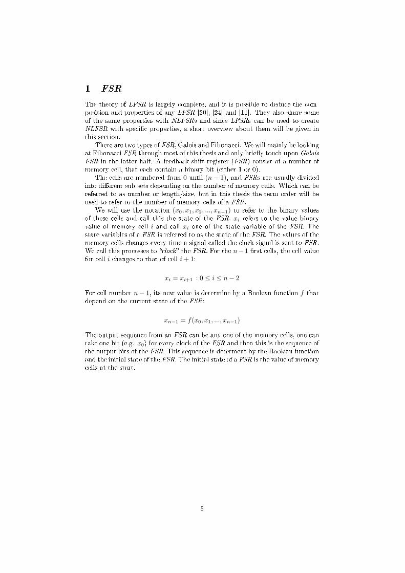
We will use the notation (x0, x1, x2, ..., xn−1) to refer to the binary valuesof these cells and call this the state of the FSR. xi refers to the value binaryvalue of memory cell i and call xi one of the state variable of the FSR. Thestate variables of a FSR is referred to as the state of the FSR. The values of thememory cells changes every time a signal called the clock signal is sent to FSR.We call this processes to �clock � the FSR. For the n− 1 �rst cells, the cell valuefor cell i changes to that of cell i+ 1:
xi = xi+1 : 0 ≤ i ≤ n− 2
For cell number n− 1, its new value is determine by a Boolean function f thatdepend on the current state of the FSR:
xn−1 = f(x0, x1, ..., xn−1)
The output sequence from an FSR can be any one of the memory cells, one cantake one bit (e.g. x0) for every clock of the FSR and then this is the sequence ofthe output bits of the FSR. This sequence is determent by the Boolean functionand the initial state of the FSR. The initial state of a FSR is the value of memorycells at the start.
5

1.1 LFSR and Sequences
Cycles and period
A cyclic shift of a sequence is the original sequence where all the entries of thesequence have been moved to the entry on the left from the original position.Except for the �rst entry, that is instead moved to the last entry.
De�nition 1. Given a sequence S = (s0, s1, ..., sn−1), a single cyclic shiftof this sequences is E1(S) = (s1, s2, ..., sn−1, s0). A ith cyclic shift Ei(S) =(si, si+1, ..., si−2, si−1).
The period p of a sequences S is the smallest positive integer, such that:
Ep(S) = (sp, sp+1, ..., sp−2, sp−1) = S
A sequence S can be shorten if p < n, to a cycle C = (s0, s1, ..., sp−1). Theoriginal sequence S can be reconstructed from C by treatingC n times. Use theterm �cycles/sequences generated by a FSR� to refer to the set of all the possiblecycle/sequences generate by a FSR. All cyclic shift of a sequence /cycle will notbe treated as di�erent sequences/cycles as the structure is identical, and it issimple to derive all cyclic shift of a sequence/cycle of a sequence/cycle.
ANF and recursive Boolean function
The algebraic normal form (ANF ) of a Boolean function f : {0, 1}n → {0, 1} isan n-variable polynomial in GF (2) on the form:
f(x0, ..., xn−1) = Σ2n−1i=0 ci · xi0
0 · xi11 · ... · xin−1
n−1
ci ∈ {0, 1} and (i0i1...in−1) is the binary expression of i with i0 being the mostsigni�cant bit and in−1 being the least signi�cant. This form is used for thisthesis and it may be presume that any function is on ANF form if nothing elseis stated.
The total number of all possible Boolean functions is 22n
, of these only 2n areLFSR. A Boolean function can be simpli�ed by introducing sub functions, thatis a function f(x0, x1, ...) may be expressed as f = h(x0, x1, ...) + g(x0, x1, ...).Here f is expressed by the two sub functions h and g. De�ne term as any subfunction that does not contain any addition modulo 2. E.g. given a Booleanfunction f(x0, x1, x2) = x1 · x2 ⊕ x0 ⊕ 1, then x1, 1 and x1 · x2 are all the termsof f . Note that a term is a sub function, but not all sub functions are terms.
6

Characteristic polynomial of a LFSR
All LFSRs have a linear feedback function, meaning that all parts of the functioncan only depend on up to one of the n state variables. So a LFSR can have anyof the variables x0 until xn−1 as a term of its feedback. But it cannot containsany term on the form xi · ... ·xj , 0 ≤ i, j ≤ n−1. So there is n+1 possible terms,that can be a part of the feedback function. Then all possible combinations sumup to:
Σn+1i=0 (
n+ 1i
) = 2n+1
A characteristic polynomial is an other way to represent a LFSR and it is in aone-to-one and onto relation to linear feedback functions. Meaning that everylinear feedback function have a unique characteristic polynomial and vice versa.Below in �gure 2 is a LFSR with the feedback function f(x0, x1, ..., xn−1) =x0⊕xn−2⊕xn−1 and this corresponds to a the characteristic polynomial f(x) =xn + xn−1 + 1.
Figure 2: A LFSR
The relation between a characteristic polynomial and the corresponding linearfeedback function is as follows:
f(x) = c1 · xn + c2 · xn−1 + ...+ cn · x+ c0 ⇐⇒
f(x0, x1, ..., xn−1) = xc00 ⊕ xc1
1 ⊕ ...⊕ xcn−1
n−1 ⊕ cn
7

Good graph
The Good graph (also called de Bruijn graph) is a graph over 2n vertexes, whereeach vertex represent one of the possible states of a FSR with order of n. Allthe vertexes have two outbound edges and two inbound edges. The outboundedges represent the register changing its state to one of the two possible nextstate, and the inbound edges represent the two possible previous state.
So any sub graph of this that satisfy the condition that all vertexes haveonly one outbound edge, correspond to a FSR. The notation Bn is used to referto the Good graph over 2n vertexes or for FSRs of order n. A FSR of order nis said to be in Bn. Below in �gure 3 is the Good graph for order 3, B3.
Figure 3: Good graph for B3
8
Singular and non-singular
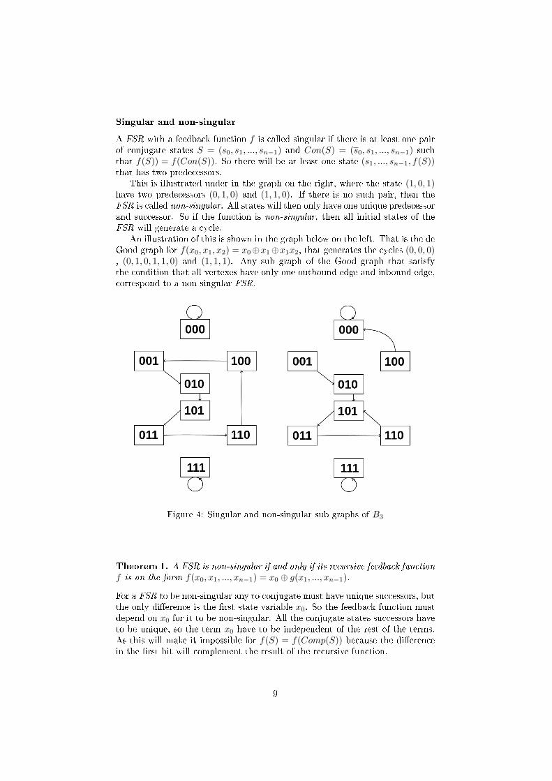
A FSR with a feedback function f is called singular if there is at least one pairof conjugate states S = (s0, s1, ..., sn−1) and Con(S) = (s0, s1, ..., sn−1) suchthat f(S)) = f(Con(S)). So there will be at least one state (s1, ..., sn−1, f(S))that has two predecessors.
This is illustrated under in the graph on the right, where the state (1, 0, 1)have two predecessors (0, 1, 0) and (1, 1, 0). If there is no such pair, then theFSR is called non-singular. All states will then only have one unique predecessorand successor. So if the function is non-singular, then all initial states of theFSR will generate a cycle.
An illustration of this is shown in the graph below on the left. That is the deGood graph for f(x0, x1, x2) = x0⊕x1⊕x1x2, that generates the cycles (0, 0, 0), (0, 1, 0, 1, 1, 0) and (1, 1, 1). Any sub graph of the Good graph that satisfythe condition that all vertexes have only one outbound edge and inbound edge,correspond to a non-singular FSR.
Figure 4: Singular and non-singular sub graphs of B3
Theorem 1. A FSR is non-singular if and only if its recursive feedback function
f is on the form f(x0, x1, ..., xn−1) = x0 ⊕ g(x1, ..., xn−1).
For a FSR to be non-singular any to conjugate must have unique successors, butthe only di�erence is the �rst state variable x0. So the feedback function mustdepend on x0 for it to be non-singular. All the conjugate states successors haveto be unique, so the term x0 have to be independent of the rest of the terms.As this will make it impossible for f(S) = f(Comp(S)) because the di�erencein the �rst bit will complement the result of the recursive function.
9

1.2 Maximum-length LFSR and M-sequences
LFSRs can be divided into two speci�c set, the set of all LFSR that can generate
a maximum-length sequence of 2n−1 and the set of the rest of LFSRs. φ(2n−1)n
LFSRs of order n can generate a maximum-length of 2n − 1(φ is Eulers totientfunction).
Finding a LFSR that generate a maximum sequence is relatively simple,because a maximum-length LFSR will have a characteristic polynomial that isprimitive. And a primitive polynomial have to be irreducible. A polynomialp(x) is irreducible if and only if:
p(x) = f(x) · g(x), g(x) 6= f(x) and 1 ≤ degree(g(x)), degree(f(x)) (2)
An irreducible polynomial p(x) is primitive if:
x(2n−1)/qi 6= 1mod(p(x)), for all prime factors qi of 2n − 1 (3)
So it is relatively easy to check if a polynomial is primitive, and the probabilityof randomly selecting a primitive polynomial by chance is 2n
φ(2n−1)n
≈ 1n if no
additional analyze is performed. So as long as n is not to big, the process to�nd a LFSR that can generate a maximum-length sequence is relatively easy.
The sequence generated by such a maximum-length LFSR is called an M-sequence. They have some useful and presumed unique properties, that givethe M-sequence good pseudo randomness. We will examine some of these in thenext sub sections.
Golombs randomness postulate
All sequences generated by any FSR is predetermined, but this can make thempredictable. We need way to determine if a generated sequence will look ran-dom, that there is no clear overall pattern to the sequence generated. TheGolumbs randomness postulates are 3 rules that ensure that any sequence thatfollows them have a good pseudo randomness. That they will look and haverelatively the same properties as a truly random sequence of bits, while stillbeing predetermined.
De�nition 2. A Run is a number of consecutive 0's or 1's. A Block is a Run
of 1's. A Gap is a Run of 0's.
Postulate 1. The number of zeros and number of ones di�er by at most oneduring a period of the sequence.Postulate 2. Half of the Runs in a full cycle have length 1, one 1
4 of all Runshave length 2, 1
8 have length 3 etc, as long as the number of Runs exceed one.Moreover, for each of these length there are equally many Gaps and Blocks.Postulate 3. The out of phase auto-correlation of the sequence always has thesame value.
All M-sequences obey and are the model for these postulates.This 3 conditions provides that pseudo randomness is guarantied and thereforeis usable for simulating true randomness. In the next section we will look at theproperty correlation and a special case of correlation named auto-correlation.
10

Correlation
Correlation is a measurement of the similarity of two phenomena. In this thesiscorrelation is used on binary sequences, but it can also be used to measure allkinds of quanti�able phenomena. Given two sequences S1 and S2 of length l,the correlation between them is an integer on the interval −l to l. Where acorrelation of l means that the sequences are identical and −l that they areeach others complement. If it is 0, then there is no bias.
The correlation between two sequence C(S1, S2) = l − 2 ·D(S1, S2), whereD(S1, S2) is the number of sequence bit of S1 and S2 that are di�erent. E.g.the two sequences S1 = (1, 0, 0, 1, 1) and S2 = (0, 0, 1, 1, 0) have a correlationC(S1, S2) = 5− 2 ·D(S1, S2) = 5− 2 · 3 = −1.
Auto-correlation of a sequence S is the correlation between the sequenceand a cyclic shift of itself. Denote this by CS(i) = C(S,Ei(S)), and thereis l possible auto-correlation values for the l unique shift. One of the mostinteresting property of a sequence is the maximum auto-correlation of a sequenceexcept for Cm(0)
The auto correlation of an M-sequence m of order n is:
Cm(0) = 2n − 1
Cm(t) = −1, if t 6= 0mod(2n − 1)
So M-sequences satis�es the 3rd of Golumbs randomness postulate.
Linear complexity
De�nition 3. The linear complexity of a binary sequence is the minimal pos-sible order for a LFSR that can generate it. Denoted L(S) for the linear com-plexity of the sequence S.
For any sequence S generated by a LFSR, at most 2 · L(S) bits of thesequence is needed to �nd a LFSR that can generate the whole sequence byusing the Berlekamp-Massey algorithm [17]. That gives a minimal LFSR thatwill generate the entire sequence. This means that the security of a depend onthe linear complexity of the key stream. In addition to other properties of thekey stream, that also have to be su�cient enough to provide the desired levelof security.
11
Berlekamp-Massey algorithm
Given a binary sequence S = (s0, s1, ..., sn−1), and the nth discrepancy dnis:
dn = sn ⊕ c1sn−1 ⊕ ...⊕ cLsn−L
The following algorithm produces a characteristic polynomial fS that generatesthe sequence S.
1. If S = (0, 0, ..., 0), then L(S) = 0 and fS = 1. If S = (0, 0, ..., 0, 1), thenL(S) = n+ 1 and fS can be any LFSR of length n.
2. Else, if dn = 0, then Ln = Ln−1and fn = fn−1.
3. If dn = 1, then:
Ln = { Ln−1, Ln > N/2n− Ln−1, Ln ≤ N/2
Let m be the largest integer such that Lm < Ln−1.
fn = { fn + x2∗Ln−1−n−2 + fm, if Ln−1 > N/2xn−2∗Ln−1 + fm, if Ln−1 ≤ N/2
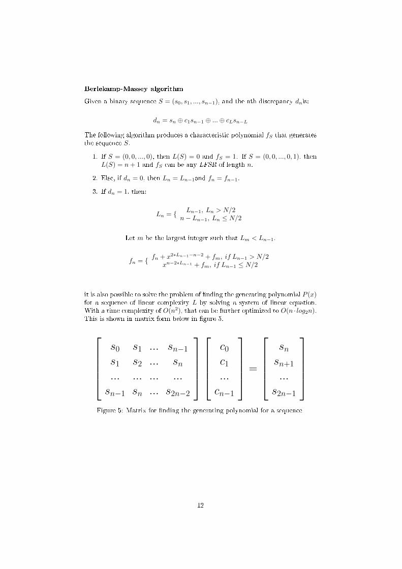
it is also possible to solve the problem of �nding the generating polynomial P (x)for a sequence of linear complexity L by solving a system of linear equation.With a time complexity of O(n2), that can be further optimized to O(n · log2n).This is shown in matrix form below in �gure 5.
s0 s1 ... sn−1
s1 s2 ... sn... ... ... ...
sn−1 sn ... s2n−2
c0c1...
cn−1
=
snsn+1
...
s2n−1
Figure 5: Matrix for �nding the generating polynomial for a sequence
12
Cycle structure
Any non-singular Boolean function f will generate a number of cycle, that maybe of di�erent length.
De�nition 4. Two Boolean function f1 and f2 of the same order have the samecycle structure if and only if they have the same number of cycles of length i,for all i.
An example of cycle structure is de Bruijn sequences. It is also possible tode�ne more speci�c structure, that have more requirements in addition to cyclicstructure. E.g. maximum-length LFSR all have the same cycle structure andhave the cycle of all zeroes.
The are methods to determine the cyclic structure of LFSRs, based on theproperties of its characteristic polynomial. As this polynomial can be polyno-mial reduced to its irreducible polynomial factors and based on this propertiescan be deduced. E.g. if the set of irreducible polynomial factors contains somemultiple factors f(x), it is possible to �nd the cycles generated by f(x)k fromlooking at the cycles of f(x). For any two polynomial f(x),h(x) it is possibleto �nd the cycles generated by f(x) · h(x) from looking at the cycles generatedby f(x) and h(x). So it is possible to �nd the cycles for any LFSR form itspolynomial irreducible factors.
2 Basic properties of NLFSRs
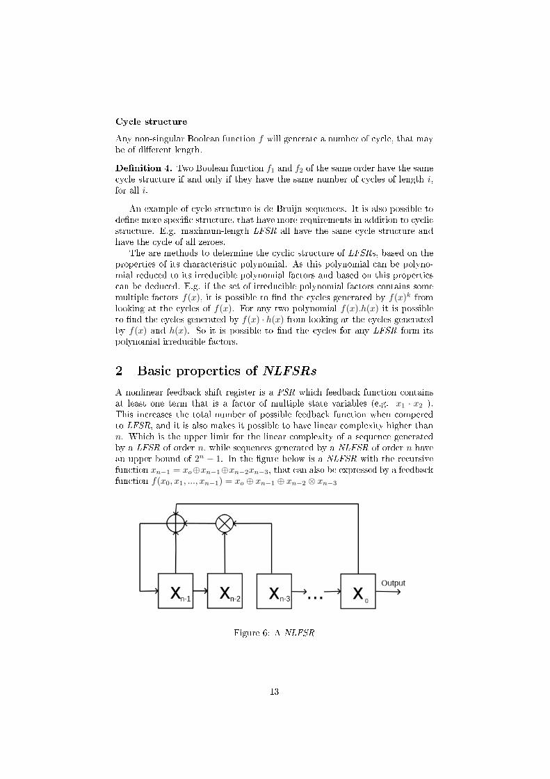
A nonlinear feedback shift register is a FSR which feedback function containsat least one term that is a factor of multiple state variables (e.g. x1 · x2 ).This increases the total number of possible feedback function when comperedto LFSR, and it is also makes it possible to have linear complexity higher thann. Which is the upper limit for the linear complexity of a sequence generatedby a LFSR of order n, while sequences generated by a NLFSR of order n havean upper bound of 2n − 1. In the �gure below is a NLFSR with the recursivefunction xn−1 = xo⊕xn−1⊕xn−2xn−3, that can also be expressed by a feedbackfunction f(x0, x1, ..., xn−1) = xo ⊕ xn−1 ⊕ xn−2 ⊗ xn−3
Figure 6: A NLFSR
13

2.1 Cycle joining and splitting
Pure cycling register
The pure cyclic register (PCR) is the non-singular function f(x0, ..., xn−1) =x0 ⊕ g(x1, ..., xn−1) of any order n and g(x1, ..., xn−1) = 0. Then the weightof g's truth table is 0, as all the 2n entries of the truth table are 0. Then thenumber of cycles of f is equal to
Z(n) = 1n ·Σd|nφ(d) · 2n/d
and the total number of cycles for a function of order n can not be greater thanZ(n). This was conjectured by Golomb [11] and proven by Mykkeltveit [19].Based on this and the fact that changing one of the entries in the truth tableof g for any non-singular FSR f , leads to an increase or decrease of one in thenumber cycles generated by f .
Since the weight of g′s truth table for PCR is 0, and the number of cyclesof PCR is an even number as Z(n) is even for all n. All the other non-singularfunctions can be created by incrementally changing the entries of g. So for anynon-singular function f , the parity of the weight of g's truth table is equal tothe parity of the number of cycles generated by f .
For the function f(x0, ..., xn−1) = x0 ⊕ g(x1, ..., xn−1) of any order n andg(x1, ..., xn−1) = 1. Then the weight of f is 2n as all the 2n entries of the truthtable are 1. Then the number of cycles of f is equal to
Z∗(n) = 12n ·
∑d|n
d : odd
φ(d) · 2n/d
This is proven in [9].
14
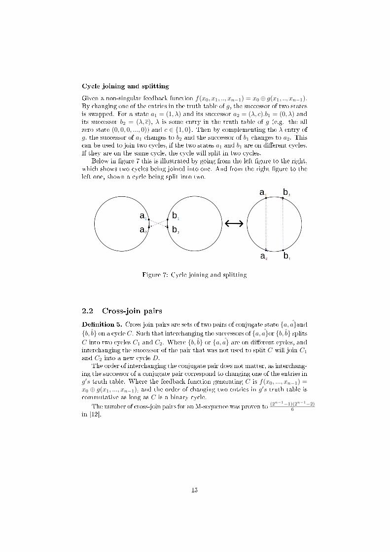
Cycle joining and splitting
Given a non-singular feedback function f(x0, x1, .., xn−1) = x0 ⊕ g(x1, .., xn−1).By changing one of the entries in the truth table of g, the successor of two statesis swapped. For a state a1 = (1, λ) and its successor a2 = (λ, c).b1 = (0, λ) andits successor b2 = (λ, c), λ is some entry in the truth table of g (e.g. the allzero state (0, 0, 0, ..., 0)) and c ∈ {1, 0}. Then by complementing the λ entry ofg, the successor of a1 changes to b2 and the successor of b1 changes to a2. Thiscan be used to join two cycles, if the two states a1 and b1 are on di�erent cycles.If they are on the same cycle, the cycle will split in two cycles.
Below in �gure 7 this is illustrated by going from the left �gure to the right,which shows two cycles being joined into one. And from the right �gure to theleft one, shown a cycle being split into two.
Figure 7: Cycle joining and splitting
2.2 Cross-join pairs
De�nition 5. Cross-join pairs are sets of two pairs of conjugate state {a, a}and{b, b} on a cycle C. Such that interchanging the successors of {a, a}or {b, b} splitsC into two cycles C1 and C2. Where {b, b} or {a, a} are on di�erent cycles, andinterchanging the successor of the pair that was not used to split C will join C1
and C2 into a new cycle D.The order of interchanging the conjugate pair does not matter, as interchang-
ing the successor of a conjugate pair correspond to changing one of the entries ing′s truth table. Where the feedback function generating C is f(x0, ..., xn−1) =x0 ⊕ g(x1, ..., xn−1), and the order of changing two entries in g′s truth table iscommutative as long as C is a binary cycle.
The number of cross-join pairs for an M-sequence was proven to (2n−1−1)(2n−1−2)6
in [12].
15

2.3 De Bruijn sequences
A de Bruijn sequence is a sequence over an alphabet of k-symbol with a periodof kn where all possible n-tuples appears. It was rediscovered by de Bruijn [2]and generalized for larger alphabet, the binary de Bruijn sequences was originaldiscovered by Flye Sainte-Marie [8].
In Cryptology most work with de Bruijn sequences are over a binary alpha-bet, as this correspond to binary computers. Biology and other �elds of sciencecan use larger alphabet. The main focus will be on binary de Bruijn of length2n, will use the formulation �de Bruijn sequences of order n� to refer to a deBruijn sequence of period 2n.There is a total of 22
n−1−n di�erent de Bruijnsequences of order n.
Properties
Chan, Games and Key [3] proved that the linear complexity of de Bruijn se-quences S of order n is bound by 2n−1 + n + 1 ≤ L(S) ≤ 2n − 2. Also it isimpossible for a de Bruijn to have a linear complexity of 2n−1 + n + 1. Thecomplement of a de Bruijn sequence S will have the same complexity as S [3].
Requirements
It is possible to deduce some simple requirement for an ANF feedback functionof order n that generates a de Bruijn sequence of length 2n. The function willhave to be non-singular as there cannot be any multiple predecessors for anystate. Because this makes it impossible for the generated sequence to be ofmaximum-length. Since the feedback function only have one cycle, the all zerostate (0, 0, 0, ..., 0) of the FSR must not give a 0. This means that it have to be1. Else the all zero state would be a part of a cycle with a length of one, since itwould be its own predecessor and successor. This is contradiction, as the totalnumber of cycles have to be one.
Next the parity of the sub function g is equivalent to the parity of the cyclesgenerated by a non-singular FSR. This means that the parity g will have beodd, for any feedback function f that generates a de Bruijn sequence.
16

Lemma 1. The only term that changes the parity of the truth table for the sub
function g for any non-singular function f for order n, is the term x1x2...xn−1.
Proof. Denote the original feedback sub function as g. The constant term 1complement all 2n−1 entries in truth table of g, so the new weight of g′ =2n−1 −weight(g). So if the parity of g is even it is even for g′, and if the parityg is odd it is odd for g′. So the parity is the same as the original one.
Next by adding a term of j state variables changes 2n−1−j entries of thetruth table of g, n − 1 > j. If the number of changes in the truth table from1 → 0, 0 → 1 is even, then the parity is same as the g. If the number of changesare odd, then changes1 → 0 changes the parity of the truth table, and thechanges 0 → 1 also changes the parity of the truth table. So the result of thisis that the parity overall is unchanged. If n − 1 = j then the term of j statevariables change only one entry. So this changes the parity of the truth table.
So any function that generates a de Bruijn sequence must have this term.
Another property is that the weight of the truth table have to be in the interval:
Z(n)− 1 ≤ W (f) ≤ 2n − Z∗(n) + 1
As it has been shown that the feedback function with the weight of g is 0 hasZ(n) cycles and any change of the parity of the truth table of g will change theparity of the of the number of cycles [11],[19]. So if the weight of g is incrementedthe number of cycles changes by one. The minimum weight of g of a de Bruijnfunction have to be at least Z(n)− 1.
Another restriction can be found from looking at the non-singular Booleanfunction f with the weight of g equal to 2n, as this function generates Z ∗ (n)cycles and an decrementation of the weight of g will change the number of cyclesby one. The weight of any de Bruijn function has to be at most 2n −Z∗(n)+ 1.
Finally since a function of order n that generates a de Bruijn sequence oforder n, only have one cycle. The all one state (1, 1, 1, ..., 1) of the FSR musthave the state (1, 1, ..., 1, 0) as its successor, so f(1, 1, 1, ..., 1) = 0. As all nonzeroterms will give a 1 for the state (1,1,1,...,1), the total number of terms most beeven for this to happen.
These facts sum up to a general form that all ANF feedback function thatgenerates a de Bruijn sequence of the same order will have to be on:
f(x0, x1, ..., xn−1) = x0 ⊕ g(x1, ..., xn−1)
g(x1, ..., xn−1) = 1⊕ x1x2...xn−1 ⊕ ....
Weight(terms(g(x1, ..., xn−1))) ≡ 0mod(2)
The number of non-singular FSR is 22n−1
, and half of these functions have theconstant term 1. Since this is a requirement for a de Bruijn function, the numberof candidates for FSRs that can generate de Bruijn of order n is 22
n−1−1. Halfof these will have the term x1x2...xn−1, that is also a requirement to a de Bruijnfunction.
This limits the number of candidates to 22n−1−2. Since half of these again
will have an even weight of gs truth table, the �nal numbers of candidates is22
n−1−3. Which makes it possible to �nd all the de Bruijn functions for order3, without doing any testing.
17

Maximum-length LFSR vs maximum-length NLFSR
The main di�erences between maximum-length LFSR and maximum-lengthNLFSR is illustrated below in table 1, that shows the most important di�erencesbetween them. When n ≥ 3, they have the following properties.
LFSR NLFSR
Number of functions φ(2n−1)n 22
n−1−n
Length 2n − 1 2n
Maximum linear complexity n 2n − 1minimum linear complexity n 2n−1 + nMaximum number of terms n+ 1 2n
Table 1: The di�erences between maximum LFSR and NLFSR
2.4 Representation
Any FSR of order n can be represented by a Boolean feedback function of the nstate variables. From the n state variables it is possible to construct 2n logicallydi�erent ANF terms. Where (n+ 1) are the linear terms that consist of one ofthe n state variable and the constant 1, that can be used to construct LFSRs.Any implementation of a NLFSR will have to do some operations before thenext bit from the feedback function can be calculated.
First all the di�erent terms have to be checked if they are true or not. Thenit will have to check if the number of true terms is even or odd. The complexityof �nding the truth values of the di�erent terms, depend on the number of statevariables for each term. This can be performed by looking up all the statevariables that the term depends on.
Now let T denote the number of terms of the feedback function f . To �nd ifthe output of f is true or false for any state, it depends on if the number of trueterms is even or odd. So all t ∈ T will have to be checked to �nd the truth valueof the function. This may be relative slow, if the number of terms is relativelylarge.
In part 5, a hardware implementation is shown that can generate a bit ofa de Bruijn sequence of order n in O(log22n) basic operations. With a memoryand component complexity of O(n · log2n). In part 2 we saw that a LFSR
can be represented by a characteristic polynomial and that the property ofthis polynomial allowed us to deduce information about the period and cyclestructure of the LFSR.
For any implementation there is a number of factors that can reduces thee�ciency of generating bits. In software this is measured in time and memoryand in hardware it is time and memory/components. For a NLFSR this can befurther specify into 3 values that measure the e�ciency of the implementation.
18

The time to clock a bit
One of the most important property of any representation for a FSR, as thiscan directly limit the usability. If it cannot produce the required amount of bitsper time unit, it is not usable.
The time to switch one state to another
This time depend on the size of a state in the implementation, and how theprocess of changing from a state is implemented.
The size of a state
The size of all the information store in a single state of the FSR is usually equalto the number of memory cells. Of course there may be a di�erence betweenthe order of the FSR and the linear complexity of the sequence generated bythe FSR.
In the next section we will look at some advanced NLFSR sub classes andways NLFSR can be used as building blocks to generate complex sequences.
3 Advanced properties of NLFSRs
3.1 Symmetric feedback function and Kjeldsen mapping
The symmetric shift registers has been studied by Kjeldsen [13] and Søreng[21],[22]. They have a minimal period dividing n · (n+ 1).
3.2 General algorithm
An algorithm is a clearly de�ned step-by-step list of operations that have to beperformed to solve a task. The two main resources for an algorithm is time andmemory. Time refers here to the amount of time or bound of time needed to runthe algorithm. Memory is the maximum amount of required memory needed torun the algorithm.
Algorithm to �nd the feedback function from a truth table
The task of �nd the feedback function from a truth table, can be performedby the following algorithm. For a truth table for a FSR of order n, where thebinary sequence (t0, t1, t3..., t2n−1) represents the entries in the truth table. Astate of the FSR is on the form (s0, s1, s2, ..., s2n−1). t0 is the truth value forthe state (0, 0, 0, ..., 0), t1 is the truth value for the state (0, 0, 0, ..., 1) and soon. Denote ftemp as the temporarily Boolean function. While Bin(S) as thedecimal value of the state S, where the leftmost bit is the most signi�cant oneand the rightmost is the least signi�cant bit.
1. Start with i = (0, 0, 0, ..., 1). If t0 = 1, then ftemp = 1. Else ftemp = 0.
2. If tBin(i) 6= ftemp(i), then ftemp = ftemp +∏
si=1 xi. Increment i andrepeat step 2 until i = 2n.
This produces the feedback function on algebraic normal form (ANF).
19

3.3 Modi�ed de Bruijn sequences
By removing the all zero state or the all one state from a de Bruijn sequence, anew type of sequence is created. Denote the �rst as a type 0 modi�ed de Bruijnand the latter as a type 1. Given a de Bruijn sequence S, let m0S denote thetype 0 modi�ed de Bruijn sequence created from S and m1s the type 1. LetDS(n) denote the set of all de Bruijn sequences of order n. DS0(n) denote theset of all type 0 modi�ed de Bruijn sequences and DS1(s) the set of all type 1,both created from the elements of DS(n). Note that the set of all M-sequencesof order n, is a subset of DS0(n). Mayhew and Golomb [18] proved that forn ≥ 4, the linear complexity of a type 0 sequence S is bounded by:
n ≤ L(S) ≤ 2n − 2
An overview of the complexity distribution for orders 4,5 and 6 is also given.Zheng, Cao, Zhou and Xu [23] proves the following theorem:
Theorem 2. If s ∈ DS0(n), m0s ∈ DS0(n) and m1s ∈ DS1(s), thenL(m1cs) = LC(m0s) + 1, L(m0cs) = L(m1s)− 1.
Which gives a complexity comparison between s, m0s and m1s for order4 and 5. In [21] Mayhew gives a run through the auto-correlation of type 0modi�ed de Bruijn sequences, for orders 4, 5 and 6.
3.4 Galois FSR
A Galois FSR di�ers from a Fibonacci FSR by that all the memory cells ofthe FSR may have a feedback function. While the Fibonacci FSR only have afeedback function for the last cell. Because of this, the Galois FSR are morecomplex to analyze and the period of state of the register may be greater thanthe period of some of the memory cells. So the output sequence will depend onwhich of the memory cells is the output. As the output stream usually is one ofmemory cells. But as the state of the memory cells determines the next state,the period of the register cannot be greater than 2n. Below in �gure 8 is a GaloisFSR with the feedback function fn−1 = xo ⊕ xn−1 ⊕ xn−2, fn−2 = xn−1 ⊕ xn−2
and fi = xi+1 : 0 ≤ i ≤ n− 3.
Figure 8: A Galois FSR
In the next part we will look at a transformation from a Fibonacci NLFSR toan equivalent Galois NLFSR.
20
3.5 Transformation from a Fibonacci to an equal Galois
NLFSR
Dubrova [5] present a transformation from a Fibonacci NLFSR to an equiva-lent Galois NLFSR. This transformation is based on shifting the terms of thefeedback functions.
De�nition 6. Let fa and fb be feedback functions of the bits a and b of a
NLFSR of order n. The operation shifting, denoted by faP→ fb, moves a set of
product-terms P ⊆ term(fa) from the ANF of fa to the ANF of fb. The indexof each variable xi of each product-term in P changed to x(i−a+b)mod(n).
To make sure that this operation gives an equivalent NLFSR, some condi-tions have to be satis�ed.
De�nition 7. The terminal bit τ of a NLFSR of order n is the bit with themaximal index which satis�es the following condition:
For all bits i such that i < τ , the feedback function fi is of type fi = xi+1.
De�ne min_index(f) and max_index(f) as the smallest and largest indexvariable that the function f depends on. E.g. for f = x3⊕x2x1 min_index(f) =1 and max_index(f) = 3.
De�nition 8. An NLFSR of order n is uniform if:a) All its feedback functions are singular functions of type (1).b) For all its bits i > τ , the following condition holds:max_index(gi)≤ τ , where τ is the terminal bit of the NLFSR.
Theorem 3. Given a uniform NLFSR with the terminal bit a, a shifting faP→
fb, P ⊆ term(fa), b < a. Results in an equivalent NLFSR if the transformed
NLFSR is uniform as well.
Algorithm to �nd a fully shifted Galois NLFSR from a Fibonacci
NLFSR
Dubrova [5] also gives an algorithm to �nd the fully shifted Galois NLFSR. Givena uniform Fibonacci NLFSR N of order n, the fully shifted Galois NLFSR Nwhich is equivalent to N is obtained as follows:
First, the terminal bit τ of N is computed as:
τ = max∀p∈Agn−1
(max_index(p)−max_index(p))
Then, each product product-term p ∈ Agn−1with min_index(p) ≤ (n− 1)− τ
is shifted to gn−1−min−index(p):
gn−1{p}−→ gn−1−min−index(p)
and each product product-term p ∈ Agn−1 with min_index(p) > (n− 1)− τ isshifted to gτ :
gn−1{p}−→ gτ
This provide a way to transform a Fibonacci NLFSR to an equivalent GaloisNLFSR, and Dubrova [6] gives a survey of the improvement to e�ciency thisgives to NLFSR by using this transformation.
21

3.6 Combinators
By combing multiple systems like LFSR and NLFSR, it is possible to create newkey stream generators. it is also possible to combine them with logic blocks tofurther create complex systems. We will give a brief overview of some di�erenttechniques to create Combinators.
Multiplication of sequences
The bitwise multiplication of sequences is an easy way to generate sequenceswith higher period and linear complexity. Given two repeating binary sequencesS and T with per(S), per(T ) > 0. If gcd(per(S), per(T )) = 1 then the bitwisemultiplication of S and T will produce a new sequence S ⊗ T with periodp(S ⊗ T ) = per(S) · per(T ) and the linear complexity L(S ⊗ T ) = L(S) · L(T ).
Note that the distribution is generally bad, as the sequence will contains3 times more zeroes than ones. So the possibility that a random bit of thesequence is 1 is 25 % and the possibility that a random bit of the sequence iszero is 75 %.Which makes it easy to use a correlation attack on the key stream,to �nd S and T.
3.7 Basic ways to create de Bruijn sequences from others
of the same order
A few basic ways to �nd de Bruijn sequence from another one of the same order.
By reversing a de Bruijn sequence
Theorem 4. The reverse of a de Bruijn sequence is also a de Bruijn sequence
for any k-alphabet.
Proof. A de Bruijn sequence of order n contains all possible state of length n.For any state S = (s0, s1, ..., sn−1) of any de Bruijn sequence B, the reversestate R(S) = (sn−1, sn−2, ..., s0) is also a state of B as its a length is n. Thereversing of a state is a one-to-one and onto homomorphism. So all kn the statesof the reversed sequence will be unique states, which is the de�nition of a deBruijn sequence.
For any non-singular feedback function f(xo, x1, x2, ..., xn−2, xn−1) there ex-ist a transformation to a Boolean function f
′such that f
′generates all the
reversed cycles of f . Given by f′= f(xo, xn−1, xn−2, ..., x2, x1), so by simply
swapping the index of state variables from 1 until n− 1 to produces a functionthat generate the reverse cycles of the original function. So this will generatethe reverse de Bruijn sequence for any de Bruijn sequence.
22

By complementing a de Bruijn sequence
Theorem 5. The complement of a de Bruijn sequence is also a de Bruijn
sequence.
Proof. A de Bruijn sequence of order n contains all the possible state of lengthn. For any state S = (s0, s1, ..., sn−1) of any de Bruijn sequence B, the inversestate S = (s0, s1, ..., sn−1) = C(S) is also a state of B as its length is n. Andthe complement of a state is a one-to-one and onto homomorphism. So all kn
states of the inverse sequence will be unique states, which is the de�nition of ade Bruijn sequence.
For any non-singular feedback function f(xo, x1, x2, ..., xn−2, xn−1) there ex-ist a transformation to a Boolean function f
′such that f
′generates all the
complement cycles of f . Given by f′= f(xo⊕1, x1⊕1, x2⊕1, ..., xn−1⊕1)⊕1,
so by simply complementing all the variables and the function itself produces afunction that generate the complement cycles of the original function. So thiswill generate the complement de Bruijn sequence for any de Bruijn sequence.
By complementing the reverse of a de Bruijn sequence
Theorem 6. The reverse complement of a de Bruijn sequence is equal to the
complement reversed of de Bruijn sequence, and also a de Bruijn sequence.
Proof. By the theorem 12 and 13, it is clear that both are de Bruijn sequences.The complement of any binary sequence is simply switching the symbols, so thestructure of the sequence is identical. So the reversed complement is structurallyequal to the reversed also a de Bruijn sequence and the reverse sequences of a deBruijn. The reversed complement of a de Bruijn sequence S is also a de Bruijnsequence and identical to the complement reversed de Bruijn sequence of S.
23
The set of connected de Bruijn sequence
De�ne the set of connected de Bruijn sequence as the set containing a de Bruijnsequence, the reverse sequence, the complemented sequence and the reversecomplement of it. So any de Bruijn sequence is a part of such a set, that cancontain up to four unique de Bruijn sequences. The possible number of uniquesequences in such a set is 1,2 and 4.
Lemma 2. It is impossible for a set of connected de Bruijn sequence to contain
exactly 3 unique de Bruijn sequences.
Proof. Prove this by showing that it is impossible to construct a set of exactly3 unique de Bruijn sequences. For each part S is refer to a reference de Bruijnsequences, R(S) is the reverse sequence of S, C(S) is the compliment sequenceand RC(S) = CR(S) is the reverse complement(or complemented reverse) ofthe sequence.
Assume that S, R(S) and C(S) are all unique, and RC(S) = CR(S) is equalto S,R(S) or C(S). If C(S) = CR(S) then, C(S) = C(CR(S) = R(S) whichis a contradiction. If S = RC(S) then, R(S) = R(RC(S) = C(S) which isa contradiction. If R(S) = RC(S) then, R(R(S)) = S = C(S) which is acontradiction. So S,R(S) and C(S)can not be unique while RC(S) is not.
Assume that S, R(S) and RC(S) are all unique, and C(S) is equal to S,R(S)or RC(S). If C(S) = CR(S) then, C(S) = C(CR(S) = R(S) which is a contra-diction. If C(S) = S then, RC(S) = CR(S) = R(S) which is a contradiction.If C(S) = CR(S) then, S = R(S) which is a contradiction. So S,R(S) andRC(S)can not be unique while RC(S) is not.
Assume that S, RC(S) and C(S) are all unique, and R(S) is equal to S,RC(S)or C(S). If R(S) = CR(S) then, S = C(S) which is a contradiction. IfR(S) = S then, CR(S) = C(S) which is a contradiction. If R(S) = C(S) then,CR(S) = S which is a contradiction. So S,R(S) and C(S)can not be uniquewhile RC(S) is not.So all possible the combination of only 3 unique set of de Bruijn sequences allleads to contradictions, so it is impossible to have any set of exactly 3 uniquede Bruijn sequences.
A de Bruijn sequences in a set of connected de Bruijn sequences will have thesame relative security as the other sequence in the set, as it is easy to �nd anyof them from any of the other sequences.
24

3.8 Problems
The �eld of NLFSR have relatively many unsolved problem, little is knownabout any possible alternative representation of NLFSR. Below is a list of themost essential problems that have yet to be solved.
Finding the period of any NLFSR
One of the main problem of this particular �eld of research, and one of thehardest. Given a general method for this would vastly improve the possibilityof the �eld.
Determine if a NLFSR generates a de Bruijn sequence
These is a sub problem of the �rst problem and the most important usability ofthese problem.
Bound on NLFSR and classes of NLFSR
Finding bounds on complexity or period for NLFSR classes. That gives se-quences with a lower bound on the period and linear complexity. Symmetricshift register and de Bruijn is examples of classes where this is found.
Find a ways to e�ciently generate de Bruijn sequences
A relatively hard problem, there exist algorithm to �nd this from de Bruijnsequences of lower orders. But the e�ciency scales quite badly for large orders,either in time or memory requirement. Some algorithm to �nd special de Bruijnsequences for all order higher than 2, as the �Prefer� one and �Prefer same� one.But these sequences have low security as they are easy to �nd.
There is also algorithm for recursively �nd new de Bruijn sequence fromothers of lower orders. Lempels inverse D-homomorphism can be applied to ade Bruijn sequence in Bn to produce two cycles D1 and D2 of length 2n in Bn+1.Any changing of successors of conjugate pair that are on di�erent cycles (D1
and D2 ) produces a cycle of length 2n in Bn+1, which is a de Bruijn sequenceof order n+ 1.
In the next section we will give a list of algorithms and methods to generatede Bruijn sequences.
25

4 Algorithms and methods to �nd de Bruijn se-
quence
Most of these algorithms are explored more fully in a survey by Fredricksen [9].
4.1 Make de Bruijn sequences form LFSRs
From an M-sequence
Let f(x0, x1, ..., xn−1) = x0 ⊕ g(x1, .., xn−1) generate an M-sequence of order n,then a de Bruijn sequence can be created by joining the two cycles generated byf . As changing one of the values of the truth table of g will change the successorof two states are swapped, this can be used to join to cycles. If the two statesare on di�erent cycles, the cycles will be joined. But if they are on the samecycle, the cycle will be split into two.
A maximum-length LFSR have two cycles the all zero cycle of period oneand the main cycle with all the other states, that has a period of 2n − 1.Then by simply changing the �rst entry in the truth table (0, 0, 0, ..., 0) ⇒ 0to (0, 0, 0, ..., 0) ⇒ 1, the two cycles are joined into a single cycle of length 2n.This is a de Bruijn sequence that can have maximum linear complexity of 2n−2.But it has a relatively low security, as it is easy to �nd the original M-sequenceby simply using the Berlekamp-Massey algorithm.
From a FSR by using cycle joining
Given a non-singular FSR with c cycles, it is possible to make a de Bruijnsequence by iteratively join one and one cycle. So after (c− 1) such operationsthe result is a de Bruijn sequence. E.g. start with the PCR which has Z(n)cycles, can be joined into a de Bruijn sequence in Z(n) − 1 operations. Thisgives a truth table of weight Z(n) − 1, so the truth table can be presented byZ(n)−1 integers in the range form 0 until 2n. Then n · (Z(n)−1) = n ·Z(n)−nbits are needed to represent the integers, this can be further optimized as thereare some values that have to be 1. E.g. there is only one way to join somecycles, as the all zero cycle.
4.2 From some LFSRs with reducible characteristic poly-
nomials
C. Li, X. Zeng, C. Li, T. Helleseth and M. Li [16] gives a method to �nd a classof de Bruijn sequences from a reducible polynomial
q(x) = p0(x) · p1(x) · p2(x) · ... · pk(x),
pi(x), 0 ≤ i ≤ k are all primitive polynomials. The degree of pj(x) > pj−1(x),1 ≤ j ≤ k and p0 = (1 + x). n is the degree of q(x) and dk is the degree ofpk. This process have time complexity O(2n−dk · k · n) and memory complexity
O(2k · k · n). If n ≥ 8 it is possible to have time complexity of O(nlog22n).
This is done determining the cycle structure and adjacency graph.
26

A class of de Bruijn sequences
C. Li, X. Zeng, C. Li, T. Helleseth [15] gives a method to �nd a class of deBruijn sequences from the polynomial q(x) = (1 + x3) · p(x), p(x) is a primitivepolynomial of degree n > 2. Which is done by determining the cycle structureand adjacency graph of q(x).
4.3 Iterative construction of the �Prefer one� de Bruijn
sequence
The �Prefer one� de Bruijn sequence is the sequence constructed by starting withthe all zero state, and for each current state Si = (si, si+1, ..., si+n−1) check ifthe state S1 = (si+1, si+2, ..., si+n−1, 1) have already occurred in the sequence.If it have not, then the next state is S1. And if it have, the next state is then(si+1, si+2, ..., si+n−1, 0) .
Simple algorithm
1. Start with the all zero state (0, 0, 0, ..., 0).
2. The current state is Si = (si, si+1, ..., si+n), then if the state Si+1 =(si+1, ..., si+n, 1) has not previously appeared in the sequence then theSi+1 is the next state and repeat part 2. Otherwise go to part 3.
3. The current state is Si = (si, si+1, ..., si+n), then if the state Si+1 =(si+1, ..., si+n, 0) has not previously appeared in the sequence then theSi+1 is the next state and go to part 2. Otherwise the algorithm is �nish.
This algorithm generate a de Bruijn sequence in O(2n) operations, but requireO(2n)memory, so it is not usable for generating sequences of orders that requiresmore that the available memory.
Advanced algorithm
This is an advanced algorithm for �nding the �Prefer one� sequence.
1. From βi = (b1, b2, ..., bn) produces βi+1 = (b2, ..., bn+1). If (b1, b2, ..., bn) =(b1, 1, 1, ..., 1), the next n-tuple is (1, 1− ..., 1, b1). Otherwise go to step 2.
2. β∗i = (b2, ..., bn, 1). Go to step 3
3. Find the largest state mi = (bs, ..., bn, 1, b2, ..., bs−1) of all the cyclic shiftsof β∗
i . Go to step 4.
4. If b2 = b3 = ... = bs−1 = 0, then βi+1 = (b2, ..., bn, b1). Otherwiseβi+1 = (b2, ..., bn, b1). Go to step 1.
This algorithm only requires (3∗n) bits to store the current value for β∗i , βi and
the current larges value of cyclic shift of β∗i . The time complexity to generate
a bit is O(n), as the operation to �nd mi can take n operations. Then thecomplexity to generate a whole de Bruijn of order n is O(n · 2n). Also thesimple algorithm have to start at the all zero state, but this can start at anystate.
27
Finding new sequences form the �Prefer one� by using cross-join pair
Because the structure of the �Prefer one� sequences is known, it is possible toconstruct 22n−5 de Bruijn sequences by �nding di�erent cross-join pair. The 3following method �nds independent sets of cross-join pairs.
1: The number ai, bi = 2i, 2n−2−i determines nonintersecting cross-joinpairs for 0 ≤ i ≤ [n− 3
2 ].2: The numbers ai, bi = 2n−1 − 1 − 2i, 2n−1 − 1 − 2n−2−i determines non-
intersecting cross-join pair for 0 ≤ i ≤ [n− 32 ].
3: The numbers ai, bi = 2i − 1, Σij=12n − 1 − j determine nonintersecting
cross-join pair for 1 ≤ i ≤ n− 2.These pairs can then be used to generate a de Bruijn sequence that di�er formthe �Prefer one�s truth table, by two times the number of cross-join pairs
4.4 Iterative construction of the �Prefer same� de Bruijn
sequence
The �prefer same� is a de Bruijn sequence constructed in much the same way asthe �Prefer one�, but instead of preferring that the next bit of the sequences isa 1, the preferred next bit is the same as the current last bit.
1. Start with n ones followed by n zeroes, on the form:
x1x2...xn+1xn+2...x2n = 11...00...0.
2. Next bit of the sequences xk,k ≥ (2·n) is equal to the previous bit xk−1 = iif the two following conditions are ful�lled. If they are, then repeat step2. Otherwise go to step 3.
• The n-tuple xk−n+2...(xk = i)(xk+1 = i) has not previously appearedin the sequence.
• If placing xk+1 = i makes a string of i's of length t, then we have notalready written 2n−2−t strings of i's of length t in the sequence.
3. Set xk+1 = i if this does not violate the two conditions of step 2, andgot to step 2. If not, then the sequence is complete and the algorithmterminate.
As the simple algorithm for �nding the �Prefer one� de Bruijn sequence, thisalgorithm uses O(2n) bit of memory. There is no known advanced algorithmsthat lowers the requires amount of memory needed to generate this sequence.
28
4.5 Generating de Bruijn sequences by recursively using
the inverse D-homomorphism
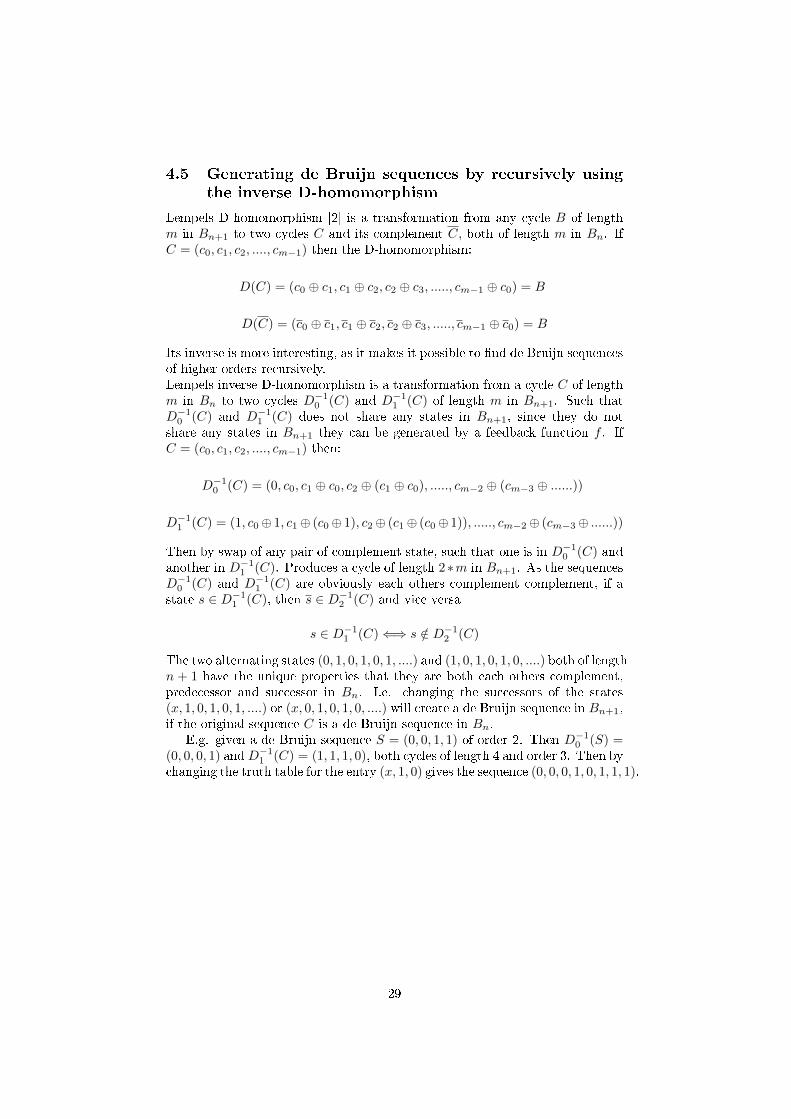
Lempels D-homomorphism [2] is a transformation from any cycle B of lengthm in Bn+1 to two cycles C and its complement C, both of length m in Bn. IfC = (c0, c1, c2, ...., cm−1) then the D-homomorphism:
D(C) = (c0 ⊕ c1, c1 ⊕ c2, c2 ⊕ c3, ....., cm−1 ⊕ c0) = B
D(C) = (c0 ⊕ c1, c1 ⊕ c2, c2 ⊕ c3, ....., cm−1 ⊕ c0) = B
Its inverse is more interesting, as it makes it possible to �nd de Bruijn sequencesof higher orders recursively.Lempels inverse D-homomorphism is a transformation from a cycle C of lengthm in Bn to two cycles D−1
0 (C) and D−11 (C) of length m in Bn+1. Such that
D−10 (C) and D−1
1 (C) does not share any states in Bn+1, since they do notshare any states in Bn+1 they can be generated by a feedback function f . IfC = (c0, c1, c2, ...., cm−1) then:
D−10 (C) = (0, c0, c1 ⊕ c0, c2 ⊕ (c1 ⊕ c0), ....., cm−2 ⊕ (cm−3 ⊕ ......))
D−11 (C) = (1, c0⊕ 1, c1⊕ (c0⊕ 1), c2⊕ (c1⊕ (c0⊕ 1)), ....., cm−2⊕ (cm−3⊕ ......))
Then by swap of any pair of complement state, such that one is in D−10 (C) and
another in D−11 (C). Produces a cycle of length 2∗m in Bn+1. As the sequences
D−10 (C) and D−1
1 (C) are obviously each others complement complement, if astate s ∈ D−1
1 (C), then s ∈ D−12 (C) and vice versa
s ∈ D−11 (C) ⇐⇒ s /∈ D−1
2 (C)
The two alternating states (0, 1, 0, 1, 0, 1, ....) and (1, 0, 1, 0, 1, 0, ....) both of lengthn + 1 have the unique properties that they are both each others complement,predecessor and successor in Bn. I.e. changing the successors of the states(x, 1, 0, 1, 0, 1, ....) or (x, 0, 1, 0, 1, 0, ....) will create a de Bruijn sequence in Bn+1,if the original sequence C is a de Bruijn sequence in Bn.
E.g. given a de Bruijn sequence S = (0, 0, 1, 1) of order 2. Then D−10 (S) =
(0, 0, 0, 1) andD−11 (C) = (1, 1, 1, 0), both cycles of length 4 and order 3. Then by
changing the truth table for the entry (x, 1, 0) gives the sequence (0, 0, 0, 1, 0, 1, 1, 1).
29

The D-homomorphism on the Boolean function
Lempel [2] also introduces an operation to apply the D-homomorphism directlyon the recursive feedback function. For the original function φ(x0, x1, ..., xn−1)and let the inverse D-homomorphism be f(x0, x1, ..., xn). The relation betweenthem is as follows:
f(x0, x1, ..., xn) = xn ⊕ φ((x0 ⊕ x1), (x1 ⊕ x2), ..., (xn−2 ⊕ xn−1))
This makes it possible to �nd the inverse D-homomorphism of a functiondirectly, and the complexity of this operation depends on the number of terms ofthe original function φ, and the number of variables for each term. The resultingfunction f will have Σvi terms, where vi is the number of variables a term of φ.So before any shortening of f , the number of terms is term(f) ≥ 2 · term(φ).The number of terms after a shortening is bounded by 2n ≥ term(f) ≥ 0.
If φ is a de Bruijn sequence, the two cycles generated by f can then bejoined by adding the term x1x2x3, ... or x1x2x3, .... that corresponds to one ofthe two alternating states to f . The problem of �nding a feedback function forthis on ANF form is generally hard. But since this function transformation canbe applied to function that is not on ANF form, so this is not really a problem.But it does increase the number of possible unique terms from 2n to 22·n.
So an algorithm for �nding a function that generates a de Bruijn sequenceof order n from a function that generates a de Bruijn sequence of order m bythe inverse D-homomorphism. The time and memory needed to do this, willdepend on the number of terms for each recursive step from an order k to orderk+ 1. As there exist at the time no way to accurately calculate this, this meanthe cost in time and memory is unpredictable and the function may then notterminate in a reliable time interval.
4.6 Games generalization of the D-homomorphism
Games [10] gives a method to construct a de Bruijn sequence S of order n+ 1,from two de Bruijn sequences S1 and S2 of order n. That relates the linearcomplexity of S1 and S2to the linear complexity of S. If both S1 and S2 havea linear complexity of 2n − 1, then S also have a linear complexity of 2n+1 − 1.
De�nition 9. The image of a sequence S = (s0, s1, ..., sn−1) of order n is
denoted Im(S). That is the set of states of length n that occur in S. The shift
operation is:
Ei(S) = (si, si+1, .., si−2, si−1)The Method is generalized here as a theorem:
Theorem 7. If r, s are two de Bruijn sequences of order n, such that Im(D−10 (r)) =
Im(D−10 (s)) and hence Im(D−1
1 (r)) = Im(D−11 (s)).
For any i, j such that:
Ei(D−10 (r)) = (u0, u1, ..., u2n−n−2, a0, a1, ..., an) and
Ej(D−11 (r)) = (v0, v1, ..., v2n−n−2, a0, a1, ..., an)
Then Ei(D−10 (r))||Ej(D−1
0 (r)) =(u0, u1, ..., u2n−n−2, a0, a1, ..., an, v0, v1, ..., v2n−n−2, a0, a1, ..., an)is a de Bruijn sequence of order n+1.
30

This holds for any conjugate states (a0, a1, ..., an) and (a0, a1, ..., an) thatare on di�erent image sets. And if r = s this is just Lempels inverse D-homomorphism, and a joining of the cycles by interchanging the successor ofconjugate states on D−1
0 (C) and D−11 (C). So this method can be seen as a
generalization of this.Games [10] also looks at reverse de Bruijn that have the same type-0 im-
ages, that is Im(D−10 (S)) = Im(D−1
0 (R(S))). These de Bruijn sequences arecalled self D−1
0 image reversing sequences, it is shown that the order of thethese have to be even. For any self D−1
0 image reversing sequences r of order n,s = D(D−1
0 (r))[a , b; c , d] and [a , b; c , d] is a cross-join pair of D−10 (r). Then s
is also a self D−10 image reversing sequences of order n, that is not equal to r.
4.7 Annexsteins algorithm
Annexsteins [1] gives an e�cient implementation on recursively generating deBruijn sequences of order n from any de Bruijn sequence of order n > m ≥ 2 byusing the inverse of Lempels D-homomorphism. This work directly on the deBruijn sequence and sub parts of it, taking sub sequences, complementing someand concatenate the results recursively for each order.
This requires O(2n) operations to generate a de Bruijn sequence of length2n, but it is bound by a memory constrain as sub sequences of the de Bruijnsequence for an order will have to be stored in the memory. So the memorycomplexity is O(2n), and therefore is not applicable to generating de Bruijnsequences of high orders.
For each recursive step a binary decision is made between using one of the twoalternating sequence of length (k−1), for a total number of 2n−m combinations.Which correspond to the 2n−m unique de Bruijn of order that can be generatedthis way from a starting de Bruijn sequence. Each unique sequence can beidenti�ed by a (n−m) bit string that determine the decision for each recursivestep. E.g. the second bit indicate that the alternating sequence used at therecursive step number 2 is 0101... if it is 0 or 1010... if it is 1.
31
4.8 Generating de Bruijn sequences by non-recursively us-
ing the inverse D-homomorphism
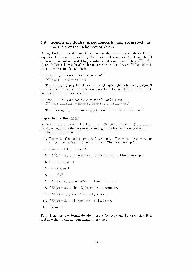
Chang, Park, Kim and Song [4] present an algorithm to generate de Bruijnsequence of order n from a de Bruijn feedback function of order k. The number ofexclusive or operation needed to generate one bit is approximately k(2W (n−k)−1), and W (r) is the weight of the binary representation of r. So if W (n−k) = 1,the e�ciency depends only on k.
Lemma 3. If m is a nonnegative power of 2:
Dm(x0,x1, ..., xm) = x0 ⊕ xm
This gives an expression of non-recursively using the D-homomorphism, ifthe number of state variables is one more than the number of time the D-homomorphism transformation used.
Lemma 4. If m is a nonnegative power of 2 and n > m:
Dm(x0, x1, ..., xn−1) = (x0 ⊕ xm, x1 ⊕ xm+1, ..., xn−m ⊕ xn)
The following algorithm �nds ∆ni (x) , which is used in the theorem 9:
Algorithm to �nd ∆ni (x)
De�ne φ = (0, 0, 0, ...), δ = (1, 0, 1, 0, ...), α = (0, 1, 0, 1, ...) and τ = (1, 1, 1, 1, ...).Let φn, δn, αn, τn be the sequence consisting of the �rst n bits of φ, δ, α, τ .
Given inputs n,i and x:
1. If x = δn, then ∆ni (x) := 1 and terminate. If x = αn, or x = τn, or
x = φn, then ∆ni (x) := 0 and terminate. Else move to step 2.
2. d ; = n− i+ 1 go to step 3.
3. if Dd(x) 6= φn−d, then ∆ni (x) := 0 and terminate. Else go to step 4.
4. k := 1,m := d− 1
5. while k < m do
6. t :=⌊k+m2
⌋7. if Dt(x) = δn−t, then ∆n
i (x) := 1 and terminate.
8. if Dt(x) = αn−t, then ∆ni (x) := 1 and terminate.
9. if Dt(x) = τn−t, then t := t− 1 go to step 7.
10. if Dt(x) = φn−t, then m := t− 1 else k ; = t.
11. Terminate.
This algorithm may terminate after just a few step and [4] show that it isprobable that it will not run longer than step 3.
32
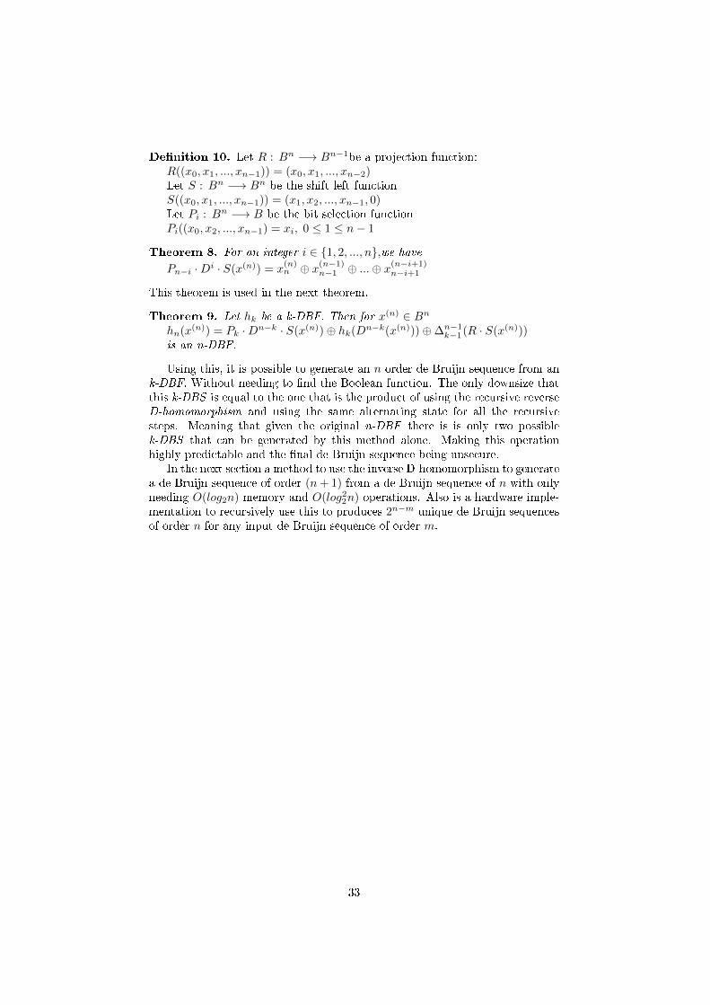
De�nition 10. Let R : Bn −→ Bn−1be a projection function:R((x0, x1, ..., xn−1)) = (x0, x1, ..., xn−2)Let S : Bn −→ Bn be the shift left functionS((x0, x1, ..., xn−1)) = (x1, x2, ..., xn−1, 0)Let Pi : B
n −→ B be the bit selection functionPi((x0, x2, ..., xn−1) = xi, 0 ≤ 1 ≤ n− 1
Theorem 8. For an integer i ∈ {1, 2, ..., n},we have
Pn−i ·Di · S(x(n)) = x(n)n ⊕ x
(n−1)n−1 ⊕ ...⊕ x
(n−i+1)n−i+1
This theorem is used in the next theorem.
Theorem 9. Let hk be a k-DBF. Then for x(n) ∈ Bn
hn(x(n)) = Pk ·Dn−k · S(x(n))⊕ hk(D
n−k(x(n)))⊕∆n−1k−1(R · S(x(n)))
is an n-DBF.
Using this, it is possible to generate an n order de Bruijn sequence from ank-DBF. Without needing to �nd the Boolean function. The only downsize thatthis k-DBS is equal to the one that is the product of using the recursive reverseD-homomorphism and using the same alternating state for all the recursivesteps. Meaning that given the original n-DBF there is is only two possiblek-DBS that can be generated by this method alone. Making this operationhighly predictable and the �nal de Bruijn sequence being unsecure.
In the next section a method to use the inverse D-homomorphism to generatea de Bruijn sequence of order (n+ 1) from a de Bruijn sequence of n with onlyneeding O(log2n) memory and O(log22n) operations. Also is a hardware imple-mentation to recursively use this to produces 2n−m unique de Bruijn sequencesof order n for any input de Bruijn sequence of order m.
33
5 Hardware implementation to generate de Bruijn
recursively
This section present a method to use the inverse D-homomorphism on a deBruijn sequence of order n, to generate a de Bruijn sequence of order (n +1) without storing the state. While only using O(log2n) bits of memory andO(log22n) logic operations. Later in the section a hardware implementation ofthis is shown, that can be connected in series to a generating de Bruijn sequencesof order n from a de Bruijn sequence of order m.
The main focus here is on simply generating de Bruijn sequence of relativelyhigh orders. To clarify this order 150 and 300 are here low orders, and orderhigher than 10000 are high. Many of the known algorithms and methods togenerate de Bruijn sequences have relatively bad scaling in either the time ormemory requirement to generate the sequences.
5.1 Method to implement the inverse D-homomorphism
without storing the state
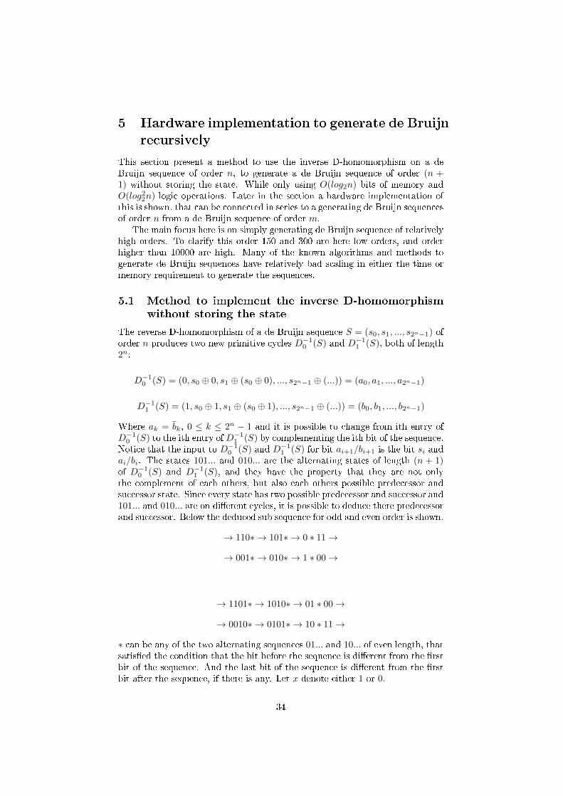
The reverse D-homomorphism of a de Bruijn sequence S = (s0, s1, ..., s2n−1) oforder n produces two new primitive cycles D−1
0 (S) and D−11 (S), both of length
2n:
D−10 (S) = (0, s0 ⊕ 0, s1 ⊕ (s0 ⊕ 0), ..., s2n−1 ⊕ (...)) = (a0, a1, ..., a2n−1)
D−11 (S) = (1, s0 ⊕ 1, s1 ⊕ (s0 ⊕ 1), ..., s2n−1 ⊕ (...)) = (b0, b1, ..., b2n−1)
Where ak = bk, 0 ≤ k ≤ 2n − 1 and it is possible to change from ith entry ofD−1
0 (S) to the ith entry ofD−11 (S) by complementing the ith bit of the sequence.
Notice that the input to D−10 (S) and D−1
1 (S) for bit ai+1/bi+1 is the bit si andai/bi. The states 101... and 010... are the alternating states of length (n + 1)of D−1
0 (S) and D−11 (S), and they have the property that they are not only
the complement of each others, but also each others possible predecessor andsuccessor state. Since every state has two possible predecessor and successor and101... and 010... are on di�erent cycles, it is possible to deduce there predecessorand successor. Below the deduced sub sequence for odd and even order is shown.
→ 110∗ → 101∗ → 0 ∗ 11 →
→ 001∗ → 010∗ → 1 ∗ 00 →
→ 1101∗ → 1010∗ → 01 ∗ 00 →
→ 0010∗ → 0101∗ → 10 ∗ 11 →
∗ can be any of the two alternating sequences 01... and 10... of even length, thatsatis�ed the condition that the bit before the sequence is di�erent from the �rstbit of the sequence. And the last bit of the sequence is di�erent from the �rstbit after the sequence, if there is any. Let x denote either 1 or 0.
34
The cycles D−10 (S) and D−1
1 (S) can be joined by change the successor of thetwo states on the form x01∗ or x10∗ for even length (n+ 1). Or the two stateson the form x010∗ or x101∗ for odd length (n + 1). But this also changes thephase of the output sequence in comparison to the input sequence S. E.g. ifthe successor of the states on the form x01∗ is changed, starting in the cyclecontaining the sub sequence → 110∗ → 101∗ → 0∗11 → gives the following twoparts of the joined cycle.
→ 110∗ → 101∗ → 010∗ → 1 ∗ 00 →
→ 001∗ → 0 ∗ 11 →
So instead of going to the state 0 ∗ 11, it goes to 010∗. If look at the deducedsub sequences of D−1
0 (S) and D−11 (S), 010∗ is one state earlier than 0 ∗ 11. So
the input S have to be shifted minus one entries, i.e. to �nd the next bits ofthe joined sequence, si+1 will have to be used instead of si.
This continues until the state 001∗ is reached, its new successor is 0 ∗ 11,instead of 010∗. Here 0 ∗ 11 is one state later than 010∗. So the input S haveto be shifted plus one entries, back to the original. I.e. to �nd the next bits ofthe joined sequence, si will have to be used instead of si+1.Let denote this shift as �phase� of the input.
De�nition 11. Phase is a variable for the input to the function denoted p, andthe input to the function is bit si+pmod(2n−1) of S at time (i+ 1).
35

Theorem 10. The phase shift is determined by the two �rst bit of the selected
alternating state on the form x01∗ or x10∗. If they are the same the phase have
to be shifted by +1 and if they are di�erent it will have to be changed −1. Phasecan only take on the values 0,−1,+1.
Proof. Prove this by showing that for n even or odd, the alternating states bothfollows this rule.
n even:x01∗: this gives the following parts of the DBS.
→ 110∗ → 101∗ → 010∗ → 1 ∗ 00 →→ 001∗ → 0 ∗ 11 →101∗ new successor 010∗ is one state earlier than its original successor state
0 ∗ 11. So the phase is −1, which is in accordance with the stated hypothesis.001∗ new successor 0 ∗ 11 is one state later than its original successor state
010∗. So the phase is +1, which is in accordance with the stated hypothesis.
x10∗: this gives the two following sub parts of the DBS.
→ 110∗ → 1 ∗ 00 →→ 001∗ → 010∗ → 101∗ → 0 ∗ 11 →010∗ new successor 101∗ is one state earlier than its original successor state
1 ∗ 00. So the phase is −1, which is in accordance with the stated hypothesis.110∗ new successor 1 ∗ 00 is one state later than its original successor state
101∗. So the phase is +1, which is in accordance with the stated hypothesis.
n odd:x010∗: this gives the following parts of the DBS.
→ 1101∗ → 1010∗ → 0101∗ → 10 ∗ 11 →→ 0010∗ → 01 ∗ 00 →0010∗ new successor 01 ∗ 00 is one state earlier than its original successor
010 ∗ 1. So the phase is +1, which is in accordance with the stated hypothesis.1010∗ new successor 0101∗ is one state later than its original successor 01∗00
. So the phase is −1, which is in accordance with the stated hypothesis.
x101∗: this gives the following parts of the DBS.
→ 1101∗ → 10 ∗ 11 →→ 0010∗ → 0101∗ → 1010∗ → 01 ∗ 00 →0101∗ new successor 1010∗ is one state earlier than its original successor
10 ∗ 11. So the phase is −1, which is in accordance with the stated hypothesis.1101∗ new successor 10∗11 is one state later than its original successor 1010∗.
So the phase is +1, which is in accordance with the stated hypothesis.
36
So it is possible to determine the phase after any alternating sequence onthe form x01∗ or x10∗ and this makes it possible to join the cycle D−1
0 (S) andD−1
1 (S) into two unique de Bruijn sequences of order (n+ 1).
Theorem 11. This method can be used to generate 2n−m unique de Bruijn
sequences of order n for all de Bruijn sequences of order m.
Proof. [2] proves that the D-homomorphism has a one-to-one correspondencebetween S and the pair D−1
0 (S), D−11 (S) if S has an even weight. De Bruijn
sequence have even weight, so D−10 (S), D−1
1 (S) is unique for every de Bruijnsequence S. Let S+1 be the resulting de Bruijn sequence from joining D−1
0 (S),D−1
1 (S) for some de Bruijn sequence of order n S, by changing the successorsof the state x01∗ or x10∗.
Assume that S+1is created by joining D−10 (S), D−1
1 (S) by changing thesuccessor of x01∗, and the feedback function for S+1 is f(x0, x1, ..., xn−1) =x0 ⊕ g(x1, .., xn−1). Then the only di�erence between the feedback functionthat generates D−1
0 (S), D−11 (S) and the one generating S+1, is the entry of
g(0, ..., 1). Then is there then any S′ 6= S such that joining D−10 (S′), D−1
1 (S′)by changing the successor of the state x01∗ or x10∗, equals S+1.
The changing the successor of x01∗ of S+1 gives D−10 (S), D−1
1 (S), and sincethere is a one-to-one correspondence between S and the pair D−1
0 (S), D−11 (S).
S+1 cannot be constructed from S′ by joining D−10 (S′), D−1
1 (S′) changing thesuccessor of x0...1.
The changing the successor of x10∗ of S+1 gives 2 cycles, one of length 2n−2and 2. As S+1 was constructed by changing the successor of x0∗1, which resultin that the successor to the state 101∗ is 010∗. And the changing of the successorof 01∗0 = 010∗ to 101∗ creates the cycle of length 2. Which means that it is notpossible to construct S+1 from a S′ 6= S by changing the successors of the statex01∗ or x10∗ to join D−1
0 (S′), D−11 (S′). So every possible de Bruijn sequence of
order n can be used to create two unique de Bruijn sequence of order n+1.
By only looking at the two �rst bit of the selected form and count thenumber of alternating output bits up to (n − 1). In the following sections ahardware implementation of this is shown, that have a component complexityof O(n · log2n) and a time complexity to produce a bit of O(log22n).
37
5.2 Introduction to the hardware implementation
When any computational task is to be performed, there is generally two waysto do this. The �rst way is to solve it by writing a software program and runthis program on a computer to get the result. The other way to is to createa special piece of hardware that will solve the problem. The software way isgeneral solution as there will be no additional cost in physical resources and itcan be performed on any computer.
The hardware way makes it possible to divide tasks into multiple separatelyindependent operations. Which can then be run in parallel to solve the problemfaster. Will in this part look at a hardware implantation to generate longde Bruijn sequences from a shorter de Bruijn sequence using Lempels inverseD-homomorphism.
All modern digital electronics is primarily created by using logic gates. Alogic gate take a number of binary input and gives binary output in accordancewith the truth table of the gate. The most simple are AND, NOT, OR andXOR logic gates. In addition there is the complement of OR, NOR. By usingthese as building blocks, its possible to construct complex logical systems. Tomeasure the e�ciency of system, one have to look at the cost in resources tobuild the system and the cost to operate it.
When any hardware generator is implemented, the two main resources aretime and component. The most important cost in time, is the time to solve atask and to implement it into a system that generate the sequence. The timeneeded to generate one sub part of the main task.
For components, the number of transistor is a good measurement of e�-ciency, another one is the number of logic gates and memory cells. Here thesum number of logic gates and memory is used to indicate the complexity of thesystem. As logic gates and memory can be constructed from primarily transis-tor and memory cells, this is a relatively good measurement of the complexityof the system.
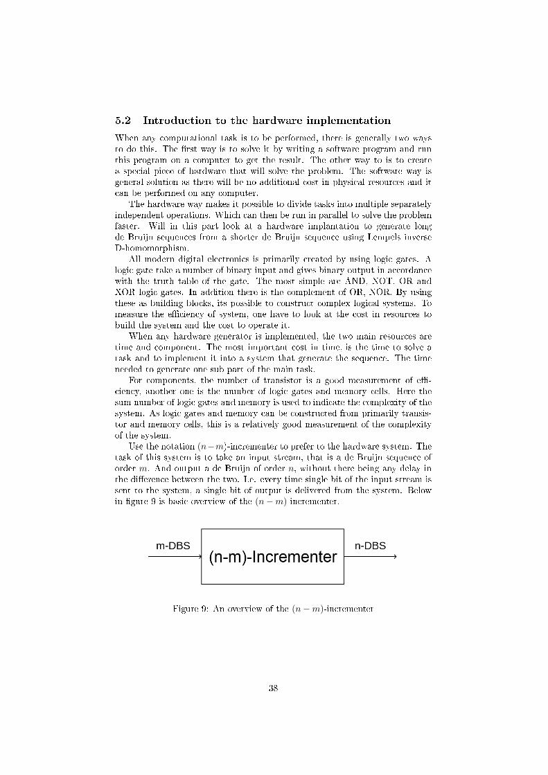
Use the notation (n−m)-incrementer to prefer to the hardware system. Thetask of this system is to take an input stream, that is a de Bruijn sequence oforder m. And output a de Bruijn of order n, without there being any delay inthe di�erence between the two. I.e. every time single bit of the input stream issent to the system, a single bit of output is delivered from the system. Belowin �gure 9 is basic overview of the (n−m)-incrementer.
Figure 9: An overview of the (n−m)-incrementer
38

The (n−m)-incrementer consist of (n−m) independent sub system calledincrementers. These are independent, as they can operate at the same timewithout any of the incrementers having to wait for an input from another forevery clock cycle. The clock frequency is limited by the slowest incrementer, asall the incrementers have to complete there task before the system can clock.Also incrementers can use a shared memory cells, as long as only one incrementersets the value of the cell.
An incrementer takes as an input a de Bruijn sequence of order k and out-put a de Bruijn sequence of order (k + 1). In �gure 10 below, it is shown anillustration of how the incrementers are used as building blocks of the (n −m)-incrementer.
Figure 10: An overview of the (n−m)-incrementer
5.3 Components
This hardware implementation uses AND, XOR, NOT gates and D �ip-�ops.It can be further optimized by using some of the complement gates, but forsimplicity only the simple implementation is used. All of these component canbe made from transistors in several di�erent ways, that gives di�erent propertiesin terms of the number of transistors used and propagation delay. The mostimportant properties of the logic gates in an overhead view is:
De�nition 12. Propagation delay is the maximum time it takes for the outputof a logic gate to change, when there is a change in the input to the logic gate.This limits the speed of which the logic block can operate without there beinga logical error.Fan-out is the maximum number of parallel logic gate that the output of a logicgate can give a signal to, without there being a logical error.
The Propagation delay of a logic block is the longest time for the blocks outputto change into its �nal state, when any input to the block changes. This dependon the �longest path� of the block, which is the longest path of componentsan input signal has to travel to an output. So the total propagation delay isthe sum of the propagation delay of the components on the �longest path�. Ofcourse this is only applicable to a logic block that stabilizes for all inputs. I.e.that all output will eventually reach a constant truth value, for all input.
While there may be a more e�cient ways to construct the logic blocks, byusing these few components the design does not get to complex to understand.No electrical analysis on the power levels, noise cancellation, boosting of signaland other details is performed. As this is only meant as a basic look at how gen-erally e�cient this method of generating de Bruijn sequence can be implementedin hardware circuit.
39
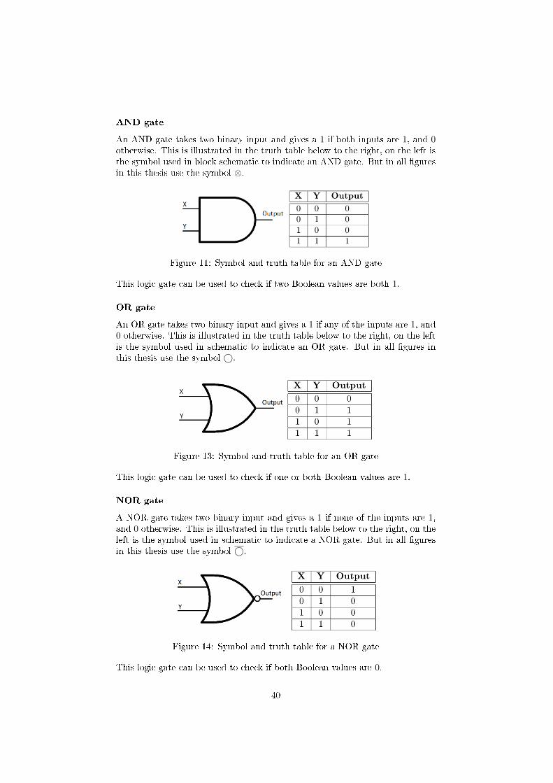
AND gate
An AND gate takes two binary input and gives a 1 if both inputs are 1, and 0otherwise. This is illustrated in the truth table below to the right, on the left isthe symbol used in block schematic to indicate an AND gate. But in all �guresin this thesis use the symbol ⊗.
Figure 11: Symbol and truth table for an AND gate
This logic gate can be used to check if two Boolean values are both 1.
OR gate
An OR gate takes two binary input and gives a 1 if any of the inputs are 1, and0 otherwise. This is illustrated in the truth table below to the right, on the leftis the symbol used in schematic to indicate an OR gate. But in all �gures inthis thesis use the symbol ©.
Figure 13: Symbol and truth table for an OR gate
This logic gate can be used to check if one or both Boolean values are 1.
NOR gate
A NOR gate takes two binary input and gives a 1 if none of the inputs are 1,and 0 otherwise. This is illustrated in the truth table below to the right, on theleft is the symbol used in schematic to indicate a NOR gate. But in all �guresin this thesis use the symbol ©.
Figure 14: Symbol and truth table for a NOR gate
This logic gate can be used to check if both Boolean values are 0.
40
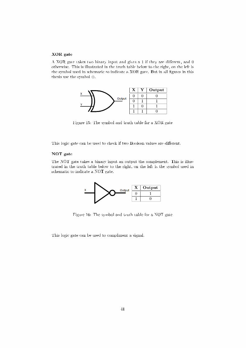
XOR gate
A XOR gate takes two binary input and gives a 1 if they are di�erent, and 0otherwise. This is illustrated in the truth table below to the right, on the left isthe symbol used in schematic to indicate a XOR gate. But in all �gures in thisthesis use the symbol ⊕.
Figure 15: The symbol and truth table for a XOR gate
This logic gate can be used to check if two Boolean values are di�erent.
NOT gate
The NOT gate takes a binary input an output the complement. This is illus-trated in the truth table below to the right, on the left is the symbol used inschematic to indicate a NOT gate.
Figure 16: The symbol and truth table for a NOT gate
This logic gate can be used to compliment a signal.
41

D �ip-�op
A D �ip-�op is a component that holds a single binary value Q, that also is itsoutput. For any new clock cycle the value of Q is updated to that of the inputD. There are also two other input to the �ip-�op S and R, that both are set to0 for normal use. Below in �gure 17, the truth table for a D �ip-�op in normaluse (S = R = 0) is shown on the right. On the left is the symbol used in blockschematics. But in so �gure in this thesis also uses a simple square to representa stored it, with inbound arrow for the D signal and an outbound arrow for theQ signal.
Figure 17: Truth table for a D �ip-�op in normal use (S = R = 0)
By changing the values of S and R it is possible to set the value of Q to 1 or 0,without need to wait for a new clock cycle. In table 2 below is the truth tablefor the D �ip-�op when it is being set to a speci�c value.
S R D Clock Q
0 1 x x 01 0 x x 11 1 x x 1
Table 2: Truth table for setting and resetting the output of a D �ip-�op
Propagation delay of components
While all of these components can have di�erent propagation delay ranging from350 ps (picosecond) to 600 ns (nanosecond). This analysis we will use a 5 nspropagation delay for the components AND, OR, NOR, XOR and D �ip-�op.
42
5.4 General concept of the hardware implementation
The main concept is to separate the process of generating a de Bruijn sequenceof order n from a de Bruijn sequence of order m into (n − m) independentsub processes called incrementers. Such that each takes a de Bruijn sequencebit stream of order k and calculate the next bit of the k + 1 order de Bruijnsequence bit stream, and store it and send the previously stored bit to the nextincrementer.
Each of the incrementers uses the inverse of the D-homomorphism to �nd thenext bit of the bit stream and complement it if the last (k−1) bit correspond tothe selected alternation sequence for the sub process, and shift the input streamaccording to theorem 10.
Storing one bit and thereby adding a one bit delay for each incrementer,makes it possible to have all the incrementer be independent of each other. Sothe (n−m) incrementers can be run in parallel, and this allows for a much higherclock frequency than if they where to be computed in a series. Which allow itto produce a higher output of bits per second. This can be further optimize, byminimize the time it take to complete the slowest of the incrementers.
To detect that the last (k− 1) output bits from a incrementer correspond tothe selected alternating state, the naive approach would be to save the (k − 1)last bit and check if they correspond to the selected state. But this take up
(k − 1) bit of memory, and this will take approximately n·(n+1)2 bit of memory
for a (n− 2)-incrementer.A more memory e�cient way would be to count the number of alternating
bit of the bit stream that corresponding to the selected alternating state. Thisuses dlog2 k − 1e bit, and will sum up to approximately n · dlog2 n− 1e bit ofmemory for a (n−2)-incrementer. This can also be implemented by any countermodule, in this implementation a basic counter is implemented by a primitiveLFSR. But a counter implemented by a LFSR while must have a period greaterthan (k− 1), as the starting state must be di�erent from the state after (k− 1)clock of the LFSR.
43
5.5 The hardware implementation
List of signals in an incrementer
• Reset 1: Set k-2 until 0 memory cells of the LFSR counter.
• Reset 2: Set the memory cell (k − 1) of the LFSR counter.
• Shift: Indicate that the counter have reached (k− 1), and that the inputshould be shifted.
• Xi: The input stream to the incrementer that is a k-order de Bruijnsequence.
• Yi: The output signal from the incrementer that is a S(k + 1)-order deBruijn sequence.
• Mode: A binary value that determines the selected alternatingsequence. If it is 0 it is x01.., and if it is 1 it is x10....
• First state bit: The �rst bit of the current possible alternating state.
• P: If 1, indicates that the current phase is 0.
• P−: If 1, indicate that the current phase is +1.
• P+: If 1, indicate that the current phase is −1.
List of signals that are common for all incrementers
• Set state: If 1, then the system will output its current state and set thestate of the system to be the input. If 0, then it will have no e�ect on thesystem.
44

The Main module
The binary inverse of the D-homomorphism is:
D−1k (C) = (k, c0 ⊕ k, c1 ⊕ (c0 ⊕ k), ..., c2m−1 ⊕ (...), k ∈ {0, 1}
As can seen by this, the sequence generated by the D-homomorphism starts witheither a zero or a one. The next bit is the �rst bit of the input stream exclusive
or with the previous output bit, and so on. So it is obvious that the previousoutput bit have to be stored for every module. To implement the joining of thetwo cycles generated, one of the two alternating sequences have to be chosen.As this is a binary decision, it needs only one bit to be represent in an encoding.The problem is then to detect that the last (n − 1) bits of the output streamcorrespond to the chosen alternating sequences. This can be implemented by acounter that count up to (n−1) if the sequences matches, and reset the counterif it does not.
For the following input bits have to be shifted, and this can be implementedby storing two previous input bit. Details of the module that handle phaseshown in the next sub section. The counter and the control module that run thecircuit and manages the setting of the register, is presented in the sub sectionsafter that. Below is a block schematic of the main module that performs theD-homomorphism implementation on the input stream Xi+1 and the shiftedinput bits Xi, Xi+2.
Figure 18: The block schematic of the Main module
45
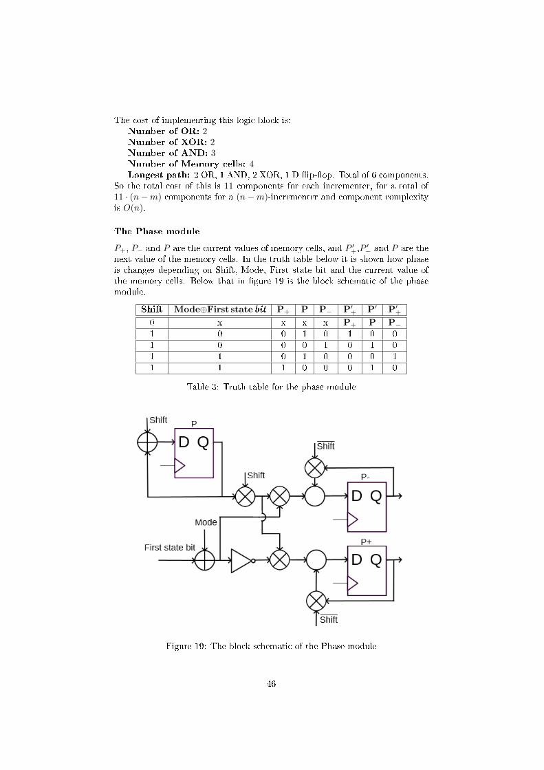
The cost of implementing this logic block is:Number of OR: 2Number of XOR: 2Number of AND: 3Number of Memory cells: 4Longest path: 2 OR, 1 AND, 2 XOR, 1 D �ip-�op. Total of 6 components.
So the total cost of this is 11 components for each incrementer, for a total of11 · (n−m) components for a (n−m)-incrementer and component complexityis O(n).
The Phase module
P+, P− and P are the current values of memory cells, and P ′+,P
′− and P are the
next value of the memory cells. In the truth table below it is shown how phaseis changes depending on Shift, Mode, First state bit and the current value ofthe memory cells. Below that in �gure 19 is the block schematic of the phasemodule.
Shift Mode⊕First state bit P+ P P− P′+ P′ P′
+
0 x x x x P+ P P−1 0 0 1 0 1 0 01 0 0 0 1 0 1 01 1 0 1 0 0 0 11 1 1 0 0 0 1 0
Table 3: Truth table for the phase module
Figure 19: The block schematic of the Phase module
46

The cost of implementing this logic block is:Number of NOT: 1Number of OR: 2Number of XOR: 2Number of AND: 5Memory cells: 3Longest path: 1 NOT, 1 AND, 1 XOR, 1 D �ip-�op. Total of 5 compo-
nents.So the total cost of this is 13 components for each incrementer, for a total of13 · (n−m) components for a (n−m)-incrementer and component complexityis O(n).
The Set First State bit module
This module is used to store the �rst bit of any possible alternating state x01...or x10.. depending on which is selected. Below in the truth table it is shownhow the value of the memory cell changes depending on the values of Reset 1and Reset 2. Under that in �gure 20 is the block schematic for the module.
Reset 1 Reset 2 First state bit
0 x First state bit1 0 yi−1
1 1 yi
Table 4: Truth table for the Set First State bit module
Figure 20: The block schematic of the Set First State bit module
The cost of implementing this logic block is:Number of OR: 1Number of AND: 2Number of Memory cells: 1Longest path: 1 AND, 1 OR, 1 D �ip-�op. Total of 3 components.
So the total cost of this is 4 components for each incrementer, for a total of4 · (n−m) components for a (n−m)-incrementer and component complexity isO(n).
47

The State counter module implemented by a LFSR
If the previous output bit and the current output bit are di�erent the counterwill increment itself, as this correspond to a part of an alternating sequence.The counter itself will need to count up to (k − 1) for an k-incrementer, so theLFSR must have to have a period of at least k. Which means that the order ofthe LFSR have to be at least dlog2 ke, and use dlog2 ke bits of memory.
Next the feedback function should have be as simple as possible, preferablyonly depend on two state variables (which is minimum for a maximum-lengthLFSR). To detect that the counter has reach (k−1) it will have to look at someof the state variables, and the number of these should be as low as possible.
E.g. for (k−1) = 5, the order of the LFSR have to be at least 3. The feedbackfunction f(x0, x1, x2) = x2 ⊕ x1 and the initial state (0, 0, 1) will generate thecycle (0, 0, 1, 1, 1, 0, 1) and the state after �ve clock is (0, 1, 0). To detect thisthe detecting function D(x0, x1, x2) = x0 ⊗ x2, which is be true for only thisstate. As the all zero state does not occur in sequence of length greater than 1,if it is generated by a LFSR.
Figure 21: The block schematic of the LFSR counter module
To calculate the cost of such a LFSR counter, assume that the feedback functiondepend on two state variables. Then this can be implemented by a single XORgate. Assume that dlog2 ke state variables have to be check to detect at theLFSR a have reached the (k−1) state. This can be implemented by dlog2 ke−1AND gates, and the register will need dlog2ke memory cells.
The cost of implementing this logic block is:Number of XOR: 1Number of AND: dlog2ke − 1Number of Memory cells: dlog2keLongest path: log2(dlog2ke)−1 AND, 1 D �ip-�op or 1 XOR, 1 D �ip-�op.
Total of log2(dlog2ke)− 1 or 2 components.This gives a component complexity of O(log2k) = O(log22k) and the propagationdelay is log2(dlog2ke) AND or 2 components as this is the longest part any signalhas to travel for every clock. So the time complexity is O(log2k) = O(log22k).
48

The module to reset the LFSR counter
When the two consecutive output bits of the main module are identical (either00 or 11) the counter will have to be reset. If the two bit are the same as the�rst bit of the chosen alternating sequence, the counter will have to be resetto 1 as the last bit can then be the �rst bit of a sequence that is equal to thechosen alternating sequence. But if it is not, then the counter will have to bereset to zero. So the di�erence between those two type of rest are only the valueof memory cell (n − 1). This implement by the two reset signals Reset 1, andReset 2.
When the logic block that check if the counter has reached step (k− 1), thecells (n− 2) until 0 is set to 1. Cell (n− 1) is set to 1 if the current bit can bethe �rst bit of the selected alternating sequence, and set to 0 otherwise. Thiscan be implemented by a small logic block that checks if the two subsequentbits are the same, and if they are it checks if the last bit can be the �rst bit ofthe selected alternating sequence. Below the logic block for this is shown.
Note that the signal Reset 1 is stored in a memory cell and is used to resetthe memory cells of the counter in the same clock cycle that it is stored. If theReset 1 memory cell that stores Reset 1 don´t have a strictly faster propagationdelay than the memory cells of the counter, it can also reset the counter at thestart of the following clock cycle. This problem may also be �xed by changingthe implementation, either by using other types of components or redesigningthe way the resetting of the counter works.
Figure 22: The block schematic for the module to reset the counter
49

The cost of implementing this logic block is:Number of OR: 1Number of XOR: 2Number of AND: 1Memory cells: 1Longest path: 1 XOR, 1 OR, 1 D �ip-�op or 1 XOR, 1 AND, 1 D �ip-�op.
Total of 3 components.So the total cost of this is 5 components for each incrementer, for a total of5 · (n−m) components for a (n−m)-incrementer and component complexity isO(n).
The module for setting and retrieving the state of the (n−m)-incrementer
The problem of retrieving the information stored in all the D �ip-�op can besolved by having them be connected by an AND gate, that has as input theprevious memory cell and a control signal Set state. So if Set state = 1 thebits are then shifted out one at a time, and a new state can be simultaneouslyshifted in. To make sure that the values of the memory cells are only shiftedand not changes, the normal processes of the FSR have to be stopped. So thenormal processes must have the requirement that Set state = 0, use Set stateto refer to the complement of Set state.
The bits Yi,Yi+2and Xi+2 are already shifted. The same with the memorycells of the LFSR register.This process can be implemented by using 2 ANDand 1 Xor gate before any memory cells which input is not simply a shift fromanother memory cell. The original input goes through an AND gate that isopen if Set state = 1, and the input from the shift goes through an AND gatethat is open if Set state = 0. Both signals are then sent to a XOR gate, and theoutput of this is then sent to the memory cell. The schematic of this is shownon the next page, the signal �Run input� is the original input signal.
The cost of implementing this logic block is:Number of XOR: 8Number of AND: 16
So the total cost of this is 24 components for each incrementer, for a total of24 · (n−m) components for a (n−m)-incrementer and component complexityis O(n).
50
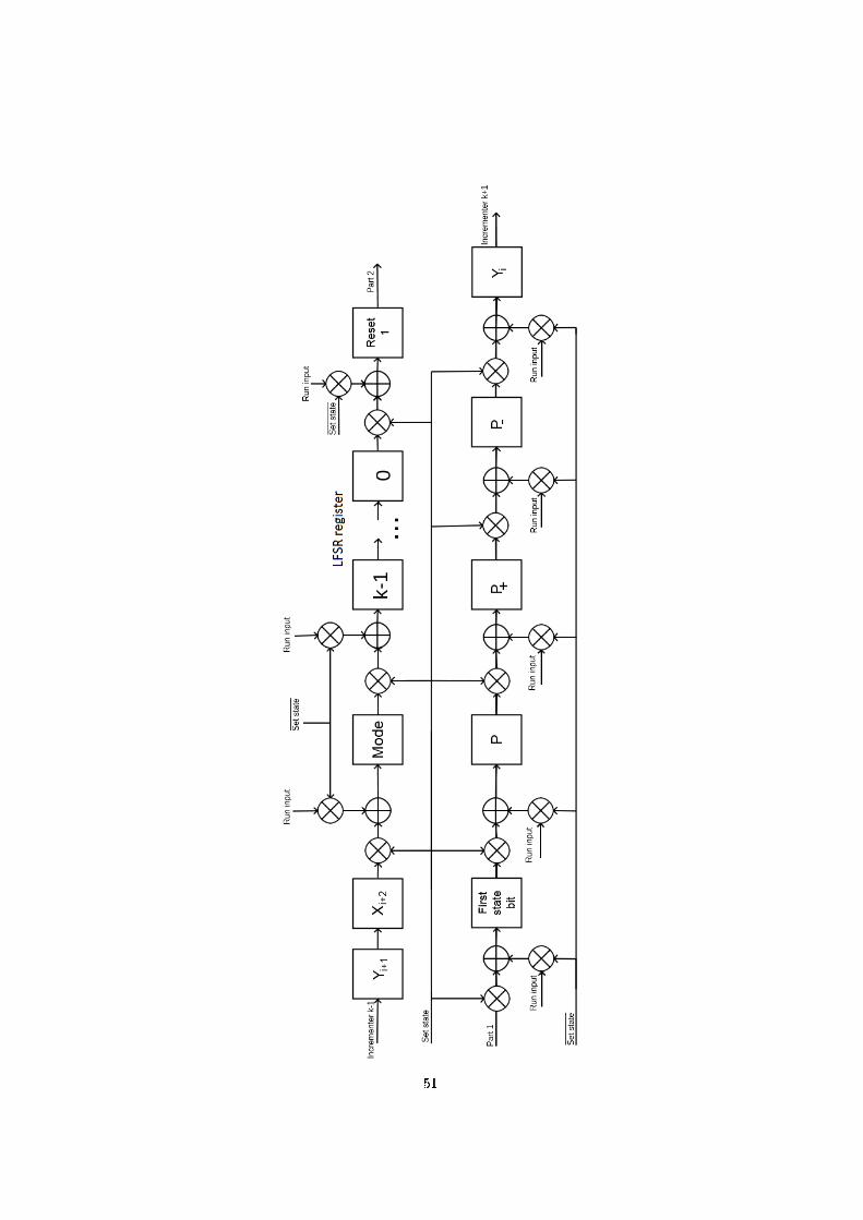
51

Staring the (n−m)-incrementer for an initial state
Since every incrementer need two bit of the input stream to be able to start run-ning (Xi−1 and Xi), the clock signal to the di�erent incrementers memory haveto be delayed by 2 clock cycle for every incrementers. So an (n−m)-incrementersneed to clock 2 · (n−m) times before it can being to output the �nal de Bruijnsequence of order n.
This operation can be performed by a software program, to reduce the num-ber of required components, a hardware solution is not implemented in thisthesis. As this is only a one time operation, that can be relatively e�cientlyimplemented by a software application.
5.6 Correctness
To prove the correctness of this implementation, that it do produce a unique deBruijn sequence for all valid con�guration of the device. Start by looking at themost simple iteration.
Given an m order de Bruijn sequences incrementer, and let the output beof order (m+ 1). By selecting one of the two alternating sequences, one of twopossible de Bruijn are produces. Then as long as the incrementer can detectthe selected alternating state and complement the next output bit. The outputsequence will be a de bruijn sequence of order (m+ 1).
By adding another incrementer that takes this (m + 1) order de Bruijnsequence as an input, and output a (m + 2) order de Bruijn sequence. So ifthe implementation works for a simple incrementor, it can work for an (n −m)-incrementor. As it is only serie of simple incrementers. This produces ade Bruijn for any of order, given enough incrementors. This given that all themodules are correctly implemented.
52
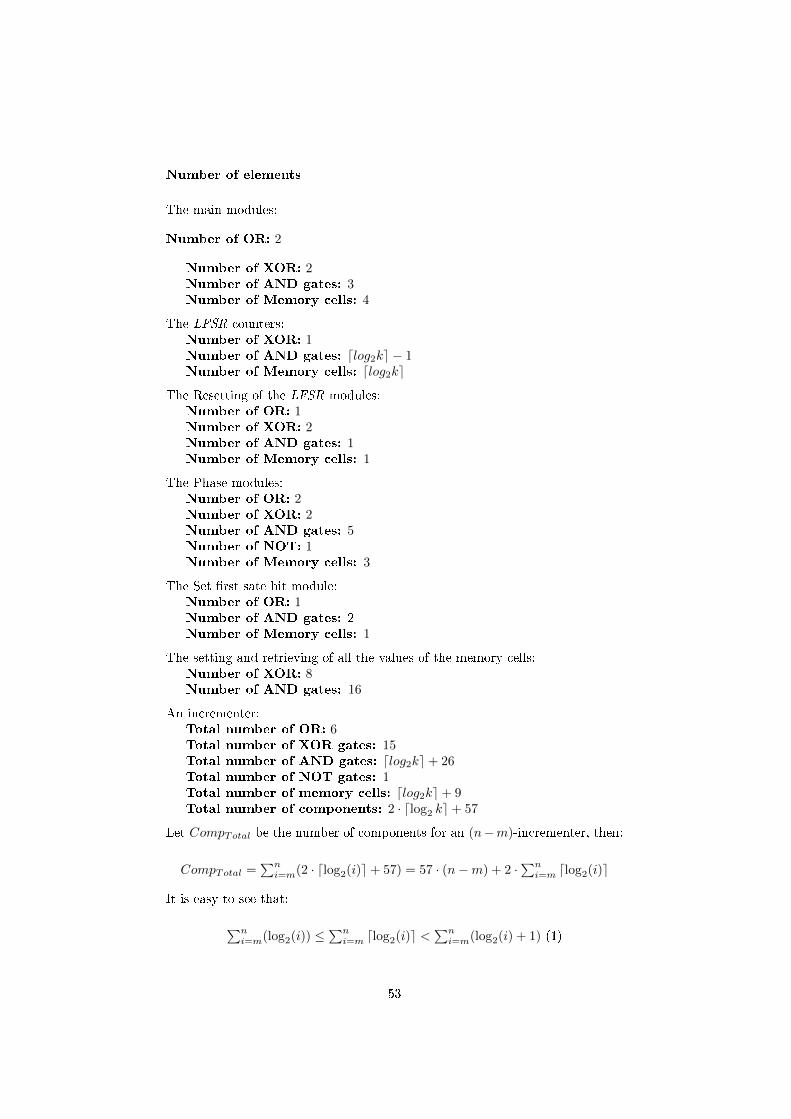
Number of elements
The main modules:
Number of OR: 2
Number of XOR: 2Number of AND gates: 3Number of Memory cells: 4
The LFSR counters:Number of XOR: 1Number of AND gates: dlog2ke − 1Number of Memory cells: dlog2ke
The Resetting of the LFSR modules:Number of OR: 1Number of XOR: 2Number of AND gates: 1Number of Memory cells: 1
The Phase modules:Number of OR: 2Number of XOR: 2Number of AND gates: 5Number of NOT: 1Number of Memory cells: 3
The Set �rst sate bit module:Number of OR: 1Number of AND gates: 2Number of Memory cells: 1
The setting and retrieving of all the values of the memory cells:Number of XOR: 8Number of AND gates: 16
An incrementer:Total number of OR: 6Total number of XOR gates: 15Total number of AND gates: dlog2ke+ 26Total number of NOT gates: 1Total number of memory cells: dlog2ke+ 9Total number of components: 2 · dlog2 ke+ 57
Let CompTotal be the number of components for an (n−m)-incrementer, then:
CompTotal =∑n
i=m(2 · dlog2(i)e+ 57) = 57 · (n−m) + 2 ·∑n
i=m dlog2(i)e
It is easy to see that:
∑ni=m(log2(i)) ≤
∑ni=m dlog2(i)e <
∑ni=m(log2(i) + 1) (1)
53
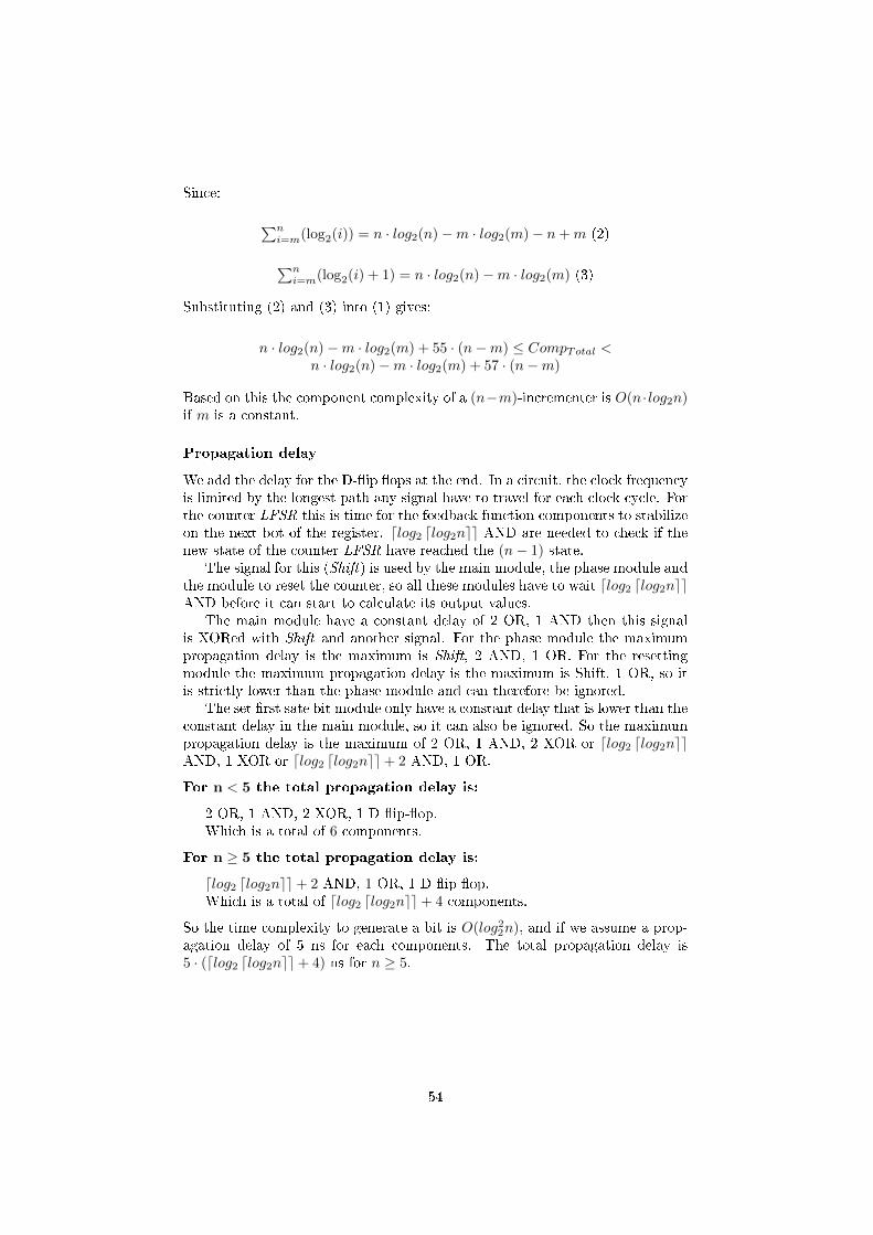
Since:
∑ni=m(log2(i)) = n · log2(n)−m · log2(m)− n+m (2)
∑ni=m(log2(i) + 1) = n · log2(n)−m · log2(m) (3)
Substituting (2) and (3) into (1) gives:
n · log2(n)−m · log2(m) + 55 · (n−m) ≤ CompTotal <n · log2(n)−m · log2(m) + 57 · (n−m)
Based on this the component complexity of a (n−m)-incrementer is O(n · log2n)if m is a constant.
Propagation delay
We add the delay for the D-�ip �ops at the end. In a circuit, the clock frequencyis limited by the longest path any signal have to travel for each clock cycle. Forthe counter LFSR this is time for the feedback function components to stabilizeon the next bot of the register. dlog2 dlog2nee AND are needed to check if thenew state of the counter LFSR have reached the (n− 1) state.
The signal for this (Shift) is used by the main module, the phase module andthe module to reset the counter, so all these modules have to wait dlog2 dlog2neeAND before it can start to calculate its output values.
The main module have a constant delay of 2 OR, 1 AND then this signalis XORed with Shift and another signal. For the phase module the maximumpropagation delay is the maximum is Shift, 2 AND, 1 OR. For the resettingmodule the maximum propagation delay is the maximum is Shift, 1 OR, so itis strictly lower than the phase module and can therefore be ignored.
The set �rst sate bit module only have a constant delay that is lower than theconstant delay in the main module, so it can also be ignored. So the maximumpropagation delay is the maximum of 2 OR, 1 AND, 2 XOR or dlog2 dlog2neeAND, 1 XOR or dlog2 dlog2nee+ 2 AND, 1 OR.
For n < 5 the total propagation delay is:
2 OR, 1 AND, 2 XOR, 1 D �ip-�op.Which is a total of 6 components.
For n ≥ 5 the total propagation delay is:
dlog2 dlog2nee+ 2 AND, 1 OR, 1 D �ip-�op.Which is a total of dlog2 dlog2nee+ 4 components.
So the time complexity to generate a bit is O(log22n), and if we assume a prop-agation delay of 5 ns for each components. The total propagation delay is5 · (dlog2 dlog2nee+ 4) ns for n ≥ 5.
54
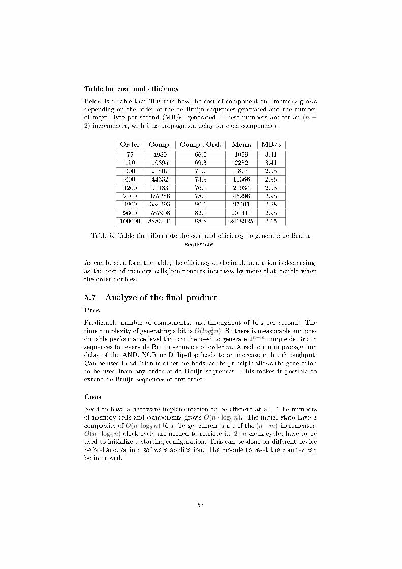
Table for cost and e�ciency
Below is a table that illustrate how the cost of component and memory growsdepending on the order of the de Bruijn sequences generated and the numberof mega Byte per second (MB/s) generated. These numbers are for an (n −2)-incrementer, with 5 ns propagation delay for each components.
Order Comp. Comp./Ord. Mem. MB/s
75 4989 66.5 1059 3.41150 10395 69.3 2282 3.41300 21507 71.7 4877 2.98600 44332 73.9 10366 2.981200 91183 76.0 21934 2.982400 187286 78.0 46296 2.984800 384293 80.1 97401 2.989600 787908 82.1 204410 2.98100000 8883441 88.8 2468925 2.65
Table 5: Table that illustrate the cost and e�ciency to generate de Bruijnsequences
As can be seen form the table, the e�ciency of the implementation is decreasing,as the cost of memory cells/components increases by more that double whenthe order doubles.
5.7 Analyze of the �nal product
Pros
Predictable number of components, and throughput of bits per second. Thetime complexity of generating a bit is O(log22n). So there is measurable and pre-dictable performance level that can be used to generate 2n−m unique de Bruijnsequences for every de Bruijn sequence of order m. A reduction in propagationdelay of the AND, XOR or D �ip-�op leads to an increase in bit throughput.Can be used in addition to other methods, as the principle allows the generationto be used from any order of de Bruijn sequences. This makes it possible toextend de Bruijn sequences of any order.
Cons
Need to have a hardware implementation to be e�cient at all. The numbersof memory cells and components grows O(n · log2 n). The initial state have acomplexity of O(n · log2 n) bits. To get current state of the (n−m)-incrementer,O(n · log2 n) clock cycle are needed to retrieve it. 2 · n clock cycles have to beused to initialize a starting con�guration. This can be done on di�erent devicebeforehand, or in a software application. The module to reset the counter canbe improved.
55

Hardware vs software
The di�erence in time and space/component complexity for the hardware andsoftware is shown below in table 6.
Software Hardware
Time complexity to generate a bit O(n) O(log22n)Space/component complexity O(n · log2n) O(n · log2n)
Table 6: Table show the di�erence between this hardware implementation anda general software implementation
Testing
For every start con�guration at least k ·n should be generated, for some constantk. The resulting output sequence should be tested try to �nd the from this subsequence. The worst case is that the sequence generated is de Bruijn sequencethat can be found by joining the two cycles of a LFSR with a maximum period.Which can be found by using the Berlekamp-Massey algorithm on at most (2 ·n)bits. Of course this may fail if the 0 bit from the all zero cycle of the LFSR, isa part of the (2 · n) bit the algorithm is run on. So this should be taken intoconsideration when testing the sequence.
The same is true if the de Bruijn sequence is complemented sequence ofa de Bruijn sequence that can be found by joining the two cycles of a LFSR
with maximum period. Which can be found the same way by running thecomplemented bit. The reversed complement is also easy to �nd, so it shouldbe checked to make sure that the sequence at least cannot be found by simplyusing the Berlekamp-Massey algorithm.
Usability
As the devices simply takes a de Bruijn sequence stream as an input, it can becombined with di�erent technique that are able to e�cient generate de Bruijnsequences as long as there is enough memory, e.g. Annexstein [1]. This sequencecan then the input, this reduces the total number of components. The devicecan also be more generalized, by making it possible to have multiple input andoutput points. So that the order on the input sequence and output sequencecan be changed. Also possible to add complementing of any of the orders.
56

Conclusion
The main thing I have been working on
I have created a method to apply Lempels inverse D-homomorphism on a bitstream, without having to store the current state. That takes any de Bruijnsequence S of order m and binary sequence s of length (n −m) and generatesunique a de Bruijn order n for each unique pair of S and s. For a total of22
m−1+n−2·m unique sequences.This was implemented in a simple hardware circuit, that has a time com-
plexity to generate a bit of O(log22n) a component complexity of O(n · log2n).This is relatively good scales time and space/component complexity, and thecost in time and components are predictable.
Other things I have been looking at
Method to �nd de Bruijn by looking for cross-join pairs
Thought of a method to �nd new de Bruijn functions of order n from a deBruijn functions of order n. The �rst step is to search for i subsequent bits thatdi�er by only one bit t from a possible cycle in Bn. So if the entry in g thatdetermines this bit t is swapped, and this does not change any of the other bit.Then de Bruijn cycle is split into two cycles of length 2n − i and i. Since wenow all the states of the cycle with i bits, it is easy to �nd out if one or more ofthese states s have a possible successor in the cycle of length 2n − i.
If there is such a state, then by changing the value of truth table for g forthe entry that changes the successor of s. This will join the two cycles in a newde Bruijn sequence, if t 6= s.
Note that in a cycle each state have only one successor and one predecessor,so for a cycle of length i. Start with a state s, if both possible successor arein the cycle, then the number of possible successors are i − 2. Then take thenext state that has not have its possible successor looked at and continue. Sincethe number of possible successor is lowered by 2 for each check that does not�nd a join-state is not found. If i is an odd number, the cycle is guarantiedto contain at least one state that can be used to join the two cycles into a deBruijn sequence, such that t 6= s.
Did not �nd a way to construct a reliable algorithm, such that this e�cientlyimplemented.
de Bruijn sequences over non-binary alphabets
Did some basic works on de Bruijn sequences over alphabet larger than 2 andthe relation between them and binary ones. No real progress was made.
New methods to generate new de Bruijn sequences
Did work on a new method to �nd de Bruijn sequences from de Bruijn of lowerorders. But did not �nd a new method.
57

New methods to generate new de Bruijn sequences from others of thesame order
Did work on a new method to �nd de Bruijn sequences from de Bruijn of thesame orders. Did �nd some basic results, but nothing new.
Thing I would have like to do if I had more time
• Would like to improve or redesign parts of the hardware implementa-tion that I was not satis�ed with. The way the counter module is be-ing rest, or the module to change or retrieve the current state of the(m− n)-incrementer could have been improved.
• Physically make a prototype of a (n − m)-incrementer, for a relativelysmall n to get more practical data on how to optimize the process.
• Try to �nd ways to merge multiple subsequent incrementers to make itpossible to optimize the implementation.
• Try to deduce bounds on linear complexity, distribution and correlationof the sequences that can be generated by (n−m)-incrementer.
Subjects that I would like to look into
• The properties of modi�ed de Bruijn sequences especially type 1. Andways to use this with (n−m)-incrementers.
• Looking for more and e�cient ways to generate binary de Bruijn sequencesthat scales well for very large orders.
• Try to �nd ways to e�ciently generate de Bruijn sequences of high ordersover non-binary alphabets.
58

References
[1] F. S. Annexstein, �Generating de Bruijn sequences: AN e�cient implemen-tation,� IEEE Trans. Comput., vol 46, no. 2, pp. 198�200, Feb. 1997.
[2] N. G. de Bruijn, �A combinatorial problem�, Koninklijke Nederlandse
Akademie van Wetenschappen, vol 49, no. 1, pp. 758�764, 1946.
[3] A. H. Chan, R. A. Games, E. L. Key, �On the complexities of de Bruijnsequences,� J. Combin. Theory, Ser A, vol. 33, pp. 233�246, Nov. 1982.
[4] T. Chang, B. Park, Y.H. Kim, I. Song, �An e�cient implementation of theD-homomorphism for generation of de Bruijn sequences,� IEEE Transac-
tions on Information Theory 45, pp. 1280�1283, May 1999.
[5] E. Dubrova, �A Transformation From the Fibonacci to the Galois NLFSRs�.IEEE Transactions on Information Theory, vol. 55, no. 11, Nov. 2009.
[6] E. Dubrova, Sequences and Their Applications � SETA 2010.
[7] E. Dubrova, Des. Codes Cryptogr. 2014.
[8] C. Flye Sainte-Marie, �Solution to question nr. 48,� I'lntermediuire des
iathematiciens, pp. 107�110, 1894.
[9] H. Fredricksen, �A Survey of Full Length Nonlinear Shift Register CycleAlgorithms,� SIAM Review 24, no. 2 , pp. 195�221, Apr. 1982.
[10] R. Games, �A generalized recursive construction for de Bruijn sequences,�IEEE Transactions on Information Theory, vol. 29, no. 6, pp. 843�850,Nov. 1983.
[11] S. W. Golomb, Shift Register Sequences, Holden-Day, San Francisco, CA,1967.
[12] T. Helleseth, T. Klove, �The number of cross-join pairs in maximum lengthlinear sequences,� IEEE Transactions on Information Theory, vol. 37, no.6, pp. 1731�1733, Nov. 1991.
[13] K. Kjeldsen, �On the cycle structure of a set of nonlinear shift registerswith symmetric feedback functions,� J. Combinatorial Theory, Ser. A., 20, pp. 154�169, Mar. 1976.
[14] A. Lempel, �On a homomorphism of the de Bruijn graph and its applica-tions to the design of feedback shift registers�, IEEE Trans. Comput., vol19, no. 12, pp. 1204�1209, Dec. 1970.
[15] C. Li, X. Zeng, C. Li, T. Helleseth, �A Class of de Bruijn Sequences,� IEEETransactions on Information Theory, vol. 60, no. 12, pp. 7955�7969, Dec.2014.
[16] C. Li, X. Zeng, C. Li, T. Helleseth and M. Li, �Construction of de BruijnSequences From LFSRs With Reducible Characteristic Polynomials,� IEEETransactions on Information Theory, vol. 62, no. 1, pp. 610�624, Jan. 2016.
59
[17] J. Massey, �Shift-register synthesis and BCH decoding,� IEEE Transactions
on Information Theory, vol. 15, no. 1, pp. 122�127, Jan. 1969.
[18] G. L. Mayhew, S. W. Golomb, �Linear spans of modi�ed de Bruijn se-quences,� IEEE Transactions on Information Theory, vol. 36, no. 5, pp.1166�1167, Sep. 1990.
[19] J. Mykkeltveit, �A proof of Golomb's conjecture for the de Bruijn graph,�J. Comb. Theory, Ser. A, 13, pp. 40�45, Aug 1972.
[20] E. Selmer, Linear Recurrence Relations over Finite Fields, Dept. of Math.,University of Bergen, 1966.
[21] J. Søreng, �Symmetric shift registers,� Paci�c J. Math., 85 , pp. 201�229,Nov. 1979.
[22] J. Søreng, �Symmetric shift registers. II,� Paci�c J. Math., 98, pp. 203�234,Jan. 1982.
[23] W. Zheng, Y. L. Cao, Y. C. Zhou and T. Y. Xu, �A generalization of modi-�ed de Bruijn sequences,� The 2nd International Conference on InformationScience and Engineering, Hangzhou, China, pp. 1705�1708, 2010.
[24] N. Zierler, �Linear recurring sequences,� J. Soc. Indust. Appl. Math. 7, pp.31�48, 1959.
60