Revealing voxel correlation cliques by functional holography analysis of fMRI
ARTICLE IN PRESS
Mechanical Systemsand
Signal Processing
0888-3270/$ - se
doi:10.1016/j.ym
�CorrespondE-mail addr
Mechanical Systems and Signal Processing 20 (2006) 1338–1349
www.elsevier.com/locate/jnlabr/ymssp
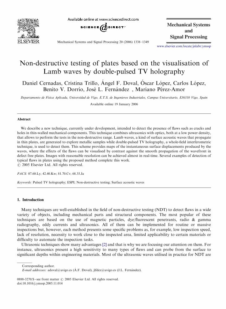
Non-destructive testing of plates based on the visualisation ofLamb waves by double-pulsed TV holography
Daniel Cernadas, Cristina Trillo, Angel F. Doval, Oscar Lopez, Carlos Lopez,Benito V. Dorrıo, Jose L. Fernandez�, Mariano Perez-Amor
Departamento de Fısica Aplicada, Universidad de Vigo, E.T.S. de Ingenieros Industriales, Campus Universitario, E36310 Vigo, Spain
Available online 19 January 2006
Abstract
We describe a new technique, currently under development, intended to detect the presence of flaws such as cracks and
holes in thin-walled mechanical components. This technique combines ultrasonics with optics, both at a low power density,
that allows to perform the tests in the non-destructive range. Lamb waves, a kind of surface acoustic waves that propagate
in thin plates, are generated to explore metallic samples while double-pulsed TV holography, a whole-field interferometric
technique, is used to detect them. This scheme provides maps of the instantaneous surface displacements produced by the
waves, where the effects of the flaws can be visualised by contrast against the smooth propagation of the wavefront in
defect free plates. Images with reasonable resolution can be achieved almost in real-time. Several examples of detection of
typical flaws in plates using the proposed method complete this work.
r 2005 Elsevier Ltd. All rights reserved.
PACS: 07.60.Ly; 42.40.Kw; 81.70.Cv; 68.35.Ja
Keywords: Pulsed TV holography; ESPI; Non-destructive testing; Surface acoustic waves
1. Introduction
Many techniques are well-established in the field of non-destructive testing (NDT) to detect flaws in a widevariety of objects, including mechanical parts and structural components. The most popular of thesetechniques are based on the use of magnetic particles, dye/fluorescent penetrants, radio & gammaradiography, eddy currents and ultrasonics. All of them can be implemented for routine or massiveinspections but, however, each method presents some specific problems as, for example, low inspection speed,lack of resolution, necessity to work close to the inspected area, limited applicability to certain materials ordifficulty to automate the inspection tasks.
Ultrasonic techniques show many advantages [2] and that is why we are focusing our attention on them. Forinstance, ultrasonics present a high sensitivity to many types of flaws and can probe from the surface tosignificant depths within engineering materials. Most of the ultrasonic waves utilised in practice for NDT are
e front matter r 2005 Elsevier Ltd. All rights reserved.
ssp.2005.11.014
ing author.
esses: [email protected] (A.F. Doval), [email protected] (J.L. Fernandez).
ARTICLE IN PRESSD. Cernadas et al. / Mechanical Systems and Signal Processing 20 (2006) 1338–1349 1339
the bulk acoustic waves (BAW). This kind of waves propagate within the volume of elastic bodies and they areclassified, in isotropic solids, as longitudinal (P waves) or transversal (S waves). Less usual but of increasingsignificance in NDT, are surface acoustic waves (SAW), which propagate as guided waves on the surfaces ofelastic solids [1]. Within this category, it is worth mentioning Rayleigh and Lamb waves; these last are used inthe technique herein presented.
The generation and detection of ultrasound is traditionally performed by means of piezoelectrictransducers. This technology offers a high sensitivity, flexibility in what regards the placement and shape ofthe transducers, a quite wide frequency range and the possibility to be incorporated in automatic NDTsystems. However, it also presents important drawbacks, namely: the need of mechanical contact or of acouplant, a limited lateral resolution, the measurements are single-channel (pointwise)—a detector array or amechanical scanning is needed to acquire information of the whole ultrasonic field—the phenomenon tomeasure can be altered due to the contact nature of the method, piezoelectric materials have strong limitationsto work in adverse environments—high temperature, corrosive or radioactive—the position of the transducersmay be critical for the detection of a given defect and, finally, it is not suited for inspecting parts whose surfacemust be kept clean and free of scratches, with complicated topography, difficult access—cavities, steppedsurfaces—or small-size.
There are a range of emerging NDT techniques that, combining the high degree of interaction with the flawsoffered by the ultrasonic waves with the true remote detection nature of the optical methods, can overcomesome of the above mentioned drawbacks. Probably the most popular of these new techniques is the so-called‘‘laser ultrasonics’’, in which the acoustic wave is generated by focusing a high-power laser beam on the objectsurface and subsequently detected with an optical interferometer focused on an adjacent area, which yields anoutput signal that is proportional to the instantaneous spatial average of the velocity or displacement over thisarea [5]. Both excitation and detection are, therefore, remote. Furthermore, since this is a single-channeldetection scheme, the acquisition and processing hardware is not shared with any other detection channelwhich results in a high bandwidth—i.e., a high temporal sampling rate—as well as a high frequency resolutionin the sampled signal spectrum. However, laser ultrasonics presents severe limitations to deal with inspectiontasks that involve to check for cracks or other flaws along a whole surface in a short time, being the usualsolution to perform a scanning over an array of different positions on the object surface repeating theexcitation-detection sequence.
A very interesting alternative to this approach is to arrange a number of detectors in parallel to obtain aninstantaneous map of the displacement field produced by the acoustic wave. When a high spatial resolution isnecessary, for example hundreds of samples along each direction on the surface, a practical solution is to use avideo camera to acquire the output intensity pattern produced by a whole-field optical technique which issensitive enough to record the small displacements associated to the wave fields. As these surfacedisplacements are typically of tens of nanometres or even smaller, very special devices and techniques arenecessary. To the best of our knowledge, to date only two whole-field optical techniques have allowed tovisualise such ultrasonic fields on non specular-finished surfaces, namely: holographic interferometry and TVholography.
Holographic interferometry (HI) techniques have been applied in two basic modes: continuous andtransient. In the continuous mode, a hologram recorded with the specimen at rest is then reconstructed whilean ultrasonic wave burst is periodically applied to the specimen at the same rate that a video camera integratesand reads the resulting interferograms (usually tens of milliseconds per frame). As the ultrasonic period istypically in the range of microseconds, stroboscopic illumination or detection must be used to avoid the timeaveraging of the signal within each frame. This approach has been successfully used to detect the displacementfields of Rayleigh waves in real time [11].
In the transient mode, on the other hand, the mechanical state of the specimen is frozen by pulsed laserillumination at two very close instants, generally separated by just a few microseconds, and recorded in thesame hologram. The relative displacement of each surface point between the two selected states is thenmeasured by reconstructing both together from the hologram. Some authors have used this method to detectRayleigh wave displacement fields [8]. The short acquisition time involved in the transient mode presentsseveral advantages with respect to the continuous one: a high immunity to environmental perturbations, avery fine temporal resolution, and the possibility to select the recorded states close enough to the starting time
ARTICLE IN PRESSD. Cernadas et al. / Mechanical Systems and Signal Processing 20 (2006) 1338–13491340
of the excitation to avoid the presence of waves reflected at the edges of the inspected part. This last advantageshould not be underestimated, as such reflected waves could interfere with the incident waves hiding the effectsproduced by the defects. Hence, operating in the transient mode makes unnecessary to arrange acousticabsorbers in the inspected part. On the other hand, the main hindrance of the transient mode is theexperimental complexity associated to the use of a pulsed laser and fast electronics.
Though their performances are remarkable, HI techniques need a photosensitive medium with high spatialresolution to record the holograms, and this fact limits their practical use mainly by economical reasons. Otherpotential disadvantages (not for all the HI technologies) are: the necessity of darkening the working place, theslow processes of developing and optical reconstruction, and the fragility of holographic equipment.
TV holography (TVH)—i.e., the family of techniques based on the recording of holograms with videocameras and their electronic, either analog or digital, processing [6]—, also called ESPI, has become anattractive alternative to HI since it can overcome some of the above cited limitations. There are alsocontinuous-stroboscopic and transient operation modes in TVH, as in HI, with the same respective principlesand advantages. However, TVH presents an intrinsic disadvantage with respect to HI, that is, there isresolvable speckle noise in the output images that degrades the sensitivity. The first results that have beenpublished concerning the detection of ultrasonic waves with TVH were, in our knowledge, limited to thestroboscopic mode, in which the averaging of the signal over an extended time interval allows to discriminatethe signal from the noise using standard experimental equipment [9].
We have recently developed a double-pulsed TVH technique to detect surface acoustic waves like Rayleighand Lamb waves [13], and shown some preliminary results that pointed out its applicability for non-destructive testing [4]. In this paper, we report a new technique to detect flaws in thin plates by combiningLamb wave excitation and the aforementioned TVH detection technique. We also present some interestingfringe patterns obtained with our system which show the propagation of these waves on aluminum plates aswell as scattering phenomena produced when a flaw is intercepted by the ultrasonic wavefront.
2. Principles of the technique
2.1. Characterisation of the ultrasonic wave field
Lamb waves are a particular class of SAW that propagate in plates limited by two stress-free parallelboundaries. We will restrict the theoretical treatment to plane plates and will suppose that the wavefronts aresufficiently smooth to neglect the variations along the coordinate perpendicular to the sagittal plane, which isthe plane perpendicular to the free boundaries that contains the propagation direction (this means to ignorediffraction effects). In these conditions, the displacements produced by the Lamb waves have components onlyin the sagittal plane, and the wave can be considered like a superposition of P and S waves guided by the plate.Except for very special values of the angles of incidence, each reflection of a P wave in the boundary generatestwo reflected waves, a P and a S ones, and the same is true for the reflection of S waves.
Let us define the axes x1 parallel to the propagation direction and x3 perpendicular to both free surfaces ofthe plate, it is possible to write the expressions of the displacements along these axes corresponding to a givenfamily of modes of Lamb waves as [10]
u1 ¼ ð{xC1 cos k3x3 � k3C2 cos k3x3Þ exp½{ðxx1 � oMtÞ� (1)
and
u3 ¼ ð�k3C1 sin k3x3 þ {xC2 sin k3x3Þ exp½{ðxx1 � oMtÞ�, (2)
where C1 and C2 are two complex constants, k � ðk1; k2; k3Þ and j � ðk1;k2;k3Þ are the wavevectorscorresponding to the longitudinal and transversal bulk elastic waves associated with these Lamb modes,respectively, x ¼ k1 ¼ k1 is the modulus of the wavevector associated to a given Lamb mode propagating inthe direction of x1, oM is the angular frequency of the mode, t is the time and { is the imaginary unit.
The modes given by (1) and (2) are called symmetrical modes, since u1ð�x3Þ ¼ u1ðx3Þ and u3ð�x3Þ ¼ �u3ðx3Þ
and, therefore, the displacement is symmetric with respect to the plane x3 ¼ 0.
ARTICLE IN PRESS
(a)
(b)
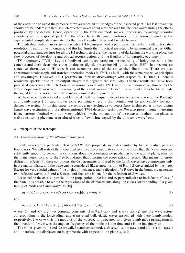
Fig. 1. Instantaneous displacements produced across the thickness of a plate by harmonic Lamb waves propagating from left to right: (a)
symmetrical mode, (b) antisymmetrical mode.
D. Cernadas et al. / Mechanical Systems and Signal Processing 20 (2006) 1338–1349 1341
It is also possible to demonstrate the existence of another class of modes, with the correspondingdisplacements along x1 and x3 given by
u1 ¼ ð{xD1 sin k3x3 � k3D2 sin k3x3Þ exp½{ðxx1 � oMtÞ� (3)
and
u3 ¼ ðk3D1 cos k3x3 � {xD2 cos k3x3Þ exp½{ðxx1 � oMtÞ�, (4)
where D1 and D2 are two complex constants. In these modes, the displacement verifies u1ð�x3Þ ¼ �u1ðx3Þ andu3ð�x3Þ ¼ u3ðx3Þ; thus, they are known as antisymmetrical Lamb modes.
These two classes of modes can propagate independently each from the other. Only a discrete number ofmodes exist for a given thickness of the plate and a given value of oM , and each one has its particular value ofx. This takes us to a relevant characteristic of Lamb waves: they are dispersive, i.e., their phase and groupvelocities depend on the angular frequencies of the modes that are present and on the thickness of the plate. InFig. 1(a) and (b), we illustrate the displacement produced across the section of the plate by the propagation ofharmonic symmetrical and antisymmetrical modes, respectively.
Lamb waves can be used in NDT to detect surface and subsurface flaws in materials by analysing thebehaviour of the waves scattered by these defects. But at present there does not exist any general theory ofsurface waves scattering and one has to resort to numerical simulations to understand the effects produced bythe flaws, habitually by using 2D models that give incomplete information. Furthermore, it would be useful tohave a mathematical model of inversion powerful enough to detect and characterise an unknown kind of flawfrom the measured scattering pattern. In any case, actual data from experiments are necessary to feedback thenumerical work. So, the proposed study requires a high degree of specialisation in several branches of scienceand technology, for which an interdisciplinary research team is desirable.
2.2. Generation of the Lamb wave fields
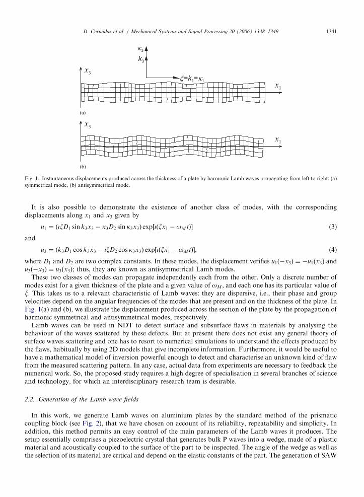
In this work, we generate Lamb waves on aluminium plates by the standard method of the prismaticcoupling block (see Fig. 2), that we have chosen on account of its reliability, repeatability and simplicity. Inaddition, this method permits an easy control of the main parameters of the Lamb waves it produces. Thesetup essentially comprises a piezoelectric crystal that generates bulk P waves into a wedge, made of a plasticmaterial and acoustically coupled to the surface of the part to be inspected. The angle of the wedge as well asthe selection of its material are critical and depend on the elastic constants of the part. The generation of SAW
ARTICLE IN PRESS
(a)
(b)
(c)
(d)
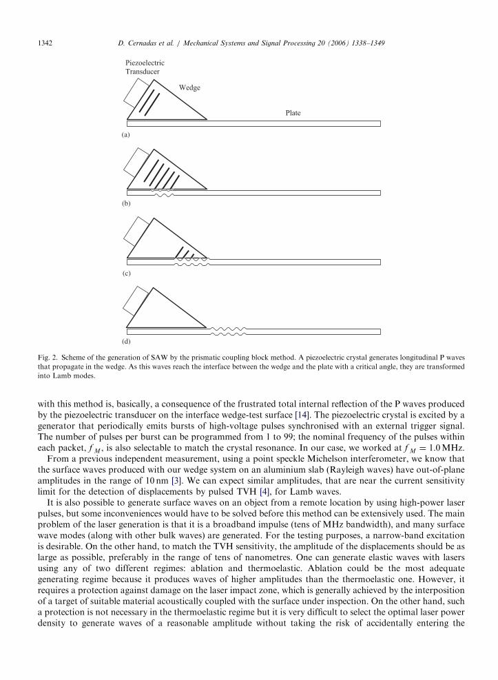
Fig. 2. Scheme of the generation of SAW by the prismatic coupling block method. A piezoelectric crystal generates longitudinal P waves
that propagate in the wedge. As this waves reach the interface between the wedge and the plate with a critical angle, they are transformed
into Lamb modes.
D. Cernadas et al. / Mechanical Systems and Signal Processing 20 (2006) 1338–13491342
with this method is, basically, a consequence of the frustrated total internal reflection of the P waves producedby the piezoelectric transducer on the interface wedge-test surface [14]. The piezoelectric crystal is excited by agenerator that periodically emits bursts of high-voltage pulses synchronised with an external trigger signal.The number of pulses per burst can be programmed from 1 to 99; the nominal frequency of the pulses withineach packet, f M , is also selectable to match the crystal resonance. In our case, we worked at f M ¼ 1:0MHz.
From a previous independent measurement, using a point speckle Michelson interferometer, we know thatthe surface waves produced with our wedge system on an aluminium slab (Rayleigh waves) have out-of-planeamplitudes in the range of 10 nm [3]. We can expect similar amplitudes, that are near the current sensitivitylimit for the detection of displacements by pulsed TVH [4], for Lamb waves.
It is also possible to generate surface waves on an object from a remote location by using high-power laserpulses, but some inconveniences would have to be solved before this method can be extensively used. The mainproblem of the laser generation is that it is a broadband impulse (tens of MHz bandwidth), and many surfacewave modes (along with other bulk waves) are generated. For the testing purposes, a narrow-band excitationis desirable. On the other hand, to match the TVH sensitivity, the amplitude of the displacements should be aslarge as possible, preferably in the range of tens of nanometres. One can generate elastic waves with lasersusing any of two different regimes: ablation and thermoelastic. Ablation could be the most adequategenerating regime because it produces waves of higher amplitudes than the thermoelastic one. However, itrequires a protection against damage on the laser impact zone, which is generally achieved by the interpositionof a target of suitable material acoustically coupled with the surface under inspection. On the other hand, sucha protection is not necessary in the thermoelastic regime but it is very difficult to select the optimal laser powerdensity to generate waves of a reasonable amplitude without taking the risk of accidentally entering the
ARTICLE IN PRESSD. Cernadas et al. / Mechanical Systems and Signal Processing 20 (2006) 1338–1349 1343
ablation mode and damaging the surface under test. These difficulties would have to be overcome before afully remote NDT tool based on our technique can be implemented; so, in this stage of development we havepreferred to use a well known and controllable Lamb wave generation technique.
2.3. Detection of the Lamb wave fields
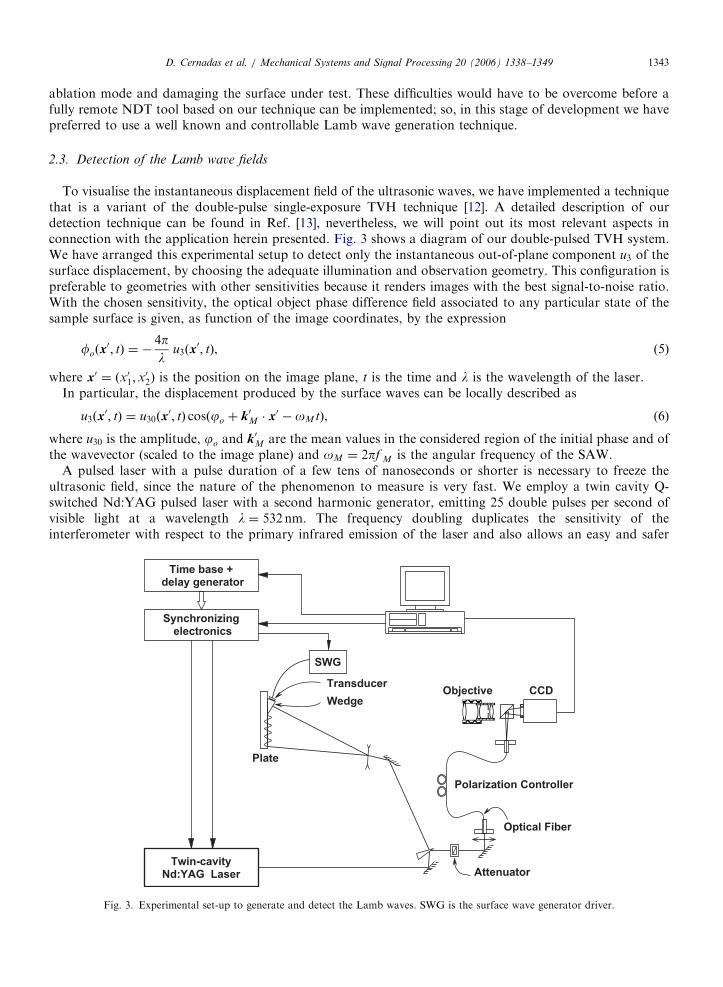
To visualise the instantaneous displacement field of the ultrasonic waves, we have implemented a techniquethat is a variant of the double-pulse single-exposure TVH technique [12]. A detailed description of ourdetection technique can be found in Ref. [13], nevertheless, we will point out its most relevant aspects inconnection with the application herein presented. Fig. 3 shows a diagram of our double-pulsed TVH system.We have arranged this experimental setup to detect only the instantaneous out-of-plane component u3 of thesurface displacement, by choosing the adequate illumination and observation geometry. This configuration ispreferable to geometries with other sensitivities because it renders images with the best signal-to-noise ratio.With the chosen sensitivity, the optical object phase difference field associated to any particular state of thesample surface is given, as function of the image coordinates, by the expression
foðx0; tÞ ¼ �
4pl
u3ðx0; tÞ, (5)
where x0 ¼ ðx01;x02Þ is the position on the image plane, t is the time and l is the wavelength of the laser.
In particular, the displacement produced by the surface waves can be locally described as
u3ðx0; tÞ ¼ u30ðx
0; tÞ cosðjo þ k0M � x0 � oMtÞ, (6)
where u30 is the amplitude, jo and k0M are the mean values in the considered region of the initial phase and ofthe wavevector (scaled to the image plane) and oM ¼ 2pf M is the angular frequency of the SAW.
A pulsed laser with a pulse duration of a few tens of nanoseconds or shorter is necessary to freeze theultrasonic field, since the nature of the phenomenon to measure is very fast. We employ a twin cavity Q-switched Nd:YAG pulsed laser with a second harmonic generator, emitting 25 double pulses per second ofvisible light at a wavelength l ¼ 532 nm. The frequency doubling duplicates the sensitivity of theinterferometer with respect to the primary infrared emission of the laser and also allows an easy and safer
Fig. 3. Experimental set-up to generate and detect the Lamb waves. SWG is the surface wave generator driver.
ARTICLE IN PRESSD. Cernadas et al. / Mechanical Systems and Signal Processing 20 (2006) 1338–13491344
alignment. The laser output is split into the reference and object beams; this last is expanded by a negative lensand illuminates the surface to be tested. The light scattered from it and the reference beam are coherentlysuperimposed by a beam combiner and imaged onto the photosensitive surface of a CCD camera. This is a fastprogressive scanning interline-transfer camera that can record two independent images, separated down to1ms from each other, with a full spatial resolution of 1280� 1024 pixels; it is also thermoelectrically cooledand digitizes the data with a resolution of 12 bits, therefore yielding a very low noise-floor. Two high-precisiondigital delay generators, supported with custom designed synchronisation electronics, control the triggering ofthe laser flash lamps and Q-switches, of the camera integration period and of the ultrasonic wave generator.
A key point of our technique is to record two primary correlograms, one for each laser light pulse, with avery short time lapse. Each primary correlogram stores information about the state of the dynamicdeformation of the observed surface at a given instant tn ðn ¼ 1; 2Þ, and they can be represented by [6]
In ¼ gIo½1þV cosðcp � fr;n þ fo;nÞ�, (7)
where In ¼ Inðx0Þ is the primary correlogram corresponding to the pulse of cavity n ðn ¼ 1; 2Þ, g ¼ gðlÞ is the
spectral sensitivity of the camera, Io ¼ Ioðx0Þ is the local central value of the intensity,V ¼Vðx0Þ is the local
visibility, cp ¼ cpðx0Þ is the random phase difference of the interfering speckle patterns, fr;n ¼ frðtnÞ is the
reference phase difference and fo;n ¼ foðx0; tnÞ is the object phase difference as defined in Eq. (5).
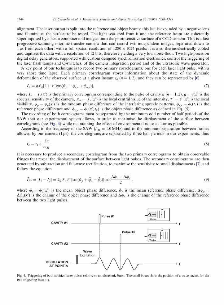
The recording of both correlograms must be separated by the minimum odd number of half periods of theSAW that our experimental system allows, in order to maximise the displacement of the surface betweencorrelograms (see Fig. 4) while maintaining the effect of environmental noise as low as possible.
According to the frequency of the SAW ðf M ¼ 1:0MHzÞ and to the minimum separation between framesallowed by our camera ð1msÞ, the correlograms are separated by three half periods in our experiments, thus
t2 ¼ t1 þ3poM
. (8)
It is necessary to produce a secondary correlogram from the two primary correlograms to obtain observablefringes that reveal the displacement of the surface between light pulses. The secondary correlograms are thengenerated by subtraction and full-wave rectification, to maximise the sensitivity to small displacements [7], andfollow the equation
~I fw ¼ jI1 � I2j ¼ 2gIoVj sinðcp þ fo � frÞj sinDfo � Dfr
2
��������, (9)
where fo ¼ foðx0Þ is the mean object phase difference, fr is the mean reference phase difference, Dfo ¼
Dfoðx0Þ is the change of the object phase difference and Dfr is the change of the reference phase difference
between the two light pulses.
Fig. 4. Triggering of both cavities’ laser pulses relative to an ultrasonic burst. The small boxes show the position of a wave packet for the
two triggering instants.
ARTICLE IN PRESSD. Cernadas et al. / Mechanical Systems and Signal Processing 20 (2006) 1338–1349 1345
Let us define the local average brightness as B ¼ h ~Iðx0Þi, with h�i the spatial average in the neighbourhood ofx0. The changes of B create a pattern of clear and dark fringes that can be easily noted in the display, and thatfor full-wave rectification has the expression
Bfw ¼4
pghIoVi sin
Dfo � Dfr
2
��������. (10)
By combining Eqs. (5), (6) and (8) and assuming that the amplitude of the SAW, u30, is constant in time, oneobtains that the local average brightness represents
Bfw ¼4
pghIoVi sin
4pl
u30ðx0Þ cos½jo þ k0M � x
0 � oMt1� þDfr
2
� ���������. (11)
If the TVH system is set slightly over the quadrature point by selecting a small positive value for Dfr, thusmaintaining the value of the argument of the sine function in (11) positive in every point [13], and u305l, thelocal average brightness can be approximated by
Bfw ffi B0 þ 16ghIoViu3ðx
0; t1Þ
l(12)
being B0 a constant. So, the local average brightness (i.e., grey level) Bfw of the output image is approximatelyproportional to the instantaneous ultrasonic displacement at each point.
3. Experimental results and discussion
The observation of the perturbations experienced by the fields of elastic deformation when the incidentwaves are scattered by the defects is, essentially, the operating principle of our flaw-detection scheme. It is,therefore, highly advisable to characterise the displacement fields on defect-free samples before proceedingwith the flaw-detection tests.
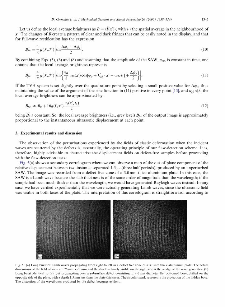
Fig. 5(a) shows a secondary correlogram where we can observe a map of the out-of-plane component of therelative displacement between two instants, separated 1:5ms (three half-periods), produced by an unperturbedSAW. The image was recorded from a defect free zone of a 3.0mm thick aluminium plate. In this case, theSAW is a Lamb wave because the slab thickness is of the same order of magnitude than the wavelength; if thesample had been much thicker than the wavelength, we would have generated Rayleigh waves instead. In anycase, we have verified experimentally that we were actually generating Lamb waves, since the ultrasonic fieldwas visible in both faces of the plate. The interpretation of this correlogram is straightforward: according to
Fig. 5. (a) Long burst of Lamb waves propagating from right to left in a defect free zone of a 3.0mm thick aluminium plate. The actual
dimensions of the field of view are 75mm� 61mm and the shadow barely visible on the right side is the wedge of the wave generator. (b)
Long burst identical to (a), but propagating over a subsurface defect consisting in a 6mm diameter flat bottomed bore, drilled on the
opposite side of the plate, with a depth 1.5mm less than the plate thickness. The circular mark represents the projection of the hidden bore.
The distortion of the wavefronts produced by the defect becomes evident.
ARTICLE IN PRESSD. Cernadas et al. / Mechanical Systems and Signal Processing 20 (2006) 1338–13491346
Eq. (12), the average grey level at each point is approximately proportional to the instantaneous absolute out-of-plane ultrasonic displacement at this point.
There is only a significant error in the zones corresponding to the first and last fringe of each burst, due tothe nonstationary nature of the measurand [13]. The number of pulses of the burst that can be seen in thefigure is long enough to cover the entire inspected area but, at the same time, the measurement has beensynchronised to be complete before the wavefront reaches the edges of the part, thus avoiding the occurrenceof undesired reflected waves that could interfere with the primary one.
In Fig. 5(b), on the other hand, we can see a secondary correlogram showing a long burst of Lambwaves that propagates on another zone of the same plate where a major defect is present: a 6mm diameter
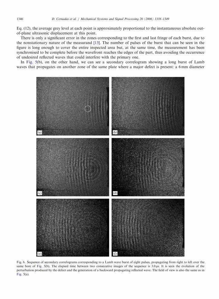
Fig. 6. Sequence of secondary correlograms corresponding to a Lamb wave burst of eight pulses, propagating from right to left over the
same bore of Fig. 5(b). The elapsed time between two consecutive images of the sequence is 3:0ms. It is seen the evolution of the
perturbation produced by the defect and the generation of a backward propagating reflected wave. The field of view is also the same as in
Fig. 5(a).
ARTICLE IN PRESSD. Cernadas et al. / Mechanical Systems and Signal Processing 20 (2006) 1338–1349 1347
flat-bottomed bore perpendicularly drilled from the opposite side to the observed surface and with a depth ofone half the thickness of the plate. Observing both images in this figure, it becomes apparent that the presenceof the bore produces noticeable effects in the fringes.
Fig. 6 presents a sequence of secondary correlograms taken at intervals of 3ms, which shows in detail theevolution of a short burst of Lamb waves comprising eight pulses that propagates on the same zone of theplate pictured in Fig. 5(b). In Fig. 6(a) we can see that the fringes still keeping their original curvature (concaveas seen from the source). Then in Fig. 6(b) the fringes begin to suffer a perturbation in their curvature in azone situated near the projection of the actual position of the bore. The further evolution of the perturbedfringes is shown in Figs. 6(c–f). Even the presence of a retro-reflected wave originated at the position of thebore is observable. From this analysis, it is evident that the possibility to select the number of pulses, accordingto a particular situation, provides this inspection method with a remarkable flexibility.
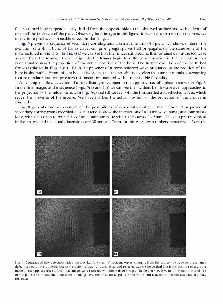
An example of flaw detection of a superficial groove open to the opposite face of a plate is shown in Fig. 7.In the first images of the sequence (Figs. 7(a) and (b)) we can see the incident Lamb wave as it approaches tothe projection of the hidden defect. In Fig. 7(c) and (d) we see both the transmitted and reflected waves, whichreveal the presence of the groove. We have marked the actual position of the projection of the groove inFig. 7(d).
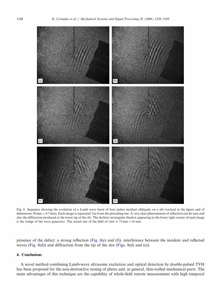
Fig. 8 presents another example of the possibilities of our double-pulsed TVH method. A sequence ofsecondary correlograms recorded at 3 ms intervals show the interaction of a Lamb wave burst, just four pulseslong, with a slit open to both sides of an aluminium plate with a thickness of 3.5mm. The slit appears verticalin the images and its actual dimensions are 30mm� 0:7mm. In this case, several phenomena result from the
Fig. 7. Sequence of flaw detection with a burst of Lamb waves. (a) Incident waves emerging from the source, (b) wavefront reaching a
defect located on the opposite face of the plate, (c) and (d) transmitted and reflected waves (the vertical line is the position of a groove
made on the opposite free surface). The images were recorded with intervals of 3:75ms. The field of view is 93mm� 74mm, the thickness
of the plate 3:5mm and the dimensions of the groove are: 36.8mm length, 0.7mm width and a depth of 0.6mm less than the plate
thickness.
ARTICLE IN PRESS
Fig. 8. Sequence showing the evolution of a Lamb wave burst of four pulses incident obliquely on a slit (vertical in the figure and of
dimensions 30mm� 0:7mmÞ. Each image is separated 3ms from the preceding one. A very clear phenomenon of reflection can be seen and
also the diffraction produced at the lower tip of the slit. The darkest rectangular shadow appearing in the lower right corner of each image
is the wedge of the wave generator. The actual size of the field of view is 75mm� 61mm.
D. Cernadas et al. / Mechanical Systems and Signal Processing 20 (2006) 1338–13491348
presence of the defect: a strong reflection (Fig. 8(e) and (f)), interference between the incident and reflectedwaves (Fig. 8(d)) and diffraction from the tip of the slot (Figs. 8(d) and (e)).
4. Conclusions
A novel method combining Lamb-wave ultrasonic excitation and optical detection by double-pulsed TVHhas been proposed for the non-destructive testing of plates and, in general, thin-walled mechanical parts. Themain advantages of this technique are the capability of whole-field remote measurement with high temporal
ARTICLE IN PRESSD. Cernadas et al. / Mechanical Systems and Signal Processing 20 (2006) 1338–1349 1349
resolution, almost real-time visualisation and, due to the short temporal gap between both exposures, highimmunity to environmental perturbations. Furthermore, the actual implementation of the technique renders agreat flexibility in the temporisation of the events: the triggering of the laser pulses—which establish the twomechanical states to be compared—and the generation of the ultrasonic wave, comprising the starting timeand the duration of the burst. This flexibility makes possible to inspect a wide area of the test piece before theultrasonic field undergoes reflections from the edges or discontinuities like rivets, steps, etc.
The results obtained to date show that this technique holds a great potential to detect different types offlaws and that it is suitable to be adapted for industrial inspection outside the laboratory.
Acknowledgements
The work herein reported was part of the research project TAP-99-1167-C03-01, kindly supported by theComision Interministerial de Ciencia y Tecnologıa. We also acknowledge the supplementary funding providedby the Universidad de Vigo (research project 64102I022).
References
[1] B.A. Auld, Acoustic Fields and Waves in Solids, Krieger, Malavar, FL, 1990.
[2] A.S. Birks, R.E. Green (Eds.), Nondestructive Testing Handbook, Volume Seven: Ultrasonics Testing, ASNT, 1991.
[3] D. Cernadas, C. Trillo, A.F. Doval, B.V. Dorrıo, C. Lopez, J.L. Fernandez, M. Perez-Amor, Rayleigh wave amplitude field
determination by a simple speckle point interferometer, in: P. Jacquot, J.-M. Fournier (Eds.), Interferometry in Speckle Light, Theory
and Applications, Proceedings of the International Conference, 25–28 September 2000, Lausanne, Switzerland, Springer, Berlin,
2000, pp. 297–304.
[4] D. Cernadas, C. Trillo, A.F. Doval, J.C. Lopez, B.V. Dorrıo, J.L. Fernandez, M. Perez-Amor, Non-destructive testing with surface
acoustic waves using double-pulse TV holography, Meas. Sci. Technol. 13 (2002) 438–444.
[5] R.J. Dewhurst, Q. Shan, Optical remote measurement of ultrasound, Meas. Sci. Technol. 10 (1999) 139–168.
[6] A.F. Doval, A systematic approach to TV holography, Meas. Sci. Technol. 11 (2000) R1–R36.
[7] A.F. Doval, C. Trillo, D. Cernadas, B.V. Dorrıo, C. Lopez, J.L. Fernandez, M. Perez-Amor, Enhancing the sensitivity to small phase
changes in double-exposure stroboscopic television holography, Appl. Opt. 39 (2000) 4582–4588.
[8] R.M. Gagosz, Pulsed holography, in: R.K. Erf (Ed.), Holographic Nondestructive Testing, Academic Press, Orlando, FL, 1974
(Chapter 3).
[9] T.D. Mast, G.A. Gordon, Quantitative flaw reconstruction from ultrasonic surface wavefields measured by electronic speckle pattern
interferometry, IEEE Trans. Ultrasonics, Ferroelectrics, Frequency Control 48 (2001) 432–444.
[10] D. Royer, E. Dieulesaint, Elastic Waves in Solids I. Free and Guided Propagation, Springer, Berlin, 2000.
[11] F.D. Schroeder, H.A. Crostack, Real-time holography of ultrasonic surface waves, Proc. SPIE 2782 (1996) 290–295.
[12] R. Spooren, Double-pulse subtraction TV holography, Opt. Eng. 31 (1992) 1000–1007.
[13] C. Trillo, D. Cernadas, A.F. Doval, C. Lopez, B.V. Dorrıo, J.L. Fernandez, Detection of transient surface acoustic waves of
nanometric amplitude with double-pulse TV holography, Appl. Opt. 42 (2003) 1228–1235.
[14] I.A. Viktorov, Rayleigh and Lamb Waves: Physical Theory and Applications, Plenum, New York, 1967.
Copyright © 2022 FDOKUMEN