NIGHT VISION GOGGLES
36
USER MANUAL PVS-7 NIGHT VISION GOGGLES
-
Upload
khangminh22 -
Category
Documents
-
view
1 -
download
0
Transcript of NIGHT VISION GOGGLES

USER MANUAL
PVS-7NIGHT VISION GOGGLES

© 2021 AGM Global Vision, LLC. All rights reserved.This documentation is subject to change without notice.No parts of this manual, in whole or in part, may be copied, photocopied, translated, or transmitted by any electronic medium or in machine-readable form without the prior written permission of AGM Global Vision, LLC.
If you have questions that are not covered in this manual, or need service, contact AGM Global Vision customer support for additional information prior to returning a product.
AGM Global Vision, LLC
173 West Main StreetPO Box 962Springerville, AZ 85938Tel. [email protected]
EXPORT INFORMATIONBuyer acknowledges that all products supplied by AGM Global Vision, LLC are subject to U.S. export control laws, including, but not limited to, the Export Administration Regulations, the International Economic Emergency Powers Act, and various U.S. embargoes and sanctions. AGM Global Vision products may not be exported, re-exported, or transferred contrary to U.S. export control laws. In particular, AGM Global Vision products may not be exported, re-exported, or transferred to prohibited countries, individuals, organizations, or entities, including but not limited to those individuals and entities listed on the List of Specially Designated Nationals and Blocked Persons administered or maintained by the U.S. Office of Foreign Assets Control (“OFAC”), the various lists maintained by the Bureau of Industry and Security of the Department of Commerce, and the U.S. State Department and Buyer represents and warrants that neither Buyer nor any of its officers, directors, or employees are on such lists. Distribution or resale by Buyer to such countries, individuals, organizations, or entities is expressly prohibited. Buyer has and will maintain a positive process to ensure compliance with this Section.
2021.03.16

3PVS-7 USER MANUAL
LIST OF CONTENTS
TITLE PAGE
Safety Summary 4SECTION 1. GENERAL INFORMATION 61.1 System Description 61.2 Operation Principles 61.3 Standard and Optional Equipment 8SECTION 2. OPERATING INSTRUCTIONS 102.1 Controls and Indicators 102.2 Assembly and Preparation for Use 122.3 Operating Procedures 20SECTION 3. MAINTENANCE AND TROUBLESHOOTING 263.1 Maintenance 263.2 Troubleshooting 28SECTION 4. WARRANTY INFORMATION 304.1 Warranty Information and Registration 30SECTION 5. SPECIFICATIONS 325.1 Specifications 34APPENDIX 34A. Spare Parts List 34
4 AGM Global Vision
SAFETY SUMMARY
• Read and follow all instructions• Read all warnings• Only use the attachments/accessories specified by the manufacturer• All service must be provided by the manufacturer
WARNING:
This product contains natural rubber latex, which may cause potentially fatal allergic reactions! If you are allergic to latex, it is important that you strictly avoid exposure to products that contain it.
WARNINGS:
The intensifier’s phosphor screen contains toxic materials. Please note:
• If the intensifier tube breaks, be extremely careful to avoid inhaling the phosphor screen material. DO NOT allow the material to come in contact with your mouth, eyes, or any open wounds on the skin.
• If the phosphor screen material comes in contact with your skin, wash it off immediately with soap and water.
• If you inhale or swallow any phosphor screen material, drink a lot of water, induce vomiting, and seek medical attention as soon as possible.
WARNINGS:
• When used in total darkness, the light from the unit’s infrared (IR) illuminator is invisible to the naked eye. However, the light can be detected by other Night Vision Devices (NVD).
• To reduce the risk of detection by another NVD, avoid prolonged use of the IR illuminator.
• Light from the IR illuminator is more easily detected by other NVDs when used in fog, smoke, and rain. Avoid prolonged use of the IR illuminator in these conditions.
• The compass illuminator is visible to other people using night vision devices.
• Do not use contaminated eye cups. If contaminated, they must be replaced.
• When installing the head mount over the protective mask, be careful not to break the seal of the protective mask around your face.

5PVS-7 USER MANUAL
CAUTION:
• The PVS-7 is a precision optical instrument. To prevent damage to the unit, it should be handled carefully at all times.
• To protect the device from damage, do not direct it at bright light sources such as street lights, headlights, lanterns, fire, etc.
• Do not test the device in daylight for more than ten (10) minutes, even with the daylight filter/lens cap on.
• To protect the image intensifier when using the device in daylight or when the device is not in use, keep the lens cap securely fitted over the objective lens.
• Use of rubber eye cups for extended periods of time may cause skin irritation or inflammation. If any symptoms develop, consult a doctor immediately.
• Do not scratch the external lens surfaces or touch them with your fingers.
NOTES:
To avoid physical danger to the user and damage to the equipment, you must read and understand the following equipment limitations.
• The unit is equipped with an Automatic Shut-off System. If the goggles are removed from the head or helmet while turned on, they will turn off automatically. To turn the unit on after automatic shut-off, you will need to rotate the knob to the OFF position first, and then return it to the ON position.
• The built-in IR illuminator is meant to provide additional illumination when needed, while viewing scenes at close distances (up to 3 meters).
• To operate properly, the equipment requires some ambient light in the environment (moonlight, starlight, etc.).
• Performance of the device in night-time conditions is dependent on the level of ambient light in the environment. Please remember:
– The level of ambient light in an area is reduced by the presence of clouds, shade, or objects that block natural light, such as trees, buildings, or large vehicles.
– The equipment is less effective when operated in shadows and other conditions where there is very little to no ambient light.
– The equipment is less effective when operated in smoke, dust, rain, fog, sleet, or snow.
– The equipment cannot “see” through dense smoke.

6 AGM Global Vision
1 GENERAL INFORMATION
1.1 SYSTEM DESCRIPTION
The PVS-7 is a handheld, head-mounted or helmet-mounted night vision system that enables mobility in moonlit or starlit conditions. This includes driving, use of weapons, short-range surveillance, map reading, vehicle maintenance, and administering first aid. Each unit is vertically and horizontally adjustable for sizing and comfort, and features objective lens focus, eyepiece focus, and eye relief distance adjustment. The goggles are also equipped with an infrared (IR) light-emitting diode (or illuminator) and a low battery LED indicator. The goggles automatically shut off when disconnected from the head mount or helmet mount, or when flipped up on the helmet mount. A bright light cutoff feature shuts off power to the goggles when they are exposed to excessive levels of light for more than 70 (±30) seconds.
1.2 OPERATION PRINCIPLES
1.2.1 MECHANICAL FUNCTIONS
The PVS-7 includes mechanical adjustments to accommodate physical differences between individual users. Functional features include the power switch, interpupillary adjustment, release latch, eye relief adjustment, diopter adjustment, IR spot/flood focus (optional), compass illumination (optional), and objective lens focus. The mechanical controls are identified in Figure 1-1.
INTERPUPILLARY ADJ.
EYE RELIEF
DIOPTER ADJ. RING
LATCH
RESET/OFF-ON-IR/PULL SWITH KNOB
IR SPOT/FLOOD FOCUS KNOB
COMPASS ILLUMINATION BUTTON (UNDERNEATH)
OBJECTIVE LENS FOCUS KNOB
LENS CAP
FIGURE 1-1. MECHANICAL FUNCTIONS FOR PVS-7

7PVS-7 USER MANUAL
1.2.2 OPTICAL FUNCTIONS
The optical functions include an objective lens, image intensifier, a collimator lens, and two eyepieces. The objective lens collects light reflected from the moon, stars, or other ambient light in the environment, and inverts and focuses an image of the scene onto the image intensifier. The image intensifier converts the captured light into a visible image, re-inverting it so that can be viewed though eyepiece lens.
1.2.3 ELECTRICAL FUNCTIONS
A. Power Source. The electronic circuit is powered by replaceable batteries; you have the option of using either a 3.0 Volt Lithium battery (BA-5567/U) or two AA 1.5 Volt Alkaline batteries (BA-3O5S/U).B. Power Switch. Power from the batteries is supplied to the components through the RESET/OFF-ON-IR/PULL switch as follows:
RESET/OFF Position. With the switch in the OFF position, the circuit will not supply energy to the image intensifier or the IR illuminator. You can also turn the switch to this position to reset your device after automatic shut-off or bright light cutoff.ON Position. Energy is drawn from the battery compartment to power the goggles. When the voltage drops to 2.4 VDC, a low battery indicator will begin to blink on the right side of the eyepiece, indicating approximately 30 minutes of remaining power.IR/PULL Position. Energy is drawn from the battery compartment to power the goggles and IR light source, and a steady red indicator light will appear in the left side region of the eyepiece. The IR can be activated momentarily by turning the switch ON without pulling the knob.
C. Automatic Shutoff. If the goggles are activated, removing it from the head mount or helmet mount will cause it to shut off automatically. This will eliminate the green glow produced by the image intensifier and prevent detection by other NVDs. To turn the goggles back on, flip the switch to RESET/OFF and then back to ON again.D. Bright Light Cutoff. The goggles will automatically shut off after 70 (±30) seconds of operation in daylight or bright room light. Individual bright lights (headlights, flashlights, or other concentrated light sources) will not activate this function, unless the high light detector on the front of the goggles is pointed directly at the light source. To turn the goggles back on in the event that this function is triggered, flip the switch to RESET/OFF and then back to ON again.
1.3 STANDARD AND OPTIONAL EQUIPMENT
A. PVS-7 Goggles Assembly. The goggles assembly consists of four primary subassemblies: (1) a simple objective lens; (2) a wired housing assembly; (3) an image intensifier tube (IIT) assembly (not shown); and (4) a rear cover assembly. The wired housing assembly contains a built-in battery compartment, attached battery cap, and the RESET/OFF-ON-IR/PULL switch.B. Head Mount Assembly. The adjustable, cushioned head mount assembly secures the goggles to the operator’s head, providing hands-free operation and allowing the use of weapons, protective masks, and other devices. The Large (thin) brow pad comes attached to the head mount and should be used by physically larger individuals; the Small (thick) and Medium brow pads are stored in the carrying case and may be more appropriate for users who are of small or average build.C. Carrying Case. The canvas carrying case is provided for the transportation, protection, and storage of the PVS-7, head mount assembly, batteries, and accessories. A carrying case strap is also included.

8 AGM Global Vision
D. Demist Shields. The two demist shields are used to prevent the eyepiece lenses from becoming fogged.E. Sacrificial Window. A replaceable sacrificial window is supplied to protect the objective lens during operation in adverse conditions.F. Neck Cord. This additional authorized item can be attached to the compass or 3x magnifier lens and worn by the operator to prevent them from dropping or losing these items.I. Optional Equipment. Optional equipment includes helmet mount assembly, 3x, 5x, and 8x magnifier lenses, IR spot/flood lens, compass, long-range infrared illuminator, and hard shipping/storage case. The PVS-7 standard components shown in Figure 1-2 and listed in Table 1-1.The ITEM column indicates the number used to identify items in Figure 1-2.
TABLE 1-1. PVS-7 STANDARD COMPONENTS
ITEM DESCRIPTION ITEM DESCRIPTION
1 PVS-7 Assembly 7 Demist Shield Assembly
2 Head mount Assembly 8 Sacrificial Window
3 Large Brow Pad 9 Neck Cord
4 Medium Brow Pad 10 User Manual
5 Small Brow Pad 11 Carrying Case
6 Shoulder Strap Assembly 12 Lens Paper (Not Shown)
FIGURE 1-2. PVS-7 STANDARD COMPONENTS
1 2
3
6
7 8 9
10
11
45

9PVS-7 USER MANUAL
The PVS-7 optional equipment is shown in Figure 1-3 and listed in Table 1-2.The ITEM column indicates the number used to identify items in Figure 1-3.The PART NO. column indicates the primary number used by the manufacturer to identify an item.The NSN column indicates the National Stock Number.
TABLE 1-2. PVS-7 OPTIONAL EQUIPMENT
ITEM DESCRIPTION PART NO. NSN
1 MICH Helmet Mount Assembly USA 6103MHM1
2 PASGT Helmet Mount Assembly USA 6103PHM1
3 3x Afocal Mil-Spec Lens 5855-01-423-0817
4 5x Afocal Mil-Spec Lens 5855-01-511-8594
5 Afocal Magnifier Lens Assembly, 3X 61023XA1
6 Afocal Magnifier Lens Assembly, 5X 61025XA1
7 8x Lens for PVS-7 61018XL1
8 IR Spot/Flood Lens 5855-01-382-5169
9 Magnetic Compass #110 5855-01-381-6052
10Sioux850 Long-Range Infrared Illuminator comes included with Rechargeable Battery and Charger
501SIOUX850IR1
11 Hard Case for Storage/Transportation 6610HCS1
FIGURE 1-3. PVS-7 OPTIONAL EQUIPMENT
1 2 3 6
7 8 9 1011
4 5

10 AGM Global Vision
2 OPERATING INSTRUCTIONS
2.1 CONTROLS AND INDICATORS
CAUTION:
The PVS-7 is a precision electro-optical instrument and must be handled carefully at all times.
The PVS-7 is adjustable to accommodate different users and will correct for most differences in eyesight. The controls and indicators for the PVS-7 are shown or described in Figure 2-1 and Table 2-1.
1
2
3
4
5 6
710
1211
FIGURE 2-1. PVS-7 CONTROLS

11PVS-7 USER MANUAL
TABLE 2-1. CONTROLS AND INDICATORS
ITEM CONTROLS AND INDICATORS FUNCTIONS
1 RESET/OFF-ON-IR/PULL
Controls goggles and IR light power ON or OFF.RESET/OFF: Same as system OFF. Also resets goggles after automatic shut-off or high light cutoff.ON: Goggles activated.IR/PULL: Pull switch out and turn clockwise to activate goggles and IR. Illuminates LED indicator in left eyepiece.
NOTES:
Some PVS-7’s contain an additional, momentary IR function. For momentary IR, continue to turn the switch knob clockwise, past the ON position and without pulling. The switch will return to the ON position when released.
2 RESET/OFF-ON-IR/PULL Label
Defines the switch positions.
3 IR Spot/Flood Lens Focuses the IR light for a narrow beam (spot) or wide angle beam (flood) illumination.
4 Compass Illuminator Button
Pressing this button activates the compass illuminator LED, which makes compass readings visible in the goggles’ viewing area. Additional pressure will make the image brighter. The image will disappear when the button is released.
5 Objective Focus Ring Focuses the objective lens. Adjusts for the sharpest image.
6 Battery/Polarity Indicator
The polarity icons are engraved into the PVS-7, and show the proper orientation of the batteries.
7 Latch The latch is used to separate the goggles’ assembly from the head mount/helmet mount’s assembly.
8 LED ON Indicator (Not Shown)
When illuminated (appears in the left eyepiece), this light indicates that the IR illumination is on.
9 Low Battery Indicator (Not Shown)
When illuminated (appears in the right eyepiece), this light indicates a low battery, with less than 30 minutes of power remaining.
10 Diopter Adjustment Ring
Focuses the eyepiece lens for each eye (user will not need glasses). Adjusts for sharper image on intensifier screen.
11 Interpupillary Adjustment
Adjusts the distance between each eyepiece by sliding them together or apart, allowing for each eye to observe the entire field at the same time.
12 Eye Relief Adjusts the distance between your eyes and the goggles.

12 AGM Global Vision
2.2 ASSEMBLY AND PREPARATION FOR USE
This chapter contains the necessary information to prepare the goggles for operation. This includes unpacking, inspections for damage and defects, battery installation, sacrificial window installation, and head mount installation and adjustments.
2.2.1 UNPACKING
The following steps must be done before each mission.1. Open the carrying case (Figure 1-2), remove the PVS-7, and inventory all items.2. Inspect the goggles for obvious evidence of damage to the optical surfaces, body, eyecups,
RESET/OFF-ON-IR/PULL switch, battery cap, etc. Ensure that all optical surfaces are clean and ready for use. If necessary, clean with lens paper.
2.2.2 INSTALLATION OF BATTERIES
CAUTION:
To protect the image intensifier, keep the lens cap securely fitted over the objective lens when the goggles are not being used or when performing daylight checks.
WARNING:
The Lithium battery contains sulphur dioxide gas, which is under pressure. Do not heat, puncture, disassemble, short circuit, attempt to recharge, or otherwise tamper with the batteries.If the battery compartment becomes excessively hot, turn off the equipment. If possible, wait until the batteries have cooled before removing them.These types of batteries have safety vents to prevent explosion. When they are venting gas, they release a very potent smell, and you may hear the sound of gas escaping. When the safety vents have worked correctly, the risk of explosion is significantly reduced. However, the batteries must still be handled with extreme care due to high heat and remaining risk.If you inhale sulphur dioxide, seek medical attention immediately.The PVS-7 can be powered with either of the two battery types identified in Table 5-2. Batteries are not supplied with the PVS-7 and must be purchased by the user.
TABLE 2-2. ESTIMATED BATTERY LIFE
BATTERY TYPE NEGLIGIBLE IR USAGE IR USAGE 10% OF THE TIME
Lithium (BA-5567/U) 22 Hours 20 Hours
AA Alkaline (BA-3058/U) 60 Hours 55 Hours
NOTE:
The battery data in Table 2-2 represents operation at room temperature. When operating in colder conditions, the battery life will decrease.

13PVS-7 USER MANUAL
CAUTION:
– Always verify that the RESET/OFF-ON IR/PULL SWITCH is in the OFF position before installing the batteries.
– Do not mix battery types in the compartment (e.g., one Alkaline and one Lithium).
To install either two (2) AA batteries or one (1) BA-5567/U Lithium battery: 1. Turn the battery cap counterclockwise and remove it.2. Verify that the O-ring is present. If it’s not, replace it.3. Following the polarity markings on the outside of the battery compartment, insert either two AA
(1.5 V) batteries or one BA-5567/U Lithium (3.0 V) battery into the battery compartment, positive (+) end first (see Figure 2-2).
4. Secure the battery cap back on by placing it over the compartment and turning it clockwise. Verify that it is secure to ensure a watertight seal.
2.2.3 INSTALLATION OF THE EYECUPS
To install the eyecups (refer to Figure 2-2):1. Carefully press each eyecup over the diopter cell retainer.2. Rotate each eyecup into the proper viewing position. Adjust for the best fit. The eyecups must
seal around your eyes and prevent the green light from showing outside of the eyepieces.
2.2.4 INSTALLATION OF THE DEMIST SHIELDS
To install the demist shields on the diopter lenses (refer to Figure 2-3):
CAUTION:
If the demisting shields need to be cleaned, make sure the shields are dry and only use dry lens paper. If the demist shields are wiped while wet or with wet lens paper, you will damage the coating.
ALKALINEBATTERIES
(SIZE AA)
BATTERY CUP WITH O-RING
LITHIUM BATTERY (BA-5567/U )
EYECUP
FIGURE 2-2. BATTERY AND EYE CAP INSTALLATION

14 AGM Global Vision
NOTE:
If you are aware that inclement weather (e.g. significant temperature changes or high humidity) could occur while using the PVS-7, install the demist shields before operation in order to minimize diopter lens fog.
1. Carefully remove the eyecups.2. Carefully press a demist shield onto each eyepiece. Be careful not to smudge the eyepieces or
demist shields.3. Replace the eyecups (see Paragraph 2.2.3).
2.2.5 INSTALLATION OF THE SACRIFICIAL WINDOW
To install the sacrificial window (refer to Figure 2-3):
CAUTION:
If you will be using the PVS-7 in dusty or sandy environments, attach the sacrificial window to protect the objective lens from scratches or other damage.
1. If the compass assembly or lens cap is in place, remove it.2. Carefully push the sacrificial window over the objective lens until it stops. Turn the sacrificial
window clockwise until it snaps into place.
2.2.6 INSTALLATION OF THE COMPASS ASSEMBLY
CAUTION:
– Use of the compass with a plastic head mount or plastic helmet mount will result in inaccurate compass readings. The magnet cannot be removed from these mounts.
– The magnet must be removed from the ruggedized metal helmet mount before installation of the compass. Failure to do so will result in inaccurate compass readings.
– If the magnet is not removed, you will need to contact Customer Support to have it removed.
SACRIFICIALWINDOW
DEMISTSHIELDS
FIGURE 2-3. INSTALLATION OF DEMIST SHIELDS AND SACRIFICIAL WINDOW

15PVS-7 USER MANUAL
NOTES:
Prepare the PVS-7 for operation.Ensure the neck cord is secured to the compass and clothing before installing.
1. If the sacrificial window or lens cap is in place, remove it.2. Turn the PVS-7 on.3. While looking through the goggles, rotate the objective lens focus completely counterclockwise.
NOTE:
For the compass to fit properly, the O-ring must be in place in the compass assembly.
4. Press the compass assembly onto the objective lens at an angle. Slowly turn the compass assembly counterclockwise until it is in the vertical position (with the compass illumination button pointing down). See Figure 2-4.
5. Ensure that the compass attaches securely to the PVS-7.6. Refer to Paragraph 2.3.4 for information on compass operation.
2.2.7 INSTALLATION OF THE IR SPOT/FLOOD LENS
Press the IR spot/flood lens over the IR source until it is tight against the goggles. Refer to Figure 2-5.
FIGURE 2-4. INSTALLATION OF COMPASS
FIGURE 2-5. INSTALLATION OF THE IR SPOT/FLOOD LENS

16 AGM Global Vision
2.2.8 INSTALLATION AND ADJUSTMENT OF THE HEAD MOUNT ASSEMBLY
NOTE:
Do not put the head mount on while the PVS-7 is attached to it.
To install the head mount assembly and adjust it for the operator:1. Before putting the head mount on, loosen the four chin straps so the ends of each strap are
approximately two inches from the sliding bar buckles (see Figure 2-6).2. Snap the front and rear snaps into place.
NOTE:
If the head mount is too loose, remove the (attached) thin brow pad and replace it with either the medium or large brow pad (both are stored in the carrying case). Refer to Paragraph 3.1.2 for brow pad removal and replacement instructions.
3. With both hands, grasp the neck pad assembly. Pull the harness over your head and the neck pad down to the back of your neck.
4. While holding the chin cup in position on your chin, adjust both rear chin cup assembly straps until you feel light pressure against your chin. (DO NOT TIGHTEN).
5. Maintain the position of the chin cup and remove any slack from the front and rear chin straps (DO NOT TIGHTEN).
6. Ensure that the cross-strap assembly is not twisted and remove any slack by adjusting the vertical adjustment strap on the neck pad.
7. Adjust the chin strap and vertical adjustment until the chin cup and headband assembly fit firmly but comfortably.
NOTE:
After installing the PVS-7, minor strap adjustments may be necessary to achieve the ideal fit.
SOCKET RELEASE BUTTON (EYE RELIEF ADJUSTMENT)
CHIN CUP
HEADBAND
SLIDING BAR BUCKLES
CHIN STRAP ADJUSTMENT
AND SNAP
NECK PAD
HEAD MOUNT SOCKET
CROSS-STRAPBROWPAD
VERTICAL ADJUSTMENT
(HIDDEN)
FIGURE 2-6. PVS-7 HEAD MOUNT ADJUSTMENTS
17PVS-7 USER MANUAL
2.2.9 INSTALLATION OF THE HEAD MOUNT ASSEMBLY WITH A PROTECTIVE MASK
To use the head mount with a protective mask:1. Place protective mask on your head per the provided mask.
WARNING:
When installing the head mount over the protective mask, be careful not to break the protective mask seal around your face.
2. To install the head mount assembly, see the instructions in Paragraph 2.2.8.
NOTE:
It may be necessary to remove the brow pad when wearing the head mount over a protective mask.
2.2.10 INSTALLATION OF THE HEAD MOUNT ASSEMBLY WITH A HELMET
Install the head mount assembly per the instructions in Paragraph 2.2.8. The helmet is worn over the head mount.
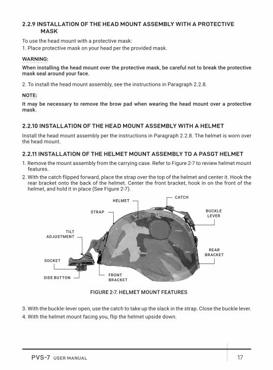
2.2.11 INSTALLATION OF THE HELMET MOUNT ASSEMBLY TO A PASGT HELMET
1. Remove the mount assembly from the carrying case. Refer to Figure 2-7 to review helmet mount features.
2. With the catch flipped forward, place the strap over the top of the helmet and center it. Hook the rear bracket onto the back of the helmet. Center the front bracket, hook in on the front of the helmet, and hold it in place (See Figure 2-7).
3. With the buckle-lever open, use the catch to take up the slack in the strap. Close the buckle lever. 4. With the helmet mount facing you, flip the helmet upside down.
FRONT BRACKET
REAR BRACKET
SOCKET
SIDE BUTTON
TILTADJUSTMENT
STRAP
HELMETCATCH
BUCKLELEVER
FIGURE 2-7. HELMET MOUNT FEATURES

18 AGM Global Vision
NOTE:
Steps 5 and 6 describe how to connect the neck strap to the chin strap. In order to do this, it may be necessary to unthread the chin strap from the helmet.
5. Thread the chin strap through the right end of neck strap and close the neck strap fastener (refer to Figure 2-8).
6. Thread the chin strap through the left end of the neck strap and close the neck strap fastener (refer to Figure 2-8).
7. Unfasten the neck strap latch on the left side of the neck strap.8. Put the helmet on.9. Fasten the neck strap with the neck strap latch. Tighten the chin strap and neck strap until they
fit securely. The brow of the helmet should be parallel to the ground.
2.2.12 INSTALLATION OF THE QUICK DISCONNECT HELMET MOUNT ASSEMBLY
1. Remove the helmet mount assembly from the carrying case. Make sure the helmet mount is complete. See Figure 2-9 for helmet mount components and features.
2. If the mount assembly and clip/strap assembly are connected, remove the mount assembly. To do this, push the release lever at the top center of the mount and slide the two assemblies apart.
3. Adjust the clip/strap assembly to fit the appropriate helmet size.4. With the catch fully extended, place the strap over the top of the helmet, center it, and hook the
rear bracket onto the back of the helmet. Center the front bracket hook on the front of the helmet and hold it in place.
5. With the buckle lever open, use the catch to tighten the strap to remove the slack in the clip/strap assembly. Close the buckle lever.
6. If the PASGT helmet has its cloth cover and camouflage strap installed, it will be necessary to slide the camouflage strap up (at an approximately 30°-45° angle) at the front of the helmet.
7. Unfasten the neck strap latch on the left side of the neck strap.8. Put the helmet on. Do not fasten the helmet chin strap.
NAPE STRAP FASTENER TABS
NAPE STRAPS
CHIN STRAP
Loop the nape strap fastener tabs around the corners of the chin strap and snap closed. After closure, the snaps will be on the outside, away from your chin.
FIGURE 2-8. NAPE STRAP INSTALLATION
SOCKET
TILT ADJUSTMENT
MOUNTING CLIP
HELMET
RELEASE LEVER
FIGURE 2-9. QUICK DISCONNECT HELMET MOUNT FEATURES

19PVS-7 USER MANUAL
9. Fasten the neck strap using the neck strap latch. Tighten the neck strap until it fits securely, then install and tighten the helmet chin strap. The brow of the helmet should be parallel to the ground and the helmet should be stable on the head.
10. To install the mount assembly into the clip/strap assembly, slide its top flange into the top groove of the mounting clip. Push the bottom of the mount assembly until it locks into place (you should hear an audible click).
CAUTION:
To prevent possible equipment damage, remove both the goggles and the mount assembly from the helmet when not required for immediate use. The clip/strap assembly can remain in place on the helmet.
2.2.13 INSTALLATION OF THE MAGNIFIER LENS ASSEMBLY
1. If the sacrificial window or lens cap is in place, remove it.2. The magnifier can be threaded directly into the objective lens. It can also be threaded into the
focus ring adapter and slipped on over the end of the objective lens.
2.2.14 MOUNTING LONG-RANGE IR ILLUMINATOR
To mount an IR illuminator to the PVS-7, use the Adapter. Refer to Figure 2-11 and complete the following steps:1. Loosen the adapter’s clamp screws.2. Put the adapter onto the objective lens.
FIGURE 2-10. PVS-7 WITH MAGNIFIER LENS ASSEMBLY INSTALLED
NOTE:
Steps 5 and 6 describe how to connect the neck strap to the chin strap. In order to do this, it may be necessary to unthread the chin strap from the helmet.
5. Thread the chin strap through the right end of neck strap and close the neck strap fastener (refer to Figure 2-8).
6. Thread the chin strap through the left end of the neck strap and close the neck strap fastener (refer to Figure 2-8).
7. Unfasten the neck strap latch on the left side of the neck strap.8. Put the helmet on.9. Fasten the neck strap with the neck strap latch. Tighten the chin strap and neck strap until they
fit securely. The brow of the helmet should be parallel to the ground.
2.2.12 INSTALLATION OF THE QUICK DISCONNECT HELMET MOUNT ASSEMBLY
1. Remove the helmet mount assembly from the carrying case. Make sure the helmet mount is complete. See Figure 2-9 for helmet mount components and features.
2. If the mount assembly and clip/strap assembly are connected, remove the mount assembly. To do this, push the release lever at the top center of the mount and slide the two assemblies apart.
3. Adjust the clip/strap assembly to fit the appropriate helmet size.4. With the catch fully extended, place the strap over the top of the helmet, center it, and hook the
rear bracket onto the back of the helmet. Center the front bracket hook on the front of the helmet and hold it in place.
5. With the buckle lever open, use the catch to tighten the strap to remove the slack in the clip/strap assembly. Close the buckle lever.
6. If the PASGT helmet has its cloth cover and camouflage strap installed, it will be necessary to slide the camouflage strap up (at an approximately 30°-45° angle) at the front of the helmet.
7. Unfasten the neck strap latch on the left side of the neck strap.8. Put the helmet on. Do not fasten the helmet chin strap.
NAPE STRAP FASTENER TABS
NAPE STRAPS
CHIN STRAP
Loop the nape strap fastener tabs around the corners of the chin strap and snap closed. After closure, the snaps will be on the outside, away from your chin.
FIGURE 2-8. NAPE STRAP INSTALLATION
SOCKET
TILT ADJUSTMENT
MOUNTING CLIP
HELMET
RELEASE LEVER
FIGURE 2-9. QUICK DISCONNECT HELMET MOUNT FEATURES

20 AGM Global Vision
3. Tighten the screws to secure the adapter.4. Loosen the screw on the IR illuminator.5. Mount the IR illuminator on the rail of adapter and tighten the screw.
2.3 OPERATING PROCEDURES
This chapter contains operational procedures for using the PVS-7 in various modes, including handheld, head-mounted, and helmet-mounted. Prior to using the goggles, ensure that all steps in Chapter 2.2 have been completed.
2.3.1 HEAD-MOUNTED OPERATION
Perform the following procedures for head-mounted operation.
CAUTION:
Only operate the PVS-7 in dark environments. If you must operate the device in daylight, always use the lens cap to cover the objective lens.
NOTE:
Proper objective focus cannot be achieved while the objective lens cap is covering the objective lens. Objective focus must be done in the dark with the objective lens cover removed.
1. Ensure that the batteries are installed per Paragraph 2.2.2.2. Wear the head mount per the instructions in Paragraph 2.2.8.
NOTE:
Paragraphs 2.2.9 and 2.2.10 provide additional information that is required to install the head mount with a protective mask or helmet.
Before attaching the goggles to the helmet, and to make it easier to align the eyecups and diopter eyepieces with your eyes, press down on the socket-release button (Figure 2-6) and slide the head mount socket completely forward.3. Align the PVS-7‘s latch (Figure 2-1) to the head mount socket (See Figure 2-6). Hold the latch
lever down and install the goggles onto the socket of the head mount. Once the goggles are fully installed, release the latch.
FIGURE 2-11. LONG-RANGE IR ILLUMINATOR
ADAPTER CLAMP SCREW
RAIL
IR ILLUMINATOR

21PVS-7 USER MANUAL
4. For maximum eye comfort, press the socket release button and move the PVS-7 backwards until the eyecups seal comfortably around your eyes.
5. Turn the RESET/OFF-ON-IR/PULL switch ON.6. Adjust the interpupillary distance (Figure 2-1) by sliding the eyepieces together or apart so each
eye can observe the entire field of view at the same time. The eyepieces adjust independently.7. To adjust the head mount vertically, tighten/loosen the vertical strap assembly (Figure 2-6). The
PVS-7 should be properly aligned with your eyes.8. Fold the right eyecup over the eyepiece with your right thumb or forefinger to obstruct the view
through the right eyepiece. Rotate the left diopter adjustment ring until you observe the clearest possible view through the image intensifier screen.
9. Repeat step 8 for the left eyecup.10. Adjust the eye relief distance by pressing the socket release button (Figure 2-6) and sliding the
PVS-7 forward and backward until you can observe the full field of view. Adjust the diopter rings for the sharpest, clearest image.
NOTE:
Any changes to maximize eye relief will require readjustment of the diopter rings.
11. While viewing an object with the device, adjust the objective lens focus (Figure 2-1) until the image becomes sharp and clear.
NOTE:
The sharpest image can only be viewed when the objective lens and both eyepieces are properly focused. The objective lens focus adjustment is used to focus on objects at varying distances. The diopter adjustment rings are used to focus your eyesight (without glasses) on the image intensifier screen. These adjustments operate independently and must be made separately.
2.3.2 HELMET-MOUNTED OPERATION
Perform the following procedures for using the device while mounted on a helmet.1. Confirm proper installation of the batteries (Paragraph 2.2.2).2. Put the helmet mount on per the instructions in Paragraph 2.2.11.3. Place the PVS-7 in the socket of the helmet mount (Figure 2-7). To set your eye relief focus, press
the side buttons and carefully move the goggles forward or backward until the eyecups are comfortably sealed around the eyes. Readjust the helmet straps as required.
4. Turn the power switch ON. Adjust the tilt by using the tilt adjustment knob (Figure 2-7) until you reach a comfortable viewing angle.
5. Adjust the interpupillary distance (Figure 2-1) by sliding the eyepieces together or apart so that each eye can observe the entire field of view at the same time. The eyepieces adjust independently. If necessary, adjust the eye relief.
6. Fold the right eyecup over the eyepiece with your right thumb or forefinger to obstruct the view through the right eyepiece. Rotate the left diopter adjustment ring until you observe the clearest view possible through the image intensifier screen.
7. Repeat step 6 for the left eye.8. To adjust the eye relief distance, press the socket side button (Figure 2-7) and slide the PVS-7
forward or backward until you are able to observe the full field of view. Adjust the diopter rings for the clearest image.

22 AGM Global Vision
NOTE:
Any changes to maximize eye relief will require readjustment of the diopter rings.
9. While looking through the device, adjust the objective lens focus until the image becomes clear and sharp.
NOTE:
The sharpest image will only be observed if the objective lens and both eyepieces are properly focused. The objective focus adjustment is used to focus on objects at varying distances. The diopter adjustment rings are used to focus your eyesight (with or without glasses) through the image intensifier screen. These adjustments operate independently and must be made separately.
10. To flip the device up, place your hand under the goggles. Grasp and rotate them up and backwards until the latch clicks into place.
NOTE:
The PVS-7 will turn off automatically when flipped up; however, it will not turn on automatically when flipped back down. You will need to turn it on manually.
11. To flip the device down, grasp the goggles and rotate them down and forwards until the latch clicks into place (Figure 2-12).
12. To resume operation, turn the switch to the RESET/OFF position, then to the ON position.
2.3.3 HANDHELD OPERATION
CAUTION:
Only operate the PVS-7 in dark environments. If you need to operate the device in daylight, always use the lens cap to cover the objective lens.
NOTE:
When using the PVS-7 without a mounting device, always use the neck cord.
1. Verify that the batteries are properly installed (Paragraph 2.2.2).2. Turn the RESET/OFF-ON-IR/PULL switch ON.
FIGURE 2-12. FLIP-UP HELMET MOUNT

23PVS-7 USER MANUAL
3. Adjust the interpupillary distance (Figure 2-1) by sliding the eyepieces together or apart so that each eye can observe the entire field of view at the same time. The eyepieces adjust independently.
4. Hold the PVS-7 with your left hand and fold the left eyecup over the eyepiece with your left thumb or forefinger to obstruct the view through the left eyepiece. Rotate the right diopter adjustment ring until you are able to observe the clearest possible view through the image intensifier screen.
5. Repeat step 4 for the right eye6. While looking through the device, adjust the objective lens until the image becomes clear and
sharp.
2.3.4 OPERATION WITH COMPASS ASSEMBLY
NOTE:
The objective lens focus can be fine-tuned after installation. Note that, in order to obtain an accurate reading, the compass must be vertical and the compass image must be level.
1. Install per Paragraph 2.2.6.2. For a clearer view of objects at a distance, adjust the objective focus by turning the compass
clockwise.3. To view the compass through the PVS-7, grip the compass with your index finger on top and your
thumb on the illumination button on the bottom (Figure 2-4). Gently press the button with your thumb until the proper brightness is reached. The image should appear as shown in Figure 2-13.
NOTE:
Increase the brightness slowly. If brightness is increased too quickly, the excessive brightness may burn a temporary image into the image intensifier. The goggles must be focused at or near infinity for proper compass operation.
4. The compass readings should change when you move your head from side to side. Rotate or tap the compass slightly to ensure that it is operating correctly. Hold the PVS-7 in a level position to verify live rotation of the compass scale.
WARNING:
The compass illuminator can be seen by other night vision devices.
FIGURE 2-13. VIEW THROUGH INSTALLED COMPASS

24 AGM Global Vision
NOTE:
The compass reading is magnetic North, not true North. The compass reading is within 2° of correct absolute magnetic bearing. Compass readings with a mounted PVS-7 (head mount or helmet mount) can be up to ±15° of correct absolute magnetic bearing. This occurs most in East (90°) to West (270°) readings, and less in North (0°) to South (360°) readings. If the compass is inadvertently magnetized, this could cause an additional 15° error.
5. The tick mark closest to the center of the lighted display is the compass bearing. The tick marks are in degrees, with longer marks every five (5) degrees and bearing labels every ten (10) degrees.
2.3.5 USE OF THE 3X OR 5X MAGNIFIER LENS ASSEMBLY
When the sacrificial window is removed, the 3x or 5x magnifier lens assembly can be threaded directly into the 1x objective lens.
NOTE:
The neck cord can be used to tether the magnifier to the operator and prevent damage, loss, or misplacement of the device. To use the neck cord, tie the end without the clip tightly around the magnifier. Attach the clip to your collar, belt loop, etc.
2.3.6 INFRARED (IR) OPERATIONS
WARNING:
In extreme darkness, light from the IR illuminator is invisible to the naked eye. However, it can be detected by other night vision devices.
1. Pull the RESET/OFF-ON-IR/PULL switch knob (Figure 2-1) out and rotate it clockwise to the IR position. While looking through the PVS-7, check that a red light appears in the left eyepiece. This indicates that the IR illuminator is operating. When the “momentary IR” feature is used, this light should only flash on briefly.
2. To Operate with the IR Spot/Flood Lens: Pull the RESET/OFF-ON-IR/PULL switch knob out and rotate it clockwise to the IR position. While looking through the PVS-7, turn the IR spot/flood until the area you want to view is fully, properly illuminated. Turn the RESET/OFF-ON-IR/PULL switch counterclockwise to the ON position. Check that the red indicator light disappears.
2.3.7 PREPARATION FOR STORAGE
A. Shut down. To shut down the PVS-7: 1. Turn the RESET/OFF-ON-IR/PULL switch OFF.2. Remove the PVS-7 from the head mount or helmet mount (if applicable) by pressing down on the
latch lever (Figure 2-1) and removing the PVS-7 from the socket.B. Packaging After Use.1. Unscrew the battery cap and remove the battery or batteries.2. Inspect the battery compartment for corrosion or moisture. Clean and dry if necessary.3. Replace the battery cap.

25PVS-7 USER MANUAL
4. Remove the demist shields, sacrificial window, or compass assembly if installed. Replace the lens cap.
NOTE:
Prior to placing the PVS-7 and its accessories into the carrying case, ensure that the goggles and case are free of dirt, dust, and moisture.
5. Place the manual, carrying case strap, lens paper, demist shields, batteries, sacrificial window, brow pads, and head mount into the carrying case.
6. With the objective lens facing downward, place the PVS-7 into the shallow pocket of the carrying case.

26 AGM Global Vision
3 MAINTENANCE AND TROUBLESHOOTING
3.1 MAINTENANCE
3.1.1 CLEANING
CAUTION:
• The PVS-7 is a precision electro-optical instrument and must be handled carefully. • Do not scratch the external lens surfaces or touch them with your fingers.• Wiping demist shields while wet, or with wet lens paper, can damage the coating.
If necessary, clean the goggles with water and dry them thoroughly. Clean the lenses with lens paper (and water if necessary, except for demist shields).Demist shields must be dry before being cleaned with dry lens paper.
3.1.2 HEAD MOUNT MAINTENANCE
A. Brow Pad Replacement. Replace the brow pad when cracked, torn, or contaminated. To remove and replace the brow pads:
CAUTION:
To protect the image intensifier, disconnect the PVS-7 from the head mount prior to replacing the brow pads.
1. Grasp the head mount firmly and remove the old brow pad.2. Gently press the new brow pad on. Smooth out any wrinkles in the new brow pad.B. Neck Pad Installation. The neck pad may become separated from the headband. To reattach the neck pad:1. Lift the upper headband strap retention tab (see Figure 3-1). This will allow you to insert the neck
pad strap underneath.2. Slip the neck pad strap all the way under the upper strap retention tab. Pull the lower part of the
neck pad strap under the lower strap retention.3. If necessary, repeat steps 1 and 2 for the other side of the headband and neck pad.

27PVS-7 USER MANUAL
C. Lacing the Sliding Bar Buckles. While putting on and adjusting the head mount, the straps may slip out of the fasteners. To replace the straps and sliding bar buckles:1. From inside of the buckle, thread the strap over the moveable sliding bar (Figure 3-2). Thread the
strap back through the buckle; this time, thread it under the sliding bar and over the serrated part of the buckle.
2. Pull the strap through the buckle and tighten.3. Repeat steps 1 and 2 for any other undone straps or buckles.
LOWER STRAPRETENTION TAB
UPPER STRAPRETENTION TAB
NECK PAD STRAP
FIGURE 3-1. RE-INSTALLING THE NECK PAD
FIXED SERRATED BARMOVEABLE
SLIDING BAR
FIGURE 3-2. LACING THE SLIDING BAR BUCKLES
28 AGM Global Vision
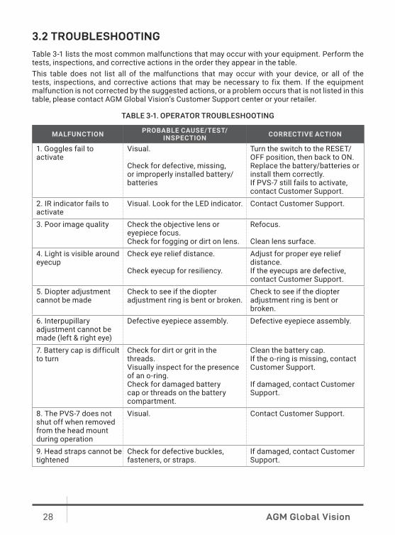
3.2 TROUBLESHOOTING
Table 3-1 lists the most common malfunctions that may occur with your equipment. Perform the tests, inspections, and corrective actions in the order they appear in the table.This table does not list all of the malfunctions that may occur with your device, or all of the tests, inspections, and corrective actions that may be necessary to fix them. If the equipment malfunction is not corrected by the suggested actions, or a problem occurs that is not listed in this table, please contact AGM Global Vision’s Customer Support center or your retailer.
TABLE 3-1. OPERATOR TROUBLESHOOTING
MALFUNCTION PROBABLE CAUSE/TEST/INSPECTION CORRECTIVE ACTION
1. Goggles fail to activate
Visual.
Check for defective, missing, or improperly installed battery/batteries
Turn the switch to the RESET/OFF position, then back to ON.Replace the battery/batteries or install them correctly.If PVS-7 still fails to activate, contact Customer Support.
2. IR indicator fails to activate
Visual. Look for the LED indicator. Contact Customer Support.
3. Poor image quality Check the objective lens or eyepiece focus. Check for fogging or dirt on lens.
Refocus.
Clean lens surface.4. Light is visible around eyecup
Check eye relief distance.
Check eyecup for resiliency.
Adjust for proper eye relief distance.If the eyecups are defective, contact Customer Support.
5. Diopter adjustment cannot be made
Check to see if the diopter adjustment ring is bent or broken.
Check to see if the diopter adjustment ring is bent or broken.
6. Interpupillary adjustment cannot be made (left & right eye)
Defective eyepiece assembly. Defective eyepiece assembly.
7. Battery cap is difficult to turn
Check for dirt or grit in the threads.Visually inspect for the presence of an o-ring.Check for damaged battery cap or threads on the battery compartment.
Clean the battery cap.If the o-ring is missing, contact Customer Support.
If damaged, contact Customer Support.
8. The PVS-7 does not shut off when removed from the head mount during operation
Visual. Contact Customer Support.
9. Head straps cannot be tightened
Check for defective buckles, fasteners, or straps.
If damaged, contact Customer Support.

29PVS-7 USER MANUAL
MALFUNCTION PROBABLE CAUSE/TEST/INSPECTION CORRECTIVE ACTION
10. Head mount or helmet mount socket and goggles do not connect properly
Check socket or latch for dirt. Check socket or latch for damage.
Clean socket and latch.If damaged, contact Customer Support.
11. The PVS-7 does not shut off when exposed to daylight or bright room light.
Perform the following tests in daylight or bright room light.Place the lens cap on the objective lens. Turn the PVS-7 on and verify that they shut off within 70 (±30) seconds after powering on.Turn the goggles off and then back on.
If damaged, contact Customer Support.

30 AGM Global Vision
4 WARRANTY INFORMATION
4.1 WARRANTY INFORMATION AND REGISTRATION
4.1.1 WARRANTY INFORMATIONThis product is guaranteed to be free from manufacturing defects in material and workmanship under normal use for a period of three (3) years from the date of purchase. In the event that a defect covered by the warranty below occurs during the applicable period stated above, AGM Global Vision, at its discretion, will either repair or replace the product; such action on the part of AGM Global Vision shall be the full extent of AGM Global Vision’s liability, and the Customer’s sole and exclusive reparation. This warranty does not cover a product if it has been (a) used in ways other than its normal and customary manner; (b) subjected to misuse; (c) subjected to alterations, modifications or repairs by the Customer or by any party other than AGM Global Vision without prior written consent of AGM Global Vision; (d) is the result of a special order or categorized as “close-out” merchandise or merchandise sold “as-is” by either AGM Global Vision or the AGM Global Vision dealer; or (e) merchandise that has been discontinued by the manufacturer and either parts or replacement units are not available due to reasons beyond the control of AGM Global Vision. AGM Global Vision shall not be responsible for any defects or damage that in AGM Global Vision’s view are a result from the mishandling, abuse, misuse, improper storage or improper operation of the device, including use in conjunction with equipment that is electrically or mechanically incompatible with, or of inferior quality to, the product, as well as failure to maintain the environmental conditions specified by the manufacturer. This warranty is extended only to the original purchaser. Any breach of this warranty shall be enforced unless the customer notifies AGM Global Vision at the address noted below within the applicable warranty period.The customer understands and agrees that except for the foregoing warranty, no other warranties written or oral, statutory, expressed or implied, including any implied warranty of merchantability or fitness for a particular purpose, shall apply to the product. All such implied warranties are hereby and expressly disclaimed.
4.1.2 LIMITATION OF LIABILITYAGM Global Vision will not be liable for any claims, actions, suits, proceedings, costs, expenses, damages, or liabilities arising out of the use of this product. Operation and use of the product are the sole responsibility of the Customer. AGM Global Vision’s sole undertaking is limited to providing the products and services outlined herein in accordance with the terms and conditions of this Agreement. The provision of products sold and services performed by AGM Global Vision to the Customer shall not be interpreted, construed, or regarded, either expressly or implied, as being for the benefit of or creating any obligation toward any third party of legal entity outside AGM Global Vision and the Customer; AGM Global Vision’s obligations under this Agreement extend solely to the Customer. AGM Global Vision’s liability hereunder for damages, regardless of the form or action, shall not exceed the fees or other charges paid to AGM Global Vision by the customer or customer’s dealer. AGM Global Vision shall not, in any event, be liable for special, indirect, incidental, or consequential damages, including, but not limited to, lost income, lost revenue, or lost profit, whether such damages were foreseeable or not at the time of purchase, and whether or not such damages arise out of a breach of warranty, a breach of agreement, negligence, strict liability, or any other theory of liability.

31PVS-7 USER MANUAL
4.1.3 PRODUCT REGISTRATIONIn order to validate the warranty on your product, the customer must complete and submit AGM Global Vision PRODUCT REGISTRATION FORM on our website (www.agmglobalvision.com/customer-support).
4.1.4 OBTAINING WARRANTY SERVICETo obtain warranty service on your unit, the End-user (Customer) must notify the AGM Global Vision service department via e-mail. Send any requests to [email protected] to receive a Return Merchandise Authorization number (RMA). When returning any device, please take the product to your retailer, or send the product, postage paid and with a copy of your sales receipt, to AGM Global Vision’s service center at the address listed above. All merchandise must be fully insured with the correct postage; AGM Global Vision will not be responsible for improper postage or merchandise that becomes lost or damaged during shipment. When sending product back, please clearly write the RMA# on the outside of the shipping box. Please include a letter that indicates your RMA#, the Customer’s Name, a Return Address, reason for the return, contact information (valid telephone numbers and/or an e-mail address), and proof of purchase that will help us to establish the valid start date of the warranty. Product merchandise returns that do not have an RMA# listed may be refused, or a significant delay in processing may occur. Estimated Warranty service time is 10-20 business days. The End-user/Customer is responsible for postage to AGM Global Vision for warranty service. AGM Global Vision will cover return postage/shipping after warranty repair to the End-user/Customer only if the product is covered by the aforementioned warranty. AGM Global Vision will return the product after warranty service by domestic UPS Ground service and/or domestic mail. Should any other requested, required, or international shipping methods be necessary, the postage/shipping fee will be the responsibility of the End-user/Customer.
For service, repair or replacement, please contact:
AGM Global Vision, LLC
173 West Main StreetPO Box 962Springerville, AZ 85938Tel. [email protected]

32 AGM Global Vision
5 SPECIFICATIONS
5.1 SPECIFICATIONS
The following tables provide information pertaining to the operational, electrical, mechanical, optical, and environmental characteristics of the goggles.
TABLE 5-1. OPERATOR ADJUSTMENT LIMITS
ITEM LIMITS
Interpupillary Distance 55 to 71 mm
Diopter Focus +2 to -6 diopters
Objective Focus 9.8 in / 25 cm to infinity
TABLE 5-2. ELECTRICAL DATA
ITEM DATA
Power Source Battery (3 VDC max.)
Battery Requirements 2 AA Alkaline or 1 Lithium (BA-5567/U)
TABLE 5-3. MECHANICAL DATA
ITEM DATA
Soft Carrying Case Size: Approx. 14 × 8 in / 355 × 203 mm
Goggles
Size: 7.9 × 6.0 × 3.5 in / 200 × 152 × 90 mmSize (without eyecups and lens cap): 5.8 × 6.0 × 3.5 in / 147 × 152 × 90 mmWeight*: 1.5 lb / 680 g
* The weight of the PVS-7 does not include the added weight of the accessories.
TABLE 5-4. OPTICAL DATA
ITEM DATA
Magnification 1.0x
Field of View 40°
Eyepiece Focus +2 to -6 diopters
Focus Range 9.8 in / 25 cm to infinity

33PVS-7 USER MANUAL
TABLE 5-5. ENVIRONMENTAL DATA
ITEM DATA
Operating Temperature -40 to +122°F / -40 to +50°C
Storage Temperature -58 to +158°F / -50 to +70°C
Illumination Required Overcast starlight to moonlight
Waterproof 1 yd / 1 m for 30 min.
NOTE:
All data are subject to change without notice.

34 AGM Global Vision
APPENDIX
A. SPARE PARTS LIST
The parts authorized in this list of spare parts are required for operator maintenance. This list includes parts that must be removed in order to replace authorized parts.The PART NO. Column indicates the primary number used by the manufacturer to identify an item; this number controls the design and characteristics of the item, including standards, engineering specifications, and inspection requirements.The NSN column indicates the National Stock Number.
FIGURE A-1. PVS-7 SPARE PARTS
7
685
4
1
3
15
1716
13
1110 129
14

35PVS-7 USER MANUAL
TABLE A-1. PVS-7 SPARE PARTS LIST
ITEM DESCRIPTION PART NO. NSN
1 Battery Cap 5855-01-246-82652 O-Ring (not shown) 5330-00-729-49923 Lens Cap 5340-01-397-66084 Objective Lens Assembly 5855-01-246-68075 Eyepiece Assembly 5855-01-246-68106 Eyecup 5855-01-246-82737 Switch Knob 5930-01-246-82648 Head Mount Assembly 5855-01-246-82669 Large Brow Pad 5855-01-297-7847
10 Medium Brow Pad 5855-01-355-860011 Small Brow Pad 5855-01-355-859912 Shoulder Strap Assembly 5340-01-250-243113 Demist Shield 5855-01-246-827214 Sacrificial Window 5855-01-246-827115 Neck Cord 5340-01-451-773716 User Manual 12PV7USMN17 Carrying Case 5855-01-398-4284

AGMglobalvision.com
AGM Global Vision, LLC
MAIN OFFICE
173 West Main Street
PO Box 962
Springerville, AZ 85938
USA
Tel. +1.928.333.4300
www.agmglobalvision.com
EUROPEAN OFFICE
Andrey Lyapchev #7
Sofia, P.C. 1756
Bulgaria
Tel. +35.988.412.5573
www.agmglobalvision.eu