New two chamber transfer switch for 6500 A commutation ...
8
344 www.geidco.org Global Energy Interconnection Full-length article Vol. 1 No. 3 Aug. 2018 DOI: 10.14171/j.2096-5117.gei.2018.03.005 New two chamber transfer switch for 6500 A commutation current Lutz-Rüdiger Jänicke 1 , Jörg Teichmann 1 , Shibani Bose 2 , Weidong Han 3 , Xiaoming Wang 3 1. Siemens AG, Nonnendammallee 104, 13629 Berlin, Germany 2. Siemens Ltd. China, 43 Ximei Road 214028 Wuxi, P.R. China 3. Siemens High voltage Circuit Breaker Co., Ltd., 6th Road, 310018 Hangzhou, P.R. China Abstract: HVDC transfer switches are used in different locations in electrode lines of HVDC transmission systems for their reconfigurations. They have to carry and commutate currents to the overload currents of HVDC transmission systems, which increased to 6,400 A in the past years. Common designs of transfer switches use combinations of several switching units connected in series and parallel. This paper describes the design and development of a new DC commutation switch with two switching units only, but it is able to carry currents up to 10,000 A and has an actual tested commutation capability of 6,500 A. Keywords: HVDC, Switch, Passive resonance, 6,500 A commutation current, 10,000 A nominal current. 1 Introduction HVDC power transmission technology requires different kinds of switches installed in transmission lines and neutral systems which follow specific technical conditions. These conditions are currently not completely covered by international standards. CIGRE technical brochure 683 summarizes requirements and specifications of state of the art HVDC switching equipment, as in [1] and IEC TS 63014-1 describes switches installed in LCC systems, as in [2]. But some national Chinese standards are Received: 8 June 2018/ Accepted: 18 June 2018/ Published: 25 August 2018 Lutz-Rüdiger Jänicke [email protected] Jörg Teichmann [email protected] Shibani Bose [email protected] Weidong Han [email protected] Xiaoming Wang [email protected] available about high-voltage direct current by-pass switches and high-voltage direct current transfer switches, as in [3] and [4]. Especially the transfer switches installed in neutral systems are key elements of reliable HVDC-transmissions. These transfer switches will equalize asymmetric conditions by utilizing the ground systems of the DC transmission systems. According to [1] and [2], there are four types of switches used in neutral systems in general: ERTS : Earth Return Transfer Switch MRTS : Metal Return Transfer Switch NBS : Neutral Bus Switch NBES : Neutral Bus Earthing Switch Usually a mechanical switching device, a so-called commutation switch (often a modified AC circuit- breaker), is used with both a series oscillating circuit and a surge arrester in parallel. During the reconfiguration of HVDC transmission systems, all of them are required to carry or commutate currents up to the overload current of HVDC transmission systems, which increased to 6,400 A in the latest HVDC transmission projects. To do so, the commutation switch generates a special rise of arcing voltage during the opening operation. This rise of the arcing voltage interacts with the series resonance circuit in a way that oscillations are created and the current is
-
Upload
khangminh22 -
Category
Documents
-
view
0 -
download
0
Transcript of New two chamber transfer switch for 6500 A commutation ...

344
www.geidco.org
Global Energy Interconnection
Full-length article
Vol. 1 No. 3 Aug. 2018
DOI: 10.14171/j.2096-5117.gei.2018.03.005
New two chamber transfer switch for 6500 A commutation current
Lutz-Rüdiger Jänicke1, Jörg Teichmann 1, Shibani Bose 2, Weidong Han 3, Xiaoming Wang 3
1. Siemens AG, Nonnendammallee 104, 13629 Berlin, Germany2. Siemens Ltd. China, 43 Ximei Road 214028 Wuxi, P.R. China3. Siemens High voltage Circuit Breaker Co., Ltd., 6th Road, 310018 Hangzhou, P.R. China
Abstract: HVDC transfer switches are used in different locations in electrode lines of HVDC transmission systems for their reconfigurations. They have to carry and commutate currents to the overload currents of HVDC transmission systems, which increased to 6,400 A in the past years. Common designs of transfer switches use combinations of several switching units connected in series and parallel. This paper describes the design and development of a new DC commutation switch with two switching units only, but it is able to carry currents up to 10,000 A and has an actual tested commutation capability of 6,500 A.
Keywords: HVDC, Switch, Passive resonance, 6,500 A commutation current, 10,000 A nominal current.
1 Introduction
HVDC power transmission technology requires different kinds of switches installed in transmission lines and neutral systems which follow specific technical conditions. These conditions are currently not completely covered by international standards. CIGRE technical brochure 683 summarizes requirements and specifications of state of the art HVDC switching equipment, as in [1] and IEC TS 63014-1 describes switches installed in LCC systems, as in [2]. But some national Chinese standards are
Received: 8 June 2018/ Accepted: 18 June 2018/ Published: 25 August 2018
Lutz-Rüdiger Jänicke [email protected]
Jörg Teichmann [email protected]
Shibani Bose [email protected]
Weidong Han [email protected]
Xiaoming Wang [email protected]
available about high-voltage direct current by-pass switches and high-voltage direct current transfer switches, as in [3] and [4]. Especially the transfer switches installed in neutral systems are key elements of reliable HVDC-transmissions. These transfer switches will equalize asymmetric conditions by utilizing the ground systems of the DC transmission systems. According to [1] and [2], there are four types of switches used in neutral systems in general: ERTS : Earth Return Transfer Switch
MRTS : Metal Return Transfer Switch NBS : Neutral Bus Switch NBES : Neutral Bus Earthing SwitchUsually a mechanical switching device, a so-called
commutation switch (often a modified AC circuit-breaker), is used with both a series oscillating circuit and a surge arrester in parallel. During the reconfiguration of HVDC transmission systems, all of them are required to carry or commutate currents up to the overload current of HVDC transmission systems, which increased to 6,400 A in the latest HVDC transmission projects. To do so, the commutation switch generates a special rise of arcing voltage during the opening operation. This rise of the arcing voltage interacts with the series resonance circuit in a way that oscillations are created and the current is

345
Lutz-Rüdiger Jänicke et al. New two chamber transfer switch for 6500 A commutation current
split to both parallel branches. Depending on the arcing voltage, these oscillations rise and a current of zero occurs in the branch with the commutation switch, whereby the arc extinguishes. The capacitor in the oscillating branch is charged until its voltage activates the surge arrester in parallel, which dissipates the residual energy.
2 History of HVDC switches in Siemens
At the end of last century, the Siemens circuit-breaker factory in Berlin started to deliver the first HVDC switches for different applications with rated voltages up to 800 kV and rated currents up to 4,000 A. The different DC switches are not only used as transfer switches in parallel to converters (by-pass switches) or in electrode lines (commutation switches), as in [1], but also as paralleling switches nowadays .
All switches for HVDC applications manufactured by Siemens are based on reliable buffer type AC circuit-breakers using a durable double nozzle design for the switching units. Actually, they are also fitted with composite insulators to reduce the degradation of dielectric performance because of pollution and limit the risk caused by bursting insulators in cases of internal faults. Fig. 1 shows, as an example, the standard switching unit of the HVDC commutation switch 3AT2ES-DC-CS in closed position, with the linkage to the driving mechanism on the right-hand side. In Fig. 2, the same switching unit is shown in the open position.
Inside the switching unit, two fixed contacts facing each other with a sliding contact around, which bridges the gap in closed position. The fixed contacts consist of two metal
tubes on both sides of the switching gap with high durable, high arc resistance nozzles (colored in light yellow in both figures). The sliding contact, named as guide, is surrounded by a so-called blast cylinder consisting of a cylindrical isolating tube and an isolating bottom on the gap side (colored in dark yellow in both figures). On the drive side, a piston is installed between the blast cylinder and the guide.
This design provides several advantages for application in DC systems.
• In the open position, only insulating gas remains in the switching gap, which is beneficial under any kind of voltage stresses, especially direct voltage.
• During switching operations, this design provides an extreme high arc voltage, when the arc is blowed inside the tubes by cold compressed insulating gas. Therefore, these switches are suitable for any applications where currents with high DC components should be counteracted.
• It has high durability of switching gap against high current arcing. High power testing stations all over the world are using such switches as auxiliary breakers for switching currents up to 100 kA and with a sum current, for example, 3,000 kA as criteria for maintenance. For DC applications this provides a high reliability in case of failed commutation.
• During opening operation, the gas is compressed between the blast cylinder and the piston. This compressed gas blows the switching arc inside the nozzles and along the tubes, whereby the arc is prolonged. This increases the arc resistance significantly. Shortly before the moveable sliding contact reaches its final open position at the end of the switching operation, the compression volume is cut off from the gap by the bottom of blast cylinder.
3 HVDC commutation switches series 3AT2ES-DC-CS
At the end of 2011, a new HVDC commutation switch for a rated voltage of 150 kV was successfully tested for a commutation current of 5,000 A at CESI testing station IPH in Berlin, as first of its kind with two standard switching units in series only, as in [2]. This HVDC commutation switch is based on the two chamber AC circuit-breaker 3AT2EI-245 kV – 80 kA, which is rated for a voltage of 245 kV and a short-circuit breaking current of 80 kA. The design of the switching units is presented in Fig. 1 and 2 above.
In the following months, all other types of tests were finished to show its ability for seismic requirements of 0.5 g and for service in a temperature range from -60° to +50°C.
Fig. 2 Standard switching unit 3AT2ES-DC-CS in open position
Fig. 1 Standard switching unit 3AT2ES-DC-CS in closed position

346
Global Energy Interconnection Vol. 1 No. 3 Aug. 2018
Fig. 3 shows the HVDC commutation switch 3AT2ES-DC-CS prepared for the low and high temperature test from -60°C to +50°C in climatic test chamber of Karlsruhe Institute of Technology (KIT) in Germany.
Fig. 3 HVDC commutation switch in climatic chamber at KIT
To cope with low ambient temperatures below -40°C, the HVDC commutation switch 3AT2ES-DC-CS was fitted with a thermal housing, which encloses the base with the electro-hydraulic driving mechanism. In addition, the HVDC commutation switch is filled with a mixed gas filling consisting of CF4 and SF6. Utilizing this mixed gas filling has two major advantages:
• The environmental impact is reduced from a CO2-equivalent of 450 t for pure SF6 to 205 t for the CF4/SF6 gas mixture.
• One set of type tests is applicable for all environmen-tal conditions. Only the “low and high temperature tests” have to be performed twice, one with thermal housing and one without.
Additional tests were performed at CESI testing station IPH in this period to establish the arcing characteristic of the HVDC commutation switch using the standard
switching units. Therefore, the switch was open during current flowing through the switch, without any oscillating branch in parallel. During these tests, the arc voltage across the commutation switch and the current flowing in the arc during test were measured with high resolution. The test process was terminated by closing a short-circuiting device, which was installed parallel to the HVDC commutation switch, a few tens of milliseconds after the HVDC commutation switch reached its final open position.
During these test, the switch was able to quench arcs carrying currents up to 1,000A towards a voltage of approx. 25 kV, which was supplied by the inductance of the test circuit. Based on these data a simulation model of arc characteristic was established as formula. Figure 4 shows a comparison of re-calculated arc resistance from some measurements (red lines) and this ‘formulistic’ model of arc resistance (blue line).
Fig. 4 Comparison of arc resistancere-calculated from measurement (red lines)
model of arc resistance (blue line).
0 0.005 0.01 0.015 0.02 0.025
t/s
0
0.5
1
1.5
2
2.5
3T a
rk /
Ω
The significant drop in the re-calculated arc resistance at approximately 18ms indicates the end of gas flow when the compression volume was cut off. Therefore, the arc collapses and re-establishes directly between both nozzles burning with reduced arcing voltage. In cases where a serial oscillating circuit is installed in parallel to the HVDC commutation switch, the oscillation in-between drops down in amplitude also. This moment marks the maximum possible arcing time in which the HVDC transfer switch is able to commutate the current.
The established model was verified by the comparison between calculated results and data from performed tests in different test setups. Today, this model is used for simulations of HVDC transmission systems in order to define relevant components like capacitors, inductors and surge arresters.

347
Lutz-Rüdiger Jänicke et al. New two chamber transfer switch for 6500 A commutation current
In parallel, the development of arcing voltage was simulated by a CFD (Computational Fluid Dynamics) tool. Results of this simulation model were verified for different parameters (e. g. current, number of switching units, insulating gas and its pressure) by comparison with both the results from testing at CESI testing station IPH and further with simulation using the calculation model.
Both models are used to improve the switching capability of the commutation switch to higher currents by appropriate adjustment of the components of passive series oscillating circuit in parallel to the HVDC commutation switch. In summer of 2017, the commutation switch was successfully tested at a commutation current of 6,500 A at CESI testing station IPH, again using two switching units in series only.
4 Beyond the limits – improved design called Coax
Although it is not capable of carrying the nominal current, which is restricted to 5,600 A at an ambient temperature of +40°C by the design of contact system, this design is considered as sufficient for HVDC transmission projects with a capacity of 8 GW all over the world, and also in areas with higher temperatures. Nevertheless, it is not suitable to cover the requirements of a nominal current of 6,400 A in current projects in China.
Based on this requirement and the results of performed test, the necessity is given to upgrade the contact system without changing the arc quenching system in principle and the outer dimensions of the commutation switch. Inspired by modern self-blast circuit-breakers which have outer nominal current systems inner arcing contact systems, another contact system is designed coaxially arranged around the existing one. Therefore, the insulating tube of the blast cylinder is replaced by a metallic one and complemented with two sliding contacts in the sockets on both ends. Fig. 5 shows the new switching unit of the HVDC commutation switch in the closed position and Fig. 6 illustrates it in the open position, again with the linkage to the driving mechanism on the right-hand side.
Most parts of this additional contact system, like contact lamellas and contact band are the same as used in the well proven AC self-blast circuit-breaker family 3AP. The new parts like sockets or cylinders are designed according to the rules of the mentioned circuit-breaker family. Fig. 7 shows the new contact system.
The shape, diameter and distances of the new contact system especially regarding to the composite insulator are optimized by dielectric field simulations. In Fig. 8 the
electric field strength at the contact gap is illustrated.The maximum electric field strength is reached at the
nozzles of the inner contact system. The calculated values are within the limits set for the standard contact system
Fig. 5 Coaxial switching unit in closed position
Fig. 6 Coaxial switching unit in open position
Fig. 7 Contact system of Coax switching unitLeft: Fixed contact, terminal side
Middle: Movable contactRight: Fixed contact, drive side
Fig. 8 Electric field strength at contact gap of coaxial switching unit
348
Global Energy Interconnection Vol. 1 No. 3 Aug. 2018
which has been used for several decades. But the field distribution in air on the outside of the chamber insulator is also affected by the switching gap. Too short distances in the gap or between contacts and insulator compresses, the lines of equal potential in air, whereby the dielectric stress is increased. Fig. 9 shows the distribution of lines of equal potential for one switching unit.
Fig. 9 Distribution lines of equal potential for coaxial switching unit
The calculated distribution of lines of equal potential in the area of the gap is considered as sufficient.
The dielectric tests on a HVDC commutation switch using the new contact system are performed successfully in October 2017 at CESI testing station FGH in Manheim. Fig. 10 shows the HVDC commutation switch with the DC voltage generator in background.
The proofed withstand capability is related to a rated DC voltage of 150 kV and is comparable with the requirements for the AC rated voltage of 145 kV. Table 1 shows the results of the high voltage test at CESI testing station FGH in Manheim.
Table 1 Tested values during high voltage tests at FGH, Germany
Performed test Value
Direct withstand voltage, dry and wet 225 kV
Lightning impulse withstand voltage 650 kV
Switching impulse withstand voltage, wet 550 kV
RIV level @ direct voltage 10 µV @ 195 kV
RIV level @ power-frequency voltage 225 µV @ 195 kV
Polarity reversal test, with PD measurement <500 pC @ 225 kV
Based on the model of the switching units, a temperature rise simulation using the finite elements
method (FEM) was performed. All materials and contacts were emulated with their resistances. By applying different currents for the simulation, the losses of the switching units were calculated. The simulation results were expressed in temperatures which were compared with the limits given in IEC 62271-1, as in [6]. From these results, a nominal current of 10,000 A was expected for the new contact system.
In service, several wires have to be used, to supply such high current to the HVDC-commutation switch. Therefore another terminal plate is installed on each outer side of the HVDC commutation switch to provide sufficient space for connecting the necessary wires.
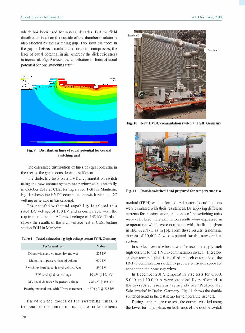
In December 2017, temperature rise tests for 6,600, 8,000 and 10,000 A were successfully performed in the accredited Siemens testing station ‘Prüffeld der Schaltwerke’ in Berlin, Germany. Fig. 11 shows the double switched head in the test setup for temperature rise test.
During temperature rise test, the current was fed using the lower terminal plates on both ends of the double switch
Fig. 11 Double switched head prepared for temperature rise
Fig. 10 New HVDC commutation switch at FGH, Germany
Terminal 1
Terminal 2
349
Lutz-Rüdiger Jänicke et al. New two chamber transfer switch for 6500 A commutation current
head only. Because of the current concentration in only one terminal plate, this attempt was more severe than the distributed connection of several wires, as usually done in a substation.
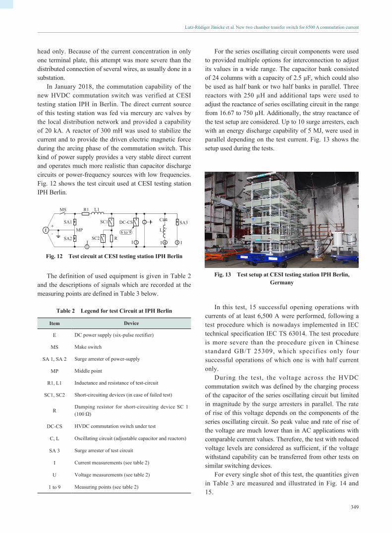
In January 2018, the commutation capability of the new HVDC commutation switch was verified at CESI testing station IPH in Berlin. The direct current source of this testing station was fed via mercury arc valves by the local distribution network and provided a capability of 20 kA. A reactor of 300 mH was used to stabilize the current and to provide the driven electric magnetic force during the arcing phase of the commutation switch. This kind of power supply provides a very stable direct current and operates much more realistic than capacitor discharge circuits or power-frequency sources with low frequencies. Fig. 12 shows the test circuit used at CESI testing station IPH Berlin.
13
2
4 5
6 to 9
MS
MP
SA1 SA3SC1 DC-CS
SC2
R1
R
L1
I I I
C
L
I
E+
-SA2
Fig. 12 Test circuit at CESI testing station IPH Berlin
The definition of used equipment is given in Table 2 and the descriptions of signals which are recorded at the measuring points are defined in Table 3 below.
Table 2 Legend for test Circuit at IPH Berlin
Item Device
E DC power supply (six-pulse rectifier)
MS Make switch
SA 1, SA 2 Surge arrester of power-supply
MP Middle point
R1, L1 Inductance and resistance of test-circuit
SC1, SC2 Short-circuiting devices (in case of failed test)
RDamping resistor for short-circuiting device SC 1 (100 Ω)
DC-CS HVDC commutation switch under test
C, L Oscillating circuit (adjustable capacitor and reactors)
SA 3 Surge arrester of test circuit
I Current measurements (see table 2)
U Voltage measurements (see table 2)
1 to 9 Measuring points (see table 2)
For the series oscillating circuit components were used to provided multiple options for interconnection to adjust its values in a wide range. The capacitor bank consisted of 24 columns with a capacity of 2.5 µF, which could also be used as half bank or two half banks in parallel. Three reactors with 250 µH and additional taps were used to adjust the reactance of series oscillating circuit in the range from 16.67 to 750 µH. Additionally, the stray reactance of the test setup are considered. Up to 10 surge arresters, each with an energy discharge capability of 5 MJ, were used in parallel depending on the test current. Fig. 13 shows the setup used during the tests.
Fig. 13 Test setup at CESI testing station IPH Berlin, Germany
In this test, 15 successful opening operations with currents of at least 6,500 A were performed, following a test procedure which is nowadays implemented in IEC technical specification IEC TS 63014. The test procedure is more severe than the procedure given in Chinese standard GB/T 25309, which specifies only four successful operations of which one is with half current only.
During the test, the voltage across the HVDC commutation switch was defined by the charging process of the capacitor of the series oscillating circuit but limited in magnitude by the surge arresters in parallel. The rate of rise of this voltage depends on the components of the series oscillating circuit. So peak value and rate of rise of the voltage are much lower than in AC applications with comparable current values. Therefore, the test with reduced voltage levels are considered as sufficient, if the voltage withstand capability can be transferred from other tests on similar switching devices.
For every single shot of this test, the quantities given in Table 3 are measured and illustrated in Fig. 14 and 15.

350
Global Energy Interconnection Vol. 1 No. 3 Aug. 2018
Table 3 Legend of measuring points and colors in diagrams
Number Measurement category
1 Current in main circuit iDC
2 Voltage across HVDC commutation switch uTO
3 Current in HVDC commutation switch iCS
4 Current in oscillating circuit iLC
5 Current in surge arrester Iarr
6 Contact travel of HVDC commutation switch travel
7Closing command for HVDC commutation switch
Imp C
8Opening command for HVDC commutation switch
Imp O
9 Arc detection of HVDC commutation switch light 1
Fig. 14 shows the measured signals of a single shot as an overview. All currents (iDC, iCS, iLC, Iarr) are shown in the upper diagram aligned with one common x-coordinate. In the lower diagram, the other signals (uTO, travel, Imp O, light 1) without closing command for the HVDC commutation switch (Imp C) are illustrated.
In Fig. 15, the same signals as in Fig. 14 are shown but expanded in time for the relevant period of arcing.
The arc detection signal of HVDC commutation switch (light 1) indicates the light emitted by the switching arcs in both switching units. This light is captured by special sensors at the gear housing of the double switching head, is Fig. 3 and 10, and channeled via fiber optics, which are partly integrated in the support insulator to the control cabinet of the switch. The delivered information is thus used during the test for observe the arcing of the HVDC commutation switch in order to distinguish between failures in test object, auxiliary switches and other equipment of testing station.
In substations, customers can forward this information by their own fiber optics from the control cabinet to control room. Systems to convert the light to electrical signals and feed them to control and protection system are commercially available, as in [7] and [8]. Combined with timing information concerning the commutation switch, like opening time, maximum possible arcing time, this information can be used for switch failure protection. Optical arc detection is available as optional feature for all HVDC commutation switches and all HVDC make switches.
After passing the main type tests of the new commutation switch 3AT2ES-DC-CS, the official ratings were fixed as given in Table 4.
Table 4 Ratings of new commutation switch
Rating Value
Direct voltage 150 kV
Direct withstand voltage 225 kV
Lightning impulse withstand voltage 650 kV
Switching impulse withstand voltage 550 kV
RIV level @ direct voltage 10 µV @ 195 kV
Nominal current 10,000 A
Commutation current 6,500 A
Number of mechanical operation 3000
Ambient temperature (-60) -40 to +50
Seismic qualification according IEC 0.5 g
5 Conclusion
Buffer type switches using the durable double nozzle
Fig. 14 Measured signals during test at IPH Berlin (overview)
Fig. 15 Measured signals during test at IPH Berlin (expanded in time)

351
Lutz-Rüdiger Jänicke et al. New two chamber transfer switch for 6500 A commutation current
design are able to commutate high direct currents of 6,500 A with two switching units connected in series only. By adding a second contact system arranged coaxially around the existing one, the nominal current of the switch could be increased to 10,000 A. Using computer-based calculations and simulations for dielectric, gas dynamic and arcing concerns during design phase, outer dimensions and driving mechanism could keep unchanged. A further increase of commutation current will be possible by an appropriate adjustment of components of passive series oscillating circuit in parallel to the switch.
References
[1] Technical brochure 683 : Technical requirements and specifications of state-of-the-art HVDC switching equipment, CIGRE, Paris
[2] Technical specification IEC TS 63014 : High voltage direct current (HVDC) power transmission - system requirements for DC-side equipment, Part 1: Using Line-Commutated Converters
[3] Chinese standard GB/T 25307 : High-voltage direct current by-pass switches
[4] Chinese standard GB/T 25309 : High-voltage direct current transfer switches
[5] Borchert R (2012) Report 22 : Challenging HVDC transmission, IPH, Berlin
[6] International standard IEC 62271-1 : High-voltage switchgear and controlgear – Part 1 : Common specifications for alternating current switchgear and controlgear
[7] Meiß M, Reuter E, Vogl F (1994) Einsatz von optoelektronischen Lichtbogenerfassungssystemen in gasisolierten Schaltanlagen. Elektrizitätswirtschaft, Jg. 93, Heft 25
[8] Reisinger F, Vogl F (1995) Optoelectronic Arc Detection Systems in Gas-Insulated Switchgear. VEO Journal 5/95
Biographies
Lutz-Rüdiger Jänicke received his engineer degree in electrical engineering in 1989 from Technical University of Berlin, Germany. 1989 he joined Siemens high voltage circuit-breaker factory in Berl in, working as development engineer dealing with dielectric and high power issues of circuit-breakers. Currently he is working as project manager for
special application switches for EHV, UHV, FACTS and HVDC.
Jörg Teichmann received his engineer degree in electrical engineering in 1995 from Ruhr-University Bochum. In 1998 he received his Ph.D. degree in electrical engineering from Ruhr-University Bochum in the field of switching arc engineering. He joined Siemens in 1998 as development engineer in MV GIS. In 2009 he took over the development
department of Vacuum Interrupters and in 2011 he became head of the R&D department of high voltage air insulated switchgear including circuit breaker, disconnector and surge arrester.
Shibani Bose received her engineer degree in aeronautical engineering in 1994 from Technical University of Berlin, Germany. In 2002 she received her Ph.D. degree in aeronautical engineering from Technical Universi ty of Berl in, Germany. Since 2006, she has been an engineer at Siemens High Voltage circuit breakers working on
the development of a CFD Arc simulation software tool. She is currently working as Chief Technology Officer for AIS products for Siemens Limited China in Wuxi and Hangzhou.
Weidong Han received his Master Degree of Industrial Economics in 2011 from Zhejiang Sci-Tech University, China. Since 2011, he has been working at Siemens High Voltage Circuit Breaker Co., Ltd., Hangzhou, in China. Currently he is working as HVDC project manager.
Xiaoming Wang received his bachelor degree from Beijing Technology and Business University in 2005. Since 2006, he has been an engineer at Siemens High Voltage Circuit Breaker Co., Ltd., Hangzhou, in China. His current major fields of interest are high voltage AC circuit-breakers and DC switches.
(Editor Zhou Zhou)