NEW STANDARD REMOTE CONTROLLER - Iris Hellas
72
www.lg.com OWNER’S & INSTALLATION MANUAL NEW STANDARD REMOTE CONTROLLER P/NO : MFL69312302 Rev01.022216 Please read this installation manual completely before installing the product. Installation work must be performed in accordance with the national wiring standards by authorized personnel only. Please retain this installation manual for future reference after reading it thoroughly.. Model type: NEW STANDARD REMOTE CONTROLLER Model name: PREMTB100 ENGLISH FRANÇAIS ITALIANO DEUTSCH ESPAÑOL РУССКИЙ ЯЗЫК POLSKI PORTUGUÊS 中文 ČEŠTINA
-
Upload
khangminh22 -
Category
Documents
-
view
2 -
download
0
Transcript of NEW STANDARD REMOTE CONTROLLER - Iris Hellas

www.lg.com
OWNER’S & INSTALLATIONMANUAL
NEW STANDARDREMOTE CONTROLLER
P/NO : MFL69312302Rev01.022216
Please read this installation manual completely before installing the product.Installation work must be performed in accordance with the national wiring standards by authorized personnel only.Please retain this installation manual for future reference after reading it thoroughly..
Model type: NEW STANDARD REMOTE CONTROLLERModel name: PREMTB100
ENG
LISH
FRA
NÇ
AIS
ITALIA
NO
DEU
TSC
HES
PA
ÑO
LР
УСС
КИЙ
ЯЗЫ
КP
OLS
KI
PORTUGUÊS
中文
ČEŠ
TINA

3IMPORTANT SAFETY INSTRUCTIONS
IMPORTANT SAFETY INSTRUCTIONSREAD ALL INSTRUCTIONS BEFORE USING THE APPLIANCE.Always comply with the following precautions to avoid dangerous situations and ensure peakperformance of your product
WARNINGThis symbol indicates potentially hazardous situation which, if not avoided could result in death orserious injury.
CAUTIONThis symbol indicates a potentially hazardous situation which, if not avoided, may result in minoror moderate injury.
WARNING
Installation• For electrical work, contact the dealer, seller, a qualified electrician, or an authorized service Center.
- Do not disassemble or repair the product. There is risk of fire, electric shock, explosion, equipmentmalfunction, or injury.
• Request to the service center or installation specialty store when reinstalling the installed product.
- There is risk of fire, electric shock, explosion, equipment malfunction, or injury.
• Do not disassemble, fix, and modify products randomly.
- There is risk of fire, electric shock, explosion, equipment malfunction, or injury.
• The product shall be installed according to the national standards and local code.
• Apply totally enclosed noncombustible conduit in case of local building code requiring plenum.
• Use appropriate unit mounting procedures.
• Avoid direct sunlight.
• Avoid moist areas.
In-Use• Do not place flammable objects close to the product.
- There is risk of fire, electric shock, explosion, equipment malfunction or injury.
• Do not allow product to get wet.
- There is risk of fire, electric shock, explosion, equipment malfunction or injury.
• Avoid dropping the product.
- There is risk of fire, electric shock, explosion, equipment malfunction or injury.
• If product gets wet, contact your dealer or authorized service center.
- There is risk of fire, electric shock, explosion, equipment malfunction, or injury. If the instructionsare not followed, it may cause death or severe injury of the user.
• Do not use sharp or pointed objects on product.
- There is risk of fire, electric shock, explosion, equipment malfunction or injury.
• Do not touch or pull the lead wire with wet hands.
- There is risk of product breakdown or electric shock.
!
!
!
• Do not cool excessively indoors. This may consume more electricity.• Block sunlight with blinds or curtains while you are operating the air conditioner.• Keep doors or windows closed tightly while you are operating the air conditioner.• Adjust the direction of the air flow vertically or horizontally to circulate indoor air.• Speed up the fan to cool or warm indoor air quickly, in a short period of time.• Clean the air filter once every 2 weeks. Dust and impurities collected in the air filter may block the
air flow or reduce the cooling / dehumidifying functions.
For your records
Staple your receipt to this page in case you need it to prove the date of purchase or for warranty purposes. Write the model number and the serial number here:
Model number :
Serial number :
You can find them on a label on the side of each unit.
Dealer’s name :
Date of purchase :
Here are some tips that will help you minimize the power consumption when you use the airconditioner. You can use your air conditioner more efficiently by referring to the instructionsbelow:
TIPS FOR SAVING ENERGY2EN
GLIS
HTIPS FOR SAVING ENERGY

5
2 TIPS FOR SAVING ENERGY
3 IMPORTANT SAFETY IN-STRUCTIONS
8 DESCRIPTION
9 READ BEFORE OPERATINGTHE CONTROLLER
9 Menu Structure
14 DESCRIPTION OF THE OP-ERATION
14 Main screen
14 Menu screen
15 Setting screen
15 Popup screen
16 Monitoring / Additional function screen
17 Interface screen
17 Returning to the screen
18 OPERATION SETTING18 On / Off
18 Operation mode
19 Cooling Operation
20 Heating Operation
21 Dry Operation
22 Fan Only Operation
23 AI / Auto operation
24 Power Cool Operation
25 OPERATION SETTING -VENTILATOR
25 Operation mode
26 TEMPERATURE SETTING26 Controlling Desired Temperature
27 Check Room Temperature
28 WIND SETTING28 Fan speed control
28 Fan speed control - ventilation
28 Air flow control
29 ADDITIONAL OPERATION –VENTILATION
29 Additional operation
30 EXTERNAL EQUIPMENTCONTROL SETTING
30 External equipment control
31 ADDITIONAL FUNCTIONSETTING
31 Additional function entrance and settingmethod
32 Energy Saving Setting
33 Plasma Purification Setting
34 Fan Auto Setting
35 Humidification setting
36 Electric Heater Setting
37 Robot Cleaning Setting
38 Ventilation kit Setting
39 Comfort Cooling Setting
40 LOCK SETTING40 How to enter lock setting
40 Lock setting – all, on/off, mode, tempera-ture range lock
41 TIMER SETTING41 Timer entrance and setting method
42 Simple timer
43 Sleep timer
44 Turn-off Reservation
TABLE OF CONTENTS
TABLE OF CONTENTS
CAUTIONIn-use
• Do not clean using powerful detergents like solvent but use soft cloths. There is risk of fire, electric shock, explosion, equipment malfunction or deformation.
• Do not press the screen using powerful pressure. There is risk of product break-down or malfunction.
!
IMPORTANT SAFETY INSTRUCTIONS4EN
GLIS
H

TABLE OF CONTENTS 76 TABLE OF CONTENTSEN
GLIS
H
45 Turn-on Reservation
46 SCHEDULE SETTING46 How to enter schedule
47 Daily Schedule
48 Schedules & Edit
49 Schedules & Edit – Add schedule
50 Exception day
51 ENERGY51 How to enter energy
52 Instantaneous power check
53 Energy consumption
55 Energy saving - Temperature Setback Timer
56 Energy saving - Time Limit Control
57 Energy setting- outdoor unit capacity setting
58 Energy setting - target instantaneous powersetting
59 Energy setting - target power consumption
60 Energy setting - target operation time
61 Energy setting - Alarm Popup Setting
62 Energy setting – Usage data initialization
63 FUNCTION SETTING63 How to enter function setting
64 Function Setting
65 Vane angle control setting
66 Elevation grill setting
67 Robot cleaning setting
67 Auto dry setting
68 Filter sign check and initialization
69 Change temperature setting
70 Wi-Fi pairing setting
71 Comfort cooling setting
71 ODU Refrigerant Noise Reduction setting
72 Defrost mode setting
73 Smart load control(SLC) setting
74 Low noise mode time setting
75 Advanced fan speed “Auto” setting
76 Delay time (exclusive for ventilation)
77 Midnight air cooling (ventilation interface)
78 USER SETTING78 How to enter user setting
78 User Setting
79 Language setting
80 Temperature unit setting
81 Screen saver timer setting
82 LCD brightness in idle setting
83 External device setting
83 External device use
84 External device types
85 On condition / Off condition
86 Date setting
87 Time setting
88 Summer time setting
89 Password setting
90 Schedule initialization
91 Theme setting
92 System restart
93 SERVICE SETTING93 How to enter service setting
93 Service setting
94 Service contact
95 Model information
96 RMC Version Information
97 Error history
98 Open source license
99 INSTALLATION99 Installation of Remote Controller
101 Group control
103 INSTALLATION METHODTO USE EXTERNAL DEVICE
103 Cable connection method to use externaldevice
104 AIR CONDITIONER ANDVENTILATION INTERFACE
105 INSTALLER SETTING105 How to enter installer setting
106 Installer setting – air conditioner
108 Installer setting - ventilator
109 Test run setting (air conditioner / DX venti-lator)
110 Central control address setting (air condi-tioner / DX ventilator)
111 ESP setting (air conditioner / general, DXventilator)
112 Temperature sensor(2TH) setting(air condi-tioner)
113 Ceiling height setting (air conditioner)
114 Static pressure setting(air conditioner)
115 Remote controller master / slave setting (airconditioner / General, DX ventilator)
116 Override M/S setting (air conditioner / Gen-eral, DX ventilator)
117 Dry contact mode setting (air conditioner /DX ventilator)
118 Fixed fan speed setting (air conditioner / DXventilator)
119 Emergency heater setting (air conditioner)
120 Function control during group Control set-ting (air conditioner)
121 External devices of indoor unit setting (airconditioner)
122 Indoor unit address verification (air condi-tioner)
123 Static pressure step setting (air conditioner)
124 Fan speed in Cooling thermal off (air condi-tioner)
125 Primary heater setting(air conditioner)
126 Air conditioner Fan operation interlockedwith ventilation setting (air conditioner)
127 Indoor unit Auto-Start setting(air condi-tioner)
128 Occupancy duration time setting(air condi-tioner)
129 CN_CC setting (air conditioner)
130 CN_EXT setting (air conditioner)
131 Outdoor unit function master setting (airconditioner)
132 Fan continuous operation setting (air condi-tioner)
133 Low Noise Mode Priority setting (air condi-tioner)
134 Password initialization (air conditioner / gen-eral, DX ventilator)
135 Product direction (general ventilator)
136 Express ventilation priority (general , DXventilator)
137 Humidification of stand-alone ventilationmode (general , DX ventilator)
138 Humidification of ventilation with heatingoperation (DX ventilator)
139 Ventilation Fan Speed Alignment(DX venti-lator)
140 GUIDE TO DIFFERENTMODE OPERATION/OPENSOURCE SOFTWARE
140 Different mode operation
140 Open Source License Notice Information

9READ BEFORE OPERATING THE CONTROLLER8 DESCRIPTIONEN
GLIS
HDESCRIPTIONLG RS3 Standard Wired remote controller
OK
Operation display window
On/Off Button
OK Button
Back button
Up/Down/Left/Right Button
Operation display window Operation and Settings status display
Back button When you move to the previous stage from the menu’s set-ting stage
Up/down/left/right button When you change the menu’s setting value
OK button When you save the menu’s setting value
On/Off button When you turn ON/OFF the air conditioner
Accessories
Connecting cable(1 EA)
Remote controllerfixing screws (4 EA)
User/Installation Manual
READ BEFORE OPERATING THE CONTROLLERMenu Structure
Menu
Sub function
Energy Saving
Plasma Purification
Fan Auto
Humidification
Electric Heater
Robot Cleaning
Ventilation Kit
Comfort Saving
All Lock
On/Off Lock
Mode Lock
Set temp range lock
Simple Timer
Sleep Timer
Turn-off reservation
Turn-on reservation
Daily Schedule
Schedules & Edit
Exception Day
Timer
Schedule
Lock
..............................................................................12
..............................................................................33
..............................................................................34
..............................................................................35
..............................................................................36
..............................................................................37
..............................................................................38
..............................................................................69
..............................................................................40
..............................................................................40
..............................................................................40
..............................................................................40
..............................................................................42
..............................................................................43
..............................................................................44
..............................................................................45
..............................................................................47
..............................................................................48
..............................................................................50

.........................................................................52
..........................54
..........................54
..........................54
..........................54
..........................55
..........................56
..........................56
................57
................58
..........................59
..........................60
..........................61
..........................64
..........................65
..........................66
..........................66
11READ BEFORE OPERATING THE CONTROLLER10 READ BEFORE OPERATING THE CONTROLLEREN
GLIS
H
Energy
Instantaneous Power
Energy Consumption
Energy Saving
Energy Setting
Function
Year-on-year Usage
Weekly Usage
Monthly Usage
Yearly Usage
Temp Setback Timer
Time Limit control
Outdoor Unit Capacity
Target Instantaneous Power
Target Power Consumption
Target Operation Time
Alarm Popup
Usage Data Initialization
Vane Angle Control
Elevation Grill
Robot Cleaning
Auto Dry
Setting
...............................67
...............................68
...............................69
...............................70
...............................71
...............................72
...............................73
...............................78
...............................79
...............................80
...............................81
...............................82
...............................85
...............................86
...............................87
...............................88
...............................89
...............................90
...............................91
User
Filter Sign
Change Temperature
Wi-Fi Pairing
Comfort Cooling
ODU Refrigerant NoiseReduction
Defrost Mode
Smart Load Control
Low Noise Mode Time
Advanced fan speed“Auto”
Midnight Air Cooling(Ventilator)
Delay Time(Ventilator)
Language
Temperature Unit
Screen Saver Timer
LCD Brightness In Idle
External Device
Date
Time
Summer Time
Password
Schedule Initialization
Theme
System Reboot
...............................70
...............................74
...............................75
...............................76

13READ BEFORE OPERATING THE CONTROLLER12 READ BEFORE OPERATING THE CONTROLLEREN
GLIS
H
............................93
............................94
............................95
............................96
............................97
..........................108
..........................109
..........................110
..........................111
..........................112
..........................113
..........................114
..........................115
..........................116
..........................117
..........................118
..........................119
..........................120
..........................121
..........................122
Service
Service Contact
Model Information
RMC Version Information
Error History
Open Source License
Test Run
Central Control Address
ESP
Temperature Sensor(2TH)
Ceiling Height Selection
Static Pressure
RMC Master/Slave
Override Master/Slave
Dry Contact Mode
Fixed Air Volume
Emergency Heater
Function Control During GroupControl
External devices of indoor unit
IDU Address Verification
Static Pressure Step
Fan Speed In Cooling Thermaloff
Installer
..........................123
.............................126
................................xx
.............................127
.............................128
.............................129
.............................130
.............................131
.............................132
.............................133
Primary Heater
AC Fan Operation InterlockedWith Ventilation
IDU Auto-Start
Occupancy Duration Time
CN_CC
CN_EXT
ODU Function Master
Fan Continuous Operation
Low Noise Mode Priority
Password Initialization
Product direction(ventilator)
Express ventilationpriority(Ventilator)
Humidification of stand-aloneventilation mode(Ventilator)
Humidification of ventilation withheating operation(Ventilator)
Ventilation Fan Speed Align-ment(Ventilator)
.............................125
.............................124
.............................134
.............................135
.............................136
.............................137
Notice• Some functions may not work in some indoor unit products.

15DESCRIPTION OF THE OPERATION14 DESCRIPTION OF THE OPERATIONEN
GLIS
HDESCRIPTION OF THE OPERATIONMain screenIn the main screen, press [<, >(left/right)] button to select the category to set, and you can con-trol by pressing [∧,∨ (up/down)] button.
Menu screen
In the main screen, press [<, >(left/right)] button to select the menu and press [OK] button tomove to menu screen.
In the menu screen, press [<, >(left/right)] button to select the category to set, and press [OK]button to move to the detail screen.
< Air conditioner main screen> <Genernal Ventilation mainscreen>
<Dx Ventilation main screen>
Setting screenSelect the category to set using [∧,∨(up/down)] button.
Popup screen
The toast message is the message displayed at the bottom of the screen when an operation isturned On/Off or if a function is set / cancelled.
The popup message is mainly displayed when an error occurred in the product.
In each detail screen of the menu, as in the box in the left figure,when “<,>” icons are displayed at the same time, you can im-mediately apply the setting value by pressing [<, >(left/right)]button.
※ For the values that can be set in each category, refer to thedetail manual for each function.
In each detail screen of the menu, as in the box in the left figure,if only “>” icon is displayed, you can move to the detail settingscreen by pressing [>(right) or OK] button.
※ For the values that can be set in each category, refer to thedetail manual for each function.
< Toast message > < Popup message >

16 DESCRIPTION OF THE OPERATION 17DESCRIPTION OF THE OPERATIONEN
GLIS
H
Monitoring / Additional function screenIn the main screen, you can enter the monitoring / additional function screen by pressing [Back]button and then pressing [<, >(left/right)] button.
- In the monitoring screen, you can check the indoor temperature and outdoor unit monitoring in-formation.
- In the additional function screen, you can turn on or off the additional function supported by theproduct.
Interface screenSelect the product (air conditioner or ventilation) to set using [<, >(left/right)] button.
Returning to the screen
In the main screen, after moving to the category by pressing [<, >(left/right)] button, if there is noremote controller operation, after 10 seconds, it returns to the main screen basic position. (basicposition: indoor temperature display part)
In the screens except the main screen, if there is no remote controller operation for 1 minute, itmoves to the main screen.
When you control the air conditioner and the ventilation productwith one remote controller, the screen is displayed as in the sidefigure. You can set the air conditioner by pressing [<(left)] but-ton and pressing [OK] button to move to the air conditionerscreen.
When you control the air conditioner and the ventilation productwith one remote controller, the screen is displayed as in the sidefigure. You can set the ventilation by pressing [>(right)] buttonand pressing [OK] button to move to the ventilation screen.

19OPERATION SETTING18 OPERATION SETTINGEN
GLIS
HOPERATION SETTINGOn / OffAir conditioner and ventilator will be turned on or off.
Press the remote controller’s (On/Off) button.
- If the product is in operation, On/Off button will be illuminated. If the product is in off, On/Off button backlight will be off.
Operation modeYou can easily control the desired operation mode.
In the main screen, press [<,>(left/right)] button to select the operation mode or home leave orhold category, and press [∧,∨(up/down)] button to set the operation mode.
※Some products may not support some operation modes.
Mode Description
Cool Cool the room to the desired temperature.
Dry It removes the moisture with cooling.
Heat Heats the room to the desired room temperature.
AI / Auto The product automatically provides the appropriate fan speed based onthe temperature of the room.
Fan It blows the indoor air as it is, not a cold wind.
Power Cool It provides strong cooling in short time.
Cooling OperationCooling operation’s minimum setting temperature is 18°C.
For some types of the indoor units, the desired temperature can be controlled in the units of 1°Cor 0.5°C.
- Set the desired temperature lower than the indoor temperature.
- Indoor temperature is displayed on the default screen of the remote controller.
- If the setpoint is set higher than the room temperature, then the unit will remain in the coolmode but will not begin to cool unit the room temperature exceeds the setpoint.
- If you unit is operating in cooling mode and you press the [On/Off] button the cooling operationwill shut off.
NOTE!The compressor starts after 3 minutes and the cold wind comes out.
In the cooling operation, you can select the desired temperature in the range of 18°C ~ 30°C.
The favorable temperature difference between the indoor temperature and the outdoor tem-perature is 5°C.
What is 3 minute delay function?
After the cooling stops, when the product is started right away, the reason that the coldwind does not come out is that it is the function to protect the compressor.
The compressor starts after 3 minutes and the cold wind comes out.

21OPERATION SETTING20 OPERATION SETTINGEN
GLIS
H
Heating OperationThe heating operation’s minimum setting temperature is 16°C.
For some types of the indoor units, the desired temperature can be controlled in the units of 1°Cor 0.5°C.
- Set the desired temperature higher than the indoor temperature.
- Indoor temperature is displayed on the default screen of the remote controller.
- When the desired temperature is set lower than the indoor temperature, warm wind does notcome out, and for some products, wind comes out in wind only state or wind may not comeout.
- If you unit is operating in heating mode and you press the [On/Off] button the heatling operationwill shut off.
NOTE!In the heating operation, you can select the desired temperature in the range of 16°C ~ 30°C.
Heating operation is operated only in cooling/heating model. The heating is not operated incooling exclusive model.
Dry OperationDry operation’s initial fan speed is “Low”.
Dry operation does not have a separate desired temperature.
- If you unit is operating in dehumidification mode and you press the [On/Off] button the dehu-midification operation will shut off.
NOTE!If you use it in the rainy season, or when the humidity is high, you can have both the effec-tive dehumidification and cooling operation at the same time.

23OPERATION SETTING22 OPERATION SETTINGEN
GLIS
H
Fan Only OperationFan only operation’s initial wind strength is “High”.
Fan only operation does not have a separate desired temperature.
- If you unit is operating in fan only mode and you press the [On/Off] button the fan olny opera-tion will shut off.
NOTE!It provides the Fan only without the temperature difference with the indoor temperature, so itprovides the indoor air circulation function.
AI / Auto operationAuto operation’s initial desired temperature is 25°C.
The cooling exclusive model’s initial desired temperature is “It’s Fine”.
Cooling/heating model’s desired temperature can be controlled in the units of 1°C or 0.5°C.
For cooling exclusive model, the value can be controlled from “hot” stage to “cold” stage.
- Hot
- A little hot
- It’s fine
- A little cold
- Cold
- If you unit is operating in ai/auto mode and you press the [On/Off] button the ai/auto operationwill shut off.
NOTE!If the product is a cooling/heating model, in the auto operation, the desired temperature canbe selected in the range of 18°C ~ 30°C.
If it does not operate as you wish, select another operation mode.

25OPERATION SETTING - VENTILATOR24 OPERATION SETTINGEN
GLIS
H
Power Cool OperationPower cooling quickly lowers the indoor temperature.
Desired temperature: 18°C
Fan speed : Power fan speed
fan direction: Current fan direction
- During the power cooling, if fan speed or desired temperature is changed, the power cooling iscleared, and it operates in the cooling operation mode.
- During the power cooling, if you press [On/Off] button, the power cooling operation stops, andwhen you press [On/Off] button again, it operates in the cooling operation mode.
OPERATION SETTING - VENTILATOROperation modeVentilation (general and direct cooling type ventilation) operation mode supports the following op-eration modes.
※Some products may not support some operation modes.
In the main screen, press [<,>(left/right)] button to select the operation mode category, and press[∧,∨(up/down)] button to set the operation mode.
※The direct cooling type ventilation’s air conditioner operation mode is composed separatelyfrom the ventilation operation mode.
Mode Classification Description
Auto
Ventilation operationmode – commonlysupported by ventila-tion products
It measures the ventilation system’s indoor tempera-ture and the outdoor temperature for the automatic op-eration in the optimal ventilation mode state.
Heat Exchange
It is the mode of ventilation with both supply/dischargethrough the heat exchanger. It is adequate to use insummer/winter where the indoor/outdoor temperaturedifference is big.
Bypass
It is the ventilation where the exhausted air is ventilatedwithout going through the exchanger. It is adequate touse in spring/fall or when the indoor contamination issevere.
Cool
Air conditioner opera-tion mode – supportsdirect cooling typeventilation
Cools down the room to desired temperature.
Heat It provides warm wind to the room.
Auto The product automatically provides the appropriate fanspeed based on the temperature of the room.
Stop It stops the product’s air conditioner operation.

27TEMPERATURE SETTING26 TEMPERATURE SETTINGEN
GLIS
HTEMPERATURE SETTINGControlling Desired TemperatureYou can easily control to the desired temperature.
• In the main screen, press [<,>(left/right)] button to select the desired temperature category,and press [∧,∨(up/down)] button to set the desired temperature.- In the cooling, heating, and AI/auto mode, the desired temperature control is possible.
Mode Description
Cool
If the desired temperature is higher than the indoor temperature, thecooling is not performed.
Set the desired temperature lower than the indoor temperature.
You can select in the range of 18°C ~ 30°C.
Heat
If the desired temperature is lower than the indoor temperature, the heat-ing is not performed.
Set the desired temperature higher than the indoor temperature.
You can select in the range of 16°C ~ 30°C.
AI / AutoFor cooling/heating product, you can select in the range of 18°C ~ 30°C.
For cooling exclusive product, you can select Hot, A little hot, Adequate,A little Cold, and Cold.
NOTE!The favorable temperature difference between the indoor temperature and the outdoor tem-perature is 5°C.
Check Room TemperatureYou can check the current indoor temperature.
• In the remote controller’s the main screen, you can check the indoor temperature.
NOTE!The temperature distribution in the remote controller installation space is not uniform, sothere can be a little difference between the temperature you actually feel and the remotecontroller’s room temperature display
According to Control type setting value
• 1Set pointsFahrenheit: 34~99 °F
- below 34 °F: display ‘LO’- over 99 °F: display ‘HI’
Celsius: 0.5~39.5 °C- below 0.5 °C: display ‘LO’- over 39.5 °C: display ‘HI’
• 2Set points- Room temperature display range
Fahrenheit: 52~99 °F- below 52 °F: display ‘LO’- over 99 °F: display ‘HI’
Celsius: 10.5~39.5 °C- below 10.5 °C: display ‘LO’- over 39.5 °C: display ‘HI’- For indoor temperature below 50 °F (10 °C), the value perceived by the Thermostat(withcable) is displayed.
• Because of location of Temperature sensing, the real room temperature and the this dis-played value can be different.
29ADDITIONAL OPERATION –VENTILATION28 WIND SETTINGEN
GLIS
HWIND SETTINGFan speed controlYou can easily coIn the main screen, press [<,>(left/right)] button to select the fan speed cate-gory, and press [∧,∨(up/down)] button to set the fan speed control the desired fan speed.
- It circulates in the order of Slow ↔ Low ↔Medium ↔ High ↔ Power ↔ Auto.
※For some product functions, some fan speed may not be set.
Fan speed control - ventilationYou can easily control the desired fan speed.
• In the main screen, press [<,>(left/right)] button to select the fan speed category, and press[∧,∨(up/down)] button to set the fan speed.- It circulates in the order of low ↔ high ↔ power ↔ auto.
※The auto Fan can be used only when the air contamination (CO2) sensor is installed.
Air flow controlYou can easily control the desired air flow
• In the main screen, press [<,>(left/right)] button to select the air flow category, and press[∧,∨(up/down)] button to set the air flow.- It circulates in the order of Off ↔ up/down swing ↔ left/right swing ↔ U/D/L/R swing ↔ Com-fort
※For some product functions, some air flow may not be set.
ADDITIONAL OPERATION –VENTILATIONAdditional operationYou can change the additional operation of the ventilation product.
• In the main screen, press [<,>(left/right)] button to select the additional operation category, andpress [∧,∨(up/down)] button to set the additional operation.
Additional Operation Description
Fast
It ventilates in short period of time.
It is the function to operate the ventilation function more efficientlythrough the express setting which is an additional operation of the ventila-tion product.
Energy saving It performs the energy saving function while ventilating efficiently.
NOTE!The general ventilation and the direct cooling type ventilation’s additional operation are thesame.
The ventilation product’s additional functions (air cleaning / heater / humidification / fan auto)setting methods are the same as the air conditioner.

31ADDITIONAL FUNCTION SETTING30 EXTERNAL EQUIPMENT CONTROL SETTINGEN
GLIS
HEXTERNAL EQUIPMENT CONTROL SETTINGExternal equipment controlIt is the function to set the contact point output of the external equipment control mode.
• In the main screen, press [<,>(left/right)] button to select the external equipment control cate-gory, and press [∧,∨(up/down)] button to set the contact point output.
Mode Description
On When it is set to “On”, it always performs the contact point output.
Off When you set it to “Off”, it does not perform the contact point output inany case.
Auto When it is set to “auto”, the contact point output is decided according tothe user setting’s external equipment logic setting value.
NOTE!Please use the corresponding function when the external equipment is actually connected.
When the external equipment is not set, please maintain “Off” status.
For the detail external equipment control condition setting, refer to the user setting - externalequipment logic setting.
ADDITIONAL FUNCTION SETTINGAdditional function entrance and setting methodIn the menu screen, press [<,>(left/right)] button to select the additional function category, andpress [OK] button to move to the additional function setting list screen.
In the additional function setting list screen, if you press [∧,∨(left/right)] button, you can turnon/off the corresponding additional function. (method 1)
In the main screen, press [Back] button to move to the monitoring/additional function screen, andpress [<,>(left/right)] button to move to the additional function screen. In the additional functionscreen, select the additional function category to set, and if you press [OK] button, you can turnon/off the corresponding function. (method 2)

33ADDITIONAL FUNCTION SETTING32 ADDITIONAL FUNCTION SETTINGEN
GLIS
H
Energy Saving SettingThe energy saving cooling function is the function to control the desired temperature during thecooling operation to improve the pleasant feeling of the user and to improve the power savingperformance.
NOTE!The energy saving function is an additional function, and it may not be displayed/operated insome products.
The energy saving function is possible only when the product is in the cooling operation.
Plasma Purification SettingIt makes the indoor air clean and pleasant.
NOTE!The air cleaning function is an additional function, and it may not be displayed/operated insome products.
The air cleaning function is possible only when the product is in operation.
If you want air cleaning single operation, set air cleaning in the wind only operation.

35ADDITIONAL FUNCTION SETTING34 ADDITIONAL FUNCTION SETTINGEN
GLIS
H
Fan Auto SettingSelect fan operation after performing thermal control of indoor units.
If set to 'ON', fan operation keeps on after thermal operation of indoor units.
NOTE!The fan auto function is an additional function, and it may not be displayed/operated in someproducts.
Humidification settingIt is the function to activate the humidifier installed in the product when the indoor air is dry.
NOTE!The humidification function is an additional function, and it may not be displayed/operated insome products.

37ADDITIONAL FUNCTION SETTING36 ADDITIONAL FUNCTION SETTINGEN
GLIS
H
Electric Heater SettingIt is the function to reinforce the heating capability by turning on the electric heater during theheating operation.
NOTE!It can be set only in the heating operation.
The heater function is an additional function, and it may not be displayed/operated in someproducts.
Robot Cleaning SettingRobot cleaning function is the function to automatically perform the filter cleaning with thecleaner in the product when the air conditioner is used for certain period of time.
NOTE!It can be set 30 seconds after the operation stopped.
The robot cleaning function is an additional function, and it may not be displayed/operated insome products.

39ADDITIONAL FUNCTION SETTING38 ADDITIONAL FUNCTION SETTINGEN
GLIS
H
Ventilation kit SettingFunction enables operation of an optional ventilation kit with indoor units
NOTE!The ventilation kit function is an additional function, and it may not be displayed/operated insome products.
Comfort Cooling SettingThe comfort cooling is the function to automatically control the cooling strength to maintain thepleasant feeling without turning off the product after the indoor temperature reached the desiredtemperature.
NOTE!The comfort cooling function is an additional function, and it may not be displayed/operated insome products.
The comfort cooling function is only possible when the product is in the cooling operation.

41TIMER SETTING40 LOCK SETTINGEN
GLIS
HLOCK SETTINGHow to enter lock setting• In the menu screen, press [<,>(left/right)] button to select “lock setting” category, and press
[OK] button to move to the lock setting list screen.
• In the lock setting list, if you press [∧ ,∨(up/down)] button, you can turn on/off the correspon-ding lock function.
Lock setting – all, on/off, mode, temperature range lock• It is the function to lock the button operation of the remote controller so that children or other
persons cannot use it without permission.
• It is the function to limit the desired temperature range that can be set in the wired remote con-troller.
NOTE!In the central controller, when the central control temperature range lock is set, the wired re-mote controller’s temperature lock setting is cleared.
The temperature change by external equipment is reflected regardless of the remote con-troller temperature range lock.
OK
Lock Description
All lock It locks all button operation of the remote controller.
On/Off lock It locks the On/Off button operation of the remote controller.
Mode lock It locks the operation mode button operation of the remote controller.
Temperature rangelock
It is the function that can limit the range of the desired temperature thatcan be set in the wired remote controller.It works as soon as you press the [∧,∨(up/down)]Lower limit: 16°C~30°CUpper limit: 18°C~30°C
TIMER SETTINGTimer entrance and setting method• In the menu screen, press [<,>(left/right)] button to select the timer category, and press [OK]
button to move to the timer setting list screen.
• In the timer setting list screen, press [∧,∨(up/down)] button to select the timer to set, andpress [OK] button to move to the detail screen.
• After setting the value, when you press [OK] button, the timer is activated.
• After setting the value, if you press [Back] button, the changed value will not be reflected.
OK

43TIMER SETTING42 TIMER SETTINGEN
GLIS
H
Simple timerYou can easily set the timer in the range of 1~7 hours in the units of 1 hour.
OK
NOTE!If the product operation is On, the easy timer turns off the operation after the correspondingtime.
If the product operation is Off, the easy timer turns on the operation after the correspondingtime.
If the easy timer operation is turned On/Off before the timer operation, the set timer will becleared.
Sleep timerSleep timer is the function to operate the air conditioner in sleep mode before going to sleep forcertain hours and stop the operation.
OK
NOTE!You can set the sleep timer while the product is in operation.
If the sleep timer operation is turned On before the timer operation, the set timer will becleared.

45TIMER SETTING44 TIMER SETTINGEN
GLIS
H
Turn-off ReservationThe product is automatically turned Off at the set timer time.
OK
NOTE!Even if the Turn-off Reservation operation is turned On/Off after the setting and before thetimer operation, the set timer is not cleared.
Turn-on ReservationThe product is automatically turned On at the set timer time.
OK
NOTE!Even if the Turn-on Reseravation operation is turned On/Off after the setting and before thetimer operation, the set timer is not cleared.

47SCHEDULE SETTING46 SCHEDULE SETTINGEN
GLIS
HSCHEDULE SETTINGHow to enter schedule• In the menu screen, press [<,>(left/right)] button so select the schedule category, and press
[OK] button to move to the schedule setting list screen.
• In the schedule setting list screen, press [∧,∨(up/down)] button to select the menu to set, andpress [OK] button to move to the detail screen.
OK
Daily ScheduleIt is the function that can check the status of the timer (schedule) saved in the remote controller.
• In the schedule list, select the daily schedule status category, and press [OK] button to move tothe detail daily schedule status screen.
• You can use the remote controller’s [<,>(left/right)] button to check the timer information ofother dates.
• You can use the remote controller’s [∧,∨(up/down)] button to check the corresponding date’sother timer information.
• Select the timer information, and press [OK] button to move to the corresponding timer’s editscreen.
NOTE!In the daily schedule status screen, even if the timer (schedule) is set, if the correspondingdate is designated as an exception date, the schedule will not be performed.
Less than 5 schedules per day is recommended.

49SCHEDULE SETTING48 SCHEDULE SETTINGEN
GLIS
H
Schedules & Edit
It is the function that can check the status of the timer (schedule) saved in the remote controller.
• In the schedule list, select the daily schedule status category, and press [OK] button to move tothe daily schedule status detail screen.
• You can use the remote controller’s [<,>(left/right)] button to check other date’s timer informa-tion.
• You can edit the saved schedule’s timer information.- Select the schedule to edit using [∧,∨(up/down)] button, and press [OK] button to move tothe edit screen.
• Select the timer information, and press [OK] button to move to the corresponding timer’s editscreen.
You can check the settimer’s operation infor-mation (operationOn/Off, operationmode, desired tempera-ture), timer time, period,and day of week.
< If schedule is changed > < If schedule is deleted >
Schedules & Edit – Add schedule
Description of each stage in Add schedule
In ‘Stage 1’, it sets the period to perform the timer.
In ‘Stage 2’, it sets the day of week to perform the timer.- You can select ‘Everyday / Weekend / Weekdays / Individual selection’.
In ‘Stage 3’, it sets the start time for the timer.
In ‘Stage 4’, it sets the timer operation information.- If ‘Stop’ is selected, you cannot set the mode / temperature / fan speed.
When stages 1~4 are completed, along with the message of ‘schedule is added’, it moves toView and edit schedule screen.
Stage 1. Period setting Stage 2. Day of week setting
Stage 3. Time setting Stage 4. Operation setting
Add schedule is completed

51ENERGY50 SCHEDULE SETTINGEN
GLIS
H
Exception dayIt is the function to automatically stop the operation on the set timer day.
• In the schedule list, select the exception day category, and press [OK] button to move to theException day designation detail screen.
• In the exception day, you can check, and add/change/delete the exception day informationsaved in the remote controller.
- To add an exception day, in the Exception day registration detail screen, designateyear/month/day, and press [OK] button to save the Exception day.
- Select the Exception day to edit using [∧,∨(up/down)] button, and press [OK] button to moveto the edit screen.
- In the exception day edit screen, you can check, delete/change the corresponding exceptionday’s setting contents.
- When you change the exception day information, you need to save it after the change.
ENERGYHow to enter energy• In the menu screen, press [<,>(left/right)] button to select the energy category, and press [OK]
button to move to the energy list.
OK

53ENERGY52 ENERGYEN
GLIS
H
Instantaneous power checkIt is the function that can check the product’s instantaneous power.
※There may be some error with the actual instantaneous power, so use it only for reference.
• In the energy list, select the “Instantaneous power” category, and press [OK] button to moveto the detail screen.
• The target and the value of all can be set in the energy setting.
• The usage ratio compared to the target is the value expressed in current/target * 100.
※For how to set the energy, refer to the energy setting.
OK
NOTE!Instantaneous power: It is the power currently used in the product.
Energy consumptionYou can check the energy consumption (operation time, power consumption).
※There may be some error with the actual consumption, so use it only for reference.
• In the energy list, select the “energy consumption” category, and press [OK] button to move tothe detail screen.
• In the detail screen, press [<,>(left/right)] button to move to the power consumption and opera-tion time screen.
OK
<, >

55ENERGY54 ENERGYEN
GLIS
H
• Operation time unit is time (hr.), and power consumption unit is kWh.
• The power consumption display can be checked when it is connected to the indoor unit thatsupports the power consumption information display function.
ListDescription
Power consumption Operation time
Year On Year UsageYou can see the power consump-tion compared to the same monthof the previous year.
You can see the operation timecompared to the same month ofthe previous year.
Weekly usage It displays the daily power con-sumption of the current month.
It displays the daily operation timeof the current month.
Monthly usage It displays the weekly power con-sumption of the current month.
It displays the weekly operationtime of the current month.
Yearly usage It displays the monthly power con-sumption of the current year.
It displays the monthly operationtime of the current year.
Energy saving - Temperature Setback TimerIt is the function to return to the desired temperature after the set time after the product opera-tion for energy saving.
• In the energy list, select “Energy saving” category, and press [OK] button to move to the en-ergy saving screen.
• In the energy saving list, select “Temperature Setback Timer” category, and press [OK] buttonto move to the Temperature Setback Timer setting screen.
• When it is set to On, you can set the time (10 minutes ~ 120 minutes, 10 minutes unit) and thetemperature (18°C ~ 30°C), and after the setting, when you press [OK] button, the set value issaved.
• When the desired temperature setback timer setting is set to “On”, after the set time, the de-sired temperature is recovered to the set temperature.
OK
OK
NOTE!When it is set at the same time with the remote controller desired temperature range lock orthe central control temperature range lock, it may not return to the desired temperature.

5756 ENERGYEN
GLIS
H
Energy saving - Time Limit ControlIt is the function to stop the product operation after the set time after starting the product opera-tion for the energy saving.
• In the energy saving list, select “time limit control” category, and press [OK] button to move tothe time limit control setting screen.
• In the detail screen, you can select “On/Off” to turn on and off the time limit control function.When it is set to On, you can set the time (30 minutes ~ 540 minutes, 30 minutes unit), andafter the setting, if you press [OK] button, the set value is saved. If you do not press [OK] button but press [Back] button, it moves to the list screen without sav-ing the set value.
• If the time limit control is set to “On”, the operation stops after the set time.
OK
OK
NOTE!If it is set at the same time with the remote controller operation lock, the time limit controlwill not be performed.
Energy setting- outdoor unit capacity settingIt is the function that can set the outdoor unit capacity.
• In the energy list, select “energy setting” category, and press [OK] button to move to the en-ergy setting screen.
• In the energy setting list, select “outdoor unit capacity setting” category, and press [OK] buttonto move to the outdoor unit capacity setting screen.
• In the detail screen, you can select “On/Off” to set the outdoor unit capacity. If it is set to On,you can set the outdoor unit capacity (minimum 1kW), and after the setting, if you press [OK]button, the set value is saved. If you do not press [OK] button but press “Back’ button, itmoves to the list screen without saving the set value.
• If the capacity setting is set to “On”, in the Instantaneous power screen, it is displayed as “all”capacity.
• For the outdoor unit capacity, refer to the label of the outdoor unit product.
- For Single product and Multi product, the first 3 digits of the model name is the outdoor unitcapacity. ex) For ABC1019…, it is 10.1kW
- For Multi-V product, the first 2 digits of the model name < 0.75 is the outdoor unit capacity. ex) For ABCD101.…, it is 10 * 0.75 = 7.5kW
• For TMS users, refer to the all capacity displayed on TMS.
OK
OK
NOTE!According to the user input, there may be difference to the actual product capacity.
58 59ENERGYEN
GLIS
H
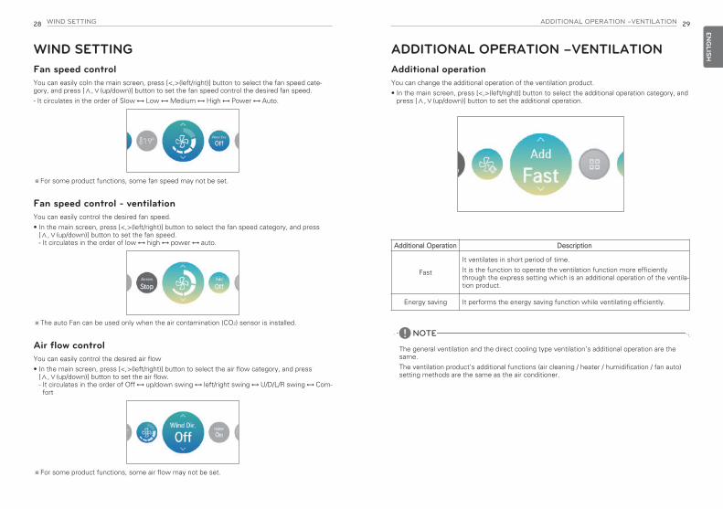
Energy setting - target instantaneous power settingIt is the function that can set the Instantaneous power’s target value.
You can set the target value to find the power consumption status.
• In the energy setting list, select “target Instantaneous power” category, and press [OK] buttonto move to the target Instantaneous power setting screen.
• In the detail screen, you can select “On/Off” to set the target Instantaneous power. If it is set to On, you can set the target Instantaneous power (minimum 1kW), and after the set-ting, if you press [OK] button, the set value is saved.
- If the outdoor unit capacity is set, the maximum value is the outdoor unit capacity
- If the outdoor unit capacity is not set, the maximum value is 9999kWIf you do not press [OK] button but press “Back’ button, it moves to the list screen withoutsaving the set value.
• When the target Instantaneous power setting is set to “On”, in the Instantaneous powerscreen, it is displayed as “all” capacity.
OK
OK
Energy setting - target power consumptionIt is the function to set the target power consumption per hour.
• In the energy setting list, select “target power consumption” setting category, and press [OK]button to move to the target power consumption setting screen.
• In the detail screen, you can select “On/Off” to set the target power consumption. When it is set to On, you can set the target power consumption (minimum 1kWh, maximum100kWh), and after the setting, if you press [OK] button, the set value is saved.If you do not press [OK] button but press “Back’ button, it moves to the list screen without sav-ing the set value.
• If the target power consumption setting is set to “On”, it is displayed as the energy consump-tion’s power consumption target value.
- Daily target consumption: Weekly usage’s daily target
- Weekly target consumption: Monthly usage’s weekly target (daily target * 7)
- Monthly target consumption: Yearly usage’s monthly target (daily target * 31)
OK
OK

61ENERGY60 ENERGYEN
GLIS
H
Energy setting - target operation timeIt is the function that can set the Instantaneous power’s target value.
You can find the power consumption status by setting the target value.
• In the energy setting list, select “target operation time” category, and press [OK] button tomove to the target operation time setting screen.
• In the detail screen, you can select “On/Off” to set the target operation time.When it is set to On, you can set the target operation time (minimum 1hr. and maximum 24hr.),and after the setting, if you press [OK] button, the set value is saved. If you do not press [OK] button but press “Back’ button, it moves to the list screen without sav-ing the set value.
• If the target operation time setting is set to “On”, it is displayed as the energy consumption’soperation time target value.
- Daily target : Weekly usage’s daily target
- Weekly target : Monthly usage’s weekly target (daily target * 7)
- Monthly target : Yearly usage’s monthly target (daily target * 31)
OK
OK
Energy setting - Alarm Popup SettingIt is the function to set whether to use the target power consumption and the target operationtime notice popup window.
• In the energy setting list, select “target operation time” category, and press [OK] button tomove to the target operation time setting screen.
• In the notice popup list, select “target power consumption notice or target operation time no-tice” category, and press [OK] button to move to the detail setting screen.
• You can set the notice popup as “daily”, “weekly”, “monthly”.After the setting, if you press [OK] button, the setting is saved and moves to the previousscreen.
• When the target power consumption notice is set to “On, daily” If the daily target power consumption’s 80%, 90%, 95%, and 100% power is used a day, thepopup screen appears.
• When the target operation time notice is set to “On, daily”When the product is operated at the daily target operation time’s 80%, 90%, 95%, and 100%,the popup screen appears.
OK
OK
NOTE!The popup message appears once every hour.
OK

63FUNCTION SETTING62 ENERGYEN
GLIS
H
Energy setting – Usage data initializationIt is the function to initialize all of the power consumption and operation time information.
• In the energy setting list, select “consumption data initialization” category, and press [OK] but-ton to move to the consumption data initialization setting screen.
• In the initialization popup screen, if you press “check” button, all previously saved power con-sumption and operation time are deleted.
OK
OK
OK
FUNCTION SETTINGHow to enter function settingTo enter the menu displayed at the bottom, you need to enter the function setting menu as fol-lows.
• In the menu screen, press [<,>(left/right)] button to select the setting category, and press [OK]button to move to the setting list.
• In the setting list, select the function setting category, and press [OK] button to move to thefunction setting list.
OK

65FUNCTION SETTING64 FUNCTION SETTINGEN
GLIS
H
Function Setting
Menu Description
Vane up/down controlsetting You can control the Air Direction angle.
Elevation grill setting It is the function to operate the Elevation grill for the indoor unit filtercleaning.
Robot cleaning setting
Robot cleaning function is the function to automatically perform the fil-ter cleaning with the cleaner of the product when the air conditioner isused for certain time period. It sets the manual or automatic operationof the robot cleaning. You can set it 30 seconds after the stopping ofthe operation.
Auto dry settingAuto dry function is the function to remove mold and moisture by dry-ing the inside of the indoor unit after the cooling operation and whenthe product is turned off.
Filter status check andinitialization
When it becomes the time for the indoor unit filter cleaning, the filtercleaning display appears, and it is the function to remove the display.
Change Temperaturesetting
Change Temperature is the function to set the temperature for the au-tomatic conversion between cooling and heating according to thetemperature in AI operation mode.
Wi-Fi pairing It is the function to perform the pairing function of the Wi-Fi moduleconnected to the indoor.
Comfort saving setting It is the function to set the outdoor unit Comfort saving operationstage value.
ODU Refrigerant NoiseReduction setting
It is the function to set the outdoor unit’s refrigerant noise reductionfunction.
Defrost Mode setting It is the function to set the outdoor unit’s defrost mode operation.
Smart load control set-ting
It is the function to set the outdoor unit’s smart load control stagevalue. (Smart load control is the function to calculate the necessaryperformance with the indoor and outdoor air temperature and humid-ity and operate.)
Low noise mode timesetting
It is the function to set the start and end time of the outdoor unit’slow noise mode operation.
Advanced fan speed“Auto” It is the function to set the indoor unit’s fan auto by temperature.
Delay time setting (ex-clusive for ventilation)
It is the function to set the ventilation operation to start after the delaytime.
Midnight air cooling (ventilation interface)
It is the function to discharge indoor air and supply cool outdoor airinto the indoor during summernights to save energy.
Vane angle control settingYou can control the wind blowing angle.
- In the function setting list screen, press [∧,∨(up/down)] button to select the vane angle controlcategory, and press [OK] button to move to the up/down vane angle detail screen.
• In the detail screen, press [∧,∨(up/down)] button to select “individual control, overall control,standard”.
• Use [<,>(left/right)] button to select the vane.
- The selected vane is moving. Check the moving vane.
• Press [∧,∨ (up/down)] button to select the desired wind angle, and press [OK] button to savethe setting.
- The wind angle’s setting range can be changed to 5 stages or 6 stages according to the prod-uct.
※If you do not press [OK] button, the selected wind angle will not be reflected.
OK
NOTE!For some product types, there are products with only 1 or 2 vanes.
Control Description
Each It sets the vane angle individually.
All It sets the vane angle of all the vanes of the product at once.
Standard It sets the vane angle to the factory initialization state.

67FUNCTION SETTING66 FUNCTION SETTINGEN
GLIS
H
Elevation grill settingIt is the function to operate the Elevation grill for the indoor unit filter cleaning.
- While the product operation is stopped, if you use [<,>(left/right)] button to select the settingvalue, the grill operation status changes.
Value Description
Up Raises the Elevation grill toward the product
Stop Stops the movement of the Elevation grill
Down Lowers the Elevation grill toward the floor
NOTE!The Elevation grill setting function may not work in some products.
Robot cleaning settingRobot cleaning function is the function to perform the automatic filter cleaning with the cleanerof the product when the conditioner is used for certain period of time. It sets the manual or auto-matic operation of the robot cleaning.
- It can be set 30 seconds after the operation stop.
• You can use [<,>(left/right)] button to set the following setting values as follows.
Auto dry settingAuto dry function is the function to remove mold and moisture by drying inside the indoor unitafter the cooling operation and when the product is turned off.
• You can use [<,>(left/right)] button to set the following setting values as follows.
Value Description
Auto It automatically performs the robot cleaning when the accumulated in-door unit operation time passes 30 hours
Manual It manually performs the robot cleaning.
NOTE!The robot cleaning setting function may not work in some products.
Value Description
Use Use auto dry function
Not Use Not use auto dry function
NOTE!Auto dry setting function may not work in some products.

69FUNCTION SETTING68 FUNCTION SETTINGEN
GLIS
H
Filter sign check and initializationWhen it becomes the time for the indoor unit filter cleaning, the filter cleaning message appears,and it is the function to remove the message.
• In the function setting list, select the Filter sign check and initialization category, and press [OK]button to display the detail screen.
- When it becomes time to the filter clean, “Filter cleaning or replacement is required.” messageis displayed. Enter the Filter sign check and initialization detail screen.
- If the product has the function to display the time remaining until the filter cleaning, even if thefilter cleaning message is not displayed, you can enter the Filter sign check and initialization.
- If there is a remaining time display function, when you enter the Filter sign detail screen, youcan see the consumption and the remaining time.
OK
NOTE!• Some products have a Filter Time Remaining function that can be accessed with Filter Sign
check.
• Dirty filters will increase the cost to cool or heat the conditioned space.
• The filter check message is cleared after certain time without a separate clearing.
Filter sign Description
Good Usage time is 70% or less
Normal Usage time is 71~80%
Caution Usage time is 81~99%
Bad Usage time is 100%
Change temperature settingChange Temperature is the function to set the automatic Change Temperature between coolingand heating operation according to the temperature in AI operation mode.
• In the function setting list, select the Change Temperature category, and press [OK] button tomove to the detail screen.
It is the function that can be used only in cooling/heating product.
Example of using Change Temperature
Condition1) Mode: AI mode2) temperature: 22°C3) Change Temperature: 3°C → Change Temperature 3°C difference
※In case of the above conditions, it operates as in the graph.
OK
NOTE!The Change Temperature setting function may not work in some products.
Value
1~7°C(Default : 2°C)
Temp( )
25
22
19
: Cooling operation start: Heating operation start

71FUNCTION SETTING70 FUNCTION SETTINGEN
GLIS
H
Wi-Fi pairing settingIt is the function to perform the pairing function of the Wi-Fi module connected to the indoor unit.
• In the function setting list, select the Wi-Fi pairing category, and press [OK] button to move tothe detail screen.
- After selecting “Apply”, if you press [OK] button, the Wi-Fi pairing popup window is created,select “check” and press [OK] button to request the Wi-Fi pairing.
OK
NOTE!The Wi-Fi setting function may not work in some products.
Comfort cooling settingIt is the function to set the outdoor unit Comfort saving operation value.
• You can set the following values using [<,>(left/right)] button.
ODU Refrigerant Noise Reduction settingIt is the function to set the outdoor unit’s refrigerant noise reduction function.
• You can use [<,>(left/right)] button to set the following setting values as follows.
Value
Step 1
Step 2
Step 3
NOTE!The Comfort cooling function does not work in the group control.
Comfort cooling setting function is only available in some products.
NOTE!The ODU Refrigerant Noise Reduction function can be set only when the installer setting’soutdoor unit function M/S setting is set to “Master”.
ODU Refrigerant Noise Reduction function is only available in some products.
Value Description
Step 0 Not use
Step 1 Outdoor unit noise mode 1
Step 2 Outdoor unit noise mode 2

73FUNCTION SETTING72 FUNCTION SETTINGEN
GLIS
H
Defrost mode settingChange the outdoor unit’s defrost mode operation.
• Select value using [<,>(left/right)] button.
Value
Step 0 Not use
Step 1 Forced snow removal
Step 2 Quick defrost
Step 3 Forced snow removal + quick defrost
NOTE!The Defrost mode setting function can be set only when the installer setting’s outdoor unitfunction M/S setting is set to “Master”.
Defrost mode setting function is only available in some products.
Smart load control(SLC) settingChange the outdoor unit’s Smart Load Control stage value. (Smart load control is the function to calculate the indoor air temperature, outdoor air tempera-ture, and humidity to operate effectivly.)
• In the function setting list, select the Smart load control category, and press [OK] button tomove to the detail screen.
- When SLC is operations, on the expanded screen’s monitoring information, ‘In Smart load con-trol’ is displayed.
Value
Off Step 0
On
Step 1
Step 2
Step 3
NOTE!Smart load control function can be set only when the installer setting’s outdoor unit functionM/S setting is set to “Master”.
Smart load control function is only available in some products.
OK

75FUNCTION SETTING74 FUNCTION SETTINGEN
GLIS
H
Low noise mode time settingIt is the function to set the start and end time of the outdoor unit’s low noise mode operation.
• In the function setting list, select the filter ODU silent mode timer category, and press [OK] but-ton to move to the detail screen.
- After setting the start time and the end time, press [OK] button to move to the upper levellist.
- If the start time and the current time are the same, it enters the outdoor unit low noise opera-tion mode, and in the monitoring screen, ‘in outdoor unit low noise operation mode’ messageis displayed.
- If the end time and the current time are the same, the outdoor unit low noise operation modeis cleared.
NOTE!Low noise mode time setting function can be set only when the installer setting’s outdoorunit function M/S setting is set to “Master”.
Low noise mode time setting function is only available in some products.
OK
CAUTION
If the function is not used, please set it to Off.
When you enter the low noise operation, the cooling capacity may be degraded.
!
Advanced fan speed “Auto” settingIt is the function to set the indoor unit’s temperature based auto fan usage.
It is the function to automatically change the fan speed according to the difference between theindoor temperature and the desired temperature.
• You can set the following setting values using [<,>(left/right)] button.
Value Description
Set Do not change the fan speed automatically
Clear Change the fan speed automatically
NOTE!Advanced fan speed “Auto” setting function is only available in some products.

77FUNCTION SETTING76 FUNCTION SETTINGEN
GLIS
H
Delay time (exclusive for ventilation)It is the function to set the ventilation operation to start after the delay time.
• In the function setting list, select the delay time category, and press [OK] button to move to thedetail screen.- After setting the minute, press [OK] button to move to the upper level list.
Value
0 ~ 60 Minutes
OK
Midnight air cooling (ventilation interface)It is the function to discharge indoor air and supply cool outdoor air into the indoor during sum-mer nights to save energy.
• In the function setting list, if you select midnight outdoor air cooling category and press [OK]button, it moves to the detail screen.- When you set the start and end time and press [OK] button, it saves and moves to the upperlevel list.
NOTE!Whether to run the midnight air cooling is decided only when both air conditioner and ventila-tion are stopped.
• Even if it is the set midnight air cooling time, it enters the midnight air cooling only whenthe outdoor temperature conditions is met.
• During the midnight air cooling operation, “in midnight outdoor air cooling” message is dis-played on the monitoring screen.
• Midnight air cooling function may not work in some products.
OK
CAUTION
. If you do not use the function, please set it as off.
!

79FUNCTION SETTING78 FUNCTION SETTINGEN
GLIS
HUSER SETTINGHow to enter user settingTo enter the menu displayed at the bottom, you need to enter the user setting menu as follows.
• Select the setting category, and press [OK] button to move to the setting list.
• Select the user setting category, and press [OK] button to move to the user setting list.
User Setting• You can set the product user functions.
• Some functions may not be available in some product types.
OK
Menu Description
Language setting Set the language to be displayed on the remote controller.
Temperature unit setting Set the temperature unit displayed on the remote controller.
Screen saver timer setting Adjust the screen Off time of the remote controller.
LCD brightness in idle setting Adjust the remote controller’s screen brightness.
External device setting Set the name of external equipment and equipment logic setting
Date setting Set the date displayed on the remote controller.
Time setting Set the time displayed on the remote controller.
Summer time setting Set the summer time in the remote controller.
Password setting Set the password to prevent unauthorized change to remote con-troller settings.
Schedule initialization Initialize all timer settings in the remote controller.
Theme setting Set the theme of the remote controller screen.
System reboot Restart the remote controller.
Language settingSet the language to be displayed on the remote controller.
• In the user setting list, select the language category, and press [OK] button to move to the de-tail screen.
• After the setting, if you press [OK] button, the setting is saved and moves to the previousscreen.
Language
한국어 English Français
Deutsche Italiano Español
Русский Polskie Português
中文 Čeština
OK

81USER SETTING80 USER SETTINGEN
GLIS
H
Temperature unit settingSet the temperature unit displayed on the remote controller.
• In the user setting list, select the temperature unit setting category, and press [OK] button tomove to the detail screen.
ValueCelsius
1°C
0.5°C
Fahrenheit
OK
CAUTION
The temperature unit function may not work or work differently in some products.
You cannot set the temperature unit in the slave wired remote controller.
!
Screen saver timer settingAdjust the screen Off time of the remote controller.
• Select the following setting values using [<,>(left/right)] button.
Value
15sec 30sec (default) 1min
CAUTION
Selecting longer stand by screen will decrease LCD lifespan.
!

83USER SETTING82 USER SETTINGEN
GLIS
H
LCD brightness in idle settingAdjust the remote controller’s screen brightness.
• Select the following setting values using [<,>(left/right)] button.
Value
0% 10%(default) 20% 30%
CAUTION
Selecting brighter stand by screen will decrease LCD lifespan.
!
External device settingSet the name of external equipment and equipment logic setting
• In the user setting list, select the external device setting category, and press [OK] button tomove to the detail screen.
External device use• In the external device setting list, select “External device use” category, and press [OK] button
to move to the external device use setting screen.- If external device use setting value is use, you can see the control unit of external device inmain screen.
OK
Value
Not use Use

85USER SETTING84 USER SETTINGEN
GLIS
H
External device typesIt is the function to set the name of the External device attached to the remote controller.
• You can set the following setting values using [<,>(left/right)] button.
Value
Motor Lighting Fan Heater Pump Others
On condition / Off conditionIt is the function to set to use the information managed by the wired remote controller as thecontact point control condition to widen the usage of the contact point (Digital Output) installed inthe remote controller.
• In the external device setting list, select the On/Off condition setting category, and press [OK]button to move to the detail screen.
• The External device operates as the operation set in the conditions 1~3.
• If the External device is set to auto while both ON condition and OFF condition are not set, con-tact point OFF is output.
• If the ON condition and OFF condition are the same, it is finally processed as OFF condition.
OK
Condition 1 Condition 2 Condition 3 Condition 4
None Deactivate - Deactivate
Aircon
On -
External device name On
External device name Off
Cool mode -
Heat mode -
Fan mode -
Dry mode -
Auto mode -
Current Temp. 1°C~ 39.5°COver
Under
Occupied - -
Unoccupied - -

87USER SETTING86 USER SETTINGEN
GLIS
H
Date settingSet the date displayed on the remote controller.
• In the user setting list, select the date category, and press [OK] button to move to the detailscreen.
• After the setting, if you press [OK] button, the setting is saved and moves to the previousscreen.
OK
Time settingSet the time displayed on the remote controller.
• In the user setting list, select the time category, and press [OK] button to move to the detailscreen.
• After the setting, if you press [OK] button, the setting is saved and moves to the previousscreen.
OK

89USER SETTING88 USER SETTINGEN
GLIS
H
Summer time settingSet the daylight savings time dates in the remote controller.
• In the user setting list, select the summer time setting category, and press [OK] button tomove to the detail screen.
- Summer time: The system to advance the time by 1 hour from the spring when the day islonger and return back in the fall when the day gets shorter.
- When it becomes AM 02:00 on the DST start date, the current time changes to AM 03:00,and when it becomes AM 02:00 of the DST end date, the current time changes to AM 01:00.
OK
Password settingSet the password to prevent unauthorized change to remote controller settings.
• Select the user password setting category, and press [OK] button to move to the detail screen.
- If the password is set, when you enter “menu – setting”, you need to input password toenter the setting list.
- When you forgot the password, you can initialize the password using the installer setting’s“password initialization”.The initialized password is “0000”.
OK

91USER SETTING90 USER SETTINGEN
GLIS
H
Schedule initializationInitialize all timer settings in the remote controller.
• In the user setting list, select the schedule initialization setting category, and press [OK] buttonto move to the detail screen.
- Press the check button to initialize the sleep/simple timer, on/off timer, schedule and excep-tion date in the remote controller.
OK
Theme settingSet the theme of the remote controller screen.
• Select either white or black using [<,>(left/right)] button.

93SERVICE SETTING92 USER SETTINGEN
GLIS
H
System restartRestart the remote controller.
• In the user setting list, select the system restart setting category, and press [OK] button tomove to the detail screen.
- In the detail screen, when you press [OK] button, a popup message is displayed, press thecheck button, to restart the system.
- For forced reset, press down [On/Off + Back] button for 5 seconds to restart the system.
OK
SERVICE SETTINGHow to enter service settingTo enter the menu displayed at the bottom, you need to enter the service setting menu as fol-lows.
• In the menu screen, press [<,>(left/right)] button to select the setting category, and press [OK]button to move to the setting list.
• In the setting list, select the service setting category, and press [OK] button to move to theservice setting list.
Service setting• You can set the product service functions.
• Some functions may not be displayed/operated in some product types.
OK
Menu Description
Service contact Check and input the service center phone number that you can callwhen there is service issue.
Model Information Check the indoor/outdoor product group and capacity information towhich the remote controller is connected.
RMC Version Information Check the remote controller model name and software version.
Error History View the connected indoor unit’s error history.
Open Source License View the remote controller’s open source license.

95SERVICE SETTING94 SERVICE SETTINGEN
GLIS
H
Service contactCheck and input the service center phone number that you can call when there is service issue.
• In the service setting list, select the service contact point and press [OK] button to move to thedetail screen.
• While “edit” button is selected, press [OK] button to move to the edit screen, change it, andpress [OK] button to change the service contact point.
OK
OK
Model informationCheck the indoor/outdoor product group and capacity information to which the remote controlleris connected.
• In the service setting list, select the indoor/outdoor model information category, and press [OK]button to move to the detail screen.
• Indoor unit capacity
- 1kWh = 1kBtu * 0.29307kWh is the result calculated based on Btu, There may be a small difference between calcu-lated and actual capacity.Ex) If the indoor unit capacity is 18kBtu, it is displayed as 5kWh.
OK

97SERVICE SETTING96 SERVICE SETTINGEN
GLIS
H
RMC Version InformationCheck the indoor/outdoor product group and capacity information to which the remote controlleris connected.
• In the service setting list, select the remote controller version information check category, andpress [OK] button to move to the detail screen.
OK
Error historyView the connected indoor unit’s error history.
• In the service setting list, select ‘check error history’ category, and press [OK] button to moveto the detail screen.
- You can view up to 20 error instances sorted by date occurred.
OK

99INSTALLATION98 SERVICE SETTINGEN
GLIS
H
Open source licenseView the remote controller’s open source license.
• In the service setting list, select the open source license category, and press [OK] button tomove to the detail screen.
OK
INSTALLATIONInstallation of Remote Controller• After fixing the remote controller installation plate on the desired location, fix it firmly with the
provided screws.
- If the installation is bent, installation defect may occur, so install it without bending.
- If there is a reclamation box, install the remote controller installation plate according to thereclamation box as in the following figure.
- Do not leave a gap with the wall or product shaking after the installation.
• The wired remote controller cable can be installed in 3 directions. Install to the suitable direc-tion according to the installation environment.
- Installation direction: wall reclamation, top side, right side
- When you install the remote controller cable at the top side and right side, remove the remotecontroller cable guide hole before the installation.※ Use a long nose to remove the guide hole.
• After removing the hole, trim the cut surface neatly.
• After fixing the remote controller top side on the installation plate attached to the wall as in thefollowing figure, press the bottom side to combine with the installation plate.
- Do not leave a gap in the top, bottom, left, and right side of the remote controller and the in-stallation plate after combining them.
- Before combining with the installation plate, arrange the cables to avoid interference with thecircuit parts.
<Order of Combining>
<4 socket reclamation box installation> <2 socket reclamation box installation>
Top side guide groove
Top side guide groove
Wall reclamation
Right side guide groove
Right side guide groove
Wall Wall

101INSTALLATION100 INSTALLATIONEN
GLIS
H
• When you remove the remote controller from the installation plate, insert a small flat headscrewdriver into the bottom side separation hole and turn clockwise to separate the remotecontroller.
- There are 2 separation holes at the bottom part. Slowly separate one by one.
- Be careful not to damage the internal parts during the removal.
<Order of Separation>
• Use the connection cables to connect the indoor unit with the remote controller.
• For the following cases, separately purchase and use the cables suitable for the situation.
- Do not install the cable over 50 m. (It may cause communication issues.)
- If the distance between the wired remote controller and the indoor unit is 10 m or more : 10m extension cable (model name: PCW-QE10A)
- If you control several indoor unit products with one wired remote controller : Group controlcable (model name: PCW-QG00A)
Wal
l Sid
e
Please check if connector is normally connected.
Connecting cable
IndoorUnit sideOK
DC 12 V Red
Signal Yellow
GND Black
NOTE!During the wired remote controller installation, do not install with wall reclamation. (It maycause temperature sensor failure.)
Do not install the cable over 50 m. (It may cause communication defect.)
When you install the extension cable, carefully check the direction of the connectors on theremote controller side and the product side before the installation.
When you install the extension cable, carefully check the direction of the connectors on theremote controller side and the product side before the installation.
Extension cable specification: Use 2547 1007 22# 2core 3shield, 5 Ø or equivalent or higherlevel
Group control
• It connects and controls 2 or more air conditioner indoor units to one wired remote controller.
※Connect using the group control cable.
① Group control cable (PZCWRCG3): Connect to indoor unit’s wired remote controller connector
② Extension cable (PZCWRC1): Connect to No. ① cable and slave indoor unit’s wired remotecontroller connector
While No. ① cable is connected, connect No. ② cable.
• After checking the existence of the event communication in the product manual, change mas-ter/slave of the remote controller.
※For details, refer to ‘remote controller master/slave’ contents.
• Change master/slave of the indoor unit.- For ceiling cassette and duct product group, change the setting with the indoor unit PCBswitch.
Indoor unit Main PCB
Indoor unit 1 Indoor unit 2 Indoor unit 3Master Slave SlaveRED(12V)YELLOW(SIG)BLACK(GND)
YELLOW(SIG)BLACK(GND)
YELLOW(SIG)BLACK(GND)
OK
1 2
NOTE!• Connect only GND and signal cable to the indoor unit set as slave. (If power cable is also
connected, it may cause loss of communication)
• Inquiries related to the purchase of the cable shall be directed to the specialized companyand the service center.
Master Slave Slave
GND
GND
12VSignal cable
Signal cable
Black Red
No. 3 switch OFF: master (factory ship-out based)
No. 3 switch ON: slave
YellowYellow
Yellow
OK

103INSTALLATION METHOD TO USE EXTERNAL DEVICE102 INSTALLATIONEN
GLIS
H
- For the details on the wireless remote controller master/slave setting changes, refer to thewireless remote controller manual.
- After completing the master/slave setting in the indoor unit product, turn Off the power of theindoor unit product, and turn On the power after 1 minute.
NOTE!• During the group control, set only 1 indoor unit as master.
• During the group control, some functions other than the basic operation setting, fan speedLow/Med/High, remote controller lock setting, and time setting may be limited.
• During the individual control, if the master indoor unit Dip switch is set to slave, malfunctionmay occur.
INSTALLATION METHOD TO USE EXTERNALDEVICECable connection method to use external device1) Wired remote controller-cable connection method.
- In the wired remote controller, connect the part marked in the following figure (J02C, DO-Port) to the cable.
- According to the installation environment, there are 3 directions (wall reclamation, top side,and right side) for the installation.
2) Cable extension connection method
- Among the cables connected to the wired remote controller, cut the remaining connectorson the other side, and then extend and connect the cables
- Extension cable specification: 24~26AWG.
CAUTION
For the External device connection, use the cable insulated with sheath for the extension connec-tion.
Before combining with the installation plate, arrange the cables to avoid interference with the in-ternal parts.
!
RMCDO-Port
2 (GND_Black)3 (DC 12 V_Red)
Field connection
30cm• Output specification - Voltage : DC 11~12V - Current : 5mA
Remote controller product composition

105INSTALLER SETTING104 AIR CONDITIONER AND VENTILATION INTERFACEEN
GLIS
HAIR CONDITIONER AND VENTILATION IN-TERFACE• It controls using the wired remote controller at a place where the air conditioner indoor unit and
the ventilation product are connected and installed at the same time.
- When the power is applied, the remote controller recognizes the product and operates nor-mally.
※The wiring method is the same as the air conditioner user manual. (Refer to the remote con-troller manual group control page contents)
※Ventilation product means general ventilation product and direct cooling type ventilation prod-uct.
Independent operation Interfaced operation
Generalventilation
Wiredremotecontroller
Generalventilation
OK
Wiredremotecontroller
GeneralventilationAir conditioner
indoor unit
OK
Directventilation
Wiredremotecontroller
Generalventilation
OK
Wiredremotecontroller
GeneralventilationAir conditioner
indoor unit
OK
[general ventilation independent operation]
[General ventilation interfaced operation]
[Direct ventilation interfaced operation] [Direct ventilation independent operation]
INSTALLER SETTINGHow to enter installer setting
• In the menu screen, press [<,>(left/right)] button to select the setting category, and press[∧(up)] button for 3 seconds to enter the password input screen for the installer setting.
• Input the password and press [OK] button to move to the installer setting list.
※Installer setting password
Main screen → menu → setting → service → RMC version information → SW Version
Example) SW version : 1.00.1 a
In the above case, the password is 1001.
CAUTION
The installer setting mode is the mode to set the remote controller’s detail function. If the in-staller setting mode is incorrectly set, it may cause product failure, user’s injury, or property dam-age. It must be set by the installation specialist with the installation license, and if it is installed orchanged without installation license, all problems caused will be the responsibility of the installer,and may void the LG warrenty.
!
OK OK
NOTE!Some categories of the installer setting menu may not be available depending on the prod-uct function or the menu name may be different.

107INSTALLER SETTING106 INSTALLER SETTINGEN
GLIS
H
Installer setting – air conditioner• You can set the product user functions.
• Some functions may not be displayed/operated in some product types.
Menu Description
Test run setting It is the function to set the trial operation at the initial product installa-tion.
Central control address
SettingIt is the function to set the central control address of the indoor unitduring the central controller connection.
ESP setting It is the function to set the wind amount value corresponding to eachwind amount for easy installation.
Temperature sensor setting It is the function to select the temperature sensor that will decide theindoor temperature.
Ceiling height setting It is the function to control the wind amount stage according to theceiling height for the ceiling type products.
Static pressure setting The fixed pressure setting can be set only in the duct products.It cannot be set in other products.
RMC master/slave setting It is the function to set group control or 2-remote controller control.
Override master/slave setting
The operation master / slave selection function is to avoid other modeoperations, and it is the function to prevent the selection of the oppo-site mode of the indoor unit set as master by the indoor units set asslaves.
Dry contact mode setting Dry contact function is the function that can be used only when thedry contact devices is separately purchased and installed.
Fixed fan speed setting It is the function to apply different fan speeds automatically for eachthermal control status.
Emergency Heater setting It is the function to set whether to use emergency heater controlfunction and the usage environment.
Func. control during grp. Control setting
It is the function to set common functions or some functions to becontrolled by the master indoor unit standard during the group control.
Option Kit – Plasma / Heater /Humidification / Elevation grill/ Ventilation / Refrigerant leak-
age detection sensor
It is the function to set whether to mount option unit (Plasma / Humid-ification / Heater / Ventilation / Elevation grill / Refrigerant leakage de-tection sensor) when it is additionally installed or removed after themass production.
Indoor unit address verifica-tion
This function allows you to check the address of the indoor unit desig-nated by the outdoor unit.
Refrigerant leak sensor set-ting
It is the function to set whether to install the leakage sensor in the in-door unit Flare locking part and welding part.
Menu Description
Static pressure step setting This is the function that static pressure of the product is divided in 11steps for setting.
Cooling thermal off fan opera-tion setting
It is a function that sets the indoor unit fan movement, in coolingmode, when thermal is off.
Primary heater setting It is the function to set the heater usage to have higher priority overthe outdoor unit cycle during the indoor unit heating operation.
Air conditioner Fan operationinterlocked with ventilation
setting
It is the function to set whether to operate the air conditioner fan dur-ing the interface operation of the air conditioner and the ventilationproduct.
Indoor unit Auto-Start
setting
It is a function that sets whether to restore the indoor unit operationby resuming the previous power-on state or as power-off state in thepower failure compensation.
Occupancy duration time setting
It is the function to set the occupied decision maintaining time amongthe occupied sensor values.
CN_CC settingIt is the function to set whether to install (use) Dry Contact. (It is not a function for Dry Contact installation, but it is a function toset the usage of the indoor unit’s CN_CC port.)
CN_EXT setting
It is the function to set the indoor unit’s Dry Contact Port to control ex-ternal input and output according to DI/DO set by the customer. (It isthe function to decide the usage of the contact point port (CN_EXT)mounted in the indoor unit PCB.)
ODU function master setting It is the function to set the outdoor unit’s function Master / Slave.
Fan continuous operation setting
It is the function to set the indoor unit’s continued Fan function usage.It is the function to maximize the cooling/heating efficiency by the out-door unit operating the indoor unit fan operation longer than the previ-ous operation method.
Low noise mode priority setting
It is the function to set the main agent of the low noise mode control.(It is the function to set only one of the outdoor unit / remote con-troller can control the low noise operation.)
Password initialization It is the function to initialize (0000) the password when you forgot thepassword set in the remote controller.

109INSTALLER SETTING108 INSTALLER SETTINGEN
GLIS
H
Installer setting - ventilator• You can set the product user functions.
• Some functions may not be displayed/operated in some product types.
Menu Applied products Description
Test run setting DX(Direct Ex-changer) Type
It is the function to set the trial operation at the initialproduct installation.
Central control addressSetting General It is the function to set the central control address of
the indoor unit during the central controller connection.
Air supply ESP
General/DX Type
It is the function to set the fan speed value correspon-ding to the air supply side fan speed.
Air discharge ESP It is the function to set the fan speed value correspon-ding to the air discharge side fan speed.
Product direction General It is the function to set the ventilation indoor unit’s in-stallation direction.
Express ventilation pri-ority
General/DX Type
It is the function to set the priority of the air supply anddischarge during the express ventilation operation.
RMC master/slave set-ting
It is the function to set group control or 2-remote con-troller control.
Override master/slavesetting DX Type
The operation master / slave selection function is toavoid other mode operations, and it is the function toprevent the selection of the opposite mode of the in-door unit set as master by the indoor units set asslaves.
Dry contact mode set-ting DX Type
Dry contact function is the function that can be usedonly when the dry contact devices is separately pur-chased and installed.
Fixed fan speed setting DX Type It is the function to set the indoor unit’s fan speed op-tion to variable or fixed.
Hum. Of Stand-aloneVent. Mode General/DX Type
It is the function to set whether to use the humidifica-tion function in the direct cooling type ventilation’s ven-tilation single operation.
Hum. Of Vent. WithHeating Oper. DX Type It is the function to set the direct cooling type ventila-
tion’s heating humidification function as auto or manual.
Vent. Fan Speed Align-ment General
It is the function to increase/decrease ventilation’s stan-dard fan speed from the current status according to thefield environment.
Test run setting (air conditioner / DX ventilator)After product installation, the Test run must be performed. For Test run related details, refer tothe product manual.
• In the installer setting list, select the Test run setting category, and press [OK] button to moveto the detail screen.
- You can select ‘cooling Test run / heating Test run’
- During the Test run, if you start the following functions, the Test run stops.
☞ Operation mode, desired temperature, fan speed, wind direction, start/stop
OK

111INSTALLER SETTING110 INSTALLER SETTINGEN
GLIS
H
Central control address setting (air conditioner / DX ventilator)It is the function to set the central control address of the indoor unit to allow communication witha central controller,
• In the installer setting list, select the central control address setting category, and press [OK]button to move to the detail screen.
- Select a hex value between 00 and FF.Value 1: group address setting / value 2: indoor unit address setting
OK
ESP setting (air conditioner / general, DX ventilator)It is the function to set the fan speed value corresponding to each fan speed for easy installation.
• In the installer setting list, select the ESP setting category, and press [OK] button to move tothe detail screen.
OK
NOTE!If ESP is incorrectly set, the air conditioner may malfunction.
This function must be set by the installation specialist that holds an installation license.
For ventilation products, separate ESP values are used for the supply and exhaust fans.
NOTE!Be especially careful not to switch ESP values corresponding to each fan speed.
Engineering manuals have ESP setting tables that reference air flow and correspondingvalue setting to achieve the flow.
The ESP values that can be set may be different for each product and capacity.
Product ESP fan speed value
Air conditioner
Slow
0 ~ 255
Low
Med
High
Power
Ventilation
Low
High
Power

113INSTALLER SETTING112 INSTALLER SETTINGEN
GLIS
H
Temperature sensor(2TH) setting(air conditioner)It is the function to select the temperature sensor to decide the indoor temperature.
• You can set the following setting values using [<,>(left/right)] button.
• 2TH function’s operation characteristics may be different for each product.
Temperature sensor location Description
Remote controller Operate the system with wired remote controller’s temperaturesensor
Indoor Unit Operate the system with indoor unit’s temperature sensor
2TH
CoolCompare the temperatures of the indoor unit and the wired re-mote controller and operate with the higher temperature (There are system operated with lower temperature)
Heat Compare the temperatures of the indoor unit and the wired re-mote controller and operate with the lower temperature
Ceiling height setting (air conditioner)It is the function to control the fan speed stage according to the ceiling height in the ceiling typeproduct.
• You can set the following setting values using [<,>(left/right)] button.
Ceiling height Description
Low Fan speed operates one step slower than the default value.
Standard Operates at the default fan speed
High Fan speed operates one step faster than the default value.
Very high Fan speed operates two steps faster than the default value.
NOTE!When group control is enabled some functions are limited depending on product type.

115INSTALLER SETTING114 INSTALLER SETTINGEN
GLIS
H
Static pressure setting(air conditioner)Static pressure setting can be set only in the duct products. (It cannot be set in other products.)
• You can set the following setting values using [<,>(left/right)] button.
• 2TH function’s operation characteristics may be different for each product.
Static pressureDescription
Variable / Fixed ESP default value
Variable high static pressure V-H Variable High static pressure(High)
Fixed high static pressure F-H Fixed High static pressure(High)
Variable low static pressure V-L Variable Low static pressure(Low)
Fixed low static pressure F-L Fixed Low static pressure(Low)
Remote controller master / slave setting (air conditioner / General, DX ventilator)This function sets configuration for the master/slave setting through the remote controller.
• Change setting values using [<,>(left/right)] button.
• 2TH function’s operation characteristics may be different for each product.
M/S Description
Master (default) Using group control, the indoor units are operated based on the re-mote controller.
Slave Using group control, all remote controllers except 1 master remotecontroller are set as slaves.

117INSTALLER SETTING116 INSTALLER SETTINGEN
GLIS
H
Override M/S setting (air conditioner / General, DX ventilator)The operation master / slave selection function is to avoid other mode operations, and it is thefunction to prevent the selection of opposite mode of the indoor unit master by the indoor unitsset as slaves.
• Change setting values using [<,>(left/right)] button.
M/S Description
Master Using group control, this master sets the made of slave IDU’s.
Slave
For the indoor unit set as slave, it can only select the some operationmode of the master indoor unit cycle.
Ex) Master is in cooling cycle, Slave can select cooling, dehumidifica-tion, auto, and wind only
Master is in heating cycle, Slave can select auto, heating, and windonly
NOTE!Override M/S setting function is only available in some products.
Dry contact mode setting (air conditioner / DX ventilator)Dry contact function is the function that can be used only when the dry contact devices is sepa-rately purchased and installed.
• Change setting values using [<,>(left/right)] button.
Value
Auto
manual
NOTE!For dry contact mode related detail functions, refer to the individual dry contact manual.
What is dry contact?
It means the contact point signal input when the hotel card key, human body detection sen-sor, etc. are interfacing with the air conditioner.
Added system functionality by using external inputs (dry contacts and wet contacts).

119INSTALLER SETTING118 INSTALLER SETTINGEN
GLIS
H
Fixed fan speed setting (air conditioner / DX ventilator)It is the function to apply different fan speeds automatically for each thermal control status.
• You can set the following setting values using [<,>(left/right)] button.
Value Comp on Comp off
Variable Set fan speed Low
Fixed Set fan speed Set fan speed
Emergency heater setting (air conditioner)Enable the emergency heater control function and the usage environment.
• In the installer setting list, select the emergency heater setting category, and press [OK] buttonto move to the detail screen.
- In case of an error, it sets whether the emergency heater can be used / outdoor temperaturestandard heater operation usage setting and temperature step value setting / and during theemergency heater operation, whether to use the indoor unit fan operation.
OK
Value Outdoor temperature standard heater operation
Fan operation in emergencycontrol
Not use - -
Use
Emergency heater Step 0 ~ 3
On/OffExtended emer-
gency heater Step 0 ~ 15
NOTE!This function setting must be carried out by a certified-technician.

121INSTALLER SETTING120 INSTALLER SETTINGEN
GLIS
H
Function control during group Control setting (air conditioner)This function enables the control of the common functions or some functions based on the mas-ter indoor unit during the group control.
• Change setting values using [<,>(left/right)] button.
Value Description
Not use Common function,
Use Use expanded function whichis based on master indoor unit
NOTE!Common functions and some indoor unit master standard setting shall be set only duringthe group control with the same type indoor units.
During the group control with different indoor unit types, set it as ‘000’ to use the existinggroup control method.
External devices of indoor unit setting (air conditioner)At the Code field, select when air cleaner/heater/humidifier/elevation grill/ventilation KIT/refriger-ant leakage detection sensor are newly installed to the indoor unit or when an installed KIT is re-moved.
• You can set the following setting values using [<,>(left/right)] button.
Function Value
Plasma purification
Not install / Install
Heater
Humidifier
Elevation grill
Ventilation Kit
Refrigerant leakage detection sensor

123INSTALLER SETTING122 INSTALLER SETTINGEN
GLIS
H
Indoor unit address verification (air conditioner)This function allows you to check the address of the indoor unit designated by the outdoor unit.
• In the installer setting list, select the indoor unit address check category, and press [OK] buttonto move to the detail screen.
OK
Static pressure step setting (air conditioner)It is the function to subdivide and set the product’s Static pressure to 11 stages.
• Change setting values using [<,>(left/right)] button.
Value
Step 0 ~ Step 11
NOTE!If Static pressure step setting is used, the Static pressure setting is not used.
For the Static pressure step value for each stage, refer to the indoor unit product manual

125INSTALLER SETTING124 INSTALLER SETTINGEN
GLIS
H
Fan speed in Cooling thermal off (air conditioner)Indoor unit fan, in cooling mode, during thermal off condition.
• Select value using [<,>(left/right)] button.
Value
Fan speed low
Fan off
fan speed setting value
Primary heater setting(air conditioner)It is the function to set the air conditioner fan operation if the ventilation is operated while the airconditioner operation is stopped when the air conditioner and the ventilation are installed to inter-face with each other.
• You can set the following setting values using [<,>(left/right)] button.
Value Description
Not use During the heating, heater is set to be used as secondary
Use During the heating, heater is set to be used as main

127INSTALLER SETTING126 INSTALLER SETTINGEN
GLIS
H
Air conditioner Fan operation interlocked with ventilation setting(air conditioner)It is the function to set the air conditioner fan operation if the ventilation is operated while the airconditioner operation is stopped when the air conditioner and the ventilation are installed to inter-face with each other.
• You can set the following setting values using [<,>(left/right)] button.
- When the air conditioner operation is Off, if the ventilation product is in operation, the air condi-tioner fan shall be operated, and when the fan is in operation, dust may fall, so it is the functionto set the air conditioner fan operation status in case of ventilation interface through the setting.
Value Description
Off The air conditioner indoor unit Fan is Off during the ventilation interface
On The air conditioner indoor unit operates in very weak wind during the ventila-tion interface
Indoor unit Auto-Start setting(air conditioner)It is a function that sets whether to restore the indoor unit operation by resuming the previouspower-on state or as power-off state in the power failure compensation.
• You can set the following setting values using [<,>(left/right)] button.
Value Description
Use Use indoor unit auto restart
Not use Not use indoor unit auto restart

129INSTALLER SETTING128 INSTALLER SETTINGEN
GLIS
H
Occupancy duration time setting(air conditioner)It is a function that sets the light-on/occupancy duration after motion is detected when installingan occupancy sensor.
• You can set the following setting values using [<,>(left/right)] button.
Value
0 Minute
10 Minutes
30 Minutes
60 Minutes
CN_CC setting (air conditioner)It is the function to set the usage of the indoor unit’s CN_CC port.
• Select CN_CC setting category, and press [OK] button to move to the detail screen.
OK
Value Description
DC auto install (default)
When power is applied to the product, indoor unit when the contactpoint is on in Dry Contact installed state recognizes Dry Contact installa-tion
DC manual not install Do not use (install) Dry Contact
DC manual install Use (install) Dry Contact
Programmable DI/DO Use as Programmable DI/DO (Simple On/Off)
NOTE!CN_CC is the device connected to the indoor unit to recognize and control the external con-tact point.

131INSTALLER SETTING130 INSTALLER SETTINGEN
GLIS
H
CN_EXT setting (air conditioner)It is the function to set to control the external input and output according to DI/DO set by the cus-tomer using the indoor unit’s Dry Contact Port. (It is the function to decide the usage of the con-tact point port (CN_EXT) mounted in the indoor unit PCB.)
• In the installer setting list, select CN_EXT setting category, and press [OK] button to move tothe detail screen.
OK
Value Description
Not use (default)
Use installer code No. 41 setting value (simple Dry Contact settingvalue)
Simple operation control Simple operation On/Off
Single emergency stop Indoor unit single emergency stop
Occupied / Unoccupied Occupied / Unoccupied
All emergency stopIndoor unit all emergency stop
※It can be set only when there is indoor unit emergency stopfunction.
Outdoor unit function master setting (air conditioner)It is the function to set the outdoor unit’s function Master / Slave.
• You can set the following setting values using [<,>(left/right)] button.
Value Description
Slave
Cannot enter the Smart load control function settingCannot enter the low noise operation time settingCannot enter the refrigerant noise reduction settingCannot enter the defrost mode setting
Master
Smart load control function setting is possibleLow noise operation time setting is possibleRefrigerant noise reduction setting is possibleLow noise operation control main agent setting is possibleDefrost mode setting is possible
CAUTION
※When you change the outdoor unit function master setting from master to slave, check the op-eration status of the outdoor unit function (outdoor unit low noise operation, smart load control)and make sure to stop the outdoor unit function before the change.
!

133INSTALLER SETTING132 INSTALLER SETTINGEN
GLIS
H
Fan continuous operation setting (air conditioner)It is the function to set the indoor unit’s continued fan function usage. (It is the function to maxi-mize the cooling/heating efficiency by the outdoor unit operating the indoor unit fan operationlonger than the previous operation method.)
• You can set the following setting values using [<,>(left/right)] button.
Value Description
Clear Do not use continued fan usage
Set Use continued fan usage
Low Noise Mode Priority setting (air conditioner)It is the function to set the low noise mode control main agent. (It is the function to set that onlyone of the outdoor unit / remote controller can control the low noise operation.)
• You can set the following setting values using [<,>(left/right)] button.
Value Description
RMCIgnore the outdoor unit PCB’s low noise operation Switch Setting value- Function setting – remote controller low noise operation time menu de-activation
ODU(default)
It is controlled in the outdoor unit itself according to the outdoor unitPCB’s low noise operation Switch Setting value- Function setting – remote controller low noise operation time menu de-activation

135INSTALLER SETTING134 INSTALLER SETTINGEN
GLIS
H
Password initialization (air conditioner / general, DX ventilator)It is the function to initialize (0000) when you forgot the password set in the remote controller.
• In the installer setting list, select the password initialization setting category, and press [OK]button to move to the detail screen.
• When you press “initialization” button, a popup screen appears, and when you press “check”button, password initialization starts, and the user password is changed to 0000.
OK
Product direction (general ventilator)It is the function to set the direction of the ventilation product.
• Select value using [<,>(left/right)] button.
Value
Normal Reverse

137INSTALLER SETTING136 INSTALLER SETTINGEN
GLIS
H
Express ventilation priority (general , DX ventilator)It is the function to set the priority of the air supply and air discharge during the express ventila-tion operation.
• Select value using [<,>(left/right)] button.
Value
Priority in air supply Priority in air discharge
Humidification of stand-alone ventilation mode (general , DXventilator)It is the function to set whether to use the humidification function during the ventilation productsingle operation.
• Select value using [<,>(left/right)] button.
Value
Not use Use

139INSTALLER SETTING138 INSTALLER SETTINGEN
GLIS
H
Humidification of ventilation with heating operation (DX ventilator)It is the function to set the heating humidification function of the direct ventilation to be auto-matic or manual.
• Select value using [<,>(left/right)] button.
Value
Not use Use
Ventilation Fan Speed Alignment(DX ventilator)It is the function to change the standard fan speed of the ventilation product.
• Select value using [<,>(left/right)] button.
Value
Default value 10% increase 10% decrease 20% decrease

141140 GUIDE TO DIFFERENT MODE OPERATION/OPEN SOURCE SOFTWAREEN
GLIS
HGUIDE TO DIFFERENT MODEOPERATION/OPEN SOURCE SOFTWAREDifferent mode operationDifferent mode operation is the case when the indoor units’ operation modes are different whenmultiple indoor units are installed to one outdoor unit. (Different mode operation doesn’t happenin the cooling exclusive model.)
• Example of different mode operation
- When one indoor unit is operated in heat while several indoor units one outdoor unit are oper-ated in cooling, the heating operation is not performed.
- With one outdoor unit, while several indoor units are in heat mode, if one indoor unit requestsin cooling or dehumidification, the operation is not performed.
Open Source License Notice InformationTo obtain the source code under GPL, LGPL, MPL, and other open source licenses, that is con-tained in this product, please visit http://opensource.lge.com. In addition to the source code, allreferred license terms, warranty disclaimers and copyright notices are available for download. LG Electronics will also provide open source code to you on CD-ROM for a charge covering thecost of performing such distribution (such as the cost of media, shipping, and handling) uponemail request to [email protected]. This offer is valid for three (3) years from the date onwhich you purchased the product.