NEW PRODUCT GUIDE - MCDI - LTD
17
NEW NEW NEW NEW NEW NEW NEW NEW NEW NEW NEW NEW NEW NEW NEW NEW NEW NEW NEW NEW NEW NEW NEW NEW NEW Q 2 2019 NPG19Q2 NEW PRODUCT GUIDE
-
Upload
khangminh22 -
Category
Documents
-
view
4 -
download
0
Transcript of NEW PRODUCT GUIDE - MCDI - LTD

NEWNEWNEWNEWNEWNEWNEWNEWNEWNEWNEWNEWNEWNEWNEWNEWNEWNEWNEWNEWNEWNEWNEWNEWNEW
Q22019
NPG19Q2
NEW PRODUCTGUIDE

AMPLIFIERS
FILTERS
COUPLERS
EQUALIZERS
SPLITTERS/COMBINERS
TEST SOLUTIONS
TABLEOFCONTENTS
AMPLIFIERS4
COUPLERS8
EQUALIZERS12
FILTERS14
SPLITTERS COMBINERS
26
TEST SOLUTIONS
28Look inside for specifi ed models!

5www.minicircuits.com
AM
PLIFIERS
AM AMPLIFIERS50Ω DC to 12000 MHz
50Ω 50 to 15000 MHz
• Outstanding fl atness over wide bandwidths• No external matching required
• Wide bandwidths with fl at gain• Noise fi gure as low as 0.5 dB• IP3 up to +40 dBm
Ultra-Wideband, Flat Gain MMIC Amplifi ers
Low Noise, High-Dynamic Range MMIC Amplifi ers
AM
PLIFIERS
Model Number
FrequencyRange (MHz)
Gain (dB)Typ.
NF (dB)Typ.
P1dB (dBm)Typ.
OIP3(dBm)Typ.
Input VSWR
(:1) Typ.
Output VSWR
(:1) Typ.
Voltage (V)
Current (mA)
GVA-123+ 10-12000 16.9 4 16.2 30 1.2 1.2 5 52
GVA-93+ 10- 9000 16.9 4 16.2 30 1.2 1.2 5 52
GVA-82+ DC-7000 13.8 6.6 20.6 36 1.3 1.6 5 106
GVA-83+ DC-7000 17.1 6.2 18.6 31.5 1.3 1.8 5 72
GVA-84+ DC-7000 16 5.5 20.6 35.8 1.3 2.6 5 108
GVA-62+ 10-6000 15.4 5.1 19.2 33.6 1.5 1.3 5 82
GVA-63+ 10-6000 20 3.7 18.6 32.2 1.1 1.35 5 69
GVA-81+ DC-6000 10 7.4 19.7 36.6 1.3 1.3 5 103
GVA-60+ 10-5000 19.8 4 19.5 35.6 1.4 1.9 5 92
GVA-91+ 869-2170 20.4 6.4 28.8 40 1.8 1.3 5 147
GVA-92+ 869-2170 21.2 6 24.1 42 1.8 2 5 99
Model Number
Frequency Range(MHz)
Gain (dB)Typ.
NF (dB)Typ.
P1dB (dBm)Typ.
OIP3(dBm)Typ.
Input VSWR
(:1) Typ.
Output VSWR
(:1) Typ.
Voltage (V)
Current (mA)
PMA2-153LN+ 500-15000 16.8 2.6 14.8 26.8 1.97 1.15 5.0/6.0 50/66
PMA2-133LN+ 10000-13000 15.3 1.3 13.5 28.6 1.24 1.08 3.0/5.0 13/29
PMA2-123LN+ 500-12000 16.8 2.6 14.9 27 1.96 1.17 5.0/6.0 51/68
PMA3-83LN+ 500-8000 22.1 1.3 20.7 35.2 1.38 1.58 5.0/6.0 60/77
PMA3-63GLN+ 1800-6000 27.9 0.7 14.1 26.6 1.78 1.92 5.0 69
PMA-545+ 50-6000 14.2 0.8 20.3 36.4 2.3 1.3 3 80
PMA-5451+ 50-6000 13.7 0.8 16.8 30.8 2.6 1.3 3 30
PMA-5452+ 50-6000 14 0.7 18.3 34.1 2.6 1.3 3 40
PMA-5453+ 50-6000 14.3 0.7 19.64 36.8 2.6 1.3 3 60
PMA-5454+ 50-6000 13.5 0.9 14.6 28.1 2.9 1.3 5 20
PMA-5455+ 50-6000 14 0.8 19.1 32.7 2.6 1.3 5 40
PMA-5456+ 50-6000 14.4 0.8 21.5 36 2.6 1.3 5 60
PMA2-43LN+ 1100-4000 19.9 0.46 19.9 32.9 1.35 1.64 5 51
PMA3-352GLN+ 2500-3500 28.5 0.7 14.8 27.8 1.78 1.92 5.0 69
PMA4-33GLN+ 700-3000 38.9 0.47 22.6 40.4 1.6 1.9 5 152
PMA2-33LN+ 400-3000 19.1 0.38 17.2 34.5 1.9 1.2 3 56
PMA2-252LN+ 1500-2500 17.6 0.8 17.8 30 1.3 1.3 4 57
PMA-545G1+ 400-2200 31.3 1 22.2 33.6 1.6 1.4 5 158
PMA-545G2+ 1100-1600 30.4 1 22 33.6 1.6 1.4 5 158
PMA2-162LN+ 700-1600 22.7 0.5 20 30 1.3 1.3 4 55
PMA-545G3+ 700-1000 31.3 0.9 21.9 33.4 1.6 1.4 5 158
H I G H L I G H T S
AMPLIFIERS
Wideband, Flat-Gain MMIC Amplifi ers
Low Noise, High-Linearity MMIC Amplifi ers
High-Dynamic Range MMIC Amplifi ers for VHF/UHF with Shutdown Feature
Hi-Rel Ceramic MMIC LNA Covers DC to 18 GHz
New Connectorized LNA and High Power Amplifi er Module
NEW RELEASE
NEW RELEASE

76 ISO 9001 ISO 14001 AS 9100 www.minicircuits.com
AM AMPLIFIERS
ModelNumber
FrequencyRange (MHz)
Gain(dB)Typ.
NF(dB)Typ.
P1dB(dBm)Typ.
OIP3(dBm)Typ.
Input VSWR (:1)
Typ.
Output VSWR (:1)
Typ.
Voltage (V)
Current (mA)
ConnectorType
ZX60-33LNR-S+ 50-3000 14.1 1.1 19 35 2 1.6 5 80 SMA
ModelNumber
FrequencyRange (MHz)
Gain(dB)Typ.
NF(dB)Typ.
P1dB(dBm)Typ.
OIP3(dBm)Typ.
Input VSWR
(:1) Typ.
Output VSWR (:1)
Typ.
Voltage (V)
Current (mA)
ConnectorType Option
ZHL-20W-52-S 70-500 50 7.0 42 53 1.5 2.0 24 4700 SMA Heat Sink
50Ω 50 to 3000 MHz
50Ω 70 to 500 MHz
• Low noise fi gure, 1.1 dB• High IP3, +35 dBm• Rugged unibody constriction with SMA connectors
• Excellent gain fl atness, ±0.7 dB• High output power, 20W
• High gain, 50 dB• High directivity, 25 dB
• Low noise, 0.5 dB• High gain, 24.1 dB• High IP3, +32.3 dBm
• High P1dB, +19.6 dBm• Low current, 60mA
Coaxial Low Noise Amplifi er
20W Class A Amplifi er
50Ω 1 to 2000 MHz
50Ω 10 to 4000 MHz
• Extremely wide bandwidths cover VHF/UHF applications
• Noise fi gure as low as 1.1 dB
• IP3 up to +42.9 dBm• Internal shutdown feature• 3.5V and 8V supply options
Ultra-Low Noise D-PHEMT Transistor
50Ω DC to 18000 MHz
• Ceramic, hermetically sealed, nitrogen fi lled• Excellent gain fl atness, ±2.1 dB
• Low current, 20 mA typ.• No external matching required
Ultra-Wideband Hi-Rel Ceramic MMIC Amplifi ers
Model Number
FrequencyRange (MHz)
Gain (dB)Typ.
NF(dB)Typ.
P1dB(dBm)Typ.
OIP3(dBm)Typ.
Input VSWR (:1)
Typ.
Output VSWR (:1)
Typ.
Voltage (V)
Current (mA)
PackageSize
CMA-183L+ DC-18000 14.2 5.5 5.4 17.5 - - 5 20 0402
Model Number
Frequency Range(MHz)
Gain (dB)Typ.
NF (dB)Typ.
P1dB (dBm)Typ.
OIP3(dBm)Typ.
Input VSWR
(:1) Typ.
Output VSWR
(:1) Typ.
Voltage (V)
Current (mA)
TSS-13LN+ 1-1000 22.8 1.1 24.5 39.2 1.28 1.32 5/3 142/72
TSS-13HLN+ 1-1000 23 1.4 28.4 42.9 1.43 1.37 8 234
TSS-23LN+ 30-2000 21.5 1.2 24.1 36.4 1.92 1.67 5/3 139/74
TSS-23HLN+ 30-2000 21.8 1.4 28.5 42.6 1.92 1.67 8 236
10
15
20
25
30
35
40
45
50
0 500 1000 1500 2000 2500 3000 3500
Out
put I
P3 (d
Bm)
Frequency (MHz)
Ouput IP3 @ 5VIP3 @ 5V
FREQUENCY
30
32
34
36
38
40
42
44
46
48
50
50 100 150 200 250 300 350 400 450 500 550 600
Pout
(dBm
)
Frequency (MHz)
Pout @ 24V
Pout at 1dB Compression
Pout at Saturation
FREQUENCY
Pout @ 24V
0.0
0.5
1.0
1.5
2.0
2.5
3.0
3.5
4.0
0 500 1000 1500 2000 2500 3000 3500
Noi
se F
igur
e (d
B)
Frequency (MHz)
Noise Figure @ 5VNoise Figure @ 5V
FREQUENCY
TSS-13HLN+ TSS-13HLN+
10
12
14
16
18
20
22
24
26
28
30
0 200 400 600 800 1000 1200
GAI
N (d
B)
FREQUENCY (MHz)
GAIN vs. FREQUENCY & TEMPERATUREINPUT POWER = -25.00dBm, Vd = 8.00V
-45°C
+25°C
+95°C
FREQUENCY20
25
30
35
40
45
50
55
60
65
70
0 200 400 600 800 1000 1200
OUT
PUT
IP3
(dBm
)
FREQUENCY (MHz)
OUTPUT IP3 vs. FREQUENCY & TEMPERATUREOUTPUT POWER = 0.00dBm, Vd = 8.00V
-45°C
+25°C
+95°C
FREQUENCY
SAV-331+ SAV-331+
10
12
14
16
18
20
22
24
26
28
30
0.0 0.5 1.0 1.5 2.0 2.5 3.0 3.5 4.0
GA
IN (
dB)
FREQUENCY (GHz)
GAIN vs FREQUENCY & TEMPERATURE(1)
@ VDS=4V, IDS=60mA
-45°C
+25°C
+85°C
FREQUENCY0.0
0.5
1.0
1.5
2.0
2.5
3.0
3.5
4.0
4.5
5.0
5.5
6.0
0.0 0.5 1.0 1.5 2.0 2.5 3.0 3.5 4.0
NO
ISE
FIG
UR
E (
dB)
FREQUENCY (GHz)
NF vs FREQUENCY & TEMPERATURE(1)
@ VDS=4V, IDS=60mA
-45°C
+25°C
+85°C
FREQUENCYFREQUENCY
0
2
4
6
8
10
12
14
16
18
20
0 2000 4000 6000 8000 10000 12000 14000 16000 18000
GAI
N (d
B)
FREQUENCY (MHz)
GAIN vs. FREQUENCY & TEMPERATUREINPUT POWER = -25.00dBm, Vd = 5.00V
-55°C
+25°C
+85°C
Gain
FREQUENCY
05
1015202530354045505560
0 2000 4000 6000 8000 10000 12000 14000 16000 18000
INPU
T RE
TURN
LO
SS (d
B)
FREQUENCY (MHz)
INPUT RETURN LOSS vs. FREQUENCY & TEMPERATUREINPUT POWER = -25.00dBm, Vd = 5.00V
-55°C
+25°C
+85°C
Input Return Loss
FREQUENCY
30
35
40
45
50
55
60
65
50 100 150 200 250 300 350 400 450 500 550 600
Gai
n (d
B)
Frequency (MHz)
Gain @ 24VGain @ 24V
FREQUENCY
40
42
44
46
48
50
52
54
56
58
60
50 100 150 200 250 300 350 400 450 500 550 600
Out
put I
P3 (d
Bm)
Frequency (MHz)
Ouput IP3 @ 24VOutput IP3 @ 24V
FREQUENCY
Ultra-High Dynamic Range MMIC Amplifi ers with Shutdown Feature
AM
PLIFIERS
AM
PLIFIERS
AM
PLIFIERS
AM
PLIFIERS
AM
PLIFIERS
AM
PLIFIERSA
MPL
IFIE
RS
AM
PLIF
IER
SA
MPL
IFIE
RS
AM
PLIF
IER
SA
MPL
IFIE
RS
AM
PLIF
IER
S
Model Number
Frequency Range(MHz)
Gain (dB)Typ.
NF (dB)Typ.
P1dB (dBm)Typ.
OIP3(dBm)Typ.
Input VSWR
(:1) Typ.
Output VSWR
(:1) Typ.
Voltage (V)
Current (mA)
SAV-331+ 10-4000 24.1 0.5 19.6 32.3 - - 4 60
9www.minicircuits.com
NEW RELEASESFrequency
Range (GHz)
Coupling
Mainline Loss (dB) Typ.
Directivity (dB) Typ.
VSWR(:1) Typ.
PowerInput Max. (W)
Type Construction Package
Model Number
D17IA+ 2.3-2.6 17.1 0.4 14 1.1 4 Directional MMIC 3.1 x 3.0 x 1.6mm
D17W+ 0.7-3.5 16-26 0.4 14 1.25 4 Directional MMIC 3.1 x 3.0 x 1.6mm
D18PA+ 1.7-2.0 19.3 0.3 16 1.1 4 Directional MMIC 3.1 x 3.0 x 1.6mm
D19GA+ 1.4-1.7 20.7 0.3 17 1.1 4 Directional MMIC 3.1 x 3.0 x 1.6mm
D20C+ 0.81-0.96 19.2 0.3 15 1.1 1 Directional MMIC 3.1 x 3.0 x 1.6mm
EBDC19-KA-D+ 5-43.5 18.7 0.6 10 1.45 1.45 Bi-Directional MMIC Die
EDC10-183+ 6-18 10 1.3 16 1.329 0.63 Directional MMIC 4x4mm
EDC10-273+ 6-26.5 10 1.4 15 1.329 0.63 Directional MMIC 4x4mm
EDC10-273-D+ 6-26.5 10 1.4 15 1.329 0.63 Directional MMIC Die
EDC19-KA-D+ 5-43.5 18.3 0.5 9.3 1.4 1.47 Directional MMIC Die
EDC21-24+ 4-20 21 0.7 19 1.37 1.77 Directional MMIC 4x4mm
EDC21-24-D+ 4-20 21 0.7 19 1.37 1.77 Directional MMIC Die
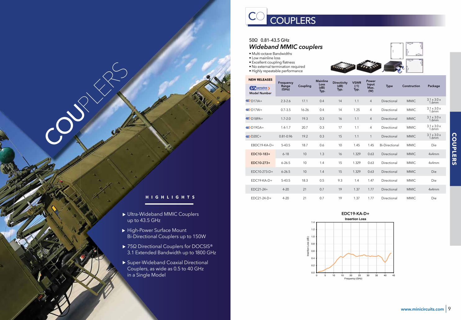
50Ω 0.81-43.5 GHz
• Multi-octave Bandwidths• Low mainline loss• Excellent coupling fl atness• No external termination required• Highly repeatable performance
Wideband MMIC couplers
CO COUPLERS
10
15
20
25
30
35
40
45
50
0 5 10 15 20 25 30 35 40 45
Cou
plin
g Lo
ss (d
B.)
Frequency (GHz)
Coupling
0
2
4
6
8
10
12
14
16
18
20
0 5 10 15 20 25 30 35 40 45
Dire
ctiv
ity (d
B.)
Frequency (GHz)
Directivity
0.0
0.2
0.4
0.6
0.8
1.0
1.2
1.4
0 5 10 15 20 25 30 35 40 45
Inse
rtion
Los
s (d
B.)
Frequency (GHz)
Insertion LossEDC19-KA-D+
AM
PLIFIERS
CO
UPLER
S
COUPLERS
H I G H L I G H T S
Ultra-Wideband MMIC Couplers up to 43.5 GHz
High-Power Surface Mount Bi-Directional Couplers up to 150W
75Ω Directional Couplers for DOCSIS® 3.1 Extended Bandwidth up to 1800 GHz
Super-Wideband Coaxial Directional Couplers, as wide as 0.5 to 40 GHz in a Single Model

1110 ISO 9001 ISO 14001 AS 9100 www.minicircuits.com
CO COUPLERS50Ω 800 to 6000 MHz
75Ω 5 to 1800 MHz
• Very high power in miniature SMT package, up to 150W• Low mainline loss• Good directivity, up to 28 dB
• Supports DOCSIS 3.1 extended bandwidth• 10 dB coupling with excellent fl atness across the full band
High Power Stripline Bi-Directional Couplers
ZDDC-50-521+
0
5
10
15
20
25
30
35
40
45
50
0 100 200 300 400 500 600 700 800 900 1000 1100 1200 1300
Ret
urn
Loss
(dB)
Frequency (MHz)
Return Loss
Return Loss In
Return Loss Out
Return Loss CPL
0
5
10
15
20
25
30
35
40
45
50
0 100 200 300 400 500 600 700 800 900 1000 1100 1200 1300
Ret
urn
Loss
(dB)
Frequency (MHz)
Return Loss
Return Loss In
Return Loss Out
Return Loss CPL
Return Loss (dB)Insertion Loss (dB)
9.6
9.7
9.8
9.9
10.0
10.1
10.2
10.3
10.4
10.5
10.6
0 100 200 300 400 500 600 700 800 900 1000 1100 1200 1300
Cou
plin
g (d
B)
Frequency (MHz)
Coupling Coupling (dB)
50Ω 0.5 to 40 GHz
• Industry leading bandwidth, 0.5 to 40 GHz in a single model!• Excellent directivity
LATEST RELEASES Frequency Range(MHz)
Coupling (dB)
Nom.
Mainline Loss
(dB) Typ.
Directivity (dB) Typ.
VSWR (:1) Typ.
Power Input
Max. (W)Type Construction
ModelNumber
ZCDC10-5R263-S+ 500 - 26500 10 1.2 22 1.12 20 Directional Microstrip / Stripline
ZCDC10-01263-S+ 1000 - 26500 10 0.9 21 1.17 20 Directional Microstrip / Stripline
ZCDC10-02263S+ 2000 - 26500 10 0.9 27 1.11 20 Directional Microstrip / Stripline
ZCDC10-06263-S+ 6000 - 26500 10 1.0 22 1.17 20 Directional Microstrip / Stripline
ZCDC10-18263-S+ 18000 - 26500 10 0.9 24 1.15 20 Directional Microstrip / Stripline
ZCDC10-K5R44W+ 500 - 40000 10 1.3 23 1.12 15 Directional Microstrip / Stripline
ZCDC10-K0144+ 1000 - 40000 10 2.2 16 1.22 19 Directional Microstrip / Stripline
ZCDC10-K0244+ 2000 - 40000 10 1.2 23 1.11 15 Directional Microstrip / Stripline
ZCDC10-K0644+ 6000 - 40000 10 1.0 24 1.12 17 Directional Microstrip / Stripline
ZCDC10-K1844+ 18000 - 40000 10 1.2 21 1.22 17 Directional Microstrip / Stripline
ZCDC13-5R263-S+ 500 - 26500 13 1.3 21 1.73 20 Directional Microstrip / Striplin
ZCDC13-01263-S+ 1000 - 26500 13 1.2 21 1.17 19 Directional Microstrip / Stripline
ZCDC13-K0144+ 1000 - 40000 13 1.5 19 1.73 13 Directional Microstrip / Stripline
ZCDC13-K0244+ 2000 - 40000 13 0.95 24 1.11 20 Directional Microstrip / Stripline
ZCDC13-K1844+ 18000 - 40000 13 0.9 21 1.13 20 Directional Microstrip / Stripline
ZCDC13-K26344+ 26500 - 40000 13 0.9 21 1.22 20 Directional Microstrip / Stripline
ZCDC16-5R263-S+ 500 - 26500 16 1.4 23 1.12 20 Directional Microstrip / Stripline
ZCDC16-01263-S+ 1000 - 26500 16 0.9 21 1.14 20 Directional Microstrip / Stripline
ZCDC16-K0144+ 1000 - 40000 16 1.3 20 1.22 19 Directional Microstrip / Stripline
ZCDC16-K1844+ 18000 - 40000 16 0.7 23 1.10 20 Directional Microstrip / Stripline
ZCDC20-5R263-S+ 500 - 26500 20 0.9 25 1.09 20 Directional Microstrip / Stripline
ZCDC20-01263-S+ 1000 - 26500 20 0.9 23 1.12 20 Directional Microstrip / Stripline
ZCDC20-02263S+ 2000 - 26500 20 0.5 18 1.33 20 Directional Microstrip / Stripline
ZCDC20-06263-S+ 6000 - 26500 20 0.5 26 1.14 20 Directional Microstrip / Stripline
ZCDC20-18263-S+ 18000 - 26500 20 0.4 24 1.14 20 Directional Microstrip / Stripline
ZCDC20-K0144+ 1000 - 40000 20 1.2 20 1.20 20 Directional Microstrip / Stripline
ZCDC20-K0244+ 2000 - 40000 20 1.0 20 1.17 20 Directional Microstrip / Stripline
ZCDC20-K0644+ 6000 - 40000 20 0.7 22 1.07 20 Directional Microstrip / Stripline
ZCDC20-K1844+ 18000 - 40000 20 0.7 19 1.17 20 Directional Microstrip / Stripline
ZCDC30-5R263-S+ 500 - 26500 30 0.6 28 1.07 20 Directional Microstrip / Stripline
ZCDC30-01263-S+ 1000 - 26500 30 0.8 23 1.14 20 Directional Microstrip / Stripline
ZCDC30-02263-S+ 2000 - 26500 30 0.6 23 1.14 20 Directional Microstrip / Stripline
ZCDC30-06263-S+ 6000 - 26500 30 0.6 23 1.12 20 Directional Microstrip / Stripline
ZCDC30-18263-S+ 18000 - 26500 30 0.6 21 1.14 20 Directional Microstrip / Stripline
ZCDC30-K0644+ 6000 - 40000 30 0.5 22 1.12 20 Directional Microstrip / Stripline
ZCDC30-K1844+ 18000 - 40000 30 0.6 22 1.15 20 Directional Microstrip / Stripline
ModelNumber
Frequency Range(MHz)
Coupling (dB)
Nom.
Mainline Loss
(dB) Typ.
Directivity (dB) Typ.
VSWR (:1) Typ.
Power Input
Max. (W)Type Construction
BDCH-20-63A+ 2000 - 6000 18 0.15 29 1.1 140 Bi-Directional Microstrip / Stripline
BDCH-25-33+ 800 - 3000 25 0.2 28 1.2 150 Bi-Directional Microstrip / Stripline
Model Number
Frequency Range(MHz)
Coupling (dB)
Nom.
Mainline Loss
(dB) Typ.
Directivity (dB) Typ.
VSWR (:1) Typ.
Power Input
Max. (W)Type Construction
RDC-10-182-75X+ 5 - 1800 10 1.3 20 1.2 1 Directional Transformer
BDCH-20-63A+
17
18
19
20
21
22
23
24
25
26
27
1000 2100 3200 4300 5400 6500 7600
Cou
plin
g Lo
ss (d
B)
Frequency (MHz)
Coupling Loss
In - Fwd
Out - Rev
0.00
0.05
0.10
0.15
0.20
0.25
0.30
0.35
0.40
0.45
0.50
1000 2100 3200 4300 5400 6500 7600
Inse
rtion
Los
s (d
B)
Insertion Loss vs. Temperature
@ -55°C
@ +25°C
@ +105°C
10
18
26
34
42
50
58
66
74
82
90
1000 2100 3200 4300 5400 6500 7600
Dire
ctiv
ity (d
B)
Frequency (MHz)
Directivity vs. Temperature
@ -55°C
@ +25°C
@ +105°C
Insertion Loss Vs. Temperature Directivity Vs. TemperatureCoupling Loss
BDCH-25-33A+
24
25
26
27
28
29
30
31
32
33
34
500 1000 1500 2000 2500 3000 3500
Cou
plin
g Lo
ss (d
B)
Coupling Loss
In - Fwd
Out - Rev
0.00
0.05
0.10
0.15
0.20
0.25
0.30
0.35
0.40
0.45
0.50
500 1000 1500 2000 2500 3000 3500
Inse
rtion
Los
s (d
B)
Insertion Loss vs. Temperature
@ -55°C
@ +25°C
@ +105°C
0
5
10
15
20
25
30
35
40
45
50
500 1000 1500 2000 2500 3000 3500
Dire
ctiv
ity (d
B)
Frequency (MHz)
Directivity vs. Temperature
@ -55°C
@ +25°C
@ +105°C
Insertion Loss Vs. Temperature Return LossCoupling Loss
Super-Wideband CoaxialDirectional Couplers
FREQUENCY (MHz)
FREQUENCY (MHz)
FREQUENCY (MHz)FREQUENCY (MHz)FREQUENCY (MHz)
FREQUENCY (MHz)FREQUENCY (MHz)
FREQUENCY (MHz) FREQUENCY (MHz)
AM
PLIFIERS
CO
UPLER
SA
MPLIFIER
SC
OU
PLERS
AM
PLIFIERSA
MPL
IFIE
RS
CO
UPL
ERS
AM
PLIF
IER
SC
OU
PLER
SA
MPL
IFIE
RS
Wideband Directional Couplers for DOCSIS® 3.1

13www.minicircuits.com
NEW RELEASES
Model Number
Package Frequency Range (GHz)
Impedance(Ω)
Insertion Loss (dB) @ Freq. Range
VSWR (:1) Typ. Input
VSWR (:1) Typ. Output
Max Input Power(dBm)
EQY-1-63+EQY-1-63-D+
2x2mm QFNDie DC-6 50 1.6-0.4 1.24 1.24 31
EQY-2-24+ 2x2mm QFN DC-20 50 3.0-0.9 1.16 1.16 31
EQY-2-63+EQY-2-63-D+
2x2mm QFNDie DC-6 50 2.5-0.4 1.29 1.29 31
EQY-3-24+EQY-3-24-D+
2x2mm QFNDie DC-20 50 3.8-0.7 1.15 1.15 34
EQY-3-63+EQY-3-63-D+
2x2mm QFNDie DC-6 50 3.8-0.6 1.29 1.29 31
EQY-4-63+EQY-4-63+
2x2mm QFNDie DC-6 50 4.8-0.6 1.25 1.25 31
EQY-5-24+ 2x2mm QFN DC-20 50 5.8-0.7 1.24 1.24 34
EQY-5-63+EQY-5-63-D+
2x2mm QFNDie DC-6 50 6-1 1.24 1.24 31
EQY-6-24+EQY-6-24-D+
2x2mm QFNDie DC-20 50 6.8-0.5
6.8-0.71.221.30
1.221.30 31
EQY-6-63+EQY-6-63-D+
2x2mm QFNDie DC-6 50 7-0.5 1.2 1.2 32
EQY-8-24+EQY-8-24-D+
2x2mm QFNDie DC-20 50 9.1-0.8
9.1-1.11.181.31
1.181.31 34
EQY-8-63+EQY-8-63-D+
2x2mm QFNDie DC-6 50 8.7-0.5 1.21 1.21 31
EQY-10-24+EQY-10-24-D+
2x2mm QFNDie DC-20 50 11.1-0.9
11.1-1.11.181.28
1.181.28 33
EQY-10-63+EQY-10-63-D+
2x2mm QFNDie DC-6 50 11.2-1 1.12 1.12 31
EQY-12-24+EQY-12-24-D+
2x2mm QFNDie DC-20 50 13.4-1.4
13.4-1.51.091.17
1.091.17 30
50Ω DC to 20 GHz
• Now 6 GHz and 20 GHz Versions• Excellent return loss, 20 dB typ.• 2x2mm QFN and bare die
Ultra-Wideband MMIC Fixed Equalizers
EQ EQUALIZERS
1.00
1.05
1.10
1.15
1.20
1.25
1.30
1.35
1.40
1.45
1.50
1.55
1.60
0 2000 4000 6000 8000 10000 12000 14000 16000 18000 20000 22000 24000
)1:( R
WSV TUP
NI
FREQUENCY (MHz)
INPUT VSWR vs. TEMPERATURE INPUT POWER = 0 dBm
-55°C
+25°C
+105°C
1.00
1.05
1.10
1.15
1.20
1.25
1.30
1.35
1.40
1.45
1.50
1.55
1.60
0 2000 4000 6000 8000 10000 12000 14000 16000 18000 20000 22000 24000
)1:( R
WSV TUP
NI
FREQUENCY (MHz)
INPUT VSWR vs. TEMPERATURE INPUT POWER = 0 dBm
-55°C
+25°C
+105°C
1.00
1.05
1.10
1.15
1.20
1.25
1.30
1.35
1.40
1.45
1.50
1.55
1.60
0 2000 4000 6000 8000 10000 12000 14000 16000 18000 20000 22000 24000
OU
TPU
T VS
WR
(:1)
FREQUENCY (MHz)
OUTPUT VSWR vs. TEMPERATUREINPUT POWER = 0 dBm
-55°C
+25°C
+105°C
1.00
1.05
1.10
1.15
1.20
1.25
1.30
1.35
1.40
1.45
1.50
1.55
1.60
0 2000 4000 6000 8000 10000 12000 14000 16000 18000 20000 22000 24000
OU
TPU
T VS
WR
(:1)
FREQUENCY (MHz)
OUTPUT VSWR vs. TEMPERATUREINPUT POWER = 0 dBm
-55°C
+25°C
+105°C
0.0
0.5
1.0
1.5
2.0
2.5
3.0
3.5
4.0
0 2000 4000 6000 8000 10000 12000 14000 16000 18000 20000 22000 24000
INSE
RTI
ON
LO
SS (d
B)
FREQUENCY (MHz)
INSERTION LOSS vs. TEMPERATURE INPUT POWER = 0 dBm
-55°C
+25°C
+105°C
0
1
2
3
4
5
6
7
8
9
10
0 2000 4000 6000 8000 10000 12000 14000 16000 18000 20000 22000 24000
INSE
RTI
ON
LO
SS (d
B)
INSERTION LOSS vs. TEMPERATURE INPUT POWER = 0 dBm
-55°C
+25°C
+105°C
EQY-3-24+
EQY-8-24+
EQUALIZERS
AM
PLIFIERS
EQU
ALIZER
S
Model Number
FREQUENCY (MHz) FREQUENCY (MHz) FREQUENCY (MHz)
FREQUENCY (MHz)FREQUENCY (MHz)FREQUENCY (MHz)
H I G H L I G H T S
Expanded selection of our popular MMIC fi xed gain slope equalizers now includes models with ultra-wide frequency range from DC to 20 GHz!

15www.minicircuits.com
ModelNumber
Passband (GHz)
Stopband F3 (MHz)
Rejection @ F3 (dB)
Stopband F4 (MHz)
Rejection @ F4 (dB) Flter Type Technology
WVBP-283-WR28+ 27.5 - 28.35 22000-27000 48 28850-38000 34 Band Pass Rectangular Waveguide
WVBP-383-WR28+ 37 - 40 22000-36000 59 41000-42000 34 Band Pass Rectangular Waveguide
WVBP-613-WR15+ 57.2 - 65.9 50000-56200 74 66900-75000 65 Band Pass Rectangular Waveguide
WVBP-673-WR12+ 64 - 71 60000-61500 56 73500-90000 28 Band Pass Rectangular Waveguide
WVBP-733-WR12+ 71 - 76 60000-69500 56 77500-90000 66 Band Pass Rectangular Waveguide
WVBP-783-WR12+ 76 - 81 60000-74500 67 82500-90000 48 Band Pass Rectangular Waveguide
WVBP-833-WR12+ 81 - 86 60000-79000 64 88000-90000 38 Band Pass Rectangular Waveguide
Frequency Bands from: 27 to 86 GHz
• Precision machining and plating• Outstanding return loss• Super-high rejection and fast roll off• Standard WR-12 to WR-28 waveguide interfaces
Waveguide Bandpass Filters
FL FILTERS
0.1
1.0
10.0
100.0
1000.060 65 70 75 80 85 90
Inse
rtion
Los
s (d
B)
Insertion Loss Insertion Loss
WVBP-833-WR12+0.1
1.0
10.0
100.0
1000.050 55 60 65 70 75
Inse
rtion
Los
s (d
B)
Frequency (GHz)
Insertion Loss Insertion Loss
WVBP-613-WR15+
0.1
1.0
10.0
100.022 24 26 28 30 32 34 36 38
Inse
rtion
Los
s (d
B)Frequency (GHz)
Insertion Loss Insertion LossWVBP-283-WR28+
AM
PLIFIERS
FILTERS
FILTERS &
DIPLEXERS
FREQUENCY (MHz)FREQUENCY (MHz)
FREQUENCY (MHz)
H I G H L I G H T S
New Line of Waveguide Bandpass Filters for Millimeter Wave Applications up to 86 GHz!
New high-Q surface mount ceramic resonator bandpass fi lters
Suspended substrate diplexers with ultra-wide bassbands
LTCC Low pass fi lters with enhanced rejection and reduced size

16 ISO 9001 ISO 14001 AS 9100 17www.minicircuits.com
FL FILTERS
50Ω 800 to 6000 MHz
• Low insertion loss with excellent power handling• Fractional bandwidth from 3% to 25%• Low profi le designs with min. height of 0.120”• Excellent temperature stability• Rugged construction to handle demanding
environmental conditions
Ceramic Resonator Bandpass Filters
LATEST RELEASES Passband F1
(MHz)
PassbandF2
(MHz)
Stopband F3
(MHz)
Rejection @ F3 (dB)
Stopband F4
(MHz)
Rejection @ F4 (dB)
FilterType
Model Number
CBP-1413R5A+ 1400 1427 1300-1350 20 1475-1520 20 Band Pass
CBP-5800AG+ 5725 5825 DC-5100 20 6250-7300 20 Band Pass
CBP-1060Q+ 1030 1090 500-930 20 1190-1400 20 Band Pass
CBP-1320Q+ 1280 1360 900-1170 20 1490-20000 20 Band Pass
CBP-2250A+ 2000 2500 DC-1630 20 2900-6000 35 Band Pass
ZX75BP-4700-S+ 4400 5000 DC-2800 40 6300-8000 30 Band Pass
AM
PLIFIERS
AM
PLIFIERS
FILTERS
AM
PLIFIERS
FILTERS
AM
PLIFIERSA
MPL
IFIE
RS
FILT
ERS
AM
PLIF
IER
SFI
LTER
SA
MPL
IFIE
RS
CBP-5800AG+
0
10
20
30
40
50
60
70
800 2000 4000 6000 8000 10000 12000 14000 16000 18000
INS
ER
TIO
N L
OS
S (
dB
)
FREQUENCY (MHz)
INSERTION LOSSINPUT POWER = 0 dBm
FREQUENCY (MHz)
NEW RELEASE Passband(MHz)
Passband IL (MHz)
Rejection (dB)
Return Loss (dB)
Crossover Isolation (dB) Filter Type Technology
Model Number
ZDSS-3G4G-S+ DC-30004000-20000 1.5 30 @ 4000-20000
15 @ DC-3000 10 - Diplexer Suspended Substrate
ZDSS-5G6G-S+ DC-50006000-20000 1.5 80 @ 7200-20000
50 @ DC-4000108 - Diplexer Suspended
Substrate
50Ω DC-26 GHz, 40000-20000 MHz
• Low insertion loss• Ultra-wide passband width• Fast roll-off with wide stopband• Passband up to 26 GHz• Stopband up to 26.5 GHz can extend to 40 GHz
Suspended Substrate Filters and DiplexersSuspended Substrate Filters and Diplexers
0
10
20
30
40
50
60
70
80
90
1000 5000 10000 15000 20000
CROSSOVER ISOLATIONINPUT POWER = 0 dBm
FREQUENCY (MHz)
0
20
40
60
80
1000 5000 10000 15000 20000
INS
ER
TIO
N L
OS
S (
dB
)
LOWPASS INSERTION LOSS INPUT POWER = 0 dBm
FREQUENCY (MHz)
0
10
20
30
40
50
60
70
800 5000 10000 15000 20000
INS
ER
TIO
N L
OS
S (
dB
)FREQUENCY (MHz)
HIGHPASS INSERTION LOSSINPUT POWER = 0 dBm
FREQUENCY (MHz)
Band Pass
Low Pass
High Pass
ModelNumber
Passband F1
(MHz)
Passband F2
(MHz)
Stopband F3
(MHz)
Rejection @ F3 (dB)
Stopband F4
(MHz)
Rejection @ F4 (dB)
FilterType Technology
ZBSS-7975-S+ 7825 8125 DC-6900 35 9350-15000 35 Band Pass SuspendSubstrate
ZLSS-2R8G-S+ 2800 3300 4000-4700 20 4700-26500 40 Low Pass Suspended Substrate
ZLSS-4G-S+ 4000 4500 5500-6300 20 6300-26500 40 Low Pass Suspended Substrate
ZLSS-6G-S+ 6000 6600 8200-9600 20 9600-26500 40 Low Pass Suspended Substrate
ZLSS-8G-S+ 8000 8600 10800-12500 20 12500-26500 40 Low Pass Suspended Substrate
ZLSS-11G-S+ 11000 11400 12500-14500 20 14500-26500 40 Low Pass Suspended Substrate
ZLSS-14G-S+ 14000 15100 16500-18000 20 18000-26500 40 Low Pass Suspended Substrate
ZHSS-8G+ 8000-24000 - 5300-5800 20 DC-5300 40 High Pass Suspended S ubstrate
ZDSS-5G6G-S+
Diplexers

18 ISO 9001 ISO 14001 AS 9100
FL FILTERSA
MPL
IFIE
RS
FILT
ERS
AM
PLIF
IER
SFI
LTER
SA
MPL
IFIE
RS A
MPLIFIER
S
Model Number
Passband F1(MHz)
Passband F2 (MHz)
Stopband F3 (MHz)
Rejection @ F3 (dB)
Stopband F4 (MHz)
Rejection @ F4 (dB)
Package size
LFCG-42+ DC-435 475 625 20 650-2700 30 0805
LFCG-92+ DC -990 1400 1700 20 1800-2700 30 0805
LFCG-320+ DC-320 440 660-2000 33 2000-6000 20 0805
LFCG-400+ DC-400 520 800-2500 30 2500-4500 20 0805
LFCG-530+ DC-530 670 980-2600 30 2600-4000 25 0805
LFCG-575+ DC-575 725 1020-2500 30 2500-4400 25 0805
LFCG-1000+ DC-1000 1370 1550-1900 20 1900-6000 30 0805
LFCG-1575+ DC-1575 1850 2175-2400 20 2400-7000 40 0805
LFCG-1700+ DC-1700 2025 2400-2800 20 2800-8000 30 0805
LFCG-2250+ DC-2250 2500 2800-3600 20 3600-8000 30 0805
LFCG-2850+ DC-2850 3250 3800-4400 20 4400-12000 30 0805
50Ω DC to 2850 MHz
• Excellent rejection, up to 33 dB• Rugged, ceramic construction• Excellent power handling, up to 5W• Tiny size, 0.079 x 0 .049 x 0.037" (2.0 x 1.25 mm)
LTCC Low Pass Filters with Enhanced Rejection
Small Size
LFCG-400+ LFCG-575+
0
5
10
15
20
25
30
35
40
45
50
55
60
650 500 1000 1500 2000 2500 3000 3500 4000 4500
INS
ER
TIO
N L
OS
S (
dB)
FREQUENCY (MHz)
INSERTION LOSSINPUT POWER = 0 dBm
0
5
10
15
20
25
30
35
40
45
50
55
60
650 500 1000 1500 2000 2500 3000 3500 4000 4500
INS
ER
TIO
N L
OS
S (
dB)
FREQUENCY (MHz)
INSERTION LOSSINPUT POWER = 0 dBm
Insertion LossInput power = 0 dBm
Insertion LossInput power = 0 dBm
LFCG-320+
0
10
20
30
40
50
600 500 1000 1500 2000 2500 3000 3500 4000 4500 5000 5500 6000
INS
ER
TIO
N L
OS
S (
dB)
FREQUENCY (MHz)
INSERTION LOSSINPUT POWER = 0 dBm
Insertion LossInput power = 0 dBm
FREQUENCY (MHz)
FREQUENCY (MHz)FREQUENCY (MHz)
Low Profi le
Over 1300 models available to sample for free!Free shipping to over 200 countries
www.minicircuits.com P.O. Box 350166, Brooklyn, NY 11235-0003 (718) 934-4500 [email protected]
EZ-Sample is Mini-Circuits’ free, online sample request program for RF components. We off er a wide selection of our surface mount parts for free sample to support your product validation eff orts and help you make an informed decision at no cost.
Try it Before you Buy it!
21www.minicircuits.com
FL FILTERSA
MPLIFIER
SA
MPLIFIER
SFILTER
SA
MPLIFIER
SFILTER
SA
MPLIFIER
S
FILTERS &
DIPLEXERS
APPLICATIO
N NOTE
Achieving First-Spin Success in LTCC Components with Advanced Material Simulation Models
Aaron Vaisman, Ben Kahtan and Camilo Gomez-Duarte, Mini-Circuits LTCC Design Group IntroductionSince the advent of Network Synthesis Theory at the turn of the last century, fi lter designers have been developing ever more sophisticated solutions to translate polynomial transfer functions into working, physical components. The body of knowledge for lumped components is well established in the famous “Big Red Filter Bible,” Microwave Filters, Impedance Matching Networks, and Coupling Structures, by Matthaei, Young and Jones, and for distributed components in James Hong’s Microwave Filters for RF/Microwave Applications. This knowledge combined with the advent of advanced software tools for fi lter synthesis and the commercialization of computerized full fi eld solution algorithms such as the Method of Moments (MoM) and the Finite Element Method (FEM) have given designers a powerful toolkit to realize both known and arbitrary topologies.Even given the maturity of the theory and state of the art in fi lter synthesis and simulation software, simulation results are still generally taken with a measure of caution. One of the most signifi cant design challenges remains achieving agreement between simulation and working design in a timely fashion. Depending on the technology being used, it’s not unusual for designers to cycle through multiple design and manufacturing spins before results meet the desired performance. This adds substantial time and cost to the design cycle, and directly affects time to revenue. Setting up a truly accurate simulation requires capturing every physical parameter that may affect real-world fi lter performance. Designers need to consider a daunting variety of factors. Some questions that must be considered include:
• Has the simulation model been parameterized such that the real world variables related to the physical implementation and operating conditions are accounted for?
• What kind of interpolation should be used between frequency points? • Does the 3D model capture the physical manifestation of a given structure? • Is the meshing different at different frequency bands? • Is skin depth accounted for correctly within the simulation tool for lower frequency bands? • Is the substrate dispersive, and if so what are its dispersion curves?• Have effective conductivity and the conductor’s surface roughness models been accounted for?
Mini-Circuits LTCC design group has spent years addressing these questions and many others. The reality of traditional simulations is that in the past, material impacts have not been well enough understood to account for all the real-world effects on performance. Therefore, a deeper understanding was necessary to eliminate superfl uous manufacturing spins and meet performance requirements on the fi rst try. By combining hundreds of different test structures, extensive material characterization and modelling, novel design workfl ows and home-brewed algorithms, Mini-Circuits has been able to transfer the trial and error from production runs at the fab to the simulation phase, early in the design process. These innovations have enabled us to consistently achieve fi rst-spin success on LTCC fi lters and other components beyond 50 GHz.
This article will explore some of the specifi c challenges of simulating LTCC structures. The design workfl ow will be described and case studies provided to demonstrate fi rst-spin fi delity between simulation and measurement. Finally, extensions will be discussed for other exploratory fi lter topologies at high frequencies as well as for other products and technologies.
Material Characterization and ModellingMini-Circuits typically combines two common simulation techniques to predict the RF performance of passive devices prior to their fabrication, each with its own pros and cons. The Method of Moments (MoM) technique works by meshing the conductive metallizations within the structure. This method is fast to perform and iterate and is useful for structures with low port count and low ratio of metallization to substrate. However, it is mostly limited to 2D surfaces and assumes substrates extend infi nitely in space, so it doesn’t provide a true substrate truncated 3D model.
By Aaron Vaism
an, Ben Kahtan and Camilo
Gomez-D
uarte,
Mini-C
ircuits
LTCC D
esign G
roup

23www.minicircuits.com
FL FILTERSA
MPLIFIER
SA
MPLIFIER
SFILTER
SA
MPLIFIER
SFILTER
SA
MPLIFIER
SAM
PLIF
IER
SA
MPL
IFIE
RS
FILT
ERS
AM
PLIF
IER
SFI
LTER
SA
MPL
IFIE
RS
The Finite Element Method (FEM) of simulation provides a true 3D model that allows us to truncate volumes. This is a frequency based method that works by meshing the substrate structures rather than the conductors. FEM simulations better capture the coupling and parasitic effects through the substrate as well as the effects of truncating the 3D structure, which are absent in MoM. The drawback is that FEM simulations are typically slower to implement.The FEM approach is more accurate for LTCC fi lters where the signal travels in a 3D fashion through a monolithic structure. Ideally, the characteristics of that structure would be uniform. However, in reality, LTCC structures consist of multiple layers of ceramic and conductive material with dispersive and anisotropic behavior. A true 3D characterization of the material is therefore required to account for the non-linear behavior of signals traveling through a structure with these properties. While these two approaches are powerful, in the past, they were incapable by themselves of achieving close agreement between simulation and measurement, and multiple design spins were still required. This limitation necessitated a deeper understanding of the material structure for its contributions to the real-world performance of the device. Mini-Circuits has gone through the painstaking effort of characterizing the material properties of substrates and conductive elements used in LTCC products up to the millimeter wave range. This required the use of hundreds of test structures, including single- and multi-modal resonator topologies, waveguide resonators, lumped capacitor and inductor structures, among others. A proprietary algorithm was developed just to analyze the volume of test data from our measurement workfl ow.
Multi-Physics Workfl owOur comprehensive material modelling combined with state-of-the-art design and simulation tools has allowed us to innovate a novel, multi-physics simulation workfl ow. A multi-physics simulation incorporates multiple simulators, each working within a particular domain: electromagnetic, structural and thermal. The individual simulators use each other’s results as a component of their own simulation setups. For example, electrical simulation results from HFSS® are employed to defi ne spatially-varying heat generation in a thermal simulation in ANSYS®. The computed temperature rise is then employed in turn to compute deformation of the model geometry.This initial simulation series often results in performance that does not meet the specifi ed design requirements, so the effects of thermal and mechanical analysis are fed back into the MoM and FEM engines to compensate for the effects of the thermal impact. This iterative process is completed as many times as necessary to achieve the desired performance. In a traditional design cycle, a prototype would be fabricated after the fi rst round of simulations, tested in the lab, and then redesigned and fabricated again. Our workfl ow moves that trial and error to the front of the design cycle, avoiding multiple rounds of fabrication and testing in the lab.
After two years of intensive effort building and characterizing test coupons and then modelling the measured performance into our simulation tools across broad bandwidths, Mini-Circuits has amassed what we believe is one of the most advanced understandings of LTCC technology in the industry. Our efforts have included characterization and modelling of the material properties of all elements used not only in our LTCC product line, but also in semiconductor products and other technologies as well. We now have high confi dence in our material models which, combined with our suite of design tools and novel design fl ow, has enabled us to achieve fi rst spin success on component designs up to 50 GHz.This capability is unique in the industry. It enables Mini-Circuits to develop and release standard parts to our catalog at a faster rate, which supports the needs of customers with high volume requirements, and it enables us to develop highly customized solutions for customers in more specialized applications with very fast turnaround. In all cases, it translates to lower development time and cost, and faster time to market.
(c)
(a)
(d)
(b)
(e)
Figure 1: (a) LTCC panel with test coupons. (b) Diagram of measurement setup with RF probes. (c) 3D model of ring resonator (top and bottom layers hidden). (d) Ring resonator: E-Field plot of 1st harmonic. (e) Ring resonator: E-Field plot of 7th harmonic.
Figure 2: Multi-physics workfl ow incorporating electromagnetic, thermal and structural simulations
Consider for example a customer requirement for a part that can handle 4W RF input power. Traditionally, the part would be designed and an evaluation run fabricated. The parts would be soldered to eval boards and put through burn-in test. If the part then burns out at 3W, it would need to be redesigned. Because LTCC products are monolithic, it isn’t practical to fi nd the point of failure through destructive physical analysis. By contrast, with a multi-physics simulation workfl ow, we are able to accurately and reliably evaluate power handling prior to the fi rst build of the device, saving time, cost, and no small measure of frustration.
Advantages of this workfl ow include:• Greater insight into the power handling of a model under diverse operating
conditions (DC, RF and transient)• Realistic assessment and optimization of thermal impact on RF performance and reliability• Forecasting of mechanical integrity of terminals in the presence of CTE mismatches• Optimization of the physical structures to reduce size
22 ISO 9001 ISO 14001 AS 9100

25www.minicircuits.com24 ISO 9001 ISO 14001 AS 9100
FL FILTERSA
MPLIFIER
SA
MPLIFIER
SFILTER
SA
MPLIFIER
SFILTER
SA
MPLIFIER
SAM
PLIF
IER
SA
MPL
IFIE
RS
FILT
ERS
AM
PLIF
IER
SFI
LTER
SA
MPL
IFIE
RS
Figure 3: Simulations in multi-physics workfl ow:
(a) EM simulation mesh used to determine heat generation as an input to the thermal simulator.
(b) FEM thermal/mechanical simulation mesh.
(c) Thermal simulation results showing temperature distribution.
(d) Mechanical stresses after phy sical deformation is computed from the thermal results.
Figure 4: Standard simulation and MCL material simulation vs. measured S21 performance of an LTCC bandpass fi lter after fi rst spin manufacturing run.
Figure 6: Simulated vs. measured performance of an LTCC combline bandpass fi lter after fi rst spin.
(a)
(b)
(c)
(d)
a b
(a)
(b)
(c)
(d)
c d
Examples of Simulation vs. MeasurementFigure 4 shows a plot of S21 for an LTCC bandpass fi lter from a standard simulation model, Mini-Circuits advanced material simulation model and actual measured performance. The pink plot represents the simulation results without the material knowledge we’ve modelled into newer simulations. Note the disparity between this simulation and the measured performance. The red line represents Mini-Circuits’ new simulation workfl ow incorporating all the material characterization and modelling we’ve conducted. Note that this simulation tracks the measured fi lter performance very closely across the full measured range.
Figure 5 shows additional comparisons between Mini-Circuits’ advanced simulation results and measured performance for a different LTCC bandpass fi lter model. Both S21 and S11 are shown, illustrating highly accurate simulation results for both parameters. These cases are representative of the unique capability to achieve close agreement between simulation results and measured performance after the fi rst design run from the fab.
ExtensionsThe learnings illustrated above were shown for LTCC fi lter designs utilizing lumped topologies, but they have broad applicability for exploratory fi lter topologies and other technologies as well.
The recent shift to applications at higher and higher frequencies has necessitated exploration of distributed fi lter topologies. Genesys® offers fi lter synthesis for some of the known distributed topologies, but doesn’t include synthesis and optimization tools for fi lters derived from Coupled Matrix Filter Synthesis Theory. At Mini-Circuits’ we’ve taken many of the concepts from the research literature and created our own algorithm capable of synthesizing arbitrary distributed fi lter topologies based on our specs. We’ve also created an optimization tool capable of producing simulated S-parameters and optimized dimensions on a full 3D model.
We have extended the material simulations used for LTCC components to other technologies in our portfolio including MMIC and stripline architectures. The same capability is also a vital element of our active effort to develop advanced packaging solutions for surface-mount components on soft substrate up to 55 GHz.
ConclusionSingle pass success has long been considered the holy grail in design workfl ows. The physically complex nature of LTCC technology makes it particularly challenging to achieve agreement between simulation and working design on the fi rst try. By using extensive material characterization and modelling together with advanced design tools, proprietary algorithms and our novel design workfl ow, our simulations now account for real world effects on performance to the degree that we can consistently achieve fi rst-spin success in LTCC designs. Our capabilities in this area have helped us accelerate standard and custom parts to reduce customers’ time to market and to enhance existing LTCC fi lter designs, reducing size and improving rejection performance. The design capability presented in this article extends to other technologies and innovations in high-frequency packaging solutions. These extensions will be addressed in greater depth in subsequent papers.Inquiries: [email protected]
IMPORTANT NOTICE© 2019 Mini-Circuits This document is provided as an accommodation to Mini-Circuits customers in connection with Mini-Circuits parts only. In that regard, this document is for informational and guideline purposes only. Mini-Circuits assumes no responsibility for errors or omissions in this document or for any information contained herein. Mini-Circuits may change this document or the Mini-Circuits parts referenced herein (collectively, the “Materials”) from time to time, without notice. Mini-Circuits makes no commitment to update or correct any of the Materials, and Mini-Circuits shall have no responsibility whatsoever on account of any updates or corrections to the Materials or Mini-Circuits’ failure to do so.Mini-Circuits customers are solely responsible for the products, systems, and applications in which Mini-Circuits parts are incorporated or used. In that regard, customers are responsible for consulting with their own engineers and other appropriate professionals who are familiar with the specifi c products and systems into which Mini-Circuits’ parts are to be incorporated or used so that the proper selection, installation/integration, use and safeguards are made. Accordingly, Mini-Circuits assumes no liability therefore. In addition, your use of this document and the information contained herein is subject to Mini-Circuits’ standard terms of use, which are available at Mini-Circuits’ website at https://www.minicircuits.com/homepage/terms_of_use.html.Mini-Circuits and the Mini-Circuits logo are registered trademarks of Scientifi c Components Corporation d/b/a Mini-Circuits. All other third-party trademarks are the property of their respective owners. A reference to any third-party trademark does not constitute or imply any endorsement, affi liation, sponsorship, or recommendation: (i) by Mini-Circuits of such third-party’s products, services, processes, or other information; or (ii) by any such third-party of Mini-Circuits or its products, services, processes, or other information.
Figure 5: Advanced simulation of S21 and S11 of an LTCC bandpass fi lter model versus measured performance after fi rst spin.
Simulation Result
Lab Measurement
Frequency (GHz)Frequency (GHz)
(a)
(b)
(c)
(d)
Figure 4: Standard simulation and MCL material simulation vs. measured S21 performance of an LTCC bandpass fi lter after fi rst spin manufacturing run.
Frequency (GHz)

Model Number
No. of
Ways
FrequencyRangeGHz
Isolation (dB),Typ.
Insertion Loss (dB)
Above Theoretical,
Typ.
Phase Unbalance
(deg),Typ.
Amplitude Unbalance
(dB),Typ.
Power Input (W)
as Splitter,Max.
Technology
ZC2PD-K1844+ 2 18-40 27 0.8 1.1 0.05 20 -
ZC3PD-18263-S+ 3 10-26.5 35 0.9 2.0 0.17 20 Stripline
ZC4PD-06263-S+ 4 6-26.5 26 1.5 2.0 0.13 20 Stripline
ZC4PD-18263-S+ 4 18-26.5 28 1.1 2.5 0.1 20 Stripline
ZC4PD-K0644+ 4 6-40 26 1.5 2.9 0.13 20 Stripline
ZC6PD-K1844+ 6 18-40 25 1.6 6.2 0.35 20 Stripline
50Ω 6 to 40 GHzUltra-Wideband Coaxial Splitter/Combiners
SC SPLITTERS/COMBINERSSPLITTER
S/CO
MB
INER
S
27www.minicircuits.com
6.0
6.5
7.0
7.5
8.0
8.5
9.0
9.5
10.0
5000 10000 15000 20000 25000 30000 35000 40000 45000
)Bd( ssoL noitresnI
Frequency (MHz)
Total Loss Insertion Loss S-1
Insertion Loss S-2
Insertion Loss S-3
Insertion Loss S-4
0
5
10
15
20
25
30
35
40
45
50
5000 10000 15000 20000 25000 30000 35000 40000 45000
Isol
atio
n (d
B)
Frequency (MHz)
Isolation
Isolation 1-2
Isolation 1-4
Isolation 3-4
1.0
1.1
1.2
1.3
1.4
1.5
1.6
5000 10000 15000 20000 25000 30000 35000 40000 45000
VSW
R (:
1)
Frequency (MHz)
VSWR
VSWR S
VSWR 1
VSWR 2
VSWR 3
VSWR 4
ZC4PD-K0644+
SPLITTERS/
COMBINERS
• Super wideband, up to 40 GHz• Low insertion loss, as low as 0.8 dB• High Isolation, up to 35 dB• 20W power handling
SPLITTERS/C
OM
BIN
ERS
SPLITTERS/C
OM
BIN
ERS
H I G H L I G H T S
20W Ultra-Wideband Coaxial Splitter Combiners up to 40 GHz

29www.minicircuits.com
TS TEST SOLUTIONS
Model Number
Switch Type
Number ofSwitches
Control Interfaces
Frequency Range(GHz)
Insertion Loss (dB), Typ.
Isolation (dB), Typ.
VSWR(:1), Typ.
RF Power (W),
Max.
RC-2SP6T-26 SP6T USB & Ethernet 2 DC-26.5 0.25 90 1.35 20
50Ω DC to 26.5 GHz
• Two independently controlled electromechanical SP6T switches• High isolation (80-90 dB) and low insertion loss (0.25 dB)• 5W power rating (cold switching)• User friendly GUI and full API included
USB/Ethernet Dual SP6T Switch Module
Page 3 of 7Mini-Circuits®
www.minicircuits.com P.O. Box 350166, Brooklyn, NY 11235-0003 (718) 934-4500 [email protected]
RC-2SP6T-26RF SP6T Switch Matrix
0
20
40
60
80
100
120
140
160
0 2500 5000 7500 10000 12500 15000 17500 20000 22500 25000
dB
Frequency (MHz)
Isolation (Inactive Paths)
COM-1 (J2 Active)COM-2 (J3 Active)COM-3 (J4 Active)COM-4 (J5 Active)
0
0.05
0.1
0.15
0.2
0.25
0.3
0.35
0.4
0.45
0 2500 5000 7500 10000 12500 15000 17500 20000 22500 25000
dB
Frequency (MHz)
Insertion Loss
COM-1 COM-2 COM-3
COM-4 COM-5 COM-6
1
1.1
1.2
1.3
1.4
1.5
1.6
1.7
0 2500 5000 7500 10000 12500 15000 17500 20000 22500 25000
:1
Frequency (MHz)
VSWR (Internal Termination)
J1 J2 J3
J4 J5 J6
1
1.1
1.2
1.3
1.4
1.5
1.6
1.7
0 2500 5000 7500 10000 12500 15000 17500 20000 22500 25000
:1
Frequency (MHz)
VSWR (Active Ports)
COM J1 J2J3 J4 J5J6
Typical Performance Data (per Switch)
Page 3 of 7Mini-Circuits®
www.minicircuits.com P.O. Box 350166, Brooklyn, NY 11235-0003 (718) 934-4500 [email protected]
RC-2SP6T-26RF SP6T Switch Matrix
0
20
40
60
80
100
120
140
160
0 2500 5000 7500 10000 12500 15000 17500 20000 22500 25000
dB
Frequency (MHz)
Isolation (Inactive Paths)
COM-1 (J2 Active)COM-2 (J3 Active)COM-3 (J4 Active)COM-4 (J5 Active)
0
0.05
0.1
0.15
0.2
0.25
0.3
0.35
0.4
0.45
0 2500 5000 7500 10000 12500 15000 17500 20000 22500 25000dB
Frequency (MHz)
Insertion Loss
COM-1 COM-2 COM-3
COM-4 COM-5 COM-6
1
1.1
1.2
1.3
1.4
1.5
1.6
1.7
0 2500 5000 7500 10000 12500 15000 17500 20000 22500 25000:1
Frequency (MHz)
VSWR (Internal Termination)
J1 J2 J3
J4 J5 J6
1
1.1
1.2
1.3
1.4
1.5
1.6
1.7
0 2500 5000 7500 10000 12500 15000 17500 20000 22500 25000
:1
Frequency (MHz)
VSWR (Active Ports)
COM J1 J2J3 J4 J5J6
Typical Performance Data (per Switch)
Insertion Loss
Isolation (Inactive Paths)
GUI Main Screen
AM
PLIFIERS
TEST SOLU
TION
S
TEST SOLU
TIONS
H I G H L I G H T S
USB/Ethernet Dual SP6T Switch Module up to 26.5 GHz
4-Channel Programmable Attenuators
8 IN-LB Calibrated Break-Over Torque Wrench for SMA, 3.5mm, 2.92mm, 2.4mm, and 1.8mm Connectors

31www.minicircuits.com
TS TEST SOLUTIONS
Model Number Case Style Description Torque (in-lbs) Connector Type
TRQ-516-08 MY2727 Break-over Torque Wrench 8 in-lbs 8 SMA, 1.85mm, 2.4mm,
2.92mm, 3.5mm
Wrench Torque Case Style
Wrench Size 8±0.32 inch-lbs(0.9±0.04 NM)
Wrench Head 8.0 mm (5/16 inches)
Color Stainless steel
Handle Blue Handle
Length 6.44±.030
Weight 83.05 gms
A B C wt
6.44 .563 .313 grams
163.6 14.3 8.0 83.05
• Lab quality• Precise preset torque, 8 IN-LB• Prevents over or under tightening• Light weight, easy to use in tight spots
GUI Main Screen
Outline Drawing
Outline Dimensions (inch)
mmProduct Specifi cations
Model Number
Control Interfaces
Number of
Channels
Frequency Range(MHz)
Attenuation Range (dB),
Typ
Attenuation Step (dB),
Typ
Insertion Loss (0 dB Setting)
(dB), Max
Attenuation Accuracy (dB), Typ
Max Input Power (dBm)
IP3 (dB), Typ
RC4DAT-6G-60 USB & Ethernet 4 1-6000 63 0.25 7.5 ± 0.6 23 53
RC4DAT-6G-95 USB & Ethernet 4 1-6000 95 0.25 10.0 ± 0.4 20 54
RC4DAT-6G-30 USB & Ethernet 4 1-6000 30 0.25 5.0 ± 0.35 23 53
50Ω 0-95 dB, 0.25 dB Step, 1-6000 MHz
• Four independently programmable channels• Wide attenuation range, up to 95 dB• Fine attenuation resolution, 0.25 dB• Ideal for MIMO test sets, automated test equipment,
handover system evaluation and more!
USB/Ethernet 4-Channel Programmable Attenuators
GUI Main ScreenGraphical User Interface (GUI) for WindowsKey Features• Manual attenuation setting• Sweep and Hop attenuation
sequences directed from the PC, or entire sequence loaded into RC4DAT.
• Attenuator address confi gurationand Firmware upgrade
• Attenuation at power up may be set to selected attenuation level or last attenuation state recorded.
• USB, HTTP or Telnet control of RC4DAT
• Setting Ethernet confi guration
Block Diagram
Break-Over Torque Wrench for SMA, 3.5mm, 2.92mm, 2.4mm & 1.8mm connectors
Outline Drawing
MINI-CIRCUITS LOGO
MINI-CIRCUITS PART NO.TORQUE VALUE, SIZE
SERIAL NUMBER
The wrench kit consists of:(1) Break-over torque wrench(2) Calibration certifi cate*(3) A solid wooden instrument case
* Recommended duration of calibration is one year. Calibration intervals set by national andinternational standards are either one year or 5000 cycles, whichever comes fi rst. However,to ensure that the performance is in accordance to factory calibrated standards, actual needof calibration may vary based on use. Contact AM or RMA for recalibration.
30 ISO 9001 ISO 14001 AS 9100
AM
PLIFIERS
TEST SOLU
TION
S

www.minicircuits.com P.O. Box 350166, Brooklyn, NY 11235-0003 (718) 934-4500 [email protected]
Technical Support› NORTH AMERICA
[email protected](718) 934-4500
› SINGAPORE, INDONESIAMALAYSIA, THAILAND
[email protected](604) 646-2828
› [email protected] 4 8749100
› TAIWAN & [email protected]
› [email protected] 1252 832600
› [email protected] 44 2 2622575
› [email protected] 591-8787 [email protected] 020-8734 0992
Direct Sales› BROOKLYN
[email protected] 1 718-934-4500
› [email protected] 417-335-5935
› [email protected] 1252-832600
› [email protected] 3 318 4450
www.minicoircuits.com