never rests.
350
2005 Test, Measurement and Monitoring Product Catalog 2005 Product Catalog Test,Measurement and Monitoring never rests.
-
Upload
khangminh22 -
Category
Documents
-
view
0 -
download
0
Transcript of never rests.

C M Y K 0.4375" spine0.5625" foot trim0.125" glue lap
8"x10" page 8"x10" page
For Further Information Tektronix maintains a comprehensive, constantly expanding collection of application notes, technical briefsand other resources. Please visit www.tektronix.com. 49A-18205-0
20
05
Test, Measurement and MonitoringProduct Catalog 2005
Pro
du
ct C
ata
log
Te
st,M
ea
su
rem
en
t an
d M
on
itorin
g
Visit our web site for up-to-date information on:
Product Information www.tektronix.com/home/products.html
Technical Resources www.tektronix.com/home/apps_technology.html
Contact Us www.tektronix.com/contactus
Support www.tektronix.com/Measurement/Service/home.html
never rests.

C M Y K 0.4375" spine0.5625" foot trim0.125" glue lap
8"x10" page 8"x10" page
Copyright © 2004, Tektronix, Inc. All rights reserved. Printed in the U.S.A. Tektronix products are covered by U.S. and foreign patents,issued and pending. Information in this publication supersedes that in all previously published material. Specifications and price changeprivileges reserved. TEKTRONIX and TEK are registered trademarks.
For further information, contact: Tektronix, Inc., P.O. Box 500, Beaverton, Oregon 97077-0001, USA, 1 (800) 833-9200. For other areas,contact Export Sales 1 (503) 627-7111. For the most up-to-date product information visit our web site at www.tektronix.com
Resources ForYoureliable and complete
www.tektronix.comRich, relevant content a click away.
The Tektronix Web site is your reliable resource for product information, application solutions, selection guides and more.
The Most Current Source
Application Notes
Technical Briefs
Interactive Product Demos
Selection Guides
White Papers
Resources
Request a Quote
Ask the Experts/FAQs
Request a Demo
Product Registration
Recommended Product Calibration Intervals
Career Opportunities with Tektronix
Contact Us – Worldwide, 24/7
MyTek Resource CenterBecome a MemberGet timely access to the latest information – from manuals and software to tutorials to pricing and industry newsletters.
Relevant to the Products You Use:
Software and Firmware Updates
New Online Tutorials
Industry Newsletters
And more
Fast Online Tools:
Manual Finder
Software and Firmware Downloads
Local Price Listing
Service Status
Order Status

Alphanumeric Index..................................................3-13Functional Index.....................................................15-24New Products/Worldwide Web .............................25-39Service and Support .............................................40-42Measurement Products .......................................43-317
Oscilloscopes .................................................................................43Accessories ..................................................................................123
Probes/Probe Accessories.......................................................124Other Accessories....................................................................164Carts.........................................................................................172
Logic Analyzers.............................................................................173Mixed Signal Sources ...................................................................203Logic Sources ...............................................................................213Semiconductor Testers .................................................................218Spectrum Analyzers ......................................................................219Wireless Communication Test Sets ..............................................227Network Monitoring System.........................................................234Protocol Analyzers........................................................................237Video Products.............................................................................268
Waveform Monitors..................................................................270Audio Test ................................................................................273Generators...............................................................................279Measurement Sets ..................................................................283MPEG Test and Monitoring ......................................................299Picture Quality Analysis System ...............................................308Video Network Monitoring........................................................312
General Customer Information ..........................318-321General Business Information .......................................................318
Leasing Programs ....................................................................319Rental Programs......................................................................320Federal Government Customers .............................................320Reconditioned Instruments: TekSelect™ ....................................321
Customer Support ....................................................322Product Support Services .................................................................322
Power Cords/Plugs ......................................................................324Worldwide Sales/Service Offices ..................................................325
Video Dealers/VARs/System Integrators..................................336Rental Companies ....................................................................319Distributors ..............................................................................338
Tektronix Web Site:The Source for Completeand Current ProductInformationThe Tektronix measurement productsweb site is your reliable resource for product information, applicationsolutions, selection guides and more.See the inside front cover.
New Products . . . . .See pages 25-39
Product Support. . . . . . . . . . See page 322
Table of Contents
For the most up-to-date and complete product information, visit our web site atwww.tektronix.com
2005 Tektronix Condensed CatalogBecause your product selection decision needs to be made using the most up-to-date information,the Tektronix web site is your reliable resource. The 2005 catalog provides key product highlightsand specifications, plus the URLs to direct you to the web site location for complete, current production information.


ADSA Standalone Deferred Time Software . . . . . . . . . . . . .299
AD007 GPIB-LAN Adapter . . . . . . . . . . . . . . . . . . . . . . . . . .166
ADA400A Differential Amplifier . . . . . . . . . . . . . . . . . . . . . . . . .125
AD951A MPEG Test System . . . . . . . . . . . . . . . . . . . . . . . . .297
AD953A MPEG Test System . . . . . . . . . . . . . . . . . . . . . . . . .295
AD954 MPEG Portable Analyzer . . . . . . . . . . . . . . . . . . . . . .304
AFG310 Arbitrary Function Generator . . . . . . . . . . . . . .205, 211
AFG320 Arbitrary Function Generator . . . . . . . . . . . . . .205, 211
AFTDS Differential Signal Adapter . . . . . . . . . . . . . . . . . . . .165
AMT75 75Ω Signal Adapter . . . . . . . . . . . . . . . . . . . . . . . .165
AWG2005 Arbitrary Waveform Generator . . . . . . . . . . . . .205, 210
AWG420 Arbitrary Waveform Generator . . . . . . . . . . . . .205, 209
AWG430 Arbitrary Waveform Generator . . . . . . . . . . . . .205-209
AWG520 Arbitrary Waveform Generator . . . . . . . . . . . . .205, 208
AWG615 Arbitrary Waveform Generator . . . . . . . . . . . . .205, 207
AWG710B Arbitrary Waveform Generator . . . . . . . . . . . . .205, 206
AXW100 ArbExpress™ Software for Arbitrary
Waveform Generators . . . . . . . . . . . . . . . . . . . . . . .212
A1001 Blank Adapter . . . . . . . . . . . . . . . . . . . . . . . . . . . . .218
A1002 In-Line Adapter . . . . . . . . . . . . . . . . . . . . . . . . . . . .218
A1005 Axial Lead Diode Adapter . . . . . . . . . . . . . . . . . . . . .218
A6302 50 MHz AC/DC Current Probe . . . . . . . . . . . . . . . . .126
A6312 100 MHz AC/DC Current Probe . . . . . . . . . . . . . . . .126
A6302XL Current Probe . . . . . . . . . . . . . . . . . . . . . . . . . . . . .126
A6303XL Current Probe . . . . . . . . . . . . . . . . . . . . . . . . . . . . .126
A6303 15 MHz AC/DC Current Probe . . . . . . . . . . . . . . . . .126
A6304XL Current Probe . . . . . . . . . . . . . . . . . . . . . . . . . . . . .126
Alphanumeric Index
Alphanumeric Index • 3For the most up-to-date and complete product information, visit our web site atwww.tektronix.com

CDMA2000 Protocol Analyzer Application Software . . . . . . . . . . .253
CSA7404B Communications Signal Analyzer . . . . . . . . . . . . . . . .78
CSA8200 Communications Signal Analyzer . . . . . . . . . . . . . . . .50
CT1 1 GHz Current Transformer . . . . . . . . . . . . . . . . . . .126
CT2 200 MHz Current Transformer . . . . . . . . . . . . . . . . .126
CT6 2 GHz Current Probe . . . . . . . . . . . . . . . . . . . . . . . .126
DG2040A Data Generator . . . . . . . . . . . . . . . . . . . . . . . . . . . .216
DG2030 Data Generator . . . . . . . . . . . . . . . . . . . . . . . . . . . .216
DS1001A Television Demodulator . . . . . . . . . . . . . . . . . . . . . .314
DS1001G Television Demodulator . . . . . . . . . . . . . . . . . . . . . .314
DS1002 Television Demodulator . . . . . . . . . . . . . . . . . . . . . .314
DTG5078 Date Timing Generator . . . . . . . . . . . . . . . . . . . . . . .214
DTG5274 Date Timing Generator . . . . . . . . . . . . . . . . . . . . . . .214
ECO422D Changeover Unit . . . . . . . . . . . . . . . . . . . . . . . . . . .281
GPRS Protocol Analyzer Application Software . . . . . . . . . . .249
GSM/PC Protocol Analyzer Application Software . . . . . . . . . . .257
HCTEK321 Hard Plastic Carrying Case . . . . . . . . . . . . . . . . . . . .172
IP Protocol Analyzer Application Software . . . . . . . . . . .256
iLinkTM Tool Set . . . . . . . . . . . . . . . . . . . . . . . . . . . . . . . . . .176
iViewTM D/A Display . . . . . . . . . . . . . . . . . . . . . . . . . . . . . . .176
K1297-G20 Protocol Tester . . . . . . . . . . . . . . . . . . . . . . . . . . . . .238
K15 Protocol Tester . . . . . . . . . . . . . . . . . . . . . . . . . . . . .259
K4000 Mobile Workstation . . . . . . . . . . . . . . . . . . . . . . . . .172
K420 Work Bench Cart . . . . . . . . . . . . . . . . . . . . . . . . . . .172
K475 Workstation Tower . . . . . . . . . . . . . . . . . . . . . . . . . .172
K5302 Digital Access System . . . . . . . . . . . . . . . . . . . . . . .263
Alphanumeric Index
4 • Alphanumeric IndexFor the most up-to-date and complete product information, visit our web site at
www.tektronix.com

MLM1000 Multi-layer Monitoring Software . . . . . . . . . . . . . . . .306
MTM400 MPEG Transport Stream Monitor . . . . . . . . . . . . . . .301
MTS4EA Elementary Stream Analysis Software . . . . . . . . . . . .293
MTX100 MPEG Recorder and Player . . . . . . . . . . . . . . . . . . .303
Net-7 Monitoring System . . . . . . . . . . . . . . . . . . . . . . . . . .234
PPM203B Articulated Arm . . . . . . . . . . . . . . . . . . . . . . . . . . . .168
PPM100 Articulated Arm . . . . . . . . . . . . . . . . . . . . . . . . . . . .168
PQA300 Picture Quality Analysis System . . . . . . . . . . . . . . . .308
P2200 Passive Voltage Probe . . . . . . . . . . . . . . . . . . . . . . .124
P3010 100 MHz, 10X Probe . . . . . . . . . . . . . . . . . . . .124, 146
P3420 Variable Level Pod . . . . . . . . . . . . . . . . . . . . . . . . . .216
P5050 500 MHz, 10X Probe . . . . . . . . . . . . . . . . . . . . . . . .144
P5100 250 MHz, 2.5 kV, 100X Probe . . . . . . . . . . . . .124, 148
P5102 100 MHz, 1 kV High Voltage Probe . . . . . . . . .124, 148
P5120 Passive High Voltage Probe . . . . . . . . . . . . . . .124, 148
P5200 Active Differential Probe . . . . . . . . . . . . . . . . . .125, 151
P5205 Active Differential High Voltage Probe . . . . . . . .125, 151
P5210 Active Differential High Voltage Probe . . . . . . . .125, 151
P6015A 75 MHz, 40 kV, 1000X Probe . . . . . . . . . . . . .124, 148
P6021 60 MHz Current Probe . . . . . . . . . . . . . . . . . . .126, 163
P6022 120 MHz Current Probe . . . . . . . . . . . . . . . . . .126, 163
P6101B 15 MHz, 1X Probe . . . . . . . . . . . . . . . . . . . . . .124, 146
P6105A 100 MHz, 10X Probe . . . . . . . . . . . . . . . . . . . . . . . .124
P6106A 250 MHz, 10X Probe . . . . . . . . . . . . . . . . . . . . . . . .124
P6109B 100 MHz, 10X Probe . . . . . . . . . . . . . . . . . . . .124, 146
P6111B 200 MHz, 10X Probe . . . . . . . . . . . . . . . . . . . .124, 146
Alphanumeric Index
Alphanumeric Index • 5For the most up-to-date and complete product information, visit our web site atwww.tektronix.com

P6112 100 MHz, 10X Probe . . . . . . . . . . . . . . . . . . . .124, 146
P6114B 400 MHz, 10X Probe . . . . . . . . . . . . . . . . . . . .124, 146
P6117 200 MHz, 10X Probe . . . . . . . . . . . . . . . . . . . .124, 146
P6131 300 MHz, 10X Probe . . . . . . . . . . . . . . . . . . . .124, 144
P6133 150 MHz, 10X Probe . . . . . . . . . . . . . . . . . . . .124, 144
P6136 350 MHz, 10X Probe . . . . . . . . . . . . . . . . . . . .124, 144
P6137 400 MHz, 10X Probe . . . . . . . . . . . . . . . . . . . .124, 144
P6138A 400 MHz, 10X Probe . . . . . . . . . . . . . . . . . . . .124, 144
P6139A 500 MHz, 10X Probe . . . . . . . . . . . . . . . . . . . .124, 144
P6150 9 GHz, High BW, Low Impedance Probe . . . . . .125, 150
P6158 3 GHz, 20X, Low Capacitance Probe . . . . . . . .125, 150
P6205 750 MHz, 10X, FET Probe . . . . . . . . . . . . . . . . . . . .125
P6241 Active Probe . . . . . . . . . . . . . . . . . . . . . . . . . .125, 132
P6243 1 GHz Active Probe . . . . . . . . . . . . . . . . . . . . .125, 135
P6245 1.5 GHz, FET Probe . . . . . . . . . . . . . . . . . . . . .125, 135
P6246 Active Differential Probe . . . . . . . . . . . . . . . . . .125, 142
P6247 Active Differential Probe . . . . . . . . . . . . . . . . . .125, 142
P6248 Active Differential Probe . . . . . . . . . . . . . . . . . .125, 142
P6249 4 GHz, Active Probe . . . . . . . . . . . . . . . . . . . . .125, 132
P6330 Differential Probe . . . . . . . . . . . . . . . . . . . . . . .125, 140
P6417 Logic Analyzer Probe . . . . . . . . . . . . . . . . . . . . . . . .200
P6418 Logic Analyzer Probe . . . . . . . . . . . . . . . . . . . . . . . .200
P6419 Logic Analyzer Probe . . . . . . . . . . . . . . . . . . . . . . . .200
P6434 Logic Analyzer Probe . . . . . . . . . . . . . . . . . . . . . . . .200
P6810 Logic Analyzer Probe . . . . . . . . . . . . . . . . . . . . . . . .200
P6860 Logic Analyzer Probe . . . . . . . . . . . . . . . . . . . . . . . .200
Alphanumeric Index
6 • Alphanumeric IndexFor the most up-to-date and complete product information, visit our web site at
www.tektronix.com

P6864 Logic Analyzer Probe . . . . . . . . . . . . . . . . . . . . . . . .200
P6880 Logic Analyzer Probe . . . . . . . . . . . . . . . . . . . . . . . .200
P6980 Logic Analyzer Probe . . . . . . . . . . . . . . . . . . . . . . . .200
P7225 Active Probe . . . . . . . . . . . . . . . . . . . . . . . . . .125, 134
P7240 Active Probe . . . . . . . . . . . . . . . . . . . . . . . . . .125, 132
P7260 Active Probe . . . . . . . . . . . . . . . . . . . . . . . . . .125, 131
P7330 Differential Probe . . . . . . . . . . . . . . . . . . . . . . .125, 140
P7350 Differential Probe . . . . . . . . . . . . . . . . . . . . . . .125, 140
P7350SMA Differential Probe with SMA Input . . . . . . . . . . .125, 139
P7380 Differential Probe . . . . . . . . . . . . . . . . . . . . . . .125, 137
P7380SMA High Performance Differential Probe . . . . . . . .125, 138
P8018 TDR Probe . . . . . . . . . . . . . . . . . . . . . . . . . . . . . . . . .98
RFA300A 8VSB Measurement Set . . . . . . . . . . . . . . . . . . . . . .310
RFM210 DVB-T Measurement Receiver . . . . . . . . . . . . . . . . .312
RSA2203A Real-time Spectrum Analyzer . . . . . . . . . . . . . . . . . .220
RSA2208A Real-time Spectrum Analyzer . . . . . . . . . . . . . . . . . .220
RSA3303A Real-time Spectrum Analyzer . . . . . . . . . . . . . . . . . .220
RSA3308A Real-time Spectrum Analyzer . . . . . . . . . . . . . . . . . .220
SDA601 Handheld Serial Digital Analyzer . . . . . . . . . . . . . . . .270
SF201A SureFoot® Interconnect for FET Probes . . . . . . . . . . .167
SF202A SureFoot® Interconnect for FET Probes . . . . . . . . . . .167
SF203A SureFoot® Interconnect for FET Probes . . . . . . . . . . .167
SF501 SureFoot® Interconnect for SMD Probes . . . . . . . . . .167
SF502 SureFoot® Interconnect for SMD Probes . . . . . . . . . .167
SF503 SureFoot® Interconnect for SMD Probes . . . . . . . . . .167
SMK4 Micro KlipChip™ Adapter . . . . . . . . . . . . . . . . . . . .167
Alphanumeric Index
Alphanumeric Index • 7For the most up-to-date and complete product information, visit our web site atwww.tektronix.com

Alphanumeric Index
8 • Alphanumeric IndexFor the most up-to-date and complete product information, visit our web site at
www.tektronix.com
SMG50 SMT KlipChip™ Pkg. . . . . . . . . . . . . . . . . . . . . . . . . .167
SPG300 SD Sync Pulse Generator . . . . . . . . . . . . . . . . . . . . .280
SPG600 SD Sync Pulse Generator . . . . . . . . . . . . . . . . . . . . .280
ST501 SureFoot® Interconnect for SMD Probes . . . . . . . . . .167
SureFoot® Surface Mount Device Interconnects . . . . . . . . . . . .167
TCA-BNC TekConnect-to-BNC Adapter . . . . . . . . . . . . . . . . . .157
TCA-N TekConnect-to-N Adapter . . . . . . . . . . . . . . . . . . . . .157
TCA-SMA TekConnect-to-SMA Adapter . . . . . . . . . . . . . . . . . .157
TCA-1MEG TekConnect-to-1MEG Adapter . . . . . . . . . . . . . . . . .153
TCA75 TekConnect-to-75 Ω Adapter . . . . . . . . . . . . . . . . .157
TCP202 50 MHz Current Probe . . . . . . . . . . . . . . . . . . .126, 162
TCPA300 Current Probe . . . . . . . . . . . . . . . . . . . . . . . . .126, 159
TCPA303 Current Probe . . . . . . . . . . . . . . . . . . . . . . . . .126, 159
TCPA305 Current Probe . . . . . . . . . . . . . . . . . . . . . . . . .126, 159
TCPA312 Current Probe . . . . . . . . . . . . . . . . . . . . . . . . .126, 159
TCPA400 Current Probe . . . . . . . . . . . . . . . . . . . . . . . . .126, 159
TCPA404XL Current Probe . . . . . . . . . . . . . . . . . . . . . . . . .126, 159
TDSCPM2 Communications Pulse Measurement Software . . . .120
TDSDVD Optical Storage Analysis and Measurement Software .110
TDSDVI DVI Compliance Test Solution . . . . . . . . . . . . . . . . . .108
TDSHT3 HDMI Compliance Test Software . . . . . . . . . . . . . . . .119
TDSET3 Ethernet Compliance Test Software . . . . . . . . . . . . .116
TDSUSB2 Universal Serial Bus Compliance Test Package . . . . .114
TDSJIT3 Jitter Analysis Software . . . . . . . . . . . . . . . . . . . . . .102
TDSPWR3 Power Measurement Software . . . . . . . . . . . . . . . . .104
TDSRT-EYE Serial Data Compliance and Analysis Software . . . . .112
TDS1002 Digital Storage Oscilloscope . . . . . . . . . . . . . . . . . . . .57
TDS1012 Digital Storage Oscilloscope . . . . . . . . . . . . . . . . . . . .57

Alphanumeric Index
Alphanumeric Index • 9For the most up-to-date and complete product information, visit our web site atwww.tektronix.com
TDS2PWR1 Power Measurement and Analysis Software . . . . . . .106
TDS2002 Digital Storage Oscilloscope . . . . . . . . . . . . . . . . . . . .57
TDS2012 Digital Storage Oscilloscope . . . . . . . . . . . . . . . . . . . .57
TDS2014 Digital Storage Oscilloscope . . . . . . . . . . . . . . . . . . . .57
TDS2022 Digital Storage Oscilloscope . . . . . . . . . . . . . . . . . . . .57
TDS2024 Digital Storage Oscilloscope . . . . . . . . . . . . . . . . . . . .57
TDS3AAM Advanced Analysis . . . . . . . . . . . . . . . . . . . . . . . . . . .62
TDS3LIM Limit Test Module . . . . . . . . . . . . . . . . . . . . . . . . . . .62
TDS3SDI Digital Video Module . . . . . . . . . . . . . . . . . . . . . . . . .62
TDS3VID Extended Video Application Module . . . . . . . . . . . . . .62
TDS3GV GPIB and RS-232 Interface . . . . . . . . . . . . . . . . . . . .62
TDS3BATB Battery Pack . . . . . . . . . . . . . . . . . . . . . . . . . . . . . . .62
TDS3CHG Charger for Battery Pack . . . . . . . . . . . . . . . . . . . . . .62
TDS3012B 100 MHz Digital Phosphor Oscilloscope . . . . . . . . . . .60
TDS3014B 100 MHz Digital Phosphor Oscilloscope . . . . . . . . . . .60
TDS3024B 200 MHz Digital Phosphor Oscilloscope . . . . . . . . . . .60
TDS3032B 300 MHz Digital Phosphor Oscilloscope . . . . . . . . . . .60
TDS3034B 300 MHz Digital Phosphor Oscilloscope . . . . . . . . . . .60
TDS3044B 400 MHz Digital Phosphor Oscilloscope . . . . . . . . . . .60
TDS3052B 500 MHz Digital Phosphor Oscilloscope . . . . . . . . . . .60
TDS3054B 500 MHz Digital Phosphor Oscilloscope . . . . . . . . . . .60
TDS3064B 600 MHz Digital Phosphor Oscilloscope . . . . . . . . . . .60
TDS5032B Digital Phosphor Oscilloscope . . . . . . . . . . . . . . . . . .65
TDS5034B Digital Phosphor Oscilloscope . . . . . . . . . . . . . . . . . .65
TDS5052B Digital Phosphor Oscilloscope . . . . . . . . . . . . . . . . . .65
TDS5054B Digital Phosphor Oscilloscope . . . . . . . . . . . . . . . . . .65

TDS5054BE Digital Phosphor Oscilloscope . . . . . . . . . . . . . . . . . .65
TDS5104B Digital Phosphor Oscilloscope . . . . . . . . . . . . . . . . . .65
TDS6604B Digital Phosphor Oscilloscope . . . . . . . . . . . . . . . . . .69
TDS6804B Digital Phosphor Oscilloscope . . . . . . . . . . . . . . . . . .69
TDS7054 Digital Phosphor Oscilloscope . . . . . . . . . . . . . . . . . .73
TDS7104 Digital Phosphor Oscilloscope . . . . . . . . . . . . . . . . . .73
TDS7154B Digital Phosphor Oscilloscope . . . . . . . . . . . . . . . . . .73
TDS7254B Digital Phosphor Oscilloscope . . . . . . . . . . . . . . . . . .73
TDS7404B Digital Phosphor Oscilloscope . . . . . . . . . . . . . . . . . .73
TDS7704B Digital Phosphor Oscilloscope . . . . . . . . . . . . . . . . . .73
TDS8200 Digital Sampling Oscilloscope . . . . . . . . . . . . . . . . . . .50
TekSelect Reconditioned Instruments . . . . . . . . . . . . . . . . . . . .321
TekScope® THS720A Handheld Battery Operated
Oscilloscope/DMM . . . . . . . . . . . . . . . . . . . . . . . . . . .63
TekScope® THS720P Handheld Battery Operated
Oscilloscope/DMM . . . . . . . . . . . . . . . . . . . . . . . . . . .63
TekScope® THS730A Handheld Battery Operated
Oscilloscope/DMM . . . . . . . . . . . . . . . . . . . . . . . . . . .63
TG2000 Signal Generator . . . . . . . . . . . . . . . . . . . . . . . . . . .280
TG700 Signal Generator . . . . . . . . . . . . . . . . . . . . . . . . . . .280
THS7BAT Ni-Cad Battery Pack . . . . . . . . . . . . . . . . . . . . . . . . .64
THS7CHG Battery Charger . . . . . . . . . . . . . . . . . . . . . . . . . . . . .64
THS7HCA Hard Carrying Case . . . . . . . . . . . . . . . . . . . . . . . . . .64
THS720A 100 MHz Handheld Battery Operated
Oscilloscope/DMM . . . . . . . . . . . . . . . . . . . . . . . . . . .63
THS720P 100 MHz Handheld Battery Operated
Oscilloscope/DMM . . . . . . . . . . . . . . . . . . . . . . . . . . .63
THS730A 200 MHz Handheld Battery Operated
Oscilloscope/DMM . . . . . . . . . . . . . . . . . . . . . . . . . . .63
TLA5201 Logic Analyzer . . . . . . . . . . . . . . . . . . . . . . . . . . . .197
TLA5202 Logic Analyzer . . . . . . . . . . . . . . . . . . . . . . . . . . . . .197
Alphanumeric Index
10 • Alphanumeric IndexFor the most up-to-date and complete product information, visit our web site at
www.tektronix.com

TLA5203 Logic Analyzer . . . . . . . . . . . . . . . . . . . . . . . . . . . . .197
TLA5204 Logic Analyzer . . . . . . . . . . . . . . . . . . . . . . . . . . . . .197
TLA7NAX Logic Analyzer Module . . . . . . . . . . . . . . . . . . . . . . .183
TLA7AXX Logic Analyzer Module . . . . . . . . . . . . . . . . . . . . . . .180
TLA7XM Expansion Mainframe . . . . . . . . . . . . . . . . . . . . . . .177
TLA715 Portable Color Logic Analyzer Mainframe . . . . . . . . .177
TLA721 Benchtop Color Logic Analyzer Mainframe . . . . . . . .177
TLA7PG2 Logic Analyzer Module . . . . . . . . . . . . . . . . . . . . . . .192
TPS2012 Digital Storage Oscilloscope . . . . . . . . . . . . . . . . . . . .54
TPS2014 Digital Storage Oscilloscope . . . . . . . . . . . . . . . . . . . .54
TPS2024 Digital Storage Oscilloscope . . . . . . . . . . . . . . . . . . . .54
TSG131A PAL Multiformat Generator . . . . . . . . . . . . . . . . . . . .280
TSG200 NTSC Signal Generator . . . . . . . . . . . . . . . . . . . . . .280
TSG601 Handheld Serial Component Generator . . . . . . . . . . .280
TSG95 NTSC/PAL Generator . . . . . . . . . . . . . . . . . . . . . . . .280
UMTS Protocol Analyzer Application Software . . . . . . . . . . .242
VITS200 NTSC Generator/Inserter . . . . . . . . . . . . . . . . . . . . .280
VITS201 Insertion Generator . . . . . . . . . . . . . . . . . . . . . . . . .280
VM5000HD Automated Video Measurement Set . . . . . . . . . . . . .288
VM700T Video Measurement Set . . . . . . . . . . . . . . . . . . . . . .283
WaveStar™ Oscilloscope Software . . . . . . . . . . . . . . . . . . . . . . .121
WCA230A Wireless Communication Analyzer . . . . . . . . . . . . . .224
WCA280A Wireless Communication Analyzer . . . . . . . . . . . . . .224
WCA330 Wireless Communication Analyzer . . . . . . . . . . . . . .226
WCA380 Wireless Communication Analyzer . . . . . . . . . . . . . .226
WFMNLE Software Waveform Monitors for
Non-linear Editing Systems . . . . . . . . . . . . . . . . . . .276
Alphanumeric Index
Alphanumeric Index • 11For the most up-to-date and complete product information, visit our web site atwww.tektronix.com

WFM601A Serial Component Monitor . . . . . . . . . . . . . . . . . . . .269
WFM601E Serial Component Monitor with Eye Pattern . . . . . . .269
WFM601M Serial Component Measurement Set . . . . . . . . . . . .269
WFM700 Waveform Monitors . . . . . . . . . . . . . . . . . . . . . . . . .269
WFM90D Waveform/Vector/Picture/
Audio Monitor (NTSC) . . . . . . . . . . . . . . . . . . .269, 270
WFM91D Waveform/Vector/Picture/Audio Monitor (PAL) . .269, 270
WSTRO WaveStar™ Software for Oscilloscopes . . . . . . . . . . .121
WVR500 Waveform/Vector Rasterizer . . . . . . . . . . . . . . .269, 270
WVR600 Waveform/Vector Rasterizer . . . . . . . . . . . . . . . . . . .269
WVR700 Waveform/Vector Rasterizer . . . . . . . . . . . . . . . . . . .269
YBA250 NetTek® BTS Antenna/
Transmission Line Analyzer . . . . . . . . . . . . . . . . . . .232
YBAC1 Calibration Kit . . . . . . . . . . . . . . . . . . . . . . . . . . . . .232
YBT1 NetTek® Backhaul/T1 Tester . . . . . . . . . . . . . . . . . . .231
YBT250 NetTek® BTS Transmitter/Interference Analyzer . . . . .228
Y400 NetTek® Analyzer . . . . . . . . . . . . . . . . . . . . . . . . . . .228
1705A Spectrum Monitor . . . . . . . . . . . . . . . . . . . . . . . . . .316
1720 Vectorscope for NTSC System Application . . . . . . . .270
1721 Vectorscope for PAL System Application . . . . . . . . . .270
1725 Vectorscope for PAL/NTSC . . . . . . . . . . . . . . . . . . . .270
1730 Waveform Monitor NTSC System Application . . . . . .270
1731 Waveform Monitor for PAL System Application . . . . .270
1735 Waveform Monitor for PAL/NTSC . . . . . . . . . . . . . . .270
1740A NTSC Waveform/Vector Monitor . . . . . . . . . . . . . . . .270
1741A PAL Waveform/Vector Monitor . . . . . . . . . . . . . . . . .270
1745A NTSC/PAL Waveform/Vector Monitor . . . . . . . . . . . .270
1750A NTSC Waveform/Vector/SCH Monitor . . . . . . . . . . . .270
Alphanumeric Index
12 • Alphanumeric IndexFor the most up-to-date and complete product information, visit our web site at
www.tektronix.com

1751A PAL Waveform/Vector/SCH Monitor . . . . . . . . . . . . .270
1755A NTSC/PAL Waveform/Vector/SCH Monitor . . . . . . . .270
1760 NTSC/Component Waveform/Vector Monitor . . . . . .270
1761 PAL/Component Waveform/Vector Monitor . . . . . . . .270
1765 NTSC/PAL/Component Waveform/Vector Monitor . . .270
370B Programmable Curve Tracer . . . . . . . . . . . . . . . . . . .218
371B Programmable Curve Tracer . . . . . . . . . . . . . . . . . . .218
760A Stereo Audio Monitor . . . . . . . . . . . . . . . . . . . . . . . .269
764 Digital Audio Monitor . . . . . . . . . . . . . . . . . . . . . . . .269
80A01 Pre-scaled Trigger Amplifier . . . . . . . . . . . . . . . . . . . .96
80A02 EOS/ESD Protection Module . . . . . . . . . . . . . . . . . . . .96
80A03 TekConnect Probe Interface Module . . . . . . . . . . . . . .97
80A05 Electrical Clock Recovery Module . . . . . . . . . . . . . . . .91
80C01 Optical Sampling Modules . . . . . . . . . . . . . . . . . . . . .87
80C02 Optical Sampling Modules . . . . . . . . . . . . . . . . . . . . .87
80C07B Optical Sampling Modules . . . . . . . . . . . . . . . . . . . . .87
80C08C Optical Sampling Modules . . . . . . . . . . . . . . . . . . . . .87
80C10 Optical Sampling Modules . . . . . . . . . . . . . . . . . . . . .87
80C11 Optical Sampling Modules . . . . . . . . . . . . . . . . . . . . .87
80C12 Optical Sampling Modules . . . . . . . . . . . . . . . . . . . . .87
80E01 Electrical Sampling Modules . . . . . . . . . . . . . . . . . . .94
80E02 Electrical Sampling Modules . . . . . . . . . . . . . . . . . . .94
80E03 Electrical Sampling Modules . . . . . . . . . . . . . . . . . . .94
80E04 Electrical Sampling Modules . . . . . . . . . . . . . . . . . . .94
80E06 Electrical Sampling Modules . . . . . . . . . . . . . . . . . . .94
82A04 Phase Reference Module . . . . . . . . . . . . . . . . . . . . . .85
Alphanumeric Index
Alphanumeric Index • 13For the most up-to-date and complete product information, visit our web site atwww.tektronix.com


A
Accessories . . . . . . . . . . . . . . . . . . . . . . . . . . . . . . . . . . . . . . . . .125-172
Articulated Arm . . . . . . . . . . . . . . . . . . . . . . . . . . . . . . . . . . . . . . . .167
Adapters . . . . . . . . . . . . . . . . . . . . . . . . . . . . . . . . .157, 164, 169-170
Attenuators . . . . . . . . . . . . . . . . . . . . . . . . . . . . . . . . . . . . . . .169-170
Carrying Cases . . . . . . . . . . . . . . . . . . . . . . . . . . . . . . . . . . . . . . . .172
Carts . . . . . . . . . . . . . . . . . . . . . . . . . . . . . . . . . . . . . . . . . . . . . . . .172
Ground Leads . . . . . . . . . . . . . . . . . . . . . . . . . . . . . . . . . . . . .169-170
Probe Accessories . . . . . . . . . . . . . . . . . . . . . . . . . . . . . . . . . .169-170
Product Accessories see Individual Product Pages
Rackmount Kits . . . . . . . . . . . . . . . . . . . . . . . . . . . . . . . . . . . . . . . .171
Transit (Carrying) Cases . . . . . . . . . . . . . . . . . . . . . . . . . . . . . . . . . .172
Active Probes (FET, Bipolar) . . . . . . . . . . . . . . . . . . . . . . . . . . . .125, 133
Adapters
TCA-BNC TekConnect® Probe . . . . . . . . . . . . . . . . . . . . . . . . . . . . .157
TCA-N TekConnect Probe . . . . . . . . . . . . . . . . . . . . . . . . . . . . . . . .157
TCA-SMA TekConnect Probe . . . . . . . . . . . . . . . . . . . . . . . . . . . . . .157
TekConnect® . . . . . . . . . . . . . . . . . . . . . . . . . . . . . . . . . . . . . .155-158
Amplifiers, Plug-In
Differential Preamplifier . . . . . . . . . . . . . . . . . . . . . . . . . . . . . . . . . .125
Operational . . . . . . . . . . . . . . . . . . . . . . . . . . . . . . . . . . . . . . . . . . .159
Analyzers
Communications Signal . . . . . . . . . . . . . . . . . . . . . . . . . . . . . . . . . . .78
Eye Diagram . . . . . . . . . . . . . . . . . . . . . . . . . . . . . . . . . . . . . . . . . . .78
Handheld, Audio Monitor . . . . . . . . . . . . . . . . . . . . . . . . . . . . .269, 270
Logic . . . . . . . . . . . . . . . . . . . . . . . . . . . . . . . . . . . . . . . . . . . . . . . .173
Measurement Sets . . . . . . . . . . . . . . . . . . . . . . . . . . . . . . . . . . . . .283
Modulation . . . . . . . . . . . . . . . . . . . . . . . . . . . . . . . . . . . . . . . . . . .219
Spectrum . . . . . . . . . . . . . . . . . . . . . . . . . . . . . . . . . . . . . . . . . . . .219
Wireless Communication . . . . . . . . . . . . . . . . . . . . . . . . . . . . .227-233
Arbitrary Function Generator . . . . . . . . . . . . . . . . . . . . . . . . . . . . . . .211
Arbitrary Generators Software . . . . . . . . . . . . . . . . . . . . . . . . . . . . . .212
Arbitrary Waveform Generators . . . . . . . . . . . . . . . . . . . . . . . . .205-210
Audio
Audio Measurement Set . . . . . . . . . . . . . . . . . . . . . . . . . . . . . . . . .283
Handheld Monitor . . . . . . . . . . . . . . . . . . . . . . . . . . . . . . . . . .269, 270
Signal Generators . . . . . . . . . . . . . . . . . . . . . . . . . . . . . . . . . .279-282
Stereo Audio Monitors . . . . . . . . . . . . . . . . . . . . . . . . . . . . . . .269-278
Functional Index
Functional Index • 15For the most up-to-date and complete product information, visit our web site atwww.tektronix.com

B
Battery Operated Instruments . . . . . . . . . . . . .54, 57, 60, 269, 270, 278
BNC
Adapters . . . . . . . . . . . . . . . . . . . . . . . . . . . . . . . . . . . . . . . . .165, 169
Cables . . . . . . . . . . . . . . . . . . . . . . . . . . . . . . . . . . . . . . . . . . . . . . .171
C
Cables
BNC, BSM, SMA (3 mm and 3.5 mm) . . . . . . . . . . . . . . . . . . . . . . .171
Cable TV/RF
Signal Generator . . . . . . . . . . . . . . . . . . . . . . . . . . . . . . . . . . . . . . .277
Calibration Services . . . . . . . . . . . . . . . . . . . . . . . . . . . . . . . . . . . . . .322
Camera Measurement Set . . . . . . . . . . . . . . . . . . . . . . . . . . . . . . . . .283
Carrying Cases . . . . . . . . . . . . . . . . . . . . . . . . . . . . . . . . . . . . . . . . . .172
Carts . . . . . . . . . . . . . . . . . . . . . . . . . . . . . . . . . . . . . . . . . . . . . . . . . .172
Communication Analyzer, Wireless . . . . . . . . . . . . . . . . . . . . . . . . . .219
Communication Interfaces
Communication Test Sets . . . . . . . . . . . . . . . . . . . . . . . . . . . . . . . . .219
GPIB-LAN Adapter . . . . . . . . . . . . . . . . . . . . . . . . . . . . . . . . . . . . . .164
Logic Analyzers . . . . . . . . . . . . . . . . . . . . . . . . . . . . . . . . . . . . . . . .173
Oscilloscopes . . . . . . . . . . . . . . . . . . . . . . . . . . . . . . . . . . . . . . . .43-99
Signal Sources . . . . . . . . . . . . . . . . . . . . . . . . . . . . . . . . . . . . .203-217
Spectrum Analyzers . . . . . . . . . . . . . . . . . . . . . . . . . . . . . . . . .219-226
Communications Pulse Measurement Software . . . . . . . . . . . . . . . .122
Communications Signal Analyzers . . . . . . . . . . . . . . . . . . . . .44, 78, 83
Communications Test Sets . . . . . . . . . . . . . . . . . . . . . . . . . . . . . . . . .227
Current Measurements . . . . . . . . . . . . . . . . . . . . . . . . . . . . . . . . . . . .159
Current Probes . . . . . . . . . . . . . . . . . . . . . . . . . . . . . . . . . . . . . . . . . .159
Curve . . . . . . . . . . . . . . . . . . . . . . . . . . . . . . . . . . . . . . . . . . . . . . . . . .218
Adapters . . . . . . . . . . . . . . . . . . . . . . . . . . . . . . . . . . . . . . . . . . . . .218
Functional Index
16 • Functional IndexFor the most up-to-date and complete product information, visit our web site at
www.tektronix.com

Customer Information . . . . . . . . . . . . . . . . . . . . . . . . . . . . . . . . .318-324
Calibration Services . . . . . . . . . . . . . . . . . . . . . . . . . . . . . . . . . . . . .322
Customer Support . . . . . . . . . . . . . . . . . . . . . . . . . . . . . . . . . . . . . .322
Federal Customers . . . . . . . . . . . . . . . . . . . . . . . . . . . . . . . . . . . . .320
General Business Information . . . . . . . . . . . . . . . . . . . . . . . . . . . . .318
Leasing Program . . . . . . . . . . . . . . . . . . . . . . . . . . . . . . . . . . . . . . .319
Order Information see Individual Product Pages
Power Cords/Plugs . . . . . . . . . . . . . . . . . . . . . . . . . . . . . . . . . . . . .324
Price List . . . . . . . . . . . . . . . . . . . . . . . . . . . . . . . . . . . . . . . . . . . . .347
Reconditioned Instruments: TekSelectSM . . . . . . . . . . . . . . . . . . . . . .321
Rental Program . . . . . . . . . . . . . . . . . . . . . . . . . . . . . . . . . . . . . . . .320
Repair . . . . . . . . . . . . . . . . . . . . . . . . . . . . . . . . . . . . . . . . . . . . . . .322
Sales & Service Location Listing . . . . . . . . . . . . . . . . . . . . . . . . . . .325
Service . . . . . . . . . . . . . . . . . . . . . . . . . . . . . . . . . . . . . . . . . . . . . .322
Technical Support . . . . . . . . . . . . . . . . . . . . . . . . . . . . . . . . . . . . . .322
Terms and Methods of Sale . . . . . . . . . . . . . . . . . . . . . . . . . . . . . . .318
Upgrade Services . . . . . . . . . . . . . . . . . . . . . . . . . . . . . . . . . . . . . .322
Warranty . . . . . . . . . . . . . . . . . . . . . . . . . . . . . . . . . . . . . . . . . . . . .322
Customer Service/Support . . . . . . . . . . . . . . . . . . . . . . . . . . . . . . . . .322
D
Data Capture, Analysis, Documentation Software . . . . . . . . . . . . . .123
Data Generators (also see Generators) . . . . . . . . . . . . . . . . . . .213, 216
Data Time Generators (see Generators) . . . . . . . . . . . . . . . . . .213, 214
DC Coupled Current Probe . . . . . . . . . . . . . . . . . . . . . . . . . . . . . . . . .162
Debug Tools Software . . . . . . . . . . . . . . . . . . . . . . . . . . . . . . . . . . . .176
Differential Probes . . . . . . . . . . . . . . . . . . . . . . . . . . . . . . . . . . . . . . .139
Digital Signal Processing Systems
Oscilloscopes . . . . . . . . . . . . . . . . . . . . . . . . . . . . . . . . . . . . . . . . . .43
Spectrum Analyzers . . . . . . . . . . . . . . . . . . . . . . . . . . . . . . . . . . . . .219
Digitizers (also see Oscilloscopes)
Logic Analyzer Based . . . . . . . . . . . . . . . . . . . . . . . . . . . . . . . . . . . .173
Distributors . . . . . . . . . . . . . . . . . . . . . . . . . . . . . . . . . . . . . . . . . . . . .338
DVB-T Measurement Receiver . . . . . . . . . . . . . . . . . . . . . . . . . . . . . .312
DVI Compliance Software . . . . . . . . . . . . . . . . . . . . . . . . . . . . . . . . . .108
E
Electrical Sampling Modules . . . . . . . . . . . . . . . . . . . . . . . . . . . . . . . .94
Ethernet Compliance Software . . . . . . . . . . . . . . . . . . . . . . . . . . . . .116
Functional Index
Functional Index • 17For the most up-to-date and complete product information, visit our web site atwww.tektronix.com

F
FET Probes . . . . . . . . . . . . . . . . . . . . . . . . . . . . . . . . . . . . . . . . . .131-136
Floating Measurements . . . . . . . . . . . . . . . . . . . . . . . . . . . . . . .151, 159
Furniture (also see Carts)
Carts . . . . . . . . . . . . . . . . . . . . . . . . . . . . . . . . . . . . . . . . . . . . . . . .172
G
Generators, Signal
Arbitrary Function . . . . . . . . . . . . . . . . . . . . . . . . . . . . . . . . . . . . . .211
Arbitrary Waveform . . . . . . . . . . . . . . . . . . . . . . . . . . . . . . . . .203-210
Audio . . . . . . . . . . . . . . . . . . . . . . . . . . . . . . . . . . . . . . . . . . . . . . .279
CATV . . . . . . . . . . . . . . . . . . . . . . . . . . . . . . . . . . . . . . . . . . . . . . . .279
Component – Serial, Analog, NTSC, PAL, Digital . . . . . . . . . . . . . . . .279
Data . . . . . . . . . . . . . . . . . . . . . . . . . . . . . . . . . . . . . . . . . . . .214, 216
Digital Component . . . . . . . . . . . . . . . . . . . . . . . . . . . . . . . . . . . . . .279
Digital Composite, NTSC . . . . . . . . . . . . . . . . . . . . . . . . . . . . . . . . .279
Ghost Canceler Reference . . . . . . . . . . . . . . . . . . . . . . . . . . . . . . . .279
Handheld . . . . . . . . . . . . . . . . . . . . . . . . . . . . . . . . . . . . . . . . . . . . .279
High Definition Sync, Test Signal, Waveform Monitor . . . . . . . . .269, 279
Insertion . . . . . . . . . . . . . . . . . . . . . . . . . . . . . . . . . . . . . . . . . . . . .279
MPEG . . . . . . . . . . . . . . . . . . . . . . . . . . . . . . . . . . . . . . . . . . .293-307
Pattern . . . . . . . . . . . . . . . . . . . . . . . . . . . . . . . . . . . . . . . . . . . . . .279
Programmable . . . . . . . . . . . . . . . . . . . . . . . . . . . . . . . . . . . . . . . . .279
Pulse . . . . . . . . . . . . . . . . . . . . . . . . . . . . . . . . . . . . . . . . . . . . . . . .279
Sync . . . . . . . . . . . . . . . . . . . . . . . . . . . . . . . . . . . . . . . . . . . . . . . .279
Television Test Signal . . . . . . . . . . . . . . . . . . . . . . . . . . . . . . . . . . . .279
Ground Leads, Probe . . . . . . . . . . . . . . . . . . . . . . . . . . . . . . . . .169, 170
H
Handheld Products
Audio (TV) Analyzer/Generator . . . . . . . . . . . . . . . . . . . . . . . . . . . . .279
Digital Audio (TV) Analyzer/Generator . . . . . . . . . . . . . . . . . . . . . . . .279
Oscilloscopes . . . . . . . . . . . . . . . . . . . . . . . . . . . . . . . . .54, 57, 60, 63
PAL/NTSC Signal Generator . . . . . . . . . . . . . . . . . . . . . . . . . . . . . . .279
Waveform/Vector/Picture/Audio Monitor . . . . . . . . . . . . . . . . . . . . . .269
High Definition
Programmable TV Generator . . . . . . . . . . . . . . . . . . . . . . . . . . . . . .279
Television Oscilloscopes . . . . . . . . . . . . . . . . . . . . . . . . . . . . . . . . . . .65
Television Sync Generator . . . . . . . . . . . . . . . . . . . . . . . . . . . . . . . .279
Waveform Monitor . . . . . . . . . . . . . . . . . . . . . . . . . . . . . . . . . . . . . .269
High Voltage Probes . . . . . . . . . . . . . . . . . . . . . . . . . . . . . . . . . .124, 144
I
Indices
Alphanumeric . . . . . . . . . . . . . . . . . . . . . . . . . . . . . . . . . . . . . . . . . . .3
Functional . . . . . . . . . . . . . . . . . . . . . . . . . . . . . . . . . . . . . . . . . . . . .15
Insertion/Generator . . . . . . . . . . . . . . . . . . . . . . . . . . . . . . . . . . . . . .279
Instrument/Probe Reference Chart . . . . . . . . . . . . . . . . . . . . . . . . . .124
Instruments, Reconditioned . . . . . . . . . . . . . . . . . . . . . . . . . . . . . . . .321
Functional Index
18 • Functional IndexFor the most up-to-date and complete product information, visit our web site at
www.tektronix.com

J
Jitter/Timing Analysis Software . . . . . . . . . . . . . . . . . . . . . . . . . . . .102
L
Leasing Program . . . . . . . . . . . . . . . . . . . . . . . . . . . . . . . . . . . . . . . . .319
Local Area Network (LAN) Adapter . . . . . . . . . . . . . . . . . . . . . . . . . .166
Logic Analyzers . . . . . . . . . . . . . . . . . . . . . . . . . . . . . . . . . . . . . .173-202
Bus Support . . . . . . . . . . . . . . . . . . . . . . . . . . . . . . . . . . . . . . . . . .202
Software . . . . . . . . . . . . . . . . . . . . . . . . . . . . . . . . . . . . . . . . . . . . .176
Low Capacitance Probes . . . . . . . . . . . . . . . . . . . . . . . . . . . . . .123, 148
Low Impedance Voltage Probes . . . . . . . . . . . . . . . . . . . . . . . . .123, 148
M
Mainframes
Logic Analyzers . . . . . . . . . . . . . . . . . . . . . . . . . . . . . . . . . . . . . . . .219
Oscilloscopes . . . . . . . . . . . . . . . . . . . . . . . . . . . . . . . . . . . . . . . . . .43
Memory Comparison . . . . . . . . . . . . . . . . . . . . . . . . . . . . . . . . . . . . .219
Meter Leads . . . . . . . . . . . . . . . . . . . . . . . . . . . . . . . . . . . . . . . .169, 170
Microprocessor Support Products . . . . . . . . . . . . . . . . . . . . . . . . . . .202
Microwave & RF Instruments
Accessories . . . . . . . . . . . . . . . . . . . . . . . . . . . . . . . . . . .125, 203-217
Communications Test Sets . . . . . . . . . . . . . . . . . . . . . . . . . . . . . . . .227
Spectrum Analyzers . . . . . . . . . . . . . . . . . . . . . . . . . . . . . . . . . . . . .219
Spectrum Monitor . . . . . . . . . . . . . . . . . . . . . . . . . . . . . . . . . . . . . .269
Mobile Radio Test Sets . . . . . . . . . . . . . . . . . . . . . . . . . . . . . . . . . . . .227
Modulation Analyzer . . . . . . . . . . . . . . . . . . . . . . . . . . . . . . . . . . . . . .219
Monitors
Spectrum . . . . . . . . . . . . . . . . . . . . . . . . . . . . . . . . . . . . . . . .219, 269
Stereo Audio . . . . . . . . . . . . . . . . . . . . . . . . . . . . . . . . . . . . . . . . . .269
Waveform . . . . . . . . . . . . . . . . . . . . . . . . . . . . . . . . . . . . . . . . . . . .269
MPEG Products . . . . . . . . . . . . . . . . . . . . . . . . . . . . . . . . . . . . . . . . . .293
MPEG Interface Cards . . . . . . . . . . . . . . . . . . . . . . . . . . . . . . . . . . .295
MPEG Portable Analyzer . . . . . . . . . . . . . . . . . . . . . . . . . . . . . . . . .304
MPEG Recorder and Player . . . . . . . . . . . . . . . . . . . . . . . . . . . . . . .303
MPEG Signal Source/Source Scheduler . . . . . . . . . . . . . . . . . . . . . .297
MPEG Test System . . . . . . . . . . . . . . . . . . . . . . . . . . . . . . . . . .295-307
MPEG Transport Stream Monitor . . . . . . . . . . . . . . . . . . . . . . . . . . .301
N
Network Analyzers . . . . . . . . . . . . . . . . . . . . . . . . . . . . . . . . . . . . . . .234
New Products . . . . . . . . . . . . . . . . . . . . . . . . . . . . . . . . . . . . . . . . .25-39
Functional Index
Functional Index • 19For the most up-to-date and complete product information, visit our web site atwww.tektronix.com
O
Optical Storage Analysis Software . . . . . . . . . . . . . . . . . . . . . . . . . .112
Optical Fiber/Cable Test Products
Accessories . . . . . . . . . . . . . . . . . . . . . . . . . . . . . . . . . . . . . . .123-172
ATM Protocol Tester . . . . . . . . . . . . . . . . . . . . . . . . . . . . . . . . . . . . .238
Communications Signal Analyzer . . . . . . . . . . . . . . . . . . . . . .44, 78, 83
ISDN Analyzers . . . . . . . . . . . . . . . . . . . . . . . . . . . . . . . . . . . .237-267
ISDN Service Set . . . . . . . . . . . . . . . . . . . . . . . . . . . . . . . . . . . . . . .237
ISDN Simulator/Monitor . . . . . . . . . . . . . . . . . . . . . . . . . . . . . . . . . .237
Probes . . . . . . . . . . . . . . . . . . . . . . . . . . . . . . . . . . . . . . . . . . . . . .123
Protocol Tester . . . . . . . . . . . . . . . . . . . . . . . . . . . . . . . . . . . .237, 238
Protocol Tester Software . . . . . . . . . . . . . . . . . . . . . . . . . . . . . .242-258
RS-232 Analyzer . . . . . . . . . . . . . . . . . . . . . . . . . . . . . . . . . . . . . . .173
Spectrum Analyzers . . . . . . . . . . . . . . . . . . . . . . . . . . . . . . . . . . . . .219
Waveform Analyzer . . . . . . . . . . . . . . . . . . . . . . . . . . . . . . . . . . . . .173
Optical Signal Analysis . . . . . . . . . . . . . . . . . . . . . . . . . . . . . . . . .78, 219
Optical Sampling Modules . . . . . . . . . . . . . . . . . . . . . . . . . . . . . . .87-88
Oscilloscope Software . . . . . . . . . . . . . . . . . . . . . . . . . . . . . . . .100-122
Oscilloscopes
Accessories . . . . . . . . . . . . . . . . . . . . . . . . . . . . . . . . . . . . . . .123-172
Battery Operated . . . . . . . . . . . . . . . . . . . . . . . . . . . . . . . . . .54, 57, 63
Carts . . . . . . . . . . . . . . . . . . . . . . . . . . . . . . . . . . . . . . . . . . . . . . . .172
Communications Signal Analyzer . . . . . . . . . . . . . . . . . . . . . .44, 78, 83
Digital/Optical Communications . . . . . . . . . . . . . . . . . . . . . . . . . .65-99
Digital Phosphor . . . . . . . . . . . . . . . . . . . . . . . . . . . .57, 60, 65, 69, 73
Digital Sampling . . . . . . . . . . . . . . . . . . . . . . . . . . . . . . . . . . . . . . . .83
Digital Storage . . . . . . . . . . . . . . . . . . . . . . . . . . . . . . . . . . . . . .43-123
DMM . . . . . . . . . . . . . . . . . . . . . . . . . . . . . . . . . . . . . . . . . . . . . .57, 60
Handheld . . . . . . . . . . . . . . . . . . . . . . . . . . . . . . . . . . . . . . .54-64, 270
Logic Analyzer Based . . . . . . . . . . . . . . . . . . . . . . . . . . . . . . . . . . . .173
Mainframes for Modular Plug-Ins . . . . . . . . . . . . . . . .87, 91, 94, 96-99
Modular . . . . . . . . . . . . . . . . . . . . . . . . . . . . . . . . . . . . .65, 69, 73, 89
Portable . . . . . . . . . . . . . . . . . . . . . . . . . . . . . . . . . . . . . . . . . . . .54-64
Probes . . . . . . . . . . . . . . . . . . . . . . . . . . . . . . . . . . . . . . . . . . . . . .123
Rackmount, see Individual Product Options
Rackmount Kits . . . . . . . . . . . . . . . . . . . . . . . . . . . . . . . . . . . . . . . .172
Sampling . . . . . . . . . . . . . . . . . . . . . . . . . . . . . . . . . . . . . . . . . . . . . .89
Service . . . . . . . . . . . . . . . . . . . . . . . . . . . . . . . . . . . . . . . . . . . .54-64
Software . . . . . . . . . . . . . . . . . . . . . . . . . . . . . . . . . . . . . . . . .100-122
Storage . . . . . . . . . . . . . . . . . . . . . . . . . . . . . . . . . . . . . . . . . . .65-122
Variable Persistence . . . . . . . . . . . . . . . . . . . . . . . . . . . . . . . . . .69, 73
Telecommunications . . . . . . . . . . . . . . . . . . . . . . . . . . . . . . . . . . .65-77
Television . . . . . . . . . . . . . . . . . . . . . . . . . . . . . . . . . . . . . . . . . . .65-77
Travel Accessories . . . . . . . . . . . . . . . . . . . . . . . . . . . . . . . . . . . . . .172
P
Passive Voltage Probes . . . . . . . . . . . . . . . . . . . . . . . . . . . .123, 144-149
Pattern Generator . . . . . . . . . . . . . . . . . . . . . . . . . . . . . . . . . . . . . . . .175
Performance Analysis Support . . . . . . . . . . . . . . . . . . . . . . . . . . . . .173
Picture Monitor, Handheld . . . . . . . . . . . . . . . . . . . . . . . . . . . . .269, 278
Picture Quality Analysis System . . . . . . . . . . . . . . . . . . . . . . . . . . . .308
Power Measurement Software . . . . . . . . . . . . . . . . . . . . . . . . . . . . . .104
Power Plug Options . . . . . . . . . . . . . . . . . . . . . . . . . . . . . . . . . . . . . .324
Functional Index
20 • Functional IndexFor the most up-to-date and complete product information, visit our web site at
www.tektronix.com

Probes
1X-10X Switchable . . . . . . . . . . . . . . . . . . . . . . . . . . . . . . . . .123-149
Accessories . . . . . . . . . . . . . . . . . . . . . . . . . . . . . . . . . . . . . . .123, 164
Active (FET, Bipolar, Bias/Offset) . . . . . . . . . . . . . . . . . . . . . . . .123, 131
Adapters . . . . . . . . . . . . . . . . . . . . . . . . . . . . . . . . . . . . . . . . .157, 165
Arms/Probing Stations . . . . . . . . . . . . . . . . . . . . . . . . . . . . . . . . . . .168
Current . . . . . . . . . . . . . . . . . . . . . . . . . . . . . . . . . . . . . . . . . . . . . .123
Current Amplifiers . . . . . . . . . . . . . . . . . . . . . . . . . . . . . . . . . . . . . .159
DC Coupled Current Probe . . . . . . . . . . . . . . . . . . . . . . . . . . . . . . . .162
Differential . . . . . . . . . . . . . . . . . . . . . . . . . . . . . . . . . . . .123, 137-143
Floating Measurements . . . . . . . . . . . . . . . . . . . . . . . . . .123, 150-154
Ground Leads . . . . . . . . . . . . . . . . . . . . . . . . . . . . . . . . . . . . .169-170
High Frequency . . . . . . . . . . . . . . . . . . . . . . . . . . . . . . . . . . . .123-145
High Voltage . . . . . . . . . . . . . . . . . . . . . . . . . . . . . . . . . .123, 148, 151
Instrument/Probe Reference Chart . . . . . . . . . . . . . . . . . . . . . . . . . .124
Low Capacitance . . . . . . . . . . . . . . . . . . . . . . . . . . . . . . . . . . .125, 150
Low Impedance . . . . . . . . . . . . . . . . . . . . . . . . . . . . . . . . . . . . . . . .125
Low Loading . . . . . . . . . . . . . . . . . . . . . . . . . . . . . . . . . .123, 125, 131
Oscilloscope to Probe Cross Reference . . . . . . . . . . . . . . . . . . . . . .127
Passive Voltage . . . . . . . . . . . . . . . . . . . . . . . . . . . . . . . . . . . .123, 144
Replacement Parts . . . . . . . . . . . . . . . . . . . . . . . . . . . . . . . . . . . . .172
Specification Chart . . . . . . . . . . . . . . . . . . . . . . . . . . . . . . . . . .123-126
Voltage
Active . . . . . . . . . . . . . . . . . . . . . . . . . . . . . . . . .123, 125-136, 164
High Voltage . . . . . . . . . . . . . . . . . . . . . . . . . . . . . . . . . . . .123, 148
Low Impedance . . . . . . . . . . . . . . . . . . . . . . . . . . . . . . . . . . . . .125
Passive . . . . . . . . . . . . . . . . . . . . . . . . . . . . . . . . . . . . . . .123, 144
Specification Chart . . . . . . . . . . . . . . . . . . . . . . . . . . . . . . .123-126
Protocol Analyzers . . . . . . . . . . . . . . . . . . . . . . . . . . . . . . . . . . . . . . .237
Protocol Testers . . . . . . . . . . . . . . . . . . . . . . . . . . . . . . . . . . . . . . . . .237
Protocol Tester Software . . . . . . . . . . . . . . . . . . . . . . . . . . . . . .242-258
R
Rackmount Products
Carts . . . . . . . . . . . . . . . . . . . . . . . . . . . . . . . . . . . . . . . . . . . . . . . .172
Communication Test Sets . . . . . . . . . . . . . . . . . . . . . . . . . . . . .227-233
Oscilloscopes . . . . . . . . . . . . . . . . . . . . . . . . . . . . . . . . . . . . . . . .43-99
Signal Sources . . . . . . . . . . . . . . . . . . . . . . . . . . . . . . . . . . . . .203-217
Spectrum Analyzer . . . . . . . . . . . . . . . . . . . . . . . . . . . . . . . . . .219-226
Radio Communication . . . . . . . . . . . . . . . . . . . . . . . . . . . . . . . . .227-233
Reconditioned Instruments: TekSelectSM . . . . . . . . . . . . . . . . . . . . . .321
Reference Information
Arbitrary Generators . . . . . . . . . . . . . . . . . . . . . . . . . . . . . . . . . . . .204
Instrument/Probe Chart . . . . . . . . . . . . . . . . . . . . . . . . . . . . . .124-130
Logic Analyzer . . . . . . . . . . . . . . . . . . . . . . . . . . . . . . . . . . . . . . . . .173
Logic Sources . . . . . . . . . . . . . . . . . . . . . . . . . . . . . . . . . . . . . . . . .213
Oscilloscopes . . . . . . . . . . . . . . . . . . . . . . . . . . . . . . . . . . . . . . . .44-53
Oscilloscope Selection Guide . . . . . . . . . . . . . . . . . . . . . . . . . . . .44-53
Oscilloscope to Probe Cross Reference . . . . . . . . . . . . . . . . . . .127-130
Power Plug Options . . . . . . . . . . . . . . . . . . . . . . . . . . . . . . . . . . . . .324
Probe Selection . . . . . . . . . . . . . . . . . . . . . . . . . . . . . . . . . . . .124-130
Voltage Probe Reference Chart . . . . . . . . . . . . . . . . . . . . . . . . .124-130
Rental Companies . . . . . . . . . . . . . . . . . . . . . . . . . . . . . . . . . . . . . . . .320, 337
Rental Program . . . . . . . . . . . . . . . . . . . . . . . . . . . . . . . . . . . . . . . . . .320, 337
Repair, Upgrade, Warranty Services . . . . . . . . . . . . . . . . . . . . . . . . . . . . . . . .322
Representatives . . . . . . . . . . . . . . . . . . . . . . . . . . . . . . . . . . . . . .325, 336, 338
Functional Index
Functional Index • 21For the most up-to-date and complete product information, visit our web site atwww.tektronix.com

S
Sales & Service Offices . . . . . . . . . . . . . . . . . . . . . . . . . . . . . . . . . . .325
Sampling
Accessories . . . . . . . . . . . . . . . .56, 59, 62, 64, 68, 72, 77, 82, 84, 90
Mainframe . . . . . . . . . . . . . . . . . . . . . . . . . . . . . . . . . . . . . . . . . .78, 83
Modules . . . . . . . . . . . . . . . . . . . . . . . . . . . . . . . . . . . . . . . . . . .87, 94
Oscilloscopes . . . . . . . . . . . . . . . . . . . . . . . . . . . . . . . . . . . .78, 83, 89
Selection Guides
Arbitrary Generators . . . . . . . . . . . . . . . . . . . . . . . . . . . . . . . . . . . .204
Instrument/Probe Chart . . . . . . . . . . . . . . . . . . . . . . . . . . . . . .124-130
Logic Analyzer . . . . . . . . . . . . . . . . . . . . . . . . . . . . . . . . . . . . . . . . .173
Logic Sources . . . . . . . . . . . . . . . . . . . . . . . . . . . . . . . . . . . . . . . . .213
Oscilloscopes . . . . . . . . . . . . . . . . . . . . . . . . . . . . . . . . . . . . . . . .44-53
Oscilloscope Selection Guide . . . . . . . . . . . . . . . . . . . . . . . . . . . .44-53
Oscilloscope to Probe Cross Reference . . . . . . . . . . . . . . . . . . .127-130
Power Plug Options . . . . . . . . . . . . . . . . . . . . . . . . . . . . . . . . . . . . .324
Probe Selection . . . . . . . . . . . . . . . . . . . . . . . . . . . . . . . . . . . .124-126
Voltage Probe Reference Chart . . . . . . . . . . . . . . . . . . . . . . . . . . . .126
Semiconductor Testers
Curve Tracers . . . . . . . . . . . . . . . . . . . . . . . . . . . . . . . . . . . . . . . . .218
Socket Adapters . . . . . . . . . . . . . . . . . . . . . . . . . . . . . . . . . . . . . . .218
Serial Data Compliance Software . . . . . . . . . . . . . . . . . . . . . . . . . . .112
Serial Digital
Video Interface . . . . . . . . . . . . . . . . . . . . . . . . . . . . . . . . . . . . . . . .279
Waveform Monitor . . . . . . . . . . . . . . . . . . . . . . . . . . . . . . . . . .269, 270
Service Information
Calibration . . . . . . . . . . . . . . . . . . . . . . . . . . . . . . . . . . . . . . . . . . . .322
Warranty, Repair and Upgrade . . . . . . . . . . . . . . . . . . . . . . . . . . . . .322
Service Oscilloscopes . . . . . . . . . . . . . . . . . . . . . . . . . . . . . . . . . . .54-62
Signal Analyzers . . . . . . . . . . . . . . . . . . . . . . . . . . . . . . . . . . . . . .78, 219
Signal Sources
Arbitrary Generators . . . . . . . . . . . . . . . . . . . . . . . . . . . . . . . . . . . .204
Logic Sources . . . . . . . . . . . . . . . . . . . . . . . . . . . . . . . . . . . . . . . . .213
Television . . . . . . . . . . . . . . . . . . . . . . . . . . . . . . . . . . . . . . . . . . . .279
SMA
Adapters . . . . . . . . . . . . . . . . . . . . . . . . . . . . . . . . . . . . . . . . . . . . .164
SMD Probe/Interconnects . . . . . . . . . . . . . . . . . . . . . . . . . . . . .164, 167
Software
Data Capture, Analysis, Documentation . . . . . . . . . . . . . . . . . . . . . .121
Debug Tools . . . . . . . . . . . . . . . . . . . . . . . . . . . . . . . . . . . . . . . . . .173
DVI Compliance . . . . . . . . . . . . . . . . . . . . . . . . . . . . . . . . . . . . . . . .108
Ethernet Compliance . . . . . . . . . . . . . . . . . . . . . . . . . . . . . . . . . . . .116
Jitter/Timing Analysis . . . . . . . . . . . . . . . . . . . . . . . . . . . . . . . . . . . .100
Logic Analyzer . . . . . . . . . . . . . . . . . . . . . . . . . . . . . . . . . . . . . . . . .173
Optical Storage Analysis . . . . . . . . . . . . . . . . . . . . . . . . . . . . . . . . .110
Oscilloscope . . . . . . . . . . . . . . . . . . . . . . . . . . . . . . . . . . . . . .100-121
Power Measurement . . . . . . . . . . . . . . . . . . . . . . . . . . . . . . . . . . . .104
Protocol Tester Software . . . . . . . . . . . . . . . . . . . . . . . . . . . . . .242-258
Serial Data Compliance . . . . . . . . . . . . . . . . . . . . . . . . . . . . . . . . . .112
USB Measurement . . . . . . . . . . . . . . . . . . . . . . . . . . . . . . . . . . . . .114
VM700T . . . . . . . . . . . . . . . . . . . . . . . . . . . . . . . . . . . . . . . . . . . . .283
Source Code Support . . . . . . . . . . . . . . . . . . . . . . . . . . . . . . . . . . . . .173
Spectrum Analyzers . . . . . . . . . . . . . . . . . . . . . . . . . . . . . . . . . .219-226
State Analyzer . . . . . . . . . . . . . . . . . . . . . . . . . . . . . . . . . . . . . . . . . . .173
Functional Index
22 • Functional IndexFor the most up-to-date and complete product information, visit our web site at
www.tektronix.com

T
Technical Support . . . . . . . . . . . . . . . . . . . . . . . . . . . . . . . . . . . . . . . .322
Telecommunications Test see Optical Fiber/Cable Test
Television Test Equipment . . . . . . . . . . . . . . . . . . . . . . . . . . . . . .268-317
Audio Analyzers . . . . . . . . . . . . . . . . . . . . . . . . . . . . . . . . . . . .269-278
Audio Measurement Set . . . . . . . . . . . . . . . . . . . . . . . . . . . . . .269-278
Audio Signal Generators . . . . . . . . . . . . . . . . . . . . . . . . . . . . . .279-282
Automated Video Measurement Set . . . . . . . . . . . . . . . . . . . . . . . . .288
Generators . . . . . . . . . . . . . . . . . . . . . . . . . . . . . . . . . . . . . . . .279-282
Handheld Test Signal . . . . . . . . . . . . . . . . . . . . . . . . . . . . . . . .279-282
Insertion . . . . . . . . . . . . . . . . . . . . . . . . . . . . . . . . . . . . . . . . .279-282
Measurement Sets . . . . . . . . . . . . . . . . . . . . . . . . . . . . . . . . . .283-292
MPEG Test System . . . . . . . . . . . . . . . . . . . . . . . . . . . . . . . . . .293-307
MPEG Players/Recorders . . . . . . . . . . . . . . . . . . . . . . . . . . . . . . . . .297
MPEG Portable Analyzers . . . . . . . . . . . . . . . . . . . . . . . . . . . . . . . . .304
MPEG Transport Stream Monitors . . . . . . . . . . . . . . . . . . . . . . . . . .301
Picture Quality Testing and Monitoring . . . . . . . . . . . . . . . . . . . . . . .308
RF Testing and Monitoring . . . . . . . . . . . . . . . . . . . . . . . . . . . . . . . .310
Serial Digital Video Interface . . . . . . . . . . . . . . . . . . . . . . . . . . .279-282
Spectrum Monitor . . . . . . . . . . . . . . . . . . . . . . . . . . . . . . . . . .269-278
Stereo Audio Monitors . . . . . . . . . . . . . . . . . . . . . . . . . . . . . . .269-278
Test Signal Generators/Inserters . . . . . . . . . . . . . . . . . . . . . . . .279-282
Vectorscopes . . . . . . . . . . . . . . . . . . . . . . . . . . . . . . . . . . . . . .269-278
Video Signal Generators . . . . . . . . . . . . . . . . . . . . . . . . . . . . . .279-282
Waveform Monitors . . . . . . . . . . . . . . . . . . . . . . . . . . . . . . . . .269-278
Terms and Methods of Sale . . . . . . . . . . . . . . . . . . . . . . . . . . . . . . . .318
Test Leads . . . . . . . . . . . . . . . . . . . . . . . . . . . . . . . . . . . . . . . . . . . . . .172
Test & Measurement Software
Arbitrary Generators . . . . . . . . . . . . . . . . . . . . . . . . . . . . . . . . . . . .204
Data Capture, Analysis, Documentation . . . . . . . . . . . . . . . . . . . . . .121
Debug Tools . . . . . . . . . . . . . . . . . . . . . . . . . . . . . . . . . . . . . . . . . .176
DVI Compliance . . . . . . . . . . . . . . . . . . . . . . . . . . . . . . . . . . . . . . . .108
Ethernet Compliance . . . . . . . . . . . . . . . . . . . . . . . . . . . . . . . . . . . .116
Jitter/Timing Analysis . . . . . . . . . . . . . . . . . . . . . . . . . . . . . . . . . . . .102
Logic Analyzer . . . . . . . . . . . . . . . . . . . . . . . . . . . . . . . . . . . . . . . . .176
Optical Storage Analysis . . . . . . . . . . . . . . . . . . . . . . . . . . . . . . . . .110
Oscilloscope . . . . . . . . . . . . . . . . . . . . . . . . . . . . . . . . . . . . . .100-122
Power Measurement . . . . . . . . . . . . . . . . . . . . . . . . . . . . . . . . . . . .104
Protocol Tester Software . . . . . . . . . . . . . . . . . . . . . . . . . . . . . .242-259
Serial Data Compliance . . . . . . . . . . . . . . . . . . . . . . . . . . . . . . . . . .112
USB Measurement . . . . . . . . . . . . . . . . . . . . . . . . . . . . . . . . . . . . .114
VM700T . . . . . . . . . . . . . . . . . . . . . . . . . . . . . . . . . . . . . . . . . . . . .283
Time Domain Reflectometry (TDR) Systems
Oscilloscope . . . . . . . . . . . . . . . . . . . . . . . . . . . . . . . . . . . . . . . .69, 73
Probes, Low Frequency . . . . . . . . . . . . . . . . . . . . . . . . . . . . . .124-128
Timing Analyzer . . . . . . . . . . . . . . . . . . . . . . . . . . . . . . . . . . . . . . . . .173
Transmitter Verification, Digital and Analog . . . . . . . . . . . . . . .227-233
Travel Accessories . . . . . . . . . . . . . . . . . . . . . . . . . . . . . . . . . . . . . . .172
Functional Index
Functional Index • 23For the most up-to-date and complete product information, visit our web site atwww.tektronix.com

U
USB Measurement Software . . . . . . . . . . . . . . . . . . . . . . . . . . . . . . .114
V
Value-added Resellers . . . . . . . . . . . . . . . . . . . . . . . . . . . . . . . . . . . .336
Vectorscopes . . . . . . . . . . . . . . . . . . . . . . . . . . . . . . . . . . . . . . . .269-278
Video Measurement Sets . . . . . . . . . . . . . . . . . . . . . . . . . . . . . . . . . .283
VITS/ITS Inserter . . . . . . . . . . . . . . . . . . . . . . . . . . . . . . . . . . . . .279-282
VM700T Software . . . . . . . . . . . . . . . . . . . . . . . . . . . . . . . . . . . . . . . .283
Voltage/Probe Reference Chart . . . . . . . . . . . . . . . . . . . . . . . . .124-128
W
Warranty, Repair and Upgrade Services . . . . . . . . . . . . . . . . . . . . . .322
Waveform Monitors . . . . . . . . . . . . . . . . . . . . . . . . . . . . . . . . . . .269-278
Wireless Communication Analyzer . . . . . . . . . . . . . . . . . . . . . . .224-226
Workstation, Carts . . . . . . . . . . . . . . . . . . . . . . . . . . . . . . . . . . . . . . .172
Functional Index
24 • Functional IndexFor the most up-to-date and complete product information, visit our web site at
www.tektronix.com

New Products | 25www.tektronix.com
Resources ForYoureliable and complete
www.tektronix.comRich, relevant content a click away.
The Tektronix Web site is your reliable resource for product information, application solutions, selection guides and more.
The Most Current Source
Application Notes
Technical Briefs
Interactive Product Demos
Selection Guides
White Papers
Resources
Request a Quote
Ask the Experts/FAQs
Request a Demo
Product Registration
Recommended Product Calibration Intervals
Career Opportunities with Tektronix
Contact Us – Worldwide, 24/7
MyTek Resource CenterBecome a MemberGet timely access to the latest information – from manuals and software to tutorials to pricing and industry newsletters.
Relevant to the Products You Use:
Software and Firmware Updates
New Online Tutorials
Industry Newsletters
And more
Fast Online Tools:
Manual Finder
Software and Firmware Downloads
Local Price Listing
Service Status
Order Status

Innovation
www.tektronix.com26 | New Products
OscilloscopesLogic Analyzers
Mobile Protocol TestVideo Test Products
Signal SourcesSpectrum Analyzers
neverrests
Our world-class products and services empower our global customers to design, deploy, manage, and monitor a gamut of key technologies – across an equally wide range of industries and end-user applications. We help designers of the next wave of semi-conductor, communications, and computing technologies measure, monitor, and test just about any signal – from the simplest to the most complex.
The following pages of new products demonstrate the Tektronix commitment to continue enabling innovation by providing a portfolio of products in the Design and Manufacturing, Network Monitoring, Video Test, Signal Sources, and RF Tools markets:

27 | New Productswww.tektronix.com
Oscilloscopesthe productivity machines
Up to 7.25 GHz True Analog Bandwidth
Down to 43 ps Rise Time
With DPX ® Technology, >400,000 wfms/sWaveform Capture Rate
20 GS/s Maximum Real-time Sample Rate
TDS7000B Series Digital Phosphor Oscilloscope
The TDS7000B Series’ unique combination of superior measurementfidelity, unrivaled analysis, and uncompromised usability makes it theultimate test machine to simplify and speed the design of high-speed,complex systems. This family offers the industry’s best solution to thechallenging signal integrity issues faced by designers verifying, charac-terizing and debugging sophisticated electronic designs.

28 | New Products www.tektronix.com
Oscilloscopesenable you to do a better job in less time
DPOs with MyScope™ Functionality Work the Way You Do For electrical engineers and manufacturing technicians the TDS5000B DPO Series simplifies your test activities. With MyScope™ control windows, the TDS5000B is now theworld’s easiest to use mid-range oscilloscope. With six models to choose from, ranging inbandwidths from 350 MHz to 1 GHz, MyScope functionality makes it your oscilloscope.
All the Performance You Need.And Then Some. To shorten your design process when working with thefastest and most complex designs, the TDS6000B DSO has the best performance and the accuracy of Pinpoint™
Triggering for uncompromised integrity of your signals.
Rapidly Characterize and Discover Sources of JitterTDSJIT3 v2.0 provides the highest accuracy and lowest jitternoise measurements available in any real-time instrument.Significantly improved, TDSJIT3 v2.0 addresses your latestdemands for jitter and timing analysis up to 5 Gb/s. TDSJIT3 v2.0provides flexibility and a broad set of jitter measurement andanalysis features regardless of what standard or type of designs(such as PLL, Clock and SONET/SDH) you are working on.

New Products | 29www.tektronix.com
Oscilloscope Modulesflexibility
In High-speed Designs up to 40 Gb/s, Every Femtosecond Matters Ensure the integrity of your design with the CSA8200and 82A04 phase reference module, whether you areworking in long-distance telecom and high-speed datacom,or developing components, modules and network elements.The CSA/TDS8200 with the 82A04 phase reference modulegives you back margin, provides advanced debug andanalysis capability, reduces test time and provides youmore testing capacity and configuration options.
Complete Optical Test Solutions for Telecom or Datacom ApplicationsThe 80C012 multi-rate datacomand telecom Optical Sampling Module is a broad wavelength (700 to 1650 nm)module providing 1G, 2G and 4G telecomand datacom testing. This highly flexiblemodule can be configured to support eitherlower data rate applications (1 to 4 Gb/s) ora wide variety of 10 Gb/s applications.
Enabling Clock Recovery forElectrical SignalsThe highly flexible 80A05 Electrical ClockRecovery Module recovers clock for all ofthe most common standards in the range from50 Mb/s to 12.6 Gb/s. This wide range, avail-able in a single module, provides completeclock recovery support foracquisition of communica-tions and computer electrical signals.

30 | New Products www.tektronix.com
Software
Deliver New Products on Time with Efficient Validation Opt. SST Serial ATA and Serial Attached SCSItest module (TDSRT-Eye software package) enables youto perform a wide range of quality and interoperabilitytests as recommended by the SATA and SAS WorkingGroup. The automation offered by the SATA and SAS testsoftware enhances test efficiency with faster validationcycles and offers the best in reliability.
Reliable and Faster Validation Cycles As an engineer designing and validating HDMI devices,you face constant pressure to improve efficiency. Youneed to perform a wide range of compliance tests quickly and reliably right on your bench. TDSHT3 HDMI Compliance Test Software automates acomprehensive range of tests enabling unprecedentedefficiency with faster validation cycles with reliable results.
transform your oscilloscope into a specialized tool

New Products | 31www.tektronix.com
Powerful, Portable, AffordableThe TDS3000B Series digital phosphor oscil-loscopes (DPO) pack the power of a DPO, digitalreal-time (DRT) sampling technology, WaveAlert®
automatic anomaly detection, OpenChoice®
documentation and analysis solutions and fiveapplication-specific modules into a lightweight,battery-capable design.
We now offer a wide range of bandwidths from100 to 600 MHz on our TDS3000B Series DPO to best suit the needs of your most demandingprojects, so that you can complete your tasks on time and with confidence.
Powerful Productivity from Bench to Field The TPS2000 Series – the world’s first 4-isolated-channel,full-featured, battery-powered oscilloscope – allows you toquickly tackle the tough challenges you face in the design, testand installation of advanced electronics and industrial powersystems and subsystems. This oscilloscope family deliversthe performance, functionality and reliability you need – frombench to lab to field – all designed with your safety in mind.
Our power bundle (TPS2PBND), includes four P5120 high-voltage passive probes and TPS2PWR1 power measurementand analysis software which allows you to easily confront theunique challenges of industrial power design and installation –up to 600 VRMS CAT II (or 300 VRMS CAT III) floating.
Oscilloscopespowerful productivity

32 | New Products www.tektronix.com
ProbesAn essential component of every test toolset.
Our Newest High-speed Differential Signal Acquisition System If you need to perform compliance testing andvalidation of high-speed serial interfaces with real-time oscilloscopes, our 8 GHz DifferentialAcquisition System, P7380SMA, utilizestoday’s most advanced technology, 7 HP,SiGe technology.
New Z-Active™ Probing Architecture Leads theWay for High-speed Probing Applications Leveraging Tektronix expertise and innovation, we created a revolutionaryZ-Active probe architecture that sets the industry benchmark for signal fidelity.
Tektronix’ new P7380 active probe architecture preserves highbandwidth while providing improved connectivity with low loading. The Z-Active architecture is a new hybrid approach composed of a distributedattenuator topology feeding an active probe amplifier. The interchangeableprobe tip system of the P7380 lets you configure your probe with thebest tip for your application.

New Products | 33www.tektronix.com
Real-time
Spectrum Analyzersmeasure your complex RF signals
As a designer or researcher working on advanced RF applica-tions, you need efficient tools that can trigger, capture andanalyze the spectral behavior of rapidly changing signals over
relatively long time periods.
Today’s broad ranges of RF applications are as diverse as spectrum monitoring and 3G development, but each has
a common denominator: the signal is present one moment, absent the next andvariable over time. These signals use modulation, frequency hopping, bursting and othertechniques and continue to elude swept spectrum analyzers.
Real-time Spectrum Analyzers Trigger, Capture andAnalyze RF Signals Enabling In-depth Analysis ofToday’s Cutting-edge RF Applications
Our RSA2200A and RSA3300A Series meets these demands by offering unmatched synergy between triggering, capture and analysis features. Real-time frequency domain triggering and other intuitive trigger modes allow the user to trigger on acquisition based on specificevents in the frequency domain. Once triggered, the RSA captures aseamless time record of a span of RF frequencies all at once. Thisrecord of real-time signal behavior supports powerful analysis tools suchas the spectrogram display, which plots frequency and power changesover time – many minutes of time in some cases. The frequency, timeand modulation domains are all visible in time-correlated displays, whilethe spectrogram itself summarizes all aspects of the signal, enabling an intuitive, three-dimensional look at the time-varying signal behavior,otherwise unseen in traditional frequency domain displays.

34 | New Products www.tektronix.com
Mixed Signal Sourcesworld-class signal fidelity
Solve Ever-increasingMeasurement Challenges Our AWG615 combines a 2.7 GS/s signalfidelity with high-speed mixed signal simu-lation, a powerful sequencing capability andgraphical user interface with flexible wave-form editor. The built-in signal applicationsenable you to easily create standard wave-forms for disk drive read channels, com-munications up to 2.7 Gb/s.
Efficient and EffortlessWaveform Creation and Editing Tool for Tektronix AWG and AFGs Designers often need to ensure their designs operate under real-world conditions.Engineers need tools to quickly and effec-tively harness the power of their ArbitraryWaveform Generator.
ArbExpress™ software allows forimproved efficiency with fast and effortlesswaveform creation and transfer to yourTektronix AFG/AWG mixed signal sources.
Solve the toughest measurement challenges in the disk drive, communications and semiconductor design/test industries.Our AWG710B with a signal fidelity at 4.2 GS/s delivers ultra high-speed mixed signalsimulation, a powerful sequencing capability and graphical user interface with flexiblewaveform editor and up to 64 MB of memory.
We’ve added a master/slave synchronization capability to ourAWG710B, affording users a multi-channel solution. This enablescommunication engineers the ability to generate ultra high-speedIQ signals with world-class signal fidelity, simulating real-world,next-generation communication signals.

New Products | 35www.tektronix.com
Videoinnovative solutionsdefining the future of video test
Continuing our Innovation in Waveform Monitoring Solutions Designed for use on Avid systems, our WFMNLE (waveform software monitor) incorporatesthe essential elements of our waveform monitoring technology, in an easy-to-use, cost-effective package. Visit our Web site www.tektronix.com/wfmnle to download a free 60-daytrial version of the software and see how the WFMNLE can improve your workflow.
Save time – You can quickly and easily identifyproblem areas in your material. Hints and easilyaccessible information provide guidance on what needs to be done to ensure your materialmeets specifications.
Save space – The software WFMNLE is seamlesslyintegrated into the NLE environment.
Learn to use it quickly – Innovative displays makethis an intuitive and straightforward waveformmonitoring solution – you have to see the NEWAlarmVu and the Picture with Error Bright-up Displays.
Flexible and Cost EffectiveThe SPG600/SPG300 Series is a flexible, cost-effective solution to the synchronizing needs of analog and digital facilities. The SPG600 is 1RU, ideal for large to medium applications, offering a variety of configurations to suit a “hybrid” facility. The SPG300 is 1/2RU, ideally suited for small tomedium applications such as edit suites and remote trucks.

36 | New Products www.tektronix.com
Meeting the HDTV Quality-monitoring Demands of Broadcasters and Video Editors The WVR7000 Series rasterizer adds HD monitoring capability to the popular family ofTektronix rasterizers. With the WVR7000 Series, you can now monitor HD, SD, analog compositesignals, as well as digital and analog audio, all from a compact 1RU, full rack monitoring solution.
We also incorporated many of the capabilities that have made theWVR600 (SD base unit) so successful, such as the configurable FlexVu™
display, intuitive user interface combined with the fully digital design thatprovides reliable and repeatable measurements.
Visit our Web site www.tektronix.com/wvr7000 to learn more about this exciting new product–IQ signals with world-class signal fidelity, simulating real-world, next-generation communication signals.
Next Generation Compression Elementary Stream Analysis SupportThe MTS4EA Video Elementary Stream (ES) Analyzer offers a flexible, upgradeable test solution for the next and current generationvideo compression technologies. The Tektronix MTS4EA ES Analyzer software is the first product providing complete elementary stream analysis support for MPEG-2, MPEG-4, 3GPP and H.264.
Videoinnovative solutions defining the

New Products | 37www.tektronix.com
Enabling complete visibility of the error status of a transmission network. As an operator or engineer, you understand the importance of an SNMP-based monitoring andmanagement system that is capable of providing 24x7 automatic monitoring.
The MLM1000 multi-layer monitoring client and server application provides a simpleuser interface to manage multiple Tektronix monitoring devices (WFM700, WVR600,MTM400 and RFM210) on the network.
You can access the system from a centralized location or from a remote location wherenetwork connectivity is available. Simple indicators allow you to quickly identify theregion where a problem exists and take action to correct the problem in the network. It provides simple security for the system and user and administrator-specific levels ofaccess to the system.
The MLM1000 application is a centralizedand integrated transmission monitoringsolution providing multi-layer and remote monitoring.
future of video test

38 | New Products www.tektronix.com
Logic Analyzers
Using the new, industry-leading D-Max™ probing technology, theP6960 and P6980 connectorless probes incorporate a durable new inter-connect technology that ensures positive contact to board-mounted pads.
High-density Connectorless Probing TechnologyNo test and measurement solution is complete without addressingprobing and considering its impact on your system and your meas-urement time. Digital designers who must address today’s multi-GHzbus speeds and commensurately tighter circuit design tolerancesrequire new probes that provide the industry’s densest channelcount per unit area.
Breakthrough Solutions for Real-time Digital Systems AnalysisThe TLA700 Series with new TLA7NAx Logic AnalyzerModules speeds debug and verification of fast buses andcomplex embedded systems with an industry-leadingcombination of acquisition, triggering and analysis capabilities.Quickly debug fast buses like DDR memory and PCI-X,using long record length to capture intermittent eventsover a wide time window and MagniVu™ high-speed timingto simultaneously capture glitches as small as 125 ps (8 GHz).The TLA7NAx module’s advanced triggering capabilitiesallow you to trigger on microprocessor operation failures,which speeds troubleshooting of embedded systems.
Today’s digital design engineers face daily pressures to speed new products to the marketplace

New Products | 39www.tektronix.com
Wireless Field Testrevolutionizing field maintenance
Affordable, Portable,Ready for the Field Combined with various testmodules, the NetTek Y400offers proven measurementcapability in a portable, easy-to-use package, suitable for all field environments.
The NetTek Analyzer is based around the familiar Windows CE interface, combinedwith a rugged touch screen. As a result, users will spend less time learning theinstrument and more time troubleshooting the network. Common measurementshave been optimized for quick, repeatable results. For example, novice users candisplay results with straightforward Windows-like zoom and resize controls. Theplatform is designed to withstand day-to-day abuse wherever testing is required.

www.tektronix.com/support40 | Tektronix Support
Protect Your Investment withTektronix Service PlansWhen you buy a Tektronix instru-ment, our goal is to maintain yourinstrument at peak performancethrough the warranty period andbeyond. Our highly qualified tech-nicians calibrate and repair all theinstruments in the Tektronix port-folio. With training that is at theforefront of our innovative technol-ogy, their expertise in our fieldmakes you an expert in yours.
Basic Coverage for Your New Instrument
What do you get when you buy a Tektronix instrument?Our promise that you are buying the best productavailable to do your job. We back this commitmentby providing you the best service available in theindustry today.
Your product is manufactured to provide thehighest level of reliability and performance,and is covered either by a one- or three-yearwarranty, depending on the product.
Your product ships with factory-standard calibra-tion.
Your product warranty is honored worldwide.
What happens if you need service?We could say, “Call us, we’ll fix it.” But there’s moreto our promise than that. When you call Tektronixfor service, you:
Experience optimized performance.– As the original manufacturer, we have the
technical know-how and properly calibratedservice equipment to return your instrument to factory settings.
– We have access to engineering design teamsresponsible for product development.
– And we excel at helping you resolve complexissues that stand between you and a successful test.
Benefit from our know-how*– 90-day unconditional service warranty.– No charge for shipping, both ways,
many countries.– Highly qualified experts provide technical support
response by the next business day, worldwide.
Manage your service needs*– We have service capabilities in more than 50
countries around the world.– Turnaround time quoted before you ship
the instrument.– You can check service status online, anytime,
worldwide.– We’ll call you if for some reason we can’t
meet our delivery commitment.
*Exceptions apply in countries serviced by Authorized
Service Providers.
Completethe SolutionTektronix support

To continue this extraordinary levelof support after the warranty periodends, we invite you to considerpurchasing a Service Plan. Thishelps manage your cost of owner-ship and simplifies the serviceexperience.
One PO for the entire service contract.
Prices are locked during the life of the service contract.
No surprise, unbudgeted repairs in the future.
One phone call gets the process started.– Immediate RMA assignment over the phone.– Any person in your company can request
an RMA.
We send calibration-due notices so you don’thave to watch the calendar.
If you need service, you can reach us anytimethrough our worldwide network.
Tektronix Service Plans
Available at time of purchase, Service Plans provide you instant peace of mind. They alsocan be added anytime during the warranty period.
Service Plans are offered in three- and five-yearincrements and provide calibration or repairservices. We’re also flexible. If you have specialneeds, please ask.
Once a Service Plan expires, you have theoption to extend coverage on an annual basisuntil the instrument exits support.
Our Service Plans are honored worldwide.If you choose not to purchase a Service Plan,you can request repair and calibration service as needed.
Tektronix Calibration Service
Keeps products at their manufactured specifications.
Enables you to maintain compliance with regulatory and quality standards.
Includes notification of next calibration due.
Includes verification of performance specification.
Includes Report of Verification Failures,recording values of parameters found out ofspecification as measured.
Includes necessary adjustments.
Includes Certificate of Traceable Calibration,or, for not-traceable products, a verification certificate.
Tektronix support
www.tektronix.com/support Tektronix Support | 41

www.tektronix.com/support
Tektronix Calibration Data Reports
Provides Data as appropriate for metrology andquality management purposes, including calibra-tion procedure and calibration equipment.
Documents the actual recorded values of measurements made during calibration.
As appropriate, provide before and after datashowing instrument performance as received,compared with performance of any necessaryadjustments.
Calibration Option C3/C5
Provides three or five full years of calibration coverage at the recommended intervals,including the initial calibration with the delivery of the product.
Data Reports Option D3/D5
Provides a calibration data report with each calibration performed in conjunction with a C3 or C5 option.
Tektronix Repair Service
Includes all parts, no exclusions or fine print.
Includes necessary adjustments and verificationof performance to specification, except in thosecountries with different regulatory or govern-ment requirements.
Safety and reliability updates included.
“Feature set” upgrade installation available for an extra fee.
Repair Option R3/R5
Extends repair coverage through the third or fifthyear or ownership.
Completethe SolutionTektronix support
42 | Tektronix Support

There is a reason why Tektronix has been the worldwide leader in oscilloscopes for more than55 years. In fact, there are several. Tektronix oscilloscopes are powerful, easy to use, and flexi-ble. They allow you to create better designs, characterize circuit performance with greater precision, easily verify system compliance, and streamline troubleshooting.
Simply put, Tektronix oscilloscopes enable you to do a better job, in less time.
With bandwidths from 60 MHz to 8 GHz on real-time oscilloscopes and beyond 70 GHz on digital sampling oscilloscopes, Tektronix offers the widest selection of oscilloscopes in the world.From immensely powerful instruments that outpace today’s fastest signals to handheld tools thatare ultra portable and high in value, there is an instrument for every design and user need.
A Tektronix digital phosphor oscilloscope (DPO) is ideal for those who need the best design andtroubleshooting tool for a wide range of applications. Exemplary for communication mask test-ing, digital debug of intermittent signals, repetitive digital design, and timing applications, theseoscilloscopes dedicate specialized ASIC hardware to the task of acquiring waveform images.This provides the user with enough power to acquire the fastest waveforms quickly – up to400,000+ waveforms per second – and with concise clarity.
Tektronix digital storage oscilloscopes (DSO) allow you to capture and view events that may happen only once – known as transients. A DSO is ideal for low-repetition-rate or single-shot,high-speed, multi-channel design applications. In the real world of digital design, an engineerusually examines four or more signals, making the DSO a critical companion.
Tektronix sampling oscilloscopes are ideal tools to accurately capture those frequency compo-nents that are much higher than the oscilloscope’s sample rate. These instruments are capableof measuring signals of up to an order of magnitude faster than any other oscilloscope. Theycan achieve bandwidth and high-speed timing ten times higher than other oscilloscopes forrepetitive signals.
Tektronix also offers the highest performance and best value portable oscilloscopes on the market. These rugged, battery-operated instruments feature isolated channels at full bandwidthwith digital real-time sampling technology. They are also the only portable, full-featured oscillo-scopes to offer automated power measurements, statistics and harmonics measurements.
In addition to the industry’s best range of performance and functionality, Tektronix oscilloscopesare more flexible and easy to use than ever. With new features to Tektronix’ OpenChoice®
oscilloscope software, programming and analysis tasks are vastly simplified. These new additionsinclude industry-standard Interchangeable Virtual Instrument (IVI) drivers that bring a uniformprogramming environment to Tektronix open Windows oscilloscopes. The new OpenChoice environment simplifies interaction with applications such as National Instrument’s LabVIEW,MATLAB, and others. Added utilities include a Windows-based report generator that automaticallycreates customized reports.
With an optimum balance between performance and simplicity – and tools that span the entiredesign spectrum – Tektronix oscilloscopes are able to meet your every need.
Contents
Selection Tables . . . . . . . . . . . . . . . . .44
Oscilloscope Replacement Guide . . . . .53
Real-time Oscilloscopes
TPS2000 Series . . . . . . . . . . . . . . . . .54
TDS1000/2000 Series . . . . . . . . . . . .57
TDS3000B Series . . . . . . . . . . . . . . . .60
THS700 Series . . . . . . . . . . . . . . . . . .63
TDS5000B Series . . . . . . . . . . . . . . . .65
TDS6000B Series . . . . . . . . . . . . . . . .69
TDS7000B . . . . . . . . . . . . . . . . . . . .73
Communication Signal Analyzers
CSA7404B . . . . . . . . . . . . . . . . . . . . .78
CSA8200 . . . . . . . . . . . . . . . . . . . . .83
82A04 . . . . . . . . . . . . . . . . . . . . . . . .85
Optical Sampling Modules . . . . . . . . .87
Digital Sampling Oscilloscopes
TDS8200 . . . . . . . . . . . . . . . . . . . . .89
80A05 . . . . . . . . . . . . . . . . . . . . . . . .91
Electrical Sampling Modules . . . . . . . .94
Sampling OscilloscopesProbes and Accessories . . . . . . . . . . .96
P8018 . . . . . . . . . . . . . . . . . . . . . . . .98
Application Solutions for Real-time Oscilloscopes
Introduction . . . . . . . . . . . . . . . . . . .100
Jitter and Timing Analysis . . . . . . . . .102
Power Measurements . . . . . . . . . . . .104
DVI Compliance . . . . . . . . . . . . . . . .108
Optical Storage Analysis . . . . . . . . . .110
TDSRT-Eye . . . . . . . . . . . . . . . . . . . .112
USB Measurements . . . . . . . . . . . . .114
Ethernet Compliance . . . . . . . . . . . .116
HDMI Compliance . . . . . . . . . . . . . . .119
Communications Pulse Measurements . . . . . . . . . . . . . . . . .120
Data Capture, Analysis and Documentation . . . . . . . . . . . . .121
Probes and Accessories . . . . . . . . .123
Oscilloscopes
Oscilloscopes • 43For the most up-to-date and complete product information, visit our web site atwww.tektronix.com/oscilloscopes

44 • Oscilloscopes For the most up-to-date and complete product information, visit our web site at
www.tektronix.com/oscilloscopes
Be more productive. Get more done. Go to the next thing.
TDS6804B TDS7704B TDS6604B TDS7404B CSA7404B TDS7254B TDS7154BCatalog Page # 69 73 69 73 78 73 73Vertical SystemBandwidth 8 GHz 7 GHz 6 GHz 4 GHz 4 GHz 2.5 GHz 1.5 GHzRise Time (10 to 90%) 50 ps 62 ps 70 ps 100 ps 100 ps 130 ps 200 psElectrical Channels 4 4 4 4 4 4 4Optical Channels — — — — 1 — —with Ref. ReceiverVertical Resolution 8 bits 8 bits 8 bits 8 bits 8 bits 8 bits 8 bitsInput Sensitivity 2 mV to 1 V 2 mV to 1 V 2 mV to 1 V 2 mV to 1 V 2 mV to 1 V 2 mV to 1 V 2 mV to 1 V50 Ω (/div)Input Sensitivity — — — — — — —1 MΩ (/div)DC Gain Accuracy ±2% + ±2.5% + ±2% + ±2% + ±2% + ±2% + ±2% +
(2% x offset) (2% x offset) (2% x offset) (2% x offset) (2% x offset) (2% x offset) (2% x offset)Max Input Voltage, <7 VRMS for <1 VRMS for <7 VRMS for <1 VRMS for <1 VRMS for <1 VRMS for <1 VRMS for 50 Ω ≥100 mV/div <100 mV/div, ≥100 mV/div <100 mV/div, <100 mV/div, <100 mV/div, <100 mV/div,
<5 VRMS for <5 VRMS for <5 VRMS for <5 VRMS for <5 VRMS for≥100 mV/div ≥100 mV/div ≥100 mV/div ≥100 mV/div ≥100 mV/div
Max Input Voltage,1 MΩ — — — — — — —Timebase SystemTimebase Range 25 ps to 40 s/div 50 ps to 10 s/div 25 ps to 40 s/div 50 ps to 10 s/div 50 ps to 10 s/div 50 ps to 10 s/div 50 ps to 10 s/divChannel Deskew ±75 ns ±75 ns ±75 ns ±75 ns ±75 ns ±75 ns ±75 nsTrigger Jitter (typical) <1.5 psRMS 1.2 psRMS <1.5 psRMS 1.5 psRMS 1.5 psRMS 2 psRMS 2 psRMS
AcquisitionSample Rate 20/20/20 20/10/5 20/20/20 20/10/5 20/10/5 20/10/5 20/10/5(GS/s on 1/2/4 ch)Sample Rate (ET) 2 TS/s 1 TS/s 2 TS/s 1 TS/s 1 TS/s 1 TS/s 1 TS/sStd. Record Length 2/2/2 M 4/2/1 M 2/2/2 M 4/2/1 M 4/2/1 M 4/2/1 M 4/2/1 M(1/2/4 ch)Optional Record 32 M (all) 64 M 32 M (all) 64 M 64 M 64 M 64 MLength (1 ch)FastAcq Acquisition — Std — Std Std Std StdWaveform Capture Rate — >400,000 wfm/s — >400,000 wfm/s >400,000 wfm/s >400,000 wfm/s >400,000 wfm/sWaveform Database Std Std Std Std Std Std StdMin. Peak Detect Pulse 50 ps 400 ps 50 ps 400 ps 400 ps 400 ps 400 psEnvelope, Averaging Std Std Std Std Std Std StdHi-Res Std Std Std Std Std Std StdTriggeringPinpoint™ Triggering Std Std Std Std Std Std StdEdge, Glitch, Width, Std Std Std Std Std Std StdRunt, Timeout,Transition, Setup/Hold,Pattern, StateWindow — Std — Std Std Std StdVideo (NTSC, PAL, — — — — — — —SECAM)Serial Pattern Opt Opt Opt Opt Std Opt OptComm. Opt Opt Opt Opt Std Opt OptClock Recovery Opt Opt Opt Opt Std Opt Opt
Oscilloscopes Oscilloscope Selection Made Easy

Oscilloscopes • 45For the most up-to-date and complete product information, visit our web site atwww.tektronix.com/oscilloscopes
Oscilloscopes Oscilloscope Selection Made Easy
Be more productive. Get more done. Go to the next thing.
TDS7104 TDS5104B TDS5054B TDS5054BE TDS5052B TDS5034B TDS5032BCatalog Page # 73 65 65 65 65 65 65Vertical SystemBandwidth 1 GHz 1 GHz 500 MHz 500 MHz 500 MHz 350 MHz 350 MHzRise Time (10 to 90%) 400 ps 300 ps 800 ps 800 ps 800 ps 1.15 ns 1.15 nsElectrical Channels 4 4 4 4 2 4 2Optical Channels — — — — — — —with Ref. ReceiverVertical Resolution 8 bits 8 bits 8 bits 8 bits 8 bits 8 bits 8 bitsInput Sensitivity 1 mV to 1 V 1 mV to 1 V 1 mV to 1 V 1 mV to 1 V 1 mV to 1 V 1 mV to 1 V 1 mV to 1 V50 Ω (/div)Input Sensitivity 1 mV to 10 V 1 mV to 10 V 1 mV to 10 V 1 mV to 10 V 1 mV to 10 V 1 mV to 10 V 1 mV to 10 V1 MΩ (/div)DC Gain Accuracy 1% 1.5% 1.5% 1.5% 1.5% 1.5% 1.5%Max Input Voltage, 50 Ω 5 VRMS w/peaks <100 mV/div, <1 VRMS 5 VRMS w/peaks 5 VRMS w/peaks 5 VRMS w/peaks 5 VRMS w/peaks 5 VRMS w/peaks
<±30 V ≥100 mV/div, <5 VRMS <±30 V <±30 V <±30 V <±30 V <±30 VMax Input Voltage, 1 MΩ ±150 V CAT 1 ±150 V CAT 1 ±150 V CAT 1 ±150 V CAT 1 ±150 V CAT 1 ±150 V CAT 1 ±150 V CAT 1 Timebase SystemTimebase Range 200 ps to 40 s/div 200 ps to 1000 s/div 200 ps to 1000 s/div 200 ps to 1000 s/div 200 ps to 1000 s/div 200 ps to 1000 s/div 200 ps to 1000 s/divChannel Deskew ±25 ns ±75 ns ±75 ns ±75 ns ±75 ns ±75 ns ±75 nsTrigger Jitter (typical) 8 psRMS 8 psRMS 8 psRMS 8 psRMS 8 psRMS 8 psRMS 8 psRMS
AcquisitionSample Rate 10/5/2.5 5/2.5/1.25 5/2.5/1.25 1 GS/s 5/2.5 5/2.5/1.25 5/2.5(GS/s on 1/2/4 ch)Sample Rate(ET) 250 GS/s 250 GS/s 250 GS/s 200 GS/s 250 GS/s 250 GS/s 250 GS/sStd. Record Length 2 M/1 M/500 k 8/4/2 M 8/4/2 M 8/4/2 M 8/4 M 8/4/2 M 8/4 M(1/2/4 ch)Optional Record 16 M 16 M 16 M 16 M 16 M 16 M 16 MLength (1 ch)FastAcq Acquisition Std Std Std Std Std Std StdWaveform Capture Rate >200,000 wfm/s >100,000 wfm/s >100,000 wfm/s >100,000 wfm/s >100,000 wfm/s >100,000 wfm/s >100,000 wfm/sWaveform Database Std Std Std Std Std Std Std1-2 Channel 400 ps 400 ps 400 ps 400 ps 400 ps 400 ps 400 ps3-4 Channel 800 ps 800 ps 800 ps 800 ps 800 ps 800 ps 800 psMin. Peak Detect Pulse ≤1 ns 800 ps 800 ps 800 ps 400 ps 800 ps 400 psEnvelope, Averaging Std Std Std Std Std Std StdHi-Res Std Std Std Std Std Std StdTriggeringEdge, Glitch, Width, Std Std Std Std Std Std StdRunt, Timeout,Transition, Setup/Hold,Pattern, StateWindow — Std Std Std — Std —Video (NTSC, PAL, — Std Std Std Std Std StdSECAM)Serial Pattern — — — — — — —Comm. Opt Opt Opt Opt Opt Opt OptClock Recovery — — — — — — —

Oscilloscopes Oscilloscope Selection Made Easy
46 • OscilloscopesFor the most up-to-date and complete product information, visit our web site at
www.tektronix.com/oscilloscopes
TDS6804B TDS7704B TDS6604B TDS7404B CSA7404B TDS7254B TDS7154BCatalog Page # 69 73 69 73 78 73 73AnalysisOpenChoice® Platform Yes Yes Yes Yes Yes Yes YesZoom Std Std Std Std Std Std StdBasic Math, Std Std Std Std Std Std StdStatistics, CursorsIntegration, Std Std Std Std Std Std StdDifferentiation,HistogramsFFT Std Std Std Std Std Std StdEquation on Std Std Std Std Std Std StdEditor/MathMeasurementsAdditional FeaturesAutoset, On-line Help Std Std Std Std Std Std StdStored Setups/ 10/4 10/4 10/4 10/4 10/4 10/4 10/4WaveformsRecovered clock, Data, Opt — Opt — Std — —O/E outputsWindows Processor 2.8 GHz 2.8 GHz 2.8 GHz 2.8 GHz 2.8 GHz 2.8 GHz 2.8 GHz(Pentium 4)Windows PC RAM 1 GB 1 GB 1 GB 1 GB 1 GB 1 GB 1 GBHard-disk 40 GB 40 GB 40 GB 40 GB 40 GB 40 GB 40 GBDisplay 10.4" color 10.4" color 10.4" color 10.4" color 10.4" color 10.4" color 10.4" colorCD-RW Std Std Std Std Std Std StdBuilt-in Printer — — — — — — —LAN, USB, PS-2, Std Std Std Std Std Std StdDual monitor, AudioFloppy, GPIB, RS-232, Std Std Std Std Std Std StdCentronics, VGAStandard Probes — — — — — (2) TCA-1 MEG (2) TCA-1 MEGDimensions HWD (in.) 11.1x18.0 10.9x17.9 11.1x18.0 10.9x17.9 10.9x17.9 10.9x17.9 10.9x17.9
x23.25 x16.75 x23.25 x16.75 x16.75 x16.75 x16.75Weight (lbs.) 39 41 39 41 42 41 41
Be more productive. Get more done. Go to the next thing.

Oscilloscopes • 47For the most up-to-date and complete product information, visit our web site atwww.tektronix.com/oscilloscopes
Oscilloscopes Oscilloscope Selection Made Easy
Be more productive. Get more done. Go to the next thing.
TDS7104 TDS5104B TDS7054B TDS5054B TDS5054BE TDS5052B TDS5034B TDS5032BCatalog Page # 73 65 73 65 65 65 65 65AnalysisOpenChoice®
Platform Yes Yes Yes Yes Yes Yes Yes YesZoom Std Std Std Std Std Std Std StdBasic Math, Std Std Std Std Std Std Std StdStatistics, CursorsIntegration, Std Std Std Std Std Std Std StdDifferentiation,HistogramsFFT Std Std Std Std Std Std Std StdEquation on Std Std Std Std Std Std Std StdEditor/MathMeasurementsAdditional FeaturesAutoset, On-line Help Std Std Std Std Std Std Std StdStored Setups/ 10/4 10/4 10/4 10/4 10/4 10/4 10/4 10/4WaveformsRecovered clock, — — — — — — — —Data, O/E OutputsWindows Processor 850 MHz 2.4 GHz 850 MHz 2.4 GHz 2.4 GHz 2.4 GHz 2.4 GHz 2.4 GHz(Celeron)Windows PC RAM 512 MB 512 MB 512 MB 512 MB 512 MB 512 MB 512 MB 512 MBHard-disk 40 GB 80 GB 40 GB 80 GB 80 GB 80 GB 80 GB 80 GBDisplay 10.4" color 10.4" color 10.4" color 10.4" color 10.4" color 10.4" color 10.4" color 10.4" colorCD-RW Std Std Std Std Std Std Std StdBuilt-in Printer — Opt — Opt Opt Opt Opt OptLAN, USB, PS-2, Std Std Std Std Std Std Std StdDual monitor, AudioFloppy, GPIB, RS-232, Std Std Std Std Std Std Std StdCentronics, VGAStandard Probes (4) P5050 — — (4) P5050 (4) P5050 (2) P5050 (4) P5050 (2) P5050Dimensions HWD (in.) 10.9x17.9 11.2x17.6 10.9x17.9 11.2x17.6 11.2x17.6 11.2x17.6 11.2x17.6 11.2x17.6
x16.75 x11.35 x16.75 x11.35 x11.35 x11.35 x11.35 x11.35Weight (lbs.) 43 25 43 25 25 25 25 25

48 • OscilloscopesFor the most up-to-date and complete product information, visit our web site at
www.tektronix.com/oscilloscopes
Oscilloscopes Oscilloscope Selection Made Easy
TDS6804B TDS7704B TDS6604 TDS7404B/ TDS7254B TDS7154B TDS7104 TDS5104B TDS7054CSA7404B
Catalog Page # 69 73 69 73/78 73 73 73 65 73Software DVI Compliance – X X X X X — — — —TDSDVIDisk Drive Analysis – — X — X X X X X XTDSDDM2Ethernet Compliance – X X X X X X X X XTDSET3Jitter and Timing X X X X X X X X XAnalysis – TDSJIT3Jitter and Timing X X X X X X X X XAnalysis – TDSJIT3 EssentialsOptical Storage — X — X X X X X XAnalysis – TDSDVDPower Measurement – X X X X X X X X XTDSPWR3Serial Data X X X X X X — — —Compliance –TDSRT-EyeTelecom Pulse X X X X X X X X XCompliance –TDSCPM2USB 2.0 Compliance – X X X X X X X X XTDSUSBHDMI Compliance – X X X X X — — — —TDSHT3SATA and Serial X X — X — — — — —Attached SCSI AnalysisTDSSSA
Be more productive. Get more done. Go to the next thing.

Oscilloscopes • 49For the most up-to-date and complete product information, visit our web site atwww.tektronix.com/oscilloscopes
Oscilloscopes Oscilloscope Selection Made Easy
Be more productive.Get more done.Go to the next thing. (continued)
Be more productive.Get more done.Go to the next thing. (continued)
TDS5054B TDS5054BE TDS5052B TDS5034B TDS5032BCatalog Page # 65 65 65 65 65Software DVI Compliance – — — — — —TDSDVIDisk Drive Analysis – X X X — —TDSDDM2Ethernet Compliance – X — X X XTDSET3Jitter and Timing X X — — —Analysis – TDSJIT3Jitter and Timing X X — X —Analysis – TDSJIT3 EssentialsOptical Storage X X X — —Analysis – TDSDVDPower Measurement – X X X X XTDSPWR3Serial Data Compliance – — — — — —TDSRT-EyeTelecom Pulse X X X X XCompliance –TDSCPM2USB 2.0 Compliance – X X — X —TDSUSBHDMI Compliance – — — — — —TDSHT3SATA and Serial — — — — —Attached SCSI AnalysisOpt. SST–TDSRT-Eye
CSA8200/TDS8200 TDR-TDS8200Catalog Page # 83/89 89Bandwidth 70+ GHz 20 GHzElectrical Ch 8Optical Ch 2Vertical Resolution 14 bitsMax. Trigger Rate 200 Ksamples/sRecord Length 4000 samplesTrigger Sources External direct trigger,
External pre-scaled trigger,Internal clock trigger,
Clock recovery triggersJitter ≤0.8 psRMS (typical)Channels 8Input Impedance 50 ±0.5 ΩChannel Input 3.5 mmConnectorTDR System ≤35 ps each polarityReflected Rise TimeTDR System 28 ps (typical)Incident Rise TimeTDR Step Max. 200 kHzRepetition RateTDR System Step +10%, –5% or less Response typical for the first Aberrations 400 ps following
step transition

Oscilloscopes Oscilloscope Selection Made Easy – CSA/TDS8200 Series Module Matrix
50 • OscilloscopesFor the most up-to-date and complete product information, visit our web site at
www.tektronix.com/oscilloscopes
Optic
al M
odul
es
Module Opt. Bandwidth Wavelength Fiber Mask Test 155 622 1063 1250 2125 2488 2500 3.125 3.188 3.32 4.25 9.95 10.31 10.52 10.66 10.71 11.1 39.81 43.02(GHz) Range (nm) Input Sensitivity M/bs M/bs M/bs M/bs M/bs M/bs M/bs Gb/s Gb/s Gb/s Gb/s Gb/s Gb/s Gb/s Gb/s Gb/s Gb/s Gb/s Gb/s
(µm) (dBm)80C01 20 1100 to 1650 9 –8
CR 20 1100 to 1650 9 –8 • • •80C02 30 110 to 1650 9 –9
CR 30 1100 to 1650 9 –9 •80C07B F1 2.5 700 to 1650 9 & –22
62.5F2 2.5 700 to 1650 9 & –22
62.5F3 2.5 700 to 1650 9 & –22
62.5F4 2.5 700 to 1650 9 & –22
62.5F5 2.5 700 to 1650 9 & –22
62.5F6 2.5 700 to 1650 9 & –22
62.5F7 2.5 700 to 1650 9 & –22
62.5F8 2.5 700 to 1650 9 & –22
62.5F9 2.5 700 to 1650 9 & –22
62.5F10 2.5 700 to 1650 9 & –22
62.5CR1 2.5 700 to 1650 9 & –22 • • • • • • •
62.580C08C 10 700 to 1650 9 & –15
62.5CR1 10 700 to 1650 9 & –15 • •
62.5CR2 10 700 to 1650 9 & –15 • •
62.5CR4 10 700 to 1650 9 & –15 • • • • • •
62.580C10 65 1290 to 1330 9 0
1539 to 157080C11 30 1100 to 1650 9 –9
CR1 30 1100 to 1650 9 –9 •CR2 30 1100 to 1650 9 –9 • •CR3 30 1100 to 1650 9 –9 • •CR4 30 1100 to 1650 9 –9 • • • • • •
80C12 F1 4.25 700 to 1650 9 & –15 62.5
F2 9 700 to 1650 9 & –15 62.5
F3 9 700 to 1650 9 & –15 62.5
F4 4.25 700 to 1650 9 & –15 62.5
F5 9 700 to 1650 9 & –15 62.5
F6 9 700 to 1650 9 & –15 62.5
FC 9 700 to 1650 9 & –15 62.5
10G 10 700 to 1650 9 & –12 62.5
(80C12 CR using 80A05) • • • • • • • • • • •(80C12 CR using 80A05 with Opt. 10G) • • • • • • • • • • • • • • • • •
Electrical Clock Recovery80A05
10G
Electrical Modules80E01 80E02 80E03 80E04 80E06
Bandwidth (GHz) 50 12.5 20 20 70Number of Channels 1 2 2 2 1
Be more productive. Get more done. Go to the next thing.

Be more productive. Get more done. Go to the next thing.
Oscilloscopes
Tektronix TDS3064B TDS3052B TDS3044B TDS3032B TDS3024B TPS2024 TDS2022 TDS3054B TDS3034B TDS2024
Catalog Page # 60 60 60 60 60 54 57Signal Acquisition Bandwidth 600 MHz 500 MHz 400 MHz 300 MHz 200 MHz 200 MHz 200 MHzChannels 4 2, 4 4 2, 4 4 4 2, 4 Sample Rate (each ch.) 5 GS/s 5 GS/s 5 GS/s 2.5 GS/s 2.5 GS/s 2 GS/s 2 GS/sRecord Length (each ch.) 10 k 10 k 10 k 10 k 10 k 2.5 k 2.5 kWaveform Capture Rate 3,600 wfms/s 3,600 wfms/s 3,600 wfms/s 3,600 wfms/s 3,600 wfms/s 180 wfms/s 180 wfms/sVertical Resolution 9 bits 9 bits 9 bits 9 bits 9 bits 8 bits 8 bitsVertical Sensitivity (/div) 1 mV to 10 V 1 mV to 10 V 1 mV to 10 V 1 mV to 10 V 1 mV to 10 V 2 mV to 5 V 2 mV to 5 VVertical Accuracy ±2% ±2% ±2% ±2% ±2% ±3% ±3%Time Base Range (/div) 1 ns to 10 s 1 ns to 10 s 1 ns to 10 s 2 ns to 10 s 2 ns to 10 s 2.5 ns to 50 s 2.5 ns to 50 sTime Base Accuracy 20 ppm 20 ppm 20 ppm 20 ppm 20 ppm 50 ppm 50 ppmMax. Input Voltage ±150 V CAT I ±150 V CAT I ±150 V CAT I ±150 V CAT I ±150 V CAT I ±300 V CAT II ±300 V CAT IITriggering Edge, Video, Pulse Width Std. Std. Std. Std. Std. Std. Std.(or Glitch), ExternalPattern, State, Runt, Slew Std. Std. Std. Std. Std. — —Rate, Alternate, Delay by Time/EventHDTV, Serial Digital 601 Opt. Opt. Opt. Opt. Opt. — —Comm. Triggers Opt. Opt. Opt. Opt. Opt. — —Analysis Peak Detection 1 ns 1 ns 1 ns 1 ns 1 ns 12 ns 12 nsEnvelope Std. Std. Std. Std. Std. — —Average, Roll Mode Std. Std. Std. Std. Std. Std. Std.WaveAlert™ Detection Std. Std. Std. Std. Std. — —Std. Automatic Measurements 25 25 25 25 25 11 11Cursors Std. Std. Std. Std. Std. Std. Std.Measurement Gating Std. Std. Std. Std. Std. — —Zoom Std. Std. Std. Std. Std. Std. Std.XY Mode Std. Std. Std. Std. Std. Std. Std.XYZ Mode Std. Std. Std. Std. Std. — —Math +, -, *, / +, -, *, / +, -, *, / +, -, *, / +, -, *, / +, -, * +, -Equation Editor Opt. Opt. Opt. Opt. Opt. — —Integration, Differentiation Opt. Opt. Opt. Opt. Opt. — —FFT Std. Std. Std. Std. Std. Std. Std.Comm Mask/Template Testing Opt. Opt. Opt. Opt. Opt. — —Additional Features Autoset Std. Std. Std. Std. Std. Std. Std.Stored Setups/Waveforms 10/4 10/4 10/4 10/4 10/4 10/4 10/2,4On-line Help — — — — — Std. Std.Multi-language UI Std. Std. Std. Std. Std. Std. Std.BW limiters 20, 150 MHz 20, 150 MHz 20, 150 MHz 20, 150 MHz 20, 150 MHz 20 MHz 20 MHze*Scope® Remote Control Std. Std. Std. Std. Std. — —Probe Check Wizard — — — — — Std. Std.Channel Deskew Std. Std. Std. Std. Std. — —General Display 6.5" Color 6.5" Color 6.5" Color 6.5" Color 6.5" Color 5.6" Color 5.6" ColorFloppy Std. Std. Std. Std. Std. — —CompactFlash® Mass Storage — — — — — Std. Opt.LAN Std. Std. Std. Std. Std. — AD007GPIB, RS-232 Opt. Opt. Opt. Opt. Opt. N/A; Std. Opt.Centronics Std. Std. Std. Std. Std. 1 Std. Opt.VGA Opt. Opt. Opt. Opt. Opt. — —Battery Opt. Opt. Opt. Opt. Opt. — —Standard Probes (4) P6139A (2/4) P6139A (4) P6139A (2/4) P6139A (2/4) P6139A (4) P2220 (2/4) P2220Dimensions HWD (in.) 6.9x14.8x5.9 6.9x14.8x5.9 6.9x14.8x5.9 6.9x14.8x5.9 6.9x14.8x5.9 6.33x13.24x5.1 6x12.75x4.9Weight (lbs.) 7 7 7 7 7 7 4.4
For the most up-to-date and complete product information, visit our web site atwww.tektronix.com/oscilloscopes Oscilloscopes • 51

52 • OscilloscopesFor the most up-to-date and complete product information, visit our web site at
www.tektronix.com/oscilloscopes
Oscilloscopes
Be more productive. Get more done. Go to the next thing. (continued)Tektronix TDS3012B TPS2014 TPS2012 TDS2012 TDS1012 TDS2002 TDS1002
TDS3014B TDS2014Catalog Page # 60 54 54 57 57 57 57Signal Acquisition Bandwidth 100 MHz 100 MHz 100 MHz 100 MHz 100 MHz 60 MHz 60 MHz Channels 2, 4 4 2 2, 4 2 2 2 Sample Rate (each ch.) 1.25 GS/s 1 GS/s 1 GS/s 1 GS/s 1 GS/s 1 GS/s 1 GS/s Record Length (each ch.) 10 k 2.5 k 2.5 k 2.5 k 2.5 k 2.5 k 2.5 k Waveform Capture Rate 3,600 wfms/s 180 wfms/s 180 wfms/s 180 wfms/s 180 wfms/s 180 wfms/s 180 wfms/s Vertical Resolution 9 bits 8 bits 8 bits 8 bits 8 bits 8 bits 8 bits Vertical Sensitivity (/div) 1 mV to 10 V 2 mV to 5 V 2 mV to 5 V 2 mV to 5 V 2 mV to 5 V 2 mV to 5 V 2 mV to 5 V Vertical Accuracy ±2% ±3% ±3% ±3% ±3% ±3% ±3% Time Base Range (/div) 4 ns to 10 s 5 ns to 50 s/div 5 ns to 50 s/div 5 ns to 50 s 5 ns to 50 s 5 ns to 50 s 5 ns to 50 s Time Base Accuracy 20 ppm 50 ppm 50 ppm 50 ppm 50 ppm 50 ppm 50 ppm Max. Input Voltage ±150 V CAT I ±300 V CAT II ±300 V CAT II ±300 V CAT II ±300 V CAT II ±300 V CAT II ±300 V CAT II Triggering Edge, Video, Pulse Width, Std. Std. Std. Std. Std. Std. Std.Glitch, ExternalPattern, State, Runt, Slew Rate, Std. — — — — — — Alternate, Delay by Time/EventHDTV, Serial Digital 601 Opt. — — — — — — Comm. Triggers Opt. — — — — — — Analysis Peak Detection 1 ns 12 ns 12 ns 12 ns 12 ns 12 ns 12 ns Envelope Std. — — — — — — Average, Roll Mode Std. Std. Std. Std. Std. Std. Std.WaveAlert™ Detection Std. — — — — — — Std. Automatic Measurements 25 11 11 11 11 11 11 Cursors Std. Std. Std. Std. Std. Std. Std.Measurement Gating Std. — — — — — — Zoom Std. Std. Std. Std. Std. Std. Std.XY Mode Std. Std. Std. Std. Std. Std. Std.XYZ Mode — — — — — — — Math +, -, *, / +, -, * +, -, * +, - +, - +, - +, - Equation Editor Opt. — — — — — — Integration, Differentiation Opt. — — — — — — FFT Std. Std. Std. Std. Std. Std. Std.Comm Mask/Template Testing Opt. — — — — — — Additional Features Autoset Std. Std. Std. Std. Std. Std. Std.Stored Setups/Waveforms 10/4 10/4 10/2 10/2,4 10/2 10/2 10/2 On-line Help Std. Std. Std. Std. Std. Std. Std.Multi-language UI Std. Std. Std. Std. Std. Std. Std.BW limiters 20 MHz 20 MHz 20 MHz 20 MHz 20 MHz 20 MHz 20 MHz e*Scope® Remote Control Std. — — — — — — Probe Check Wizard — Std. Std. Std. Std. Std. Std.Channel Deskew Std. — — — — — — General Display 6.5" Color 5.6" Color 5.6" Color 5.6" Color 5.6" Mono 5.6" Color 5.6" Mono Floppy Std. — — — — — — CompactFlash® Mass Storage — Std. Std. Opt. Opt. Opt. Opt.LAN Std. — — AD007 AD007 AD007 AD007 GPIB, RS-232 Opt. N/A; Std. N/A; Std. Opt. Opt. Opt. Opt.Centronics Std. Std. Std. Opt. Opt. Opt. Opt.VGA Opt. — — — — — — Battery Opt. 1 Std. 1 Std. — — — — Standard Probes (2/4) P3010 (4) P2220 (2) P2220 (2/4) P2220 (2) P2220 (2) P2220 (2) P2220 Dimensions HWD (in.) 6.9x14.8x5.9 6.33x13.24x5.1 6.33x13.24x5.1 6x12.75x4.9 6x12.75x4.9 6x12.75x4.9 6x12.75x4.9 Weight (lbs.) 7 7 7 4.4 4.4 4.4 4.4
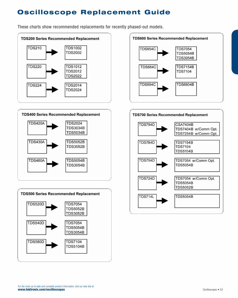
These charts show recommended replacements for recently phased-out models.
Oscilloscope Replacement Guide
Oscilloscopes • 53For the most up-to-date and complete product information, visit our web site atwww.tektronix.com/oscilloscopes

Digital Storage OscilloscopesTPS2012 • TPS2014 • TPS2024
54 • OscilloscopesFor the most up-to-date and complete product information, visit our web site at
www.tektronix.com/tps2000
As an engineer or technician, you must oftenmake floating, or differential, measurements. Youface faster edges and clocks due to the migrationof higher performance technologies to widelyimplemented electronic systems and subsystems,with the pressure to conform to customer specifi-cations or industry requirements.
And you may need to develop and test designs ina variety of challenging environments thatdemand versatility.
You can quickly tackle these tough challenges tospeed the design, trouble-shooting, installation,and maintenance of components and systemswith the world’s first 4-isolated-channel, full fea-tured, battery-powered oscilloscope – theTPS2000 Series.
Make Floating and DifferentialMeasurements – Quickly,Accurately, Affordably
Make floating and differential measurementsmuch more quickly and accurately and speed verification of power supply performance, complexcontrol circuits and the effects of neutral currentfor differential voltages, up to 30 VRMS floatingon four channels simultaneously, when theTPS2000 Series is paired with its standard P2220 passive probe.
Easily perform these measurements up to 600 VRMS CAT II (or 300 VRMS CAT III) floatingwhen the oscilloscope is coupled with its optionalP5120 passive, high-voltage probe.
Accurately characterize rise and fall times andother waveform parameters in circuits with different low levels or ground references, whileremoving ground loop interference, with just 37 pf capacitance to chassis on each of four isolated channels.
Innovative IsolatedChannel™ technology makesthese measurements possible – all designed withyour safety in mind.
Features & Benefits100 MHz and 200 MHz Bandwidths
Sample Rates Up to 2 GS/s Real-time
2 or 4 Fully Isolated and FloatingChannels, Plus Isolated External Trigger
8 Hours of Continuous BatteryOperation with Two Batteries Installed,Hot-swappable for Virtually UnlimitedFreedom from an AC Power Source
Optional Power Application SoftwareOffers the Broadest Range of PowerMeasurements at its Price Point
Quickly Document and AnalyzeMeasurement Results withOpenChoice® Software or IntegratedCompactFlash Mass Storage
FFT Standard on All Models
Advanced Triggers to Quickly Capturethe Event of Interest
Easily Operate the Oscilloscope withTraditional, Analog-style Knobs and Multi-language User Interface
Simplify Setup and Operation withAutoset Menu, Autorange, Waveformand Setup Memories, and Built-in,Context-sensitive Help
Adjust the Oscilloscope to YourOperating Environment with BacklitMenu Buttons/Display andBrightness/Contrast Controls
11 Automatic Measurements
Applications Industrial Power Design,Troubleshooting, Installation and Maintenance
Advanced Electronics Design,Troubleshooting, Installation and Maintenance
Automotive Design and Test
Education
TPS2000 Series Oscilloscopes Deliver Powerful Productivity from Bench to Field
For your local Tektronix representative see the list in the back of this catalog or outside the U.S. call: 1-503-627-7111, inside the U.S. call: 1-800-833-9200.
Product(s) are manufactured in ISO registered facilities.
Four IsolatedChannel™ inputs and isolatedexternal trigger input for quick, accurate,affordable floating and differential measurements.

Speed the Design and Test of Industrial Power Systemsand Subsystems
The TPS2000 Series easily addresses the unique challenges that plague industrial powerdesigners and technicians. You regularly confronthigh voltages and currents, and must often makepotentially hazardous floating measurements. Withthe TPS2000 Series’ power bundle (TPS2PBND),which includes the P5120 passive, high-voltageprobes and TPS2PWR1 power measurement andanalysis software, you can use a single instrumentto make a broad range of measurements.
Easily evaluate these high voltages and currents,or debug power electronics control circuits, withdifferential voltages up to 600 VRMS CAT II (or300 VRMS CAT III) floating. Accurately measurethree-phase power and circuits with different lowlevels or ground references.
Quickly perform a broad range of power-specificmeasurements, such as switching loss, harmonicdistortion measurements to the 50th harmonic,and dv/dt and di/dt cursor measurements.
Quickly Debug and CharacterizeSignals with DRT SamplingTechnology
Characterize a wide range of signal types on fourchannels simultaneously with the TPS2000Series’ unique digital real-time (DRT) samplingtechnology. This acquisition technology makes itpossible to capture high-frequency information,such as glitches and edge anomalies, that eludesother oscilloscopes in its class, so that you canbe sure to get a complete view of your signal tospeed debug and characterization.
Easily Analyze and DocumentYour Measurement Results
Quickly reveal signal interference, cross-talk andthe effects of vibration with frequency domainanalysis using the TPS2000 Series’ standard FastFourier Transform (FFT) feature. Easily analyzeand document your measurement results withintegrated CompactFlash mass storage orOpenChoice® software.
Correlate Your Measurementsfrom Bench to Lab to Field*1
Use the TPS2000 Series on your bench, in thelab, or in the field, with the industry’s longestcontinuous battery life – 8 hours and beyond – in a highly mobile package. Harness the power ofvirtually unlimited freedom from an AC powersource with hot-swappable batteries. Easily corre-late measurements between bench, lab and fieldwith its portability.
Optimize Your Productivity with Versatility
Intuitively operate the oscilloscope with familiar,analog-style knobs per channel. Reduce yourmeasurement time with features like autoset,autorange, automatic measurements, 10X to1000X vertical position control, probe check wiz-ard, and context-sensitive help. Effectively workin a variety of challenging environments – frombright daylight to dimly lit areas – using backlitmenu buttons and brightness/contrast controls.
*1 Please refer to Environmental and Safety specifications.
Oscilloscopes • 55For the most up-to-date and complete product information, visit our web site atwww.tektronix.com/tps2000
Digital Storage OscilloscopesTPS2012 • TPS2014 • TPS2024
Perform three-phase power measurements ofvariable frequency drives.
Conduct harmonic distortion measurementswith TPS2PWR1 software.
Capture elusive glitches – the first time – withdigital real-time (DRT) sampling technology.
Speed documentation and analysis of measurements results with OpenChoice®
software and integrated CompactFlash mass storage.

Digital Storage OscilloscopesTPS2012 • TPS2014 • TPS2024
56 • OscilloscopesFor the most up-to-date and complete product information, visit our web site at
www.tektronix.com/tps2000
TPS2012, TPS2014, TPS2024 Digital Storage Oscilloscopes.Standard Accessories Probes – P2220 200 MHz, 1X/10X switchable passive probe (one per channel).Battery (1) – Lithium-Ion battery with fuel gauge for4-hour battery life. Two batteries required for 8 hourscontinuous battery operation.TDSPCS1 OpenChoice® PC Connectivity Software –A collection of programs that enable fast and easycommunication between MS Windows PCs andTPS2000 Series oscilloscopes.Documentation – 1 each set of instruction manuals (seebelow for the appropriate language manual part number).AC Adapter with Power Cord.NIM/NIST-Traceable Certificate of Calibration.Front Protective Cover.Recommended Accessories TPS2PBND – Power bundle for TPS2000 Series oscilloscopes. Includes (4) P5120 passive, high-voltageprobes and TPS2PWR1 power measurement andanalysis software.TDS2PWR1 – Power measurements application package. Instantaneous power waveform analysis,waveform analysis, harmonics analysis, switching loss,phase angles, dv/dt and di/dt cursors.WSTRO – WaveStar™ software; Windows98/2000/ME/NT 4.0 application for waveform capture, analysis,documentation and control from your PC. Providesenhanced oscilloscope data measurement, analysis,remote setup and charting features.TPSBAT – Additional battery.TPSCHG – Battery charger.AC2100 – Soft case for carrying instrument.HCTEK321 – Hard case for carrying instrument.
343-1689-00 – Versatile hanger.Service Manual – English only (P/N 071-1465-xx).Programmer Manual – English only (P/N 071-1075-xx).156-9413-00 – CompactFlash memory card, 32 MBor more.Recommended Probes A621 – 2000 A, 5 to 50 kHz AC current probe/BNC.A622 – 100 A, 100 kHz AC/DC current probe/BNC.P5120 – Passive high-voltage probe (1000 V CAT II tipto ground; 600 V CAT II reference to earth ground).P5200 – High-voltage active differential probe (1300 Vpk-pk, 25 MHz).P5205 – High-voltage active differential probe (1300 Vpk-pk, 100 MHz). (1103 power supply required).P5210 – High-voltage active differential probe (5600 Vpk-pk, 50 MHz). (1103 power supply required).CT2 – 2.5 A, 200 MHz AC current probe.CT4 – AC current probe up to 2000 Apk-pk. (TCP202and 1103 power supply required.) TCP202 – 15 A, 50 MHz AC/DC current probe. (1103power supply required.) TCP303/TCPA300 – 15 A, 15 MHz AC/DC currentprobe/amplifier.TCP305/TCPA300 – 50 A, 50 MHz AC/DC currentprobe/amplifier.TCP312/TCPA300 – 30A, 100 MHz, DC/AC currentprobe/amplifier.TCP404XL/TCPA400 – 500 A, 2 MHz AC/DC currentprobe/amplifier.International Power Plugs Opt. A0 – North America power.Opt. A1 – Universal EURO power.Opt. A2 – United Kingdom power.Opt. A3 – Australia power.
Opt. A5 – Switzerland power.Opt. A6 – Japan power.Opt. A10 – China power.Opt. A99 – No power cord or AC adapter.Accessory Cables RS-232, 9-Pin female to 25-Pin male, 4.6 m (15ft.), for Modems – Order 012-1241-00.RS-232, 9-Pin female to 9-Pin female, nullmodem, for computers – Order 012-1651-00.RS-232, 9-Pin female to 25-Pin female, nullmodem, for computers – Order 012-1380-00.RS-232, 9-Pin female to 25-Pin male, nullmodem, for printers – Order 012-1298-00.Centronics, 25-Pin male to 36-Pin Centronics,2.4 m (8 ft.), for Parallel Printer Interfaces –Order 012-1214-00.
International User ManualLanguage Options Opt. L0 – English (071-1441-xx).Opt. L1 – French (071-1442-xx).Opt. L2 – Italian (071-1443-xx).Opt. L3 – German (071-1444-xx).Opt. L4 – Spanish (071-1445-xx).Opt. L5 – Japanese (071-1446-xx).Opt. L6 – Portuguese (071-1447-xx).Opt. L7 – Simplified Chinese (071-1448-xx).Opt. L8 – Traditional Chinese (071-1449-xx).Opt. L9 – Korean (071-1450-xx).Opt. L10 – Russian (071-1451-xx).Translated front panel overlay included with its respec-tive user manual.Warranty Information Three year warranty covering all labor and parts,excluding probes and accessories.
Ordering InformationCurrent price information is available worldwide on-line from the Tektronix web site or from your local Tektronix representative. Inside the U.S., also see the price list in the back of this catalog.
Soft Carrying Case. P5120 Probe. Current Probes.
TPS2000 Series Electrical Characteristics
Characteristics
Feature TPS2012 TPS2014 TPS2024 Isolated Channels 2 4 4 Bandwidth*1 (MHz) 100 100 200 Sample Rate (GS/s) Per Channel 1.0 1.0 2.0 Record Length 2.5 K pointsDisplay (1/4 VGA LCD) Color Battery Operation Capacity for two hot-swappable battery packs. One standard battery pack offers 4 hours of battery operation. Optional second
battery pack extends battery operation to 8 hours. Continuous battery operation is possible by hot-swapping charged batteries

For the most up-to-date and complete product information, visit our web site atwww.tektronix.com/tds2000 Oscilloscopes • 57
The TDS1000 Series and TDS2000 Series digitalstorage oscilloscopes deliver an unbeatable combination of superior performance, unmatchedease-of-use, and affordability in an ultra light-weight, portable package.
Affordable Digital Precision
With up to 200 MHz bandwidth and 2 GS/s maxi-mum sample rate, no other color digital storageoscilloscope offers as much bandwidth and sam-ple rate for the price. The TDS1000 andTDS2000 Series oscilloscopes provide accuratereal-time acquisition up to their full bandwidth,advanced triggers to isolate signals of interest,and 11 standard automatic measurements on allmodels. Their Fast Fourier Transform (FFT) mathfunction allows the user to analyze, characterizeand troubleshoot circuits by viewing frequencyand signal strength (standard on all models).
Features & Benefits60 MHz, 100 MHz, and 200 MHzBandwidths
Sample Rates up to 2 GS/s
2 or 4 Channels
Color or Monochrome LCD Display
CompactFlash® Mass Storage Option with TDS2MEM Module
Autoset Menu with Waveform Selection
Probe Check Wizard to EnsureCorrect Probe Usage
Context-sensitive Help
Dual Time Base
Advanced Triggers, Including PulseWidth Trigger and Line-SelectableVideo Trigger
11 Automatic Measurements
Multi-language User Interface
Waveform and Setup Memories
FFT Standard on All Models
OpenChoice® Solutions SpeedDocumentation and Analysis ofMeasurement Results – TDS2CMAX Communication
Module – TDS2MEM Storage Memory
and Communication Module – TDSPCS1 OpenChoice Software– WaveStar™ Software– Integration with
Third-party Software
Applications Design and Debug
Education and Training
Manufacturing Test and Quality Control
Service and Repair
Digital Storage Oscilloscopes TDS1002 • TDS1012 • TDS2002 • TDS2012 • TDS2014 • TDS2022 • TDS2024
TDS1000 and TDS2000 Series Oscilloscopes. Colorful Performance at a Black and White Price.
For your local Tektronix representative see the list in the back of this catalog or outside the U.S. call: 1-503-627-7111, inside the U.S. call: 1-800-833-9200.
Product(s) are manufactured in ISO registered facilities.

58 • OscilloscopesFor the most up-to-date and complete product information, visit our web site at
www.tektronix.com/tds2000
Ultra-fast Setup and Use
The simple user interface with classic, analog-style controls makes these instruments easy touse, reducing learning time and increasing effi-ciency. Innovative features, such as the autosetmenu, probe check wizard, context-sensitive helpmenu and color LCD display (TDS2000 Series)optimize instrument setup and operation.
Simple, Speedy Documentation and Analysis
OpenChoice™ solutions deliver simple, seamlessintegration between the oscilloscope and the personal computer, providing you with multiplechoices to easily document and analyze yourmeasurement results.
Choose from optional communication modules,CompactFlash® mass storage capability,OpenChoice software and integration with third-party software.
Digital Storage Oscilloscopes TDS1002 • TDS1012 • TDS2002 • TDS2012 • TDS2014 • TDS2022 • TDS2024
I/O interface TDS2CMAX Communication Module TDS2MEM Storage Memory and Communication Module
Compatibility TDS200, TDS1000, TDS2000 Series Oscilloscopes TDS1000, TDS2000 Series Oscilloscopes Printer Port Centronics-type Parallel Printer Capability Graphics File Formats – TIFF, PCX (PC Paint Brush), BMP (Microsoft Windows), EPS (Encapsulated Postscript) and RLE (Requires Module) Printer Formats – Bubble Jet, DPU-411, DPU-412, DPU-3445, Thinkjet, Deskjet, Laser Jet,
Epson Dot (9- or 24-pin)*2, Epson C60*2, Epson C80 Layout – Landscape and Portrait
RS-232 Programmability Full talk/listen modes. Control of all modes, settings and measurements.Baud rate up to 19,200. 9-pin DTE RS-232 Cable (012-1651-00) included
GPIB (IEEE std. 488-1987) Full talk/listen modes. Control of all modes, Not Available Programmability settings and measurements.Mass Storage Not Available • Type 1 CompactFlash memory card supplied with Module*3
CompactFlash® Memory • Accepts any Type 1 CompactFlash card, up to and including 1 GB• Built-in Clock/Calendar
• Includes CompactFlash to USB Memory Card Readerfor use with Personal Computer
OpenChoice™ PC • TDSPCS1 OpenChoice PC Communications Software included with each ModuleCommunications • Seamless connection from oscilloscope to PC through GPIB and RS-232Software • Transfer and save settings, waveforms, measurements, and screen images
• Includes a Windows desktop data transfer application in addition to convenient Microsoft Word and Excel Toolbar Add-ins
*2 Requires instrument firmware version 2.12/4.12 or higher to support Epson C60/C80 printer formats.
*3 Supplied Type 1 CompactFlash memory card storage capacity 8 MB or greater.
I/O Interface
Quickly transfer waveforms and measurement data to an external PC or between oscilloscopes.
Easily document and analyze measurementresults using OpenChoice™ software.
Unparalleled measurement accuracy with up to 200 MHz bandwidth and 2 GS/s maximum sample rate.

Oscilloscopes • 59For the most up-to-date and complete product information, visit our web site atwww.tektronix.com/tds2000
Digital Storage Oscilloscopes TDS1002 • TDS1012 • TDS2002 • TDS2012 • TDS2014 • TDS2022 • TDS2024
TDS1002, TDS1012, TDS2002,TDS2012, TDS2014, TDS2022,TDS2024
Standard Accessories Probes – P2200 200 MHz 10X to 1X SwitchablePassive Probes (one per channel).Documentation – User manual.Power cord.NIM/NIST-Traceable Certificate of Calibration.
Service Opt. C3 – Calibration Service 3 Years.Opt. C5 – Calibration Service 5 Years.Opt. D1 – Calibration Data Report.Opt. D3 – Calibration Data Report 3 Years (with Option C3).Opt. D5 – Calibration Data Report 5 Years (with Option C5).
Recommended Accessories TDS2CMAX – Communication Module (GPIB, RS-232,Centronics-type Printer Port) includes: TDSPCS1OpenChoice™ PCCommunication Software, RS-232 cable.TDS2MEM – Storage Memory and CommunicationModule (RS-232, Centronics-type Printer Port)includes: Type 1 CompactFlash® memory card,CompactFlash to USB Memory Card Reader, TDSPCS1OpenChoice PC Communication Software,RS-232 cable.TDSPCS1 OpenChoice PC CommunicationSoftware – A collection of programs that enable fastand easy transfer communication between
MS Windows PCs and TDS3000B, TDS2000,TDS1000, and TDS200 Series oscilloscopes; includedwith TDS2CMAX and TDS2MEM communication modules.WaveStar™ Software for Oscilloscopes (WSTRO) – application for waveform capture, analysis,documentation, and control from your PC.AD007 – LAN/WAN GPIB converter.AC2100 – Soft case for carrying instrument.HCTEK321 – Hard plastic case for carrying instrument.RM2000 – Rackmount kit.Operator Training Kit – Extensive instructions and step-by-step lab exercises provide education aboutthe operation of the TDS1000 and TDS2000 Seriesoscilloscopes.
Recommended Probes P2220 – 200 MHz, 10X to 1X Switchable Passive Probe.P6015A – 1000X high voltage passive probe (75 MHz).P5100 – 100X high voltage passive probe (250 MHz).P5200 – High voltage active differential probe (25 MHz).P6021 – 60 MHz AC current probe.P6022 – 120 MHz AC current probe.A621 – 2000 A AC current probe/BNC.A622 – 100 A AC/DC current probe/BNC.AM503S – AC/DC current probe system.
International User Manual(TDS1000 and TDS2000 SeriesDigital Storage Oscilloscopes,includes TDS2CMAX*1 userinformation) Opt. L0 – English (071-1064-00).Opt. L1 – French (071-1065-00).Opt. L2 – Italian (071-1066-00).Opt. L3 – German (071-1067-00).Opt. L4 – Spanish (071-1068-00).Opt. L5 – Japanese (071-1069-00).Opt. L6 – Portuguese (071-1070-00).Opt. L7 – Simplified Chinese (071-1071-00).Opt. L8 – Traditional Chinese (071-1072-00).Opt. L9 – Korean (071-1073-00).Opt. LR – Russian (071-1074-00).Translated front panel overlays included with theirrespective user manuals.*1 The user information for the TDS2CMA communication
module that appears in this manual also applies to theTDS2CMAX communication module.
Warranty Information Three year warranty covering all labor and parts,excluding probes and accessories.
Product(s) are manufactured in ISO registered facilities.
Ordering InformationCurrent price information is available worldwide on-line from the Tektronix web site or from your local Tektronix representative. Inside the U.S., also see the price list in the back of this catalog.
Tektronix probes are expressly designed for your oscilloscope, with identical quality standards and built-in compatibility for optimum performance.
Pulse-width and field- and line-selectable videotriggers make the oscilloscope ideal for a widerange of applications.
Precisely analyze, characterize and troubleshoot circuits – at the push of a button with the autoset menu.
TDS1000 and TDS2000 Series Electrical CharacteristicsTDS1002 TDS1012 TDS2002 TDS2012 TDS2014 TDS2022 TDS2024
Display (1/4 VGA LCD) Mono Mono Color Color Color Color Color Bandwidth*1 60 MHz 100 MHz 60 MHz 100 MHz 100 MHz 200 MHz 200 MHz Channels 2 2 2 2 4 2 4 Sample Rate 1.0 GS/s 1.0 GS/s 1.0 GS/s 1.0 GS/s 1.0 GS/s 2.0 GS/s 2.0 GS/s on each channelRecord Length 2.5 K points on all models
*1 Bandwidth is 20 MHz at 2 mV/div, all models.
Characteristics

60 • OscilloscopesFor the most up-to-date and complete product information, visit our web site at
www.tektronix.com/tds3000b
The TDS3000B packs the power of a DPO, digitalreal-time (DRT) sampling technology, WaveAlert™
waveform anomaly detection, OpenChoice documentation and analysis solutions and fiveapplication- specific modules into a lightweight,battery-capable design.
A DPO Provides a GreaterLevel of Insight into Complex Signals
The TDS3000B Series DPO delivers 3,600 wfms/scontinuous waveform capture rate to captureglitches and infrequent events three times fasterthan comparable oscilloscopes. Some oscillo-scope vendors claim high waveform capture rates for short bursts of time, but only DPOs candeliver these fast waveform capture rates on acontinuous basis – saving minutes, hours or evendays by quickly revealing the nature of faults soadvanced triggers can be applied to isolate them.
In addition, the TDS3000B DPO’s real-time intensity grading highlights the details about the“history” of a signal’s activity, making it easier tounderstand the characteristics of the waveformsyou’ve captured.
Digital Phosphor OscilloscopesTDS3012B • TDS3014B • TDS3024B • TDS3032B • TDS3034B • TDS3044B • TDS3052B • TDS3054B • TDS3064B
For your local Tektronix representative see the list in the back of this catalog or outside the U.S. call: 1-503-627-7111, inside the U.S. call: 1-800-833-9200.
The TDS3000B Series of Digital PhosphorOscilloscopes Provides Unmatched Performanceand Portability at an Affordable Price
The TDS3000B DPO provides unmatched insight into complex signal behavior,such as metastable events.
Features & Benefits100 to 600 MHz Bandwidths
5 GS/s Maximum Real-time SampleRate, with Sin(x)/x Interpolation
3,600 wfms/s Continuous WaveformCapture Rate
2 or 4 Channels
Full VGA Color LCD
25 Automatic Measurements
FFT Standard
Multi-language User Interface
QuickMenu Graphical User Interfacefor Easy Operation
WaveAlert™ Automatic WaveformAnomaly Detection
OpenChoice® Solutions Simplify Instrument Control,Documentation and Analysis – e*Scope® Web-based Remote
Control – Built-in Ethernet Port – GPIB, RS232, VGA – TDSPCS1 OpenChoice Software – WaveStar™ Software – Integration with Third-party
Software
Application Modules for SpecializedAnalysis – Advanced Analysis Module – Limit Testing Module – Telecommunications Mask Testing
Module – Extended Video Module – 601 Serial Digital Video Module
Optional Internal Battery Operation up to 3 Hours
Plug-in Printer for PortableDocumentation of Results
TekProbe™ Interface Supports Active,Differential and Current Probes forAutomatic Scaling and Units
Applications Digital Design, Debug and Test
Video Installation and Service
Power Supply Design
Education and Training
Telecommunications Mask Testing
Manufacturing Test

Oscilloscopes • 61For the most up-to-date and complete product information, visit our web site atwww.tektronix.com/tds3000b
Digital Phosphor OscilloscopesTDS3012B • TDS3014B • TDS3024B • TDS3032B • TDS3034B • TDS3044B • TDS3052B • TDS3054B • TDS3064B
Higher Speeds Demand Greater Bandwidth
You face faster clock rates and edge speeds,increasingly complex signals and mounting time-to-market pressures. The higher the bandwidth ofyour oscilloscope, the more accurate the repro-duction of your signal. The TDS3000B Seriesoffers a wide range of bandwidths from 100 MHzto 600 MHz to best suit the needs of your mostdemanding projects, so that you can completeyour tasks on time and with confidence.
Quickly Debug andCharacterize Signals with DRT Sampling Technology and Sin(x)/x Interpolation
The TDS3000B Series combines unique digitalreal-time (DRT) sampling technology with sin(x)/xinterpolation to allow you to accurately character-ize a wide range of signal types on all channelssimultaneously. This sampling technology makesit possible to capture high-frequency information,such as glitches and edge anomalies, that eludesother oscilloscopes in its class, while sin(x)/xinterpolation ensures precise reconstruction ofeach waveform. The result – a complete view ofyour signal to speed debug and characterization.
Enhanced TroubleshootingAbility
WaveAlert™ waveform anomaly detection speedsyour troubleshooting tasks by helping you findthose elusive problems faster. WaveAlert detec-tion monitors the incoming signals on all chan-nels and will detect and highlight any waveformthat deviates from the normal waveform beingacquired. Because the TDS3000B oscilloscopecan stop acquisition, sound a beep, make a hardcopy or save the waveform when it detects ananomaly, you can run tests over long time periods– even unattended – to find those challenging,very infrequent failures.
WaveAlert™ waveform anomaly detection alertsyou to any waveform that deviates from the“normal” input, such as the glitch on channel 2.
An increase in performance from 500 to 600 MHz bandwidth offers a 20% improvementin rise-time measurement accuracy, as illustrated with these measurements of a 20 ps rising edge. The lower trace is a reference waveform, showing the rise-time performance of a 500 MHz oscilloscope.The upper trace shows the improved performance of a 600 MHz oscilloscope.
Even with 2 GS/s sample rate, which exceedsthe Nyquist requirement of 2X oversampling,this 500 MHz oscilloscope with linear interpola-tion does not provide accurate reconstruction ofthe same 500 MHz sine wave.
The TDS3054B’s 5 GS/s real-time sample rateand sin(x)/x interpolation ensure accuratereconstruction of a 500 MHz sine wave.
TDS3000B Series Electrical Characteristics
Characteristics
TDS3012B TDS3014B TDS3024B TDS3032B TDS3034B TDS3044B TDS3052B TDS3054B TDS3064B Bandwidth 100 MHz 100 MHz 200 MHz 300 MHz 300 MHz 400 MHz 500 MHz 500 MHz 600 MHz Channels 2 4 4 2 4 4 2 4 4 Sample Rate on 1.25 GS/s 1.25 GS/s 2.5 GS/s 2.5 GS/s 2.5 GS/s 5 GS/s 5 GS/s 5 GS/s 5GS/sEach ChannelMaximum 10 K points on all models Record LengthDisplay (VGA) Color active matrix LCD on all models

62 • OscilloscopesFor the most up-to-date and complete product information, visit our web site at
www.tektronix.com/tds3000b
Digital Phosphor OscilloscopesTDS3012B • TDS3014B • TDS3024B • TDS3032B • TDS3034B • TDS3044B • TDS3052B • TDS3054B • TDS3064B
TDS3012B, TDS3014B,TDS3024B, TDS3032B,TDS3034B, TDS3044B,TDS3052B, TDS3054B,TDS3064B
Standard Accessories Probes: 2 each P3010 10X passive probes(TDS3012B), 4 each P3010 10X passive probes(TDS3014B), 2 each P6139A 10X passive probes(TDS3032B and TDS3052B), 4 each P6139A 10X passive probes (TDS3024B, TDS3034B, TDS3044B,TDS3054B and TDS3064B).Documentation: User Manual, quick reference manual and programmer’s manual.Power cord.Accessory tray.Protective front cover: Has holder for user manualand/or 3.5 in. floppy disks.NIST-Traceable Certificate of Calibration.
Recommended Accessories TDS3TMT – Telecom mask testing application module.TDS3AAM – Advanced analysis module.TDS3LIM – Limit test module.TDS3VID – Extended video application module.TDS3SDI – 601 serial digital video module. Requires a4-channel TDS3000B Series oscilloscope.TDS3GV – GPIB, VGA, RS-232 interfaces andTDSPCS1 OpenChoice® PC Communication software.TDSPCS1 OpenChoice PC CommunicationSoftware – A collection of programs that enable fastand easy transfer communication between MSWindows PCs and Tektronix oscilloscopes. Available in single-license packages and included in TDS3GVcommunication module.WaveStar™ Software for Oscilloscopes –Microsoft Windows 98/ME/2000/NT 4.0 Application.
TDS3BATB – Lithium Ion battery pack for up to 3hours continuous operation without line power.TDS3CHG – Fast charger for battery pack.TDS3PRT – Plug-in printer adds easy, portable docu-mentation capability to your TDS3000B oscilloscope.AC3000 – Soft case for carrying instrument.HCTEK321 – Hard plastic case for carrying instrument.RM3000 – Rackmount kit.Service Manual (TDS3000B Series) – English only(071-0972-00).TNGTDS01 – Self-paced self-study operator training kit.
Recommended Probes P6243 – 1 GHz, ≤1 pF input C 10x active probe.P6246 – 400 MHz differential probe.P6247 – 1 GHz differential probe.P5205 – 1.3 kV, 100 MHz high voltage differential probe.P5210 – 5.6 kV, 50 MHz high voltage differential probe.P5100 – 2.5 kV, 100X high voltage passive probe.TCP202 – 50 MHz, 15 A AC/DC current probe.TCP300/400 Series current probes.*1
*1 TCP300 probes require TCPA300 probe amplifier; TCP400 probesrequire TCPA400 probe amplifier.
Language Options (Includes front panel overlay) Opt. L0 – English.Opt. L1 – French.Opt. L2 – Italian.Opt. L3 – German.Opt. L4 – Spanish.Opt. L5 – Japanese.Opt. L6 – Portuguese.Opt. L7 – Simplified Chinese.Opt. L8 – Traditional Chinese.Opt. L9 – Korean.Opt. L10 – Russian.Opt. L99 – No Manual.
Service Opt. C3 – Calibration Service 3 Years.Opt. C5 – Calibration Service 5 Years.Opt. D1 – Calibration Data Report.Opt. D3 – Calibration Data Report 3 Years (with Opt. C3).Opt. D5 – Calibration Data Report 5 Years (with Opt. C5).Opt. R5 – Repair Service 5 Years.
Warranty Three year warranty covering all labor and parts,excluding probes.
Ordering InformationCurrent price information is available worldwide on-line from the Tektronix web site or from your local Tektronix representative. Inside the U.S., also see the price list in the back of this catalog.

Oscilloscopes • 63For the most up-to-date and complete product information, visit our web site atwww.tektronix.com/ths700
Handheld Battery OperatedOscilloscopes
The TekScope® THS700 Series Scope/DMM com-bines a full-featured real-time oscilloscope with aTrue RMS digital multimeter in rugged, battery-operated instruments. Scope and meter modescan operate simultaneously and independently onthe same or separate signals. The high-resolution,backlit display and pop-up menus make it easyfor users to take full advantage of the instru-ment’s many features. These include cursors,video trigger, voltage and resistance measure-ments, and storage of waveforms, data, andinstrument setups. In addition, they offer the mostcomprehensive triggering capabilities – externaltrigger and extensive triggering including delay,pulse width, and video.
The THS700A Series is ideal for electronic applications – at the bench or at the site.
The THS720P Scope/DMM includes features toaddress the needs of electrical/power electronics measurements.
The Only Safe MeasurementSolution for Power Electronics
The THS720P TekScope IsolatedChannel™
Scope/DMM is ideal for electrical/power electronics applications.
The THS720P includes features specifically forelectrical/power electronics measurements whichallow testing and verifying correct operation ofmotors, checking transformer efficiency, verifyingpower-supply performance, and measuring theeffect of neutral current. These features includeharmonic analysis, power measurements and statistics and PWM motor drive triggering. It alsocontains the powerful features of a modern oscilloscope that enable troubleshooting and verification of complicated electronic control circuits controlling the high-voltage power-electronics circuitry.
The THS720P shares measurement features withthe THS730A, THS720A Scope/DMMs, which areideal for electronic applications.
Handheld Battery OperatedOscilloscope/DMM/Power Analyzers THS700 Series
THS720P.THS730A.
Features & Benefits
THS730A/THS720A/THS720P
200 and 100 MHz Bandwidth
1 GS/s and 500 MS/s Sampling Ratesper Channel
Two Channels and Dual Digitizers
External Trigger
3-3/4 Digit DMM with Datalogger
Roll Mode
Extra Bright Backlit Display
8 ns Glitch Capture
Independently Floating Isolated Scopeand DMM Channels for Safety
Full Floating Measurement Capabilityup to 600 VRMS
Advanced Trigger - Delay, Pulse, andVideo (Line Count and Field Select)
21 Automatic Measurements
RS-232Programmability/Communications
NiCd Battery and AC Adapter
Deluxe Soft Carrying Case
THS720P Only
Measures Harmonics up to 31st(Fundamental from 30 Hz to 450 Hz)
Automatic Power Measurement with Statistics
Advanced Trigger – Delay, Pulse,Video (Line Count and Field Select),PWM Motor Drive
1 kV High-voltage Probes
Applications
THS730A/THS720A/THS720P
Field or Bench ElectronicTroubleshooting
Floating (Nongrounded) SystemMeasurements
Industrial Electronic EquipmentTroubleshooting (THS720P)
Power Quality Surveys (THS720P)
THS700 Series
For your local Tektronix representative see the list in the back of this catalog or outside the U.S. call: 1-503-627-7111, inside the U.S. call: 1-800-833-9200.
Product(s) are manufactured in ISO registered facilities.

64 • OscilloscopesFor the most up-to-date and complete product information, visit our web site at
www.tektronix.com/ths700
Characteristics
Power Measurements(THS720P Only)
W True power VA Apparent power VAR Reactive power V Volts (RMS, Peak) A Amps (RMS, Peak) THD-F Total harmonic distortion as a
percentage of the fundamental THD-R Total harmonic distortion of the
RMS of the input signal PF Power factor DPF Displacement power factor PHI Phase difference between the
voltage and current
DMM Specifications
DC Voltage Ranges – 400.0 mV to 880 V.DC Volts Accuracy –±(0.5% of reading + 5 counts).True RMS AC Voltage Ranges – 400.0 mV to 640 V.Maximum Float Voltage – 600 VRMS CAT II,each channel (probe dependent).Resolution – 4000 count, 3-3/4 digits.AC Volts Accuracy – ±(2% of reading + 5 counts).Resistance Ranges – 400.0 Ω to 40.00 MΩ.Resistance Accuracy – ±(0.5% of reading + 2counts); 40 MΩ: ±(2% of reading + 5 counts).Diode Test Range – 0 to 2 V.Continuity Check – Audible tone when <50 Ω.Modes – Min, Max, Delta, Max-Min, Avg, Hold.Nonvolatile Storage – 10 DMM screenshots.External Trigger Input – 5 MHz TTL compatible.Vertical Zoom Capability – 2X, 5X, 10X.dB Scale – Selectable, referenced from 1 mV to 10 V.dBm Scale – Selectable, referenced from 50 Ωto 600 Ω.
Handheld Battery Operated Oscilloscope/DMM/Power Analyzers THS700 Series
THS730A THS720A THS720P Bandwidth 200 MHz 100 MHz 100 MHz Sample Rate (Each Channel) 1 GS/s 500 MS/s 500 MS/s Time/Division Range 2 ns to 50 s/div 5 ns to 50s/div 5 ns to 50s/div Power Measurements N N Y
Oscilloscope Functions
THS730A, THS720AHandheld Battery Operated Oscilloscope/DMM.Includes: Two P6117 10X Passive Probes, UserManual, Quick Reference Manual, Standard Meter LeadSet, NiCd Rechargeable Battery Pack, AC PowerAdapter, Soft Carrying Case, Cable and Adapters forRS-232, NIST-traceable Certificate of Calibration.
THS720PHandheld Battery Operated Oscilloscope/DMM.Includes: Two P5102 10X Passive Probes, UserManual, Quick Reference Manual, Standard Meter LeadSet, NiCd Rechargeable Battery Pack, AC PowerAdapter, Soft Carrying Case, Cable and Adapters forRS-232, NIST-traceable Certificate of Calibration.
Language Options Opt. L0 – English User Manual.Opt. L1 – French User Manual.Opt. L2 – Italian User Manual.Opt. L3 – German User Manual.Opt. L4 – Spanish User Manual.Opt. L5 – Japanese User Manual.Opt. L6 – Portuguese User Manual.Opt. L7 – Simplified Chinese User Manual.Opt. L8 – Traditional Chinese User Manual.Opt. L9 – Korean User Manual.
Recommended Accessories Also see Accessories.P5102 – 10X 100 MHz Passive Probe for higher voltage application: 1000VRMS Tip-to-reference; 600VRMS Reference-to-earth Ground (float).A621, A622 – Current Probes.P6117 (replacement) – 10X Passive Probe.Battery Charger – THS7CHG.Rechargeable Battery (replacement) – THS7BAT.
Standard Meter Lead Set (replacement) –012-1482-00.Deluxe Meter Lead Set – ATLDX1.Hard Carrying Case – THS7HCA.Soft Carrying Case (replacement) – 016-1399-01.
Software WSTRO – WaveStar™ software for Oscilloscopes,Windows 95/98/NT application for waveform capture,analysis, documentation and control form your PC.
Warranty Three years (excluding probes).
For your local Tektronix representative see the list in the back of this catalog or outside the U.S. call: 1-503-627-7111, inside the U.S. call: 1-800-833-9200.
Product(s) are manufactured in ISO registered facilities.
Ordering InformationCurrent price information is available worldwide on-line from the Tektronix web site or from your local Tektronix representative. Inside the U.S., also see the price list in the back of this catalog.

Oscilloscopes • 65For the most up-to-date and complete product information, visit our web site atwww.tektronix.com/tds5000b
Digital Phosphor Oscilloscopes TDS5032B • TDS5034B • TDS5052B • TDS5054B • TDS5054BE • TDS5104BNEW
MyScope Custom Control Windows
The TDS5000B Series offers the industry’s firsteasily customizable oscilloscope user interface.MyScope control windows is a revolutionary newfeature that allows you to build your own controlwindows with only the controls, features andcapabilities that you care about and are importantin your job. For the first time, you can pull all thefunctionality you need from all the various parts of the oscilloscope into one control window,effectively creating your own personalized “tool-box” of oscilloscope features. No longer do youneed to search through menus for features or re-learn how to drive the oscilloscope after abreak from the lab.
MyScope control windows enable you to spendyour valuable time focused on the task at handrather than navigating menus on your oscillo-scope. And creating these custom control win-dows isn’t a long drawn-out or complex process.They are easily created in a matter of minutesusing a simple, visual, drag and drop process.Once created, these custom control windows are easily accessed through a dedicated MyScopebutton and menu selection on the oscilloscopebutton/menu bar, just like any other control window.You can make an unlimited number of custom con-trol windows, enabling each person who uses theoscilloscope, in a shared environment, to have
their own unique control window. Since the control windows are stored as files on the harddrive, they can easily be transferred to otherTDS5000B Series oscilloscopes, or they can evenbe e-mailed to a co-worker around the world whenthe need arises. MyScope control windows willbenefit all oscilloscope users, from eliminating the ramp-up time that many face when returningto the lab after not using an oscilloscope for awhile, to the power user who can now operate far more efficiently. Everything you need is foundin one control window rather than having to constantly navigate through menu after menu to repeat similar tasks.
Features & Benefits1 GHz, 500, 350 MHz Bandwidth Models
2 and 4 Channel Models
5 GS/s Sample Rate
Up to 16 M Record Length
100,000 wfms/s Maximum WaveformCapture Rate
MyScope™ Custom Control Windows Enhance Productivity
Right Mouse Click Menus forExceptional Efficiency
OpenChoice® Platform with Windows2000 Delivers Built-in Networking and Analysis
Small Footprint and Light Weight
10.4 in. Bright Display
Suite of Advanced Triggers
Built-in Printer (Optional)
CD-RW Drive
Interoperability with Tektronix Logic Analyzers
ApplicationsDigital Design and Debug
Mask Testing for Telecomm/Datacomm/Video Standards
Investigation of Transient Phenomena
Power Measurements
Video Design and Debug
DVD, Jitter and Timing, SpectralAnalysis
Automotive Electronics
Manufacturing Test
Electro-mechanical
Bio-medical
Industrial Control
Elusive Glitch. Fast waveform capture rate,enabled by Tektronix proprietary DPX acquisitiontechnology, maximizes the probability of captur-ing elusive glitches and other infrequent events.
For your local Tektronix representative see the list in the back of this catalog or outside the U.S. call: 1-503-627-7111, inside the U.S. call: 1-800-833-9200.
Tektronix measurement products are manufactured in ISO registered facilities.
The World’s Easiest to Use Midrange Oscilloscope

66 • OscilloscopesFor the most up-to-date and complete product information, visit our web site at
www.tektronix.com/tds5000b
Digital Phosphor Oscilloscopes TDS5000B Series
Performance The TDS5000B Series digital phosphor oscillo-scopes (DPO) deliver up to 1 GHz bandwidth,5 GS/s real-time sample rate, 16 M record length,and a suite of advanced triggers, enabling you tocapture and characterize even your mostdemanding signals. DPOs provide unmatchedinsight into signal behavior by displaying, storingand analyzing complex signals in real-time usingthree dimensions of signal information: amplitude,time and distribution of amplitude over time. TheTDS5000B Series DPO, enabled by Tektronix proprietary DPX® acquisition technology, deliversgreater than 100,000 waveforms per second capture rates. Some oscilloscope venders claimhigh waveform capture rates for short bursts oftime, but only DPOs, enabled by DPX technology,can deliver these fast waveform capture rates ona sustained basis – saving minutes, hours or evendays by quickly revealing the nature of faults sosophisticated trigger modes can be applied to iso-late them.
OpenChoice® Architecture The TDS5000B Series includes open access tothe MS Windows 2000 operating environment.While the instrument remains a dedicated oscillo-scope, the ability to access the MS Windowsdesktop creates a powerful tool. Built-in applica-tions such as WordPad, Paint and a Web browserallow you to concurrently maintain lab notes whileworking with the instrument. This saves time andeliminates error-prone steps associated withtransporting images for later report development.Other applications such as Microsoft Word orExcel, MATLAB and LabVIEW can be installed onthe instrument to accomplish local documentationor signal analysis. Installation of the oscilloscopeon the LAN enables Web-based informationbrowsing, e-mail exchange, printing and file sharing. Using the embedded PCI bus, waveformdata can be moved directly from acquisition toanalysis applications on the Windows desktop atmuch faster speeds than conventional GPIB transfers.
Open Windows Platform. TDS5000 Series waveform display with Excel window andActiveX toolbar.
TDS5032B/TDS5034B TDS5052B/TDS5054B/ TDS5104B TDS5054BE
Input Channels 2/4 2/4/4 4 Analog Bandwidth (–3 dB) 5 mV/div to 1 V/div 350 MHz 500 MHz 1 GHz Calculated Rise Time 5 mV/div (typical) 1.15 ns 800 ps 300 ps Hardware Bandwidth Limits 150 MHz or 20 MHz Input Coupling AC, DC, GND Input Impedance, 1 MΩ ±1% Input Impedance, 50 Ω ±1% ±2.5% Input Sensitivity, 1 MΩ 1 mV/div to 10 V/div Input Sensitivity, 50 Ω 1 mV/div to 1 V/div Vertical Resolution 8-bits (>11-bits w/ averaging) Max Input Voltage, 1 MΩ 150 V CAT I, ≤400 V peak. Derate at 20 dB/decade to 9 VRMS above 200 kHzMax Input Voltage, 50 Ω 5 VRMS with peaks <±30V 5 VRMS with peaks <±30V <100 mV/div <1 VRMS
≥100 mV/div <5 VRMS
DC Gain Accuracy 1.5% with offset set to 0 V Offset Range, 1 MΩ 1 mV/div to 99.5 mV/div ±1 V
100 mV/div to 1 V/div ±10 V1.01 V/div to 10 V/div ±100 V
Offset Range, 50 Ω 1 mV/div to 99.5 mV/div ±1 V 1 mV to 50 mV/div ±0.5 V100 mV to 1 V/div ±10 V 50.5 mV to 99.5 mV ±0.25 V
100 mV to 500 mV ±5V505 mV to 1 V/div ±2.5 V
Channel-to-Channel Isolation Any ≥100:1 at ≤100 MHz and ≥30:1 at >100 MHz up to the rated bandwidthTwo Channels at Equal Vertical Scale
Vertical System
Characteristics

Oscilloscopes • 67For the most up-to-date and complete product information, visit our web site atwww.tektronix.com/tds5000b
Digital Phosphor Oscilloscopes TDS5000B Series
Timebase SystemAll Models
Timebase Range 200 ps/div to 1000 s/div Timebase Delay Time Range (s/div x 10) to 1000 sChannel-to-Channel Deskew Range ±75 ns Timebase Accuracy 15 ppmDelta Time Measurement Accuracy (0.06/sample rate + 15 ppm x |Reading|)RMS
Trigger Jitter (RMS) 8 psRMS (typical) Long-Term Sample Rate and Delay Time Accuracy ±15 ppm over any ≥1 ms interval
Acquisition System TDS5032B/5052B TDS5034B/5054B/5104B TDS5054BE
Real-time Sample Rates1 Channel (max) 5 GS/s 5 GS/s 1GS/s2 Channels (max) 2.5 GS/s 2.5 GS/s 1GS/s3-4 Channels (max) — 1.25 GS/s 1GS/sEquivalent Time Sample Rate (max) 250 GS/s 250 GS/s 200 GS/sMaximum Record Length per Channel with Standard Memory 8 M/4 M/— 8 M/4 M/2 M 8 M/4 M/2 MWith Opt. 3M 16 M/8 M/— 16 M/8 M/4 M 16 M/8 M/4 M
All Models FastAcq Acquisition FastAcq optimizes the instrument for analysis of dynamic signals and capture of infrequent
events. Maximum FastAcq waveform capture rate is 100,000 wfms/sSample Acquire sampled values Peak Detect Captures narrow glitches (<1 ns) at all real-time sampling rates Averaging From 2 to 10,000 waveforms included in average Envelope From 2 to 2 x 10⁹ waveforms included in min-max envelope Hi-res Real-time boxcar averaging reduces random noise and increases resolutionWaveform Database Accumulates a waveform database that provides a three-
dimensional array of amplitude, time and countsFastFrameTM Acquisition Acquisition memory divided into segments; maximum
trigger rate >225,000 waveforms per second
Acquisition Modes
Maximum Duration at Highest Real-time Resolution (1 ch)
TDS5054BE All Other Models Time Resolution (single shot) 1 ns (1 GS/s) 200 ps (5 GS/s) Max Duration with Standard Memory 8 ms 1.6 ms Max Duration with Opt. 3M 16 ms 3.2 ms

68 • OscilloscopesFor the most up-to-date and complete product information, visit our web site at
www.tektronix.com/tds5000b
Trigger Modes Edge – Positive or negative slope on any channel orfront panel auxiliary input. Coupling includes DC, AC,noise reject, HF reject, and LF reject.Video – Trigger on NTSC, PAL, SECAM, analog HDTV,and non-standard video formats.Glitch – Trigger on or reject glitches of positive,negative or either polarity. Minimum glitch width is1.0 ns with 200 ps resolution.Width – Trigger on width of positive or negative pulseeither within or out of selectable time limits rangingfrom 1 ns to 1 s with 200 ps resolution.Runt – Trigger on a pulse that crosses one thresholdbut fails to cross a second threshold before crossingthe first again. Event can be time or logic qualified(logic on 4 channel models only).Window – Trigger on an event that enters or exits a window defined by two user-adjustable thresholds.Event can be time or logic qualified (logic on 4 channelmodels only).Timeout – Trigger on an event which remains high,low or either, for a specified time period, selectablefrom 1 ns to 1 s with 200 ps resolution.
Transition – Trigger on pulse edge rates that arefaster or slower than specified. Slope may be positive,negative or either.Setup/Hold – Trigger on violations of both setup timeand hold time between clock and data present on anytwo input channels.Pattern – Trigger when pattern goes false or staystrue for specified period of time. Pattern (AND, OR,NAND, NOR) specified for four input channels definedas High, Low or Don’t Care.State – Any logical pattern of channels (1, 2, 3) clockedby edge on channel 4 (channel 2 on TDS5032B/TDS5052B). Trigger on rising or falling clock edge.Comm (requires Opt. SM) – Support for AMI, HDB3,B3ZS, B6ZS, B8ZS, CMI, NRZ and MLT3 encoded communication signals. Select among isolated positiveor negative one, zero pulse form or eye patterns asapplicable to standard.Trigger Delay by Time – 16 ns to 250 seconds.Trigger Delay by Events – 1 to 10,000,000 Events.
Computer System and Peripherals
Operating System – Windows 2000.CPU – Intel Celeron Processor, 2.0 GHz.PC System Memory – 512 MB.Internal Hard Disk Drive – ≥80 GB capacity.Front Removable Hard Disk Drive (optional) –≥40 GB capacity.Floppy Disk Drive – Front panel 3.5 in floppy diskdrive, 1.44 MB capacity.CD-RW Drive – Side panel CD-RW drive, ≥24X readand write speed.Printer (optional) – Built-in thermal printer.Mouse – Optical wheel mouse, USB interface.
Digital Phosphor Oscilloscopes TDS5000B Series
TDS5032B350 MHz, 5 GS/s, 2 channel digital phosphor oscilloscope.
TDS5034B350 MHz, 5 GS/s, 4 channel digital phosphor oscilloscope.
TDS5052B500 MHz, 5 GS/s, 2 channel digital phosphor oscilloscope.
TDS5054B500 MHz, 5 GS/s, 4 channel digital phosphor oscilloscope.
TDS5054BE500 MHz, 1 GS/s, 4 channel digital phosphor oscilloscope.
TDS5104B1 GHz, 5 GS/s, 4 channel digital phosphor oscilloscope.All Models Include: (1) P5050 500 MHz,10x passive probe per channel, Accessory Pouch (016-1935-00), Front Cover (200-4651-00), Mouse(119-6936-00), Quick Start User Manual, TDS5000BSeries Product Software CD-ROM, TDS5000B SeriesOperating System Restoration CD-ROM, GPIBProgrammer’s Reference, Optional ApplicationsSoftware CD-ROM, Getting Started with OpenChoice®
book, and Software Developer’s Kit CD (020-2513-00),30-day Evaluation Copies of MATLAB (063-3609-00)and LabVIEW (020-2476-02), Performance VerificationProcedure PDF file, Calibration Certificate DocumentingNIST Traceability, Z540-1 Compliance, and ISO 9001Registration, Power Cord.Please specify power plug and manual version when ordering.
Service Options Opt. C3 – Calibration Service 3 Years.Opt. C5 – Calibration Service 5 Years.Opt. D1 – Calibration Data Report.Opt. D3 – Calibration Data Report 3 Years (with Opt. C3).Opt. D5 – Calibration Data Report 5 Years (with Opt. C5).Opt. R3 – Repair Service 3 Years (including warranty).Opt. R5 – Repair Service 5 Years (including warranty).
For your local Tektronix representative see the list in the back of this catalog or outside the U.S. call: 1-503-627-7111, inside the U.S. call: 1-800-833-9200.
Tektronix measurement products are manufactured in ISO registered facilities.
Ordering InformationCurrent price information is available worldwide on-line from the Tektronix web site or from your local Tektronix representative. Inside the U.S., also see the price list in the back of this catalog.
All Models Sensitivity Internal DC Coupled 0.35 div DC to 50 MHz increasing to 1 div at rated bandwidth External (auxiliary input) 400 mV from DC to 50 MHz increasing to 750 mV at 100 MHz Main Trigger Modes Auto, normal, and single Trigger Sequences Main, delayed by time, delayed by events. All sequences can include separate
horizontal delay after the trigger event to position the acquisition window in time Trigger Level Range Any Channel ±10 divisions from center of screen External (auxiliary in) ±8 V Line Fixed at 0 V Trigger Coupling DC, AC (attenuate <60 Hz), HF reject (attenuate >30 kHz),
LF reject (attenuates <80 kHz), Noise reject (reduce sensitivity) Trigger Holdoff Range 1.5 µs to 12 s maximum
Trigger System

Oscilloscopes • 69For the most up-to-date and complete product information, visit our web site atwww.tektronix.com/tds6000
TDS6000B Series digital storage oscilloscopesprovide unprecedented performance along with acomplete feature set designed to address designvalidation, debug, and compliance challenges of next generation computer, datacom, and commu-nications equipment. High bandwidth, high samplerate, and deep memory also provide the idealsolution for data acquisition applications.
Uncompromised Acquisition
Never again will you need to trade off bandwidth,record length, and sample rate. The TDS6000BSeries DSO provides a new acquisition architec-ture that has maximum sample rate (20 GS/s)and record length (32 Megasamples) on each
of the four channels simultaneously. TheTDS6804B provides matched 8 GHz performanceacross all four channels using advanced DSPenhancement, important for high speed channel-channel measurements. The DSP filter on eachchannel provides magnitude and phase compen-sation of the analog bandwidth to provide moreaccurate signal fidelity for high-speed measure-ments. Ideal for analyzing and debugging multi-lane serial device designs and interconnect. Fourlanes of serial data traffic can be analyzed simul-taneously. The DSP filter on each channel canalso be disabled to take advantage of the true7 GHz analog bandwidth.
*1 TDS6804B Only. Analog BW is 7 GHz with 43 ps (20 to 80%) typicalrise time. Rise time specified with 10 ps (20 to 80%) source.
Digital Storage Oscilloscope TDS6000B Series NEW
Features & Benefits8 GHz (TDS6804B) and 6 GHz(TDS6604B) Models
Uncompromised Performance forSignal Integrity Applications
8 GHz Guaranteed Bandwidth, 35 ps (20 to 80%) Typical Rise Time, With Channel Matched, User Selectable DSP*1
20 GS/s Real-time Sample Rate (500 fs Interpolated Resolution) on Each Channel
32 Megasamples Record Length onEach Channel (Up to 1.6 msecMaximum Capture at Full Sample Rate)
MultiView Zoom™ for Quick Navigationof Long Records
Pinpoint™ Triggering Provides Highest Performance and Over 1400 Triggering Combinations
Serial Data Compliance and Analysis Up to 5 Gb/s
Dual Processor System (2.8 GHzPentium 4 and 583 MHz PowerPC)Provide Fast Waveform Processing
OpenChoice® with Windows XP OSDelivers Built-in Networking and Analysis
Technology-specific SoftwareSolutions Provide Built-in DomainExpertise for Serial Data, Jitter, Ethernet,DVI, USB2.0, Communications and Power Measurements
System Includes: High-resolution XGADisplay, Front Panel CD-R/W, FrontPanel USB2.0 Port and 1000Base-TNetwork Connection
Applications Signal Integrity, Jitter and Timing Analysis
Validation, Debug Characterizationand Compliance of Next GenerationDigital Designs
High Speed Serial StandardsValidation and Compliance Testing Up to 5 Gb/s
PCI Express, XAUI, Serial ATA, SerialAttached SCSI, 10G Fibre Channel,InfiniBand, Serial Memory, etc.
Computer, Datacom, Storage AreaNetwork Equipment Designs andHigh-speed Backplanes
High Energy Physical Measurementsand Data Acquisition
For your local Tektronix representative see the list in the back of this catalog or outside the U.S. call: 1-503-627-7111, inside the U.S. call: 1-800-833-9200.
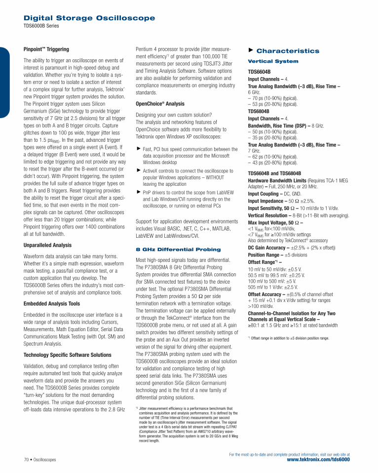
70 • OscilloscopesFor the most up-to-date and complete product information, visit our web site at
www.tektronix.com/tds6000
Pinpoint™ Triggering
The ability to trigger an oscilloscope on events ofinterest is paramount in high-speed debug andvalidation. Whether you’re trying to isolate a sys-tem error or need to isolate a section of interestof a complex signal for further analysis, Tektronix’new Pinpoint trigger system provides the solution.The Pinpoint trigger system uses SiliconGermanium (SiGe) technology to provide triggersensitivity of 7 GHz (at 2.5 divisions) for all triggertypes on both A and B trigger circuits. Captureglitches down to 100 ps wide, trigger jitter lessthan to 1.5 psRMS. In the past, advanced triggertypes were offered on a single event (A Event). Ifa delayed trigger (B Event) were used, it would belimited to edge triggering and not provide any wayto reset the trigger after the B-event occurred (ordidn’t occur). With Pinpoint triggering, the systemprovides the full suite of advance trigger types onboth A and B triggers. Reset triggering providesthe ability to reset the trigger circuit after a speci-fied time, so that even events in the most com-plex signals can be captured. Other oscilloscopesoffer less than 20 trigger combinations; whilePinpoint triggering offers over 1400 combinationsall at full bandwidth.
Unparalleled Analysis
Waveform data analysis can take many forms.Whether it’s a simple math expression, waveformmask testing, a pass/fail compliance test, or acustom application that you develop. TheTDS6000B Series offers the industry’s most com-prehensive set of analysis and compliance tools.
Embedded Analysis Tools
Embedded in the oscilloscope user interface is awide range of analysis tools including Cursors,Measurements, Math Equation Editor, Serial DataCommunications Mask Testing (with Opt. SM) andSpectrum Analysis.
Technology Specific Software Solutions
Validation, debug and compliance testing oftenrequire automated test tools that quickly analyzewaveform data and provide the answers youneed. The TDS6000B Series provides complete“turn-key” solutions for the most demandingtechnologies. The unique dual-processor systemoff-loads data intensive operations to the 2.8 GHz
Pentium 4 processor to provide jitter measure-ment efficiency*2 of greater than 100,000 TIEmeasurements per second using TDSJIT3 Jitterand Timing Analysis Software. Software optionsare also available for performing validation andcompliance measurements on emerging industrystandards.
OpenChoice® Analysis
Designing your own custom solution? The analysis and networking features ofOpenChoice software adds more flexibility toTektronix open Windows XP oscilloscopes:
Fast, PCI bus speed communication between thedata acquisition processor and the MicrosoftWindows desktop
ActiveX controls to connect the oscilloscope topopular Windows applications – WITHOUT leaving the application
PnP drivers to control the scope from LabVIEWand Lab Windows/CVI running directly on theoscilloscope, or running on external PCs
Support for application development environmentsincludes Visual BASIC, .NET, C, C++, MATLAB,LabVIEW and LabWindows/CVI.
8 GHz Differential Probing
Most high-speed signals today are differential.The P7380SMA 8 GHz Differential ProbingSystem provides true differential SMA connection(for SMA connected test fixtures) to the deviceunder test. The optional P7380SMA DifferentialProbing System provides a 50 Ω per side termination network with a termination voltage.The termination voltage can be applied externallyor through the TekConnect® interface from theTDS6000B probe menu, or not used at all. A gainswitch provides two different sensitivity settings ofthe probe and an Aux Out provides an invertedversion of the signal for driving other equipment.The P7380SMA probing system used with theTDS6000B oscilloscopes provide an ideal solutionfor validation and compliance testing of highspeed serial data links. The P7380SMA uses second generation SiGe (Silicon Germanium)technology and is the first of a new family of differential probing solutions.
*2 Jitter measurement efficiency is a performance benchmark thatcombines acquisition and analysis performance. It is defined by thenumber of TIE (Time Interval Error) measurements per secondmade by an oscilloscope’s jitter measurement software. The signalunder test is a 4 Gb/s serial data bit stream with repeating CJTPAT(Compliance Jitter Test Pattern) from an AWG710 arbitrary wave-form generator. The acquisition system is set to 20 GS/s and 8 Meg record length.
Characteristics
Vertical System
TDS6604BInput Channels – 4.True Analog Bandwidth (–3 dB), Rise Time –6 GHz.– 70 ps (10-90%) (typical).– 53 ps (20-80%) (typical).TDS6804B Input Channels – 4.Bandwidth, Rise Time (DSP) – 8 GHz.– 50 ps (10-90%) (typical).– 35 ps (20-80%) (typical).True Analog Bandwidth (–3 dB), Rise Time –7 GHz.– 62 ps (10-90%) (typical).– 43 ps (20-80%) (typical).
TDS6604B and TDS6804BHardware Bandwidth Limits (Requires TCA-1 MEGAdapter) – Full, 250 MHz, or 20 MHz.Input Coupling – DC, GND.Input Impedance – 50 Ω ±2.5%.Input Sensitivity, 50 Ω – 10 mV/div to 1 V/div.Vertical Resolution – 8-Bit (>11-Bit with averaging).Max Input Voltage, 50 Ω –<1 VRMS for<100 mV/div,<7 VRMS for ≥100 mV/div settingsAlso determined by TekConnect® accessory DC Gain Accuracy – ±(2.5% + (2% x offset)) Position Range – ±5 divisions Offset Range*1 –10 mV to 50 mV/div: ±0.5 V.50.5 mV to 99.5 mV: ±0.25 V.100 mV to 500 mV: ±5 V.505 mV to 1 V/div: ±2.5 V.Offset Accuracy – ±(0.5% of channel offset + 15 mV +0.1 div x V/div setting) for ranges>100 mV/div.Channel-to-Channel Isolation for Any TwoChannels at Equal Vertical Scale –≥80:1 at 1.5 GHz and ≥15:1 at rated bandwidth
*1 Offset range in addition to ±5 division position range.
Digital Storage Oscilloscope TDS6000B Series

Oscilloscopes • 71For the most up-to-date and complete product information, visit our web site atwww.tektronix.com/tds6000
Timebase System
Timebase Range – 25 ps to 40 s/div; Interpolationdown to 500 fs/pt.Timebase Delay Time Range – 5 ns to 250 s.Channel-to-Channel Deskew Range – ±75 ns.Trigger Jitter (RMS) – <1.5 psRMS (typical).Long Term Sample Rate and Delay TimeAccuracy – 2.5 ppm over any ≥100 ms interval.Clock Stability –<1 ppm (typical).<2.5 ppm (typical).
Acquisition System
Max Sample Rate – 20 GS/s on all 4 Channels.Equivalent Time Sample Rate (max) – 2 TS/s.Maximum Record Length per Channel –
Standard – 2 M on all 4 Channels.With Memory Opt. 2M – 8 M on all 4 Channels.With Memory Opt. 3M – 16 M on all 4 Channels.With Memory Opt. 4M – 32 M on all 4 Channels.
Maximum Time DurationCaptured at Highest Real-timeResolution (All Channels)
Max Duration with Standard Memory – 100 µs.Max Duration with Opt. 2M – 400 µs.Max Duration with Opt. 3M – 800 µs.Max Duration with Opt. 4M – 1.6 ms.
Acquisition Modes
Waveform Database – Accumulate WaveformDatabase providing three-dimensional array of amplitude, time and counts.Sample – Acquire sampled values.Peak Detect – Captures narrow glitches at all real-time sampling rates.Minimum Peak Detect Pulse Width – 50 ps.Averaging – From 2 to 10,000 waveforms included in average.Envelope – From 2 to 2x10⁹ waveforms included in min-max envelope.Hi-Res – Real-time boxcar averaging reduces random noise and increases resolution.FastFrame™ Acquisition – Acquisition memory divided into segments; maximum trigger rate>310,000 waveforms per second. Time of arrivalrecorded with each event.Roll Mode – 200 kSamples/sec at 8 Meg RecordLength and 500 kSamples/sec at 4 Meg RecordLength on all channels.
Pinpoint™ Trigger System
Sensitivity Internal DC Coupled – 0.5 div DC to 50 MHzincreasing to 2.5 div at 7 GHz (typical).External (auxiliary input) – 200 mV from DC to50 MHz increasing to 500 mV at 2 GHz.Trigger Characteristics Main Trigger Modes – Auto, Normal, and Single.A Event and Delayed B Event Trigger Types – Edge, Glitch, Runt, Width, Transition Time, Timeout,Pattern, State, Setup/Hold, Window – all except Edge,Pattern, and State can be Logic State qualified by up totwo channels.Trigger Sequences – Main, Delayed by Time,Delayed by Events, Reset by Time, Reset by State,Reset by Transition. All sequences can include separatehorizontal delay after the trigger event to position theacquisition window in time.Communications-related Triggers – Support forAMI, HDB3, BnZS, CMI, MLT3 and NRZ encoded com-munications signals (requires Opt. SM) up to 3.125Gb/s. Select among isolated positive or negative one,zero pulse form or eye patterns as applicable to standard.Serial Pattern Trigger (requires Opt. ST) – 64-Bit serial word recognizer, bits specified in binary(high, low, don’t care) or hex format. Trigger on NRZ-encoded data up to 1.25 G Baud.Trigger Level Range Internal – ±12 divisions from center of screen.External (auxiliary in) – ±5 V.Line – Fixed at 0 V.Trigger Coupling – DC, AC (attenuate <60 Hz),HF reject (attenuate >30 kHz) LF reject (attenuates<80 kHz) Noise reject (reduce sensitivity).Trigger Holdoff Range – 250 ns minimum to 12 s maximum.
Trigger Types
Edge – Positive and/or negative slope on any channelor front panel auxiliary input. Coupling includes DC, AC,noise reject, HF reject and LF reject.Glitch – Trigger on or reject glitches of positive,negative or either polarity. Minimum glitch width isdown to 100 ps with rearm time of 250 ps.Width – Trigger on width of positive or negative pulse (down to 100 ps) either within or out of selectable time limits.Runt – Trigger on a pulse that crosses one thresholdbut fails to cross a second threshold before crossingthe first again. Optional time qualification.Timeout – Trigger on an event which remains high,low, or either, for a specified time period, selectablefrom 360 ps to 1 s.Transition – Trigger on pulse edge rates that arefaster or slower than specified. Slope may be positive, negative or either.Setup/Hold – Trigger on violations of both setup timeand hold time between clock and data present on anytwo input channels.Pattern – Trigger when pattern goes false or staystrue for specified period of time. Pattern (AND, OR,
NAND, NOR) specified for four input channels definedas HIGH, LOW or Don’t Care.State – Any logical pattern of channels (1, 2, 3)clocked by edge on channel 4. Trigger on rising orfalling clock edge.Window – Trigger on an event that enters or exits a window defined by two user-adjustable thresholds. Event can be time or logic qualified.Trigger Delay by Time – 5 ns to 250 seconds.Trigger Delay by Events – 1 to 10,000,000 Events.
Waveform Measurements
Amplitude – Amplitude, High, Low, Maximum,Minimum, Peak-to-Peak, Mean, Cycle Mean, RMS,Cycle RMS, Positive Overshoot, Negative Overshoot.Time – Rise Time, Fall Time, Positive Width, NegativeWidth, Positive Duty Cycle, Negative Duty Cycle, Period,Frequency, Delay.Combination – Area, Cycle Area, Phase, Burst Width.Trigger – Direct readout of measured signal frequency(clock or data) measured by trigger system.Histogram-related – Waveform Count, Hits In Box,Peak Hits, Median, Maximum, Minimum, Peak-to-Peak,Mean (µ), Standard Deviation (s), µ + 1s, µ + 2s,µ + 3s.Eye Pattern-Related – Extinction Ratio (absolute, %,and dB), Eye Height, Eye Top, Eye Base, Eye Width,Crossing %, Jitter (peak-to-peak, RMS and 6sigma),Noise (peak-to-peak and RMS), S/N ratio, CycleDistortion, Q-factor.
Waveform Processing/Math
Algebraic Expressions – Define extensive algebraicexpressions including waveforms, scalars and resultsof parametric measurements e.g.,(Integral (CH.1-Mean(CH.1) x 1.414).Arithmetic – Add, subtract, multiply, divide waveformsand scalars.Relational – Boolean result of comparison >, <,≥, ≤, =, ≠.Calculus – Integrate, differentiate.Frequency Domain Functions – Spectral magnitudeand phase, real and imaginary spectra.Vertical Units – Magnitude: Linear, dB, dBm; Phase:Degrees, radians.Window Functions – Rectangular, Hamming,Hanning, Kaiser-Bessel, Blackman-Harris, Gaussian,Flattop2, Tek Exponential.Waveform Definition – As arbitrary math expressions.
Display Characteristics
Display Type – Liquid crystal active-matrix color display.Display Size – Diagonal: 264 mm (10.4 in.).Display Resolution – 1024 horizontal x 768 vertical pixels.Waveform Styles – Vectors, Dots, VariablePersistence, Infinite Persistence.
Digital Storage Oscilloscope TDS6000B Series

72 • OscilloscopesFor the most up-to-date and complete product information, visit our web site at
www.tektronix.com/tds6000
Digital Storage Oscilloscope TDS6000B Series
TDS6604B6 GHz Digital Storage Oscilloscope.
TDS6804B 8 GHz Digital Storage Oscilloscope.TDS6604B and TDS6804B Include: Accessorypouch, front cover, USB mouse, PS2 mini-keyboard,user manual (071-1503-xx), quick reference kit (020-2552-xx), TDS6000B Series Documentation
CD-ROM (063-3760-xx), TDS6000B Series productsoftware CD-ROM (063-3761-xx), TDS6000B Seriesoperating system restoration CD-ROM (063-3762-xx), TDS6000B Series optional applications software CD-ROM (063-3478-xx),performance verification procedure PDF file,GPIB programmer’s reference (on product softwareCD-ROM), calibration certificate documenting NISTtraceability, 2 540-1 compliance and ISO 9000,
power cord, one year warranty. (4) TekConnect®
to SMA adapters (TCA-SMA), Deskew Fixture (067-0484-xx). Please specify power plug when ordering.
For your local Tektronix representative see the list in the back of this catalog or outside the U.S. call: 1-503-627-7111, inside the U.S. call: 1-800-833-9200.
Ordering InformationCurrent price information is available worldwide on-line from the Tektronix web site or from your local Tektronix representative. Inside the U.S., also see the price list in the back of this catalog.
Computer System andPeripherals
CPU – Intel Pentium 4 processor, 2.8 GHz.PC System RAM – 1 GB (266 MHz DDR).Hard Disk Drive – 40 GB removable hard disk drive:rear-panel standard or front-panel (Option FHD).USB Ports – One front panel, four on rear panel,USB2.0 compliant.CD-R/W Drive – Front-panel CD-R/W standard or rear-panel (option FHD).Mouse – Thumb wheel model included, USB interface.Keyboard – Small keyboard included (fits in pouch). Order119-6297-xx for full-size keyboard; USB interface and hub.
Input/Output Ports
Front Panel
Probe Compensator Output – Front panel SMA connector, requires Probe Cal-Deskew Fixture(included) for probe attachment. Amplitude 350 mV±20% into a ≥50 Ω load, frequency 1 kHz ±5%,200 ps typical rise time.Recovered Clock – SMA connector, ≤1.25 Gb/s,Output swing ≥130 mVp-p into 50 Ω. Requires Opt.SM or Opt ST to enable.Recovered Data – SMA connector, ≤1.25 Gb/s,Output swing of 1010 repeating pattern 200 mV into 50 Ω. Requires Opt. SM or Opt ST to enable.Probe Calibration Output – BNC connector,±10 V DC for DC probe calibration.AUX Trigger Output – BNC connector, provides aTTL-compatible, polarity switchable pulse when theoscilloscope triggers.USB2.0 Port – One in front. Allows connection or disconnection of USB keyboard, mouse, or storagedevice while oscilloscope is on.
Rear Panel
External Time Base Reference In – BNC connector, timebase system can phase-lock to external 10 MHz reference.Time Base Reference Out – BNC connector, accepts TTL-compatible output of internal 10 MHz reference oscillator.Aux Trigger Input – BNC, see Ext Trigger specification.Parallel Port – IEEE 1284, DB-25 connector.Audio Ports – Miniature phone jacks for stereomicrophone input and stereo line output.USB2.0 Ports – Four in back. Allows connection ordisconnection of USB keyboard, mouse, or storagedevice while oscilloscope power is on.Keyboard Port – PS-2 compatible.Mouse Port – PS-2 compatible.
LAN Port – RJ-45 connector, supports 10Base-T,100Base-T, and 1000Base-T.Serial Port – DB-9 COM1 port.Windows Video Port – 15 pin D-sub connector on the rear panel; connect a second monitor to usedual-monitor display mode allowing analysis resultsand plots to be viewed along with the oscilloscope display. Video is DDC2B compliant.GPIB Port – IEEE 488.2 standard.Oscilloscope XGA Video Port – 15 pin D-sub con-nector on the rear panel, video is IBM XGA compatible.Connect to show the oscilloscope display, including livewaveforms on an external monitor or projector. The pri-mary Windows desktop can also be displayed on anexternal monitor using this port.
Power Source
Power – 100 to 240 VRMS, ±10%, 50/60 Hz;115 VRMS ±10%, 400 Hz; CAT II, <300 W (450 VA).
Physical Characteristics
BENCHTOP CONFIGURATION Dimensions mm in.Height 282 11.1 Width 457 18.0 Depth 540 2325 Weight kg lb.Net 21 47 Shipping 32.3 71.2
RACKMOUNT CONFIGURATION Dimensions mm in.Height 267 10.5 Width 491 19.3 Depth 638 25.1 Weight kg lb.Net 22 49Kit 5.6 12.25
Mechanical Cooling – mm in.Required ClearanceTop 0 or >76 0 or >3 Bottom 25 1 Left side 76 3 Right side 76 3 Front 0 0 Rear 0 0
Environmental
Temperature
Operating – +5 ºC to +50 ºC, excluding CD-R/Wdrive; +10 ºC to +45 ºC, including CD-R/W drive.Nonoperating – –22 ºC to +60 ºC.
Humidity
Operating – 20% to 80% relative humidity with a maximum wet bulb temperature of +29 ºC at orbelow +50 ºC, noncondensing. Upper limit derated to25% relative humidity at +50 ºC.Nonoperating – 5% to 90% relative humidity with amaximum wet bulb temperature of +29 ºC at or below+60 ºC, noncondensing. Upper limit derated to 20%relative humidity at +60 ºC.
Altitude Operating – 10,000 ft. (3,048 m).Nonoperating – 40,000 ft. (12,190 m).
Random Vibration
Operating – 0.000125 g2/Hz from 5 to 350 Hz,–3 dB/octave from 350 to 500 Hz, 0.0000876 g2/Hzat 500 Hz. Overall level of 0.24 gRMS.Nonoperating – 0.0175 g2/Hz from 5 to 100 Hz,–3 dB/octave from 100 to 200 Hz, 0.00875 g2/Hzfrom 200 to 350 Hz, –3 dB/octave from 350 to500 Hz, 0.006132 g2/Hz at 500 Hz. Overall level of 2.28 gRMS.
Certifications
Electromagnetic Compatibility – 89/336/EEC.Safety – UL 3111-1, CSA1010.1, EN61010-1,IEC 61010-1.
Service Options
Opt. C3 – Calibration Service 3 Years.Opt. C5 – Calibration Service 5 Years.Opt. D1 – Calibration Data Report.Opt. D3 – Calibration Data Report 3 Years (requires Opt. C3).Opt. D5 – Calibration Data Report 5 Years (requires Opt. C5).Opt. R3 – Repair Service 3 Years.Opt. R5 – Repair Service 5 Years.

Oscilloscopes • 73For the most up-to-date and complete product information, visit our web site atwww.tektronix.com/tds7000b
The TDS7000B Series’ unique combination ofsuperior measurement fidelity, unrivaled analysis,and uncompromised usability makes it the ulti-mate test machine to simplify and speed thedesign of high-speed, complex systems. Thisfamily offers the industry’s best solution to thechallenging signal integrity issues faced bydesigners verifying, characterizing and debuggingsophisticated electronic designs.
They deliver up to 7.25 GHz (typical) true analogbandwidth, down to 43 ps rise time (20% to 80%)and 20 GS/s maximum real-time sample rate tocapture critical events with fine detail. Exclusive
DPX® acquisition technology enables waveformcapture rates up to 400,000 wfms/s to quicklyfind rare glitches in seconds or minutes, insteadof hours or days. Innovative software solutionsdeliver domain expertise for advanced analysisand compliance testing, while the OpenChoice®
architecture enables users to integrate theirexpertise through the ability to easily write customprograms or utilize popular commercial software.The intuitive graphical user interface deliverssophisticated capability to advanced users withoutintimidating occasional users.
Digital Phosphor Oscilloscopes TDS7000B Series
Features & BenefitsUp to 7.25 GHz True AnalogBandwidth and Down to 43 ps RiseTime (20% to 80%)
>400,000 wfms/s Waveform CaptureRate, Powered by Exclusive DPX®
Acquisition Technology
20 GS/s Maximum Real-time SampleRate
Exceptional Delta-time Accuracy forHigh-confidence in Critical TimingMeasurements
Powerful Triggering Features for FastDetection of Relevant Faults
Communications Mask Testing Up to4.25 Gb/s Rates
Clock Recovery from Serial DataStreams up to 3.125 Gb/s
Up to 64 MB Record Length withMultiView Zoom™ for QuickNavigation of Long Records
TekConnect® Interface for HighFidelity Connection
Classic Direct Controls, Touch-sensitive Display or Mouse Navigation
OpenChoice® with Windows 2000Delivers Built-in Networking andAnalysis
XGA 1024x768 display
Applications Signal Integrity, Jitter and TimingAnalysis
Verification, Debug and Characterizationof Sophisticated Designs
Design Development and ComplianceTesting of Serial Data Streams Up to4.25 Gb/s Rates
Debug of Telecom, Datacom andStorage Area Network EquipmentDesigns and High-speed Backplanes
Spectral Analysis
Investigation of Transient Phenomena
Superior Measurement Fidelity, Unrivaled Analysis,Uncompromised Usability
For your local Tektronix representative see the list in the back of this catalog or outside the U.S. call: 1-503-627-7111, inside the U.S. call: 1-800-833-9200.

74 • OscilloscopesFor the most up-to-date and complete product information, visit our web site at
www.tektronix.com/tds7000b
Digital Phosphor Oscilloscopes TDS7000B Series
Characteristics
TDS7054/TDS7104 TDS7154B/TDS7254B/TDS7404B/TDS7704B Time Base Range 200 ps/div to 40 s/div 50 ps to 10 s/div Time Base Delay Time Range 16 ns to 250 s 5 ns to 250 s Channel-to-channel Deskew Range ±25 ns ±75 ns Delta Time Measurement Accuracy ±((0.06/sample rate) + (15 ppm x reading)) RMS ±((0.06/sample rate) + (2.5 ppm x reading)) RMS Trigger Jitter (RMS) 8 psRMS (typical) 2 psRMS (typical) (7254B/7154B)
1.5 psRMS (typical) (7404B)1.2 psRMS (typical) (7704B)
Long Term Sample Rate and Delay Time Accuracy ±15 ppm over ≥1 ms interval 2.5 ppm over any ≥100 ms interval
Time Base System
Vertical System
TDS7054 TDS7104 TDS7154B TDS7254B TDS7404B TDS7704B Input Channels 4 4 4 4 4 4 Hardware Analog 500 MHz 1 GHz 1.5 GHz*1 2.5 GHz*1 4 GHz*1 7.25 GHz*1 (typical)Bandwidth (–3 dB) 7 GHz*1 (guaranteed)Rise Time 10% to 90% (typical) 800 ps 400 ps 200 ps 130 ps 100 ps 62 ps Rise Time 20% to 80% (typical) 135 ps 83 ps 72 ps 43 psDC Gain Accuracy 1% ±(2% + (2% x offset)) ±(2.5% + (2% x offset))Hardware Bandwidth Limits 250 MHz or 20 MHz Requires TCA-1 MEG Input Coupling AC, DC, GND DC, GND Input Impedance 1 MΩ ±0.5% or 50 Ω ±1% 50 Ω ±2.5% Input Sensitivity, 1 MΩ 1 mV/div to 10 V/div — Input Sensitivity, 50 Ω 1 mV/div to 1 V/div 2 mV/div to 1 V/div Vertical Resolution 8-Bit (>11-Bit with averaging) 8-Bit (>11-Bit with averaging) Max Input Voltage, 1 MΩ ±150 V CAT I Derate at 20 dB/decade —
to 9 VRMS above 200 kHzMax Input Voltage, 50 Ω 5 VRMS, with peaks less than ±30 Volts <1 VRMS for <100 mV/div,
<5 VRMS for ≥100 mV/div settingsAlso determined by TekConnect® accessory
Offset Range 1 mV/div to 100 mV/div: ±1 V 2 mV to 50 mV/div: ±0.5 V 101 mV/div to 1 V/div: ±10 V 50.5 mV to 99.5 mV: ±0.25 V 1.01 V/div to 10 V/div: ±100 V 100 mV to 500 mV: ±5 V
505 mV to 1 V/div: ±2.5 V Channel-to-channel Isolation ≥100:1 at 100 MHz and ≥80:1 at 1.5 GHz and Any Two Channels at Equal ≥30:1 at the rated bandwidth ≥15:1 at rated bandwidthVertical Scale Settings
*1 At ≥10 mV/div.
Note: Typical system bandwidth of TDS7404B with P7240: 4 GHz.
Note: Typical system bandwidth of TDS7404B with P7330: 3.5 GHz.
Note: Typical system bandwidth of TDS7704B with P7260: 6 GHz.
Note: Typical system bandwidth of TDS7704B with P7350: 5 GHz.
Note: Typical system bandwidth of TDS7704B with P7380: 7 GHz.

Oscilloscopes • 75For the most up-to-date and complete product information, visit our web site atwww.tektronix.com/tds7000b
Digital Phosphor Oscilloscopes TDS7000B Series
TDS7054/TDS7104 TDS7154B/TDS7254B/TDS7404B/TDS7704B FastAcq Acquisition Powered by exclusive DPXTM acquisition technology, FastAcq optimizes the instrument
for analysis of dynamic signals and capture of infrequent eventsMaximum FastAcq Waveform Capture Rate >200,000 wfms/s >400,000 wfms/s Waveform Database Accumulate Waveform Database providing three-dimensional array
of amplitude, time and counts Sample Acquire sampled values Peak Detect Captures narrow glitches at all real-time sampling rates Minimum Peak Detect Pulse Width ≤1 ns 400 ps Averaging From 2 to 10,000 waveforms included in average Envelope From 2 to 2x10⁹ waveforms included in min-max envelope Hi-Res Real-time boxcar averaging reduces random noise and increases resolution FastFrame™ Acquisition Acquisition memory divided into segments; maximum trigger rate >265,000 waveforms
per second. Time of arrival recorded with each event
Acquisition Modes
TDS7154B/ TDS7254B/ TDS7054 TDS7104 TDS7404B/ TDS7704B
Real-time Sample Rates 1 channel (max) 5 GS/s 10 GS/s 20 GS/s 2 channels (max) 5 GS/s 5 GS/s 10 GS/s 3-4 channels (max) 2.5 GS/s 2.5 GS/s 5 GS/s Equivalent Time Sample Rate (max) 250 GS/s 250 GS/s 1 TS/s Maximum Record Length per Channel 2 Mb (1-CH.), 1 Mb (2-CH.), 4 Mb (1-CH.), 2 Mb (2-CH.),with Standard Memory 500 Kb (4-CH.) 1 Mb (4-CH.) With Memory Opt. 2M 8 Mb (1-CH.), 4 Mb (2-CH.), 2 Mb (4-CH.) With Memory Opt. 3M 16 Mb (1-CH.), 8 Mb (2-CH.), 4 Mb (4-CH.) With Memory Opt. 4M 32 Mb (1-CH.), 16 Mb (2-CH.),
8 Mb (4-CH.) With Memory Opt. 5M 64 Mb (1-CH.), 32 Mb (2-CH.),
16 Mb (4-CH.)
Acquisition System
TDS7154B/TDS7254B/ TDS7054 TDS7104 TDS7404B/TDS7704B
Time Resolution (Single-shot) 200 ps (5 GS/s) 100 ps (10 GS/s) 50 ps (20 GS/s) Max Duration with Standard Memory 400 µs 200 µs 200 µs Max Duration with Opt. 2M 1.6 ms 800 µs 400 µs Max Duration with Opt. 3M 3.2 ms 1.6 ms 800 µs Max Duration with Opt. 4M 1.6 ms Max Duration with Opt. 5M 3.2 ms
Maximum Duration at Highest Real-time Resolution (1-CH)

76 • OscilloscopesFor the most up-to-date and complete product information, visit our web site at
www.tektronix.com/tds7000b
Digital Phosphor Oscilloscopes TDS7000B Series
TDS7054 TDS7104 TDS7154B/TDS7254B/TDS7404B/TDS7704B
Sensitivity Internal DC Coupled 0.35 div DC to 50 MHz increasing 0.35 div DC to 50 MHz increasing 0.5 div DC to 50 MHz increasing
to 1 div at 500 MHz to 1 div at 1 GHz to 1.5 div at 3 GHz TDS7404B/TDS7704B:2.7 div at 4 GHz (typical)
External (Auxiliary Input) 400 mV from DC to 50 MHz increasing 250mV from DC to 50 MHz increasing 150 mV from DC to 50 MHz increasingto 750 mV at 100 MHz to 500mV at 100 MHz to 500 mV at 2.5 GHz
Main Trigger Modes Auto, Normal and Single Trigger Sequences Main, Delayed by Time, Delayed by Events. All sequences can include separate horizontal delay after the
trigger event to position the acquisition window in time Trigger Characteristics Standard Trigger Types Edge, Glitch, Runt, Width, Transition Time, Edge, Glitch, Runt, Width, Transition Time,
Timeout, Pattern, State, Setup/Hold Timeout, Pattern, State, Setup/Hold,Window – all except Edge, Pattern,
and State can be logic qualified Communications-related Triggers Support for AMI, HDB3, BnZS, CMI, MLT3 and NRZ encoded communications signals.(requires Option SM) Select among isolated positive or negative one, zero pulse form or eye patterns as applicable to standard Serial Pattern Trigger (requires Option ST) 64-Bit serial word recognizer, bits
specified in binary (high, low, don’t care) or hex format. Trigger on NRZ-encoded
data up to 1.25 GBaudTrigger Level Range Internal ±12 divisions from center of screen External (Auxiliary In) ±8 V ±5 V Line fixed at 0 V Trigger Coupling DC, AC (attenuates <60 Hz), HF Rej (attenuates >30 kHz), LF Rej (attenuates <80 kHz), Noise Reject (reduces sensitivity) Trigger Holdoff Range 250 ns minimum to 12 s maximum
Trigger System
Trigger Modes
Edge – Positive and/or negative slope on any channelor front panel auxiliary input. Coupling includes DC, AC,noise reject, HF reject and LF reject.Glitch – Trigger on or reject glitches of positive, nega-tive or either polarity. Minimum glitch width is 1.0 nswith 200 ps resolution (TDS7104/TDS7054). Minimumglitch width is 170 ps (TDS7704B) or 225 ps (all otherB models) with rearm time of 250 ps (B models).Width – Trigger on width of positive or negative pulse(down to 170 ps on B models) either within or out ofselectable time limits – 1 ns (TDS7104/ TDS7054) or 340 ps (B models) to 1 s.Runt – Trigger on a pulse that crosses one thresholdbut fails to cross a second threshold before crossingthe first again. Optional time qualification.Timeout – Trigger on an event which remains high,low or either, for a specified time period, selectablefrom 1 ns (TDS7104/TDS7054) or 340 ps (B models)to 1 s with 200 ps (TDS7104/TDS7054) or 100 ps (B models).Transition – Trigger on pulse edge rates that arefaster or slower than specified. Slope may be positive,negative or either.
Setup/Hold – Trigger on violations of both setup timeand hold time between clock and data present on anytwo input channels.Pattern – Trigger when pattern goes false or staystrue for specified period of time. Pattern (AND, OR,NAND, NOR) specified for four input channels definedas HIGH, LOW or Don’t Care.State – Any logical pattern of channels (1, 2, 3)clocked by edge on channel 4. Trigger on rising orfalling clock edge.Window – Trigger on an event that enters or exits awindow defined by two user-adjustable thresholds.Event can be time or logic qualified (B models only).Logic Qualified Trigger applicable to Glitch, Width, Runt,Timeout, Transition, Setup/Hold, Window triggers –Trigger on the specified event only if the logic statedefined with the remaining unused channels occurs (B models only).Trigger Delay by Time – 16 ns (5 ns for B models)to 250 seconds.Trigger Delay by Events – 1 to 10,000,000 Events.
Computer System andPeripherals
CPU –TDS7104/TDS7054: Intel Celeron processor, 850 MHz.TDS7154B/TDS7254B/TDS7404B/TDS7704B:Intel Pentium 4 processor, 2.0 GHz.PC System Memory – 1GB.* Hard Disk Drive – 40 GB removable hard disk drive:rear-panel or (B models only) front-panel, (option FHD).Floppy Disk Drive – 1.44 MB 3.5 in floppy diskdrive: front-panel, or (B models only) rear-panel (option FHD).CD-R/W Drive – Rear-panel CD-R/W drive with CDcreation software application.Mouse – Thumb wheel model included, USB interface.Keyboard – Order 118-9402-00 for small keyboard(fits in pouch); PS-2 interface. Order 119-6633-00 forfull-size keyboard; USB interface and hub.* Available September 2004

Oscilloscopes • 77For the most up-to-date and complete product information, visit our web site atwww.tektronix.com/tds7000b
Digital Phosphor Oscilloscopes TDS7000B Series
TDS7054 500 MHz Digital Phosphor Oscilloscope.
TDS7104 1 GHz Digital Phosphor Oscilloscope.TDS7104 and TDS7054 include: (4) P6139A500 MHz, 10x Passive Probes, accessory pouch,front cover, mouse, probe calibration and deskew fix-ture (067-0405-xx), quick reference kit (020-2404-xx),user manual (071-1035-xx), TDS7000 Series productsoftware CD-ROM, TDS7000 Series operating systemrestoration CD-ROM, TDS7000 Series optional appli-cations software CD-ROM, performance verificationprocedure PDF file, GPIB programmer’s reference (on product software CD-ROM), calibration certificatedocumenting NIST traceability, 2 540-1 complianceand ISO 9000, power cord, one year warranty.
TDS7154B 1.5 GHz Digital Phosphor Oscilloscope.
TDS7254B 2.5 GHz Digital Phosphor Oscilloscope.
TDS7404B 4 GHz Digital Phosphor Oscilloscope.
TDS7704B 7 GHz Digital Phosphor Oscilloscope.TDS7154B, TDS7254B, TDS7404B, and TDS7704BInclude: Accessory pouch, front cover, mouse,user manual (071-1226-xx), quick reference kit (020-2519-xx), TDS7000B Series product softwareCD-ROM 063-3632-00 (TDS7154/7254/7404B) 063-3633-00 (TDS7704B), TDS7000B Series operatingsystem restoration CD-ROM, TDS7000B Series optionalapplications software CD-ROM, performance verifica-tion procedure PDF file, GPIB programmer’s reference(on product software CD-ROM), calibration certificatedocumenting NIST traceability, 2 540-1 complianceand ISO 9000, power cord, one year warranty.For TDS7154B and TDS7254B Only, Also Includes:(4) TekConnect® to BNC adapters (TCA-BNC),(2) TekConnect high-impedance buffer amplifiers (TCA-1MEG), and deskew fixture (067-0405-xx).For TDS7404B and TDS7704B Only, Also Includes:(4) TekConnect to SMA adapters (TCA-SMA).For TDS7404B Only, Also Includes: Deskew fixture (067-0405-xx).TDS7704B Only, Also Includes:Deskew fixture (067-0484-xx).
Please specify disk drive and power cord option whenordering.
Instrument Options
Power Plug Options Opt. A0 – North America power.Opt. A1 – Universal EURO power.Opt. A2 – United Kingdom power.Opt. A3 – Australia power.Opt. A5 – Switzerland power.Opt. A6 – Japan power.Opt. A99 – No power cord or AC adapter.Opt. A10 – China power.
Mounting Options 1K – K4000 Oscilloscope Cart.1R – Rackmount Kit.
Disk Drive Options (for TDS7154B, TDS7254B,TDS7404B and TDS7704B only) Opt. FHD – Front-panel 40 GB removable hard disk drive, replaces floppy disk drive that goes on the rear panel.
Service Options Opt. C3 – Calibration Service 3 Years.Opt. C5 – Calibration Service 5 Years.Opt. D1 – Calibration Data Report.Opt. D3 – Calibration Data Report 3 Years (with Option C3).Opt. D5 – Calibration Data Report 5 Years (with Option C5).Opt. R3 – Repair Service 3 Years.Opt. R5 – Repair Service 5 Years.
RecommendedAccessories
Probes P7350 – 5 GHz Differential Probe recommended forTDS7404B/TDS7704B.P7350SMA – 5 GHz SMA input Differential Probe.P7260 – 6 GHz Active Probe recommended for TDS7404B/TDS7704B.P6158 – 3 GHz, 20x Low C Probe.P6247 – 1.0 GHz Differential Probe.P6139A – 500 MHz, 10x Passive Probe.P6245 – 1.5 GHz Active Probe.
P6248 – 1.7 GHz Differential Probe.P7240 – 4 GHz Active Probe.P7330 – 3.5 GHz Differential Probe.
Adapters TCA-1MEG – TekConnect® High-impedance Buffer Amplifier.TCA-SMA – TekConnect-to-SMA Adapter.TCA-N – TekConnect-to-N Adapter.TCA-BNC – TekConnect-to-BNC Adapter.TCA75 – 4 GHz Precision TekConnect 75 Ω to 50 Ω Adapter with 75 Ω BNC Input Connector.AFTDS – Telecom Differential Electrical InterfaceAdapter (for line rates <8 MB/s; requires TCA-BNCadapter for TDS7404B).
Cables GPIB Cable (1 m) – Order 012-0991-01.GPIB Cable (2 m) – Order 012-0991-00.RS-232 Cable – Order 012-1298-00.Centronics Cable – Order 012-1214-00.
Test Fixtures TDSUSBF – TDSUSB test fixture for use with Opt. USB.
Software
WSTRO – WaveStar™ waveform capture and documentation software.Miscellaneous Keyboard (USB interface) – Order 119-6633-00.Service Manual – TDS7054/TDS7104:Order 071-0711-xx.TDS7154B/TDS7254B/TDS7404B/TDS7704B:Order 071-0898-xx.Transit Case – Order 016-1522-00.
For your local Tektronix representative see the list in the back of this catalog or outside the U.S. call: 1-503-627-7111, inside the U.S. call: 1-800-833-9200.
Tektronix measurement products are manufactured in ISO registered facilities.
Ordering InformationCurrent price information is available worldwide on-line from the Tektronix web site or from your local Tektronix representative. Inside the U.S., also see the price list in the back of this catalog.

78 • OscilloscopesFor the most up-to-date and complete product information, visit our web site at
www.tektronix.com/csa7000b
The CSA7404B reduces product developmenttime by providing one tool that spans circuitdevelopment and physical layer testing. With thisfamily, engineers can test designs for complianceto network communications standards as well asanalyze critical internal parameters such as signalintegrity, timing margins and jitter.
The CSA7404B has a 4 GHz true analog bandwidth,20 GS/s maximum real-time sample rate and morethan 400,000 wfms/s waveform capture rate,enabled by exclusive DPX® acquisition technology,to rapidly acquire electrical and optical signalinformation not revealed with other analysis tools.Integrated broad wavelength optical response,
clock recovery, serial pattern triggering, and mask testing make testing faster, easier, andmore efficient. Innovative software solutions deliver domain expertise for advanced analysisand compliance testing, while the OpenChoice®
architecture enables users to integrate theirexpertise through the ability to easily write customprograms or utilize popular commercial software.Instrument operation is familiar and intuitivethrough direct controls and a graphical user interface. This unique combination of superiormeasurement fidelity, unrivaled analysis anduncompromised usability speeds the developmentof network communications circuit designs.
Communications Signal Analyzers CSA7404B
Features & BenefitsReal-time Oscilloscope Platform With Up to 4 GHz True AnalogBandwidth and Down to 72 ps Rise Time (20% to 80%)
>400,000 wfms/s Waveform CaptureRate, Powered by Exclusive DPX®
Acquisition Technology
20 GS/s Maximum Real-time Sample Rate
Built-in Compliance Mask Tests withUp to 2.5 Gb/s Optical and ElectricalSerial Data Stream Rates
Integrated Optical Reference ReceiverProtects Integrity of System Calibration
Integrated Hardware Clock RecoveryProvides Single-connectionConvenience
Up to 64 MB Record Length withMultiView Zoom™ for Quick Navigation of Long Records
64-Bit Serial Trigger for Isolation ofPattern-dependent Effects
Complete Eye Pattern MeasurementsSuite Including Extinction Ratio, Q-factor,Eye Height/Width, Jitter and Noise
Waveform Database AcquisitionTechnology for Accurate ParametricMeasurements on Eye Patterns
TekConnect® Interface for High Fidelity Connection
OpenChoice® with Windows 2000Delivers Built-in Networking and Analysis
Applications Design Development and ComplianceTesting of Optical and ElectricalSignals to 2.5 Gb/s Rates
Physical Layer Characterization ofCommunication Signals in Backplane,Midplane and Embedded Designs
Optical and Electrical Signal Integrity,Margin Verification, Jitter and Timing Analysis
For your local Tektronix representative see the list in the back of this catalog or outside the U.S. call: 1-503-627-7111, inside the U.S. call: 1-800-833-9200.
Versatile, High-performance Real-time DigitalOscilloscopes Dedicated to Rapid Design Analysis and Verification of Communications Signals Up To 2.5 Gb/s Rates (OC-48/STM-16 or Fibre Channel FC2125)

Oscilloscopes • 79For the most up-to-date and complete product information, visit our web site atwww.tektronix.com/csa7000b
Characteristics
Communications Signal Analyzers CSA7404B
CSA7404B Input Channels 4*1
Hardware Analog Bandwidth (–3 dB) 4 GHz Rise Time, 10% to 90% (Typical) 100 ps Rise Time, 20% to 80% (Typical) 72 ps Input Coupling DC, GND Input Impedance 50 ΩInput Sensitivity 2 mV/div to 1 V/div Vertical Resolution 8 bits, (>11 bits with averaging) Max. Input Voltage <1 VRMS for <100 mV/div, <5 VRMS for ≥100 mV/div settings.
Also determined by TekConnect® accessory Offset Range 2 mV to 50 mV/div ±0.5 V 50.5 mV to 99.5 mV ±0.25 V
100 mV to 500 mV ±5 V 505 mV to 1 V/div ±2.5 V DC Gain Accuracy 4 mV/div to 1 V/div ±(2% + (2% x net offset/10)) net offset = voltage level at center screen (vertically)*1 ≥10 mV/div.
Vertical System
Specifications assume use of the included 013-0327-00 O-to-E Output to CH1 interconnect (unless otherwise noted).CSA7404B
Optical Channel Unfiltered Bandwidth 2.4 GHz Input Connector Rifocs universal connector Wavelength Range 700 nm to 1650 nm Calibrated Wavelengths 780 nm, 850 nm, 1310 nm, 1550 nm O/E Gain ≥0.27 V/mW (0.35 V/mW typical) @ 780 nm ±20nm
≥0.33 V/mW (0.40 V/mW typical) @ 850 nm ±20nm≥0.64 V/mW (0.75 V/mW typical) @ 1310 nm ±20nm≥0.64 V/mW (0.75 V/mW typical) @ 1550 nm ±20nm
Sensitivity (smallest average power for mask test) 40 µWp-p at 1310 nm and 1550 nm. 20 µW (–17 dBm) average power assuming 50% average duty cycleAssumes scale factor is set to minimum µW/div 80 µWp-p at 780 nm and 850 nm. 40 µW (–14 dBm) average power assuming 50% average duty cycle settings and signal is at least 4 divisionsp-p
RMS Noise ≤1.1 µW + (6.5% of W/div setting) at 1310 nm and 1550 nm≤2.1 µW + (6.5% of W/div setting) at 850 nm≤2.6 µW + (6.5% of W/div setting) at 780 nm
Input Range 10 µW/div to 500 µW/divOptical reference receiver typically available over the following range:40 µW (–14 dBm) to 400 µW (–4 dBm) at wavelength <1200 nm; 25 µW (–16 dBm) to 250 µW (–6 dBm) at wavelength >1200 nm
Absolute Maximum Nondestructive Optical Input 5 mW average; 10 mW peak at wavelength with highest relative responsivity Maximum Nonsaturating Linear Response <170 µW average input (340 µW pk) at 850 nm to Transient Input (Typical) <120 µW average input (240 µW pk) at 1310 and 1550 nmFiber Input 62.5 µm core multimode fiber Input Return Loss (Typical) With 50 µm or 62.5 µm core multimode fiber (CPC6) attached:
>14 dB for 780 nm ±20 nm>14 dB for 850 nm ±20 nm
With 9 µm core single mode fiber (SMF-28) attached:>28 dB for 1310 nm ±20 nm>28 dB for 1550 nm ±20 nm
Optoelectronic System

80 • OscilloscopesFor the most up-to-date and complete product information, visit our web site at
www.tektronix.com/csa7000b
Communications Signal Analyzers CSA7404B
Fourth-order Bessel-Thompson filter response at the following rates:CSA7404B
SONET/SDH OC-1/STM0 (51.84 Mb/s)OC-3/STM1 (155.52 Mb/s)OC-12/STM4 (622.08 Mb/s)OC-48/STM16 (2488.3 Mb/s)
OC-48 FEC (2.666 Gb/s) Gigabit Ethernet 1000Base SX (1.25 Gb/s)
1000Base LX (1.25 Gb/s) Fibre Channel FC133 (132.7 Mb/s)
FC266 (265.6 Mb/s)FC531 (531.2 Mb/s)
FC1063 (1063.5 Mb/s)FC2125 (2127 Mb/s)
IEEE 1394b S400 (491.5 Mb/s)S800 (983.04 Mb/s)S1600 (1.9661 Gb/s)
InfiniBand 2.5 Gb/s (2127 Mb/s) VSR 1.24416 Gb/s
Optical Reference Receiver System
Clock Recovery System
Communications Mask Testing
CSA7404B Clock Recovery Phase Locked Loop Bandwidth Fbaud/1600 typical Tracking/Acquisition Range ±2% of requested baudClock Recovery Jitter (Typical) <0.2% bit period +5 psRMS for PRBS data pattern
or 4 psRMS for repeating “011” data patternsInput Sensitivity for Clock Recovery 1 division pk-pk displayed signal Input Data Rates 1.5 Mbaud to 3.125 Gbaud
CSA7404B SONET/SDH GR 253-CORE (Issue 39/21/2000) OC-1/STM0
OC-3/STM1OC-12/STM4OC-48/STM16
OC-48 FEC (2.666 Gb/s)ITU-T G.703 (10/98) DS1 Rate, DS2 Rate Sym Pair, DS2 Rate Coax, DS3 Rate E1 Sym Pair, E1 Coax, E2, E3 E4 Binary 0,
E4 Binary 1 32 Mb, 97 Mb STM 1E 0/Bin 0, STM 1E 1/Bin 1 ANSI T1.102-1993 (R1999) DS1, DS1A, DS1C, DS2, DS3, DS4NA, DS4NA Max Output STS-1 Pulse, STS-1 Eye STS-3, STS-3 Max Output Ethernet IEEE Std 802.3 and ANSI X3.263-1995 100Base-T STP, 100Base-T UTP
1000Base-SX Short Wave Optical1000Base-LX Long Wave Optical
1000Base-CX Fibre Channel Optical (ANSI X3.303-1997) FC133, FC266, FC531, FC1063, FC1063 Draft Rev 11
FC2125 Draft Rev 11 Fibre Channel Electrical (ANSI X3.303-1997) FC133E, FC266E, FC531E, FC1063E, FC1063E
Normalized Beta, Delta, Gamma Transmit FC1063E Absolute Beta, Delta, Gamma Transmit FC1063E Absolute Beta, Delta, Gamma Receive
FC2125E Normalized Beta, Delta, Gamma Transmit FC2125E Absolute Beta, Delta, Gamma Transmit FC2125E Absolute Beta, Delta, Gamma Receive
USB (Rev 2.0 April 2000) FS (12 Mb/s)HS: T1, T2, T3, T4, T5, T4 (480 Mb/s)
InfiniBand (Draft) 2.5 Gb/s Optical 2.5 Gb/s Electrical

Oscilloscopes • 81For the most up-to-date and complete product information, visit our web site atwww.tektronix.com/csa7000b
Communications Signal Analyzers CSA7404B
CSA7404B IEEE 1394b (Draft) S400 Optical S400b T1, S400b T2
S800 Optical S800b T1, S800b T2S1600 Optical S1600b T1, S1600b T2
Serial ATA (Rev 1.0 June 2002) G1 Rx (5 Cycle), G1 Tx (5 Cycle) Rapid IO LP_LVDS Rev 0.3 (Draft) 5/2002 +Drv: 500 Mb/s, 750 Mb/s, 1 Gb/s,
1.5 Gb/s, 2.0 Gb/s+Ext Drv: 500 Mb/s, 750 Mb/s, 1 Gb/s,
1.5 Gb/s, 2.0 Gb/s+Rcv: 500 Mb/s, 750 Mb/s, 1 Gb/s,
1.5 Gb/s, 2.0 Gb/s Rapid IO Serial Rev 1.1 December, 2001 RIO Serial: 1.25 Gb/s, 2.5 Gb/s OIF Standards Draft 1.13 June 5, 2002 SFI-5, SPI-5 TA/TC/RB/RD data/clock (2.4888 Gb/s)
SFI-5, SPI-5 TC Data (2.4888 Gb/s)SFI-5, SPI-5 TA Clk (2.4888 Gb/s)SFI-5, SPI-5 TC Clk (2.4888 Gb/s)SFI-5, SPI-5 Data (2.4888 Gb/s)
SFI-5, SPI-5 RD Data (2.4888 Gb/s)SFI-5, SPI-5 RB Clk (2.4888 Gb/s)
SFI-5, SPI-5_5 RD Clk (2.4888 Gb/s)VSR OC 192/STM64 1.24416 Gb/s
TFI-5 (2.4888 Gb/s) PCI-Express Rev 1.0 Transmit/Receive (2.5 Gb/s)
Communications Mask Testing Supported Standards (continued)
CSA7404B Timebase Range 50 ps to 10 s/div Timebase Delay Time Range 5 ns to 250 s Channel to Channel Deskew Range ±75 ns in 1 ps steps Time Interval Accuracy, Single-shot Sample Mode (0.06/sample rate + 2.5 ppm x |reading|) RMS Trigger Jitter 1.5 psRMS typical Long Term Sample Rate and Delay Time Accuracy ±2.5 ppm over ≥100 ms interval; aging <1 ppm per year from date of factory calibration External Timebase Reference Rear Panel Connection External Reference Input Frequency Range 9.8 MHz to 10.2 MHz External Reference Input Sensitivity Vin ≥200 mVp-p
External Reference Maximum Input Signal 7 Vp-p
Internal Reference Output Frequency ±2.5 ppm over ≥100 ms interval; aging <1 ppm per year from date of factory calibration Internal Reference Output Voltages Vout (Hi) ≥2.5 V open circuit; ≥1.0 V into 50 Ω load to gnd
Vout (Lo) ≤0.7 V into a load of ≤4 mA; ≤0.25 V into 50 Ω load to gnd
Timebase System
Real-time Sample Rates CSA7404B 1 channel (Max. rate) 20 GS/s 2 channels (Max. rate) 10 GS/s 3-4 channels (Max. rate) 5 GS/s Equivalent Time Sample Rate (Maximum) 1 TS/s Maximum Record Length per Channel with Standard Memory 4 M (1 ch), 2 M (2 ch), 1 M (4 ch) With Memory Opt. 2M 8 M (1 ch), 4 M (2 ch), 2 M (4 ch) With Memory Opt. 3M 16 M (1 ch), 8 M (2 ch), 4 M (4 ch) With Memory Opt. 4M 32 M (1 ch), 16 M (2 ch), 8 M (4 ch) With Memory Opt. 5M 64 M (1 ch), 32 M (2 ch), 16 M (4 ch)
Acquisition System

82 • OscilloscopesFor the most up-to-date and complete product information, visit our web site at
www.tektronix.com/csa7000b
Communications Signal Analyzers CSA7404B
Trigger System
CSA7404B 4 GHz Communications Signal Analyzer.Includes: Accessory pouch, front cover, mouse, probecalibration and deskew fixture (067-0405-xx), O/EElectrical Output to Ch. 1 Input Adapter (013-0327-xx),Fiber cleaning kit (020-2494-xx), GPIB Programmer’sReference, Optional Applications Software CD-ROM,Oscilloscope Analysis and Connectivity Made Easy Kit, Performance verification procedure PDF file,NIST, MIL-STD-45662A, ISO 9000 CalibrationCertificate and Power CordCSA7404B Also Includes:, (4) TekConnect® to SMAadapters (TCA-SMA), Quick Reference (020-2404-xx),User Manual (071-1035-xx), Option SM and ST User
Manual (071-1228-xx), TDS/CSA7000B Series ProductSoftware CD-ROM and TDS/CSA7000B Series operatingsystem restoration CD-ROM.Please specify power plug and disk drive option when ordering.
Service OptionsOpt. C3 – Calibration Service 3 Years.Opt. C5 – Calibration Service 5 Years.Opt. D1 – Calibration Data Report.Opt. D3 – Calibration Data Report 3 Years (with Opt. C3).Opt. D5 – Calibration Data Report 5 Years (with Opt. C5).Opt. R3 – Repair Service 3 Years.Opt. R5 – Repair Service 5 Years.
For your local Tektronix representative see the list in the back of this catalog or outside the U.S. call: 1-503-627-7111, inside the U.S. call: 1-800-833-9200.
Tektronix measurement products are manufactured in ISO registered facilities.
Ordering InformationCurrent price information is available worldwide on-line from the Tektronix web site or from your local Tektronix representative. Inside the U.S., also see the price list in the back of this catalog.
CSA7404B FastAcq Acquisition Powered by DPX ® acquisition technology, FastAcq optimizes the instrument for analysis of dynamic signals and capture of infrequent events Maximum FastAcq Waveform Capture Rate >400,000 wfms/s Sample Acquire sampled values Waveform Database (WfmDB) Accumulate waveform database providing three-dimensional array of amplitude, time and counts Peak Detect Captures narrow glitches at all real-time sampling rates Minimum Peak Detect Pulse Width 400ps Average From 2 to 10,000 waveforms included in average Envelope From 2 to 2x10⁹ waveforms included in min-max envelope Hi-Res Real-time boxcar averaging reduces random noise and increases resolution FastFrame™ Acquisition Acquisition memory divided into segments; maximum trigger rate >265,000 waveforms per second
Time of arrival recorded with each event
Acquisition Modes
CSA7404B Sensitivity Internal DC Coupled, Main Trigger 0.5 div from DC to 50 MHz, ≤1.5 div at 3 GHz External (Auxiliary Input) 100 mV from DC to 50 MHz
increasing to 500 mV at 2.5 GHz Main Trigger Modes Auto, Normal and Single Trigger Sequences Main, Delayed by Time, Delayed by Events. All sequences can include separate
horizontal delay after the trigger event to position the acquisition window in time Trigger Level Range Internal ±12 divisions from center of screen External (Auxiliary Input) ±5 V Line fixed at 0 V Trigger Coupling DC, AC (attenuate <60 Hz), HF Rej (attenuate >30 kHz), LF Rej
(attenuates <80 kHz), Noise Reject (reduce sensitivity) Trigger Holdoff Modes Random, Automatic or User-specified Time Trigger Holdoff Range 250 ns minimum to 12 seconds maximum

Oscilloscopes • 83For the most up-to-date and complete product information, visit our web site atwww.tektronix.com/oscilloscopes
Specifically designed for high-performance communications applications, the CSA8200Communications Signal Analyzer is the ideal toolfor design, evaluation and manufacturing test ofdatacom and telecom components, transceiversubassemblies and transmission systems. TheCSA8200 generates measurement results, notjust raw data, with time and amplitude histograms,mask testing and statistical measurements. It provides a communications-tailored measurementset that includes jitter, noise, duty cycle, overshoot,undershoot, OMA, extinction ratio, Q-factor, meanoptical power and amplitude measurements forboth RZ and NRZ signals. In addition, mask testingof SDH/SONET, 10 Gigabit and Gigabit Ethernetand other Optical and Electrical standards supports
conformance testing. Color-grading and gray-scalegrading of waveform data adds a third dimension,sample density, to your signal acquisitions andanalyses, while industry’s first variable databasepersistence allows exact data ageing to all of thefunctions, and facilitates eye measurements onDUTs under adjustment.
Flexibility and Modularity
The CSA8200 supports a large family of opticaland electrical plug-in modules; this modulararchitecture lets you configure the instrumentwith the right features for your application bothnow and in the future. The mainframe’s 6 moduleslots support a variety of module combinations for a number of functions and channels.
Communications Signal AnalyzerCSA8200NEW
Features & BenefitsState of the Art CommunicationMeasurements: – Wide Bandwidth (DC to 70+ GHz*1) – Fastest Acquisition Rate
Very Low Jitter with the PhaseReference Module – Jitter <200 fsRMS
*2
– Both Free Run and Triggered ModesAvailable with Same Low Jitter
– 2 to 60 GHz Continuous
Modular Architecture – Wide Range of Optical
and Electrical Standards Supported – Up to 8 Input Channels – Wide Range of Electrical
and Optical Clock RecoveryRanges in Modules
Automated ITU/ANSI/IEEE Mask Testing
Automated CommunicationMeasurements
FrameScan® Acquisition Mode withEye Diagram Averaging: – Isolate Data Dependent Faults – Examine Low-power Signals – Investigate Deterministic Jitter
(Pattern-related) with Sub-100 fs Resolution
– Random Jitter/DDj (ISI)Measurements
MS Windows 2000 Operating System
Advanced Connectivity to Third-partySoftware
Includes TDR and All Other Features ofthe TDS8200 Sampling Oscilloscope
Applications Design/Verification of Telecom andDatacom Components and Systems
Manufacturing/Testing forITU/ANSI/IEEE/SONET/SDHConformance
*1 Bandwidth is determined by plug-in modules and may exceed 70GHz as higher speed modules will become available in the future.
*2 Typical, with the new Phase Reference Module, some conditionsapply. Without the module, the jitter is <800 psRMS (typical).
For your local Tektronix representative see the list in the back of this catalog or outside the U.S. call: 1-503-627-7111, inside the U.S. call: 1-800-833-9200.
Tektronix measurement products are manufactured in ISO registered facilities.
Advanced Communications Signal Analysis Solutions

84 • OscilloscopesFor the most up-to-date and complete product information, visit our web site at
www.tektronix.com/oscilloscopes
Both optical and electrical modules are availableand support clock recovery for a simple connectionto the DUT with optical, electrical, or electrical differential signals.
The optical modules provide complete optical testsolutions for standards of both telecom from 155Mbps to 43 Gbps and datacom (Fibre Channel,InfiniBand® and Gigabit Ethernet applications.Modules include an average power monitor,selectable number of data rate filters and/or a fullbandwidth path, and a choice of clock recoveryincluding a variable rate clock recovery.
The electrical modules include a variety of acquisition modules with bandwidths of up to70+ GHz, as well as Time Domain Reflectometry(TDR) modules.
In addition, specialized modules supporting features such as single-ended and differentialelectrical clock recovery, electrostatic protectionfor the TDR, connectivity to the popular TekConnect®
probing system, which brings the performance ofTektronix’ state-of-the-art probes for high imped-ance and differential probing to the CSA8200family. Low impedance probes for 50 Ω probingand for TDR probing are also available.
Compatibility
Building on the success of the TDS/CSA8000B,with which it is compatible, the CSA8200 acceptsall of the 80x00 modules, as well as the newest82A04 module. Future Tektronix 80x00 modulescan be used on both 8200 and 8000 Seriesinstruments; 82x00 modules are 8200 Series-specific. TDS8200 and CSA8200 instrumentshave the same features and capabilities.
Superior Performance
With its industry-best horizontal timebase stability,signal sensitivity and noise performance, theinstrument ensures the most accurate acquisitionof high-speed communications signals. Advancedanalysis benefits from the 200 fs acquisition jitterare made possible by the new 82A04 PhaseReference module.
In all modes the CSA8200’s multi-processorarchitecture, with dedicated per slot digital signalprocessors (DSPs), also provides industry-bestwaveform acquisition rates, shortening the testtimes necessary for reliable characterization andcompliance verification.
The CSA8200 supports the popular FrameScan®
acquisition mode, which can be used with patternsfrom DUTs, BERTs, etc. to isolate pattern dependenteffects in transmitters or show the bit sequencepreceding a mask violation. FrameScan alsoallows the user to view an averaged eye diagramfor applications such as evaluating Inter-Symbol-Interferences or separating pattern relatedDeterministic Jitter from Random Jitter. In con-junction with the new 82A04 Phase Referencemodule, FrameScan achieves new, unprecedentedlevels of performance. The instrument can acceptsignal modules, clock recovery module, and aPhase Reference module all at the same time, sothe clock recovery Clock Out signal can be usedby the Phase Reference module, to decrease thejitter of the acquired signal.
8200 Series SamplingOscilloscope Platform
The CSA8200 is built on Tektronix’ samplingoscilloscope platform that combines familiar MSWindows® 2000-based PC technologies withworld-class waveform acquisition technology.This platform provides a wide array of standard instrumentation and communications interfaces(such as GPIB, Parallel Printer Port, RS-232-Cand USB Serial Ports and an Ethernet LAN connection). In addition, the platform includesseveral mass storage devices (floppy disk,removable hard drive and CD-ROM). Gated trig-gering, a feature that allows the exclusion ofselected time periods from being measured, isoffered as an option. Finally, because the systemsupports an Open Windows environment, new levels of data analysis can be done directly on theinstrument using commercially available softwarepackages. Additionally, TekVISA,™ a standard software accessory, allows the instrument to beplaced under the control of software applications(e.g., LabVIEW, LabWindows, Visual Basic,Microsoft Excel, C, etc.) running on the instrument,or on external PC workstations network connectedto the instrument, without the need for a GPIBhardware interface. Plug-and-Play drivers forLabVIEW and other programs are also supplied.
Communications Signal AnalyzerCSA8200
Ordering InformationCurrent price information is available worldwide on-line from the Tektronix web site or from your local Tektronix representative. Inside the U.S., also see the price list in the back of this catalog.
CSA8200 Communications Signal Analyzer.Includes: User manual, quick reference card,MS Windows 2000 compatible keyboard, MS Windows2000 compatible mouse, touch screen stylus, onlinehelp, programmer online guide, power cord.With OpenChoice® software, Tektronix providesenhanced test and measurement analysis with thecapability of full integration of third-party software onthe Open Windows oscilloscopes. By working with theindustry leaders, National Instruments and TheMathWorks, examples of software programs fromthese companies are featured on all Tektronix OpenWindows oscilloscopes.
CSA8200 Options Option 1K – Cart.Option 1R – Rackmount kit (includes: hardware, toolingand instructions for converting bench model to rack-mount configuration).Option GT – Gated Trigger.
Service Options Opt. C3 – Calibration Service 3 Years.Opt. C5 – Calibration Service 5 Years.Opt. D1 – Calibration Data Report.Opt. D3 – Calibration Data Report 3 Years (with Option C3).Opt. D5 – Calibration Data Report 5 Years (with Option C5).Opt. R3 – Repair Service 3 Years.Opt. R5 – Repair Service 5 Years.
For your local Tektronix representative see the list in the back of this catalog or outside the U.S. call: 1-503-627-7111, inside the U.S. call: 1-800-833-9200.
Tektronix measurement products are manufactured in ISO registered facilities.

The 82A04 Phase Reference Module extends thecapability of the CSA/TDS8200 CommunicationsSignal Analyzer mainframe by providing extremelylow jitter/low drift sample position information tothe mainframe. This sample position informationis based on the phase of a clock the user providesto the 82A04 input.
The benefits of using the sample position infor-mation based on a clock signal are two-fold – an extremely low Jitter of <200 fsRMS (typical),and the possibility of a triggerless acquisition.Typical application is the acquisition and analysisof very high speed optical and electrical signals in high-speed communication devices and systemsand similar areas.
The 82A04 together with the CSA/TDS8200implements the phase reference timebase functionality in a novel way, giving the user thefreedom to select from timebase and acquisitionmodes without compromises; any phase-referencefrequency within the operating range is accom-modated, and even the advanced features, suchas FrameScan®, remain available. The separateDSP per acquisition slot architecture of theCSA/TDS8200 enables the acquisition rate in thephase reference mode to reach over 40 kS/s.*1
*1 Typical performance, some settings will lower the throughput.
Phase Reference Module for theCSA/TDS8200 Communications SignalAnalyzer/Sampling Oscilloscope
82A04NEW
Oscilloscopes • 85For the most up-to-date and complete product information, visit our web site atwww.tektronix.com/oscilloscopes
Features & BenefitsExtremely Low Jitter <200 fsRMS (typical)
Flexible Operation – Triggered – Un-triggered (Free-running)
Acquisition Without Trigger Signal
Support for Enhanced AcquisitionModes (FrameScan®)
Wide and Continuous FrequencyRange 2 GHz to 60 GHz
Small Module Implementation Allows: – Acquisition on Six Other Channels – Placement Close to the DUT With
Module Extender Cable
Fast Acquisition Rate
Applications Design, Verification and Manufacturingof Telecom and Datacom
Components and Systems Operating at 10 Gb/s and Faster
Extremely Low Jitter, Flexible Signal Acquisition Solution
For your local Tektronix representative see the list in the back of this catalog or outside the U.S. call: 1-503-627-7111, inside the U.S. call: 1-800-833-9200.
Tektronix measurement products are manufactured in ISO registered facilities.
Product(s) complies with IEEE Standard 488.2-1987,RS-232-C, and with Tektronix Standard Codes and Formats.

Modes of Operation The operation of the Phase Reference is based onacquisition of a clock synchronous to the signalunder observation. This clock can be a user-sup-plied signal (e.g., a clock from a BERT), or theClock Output of one of the CSA/TDS8200 clockrecovery or optical modules. In addition, the usercan also provide a traditional external trigger sig-nal either to the Direct Trigger input, or to theTrigger Prescaler input of the mainframe.
Phase Ref Free-Run – With no external triggerto the CSA/TDS8200 mainframe needed, the82A04 module can, together with the mainframe,create a timebase based on the phase of the ref-erence clock (effectively the timebase of theinstrument functions as a “Phase-base” instead).The signal displayed on the screen will thereforerepeat after one period of the reference clock. Alluser controls remain enabled, even while the hor-izontal position has relative meaning only. Thetiming information presented by the oscilloscopeis based solely on the phase reference clock fre-quency as entered by the user in the Input Freqfield of the Phase Reference Setup dialog.
Phase Ref Triggered – When the CSA8200mainframe is supplied both the reference clockand a traditional external trigger; the mainframetriggers on the trigger signal, and uses the phasereference information from the 82A04 to minimize the jitter. Otherwise the acquisition process doesn’tchange from traditional acquisition, the signalremains referenced to the trigger point.
Characterize – To operate properly in either thePhase Ref Triggered or the Phase Ref Free-Runmodes the Phase Reference module has to firstCharacterize the Phase Reference signal. The sig-nal needs to be stable during the characterizationand afterwards. The instrument indicates when characterization is necessary.
CharacteristicsAcquisition Modes – Free Run Synchronous, Triggered Synchronous.Mainframe Resources: any one active*1 small (electrical) module slot. Both acquisition channels associated with the slot became unavailable. Only one 82A04 module can be activated in a mainframe at a time.Compatible Mainframes: CSA/TDS8200. Does notoperate in the CSA/TDS8000 or 8000B mainframes.
Reference Clock ParametersSupported
Amplitude: Operational: 100 mVPk-Pk to 1.8 VPk-Pk. Jitterperformance guaranteed from 600 mVPk-Pk to 1.8 VPk-Pk.Guaranteed Frequency Range: 2 GHz to 25 GHz continuous; for non-sinewave reference clock signal in the 2 GHz to 8 GHz range an additional filter*2
typically is required.Guaranteed Frequency range is 2 to 60 GHz continuouswith Option 60G; for non-sinewave reference clock signal in the 2 GHz to 8 GHz range an additional filter*2 typically is required.
System Performance
Jitter: System jitter of 200 fsRMS typical, on a 10 GHz orfaster acquisition module, in CSA/TDS8200 mainframe,with f ≥8 GHz, VREF ≥0.6 V Phase Reference Signal.
Jitter: System jitter of 280 fsRMS typical, on a 10 GHz orfaster acquisition module, in CSA/TDS8200 main-frame, with 2 GHz ≤f <8 GHz, VREF ≥0.6 V PhaseReference Signal.Time Accuracy (timebase) and Timing Deviation (phase reference).Phase Reference Timebase – Triggered: maximum timing deviation relative to phasereference signal:
horizontal position >40 ns after trigger event:0.2% of phase reference signal period (typical).
horizontal position ≤ 40 ns after trigger event:0.4% of phase reference signal period (typical).
Phase Reference Timebase – Free Run: maximum timing deviation relative to phase reference signal:
0.1% or better of phase reference signal period (typical).
Input Input Impedance – 50 Ω ±0.5 Ω AC (5 pF typical AC coupling).1.85 mm female (“V”) connector.Precision adapter to 2.92 mm female included with 50 Ω SMA termination.
Environmental Matches the mainframe specifications.
Physical CharacteristicsDimensions mm in.Width 79 3.1 Height 25 1.0 Depth 135 5.3 Weight kg oz.Net 0.4 13 *1 Channels not displaced by a large (optical) module.*2 See list of accessories at the end of this datasheet
for recommended filters.
Phase Reference Module for the CSA/TDS8200 CommunicationsSignal Analyzer/Sampling Oscilloscope82A04
86 • OscilloscopesFor the most up-to-date and complete product information, visit our web site at
www.tektronix.com/oscilloscopes
82A04 Phase Reference Module.Includes: User manual, 1; Precision adapter 1.85/2.4 mm male to 2.92 mm female included with 50 Ω SMA termination, 1.
82A04 Options Opt. 60G – Extends the BW range to 60 GHz.Opt. R3 – Repair Service 3 Years.Filter – For non-sinusoidal phase reference clock signal with frequency below 8 GHz please also orderappropriate filter from the accessory list below.
Other Accessories 82A04 Filter 2 GHz – Filter kit for non-sinusoidalphase reference clock signal with frequency between 2 GHz and 4 GHz. Order 020-2566-00.82A04 Filter 4 GHz – Filter kit for non-sinusoidalphase reference clock signal with frequency between 4 GHz and 6 GHz. Order 020-2567-00.
82A04 Filter 6 GHz – Filter kit for non-sinusoidalphase reference clock signal with frequency between 6 GHz and 8 GHz. Order 020-2568-00.
Interconnect Cables*1
The W.L. Gore & Associates’ cable assemblies listedbelow are compatible with the 2.92 mm, 2.4 mm, and1.85 mm connector interface of the 80E0x modules.Assemblies can be ordered by contacting Gore byphone at (800) 356-4622, or on the Web at www.goreelectronics.com (click on “Contact Us”).
High Frequency InterconnectCables for Electrical Sampling Modules TEK40HF06PP – Frequency: 40 GHz; Connectors:2.92 mm male; Length: 6.0 inches.TEK40HF06PS – Frequency: 40 GHz; Connectors:2.92 mm male; 2.92 mm female; Length: 6.0 inches.TEK50HF06PP – Frequency: 50 GHz; Connectors:2.4 mm male; Length: 6.0 inches.
TEK50HF06PS – Frequency: 50 GHz; Connectors:2.4 mm male; 2.4 mm female; Length: 6.0 inches).TEK65HF06PP – Frequency: 65 GHz; Connectors:1.85 mm male; Length: 6.0 inches.TEK65HF06PS – Frequency: 65 GHz; Connectors:1.85 mm male, 1.85 mm female; Length: 6.0 inches.
For your local Tektronix representative see the list in the back of this catalog or outside the U.S. call: 1-503-627-7111, inside the U.S. call: 1-800-833-9200.
Tektronix measurement products are manufactured in ISO registered facilities.
Product(s) complies with IEEE Standard 488.2-1987,RS-232-C, and with Tektronix Standard Codes and Formats.
Ordering InformationCurrent price information is available worldwide on-line from the Tektronix web site or from your local Tektronix representative. Inside the U.S., also see the price list in the back of this catalog.

Oscilloscopes • 87For the most up-to-date and complete product information, visit our web site atwww.tektronix.com/oscilloscopes
The CSA/TDS8200 Series SamplingOscilloscopes, when configured with one or more optical sampling modules, provide completeoptical test solutions for Telecom (155 Mb/s to43.018 Gb/s) or Datacom (Fibre Channel, GigabitEthernet, 10GbE and InfiniBand) applications, aswell as general purpose optical component testing.
Each optical module includes all the elementsnecessary for optical testing:
Optical to electrical converter
Average power monitor
One or more reference receiver filters
A full bandwidth optical path
A low-noise electrical sampler
Optional integrated clock recovery (80C12 clock recovery is provided via the 80A05 Clock Recovery Module – sold separately)
Universal optical input connector
80C01 Multi-rate Telecom Sampling Module –The 80C01 module supports waveform conformance testing of long-wavelength (1100 to 1650 nm) signals at 622, 2488 Mb/sand 9.953 Gb/s as well as general-purpose testing with up to 20 GHz optical bandwidth.With its clock recovery option, the 80C01 pro-vides testing solutions for 622 and 2488 Mb/s telecom applications.
80C02 High-performance Telecom SamplingModule – The 80C02 module is optimized fortesting of long-wavelength (1100 to 1650 nm)signals at 9.953 Gb/s (SONET OC-192/SDH STM-64).With its high optical bandwidth of 30 GHz (typical),it is also well-suited for general purpose, high-performance optical component testing.The 80C02 can be optionally configured withclock recovery that supports 9.953 Gb/s telecom standards.
Optical Sampling Modules80C01 • 80C02 • 80C07B • 80C08C • 80C10 • 80C11 • 80C12
Features & Benefits
10 Gb/s Telecom & Datacom – 80C08C and 80C12 – Low-noise,
High Optical Sensitivity and BroadWavelength Conformance Testingfor 10GbE LAN, WAN, and FEC, 10G Fibre Channel, and 10 Gb/sTelecom Standard and FEC Rates
– 80C11 30 GHz Optical BandwidthConformance Testing andCharacterization for 10 Gb/sTelecom and Datacom Standardsand FEC Rates
– 80C08C and 80C11 IntegratedClock Recovery Supports AllCurrent 10 Gb/s Standards or UserDefined Rate from 9.8 to 12.6 Gb/s
– 80C12 Clock Recovery Available Via80A05 Clock Recovery Module
40 Gb/s Telecom – 80C10 Provides 65 GHz
Optical Bandwidth for SignalCharacterization of 40 Gb/s RZ or NRZ Data
– 80C10 Provides ReferenceReceivers for Conformance Testingof 39.813 Gb/s (OC-768/STM-256) and 43.018 Gb/s (ITU-T G.709 FEC)
Tributary Telecom & Datacom – 80C07B and 80C12 Provide
Excellent Optical Sensitivity andBroad Wavelength Test Capability
– 80C07B, 80C12, 80C01 Multi-rateTelecom Conformance TestingSolutions from 155 Mb/s (OC-3/STM-4) Through 9.953 Gb/s(OC-192/STM-64) and DatacomConformance Testing Solutions forFibre Channel, Ethernet andInfiniBand Standards
Applications High-speed Optical Communications Testing
Extinction Ratio and Q-factorMeasurements
Eye-pattern and Pulse Shape Analysis
Relaxation Oscillation Testing
Optical Signal Analysis
Conformance Testing
NRZ and RZ Pulse Characterization
For your local Tektronix representative see the list in the back of this catalog or outside the U.S. call: 1-503-627-7111, inside the U.S. call: 1-800-833-9200.
Tektronix measurement products are manufactured in ISO registered facilities.
CSA/TDS8200 Series Sampling Oscilloscope Optical Modules

88 • OscilloscopesFor the most up-to-date and complete product information, visit our web site at
www.tektronix.com/oscilloscopes
Optical Sampling Modules80C01 • 80C02 • 80C07B • 80C08C • 80C10 • 80C11 • 80C12
80C07B Multi-rate, Datacom & TelecomOptical Sampling Module – The 80C07B module is a broad wavelength (700 to 1650 nm)multi-rate optical sampling module optimized fortesting datacom/telecom signals from 155 to2500 Mb/s. With its amplified O/E converterdesign, this module provides excellent signal-to-noise performance, allowing users to examinelow-power optical signals. The 80C07B can beoptionally configured with clock recovery thatsupports 155, 622, 1063, 1250, 2125, 2488,2500 and 2666 Mb/s rates.
80C08C Multi-rate, Datacom & TelecomOptical Sampling Module with 10GbEForward Error Correction – The 80C08C module is a broad wavelength (700 to 1650 nm)multi-rate optical sampling module providing datacom rate testing for 10GbE applications at9.953, 10.3125, 11.0957 Gb/s and 10G FibreChannel applications at 10.51875 Gb/s. The80C08C also provides telecom rate testing at9.953, 10.664, and 10.709 Gb/s. With its amplified O/E converter design, this module provides excellent signal-to-noise performanceand high optical sensitivity, allowing users toexamine low-power level optical signals. The80C08C can be optionally configured with clock recovery options that can support any standard or user defined rate in the continuousrange from 9.8 to 12.6 Gb/s.
80C10 65 GHz 40 Gb/s Optical SamplingModule with 43 Gb/s ITU-T G.709 ForwardError Correction – The 80C10 module providesintegrated and selectable reference receiver filtering, enabling conformance testing at either1310 nm or 1550 nm for 39.813 Gb/s (OC-768/STM-256) and 43.018 Gb/s (43 Gb/sITU-T G.709 FEC) rates. In addition to the filterrates, the user may also choose selectable band-widths of 30 GHz or 65 GHz for optimal noise vs.bandwidth performance for accurate signal char-acterization. The 80C10 is optionally available ina bundled ordering configuration which includes a 70+ GHz electrical sampling channel.
80C11 Multi-rate, Datacom & Telecom OpticalSampling Module – The 80C11 module is along wavelength (1100 to 1650 nm) multi-rateoptical sampling module optimized for testing 10 Gb/s datacom and telecom standard rates at9.953, 10.3125, 10.51875, 10.664, 10.709, and11.0957 Gb/s. With its high optical bandwidth ofup to 30 GHz (typical) it is well-suited for generalpurpose high-performance 10 Gb/s optical com-ponent testing. The 80C11 can be optionally configured with clock recovery options that can support any standard or user defined rate in the continuous range from 9.8 to 12.6 Gb/s.
80C12 Multi-rate, Datacom & Telecom OpticalSampling Module – The 80C012 module is abroad wavelength (700 to 1650 nm) multi-rateoptical sampling module providing 1G, 2G, and4G telecom and datacom testing. This highly flexible module can be configured to supporteither lower data rate applications (1 to 4 Gb/s)or a wide variety of 10 Gb/s applications. The lowdata rate applications include: 1, 2, and 4 FibreChannel and “by 4” wavelength division multiplexstandards such as 10G Base-X4 and 4-Lane 10 Gb/s Fibre Channel. The supported 10 Gb/sapplication includes both datacom and telecomapplication. The supported 10 Gb/s datacomapplications include 10GbE applications at 9.953,10.3125, 11.0957 Gb/s and 10G Fibre Channelapplications at 10.51875 Gb/s. The 80C12 alsoprovides telecom rate testing at 9.953, 10.664,and 10.709 Gb/s. With its amplified O/E converterdesign, this module provides excellent signal-to-noise performance and high optical sensitivity,allowing users to examine low-power level opticalsignals. Clock recovery for the 80C12 is providedvia the 80A05 (sold separately).
80C01 Optical Sampling Module.Includes: User manual, FC/PC optical connector.Frequency response curves for 622, 2488 and9953 Mbps filter rates.Opt. CR – 622 and 2488 Mb/s clock recovery.
80C02 Optical Sampling Module.Includes: User manual, FC/PC optical connector.Frequency response curves for 9.953 Gb/s filter rates.Opt. CR – 9.953 Gb/s clock recovery.
80C07B Multi-rate Datacom and Telecom Optical Sampling Module.Includes: User Manual, FC/PC Optical Connector.Frequency response curves for 2.488, 2.500 Gbpsdata rates plus selected filter option data rates.Opt. CR1 – 155/622/1063/1250/2125/2488/2500/2666 Mb/s clock/data recovery.
80C08CMulti-rate Datacom and Telecom Optical Sampling Module.Includes: User Manual, FC/PC optical connector.Frequency response curves for 9.953, 10.31, 10.52,10.66, 10.71, 11.1 Gbps filter rates.
80C10Multi-rate Optical Sampling Module.Includes: User manual, FC/PC optical connector.Frequency response curves for 39.813 and43.108 Gb/s filter rates.80C10E1 – Bundled ordering configuration includes80C10 plus one 80E06 single-channel 70+ GHz elec-trical module.
80C11 Multi-rate Datacom and Telecom Optical Sampling Module.Includes: User Manual, FC/PC optical connector.
80C12 Multi-rate Datacom and Telecom Optical Sampling Module.Includes: User Manual, FC/PC optical connector.
Service Opt. C3 – Calibration Service 3 Years.Opt. C5 – Calibration Service 5 Years.Opt. D1 – Calibration Data Report.Opt. D3 – Calibration Data Report 3 Years (with Option C3).Opt. D5 – Calibration Data Report 5 Years (with Option C5).Opt. R3 – Repair Service 3 Years.Opt. R5 – Repair Service 5 Years.
For your local Tektronix representative see the list in the back of this catalog or outside the U.S. call: 1-503-627-7111, inside the U.S. call: 1-800-833-9200.
Tektronix measurement products are manufactured in ISO registered facilities.
Ordering InformationCurrent price information is available worldwide on-line from the Tektronix web site or from your local Tektronix representative. Inside the U.S., also see the price list in the back of this catalog.

Oscilloscopes • 89For the most up-to-date and complete product information, visit our web site atwww.tektronix.com/oscilloscopes
The TDS8200 Digital Sampling Oscilloscope is acomprehensive acquisition and measurementinstrument capable of processing very fast signals. It is the prime tool for research, designevaluation, and manufacturing test in fields ofsemiconductor test, components test, TDR, andother applications requiring bandwidths into tens of GHz.
The TDS8200 acquires data with very low jitterand at a very fast acquisition rate. It can acquirethe data in several time windows, each with itsown acquisition parameters and display window.It provides a comprehensive suite of measurementcapabilities to evaluate the data, as well as acquisition math and waveform math functionalityto process the results farther, with histograms,mask testing and statistics.
Acquired data can be stored in waveform (vector)format, traditionally used for waveforms, and in a3D database format common for eye diagramstorage. The TDS8200 provides great flexibility ofdata storage in database format with four 3Ddatabases available simultaneously; the databasesoffer an industry-first variable data persistencewith accurate data ageing. Color-grading of wave-form data adds a third dimension, sample density,
to your signal acquisitions and analyses; severalmappings of sample density-to-color are available.
Modularity and Flexibility
Building on the success of the TDS/CSA8000B,with which it is compatible, the TDS8200 supportsa large and growing family of electrical and opticalplug-in modules. This family includes the first8200 module for the 8200 series, the 82A04, aswell as the 8000 series modules, which work inboth the new TDS/CSA8200 mainframe as well asin the older TDS/CSA8000 and TDS/CSA8000Bmainframe. This modular architecture lets youconfigure the instrument with the right featuresfor a very wide range of existing standards andapplications, and with new modules for the futureneeds. With its differential clock recovery modulethe instrument can be used for acquisition of differential electrical signals even when there is no trigger available, just like a traditional Real-time Oscilloscope.
Digital Sampling OscilloscopeTDS8200NEW
Features & BenefitsDC to 70+ GHz*1 Bandwidth
Very Low Jitter with the PhaseReference Mode New!– Jitter <200 fsRMS
*2
– Both Free Run and TriggeredModes Available with Same Low Jitter
– 2 to 60 GHz Continuous
Up to Eight Signal Channels
TDR ≤35ps Reflected Risetime
True Differential TDR/TDT
Up to Four Differential Pairs forTDR/TDT/Crosstalk
TDR Probes, Static ProtectionModules Available
Four Color Graded VariablePersistence Waveform Databases
MS Windows 2000 Operating System
Modular Architecture
Fast Acquisition Rate
Excellent Signal Fidelity
FrameScan™ Acquisition Mode
Comprehensive MeasurementSystem with IndependentlyCustomizable Measurements
Includes All of the Features of the CSA8200 Communication Signal Analyzer
ApplicationsHigh Speed Component Test
TDR/TDT/Crosstalk Test ofComponents and Assemblies
Communications Testing
*1 Bandwidth is determined by plug-in modules and may exceed70 GHz as higher speed modules will become available in thefuture.
*2 Typical, with the new Phase Reference Module, some conditionsapply. Without the module, the jitter is <800 psRMS (typical).
For your local Tektronix representative see the list in the back of this catalog or outside the U.S. call: 1-503-627-7111, inside the U.S. call: 1-800-833-9200.
Tektronix measurement products are manufactured in ISO registered facilities.
State-of-the-Art Acquisition System

90 • OscilloscopesFor the most up-to-date and complete product information, visit our web site at
www.tektronix.com/oscilloscopes
The available electrical modules include a varietyof modules with bandwidths up to 70 GHz andspecialized features such as Time DomainReflectometry (TDR). For the TDR probing, theP8018 probe supports full TDR bandwidth, whilethe 80A02 module provides protection from thedamage by electrostatic discharge. These features enable even measurements performed in manufacturing environment to achieve highly precise results, while protecting the TDR module itself.
The probing solutions for the electrical signalsinclude adapter for the popular TekConnect®
probing system, bringing the performance ofTektronix’ state-of-the-art probes (high impedance,differential, etc.) to the TDS8200 family. An elec-trical clock recovery module covering most popular rates between 50 Mb/s and 12.6 Gb/s is available; the ranges are broad enough to cover even future needs.
Optical modules provide complete optical testsolutions for both telecom (155 Mb/s to 43 Gb/s)and Datacom (Fibre Channel, InfiniBand andGigabit Ethernet) applications, with clock recoveryavailable as an option for most optical modules; a variable clock recovery is available for mostpopular ranges.
Signal acquisition at high frequency ranges above2.0 Gb/s will benefit from the ultra-low jitterbrought to the TDS8200 by the 80A04 PhaseReference module. Using a customer suppliedclock synchronous to the signal under the test,this module can either de-jitter traditionallyacquired samples, or dispense with the traditionaltrigger + timebase sample placing altogether andacquire in a free-run (random) mode. Uniquely,the instrument can accept signal modules, clockrecovery module, and a Phase Reference module
all at the same time, so the clock recovery ClockOut signal can be used by the Phase Referencemodule to decrease the jitter of the acquired signal.
Superior Performance
With its industry-best horizontal timebase stability,signal sensitivity and noise performance, theinstrument ensures the most accurately acquiredsignal. The newest Phase Reference module forthe TDS8200 rounds up instrument’s timebasemodes for the state-of-the art with jitter perform-ance, available with windowed acquisition and all in all other modes of operation, and for virtuallyunlimited timebase depth.
In every mode the TDS8200’s multi-processorarchitecture, with dedicated per channel digitalsignal processors (DSP), guarantees a very highacquisition rate.
The TDS8200 True differential TDR capability onas many as four differential pairs of signal, eachwith rise time well below 35 ps (reflected) enablecomplete TDR/TDT/Crosstalk measurements ofcomplex assemblies. TDR Autoset simplifies thetest setup.
The TDS8200 implements the popular FrameScan®
acquisition mode, which can be used for scanningof the data bits to isolate pattern-dependenteffects, viewing sub-harmonic interference orcapture the sequence leading to a mask violation.Unexpected features such as averaging of eyediagrams, etc. FrameScan also allows the user to view an averaged eye diagram for applicationssuch as evaluating Inter-Symbol-Interferences or separating pattern related Deterministic jitterfrom Random Jitter.
8200 Series SamplingOscilloscope Platform
The TDS8200 is built on Tektronix’ samplingoscilloscope platform that combines familiar MSWindows® 2000-based PC technologies withworld-class waveform acquisition technology. Thisplatform provides a wide array of standard instru-mentation and communications interfaces (suchas GPIB, Parallel Printer Port, RS-232-C and USBSerial Ports and an Ethernet LAN connection).In addition, the platform includes several massstorage devices (floppy disk, removable hard driveand CD-ROM). Gated triggering, a feature thatallows the exclusion of selected time periods frombeing measured, is offered as an option. Finally,because the system supports an Open Windowsenvironment, new levels of data analysis can bedone directly on the instrument using commerciallyavailable software packages. Additionally,TekVISA™, a standard software accessory, allowsthe instrument to be placed under the control ofsoftware applications (e.g., LabVIEW, LabWindows,Visual Basic, Microsoft Excel, C, etc.) running onthe instrument, or on external PC work-stationsnetwork connected to the instrument, without the need for a GPIB hardware interface. Plug-and-Play drivers for LabVIEW and other programs arealso supplied.
Digital Sampling OscilloscopeTDS8200
TDS8200 Digital Sampling Oscilloscope.Includes: User manual, quick reference card,MS Windows 2000 compatible keyboard, MS Windows2000 compatible mouse, touch screen stylus, onlinehelp, programmer online guide, power cord.With OpenChoice™ software, Tektronix providesenhanced test and measurement analysis with thecapability of full integration of third-party software on the Open Windows oscilloscopes. By working with the industry leaders, National Instruments and The MathWorks, examples of software programs fromthese companies are featured on all Tektronix Open Windows oscilloscopes.
Service Options Opt. C3 – Calibration Service 3 Years.Opt. C5 – Calibration Service 5 Years.Opt. D1 – Calibration Data Report.Opt. D3 – Calibration Data Report 3 Years (with Option C3).Opt. D5 – Calibration Data Report 5 Years (with Option C5).Opt. R3 – Repair Service 3 Years.Opt. R5 – Repair Service 5 Years.
For your local Tektronix representative see the list in the back of this catalog or outside the U.S. call: 1-503-627-7111, inside the U.S. call: 1-800-833-9200.
Tektronix measurement products are manufactured in ISO registered facilities
Ordering InformationCurrent price information is available worldwide on-line from the Tektronix web site or from your local Tektronix representative. Inside the U.S., also see the price list in the back of this catalog.

The 80A05 Electrical Clock Recovery Moduleenables clock recovery for electrical signals, aswell as internal triggering on the recovered clockfor the 8000 Series Communications SignalAnalyzers and Sampling Oscilloscopes.
This module recovers clocks from serial datastreams for all of the most common electricalstandards in the 50 Mb/s to 4.25 Gb/s range.
Option 10G adds support for other standard ratesup to 12.6 Gb/s.
In addition to standard rate support, users canspecify custom bit rates in order to test devices,modules and systems running at emerging ornon-standard rates.
The wide clock recovery range and support foruser-specified bit-rates – all in a single module –provides a complete clock recovery solution fortesting of a whole range of computer and com-munications signaling rates and standards.
The module accepts either single-ended or complementary (±Data In) signals at its input.
With either single-ended or complementary inputsignals, the unmodified input signal is available atapproximately 50% amplitude on the front panel±Data Out “through” outputs.
The front-panel output signals can therefore beconnected to a high frequency sampling module(for example, the 80E03 (20 GHz) ElectricalSampling Module) and be acquired for analysiswhile preserving high frequency features of the signal.
Electrical Clock Recovery Module80A05 – Electrical Clock Recovery Module for 8000 Series
Communications Signal Analyzers and Sampling OscilloscopesNEW
For the most up-to-date and complete product information, visit our web site atwww.tektronix.com/oscilloscopes Oscilloscopes • 91
Features & BenefitsElectrical Clock Recovery for Bit RatesBetween 50 Mb/s and 12.6 Gb/s
Single-ended and Differential ClockRecovery
Trigger Clock Out
Internal Trigger Path to the 8000Series Sampling Oscilloscope orCommunications Analyzer Mainframe
High Fidelity 50% Through Signal Out
Low Jitter: (≤ 2.0 psecRMS at 10 Gb/s)
High Input Signal Sensitivity (8 mVp-p
*1)
Applications High-speed Serial Data Links forComputer and CommunicationsApplications
Conformance Testing of ElectricalSignaling
Testing of Frequency Agile or Multi-rate Devices
Recovered Clock Outputs Can BeUsed to Clock and Trigger OtherInstruments
Single Module Solution for All of YourMulti-gigabit Electrical Clock RecoveryNeeds*1 2.5 Gb/s signal on both ±Data In.
For your local Tektronix representative see the list in the back of this catalog or outside the U.S. call: 1-503-627-7111, inside the U.S. call: 1-800-833-9200.
Tektronix measurement products are manufactured in ISO registered facilities.
Product(s) complies with IEEE Standard 488.2-1987,RS-232-C, and with Tektronix Standard Codes and Formats.

Electrical Clock Recovery Module80A05 – Electrical Clock Recovery Module for 8000 Series Communications Signal Analyzers and Sampling Oscilloscopes
92 • OscilloscopesFor the most up-to-date and complete product information, visit our web site at
www.tektronix.com/oscilloscopes
Characteristics
Product Feature/Characteristic Specification Enumerated Standards (without Option 10G) Standard Rate These rates are selectable directly from the graphical OC3/STM1 155.52 Mb/s user interface and the programmatic interface. OC12/STM4 622.08 Mb/sNon-enumerated rates are supported as user-specified Fibre Channel 1.063 Gb/snumeric values for the supported ranges shown below Gigabit Ethernet 1.250 Gb/s
2 Gigabit Fibre Channel 2.125 Gb/sOC48/STM16 2.488 Gb/s
2 Gigabit Ethernet 2.500 Gb/sInfiniBand® 2.500 Gb/s
2.5G G.709 FEC 2.666 Gb/s4 Gigabit Fibre Channel 4.250 Gb/s
Additional enumerated standard rates are supported with 8000 Series Firmware Releases higher than 2.0.1.5
Clock Recovery Ranges without Option 10G Range Emerging Standardsfor custom (user specified) rates. (These are 50 Mb/s to 2.700 Gb/s VSR5in addition to the enumerated list above) 3.00 Gb/s to 3.188 Gb/s PCI Express, SATA
SATA-2, XAUI, 4-lane 10FC Enumerated Standards Added with Option 10G Standard Rate
OC192/STM64 9.953 Gb/s10GBase-W 9.953 Gb/s10GBase-R 10.31 Gb/s
10G Fibre Channel 10.51 Gb/sG.975 FEC 10.66 Gb/sG.709 FEC 10.71 Gb/s
10GbE w/FEC 11.10 Gb/s Additional enumerated standard rates are supported with 8000 Series
Firmware Releases higher than 2.0.1.5 Clock Recovery Ranges Added with Option 10G Range Emerging Standardsfor custom (user specified) rates. (These are 2.7 Gb/s to 3.0 Gb/s SATA-3, 2x XAUI, PCI Express 2in addition to the enumerated lists above) 3.267 Gb/s to 4.250 Gb/s OC192 Super FEC
4.900 Gb/s to 6.375 Gb/s9.800 Gb/s to 12.60 Gb/s
Sensitivity (clock recovery will lock), Differential Single-ended50 Mb/s to 2.70 Gb/s ≤8 mVp-p (on each input) 10 mVp-p2.70 Gb/s to 11.19 Gb/s ≤12 mVp-p (on each input) 15 mVp-p11.19 to 12.60 Gb/s ≤15 mVp-p (on each input) 20 mVp-p
Jitter (max.)Bit rate: 50 Mb/s to 2.70 Gb/s ≤1.0% of Unit Interval or “bit-time” (RMS); 0.50% typ.Bit rate: 2.70 to 6.375 Gb/s ≤2.5 psecRMS; 1.5 psec typ.Bit rate: 9.80 to 12.60 Gb/s ≤2.0 psecRMS; 1.0 psec typ.

Electrical Clock Recovery Module80A05 – Electrical Clock Recovery Module for 8000 Series Communications Signal Analyzers and Sampling Oscilloscopes
Oscilloscopes • 93For the most up-to-date and complete product information, visit our web site atwww.tektronix.com/oscilloscopes
I/O Characteristics Input/Output Connectors SMA Input/Output Impedance 50 ΩInput Characteristics Inputs +Data In and –Data In: complementary signals Input Voltage:Absolute Maximum non-destructive 2.5 Vp-p (each input)Maximum operational (input to ground) 2.0 Vp-p (either input); 1.0 Vp-p differential Maximum Input Signal Skew(+Data In to –Data In) under which the unit 50 Mb/s to 2.70 Gb/s: 20% of Unit Intervalwill still meet its sensitivity specification 2.70 Gb/s to 12.6 Gb/s: 20 psec CouplingClock Recovery internally to mainframe ACTo Data Out DC Output Characteristics +Data Out and –Data Out (complementary signals) Attenuation+Data In to +Data Out, 6.6 dB ±0.6 dB (ratio of +Data Out to +Data In)–Data In to –Data OutBandwidth (–3 dB)+Data In to +Data Out, ≥20 GHz –Data In to –Data OutRecovered TRIGGER CLOCK Output
Output FrequencyInput bit rate <2.70 Gb/s Input bit rate Input bit rate ≥2.70 Gb/s Input bit rate/16 Jitter (max.)Bit rate 155 Mb/s to 2.70 Gb/s ≤1.0% of Unit Interval or “bit-time” (RMS)Bit rate 2.70 to 6.38 Gb/s ≤2.5 psecRMSBit rate 9.80 to 12.6 Gb/s ≤2.0 psecRMS
Amplitude >400 mV (typ) Recovered 10G Clock Out (Option 10G only)
Jitter (max.) (SMA, internal trigger)Bit rate 2.70 to 3.14 Gb/s 4 x input bit rate; 2.5 psecRMSBit rate 3.27 to 4.25 Gb/s 3 x input bit rate; 2.5 psecRMSBit rate 4.90 to 6.38 Gb/s 2 x input bit rate; 2.5 psecRMSBit rate 9.80 to 12.6 Gb/s 1 x input bit rate; <2.0 psecRMS
Amplitude >500 mV (typ)
Characteristics (continued)
80A05 Multi-rate Electrical Clock Recovery Module.Includes: User Manual.
Product Options Opt. 10G – Add bit rates above 4.25 Gb/s and rangesabove 3.1875 Gb/s.
Service Options Opt. C3 – Calibration Service 3 Years.Opt. C5 – Calibration Service 5 Years.Opt. D1 – Calibration Data Report.Opt. D3 – Calibration Data Report 3 Years (with Option C3).Opt. D5 – Calibration Data Report 5 Years (with Option C5).Opt. R3 – Repair Service 3 Years.Opt. R5 – Repair Service 5 Years.
For your local Tektronix representative see the list in the back of this catalog or outside the U.S. call: 1-503-627-7111, inside the U.S. call: 1-800-833-9200.
Tektronix measurement products are manufactured in ISO registered facilities.
Product(s) complies with IEEE Standard 488.2-1987,RS-232-C, and with Tektronix Standard Codes and Formats.
Ordering InformationCurrent price information is available worldwide on-line from the Tektronix web site or from your local Tektronix representative. Inside the U.S., also see the price list in the back of this catalog.

94 • OscilloscopesFor the most up-to-date and complete product information, visit our web site at
www.tektronix.com/oscilloscopes
80E01 Sampling Module
The 80E01 is a single-channel, 50 GHz bandwidth sampling module. The 80E01 has ameasured bandwidth ≥50 GHz and a calculatedrise time ≤7.0 ps. Displayed noise is typically1.8 mVRMS. The front-panel connector is female2.4 mm and an SMA adapter is provided (2.4 mmmale to 2.92 mm female) to maintain compatibil-ity with SMA connector systems.
80E02 Low-noise Sampling Module
The 80E02 is a dual-channel, 12.5 GHz samplingmodule specifically designed for low-noise meas-urements in digital communications and devicecharacterization applications. It provides an acqui-sition rise time of 28 ps and typically 400 µVRMS
of displayed noise.
The 80E02 is the ideal instrument for low-noiseapplications. Common applications for the 80E02are capturing and displaying switching character-istics of high-speed communications circuits,making accurate statistical measurements of signal noise and signal timing jitter, or obtainingstable timing measurements of fast digital ICs.
80E03 Sampling Module
The 80E03 is a dual-channel, 20 GHz sampling module. This sampling module providesan acquisition rise time of 17.5 ps or less.
80E04 TDR Sampling Module
The 80E04 is a dual-channel Time DomainReflectometry (TDR) sampling module. This sam-pling module provides an acquisition rise time of17.5 ps or less, with a typical 20 GHz equivalentbandwidth.
Each channel of the 80E04 is capable of generating a fast step for use in TDR mode andthe acquisition portion of the sampling modulemonitors the incident step and any reflected energy. The reflected rise time of the TDR step is35 ps or less and the polarity of each channel’sstep can be selected independently. This allowsfor differential or common-mode testing of twocoupled lines, in addition to the independent test-ing of isolated lines.
The 80E04 characterizes crosstalk by using theTDR step to drive one line while monitoring a second line with the other channel.
The “filter” function on the CSA8200/TDS8200can be used with TDR or crosstalk measurementsto characterize expected system performancewith slower edge rates.
80E06 Electrical Sampling Module
8000 Series Sampling Oscilloscopes configuredwith the 80E06 – 70+ GHz Electrical SamplingModule – allow users to characterize high-speeddevices and circuits. This module’s ultra-highbandwidth, coupled with its low noise, providesworld-class signal fidelity in the acquired signal.The front panel connector is female 1.85 mm,which includes a precision adapter to 2.92 mmwith a 50 Ω SMA termination.
Electrical Sampling Modules80E01 • 80E02 • 80E03 • 80E04 • 80E06
For your local Tektronix representative see the list in the back of this catalog or outside the U.S. call: 1-503-627-7111, inside the U.S. call: 1-800-833-9200.
Features & Benefits
ALL MODULES– Dual Channel (except 80E01
and 80E06)– Probe Support (except 80E06)
80E01– 50 GHz Bandwidth– Single Channel– 2.4 mm Precision Connector
80E02– 12.5 GHz Bandwidth– Dual Channel– Low Noise
80E03– 20 GHz Bandwidth– Dual Channel
80E04– 20 GHz Bandwidth– Dual Channel– 35 ps TDR Reflected Rise Time– True Differential TDR
80E06– 70+ GHz Electrical
Bandwidth (typical)– Single Channel– 2.0 mVRMS Noise (typical)– 1.85 mm Precision Connector
Applications
80E01– High Frequency Acquisition,
Fast Rise Time
80E02– Low-level Signals
80E03– Device Characterization,
Transmission Quality, Waveform Parameters
80E04– Transmission Line Quality,
Impedance Measurements,Crosstalk Measurements
80E06– High-speed Electrical
Device Characterization– Waveform Parameters– Acquisition of Ultra-fast
Rise Time Signals

Oscilloscopes • 95For the most up-to-date and complete product information, visit our web site atwww.tektronix.com/oscilloscopes
Electrical Sampling Modules80E01 • 80E02 • 80E03 • 80E04 • 80E06
80E01Single Channel, 50 GHz Sampling Module.Includes: User manual, Calibration data report, preci-sion adapter to 2.92 mm included with 50 Ω SMAtermination.
80E02Dual Channel, 12.5 GHz Low-noise Sampling Module.Includes: User manual, Calibration data report, two 50 Ω SMA terminations.
80E03Dual Channel, 20 GHz Sampling Module.Includes: User manual, Calibration data report, two 50 Ω SMA terminations.
80E04Dual Channel, 20 GHz TDR Sampling Module.Includes: User manual, Calibration data report, two 50 Ω SMA terminations.
80E0670+ GHz Electrical Sampling Module.Includes: User manual, Calibration data report, preci-sion adapter to 2.92 mm with 50 Ω SMA termination.
Service OptionsOpt. C3 – Three years of Calibration Service.Opt. C5 – Five years of Calibration Service.Opt. D1 – Calibration data reports.Opt. D3 – Three years of Calibration data reports.Opt. D5 – Five years of Calibration data reports.Opt. R3 – Extended repair warranty to three years.Opt. R5 – Extended repair warranty to five years.
For your local Tektronix representative see the list in the back of this catalog or outside the U.S. call: 1-503-627-7111, inside the U.S. call: 1-800-833-9200.
Tektronix measurement products are manufactured in ISO registered facilities.
Ordering InformationCurrent price information is available worldwide on-line from the Tektronix web site or from your local Tektronix representative. Inside the U.S., also see the price list in the back of this catalog.
Application Channels Bandwidth*1 Rise Time RMS Dynamic Input Channel Type (10% to 90%) Noise*1 Range Impedance Input Connector
80E01 Microwave 1 50 GHz 7 ps (typical)*2 1.8 mV ≤2.3 mV 1.0 Vp-p 50 ±0.5 Ω 2.4 mm female General Purpose (maximum) adapter precision to
2.92 mm included with 50 Ω SMA
termination80E02 Low-level Signals 2 12.5 GHz*2 ≤28ps 400 µV ≤800 µV 1.0 Vp-p 50 ±0.5 Ω 3.5 mm female
(maximum)80E03 Device 2 20 GHz*2 ≤17.5 ps 600 µV ≤1.2 mV 1.0 Vp-p 50 ±0.5 Ω 3.5 mm female
Characterization (maximum)80E04 TDR Impedance 2 20 GHz*2 ≤17.5 ps 600 µV ≤1.2 mV 1.0 Vp-p 50 ±0.5 Ω 3.5 mm female
Characterization (maximum)with single-ended,common, differential
TDR capability80E06 High-speed 1 70+ GHz 5.0 ps*3 1.8 mV ≤2.4 mV 1.0 Vp-p 50 ±0.5 Ω 1.85 mm female
Electrical Device (maximum) adapter precision to Characterization 2.92 mm included
with 50 Ω SMA termination
*1 Values shown are warranted unless printed in an italic typeface, which represents a non-warranted characteristic value that the instrument will typically perform to.
*2 Calculated from 0.35 bandwidth rise time product.
*3 80E06 rise time is calculated from formula rise time = 0.35 / typical bandwidth.
Electrical Sampling Module Characteristics
80E04Channels 2Input Impedance 50 ±0.5 ΩChannel Input Connector 3.5 mmBandwidth 20 GHzTDR Step Amplitude 250 mV (polarity of either step may be inverted)TDR System Reflected Rise Time ≤35 ps each polarityTDR System Incident Rise Time 28 ps (typical)TDR Step Maximum Repetition Rate 200 kHzTDR System Step Response Aberrations ±3% or less over the zone 10 ns to 20 ps before step transition; +10%, –5% or less
typical for the first 400 ps following step transition; ±3% or less over the zone 400 ps to 5 nsfollowing step transition; ±1% or less after 5 ns following step transition
TDR System (80E04 only)
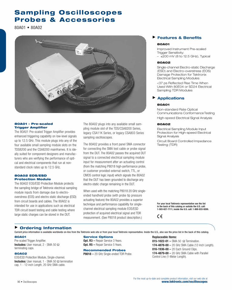
96 • OscilloscopesFor the most up-to-date and complete product information, visit our web site at
www.tektronix.com/oscilloscopes
80A01 – Pre-scaled Trigger Amplifier
The 80A01 Pre-scaled Trigger Amplifier providesenhanced triggering capability on low-level signalsup to 12.5 GHz. This module plugs into any of thefour available small sampling module slots on theTDS8200 and the CSA8200 mainframes. It is ide-ally suited for component designers and manufac-turers who are verifying the performance of opti-cal and electrical components that run at non-standard clock rates up to 12.5 GHz.
80A02 EOS/ESD Protection Module
The 80A02 EOS/ESD Protection Module protectsthe sampling bridge of Tektronix electrical samplingmodule inputs from damage due to electro-overstress (EOS) and electro static discharge (ESD)from circuit boards and cables. The 80A02 isintended for use in applications such as electricalTDR circuit board testing and cable testing wherelarge static charges can be stored in the DUT.
The 80A02 plugs into any available small sam-pling module slot of the TDS/CSA8200 Series,legacy CSA11K Series, or legacy CSA803 Seriessampling oscilloscopes.
The 80A02 provides a front panel SMA connectorfor connecting the SMA test cable or probe signalfrom the DUT. The 80A02 passes the acquired DUTsignal to a connected electrical sampling moduleinput for measurement after an actuating control(from the matching P8018 high-performance probe,or customer provided external switch, TTL, or CMOS control logic input) which signals the 80A02that the DUT has been grounded to discharge any electro-static charge remaining in the DUT.
When used with the matching P8018 20 GHz single-ended handheld probe (with probe tip pressureactuating feature) the 80A02 provides a superiortechnique and performance capability for single-channel electrical sampling module EOS/ESD protection of acquired electrical signal and TDRmeasurement. (See P8018 product description.)
Features & Benefits
80A01
Improved Instrument Pre-scaledTrigger Sensitivity: – ≤200 mV (8 to 12.5 GHz), Typical
80A02
Single-channel Electro-static Discharge(ESD) and Electro-overstress (EOS)Damage Protection for TektronixElectrical Sampling Modules
<37 ps Reflected Rise Time When Used With 80E04 or SD24 ElectricalSampling TDR Modules
Applications
80A01
Non-standard Rate OpticalCommunications ConformanceTesting
High-speed Electrical Signal Analysis
80A02
Electrical Sampling Module InputProtection for High-speed ElectricalSignal Analysis
Circuit Board Controlled ImpedanceTesting (TDR)
80A01Pre-scaled Trigger Amplifier.Includes: User manual, 2 - SMA 50 Ωterminating caps.
80A02EOS/ESD Protection Module, Single-channel.Includes: User manual, 1 - SMA 50 Ω terminationcap, 1 - 12-inch Length, 20 GHz SMA cable.
Service OptionsOpt. R3 – Repair Service 3 Years.Opt. R5 – Repair Service 5 Years.
Recommended ProbesP8018 – 20 GHz Single-ended TDR Probe.
Replaceable Items:015-1022-01 – SMA 50 Ω Termination.174-4878-00 – 20 GHz SMA Cable (12-Inch Length).016-1936-00 – 20 Each Ground Clips.174-4879-00 – 20 GHz SMA Cable with ParallelControl Line (1-Meter Length).
Ordering InformationCurrent price information is available worldwide on-line from the Tektronix web site or from your local Tektronix representative. Inside the U.S., also see the price list in the back of this catalog.
Sampling Oscilloscopes Probes & Accessories80A01 • 80A02
For your local Tektronix representative see the list in the back of this catalog or outside the U.S. call: 1-503-627-7111, inside the U.S. call: 1-800-833-9200.

Oscilloscopes • 97For the most up-to-date and complete product information, visit our web site atwww.tektronix.com/oscilloscopes
The 80A03 TekConnect® Probe Interface
Module extends the capabilities of the
CSA/TDS8200 series oscilloscope and makes
debugging today’s high-performance electri-
cal and optical designs a little easier.
Using the 80A03 with the CSA/TDS8200
series oscilloscope, design engineers can
benefit from Tektronix’ industry-leading
active and differential probes to measure
signals on SMD pins and other challenging
circuit features.
Tektronix High-performanceProbing Solutions
Tektronix offers a variety of industry-leading
active and differential probes. The P7260
6 GHz active probe offers the highest
bandwidth available in a single-ended
active probe. The P7380 8 GHz differential
probe enables true differential probing of
electrical signals. The P7380SMA 8 GHz
differential probe provides a true-differential
SMA input. Tektronix high-performance
probes feature small probe heads and
numerous adapters to provide a flexible
and reliable connection to the device
under test (DUT).
Features & Benefits
80A03
Interfaces Tektronix P7000 SeriesHigh-performance Active andDifferential Probes to CSA/TDS8200Series Sampling Scopes
Enables True-differential ProbingUsing the Tektronix P7850 andP7380SMA 8 GHz Differential Probes
Seamless Integration – Automatically Scales Measurement
for Probe Attenuation Setting – Requires No User Adjustments – Powered Through the Oscilloscope
Interface – Requires No ExternalPower Cord
Integrated Extender Cable Plugs intoany of the Four Electrical SamplingModule Slots
Upgradeable to Future Higher-bandwidth Active and Differential Probes
ApplicationsCommunications (Gigabit Ethernet,Fibre Channel, InfiniBand)
Semiconductor Characterization &Validation (PCI-Express, Serial ATA,IEEE 1394, USB 2.0, RAMBUS, DDR)
High-speed Digital Systems Design
Component Design/Characterization
Manufacturing Engineering and Test
Sampling Oscilloscopes Probes & Accessories
80A03 NEW
80A03TekConnect Probe Interface Module.Includes: User manual, 2 – SMA semi-rigid jumper cables.
Service OptionsOpt. R3 – Repair Service 3 Years.Opt. R5 – Repair Service 5 Years.
Recommended ProbesP7350SMA – 5 GHz Differential Probe with SMA inputs.
P7350 – 5 GHz Differential Probe.P7330 – 3.5 GHz Differential Probe.P7260 – 6 GHz Active Probe.P7240 – 4 GHz Active Probe.P7225 – 2.5 GHz Active Probe.P7380SMA*1 – 8 GHz Differential Probes with SMA Interface.P7380*1 – 8 GHz Differential Probe.*1 80A03 product serial numbers below B010158 require a factory
installed firmware update to be compatible with these probe types.
Replaceable Items:015-1022-01 – SMA 50 Ω Termination.174-4878-00 – 20 GHz SMA Cable (12-Inch Length).016-1936-00 – 20 Each Ground Clips.174-4879-00 – 20 GHz SMA Cable with ParallelControl Line (1-Meter Length).
For your local Tektronix representative see the list in the back of this catalog or outside the U.S. call: 1-503-627-7111, inside the U.S. call: 1-800-833-9200.
Ordering InformationCurrent price information is available worldwide on-line from the Tektronix web site or from your local Tektronix representative. Inside the U.S., also see the price list in the back of this catalog.

The P8018 Handheld TDR Probe is a greaterthan 20 GHz, 50 Ω input impedance, single-ended passive probe with a precision 20 GHzbandwidth SMA cable that provides a high per-formance solution for electrical sampling TDR circuit board impedance characterization andhigh-speed electrical signal analysis applications.The P8018 probe can be used as a stand-alonehigh bandwidth probe, but it is specially designedwith features to be used with the 80A02 EOS/ESDProtection Module for protecting the samplingbridge of Tektronix electrical sampling modulesfrom damage due to electro-overstress (EOS) andelectro-static discharge (ESD) where large staticcharges can be stored in the DUT.
The P8018 provides a unique probe tip pressureactuating feature and control circuit which, usedwith the matching 80A02 EOS/ESD ProtectionModule, enables a superior technique and performance capability for electrical samplingmodule EOS/ESD protection of acquired electricalsignals and TDR measurements. (See 80A02product description.)
20 GHz Single-ended TDR ProbeP8018
98 • OscilloscopesFor the most up-to-date and complete product information, visit our web site at
www.tektronix.com/oscilloscopes
Features & Benefits20 GHz Probe Tip Bandwidth
50 Ω Impedance TDR Passive Probe
Undisturbed 50 Ω Probe Reference Section
Includes 20 GHz Precision SMA Cable
Probe Tip Pressure Actuation Featureused to Actuate 80A02 EOS/ESDProtection Module
Applications Circuit Board Controlled ImpedanceTesting (TDR)
Designed for Use with 80A02EOS/ESD Protection Module
For your local Tektronix representative see the list in the back of this catalog or outside the U.S. call: 1-503-627-7111, inside the U.S. call: 1-800-833-9200.

Characteristics Nominal Length with Cable – 1 meter.Attenuation – 1X.Probe Only Bandwidth – >20 GHz.Probe Pitch – 1.8 mm (signal to ground).Cable Bandwidth – 20 GHz.Connector Type – SMA.Measured Reflected TDR Fall Time – <38 ps spec(<28 ps typical measure with 80E04).Loading Input – 50 Ω.Max Vin – 5.0 V.Probe Only Propagation Delay – 1.0 ns.TDR Control Activation Force – 200 to 260 grams.(Note: numeric values shown are typical.)
20 GHz Single-ended TDR ProbeP8018
Oscilloscopes • 99For the most up-to-date and complete product information, visit our web site atwww.tektronix.com/oscilloscopes
P8018 20 GHz Single-ended TDR Probe.Includes: 20 GHz bandwidth 50 Ω input impedance,single-ended passive handheld probe with precision 20 GHz SMA cable, 20 each replaceable ground clips.
Replaceable Items 016-1936-00 – 20 each Ground Clips.174-4879-00 – 20 GHz SMA Cable with ParallelControl Line (1 Meter Length).
For your local Tektronix representative see the list in the back of this catalog or outside the U.S. call: 1-503-627-7111, inside the U.S. call: 1-800-833-9200.
Ordering InformationCurrent price information is available worldwide on-line from the Tektronix web site or from your local Tektronix representative. Inside the U.S., also see the price list in the back of this catalog.

Oscilloscopes are inherently general-purpose instruments, capable of performing a wide array ofstandard measurement tasks. However, by utilizing application modules, software and upgrades,an oscilloscope can be transformed into a highly specialized and powerful analysis tool.Tektronix offers exceptional application solutions that instill your oscilloscope with specific technology or procedural expertise, vastly simplifying the development and testing of specialized designs.
Tektronix oscilloscopes can be converted into focused tools for standards compliance, powermeasurements, jitter and timing analysis, communications standards testing, optical storageanalysis, disk drive measurements, advanced analysis of networking software, and data capture/analysis/documentation – to name a few.
Standards Compliance
New software and hardware solutions are available to speed critical compliance and validationtesting for emerging serial data standards, such as PCI-Express™ and InfiniBand.™ In conjunctionwith a high-performance Tektronix oscilloscope, these new tools create a complete, automatedmeasurement system that meets the advanced requirements of the particular standard, such aspreserving sensitive, log-amplitude, serial signals. The solutions provide a high-bandwidth, low-loss environment that delivers differential data signals to the acquisition system, where it is analyzed for compliance with the standard.
Power Measurements
Tektronix oscilloscopes can be configured for power conversion applications, providing automaticcalculations of True Power, Apparent Power, Power Factor, Instantaneous Power, and Energy, aswell as design and troubleshooting of power supplies.
Jitter and Timing Analysis
Software packages are available to turn several Tektronix oscilloscope families into leading-edgetools for jitter and timing analysis, as well as comprehensive margin timing analysis for high-speed industry standards, such as InfiniBand, Fibre Channel and DDR. TDSJIT3 includes Rj/Djanalysis and BER estimation.
Communications Standards Testing
A wide range of application modules, software and accessories let you equip Tektronix oscilloscopes with powerful capabilities for communications standards performance and conformance testing.
Optical Storage Analysis
TDSDVD optical storage analysis package delivers the flexibility, analysis, time interval display,automatic industry-specific measurements, and familiar, analog-like display for transformingTektronix oscilloscopes into ideal test tools for the design of state-of-the-art optical storage systems.
Disk Drive Measurements
Tektronix provides software packages that deliver industry-leading disk drive measurement capabilities.
Contents
Jitter and Timing Analysis . . . . . . . . .102
Power Measurements . . . . . . . . . . . .104
DVI Compliance . . . . . . . . . . . . . . . .108
Optical Storage Analysis . . . . . . . . . .110
TDSRT-Eye . . . . . . . . . . . . . . . . . . . .112
USB Measurements . . . . . . . . . . . . .114
Ethernet Compliance . . . . . . . . . . . .116
HDMI Compliance . . . . . . . . . . . . . . .119
Communications Pulse Measurements . . . . . . . . . . . . . . . . .120
Data Capture, Analysis and Documentation . . . . . . . . . . . . .121
100 • OscilloscopesFor the most up-to-date and complete product information, visit our web site at
www.tektronix.com/oscilloscopes
Oscilloscope Software Introduction

Oscilloscope Software Introduction (continued)
Oscilloscopes • 101For the most up-to-date and complete product information, visit our web site atwww.tektronix.com/oscilloscopes
USB Measurements
Tektronix oscilloscopes, equipped with TDSUSB2 software, enable designers to quickly and accuratelyperform all USB-IF recommended compliance tests, such as eye diagram and parametric testing for low-speed, full-speed, and high-speed devices and hubs.
Advanced Analysis and Networking Software
With OpenChoice®, Tektronix’ open Windows oscilloscopes allow you to run a vast array of popularWindows-compatible analysis and productivity software, such as MATLAB and National Instrument’sLabVIEW, right on the oscilloscope.
Data Capture, Analysis, and Documentation
TDSPCS1 OpenChoice software, a collection of applications, delivers simple, seamless integrationbetween TDS3000B, TPS2000, TDS2000 and TDS1000 Series oscilloscopes and an external PC,providing you with multiple choices to easily capture, transfer, document and analyze your measurementresults, according to your application environment and preference.
WaveStar™ software offers live remote waveform reproduction, active remote control of oscilloscope-specific settings, advanced measurements and power harmonics analysis. Capture, analyze, documentand control active analysis sheets, or insert data directly into Microsoft Office applications for documentation and presentation.
For transforming your oscilloscope into a highly specialized and powerful analysis tool, Tektronix has the application software to meet your specialized design and test needs.

102 • OscilloscopesFor the most up-to-date and complete product information, visit our web site at
www.tektronix.com/jitter
TDSJIT3 v2.0 is the premiere jitter and timinganalysis software package available for real-timeoscilloscopes. Running externally or within theTektronix TDS5000B, TDS6000B and CSA/TDS7000BSeries oscilloscopes, TDSJIT3 v2.0 provides thehighest accuracy and lowest noise jitter measure-
ments available in any real-time instrument.With comprehensive jitter analysis algorithms,TDSJIT3 v2.0 simplifies discovering jitter and itsrelated sources in today’s high-speed digital,communication and system designs.
TDSJIT3 v2.0 Advanced and TDSJIT3 v2.0 Essentials
Jitter and Timing Analysis Software NEW
Features & BenefitsUse the v2.0 Jitter Wizard to EasilyMake Accurate Jitter Measurements
Obtain Accurate Tj @ BER and Rj/DjSeparation (TDSJIT3 Advanced Only)
Analyze Repeating or ArbitraryRandom Data Patterns
Analyze Low Probability and LowAmplitude Deterministic Jitter with Spectral Peak Detection and Averaging
Analyze Frequency Bounded Jitterand Timing Measurements with aVariety of Timing Measurement Filters(first, second and third orderButterworth)
Acquire, Capture, Store and AnalyzeWorst-case Offenders
Qualify Jitter Measurements Using Channel Inputs, Cursors or Timing Details, Population Size andAmplitude Range
Analyze Random and DeterministicJitter (Rj/Dj) and Estimate Tj @ BER
1.5 psRMS Jitter Noise Floor (withTDS6804B/TDS7704B, typical over 1 ms acquisition)
3.0 psRMS Jitter Accuracy (withTDS6804B, TDS7704B)
Differential Crossover VoltageMeasurements (TDSJIT3 Advancedonly)
ApplicationsCharacterize Timing and ACPerformance of High-speed Paralleland Serial Designs and Systems to6.25 Gbps and Beyond
Characterize Data-to-Data and Clockto Data Jitter
Characterize PLL DynamicPerformance and Transfer Functions
Characterize Modulation of SpreadSpectrum Clock Circuits
Characterize Jitter Generation,Transfer and Tolerance
Characterize Clock and Data Jitter inHyperTransport, PCI Express, FibreChannel, SONET, Serial ATA and OtherElectrical or Optical Physical LayerCircuits
User-installed, Oscilloscope-resident Timing Analysis Package
For your local Tektronix representative see the list in the back of this catalog or outside the U.S. call: 1-503-627-7111, inside the U.S. call: 1-800-833-9200.
General Measurements Rise Time, Fall Time, Positive Width, Negative Width, High Time, Low Time, Skew, Differential Cross-over Voltage*1
Clock Measurements Frequency, Period, Cycle-Cycle, N-Cycle, Positive Cy-Cy Duty, Negative Cy-Cy Duty, Positive Duty Cycle,Negative Duty Cycle, Clock TIE, Clock PLL TIE*1
Data Measurements Data Frequency, Data Period, Data TIE, Data PLL TIE*1
Clock to Data Setup, Hold, Clock-out Advanced Analysis*1 Rj, Dj, Pj, DCD, DDj, Tj, BER Plots Histogram, Time Trend, Cycle Trend, Spectrum,
Eye Diagram Statistics*1 (BER CDF Curve),Phase Noise, Transfer Function
Data Logging Statistics, Min/Max Wfm, Snapshot, Worstcase*1 Features are only available with TDSJIT3 v2.0 Advanced.
Measurements

Oscilloscopes • 103For the most up-to-date and complete product information, visit our web site atwww.tektronix.com/power
Characteristics
TDS6804B, TDS6604B,CSA7404B, CSA7154
TDS7704B, TDS7404B,TDS7254B, TDS7154B
Jitter Noise Floor – 0.7 psRMS (TDS6804B, typicalover 10 µs acquisition).Jitter Measurement Accuracy – 1.5 psRMS(TDS6804B, typical over 10 µs acquisition).
Delta Time Accuracy – 3.0 psRMS (20 GS/s, ≤10 nSmeasurement period).
Delta Time Accuracy Specification:[0.06/(sample_rate) + 3.5 ppm x|Measurement_period|]RMS ±[0.30/(sample_rate) + 3.5 ppm x|Measurement_period|] PEAK
Physical Characteristics
Software supplied on compact disk media.Software application running on the TDS5000B,TDS6000B and TDS/CSA7000B Series on 4 channel oscilloscopes.
TDSJIT3 v2.0Includes: Software on CD, manual on CD.Recommended Accessories Arbitrary Waveform Generator – AWG710.High-bandwidth Single-ended Probe –P7260 Active Probe, 6 GHz.High-bandwidth Differential Probe –P7380 Differential Probe, 8 GHz.High-bandwidth Differential Acquisition Systemwith SMA Inputs – P7380SMA Differential Probeadapter, 8 GHz.Notes: TDSJIT3 v2.0 is not compatible with theTDS5032 and TDS5052 two-channel oscilloscopes.Installing TDSJIT3 v2.0 replaces earlier versions,such as TDSJIT2.
TDSJIT3 v2.0 Advanced, TDSRTE Bundle
To have pre-installed on a new TDS6000B or TDS/CSA7000B Series Oscilloscope: order Opt. RJA.
TDSJIT3 v2.0 Advanced, TDSRTE, SM Bundle
To have pre-installed on a new TDS6000B orTDS7000B Series Oscilloscope: order Opt. RSA.Not available on CSA7000B instruments.
TDSJIT3 v2.0 Advanced To have pre-installed on a new TDS5000B, TDS6000B,TDS7000B or CSA7000B Series Oscilloscope: order Opt. JA3.
To upgrade your existing TDS5000/B,TDS6000/B or TDS/CSA7000/B Series Oscilloscope:
Oscilloscope Order TDS5104, 5054, 5034 TDS5UP Opt. JA3 TDS5104B, 5054B, TDS5BUP Opt. JA35054BE, 5034B
TDS6604, 6404 TDS6UP Opt. JA3 TDS6804B, 6604B TDS6BUP Opt. JA3 TDS7404, 7254, 7154, TDS7UP Opt. JA3 7104, 7054TDS7704B, 7404B, TDS7BUP Opt. JA3 7254B, TDS7154BCSA7404, 7154 CSA7UP Opt. JA3 CSA7404B CSA7BUP Opt. JA3
TDSJIT3 v2.0 Essentials To have pre-installed on a new TDS5000, TDS6000 orTDS/CSA7000 Series Oscilloscope: Order Opt. JE3.
To upgrade your existing TDS5000, TDS6000or TDS/CSA7000 Series Oscilloscope:
Oscilloscope Order TDS5104, 5054, 5034 TDS5UP Opt. JE3 TDS5104B, 5054B, TDS5BUP Opt. JE35054BE, 5034B TDS6604, 6404 TDS6UP Opt. JE3 TDS6804B, 6604B TDS6BUP Opt. JE3 TDS7404, 7254, 7154, TDS7UP Opt. JE37104, 7054 TDS7704B, 7404B, TDS7BUP Opt. JE37254B, TDS7154B CSA7404, 7154 CSA7UP Opt. JE3 CSA7404B CSA7BUP Opt. JE3
Ordering InformationCurrent price information is available worldwide on-line from the Tektronix web site or from your local Tektronix representative. Inside the U.S., also see the price list in the back of this catalog.
Upgrade Path Order*2
TDSJIT3 (JT3) v1 to TDSJIT3 v2 Advanced (JA3) TDSXXUP Opt. JTA TDSJIT3 (JE3) v2 Essentials to TDSJIT3 v2 Advanced (JA3) TDSXXUP Opt. E3A TDSJIT3 (J3E) Essentials v1 to TDSJIT3 v2 Advanced (JA3) TDSXXUP Opt. 3EA TDSJIT3 (J3E) Essentials v1 to TDSJIT3 v2 Essentials (JE3) TDSXXUP Opt. 3EE TDSJIT2 (J1) to TDSJIT3 v2 Advanced (JA3) TDSXXUP Opt. J1A TDSJIT2 (J1) to TDSJIT3 v2 Essentials (JE3) TDSXXUP Opt. J1E TDSJIT3 (JA3) v2 Advanced to RJA Bundle (RJA) TDSXXUP Opt. JAR TDSRTE (RTE) to RJA Bundle (RJA) TDSXXUP Opt. RJA *2 XX Key: For TDS5000/B instruments use TDS5UP or TDS5BUP; TDS6000/B use TDS6UP or TDS6BUP; TDS7000/B use TDS7UP or TDS7BUP;
CSA7000/B use CSA7UP or CSA7BUP.
TDSJIT3 v2.0 Upgrade To upgrade between versions of TDSJIT3:
TDSJIT3 v2.0 Advanced and TDSJIT3 v2.0 EssentialsJitter and Timing Analysis Software

104 • OscilloscopesFor the most up-to-date and complete product information, visit our web site at
www.tektronix.com/power
Product Description
TDSPWR3 power measurement and analysis software transforms Tektronix digital oscilloscopesinto sophisticated analysis tools that quicklymeasure and analyze power dissipation in powersupply switching devices and magnetic componentsand then generates detailed test reports in cus-tomizable formats. TDSPWR3, used with a TektronixTDS5000B, TDS/CSA7000B or TDS6000B Seriesoscilloscope and differential voltage and currentprobes, forms a complete measurement systemfor power supply design and test.
To improve the efficiency of switching power supplies with increased power densities, designersneed to analyze power dissipation and characterizetransitions at higher switching frequencies. UsingTDSPWR3’s unique switching loss and B-H analysisfeatures, you can measure switching and magneticdevice power dissipation with a touch of a button.Tektronix oscilloscopes’ high bandwidth, highsample rate and deep memory, combined with the
TDSPWR3, enable you to efficiently and accuratelycharacterize switching power supplies by measuringpower loss at the switching device and magneticcomponent. Reliability at the component level ofthe switching power supply can be analyzed usingSafe operating area with mask test capability andmeasuring the peak flux density.
With the current harmonic standard (EMC) beingimposed worldwide to maximize the efficiency ofthe existing total generation capacity, complianceto the IEC EN61000-3-2, EN61000-3-2 AM14 iscritical. Reduce your development and testingtime by using the pre-compliance testing capabilityof TDSPWR3 to test power supply designs tothese standards from your bench.
TDSPWR3 enables you to set units and scale factorfor Tektronix current and voltage probes to readthe result in the right unit. Automated deskewcapabilities help you to get accurate results.
Power Measurement and Analysis Software TDSPWR3
Features & BenefitsHiPower Finder and B-H AnalysisPinpoint the Source of ReliabilityProblems
Power Loss Measurements at theSwitching Device and MagneticComponent Improve SwitchingPower Supply Efficiency
Sophisticated Report GenerationSaves Time
Customizable Safe Operating AreaMask Testing with Linear and LogScale for Reliability Testing
In-circuit Bpeak, Permeability andCoercive Force MeasurementsDetermine the Reliability of theMagnetic Component
Automatic Ripple Measurement SetupEliminates Manual Processes
Spectrum Analysis Locates Rippleand Noise on the Output Voltage and EMI Issues with the SwitchingPower Supply
Reduces Compliance Test Time and Risk
Automated THD, True Power,Apparent Power, Power Factor andCrest Factor Features EliminateTedious Manual Calculations
Modulation Analysis Quickly ProvidesAccurate Active Power FactorCharacterization
Automatic Deskew Ensures Accurate,Time-correlated Results
Correct Scale Factor and Unit DisplayWhile Using Third-party CurrentProbes Eliminates ManualCalculations and Human Error
ApplicationsPower Loss Measurement atSwitching Device and MagneticComponent
Characterization of PowerSemiconductor Devices
Optimal Drive Characterization ofSynchronous Rectifiers
Measurement and Analysis of Rippleand Noise
Pre-compliance Testing to IECStandard EN61000-3-2, EN61000-3-2AM14 and MIL Standard 1399 (400Hz)
Debugging Active Power FactorCorrection Circuits
For your local Tektronix representative see the list in the back of this catalog or outside the U.S. call: 1-503-627-7111, inside the U.S. call: 1-800-833-9200.

Oscilloscopes • 105For the most up-to-date and complete product information, visit our web site atwww.tektronix.com/power
Power Measurement and Analysis SoftwareTDSPWR3
CharacteristicsPower Device Analysis – Switching Loss, HiPowerFinder, B-H Analysis, Magnetic Loss, Inductance,Maximum Magnetic Flux Density, Permeability,Remenence Flux Density, Coercive Force, Total Loss*1,Safe Operating Area (SOA), Gated SOA, SOA Mask Editorwith Mask Testing, Dynamic On Resistance, di/dt, dv/dt.Line Power Measurements – True Power, ApparentPower, Power Factor, Crest Factor, Current Harmonic,THD, Pre-compliance testing for EN61000-3-2,EN61000-3-2 AM14 standard and MIL -1399 standard (400Hz).Output Measurement – Ripple due to line frequencyand switching frequency, turn-on time.Modulation Analysis – Pulse Width, Duty Cycle,Period, and Frequency variation vs. Time.
Spectral Analysis – Automated Spectral analyses bysetting start frequency, stop frequency and resolutionbandwidth.Report Generation – Create template, custom reportlayout and report generation.Deskew – Automatic.
Tektronix Oscilloscopes andProbes Supported TDS5000B Series Digital PhosphorOscilloscopes – TDS5032B, TDS5034B, TDS5054B,TDS5054BE TDS5052B, TDS5104B.TDS7000B Series Digital PhosphorOscilloscopes – TDS7054, TDS7104, TDS7154B*2,TDS7254B*2, TDS7404B*2, TDS7704B*2.CSA7000B Series Communications SignalAnalyzer – CSA7154*2, CSA7404B*2
TDS6000 Series Digital Storage Oscilloscope – TDS6604B*2 TDS6804B*2
Current Probes – TCP202, TCPA 300 with TCP312, TCP305, TCP303,TCPA400 with TCP404XL, AM503B with A6312, A6302,A6303, P6021 or P6022 Differential Probes – P5205, P5210, P5200 and ADA400A Deskew fixture – 067-1478-00 Probe adapter – TCA-1MEG, while using with TDS6000B/CSA7000B/TDS7154B/TDS7254B/TDS7404B/TDS7704B *1 Total loss measurement needs four channels; it is not supported in
TDS5032 or TDS5052.*2 A TCA-1MEG TekConnect® 1MΩ buffer amplifier is required to use
a 1MΩ differential probe with the TDS7154B/TDS7254B/TDS7404B/TDS6000B and CSA7000B Series oscilloscopes.
When ordered along withTDS5000B/TDS7000B/CSA7000B/TDS6000B Opt. PW3 (includes Opt. 2A for advanced math forTDS5000).Includes: Application CD and electronic documentation.
After-purchase Upgrade TDS5UP– Opt. PW3.TDS7UP– Opt. PW3.CSA7UP– Opt. PW3.TDS6UP– Opt. PW3.
Recommended Accessories TDS5000B – Opt. 2M. Opt. 17.TDS/CSA7000B – Opt 3M or Opt. 4M
For your local Tektronix representative see the list in the back of this catalog or outside the U.S. call: 1-503-627-7111, inside the U.S. call: 1-800-833-9200.
Ordering InformationCurrent price information is available worldwide on-line from the Tektronix web site or from your local Tektronix representative. Inside the U.S., also see the price list in the back of this catalog.

As an industrial power designer or technician,you must perform a range of power-specificmeasurements to develop, test and race productsto market. The TPS2000 Series oscilloscopes, whenequipped with TDS2PWR1 power measurementand analysis software, allows you to optimize yourproductivity by reducing your development andtest time with a broad range of power-specificmeasurements, such as switching loss (includingturn-on, turn-off and conduction losses), harmonicdistortion measurements to the 50th harmonic,and dv/dt and di/dt cursor measurements. Use a single instrument to make an array of measure-ments – from measuring high voltages*1 and highcurrents to debugging control circuits.
To improve the efficiency of industrial power designs,you must analyze power dissipation and charac-terize transitions at higher switching frequencies.
Using TDS2PWR1’s unique switching loss feature,you can measure switching device power dissipa-tion with the touch of a button. Coupled with theTPS2000 Series oscilloscopes’ unique digital real-time (DRT) sampling technology, the TDS2PWR1software package enables you to efficiently andaccurately characterize industrial power systemsby measuring power loss at the switching device.
Reduce your development and testing time byusing TDS2PWR1’s harmonic testing capability to the 50th harmonic to test power supplydesigns to these standards from your bench,the power lab, or on-site.
In addition, TDS2PWR1 software enables you toset units and scale factor for Tektronix current andvoltage probes to read the result in the right unit.
*1 To make floating measurements greater than 30 VRMS, use the optional P5120 passive high-voltage probe or similarly ratedpassive high-voltage probe, or an appropriately rated high-voltagedifferential probe, subject to the ratings of such high-voltage probe.
Power Measurement and Analysis SoftwareTDS2PWR1NEW
106 • SoftwareFor the most up-to-date and complete product information, visit our web site at
www.tektronix.com/power
Features & BenefitsImprove Efficiency of Power Designswith Switching Loss MeasurementsIncluding Turn-on, Turn-off andConduction Losses
Reduce Test Time with HarmonicMeasurements to the 50th Harmonic
Eliminate Manual Calculations withAutomated Power Analysis,Waveform Analysis and PhaseAnalysis with True Power, ReactivePower, Power Factor, Crest Factor,Phase Relationships
Reduce Measurement Time withdv/dt and di/dt Cursors
Applications Motor Drive Design and Test
UPS Design and Test
Power SemiconductorCharacterization
Power Quality Equipment Design and Test
Power Monitoring and PerformanceVerification
Power Measurement and Analysis Software
For your local Tektronix representative see the list in the back of this catalog or outside the U.S. call: 1-503-627-7111, inside the U.S. call: 1-800-833-9200.

CharacteristicsPower Measurements – True real power in watts,reactive power in VAR, power factor, crest factor, RMSmeasurements, frequency measurements.Cursors – dv/dt and di/dt.Phase Angles – CH1 & CH2, CH2 & CH3 (four channelscopes only), CH1 & CH3 (four channel scopes only).Harmonics Measurements – Up to the 50th harmonic, THD, individual harmonic levels display,individual harmonic phase to fundamental, RMS values.Switching Loss Measurements – Turn-on loss,turn-off loss, conduction loss, total switch loss.
Tektronix Oscilloscopes andProbes Supported
TPS2000 Series oscilloscopes – TPS2012, TPS2014, TPS2024.
Current Probes A621, A622, TCP202 with 1103 power supply,TCPA300 with TCP312, TCP305, TCP303, TCPA400with TCP404XL, P6021, P6022, CT2, CT4 withTCP202 and 1103 power supply.
Passive Voltage Probes
P2220 – 200 MHz, 10X to 1X switchable passive probe.P5120 – Passive high-voltage probe (1000 V CAT IItip to ground; 600 V CAT II reference to earth ground).
Differential Probes
P5200 – High-voltage active differential probe (1300 Vp-p, 25 MHz).P5205 – High-voltage active differential probe (1300 Vp-p, 100 MHz) (1103 power supply required).P5210 – High-voltage active differential probe (5600 Vp-p, 50 MHz) (1103 power supply required).
Power Measurement and Analysis SoftwareTDS2PWR1
Software • 107For the most up-to-date and complete product information, visit our web site atwww.tektronix.com/power
TDS2PWR1 Power Measurement and Analysis Software
TDS2PBND Power bundle for TPS2000 Series oscilloscopes.Includes (4) P5120 probes and TDS2PWR1 powermeasurement and analysis software.
International User Manual Opt. L0 – English (071-1452-xx).Opt. L1 – French (071-1453-xx).
Opt. L2 – Italian (071-1454-xx).Opt. L3 – German (071-1455-xx).Opt. L4 – Spanish (071-1456-xx).Opt. L5 – Japanese (071-1457-xx).Opt. L6 – Portuguese (071-1458-xx).Opt. L7 – Simplified Chinese (071-1459-xx).Opt. L8 – Traditional Chinese (071-1460-xx).Opt. L9 – Korean (071-1461-xx).Opt. L10 – Russian (071-1462-xx).
For your local Tektronix representative see the list in the back of this catalog or outside the U.S. call: 1-503-627-7111, inside the U.S. call: 1-800-833-9200.
Tektronix measurement products are manufactured in ISO registered facilities.
Ordering InformationCurrent price information is available worldwide on-line from the Tektronix web site or from your local Tektronix representative. Inside the U.S., also see the price list in the back of this catalog.

108 • OscilloscopesFor the most up-to-date and complete product information, visit our web site at
www.tektronix.com/dvi
Engineers involved in design, characterization andvalidation of DVI devices face constant pressureto speed new products to the marketplace.Developers need to improve efficiency with fastervalidation cycles. Design and validation engineersneed tools to perform quick and reliable compli-ance testing right on their bench.
TDSDVI Compliance Test Solution, coupled withTDS7404B, TDS7254B, CSA7404B and TDS6000BSeries oscilloscopes, enhances test efficiencywith faster validation cycles and offers higher reliability for conformance to standards.
Comprehensive Range of Measurements
TDSDVI addresses the wide spectrum of transmit-ter, cable and receiver tests. The portfolio of testsincludes eye diagram, jitter, skew, and rise andfall time testing.
Reliable Testing with in-depth Information
TDSDVI is the industry’s first compliance test toolthat conducts testing according to DVI specifica-tion and the DVI Test and Measurement Guide.It first calculates the unit interval (Tbit), accumu-lates a million acquisitions and performs the eye diagram test on the worst-case eye amongthe ten bits of a pixel. The mask hit-count provides detailed information about the signal characteristics.
Easy to Use
TDSDVI automatically sets up the oscilloscope forthe selected test, creates the eye mask and alsoperforms other parametric tests. Pass/fail indica-tion for the conducted tests, substantiated withdetailed results, makes TDSDVI the preferredsolution for DVI compliance testing. An automaticreport generator provides the detailed report forthe conducted tests.
DVI Compliance Test SolutionTDSDVI
Accurate, fast, and reliable in-house testing for DVI physical layer.
Features & BenefitsWide Range of Tests EnableComplete Validation to Standards
Automatic “One-button” TestingEnsures Faster Testing with HigherReliability
Comprehensive Range of Tests for Transmitter, Cable and ReceiverTesting – Eye Diagram Test, Peak-to-Peak Jitter, Inter-pair and Intra-pairSkew, Rise and Fall Time
Automatic Pass/Fail Notification forQuick Conformance to Standards
Supports All Resolutions Up to UXGA
Half Clock and Pseudo RandomPatterns for Various Resolutions AllowTesting as per DDWG Procedures
Online Context-sensitive HelpProvides Assistance
Sophisticated Report GeneratorSaves Time
Unique Result Comparison FeatureEnables Comparing Results of TestsConducted on Two Different Devices
Applications DVI Physical Layer Compliance Testing
Characterize the Quality of Your DVI Designs
Eye diagram showing mask hits.
For your local Tektronix representative see the list in the back of this catalog or outside the U.S. call: 1-503-627-7111, inside the U.S. call: 1-800-833-9200.
Oscilloscopes • 109For the most up-to-date and complete product information, visit our web site atwww.tektronix.com/dvd
Characteristics Transmitter Tests – Eye diagram, Peak-to-Peak Jitter,Skew (Intra and Inter pair), Rise and Fall time.Cable Tests – Eye diagram (high-amplitude and low-amplitude), Peak-to-Peak Jitter, Skew (Intra and Inter pair).Receiver Tests – Eye diagram (high-amplitude andlow-amplitude).
Patterns for Compliance Testing as per DDWGProcedures – Half Clock and Pseudo random patterns for resolutions from VGA to UXGA.
Tektronix OscilloscopesRequired TDS7404B/7404, CSA7404B/7404, TDS7254B/7254,*1
and TDS6000B/6000 Series oscilloscopes with version2.2.0 or above.
Note: TDS6000B/6000 Series oscilloscopes offers Eye-Trends feature to provide continuous trends of eyeformation and various important parameters, such asTbit, Hopen, Vopen, etc.*1 Supports resolutions up to SVGA.
DVI Compliance Test SolutionTDSDVI
TDSDVI DVI Compliance Test Software.Includes: Application CD and electronic documentation.
To order along with TDS7404B,CSA7404B, TDS7254B andTDS6000B Series oscilloscopes Opt. DVI – DVI Compliance Test Solution.
To upgrade existing oscilloscope TDS6000B/6000 – Order TDS6UPB/6UP – Opt. DVI.TDS7000B/7000*2 – Order TDS7UPB/7UP – Opt. DVI.CSA7000B/7000*3 – Order CSA7UPB/7UP – Opt. DVI.
Recommended AccessoriesDifferential Probes – P7350, P7330, P6330.TDSJIT3 – Jitter analysis package.Single ended probes – P7240.Arbitrary Waveform Generator – AWG510,AWG520, AWG610, AWG710.
Data Generator – DG2020A.Time Domain Reflectometer – TDS8000/ 80E04.*2 TDS7UPB/7UP supports TDS7254B/7254 and TDS7404B/7404 ONLY.*3 CSA7UPB/7UP supports CSA7404B/7404 ONLY.
For your local Tektronix representative see the list in the back of this catalog or outside the U.S. call: 1-503-627-7111, inside the U.S. call: 1-800-833-9200.
Ordering InformationCurrent price information is available worldwide on-line from the Tektronix web site or from your local Tektronix representative. Inside the U.S., also see the price list in the back of this catalog.

110 • OscilloscopesFor the most up-to-date and complete product information, visit our web site at
www.tektronix.com/dvd
The TDSDVD optical storage analysis and meas-urement software package, coupled with TektronixTDS5000, TDS7000 and CSA7000 Series digitalphosphor oscilloscopes, is the first test tool todeliver the flexibility, analysis, time interval display,automatic industry-specific measurements, andfamiliar, analog-like display for design and testengineers developing state-of-the-art optical stor-age systems. This superior test solution combinesthe capabilities of an analog oscilloscope, digitaloscilloscope and jitter analyzer into one simple-to-use tool that provides complete system char-acterization and allows designers to maximize the performance of existing systems and next-generation designs.
TekFlex™ Delivers an Ideal Design Solution for Next-generation OpticalStorage Systems
TDSDVD’s TekFlex feature enables designers todevelop next-generation designs or optimize theperformance of existing optical storage systemsbeyond current ECMA standards by allowing themto modify or substitute various signal processingblocks, such as the Equalizer, Low pass filter,Slicer and PLL. When installed on a PC, the TDSDVD application software utilizes the excep-tional computational power of the workstation tomake complex calculations sometimes requiredwhen fine-tuning intricate designs.
Optical Storage Analysis and Measurement SoftwareTDSDVD
Features & BenefitsAutomatic Industry-specific OpticalStorage, Amplitude and TimingMeasurements Help CharacterizeDesigns Efficiently
TekFlex™ Feature Offers Unprece-dented Flexibility to Modify SignalProcessing Blocks – Equalizer, LowPass Filter, Slicer and PLL – toDevelop Next-generation Optical Designs
Digital Phosphor Technology Delivers the Complex RF Eye Display as Previously Seen Only onAnalog Oscilloscopes
Automatic Determination of ClockPeriod for Advanced ConstantAngular Velocity (CAV) Drives forEasier and More Accurate Analysis
Tracking Error Counter Enables Usersto Determine Tracking Error Count
Input Block Diagram Allows Bypassingof Various Signal-processing Blocks
Time Interval Analysis (TIA) DisplayProvides Histogram Display of PulseWidth Measurements Over T Values
Five Display Modes – Summary, Listby nT, Plot, Histogram and List –Enable Users to View the Output inVarious Formats for In-depth Analysis
Statistical Information Including Mean,Max, Min, Average and StandardDeviation Offers Greater Insight intoSignal Behavior
Applications Design and Debug of DVD, CD and MO
Development of Next-generation Optical Systems
Development of Systems BeyondCurrent ECMA Standards
Optical Storage Analysis and Measurement Software Package
Time Interval Analysis (TIA) display providesdata-pulse-width measurements as histogramdisplays plotted over T values.
For your local Tektronix representative see the list in the back of this catalog or outside the U.S. call: 1-503-627-7111, inside the U.S. call: 1-800-833-9200.

Characteristics
Amplitude MeasurementsAmplitude – High, Low, Peak-to-Peak,Decision Level, Asymmetry, Symmetry.Modulation – Resolution, Ratio.
Timing MeasurementsData – Timing Jitter, Data Pulse Width.Clock – Clock Jitter.Data-to-Clock Edge Shift – Leading, Trailing,Leading and Trailing, Leading or Trailing.
Tracking Error Counter
Tracking Error Count.
GatingBy Cursors.
User Options
Select Voltage Threshold – To determine “pit”and “space.”Select Clock Source – Synthesized, measured or extracted.
Physical CharacteristicsSoftware supplied on compact disk media. Softwareapplication running on the TDS5000, TDS7000B andCSA7000B Series oscilloscopes, or on a stand-alone PC connected to an oscilloscope running TDSDVD software application.
Optical Storage Analysis and Measurement SoftwareTDSDVD
Oscilloscopes • 111For the most up-to-date and complete product information, visit our web site atwww.tektronix.com/dvd
TDSDVDOptical Storage Analysis and Measurement Software.Includes: Application CD, online documentation and quick reference guide. For your local Tektronix representative see the list
in the back of this catalog or outside the U.S. call: 1-503-627-7111, inside the U.S. call: 1-800-833-9200.
Ordering InformationCurrent price information is available worldwide on-line from the Tektronix web site or from your local Tektronix representative. Inside the U.S., also see the price list in the back of this catalog.

112 • Oscilloscopes
Accurate, Simple andCustomizable Physical LayerTesting on Emerging SerialData Standards up to 3.2Gb/s
When designing to industry standards, analog validation and compliance testing is critical toensure device interoperability. RT-Eye Serial DataCompliance and Analysis software (Opt RTE) usedwith the TDS/CSA7000B and TDS6000B series of high performance oscilloscopes, and properprobing solutions, provides the complete solutionfor analog validation and compliance testing ofserial data buses.
RT-Eye Clock Recovery and Eye Rendering
The first step in creating an eye diagram and performing accurate jitter measurements on datais recovering the clock from the serial bit stream.The RT-Eye eye rendering technique provides userselectable algorithms (PLL or Constant Clock) torecover the clock. This technique provides the following benefits:
High Precision Eye Diagrams – Since thewaveform is captured from a single trigger event,and the clock is recovered through software, thismethod provides a much lower JNF than mostequivalent time (ET) hardware based clock recov-ery techniques.
Standard Specific Clock Recovery – PLL-based clock recovery is most common in manydata communications standards. However, somestandards such as PCI Express require supportingmany receiver clock recovery topologies such asphase interpolation and oversampling. Softwarebased clock recovery allows you to select theclock recovery method that best suits your device.Further, use of the new SmartGating featureallows the user to define a “clock recovery window” within the acquisition as well as an additional “analysis window” that defines where
in the recovery window the measurements will be made.
Pattern Length Verification – To perform realtime jitter measurements such as random jitter(RJ), deterministic jitter (DJ), and total jitter (TJ) at10-12 BER, a jitter test pattern length must bespecified. The RT-Eye software lets you enter apattern length or select from a number of popularjitter test patterns such as TS1, CJTPAT, CSPAT,CRPAT, etc. The software then verifies your deviceis transmitting a valid pattern length for themeasurement.
De-emphasis Measurements – The real-timecapture provides the ability to differentiatebetween transition bits and trailing bits for masktesting and measurements useful in systemsemploying de-emphasis (form of active equaliza-tion also known as pre-emphasis or equalization).Amplitude measurements can be made separatelyon the emphasized bits and the non-emphasizedbits, allowing a de-emphasis measurement ratioto be displayed.
Waveform Eye Diagrams andJitter Measurements areInseparable
In the past, waveform mask testing and jittermeasurements have been performed with at leasttwo, and sometimes three pieces of instrumenta-tion. Waveform eye diagrams were viewed withsequential equivalent time (ET) sampling oscillo-scopes or real time oscilloscopes operating in arandom ET mode. Until the recent advent of realtime jitter (RJ, DJ, and TJ @ BER) methodology in TDS oscilloscopes, BERT and/or time intervalanalyzers were required to make total jitter meas-urements, using methods developed by data com-munications industry groups. More recently, somestandards in the computer industry, such as PCIExpress and Serial ATA, require that jitter meas-urements be performed on a specified number ofconsecutive (contiguous) bits, a requirement onlysatisfied by real-time oscilloscope technology.Whichever jitter measurement method is required,TDS RT-Eye software performs eye diagrams andvarious industry-specified jitter measurementsfrom a single real-time waveform acquisition.Additional confidence can be gained by accumu-lating statistics over multiple acquisitions. Thisallows you to use a single high-performance real-time oscilloscope for design, debug, validationand compliance of your serial data components.
RT-Eye™ Serial Data Compliance andAnalysis Software TDSRT-Eye
Features & BenefitsReal-time Acquisition and Analysis onElectrical Standards Up to 3.2 Gb/s
Real-time Eye (RT-Eye) ClockRecovery and Eye Rendering Provides:– High-precision Eye Diagrams and
Accurate Jitter Measurements*1
– Standard Specific Clock Recovery – Pattern Length Verification for Jitter
Measurement – De-emphasis Measurements
Selectable Clock Recovery Algorithmsthat Model Receiver Device Behavior
SmartGating feature for Flexible ClockRecovery and Measurement Windowing
Amplitude, Timing and JitterMeasurements (including RJ, DJ andTotal Jitter @ 10–12 BER)
Automated Pass/Fail Waveform Maskand Measurement Limit Testing
Flexible Plotting and Export Tools forFurther Serial Data Analysis
Multiple Graticule Plotting Windowsfor Simultaneous Eye Diagram, Trend,Histogram, Spectrum and BathtubCurve Analysis
Limits Module Feature for CustomizedCompliance Testing
Compliance Analysis Modules (optional)Provide “Plug-fest” Level Tests – Available: PCI Express (Opt. PCE),
InfiniBand (Opt. IBA); SATA and SAS Analysis Module (Opt. SST*1)
– Other Standards: Under Development
Custom and Standard Specific Report Generation
Programming Interface for TestAutomation Via OpenChoice®
Software (GPIB and LAN)
ApplicationsAnalog validation and compliancetesting of emerging Serial Datastandards including:
PCI Express
InfiniBand
Serial ATA
Serial Attached SCSI (SAS)
Fibre Channel
10 GbE XAUI
10 GbFC XAUI
IEEE 1394b
RapidIO *1 Down to 700 fs RMS (TDS6000) and down to 1.5 ps RMS
(TDS/CSA7000).
For your local Tektronix representative see the list in the back of this catalog or outside the U.S. call: 1-503-627-7111, inside the U.S. call: 1-800-833-9200.
For the most up-to-date and complete product information, visit our web site atwww.tektronix.com/serial_data

Oscilloscopes • 113For the most up-to-date and complete product information, visit our web site atwww.tektronix.com/serial_data
Simple and Parametric Limits Modules
Mask testing and jitter measurements performedwith TDS RT-Eye software can be turned into acustom compliance test by defining a Limits Fileand a User Mask file. A Limits File allows you toselect which measurements you want to performPass/Fail compliance testing on. Test limits onmasks and measurements can be edited andsaved into User Mask and Limits Files.
Standard-specific Complianceand Analysis Modules
TDS RT-Eye software can also be configured withoptional Compliance and Analysis Modules. Themodules provide specific Pass/Fail waveformmask and measurement limit testing performed atindustry hosted “plug-fests.” Compliance andanalysis modules currently available include:
InfiniBand Compliance Module – TheInfiniBand Compliance Module (Opt. IBA), whenordered with TDS RT-Eye software, provides thecomplete solution for electrical compliance tests.Module includes physical layer measurementscalled out in Chapter 6 of version 1.1 of theInfiniBand architecture specification.
PCI Express Compliance Module – The PCIExpress compliance module (Opt. PCE), whenordered with TDS RT-Eye software, provides thecomplete solution for electrical compliance tests.Module includes physical layer measurementscalled out in Section 4.3 of version 1.0a of thePCI Express Base Specification.
Standard Specific Analysis Module – TDSRT-Eyesoftware can be configured with an optional standardspecific analysis module. This module follows thetest methodology recommended by the standards.It also provides designers the flexibility to debugthe designs by modifying the test setups.
SATA and SAS Analysis Module – The SATAand SAS analysis module (Opt. SST), whenordered with TDSRTE, provides the test solution toconduct electrical tests. Module includes physicalmeasurements specified in SATA Working Groupand T10 (SAS) committee.
Custom and Standard SpecificReport Generation
Whether you’re documenting results in the validationstage of your design or archiving compliancereports for future reference, the TDSRT-Eye software provides both standard compliancereport templates and a Report Generator thatallows you to customize your test reports.
CharacteristicsBit Rates Supported – Up to [oscilloscope bandwidth(GHz)/1.5] Gb/s on 8B/10B encoded copper standards.Measurements
Timing – Eye Width, Rise Time, Fall Time, UnitInterval, Bit Rate, Differential Skew Amplitude – Eye Height, Differential Voltage, HighAmplitude, Low Amplitude, Common Mode DCVoltage, Common Mode AC Voltage, De-Emphasis Jitter – Jitter @ BER (RJ, DJ, TJ and Jitter EyeOpening for a specified Bit Error Ratio), Jitter TIE(Data Time Interval Error).
Mask and Measurement Compliance Testing(Pass/Fail) – User-definable mask geometries (UserMask) and measurement limit definition (Limits File).Masks and Limits hardcoded in Compliance Modules.Clock Recovery – PLL (fc/1667 or custom), Mean,Median, Gated.SmartGating – Provides up to two gated regions forclock recovery and measurement results.Gating Options – Cursors, Unit Intervals, Edges Population Control – Halts measurement accumula-tion on a specified Measurement Population or Numberof Acquisitions.Plots – Define up to four plots on multiple graticules.Plots can be viewed on instrument display or secondmonitor. Supported Plot Types: Unit Interval, Trend,Histogram, Spectrum, Bathtub Curve.Worst Case Waveform Logging – Provides captureof worst case waveform for specified test condition.Remote Control for Automation – The software canbe controlled over GPIB or 100BaseT LAN connection.Windows and Unix remote operation is supported.Online Help – Provides easy reference to standard testdefinitions.
Tektronix OscilloscopesSupported TDS6000 and TDS/CSA7000 series oscilloscopes (1.5 GHz models and above)
Recommended SystemRequirements
Windows 2K OS (order upgrade TDS7UP,CSA7UP or TDS6UP Opt. W2K )
SDRAM (order upgrade 040-1682-00, 256 MBDIMM module)
850 MHz Processor (order upgrade TDS7UP,CSA7UP or TDS6UP Opt. CPU)
Version 2.4 Firmware(www.tek.com/site/sw/search/)
RT-Eye™ Serial Data Compliance and Analysis Software TDSRT-Eye
TDSRTE RT-Eye™ Serial Data Compliance and Analysis Software Option Includes: Software on a compact disk, online docu-mentation, and quick reference guide. Five-time freetrial available to all supported instrument models.
When ordering a newoscilloscope: Order from the options listed below.
When upgrading an existingoscilloscope: Order TDS6BUP/6UP, TDS7BUP/7UP or CSA7BUP/7UPwith the options listed below.
Options Opt. RTE – RT-Eye Serial Data Analysis software forTDS6000B and TDS/CSA7000B series oscilloscopes(1.5 GHz instrument models and above).
Opt. IBA – Requires Opt. RTE. Adds InfiniBandCompliance Software Module (4 GHz instrument models and above).Opt. PCE – Requires Opt. RTE. Adds PCI ExpressCompliance Software Module (4 GHz instrument models and above).Opt. SST – Requires Opt. RTE. Adds SATA and SASAnalysis Software Module (6 GHz instrument modelsand above).
Recommended Accessories P7350 – 5 GHz differential probe.P7350SMA – 5 GHz SMA input differential probe.P7380 – 8 Ghz differential probe.P7380SMA – 8 GHz SMA input differential probe.P7260 – 6 GHz single ended probe.P7240 – 4 GHz single ended probe.
TCA-BNC – TekConnect-to-BNC adapter.AWG610/615/710B – Arbitrary waveform generator.DTG5274 – Data timing generator.Test Fixtures –SATA Test Fixtures:
TF-SATA-NE Serial ATA Near-end Test Fixture TF-SATA-FE Serial ATA Far-end Test Fixture TF-SATA-IS Serial ATA In-system Test Fixture
For ordering, contact Crescent Heart Software (www.c-h-s.com)
For your local Tektronix representative see the list in the back of this catalog or outside the U.S. call: 1-503-627-7111, inside the U.S. call: 1-800-833-9200.
Ordering Information Current price information is available worldwide on-line from the Tektronix web site or from your local Tektronix representative. Inside the U.S., also see the price list in the back of this catalog.

114 • OscilloscopesFor the most up-to-date and complete product information, visit our web site at
www.tektronix.com/usb
USB2.0 Physical LayerVerification and ComplianceTest Package
Engineers involved in design, characterization andvalidation of USB2.0 devices face daily pressuresto speed new products to the marketplace.USB2.0 designers need tools to properly charac-terize their designs and verify compliance toindustry standards. Characterization of theseelectrical signals includes mask testing as well asparametric testing, up to 480 Mbps.
TDSUSB2 eliminates the tedium of manually set-ting up the oscilloscope by providing predefinedoscilloscope setups for various tests. Users canquickly perform all USB-IF recommended tests,such as eye diagram and parametric testing forLow-speed, Full-speed and High-speed devicesand hubs. The comprehensive test fixture sup-ports a wide range of tests.
Quick Pass/Fail tests substantiated with resultsmake the TDSUSB2 application the preferredsolution for USB2.0 physical layer validation. In-depth analysis is possible with the statisticalinformation about the tests performed. The user-defined measurement limits also help to performtolerance testing on a design.
TDSUSB2 comes on a CD and can be easilyinstalled by the user. After installation, the appli-cation is accessible from File> Run Application inthe menu bar of the TDS/CSA7000B, TDS6000Bor the TDS5000B Series oscilloscopes.
Compliance Test Fixture
A comprehensive compliance test fixture providesa probing solution for the Signal Quality test,Inrush Current check, Drop and Droop test,Receiver Sensitivity and Impedance Measurementtest. Connectors are available for the DG2040data generator and TDS8200 oscilloscope withTDR module. The test fixture is ordered separately.
Universal Serial Bus (USB2.0) Compliance Test Package TDSUSB2
Features & BenefitsFully Compliant with USB-IF Tests for USB2.0 Compliance Testing
Automated Eye Diagram Analysis
Automated Oscilloscope Setups for Various Tests Eliminate TimeConsuming Manual Setups
Comprehensive Test Fixture EnablesQuick Setup for a Wide Range of Tests
High Speed Tests: Signal Quality,Receiver Sensitivity, Chirp, Reset,Resume, Suspend, Packet Parameterand Monotonicity Test
Automatic Rise and Fall TimeMeasurements Increase TestThroughput
Automatic Deskew for AccurateMeasurements
Online Help Provides Assistance
User Configurable Report Formats for Customization
User Configurable MeasurementLimits for Tolerance Testing
Applications USB2.0 Physical Layer Verification and Compliance Testing
Characterize the Quality of USB2.0 Designs
For your local Tektronix representative see the list in the back of this catalog or outside the U.S. call: 1-503-627-7111, inside the U.S. call: 1-800-833-9200.
USB2.0 Compliance Test Fixture (TDSUSBF).

Oscilloscopes • 115For the most up-to-date and complete product information, visit our web site atwww.tektronix.com/Measurement/usb
Characteristics
Specifications TDSUSB2 Tests – Host, hubs and devices.Signal Quality Test – Eye diagram test, jitter (JK, KJ and consecutive), cross over voltage range,signal rate, end of packet width, rise time, fall time.High Speed Tests – Receiver sensitivity, chirp,reset, resume, suspend, packet parameter and monotonicity test.Inrush Current Check – Coulombs and capacitance readout.Droop test – Volts readout.Speed Selection – Low-speed (LS), full-speed (FS)and high-speed (HS).Signal Direction – Upstream and downstream.Test Point Selection – Near end and far end.Report Generation format – Plugfest, user specificand Tektronix format.
Tektronix Digital Oscilloscopes Required For High-speed – TDS7404B, TDS/CSA7404B,TDS7254B, TDS6804B and TDS6604B.For Low-speed and Full-speed – All TDS7000/CSA7000B Series, TDS6804B, TDS6604B,TDS5034B, TDS5054B, and TDS5104B oscilloscopes.
USB2.0 Complete Solution The following components make up the completeUSB2.0 testing solution for the physical layer measurements and compliance testing.
Universal Serial Bus (USB2.0) Compliance Test Package TDSUSB2
Measurement Select and Results menu for the Signal Integrity test.
A000_1185.tif
TDSUSB2Universal Serial Bus (USB2.0) Compliance Test Package.Please specify power plug when ordering.
Power Plug Options (forTDSUSB2 and TDSUSBF)Opt. A0 – US Plug, 115 V, 60 Hz.Opt. A1 – Euro Plug, 220V, 50 Hz.Opt. A2 – UK Plug, 240V, 50 Hz.Opt. A3 – Australian Plug, 240V, 50 Hz.Opt. A99 – No Power Cord.Opt. AC – China Plug, 50 Hz.
Note: Option USB and TDSUSBS do not include thecompliance test fixture. Must be ordered separately as TDSUSBF.System requirements for TDSUSB2 software on Windows-based oscilloscopes – Runs on theTDS5000B*1/TDS6000B/TDS–CSA7000B Series oscilloscopes.
TDSUSB2 RecommendedAccessoriesDG2040 – Data Generator (Receiver Sensitivity orSquelch test).AWG610 – Arbitrary Waveform Generator.
Probes High Bandwidth Differential Probes.High Bandwidth Single Ended Active Probes.Current Probes (TCP202).TDS8200 Oscilloscope with 80E04 TDR samplingmodule (Impedance Measurement test).*1 TDS5000B Series – Option USB can be ordered only for the
TDS5054B and TDS5104B.
For your local Tektronix representative see the list in the back of this catalog or outside the U.S. call: 1-503-627-7111, inside the U.S. call: 1-800-833-9200.
Ordering Information Current price information is available worldwide on-line from the Tektronix web site or from your local Tektronix representative. Inside the U.S., also see the price list in the back of this catalog.
TDS5000B*1/TDS6000B/TDS7000B Series
For new TDS5000B*1/TDS6000B/ As an upgrade to existing TDS5000B*1/TDS6000B/TDS-CSA7000B Series Instrument Orders TDS-CSA7000B Series Instrument Orders
For test Fixture ONLY TDSUSBF TDSUSBFFor test software only Option USB TDS5B/6B/7BUP; CSA7BUP Option USBFor Software AND hardware Option USB and TDSUSBF Option USB and TDSUSBF

116 • OscilloscopesFor the most up-to-date and complete product information, visit our web site at
www.tektronix.com/Measurement/ethernet
Engineers designing and validating the Ethernetphysical layer of their devices face constant pressure to improve efficiency. Engineers need to perform a wide range of compliance testsquickly and reliably right on their bench.
TDSET3 Ethernet Compliance Test Softwareenables unprecedented efficiency with a compre-hensive range of tests that include Return Lossand a complete solution featuring an elaboratetest fixture.
Wide range of tests
TDSET3 automates a wide range of tests for10BaseT, 100Base-TX and 1000BaseT technolo-gies. The portfolio of tests includes core PMA andMDI tests like Template, Distortion, Return Loss,Jitter, Common mode voltage and more.
Comprehensive Return Loss Test
TDSET3 ingeniously performs the Return Loss test for 85, 100, and 115 Ω impedances as pre-scribed by the standards. The tests are done usingthe same tools like oscilloscope and AWG usedfor other tests, implying efficient usage of resources.
Faster Validation Cycles
The unparalleled automation enables faster validation including the tedious task of generatingreports. Generate summary or detailed reports ata press of a button.
Ethernet Compliance Test SoftwareTDSET3
Features & BenefitsWide Range of Tests for10/100/1000BaseT Enables CompleteValidation to Standards
Accurate Normalization and DisturberRemoval Ensure Reliable Results
Return Loss Tests for 85, 100, 115 ΩImpedances for Thorough ValidationAlong with Efficient Utilization ofResources
Automatic “One-button” TestingEnsures Faster Testing with MuchHigher Reliability
Elaborate Test Fixture from CrescentHeart Software Completes theCompliance Solution
Automatic Pass/Fail NotificationDelivers Quick Results
Mask-Auto-Fit and Locate HitsFeatures Minimize Time for Testing
Automated Jitter MeasurementsEliminate Human Intervention forFaster and Reliable Measurements
Sophisticated Report GeneratorSaves Time
One-button Summary and ReportSave Time
Applications Design and Validation of 1000BaseTPhysical Layer
Design and Validation of 100Base-TXPhysical Layer
Design and Validation of 10BaseTPhysical Layer
Ethernet Physical Layer Compliance Testing
For your local Tektronix representative see the list in the back of this catalog or outside the U.S. call: 1-503-627-7111, inside the U.S. call: 1-800-833-9200.

Characteristics
1000BaseT Tests
Templates – Points A, B, C, D, F, H.Peak Voltage – Points A, B.Level Accuracy – Points B, C, D.Droop – Points G, J.Distortion – With, Without TX_TCLK*1.Jitter – Master, Slave*2, Unfiltered, Filtered.Return Loss – 85, 100, 115 Ω*3.
Common Mode Output Voltage.Disturber Options – With, Without.
100Base-TX Tests
Template, Output Voltage, Amplitude Symmetry,Rise and Fall Time, Rise/Fall Symmetry, Overshoot,Jitter and Duty Cycle Distortion.Polarity – Positive and Negative.Return Loss – 85, 100, 115 Ω*3.
10BaseT Tests
Template – MAU Ext (and inverted), MAU_Int (andinverted), TP_IDL, Link Pulse (and Timing*5).Jitter – With and without cable.Harmonic – Content of Ones.Amplitude – Differential Voltage.MAU Template Scale – 0.9 and 1.1.Return Loss – 85, 100, 111 Ω*3.Common Mode Output Voltage.
General
Mask – Auto-Fit, Waveform/Sample Count.
Tektronix Oscilloscopessupported
TDS/CSA7000B DPO and TDS6000B*4 Series oscilloscopes with version 2.2.0 or above.TDS5000B series (except TDS5054BE) oscilloscopes.
Recommendations:For 1000BaseT tests, bandwidth of 1 GHz or more.
For 100BaseTX tests, bandwidth of 500MHz or more.
8 Meg Record length or more for 1000BaseTFiltered Jitter tests.
For 1000BaseT Jitter tests, select TDS7000B seriesoscilloscope.
Disturbing Signal and ReturnLoss Sources
For Return Loss Tests – AWG2021 with 2 ch, 520,610 AWG4xx for 10/100BaseT only.For Disturbing Signal – AWG4xx, 2021 with 2 ch,520, 610.
Differential Probes
Recommended P6247, P6248, P6330, P7330 and P7350.Note: 10BaseT tests without TPM require P6247 andP6248. Two probes required for Return Loss tests.
Test Fixture
TF-GBE-BTP – Basic Test Package.TF-GBE-ATP – Advanced Test Package includes JitterChannel required for 1000BaseT tests.
For ordering, contact Crescent Heart Software (www.c-h-s.com).AWG Automation – USB-GPIB-A/B: USB-to-GPIBcontroller.For ordering, contact National Instruments (www.ni.com).
*1 If clock inaccuracy is high, results may vary on TDS5000B/6000Bseries oscilloscopes.
*2 Slave Filtered tests require four-channel oscilloscopes.*3 85 Ω and 115 Ω plots require four-channel oscilloscopes.*4 Specifications for 1000BaseT Jitter tests on on
TDS6604B/6604/6406:a. Unfiltered – 13M waveform database samples.b. Filtered – 1250 edges.
*5 Link pulse timing test not available on TDS6404B/6604B oscilloscopes.
Oscilloscopes • 117For the most up-to-date and complete product information, visit our web site atwww.tektronix.com/ethernet
Ethernet Compliance Test SoftwareTDSET3
Test SoftwareIncludes: Application CD and electronic documentation.
To order along with oscilloscope Opt. ET3 – Ethernet Test Software.
To upgrade existing oscilloscope TDS6000/6000B – Order TDS6UP/6BUP – Opt. ET3.TDS7000/7000B – Order TDS7UP/7BUP – Opt. ET3.CSA7000/7000B – Order CSA7UP/7BUP – Opt. ET3.TDS5000B – Order TDS5BUP – Opt. ET3.
To upgrade existing TDSET2 TDS6000 – Order TDS6UP – Opt. E23.TDS7000 – Order TDS7UP – Opt. E23.CSA7000 – Order CSA7UP – Opt. E23.
For your local Tektronix representative see the list in the back of this catalog or outside the U.S. call: 1-503-627-7111, inside the U.S. call: 1-800-833-9200.
Ordering InformationCurrent price information is available worldwide on-line from the Tektronix web site or from your local Tektronix representative. Inside the U.S., also see the price list in the back of this catalog.


Oscilloscopes • 119For the most up-to-date and complete product information, visit our web site atwww.tektronix.com/hdmi
Engineers designing and validating the HDMIphysical layer of their devices face constant pressureto improve efficiency. Engineers need to perform awide range of compliance tests quickly and reliablyright on their bench.
TDSHT3 HDMI Compliance Test Software auto-mates a comprehensive range of tests enablingunprecedented efficiency with reliable results.
Characteristics
Source Tests
Eye Diagram*1 – PLL, Raw and Ideal clock.Clock Jitter*1 – PLL, Raw and Ideal clock.Clock Duty CycleRise Time and Fall TimeOvershoot/Undershoot – VH and VL.Inter-pair Skew*2 – CLK-Data and Data-Data.Intra-pair Skew – All channels.Low Amplitude
Sink Tests
Jitter Tolerance*1
Jitter Frequencies (D/CK) –500 KHz/10 MHz or 1 MHz/7 MHz.DUT Frequency (Pixel Clock) – 25.125, 27, 74.25, 148.5 MHz.
Differential Sensitivity –170 to 70 mV, 20 mV steps.Intra-pair Skew – <1 ns, 0.1 Tbit steps.
Cable Tests
Eye Diagram*1 – TP1 and TP2.
Tektronix Oscilloscopes Supported
TDS7254/B*3, TDS/CSA7404/B*3, TDS7704B, andTDS6000B series oscilloscopes.
*1 Requires record length of more than 16M on each channel.*2 Requires Serial Trigger option on oscilloscope (Opt. ST).*3 For testing higher resolutions, oscilloscope with bandwidth 6 GHz
or more is recommended.
HDMI Compliance Test SoftwareTDSHT3NEW
Features & BenefitsConformance to HDMI Standards andTest Specifications (CTS) Ensures Reliable Results
Complete Validation to Standards withWide Range of Tests for Source, Sink,and Cable Devices
Accurate Source Tests Using Precise MeasurementTechniques
Dependable Sink Tests with Closed-loop Measurements that EliminateNon-linearities in Test Setup
Shrink Test Times by AutomatingComplex Sink and Cable Tests withRemote Control of Signal Sources
Get Quick Results with AutomaticMask-Fit, Measurements and Pass/Fail Notification
Get In-depth Analysis with Statistical Analysis and Mask Margins
Ensure Faster Testing with One-but-ton Selection of Multiple Tests
Save Time with One-button CSV-for-mat Summary and Reports
Complete Compliance Solution withan Elaborate Test Fixture, SignalSources and TDR
Applications Design and Validation of HDMIPhysical Layer
HDMI Physical Layer Compliance Testing
TDSHT3 HDMI Compliance Test Software.Includes: Application CD, pattern files for DTG andAWG and electronic documentation.
To Order Along with Oscilloscope Opt. HT3 – HDMI Compliance Test Software.
To Upgrade Existing Oscilloscope TDS6000B – Order TDS6BUP – Opt. HT3.TDS7000/TDS7000B –Order TDS7UP/7BUP – Opt. HT3.CSA7000/CSA7000B –Order TDS7UP/7BUP - Opt. HT3
Ordering InformationCurrent price information is available worldwide on-line from the Tektronix web site or from your local Tektronix representative. Inside the U.S., also see the price list in the back of this catalog.
For your local Tektronix representative see the list in the back of this catalog or outside the U.S. call: 1-503-627-7111, inside the U.S. call: 1-800-833-9200.
Tektronix measurement products are manufactured in ISO registered facilities.Product(s) complies with IEEE Standard 488.2-1987,RS-232-C, and with Tektronix Standard Codes and Formats.

120 • OscilloscopesFor the most up-to-date and complete product information, visit our web site at
www.tektronix.com/oscilloscopes
Compliance to industry standards is key to thesuccess of telecommunications manufacturers.Telecommunications pulse mask testing of electri-cal signals has been done with oscilloscopes foryears because of features such as variable timedelay, voltage scales and communications trig-gers. TDSCPM2 software on a TDS7000B orCSA7000B DPO Series oscilloscope, with AMT75or AFTDS electrical interface adapters, provide thethird-generation Digital Interface Test System(DITS) needed for full electrical compliance testing.
Mask testing (standard on CSA7000B Series andoptional on TDS7000B Series instruments) pro-vides waveform masks, autoset and auto-fit tomask, as well as built-in mask margin and editingcapability. The AFTDS electrical adapter providesthe bantam adapter input for signals less than 8 Mb/sec, and the AMT75 provides a precision75 Ω termination for electrical signals greaterthan 8 Mb/sec up to 1 GHz. TDSCPM2 software
completes the solution with compliance measure-ments and Pass/Fail Indication on PulseAmplitude, Spectral Power, Pulse Imbalance,Pulse Symmetry and Zero Level. This combinationof mask and compliance measurement testingensures compliance with ANSI T1.102 and ITU-TG.703 industry standards.
TDSCPM2 software is easily installed from a CD.After installation, the application is accessible fromthe oscilloscope’s touch screen or by using a mouse.
Characteristics
Tektronix OscilloscopesSupported TDS7000B/CSA7000B Series of Digital PhosphorOscilloscopes (Opt. SM serial communication mask testing required).
Communications Pulse Measurement Software TDSCPM2
Features & BenefitsPerforms Measurements andPass/Fail Testing of: – Pulse Amplitude – Spectral Power – Pulse Imbalance – Pulse Symmetry – Zero Level
Supports Electrical Tributary RateStandards up to 155 Mb/sec: – ANSI T1.102 – ITU-T G.703
Report Generation for SavingMeasurement Results in a .CSV Filefor Further Analysis or Archiving
Supports GPIB/LAN Control for Automated Testing
Easy to Install and Use
Applications Characterizing Standards Complianceof Electrical Communications Signals
Line Card Compliance Testing in Manufacturing
User-installed, Oscilloscope-resident Communication PhysicalLayer Compliance Measurement Package
TDSCPM2Communications Pulse Measurement Software.
For your local Tektronix representative see the list in the back of this catalog or outside the U.S. call: 1-503-627-7111, inside the U.S. call: 1-800-833-9200.
CE Marking Not Applicable.
Ordering InformationCurrent price information is available worldwide on-line from the Tektronix web site or from your local Tektronix representative. Inside the U.S., also see the price list in the back of this catalog.

Oscilloscopes • 121For the most up-to-date and complete product information, visit our web site atwww.tektronix.com/accessories
WaveStar™ for Oscilloscopes is a MicrosoftWindows application bringing measurement information to your Windows desktop.
Capture
Set up communication to instruments through theWaveStar Instrument Manager. The Explorer Viewdisplays these instruments and reveals their cor-responding properties. To capture measurements,select a property, click, drag and drop into anactive application sheet and begin analysis.
Analyze
Use up to twelve data sheets for analysis:
Graticule Sheets – Capture waveforms in YT orXY mode. Graphically view or edit multiple wave-forms and masks on a graticule, with the samescale and position as the oscilloscope. Includescursor measurements, horizontal and verticalgates, zoom function and annotation.
Instrument Explorer Sheet – Move and manipu-late files to and from the MS Windows desktop orother instruments, add/delete directories, formatdrives and more.
WaveStar™ Software for Oscilloscopes WSTRO
Features & BenefitsCapture Measurement Waveformsand Data Easily Without Programming
Create, Edit and TransferTelecommunication Masks
Access, Organize, Move andManipulate Instrument Files
Data Log Measurements from Singleor Multiple Instruments
Perform Harmonic Analysis on Power Waveforms
Control Instrument Settings andMeasurements Remotely from the PC
Works on Tektronix Open Windows Oscilloscopes
WaveStar Reader Application Includedfor Information Sharing
30-day WaveStar Product EvaluationAvailable at www.tektronix.com
Applications Telecommunications
Digital Design
Research and Development
Manufacturing Test
Service
Education
Software to Capture, Analyze, Document and Control Data
For your local Tektronix representative see the list in the back of this catalog or outside the U.S. call: 1-503-627-7111, inside the U.S. call: 1-800-833-9200.
122 • Oscilloscopes
Stripchart Sheet – Automatically plots multiplewaveform measurements, such as rise time data,in a classic stripchart fashion. Sheet features cursor measurements, alarm control and annotation capabilities.
Tabular Sheets – Capture, store, display and edit either waveform or data log information as a table of numbers on corresponding sheets.The Scalar Viewer Sheet displays measurementsfrom the oscilloscope.
Measurement Sheet – Calculate frequency,pulse width, rise/fall time, duty cycle, overshoot,peak-to-peak, amplitude, min, max, mean, cyclemean and RMS measurements.
Harmonic Analysis Sheet – Produce powerwaveforms from current and voltage and calculateup to 51 harmonics.
Notes Sheet – Prepare simple reports; captureand save instrument hard copy; save, edit andrestore instrument setups.
Document
Quickly and simply insert information intoMicrosoft Office applications, such as Excel,Word or PowerPoint. Transfer Information intoMicrosoft Windows applications, such as MATLAB,through the MS Windows clipboard.
Characteristics
Software Compatibility Instrument Interface Support – GPIB, LAN, or RS-232 interfaces with full talk-listen modes.Windows Clipboard – Drag and drop to compatibleMicrosoft Office applications or copy/paste throughWindows clipboard.Printer Plotter Support – Uses standard MicrosoftWindows printer drivers.Waveform Export Format – Microsoft Excel 6.0compatible.
Computer Configuration Required – Type: IBM PC-compatible.Operating System: Windows 98SE/ME/2000/XP Pro or Windows NT 4.0, SP6+.CD-ROM Drive: 4X or better.Monitor: Super VGA.Recommended – Processor: Pentium, 500 MHz.RAM: 128 MB.Instrument Interface Card: GPIB: National Instruments or CEC IEEE-488 Interface Card.RS-232: One free RS-232 port.Ethernet Interface Card: Inquire about Tektronix AD007,GPIB-LAN Adapter, TekVISA™ on Tektronix Open Windows Oscilloscopes.
WaveStar™ Software for Oscilloscopes WSTRO
Series*1 Restore*2 Settings*2 Picture*2
TDS200/1000/2000/3000B/CSA8000B Yes Yes Yes TDS400/500/600/700/5000/ Yes Yes Yes6000/7000B/8000B/CSA7000BTHS700 Yes Yes Yes
*1 Includes the newest DPO oscilloscopes.*2 Restore waveforms, acquire/restore settings, acquire picture.
Table 1. Tektronix Supported Instruments
WSTROWaveStar Software for Oscilloscopes, MicrosoftWindows 98/ME/2000/NT 4.0 version.Includes: CD-ROM, manual (071-0220-XX).
For your local Tektronix representative see the list in the back of this catalog or outside the U.S. call: 1-503-627-7111, inside the U.S. call: 1-800-833-9200.
Ordering InformationCurrent price information is available worldwide on-line from the Tektronix web site or from your local Tektronix representative. Inside the U.S., also see the price list in the back of this catalog.
For the most up-to-date and complete product information, visit our web site atwww.tektronix.com/accessories

Precision Measurements start right at the probe tip. The right probes matched to the oscilloscopeand the device-under-test (DUT) allow the signal to be brought to the oscilloscope cleanly for the greatest signal fidelity and measurement accuracy.
To measure typical signal and voltage levels, passive probes provide ease-of-use and a widerange of measurement capabilities at an affordable price. The pairing of a passive voltage probewith a current probe will provide you with an ideal solution to measure power.
However, general-purpose passive probes cannot accurately measure signals with the fastestrise times, and may excessively load sensitive circuits. To measure signals with fast rise times,a high-speed active or differential probe will provide more accurate results.
Tektronix is the leader in probing technologies. We offer the world's most advanced high-bandwidth differential and active probes — up to 8 GHz differential and 6 GHz active — toaccess dense, high-speed circuitry with the highest signal fidelity currently achievable, allmatched perfectly to Tektronix oscilloscopes.
In addition to its industry-leading probes, Tektronix offers carts and workstations to free upbench space and make equipment easy to share and move around. Our rugged transit casesand travel accessories can be used to ship or transport your instrument.
Oscilloscope Probes and Adapters
Accessories • 123For the most up-to-date and complete product information, visit our web site atwww.tektronix.com/accessories
Contents
Accessories Introduction
Probe Specification Charts . . . . .124-128
Oscilloscope to Probe Cross Reference . . . . . . . . . . . .127-130
Probes
Active Probes . . . . . . . . . . . . . . . . . .125
Differential Probes . . . . . . . . . . . . . .137
Passive Probes . . . . . . . . . . . . . . . . .144
Low Capacitance Probes . . . . . . . . . .150
High Voltage Differential Probes . . . .151
Amplifiers . . . . . . . . . . . . . . . . . . . .153
Adapters . . . . . . . . . . . . . . . . . . . . .157
Current Measurement Systems . . . . .159
Current Probes . . . . . . . . . . . . . . . . .162
Oscilloscope & Probe Accessories . . . . . . . . . . . .164
Carts . . . . . . . . . . . . . . . . . . . . . . . .172
Transit Case . . . . . . . . . . . . . . . . . . .172

I. Voltage Probes
Probe Accessories Specifications Chart
124 • AccessoriesFor the most up-to-date and complete product information, visit our web site at
www.tektronix.com/accessories
Type Cable Length Attenuation Bandwidth System Input Typical Max Voltage Compensation Read Out ID/Gnd Ref. Tip/Head at -3 dB Resistance Input C Range Style
1X Passive Probe P6101B 2 m 1 15 MHz 1 MΩ 100 pF 300 VRMS CAT I NA 5 mm (Min.) 10X Passive Probes P3010 2 m 10 100 MHz 10 MΩ 13 pF 420 VRMS CAT I 15 to 35 pF X 5 mm (Min.) P5050 1.3 m 10 500 MHz 10 MΩ 11.1 pF 300 VRMS CAT II 16 to 22 pF X 3.5 mm (Comp.) P5102 3.1 m 10 100 MHz 5 MΩ 11.2 pF 1000 VRMS CAT II 24 to 28 pF Mono P6105A 2 m 10 100 MHz 10 MΩ 11 pF 500 V CAT I 15 to 35 pF X X 5 mm (Min.) P6106A 2 m 10 250 MHz 10 MΩ 11 pF 500 V CAT I 15 to 35 pF X X 5 mm (Min.) P6109B 2 m 10 100 MHz 10 MΩ 13 pF 420 V CAT I 15 to 35 pF X 5 mm (Min.) P6111B 2 m 10 200 MHz 10 MΩ 14 pF 420 V CAT I 15 to 35 pF X 5 mm (Min.) P6112 2 m 10 100 MHz 10 MΩ 13.3 pF 300 VRMS CAT II 15 to 35 pF 5 mm (Min.)
420 VRMS CAT IP6114B 2 m 10 400 MHz 10 MΩ 14.1 pF 300 VRMS CAT II 10 to 35 pF X 5 mm (Min.)
420 VRMS CAT IP6117 2 m 10 200 MHz 10 MΩ 13.3 pF 300 VRMS CAT II 15 to 35 pF 5 mm (Min.)
420 VRMS CAT IP6131 1.3 m 10 300 MHz 10 MΩ 10.8 pF 300 VRMS CAT I 14 to 18 pF X 2.5 mm (Sub.)
150 VRMS CAT IIP6133 2 m 10 150 MHz 10 MΩ 12.7 pF 300 VRMS CAT I 10 to 25 pF X 2.5 mm (Sub.)
150 VRMS CAT IIP6136 1.3 m 10 350 MHz 10 MΩ 10.8 pF 300 VRMS CAT I 12 to 18 pF X 2.5 mm (Sub.)
150 VRMS CAT IIP6137 1.5 m 10 400 MHz 10 MΩ 10.8 pF 500 VPk 12 to 18 pF X X 3.5 mm (Comp.) P6138A 1.3 m 10 400 MHz 10 MΩ 10 pF 300 VRMS CAT II 12 to 18 pF X 3.5 mm (Comp.)
420 VRMS CAT IP6139A 1.3 m 10 500 MHz 10 MΩ 8 pF 300 VRMS CAT II 8 to 15 pF X 3.5 mm (Comp.)
420 VRMS CAT II 1X/10X Switchable P2220*1 1.5 m 10/1 200/6 MHz 10/1 MΩ 17/110 pF 300 VRMS CAT II 15 to 25 pF X 5 mm (Min.)
420 VRMS CAT II150 VRMS CAT II
P5120 3 m 20 200 MHz 5 MΩ 11.2 pF 1,000 VRMS CAT II 15 to 25 pF Mono100X/1000X High Voltage P5100 3.1 m 100 250 MHz 10 MΩ 2.75 pF 1,000 V CAT III 7 to 30 pF X Mono
2500 Vdc + pkac
P6015A 3.0 m 1000 75 MHz 100 MΩ 3.0 pF 20,000 V 7 to 49 pF HVP P6015A Opt 1R 3.0 m 1000 75 MHz 100 MΩ 3.0 pF 20,000 V 7 to 49 pF X HVP P6015A Opt 25 7.6 m 1000 25 MHz 100 MΩ 3.0 pF 20,000 V 7 to 49 pF HVP P6015A Opt 2R 7.6 m 1000 25 MHz 100 MΩ 3.0 pF 20,000 V 7 to 49 pF X HVP
m = meters, V = volts, MHz = Megahertz, Mono. = Monolithic, HVP = high voltage probe, pF = picofarads, mm = millimeters.
*1 P2220 when used with TPS2000 Series may be floatable to <30 VRMS. For TDS1000/2000 Series and all other ground-referenced oscilloscopes, no floating allowed.
Passive Probes

Probe Accessories Specifications Chart
Accessories • 125For the most up-to-date and complete product information, visit our web site atwww.tektronix.com/accessories
Type Cable Length Attenuation Bandwidth System Input Typical Max Voltage Instrument Read Out ID/Gnd Ref. Tip/Head at –3 dB Resistance Input C Input Style
P6150 1 m 10 9 GHz 500 Ω <0.15 pF 12.5 VRMS*1 50 Ω 4 mm 1 3 GHz 50 Ω N/A 50 Ω
P6158 1.2 m 20 3 GHz 1 kΩ 1.5 pF 22 VRMS 50 Ω X 3.5 mm (Comp.) P8018 1 m 1 20 GHz 50 Ω N/A 5 VRMS 50 Ω 1.8 mm Pitch
(Sig to Gnd)
*1 Limited by oscilloscope input or 42 VRMS.
Low Capacitance 50 Ω Probes
Type Cable Length Attenuation Bandwidth System Input Typical Max Voltage Linear DC Offset Interface Tip/Head at -3 dB Resistance Input C RMS Range Range Style Style
P6205 1.5 m 10 750 MHz 1 MΩ <2 pF ±40 V ±10 V N/A TEKPROBE® 5 mm (Min.) P6241 1.3 m 10 4 GHz 40 kΩ <0.8 pF ±30 V ±4.0 V ±10 V TEKPROBE SMD Active P6243 1.3 m 10 1 GHz 1 MΩ ≤1 pF ±15 V ±8.0 V N/A TEKPROBE SMD Active P6245 1.3 m 10 1.5 GHz 1 MΩ ≤1 pF ±15 V ±8.0 V ±10 V TEKPROBE SMD Active P6249 1.4 m 5x 4 GHz 20 kΩ ≤1 pF ±30 V ±2.0 V ±5 V TEKPROBE SMD Active P7225 1.3 m 10 2.5 GHz 40 kΩ ≤0.8 pF ±30 V ±4.0 V ±10 V TekConnect® SMD Active P7240 1.4 m 5x 4 GHz 20 kΩ ≤1 pF ±30 V ±2.0 V ±5 V TekConnect SMD Active P7260 1.12 m 5 6 GHz 20 kΩ <0.5 pF ±30 V ±0.75 V ±5 V TekConnect SMD Active
25 ±3.0 V ±5 V
Active Probes
Type Cable Length Attenuation Bandwidth Differential Input Differential Max Voltage Differential Common Mode Typical Interface at -3 dB Resistance Input C RMS Input Voltage Input Voltage CMRR Style
ADA400A X 100 1 MHz 1 MΩ 55 pF N/A ±10 V 0.01V >80 dB TEKPROBE X 10 ±10 V 1 V @ 10 kHzX 1 ±40 V 10 V
X 0.1 ±40 V 80 V P5200 1.8 m 50 25 MHz 4 MΩ 7 pF N/A 1300 VRMS 1000 VRMS >50 dB TEKPROBE
500 CAT II @ 1 MHzP5205 1.8 m 50 100 MHz 4 MΩ 7 pF N/A 1300 VRMS 1000 VRMS >50 dB TEKPROBE
500 CAT II @ 1 MHzP5210 1.8 m 100 50 MHz 8 MΩ 7 pF N/A 4400 VRMS 2200 VRMS >50 dB TEKPROBE
1000 CAT II @ 1 MHzP6246 1.2 m 1 400 MHz 200 kΩ <1 pF ±25 V ±850 mV ±7 V >60 dB TEKPROBE
10 ±8.5 V @ 1 MHzP6247 1.2 m 1 1 GHz 200 kΩ <1 pF ±25 V ±850 mV ±7 V >60 dB TEKPROBE
10 ±8.5 V @ 1 MHzP6248 1.2 m 1 1.5 GHz 200 kΩ <1 pF ±25 V ±850 mV ±7 V >60 dB TEKPROBE
10 ±8.5 V @ 1 MHzP6330 1.3 m 5 3.5 GHz 100 kΩ <0.3 pF ±15 V ±2 V +5 V to –4 V >60 dB TEKPROBE
@ 1 MHzP7330 1.3 m 5 3.5 GHz 100 kΩ <0.3 pF ±15 V ±2 V +5 V to –4 V >60 dB TekConnect®
@ 1 MHzP7350 1.3 m 6.25 5 GHz 100 kΩ <0.3 pF ±15 V ±2.5 V +6.25 V to –5 V >45 dB TekConnect
@ 1 MHzP7350SMA 1.2 m 6.25 5 GHz 100 Ω N/A ±15 V ±2.5 V +6.25 V to –5 V >55 dB TekConnect
@ 1 MHzP7380SMA .96 m 2.5 8 GHz 100 Ω N/A ±5 V 0.625 Vp-p ±2.5 V >35 dB TekConnect
12.5 (Typical) 3.0 Vp-p @ 1 GHzP7380 1.2 m 5 8 GHz 100 kΩ Loading Zmin ±15 V ±6.25 V +4 V to –3.0 V >45 dB TekConnect
25 (Typical) >300 Ω ±2 V @ 1 MHz
Differential Probes

Probe Accessories Specifications Chart
126 • AccessoriesFor the most up-to-date and complete product information, visit our web site at
www.tektronix.com/accessories
Bandwidth Peak Max Derate Derate Max DC Amp-S Current/Div Rise Insertion Max Max CableHz to MHz Pulse ACP-P Below Above Product Display Time Impedance Barewire Conductor Length
Range @ 1 MHz Voltage DiameterTCP300 and TCP400 Series Products For TEKPROBE™,TekConnect® and Standard 50 Ω/1 MΩ BNC Oscilloscope Systems TCP312 DC to 100 50 A 60 A N/A 50 kHz 5 A to 50 A*6µS 1 A/V ≤3.5 ns 0.08 Ω Insulated 3.8 mm 1.5 mw/TCPA300 1 A/V to 1 A/V 10 A/V Wire Only (0.15 in.)
30 A to 500 A*6 µS 10 A/V to 10 A/V
TCP312 0.5 to 20 20 kA*62 2 kA*63 50 Hz 1.2 kHz 20 A 0.5 A*1S 20 A/V <17.5 ns 2.5 mΩ 3 kV 38 mm 1.5 m10 kA/V (1.5 in.)
TCP305 DC to 50 50 A 100 A N/A 2 kHz 25 A to 5 A/V 500 A*6µS 5 A/V ≤7 ns 0.035 Ω Insulated 3.8 mmw/TCPA300 50 A to to 5 A/V 10 A/V Wire Only (0.15 in.) 1.5 m
10 A/V NA to 10 A/VTCP305 0.5 to 20 20 kA*62 2 kA*63 50 Hz 1.2 kHz 20 A 5 A*6S typ 100 A/V <17.5 ns 1.1 mΩ 3 kV 38 mm 1.5 musing CT4 10 kA/V (1.5 in.)TCP303 DC to 15 150 A 424 A N/A 1 kHz 25 to 5 A/V 3,000 A*6 5 A/V ≤23 ns 0.01 Ω 600 VRMS 21 mm x 2 mw/TCPA300 150 to µS to 5 A/V 50 A/V CAT I & II 25 mm
50 A/V 15,000 A*6 300 VRMS (0.83 x µS to 50 A/V CAT III 1.0 in.)
TCP404XL DC to 2 750 A 1414 A N/A 1.8 kHz 750 A*65 NA to 1 A/mV ≤175 ns 0.1 mΩ 600 VRMS 21 mm x 8 mw/TCPA400 to 1 A/mV 1 A/mV CAT I & II 25 mm
500 A to 300 VRMS (0.83 x1 A/mV CAT III 1.0 in.)
Direct Connect Current Probes TCP202 DC to 50 50 A 40 A N/A 20 kHz 15 A 500x10-6 *5 ≤7.0 ns 0.07 Ω 300 V CAT I 0.15 in. 2.2 m TCP202 0.5 to 20 20 kA*3 2 kA*4 50 Hz 1.2 kHz 15 A 0.1 *5 ≤17.5 ns 30 mΩ 3 kV 1.5 in. 2.2 mw/CT4AM5030 Amplifier Current Probes (for AM5030S Systems) A6312 DC to 100 50 A 40 A N/A 20 kHz 20 A 100x10-6 1 mA ≤3.5 ns 0.1 Ω 300 V CAT I 0.15 in. 2 m
to 5 A*2
A6312 0.5 to 20 20 kA*3 2 kA*4 50 Hz 1.2 kHz 20 A 0.1 20 mA ≤17.5 ns 30 mΩ 3 kV 1.5 in. 2 m w/CT4 to 5 kA*2
A6302 DC to 50 50 A 40 A N/A 20 kHz 20 A 100x10-6 1 mA ≤7.0 ns 0.1 Ω 300 V CAT I 0.15 in. 2 m to 5 A*2
A6302 0.5 to 20 20 kA*3 2 kA*4 50 Hz 1.2 kHz 20 A 0.1 20 mA ≤17.5 ns 30 mΩ 3 kV 1.5 in. 2 m w/CT4 to 5 kA*2
A6302XL DC to 17 50 A 40 A N/A 20 kHz 20 A 100x10-6 1 mA ≤20 ns 0.1 Ω 300 V CAT I 0.15 in. 8 mto 5 A*1
A6302XL 0.5 to 13 20 kA*3 2 kA*4 50 Hz 1.2 kHz 20 A 0.1 20 mA ≤20 ns 30 mΩ 3 kV 1.5 in. 8 m w/CT4 to 5 kA*2
A6303 DC to 15 500 A 200 A N/A 20 kHz 100 A 10,000x10-6 5 mA ≤23 ns 0.02 Ω 600 V CAT II 0.83 in. 2 m to 50 A*2
A6303XL DC to 10 500 A 200 A N/A 1.8 kHz 100 A 10,000x10-6 5 mA ≤35 ns 0.02 Ω 600 V CAT II 0.83 in. 8 m to 50 A*2
A6304XL DC to 2 700 A 700 A N/A 1.8 kHz 500 A 0.4 500 mA ≤175 ns 0.2 Ω 600 V CAT II 0.83 in. 8 m to 200 A*2
Other Current Probe Solutions P6021 120 to 60 250 A 15 A 300 Hz 0.5 MHz 0.5 A 500x10-6 20 mA or ≤5.8 ns 0.03 Ω 600 V 0.15 in. 1.5 m
100 mA*2
P6021 120 to 20 20 kA*3 2 kA*4 300 Hz 1.2 MHz 20 A 0.5 400 mA or ≤17.5 ns 0.03 Ω 3 kV 1.5 in. 1.5 m w/CT4 100 A*2
P6022 935 to 120 100 A 6 A 3 kHz 10 MHz 0.2 A 9x10⁻⁶ 10 mA or ≤2.2 ns 0.03 Ω 600 V 0.10 in. 2.75 m 100 mA*2
CT1 25 K 12 A 1.4 A 0.3 A 1x10⁻⁶ 2 mA*2 ≤0.35 ns 1 Ω 175 VRMS 0.070 in. 1.07 m to 1000 (5 mV/mA) CAT I
CT2 1.2 K 36 A 7 A 0.3 A 50x10-6 10 mA*2 ≤0.5 ns 0.1 Ω 175 VRMS 0.052 in. 1.07 m to 200 (1 mV/mA) CAT I
CT6 250 K 6 A 0.7 A 0.2 A 0.25x10⁻⁶ 2 mA <200 ps 1.1 Ω 30 VRMS 0.032 in. 1 m to 2000 (5 mV/mA)
II. Current Probes
*2 Scope set at 10 mV/div.
*3 Based on voltage breakdown.
*4 Based on thermal heating limits in CT-4.
*5 Depends on instrument used.
*6 Derated w/ duty cycle and frequency.For your local Tektronix representative see the list in the back of this catalog or outside the U.S. call: 1-503-627-7111, inside the U.S. call: 1-800-833-9200.

Oscilloscopes to Probes Cross Reference
Accessories • 127For the most up-to-date and complete product information, visit our web site atwww.tektronix.com/accessories
Oscilloscope Passive 1X Passive 10X Passive 1X/10X Passive 100X Passive 1000X 50 Ω (Zo) Active Single-Ended CSA7000B (TekConnect®), /CSA8200 TDS8200 Series CSA7404B*1 P7240, P7260 CSA7404B P6150(w/TCA-SMA)CSA7404B P6158 P6245, P6249 (w/TCA-BNC)CSA7404B P6101B P6139A P5100 P6015A(w/TCA-1MEG)CSA/TDS8200 P8018w/80A02 (TDR)CSA/TDS8200 P7225, P7240,w/80A03*2 P7260CSA/TDS8200 P6150w/80E01/80E02/80E03/80E04TDS1000/2000/3000B/5000/7000B/TPS2000 Series TDS1002, TDS1012 P6101B P2220 P5100 P6015ATDS2002, TDS2012, P6101B P2220 P5100 P6015ATDS2014TDS2022, TDS2024 P6101B P2220 P5100 P6015ATPS2012/TPS2014/ P2220 P5120TPS2024 (20 X)TDS3012B/3014B P6101B P3010 P5100 P6015A P6158 P6205, P6243 TDS3032B/3034B P6101B P6139A P5100 P6015A P6158 P6205, P6243 TDS3052B/3054B P6101B P6139A P5100 P6015A P6158 P6205, P6243 TDS5032B/5034B P6101B P5050 P5100 P6015A P6158 P6205, P6243, P6245 TDS5052B/5054B P6101B P5050 P5100 P6015A P6158 P6205, P6243, P6245 TDS5054BE P6101B P5050 P5100 P6015A P6158 P6243, P6245TDS5104B P6101B P5050 P5100 P6015A P6158 P6243, P6245 TDS7054 P6101B P6139A P5100 P6015A P6158 P6243, P6245, P6249TDS7104 P6101B P6139A P5100 P6015A P6158 P6243, P6245, P6249
*1 Additional adapters for TDS/CSA7000B and TDS6000B (TekConnect) oscilloscopes include TCA-N and TCA75.
*2 80A03 TekConnect Interface Adapter enables all TekConnect probes to be used with CSA/TDS8200.
*3 10x High Voltage Probe for THS700 Series.
*4 TCP300/TCPA300 Amplifier with TCP305 or TCP312.
Recommended Probe Cross Reference – Passive/Active Probes
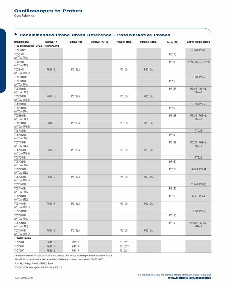
Oscilloscopes to Probes Cross Reference
128 • AccessoriesFor the most up-to-date and complete product information, visit our web site at
www.tektronix.com/accessories
Oscilloscope Passive 1X Passive 10X Passive 1X/10X Passive 100X Passive 1000X 50 Ω (Zo) Active Single-Ended TDS6000B/7000B Series (TekConnect®) TDS6404*1 P7240, P7260 TDS6404 P6150(w/TCA-SMA)TDS6404 P6158 P6245, P6249, P6241 (w/TCA-BNC)TDS6404 P6101B P6139A P5100 P6015A(w/TCA-1MEG)TDS6604B*1 P7240, P7260 TDS6604B P6150(w/TCA-SMA)TDS6604B P6158 P6245, P6249,(w/TCA-BNC) P6241 TDS6604B P6101B P6139A P5100 P6015A(w/TCA-1MEG)TDS6804B*1 P7240, P7260TDS6804B P6150(w/TCA-SMA)TDS6804B P6158 P6245, P6249,(w/TCA-BNC) P6241TDS6804B P6101B P6139A P5100 P6015A(w/TCA-1MEG)TDS7154B*1 P7225 TDS7154B P6150(w/TCA-SMA)TDS7154B P6158 P6243, P6245,(w/TCA-BNC) P6241TDS7154B P6101B P6139A P5100 P6015A(w/TCA-1MEG)TDS7254B*1 P7225 TDS7254B P6150(w/TCA-SMA)TDS7254B P6158 P6249, P6241 (w/TCA-BNC)TDS7254B P6101B P6139A P5100 P6015A(w/TCA-1MEG)TDS7404B*1 P7240, P7260 TDS7404B P6150(w/TCA-SMA)TDS7404B P6158 P6241, P6249 (w/TCA-BNC)TDS7404B P6101B P6139A P5100 P6015A(w/TCA-1MEG)TDS7704B*1 P7240, P7260TDS7704B P6150(w/TCA-SMA)TDS7704B P6158 P6245, P6249,(w/TCA-BNC) P6241TDS7704B P6101B P6139A P5100 P6015A(w/TCA-1MEG)THS700 SeriesTHS720A P6101B P6117 P5102*3
THS720P P6101B P6117 P5102*3
THS730A P6101B P6117 P5102*3
*1 Additional adapters for TDS/CSA7000B and TDS6000B (TekConnect) oscilloscopes include TCA-N and TCA75.
*2 80A03 TekConnect Interface Adapter enables all TekConnect probes to be used with CSA/TDS8200.
*3 10x High Voltage Probe for THS700 Series.
*4 TCP300/TCPA300 Amplifier with TCP305 or TCP312.
Recommended Probe Cross Reference – Passive/Active Probes
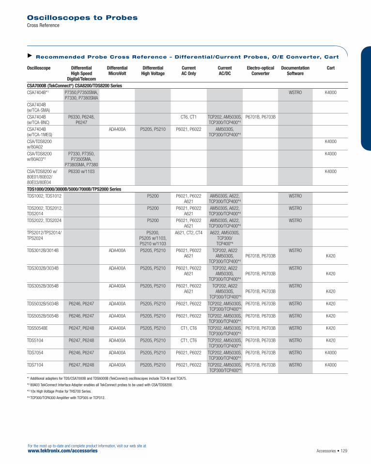
Oscilloscope Differential Differential Differential Current Current Electro-optical Documentation CartHigh Speed MicroVolt High Voltage AC Only AC/DC Converter Software
Digital/TelecomCSA7000B (TekConnect®) CSA8200/TDS8200 Series CSA7404B*1 P7350,P7350SMA, WSTRO K4000
P7330, P7380SMACSA7404B (w/TCA-SMA)CSA7404B P6330, P6248, CT6, CT1 TCP202, AM5030S, P6701B, P6703B(w/TCA-BNC) P6247 TCP300/TCP400*4
CSA7404B ADA400A P5205, P5210 P6021, P6022 AM5030S,(w/TCA-1MEG) TCP300/TCP400*4
CSA/TDS8200 K4000w/80A02CSA/TDS8200 P7330, P7350, K4000w/80A03*2 P7350SMA,
P7380SMA, P7380CSA/TDS8200 w/ P6330 w/1103 K400080E01/80E02/80E03/80E04TDS1000/2000/3000B/5000/7000B/TPS2000 Series TDS1002, TDS1012 P5200 P6021, P6022 AM5030S, A622, WSTRO
A621 TCP300/TCP400*4
TDS2002, TDS2012, P5200 P6021, P6022 AM5030S, A622, WSTROTDS2014 A621 TCP300/TCP400*4
TDS2022, TDS2024 P5200 P6021, P6022 AM5030S, A622, WSTROA621 TCP300/TCP400*4
TPS2012/TPS2014/ P5200, A621, CT2, CT4 A622, AM5030S,TPS2024 P5205 w/1103, TCP300/
P5210 w/1103 TCP400*4
TDS3012B/3014B ADA400A P5205, P5210 P6021, P6022 TCP202, A622 WSTROA621 AM5030S, P6701B, P6703B K420
TCP300/TCP400*4
TDS3032B/3034B ADA400A P5205, P5210 P6021, P6022 TCP202, A622 WSTROA621 AM5030S, P6701B, P6703B K420
TCP300/TCP400*4
TDS3052B/3054B ADA400A P5205, P5210 P6021, P6022 TCP202, A622 WSTROA621 AM5030S, P6701B, P6703B K420
TCP300/TCP400*4
TDS5032B/5034B P6246, P6247 ADA400A P5205, P5210 P6021, P6022 TCP202, AM5030S, P6701B, P6703B WSTRO K420 TCP300/TCP400*4
TDS5052B/5054B P6246, P6247 ADA400A P5205, P5210 P6021, P6022 TCP202, AM5030S, P6701B, P6703B WSTRO K420TCP300/TCP400*4
TDS5054BE P6247, P6248 ADA400A P5205, P5210 CT1, CT6 TCP202, AM5030S, P6701B, P6703B WSTRO K420 TCP300/TCP400*4
TDS5104 P6247, P6248 ADA400A P5205, P5210 CT1, CT6 TCP202, AM5030S, P6701B, P6703B WSTRO K420 TCP300/TCP400*4
TDS7054 P6246, P6247 ADA400A P5205, P5210 P6021, P6022 TCP202, AM5030S, P6701B, P6703B WSTRO K4000 TCP300/TCP400*4
TDS7104 P6247, P6248 ADA400A P5205, P5210 P6021, P6022 TCP202, AM5030S, P6701B, P6703B WSTRO K4000TCP300/TCP400*4
*1 Additional adapters for TDS/CSA7000B and TDS6000B (TekConnect) oscilloscopes include TCA-N and TCA75.
*2 80A03 TekConnect Interface Adapter enables all TekConnect probes to be used with CSA/TDS8200.
*3 10x High Voltage Probe for THS700 Series.
*4 TCP300/TCPA300 Amplifier with TCP305 or TCP312.
Oscilloscopes to Probes Cross Reference
Accessories • 129For the most up-to-date and complete product information, visit our web site atwww.tektronix.com/accessories
Recommended Probe Cross Reference – Differential/Current Probes, O/E Converter, Cart

Oscilloscopes to Probes Cross Reference
For the most up-to-date and complete product information, visit our web site atwww.tektronix.com/accessories
Oscilloscope Differential Differential Differential Current Current Electro-optical Documentation CartHigh Speed MicroVolt High Voltage AC Only AC/DC Converter Software
Digital/TelecomTDS6000/7000B Series TDS6404*1 P7350, WSTRO K4000
P7350SMA, P7330TDS6404 (w/TCA-SMA) TDS6404 P6248, P6330 CT6, CT1 TCP202, AM5030S, P6701B, P6703B(w/TCA-BNC) TCP300/TCP400*4
TDS6404 ADA400A P5205, P5210 P6021, P6022 AM5030S,(w/TCA-1MEG) TCP300/TCP400*4
TDS6604B*1 P7350, WSTRO K4000 P7350SMA, P7330,P7380SMA, P7380
TDS6604B (w/TCA-SMA)TDS6604B P6248, P6330 CT6, CT1 TCP202, AM5030S, P6701B, P6703B(w/TCA-BNC) TCP300/TCP400*4
TDS6604B ADA400A P5205, P5210 P6021, P6022 AM5030S,(w/TCA-1MEG) TCP300/TCP400*4
TDS6804B*1 P7350, P7350SMA, WSTRO K4000P7330, P7380SMA,
P7380TDS6804B (w/TCA-SMA)TDS6804B P6248, P6330 CT6, CT1 TCP202, AM5030S, P6701B, P6703B(w/TCA-BNC) TCP300/TCP400*4
TDS6804B ADA400A P5205, P5210 P6021, P6022 TCP300/TCP400*4,(w/TCA-1MEG) AM5030STDS7154B*1 P7350, WSTRO K4000
P7350SMA, P7330TDS7154B (w/TCA-SMA)TDS7154B P6248, P6330 CT6, CT1 TCP202, AM5030S, P6701B, P6703B(w/TCA-BNC) TCP300/TCP400*4
TDS7154B ADA400A P5205, P5210 P6021, P6022 AM5030S,(w/TCA-1MEG) TCP300/TCP400*4
TDS7254B*1 P7350, WSTRO K4000 P7350SMA, P7330
TDS7254B (w/TCA-SMA)TDS7254B P6248, P6330 CT6, CT1 TCP202, AM5030S, P6701B, P6703B(w/TCA-BNC) TCP300/TCP400*4
TDS7254B ADA400A P5205, P5210 P6021, P6022 AM5030S,(w/TCA-1MEG) TCP300/TCP400*4
TDS7404B*1 P7350, WSTRO K4000 P7350SMA, P7330,P7380SMA, P7380
TDS7404B (w/ TNC-SMA)TDS7404B P6248, P6330 CT6, CT1 TCP202, AM5030S, P6701B, P6703B(w/ TCA-BNC) TCP300/TCP400*4
TDS7404B ADA400A P5205, P5210 P6021, P6022 AM5030S,(w/TCA-1MEG) TCP300/TCP400*4
TDS7704B*1 P7350, WSTRO K4000 P7350SMA, P7330,P7380SMA, P7380
TDS7704B (w/TCA-SMA)TDS7704B P6248, P6330 CT6, CT1 TCP202, AM5030S, P6701B, P6703B(w/TCA-BNC) TCP300/TCP400*4
TDS7704B ADA400A P5205, P5210 P6021, P6022 TCP300/TCP400*4,(w/TCA-1MEG) AM5030STHS700 Series THS720A A621 A622 WSTROTHS720P A621 A622 WSTROTHS730A A621 A622 WSTRO
*1 Additional adapters for TDS/CSA7000B and TDS6000B (TekConnect) oscilloscopes include TCA-N and TCA75.
*2 80A03 TekConnect Interface Adapter enables all TekConnect probes to be used with CSA/TDS8200.
*3 10x High Voltage Probe for THS700 Series.
*4 TCP300/TCPA300 Amplifier with TCP305 or TCP312.
Recommended Probe Cross Reference – Differential/Current Probes, O/E Converter, Cart
130 • Accessories
For your local Tektronix representative see the list in the back of this catalog or outside the U.S. call: 1-503-627-7111, inside the U.S. call: 1-800-833-9200.

P7260 Single-endedActive Probe
The P7260 is the fastest active probe in the world.It provides high-bandwidth, low circuit loading, lownoise and accurate probing solutions for high-speedcircuit designers. This probe has a small probe headfor accessing connection points in tight physicalconstraints and with today’s fine pitch circuitry.
The P7260 is the world’s first probe to be devel-oped with silicon germanium (SiGe).It features atoggle/switch that offers the choice of using theprobe at either 1.5 Vp-p or 6 Vp-p dynamic range.
TekConnect® interface takes probe intelligence tothe next level, providing probe power, automatedsignaling of scale factor and offset voltage. It alsoadds automatic bandwidth adjustment and voltagemeasurement. The TekConnect interface extendsuseful bandwidth and signal fidelity out to 18 GHz.A full complement of versatile probe tip accessorieshelps connect to the wide range of devices facedby digital designers.
Characteristics
Designed for use with the TDS6604B oscilloscope – thesystem bandwidth is typically 6 GHz.
Attribute Specification 5x Specification 25x Type TekConnect Active, Single-ended Bandwidth 6 GHz 6 GHz (probe only,typical)Rise time <75 ps <85 ps (guaranteed)Input <0.5 pF <0.5 pF capacitance(pF)Attenuation 5x 25x Dynamic range ±0.75 V (1.5 Vp-p) ±3.0 V (6.0 Vp-p) DC offset range ±5 V ±5 V Input resistance 20 kΩ at DC 20 kΩ at DC Maximum 30 V (DC plus peak AC)nondestruct voltage Compatible *1 TDS6604B, TDS7404B,oscilloscopes all TekConnect oscilloscopes
*1 Requires firmware version 2.1 or higher for TDS/CSA7000B Series.
Active Probe P7260
Accessories • 131For the most up-to-date and complete product information, visit our web site atwww.tektronix.com/accessories
Features & Benefits6 GHz Bandwidth
Switchable Attenuation Provides up to 6 Vp-p Dynamic Range
Low Input Capacitance <0.5 pF
Provides 6 GHz System Bandwidth at Probe Tip with TDS6604BTekConnect Oscilloscope
Connect and Adapt to Various CircuitDesigns with Small Probe Head andNumerous Connection Accessories
TekConnect Interface
Applications High-speed Digital Systems Design
Component Design/Characterization
Manufacturing Engineering and Test
P7260 6.0 GHz Active Probe, TekConnect interface.Includes: Probe tip accessories (see list), user manual,storage case.Warranty: One year.
Service Opt. C3 – Calibration Service 3 Years.Opt. C5 – Calibration Service 5 Years.Opt. D1 – Calibration Data Report.Opt. D3 – Calibration Data Report 3 Years (with Option C3).Opt. D5 – Calibration Data Report 5 Years (with Option C5).Opt. R3 – Repair Service 3 Years.Opt. R5 – Repair Service 5 Years.
Ordering InformationCurrent price information is available worldwide on-line from the Tektronix web site or from your local Tektronix representative. Inside the U.S., also see the price list in the back of this catalog.
P7260 Included AccessoriesDescription Quantity Part Number/Status Instruction manual 1 each 071-0922-xx Probe carry case 1 each 016-1879-xx Y lead adapter 2 each 196-3434-xx 3" ground lead 2 each 196-3437-10 SMT KlipChip™adapter 2 each 206-0364-xx SureToe™(set of 12) 1 set ST501 Accessory reorder sheet 1 each 001-1349 Short ground pogo pin (set of 8) 1 set 016-1917-xx Square pin adapter (set of 4) 1 set 016-1910-xx (adapt to .100" centered square pins)Color coding bands, 5 colors 1 set 016-1886-xx “L” adapter (set of 2) 1 set 016-1913-xx Anti-static wrist strap 1 each 006-3415-xx Customizable grounded lead (set of 5) 1 set 196-3482-xx
For your local Tektronix representative see the list in the back of this catalog or outside the U.S. call: 1-503-627-7111, inside the U.S. call: 1-800-833-9200.
Tektronix measurement products are manufactured in ISO registered facilities.

Selecting the right probe for your application is key to attaining the best signal fidelity in yourmeasurements. Active probes provide truer signal reproduction and fidelity for high frequency measurements. Tektronix provides you a widerange of 4 GHz active probes to select from for your application.
TekConnect® Interface – P7240
The P7240 with TekConnect interface is a high-performance active probe with high bandwidthand low capacitive loading to make it the probe of choice for demanding design applications, suchas Rambus, DDR DRAM and AGP. This probe andothers in the family are also suited for applicationsin the communication industry, for measurementson Fibre Channel and Gigabit Ethernet. With theTekConnect interface, you can be assured thatmaximum signal integrity is maintained to meetpresent and future bandwidth needs.
TekProbe™ BNC Interface –P6249 and P6241
The P6249 and P6241 have similar performancesto the P7240. Primarily used for the TDS694Cand TDS794D performance scopes, these probesmay also be used with conventional BNC inter-faces via the Tektronix 1103 TekProbe® PowerSupply. The P6249 provides 4 Vp-p dynamicrange. The P6241 offers a 10X attenuation and a 8 Vp-p dynamic range plus has a lower inputcapacitance due to the unique probe tip. A fullcomplement of versatile probe tip accessorieshelps users connect to the wide range of devicesfaced by digital designers.
4 GHz Active Probes P7240 • P6249 • P6241
Features & Benefits<120 ps Rise Time (Guaranteed)
4 GHz Bandwidth
<0.5 pF Input Capacitance (P6241 Only)
Small Form Factor Probe Head
8 Vp-p Dynamic Range (P6241 Only)
Direct Access to SMDs
Oscilloscopes Supported: – P7240 TDS/CSA7000B Series – P6249 TDS/CSA7000B,
6000B Series – P6241 TDS/CSA7000B,
6000B, Series
Probe Interfaces: – P7240 TekConnect Interface – P6249 TekProbe II BNC Interface – P6241 TekProbe II BNC Interface
ApplicationsHigh-speed Digital Systems Design
Component Design/Characterization
Signal Integrity, Jitter and Timing Analysis
Manufacturing Engineering and Test
Signals with Voltage Swings up to 8 Vp-p
Measures 3.0 V Logic, InfiniBand, PCI Express, DDR, Rambus DataLines, Gigabit Ethernet
For your local Tektronix representative see the list in the back of this catalog or outside the U.S. call: 1-503-627-7111, inside the U.S. call: 1-800-833-9200.
Tektronix measurement products are manufactured in ISO registered facilities.
Characteristics
P7240 P6249 P6241 Rise Time <120 ps <120 ps <120 ps Bandwidth 4.0 GHz 4.0 GHz 4.0 GHz Attenuation 5X 5X 10X DC Resistance 20 kΩ 20 kΩ 40 kΩInput Capacitance <1 pF <1 pF <0.5 pF Dynamic Range ±2 V ±2 V ±4 V Offset Range ±5 V ±5 V ±10 V Interface TekConnect® TekProbe® II TekProbe II Warranty 1 Year 1 Year 1 Year
For the most up-to-date and complete product information, visit our web site atwww.tektronix.com/accessories132 • Accessories

4 GHz Active Probes P7240 • P6249 • P6241
Accessories • 133For the most up-to-date and complete product information, visit our web site atwww.tektronix.com/accessories
P72404.0 GHz Active Probe.
P62494.0 GHz Active Probe.
P62414.0 GHz Active Probe.
Support Options Opt. C3 – Calibration Service 3 Years.Opt. C5 – Calibration Service 5 Years.Opt. D1 – Calibration Data Report.Opt. D3 – Calibration Data Report 3 Years (with Option C3).Opt. D5 – Calibration Data Report 5 Years (with Option C5).Opt. R3 – Repair Service 3 Years.Opt. R5 – Repair Service 5 Years.
For your local Tektronix representative see the list in the back of this catalog or outside the U.S. call: 1-503-627-7111, inside the U.S. call: 1-800-833-9200.
Tektronix measurement products are manufactured in ISO registered facilities.
Ordering InformationCurrent price information is available worldwide on-line from the Tektronix web site or from your local Tektronix representative. Inside the U.S., also see the price list in the back of this catalog.
P6241 P7240/P6249Product Name/Description Part Number Quantity Part Number Quantity 3 Inch Ground Leads (Set of 2) 196-3437-10 1Customizable Ground Lead (Set of 5) 196-3482-00 1 196-3482-00Lead Set: 196-3437-00 (3) 196-3457-00 (2) 196-3456-00 1 Y Lead Adapter 196-3434-00 2L Adapter (Set of 2) 016-1913-00 1Adapter Spring (Set of 10) 016-1774-00 1 SMT KlipChip™ Adapter 206-0364-01 2 206-0364-01 2 Short Pogo Pin Ground (Set of 8) 016-1917-00 1Pogo Pin (Set of 15) 016-1772-00 1 Square Pin Socket (Set of 15) 016-1773-00 1 Square Pin Adapter (Set of 4) 016-1910-01 1Probe Tip (Set of 30) 131-5638-30 1 Color Coding Bands, 2 Each of 5 Colors 016-1315-00 1 016-1315-00 1 Probe Carrying Case 016-1879-01 1 016-1879-01 1 Accessory Case 006-7164-00 1 016-7164-00 1 Wrist Strap 006-3415-04 1 006-3415-04 1 SureToe™ (Set of 12) ST501 (Replacement 1 ST501 (Replacement 1
Pkg. of 12) Pkg. of 12)

Selecting the right probe for your application iskey to attaining the best signal fidelity in yourmeasurements. Active probes provide truer signalreproduction and fidelity for high frequency meas-urements. With our ultra-low input capacitanceand high input resistance provided by the P7225,you are able to make measurements with minimalsignal distortion. This probe offers a wide 8 Vp-p
dynamic range to access today’s voltage levels.
CharacteristicsRise Time – <140 ps.Bandwidth – 2.5 GHz.Attenuation – 10X.DC Resistance – 40 kΩ.Input Capacitance – ≤0.8 pF.Dynamic Range – ±4 V.Offset Range – ±10 V.Interface – TekConnect.®
Active Probe P7225
134 • Accessories
Features & Benefits<140 ps Rise Time (guaranteed)
2.5 GHz Bandwidth
≤0.8 pF Input Capacitance
8 Vp-p Dynamic Range
40 kΩ Input Resistance
TekConnect Interface
Supports TDS7154/7254 Active ProbeNeeds By Providing a TekConnect2.5 GHz, 8 Vp-p Dynamic Range CostEffective Probing Solution for Mid-band Real-time Oscilloscopes
10X Attenuation
Applications Verification, Debug and Characterizationof High-speed Designs
Design, Development andCompliance Testing
Signal Integrity, Jitter and Timing Analysis
Manufacturing Engineering and Test
Signals with Voltage Swings Up to 8 Vp-p
P7225Active Probe.
Service Opt. C3 – Calibration Service 3 Years.Opt. C5 – Calibration Service 5 Years.Opt. D1 – Calibration Data Report.Opt. D3 – Calibration Data Report 3 Years (with Option C3).Opt. D5 – Calibration Data Report 5 Years (with Option C5).Opt. R3 – Repair Service 3 Years.Opt. R5 – Repair Service 5 Years.
For your local Tektronix representative see the list in the back of this catalog or outside the U.S. call: 1-503-627-7111, inside the U.S. call: 1-800-833-9200.
Tektronix measurement products are manufactured in ISO registered facilities.
Ordering InformationCurrent price information is available worldwide on-line from the Tektronix web site or from your local Tektronix representative. Inside the U.S., also see the price list in the back of this catalog.
Included Accessories
Product Name/Description Part Number Quantity Ground lead kit – 3 in. and Y Lead Adapter 196-3456-00 1 Each SMT KlipChip™Adapter 206-0364-00 1 5 Colors, Color Coding Clips 016-1315-00 1 Pogo Pin Ground (set of 10) 016-1772-00 1 Square Pin Sockets (set of 10) 016-1773-00 1 Customizable Ground Lead (set of 5) 196-3482-00 1 Probe Tips (set of 10) 131-5638-00 1 SureToe™Adapter (set of 12) ST501 1 Instruction Manual 071-1186-00 1 Probe Carrying Case 016-1879-01 1 Accessory Case 006-7164-00 1 Wrist Strap 006-3415-04 1 Certificate of Traceability — 1
For the most up-to-date and complete product information, visit our web site atwww.tektronix.com/accessories

P6245
The P6245 Active FET probe achieves high-speed signal acquisition by solving three traditional problems:
Lower DUT loading (≤1 pF/1 MΩ probe loading)
Direct and easy access to SMDs
Access DUT signals and scope bandwidth forTDS600/700/3000/5000/6000/7000*1 andCSA7000 scopes up to 1 GHz bandwidths
The P6245 and P6243 Active probes provide theelectrical and mechanical performance requiredfor today’s digital systems designs. No additionalpower supplies or cables are required when usedwith TEKPROBE BNC oscilloscopes. Both theP6245 and P6243 achieve high-speed signalacquisition and low circuit loading, required forsolving today’s problems faced by designers.
The small compact probe head and versatileattachment accessories allow direct connection to the device under test.
The P6245 and P6243 Active Probes providescope bandwidth at the probe tip for theTDS500/600/700; the P6243 provides scopebandwidth at the probe tip for the TDS3000Series scope up to 1 GHz bandwidth.
*1 TDS6000B, TDS7000B, or CSA7000B TekConnect® oscilloscopesrequire a TCA-BNC adapter.
P6243
The P6243 Active FET probe is the high perform-ance probing solution for 500 MHz oscilloscopes.The P6243 has a probe only bandwidth of 1 GHzand will provide a 500 MHz system bandwidthwhen used with Tektronix’ full line of 500 MHzoscilloscopes. In addition, the P6243 is poweredby the TEKPROBE BNC interface, eliminating theneed for additional power supplies and cableswhen used with TEKPROBE BNC oscilloscopes.
The P6243 offers superior signal acquisition onsurface mount devices compared to the muchhigher capacitive loading of passive probes. TheP6243 has ≤1 pF capacitive loading which allowsit to measure high speed signals without affectingthe signal or device under test. Furthermore, theincluded accessories and adapters allow for easyattachment to SMDs.
Active Probe for SMDs P6245 • P6243
Accessories • 135For the most up-to-date and complete product information, visit our web site atwww.tektronix.com/accessories
Features & Benefits
P6245
≥1.5 GHz Bandwidth (Typical, Probe Only)
≤1 pF Input Capacitance
1 MΩ Input Resistance
Direct Access to SMDs as Small as 0.5 mm Pitch
Measures CMOS, BiCMOS, ECL,GaAs and TTL Logic
P6243
1 GHz Bandwidth (probe only)
≤1 pF Input Capacitance
1 MΩ Input Resistance
Direct Access to SMDs as Small as 0.5 mm Pitch
Measures CMOS, BiCMOS, ECL,GaAs and TTL Logic
Low Mass Probe Head/Cable
No Additional Power Supplies or Cables Are Required with TEKPROBE BNC Interface
Applications High-speed Digital Systems Design
Component Design/Characterization
Manufacturing Engineering and Test
Educational Research
P6245 and P6243 Active Probes for TEKPROBE® BNC Interfaces
For your local Tektronix representative see the list in the back of this catalog or outside the U.S. call: 1-503-627-7111, inside the U.S. call: 1-800-833-9200.
Tektronix measurement products are manufactured in ISO registered facilities.
P6243.

Characteristics
Probe Type P6243 P6245 Cable Length 1.3 m 1.3 m Attenuation 10X 10X Bandwidth in GHz 1 GHz 1.5 GHz(Probe Only)Rise-time <350 ps <250 ps Input C in pF 1 pF 1 pF Input R in Ω 1 MΩ 1 MΩLinear Dynamic ±8 V ±8 V RangeDC Offset Range N/A ±10 V Max Voltage ±15 V ±15 V (Nondestruct) (DC+PkAC)Propagation Delay 5.3 ns ±200 ps 5.3 ns ±200 ps
Active Probe for SMDs P6245 • P6243
136 • AccessoriesFor the most up-to-date and complete product information, visit our web site at
www.tektronix.com/accessories
P6245 Active Probe.
P6243 Active Probe.
Service Opt. C3 – Calibration Service 3 Years.Opt. C5 – Calibration Service 5 Years.Opt. D1 – Calibration Data Report.Opt. D3 – Calibration Data Report 3 Years (with Option C3).Opt. D5 – Calibration Data Report 5 Years (with Option C5).Opt. R3 – Repair Service 3 Years.Opt. R5 – Repair Service 5 Years.
Recommended Accessories SMD Probing Adapters*1
SureFoot® Adapters –50 mil pitch. Order SF501.25 mil and 0.65 mm pitch. Order SF502.0.5 mm pitch. Order SF503.IC Grabber – 0.5 mm pitch. Order 013-0309-00 (See SureFoot Adapters).
*1 See SureFoot for complete SMD Adapters information.
For your local Tektronix representative see the list in the back of this catalog or outside the U.S. call: 1-503-627-7111, inside the U.S. call: 1-800-833-9200.
Tektronix measurement products are manufactured in ISO registered facilities.
Ordering InformationCurrent price information is available worldwide on-line from the Tektronix web site or from your local Tektronix representative. Inside the U.S., also see the price list in the back of this catalog.
Included Accessories Description Quantity P6245 Quantity P6243 Reorder Part Number Solderable Probe Tips 10 each 10 each 131-5638-xx (Pkg. of 10) 1 in. Ground Lead 2 each 2 each 196-3439-xx (Pkg. of 10) 6 in. Ground Lead 2 each 1 each 196-3436-xx 3 in. Ground Lead 2 each 1 each 196-3437-xx Y Lead Adapters 2 each 1 each 196-3463-xx SMT KlipChip™ adapter 4 each 2 each 206-0364-xx Color Coding Clips, 2 each 5 colors 1 each 1 each 016-1315-xx Right Angle Square Pin Adapter 2 each 1 each 214-4227-xx 100 Mil Square Pin Adapter 2 each 1 each 131-5777-xx
Recommended Probe Accessories Part Number Description003-1433-02 Adjustment Tool.016-1315-00 Two each - Five Colors of Cable Markers.131-5638-11 10 each - Solderable Probe Tips.131-5777-00 100 mil Square Pin Ground Adapter.196-3410-00 Ground Lead Set Includes: 2 each - 1 in., 3 in., 6 in. Ground Leads w/Square Pin Receptacle;
2 each - Y Lead Adapters.196-3436-10 6 in. Ground Lead (Pkg. Of 2)196-3437-10 3 in. Ground Lead (Pkg. Of 2)196-3438-10 1 in. Ground Lead (Pkg. Of 2)196-3463-10 Y Lead Adapter (Pkg. Of 2)206-0364-01 SMT KlipChip™ Adapter, 1 each.214-4227-00 Right Angle Square Pin Adapter.SF501 SureFoot® Probe Tip Adapter, pkg. of 12, Yellow, 50 mil Pitch.SF502 SureFoot Probe Tip Adapter, pkg. of 12, Blue, 25 mil/0.65 mm Pitch.SF503 SureFoot Probe Tip Adapter, pkg. of 12, Red, O.5 mm pitch.SMG50 SMT KlipChip Adapter, 20 each.013-0309-00 IC Grabber (2 each).

Leveraging Tektronix expertise and innovation, wecreated a revolutionary Z-Active probe architecturethat sets the industry benchmark for signal fidelity.Tektronix’ new active probe architecture preserveshigh bandwidth while providing improved connectivitywith low loading. The Z-Active architecture is a newhybrid approach composed of a distributed atten-uator topology feeding an active probe amplifier.
With Z-Active architecture, the P7380 uses a tinypassive probe tip element that is separate fromthe amplifier, extending the usable reach of theprobe. In traditional active probes, adding thismuch length can introduce signal fidelity problems.However the new P7380 architecture maintainshigh DC input resistance and presents a higherAC impedance than previous probe architectures.It accomplishes this while providing significantlength between the probe body and the probeattachment point to the DUT. This architectureprovides the best of both worlds, high DC imped-ance like existing active probes, along with thestable high frequency loading of Z0 probes.
CharacteristicsBandwidth (Probe Only) – >8.0 GHz (typical).(20 ºC to 30 ºC).Rise Time 10% to 90% – <55 ps (guaranteed).(20 ºC to 30 ºC).Rise Time 20% to 80% – <35 ps (typical).Attenuation – 5x or 25x selectable.Differential Input Range –5X: ±0.625V, 1.25Vp-p.25X: ±2V, 4Vp-p.Common Mode Input Range – +4 V to –3.0 V.Offset Range – +4 V to –3.0 V.Loading –DC Input Resistance: 100 KΩ differential,50 KΩ single ended.AC Zmin: >300 Ω differentially at 8 GHz.Max Voltage (Non-destruct) – ±15 V (DC plus peak AC).CMRR – >45 dB at 1 MHz (typical).Noise – <35 nV/Root Hz.Interface – TekConnect.®
Cable Length – 1.2 m.
Features & BenefitsSignal Fidelity – >8.0 GHz Bandwidth (Typical) – <55 ps Rise Time 10% to
90% (Guaranteed) – <35 ps Rise Time 20% to
80% (Typical)
Low Probe Loading – DC Input Resistance
– 100 KΩ Differential – 50 KΩ Single-ended
– AC Loading – Zmin 300 Ω Differentially
at 8 GHz
Versatility – Solder Down Capability – Handheld Probing with Variable
Spacing and Compliance – Fixtured Probing
Interchangeable Tip-Clip™ Assemblies – Connect to a Variety
of Devices – Economical
TekConnect Interface
ApplicationsComputer (PCI-Express, Serial ATA,USB 2.0, DDR)
Communications (Gigabit Ethernet, Fibre Channel,InfiniBand)
Disk Drive Design
Accessories • 137For the most up-to-date and complete product information, visit our web site atwww.tektronix.com/accessories
High Performance Differential Probes P7380NEW
New Z-Active™ Probing Architecture Leads the Way for High-speed Probing Applications
P7380 >8.0 GHz Differential Probe.
Service Options Opt. C3 – Calibration Service 3 Years.Opt. C5 – Calibration Service 5 Years.
Opt. D3 – Calibration Data Report 3 Years (with Option C3).Opt. D5 – Calibration Data Report 5 Years (with Option C5).
Opt. R3 – Repair Service 3 Years.Opt. R5 – Repair Service 5 Years.
For your local Tektronix representative see the list in the back of this catalog or outside the U.S. call: 1-503-627-7111, inside the U.S. call: 1-800-833-9200.
Ordering InformationCurrent price information is available worldwide on-line from the Tektronix web site or from your local Tektronix representative. Inside the U.S., also see the price list in the back of this catalog.

Tektronix’ proven expertise in differential probingbrings you our newest high-speed differential sig-nal acquisition system. This acquisition systemutilizes our new SiGe probe ASIC developed withtoday’s most advanced technology. TheP7380SMA is designed for measuring differentialsignals in a 50 Ω signaling environment, provid-ing the ability to convert from a dual-SMA signalpath to a single oscilloscope input channel. Manyof the new high-speed serial data standardsemploy differential signaling on multiple lanes.The P7380SMA provides the ability to measure a high-speed differential signal on each channelof a multiple channel oscilloscope.
CharacteristicsBandwidth (Differential Signal AcquisitionSystem) – >8 GHz (typical).Rise Time – <55 ps 10% to 90% (guaranteed).Rise Time – <35 ps 20% to 80% (typical).
Dual SMA Input Gain Attenuation – 0.40 (2.5 X) and 0.08 (12.5 X).Differential Input Dynamic Range – 625 mVp-p(2.5 X) and 3.0 Vp-p (12.5 X).Common Mode Voltage Range – ±2.5 V.Termination Voltage Range – ±2.5 V.Max Voltage (Non-destruct) – ±5 V (DC plus peak AC).CMRR –DC >60 dB.100 MHz >50 dB.1 GHz >35 dB.5 GHz >20 dB.8 GHz >15 dB.Differential Return Loss –<30 dB to 5 GHz (VSWR <1.065:1).<20 dB to 8 GHz (VSWR <1.22:1).Noise, Referred To Input – <13 nV/Root Hz (2.5 X) and <40 nV/Root Hz (12.5 X).Interface – TekConnect.®
Features & Benefits>8 GHz Bandwidth (typical)
<55 ps 10% to 90% Rise Time (guaranteed)
<35 ps 20% to 80% Rise Time (typical)
Dual SMA Inputs to Internal 50 ΩTermination Network
High Bandwidth Differential Amplifierwith Excellent CMRR
Internal Termination VoltageGenerator Controlled by Internal(oscilloscope)1, External Source orAutomatically
Switchable Gain for ExtendedDynamic Range
Low Differential Input VSWR
Phase Matched SMA Cables (1 mlength) with Cable LossCompensation
Excellent Pulse Response for Optimum Eye PatternMeasurements
Low Pulse Response Aberrations for Optimum Eye PatternMeasurements
Compatible with 80A03 for Sampling Applications
Auxiliary (inverted) Output for Use with Spectrum Analyzers,Network Analyzers or as a ClockRecovery Trigger Source
TekConnect® Interface
ApplicationsAnalog Validation and ComplianceTesting of Emerging Serial DataStandards Including: – PCI Express, InfiniBand, Serial ATA,
10GbE XAUI, FibreChannel
Communications (Gigabit Ethernet, FibreChannel,InfiniBand)
Semiconductor Characterization and Validation (PCI Express, Serial ATA, IEEE 1394, USB 2.0, RAMBUS, DDR)
1 Not available on all oscilloscopes.
138 • AccessoriesFor the most up-to-date and complete product information, visit our web site at
www.tektronix.com/accessories
High Performance Differential Probes P7380SMA NEW
P7380SMA >8 GHz Differential Signal Acquisition System withSMA Inputs.
Service Options Opt. C3 – Calibration Service 3 Years.Opt. C5 – Calibration Service 5 Years.Opt. D1 – Calibration Data Report.Opt. D3 – Calibration Data Report 3 Years (with Option C3).
Opt. D5 – Calibration Data Report 5 Years (with Option C5).Opt. R3 – Repair Service 3 Years.Opt. R5 – Repair Service 5 Years.
For your local Tektronix representative see the list in the back of this catalog or outside the U.S. call: 1-503-627-7111, inside the U.S. call: 1-800-833-9200.
Ordering InformationCurrent price information is available worldwide on-line from the Tektronix web site or from your local Tektronix representative. Inside the U.S., also see the price list in the back of this catalog.

Tektronix brings you the first-available high-speeddifferential SMA input probe. The P7350SMA provides a tool for measuring differential signalsin a 50 Ω signaling environment. By integrating a dual 50 Ω termination network and a differen-tial amplifier in the probe head, the P7350SMAmeasures a differential signal pair on eachchannel of a multiple channel oscilloscope. Sincemany of the new high-speed serial data standardsdefine differential signaling on multiple channels,the P7350SMA provides a more efficient meas-urement solution.
An active differential buffer amplifier in the probehead enables the P7350SMA probe to move themeasurement interface from the oscilloscope frontpanel to the circuit-under-test. This can reduce thelength of electrical interconnect cabling, which formulti-gigabit data signals also reduces frequencydependent loss distortion in signal measurements.
The P7350SMA is connected to an oscilloscopewith the patented TekConnect® interface which preserves signal integrity to 10 GHz and beyond to meet present and future bandwidth needs.
CharacteristicsRise Time – <100 ps 10% to 90% (guaranteed).<65 ps 20% to 80% (typical).Bandwidth (Probe Only) – 5.0 GHz (typical).Input – SMA.Attenuation – 6.25X.Differential Input Resistance – 100 Ω ±2%.Common Mode Input Resistance – 50 Ω ±1%.Input Skew – <1 ps.Differential Input Range – ±2.5 V (20 ºC to 30 ºC).Common Mode Input Range – +6.25 V to –5 V.Maximum Termination Resistor Power – <0.5 Wper side.*1
Max Voltage (Non-destruct) – ±15 V (DC plus peak AC).CMRR – >60 dB at DC, >55 dB at 1 MHz,>50 dB at 30 MHz, >30 dB at 1 GHz (typical).
Differential Input Return Loss Frequency Differential Return Loss 625 MHz >20 dB (fundamental for 1.25 Gbps)1.25 GHz >16 dB (fundamental for 2.5 Gbps)1.56 GHz >14 dB (fundamental for 3.125 Gbps)2.50 GHz >12 dB 3.125 GHz >10 dB
Noise – Approximately 46 nV Interface – TekConnect.Cable Length – 1.2 m.
*1 See manual for calculation.
5.0 GHz Differential Probe with SMA InputP7350SMA
Accessories • 139For the most up-to-date and complete product information, visit our web site atwww.tektronix.com/accessories
Features & Benefits<100 ps Rise Time (Guaranteed)
5.0 GHz Bandwidth (Typical)
Dual SMA Inputs to Internal 50 Ω Termination Network
Internal Differential Amplifier with High CMRR
DC Bias Port for Common ModeVoltage Termination (LVPECL and CML Bias Capability)
Good Differential Input Return Loss
Low Input Skew
Supplied with Low Loss MatchedDelay Cables
TekConnect Interface
Applications Communications (Gigabit Ethernet, Fibre Channel, InfiniBand)
Semiconductor Characterization and Validation (PCI-Express, Serial ATA,IEEE 1394, USB 2.0,RAMBUS, DDR)
P7350SMA 5.0 GHz Differential SMA Probe for TekConnect Interface.
Includes: 50 Ω Terminator – Order 015-0122-xx, 2 each.Matched Pair SMA Cables, 12 in. – Order 174-4866-xx, 1 set.Banana Plug Shorting Strap – Order 012-1667-xx,1 each.BNC-M to SMA-F Adapter – Order 015-0572-xx,1 each.
Cable Marker Set (5 colors) – Order 016-1886-xx,1 each.Wrist Strap – Order 006-3415-xx, 1 each.Certificate of Traceable Calibration – 1 each.Instruction Manual – Order 017-1264-xx, 1 each.
Service Options Opt. C3 – Calibration service 3 years.Opt. C5 – Calibration service 5 years.Opt. D1 – Calibration data report.Opt. D3 – Calibration data report 3 years (with Option C3).
Opt. D5 – Calibration data report 5 years (with Option C5).Opt. R3 – Repair service 3 years.Opt. R5 – Repair service 5 years.
For your local Tektronix representative see the list in the back of this catalog or outside the U.S. call: 1-503-627-7111, inside the U.S. call: 1-800-833-9200.
Ordering InformationCurrent price information is available worldwide on-line from the Tektronix web site or from your local Tektronix representative. Inside the U.S., also see the price list in the back of this catalog.
Hz.

Tektronix’ proven expertise in probes brings you the highest fidelity in high-speed differential probing. The P7350, P7330, P6330 high BW differential probes offer excellent signal fidelity,meeting the needs of engineers in design anddebug of technologies with very fast clock speedsand edge rates. They provide high-bandwidth,low circuit loading, low noise differential probingsolutions for high-speed circuit designers.
P7350
The P7350 improves usability with variable spacingand solder down capability, and a small form factorfor ease of use on densely packed circuit boardswith difficult-to-reach probe points. It employs thepatented TekConnect® Interface, which preservessignal integrity to 10 GHz and beyond to meetpresent and future bandwidth needs.
P7330 and P6330
The P7330 and P6330 enable users to maketime domain or frequency domain measurementson high bandwidth signals commonly found indigital IC designs, communication applications,and disk drive applications. The P7330 and P6330provide high-bandwidth, low circuit loading, andlow noise differential probing solutions. The smallprobe head geometry and assorted probe tipaccessories allow these probes to easily accom-modate manual probing of surface mount devices.
High Performance Differential Probes P7350 • P7330 • P6330
140 • AccessoriesFor the most up-to-date and complete product information, visit our web site at
www.tektronix.com/accessories
Features & Benefits<100 ps Rise Time (P7350 Guaranteed)
5 GHz to 3.5 GHz Bandwidths (Typical)
Low Input Capacitance: – <0.3 pF Differential (P7350 Typical) – ≥60 dB (1000:1) Common Mode
Rejection Ratio (CMRR) at 1 MHz(P7330, P6330 Typical)
Small Probe Head Allows EasyProbing of SMDs
P7350, P7330 TekConnect Interface
P6330 TEKPROBE® II BNC interface(connects to TEKPROBE II BNCInterface on TDS Series Oscilloscopes.Use 1103 TEKPROBE® Power Supplyto Interface with other BNC Instruments)
Applications Communications (Gigabit Ethernet,Fibre Channel, InfiniBand)
Semiconductor Characterization andValidation (PCI-Express, Serial ATA,IEEE 1394, USB 2.0, RAMBUS, DDR)
Disk Drive Design
For your local Tektronix representative see the list in the back of this catalog or outside the U.S. call: 1-503-627-7111, inside the U.S. call: 1-800-833-9200.
CE Marking Not Applicable.
Tektronix measurement products are manufactured in ISO registered facilities.
CharacteristicsP7350 P7330 P6330
Rise Time <100 ps <140 ps <140 ps(guaranteed) (guaranteed) (guaranteed)
Bandwidth 5.0 GHz 3.5 GHz 3.5 GHz Attenuation 6.25X 5X 5X Differential Input C <0.3 pF (typical)Differential Input Resistance 100 k Ω 100 k Ω 100 k ΩDifferential Input Range ±2.5 V ±2 V ±2 V
(20 ºC to 30 ºC) (20 ºC to 30 ºC) (20 ºC to 30 ºC) Common Mode Input Range +6.25 V to –5 V +5 V to –4 V +5 V to –4 V Max Voltage (non-destruct) ±15 V ±15 V ±15 V
(DC plus peak AC) (DC plus peak AC) (DC plus peak AC) CMRR >45 dB at 1 MHz >60 dB at 1 MHz >60 dB at 1 MHz
(typical) (typical) (typical)Noise Approx. 46 nV/root Hz Approx. 35 nV/root Hz Approx. 35 nV/root Hz Interface TekConnect TekConnect TEKPROBE II BNC Cable Length 1.3 m 1.3 m 1.3 m

High Performance Differential Probes P7350 • P7330 • P6330
Accessories • 141For the most up-to-date and complete product information, visit our web site atwww.tektronix.com/accessories
P7350 5.0 GHz Differential Probe for TekConnect Interface.Includes: See accessories table below (to the right).
P7330 3.5 GHz Differential Probe for TekConnect Interface.Includes: See accessories table below (to the right).
P6330 3.5 GHz Differential Probe for TEKPROBE® BNCInterface.Includes: See accessories table below (to the right).
Service Opt. C3 – Calibration Service 3 Years.Opt. C5 – Calibration Service 5 Years.Opt. D1 – Calibration Data Report.Opt. D3 – Calibration Data Report 3 Years (requires Option C3).Opt. D5 – Calibration Data Report 5 Years (requires Option C5).Opt. R3 – Repair Service 3 Years.Opt. R5 – Repair Service 5 Years.
Ordering InformationCurrent price information is available worldwide on-line from the Tektronix web site or from your local Tektronix representative. Inside the U.S., also see the price list in the back of this catalog.
P7350 P7330 P6330 Part No. Quantity Part No. Quantity Part No. Quantity
Y Lead Adapter 196-3434-00 2 each 196-3434-00 2 each 196-3434-00 2 each 3" Ground Lead 196-3469-00 2 each 196-3469-00 2 each 196-3469-00 2 each IC Grabber (Pkg of 2) — — 013-0309-00 1 pkg 013-0309-00 1 pkg SMT KlipChip™ 206-0364-00 2 each 206-0364-00 2 each 206-0364-00 2 each AdapterTwinFoot™ Adapter 016-1785-00 1 pkg 016-1785-00 1 pkg 016-1785-00 1 pkg (Pkg of 2)Square Pin Adapter 016-1884-00 1 pkg 016-1884-00 1 pkg 016-1884-00 1 pkg (Pkg of 4)Plastic Accessory 006-7164-00 1 006-7164-00 1 006-7164-00 1 BoxCoding Color 016-1886-00 1 — — — — Marker KitColor Coding Clips — — 016-1315-00 1 set 016-1315-00 1 set Variable Spacing 016-1885-00 1 pkg 016-1885-00 1 pkg 016-1885-00 1 pkg Adapter (pkg of 4)Probe Carrying Case 016-1879-00 1 016-1879-00 1 016-1879-00 1 Instruction Manual 071-1238-xx 1 071-0758-xx 1 071-0757-xx 1 Certificate of — 1 — 1 — 1 Traceable CalibrationAnti-static 006-3415-04 1 006-3415-04 1 006-3415-04 1 Wrist StrapPin Jumper Lead 196-3473-00 2 196-3473-00 2 196-3473-00 2 Solder In Kit 020-2505-00 1 — — — —
Accessories

The P6248, P6247 and P6246 enable users tomake time domain or frequency domain measure-ments on high bandwidth signals commonly foundin disk drive, digital IC design (RAMBUS) andcommunication applications (Gigabit Ethernet,IEEE-1394 Firewire and Fibre Channel). TheP6248 includes accessories that allow RAMBUSvia probing and IEEE-1394 interconnect access.The small probe head geometry and assortedprobe tip accessories allow these probes to easilyaccommodate manual probing of surface mountdevices while maintaining high CMRR.
The P6246, P6247 and P6248 are ideal fordesign verification of disk drive read channelelectronics and timing analysis for troubleshootingground bounce problems associated with highspeed logic. They can also be used for pulseshape or cross talk compliance testing of highspeed communication signals.
CharacteristicsBandwidth (guaranteed) – P6248: DC to 1.5 GHz.P6247: DC to 1.0 GHz.P6246: DC to 400 MHz.Rise Time (specified) – <265 ps (P6248), <350 ps (P6247), <875 ps (P6246).
DC Attenuation Accuracy – ±2%.Common Input Voltage Range – ±7.0 V, 1X;±7.0 V, 10X.Differential Input Voltage Range – ±850 mV, 1X;±8.5 V, 10X.Max. Nondestruct Input Voltage – ±25 V(DC + peak AC).Electrostatic Immunity – >15 kV.TEKPROBE Interface – Probe power, auto-scaling,auto-termination with TDS scopes.Bandwidth Limit – Switchable, 200 MHz (P6246 & P6247).DC Reject – 0.4 Hz, 1X; 4.0 Hz, 10X (P6246 & P6247).
Typical Specifications Input C – <1 pF (differential mode).<2 pF (common mode).Input R – 200 kΩ (differential mode).100 kΩ (common mode).Linearity – ±2%.Noise – <50 nV/squareroot Hz.Harmonic Distortion – ≤1.5% @ 100 MHz.Passband Ripple – <±0.25 dB.P6248: DC to 1.5 GHz.P6247: DC to 850 MHz.P6246: DC to 400 MHz.Output Termination – Terminate into 50 Ω.
Differential Probes P6248 • P6247 • P6246
142 • AccessoriesFor the most up-to-date and complete product information, visit our web site at
www.tektronix.com/accessories
Features & Benefits
P6248
1.7 GHz (Typical Probe Only ≤27 ºC)1X Mode
1.5 GHz Bandwidth (Guaranteed)
1.85 GHz (Typical Probe Only ≤27 ºC)10X Mode
P6247
>1.0 GHz Bandwidth (Guaranteed)
P6246
400 MHz Bandwidth (Guaranteed)
Features & Benefits
Low Input Capacitance: <1 pFDifferential
Probe Input Connector: Two Standard0.025 in./0.63 mm (0.1 in. center)Square Pin Receptacle (Female)
Electrostatic Discharge Tolerant(IEC 801-2)
Connects to TEKPROBE™ BNCInterface on TDS Series Oscilloscopesor Other Instruments Using 1103TEKPROBE® Power Supply
For Use with Oscilloscopes, Spectrumor Network Analyzers
>60 dB (1000:1) Common ModeRejection Ratio (CMRR)
Small Probe Head Allows EasyProbing of SMDs
Applications Communications (Gigabit Ethernet,IEEE-1394, Fibre Channel)
Semiconductor Characterization(RAMBUS)
Disk Drive Read Channel Design
Communication Pulse ShapeCompliance
Jitter, Cross-Talk, BERTMeasurements
Location of Ground Bounce
For your local Tektronix representative see the list in the back of this catalog or outside the U.S. call: 1-503-627-7111, inside the U.S. call: 1-800-833-9200.
CE Marking Not Applicable.
Tektronix measurement products are manufactured in ISO registered facilities.
The P6246, P6247 and P6248 Differential Probes
P6248.

Physical Characteristics Weight (probe only) – 160 g (0.36 lb.).Probe Head Volume – 6 cm3 (0.3 in.3).Probe Head Input Connection – 0.63 mm(0.025 in.) square pins on 2.54 mm (0.1 in.) centers.Output Cable Length – 1.2 m (4.0 ft.).
Environmental Characteristics Temperature – Operating: 0 ºC to 50 ºC.Nonoperating: –55 ºC to +75 ºC.Humidity (0 to 90% RH) – Operating: 30 ºC to 50 ºC.Nonoperating: 30 ºC to 60 ºC.
Differential Probes P6248 • P6247 • P6246
Accessories • 143For the most up-to-date and complete product information, visit our web site atwww.tektronix.com/accessories
P6248 1.7 GHz Differential Probe (typical ≤ 27 ºC). 1.5 GHzDifferential Probe (guaranteed).
P6247 1.0 GHz Differential Probe (guaranteed).
P6246 400 MHz Differential Probe (guaranteed).
Service Opt. C3 – Calibration Service 3 Years.Opt. C5 – Calibration Service 5 Years.Opt. D1 – Calibration Data Report.Opt. D3 – Calibration Data Report 3 Years (with Option C3).Opt. D5 – Calibration Data Report 5 Years (with Option C5).Opt. R3 – Repair Service 3 Years.Opt. R5 – Repair Service 5 Years.
For your local Tektronix representative see the list in the back of this catalog or outside the U.S. call: 1-503-627-7111, inside the U.S. call: 1-800-833-9200.
CE Marking Not Applicable.
Tektronix measurement products are manufactured in ISO registered facilities.
Ordering InformationCurrent price information is available worldwide on-line from the Tektronix web site or from your local Tektronix representative. Inside the U.S., also see the price list in the back of this catalog.
Product Name/Description P6246/P6247 Quantity P6248 Quantity Reorder Part Number*1
Y Lead Adapter 2 Each 2 Each 196-3434-00 (1 pkg. of 1)*2
3 in. Ground Lead None 4 Each 196-3437-10 (1 pkg. of 2)*2
6 in. ground lead 2 Each 2 Each 196-3436-10 (1 pkg. of 2)*2
SMT KlipChip™Adapter 3 Each 4 Each 206-0364-00 (1 pkg. of 1) BNC to Probe Tip Adapter 1 Each 1 Each 679-4094-00 (1 pkg. of 1) TwinFoot™Adapter 2 Each 4 Each 016-1785-00 (1 pkg. of 4) TwinTip™Adapter 2 Each 4 Each 016-1786-00 (1 pkg. of 4) Short Ground Contact 2 Each 10 Each 016-1783-00 (1 pkg. of 10) Spring Loaded Ground 2 Each 6 Each 016-1782-00 (1 pkg. of 6) Probe Tip Connector Saver None 2 Each 016-1781-00 (1 pkg. of 2) Longhorn Via Adapter None 5 Each 016-1780-00 (1 pkg. of 5) VariTip™Adapter None 8 Each 016-1891-00 (1 pkg. of 8) Straight Tip None 8 Each 016-1890-00 (1 pkg. of 8) Color Coding Clips 1 Each 1 Each 016-1315-00 (2 each of 5 colors) (1 pkg. of 2/each of 5 colors) Certificate of Traceability 1 Each 1 Each
*1 Reorder quantities may differ from original included quantities.
*2 Part number 196-3462-00 includes: 2 each, Y Lead Adapters (replacement part number 196-3434-00 pkg of 1); 2 each, 6 inch ground leads(replacement part number 196-3436-10 pkg. of 2); 4 each, 3 inch ground leads (replacement part number 196-3437-10 pkg. of 2).
Included Accessories
Frequency Attenuation P6246 P6247 P6248 Setting
1 MHz ÷ 1 >60 dB >60 dB >60 dB ÷ 10 >45 dB >45 dB >45 dB
100 MHz ÷ 1 >38 dB >38 dB >38 dB ÷ 10 >25 dB >25 dB >25 dB
500 Mhz ÷ 1 N/A >35 dB >35 dB ÷ 10 N/A >20 dB >20 dB
1 GHz ÷ 1 N/A >30 dB >30 dB ÷ 10 N/A >18 dB >18 dB
1.5 GHz ÷ 1 N/A N/A >25 dB (typical)÷ 10 N/A N/A >18 dB (typical)
Characteristics (continued)

This family of oscilloscope probes sets the standard for high performance passive voltage probes. Continued growth of the family paces Tektronix’ new series of highperformance bench top oscilloscopes, theTDS400/500/600/700/3000B/5000/7000B Series high performance portable oscilloscopes.
These probes feature modular construction,HYBRID/SMT circuitry, a smaller probe head/cableassembly than traditional passive probes, 10Xattenuation readout encoding and a full comple-ment of attachment accessories. Smaller probetips and lightweight cable assemblies allow easynegotiation of dense circuitry or tight spaces.
The compact probe head/tip assembly is compatible with the full line of compact accessories. When the Subminiature/Compact-to-miniature probe tip adapter (013-0202-03) is installed over the probe head/tip, the P5050,P6138A and P6139A probes are fully compatiblewith all miniature tip accessories.
The NEW P5050 probe is designed to provide500 MHz bandwidth at the probe tip for theTDS5000 Series oscilloscopes. The P6139A probehas been designed to meet the signal path require-ments of the TDS500/600/700/3000B/7000B Seriesof oscilloscopes. Similarly, the P6138A’s designmeets the TDS400 Series signal path requirements,helping to ensure the highest accuracy ever in a general purpose oscilloscope.
Passive Voltage ProbesP6131 • P6133 • P6136 • P6137 • P6138A • P6139A • P5050
144 • AccessoriesFor the most up-to-date and complete product information, visit our web site at
www.tektronix.com/accessories
Features & BenefitsSmall Geometry Tips – Easier Circuit Access
Readout for 10X Attenuation Factor –Reduces Confusion and Errors inMeasurement Readings
Flexible Lightweight Cable – Easier toUse and Reduces Mechanical Stressto Device Under Test
HYBRID/SMT Circuitry – ProvidesImproved Performance and Reliability
Modularity – Provides Lower Cost of Ownership
Compact Size Accessories – ProvidesCompatibility with Existing Adapters
UL3111-2-031, CSA1010.2.032,EN61010-2-031 (UL1244, CSA231 –P6137 only)
Applications High and Low Frequency RelativeMeasurements for: – Design – Service – Manufacturing
P6139A.
For your local Tektronix representative see the list in the back of this catalog or outside the U.S. call: 1-503-627-7111, inside the U.S. call: 1-800-833-9200.
NOT AVAILABLE IN EUROPE.
Tektronix measurement products are manufactured in ISO registered facilities.

Passive Voltage ProbesP6131 • P6133 • P6136 • P6137 • P6138A • P6139A • P5050
Accessories • 145For the most up-to-date and complete product information, visit our web site atwww.tektronix.com/accessories
P6137.
Type Cable Bandwidth Atten. Comp. Input C pF System Input Input Readout Oscilloscope/ProductLength MHz Range pF Resistance Voltage ID/Ground Compatibility
in Meters Megaohm Ref.P6131 1.3 300 10X 14 to 18 10.8 10 150 VRMS CATII Y/N/N 2400 Series (2445, 2465) P6133 2 150 10X 10 to 25 12.7 10 150 VRMS CATII Y/N/N 2400 Series (2430/A/M,
2445A, 2445B) P6136 1.3 350 10X 12 to 18 10.8 10 150 VRMS CATII Y/N/N 2400 Series (2431L, 2439,
2455 A/B, 2465A, 2467) P6137 1.5 400 10X 12 to 18 10.8 10 400 VDC + pkAC Y/N/N 2400 Series (2432/A/M, 2440/MU,
2445B, 2465B, 2467B/HD) P6138A 1.3 400 10X 12 to 18 10 10 300 VRMS CATII Y/N/N TDS400 Series P6139A 1.3 500 10X 8 to 12 8 10 300 VRMS CATII Y/N/N TDS500, 600, 700, 7000
and 3000/B Series P5050 1.3 500 10X 16 to 22 11.1 10 300 VRMS CATII Y/N/N TDS5000 Series
NOTE: Maximum voltage DC + peak AC ≤500.
Characteristics
P6131 10X, 300 MHz Modular Subminiature Probe.Includes: Retractable hook tip; adjustment tool; 8 in.ground lead; 6 in. ground lead; 2 in. ground lead withalligator clip; probe holder; 4 pairs of colored cablemarkers; instruction sheet (070-5514-03).
P6133 10X, 150 MHz Modular Subminiature Probe.Includes: Same as P6131 except instruction sheet(070-5795-04).
P6136 10X, 350 MHz Modular Subminiature Probe.Includes: Same as P6131 except instruction sheet(070-5795-04).
P6137 10X, 400 MHz Modular Compact Probe.Includes: Adjustment tool; retractable hook tip; 2 in.ground lead; 6 in. ground lead with 0.025 in. square-pin receptacle; 6 in. ground lead with alligator clip;SMT KlipChip adapter; low inductance lead ground collar; 4 pairs of colored cable market; instructionsheet (070-6432-03).
P6138A 10X, 400 MHz Modular Compact Probe.Includes: Adjustment tool; retractable hook tip; 2 in.ground lead; 6 in. 2 each of SureFoot® tip guidesground lead with 0.025 in. square-pin receptacle; 6 in.ground lead with alligator clip; SMT KlipChip adapter;low inductance lead ground collar; 2 in. low inductanceground lead; 4 pairs of colored cable markers; acces-sory pouch; instruction sheet (063-0835-00).
P6139A 10X, 500 MHz Modular Compact Probe.Includes: Same as P6138A except instruction sheet(063-0870-04).
P5050 10X, 500 MHz Modular Compact Probe.Includes: Same as P6138A except instruction sheet(071-1018-01).
For your local Tektronix representative see the list in the back of this catalog or outside the U.S. call: 1-503-627-7111, inside the U.S. call: 1-800-833-9200.
NOT AVAILABLE IN EUROPE.
Tektronix measurement products are manufactured in ISO registered facilities.
Ordering InformationCurrent price information is available worldwide on-line from the Tektronix web site or from your local Tektronix representative. Inside the U.S., also see the price list in the back of this catalog.

Passive voltage probes are the most commonlyused oscilloscope probe. Other specialty probesexpand the range and functionality of an oscillo-scope as a measurement system, but a generalpurpose, passive voltage probe is the working end of the oscilloscope, a tool used every day by engineers and technicians.
Two years of customer research, design innova-tion and an exhaustive test program resulted in a most remarkable family of oscilloscope probes.This family of passive voltage probes is specificallydesigned for Tektronix’ analog and digital portableoscilloscopes. The 1X and 10X switchable P2220probe combine the same high quality electricalperformance that customers expect from Tektronixwith a new rugged mechanical design.
These probes are encased in a resilient, moldedrubber body that is virtually indestructible. Theyare lighter in weight, more comfortable to hold and more reliable than modular probe styles. Theprobes’ replaceable tips are designed to withstandup to 20 pounds of force. Patented integral strainrelief allows complete freedom of movement whileproviding superior cable flex. Each probe hasreceived UL safety certification and meets MIL-T-28800, Class 3, environment specifications –something portable scope users will appreciate.
The P3010, P6101B, P6109B, P6111B, P6112,P6114B and P6117 probes are designed to com-plement Tektronix’ family of portable DSO and ARTinstruments. The core of each probe’s performanceis supplied by a Tektronix HYBRID/SMT device.
Tektronix’ instrumentation experience provides anextra margin of quality and reliability to the moldedprobes that is not commonly available to probemanufacturers. These molded probes have beendesigned and tested to support the overall systemperformance and measurement quality thatTektronix oscilloscopes guarantee.
Through the introduction of the molded probes,Tektronix has set a new standard for passive volt-age probe styling, performance and durability.
Features & Benefits 1 MΩ Inputs
P6101B – 1X, 15 MHz, 300 V, CAT I
P6109B – 10X, 100 MHz, 300 V, CAT II – Readout
P6111B – 10X, 200 MHz, 300 V, CAT II – Readout
P6112 – 10X, 100 MHz, 300 V, CAT II
P6114B – 10X, 400 MHz, 300 V, CAT II
P6117 – 10X, 200 MHz, 300 V, CAT II
P3010 – 10X, 100 MHz (P3010)
Molded Passive Voltage Probes
Single Piece, Molded Rubber Body
Lightweight Ergonomic Design
10 Times Improvement in Durability
HYBRID/SMT Circuitry on Multi-layerCircuit Board for ImprovedPerformance and Reliability
New Stronger Replaceable Probe Tip
Safety Certification – UL3111-2-031, CSA1010.2.031,
EN61010-2-031, IEC61010-2-031
1 Year Unconditional Guarantee
Miniature Probe Tip Compatible with aWide Range of Tektronix Accessoriesand Adapters
Applications Mixture of High, Medium and LowFrequency General Purpose RelativeMeasurements – Engineering and Design – Service – Manufacturing
Passive Voltage Probes P3010 • P6101B • P6109B • P6111B • P6112 • P6114B • P6117
For the most up-to-date and complete product information, visit our web site atwww.tektronix.com/accessories 146 • Accessories
B-Series Family Photo.
P6109B/P3010.
For your local Tektronix representative see the list in the back of this catalog or outside the U.S. call: 1-503-627-7111, inside the U.S. call: 1-800-833-9200.
CE Marking Not Applicable for P6015A.
P5100/P5102
Tektronix measurement products are manufactured in ISO registered facilities.

Passive Voltage Probes P3010 • P6101B • P6109B • P6111B • P6112 • P6114B • P6117
For the most up-to-date and complete product information, visit our web site atwww.tektronix.com/accessories Accessories • 147
P6117. Standard Accessories.
Characteristics
Type Attenuation Bandwidth Comp. Range System Input Typical Input C Input RMS Readout Oscilloscope/ProductMegahertz Picofarads (pF) Resistance Picofarads CATI CATII
(MHz) (MΩ) (pF) (Volts)P6101B 1X 15 NA 1 100 300 VRMS CAT I All Oscilloscopes P6109B 10X 100 15 to 35 10 13 400 VRMS CAT I X 2211, 2221, 2224, 2230
300 VRMS CAT II 2232, 2235A, 2236A 2246A, 2245A, 2247A 2252, TAS455, TAS465
TAS475, TDS310, TDS320 TDS340, TDS340A
P6111B 10X 200 15 to 35 10 14 400 VRMS CAT I X TAS485, TDS350, TDS360 300 VRMS CAT II
P6112 10X 100 15 to 35 10 13.3 400 VRMS CAT I TDS200 300 VRMS CAT II
P6114B 10X 400 10 to 35 10 14.1 400 VRMS CAT I X TDS380 300 VRMS CAT II
P6117 10X 200 15 to 35 10 13.3 400 VRMS CAT I THS700 300 VRMS CAT II
P3010 10X 100 15 to 35 10 13 400 VRMS CAT I X TDS3012, TDS3012B,300 VRMS CAT II TDS3014, TDS3014B
P6101B 1X, 15 MHz Passive Voltage Probe.Includes: 4 pairs of colored cable markers; retractablehook tip; 6 in. ground lead; 2 replacement probe tips;BNC to probe tip adapter; adjustment tool; storagepouch; instruction manual (070-7819-07).
P6109B 10X, 100 MHz Passive Voltage Probe with Readout.Includes: Same as P6101B except instruction manual(070-7849-06).
P6111B 10X, 200 MHz Passive Voltage Probe.Includes: Same as P6101B except instruction manual(070-8543-05).
P6112 10X, 100 MHz Passive Voltage Probe.Includes: 4 pairs of colored cable markers; retractablehook tip; 6 in. ground lead; BNC to probe tip adapter;adjustment tool; instruction manual (070-9694-00).
P6114B 10X, 400 MHz Passive Voltage Probe.Includes: Same as P6112 except instruction manual(070-9491-02).
P6117 10X, 200 MHz Passive Voltage Probe.Includes: Same as P6112 except instruction manual(070-9729-00).
P3010 10X, 100 MHz Passive Voltage Probe.Includes: Same as P6101B except instruction manual(071-0466-00).
For your local Tektronix representative see the list in the back of this catalog or outside the U.S. call: 1-503-627-7111, inside the U.S. call: 1-800-833-9200.
CE Marking Not Applicable for P6015A.
P5100/P5102
Tektronix measurement products are manufactured in ISO registered facilities.
Ordering InformationP6103 has been discontinued. Current price information is available worldwide on-line from the Tektronix web site or from your local Tektronix representative. Inside the U.S., also see the price list in the back of this catalog.

P5100 High Voltage Probe
The P5100 is a low-input capacitanceHigh Voltage Probe (2.5 kV) designed for higherfrequency applications. The probe can be com-pensated to match plug-ins and oscilloscopeswith nominal input capacitances of 7 to 30 pF.A variety of screw-on accessories provide easyconnection to the device under test.
P5102 & P5120IsolatedChannel™ Applications
In many applications, it is important to be able to isolate the measurement from earth groundand also to isolate the common voltage betweenchannels. The P5102, paired with the THS700
Series handheld digital storage oscilloscopes,and the P5120, coupled with the TPS2000 Series digital storage oscilloscopes, deliver both the isolation for the measurement from earth groundand full isolation between the channels.
The 100 MHz P5102 is designed to give you isolated channel performance for up to 1,000 VRMS
CAT II when used with the THS700 Series oscillo-scopes. The 200 MHz P5120 passive high voltageprobe, for use with the TPS2000 Series oscilloscopes,is designed to give you up to 1,000 VRMS CAT II ofisolated channel performance. A variety of screw-onadapters are available for easy connection to thedevice under test.
Passive High Voltage Probes P5100 • P5102 • P6015A • P5120 NEW
148 • AccessoriesFor the most up-to-date and complete product information, visit our web site at
www.tektronix.com/accessories
P5120.
Features & Benefits
P5100
DC to 250 MHz
1000V CAT III (2500 V DC + Peak AC)
100X with Readout Coding
UL3111-1, EN61010-1, IEC61010-2-031, CSA1010.1,CSA1010.2.031
7 to 30 pF Compensation Range
P5102
DC to 100 MHz
1,000 VRMS CAT II
Floatable up to 600 VRMS CAT II or 300 VRMS CAT III
10X
For THS700 Series
UL3111-1, EN61010-1, IEC61010-2-031, CSA1010.1,CSA1010.2.031
P5120
DC to 200 MHz
1,000 VRMS CAT II
Floatable up to 600 VRMS CAT II or 300 VRMS CAT III
20X
15 to 25 pF Compensation Range
For TPS2000 Series
UL61010B-2-031, EN61010-2-031,IEC61010-2-031, CSA61010.2.031
P6015A
High Voltage – 20 kV DC/40 kV Peak(100 ms Pulse Width)
High Bandwidth – 75 MHz
Silicone Dielectric
Optional 1,000X Readout Coding
Wide Compensation Range (7 to 49 pF)
Heavy Duty Versatile Ground Leadand Alligator Clip
Applications Power Supply Design
Design Motor Drive
Electronic Ballast
Power Semiconductors
Switch Mode Control
UPS Systems
Power Converters

Passive High Voltage Probes P5100 • P5102 • P6015A • P5120
Accessories • 149For the most up-to-date and complete product information, visit our web site atwww.tektronix.com/accessories
P5100 100X, 10 ft. High Voltage Probe.Includes: Cable markers set, 1 each crocodile clip,1 each adjustment tool, 1 each hooktip (small), 1 eachhooktip (large), 1 each 18-inch ground lead, 1 each 6-inch ground lead, instruction manual (070-8151-04).
Recommended Accessories Probe Tip to BNC Adapter –Order 013-0291-00.0.080 in. Diameter Spring Tip –Order 206-0060-00.
P5102 10X, High Voltage Probe for THS700 Series.Includes: Large retractable hook tip, small retractablehook tip, 6-inch common lead, 18-inch common lead,large crocodile clip, colored cable markers, adjustmenttool, instruction manual (070-9294-00).
P5120 20X, High Voltage Probe for TPS2000 Series.Includes: Large retractable hook tip, small retractablehook tip, 6-inch common lead, 18-inch common lead,large crocodile clip, colored cable markers, adjustmenttool, instruction manual (071-1463-00).
P6015A 1,000X, 10-foot High Voltage Probe.Includes: Hook probe tip (206-0463-00); banana plugtip (134-0016-00); crocodile clip – plugs onto groundlead (344-0461-00); ground lead (196-3363-00); carrying case (016-1147-00); instruction manual(070-8223-04).Opt. 1R – 10 ft. with readout.Opt. 25 – 25 ft. without readout.Opt. 2R – 25 ft. with readout.
Service (P6015 only) Opt. C3 – Calibration Service 3 Years.Opt. C5 – Calibration Service 5 Years.Opt. D1 – Calibration Data Report.Opt. D3 – Calibration Data Report 3 Years (with Option C3).Opt. D5 – Calibration Data Report 5 Years (with Option C5).Opt. R3 – Repair Service 3 Years.Opt. R5 – Repair Service 5 Years.
For your local Tektronix representative see the list in the back of this catalog or outside the U.S. call: 1-503-627-7111, inside the U.S. call: 1-800-833-9200.
CE Marking Not Applicable for P6015A.
P5100/P5102
Tektronix measurement products are manufactured in ISO registered facilities.
Ordering InformationCurrent price information is available worldwide on-line from the Tektronix web site or from your local Tektronix representative. Inside the U.S., also see the price list in the back of this catalog.
P6015A.
Characteristics
P5100/P5102/P5120/P6015A
Probe Nominal Attenuation Bandwidth Rise time Loading Max. Input V Max. Comp. Range ReadoutLength (typical) DC or RMS Float V in pF
P5100 10 ft. 100X 250 MHz 1.75 ns 10 MΩ/ 2.5 kV (DC + N/A 7 to 30 Yes2.75 pF Pk AC) 1,000 V
CAT IIIP5102 2 m 10X 100 MHz 3.5 ns 5 MΩ/ 1,000 VRMS 600 VRMS 24 to 28 No
11.2 pF CAT II CAT IIP5120 3 m 20X 200 MHz 2.2 ns 5 MΩ/ 1,000 VRMS 600 VRMS 15 to 25 No
11.2 pF CAT II CAT II,300 VRMS CAT III
P6015A 10 ft. 1000X 75 MHz 4.0 ns 100 MΩ/ 20 kV N/A 7 to 49 No 3 pF
P6015A 10 ft. 1000X 75 MHz 4.0 ns 100 MΩ/ 20 kV N/A 7 to 49 Yes Opt. 1R 3 pFP6015A 25 ft. 1000X 25 MHz 14 ns 100 MΩ/ 20 kV N/A 7 to 49 No Opt. 25 4 pFP6015A 25 ft. 1000X 25 MHz 14 ns 100 MΩ/ 20 kV N/A 7 to 49 Yes Opt. 2R 4 pF
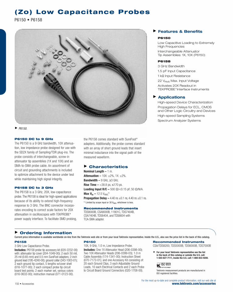
P6150 DC to 9 GHz
The P6150 is a 9 GHz bandwidth, 10X attenua-tion, low impedance probe designed for use withthe SD2X family of Sampling/TDR plug-ins. Theprobe consists of interchangeable, screw-inattenuator tip assemblies (1X and 10X) and anSMA-to-SMA probe cable. An assortment of circuit and grounding attachments is included to optimize attachment to the device under testwhile maintaining high signal integrity.
P6158 DC to 3 GHz
The P6158 is a 3 GHz, 20X, low-capacitanceprobe. The P6158 is ideal for high-speed applicationsbecause of its ability to extend high-frequencyresponse to 3 GHz. The BNC connector incorpo-rates encoding to correct scale factors for 20Xattenuation in oscilloscopes with TEKPROBE®
power supply interface. To facilitate SMD probing,
the P6158 comes standard with SureFoot®
adapters. Additionally, the probe comes standardwith an array of short ground leads that insertminimal inductance into the signal path of themeasured waveform.
Characteristics Nominal Length – 1 m.Attenuation – 10X: ±2%, 1X: ±2%.Bandwidth – 9 GHz, ≥3 GHz.Rise Time – <38.8 ps, ≤170 ps.Loading Input R/C – 500 Ω/<0.15 pF, 50 Ω/N/A.Max Vin – 12.5 VRMS.*1
Propagation Delay – 4.40 ns ±0.1 ns, 4.40 ns ±0.1 ns.*1 Limited by scope input or 30 VRMS, whichever is less.
Recommended Instruments TDS8000B, CSA8000B, 11801C, TDS7404B,CSA7404B, TDS6404, and TDS6604 with TCA-SMA adapter.
Features & Benefits
P6150
Low Capacitive Loading to ExtremelyHigh Frequencies
Interchangeable Attenuator Tip Assemblies: 1X, 10X (P6150)
P6158
3 GHz Bandwidth
1.5 pF Input Capacitance
1 kΩ Input Resistance
22 VRMS Max. Input Voltage
Activates 20X Readout in TEKPROBE™Interface Instruments
Applications High-speed Device Characterization
Propagation Delays for ECL, CMOSand Other Logic Circuitry and Devices
High-speed Sampling Systems
Spectrum Analyzer Systems
(Zo) Low Capacitance ProbesP6150 • P6158
For the most up-to-date and complete product information, visit our web site atwww.tektronix.com/accessories 150 • Accessories
P6150.
P6158 3 GHz Low Capacitance Probe.Includes: P6158 probe tip accessory kit (020-2232-00)with: attenuator tip cover (204-1049-00); 2 each 50 mil,25 mil (0.65 mm) and 0.5 mm SureFoot adapters; 2-inchground lead (195-4240-00); ground collar (343-1003-01);2 each ground tip contact, 5 lengths w/cover shell (016-1077-00); 2 each compact probe tip circuitboard test points; 2 each marker set, various colors (016-0633-00); instruction manual (071-0123-00).
P6150 10X, 9 GHz, 1.0 m, Low Impedance Probe.Includes: One 1X Attenuator Head (206-0398-00);Two 10X Attenuator Heads (206-0399-03); 1.0 mCable Assembly (174-1341-00); Instruction Sheet(070-7173-01); and one Accessory Kit consisting of:20 each Ground Clips, 3 each Adjustable GroundLeads, 10 each Electrical Contacts and 2 each Probeto Circuit Board Ground Connectors (020-1708-00).
Recommended InstrumentsCSA/TDS8200, TDS5000B, TDS6000B, TDS7000B
For your local Tektronix representative see the list in the back of this catalog or outside the U.S. call: 1-503-627-7111, inside the U.S. call: 1-800-833-9200.
Tektronix measurement products are manufactured in ISO registered facilities.
Ordering InformationCurrent price information is available worldwide on-line from the Tektronix web site or from your local Tektronix representative. Inside the U.S., also see the price list in the back of this catalog.

Accessories • 151For the most up-to-date and complete product information, visit our web site atwww.tektronix.com/accessories
The P5200 can be used with any oscilloscopeand enables users to safely make measurementsof floating circuits with their oscilloscope grounded.The P5200 Active Differential Probe convertsfloating signals to low voltage ground referencedsignals that can be displayed safely and easily onany ground referenced oscilloscope.
The P5210 is a Differential Probe that is capableof measuring floating voltages up to 5,600 V (DC +pk AC) safely and has a bandwidth up to50 MHz. It is supplied with two sizes of hook tipsand has an overrange visual and audible indicatorwhich warns the user when they are exceedingthe linear range of the probe. It can be used withTektronix TEKPROBE™ interface oscilloscopesdirectly or with any oscilloscope with the use ofthe 1103 TEKPROBE® Power Supply.
The P5205 is a 100 MHz Active Differential Probecapable of measuring fast rise times of signals infloating circuits. This 1,300 V differential probecan measure safely voltages in IGBT circuitssuch as motor drives or power converters. It isspecifically designed to operate on Tektronixoscilloscopes with TEKPROBE interface.
Features & Benefits Bandwidths up to 100 MHz
Up to 5,600 V Differential (DC +pk AC)
Up to 2,200 V Common (RMS)
Overrange Indicator
Safety Certified
Switchable Attenuation
Switchable Bandwidth Limit
Applications Floating Measurements
Switching Power Supply Design
Motor Drive Design
Electronic Ballast Design
CRT Display Design
Power Converter Design and Service
Power Device Evaluation
High Voltage Differential Probes P5200 • P5205 • P5210
Specifications P5200 P5205 P5210 Bandwidth (-3 dB) 25 MHz 100 MHz 50 MHz Differential Mode Voltage (RMS or DC) 1000 V CAT II 1000 V CAT II 4400 V (between positive and negative input leads)Differential Mode Voltage (Peak)*1 1300 V 1300 V 5600 V(between positive and negative input leads)Common Mode Voltage (RMS or DC + Pk AC) 1000 V CAT II 1000 V CAT II 2200 V CAT II(between positive lead and ground or negative 600 V CAT III 600 V CAT III 1000 V CAT III lead and ground)
Attenuation (switchable) 50X/500X 50X/500X 100X/1000X CMRR @ 60 Hz/1 MHz (typical) 80 dB/50 dB 80 dB/50 dB 80 dB/50 dBInput R (each input) 4 MΩ 4 MΩ 8 MΩInput C (each input) 7 pF 7 pF 7 pF Power Source AC wall adapter TEKPROBE Power Supply TEKPROBE Power Supply Safety (all) UL3111-1/CSA1010.1/CSA1010.2.031/IEC61010-2-031/EN61010-2-031 Compatible Products ALL TDS400/500/600/700/ TDS400/500/600/700/
TDS3000B/5000B/6000B*2/7000B*2/ TDS3000B/5000B/6000B*2/7000B*2/CSA7000B*2 and 11000 Series CSA7000B*2 and 11000 Series
*1 The RMS value of the waveform shall not exceed the Common Mode Voltage (RMS) for either lead.
*2 TDS7154B, TDS7254B, TDS7404B, TDS6404, TDS6604, CSA7154, and CSA7404B require a TCA-1MEG Buffer Amplifier.
Characteristics
P5205. P5200.
P5210.
For your local Tektronix representative see the list in the back of this catalog or outside the U.S. call: 1-503-627-7111, inside the U.S. call: 1-800-833-9200.
NOT AVAILABLE IN EUROPE.
Tektronix measurement products are manufactured in ISO registered facilities.

High Voltage Differential Probes P5200 • P5205 • P5210
152 • AccessoriesFor the most up-to-date and complete product information, visit our web site at
www.tektronix.com/accessories
P5200 Active Differential Probe.Includes: 2 crocodile clips; 2 plunger clips; 9 V DCpower supply; manual (070-9018-01). Please specifypower cord when ordering.
P5205 Active Differential Probe.Includes: 2 each plunger clamps; 2 each crocodileclips; 2 each extender leads; 2 each lead adapters; 2 each plunger hook clips; soft case; manual (070-9472-01).
P5210 Active Differential Probe.Includes: 2 each large hook clips; 2 each small hookclips; 2 each probe heads; soft case; manual (070-9841-01).
Service Opt. C3 – Calibration Service 3 Years.Opt. C5 – Calibration Service 5 Years.Opt. D1 – Calibration Data Report.Opt. D3 – Calibration Data Report 3 Years (with Option C3).Opt. D5 – Calibration Data Report 5 Years (with Option C5).Opt. R3 – Repair Service 3 Years.Opt. R5 – Repair Service 5 Years.Please see the Customer Support page.
For your local Tektronix representative see the list in the back of this catalog or outside the U.S. call: 1-503-627-7111, inside the U.S. call: 1-800-833-9200.
NOT AVAILABLE IN EUROPE.
Tektronix measurement products are manufactured in ISO registered facilities
Ordering InformationCurrent price information is available worldwide on-line from the Tektronix web site or from your local Tektronix representative. Inside the U.S., also see the price list in the back of this catalog.
P5200. P5205. P5210.

The TCA-1MEG high-impedance buffer amplifiersystem extends the capabilities of Tektronix high-performance oscilloscopes, making them ideal for a variety of general-purpose measurements.The TCA-1MEG amplifier system provides a1 MΩ path that is easily removed and replacedwith a wide array of TekConnect probes, amplifiersand adapters.
This amplifier system delivers versatility toTektronix high-performance oscilloscopes throughthe addition of input coupling (selectable), band-width limit (selectable), and a 1 MΩ input thatprovides access to a wide array of measurementsolutions. These solutions include general-purposepassive probes, high voltage probes (passive single-ended and active differential), micro-voltdifferential probes and current probes.
With this tool, Tektronix high-performance oscillo-scopes may now perform measurements such asprimary and secondary power supply voltage levels,currents and elevated voltages, and assess thepower requirements of the device-under-test.
For today’s high-speed measurement solutions,having the 50 Ω and 1 MΩ terminations on the same input path compromises signal fidelity.By making the 1 MΩ path replaceable, the TCA-1MEG high impedance buffer amplifier systemeliminates a permanent degradation of the high-speed signal path. This also allows users to easilyand quickly configure each channel for the inputcharacteristics required for their measurements.By exchanging the TCA-1MEG for a high-performance50 Ω path or other high-speed probing solution,maximum signal fidelity is maintained at the oscilloscope’s input.
Features & Benefits Bandwidth – DC to ≥500 MHz
Input Impedance – 1 MΩ/10 pF
Bandwidth Limiting –Full/100 MHz/20 MHz
Input Coupling – DC/AC/GND
Includes P6139A, 500 MHz, 10XPassive Probe
TekConnect Interface DeliversSuperior Signal Fidelity, UnparalleledVersatility and Ease-of-use
Applications Verification, Characterization andDebug of Sophisticated Designs in Communications, Computer and Semiconductor ElectronicEnvironments – Jitter and Timing Analysis
(Computer Systems) – Disk Drive Analysis – Investigation of Transient
Phenomena – Spectral Analysis – Power Supplies/Inverters
(Switching and Linear) – Semiconductor Devices (SCRs,
IGBTs, FETs, CMOS) – Electronic Ballasts – Industrial/Consumer Electronics – Mobile Communications
(Phone, Satellite, Relay Stations) – Motor Drives – Transportation Systems
(Electronic Vehicles, Electric Trains,Locomotives, Avionics)
High-impedance Buffer Amplifier System TCA-1MEG
Accessories • 153For the most up-to-date and complete product information, visit our web site atwww.tektronix.com/accessories
For your local Tektronix representative see the list in the back of this catalog or outside the U.S. call: 1-503-627-7111, inside the U.S. call: 1-800-833-9200.
Tektronix measurement products are manufactured in ISO registered facilities.
TekConnect® TCA-1MEG Buffer Amplifier SystemExpands the Functionality of Tektronix High-performance Oscilloscopes

Characteristics Nominal
Inputs – 1 (TEKPROBE™ BNC 1 MΩ).Input Coupling – DC, AC or GND.
Dimensionsmm in.
Length 180.08 4.255 Width 31.5 1.240 Height 46.1 1.815
Safety Certifications U.S. NRTL Listing –UL3111-1. UL3111-2-032.Canadian Certification – CAN/CSA C22.2No.1010.1. CAN/CSA C22.2 No.1010.2.032.European Union Compliance – EN61010-1/A2.EN61010-2-032.Other – IEC61010-1/A2. IEC61010-2-032.GPIB Programmable – Through Host Instrument Commands.Power Requirements – TekConnect.Adapter Model Compatibility – Refer toTDS7000 Series TekConnect Adapters Compatibility Table.Warranty – One year.
High-impedance Buffer Amplifier System TCA-1MEG
154 • AccessoriesFor the most up-to-date and complete product information, visit our web site at
www.tektronix.com/accessories
TCA-1MEG High-impedance Buffer Amplifier System.Service Options Opt. C3 – Calibration Service 3 Years.Opt. C5 – Calibration Service 5 Years.Opt. D1 – Calibration Data Report.
Opt. D3 – Calibration Data Report 3 Years (with Option C3).Opt. D5 – Calibration Data Report 5 Years (with Option C5).Opt. R3 – Repair Service 3 Years.Opt. R5 – Repair Service 5 Years.
For your local Tektronix representative see the list in the back of this catalog or outside the U.S. call: 1-503-627-7111, inside the U.S. call: 1-800-833-9200.
Tektronix measurement products are manufactured in ISO registered facilities
Ordering InformationCurrent price information is available worldwide on-line from the Tektronix web site or from your local Tektronix representative. Inside the U.S., also see the price list in the back of this catalog.
Bandwidth (–3 dB) DC to ≥500 MHz (in a host instrument with bandwidth >1.5 GHz)
Probe Tip Bandwidth (with P6139A at –3 dB) DC to ≥500 MHz (host instrument bandwidth >1.5 GHz) BW Limit Full, 100 MHz ±25%, 20 MHz ±25% DC Gain Accuracy ±3% (TCA-1MEG with or without P6139A probe)*1
Propagation Delay (input-to-output) <2 ns Input Impedance 1 MΩ/10 pF (at DC) Maximum Input Voltage (derated with frequency) 150 VRMS CAT I
100 VRMS CAT IIAbove 200 kHz derate at 20 dB per decade;
limit to 13 Vpk AC at 3 MHz and above
*1 Probe calibration required in TekConnect® host instrument.
Model Specifications
Displayed System Input Offset ±0.2 div Rise Time (calculated small signal tr = 0.4/F3 dB) ≤0.8 ns (minimum rise time) Linear Dynamic Range The lesser of ±5 divisions or the dynamic
range of the TekConnect host instrument Linearity ±0.2%
Typical

TekConnect® Amplifier, Adapters and Probes Compatibility*1
Accessories • 155For the most up-to-date and complete product information, visit our web site atwww.tektronix.com/accessories
TekConnect® Amplifier, Adapters and Probes Compatibility*1
Accessory Oscilloscope TekConnect Amplifiers, Adapters and ProbesType TDS6000B TDS/CSA7000B TekConnect Series
6 GHz 4 GHz 1.5 GHz TCA-1MEG TCA-BNC TCA-SMA TCA-N TCA758 GHz 2.5 GHz High Adapter Adapter Adapter Adapter
Impedance (Standard (Standard Buffer with with
Amplifier w/TDS7154/ TDS7404/(P6139A TDS7254/ CSA7404)Included) CSA7154)
Instrument Input TekConnect® Interface TEKPROBE™ TEKPROBE BNC SMA-to- N-to- 75 to 50 ΩConnection BNC 1 MΩ-to- 50 Ω-to- TekConnect TekConnect TekConnect
TekConnect TekConnect Interface Interface AdapterInterface Interface
Instrument Input TekConnect Interface Probes, Amplifier and 1 MΩ/10 pF 50 Ω 50 Ω 50 Ω 50 ΩImpedance Adapter DependentPassive Voltage P6101B w/TCA-1MEG P6101B N/A N/A N/A N/AProbes (1X)Passive Voltage P6139A w/TCA-1MEG P6139A N/A N/A N/A N/AProbes (10X)50 Ω Divider P6150 w/TCA-SMA N/A P6158 P6150 N/A N/AVoltage Probes P6158 w/TCA-BNC
Active Voltage P6245 w/TCA-BNC N/A P6245 N/A N/A N/AProbes General P6243 w/TCA-BNC P6243
Active Voltage P7260*2, P7240*2 P7225*2, P7240*2 N/A P6249 N/A N/A N/AProbes >2 GHz P6249 w/TCA-BNC P6249 w/TCA-BNC P6241
P6241 w/TCA-BNC P6241 w/TCA/BNC*1 Firmware version 2.1 or greater required for all referenced oscilloscopes.*1 P7225, P7240, P7260, P7330, P7350SMA, P7380 and P7380SMA are high-speed active and differential probing solutions
Please refer to TekConnect Amplifier data sheet for more information about amplifiers.

TekConnect® Amplifier, Adapters and Probes Compatibility*1
156 • AccessoriesFor the most up-to-date and complete product information, visit our web site at
www.tektronix.com/accessories
TekConnect® Amplifier, Adapters and Probes Compatibility*1 (continued)
Accessory Oscilloscope TekConnect Amplifiers, Adapters and ProbesType TDS6000B TDS/CSA7000B TekConnect Series
6 GHz 4 GHz 1.5 GHz TCA-1MEG TCA-BNC TCA-SMA TCA-N TCA758 GHz 2.5 GHz High Adapter Adapter Adapter Adapter
Impedance (Standard (Standard Buffer with with
Amplifier w/TDS7154/ TDS7404/(P6139A TDS7254/ CSA7404)Included) CSA7154)
Differential Voltage P7380*2 P7380*2 P7350*2 N/A P6330 N/A N/A N/AProbes >2 GHz P7380SMA*2 P7380SMA*2 P7350SMA*2
P7350*2 P7350*2 P7330*2
P7350SMA*2 P7350SMA*2 P6330 w/TCA-BNCP6330 w/TCA-BNC P7330*2
P6330 w/TCA-BNCDifferential P6248 w/TCA-BNC N/A P6248 N/A N/A N/AVoltage Probes P6247 w/TCA-BNC P6247<1.8 GHz P6246 w/TCA-BNC P6246<8 V LogicDifferential Voltage ADA400A w/TCA-1MEG ADA400A N/A N/A N/A N/AProbes Micro-voltHigh Voltage Probes P5205 w/TCA-1MEG P5205 N/A N/A N/A N/ADifferential P5210 w/TCA-1MEG P5210High Voltage Probes P5100 w/TCA-1MEG P5100 N/A N/A N/A N/ASingle-ended P6015A w/TCA-1MEGCurrent Probe TCP202 w/TCA-BNC N/A TCP202 N/A N/A N/AAC/DC <15 ACurrent Probe TCP300/TCP400/AM5030S w/TCA-BNC or TCA-1MEG TCP300/TCP400/ TCP300/TCP400/ N/A N/A N/AAC/DC AM5030S AM5030S5 mA to 20 ACurrent Probe CT6 w/TCA-BNC N/A CT6 N/A N/A N/AAC High Frequency CT1 w/TCA-BNC CT1Current Probe P6021 w/TCA-1MEG P6021 N/A N/A N/A N/AAC Low Frequency P6022 w/TCA-1MEG P6022O/E Converter P6701B w/TCA-BNC N/A P6701B N/A N/A N/AProbes P6703B w/TCA-BNC P6703B*1 Firmware version 2.1 or greater required for all referenced oscilloscopes.*2 P7225, P7240, P7260, P7330, P7350SMA, P7380 and P7380SMA are high-speed active and differential probing solutions
Please refer to TekConnect Amplifier data sheet for more information about amplifiers.

The TekConnect interface ensures superior signalfidelity with useful bandpass up to 18 GHz at theTDS/CSA7000B and TDS6000 series oscilloscopeinputs, while offering unparalleled versatility withthe world’s widest array of accessory signalacquisition solutions for high-performance, real-time oscilloscopes. This interface delivers a morerobust oscilloscope interface for next-generationproducts with multi-GHz analog bandwidths, over-coming many of the inherent bandwidth limitationsof BNC-based interfaces. The TekConnect interfacepreserves a low voltage standing wave ratio (VSWR)50 Ω environment as well as a reliable electricalconnection. A convenient, one-button release andlocking mechanism provides quick, easy installationand removal of probes, amplifiers, and adapters.
TekConnect TCA SeriesAdapters Expand theFunctionality of TektronixHigh-performanceOscilloscopesThis family of adapter systems provides less signal distortion and better performance than traditional connections used to move a signalfrom one environment to another, such as BNC to N or BNC to SMA.
TCA75 Adapter (75 to 50 Ω)
The TCA75 adapter allows Tektronix oscilloscopeswith TekConnect interface to easily access andmeasure 75 Ω terminated circuitry. The TCA75’sattenuation factor is automatically corrected toprovide the end user with correctly displayed signal magnitudes.
TCA-BNC Adapter (50 Ω only)
A direct 50 Ω input with TEKPROBE BNC 50 Ωcapability, this adapter may be used as a direct50 Ω BNC input or with Tektronix high-speedactive and differential probes requiring theTEKPROBE BNC 50 Ω interface.
TCA-SMA and TCA-N Adapters(50 Ω only)
The high-speed SMA and N type adapters allow a more direct connection to the signal under test requiring N or SMA connections without losing performance by adding other external conversion adapters.
Features & Benefits TCA75 – TekConnect-to-75 Ω BNC – DC to ≥4 GHz (Instrument
Dependent) – VSWR - 1.1:1 (26.45 dB) – 75 Ω Input – Auto Attenuation Factor Correction
TCA-BNC – TekConnect-to-TEKPROBE™ BNC 50 Ω– DC to ≥4 GHz (Instrument
Dependent) – 50 Ω Input (Only) – Probe Control TEKPROBE BNC (50 Ω)
TCA-SMA – TekConnect-to-SMA – DC to ≥18 GHz (Instrument
Dependent) – 50 Ω Input (Only)
TCA-N – TekConnect-to-N – DC to ≥11 GHz (Instrument
Dependent) – 50 Ω Input (Only)
Applications Signal Integrity, Jitter, and Timing Analysis
Verification, Characterization, andDebug of Sophisticated Designs
High-speed Digital Devices and Circuits
Power Supplies/Inverters
Semiconductor Devices
Electronic Ballasts
Industrial/Consumer Electronics
Mobile Communications
Motor Drives
Transportation Systems
Disk Drive Analysis
Investigation of Transient Phenomena
Spectral Analysis
Video Design and Development – HDTV and Streaming Digital Video
TekConnect® Adapters TCA75 • TCA-BNC • TCA-SMA • TCA-N NEW
Accessories • 157For the most up-to-date and complete product information, visit our web site atwww.tektronix.com/accessories
For your local Tektronix representative see the list in the back of this catalog or outside the U.S. call: 1-503-627-7111, inside the U.S. call: 1-800-833-9200.
Tektronix measurement products are manufactured in ISO registered facilities.
TekConnect Interface Delivers Superior SignalFidelity, Unparalleled Versatility, and Ease-of-Use

TekConnect® Adapters TCA75 • TCA-BNC • TCA-SMA • TCA-N
158 • AccessoriesFor the most up-to-date and complete product information, visit our web site at
www.tektronix.com/accessories
Model Specification TCA75 TCA-BNC TCA-SMA TCA-N Attenuation Accuracy at DC 2.46X ±1.5% Refer to Host Instrument Specification Input Resistance at DC 75 Ω ±1.5% 50 Ω 50 Ω 50 ΩTypical Bandwidth (–3 dB) DC to 4 GHz (Adapter Only) DC to 4 GHz DC to ≥18 GHz DC to ≥11 GHz
(Maximum Frequency) (Maximum Frequency) (Maximum Frequency)(Limited By Host Instrument) (Limited By Host Instrument) (Limited By Host Instrument)
Propogation Delay (Input-to-Output) <200 ps RMS Noise Refer to Host Instrument Specification VSWR (Return Loss) 1.1:1 (26.45 dB) 1.15:1 (23.13 dB) 1.05:1 + 0.01 x F 1.3:1 (17.7 dB)
(in GHz) (32.25 dB)RF Insertion Loss 6.05 dB (Adapter Only) 0.25 dB Max (Adapter Only) 0.06*SQRT F (GHz) (Adapter Only) 0.3 dB Max (Adapter Only) Rise Time <100 ps*1 (Minimum Rise Time) ≤100 ps (Minimum Rise Time) ≤22 ps (Minimum Rise Time) ≤36 ps (Minimum Rise Time)
(Limited By Host Instrument) (Limited By Host Instrument) (Limited By Host Instrument) (Limited By Host Instrument)Maximum Input Voltage ≤12 V DC or ≤12 VRMS (2 W Max.) Refer to Host Instrument Specification (Derated with Frequency)Nominal Inputs 1 (BNC 75 Ω) 1 (TEKPROBE® BNC 50 Ω) 1 (SMA 50 Ω) 1 (N 50 Ω) Adapter Model Compatibility Refer to TekConnect Amplifier, Adapters and Probes Compatibility Table Warranty 1 Year
*1 Calculated Small Signal t1 = 0.4/F3 dB.
Characteristics
TCA75 TekConnect-to-75 Ω Adapter.
TCA-BNC TekConnect-to-BNC Adapter.
TCA-SMA TekConnect-to-SMA Adapter.
TCA-N TekConnect-to-N Adapter.All Include: Instruction Manual and Certificate of Compliance.
For your local Tektronix representative see the list in the back of this catalog or outside the U.S. call: 1-503-627-7111, inside the U.S. call: 1-800-833-9200.
Tektronix measurement products are manufactured in ISO registered facilities
Ordering InformationCurrent price information is available worldwide on-line from the Tektronix web site or from your local Tektronix representative. Inside the U.S., also see the price list in the back of this catalog.

The TCP300 and TCP400 series AC/DC CurrentMeasurement family is a highly advanced currentmeasurement system for today’s current measure-ment needs. The split-core probes incorporate bothtransformer and Hall effect technology to providebroad bandwidth measurement capabilities fromDC up to 100 MHz at current levels as low as1 milliamp to thousands of amps (when used withCT4 current transformer). When connected toTektronix TDS Oscilloscopes with TEKPROBE™ Level IIor TekConnect® (w/TCA-BNC) interfaces, currentmeasurements and calculations are simple and easy.
Additional measurement power is available withadd on software such as the TDSPWR2 powermeasurements package. With all this measure-ment power, current measurements have neverbeen easier.
Meets Today’s AC/DC CurrentMeasurement Applications
The TCPA300 amplifier, when used with TCP312,TCP305, or TCP303 probes, provide a wide rangeof current measurement capability and spans thegap between low level milliamp measurements tovery high current levels. These three probes providecurrent measurement capabilities of 30A, 50A,and 150A DC continuous. For even higher currentlevels, the TCPA400 amplifier with the TCP404XLcurrent probe measures 500A DC continuous and750A DC continuous, derated with duty cycle.
Higher frequency performance is available withthe TCP312 w/TCPA300 providing ≥100 MHzbandwidth and a maximum current of 30A DC.
Measurement Errors andManual Calculations are Now a Thing of the Past
With this new series of current measurementtools, automatic control and on-screen scalingand units is provided for users of TektronixTDS3000, TDS400A, TDS500, TDS600, TDS700,TDS5000, TDS6000, and TDS7000 series oscillo-scope systems. Status LEDs quickly show youTCP300/400 series operating status or potentialerror conditions that may have caused measure-ment errors in the past.
The TCP300/TCP400 Current MeasurementSystems seamlessly integrate with your TDSseries oscilloscope and the TDSPWR2 softwarepackage to easily make those time consumingpower measurements and calculations for you.
Even non-TEKPROBE systems can use theTCPA 300/400 series to make proper currentmeasurements by simply multiplying the meas-ured output voltage on the oscilloscope by theTCPA 300/400 series range setting.
Features & Benefits AC / DC Measurement Capabilities
DC – 100 MHz, Current ProbeAmplifier (TCPA300) Uses: – DC – 100 MHz, 30 A DC (TCP312) – DC – 50 MHz, 50 A DC(TCP305) – DC – 15 MHz, 150 A DC (TCP303)
DC – 50 MHz, Current Probe Amplifier(TCPA400) Uses: – DC – 2 MHz, 750*1 A DC
(TCP404XL) (500 A DC Continuous)
Direct Scaling and Units*2 –Oscilloscope On-screen ReadoutReduces Measurement Errors byEliminating Hand Calculations
AC / DC Input Coupling
Low Insertion Impedance ReducesDevice Under Test Loading
Small Mechanical Package – LessDesktop Space, Easier Storage and Handling
Split-Core Construction Allows EasyCircuit Connection
Status Indicators Provide Notificationof Potential Error Conditions
Lower DC Drift and Noise
Certified for U.S., Canada, and Europe
Applications Development and Analysis for: – Power Supplies – Semiconductor Devices– Power Inverters/Converters – Electronic Ballasts – Industrial /Consumer Electronics – Mobile Communications – Motor Drives – Transportation Systems
*1 Derated with Duty Cycle.
*2 Requires a TDS TEKPROBE Oscilloscope or a TekConnectOscilloscope with TCA-BNC.
AC/DC Current Measurement Systems TCPA300 • TCP312 • TCP305 • TCP303 • TCPA400 • TCP404XL
Accessories • 159For the most up-to-date and complete product information, visit our web site atwww.tektronix.com/accessories
For your local Tektronix representative see the list in the back of this catalog or outside the U.S. call: 1-503-627-7111, inside the U.S. call: 1-800-833-9200.
Increased Performance and Simplicity

AC/DC Current Measurement Systems TCPA300 • TCP312 • TCP305 • TCP303 • TCPA400 • TCP404XL
160 • AccessoriesFor the most up-to-date and complete product information, visit our web site at
www.tektronix.com/accessories
TCP312 w/TCPA300 TCP305 w/TCPA300 TCP303 w/TCPA300 TCP404XL w/TCPA400 Bandwidth (–3 dB) DC to 100 MHz DC to 50 MHz DC to 15 MHz DC to 2 MHz *1
Rise Time ≤3.5ns ≤7ns ≤23ns ≤175ns Maximum Current Ratings:High Current Sensitivity Range 10 A/V Range 10 A/V Range 50 A/V Range 1A/mV RangeDC (continuous) 30 A 50 A 150 A 500 A (750 A*2)RMS (sinusoidal) 21.2 A 35.4 A 150 A 500 APeak Pulse 50 A 50 A 500 A 750 A Low Current Sensitivity Range 1 A/V Range 5 A/V Range 5 A/V Range N/A DC (continuous) 5 A 25 A 25 ARMS (sinusoidal) 3.5 A 17.7 A 17.7 APeak Pulse 50 A 50 A 500 ADC Accuracy ±3% of reading ±3% of reading ±3% of reading (10 ºC to 50 ºC) ±3% of reading(Operating temp 0 ºC to 50 ºC) +3%/–6% of reading (0 ºC to <10 ºC) DC Accuracy, Typical ±1% of reading ±1% of reading ±1% of reading ±1% of reading (Operating temp 23 ºC ±5 ºC)Nominal Maximum Bare Wire Voltage For Use With Insulated Wires Only 600VRMS CAT I and II, 300VRMS CAT III Lowest Measurable Current 1 mA 5 mA 5 mA 1 mA(at ±3% accuracy at DC) Scope Set To 1mV/div and Scope Set To 1 mV/div and
20 MHz BW Limited 20 MHz BW LimitedInsertion Impedance 0.08 Ω at 1 MHz 0.035 Ω at 1 MHz 0.01 Ω at 1 MHz 0.1 Ω at 10 kHz(See Curves Below) 0.15 Ω at 10 MHz 0.12 Ω at 10 MHz 0.025 Ω at 5 MHz 0.6 Ω at 100 kHz
0.27 Ω at 50 MHz 0.4 Ω at 50 MHz 0.1 Ω at 15 MHz 8 m Ω at 1 MHz0.7 Ω at 100 MHz 16 m Ω at 2 MHz
Typical Maximum Amp-Second Product 50 A*µS to 1 A/V 500 A*µS to 10 A/V 3,000 A*µS to 5 A/V NA to 1 A/mV(Based on Amplifier Range setting) 500 A*µS to 10 A/V NA to 10 A/V 15,000 A*µS to 50 A/VAC Coupling Low Frequency <7 HzBandwidth (Low Pass - 3 dB point)Displayed RMS Noise ≤250 µARMS ≤1.25 mARMS ≤2.5 mARMS ≤250 mARMS(at 20 MHz Bandwidth Limit)Signal Delay (Delay to Output BNC) 17 ns 19 ns 53 ns 103 ns Inputs (probe amplifier) 1 Probe Open Indicator YES Overload Indicator YES Termination Indicator YES Non-Compatible Probe Indicator YES Safety Certifications U.S. NRTL Listing UL3111-1 (Amplifier) UL3111-2-032; UL3111-1 (Probe and Amplifier)Canadian Certification CAN/CSA C22.2 No.1010.1 (Amplifier) CAN/CSA C22.2 No.1010.2.032
CAN/CSA C22.2 No.1010.1 (Probe and Amplifier)European Union Compliance EN61010-1/A2 (Amplifier) EN61010-1/A2; EN61010-2-032; EN61010-1/A2
(Probe and Amplifier) Other IEC61010-1/A2 (Amplifier) IEC61010-2-032; IEC61010-1/A2 (Probe and Amplifier) Electromagnetic Compatibility Meets: EC Council Directive 89/336/EEC, FCC Part 15, Subpart B Class A, AS/NZS 2064.1/2 Power Requirements 90 V to 264 V; 47 to 440 Hz; 50 W(TCPA300/TCPA400 Amplifiers) Maximum CAT II (Auto Switch) Power Requirements (Probes) Requires TCPA300 Amplifier Requires TCPA300 Amplifier Requires TCPA300 Amplifier Requires TCPA400 Amplifier Probe Model TCP312 TCP305 TCP303 TCP404XL Warranty 1 Year
Characteristics

AC/DC Current Measurement Systems TCPA300 • TCP312 • TCP305 • TCP303 • TCPA400 • TCP404XL
Accessories • 161For the most up-to-date and complete product information, visit our web site atwww.tektronix.com/accessories
TCP312 Probe; AC/DC Current, DC to 100 MHz; 30A DC(Requires TCPA300 Amplifier).
TCP305 Probe; AC/DC Current, DC to 50 MHz; 50A DC(Requires TCPA300 Amplifier).
TCP303 Probe; AC/DC Current, DC to 15 MHz; 150A DC(Requires TCPA300 Amplifier).
TCP404XL Probe; AC/DC Current, DC to 2 MHz; 500A DC (750A DC De-rated With Duty Cycle) (RequiresTCPA400 Amplifier).
All TCP300/TCP400 Current Probes Include:AC/DC Current Probe; Instruction Sheet; Probe Cover;Certificate of Traceable Calibration.
TCPA300 Amplifier; AC/DC Current Probe, DC to 100 MHz,(Requires TCP305 or TCP312 or TCP303 Probes).
TCPA400 Amplifier; AC/DC Current Probe, DC to 50 MHz,(Requires TCP404XL Probe).All TCPA300/TCPA400 Current Probe AmplifiersInclude: AC/DC Current Probe Amplifier;Instruction/Service Manual; TEKPROBE™ InterfaceCable; Male to Male BNC cable (50 Ω); 50 Ω feed-through termination; Certificate of Traceable Calibration.
All TCP300/TCPA300/TCP400/TCPA400 Series
Service Options Opt. C3 – Calibration Service 3 Years.Opt. C5 – Calibration Service 5 Years.Opt. D1 – Calibration Data Report.Opt. D3 – Calibration Data Report 3 Years (with Option C3).Opt. D5 – Calibration Data Report 5 Years (with Option C5).Opt. R3 – Repair Service 3 Years.Opt. R5 – Repair Service 5 Years.
For your local Tektronix representative see the list in the back of this catalog or outside the U.S. call: 1-503-627-7111, inside the U.S. call: 1-800-833-9200.
Ordering InformationCurrent price information is available worldwide on-line from the Tektronix web site or from your local Tektronix representative. Inside the U.S., also see the price list in the back of this catalog.
Characteristics (cont’d)
TCP312 w/TCPA300 TCP305 w/TCPA300 TCP303 w/TCPA300 TCP404XL w/TCPA400 Probe Mechanical Characteristics Probe Cable Length 1.5 meters (60 inches) 2 meters (78.7 inches) 8 meters (315 inches) Probe Jaw Size (Max Conductor Size) 3.8 mm (0.15 inches) 21 mm x 25 mm (0.83x1.0 inches) Length: 20 cm (7.87 inches) 26.8 cm (10.55 inches) 26.8 cm (10.55 inches)Width: 1.6 cm (0.625 inches) 4.1 cm (1.60 inches) 4.1 cm (1.60 inches)Height: 3.2 cm (1.25 inches) 15.6 cm (6.13 inches) 15.6 cm (6.13 inches)Weight: 0.15 kg (0.33 lb) 0.66 kg (1.45 lb) 0.88 kg (1.90 lb) TCPA300 and TCPA400 Mechanical Characteristics Length: 17.3 cm (6.8 in)Width: 16.7 cm (6.6 in)Height: 9.14 cm (3.6 in)Weight: 1.14 kg (2.5 lb)
*1 Calculated from Rise Time.
*2 Derated w/ duty cycle and frequency.

TCP202 DC Coupled Current Probe
When combined with a Tektronix TDS oscilloscope,the TCP202 enables users to make direct readoutDC and AC current measurements, resulting inaccurately displayed and recorded measurements.
The TCP202 is a general-purpose probe for displaying and measuring current in electroniccircuits. It is ideal for power supply and motordrive design, and for device testing.
CharacteristicsBandwidth – DC to 50 MHz.Max DC + Peak AC Current – 15 A.Max Peak Pulse Current – 50 A.Minimum Sensitivity – 10 mA/div.DC Accuracy – ±1% (with probe calibrator).±3% (without probe calibrator).Max Bare Wire Voltage – 300 V (CAT I).
Typical Characteristics Insertion Impedance – 0.002 Ω at 1 kHz.0.1 Ω at 5 MHz.Propagation Delay – 17 ns.Max Conductor Diameter – 3.8 mm (0.15 in.).Electrostatic Immunity – (per IEC 801-2) >8 kV.Ampere-Sec Product – 500 x 10-6 Amp*Sec.Rise Time – ≤7.0 ns.
Physical Characteristics Weight – 0.19 kg (0.44 lbs.).Cable Length – 2.2 m (7.2 ft.).Power Requirements – TCP202 is powered by theTDS oscilloscope via the TEKPROBE interface.
Safety UL 3111-1, CSA1010.1, EN61010-1, IEC61010-1,EN61010-2-032, IEC61010-2-032.
Recommended Oscilloscopes TDS520B; TDS520C; TDS520D; TDS540B; TDS540C;TDS540D; TDS580C; TDS580D; TDS654C; TDS680C;TDS684C; TDS694C; TDS724A; TDS724C; TDS724D;TDS744A (S/N B040100 or higher); TDS754A; TDS754C;TDS754D; TDS784A (S/N B040100 or higher); TDS784C;TDS784D; TDS794D; TDS3000 Series; TDS3000B Series;TDS5000 Series; TDS5000B Series; TDS6000 Seriesand TDS6000B Series with TCA-BNC adapter; TDS7000Series and TDS7000B Series with TCA-BNC adapter.For TCP202 operation with other TDS400, TDS500,TDS600 and TDS700 Series oscilloscopes, the scalefactor will be correct but measurement will be indicatedas V instead of A.
DC Coupled Current Probe TCP202
162 • AccessoriesFor the most up-to-date and complete product information, visit our web site at
www.tektronix.com/accessories
Features & BenefitsEasy Current Measurements
Probe Connects Directly to TDSScope through TEKPROBE™
BNC Interface
Split Core Construction for EasyCircuit Connection
DC to 50 MHz Bandwidth
15 Amps DC + Peak AC Current
50 Amps Peak Pulse Current
500 x 10-6 Ampere-Sec Product
Safety Certified
Applications Motor Drives
Switching Power Supplies
Disk Drive
Electronic Ballasts
Inverters
Avionics
TCP202.
Ordering InformationCurrent price information is available worldwide on-line from the Tektronix web site or from your local Tektronix representative. Inside the U.S., also see the price list in the back of this catalog.
TCP202 DC Coupled Current Probe.Includes: Instruction manual (070-9542-02),reference manual (070-9543-03).
For your local Tektronix representative see the list in the back of this catalog or outside the U.S. call: 1-503-627-7111, inside the U.S. call: 1-800-833-9200.
Tektronix measurement products are manufactured in ISO registered facilities.

P6021 and P6022Current Probes
The P6021 and P6022 Current Probes provide versatile AC current measurements. Both probesprovide accurate current measurements over awide range of frequencies. The P6021 and P6022allow current measurements without breaking thecircuit by clipping onto the current carrying conductor.Shielded probe heads are not grounded when theslides are in their open positions, eliminating acci-dental grounding of the circuit under test.
P6021 Current Probe
For general purpose applications, the P6021 provides wide-band performance with excellentlow-frequency characteristics. Bandwidth is120 Hz to 60 MHz. The passive termination isswitchable from 2 mA/mV to10 mA/mV.
P6022 Current Probe
With a head size of 0.47 in. x 0.25 in. (10 mm x6 mm, about half the size of the P6021) and abandwidth of 935 Hz to 120 MHz, the P6022 isideal for measuring currents in compact, high-performance circuits. Passive termination outputis switchable between 1 mA/mV or 10 mA/mV.
Characteristics
Safety UL3111-2-032, CSA1010.2.032, EN61010-2-032,IEC61010-2-032.
AC Current Probes P6021 • P6022
Accessories • 163For the most up-to-date and complete product information, visit our web site atwww.tektronix.com/accessories
P6021 and P6022 AC Current Probes.
Ordering InformationCurrent price information is available worldwide on-line from the Tektronix web site or from your local Tektronix representative. Inside the U.S., also see the price list in the back of this catalog.
Features & Benefits
P6021
120 Hz to 60 MHz
15 A Peak
For 1 MΩ Inputs
Shielded Probe Heads
AC Only
Split Core
P6022
935 Hz to 120 MHz
6 A Peak
For 1 MΩ Inputs
Shielded Probe Heads
AC Only
Split Core
Applications Motor Drives
Inverters
Power Supply
Avionics
P6021 5 ft. Current Probe with Termination.Includes: 6 in. ground lead (196-3120-xx); instructionmanual (070-0947-xx).
P6022 5 ft. Current Probe with Termination.Includes: Same as the P6021; instruction manual(070-0948-xx).Passive Termination Only–(P6021) – Order 011-0105-xx.(P6022) – Order 011-0106-xx.
For your local Tektronix representative see the list in the back of this catalog or outside the U.S. call: 1-503-627-7111, inside the U.S. call: 1-800-833-9200.
Tektronix measurement products are manufactured in ISO registered facilities.

Oscilloscope & Probe Accessories
164 • AccessoriesFor the most up-to-date and complete product information, visit our web site at
www.tektronix.com/accessories
IntroductionTektronix has the right test accessories for your application. Your oscilloscope and othermeasurement tools are only as good as the datathey receive from probes and other input devices.
Tektronix offers a complete set of high performance probing solutions and a wide range of other accessories.
LAN and Communication Adapters (ADA007,AFTDS, AMT75).
Articulated Probe Arms (PPM100).
Surface Mount Device Interconnects (SMG50,SMCK4, ST501, SF501,SF502, SF503, SF201A,SF202A, SF203A).
Oscilloscope & Probe Accessories
Differential Signal Adapters . . . . . . . .165
75 Ω Adapter . . . . . . . . . . . . . . . . . .165
LAN and Communication Adapters . . . . . . . . . . . . . . . . . . . . .166
Surface Mount Interconnects . . . . . . . . . . . . . . . . . .167
Articulated Probe Arms . . . . . . . . . . .168
2.5 mm Probe Accessories . . . . .169-170
3.5 mm Probe Accessories . . . . .169-170
5 mm Probe Accessories . . . . . .169-170
Replacement Parts . . . . . . . . . . . . . .171
Carts . . . . . . . . . . . . . . . . . . . . . . . .172
Transit Case . . . . . . . . . . . . . . . . . . .172

Probe AccessoriesAFTDS • AMT75
Accessories • 165For the most up-to-date and complete product information, visit our web site atwww.tektronix.com/accessories
The AFTDS Differential Signal Adapter and theAMT75 75 Ω Adapter provide an effective meansfor 50 Ω terminated instruments to connect to,and analyze differential and high speed electricalcommunication signals, as well as video signals.
Both adapters are rugged and have theTEKPROBE interface, which provides convenientauto-scaling of waveforms on Tektronix TDSSeries oscilloscopes. Also, the low VSWR (ReturnLoss) performance minimizes measurement errorscommonly associated when interfacing with complex electrical signals.
Ideal for use in pulse shape compliance testing ofhigh-speed electrical communication signals.
Characteristics AFTDS Differential SignalAdapter Electrical Standards – DS-1: (1.544 Mb/s) DS-1A: (2.048 Mb/s) DS-1C: (3.152 Mb/s) DS-2: (6.312 Mb/s) E-1: (2.048 Mb/s).
Standards of Compliance – ANSI T1.102,ITU-T G7.03.Bandwidth (–3 dB) – 7 kHz to 120 MHz.Rise Time – <3.0 ns.Attenuation – 5x, (–14 dB) ±5.0% (valid over 50 kHzto 30 MHz).Droop – ≤2.0% per 700 ns.VSWR (return loss) – ≤1.1:1 (≥26 dB), typical (validover 50 kHz to 30 MHz).
AFTDS Features TEKPROBE Interface – Auto-scaling and auto-termination with Tektronix TDS scopes.Input Impedance – 100 Ω, 110 Ω or 120 Ω ±3.0%(selectable). (Valid over 50 kHz to 30 MHz.) Load Impedance – 50 Ω ±3.0%.Safety – UL3111-1, CSA1010.1, EN61010-1,IEC61010-1 (AFTDS only).
AMT75 75 Ω ADAPTER Electrical Standards – DS-3: (44.736 Mb/s).DS-4: (139.264 Mb/s).STS-1: (51.84 Mb/s).STS-3: (155.51 Mb/s).STM-1: (155.51 Mb/s).E-2: (8.448 Mb/s).E-3: (34.368 Mb/s).E-4: (139.264 Mb/s).D-1: (270 Mb/s).D-2: (143 Mb/s).Standards of Compliance – ANSI T1.102,ITU-T G.957, ITU-T G7.03, Bellcore GR-253-CORE.Bandwidth (–3 dB) – DC to 1.0 GHz (typical).Rise Time – <350 ps (typical).Attenuation – 5X, (–14 dB) ±2.0%.VSWR (return loss) – ≤1.1:1 (≥26 dB), up to 1 GHz (typical).TEKPROBE Interface – Auto-scaling and auto-termination with Tektronix TDS scopes.Input Impedance – 75 Ω ±1.5%.Output Impedance – 50 Ω ±1.5%.
Ordering InformationCurrent price information is available worldwide on-line from the Tektronix web site or from your local Tektronix representative. Inside the U.S., also see the price list in the back of this catalog.
Features & Benefits
AFTDS Differential SignalAdapter for ElectricalCommunication
Complies with ANSI T1.102 and ITU-T G.703 Standards
120 MHz Bandwidth
Low VSWR (Return Loss) ≤1.1:1,(≥26 dB)
Connects Directly to TDS SeriesScope (TEKPROBE™ Interface) orOther 50 Ω Terminated Instruments
CE Certified
AMT75 75 Ω to 50 Ω Adapterfor Electrical Communicationand Video Signals
Complies with ANSI T1.102, ITU-T G.957, ITU-T G.703 Standardsand Bellcore GR-253-CORE
1.0 GHz Bandwidth
Low VSWR (Return Loss) ≤1.1:1,(≥26 dB)
Connects Directly to TDS SeriesScope (TEKPROBE Interface) orOther 50 Ω Terminated Instruments
Applications Communication Pulse Shape or EyePattern Testing
Electrical Communication and VideoSignal Interface for 50 Ω TerminatedInstruments
AFTDS Differential Signal Adapter. Includes: Bantam (M) toSiemens (F) cable, 5 in. (012-1520-00), users manuals(English) (070-9483-00), Certificate of Traceable Calibration.
Service Opt. C3 – Calibration Service 3 Years.Opt. D1– Calibration Data Report.Opt. D3 – Calibration Data Report 3 Years (with Opt. C3).Opt. R3 – Repair Service 3 Years.
Recommended Accessories Siemens (M) to Siemens (M) Cable – 2 m (6.5 ft.),120 Ω. Order 012-1469-00.Bantam (M) to Bantam (M) Cable – 0.9 m (3 ft.).Order 012-1522-00.Bantam (M) to RJ11 (M) Cable – 1.8 m (6 ft.).Order 012-1521-00.RJ45/RJ11 (F) to RJ45 (F) Adapter – Order 103-0409-00.
AMT75 75 Ω Signal Adapter. Includes:Users manuals (English)(070-9479-00), Certificate of Traceable Calibration.
Service Opt. C3 – Calibration Service 3 Years.Opt. D1– Calibration Data Report.Opt. D3 – Calibration Data Report 3 Years (with Opt. C3).Opt. R3 – Repair Service 3 Years.
Recommended Accessories 50 Ω, BNC (F) to BNC (F) Feed-through Adapter –Order 103-0028-00.
Optional Accessories forInstrument Connections 50 Ω, BNC (M) to BNC (F) Coaxial Cable – 18 in.Order 012-0104-00.50 Ω, BNC Coaxial Terminator Adapter – Order011-0049-02.50 Ω, BNC (F) to SMA (M) Adapter – Order 015-0554-00.
Recommended Oscilloscopes TDS500 Series Digitizing Oscilloscopes.TDS600 Series Digitizing Oscilloscopes.TDS700 Series Digitizing Oscilloscopes.TDS5000B Series Oscilloscopes.TDS6000B, TDS/CSA7000B Series Oscilloscopes with TCA-BNC.11000 Series Oscilloscopes.
For your local Tektronix representative see the list in the back of this catalog or outside the U.S. call: 1-503-627-7111, inside the U.S. call: 1-800-833-9200.
Tektronix measurement products are manufactured in ISO registered facilities.

Oscilloscope & Probe Accessories AD007
166 • AccessoriesFor the most up-to-date and complete product information, visit our web site at
www.tektronix.com/accessories
Instrument to Local AreaNetwork (LAN) Connectivity
Control your Tektronix TDS Series oscilloscopefrom any networked PC. Check on its status orcapture waveforms any time you want from youroffice, another site or from anywhere usingWaveStarTM application software or your own software. Or command your TDS Series oscilloscope to print to a networked printer.
Print to Networked Printers
Using any web browser, select the networkedprinter to which your TDS Series oscilloscope willprint and route your hardcopy output to your highquality monochrome or color networked printer.
Microsoft Windows95/98/2000 or NT 4.0Compatibility
Now, you can perform waveform capture fromyour TDS Series oscilloscopes across the LAN by using Tektronix WaveStar for oscilloscopesapplication software. Or write a program using C,C++ or Microsoft Visual Basic to capture data orcontrol your instrument. As long as the program iswritten using the standard VISA interface, theGPIB-LAN adapter’s software will turn your PCinto a GPIB talker, listener, controller.
Network Details
The AD007 implements a full range of adapterfunctions and Ethernet-based TCP/IP protocols. Itoperates with all of the popular network protocolssuch as BOOTP, DHCP, DNS, LPD, HTTP and FTP.
Ease of Installation
Simply connect your AD007 to your LAN with thecable provided, connect the GPIB interface to yourinstruments and power up the unit. It automaticallyrequests an IP address from the network’s bootserver or this can be manually entered using theadapter’s internal web page. Upon power-up, theunit also performs hardware diagnostics/self-test.
Characteristics
System Requirements Computer Type – IBM PC-compatible with MicrosoftWindows 95/98 or NT 4.0 Operating System. ConsultMicrosoft documentation for recommended configuration.Hard Disk – 5 MB or greater.RAM – Consult Microsoft documentation for recommended minimum configuration.CD-ROM – Required.NOTE: For printing, only a web browser is required.
Network Compatibility Ethernet Port – 10Base-T, RJ-45 connector.Protocols – BOOTP, DHCP, LPD, DNS, HTTP, FTP.Networked Printer – Compatibility: Must be compati-ble with the GPIB instrument’s hardcopy output format.Print Protocol: Must support LPD Network Print protocol.
IEEE 488 (GPIB) Compatibility Connection – No cable required for most applications.Compatibility – Fully IEEE488.2 compatible.NOTE: Not suitable for connection to the public telecommunications (telephone) network.
Ordering InformationCurrent price information is available worldwide on-line from the Tektronix web site or from your local Tektronix representative. Inside the U.S., also see the price list in the back of this catalog.
Features & BenefitsControl Tektronix Oscilloscopes andOther Instruments Via a LAN-based(Ethernet) TCP/IP Network PC
Interface Up to 14 GPIB Devices toEach AD007
Talk to Several GPIB Instruments/Systems from Several Networked PCs
Print to Networked Printers
Ethernet Twisted Pair (10Base-T)Adapter
Operates on All Microsoft Windows95/98 and NT 4.0 Operating Systems
Compatible with WaveStar forOscilloscopes Applications Softwareand Custom, Proprietary Programs(C, C++ or Microsoft Visual Basic)
Compact Size
Web Page-based Configuration and Statistics
Applications Digital Design
Research and Development
Manufacturing Test
Service and Support
Education
AD007 GPIB-LAN Adapter.Includes: Adapter, regulated power supply, CD-ROMsoftware, RJ-45 cable, manual.Please specify power plug when ordering.
Power Plug Options Opt. A0 – US Plug, 115 V, 60 Hz.Opt. A1 – Euro Plug, 220V, 50 Hz.Opt. A2 – UK Plug, 240V, 50 Hz.Opt. A3 – Australian Plug, 240V, 50 Hz.Opt. A5 – Swiss Plug, 220V, 50 Hz.Opt. A6 – Japanese Plug, 100V, 110/120 Volt, 60 Hz.
Service Opt. R3 – Repair Service 3 Years.Opt. R5 – Repair Service 5 Years.
For your local Tektronix representative see the list in the back of this catalog or outside the U.S. call: 1-503-627-7111, inside the U.S. call: 1-800-833-9200.
Tektronix measurement products are manufactured in ISO registered facilities.
Product(s) complies with IEEE Standard 488.2-1987,RS-232-C, and with Tektronix Standard Codes and Formats.

Oscilloscope & Probe Accessories SMK4 • SMG50 • SureFoot® •ST501
Accessories • 167For the most up-to-date and complete product information, visit our web site atwww.tektronix.com/accessories
Surface Mount Device Probing
and Interconnects
The increasing use of surface mount technology(SMT) brings many benefits to electronic circuitboard (ECB) design and manufacture. Amongthese are increased circuit density, increasedproduct reliability and lower assembly costs.
Troubleshooting and device interconnection,however, have become more difficult due todecreased device size, tighter lead spacing andincreased ECB densities. Tektronix’ offering of thefollowing SMT probing and interconnect devicesmeets these demanding requirements.
SMT KlipChip Adapter.
Features & Benefits
Micro KlipChip™ AdapterSMK4
Hand Probe Fine-pitch SMD Package – 25 mil JEDEC – 0.65 mm EIAJ – 0.5 mm EIAJ
Thin Clip Body Width Allows ManyPQFP Clips to Be Mounted Side-by-Side and Simultaneously Tested
SureFoot Adapters SF200Aand SF500 Series
Hand Probe Fine-pitch SMDPackages – 25 mil JEDEC – 0.65 mm EIAJ – 0.5 mm EIAJ
SF500 Series for P6561A, P6562A,P6563A, P6240, P6243, P6245,P6209, P6249 and P7240.
SF200A Series for P613X Family (3.5mm) (P6133 Opt. 25, P6134C, P6136Opt. 25, P6137, P6135A, P6138A,P6139A, P6158, P6339A, P5050.)
SMG50 KlipChip Adapter
Access to 0.050 in. Centers PLCC,SOIC and Other Packages
Applications Research and Design
Manufacturing Test of SMD Circuitry
Servicing of SMD Circuitry
Prototype Debug and Design
SureFoot Adapter Selection Guide Package Package Color 3.5 mm Active SMD Probes SMD ProbesLead Standard Code (Compact) P6241/P6243/ P6561A/2A/3ASpacing (P613X) P6245/P6249/
P6209/P7240/P726050 mil JEDEC Yellow SF201A SF501 SF501 25 mil JEDEC Blue SF202A SF502 SF502 0.65 mm EIAJ Blue SF202A SF502 SF502 0.5 mm EIAJ Red SF203A SF503 SF503 0.010 in. JEDEC/EIAJ ST501 ST501
Ordering InformationCurrent price information is available worldwide on-line from the Tektronix web site or from your local Tektronix representative. Inside the U.S., also see the price list in the back of this catalog.SMK4 Micro KlipChip™ Adapter.Includes: 4 each adapters.
SMG50 SMT KlipChip Adapter.Includes: 20 SMT KlipChip.
SF201A (50 mil pitch) SureFoot Adapter for P613X (3.5 mm) Passive Probes.Includes: 12 yellow 50 mil/0.65 mm SureFootAdapter tip guide.
SF202A (25 mil pitch/0.65 mm pitch)SureFoot Adapter for P613X (3.5 mm) Passive Probes.Includes: 12 blue 25 mil/0.65 mm SureFoot Adaptertip guides.
SF203A (0.5 mm pitch) SureFoot Adapter for P613X (3.5 mm) Passive Probes.Includes: 12 red 0.5 mm SureFoot Adapter tip guides.
SF501 (50 mil) SureFoot Adapter for P6561A, P6562A, P6563A,P6243, P6245, P6249, P7240 SMD Probes.Includes: 12 yellow 50 mil (25 mil-Pin) SureFootAdapter tip guides.
SF502 (25 mil/0.65 mm Pitch) SureFoot Adapter for P6561A, P6562A, P6563A,P6243, P6245, P6249, P7240 SMD Probes.Includes: 12 blue 25 mil/0.65 mm (25 mil-Pin)SureFoot Adapter tip guides .25 mil/0.65 mm.
SF503 (0.5 mm Pitch) SureFoot Adapter for P6561A, P6562A, P6563A,P6243, P6245, P6249, P7240 SMD Probes.Includes: 12 red 0.5 mm (25 mil-Pin) SureFootAdapter tip guides.
ST501 (0.010 in. Pitch) SureFoot Adapter for P6243, P6245, P6249, P7240P656XA Series SMD Probes.
For your local Tektronix representative see the list in the back of this catalog or outside the U.S. call: 1-503-627-7111, inside the U.S. call: 1-800-833-9200.
SMK4 Direct Connection Used with Probe Direct Connection to Probe Head P6561A, P6562A, P6563A, P6243, P6245, P6249, P7240 196-3268-01 Ground Lead w/ 0.025 in. Receptacle P6561A, P6562A, P6563A 196-3302-00 6 in. Receptacle Ground Lead P6131, P6133, P6133 Opt. 25, P6136, 6136 Opt. 25, P6138A, P6139A 196-3305-00 6 in. Receptacle Ground Lead P6131, P6133, P6133 Opt. 25, P6134, P6134C 196-3382-00 3 in. Receptacle Ground Lead P6131, P6133, P6133 Opt. 25, P6134, P6134C 196-3465-00 3 in. Ground Lead P7330/P6330, P6248, P6247, P6246 103-0177-01 Flexible Tip P61XXB, P6202A, P6204, P6205 206-0193-00 Flex Tip for 0.025 in. Square Pin P61XXB, P6202A, P6204, P6205 015-0325-00 Dual Lead Adapter P61XXB, P6202A, P6204, P6205 020-2008-00 Y-lead Adapter P6240 196-3434-00 Y-lead Adapter P6330/P7330, P6246, P6247, P6248
SMK4 Use Guide

PPM203B
The PPM203B has a three-axis arm system.It is a general-purpose benchtop probing aiddesigned to be used when probing PC boards,hybrids and MCMs that employ fine-pitch devicesand interconnects.
The PPM203B incorporates a weighted base thatmakes it well-suited to probing fine pitches inbenchtop applications.
PPM100
The PPM100 is a low-cost probing aid designedto provide quick and easy access to PC boards,hybrid circuitry and many other devices thatrequire hands-free probing. The PPM100 has aflexible “gooseneck” arm allowing multiple adjust-ment positions. Once positioned the course adjustknobs lock the probe holder into position. A fineadjustment control at the arm head allows furtherpressure adjustment after the probe is initiallypositioned. The spring compliance incorporatedinto the probe head holder keeps pressure on theprobe to circuit, maintaining a superior connectionto the device under test.
The PPM100 includes both a weighted base fordesktop applications and a C-clamp base forattaching to chassis or rack applications.
PPM203B Probe AdapterCompatibility Chart Probe Probe CompatibleAdapter Type Probe List Part No.407-4365-00 SMD Passive P6563A, P6562A,
Probes P6561A 407-4366-00 2.5 mm P6130, P6131,
Subminiature P6133, P6136 Tip Probes
407-4367-00 3.5 mm Compact P6133 Opt. 25,Tip Probes P6134C, P6136 Opt. 25,
P6137, P6138A,P6139A, P6339A,
P5050, P6158 407-4368-00 SMD Active P6243, P6245, P6209,
Probes P6249, P7240, P7260,P6330, P7330, P7225,
P7350, P6241407-4369-00 5 mm Miniature P6101B, P6103B,
Probes P6105A, P6106A,P6109B, P6204,
P6205407-4370-00 4 mm Active P6207, P6217,
and Zo Probes P6150013-0339-00 Active Differential P7380
PPM100 Probe AdapterCompatibility Chart Probe Type Compatible Probe List SMD Passive Probes P6563A, P6562A, P6561A 2.5 mm Subminiature P6130, P6131, P6133, P6136 Tip Probes3.5 mm Compact P6133 Option 25, P6134C,Tip Probes P6136 Opt. 25, P6137, P6138A,
P6139A, P6339A,P5050, P6158
SMD Active Probes P6243, P6245, P6209, P6249,P7240, P7260, P7225, P6241
5 mm Miniature P6101B, P6103B, P6105A,Probes P6106A, P6109B, P6204, P6205 4 mm Active P6207, P6217, P6150 and Zo ProbesActive Differential P6246, P6247, P6248,Probes P6330, P7330, P7350
Oscilloscope & Probe Accessories PPM203B • PPM100
168 • AccessoriesFor the most up-to-date and complete product information, visit our web site at
www.tektronix.com/accessories
PPM100.
Ordering InformationCurrent price information is available worldwide on-line from the Tektronix web site or from your local Tektronix representative. Inside the U.S., also see the price list in the back of this catalog.
Features & BenefitsThree Axis Articulated Arm with HI-mass Base (PPM203B)
Multi-turn Fine Adjustment Controlsfor All Three Axes (PPM203B)
Fully Flexible “Gooseneck” Arm forDifferent Positions (Locks Securely in Place with Adjustment ControlKnob) (PPM100)
Fine Adjustment Knob on ProbeHolder (PPM100) – Spring Compliance in Probe Holder
Keeps Pressure at the ProbePoint (PPM100)
Heavy Base for Desktop Applicationsor C-clamp for Other (Rack)Applications, Both Included (PPM100)
Adaptable to Most Tektronix Probe Types
Applications
Research, Electronic Design,Service and Manufacture ofSmall Geometry Circuitry
Fine-pitched Controls to AccessCircuitry Such as MCMs, Hybrids andOther IC Technology
Multiple Test Points Access AllowingHands-free Operation
PPM203B Articulated arm, 3 axis with HI-mass base.Includes: Articulated arm; HI-mass base; 6 probeadapters to attach various probe styles.
Probe Adapters Additional Probe Adapters Can be Ordered by theFollowing Part Numbers:SMD Probes – Order 407-4365-00.P6245 – Order 407-4368-00.4 mm, Active Probes – Order 407-4370-00.
2.5 mm, Subminiature Probes – Order 407-4366-00.3.5 mm, Compact Probes – Order 407-4367-00.5 mm, Miniature Probes – Order 407-4369-00.Adapter Fixture for P7380 – Fits PPM100 andPPM203B. Order 013-0339-00.
PPM100 Flexible arm probe positioner, 3 axis with HI-mass baseand C-clamp.Includes: HI-mass base with interlocking feet; probepost; C-clamp with post; adjustable (flexible) arm withprobe holder; flexible retention rings (8 each).
Replaceable Parts List Post – Order 384-1861-00.Flexible Arm w/Probe Holder – Order 020-2473-00.Clamp – Order 343-1677-00.Flexible Retention Rings (set of 8) – Order 016-1914-00.
For your local Tektronix representative see the list in the back of this catalog or outside the U.S. call: 1-503-627-7111, inside the U.S. call: 1-800-833-9200.

Probe Accessories2.5 mm • 3.5 mm • 5 mm
Passive Probe Accessories
Part Number Description 2.5*1 mm 3.5*2 mm 5*3 mm003-1433-02 Adjustment tool X X X013-0084-04 Miniature Probe Tip to BNC Adapter (non-terminated) X013-0107-08 Retractable Hook Tip (black) X013-0195-00 Subminiature Probe Tip to BNC Adapter X
Subminiature/compact-to-miniature probe to adapter (allows use of miniature probe tip accessories)013-0202-03 Adapter subminiature/compact-to-miniature for P613X Series X X013-0208-02 Retractable Hook Tip for subminiature tip probes X013-0226-00 Compact Probe Tip to BNC Adapter (non-terminated) X013-0227-00 50 Ω Compact Probe Tip to BNC Termination Adapter X013-0240-00 Subminiature Probe Tip Chasis Mount Test Jack X013-0253-00 Subminiature Probe Tip to BNC Adapter Thread Locking (non-terminated) X013-0254-00 Compact probe tip to BNC Adapter Thread Locking (non-terminated) X015-0201-07 IC Test Ground cover, gray (100 mm spacing), package of 10 X015-0325-01 Dual Lead Adapter X016-0633-00 Cable marker set for all modular cables (P610X/A/B, P612X, P613X/A, P62X, (except P6201, P6202A) X X X016-1077-00 Ground Tip Contact for Compact Tip Probes. 2 each. Five different Probe Tip to Ground contact spacings. X103-0177-01 Flexible Tip X131-0258-00 Chassis Mount Test Jack X131-2766-03 Subminiature probe tip circuit board test points (package of 2) X131-4210-00 Compact Probe Tip Chassis Mount Test Jack X131-4353-00 Circuit Board Test Point, package of 25 X131-5031-00 Compact Probe Tip Circuit Board Test Points (package of 25) X166-0404-01 Insulating ground cover X195-4240-00 Low-impedance ground contact X X196-3113-04 6-inch slip-on ground lead X X*1 2.5 mm probe accessories for P6130, P6131, P6133, P6134, P6135, P6136, P6230, P6231.*2 3.5 mm probe accessories for P6053C, P6133 Opt. 25, P6134C, P6135A, P6136 Opt. 25, P6137,
P6138, P6138A, P6139A, P6339A, P6156, P6158, P5050.*3 5 mm probe accessoris for P3010, P6048, P6053, P6053B, P6055, P6056, P6057, P6062B,
P6063B, P61XX/A Family, P612X Family, P6202A with adapter, P6203, P6204, P6205, P6206.
Accessories • 169For the most up-to-date and complete product information, visit our web site atwww.tektronix.com/accessories
2.5 mm. 3.5 mm. 5 mm.
PROBE GROUND SYSTEMPROBE TIP SYSTEM

Probe Accessories2.5 mm • 3.5 mm • 5 mm
170 • AccessoriesFor the most up-to-date and complete product information, visit our web site at
www.tektronix.com/accessories
Passive Probe Accessories (continued)
Part Number Description 2.5*1 mm 3.5*2 mm 5*3 mm196-3120-01 6-inch cliip-on ground lead X196-3121-01 12-inch clip-on ground lead X196-3198-01 6-inch clip-on ground lead (with 0.025-inch pin receptacle) X196-3286-00 10-inch alligator ground lead X X X196-3287-00 12-inch slip-on ground lead X X X196-3302-00 6-inch alligator ground lead (not compatible with P6137, P6134C, P6053C or P6156) X X X196-3382-00 3-inch alligator ground lead X X204-0925-01 Subminiature Probe Tip attenuator tip cover X204-1049-00 Compact Probe Tip attenuator tip cover X206-0193-00 Flex Tip for 0.025-inch square pin X206-0364-01 SMT KlipChip™ adapter X X214-4125-00 Electrical contact ground X343-1003-02 Ground collar X X344-0046-01 #6-32 thread alligator ground clip X X X352-0351-00 Probe holder, self-adhesive back, black X X X352-0670-00 Tip holder XSMD Attachment ToolsSMG50 SMT KlipChip adapter, package of 20 X X X013-0309-00 IC Grabber (2 each) X X XSF201A SureFoot® Probe Tip adapter, package of 12, yellow, 50 mm pitch XSF202A SureFoot Probe Tip adapter, package of 12, blue, 25 mm/0.65 mm pitch XSF203A SureFoot Probe Tip adapter, package of 12, red, 0.5 mm pitch X*1 2.5 mm probe accessories for P6130, P6131, P6133, P6134, P6135, P6136, P6230, P6231.*2 3.5 mm probe accessories for P6053C, P6133 Opt. 25, P6134C, P6135A, P6136 Opt. 25, P6137,
P6138, P6138A, P6139A, P6339A, P6156, P6158, P5050.*3 5 mm probe accessoris for P3010, P6048, P6053, P6053B, P6055, P6056, P6057, P6062B,
P6063B, P61XX/A Family, P612X Family, P6202A with adapter, P6203, P6204, P6205, P6206.
For your local Tektronix representative see the list in the back of this catalog or outside the U.S. call: 1-503-627-7111, inside the U.S. call: 1-800-833-9200.
2.5 mm. 3.5 mm. 5 mm.
PROBE GROUND SYSTEM
PROBE TIP SYSTEM

Probes AccessoriesPassive and Active Probe General Replacement Parts
Accessories • 171For the most up-to-date and complete product information, visit our web site atwww.tektronix.com/accessories
Ordering Information
Probe Length (m) Connector/Comp. Box Probe Cable Probe Head Probe Tip/Hybrid Tip P6101B 2 N/A N/A N/A 131-4997-01*2
P3010 2 N/A N/A N/A 131-4997-01*2
P6105A 1 206-0331-00 174-0975-00 206-0328-00 206-0336-01*2
2 206-0334-00 174-0976-00 206-0301-00 206-0337-01*2
P6106A 1 206-0313-01 174-0975-00 206-0328-00 206-0336-01*2
2 206-0319-01 174-0976-00 206-0301-00 206-0337-01*2
P6109B 2 N/A N/A N/A 131-4997-01*2
P6111B 2 N/A N/A N/A 131-4997-01*2
P6112 2 N/A N/A N/A 131-4997-01*2
P6113B 2 N/A N/A N/A 131-4997-01*2
P6117 2 N/A N/A N/A 131-4997-01*2
P6119B 2 N/A N/A N/A 131-4997-01*2
P6129B 2 N/A N/A N/A 131-4997-01*2
P6201 1.8 N/A N/A N/A 206-0200-00*3
P6202A 2 N/A N/A N/A 206-0230-03*1
P6204*4 1.5 N/A N/A 206-0390-00 131-4280-00*3
P6205*4 1.5 N/A N/A N/A 131-4280-00*3
P6243*4 1.3 N/A N/A N/A 131-5638-11*1
P6245*4 1.3 N/A N/A N/A 131-5638-11*1
P6561A 1.3 N/A 206-0417-10 N/A 131-5638-11*1
P6562A 1.3 N/A 206-0417-10 N/A 131-5638-11*1
*1 Probe tips in package of ten.*2 Probe hybrid tip assemblies in packages of two each.*3 Probe hybrid tip assembly in quantities of one.*4 131-3627-02 contact for readout and power (P6204, P6205, P6217, P6245, P6243, P6231, P6339A).
Probe Length (m) Connector/Comp. Box Probe Cable Probe Tip/Hybrid Tip Probe Tip/Hybrid Tip Color P6131 1.3 206-0314-00 174-0973-00 206-0265-10*1 tip-clear/tail-blue Opt. 02 2 206-0321-00 174-0971-01 206-0265-12*1 tip-clear/tail-yellow P6133 2 206-0350-00 174-0971-01 206-0265-12*1 tip-clear/tail-yellow Opt. 01 1.3 206-0349-00 174-0973-01 206-0265-13*1 tip-clear/tail-clear Opt. 03 3 N/A 174-0972-01 N/A tip-clear/tail-red Opt. 25 1.3 206-0349-00 174-0973-01 206-0393-00*1 tip-clear/tail-natural P6135A (13 to 17pF)*3 1.5 N/A N/A 206-0416-00*2 tip-red/tail-natural P6135A (18 to 22pF)*3 1.5 N/A N/A 206-0419-00*2 tip-black/tail-yellow P6135A (45 to 49pF)*3 1.5 N/A N/A 206-0415-00*2 tip-blue/tail-natural P6136 1.3 206-0359-00 174-0978-01 206-0265-10*1 tip-clear/tail-blue Opt. 25 1.3 206-0359-00 174-0978-01 206-0392-00*1 tip-gray/tail-blue P6137 1.5 206-0389-01 174-1081-04 206-0378-00*1 tip-black/tail-natural P6138 1.3 N/A 174-0978-01 206-0392-00*1 tip-gray/tail-blue P6138A 1.3 N/A 174-0978-01 206-0392-00*1 tip-gray/tail-blue P6139A 1.3 206-0440-02 174-0978-01 206-0441-00*1 tip-blue/tail-yellow P6150 (10X) 1 N/A 174-1341-00 206-0399-03*1 N/A P6150 (1X) 1 N/A 174-1341-00 206-0398-00*1 N/A P6158 1.2 N/A 174-3889-01 206-0381-00*1 tip-gray/tail-black P6339A*4 1.3 206-0485-00 174-0978-01 206-0441-00*1 tip-blue/tail-yellow P5050 1.3 N/A 174-0978-01 206-0378-00 tip-black/tail-natural *1 Probe hybrid tip assembly in quantities of one.*2 Consists of a matched pair.*3 Scope Input Capacitance Range.*4 131-3627-02 contact for readout and power (P6204, P6205, P6217, P6245, P6243, P6231, P6339A). Tektronix measurement products are manufactured in
ISO registered facilities.

Carts/Transit CaseK4000 • K475 • K420 • HCTEK321
172 • AccessoriesFor the most up-to-date and complete product information, visit our web site at
www.tektronix.com/accessories
K4000 Designed for Today’sEnvironment
The K4000 Mobile Workstation provides convenientinstrument transportation while adding valuableworkspace for those crowded labs. This compactthree-shelf cart is based on the sturdy K400series architecture, able to support a varied combination of instruments, PC, printers and/ordisplay monitors up to 21 inches. Key enhancementsfeature an extended middle shelf for comfort andspace when using a keyboard and mouse withWindow-based instrumentation. Bonus itemsinclude a skyhook for probe cable management,monitor clips and instrument brackets for stabilityand a storage drawer.
HCTEK321 Transit Case
The HCTEK321 is a ruggedized transit casespecifically designed to provide travel and storageprotection for TDS3000B, TPS2000, TDS2000,TDS1000 and TDS200 Series oscilloscopes. Thecase protects instruments from shock, vibrationand moisture and provides room for associatedaccessories, such as probes, adapters and manuals.
Other features include an air pressure equaliza-tion control valve for use during air transport andsecurity rings for use with locks (locks not included).
The HCTEK321 consists of a heavy duty outershell and an inner layer of foam. The oscilloscopeis placed in a AC3000 (TDS3000B) or an AC2100(TPS2000, TDS2000, TDS1000 or TDS200) softcase, and inserted into the foam cavity. The AC3000or AC2100 soft case is a required component ofthis system and must be purchased separately.
Specifications
Material/Color – Ultra-high-ImpactPolypropylene/Black, Polyurethane foam linings.Outside Dimensions – 23.25 inches long by 20.75 inches wide by 9 inches high.Inside Dimensions – 22 inches long by 17 incheswide by 8 inches high.Shipping Weight – 27 lbs.
Features & Benefits
K4000
Compact Design for Use Anywhere
Extended Workspace for Keyboardand Mouse Use
Stable/Sturdy Platform
Easy Assembly
3 Height-adjustable Shelves
K475
Rugged Workstation Tower OfferingSturdy, Mobile Instrument Platform
Oversized Shelf for LargerOscilloscopes or Fixed KeyboardPlatform
4 Instrument Restraining Straps
Steel and Aluminum Design EnsuresSolid Support
Shipped Ready-to-Assemble to GiveMaximum Configurability
K420
Stable/Mobile Platform
Tiltable Shelf for Optimum Viewing
Work-bench Height
Heavy-duty Nylon Instrument Straps
Surge and Noise Suppression
Surge-protected, Four-outlet PowerStrip Accessory
Shipped Ready-to-Assemble
Applications Instrument Transportation
Mobile Work Bench
Instrument Sharing Tool
HCTEK321
Travel and Storage Protection
Air Pressure Control Valve for Air Transport
Ordering InformationCurrent price information is available worldwide on-line from the Tektronix web site or from your local Tektronix representative. Inside the U.S., also see the price list in the back of this catalog.
K4000 Mobile Workstation.Includes: Skyhook, instrument brackets, monitor clips,nylon safety straps, hex wrench, instruction manual.
K475 Workstation Tower.Includes: Two probe holders, four nylon instrumentstraps, hex wrench, level, instrument manual.
Recommended Accessories U.S. Power Strip – UL listed four outlet, 15 ft.,noise/surge suppression. Order 131-5342-01.Skyhook – Order 384-1800-00.Mouse Pad – Order 436-0317-00.
K420 Work Bench Cart.Includes: Probe holders, two heavy duty nylon instrumentstraps, instrument manual, retainer bar, hex wrench, level.
Attachment Bracket Set – Required for use withTDS5000B or TLA5000 Series. Comes standard withTDS5000 Opt. K. Order 407-4996-00.
HCTEK321Transit case – For TDS3000B, TPS2000, TDS2000,TDS1000 and TDS200 series oscilloscopes.
For your local Tektronix representative see the list in the back of this catalog or outside the U.S. call: 1-503-627-7111, inside the U.S. call: 1-800-833-9200.
K4000.
HCTEK321.

Tektronix logic analyzers provide a wide range of solutions for real-time digital systems analysis,so you can deal with the faster edge speeds and tighter timing margins of next-generationdesigns with confidence. From single synchronous-bus state and timing analysis to debug and verification of multiple-bus digital systems, there is a Tektronix logic analyzer to meet your needs.
Tektronix’ patented MagniVu™ acquisition technology provides up to 125 ps timing resolution onall channels simultaneous with state or timing acquisition, through a single logic analyzer probe.For advanced processors and buses, the TLA700 Series provides 800 MHz state acquisition or1.25 Gb/s data rate. Connect a Tektronix oscilloscope to your logic analyzer for unprecedenteddigital-analog system visibility and even faster debugging. The TLA700-exclusive iLink™ Tool Setallows you to use an oscilloscope and a single logic analyzer probe to capture, display and analyze time-correlated analog and digital measurements.
High-density connectorless probes using new D-Max™ probing technology provides leadingchannel density and signal integrity for applications where circuit board space is at a premium.The P6900 Series of probes provide a footprint 61% smaller than the previous P6800 generation,and the lowest capacitance rating available in the industry, typically 0.5 pF, to maintain theintegrity of the signals being observed.
Tektronix logic analyzers are “open” to support how you want to analyze and document yourwork. OpenChoice® provides a high degree of flexibility to network and adapt the logic analyzerinto new or existing systems and to automate data acquisition, measurement, analysis and documentation.
Contents
Family Selection Guide . . . . . . . . . . .174
TLA700 SeriesiLink Tool Set . . . . . . . . . . . . . . . .176
TLA700 Mainframes . . . . . . . . . . .177
TLA7Axx Modules . . . . . . . . . . . . .180
TLA7NAx Modules . . . . . . . . . . . .183
TLA7N4 Module . . . . . . . . . . . . . .187
TLA7PG2 Pattern Generator Module . . . . . . . . . . . . .192
TLA5000 Series . . . . . . . . . . . . . . . .197
Probe Selection Guide . . . . . . . . . . . .200
Microprocessor/Bus Solutions . . . . . .202
Logic Analyzers
Logic Analyzers • 173For the most up-to-date and complete product information, visit our web site atwww.tektronix.com/logicanalyzers
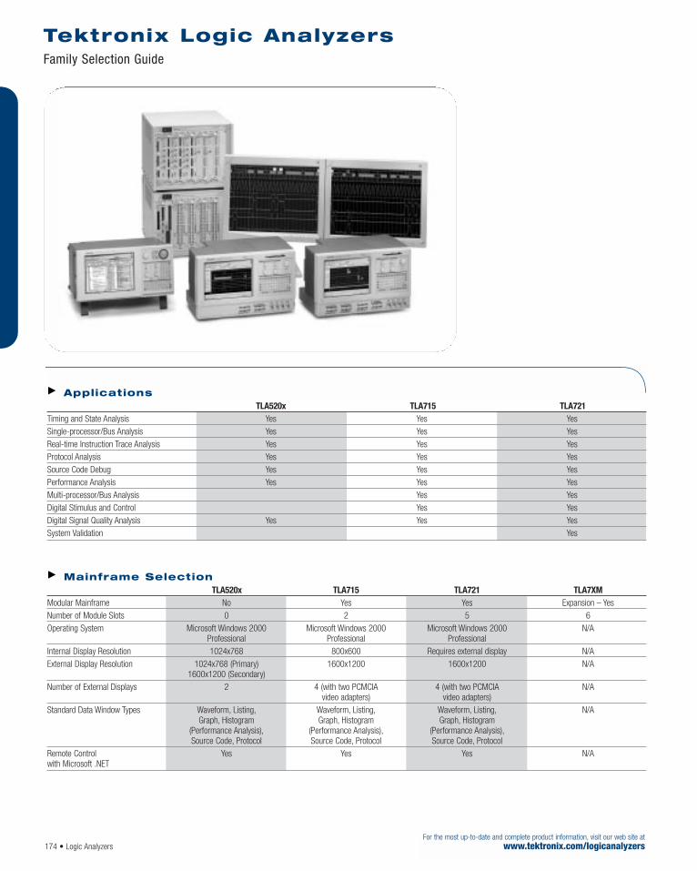
Tektronix Logic Analyzers Family Selection Guide
174 • Logic AnalyzersFor the most up-to-date and complete product information, visit our web site at
www.tektronix.com/logicanalyzers
Applications TLA520x TLA715 TLA721
Timing and State Analysis Yes Yes Yes Single-processor/Bus Analysis Yes Yes Yes Real-time Instruction Trace Analysis Yes Yes Yes Protocol Analysis Yes Yes Yes Source Code Debug Yes Yes Yes Performance Analysis Yes Yes Yes Multi-processor/Bus Analysis Yes Yes Digital Stimulus and Control Yes Yes Digital Signal Quality Analysis Yes Yes Yes System Validation Yes
Mainframe Selection TLA520x TLA715 TLA721 TLA7XM
Modular Mainframe No Yes Yes Expansion – Yes Number of Module Slots 0 2 5 6 Operating System Microsoft Windows 2000 Microsoft Windows 2000 Microsoft Windows 2000 N/A
Professional Professional ProfessionalInternal Display Resolution 1024x768 800x600 Requires external display N/A External Display Resolution 1024x768 (Primary) 1600x1200 1600x1200 N/A
1600x1200 (Secondary)Number of External Displays 2 4 (with two PCMCIA 4 (with two PCMCIA N/A
video adapters) video adapters)Standard Data Window Types Waveform, Listing, Waveform, Listing, Waveform, Listing, N/A
Graph, Histogram Graph, Histogram Graph, Histogram (Performance Analysis), (Performance Analysis), (Performance Analysis),Source Code, Protocol Source Code, Protocol Source Code, Protocol
Remote Control Yes Yes Yes N/Awith Microsoft .NET

Tektronix Logic Analyzers Family Selection Guide
Logic Analyzers • 175For the most up-to-date and complete product information, visit our web site atwww.tektronix.com/logicanalyzers
Logic Analyzer Selection TLA520x TLA7Nx4 TLA7NAx TLA7Axx
Channels 34, 68, 102, 136 136 per module 34, 68, 102, 136 per module 34, 68, 102, 136 per module Max Channels per 136 272 in TLA715; 408 in TLA721 272 in TLA715; Timebase (merged) 408 in TLA721 680 in TLA721Max Channels per Mainframe 136 272 in TLA715; 680 in TLA721 272 in TLA715;
680 in TLA721 680 in TLA721Max Channels per System 136 1,768 (with TLA715 and 1,768 (with TLA715 and 1,768 (with TLA715 and
two TLA7XMs); 8,160 (with two TLA7XMs); 8,160 (with two TLA7XMs); 8,160 (with TLA721 and ten TLA7XMs) TLA721 and ten TLA7XMs) TLA721 and ten TLA7XMs)
Max Independent Buses 1 13 (with TLA715 and 13 (with TLA715 and 13 (with TLA715 and per System two TLA7XMs); 60 (with two TLA7XMs); 60 (with two TLA7XMs); 60 (with
TLA721 and ten TLA7XMs) TLA721 and ten TLA7XMs) TLA721 and ten TLA7XMs)State Clock Rate 235 MHz 100 MHz std.; 235 MHz std.; 120 MHz std.;
200 MHz opt. 450 MHz opt. 235, 450 MHz opt.Max State Clock Rate 235 MHz 200 MHz 450 MHz 800 MHz (half channel mode)Max State Data Rate 470/235 Mb/s 400/200 Mb/s 470/235 Mb/s 1,250/900/450 Mb/s
(half/full channels) (half/full channels) (half/full channels) (quarter/half/full channels) MagniVu™ Timing 125 ps (8 GHz) 500 ps (2 GHz) 125 ps (8 GHz) 125 ps (8 GHz) (all channels, all the time) with 16 Kb depth with 2 Kb depth with 16 Kb depth with 16 Kb depthSimultaneous State and Yes Yes Yes Yes Timing Through Same ProbeAnalog Measurements No No No Yes Through Same ProbeDeep Memory Timing 500 ps (2 GHz)/ 2 ns (500 MHz)/ 500 ps (2 GHz)/ 500 ps (2 GHz)/
1 ns (1 GHz)/ 4 ns (250 MHz) 1 ns (1 GHz)/ 1 ns (1 GHz)/2 ns (500 MHz) (half/full channels) 2 ns (500 MHz) 2 ns (500 MHz)
(quarter/half/full channels) (quarter/half/full channels) (quarter/half/full channels) Analog Outputs (four per No No No Yesmodule – analog MUX)Memory Depth 2 Mb/1 Mb/512 Kb 128/64 Kb to 64/32 Mb 2 Mb/1 Mb/512 Kb 512/256/128 Kb to
to 32/16/8 Mb (half/full channels to 128/64/32 Mb 256/128/64 Mb (quarter/half/full channels with timestamp) (quarter/half/full channels (quarter/half/full
with timestamp) with timestamp) channels with timestamp) Source Synchronous Clocking No No No Yes
Digital Storage Oscilloscope Capability TDS Oscilloscopes*1 (External)
Channels per Module 2 & 4 Max Channels per Mainframe 4 Max Channels per System 4 Bandwidth 60 MHz to 8 GHz Sample Rate 1.0 GS/s to 20 GS/s Vertical Resolution 8-Bits and 9-Bits Memory Depth 2.5 Kb to 64 Mb
*1 For a complete list of currently supported TDS oscilloscopes, please visit our website http://www.tektronix.com/iview.
Pattern Generator Module TLA7PG2
Channels 64 Max Channels per Bus (merged) 128 (with TLA715); 320 (with TLA721) Max Channels per Mainframe 128 (with TLA715); 320 (with TLA721) Max Channels per System 832 (with TLA715 and two TLA7XMs); 3,840 (with TLA721 and ten TLA7XMs) Pattern Speed (half/full channels) 268/134 MHz Memory Depth (half/full channels) 512/256 Kb to 2/1 Mb Logic Families Supported CMOS/TTL, ECL, LVCMOS, PECL/LVPECL, LVDS, Variable

176 • Logic AnalyzersFor the most up-to-date and complete product information, visit our web site at
www.tektronix.com/logicanalyzers
TLA700 Series iLink™ Tool Set
Chances are, you’re now or will soon be developingproducts using new logic families with fasteredges, resulting in problems you may not haveseen before. Older digital systems could toleratewide variances of digital signals. In newer sys-tems, this is no longer the case. As design marginsdecrease, analog characteristics of digital signalsincreasingly affect the integrity of your digital system.You need to be able to simultaneously measure thedigital and analog characteristics of your system tofind the source of these elusive anomalies.
TLA700 Series Logic Analyzers include the iLink™
Tool Set which seamlessly integrates the logicanalyzer with an oscilloscope to provide instantdigital and analog insight, and radically speedsthe debugging of multiple signals.
The iLink tools are:
iCapture™ simultaneous digital and analog data acquisition through a single logic analyzer probe
iView™ time-correlated, integrated digital-analog display
iVerify™ multi-channel analysis and validationtesting using powerful oscilloscope-generatedeye diagrams
Connect, acquire, see and validate the analog anddigital aspects of your digital system using theiLink Tool Set. From there, it’s easy to use yourTektronix oscilloscope for further analysis on theanomalies you’ve discovered and take advantageof the fastest acquisition, industry-leading band-width and advanced analysis capabilities of theTDS/CSA7000B DPO Series, TDS6000B andTDS5000B DPO Series real-time oscilloscopes.
iLink Tool Set-supported Tektronix Oscilloscopes:
TDS5000/5000B DPO Series
TDS6000/6000B Series
CSA/TDS7000/7000B DPO Series
TDS configuration requirements – The iView™
cable does not fully connect to the TDS1000/2000Series oscilloscopes without a GPIB extender. Tektronixrecommends a standard GPIB cable as an extender,or order a cable adapter (Tektronix part number 103-0371-00). TDS2CMA Communications ExtensionModule is required for iView capability on anyTDS1000/2000 Series. TDS3GM GPIB/RS232 InterfaceModule required for iView capability on any TDS3000series. TDS3GV GPIB/RS232/VGA Interface Modulerequired for iView capability on any TDS3000B series.If using iView with the TDS6000B Series, TDS7254B,CSA7154B, TDS7404B, or CSA7404B oscilloscope, order a TCA-BNC connector to be compatible with a BNCcable run from a TLA7Axx module analog output.Number of TDS oscilloscopes that can be connected to a TLA system – 1.External Oscilloscopes Supported – TPS1000 SeriesTDS2000 SeriesTDS3000/3000B SeriesTDS5000/5000B DPO SeriesTDS6000/6000B SeriesTDS/CSA7000/7000B DPO SeriesTDS754C, TDS784C, TDS724D, TDS754D, TDS784D,TDS794D, TDS684C, TDS694C.TLA Connections – USB,Trigger In, Trigger Out,Clock Out.TDS Connections – GPIB, Trigger In, Trigger Out,Clock In (when available).Setup – iView™ external oscilloscope wizard automates setup.Data Correlation – After TDS oscilloscope acquisitionis complete, the data is automatically transferred to theTLA and time correlated with the TLA acquisition data.Deskew – TDS and TLA data is automaticallydeskewed and time correlated when using the iView™
external oscilloscope cable.iView™ External Oscilloscope Cable Length – 2 m.
TLA715 Series with TDS7000 Series oscilloscope.
For your local Tektronix representative see the list in the back of this catalog or outside the U.S. call: 1-503-627-7111, inside the U.S. call: 1-800-833-9200.

Logic Analyzers • 177
The TLA715 and TLA721 mainframes are modular mainframes that accept TLA7Axx andTLA7Lx/Mx/Nx/Px/Qx logic analyzer modules, aswell as TLA7PG2 pattern generator modules. TheTLA715 and TLA721 can be used in conjunctionwith a TLA7XM expansion mainframe to providesolutions for large numbers of buses and highchannel count requirements.
The TLA715 and TLA721 mainframes are built ona Microsoft Windows 2000 Professional PC plat-form that offers a familiar work environment. TLAapplications operate like any other PC application.
The TLA715 and TLA721 mainframes come standard with dual display capability for extendeddesktop viewing, in addition to an internal CD-RW,hard disk and PC card slots for expansion. Areplaceable hard disk is standard on both main-frames, ideal for security or enabling individualteam members to store personal setups and data.Trigger in/out connections provide an interface toother external instrumentation, such as TDS oscil-loscopes, for correlating measurement results.
Characteristics
General (TLA715, TLA721,TLA7XM) Instrument Slots – TLA715: Holds 4 single-wide or 2 double-wide modules.TLA721: Holds 10 single-wide or 5 double-wide modules.TLA7XM: Holds 12 single-wide or 6 double-wide modules.
Quantity of TLA7XMs – The TLA700 Series Mainframes can support multipleTLA7XM mainframes.TLA715: Up to two TLA7XM mainframes can be usedproviding 13 dual/26 single instrument slots*2 *3.TLA721: Up to ten TLA7XM mainframes can be usedproviding 60 dual/120 single instrument slots*2 *3.
Mainframe LA*1 PG*1
Max channels per module 136 ch. 64 ch.TLA715 1,768 832 TLA721 8,160 3,840
*1 All logic analyzer (LA) and pattern generator (PG) modules are dual-wide or occupy two single-wide slots.
*2 TLA7XM Expansion Module occupies one single-wide slot in boththe TLA715/TLA721 mainframes and the TLA7XM expansion main-frame.
*3 Using a TLA7XM expansion mainframe with an existingTLA714/TLA720 mainframe requires Version 4.0 or higher TLAapplication software. TLA720 benchtop mainframes, S/N: B019999and lower, require TLA7UP Option 09 TLA720 Benchtop MainframeUpgrade. Please refer to the TLA Upgrade Guide for further details.
For configurations beyond ten TLA7XM expansion mainframes, please contact your local Tektronix account manager.
TLA700 PC Characteristics(TLA715 and TLA721) Operating System – Microsoft Windows 2000Professional.Processor – Intel Pentium III.Chipset – Intel 815E.DRAM – 512 MB SDRAM.Display Memory – 4 MB.Dual Monitor Support – 1600x1200 Resolution.Sound – Built-in PC speaker transducer; multimediasound can be added via PC Card interface.
Tektronix Logic Analyzers TLA700 Series Mainframes
For the most up-to-date and complete product information, visit our web site atwww.tektronix.com/logicanalyzers
Features & BenefitsModular Mainframes Provide Flexibilityand Expandability
Utilize Logic Analyzer or PatternGenerator Modules
Expansion Mainframe Supports Up to 8160 Logic Analyzer Channels,60 Independent Buses
All Measurement Modules Are FullyInterchangeable Between Portableand Benchtop Mainframes
Integrated View (iViewTM) CapabilityProvides up to 6 GHz, 20 GS/s, and32 Mb Analog Acquisition with aStand-alone Tektronix TDS DigitalStorage Oscilloscope
Microsoft® Windows® 2000Professional PC Platform ProvidesFamiliar User Interface With Network Connectivity
View Data in Waveform, Listing,Source Code, Histogram(Performance Analysis) Displays toPerform Cross-domain Analysis
Remote Control Using Microsoft®
COM/DCOM Technology SupportsAdvanced Data Analysis
Broad Processor and Bus Support
TLAVu and PatGenVu Off-line AnalysisCapability for Viewing Data andCreating Setups on a Separate PC
Applications Hardware Debug and Verification
Processor/Bus Debug and Verification
Embedded Software Integration,Debug and Verification
Breakthrough Solutions for Real-time Digital Systems Analysis
For your local Tektronix representative see the list in the back of this catalog or outside the U.S. call: 1-503-627-7111, inside the U.S. call: 1-800-833-9200.
Tektronix measurement products are manufactured in ISO registered facilities.

Tektronix Logic Analyzers TLA700 Series Mainframes
For the most up-to-date and complete product information, visit our web site atwww.tektronix.com/logicanalyzers
Replaceable Hard Disk Drive – TLA715: 40 GB.TLA721: 40 GB.CD ROM – Internal 8/4/32 CD-RW.Floppy Disk Drive – Built-in 3.5 in. 1.44 MB drive.
TLA700 Integral Controls(TLA715 only) Front-panel Display – Size: 10.4 in. diagonal.Type: Active-matrix color TFT LCD with backlight.Resolution: 800x600.Colors: 16.8 M (true color).Simultaneous Display Capability – Both the front-panel and one external display can be used simultane-ously at 800x600 resolution.Front-panel Knobs – Special function knobs forinstrument control.Front-panel QWERTY Keypad – Mini-QWERTY keypad and Hex keypad.Front-panel Pointing Device – Trackball.
TLA700 External PeripheralInterfaces (TLA715 andTLA721) External Display Port Type – (2) Female DB15 connectors.External Display Resolution – Up to 1600x1200non-interlaced at 256 colors, for both primary and secondary displays.External Display Compatibility – DDC2B (dynamicdisplay configuration 2).External Keyboard Port Type – PS2 mini-DIN.External Mouse Port Type – PS2 mini-DIN.Parallel Interface Port Type – IEEE 1284-C connector(comes standard with adapter to female DB25 connector).Parallel Interface Modes – Centronics mode, EPP(Extended Parallel Port), ECP (Microsoft high-speed mode).Serial Interface Port Type – Male DB9.PC Card (CardBus) Slot Types – Two slots, two PCCard Type I/II or one PC Card Type III.USB Port – Two (2).
Integrated View (iViewTM)Capability TLA mainframe configuration requirements – TLA714/720/715/721 Series mainframes, TLA520Xinstruments and TLA6XX instruments.TLA App S/W V 4.1 or greater.256 MB DRAM Minimum, 512 MB recommended.
Symbolic Support Number of Symbols/Ranges – Unlimited (limited only by amount of virtual memoryavailable on TLA).Object File Formats Supported –
IEEE 695
OMF 51, OMF 86, OMF 166, OMF 286, OMF 386
COFF
Elf/Dwarf 1 and 2
Elf/Stabs
TSF (if your software development tools do notgenerate output in one of the above formats,TSF or the Tektronix symbol file, a generic ASCIIfile format is supported. The generic ASCII fileformat is documented in the TLA User Manual).If a format is not listed, please contact your localTektronix representative.
External InstrumentationInterfaces System Trigger Output – Asserted whenever a systemtrigger occurs (TTL-compatible output, back-terminatedinto 50 Ω).System Trigger Input – Forces a system trigger(triggers all modules) when asserted (TTL-compatible,edge-sensitive, falling-edge latched).
178 • Logic Analyzers
Example of TLA721 with ten TLA7XM Mainframes.
TLA715 Portable Mainframe.
TLA721 and TLA7XM Benchtop and Expansion Mainframes.
TLA721 and TLA7XM Benchtop and Expansion Mainframes with TLA721/TLA7XM Rackmount Kit.

Tektronix Logic Analyzers TLA700 Series Mainframes
Logic Analyzers • 179
External Signal Output – Can be used to driveexternal circuitry from a module’s trigger mechanism(TTL-compatible output, back-terminated into 50 Ω).External Signal Input – Can be used to provide anexternal signal to arm or trigger any or all modules (TTL-compatible, level-sensitive).P6041 External Signal Cable Length – (SMB toBNC adapter cable, two each TLA721 only) 1.1 m (42 in.).
Power TLA715 – Voltage range/frequency: 90-250 VAC at 45-66 Hz.100-132 VAC at 360-440 Hz.Input current: 6 A maximum at 90 VAC (70 A surge).Power consumption: 600 W maximum.TLA721 and TLA7XM – Voltage range/frequency: 90-250 VAC at 45-66 Hz,100-132 VAC at 360-440 Hz.Input current: 16.5 A maximum at 90 VAC (70 A surge).Power consumption: 1,450 W maximum.
Physical CharacteristicsDimensions mm in.Height 235 9.25 Width 432 17 Depth 455 17.5 Weight kg lb.Net (w/o modules) 11.4 25 Shipping (typical) 25.5 56
TLA721 Benchtop & TLA7XM Expansion Dimensions mm in.Height 346 13.65 Width 425 16.7 Depth 673 26.5 Weight kg lb.Net (w/o modules) 22.7 50 Shipping (typical) 51.8 114
Environmental Temperature – Operating: +5ºC to +50ºC.Nonoperating: –20ºC to +60ºC.Humidity – 20% to 80%.Operating: ≤30ºC; 80% relative humidity (29ºC maximum wet bulb temperature).Nonoperating: 8% to 80% (29ºC maximum wet bulb temperature).
Altitude – Operating: –1,000 ft. to 10,000 ft.(–305 meters to 3,050 meters).Safety – UL3111-1, CSA1010.1, EN61010-1,IEC61010-1.
For the most up-to-date and complete product information, visit our web site atwww.tektronix.com/logicanalyzers
LACART Instrument Cart (adjustable probe skyhook not shown).
K4000 Instrument Cart.
TLA715 Dual Monitor Portable Mainframe.Includes: Wheel mouse, keyboard, LAN PC Card,front-panel cover, accessory pouch, two dual-widepanel fillers for empty slots, printer adapter, software,certificate of calibration and one-year warranty (returnto Tektronix), power cord, and user manual. Pleasespecify power plug when ordering.
TLA721 Dual Monitor Benchtop Mainframe.Includes: Wheel mouse, keyboard, LAN PC Card, fivedual-wide panel fillers for empty slots, printer adapter,two P6041 SMB to BNC adapter cables; software,certificate of calibration and one-year warranty (return toTektronix), power cord, and user manual. Please specifypower plug when ordering. Display is not included.
TLA7XM Expansion Mainframe.If installing a TLA7XM expansion mainframe into aTLA700 Series mainframe, please consult the TLAFamily Upgrade Guide for upgrade information.Includes: Two expansion modules, three expansioncables, six dual-wide panel fillers for empty slots, onesingle-wide panel filler for empty slot, statement ofcompliance and one-year warranty (return to Tektronix),power cord, and user manual. Please specify powerplug when ordering.
Service Options Opt. C3 – Calibration Service 3 Years.Opt. C5 – Calibration Service 5 Years.Opt. D1 – Calibration Data Report.Opt. D3 – Calibration Data Report 3 Years (with Option C3).
Opt. D5 – Calibration Data Report 5 Years (with Option C5).Opt. R3 – Repair Service 3 Years.Opt. R5 – Repair Service 5 Years.Opt. IN – Product Installation Service.Opt. S1 – On-site Service 1 Year.Opt. S3 – On-site Service 3 Years (with R or C Option).
For your local Tektronix representative see the list in the back of this catalog or outside the U.S. call: 1-503-627-7111, inside the U.S. call: 1-800-833-9200.
Tektronix measurement products are manufactured in ISO registered facilities.
Ordering InformationCurrent price information is available worldwide on-line from the Tektronix web site or from your local Tektronix representative. Inside the U.S., also see the price list in the back of this catalog.

For the most up-to-date and complete product information, visit our web site atwww.tektronix.com/logicanalyzers
Today’s digital design engineers face daily pres-sures to speed new products to the marketplace.The TLA7Axx Series logic analyzer modulesanswer the need with breakthrough solutions forthe entire design team, providing the ability toquickly monitor, capture and analyze real-timedigital system operation in order to debug, verify,optimize and validate digital systems.
Hardware developers, hardware/software integratorsand embedded software developers will appreciatethe range of capabilities of the TLA7Axx Serieslogic analyzer modules. Its broad feature setincludes capturing and correlating elusive hard-ware and software faults; providing simultaneousstate, high-speed timing, and analog analysisthrough the same probe; using deep state acqui-sition to find the cause of complex problems;real-time, non-intrusive software execution tracingthat correlates to source code and to hardwareevents; and non-intrusive connectorless probing.
The TLA7Axx Series logic analyzer modules offerTektronix’ breakthrough MagniVu technology forproviding high-speed sampling (up to 8 GHz) thatdramatically changes the way logic analyzerswork and enables them to provide startling newmeasurement capabilities.
The TLA7Axx modules offer high-speed state syn-chronous capture, high-speed timing capture andanalog capture through the same set of probes.They capitalize on MagniVu technology to offer up to 125 ps timing on all channels, glitch andsetup/hold triggering and display and timestampthat is always on at up to 125 ps resolution. TheTLA7Axx also offers new capabilities to capturesource synchronous applications.
Characteristics
General Number of Channels (all channels are acquiredincluding clocks) – TLA7AA1: 34 channels (2 are clock channels).TLA7AA2, TLA7AB2: 68 channels (4 are clock channels).TLA7AA3: 102 channels (4 are clock and 2 are qualifier channels).TLA7AA4, TLA7AB4: 136 channels (4 are clock and 4 are qualifier channels).Channel Grouping: No limit to number of groups or number of channels per group (all channels can bereused in multiple groups).TLA700 Module “Merging” – Five 102 channel or 136 channel modules can be“merged” to make up to a 680 channel module. Mergedmodules exhibit the same depth as the lesser of the fiveindividual modules.Word/setup-and-hold/glitch/transition recognizers spanall five modules. Range recognizers limited to threemodule merge. Only one set of clock connections is required.
Tektronix Logic Analyzers TLA7Axx Logic Analyzer Modules
180 • Logic Analyzers
Features & Benefits34/68/102/136 Channel LogicAnalyzers with up to 256 Mb Depth
Up to 500 ps (2 GHz)/256 Mb DeepMemory Timing Analysis
MagniVu™Acquisition TechnologyProvides up to 125 ps (8 GHz) Timing Resolution to Find DifficultProblems Quickly
Up to 800 MHz State AcquisitionAnalysis of Synchronous Digital Circuits
Glitch and Setup/Hold Triggering andDisplay Finds and Displays ElusiveHardware Problems
Transitional Storage Extends theSignal Analysis Capture Time
Simultaneous Analog and DigitalMeasurements Through the Same Probe
Compression Probing System With0.5 pF Capacitive Loading EliminatesNeed For On-board Connectors,Minimizes Intrusion on Circuits and isIdeal for Differential Signal Applications
Broad Processor and Bus Support
ApplicationsHardware Debug and Verification
Processor/Bus Debug and Verification Including SourceSynchronous Clocking
Embedded Software Integration,Debug and Verification
The TLA700 Series offers the highest performance for today’s demanding applications and consists of portable and benchtop modular mainframes with expansion mainframe capability.
Breakthrough Solutions for Real-time Digital Systems Analysis
For your local Tektronix representative see the list in the back of this catalog or outside the U.S. call: 1-503-627-7111, inside the U.S. call: 1-800-833-9200.
Tektronix measurement products are manufactured in ISO registered facilities.

Logic Analyzers • 181
Time Stamp – 51-Bits at 125 ps resolution (3.25 days duration).Clocking/Acquisition Modes – Internal, internal 2X,internal 4X, external, external 2X, external 4X, sourcesynchronous. 8 GHz MagniVu™ high-speed timing isavailable simultaneous with all modes.Number of Mainframe Slots Required perTLA700 Module – 2.
Input Characteristics (withP6810, P6860, P6864, P6880,P6960 or P6980 probes) Capacitive Loading – 0.5 pF typical clock/data (P6960, P6980); 0.7 pF typical clock/data (P6810, P6860, P6864,P6880); (1.0 pF for P6810 in group configuration).Threshold Selection Range – From –2.0 V to +4.5 V in 5 mV increments.Threshold presets include TTL (1.5 V), CMOS (1.65 V),ECL (–1.3 V), PECL (3.7 V), LVPECL (2.0 V), LVCMOS 1.5 V(0.75 V), LVCMOS 1.8 V (0.9 V), LVCMOS 2.5 V (1.25 V),LVCMOS 3.3 V (1.65 V), LVDS (0 V) and user-defined.Threshold Selection Channel Granularity –Separate selection for each of the clock/qualifier channels and one per group of 16 data channels foreach 34 channel probe.Threshold Accuracy (including probe) – ±(35 mV + 1%).Input Voltage Range – Operating: –2.5 V to 5.0 V.Nondestructive: ±15 V.Minimum Input Signal Swing – 300 mV (single-ended).V-MAX – V-MIN > 150 mV (differential).Input Signal Minimum Slew Rate – 200 mV/ns typical.State Memory Depth with Timestamps – (quarter/half/full channels) 512/256/128 Kb,2 Mb/1 Mb/512 Kb, 8/4/2 Mb, 32/16/8 Mb,128/64/32 Mb, 256/128/64 Mb per channel.Setup and Hold Time Selection Range – From 16 ns before, to 8 ns after clock edge in 125 psincrements. Range may be shifted towards the setupregion by 0 ns [+8, –8] ns, 4 ns [+12, –4] ns, or 8 ns[+16, 0] ns.Setup-and-Hold Window – All Channels: 625 ps typical.Single Channel: 500 ps typical.Minimum Clock Pulse Width – 500 ps (P6860,P6880), 700 ps (P6810).Active Clock Edge Separation – 400 ps.
Demux Channel Selection – Channels can bedemultiplexed to other channels through user interfacewith 8 channel granularity.Source Synchronous Clocking – Up to four “Fast Latches” per module (20 max per 5-way merge) to strobe source-synchronous buses intoTLA7Axx Modules.Four sets of any predefined “Fast Latches” may be combined with qualification data and data pipelining tostore four independent source-synchronous data buses.Two “Fast Latches” may be combined to address DDR applications.
Timing AcquisitionCharacteristics (with P6810,P6860, P6864, P6880, P6960or P6980 probes) MagniVu Timing – 125 ps max, adjustments to250 ps, 500 ps, 1 ns, and 2 ns.MagniVu Timing Memory Depth – 16 Kb per channel,with adjustable trigger position.Deep Timing Resolution (quarter/half/full channels) – 500 ps/1 ns/2 ns to 50 ms.Deep Timing Resolution with Glitch StorageEnabled – 4 ns to 50 ms.Deep Timing Memory Depth (quarter/half/fullchannels with timestamps and with or withouttransitional storage) – 512/256/128 Kb,2 Mb/1 Mb/512 Kb, 8/4/2 Mb,32/16/8 Mb,128/64/32 Mb, 256/128/64 Mb per channel.Deep Timing Memory Depth with Glitch StorageEnabled – Half of default main memory depth.Channel-to-Channel Skew – 300 ps typical.Minimum Recognizable Pulse/Glitch Width (singlechannel) – 500 ps (P6860, P6880), 750 ps (P6810).Minimum Detectable Setup/Hold Violation – 250 ps.Minimum Recognizable Multi-channel TriggerEvent – Sample period + channel-to-channel skew.
Analog AcquisitionCharacteristics (with P6810,P6860, P6864, P6880, P6960or P6980 probes) Bandwidth – 2 GHz typical.Attenuation – 10x, ±1%.Offset and Gain (Accuracy) – ±50 mV, +/–2% of Signal Amplitude.Channels Demultiplexed – 4.Run/Stop Requirements – None, analog outputs arealways active.iView™Analog Outputs – Compatible with any internalTLA7Dx/Ex DSO module or supported TDS externaloscilloscope.iView Analog Output BNC Cable – Low loss, 10x, 36-in.
Trigger Characteristics Independent Trigger States – 16.Maximum Independent If/then Clauses perState – 16.Maximum Number of Events per If/then Clause – 8.Maximum Number of Actions per If/thenClause – 8.Maximum Number of Trigger Events – 18 (2 counter/timers plus any 16 other resources).Number of Word Recognizers – 16.Number of Transition Recognizers – 16.Number of Range Recognizers – 4.Number of Counter/Timers – 2.Trigger Event Types – Word, group, channel, transi-tion, range, anything, counter value, timer value, signal,glitch, setup-and-hold violation, snapshot.Trigger Action Types – Trigger module, trigger allmodules, trigger main, trigger MagniVu, store, don’tstore, start store, stop store, increment counter, decre-ment counter, reset counter, start timer, stop timer, resettimer, snapshot current sample, goto state, set/clear signal, do nothing.Maximum Triggerable Data Rate – 1250 Mb/s (4X clocking mode).Trigger Sequence Rate – DC to 500 MHz (2 ns).Counter/Timer Range – 51 Bits each (>50 days at 2 ns).Counter Rate – DC to 500 MHz (2 ns).Timer Clock Rate – 500 MHz (2 ns).Counter/Timer Latency – 2 ns.Range Recognizers – Double bounded (can be as wide as any group (408 channel max), must begrouped according to specified order of significance).Setup-and-Hold Violation Recognizer Setup TimeRange – From 8 ns before to 7 ns after clock edge in125 ps increments. This range may be shifted towardsthe positive region by 0 ns, 4 ns, or 8 ns.Setup-and-Hold Violation Recognizer Hold TimeRange – From 7 ns before to 8 ns after clock edge in 125 ps increments. This range may be shiftedtowards the positive region by 0 ns [+8, –8] ns, 4 ns[+12, –4] ns, or 8 ns [+16, 0] ns.
Tektronix Logic Analyzers TLA7Axx Logic Analyzer Modules
For the most up-to-date and complete product information, visit our web site atwww.tektronix.com/logicanalyzers
State Acquisition
Full Channel Half Channel Quarter Channel 120 MHz Standard 235 MHz/235 Mb/s or 240 Mb/s (DDR) 235 MHz/470 Mb/s 235 MHz Optional 450 MHz/450 Mb/s or 470 Mb/s (DDR) 450 MHz/900 Mb/s 450 MHz Optional 800 MHz/800 Mb/s or 900 Mb/s (DDR) 625 MHz/1.25 Gb/s

For the most up-to-date and complete product information, visit our web site atwww.tektronix.com/logicanalyzers
Tektronix Logic Analyzers TLA7Axx Logic Analyzer Modules
182 • Logic Analyzers
TLA7Axx Logic Analyzer Modules Includes: Probe retainer bracket, certificate of calibration, one-year warranty (return to Tektronix)and user manual.Probes are ordered separately – You can order anycombination and quantity of probes by ordering theP6960, P6980, P6810, P6860 or P6880 individually.TLA7AA1 – 34 channel Logic Analyzer module, 8 GHztiming, 120 MHz state, 128 Kb depth. Options for up to32 Mb depth and/or up to 450 MHz state.TLA7AA2 – 68 channel Logic Analyzer module, 8 GHztiming, 120 MHz state, 128 Kb depth. Options for up to32 Mb depth and/or up to 450 MHz state.TLA7AA3 – 102 channel Logic Analyzer module,8 GHz timing, 120 MHz state, 128 Kb depth. Optionsfor up to 32 Mb depth and/or up to 450 MHz state.TLA7AA4 – 136 channel Logic Analyzer module,8 GHz timing, 120 MHz state, 128 Kb depth. Optionsfor up to 32 Mb depth and/or up to 450 MHz state.TLA7AB2 – 68 channel Logic Analyzer module, 8 GHztiming, 120 MHz state, 64 Mb depth. Option for up to450 MHz state.TLA7AB4 – 136 channel Logic Analyzer module,8 GHz timing, 120 MHz state, 64 Mb depth. Option forup to 450 MHz state.
Logic Analyzer TLA7AAx Module Options (Base configuration is 128 Kb depth at 120 MHz state).Opt 1S – Increase to 512 Kb Depth at 120 MHz State.Opt 2S – Increase to 2 Mb Depth at 120 MHz State.
Opt 3S – Increase to 8 Mb Depth at 120 MHz State.Opt 4S – Increase to 32 Mb Depth at 120 MHz State.Opt 5S – Increase to 128 Kb Depth at 235 MHz State.Opt 6S – Increase to 512 Kb Depth at 235 MHz State.Opt 7S – Increase to 2 Mb Depth at 235 MHz State.Opt 8S – Increase to 8 Mb Depth at 235 MHz State.Opt 9S – Increase to 32 Mb Depth at 235 MHz State.Opt AS – Increase to 128 Kb Depth at 450 MHz State.Opt BS – Increase to 512 Kb Depth at 450 MHz State.Opt CS – Increase to 2 Mb Depth at 450 MHz State.Opt DS – Increase to 8 Mb Depth at 450 MHz State.Opt ES – Increase to 32 Mb Depth at 450 MHz State.
Logic Analyzer TLA7ABx Module Options (Base configuration is 64 Mb depth at 120 MHz state).Opt 1S – Increase to 64 Mb Depth at 235 MHz State.Opt 2S – Increase to 64 Mb Depth at 450 MHz State.
TLA700 Series Module Upgrades You can increase the memory depth and state speed of most existing TLA700 Series logic analyzer modules.You can also install a TLA7Axx logic analyzer moduleinto an existing TLA714/715/720/721/7XM mainframe.Please refer to the TLA Family Upgrade Guide for further details.
Service Options Opt. C3 – Calibration Service 3 Years.Opt. C5 – Calibration Service 5 Years.Opt. D1 – Calibration Data Report.Opt. D3 – Calibration Data Report 3 Years (with Option C3).Opt. D5 – Calibration Data Report 5 Years (with Option C5).Opt. R3 – Repair Service 3 Years.Opt. R5 – Repair Service 5 Years.Opt. IN – Product Installation Service.
For your local Tektronix representative see the list in the back of this catalog or outside the U.S. call: 1-503-627-7111, inside the U.S. call: 1-800-833-9200.
Tektronix measurement products are manufactured in ISO registered facilities.
Ordering InformationCurrent price information is available worldwide on-line from the Tektronix web site or from your local Tektronix representative. Inside the U.S., also see the price list in the back of this catalog.
Trigger Position – Any data sample.MagniVu™Trigger Position – MagniVu position can beset from 0% to 60% centered around the MagniVu trigger.Storage Control (data qualification) – Global (con-ditional), by state (start/stop), block, by trigger action, ortransitional. Also force main prefill selection available.
Physical Characteristics Dimensions mm in.Height 262 10.3 Width 61 2.4 Depth 381 15 Weight kg lb.Net 3.1 6.7 Shipping 6.3 13.7
P6810 Probe Cable Length – 1.8 m (6 ft.).P6860 Probe Cable Length – 1.8 m (6 ft.).P6864 Probe Cable Length – 1.8 m (6 ft.).P6880 Probe Cable Length – 1.8 m (6 ft.).P6960 Probe Cable Length – 1.8 m (6 ft.).P6980 Probe Cable Length – 1.8 m (6 ft.).
All four probes have the same electrical length and aredelay matched.

Logic Analyzers • 183For the most up-to-date and complete product information, visit our web site atwww.tektronix.com/logicanalyzers
The TLA700 Series with TLA7NAx Logic AnalyzerModule speeds debug and verification of fastbuses and complex embedded systems with anindustry-leading combination of acquisition,triggering and analysis capabilities. Quickly debugfast buses like DDR memory and PCI-X, usinglong record length to capture intermittent eventsover a wide time window and MagniVu™ high-speed timing to simultaneously capture glitchesas small as 125 ps.
The TLA7NAx module’s advanced triggering capabilities allow you to trigger on microprocessoroperation failures, which speeds troubleshootingof embedded systems incorporating microproces-sors such as the PowerQUICCIII. Additional toolslike source code and protocol analysis and listingview make monitoring and debugging processoroperation faster and easier.
Tektronix Logic Analyzers TLA7NAx Logic Analyzer Modules NEW
Features & Benefits34/68/102/136 Channel Logic Analyzerswith up to 128 Mb Record Length toCapture Long Periods of Time
500 ps (2 GHz)/32 Mb Timing Analysisto Track Down Elusive TimingProblems Faster
125 ps (8 GHz) MagniVu™ AcquisitionSimultaneous with Timing or State Acquisition to Find DifficultProblems Quickly
Up to 450 MHz State AcquisitionAnalysis of Synchronous Digital Circuits
Glitch and Setup/Hold ViolationTriggering and Display Finds andDisplays Elusive Hardware Problems
Transitional Storage Extends theSignal Analysis Capture Time
Connectorless Probing System with0.5 pF (typical) Capacitive LoadingEliminates Need for On-boardConnectors, Minimizes Intrusion onCircuits and is Ideal for Differential Signal Applications
Broad Processor and Bus Support
Applications
Hardware Debug and Verification
Processor/Bus Debug andVerification Including SourceSynchronous Clocking
Embedded Software Integration,Debug and Verification
The TLA700 Series offers the highest performance for today’s demanding applications and consists of portable and benchtop modular mainframes with expansion mainframe capability.
Breakthrough Solutions for Real-time Digital Systems Analysis
For your local Tektronix representative see the list in the back of this catalog or outside the U.S. call: 1-503-627-7111, inside the U.S. call: 1-800-833-9200.
Tektronix measurement products are manufactured in ISO registered facilities.
Characteristics
General
Number of Channels (all channels are acquiredincluding clocks) – TLA7NA1: 34 channels (2 are clock channels).TLA7NA2: 68 channels (4 are clock channels).TLA7NA3: 102 channels (4 are clock and 2 are qualifier channels).TLA7NA4: 136 channels (4 are clock and 4 are qualifier channels).Channel Grouping: No limit to number of groups ornumber of channels per group (all channels can bereused in multiple groups).TLA700 Module “Merging” – Five 102 channel or 136 channel modules can be “merged” to make upto a 680 channel module. Merged modules exhibit thesame depth and state speed as the lesser of the fiveindividual modules. Word/setup and hold/glitch/transition recognizers span all five modules. Range recognizers limited to three module merge. Only oneset of clock connections is required.Time Stamp – 51-Bits at 125 ps resolution (3.25 days duration).Clocking/Acquisition Modes – Internal, internal 2X,internal 4X, external, external 450 (with option 45only). 8 GHz MagniVu™ high-speed timing is availablesimultaneous with all modes.Number of Mainframe Slots Required perTLA700 Module – 2.
Input Characteristics (withP6960, P6980, P6810, P6860,P6864, or P6880 probes)
Capacitive Loading – 0.5 pF typical (P69xx),< 0.7 pF (P68xx) clock/data.Input Voltage Range – Operating: –2.5 V to 5.0 V.Nondestructive: ± 15 V.Threshold Selection Range – From –2.0 V to +4.5 V in 5 mV increments.Threshold presets include TTL (1.5 V), CMOS (1.65 V), ECL (–1.3 V), PECL (3.7 V), LVPECL (2.0 V),LVCMOS 1.5 V (0.75 V), LVCMOS 1.8 V (0.9 V),LVCMOS 2.5 V (1.25 V), LVCMOS 3.3 V (1.65 V),LVDS (0 V), and user defined.
Threshold Selection Channel Granularity – Separate selection for each of the clock/qualifier channels and one per group of 16 data channels for each 34 channel probe.Threshold Accuracy (including probe) – ±(35 mV + 1%).Minimum Input Signal Swing – 300 mV (single-ended).VMAX - VMIN >150 mV (differential).Input Signal Minimum Slew Rate –200 mV/ns typical.Setup-and-Hold Time Selection Range –16 ns range that may be shifted towards the setupregion by 0 ns [+8, –8] ns, 4 ns [+12, –4] ns or 8 ns [+16, 0] ns.
Setup-and-Hold Window –All Channels: 625 ps typical.Single Channel: 500 ps typical.Minimum Clock Pulse Width – 500 ps (P6960,P6980, P6860, P6864, P6880), 750 ps (P6810).Active Clock Edge Separation – 400 ps.Demux Channel Selection – Channels can bedemultiplexed (by two) to other channels through user interface with 8 channel granularity. Available with option 45 only.
Tektronix Logic Analyzers TLA7NAx Logic Analyzer Modules
184 • Logic AnalyzersFor the most up-to-date and complete product information, visit our web site at
www.tektronix.com/logicanalyzers
State Acquisition Characteristics
Timing Record Length (with or without transitional storage)
State Acquisition Full Channel Half Channel 235 MHz Standard N/A 450 MHz Optional 450 MHz/450 Mb/s or 235 MHz/470 Mb/s (DDR)
State Record Length with Timestamps Full Channel Half Channel*1
512 Kb Standard 1 Mb 2 Mb Optional 4 Mb 8 Mb Optional 16 Mb 32 Mb Optional 64 Mb *1 Half channel record length available with option 45 only.
Full Channel Half Channel Quarter Channel512 Kb Standard 1 Mb 2 Mb 2 Mb Optional 4 Mb 8 Mb 8 Mb Optional 16 Mb 32 Mb 32 Mb Optional 64 Mb 128 Mb

Timing AcquisitionCharacteristics
MagniVu Timing Sample Rate – 125 ps max,adjustments to 250 ps, 500 ps, 1 ns and 2 ns.MagniVu Timing Record Length – 16 Kb per channel, with adjustable trigger position.Timing Resolution (quarter/half/full channels) – 500 ps/1 ns/2 ns to 50 ms.Timing Resolution with Glitch Storage Enabled(full channels) – 4 ns to 50 ms.Timing Record Length with Glitch StorageEnabled – Half of default main record length.Channel-to-channel Skew – 300 ps typical.Minimum Recognizable Pulse/Glitch Width (single channel) – 500 ps (P6960, P6980, P6860,P6880), 750 ps (P6810).Minimum Detectable Setup/Hold Violation – 250 ps.Minimum Recognizable Multi-channel TriggerEvent – Sample period + channel-to-channel skew.
Trigger Characteristics
Independent Trigger States – 16.Maximum Independent If/Then Clauses per State – 16.Maximum Number of Events per If/ThenClause – 8.Maximum Number of Actions per If/ThenClause – 8.Maximum Number of Trigger Events – 18 (2 counter/timers plus any 16 other resources).Number of Word Recognizers – 16.Number of Transition Recognizers – 16.Number of Range Recognizers – 4.Number of Transition Recognizers – 1.Number of Counter/Timers – 2.Trigger Event Types – Word, group, channel,transition, range, anything, counter value, timer value,signal, glitch, setup-and-hold violation, snapshot.Trigger Action Types – Trigger module, trigger all, modules, trigger main, trigger MagniVu,™store,don’t store, start store, stop store, increment counter,decrement counter, reset counter, start timer, stoptimer, reset timer, snapshot current sample, goto state,set/clear signal, do nothing.Maximum Triggerable Data Rate – 500 MHz.Trigger Sequence Rate – DC to 500 MHz (2 ns).Counter/Timer Range – 51 Bits each (>50 days at 2 ns).Counter Rate – DC to 500 MHz (2 ns).Timer Clock Rate – 500 MHz (2 ns).Counter/Timer Latency – 2 ns.Range Recognizers – Double bounded (can be aswide as any group (408 channel max), must begrouped according to specified order of significance).
Setup-and-Hold Violation Recognizer Setup Time Range – From 8 ns before to 7 ns after clockedge in 125 ps increments.Setup-and-Hold Violation Recognizer Hold Time Range – From 7 ns before to 8 ns after clockedge in 125 ps increments.Trigger Position – Any data sample.MagniVu Trigger Position – MagniVu position can be set from 0% to 60% centered around theMagniVu trigger.Storage Control (data qualification) – Global (conditional), by state (start/stop), block, by triggeraction, or transitional. Force main prefill selection isavailable to fill memory before the trigger position priorto triggering the analyzer.
Physical Characteristics Dimensions mm in.Height 262 10.3 Width 61 2.4 Depth 381 15 Weight kg lb.Net 3.1 6.7 Shipping 6.3 13.7
P6960 Probe Cable Length – 1.8 m (6 ft.).P6980 Probe Cable Length – 1.8 m (6 ft.).P6810 Probe Cable Length – 1.8 m (6 ft.).P6860 Probe Cable Length – 1.8 m (6 ft.).P6864 Probe Cable Length – 1.8 m (6 ft.).P6880 Probe Cable Length – 1.8 m (6 ft.).All six probes have the same electrical length and are delay matched.
Tektronix Logic Analyzers TLA7NAx Logic Analyzer Modules
Logic Analyzers • 185For the most up-to-date and complete product information, visit our web site atwww.tektronix.com/logicanalyzers

TLA7NAx Logic Analyzer Modules Includes: Certificate of calibration, installation manual,TLA Documentation CD, one-year warranty (return toTektronix).Probes must be ordered separately.TLA7NA1 – 34 channel Logic Analyzer module,MagniVu™ Acquisition simultaneous with 500 ps Timingand 235 MHz State, 512 Kb Record Length LogicAnalyzer Module.Options for up to 32 Mb record lengthand/or up to 450 MHz State.TLA7NA2 – 68 channel Logic Analyzer module, 125ps MagniVu Acquisition simultaneous with 500 psTiming and 235 MHz State, 512 Kb Record LengthLogic Analyzer Module.Options for up to 32 Mb record length and/or up to 450 MHz State.
TLA7NA3 – 102 channel Logic Analyzer module,125 ps MagniVu Acquisition simultaneous with 500 psTiming and 235 MHz State, 512 Kb Record LengthLogic Analyzer Module.Options for up to 32 Mb record length and/or up to 450 MHz State.TLA7NA4 – 136 channel Logic Analyzer module,125 ps MagniVu Acquisition simultaneous with 500 psTiming and 235 MHz State, 512 Kb Record LengthLogic Analyzer Module.Options for up to 32 Mb record length and/or up to 450 MHz State.
Logic Analyzer TLA7NAx ModuleOptions (Base configuration is 512 Kb record length at 235 MHz state.) Opt 7S – Increase to 2 Mb Record Length.Opt 8S – Increase to 8 Mb Record Length.Opt 9S – Increase to 32 Mb Record Length.Opt 45 – Increase state speed to 450 MHz.
TLA7NAx Service Options Opt. C3 – Calibration Service 3 Years.Opt. C5 – Calibration Service 5 Years.Opt. D1 – Calibration Data Report Opt. D3 – Calibration Data Report 3 Years (with Option C3).Opt. D5 – Calibration Data Report 5 Years (with Option C5).Opt. R3 – Repair Service 3 Years.Opt. R5 – Repair Service 5 Years.Opt. IN – Product Installation Service.
For your local Tektronix representative see the list in the back of this catalog or outside the U.S. call: 1-503-627-7111, inside the U.S. call: 1-800-833-9200.
Tektronix Logic Analyzers TLA7NAx Logic Analyzer Modules
186 • Logic AnalyzersFor the most up-to-date and complete product information, visit our web site at
www.tektronix.com/logicanalyzers
Logic Analyzer Module Probes
Logic Analyzer Probe Selection GuidelinesThere is a flexible choice of logic analyzer probes available for use with TLA7NAx modules.
Category P6810 P6960 P6860 P6980 P6880 P6864 Logic Analyzer TLA7Axx Logic Analyzer ModulesUsed TLA7NAx Logic Analyzer Modules Recommended For most For For For For For high Use general- applications applications applications applications data rate
purpose requiring requiring requiring full requiring full (>450 MHz) applications the best good signal differential differential applications where signal signal density and a probing probing that require
integrity density and a quick reliable with the with good internal 4X is critical quick reliable attachment best signal signal demux and a
attachment density and a density and a connectorless or for general- quick reliable quick reliable probe
purpose attachment attachment attachmentprobing withflying leads
Attachment to Fits both D-Max™ Connectorless D-Max Connectorless Connectorless Target System 0.100 in. Probing compression Probing compression compression
and 2 mm Technology elastomer Technology elastomer elastomersquare pin compression compression
configurations cLGA with cLGAoptional flying
lead setProbe Type 34-Ch 34-Ch 34-Ch 34-Ch 34-Ch 17-Channel
general high high differential differential probe,purpose density density high high signals
density density demuxed to 68 channels
Logic Signals Differential Differential Differential Differential Differential DifferentialSupported clock clock clock clock clock clock
differential single-ended single-ended differential differential single-ended data data data data data data
Probe Load 0.7 pF/20 k 0.5 pF/20 k 0.7 pF/20 k 0.5 pF/20 k 0.7 pF/20 k 0.7 pF/20 kAC/DC to ground to ground to ground to ground to ground to ground
Ordering Information

Logic Analyzers • 187For the most up-to-date and complete product information, visit our web site atwww.tektronix.com/logicanalyzers
Today’s digital design engineers face daily pres-sures to speed new products to the marketplace.The TLA7N4 logic analyzer module answers theneed with breakthrough solutions for the entiredesign team, providing the ability to quickly monitor, capture and analyze real-time digital system operation in order to debug, verify,optimize and validate digital systems.
Hardware developers, hardware/software integratorsand embedded software developers will appreci-ate the range of capabilities of the TLA7N4 logicanalyzer module. Its broad feature set includescapturing and correlating elusive hardware andsoftware faults; providing simultaneous state and high-speed timing analysis through the same probe; using deep state acquisition to find the cause of complex problems; real-time,non-intrusive software execution tracing that correlates to source code and to hardwareevents; and non-intrusive probing.
The TLA7N4 logic analyzer module offersTektronix’ breakthrough MagniVu technology forproviding high-speed sampling (up to 2 GHz) thatdramatically changes the way logic analyzerswork and enables them to provide startling newmeasurement capabilities.
The TLA7N4 module offers high-speed state syn-chronous capture and high-speed timing capturethrough the same set of probes. It capitalizes onMagniVu technology to offer 500 ps timing on allchannels, glitch and setup/hold triggering anddisplay, and timestamp that is always on at up to 500 ps resolution.
The TLA700 Series logic analyzer modules areideal for timing analysis, multi-processor/busapplications and embedded software analysis.
Tektronix Logic Analyzers TLA7N4 Logic Analyzer Module
Features & Benefits136 Channel Logic Analyzer with up to8 Mb Depth
MagniVu™ Acquisition TechnologyProvides 2 GHz (500 ps) TimingResolution to Find Difficult Problems Quickly
Up to 200 MHz State AcquisitionAnalysis of Synchronous Digital Circuits
Simultaneous State and High-speedTiming Analysis Through the SameProbe Pinpoints Elusive Faults WithoutDouble Probing
500 MHz Deep Timing Analysis withUp to 8 Mb Per Channel
Glitch and Setup/Hold Triggering andDisplay Finds and Displays ElusiveHardware Problems
Transitional Storage Extends theSignal Analysis Capture Time
Broad Processor and Bus Support
Full Range of General-purpose andHigh-density, Non-intrusive Probes
ApplicationsHardware Debug and Verification
Processor/Bus Debug and Verification
Embedded Software Integration,Debug and Verification
Breakthrough Solutions for Real-time Digital Systems Analysis
For your local Tektronix representative see the list in the back of this catalog or outside the U.S. call: 1-503-627-7111, inside the U.S. call: 1-800-833-9200.
Tektronix measurement products are manufactured in ISO registered facilities.

CharacteristicsGeneral Number of Channels (all channels are acquiredincluding clocks) – TLA7N4: 136 channels (4 areclock and 4 are qualifier channels).Channel Grouping – No limit to number of groups ornumber of channels per group (all channels can bereused in multiple groups).TLA700 Module “Merging” – Three modules can be“merged” to make up to a 408-Channel module.Merged modules exhibit the same depth as the lesser of the three individual modules. Word/range/setup-and-hold/glitch/transition recognizers span all threemodules. Only one set of clock connections is required.Time Stamp – 50-Bit at 500 ps resolution (6.5 day range).Clocking/Acquisition Modes – Internal, internal 2X,external. 2 GHz MagniVu™ high-speed timing is availablesimultaneous with all modes.Number of Mainframe Slots Required perTLA700 Module – 2.
Input Characteristics (with P6417, P6418, P6419 or P6434 probes) Capacitive Loading – <0.7 pF data and clock (P6419).1.4 pF typical data; 2 pF typical clock (P6418).2 pF typical data and clock (P6417 and P6434).
Threshold Selection Range – From +5.0 V to–2.0 V in 50 mV increments.Threshold Selection Channel Granularity – Separate selection for clock (1) and data (16) for each17-Channel probe connector.Threshold Accuracy (including probe) – ±100 mV.Input Voltage Range – Operating: 6.5 Vp-p centeredaround the programmed threshold.Non-destructive: ±15 V.Minimum Input Signal Swing – 250 mV or 25% ofsignal swing, whichever is greater (P6417, P6418 and P6419).300 mV or 25% of signal swing (P6434).Input Signal Minimum Slew Rate – 200 mV/ns typical.
State Acquisition Characteristics (with P6417, P6418, P6419 or P6434 probes) State Clock Rate –100 MHz standard, 200 MHz optional.State Data Rate (half/full channels) – 400/200 Mb/s,typical. Requires 200 MHz state option.State Memory Depth with Timestamps – 64 Kb,256 Kb, 1 Mb or 4 Mb per channel.Setup-and-hold Time Selection Range – From8.5 ns before to 7.0 ns after clock edge.Setup-and-Hold Window – 2 ns typical.Minimum Clock Pulse Width – 2 ns.Active Clock Edge Separation – 5 ns.
Demux Channel Selection – Channels can bedemultiplexed to other channels through user interfacewith 8-Channel granularity.
Timing Acquisition Characteristics(with P6417, P6418, P6419 or P6434 probes) MagniVu Timing – 500 ps.MagniVu Timing Memory Depth – 2 Kb (2048) per channel.Deep Timing Resolution (half/full channels) – 2/4 ns to 50 ms.Deep Timing Resolution with Glitch StorageEnabled – 10 ns to 50 ms.Deep Timing Memory Depth (half/full channelswith timestamps and with or without transition-al storage) – 128/64 Kb, 512/256 Kb, 2/1 Mb,8/4 Mb per channel.Deep Timing Memory Depth with Glitch StorageEnabled – Half of default main memory depth.Channel-to-channel Skew – <1 ns typical.Minimum Recognizable Pulse Width (singlechannel) – 2 ns.Minimum Recognizable Glitch Width (singlechannel) – 2 ns.Minimum Recognizable Multi-channel TriggerEvent – Sample period +2 ns.
Tektronix Logic Analyzers TLA7N4 Logic Analyzer Module
For the most up-to-date and complete product information, visit our web site atwww.tektronix.com/logicanalyzers188 • Logic Analyzers

Logic Analyzers • 189
Tektronix Logic Analyzers TLA7N4 Logic Analyzer Module
Ordering InformationCurrent price information is available worldwide on-line from the Tektronix web site or from your local Tektronix representative. Inside the U.S., also see the price list in the back of this catalog.
TLA7N4 Logic Analyzer Module Includes: Probe retainer bracket, probe manual,certificate of calibration, one-year warranty (return to Tektronix), and user manual.Probes must be ordered separately – Order any combination and quantity of probes by ordering theP6417, P6418, P6419 or P6434 individually.TLA7N4 – 136-Channel Logic Analyzer module,2 GHz timing, 100 MHz state, 64 Kb depth. Options for up to 4 Mb depth and/or 200 MHz state.
Quantity of Probes to Order Per Option Probe TLA7N4 P6418 Probes 8 P6434 Probes 4 P6417 Probes 8 P6419 Probes 8
Logic Analyzer Module Options (Base configuration is 64 K depth at 100 MHz state) Opt. 1S – Increase to 256 K depth at 100 MHz state.Opt. 2S – Increase to 1 M depth at 100 MHz state.Opt. 3S – Increase to 4 M depth at 100 MHz state.Opt. 4S – Increase to 64 K depth at 200 MHz state.Opt. 5S – Increase to 256 K depth at 200 MHz state.Opt. 6S – Increase to 1 M depth at 200 MHz state.Opt. 7S – Increase to 4 M depth at 200 MHz state.
TLA7N4 Service Options Opt. C3 – Calibration Service 3 Years.Opt. C5 – Calibration Service 5 Years.Opt. D1 – Calibration Data Report.Opt. D3 – Calibration Data Report 3 Years (with Opt. C3).Opt. D5 – Calibration Data Report 5 Years (with Opt. C5).Opt. R3 – Repair Service 3 Years.Opt. R5 – Repair Service 5 Years.Opt. IN – Product Installation Service.
TLA7N4 Service Manual and Test Fixtures TLA7N4 Logic Analyzer Performance Verificationand Adjustment Fixture (includes AC adapter;requires local power cord) – Order 671-3599-00.TLA7N4 Logic Analyzer Modules Service Manual(includes Performance Verification andAdjustment procedures) – Order 071-0864-01.
TLA700 Series Module Upgrades You can increase the memory depth and state speedof most existing TLA700 Series logic analyzer modules.You can also install a TLA7N4 logic analyzer moduleinto an existing TLA714/715/720/721/7XM main-frame. Please refer to the TLA Family Upgrade Guidefor further details.
For the most up-to-date and complete product information, visit our web site atwww.tektronix.com/logicanalyzers
Trigger Characteristics Independent Trigger States – 16.Maximum Independent If/then Clauses perState – 16.Maximum Number of Events per If/then Clause – 8.Maximum Number of Actions per If/thenClause – 8.Maximum Number of Trigger Events – 18 (2 counter/timers plus any 16 other resources).Number of Word Recognizers – 16.Number of Range Recognizers – 4.Number of Transition Recognizers – 1.Number of Counter/Timers – 2.Trigger Event Types – Word, group, channel, transi-tion, range, anything, counter value, timer value, signal,glitch, setup-and-hold violation.
Trigger Action Types – Trigger module, trigger all,store, don’t store, start store, stop store, incrementcounter, reset counter, start timer, stop timer, reset timer,goto state, set/clear signal, do nothing.Trigger Sequence Rate – DC to 250 MHz (4 ns).Counter/Timer Range – 51 Bits each (>100 days at 4 ns).Counter Rate – DC to 250 MHz (4 ns).Timer Clock Rate – 250 MHz (4 ns).Counter/Timer Latency – None (can be tested orreset immediately after starting).Range Recognizers – Double bounded (can be aswide as any group, must be grouped according to specified order of significance).Setup-and-hold Violation Recognizer Setup TimeRange – From 8 ns before to 7 ns after clock edge in0.5 ns increments.Setup-and-hold Violation Recognizer Hold TimeRange – From 7 ns before to 8 ns after clock edge in0.5 ns increments.
Trigger Position – Any data sample.MagniVu Trigger Position – MagniVu data is centered around the module trigger.Storage Control (data qualification) – Global (conditional), by state (start/stop), by trigger action or transitional.Storage Window Granularity – Single sample orblock-of-31 samples before and after.Safety – CSA C22.2 No. 1010.1, EN61010-1,IEC61010-1, UL 3111-1
Physical Characteristics Dimensions mm in.Height 262 10.3 Width 61 2.4 Depth 381 15 Weight kg lb.Net (without probes) 3.1 6.7 Shipping (typical) 6.3 13.7
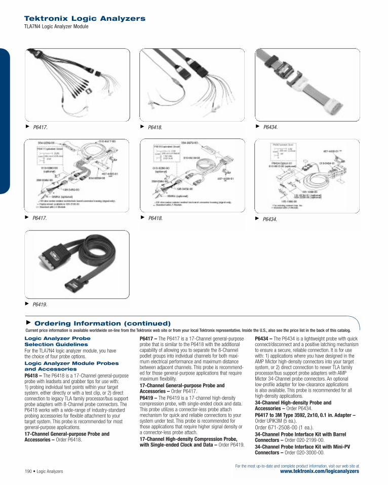
190 • Logic AnalyzersFor the most up-to-date and complete product information, visit our web site at
www.tektronix.com/logicanalyzers
Tektronix Logic Analyzers TLA7N4 Logic Analyzer Module
Logic Analyzer Probe Selection Guidelines For the TLA7N4 logic analyzer module, you have the choice of four probe options.Logic Analyzer Module Probesand Accessories P6418 – The P6418 is a 17-Channel general-purposeprobe with leadsets and grabber tips for use with:1) probing individual test points within your target system, either directly or with a test clip, or 2) directconnection to legacy TLA family processor/bus supportprobe adapters with 8-Channel probe connectors. TheP6418 works with a wide-range of industry-standardprobing accessories for flexible attachment to your target system. This probe is recommended for mostgeneral-purpose applications.17-Channel General-purpose Probe and Accessories – Order P6418.
P6417 – The P6417 is a 17-Channel general-purposeprobe that is similar to the P6418 with the additionalcapability of allowing you to separate the 8-Channelpodlet groups into individual channels for both maxi-mum electrical performance and maximum distancebetween adjacent channels. This probe is recommend-ed for those general-purpose applications that requiremaximum flexibility.17-Channel General-purpose Probe and Accessories – Order P6417.P6419 – The P6419 is a 17-channel high-densitycompression probe, with single-ended clock and data.This probe utilizes a connector-less probe attachmechanism for quick and reliable connections to yoursystem under test. This probe is recommended forthose applications that require higher signal density ora connector-less probe attach.17-Channel High-density Compression Probe,with Single-ended Clock and Data – Order P6419.
P6434 – The P6434 is a lightweight probe with quickconnect/disconnect and a positive latching mechanismto ensure a secure, reliable connection. It is for usewith: 1) applications where you have designed in theAMP Mictor high-density connectors into your targetsystem, or 2) direct connection to newer TLA familyprocessor/bus support probe adapters with AMP Mictor 34-Channel probe connectors. An optionallow-profile adapter for low-clearance applications is also available. This probe is recommended for allhigh-density applications.34-Channel High-density Probe and Accessories – Order P6434.P6417 to 3M Type 3592, 2x10, 0.1 in. Adapter –Order UPIK3M (5 ea.).Order 671-2508-00 (1 ea.).34-Channel Probe Interface Kit with BarrelConnectors – Order 020-2199-00.34-Channel Probe Interface Kit with Mini-PVConnectors – Order 020-3000-00.
Ordering Information (continued)Current price information is available worldwide on-line from the Tektronix web site or from your local Tektronix representative. Inside the U.S., also see the price list in the back of this catalog.
P6434.
P6434.
P6418.
P6418.
P6417.
P6417.
P6419.

Differential-to-Single-endedConverters Each podlet converts 8 input differential pairs to a single-ended output for use with the TLA Logic Analyzer. Theydraw their power from separate wires connected to thesystem under test. The units are shipped without anyinput termination connected and a supply of 100 Ωtermination resistors for use and installation by theuser, if desired. The units are shipped without inputleadsets. Leadsets are also available.
Differential ECL/PECL to Single-ended ECL Converter Pod Each channel is converted via an ON SemiconductorMC10E416 buffer which will support speeds as highas 800 MHz. The inputs have provisions for differentialand/or parallel termination. The input power is providedvia two leads that are connected to a lower voltage anda higher voltage, each DC-isolated from the output,allowing operation in both ECL and PECL systems.
Differential LVDS/TTL to Single-ended TTL Converter Pod Each channel is converted via a National SemiconductorDS90LV032A receiver supporting data rates in excessof 400 Mbps (200 MHz). The inputs have provisions fordifferential terminations and have resistor-diode inputprotection from over voltage.For information or ordering, please contact:
Dragonfly Software Development 4905 SW Griffith Drive, Suite 100 Beaverton, OR 97005-8724 (503) 643-3800 phone (503) 626-9653 fax [email protected]
For your local Tektronix representative see the list in the back of this catalog or outside the U.S. call: 1-503-627-7111, inside the U.S. call: 1-800-833-9200.
Tektronix measurement products are manufactured in ISO registered facilities.
Logic Analyzers • 191For the most up-to-date and complete product information, visit our web site atwww.tektronix.com/logicanalyzers
Tektronix Logic Analyzers TLA7N4 Logic Analyzer Module
UPIK3M.
Differential-to-single-ended converter pods.Differential-to-single-ended converter pods.Differential-to-single-ended converter pods.
Ordering Information (continued)Current price information is available worldwide on-line from the Tektronix web site or from your local Tektronix representative. Inside the U.S., also see the price list in the back of this catalog.

Hardware and software engineers need the abilityto generate digital stimuli to simulate infrequentlyencountered test conditions in hardware designand software program testing. A pattern generatorenables you to perform functional verification,debugging and stress testing for system hardwaredesign. This multi-channel, programmable patterngenerator module with sequential control stimu-lates a prototype with data from a simulator forextended analysis. The pattern generator is idealfor designing systems where surrounding boards,ICs or buses that normally provide digital signalsto the device under test are missing. With thepattern generator, you can place a circuit in adesired state, operate it at full speed, or single-step it through a series of states.
The TLA7PG2 features 64 channels and supportsup to a 268 MHz clock rate for data output. TheTLA7PG2 is made compatible with numerous voltage levels and technologies through the use of external pattern generator probes.
The TLA700 Series logic analyzers capture waveform data in a form that can be read bySynaptiCAD™ WaveFormer Pro, VeriLogger Pro,and TestBencher Pro software tools. SynaptiCAD’stools can convert the logic analyzer waveformdata into stimulus vectors for VHDL, Verilog,SPICE, ABEL and pattern generators, including the TLA7PG2. This functionality gives engineersthe ability to leverage the work done during thedesign phase of a product, simplifying the devel-opment of a hardware test environment that provides complete test coverage and excellentdebug capability.
Features & Benefits64 Channel Modules with up to 2 MbVector Depth
Up to 268 MHz Clock Rate
Supports TTL/CMOS, ECL,PECL/LVPECL, LVDS, LVCMOSStandard Logic Levels
Variable Probe for Supporting VariableVoltage Levels and Delay of TwoChannels for Functional Verification
Pattern Sequencing Control of VectorOutput Allows Flexible Definition ofComplex Events
Works with all TLA700 Series LogicAnalyzer Mainframes
Applications Digital Hardware Verification and Debug
Digital Hardware Simulation and Debug
Logic AnalyzersTLA7PG2 Pattern Generator Module
For the most up-to-date and complete product information, visit our web site atwww.tektronix.com/logicanalyzers192 • Logic Analyzers
Breakthrough Solutions for Real-time DigitalSystems Analysis
For your local Tektronix representative see the list in the back of this catalog or outside the U.S. call: 1-503-627-7111, inside the U.S. call: 1-800-833-9200.

Characteristics
GeneralData Width – 64 Channel full channel mode.32 Channel half channel mode.Module “Merging” – Five modules can be “merged” to make up to a 320 channel module.Merged modules exhibit the same depth as the lesser of the five individual modules.Number of Mainframe Slots Required – 2.Data Rate – Internal Clock:
0.5 Hz to 134 MHz full channel mode.1.0 Hz to 268 MHz half channel mode.
External Clock:DC to 134 MHz full channel mode.DC to 268 MHz half channel mode.
External Clock Input – Polarity: positive or negative.Threshold: –2.56 V to +2.54 V, nominal; programmable in 20 mV increments.Sensitivity: <500 mVp-p.Impedance: 1 kΩ terminated to ground.Data Depth – 256 k full channel/512 k half channel.1 M full channel/2 M half channel (optional).
Pattern SequencingCharacteristicsBlocks – Separate sections of pattern program that areoutput in a user definable order by the Sequencer. Blockpattern depth can be from 40 sequences (full channelmode) or 80 sequences (half channel mode) up to theentire depth of the TLA7PG2. A maximum of 4,000Blocks may be defined.Sequencer – A 4,000 line memory that allows theuser to pick the output order of individual Blocks. Eachline in the sequencer allows the definition of a Block tobe output, a Repeat Count for that Block, A Wait Forevent condition for the Block, the Signal state for thatBlock (asserted or unasserted), and a Jump If eventcondition, with a sequence line to jump to if the condition is satisfied.Sub-sequences – Up to 256 contiguous lines of the Sequencer memory may be defined as a Sub-sequence. A Sub-sequence can then be treated like ablock. (Example: 15 Sequences of Blocks are definedas Sub-sequence A1. Now any line in the Sequencercan output A1. Five calls to Sub-sequence A1 will beflattened out to 75 sequences at run time.)Jump If – Jumps to the specified sequence if a userdefined event is true. The user-defined event is aboolean combination of the eight external event input.Wait For – Pattern output is paused until the user-defined event is true. One Wait For may be defined for every Block.Assert Signal – One of the four inter-module signals is selected to be controlled from the patterngenerator program. Signals may be asserted andunasserted allowing true interaction with the logic analyzer modules and with other pattern generatormodules. Signal action (assert or unassert) may bedefined for every Block.
Repeat Count – The sequence is repeated from 1 to 65,536 times. Infinite may also be selected. OneRepeat Count may be defined for every block. Notethat a repeat value of 10,000 takes one sequence line in memory, not 10,000.Step – While in Step mode, the TLA7PG2, the usercan manually satisfy (i.e., click an icon) Wait For andJump conditional events. This allows the user to debug the logic flow of the program’s sequencing.Initialization Block – The unconditional Jump command allows the user to implement an equivalent function.
Logic Analyzer/PatternGenerator Connectivity toSimulation EnvironmentsThe TLA520X and TLA700 Series logic analyzers capturewaveform data in a form that can be read bySynaptiCAD WaveFormer Pro,VeriLogger Pro, andTestBencher Pro software tools. SynaptiCAD’s tools canconvert the logic analyzer waveform data into stimulusvectors for VHDL, Verilog, SPICE, ABEL, and pattern generators including the TLA7PG2.SynaptiCAD’s WaveFormer Pro product offers a timingdiagram editing environment that enables stimulus to becreated using a combination of graphically drawn signals,timing parameters that constrain edges, clock signals,and temporal and Boolean equations for describingcomplex, quasi-repetitive signal behavior. Advancedoperations on signals such as time scaling and shifting,and block copy and pasting of signal behavior over aninterval of time are also supported.
Common to P6470 TTL/CMOS,P6471 ECL, P6473 LVDS,P6474 LVCMOS ProbesNumber of Data Outputs – 16 in Full Channel Mode.8 in Half Channel Mode.Number of Clock Outputs – 1. (Only one of ClockOutput and Strobe Output can be enabled.)Number of Strobe Outputs – 1. (Only one of ClockOutput and Strobe Output can be enabled.)Clock Output Polarity – Positive.Strobe Type – RZ only.Strobe Delay – Zero or Trailing Edge.
P6470 TTL/CMOS ProbeOutput Type – HD74LVC541A for Data Output.HD74LVC244A for Clock/Strobe Output.Output Voltage (nominal, load: 1 MΩ) –
Series Terminator Resistor – 75 Ω standard. 43,100, 150 Ω optional.
VOH: 2.0 V to 5.5 V, tri-stateable, programmable in 25 mV increments.Data Output Skew – <570 ps typical between all data output pins of all modules in the mainframe after inter-module skew is adjusted manually.<440 ps typical between all data output pins of single probe.Data Output to Strobe Output Delay – 1.7 ns typical when strobe delay set to zero.Data Output to Clock Output Delay – 2.4 ns typical.
External Clock Input to Clock Output Delay – Full channel mode: 61 ns typical.Half channel mode: 61 ns typical.Number of External Event Inputs – 1.Number of External Inhibit Inputs – 1.External Inhibit Input to Output Enable Delay –34 ns typical for Data Output.External Inhibit Input to Output Disable Delay –86 ns typical for Data Output.Probe D Data Output to Output Enable Delay –(for Internal Inhibit) 7 ns typical for Data Output.Probe D Data Output to Output Disable Delay –(for Internal Inhibit) 8 ns typical for Data Output.External Event Input to Clock Output Setup (for inhibit) (event-filter: off) – Full channel mode: 1.5 clocks + 240 ns typical.Half channel mode: 2 clocks + 240 ns typical.External Event Input and Inhibit Input – Input Type: 74LVC14A.Minimum Pulse Width: 200 ns.
P6471 ECL ProbeOutput Type – 100E151 for data output.100EL16 for strobe output.100EL04 for clock output.All outputs are unterminated.
Rise/Fall Time (20% to 80%)Timing values measured using 51 Ω to –2.0 V.Clock Output:
Rise: 320 ps typicalFall: 330 ps typical
Data Output:Rise: 1200 ps typicalFall: 710 ps typical
Strobe Output:Rise: 290 ps typicalFall: 270 ps typical
Tektronix Logic AnalyzersTLA7PG2 Pattern Generator Module
Logic Analyzers • 193For the most up-to-date and complete product information, visit our web site atwww.tektronix.com/logicanalyzers
Easily Create TLA7PG2 Stimulus Files.The TLA7PG2 Pattern Generator stimulus can be created from a mixture of VHDL and Verilogtest benches, simulation waveforms, real worlddata acquired by a logic analyzer, and wave-forms created within SynaptiCAD’s timing diagram editing environment.

Data Output Skew – <255 ps typical between alldata output pins of all modules in the mainframe after inter-module skew is adjusted manually.<210 ps typical between all data output pins of single probe.Data Output to Strobe Output Delay – 2.94 ns typical when strobe delay set to zero.Data Output to Clock Output Delay –780 ps typical.External Clock Input to Clock Output Delay –50 ns typical.Number of External Event Inputs – 2.External Event Input – Input Level: ECL, terminated with 75 kΩ, –2 V.Input Type: 10H116.Minimum Pulse Width: 150 ns.
P6472 PECL/LVPECL ProbeNumber of Data Outputs – 8 in full channel mode or half channel mode.Number of Clock Outputs – 1. (Only one of clock output and strobe output can be enabled.)Number of Strobe Outputs – 1. (Only one of clock output and strobe output can be enabled.)Number of External Event Inputs – 2.Number of External Inhibit Inputs – 0.Clock Output Polarity – Positive.Strobe Type – RZ only.Strobe Delay – Zero or Trailing Edge.Output Type – 100EP90 for data output.100EP90 for clock/strobe output.Rise/Fall Time (20% to 80%) –
Rise: 330 ps typicalFall: 970 ps typical
Output Voltage Level – PECL, LVPECL.Data Output Skew – <385 ps between all data output pins of all modules in the mainframe after inter-module skew is adjusted manually.<370 ps between all data output pins of all probes of a single module.<340 ps between all data output pins of a single probe.
Data Output to Strobe Output Delay –+2.93 ns when strobe delay set to zero.Data Output to Clock Output Delay – +1.12 ns.External Clock Input to Clock Output Delay – 50 ns.Event Input Voltage Level – PECL, LVPECL.Input Type – 100EL91, unterminated.Minimum Pulse Width – 150 ns.
P6473 LVDS ProbeNumber of External Event Inputs – 1.Number of External Inhibit Inputs – 1.Output Type –LVDS (TIA/EIA-644 compatible) for data output.LVDS (TIA/EIA-644 compatible) for clock/strobe output.Rise/Fall Time (20% to 80%) –
Rise: 910 ps typicalFall: 750 ps typical
Data Output Skew – <365 ps between all data output pins of all modules in the mainframe after inter-module skew is adjusted manually.<350 ps between all data output pins of all probes of a single module.<320 ps between all data output pins of a single probe.Data Output to Strobe Output Delay ––280 ps when strobe delay set to zero.Data Output to Clock Output Delay – 1.2 ns.External Clock Input to Clock Output Delay – 55 ns.External Inhibit to Output Enable Delay – 9 ns for data output.External Inhibit Input to Output Disable Delay –12 ns for data output.Probe D Data Output to Output Enable Delay –2 ns for data output.Probe D Data Output to Output Disable Delay –5 ns for data output.External Event Input to Clock Output Setup –Full Channel Mode: 1.5 Clocks + 180 ns.Half Channel Mode: 2 Clocks + 180 ns.External Event Input and Inhibit Input – Input Type: LVDS, positive true.Minimum Pulse Width: 150 ns.
P6474 LVCMOS ProbeNumber of External Event Inputs – 2.Number of External Inhibit Inputs – 1.Output Type – 74AVC16244 for data, clock,strobe outputs.Series Terminator Resistor – 75 Ω standard. 43,100, and 150 Ω optional.Rise/Fall Time (20% to 80%) –Load: 1 MΩ + <1 pF
Rise: 1.2 nsFall: 610 ps typical
Load: 510 Ω + 50 pFRise: 3.4 nsFall: 3.2 ns
Output Voltage Level – 1.2 V to 3.3 V, 25 mV step,into 1 MΩ.Data Output Skew – <590 ps between all data output pins of all modules in the mainframe after inter-module skew is adjusted manually.<500 ps between all data output pins of all probes of a single module.<460 ps between all data output pins of a single probe.Data Output to Strobe Output Delay –460 ps when strobe delay set to zero.Data Output to Clock Output Delay – 1.84 ns.External Clock Input to Clock Output Delay – 55 ns.External Inhibit to Output Enable Delay – 36 ns for data output.External Inhibit Input to Output Disable Delay –18 ns for data output.Probe D Data Output to Output Enable Delay –6 ns for data output.Probe D Data Output to Output Disable Delay –7 ns for data output.External Event Input to Clock Output Setup –Full Channel Mode: 1.5 clocks + 180 ns.Half Channel Mode: 2 clocks + 180 ns.External Event Input and Inhibit Input – 74AVC16244, Positive True, 1 kΩ to ground.The Vcc of the input receiver is variable and is the same as the output driver.Minimum Pulse Width: 150 ns.
Tektronix Logic AnalyzersTLA7PG2 Pattern Generator Module
194 • Logic AnalyzersFor the most up-to-date and complete product information, visit our web site at
www.tektronix.com/logicanalyzers

Logic Analyzers • 195For the most up-to-date and complete product information, visit our web site atwww.tektronix.com/logicanalyzers
P6475 Variable ProbeRise/Fall Time (20% to 80%) – Load: 1 MΩ + <1 pF
Rise: 550 psFall: 640 ps
Load: 50 ΩRise: 430 psFall: 510 ps
Output Voltage Level – VOL: –3 V to 6.5 V, 10 mV step, into 1 MΩ.VOH: –2.5 V to +7 V, 10 mV step, into 1 MΩ.Output Voltage Swing –250 mVp-p to 9 Vp-p.Output Voltage Control –Ch. 0 to Ch. 5: Common.Ch. 6 to Ch. 7, clock: Independent.Accuracy – ±3% of value ±0.1 V.Delay Channels – Ch. 6 and Ch. 7 (Independent).Delay Time – 0 ns to 50 ns with reference to Ch. 0.Ch. 6 Output Modes – Normal.Ch. 6 OR Ch. 7.Ch. 6 AND Ch. 7.Ch. 6 OR (NOT Ch. 7).Ch. 6 AND (NOT Ch. 7).
Delay Accuracy – ±(3% of Delay Time) ±0.8 ns (to Ch. 0). (At maximum slew rate setting).Slew Rate Control – 0.5 V/ns to 2.5 V/ns,100 mV/ns step.Data Output Skew – <295 ps between all data output pins of all modules inthe mainframe after inter-module skew is adjusted manually.<280 ps between all data output pins of all probes of asingle module.<250 ps between all data output pins of a single probe.Data Output to Clock Output Delay – 940 ps.External Clock Input to Clock Output Delay –62 ns.Number of External Event Inputs – 2.Number of External Inhibit Inputs – 1.External Inhibit to Output Enable Delay –30 ns for data output.External Inhibit Input to Output Disable Delay –28 ns for data output.Probe D Data Output to Output Enable Delay ––100 ps for data output.Probe D Data Output to Output Disable Delay ––4.4 ns for data output.External Event Input to Clock Output Setup –Full Channel Mode: 1.5 Clocks + 180 ns.Half Channel Mode: 2 Clocks + 180 ns.
External Event Input and Inhibit Input – Polarity: Positive True.Impedance: 1 kΩ to ground.Threshold Level: –2.5 V to +2.5 V, Event and Inhibit are independent.Threshold Resolution: 20 mV.Minimum Pulse Width: 150 ns.
Physical Characteristicsfor TLA7PG2Dimensions mm in.Height 262 10.3Width 61 2.4Depth 381 15Weight kg lb.Net 3 6.5Shipping 6.2 13.5
P6470 Probe Cable Length – 1.6 m (5 ft.).P6471 Probe Cable Length – 1.6 m (5 ft.).P6472 Probe Cable Length – 1.6 m (5 ft.).P6473 Probe Cable Length – 1.6 m (5 ft.).P6474 Probe Cable Length – 1.6 m (5 ft.).P6475 Probe Cable Length – 1.6 m (5 ft.).
Tektronix Logic AnalyzersTLA7PG2 Pattern Generator Module
P6471.P6470.

196 • Logic AnalyzersFor the most up-to-date and complete product information, visit our web site at
www.tektronix.com/logicanalyzers
Tektronix Logic AnalyzersTLA7PG2 Pattern Generator Module
P6475 8-Channel Variable Probe and Accessories for TLA7PG2 Pattern Generator Module.
P6474 16-Channel LVCMOS Probe and Accessories for TLA7PG2 Pattern Generator Module.
P6473 16-Channel LVDS Probe and Accessories for TLA7PG2 Pattern Generator Module.
TLA7PG2Pattern Generator Module64-channel pattern generator module, 134 MHz datarate, 256 K depth.Includes: Four probe cables, user manual,certificate of calibration and one-year warranty (return to Tektronix).Opt. 1M – Increase to 1 Mb depth. Probes sold separately.
Other AccessoriesTLA7PG2 pattern generator module performance verification and adjustment fixture – Order 067-A018-00.TLA7PG2 pattern generator module service manual(includes performance verification and adjustment procedures) – Order 071-0714-01.
TLA700 Series Pattern GeneratorModule(s) UpgradesYou can increase the memory depth of most existingTLA700 Series pattern generator modules. You canalso install a TLA7PG2 pattern generator module intoand existing TLA714/715/720/721/7XM mainframe.Please refer to the Family Upgrade Guide for further details.
Service OptionsOpt. R3 – Extends depot repair warranty service period to three years.Opt. R5 – Extends depot repair warranty serviceperiod to five years.
For your local Tektronix representative see the list in the back of this catalog or outside the U.S. call: 1-503-627-7111, inside the U.S. call: 1-800-833-9200.
Ordering InformationCurrent price information is available worldwide on-line from the Tektronix web site or from your local Tektronix representative. Inside the U.S., also see the price list in the back of this catalog.
P6472.

Logic Analyzers • 197
The affordable TLA5000 Series logic analyzersmake high-speed timing resolution, fast stateacquisition, deep memory, and sophisticated triggering available to any digital designer whoneeds to identify initialization failures, operationcrashes and intermittent operation. For first-timeas well as experienced logic analyzer users, theTLA5000 Series is ideal for single-bus timing andstate analysis. An intuitive user interface, familiarWindows-based desktop and OpenChoice™
networking and analysis features make theTLA5000 Series logic analyzers easy to networkinto your design environment.
500 ps timing resolution and 32 Mb memorydepth with simultaneous 125 ps MagniVu™ timingresolution within each acquisition means you can measure digital signal timing on increasinglyfaster signals with confidence. With MagniVu timing resolution, find difficult problems such asdigital logic errors, glitches, setup/hold violations,and crosstalk quickly. Use setup/hold violationtriggering and display to validate setup/hold performance of digital devices.
Today, most designs can have both digital andanalog anomalies. With iView™ time-correlateddigital-analog view, you’ll clearly see how analoganomalies are affecting your digital signals – right on your logic analyzer display.
Features & Benefits500 ps (2 GHz)/32 Mb Deep MemoryTiming to Capture Intermittent Eventsover a Wide Time Window
125 ps Resolution MagniVu™ TimingSimultaneous with State or DeepMemory Timing Acquisition to FindElusive Timing Problems Quickly,Without Double Probing
Glitch and Setup/Hold ViolationTriggering and Display to Find andDisplay Elusive Hardware Problems
235 MHz State Acquisition ProvidesAnalysis of High-speed SynchronousDigital Circuits
iView™ Time-correlated Digital-analog View to Clearly See HowAnalog Anomalies are Affecting Your Digital Signals
34/68/102/136 ChannelConfigurations Offer Flexible Solutions to Fit any Budget
Applications Digital Hardware Verification and Debug
Monitoring and Measurement of Digital Hardware Performance
Single Microprocessor or Bus Debug
TLA5000 Series Logic AnalyzersTLA5201 • TLA5202 • TLA5203 • TLA5204
For the most up-to-date and complete product information, visit our web site atwww.tektronix.com/logicanalyzers
TLA5000 Series Logic Analyzers Combine Debug Power with Simplicity and Affordability
For your local Tektronix representative see the list in the back of this catalog or outside the U.S. call: 1-503-627-7111, inside the U.S. call: 1-800-833-9200.
Tektronix measurement products are manufactured in ISO registered facilities.
Product(s) complies with IEEE Standard 488.1-1987,RS-232-C, and with Tektronix Standard Codes and Formats.

For the most up-to-date and complete product information, visit our web site atwww.tektronix.com/logicanalyzers
TLA5000 Series Logic AnalyzersTLA5201 • TLA5202 • TLA5203 • TLA5204
198 • Logic Analyzers
Characteristics
General Number of Channels – (all channels are acquired including clocks).TLA5201: 34 channels (2 are clock channels).TLA5202: 68 channels (4 are clock channels).TLA5203: 102 channels (4 are clock and 2 are qualifier channels).TLA5204: 136 channels (4 are clock and 4 are qualifier channels).Time Stamp – 51-Bits at 125 ps resolution (3.25 days duration).Clocking/Acquisition Modes – Internal, internal 2X,internal 4X, external, external 2X, source synchronous.125 ps (8 GHz) MagniVu™ high-speed timing is avail-able simultaneous with all modes.
Input Characteristics (with P6417, P6418, P6419 or P6434 probes) Capacitive Loading – <0.7 pF typical data/clock (P6419).1.4 pF typical data; 2 pF typical clock (P6418).2 pF typical data/clock (P6417, P6434).Threshold Selection Range – From –2.0 V to +4.5 V in 5 mV increments.Threshold presets include TTL (1.5 V), CMOS (1.65 V),ECL (–1.3 V), PECL (3.7 V), LVPECL (2.0 V),LVCMOS 1.5 V (0.75 V), LVCMOS 1.8 V (0.9 V),LVCMOS 2.5 V (1.25 V), LVCMOS 3.3 V (1.65 V),LVDS (0 V), and user-defined.Threshold Selection Channel Granularity –Separate selection for each of the clock/qualifier channels and one per group of 16 data channels.Threshold Accuracy (including probe) –±(100mV).Input Voltage Range – Operating: –2.5 V to 5.0 V.Nondestructive: ±15 V.Minimum Input Signal Swing – ±250mV (P6417, P6418, P6419).±300mV (P6434).Input Signal Minimum Slew Rate –200 mV/ns typical.
State AcquisitionCharacteristics (with P6417, P6418, P6419 or P6434 probes) Maximum State Clock Rate – 235 MHz.Maximum State Data Rate – 470 Mb/s.State Memory Depth with Timestamps (half/fullchannels) – 1 Mb/512 Kb, 4/2 Mb, 16/8 Mb.Setup and Hold Time Selection Range –16 ns range that may be shifted towards the setupregion by 0 ns [+8, –8] ns, 4 ns [+12, –4] ns,or 8 ns [+16, 0] ns.Setup-and-Hold Window – All Channels:1.5 ns typical.Minimum Clock Pulse Width –1.5 ns (P6434).1.25 ns (P6417, P6418, P6419).
Demux Channel Selection – Channels can bedemultiplexed to other channels through user interface with 8 channel granularity.
Timing AcquisitionCharacteristics (with P6417, P6418, P6419 or P6434 probes) MagniVu™ Timing –125 ps (8 GHz).Storage rate adjustable to 250 ps, 500 ps, 1 ns,and 2 ns.MagniVu Timing Memory Depth – 16 Kb per channel, with adjustable trigger position.Deep Memory Timing Resolution(quarter/half/full channels) – 500 ps/1 ns/2 ns to 50 ms.Deep Memory Timing Memory Depth(quarter/half/full channels with timestamps and with or without transitional storage) –2 Mb/1 Mb/512 Kb, 8/4/2 Mb, 32/16/8 Mb per channel.Deep Memory Timing Memory Depth with Glitch Storage Enabled – Half of default main memory depth.Channel-to-Channel Skew – 1 ns.900 ps typical.Minimum Recognizable Pulse/Glitch Width (single channel) – 1 ns (P6417, P6418, P6419)1.25 ns (P6434).Minimum Detectable Setup/Hold Violation –250 ps.Minimum Recognizable Multi-channel TriggerEvent – Sample period + channel-to-channel skew.
Trigger Characteristics Independent Trigger States – 16.Maximum Independent If/then Clauses per State – 16.Maximum Number of Events per If/then Clause – 8.Maximum Number of Actions per If/thenClause – 8.Maximum Number of Trigger Events – 18 (2 counter/timers plus any 16 other resources).Number of Word Recognizers – 16.Number of Transition Recognizers – 16.Number of Range Recognizers – 4.Number of Counter/Timers – 2.Trigger Event Types – Word, group, channel,transition, range, anything, counter value, timer value,signal, glitch, setup-and-hold violation, snapshot.Trigger Action Types – Trigger main, triggerMagniVu, store, don’t store, start store, stop store,increment counter, decrement counter, reset counter,start timer, stop timer, reset timer, snapshot currentsample, goto state, set/clear signal, do nothing.Trigger Sequence Rate – DC to 500 MHz (2 ns).Counter/Timer Range – 51 Bits each (>50 days at 2 ns).Counter Rate – DC to 500 MHz (2 ns).Timer Clock Rate – 500 MHz (2 ns).
Counter/Timer Latency – 2 ns.Range Recognizers – Double bounded (can be as wide as any group, must be grouped according to specified order of significance).Setup-and-Hold Violation Recognizer Setup Time Range – From 8 ns before to 7.5 ns after clockedge in 125 ps increments.Setup-and-Hold Violation Recognizer Hold Time Range – From 7.5 ns before to 8 ns after clockedge in 125 ps increments.Trigger Position – Any data sample.MagniVu Trigger Position – MagniVu position can be set from 0% to 60% centered around theMagniVu trigger.Storage Control (data qualification) –Global (conditional), by state (start/stop), block,by trigger action, or transitional. Force main prefillselection available.
PC Characteristics Operating System – Microsoft Windows 2000Professional SP4.Processor – Intel Celeron 2.0 GHz.Chipset – Intel 845GV.DRAM – 512 MB SDRAM.Sound – 16-Bit I/O and Mic In port.Hard Disk Drive – 80 GB.CD-ROM – Internal 24/10/24 CD-RW.Floppy Disk Drive – Built-in 3.5 in. 1.44 MB drive.
Integral Controls Front-panel Display – Size: 10.4 in. diagonal.Type: Active-matrix color TFT LCD with backlight.Resolution: 1024x768.Colors: 256 K.Simultaneous Display Capability – The front-paneland secondary displays can be operated simultaneouslyusing the same resolution. The secondary external display can be used simultaneously using an independ-ent resolution.Front-panel Controls – Special function knobs forinstrument control and mini-QWERTY keypad.
External Peripheral Interfaces External Display Port Type – Female DB15 SVGAconnector.External Display Resolution – Up to 1600x1200non-interlaced at 16.8 M colors.LAN Port Type – 10/100Base-T, RJ-45.External Keyboard Port Type – PS2 mini-DIN.External Mouse Port Type – PS2 mini-DIN.Parallel Interface Port Type – Female DB25.Parallel Interface Modes – Centronics mode,EPP (Extended Parallel Port), ECP (Microsoft high-speed mode).Serial Interface Port Type – Male DB9.Audio Out Port Type – Stereo minijack.Mic In Port Type – Minijack.USB Port – Two USB 2.0.

Logic Analyzers • 199
Symbolic Support Number of Symbols/Ranges – Unlimited (limitedonly by amount of virtual memory available on TLA).
Object File Formats Supported
IEEE 695
OMF 51, OMF 86, OMF 166, OMF 286,OMF 386
COFF
Elf/Dwarf 1 and 2
Elf/Stabs
TSF (if your software development tools do notgenerate output in one of the above formats,TSF or the Tektronix symbol file, a generic ASCIIfile format is supported. The generic ASCII fileformat is documented in the TLA User Manual).If a format is not listed, please contact your local Tektronix representative.
External InstrumentationInterfaces System Trigger Output – Asserted whenever a system trigger occurs (TTL-compatible output,back-terminated into 50 Ω). BNC type connector.System Trigger Input – Forces a system trigger (triggers all modules) when asserted (TTL-compatible,edge-sensitive, falling-edge latched). BNC type connector.External Signal Output – Can be used to driveexternal circuitry from a module’s trigger mechanism(TTL-compatible output, back-terminated into 50 Ω).BNC type connector.External Signal Input – Can be used to provide anexternal signal to arm or trigger any or all modules(TTL-compatible, level-sensitive). BNC type connector.
Power Voltage Range/Frequency – 90 to 240 VAC at 47 to 63 Hz.Input Current – 5 A maximum at 90 VAC.Power Consumption – 300 W maximum.
Physical Characteristics TLA5000 Dimensions mm in.Height 285 11.2 Width 438 17.5 Depth 288 11.35 Weight kg lb.Net (w/o probes) 12 26 Shipping (typical) 18.5 41
Environmental Temperature – Operating: +5 ºC to +50 ºC.Nonoperating: –20 ºC to +60 ºC.Humidity – 20% to 80%.Operating: 20% to 80% relative humidity (29 ºC maximum wet bulb temperature).Nonoperating: 8% to 80% (29 ºC maximum wet bulb temperature).Altitude – Operating: –1,000 ft. to 10,000 ft.(–305 meters to 3,050 meters).Safety – UL3111-1, CSA1010.1, EN61010-1,IEC61010-1.
TLA5000 Series Logic AnalyzersTLA5201 • TLA5202 • TLA5203 • TLA5204
For the most up-to-date and complete product information, visit our web site atwww.tektronix.com/logicanalyzers
TLA5000 Logic Analyzer I/O.
TLA5201 34 Channel, 2 GHz Deep Memory Timing with 125 psMagniVu™ Acquisition, 235 MHz State, 512 Kb LogicAnalyzer.
TLA5202 68 Channel, 2 GHz Deep Memory Timing with 125 psMagniVu Acquisition, 235 MHz State, 512 Kb LogicAnalyzer.
TLA5203 102 Channel, 2 GHz Deep Memory Timing with 125 psMagniVu Acquisition, 235 MHz State, 512 Kb LogicAnalyzer.
TLA5204 136 Channel, 2 GHz Deep Memory Timing with 125 psMagniVu Acquisition, 235 MHz State, 512 Kb LogicAnalyzer.All Include: Mini Keyboard (119-6906-00), OpticalWheel Mouse (119-6900-00), Front Panel Cover (200-4651-00), Probe Retainer Bracket (407-4435-01),Accessory Pouch (016-1935-00), Mouse Pad (016-1524-04), TLA5000 Series Product Software CD(063-3487-03), TLA5000 Series Operating SystemRestore CD (063-3672-01), TLA Documentation CD
(063-3671-02), TLA5000 Quick Installation Reference(071-1302-00), TLA User Manual (071-1236-00),TLA5000 Installation Manual (071-1301-00), Certificateof Traceable Calibration, Power Cord.Please specify power cord and language options when ordering.Probes are sold separately.
Instrument Options Opt. 1C – Add iView™ external oscilloscope cable kit (012-1614-01).Opt. 7S – Increase to 2 Mb base memory depth per channel.Opt. 8S – Increase to 8 Mb base memory depth per channel.
Recommended Accessories
Logic Analyzer Cart – LACART, K4000.
Logic Analyzer Cart Mounting Bracket Kit – (407-4996-00).
TLA5000 Rackmount Kit – (016-1887-00).
TLA5000 Wheeled Transport Case –(016-1937-00).
TLA5000 Service Manual – (071-1305-00).
Service Options Opt. C3 – Calibration Service 3 Years.Opt. C5 – Calibration Service 5 Years.Opt. D1 – Calibration Data Report.Opt. D3 – Calibration Data Report 3 Years (with Option C3).Opt. D5 – Calibration Data Report 5 Years (with Option C5).Opt. R3 – Repair Service 3 Years.Opt. R5 – Repair Service 5 Years.
For your local Tektronix representative see the list in the back of this catalog or outside the U.S. call: 1-503-627-7111, inside the U.S. call: 1-800-833-9200.
Tektronix measurement products are manufactured in ISO registered facilities.
Product(s) complies with IEEE Standard 488.1-1987,RS-232-C, and with Tektronix Standard Codes and Formats.
Ordering InformationCurrent price information is available worldwide on-line from the Tektronix web site or from your local Tektronix representative. Inside the U.S., also see the price list in the back of this catalog.

For the most up-to-date and com
plete product information,visit our w
eb site atw
ww
.tektronix.com/logicanalyzers
Te
ktr
on
ix L
og
ic A
na
lyze
rs
Probe Selection Guide
200• Logic Analyzers
Tektronix Logic Analyzer Probe Selection Guide
P6810 P6860 P6864 P6880 P6960 P6980 P6417 P6418 P6419 P6434 Logic Analyzer TLA7AAx Logic Analyzer Modules TLA6xx Logic AnalyzersUsed TLA7ABx Logic Analyzer Modules TLA520x Logic Analyzer
TLA7NAx Logic Analyzer Modules TLA7Lx/Mx/Nx/Px/Qx Logic Analyzer Modules
Recommended Use Recommended Recommended Recommended Recommended Recommended Recommended Recommended Recommended Recommended for Recommended for most general- for applications for applications for applications for Applications for Applications for most general- for most general- applications for applications
purpose uses requiring good where high data requiring full requiring the best requiring full purpose uses that purpose uses many channels requiring manythat require signal density rate signals in differential probing signal density differential probing require maximum to be quickly channels to be
maximum flexibility and quick, reliable excess of with good signal and quick reliable with the best flexibility connected in a quickly connected for single-ended attachment 450 MHz density and attachment signal density and small footprint in a small
or differential requiring quick quick, reliable or for general a quick reliable footprintrequirements connect to a attachment purpose probing attachment
small footprint with flying leads Attachment to Probe leadsets Connectorless “Compression” Connectorless D-Max™ Probing D-Max Probing Probe leadsets Probe leadsets Connectorless AMP MictorTarget System adapt to “compression” contact “compression” Technology Technology adapt to industry adapt to “compression” 34 channel
industry standard contact (Adapter for contact Connectorless Connectorless standard industry standard contact (Adapter connector interfaces; leads (Adapter for Mictor connector (Adapter for “compression” “compression” interfaces; leads interfaces for Mictor (Adapter to usespread over a Mictor connector not recommended) Mictor connector cLGA with optional cLGA spread over a connector P6434 with
wide area available) available) flying lead set wide area available P6860/80high-densitycompression land footprint
available)Probe Type General purpose, High density, 17 channel probe, High density, High-density, High-density, General purpose, General purpose, High-density, High-density,
34 channel 34 channel signals demuxed 34 channel active 34 channel 34-channel active 17 channel 17 channel 17 channel 34 channelactive probe active probe to 68 channels differential probe active probe differential probe passive probe passive probe passive probe passive probe
(34-ch per (17-ch per AMP Mictorprobe head) probe head) connector required
Pin Spacing 0.100 in. N/A N/A N/A 0.100 in. and 2 mm N/A 0.100 in. 0.100 in. N/A N/ASupported and 2 mm with flying lead set and 2 mm and 2 mmLogic Signals Differential Clock Differential Clock Differential Clock Differential Clock Differential Clock Differential Clock Single-ended Single-ended Single-ended Single-endedSupported Differential Data Single-ended Data Single-ended Data Differential Data Single-ended Data Differential Data Clock and Data Clock and Data Clock and Data Clock and Data
(Differential signal (Differential signaladapters available) adapters available)
Simultaneous State/Timing to: 800 MHz/8 GHz 235 MHz/8 GHz SimultaneousState/Timing/ 800 MHz/ 8 GHz/ 2 GHz N/AAnalog to:
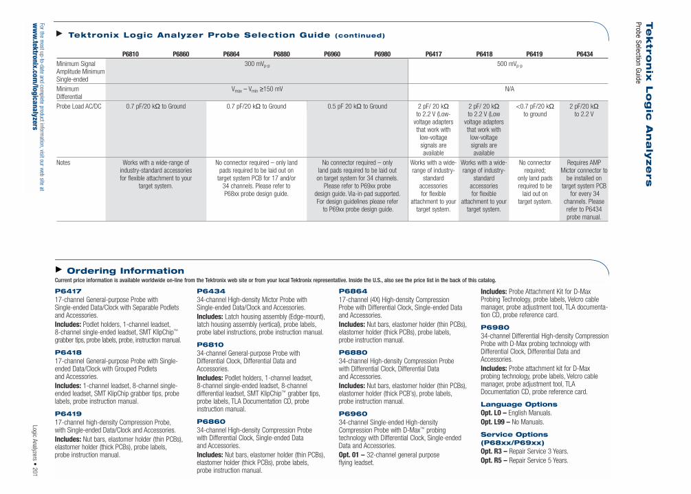
Logic Analyzers • 201For the m
ost up-to-date and complete product inform
ation,visit our web site at
ww
w.tektronix.com
/logicanalyzers
Te
ktr
on
ix L
og
ic A
na
lyze
rs
Probe Selection Guide
P6417 17-channel General-purpose Probe with Single-ended Data/Clock with Separable Podletsand Accessories.Includes: Podlet holders, 1-channel leadset,8-channel single-ended leadset, SMT KlipChip™
grabber tips, probe labels, probe, instruction manual.
P6418 17-channel General-purpose Probe with Single-ended Data/Clock with Grouped Podletsand Accessories.Includes: 1-channel leadset, 8-channel single-ended leadset, SMT KlipChip grabber tips, probelabels, probe instruction manual.
P6419 17-channel high-density Compression Probe,with Single-ended Data/Clock and Accessories.Includes: Nut bars, elastomer holder (thin PCBs),elastomer holder (thick PCBs), probe labels,probe instruction manual.
P6434 34-channel High-density Mictor Probe withSingle-ended Data/Clock and Accessories.Includes: Latch housing assembly (Edge-mount),latch housing assembly (vertical), probe labels,probe label instructions, probe instruction manual.
P6810 34-channel General-purpose Probe withDifferential Clock, Differential Data andAccessories.Includes: Podlet holders, 1-channel leadset,8-channel single-ended leadset, 8-channel differential leadset, SMT KlipChip™ grabber tips,probe labels, TLA Documentation CD, probeinstruction manual.
P6860 34-channel High-density Compression Probe with Differential Clock, Single-ended Data and Accessories.Includes: Nut bars, elastomer holder (thin PCBs),elastomer holder (thick PCBs), probe labels,probe instruction manual.
P6864 17-channel (4X) High-density Compression Probe with Differential Clock, Single-ended Dataand Accessories.Includes: Nut bars, elastomer holder (thin PCBs),elastomer holder (thick PCBs), probe labels,probe instruction manual.
P6880 34-channel High-density Compression Probe with Differential Clock, Differential Data and Accessories.Includes: Nut bars, elastomer holder (thin PCBs),elastomer holder (thick PCB’s), probe labels,probe instruction manual.
P6960 34-channel Single-ended High-densityCompression Probe with D-Max™ probing technology with Differential Clock, Single-endedData and Accessories.Opt. 01 – 32-channel general purpose flying leadset.
Includes: Probe Attachment Kit for D-MaxProbing Technology, probe labels, Velcro cablemanager, probe adjustment tool, TLA documenta-tion CD, probe reference card.
P6980 34-channel Differential High-density CompressionProbe with D-Max probing technology withDifferential Clock, Differential Data andAccessories.Includes: Probe attachment kit for D-Max probing technology, probe labels, Velcro cablemanager, probe adjustment tool, TLADocumentation CD, probe reference card.
Language Options Opt. L0 – English Manuals.Opt. L99 – No Manuals.
Service Options (P68xx/P69xx)Opt. R3 – Repair Service 3 Years.Opt. R5 – Repair Service 5 Years.
Ordering InformationCurrent price information is available worldwide on-line from the Tektronix web site or from your local Tektronix representative. Inside the U.S., also see the price list in the back of this catalog.
Tektronix Logic Analyzer Probe Selection Guide (continued)
P6810 P6860 P6864 P6880 P6960 P6980 P6417 P6418 P6419 P6434 Minimum Signal 300 mVp-p 500 mVp-pAmplitude MinimumSingle-ended Minimum Vmax – Vmin ≥150 mV N/ADifferential Probe Load AC/DC 0.7 pF/20 kΩ to Ground 0.7 pF/20 kΩ to Ground 0.5 pF 20 kΩ to Ground 2 pF/ 20 kΩ 2 pF/ 20 kΩ <0.7 pF/20 kΩ 2 pF/20 kΩ
to 2.2 V (Low- to 2.2 V (Low to ground to 2.2 Vvoltage adapters voltage adaptersthat work with that work with
low-voltage low-voltagesignals are signals areavailable available
Notes Works with a wide-range of No connector required – only land No connector required – only Works with a wide- Works with a wide- No connector Requires AMP industry-standard accessories pads required to be laid out on land pads required to be laid out range of industry- range of industry- required; Mictor connector tofor flexible attachment to your target system PCB for 17 and/or on target system for 34 channels. standard standard only land pads be installed on
target system. 34 channels. Please refer to Please refer to P69xx probe accessories accessories required to be target system PCBP68xx probe design guide. design guide. Via-in-pad supported. for flexible for flexible laid out on for every 34
For design guidelines please refer attachment to your attachment to your target system. channels. Pleaseto P69xx probe design guide. target system. target system. refer to P6434
probe manual.

For the most up-to-date and complete product information, visit our web site atwww.tektronix.com/logicanalyzers
Engineers involved with system or componentstart-up or debug face a myriad of challenges,including: CPU, chipset, board and system validation,verification or optimization; validation of hardwareand software compatibility; and capturing elusivesystems and software problems including:
System initialization failure
System timing violations
Unexpected and slow software execution
Memory variable corruption
Memory leaks
Stack overruns
Incorrect interrupt levels masking and tasking switching
Inefficient coding
The complexity introduced by these challengescan lead to uncertainty and error. Tektronix logicanalyzers help resolve many of these challenges,simplifying debug and validation tasks and speedingyour design to market.
Tektronix logic analyzers – with high synchronousacquisition speed across many channels, deep tracecaptures, very fine timing resolution and powerfultriggering – provide a base level of capability.Some technologies require specialized hardwareto access the bus and software to acquire anddisassemble the data. For system-level debug, itrequires monitoring many basis, viewed simulta-neously and time-correlated to understand howthe various sub-assemblies function as a unit andas a system.
Tektronix, along with selected third-party vendors,offers a wide range of hardware and softwareproducts that are used in conjunction with logicanalyzers to gain visibility into today’s highestbandwidth, most complicated microprocessorsand buses.
For the complete list of microprocessor and bussupport products, please visit www.tektronix.com/processors and visit
Dragonfly Software, http://www.dfsw.comNexus Technology, http://www.busboards.com
Established in 1991, Nexus Technology Inc. is thepremiere bus support and accessories supplier for Tektronix TLA Logic Analyzers. With a widerange of products, from small probe adapters and converters to high-speed PCI-X and DDRIIinterposers, Nexus and Tektronix can help anengineering team bring a product to market more quickly and with a higher level of confi-dence in their design.
In many cases a target may have connections on it that are not easily probed using the LogicAnalyzer probes that are available. Nexus offersmany different adapters, supporting various com-pression, Mictor and flying leadset configurations,to try to solve this problem. Many of theseadapters also make it more convenient to connectan oscilloscope to the available connections foranalyzing the signal integrity of the design.
In other instances a designer is looking for aneasy way to connect a TLA to a complex bus suchas PCI, PCI-X or DDR. Nexus offers many differenttypes and styles of probes to make this task easy,with designs that are simple yet created with sig-nal integrity uppermost in mind. This results inadapters that use rigid-flex-rigid manufacturingtechniques offering matched impedances, lowcapacitive loading and matched trace lengths toensure minimal intrusion upon the target design.Most of the bus supports also include softwaresupport packages that integrate with the TLA toprovide unsurpassed data acquisition and datadisplay capability of the bus in question. Nexushas also pioneered the NEXVu-style of DDRIImemory adapter to support debug of the highestmemory data rates presently in the industry.
Nexus will also work with designers to create cus-tomized solutions for their debug problems.
For more information about our existing products,or to contact us to discuss any specific needs,please contact us at:
Nexus Technology, Inc.PO Box 6575Nashua, NH 03063 www.busboards.com TEL: 877-595-8116 FAX: 877-595-8118 e-mail: [email protected]
Dragonfly Software Developmentwww.dfsw.com
Logic Analyzers Microprocessor and Bus Supports
202 • Logic Analyzers
Microprocessor & Bus Supports
Microprocessors/ General-purpose Memory Specialized Serial VideoMicrocontrollers Buses Buses Buses Buses BusesAMD, Compaq, Cypress, PCI, PCI-X, cPCI, S-DIMM, SIMM, RapidIO, SPI-4.2, IEE-1394a, USB2.0/1.1, AGP, AGP 4X, AGP3.0Cyrx, Dallas, Hitachi, IBM, GPIB, VME PC-100/133, Utopia (L1/L2/L3) Serial ATA, PCI Express,Intel, Motorola, NEC, DDR, DDR2 HypertransportRockwell, Siemens,ST Macroelectronics,TEMIC, Texas Instruments,Tsqware, Zilog

Contents
Selection Chart . . . . . . . . . . . . . . . . .205
Analog/Mixed Signal Source
AWG710B . . . . . . . . . . . . . . . . . . . . .206
AWG615 . . . . . . . . . . . . . . . . . . . . . .207
AWG520 . . . . . . . . . . . . . . . . . . . . . .208
AWG400 . . . . . . . . . . . . . . . . . . . . . .209
AWG2005 . . . . . . . . . . . . . . . . . . . . .210
AFG310/320 . . . . . . . . . . . . . . . . . . .211
AXW100 . . . . . . . . . . . . . . . . . . . . . .212
Logic Source
DTG5078/DTG5274 . . . . . . . . . . . . . .214
DG2020A/P3420 . . . . . . . . . . . . . . . .216
370B/371B Curve Tracers . . . . . . . . .218
Signal Sources • 203For the most up-to-date and complete product information, visit our web site atwww.tektronix.com/signal_sources
Signal Sources
Today’s demanding test and measurement environments call for best-in-class performance andseamless integration. Best-in-class solutions start with precise, reliable, absolutely replicablesignal generation, whether analog waveform, digital pattern or both. Fast and effective validationand characterization require both precise reference signals and true-to-life distorted signals –allowing you to quickly test your design under the widest variety of critical real-world conditions.
Tektronix’ signal sources – analog, digital and mixed – allow you to quickly isolate, reproduceand solve problems, validate designs and characterize performance to speed new products to market.
Signal Sources

Analog/Mixed Signal Sources
Analog/mixed signal sources – also known asarbitrary waveforms generators and arbitraryfunction generators – offer a degree of versatilitythat few other instruments can match. In additionto creating standard waveforms, they can generate“real world” signals with all the glitches, drift, noiseand other anomalies that a device-under-test willencounter when it leaves the lab or manufacturingfloor. With their ability to produce any waveformyou can imagine, mixed signal sources embraceapplications that include automotive ABS simula-tion and engine control, wireless network stresstesting, serial data communication simulation,disk drive testing, transducer and biomedical simulations, and much more.
Tektronix offers a wide variety of arbitrary wave-form generators (AWG) that have the capabilitiesto earn the title of “Mixed Signal Source.” Fromthe high performance AWG710B that combines
world class signal fidelity with ultra high-speedmixed-signal simulation, to the affordable 16 MS/sbench AFG300 Series, Tektronix has an arbitrarysignal source to meet your application needs.
Arbitrary waveform generators have evolved fromsimple digital-to-analog (D/A) converters tosophisticated signal sources with powerful creation,editing, triggering and real-time sequencing capa-bilities. Designers use these instruments to testtheir products to ensure that they operate underthe actual conditions that their designs willencounter in the “real world.”
Tektronix’ AWGs combine world-class signal fidelitywith ultra high-speed mixed signal simulation, apowerful sequencing capability and graphical userinterface with flexible waveform editor to solve the toughest measurement challenges in the diskdrive, communications and semiconductordesign/test industries.
Analog/Mixed Signal Sources
204 • Signal SourcesFor the most up-to-date and complete product information, visit our web site at
www.tektronix.com/signal_sources
Applications Storage Media – Magnetic Disk and Optical Disk – Read/Write Channel – Peak Shift – Bit Drop Out– Servo Control– Mixed Signal ASICs
Simulate Network Physical Layer – PCI-Express/Serial-ATA– Gigabit Ethernet/SONET– Pre-emphasis and
De-emphasis Signal– Jitter Generation– Spread Spectrum Clocking
Simulate Wireless Signals – IQ, IF and RF Signal– Mobile Communication– High Data Rate Digital Modulation– FSK, PSK, AM
Automotive Simulation – Engine Control Modules– Ignition Systems– Mechanical Vibration Analysis– Anti-lock Braking– Safety Restraining Systems
Simulate Biomedical Waveforms – Physiological Responses– Heart Fibrillation– Blood Gas Content– EEG and EKG
Avionics Simulation – Radar System– Flight Characterization– Data Recorders– ILS/MLS/VOR

Signal Sources
Signal Sources • 205For the most up-to-date and complete product information, visit our web site atwww.tektronix.com/signal_sources
Product Channels Sample Memory Vertical Output Marker Parallel Integrated Built-in Complementary(Max.) Rate Depth Resolution Amplitude Outputs Digital Editors Applications Products
(Max.) (Max.) (bits) (Max.)*1 (Max.) Outputs (Max.)
AWG710B 1 4.2 GS/s 64 M 8 2 2/ch – G, E, S DD, NPL, JGAWG615 1 2.7 GS/s 64 M 8 2 2/ch – G, E, S DD, NPL, JGAWG520 2 1.0 GS/s 4 M 10 2 2/ch 10 G, E, S DD, NPL, JGAWG400 Series 3 200 MS/s 16 M 16 5 2/ch 48 G, E, S NPL, JG, DMAWG2005 4 20 MS/s 64 k 12 10 1/ch 24 G, E, S –
AFG300 Series 2 16 MS/s 16 k 12 10 1 (Sync) – T –
ArbExpress™ G, E AWG, AFG, TDS1000,TDS2000, TDS3000Series oscilloscopes
*1 Vp-p into 50 Ω.
Analog/Mixed Signal Source Selection Made Easy
Integrated Editors: Built-in Features:G = Graphical DD = Disk DriveE = Equation NPL = Network Physical LayerS = Sequence JG = Jitter GenerationT = Text DM = Digital Modulation
Arbi
trary
Wav
efor
m a
nd F
unct
ion
Gene
rato
rs
TDS/CSA7000B,TDS6000BSeries oscilloscopes,TLA logic analyzers
TDS5000B, TDS3000BSeries oscilloscopes,TLA logic analyzers
TDS3000B, TDS2000,TDS1000 Series
oscilloscopes
Logi
c An
alyz
er M
odul
e an
d Da
ta T
imin
g/Da
ta P
atte
rn G
ener
ator
s Product Channels Data Rate Pattern Timing Output Rise/Fall Auxiliary Auxiliary Advanced Complementary(Max.) (Max.) Depth Resolution/ Amplitude / Time*1 Inputs Outputs Features Products
(Max.) Range Resolution(Max) *1
DTG5274 16 3.35 Gb/s 32 M 200 fs / 480 ns*2 Three modules Three modules CI, PL, DC, CO, PC, JG, TLA logic analyzers;DTG5078 96 800 Mb/s 8 M 1 ps / 480 ns*2 support from offer from TI, TR, TO, SO VC, PG TDS/CSA7000,
0.03 to 3.5 <540 ps to EI, SI TDS6000 Series Vp-p/5 mV <110 ps*3 oscilloscopes
DG2020A 36 200 Mb/s 64 k 100 ps *7 / 20 ns Two pods Two pods CI, TR, II CO, EO, TS TLA logic analyzers;support TTL support from SO TDS/CSA7000,and variable <5 ns TDS6000 Series
up to 9.0 to <3 ns oscilloscopesVp-p/100 mV
TLA7PG2*8 64 per 268 MHz 2 M period Various pods Various pods CI, EI, II*9 CO*9, ST*9 PC,TS*9 TLA7PG2 is the patternmodule, clock rate resolution support TTL, support from generator module for
3,840 per 8 digits/ CMOS, ECL, 320 ps TLA700 Series system 2.0000000 s to PECL, LVPECL, to 6.5 ns logic analyzers
3.7313432 ns and variable
Logic Signal Source Selection Made Easy
*1 Vp-p into 50 Ohm, unless noted
*2 Based on data rate setting
*3 Variable or fixed, depending on module
*4 Channel delay only
*5 Fixed
*6 Variable
*7 Four channels only per pod, delay only
*8 Pattern generator module for TLA700 Series logic analyzers
*9 Depends on pod
Advanced Features:PC = PC/Windows platformJG = Jitter generationVC = Variable crossing points, duty cyclePG = Pulse generator modeTS = Tri-state output control
Auxiliary Inputs:CI = External Clock INPL = Phase Lock INTI = 10 MHz Ref INTR = Trigger INEI = Event INII = Inhibit INSI = Skew Cal IN
Auxiliary Outputs:DC = DC outputsCO = Clock OUTTO = 10 MHz Ref OUTEO = Event OUTSO = Sync OUTST = Strobe Output

206 • Signal SourcesFor the most up-to-date and complete product information, visit our web site at
www.tektronix.com/signal_sources
Arbitrary Waveform GeneratorAWG710BNEW
New two-box synchronous operation function supports 2 ch 4.2 GS/s solution.
The AWG710B combines world-class signal fidelitywith ultra high-speed mixed signal simulation, apowerful sequencing capability and graphical userinterface with flexible waveform editor, to solvethe toughest measurement challenges in the diskdrive, communications and semiconductordesign/test industries.
The built-in signal applications enable you to easilycreate standard waveforms for disk drive readchannels, communications up to 4.2 Gb/s. Alsoincluded is AXW100 ArbExpress™ waveform creation and editing software. This softwareallows for easy waveform import from oscilloscopesor basic, advanced, and math waveform creation and edit capabilities.
Features & Benefits4.2 GS/s Sample Rate SimulatesReal-world Signals Up To 2.1 GHz
Two Markers With 2.0 psRMS(at 4.2 GS/s Typical) Jitter DeliverStable Timing to the Device-under-Test (DUT)
32.4 M (32,400,000) or 64.8 M(64,800,000) Point Record LengthProvide Longer Data Streams
Analog Bandwidth to 2 GHz (Option02, Calculated Based on Rise Time)Provides the Highest Signal Fidelity of All High-speed AWGs
Direct External Clock Input AllowsJittered and Non-jittered Signals forHigh-speed Data Stream TimingMargin Test Up To 4.2 Gb/s
Synchronous Operation ModeSupports Two AWG710B Outputs (2: Analog, 4: Marker) Synchronizationfor High Data Rate Wireless and DataCommunication Test and OpticalWrite Channel Strategy Signal Test
Waveform Quick Editor with 300 fsEdge Timing Resolution DeliversOutput Edge Control with Near Real-time Precision
Allows Two-signal Mix FunctionDigitally to Support Disk Drive Noise Performance Test and Pre/De-emphasis Serial DataCommunication Test
Real-time Sequencing Creates Infinite Waveform Loops, Jumps,Patterns and Conditional Branches
Applications Disk Drive Read/Write Design and Test
Communications Design and Test
Arbitrary IF and IQ Base-band Signals
Standard Waveforms forCommunications
Pulse Generation
AWG710B4.2 GS/s, 8-bit, 32 M point, single-channel arbitrary waveform generator.Includes: User manual, Programmer’s manual,Floppy disk: sample waveform library (063-A3740-00),performance verification (063-3721-00), SampleProgram (062-A258-50), AXW100 ArbExpressSoftware Utility CD (063-3763-00 ), Certificate ofCalibration, power cable. 50 Ω SMA Terminator twoeach (015-1022-01).Please specify power plug when ordering.
Options Opt. 01 – 64 M points waveform memory.Opt. 02 – Extends analog bandwidth to 2 GHz (calculated based on rise time).Opt. 10*1 – Flash disk and standby switch (alternativefor standard hard disk drive).Note: Option 10 is for ATE and system usage needing7x24 hour operation. Also adds capability to poweron/off by rear panel main switch.Opt. 11*1 – Removable Hard Drive.Opt. 1R – Rack Mount Kit.*1 Options 10 and 11 are mutually exclusive.
For your local Tektronix representative see the list in the back of this catalog or outside the U.S. call: 1-503-627-7111, inside the U.S. call: 1-800-833-9200.
Ordering InformationCurrent price information is available worldwide on-line from the Tektronix web site or from your local Tektronix representative. Inside the U.S., also see the price list in the back of this catalog.
Disk drive read channel application.
The AWG710B Arbitrary Waveform Generator Delivers World-class Signal Fidelity at 4.2 GS/s to Solve Ever-increasing Measurement Challenges

Signal Sources • 207
Arbitrary Waveform GeneratorAWG615NEW
New two box synchronous operation function supports 2ch 2.7 GS/s solution.
The AWG615 combines world-class signal fidelitywith high-speed mixed signal simulation, a pow-erful sequencing capability and graphical userinterface with flexible waveform editor, to solvethe toughest measurement challenges in the diskdrive, communications and semiconductordesign/test industries.
The built-in signal applications enable you to eas-ily create standard waveforms for disk drive readchannels, communications up to 2.7 Gb/s such asITU-T,TI.102, Fibre Channel and SDH/SONET alsovarious semiconductor applications.
Features & Benefits2.7 GS/s Sample Rate Simulates Real-world Signals Up To 1.35 GHz
2 Markers With 2.1 psRMS (@ 2.7 GS/s,Typical) Jitter Deliver Stable Timing tothe Device-under-test (DUT)
32.4 Mb (32,400,000) or 64.8 Mb(64,800,000) Point Record LengthProvide Longer Data Streams
Analog Bandwidth to 2 GHz (Option02, Calculated Based on Rise Time)Provides the Highest Signal Fidelity of All High-speed AWGs
Direct External Clock Input AllowsJittered and Non-jittered Signals forHigh-speed Data Stream TimingMargin Test up to 2.7 Gb/s
Synchronous Operation ModeSupports Two AWG615B Outputs (2: Analog, 4: Marker) Synchronizationfor High Data Rate Wireless and DataCommunication Test and Optical WriteChannel Strategy Signal Test
Waveform Quick Editor with 400 fsEdge Timing Resolution DeliversOutput Edge Control with Near Real-time Precision
Allows Two-signal Mix FunctionDigitally to Support Disk Drive NoisePerformance Test and Pre/De-emphasisSerial Data Communication Test
Real-time Sequencing Creates InfiniteWaveform Loops, Jumps, Patternsand Conditional Branches
Applications Disk Drive Read/Write Design and Test
Communications Design and Test
Arbitrary IF and IQ Base-band Signals
Pulse Generation
High-speed, Low-jitter Data and Clock Source
Mixed Signal Design and Test
The AWG615 Arbitrary Waveform Generator DeliversWorld-class Signal Fidelity at 2.7 GS/s to SolveEver-increasing Measurement Challenges
AWG6152.7 GS/s, 8-bit 32 M point, single channel arbitrarywaveform generator.Includes: User manual (071-1512-00), Programmer’smanual (071-1513-00), Floppy disk: sample waveformlibrary (063-3779-00), performance verification (063-3780-00), Sample Program (062-A258-50),Certificate of Calibration, 50 Ω SMA Terminator 2 each(015-1022-01), power cable.
Options Opt. 01 – 64 M points waveform memory.Opt. 02 – Extends analog bandwidth to 2 GHz (calculated based on rise time).Opt. 10 – Flash disk and standby switch (alternativefor standard hard disk drive).Note: Option 10 is for ATE and system usage needing7x24 hour operation. Also adds capability to power on/offby rear panel main switch.Opt. 1R – Rackmount kit.
For your local Tektronix representative see the list in the back of this catalog or outside the U.S. call: 1-503-627-7111, inside the U.S. call: 1-800-833-9200.
Ordering InformationCurrent price information is available worldwide on-line from the Tektronix web site or from your local Tektronix representative. Inside the U.S., also see the price list in the back of this catalog.
Waveform Mixing Function.
For the most up-to-date and complete product information, visit our web site atwww.tektronix.com/signal_sources

The AWG520’s unique design combines a graphicalediting display with powerful output capabilitiesto simplify the creation of arbitrary and complexwaveforms and enable easy on-screen waveformediting. With the AWG520’s many built-in intuitiveand powerful features, you can easily developand edit custom waveforms. Option 03 adds anindependent 10-bit-wide digital data port that canbe used in conjunction with marker outputs fordata generation up to 14-bits wide at up to 1GHz. Direct waveform transfer capability makesthe AWG520 the perfect complement to selectedTektronix oscilloscopes for:
Communications Design and Test – Low frequency modulated RF with components
using AM and FM modulation – Digital information encoding using FSK, PSK
and QAM (Quadrature Modulation) for cellular,fax and modem communications
Optical Communications Design and Test – Reflections, Crosstalk and Ground
Bounce Simulation
Pulse Generation – Duty Cycle Ranges from 0% to 100%
for NRZ Data – Testing Clock/Gating Width Variations
Real-world Simulations– Corrupt Ideal Waveforms – Add Jitter to Waveforms – Power Supply Noise and Ripple
Arbitrary Waveform Generator AWG520
208 • Signal SourcesFor the most up-to-date and complete product information, visit our web site at
www.tektronix.com/signal_sources
AWG520 1 GS/s, 10 bit, 4 M point, Dual-channel Arbitrary Waveform Generator.Includes: User manual (071-0099-50), Programmermanual (070-A810-50), GPIB programming examplesdisk (063-2982-50), sample waveform library disk(063-2981-50), performance verification disk (063-2983-50), ArbExpress™ (AXW100), power cord,fuse (159-0239-00).
Options Opt. 03 – Ch 2 10-Bit output up to 1 GHz.Opt. 10 – Flashdisk (128 MB) and standby switch –removes HDD. (Opt. 10 is best suited for ATE and system usage requiring 7x24 hour operation.)Opt. 11 – Removable Hard Disk (exclusive to Opt. 10and/or Opt. 3).Opt. 1R – Rackmount kit.
For your local Tektronix representative see the list in the back of this catalog or outside the U.S. call: 1-503-627-7111, inside the U.S. call: 1-800-833-9200.
Ordering InformationCurrent price information is available worldwide on-line from the Tektronix web site or from your local Tektronix representative. Inside the U.S., also see the price list in the back of this catalog.
AWG520 Solves Communications Physical Layer andMedia Storage Design and Test Challenges
Features & BenefitsTwo Channels with 10-Bit Vertical Resolution
Independent 10-Channel, 1 GHzDigital Data Generation (with Opt. 03)
Built-in Independent Real-time Noise Generation
External Clock Input Permits JitterInsertion and Synchronization
Unique Real-time Sequencing LinksMultiple Waveform Files CreatingWaveforms of Nearly Infinite Length
Built-in Application Generates Jitter,Data Communication and Disk DriveWaveforms
Built-in 10 GB Hard Drive for MassData Storage That Can Optionally Be Made Removable for SecureApplications (Using Opt 11)
Optional 128 MB Flash Disk for ATE Applications (Opt. 10)
Applications Communications Design and Test: – Low Frequency Modulated RF
with Components Using AM and FM Modulation
– Digital Information Encoding UsingFSK, PSK and QAM for Cellular, Fax and Modem Communications
Optical Communications Design and Test: – Reflections, Crosstalk and Ground
Bounce Simulation
Pulse Generation: – Duty Cycle Ranges From 0%
to 100% for NRZ Data – Testing Clock/Gating Width Variations

The AWG400 Series performs a wide range ofmodulated (I&Q) and mixed signal simulations(analog & digital) for wireless and wired datacommunication, in addition to semiconductordevice characterization. The AWG400 is ideal fordesign or manufacturing test engineers who needto replicate marginal and erroneous analog andmixed signal conditions. The only product in itsclass offering 200 MS/s, 16-Bit vertical resolution,
2 or 3 channel configurations and optional digitaloutputs (32 or 48). The AWG400 is a superiorchoice for those who need an additional channel,longer memory or higher vertical resolution. Thecolor display, graphical user interface and stand-alone Microsoft Windows-based waveform creatingutility (ArbExpress™) supports quick creation, edit-ing and output of custom or imported waveforms.
Arbitrary Waveform Generator AWG400 Series
Signal Sources • 209For the most up-to-date and complete product information, visit our web site atwww.tektronix.com/signal_sources
Features & Benefits2 or 3 Independent Waveform Channels
16-Bit Vertical Resolution
200 MS/s Sample Rate
Up to 16 Mb Point Record Length
Optional 32/48-Bit 100 MHz (CMOS)Digital Data Generator for Mixed-signal Device Testing
4 or 6 Digital Marker Outputs
Independent Channel Internal Noise Generator
Independent Channel Skew Control
Independent Channel External SignalADD-INPUT
External Clock and ExternalReference Inputs
Applications
Designing, Testing and Deploying
Quadrature Digitally Modulated I&Q Signals and Displays
Mixed (Analog/Digital) Signals
Stimulus Signals for Imaging Displayand Recording Devices (CCD, LCD)
Enhanced/Corrupted Playback of DSO Captured Signals
Simulation Waveform VectorsImported from Mathcad, Matlab,Excel and Others
AWG420.
AWG420200 MS/s, 16-Bit Two Channel Arbitrary Waveform Generator.
AWG430200 MS/s, 16-Bit Three Channel Arbitrary Waveform Generator.All Include: User manual (070-A809-51), Programmermanual (070-A810-50), GPIB programming examples(062-A258-50), sample waveform library disk (062-A257-50), performance verification (062-A270-50),Cal. Certificate no charge, ArbExpress (AXW100),software, power cord.
Options Opt. 01 – 16 M point waveform memory.Opt. 03 – CMOS Digital Data Outputs – 32/48-Bit (numberof digital output bits depends on AWG400 model).Opt. 05 – Single-ended output (alternative for standardcomplementary output).Opt. 10 – 128 MB Flash disk and standby switch(alternative for standard hard disk drive).Note: Opt. 10 is for ATE and system usage needing24x7 hour operation. Also adds capability to poweron/off by rear panel main switch.Opt. 1R – Rackmount kit.
For your local Tektronix representative see the list in the back of this catalog or outside the U.S. call: 1-503-627-7111, inside the U.S. call: 1-800-833-9200.
Product(s) complies with IEEE Standard 488.1-1987,RS-232-C, and with Tektronix Standard Codes and Formats.
Ordering InformationCurrent price information is available worldwide on-line from the Tektronix web site or from your local Tektronix representative. Inside the U.S., also see the price list in the back of this catalog.

210 • Signal SourcesFor the most up-to-date and complete product information, visit our web site at
www.tektronix.com/signal_sources
Arbitrary Waveform GeneratorAWG2005
The AWG2005 offers 20 MS/s and 64 k memory.As with the entire AWG2000 Series, the graphicaluser interface allows on-screen viewing of wave-form editing, simplifying “what if” test scenariosby allowing the easy creation of composite signals.
The standard AWG2005 configuration providestwo independent 10 V outputs or a third andfourth 10 V output (Option 02) each with 12-Bitsvertical resolution.
Option 04 adds TTL digital levels with (2) 12-Bit,20 MS/s ports and combines with the markeroutputs to provide a total of 28-Bits wide.
The built-in frequency domain (FFT) editor (Option09) is a perfect addition for customers performingproprietary or standard I & Q modulation simulations,filter design or in circuit testing of physical layer.
Real time waveform sequencing extends the effec-tive record length output to over a billion points!
The AWG2005 easily simulates signals wheremoderate point definition and long records arerequired for simulating complex waveform condi-tions. Direct waveform transfer capability makesthe AWG2005 the perfect complement to selectedTektronix oscilloscopes.
Features & Benefits20 MS/s (50 ns) Clock Rate Providesup to 10 MHz Waveforms
Up to Four Channels of 64 k Record Length
12-Bit Vertical Resolution
Direct DSO Waveform Transfers
Region Shift Provides 50 ps Edge Placement
24-Bit Channel, TTL Digital DataGenerator (Opt. 04)
Built-in 1.44 MB, 3.5 in. Floppy Disk
Frequency Domain Editing with FFT Editor (Opt. 09)
Real-time Waveform Sequencer to Easily Create Automatic Test Sequences and Extremely Long Patterns
Formula Entry Waveforms
Fully Programmable from Front Panel,RS-232 and GPIB (IEEE 488.2)
Applications Analog & Digital Modulation
Digital Baseband Modulation
Sonar Testing
Transducer Simulation
Motor Control
Automotive
Education
Industrial
Sensors
Semiconductor/Logic
AWG200520 MS/s, 12-bit 64k point, Dual Channel ArbitraryWaveform Generator.Includes: User manual (070-8958-50), Programmer’smanual (070-8657-50), Floppy disk: sample waveformlibrary (063-1704-50), performance verification (063-1706-50), Sample Program (063-1708-50),Certificate of Calibration, ArbExpress™ software(AXW100), power cable.
OptionsOpt. 02 – Add Two Channels (four total).Opt. 04 – 24-Bit, TTL Digital Data Out*1*2.Opt. 05 – Add Clock Sweep.Opt. 09 – Add FFT Editor. Allows editing waveforms inthe frequency domain*1.Opt. 1R – Rackmount. Floppy Drive Access Moved to Front.*1 Opt. 04 and Opt. 09 are mutually exclusive.*2 Opt. 04 eliminates RS-232 interface.
For your local Tektronix representative see the list in the back of this catalog or outside the U.S. call: 1-503-627-7111, inside the U.S. call: 1-800-833-9200.
Ordering InformationCurrent price information is available worldwide on-line from the Tektronix web site or from your local Tektronix representative. Inside the U.S., also see the price list in the back of this catalog.
The AWG2005 Arbitrary Waveform GeneratorDelivers Four Channel Output with High Amplitudefor Multi-purpose Signal Generation

Signal Sources • 211For the most up-to-date and complete product information, visit our web site atwww.tektronix.com/signal_sources
Arbitrary Function Generators AFG310 • AFG320
Function Generator
The AFG300 Series is an excellent 16 MHz function generator with built-in arbitrary waveform,burst, sweep, and modulation capabilities. Theinstruments support standard waveforms includingsine, square, triangle, ramp, pulse, DC and noise.Its sweep function includes Linear and Logarithmic(up or down) while operating in the Continuous,Triggered and Burst modes.
Arbitrary Waveform Generation
With a sampling rate of 16 MS/s, 12-Bit verticalresolution and a non-volatile memory that holdsfour 16,384-point waveforms, the AFG300 Seriesare powerful tools for simulating complex waveforms. Waveforms can be downloadeddirectly from selected Tektronix oscilloscopes andarbitrary waveform generators via GPIB, createdwith the standard ArbExpress™ waveform editingsoftware package, or entered via the front panel.
AFG310/AFG320.
Features & BenefitsFive Functions in One Instrument – Function Generator – Arbitrary Waveform Generator – Burst Generator – Sweep Generator – Modulation Source
AFG320 Offers Two Independent Channels
Load Waveforms Directly fromSelected Tektronix DigitalOscilloscopes via the GPIB Interface
Windows-based ArbExpressWaveform Editing Software PackageIncluded for Convenient Creation andEditing of Arbitrary Waveforms
Optional Rackmount Kit for System Applications
Applications Simulate Waveforms in Design, Testand Manufacturing
Computer and CommunicationsSerial Data and Clock, MagneticCard Readers, Power SupplyLoads, Noise Injection
AutomotiveEngine Control Modules, IgnitionSystems, Anti-lock Braking, SafetyRestraining Systems
BiomedicalPhysiological Responses, HeartFibrillation, EEG and EKG
IndustrialSensor Simulation, Actuator Drive Signals
EducationLaboratory Classes, GraduateResearch
AFG310Single-channel Programmable Arbitrary Function Generator.
AFG320Dual-channel Programmable Arbitrary Function Generator.Includes: User manual, Calibration Certificate, powercord, ArbExpress Software.
Service OptionsTektronix CAL and REP Service programs allow you topre-purchase genuine Return to Tektronix Service. Askyour Distributor for details.
Opt. C3 – Calibration Service 3 Years.Opt. D1 – Calibration Data Report.Opt. D3 – Calibration Data Report 3 Years (with Option C3).
For your local Tektronix representative see the list in the back of this catalog or outside the U.S. call: 1-503-627-7111, inside the U.S. call: 1-800-833-9200.
Product(s) complies with IEEE Standard 488.1-1987,RS-232-C, and with Tektronix Standard Codes and Formats.
Product Area Assessed: The planning, design/development andmanufacture of electronic Test and Measurement instruments.
Ordering InformationCurrent price information is available worldwide on-line from the Tektronix web site or from your local Tektronix representative. Inside the U.S., also see the price list in the back of this catalog.
AFG300 Series Delivers Five Functions in One Tool

Designers often need to ensure their designsoperate under real-world conditions. Engineersneed tools to quickly and effectively harness thepower of their Arbitrary Waveform Generator.
ArbExpress™ allows for improved efficiency withfast and effortless waveform creation and transferto your Tektronix AFG/AWG mixed signal sources.
CharacteristicsUser Interface – Windows-based 98/Me/NT4/2000/XP.Displays – Waveform and Marker Data.
Waveform Translation
Oscilloscope – Import Waveforms directly from TDS1000, 2000, 3000series oscilloscopes.Translation of Oscilloscope .WFM Waveform formats toAWG/AFG formats.
MATLAB – Command set.AWG – Tektronix AWG 400, 500, 600, 700 and 2000 series.AFG – Tektronix AFG300 series.MATHCAD – ASCII.Others – *.CSV, ASCII.
Standard Waveforms
Basic Waveforms – Sine, Square, Triangle, DC,Pulse, Noise (Gaussian White, Pink) Exponential riseand Exponential decay.Advance Waveforms – Sinc, Sweep (linear),Multi-tone, and Lorentz.Users can control the different parameters of the waveform being created.Parameters – Amplitude, Frequency, Phase, Cycles.Extended Functions –Supports preview before committing to changes.Supports Multiple Waveform Display.
Features & BenefitsComprehensive Library Enables Quick Waveform Creation ChosenFrom Standard or Advance Waveform Selections
Capture of Oscilloscope Data andSeamless Translation, ShrinksTranslation Time and Minimize Errors
Send Waveforms to AWG DirectlyFrom ArbExpress or Matlab
Unparalleled Ease of Equation Building Increases Efficiency
Validation of Waveform Parameters Specific to the Selected Instrument Type
Math Operations on Waveforms(From Waveform Library, Scalar & Clip Board)
Digital Marker Output Editor Allows for Easy Generation and Editing of Marker Pulses
Multi Waveform Overlay Viewing forEasy Comparisons and Editing.
File Transfer and Control Allows forEasy Loading of Edited Waveforms to the Connected AWG/AFG
.NET Based Application
Applications Program Arbitrary and StandardWaveforms for– Characterization– Functional Test– Design and Validation
Create Complex Waveforms for – Phase Comparator Test by Phase
Difference Signals– Modulation Signal Test by
AM/FM/PM Signals– Frequency Response Test by
Sweep (Liner) Signals– SFDR/Signal IM Test by Multi-tone
Signals
Create Real-world Signals for– Sensors Output Simulation– Actuator Driving Signals
Capture, Edit and Replay of DSORecorded Real-world Signals
212 • Signal SourcesFor the most up-to-date and complete product information, visit our web site at
www.tektronix.com/signal_sources
ArbExpress™ Software for Arbitrary Waveformand Arbitrary Function Generators
AXW100NEW
Efficient and Effortless Waveform Creation and EditingTool for Tektronix AWG and AFGs
AXW100 ArbExpressAvailable only as a free download fromwww.tektronix.com/axw.
For your local Tektronix representative see the list in the back of this catalog or outside the U.S. call: 1-503-627-7111, inside the U.S. call: 1-800-833-9200.
Ordering InformationCurrent price information is available worldwide on-line from the Tektronix web site or from your local Tektronix representative. Inside the U.S., also see the price list in the back of this catalog.
AA000000__22447799..ttiiff

Logic Sources
Logic sources – also known as data, pattern andpulse generators – are specialized tools used totackle specific digital test requirements. Theirmission is to produce digital signals with precisecontrol over digital signals properties like edgeplacement and amplitudes to meet a variety ofdigital stimulus needs, producing the streams of1s and 0s needed to test high bandwidth buses,semi conductor devices and other digital systems.
Data rates up to 3.35 Gbps and timing resolution down to 0.2 ps
96 channels and beyond
Advanced controls support stressed eye generation
Built-in jitter generation
Full complement of auxiliary inputs to synchronize and trigger between devices
Pulse generator (PG) and data generator (DG) modes speed setup
Compact form factor with modular, configurablearchitecture scales to changing needs
Logic Sources • 213For the most up-to-date and complete product information, visit our web site atwww.tektronix.com/signal_sources

214 • Logic SourcesFor the most up-to-date and complete product information, visit our web site at
www.tektronix.com/signal_sources
New serial data standards, expanding networks,and ubiquitous computing continually redefine the cutting-edge of technology. The design engineer is challenged to economize without sacrificing performance.
The DTG5000 Series combines the power of adata generator with the capabilities of a pulse generator in a versatile, bench-top form factor,simplifying the generation of low-jitter, high-accuracy clock signals and serial data across multiple channels. Its modular platform allowsyou to easily configure the performance of the instrument to your existing and emerging needs to minimize equipment costs. Two mainframes and three plug-in output modules combine to cover a range of applications from legacy devicesto the latest technologies. In addition, eight low-current, independently-controlled DC outputscan substitute for external power supplies. Eachmainframe incorporates a full complement of auxiliary input and output channels to easily integrate with other instruments, such as oscilloscopes and logic analyzers, to create a flexible and powerful lab.
The mainframe’s high-performance internal clock determines maximum data rate, and theinternal architecture determines maximum channel count and pattern memory per channel.
The plug-in module’s output drivers determinevoltages as well as transition times as indicated in the table that follows.
Both mainframes support two operating modes.The pulse generator mode easily creates pulsepatterns on channels along with delays asrequired. The DG mode supports more complextest setups and data patterns. In addition, eightadjustable DC Outputs are built right into theinstrument – an industry first.
Robust Pattern Tools
Long Pattern Memory andPowerful Sequencer EqualUnrivaled Flexibility
Long pattern memory is important not only tosupport long individual data patterns, but also tosupport multiple vectors called up in sequencing.Both DTG mainframes come with more memoryper channel than any other comparable instru-ment. The DTG5078 offers 8 Mbits of patternmemory and the DTG5274 comes with 32 Mbitsper channel. When combined with the powerfulsequencer, you have unprecedented ability tocontrol waveform data for the most demandingtesting regimens. This amount of memory, and thepowerful sequencer, allows you to conduct moretests without the need to transfer data to the DTG.
Features & BenefitsUp to 2.7 Gbps Data Rate,Extendable to 3.35 Gbps
From 2 to 96 Data Channels(Master/Slave) and More ThroughClock Synchronization
Class Leading Delay Resolution and Range – 0.2 ps (DTG5274), 1 ps (DTG5078)
Delay Resolution – Up to 600 ns of Total Delay
Versatile Platform Combines Featuresof Data Generator, Pulse Generator,and DC Source
Modular Architecture Helps to Protect Your Investment and Allowsthe Instrument to Expand With YourGrowing Needs
Advanced Control Over SignalParameters to Meet Most CurrentTesting Needs; Like Stressed Eye Generation – Built-in Jitter Generation and
Crossing Point Control – Level Control with 5 mV Resolution – Variable Edge Slew Rates
Easy to Use and Learn Shortens Time to Test – Plug-in Modules Easily Configure
Instrument to Your Needs – Intuitive User Interface Based
on Windows 2000 – Convenient Bench Top Form Factor – Integrated PC Supports Network
Integration and Built-in CD-ROM,LAN, Floppy Drive, USB Ports
Up to 32 Mbit Pattern Depth SupportsLong Data Patterns
Applications Semiconductor Device FunctionalTest and Characterization – Support for Semiconductor
Technologies from TTL to LVDS,Depending on Output Module
– Initial Verification and Debugging,Comprehensive Characterization,Manufacturing and Quality Control
Functional, Compliance and Interoperability Testing to Emerging Standards – PCI-Express – InfiniBand – RapidIO – DVI – HDMI
Magnetic and Optical Storage Design – Characterization and Functional
Testing of Next-generationMagnetic and Optical StorageDevices (HD, CD/DVD/Blue-ray)
Jitter Transfer and Jitter Tolerance Testing
Data Timing GeneratorDTG5078 • DTG5274

Data Timing GeneratorDTG5078 • DTG5274
Logic Sources • 215For the most up-to-date and complete product information, visit our web site atwww.tektronix.com/signal_sources
Class-Leading Timing Control
Starting with precise control over timing parameters, the internal clocks of the DTG5000Series provide for a wide range of data rates withsetting resolution to 8 digits with an internal clockaccuracy of ±1 ppm. Custom delay circuitry provides the all-important ability to add exactamounts of delay between channels. Adding precisely controlled amounts of skew betweenchannels is fundamental for exploring setup-and-hold relationships and testing a device’s tolerancefor channel-to-channel skew. The DTG5078’s resolution setting is 1 ps, the setting for theDTG5274 is a class-leading 0.2 ps.
Mainframes
DTG5078750 Mbps, 8 slot mainframe.
DTG52742.7 Gbps, 4 slot mainframe.Mainframes Include: Windows® 2000 professionaloperating system recovery disk, DTG5000 Series application software install disk, user manual (volumesI and II), programmers manual, technical reference,registration card, accessory pouch, front cover, compactUSB keyboard, USB mouse, lead set for DC Output,16-CON, twisted pair, 24 in. (60 cm), 50 Ω SMA terminator (male, DC to 18 GHz), SMA connector cap(10 ea. with DTG5078, 8 ea. with DTG5274), powercord, calibration certificate.Please specify power cord and language optionwhen ordering.
Service OptionsOpt. C3 – Calibration Service 3 Years.Opt. C5 – Calibration Service 5 Years.Opt. TDAT – Calibration Data Report (Japanese).Opt. D1 – Calibration Data Report (English).Opt. D3 – Calibration Data Report 3 Years (with Option C3).Opt. D5 – Calibration Data Report 5 Years (with Option C5).Opt. R3 – Repair Service 3 Years.Opt. R5 – Repair Service 5 Years.
For your local Tektronix representative see the list in the back of this catalog or outside the U.S. call: 1-503-627-7111, inside the U.S. call: 1-800-833-9200.
Product(s) are manufactured in ISO registered facilities.
Product(s) complies with IEEE Standard 488.1-1987,RS-232-C, and with Tektronix Standard Codes and Formats.
Ordering InformationCurrent price information is available worldwide on-line from the Tektronix web site or from your local Tektronix representative. Inside the U.S., also see the price list in the back of this catalog.
Mainframe DTG5078 DTG5274Max. Data Rate 750 Mbits (NRZ) 2.7 Gb/s (NRZ)
375 Mbits (RZ, R1, pulse) 1.35 Gb/s (RZ, R1, pulse)(extendable to 800 Mbits (NRZ)) (extendable to 3.35 Gb/s (NRZ))
Number of Module Slots 8 4Delay control 1 ps resolution (All ch) 0.2 ps resolution (All ch)Width control 5 ps resolution (for A-D) 5 ps resolution (All ch)Data depth 8 Mbits per channel 32 Mbits per channel
Output Module DTGM10 DTGM20 DTGM30 DTGM10 DTGM20 DTGM30Number of Channels 4 4 2 2 of 4 2 of 4 2Level (50 Ω) 3.5 Vp-p 3.5 Vp-p 1.25 Vp-p 3.5 Vp-p 3.5 Vp-p 1.25 Vp-pLevel (1 MΩ) 10 Vp-p 7 Vp-p 2.5 Vp-p 10 Vp-p 7 Vp-p 2.5 Vp-pTr/Tf at 1 Vp-p <540 ps <340 ps <110 ps <540 ps <340 ps <110 psinto 50 Ω (Variable) (Variable) (Variable) (Variable)(20% - 80%)
Master-Slave operation Up to 3 DTG5078 Up to 2 DTG5274
Characteristics

For the most up-to-date and complete product information, visit our web site atwww.tektronix.com/signal_sources216 • Logic Sources
The DG2020A digital pattern generator providesdigital designers with the high-performance toolsneeded to evaluate advanced digital semi-conductors and logic circuits. Whatever you callyour design process – characterization, debug,validation or verification – as a digital designeryou must have a state-of-the-art digital patterngeneration as you push the edge of the technologyenvelope and race to market.
DG2020A Data Rate 200 Mb/s Pattern Depth 64 K/CH.Rise & Fall Time 2 ns (20% to 80%)No. of channels 12, 24 or 36 Features Bus wide
testing
Critical Timing
The DG2020A is the ideal solution for applicationswhere you must characterize device or circuit timingand amplitude margins. The DG2020A is perfectfor simulating setup and hold violations or conditionsof metastability. The DG2020A graphical user interface allows you to quickly create complex data patterns with a few keystrokes on the front panel.Use the advanced sequence editing capability to insert infrequent faults or glitches in your datapatterns to verify device or circuit recovery. TheDG2020A is an invaluable tool, allowing you tosimulate missing system functionality while meetingcritical market windows.
Excellent Signal Flexibility
The DG2020A outputs data at rates up to 200 Mb/swith 64 K data word length on up to 36 channels(12 standard) in 12-channel increments with100 ps timing control. The P3420 variable outputpod provides 500 mVp-p to 9 Vp-p (–3 V to 7 V) in100 mV steps. SMB connectors are used for eachchannel. The P3420 is capable of sourcing >30 mAcurrent per channel – enough for your most demanding applications.
DG2020ADG2020A • P3420
Features & BenefitsData Rate to 200 Mb/s
Data Pattern Depth to 64 kbits.
Multiple Output Channels Increases Flexibility – DG2020A: 12, 24, or 36
Precise Control of Output Parameters Include: – Tri-state Output Control
Flexible Sequence Control with Jump,Event and Nested Loops
Large Display for Easy-to-Use Data Editing
Import Pattern Data with DG-linkSoftware Utility
Integrate into ATE Systems ViaGPIB/RS-232-C Interface
Applications Low Jitter for Clock Substitution
Characterize Device Timing for TTL,CMOS, ECL Families
Simulate Missing Functions in Systemor Subsystem Evaluation
Characterize and Verify ASIC, FPGAand DACs
Evaluate Media Storage Devices andComponents (HDD, FDD, ODD, DVD)
Test Printer Engines or LCD Display Drivers
Construct Logic Verification SystemsUtilizing Tektronix Oscilloscopes orLogic Analyzers
For your local Tektronix representative see the list in the back of this catalog or outside the U.S. call: 1-503-627-7111, inside the U.S. call: 1-800-833-9200.

Pattern Editing
The DG2020A is designed for serious digitaldesigners who create their own digital patterns orrely on a logic simulator to supply digital vectors.A large graphical display simplifies data entry andediting functions, allowing the user to easily viewand shape large segments of the data pattern(Figure 1). A wide variety of commonly used datapatterns are built into the data editor to furthersimplify data creation. Built-in data functionsinclude counters, shift registers, serial data converters and clocks.
Easy to use menu driven editing functions areprovided to define data bit, cursor location anddata width. Data can be manipulated at the bit,byte or word level. Various functions such as datacut/copy/paste, invert, magnify, insert and deleteare supported, as are data shift, add and rotate.Advanced functions are used to create clock patterns and PRBS data. A variety of data presen-tations are available to clearly illustrate the datapattern including table, timing, binary and numeric.
Pattern Sequencing
The DG2020A combines deep memory withadvanced data flow sequencing to provide thedesigner with a flexible digital stimulus source.
Pattern sequencing is a capability that can extendthe DG2020A pattern memory almost to infinity.Sequencing allows segments of pattern memoryto be looped or repeated until some internal orexternal event occurs when pattern execution thencontinues. Each line in the sequence list can becontrolled by an external event that can cause ajump to a different block of data. External eventand inhibit Input signals are also used to controlthe flow and impedance of the DG2020A output.Three types of sequences are offered:
Simple Sequence – For repeat, single or stepoperation modes
Enhanced Sequence – Supports more interactiveand dedicated sequence control
Sub-Sequence – Supports defined sub-sequencesthat manage multiple blocks as a single block.Uses only one sequence entry in the sequencedefinition table
Import Data
Tektronix’ DG-Link software accessory importsdata from Tektronix TDS oscilloscopes, TLS logic scopes or TLA logic analyzers for use as data pattern sources. Logic simulators that outputComma Separated Value (CSV) format can also beused as a source file for DG-link and downloadedinto the DG2020A.
DG2020ADG2020A • P3420
Logic Sources • 217For the most up-to-date and complete product information, visit our web site atwww.tektronix.com/signal_sources
DG2020AData Generator.Includes: User Manual (071-0053-04), ProgrammerManual (071-0054-01), 3.5 in. Performance CheckDisk (063-2198-00), GPIB Sample Program (063-2919-01), DG-Link Application Software (063-2920-03), Pod Connection Cable (174-3548-00),Power Cord, ISO-qualified Inspection PassedCertificate. Order P3410 or P3420 Pod separately.Please specify power plug when ordering.
P3420 Variable-level Pod with 12 Output Channels.
Includes: SMB-to-Pin Header Output Cable Set (012-1504-00) for 12 output channels, ISO QualifiedInspection Passed Certificate.
P3420 Service OptionsOpt. D1 – Calibration Data Report.Opt. R3 – Repair Service 3 Years.
ServiceOpt. C3 – Calibration Service 3 Years.Opt. D1 – Calibration Data Report.Opt. D3 – Calibration Data Report 3 Years (with Option C3).Opt. R3 – Repair Service 3 Years.
For your local Tektronix representative see the list in the back of this catalog or outside the U.S. call: 1-503-627-7111, inside the U.S. call: 1-800-833-9200.
Product Area Assessed: The planning, design/development andmanufacture of electronic Test and Measurement instruments.
Ordering InformationCurrent price information is available worldwide on-line from the Tektronix web site or from your local Tektronix representative. Inside the U.S., also see the price list in the back of this catalog.
Figure 1. Examples of data entry displays. Datais entered easily as hex data or diagrammatically.

Tektronix curve tracers offer power and versatilityto test the DC characteristics of semiconductordevices. The 370B and 371B curve tracers com-bine a simple-to-use front panel, digital acquisitionand display, and programmability to serve a varietyof application needs.
The 370B, the world standard for high-resolutioncurve tracers, provides up to 20A/2,000V sourcingcapability combined with 1 pA and 50 V measure-ment resolution. The 370B performs DC parametriccharacterization of transistors, thyristors, diodes,SCRs, MOSFETs, electro-optic components, solarcells, solid-state displays and other semiconductordevices. Its push-button source and measurementconfiguration makes it easy to change from onetest to the next.
The 371B, the industry leader in high-power curvetracers, performs DC parametric characterizationon a wide variety of power semiconductors, suchas thyristors, SCRs, IGBTs, and power MOSFETs.The high-voltage collector mode permits testingthe Off-characteristics of a device up to 3,000volts. The pulsed high-current collector modeprovides output current pulses greater than 400amps peak to test On-characteristics, and permitshigh-power testing up to 3,000 watts. In the sweepmeasurement mode, the 371B automatically con-structs a family of curves while stimulating thedevice with low-duty-cycle pulses without excessiveheating of the device.
218 • Logic SourcesFor the most up-to-date and complete product information, visit our web site at
www.tektronix.com/signal_sources
Features & BenefitsHigh-resolution DC ParametricMeasurements With the 370B(Resolution Down to 1 pA or 2 µV)
High Voltage and Current SourcingWith the 371B (Up to 3,000 V or 400 A)
Built-in Cursor Measurements –Dot, Window and Function Line
Kelvin Sense Measurements
Sweep Measurement Mode
Waveform Comparison andAveraging
Fully Programmable
1.44 MB Floppy Drive Stores Setupand Bitmap of Curves
Direct Hardcopy with Third-party Printer
Applications Parametric Characterization of Semiconductors
Failure Analysis
Data Sheet Generation
Manufacturing Test
Process Monitoring and Quality Control
Incoming Inspection
Component Matching
Curve Tracers370B • 371B
370B Curve Tracer Includes:A1001 – Blank adapter for mounting custom sockets.A1002 – In-line transistor adapter.A1005 – Axial diode lead adapter.User Manual – Order 070-A838-50 (English).Protective Cover – Order 337-3344-02.Power Cord – Order 161-0066-00.Fuses – Order 159-0260-00 (125 V, 4 A).Order 159-0259-00 ( 250 V, 2 A).Utility Software – Order 063-3341-50.
371B Curve TracerA1002 – In-line transistor adapter.User Manual – Order 070-A840-50 (English).Power Cord – Order 161-0066-00.Wire Set – Order 012-1371-00.Fuses – Order 159-0291-00 (250 V, 1 A).Order 159-0238-00 (250 V, 4 A).Utility Software – Order 063-3341-50.
Service OptionsOpt. D1 – Calibration data report.Opt. C3 – Additional two years of Calibration Service.Opt. D3 – Calibration data report for Option C3.
Opt. R3 – Additional two years of repair warranty.Opt. C5 – Additional four years of Calibration Service.Opt. D5 – Calibration data report for Option C5.Opt. R5 – Additional four years of repair warranty.
For your local Tektronix representative see the list in the back of this catalog or outside the U.S. call: 1-503-627-7111, inside the U.S. call: 1-800-833-9200.
Product(s) complies with IEEE Standard 488.1-1987,RS-232-C, and with Tektronix Standard Codes and Formats.
Ordering InformationCurrent price information is available worldwide on-line from the Tektronix web site or from your local Tektronix representative. Inside the U.S., also see the price list in the back of this catalog.
Characterization and Test Solutions for Semiconductor Design, Manufacture and Quality Assurance

Introduction
Many of today’s RF signals change from one instant to the next. Some hop frequencies; otherstransmit briefly, then disappear; many carry complex modulation. And these activities can pro-duce their own side-effects: random transients, interference, switching anomalies, and more.Where once it was enough to understand each domain (time, frequency and modulation) ontheir own, today’s RF signals require that these domains are analyzed together in a singletime correlated view. As a result, there is a growing requirement for tools whose capabilitiesmirror the time-varying nature of today’s signals. Engineers need real-time instruments thatcan trigger the instant the signal changes, capture the signal seamlessly, and analyze theeffects of the change in all domains. Tektronix’ Real-time Spectrum Analyzers can do it all!
Contents
Selection Guide . . . . . . . . . . . . . . . . 219
RSA2203A. . . . . . . . . . . . . . . . . . . . 220
RSA2208A. . . . . . . . . . . . . . . . . . . . 220
RSA3303A. . . . . . . . . . . . . . . . . . . . 220
RSA3308A. . . . . . . . . . . . . . . . . . . . 220
WCA230A . . . . . . . . . . . . . . . . . . . . 224
WCA280A . . . . . . . . . . . . . . . . . . . . 224
WCA300 . . . . . . . . . . . . . . . . . . . . . 226
WCA11G . . . . . . . . . . . . . . . . . . . . . 226
Real-time SpectrumAnalyzers
Spectrum Analyzers • 219For the most up-to-date and complete product information, visit our web site atwww.tektronix.com/rsa
Frequency Memory Modulation Real-time Triggering Model Range Depth Analysis Capture Bandwidth ModesRSA2203A 10 MHz to 3 GHz 512 ksamples AM, FM (ASK, FSK), PM 10 MHz IF Level
DC to 3 GHz (Opt. 05)RSA2208A 10 MHz to 8 GHz 512 ksamples AM, FM (ASK, FSK), PM 10 MHz IF Level
DC to 8 GHz (Opt. 05)RSA3303A DC to 3 GHz 16.384 Msamples AM, FM (ASK, FSK), PM; 15 MHz IF Level; Frequency
65.536 Msamples general purpose digital Mask Trigger and Power (Opt. 02) mod analysis (Opt. 21) (Span BW) (Opt. 02)
RSA3308A DC to 8 GHz 16.384 Msamples, AM, FM (ASK, FSK), PM; 15 MHz IF Level; Frequency65.536 Msamples general purpose digital Mask Trigger and Power
(Opt. 02) mod analysis (Opt. 21), (Span BW) (Opt. 02)WCA230A DC to 3 GHz 16.384 Msamples, Wireless standards and 15 MHz IF Level; Frequency
65.536 Msamples general purpose analog Mask Trigger and Power(Opt. 02) and digital modulation (Span BW) (Opt. 02)
WCA280A DC to 8 GHz 16.384 Msamples, Wireless standards and 15 MHz IF Level; Frequency65.536 Msamples general purpose analog Mask Trigger and Power
(Opt. 02) and digital modulation (Span BW) (Opt. 02)
Price/Performance Choice: Real-Time Spectrum Analyzers

220 • Spectrum AnalyzersFor the most up-to-date and complete product information, visit our web site at
www.tektronix.com/rsa
Real-time Spectrum AnalyzersRSA2200A Series • RSA3300A Series
Quickly Solve Design, Production or Operational Problems With ComprehensiveCharacterization of Time-varying and Transient RF Signals
Define issues and solve problems faster by char-acterizing your device, system or signal morecompletely and rapidly than previously possiblewith swept spectrum analyzers. TektronixRSA2200A and RSA3300A Series Real-timeSpectrum Analyzers capture many signals notviewable on swept spectrum analyzers by seam-lessly capturing and storing a span of RF frequen-cies all at one time.*1 Once a signal is captured,it can be viewed simultaneously and analyzed intime-correlated frequency, time and modulationdomains. RSA Series instruments include not onlyReal-time Spectrum Analyzer fast-signal capture,internal memory and modulation analysis but alsofunctionality and operation of a swept spectrumanalyzer for looking at very wide spans, all in anintegrated, transportable package.
*1 See Tektronix Real-time Spectrum Analysis Technical Brief (lit #37W-17252-0) for an explanation of how RTSA works and itsunique capabilities.
Features & BenefitsReal-time Spectrum Analysis Provides Seamless Capture of Time-varying, Transient or Periodic RF Signals not Possible with SweptSpectrum Analyzers
Up to 65.536 Ms (256 MB) of InternalMemory Provides for CompleteAnalysis of Signals Over Time WithoutMaking Multiple Measurements
Time-correlated, Simultaneous Viewsof Time, Frequency, and ModulationDomains Provide Greater and Unique Understanding of Signal Behavior
Spectrogram Provides a RevealingPicture of RF Signal Frequency and Amplitude Behavior Over Time – Not Possible with a Swept Spectrum Analyzer
Frequency Mask Trigger in RSA3300ASeries – Available only from Tektronix –Makes it Easy to Capture Fast, Transient,or Intermittent Signals that SweptSpectrum Analyzers Would Miss
Spectrum Analyzer Mode for VeryWide Span Analyses
Built-in Demodulators EnhanceAnalysis of AM, ASK, FM, FSK, and PM Signals
Digital Demodulator in RSA3300ASeries Offers Affordable Vector Signal Analysis
Applications Analog and Digital Modulation SignalQuality Analysis
Understanding Frequency andSpectral Occupancy Behavior Over Time
Capture and Characterization of Undesired, Unknown, or Interfering Signals
Device/System Design or OperationalDiagnostic Measurement
Getting Answers to Elusive EMI Problems
VCO/Synthesizer Design, RFID Device Characterization, GeneralPurpose Digital Modulation VectorSignal Analysis, Spectrum Monitoring, Radar Measurements
For your local Tektronix representative see the list in the back of this catalog or outside the U.S. call: 1-503-627-7111, inside the U.S. call: 1-800-833-9200.
Trigger, Capture, Analyze Your RF Signal
RSA Series Spectrogram uniquely shows time-varying signal behavior in frequencychange/stability, spectrum occupancy, pulsedsignal timing, power change and more! Thesample above shows the frequency settlingcharacteristic of a transmitting device.
Time-correlated multi-domain view provides anew level of insight about design or operationalproblems. This example shows the time,frequency and PM analysis views of a phase-variant pulsed signal.

Spectrum Analyzers • 221For the most up-to-date and complete product information, visit our web site atwww.tektronix.com/rsa
You Can Easily Catch an Elusive RF Signal and Analyze it at Your Convenience
Sensitive and fast, RSA Series Real-timeSpectrum Analyzer triggering easily captures unknown, periodic or intermittent sig-nals. Using the Tektronix exclusive FrequencyMask Trigger, you can configure a custom fre-quency domain mask including signal guardbands and levels then trigger on events isolatedto a specific frequency or frequency range. Assignals are captured, they are automatically savedto RSA internal memory, making it easy to per-form in-depth, time-correlated analysis across thefrequency, time and modulation domains with noexternal computer required! Quick-to-set-up IF Level and Power (Span Bandwidth) triggersprovide very convenient capture of signals inapplications such as incident carrier-and-response interaction between two devices orburst signal carrier ramp up. Continuous TriggerMode ensures a sequence of events are automat-ically captured into memory; you capture only theevents and not time in between, maximizingmemory efficiency and minimizing analysis time.
Inputs and Outputs Front Panel Input – 50 Ω, type N.Preamp Power – Standard RSA3303A andRSA3308A, Opt. 2A, RSA2203A and RSA2208A:LEMO 6 pin connector – Pin 1, NC; Pin 2, ID1; Pin 3, ID2; Pin 4, –12V; Pin 5, GND; Pin 6, +12V.Rear Panel 10 MHz REF OUT – 50 Ω, BNC, >–3 dBm.10 MHz REF IN – 50 Ω, BNC, –10 dBm to +6 dBm.–I, +I, –Q, +Q inputs – RSA3303A with Opt. 03,and RSA3308A with Opt. 03.EXTERNAL TRIG IN – Ext Trig. BNC, High: 1.6 to 5.0 V, Low: 0 to 0.5 V.GPIB Interface – IEEE 488.2 TRIGGER OUT – 50 Ω, BNC, High >2.0 V,Low: <0.4 V (output current 1 mA).Side Panel LAN Interface (Ethernet) – 10/100 Base-T (std.).Serial Interface – USB 1.1, 2 ports.VGA Output – VGA compatible, 15 pin DSUB.
Automated Measurements Automated Measurements – Channel Power, ACPR, Carrier to Noise, Occupied BW,Carrier Frequency, Emission BW, Spurious Search, CCDF,dB/Hz Mkr, dBc/Hz Mkr.
General Specifications Temperature Range – Operating: +10 ºC to +40 ºC.Storage: –20 ºC to +60 ºC.Warm-up Time – 20 min.Safety and EMI Compatibility –UL 61010B-1; CSA C22.2 No.1010.1.EC Council Low Voltage Directive (LVD) 73/23/EEC,amended by 93/68/EEC.EC Council EMC Directive 89/336/EEC, amended by93/68/EEC.Power Requirements –100 VAC to 240 VAC, 47 Hz to 63 Hz.Power Consumption – 350 VA max.Data Storage – Internal HDD (20 GB) + USB port +Floppy Disk Drive.Weight, without options – 19 kg.Dimensions –215 mm (H) x 425 mm (D) x 425 mm (W) withoutbumpers and feet.238 mm (H) x 470 mm (D) x 445 mm (W) withbumpers and feet.Calibration Interval – 1 year.Warranty – 1 year.
Real-timeSpectrum AnalyzersRSA2200A Series • RSA3300A Series
Abbreviated Characteristics
Frequency Range RSA2203A RSA2208A RSA3303A RSA3308A 10 MHz to 3 GHz 10 MHz to 8 GHz DC to 3 GHz DC to 8 GHz Opt. 05: DC to 3 GHz Opt. 05: DC to 8 GHzTotal Reference Frequency Error RSA2203A RSA2208A RSA3303A RSA3308A 4 x 10⁻⁶ 4 x 10⁻⁶ 2 x 10⁻⁷ 2 x 10⁻⁷
Opt. 10: 2 x 10⁻⁷ Opt. 10: 2 x 10⁻⁷
Frequency
Trigger, Capture, Analyze

For the most up-to-date and complete product information, visit our web site atwww.tektronix.com/rsa222 • Spectrum Analyzers
Real-timeSpectrum AnalyzersRSA2200A Series • RSA3300A Series
Memory Depth (Time) – RSA2203A and RSA2208A
Span Sample Rate Record Length SpectrumFrame Time
20MHz (Baseband) 25.6 Msps 0.02 s 40 µs 10 MHz 12.8 Msps 0.04 s 80 µs 5 MHz 6.4 Msps 0.08 s 160 µs 2 MHz 3.2 Msps 0.16 s 320 µs 1 MHz 1.6 ksps 0.32 s 640 µs 500 kHz 800 ksps 0.64 s 1.280 ms 200 kHz 320 ksps 1.6 s 3.2 ms 100 kHz 160 ksps 3.2 s 6.4 ms 50 kHz 80 ksps 6.4 s 12.8 ms 20 kHz 32 ksps 16 s 32 ms 10 kHz 16 ksps 32 s 64 ms 5 kHz 8 ksps 64 s 128 ms 2 kHz 3.2 ksps 160 s 320 ms 1 kHz 1.6 ksps 320 s 640 ms 500 Hz 800 sps 640 s 1.28 s 200 Hz 320 sps 1600 s 3.2 s 100 Hz 160 sps 3200 s 6.4 s
Memory Depth (Time) – RSA3303A and RSA3308A
Span Sample Rate Record Length Record Length Spectrum Opt. 02 Frame Time
20MHz (Baseband) 25.6 Msps 0.64 s 2.56 s 40 µs 15 MHz 25.6 Msps 0.64 s 2.56 s 40 µs 10 MHz 12.8 Msps 1.28 s 5.12 s 80 µs 5 MHz 6.4 Msps 2.56 s 10.24 s 160 µs 2 MHz 3.2 Msps 5.12 s 20.48 s 320 µs 1 MHz 1.6 Msps 10.24 s 40.96 s 640 µs 500 kHz 800 ksps 20.48 s 81.92 s 1.280 ms 200 kHz 320 ksps 51.20 s 200.48 s 3.2 ms 100 kHz 160 ksps 102.40 s 409.60 s 6.4 ms 50 kHz 80 ksps 204.80 s 819.20 s 12.8 ms 20 kHz 32 ksps 512 s 2048 s 32 ms 10 kHz 16 ksps 1024 s 4096 s 64 ms 5 kHz 8 ksps 2048 s 8192 s 128 ms 2 kHz 3.2 ksps 5120 s 20480 s 320 ms 1 kHz 1.6 ksps 10240 s 40960 s 640 ms 500 Hz 800 sps 20480 s 81920 s 1.28 s 200 Hz 320 sps 51200 s 204800 s 2.56 s 100 Hz 160 sps 102400 s 409600 s 5.12 s

For the most up-to-date and complete product information, visit our web site atwww.tektronix.com/rsa Spectrum Analyzers • 223
Real-timeSpectrum AnalyzersRSA2200A Series • RSA3300A Series
RSA2203A Real-time Spectrum Analyzer, 10 MHz to 3 GHz.
RSA2208A Real-time Spectrum Analyzer, 10 MHz to 8 GHz.Standard Accessories User Manual, Programmers manual, power cord,BNC-N adapter.
Options Opt. 1R – Rackmount.Opt. 2A – Preamp, external, 20 dB gain to 3 GHz, +factory-installed Power Supply, internal.Opt. 05 – DC to 20 MHz Baseband FrequencyExtension.Opt. 10 – OXCO Hi-stability Reference Oscillator,1x10-7/day.Opt. 12 – USB Keyboard and Mouse.
RSA3303A Real-time Spectrum Analyzer, DC to 3 GHz.
RSA3308A Real-time Spectrum Analyzer, DC to 8 GHz.Standard Accessories User Manual, Programmers Manual, power cord, USBkeyboard, USB mouse, BNC-N adapter.
Options Opt. 1R – Rackmount.Opt. 1A – External preamp, 20 dB gain to 3 GHz.Opt. 02 – 256 MB Data Memory with Frequency MaskTrigger and Power (Span BW) Trigger.Opt. 03 – Differential IQ Inputs.Opt. 21 – General Purpose Digital Modulation Analysis.
Upgrades RSA3UP 21 – General Purpose Digital ModulationAnalysis Upgrade (customer-installable).RSA3UP IF – Installation for RSA3UP 21.
International Power Plugs Opt. A0 – North America power.Opt. A1 – Universal EURO power.Opt. A2 – United Kingdom power.Opt. A3 – Australia power.Opt. A4 – 240 V, North America power.
Opt. A5 – Switzerland power.Opt. A6 – Japan power.Opt. A10 – China power.Opt. A99 – No power cord or AC adapter.
Language Option Option L0 – English User/Programmers Manual.Option L5 – Japanese User/Programmers Manual.
Service Options Opt. C3 – Calibration Service 3 Years.Opt. C5 – Calibration Service 5 Years.Opt. D1 – Calibration Data Report.Opt. D3 – Calibration Data Report 3 Years (with Option C3).Opt. D5 – Calibration Data Report 5 Years (with Option C5).Opt. R3 – Repair Service 3 Years.Opt. R5 – Repair Service 5 Years.
For your local Tektronix representative see the list in the back of this catalog or outside the U.S. call: 1-503-627-7111, inside the U.S. call: 1-800-833-9200.
Ordering InformationCurrent price information is available worldwide on-line from the Tektronix web site or from your local Tektronix representative. Inside the U.S., also see the price list in the back of this catalog.
Displayed Average Noise Level (DANL)
Frequency RSA2203A, RSA2203A, RSA3303A, RSA3303A,RSA2208A RSA2208A RSA3308A RSA3308A
Spec, dBm/Hz Typical, dBm/Hz, Spec, Typical, dBm/Hz,with Preamp dBm/Hz with Preamp
1 kHz – 10 kHz –144*1 N/A –144 N/A 10 kHz – 10 MHz –150*1 N/A –151 N/A 10 MHz – 100 MHz –148 N/A –151 N/A 100 MHz – 1 GHz –148 –164 –151 –164 1 GHz – 2 GHz –148 –164 –150 –164 2 GHz – 3 GHz –147 –153 –150 –158 3 GHz – 5 GHz –142*2 N/A –142*3 N/A 5 GHz – 8 GHz –142*2 N/A –142*3 N/A
*1 RSA2203A or RSA2208A Opt. 05 only.*2 RSA2208A only.*3 RSA3308A only.

Improve Your ViewThe WCA230A (3 GHz) and WCA280A (8 GHz)Wireless Communication Analyzers are extremelyversatile, practical and easy to use. Developed fordesigners and manufacturers of wireless compo-nents and devices, these analyzers combine solidfrequency-domain analysis with high-performanceand flexible modulation analysis, making themideal for characterization, troubleshooting, andverification of wireless devices. Coupled with itsexceptional measurement speed and outstandingaccuracy, the WCA200A Series is an equallypractical tool for manufacturing applications.
Characterization – The VersatileWCA200A Series Lets You SeeMore of What is There
The WCA230A and WCA280A provide designengineers with all the measurement capabilitiesneeded to fully characterize devices in an accurate,efficient manner – ensuring a complete picture ofthe device’s capability.
2G, 2.5G, 3G Demodulation Software – TheWCA200A Series offers demodulation softwarethat provides one-button measurement routinesthat quickly and accurately perform measurementsthat conform to the relevant industry standards,including HSDPA and Cdma 2000 IXENDO.
W-CDMA Compressed Mode – The WCA200ASeries, with its unique ability to analyze W-CDMAcompressed mode, allows engineers to quicklyand easily monitor their device during the complexhandover process between W-CDMA and GSM.
Differential I/Q Inputs – By providing differentialI/Q inputs, the WCA200A Series is the only prod-uct in this class that addresses the increasinglycommon need of 3G UE designers to directlymeasure their differential I/Q signals.
3D Graphical Display – The WCA200A Series is the only one-box solution that offers engineersextremely useful graphical representations, suchas spectrogram and codogram, that give a com-plete picture of what is happening with the signalunder test.
Troubleshooting – Now It Is Simple To See WhatCouldn’t Be Seen
Troubleshooting a design can be a challenging,time-consuming task for any engineer. The WCA200ASeries is designed to let you focus on the task athand, troubleshooting your design, and not spendyour time learning specialized test equipment or using external software for post processing.The WCA200A Series was designed to provideadvanced modulation analysis and troubleshootingcapability in an easy-to-use, one-box solution,which allows you to use these advanced trouble-shooting tools without having to become an experton the test equipment.
Concurrent Multi-domain Analysis – TheWCA200A Series lets you perform simultaneousmeasurements in the frequency, time, code, andmodulation domains, which enables simple, fastand complete analysis of all complex RF signalwithout the need for multiple and non-concurrent
For the most up-to-date and complete product information, visit our web site atwww.tektronix.com/rsa
Features & BenefitsMulti-domain Analysis Enables Fast, Complete Signal Analysis inFrequency, Time, Code andModulation Domains – Without theNeed for Multiple Measurements Extended Memory Enables 10 Secondsof W-CDMA Signal to be Captured,Ensuring All the Necessary Informationis Available to Make a CompleteAnalysis of the Signal Frequency Mask Trigger CapturesSingle or Multiple RF Signals, Evenin the Presence of Other RF Signalsthat Traditional Spectrum and VectorAnalyzers Would Miss Fast and Accurate 2 G, 2.5 G, and 3 G Measurements At the Touch of a Button Codogram Provides a Simple,Graphical Means of Analyzing Code Power vs. Time W-CDMA Compressed ModeEnables Analysis of HandoversBetween W-CDMA and GSM Differential I/Q Inputs EnableStraightforward Analysis of Differential Baseband Signals Fast Measurement Speed andExceptional Accuracy ImproveProduction Throughput WithoutAffecting Yield Versatile General DemodulationCapabilities Ranging from BPSK to 256 QAM, As Well As SelectableFilters Allow Analysis of Non-standard Signals One Instrument, Practical and Useful Every Day, to Cover All YourSpectrum and Vector Analysis Needs
Applications 2.5 and 3 G Wireless Design and Manufacturing – Characterization – Troubleshooting – Verification Bluetooth Design
224 • Spectrum Analyzers
Wireless Communication AnalyzersWCA230A • WCA280A
For your local Tektronix representative see the list in the back of this catalog or outside the U.S. call: 1-503-627-7111, inside the U.S. call: 1-800-833-9200.
Product(s) complies with IEEE Standard 488.1-1987,RS-232-C, and with Tektronix Standard Codes and Formats.
Tektronix Measurement products are manufactured in ISOregistered facilities.

Spectrum Analyzers • 225For the most up-to-date and complete product information, visit our web site atwww.tektronix.com/rsa
measurements. By removing the need for multiplemeasurements you can be sure that your resultscorrelate between the domains, thus ensuringaccurate comparisons.
Frequency Mask Trigger – The ability to triggeroff any signal, either known or unknown, in thefrequency domain ensures that signals whichtraditional spectrum analyzers and vector signalanalyzers would miss can be captured and analyzedin all domains – providing you with a complete viewof even the most random signals.
Long Acquisition Memory – Extended memoryenables 10 seconds of W-CDMA signal to becaptured, ensuring all the necessary informationis available to make a complete analysis of the signal.
Simultaneous Analysis of UE and BTSInteraction – When two WCA200A Series instruments are synchronized, the unique frequencymask trigger coupled with the long memory captureenables the complete call up set interactionsbetween UE and BTS be recorded so interoper-ability issues can be identified.
Ease of Use – The user interface of theWCA200A Series was designed to ensure that itsadvanced troubleshooting capabilities are easyto use. As a result, you will spend less time pon-dering operation and more time troubleshootingthe device under test.
Verification – Practical for Everyday Use, theWCA230A/280A Lets You View Test Results Sooner
When verifying your product, two critical questionsmust be asked about your test equipment. Howquickly can I get the results? How accurate arethe results? The WCA200A Series answers thesequestions with a powerful combination of speedand accuracy. Even when your test challenges
change day to day, the WCA200A Series enablesyou to solve your measurement challenges, quicklyand accurately.
Fast Power Measurements – Whether you aremaking power calibration measurements on acell phone production line or testing the ACLRperformance of a PA to the W-CDMA standard,the WCA200A Series offers not only exceptionalmeasurements, but outstanding accuracy, aswell, thereby improving production throughputwithout affecting yield.
Reduced Test Setup and Cost – The WCA200ASeries removes the need for test systems toinclude several different analyzers. This one-boxsolution that can meet all your demodulationrequirements, without sacrificing the traditionalRF performance that you need to satisfy your RFtest challenges.
Flexible Connectivity – The WCA200A Seriesprovides users with many different ways toaccess their measurement results. Ethernet,USB (2 ports), GPIB and Serial ports are suppliedas standard, along with a floppy disk drive.
Wireless Communication AnalyzersWCA230A • WCA280A
Extended memory allows capture of PRACHpreamble and entire message.
Code domain power analysis of AICH.
Codogram allows analysis of W-CDMA compressed mode.
Multi-domain analysis of handset power control behavior.
WCA230AWireless Communication Analyzer (DC to 3 GHz).
WCA280AWireless Communication Analyzer (DC to 8 GHz).
Includes: User manual, Programmer manual, powercord, USB keyboard, USB mouse, BNC-N adapter.
Options Option 1A – External Pre-amplifier (20 dB gain to 3 GHz).Option 1R – Rackmount Kit.Option 02 – 256 MB Data Memory with FrequencyMask Trigger.Option 03 – Differential I/Q Input Function.
Option 23 – W-CDMA Uplink Analysis Software.Option 24 – GSM/EDGE Analysis Software.Option 27 – WCDMA and HSDPA Downlink Analysis Software.
Power Plug Options Option A1 – Euro Plug, 220 V, 50 Hz.Option A2 – UK Plug, 240 V, 50 Hz.Option A3 – Australian Plug, 240 V, 50 Hz.Option A4 – N. American Plug, 240 V, 50 Hz.Option A5 – Swiss Plug, 220 V, 50 Hz.Option A6 – Japanese Plug, 100 V, 110/120 V,60 Hz.Option A99 – No Power Cord.
Option AC – China Plug, 240 V, 50 Hz.
Language Option Option L5 – Japanese User/Programmers manual.
Service Options Option C3 – Calibration Service 3 Years.Option C5 – Calibration Service 5 Years.Option D1 – Calibration Data Report.Option D3 – Calibration Data Report 3 Years (with Option C3).Option D5 – Calibration Data Report 5 Years (with Option C5).Option R3 – Repair Service 3 Years.Option R5 – Repair Service 5 Years.
Ordering InformationCurrent price information is available worldwide on-line from the Tektronix web site or from your local Tektronix representative. Inside the U.S., also see the price list in the back of this catalog.

WCA330/WCA380Voice mobile communication has already transitioned from analog to digital, and is nowtransitioning to include high-speed data trans-mission. Given these kinds of changes, the chal-lenges facing engineers are signals that are widerin bandwidth, higher in complexity for modulationand coding, and at ever increasing frequencies.
WCA11GWCA11A Signal Analysis Software enhances theWCA380 Wireless Communications Analyzer toprovide the complete evaluation of RF signals in IEEE 802.11a 5 GHz high-speed wireless LANsystems. The software runs on an external PCconnected to the WCA380 over a wireline Ethernetlink. The WCA11A automatically configures theWCA380 to acquire transmission data and transfersthe results to the PC. Data is analyzed offline,where results can be easily organized, displayedand documented.
Features & Benefits
WCA330/WCA380
DC to 8 GHz Coverage – SeamlessCapture up to 30 MHz BW
65 dB ACLR Measurement (3GPP)
Code Domain Power andComplementary CumulativeDistribution Function (CCDF) for IS-95,3GPP (3GPP Release 99) Signals
Analyzes in Frequency, Time andModulation Domains
Seamless Acquisition for Capture ofShort Duration or Intermittent Events
Frequency Event Trigger forAcquisition of Burst or InfrequentlyOccurring Signals
WCA11G
Simple, Familiar Configuration – UsesStandard External PC to Control theAnalyzer and to Acquire, Store andAnalyze Data Offline in a StandardWindows Environment, EliminatingTedious Setups and Uncertainties
Powerful Spectrum Mask TestingAutomatically Detects Out-of-LimitConditions and Captures Signals to Help Identify and Troubleshoot the Causes
Applications
WCA330/WCA380
Spectrum Monitoring (Interferenceand Multipath Fading)
WCA11G
Debugging and TroubleshootingProduct Designs
Qualification Testing to Ensure thatProducts Conform with Standards
Documentation of Test Results to Demonstrate Conformance
Spectrum AnalyzersWCA330 • WCA380 • WCA11G
WCA A330 DC to 3 GHz real-time spectrum analyzer.Includes: Mouse, keyboard, manual and power cordare included as standard. This standard demodulationsoftware includes PDC, PHS, W-CDMA Down Link,NADC, TETRA, GSM, CDPD, IS-95 and T53.
WCA380 DC to 8 GHz real-time spectrum analyzer.Includes: Mouse, keyboard, manual and power cordare included as standard. This standard demodulationsoftware includes PDC, PHS, W-CDMA Down Link,NADC, TETRA, GSM, CDPD, IS-95 and T53.
WCA11A Signal Analysis Software for IEEE 802.11a.Included Accessories – Operators manual.
ServiceOpt. C3 – Service, 3 years of calibration services (initial certification and 2 calibrations).Opt. D1 – Calibration data report.Opt. D3 – Service, test data (requires Opt. C3).Opt. R3 – Repair warranty, extended to cover 3 years.Opt. C3 – Calibration Service 3 Years.Opt. C5 – Calibration Service 5 Years.Opt. D1 – Calibration Data Report.Opt. D3 – Calibration Data Report 3 Years (with Option C3).Opt. D5 – Calibration Data Report 5 Years (with Option C5).Opt. R3 – Repair Service 3 Years.Opt. R5 – Repair Service 5 Years.
For your local Tektronix representative see the list in the back of this catalog or outside the U.S. call: 1-503-627-7111, inside the U.S. call: 1-800-833-9200.
Product(s) complies with IEEE Standard 488.2-1987,RS-232-C, and with Tektronix Standard Codes and Formats.
Ordering InformationCurrent price information is available worldwide on-line from the Tektronix web site or from your local Tektronix representative. Inside the U.S., also see the price list in the back of this catalog.
For the most up-to-date and complete product information, visit our web site atwww.tektronix.com/rsa226 • Spectrum Analyzers

Contents
YBT250/Y400 . . . . . . . . . . . . . . . . . 228
YBT1 . . . . . . . . . . . . . . . . . . . . . . . 231
YBA250/YBAC1 . . . . . . . . . . . . . . . . 232
Wireless Communication Test Sets • 227For the most up-to-date and complete product information, visit our web site atwww.tektronix.com/wireless
Signaling
Radio test sets, covering major national and international standards, including CDMA, GSM,GPRS, EDGE, CDMA2000, WCDMA, DCS1800, PCS1900 and AMPS are described here.
In addition to the conventional RF and AF measuring facilities, many units also include specialsignaling capabilities. Testers with signaling simulate the base station and perform all signalingmeasurements to PTT regulations, in addition to all conventional radio measurements. For largecellular-radio networks, they also provide base-station testing, including signaling.
Integration of a signaling unit into the radio tester ensures fast data exchange between the controlunits, thus creating the prerequisites for real-time measurements under practical conditions.
If in-depth spectral analysis is required, including modulation without signaling, refer to theSpectrum Analyzers section.
Wireless CommunicationTest Sets

228 • Wireless Communication Test SetsFor the most up-to-date and complete product information, visit our web site at
www.tektronix.com/wireless
Features & BenefitsHandheld, Multi-standard BaseStation Transmitter Field Tester
Measure Power and Verify the MostImportant RF Transmitter Functions of GSM/GPRS, EDGE, W-CDMA/UMTS, cdmaOne,CDMA2000 1x RTT, CDMA2000 1xEV-DO, TDMA and Analog BaseStations
Interference Analyst with High Sensitivity, Including AM and FM Demodulation, HelpsIdentify Interference Problems
Modular Instrument for HandheldNetTek® Platform Which Allows forEasy Future Expansion for NewFunctions
ApplicationsBase Station TransmitterTroubleshooting in the Field
Resolve Interference Problems
Maintenance and Installation Checks
RF QoS Monitoring
NetTek® AnalyzerYBT250 • Y400
Digital and Analog Transmitter Verification with Outstanding InterferenceResolution Capabilities
The Tektronix NetTek® analyzer is a revolutionaryportable field tool. The YBT250 test module tailorsthis system for fast trouble resolution and easytransmitter verification of cellular, DCS/PCS and3G base stations and Node Bs.
The NetTek analyzer with the YBT250 test moduleis not an expensive, do-everything solution;instead, the YBT250 test module is optimized toperform the day-to-day RF and demodulationmeasurement tasks that occupy the majority of atechnician’s time. Further, the YBT250 test moduleoffers this capability at a surprisingly low price,in a rugged, easy-to-use package, suitable for all field environments.
Multi-standard
Now, only one tool is needed for RF transmittermaintenance, with specific measurements forGSM/GPRS, EDGE, W-CDMA/UMTS, cdmaOne,CDMA2000 1x RTT, CDMA2000 1x EV-DO,TDMA, and analog.
Easy to Use
The NetTek analyzer is based around the familiarWindows CE operating system. As a result, userswill spend less time learning the instrument andmore time troubleshooting the network. TheYBT250 test module puts measurement functionsjust a point of the finger away. Furthermore, built-in help guides speed the measurement process.
Common measurements have been optimized forquick, repeatable results. For example, novice userscan display spectrum analyzer results with straight-forward Windows-like zoom and resize controls.
The Sequencer allows users to do a customizedselection of the RF Power Carrier Frequency,Occupied Bandwidth, Code Domain Signal Quality,and Code Domain Power measurements.
Interference Analyst Option
The YBT250 test module helps locate and identifystray signals that cause dropped calls and poorquality service. To better see what signals may bepolluting a Base Station receiver, the optionalinterference package allows measurements to–135 dBm. This sensitivity also makes the unitideal for site surveys.
The YBT250 test module also includes a spectrogramdisplay, allowing the user to capture spectrum activ-ity while displaying frequency, power level, and timeinformation. This translates to easier identificationof hard-to-find, periodic interference problems.
The Interference option includes a built-in modulation ID function. Simply touch a signal,and the instrument will offer information on thelikely modulation type, differentiating between3G CDMA, cdmaOne, GSM, IS-136, and analogtransmissions. A strength meter can then helpfind the location of the interferer.
Power Measurement
This portable instrument does not sacrifice accuracy. The YBT250 test module allows you to measure channel power for common CDMA,GSM, TDMA, and analog systems. Measurementaccuracy is ±0.75 dB.
Furthermore, peak-to-average power characteristicscan be reported for digital carriers.
Burst power can also be measured automaticallywith the YBT250 test module for GSM systems.
For CDMA2000 1x EV-DO systems, the YBT250provides an idle and non-idle time domain maskas well as Pilot/MAC power and Idle Activity.
Maintenance Tx Checks
The YBT250 test module’s combination of measurements means the unit is up to the task of performance monitoring and troubleshooting.
Measurement results can be saved into Windows-compatible formats, and results can be overlaid on the instrument to yield insight into system degradation. Furthermore, the spectrogram formats allow the user to easilymonitor transmitter performance over time, withuser defined sample intervals.
YBT250 Base StationTransmitter andInterference Analyzer
For your local Tektronix representative see the list in the back of this catalog or outside the U.S. call: 1-503-627-7111, inside the U.S. call: 1-800-833-9200.
Tektronix measurement products are manufactured in ISO registered facilities.

Wireless Communication Test Sets • 229For the most up-to-date and complete product information, visit our web site atwww.tektronix.com/wireless
Channel power and frequency error measure-ments can be performed on multiple radios withjust a few taps.
Optional cdmaOneDemodulation
The cdmaOne test suite adds to the extensivecapabilities of the YBT250 test module to includecdmaOne operators. With this option, the instru-ment can perform code domain power, pilot, PNoffset, CDMA Carrier Frequency, ρ, and carrierfeedthrough measurements.
For performance monitoring of cdmaOne systems,the spectrogram functions have been broadened toinclude cdmaOne Walsh codes. As a result, codeperformance can be graphically monitored over time.
Optional CDMA2000 1x RTT Demodulation
This CDMA2000 option adds 1x (RC1-RC5)demodulation capabilities to the YBT250. Likeoption CD1 for cdmaOne, this option provides theuser with code domain power, pilot, PN offset, ρ,and other CDMA2000 specific measurements.
Optional CDMA2000 1x EV-DO Demodulation
With this CDMA2000 1x EV-DO option, the instrument can perform MAC code domain power,pilot and overall ρ, PN offset, data modulationtype identification, and other CDMA2000 1x EV-DO measurements.
Optional GSM/GPRS and EDGERF and Demodulation Testing
This GSM/GPRS and EDGE measurement suiteadds the capability to test EGPRS signals to theYBT250. It provides the user with the most important base station RF measurements. Thesemeasurements include RF power measurementsfor each time slot, Power vs. Time, EVM, PhaseError, Origin Offset, Carrier to Interference ratio,and other EDGE measurements.
Optional W-CDMA/UMTSDemodulation
This W-CDMA/UMTS option adds IMT-2000demodulation capabilities to the YBT250. It provides the user with code domain power, pilotand sync power, scrambling code, EVM, and other W-CDMA/UMTS specific measurements.
Optional W-CDMA/UMTS Over-the-Air Test
This W-CDMA/UMTS option adds the capability toevaluate the co-channel interference from
neighboring Node B base stations. This enablesusers to determine the effect of making changesto or adding a Node B base station to their network, and evaluate any changes which might contribute to pilot pollution.
The Modules and the Platform
The Tektronix NetTek analyzer platform is requiredfor using NetTek modules and cards. The NetTekplatform includes the display, power supply, CPUand battery compartments. Modules can then beattached to the back. Up to four modules can beattached at once. A variety of modules andoptions allows you to tailor the instrument toservice the standards and interfaces in use inyour network.
The modular design also means that the instrumentcan easily be upgraded. New measurements orstandards can be added with software upgrades,or with additional modules.
Characteristics
YBT250 Test Module
Operation Modes
Transmitter Testing. Interference Analysis.Spectrum Monitoring.
Measurement Packages
Interference Option IN1
AM/FM Demodulation.Interference Identification. Spectrogram with Variable Duration. Signal Strength. Noise Floor Measurement.
RF Measurement Options GR1,CR1, CRE, WR1, IR1, AR1, EM1
(Specified for 0 ºC to 50 ºC).RF Carrier Frequency – ±10 Hz + Time base Error,99% Confidence Interval.Occupied Bandwidth (OBW) – Bandwidth withinwhich 99% of the power transmitted on a single channel lies.FM Deviation (Applicable to AR1) – ±10% typ.For deviations 2 to 10 kHz; usable range to 15 kHz.Audio frequency = maximum 3 kHz.RF Channel Power (CW or Peak Envelope Power) –±0.75 dB for –20 dBm to +30 dBm [±0.5 dB typ.].±1.25 dB for –80 dBm to –20 dBm [±1.0 dB typ.].Burst Power Measurement (Applicable to GR1, CRE, and EM1) –±1.0 dB for –20 dBm to +30 dBm [±0.75 dB typ.].±1.5 dB for –80 dBm to –20 dBm [±1.25 dB typ.].
cdmaOne, CDMA2000 1x RTT,and CDMA2000 1x EV-DODemodulation Options CD1, CD2, CDE
(Specified for 0 ºC to 50 ºC.) Waveform Quality – ±0.005 for 0.9 < ρ <1.0.Code Domain Power – ±1 dB when >–20 dB relative to Tx power. Code Domain Power display update:1 sec. (typical).Timing Error – ±250 ns, typical.Carrier Feedthrough – ±2 dB, –50 dBc residualfloor (applicable to CD1 and CD2).Other Measurements – Codogram, Pilot Power,Error Vector Magnitude.PN Offset – Identification from Base Station. Off-the-air measurement requires an external GPS with 1ppes.
GSM/GPRS and EDGE RF andDemodulation MeasurementsOption EM1
Error Vector Magnitude (8-PSK Only) –±1.5%; 4% ≤ EVM ≤10%.Phase Error (GMSK Only) –±1.0º; 2º ≤ Phase Error ≤12º.RF Power vs. Time – Resolution: 1 µs, 1 symbol.Time Uncertainty: ±0.2 symbol, ±0.8 µs.Other Measurements – Slot Aware Burst Power,RF Carrier Frequency, Occupied Bandwidth, OriginOffset, Carrier to Interference Ratio.W-CDMA/UMTS Demodulation Option WD1 – (Specified for 0 ºC to 50 ºC.) Error Vector Magnitude – Resolution 0.01%.Code Domain Power –±1 dB when >–20 dB relative to Tx power.Code Domain Power display update: 1 sec. (typical).Scrambling Code –Determination 2 seconds.
Over-the-Air Scrambling CodeAnalyzer for W-CDMA/UMTSOption WS1
Input Signal Range – –117 dBm to +30 dBm.Resolution – 0.1 dB.Accuracy (Ec) –±2 dB for Ec ≥–102 dBm and Ec/Io ≥–12 dB (typical).±3 dB for Ec ≥–112 dBm and Ec/Io ≥–14 dB (typical).
General Specifications
Frequency Characteristics Input Range – 30 MHz to 2500 MHz.Internal Frequency Accuracy (Time base Error) –±0.5 ppm.Internal Frequency Aging (Time base Error) –±1 ppm/yr.Available Spans (in Spectrum Monitoring) –10 kHz to 2470 MHz.Resolution Bandwidths (automatically set inSpectrum Monitoring Mode) – 100 Hz to 6 MHz.Phase Noise – ≤–70 dBc/Hz at 20 kHz offset.
NetTek® BTS Transmitter and Interference AnalyzerYBT250 • Y400

230 • Wireless Communication Test SetsFor the most up-to-date and complete product information, visit our web site at
www.tektronix.com/wireless
Amplitude Characteristics (CW or peak envelope, measured in 100 kHz span)
Amplitude Range ––114 dBm to +30 dBm.–134 dBm to +30 dBm (100 MHz to 2 GHz) withInterference option IN1.–132 dBm to +30 dBm (2 GHz to 2.2 GHz) withInterference option IN1.RF Input Overload Protection – +30 dBm to 50 W.Signal Related Spurious Response –IM3 better than –70 dBc, typ.Second harmonic better than –60 dBc, typ.Amplitude Display – 10 Divisions; 1 to 10 dB per division.Spectrum Display Modes – Max., min., norm., avg.,dual trace.
Inputs
RF – 50 Ω, type N.Frequency Reference –50 Ω, type BNC (f).freqin = 2, 4.8, 10, 13, 15, or 19.6608 MHz and others. Automatically detected.Demodulation Trigger – 10 kΩ, type BNC (f).YBT250 Test Module Weight – 1.4 kg/3.1 lbs.NetTek Mainframe Weight – 4.1 kg/9.04 lbs.Operating Temperature –Specified temperature range: 0 ºC to 50 ºC.Functional temperature range: –10 ºC to +50 ºC.Storage Temperature – –40 ºC to +60 ºC.Calibration – 2 year cycle.Warranty – 1 year.
Physical Characteristics YBT250Dimensions mm in.Height 187 7.375 Width 241 9.5 Depth 32 1.25 Weight kg lbs.Net 1.4 3.1
Y400 NetTek PlatformCharacteristics Module Support –Connect up to 4 test modules.Field interchangeable.Additional mini-test modules supported on PCMCIA.Display – 26 cm (10.4 in.),640x480 pixel, transmissive color LCD.Touch screen display optimized for finger use – does notrequire special scribes or other tools to operate.Power –AC power: AC: 90 to 264 VAC, 47 to 63 Hz.DC power: 24 VDC ±1.2 VDC, 72 W maximum.One Li-Ion battery standard.Measurement operation time on battery:
>2 hours per battery, >4 hours typical usage.Actual operation time dependent on type and number of applications running.
Can hold two batteries (second battery optional) for total of >4 hours of continuous measurement;>8 hours typical usage.DC 12 V car adapter (optional).Recharge time (non-operating): 4.5 hours.
Warranty/Calibration –1 year warranty, regular platform calibration not required.Interface Ports –RS-232 serial: 9-pin, up to 115.2 kb/s serial.USB: 1.1 compatible Master & Slave Ports.Keyboard: PS/2 compatible, Mini-DIN connector.Microphone jack: 3.5 mm jack for external microphone.Headphone jack: 3.5 mm jack for external headphone.Built-in speaker.PCMCIA: 2 PCMCIA type II ports.Ethernet Port: Compatible 10Mb.File/Test Storage – Internal memory (standard): 32 MB available for storageand running Windows CE applications.USB Floppy disk (optional): MS-DOS compatible 3.5", 1.4 MB.PCMCIA Memory card (optional): 128 MB.Port supports standard PCMCIA memory cards.Environmental – Operating temperature: –10 ºC to +50 ºC.Storage temperature: –40 ºC to +60 ºC.Humidity, operating: 5% to 95%.
Physical Characteristics Y400Dimensions*1 mm in.Height 249 9.8 Width 330 13.0 Depth 89 3.5 Weight*1 kg lbs.With one battery 4.1 9.04
*1 Not including application module.
NetTek® BTS Transmitter and Interference AnalyzerYBT250 • Y400
YBT250Module without platform. Module must be ordered with1 standard RF Measurement package. NetTek analyzerplatform is required for using NetTek modules and cards.
ServiceOpt. C3 – Calibration Service 3 Years.Opt. C5 – Calibration Service 5 Years.Opt. D1 – Calibration Data Report.Opt. D3 – Calibration Data Report 3 Years (with Option C3).
Opt. D5 – Calibration Data Report 5 Years (with Option C5).Opt. R3 – Repair Service 3 Years.Opt. R5 – Repair Service 5 Years.
Y400 NetTek Analyzer platform must be combined with anapplication module for operation.Includes: Shoulder strap, Tilt Stand, Stylus,AC Power Supply, One Li-Ion battery, Setup Reference,RS-232 Cable and Soft Carry Case.Please specify power connection when ordering.
Service Opt. R3 – Repair Service 3 Years.Opt. R5 – Repair Service 5 Years.
For your local Tektronix representative see the list in the back of this catalog or outside the U.S. call: 1-503-627-7111, inside the U.S. call: 1-800-833-9200.
Tektronix measurement products are manufactured in ISO registered facilities.
Ordering InformationCurrent price information is available worldwide on-line from the Tektronix web site or from your local Tektronix representative. Inside the U.S., also see the price list in the back of this catalog.

Wireless Communication Test Sets • 231For the most up-to-date and complete product information, visit our web site atwww.tektronix.com/wireless
NetTek® AnalyzerYBT1 Backhaul T1 Tester
Affordable, Portable,Ready for the Field
T1 Circuit Tester for NetTek
BTS Field Tool
The Tektronix NetTek analyzer is a revolutionaryportable BTS field tool. The YBT1 Backhaul T1tester enables mobile operators to troubleshootthe T1 connection to the base station. The YBT1PC card offers this capability at a surprisingly lowprice, in a rugged, easy-to-use package, suitablefor all field environments.
Field Troubleshooting
The YBT1 card for the NetTek BTS Field Toolincludes the most common measurements needed to uncover T1 problems affecting a livemobile network. In monitor mode, the YBT1 canverify the presence of T1 signals. Frame format,synchronization and line coding are displayed.
The YBT1 also has the capability to display thealarm and error status of the T1 span.
The YBT1 allows users to gather detail on any ofthe alarm or error events. Simply touch any of thered events and the instrument provides detailabout the network event. This detail includes thenumber of events and the time of the event, andprovides useful information to correlate networklogs to field data.
Installation Tests
Many of the same tests available for field troubleshooting are also useful for installing the T1 span. The YBT1, however, also supports measurements that specifically aid in the acceptance of a new, or repaired, T1 circuit.
The YBT1 provides a “channel gram” feature formonitoring the status of each of the 24 DS0s thatmake up a T1. This enables quick verification ofdata content of the T1 span – this feature is particularly useful for checking the correct configuration of a multiplexed circuit.
The DSO Activity Graph arranges the DS0s intocolumns. Time is the vertical axis and differentdensities are shown with different colors. Withthis unique feature, users can quickly verify thepresence of traffic, signaling channels, etc. andhow the data is changing over time.
User-defined multiple pattern tests can be createdwith the YBT1. These are automated sequencesthat can be run for minutes, or hours, of performance testing. The sequence for the testand the length of time for each pattern can beselected. These sequences can be saved with a unique filename for future use, including e-mailing to multiple users so that all spans, eventhose in remote locations, are being tested withthe same method.
For characteristics, see page 217.
Features & BenefitsT1 Circuit Testing Capability Adds to the Flexibility of the NetTek BTSField Tool
User-defined Pattern SequenceTesting and Timed Testing
Verify the Most Important T1Characteristics for Field Testing:Signal, Line Coding, Frame Sync
Modular Instrument for HandheldNetTek Y400, Which Allows for EasyFuture Expansion for New Functions
ApplicationsTimed T1 Acceptance Tests
Visual Verification of Timeslot Configuration
Troubleshooting and Diagnosis of T1 Alarms and Errors
For your local Tektronix representative see the list in the back of this catalog or outside the U.S. call: 1-503-627-7111, inside the U.S. call: 1-800-833-9200.
Tektronix measurement products are manufactured in ISO registered facilities.

232 • Wireless Communication Test SetsFor the most up-to-date and complete product information, visit our web site at
www.tektronix.com/wireless
Antenna and Transmission LineAnalyzer for WirelessCommunications Systems
The Tektronix NetTek analyzer is a revolutionaryportable BTS field tool. The YBA250 test moduletailors this system for fast identification of basestation antenna and transmission line trouble, andeasy location of those faults. The YBA250 testmodule offers this capability at a surprisingly lowprice, in a rugged, easy-to-use package, suitablefor all field environments.
Return Loss/VSWR
The YBA250 antenna test module allows you toquickly analyze the system using either ReturnLoss or VSWR. Comparisons against initial conformance tests enable users to easily identifydegradation in system performance. Viewing thefrequency response vs. channel tables for variousstandards provides easier interpretation of howthe problem may be affecting performance.
Cable Loss
System performance can also be analyzed interms of insertion loss, which can be measuredusing the Cable Loss feature of the YBA250.Cable loss is commonly measured from one endon installed cables, where access to the oppositeend is difficult.
Distance-to-Fault (DTF)
The YBA250 test module helps locate antennaand transmission line faults quickly and easily.Using the Distance-to-Fault (DTF) capability,users are able to identify problem areas and their location. The YBA250’s interface provides accessto multiple cable types and easier setup of DTFparameters for faster troubleshooting.
Easy to Use
To further minimize troubleshooting time andimprove effectiveness, users can control theYBA250’s accuracy and resolution to optimizemeasurement results. For easier interpretation of these results, the YBA250 also enables user-defined masks to qualify antenna performance. This provides faster analysis andallows users to share masks and results.
Advanced Calibration
By using Tektronix’ expert factory calibration program, the YBA250 speeds up and simplifiesthe troubleshooting process. By enabling users toreference a single calibration across the entirefrequency range, we have eliminated antiquatedcalibration procedures each time the frequency or display range is changed.
See next page for characteristics.
NetTek® BTS Antenna and Transmission LineAnalyzer, Calibration Kit YBA250 • YBAC1
YBA250.
For your local Tektronix representative see the list in the back of this catalog or outside the U.S. call: 1-503-627-7111, inside the U.S. call: 1-800-833-9200.
Tektronix measurement products are manufactured in ISO registered facilities.
Features & BenefitsImprove Quality of Service ThroughPreventative Maintenance ActivitiesOn Antennas, Before They BecomeService-affecting
Quickly Analyze the Most ImportantAntenna and Transmission Line Problems
Easy-to-Use Distance-to-Fault (DTF)Measurements for Locating Antennaand Transmission Line Trouble
Advanced Calibration TechniqueSpeeds and Simplifies YourMeasurements by Allowing a SingleCalibration for Use Across EntireFrequency Range
Modular Instrument for HandheldNetTek Y400, Which Allows for Easy Future Expansion for New Functions
ApplicationsReturn Loss/VSWR/Cable LossMeasurements for Antenna andTransmission Line Analysis
Distance-to-Fault (DTF)Measurements for Locating Problems
Maintenance and Installation Checks

Wireless Communication Test Sets • 233For the most up-to-date and complete product information, visit our web site atwww.tektronix.com/wireless
NetTek® Analyzer, BTS Antenna and Transmission Line Analyzer,Calibration KitYBT1 • YBA250 • YBAC1
Characteristics
YBT1 MeasurementCharacteristics Line Coding – AMI.B8ZS.Framing Modes – D4 (Superframe).ESF (Extended Superframe).Connection Configurations – Monitor.Terminate.Loopback.Bridge.Circuit Status Reports – T1 Pulses.Line Coding.Frame ID and Sync.Pattern ID and Sync.Alarm Detection – Blue Alarms.Yellow Alarms.Error Detection – Bit, CRC, Frame.Error Insertion – BPV, Bit Error, Framing.Pattern Generation and Detection – QRSS, 1-in-8, 2-in-8, 3-in-24, T1-1 (Min/Max),T1-2 (Trip Test), T1-3 (54 Octet), T1-4 (120 Octet),T1-5 (53 Octet), T1-6 (55 Octet), User defined, Allzeros, All ones.
General Characteristics
Temperature – Operating: 0 ºC to +50 ºC.Nonoperating: –40 ºC to +60 ºC.Humidity – Operating: 5% to 80% up to 30 ºC; 5% to 35% from 30 ºC to 50 ºC.Altitude – Operating: Up to 15,000 ft. (4,570 m).Nonoperating: Up to 50,000 ft. (15,240 m).Physical – PCMCIA Type II standard.Warranty – One year parts and labor.
YBA250 Antenna and Transmission Line Analyzer ModuleOperation Modes – Return Loss/VSWR/Cable Loss.Distance-to-Fault (DTF).
Measurement Characteristics Return Loss/VSWR – Range:Return Loss – 0.00 to 54.00 dB.VSWR – 1.00 to 65.00.Resolution:Return Loss – 0.01 dB.VSWR – 0.01.Accuracy:Factory Calibration – ≤1.2 dB, typical (from 0 ºC to 40 ºCup to 2.5 GHz, measuring a 17 dB return loss.) User Calibration – <0.05 + |20 log (1±10[(RLrel)/20])| dB,typical. Where RLrel is the measured return loss valueminus the calibration return loss value. Return lossmeasurement accuracy is dependent on the quality ofthe calibration standards used. Tektronix recommendsthe use of a YBAC1 calibration kit or equivalent.Cable Loss – Range: 0.00 to 27.00 dB.Resolution: 0.01 dB.Distance-To-Fault (DTF) – Vertical Range:Return Loss – 0.00 to 54.00 dB.VSWR – 1.00 to 65.00.Distance Range: 0 to 1486*Vrel m. Where Vrel is the signal velocity in the line with respect to the speed of light.Resolution: ≤6.1*Vrel cm at a distance of 200 meters,across frequency range up to 2.5 GHz.Accuracy: Timing accuracy is equal to ±75 ppm.Distance accuracy varies with uncertainty in the velocityof propagation of the measured cable, along with theuncertainty of the timing accuracy.Inputs/Outputs – Frequency Range: 25 MHz to 2.5 GHz.Signal Source: +3 dBm, –20 dBm (nominal).Input Level: +20 dBm (maximum safe input).Interference Immunity: +11 dBm.RF Connector: 50 Ω, type N.
General Characteristics Temperature – Operating: 0 ºC to 50 ºC.Nonoperating: –40 ºC to +60 ºC.Altitude – Operating: Up to 15,000 ft. (4,550 m).Nonoperating: Up to 50,000 ft. (12,192 m).Humidity – 5% to 95% up to 30 ºC.Calibration – 1 year cycle.Warranty – 1 year.
Physical Characteristics YBA250 Dimensions mm in.Height 187 7.375 Width 241 9.5 Depth 32 1.25 Weight kg lbs.Net 1.0 2.2
YBAC1 Calibration Kit General Characteristics Precision Open – Connector: Type N.Frequency Range: 0.1 to 18.0 GHz.Phase Accuracy: ±2.0 degrees.Reflection Coefficient: 0.99 (minimum).Precision Short – Connector: Type N.Frequency Range: DC to 18.0 GHz.Precision Load – Connector: Type N.Impedance: 50 Ω (nominal).Frequency Range: DC to 18.0 GHz.VSWR: 1.02 – From DC to 2.5 GHz.Calibration – 1 year cycle.Warranty – 1 year.Weight – 1.1 lb (0.5 kg).
YBT1 Circuit Tester.PC Card without platform. NetTek Y400 analyzer platform is required for using NetTek modules and cards.Includes: YBT1 PC card, user manual, Software CD-ROM, RJ48C T1 dongle, Loopback plug,RJ48C-to-Bantam Y cable.
YBA250 Module without platform. NetTek Y400 analyzer plat-form is required for using NetTek modules and cards.
Service Opt. C3 – Calibration Service 3 Years.Opt. C5 – Calibration Service 5 Years.Opt. D1 – Calibration Data Report.Opt. D3 – Calibration Data Report 3 Years (with Option C3).Opt. D5 – Calibration Data Report 5 Years (with Option C5).Opt. R3 – Repair Service 3 Years.Opt. R5 – Repair Service 5 Years.
YBAC1 Calibration kit for YBA250.Service Opt. R3 – Repair Service 3 Years.Opt. R5 – Repair Service 5 Years.
For your local Tektronix representative see the list in the back of this catalog or outside the U.S. call: 1-503-627-7111, inside the U.S. call: 1-800-833-9200.
Ordering InformationCurrent price information is available worldwide on-line from the Tektronix web site or from your local Tektronix representative. Inside the U.S., also see the price list in the back of this catalog.

234 • Network Monitoring SystemFor the most up-to-date and complete product information, visit our web site at
www.tektronix.com/signaling
Contents
NET-7TM . . . . . . . . . . . . . . . . . . . . . .235
To bring clarity to your network, NET-7 provides a centralized remote monitoring system thatgives you a broad, yet detailed view of the entire network. Designed to meet the most demand-ing requirements of fixed and mobile operations, NET-7 is a robust network monitoring systemthat offers complete network management and supervision capabilities.
Network Monitoring System

Network Monitoring System • 235For the most up-to-date and complete product information, visit our web site atwww.tektronix.com/signaling
Designed by Tektronix to meet the most demandingrequirements of fixed and mobile operators, theNET-7 system is a robust SS7/GSM/GPRS non-intrusive network monitoring system.
The NET-7 protocol library includes more than150 protocols and protocol variants for both fixedand mobile 2G, 2.5G and 3G networks. The flexibledesign of the NET-7 system meets requirementsof high modularity and scalability.
The system architecture can range from a small,single-site system (a few links) to a fully distributed,multi-site system (thousands of links).
NET-7 System Capabilities
Real-time Status Monitoring
Traffic Monitoring and Signaling Measurements
KPI’s for BSSAP, MAP, Q752, TTS, GPRS Gb
Signaling Accounting
CDR (Call Data Record) and TDR (TransactionData Record) Generation
Traffic Analysis and Profiling
Quality of Service Reports According to E.422 Recommendations
Billing Verification
Call/Procedure Trace
Protocol Analysis
Fraud Detection
Carrier/Destination Traffic Monitoring andAnalysis (QUATTRO Application)
“Welcome” and Personalized InformationMessage Generation for Roamers(SMS Ciao System)
Performance Analysis of Intelligent Networks Services
Roaming Supervision and SIM Cloning Detection
Routing Verification
GPRS Monitoring – Network Optimization Tool
GPRS Procedure Trace – Support of Gb Deciphering – Support of Business Oriented Applications
System Architecture
The NET-7 system architecture includes remotemonitoring probes connected via a communicationsnetwork (a WAN with TCP/IP) to a central unit. Alarge number of user sites can be supported froma single central unit.
The NET-7 system physically links to the networkat the monitoring site interface, located in a networknode (e.g., local exchange, transit exchange, STPor MSC link or databases such as SCP and HLR).
Features & Benefits
Maximize Revenues andImprove OperationalEfficiency
Prevent Revenue Losses Due To Fraud with ProactiveDetection Capabilities
Minimize Losses Due To Billing Errorswith Accurate Generation ofCustomer Call Detail Records forEvery Call and Call Attempt
Locate and Bill for Previously Unbilled Services
Increase Customer Satisfaction and Reduce Chum by Delivering a Better QoS
Build and Strengthen Your Network’sReputation for Quality and EnjoySmoother Relations with Regulators,Other Operators and Carriers
Provide a Comprehensive Quality of Service (QoS) Solution to YourOperations and Maintenance,Planning and Engineering Quality,Marketing, Security and BillingDepartments
Increase Maintenance Efficiency by Centralizing Operations andEnabling Fast, AccurateTroubleshooting and Planning
Increase Revenue-per-customer by Increasing Network Uptime
Applications Complete Monitoring SystemManagement and NetworkSupervision
Billing Verification
Signaling Protocol Test and Traffic Accounting
Call Trace
Q.752 Real Time Measurements
CDR Generation and Reporting
Fraud Detection and Management Applications
Best Carrier Selection
For your local Tektronix representative see the list in the back of this catalog or outside the U.S. call: 1-503-627-7111, inside the U.S. call: 1-800-833-9200.
Monitoring System NET-7TM System
SS7/GSM/GPRS Monitoring and Analysis

236 • Network Monitoring SystemFor the most up-to-date and complete product information, visit our web site at
www.tektronix.com/signaling
Monitoring sites – which can be distributed any-where in the network – contain one or more racksequipped with:
Monitoring probes having different interfaceboards to access SS7, GSM, GPRS network links
Mass storage of signaling raw data
WAN connectivity hardware (e.g., hub and routers)
GPS antenna
The monitoring probes provide the following functions:
Nonintrusive interface to the E1/T1 and10/100 Mb/s Ethernet links
Analysis of differentSS7/GSM/GPRS/IN/CDMA/TDMA signaling protocols and protocol variants
Decoding and storage of signaling data on a local hard disk
Evaluation and storage of call and transactionrelated information
Communications and synchronization with othermonitoring probes for multi-protocol distributedcall-trace
Data Collection
The monitoring probes provide simultaneous moni-toring of a number of signaling data links, collectingand decoding signaling information and alarms.
The NET-7 system can be used with differentcommon channel signaling systems, both in fixed and mobile network environments. No user intervention is required for normal operation ofthe system.
Data Analysis and Storage
Statistical measurements and counters are provided at different intervals based on specificprotocol messages to evaluate the performance of the signaling network.
Call or transaction related information is as wellprovided by the system to allow Call Detail Records(CDR) for every call or call attempt in the network.
Data storage can occur either in the central unitor in the monitoring probe hard disk for a limitedtime period, in order to buffer data locally in caseof communications problems over the WAN.
To be able to interpret and consolidate collecteddata, information about the network structure isstored in the system. This allows the NET-7 systemto determine for instance the origin and destinationof each call.
An optional feature, the raw data storage, providesa file server with a large disk array at the monitor-ing site. This allows storing every single protocolmessage unit, for many days.
Data Synchronization and Correlation
Data collected by different monitoring probesneed to be synchronized across the entire networkto ensure a correct interpretation of the information.To do so, a GPS is provided in each of the monitor-ing sites so that information gathered by the cen-tral unit can be analyzed in the correct sequence.
Graphical User Interface (GUI)
Elementary Information
By analyzing the signaling flow, the monitoringprobes generate, in real time, protocol data (dumpof MSUs), CDRs, statistic counters and alarms.MSUs feed the protocol analysis and call traceapplications; all the messages are time stampedand displayed in real time to the operator, whichcan choose the level of details with which theinformation is displayed. Besides being displayedin real time, the information can be stored forsubsequent off-line analysis.
Maps and Alarms
Hierarchical maps provide a global view of networkperformance and behavior.
By clicking on the map’s elements, you can thendisplay all the alarms associated with their status.
Reports: Tables and Graphs
Starting from elementary information (like individualCDRs or SS7 statistical counters), it is possible toevaluate complex parameters and measures fordifferent origins and destinations of signaling andtraffic along the network.
Monitoring System NET-7TM System

Protocol Analyzers • 237For the most up-to-date and complete product information, visit our web site atwww.tektronix.com/signaling
Tektronix Protocol Analyzers provide powerful monitoring tools for your signaling network.These tools offer versatile simulation and emulation capabilities that enable you to efficientlytest both equipment and network to verify proper operation and responses to specific faults.This makes the design, deployment and maintenance of next-generation communication networks an easy task.
Protocol AnalyzersContents
K1297-G20 Protocol Tester . . . . . . . .238
UMTS Software . . . . . . . . . . . . . . . .242
GPRS Software . . . . . . . . . . . . . . . . .249
CDMA2000 Software . . . . . . . . . . . . .253
IP Software . . . . . . . . . . . . . . . . . . .256
GSM/PCS Software . . . . . . . . . . . . . .257
Transport, ISUP, IN Software . . . . . . .258
K15 . . . . . . . . . . . . . . . . . . . . . . . . .259
K5302 DASY . . . . . . . . . . . . . . . . . . .263

238 • Protocol AnalyzersFor the most up-to-date and complete product information, visit our web site at
www.tektronix.com/signaling
K1297-G20 Protocol Tester
The K1297-G20 Protocol Tester provides a veryflexible modular hardware and software platformfor monitoring, simulating and emulating networktraffic. A selection of interface modules and software packages allow testing of most inter-faces in mobile, core and access networks. TheK1297-G20 performs monitoring, simulation andemulation, including network element emulationand interdependence testing.
Architecture Supports HighPerformance, Configurability
The K1297-G20 Protocol Tester uses an efficienthardware architecture that separates the user- anddata-handling functions from the measurementapplications and incorporates dedicated processorsand communication controllers in each section.
The compact K1297-G20 utilizes a VME bus sys-tem with 5 (portable) or 8 (benchtop) slots thatenable a broad variety of configuration options,as well as the ability to expand as needs grow.
Slot 1 contains a Pentium III 850 MHz, 512 MBPC System Processor, with an external XVGAconnection, SCSI interface, Ethernet connectionfor 10/100 Base-T, as well as two serial portsand one parallel port. In addition to the systemprocessor (PC) and application processor (AP)cards, the VME backplane also accommodatesan assortment of test interface cards.
K1297-G20 standard version is equipped with ahigh-contrast XVGA-compatible color TFT displaykeyboard, floppy and hard disk drives. The built-in Ethernet adapter makes the K1297-G20 avail-able for remote control use in a network, whilethe USB and PCMCIA slots also accept variouscommunication interfaces (e.g., WLAN, GPRScard or modem for remote operation). TheOperation System is WinXp Embedded.
Features & BenefitsProtocol Monitoring, Simulation andEmulation in a Single Cost-effectiveUnit for Development, Operation andMaintenance Applications
Directly Address UMTS, TD-SCDMA,GPRS, GSM, CDMA2000 and OtherMobile, Core, XoIP and AccessNetworks with More than 1800Protocols – No Need for SeparateTest Equipment
Adaptable – Selection of Protocolsand Network Interface ModulesConfigurable for Current and FutureSpecific Testing Needs
Powerful – Simultaneous Multi-layerProtocol Measurements at MultipleDifferent Interfaces – SupportInterworking Tests, Valuable Tools forIdentifying the Sources of Problems
Simple, Intuitive Environment forOperators, Flexible Programming Toolsfor Advanced Users, Covers AllNeeds with Low Risk of Errors
ApplicationsFor Manufacturers of CommunicationSystems and Components– Functional Testing from
Development to Operation– Integration/Testing of
New Products– System and
Conformance Tests– Monitoring for Error Analysis– Functional Testing to Reproduce
Error Situations
For Private and Public Network Operators– Acceptance and
Conformance Tests– Monitoring Networks for Error
Detection and Analysis in the Field– Functional Testing to Reproduce
Error Situations– Assessing Interoperability of
Services Through the DifferentAccess and Core Technologiessuch as UMTS, GPRS, GSM,CDMA2000, SS7, IN and IP
– Network Element Emulation, forExample, SGSN, BSS, HLR
– Interworking and End-to-End Testing
For your local Tektronix representative see the list in the back of this catalog or outside the U.S. call: 1-503-627-7111, inside the U.S. call: 1-800-833-9200.
Flexible, Comprehensive Protocol Testing

Protocol Analyzers • 239For the most up-to-date and complete product information, visit our web site atwww.tektronix.com/signaling
A Wide Array of Measurementand Test Interface Boards
The K1297-G20 is specifically designed to offerthe user exceptional flexibility and expandabilityfor protocol analysis applications. The 4 or 7measurement slots, respectively, enable a broadvariety of configuration options, as well as theability to expand as needs grow.
The K1297-G20 may be equipped with meas-urement boards for monitoring, simulation andemulation applications. Available test hardwareincludes VME bus cards for DS1 (PCM24), E1(PCM30), interfaces for broadband ATM and a100 Mb/s Ethernet board.
Record Play Back
Each K1297-G20 offers offline analysis with thesame features as are available online, for example,filter, call trace and statistics. This record play backwith analysis is also available for use on a PC.
Simulation and EmulationApplications To AssessSystem PerformanceUnder ControlledConditions
Tools for Functional, Systemand Conformance Testing
The K1297-G20 Protocol Tester combines simula-tion and emulation tools, such as test suites andtraffic generation, with monitoring capabilities toaddress functional testing applications. TheK1297-G20 Protocol Tester is a comprehensive,configurable platform for intrusive and non-intru-sive protocol testing and analysis in communica-tion networks, especially in mobile networks. Itsopen, flexible architecture adapts the ProtocolTester to most measurement challenges andmakes it easy to configure and operate.
Test generation capabilities provide the means to simulate specific protocol layers and emulateall underlying layers automatically, or even toemulate the full function of network elements.The K1297-G20 features the ability to generatetraffic on almost all interfaces and to mix tech-nologies in one test scenario, a vital advantage in interworking and interoperability testing for the optimization of resources.
Simulation and EmulationApplication Examples
Predefined message flows. The K1297-G20 isable to send an individual message or handle apredefined message flow, such as conformancetests or individually developed test cases.
Layer Emulation. The K1297-G20 provides thefunctionality of a specific protocol layer whichbehaves as the corresponding function in a net-work element.
Functional Tests. The K1297-G20 offers flexibleprotocol configuration mechanisms and a wideselection of programming and scripting tools,which allows test case definition on an abstractlevel as well as on a detailed protocol level.
Conformance Tests. A variety of different conformance tests can be executed, configuredand controlled via the TTCN execution environ-ment or Message Sequence Charts.
Interoperability Tests. In today’s telecommuni-cation world, proof of interoperability of servicesthrough the different access and core technolo-gies such as GSM, UMTS, SS7, IN and IP is essential. The K1297-G20 offers an open platform that allows the free combination of allsupported technologies and protocols in one testscenario. This saves time creating interoperabilitytest suites or protocol converters involving different protocol families in one test/emulation.
Network Element Emulation. In the early devel-opment phase and in the beginning of trial phas-es, hardware versions of network elements arenot always available or affordable. The K1297-G20 can replace missing network functionality by emulating individual interfaces of network ele-ments such as BSS, HLR or SGSN, or even wholeportions of the network such as GGSN and theInternet. With its wide set of pre-developed networkelement emulations and a flexible configuration,the K1297-G20 substantially shortens time tomarket/operation in a continuously changing environment.
Monitoring ApplicationsTo Verify Performanceand TroubleshootProblems Powerful, Yet Easy-to-Use Monitoring Tools For:
Network Monitoring and Analysis of UMTS, TD-SCDMA, GPRS, GSM900, DCS1800, PCS1900,XoIP, CDMA2000, SS7, and IP
Interworking Measurements
In-service error detection for GPRS Interfaces
Detection of all activities in the core network
Verification of protocol implementation (for manufacturers)
Sophisticated filters can be used to reduce thereceived data to the desired essential results.
The K1297-G20 Protocol Tester provides severaldisplay formats. Message components aredecoded online, interpreted and issued inmnemonic form as well as binary or hexadecimal.Special search functions enable the targeting ofany message components, such as call tracingwith a subscriber number or an IMSI/TMSI(International/Temporary Mobile SubscriberIdentification).
Besides the provided protocol stacks, a powerful,graphical protocol stack editor allows users toeasily compile the required protocols for eachapplication out of the more than 1800protocols available.
K1297-G20 Protocol Tester

240 • Protocol AnalyzersFor the most up-to-date and complete product information, visit our web site at
www.tektronix.com/signaling
Characteristics
Physical Characteristics(Base Unit)
PORTABLE UNITDimensions*1 mm in.Height 290 11.4Width 370 14.6Depth 200 7.9Weight kg lbs.Net (approx.) 9 to 12*2 19 to 26*2
BENCHTOP UNITDimensions*1 mm in.Height 320 12.6Width 410 16.1Depth 300 11.8Weight kg lbs.Net (approx.) 16 to 20*2 35 to 44*2
*1 Keyboard attached; without carrying handle.
*2 Depending on number of equipped Interface Boards.
Power SupplyLine Adapter – Safety class I (protective grounding).Line Voltage – Rated Range of Use: 100 V/240 V±10%. Automatic changeover.Line Frequency – Rated Range of Use: 50/60 Hz,–6% to +5%.Power Consumption – Maximum Value: 460 VA.
Cables and ConnectorsPlease refer to:www.tektronix.com/Measurement/signaling/index/selection_guide/order.html
EnvironmentalCharacteristicsAmbient Temperature – Reference Value: 23 °C ±5% (73 °F ±5%).Rated Range of Use: 4 °C to 40 °C (39 °F to 104 °F).Limit Range for Storage and Transportation: –20 °C to+55 °C (–4 °F to +131 °F) at 85% relative humidity.Barometric Pressure, Altitude –Reference Value: 101.3 kPa (1013 mbar).Rated Range of Use I: 70.0 to 106.0 kPa (up to 2200 m)(700 to 1060 mbar).Limit Range of Operation: 53.3 to 106.0 kPa (up to4300 m) (533 to 1060 mbar).Safety – UL3111-1, CSA1010.1, EN61010-1,IEC61010-1.
Measurement Modules
E1/DS1 Interface Board(PRIMO)The PRIMO VME bus card contains four monitoring onlyinterfaces, configured by the basic software to be DS1or E1. The interfaces connect to transmission lines viaDB9 connectors and matching adapter cables. ThePRIMO board allows connection to protected or unpro-tected monitoring points and the software selects eitherhigh-impedance or low-impedance inputs. With sixPRIMO modules installed (benchtop model), the K1297-G20 is capable of simultaneously monitoring 24 inter-faces with 48 (full duplex) time slots.
E1/DS1 Monitoring/SimulationBoards (PRIME)PRIME modules are available for two transmission rates,1.554 Mb/s and 2.048 Mb/s. Four simulation socketsare provided – each containing a transmitter and receiv-er for PCM signals. For monitoring, a receiver from eachof the two adjacent simulation sockets is combined on asingle socket.
Each board has the ability to:
Simulate on four ports (no monitoring)
Simulate on two ports and monitor on one
Monitor on two ports
Ethernet BoardThe Ethernet board is equipped with two modules forspecial applications such as GPRS Gn/Gi. The modulescomply with the IEEE 802.3 for 10Base-T and100Base-T; and both full duplex and half duplexmodes are supported.
Broadband (ATM) Boards
PCE I AAL BoardThe main component of PCE I boards is the host proces-sor board. The PCE I board can be equipped with one ortwo line interface boards.
PCE I STM-1/SONET OC-3: 155 Mb/s, Optical,LC Duplex Slim Line Interface
ITU G.957-S1.1 optical ITU G.708
SDH (SONET) section
Two Rx, 1200 to 1600 nm (single- and multi-mode)
Two Tx, single-mode, 1310 nm, typical
PCE I E1/T1 Line Interface
E1/T1 switchable
Four Rx, four Tx
SoftwareCharacteristicsOperating System – Windows XP Embedded.
Application Software
Context-sensitive online help
All tools required for passive monitoring andinteractive protocol testing are provided
Automatic Configuration: Searches the signaling channels in the connected PCM sections automatically
Unlimited monitoring links and a license for one simulation/emulation link are included in the base units
K1297-G20 Protocol Tester

Protocol Analyzers • 241For the most up-to-date and complete product information, visit our web site atwww.tektronix.com/signaling
Software Tools for theDevelopment of TestCases/EmulationsThe Emulation Scenario Editor (ESE) is the maincontrol center for intrusive test configuration and execu-tion. Its Diagram View offers a very flexible and easy-to-use process to configure the K1297-G20 hardwareaccording to a given protocol stack and test configura-tion. The Test Scenario Control Center (TSCC) configurescustomized arrangements of parameters for specificapplications. Large libraries of sample configurationsof standard configurations and test applications areprovided for both ESE and TSCC.
The Message Building System (MBS) allows thecreation of message templates that will be sent or becompared graphically with received messages. Usersare able to select and combine protocol elements todefine messages, with the aid of protocol specificinformation that is presented graphically. The result isa message pool that can be used by the various testcase development tools. This feature is important in thedesign and integration of new implementations.
The Message Sequence Chart (MSC) supports thefull range of test scenarios from the very simple to themost complex. This development tool defines testsequences in an intuitive and graphic way by placingmessages, timers, loops and other elements in a self-documenting message flow chart.
FORTH Script Interpreter is a language that sup-ports iterative interactive test script development.
The C-Programming language supports direct pro-gramming of complex emulations or test scenarios in afamiliar programming language and is commonly usedduring system integration and test.
Software Tools for the Development of Automatic TestProgramsRemote Operation. The Tektronix Remote OperationPackage. This package is based on CORBA (CommonObject Request Broker Architecture) and contains primi-tives and messages to remotely manage a complete test session.Test Management System for Test Automation.With the Test Management System users can assembletheir own test suites for local or remote automatedand/or regression testing. The stand-alone graphicaluser interface can be operated from any Windows PC,and the communication with the K1297-G20 is estab-lished via a TCP connection. Change management isprovided to fulfill ISO 9000 requirements.PC Development Environment. Physical measure-ment equipment is capital intensive and frequently inuse, so it is important to have a tool that allows you to develop test programs without using the actual test hardware.
The K1297-G20 Offline Development Environment offers:
Test case development (MBS, MSC, C, TTCN, FORTH)
Test configuration (offline parameter of ESE and TSCC)
Playback (decode, filter, monitoring applications)of trace files as if they were live
Analysis of test automation log files
Use of offline optimization tools
K1297-G20 Protocol Tester
Ordering InformationCurrent price information is available worldwide on-line from the Tektronix web site or from your local Tektronix representative. Inside the U.S., also see the price list in the back of this catalog.
K1297-G20Protocol Tester.Includes:7KK1200-1BU11 – K12xx HW Unit & System SW;Protocol Tester K1297-G20 with basic SW for SIM &MON appl. (7KK1220-0SC); benchtop unit (7 slots),w/o AP, license for 1 log sim link, Celeron CPU, TFT,115/230V, 1.44MB FD, SCSI-HD, WIN-NT.
7KK1200-1PU11 – K12xx HW Unit & System SW;Protocol Tester K1297-G20 with basic SW for SIM &MON appl. (7KK1220-0SC); portable unit (4 slots),w/o AP, license for 1 log sim link, Celeron CPU, TFT,115/230V, 1.44MB FD, SCSI-HD, WIN-NT, transp.-box.
ServiceFor the latest information on Customer Training orService, visit our web site at www.tektronix.com/support
For your local Tektronix representative see the list in the back of this catalog or outside the U.S. call: 1-503-627-7111, inside the U.S. call: 1-800-833-9200.

242 • Protocol AnalyzersFor the most up-to-date and complete product information, visit our web site at
www.tektronix.com/signaling
Application SoftwareUMTS Software
Features & BenefitsMonitoring and Simulation/Emulation of Signaling Protocols at the Iu, Iub,Iur, lu-BC, lu-PC, Nb, Mc and NcInterfaces Ensure QualityImplementation of Protocol Definitionand Behavior
Powerful Tools for Development andTest of UMTS Network ElementsAllow Earlier and Cost EffectiveAvailability of Adjacent Network Node Functions
Simultaneous Handling of AAL2 and AAL5 Virtual Channels AllowsSimultaneous Testing of Control andUser Plane Protocols
Call Generation for MOC (MobileOriginated Calls) and MTC (MobileTerminated Calls)
Supports Interface Boards ATME1/DS1 (Rx/Tx and Rx/Rx) and ATMSTM1/ SONET OC3 Optical (Rx/Txand Rx/Rx) to Cover the Needs ofUMTS Networks
Seamless Access to PCM LinesUsing IMA (Inverse Multiplexing Over ATM) and Fractional ATM
ApplicationsFunctional Testing of ProtocolImplementations
System Testing of Network Nodes
Simulation of RNC, CN (SGSN/MSC),Media Gateway Controller, MediaGateway, and Node B
All-IP UTRAN Test Application
Calltrace for Iub, Iu-CS and Iu-PS
Iub Deciphering
Iu-PS Capacity Tests
For your local Tektronix representative see the list in the back of this catalog or outside the U.S. call: 1-503-627-7111, inside the U.S. call: 1-800-833-9200.
As the third-generation mobile standard, UMTSallows sophisticated services through the latestCDMA and network technologies. Extensive sim-ulation and monitoring test tools are required morethan ever, due to the advances and complexity ofdeveloping, deploying, and operating these mobilenetworks. As a leader in the mobile measurementbusiness, Tektronix offers solutions to meetProtocol Test challenges.
Software for the K1297-G20 Protocol Tester supports functional tests in UMTS R99, R4, R5and R6 system development, and system testsfor system integration. Monitoring, Simulation,and Emulation functions are provided for relevantUMTS signaling protocols and user plane protocols. Solutions are available for the mostchallenging test functions such as PER encodedRANAP, NBAP, and RNSAP protocols.
UMTS Iu, Iub, and Iur test software allows theRNC or CN at both sides of Iu interfaces, as wellas RNC and Node B, to be simulated and tested.The software enables telecommunication equipmentmanufacturers to verify the software implementationof the RNC, CN, and Node B, ensures product devel-opment quality, minimizes development time, andreduces the risks for UMTS projects.
Continuous protocol version upgrades are madeavailable in order to comply with the latest 3GPPspecifications. For fast trouble ticket resolutionthe K1297-G20 base SW offers Single-InterfaceCalltrace for Iub, Iu-CS and Iu-PS interfaces. ACalltrace captures all relevant messages on oneinterface related to a certain subscriber or to acertain transaction. A mobile operator may beinterested in singling out all transactions relatedto a certain network problem, like congestion ortemporary failures.
UMTS Software

Protocol Analyzers • 243For the most up-to-date and complete product information, visit our web site atwww.tektronix.com/signaling
The software packages support the following test functions (selection):
Monitoring and simulation of Iu UP (TS25.415)
Monitoring and simulation of Iub FP (TS25.427,TS25.435)
Monitoring and simulation of MAC (TS25.321)
Monitoring and simulation of RLC (TS25.322)
Monitoring and simulation of RANAP (TS25.413)
Monitoring and simulation of NBAP (TS25.433)
Monitoring and simulation of RNSAP (TS25.423)
Monitoring and simulation of SABP (TS25.419)
Monitoring and simulation of RRC (TS25.331)
Monitoring and simulation ofMM/CC/RR/GPRSMM/SM (TS24.008)
Monitoring and simulation of SMS (TS23.040,TS24.011)
Monitoring and simulation of PCAP (TS25.463)
Monitoring and simulation of supplementaryservices (TS24.080)
Monitoring, simulation, and emulation of M3UAand SCTP
Monitoring, simulation, and emulation of ALCAP(Q.2630.1, Q.2630.2, and Q.2150.1/2)
Monitoring, simulation, and emulation of GTP(TS29.060)
Monitoring, simulation, and emulation of PDCP(TS 25.323)
Monitoring and simulation of BICC
Monitoring and emulation of RTP/RTCP
Send and receive speech on interfaces such asUMTS Iu, Iub, Nb, GSM A, and PSTN
Emulation of IPv6
Mobile originated call generation for circuit andpacket switched calls by simulating RNC or CNat the Iu interface
IP packet generator and comparator on top of GTP-emulation
UMTS Reference Model UMTS architecture can be seen as the next stepbeyond the 2G and 2.5G technologies (GSM andGPRS). Thus, UMTS will not replace these tech-nologies and their network elements, but willextend the network architecture. UMTS R99 intro-duced new network elements, such as the RadioNetwork Controller (RNC) and Node B, as shownin Figure 1. These two new network elements willform three new UMTS specific interfaces:
The Iu interface between RNC andMSC/SGSN, with the Circuit Switched (CS)and Packet Switched (PS) part
The Iub interface between RNC and Node B
The Iur interface between RNCs
UMTS R4 introduced new network elements suchas the MSC Server and the Media Gateway (MGW),as well as new interfaces Nc, Nb, and Mc, asshown in Figure 1. In addition, new functionalitieshave been added to already existing UMTS/GPRSprotocols.
These new elements, the interfaces between them,and the great number of new protocols create ahuge demand for test applications. Examples oftest configurations that can be handled with theK1297-G20 UMTS solution are described on thenext page.
UMTS R5 introduced an All-IP architecture, end-to-end support for VoIP, the Stand-alone A-GPSSMLC (SAS) and new features (e.g., HSDPA) thatwill enable new services and reduce operatingcosts. The Iu-PC interface connects the SAS withthe RNC. Further, support of the TD-SCDMA technology has been included in UMTS R5.
UMTS Release 6 supports key features such asMultimedia Broadcast/Multicast Service (MBMS),Network Sharing, Priority Service, WirelessLAN/UMTS Interworking, IMS Phase 2, PushServices and Presence.
Application SoftwareUMTS Software
Figure 1. UMTS reference model, according to Release 99 and Release 4.

244 • Protocol AnalyzersFor the most up-to-date and complete product information, visit our web site at
www.tektronix.com/signaling
Figure 2 shows a K1297-G20, which simulatesthe RNC network element towards the MSC andSGSN. Depending on the test purpose, the protocollayer will be simulated or emulated. The messageflow for the protocol to be simulated is usuallydefined in a simple way with the Message SequenceChart (MSC) Tool offered by the K1297-G20 BaseSoftware. Emulations, which behave according tothe standards, are used for all layers below thesimulated protocol layer.
In Figure 3, the K1297-G20 simulates a MSCtowards the SGSN and the RNC. This configurationrequires the appropriate GPRS packages for Gs
interface simulation. Applications, such as the CallGenerator, help to test the basic call handling.
Application SoftwareUMTS Software
Figure 2. K1297-G20 simulating a Radio Network Controller (RNC).
Figure 3. K1297-G20 simulating a MSC towards SGSN and RNC.

Protocol Analyzers • 245For the most up-to-date and complete product information, visit our web site atwww.tektronix.com/signaling
Monitoring UMTS interfaces adds additional testchallenges. As the physical layer is often opticalin nature (e.g., STM1 optical) it is not possible to hook the unit to an interface with-out disconnecting the lines between the network nodes unless there are special moni-toring points. In addition, an optical coupler (eachdirection) may be necessary to allow passivemonitoring. The K1297-G20 in Figure 4 monitorsthe complete Iu interface (Iu-CS and Iu-PS) at thesame time.
Figure 5 shows a K1297-G20 monitoring the Iuband the Iur interface.
Iu-PS Capacity Tests
The SGSN in the UMTS core network is testedfrom both the Gi and IuPS interface by the testunit. The test unit emulates many RNCs support-ing multiple UEs at IuPS. The UEs and RNCs aremodeled as performing real world mobile proce-dures, like:
Attach
Detach
PDP Context Activation
PDP Context Deactivation
PDP Context Modification
Intra/Inter-SGSN RAU with simultaneous data transmission
PTMSI Reallocation
Paging PS
Uplink/Downlink Data Send
Uplink/Downlink Data Receive
SMS Send
SMS Receive For more detailed information refer to the Iu-PS Capacity Test Application Note 2FW-17575-0.
Application SoftwareUMTS Software
Figure 4. K1297-G20 monitoring the Iu interface.
Figure 5. K1297-G20 monitoring of Iub and Iur interface.

For the most up-to-date and complete product information, visit our web site atwww.tektronix.com/signaling246 • Protocol Analyzers
Dynamic Allocation of AAL2Links with a K1297-G20/K15on a Iub Interface
The Iub interface protocol architecture consists oftwo functional layers, as shown in Figure 6:
The radio network layer defines proceduresrelated to the operation of Node B. It consists ofa radio network control plane and a radio net-work user plane
The transport layer defines procedures for estab-lishing physical connections between Node Band the RNC
In order to decode the dynamically openedSignaling Radio Bearers (Signaling RABs) from andtowards the User Equipment (UE), the signaling onIub Control Plane (NBAP) and Transport NetworkControl Plane (ALCAP) must be traced.
Each connected Node B requires configuring atleast one pair of NBAP and ALCAP links.
An appropriate application analyzes this signaling, and opens the appropriate Commonand Dedicated Control Channel.
One Node B serves a certain number of cells. Foreach cell there is a complete set of Common ControlChannels, such as PCCH, BCCH, and CCCH.These channels are called Logical Channels.See Figure 7.
Application SoftwareUMTS Software
Figure 6. lub interface protocol structure.
Figure 7. Set of common transport channels.

Protocol Analyzers • 247For the most up-to-date and complete product information, visit our web site atwww.tektronix.com/signaling
Iub Deciphering
Ciphering in UMTS is performed between UE andRNC over Air and Iub-Interface. For the structureof the Iub protocol stack refer to Figure 8.
The ciphering function is performed either in theRLC sublayer or in the MAC sublayer, according to the following rules:
If a radio bearer is using a non-transparent RLC Mode (AM, UM), ciphering is performed in the RLC sublayer
If a radio bearer is using the transparent RLC Mode (TM), ciphering is performed in the MAC sublayer (MAC-d entity)
In effect, if a protocol tester without Decipheringapplication is used on Iub-Interface and Cipheringis activated, all RRC messages and above plus allUser Data cannot be decoded anymore.
Ciphering will be activated after exchange ofsecurityModeCommand and securityModeComplete(see Figure 9). The deciphering application of the K1297-G20 works in automatic and manualmode. In order to capture the ciphering key CK in automatic mode, access to the Iu Interface isrequired. The manual mode is designed for testlabs that are able to manipulate the ciphering keyCK. For this use case no access to the Iu-Interfaceis necessary. The Iub Deciphering application willtrace up to 1000 (automatic mode) or 50 (manualmode) different connections on Iu- and Iub-Interfaces.
The recording shown in Figure 10 shows anauthentication and call setup procedure (MOC) on Iu- (blue color) and Iub-Interface (black color).All NAS-messages after the security procedureare encrypted on Iub-Interface. Therefore withoutdeciphering application, the SETUP, CPROG messages are decoded on Iu-Interface, but not on Iub-Interface anymore.
The K1297-G20 deciphering application works inonline and offline mode and also tracks complexprocedures, like Softer-Handover and ChannelType Switching.
Figure 8: Iub protocol stack with Ciphering.
Figure 9: Ciphering activation.
Figure 10: Ciphering authentication and key agreement.
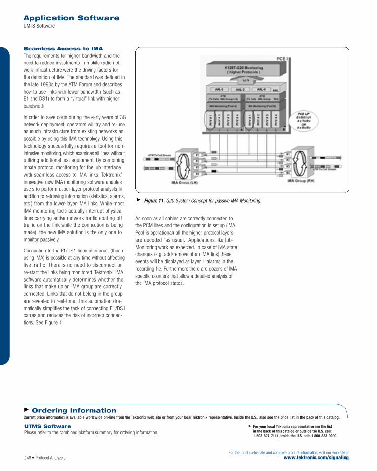
Seamless Access to IMA
The requirements for higher bandwidth and theneed to reduce investments in mobile radio net-work infrastructure were the driving factors forthe definition of IMA. The standard was defined inthe late 1990s by the ATM Forum and describeshow to use links with lower bandwidth (such asE1 and DS1) to form a “virtual” link with higherbandwidth.
In order to save costs during the early years of 3Gnetwork deployment, operators will try and re-useas much infrastructure from existing networks aspossible by using this IMA technology. Using thistechnology successfully requires a tool for non-intrusive monitoring, which examines all lines withoututilizing additional test equipment. By combininginnate protocol monitoring for the lub interfacewith seamless access to IMA links, Tektronix’innovative new IMA monitoring software enablesusers to perform upper-layer protocol analysis inaddition to retrieving information (statistics, alarms,etc.) from the lower-layer IMA links. While mostIMA monitoring tools actually interrupt physicallines carrying active network traffic (cutting offtraffic on the link while the connection is beingmade), the new IMA solution is the only one tomonitor passively.
Connection to the E1/DS1 lines of interest (thoseusing IMA) is possible at any time without affectinglive traffic. There is no need to disconnect or re-start the links being monitored. Tektronix’ IMAsoftware automatically determines whether thelinks that make up an IMA group are correctlyconnected. Links that do not belong in the groupare revealed in real-time. This automation dra-matically simplifies the task of connecting E1/DS1cables and reduces the risk of incorrect connec-tions. See Figure 11.
As soon as all cables are correctly connected tothe PCM lines and the configuration is set up (IMAPool is operational) all the higher protocol layersare decoded “as usual.” Applications like Iub-Monitoring work as expected. In case of IMA statechanges (e.g. add/remove of an IMA link) theseevents will be displayed as layer 1 alarms in therecording file. Furthermore there are dozens of IMAspecific counters that allow a detailed analysis ofthe IMA protocol states.
Application SoftwareUMTS Software
For the most up-to-date and complete product information, visit our web site atwww.tektronix.com/signaling248 • Protocol Analyzers
For your local Tektronix representative see the list in the back of this catalog or outside the U.S. call: 1-503-627-7111, inside the U.S. call: 1-800-833-9200.
Ordering InformationCurrent price information is available worldwide on-line from the Tektronix web site or from your local Tektronix representative. Inside the U.S., also see the price list in the back of this catalog.
UTMS SoftwarePlease refer to the combined platform summary for ordering information.
Figure 11. G20 System Concept for passive IMA Monitoring.

GPRS Software Tektronix GPRS software offers complete testsolutions for functional tests of GPRS networkelements, monitoring and analysis of GPRS networks, and end-to-end service quality testing.A combination of monitoring, simulation, andemulation functions, as well as capability ofconformance and interoperability testing is provided, chiefly needed during design and instal-lation/deployment of GPRS networks. This alsoincludes monitoring and analysis functions neededduring field trials, operation and maintenance, andnetwork optimization.
Solutions for NetworkMonitoring andOptimization
Monitoring
GPRS network managers struggle with the difficultproblems of network installation, deployment,and optimization. GPRS software for the K1297 consists of all necessary GPRS features andapplications that help users overcome their mostdifficult network issues. They can be carried outin off-line mode and online mode.
Single Interface and Multi Interface Call and Transaction Traces
Single Interface Call and Transaction Traces allowa fast overview about all data and messagesrelated to a call/transaction. This offers fast andeasy analysis of subscriber-related problems.
The “Multi Interface Call Trace” application is anexpert software that permits tracing calls/sessionsin real-time and off-line as they evolve overmultiple interfaces.
Simple parameters are used to identify the subscriber (for example, IMSI) and to triggerthe search. The call/session is traced even ifparameters identifying the subscriber changedynamically during the transactions (such as IMSI,P-TMSI). The call/session is traced even if itspans multiple interfaces (for example Gb, Gr, Gn)and involves different network elements (forexample SGSN, HLR, GGSN).
The GUI allows drill-down troubleshooting fromthe problem symptom to the root cause with justa mouse-click.
Features & BenefitsSimultaneous Monitoring on All Gx-interfaces (Ga, Gb, Gc, Gd, Gf, Gi,Gn, Gp, Gr, Gs)
Monitoring on Abis-interfaces (Alcatel,Ericsson, Lucent, Motorola, Nokia,Nortel, Siemens)
Single Call and Transaction Trace onGb-, Gn-, Gr-, Gc-, Gp-interface
Multi Interface Call Trace on Gb,Gr, Gn/Gp and A Interface in CaseData Sessions are Interrupted byVoice Calls
Deciphering on Gb-interface Up to aValue of 5000 Users
Monitoring and Analysis of GPRSSessions and Crucial QoS Parametersat the Gb-interface (GPRS GbMonitor/Analyzer)
Simulation and Emulation of AllNetwork Elements (BSS, SGSN,GGSN, VLR, HLR)
Simulation of an Entire GPRS NetworkSwitching Subsystem (NSS) IncludingInternet Access
Traffic Generation Across the GPRSNetwork for End-to-End Diagnostics
Simulation of Up to 10,000Subscribers (BSS or SGSN) PerInterface Module
For the most up-to-date and complete product information, visit our web site atwww.tektronix.com/signaling
Application SoftwareGPRS Software
Protocol Analyzers • 249
GPRS reference model.
For your local Tektronix representative see the list in the back of this catalog or outside the U.S. call: 1-503-627-7111, inside the U.S. call: 1-800-833-9200.

For the most up-to-date and complete product information, visit our web site atwww.tektronix.com/signaling250 • Protocol Analyzers
Application SoftwareGPRS Software
The “Overview Window” lists detected calls/sessions and highlights their status (normal, failed)at a glance for quick problem identification, andallows filtering out uninteresting (normal) calls.
The “Arrow Diagram” graphically displays, in a very intuitive way, the message flow (arrows) and network elements (vertical lines) involvedin a call/session without requiring a deep protocol knowledge.
The “Detailed Monitor Window” shows all thedetails of protocol messages and parameters forin-depth troubleshooting of root cause of problems.
Deciphering
GPRS network operators transmit ciphered databetween GPRS terminals and the network moreoften than they previously have. Whenever enciphering is switched on in GPRS networks,all signaling data and payload above the protocollayer Logical Link Control (LLC) are encrypted.The K1297-G20 Protocol Tester supplies the firstdeciphering test and observation tools, enablinganalysis and processing of all data above the protocol layer LLC.
The GPRS Deciphering application decryptsControl- and User Plane messages on the Gb-Interface not only for GPRS but also for UMTSmobiles (e.g., after an Intersystem Change for PS-Services from UTRAN to GSM BSS). It supportsthe GPRS Encryption Algorithm-1 and -2 (GEA 1and GEA-2). In automatic mode the applicationcollects ciphering keys (Kc or CK) from the Gr-Interface (see picture below). In manual modeno access to the Gr-Interface is required. This is aspecial use case for test labs, where the user canmanipulate the ciphering key.
Deciphering solution – deciphered messages.
Multi Interface Call and Transaction Trace Application.

Protocol Analyzers • 251For the most up-to-date and complete product information, visit our web site atwww.tektronix.com/signaling
RLC/MAC Reassembling
The RLC/MAC reassembling application picks upframes at the GPRS Abis interface that are cut intoslices of different sizes depending on the codingscheme and assembles them to the originalframe. This comprises LLC frames and RLCcontrol frames.
Benefits of RLC/Mac Monitoring on the Abis-Interface:
Verification of PCU transportation layer implementation (NEM only)
Verification/Observation of Air Interface parame-ter (e.g., Power level,Receiver sensitivity)
Analysis of faulty behavior related to the Air Interface (e.g., Retransmissions)
Compliance verification of Mobiles and Network(Interoperability)
Automatic Configuration of Abis GPRS/EDGEinterface (Siemens)
The GPRS/EDGE Automatic Configuration is anapplication that guides the technicians in config-uring the instrument for Abis monitoring andallows them to reduce overhead time needed forinstrument set-up. Once the RSL link on the Abis
interface has been identified, the applicationautomatically configures all the necessary logicallinks containing USER DATA FRAMEs and assignsthe proper bandwidth to the logical links.
GPRS Gb Monitor/Analyzer
The GPRS Gb Monitor application provides anextensive overview on the traffic that is actuallyrunning on the Gb-interface of a GPRS network.Numerous filter possibilities, including cell ID,IMEI, IMSI, and IP addresses, are available;measuring Quality of Service (QoS) parameters,such as throughput and response time, is easilyaccomplished.
The GPRS Gb Analyzer application, which isplaced on top of the GPRS Gb Monitor, providescrucial statistics, detects failed GMM, SM procedures and enables easy and rapid troubleshooting.
Solutions for ActiveTesting
Simulation/Emulation of GPRSNetwork Elements
Create and emulate functioning network elementsfor test purposes. Emulate multiple network ele-ments (NE) in parallel to real NE for complex testscenarios. Compare reaction of emulated to real NE.
Home Location RegisterEmulation
Replace expensive Home Location Register (HLR)in test networks. Take advantage of features suchas fault tolerant reaction and fast reset capability.Parameters are easy to set.
Base Station Subsystem and Mobile Emulation
Emulate thousands of mobiles (MS) on multipleBase Station Subsystems (BSS) with one K1297Protocol Tester. By emulating MS and BSS, you’llbe able to identify Network Switching Subsystem(SGSN, GGSN, HLR, PDN) problems quickly and easily.
Application SoftwareGPRS Software
GPRS Gb monitor.

252 • Protocol AnalyzersFor the most up-to-date and complete product information, visit our web site at
www.tektronix.com/signaling
Network Switching Subsystem Emulation
Browse the Web with a GPRS mobile and BSSconnected to K1297-G20 Protocol Tester, replacingthe entire GPRS core network. Find BSS or mobileproblems by reducing error possibilities by emulating the complete Network SwitchingSubsystem (NSS).
Short Message Service Testing
Ensure Short Message Service (SMS) functionalityvia GPRS Gb- and Gd-interface.
Integrated Test Functions
Integrated test functions in Mobile/Base StationSubsystem provide fast and easy testing and execution of:
GPRS attach/detach
IMSI attach/detach
Combined GPRS/IMSI attach/detach
Location area updates
Routing area updates
Cell reselection
PDP Context activation/modification/deactivation
Transfer of IP data
Paging for CS and PS
Enhanced Test Tools
The enhanced Test Management System enableslocal and/or remote automated and regressiontesting with the K1297-G20, reducing manualtest time. ISO Standards require change manage-ment support; with the “shared file systemapproach,” users can fulfill these requirementsand successfully complete regression testingaccording the ISO standards. Automatically recording files for all test cases provides testresults in full detail, down to the bit level, if needed.
Application SoftwareGPRS Software
GPRS End-to-End tests for K1297-G20 Protocol Tester.
For your local Tektronix representative see the list in the back of this catalog or outside the U.S. call: 1-503-627-7111, inside the U.S. call: 1-800-833-9200.
Ordering InformationCurrent price information is available worldwide on-line from the Tektronix web site or from your local Tektronix representative. Inside the U.S., also see the price list in the back of this catalog.
GPRS Software for K1297-G20Please refer to the K1297-G20 Protocol Tester for further information.

Protocol Analyzers • 253For the most up-to-date and complete product information, visit our web site atwww.tektronix.com/signaling
CDMA2000 SystemArchitectureFigure 1 illustrates the CDMA2000 system architecture.
A1 InterfaceThe A1 interface is the Interface between the BSS (Base Station Subsystem) and MSC(Mobile Switching Center) for the circuit-switchedside of the CDMA2000 network, as shown inFigure 2.
A1 Interface Test Capabilities
Monitoring with advanced Filtering and Analysis applications
Simulation with Message Building System (MBS)and Message Sequence Chart Tool – test casedevelopment and detail level testing
Voice Channel Verification feature
BSS and MSC Network Element Emulation for system level testing, supporting 240 subscribers
Figure 1. CDMA2000 architecture diagram.
Features & BenefitsA1 Interface
A1, A10/A11 Multi-interface Calltraceup to IOS-4.2
A10/A11 and PH Interface
IS-41 Interface
Monitoring with Advanced Filtering on A1, A8, A9, A10, A11, PH and IS-41 Interfaces
Simulation with Message Building System (MBS) and MessageSequence Chart Tool – Test CaseDevelopment and Detail Level Testing
BSS, HLR and MSC Network Element Emulation for System LevelTesting, Supporting 240 Subscribers
ApplicationsCreation of Network Statistics andCall Detail Records
Call Tracing and Troubleshooting
Replacing Real Equipment in aNetwork for Testing Purposes
System Verification and End-to-end Testing
Voice Channel Verification
Application Software CDMA2000 Software
Figure 2. A1 Interface testing diagram.
For your local Tektronix representative see the list in the back of this catalog or outside the U.S. call: 1-503-627-7111, inside the U.S. call: 1-800-833-9200.

254 • Protocol AnalyzersFor the most up-to-date and complete product information, visit our web site at
www.tektronix.com/signaling
A10/A11 and P-HInterfaceSee Figures 3, 4 and 5.
A10/A11 and P-H (Mobile IP) Interface Test Tools
Monitoring with advanced Filtering and Analysis applications
Simulation with Message Building System (MBS)and Message Sequence Chart Tool – test casedevelopment and detail level testing
IP Gateway Emulation for feeding IP applicationdata (web browsing) into the A10 protocol stack
IP Packet Generator/Comparator
Application Software CDMA2000 Software
Figure 3. A11 Interface testing diagram (Open R-P Control Plane).
Figure 4. A10 Interface testing diagram (Open R-P Data Plane).
Figure 5. P-H Interface testing diagram (Mobile IP).

Protocol Analyzers • 255For the most up-to-date and complete product information, visit our web site atwww.tektronix.com/signaling
IS-41 InterfaceSee Figure 6.
IS-41 Test Tools
Monitoring with advanced Filtering and Analysis applications
Simulation with Message Building System (MBS)and Message Sequence Chart Tool – test casedevelopment and detail level testing
Support of WIN and Prepaid Services Protocols (IS-771, IS-826)
HLR Network Element Emulation for system level testing
Application Software CDMA2000 Software
Figure 6. IS-41 Interface testing diagram.
For your local Tektronix representative see the list in the back of this catalog or outside the U.S. call: 1-503-627-7111, inside the U.S. call: 1-800-833-9200.
Ordering InformationCurrent price information is available worldwide on-line from the Tektronix web site or from your local Tektronix representative. Inside the U.S., also see the price list in the back of this catalog.
CDMA2000 System Test Software for A1, A8, A9, A10, A11, P-H and IS-41 Interface Testing

256 • Protocol AnalyzersFor the most up-to-date and complete product information, visit our web site at
www.tektronix.com/signaling
Tektronix offers for K1297-G20 ProtocolTester the following software packages for IP:
Transport Packet Data (see Transport, ISUP, IN data sheet)
IP/SS7
VoIP
IP Applications
K1297-G20 decodes all needed protocols in theinterface between SG (Signaling Gateway) andMGC (Media Gateway Controller), i.e., IP/SS7(M3UA/SCTP). For UMTS the same functionality isneeded and supported for the Iu-PS and the IurInterface. The interface between MGC and MG(Media Gateway) and also H.323 is decodable(VoIP package). Higher layer applications likeHTTP, Radius, Telnet, etc. are also supported. Forthe K1297-G20, we are offering IP, TCP and UDPemulations as a basis for further developments(see Transport, ISUP, IN data sheet). Intelligentdata reduction is possible through IP address fil-tering (Berkeley Filter configurable via LL setup)already on the Ethernet board.
Application SoftwareIP Software
Features & BenefitsMonitoring– Decode IP Related Protocols– IP Traffic Analyzer
Simulation/Emulation– IP Emulation Capabilities
are Realized in Packet Data Transport Package (see Transport, ISUP, IN Data Sheet)
Applications Internet Protocol (IP)
Voice Over IP (VoIP)
IP/SS7
For your local Tektronix representative see the list in the back of this catalog or outside the U.S. call: 1-503-627-7111, inside the U.S. call: 1-800-833-9200.
Ordering InformationCurrent price information is available worldwide on-line from the Tektronix web site or from your local Tektronix representative. Inside the U.S., also see the price list in the back of this catalog.
IP SoftwarePlease refer to the K1297-G20 Protocol Tester Hardware and K1297-G20 Base Software for further information.

For the most up-to-date and complete product information, visit our web site atwww.tektronix.com/signaling Protocol Analyzers • 257
The Global System for Mobile Communication(GSM) is related to the 2nd Generation (2G) ofMobile Networks. From its rollout at the beginningof the 90s, GSM has become a worldwide acceptedstandard for digital mobile communication and ispreferred for speech and narrowband tele services(i.e., SMS or WAP).
Tektronix offers the following software packagesfor the mobile network GSM for K1297-G20Protocol Tester. With the software, functions of theGSM network elements Base Station Subsystem(BSS) and Network Switching Subsystem (NSS)and their interaction can be tested:
GSM Monitoring
GSM Monitoring/Simulation/Emulation
SMS Monitoring
SMS Monitoring/Simulation
WAP Monitoring
Emulation of Network Elements MSC and BSS
Emulation of Network Element SCP
Abis Post-processing Software Tool
Tektronix now offers a complete range of monitor-ing applications for GSM protocols for theSubnetworks BSS and NSS and in addition forK1297-G20 the capability to simulate GSM proto-cols by using MBS to emulate important parts ofnetwork elements such as MSC, BSS, HLR, VLRand SCP. 2G protocol packages can be combinedwith all transport protocol packages (SS#7,IP, ATM).
Application SoftwareGSM/PCS Software
For your local Tektronix representative see the list in the back of this catalog or outside the U.S. call: 1-503-627-7111, inside the U.S. call: 1-800-833-9200.
Ordering InformationCurrent price information is available worldwide on-line from the Tektronix web site or from your local Tektronix representative. Inside the U.S., also see the price list in the back of this catalog.
Features & BenefitsGSM Monitoring, Simulation and Emulation
SMS Monitoring and Simulation
WAP Monitoring
Emulation of Network Elements
Applications Testing of GSM Base Station Subsystem (BSS)
Testing of GSM Network Switching Subsystem (NSS)
GSM/PCS Software
Please refer to K1297-G20 Protocol Tester Hardware and K1297-G20 Base Software for further information.

For the most up-to-date and complete product information, visit our web site atwww.tektronix.com/signaling258 • Protocol Analyzers
Transport software packages are the basis for mostof other application software for the K1297-G20Protocol Tester. These products provide monitoring/simulation/emulation capabilities for transport pro-tocol layers, i.e. OSI layer 2 and layer 3. Dependingon the upper layer protocols, appropriate transportpackages need to be ordered.
Tektronix offers a complete range of monitoring/simulation/emulation applications for SS#7, IP,SSCOP/SSCF, MTB3b, ISUP/TUP and IN Protocols.The MBS provides the possibility to changeparameters for simulation and to emulate the network elements SSP and SCP.
MONITORING FEATURES
Decoding of Transport Protocols and Decodingof ISUP/TUP Protocols
Call Detail Records (CDR)
Call Statistics
Free Programmable Counters
Call Trace
Busy Hour Call Attempt (BHCA)Measurements
Decoding of IN Protocols
– IN Call Trace
SIMULATION/EMULATION FEATURES
Simulations and Emulation Capability of SS#7Protocol Elements
Simulations and Emulation Capability ofISUP/TUP Protocols
Simulations/Emulation of IN Protocols
IN Call/Transaction Generator
Free Programmable Statistics
SSP Network Element Emulation (acc. ETSI)
SCP Network Element Emulation (acc. ETSI)
Application SoftwareTransport, ISUP and Intelligent Network Software
For your local Tektronix representative see the list in the back of this catalog or outside the U.S. call: 1-503-627-7111, inside the U.S. call: 1-800-833-9200.
Ordering InformationCurrent price information is available worldwide on-line from the Tektronix web site or from your local Tektronix representative. Inside the U.S., also see the price list in the back of this catalog.
Transport, ISUP and Intelligent Network Software
Please refer to K1297-G20 Protocol Tester Hardware and K1297-G20 Base Software for further information.

Protocol Analyzers • 259For the most up-to-date and complete product information, visit our web site atwww.tektronix.com/signaling
Tektronix Monitoring Solution for Mobile Networks K15
Features & Benefits“Automatic UMTS Iub Monitoring/Configuration,” Configures allParameters to Monitor the IubWithout the Need of Restarting the Node B
“Multi-interface Calltrace,” an ExpertSoftware Application for SS7, GSM,GPRS, EDGE, UMTS, cdmaOne,CDMA2000 Networks, Enabling Fast and Easy Identification of ProblemsFrom the Symptom Down to the Root Cause
Availability in the CompactPCIPlatform of E1/DS1/J1, STM-1/OC-3c,10/100 Fast Ethernet Monitoring CardsWith High Port Density Along WithFixed Network, SS7, GSM, GPRS,EDGE, UMTS, HSDPA, cdmaOne,CDMA2000 Protocol Decoding Allow Interoperability Tests Between Multiple Technologies
“Stream to Disk” Capabilities Permits Data Storage in a MassStorage Device for Subsequent Off-line Analysis
NTP- and GPS Synchronization Along With the “File Merge”Application Permits Distributed Multi-site Monitoring
“Remote Desktop” Eliminates theNeed to Move to Remote Sites
Applications The K15 is for GSM/GPRS/EDGE/UMTS/cdmaOne/CDMA2000 MobileNetwork Operators’ Operation andMaintenance Technicians Who Need to Perform Effective Troubleshootingof Live or Trial Networks UnderSignificant Traffic Load ConditionsWithin Affordable Time and Cost Limits
The K15 is for GSM/GPRS/EDGE/UMTS/cdmaOne/CDMA2000Equipment Manufactures’ TestEngineers Who Need to PerformEfficient Troubleshooting During Load,Stress, Duration and AcceptanceTests of Network Elements in the Lab or Trial Networks
For your local Tektronix representative see the list in the back of this catalog or outside the U.S. call: 1-503-627-7111, inside the U.S. call: 1-800-833-9200.
The K15 is the new Tektronix dedicated monitoringsolution for mobile network testing, based on ahigh performance transportable platform equippedwith real-time powerful troubleshooting applicationsand designed to handle the new demanding highperformance requirements of mobile networks.
Platform
The CompactPCI compliant platform houses a PCrunning Windows XP embedded operating systemand up to five application boards in a small, easilytransportable box. A complete operator interfaceis provided on the front panel, including a 14"XGA color display and attachable keyboard withpointing device. A central front foot allows optimalviewing angle. The top cover, which opens to therear, can be left in place to protect from dusteven when cables are connected.
Flexible data storage and communicationresources are provided; drives are accessiblefrom the side of the unit.
Top access is provided for up to six 6U CompactPCIboards, housed vertically, and for a dual-slot plug-in AC power supply. Five slots are available forInterface/Measurement Application Boards; thesixth slot is equipped with a Pentium III CPUboard. The backplane is compliant with the telecomextension of CompactPCI (H.110/PICMG2.5) andprovides access to four system-wide clock/sync signals. Each K15 unit can act as synchronizationmaster or slave; GPS input is also supported.
An Intelligent Platform Management subsystem(IPMI ver. 1.1 compliant) provides flexible manage-ment of platform ID, temperatures, fans, and othersystem values, and also provides low acoustic noisein low-power-consumption application.
Breakthrough Solution for Mobile Network Troubleshooting

260 • Protocol AnalyzersFor the most up-to-date and complete product information, visit our web site at
www.tektronix.com/signaling
Automatic UMTS Iub Monitoring Configuration
Just by monitoring the UMTS Iub interface livetraffic and without the need of restarting the NodeB, this application consists of an expert softwarecapable of automatically configuring all the logicallinks necessary to carry out Iub monitoring in justa few minutes.
On the Iub interfaces being monitored by theequipment, the expert software automaticallyidentifies the following parameters and configures the logical links accordingly:
AAL5 ATM VPI/VCI for NBAP and ALCAP traffic for each Node B
AAL2 ATM VPI/VCI/CID for RACH, FACH and PCHCCCH for each cell
A wizard, designed for both beginners and experts,guides the user through the configuration process.Once the configuration process is finished and allthe necessary logical links have been set up, theresults can be saved for subsequent use.
Multi Interface Call Trace
The “Multi Interface Call Trace” application is anexpert software that helps trace calls/sessions inreal-time and off-line as they evolve over multipleinterfaces.
Simple parameters like the IMSI are used to identify the subscriber identity and to trigger thesearch. The call/session can even be traced if theidentifying parameters change dynamically duringthe transactions (for example IMSI, P-TMSI), evenif it spans over multiple interfaces (such as Iub –Iu-PS – Gr) and involves different network ele-ments (like Node B, RNC, HLR).
The GUI allows drill-down troubleshooting fromthe problem symptom to the root cause with justa mouse-click.
The “Overview Window” lists detected calls/sessions and highlights their status at a glance(normal, failed) for quick identification of problems.This allows filtering out calls that are not ofinterest for the particular test being performed (normal calls).
The “Arrow Diagram” graphically shows the mes-sage flow (arrows) of the call/session and theinvolved network elements (vertical lines) in a veryintuitive way. A deep protocol knowledge is notrequired.
For in-depth troubleshooting of the problem’s rootcause, all details about the protocol messagesand their parameters are shown in the “DetailedMonitor Window.”
Supported interfaces are:
SS7/GSM (ISUP, INAP)
GPRS/EDGE (Abis, A, Gb, Gr, Gn/Gp)
UMTS (Iub, Iu-PS, Iu-CS)
cdmaOne/CDMA2000 (A1, A10/A11)
Protocol Analysis
The K15 monitors a wide range of SS7, GSM,GPRS, EDGE, UMTS, HSDPA, cdmaOne andCDMA2000 protocols, featuring a graphical userinterface that allows visualizing protocol messageswith increasing level of details, along with easy touse powerful filtering capabilities.
Tektronix Monitoring Solution for Mobile Networks K15

For the most up-to-date and complete product information, visit our web site atwww.tektronix.com/signaling Protocol Analyzers • 261
Distributed MonitoringApplications
The K15 embeds all the fundamental buildingblocks for a distributed monitoring architecture.
The “Remote Desktop” capabilities, allow the K15 to:
Reduce technicians travelling cost and time,because operations can be centralized
Reduce the time needed to solve problems,because inexperienced technicians in remotesites can be supported by skilled personnel at headquarters
Maximize use of experts at headquarters, becausetroubles can be analyzed in real-time withoutwaiting for the technicians to collect traces
With the “NTP and GPS synchronization”capabilities, the K15:
Reduces the time needed to identify the root cause of a problem: with the new “multi-interface call trace,” all interfaces and network elements in the problem domain can be analyzed simultaneously
Grows with the needs: if one instrument is not enough to cope with an increasing numberof interfaces, additional test systems can beadded and synchronized with the existing instrumentation
Deals with the new high complexity problems in 2.5/3G networks: the new categories of problems which occur in the next-generationmobile infrastructures require the ability tomeasure simultaneously and time synchronizedat multiple interfaces in different geographiclocations
The capability to stream protocol data to ahard drive while simultaneously conductingreal time analysis allows the K15 to:
Collect a large amount of data for subsequentanalysis by using a simple “recording pipeline”that stores monitored protocol data in to aninternal HD, to an external HD or to a networkfile system
Merge data collected from different instrumentsat different sites by using an easy to use “FileMerge Application”
Use previously collected data to perform offlineanalysis by using our offline or post processingsoftware
Characteristics
General
Host Processor Board Processor – Mobile Pentium III, 256 KB L2 cache on chip, full speed.Memory – 256 MB SDRAM ECC.Timer – User programmable, allows real-time functions.Bus – CompactPCI; 64 bit/33 MHz.Ethernet Interface – Two 10/100Base-T; connectors on the board panel.VGA Interface – Connector on the board panel.USB Interface – Connector on the board panel USB 1.1.PMC Slots – One, providing connection to the backplane.
Rear Panel I/O PS/2 Interface – Two connectors for ext.keyboard/mouse.Parallel Interface – One IEEE 1284 Type A connector.SCSI Interface – Connector on the rear of the unit.USB Interface – One connector.Relay Output – 4 mm banana plug providing ext.trigger/alarm.Clock/Sync – Two connectors for ext. clock/sync I/O SMB.Two connectors for 1 pps/10 MHz I/O (can accept GPS signals) output 10 MHz/3 ppm.
Data Storage Floppy – 3.5", 1.44 MB.Hard Disk – 30+ GB, 2.5" IDE hard disk drive.CD-R/W.
Tektronix Monitoring Solution for Mobile Networks K15

262 • Protocol AnalyzersFor the most up-to-date and complete product information, visit our web site at
www.tektronix.com/signaling
Display Type – TFT LC active-matrix color display with backlightand sleep mode.Dimensions – 14".Resolution – 1024x768 pixel – XGA compliant.An External Monitor may be connected, using the VGAconnector located on top of the unit.
Keyboard Type – Full-QWERTY; attachable to the front of the unitfor transport.An External Keyboard may be connected, using the PS/2connector on the rear-panel.
Pointing device Type – 2-button touch pad integrated with the keyboard.An External Mouse may be connected, using the PS/2connector on the rear panel.
Platform ManagementSubsystem (IPMI compliant) Features – Fan speed control; temperature control; platform hardware ID management; power outage control.The IPMI interface connector is for Tektronix service use only.
Operating System Microsoft Windows XP Embedded.
Physical CharacteristicsDimensions (excluding handle) Width 365 mm Depth 227 mm Height 340 mm
Without cover 305 mm Weight Without application boards 10.9 kg
Inclination – One reclinable central front foot (can reach 70 mm).Top Cover – Detachable plastic cover; open on the rear.Transport Handle – Fiber enforced plastic with rubber overmold.Transport Case (optional) – Hard-shell case with wheels and retractable handle (520 mm H x 695 mm W x 405 mm D).
Backplane – CompactPCI Features – Passive; 6 slots; one CompactPCI segment, PICMG 2.1 compliant, 64 bit/33MHz.H.110 Bus – (PICMG 2.5) on P4 of peripheral slots.Clock/Sync – 4 signals distributed on P2.
Power Type – Industrial grade, 350 W; plug-in modulewith over-temperature protection.Fuse Data – 6.3A Time-delayed, 250 V.AC Input – 600 VA, 100 to 240 VAC ±10%,50/60 Hz.DC Output – 50 W per application slot.DC Output Available for the Application Slots –+5 V 35 A +3.3 V 30 A +12 V 10 A –12 V 2.5 A
Regulatory Safety – UL and CUL to UL3111-1 [reference: PO61];CE mark: EN61010-1.EMC – FCC part 15, class A; CE mark: EN61326,class A.
EnvironmentalTemperature – Operating: +4 ºC to +40 ºC.Nonoperating: –20 ºC to +65 ºC.
Relative Humidity – Operating: Up to 80% below 30 ºC, derate to 45% at40 ºC, noncondensing.Nonoperating: Up to 90% below 20 ºC, derate to 60% at 20 ºC, noncondensing.
Altitude – Operating: 10,000 ft. (3000 m).Nonoperating: 40,000 ft. (12000 m).Shock – Operating: Half-sine 2 g.Nonoperating: Half-sine 30 g.Random Vibration – Operating: 0.22 gRMS.Nonoperating: 2.28 gRMS.Acoustic Noise – ETSI 300 753 for Business area (63 dBa).ETSI 300 753 for Office-desktop (50 dBa) for low-power-consumption applications.
Timestamps Accuracy NTP – ±10 ms with network jitter ±3 ms.GPS – ±1 ms.
Interface Boards (depending on selected configuration)
Single Slot Boards PowerWAN – Interfaces up to 8 E1/DS1/J1 bi-directional PCM links.PowerWAN Light – Interfaces up to 4 E1/DS1/J1 bi-directional PCM links.PowerWAN Light with Ethernet Module –Interfaces up to 4 E1/DS1/J1 bi-directional PCM linksand up to 2 10/100 Mb/s Fast Ethernet links.
Double Slot Boards PCE-2 – Can mount up to 2 LIF (LIF type A or LIF type B) in any combination.
LIF Type A – Interfaces up to 2 STM-1/OC-3c bi-directional optical links.LIF Type B – Interfaces up to 4 E1/DS1/J1 ATM links.
Tektronix Monitoring Solution for Mobile Networks K15
For your local Tektronix representative see the list in the back of this catalog or outside the U.S. call: 1-503-627-7111, inside the U.S. call: 1-800-833-9200.
Ordering InformationCurrent price information is available worldwide on-line from the Tektronix web site or from your local Tektronix representative. Inside the U.S., also see the price list in the back of this catalog.
K15 Monitoring Solution for Mobile Networks

Protocol Analyzers • 263For the most up-to-date and complete product information, visit our web site atwww.tektronix.com/signaling
The K5302 DASY (Digital Access System) is amultiplexer for E1 and DS1 PCM lines. It consistsof a mainframe, a control unit (DRC) with display,a power supply and a number of input and outputboards. DASY’s main function is to couple singletimeslots or PCM streams from an input board toone or more output boards. With the latest Firm-and Software the DASY also supports the coupling of groups of timeslots, which will haveexactly the same delay when coupled through the DASY.
The K5302 mainframe offers 13 slots to be used by input (DDM) or output (DDA) boards.Any combination of boards is possible, however,at least 1 input and 1 output board are required.As each DDM module can handle up to 8bi-directional PCM lines (either E1 or DS1), theconfiguration with 12 DDM boards and 1 DDAboard would offer a maximum of 96 incomingPCM lines to be connected to the DASY. Theremaining DDA board would offer 4 Tx/Tx (8Rx/Tx respectively) PCM lines. Each of the 2076input timeslots (96*31, TS 0 to be handled sepa-rately) can be coupled to any of the output timeslots.
In order to increase the overall capacity of thesystem, several DASYs may be cascaded.
Features & BenefitsDigital Multiplexer to ConcentratePCM Signaling Timeslots
Duplication of Timeslots Possible
Supports E1 and DS1
Can be Used and Configured Stand Alone
Powerful Application to ControlSeveral DASYs Available (Directly via RS-232 or Remotely via Modemor LAN IEEE 803.2)
Clock Supply: Internal, External, PCM Link
Designed to Enhance the Capabilitiesof Protocol Testers
Support of Time-synchronizedCouplings – Allows Coupling of Logical Links on Gb Interface in GPRS Networks
ApplicationsProvide Protocol Testers with Flexible and Convenient Access to TestEnvironment with Many Links to be Analyzed
Concentrate PCM Signaling Timeslots to Enhance Capabilities of Protocol Testers
Duplicate Signaling Timeslots/PCMLinks to Make the Same SignalingAvailable for Several Users
Digital Access System K5302 DASY
For your local Tektronix representative see the list in the back of this catalog or outside the U.S. call: 1-503-627-7111, inside the U.S. call: 1-800-833-9200.
Functional Description

264 • Protocol AnalyzersFor the most up-to-date and complete product information, visit our web site at
www.tektronix.com/signaling
Fields of Application
The K5302 has been designed for various purposes:
To provide protocol testers with flexible and convenient access to a test environment with a huge number of links to be analyzed
Testing under lab conditions often means analyzingdifferent interfaces. The configurations and thusthe cabling often change. After connecting allpossible PCM links to the multiplexer, DASY offersan easy way to couple the appropriate input linksto the output.
To concentrate PCM signaling timeslots in orderto enhance capabilities of protocol testers suchas the K1205
The number of physical PCM interfaces of a pro-tocol tester is usually limited. On the other hand,it is quite common that only very few (even justone) timeslots of a PCM link are used for signal-ing purposes. By multiplexing single timeslots ofseveral links to one output PCM link DASY offersa solution to solve this contradiction.
To duplicate signaling timeslots/PCM links inorder to make the same signaling available forseveral users
It is not unusual for certain PCM links to be ofinterest to different users working with differentanalyzers. Connecting a number of protocol testersto a PCM link may have an impact (due to imped-ance reasons) on this link. As the DASY offers aconvenient way to duplicate single timeslots or evenPCM links, it will make the same link available forseveral users without degrading the performance ofthe PCM links.
In order to avoid operating errors when settingcouplings, a 4 digit PIN can be assigned to eachoutput connector. If the password protection isturned on, users can only set/reset couplings onoutput connectors they have logged into before.To control the configuration of PINs, the usermust have a Master PIN. Couplings may be storedin an EEPROM and will then automatically berestored after a power outage.
Modes of Operation
DASY can be operated in 3 modes:Stand Alone – The complete set of features ofthe DASY can be used without any additionalhardware or software*1. A 20*4 character LCDprovides an intuitive menu to operate DASY withonly 5 keys. This mode of operation should beused for quasi-static configurations
*1 Grouped Couplings can only be set up, modified, and deleted usingthe Remote Control Software.
With DASY Remote Control SW – If more frequent changes of the coupling matrix are required, the remote control application,which comes with the DASY, should be used.This application runs under Windows NT/95/98/Me/2000/XP and provides an easy to useinterface. The PC running this application can beconnected via RS-232 and/or LAN (IEEE 802.3,RJ-45) interface to the DASY. Besides using adirect serial connection via RS-232 (data rates1,200 to 19,200 b/s), it is possible to connect a modem to the DASY and dial in remotely.With the LAN interface it is even possible to control the DASY using the Internet as a transport media
From a User Application – Tektronix offers aControl C Library for Windows NT/95/98/Me/2000/XP, which provides a well defined API(application programming interface). It enables a user to control the DASY from a user applica-tion. This library supports the serial interface aswell as the LAN interface and gives full accessto DASY’s functionality. By using this API, it ispossible to set up to 4 couplings per second.DASY can handle up to 10 TCP/IP connectionssimultaneously
Digital Access System K5302 DASY

Protocol Analyzers • 265For the most up-to-date and complete product information, visit our web site atwww.tektronix.com/signaling
DASY Remote Control Application
The easiest way to operate the DASY is theremote control application. This software is ableto control an unlimited number of DASYs regard-less whether the units are connected directly viaa serial cable, via a modem or a LAN connection(see Figure 1). A Microsoft Explorer-like treestructure offers an easy way to navigate throughthe different DASYs and their input and outputboards. The software automatically detects thehardware and firmware versions of the DASY con-nected to it, and can thus also control elder units.This software offers the following functions:
Easy setup of couplings
Couplings are displayed in a tabular format
Each coupling can be assigned a specific namewhich will be stored (see Figure 2)
The complete configuration can be stored andlater retrieved
Digital Access System K5302 DASY
Figure 2. Add a new coupling.
Figure 1. DASY Overview.

266 • Protocol AnalyzersFor the most up-to-date and complete product information, visit our web site at
www.tektronix.com/signaling
The coupling scheduler provides a simple way todefine time limited couplings (see Figure 3)
Configure impedance, framing mode and linecode of DDM-2 and DDA-2 modules
Configure IP address and port as well as the serial parameters (baud rate) for the DRC-2 modules
DASY Remote Control SW displays receiveralarms (overview and details) of all DASYs (see Figure 4)
Configuration/Administration can be automatedusing a simple scripting language
New:
Support of time-synchronized couplings (“Group Couplings”)
Status Display of internal resources (see Figure 5 on next page)
Improved synchronization between resources in DASY and Remote Control Software
Export of DASY configuration and coupling information to CSV file (for further usage in spreadsheet and database applications)
Digital Access System K5302 DASY
Figure 4. Display of DASY receiver alarms.
Figure 3. Working with the coupling scheduler.

Protocol Analyzers • 267For the most up-to-date and complete product information, visit our web site atwww.tektronix.com/signaling
Characteristics
Clock Supply Rx Clock – The control processor scans all interfaces for a valid signal. The clock of the first inter-face found with a correct signal will be used as the system clock.
External – A 2 MHz clock as per ITU-TRecommendation G.703 must be fed into the DRCmodule and is then used as the system clock.Internal – The system clock is generated internally.Detectable Alarms (indicated by different flashing period of LEDs) – Loss of Signal (LOS),Alarm Indication Signal (AIS), Loss of Frame (LOF),Remote Alarm Indication (RAI).
General Data
Power Supply Protection Class: Safety Class 1 (protective ground).Mains Input – Rated range of use – AC 100 to 240 V ±10%.Line Frequency – Rated range of use 50/60 Hz –6% to +5%.Output Voltage – DC 5 V, 16 A.Power Consumption – 145 VA MAX (fully equipped).Fuse – 1.6 AT, 250 V, Type: IEC 5x20 mm.
Certifications and Compliance CB certificate according IEC61010-1 –
EU: CE mark – In accordance with EMC:89/336EEC – EN61326 class A.LVD: 73/23EEC & 93/68EEC – EN61010-1ed.1/A2.
US and Canada Certification – In accordance withUL 61010B-1, First Edition, CAN/CSA-C22.2No.1010.1-92.Australia & New Zealand, CTICK – AS/NZS2064.1/2.Protection Class – Safety Class 1.
EnvironmentalConditions
Ambient Temperature Ambient Temperature – +23 ºC ±5% (with 55% humidity).Operating Range – +5 ºC to +40 ºC (less than 85% humidity, without condensation).Transportation/Storage – –20 ºC to +55 ºC.Barometric Pressure – 101.3 kPa (1013 mbar).Altitude – 2000 m, maximum operating.Pollution Degree – Pollution degree 2 (as defined in IEC61010-1).Note: Rated for indoor use only.
Physical Characteristics Dimensions mm in.Width 450 17.7 Height 315 12.4 Depth 311 12.2 Weight kg lbs.Basic unit with handle 12 26.5 Fully equipped 17 37.5
Digital Access System K5302 DASY
Figure 5. Status Display of internal resources.
Interface conditions as per ITU-T Recommendation G.703.
Mode E1 DS1 Bit Rate 2,048 kb/s 1,544 kb/s Line Code HDB3, AMI B8ZS, AMI Input Impedance 120 Ω, 75 Ω, >3 kΩ 100 Ω, >3 kΩFrame Formats double frame, 12-frame multiframe (F12),
CRC multiframe 24-frame multiframe (FS24) = extended super frame (ESF)
Input Voltage 150 mV to 3 V 150 mV to 3 V Jitter Tolerance better than ITU-T G.823 better than ITU-T G.823 Transmit Level*1 3 V at 120 Ω 3 V at 100 Ω
*1 Only valid for Output (DDA) module.
Note: The mode (E1/DS1) can be changed with a DIP-switch on the board. Line code, impedance and frame formatcan be configured via menu or software.
Technical Data of the 2 Mbps Modules
Digital Access System DASY-2 (UL)
Mainframe with display and control unit, 13 slots forinput and output modules, RS-232 and Ethernetinterface for remote control; 100 to 250 V
auto-range power supply; Remote Control SW7KK5302-8AB11; manual (German/English);Requirement: at least 1 input and 1 output module are needed to run the system.(Please order separately).
For your local Tektronix representative see the list in the back of this catalog or outside the U.S. call: 1-503-627-7111, inside the U.S. call: 1-800-833-9200.
Ordering InformationCurrent price information is available worldwide on-line from the Tektronix web site or from your local Tektronix representative. Inside the U.S., also see the price list in the back of this catalog.

268 • VideoFor the most up-to-date and complete product information, visit our web site at
www.tektronix.com/video_audio
Video Test Products
Contents
Waveform Monitors
Introduction . . . . . . . . . . . . . . . . . . . . . . . . . . . 269
Selection Guide . . . . . . . . . . . . . . . . . . . . . . . . . 270
Video Monitoring . . . . . . . . . . . . . . . . . . . . . . . . 272
Audio Monitoring . . . . . . . . . . . . . . . . . . . . . . . .273
Advance Displays . . . . . . . . . . . . . . . . . . . . . . . 274
WFM700 Series Highlights . . . . . . . . . . . . . . . . . 275
WFMNLE Series Highlights . . . . . . . . . . . . . . . . . 276
WFM601, WFM90D/91D, 1700 Series Highlights . 277
WVR600 Series, WVR7000 Series Highlights . . . .278
Video and Audio Signal Generators
Introduction . . . . . . . . . . . . . . . . . . . . . . . . . . . 279
Selection Guide . . . . . . . . . . . . . . . . . . . . . . . . . 280
TG700 Highlight . . . . . . . . . . . . . . . . . . . . . . . . .281
TG2000 Highlights . . . . . . . . . . . . . . . . . . . . . . .281
ECO422D Highlight . . . . . . . . . . . . . . . . . . . . . . .281
SPG600/SPG300 Highlight . . . . . . . . . . . . . . . . .282
Measurement Sets
VM700T . . . . . . . . . . . . . . . . . . . . . . . . . . . . . . 277
VM5000 . . . . . . . . . . . . . . . . . . . . . . . . . . . . . . 282
MPEG Test Systems
MTS4EA . . . . . . . . . . . . . . . . . . . . . . . . . . . . . . .293
AD953A . . . . . . . . . . . . . . . . . . . . . . . . . . . . . . 295
MPEG Test Systems
AD951A . . . . . . . . . . . . . . . . . . . . . . . . . . . . . . 297
Standalone Software . . . . . . . . . . . . . . . . . . . . . 299
MPEG Transport Stream Monitors
MTM400 . . . . . . . . . . . . . . . . . . . . . . . . . . . . . . 301
MPEG Players/Recorders
MTX100 . . . . . . . . . . . . . . . . . . . . . . . . . . . . . . .303
MPEG Portable Analyzers
AD954 . . . . . . . . . . . . . . . . . . . . . . . . . . . . . . . 304
Multi-layer Monitor
MLM1000 . . . . . . . . . . . . . . . . . . . . . . . . . . . . .306
Picture Quality Testing and Monitoring
PQA300 . . . . . . . . . . . . . . . . . . . . . . . . . . . . . . 308
Video RF Testing and Monitoring
RFA300A . . . . . . . . . . . . . . . . . . . . . . . . . . . . . . 310
RFM210 . . . . . . . . . . . . . . . . . . . . . . . . . . . . . . .312
DS1001A/G; DS1002 . . . . . . . . . . . . . . . . . . . . .314
1705A . . . . . . . . . . . . . . . . . . . . . . . . . . . . . . . .316

Video • 269For the most up-to-date and complete product information, visit our web site atwww.tektronix.com/video_audio
Regardless of your broadcast needs – video oraudio – we have a variety of monitoring andmeasurement solutions. Spanning analog, stan-dard definition and high definition, our waveformmonitors display video signal characteristics withunmatched accuracy and clarity.
For video monitoring applications, Tektronixoffers a wide spectrum of waveform monitorsand rasterizers for analog, digital or hybrid facilities.
Additionally, Tektronix is ready to meet youraudio monitoring needs with digital and analogsolutions, either as stand-alone monitors or integrated with our video monitoring tools.
In support of a broad array of applicationsrequirements, Tektronix monitoring products areavailable in the traditional 3RU form factor withan integrated display or as 1RU tools that output to separate displays.
The variety of our video and audio monitoring portfolio is detailed in the chart below.
We deliver cutting-edge, world-class solutions foryour demanding applications. Our industry-leadingEye pattern and jitter measurements, along withour patented Lightning, Arrowhead and Diamonddisplays, provide added insight into digital videosignals. This is advanced technology – availabletoday only from Tektronix.
Video and Audio Monitoring
Features & BenefitsWFM700 Series
WVR7000 Series
WFM601 Series
WVR600 Series
1700 Series
WVR500 Series
WFM90D/91D
For your local Tektronix representative see the list in the back of this catalog or outside the U.S. call: 1-503-627-7111, inside the U.S. call: 1-800-833-9200.
Tektronix measurement products are manufactured in ISO registered facilities.
Digital Tech. EnhancedAnalog SD HD Form Factor Gamut Measurements Waveform Vector Picture Audio Views
WFM700 Series yes yes 3RU, 1/2 rack width Arrowhead, Eye, Jitter, yes yes yes AES/EBU, Multimode,Diamond, Split Diamond Data (M) Embedded*3 Thumbnail
WVR7000 Series PAL, NTSC*3 yes*3 yes 1RU, full rack width Arrowhead, yes yes yes Analog, AES/EBU FlexVu™
Diamond, Split Diamond Embedded*3
WFM601 Series yes 3RU, 1/2 rack width Arrowhead, Eye, Jitter, yes yes yesDiamond Data (E/M)
WVR600 Series PAL, NTSC yes 1RU, full rack width Arrowhead, yes yes yes Analog, AES/EBUDiamond, Split Diamond Embedded*3 FlexVu
1700 Series*4 PAL, NTSC 3RU, 1/2 rack width Lightning, yes*1 yes yes yes*2
Component Diamond*1 SCH PhaseComposite
WVR500 PAL, NTSC 1RU, 1/2 rack width yes yesWFM90D/91D PAL, NTSC yes Handheld yes yes yes Analog Thumbnail760A 3RU, 1/2 rack width Analog764 3RU, 1/2 rack width AES/EBUWFMNLE PAL, NTSC yes software only Arrowhead, Diamond yes yes yes AlarmVu
*1 1760 Series only. *3 Optional capability.
*2 1740/50/60 Series only. *4 Excludes 1705A.
Video and Audio Monitoring Tools
Tektronix offers a broad range of monitoring solutions, from handheld units to high-performance rack-mountable instruments.

For the most up-to-date and complete product information, visit our web site atwww.tektronix.com/video_audio
Waveform Monitors 1720/1730 Series • 1740A/1750A/1760 Series • WVR500 • SDA601 • WFM90 Series
Model Number 1720/1721/1725 1730/1731/1735 1740A/1741A/ 1750A/1751A/ 1760/1761/1765 WVR500 SDA601 WFM90D/WFM91D1745A 1755A
Video StandardsNTSC; 525/60 X (1720/25) X (1730/35) X (1740A/45A) X (1750A/55A) X (1760/65) X X (BT.601) X (WFM90D)PAL; 625/50 X (1721/25) X (1731/35) X (1741A/45A) X (1751A/55A) X (1761/65) X X (BT.601) X (WFM91D)Dual Standard 525/625 X (1725) X (1735) X (1745A) X (1755A) X (1765) X X (BT.601)Signal InputsComposite Analog 2 2 8 8 8 2 1Component Analog (CAV) 2 2 2Serial Digital Component 1 1Stereo Audio X X X X X*5 (Analog Only)Signal DisplaysWaveform X X X X X XRGB/YRGB Parade Staircase X X XWaveform Difference XVITS Monitoring/Line Select X*3 X X X X XComposite Vector X X X X X XComponent Parade/Overlay X X XComponent Vector/Lightning/Bowtie XPicture Monitor X X X X X*7 XR-Y Sweep X*4 X X XLongitudinal Time Code X X XData Logic Analyzer XPolar SCH Phase X Opt. SCAudio Phase/Amplitude X X X X X*6 (Analog Only)MiscellaneousMeasurement Cursors X X XBandwidth (MHz) 6 6 10 10 10 6 6Vertical Magnification (#Times) 1, 5, variable 1, 5, 10, variable 1, 5, 10, variable 1, 5, 10, variable 5 5Remote PC Display XError Alarm X X X12 V DC Power X XControl InterfaceUser Presets X*3 X X X X X XFunctions XDC Logic Levels X*3 X X X XRS-232-C X X X X
*3 When connected to 173X Waveform Monitor.
*4 Output to Waveform Monitor.
*5 Displays one audio channel.
*6 Amplitude only.
*7 Picture monitor output.
Analog Monitor Selection Guide
270 • Video
Digital Monitor

Waveform Monitors WFM601 Series • WFM700 Series • WVR600 Series • WVR7000 Series • VM5000 • VM700T
*1 Waveform freeze/compare.
*2 Pseudo-composite vector from component input.
*3 When connected to 173X Waveform Monitor.
*4 Output to Waveform Monitor.
*5 Displays one audio channel.
*6 Amplitude only.
*7 Picture monitor output.
*8 Passive loopthrough.
For the most up-to-date and complete product information, visit our web site atwww.tektronix.com/video_audio Video • 271
Model Number WFM601A/ WFM700HD/ WVR600 WVR7000 VM5000 VM700TE/M A/M Series Series
Video StandardsSerial Digital Component SD X X (WFM700A/M) X Opt. SD Opt. 1S
Serial Digital Component HD X X
Analog Composite NTSC 525 WVR611A Opt. CPS Opt. 01
Analog Composite PAL 625 WVR611A Opt. CPS Opt. 11
Analog Component SD Opt. SD Opt. 30
Analog Component HD Opt. HD
Signal InputsSerial Digital Composite Opt. 1S
Serial Digital Component 2 2 std/4 opt 2*8 2*8 Opt. 1S
Analog Composite 2 (WVR611A)*8 2 (Opt. CPS)*8 3
Analog Component (CAV) Opt. SD/HD Opt. 30
Digital Audio AES/EBU Opt. DG Opt. DG/DA Opt. DG/DA Opt. 1S8 channels 16 channels 16 channels
Analog Audio Opt. AN/DA Opt. DA Opt. 4012 channels 12 channels
Signal DisplaysWaveform X X X X X X
RGB/YPbPr Parade/Overlay X X X X Opt. 30
Waveform Difference X X*1 X
Composite Vector X*2 WVR611A Opt. CPS X
Component Vector/Lightning/Bowtie X X X (No Bowtie) X (No Bowtie) X (Vector Only) Opt. 30
Diamond (RGB Gamut) X X X X
Split Diamond (RGB Gamut) X X X
Arrowhead (NTSC/PAL Gamut) X X X X
Timing Display X X
Picture Monitor X X X X X X
Safe Action/Safe Title Graticules X
Closed Caption X
VITS Monitoring/Line Select X X X X X
Longitudinal Time Code X X Opt. 1S
VITC X X X
ANC TC X X
Eye Pattern (Serial Digital) X (WFM601E/M) X (WFM700M) Opt. 1S
Digital Jitter Readout/Waveform X (WFM601M) X (WFM700M) Opt. 1S
Data Logic Analyzer X (WFM601M) X (WFM700M) Opt. 1S
Auxiliary Data Monitoring X
Polar SCH Phase X
Audio Phase/Amplitude Opt. DG Opt. AN/DG/DA Opt. DG/DA Opt. 40/41
Surround Sound Display Opt. DG
MiscellaneousMeasurement Cursors X X X X X X
Vertical Magnification (#Times) 1, 5, 10, variable 1, 5, 10, variable 1, 5, variable 1, 5, variable 1 mV to 10 V/div approximately 300
H MAG X X X X X X
Remote PC Display via Web via Web via Web X
Precision Audio Measurement Opt. 40
Automatic Measurements X (Eye) X X
Error Alarm X X X X X X
Error Log/Audio/Video Status X X X X X
Control InterfaceUser Presets X X X X X X
Remote Front Panel X
Ground Closure X X X
DC Logic Levels X
RS-232-C X X X
Ethernet X X X X
GPIB X
Digital Monitor Selection Guide (continued)

272 • VideoFor the most up-to-date and complete product information, visit our web site at
www.tektronix.com/video_audio
Waveform display. Parade displays providesimultaneous level information about each component of the video signal.
Lightning display. The Lightning display provides information on luminance gain and any timing errors between color difference signals and luminance.
Vector display. Vector displays are used forchecking the chrominance phase and amplitudeof a video signal.
Diamond display. Modern production andeffects equipment are capable of producing colors outside the gamut range for legal RGBsignals. The Diamond display is used to indicatehow a component signal fits into the RGB colorspace and if it will produce a legal signal.
Split Diamond display. The Split Diamond display improves on the traditional Diamonddisplay by making it easier for users to visualizeblack gamut errors.
Video Session display. Summarizes informationand statistics relative to video content healthand standards compliance, offering uniqueinsight into video signal quality over time.
Video and Audio Monitoring
Arrowhead display. In the TV environment,programming frequently has to be converted from one standard to another for transmission.The Arrowhead display provides an indicationthat a digital component signal, when convertedto composite analog, PAL or NTSC, will producea valid signal.
Video Alarm Status display. Reports a widerange of alarm conditions including gamuterrors, ANC errors and EDH.
Video Monitoring

Video • 273For the most up-to-date and complete product information, visit our web site atwww.tektronix.com/video_audio
Audio Level Bars and Surround Sound.View signal amplitudes for up to eight audiochannels on bar display with user-selectablemeter ballistics. Surround Sound display shows 5.1 multi-channel digital audio.
Timing display. Presents a unique timing comparison between a digital signal and a house reference signal.
Audio Channel Status. Decodes data in channelstatus block defined in AES standard for both consumer and professional grade audio.
Eye Pattern display. Eye pattern displays pro-vide the means to measure signal amplitude,rise time and overshoot of digital signals. Theuse of an eye pattern is critical to maintainingperformance of digital video systems.
Safe Action and Safe Title graticules. Providethe means to assure the actions and titles liewithin the safe areas defined in SMPTE RP218.
Closed Caption display. Decodes and displaysclosed caption data on picture display.
Jitter display. A digital measurement of jitterallows users to evaluate the quality of the SDIlayer. The trace provides information on line-related or field-related jitter problems.
Event log. Logs selected alarms and events with each entry stamped with time of day foruse in trouble shooting quality problems or documenting content quality.
Video and Audio Monitoring
Audio Monitoring Advance Capabilities
Data display. Data displays provide the analysistools required for designing, installing andmaintaining digital equipment and systems.This display identifies word values in each component channel.

Video and Audio Monitoring
274 • VideoFor the most up-to-date and complete product information, visit our web site at
www.tektronix.com/video_audio
Thumbnail view. This display capability,available in the WFM700 Series and theWFM90D/91D, allows the user to view the incoming video signal in picture mode con-currently with the main active measurement display. This reassures the user that the monitoring/measurements are being made on the intended signal. In the WFM700,the picture is displayed in the bottom right hand corner of the screen.
Multimode display. Multimode display, availablein the WFM700 Series, provides users with twoconcurrent views of a monitored signal and theflexibility to configure each window independ-ently through touch screen operation. As withFlexVu, the users can choose from virtually anunlimited variety of video and audio displays –waveform (including magnified view), vector,gamut, audio signal levels, Lissajous, surroundsound, session and status displays.
FlexVu™ display. Gives users four concurrentviews of a monitored signal and the flexibilityto configure each of the four windows inde-pendently. With a virtually unlimited variety of video and audio displays from which userscan choose – waveform (including magnifiedview), vector, gamut, picture, audio signal levels, Lissajous, session and status displays– this exceptional flexibility enables theWVR7000 Series and WVR600 Series to perform like a “4-in-1 monitor” on a singleincoming video and/or audio signal.

Video MonitoringWFM700HD • WFM700A •WFM700M
Video • 275For the most up-to-date and complete product information, visit our web site atwww.tektronix.com/video_audio
Ordering InformationCurrent price information is available worldwide on-line from the Tektronix web site or from your local Tektronix representative. Inside the U.S., also see the price list in the back of this catalog.
Monitors and measures HD and SD signals in a single unit
Diamond, Split Diamond, and Arrowhead displaysfor color gamut monitoring
HD and SD Eye pattern measurements and jitter displays (WFM700M)
Configurable/modular architecture
Optional audio module supports AES/EBU andembedded audio monitoring
Closed caption detection and decode
Ancillary data analysis
Enhanced error detection and logging
Digital processing ensures reliable and repeatablemeasurements
Color display with integrated Touch Screen Control
See interactive demo at www.tektronix.com/wfm700
WFM700 Family of Waveform Monitors
InstrumentsThe following models complete with one video inputmodule (two video inputs).
WFM700HDSMPTE 292M Serial Digital Waveform Monitor.
WFM700AITU-R BT.601 and SMPTE 292M Serial DigitalWaveform Monitor.
WFM700MITU-R BT.601 and SMPTE 292M Serial Digital WaveformMonitor with additional video measurements.
OptionsThe WFM700 is a modular platform that comes pre-configured with one video module based on theWFM700HD, WFM700A or WFM700M configuration.An additional video module can be chosen from thefollowing options:Opt. 01 – Portable cabinet.Opt. 02 – Dual rackmount.Opt. 2HD – Serial Digital Monitoring Module forSMPTE 292M.Opt. 2A – Serial Digital Monitoring Module for ITU-R BT.601 and SMPTE 292M.Opt. 2M – Serial Digital Measurement Module for ITU-R BT.601 and SMPTE 292M.
Within the WFM700 a slot is available for an audiomodule that supports 4 AES/EBU input channels (8 audio channels) or de-embedding of 8 audio channels from the SDI input. This option can be chosen by adding the following option:Opt. DG – AES/EBU Digital Audio Monitoring Module.It is possible to install video options at a later date byordering the following upgrade kits. Note that these kits are shipped as a kit and installed in the field.Maximum of two video modules and one audio modulein an instrument.
Field Upgrade KitsOpt. WFM7HD – Serial Digital Monitoring Module forSMPTE 292M.Opt. WFM7A – Serial Digital Monitoring Module forITU-R BT.601 and SMPTE 292M.Opt. WFM7M – Serial Digital Measurement Module for ITU-R BT.601 and SMPTE 292M.Opt. WFM7DG – AES/EBU Digital Audio Monitoring Module.Opt. IF – Upgrade Installation Service.
Service Opt. C3 – Calibration Service 3 Years.Opt. D1 – Calibration Data Report.Opt. D3 – Calibration Data Report 3 Years (with Option C3).Opt. R3 – Repair Service 3 Years.
Optional Accessories A variety of cabinet options and rackmount kits areavailable for the WFM700. There are a number of rack-mount options which allow installation of the WFM700alongside the 1700 series and WFM601 series.WFM7F02 – Portable cabinet includes handle, feet,tilt bail and front panel cover.WFM7F03 – Plain cabinet.WFM7F05 Opt. ON or Opt. NN – Dual rackmount for1700 Series, WFM601 Series, WFM700 Series, 760Aand 764.071-0951-00 – Service Manual for WFM700 Seriesproducts (WFM700HD, WFM700A and WFM700M).
For your local Tektronix representative see the list in the back of this catalog or outside the U.S. call: 1-503-627-7111, inside the U.S. call: 1-800-833-9200.
Tektronix measurement products are manufactured in ISO registered facilities.

The waveform monitor is a necessary tool duringthe creation and development of material in aNon-Linear Editing (NLE) environment. Unfortunately,many NLE suites do not have a dedicated wave-form monitor. The three main reasons for this are:
Waveform monitor solutions are perceived as difficult to use for tasks specific to editing.
Due to reduced budgets, many facilities cannotafford a dedicated monitor.
Some edit suites are tight on space.
The WFMNLE addresses all three issues for thosecases where a traditional dedicated hardwarebased waveform monitor isn’t desirable.
Ease of Use. In the WFMNLE, Tektronix imple-mented an entry level solution which includes the elements of a monitor that are absolutelyessential for the editing process.
Space Savings. The WFMNLE is a software-onlyapplication that is seamlessly integrated intoAvid’s NLE environments. No external hardware –no fan noise.
Entry Level Price Performance. The price of theWFMNLE is a fraction of hardware-based solutions.
Features & BenefitsSoftware Based Plug-in WaveformMonitor for Avid Media ComposerAdrenaline, Media Composer,Symphony and Xpress Pro
NEW AlarmVu Display ProvidesSummary View of Any Component orComposite Limit Violations that MightJeopardize Your Content and Lead toRejection of Material Intended for Broadcast
Tektronix Patented Displays thatEnable you to Quickly Identify WhatNeeds to Be Done to Correct Problem Spots
Error Log Provides Proof of Compliant Material
Easy Set Up of Limits to Trigger Alarm Violations
Targeted Features and Setups Appeal to the Needs of the Editorsand the Engineers
Applications Monitor for AVID Media Composer,Symphony, Adrenaline, and Xpress Pro NLE Applications.The WFMNLE Enables: – Identification of Component and
Composite Gamut Errors – Monitoring of Color Correction
Changes – Scene Matching
For the most up-to-date and complete product information, visit our web site atwww.tektronix.com/video_audio
Software Waveform Monitors For Non-Linear Editing Systems
WFMNLENEW
276 • Video
The WFMNLE seamlessly integrated in the Avid environment.
High Quality Video Waveform Monitoring in an Entry-level, Easy-to-use package
WFMNLE Software-only Video Monitor for Non-Linear Editors.Includes: Authorization Key to activate software, CDwith software, installation guide, soft/copy manual.Note: The Authorization Key, CD, and installation guidewill be mailed. Upon request, the Authorization Key can also be e-mailed. The application software is alsoavailable for download.
Options Opt. AW – Compatible with Avid NLE on Windowsoperating system.Opt. AM – Compatible with Avid NLE on Mac OS 10.xoperating system.
60 Day Demonstration Download a FREE 60 day demonstration copy atwww.tektronix.com/wfmnle or contact your Tektronixrepresentative to receive a CD version.
For your local Tektronix representative see the list in the back of this catalog or outside the U.S. call: 1-503-627-7111, inside the U.S. call: 1-800-833-9200.
Tektronix measurement products are manufactured in ISO registered facilities.
Ordering InformationCurrent price information is available worldwide on-line from the Tektronix web site or from your local Tektronix representative. Inside the U.S., also see the price list in the back of this catalog.

Video MonitoringWFM601 Series • WFM90D/WFM91D Series • 1700 Series
Video • 277For the most up-to-date and complete product information, visit our web site atwww.tektronix.com/video_audio
WFM90D/91D Analog/DigitalHandheld Waveform Monitors
Battery powered for true portability
Auto detection of Analog and SD-SDI input forease of use in a hybrid facility
Variety of displays creates a handy solution forquick troubleshooting
Full color display
1700 Series of WaveformMonitors and Vectorscopes
Available in PAL and/or NTSC
Broad range of models addresses different needs
Up to eight composite or two component input channels
WFM601 Series Waveform Monitors
Industry standard for SD-only monitoring and measurement
Two input channels
SD Eye pattern measurements and jitter displays
Three models tailored for specific applications
WFM601ASerial Component Monitor.
WFM601ESerial Component Monitor with Eye Pattern.
WFM601MSerial Component Measurement Set.All Include: WFM601 series instruments are suppliedwith an instruction manual, power cable, spare gratic-ule lamps, spare fuse and spare air filters. White (P4)phosphor is standard. To meet safety and EMI listingrequirements order a cabinet or rackmount from theOptional Accessories list. Please specify power plugwhen ordering.Note: Portable Cabinet optional.
Service Opt. C3 – Calibration Service 3 Years.Opt. C5 – Calibration Service 5 Years.Opt. D1 – Calibration Data Report.Opt. D3 – Calibration Data Report 3 Years (with Option C3).Opt. D5 – Calibration Data Report 5 Years (with Option C5).Opt. R5 – Repair Service 5 Years.
WFM90DNTSC/270 Mbps – SDI (525) HandheldWaveform/Vector/Picture/Analog Audio Monitor.
WFM91DPAL/270 Mbps – SDI (625) HandheldWaveform/Vector/Picture/Analog Audio Monitor.Note: WFM90D/WFM91D monitors are self-containedinstruments.All Include: User manual, carrying pouch with shoulderstrap, AC adapter.
1705ASpectrum Monitor.When ordering, please use the nomenclature givenhere. The standard instrument is shipped without acase or handle. If your application is for bench orportable use, please order the appropriate enclosurefrom the optional accessories list. The 1705A is a UL-recognized component and meets the requirements for listing when used in the appropriate enclosure.Includes: Instruction manual, adapter, F-type maleconnector to BNC female connector, power cord (with correct plug for the selected power plug option).Please specify power plug when ordering.
1720Vectorscope (for NTSC System Applications).
1721Vectorscope (for PAL System Applications).
1725Vectorscope (for PAL/NTSC dual System Applications).
1730Waveform Monitor (for NTSC System Applications).
1731Waveform Monitor (for PAL System Applications).
1735Waveform Monitor (for PAL/NTSC dual SystemApplications).PAL-M instruments are available as a modified product.All Include: Instruction manual, power cable assembly,spare fuse, auxiliary control cable 012-1422-01 (1720Series only).
1740ANTSC Waveform/Vector Monitor.
1741APAL Waveform/Vector Monitor.
1745ANTSC/PAL Waveform/Vector Monitor.
1750ANTSC Waveform/Vector/SCH Monitor.
1751APAL Waveform/Vector/SCH Monitor.
1755ANTSC/PAL Waveform/Vector/SCH Monitor.
1760NTSC/Component Waveform/Vector Monitor.
1761PAL/Component Waveform/Vector Monitor.
1765NTSC/PAL/Component Waveform/Vector Monitor.All Include: User manual, spare fuse and air filter.To meet safety listing requirements, order a cabinet or rackmount from optional accessories list.
Service Opt. R5 – Repair Service 5 Years.
For your local Tektronix representative see the list in the back of this catalog or outside the U.S. call: 1-503-627-7111, inside the U.S. call: 1-800-833-9200.
Rackmount Kits – Please refer to our website for details.
Tektronix measurement products are manufactured in ISO registered facilities.
Ordering InformationCurrent price information is available worldwide on-line from the Tektronix web site or from your local Tektronix representative. Inside the U.S., also see the price list in the back of this catalog.

278 • VideoFor the most up-to-date and complete product information, visit our web site at
www.tektronix.com/video_audio
Video MonitoringWVR610A • WVR611A • WVR7100
WVR610AITU-R BT.601 Serial Digital (2 inputs).
WVR611AITU-R BT.601 Serial Digital (2 inputs) and AnalogComposite (2 inputs).
WVR7100SMPTE 292 M Serial Digital (2 inputs).
WVR600 Series Options Opt. AN – Analog Audio Capability (requires cable, see below).Opt. DG – Digital Audio Capability.Opt. DA – Digital and Analog Audio Capability (requires cable, see below).012-1658-01 – Analog Audio Breakout Cable,6 feet, Male 37 pin D connector to 6XLR Male OutputConnectors and 12XLR Female Input Connectors.
WVR7000 Series Options Opt. SD – ITU-R BT.601 Serial Digital (2 inputs).Opt. CPS – Analog Composite (2 inputs).Opt. RFP – Remote Front Panel capability.Opt. DG – Digital Audio Capability.Opt. DA – Digital and Analog Audio Capability (requires cable, see below).012-1658-01 – Analog Audio Breakout Cable,6 feet, Male 37 pin D connector to 6XLR Male OutputConnectors and 12XLR Female Input Connectors.
WVR600/WVR7000 SeriesService OptionsOpt. C3 – Calibration Service 3 Years.Opt. C5 – Calibration Service 5 Years.Opt. D3 – Calibration Data Report 3 Years (with Option C3).Opt. D5 – Calibration Data Report 5 Years (with Option C5).Opt. R3 – Repair Service 3 Years.Opt. R5 – Repair Service 5 Years.
For your local Tektronix representative see the list in the back of this catalog or outside the U.S. call: 1-503-627-7111, inside the U.S. call: 1-800-833-9200.
Tektronix measurement products are manufactured in ISO registered facilities.
Ordering InformationCurrent price information is available worldwide on-line from the Tektronix web site or from your local Tektronix representative. Inside the U.S., also see the price list in the back of this catalog.
Monitors SD-SDI and analog composite in a single unit
Diamond, Split Diamond, and Arrowhead displays for color gamut monitoring
Optional monitoring for analog and/or AES/EBU Audio
FlexVu™ display capability enables ease of useand flexibility
Patented Tektronix timing display makes facilitytiming easy
Digital processing ensures accuracy, stabilityand repeatability
High-quality XGA display output and remotecontrol provide maximum flexibility for system integration
See interactive demo at www.tektronix.com/wvr600
WVR600 Series Waveform Rasterizer
Monitors HD-SDI, SD-SDI (optional), and analogcomposite (optional) in a single unit
Diamond, Split Diamond, and Arrowhead displays for color gamut monitoring
Optional monitoring for analog, digital, andembedded audio
FlexVu™ display capability enables ease of useand flexibility
Patented Tektronix timing display makes facilitytiming easy
Digital processing ensures accuracy, stabilityand repeatability
High-quality XGA display output and remotecontrol provide maximum flexibility for system integration
Remote front panel
WVR7000 Series Waveform Rasterizer

In a world where different sync signals are neededand video formats continue to evolve, you needsignal generators that are accurate yet flexible.Ideally, you will use reference and test signal gen-erators that can be configured for today’s signals and adapted as your signal needs change. Thechart below demonstrates the capabilities andrange of our video and audio signal generators.
Typically, there are two master generators withone utilized as a backup linked through a syncchangeover unit. In case of a failure with themaster generator, the changeover unit will switchto the backup generator.
Determining the number of signals needed for out-put, timing range, accuracy, reliability and the abil-ity to lock to different signals are important factorsto consider when evaluating a reference generator.
Our TG700 Generator provides multi-format genlock (NTSC, PAL, HD Tri-Level and CW) thatsupports your needs today as well as in the future.It also features a wide range of timing adjustmentsallowing sync and test signals to have independenttiming offset through a full color frame. Its config-urability and flexibility offer signal outputs asneeded. This enables you to generate simultaneousoutputs of NTSC, PAL and HD Tri-level syncs foranalog, while the digital modules provide optionaldigital sync outputs for SDI and HD-SDI.
Reference Generators
Our state-of-the-art reference generators, such as the TG700, SPG600, and SPG300 provide timing for all sources of audio and video includinganalog black, digital black, 48 KHz word clock,audio silence and tri-level sync.
Depending on your requirements, more than onegenerator may be needed. The master generatorcontrols the timing for all other generators in thefacility. The slave generator accepts timing signalsfrom the master, and has independent outputs tocorrectly time the equipment in an edit suite or separate video room.
Test Signal Generators
Test signal generators, like our TG700, SPG600,SPG300, TSG131A, TSG601 and TSG95, can helpyou maintain your video equipment and verify theperformance of video signal paths. These genera-tors can help you cut operating costs through fasttroubleshooting and dependable calibration. Foradditional performance, you can link these gener-ators with other Tektronix tools such as our wave-form monitors and the VM700T.
Determining the number of output signals needed,signal accuracy and signal set are factors to beconsidered when evaluating a test signal genera-tor. Regardless of your audio or video applicationor format, Tektronix has a signal generator thatwill meet your current and future needs. It’s whatyou would expect from the leader in video testand measurement tools.
Video • 279For the most up-to-date and complete product information, visit our web site atwww.tektronix.com/video_audio
Video and Audio Signal Generators
Typical generator use in central engineering.
Analog SD-SDI HD-SDI Audio Sync Test Handheld
TG700 NTSC, PAL, yes yes AES yes yes
Component, WidebandSPG600 NTSC, PAL, Black yes AES yes yesSPG300TSG131A PAL yesTSG95 NTSC, PAL Analog yes yesTSG601 yes AES*1 yes
*1 Embedded audio only.
Video and Audio Signal Generators
Video and Audio Signal Generators

Generators Selection Guide
280 • VideoFor the most up-to-date and complete product information, visit our web site at
www.tektronix.com/video_audio
VITS200/SPG600 SPG300 TSG95 TSG131A TG2000 TG700 TSG200 TSG601 VITS201
FormatsNTSC X X X X*8 X*8 ATG7/AVG7 X X (VITS200)PAL X X X X X*8 ATG7/AVG7 X (VITS201)PAL-M X*8
PAL-N X*8
SECAM X*8
Y/C 525/60 X*8 X*17
Y/C 625/50 X X*8 X*17
Analog Component X*8 X*17
525/60Analog Component X*1, *2 X*8 X*17
625/50Composite Digital X*9,*14 (NTSC) X*14 (w/DVG7)
(NTSC only)Component Digital (4:2:2) X X X*9 X (w/DVG7) X*7
HDTV (Digital) X*16 X (w/HDVG7)HDTV (Analog) X*10 X (w/AWVG7)FunctionsSync Signals X (AGL7/ Sync (VITS201)
BG7/ATG7)Black X X Opt. X X X X (VITS200)Color Bars X X X (ATG7)Test Signals X X X X X X X X XCable TV Test Signals X XVITS Insertion XCharacter ID ID Text, LOGO ID Text, LOGO X X ID Text, LOGO X X XAnalog Audio Tone (# channels) X (2) X (2) X (2) X (2) X (2)AES/EBU X (8) X (4) X*9,*15,*16 X (w/AG7) X*15
Digital Audio (Embedded (Embedded (Embedded in 16/SDI) 16/SDI) DVG7/HDVG7)
Genlock X X X*11 X (w/AGL7, X(Stay GenLock™) (Stay GenLock) Stay GenLock)
Tape Leader Countdown XVM 700A Source ID X XGCR Signals XZone Plates X*9
Architecture8-Bit X10-Bit X X X X X12-Bit X*12 X XControlsProgrammable XGround Closure X X X X X XRS-232 X X (VITS200)GPIB GP1Ethernet X X XMiscellaneousDC Power X X XHandheld X XHeight*4 (in./mm) 1U 1U 7.5/190.5 1U 5.23/133 1U 1U 7.5/190.5 IUWidth*5 (in./mm) Full Half 3.6/91.44 Half 19/483 Full Half 3.6/91.44 FULLDepth (in./mm) 22.9/557.5 17.2/435.7 2.2/55.8 15/381 23/584 22/559 15/381 2.2/55.8 17.3/440
(VITS200)18.4/467(VITS201)
Net Weight (lbs./kg) 11/5.0 5.5/2.5 3.31/1.5 3.25/1.47 38/17.3 3.72/8.2 13.5/6.14 3.31/1.5 10.25/4.7 (VITS200)10.5/4.8 (VITS201)
*1 Y/color-difference output.*2 RGB output.*3 Multi-format.
*4 1U = 1 rack unit (1.75 in./44 mm); 2U =2 rack units (3.5 mm).
*5 Full = Full rack width (19.0 in./483 mm);Half = Half rack width (8.1 in./206 mm).
*6 Serial Digital only.*7 Serial component digital only.*8 With AVG1 installed.
*9 With DVG1 installed.*10 With AWVG1 installed.*11 With AGL1 installed.
*12 AVG1, AWVG1.*13 Parallel; Serial optional.*14 NTSC only.
*15 Embedded in video.*16 With HDVG1 installed.*17 With AVG7 installed.

TG700 Multiformat Video Generator
The TG700 is a multiformat, analog and digital,precision signal generation platform. Designedwith the changing needs of the video industry inmind, the TG700 offers sync pulse generation andtest signal generation for a wide array of analog,serial digital, and digital high definition formats.
The TG700 has a modular architecture that offersthe flexibility to meet the single format and grow-ing multiformat needs of the video professional.
The TG700 mainframe allows up to four of thefollowing modules to be fitted in the mainframe.
Modules
AG7- Audio Generator
Four AES/EBU pairs of audio signal generation
One AES/EBU pair of silence
One 48 kHz clock output
AGL7- Analog Genlock
Stable & Robust Genlock - Stay GenLockTM
Three black outputs (selectable for HDTV tri-level or NTSC or PAL)
ATG7- Analog Test Generator
One test signal output
One color bar test signal output
Two black outputs
AVG7- Component andComposite Analog Video Generator
Selectable from;
1. Two identical component outputs
2. Two identical Y/C and Composite
3. Six identical composite outputs
AWVG7- Analog Wideband Video Generator
Two identical component outputs with a bandwidth of 30 MHz.
BG7- Black Generator
Four independently selectable outputs
NTSC and PAL black burst as well as HDTV tri-level sync
With Option CB, two of the outputs can also generate color bar test signals
DVG7- Digital Video Generator
Two identical test signal outputs
With Option BK, two additional identical serialdigital black signal outputs are available.
HDVG7- HDTV Digital Video Generator
Two identical 1.485 Gb/s serial digital video test signal outputs. Supports a broad variety of formats.
With Option BK, two additional identical serial black signal outputs are available.
TG2000
To fully characterize the performance of your design,you will need a variety of input signals – audioand video, analog and digital, standard definitionand high definition. The TG2000 lets you generatetest patterns with known and repeatable content.
Multiformat analog and digital test signal generation
Stress testing for standard and high definition digital signals
Discover whether your design conforms to analog and digital, video and audio industry standards
Generate a RAM-based test signal with non-volatile storage
Modular platform grows with your signal generation needs
ECO422D Changeover Unit
Switches analog, black, digital SD and HD and digital audio
Eleven user-configurable signal channels
Amplitude detection on all channels
Automatic or manual operation
Video and Audio Signal Generators TG2000 • TG700 • AG7 • AGL7 • ATG7 • AVG7 • AWVG7 • BG7 • DVG7 • HDVG7 • ECO422D • SPG600 • SPG300
Video • 281For the most up-to-date and complete product information, visit our web site atwww.tektronix.com/video_audio
TG2000 Multiformat Generator.TG700 Multiformat Video Generator.

SPG600 and SPG300 SyncPulse Generator.
The SPG600/SPG300 offers a flexible solution tothe synchronizing needs of an analog and digitalfacility with a variety of cost effective solutions.The SPG600 1RU solution is ideal for large to
medium application offering a variety of configu-rations to suit the challenging requirements of a “hybrid” facility. The SPG300 half rack is ideallysuited for small to medium applications such asedit suites and remote trucks were space andcost is a concern. Both units provide highly
stable outputs for video and audio synchronizationneeds of 525 or 625 systems and allow eachvideo output to be independently timed throughthe full color frame. They provide four analogBlack Burst/Test signal outputs, two SD-SDIBlack/Test signal outputs and selectable analog ordigital balanced audio from two XLR connectors.
Stay GenLock™ - Unique, robust Genlock mode provides stable synchronization signals,for digital and traditional broadcast facilities
All Analog and SD-SDI signal output channelsare configurable with selection of black burst ortest signal outputs to suit users configurations
SNMP and WEB remote control makes it easy to integrate the units into any operational environment
Adjustable synchronization of video and digitalaudio reference maintains fixed relationshipbetween video and audio signals
Video and Audio Signal Generators TG2000 • TG700 • AG7 • AGL7 • ATG7 • AVG7 • AWVG7 • BG7 • DVG7 • HDVG7 • ECO422D • SPG600 • SPG300
For the most up-to-date and complete product information, visit our web site atwww.tektronix.com/video_audio282 • Video
TG700 Mainframe*1.Opt. FP – Frame Picture function (available only forAVG7, AWVG7, DVG7 and HDVG7 modules).
AGL7 Analog Genlock.
AG7 Audio Generator.
ATG7 Analog Test Generator Module.
AVG7 Component and Composite Analog Video Generator Module.
AWVG7 Analog Wideband Video Generator Module.
BG7 Black Generator.Opt. CB – Add NTSC/PAL color bar. Option must beadded at time of order. Option cannot be added later.
DVG7 Digital Video Generator.Opt. BK – Add SDI black outputs. Option must beadded at time of order. Option cannot be added later.
HDVG7 HDTV Digital Video Generator.Opt. BK – Add SDI black outputs. Option must beadded at time of order. Option cannot be added later.
TG2000 Generator Mainframe with BG1 BlackBurst Generator.
HDST1 HD-SDI Stress Test Module for TG2000.
*1 Order requires one of the modules.
Product Area Assessed: The planning, design/development andmanufacture of electronic Test and Measurement instruments.
TSG131A Multiformat Signal Generator.
ECO422D Changeover Unit.
SPG600 SD Sync Pulse Generator.Opt. 01 – Fine timing adjustment.Opt. 02 – Adds 4 channel analog video outputs.Opt. 03 – Adds 2 channel SD-SDI video outputs.Opt. 1R – Adds rack mount kit / Rack rail type.
SPG300 SD Sync Pulse Generator.Opt. 01 – Fine timing adjustment.
SPG6UP SPG600 upgrade kit; at least one option must be selected.Opt. 01 – Upgrade; Fine timing adjustment.Opt. 02 – Upgrade; Adds 4 channel analog video outputs.Opt. 03 – Upgrade; Adds 2 channel SD-SDI video outputs.Opt. 1R – Upgrade; Adds rack mount kit / rack rail type.Opt. IF – Upgrade; SPG600 upgrade installation; no calibration required.Opt. IFC – Upgrade; SPG600 upgrade installation with calibration service.
SPG3UP SPG300 upgrade kit; at least one optionmust be selected.Opt. 01 – Upgrade; Fine timing adjustment.Opt. IF – Upgrade; SPG300 upgrade installation; no calibration required.Opt. IFC – Upgrade; SPG600 upgrade installation with calibration service.
Service Opt. C3 – Calibration Service 3 Years (all exceptECO422D).Opt. C5 – Calibration Service 5 Years (SPG600 and SPG300).Opt. D1 – Calibration Data Report (all except TG2000,ECO422D).Opt. D3 – Calibration Data Report 3 Years (with Opt. C3, all except TG2000, ECO422D).Opt. D5 – Calibration Data Report 5 Years (with Opt. C5).Opt. R3 – Repair Service 3 Years.Opt. R5 – Repair Service 5 Years (ECO422D, SPG600and SPG300 only).
For your local Tektronix representative see the list in the back of this catalog or outside the U.S. call: 1-503-627-7111, inside the U.S. call: 1-800-833-9200.
Tektronix measurement products are manufactured in ISO registered facilities.
Ordering InformationCurrent price information is available worldwide on-line from the Tektronix web site or from your local Tektronix representative. Inside the U.S., also see the price list in the back of this catalog.
SPG600 and SPG300 Sync Pulse Generator.

For the most up-to-date and complete product information, visit our web site atwww.tektronix.com/video_audio
NTSC Video Measurements
Recognized with a technical Emmy award,Tektronix’ world class core competencies haveenabled it to design and deliver the most com-prehensive video measurement solutions in the industry.
Recognized as the de facto industry standard thatkeeps pace with evolving customer needs, theVM700T is a total solution for your basebandvideo and audio monitoring and measurementneeds. Features such as an extremely fast andfully automatic measurement mode as well as fullmanual operation provides the first-time user, aswell as the seasoned professional, an unequaledvalue for their test and measurement investment.
Automatic Video Measurement Set
The VM700T Auto mode makes standard videotransmitter measurements quickly and automati-cally, including those specified in RS-250C/EIA-250C, NTC-7 and RS170A. Both vertical intervaland full field measurements can be made andcompared with user-defined limits. A dual limitverification system is employed to generate acaution or alarm message when either limit is violated. Reports can be generated and printedautomatically at operator scheduled times or triggered from a conditional event.
Graphic Displays of Measurements
Measure mode provides virtual real-time graphicdisplays of measurement results automatically.Vertical interval or full field measurements includ-ing noise spectrum, group delay, K-Factor, differ-ential gain and differential phase are presented as clever, easy to understand interactive digitaldisplays. Such displays are indispensable whenextremely fast measurement update rates (up to30 times a second) are required to provide instantfeedback of critical adjustments and analysis ofsignal variations. User-definable limits are visuallyintegrated into each graphic display and can beused to trigger a measurement report or a user-definable macro function. Such a function can,for example, dial out through a modem to reportmeasurement results or control a signal router.A relative to reference mode allows normalizing to a signal source or eliminate signal path errorsfrom the desired measurement. Up to two videoreferences can be stored in NVRAM. Additionally,after downloading to a PC through the VM700TFTP driver, the video reference can be uploadedto another VM700T for reuse. A running averag-ing mode can be used to reduce the effect ofnoise. When additional measurement data isrequired, a user can custom configure measure-ment parameters and report format.
Features & BenefitsMany Capabilities in One Instrument – Digital Waveform Monitor – Digital Vectorscope – Picture Display – Group Delay and Frequency
Response – Noise Measurement Set – Automatic Measurement Set
Measure Mode Provides GraphicDisplay of Measurements – ICPM – K Factor – Differential Gain and Phase – Chrominance to Luminance Delay – Noise Spectrum – Group Delay with Sin x/x – Color Bars – Relative to Reference on Most
Measurements – Configurable for All Standard
Test Signals
Award-winning User Interface
Extremely Fast Update Rate
Parallel and Serial Printer Ports
Three Input Channels
Channel Difference Modes
External VGA Display Port
Fully Documented Remote Control Operation
Hardcopy for Analysis andDocumentation
S-Video Capable
ApplicationsResearch and Development
Quality Assurance and SignalCompliance Testing
Automated Functional Test
Unattended Monitoring of VideoSignals from Studios, STL’s, EarthStations and Transmitters
Baseband Network Monitoring
Measurement Sets VM700T Option 01
Video • 283
VM700T.
For your local Tektronix representative see the list in the back of this catalog or outside the U.S. call: 1-503-627-7111, inside the U.S. call: 1-800-833-9200.
Tektronix measurement products are manufactured in ISO registered facilities.

Measurement Sets VM700T Option 01
284 • VideoFor the most up-to-date and complete product information, visit our web site at
www.tektronix.com/video_audio
A powerful Test Signal search capability quicklyand automatically locates and identifies valid testsignals required for a selected measurement,eliminating the annoying and time consumingtask of manually locating test signals.
Digital WaveformMonitor/Vectorscope
The VM700T Waveform mode application providesreal time graphics displays of the video signalallowing many additional measurements to bemade manually. Easy to use measurement cursorsare available to measure time, frequency andamplitude parameters of a video signal. Thesecursors allow a very quick and precise location ofthe 10%, 50% and 90% points on any transition.Cursor mode also employs an automatic calcula-tion in the wave shape in the center of the display.The parameters calculated are sine peak-to-peakamplitude, frequency and offset from blankinglevel. This is very useful for frequency responsemeasurements with the Multiburst signal.
The waveform display can be expanded aroundany point both vertically and horizontally. Sincethe data is digitized, the display remains brightand easy to read at all expansion factors. Thescales automatically expand with the waveform,so all units are correct as displayed. A channeldifference mode (A-B, A-C, B-A, B-C, C-A and C-B) is also provided. A screen memory selectionenables Envelope mode, which is useful for look-ing at teletext, Jitter or other changes over time.
Vector mode provides the normal vectorscope display. The vectors may be rotated or expanded,with the rotation angle and gain values displayednumerically on the screen.
A unique “Find ColorBars” feature searches allvideo for ColorBars and displays the vectors iffound. The vectors can be referenced to either theselected channel’s burst or the burst of one of theother two channels or continuous subcarrier. Thephase difference between the selected channeland the reference is always displayed.
Select Line in both Waveform and Vector modescan be used to quickly specify any line for displayor automatic measurement if it is the proper signal.
Picture Mode
The signal source can be quickly verified usingthe picture display. Additionally, a “bright-up” lineselect mode allows a user to select any video linefor use in Measure mode or for viewing inWaveform or Vector mode.
User Programmable Functions
Function mode is an extremely powerful featurethat allows a user to store a sequence of useroperations as a macro function for later “playback.”
For example, a set of measurements (completewith hard copy commands) to be made on atransmitter demodulator video output, could bestored as a function labeled “DEMOD.” The func-tion “playback” could then be initiated manually,remotely or completely automatically as a userspecified timed event.
Main Measure Mode display of available measurements.
Measure Mode DGDP special position acquisition feature.
In Vector Mode, the VM700T becomes a digitalvectorscope with an electronic graticule. A“ColorBarSearch” feature makes it easy to quickly display a line containing a color bar test signal.
Vertical interval test signals can be seen veryclearly for additional analysis of the signal.These can be printed as support documentationfor automatic measurement results.
Picture Mode display. (Video courtesy of KOIN-TV, Portland, Oregon).
Even a single horizontal synchronization pulsecan be displayed at a high intensity.

Measurement Sets VM700T Option 01
Video • 285For the most up-to-date and complete product information, visit our web site atwww.tektronix.com/video_audio
Function files can be stored as a text file on a PC for editing, copying or uploading to anotherVM700T. Other function capabilities include controlling of external serial devices such asvideo/audio routers, switchers, signal generators,telephone modems and many other devices which support RS-232 communications.
Hard copy
All information on the screen may be printed inhigh resolution graphics on printers supportingPostScript, Hewlett-Packard LaserJet, DeskJetand ThinkJet or 24-Pin Epson graphics via theCentronics compatible parallel port or standardRS-232C interface.
Automatic measurement results in text format can be printed on most ASCII printers using theparallel or serial ports.
Remote Operation
The VM700T has a powerful and fully document-ed remote control language. The VM700T canthus be operated from a remote terminal via RS-232C to monitor unattended transmission systems.In addition, all files can be uploaded to a maincomputer and downloaded to other VM700Ts.Two different protocols are supported: FTP (FileTransfer Protocol) and TELNET. The user can alsoselect a “no protocol” mode of the RS-232C inter-face when dealing with low baud rates. However,file transfers can only take place with FTP.
Characteristics The performance requirements cited in this section arevalid only within the following environmental limits:
Temperature range of 0 to 50 ºC, with a mini-mum warm-up time of 20 minutes. The followingtables list each measurement and its perform-ance requirement.
The range specifies the extremes between whicha measurement can be made.
All measurement accuracies specified are validonly with nominal input signals of 1 Vp-p (±6 dB)with an unweighted signal-to-noise ratio of at least 60 dB on the incoming signal and a termination accuracy of ±0.025% (Tektronix PN 011-0102-01 or equivalent).
Out-of-ServiceMeasurements Measurement Range Accuracy Test Signal Field Time 0 to 40% ±0.5% Field Distortion Square Wave
Measurement Methods – Auto-mode The following paragraphs describe the measurementmethods for each measurement. Each timing measure-ment method is written for the FCC method. If there isan RS-170A method for that same measurement, andthe RS-170A method differs from the FCC method, theRS-170A requirement is enclosed within square brack-ets in the FCC description.
Horizontal Interval TimingMeasurements These timing measurements are made within the activepicture area, averaging the results over 32 lines startingat line 50 and skipping 1 frame plus 5 lines for eachsuccessive sample (i.e., average over line 50 of first field,line 56 of second field, line 62 of the third field, etc.).
Breezeway Width: Measured from the 10%point on the trailing edge of horizontal sync(nominally –4 IRE) to the leading half-amplitudepoint of the burst envelope.
Color Burst Width: Measured from the leadinghalf-amplitude point on the burst envelope [lead-ing zero crossing of the first half-cycle of burstthat exceeds 50% of burst amplitude] to thetrailing half-amplitude point on the burst enve-lope [trailing zero crossing of the last half-cycleof burst that exceeds 50% of burst amplitude].
Front Porch Duration: Measured from the 10%point on the trailing edge of setup (+4 IRE nomi-nally) to the 10% [50%] point on the leadingedge of sync (nominally –4 [20] IRE).
Horizontal Blanking Width: Measured betweenthe points on the leading and trailing edges of horizontal blanking that are at an amplitude of 10% [50%] of sync above blanking level(nominally +4 [+20] IRE).
Horizontal Sync Rise Time and Fall Time:Measured between the 10% and 90% points onthe leading and trailing edges of horizontal sync,respectively (nominally –4 IRE and –36 IRE).
Horizontal Sync Width: Measured between the10% [50%] points on the leading and trailingedges of horizontal sync (nominally –4 [–20] IRE).
SCH Phase: Phase at the middle of burst relativeto the 50% point on the sync leading edge.
Bar Line Time measurement. Chrominance to Luminance Gain and Delaymeasurement.
Chrominance Nonlinearity measurement.

Measurement Sets VM700T Option 01
286 • VideoFor the most up-to-date and complete product information, visit our web site at
www.tektronix.com/video_audio
Sync to Setup: Measured from the 10% [50%]point on the leading edge of sync (nominally –4[–20] IRE) to the point on the trailing edge ofblanking that is equivalent to 10% of sync (nominally +4 IRE).
Sync-to-start-of-burst: Measured from the 50%point on the leading edge of sync (nominally –20 IRE) to the leading zero crossing of the firsthalf-cycle of burst that exceeds 50% of burstamplitude.
Sync-to-end-of-burst: Measured from the 10%point on the leading edge of horizontal sync(nominally –4 IRE) to the half-amplitude point onthe trailing edge of the burst envelope.
Vertical Interval Timing Equalizing Pulse Width: Measured between the10% [50%] points on the equalizing pulse (nominally –4 [–20] IRE).Serration Width: Measured between the 10% [50%]points of serration (nominally –4 [–20] IRE).Vertical Blanking Width: Measured between thepoints on setup [active picture] at a level equal to 10%[50%] of sync amplitude (nominally +4 [+20] IRE),where setup [active picture] immediately precedes andfollows the vertical blanking interval.
Color Bar Measurements Color Bar Amplitude Error: Measured as deviationof the peak-to-peak amplitude of each color bar fromthe nominal value for that color bar expressed as a percent of the nominal value. Six values reported.Color Bar Phase Error: Measured as deviation of thephase of each color bar from the nominal phase for thatcolor bar, relative to burst phase. Six values reported.Color Bar Chrominance-luminance Gain Ratio:Measured as ratio of chrominance level to luminancelevel of each color bar, relative to the nominal ratio foreach color bar. Six values reported.
Color Amplitude Phase C/L Gain Ratio Yellow 67.36% 167.59º 1.0092 Cyan 94.74% 283.54º 1.8045 Green 89.04% 240.67º 2.0123 Magenta 89.04% 60.67º 2.8957 Red 94.74% 103.54º 4.2106 Blue 67.36% 347.59º 8.1652
Amplitude and PhaseMeasurements (FCC or NTC-7Composite VITS)
Bar Top: Measured as the ratio of the bar top toZero Carrier amplitude to the blanking (at backporch) to the Zero Carrier amplitude. Resultexpressed as a percent of Max Carrier.
Bar Amplitude: Measured from the referenceblanking level (at back porch) contained withinthe test line to the level at the center of the bar.
Burst Amplitude: VITS not required. Burst amplitude must be at least 10 IRE. Measured aspeak-to-peak amplitude of the color burst atburst center.
Chrominance-luminance Delay Inequality(Relative Chrominance Time): Measured as the time difference between the luminance component and chrominance component of themodulated 12.5T pulse.
Chrominance-luminance Gain Inequality(Relative Chrominance Level): Measured as thepeak-to-peak amplitude of the chrominancecomponent of the modulated 12.5T pulse.
Differential Gain: Measured as the absoluteamplitude difference between the smallest andlargest staircase chrominance packets. Resultexpressed as a percent of the largest packetamplitude.
Differential Phase: Measured as the largest difference in phase between any two staircasechrominance packets.
Luminance Nonlinear Distortion: Measured asthe difference between the largest and smalleststep amplitudes of the staircase at the center ofeach step. Result expressed as a percent of thelargest step amplitude difference.
Relative Burst Gain: Measured as the differencebetween the peak-to-peak amplitude of burstand the staircase chrominance packet located atblanking. Result expressed as a percent of thepacket amplitude.
Relative Burst Phase: Measured as the differ-ence in phase between the color burst and thestaircase packet located at blanking.
Sync Amplitude: Measured from the tip of thehorizontal sync pulse to blanking level.
Blanking Level: Measured as the ratio of theblanking (at back porch) to Zero Carrier ampli-tude to the sync tip to Zero Carrier amplitude.Result expressed as a percent of Max Carrier.
Sync Variation: Measured as the peak-to-peakvariation of the horizontal sync pulse amplitudewithin every third line of a field.
Blanking Variation: Measured as the peak-to-peak variation of the blanking level within everythird line of a field.
Frequency ResponseMeasurements (FCC Multiburstor NTC-7 Combination VITS)
Multiburst Flag Amplitude: Measured from backporch blanking to the center point of the flag top.
Multiburst Amplitude: Measured as the peak-to-peak amplitude of each of the multiburst packets.Six results reported.
Waveform DistortionMeasurements (FCC or NTC-7 Composite VITS)
Line Time Distortion: Measured as the peak-to-peak amplitude change of the bar top, excludingthe first microsecond and the last microsecond.
Pulse-to-bar Ratio: Measured as the peakamplitude of the 2T pulse, expressed as a percent of the bar amplitude.
Short-time Waveform Distortion: Measured as a weighted function of time, the result is thepeak deviation from flatness within 1 microsecondof the center of a bar transition. ANSI/IEEEStd.–511-1979, Section 4.4, Appendix B.
Chrominance Nonlinear Gain Distortion:Measured as the peak-to-peak amplitude of thefirst (nominally 20 IRE) and last (nominally 80 IRE)chrominance packets in the 3-level chrominancesignal, referenced to the peak-to-peak amplitudeof the middle packet (nominally 40 IRE).
Chrominance Nonlinear Phase Distortion:Measured as the difference between the largestand the smallest deviation in phase among the3-level chrominance test signal subcarrier packets.
Chrominance to Luminance Intermodulation:Measured using the 3-level chrominance testsignal. Result is the maximum amplitude depar-ture of a filtered part of the luminance pedestalfrom a part of the pedestal upon which no sub-carrier has been superimposed.
2T Pulse K-Factor: Measured as the greatestweighted amplitude of a positive-going or nega-tive-going echo-term half-wave which is withinone microsecond before the 2T pulse leadingedge half-amplitude point or within onemicrosecond after the 2T pulse trailing edgehalf-amplitude point. Result expressed as a K-Factor which is the ratio of the weighted ampli-tude of the echo-term half-wave to the sampledamplitude of the 2T pulse.

Measurement Sets VM700T Option 01
Video • 287For the most up-to-date and complete product information, visit our web site atwww.tektronix.com/video_audio
VIRS Setup (Reference Black)
VIRS Chrominance Reference Amplitude:Measured from the blanking level included in thetest signal to setup level.
VIRS Chrominance Phase Relative to Burst:Measured as the amplitude of the VIRS chromi-nance packet, expressed as a percent of burst(or percent of bar if no burst).
VIRS Luminance Reference: Measured as thedifference between the VIRS chrominance packetphase and color burst phase.
Signal-to-Noise RatioMeasurements
Measured from the blanking level included in the test signal to luminance reference level(nominally 50 IRE).
Unweighted SNR: Measured as the ratio of baramplitude to the unweighted rms amplitude ofthe noise on a quiet line.
Luminance Weighted SNR: Measured as theratio of bar amplitude to the luminance weightedrms amplitude of the noise on a quiet line.
Periodic SNR: Measured as the ratio of baramplitude to the peak-to-peak value of the periodic noise.
Out-of-Service Measurements
Long Time Distortion: Measured as the peakovershoot and settling time in a flat field testsignal switched from 10% to 90% APL in lessthan 10 µs.
Field Time Distortion: Measured as the peak-to-peak amplitude change of the 100 IRE fieldsquarewave top. The first and last 250 µs areexcluded. Expressed as a percent of the fieldsquarewave amplitude.
Power Requirements Mains Voltage Range – 87 VAC to 132 VAC or 174VAC to 250 VAC.Mains Frequency – 47 Hz to 63 Hz.Power Consumption – 250 W.
Environmental Operating Temperature Range – 0 ºC to 50 ºC ambient.Safety – UL3111-1, CSA1010.1, EN61010-1,IEC61010-1.
Physical Characteristics Dimensions mm in.Width 483 19 Height 222 8.75 Depth 556 21.9 Weight kg lbs.Net approximately 20 approximately 45
VM700T Opt. 01NTSC Video Measurement Set.Includes: Instruction manual, 75 Ω terminators (3)011-0102-00, power cord.
Additional Options Opt. 11 – PAL measurements.Opt. 01/11 – Dual standard measurements.Opt. 20 – Teletext measurements.Opt. 21 – Camera measurements.Opt. 30 – Component measurements.Opt. 40 – Audio measurement module.Opt. 41 – 6 channel audio measurement module.Opt. 42 – Audio to video delay measurement.Opt. 48 – GPIB interface.Opt. 1C – Cabinet version.
Opt. 1G – Echo/rounding measurements.Opt. 1S – Serial digital video measurements.
VM700T Software Utilities VMBKUP – VM700T backup utility.VMTWIN – VM700T remote control software.
Optional Accessories VM7FR1 – Field-installable conversion kit to convertcabinet to rackmount unit.
Service Opt. C3 – Calibration Service 3 Years.Opt. C5 – Calibration Service 5 Years.Opt. D1 – Calibration Data Report.
Opt. D3 – Calibration Data Report 3 Years (with Option C3).Opt. D5 – Calibration Data Report 5 Years (with Option C5).Opt. R3 – Repair Service 3 Years.Opt. R5 – Repair Service 5 Years.
For your local Tektronix representative see the list in the back of this catalog or outside the U.S. call: 1-503-627-7111, inside the U.S. call: 1-800-833-9200.
Tektronix measurement products are manufactured in ISO registered facilities.
Ordering InformationCurrent price information is available worldwide on-line from the Tektronix web site or from your local Tektronix representative. Inside the U.S., also see the price list in the back of this catalog.

For the most up-to-date and complete product information, visit our web site atwww.tektronix.com/video_audio
Automated Video Measurement Set VM5000
288 • Video
The VM5000 automates a variety of componentanalog video measurements utilized to verify theintegrity and quality of HDTV video signals. Itautomatically assesses conformance of selectedvideo signal parameters to applicable EIA-770,SMPTE-274M, and 296M standards. It also automates measurement of other industry-standard video parameters used to quantify the performance of digital set-top boxes or other consumer video reception and play-outdevices with component analog interfaces.
By integrating automated measurement algo-rithms and a high-speed, wide bandwidth signalacquisition platform into one instrument, Tektronixoffers a reliable means to make fast, objectiveand accurate video measurements. Product verifi-cation activities that previously took hours or daysto complete can now be completed in seconds or minutes. Offering near plug-and-play videomeasurement capability, even unskilled operatorscan reliably assess video output signal quality.
As a fully integrated video analyzer, the VM5000offers simple configuration menu settings that canbe readily recalled or copied, eliminating complicatedinstrument setups, tedious manual measurements,and time-consuming results correlation. Productquality is enhanced because accurate test results
can be reliably generated, easily replicated with otherVM5000 instruments, and readily communicated acrossa global engineering, supply or sales organization.
Targeted to meet the needs of video professionalsdeveloping, testing and manufacturing the nextgeneration of digital video devices, the instrumentincorporates the power, features and functionalityneeded in R&D, quality control and production testapplications. It enables manufacturers to ensurethat HDTV or PC video signal quality is up to thechallenge of today’s high-performance displays,as well as providing clear differentiation betweeninput signal and display device impairments.
Features & BenefitsFast, Accurate and Reliable Video Measurements
Comprehensive Component AnalogSignal Analysis
Fully Automated Test of Digital TVConsumer Video Devices
Flexibly Configurable to Support SDand HDTV Formats
Picture, Vector and WaveformDisplays
Integrated Pass-fail Limit Testing
Time-saving Test Utilities
Companion Test Signal Package
GPIB Remote Control and LAN Connectivity
Complete Oscilloscope Functionality
ApplicationsDesign and Development
Compliance and Certification Test
Quality Control in Manufacturing
Automated Production Test
Off-air Video Systems Test
Summary Pass-fail Test Results Display.
For your local Tektronix representative see the list in the back of this catalog or outside the U.S. call: 1-503-627-7111, inside the U.S. call: 1-800-833-9200.

Automated Video Measurement Set VM5000
Video • 289For the most up-to-date and complete product information, visit our web site atwww.tektronix.com/video_audio
Easy to Configure and Operate
The VM5000 offers intuitive Windows-based configuration and measurement menus for easyoperation with minimal training time. A 10.4-inch(264 mm) color display provides a bright, clearand crisp display of waveforms and measurementresults. Users can easily navigate through logicallyarranged menus and make selections via radiobuttons with a mouse or optional touch screen.Line select or averaging control is easily adjustedwith convenient keyboard or knob input.
Complicated instrument setups, algorithm selec-tion, programming and other undesirable aspectsof making manual measurements are eliminatedwith the VM5000. Configuration is as simple as selecting the video format and measurementparameters from an on-screen menu. Users wantingto make manual measurements can utilize theautomated setup capability, exit the automatedmeasurement application and then access a full-featured oscilloscope. With an intuitive UI,extensive measurement automation and recallableconfiguration settings, making reliable and accurateHDTV video measurements is easy for even minimally trained personnel.
Flexibly Configurable for SD andHDTV Component Analog Video
The VM5000 can be flexibly configured to supportSD, HD or both SD and HDTV video formats withthe available video measurement options. Broadformat support enables the instrument to test digital set-top boxes, video semiconductors, DVDplayers, gaming consoles and a wide variety ofconsumer video devices.
Bandwidth and Sample RatesSuitable for HDTV Signals
The VM5000 utilizes a digital phosphor oscillo-scope platform as the basis for signal acquisitionand analysis. This technology provides unmatchedinsight into signal behavior by displaying, storingand analyzing complex signals in real time usingthree dimensions of signal information: amplitude,time and distribution of amplitude over time.Enabled by Tektronix proprietary DPX® acquisitiontechnology, the VM5000 delivers fast waveform capture rates to handle the demands of HDTVvideo measurements. This acquisition technologyis suited equally well to the analysis of high-resolution computer format video signals typicallytransmitted via VGA interfaces.
HDTV demands bandwidth and sample ratesbeyond the capability of current automated videoanalyzers. Utilizing proven, high-speed measurementarchitecture, Tektronix surpasses the limitations ofcurrent video analyzers to address the evolvingneeds of the video industry. The VM5000 offersover 1 GHz of bandwidth and 1.25 GS/s maximumreal-time sample rates to easily meet stringentHDTV measurement demands – easily assessingfrequency response for signals up to and beyond30 MHz. The high sample rates and low noisefloor of the instrument enable noise measurementaccuracy that was previously impossible on HDTVsignals. A rise time of 400 ps and superior time-base performance are sufficient to make criticalrise time measurements as required by EIA-770and SMPTE 274M. A large record length and highsample rates deliver measurement results withminimal time lag.
Comprehensive TV ComponentAnalog Video Measurement Set(Options SD and HD)
The VM5000 incorporates a comprehensive set ofautomated video measurements that enable athorough and effective assessment of componentanalog signal performance. This set of measure-ments has been selected to identify commoncomponent signal impairments, ensure operabilitywith connected display devices, and reliablyassess the video parameters known to correlatewith video signal fidelity.
Most of the component analog video measurementsmade by the VM5000 are similar to those used toassess standard definition component signals.These video parameters, popularized by the de-facto reference standard, Tektronix VM700T,have been accepted by video equipment designersand broadcast professionals worldwide. Othermeasurements and configuration settings havebeen developed to address common impairmentsand distortions unique to digital set-top boxes and HDTV signals.
The instrument incorporates measurement algorithms and automation software that havebeen specifically designed to fully employ thehigh-speed signal acquisition capabilities of the hardware platform. This integration provideskey benefits in terms of speed, accuracy andmeasurement robustness that are unmatched by manual measurements or even conventionalmeasurement routines.
Operation Configuration Menu.
Option Signal Vertical Color Space Sync Y/G or Format Frequency RGB & YPbPr Composite*1
Option SD 480i 59.94/60 Hz X X 576i 50 Hz X X 480p 59.94/60 Hz X X 576p 50 Hz X X
Option HD 720p 50/59.94/60 Hz X X 1080i 50/59.94/60 Hz X X 1080p 24 Hz X X
*1 Sync selectable via software as Ch1 (Y/G) or Ch4 input (Separate Composite Sync).
Formats Supported
Format Configuration Menu.

Automated Video Measurement Set VM5000
290 • VideoFor the most up-to-date and complete product information, visit our web site at
www.tektronix.com/video_audio
VM5000 Option SD and HD AutomatedMeasurements
Automated Video Measurements Sync Amplitude & Timing Color Bars (Levels) Noise Frequency Response Non-Linearity Inter-channel timing Multiburst Transient Response, K2T
Save and Recall MeasurementConfigurations
The instrument incorporates the capability to easilysave, recall or recall factory default measurementconfigurations. Configuration settings can bestored, instantaneously recalled or easily copiedto other instruments for proliferation of reliabletest capability. User-selected reference and limitfiles are associated with configuration files,and are automatically pulled in with a recall configuration command. This feature speeds and simplifies device testing with multiple displayoutput formats, as users can configure, store andrecall a set-up for each individual format. Thecapability also eliminates time-consuming correlationexercises as well as perceived quality issues thatcan stem from measurement hardware, algorithmand configuration differences of other systems.
Companion Test SignalPackage (Included in OptionHD and SD/HD Upgrade kits)
A specific companion test signal package has beendeveloped to enable comprehensive parametrictesting of signal fidelity for component analog signals. The matrix test signal package enablesthe VM5000 to perform multiple parametric testswithout switching test signals, eliminates potentialvideo measurement set operability issues andprevents questions regarding the quality of theinput test signal.
Because DTV has resulted in a proliferation invideo source content and signal formats, test signals are provided in a variety of pervasive formats to enable easy generation and extendedformat testing. Since encoded test signals maycontain artifacts that detract from measuring theanalog signal fidelity, the matrix test signal is alsoprovided in MPEG-2 encoded elementary andATSC transport streams. To ensure the encodedsignal is accurate, Tektronix has pre-qualified thematrix test signal for each native video format.
Test Signal Package – Signal and File formats
The matrix test signal is supplied in a variety offile and signal formats to enable convenient andcomprehensive test of set-top boxes and otherconsumer video devices. Devices with signalreformatting (1080i to 720p or 480p for example)or multiple output resolutions can be fully testedwith the available combinations of test signalsand supported measurement formats. A high-quality encoded ATSC test stream file is suppliedand is suitable for easy play-out on a TektronixMPEG player such as the MTX100 or AD953A.Matrix test signal files are also provided that canbe easily uploaded into the Tektronix TG700,enabling base band analog or digital play-out.
HDTV Matrix Test Signal
A specific matrix test signal has been created to enable both efficient and comprehensive test of component analog video signals. The matrixsignal includes a range of test signals on differentlines to enable video test without the inconvenienceof switching full field signals. One signal can beflexibly utilized for both RGB and YPbPr colorspaces, thereby minimizing test signal proliferation.
Summary Test Results Display
Integrated Pass-fail Limit Testing
Relative to Reference Results Display
Default or User Selectable Reference & Limit Files
Reference Capture Utility
Auto Mode
Automatic Special Position
Auto Range Feature
Extensive Documentation Capabilities
Complete OscilloscopeFunctionality
Recognizing that video test professionals requirethe convenience of a fully automated video analyzerand the flexibility to make manual measurements,Tektronix has incorporated complete oscilloscopefunctionality into the VM5000. The oscilloscopefunctionality is fully integrated into the VM5000package, and users can seamlessly switch backand forth between automated measurements andmanual operation of the oscilloscope.
Oscilloscope measurements can also be made ona wider variety of standards utilizing dedicatedvideo triggers including NTSC, PAL, SECAM andanalog HDTV. IRE and mV graticules can beselected for easier measurements and visualinspection. Non-standard video signals can be measured utilizing the complete menu of flexibletriggering options. For making advanced meas-urements on standard signals, the video meas-urement application can be used to configure theoscilloscope for measurement prior to utilizing theoscilloscope functionality.
For additional information on oscilloscope functionality, please consult the TDS5104B oscilloscope data sheet.
Tri-level Sync Measurement Results. Noise Measurement Results Display withCursor Control Input.
HDTV Matrix Test Signal in 16x9 Aspect Ratio.

Application Software Options
An extensive selection of oscilloscope applicationsoftware is optionally available on the VM5000.These application modules can transform aVM5000 into a highly specialized analysis toolsuitable for testing other signals and interfacesfound on modern video devices and systems.Complete details of the functionality and capabili-ties of each application software package aredetailed in the appropriate data sheet. Theseapplication software modules enable VM5000customers to test more of their product function-ality with one instrument, thereby maximizingreturn on the platform investment. For those
customers already owning a VM5000, upgradesto add this application software are available utilizing the VM5UP nomenclature:
ANSI/ITU Telecom Pulse compliance, TDSCPM2
Disk Drive Measurements, J2
Jitter and Timing Essentials, J3E
Jitter and Timing Analysis, JIT3
Optical Storage Analysis, DVD
USB 2.0 Compliance Test, USB
Power Measurements and Analysis, PW3
Ethernet Compliance Test, ET3
Physical Characteristics BENCHTOP CONFIGURATION Dimensions mm in.Height 361 14.2 Width 447 17.6 Depth 288 11.35 Weight kg lbs.Net 11.23 24.75 Shipping 25.63 56.5 RACKMOUNT CONFIGURATION Dimensions mm in.Height 267 10.5 Width 483 19 Depth 288 9.1*1
Weight kg lbs.Net 13.53 29.75 Cooling Cooling Clearance 3 inches (76 mm) required
on left side
*1 From rackmounting ear to back of instrument.
Automated Video Measurement Set VM5000
Video • 291For the most up-to-date and complete product information, visit our web site atwww.tektronix.com/video_audio
Characteristic Description Color Bar Measurement Accuracy ±2 mV ±1.5% of reading Measurement of all 8 bar levels, displayed in absolute (mV) values. YPbPr or RGB formats Noise Measurement Range and Accuracy
Unweighted –20 to –60 dB ±1 dB (30 MHz measurement bandwidth) Noise measurement bandwidth selectable, 200 KHz to 250 MHz. Trigger –60 to –70 dB ±2 dB (30 MHz measurement bandwidth) on CH 4 required for measurements below –60 dB (30 MHz BW)
Weighted –20 to –70 dB ±2 dB Unified Weighting Filter. Trigger on CH 4 required for measurements below –60 dB
Noise Floor < –76 dB, 30 MHz noise bandwidth Typically <–80 dB, 30 MHz noise bandwidth Multiburst Measurement Accuracy
Flag Amplitude ±2 mV ±1.5% of reading1 MHz to 10 MHz Packets ±0.5 dB
Measurement relative to reference flag amplitude 10 MHz to 30 MHz Packets ±0.75 dB Frequency Readout ±0.75 dB Multiburst packet frequency is measured and displayed
Frequency Response Measurement AccuracyFlag Amplitude ±2 mV ±1.5% of reading1 MHz to 10 MHz ±0.5 dB
Measurement relative to reference flag amplitude.Frequency Range10 MHz to 30 MHz ±0.75 dBFrequency RangeFrequency Readout ±0.75 dB Selected frequency is measured and displayed
Non-linearity Measurement Accuracy ±1.5% Non-linearity measurement using a ramp test signal. Incremental linearity reported over fiveequally spaced intervals, as well as an overall linearity figure for each channel
Transient Response Measurement AccuracyRise Time and Fall Time ±5 ns K2T ±5% Overshoot and Undershoot ±1.5% of reading Rise and Fall Settle Times ±5 ns Sync Measurement Accuracy
Sync Amplitude ±2 mV ±1.5% of readingBlanking interval measurements, including sync amplitude, width and rise time Sync Timing ±5 ns
Rise Time and Fall Time ±5 ns Channel Delay CH 1 to CH 2, CH 1 to CH 3, CH 2 to CH 3; readouts in ns
Range AccuracyMeasurement ±35 ns ±5 ns Delay Match Error Less than 1 ns Any two channels
Video Measurement Specifications

For the most up-to-date and complete product information, visit our web site atwww.tektronix.com/video_audio
Automated Video Measurement Set VM5000
292 • Video
VM5000HD VM5000 – Automatic Video Measurement Set.Includes: 1GHz, 5 GS/s, 4-channel digital phosphoroscilloscope, Accessory Pouch (016-1935-00), FrontCover (200-4651-00), Mini Keyboard (118-9402-00),Mouse (119-6936-00), Terminations (Qty 4), BNC T’s(Qty 4), Sync pick-off accessory (012-1680-00), VGASync Combiner (012-1664-00), TDS5000B SeriesProduct Software CD-ROM, TDS5000B SeriesOperating System Restoration CD-ROM, GPIBProgrammer’s Reference, Optional ApplicationsSoftware CD-ROM, Getting Started with OpenChoice®
book and Software Developer’s Kit CD (020-2513-00),30-day Evaluation Copies of MATLAB (063-3609-00)and LabVIEW (020-2476-02), Performance VerificationProcedure PDF file, Calibration Certificate DocumentingNIST Traceability, Z540-1 Compliance and ISO9001Registration, Power Cord.Please specify power plug and manual version whenordering. Requires at least one of Option SD or OptionHD with each new instrument ordered.Option HD – Quick Start User Manual (071-1573-00),VM5000 User Manual (071-1522-01), VM5000Product software CD-ROM (063-3768-01), VM5000Programmers manual (.pdf file). Test signal files (ATSCtransport, TG700 DNL, Bitmap) on CD-ROM (020-2611-00), Test signal files on DVD (020-2610-00);Option key enabling HD format support.Option SD – Quick Start User Manual (071-1573-00),VM5000 User Manual (071-1522-01), VM5000 Productsoftware CD-ROM (063-3768-01), VM5000 Programmersmanual (.pdf file). Test signal files on DVD (020-2610-00);Option key enabling SD format support.VM5UP SD, VM5UP HD, VM5HDUP SD – Quick StartUser Manual (071-1573-00), VM5000 User Manual(071-1522-01), VM5000 Product software CD-ROM(063-3768-01), VM5000 Programmers manual (.pdffile). Test signal files (ATSC transport, TG700 DNL,Bitmap) on CD-ROM (020-2611-00), Test signal fileson DVD (020-2610-00); Option key enabling SD andHD format support, Sync pick-off accessory (012-1680-00).
Recommended Accessories Service Manual – Order 071-1362-00.Transit Case – Order 016-1937-00.Probe Calibration, Compensation and DeskewAdapter – Order 067-0405-xx.Power Deskew Fixture – Order 067-1478-00.Video Display Clamp – Order 013-0278-xx.GPIB Cable (1m) – Order 012-0991-01.GPIB Cable (2m) – Order 012-0991-00.Centronics Cable – Order 012-1250-00.
Recommended Probes P5050 – 500 MHz, 10x passive probe.
Instrument Options Opt. 18*1 – Touch-screen interface.Opt. 1R – Rackmount kit.Opt. SM – Communication mask testing.Opt. CP2*2 – TDSCPM2 – ANSI/ITU telecom pulsecompliance testing software.Opt. DVD – TDSDVD – Optical storage analysis software.Opt. ET3 – TDSET3 – Ethernet compliance test software.Opt. HD*3 – HD Component analog video measure-ments and format support, includes test signal package.Opt. J2 – TDSDDM2 – Disk drive measurements software.Opt. J3E – TDSJIT3E – Jitter and timing analysis software essentials.Opt. JT3 – TDSJIT3 – Jitter and timing analysis software with Rj/Dj and BER.Opt. PW3 – TDSPWR3 – Power measurements software.Opt. SD*3 – SD component analog video measurementsand format support, excludes test signal package.Opt. USB – USB 2.0 Compliance test software only.
Power Plug Options Opt. A0 – North America Power.Opt. A1 – Universal EURO Power.Opt. A2 – United Kingdom Power.Opt. A3 – Australia Power.Opt. A4 – 240 V, North America Power.Opt. A5 – Switzerland Power.Opt. A6 – Japan Power.Opt. A10 – China Power.Opt. A99 – No Power Cord or AC Adapter.
Manual Options (Oscilloscope Functionality) Opt. L0 – English Manual.Opt. L1 – French Manual.Opt. L3 – German Manual.Opt. L5 – Japanese Manual.Opt. L7 – Simple Chinese Manual.Opt. L8 – Traditional Chinese Manual.Opt. L9 – Korean Manual.Opt. L10 – Russian Manual.
Service Options Opt. C3 – Calibration Service 3 Years.Opt. C5 – Calibration Service 5 Years.Opt. D1 – Calibration Data Report.Opt. D3 – Calibration Data Report 3 Years (with Opt. C3).Opt. D5 – Calibration Data Report 5 Years (with Opt. C5).Opt. R3 – Repair Service 3 Years (including warranty).Opt. R5 – Repair Service 5 Years (including warranty).
Instrument Upgrades (VM5UP) Opt. 1R – Rackmount kit.Opt. SM – Communication mask testing.Opt. CP2*2 – TDSCPM2 – ANSI/ITU telecom pulsecompliance testing software.Opt. DVD – TDSDVD – Optical storage analysis software.Opt. ET3*3 – TDSET3 – Ethernet compliance test software.Opt. HD – HD Component analog video measurementsand format support, includes test signal package.Opt. J2 – TDSDDM2 – Disk drive measurements software.Opt. J3E – TDSJIT3E – Jitter and timing analysis software essentials.Opt. JT3 – TDSJIT3 – Jitter and timing analysis software with Rj/Dj and BER.Opt. PW3 – TDSPWR3 – Power measurements software.Opt. SD – SD component analog video measurementsand format support, includes test signal package.Opt. SS – Companion test signal package.Opt. USB – USB 2.0 Compliance test software only.Upgrades equivalent to original options can be orderedto extend instrument performance after initial purchase.Users can install upgrades without opening the instru-ment case or requiring on-site service. To upgrade aVM5000, order a VM5UP with one or more of theoptions listed above. Factory installation is available byspecifying Option IF. For older VM5000HD instrumentupgrades order VM5HDUP with one or more of the following options: 1R, DVD, J2, J3E, JT3, PW3, SD, USB.
*1 No upgrade path for this option, must be ordered at time of initialpurchase.
*2 Requires option SM.*3 At least one of either Option SD or Option HD is
mandatory for each VM5000 Instrument.
For your local Tektronix representative see the list in the back of this catalog or outside the U.S. call:1-503-627-7111, inside the U.S. call: 1-800-833-9200.
Ordering InformationCurrent price information is available worldwide on-line from the Tektronix web site or from your local Tektronix representative. Inside the U.S., also see the price list in the back of this catalog.

Video • 293For the most up-to-date and complete product information, visit our web site atwww.tektronix.com/video_audio
Next Generation Compressed VideoElementary Stream AnalyzerElementary Stream Analysis Software for H.264/AVC, MPEG-2,MPEG-4, H.261, H.263, H.263+ and 3GPP Standards
Deferred Time ElementaryStream Analysis Software forWindows NT 4, 2000 or XP
PC-based software package, unique in its capability to display and analyze encoded videostreams for the H.264/AVC, MPEG-4, MPEG-2,H.263+, H.263 and H.261 video compressionstandards. Available for AD95X MPEG TestSystems and as Standalone Software for users’own PCs.
Real-time Error Checking and Reporting
Real-time checking is made on a video stream,looking for errors or noncompliance to the stan-dards. If an error is found, there is an alert “pop-up.”
Alerts can be “Fatal” or “Error” level or “Warning”or “Info,” and can be individually disabled or enabled.
This capability is vital as it may already be knownthat a particular video sequence has a particularerror which can be disabled to identify otherunknown errors.
Features & BenefitsNext Generation (H.264/AVC, MPEG-4 and 3GPP) and Legacy(MPEG-2, H.261, H.263 and H.263+)CODEC Support
Frame-by-Frame and Block-by-BlockAnalysis to Allow Easy CODECComparison
Easy-to-Interpret, Detailed GraphicalDisplays (requires user installedMicrosoft Excel)
Comprehensive Semantic Trace FileOutput to Determine Block-by-BlockEncoder Decision Making
Real-time and Non-Real-timeDecoding and Analysis ofCompressed Video Streams(dependent on PC performance)
Batch Mode to Allow AutomatedTesting
YUV Decoded Video Output forBaseband Video Analysis
Intended Users andApplicationsEquipment Manufacturers – Semiconductor Device Designers
and Manufacturer – Video CODEC Software and
Hardware Developers – STB, PVR, DVD Consumer
Electronics Developers for Cable,Satellite, Terrestrial and IP
– Video Conferencing andCommunications EquipmentDevelopers
– Mobile Video Infrastructure andHandset Developers
Video Content Transmission and Distribution – CODEC and Equipment Evaluation
and Comparison in Cable, Satellite,Terrestrial and IP Applications
– Network Operators – Network Equipment Providers – Application and Service Providers – Streaming Media Applications
For your local Tektronix representative see the list in the back of this catalog or outside the U.S. call: 1-503-627-7111, inside the U.S. call: 1-800-833-9200.
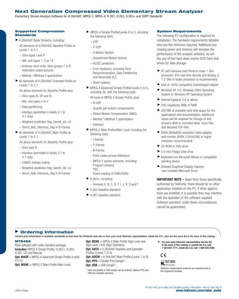
Supported CompressionStandards
H.264/AVC Bytes Streams, including:
All elements of H.264/AVC Baseline Profile atLevels 1 to 5.1
– Slice types I and P
– NAL unit types 1, 5 to 12
– Arbitrary slice order, slice groups 1 to 8,redundant coded pictures
– Method 1/Method 2 quantization
All elements of H.264/AVC Extended Profile atLevels 1 to 5.1
All above elements for Baseline Profile plus:
– Slice types B, SP and SI
– NAL unit types 2 to 4
– Data partitioning
– Interlace (permitted in levels 2.1 to 4.1 only)
– Weighted prediction flag, bipred_idc >0
– Direct_8x8_inference_flag in B-frames
All elements of H.264/AVC Main Profile at Levels 1 to 5.1
All above elements for Baseline Profile plus:
– Slice type B
– Interlace (permitted in levels 2.1 to 4.1 only)
– CABAC entropy coding
– Weighted prediction flag, bipred_idc >0
– Direct_8x8_inference_flag in B-frames
MPEG-4 Simple Profile/Levels 0 to 3, includingthe following tools:
– VOP
– P-VOP
– 4 Motion Vectors
– Unrestricted Motion Vectors
– AC/DC prediction
– Error resilience, including SliceResynchronization, Data Partitioning and Reversible VLC
– Short headers
MPEG-4 Advanced Simple Profile/Levels 0 to 5,including 3b, with the following tools:
All tools of MPEG-4 Simple Profile, plus:
– B-VOP
– Quarter-pel motion compensation
– Global Motion Compensation (GMC)
– Method 1/Method 2 quantization
– Interlace
MPEG-2 Main Profile/Main Level including thefollowing tools:
– I-frames
– P-frames
– B-frames
– Field-coded picture (Interlace)
– MPEG-2 syntax elements, including:Program streams PES Direct reading of VOBs/DVDs
H.263+, including:
– Annexes A, B, C, D, F, I, J, K, S and T
H.263 baseline standard
H.261 baseline standard
System Requirements
The following PC configuration is required for installation. The hardware requirements detailedhere are the minimum required. Additional pro-cessing power and memory will increase the performance of the analysis software, as will the use of fast hard disks and/or SCSI hard diskdrives for data storage.
PC with Genuine Intel Pentium class 1 GHzprocessor. (For real-time decode and display, a1.2 GHz or faster processor is recommended)
Intel or 100% compatible motherboard chipset
Windows NT 4.0, Windows 2000 OperatingSystem or Windows XP Operating System
Internet Explorer 5.0 or above
256 megabytes (MB) of RAM
500 MB of available hard disk space for theapplications and documentation. Additionalspace will be required for storage of teststreams (that is, recorded data), trace files and decoded YUV files
SVGA (800x600) resolution video adapter and monitor (XVGA (1024x768) or higher resolution recommended)
CD-ROM or DVD drive
3.5-inch Floppy Disk drive
Keyboard and Microsoft Mouse or compatiblepointing device
Detailed Graphical Display requires user-installed Microsoft Excel
IMPORTANT NOTE – Apart from those specificallyauthorized by Tektronix, there should be no otherapplication installed on the PC. If other applica-tions are installed, it is possible they may interferewith the operation of the software supplied.Software operation under these circumstancescannot be guaranteed.
Next Generation Compressed Video Elementary Stream AnalyzerElementary Stream Analysis Software for H.264/AVC, MPEG-2, MPEG-4, H.261, H.263, H.263+ and 3GPP Standards
294 • VideoFor the most up-to-date and complete product information, visit our web site at
www.tektronix.com/video_audio
MTS4EA Base software with video standard package.Includes: MPEG-4 Simple Profile, H.263+, H.263,H.261, CD and Manual.Opt. M4SP – MPEG-4 Advanced Simple Profile (Levels0 to 5).Opt. M2ML – MPEG-2 Main Profile Main Level.
Opt. M2HL – MPEG-2 Main Profile High Level andHigh Level 1440 (High Definition).Opt. AVCE – H.264/AVC Baseline and ExtendedProfiles (Levels 1 to 5).Opt. AVCM – H.264/AVC Main Profile (Levels 1 to 5).Opt. PPD – Parallel Port Dongle*1.Opt. USB – USB Dongle*1.*1 Only one parallel or USB dongle can be ordered. Options PPD and
USB are mutually exclusive.
For your local Tektronix representative see the list in the back of this catalog or outside the U.S. call: 1-503-627-7111, inside the U.S. call: 1-800-833-9200.
Tektronix measurement products are manufactured in ISO registered facilities.
Ordering InformationCurrent price information is available worldwide on-line from the Tektronix web site or from your local Tektronix representative. Inside the U.S., also see the price list in the back of this catalog.

Stream Playout and Recording
Record at 90 Mbps
Continuous playout of looped streams with automatic updating of time stamps
Transport stream recording with packet arrival timeinformation stored for offline timing analysis
Simultaneous play & record (option)
Real-time Monitoring
PID and program-oriented dynamic bar and pie charts
Moving PCR timing, TS rate and fullness plots
Display of PSI/SI/PSIP information
Flexible trigger-based capture of errors
Extensive logging with colored fault identifiers
TR101 290 and ATSC compliance checks
Detailed Graphical Display and Off-line Testing of
PSI/SI/PSIP tables with Huffman decoding
Transport stream and PES packets
T-STD buffer analysis including AC-3 audio
PCR/PTS/DTS timestamps
GOP (Group Of Picture), slice, macroblock and motion vector with MPEG/AC-3 audio information (option)
Stream Creation and Manipulation
Multiplexer/Demultiplexer to create multi-programtransport streams with custom SI for both DVBand ATSC
Stream Cutter, Packet Editor and PSI/SI/PSIP Editor
Carousel Analysis and Generation
DVB Data and Object Carousel analysis includingdisplay of AIT tables and ARIB B15/B24 DataCarousel Analysis (option)
Creation and Multiplexing of Object Carouselsfor Multimedia Home Platform (MHP) andInteractive TV test applications (option)
Interfaces
Wide range of interfaces including DVB-SPI (standard) and options for ASI, DHEI, M2S,SMPTE 310M.
Uses NEW: H.264 and WMV9 TS signalling and descriptorsupport now available for analysis where next-generation compression systems are used.
Development
In the development environment the AD953A is a convenient signal source and powerful diag-nostic tool. Its ability to play out the same teststream repeatedly provides the stimulus sourcefor developers of integrated receiver decoders(IRD) and modulators.
Calibrated PCR inaccuracy can be added to testthe performance of the IRD’s clock-recoveryphase locked loop.
The ability of the AD953A to capture and analyzelong streams allows engineers to rapidly searchand identify transport stream packets causingmalfunctions in the equipment under test.
Production
In the production environment the AD953A pro-vides a source of repeatable test patterns for thetest and alignment of IRDs and modulators. Thereliability, embedded diagnostics and modularityof the system provides for the minimum down-time during the unit’s working life.
Transmission Monitoring
For program and service providers, the real-timemonitoring facility of the AD953A provides confidence that the program material meets theMPEG, DVB and ATSC standards. It also savestime delays inherent in post-processing and evaluating off-line data.
Characteristics
Product Specifications Record – Maximum record time at the rate of 60 Mbps:over 1 hour.Maximum data rate: 87.5 Mb/s.(trig rec/monitor: 60 Mbps.) Minimum data rate: 250 kbps.Playout – Maximum data rate: 87.5 Mb/s.Minimum data rate:
Using internal clock: 250 kbps.Using external clock: 250 kbps.
Bit rate resolution: 1 b/s.
Features & BenefitsMPEG, DVB, ATSC and ISDBCompliance Testing
In Depth Off-line Analysis Capability to Solve Problems and Isolate Faults Quickly
Real-time Monitoring to TR101 290with Powerful Trigger Mode to TrackDown Operational Faults Quickly
Real-time and Deferred-time
Transport Stream TimingMeasurements Including PCRAccuracy (PCR_AC), PCR ArrivalInterval, PCR Overall Jitter (PCR_OJ),PCR Arrival Time (Network Jitter), PCR Frequency Offset (PCR_FO), and Deferred-time Drift Rate (PCR_DR)Measurement and Graphing*1
Stream Playout and Recording Provides Repeatable Test Source and Capture Capability for theDevelopment Environment
Easy-to-Interpret Detailed Graphical Display of Real-time and Off-line Analysis Tools
Wide Range of Industry Standard Interfaces for Plug-and-Play Connectivity
Modular Design Allows You toPurchase Only the Performance You Require Today
Easy to Upgrade for Changing Needs
Portable Platform with Hi ResolutionIntegrated Display
ApplicationsDevelopment
Production
Transmission – Satellite – Cable – Terrestrial
MPEG Test System AD953A
For the most up-to-date and complete product information, visit our web site atwww.tektronix.com/video_audio Video • 295
For your local Tektronix representative see the list in the back of this catalog or outside the U.S. call: 1-503-627-7111, inside the U.S. call: 1-800-833-9200.

296 • VideoFor the most up-to-date and complete product information, visit our web site at
www.tektronix.com/video_audio
Packet Handling
Record Input Format Storage Format
188 byte 204 byte 188 byte Y204 byte Y Y 208 byte (GSPI) Y
Playout Storage Format Output Format
188 byte 204 byte 208 byte (GSPI)
188 byte Y Y Y (Dummy RS) (Zero RS)
204 byte Y Y
External Clock Signal Input – AC coupled.Min. Signal Level – 200 mV.Input Impedance – 500 Ω.Connector Format – BNC.
Hardware Configuration 36 GB SCSI disk for stream storage DVD Read,CD-Read/Write drive.Ultra-wide SCSI port for external storage.100Base-T Ethernet.
Display Integrated LCD, 1024x768.
Power Requirements Voltage Range – 100 to 260 VRMS ±10%.Frequency Range – 50/60 Hz.Power Consumption (Typical) – 105 W.Safety – CSA C22.2 No. 1010.1-92, UL61010B-1,Low Voltage Directive 73/23/EEC, amended by93/68/EEC.
Environmental Specifications
Operating Temperature – +5 °C min. to +40 °C max..
Transport Stream InterfaceParallel Input and Output Port – Connector format input: 25 Way D Type.Connector format output: 25 Way D Type.Electrical Specification – LVDS (differential).Input Impedance – 100 Ω.Output Impedance – 100 Ω.
Physical Characteristics Dimensions mm in.Width 432 17 Height (without bottom feet) 226 8.9 Depth 560 22 Weight (system unit) kg lbs.Net 15.5 34
MPEG Test System AD953A
AD953AMPEG Test System Platform.Includes: Mainframe with integrated Hi Res display;one I/O card including DVB SPI interface; Record andPlay software; TSA, PES and Buffer, and Monitor PlusSoftware; MUX software; Make Seamless, Cutter,Maker and Editor software; keyboard with integratedpointing device.
Options Opt. DU – Adds second I/O card and HDD for duplex operation.Opt. ASPT – ASI Interface card with time stamping.
Opt. GPPC – GPSI Interface card.Opt. DB – Carousel Analyzer.Opt. CG – Carousel GeneratorOpt. DBCG – Bundle software including CarouselAnalyzer and Carousel Generator.Opt. ES – ES Analyzer.Opt. IX – Satellite Mux - Japan.Opt. BC – Cable Mux - Japan.Opt. RM – Rackmount.
36GBA – Internal 36 GB disk drive (in addition to standard drive).CDW – Internal CD ROM writer plus Adaptec Easy CD Creator software.FCT – Flight case for AD953-II.
Service Opt. R5 – Repair Service 5 Years.
For your local Tektronix representative see the list in the back of this catalog or outside the U.S. call: 1-503-627-7111, inside the U.S. call: 1-800-833-9200.
Ordering InformationCurrent price information is available worldwide on-line from the Tektronix web site or from your local Tektronix representative. Inside the U.S., also see the price list in the back of this catalog.
Interface Card Options Modes Bit Rate Connector GPSI Interface Option GPPC SMPTE 310M 19.392 Mb/s and BNC
38.785 Mb/s (support for 8 VSB & 16 VSB)
DHEI To 48 Mb/s 26 Way High Density D ECL (AC) To 50 Mb/s 26 Way High Density DECL (DC) To 50 Mb/s 26 Way High Density D
RS-422 differential To 20 Mb/s 26 Way High Density DSSI (DVB serial) To 44 Mb/s BNC
ASI and M2S (DIVICOM) Data, packet burst Data rate to 90 Mb/s BNC Opt. ASPT Transmission rate
270 Mb/s
Transport Stream Interface Options

MPEG Test SystemAD951A
Video • 297For the most up-to-date and complete product information, visit our web site atwww.tektronix.com/video_audio
Characteristics
Record Maximum Record Time at the Rate of 60 Mb/s –Over 1 hour.Maximum Data Rate – 87.5 Mb/s.(Trig Rec/Monitor – 60 Mb/s.) Minimum Data Rate – 250 kb/s.
Playout Maximum Data Rate – 87.5 Mb/s.Minimum Data Rate – Using internal clock:250 kb/s. Using external clock: 250 kb/s.Bit Rate Resolution – 1 b/s.Frequency Resolution – 0.03 Hz.Clock Accuracy – ±1 ppm.Aging and Drift – <1 ppm per year.
External Clock Signal Input – AC coupled.Min. Signal Level – 200 mV.Input Impedance – 50 Ω.Connector Format – BNC.
Hardware Configuration 36 GB SCSI disk for stream storage, DVD Read,CD-Read/Write drive. Ultra-wide SCSI port for externalstorage, 100Base-T Ethernet.
Display Integrated LCD, 1024x768.
Power Requirements Voltage Range – 100 to 240 VRMS ±10%.Frequency Range – 50/60 Hz.Power Consumption (Typical) – 105 W.Safety – CSA C22.2 No. 1010.1-92, UL61010B-1,Low Voltage Directive 73/23/EEC, amended by 93/68/EEC.
Environmental Specifications Operating Temperature – +5 ºC min. to +40 ºC max.
Transport Stream Interfaces Parallel Input and Output Port –Connector format input: 25 Way D-Type.Connector format output: 25 Way D-Type.Electrical Specification – LVDS (differential).Input Impedance – 100 Ω.Output Impedance – 100 Ω.
Features & BenefitsStream Playout and RecordingProvides Repeatable Test Source andCapture Capability for theDevelopment Environment
Wide Range of Industry StandardInterfaces for Plug-and-PlayConnectivity
Modular Design Allows You to Purchase Only the Performance You Require Today
Easy to Upgrade for Changing Needs
Portable Platform with Hi ResolutionIntegrated Display
Applications Development
Production
For your local Tektronix representative see the list in the back of this catalog or outside the U.S. call: 1-503-627-7111, inside the U.S. call: 1-800-833-9200.

MPEG Test SystemAD951A
298 • VideoFor the most up-to-date and complete product information, visit our web site at
www.tektronix.com/video_audio
Physical Characteristics Dimensions mm in.Height (without feet) 226 8.9 Width 432 17 Depth 560 22 Weight (system unit) kg lbs.Net 15.5 34
Packet Handling - Record Input Format Storage Format
188 byte 204 byte 188 byte Y204 byte Y Y 208 byte (GPSI) Y
Packet Handling - Playout Input Format Storage Format
188 byte 204 byte 208 byte (GPSI) 188 byte Y Y (Dummy RS) Y (Zero RS) 204 byte Y Y
Interface Card Options Modes Bit Rate Connector GPSI Interface – SMPTE 310M 19.392 Mb/s and 38.785 Mb/s BNC Opt. GPPC (support for 8VSB and 16VSB)
DHEI To 48 Mb/s 26 Way High Density DECL (AC) To 50 Mb/s 26 Way High Density DECL (DC) To 50 Mb/s 26 Way High Density D
RS-422 differential To 20 Mb/s 26 Way High Density D SSI (DVB serial) To 44 Mb/s BNC
ASI and M2S (DIVICOM) Data, packet burst Data rate to 87.5 Mb/s BNC Opt. ASPT Transmission rate 270 Mb/s
Transport Stream Interface Options
AD951A MPEG Test System.Mainframe with integrated Hi Res display, one I/O card including DVB SPI interface, Record and Play software, MUX software, Make Seamless, Cutter, Makerand Editor software, and keyboard with integrated pointing device.
Options Opt. DU – Adds second I/O card and HDD for duplex operation.Opt. ASPT – ASI Interface card with time stamping.Opt. GPPC – GPSI Interface card.
Opt. TSAL – Transport Stream Analyzer with file size limited to 192 MB.Opt. TSA – Transport Stream Analyzer.Opt. TSAP – Transport Stream Analyzer plus PES Analyzer and Buffer Analyzer.Opt. PB – PES and Buffer Analyzer.Opt. MPLUS – Monitor Plus software.Opt. DB – Carousel Analyzer.Opt. CG – Carousel Generator.Opt. DBCG – Bundle software including CarouselAnalyzer and Carousel Generator.
Opt. ES – ES Analyzer.Opt. IX – Satellite Mux – Japan.Opt. BC – Cable Mux – Japan.Opt. RM – Rackmount.
Service Opt. R3 – Repair Service 3 Years.
For your local Tektronix representative see the list in the back of this catalog or outside the U.S. call: 1-503-627-7111, inside the U.S. call: 1-800-833-9200.
Ordering InformationCurrent price information is available worldwide on-line from the Tektronix web site or from your local Tektronix representative. Inside the U.S., also see the price list in the back of this catalog.

Deferred Time (Off-line) MPEG-2 Analysis and MultiplexerStandalone Software forWindows NT 4.0 or 2000
Tektronix’ industry leading offline software analy-sis and multiplexing modules are available for useon a PC running either Windows NT 4 or Windows2000. The most powerful range of MPEG Analysisproducts available for analysis of streams storedon customers’ own systems.
TS Analyzer [Opt. TSA, TSAL or TSAP] –Provides deferred time Transport Stream packetdisplay and analysis, with timing and statisticaldisplays, calculation and graphical display of PCRinformation, PID Bit Rate Analysis Graphs, andElectronic Program Guide (EPG) Views.
Offline Multiplexer (including Make Seamless)[Opt. MX] – Easy to use high performance multi-plexer that allows the user to collect togethercomponents from streams recorded on disk orCD/DVD-ROM, manipulate them in an unlimitedmanner, and then rebuild a fully compliant outputstream for whatever use is desired. Along theway, the system’s in-built syntax knowledge oftables and descriptors ensures compliant outputof the final multiplex transport stream.
PES Analyzer [Opt. PB] – Provides graphicaldisplay of PES header information plus extractionand display of Presentation Time Stamp (PTS) andDisplay Time Stamp (DTS) information from thepacket header.
TS Buffer Analyzer [Opt. PB] – Provides calculation and graphical display of buffer fullnessbased on the MPEG-2 Transport Stream SystemTarget Decoder (T-STD) buffer model. Detects T-STDbuffer overflow and underflow as described inISO/IEC 13818-1 and for ATSC in A53/A65. Supports3:2 pulldown streams plus smoothing buffer andMax Bit Rate descriptor processing analysis.
Carousel Analyzer [Opt. DB and Opt. DBCG] –Provides in-depth offline analysis of MPEG-2, DVB,and ISDB Transport Streams containing DSMCCdata broadcast protocols including IP, data, andobject carousels.
Carousel Generator [Opt. CG and Opt. DBCG] –Provides in-depth off-line generation of MPEG-2,DVB Transport Streams containing DSM-CC, DVB,MHP, and Digital Terrestrial Television (DTT) Object Carousels.
ES Analyzer [Opt. ES] – Displays motion pictures,analyzes and tests Elementary Streams containedwithin Transport Streams or Program Streams.Includes slice and block layer tests together withmotion vector displays. Encoder performance veri-fication time is greatly reduced using automatedregression tests that provide reports on any errorsfound within an Elementary Stream.
Broadcast Satellite Digital Multiplexer [Opt. IX] – A complete multiplexer, demultiplexer,editing and analysis tool for ISDB-S standardstreams. It provides off-line multiplexing of existing
Features & BenefitsMPEG, DVB, ATSC and ISDB Support
In Depth Off-line Analysis Capability to Solve Problems and Isolate Faults Quickly
Easy-to-Interpret Detailed Graphical Displays
Comprehensive Deferred TimeTransport Stream PCR TimingMeasurement and Graphing
Easy to Upgrade Modular SoftwareAllows You to Purchase Only thePerformance You Require Today
Applications Development
Production
Transmission
Satellite
Cable
Terrestrial
MPEG Test System Standalone Software
Video • 299For the most up-to-date and complete product information, visit our web site atwww.tektronix.com/video_audio
For your local Tektronix representative see the list in the back of this catalog or outside the U.S. call: 1-503-627-7111, inside the U.S. call: 1-800-833-9200.

MPEG Test System Standalone Software
For the most up-to-date and complete product information, visit our web site atwww.tektronix.com/video_audio
transport streams and TMCC (Transmission andMultiplexing Configuration Control) information in order to produce ISDB-S transport streams.It can also be used to demultiplex existing ISDB-Stransport streams and allow the TMCC informationto be edited.
Broadcast Cable Digital Multiplexer [Opt. BC] –A complete multiplexer, demultiplexer, editing,and analysis tool for ISDB-C standard streams. Itprovides off-line multiplexing of existing transportstreams and TSMF (Transport Stream MultiplexingFrame) information in order to produce ISDB-Cstreams. It can also be used to demultiplex existingISDB-C streams and allow the TSMF informationto be edited.
Sky XSI Analysis [Opt. XS] – XSI support forTransport Stream Analyzer.
VIAccess [Opt. VI] – VIAccess support forTransport Stream Analyzer.
OpenTV Analysis [Opt. OP] – OpenTV supportfor Transport Stream Analyzer.
Utilities – Software utilities enabling cutting andediting of streams together with the MakeSeamless module are supplied as standard withall standalone software applications.
System Requirements
The following PC configuration is required forinstallation. The hardware requirements detailedhere are the minimum required. Additional processing power and memory will increase theperformance of the analysis software, as will the use of fast hard disks and/or SCSI hard diskdrives for data storage.
PC with Genuine Intel Pentium class 500 MHzprocessor (1 GHz or faster processor recom-mended) with Intel or 100% compatible motherboard chipset
Windows NT 4.0 or Windows 2000 OperatingSystem with Internet Explorer 5.0 or above
128 megabytes (MB) of RAM (256 MB recommended)
500 MB of available hard disk space for theapplications. Additional space will be required forstorage of transport streams (that is, recorded data)
SVGA (800x600) resolution video adapter andmonitor (XVGA (1024x768) or higher-resolutionrecommended)
CD-ROM or DVD drive and 3.5" Floppy Disk drive
Sound Blaster Live 5.1 Sound Card (onlyrequired if the ES Analyzer Software is installed)
Keyboard and Microsoft Mouse or compatiblepointing device
IMPORTANT NOTE — Apart from those specifically authorized byTektronix, there should be no other application installed on the PC.If other applications are installed it is possible they may interferewith the operation of the software supplied. Software operationunder these circumstances cannot be guaranteed.
300 • Video
ADSA – Standalone Deferred Time Software PackageTSA – DVB/ATSC/ARIB TS Analyzer software.TSAL – DVB/ATSC/ARIB TS Analyzer software (TS filesize limited to 192 MB).TSAP – DVB/ATSC/ARIB TS Analyzer software plusPES Analyzer and Buffer Analyzer.MX – DVB/ATSC/ARIB Multiplexer including Make Seamless.PB – DVB/ATSC PES and Buffer Analyzer software.DB – MPEG/DVB Carousel Analyzer.CG – Carousel Generator.DBCG – MPEG/DVB Carousel Analyzer and Carousel Generator.ES – Elementary Stream Analyzer.IX – ISDB-S Digital Multiplexer.BC – ISDB-C BCDM; Broadcast Cable Digital Multiplexer.XS – XSI Analyzer. SKY or NDS Approved Customers Only.VI – VIAccess Analyzer. VIAccess Approved Customers Only.OP – OpenTV Analyzer. OpenTV Approved Customers Only.Includes: CD, dongle and manual.
ADSAUP – ADSA Field UpgradeTSA – DVB/ATSC/ARIB TS Analyzer software.TSAL – DVB/ATSC/ARIB TS Analyzer software (TS file size limited to 192 MB).TSAP – DVB/ATSC/ARIB TS Analyzer software plusPES Analyzer and Buffer Analyzer.MX – DVB/ATSC/ARIB Multiplexer including Make Seamless.PB – DVB/ATSC PES and Buffer Analyzer software.DB – MPEG/DVB Carousel Analyzer.CG – Carousel Generator.DBCG – MPEG/DVB Carousel Analyzer and Carousel Generator.ES – Elementary Stream Analyzer.IX – ISDB-S Digital Multiplexer.BC – ISDB-C BCDM; Broadcast Cable Digital Multiplexer.XS – XSI Analyzer. SKY or NDS Approved Customers Only.VI – VIAccess Analyzer. VIAccess Approved Customers Only.OP – OpenTV Analyzer. OpenTV Approved Customers Only.Includes: CD, floppy disk to upgrade existing dongle and manual.
For your local Tektronix representative see the list in the back of this catalog or outside the U.S. call: 1-503-627-7111, inside the U.S. call: 1-800-833-9200.
Ordering InformationCurrent price information is available worldwide on-line from the Tektronix web site or from your local Tektronix representative. Inside the U.S., also see the price list in the back of this catalog.

For the most up-to-date and complete product information, visit our web site atwww.tektronix.com/video_audio Video • 301
NEW: Support for H.264 and WMV9 stream typesenables stream identification and monitoring wherenext-generation compression systems are used.
NEW: RF diagnostic mode enables measurementson signals where lock cannot be achieved.
The MTM400 is a real-time MPEG transportstream monitor. Together with the MLM1000Multi-Layer Monitoring Application,*2 the MTM400 provides a complete solution for transmissionmonitoring of MPEG transport streams.
The MTM400 uses a single transport streamprocessor board packaged in a 1RU rackmountchassis to provide monitoring of a transportstream at data rates up to 155 Mbps*3 based on a single board MPEG transport stream analysisplatform. The platform is used to provide anextended confidence monitoring product that, withthe addition of software options, provides diag-nostic monitoring capabilities. The extended confi-dence monitor provides the key MPEG tests; thisbasic level of functionality and low cost enableswidespread deployment throughout a transmis-sion network, facilitating rapid fault isolation.
The diagnostic monitoring options provide morein-depth analysis of the MPEG transport streamincluding recording capability, PSI/SI/PSIP/ARIBanalysis and unique user-defined template teststo ensure right content, right place, right time.Additionally, optional QPSK and QAM interfacesallow the MTM400 to receive RF inputs and display key RF monitoring parameters includingMER, BER and constellation displays beforedemodulating the signal to provide measurementson the health of the Transport Stream. Deployedat key network nodes, the MTM400 equipped asa diagnostic monitor enables the cause of faultsto be pinpointed and solved.
*1 Except T-STD buffer model analysis.
*2 Separate data sheet is available.
*3 Maximum transport stream bit rate is dependent on transport stream content and depth of analysis being performed. Depth of stream analysis is handled gracefully if SI/PSIP max content is exceeded to ensure critical measurements continue to be performed.
*4 Existing AD95x MPEG Test System offline software tools are available for use with the MTM400. These are stand-alone software applications intended to run on the WebMSM control PC. Separate data sheet is available.
MPEG Transport Stream MonitorMTM400
Features & BenefitsMonitor Key MeasurementsAccording to the DVB Standard WithReal-time Monitoring of TR 101 290First, Second and Third PriorityParameters*1
Remotely Monitor and Control All Units in a Monitoring Network from a Central Control Point viaIndustry-standard SNMP UsingMLM1000 Multi-layer Application*2
Embedded Solution Provides a High-reliability System that EnablesUnattended 24x7 Operation withinSmall 1RU Chassis
User-defined Template MonitoringOption to Ensure Right Content At the Right Place At the Right Time
Analyze Captured Streams UsingIndustry Leading Deferred TimeAnalysis Software Available for UseWith MTM400*4
Confidence Monitoring at the RF Modulated Layer with OptionalQPSK and QAM Interface MER, BERand Constellation Displays
Review Quantitative Results ofTransport Stream Health via Event Logging with Multi-languageLog Support for Chinese andJapanese Users
User-configurable Alarms AllowActivation of Relays, TTL Outputs, andSNMP Traps by Any Test Performed
Clock Synchronization to Either LTC Input or SNTP Enable MonitoringSystem Event and Alarm Reporting to be Accurate to Broadcast Network Time
Applications Terrestrial Distribution
Contribution and Primary Distribution
Cable Headend Monitoring
DTH or Network Operator SatelliteUplink Monitoring
For your local Tektronix representative see the list in the back of this catalog or outside the U.S. call: 1-503-627-7111, inside the U.S. call: 1-800-833-9200.
Product(s) are manufactured in ISO registered facilities.
MTM400 single-stream MPEG transport stream monitor.
Technical Overview

For the most up-to-date and complete product information, visit our web site atwww.tektronix.com/video_audio
For the most up-to-date and complete product information, visit our web site atwww.tektronix.com/video_audio302 • Video
Flexible andUpgradeable The MTM400 provides a flexible solution with anupgrade path, including diagnostic monitoringfeatures that enable customers to build a cost-effective monitoring system to suit their individualrequirements. Diagnostic capability can be addedto the key monitoring points where transportstreams are manipulated while extended confi-dence monitoring probes can be installedthroughout the network:
Triggered recording enables problems to be captured and analyzed in greater depth usingoffline analysis tools such as the Tektronix MPEG Test System Standalone Software*2
PSI/SI/PSIP/ARIB SI Analysis and repetition rategraphing allows broadcasters to determine thatthe system information is present and correct inthe transport stream
Template testing checks a number of key param-eters to ensure that the transport stream hasbeen constructed as the broadcaster intended.These parameters include the Transport StreamID and Network ID, the number of programs inthe multiplex, that each program has all of itscomponents (Video, Audio, Data, Teletext,Subtitles) and Conditional Access (CA) status
Bit rate testing determines whether PIDs,programs, services or user-defined groups ofPIDs are within user-definable limits to ensurecorrect multiplex operation. Tektronix-proprietaryPID variability test gives indication of PID bit rate variation to assess effects of statistical multiplexing
In-depth PCR analysis with graphical results viewsenable timing and jitter measurements to bemade to ensure correct operation of the network
Service logging enables verification of servicelevel agreements to ensure that contractual obligations are met
Offline analysis software applications for in depthdeferred time analysis of streams captured usingthe MTM400 gives Tektronix the most powerfulMPEG monitoring diagnostics available in theworld today*4
*2 Separate data sheet is available.
*4 Existing AD95x MPEG Test System offline software tools are avail-able for use with the MTM400. These are stand-alone softwareapplications intended to run on the WebMSM control PC. Separatedata sheet is available.
MPEG Transport Stream MonitorMTM400
MTM400 Single-stream extended confidence monitor packaged in 1RU chassis.Includes: 1RU chassis fitted with transport streamprocessor card, manual, rack slides, power cord, andlicense key certificate.
Options Opt. 01 – Triggered recording capability up to160 MB.Opt. 02 – Transport stream service information analysis(PSI/SI/PSIP/ARIB view).Opt. 03 – Template testing (for user-defined serviceplan testing).Opt. 04 – In-depth PCR analysis with graphical result views.Opt. 05 – Bit rate testing functionality.Opt. 06 – Service logging.Opt. QA – QAM Annex A interface.Opt. QB – QAM Annex B interface.Opt. QC – QAM Annex C interface.Opt. QP – QPSK interface.
Service Opt. R3 – Repair service three years.Opt. R5 – Repair service five years.
Power Connections Opt. A0 – North America Power Plug.Opt. A1 – Universal EURO Power Plug.Opt. A2 – United Kingdom Power Plug.Opt. A3 – Australia Power Plug.Opt. A4 – 240 V North America Power Plug.Opt. A5 – Switzerland Power Plug.Opt. A6 – Japan Power Plug.Opt. A10 – China Power Plug.Opt. A99 – No Power Cord or AC Adapter.
Field Upgrade Kits MTM4FQA – Field upgrade kit to add QAM Annex AInterface to an existing probe.MTM4FQB – Field upgrade kit to add QAM Annex B Interface to an existing probe.MTM4FQC – Field upgrade kit to add QAM Annex C Interface to an existing probe.MTM4FQP – Field upgrade kit to add QPSK Interfaceto an existing probe.
MTM4UP Opt. 01 – Field upgrade kit to add triggered recording capability up to 160 MB.MTM4UP Opt. 02 – Field upgrade kit to add transport stream service information analysis(PSI/SI/PSIP/ARIB view).MTM4UP Opt. 03 – Field upgrade kit to add templatetesting (for user-defined service plan testing).MTM4UP Opt. 04 – Field upgrade kit to add in-depthPCR analysis with graphical result views.MTM4UP Opt. 05 – Field upgrade kit to add bit ratetesting functionality.MTM4UP Opt. 06 – Field upgrade kit to add logging.
For your local Tektronix representative see the list in the back of this catalog or outside the U.S. call: 1-503-627-7111, inside the U.S. call: 1-800-833-9200.
Product(s) are manufactured in ISO registered facilities.
Ordering InformationCurrent price information is available worldwide on-line from the Tektronix web site or from your local Tektronix representative. Inside the U.S., also see the price list in the back of this catalog.
The summary status screen provides a quick overview of the health and contents of the stream.
QAM Signal Monitoring.

Features & BenefitsHigh Capacity Storage and High Data-rate Recording and Playout ofMPEG Transport Streams Lets YouBuild, Maintain, and Use a Large Local Library of Test Streams
Real-time Updating of Timestamps and Time Tables for Error-free Looping
PCR Jitter Insertion to Help You Fully Stress Your Product or System Design
Remote Control via Ethernet with Standard Command for Programmable Instruments (SCPI) Command Set
Sample Transport Streams Providedto Get You Started Quickly
Easy Integration With Tektronix MPEGAnalysis Tools for Transport StreamCreation to Support Compliance and Stress Testing of Video ProductsUsing MPEG-2 Technology
CD-ROM and 100Base-T EthernetDownload of Transport Streams forOptimal Flexibility in Storing andManaging Transport Stream Libraries
Color Hierarchical Display of TransportStream Components For Quick and Easy Interpretation of Complex Structures
A Full Suite of Electrical Interfaces Lets You Address a Wide Range of Applications
Applications IRD/STB Design and Manufacturing Test
Evaluation of Professional MPEG Equipment
Performance Verification of MPEG Systems
For the most up-to-date and complete product information, visit our web site atwww.tektronix.com/video_audio
MPEG Recorder and Player MTX100
Video • 303
MTX100MPEG Recorder and Player.Includes: Stream capture and playout with error-freelooping and PCR jitter insertion, 768 MB RAM, 40 GbMPEG stream storage, sample streams, USB Keyboardand Mouse, Front Cover and User Manual.Please specify power plug when ordering.
Interface Options Opt. 01 – Add ASI Interface Module.Opt. 02 – Add Universal Parallel/Serial Interface Module.Opt. 05 – Add IEEE 1394 ASI Interface Module.
Opt. 06 – SMPTE 310M ASI Interface Module.
Service Opt. C3 – Calibration Service 3 Years.Opt. D1 – Calibration Data Report.Opt. D3 – Calibration Data Report 3 Years (with Option C3).Opt. R3 – Repair Service 3 Years.
Optional Accessories 070-A835-00 – Service Manual.1700F05 – Rackmount Kit.1700F06 – Blank Panel.
For your local Tektronix representative see the list in the back of this catalog or outside the U.S. call: 1-503-627-7111, inside the U.S. call: 1-800-833-9200.
Ordering InformationCurrent price information is available worldwide on-line from the Tektronix web site or from your local Tektronix representative. Inside the U.S., also see the price list in the back of this catalog.
The MTX100 MPEG-2 Recorder and Player offersa flexible, affordable solution for design evaluationand conformance testing of digital video productsusing MPEG-2 technology. The MTX100 recordsand plays out MPEG-2 transport streams compli-ant with ATSC, DVB and ISDB standards at thehigh data rates needed to verify and troubleshootdesigns for high-performance video products andsystems. The large internal storage, CD-ROM, andEthernet download capability help you build andmaintain a large library of test streams.
The MTX100 offers continuous, error free trans-port streams looping for long duration playout,and PCR jitter insertion for stressing your designs.You can continuously loop all sample streams,including updating of all timestamps, continuitycounters and time tables (TDT or STT), withoutfear of buffer under- or overflow.
New ethernet network remote control functionalityenables control of functions such as Play, Record,Clock Rate and Jitter Insertion using the SCPI(Standard Control for Programmable Instruments)command set.
The MTX100 can play any TS files, including custom transport streams created with off linemultiplexers in the Tektronix MPEG Analysis Tools.
Characteristics System Characteristics MPEG Stream Source Characteristics – SupportsMPEG-2, DVB, ATSC and ISDB protocols. Records andplays out MPEG streams in multiple formats. Error-freelooping. PCR jitter insertion.Packet Length – 188, 204 or 208 bytes and Non-TS.Maximum Data Rate – Memory: 200 Mb/s.Disk: 120 Mb/s.Minimum Data Rate – 1 Kb/s.Number of Input/output Interfaces – One DVB SPII/O standard with a second I/O available.Available Optional Interfaces – AsynchronousSerial Interface (ASI/M2S), Universal Parallel/SerialInterface, IEEE 1394 (Firewire), SMPTE 310M.Internal Storage Capacity – 40 GB.Internal Reference Clock – 27 MHz ±1 ppm.External Reference Input – 27 MHz ±1 ppm (recommended).
Transport Stream Interfaces DVB Synchronous Parallel Interface (Standard) –Connector: 25 pin D-sub, Maximum data rate: 25 MB/s.Asynchronous Serial Interface (Option 01) –Connector: BNC, Maximum data rate: 200 Mb/s, Userselectable burst & non-burst transmission format.Universal Parallel/Serial Interface (Option 02) –Parallel, Serial, and Event Output Modes.
Parallel Mode – Connector: 25 pin D-sub,Maximum Data Rate: 25 MB/s, Output Levels: ECL,LVDS and TTL with/without termination, Single End Input Levels: ECL and TTL with termination.Serial Mode – Connector: 25 pin D-sub,Maximum Data Rate: 40 Mb/s, Output Levels: ECL,LVDS and TTL, Differential Input Levels: ECL and TTLwith/without termination, Single End Input Levels:ECL and TTL with termination.Event Output – Connector: BNC.
IEEE 1394 Interface (Option 05) – IEEE Connector:4 pin std., Data Rate: 40 Mb/s; ASI Connector: BNC;Maximum Data Rate 200 Mb/s.SMPTE 310M Interface (Option 06) – SMPTEConnector: BNC, Data Rate: 19.39 Mb/s; ASIConnector: BNC, Maximum Data Rate: 200 Mb/s.

For the most up-to-date and complete product information, visit our web site atwww.tektronix.com/video_audio
Overview The AD954 is a small, portable unit with enoughpower to debug MPEG-2 systems in the field. Itinterfaces with the Engineer’s laptop computerrunning AD954 software to create a cost effectiveand simple analysis tool for use on the move.
The AD954 is designed for engineers who work in the field on compression equipment installationand service. For them it provides instant real-timeanalysis and recording as well as off-line analysisat the transport stream level. The AD954 workswith the engineer’s own laptop on which statusinformation is provided by clear graphical displays.
The result is simple, in-the-field diagnosis andquality assurance.
Real Time Monitoring
The AD954 performs real time monitoring ofMPEG-2, DVB and ATSC transport streams.This gives “live” stream compliance status andhighlights errant stream behavior.
DVB Testing
AD954 provides real time monitoring of all the DVB defined first priority measurements.*1
It also gives status of the transport error indicator and detects unreferenced PIDs
A real time view of the SI tables is provided
ATSC Testing
In addition to the basic transport stream tests areal time view of the PSIP table is provided
PID Bit Rate Testing
User selected PIDs may be tested to checkwhether their bit rate remains constant for aperiod of greater than 1 second. The multiplexoccupancy is tested against user definable limitson either a per PID or per program basis.Installation engineers can thereby confirm thatstatistical multiplexers are functioning correctly
Recording
AD954 can record up to 15 seconds of data at bit rates of 90 Mb/s
Recording is initiated direct from the user interface
Captured files can be examined in the field usingStream Analyzer software or sent back to researchand development engineers for further analysis
Triggered Recording
Recording can be triggered by a change in stateof any one of the measurements made by theAD954, as defined by the user
The trigger point can be defined to be any pointin the recorded file
Trigger settings can be maintained between sessions
*1 Ref: European Telecommunications Standard Institute TR101 290: Digital Video Broadcasting (DVB); MeasurementGuidelines for DVB systems.
MPEG Portable Analyzer AD954
304 • Video
Features & BenefitsSupports MPEG-2/DVB/ATSCTransport Streams Which EnablesTesting to be Performed Anywhere in the World
Real Time Monitoring of KeyParameters Gives an ImmediateIndication of Major Problems
Detailed Off Line Transport StreamAnalysis Enables Full In-depth Analysis of the Transport Stream
Transport Stream Capture andTriggered Recording Provides the Capability to Send Streams Back to Base
ASI, SMPTE 310M, DVB ParallelInterfaces for Connection Anywherein an MPEG-2 Network
Small, Light and Portable
Low Power Consumption
Applications Installation and Commissioning of DVB/ATSC or any MPEG-2Transmission Chain
Testing and Debug of MPEG-2Broadcast Equipment
For your local Tektronix representative see the list in the back of this catalog or outside the U.S. call: 1-503-627-7111, inside the U.S. call: 1-800-833-9200.
Tektronix measurement products are manufactured in ISO registered facilities.

MPEG Portable Analyzer AD954
Video • 305For the most up-to-date and complete product information, visit our web site atwww.tektronix.com/video_audio
Error Logging
Both conditional tests (i.e. TR 101 290) and syntaxerrors can be logged in real time. With both timeand date for each event, the error log files helpyou assess weak points in a system by providingan accurate picture of events when you leave theunit to monitor for a period of time.
Off Line Analysis
AD954 is supplied with Stream Analyzer software,providing:
Packet Display and Analysis
Transport stream packet header interpretation
Adaptation field information for individual packets
Hexadecimal representation of transport streampacket header and payload information
Location of a transport stream packet to match a particular condition in the packet header
Timing and Statistical Displays
Statistical display of the components of thetransport stream and their data rates on a program oriented basis
Calculation and graphical display of the instanta-neous and mean bit rate for each PID and for theentire transport stream from PCR time stamp values
Calculation and graphical display of PCR information:– Repetition interval between successive PCRs
on a PID by PID basis – Inaccuracy of each PCR on a PID by PID basis
Display of MPEG-2 tables, DVB tables, EnhancedDVB SI and ATSC PSIP tables
Characteristics
Network Interfaces – AD954 is compatible with a Pentium class laptop orhigher running either Windows 95/98/2000 or WindowsNT operating systems.Connection is via a parallel port interface (ECP). Toensure optimum performance of real time monitoring werecommend that a PC with a performance equivalent toa Pentium 300 MHz unit running Windows 95/98/2000with 64 MB RAM or running Windows NT with 128 MBRAM is used with AD954.Transport Stream Interfaces – DVB parallel.DVB ASI.SMPTE310M.
Performance Storage Capacity – 192 MB.Max Data Rate – 90 Mb/s.Min Data Rate – 250 Kb/s*1.*1 Minimum data rate on ASI input with single byte mode stream.
Electrical Voltage – 6 to 12 V DC.Power – <1 amp at 6 V DC.Operating Temperature – 5 ºC to 40 ºC.
MPEG-2 Real TimeMeasurements Measurement Error No.*2
TS_sync_loss 1.1 Sync_byte_error 1.2 PAT_error 1.3 Continuity_count_error 1.4 PMT_error 1.5 PID_error 1.6 Unreferenced PID 3.4 Transport error 2.1 *2 Error No. derived from references in TR 101 290.
DVB Real Time Analysis
SI Table checks*3
MPEG-2 measurements as defined above
PID bit rate measurement
ATSC Real Time Analysis
PSIP Table checks*3
Program Paradigm Error
MPEG-2 Measurements as defined above
PID bit rate measurement *3 The display of the complete SI/PSIP information in real time is
dependent on the volume of SI in the stream being monitored, theperformance of the PC and the performance of the parallel link.
Physical Characteristics Dimensions mm in.Width 290 11.42 Height 25 0.98 Depth 220 8.66 Weight (system unit) kg lb.Net 1.3 2.87
AD954MPEG Portable Analyzer.
Platform AD954 Application software.External power supply.
Options The following cost options are available:Opt. SA – TS analyzer for use with files of any size.
Service Opt. R5 – Repair Service 5 Years.
Ordering InformationCurrent price information is available worldwide on-line from the Tektronix web site or from your local Tektronix representative. Inside the U.S., also see the price list in the back of this catalog.
For your local Tektronix representative see the list in the back of this catalog or outside the U.S. call: 1-503-627-7111, inside the U.S. call: 1-800-833-9200.
Tektronix measurement products are manufactured in ISO registered facilities.

The MLM1000 Multi-layer Monitor is an installableapplication that enables complete visibility of theerror status of a transmission network, as measuredby various monitoring instruments (WVR600 series,WFM700 series, MTM400, RFM210), from astandard Web browser or client application. Thenetwork manager is able to customize the userinterface, building up geographical maps showingthe location and status of the monitoring networkas well as mimic diagrams of the transmissionnetwork. When a fault occurs, the correspondingmonitoring point is highlighted in red, enablingthe network manager to drill down to the individ-ual monitor and determine the nature of the fault.The MLM1000 can be used to manage a mixednetwork of confidence and diagnostic monitors,displaying the appropriate level of information foreach type of monitor.
The MLM1000 Multi-layer Monitor allows remoteaccess to Tektronix Video monitoring devices(WVR600 series, WFM700 series, MTM400,RFM210) deployed in the network; this providesthe customer combined monitoring of TektronixMPEG, RF, and baseband video products in anintegrated solution.
The MLM1000 application requires only a standardJava plug-in enabled HTML Web browser. It alsoutilizes industry-standard SNMP protocols, so itcan work with Internet/Intranet links to various
remote monitors using minimal network overhead;network security is available to prevent unauthorizedaccess to the network. More than one instance ofthe MLM1000 can operate concurrently in a network,permitting (for example) a diagnostic engineer touse a dial-up link from a remote location withoutaffecting the main central console display.
The MLM1000 is licensed on a per probe basis to ensure the system is scalable according to thenumber of probes required, ensuring the systemis cost effective for the number of monitoringprobes required.
The MLM1000 provides an extremely powerfulbut easy-to-use comprehensive monitoring systemthat can quickly and easily be set-up or modifiedas required by operators and service providers.
For the most up-to-date and complete product information, visit our web site atwww.tektronix.com/video_audio
Multi-layer MonitorMLM1000 NEW
306 • Video
Features & BenefitsGeographic and Network SchematicHot Spot Views Enable the Operatorto Drill Down to Pinpoint Errors in a System
Remote Monitoring and Control viaIndustry-standard SNMP ProvidesRemote Access of All Units in aMonitoring Network from a CentralControl Point via the Ethernet
At-a-Glance Status of Complex Digital Broadcast Networks for 24x7 Monitoring of TektronixMonitoring Devices
Java and SNMP for Platform andOperating System Independence
Control of WVR600 Series, WFM700Series, MTM400 and RFM210
Flexible and scalable OrderingConfigurations to Ensure a Cost-effective System for the Number of Monitoring Probes Required
Applications Monitoring of TV BroadcastTransmission Networks
Monitoring of TV Contribution andDistribution Networks
For your local Tektronix representative see the list in the back of this catalog or outside the U.S. call: 1-503-627-7111, inside the U.S. call: 1-800-833-9200.
Tektronix measurement products are manufactured in ISO registered facilities.
Product Information
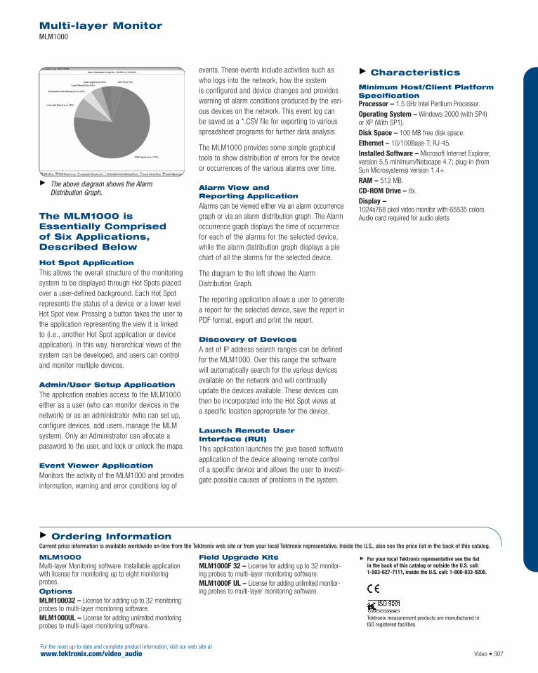
The MLM1000 isEssentially Comprised of Six Applications,Described Below
Hot Spot Application
This allows the overall structure of the monitoringsystem to be displayed through Hot Spots placedover a user-defined background. Each Hot Spotrepresents the status of a device or a lower levelHot Spot view. Pressing a button takes the user tothe application representing the view it is linkedto (i.e., another Hot Spot application or deviceapplication). In this way, hierarchical views of thesystem can be developed, and users can controland monitor multiple devices.
Admin/User Setup Application
The application enables access to the MLM1000either as a user (who can monitor devices in thenetwork) or as an administrator (who can set up,configure devices, add users, manage the MLMsystem). Only an Administrator can allocate apassword to the user, and lock or unlock the maps.
Event Viewer Application
Monitors the activity of the MLM1000 and providesinformation, warning and error conditions log of
events. These events include activities such aswho logs into the network, how the system is configured and device changes and provideswarning of alarm conditions produced by the vari-ous devices on the network. This event log can be saved as a *.CSV file for exporting to variousspreadsheet programs for further data analysis.
The MLM1000 provides some simple graphicaltools to show distribution of errors for the deviceor occurrences of the various alarms over time.
Alarm View and Reporting Application
Alarms can be viewed either via an alarm occurrencegraph or via an alarm distribution graph. The Alarmoccurrence graph displays the time of occurrencefor each of the alarms for the selected device,while the alarm distribution graph displays a piechart of all the alarms for the selected device.
The diagram to the left shows the AlarmDistribution Graph.
The reporting application allows a user to generatea report for the selected device, save the report inPDF format, export and print the report.
Discovery of Devices
A set of IP address search ranges can be definedfor the MLM1000. Over this range the softwarewill automatically search for the various devicesavailable on the network and will continuallyupdate the devices available. These devices canthen be incorporated into the Hot Spot views at a specific location appropriate for the device.
Launch Remote User Interface (RUI)
This application launches the java based softwareapplication of the device allowing remote controlof a specific device and allows the user to investi-gate possible causes of problems in the system.
Characteristics
Minimum Host/Client PlatformSpecification Processor – 1.5 GHz Intel Pentium Processor.Operating System – Windows 2000 (with SP4) or XP (With SP1).Disk Space – 100 MB free disk space.Ethernet – 10/100Base-T; RJ-45.Installed Software – Microsoft Internet Explorer,version 5.5 minimum/Netscape 4.7; plug-in (from Sun Microsystems) version 1.4+.RAM – 512 MB.CD-ROM Drive – 8x.Display –1024x768 pixel video monitor with 65535 colors.Audio card required for audio alerts.
For the most up-to-date and complete product information, visit our web site atwww.tektronix.com/video_audio
Multi-layer MonitorMLM1000
Video • 307
The above diagram shows the AlarmDistribution Graph.
MLM1000Multi-layer Monitoring software. Installable applicationwith license for monitoring up to eight monitoringprobes.Options MLM100032 – License for adding up to 32 monitoringprobes to multi-layer monitoring software.MLM1000UL – License for adding unlimited monitoringprobes to multi-layer monitoring software.
Field Upgrade Kits MLM1000F 32 – License for adding up to 32 monitor-ing probes to multi-layer monitoring software.MLM1000F UL – License for adding unlimited monitor-ing probes to multi-layer monitoring software.
For your local Tektronix representative see the list in the back of this catalog or outside the U.S. call: 1-503-627-7111, inside the U.S. call: 1-800-833-9200.
Tektronix measurement products are manufactured in ISO registered facilities.
Ordering InformationCurrent price information is available worldwide on-line from the Tektronix web site or from your local Tektronix representative. Inside the U.S., also see the price list in the back of this catalog.

For the most up-to-date and complete product information, visit our web site atwww.tektronix.com/video_audio
Picture Quality Analysis System
Introducing the PQA300… the industry’s leadingobjective picture quality measurement tool basedon the Emmy Award-winning PQA200 platform.
The PQA300 analyzes picture quality with repeat-able, objective measurements that directly repli-cate subjective human visual assessments. Thesemeasurements provide invaluable information forengineers working to optimize video compressionwithout compromising picture quality.
The PQA300 is both a generator and analyzer of reference test material for testing compressedvideo systems. Standard inputs and outputs are270 Mb/s serial component (Rec. 601). Option 01provides analog composite NTSC/PAL inputs and outputs.
Compressed Video Requires a New Method of Testing
The best measure of any analog or digital televi-sion system is the viewer’s satisfaction with theimage received. Traditionally, the quality of analogand full-bandwidth digital video systems has beenmeasured indirectly by measuring the distortionsof static test signals.
Compressed television systems, however, pose afar more difficult measurement challenge. Picturequality in these systems changes dynamically basedon the data rate, picture complexity and encodingalgorithm employed. The static nature of test signalsdoes not provide true characterization of picturequality. Natural test scenes that are far morecomplex than test signals must be used to stressthe capabilities of compressed video systems.
Until now, subjective testing using human viewershas been the only available method for evaluatingcompressed video systems. But, while useful forestablishing academic reference data, subjectivetesting has been impractical for operational,manufacturing and troubleshooting applications –until the development of the Tektronix PQA300,which provides a fast, practical and repeatableobjective measurement alternative to subjectiveevaluation of picture quality.
How It Works
The PQA300 measures a 2-second portion of a5-second video test sequence. The video testsequences may be downloaded from suppliedCD-ROMs or recorded from your own video, andplayed out to the system under test. While serialdigital interfaces are standard, analog compositeand S-Video (Y/C) interfaces can also be accom-modated with the addition of Option 01.
The output of the system under test is then stored and analysis performed with DSP-acceleratedhardware on the 2-second sequence. The measurement results in a single numeric value of
Picture Quality Analysis System PQA300
308 • Video
Features & BenefitsProvides Fast, Accurate andRepeatable Objective Picture Quality Measurements
Replaces Time Consuming andExpensive Human Picture QualityAssessment, by Utilizing a HumanVision System Model, JNDmetrix
In-depth Picture Quality Analysis System – PQR Measurement – PSNR Measurement – PSNR Difference Maps – Tabular Frame-by Frame
and Graphical Results
Choice of Tektronix Supplied or User-supplied Reference Video Test Sequences
Measures Impairments Relative to Reference Video
Applications Encoder Product and ComponentDesign Verification
Transmission Equipment and Systems Evaluation
Picture Quality Video ContentVerification and Analysis at the Program (Video) Layer
For your local Tektronix representative see the list in the back of this catalog or outside the U.S. call: 1-503-627-7111, inside the U.S. call: 1-800-833-9200.
Tektronix measurement products are manufactured in ISO registered facilities.

picture quality called Picture Quality Rating (PQR).Utilizing a human vision system model, JNDmetrix,based on years of research by the SarnoffCorporation, the PQA300 analyzes the three nec-essary dimensions for evaluation of dynamic andcomplex motion test sequences: spatial analysis,temporal analysis and full-color analysis.
In addition to reporting the Picture Quality Rating,the PQA300 provides PSNR-values and an ani-mated map whose intensity is related to the per-ceived differences between the original and cap-tured image. This provides invaluable informationfor evaluation and optimization of digital videocompression systems.
The PQA300 provides Results Summary, GraphFiles and PSNR Difference Maps for in-depth,detailed analysis to help you evaluate your equip-ment design, transmission system evaluation, orconduct your picture quality content verificationand analysis at the program (video) layer.
The Results Summary
The results summary screen shows a frame-by-frame summary of the test results, PQR, and PSNRscores for both the reference and test video.
The Graph File
The analysis performed in the graph screen allowsthe user to select any of the results in muchgreater detail. For example, as you go to the PQRgraph, you will be able to see the distribution ofthe scores on a frame-by-frame basis and identifyindividual frames that may be of interest based on the scores.
The PSNR Difference Map
A visual illustration of the differences between the reference and test video is displayed on thisdifference map. By highlighting the dissimilaritiesin the content, it visually illustrates the impair-ments that were imposed by the equipment onthe resulting video.
Characteristics
Serial Digital Video Channels Format – 270 Mb/s serial component digital video.Complies with ITU-R BT.601, BT.656, SMPTE 259M,272M, 165.Video Inputs – Active loopthrough, 75 Ω compensat-ed, BNC connector (channel 1), SMB connector(channel 2).Video Output – 75 Ω compensated, BNC connector.Return Loss – <15 dB (1-270 MHz), with power on.Serial Receiver Equalization Range – Proper oper-ation with coaxial cable up to 14.5 dB loss at 135 MHz.
Analog Video Channel (Opt. 01) Format – Analog composite baseband NTSC/PAL or S-Video.Video Inputs – Passive loopthrough, 75 Ω compen-sated, BNC connector and S-Video connector.Genlock Input – Passive loopthrough, 75 Ω compen-sated, BNC connector.Video Outputs – Analog composite, BNC connectorand S-Video connector.
Power Voltage Range – 100 to 240 VAC.Frequency – 50 or 60 Hz.Power Consumption – <200 W.
System Components Mainframe – Tektronix manufactured in portable cabinet enclosure with handle. Includes portable to rackmount conversion adapter kit (016-1921-00)enabling rackmount in standard 19 in. rack. Optionalintegrated SVGA display, mouse, and keyboard for local UI control are available (Opt. LC).Processor – Two 400 MHz Pentium II processors.System Memory – 256 MB.Real-time Clock – Real-time clock/calendar with aresolution of 1 second or less.BIOS – Phoenix BIOS, Y2K compliant, field upgradable.Bus – 32-Bit PCI.Nonvolatile Storage – Floppy Disk Drive: Standard3.5 in. PC compatible floppy disk drive; 1.44 MB high-density double sided (2HD).Mainframe Interfaces – One loop-through Ethernet port.One bi-directional RS-232/RS-422/RS-485 port.One parallel port (printer).One hot-pluggable keyboard port (on the rear panel).One hot-pluggable mouse port (on the rear panel).Network Connection – Ethernet.
Safety Designed and Tested for Compliance with – IEC 61010-1. CAN/CSA C22.2 No. 1010.1, ANSI/ISAS82.01, EN61010-1, 73/23/EEC, 93/68/EEC.
Physical Characteristics Dimensions mm in.Height 215.9 8.5 Width 431.8 17.0Depth 558.8 22.0Weight kg lbs.
17.2 38.0
Picture Quality Analysis System PQA300
Video • 309For the most up-to-date and complete product information, visit our web site atwww.tektronix.com/video_audio
PQA300 Picture Quality Analysis System.
Options Opt. 01 – Analog Video Inputs/Outputs for PQA300.
Opt. PQA300-LC – Integrated display, keyboard (U.S.),touchscreen, keypad and three-button mouse.Opt. IF – Field-configured modular installation.
Service Opt. R3 – Repair Service 3 Years.Opt. R5 – Repair Service 5 Years.
Ordering InformationCurrent price information is available worldwide on-line from the Tektronix web site or from your local Tektronix representative. Inside the U.S., also see the price list in the back of this catalog.
The Results Summary. The Graph File. The PSNR Difference Map.
A000_0343.tif

The Tektronix RFA300A provides fast, easy andefficient solutions for 8VSB RF measurement needswhile delivering the measurement accuracy andease of use you’ve come to expect from Tektronix.The range of capabilities offered by the RFA300Aincludes all measurement functions required toinstall, operate and maintain an 8VSB transmitter.
The RFA300A brings the heritage of the Tektronix VM700 to RF measurements for 8VSBDTV transmitters. The RFA300A provides a suiteof measurements that permit the user to examineor measure important DTV parameters includingconstellation, eye diagram, peak to average powerratio, linear errors and non-linear distortion.Measurement displays provide numeric data augmented with easy to interpret graphics whichallow the operator to visually determine opera-tional performance of the transmitter.
The RFA300A can measure individual operatingparameters or provide continuous monitoring oftransmitter operation with notification if user-selectable limits are violated.
Measurements
Signal/Noise, the ratio of the ideal real axis signalpower to all other contributions (noise, distortion,etc.), is an all-in-one quality measurement of the8VSB signal. Error Vector Magnitude is the squareroot of the mean complex relative noise powerdivided by the real (in-phase) part of the outermostconstellation state. Modulation Error Ratio is a com-plex form of the Signal/Noise measurement, whichis made by including quadrature channel informa-tion in the ideal and error signal computations.
Out-of-channel emissions are spectral power vs.frequency measurements similar to those madeby a spectrum analyzer. The measurement ismade and scaled in accordance with the complex,FCC specified method. The RFA300A measures to>–80 dB on the FCC scale.
Transmitter Frequency Response Error measure-ments are plots of the transmitter’s spectralamplitude vs. frequency with respect to the ideal8VSB root-cosine transmitter curve.
Transmitter Group Delay Error measurements areplots of the transmitter’s group delay response asa function of frequency.
Amplitude Error is the difference between thetransmitter’s actual vs. its ideal instantaneousoutput amplitude. This difference is plotted vs.the ideal instantaneous signal amplitude, resultingin a display of the transmitter’s dynamic powerlinearity. Phase Error similarly plots the carrier’sphase angle error as a function of instantaneoussignal amplitude. These nonlinear distortionmeasurements are unique to the RFA300A.
The In-service Phase Noise measurement displaysthe transmitter’s Phase Noise characteristics.Normally only available as an out-of-servicemeasurement, in-service phase noise is anRFA300A proprietary measurement.
Peak to Average power ratio displays the statisticalamplitude distribution of the transmitter’s signal.It is another way of determining the transmitter’spower linearity.
Simple Operation
Operation of the RFA300A is extremely user-friendly. No detailed 8VSB knowledge is requiredto make accurate measurements. The high-resolution color display provides a clear view ofmeasurement results and waveforms. A VGA out-put is also provided to drive an external monitor.Instrument control is by mouse, a VM700-liketouch screen, front panel buttons and knob or bykeyboard entry. Key parameters and measuredvalues are displayed in easy to read form, bothnumerically (in large text) and graphically.
Signal Monitor Mode – Unattended monitoring of 8VSB signals – User-specified limits (Two levels,
Caution and Alarm) – Notification when limits or masks are exceeded – Notification to control point or local
(Dry Contact Closure)
Remote measurement and control – pcANYWHERE (not included)
Printing – All devices supported by Windows NT
(serial or parallel)
RF Transmission Monitor RFA300A
310 • VideoFor the most up-to-date and complete product information, visit our web site at
www.tektronix.com/video_audio
Features & BenefitsInteractive and AutomatedMeasurements Helps You IdentifyDegradations in 8VSB Transmitter and Efficiency Before They BecomeQuality and Reliability Problems
Proprietary Nonlinearity and In-ServicePhase Noise Measurements Give You Unique Insight Into TransmitterPerformance and Helps Identify Sourcesof Quality or Reliability Problems
User Programmable Limits Mask Lets You Ensure Your 8VSBTransmission Conforms to RegulatoryStandards and the OperationalParameters You Establish
Two Switchable RF Inputs Support Close-Loop Correction of 8VSB Transmitters
A Graphical User Interface with One Touch Operation Reduce the Time and Effort Needed toPerform Installation Checks, RoutineMaintenance, or Troubleshooting
Applications 8VSB Transmitter Installation
Continuous Monitoring of 8VSBTransmitters with Limits Checking
Repair and Maintenance of 8VSB Transmitters
For your local Tektronix representative see the list in the back of this catalog or outside the U.S. call: 1-503-627-7111, inside the U.S. call: 1-800-833-9200.
Tektronix measurement products are manufactured in ISO registered facilities.

RF Transmission Monitor RFA300A
Video • 311For the most up-to-date and complete product information, visit our web site atwww.tektronix.com/video_audio
Characteristics
RF Section Tuning Range – Channels 7 to 69 (174 to 806 MHz).RF Sensitivity – +10 to +33 dBm with external 10 dB attenuator.0 to +30 dBm without external 10 dB attenuator.Return Loss – >25 dB.Input Impedance – 50 Ω.Input Connector – Type N.
Specifications Signal to Noise Accuracy – ≤±1 dB.Residual Signal to Noise – ≥40 dB.Error Vector Magnitude Accuracy – ≤±12% ofactual value.Modulation Error Ratio Accuracy – ≤±1 dB.Adjacent Channel Residual Noise Floor –≤–80 dB on the FCC scale.Frequency Response Accuracy – ≤±(0.25 + .05 x p-p reading) dB.Group Delay Accuracy – ≤±(4 + 0.2 x p-p reading) ns.Pilot Amplitude Accuracy – ≤±(0.1 + 0.2 x reading) dB.Amplitude Error – ≤±(0.1 + 0.2 x reading) dB.
Phase Error – ≤±(5 + 0.2 x reading) degrees.Out-of-channel Spectrum Accuracy – ±2 dB overa frequency range of 18 or 30 MHz.
General Characteristics
Environmental Temperature – Operating: 0 ºC to +45 ºC (32 ºF to 113 ºF).Nonoperating: –20 ºC to +60 ºC (–4 ºF to 140 ºF).Humidity: 20% to 80% noncondensing.Altitude – Operating: 10,000 ft. (Temp derated above 5,000 ft.).Nonoperating: 40,000 ft.
Certifications and Compliance EMC – Certified to the EMC Directive 89/336/EEC.Safety – UL3111-1, ANSI/ISA S82.01, CAN/CSAC22.2 No. 1010.1, EN 61010-1.Dimensions mm in.Height 226 8.9 Width 425 16.75 Depth 546 21.5 Weight kg lbs.Net 18.4 40.5
Power Source Power – Voltage Range: 90 to 250 V.Line Frequency: 47 to 63 Hz.Current: 6 A max, 1.9 A typical.
Signal/Noise Ratio, Error Vector Magnitude,Complex Modulation Error Ratio, Pilot AmplitudeError with Constellation Display and EyeDiagram Graphics.
Out-of-channel Power to Average Power withSpectral Display.
Frequency Response and Group DelayMeasurements with Graphical Displays of Errors.
Nonlinear Distortion Measurements with Graphsof Amplitude Error vs. Ideal Signal Amplitude andSignal Phase Error vs. Ideal Signal Amplitude.
Integrated Phase Jitter with display of NoisePower Spectral Density.
RFA300AMeasurement Set 8VSB.Includes: User Manual, Power Cord, Keyboard, Mouse,Front Cover, Rackmount enclosure, Back Up Software.Please specify power plug when ordering.
Power Plug Options Opt. A0 – US Plug, 115 V, 60 Hz.Opt. A4 – North American 240 V, 60 Hz.
Service Opt. C3 – Calibration Service 3 Years.Opt. C5 – Calibration Service 5 Years.
Opt. D1 – Calibration Data Report.Opt. D3 – Calibration Data Report 3 Years (with Option C3).Opt. D5 – Calibration Data Report 5 Years (with Option C5).Opt. R3 – Repair Service 3 Years.Opt. R5 – Repair Service 5 Years.
Optional Accessories Protective Cover – 200-4408-00.Rackmount Cabinet – 016-1921-00.Portable Cabinet with Handle – 016-1929-00.
For your local Tektronix representative see the list in the back of this catalog or outside the U.S. call: 1-503-627-7111, inside the U.S. call: 1-800-833-9200.
Tektronix measurement products are manufactured in ISO registered facilities.
Ordering InformationCurrent price information is available worldwide on-line from the Tektronix web site or from your local Tektronix representative. Inside the U.S., also see the price list in the back of this catalog.

312 • VideoFor the most up-to-date and complete product information, visit our web site at
www.tektronix.com/video_audio
Product Information
The RFM210 offers comprehensive RF confidencemonitoring and support for a wide range of DVB-Ttransmitter configurations, with network capabilityin an affordable, space-efficient package. Workingin combination with other Tektronix monitoringproducts and backed by Tektronix world classservice and support, the RFM210 offers a superi-or value solution for monitoring critical links inDVB-T broadcasting systems, helping broadcast-ers avoid costly quality and reliability problemsand lower overall operating expenses.
Comprehensive RF Signal Monitoring
The RFM210 measures a comprehensive set oftransmission parameters and can identify degra-dations in transmitter performance or efficiencybefore they become major quality or reliabilityheadaches. For example, most DVB-T confidencemonitors measure Bit-Error-Rate (BER) as a pri-mary figure of merit for transmitter operations.This measurement lacks the sensitivity needed to detect the onset of performance degradation.The RFM210 measures both BER and ModulationError Ratio (MER). The highly sensitive MERmeasure looks at multiple factors such as carrierleakage, I/Q level and quadrature imbalance todevelop a figure of merit that can identify subtleperformance degradations.
Flexible Configuration
DVB-T transmission systems throughout the worlduse a variety of modulation parameters. TheRFM210 has the flexible tuning/demodulationcapability needed to handle this variety. Thetuner/demodulator can handle any standard VHF,UHF or baseband input, implements both 2K and8K carrier mode options, and supports all DVBmodulation options, guard intervals and FEC rates.Options available for 6, 7 or 8 MHz bandwidths.
Multi-layer Monitoring
Broadcasters can use the RFM210 in combinationwith other Tektronix monitoring products to form a multi-layer confidence monitoring solution forDVB-T transmission systems. The RFM210demodulates the COFDM signal into either SPI orASI transport stream formats. These outputs cango directly into MPEG protocol monitors, offeringan easy, space efficient and low cost multi-layermonitoring solution. Multi-layer monitoring canhelp quickly determine if quality and reliabilityproblems in the transmitted signal came fromproblems in the RF modulation/transmission pathor the MPEG encoding and multiplexing path inthe broadcast system.
Space Efficient
At most transmitter facilities, space is at a premium.The rackmountable, 1RU-high RFM210 givesbroadcasters comprehensive RF monitoring with-out consuming large amounts of rack space.
RF Transmission Monitor RFM210
Features & BenefitsComprehensive RF Measurementand Monitoring Capability Helps You Identify Degradations inTransmitter Performance andEfficiency Before They BecomeQuality and Reliability Problems
High PerformanceTuner/Demodulator Offers the Flexibility Needed for Use in a Wide Range of DVB-T Broadcast Systems
User-configurable Alarm Relays and Alarm Reporting via SNMPNetwork Protocols Let You NotifyEngineers and Operators ofTransmitter Problems Either On-siteor in a Central Monitoring Facility
You can Connect the MPEG-2Transport Stream Output Directly to an MPEG Protocol Monitor,Offering a Compact, AffordableMonitoring Solution to Help YouQuickly Identify and Isolate Problems in Either the TransportStream or the RF Signal
Rackmountable, 1RU PackageSimplifies Installation When Space is at a Premium
Applications Quality Control and RF Signal Monitoring for DVB-TBroadcast Systems
For your local Tektronix representative see the list in the back of this catalog or outside the U.S. call: 1-503-627-7111, inside the U.S. call: 1-800-833-9200.

Characteristics
Tuner Characteristics Frequency Range – VHF/UHF 46 to 860 MHz.Channel Bandwidth – 6/7/8 MHz (Options).Input Range – –10 to –77 dBm (Optimum –20 to–55 dBm), typical.Input Impedance – 75 Ω.
Demodulator Characteristics Modulation Systems – QSPK, 16 QAM, 64 QAM.Carriers Supported – 2K/8K DVB-T.Viterbi FEC – 1/2, 2/3, 3/4, 5/6, and 7/8.Guard Intervals – 1/32, 1/16, 1/8, and 1/4.Hierarchical Modes – Both HP and LP streams available simultaneously.Error Correction – Reed Solomon (204, 188) and Viterbi.Synchronization Monitoring – Status of TPS,FEC decoder, etc.
Measurements BER – Bit Error Ratio pre/post Viterbi.MER – Modulation Error Ratio in dB, Average MER in dB, Peak MER in dB.S/N – Signal to Noise ratio in dB.STE – System Target Error, Mean and Deviation.AI – Amplitude Imbalance in %.QE – Quadrature Error in º.CS – Carrier Suppression in dB.PJ – Phase Jitter in ºRMS.SF – Sync Failure.UCE – Uncorrectable Error Blocks.TR 101 290 – Full analysis including Amplitude,Group Delay and Impulse Response.
Connectors RF Input – BNC.Baseband Input – BNC (with gain adjustment).Baseband Output – BNC (with gain adjustment).Channel Monitoring Outputs – X/Trigger – BNC.Y/W – BNC.Z – BNC.MPEG Transport Stream Output – DVB-SPI (LP/HP) – 25-Way D-type.DVB-SPI (HP) – 25-Way D-type.DVB-ASI (LP) – BNC.DVB-ASI (HP) – BNC.Alarm Port 1 – 2 SPCO relays and reset input,Connector: 9-Way D-type.Alarm Port 2 – 8 opto-isolated open collector alarms,1 SPCO relay, Connector: 15-Way D-type.VGA Monitor – 15-way high density D-type.RS-232 – 9-Way D-type.Ethernet – 10/100Base-T, Connector: RJ-45.
Environmental and Safety Temperature – +5 ºC to +35 ºC.Humidity – Operating: 20% to 80%.Altitude – 2000 meters.
Certifications EMC – Certified to the EMC Directive 89/336/EEC.Safety – UL3111-1, CAN/CSA C22.2 No. 1010.1,EN61010-1.
Power Requirements Mains Voltage Range – 95 VAC to 240 VAC.Mains Frequency – 50/60 Hz.Power Requirements – <35 W.
Physical Characteristics: Dimensions mm in.Width 483 19 Height 44 1.7 Depth 400 15.7 Weight kg lb.Net 3.86 8.5 Rack Space Height Depth Net 1 rack unit Standard
RF Transmission Monitor RFM210
Video • 313For the most up-to-date and complete product information, visit our web site atwww.tektronix.com/video_audio
RFM210 Includes: Tuner/demodulator, power cord, user manual.Please specify power plug when ordering.
RFM210 Options
Bandwidth/Attenuation Options Opt. B6 – 6 MHz BW.Opt. B7 – 7 MHz BW, VHF/UHF, no offset.Opt. B7U – 7 MHz BW, UHF only, 125 KHz offset.Opt. B7V – 7 MHz BW, VHF only, 125 KHz offset.
Opt. B8 – 8 MHz BW.Opt. TN – No Attenuator.
Power Plug Options Opt. A0 – US Plug, 115 V, 60 Hz.Opt. A1 – Euro Plug, 220V, 50 Hz.Opt. A2 – UK Plug, 240V, 50 Hz.Opt. A3 – Australian Plug, 240V, 50 Hz.Opt. A5 – Swiss Plug, 220V, 50 Hz.
Service Opt. R3 – Repair Service 3 Years.Opt. R5 – Repair Service 5 Years.
For your local Tektronix representative see the list in the back of this catalog or outside the U.S. call: 1-503-627-7111, inside the U.S. call: 1-800-833-9200.
Ordering InformationCurrent price information is available worldwide on-line from the Tektronix web site or from your local Tektronix representative. Inside the U.S., also see the price list in the back of this catalog.

The Tektronix DS1000 Series TelevisionDemodulators are the answer for cable operators,broadcasters and manufacturers that need a low-cost, high-performance demodulator. Theysupport television standards M/N and B/G.
The DS1000 Series products are full measurement-grade demodulators, with specifications betterthan demodulators twice their size. Input sensitivityand other specifications make the DS1000 Seriesideal for use as a repeater or as the analog frontend of an RF-to-digital conversion system in all-digital cable systems. It can also act as a precisionset-top converter for making baseband measure-ments in the field.
The DS1000 Series products are well suited forremote node monitoring. The addressable serialport allows remote control and status monitoringusing computers and modems.
For a complete solution that includes a graphicaldisplay, the DS1000 Series can be combined withthe 1740A Combination Waveform/Vector Monitor.
Ghost Canceling
The DS1001G incorporates state-of-the-art ghostcanceling technology which improves overall videoquality by using a specialized ghost canceling testsignal, pre-inserted into the television signal bybroadcasters, to automatically null out annoyingstatic or dynamic picture “ghosts” caused by RF signal reflections from large buildings, trucksor changing weather conditions.
Audio Support
Audio support includes BTSC stereo for systemM/N (DS1001A) as well as both FM (mono & dualtone) and NICAM support for System B/G (DS1002).The DS1001A audio outputs are through specialterminal-block connectors, which provide simulta-neous outputs of Left, Right and SAP audio channels.The DS1002 audio output is through 2xLR connectors.
These connectors can be configured in a variety ofways (depending on system), including: mono, SAP,stereo right and left, both right or both left. TheDS1001A also has a 4.5 MHz intercarrier outputfor driving an external aural modulation monitor.
Remote Programming
The DS1000 Series supports remote programmingvia either RS-232 or RS-485 at 9600 baud. Mostfront-panel controls can be accessed via the port.
Characteristics The DS1000 series television demodulator can be partof a total television monitoring system when coupledwith a VM700T video measurement set.
Environmental Temperature – Operating: +5 ºC to +35 ºC.Nonoperating: –20 ºC to +70 ºC (DS1001A/DS1001G).–20 ºC to +75 ºC (DS1002).Altitude – Operating: 0 to 6,500 ft. (2,000 m).Nonoperating: 0 to 50,000 ft. (4,572 m).Safety – Complies with: IEC61010-1, EN61010-1,UL3111-1, CSA1010.1.
Power Source Power – Voltage Range: 95 to 240 VAC.Line Frequency: 50/60 Hz.Power Consumption – 35 W maximum.
Features & BenefitsStandards Supported: – M/N (DS1001A/DS1001G) – B/G (DS1002)
Tuning Range: – 55.25 to 801.25 MHz (M/N) – 48.25 to 860.25 MHz (B/G)
Stereo Sound: BTSC, Dual Tone,NICAM (System Dependent)
Zero Carrier Pulse for Depth ofModulation Measurements
Standard and User-defined Channel Tables
RF Ghost Canceling Processing(DS1001G Only)
RS-232/RS-485 I/O Port for Remote Control
Simultaneous Left and Right and SAPAudio Output Monitoring
Remote Monitoring of RF Input Level
Lower Power Dissipation forIncreased Efficiency and Reliability
Dual Video Outputs
IF Inputs and Outputs
Front Panel Lock-out Feature
Applications Remote Node Monitoring
Operational Demodulation
Broadcast Demodulation
Television DemodulatorsDS1001A • DS1001G • DS1002
314 • VideoFor the most up-to-date and complete product information, visit our web site at
www.tektronix.com/video_audio
For your local Tektronix representative see the list in the back of this catalog or outside the U.S. call: 1-503-627-7111, inside the U.S. call: 1-800-833-9200.
Tektronix measurement products are manufactured in ISO registered facilities.

Television DemodulatorsDS1001A • DS1001G • DS1002
Video • 315For the most up-to-date and complete product information, visit our web site atwww.tektronix.com/video_audio
DS1001A M/N Television Demodulator.Includes: User’s manual, power cord, special audioterminal block connectors. Please specify power plugwhen ordering.DS1001G M/N Ghost Canceling Television Demodulator.Includes: User’s manual, power cord, special audioterminal block connectors. Please specify power plugwhen ordering.DS1002 B/G Television Demodulator.Includes: User’s manual, power cord. Please specifypower plug when ordering.Power Plug Options Opt. A0 – US Plug, 115 V, 60 Hz.
Opt. A1 – Euro Plug, 220 V, 50 Hz.Opt. A2 – UK Plug, 240 V, 50 Hz.Opt. A3 – Australian Plug, 240 V, 50 Hz.Opt. A4 – N. American Plug, 240 V, 50 Hz.Opt. A5 – Swiss Plug, 220 V, 50 Hz.
Service Opt. C5 – Calibration Service 5 Years.Opt. D1 – Calibration Data Report.Opt. D5 – Calibration Data Report 5 Years (with Option C5).Opt. R3 – Repair Service 3 Years.Opt. R5 – Repair Service 5 Years.
Recommended Accessories TVGF11A – Rackmount single DS1000 series in a483 mm (19 in.) rack.
TVGF13 – Rackmount two half-rack instruments side-by-side in a 483 mm (19 in.) rack.TVGF14 – Rackmount two half-rack instrumentsvertically in a 19 in. rack (use to combine DS1000Series with a 1700 series monitor).TVGF14 and 1700F02 – Portable case for two half-rack instruments.Support Options Contact your local Tektronix representative.
For your local Tektronix representative see the list in the back of this catalog or outside the U.S. call: 1-503-627-7111, inside the U.S. call: 1-800-833-9200.
Tektronix measurement products are manufactured in ISO registered facilities.
Ordering InformationCurrent price information is available worldwide on-line from the Tektronix web site or from your local Tektronix representative. Inside the U.S., also see the price list in the back of this catalog.
Physical Characteristics Dimensions mm in.Height 46 1.8 Width 206 8.1 Depth 440 17.3 Weight kg lbs.Net 2.2 4.8
CharacteristicsDS1001A/DS1001G (M/N) DS1002 (B/G)
RF Section RF Tuning Range 55.25 to 801.25 MHz (Under range to 53.75) 48.25 MHz to 860.25 MHz (Under range to 45.25 MHz) RF Sensitivity*1 0 to +30 dBmV, +60 to +90 dBµV 0 to +30 dBmV, +60 to +90 dBµV Return Loss >6 dB >6 dB Input Impedance 75 Ω 75 ΩInput Connector Female “F” Female “F”Channel Tables User configurable User configurable IF Section Visual IF Frequency 45.75 MHz 38.9 MHz Aural IF Frequency 41.25 MHz 33.4/33.16/33.05 MHz depending on sound systemIF Output +51 dBmV/+111 dBµV (typical), BNC +51 dBmV/+111 dBµV (typical), BNC Quadrature Video Output BNC Connector Yes Yes Video Section Video Outputs Two BNC connectors Two BNC connectors 4.5 MHz Intercarrier Input and Output Two BNC connectors None Video Signal Output 1 Vp-p baseband video (GCR 1 channel only) 1 Vp-p baseband video Video Signal-to-noise*1 >50 dB (NTC7-weighted) >50 dB (unified-weighted) Frequency Response(18 ºC to 26 ºC) ±0.7 dB, 100 kHz to 3.58 MHz (typical) ±0.7 dB, 100 kHz to 4.43 MHz Group DelaySound Trap Off ±50 ns, 100 kHz to 3.58 MHz ±60 ns, 100 kHz to 4.43 MHz Group Delay Reference Sound Trap On FCC Curve B Differential Gain <1.5% (<2.5% DS1001G typical) <1.5% Differential Phase <1.5º typical (<2º DS1001G typical) <1.5º typical Chroma/Luma Delay <40 ns <40 ns Luminance Bar Amplitude <2% <2% typical Luminance Bar Tilt <2% (typical 1%) <3% typical 2T K-factor <2.5% (typical 1%) <2.5% typical Line Time Distortion <3% typical <3% typical Audio Section Audio Outputs Terminal-block connectors (simultaneous 2 XLR configurable (Auto Switching FM or NICAM,
outputs of Left, Right, SAP) Auto Switching for Mono, Dual Sound & Stereo) Level 0 dBm across 600 Ω 0 dBm across 600 ΩFrequency Response ±0.5 dB, 50 Hz to 12 kHz (typical) ±0.5 dB, 50 Hz to 12 kHz (typical) THD <1% at 1 kHz*2 <1% at 1 kHz*2
*1 Video signal to noise tested at +19 dBmV/+79 dBµV. *2 Audio THD tested with a blackburst video signal.

The 1705A is a compact, specialized spectrummonitor designed for operators of portable televisionearth stations to adjust transmission equipmentand to correctly access geostationary satellitesoperated by public and private communicationsorganizations. The 1705A offers expanded capa-bilities for observing the 850 MHz wide frequencyband used by international satellite carriers.
Dual Band Operation
Separate signal inputs allow connection to thetwo primary signals of interest in a televisionuplink/downlink system. A 45-100 MHz bandallows observation of the television exciter at the70 MHz IF monitoring point for a check of videodeviation and aural subcarrier injection. A 950-1800 MHz band, with a separate RF input, allowsobservation of the full satellite downlink spectrumas down converted by the antenna-mounted,low-noise block down converter (not supplied).The input levels available in typical satellite television systems match the input sensitivity ofthe 1705A without need for operator adjustableinput attenuators.
In addition to a span of the full spectrum in eachband, the 1705A allows a selection of narrowspans and resolution filters for observation ofindividual satellite transponders, the video FMmodulation envelope, or associated audio carriers.
Using the 1705A, the operator can quickly identifythe assigned satellite and transponder and correctly adjust the direction and polarization ofthe portable uplink/downlink antenna. Precise
antenna pointing is facilitated by a selectable2 dB or 10 dB per major division vertical screensensitivity with vertical position control.
Compact Size
The 1705A is unique in size, shape and utility.8.5 in. (215.9 mm) wide and 5.25 in. (133.4 mm)high, it fits into a standard Tektronix dual half-rack WFM7F05 Option OO cabinet, along with a matching 1700 Series waveform, vector orcombination monitor.
Microprocessor Control
A menu selected readout offset allows on-screenindication of the Ku-band or C-band satelliteoperating frequency in steps of 10 MHz. The offsetmay be set for local oscillators operating above orbelow the received signal. The status of all frontpanel buttons is stored when power is removedand all modes are restored on power-up, readyfor quick operation. Function indicators are lightedfor visibility in television operating environments.
Features & BenefitsFull 850 MHz Span for InternationalSatellites
L-Band and 70 MHz IF Inputs
Designed for Satellite News Gathering
Easy, Reliable Operation
Cost-effective
On-screen Ku- or C-band FrequencyReadout
On-screen Setup Menu
Selectable 2 dB/div or 10 dB/divSensitivity
Resolution Bandwidth Switchable to10 kHz or 300 kHz
Span Range and Video Filter Selection
Bright, Clear Display
Applications Identification ofSatellites/Transponders in OB Vans
Monitor Satellite Spectrum atDownlink Facilities
Spectrum Monitor1705A
316 • VideoFor the most up-to-date and complete product information, visit our web site at
www.tektronix.com/video_audio
For your local Tektronix representative see the list in the back of this catalog or outside the U.S. call: 1-503-627-7111, inside the U.S. call: 1-800-833-9200.
Tektronix measurement products are manufactured in ISO registered facilities.
1705A menu flow.
L-Band modulated RF input, offset frequency display.

RF Spectrum Display
Span per division, resolution bandwidth and displayvideo bandwidth may be selected for full satellite,transponder or discrete carrier display. The bandof interest is highlighted in the full span mode,with frequency indicated as an alphanumericreadout. In 10 MHz, 1 MHz and 100 kHz span/divmodes, the readout indicates the frequency of thespectrum displayed directly under the cursor.
A CENTER FREQUENCY control marks the displayin full span and moves the spectral view throughthe entire selected band in narrower spans.
Bright, Full Size CRT Display
The signal is displayed on a bright, mesh typeCRT with internal graticule to eliminate parallax.Variable graticule illumination improves readabilityunder difficult conditions. The display is a full8x10 cm and the bezel accepts camera and viewing hood options designed for Tektronix1700 Series monitors.
Designed for Rugged Use
The 1705A spectrum monitor is designed to provide reliable operation in portable news gath-ering applications. The 1705A is built to withstandextremes of temperature, altitude and vibration.Its small size provides a freedom of systemdesign critical in the rapidly changing televisionnews environment.
Characteristics Frequency Range –L-Band: 900 to 2000 MHz (F-type connector), with performance specified over a range of 950 to 1800 MHz.70 MHz: 45 to 100 MHz (BNC type connector).Frequency Span – L-Band: Full (900 to 2000 MHz with 1000 MHz onscreen), 10 MHz/div., 1 MHz/div., 100 kHz/div.70 MHz: Full (45 to 100 MHz with 50 MHz on-screen),1 MHz/div., 100 kHz/div.Frequency Readout – Alphanumeric on-screen display with center frequency marker. Offset may beadjusted to read satellite frequency in range of 0.9 GHzto 20.0 GHz.Readout Accuracy – ±10 MHz.Frequency Marker – Full Span: Bright up marker at indicated frequency.Marked frequency will be on screen in next narrower span.MHz/div. Spans: Selected center frequency indicated by caret marker.Span/Div Accuracy – L-Band: Full span typically 0.5 minor division.70 MHz: Full span typically 1.0 minor division.Relative Amplitude Accuracy – Typically ±1 dB/100 MHz over L-Band frequency rangeof 950 to 1800 MHz.Display Sensitivity – Nominally 10 dB or 2 dB/div.Flatness – L-Band (950 to 1800 MHz) ±5 dB; 70 MHz(45 to 100 MHz) ±2 dB.Positioning Range – Vertical: ±3 divisions.Horizontal: ±2 divisions.Resolution Bandwidth – Filter Bandwidth: 6 dB down10 kHz or 300 kHz.Maximum Input Signal Level – L-Band: –30 dBm, 75 Ω.70 MHz: –20 dBm, 75 Ω.Video Filter – Reduces display video bandwidth toapproximately 10 kHz.Low Noise Blockconverter (LNB) DC Supply –+18 V DC ±5%, 250 mA max output through L-Bandinput connector, switched on/off by rear panel slideswitch LED indicator on rear panel.
CRT Display CRT Viewing Area – 80x100 mm.Accelerating Potential – 13.75 kV.Trace Rotation Range – >±1 degree from horizontal.Total range typically 8 degrees.Graticule – Internal, 8x10 division spectrum monitorgraticule with variable scale illumination.
Power Source Mains Voltage Ranges – 110 V: 90 to 132 V,100 to 132 V with LNB supply switched on.220 V: 180 to 250 V, 200-250 V with LNB supply switched on.Mains Frequency Range – 48 Hz to 66 Hz.Power Consumption – 25 W, 35 W maximum withLNB supply switched on.
Environmental Temperature – Nonoperating: –55 ºC to +75 ºC.Operating: 0 ºC to +50 ºC.Altitude – Nonoperating: To 15,240 m (50,000 ft.).Operating: To 4,572 m (15,000 ft.).Shock – Nonoperating: 30 gs, 1/2 sine, 11 ms duration, 3 shocks per surface (18 total).Vibration – Operating: 15 minutes each axis at 0.015 in.(frequency varied from cycles with instrument secured tovibration platform) 10 minutes each axis at any resonantpoint or at 55 Hz if no resonant point is found.Transportation – Qualified under NSTC TestProcedure 1A, Category II (30 in. drop).
Certifications EMC – Certified to the EMC Directive 89/336/EEC.Safety – Approved to: UL1244, CSA231.Complies with: EN61010-1, IEC61010-1.
Physical Characteristics Dimensions mm in.Height 133.4 5.25 Width 215.9 8.5 Depth 460.4 18.1 Weight kg lbs.Approximately 3.8 8.5
Spectrum Monitor1705A
Video • 317For the most up-to-date and complete product information, visit our web site atwww.tektronix.com/video_audio
1705A Spectrum Monitor.When ordering, please use the nomenclature givenhere. The standard instrument is shipped without acase or handle. If your application is for bench orportable use, please order the appropriate enclosurefrom the optional accessories list. The 1705A is a UL-recognized component and meets the requirements forlisting when used in the appropriate enclosure.Includes: Instruction manual, adapter, F-type maleconnector to BNC female connector, power cord (withcorrect plug for the selected power plug option). Pleasespecify power plug when ordering
1705A Options Opt. 74 – Substitutes white phosphor CRT.
Power Plug Options Opt. A0 – US Plug, 115 V, 60 Hz.Opt. A1 – Euro Plug, 220 V, 50 Hz.Opt. A2 – UK Plug, 240 V, 50 Hz.Opt. A3 – Australian Plug, 240 V, 50 Hz.Opt. A5 – Swiss Plug, 220 V, 50 Hz.Opt. AC – China Plug, 50 Hz.Opt. A99 – No Power Cord.
Optional Accessories 1700F00 – Plain Cabinet.1700F02 – Portable Cabinet.WFM7F05 Option OO – Rack Adapter.1700F06 – Blank Panel.
1700F07 – Utility Drawer.016-0475-00 – Viewing Hood.200-3897-01 – Front Panel Cover.
Support Options Contact your local Tektronix representative.
For your local Tektronix representative see the list in the back of this catalog or outside the U.S. call: 1-503-627-7111, inside the U.S. call: 1-800-833-9200.
Product(s) are manufactured in ISO registered facilities.
Ordering InformationCurrent price information is available worldwide on-line from the Tektronix web site or from your local Tektronix representative. Inside the U.S., also see the price list in the back of this catalog.
1705A Rear Panel.

Contents
General Customer Information . . . . . .318
Rental/Leasing Programs . . . . . . . . .319
U.S. Government Customers . . . . . . .320
TekSelectSM Products . . . . . . . . . . . . .321
Tektronix Support . . . . . . . . . . . . . . .322
Power Sources . . . . . . . . . . . . . . . . .324
318 • Customer SupportFor the most up-to-date and complete product information, visit our web site at
www.tektronix.com/Measurement
General Customer Information
Tektronix Sales and Service OfficesTektronix products, technical support and training are available from your Tektronix Account Manager through a worldwide network of sales and service offices.
Authorized Tektronix Distributors and Manufacturers RepresentativesAuthorized Tektronix Distributors and Manufacturers Representatives offer selected products in geographic areas. They will provide you with fast, convenient service and support. Take advantage of their support and purchase Tektronix products from them.
As you use this catalog, note the products that are available through our distributors and representatives. To find the distributor or representative nearest you, see the list in the back of this catalog.
Lease and Rental ProgramsTektronix measurement products are available under a variety of lease and rental programsoffered by Tektronix eQuip Finance® and through Tektronix Authorized Rental Companies.For lease and rental program details and a list of our Authorized Rental Companies, see pages 319-320.
WarrantyProducts offered by Tektronix are manufactured to provide the highest level of reliability and performance. Tektronix warrants these products against defects in materials and workmanship in accordance with the warranty statement applicable to each product.If any product fails during the warranty period, Tektronix will provide the remedy set forth in the applicable warranty. A copy of the warranty applicable to a particular product offered by Tektronix may be obtained from your nearest Tektronix office or from our web site at: http://www.tek.com/Measurement/Service/library/warranty/welcome.html.
General Terms
Prices
The prices listed in this catalog were current US MSRP at the time of publication. Tektronixreserves the right to change prices without notice. Shipping to a foreign country? Export pricing and information is available from your nearest Tektronix Office.
Payment
Net 30 from date of invoice, subject to approved credit. Other terms are available.
Credit Cards
Tektronix currently accepts the following credit cards: VISA, MasterCard and American Express.
Shipment
FOB Tektronix plant unless otherwise specified.
Electronic Data Interchange
Tektronix encourages the use of EDI/EC to communicate quotations, orders, invoices and payment. If you are capable of using this medium, please contact your nearest Tektronix Office and let us know.

Leasing Program Tektronix eQuip Finance®
Customer Support • 319For the most up-to-date and complete product information, visit our web site atwww.tektronix.com/Measurement/extranets/equipfinance/index.html
Leasing is an easy, convenient and profitable way to acquire test and measurement equipment.In 2002, according to the Equipment LeasingAssociation of America and the U.S. Department ofCommerce, an estimated $204 billion was invest-ed by businesses in equipment finance solutions.In 2001, over $284 billion dollars were investedby business in equipment finance, according tothe Equipment Lessors Association.
Why do CompaniesLease?
Improves Cash Flow – Keeps your cash working for you.
Hedge Against Equipment Obsolescence by providing the flexibility to upgrade to new technology.
Keeps Existing Credit Lines Open for other business needs.
Enjoy Tax Advantages to improve bottom line.
Avoid Large Cash Outlay by converting to fixed monthly payments.
Easy Add-on or Upgrade flexibility.
Lease the Equipment You Need Now...and Let it Pay for Itself While You Use!
Enjoy Highly Competitive Lease Rates.
Make leasing simple and convenient with our“quote and finance” program.
Select from 12- to 60-Month Lease Terms andFlexible Payment Options.
A variety of end of lease options available tomeet your company’s specific needs:
– Fair Market Value (FMV)
– $1.00 Purchase Option
Upgrade to the finest test and measurementequipment available. Partner with the leader, Tektronix.
How Can My CompanyRequest A Lease Quote? Tektronix eQuip Finance “No Hassle” 3-Step:
1. Contact Your Tektronix Account Manager,Customer Services Representative or ourTektronix eQuip Finance Hotline.
2. Request a lease quote.
3. Start profiting from your new equipment.
Check Out TektronixeQuip Finance Website At: http://www.tek.com/Measurement/extranets/equipfinance
Tektronix eQuip FinanceContact Data
United States If you have questions about the program or itsbenefits, please contact us at Tektronix, Inc.,United States at:Hotline: 1 (800) 225-4675 Email: [email protected]
Other Global Inquiries:Phone: (503) 627-1966 (U.S.A.) Email: [email protected]

General Business Information
320 • Customer SupportFor the most up-to-date and complete product information, visit our web site at
www.tektronix.com
U.S. Government Customers
Federal Order Management Office
GSA Contract Information
Logistics Data Information
Leasing Program
Authorized Rental/Leasing Companies
U.S. GovernmentCustomers
U.S. Government CustomerSupport Center
U.S. Government customers may obtain prices,delivery terms and place orders directly withTektronix at:
Tektronix, Inc.Federal SalesP.O. Box 4600, 50-290Beaverton, OR 97076-4600
FAX: 1 (503) 627-3866 Phone: (800) 682-1210
Tektronix’ General Services AdministrationMultiple Award Schedule Contracts make available many of the products listed in this catalog.
Authorized Price Lists for Tektronix products(including products available through Distributors)are available at www.tek.com/Support/GSA.
Logistics data information on products, acces-sories and parts sold by Tektronix, includingNational and NATO Stock Numbers, ECCN/HTSnumbers and other related data is available atwww.tek.com/Support/GSA.
Authorized Rental/Leasing CompaniesTektronix’ Authorized Rental Companies providethe widest selection of well-maintained Tektronixproducts, with flexible and attractive terms. Forshort term rentals, leases and lease purchaseoptions, Tektronix’ Authorized Rental Companiesprovide the right terms, the right instruments, theright options so you can make the right choice.
Our Authorized Rental Companies can provide you a solution when you want to try out newequipment before you purchase, when you need equipment for short-term projects or for an immediate requirement. They will provide you the best answers for managing your testequipment inventory, whether you rent it for amonth or lease it for a year.
When you need to rent or lease Tektronix products, look to our Authorized RentalCompanies. Call:
Continental Resources, Inc. 1-800-937-4688
Electro Rent Corporation 1-800-688-1111
Metric 1-800-432-3424
Telogy, Inc. 1-800-835-6494
TestEquity, Inc. 1-800-732-3457
TRS-RenTelco 1-800-874-7123

TekSelectSM Products
Customer Support • 321For the most up-to-date and complete product information, visit our web site atwww.tektronix.com
“TekSelect”That’s the Tektronix program name for our recon-ditioned inventory. It’s our second chance at making another happy customer with these products. We have a huge selection of inventorythat spans our entire product portfolio. LogicAnalyzers, Spectrum Analyzers, General PurposeScopes… you name it and we’ve probably got it in TekSelect inventory!
The TekSelect inventory consists mostly of formerdemonstration instruments. In the past, thisinventory has been a “best kept secret” for thosesmart buyers who found out where to get them.Now, Tektronix is making sure that everyone has the chance to get in on these excellent purchase opportunities!
Outstanding Performance
All products in the TekSelect program are serviced,calibrated and tested to meet the same high standards of quality that you’ve come to expectfrom Tektronix. That’s our way of making sure that you don’t have to sacrifice performancewhen purchasing a product from Tektronix.
Attractive Prices
Nowhere else can you buy direct from the factoryat these savings. It’s not uncommon for customerswho purchase from the TekSelect program tocomment on what an excellent deal they’ve made.This is our chance to help those customers whosebudget constraints limit their ability to buy new. Wetake great pleasure in finding them a product thatwill do the job, at a price that won’t break theirbudget. Contact your Account Manager or CustomerSupport Specialist (CSS) for the latest price andavailability on the TekSelect product inventory orvisit us on the web at www.tektronix.com/tekselect.
“Unheard-of” New ProductWarranty
While all TekSelect products are reconditioned,the warranty isn’t! We provide each TekSelectproduct with a new product warranty. That’s right!New Product Warranty!
This is one of the greatest features of the TekSelectprogram. All TekSelect products have the samewarranty as new products. Extended serviceoptions are also available on most products.That’s our commitment to ensure that you’re not short-changed on one of the most importantaspects of buying reconditioned inventory, theproduct’s warranty!
TekSelect Appearance and Condition
Because these are used products, you’ll probablynotice normal wear and tear on them. What yousacrifice in aesthetics, however you make up forin price and functionality. Remember that whilethe TekSelect products may have a few dings andscratches, they come with a full product warrantyat substantial savings from the original price. Westand behind TekSelect products.
Availability/Delivery
When you have a special project with tight deadlines,waiting for an instrument simply won’t do. TheTekSelect program can help you! In many cases,products have been reconditioned in advance andare available immediately. For those products notreconditioned in advance, or for products requiringreconfiguration, some lead-time is required for usto properly recondition your TekSelect product orinstall the added options you’ve purchased. YourCSS will help you understand the required lead-time for delivery.
TekSelect products are offered on a “first come,first serve” basis. So hurry and call your Account Manager or CSS today for availability anddelivery information or visit us on the web atwww.tektronix.com/tekselect.
Option Upgrades
Many TekSelect products can be ordered with optionupgrades. Keycode or dongle activated optionscan be ordered as an option to the main unit and receive the same discount as the main unit.Hardware upgrades are priced at list price, butcan be installed on your TekSelect product forfree. Please consult your CSS for option upgrade availability when ordering your TekSelect product.
All products are reconditioned to the configuration they were inwhen originally manufactured. Tektronix does not represent thatTekSelect inventory will match the current option configurationoffered in new products. Please contact your sales representativeor CSS for questions regarding the configuration of existingTekSelect inventory.
High quality products, attractive prices and quick delivery!

Tektronix Support
322 • Customer SupportFor the most up-to-date and complete product information, visit our web site at
www.tektronix.com/measurement/service
The Tektronix partnership, which includes ourexpertise in technical and training support, givesyou access to a broad range of flexible servicechoices that enable your success throughout the entire lifecycle of your Tektronix products.Our support professionals and infrastructureensure that you receive rapid response to yoursupport needs.
Included Services
Tektronix Web and Telephone Support
Tektronix support professionals are trainedexperts in specific products and technologies who offer their knowledge and experience to solve your support needs. Contact Tektronix support teams to obtain information on your product and service needs.
Tektronix Web and Telephone Support
Technical Support Contact Information: In the US: 1-800-833-9200 option 3Fax: 1-503-627-5695E-mail: [email protected]: 6:00AM to 5:00PM Pacific Time, Monday through FridayOutside the US: 1-503-627-2400 or contact your local Tektronix Technical Support Center www.tektronix.com/home/support.html
Tools available on the Tektronix Technical Support website: Application NotesProduct Information UpdatesFrequently Asked QuestionsSoftware, Drivers and Reference Material Download
Product Support Contact Information: In the US: 1-800-833-9200 option 2Fax: 1-503-627-6260E-mail: [email protected]: 5:00AM to 5:00PM Pacific Time, Monday through FridayOutside the US: Please contact your local Tektronix Support Center www.tektronix.com/Measurement/Service
Tools available on the Tektronix Customer Service website: Recommended calibration intervals Parts quoteWarranty searchDownload and order of selected manualsService Booking*1
*1 Service available in selected locations.

Tektronix Support
Customer Support • 323For the most up-to-date and complete product information, visit our web site atwww.tektronix.com/measurement/service
Basic Services
Repair ServicesRepair services restore your instruments to theoriginal factory standards with minimum downtime.All parts and labor are included in one bundledservice. Safety and reliability updates are provided.
Repair Service Includes:Isolation and removal of all faults
Installation of components needed to make the repair
Installation of reliability modifications, including software and firmware updates, as required for repair
Product upgrade (optional)
Installation of safety modifications
Calibration/FunctionalVerification ServiceTektronix Calibration/Functional Verificationenables you to maintain your products at theirmanufacturing specifications. It is specificallydesigned to meet the requirements of standardsincluding ISO 9001 and ISO 9002, in terms ofboth the technical service performed and the documentation supplied.
Tektronix Calibration/Functional Verificationservice includes:
Performance verification
Adjustments as necessary
Certificate of Traceable Calibration for traceable products
Certificate of compliance for non-traceable products
Product Updates as appropriate
Product Upgrade (optional)
Calibration record retention
Calibration data report (optional in some locations)
Service performed at Tektronix Centers or at your Site*1 by Tektronix Trained Technicians
Upgrades and Product Installation
Direct access to the latest product knowledgeenables Tektronix products to be upgraded andmodified to meet evolving application needs.Installation of product updates during routineservice ensures products receive required safetyand reliability modifications. Products may also beoutfitted with the latest features and functionalityduring time of service. This delivers uptime,quality and performance. The Product Installationservice is ideal for complex, modular or systemproducts and can be a very effective way to configure and install your instruments.*2
Self-service Programs*1
Tektronix is uniquely qualified to provide the latestin-depth information, documentation and trainingon its products.
Tektronix Self-Service programs include:
Exchange Service: at the module level. Theexchange module is shipped to you before the return of your affected instrument.
Manuals and documentation
Web-based parts quoting
Self-service training tools*2
On-site Services*1
Tektronix On-Site services keep your Tektronixmeasurement products at peak performance andyour operations at peak efficiency. Your productsstay at home, the turnaround time is measured in hours, not in days. In addition, the service is pre-arranged to fit your schedule needs.
Tektronix On-site services include:
Functional Verification or Calibration
Performance Verification, adjustment as necessary, installation of safety modifications.
Optional services such as Calibration DataReports and product upgrade installation.
Technical Support Tektronix Technical Support Professionals are highlyexperienced in specific fields, products and indus-tries. Many of them hold patents and publishingcredits. They assist you by offering rapid responseon: Product, Application and Operation Support;Troubleshooting and Service Support.
Service OptionsTektronix offers the convenience of obtaining support on a pre-arranged basis along with your product purchase.
*1 Service available in selected locations.*2 Service available on selected products.

Power Sources
324 • Customer SupportFor the most up-to-date and complete product information, visit our web site at
www.tektronix.com
Many products offered by Tektronix*1 providewide-range regulated supplies, or quick changeline-voltage selectors for convenient selection ofline-voltage operating ranges. In a few productstransformer taps can be changed to accommo-date specific line-voltage operating ranges or, ifspecified on the purchase order, can be factorywired for a specific range.
Most Tektronix products are designed to operatefrom a power source that will not apply more than250 Volts RMS between the supply conductors orbetween either supply conductor and ground.
For power cord/plug options not specified, contactyour local Tektronix representative for information.Products specifying Opt. A1, A2, A3, A5, A6 andAC are subject to export pricing.
*1 These options are not available for Rohde & Schwarz or ADVAN-TEST products sold in North America.
Except for some double-insulated products, mostTektronix products are equipped with either athree-conductor attached power cord or a three-terminal power cord receptacle. The third wire orterminal is connected directly to the product’schassis to protect operating personnel.
Power cord coding follows one of the two following schemes:
Scheme 1 Scheme 2Line Black BrownNeutral White Light blueGround Green- Green-(safety earth) yellow yellow
Many Tektronix products can be fitted with one of the power cord/plug options listed and wiredfor the voltage as indicated, if specified on thepurchase order.
Standard North American 120 VOpt. A1 Universal Euro 230 VOpt. A2 United Kingdom 230 VOpt. A3 Australian 240 VOpt. A4 North American 240 VOpt. A5 Switzerland 220 VOpt. A6 Japan 100 VOpt. AC China 240 V

Worldwide Sales and Service Offices
FOR COUNTRIES NOT LISTED:Customers in South America, CentralAmerica and the Caribbean should contact:
Tektronix WorldwideExport SalesTektronix, Inc.Worldwide ExportP.O. Box 500, M/S 50-235Beaverton, OR 97077USAPhone: 1 (503) 627-1916Fax: 1 (503) 627-6905
AFRICASouthern Africa: Angola, Botswana,Lesotho, Malawi, Mozambique, Namibia,South Africa, Swaziland, Zambia,Zimbabwe. Should contact:
Channels Measurement Services (Pty) LtdDistributor (Design & Manufacturing,Complementary Channel and NetworkDiagnostic products)127 15th Road, RandjesparkMidrand 1685GautengSouth AfricaPhone: +27 11 254 8360Fax: +27 11 254 8451E-mail: [email protected]: Ronel Chickory/Basil BaumWeb: www.channels.co.za
Broadcast VisionDistributor (Video Products)127 15th Road, RandjesparkMidrand 1685GautengSouth AfricaPhone: +27 11 254 8343Fax: +27 11 254 8370E-mail: [email protected]: Colin Wainer
Algeria, Benin, Burundi, Burkina Faso,Cameroun, Cape Verde, Chad, CentralAfrican Republic, Comoros, Congo (Dem.Rep.), Cote d'lvoire, Djibouti, Eritrea,Ethiopia, Gabon, Gambia, Ghana, Guinea-Bissau, Ile Maurice, Liberia, Madagascar,Mali, Mauritania, Mauritius, Niger, Rwanda,Senegal, Seychelles, Sierra Leone,Somalia, Tanzania, Togo, Uganda.
AfriTek9 Rue Berlioz75116 ParisFrancePhone: +33 1 45 01 27 31Fax: +33 1 53 64 08 85E-mail: [email protected]
ALBANIATektronix International Sales GmbHRheingoldstrasse 508212 Neuhausen am RheinfallSwitzerlandPhone: +41 (0) 52 675 3777Fax: +41 (0) 52 675 3666E-mail: [email protected]: Dimitris Tsekouras
ARGENTINALade Profesional S.A.Avenida Sequrola 1879C1407AOK Buenos Aires, ArgentinaPhone: (54-11) 4639-8939Fax: (54-11) 4639-8943E-mail: [email protected]: www.ladeprofesional.com.ar
ASIA (Caspian)East Caspian region: Customers inKazakhstan, Kyrgyzstan, Uzbekistan,Tajikistan and Turkmenistan, contact:
Tektronix Representation Officein Moscow121099 MoscowSmolenskaya Square., 3Smolensky Passage, 7th FloorRussian FederationPhone: +7 095 775 1064Fax: +7 095 775 1063E-mail: [email protected]
West Caspian region: Customers inArmenia, Azerbaijan and Georgia, contact:
Tektronix International Sales GmbHRheingoldstrasse 508212 Neuhausen am RheinfallSwitzerlandPhone: +41 (0) 52 675 3777Fax: +41 (0) 52 675 3666E-mail: [email protected]: Dave Mehta
AUSTRALIANewTek Instruments Pty LtdDistributor3 Byfield StreetNorth RydeNSW 2113AustraliaPhone: (612) 9888-0100Fax: (612) 9888-0125E-mail: [email protected]
AUSTRIAAV Professional Herbert HietlerGes.m.b.H(TV/Video Test)Hetzendorfer Strasse 53A-1120 WienAustriaPhone: +43 (0) 1 252 10 21Fax: +43 (0) 1 252 10 10E-mail: [email protected]
Dewetron Ges.m.b.H(Electronic Design Engineering)Parkring 4A-8074 Graz-GrambachAustriaPhone: +43 316 3070-0Fax: +43 316 3070-90E-mail: sales @dewetron.comwww.dewetron.com
Tektronix GmbH(Network Diagnostics)VertriebHeinrich-Pesch Strasse 9-1150739 KoelnGermanyPhone: +49 221 94 77 400Fax: +49 221 94 77 539E-mail:[email protected]
BAHRAINInternational Agencies Co Ltd.DistributorContact: Mr. Allen RebelloAli Al Wazzan Building 131, Afkhalifa Ave.PO Box 584Manama 301BahrainPhone: +973 72 71 77Fax: +973 72 72 28E-mail: [email protected]
BANGLADESHTektronix (India) Private LimitedTek Tower, Hayes RoadBangalore - 560 025IndiaPhone: +91-80-22275577Fax: +91-80-22275588E-mail: [email protected]
BELARUSItelsisDistributorUL. Akademitcheskaya 10Minsk 220012BelarusPhone: +375 17 2066481Fax: +375 17 2066481E-mail: [email protected]: Igor Golmant
BELGIUMBFi OptilasCipalstraat 32440 GEELBelgiumPhone: +32 14570670Fax: +32 14570679E-mail: [email protected]
C.N. Rood n.v./s.a.Pontbeek 45Zellik, B-1731BelgiumPhone: +32 2 467 03 50Fax: +32-2 466 25 00E-mail: [email protected]
MicroSelectAvenue Blonden 424000 LiegeBelgiumPhone: 04 252 4232Fax: 04 252 9893E-mail: [email protected]
Rato Elektronica nvSt. Jacobsmarkt 59B2000 AntwerpenBelgiumPhone: +32 (0) 3 232 72 95Fax: +32 (0) 3 232 41 16E-mail: [email protected]
Tucana Telecom N.V./S.A.Telecom Test, Monitoring andProtocol TesterMiraeusstraal 102018 AntwerpenBelgiumPhone: +32 3 237 6326Fax: +32 3 216 1587E-mail: [email protected] (for commercial)www.tucana.com
BOLIVIAElectronic Marconi S.R.L.Calle Yanacocha No 337La PazBoliviaPhone: - (2) 240-6995Fax: - (2) 240--8771E-mail: [email protected]
Ingenieria de Television yTelecomunicaciones SRLAv. Busch N 1689, Edificio LondresPiso 17, Oficina 1La PazBoliviaTelephone Number: (591) 2 2220975Fax Number: (591) 2 2241560E-mail: [email protected]
BOSNIA-HERZEGOVINATektronix International Sales GmbHRheingoldstrasse 508212 Neuhausen am RheinfallSwitzerlandPhone: +41 (0) 52 675 3777Fax: +41 (0) 52 675 3666E-mail: [email protected]: Dimitris Tsekouras
BRAZILFarnell-Newark InOne Distribuidora deComponentes Electronicos Ltda
Rua Emir Macedo Nogueira, 240Diadema-SP-BRAZILCEP: 09961-720Telephone Number: 00 55 11 4066 9499Fax Number: 00 55 11 4066 9410E-mail: [email protected]
BRUNEICustomers in Brunei should contact theTektronix office in Singapore.
Tektronix Southeast Asia Pte Ltd238A Thomson Road#23-02 Novena Square Tower A307684,SingaporePhone: (65) 6356-3900Fax: (65) 6356-4483E-mail: [email protected]
BULGARIANew - Tek Ltd.J.K. Lulin, Block 517, Entrance E, Ap. 167Sofia, BG-1359BulgariaPhone: +359 2 962 52 86Fax: +359 2 68 71 10E-mail: [email protected]: Dr. Boris Yanakiev
Tektronix offices and distributors subject to change, please see www.tektronix.com/contact us for the most up-to-date information.
For the most up-to-date and complete product information, visit our web site atwww.tektronix.com World Wide Sales and Service Offices 325

Worldwide Sales and Service Offices
CANADATektronix Canada Inc.Montreal4929 Place OliviaVille Saint-Laurent QCH4R 2V6CanadaPhone: (514) 331-4334Fax: (514) 331-5991Toll Free: (888) 221-5551
Tektronix Canada Inc.Ottawa555 March RoadKanata ONK2K 2M5CanadaPhone: (613) 599-4511Fax: (613) 599-4513
Tektronix Canada Inc.Toronto3280 Langstaff RoadUnit 1Concord ONL4K 5B6CanadaPhone: (905) 761-1899Fax: (905) 761-1992Toll Free: (800) 661-5625
Tektronix Canada Inc.Vancouver3665 Kingsway, Suite 300Vancouver, B.C.V5R 5W2CanadaPhone: (604) 639-4405Fax: (604) 435-8181The following companies areauthorized to sell select Tektronixproducts in Canada.To find the location of a branch nearest youplease contact one of these distributors orphone Tektronix at 1-800-661-5625.
Acura Technology Group, Inc.Richmond HillPhone: (905) 707-2620Fax: (905) 886-6966E-mail: [email protected]: www.acuratech.com
Allied ElectronicsFort Worth, TX(800) 433-5700www.alliedelec.com
Applied Electronics Ltd.MississaugaPhone: (905) 625-4321Fax: (905) 625-4333E-mail: [email protected]
AZCAR Technologies Incorporatedand its subsidiariesMarkhamPhone: (905) 470-2545Fax: (905) 470-2943E-mail: [email protected]
Contact EastNorth Andover, MA(800) 225-5370www.stanleyworks.com
Continental ResourcesBedford, MA(800) 937-4688www.conres.com
Electro Sonic, Inc.Willowdale, ONPhone: (800) 567-6642Web: www.e-sonic.com
Future Electronics Corp.Montreal, QCPhone: (800) 562-9294www.felectronic.com
Metric TestHayward, CA(800) 432-3424www.metrictest.com
Newark InOneLondon, ONN6E 2S8Phone: (519) 685-4280www.newarkinone.com
Newark InOneMississauga, ONL5T 2E1Phone: (905) 670-2888www.newarkinone.com
Newark InOneMt. Royal, QCH4N 2R1Toll-free: (800) 463-9275www.newarkinone.com
RS ElectronicsLivonia, MI(800) 366-7750www.rselectronics.com
Sony of Canada LimitedWillowdalePhone: (416) 499-1414Fax: (416) 499-8290E-mail: [email protected]
TestEquity, Inc.Thousand Oaks, CAPhone: (800) 732-3457www.testequity.com
TestMartSan Bruno, CA(888) 665-2765www.testmart.com
TranscatRochester, NY(800) 828-1470www.transcat.com
Tucker ElectronicsGarland, TX(800) 527-4642www.tucker.com
CHILEAvantec Ltda.Fidel Orteiza 1921 -Oficina 1106PO Box 1087ProvidenciaSantiagoChilePhone: (562) 341-1021Fax: (562) 341-1020E-mail: [email protected]
COLOMBIABalum LtdaTransversal 93 No. 61-02 Int. 54Santa-Fe de BogotaColombiaPhone: (571) 430-4188Fax: (571) 223-4893E-mail: [email protected]
COSTA RICAEbistic Costa RicaSan Francisco de dos RiosCentro Comercial DECACENTROSan Jose CRPhone: (506) 385-0019Fax: (506) 221-3565E-mail: [email protected]
CROATIA
Pimami d.o.o.DistributorXIV Podbrzje 3Zagreb - 1000CroatiaPhone: +385 1 6594 500Fax: +385 1 6594 501E-mail: [email protected]: Veljko Mudrinic
CYPRUSSprel Ltd.DistributorContact: Michael Souropetsis29 & 29A Evagoras Pallikarides Str.,LykavitosNicosia, CY-1071CyprusPhone: +357 22 377159Fax: +357 22 377284E-mail: [email protected]
CZECH REPUBLICT & M Direct s.r.o.DistributorContact: Mr. Petr NavratilTechnicka 2Praha 6CZ-166 27Czech RepublicPhone: +420 2 24 35 5808Fax: +420 2 24 35 5809E-mail: [email protected]: www.tmdirect.cz
DENMARKTeleinstrument A/SFabrijkvej 11DK-8700 HorsensDenmarkPhone: +45 7625 1818Fax: +45 7561 5658E-mail: [email protected]
ECUADORProteco Coasin Cia Ltda.Ave. 12 dse Octubre 2449 y OrellanaCasilla 228-AQuitoEcuadorPhone: (593) 223-0283Fax: (593) 256-1980E-mail: [email protected]
EGYPTMENC - Multi System Engineering Co.DistributorContact: Mostafa El-Hawary /Mr. Marwan M El Khadi28 Ali Amin StreetNasr CityCairoEgyptPhone: +20 2 40 42 903Fax: +20 2 40 49 321E-mail: [email protected]
ESTONIAOrbis Eesti OuDistributorKotka 2611312 TallinEstoniaPhone: +372 6 517 080Fax: +372 6 517 081E-mail: [email protected]
FINLANDElfasetti OyGarverigrand 100380 HelsinkiFinlandPhone: +358 9 770 588 00Fax: +358 9 731 381 24E-mail: [email protected]
Orbis OyTaivaltie 501610 VantaaFinlandPhone: +358 20 478 830Fax: +358 9 531 604E-mail: [email protected]
Suomen Huoltopalvelu OyKarvaamokuja 100380 HelsinkiFinlandPhone: +358 9 560 500Fax: +358 9 560 50 100E-mail: [email protected]
Tektronix offices and distributors subject to change, please see www.tektronix.com/contact us for the most up-to-date information.
For the most up-to-date and complete product information, visit our web site atwww.tektronix.com326 World Wide Sales and Service Offices

Worldwide Sales and Service Offices
Tecono Test and Measurement OyHannuksentie 102270 EspooFinlandPhone: +358 9 2532 0000Fax: +358 9 2532 0022E-mail: [email protected]
Teklab OyPL 191 Merituulentie 2406151 PorvooFinlandPhone: +358 19 536 000Fax: +358 19 536 0020E-mail: [email protected]
FRANCETektronix FranceSales Office - OrsayCourtaboeuf 1 - Les Ulis3 avenue du Canada - BP1391941 Courtaboeuf CedexFrancePhone: +33 (0)1 69 86 81 81Fax: +33 (0)1 69 86 81 19E-mail: [email protected]
GERMANYTektronix GmbHSales Office KoelnHeinrich-Pesch-Str. 9-11Koeln, D-50739GermanyPhone: +49 (221) 9477 400Fax: +49 (221) 9477 539E-mail: [email protected]/ge
GREECETheodorou Automation S.A.I.C.T.(Electronic Design Engineering)113 Geraka StreetPO Box 67-868GR-153 44 GerakaGreecePhone: +30 210 604 7000Fax: +30 210 604 6230E-mail: [email protected]: Mr. Georgios Koukaswww.theodorou.gr
Telmaco S.A.(Communication Test/TV-test)23 a Diakou & Varnali StrHalandriAthensGR-15233GreecePhone: +30 210 6874 100Fax: +30 210 6874 199E-mail: [email protected]: Mr. Kyriaziswww.telmaco.gr
HUNGARYFolder Trade Kft.DistributorContact: Dr. Jozsef FoldvaryVictor Hugo utca 18-22Budapest, H-1132HungaryPhone: +36 1 349 01 40Fax: +36 1 349 71 89E-mail: [email protected]: www.foldertrade.hu
ICELANDNyherji hf.Borgartun 37Reykjavik IS-105IcelandPhone: +354 569 7700Fax: +354 569 7799E-mail: [email protected]: Emil Borgwww.nyherji.is
INDIATektronix (India) Private LimitedTek Tower, Hayes RoadBangalore - 560 025IndiaPhone: +91-80-22275577Fax: +91-80-22275588E-mail: [email protected]
Area Sales OfficesBangalore OfficeTek Tower, Hayes RoadBangalore - 560 025IndiaPhone: +91-80-22275577/ 22214884Fax: +91-80-22275588E-mail:[email protected]
Chennai OfficeFlat F3, I Floor,"Jains Akriti"New No. 19 (Old No. 8)North Boag RoadT. NagarChennai: 600 017,IndiaPhone: +91-44-28154534 / 28152709Fax: +91-44-28154543E-mail:[email protected]
Mumbai OfficeSathe House, Plot #37914th Road, Khar (West)Mumbai: 400 052IndiaPhone: +91-22-26049810Fax: +91-22-26049798E-mail:[email protected]
New Delhi Office22, 6th FloorDakshineshwar10, Hailey RoadNew Delhi - 110 001,IndiaPhone: +91-11-23352633/ 23354257Fax: +91-11-23352738E-mail:[email protected]
Secunderabad OfficeH-6A, 5th FloorMinerva Commercial Complex94, Sarojini Devi RoadSecunderabad - 560 003,IndiaPhone: +91-40-27897249Fax: +91-40-27897249E-mail:[email protected]
INDONESIAPT Dian Graha ElektrikaDistributor (For Telecommunicationrelated products only)Wisma Dian Graha,Jl Rawa Gelam III No. 8Kawasan Industri Pulo GadungJakarta 13930IndonesiaPhone: (62-21) 4615354Fax: (62-21) 4616032E-mail: [email protected]
PT IndoTek JayaDistributor (For whole range ofproducts excluding Telecommunicationrelated products)Jl. Pluit Raya No. 8 Blok B-5Jakarta Utara 14450IndonesiaPhone : (62-21) 660 6223/4Fax: (62-21) 6614 172E-mail: [email protected]
IRANTektronix International Sales GmbHRheingoldstrasse 508212 Neuhausen am RheinfallSwitzerlandPhone: +41 (0) 52 675 3777Fax: +41 (0) 52 675 3666E-mail: [email protected]
IRAQAL-SAMAMA Trading Group CompanyDistributorSa'doon Street (next to MeridianPalestine Hotel)Mahala 102, Zekek 9, Building No. 135,Fourth Floor - Office No. 1BaghdadIraqPhone 1: +964 1 719 1325Phone 2: +964 1 718 7586Fax: +962 6551 2459E-mail: [email protected]: Firas S. Abbas
ISRAELEastronics Ltd.Distributor11 Rozanis St. Tel BaruchPO Box 39300Tel Aviv 61392IsraelPhone: +972 364 58 777Fax: +972 364 58 666E-mail: [email protected] [email protected] : Eli Raz, David Haskywww.eastronics.co.il
ITALYTektronix S.p.A.Sales Office MilanVia XI Febbraio, 9920090 Vimodrone (MI)ItalyPhone:+39 02 25086 1Fax: +39 02 25086 500E-mail: [email protected]
Tektronix S.p.A.Sales Office PadovaVia Lisbona, 2835127 Camin (Padova)ItalyPhone: +39 049 7623834Fax: +39 049 7623715E-mail: [email protected]
JAPANTektronix Japan, Ltd.HeadquartersShinagawa Intercity Bldg. B 6F2-15-2Konan, Minato-kuTokyo, 108-6106JapanPhone: 81 (3) 6714-3111Fax: 81 (3) 6714-3663E-mail: [email protected]
Tektronix Japan, Ltd.FukuokaNihon Seimei Hakataekimae Bldg.3-2-1Hakataekimae, Hakata-ku,Fukuoka-shiFukuoka, 812-0011JapanPhone: 81 (92) 472-2626Fax: 81 (92) 472-2627E-mail: [email protected]
Tektronix Japan, Ltd.KanagawaShinyokohama Business Center Bldg.3-2-5, Shinyokohama, Kouhoku-ku,Yokohama-shi,Kanagawa, 222-0033JapanPhone: 81 (45) 473-9871Fax: 81 (45) 473-9861E-mail: [email protected]
Tektronix Japan, Ltd.NagoyaSanko Bldg.3-21-7 Meieki, Nakamura-kuNagoya-shi,Aichi, 450-0002JapanPhone: 81 (52) 581-3547Fax: 81 (52) 563-7637E-mail: [email protected]
Tektronix Japan, Ltd.OmiyaDaiei Tsuin Bldg. S4-123 Miyamachi, Omiya-kuSaitama -shi,Saitama, 330-0802JapanPhone: 81 (48) 646-0711Fax: 81 (48) 646-0859E-mail: [email protected]
Tektronix offices and distributors subject to change, please see www.tektronix.com/contact us for the most up-to-date information.
For the most up-to-date and complete product information, visit our web site atwww.tektronix.com World Wide Sales and Service Offices 327

Worldwide Sales and Service Offices
Tektronix offices and distributors subject to change, please see www.tektronix.com/contact us for the most up-to-date information.
For the most up-to-date and complete product information, visit our web site atwww.tektronix.com328 World Wide Sales and Service Offices
Tektronix Japan, Ltd.OsakaAcross Shinosaka Bldg.4-1-6 Miyahara, Yodogawa-kuOsaka-shiOsaka, 532-0003JapanPhone: 81 (6) 6397-6531Fax: 81 (6) 6397-6532E-mail: [email protected]
JORDANMadhoun Electronics & TradeDistributorAbdali-Sayigh Center1st Floor 104-10611190 AmmanJordanPhone: +962 6 461 1863Fax: +962 6 464 9551E-mail: [email protected]
KENYABroadband CommunicationKalson Tower, 2nd FloorOpposite Mpshah HospitalP.O. Box 10840NairobiKenyaPhone: +254 2 374 6669Fax: +254 2 374 3798E-mail: [email protected]: Bernard Wahome
KUWAITTektronix International Sales GmbHRheingoldstrasse 508212 Neuhausen am RheinfallSwitzerlandPhone: +41 (0) 52 675 3777Fax: +41 (0) 52 675 3666E-mail: [email protected]
LATVIAJ. Smiglas Tehnologiskais birojs SIADistributorRopazu iela 140Riga LV-1006LatviaPhone: +371 7 541439Fax: +371 7 554674E-mail: [email protected]: Solvita Smilga
LEBANONTek SignalsDistributorPO Box 47520Khalifa StreetGIBCA Building, Suite 073Abu DhabiUnited Arab EmiratesPhone: +971 2 627 2701Fax: +971 2 627 2702E-mail: [email protected]
LIBYATektraco LtdDistributor121 B'Kara RoadSan Gwan, SGN 08MaltaPhone: +356 213 78088Fax: +356 213 76667E-mail: [email protected]: Joe Camilleriwww.tektraco.com
LITHUANIA"Savel" JSCDistributorEisiskiu 26Vilnius 02184LithuaniaPhone: +370 5 2399399Fax: +370 5 2329116E-mail: [email protected]: Andrei Shliachin
LUXEMBOURGC.N. Rood n.v./s.a.Pontbeek 45Zellik, B-1731BelgiumPhone: +32 2 467 03 50Fax: +32-2 466 25 00E-mail: [email protected]
MACEDONIATektronix International Sales GmbHRheingoldstrasse 508212 Neuhausen am RheinfallSwitzerlandPhone: +41 (0) 52 675 3777Fax: +41 (0) 52 675 3666E-mail: [email protected]: Dimitris Tsekouras
MALAYSIATekMark Sdn BhdDistributorKuala Lumpur OfficeNo.2 Jalan Radin Anum 2Sri PetalingKuala Lumpur57000MalaysiaPhone: (603) 9057-8999Fax: (603) 9057-3999E-mail: [email protected]
TekMark Sdn BhdDistributorSarawak OfficeLot 2643, 1st Floor, Green Road93400 Kuching, Sarawak.Phone: (6082) 253-177Fax: (6082) 256-177E-mail: [email protected]
TekMark Sdn. Bhd.DistributorJohor Office34A, Jalan Jayamas 2, Taman Jayamas,81300 Skudai, Johor.MalaysiaPhone: (607) 5126673Fax: (607) 5126875E-mail: [email protected]
TekMark Sdn. Bhd.DistributorPenang officeDesa Dynaview ShopofficeNo. 7, Lintang Batu Maung 1,Desa Dynaview Shopoffice,11960 Bayan Lepas,Penang,MalaysiaPhone : (60-4) 626 2228Fax : (60-4) 626 2229E-mail: [email protected]
MALTATektraco LtdDistributor121 B'Kara RoadSan Gwan, SGN 08MaltaPhone: +356 213 78088Fax: +356 213 76667E-mail: [email protected]: Joe Camilleriwww.tektraco.com
MEXICOMexico CityTektronix S.A. de C.V.Periferico Sur 5000, Piso 8Col. InsurgentesCuicuilco, Del Coyoacan,04530 Mexico DFPhone: 52 (55) 5666-6333Fax: 52 (55) 5666-6336E-mail: [email protected]
AUTHORIZED TO SELLINTO MEXICOAudiomex, S.A. de C.V.Mexico DFObrero Mundial No. 736 Col. AlamosCP 03400, Mexico, DFPhone: (55) 5538-0500Contact: Martin AvilaE-mail: [email protected]: Fanes CabreraE-mail: [email protected]: Tomas RevelesPhone: (55) 5510-9327
De Lorenzo of America, Corp. S.A. de C.V.Mexico DFPensylvania 189, Col NapolesCP 03810, Mexico, D.F.Phone: (55)5687-8183, 5687-8183Contact: Mauricio BaldassarriE-mail: [email protected]: Rosa Elena SanchezE-mail: [email protected]
Distribuidora ElectronicaCastanedo, S.A. de C.V.Pedro Moreno # 723 Col. CentroCP 44100, GuadalajaraPhone: (333) 613-2279Contact: Eduardo CastanedoE-mail:[email protected]: Luis De la MoraE-mail: [email protected]
Final Test SA de CVPrivada Islas Coronado 289, Playas TijuanaCP 22200, Tijuana BCPhone: (664) 631-8882Contact: German MedranoE-mail:[email protected]
Gadu Sistemas, S.A. de C.V.Calle Rosas No. 139 Col. BugambiliasCP 72580, Pue. Pue.Phone: (222) 233-1343Contact: Julian GastelouE-mail: [email protected]: Claudia AvilaE-mail: [email protected]
JAR Electronica Aplicada, S.A.Degollado 436 Sur Col. Maria LuisaCP 64040, Monterrey N.LPhone: (81) 8344-3491, 8344-3947Contact: Adriana BenavidesE-mail: [email protected]: Edilberto MezaE-mail: [email protected]
Radio Surtidora, S.A. de C.V.Lopez # 28 Col. CentroCP 06050, Mexico, D.FPhone: (55) 5518-3212Contact: Guillermo MargulesE-mail: [email protected] /[email protected]
Rak Sistemas de Potencia, S.A. de C.V.Mexico DFMar de la Sonda No. 16 Col. PopotlaCP 11400, Mexico, D.FPhone: (55)5341.9197 / 5341.9341Contact: Virginia ColoradoE-mail: [email protected]: David HuertaE-mail: [email protected]
MOLDOVARomTek Electronics SRLDistributorSos. Nicolae Titulescu Nr. 1, Bl. A7Sector 4, Et. 4, Ap. 105Bucuresti, RO-78151RomaniaPhone: +40 21 210 6072Fax: +40 21 210 8129E-mail: [email protected]: Florentin Gheorghiuwww.romtek.ro

Worldwide Sales and Service Offices
Tektronix offices and distributors subject to change, please see www.tektronix.com/contact us for the most up-to-date information.
For the most up-to-date and complete product information, visit our web site atwww.tektronix.com World Wide Sales and Service Offices 329
MOROCCOTradec-SignalDistributorContact : Mr. Karim Taief140 Bis, Boulevard de la GirondeCasablanca, 20 500MoroccoPhone: +212 22 442 023Fax: +212 22 442 060E-mail: [email protected]
MYANMARCustomers in Myanmar should contactthe Tektronix office in Singapore.
Tektronix Southeast Asia Pte Ltd.238A Thomson Road#23-02 Novena Square, Tower A307684SingaporePhone: (65) 6356-3900Fax: (65) 6356-4483E-mail: [email protected]: www.tektronix.com
NEPALTektronix (India) Private LimitedTek Tower, Hayes RoadBangalore - 560 025IndiaPhone: +91-80-22275577Fax: +91-80-22275588E-mail: [email protected]
THE NETHERLANDSBFi Optilas BVPB 2222400 AE Alphen aan den RijnDr. Huygensweg 172408 AJ Alphen aan den RijnNetherlandsPhone: +31 172 44 6060Fax: +31 172 44 3414E-mail: [email protected]
C.N. Rood BVBlauwroodlaan 2802718 SK ZoetermeerNetherlandsPhone: +31-79 360 00 18Fax: +31-79 362 81 90E-mail: [email protected]
Tucana Telecom B.V.Telecom Test, Monitoring andProtocol TesterEngelandlaan 3122711 DZ ZoetermeerNederlandPhone: +31 79 3461 430Fax: +31 79 3417 504E-mail: [email protected] (for commercial)www. tucana.com
NEW ZEALANDGencom Technology Ltd7 Airborne RoadAlbanyAucklandNew ZealandPhone: 64-9-913 -7500Fax: 64-9-913-7507E-mail: [email protected] Gencom Technology for Tektronixvideo and telecommunications products
CINZ Limited42 Pharazyn StreetLower HuttWellingtonNew ZealandPhone: 64-4-566-3222Fax: 64-4-566-3722E-mail: [email protected] CINZ Limited for Tektronixinstrument products includingoscilloscopes, logic analyzers, waveformgenerators, optical products and accesso-ries
NIGERIAUnikat Ventures Ltd.DistributorSuite 133, Edo House,Bar Beach,Victoria IslandLagosNigeriaPhone: +234 1 775 5755Fax: +234 1 269 1067E-mail: [email protected]: Manoj Jagtiani
NORWAYELFA Elektronikk AS(TDS1/2/3000 Series Oscilloscopes)Sandakerveien 760483 OsloNorwayPhone: +47 23 12 49 00Fax: +47 23 12 49 20E-mail: [email protected]
Farnell InOne(TDS1/2/3000 Series Oscilloscopes)Box 2003421 LierskogenNorwayPhone: 800 146 70Fax: 800 146 76E-mail: [email protected]
Nortelco ASP.O. Box 116, Manglerud0612 OsloNorwayPhone: +47 22 57 61 00Fax: +47 22 57 61 30E-mail: [email protected]
OMAN, QATAR AND YEMENTek SignalsDistributorContact: Mr. Ibrahim SleimanPO Box 47520Khalifa StreetGIBCA Building, Suite 073Abu DhabiUnited Arab EmiratesPhone: +971 2 627 27 01Fax: +971 2 627 27 02E-mail: [email protected]: www.teksignals.com
PAKISTANPakland Corporation (Pvt.) Ltd.Zuljalal Centre, Main Tariq Road,PECHS SocietyKarachi-75400Phone: 92-21-4555915, 4534205,4543889, 4524528Fax: 92-21-4555384E-mail: [email protected]
Pakland PME CorporationDistributor (Islamabad Region)Unit 7 & 8, II FloorMuhammadi Plaza, Jinnah AvenueF/6-4, Blue Area, Islamabad 44000PakistanPhone: (92-51) 2271211and (92-51) 2872136Fax: (92-51) 2271199E-mail: [email protected]
PANAMATektronix WorldwideExport SalesTektronix, Inc.Worldwide ExportP.O. Box 500, M/S 50-235Beaverton, OR 97077USAPhone: 1 (503) 627-1916Fax: 1 (503) 627-6905
PEOPLE'S REPUBLIC OF CHINATektronix (China) Co., Ltd.No.1227 Chuan Qiao Rd,Pudong New Area,Shang Hai, P.R.C.Postal code: 201206Phone: 86 (21) 50312000Fax: 86 (21) 58993156E-mail: [email protected] or www.tektronix.com.cn
Beijing OfficeTong Heng Tower Rm.101, 1/FNo.4 Hua Yuan RoadHai Dian District, Beijing P.R.C.Postal code: 100088Phone: 86 (10) 6235 1210 86 (10) 6235 1230Fax: 86 (10) 6235 1236E-mail: [email protected] or www.tektronix.com.cn
Shanghai OfficeOOCL Plaza Rm1802-06,No.841 Yan An Road,Jing An District,Shanghai P.R.C.Postal code: 200040Phone: 86 (21) 62896908Fax: 86 (21) 62897267E-mail: [email protected] or www.tektronix.com.cn
Chengdu OfficeCity Tower Block DF, 23F, No.86 SectionOneSouth People Road, Cheng Du, Si ChuanProvince, P.R.C.Postal code: 610016Phone: (86 28)86203028Fax: (86 28)86203038E-mail: [email protected] or www.tektronix.com.cn
Guang Zhou OfficeGuang Zhou International Electronics TowerRm.2107No.403 Huan Shi East Road,Guang Zhou, Guang DongP.R.C.Post Code: 510095Phone: (8620)87322008Fax: (8620)87322108E-mail: [email protected] or www.tektronix.com.cn
Shen Zhen OfficeUnitG1-02 , Shun Hing Square, Di WangCommerical Centre,5002 Shen Nan Road East,P.R.C.Post Code: 518008Phone: (86) 755-82460909Fax: (86) 755-8246 1539E-mail: [email protected] or www.tektronix.com.cn
Xi An OfficeHyatt Regency Hotel Rm.322,Xi An East Road,Xi An Shan Xi Province,P.R.C.Post Code: 710001Phone: (86) 29- 87691234-322(86) 29- 87231794Fax: (86) 29-87218549E-mail: [email protected] or www.tektronix.com.cn
Tektronix Hong Kong LimitedRoom 3501,The Lee Gardens,33 Hysan Avenue Causeway Bay,Hong KongPhone: (852)25856688Fax: (852)25986260E-mail: [email protected] or www.tektronix.com.cn
PERUImportaciones y RepresentacionesElectronicas, S.A. (IRE Ingenieros)Jr. Pumachahua 955Jesus Maria LimaPeruPhone: (511) 423-5099Fax: (511) 431-0707E-mail: [email protected]
PHILIPPINES2M Technologies & Equipment Supplies Inc.Distributor4175B, Negros StreetBrgy. Palanan,Makati CityPhilippinesTel : (63-2) 7285501/8329675FAx : (63-2) 8329676E-mail:- [email protected]@pldtdsl.net

Worldwide Sales and Service Offices
Tektronix offices and distributors subject to change, please see www.tektronix.com/contact us for the most up-to-date information.
For the most up-to-date and complete product information, visit our web site atwww.tektronix.com330 World Wide Sales and Service Offices
POLANDTespol sp. z.o.o.Contact: Mr. Stanislaw ZajacTarnogajska 11/1350-512 Wroclaw,PolandPhone: +48 71 783 6360Fax: +48 71 783 6361E-mail: [email protected]
PORTUGALDec. Medida SA(All Tektronix products excluding TelecomTest, Monitoring and Protocol Test)Rua Alfredo da Silva, 2 1aAlfragide2720-028 AmadoraPortugalPhone: +351 (21) 472 4900Fax: +351 (21) 472 4999E-mail: [email protected]: www.decmed.pt
Espectral Telecomunicacoes, SAR. Alfredo da Silva, no 2-4oBAlfragide2720-028 AmadoraPortugalPhone: +351 214707522Fax: +351 214707529E-mail: [email protected]
PUERTO RICOAllied ElectronicsCooper City, FloridaPhone: (954) 434-9001Fax: (954) 434-7801E-mail: www.alliedelec.com
Future ElectronicsDeerfield Beach, FloridaPhone: (800) 305-8181Fax: (954) 428-9477E-mail: www.futureelectronics.com
RGB Broadcast Services Corp.520 Ave AndaluciaPuerto RicoSan Juan, Puerto Rico 00920Phone: (787) 793-8091
TeleNetworks, Inc.189 - 2 O'Neill StreetHato Rey,Puerto Rico 00918Phone: (787) 766-2829Fax: (787) 764-4673Website: www.telenetworkspr.com
REPUBLIC OF IRELANDFarnell InOne(TDS1/2/3000 Series Oscilloscopes)3-5 Gofton CourtJamestown RoadFinglasDublin 11IrelandPhone: +353 183 09 277Fax: +353 183 09 016E-mail: [email protected]
Imex Systems Ltd.CastlecourtCastlebellinghamCo. LouthIrelandPhone: 042 9372300Fax: 042 9372732E-mail: [email protected]
Radionics Ltd.(TDS1/2/3000 Series Oscilloscopes)Glenview Industrial Estate,Herberton Road,Rialto,Dublin 12.IrelandPhone: +353 1 415 3100Fax: +353 1 415 3111E-mail: [email protected]
AUTHORIZED TO SELL INTOCARIBBEAN, US VIRGIN ISLANDSTeleNetworks, Inc.189 - 2 O'Neill StreetHato Rey,Puerto Rico 00918Phone: (787) 766-2829Fax: (787) 764-4673E-mail: [email protected]: www.telenetworkspr.com
AUTHORIZED TO SELL INTOEL SALVADOR, HONDURAS,NICARAGUA, COSTA RICA
Grupo Multitech SADe La Casa Italia 100 Sur300 Este y 25 Sur Casa 1167Apto. 10569-1000San Jos Costa RicaPhone: (506) 283-28769E-mail: [email protected]
REPUBLIC OF KOREATektronix Korea, Ltd.Seoul Head Office7th Floor. Ilsong Bldg.157-37, Samsung-DongKangnam-GuSeoul, 135-090KoreaPhone: 82 (2) 528-5299Fax: 82 (2) 528-0740Service Center Direct:Phone: 82 (2) 528-4664E-mail: [email protected]
Tektronix Korea, Ltd.Gumi Office3rd Floor, Dajin System143-8, Hyunggok-Dong,Gumi City,Kyoung Buk, 730-040KoreaPhone: 82-54-456-0966Fax: 82-54-456-9005E-mail: [email protected]
Tektronix Korea, Ltd.Daejon Office501-6 5th Floor Dong-AhVenture Tower, 538-8Bongmyeong-Dong Yuseong-Gu, Daejon,305-301KoreaPhone: 82-42-828-6703Fax: 82-42-828-6708E-mail: [email protected]
TMS, Inc.Distributors2F Gusung Bldg.,168-2 Poi-Dong Kangnam-Gu,Seoul 135-260KoreaPhone: 82 (2) 529 8521Fax: 82 (2) 529 8523www.tmsinc.co.kr#GA-2521 Central Distribution Centre, 1258Gurobon-Dong Guro-Gu,Seoul 152-059KoreaPhone: 82 -1544 1521/ 1544 8521Fax: 82 (2) 2060 8524www.tmsinc.co.kr
Twintech Instruments Co., Ltd.Distributors#9 15F TM21 Samudong, 546-4 Kueui-Dong Kwangjin-Gu.SEOUL144-200KoreaPhone: 82 (2) 3424 -6484Fax: 82 (2) 3424-6486www.twintech21.co.kr
Metasite Co., Ltd.Distributors#212 Suntech City, 513-15 Sangdaewon-Dong Jungwon-Gu, Seongnam-Si Kyunggi462-120KoreaPhone: 82-1588 3054Fax: 82(31)749 9545www.metasite.co.kr#Ga-2519 Central Distribution Centre, 1258Gurobon-Dong, Guro-GuSeoul 152-059KoreaPhone: 82(2) 2101 3054Fax: 82(2) 2101 3032www.metasite.co.kr
ICAN Co., Ltd.Distributors#501-8 Dong-Ah Venture Tower,538-8 Bongmyeong-DongYuseong-Gu, Daejeon 305-301KoreaPhone: 82 (42) 828 6928Fax: 82 (42) 28 6927www.ican-korea.co.kr1672 Ssangyong-Dong, Cheonan-SiChungbuk 330-950KoreaPhone: 82 (41) 579 4400Fax: 82 (41) 579 4401www.ican-korea.co.kr
Korea Measuring Instrument Co., Ltd.Distributors108-14 Hyunggok-Dong Gumi-Si Kyungbuk730-011KoreaPhone: 82 (54) 453 3766Fax: 82 (54) 452-4701www.komitec.com
TOPS Electronics Co., Ltd.Distributors#Ma-104 Electronics Material ExhibitionCentre,1665 Sankyuk2-Dong Buk-Gu,Daegu 702-717KoreaPhone: 82 (53) 604 3700Fax: 82 (53) 604 3701www.tops-e.co.kr
Utek KoreaDistributors#519 Seojin Likevill,73-2 Yongho-Dong Changwon-S iKyungnam 641-050KoreaPhone: 82 (55) 275 5885Fax: 82 (55) 275 5805www.utek.co.kr
Tekone System Co., Ltd.Distributors850-6 Seoshin-Dong Wansan-Gu, Jeonju-Si Jeonbuk 560-821KoreaPhone: 82 (63) 255 2071Fax: 82 (63) 254 2073www.tekone.co.kr832-3 Wolgyae-Dong, Gwangsan-GuGwangju 560-824KoreaPhone: 82 (62) 973 2074Fax: 82 (62) 973 2075www.tekone.co.kr
Buytek Co., Ltd.Distributors#303 Korea Cultural Foundation, 1408Bongmyeong-Dong Heungdeol-Gu,Cheongju-Si Chungbuk 361-819KoreaPhone: 82 (43) 267 9600Fax: 82 (43) 267 9601www.buytek.co.kr
Whain systech Co., Ltd.Distributors#627 Hyundai Venture Ville,24-1 Gumi-Dong Bundang-Gu, Seongnam-Si Kyunggi 463-808KoreaPhone: 82 (2) 571 5711Fax: 82 (2) 571 5714www.whain.co.kr
KOREA TEKDistributors#16-217 Industrial Goods Centre,578 Gwaebeop-Dong Sasang-Gu, Busan617-726KoreaPhone: 82 (51) 319 4954Fax: 82 (51) 319 4956www.tekkorea.com

Worldwide Sales and Service Offices
Tektronix offices and distributors subject to change, please see www.tektronix.com/contact us for the most up-to-date information.
For the most up-to-date and complete product information, visit our web site atwww.tektronix.com World Wide Sales and Service Offices 331
ROMANIARomTek Electronics SRLDistributorSos. Nicolae Titulescu Nr. 1, BI. A7,Sc. 4, Et. 4, Ap. 105Bucuresti, RO-78151RomaniaPhone: +40 21 210 6072Fax: +40 21 210 8129E-mail: [email protected]: Florentin Gheorghiuwww.romtek.ro
ARC Brasov s.r.l.Distributor(Low-end Oscillocsopes andSignal Sources)Str. Gradinarilor nr.22RO-2200 BrasovRomaniaPhone: +40 68 472 577Fax: +40 68 419 749E-mail: [email protected]: Mr. Dan Georgiawww.arc.ro
RUSSIAN FEDERATIONANNIK-TVDistributor (Video Test products)125167 MoscowLeningradsky Pr., 47Russian FederationTel: +7 095 157 4772Fax: +7 095 795 0239E-mail: [email protected]
B&K Test and MeasurementDistributor(TDS 1/2/3000 Series Oscilliscopes)119180 MoscowMalaya Polyanka Ul., 5Russian FederationPhone: +7 095 238 2718Fax: +7 095 238 4189E-mail: [email protected]
ELIKS Joint Stock CompanyDistributor (TDS 1/2/3/5000 SeriesOscilloscopes)115211 MoscowKashirskoe Sh., 57-5Russian FederationPhone: +7 095 344 8476Fax: +7 095 344 9810E-mail: [email protected]
SCAN-GROUP ZAODistributor (Monitoring and ProtocolTest, Wireless Test products)117330 MoscowDruzhby Ul., 10/32BRussian FederationPhone: +7 095 796 9125Fax: +7 095 938 2247E-mail: [email protected] or [email protected]
SWEMEL Private Joint Stock CompanyDistributor(All Test and Measurement products)125438 Moscow4th Likhachevsky Lane, 15Russian FederationPhone: +7 095 154 5181Fax: +7 095 154 0201E-mail: [email protected]
Tektronix Representation Officein Moscow121099 MoscowSmolenskaya Square., 3Smolensky Passage, 7th FloorRussian FederationPhone: +7 095 775 1064Fax: +7 095 775 1063E-mail: [email protected]
SAUDI ARABIARokn Al Bara'ah Trading Est.P.O. Box 64716Riyadh 11546Saudi ArabiaPhone +966 1 462 8958Fax: +966 1 462 8512E-mail: [email protected] [email protected]: Amr Eldahshory/Ahmed El-Sakaty
SERBIA AND MONTENEGROBel Systems d.o.o.DistributorSkender Begova 11a11000 BelgradeSerbia and MontenegroPhone: +381 11 303 3175Fax: +381 11 303 3176E-mail: [email protected]: Aleksandra Stefanovicwww.belsystems.com
SINGAPORETektronix Southeast Asia Pte Ltd.238A Thomson Road#23-02 Novena Square Tower A,307684, SingaporePhone: (65) 6356-3900Fax: (65) 6356-4483E-mail: [email protected]
Measurement and Metrology (S) Pte Ltd.Distributor (For Distribution Productsonly)32 Ang Mo Kio Industrial Park 2#02-07 Sing Industrial ComplexSingapore 569510Phone: (65) 6483-1691Fax: (65) 6483-1692E-mail: [email protected]
SLOVAKIAT&M Direct Slovensko, s.r.o.DistributorRacianska 66833 01 BratislavaSlovakiaPhone: +421 249 234 139Fax: +421 249 234 139E-mail: [email protected]: Anna Bujnovskawww.tmdirect.sk
SLOVENIABELMET, d.o.o.DistributorLjublijanske Brigade 23aSI-1000 LjubljanaSloveniaPhone: +386 1 518 8810Fax: +386 1 518 8820E-mail: [email protected]: Tomaz Pristovwww.belmet.si
SPAINAbacanto Digital SAC/ Aragoneses, 9; Oficina 2-B28108 Alcobendas (Madrid)SpainPhone: +34 91 365 84 64E-mail: [email protected]
ADYF Telecom SLSanta Susana, 45 bajo 528033 MadridSpainPhone: 91 381 72 47Fax: 91 381 93 85E-mail: [email protected]
AFC Ingenieros SAPaseo Imperial, 6-2o-D128005 MadridSpainPhone: 91 365 4405Fax: 91 365 44 04E-mail: [email protected]
Distron SLAvenida Blasco Ibanez 149-1o-Pta. 646022 ValenciaSpainPhone: 96 656 8724Fax: 96 3554065E-mail: [email protected]
~
~
~
Farnell InOneParque Empresarial CityparcEdificio Londres-2o
Ctra. Hospitalet, 147-14908940-Cornella (Barcelona)EspanaPhone: +34 934 758805Fax: +34 934 745107E-mail: [email protected]: www.farnellinone.com
GeR 3 Instrumentos SLRonda de Nelle, 811o izquierda15007 La CorunaSpainPhone: +34 981 1692 24Fax: +34 981 16 98 40E-mail: [email protected]
Instrumentation y Componentes SACtra. Madrid, Km 315, 8Edf. Expozaragoza P3 Pta.1 Ofc.150007 ZaragozaSpainPhone: 976 01 33 00Fax: 976 01 09 77E-mail: [email protected]
IsotestC/Ikea 5148940 Leioa-VizcayaSpainPhone: 902 14 30 40Fax: 902 14 30 24E-mail: [email protected]
S.A. SistelC/Santanac, 2508206 SabadellBarcelonaSpainPhone: 93 727 0074Fax: 93 725 3576E-mail: [email protected]
SodetekLuis Belmonte, 241018 SevillaSpainPhone: 95 453 9925Fax: 95 453 9840E-mail: [email protected]
SRI LANKATektronix (India) Private LimitedTek Tower, Hayes RoadBangalore - 560 025IndiaPhone: +91-80-22275577Fax: +91-80-22275588E-mail: [email protected]
SUDANTektronix International Sales GmbHRheingoldstrasse 508212 Neuhausen am RheinfallSwitzerlandPhone: +41 (0) 52 675 3777Fax: +41 (0) 52 675 3666E-mail: [email protected]

Worldwide Sales and Service Offices
Tektronix offices and distributors subject to change, please see www.tektronix.com/contact us for the most up-to-date information.
For the most up-to-date and complete product information, visit our web site atwww.tektronix.com332 World Wide Sales and Service Offices
SWEDENAlvetec ABFakturavagen 6175 62 JarfallaSwedenPhone: +46 8 445 76 61Fax: +46 8 445 76 76E-mail: [email protected]
Elfa AB(TDS1/2/3000 Series Oscilloscopes)S-175 80 JarfallaSwedenPhone: +46 20-75 80 00Fax: +46 20-75 80 10E-mail: [email protected]
ElektronikBolaget ABBox 9189102 73 StockholmSwedenPhone: +46 8 669 48 00Fax: +46 8 668 50 60E-mail: [email protected]
Orbis Technologies Sweden ABBox 1327172 26 SundbybergSwedenPhone: +46 8 445 52 70Fax: +46 8 445 52 71E-mail: [email protected]
SWITZERLANDComputer Controls AGNeunbrunnenstraβe 55CH-8050 ZurichSwitzerlandPhone: +41 1 3086666Fax: +41 1 3086655E-mail: [email protected]
Roschi Rhode & Schwarz AGMuhlestraβe 7CH-3063 IttigenSwitzerlandPhone: +41 31 9221522Fax: +41 31 9218101E-mail: [email protected]
Servilec SA27, Avenue de VaudagneCH-1217 MeyrinSwitzerlandPhone: +41 22 7852303Fax: +41 22 7852313E-mail: [email protected]
Videolink AG(TV/Video Test)Zurcherstraβe 68CH-8800 ThalwilSwitzerlandPhone: +41 1 7233880Fax: +41 1 7233881E-mail: [email protected]
SYRIATektronix International Sales GmbHRheingoldstrasse 508212 Neuhausen am RheinfallSwitzerlandPhone: +41 (0) 52 675 3777Fax: +41 (0) 52 675 3666E-mail: [email protected]
TAIWANTektronix Taiwan, Ltd. Taipei Office8th Floor, No.2Hsin Yi Road, Sec. 5Taipei, 110Taiwan, R.O.C.Phone: 886 (2) 2722-9622Fax (Main): 886 (2) 2722-2822E-mail: [email protected]
Tektronix Taiwan, Ltd. Hsinchu Office15F-5, No. 295Kuang Fu Road, Sec. 2Hsinchu, 300Taiwan, R.O.C.Phone: 886 (3) 573-6627Fax: 886 (3) 572-6700E-mail: [email protected]
Tektronix Taiwan, Ltd. Kaohsiung Office18th Floor, No.12Po-Ai 3rd RoadTso-Ying DistrictKaohsiung, 813Taiwan, R.O.C.Phone: 886 (7) 345-8251Fax: 886 (7) 345-8165E-mail: [email protected]
THAILANDTrinergy Instrument Co. LtdDistributor38/1 Soi Soonvijai 8New Petchburi RoadBangkapi, Huay Kwang, Bangkok10320, ThailandPhone: (66-2) 718-1870Fax: (66-2) 718-1871E-mail: [email protected]
TUNISIAEl EslekDistributor3 Rue Hedi NouraTunis 1001TunisiaPhone: +216 71 584 690/694Fax: +216 71 584 355E-mail: [email protected]: Hella Bader
TURKEYGate Elektronik San. Ve Tic. A.S.ODTU YerleskesiTeknokent06531 Cankaya - AnkaraTurkeyPhone: +90 312 210 1636Fax: +90 312 210 1646E-mail: [email protected]: Mr. Mutlu Sahinwww.gateelektronik.com.tr
UKRAINEORACUL-SERVICEDistributor (Network DiagnosticProducts and Video Products)Yaltinskaya 5BKiev 02099UkrainePhone: +380 44 539 30 38Fax: +380 44 565 67 84E-mail: [email protected]: Vladimir Yakowlevwww.oracul.kiev.ua
VD MAISDistributor (Design & Manufacturingand Complementary Channel)Zhilyanska Str. 2901033 KievUkrainePhone: +380 44 227 2262Fax: +380 44 227 3668E-mail: [email protected]: Alexander Lukushinwww.vdmais.kiev.ua
UNITED ARAB EMIRATESTek SignalsDistributorContact: Mr. Ibrahim SleimanPO Box 47520Khalifa StreetGIBCA Building, Suite 073Abu DhabiUnited Arab EmiratesPhone: +971 2 627 27 01Fax: +971 2 627 27 02E-mail: [email protected]
UNITED KINGDOMTektronix UK LimitedEuropean HeadquartersUK Sales OfficeUnited Kingdom and EireWestern PeninsulaWestern RoadBracknellBerkshireRG12 1RFUnited KingdomPhone: +44 (0) 1344 392400Fax: +44 (0) 1344 392401E-mail: [email protected]
UNITED STATESCorporate Office14200 S.W. Karl Braun DriveP.O. Box 500Beaverton, OR 97077-0001Phone: (503) 627-7111Toll Free: (800) 833-9200Product Price & Availability:(800) 833-9200 (press 1)Service Price & Availability:(800) 833-9200 (press 2)Application/Technical Support:(800) 833-9200 (press 3)
Western Region Sales Office230 Commerce, Suite 100Irvine, CA 92602Phone: (949) 789-7200Toll Free: (800) 255-2958Fax: (949) 789-1366Product Price & Availability:(800) 833-9200 (press 1)Service Price & Availability:(800) 833-9200 (press 2)Application/Technical Support:(800) 833-9200 (press 3)
Central Region Sales Office6333 N. State Hwy. 161, Suite 300Irving, TX 75038Phone: (972) 730-2200Toll Free: (800) 852-4043Fax: (972) 871-0650Product Price & Availability:(800) 833-9200 (press 1)Service Price & Availability:(800) 833-9200 (press 2)Application/Technical Support:(800) 833-9200 (press 3)
Eastern Region Sales Office610 Professional Drive, Suite 210Gaithersburg, MD 20879Phone: (301) 948-7151Toll Free: (800) 545-2712Fax: (301) 921-9273Product Price & Availability:(800) 833-9200 (press 1)Service Price & Availability:(800) 833-9200 (press 2)Application/Technical Support:(800) 833-9200 (press 3)
ALABAMACentral Region Sales Support OfficePhone: (972) 730-2200Toll Free: (800) 852-4043Fax: (972) 871-0650Product Price & Availability:(800) 833-9200 (press 1)Service Price & Availability:(800) 833-9200 (press 2)Application/Technical Support:(800) 833-9200 (press 3)

Worldwide Sales and Service Offices
Tektronix offices and distributors subject to change, please see www.tektronix.com/contact us for the most up-to-date information.
For the most up-to-date and complete product information, visit our web site atwww.tektronix.com World Wide Sales and Service Offices 333
ALASKAWestern Region Sales Support OfficePhone: (949) 789-7200Toll Free: (800) 255-2958Fax: (949) 789-1366Product Price & Availability:(800) 833-9200 (press 1)Service Price & Availability:(800) 833-9200 (press 2)Application/Technical Support:(800) 833-9200 (press 3)
ARIZONAWestern Region Sales Support OfficePhone: (949) 789-7200Toll Free: (800) 255-2958Fax: (949) 789-1366Product Price & Availability:(800) 833-9200 (press 1)Service Price & Availability:(800) 833-9200 (press 2)Application/Technical Support:(800) 833-9200 (press 3)
ARKANSASCentral Region Sales Support OfficePhone: (972) 730-2200Toll Free: (800) 852-4043Fax: (972) 871-0650Product Price & Availability:(800) 833-9200 (press 1)Service Price & Availability:(800) 833-9200 (press 2)Application/Technical Support:(800) 833-9200 (press 3)
CALIFORNIAWestern Region Sales Support OfficePhone: (949) 789-7200Toll Free: (800) 255-2958Fax: (949) 789-1366Product Price & Availability:(800) 833-9200 (press 1)Service Price & Availability:(800) 833-9200 (press 2)Application/Technical Support:(800) 833-9200 (press 3)
COLORADOCentral Region Sales Support OfficePhone: (972) 730-2200Toll Free: (800) 852-4043Fax: (972) 871-0650Product Price & Availability:(800) 833-9200 (press 1)Service Price & Availability:(800) 833-9200 (press 2)Application/Technical Support:(800) 833-9200 (press 3)
CONNECTICUTEastern Region Sales Support OfficePhone: (301) 948-7151Toll Free: (800) 545-2712Fax: (301) 921-9273Product Price & Availability:(800) 833-9200 (press 1)Service Price & Availability:(800) 833-9200 (press 2)Application/Technical Support:(800) 833-9200 (press 3)
DELAWAREEastern Region Sales Support OfficePhone: (301) 948-7151Toll Free: (800) 545-2712Fax: (301) 921-9273Product Price & Availability:(800) 833-9200 (press 1)Service Price & Availability:(800) 833-9200 (press 2)Application/Technical Support:(800) 833-9200 (press 3)
DISTRICT OF COLUMBIAEastern Region Sales Support OfficePhone: (301) 948-7151Toll Free: (800) 545-2712Fax: (301) 921-9273Product Price & Availability:(800) 833-9200 (press 1)Service Price & Availability:(800) 833-9200 (press 2)Application/Technical Support:(800) 833-9200 (press 3)
FLORIDACentral Region Sales Support OfficePhone: (972) 730-2200Toll Free: (800) 852-4043Fax: (972) 871-0650Product Price & Availability:(800) 833-9200 (press 1)Service Price & Availability:(800) 833-9200 (press 2)Application/Technical Support:(800) 833-9200 (press 3)
GEORGIACentral Region Sales Support OfficePhone: (972) 730-2200Toll Free: (800) 852-4043Fax: (972) 871-0650Product Price & Availability:(800) 833-9200 (press 1)Service Price & Availability:(800) 833-9200 (press 2)Application/Technical Support:(800) 833-9200 (press 3)
HAWAIIWestern Region Sales Support OfficePhone: (949) 789-7200Toll Free: (800) 255-2958Fax: (949) 789-1366Product Price & Availability:(800) 833-9200 (press 1)Service Price & Availability:(800) 833-9200 (press 2)Application/Technical Support:(800) 833-9200 (press 3)
IDAHOWestern Region Sales Support OfficePhone: (949) 789-7200Toll Free: (800) 255-2958Fax: (949) 789-1366Product Price & Availability:(800) 833-9200 (press 1)Service Price & Availability:(800) 833-9200 (press 2)Application/Technical Support:(800) 833-9200 (press 3)
ILLINOISCentral Region Sales Support OfficePhone: (301) 948-7151Toll Free: (800) 852-4043Fax: (301) 921-9273Product Price & Availability:(800) 833-9200 (press 1)Service Price & Availability:(800) 833-9200 (press 2)Application/Technical Support:(800) 833-9200 (press 3)
INDIANAEastern Region Sales Support OfficePhone: (301) 948-7151Toll Free: (800) 545-2712Fax: (301) 921-9273Product Price & Availability:(800) 833-9200 (press 1)Service Price & Availability:(800) 833-9200 (press 2)Application/Technical Support:(800) 833-9200 (press 3)
IOWACentral Region Sales Support OfficePhone: (301) 948-7151Toll Free: (800) 852-4043Fax: (301) 921-9273Product Price & Availability:(800) 833-9200 (press 1)Service Price & Availability:(800) 833-9200 (press 2)Application/Technical Support:(800) 833-9200 (press 3)
KANSASCentral Region Sales Support OfficePhone: (972) 730-2200Toll Free: (800) 852-4043Fax: (972) 871-0650Product Price & Availability:(800) 833-9200 (press 1)Service Price & Availability:(800) 833-9200 (press 2)Application/Technical Support:(800) 833-9200 (press 3)
KENTUCKYEastern Region Sales Support OfficePhone: (301) 948-7151Toll Free: (800) 545-2712Fax: (301) 921-9273Product Price & Availability:(800) 833-9200 (press 1)Service Price & Availability:(800) 833-9200 (press 2)Application/Technical Support:(800) 833-9200 (press 3)
LOUISIANACentral Region Sales Support OfficePhone: (972) 730-2200Toll Free: (800) 852-4043Fax: (972) 871-0650Product Price & Availability:(800) 833-9200 (press 1)Service Price & Availability:(800) 833-9200 (press 2)Application/Technical Support:(800) 833-9200 (press 3)
MAINEEastern Region Sales Support OfficePhone: (301) 948-7151Toll Free: (800) 545-2712Fax: (301) 921-9273Product Price & Availability:(800) 833-9200 (press 1)Service Price & Availability:(800) 833-9200 (press 2)Application/Technical Support:(800) 833-9200 (press 3)
MARYLANDEastern Region Sales Support OfficePhone: (301) 948-7151Toll Free: (800) 545-2712Fax: (301) 921-9273Product Price & Availability:(800) 833-9200 (press 1)Service Price & Availability:(800) 833-9200 (press 2)Application/Technical Support:(800) 833-9200 (press 3)
MASSACHUSETTSEastern Region Sales Support OfficePhone: (301) 948-7151Toll Free: (800) 545-2712Fax: (301) 921-9273Product Price & Availability:(800) 833-9200 (press 1)Service Price & Availability:(800) 833-9200 (press 2)Application/Technical Support:(800) 833-9200 (press 3)
MICHIGANEastern Region Sales Support OfficePhone: (301) 948-7151Toll Free: (800) 545-2712Fax: (301) 921-9273Product Price & Availability:(800) 833-9200 (press 1)Service Price & Availability:(800) 833-9200 (press 2)Application/Technical Support:(800) 833-9200 (press 3)
MINNESOTAEastern Region Sales Support OfficePhone: (301) 948-7151Toll Free: (800) 545-2712Fax: (301) 921-9273Product Price & Availability:(800) 833-9200 (press 1)Service Price & Availability:(800) 833-9200 (press 2)Application/Technical Support:(800) 833-9200 (press 3)
MISSISSIPPICentral Region Sales Support OfficePhone: (972) 730-2200Toll Free: (800) 852-4043Fax: (972) 871-0650Product Price & Availability:(800) 833-9200 (press 1)Service Price & Availability:(800) 833-9200 (press 2)Application/Technical Support:(800) 833-9200 (press 3)

Worldwide Sales and Service Offices
Tektronix offices and distributors subject to change, please see www.tektronix.com/contact us for the most up-to-date information.
For the most up-to-date and complete product information, visit our web site atwww.tektronix.com334 World Wide Sales and Service Offices
MISSOURICentral Region Sales Support OfficePhone: (301) 948-7151Toll Free: (800) 852-4043Fax: (301) 921-9273Product Price & Availability:(800) 833-9200 (press 1)Service Price & Availability:(800) 833-9200 (press 2)Application/Technical Support:(800) 833-9200 (press 3)
MONTANAWestern Region Sales Support OfficePhone: (949) 789-7200Toll Free: (800) 255-2958Fax: (949) 789-1366Product Price & Availability:(800) 833-9200 (press 1)Service Price & Availability:(800) 833-9200 (press 2)Application/Technical Support:(800) 833-9200 (press 3)
NEBRASKACentral Region Sales Support OfficePhone: (972) 730-2200Toll Free: (800) 852-4043Fax: (972) 871-0650Product Price & Availability:(800) 833-9200 (press 1)Service Price & Availability:(800) 833-9200 (press 2)Application/Technical Support:(800) 833-9200 (press 3)
NEVADAWestern Region Sales Support OfficePhone: (949) 789-7200Toll Free: (800) 255-2958Fax: (949) 789-1366Product Price & Availability:(800) 833-9200 (press 1)Service Price & Availability:(800) 833-9200 (press 2)Application/Technical Support:(800) 833-9200 (press 3)
NEW HAMPSHIREEastern Region Sales Support OfficePhone: (301) 948-7151Toll Free: (800) 545-2712Fax: (301) 921-9273Product Price & Availability:(800) 833-9200 (press 1)Service Price & Availability:(800) 833-9200 (press 2)Application/Technical Support:(800) 833-9200 (press 3)
NEW JERSEYEastern Region Sales Support OfficePhone: (301) 948-7151Toll Free: (800) 545-2712Fax: (301) 921-9273Product Price & Availability:(800) 833-9200 (press 1)Service Price & Availability:(800) 833-9200 (press 2)Application/Technical Support:(800) 833-9200 (press 3)
NEW MEXICOCentral Region Sales Support OfficePhone: (972) 730-2200Toll Free: (800) 852-4043Fax: (972) 871-0650Product Price & Availability:(800) 833-9200 (press 1)Service Price & Availability:(800) 833-9200 (press 2)Application/Technical Support:(800) 833-9200 (press 3)
NEW YORKEastern Region Sales Support OfficePhone: (301) 948-7151Toll Free: (800) 545-2712Fax: (301) 921-9273Product Price & Availability:(800) 833-9200 (press 1)Service Price & Availability:(800) 833-9200 (press 2)Application/Technical Support:(800) 833-9200 (press 3)
NORTH CAROLINACentral Region Sales Support OfficePhone: (972) 730-2200Toll Free: (800) 852-4043Fax: (972) 871-0650Product Price & Availability:(800) 833-9200 (press 1)Service Price & Availability:(800) 833-9200 (press 2)Application/Technical Support:(800) 833-9200 (press 3)
NORTH DAKOTAEastern Region Sales Support OfficePhone: (301) 948-7151Toll Free: (800) 545-2712Fax: (301) 921-9273Product Price & Availability:(800) 833-9200 (press 1)Service Price & Availability:(800) 833-9200 (press 2)Application/Technical Support:(800) 833-9200 (press 3)
OHIOEastern Region Sales Support OfficePhone: (301) 948-7151Toll Free: (800) 545-2712Fax: (301) 921-9273Product Price & Availability:(800) 833-9200 (press 1)Service Price & Availability:(800) 833-9200 (press 2)Application/Technical Support:(800) 833-9200 (press 3)
OKLAHOMACentral Region Sales Support OfficePhone: (972) 730-2200Toll Free: (800) 852-4043Fax: (972) 871-0650Product Price & Availability:(800) 833-9200 (press 1)Service Price & Availability:(800) 833-9200 (press 2)Application/Technical Support:(800) 833-9200 (press 3)
OREGONWestern Region Sales Support OfficePhone: (949) 789-7200Toll Free: (800) 255-2958Fax: (949) 789-1366Product Price & Availability:(800) 833-9200 (press 1)Service Price & Availability:(800) 833-9200 (press 2)Application/Technical Support:(800) 833-9200 (press 3)
PENNSYLVANIAEastern Region Sales Support OfficePhone: (301) 948-7151Toll Free: (800) 545-2712Fax: (301) 921-9273Product Price & Availability:(800) 833-9200 (press 1)Service Price & Availability:(800) 833-9200 (press 2)Application/Technical Support:(800) 833-9200 (press 3)
RHODE ISLANDEastern Region Sales Support OfficePhone: (301) 948-7151Toll Free: (800) 545-2712Fax: (301) 921-9273Product Price & Availability:(800) 833-9200 (press 1)Service Price & Availability:(800) 833-9200 (press 2)Application/Technical Support:(800) 833-9200 (press 3)
SOUTH CAROLINACentral Region Sales Support OfficePhone: (972) 730-2200Toll Free: (800) 852-4043Fax: (972) 871-0650Product Price & Availability:(800) 833-9200 (press 1)Service Price & Availability:(800) 833-9200 (press 2)Application/Technical Support:(800) 833-9200 (press 3)
SOUTH DAKOTAEastern Region Sales Support OfficePhone: (301) 948-7151Toll Free: (800) 545-2712Fax: (301) 921-9273Product Price & Availability:(800) 833-9200 (press 1)Service Price & Availability:(800) 833-9200 (press 2)Application/Technical Support:(800) 833-9200 (press 3)
TENNESSEECentral Region Sales Support OfficePhone: (972) 730-2200Toll Free: (800) 852-4043Fax: (972) 871-0650Product Price & Availability:(800) 833-9200 (press 1)Service Price & Availability:(800) 833-9200 (press 2)Application/Technical Support:(800) 833-9200 (press 3)
TEXASCentral Region Sales Support OfficePhone: (972) 730-2200Toll Free: (800) 852-4043Fax: (972) 871-0650Product Price & Availability:(800) 833-9200 (press 1)Service Price & Availability:(800) 833-9200 (press 2)Application/Technical Support:(800) 833-9200 (press 3)
US VIRGIN ISLANDS(see Telenetworks, Inc. above)Eastern Region Sales Support OfficePhone: (301) 948-7151Toll Free: (800) 545-2712Fax: (301) 921-9273Product Price & Availability:(800) 833-9200 (press 1)Service Price & Availability:(800) 833-9200 (press 2)Application/Technical Support:(800) 833-9200 (press 3)
UTAHWestern Region Sales Support OfficePhone: (949) 789-7200Toll Free: (800) 255-2958Fax: (949) 789-1366Product Price & Availability:(800) 833-9200 (press 1)Service Price & Availability:(800) 833-9200 (press 2)Application/Technical Support:(800)-833-9200 (press 3)
VERMONTEastern Region Sales Support OfficePhone: (301) 948-7151Toll Free: (800) 545-2712Fax: (301) 921-9273Product Price & Availability:(800) 833-9200 (press 1)Service Price & Availability:(800) 833-9200 (press 2)Application/Technical Support:(800) 833-9200 (press 3)
WASHINGTONWestern Region Sales Support OfficePhone: (949) 789-7200Toll Free: (800) 255-2958Fax: (949) 789-1366Product Price & Availability:(800) 833-9200 (press 1)Service Price & Availability:(800) 833-9200 (press 2)Application/Technical Support:(800) 833-9200 (press 3)
WEST VIRGINIAEastern Region Sales Support OfficePhone: (301) 948-7151Toll Free: (800) 545-2712Fax: (301) 921-9273Product Price & Availability:(800) 833-9200 (press 1)Service Price & Availability:(800) 833-9200 (press 2)Application/Technical Support:(800) 833-9200 (press 3)

VIETNAMMeasurement & Metrology (HCMC)Distributor329 Tran Binh TrongQ5 HCMCVietnamPhone: (84-8) 830 3981Fax: (84-8) 830 2016E-mail: [email protected]
Measurement & Metrology (Hanoi)902 Unit, 9/F, 17T4 BuildingTrung Hoa-Nhan Chinh Area,Cau Giay,Hanoi, VietnamPhone: (84-4-2510510)Fax: (84-4-2510511)E-mail: [email protected]
Worldwide Sales and Service Offices
Tektronix offices and distributors subject to change, please see www.tektronix.com/contact us for the most up-to-date information.
For the most up-to-date and complete product information, visit our web site atwww.tektronix.com World Wide Sales and Service Offices 335
WISCONSINCentral Region Sales Support OfficePhone: (301) 948-7151Toll Free: (800) 852-4043Fax: (301) 921-9273Product Price & Availability:(800) 833-9200 (press 1)Service Price & Availability:(800) 833-9200 (press 2)Application/Technical Support:(800) 833-9200 (press 3)
WYOMINGWestern Region Sales Support OfficePhone: (949) 789-7200Toll Free: (800) 255-2958Fax: (949) 789-1366Product Price & Availability:(800) 833-9200 (press 1)Service Price & Availability:(800) 833-9200 (press 2)Application/Technical Support:(800) 833-9200 (press 3)
PUERTO RICO(see Telenetworks, Inc. above)Eastern Region Sales Support OfficePhone: (301) 948-7151Toll Free: (800) 545-2712Fax: (301) 921-9273Product Price & Availability:(800) 833-9200 (press 1)Service Price & Availability:(800) 833-9200 (press 2)Application/Technical Support:(800) 833-9200 (press 3)
URUGUAYCoasin Instrumentos, S.A.Obligado 1263C.P. 11300MontevideoUruguayE-mail: [email protected]: +59 8 2708-5266Fax: +59 8 2709-0988
VENEZUELAAvcom, C.A.Av. Romulo GallegosEdificio Johnson & Johnson Piso 2Oficina [email protected]: +58 212 237-7762Phone: 239-9437/ 6474/ 7125FAX: +58 212 237 8275

CATV/TELCO PRODUCTSNATIONWIDE TVC Communications Annville, PA(800) 233-7600http://www.tvcinc.com
HAWAIIHawaii Technical Representatives(808) 538-9999
APPLICATION-SPECIFIC SYSTEMS INTEGRATORSFor updated information on each of these integrators, visit our Web site athttp://www.tek.com
CALIFORNIASystemWare, Inc.Thousand Oaks(805) 497-9603
MINNESOTAPEMSTAR, Inc.Rochester(507) 280-2473
NEW JERSEYIn-Phase TechnologiesClarksburg(888) 448-9981(609) 259-8555
Instrumentation Engineering Inc.Oakland(201) 651-1111
NEW MEXICOIntrobotics Corp.Albuquerque(505) 345-7785
Voss ScientificAlbuquerque(505) 255-4201
NEW YORKCustom Systems IntegrationEndicott(627) 757-0200
OREGONTDA Systems, Inc.Portland(503) 246-2272
TEXASSymtxAustin(512) 328-7799
VIRGINIACorMine LLCHampton
VIDEO SYSTEMS INTEGRATORSCALIFORNIANational TeleConsultants, Inc.Glendale818-265-4400www.ntc.com
Video Equipment RentalsGlendale818-956-1444www.verrents.com
TV Magic, Inc.San Diego858-650-3155www.tvmagic.tv
SignaSys, Inc.San Jose408-350-7200www.signasys.com
AF AssociatesSan Jose888-835-7669www.sony.com
FLORIDAFrontline Communications Corp.Clearwater727-573-0400www.frontlinecomm.com
The Stable CorporationMelbourne321-259-5893
Professional Communications SystemsTampa813-888-5353www.pcomsys.com
GEORGIAComprehensive Technical GroupAtlanta404-352-3000www.ctg.com
Digital Systems Technology, Inc.Norcross770-638-1378www.dstech.com
ILLINOISRoscor Corp. IllinoisMt. Prospect847-299-8080www.roscor.com
MARYLANDProfessional Products, Inc.Gaithersburg240-864-4000www.professionalproducts.com
MASSACHUSETTSWolf CoachAuburn508-754-4858www.wolfcoach.com
MINNESOTADigital ImagesEagan651-688-0888www.di2.com
NEW JERSEYThe Systems GroupHoboken201-795-4672www.tsg-hoboken.com
Diversified Systems, Inc.Kenilworth908-245-4833www.divsysinc.com
A. F. Associates, Inc.Northvale201-767-1200www.afassoc.com
OHIOHarris BroadcastMason513-459-3400www.harris.com
PENNSYLVANIAAzcar USACanonsburg724-873-0800www.azcar.com
NEPPittsburgh800-444-0054www.nepinc.com
TEXASCommercial Video Systems, Inc.Austin512-452-1482www.comvids.com
Beck Associates, Inc.Pflugerville512-252-7555www.becktv.com
Shook Mobile TechnologySan Antonio210-651-5700www.shook-usa.com
VIRGINIAInnovative Technologies, Inc.Chantilly703-322-9400www.iti-corp.com
TGS, Inc.Chantilly703-378-7800www.tgsinc.net
Communications Engineering, Inc.Newington703-550-5800www.commeng.com
Video Dealers & Value-added Resellers, System Integrators, Rental/Leasing Co.
336 • Video Dealers & Value-added Resellers, System Integrators, Rental/Leasing Co.For the most up-to-date and complete product information, visit our web site at
www.tektronix.com

Video Dealers & Value-added Resellers, System Integrators, Rental/Leasing Co.
Video Dealers & Value-added Resellers, System Integrators, Rental/Leasing Co. • 337For the most up-to-date and complete product information, visit our web site atwww.tektronix.com
VIDEO RESELLERSCALIFORNIAPreco, Inc.Burbank818-842-4632www.preco.net
Videotape Products, Inc.Burbank818-566-9898www.myvtp.com
Hoffman Video SystemsGlendale818-507-7116www.hoffmanvideo.com
R.E. Snader & Associates, Inc.San Rafael415-257-8480www.snader.com
VMI, Inc.Sunnyvale408-745-1700www.vmivideo.com
COLORADOCeavco Audio-Visual Co., Inc.Arvada303-539-3400www.ceavco.com
Burst Communications, Inc.Englewood303-649-9600www.burstvideo.com
FLORIDAMedia Products, Inc.Jacksonville904-564-2100www.mpi-itec.com
Digital Video SystemsMiami786-331-2500www.digitalvideosystems.com
HAWAIIVideo Engineering, Inc.Honolulu808-847-1088
ILLINOISJoseph ElectronicsNiles847-588-3800www.josephelectronics.com
INDIANADuncan Video, Inc.Carmel317-815-6300www.duncanvid.com
KENTUCKYBroadcast Merchandising Corp.Bowling Green270-842-7400
LOUISIANACrescent CommunicationsKenner504-466-4454www.crescentcom.com
MASSACHUSETTSDLE IncorporatedMiddleboro508-947-6801www.dlesales.com
MINNESOTAAVI SystemsEden Prairie952-949-3700www.avisys.com
MISSOURIElectronic Video SystemsSpringfield417-881-4667
NORTH CAROLINATechnical Video Systems, Inc.Winston-Salem336-748-0916www.techvid.tv
Professional VideoOverland Park913-492-1787
NEW JERSEYHartmann Media Solutions, Inc.Morris Plains877-427-8626www.877hartmann.com
Video Corporation of AmericaSomerset732-545-8000www.vca.com
NEW YORKAudio Video CorporationMenands518-449-7213www.audiovideocorp.com
All Mobile VideoNew York646-486-8090www.allmobilevideo.com
OHIOIndustrial VideoCleveland440-891-9440
PENNSYLVANIALerro CorporationNorristown610-650-4100www.lerro.com
Techni-Tool, Inc.Worcester610-825-4990www.techni-tool.com
TEXASLubbock Audio VisualLubbock806-744-2559www.lav.com
UTAHRIA Corp.Salt Lake City801-486-8822www.riacorp.com
VIRGINIAThe Whitlock GroupRichmond804-273-9100www.whitlock.com
RENTAL/LEASING COMPANIESContinental Resources, Inc.(800) 937-4688
Electro Rent Corporation(800) 688-1111
Metric(800) 432-3424
TRS-RenTelco(800) 874-7123
Telogy, Inc.(800) 835-6494
TestEquity, Inc.(800) 732-3457

338 • DistributorsFor the most up-to-date and complete product information, visit our web site at
www.tektronix.com/wheretobuy/
NATIONAL AUTHORIZATIONPlease call the toll-free number for a location in your area.
ALABAMA
Allied Electronics, Inc.Huntsville, AL (256) 721-3500www.alliedelec.com
Allied Electronics, Inc.Mobile, AL (251) 476-1875www.alliedelec.com
Future Electronics, Inc.Huntsville, AL(800) 838-3883www.futureelectronics.com
Newark InOneHuntsville, AL (256) 837-9091www.newarkinone.com
RS ElectronicsHuntsville, AL (800) 859-5859www.rselectronics.com
Techni-Tool, Inc.Madison, AL (256) 325-7676www.techni-tool.com
ARIZONA
Allied ElectronicsMesa, AZ (480) 831-2002 www.alliedelec.com
Techni-Tool, Inc.Mesa, AZ (800) 434-8665www.techni-tool.com
Contact EastPhoenix, AZ (602) 453-3169www.contacteast.com
FAI ElectronicsPhoenix, AZ (800) 409-4661www.futureelectronics.com
Future Electronics, Inc.Phoenix, AZ (800) 950-7140www.futureelectronics.com
Carlton-Bates Co.Tempe, AZ (800) 843-8704www.carlton-bates.com
Newark InOneTempe, AZ (480) 966-6340www.newarkinone.com
R&R Instrumentation, Inc.Tempe, AZ (480) 820-1500www.rrinst.com
Techni-Tool, Inc.Tempe, AZ(800) 832-4866www.techni-tool.com
NW TestTempe, AZ (480) 858-9511www.nwtest.com
ARKANSAS
Carlton-Bates Co.Little Rock, AR (501) 562-9100www.carlton-bates.com
Carlton-Bates Co.Springdale, AR (800) 632-7633www.carlton-bates.com
CALIFORNIA
W5, Inc.Anaheim, CA(714) 281-2767www.w5inc.com
TestEquity, Inc.Auburn, CA(530) 745-0417www.testequity.com
FAI ElectronicsCalabasas, CA (800) 274-0818www.futureelectronics.com
TranscatBelmont, CA (650) 533-9751www.transcat.com
Future Electronics, Inc.Calabasas, CA (800) 876-6008www.futureelectronics.com
Contact EastCastaic, CA (866) 452-5829www.contacteast.com
R&R Instrumentation, Inc.City of Industry, CA(626) 855-1015www.rrinst.com
Contact EastDiamond Bar, CA (626) 582-4515www.contacteast.com
FAI ElectronicsDiamond Bar, CA(888) 253-4608www.futureelectronics.com
Techni-Tool, Inc.Felton, CA(800) 832-4866www.techni-tool.com
NW TestFoothill Ranch, CA(949) 609-0560www.nwtest.com
MetricTestHayward, CA(800) 432-3424www.metrictest.com
FAI ElectronicsIrvine, CA (800) 967-0350www.futureelectronics.com
Future Electronics, Inc.Irvine, CA (800) 950-2147www.futureelectronics.com
TestEquity, Inc.Livermore, CA (925) 454-1122www.testequity.com
Techni-Tool, Inc.Moraga, CA(800) 832-4866www.techni-tool.com
Allied Electronics, Inc.Ontario, CA (909) 980-6522www.alliedelec.com
Newark InOnePalo Alto, CA(650) 812-6300www.newarkinone.com
FAI ElectronicsPleasanton, CA(877) 448-7760www.futureelectronics.com
Allied Electronics, Inc.Rancho Cucamonga, CA (909) 980-6522www.alliedelec.com
Allied Electronics, Inc.Rocklin, CA (916) 435-9370www.alliedelec.com
Future Electronics, Inc.Roseville, CA(800) 631-6730www.futureelectronics.com
Newark InOneSacramento, CA (916) 565-1760www.newarkinone.com
TestMartSan Bruno, CA(888) 665-2765www.testmart.com
Distributors
Distributors
Distributors • 339For the most up-to-date and complete product information, visit our web site atwww.tektronix.com/wheretobuy/
Contact EastSan Clemente, CA(866) 452-5822www.contacteast.com
Allied Electronics, Inc.San Diego, CA (858) 385-0565www.alliedelec.com
Contact EastSan Diego, CA(888) 373-5378www.contacteast.com
Contact EastSan Diego, CA(866) 452-5831www.contacteast.com
FAI ElectronicsSan Diego, CA (800) 757-9438www.futureelectronics.com
Future Electronics, Inc.San Diego, CA (800) 649-5020www.futureelectronics.com
Instrument EngineersSan Diego, CA (858) 673-3644www.ie2000.com
Newark InOneSan Diego, CA(858) 453-8211www.newarkinone.com
Allied Electronics, Inc.San Jose, CA(408) 226-7008www.alliedelec.com
FAI ElectronicsSan Jose, CA (800) 723-5817www.futureelectronics.com
Future Electronics, Inc.San Jose, CA (800) 999-2383www.futureelectronics.com
Techni-Tool, Inc.San Jose, CA(800) 832-4866www.techni-tool.com
Techni-Tool, Inc.Santa Ana, CA(800) 832-4866www.techni-tool.com
TestEquity, Inc.Santa Ana, CA(714) 744-5215www.testequity.com
Continental Resources, Inc.Santa Clara, CA (408) 263-1775www.conres.com
NW TestSanta Clara, CA(408) 492-0400www.nwtest.com
Newark InOneSanta Fe Springs, CA (562) 929-9722www.newarkinone.com
Allied Electronics, Inc.Simi Valley, CA(805) 306-0336www.alliedelec.com
TranscatStevenson Ranch, CA (661) 254-7769www.transcat.com
Allied Electronics, Inc.Stanton, CA (714) 379-2535www.alliedelec.com
Carlton-Bates Co.Sunnyvale, CA(866) 853-2300www.carlton-bates.com
Newark InOneThousand Oaks, CA(805) 449-1480www.newarkinone.com
TestEquity, Inc.Thousand Oaks, CA(800) 732-3457www.testequity.com
Continental Resources, Inc.Torrance, CA(310) 782-1522www.conres.com
Techni-Tool, Inc.Tustin, CA(714) 731-4365www.techni-tool.com
Contact EastYorba Linda, CA(714) 883-0601www.contacteast.com
COLORADO
R&R Instrumentation, Inc.Aurora, CO(303) 364-8325www.rrinst.com
Davis/InotekCentennial, CO(303) 570-0822www.davisinotek.com
Newark InOneDenver, CO(303) 373-4540www.newarkinone.com
Techni-Tool, Inc.Denver, CO (800) 832-4866www.techni-tool.com
NW TestDenver, CO(303) 361-9683www.nwtest.com
Allied Electronics, Inc.Englewood, CO(303) 790-1664www.alliedelec.com
FAI ElectronicsGolden, CO(800) 303-5701www.futureelectronics.com
Future Electronics, Inc.Golden, CO(800) 950-3532www.futureelectronics.com
CONNECTICUT
Newark InOneBloomfield, CT(860) 243-1731www.newarkinone.com
Allied Electronics, Inc.Cheshire, CT(203) 272-7730www.alliedelec.com
FAI ElectronicsCheshire, CT(800) 688-1319www.futureelectronics.com
Future Electronics, Inc.Cheshire, CT(800) 456-3225www.futureelectronics.com
Techni-Tool, Inc.West Hartford, CT (800) 832-4866www.techni-tool.com
FLORIDA
Future Electronics, Inc.Clearwater, FL(800) 234-1354www.futureelectronics.com
Allied Electronics, Inc.Cooper City, FL(954) 434-9001www.alliedelec.com
Future Electronics, Inc.Deerfield Beach, FL(800) 305-8181www.futureelectronics.com
FAI ElectronicsDestin Walton, FL(800) 914-7772www.futureelectronics.com
Newark InOneFt. Lauderdale, FL(954) 486-1151www.newarkinone.com
Continental Resources, Inc.Kissimmee, FL(407) 855-9544www.conres.com
FAI ElectronicsLake Mary, FL(800) 333-9719www.futureelectronics.com
Future Electronics, Inc.Lake Mary, FL(800) 950-0168www.futureelectronics.com
Specialized Products Co.Largo, FL(800) 794-1500www.specialized.net
Allied Electronics, Inc.Longwood, FL(407) 774-8411www.alliedelec.com
Techni-Tool, Inc.Longwood, FL(800) 832-4866www.techni-tool.com
FAI ElectronicsMarco Island, FL(888) 291-0079www.futureelectronics.com
RS ElectronicsMelbourne, FL(800) 621-6628www.rselectronics.com
Techni-Tool, Inc.New Port Richey, FL(800) 832-4866www.techni-tool.com
EMSCOOrlando, FL(800) 275-3554www.hammondelec.com
Metric TestOrlando, FL(800) 432-3424www.metrictest.com
Newark InOneOrlando, FL(407) 896-8350www.newarkinone.com
Allied Electronics, Inc.Seminole, FL(727) 392-8800www.alliedelec.com
EMSCOTampa, FL(800) 275-3031www.hammondelec.com
GEORGIA
TestEquity, Inc.Alpharetta, GA(800) 732-3457www.testequity.com
Future Electronics, Inc.Duluth, GA (800) 678-6996www.futureelectronics.com
Allied Electronics, Inc.Norcross, GA(770) 242-0699www.alliedelec.com
Newark InOneNorcross, GA(770) 448-1300www.newarkinone.com
RS ElectronicsNorcross, GA(800) 776-5284www.rselectronics.com
Carlton-Bates Co.Tucker, GA(800) 944-8292www.carlton-bates.com
IDAHO
FAI ElectronicsBoise, ID(800) 767-8139www.futureelectronics.com
Radar IncorporatedBoise, ID (208) 336-2227www.radar21.com
ILLINOIS
Contact EastChicago, IL (800) 621-0080www.contacteast.com
Newark InOneChicago, IL (773) 907-6000www.newarkinone.com
Valuetronics InternationalElgin, IL (800) 552-8258www.valuetronics.com
FAI ElectronicsHoffman Estates, IL(800) 283-1899www.futureelectronics.com
Future Electronics, Inc.Hoffman Estates, IL(800) 933-9841www.futureelectronics.com
Techni-ToolLake Villa, IL(800) 832-4866www.techni-tool.com
Newark InOneLombard, IL (630) 317-1000www.newarkinone.com
Allied Electronics, Inc.McHenry, IL(815) 759-9155www.alliedelec.com
Allied Electronics, Inc.Oak Brook, IL(630) 571-1000www.alliedelec.com
Carlton-Bates Co.Palatine, IL(800) 624-8490www.carlton-bates.com
Contact EastPlainfield, IL(847) 797-7300www.contacteast.com
Continental Resources, Inc.Wood Dale, IL(800) 937-4688www.conres.com
INDIANA
Allied Electronics, Inc.Carmel, IN(317) 571-1880www.alliedelec.com
Future Electronics, Inc.Indianapolis, IN(800) 234-0447www.futureelectronics.com
Meunier Electronic SupplyIndianapolis, IN(317) 635-3511www.meunierusa.com
Newark InOneIndianapolis, IN(317) 844-0047www.newarkinone.com
TranscatValparaiso, IN(219) 759-4226www.transcat.com
IOWA
Allied Electronics, Inc.Cedar Rapids, IA (319) 377-7051www.alliedelec.com
Distributors
340 • DistributorsFor the most up-to-date and complete product information, visit our web site at
www.tektronix.com/wheretobuy/

KANSAS
Allied Electronics, Inc.Overland Park, KS913-338-4372www.alliedelec.com
Carlton-Bates Co.Overland Park, KS(800) 786-0617www.carlton-bates.com
Future Electronics, Inc.Overland Park, KS(800) 950-1531www.futureelectronics.com
Newark InOneOverland Park, KS(913) 677-0727www.newarkinone.com
RS ElectronicsOverland Park, KS(800) 251-0067www.rselectronics.com
KENTUCKY
Allied Electronics, Inc.Louisville, KY(502) 339-0114www.alliedelec.com
Newark InOneLouisville, KY (502) 423-0280www.newarkinone.com
TranscatLouisville, KY (502) 266-9333www.transcat.com
LOUISIANA
Carlton-Bates Co.Shreveport, LA(800) 368-4621www.carlton-bates.com
TranscatBaton Rouge, LA(225) 266-5782www.transcat.com
MAINE
Contact EastPoland, ME(866) 452-5826www.contacteast.com
MARYLAND
Hagemeyer North AmericaAberdeen, MD(800) 638-7616www.hagemeyerna.com
DataPlusBaltimore, MD(410) 466-5500www.dplus.com
Davis Inotek Instruments LLCBaltimore, MD (410) 358-3900www.davisinotek.com
Techni-Tool, Inc.Baltimore, MD(800) 832-4866www.techni-tool.com
Allied Electronics, Inc.Columbia, MD (410) 312-0810www.alliedelec.com
Hagemeyer North AmericaHagerstown, MD(301) 733-1212www.hagemeyerna.com
Newark InOneHanover, MD (410) 712-6922www.newarkinone.com
FAI ElectronicsLinthicum, MD (800) 934-5206www.futureelectronics.com
Future Electronics, Inc.Linthicum, MD(800) 677-1851www.futureelectronics.com
Hagemeyer North AmericaSalisbury, MD(410) 546-1221www.hagemeyerna.com
Contact East Westminister, MD(866) 452-5812www.contacteast.com
TestEquity, Inc.Westminister, MD(800) 732-3457www.testequity.com
MASSACHUSETTS
Continental Resources, Inc.Bedford, MA (800) 937-4688www.conres.com
Contact EastBeverly, MA(866) 452-5816www.contacteast.com
FAI ElectronicsBolton, MA(800) 933-5918www.futureelectronics.com
Future Electronics, Inc.Bolton, MA(800) 444-0050www.futureelectronics.com
Contact EastChelmsford, MA(866) 452-5813www.contacteast.com
Allied Electronics, Inc.Danvers, MA(978) 646-9120www.alliedelec.com
TestPathDanvers, MA(978) 739-4800www.testpath.com
Contact EastHaverhill, MA(978) 273-9811www.contacteast.com
Newark InOneLowell, MA(800) 463-9275www.newarkinone.com
Newark InOneMarlborough, MA(508) 229-2200www.newarkinone.com
TestEquity, Inc.Medway, MA(508) 533-5036www.testequity.com
Contact EastNorth Andover, MA(800) 225-5370www.contacteast.com
Carlton-Bates Co.Norwood, MA(877) 706-5383www.carlton-bates.com
Contact EastSalem, MA(978) 828-7414www.contacteast.com
TranscatSouthbridge, MA(508) 765-1226www.transcat.com
Allied Electronics, Inc.Wrentham, MA (508) 384-0400www.alliedelec.com
MICHIGAN
FAI ElectronicsFarmington Hills, MI(800) 395-5584www.futureelectronics.com
Future Electronics, Inc.Farmington Hills, MI(800) 666-2839www.futureelectronics.com
Allied Electronics, Inc.Grand Rapids, MI(616) 365-9960www.alliedelec.com
Distributors
Distributors • 341For the most up-to-date and complete product information, visit our web site atwww.tektronix.com/wheretobuy/

Future Electronics, Inc.Grand Rapids, MI(800) 334-6808www.futureelectronics.com
RS ElectronicsGrand Rapids, MI(800) 776-1155www.rselectronics.com
Allied Electronics, Inc.Livonia, MI(248) 473-5457www.alliedelec.com
RS ElectronicsLivonia, MI(800) 366-7750www.rselectronics.com
Newark InOneTroy, MI(248) 641-8600www.newarkinone.com
MINNESOTA
Contact EastApple Valley, MN(612) 385-1035www.contacteast.com
Allied Electronics, Inc.Brooklyn Center, MN (763) 560-9760www.alliedelec.com
FAI ElectronicsChanhassen, MN(800) 894-7631www.futureelectronics.com
Future Electronics, Inc.Chanhassen, MN(800) 727-2250www.futureelectronics.com
Newark InOneMinneapolis, MN(612) 331-6350www.newarkinone.com
Stark Electronics, Inc.Minneapolis, MN(888) 372-3161www.starkelectronics.com
Techni-Tool, Inc.Plymouth, MN(800) 832-4866www.techni-tool.com
MISSOURI
Contact EastBelton, MO(866) 452-5832www.contacteast.com
TranscatChesterfield, MO(636) 530-9288www.transcat.com
Future Electronics, Inc.Creve Coeur, MO(800) 727-6805www.futureelectronics.com
TranscatFenton, MO(636) 326-2832www.transcat.com
Electronics Supply Co.Kansas City, MO (800) 669-3752www.eskc.com
Carlton-Bates Co.Maryland Heights, MO(888) 291-7550www.carlton-bates.com
RS ElectronicsMaryland Heights, MO(800) 325-4806www.rselectronics.com
Newark InOneMaryland Heights, MO(314) 291-7722www.newarkinone.com
Allied Electronics, Inc.O’Fallon, MO(636) 240-9405www.alliedelec.com
Carlton-Bates Co.Springfield, MO(800) 356-9275www.carlton-bates.com
NEBRASKA
Allied Electronics, Inc.Omaha, NE(402) 697-0038www.alliedelec.com
Newark InOneOmaha, NE(402) 592-2423www.newarkinone.com
NEVADA
FAI ElectronicsReno, NV(800) 201-2311www.futureelectronics.com
Newark InOneSparks, NV(775) 843-4640www.newarkinone.com
NEW HAMPSHIRE
Instrumentation and MetrologyHampton, NH(603) 929-9990www.imltest.com
Continental Resources, Inc.Hudson, NH(603) 881-5211www.conres.com
Allied Electronics, Inc.Nashua, NH(603) 579-0720www.alliedelec.com
MetricTestWindham, NH(800) 432-3424www.metrictest.com
NEW JERSEY
RSR ElectronicsAvenel, NJ(800) 972-2225www.elexp.com
TestEquity, Inc.Boonton, NJ(973) 299-0297www.testequity.com
Techni-Tool, Inc.Butler, NJ(973) 492-1292www.techni-tool.com
Allied Electronics, Inc.East Brunswick, NJ(732) 846-4271www.alliedelec.comNewark InOneEast Brunswick, NJ(732) 937-6600www.newarkinone.com
DataPlusMt. Laurel, NJ(856) 727-1631www.dplus.com
FAI ElectronicsMt. Laurel, NJ(800) 228-4832www.futureelectronics.com
FAI ElectronicsParsippany, NJ(800) 527-0426www.futureelectronics.com
Future Electronics, Inc.Parsippany, NJ(800) 333-9943www.futureelectronics.com
DataPlusPompton Plains, NJ(973) 835-8888www.dplus.com
Distributors
342 • DistributorsFor the most up-to-date and complete product information, visit our web site at
www.tektronix.com/wheretobuy/

Distributors
Distributors • 343For the most up-to-date and complete product information, visit our web site atwww.tektronix.com/wheretobuy/
Continental Resources, Inc.Somerset, NJ(732) 563-0900www.conres.com
TranscatMarlton, NJ(856) 596-1196www.transcat.com
NEW MEXICO
R&R Instrumentation, Inc.Albuquerque, NM(505) 881-0311www.rrinst.com
NEW YORK
Exphil Calibration LabAppalachian, NY(607) 625-3526www.exphil.com
Exphil Calibration LabBohemia, NY(631) 563-3520www.exphil.com
TranscatFarmington, NY(585) 924-8912www.transcat.com
Allied Electronics, Inc.Great Neck, NY(516) 487-5211www.alliedelec.com
Allied Electronics, Inc.Hauppauge, NY(631) 234-0485www.alliedelec.com
FAI ElectronicsHauppauge, NY(800) 964-6117www.futureelectronics.com
Future Electronics, Inc.Hauppauge, NY(800) 333-4258www.futureelectronics.com
Newark InOneHolbrook, NY(631) 738-6776www.newarkinone.com
RS ElectronicsHoltsville, NY(800) 433-8952www.rselectronics.com
Newark InOneLiverpool, NY(315) 457-4873www.newarkinone.com
TranscatPort Jervis, NY(845) 858-8080www.transcat.com
Allied Electronics, Inc.Poughkeepsie, NY (845) 452-1470www.alliedelec.com
Allied Electronics, Inc.Rochester, NY(585) 292-1670www.alliedelec.com
Future Electronics, Inc.Rochester, NY(800) 950-5539www.futureelectronics.com
TranscatRochester, NY(800) 828-1470www.transcat.com
Future Electronics, Inc.Syracuse, NY(800) 777-2371www.futureelectronics.com
DataPlusWilliston Park, NY(516) 742-0482www.dplus.com
NORTH CAROLINA
Carlton-Bates Co.Charlotte, NC(877) 875-3180www.carlton-bates.com
Davis/InotekCharlotte, NC (704) 527-5000www.davisinotek.com
Hagemeyer North AmericaCharlotte, NC(704) 583-0220www.hagemeyerna.com
Newark InOneGreensboro, NC (336) 292-7240www.newarkinone.com
Techni-Tool, Inc.Monroe, NC(704) 292-7587www.techni-tool.com
Allied Electronics, Inc.Raleigh, NC(919) 851-2131www.alliedelec.com
Carlton-Bates Co.Raleigh, NC(800) 854-1016www.carlton-bates.com
Contact EastRaleigh, NC(866) 452-5818www.contacteast.com
Future Electronics, Inc.Raleigh, NC(800) 933-7100www.futureelectronics.com
OHIO
FAI ElectronicsBeavercreek, OH(800) 430-6090www.futureelectronics.com
Future Electronics, Inc.Beavercreek, OH(800) 515-0090www.futureelectronics.com
Carlton-Bates Co.Cincinnati, OH(800) 552-2417www.carlton-bates.com
Newark InOneCleveland, OH(216) 654-1700www.newarkinone.com
RS ElectronicsCleveland, OH(800) 576-4533www.rselectronics.com
Carlton-Bates CompanyDublin, OH(800) 717-2229www.carlton-bates.com
Newark InOneFranklin, OH(937) 743-0800www.newarkinone.com
Allied Electronics, Inc.Independence, OH(216) 335-9969www.alliedelec.com
Contact EastNew Lebanon, OH(937) 687-2094www.contacteast.com
FAI ElectronicsSolon, OH(800) 843-6427www.futureelectronics.com
Future Electronics, Inc.Solon, OH(800) 945-6996www.futureelectronics.com
Allied Electronics, Inc.Worthington, OH (614) 785-1270www.alliedelec.com

OKLAHOMA
Carlton-Bates Co.Oklahoma City, OK(800) 542-4044www.carlton-bates.com
Davis/InotekPiedmont, OK(405) 373-3359www.davisinotek.com
Allied Electronics, Inc.Tulsa, OK (918) 627-9220www.alliedelec.com
Carlton-Bates Co.Tulsa, OK(800) 222-1694www.carlton-bates.com
Davis/InotekTulsa, OK(918) 627-1500www.davisinotek.com
FAI ElectronicsTulsa, OK(800) 406-8689www.futureelectronics.com
OREGON
Allied Electronics, Inc.Beaverton, OR(503) 626-9921www.alliedelec.com
Future Electronics, Inc.Portland, OR(800) 955-6532www.futureelectronics.com
Newark InOnePortland, OR(503) 297-1984www.newarkinone.com
Radar IncorporatedPortland, OR(800) 232-3404www.radar21.com
SYNTEKBeaverton, OR(503) 614-3403www.syntek.com
PENNSYLVANIA
Leff ElectronicsBraddock, PA (412) 351-5000www.leff.com
Allied Electronics, Inc.Harrisburg, PA(717) 540-7101www.alliedelec.com
Hagemeyer North AmericaLancaster, PA (717) 394-6881www.hagemeyerna.com
TranscatMalvern, PA(610) 644-3195www.transcat.com
DataPlusWest Chester, PA(877) 837-8525www.dplus.com
Davis/InotekPhiladelphia, PA(215) 673-5600www.davisinotek.com
Allied Electronics, Inc.Pittsburgh, PA(412) 242-8190www.alliedelec.com
Newark InOnePittsburgh, PA(412) 788-4790www.newarkinone.com
Newark InOneTrevose, PA(215) 396-5150www.newarkinone.com
Future Electronics, Inc.Wexford, PA (888) 214-4114www.futureelectronics.com
SOUTH CAROLINA
Carlton-Bates Co.Columbia, SC(800) 854-1002www.carlton-bates.com
Allied Electronics, Inc.Greenville, SC(864) 288-8835www.alliedelec.com
RS ElectronicsGreenville, SC(800) 258-3603www.rselectronics.com
Hagemeyer North AmericaNorth Charleston, SC(843) 745-6900www.hagemeyerna.com
TranscatRockhill, SC(803) 327-0265www.transcat.com
Hagemeyer North AmericaWest Columbia, SC(803) 739-6044www.hagemeyerna.com
TENNESSEE
Carlton-Bates Co.Gray, TN(800) 482-5439www.carlton-bates.com
R&R Instrumentation, Inc.Hendersonville, TN(615) 826-6070www.rrinst.com
Carlton-Bates Co.Knoxville, TN(800) 854-1005www.carlton-bates.com
Newark InOneKnoxville, TN(865) 670-1130www.newarkinone.com
Carlton-Bates Co.Memphis, TN(800) 223-6157www.carlton-bates.com
Carlton-Bates Co.Nashville, TN(800) 264-1232www.carlton-bates.com
TEXAS
Allied Electronics, Inc.Austin, TX(512) 219-7171www.alliedelec.com
Carlton-Bates Co.Austin, TX(800) 228-4808www.carlton-bates.com
FAI ElectronicsAustin, TX(800) 631-6430www.futureelectronics.com
Distributors
344 • DistributorsFor the most up-to-date and complete product information, visit our web site at
www.tektronix.com/wheretobuy/

Future Electronics, Inc.Austin, TX(800) 678-0991www.futureelectronics.com
Allied Electronics, Inc.Brownsville, TX(956) 548-1129www.alliedelec.com
EnTest, Inc.Carrollton, TX(800) 955-0077www.entest.net
Allied Electronics, Inc.Dallas, TX(800) 433-5700www.alliedelec.com
Davis/InotekDallas, TX(972) 243-7000www.davisinotek.com
Newark InOneDallas, TX(972) 458-2528www.newarkinone.com
Davis/InotekDripping Springs, TX(512) 894-0699www.davisinotek.com
Allied Electronics, Inc.El Paso, TX(915) 593-6291www.alliedelec.com
Carlton-Bates Co.El Paso, TX(800) 621-9822www.carlton-bates.com
Future Electronics, Inc.El Paso, TX (800) 563-7274www.futureelectronics.com
Newark InOneEl Paso, TX(915) 772-6367www.newarkinone.com
Techni-Tool, Inc.El Paso, TX(915) 845-3236www.techni-tool.com
Contact EastFlower Mound, TX(972) 355-9080www.contacteast.comAllied Electronics, Inc.Fort Worth, TX(817) 595-3500www.alliedelec.com
Techni-Tool, Inc.Gainesville, TX(800) 832-4866www.techni-tool.com
Tucker ElectronicsGarland, TX(800) 527-4642www.tucker.com
Carlton-Bates Co.Grand Prairie, TX(800) 281-7526www.carlton-bates.com
Carlton-Bates Co.Houston, TX(800) 622-4420www.carlton-bates.com
Davis/InotekHouston, TX(713) 691-3658www.davisinotek.com
EnTest, Inc.Houston, TX(800) 955-0077www.entest.net
Future Electronics, Inc.Houston, TX(800) 785-1156www.futureelectronics.com
TestEquity, Inc.Houston, TX(800) 732-3457www.testequity.com
Allied Electronics, Inc.Humble, TX(281) 446-8005www.alliedelec.com
Carlton-Bates Co.McAllen, TX(888) 232-3712www.carlton-bates.com
Continental Resources, Inc.McKinney, TX(241) 726-1729www.conres.com
FAI ElectronicsPlano, TX(800) 272-0694www.futureelectronics.com
Future Electronics, Inc.Plano, TX(800) 677-6794www.futureelectronics.com
TestEquity, Inc.Richardson, TX(800) 732-3457www.testequity.com
R&R Instrumentation, Inc.Rockwall, TX(214) 693-9288www.rrinst.com
Carlton-Bates Co.San Antonio, TX(800) 382-1176www.carlton-bates.com
Specialized Products Co.Southlake, TX(800) 866-5353www.specialized.net
TranscatWebster, TX(281) 332-3759www.transcat.com
Newark InOneThe Woodlands, TX (281) 296-6332www.newarkinone.com
UTAH
NW TestPark City, UT(435) 649-1510www.nwtest.com
Allied Electronics, Inc.Salt Lake City, UT(801) 261-5244www.alliedelec.com
Future Electronics, Inc.Salt Lake City, UT (800) 950-8755www.futureelectronics.com
VIRGINIA
DataPlusFairfax Station, VA(703) 764-8266www.dplus.com
Newark InOneRichmond, VA(804) 282-5671www.newarkinone.com
Allied Electronics, Inc.Springfield, VA(703) 644-9515www.alliedelec.com
Allied Electronics, Inc.Virginia Beach, VA(757) 363-8662www.alliedelec.com
Distributors
Distributors • 345For the most up-to-date and complete product information, visit our web site atwww.tektronix.com/wheretobuy/

WASHINGTON
NW TestBellevue, WA(425) 881-8857www.nwtest.com
FAI ElectronicsBothell, WA(800) 926-4371www.futureelectronics.com
Future Electronics, Inc.Bothell, WA(800) 365-8828www.futureelectronics.com
Radar IncorporatedBothell, WA(425) 424-2002www.radar21.com
Techni-Tool, Inc.Bothell, WA(800) 832-4866www.techni-tool.com
Allied Electronics, Inc.Kent, WA(425) 251-0240www.alliedelec.com
SYNTEKKirkland, WA(425) 822-7777www.syntek.com
TestEquity, Inc.Kirkland, WA(800) 732-3457www.testequity.com
Radar IncorporatedSpokane, WA(800) 747-3053www.radar21.com
WISCONSIN
Future Electronics, Inc.Brookfield, WI(800) 999-8079www.futureelectronics.com
Contact EastFranklin, WI(866) 452-5827www.contacteast.com
Newark InOneMadison, WI(608) 243-9230www.newarkinone.com
Dist-Tron, Inc.Menomonee Falls, WI(800) DISTRONwww.dist-tron.com
Newark InOneMilwaukee, WI(414) 453-9100www.newarkinone.com
Allied Electronics, Inc.West Allis, WI(414) 543-3372www.alliedelec.com
WEST VIRGINIATranscatPoca, WV(304) 776-9370www.transcat.com
346 • DistributorsFor the most up-to-date and complete product information, visit our web site at
www.tektronix.com/Measurement
Distributors

C M Y K 0.4375" spine0.5625" foot trim0.125" glue lap
8"x10" page 8"x10" page
Copyright © 2004, Tektronix, Inc. All rights reserved. Printed in the U.S.A. Tektronix products are covered by U.S. and foreign patents,issued and pending. Information in this publication supersedes that in all previously published material. Specifications and price changeprivileges reserved. TEKTRONIX and TEK are registered trademarks.
For further information, contact: Tektronix, Inc., P.O. Box 500, Beaverton, Oregon 97077-0001, USA, 1 (800) 833-9200. For other areas,contact Export Sales 1 (503) 627-7111. For the most up-to-date product information visit our web site at www.tektronix.com
Resources ForYoureliable and complete
www.tektronix.comRich, relevant content a click away.
The Tektronix Web site is your reliable resource for product information, application solutions, selection guides and more.
The Most Current Source
Application Notes
Technical Briefs
Interactive Product Demos
Selection Guides
White Papers
Resources
Request a Quote
Ask the Experts/FAQs
Request a Demo
Product Registration
Recommended Product Calibration Intervals
Career Opportunities with Tektronix
Contact Us – Worldwide, 24/7
MyTek Resource CenterBecome a MemberGet timely access to the latest information – from manuals and software to tutorials to pricing and industry newsletters.
Relevant to the Products You Use:
Software and Firmware Updates
New Online Tutorials
Industry Newsletters
And more
Fast Online Tools:
Manual Finder
Software and Firmware Downloads
Local Price Listing
Service Status
Order Status

C M Y K 0.4375" spine0.5625" foot trim0.125" glue lap
8"x10" page 8"x10" page
For Further Information Tektronix maintains a comprehensive, constantly expanding collection of application notes, technical briefsand other resources. Please visit www.tektronix.com. 49A-18205-0
20
05
Test, Measurement and MonitoringProduct Catalog 2005
Pro
du
ct C
ata
log
Te
st,M
ea
su
rem
en
t an
d M
on
itorin
g
Visit our web site for up-to-date information on:
Product Information www.tektronix.com/home/products.html
Technical Resources www.tektronix.com/home/apps_technology.html
Contact Us www.tektronix.com/contactus
Support www.tektronix.com/Measurement/Service/home.html
never rests.