NE2430L Oceanpower Soft Ice Cream Machine Operating Manual
27
NE2430L Shenzhen Oceanpower Ecological Food Technology Co., Ltd. Toll Free:400-888-2683 Address:7C05, Bldg.F3.8, Tianjian Building, Chegongmiao Industrial Park Shenzhen, Guangdong, China Postal Code:518040 Tel:+86-755-83300666(100 Lines) Fax:+86-755-83300728 E-mail:[email protected] Web:www.opfoods.com Oceanpower Soft Ice Cream Machine Operating Manual
-
Upload
khangminh22 -
Category
Documents
-
view
0 -
download
0
Transcript of NE2430L Oceanpower Soft Ice Cream Machine Operating Manual

NE2430L
Shenzhen Oceanpower Ecological Food Technology Co., Ltd.
Toll Free:400-888-2683
Address:7C05, Bldg.F3.8, Tianjian Building, Chegongmiao Industrial Park
Shenzhen, Guangdong, China
Postal Code:518040
Tel:+86-755-83300666(100 Lines)
Fax:+86-755-83300728
E-mail:[email protected]
Web:www.opfoods.com
Oceanpower Soft Ice Cream Machine Operating Manual
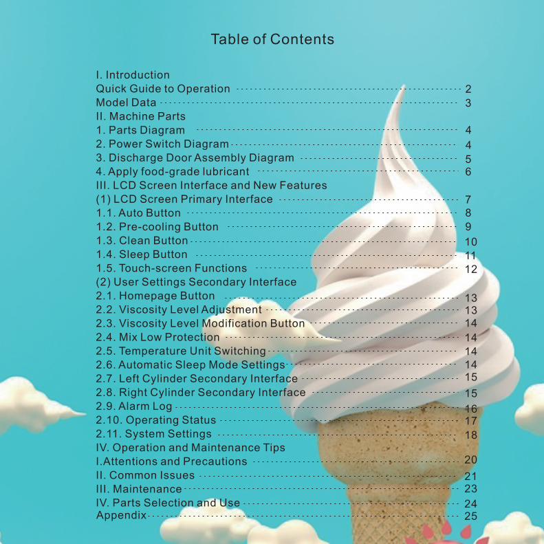
Table of Contents
2
3
4
4
56
78
9
10
1112
13
1413
14
141415
15
1617
18
20
2123
2425
I. Introduction
Quick Guide to Operation
Model Data
II. Machine Parts
1. Parts Diagram
2. Power Switch Diagram
3. Discharge Door Assembly Diagram
4. Apply food-grade lubricant
III. LCD Screen Interface and New Features
(1) LCD Screen Primary Interface
1.1. Auto Button
1.2. Pre-cooling Button
1.3. Clean Button
1.4. Sleep Button
1.5. Touch-screen Functions
(2) User Settings Secondary Interface
2.1. Homepage Button
2.2. Viscosity Level Adjustment
2.3. Viscosity Level Modification Button
2.4. Mix Low Protection
2.5. Temperature Unit Switching
2.6. Automatic Sleep Mode Settings
2.7. Left Cylinder Secondary Interface
2.8. Right Cylinder Secondary Interface
2.9. Alarm Log
2.10. Operating Status
2.11. System Settings
IV. Operation and Maintenance Tips
I.Attentions and Precautions
II. Common Issues
III. Maintenance
IV. Parts Selection and UseAppendix
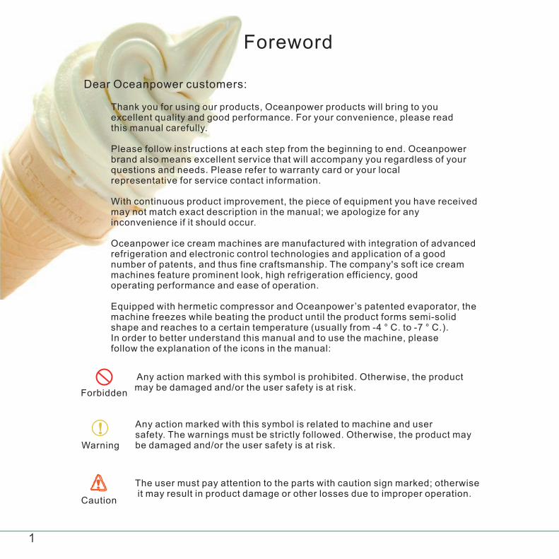
Dear Oceanpower customers:
Thank you for using our products, Oceanpower products will bring to you excellent quality and good performance. For your convenience, please read this manual carefully.
Please follow instructions at each step from the beginning to end. Oceanpower brand also means excellent service that will accompany you regardless of your questions and needs. Please refer to warranty card or your local representative for service contact information.
With continuous product improvement, the piece of equipment you have received may not match exact description in the manual; we apologize for any inconvenience if it should occur.
Oceanpower ice cream machines are manufactured with integration of advanced refrigeration and electronic control technologies and application of a good number of patents, and thus fine craftsmanship. The company's soft ice cream machines feature prominent look, high refrigeration efficiency, good operating performance and ease of operation.
Equipped with hermetic compressor and Oceanpower’s patented evaporator, the machine freezes while beating the product until the product forms semi-solid shape and reaches to a certain temperature (usually from -4 ° C. to -7 ° C.). In order to better understand this manual and to use the machine, please follow the explanation of the icons in the manual:
Any action marked with this symbol is prohibited. Otherwise, the product may be damaged and/or the user safety is at risk.
Forbidden
Any action marked with this symbol is related to machine and user safety. The warnings must be strictly followed. Otherwise, the product may be damaged and/or the user safety is at risk.Warning
The user must pay attention to the parts with caution sign marked; otherwise it may result in product damage or other losses due to improper operation.
Caution
Foreword

Installation
Open the paing and inspect the machine and parts
Place the machine in accordance with the installation instructions. For details, see (page 5) Installation Requirements.
Read and understand all safety and standard operating procedures.
Machine Preparation and Cleaning
Perform machine tune-up by cleaning and disinfecting parts.
Clean the hopper, the cylinder and all the parts Reassemble the parts and apply the lubricant,
Disinfect the machine.
Freezing
Stir the mix fully into uniformity. Pour the mix into the hopperand start freezing.
If necessary, adjust viscosity level to modify product viscosity.
Quick Guide to Operation

Model Data
3
NE2430L
14
2550/2700
1088/1316
1100
130
0.145
Air-cooled
141/83
1.0
2PCS
2×1.83
2×12
170
188
831X540X1430
22050Hz/60Hz
R134a 70g
Model
Power
Rated Amperage (A)
Rated Power (W)
Compressor Cooling Capacity (W)
Beater Motor Power (W)
Fan Power (W)
Rated Power Consumption (kw.h / kg)
Condensation
Cooling Capacity (W)
Pre-cooling Refrigerant
Refrigerant Charge (kg)
Cylinder Number
Cylinder Volume (L)
Hopper Volume (L)
Net Weight (kg)
Gross Weight (kg)
Dimensions (mm)
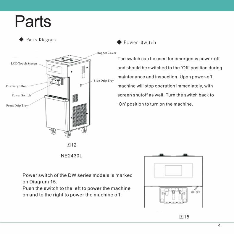
◆ Parts D iagram
图12
图15
Power switch of the DW series models is marked
on Diagram 15.
Push the switch to the left to power the machine
on and to the right to power the machine off.
4
Parts◆ Power Switch
The switch can be used for emergency power-off
and should be switched to the ‘Off’ position during
maintenance and inspection. Upon power-off,
machine will stop operation immediately, with
screen shutoff as well. Turn the switch back to
‘On’ position to turn on the machine.
LCD Touch Screen
Discharge Door
Power Switch
Front Drip Tray
Hopper Cover
Side Drip Tray
NE2430L
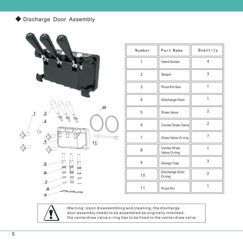
Warn ing : Upon d isassemb l ing and c lean ing , the d i scharge
door assemb ly needs to be assemb led as o r ig ina l l y i n tended ;
the cen te rd raw va lve o - r i ng has to be f i xed to the cen te r d raw va lve .
1
2
3
4
5
6
7
8
9
10
11
Hand Screw
Spigot
Pivot Pin Nut
Discharge Door
Draw Valve
Center Draw Valve
Draw Valve O-ring
Design Cap
Pivot Pin
4
3
1
1
2
2
7
1
3
2
1
Number Part Name Quantity
5
Center Draw
Valve O-ring
Discharge Door
O-ring
◆ Discharge Door Assembly

Prior to running the machine, par ts have to be sani t ized and c leaned. Food-grade lubr icant has to be appl ied as fo l lows.。
Apply lubricant to the section of the beater as illustrated above. Apply lubricant to the ripple seal ring and put it onto the beater.
Install the eight o-rings to the positions on the draw valves and then apply lubricant to them.
Install the two discharge door o-rings and apply lubricant to them.
17 18 19
Parts Functions
Air Tube——Regulates inflow and speed of inflow of mix
into the beater cylinder. If desired, turn the air tube upside
down to closethe inlet and maintain product overrun in the
beater cylinder. Soft serve products should always have
proper overrun when getting served.
Discharge Door Assembly——shapes and discharges product.
Press down spigot and discharges the product.
6
◆ Food-grade Lubricant

Touch Screen Interfaces and Functions
7
◆ User Setting Interface–Primary Level Menu
By operating the touch screen interface, the user is able to make product, clean the machine,
adjust viscosity, reset counters, etc. The main screen
also monitors and displays operating status, hopper and cylinder temperature readings,
product-making progress, among other information.

Product-making icon shows the progress and process movement.
1. Auto --After pressing Auto
8
The machine will run freezing cycle as programmed.
The cycle will stop when desired levels of product temperature and/or viscosity are
met; after a certain period when product temperature rises to a preset level,freezing
cycle will resume.

9
2.Hopper Refrigeration
When it is pressed, hopper refrigeration process starts. Otherwise,
when freezing cycle starts, hopper refrig-eration also starts; when
freezing cycle stops, hopper refrigeration also stops.

3.Clean
When pressing Clean, machine will start cleaning itself. Make sure to fill the beater cylinders with water. Beater motors start to run and the machine enters the clean mode. Clean page will be displayed on the screen
10

11
4.Sleep--When Sleep is pressed,
The machine enters night-time sleep mode, which maintain product
freshness and prevent bacteria from growing.
5.User Setting Interface--Secondary Level Menu
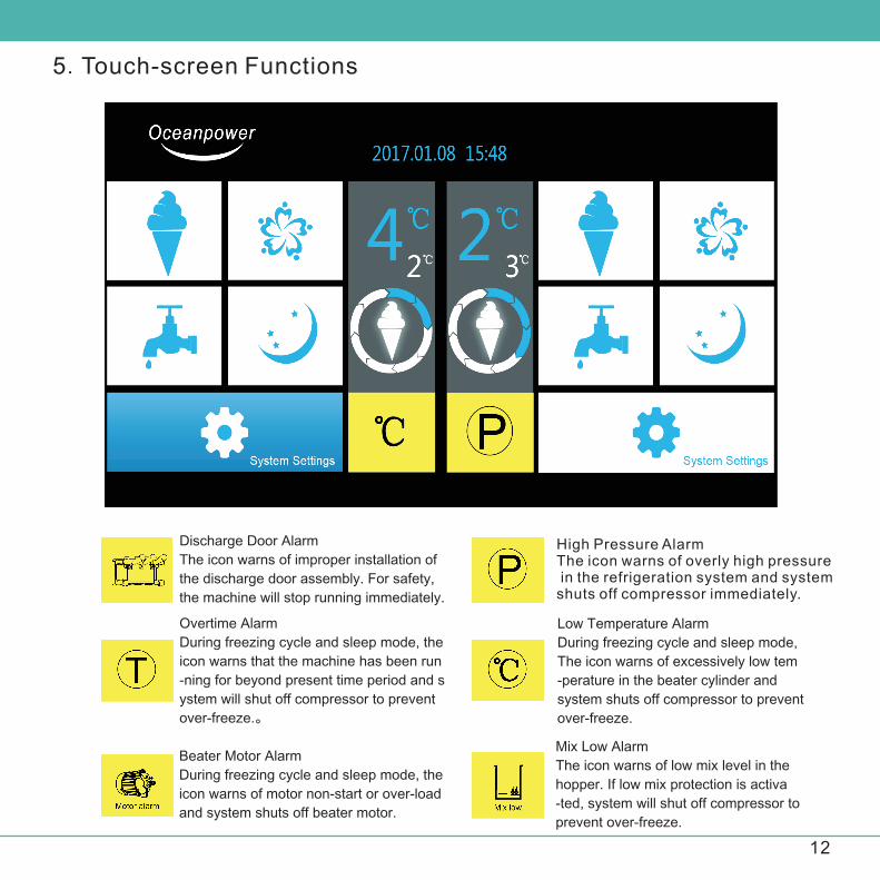
5.Touch-screen Functions
12
Mix Low Alarm
The icon warns of low mix level in the
hopper. If low mix protection is activa
-ted, system will shut off compressor to
prevent over-freeze.
Low Temperature Alarm
During freezing cycle and sleep mode,
The icon warns of excessively low tem
-perature in the beater cylinder and
system shuts off compressor to prevent
over-freeze.
Overtime Alarm
During freezing cycle and sleep mode, the
icon warns that the machine has been run
-ning for beyond present time period and s
ystem will shut off compressor to prevent
over-freeze.。
Discharge Door Alarm
The icon warns of improper installation of
the discharge door assembly. For safety,
the machine will stop running immediately.
Beater Motor Alarm
During freezing cycle and sleep mode, the
icon warns of motor non-start or over-load
and system shuts off beater motor.
High Pressure AlarmThe icon warns of overly high pressure in the refrigeration system and system shuts off compressor immediately.
13
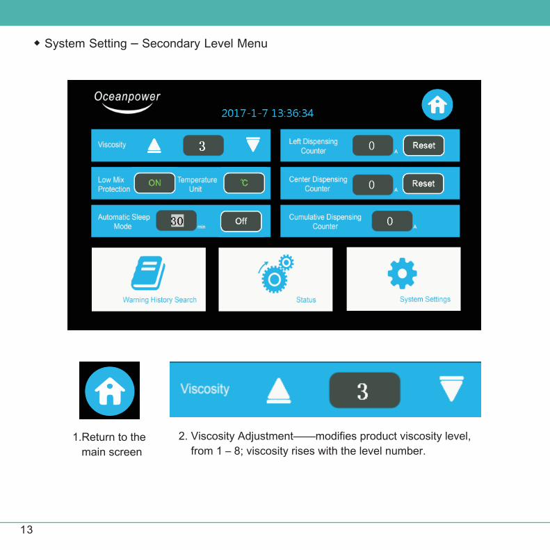
◆ System Setting – Secondary Level Menu
1.Return to the
main screen
2. Viscosity Adjustment——modifies product viscosity level,
from 1 – 8; viscosity rises with the level number.

14
3.Viscosity Arrow—
adjusts viscosity as desired for different types of mixes used.
4.Low Mix Protection——
can be turned on or off,
factory default as on.
5.Tempareture Unit——
switch between Celsius and
Fahrenheit units,displayed
on the main screen.
8.Automatic Sleep Mode——Turns on and off and configures sleep mode settings.When the machine sits idle and automatic sleep mode is turned on, system will enter sleep mode after a presetperiod of time has passed. The time period can be set between 10 and 50 minutes
15
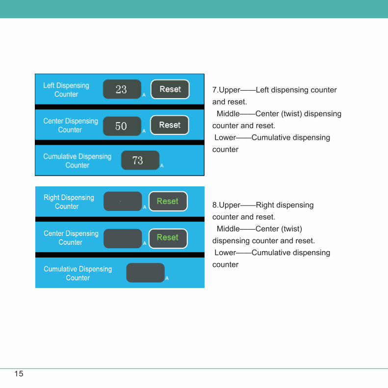
8.Upper——Right dispensing
counter and reset.
Middle——Center (twist)
dispensing counter and reset.
Lower——Cumulative dispensing
counter
7.Upper——Left dispensing counter
and reset.
Middle——Center (twist) dispensing
counter and reset.
Lower——Cumulative dispensing
counter
16
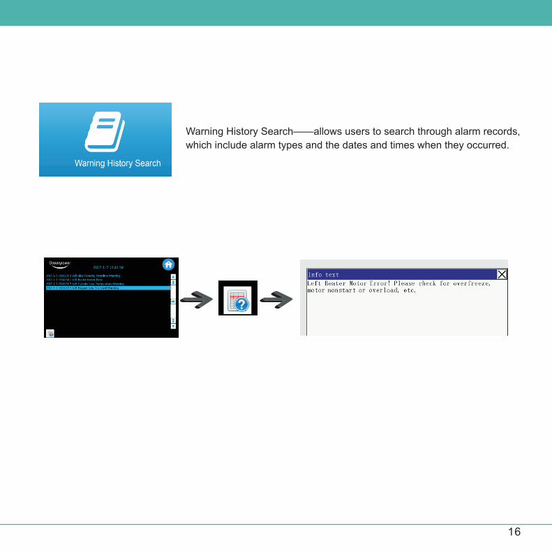
Warning History Search——allows users to search through alarm records,
which include alarm types and the dates and times when they occurred.

System Setting——Self Inspection
17
There are four status indicators on the discha-rge door; the upper one
corresponds to instal-lation of the discharge door and each of the lower
three corresponds to the relevant spigot installation.
If the discharge door or any of the three spigots is not properly installed,
indicator light will be off.
18
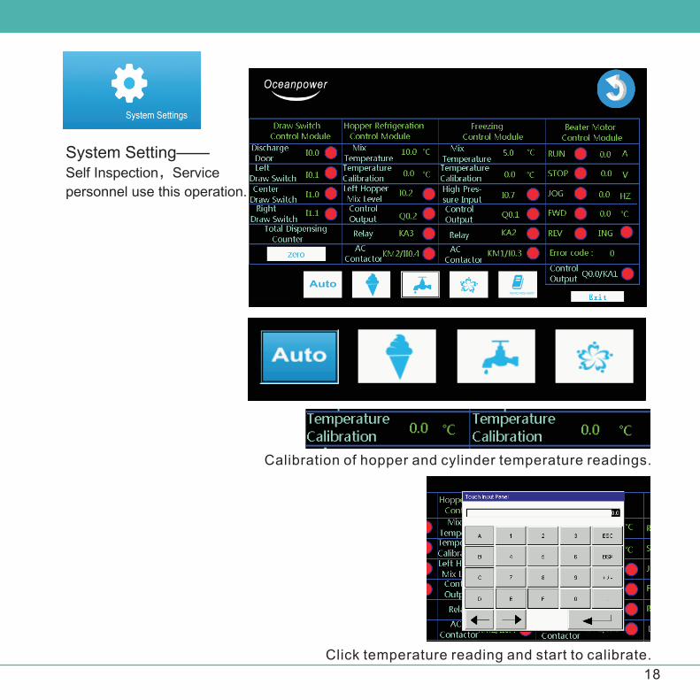
System Setting——Self Inspection,Service
personnel use this operation.
Click temperature reading and start to calibrate.
Calibration of hopper and cylinder temperature readings.
19
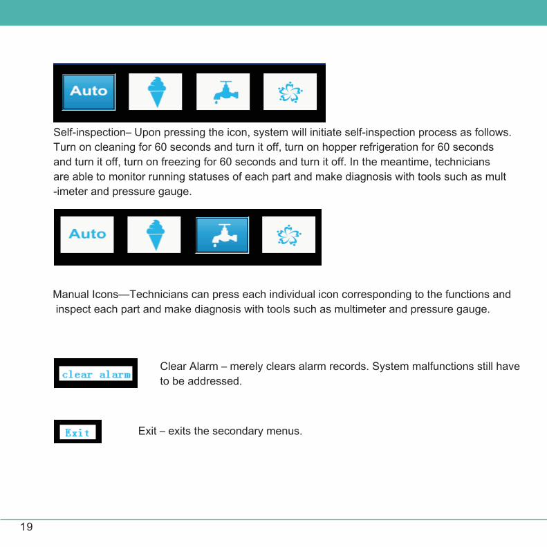
Self-inspection– Upon pressing the icon, system will initiate self-inspection process as follows.
Turn on cleaning for 60 seconds and turn it off, turn on hopper refrigeration for 60 seconds
and turn it off, turn on freezing for 60 seconds and turn it off. In the meantime, technicians
are able to monitor running statuses of each part and make diagnosis with tools such as mult
-imeter and pressure gauge.
Manual Icons—Technicians can press each individual icon corresponding to the functions and
inspect each part and make diagnosis with tools such as multimeter and pressure gauge.
Clear Alarm – merely clears alarm records. System malfunctions still have
to be addressed.
Exit – exits the secondary menus.
20
21
22


24
I
w
25