National Fire Protection Association Report
800
Public Comment No. 126-NFPA 13-2020 [ Global Input ] Do not revise the obstruction tables in Chapters 10, 11, 12, 13 & 14 (beam blocking rules) to eliminate dimensional ranges. Retain the dimensional ranges as they are in the current 2019 edition of NFPA 13. Statement of Problem and Substantiation for Public Comment The Committee Statement says that deleting the ranges will clarify the separation distances for obstructions, but this is not true. Without the ranges the tables will be more difficult to interpret than as per the exiting format and could easily lead to errors or misunderstandings. For Example, in Table 10.2.7.2 - with a horizontal distance of 3’-0 a deflector distance of 9½ inches is specified; and - with a horizontal distance of 3’-6 a deflector distance of 12 inches is specified. Without the ranges to provide the necessary clarification for this, some people might try to interpolate between these values, so: - with a horizontal distance of 3’-3, a deflector distance of 10¾ inches could be decided upon, which would be incorrect and not the intent of the table. To avoid errors such as this, the dimensional ranges are necessary. Related Item • FR-1183 Submitter Information Verification Submitter Full Name: Larry Keeping Organization: PLC Fire Safety Solutions Street Address: City: State: Zip: Submittal Date: Fri Apr 24 15:17:48 EDT 2020 Committee: National Fire Protection Association Report https://submittals.nfpa.org/TerraViewWeb/ContentFetcher?commentPar... 2 of 738 5/8/2020, 11:28 AM 1
-
Upload
khangminh22 -
Category
Documents
-
view
0 -
download
0
Transcript of National Fire Protection Association Report

Public Comment No. 126-NFPA 13-2020 [ Global Input ]
Do not revise the obstruction tables in Chapters 10, 11, 12, 13 & 14 (beam blocking rules) toeliminate dimensional ranges. Retain the dimensional ranges as they are in the current 2019 editionof NFPA 13.
Statement of Problem and Substantiation for Public Comment
The Committee Statement says that deleting the ranges will clarify the separation distances for obstructions, but this is not true. Without the ranges the tables will be more difficult to interpret than as per the exiting format and could easily lead to errors or misunderstandings. For Example, in Table 10.2.7.2- with a horizontal distance of 3’-0 a deflector distance of 9½ inches is specified; and- with a horizontal distance of 3’-6 a deflector distance of 12 inches is specified.Without the ranges to provide the necessary clarification for this, some people might try to interpolate betweenthese values, so:- with a horizontal distance of 3’-3, a deflector distance of 10¾ inches could be decided upon,which would be incorrect and not the intent of the table. To avoid errors such as this, the dimensional ranges arenecessary.
Related Item
• FR-1183
Submitter Information Verification
Submitter Full Name: Larry Keeping
Organization: PLC Fire Safety Solutions
Street Address:
City:
State:
Zip:
Submittal Date: Fri Apr 24 15:17:48 EDT 2020
Committee:
National Fire Protection Association Report https://submittals.nfpa.org/TerraViewWeb/ContentFetcher?commentPar...
2 of 738 5/8/2020, 11:28 AM
1

Public Comment No. 254-NFPA 13-2020 [ Global Input ]
The Correlating Committee directs AUT-RSS and AUT-SSI to coordinate dimension ranges in theobstruction tables of 13, 13D & 13R in a consistent manner, including Tables 10.3.6.1.4, 10.3.6.2.2,11.2.5.2.2, 11.3.6.1.3, 11.3.6.1.4, 11.3.6.2.2, 12.1.10.2.2, 12.1.11.1.3, 12.1.11.1.4, 12.1.11.2.2 & 13.2.8.3.2.
Additional Proposed Changes
File Name Description Approved
13_CCN_11.pdf 13_CCN_11
Statement of Problem and Substantiation for Public Comment
NOTE: This Public Comment appeared as CC Note No. 11 in the First Draft Report on First Revision No. 1183.
Related Item
• FR-1183
Submitter Information Verification
Submitter Full Name: CC on AUT-AAC
Organization: NFPA
Street Address:
City:
State:
Zip:
Submittal Date: Mon May 04 11:53:17 EDT 2020
Committee:
National Fire Protection Association Report https://submittals.nfpa.org/TerraViewWeb/ContentFetcher?commentPar...
4 of 738 5/8/2020, 11:28 AM
2
Correlating Committee Note No. 11-NFPA 13-2019 [ Global Input ]
Submitter Information Verification
Committee: AUT-AAC
Submittal Date: Mon Dec 16 11:55:36 EST 2019
Committee Statement
CommitteeStatement:
The Correlating Committee directs AUT-RSS and AUT-SSI to coordinate dimension ranges in theobstruction tables of 13, 13D & 13R in a consistent manner, including Tables 10.3.6.1.4, 10.3.6.2.2,11.2.5.2.2, 11.3.6.1.3, 11.3.6.1.4, 11.3.6.2.2, 12.1.10.2.2, 12.1.11.1.3, 12.1.11.1.4, 12.1.11.2.2 &13.2.8.3.2.
First Revision No. 1183-NFPA 13-2019 [Global Input]
Ballot Results
This item has passed ballot
22 Eligible Voters
3 Not Returned
19 Affirmative All
0 Affirmative with Comments
0 Negative with Comments
0 Abstention
Not Returned
Baz, Jose R.
Hilton, Luke
Su, Joseph
Affirmative All
Bell, Kerry M.
Bellamy, Tracey D.
Browning, Chase A.
Dellasanta, Steven W.
Friedman, Michael J.
Hoffman, Alex
Hopkins, Mark
Javeri, Sultan M.
Ketner, Charles W.
Koffel, William E.
Lake, James D.
LeBlanc, John A.
Linder, Kenneth W.
National Fire Protection Association Report https://submittals.nfpa.org/TerraViewWeb/ContentFetcher?commentPar...
3 of 50 5/4/2020, 11:38 AM
3

Lowrey, David O.
Medovich, Jack A.
Palenske, Garner A.
Phillips, Lawrence Richard
Seghi, Adam
Thompson, J. Michael
National Fire Protection Association Report https://submittals.nfpa.org/TerraViewWeb/ContentFetcher?commentPar...
4 of 50 5/4/2020, 11:38 AM
4
Public Comment No. 257-NFPA 13-2020 [ Global Input ]
Review metric conversions in all FR's for correlation with metric revisions made during the last revisioncycle. (see attached spreadsheet)
Additional Proposed Changes
File Name Description Approved
13_CCN_37.pdf 13_CCN_37
Statement of Problem and Substantiation for Public Comment
NOTE: This Public Comment appeared as CC Note No. 37 in the First Draft Report.
Related Item
• CCN_37
Submitter Information Verification
Submitter Full Name: CC on AUT-AAC
Organization: NFPA
Street Address:
City:
State:
Zip:
Submittal Date: Mon May 04 12:07:39 EDT 2020
Committee:
National Fire Protection Association Report https://submittals.nfpa.org/TerraViewWeb/ContentFetcher?commentPar...
5 of 738 5/8/2020, 11:28 AM
5
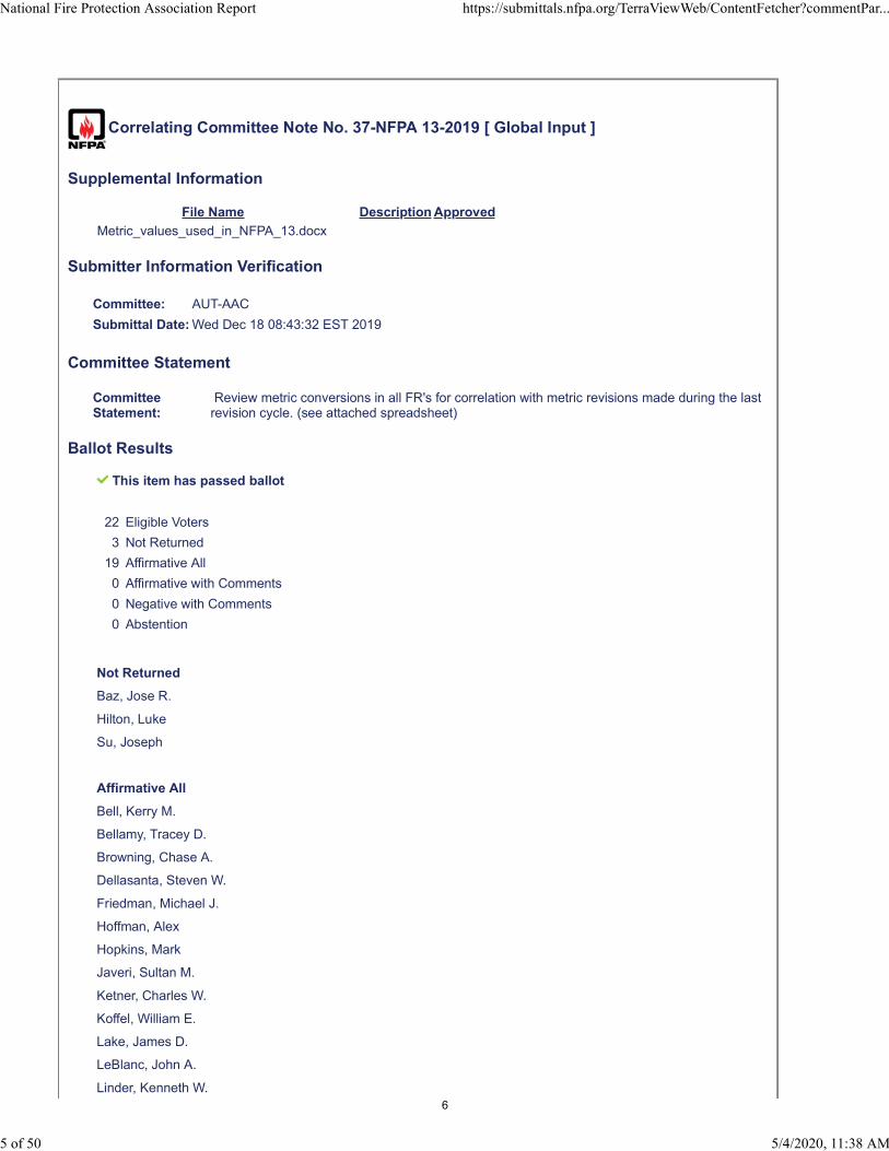
Correlating Committee Note No. 37-NFPA 13-2019 [ Global Input ]
Supplemental Information
File Name Description Approved
Metric_values_used_in_NFPA_13.docx
Submitter Information Verification
Committee: AUT-AAC
Submittal Date: Wed Dec 18 08:43:32 EST 2019
Committee Statement
CommitteeStatement:
Review metric conversions in all FR's for correlation with metric revisions made during the lastrevision cycle. (see attached spreadsheet)
Ballot Results
This item has passed ballot
22 Eligible Voters
3 Not Returned
19 Affirmative All
0 Affirmative with Comments
0 Negative with Comments
0 Abstention
Not Returned
Baz, Jose R.
Hilton, Luke
Su, Joseph
Affirmative All
Bell, Kerry M.
Bellamy, Tracey D.
Browning, Chase A.
Dellasanta, Steven W.
Friedman, Michael J.
Hoffman, Alex
Hopkins, Mark
Javeri, Sultan M.
Ketner, Charles W.
Koffel, William E.
Lake, James D.
LeBlanc, John A.
Linder, Kenneth W.
National Fire Protection Association Report https://submittals.nfpa.org/TerraViewWeb/ContentFetcher?commentPar...
5 of 50 5/4/2020, 11:38 AM
6

Lowrey, David O.
Medovich, Jack A.
Palenske, Garner A.
Phillips, Lawrence Richard
Seghi, Adam
Thompson, J. Michael
National Fire Protection Association Report https://submittals.nfpa.org/TerraViewWeb/ContentFetcher?commentPar...
6 of 50 5/4/2020, 11:38 AM
7
Dimensions Found in NFPA 13-2016
8/21/2017 1
Length
.003” .08 mm 7.5” 190 mm 26” 650 mm
.0315” .8 mm 8” 200 mm 27.6” 690 mm
1/32” 0.8 mm 8.5” 215 mm 28” 700 mm
1/16” 1.6 mm 9” 225 mm 29” 725 mm
3/32” 2 mm 9.25” 230 mm 30” 750 mm
1/8” 3 mm 9.5” 240 mm 30.5” 765 mm
3/16” 5 mm 10” 250 mm 31” 775 mm
¼” 6 mm 11” 275 mm 32” 800 mm
5/16” 8 mm 11.5” 290 mm 33” 825 mm
3/8” 10 mm 12” 300 mm 35” 875 mm
½” 13 mm 12.25” 305 mm 35.4” 885 mm
17/32” 13 mm 12.5” 315 mm 36” 900 mm
9/16” 14 mm 12.75” 320 mm 37” 925 mm
5/8” 16 mm 14” 350 mm 38” 950 mm
¾” 19 mm 15” 375 mm
40” 1000 mm
7/8” 22 mm 15.5” 390 mm 42” 1050 mm
1” 25 mm 16” 400 mm 44” 1100 mm
1.5” 40 mm 16.25” 410 mm 47” 1175 mm
1.75” 45 mm 16.5” 415 mm 48” 1200 mm
2” 50 mm 17” 425 mm 54” 1350 mm
2.5” 65 mm 17.5” 440 mm 55” 1375 mm
2.75” 70 mm 18” 450 mm 57” 1425 mm
3” 75 mm 19” 475 mm 58” 1450 mm
3.5” 90 mm 20” 500 mm 66” 1650 mm
4” 100 mm 21” 525 mm 68” 1700 mm
4.5” 115 mm 22” 550 mm 72” 1800 mm
5” 125 mm 22.5” 565 mm 76” 1900 mm
5.5” 140 mm 23” 575 mm 78” 1950 mm
5.75” 145 mm 24” 600 mm 96” 2400 mm
6” 150 mm 25” 625 mm 102” 2550 mm
7” 175 mm 25.5” 640 mm 120” 3000 mm
148” 3700 mm
8

Dimensions Found in NFPA 13-2016
8/21/2017 2
Length
3.5ft 1.1 m 10’-10” 3.3 m 22’-6” 6.9 m
3’-8” 1.1 m 11’-0” 3.4 m 24ft 7.3 m
4ft 1.2 m 11’-3” 3.4 m 25ft 7.6 m
4’-2” 1.3 m 11’-5” 3.5 m 25’-3” 7.7 m
4.5ft 1.4 m 11’-6” 3.5 m 26ft 7.9 m
4’-7” 1.4 m 11’-611/16” 3.5 m 27ft 8.2 m
4’-9” 1.4 m 11’-8” 3.6 m 28ft 8.5 m
5ft 1.5 m 12ft 3.7 m 28’-8” 8.7 m
5’-2” 1.6 m 12’-4” 3.8 m 29’-8” 9 m
5.5ft 1.7 m 13ft 4.0 m 30ft 9.1 m
5’-8” 1.7 m 13’-6” 4.1 m 32ft 10 m
5’-9 5/16” 1.8 m 13’-71/2” 4.2 m 33ft 10 m
6ft 1.8 m 13’-11” 4.2 m 35ft 11 m
6’-3” 1.9 m 14ft 4.3 m 36ft 11 m
6’-4” 1.9 m 14’-6” 4.4 m 40ft 12 m
6.5ft 2 m 15ft 4.6 m 41’-3” 13 m
6’-10” 2.1 m 15’-4” 4.7 m 45ft 14 m
7ft 2.1 m 16ft 4.9 m 50ft 15 m
7.5ft 2.3 m 16’-6” 5.0 m 51’-6” 16 m
7’-7” 2.3 m 16’-8” 5.1 m 55ft 17 m
7’-9” 2.4 m 17ft 5.2 m 60ft 18 m
8ft 2.4 m 18ft 5.5 m 65ft 20 m
8’-2” 2.5 m 18’-6” 5.6 m 70ft 21 m
8’-4” 2.5 m 19’-2” 5.8 m 75ft 23 m
8’-77/8” 2.6 m 19’-10” 6 m 76ft 23 m
9ft 2.7 m 19’-11” 6.1 m 80ft 24 m
9’-5” 2.9 m 20ft 6.1 m 100ft 30 m
9’-6” 2.9 m 20’-8” 6.3 m 200ft 61 m
10ft 3 m 21’-6” 6.6 m 250ft 76 m
10.5ft 3.2 m 21’-10” 6.7 m 300ft 91 m
10’-9” 3.3 m 22 ft 6.7 m 400ft 120 m
9

Dimensions Found in NFPA 13-2016
8/21/2017 3
Area
3.5 ft2 0.3 m2 256 ft2 24 m2 2,700 ft2 250 m2
6 ft2 0.6 m2 300 ft2 28 m2 2,734 ft2 255 m2
10 ft2 0.9 m2 306 ft2 28 m2 2,800 ft2 260 m2
12 ft2 1.1 m2 324 ft2 30 m2 3,000 ft2 280 m2
16 ft2 1.5 m2 395 ft2 37 m2 3,250 ft2 300 m2
18 ft2 1.7m2 400 ft2 37 m2 3,300 ft2 305 m2
20 ft2 1.9m2 450 ft2 42 m2 3,450 ft2 320 m2
24 ft2 2.2m2 504 ft2 47 m2 3,500 ft2 325 m2
25 ft2 2.3 m2 585 ft2 54 m2 3,600 ft2 335 m2
32 ft2 3.0 m2 600 ft2 56 m2 3,750 ft2 350 m2
50 ft2 4.6 m2 648 ft2 60 m2 3,900 ft2 360 m2
55 ft2 5.1 m2 700 ft2 65 m2 4,000 ft2 370 m2
64 ft2 5.9 m2 756 ft2 70 m2 4,100 ft2 380 m2
70 ft2 6.5 m2 768 ft2 71 m2 4,500 ft2 420 m2
80 ft2 7.4 m2 800 ft2 74 m2 4,800 ft2 445 m2
90 ft2 8.4 m2 1,000 ft2 93 m2 5,000 ft2 465 m2
100 ft2 9 m2 1,200ft2 112 m2 6,000 ft2 555 m2
110 ft2 10 m2 1,300 ft2 120 m2 6,400 ft2 595 m2
120 ft2 11 m2 1,365 ft2 125 m2 8,000 ft2 740 m2
124 ft2 12 m2 1,400 ft2 130 m2 8,800 ft2 820 m2
130 ft2 12 m2 1,500 ft2 140 m2 10,000 ft2 930 m2
144 ft2 13 m2 1,700 ft2 160 m2 13,100 ft2 1 215 m2
150 ft2 14 m2 1,800 ft2 165 m2 25,000 ft2 2 320 m2
168 ft2 16 m2 1,950 ft2 180 m2 40,000 ft2 3 720 m2
175 ft2 16 m2 2,000 ft2 185 m2 50,000 ft2 4 650 m2
196 ft2 18 m2 2,300 ft2 215 m2 52,000 ft2 4 830 m2
200 ft2 18 m2 2,500 ft2 230m2 100,000 ft2 9 230 m2
225 ft2 20 m2 2,535 ft2 235 m2
250 ft2 23 m2 2,600 ft2 240 m2
10

Dimensions Found in NFPA 13-2016
8/21/2017 4
Volume
1.76 cuin 28 ml 160 ft3 4.5 m3
15.5 ft3 0.5 m3 400 ft3 11 m3
17.4 ft3 0.5 m3 1,000 ft3 28 m3
17.6 ft3 0.5 m3 1,800 ft3 51 m3
20.7 ft3 0.6 m3 2,100 ft3 59 m3
21.1 ft3 0.6 m3 2,300 ft3 65 m3
22 ft3 0.6 m3 6,500 ft3 184 m3
100 ft3 2.8 m3 2.25M ft3 63,720 m3
Capacity
16 oz. 0.5 l
32 oz. 1 l
1 gal 4 l
5 gal 20 l
40 gal 150 l
100 gal 380 l
150 gal 570 l
250 gal 950 l
500 gal 1900 l
750 gal 2850 l
300,000 gal 1,135,500 l
Drill Size
3/32” 2,3 mm
1/8” 3,2 mm
3/8” 10 mm
Density of Cotton Bales
22.0 lb/ft3 350 kg/m3
22.7 lb/ft3 365 kg/m3
24.2 lb/ft3 390 kg/m3
28.4 lb/ft3 455 kg/m3
28.7 lb/ft3 460 kg/m3
32.2 lb/ft3 515 kg/m3
11
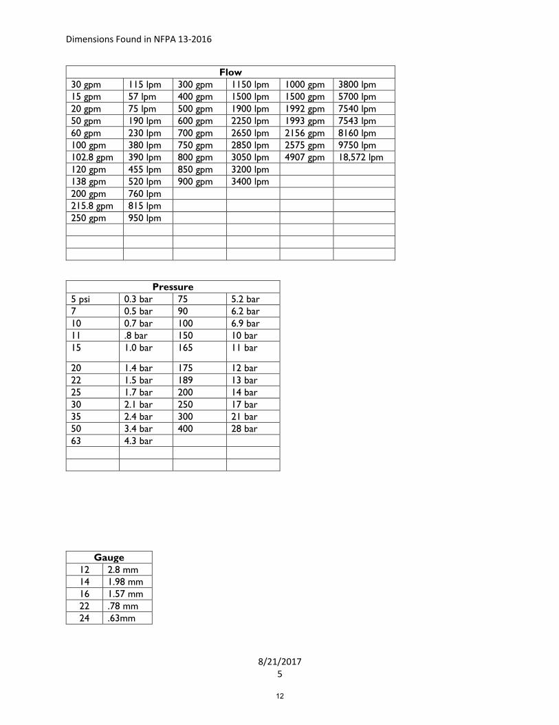
Dimensions Found in NFPA 13-2016
8/21/2017 5
Flow
30 gpm 115 lpm 300 gpm 1150 lpm 1000 gpm 3800 lpm
15 gpm 57 lpm 400 gpm 1500 lpm 1500 gpm 5700 lpm
20 gpm 75 lpm 500 gpm 1900 lpm 1992 gpm 7540 lpm
50 gpm 190 lpm 600 gpm 2250 lpm 1993 gpm 7543 lpm
60 gpm 230 lpm 700 gpm 2650 lpm 2156 gpm 8160 lpm
100 gpm 380 lpm 750 gpm 2850 lpm 2575 gpm 9750 lpm
102.8 gpm 390 lpm 800 gpm 3050 lpm 4907 gpm 18,572 lpm
120 gpm 455 lpm 850 gpm 3200 lpm
138 gpm 520 lpm 900 gpm 3400 lpm
200 gpm 760 lpm
215.8 gpm 815 lpm
250 gpm 950 lpm
Pressure
5 psi 0.3 bar 75 5.2 bar
7 0.5 bar 90 6.2 bar
10 0.7 bar 100 6.9 bar
11 .8 bar 150 10 bar
15 1.0 bar 165 11 bar
20 1.4 bar 175 12 bar
22 1.5 bar 189 13 bar
25 1.7 bar 200 14 bar
30 2.1 bar 250 17 bar
35 2.4 bar 300 21 bar
50 3.4 bar 400 28 bar
63 4.3 bar
Gauge
12 2.8 mm
14 1.98 mm
16 1.57 mm
22 .78 mm
24 .63mm
12

Dimensions Found in NFPA 13-2016
8/21/2017 6
Weight
6 lb 2.7 kg 350 lb 160 kg
10 lb 4.5 kg 440 lb 200 kg
20 lb 9.1 kg 520 lb 235 kg
40 lb 18 kg 750 lb 340 kg
61 lb 27 kg 787 lb 355 kg
91 lb 41 kg 1200 lb 544 kg
131 lb 59 kg 1634 lb 740 kg
200 lb 91 kg 2000 lb 907 kg
250 lb 115 kg 2300 lb 1043 kg
4000 lb 1815 kg
Velocity
30 mph 49 km/h
13

Dimensions Found in NFPA 13-2016
8/21/2017 7
Discharge Density
gpm/ft2 mm/min gpm/ft2 mm/min
.005 .2 .425 17.3
.05 2.04 .426 17.4
.1 4.1 .44 17.9
.15 6.1 .45 18.3
.16 6.5 .46 18.7
.17 7.0 .49 20
.18 7.3 .5 20.4
.19 7.7 .55 22.4
.2 8.2 .56 22.8
.21 8.6 .57 23.2
.225 9.2 .6 24.5
.24 9.8 .61 24.9
.25 10.2 .65 26.5
.26 10.6 .68 27.7
.28 11.4 .7 28.5
.29 11.8 .74 30.2
.3 12.2 .75 30.6
.31 12.6 .77 31.4
.32 13.0 .8 32.6
.33 13.4 .85 34.6
.34 13.9 .9 36.7
.35 14.3 .92 37.5
.37 15.1 .96 39.1
.375 15.3 1.1 44.8
.39 15.9 1.2 48.9
.4 16.3 6.0 245
.42 17.1 7.5 306
14

Public Comment No. 385-NFPA 13-2020 [ Global Input ]
Comments have been made to NFPA 13 Beam Rule Table (Table 10.2.7.2) - See PC-346 and to thepartition tables (10.2.7.3.2.1) - See PC-344. If these comments are accepted - all similar tables in thedocument should be revised to this new format. I have uploaded the new table format to thiscomment. These revision will make these tables easier to interpret.
The following tables should be reviewed (there may be others):
Chapter 10: 10.2.7.2, 10.2.7.3.2.1, 10.3.6.1.4, 10.3.6.2.2
Chapter 11: 11.2.5.2.2, 11.3.6.1.3, 11.2.6.1.4, 11.3.6.2.2
Chapter 12: 12.1.10.2.2, 12.1.11.1.3, 12.1.11.1.2, 12.1.11.2.2
Chapter 13: 13.2.8.3.2
Additional Proposed Changes
File Name Description Approved
Beam_Rule_Table_Format_2022.pdf
Partition_Rule_Table_Format_2022.pdf
Statement of Problem and Substantiation for Public Comment
Comments have been made to NFPA 13 Beam Rule Table (Table 10.2.7.2) - See PC-346 and to the partition tables (10.2.7.3.2.1) - See PC-344. If these comments are accepted - all similar tables in the document should be revised to this new format. I have uploaded the new table format to this comment. These revision will make these tables easier to interpret. See proposed table formats attached to this comment
Related Public Comments for This Document
Related Comment Relationship
Public Comment No. 346-NFPA 13-2020 [Section No. 10.2.7.2 [Excluding any Sub-Sections]]
Public Comment No. 344-NFPA 13-2020 [Section No. 10.2.7.3.2.1]
Related Item
• FR-1123 • FR-1183
Submitter Information Verification
Submitter Full Name: Roland Asp
Organization: National Fire Sprinkler Association
Affiliation: NFSA Engineering and Standards Committee
Street Address:
City:
State:
Zip:
Submittal Date: Wed May 06 15:47:24 EDT 2020
Committee:
National Fire Protection Association Report https://submittals.nfpa.org/TerraViewWeb/ContentFetcher?commentPar...
6 of 738 5/8/2020, 11:28 AM
15
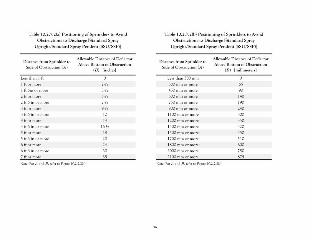
Distance from Sprinkler to Side of Obstruction (A )
Allowable Distance of Deflector Above Bottom of Obstruction
(B ) [inches]
Distance from Sprinkler to Side of Obstruction (A )
Allowable Distance of Deflector Above Bottom of Obstruction
(B ) [millimeters]
Less than 1 ft 0 Less than 300 mm 01 ft or more 2-½ 300 mm or more 651 ft 6in or more 3-½ 450 mm or more 902 ft or more 5-½ 600 mm or more 1402 ft 6 in or more 7-½ 750 mm or more 1903 ft or more 9-½ 900 mm or more 2403 ft 6 in or more 12 1100 mm or more 3004 ft or more 14 1200 mm or more 3504 ft 6 in or more 16-½ 1400 mm or more 4205 ft or more 18 1500 mm or more 4505 ft 6 in or more 20 1700 mm or more 5106 ft or more 24 1800 mm or more 6006 ft 6 in or more 30 2000 mm or more 7507 ft or more 35 2100 mm or more 875
Note: For A and B , refer to Figure 10.2.7.2(a) Note: For A and B , refer to Figure 10.2.7.2(a)
Table 10.2.7.2(a) Positioning of Sprinklers to AvoidObstructions to Discharge [Standard Spray
Upright/Standard Spray Pendent (SSU/SSP)]
Table 10.2.7.2(b) Positioning of Sprinklers to AvoidObstructions to Discharge [Standard Spray
Upright/Standard Spray Pendent (SSU/SSP)]
16

Public Comment No. 338-NFPA 13-2020 [ New Section after 1.2.2 ]
TITLE OF NEW CONTENT
1.2.2.1 Personnel Qualifications.
1.2.2.1.1 System Designer
1.2.2.1.1 Plans and specifications shall be developed in accordance with this Code by persons who are experienced inthe design, application, installation, and testing of the systems.
1.2.2.1.2 State or local licensure regulations shall be followed to determine qualified personnel.
1.2.2.1.3 Personnel shall provide documentation of their qualification by one or more of the following:
(1) Registration, licensing, or certification by a state or local authority
(2) Certification by an organization acceptable to the authority having jurisdiction
(3) Manufacturer's certification for the specific type and brand of system provided
1.2.2.1.4 The system designer shall be identified on the system design documents.
1.2.2.1.5 System design trainees shall be under the supervision of a qualified system designer.
1.2.2.1.6 The system designer shall provide evidence of their qualifications and/or certifications when required by theauthority having jurisdiction.
1.2.2.2 System Installer.
1.2.2.2.1 Installation personnel shall be qualified in the installation, inspection, and testing of the systems.
1.2.2.2.2 State or local licensure regulations shall be followed to determine qualified personnel.
1.2.2.2.3 Personnel shall provide documentation of their qualification by one or more of the following:
(1) Registration, licensing, or certification by a state or local authority
(2) Certification by an organization acceptable to the authority having jurisdiction
(3) Manufacturer's certification for the specific type and brand of system provided
1.2.2.2.4 System installation trainees shall be under the supervision of a qualified system installer.
1.2.2.2.5 The system installer shall provide evidence of their qualifications and/or certifications when requested bythe authority having jurisdiction.
Type your content here ...
Statement of Problem and Substantiation for Public Comment
This provides guidance and better understanding of the requirements for designing, installing and testing of these life safety systems to provide a reasonable degree of protection for life and property from firethrough standardization of design, installation, and testing requirements for sprinkler systems, including private fire service mains, based on sound engineering principles, test data, and field experience. I thank the committee for their consideration on this comment.
Related Public Comments for This Document
Related Comment Relationship
Public Comment No. 328-NFPA 13-2020 [Section No. 1.2.2] qualified
Related Item
• PI 664 & PI 674
National Fire Protection Association Report https://submittals.nfpa.org/TerraViewWeb/ContentFetcher?commentPar...
7 of 738 5/8/2020, 11:28 AM
17
Submitter Information Verification
Submitter Full Name: Kenneth Schneider
Organization: Ua - Itf
Affiliation: United Association
Street Address:
City:
State:
Zip:
Submittal Date: Tue May 05 15:14:38 EDT 2020
Committee: AUT-AAC
National Fire Protection Association Report https://submittals.nfpa.org/TerraViewWeb/ContentFetcher?commentPar...
8 of 738 5/8/2020, 11:28 AM
18
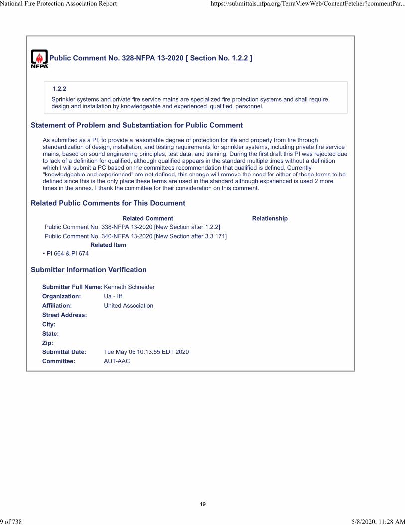
Public Comment No. 328-NFPA 13-2020 [ Section No. 1.2.2 ]
1.2.2
Sprinkler systems and private fire service mains are specialized fire protection systems and shall requiredesign and installation by knowledgeable and experienced qualified personnel.
Statement of Problem and Substantiation for Public Comment
As submitted as a PI, to provide a reasonable degree of protection for life and property from fire through standardization of design, installation, and testing requirements for sprinkler systems, including private fire service mains, based on sound engineering principles, test data, and training. During the first draft this PI was rejected due to lack of a definition for qualified, although qualified appears in the standard multiple times without a definition which I will submit a PC based on the committees recommendation that qualified is defined. Currently "knowledgeable and experienced" are not defined, this change will remove the need for either of these terms to be defined since this is the only place these terms are used in the standard although experienced is used 2 more times in the annex. I thank the committee for their consideration on this comment.
Related Public Comments for This Document
Related Comment Relationship
Public Comment No. 338-NFPA 13-2020 [New Section after 1.2.2]
Public Comment No. 340-NFPA 13-2020 [New Section after 3.3.171]
Related Item
• PI 664 & PI 674
Submitter Information Verification
Submitter Full Name: Kenneth Schneider
Organization: Ua - Itf
Affiliation: United Association
Street Address:
City:
State:
Zip:
Submittal Date: Tue May 05 10:13:55 EDT 2020
Committee: AUT-AAC
National Fire Protection Association Report https://submittals.nfpa.org/TerraViewWeb/ContentFetcher?commentPar...
9 of 738 5/8/2020, 11:28 AM
19
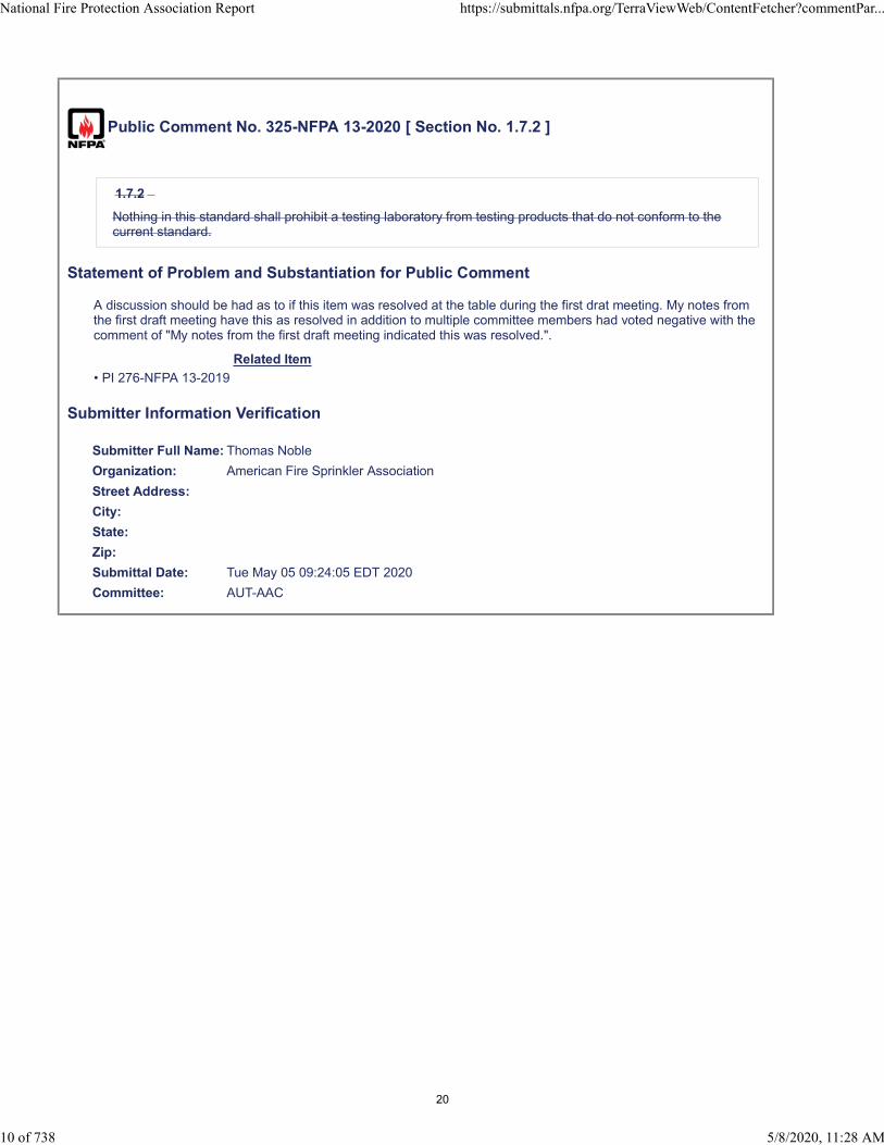
Public Comment No. 325-NFPA 13-2020 [ Section No. 1.7.2 ]
1.7.2
Nothing in this standard shall prohibit a testing laboratory from testing products that do not conform to thecurrent standard.
Statement of Problem and Substantiation for Public Comment
A discussion should be had as to if this item was resolved at the table during the first drat meeting. My notes from the first draft meeting have this as resolved in addition to multiple committee members had voted negative with the comment of "My notes from the first draft meeting indicated this was resolved.".
Related Item
• PI 276-NFPA 13-2019
Submitter Information Verification
Submitter Full Name: Thomas Noble
Organization: American Fire Sprinkler Association
Street Address:
City:
State:
Zip:
Submittal Date: Tue May 05 09:24:05 EDT 2020
Committee: AUT-AAC
National Fire Protection Association Report https://submittals.nfpa.org/TerraViewWeb/ContentFetcher?commentPar...
10 of 738 5/8/2020, 11:28 AM
20
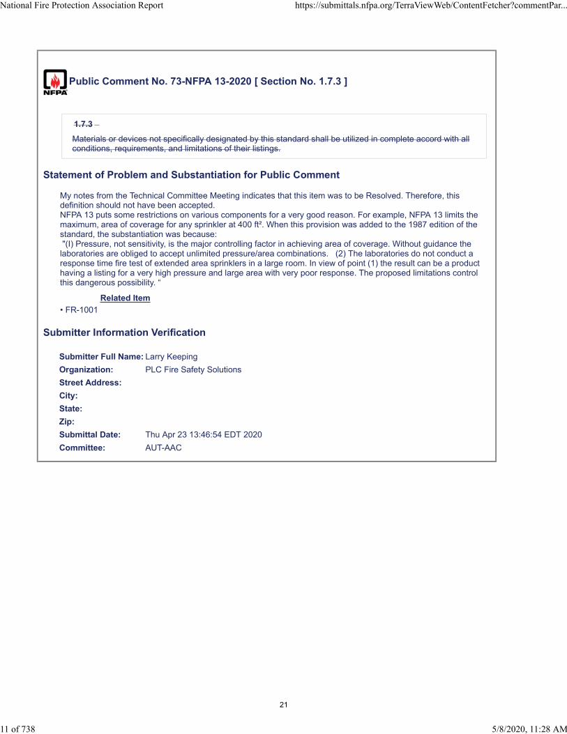
Public Comment No. 73-NFPA 13-2020 [ Section No. 1.7.3 ]
1.7.3
Materials or devices not specifically designated by this standard shall be utilized in complete accord with allconditions, requirements, and limitations of their listings.
Statement of Problem and Substantiation for Public Comment
My notes from the Technical Committee Meeting indicates that this item was to be Resolved. Therefore, this definition should not have been accepted.NFPA 13 puts some restrictions on various components for a very good reason. For example, NFPA 13 limits the maximum, area of coverage for any sprinkler at 400 ft². When this provision was added to the 1987 edition of the standard, the substantiation was because: "(I) Pressure, not sensitivity, is the major controlling factor in achieving area of coverage. Without guidance the laboratories are obliged to accept unlimited pressure/area combinations. (2) The laboratories do not conduct a response time fire test of extended area sprinklers in a large room. In view of point (1) the result can be a product having a listing for a very high pressure and large area with very poor response. The proposed limitations control this dangerous possibility. “
Related Item
• FR-1001
Submitter Information Verification
Submitter Full Name: Larry Keeping
Organization: PLC Fire Safety Solutions
Street Address:
City:
State:
Zip:
Submittal Date: Thu Apr 23 13:46:54 EDT 2020
Committee: AUT-AAC
National Fire Protection Association Report https://submittals.nfpa.org/TerraViewWeb/ContentFetcher?commentPar...
11 of 738 5/8/2020, 11:28 AM
21

Public Comment No. 38-NFPA 13-2020 [ Section No. 2.3.4 ]
National Fire Protection Association Report https://submittals.nfpa.org/TerraViewWeb/ContentFetcher?commentPar...
12 of 738 5/8/2020, 11:28 AM
22

2.3.4 ASTM Publications.
National Fire Protection Association Report https://submittals.nfpa.org/TerraViewWeb/ContentFetcher?commentPar...
13 of 738 5/8/2020, 11:28 AM
23

ASTM International, 100 Barr Harbor Drive, P.O. Box C700, West Conshohocken, PA 19428-2959.
ASTM A53/A53M, Standard Specification for Pipe, Steel, Black and Hot-Dipped, Zinc-Coated, Welded andSeamless, 2018.
ASTM A106/A106M, Standard Specification for Seamless Carbon Steel Pipe for High Temperature Service,2018.
ASTM A135/A135M, Standard Specification for Electric-Resistance-Welded Steel Pipe, 2009, reapproved2014.
ASTM A153A/153M, Standard Specification for Zinc Coating (Hot Dip) on Iron and Steel Hardware, 2016a.
ASTM A234/A234M, Standard Specification for Piping Fittings of Wrought Carbon Steel and Alloy Steel forModerate and High Temperature Service.
ASTM A312/A312M, Standard Specification for Seamless, Welded, and Heavily Cold Worked AusteniticStainless Steel Pipes, 2018.
ASTM A403/A403M, Standard Specification for Wrought Austenitic Stainless Steel Piping Fittings, 2018a.
ASTM A795/A795M, Standard Specification for Black and Hot-Dipped Zinc-Coated (Galvanized) Weldedand Seamless Steel Pipe for Fire Protection Use, 2013.
ASTM B32, Standard Specification for Solder Metal, 2008, reapproved 2014.
ASTM B43, Standard Specification for Seamless Red Brass Pipe, Standard Sizes, 2015.
ASTM B75/B75M, Standard Specification for Seamless Copper Tube, 2011.
ASTM B88, Standard Specification for Seamless Copper Water Tube, 2016.
ASTM B251/B251M, Standard Specification for General Requirements for Wrought Seamless Copper andCopper-Alloy Tube, 2017.
ASTM B446, Standard Specification for Nickel-Chromium-Molybdenum-Columbium Alloy (UNS N06625),Nickel-Chromium-Molybdenum-Silicon Alloy (UNS N06219), and Nickel-Chromium-Molybdenum-TungstenAlloy (UNS N06625) Rod and Bar, 2003, reapproved 2014.
ASTM B813, Standard Specification for Liquid and Paste Fluxes for Soldering of Copper and Copper AlloyTube, 2016.
ASTM B828, Standard Practice for Making Capillary Joints by Soldering of Copper and Copper Alloy Tubeand Fittings, 2016.
ASTM C635/C635M, Standard Specification for Manufacture, Performance, and Testing of MetalSuspension Systems for Acoustical Tile and Lay-In Panel Ceilings, 2017.
ASTM C636/C636M, Standard Practice for Installation of Metal Ceiling Suspension Systems for AcousticalTile and Lay-In Panels, 2013.
ASTM E84, Standard Test Method for Surface for Surface Burning Characteristics of Building Materials,2018a 2020 .
ASTM E119, Standard Test Methods for Fire Tests of Building Construction and Materials, 2018b 2019 .
ASTM E136, Standard Test Method for Behavior of Materials in a Assessing Combustibility of MaterialsUsing a Vertical Tube Furnace at 750°C, 2016a 2019a .
ASTM E2652, Standard Test Method for Behavior of Materials in a Assessing Combustibility of MaterialsUsing a Tube Furnace with a Cone-shaped Airflow Stabilizer, at 750°C, 2016 2018 .
ASTM E2768, Standard Test Method for Extended Duration Surface Burning Characteristics of BuildingMaterials (30 min Tunnel Test), , reapproved 2018.
ASTM E2965, Standard Test Method for Determination of Low Levels of Heat Release Rate for Materialsand Products Using an Oxygen Combustion Calorimeter, 2017.
ASTM F437, Standard Specification for Threaded Chlorinated Poly(Vinyl Chloride) (CPVC) Plastic PipeFittings, Schedule 80, 2015.
ASTM F438, Standard Specification for Socket-Type Chlorinated Poly(Vinyl Chloride) (CPVC) Plastic PipeFittings, Schedule 40, 2017.
ASTM F439, Standard Specification for Chlorinated Poly(Vinyl Chloride) (CPVC) Plastic Pipe Fittings,Schedule 80, 2013.
ASTM F442/F442M, Standard Specification for Chlorinated Poly(Vinyl Chloride) (CPVC) Plastic Pipe (SDR-PR), 2013e1.
ASTM F1121, Standard Specification for International Shore Connections for Marine Fire Applications,
National Fire Protection Association Report https://submittals.nfpa.org/TerraViewWeb/ContentFetcher?commentPar...
14 of 738 5/8/2020, 11:28 AM
24
1987, reapproved 2015.
ASTM SI10, IEEE/ASTM SI10 American National Standard for Metric Practice, 2016.
Statement of Problem and Substantiation for Public Comment
updates on ASTM fire standards
Related Item
• FR1002
Submitter Information Verification
Submitter Full Name: Marcelo Hirschler
Organization: GBH International
Street Address:
City:
State:
Zip:
Submittal Date: Wed Apr 01 14:14:36 EDT 2020
Committee: AUT-AAC
National Fire Protection Association Report https://submittals.nfpa.org/TerraViewWeb/ContentFetcher?commentPar...
15 of 738 5/8/2020, 11:28 AM
25
Public Comment No. 133-NFPA 13-2020 [ Section No. 3.3.26.4 ]
3.3.26.4 Smooth Ceiling.
A continuous ceiling free from significant irregularities, lumps, or indentations greater than 4 in . (75 mm) indepth. ( AUT-SSI)
Statement of Problem and Substantiation for Public Comment
I agree with Mr. Ryckman and his proposed input number 266. Significant is unenforceable language as currently written. The committee statement wasThe annex covers this issue in 3.3.26.4(3).There is no annex section on this topic.
First Revision No. 1125 did add the 3" allowance for smooth ceilings. See section 10.3.2.1.
Related Item
• PI#266
Submitter Information Verification
Submitter Full Name: Peter Schwab
Organization: Wayne Automatic Fire Sprinkler
Street Address:
City:
State:
Zip:
Submittal Date: Fri Apr 24 18:54:32 EDT 2020
Committee: AUT-AAC
National Fire Protection Association Report https://submittals.nfpa.org/TerraViewWeb/ContentFetcher?commentPar...
16 of 738 5/8/2020, 11:28 AM
26

Public Comment No. 134-NFPA 13-2020 [ Section No. 3.3.38 ]
3.3.38 Compartment.
A space completely enclosed by walls and a ceiling. Each wall in the compartment is permitted to haveopenings to an adjoining space if the openings have a minimum lintel depth of 8 in. (200 mm) from theceiling and the total width of the openings in each wall does not exceed 8 ft (2.4 m). A single opening of36 in. (900 mm) or less in width without a lintel is permitted where there are no other openings to adjoiningspaces. ( ( AUT-SSI)
Statement of Problem and Substantiation for Public Comment
I agree with Mr. Victor and his comments in Public Input No. 552.
Related Item
• PI#552
Submitter Information Verification
Submitter Full Name: Peter Schwab
Organization: Wayne Automatic Fire Sprinkler
Street Address:
City:
State:
Zip:
Submittal Date: Fri Apr 24 19:01:19 EDT 2020
Committee: AUT-AAC
National Fire Protection Association Report https://submittals.nfpa.org/TerraViewWeb/ContentFetcher?commentPar...
17 of 738 5/8/2020, 11:28 AM
27

Public Comment No. 2-NFPA 13-2020 [ Section No. 3.3.38 ]
3.3.38 Compartment.
A space completely enclosed by walls and a ceiling. Each wall in the compartment is permitted to haveopenings to an adjoining space if the openings have a minimum lintel depth of 8 in. (200 mm) from theceiling and the total width of the openings in each wall does not exceed 8 ft (2.4 m). A compartment ispermited to have a single opening of 36 in. (900 mm) or less up to 36in (900mm) in width without a lintelis permitted where there are no other openings to adjoining spaces where it is the only opening serving thatcompartment, such as a closet, pantry or bathroom . (AUT-SSI)
Statement of Problem and Substantiation for Public Comment
There are several changes pending to this section, regardless of where the requirements end up it should be clarified that the lintel portion of this definition applies to accessory spaces such as bathrooms, closets and pantries (at least that has always been the understanding I have, and seems to be prevalent). As the standard is written you would have to consider the space without a lintel from both sides, which effectively precludes an opening without a lintel in any situation other than a pair of rooms such as those found in a motel where the second room discharges outside. If you stood in a hotel closet it would be a separate compartment from whatever was outside of it, but once you walked into the room that hotel room would not be a separate compartment from the closet as it has an opening into an adjacent space. It should be clarified that for accessory spaces such as bathrooms/pantries/closets as long as there is only one opening into that space under 36" it would not require a lintel to be considered a separate compartment.
Related Item
• 552-NFPA 13-2019
Submitter Information Verification
Submitter Full Name: Mike Morey
Organization: Shambaugh and Son
Street Address:
City:
State:
Zip:
Submittal Date: Thu Feb 27 09:29:52 EST 2020
Committee: AUT-AAC
National Fire Protection Association Report https://submittals.nfpa.org/TerraViewWeb/ContentFetcher?commentPar...
18 of 738 5/8/2020, 11:28 AM
28

Public Comment No. 161-NFPA 13-2020 [ New Section after 3.3.46 ]
3.3.XX Water Control Valve
A valve that activates to allow water flow to the water-based fire protection system and devices
Statement of Problem and Substantiation for Public Comment
Dry Valves, Preaction Valves, and Deluge Valves are recognized by UL as Water Control Valves. As such, the castings/placards on these valves are often marked as “Water Control Valves”. By changing the definition of control valve to a valve that stops water flow rather than controls water flow these valves are excluded by that definition, so a new definition needs to be established for Water Control Valves.
Related Item
• FR-1008
Submitter Information Verification
Submitter Full Name: Kevin Hall
Organization: NFSA
Affiliation: NFSA Engineering and Standards Committee
Street Address:
City:
State:
Zip:
Submittal Date: Mon Apr 27 09:09:21 EDT 2020
Committee: AUT-AAC
National Fire Protection Association Report https://submittals.nfpa.org/TerraViewWeb/ContentFetcher?commentPar...
19 of 738 5/8/2020, 11:28 AM
29

Public Comment No. 324-NFPA 13-2020 [ Section No. 3.3.57 ]
3.3.57 Drop.
A vertical pipe supplying one or more sprinklers from above. (AUT-SSI)
Statement of Problem and Substantiation for Public Comment
A discussion should be had as to if this item was resolved at the table during the first drat meeting. My notes from the first draft meeting have this as resolved in addition to multiple committee members had voted negative with the comment of "My notes from the first draft meeting indicated this was resolved.".
Related Item
• PI-333-NFPA 13-2019
Submitter Information Verification
Submitter Full Name: Thomas Noble
Organization: American Fire Sprinkler Association
Street Address:
City:
State:
Zip:
Submittal Date: Tue May 05 09:10:36 EDT 2020
Committee: AUT-AAC
National Fire Protection Association Report https://submittals.nfpa.org/TerraViewWeb/ContentFetcher?commentPar...
21 of 738 5/8/2020, 11:28 AM
30

Public Comment No. 354-NFPA 13-2020 [ Section No. 3.3.57 ]
3.3.57 Drop.
A vertical pipe supplying one or more sprinklers from above. (AUT-SSI)
Statement of Problem and Substantiation for Public Comment
This proposed change was resolved in the first draft. The committee agreed through considerable discussion that this definition was unnecessary.
Related Item
• PI 333
Submitter Information Verification
Submitter Full Name: Jason Gill
Organization: Crews & Gregory Fire Sprinkler
Affiliation: AFSA
Street Address:
City:
State:
Zip:
Submittal Date: Wed May 06 07:27:14 EDT 2020
Committee: AUT-AAC
National Fire Protection Association Report https://submittals.nfpa.org/TerraViewWeb/ContentFetcher?commentPar...
22 of 738 5/8/2020, 11:28 AM
31

Public Comment No. 74-NFPA 13-2020 [ Section No. 3.3.57 ]
3.3.57 Drop.
A vertical pipe supplying one or more sprinklers from above. (AUT-SSI)
Statement of Problem and Substantiation for Public Comment
My notes from the Technical Committee Meeting indicates that this item was to be Resolved. Therefore, this definition should not have been accepted.
Related Item
• FR-1010
Submitter Information Verification
Submitter Full Name: Larry Keeping
Organization: PLC Fire Safety Solutions
Street Address:
City:
State:
Zip:
Submittal Date: Thu Apr 23 14:00:25 EDT 2020
Committee: AUT-AAC
National Fire Protection Association Report https://submittals.nfpa.org/TerraViewWeb/ContentFetcher?commentPar...
23 of 738 5/8/2020, 11:28 AM
32
Public Comment No. 249-NFPA 13-2020 [ Section No. 3.3.64 ]
3.3.64 Electrical Equipment Room.
A room primarily dedicated to housing electrical equipment such as switchgear, meters, and panels. (AUT-SSI)
Statement of Problem and Substantiation for Public Comment
The PI to add this definition was resolved during the first draft meeting. Discussions concluded that this is not a term that needed to be defined since the requirements of this room are included in section 9.2.6.
Related Item
• PI 376 and FR 1012
Submitter Information Verification
Submitter Full Name: Terry Victor
Organization: Johnson Controls
Street Address:
City:
State:
Zip:
Submittal Date: Mon May 04 11:12:20 EDT 2020
Committee: AUT-AAC
National Fire Protection Association Report https://submittals.nfpa.org/TerraViewWeb/ContentFetcher?commentPar...
24 of 738 5/8/2020, 11:28 AM
33
Public Comment No. 75-NFPA 13-2020 [ Section No. 3.3.64 ]
3.3.64 Electrical Equipment Room.
A room primarily dedicated to housing electrical equipment such as switchgear, meters, and panels. (AUT-SSI)
Statement of Problem and Substantiation for Public Comment
My notes from the Technical Committee Meeting indicates that this item was to be Resolved. Therefore, this definition should not have been accepted.
Related Item
• FR-1012
Submitter Information Verification
Submitter Full Name: Larry Keeping
Organization: PLC Fire Safety Solutions
Street Address:
City:
State:
Zip:
Submittal Date: Thu Apr 23 14:02:47 EDT 2020
Committee: AUT-AAC
National Fire Protection Association Report https://submittals.nfpa.org/TerraViewWeb/ContentFetcher?commentPar...
25 of 738 5/8/2020, 11:28 AM
34

Public Comment No. 391-NFPA 13-2020 [ Section No. 3.3.65 ]
3.3.65 Electrically Operated Sprinkler.
A sprinkler that is equipped with an integral means of activation using electricity. [ 25, 2020]
Statement of Problem and Substantiation for Public Comment
Automatic sprinkler systems have an exceptional history of reliability. Tinkering with the operating mechanism should be done with extreme care. Electronically operated sprinklers have no significant history of operating with the same level of reliability as traditional fusible-link and glass bulb operated automatic sprinklers. Including electronically operated sprinklers in NFPA 13 has the potential to undermine the reputation of all NFPA 13 sprinkler systems, based on a technology that is not proven in the field.
Related Item
• FR1013
Submitter Information Verification
Submitter Full Name: Steven Wolin
Organization: Reliable Automatic Sprinkler Co., Inc.
Street Address:
City:
State:
Zip:
Submittal Date: Wed May 06 16:35:50 EDT 2020
Committee: AUT-AAC
National Fire Protection Association Report https://submittals.nfpa.org/TerraViewWeb/ContentFetcher?commentPar...
26 of 738 5/8/2020, 11:28 AM
35
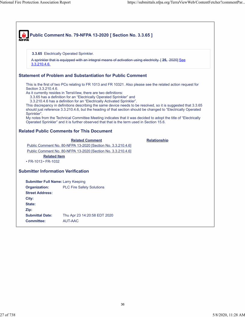
Public Comment No. 79-NFPA 13-2020 [ Section No. 3.3.65 ]
3.3.65 Electrically Operated Sprinkler.
A sprinkler that is equipped with an integral means of activation using electricity. [ 25, 2020] See3.3.210.4.6.
Statement of Problem and Substantiation for Public Comment
This is the first of two PCs relating to FR 1013 and FR 10321. Also please see the related action request for Section 3.3.210.4.6.As it currently resides in TerraView, there are two definitions: 3.3.65 has a definition for an “Electrically Operated Sprinkler” and 3.3.210.4.6 has a definition for an “Electrically Activated Sprinkler”.This discrepancy in definitions describing the same device needs to be resolved, so it is suggested that 3.3.65 should just reference 3.3.210.4.6, but the heading of that section should be changed to “Electrically Operated Sprinkler”.My notes from the Technical Committee Meeting indicates that it was decided to adopt the title of “Electrically Operated Sprinkler” and it is further observed that that is the term used in Section 15.6.
Related Public Comments for This Document
Related Comment Relationship
Public Comment No. 80-NFPA 13-2020 [Section No. 3.3.210.4.6]
Public Comment No. 80-NFPA 13-2020 [Section No. 3.3.210.4.6]
Related Item
• FR-1013 • FR-1032
Submitter Information Verification
Submitter Full Name: Larry Keeping
Organization: PLC Fire Safety Solutions
Street Address:
City:
State:
Zip:
Submittal Date: Thu Apr 23 14:20:58 EDT 2020
Committee: AUT-AAC
National Fire Protection Association Report https://submittals.nfpa.org/TerraViewWeb/ContentFetcher?commentPar...
27 of 738 5/8/2020, 11:28 AM
36

Public Comment No. 159-NFPA 13-2020 [ Section No. 3.3.71 ]
3.3.71 Exterior Projection.
Construction attached to the primary structure, An extension beyond an exterior wall capable of collectingheat below . (AUT-SSI)
Statement of Problem and Substantiation for Public Comment
Current language leaves this new definition up for interpretation. The proposed revision clarifies that this should be an extension of the footprint of the building (i.e. an ornamental projection on top of a buildings should not require sprinkler protection). Additionally, a projection might not necessarily need to be attached to pose a fire hazard (i.e. a "detached" pavilion separated by a few inches from the main structure)
Related Item
• FR-1015
Submitter Information Verification
Submitter Full Name: Kevin Hall
Organization: NFSA
Affiliation: NFSA Engineering and Standards Committee
Street Address:
City:
State:
Zip:
Submittal Date: Mon Apr 27 08:58:20 EDT 2020
Committee: AUT-AAC
National Fire Protection Association Report https://submittals.nfpa.org/TerraViewWeb/ContentFetcher?commentPar...
28 of 738 5/8/2020, 11:28 AM
37
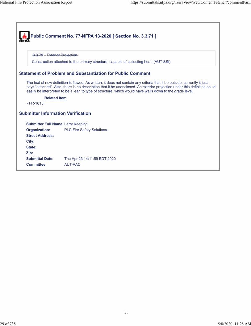
Public Comment No. 77-NFPA 13-2020 [ Section No. 3.3.71 ]
3.3.71 Exterior Projection.
Construction attached to the primary structure, capable of collecting heat. (AUT-SSI)
Statement of Problem and Substantiation for Public Comment
The text of new definition is flawed. As written, it does not contain any criteria that it be outside, currently it just says “attached”. Also, there is no description that it be unenclosed. An exterior projection under this definition could easily be interpreted to be a lean to type of structure, which would have walls down to the grade level.
Related Item
• FR-1015
Submitter Information Verification
Submitter Full Name: Larry Keeping
Organization: PLC Fire Safety Solutions
Street Address:
City:
State:
Zip:
Submittal Date: Thu Apr 23 14:11:59 EDT 2020
Committee: AUT-AAC
National Fire Protection Association Report https://submittals.nfpa.org/TerraViewWeb/ContentFetcher?commentPar...
29 of 738 5/8/2020, 11:28 AM
38
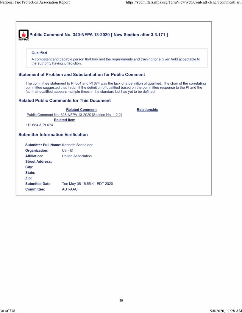
Public Comment No. 340-NFPA 13-2020 [ New Section after 3.3.171 ]
Qualified
A competent and capable person that has met the requirements and training for a given field acceptable tothe authority having jurisdiction.
Statement of Problem and Substantiation for Public Comment
The committee statement to PI 664 and PI 674 was the lack of a definition of qualified. The chair of the correlating committee suggested that I submit the definition of qualified based on the committee response to the PI and the fact that qualified appears multiple times in the standard but has yet to be defined.
Related Public Comments for This Document
Related Comment Relationship
Public Comment No. 328-NFPA 13-2020 [Section No. 1.2.2]
Related Item
• PI 664 & PI 674
Submitter Information Verification
Submitter Full Name: Kenneth Schneider
Organization: Ua - Itf
Affiliation: United Association
Street Address:
City:
State:
Zip:
Submittal Date: Tue May 05 15:55:41 EDT 2020
Committee: AUT-AAC
National Fire Protection Association Report https://submittals.nfpa.org/TerraViewWeb/ContentFetcher?commentPar...
30 of 738 5/8/2020, 11:28 AM
39
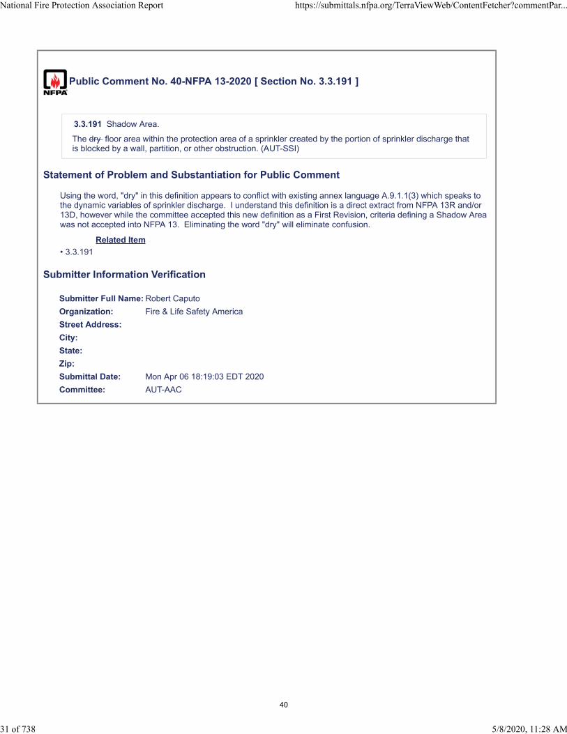
Public Comment No. 40-NFPA 13-2020 [ Section No. 3.3.191 ]
3.3.191 Shadow Area.
The dry floor area within the protection area of a sprinkler created by the portion of sprinkler discharge thatis blocked by a wall, partition, or other obstruction. (AUT-SSI)
Statement of Problem and Substantiation for Public Comment
Using the word, "dry" in this definition appears to conflict with existing annex language A.9.1.1(3) which speaks to the dynamic variables of sprinkler discharge. I understand this definition is a direct extract from NFPA 13R and/or 13D, however while the committee accepted this new definition as a First Revision, criteria defining a Shadow Area was not accepted into NFPA 13. Eliminating the word "dry" will eliminate confusion.
Related Item
• 3.3.191
Submitter Information Verification
Submitter Full Name: Robert Caputo
Organization: Fire & Life Safety America
Street Address:
City:
State:
Zip:
Submittal Date: Mon Apr 06 18:19:03 EDT 2020
Committee: AUT-AAC
National Fire Protection Association Report https://submittals.nfpa.org/TerraViewWeb/ContentFetcher?commentPar...
31 of 738 5/8/2020, 11:28 AM
40
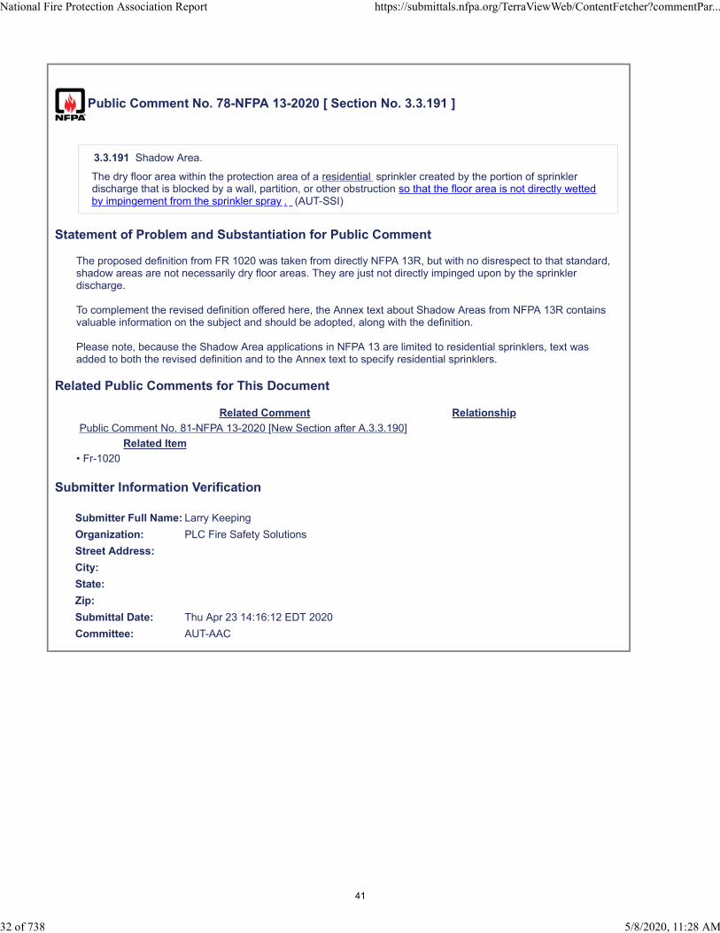
Public Comment No. 78-NFPA 13-2020 [ Section No. 3.3.191 ]
3.3.191 Shadow Area.
The dry floor area within the protection area of a residential sprinkler created by the portion of sprinklerdischarge that is blocked by a wall, partition, or other obstruction so that the floor area is not directly wettedby impingement from the sprinkler spray . (AUT-SSI)
Statement of Problem and Substantiation for Public Comment
The proposed definition from FR 1020 was taken from directly NFPA 13R, but with no disrespect to that standard, shadow areas are not necessarily dry floor areas. They are just not directly impinged upon by the sprinkler discharge.
To complement the revised definition offered here, the Annex text about Shadow Areas from NFPA 13R contains valuable information on the subject and should be adopted, along with the definition.
Please note, because the Shadow Area applications in NFPA 13 are limited to residential sprinklers, text was added to both the revised definition and to the Annex text to specify residential sprinklers.
Related Public Comments for This Document
Related Comment Relationship
Public Comment No. 81-NFPA 13-2020 [New Section after A.3.3.190]
Related Item
• Fr-1020
Submitter Information Verification
Submitter Full Name: Larry Keeping
Organization: PLC Fire Safety Solutions
Street Address:
City:
State:
Zip:
Submittal Date: Thu Apr 23 14:16:12 EDT 2020
Committee: AUT-AAC
National Fire Protection Association Report https://submittals.nfpa.org/TerraViewWeb/ContentFetcher?commentPar...
32 of 738 5/8/2020, 11:28 AM
41

Public Comment No. 160-NFPA 13-2020 [ Section No. 3.3.210.4.6 ]
3.3.210.4.6 Electrically Activated Sprinkler.
A sprinkler equipped with an integral means of activation using electricity. (AUT-SSI)
Statement of Problem and Substantiation for Public Comment
Use either "Electrically Operated Sprinkler" or "Electrically Activated Sprinkler" consistently throughout the document. With input from the sprinkler manufacturers, the NFSA Engineering and Standards Committee recommends using Electrically Operated Sprinklers.
Related Item
• FR-1014
Submitter Information Verification
Submitter Full Name: Kevin Hall
Organization: NFSA
Affiliation: NFSA Engineering and Standards Committee
Street Address:
City:
State:
Zip:
Submittal Date: Mon Apr 27 09:05:40 EDT 2020
Committee: AUT-AAC
National Fire Protection Association Report https://submittals.nfpa.org/TerraViewWeb/ContentFetcher?commentPar...
33 of 738 5/8/2020, 11:28 AM
42

Public Comment No. 80-NFPA 13-2020 [ Section No. 3.3.210.4.6 ]
3.3.210.4.6 Electrically Activated Operated Sprinkler.
A sprinkler equipped with an integral means of activation using electricity. (AUT-SSI)
Statement of Problem and Substantiation for Public Comment
This is the second of two PCs relating to FR 1013 and FR 10321. Also please see the related action request for Section 3.3.65.As it currently resides in TerraView, there are two definitions: 3.3.65 has a definition for an “Electrically Operated Sprinkler” and 3.3.210.4.6 has a definition for an “Electrically Activated Sprinkler”.This discrepancy in definitions describing the same device needs to be resolved, so it is suggested that 3.3.65 should just reference 3.3.210.4.6, but the heading of that section should be changed to “Electrically Operated Sprinkler”..My notes from the Technical Committee Meeting indicates that it was decided to adopt the title of “Electrically Operated Sprinkler” and it is further observed that that is the term used in Section 15.6.
Related Public Comments for This Document
Related Comment Relationship
Public Comment No. 79-NFPA 13-2020 [Section No. 3.3.65]
Public Comment No. 79-NFPA 13-2020 [Section No. 3.3.65]
Related Item
• fr-1013 • FR-1032
Submitter Information Verification
Submitter Full Name: Larry Keeping
Organization: PLC Fire Safety Solutions
Street Address:
City:
State:
Zip:
Submittal Date: Thu Apr 23 14:25:57 EDT 2020
Committee: AUT-AAC
National Fire Protection Association Report https://submittals.nfpa.org/TerraViewWeb/ContentFetcher?commentPar...
34 of 738 5/8/2020, 11:28 AM
43
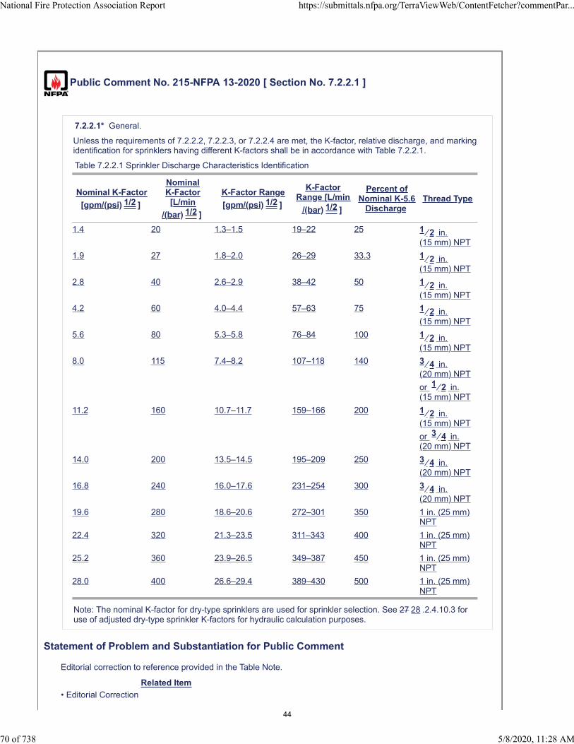
Public Comment No. 215-NFPA 13-2020 [ Section No. 7.2.2.1 ]
7.2.2.1* General.
Unless the requirements of 7.2.2.2, 7.2.2.3, or 7.2.2.4 are met, the K-factor, relative discharge, and markingidentification for sprinklers having different K-factors shall be in accordance with Table 7.2.2.1.
Table 7.2.2.1 Sprinkler Discharge Characteristics Identification
Nominal K-Factor
[gpm/(psi) 1/2 ]
NominalK-Factor[L/min
/(bar) 1/2 ]
K-Factor Range
[gpm/(psi) 1/2 ]
K-FactorRange [L/min
/(bar) 1/2 ]
Percent ofNominal K-5.6
DischargeThread Type
1.4 20 1.3–1.5 19–22 25 1 ⁄ 2 in.(15 mm) NPT
1.9 27 1.8–2.0 26–29 33.3 1 ⁄ 2 in.(15 mm) NPT
2.8 40 2.6–2.9 38–42 50 1 ⁄ 2 in.(15 mm) NPT
4.2 60 4.0–4.4 57–63 75 1 ⁄ 2 in.(15 mm) NPT
5.6 80 5.3–5.8 76–84 100 1 ⁄ 2 in.(15 mm) NPT
8.0 115 7.4–8.2 107–118 140 3 ⁄ 4 in.(20 mm) NPT
or 1 ⁄ 2 in.(15 mm) NPT
11.2 160 10.7–11.7 159–166 200 1 ⁄ 2 in.(15 mm) NPT
or 3 ⁄ 4 in.(20 mm) NPT
14.0 200 13.5–14.5 195–209 250 3 ⁄ 4 in.(20 mm) NPT
16.8 240 16.0–17.6 231–254 300 3 ⁄ 4 in.(20 mm) NPT
19.6 280 18.6–20.6 272–301 350 1 in. (25 mm)NPT
22.4 320 21.3–23.5 311–343 400 1 in. (25 mm)NPT
25.2 360 23.9–26.5 349–387 450 1 in. (25 mm)NPT
28.0 400 26.6–29.4 389–430 500 1 in. (25 mm)NPT
Note: The nominal K-factor for dry-type sprinklers are used for sprinkler selection. See 27 28 .2.4.10.3 foruse of adjusted dry-type sprinkler K-factors for hydraulic calculation purposes.
Statement of Problem and Substantiation for Public Comment
Editorial correction to reference provided in the Table Note.
Related Item
• Editorial Correction
National Fire Protection Association Report https://submittals.nfpa.org/TerraViewWeb/ContentFetcher?commentPar...
70 of 738 5/8/2020, 11:28 AM
44

Submitter Information Verification
Submitter Full Name: Tracey Bellamy
Organization: Telgian Corporation
Street Address:
City:
State:
Zip:
Submittal Date: Sat May 02 16:49:28 EDT 2020
Committee: AUT-AAC
National Fire Protection Association Report https://submittals.nfpa.org/TerraViewWeb/ContentFetcher?commentPar...
71 of 738 5/8/2020, 11:28 AM
45
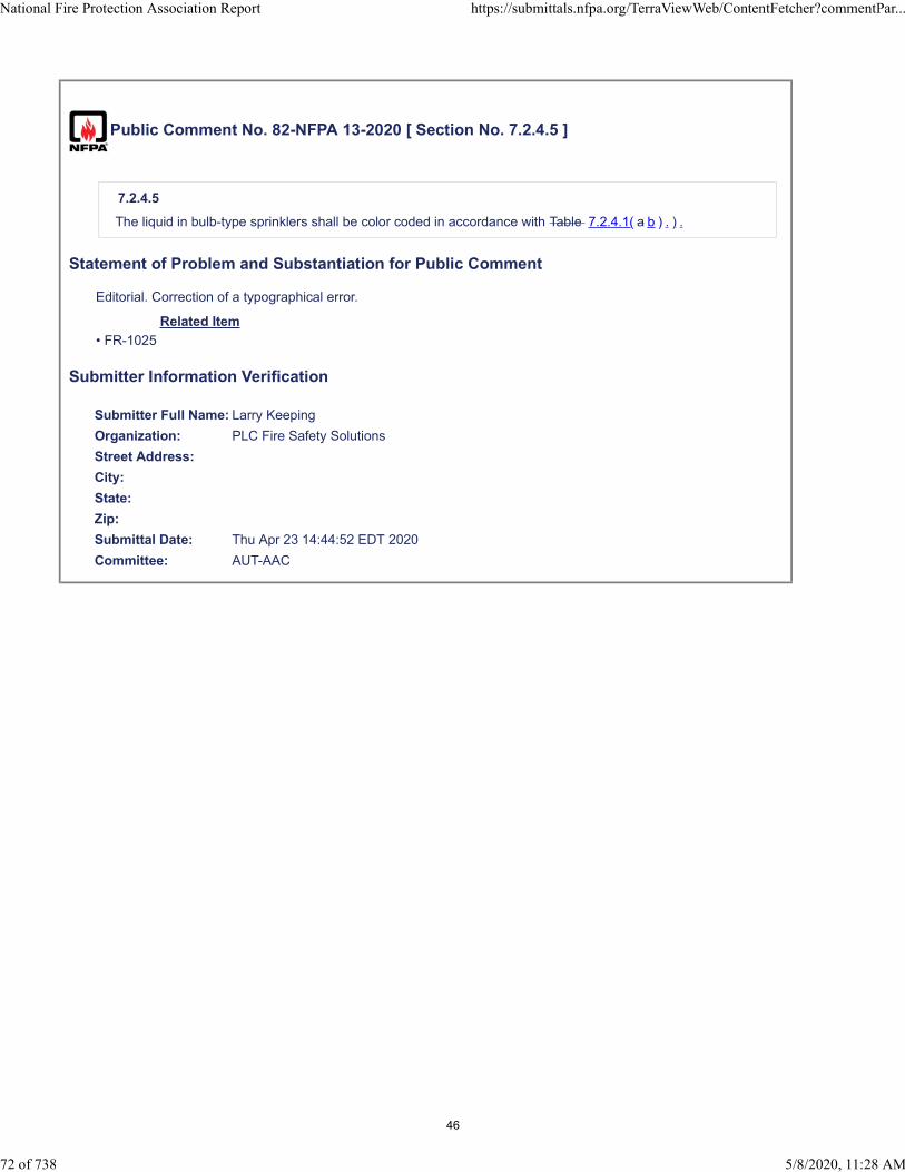
Public Comment No. 82-NFPA 13-2020 [ Section No. 7.2.4.5 ]
7.2.4.5
The liquid in bulb-type sprinklers shall be color coded in accordance with Table 7.2.4.1( a b ) . ) .
Statement of Problem and Substantiation for Public Comment
Editorial. Correction of a typographical error.
Related Item
• FR-1025
Submitter Information Verification
Submitter Full Name: Larry Keeping
Organization: PLC Fire Safety Solutions
Street Address:
City:
State:
Zip:
Submittal Date: Thu Apr 23 14:44:52 EDT 2020
Committee: AUT-AAC
National Fire Protection Association Report https://submittals.nfpa.org/TerraViewWeb/ContentFetcher?commentPar...
72 of 738 5/8/2020, 11:28 AM
46
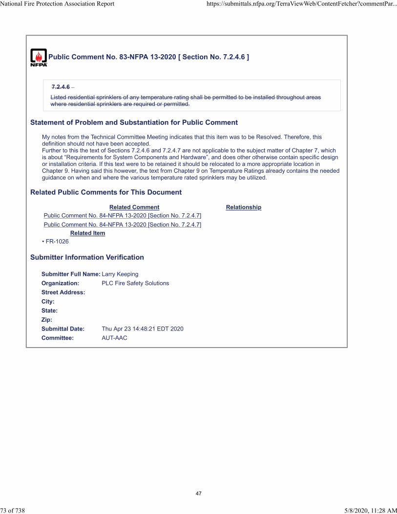
Public Comment No. 83-NFPA 13-2020 [ Section No. 7.2.4.6 ]
7.2.4.6
Listed residential sprinklers of any temperature rating shall be permitted to be installed throughout areaswhere residential sprinklers are required or permitted.
Statement of Problem and Substantiation for Public Comment
My notes from the Technical Committee Meeting indicates that this item was to be Resolved. Therefore, this definition should not have been accepted.Further to this the text of Sections 7.2.4.6 and 7.2.4.7 are not applicable to the subject matter of Chapter 7, which is about “Requirements for System Components and Hardware”, and does other otherwise contain specific design or installation criteria. If this text were to be retained it should be relocated to a more appropriate location in Chapter 9. Having said this however, the text from Chapter 9 on Temperature Ratings already contains the needed guidance on when and where the various temperature rated sprinklers may be utilized.
Related Public Comments for This Document
Related Comment Relationship
Public Comment No. 84-NFPA 13-2020 [Section No. 7.2.4.7]
Public Comment No. 84-NFPA 13-2020 [Section No. 7.2.4.7]
Related Item
• FR-1026
Submitter Information Verification
Submitter Full Name: Larry Keeping
Organization: PLC Fire Safety Solutions
Street Address:
City:
State:
Zip:
Submittal Date: Thu Apr 23 14:48:21 EDT 2020
Committee: AUT-AAC
National Fire Protection Association Report https://submittals.nfpa.org/TerraViewWeb/ContentFetcher?commentPar...
73 of 738 5/8/2020, 11:28 AM
47

Public Comment No. 162-NFPA 13-2020 [ Section No. 7.2.4.7 ]
7.2.4.7
Listed quick response sprinklers of any ordinary and/or intermediate temperature rating shall be permittedto be installed throughout areas where quick response sprinklers are required or permitted.
Statement of Problem and Substantiation for Public Comment
There are High Temperature Quick Response Sprinklers on the market; however, this section should only allow ordinary and/or intermediate temperature sprinklers to be used throughout. Higher temperature ratings should be used in specific applications
Related Item
• FR-1026
Submitter Information Verification
Submitter Full Name: Kevin Hall
Organization: NFSA
Affiliation: NFSA Engineering and Standards Committee
Street Address:
City:
State:
Zip:
Submittal Date: Mon Apr 27 09:15:00 EDT 2020
Committee: AUT-AAC
National Fire Protection Association Report https://submittals.nfpa.org/TerraViewWeb/ContentFetcher?commentPar...
74 of 738 5/8/2020, 11:28 AM
48

Public Comment No. 84-NFPA 13-2020 [ Section No. 7.2.4.7 ]
7.2.4.7
Listed quick response sprinklers of any temperature rating shall be permitted to be installed throughoutareas where quick response sprinklers are required or permitted.
Statement of Problem and Substantiation for Public Comment
My notes from the Technical Committee Meeting indicates that this item was to be Resolved. Therefore, this definition should not have been accepted.Further to this the text of Sections 7.2.4.6 and 7.2.4.7 are not applicable to the subject matter of Chapter 7, which is about “Requirements for System Components and Hardware”, and does other otherwise contain specific design or installation criteria. If this text were to be retained it should be relocated to a more appropriate location in Chapter 9. Having said this however, the text from Chapter 9 on Temperature Ratings already contains the needed guidance on when and where the various temperature rated sprinklers may be utilized.
Related Public Comments for This Document
Related Comment Relationship
Public Comment No. 83-NFPA 13-2020 [Section No. 7.2.4.6]
Public Comment No. 83-NFPA 13-2020 [Section No. 7.2.4.6]
Related Item
• FR-1026
Submitter Information Verification
Submitter Full Name: Larry Keeping
Organization: PLC Fire Safety Solutions
Street Address:
City:
State:
Zip:
Submittal Date: Thu Apr 23 14:50:09 EDT 2020
Committee: AUT-AAC
National Fire Protection Association Report https://submittals.nfpa.org/TerraViewWeb/ContentFetcher?commentPar...
75 of 738 5/8/2020, 11:28 AM
49
Public Comment No. 217-NFPA 13-2020 [ Section No. 7.2.5.3.2 ]
7.2.5.3.2
Sprinklers with ornamental finishes where utilized shall be specifically listed.
Statement of Problem and Substantiation for Public Comment
Remove unnecessary language.
Related Item
• Editiorial Correction
Submitter Information Verification
Submitter Full Name: Tracey Bellamy
Organization: Telgian Corporation
Street Address:
City:
State:
Zip:
Submittal Date: Sat May 02 16:55:12 EDT 2020
Committee: AUT-AAC
National Fire Protection Association Report https://submittals.nfpa.org/TerraViewWeb/ContentFetcher?commentPar...
76 of 738 5/8/2020, 11:28 AM
50

Public Comment No. 218-NFPA 13-2020 [ Section No. 7.5.2.2.2 ]
7.5.2.2.2
Where the design specifications require any part of the piping system to be welded in place, welding ofsprinkler piping shall be permitted where the welding process is performed in accordance with NFPA 51Band the mechanical fittings required by 16.9.11.5 and Section 16.6 are provided.
Statement of Problem and Substantiation for Public Comment
16.9.11.5 is an incorrect reference and the old correct reference 16.9.10.5 was deleted in the 1st Draft.
Related Item
• FR 1359
Submitter Information Verification
Submitter Full Name: Tracey Bellamy
Organization: Telgian Corporation
Street Address:
City:
State:
Zip:
Submittal Date: Sat May 02 16:59:52 EDT 2020
Committee: AUT-AAC
National Fire Protection Association Report https://submittals.nfpa.org/TerraViewWeb/ContentFetcher?commentPar...
77 of 738 5/8/2020, 11:28 AM
51

Public Comment No. 135-NFPA 13-2020 [ Section No. 7.5.3.3 ]
7.5.3.3
Listed flexible grooved couplings shall be differentiated from listed nonflexible couplings in a manner visiblefrom the floor level.
Statement of Problem and Substantiation for Public Comment
This is an onerous requirement. What if the owner wants to paint the system? Do we then need to install a tag to each coupling so they can be identified? The language does not say how it has to be observed? With the naked eye? With high powered field binoculars? This is simply a solution waiting for a problem.
Related Item
• FR#1191
Submitter Information Verification
Submitter Full Name: Peter Schwab
Organization: Wayne Automatic Fire Sprinkler
Street Address:
City:
State:
Zip:
Submittal Date: Fri Apr 24 19:18:45 EDT 2020
Committee: AUT-AAC
National Fire Protection Association Report https://submittals.nfpa.org/TerraViewWeb/ContentFetcher?commentPar...
78 of 738 5/8/2020, 11:28 AM
52
Public Comment No. 163-NFPA 13-2020 [ Section No. 7.5.3.3 ]
7.5.3.3
Listed flexible grooved couplings shall be differentiated from listed nonflexible couplings in a manner visiblefrom the floor level.
Statement of Problem and Substantiation for Public Comment
Marking of a flexible coupling is not practical. The substantiation from PI-34 offered only anecdotal support for the change and no technical substantiation. The six negative comments on the first draft ballot note that this is too broad to be enforceable. Additionally the submitter of PI-34 noted that this is similar to the requirements for sprinklers to be color coded; however, the requirement to be visible from the floor is not. It would be arduous to differentiate a red 3 mm glass bulb from a blue 5 mm glass bulb in a 40 ft building. The marking is for the installer not the AHJ and the current practices should suffice.
Related Item
• FR-1191
Submitter Information Verification
Submitter Full Name: Kevin Hall
Organization: NFSA
Affiliation: NFSA Engineering and Standards Committee
Street Address:
City:
State:
Zip:
Submittal Date: Mon Apr 27 09:18:25 EDT 2020
Committee: AUT-AAC
National Fire Protection Association Report https://submittals.nfpa.org/TerraViewWeb/ContentFetcher?commentPar...
79 of 738 5/8/2020, 11:28 AM
53

Public Comment No. 85-NFPA 13-2020 [ Section No. 7.5.3.3 ]
7.5.3.3
Listed flexible grooved couplings shall be differentiated from listed nonflexible couplings in a manner visiblefrom the floor level.
Statement of Problem and Substantiation for Public Comment
This provision is too vague and does not describe how a coupling should be made to be identifiable from floor level.Well it could be valuable to identify flexible couplings from rigid couplings; this proposition is totally impractical. Specific markings on a coupling cannot be differentiated from any distance, nor can physical differences, such as bolt bad configurations. Perhaps different colours could be differentiated if they were distinct from each other, but would depend on could lighting, and finishes such as those for galvanizing or painted piping would not be allowable.The only way to truly differentiate a flexible coupling from a rigid one would be to hang a sign or placard from it, and to be mandating something like that is absurd.
Related Item
• FR-1191
Submitter Information Verification
Submitter Full Name: Larry Keeping
Organization: PLC Fire Safety Solutions
Street Address:
City:
State:
Zip:
Submittal Date: Thu Apr 23 14:55:03 EDT 2020
Committee: AUT-AAC
National Fire Protection Association Report https://submittals.nfpa.org/TerraViewWeb/ContentFetcher?commentPar...
80 of 738 5/8/2020, 11:28 AM
54
Public Comment No. 136-NFPA 13-2020 [ Section No. 7.6.1 ]
7.6.1 Valve Closure Time.
Listed indicating control valves shall not close in less than 5 seconds when operated at maximum possiblespeed from the fully open position.
Statement of Problem and Substantiation for Public Comment
This was submitted as PI # 312 and appears that it was included in First Revision No. 1033. However the change does not appear in the second draft.
Related Item
• FR#1033
Submitter Information Verification
Submitter Full Name: Peter Schwab
Organization: Wayne Automatic Fire Sprinkler
Street Address:
City:
State:
Zip:
Submittal Date: Fri Apr 24 19:24:58 EDT 2020
Committee: AUT-AAC
National Fire Protection Association Report https://submittals.nfpa.org/TerraViewWeb/ContentFetcher?commentPar...
81 of 738 5/8/2020, 11:28 AM
55

Public Comment No. 137-NFPA 13-2020 [ Section No. 7.7 ]
7.7 Waterflow Alarm Devices.
Waterflow alarm devices shall be listed for the service and so constructed and installed that any flow ofwater from a sprinkler system equal to or greater than that from a single automatic sprinkler of the smallestK-factor installed on the system will result in an audible alarm on the premises within 5 minutes after 90seconds after such flow begins and until such flow stops.
Statement of Problem and Substantiation for Public Comment
I agree with Mr. Baron and his Public Input No. 217. I understand that the 90 second reference comes from the alarm code. However, I feel that 5 minutes is just too much time. We have all seen the videos about how fast furnishings burn. If I was in the same building that the fire was in, I would not want to wait five minutes before I was even made aware that there may be a fire emergency.Just because it's always been that way doesn't make it right.
Related Item
• PI#217
Submitter Information Verification
Submitter Full Name: Peter Schwab
Organization: Wayne Automatic Fire Sprinkler
Street Address:
City:
State:
Zip:
Submittal Date: Fri Apr 24 19:27:44 EDT 2020
Committee: AUT-AAC
National Fire Protection Association Report https://submittals.nfpa.org/TerraViewWeb/ContentFetcher?commentPar...
82 of 738 5/8/2020, 11:28 AM
56

Public Comment No. 33-NFPA 13-2020 [ Section No. 7.7 ]
7.7 Waterflow Alarm Devices.
Waterflow alarm devices shall be listed for the service and so constructed and installed that any flow ofwater from a sprinkler system equal to or greater than that from a single automatic sprinkler of the smallestK-factor installed on the system will result in an audible alarm on the premises within 5 minutes 90Seconds after such flow begins and until such flow stops.
Statement of Problem and Substantiation for Public Comment
A five minute delay is unacceptable for an audible alarm on the premises. I agree with the part of the committee statement that the issue of "Fire alarm monitoring is different than on site notification.". However neither this chapter nor this paragraph have anything to do with Fire Alarm Monitoring and the specific change proposed in the original PI. This PC is only to specifically change and reduce the acceptable time delay for the "Audible alarm on the premises". The committee statement and resolution seemed to be based more on the substantiation vs the actual change submitted so I will attempt to address that here. To that extent I do believe the committee is also correct in so far as this should also change 28.2.3.1 to the same time (90 seconds). The timely notification of occupants within a structure due to a fire sprinkler system water flow from a possible fire event should and does exist as a stand alone topic in this standard in 7.7. If NFPA 13 is being required and enforced in a specific new structure and NFPA 72 is not, and a flow detector activates, it is possible and allowable by this standard that the only audible alarm to activate on the premises may activate 5 minutes after flow begins! We should not have to rely on whether another standard will be required or enforced to ensure that an acceptable time frame for local notification exists. This change will also be consistent with current time frame requirements that already exist in other standards and provide a consistent message between the standards. In case of an actual fire event, who among us would want to be in a structure for 5 minutes before even being notified that there is a fire in the building. The substantiation to support this time is well established in NFPA 72 for the activation of a water flow initiating device. The maximum time delay settings for most used common water flow detectors also is between 70 -90 seconds. Problems or concerns with low water pressure or cross connection check valve cycling may be issues that can create problems with any alarm activation. The solution to resolve these issues more often time than not is, a reduction in time delay not an increase in delay. This specific problem in no way justifies allowing a delay of local notification by up to five minutes. These are separate issues that can and should be resolved and not used as an excuse to delay the timely notification or audible alarm on the premises. In respect to dry valve activation and alarm delay, the existing requirements of chapter 8 and 28 seem to actually support this time frame change already. It would be more difficult to try to delay an alarm for more than 70-90 seconds with the existing requirements for these systems. Most dry valve time frame requirements relate to water delivery time while alarm activation's relate more often to trip times or QOD activation and the pressurization of intermediate chambers whether on dry type, deluge or pre-action type valve regardless of whether they are configured as non-interlock, single or double interlock type configuration. Refer to NFPA 72 2019 ed. section 17.13.2, and A17.13.2 for technical substantiation.
Please reconsider reducing the five minute time delay for the audible alarm on premises.
Related Item
• PI217
Submitter Information Verification
Submitter Full Name: David Baron
Organization: Global Fire Protection Company
Street Address:
City:
State:
Zip:
Submittal Date: Mon Mar 23 10:22:11 EDT 2020
Committee: AUT-AAC
National Fire Protection Association Report https://submittals.nfpa.org/TerraViewWeb/ContentFetcher?commentPar...
83 of 738 5/8/2020, 11:28 AM
57

Public Comment No. 34-NFPA 13-2020 [ Section No. 7.7 ]
7.7 Waterflow Alarm Devices.
Waterflow alarm devices shall be listed for the service and so constructed and installed that any flow ofwater from a sprinkler system equal to or greater than that from a single automatic sprinkler of the smallestK-factor installed on the system will result in an audible alarm on the premises within 5 minutes 120seconds after such flow begins and until such flow stops.
Statement of Problem and Substantiation for Public Comment
If a 90 second delay is not an acceptable time frame then two minutes should be an acceptable option while still removing the unacceptable current five minute delay. For further justification refer to PC 33 substantiation. An additional 30 seconds in addition to the 90 second delay allowed and found on most paddle type flows and other delay options and should be more than acceptable. Should there be any objection to the 90 second delay based on this being a minimum standard, this allows for a variance without being so excessive as to make this requirement completely unnecessary. Try having one of the side by side fire demo's done by NFSA and delay the alarm activation by 5 minutes after flow begins, lets see what type of reaction we note from both fire professionals and the public?
Related Item
• PI217
Submitter Information Verification
Submitter Full Name: David Baron
Organization: Global Fire Protection Company
Street Address:
City:
State:
Zip:
Submittal Date: Mon Mar 23 11:52:21 EDT 2020
Committee: AUT-AAC
National Fire Protection Association Report https://submittals.nfpa.org/TerraViewWeb/ContentFetcher?commentPar...
85 of 738 5/8/2020, 11:28 AM
58
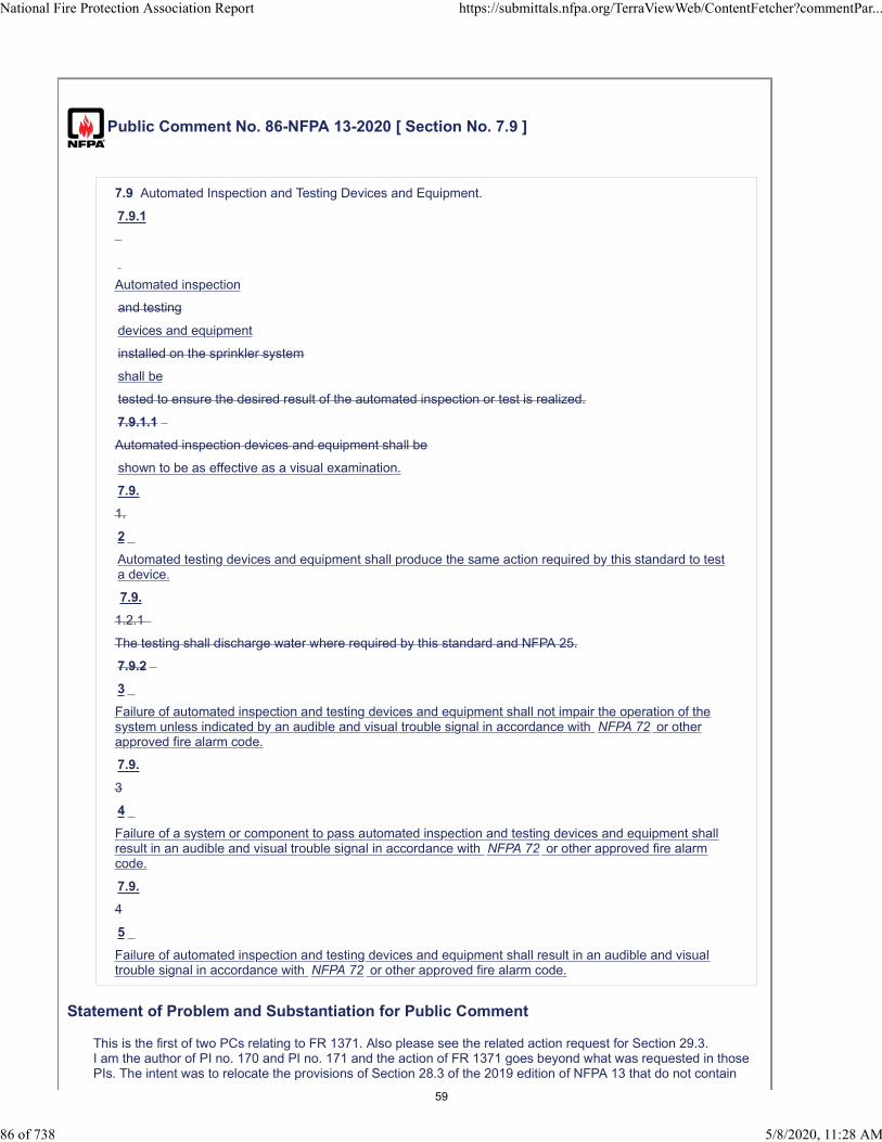
Public Comment No. 86-NFPA 13-2020 [ Section No. 7.9 ]
7.9 Automated Inspection and Testing Devices and Equipment.
7.9.1
Automated inspection
and testing
devices and equipment
installed on the sprinkler system
shall be
tested to ensure the desired result of the automated inspection or test is realized.
7.9.1.1
Automated inspection devices and equipment shall be
shown to be as effective as a visual examination.
7.9.
1.
2
Automated testing devices and equipment shall produce the same action required by this standard to testa device.
7.9.
1.2.1
The testing shall discharge water where required by this standard and NFPA 25.
7.9.2
3
Failure of automated inspection and testing devices and equipment shall not impair the operation of thesystem unless indicated by an audible and visual trouble signal in accordance with NFPA 72 or otherapproved fire alarm code.
7.9.
3
4
Failure of a system or component to pass automated inspection and testing devices and equipment shallresult in an audible and visual trouble signal in accordance with NFPA 72 or other approved fire alarmcode.
7.9.
4
5
Failure of automated inspection and testing devices and equipment shall result in an audible and visualtrouble signal in accordance with NFPA 72 or other approved fire alarm code.
Statement of Problem and Substantiation for Public Comment
This is the first of two PCs relating to FR 1371. Also please see the related action request for Section 29.3.I am the author of PI no. 170 and PI no. 171 and the action of FR 1371 goes beyond what was requested in those PIs. The intent was to relocate the provisions of Section 28.3 of the 2019 edition of NFPA 13 that do not contain
National Fire Protection Association Report https://submittals.nfpa.org/TerraViewWeb/ContentFetcher?commentPar...
86 of 738 5/8/2020, 11:28 AM
59
any Acceptance Testing criteria to Chapter 7, but instead, the entire section was relocated to Section 7.9. With this the provisions 7.9.1 and 7.9.1.2.1, which contain acceptance testing requirements do not belong in Section 7.9 and they should be reinserted into the Acceptance Testing Chapter accordingly.
Related Public Comments for This Document
Related Comment Relationship
Public Comment No. 110-NFPA 13-2020 [New Section after 29.2.6]
Public Comment No. 110-NFPA 13-2020 [New Section after 29.2.6]
Related Item
• FR-1371
Submitter Information Verification
Submitter Full Name: Larry Keeping
Organization: PLC Fire Safety Solutions
Street Address:
City:
State:
Zip:
Submittal Date: Thu Apr 23 14:57:32 EDT 2020
Committee: AUT-AAC
National Fire Protection Association Report https://submittals.nfpa.org/TerraViewWeb/ContentFetcher?commentPar...
87 of 738 5/8/2020, 11:28 AM
60

Public Comment No. 243-NFPA 13-2020 [ Section No. 7.9.1 [Excluding any Sub-
Sections] ]
Automated inspection and testing devices and equipment installed on the sprinkler system shall be testedto shall ensure the desired result of the automated inspection or test is realized.
Statement of Problem and Substantiation for Public Comment
PI 170 was submitted to move most of section 28.3 to chapter 7 because much of the text contained installation criteria and not testing criteria. However, the entire section 28.3 was moved in FR 1371 and not just the parts that included installation criteria. This first section needs to be changed to delete the testing criteria language and keep it consistent with installation criteria. Additional PCs will be submitted to further clean up this section and add testing criteria back into chapter 29.
Related Public Comments for This Document
Related Comment Relationship
Public Comment No. 244-NFPA 13-2020 [Section No. 7.9.1.2.1]
Public Comment No. 246-NFPA 13-2020 [New Section after 29.2.5]
Related Item
• PI 170 and FR 1371
Submitter Information Verification
Submitter Full Name: Terry Victor
Organization: Johnson Controls
Street Address:
City:
State:
Zip:
Submittal Date: Mon May 04 10:20:18 EDT 2020
Committee: AUT-AAC
National Fire Protection Association Report https://submittals.nfpa.org/TerraViewWeb/ContentFetcher?commentPar...
88 of 738 5/8/2020, 11:28 AM
61
Public Comment No. 244-NFPA 13-2020 [ Section No. 7.9.1.2.1 ]
7.9.1.2.1
The installation of the testing device or component shall be arranged to discharge water where requiredby this standard and NFPA 25.
Statement of Problem and Substantiation for Public Comment
This section was moved from chapter 28 but the text still contained testing criteria. The changes proposed provide installation criteria as intended.
Related Public Comments for This Document
Related Comment Relationship
Public Comment No. 243-NFPA 13-2020 [Section No. 7.9.1 [Excluding any Sub-Sections]]
Public Comment No. 246-NFPA 13-2020 [New Section after 29.2.5]
Related Item
• PI 170 and FR 1371
Submitter Information Verification
Submitter Full Name: Terry Victor
Organization: Johnson Controls
Street Address:
City:
State:
Zip:
Submittal Date: Mon May 04 10:35:02 EDT 2020
Committee: AUT-AAC
National Fire Protection Association Report https://submittals.nfpa.org/TerraViewWeb/ContentFetcher?commentPar...
89 of 738 5/8/2020, 11:28 AM
62
Public Comment No. 138-NFPA 13-2020 [ Section No. 8.1.2.1 ]
8.1.2.1
Unless the requirements of 8.1.2.2 are met, a wet pipe system shall be provided with a listed relief valve notless than 1⁄2 in. (15 mm) in size and set to operate at 175 psi 185 psi (12 bar 13 bar ) or 10 psi (0.7 bar) inexcess of the maximum system pressure, whichever is greater.
Statement of Problem and Substantiation for Public Comment
I agree with Mr. Wolin's public input. Yes the system components are possibly rated at 175 PSI. Based on the required safety factors built in by the testing laboratories, the possibility of the 10 extra PSI causing failure is negligible.
Related Item
• PI#77
Submitter Information Verification
Submitter Full Name: Peter Schwab
Organization: Wayne Automatic Fire Sprinkler
Street Address:
City:
State:
Zip:
Submittal Date: Fri Apr 24 19:34:41 EDT 2020
Committee: AUT-AAC
National Fire Protection Association Report https://submittals.nfpa.org/TerraViewWeb/ContentFetcher?commentPar...
90 of 738 5/8/2020, 11:28 AM
63

Public Comment No. 42-NFPA 13-2020 [ Section No. 8.1.2.1 ]
8.1.2.1
Unless the requirements of 8.1.2.2 are met, a wet pipe system shall be provided with a listed relief valve notless than 1⁄2 in. (15 mm) in size and set to operate at 175 psi 185 psi (12 bar 13 bar ) or 10 psi (0.7 bar) inexcess of the maximum system pressure, whichever is greater.
Statement of Problem and Substantiation for Public Comment
A Public Comment on this section was resolved due to the TC's concern about the relief valve allowing the pressure to exceed the rated pressure of the equipment if the pressure were specified as 185 psi.
NFPA 13 already permits a relief valve that is set at 10 psi in excess of that maximum system pressure. Listed and approved fire protection equipment is tested at 2 to 5 times the rated pressure. Thus, NFPA 13 permits the relief valve to be set at 10 psi in excess of the maximum system pressure and NFPA 13 requires hydrostatic pressure testing of systems at 50 psi in excess of the system working pressure. Thus, NFPA 13 requires a system with a 175 psi working pressure to be subject to 225 psi for testing. This Comment is simply to require the relief valve to be set at 10 psi in excess of the maximum system pressure, which is not less than 185 psi for an NFPA 13 system.
Listed relief valves are required by their listing to open at between 95% and 105% of their rated pressure. Thus, the use of a 175 psi relief valve on a system with a pressure of 175 psi often results in water flowing from the relief valves at normal system pressures. The use of 185 psi relief valves is appropriate for all NFPA 13 systems with a working pressure of 175 psi and less. NFPA 13 already requires 10 psi in excess of the maximum system pressure.
Related Item
• PI-77
Submitter Information Verification
Submitter Full Name: Steven Wolin
Organization: Reliable Automatic Sprinkler Co., Inc.
Street Address:
City:
State:
Zip:
Submittal Date: Thu Apr 09 14:03:00 EDT 2020
Committee: AUT-AAC
National Fire Protection Association Report https://submittals.nfpa.org/TerraViewWeb/ContentFetcher?commentPar...
91 of 738 5/8/2020, 11:28 AM
64
Public Comment No. 88-NFPA 13-2020 [ Section No. 8.2.2 ]
8.2.2 Sprinklers.
8.2.2.1
Residential sprinklers on dry pipe systems shall be listed for dry pipe applications.
8.2.2.2
The following sprinkler orientations and arrangements shall be permitted for dry pipe systems:
(1) Upright sprinklers
(2)
(3) Pendent sprinklers and sidewall sprinklers installed on return bends, where the sprinklers, returnbend, and branch line piping are in an area maintained at or above 40°F (4°C)
(4) Horizontal sidewall sprinklers installed so that water is not trapped
(5) Pendent sprinklers and sidewall sprinklers, where the sprinklers and branch line piping are in an areamaintained at or above 40°F (4°C), the water supply is potable, and the piping for the dry pipesystem is copper or CPVC specifically listed for dry pipe applications
8.2.2.1
Residential sprinklers shall be listed for dry pipe applications.
Statement of Problem and Substantiation for Public Comment
Editorial. With this revision, the need for residential sprinklers on dry pipe systems is moved to the first part of the section, to reduce any possible ambiguity.
Related Item
• FR-1035
Submitter Information Verification
Submitter Full Name: Larry Keeping
Organization: PLC Fire Safety Solutions
Street Address:
City:
State:
Zip:
Submittal Date: Thu Apr 23 15:16:31 EDT 2020
Committee: AUT-AAC
* Listed dry sprinklers
National Fire Protection Association Report https://submittals.nfpa.org/TerraViewWeb/ContentFetcher?commentPar...
92 of 738 5/8/2020, 11:28 AM
65
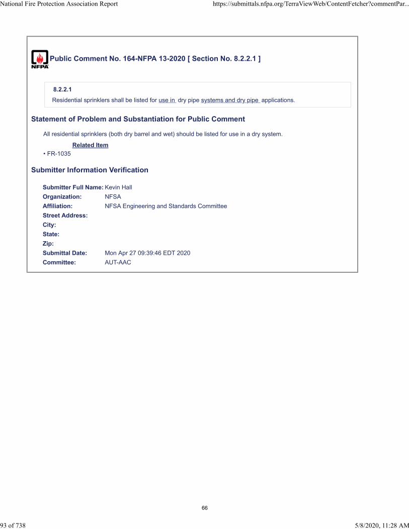
Public Comment No. 164-NFPA 13-2020 [ Section No. 8.2.2.1 ]
8.2.2.1
Residential sprinklers shall be listed for use in dry pipe systems and dry pipe applications.
Statement of Problem and Substantiation for Public Comment
All residential sprinklers (both dry barrel and wet) should be listed for use in a dry system.
Related Item
• FR-1035
Submitter Information Verification
Submitter Full Name: Kevin Hall
Organization: NFSA
Affiliation: NFSA Engineering and Standards Committee
Street Address:
City:
State:
Zip:
Submittal Date: Mon Apr 27 09:39:46 EDT 2020
Committee: AUT-AAC
National Fire Protection Association Report https://submittals.nfpa.org/TerraViewWeb/ContentFetcher?commentPar...
93 of 738 5/8/2020, 11:28 AM
66

Public Comment No. 237-NFPA 13-2020 [ Section No. 8.2.3.5 ]
8.2.3.5
Calculations of water delivery time shall be based on the time interval between the calculated point in timewhen the selected most remote sprinkler(s) opens and the calculated point in time when pressure at themost remote sprinkler reaches or surpasses the design pressure. System size shall be based on dry pipesystems being calculated for water delivery in accordance with 8.2.3.6.
Statement of Problem and Substantiation for Public Comment
There is currently no definition for water delivery time calculation. The above definition is extremely important for storage occupancies with very short water delivery time and high design sprinkler pressure. This definition is in line with FM Global definition and as such was used to define FM Global requirements for water delivery time for storage occupancies. Some of these water delivery time requirements were later transferred into NFPA 13 standard.
Related Item
• FR-1037
Submitter Information Verification
Submitter Full Name: Kevin Hall
Organization: NFSA
Affiliation: NFSA Engineering and Standards Committee
Street Address:
City:
State:
Zip:
Submittal Date: Mon May 04 09:00:05 EDT 2020
Committee: AUT-AAC
National Fire Protection Association Report https://submittals.nfpa.org/TerraViewWeb/ContentFetcher?commentPar...
94 of 738 5/8/2020, 11:28 AM
67
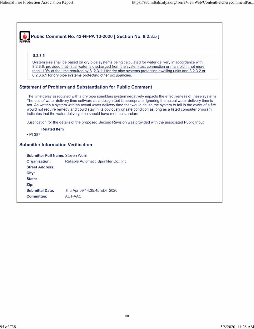
Public Comment No. 43-NFPA 13-2020 [ Section No. 8.2.3.5 ]
8.2.3.5
System size shall be based on dry pipe systems being calculated for water delivery in accordance with8.2.3.6, provided that initial water is discharged from the system test connection or manifold in not morethan 110% of the time required by 8 .2.3.1.1 for dry pipe systems protecting dwelling units and 8.2.3.2 or8.2.3.6.1 for dry pipe systems protecting other occupancies.
Statement of Problem and Substantiation for Public Comment
The time delay associated with a dry pipe sprinklers system negatively impacts the effectiveness of these systems. The use of water delivery time software as a design tool is appropriate. Ignoring the actual water delivery time is not. As written a system with an actual water delivery time that would cause the system to fail in the event of a fire would not require remedy and could stay in its obviously unsafe condition as long as a listed computer program indicates that the water delivery time should have met the standard.
Justification for the details of the proposed Second Revision was provided with the associated Public Input.
Related Item
• PI-387
Submitter Information Verification
Submitter Full Name: Steven Wolin
Organization: Reliable Automatic Sprinkler Co., Inc.
Street Address:
City:
State:
Zip:
Submittal Date: Thu Apr 09 14:35:45 EDT 2020
Committee: AUT-AAC
National Fire Protection Association Report https://submittals.nfpa.org/TerraViewWeb/ContentFetcher?commentPar...
95 of 738 5/8/2020, 11:28 AM
68
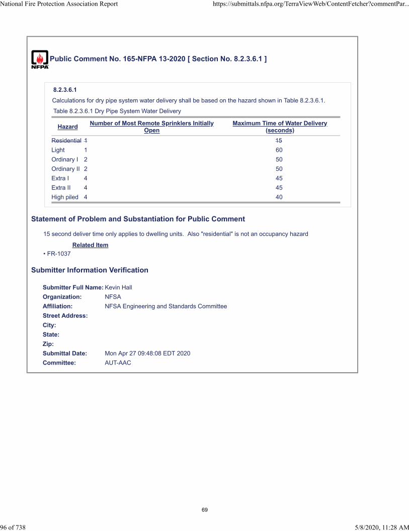
Public Comment No. 165-NFPA 13-2020 [ Section No. 8.2.3.6.1 ]
8.2.3.6.1
Calculations for dry pipe system water delivery shall be based on the hazard shown in Table 8.2.3.6.1.
Table 8.2.3.6.1 Dry Pipe System Water Delivery
HazardNumber of Most Remote Sprinklers Initially
OpenMaximum Time of Water Delivery
(seconds)
Residential 1 15
Light 1 60
Ordinary I 2 50
Ordinary II 2 50
Extra I 4 45
Extra II 4 45
High piled 4 40
Statement of Problem and Substantiation for Public Comment
15 second deliver time only applies to dwelling units. Also "residential" is not an occupancy hazard
Related Item
• FR-1037
Submitter Information Verification
Submitter Full Name: Kevin Hall
Organization: NFSA
Affiliation: NFSA Engineering and Standards Committee
Street Address:
City:
State:
Zip:
Submittal Date: Mon Apr 27 09:48:08 EDT 2020
Committee: AUT-AAC
National Fire Protection Association Report https://submittals.nfpa.org/TerraViewWeb/ContentFetcher?commentPar...
96 of 738 5/8/2020, 11:28 AM
69
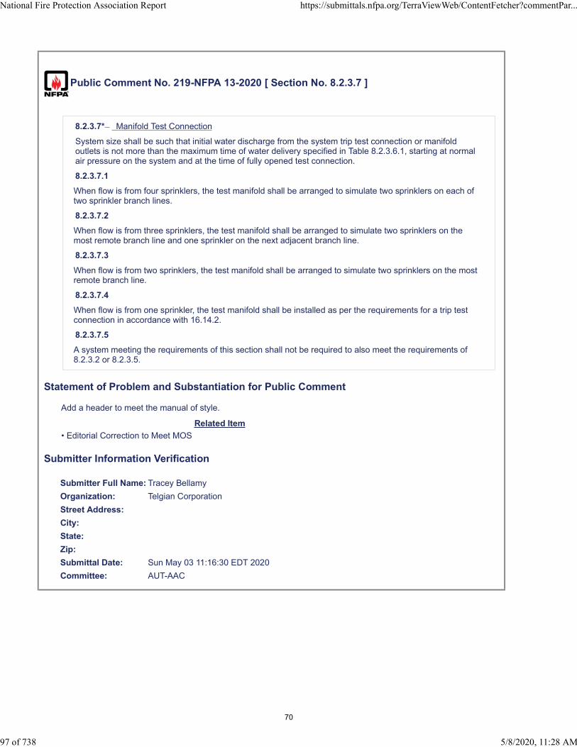
Public Comment No. 219-NFPA 13-2020 [ Section No. 8.2.3.7 ]
8.2.3.7* Manifold Test Connection
System size shall be such that initial water discharge from the system trip test connection or manifoldoutlets is not more than the maximum time of water delivery specified in Table 8.2.3.6.1, starting at normalair pressure on the system and at the time of fully opened test connection.
8.2.3.7.1
When flow is from four sprinklers, the test manifold shall be arranged to simulate two sprinklers on each oftwo sprinkler branch lines.
8.2.3.7.2
When flow is from three sprinklers, the test manifold shall be arranged to simulate two sprinklers on themost remote branch line and one sprinkler on the next adjacent branch line.
8.2.3.7.3
When flow is from two sprinklers, the test manifold shall be arranged to simulate two sprinklers on the mostremote branch line.
8.2.3.7.4
When flow is from one sprinkler, the test manifold shall be installed as per the requirements for a trip testconnection in accordance with 16.14.2.
8.2.3.7.5
A system meeting the requirements of this section shall not be required to also meet the requirements of8.2.3.2 or 8.2.3.5.
Statement of Problem and Substantiation for Public Comment
Add a header to meet the manual of style.
Related Item
• Editorial Correction to Meet MOS
Submitter Information Verification
Submitter Full Name: Tracey Bellamy
Organization: Telgian Corporation
Street Address:
City:
State:
Zip:
Submittal Date: Sun May 03 11:16:30 EDT 2020
Committee: AUT-AAC
National Fire Protection Association Report https://submittals.nfpa.org/TerraViewWeb/ContentFetcher?commentPar...
97 of 738 5/8/2020, 11:28 AM
70
Public Comment No. 220-NFPA 13-2020 [ Section No. 8.2.3.9 ]
8.2.3.9 Dry Pipe System Subdivision
Unless installed in a heated enclosure, check valves shall not be used to subdivide the dry pipe systems.
8.2.3.9.1
When check valves are used to subdivide dry pipe systems in accordance with 8.2.3.9, a hole 1⁄8 in. (3 mm)in diameter shall be drilled in the clapper of each check valve to permit equalization of air pressure amongthe various parts of the system.
8.2.3.9.2
Where auxiliary drains are not provided for each subdivided section, an approved indicating drain valvesupervised in the closed position in accordance with 16.9.3.3, connected to a bypass around each checkvalve, shall be provided as a means for draining the system.
Statement of Problem and Substantiation for Public Comment
Added a Header to Meet Manual of Style
Related Item
• Editorial Correction to Meet MOS
Submitter Information Verification
Submitter Full Name: Tracey Bellamy
Organization: Telgian Corporation
Street Address:
City:
State:
Zip:
Submittal Date: Sun May 03 11:18:28 EDT 2020
Committee: AUT-AAC
National Fire Protection Association Report https://submittals.nfpa.org/TerraViewWeb/ContentFetcher?commentPar...
98 of 738 5/8/2020, 11:28 AM
71
Public Comment No. 348-NFPA 13-2020 [ Section No. 8.2.6.6.2 ]
8.2.6.6.2
Where the air compressor supplying the a single dry pipe system has a capacity less than 5.5 ft3/min(160 L/min) at 10 psi (0.7 bar) , an air receiver or air maintenance device shall not be required.
Statement of Problem and Substantiation for Public Comment
As identified by PI-199, some are using smaller, riser mounted compressors to supply multiple systems. 8.2.6.6.1 requires compressors to have a receiver then 8.2.6.6.2 allows smaller compressors (understood to be riser mounted since it is exempting an air receiver) to avoid both an air receiver and an AMD (which is required for all air receivers). Although it is implied by 8.2.6.6.2 that avoiding an air receiver is allowed for a single system by saying THE system, this change would avoid continued misinterpretation of this section.Additionally, identifying a single point in the flow (5.5 CFM) / pressure (@ 10 psi) relationship only causes confusion. In reality, the flow change across normal system pressures is insignificant.
Related Item
• PI199
Submitter Information Verification
Submitter Full Name: Raymond Fremont
Organization: General Air Products, Inc.
Street Address:
City:
State:
Zip:
Submittal Date: Tue May 05 18:44:18 EDT 2020
Committee: AUT-AAC
National Fire Protection Association Report https://submittals.nfpa.org/TerraViewWeb/ContentFetcher?commentPar...
99 of 738 5/8/2020, 11:28 AM
72
Public Comment No. 306-NFPA 13-2020 [ Section No. 8.2.7 ]
8.2.7 Supervision.
8.2.7.1
A pressure supervisory signal-initiating device for a dry pipe sprinkler system shall indicate both high andlow pressure conditions.
8.2.7.2
For dry pipe valves, the off-normal signal shall be initiated when the pressure increases or decreases by 10psi (0.7 bar).
8.2.7.3
For low air pressure dry pipe valves, the high and low pressure values shall be set in accordance with themanufacturer’s installation instructions.
Statement of Problem and Substantiation for Public Comment
This language is in conflict with the new 8.2.6.8.4 and related language. This language is not needed and should be deleted.
Related Item
• FR 1349
Submitter Information Verification
Submitter Full Name: John Denhardt
Organization: American Fire Sprinkler Association
Street Address:
City:
State:
Zip:
Submittal Date: Mon May 04 16:27:05 EDT 2020
Committee: AUT-AAC
National Fire Protection Association Report https://submittals.nfpa.org/TerraViewWeb/ContentFetcher?commentPar...
100 of 738 5/8/2020, 11:28 AM
73

Public Comment No. 309-NFPA 13-2020 [ Section No. 8.2.7 ]
8.2.7 Supervision.
8.2.7.1
A pressure supervisory signal-initiating device for a dry pipe sprinkler system shall indicate both high andlow pressure conditions.
8.2.7.2
For dry pipe valves, the off-normal signal shall be initiated when the pressure increases or decreases by 10psi (0.7 bar).
8.2.7.3
For low air pressure dry pipe valves, the high and low pressure values shall be set in accordance with themanufacturer’s installation instructions.
Statement of Problem and Substantiation for Public Comment
This new section is redundant to and also conflicts with new section 8.2.6.7.2 and should be deleted. PI 38 was resolved and reference made to see FR 1039. The TC did not intend to have two different sections.
Related Item
• PI 135 FR 1039 • PI 38 FR 1039
Submitter Information Verification
Submitter Full Name: Terry Victor
Organization: Johnson Controls
Street Address:
City:
State:
Zip:
Submittal Date: Mon May 04 17:21:02 EDT 2020
Committee: AUT-AAC
National Fire Protection Association Report https://submittals.nfpa.org/TerraViewWeb/ContentFetcher?commentPar...
101 of 738 5/8/2020, 11:28 AM
74
Public Comment No. 89-NFPA 13-2020 [ Section No. 8.2.7 ]
8.2.7 Supervision.
8.2.7.1
A pressure supervisory signal-initiating device for a dry pipe sprinkler system shall indicate both high andlow pressure conditions.
8.2.7.2
For dry pipe valves, the off-normal signal shall be initiated when the pressure increases or decreases by 10psi (0.7 bar).
8.2.7.3
For low air pressure dry pipe valves, the high and low pressure values shall be set in accordance with themanufacturer’s installation instructions.
Statement of Problem and Substantiation for Public Comment
This proposal should not have been accepted because it goes beyond the requirements for a minimum standard. I would respectfully remind the TC of the Committee Statement in response to ROP Proposal 13-94 Log #274 AUT-SSI of the revision cycle leading to NFPA 13-2007, when a previous suggestion was made to mandate electric supervision for dry pipe systems was rejected: “Committee Statement: NFPA 13 is a minimum standard – not all systems are electrically supervised.”It must be remembered that NFPA 13 does not mandate electric supervision of control valves. Why then should electrical supervision of system air pressure be made mandatory?
Related Item
• FR-1349
Submitter Information Verification
Submitter Full Name: Larry Keeping
Organization: PLC Fire Safety Solutions
Street Address:
City:
State:
Zip:
Submittal Date: Thu Apr 23 15:21:01 EDT 2020
Committee: AUT-AAC
National Fire Protection Association Report https://submittals.nfpa.org/TerraViewWeb/ContentFetcher?commentPar...
102 of 738 5/8/2020, 11:28 AM
75

Public Comment No. 221-NFPA 13-2020 [ Section No. 8.3.2.4 ]
8.3.2.4* Supervision.
8.3.2.4.1
Sprinkler piping and fire detection devices shall be automatically supervised where more than 20 sprinklersare on the system.
8.3.2.4.2 5 Air Pressure and Supply.
Except as permitted provided by 8.3.2.4 5 .1 through 8. 3.2.5.3 , air or nitrogen supervising pressure forpreaction systems shall be installed in conformance with the dry pipe system air pressure and supply rulesof 8.2.6.
8.3.2.4 5 .3 1
The relief valves required by 8.2.6 shall be permitted to be omitted for the type of preaction systemdescribed in 8.3.2.1(1) when the air pressure is supplied from a source that is not capable of developingpressures in excess of 15 psi (1.0 bar).
8.3.2.4 5 .4 2
All A preaction system types type as described in 8.3.2.1(2) and 8.3.2. 1(3 ) shall maintain a minimumsupervising air or nitrogen pressure of 7 psi (0.5 bar).
8.3.2.4 5 .4.1 3
A pressure supervisory signal-initiating device for a preaction sprinkler system shall indicate both high andlow pressure conditions.
The high and low pressure values for the type of preaction system described in 8.3.2.
4.4.2
For preaction valves, the off-normal signal shall be initiated when the pressure increases or decreases by10 psi (0.7 bar).
8.3.2.4.4.3
For low air pressure preaction valves, the high and low pressure values 1(1) shall be set in accordancewith the manufacturer’s installation instructions.
Statement of Problem and Substantiation for Public Comment
Supervision and Air Pressure and Supply are two separate subjects and need to be in separate sections. Non-Interlock and Double-Interlock Preaction systems include air pressure operating features that are the same as a Dry-Pipe System for the release of the valve and need to point back to 8.2.6 for their set up and supervision. The single interlock systems covered by 8.3.2.1(1) only utilize air pressure to supervise piping integrity and should be treated differently as directed by the proposed new text.
Related Item
• FR 1040
Submitter Information Verification
Submitter Full Name: Tracey Bellamy
Organization: Telgian Corporation
Street Address:
City:
State:
Zip:
Submittal Date: Sun May 03 12:00:21 EDT 2020
Committee: AUT-AAC
National Fire Protection Association Report https://submittals.nfpa.org/TerraViewWeb/ContentFetcher?commentPar...
103 of 738 5/8/2020, 11:28 AM
76
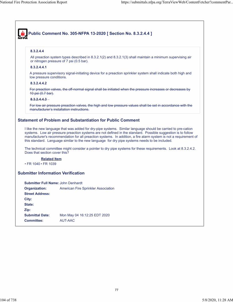
Public Comment No. 305-NFPA 13-2020 [ Section No. 8.3.2.4.4 ]
8.3.2.4.4
All preaction system types described in 8.3.2.1(2) and 8.3.2.1(3) shall maintain a minimum supervising airor nitrogen pressure of 7 psi (0.5 bar).
8.3.2.4.4.1
A pressure supervisory signal-initiating device for a preaction sprinkler system shall indicate both high andlow pressure conditions.
8.3.2.4.4.2
For preaction valves, the off-normal signal shall be initiated when the pressure increases or decreases by10 psi (0.7 bar).
8.3.2.4.4.3
For low air pressure preaction valves, the high and low pressure values shall be set in accordance with themanufacturer’s installation instructions.
Statement of Problem and Substantiation for Public Comment
I like the new language that was added for dry-pipe systems. Similar language should be carried to pre-cation systems. Low air pressure preaction systems are not defined in the standard. Possible suggestion is to follow manufacturer's recommendation for all preaction systems. In addition, a fire alarm system is not a requirement of this standard. Language similar to the new language for dry pipe systems needs to be included.
The technical committee might consider a pointer to dry pipe systems for these requirements. Look at 8.3.2.4.2. Does that section cover this?
Related Item
• FR 1040 • FR 1039
Submitter Information Verification
Submitter Full Name: John Denhardt
Organization: American Fire Sprinkler Association
Street Address:
City:
State:
Zip:
Submittal Date: Mon May 04 16:12:25 EDT 2020
Committee: AUT-AAC
National Fire Protection Association Report https://submittals.nfpa.org/TerraViewWeb/ContentFetcher?commentPar...
104 of 738 5/8/2020, 11:28 AM
77
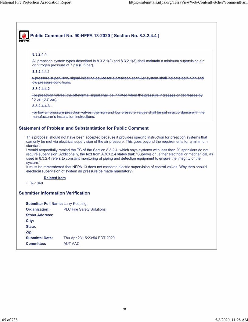
Public Comment No. 90-NFPA 13-2020 [ Section No. 8.3.2.4.4 ]
8.3.2.4.4
All preaction system types described in 8.3.2.1(2) and 8.3.2.1(3) shall maintain a minimum supervising airor nitrogen pressure of 7 psi (0.5 bar).
8.3.2.4.4.1
A pressure supervisory signal-initiating device for a preaction sprinkler system shall indicate both high andlow pressure conditions.
8.3.2.4.4.2
For preaction valves, the off-normal signal shall be initiated when the pressure increases or decreases by10 psi (0.7 bar).
8.3.2.4.4.3
For low air pressure preaction valves, the high and low pressure values shall be set in accordance with themanufacturer’s installation instructions.
Statement of Problem and Substantiation for Public Comment
This proposal should not have been accepted because it provides specific instruction for preaction systems that can only be met via electrical supervision of the air pressure. This goes beyond the requirements for a minimum standard. I would respectfully remind the TC of the Section 8.3.2.4, which says systems with less than 20 sprinklers do not require supervision. Additionally, the text from A.8.3.2.4 states that: “Supervision, either electrical or mechanical, as used in 8.3.2.4 refers to constant monitoring of piping and detection equipment to ensure the integrity of the system.”It must be remembered that NFPA 13 does not mandate electric supervision of control valves. Why then should electrical supervision of system air pressure be made mandatory?
Related Item
• FR-1040
Submitter Information Verification
Submitter Full Name: Larry Keeping
Organization: PLC Fire Safety Solutions
Street Address:
City:
State:
Zip:
Submittal Date: Thu Apr 23 15:23:54 EDT 2020
Committee: AUT-AAC
National Fire Protection Association Report https://submittals.nfpa.org/TerraViewWeb/ContentFetcher?commentPar...
105 of 738 5/8/2020, 11:28 AM
78

Public Comment No. 91-NFPA 13-2020 [ Section No. 8.6.3.7 ]
8.6.3.7
For systems with a capacity larger than 150 gal (570 L), an additional test connection shall be provided aswell as for every additional 150 gal (380 L 570 L ).
Statement of Problem and Substantiation for Public Comment
Editorial.
Related Item
• FR-1222
Submitter Information Verification
Submitter Full Name: Larry Keeping
Organization: PLC Fire Safety Solutions
Street Address:
City:
State:
Zip:
Submittal Date: Thu Apr 23 15:29:00 EDT 2020
Committee: AUT-AAC
National Fire Protection Association Report https://submittals.nfpa.org/TerraViewWeb/ContentFetcher?commentPar...
106 of 738 5/8/2020, 11:28 AM
79

Public Comment No. 175-NFPA 13-2020 [ New Section after 9.2.1.2 ]
TITLE OF NEW CONTENT
Noncombustible spaces with non-fuel-fired equipment and access panels should be considered aconcealed space and should not require sprinkler protection.
Statement of Problem and Substantiation for Public Comment
This public comment seeks to move annex language from A.9.2.1.1.1 to the body of the standard where it will be enforceable. During the first revision a Public Input (PI-493) was submitted to the body of the standard. The committee choose to accept this language but as annex text. The issue is:. Noncombustible spaces with non fuel fired equipment (such an electric appliances) where the only access is a panel for maintenance is still considered a non combustible space and sprinkler protection is not required. Due to the confusion regarding this issue this clarification should be added to the body of the standard.
Related Item
• PI-493 • FR-1351
Submitter Information Verification
Submitter Full Name: Roland Asp
Organization: National Fire Sprinkler Association
Affiliation: on Behalf of NFSA Engineering and Standards Committee
Street Address:
City:
State:
Zip:
Submittal Date: Tue Apr 28 10:16:53 EDT 2020
Committee: AUT-AAC
National Fire Protection Association Report https://submittals.nfpa.org/TerraViewWeb/ContentFetcher?commentPar...
107 of 738 5/8/2020, 11:28 AM
80

Public Comment No. 181-NFPA 13-2020 [ New Section after 9.2.1.10 ]
TITLE OF NEW CONTENT
9.2.1.11*
Soffits of combustible construction containing ductwork below drywall ceilings.
9.2.1.11.1
The depth of the soffit shall not exceed 16 in (405 mm)
9.2.1.11.1
The area of the soffit shall not exceed 55 ft² (5.1 m²)
9.2.1.11.2
The room that the soffit is located in is protected with sprinklers.
A.9.2.1.11
See figures A.9.2.1.11 (a) & (b)
Additional Proposed Changes
File Name Description Approved
A.9.2.1.11_A.1559825815772_2_.pdf Proposed Figure A.9.2.11(A)
A.9.2.1.11_B.1559825826693.pdf Proposed Figure A.9.2.11(b)
Statement of Problem and Substantiation for Public Comment
This comment is reintroducing PI-429 which was resolved at the First Draft Meeting with the following substantiation: "The allowable omissions in this section allow for omission of sprinkler protection". I do not believe this substantiation is correct as I do not see an existing section that would address this particular situation. The described soffit configuration is a common feature and the committee should address. The original substantiation for PI-429 is as follows: "In buildings of wood truss and TJI construction, many times soffits are built below the sheetrock membrane to facilitate the installation of ductwork. These soffits are usually constructed with combustible wood framing members thus creating a combustible concealed space. The room these soffits are located in may exceed 55 FT² so that section will not apply. These soffits are usually full of ductwork and a sprinkler installed in that space will be obstructed. This PI reasonably allows omission of sprinklers in these spaces."
Related Item
• PI-429
Submitter Information Verification
Submitter Full Name: Roland Asp
Organization: National Fire Sprinkler Association
Affiliation: On behalf of NFSA Engineering and Standards Committee
Street Address:
City:
State:
Zip:
Submittal Date: Wed Apr 29 08:01:32 EDT 2020
Committee: AUT-AAC
National Fire Protection Association Report https://submittals.nfpa.org/TerraViewWeb/ContentFetcher?commentPar...
108 of 738 5/8/2020, 11:28 AM
81

82

83

Public Comment No. 92-NFPA 13-2020 [ Section No. 9.2.3.2.1 ]
9.2.3.2.1
Sprinklers shall be required for porte-cocheres that are located below occupiable floor(s) above.
Statement of Problem and Substantiation for Public Comment
I do not have a problem with the concept, I absolutely believe sprinklers should be installed below building projections where there are dwelling units or office areas or classrooms directly above them. And I think this is the intent of the proposed provision. However, I have a problem with the term “below occupiable floors”. What does this mean? By “below”, is it meant to be directly below, or just off to the side of the building that has addition floors above the elevation of that projection? By “occupiable floors”, is it meant to apply to areas like offices, hotel rooms or classrooms, which can have a noteworthy number of “occupants”? Or is it meant to apply to any “occupancy”, even those such as rental storage units, which very rarely have more than a few people at a time in the building?Overall, the verbiage is not precise enough to make the intent clear. Therefore, this text should be deleted.
Related Item
• FR-1094
Submitter Information Verification
Submitter Full Name: Larry Keeping
Organization: PLC Fire Safety Solutions
Street Address:
City:
State:
Zip:
Submittal Date: Thu Apr 23 15:32:32 EDT 2020
Committee: AUT-AAC
National Fire Protection Association Report https://submittals.nfpa.org/TerraViewWeb/ContentFetcher?commentPar...
110 of 738 5/8/2020, 11:28 AM
84
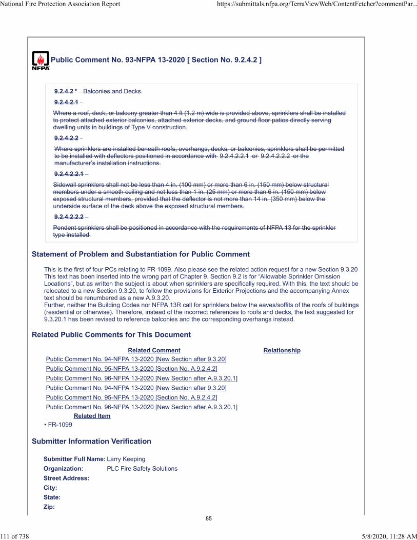
Public Comment No. 93-NFPA 13-2020 [ Section No. 9.2.4.2 ]
9.2.4.2 * Balconies and Decks.
9.2.4.2.1
Where a roof, deck, or balcony greater than 4 ft (1.2 m) wide is provided above, sprinklers shall be installedto protect attached exterior balconies, attached exterior decks, and ground floor patios directly servingdwelling units in buildings of Type V construction.
9.2.4.2.2
Where sprinklers are installed beneath roofs, overhangs, decks, or balconies, sprinklers shall be permittedto be installed with deflectors positioned in accordance with 9.2.4.2.2.1 or 9.2.4.2.2.2 or themanufacturer’s installation instructions.
9.2.4.2.2.1
Sidewall sprinklers shall not be less than 4 in. (100 mm) or more than 6 in. (150 mm) below structuralmembers under a smooth ceiling and not less than 1 in. (25 mm) or more than 6 in. (150 mm) belowexposed structural members, provided that the deflector is not more than 14 in. (350 mm) below theunderside surface of the deck above the exposed structural members.
9.2.4.2.2.2
Pendent sprinklers shall be positioned in accordance with the requirements of NFPA 13 for the sprinklertype installed.
Statement of Problem and Substantiation for Public Comment
This is the first of four PCs relating to FR 1099. Also please see the related action request for a new Section 9.3.20This text has been inserted into the wrong part of Chapter 9. Section 9.2 is for “Allowable Sprinkler Omission Locations”, but as written the subject is about when sprinklers are specifically required. With this, the text should be relocated to a new Section 9.3.20, to follow the provisions for Exterior Projections and the accompanying Annex text should be renumbered as a new A.9.3.20.Further, neither the Building Codes nor NFPA 13R call for sprinklers below the eaves/soffits of the roofs of buildings (residential or otherwise). Therefore, instead of the incorrect references to roofs and decks, the text suggested for 9.3.20.1 has been revised to reference balconies and the corresponding overhangs instead.
Related Public Comments for This Document
Related Comment Relationship
Public Comment No. 94-NFPA 13-2020 [New Section after 9.3.20]
Public Comment No. 95-NFPA 13-2020 [Section No. A.9.2.4.2]
Public Comment No. 96-NFPA 13-2020 [New Section after A.9.3.20.1]
Public Comment No. 94-NFPA 13-2020 [New Section after 9.3.20]
Public Comment No. 95-NFPA 13-2020 [Section No. A.9.2.4.2]
Public Comment No. 96-NFPA 13-2020 [New Section after A.9.3.20.1]
Related Item
• FR-1099
Submitter Information Verification
Submitter Full Name: Larry Keeping
Organization: PLC Fire Safety Solutions
Street Address:
City:
State:
Zip:
National Fire Protection Association Report https://submittals.nfpa.org/TerraViewWeb/ContentFetcher?commentPar...
111 of 738 5/8/2020, 11:28 AM
85

Submittal Date: Thu Apr 23 15:40:45 EDT 2020
Committee: AUT-AAC
National Fire Protection Association Report https://submittals.nfpa.org/TerraViewWeb/ContentFetcher?commentPar...
112 of 738 5/8/2020, 11:28 AM
86

Public Comment No. 176-NFPA 13-2020 [ Section No. 9.2.4.2.1 ]
9.2.4.2.1 *
Where a roof, deck, or balcony greater than 4 ft (1.2 m) wide is provided above, sprinklers shall be installedto protect attached exterior balconies, attached exterior decks, and ground floor patios directly servingdwelling units in buildings of Type V construction.
A.9.2.4.2.1 Type V construction is defined as structural elements entirely or partially wood or othersimilarly combustible material
9.2.4.2.2
Statement of Problem and Substantiation for Public Comment
This public comment seeks to add an annex note to section 9.2.4.2.1 to help define Type V construction for international users of the standard. Type V is a ICC classification. This proposed annex language is the language accepted in NFPA 13R.
Related Item
• FR-1099
Submitter Information Verification
Submitter Full Name: Roland Asp
Organization: National Fire Sprinkler Association
Affiliation: On behalf of NFSA Engineering and Standards Committee
Street Address:
City:
State:
Zip:
Submittal Date: Tue Apr 28 10:27:21 EDT 2020
Committee: AUT-AAC
National Fire Protection Association Report https://submittals.nfpa.org/TerraViewWeb/ContentFetcher?commentPar...
113 of 738 5/8/2020, 11:28 AM
87

Public Comment No. 139-NFPA 13-2020 [ New Section after 9.2.4.2.2.2 ]
9.2.4.3 Dwelling Unit Ventilation Equipment
9.2.4.3.1 Non combustible concealed vertical spaces containing non fuel fired ventilation equipment andassociated ductwork shall not be required to be protected.
9.2.4.3.1 Access panels for equipment maintenance shall be permitted.
Statement of Problem and Substantiation for Public Comment
In the first draft, the committee agreed in First Revision 1351 that these spaces do not require sprinkler protection. (See new annex section A.9.2.1.1.2). There were several PI's submitted in regards to this arrangement. Providing ventilation equipment in the corner of a dwelling unit in a vertical chase with access to maintain the unit with a panel is a common scenario. It is technically not a closet since there is not a door.Many AHJ's have required sprinklers in these spaces mainly because of the ventilation equipment. This language belongs in the body of the standard, not in an annex to small openings in plenums as it now is after the first draft.
Related Item
• FR#1351
Submitter Information Verification
Submitter Full Name: Peter Schwab
Organization: Wayne Automatic Fire Sprinkler
Street Address:
City:
State:
Zip:
Submittal Date: Fri Apr 24 20:10:33 EDT 2020
Committee: AUT-AAC
National Fire Protection Association Report https://submittals.nfpa.org/TerraViewWeb/ContentFetcher?commentPar...
114 of 738 5/8/2020, 11:28 AM
88
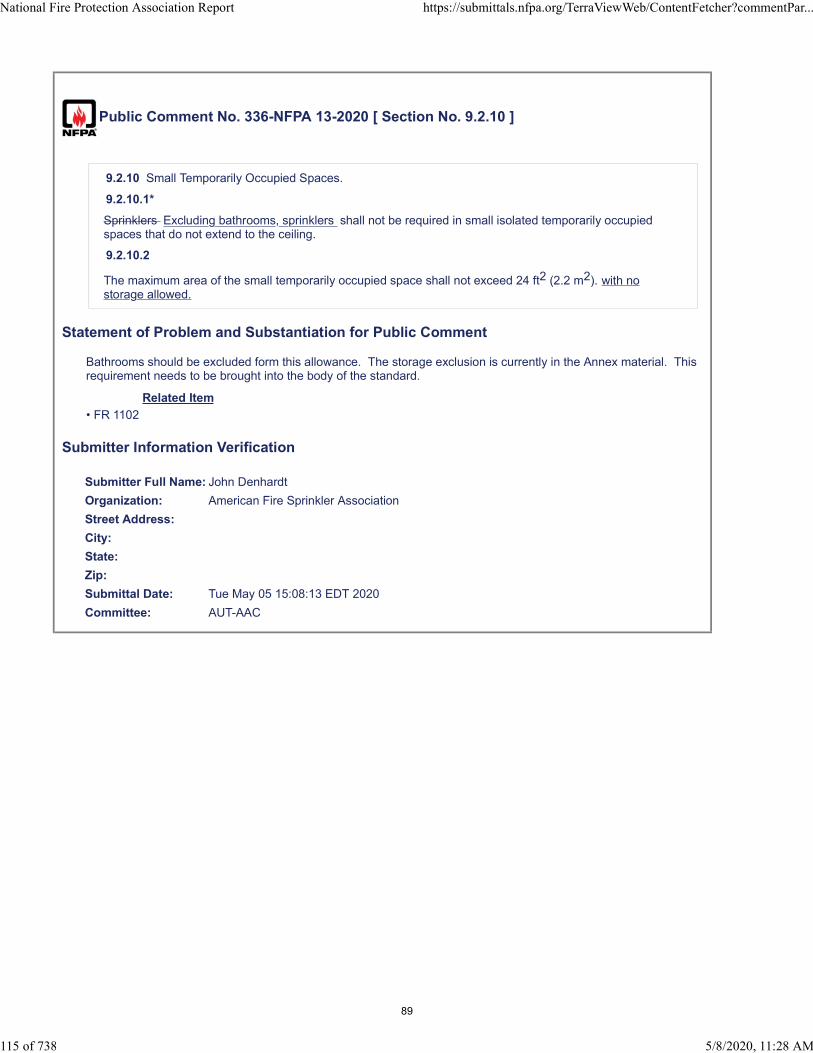
Public Comment No. 336-NFPA 13-2020 [ Section No. 9.2.10 ]
9.2.10 Small Temporarily Occupied Spaces.
9.2.10.1*
Sprinklers Excluding bathrooms, sprinklers shall not be required in small isolated temporarily occupiedspaces that do not extend to the ceiling.
9.2.10.2
The maximum area of the small temporarily occupied space shall not exceed 24 ft2 (2.2 m2). with nostorage allowed.
Statement of Problem and Substantiation for Public Comment
Bathrooms should be excluded form this allowance. The storage exclusion is currently in the Annex material. This requirement needs to be brought into the body of the standard.
Related Item
• FR 1102
Submitter Information Verification
Submitter Full Name: John Denhardt
Organization: American Fire Sprinkler Association
Street Address:
City:
State:
Zip:
Submittal Date: Tue May 05 15:08:13 EDT 2020
Committee: AUT-AAC
National Fire Protection Association Report https://submittals.nfpa.org/TerraViewWeb/ContentFetcher?commentPar...
115 of 738 5/8/2020, 11:28 AM
89
Public Comment No. 355-NFPA 13-2020 [ Section No. 9.2.10 ]
9.2.10 Small Temporarily Occupied Spaces.
9.2.10.1 *
Sprinklers shall not be required in small isolated temporarily occupied spaces that do not extend to theceiling.
9.2.10.2
The maximum area of the small temporarily occupied space shall not exceed 24 ft 2 (2.2 m 2 ).
Statement of Problem and Substantiation for Public Comment
This allowance would permit sprinkler unintended omissions in rooms such as in bathrooms located in warehouses (one example).
Related Item
• PI 265
Submitter Information Verification
Submitter Full Name: Jason Gill
Organization: Crews & Gregory Fire Sprinkler
Affiliation: AFSA
Street Address:
City:
State:
Zip:
Submittal Date: Wed May 06 07:37:47 EDT 2020
Committee: AUT-AAC
National Fire Protection Association Report https://submittals.nfpa.org/TerraViewWeb/ContentFetcher?commentPar...
116 of 738 5/8/2020, 11:28 AM
90
Public Comment No. 59-NFPA 13-2020 [ Section No. 9.2.10.1 ]
9.2.10.1*
Sprinklers shall not be required in small isolated temporarily occupied spaces that enclosures that do notextend to the ceiling where the space above the enclosure is sprinklered in accordance with the rules forextra hazard group 2 occupancies .
Statement of Problem and Substantiation for Public Comment
The justification for FR1102 was based on small booths that are sometimes portable, but always protected with sprinklers above. That concept was not carried through to the language of the standard. While there was a case of inconvenience presented, there was no case presented regarding the lack of fires in these spaces. The reality is that these enclosures are often permanent and even if they are portable, they frequently stay in place for a long time. While in place, there is still a possibility of a fire occurring. If sprinkler protection is not brought down into the enclosure, then the fire will be much bigger when it finally breaks up into the sprinklered space above the enclosure. The EH2 rules were written to handle this kind of increased fire many editions ago, which is why the definition of EH2 includes "spaces where shielding of combustibles is extensive."
I believe that sprinkler protection should be brought down into these enclosures. They can be used for storage. They can have fires start in them. They frequently have electrical equipment built in that can serve as an ignition source. If the committee agrees that sprinklers can be omitted, then the sprinklers in the space above should be required and should be beefed up to be able to handle the larger fire when the sprinklers finally activate.
Related Item
• FR1102
Submitter Information Verification
Submitter Full Name: Kenneth Isman
Organization: University of Maryland
Street Address:
City:
State:
Zip:
Submittal Date: Tue Apr 21 22:27:54 EDT 2020
Committee: AUT-AAC
National Fire Protection Association Report https://submittals.nfpa.org/TerraViewWeb/ContentFetcher?commentPar...
117 of 738 5/8/2020, 11:28 AM
91

Public Comment No. 225-NFPA 13-2020 [ Section No. 9.2.12 ]
9.2.12 Noncombustible Vertical Shafts.
Sprinklers shall not be required at the top of noncombustible or limited-combustible, nonaccessible verticalduct, electric, and mechanical shafts as permitted by 9.3.6.2 4 and 9.3.3.1.2.
Statement of Problem and Substantiation for Public Comment
Correct the reference.
Related Item
• FR 1104
Submitter Information Verification
Submitter Full Name: Tracey Bellamy
Organization: Telgian Corporation
Street Address:
City:
State:
Zip:
Submittal Date: Sun May 03 14:35:49 EDT 2020
Committee: AUT-AAC
National Fire Protection Association Report https://submittals.nfpa.org/TerraViewWeb/ContentFetcher?commentPar...
118 of 738 5/8/2020, 11:28 AM
92
Public Comment No. 226-NFPA 13-2020 [ Section No. 9.2.14 ]
9.2.14 Elevator Hoistways and Machine Rooms.
Sprinklers shall not be required in locations complying with 9.3.6.1, 9.3.6.3 , 9.3.6. 4, or 9.3.6.5.2.
Statement of Problem and Substantiation for Public Comment
Remove incorrect reference.
Related Item
• FR 1104
Submitter Information Verification
Submitter Full Name: Tracey Bellamy
Organization: Telgian Corporation
Street Address:
City:
State:
Zip:
Submittal Date: Sun May 03 14:37:35 EDT 2020
Committee: AUT-AAC
National Fire Protection Association Report https://submittals.nfpa.org/TerraViewWeb/ContentFetcher?commentPar...
119 of 738 5/8/2020, 11:28 AM
93

Public Comment No. 182-NFPA 13-2020 [ Section No. 9.3.2 ]
9.3.
2 Special Sprinklers for Horizontal Combustible Concealed Spaces.
9.3.2.1
2
Unless the requirements
of 9
of 9 .2.1.
18 are
18 are met, sprinklers used in horizontal combustible concealed spaces (with a slope not exceeding 2 in12) with combustible wood truss
construction
, wood joist construction,
composite wood joist construction,
9.3.2.3
Where permitted in accordance with the sprinkler listing, the
or bar joist construction having a combustible upper surface and where the depth of the space is less than36 in. (900 mm) from deck to deck, from deck to ceiling, or with double wood joist construction with amaximum of 36 in. (900 mm) between the top of the bottom joist and the bottom of the upper joist shall belisted for such use.
9.3.2.
2
When such sprinklers are used, construction shall include all draft curtains, blocking, and insulationrequired as part of the listing of the sprinkler.
1
Sprinklers specifically listed to provide protection of combustible concealed spaces described in 9.3.2 shallbe permitted to be used in accordance with 9.4.1.2 where the space is less than 12 in. (300 mm) fromdeck to deck or deck to ceiling
dimension in
.
9. 3. 2. 2
Sprinklers specifically listed to provide protection of combustible concealed spaces described in 9. 3.
1 shall
2 shall be permitted to
exceed 36
be used in accordance with 9 .
(900 mm).
4.1.2 throughout the area when a portion of the area exceeds a depth of 36 in. (900 mm).
9.3.2.3
Sprinklers specifically listed to provide protection of combustible concealed spaces described in 9.3.2 shallbe permitted to be used in accordance with 9.4.1.2 to protect composite wood joist construction.
Statement of Problem and Substantiation for Public Comment
National Fire Protection Association Report https://submittals.nfpa.org/TerraViewWeb/ContentFetcher?commentPar...
120 of 738 5/8/2020, 11:28 AM
94

This comment seeks to revert back to existing language from 2019 edition. This FR revision was reviewed by the UL/FM/NFSA committee and NFSA E&S committee and the recommendation is to revert to existing language. The addition of combustible wood joist construction would require additional testing to add exposed composite wood joists to listing standards. It is unclear as to the intent and/or consequences of this proposed revision.
Related Item
• FR-1355
Submitter Information Verification
Submitter Full Name: Roland Asp
Organization: National Fire Sprinkler Association
Affiliation: on Behalf of NFSA Engineering and Standards Committee
Street Address:
City:
State:
Zip:
Submittal Date: Wed Apr 29 08:25:37 EDT 2020
Committee: AUT-AAC
National Fire Protection Association Report https://submittals.nfpa.org/TerraViewWeb/ContentFetcher?commentPar...
121 of 738 5/8/2020, 11:28 AM
95
Public Comment No. 227-NFPA 13-2020 [ Section No. 9.3.2.3 ]
9.3.2.3
Where permitted in accordance with the sprinkler listing, the deck to deck or deck to ceiling dimension in9.2 3 .3.1 shall be permitted to exceed 36 in. (900 mm).
Statement of Problem and Substantiation for Public Comment
Correct reference.
Related Item
• FR 1355
Submitter Information Verification
Submitter Full Name: Tracey Bellamy
Organization: Telgian Corporation
Street Address:
City:
State:
Zip:
Submittal Date: Sun May 03 14:40:07 EDT 2020
Committee: AUT-AAC
National Fire Protection Association Report https://submittals.nfpa.org/TerraViewWeb/ContentFetcher?commentPar...
122 of 738 5/8/2020, 11:28 AM
96
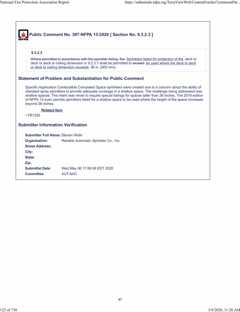
Public Comment No. 397-NFPA 13-2020 [ Section No. 9.3.2.3 ]
9.3.2.3
Where permitted in accordance with the sprinkler listing, the Sprinklers listed for protection of the deck todeck or deck to ceiling dimension in 9.2.3.1 shall be permitted to exceed be used where the deck to deckor deck to ceiling dimension exceeds 36 in. (900 mm).
Statement of Problem and Substantiation for Public Comment
Specific Application Combustible Concealed Space sprinklers were created due to a concern about the ability of standard spray sprinklers to provide adequate coverage in a shallow space. The challenge being addressed was shallow spaces. The intent was never to require special listings for spaces taller than 36 inches. The 2019 edition of NFPA 13 even permits sprinklers listed for a shallow space to be used where the height of the space increases beyond 36 inches.
Related Item
• FR1355
Submitter Information Verification
Submitter Full Name: Steven Wolin
Organization: Reliable Automatic Sprinkler Co., Inc.
Street Address:
City:
State:
Zip:
Submittal Date: Wed May 06 17:06:08 EDT 2020
Committee: AUT-AAC
National Fire Protection Association Report https://submittals.nfpa.org/TerraViewWeb/ContentFetcher?commentPar...
123 of 738 5/8/2020, 11:28 AM
97
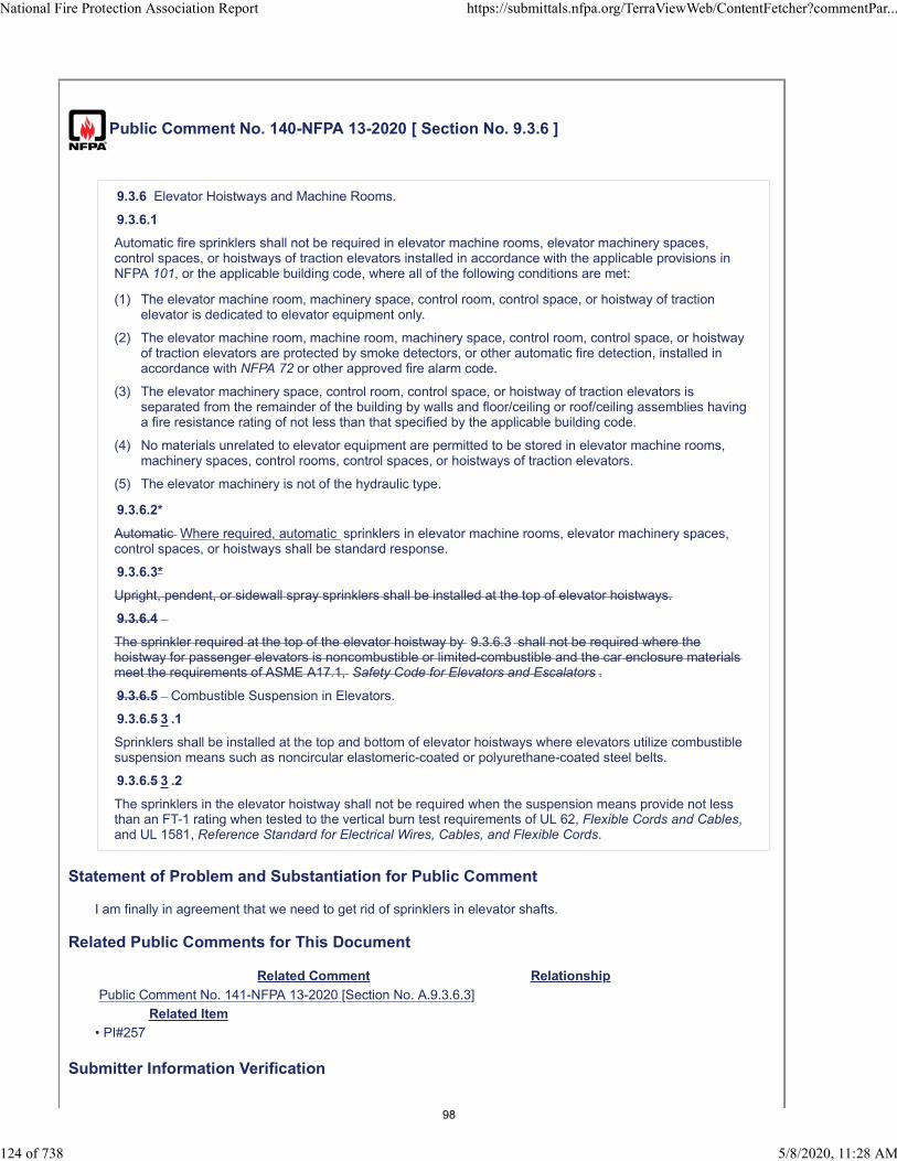
Public Comment No. 140-NFPA 13-2020 [ Section No. 9.3.6 ]
9.3.6 Elevator Hoistways and Machine Rooms.
9.3.6.1
Automatic fire sprinklers shall not be required in elevator machine rooms, elevator machinery spaces,control spaces, or hoistways of traction elevators installed in accordance with the applicable provisions inNFPA 101, or the applicable building code, where all of the following conditions are met:
(1) The elevator machine room, machinery space, control room, control space, or hoistway of tractionelevator is dedicated to elevator equipment only.
(2) The elevator machine room, machine room, machinery space, control room, control space, or hoistwayof traction elevators are protected by smoke detectors, or other automatic fire detection, installed inaccordance with NFPA 72 or other approved fire alarm code.
(3) The elevator machinery space, control room, control space, or hoistway of traction elevators isseparated from the remainder of the building by walls and floor/ceiling or roof/ceiling assemblies havinga fire resistance rating of not less than that specified by the applicable building code.
(4) No materials unrelated to elevator equipment are permitted to be stored in elevator machine rooms,machinery spaces, control rooms, control spaces, or hoistways of traction elevators.
(5) The elevator machinery is not of the hydraulic type.
9.3.6.2*
Automatic Where required, automatic sprinklers in elevator machine rooms, elevator machinery spaces,control spaces, or hoistways shall be standard response.
9.3.6.3*
Upright, pendent, or sidewall spray sprinklers shall be installed at the top of elevator hoistways.
9.3.6.4
The sprinkler required at the top of the elevator hoistway by 9.3.6.3 shall not be required where thehoistway for passenger elevators is noncombustible or limited-combustible and the car enclosure materialsmeet the requirements of ASME A17.1, Safety Code for Elevators and Escalators .
9.3.6.5 Combustible Suspension in Elevators.
9.3.6.5 3 .1
Sprinklers shall be installed at the top and bottom of elevator hoistways where elevators utilize combustiblesuspension means such as noncircular elastomeric-coated or polyurethane-coated steel belts.
9.3.6.5 3 .2
The sprinklers in the elevator hoistway shall not be required when the suspension means provide not lessthan an FT-1 rating when tested to the vertical burn test requirements of UL 62, Flexible Cords and Cables,and UL 1581, Reference Standard for Electrical Wires, Cables, and Flexible Cords.
Statement of Problem and Substantiation for Public Comment
I am finally in agreement that we need to get rid of sprinklers in elevator shafts.
Related Public Comments for This Document
Related Comment Relationship
Public Comment No. 141-NFPA 13-2020 [Section No. A.9.3.6.3]
Related Item
• PI#257
Submitter Information Verification
National Fire Protection Association Report https://submittals.nfpa.org/TerraViewWeb/ContentFetcher?commentPar...
124 of 738 5/8/2020, 11:28 AM
98

Submitter Full Name: Peter Schwab
Organization: Wayne Automatic Fire Sprinkler
Street Address:
City:
State:
Zip:
Submittal Date: Fri Apr 24 21:09:51 EDT 2020
Committee: AUT-AAC
National Fire Protection Association Report https://submittals.nfpa.org/TerraViewWeb/ContentFetcher?commentPar...
125 of 738 5/8/2020, 11:28 AM
99
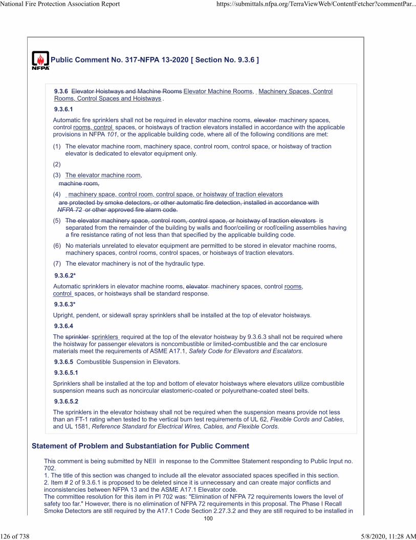
Public Comment No. 317-NFPA 13-2020 [ Section No. 9.3.6 ]
9.3.6 Elevator Hoistways and Machine Rooms Elevator Machine Rooms, Machinery Spaces, ControlRooms, Control Spaces and Hoistways .
9.3.6.1
Automatic fire sprinklers shall not be required in elevator machine rooms, elevator machinery spaces,control rooms, control spaces, or hoistways of traction elevators installed in accordance with the applicableprovisions in NFPA 101, or the applicable building code, where all of the following conditions are met:
(1) The elevator machine room, machinery space, control room, control space, or hoistway of tractionelevator is dedicated to elevator equipment only.
(2)
(3) The elevator machine room,machine room,
(4) machinery space, control room, control space, or hoistway of traction elevatorsare protected by smoke detectors, or other automatic fire detection, installed in accordance withNFPA 72 or other approved fire alarm code.
(5) The elevator machinery space, control room, control space, or hoistway of traction elevators isseparated from the remainder of the building by walls and floor/ceiling or roof/ceiling assemblies havinga fire resistance rating of not less than that specified by the applicable building code.
(6) No materials unrelated to elevator equipment are permitted to be stored in elevator machine rooms,machinery spaces, control rooms, control spaces, or hoistways of traction elevators.
(7) The elevator machinery is not of the hydraulic type.
9.3.6.2*
Automatic sprinklers in elevator machine rooms, elevator machinery spaces, control rooms,control spaces, or hoistways shall be standard response.
9.3.6.3*
Upright, pendent, or sidewall spray sprinklers shall be installed at the top of elevator hoistways.
9.3.6.4
The sprinkler sprinklers required at the top of the elevator hoistway by 9.3.6.3 shall not be required wherethe hoistway for passenger elevators is noncombustible or limited-combustible and the car enclosurematerials meet the requirements of ASME A17.1, Safety Code for Elevators and Escalators.
9.3.6.5 Combustible Suspension in Elevators.
9.3.6.5.1
Sprinklers shall be installed at the top and bottom of elevator hoistways where elevators utilize combustiblesuspension means such as noncircular elastomeric-coated or polyurethane-coated steel belts.
9.3.6.5.2
The sprinklers in the elevator hoistway shall not be required when the suspension means provide not lessthan an FT-1 rating when tested to the vertical burn test requirements of UL 62, Flexible Cords and Cables,and UL 1581, Reference Standard for Electrical Wires, Cables, and Flexible Cords.
Statement of Problem and Substantiation for Public Comment
This comment is being submitted by NEII in response to the Committee Statement responding to Public Input no. 702.1. The title of this section was changed to include all the elevator associated spaces specified in this section. 2. Item # 2 of 9.3.6.1 is proposed to be deleted since it is unnecessary and can create major conflicts and inconsistencies between NFPA 13 and the ASME A17.1 Elevator code. The committee resolution for this item in PI 702 was: "Elimination of NFPA 72 requirements lowers the level of safety too far." However, there is no elimination of NFPA 72 requirements in this proposal. The Phase I Recall Smoke Detectors are still required by the A17.1 Code Section 2.27.3.2 and they are still required to be installed in
National Fire Protection Association Report https://submittals.nfpa.org/TerraViewWeb/ContentFetcher?commentPar...
126 of 738 5/8/2020, 11:28 AM
100

accordance with NFPA 72. Accepting this public comment will just resolve the conflict between the two codes and will not eliminate any code requirement for elevator hoistway smoke detection. It should not be the jurisdiction of NFPA 13 to mandate smoke detectors in elevator associated spaces, as this is the scope of the A17.1 Code. The main problem and conflict is that per NFPA 13 Section 9.3.6.4 passenger elevators do not require sprinklers at the top of their hoistways and therefore, associated smoke detectors are not required for those elevators per the A17.1 Code (since the hoistway and car are non-combustible per the A17.1 requirements ). However, per this current NFPA Section 9.3.6.1 item # 2 it seems that a smoke detector will be required at the top of those hoistways, if sprinklers are not installed there per Section 9.3.6.4. This creates a major code conflict and enforcement problems for AHJs. The intent of the current NFPA 13 Section 9.3.6.4, which has the same code language as in many previous NFPA 13 editions, was to NOT require sprinklers at the tops of passenger elevators hoistways (meeting the A17.1 non-combustibility requirements). This NFPA 13 section never required the addition of top-of-hoistway smoke detection in lieu of this non-required sprinkler. And this is where the conflict lies: the current section 9.3.6.1 item # 2 seems like it requires a smoke detector to be installed at the top of passenger elevator hoistways when sprinklers are not required to be installed in the hoistway. The smoke detectors are still required to be provided at the top of all Machine-Room-Less (MRL) Passenger Elevators per the A17.1 Code and installed per NFPA 72. But there are still many passenger elevators with Machine Rooms (Standard overhead traction elevator and Hydraulic elevators) that currently do not require associated smoke detection at the top of their hoistways and this is the main issue that this proposal is trying to resolve by not mandating smoke detectors at the top of unsprinklered hoistways of standard overhead traction and hydraulic passenger elevators.
Related Item
• PI 702
Submitter Information Verification
Submitter Full Name: David McColl
Organization: Otis Elevator Company
Affiliation: National Elevator Industry Inc. (NEII)
Street Address:
City:
State:
Zip:
Submittal Date: Mon May 04 19:10:06 EDT 2020
Committee: AUT-AAC
National Fire Protection Association Report https://submittals.nfpa.org/TerraViewWeb/ContentFetcher?commentPar...
127 of 738 5/8/2020, 11:28 AM
101
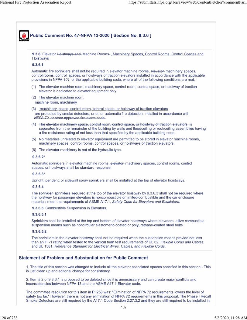
Public Comment No. 47-NFPA 13-2020 [ Section No. 9.3.6 ]
9.3.6 Elevator Hoistways and Machine Rooms. , Machinery Spaces, Control Rooms, Control Spaces andHoistways
9.3.6.1
Automatic fire sprinklers shall not be required in elevator machine rooms, elevator machinery spaces,control rooms, control spaces, or hoistways of traction elevators installed in accordance with the applicableprovisions in NFPA 101, or the applicable building code, where all of the following conditions are met:
(1) The elevator machine room, machinery space, control room, control space, or hoistway of tractionelevator is dedicated to elevator equipment only.
(2) The elevator machine room,machine room, machinery
(3) machinery space, control room, control space, or hoistway of traction elevatorsare protected by smoke detectors, or other automatic fire detection, installed in accordance withNFPA 72 or other approved fire alarm code.
(4) The elevator machinery space, control room, control space, or hoistway of traction elevators isseparated from the remainder of the building by walls and floor/ceiling or roof/ceiling assemblies havinga fire resistance rating of not less than that specified by the applicable building code.
(5) No materials unrelated to elevator equipment are permitted to be stored in elevator machine rooms,machinery spaces, control rooms, control spaces, or hoistways of traction elevators.
(6) The elevator machinery is not of the hydraulic type.
9.3.6.2*
Automatic sprinklers in elevator machine rooms, elevator machinery spaces, control rooms, controlspaces, or hoistways shall be standard response.
9.3.6.3*
Upright, pendent, or sidewall spray sprinklers shall be installed at the top of elevator hoistways.
9.3.6.4
The sprinkler sprinklers required at the top of the elevator hoistway by 9.3.6.3 shall not be required wherethe hoistway for passenger elevators is noncombustible or limited-combustible and the car enclosurematerials meet the requirements of ASME A17.1, Safety Code for Elevators and Escalators.
9.3.6.5 Combustible Suspension in Elevators.
9.3.6.5.1
Sprinklers shall be installed at the top and bottom of elevator hoistways where elevators utilize combustiblesuspension means such as noncircular elastomeric-coated or polyurethane-coated steel belts.
9.3.6.5.2
The sprinklers in the elevator hoistway shall not be required when the suspension means provide not lessthan an FT-1 rating when tested to the vertical burn test requirements of UL 62, Flexible Cords and Cables,and UL 1581, Reference Standard for Electrical Wires, Cables, and Flexible Cords.
Statement of Problem and Substantiation for Public Comment
1. The title of this section was changed to include all the elevator associated spaces specified in this section - This is just clean up and editorial change for consistency.
2. Item # 2 of 9.3.6.1 is proposed to be deleted since it is unnecessary and can create major conflicts and inconsistencies between NFPA 13 and the ASME A17.1 Elevator code.
The committee resolution for this item in PI 258 was: "Elimination of NFPA 72 requirements lowers the level of safety too far." However, there is not any elimination of NFPA 72 requirements in this proposal. The Phase I Recall Smoke Detectors are still required by the A17.1 Code Section 2.27.3.2 and they are still required to be installed in
National Fire Protection Association Report https://submittals.nfpa.org/TerraViewWeb/ContentFetcher?commentPar...
128 of 738 5/8/2020, 11:28 AM
102

accordance with NFPA 72. Accepting this public comment will just resolve the conflict between the two codes and will not eliminate any code requirement for elevator hoistways smoke detection.
This is the code section from ASME A17.1-2016 which requires Phase I Recall smoke detectors in elevator spaces:
2.27.3.2 Phase I Emergency Recall Operation by FireAlarm Initiating Devices2.27.3.2.1 In jurisdictions not enforcing theNBCC, smoke detectors or other automatic fire detectorsin environments not suitable for smoke detectors (firealarm initiating devices) used to initiate Phase IEmergency Recall Operation shall be installed in conformancewith the requirements of NFPA 72, and shall belocated(a) at each elevator lobby served by the elevator(b) in the associated elevator machine room, machineryspace containing a motor controller or drivingmachine, control space, or control room(c) in the elevator hoistway, when sprinklers arelocated in those hoistwaysNOTE [2.27.3.2.1(b)]: A machinery space containing a motor controlleror driving machine located in the elevator hoistway, or acontrol space located in the elevator hoistway requires a fire alarminitiating device regardless of the presence of sprinklers.
The intent of this proposal by eliminating item # 2 from 9.3.6.1 is to resolve the conflict between NFPA 13 and the A17.1 Code. It should not be the jurisdiction of NFPA 13 to mandate smoke detectors in elevator associated spaces, this is only the jurisdiction of the A17.1 Code.
The main problem and conflict is that per NFPA 13 Section 9.3.6.4 passenger elevators do not require sprinklers at the top of their hoistways and therefore, associated smoke detectors are not required for those elevators per the A17.1 Code (since the hoistway and car are non-combustible per the A17.1 requirements ). However, per this current NFPA Section 9.3.6.1 item # 2 it seems that a smoke detector will be required at the top of those hoistways, if sprinklers are not installed there per Section 9.3.6.4. This creates a major code conflict and enforcement problems for AHJs.
The intent of the current NFPA 13 Section 9.3.6.4 which has the same code language as in many previous NFPA 13 editions was to NOT require sprinklers at the tops of passenger elevators hoistways (meeting the A17.1 non-combustibility requirements). This NFPA 13 section never required the addition of top-of-hoistway smoke detection in lieu of this non-required sprinkler. And this is where the conflict lies: the current section 9.3.6.1 item # 2 seems like it requires a smoke detector to be installed at the top of passenger elevator hoistways when sprinklers are not required to be installed at the hoistway.
The smoke detectors are still required to be provided at the tops of all Machine-Room-Less (MRL) Passenger Elevators per the A17.1 Code and installed per NFPA 72. But there are still many passenger elevators with Machine Rooms (Standard overhead traction elevator and Hydraulic elevators) that currently do not require associated smoke detection at their top of hoistways and this is the main issue that this proposal trying to resolve: Not to mandate smoke detectors at the top of unsprinklered hoistways of standard overhead traction and hydraulic passenger elevators.
Note to the Committee members as additional information for reference only:
This proposal was supported by NEII (National Elevator Industry) and was also supported by the CA state Fire Marshal Elevator Task Group and it was removed from the next edition of the CA Building Code as an amendment to NFPA 13.
I also serve as an AHJ contributing member on the A17.1 Emergency Operation Technical Committee and the Hoistway Technical Committee and would be happy to answer any question and provide any additional information for the NFPA 13 committee if required.
Related Item
National Fire Protection Association Report https://submittals.nfpa.org/TerraViewWeb/ContentFetcher?commentPar...
129 of 738 5/8/2020, 11:28 AM
103

• PI 258
Submitter Information Verification
Submitter Full Name: Sagiv Weiss-Ishai
Organization: San Francisco Fire Department
Affiliation: SFFD
Street Address:
City:
State:
Zip:
Submittal Date: Sat Apr 11 18:08:16 EDT 2020
Committee: AUT-AAC
National Fire Protection Association Report https://submittals.nfpa.org/TerraViewWeb/ContentFetcher?commentPar...
130 of 738 5/8/2020, 11:28 AM
104
Public Comment No. 187-NFPA 13-2020 [ Section No. 9.3.6.1 ]
9.3.6.1 *
Sidewall spray sprinklers shall be installed at the bottom of each elevator hoistway not more than 2 ft(600 mm) above the floor of the pit.
A.9.3.6.1
The sprinklers in the pit are intended to protect against fires caused by debris, which can accumulate overtime. Ideally, the sprinklers should be located near the side of the pit below the elevator doors, where mostdebris accumulates. However, care should be taken that the sprinkler location does not interfere with theelevator toe guard, which extends below the face of the door opening.
9.3.6.2
The sprinkler required at the bottom of the elevator hoistway by 9.3.6.1 shall not be required for enclosed,noncombustible elevator shafts that do not contain combustible hydraulic fluids.
9.3.6.3
Automatic fire sprinklers shall not be required in elevator machine rooms, elevator machinery spaces,control spaces, or hoistways of traction elevators installed in accordance with the applicable provisions inNFPA 101, or the applicable building code, where all of the following conditions are met:
(1) The elevator machine room, machinery space, control room, control space, or hoistway of tractionelevator is dedicated to elevator equipment only.
(2) The elevator machine room, machine room, machinery space, control room, control space, or hoistwayof traction elevators are protected by smoke detectors, or other automatic fire detection, installed inaccordance with NFPA 72 or other approved fire alarm code.
(3) The elevator machinery space, control room, control space, or hoistway of traction elevators isseparated from the remainder of the building by walls and floor/ceiling or roof/ceiling assemblies havinga fire resistance rating of not less than that specified by the applicable building code.
(4) No materials unrelated to elevator equipment are permitted to be stored in elevator machine rooms,machinery spaces, control rooms, control spaces, or hoistways of traction elevators.
(5) The elevator machinery is not of the hydraulic type.
Statement of Problem and Substantiation for Public Comment
The intent of this comment is to revert to existing language (2019 edition). This issue was discussed in detail last cycle with the result that sprinkler protection remained in the standard for elevator shafts and pits. This decision was the correct one and prudent sprinkler protection for elevator pits should remain in NFPA 13. As was the case last cycle, the submitter did not provide technical documentation to indicate that the fire risk in elevator pits is negligible or that this sprinkler protection in elevator pits is not warranted or needed. Instead the submitter again proposed to remove sprinkler protection in these shafts due to maintenance difficulties. While I am sensitive to the dangers to elevator maintenance workers, the purpose of NFPA 13 is minimize the danger from fire events. It should also be noted that NFPA 13 is an international document and the safety and housekeeping protocols limiting fires in elevators common in the United States may not be universally adopted or enforced. When the decision to retain the sprinkler protection was appealed to the NFPA Standards Council, the council rejected the appeal and suggested that a research proposal be submitted to the Fire Protection Research Foundation to gather more information on this subject (See Standards Council Decision D#18-7 dated August 14, 2018). Such a research project would provide the information needed for the committee to make an informed decision on this issue. To the best of my knowledge, this project was not initiated.It should be noted that the Committee Statement for FR-112) was simply copied from the submitter's Public Input (PI-412) and is misleading. The statement says it was requested that the proponent "provide examples for elevators associated injuries and fatalities". However last cycle the committee asked for data regarding fire safety in elevator shafts and for technical justification that the omission of sprinklers as required by NFPA 13 would not lead to a dangerous situation in regards to fire safety. This data has not been provided..
Related Public Comments for This Document
Related Comment Relationship
National Fire Protection Association Report https://submittals.nfpa.org/TerraViewWeb/ContentFetcher?commentPar...
131 of 738 5/8/2020, 11:28 AM
105
Public Comment No. 190-NFPA 13-2020 [Section No. 9.3.6.2]
Related Item
• FR-1112 • FR-1113
Submitter Information Verification
Submitter Full Name: Roland Asp
Organization: National Fire Sprinkler Association
Affiliation: On behalf of NFSA Engineering and Standards Committee
Street Address:
City:
State:
Zip:
Submittal Date: Wed Apr 29 09:00:20 EDT 2020
Committee: AUT-AAC
National Fire Protection Association Report https://submittals.nfpa.org/TerraViewWeb/ContentFetcher?commentPar...
132 of 738 5/8/2020, 11:28 AM
106

Public Comment No. 190-NFPA 13-2020 [ Section No. 9.3.6.2 ]
9.3.6.2*
Automatic sprinklers in elevator machine rooms, or at the tops of elevator machinery spaces, controlspaces, or hoistways shall be standard response of ordinary- or intermediate-temperature rating .
Statement of Problem and Substantiation for Public Comment
This comment is to return to existing language from the 2019 edition. FR-1114 removed the language "at the tops" of elevators. Where sprinklers are installed at the tops of shafts, this section is needed. Additionally, there was no technical justification submitted to eliminate the use of quick response sprinklers. Has there been issues with using quick response sprinklers in this application?
Related Public Comments for This Document
Related Comment Relationship
Public Comment No. 187-NFPA 13-2020 [Section No. 9.3.6.1] related issue
Related Item
• FR-1114
Submitter Information Verification
Submitter Full Name: Roland Asp
Organization: National Fire Sprinkler Association
Affiliation: On behalf of NFSA Engineering and Standards Committee
Street Address:
City:
State:
Zip:
Submittal Date: Wed Apr 29 09:20:37 EDT 2020
Committee: AUT-AAC
National Fire Protection Association Report https://submittals.nfpa.org/TerraViewWeb/ContentFetcher?commentPar...
133 of 738 5/8/2020, 11:28 AM
107

Public Comment No. 229-NFPA 13-2020 [ Sections 9.3.6.3, 9.3.6.4 ]
Sections 9.3.6.3, 9.3.6.4
9.3.6.3*
Upright, pendent, or sidewall spray sprinklers shall be installed at the top of elevator hoistways.
9.3.6.4 *
The sprinkler required at the top of the elevator hoistway by 9.3.6.3 shall not be required where thehoistway for passenger elevators is noncombustible or limited-combustible and the car enclosure materialsmeet the requirements of ASME A17.1, Safety Code for Elevators and Escalators.
Statement of Problem and Substantiation for Public Comment
Relocate Annex * as part of move of Annex material.
Related Item
• Global FCR 41
Submitter Information Verification
Submitter Full Name: Tracey Bellamy
Organization: Telgian Corporation
Street Address:
City:
State:
Zip:
Submittal Date: Sun May 03 14:44:20 EDT 2020
Committee: AUT-AAC
National Fire Protection Association Report https://submittals.nfpa.org/TerraViewWeb/ContentFetcher?commentPar...
134 of 738 5/8/2020, 11:28 AM
108

Public Comment No. 36-NFPA 13-2020 [ Section No. 9.3.6.5.2 ]
9.3.6.
5.2 7 Combus ble Suspension in Elevators
9.3.6.7.1 Sprinklers shall be installed at the top and bo om of elevator hoistways where elevators u lizecombus ble suspension means such as noncircular elastomeric-coated or polyurethane-coated steel belts.
9.3.6.7.2 The sprinklers in the elevator hoistway shall not be required when the suspension means provide not lessthan an FT-1 ra ng when tested to the ver cal burn test requirements of
UL 62,
UL2556 Wire and Cable Test Methods, where the suspension means shall not con nue to burn for more than 60seconds, nor shall the indicator flag be burned more than 25%. UL 62, Flexible Cords and Cables , and UL 1581,Reference Standard for Electrical Wires, Cables, and Flexible Cords
Ra onale: The current requirements make reference to the FT1 ra ng when tested to ver cal burn testrequirements of UL 62 and UL 1581 standards . Since UL62 and UL1581 standards are more applicable to FlexibleElectrical Wire & Cables and there are no design criteria for noncircular elastomeric-coated or polyurethane-coatedsteel belts addressed by ASME A17.1, a reference to UL 2556 along with the pass criteria is more appropriate for theFT1 ra ng for suspension means.
Statement of Problem and Substantiation for Public Comment
The current requirements make reference to the FT1 rating when tested to vertical burn test requirements of UL 62 and UL 1581 standards. Since UL62 and UL1581 standards are more applicable to Flexible Electrical Wire & Cables and there are no design criteria for noncircular elastomeric-coated or polyurethane-coated steel belts addressed by ASME A17.1, a reference to UL 2556 is more appropriate for the FT1 rating.
RelatedItem
• 9.3.6.5.3 The suspension means shall not continue to burn for more than 60 seconds nor shall theindicator flog more than 25 percent.
Submitter Information Verification
Submitter Full Name: Lawrence Taylor
Organization: Schindler Elevator Corporation
Affiliation: Schindler Elevator Corporation and NEII
Street Address:
City:
State:
Zip:
Submittal Date: Mon Mar 30 14:48:07 EDT 2020
Committee: AUT-AAC
National Fire Protection Association Report https://submittals.nfpa.org/TerraViewWeb/ContentFetcher?commentPar...
135 of 738 5/8/2020, 11:28 AM
109

Public Comment No. 230-NFPA 13-2020 [ Section No. 9.3.9 [Excluding any Sub-
Sections] ]
Duct protection shall be required to meet the requirements of 9.3.8 9 where required by the authorityhaving jurisdiction or the applicable referenced code or standard.
Statement of Problem and Substantiation for Public Comment
Correct reference.
Related Item
• Editorial Correction of Reference
Submitter Information Verification
Submitter Full Name: Tracey Bellamy
Organization: Telgian Corporation
Street Address:
City:
State:
Zip:
Submittal Date: Sun May 03 14:46:15 EDT 2020
Committee: AUT-AAC
National Fire Protection Association Report https://submittals.nfpa.org/TerraViewWeb/ContentFetcher?commentPar...
136 of 738 5/8/2020, 11:28 AM
110

Public Comment No. 142-NFPA 13-2020 [ Section No. 9.3.16.3 ]
9.3.16.3
Skylights that allow venting, other than smoke and heat venting per 20.6.5 ?????? , shall be provided withsprinkler protection installed in the skylight.
Statement of Problem and Substantiation for Public Comment
The reference to section 20.6.5 does not seem to be correct.
Related Item
• FR#1116
Submitter Information Verification
Submitter Full Name: Peter Schwab
Organization: Wayne Automatic Fire Sprinkler
Street Address:
City:
State:
Zip:
Submittal Date: Fri Apr 24 21:26:03 EDT 2020
Committee: AUT-AAC
National Fire Protection Association Report https://submittals.nfpa.org/TerraViewWeb/ContentFetcher?commentPar...
137 of 738 5/8/2020, 11:28 AM
111

Public Comment No. 231-NFPA 13-2020 [ Section No. 9.3.16.3 ]
9.3.16.3
Skylights that allow venting, other than smoke and heat venting per 20.6 9 .5, shall be provided withsprinkler protection installed in the skylight.
Statement of Problem and Substantiation for Public Comment
Correction of reference.
Related Item
• FR 1354
Submitter Information Verification
Submitter Full Name: Tracey Bellamy
Organization: Telgian Corporation
Street Address:
City:
State:
Zip:
Submittal Date: Sun May 03 14:47:55 EDT 2020
Committee: AUT-AAC
National Fire Protection Association Report https://submittals.nfpa.org/TerraViewWeb/ContentFetcher?commentPar...
138 of 738 5/8/2020, 11:28 AM
112

Public Comment No. 94-NFPA 13-2020 [ New Section after 9.3.20 ]
TITLE OF NEW CONTENT
. 9.3.20* Balconies and Decks.
9.3.20.1 Where a balcony or corresponding overhang greater than 4 ft (1.2 m) wide is provided above,
sprinklers shall be installed to protect attached exterior balconies, and ground floor patios directly servingdwelling units in buildings of Type V construction.
9.3.20.2 Where sprinklers are installed beneath balconies or corresponding overhangs, sprinklers shall be
permitted to be installed with deflectors positioned in accordance with 9.3.20.3 or 9.3.20.4 or themanufacturer’s installation instructions.
9.3.20.3 Sidewall sprinklers shall not be less than 4 in. (100 mm) or more than 6 in. (150 mm) below
structural members under a smooth ceiling and not less than 1 in. (25 mm) or more than 6 in. (150 mm)
below exposed structural members, provided that the deflector is not more than 14 in. (350 mm) below theunderside surface of the deck above the exposed structural members.
9.3.20.4 Pendent sprinklers shall be positioned in accordance with the requirements of NFPA 13 for the
sprinkler type installed.
Statement of Problem and Substantiation for Public Comment
This is the second of two PCs relating to FR 1099. Also please see the related action request for deletion of Section 9.2.4.2.This text has been inserted into the wrong part of Chapter 9. Section 9.2 is for “Allowable Sprinkler Omission Locations”, but as written the subject is about when sprinklers are specifically required. With this, the text should be relocated to a new Section 9.3.20, to follow the provisions for Exterior Projections and the accompanying Annex text should be renumbered as a new A.9.3.20.Further, neither the Building Codes nor NFPA 13R call for sprinklers below the eaves/soffits of the roofs of buildings (residential or otherwise). Therefore, instead of the incorrect references to roofs and decks, the text suggested for 9.3.20.1 has been revised to reference balconies and the corresponding overhangs instead.
Related Public Comments for This Document
Related Comment Relationship
Public Comment No. 93-NFPA 13-2020 [Section No. 9.2.4.2]
Public Comment No. 95-NFPA 13-2020 [Section No. A.9.2.4.2]
Public Comment No. 96-NFPA 13-2020 [New Section after A.9.3.20.1]
Public Comment No. 93-NFPA 13-2020 [Section No. 9.2.4.2]
Public Comment No. 95-NFPA 13-2020 [Section No. A.9.2.4.2]
Public Comment No. 96-NFPA 13-2020 [New Section after A.9.3.20.1]
Related Item
• FR1099
Submitter Information Verification
Submitter Full Name: Larry Keeping
Organization: PLC Fire Safety Solutions
Street Address:
City:
State:
Zip:
Submittal Date: Thu Apr 23 15:46:34 EDT 2020
National Fire Protection Association Report https://submittals.nfpa.org/TerraViewWeb/ContentFetcher?commentPar...
139 of 738 5/8/2020, 11:28 AM
113

Committee: AUT-AAC
National Fire Protection Association Report https://submittals.nfpa.org/TerraViewWeb/ContentFetcher?commentPar...
140 of 738 5/8/2020, 11:28 AM
114
Public Comment No. 233-NFPA 13-2020 [ Section No. 9.3.20.1 ]
9.3.20.1*
Unless the requirements of 9.2.6 are met, sprinkler protection shall be required in electrical equipmentrooms.
Statement of Problem and Substantiation for Public Comment
Delete Annex * as part of deletion of Annex Material.
Related Item
• Editorial Correction
Submitter Information Verification
Submitter Full Name: Tracey Bellamy
Organization: Telgian Corporation
Street Address:
City:
State:
Zip:
Submittal Date: Sun May 03 14:53:05 EDT 2020
Committee: AUT-AAC
National Fire Protection Association Report https://submittals.nfpa.org/TerraViewWeb/ContentFetcher?commentPar...
141 of 738 5/8/2020, 11:28 AM
115

Public Comment No. 143-NFPA 13-2020 [ Section No. 9.4.2.5 ]
National Fire Protection Association Report https://submittals.nfpa.org/TerraViewWeb/ContentFetcher?commentPar...
142 of 738 5/8/2020, 11:28 AM
116

9.4.2.5*
National Fire Protection Association Report https://submittals.nfpa.org/TerraViewWeb/ContentFetcher?commentPar...
143 of 738 5/8/2020, 11:28 AM
117
The following practices shall be observed to provide sprinklers of other than ordinary-temperatureclassification unless other temperatures are determined or unless high-temperature sprinklers are usedthroughout, and temperature selection shall be in accordance with Table 9.4.2.5(a), Table 9.4.2.5(b), Table9.4.2.5(c), and Figure 9.4.2.5:
(1)
(2) Sprinklers located within 12 in. (300 mm) to one side or 30 in. (750 mm) above an uncovered steammain, heating coil, or radiator shall be of the intermediate-temperature classification.
(3) Sprinklers within 7 ft (2.1 m) of a low-pressure blowoff valve that discharges free in a large room shallbe of the high-temperature classification.
(4) Sprinklers under glass or plastic skylights exposed to the direct rays of the sun shall be of theintermediate-temperature classification.
(5) Sprinklers in an unventilated, concealed space, under an uninsulated roof, or in an unventilated atticshall be of the intermediate-temperature classification.
(6) Sprinklers in unventilated show windows having high-powered electric lights near the ceiling shall beof the intermediate-temperature classification.
(7) Sprinklers protecting commercial-type cooking equipment and ventilation systems shall be of the high-or extra high–temperature classification as determined by use of a temperature-measuring device.(See 8.9.6.)
(8) Sprinklers protecting residential areas installed near specific heat sources identified in Table 9.4.2.5(c)shall be installed in accordance with Table 9.4.2.5(c).
(9) Ordinary-temperature sprinklers located adjacent to a heating duct that discharges air that is less than100°F (38°C) are not required to be separated in accordance with Table 9.4.2.5(a) or Table 9.4.2.5(c).
(10) Sprinklers in walk-in type coolers and freezers with automatic defrosting shall be of the intermediate-temperature classification or higher.
(11) Sprinklers in closets containing ventless clothes dryers shall be of the intermediate-temperatureclassification or higher.
Table 9.4.2.5(a) Temperature Ratings of Sprinklers Based on Distance from Heat Sources
Type of HeatCondition
Ordinary-Temperature
RatingIntermediate-Temperature Rating
High-TemperatureRating
(1) Heating ducts
(a) AboveMore than 2 ft 6 in.(750 mm)
2 ft 6 in. or less (750 mm)
(b) Side andbelow
More than 1 ft 0 in.(300 mm)
1 ft 0 in. or less (300 mm)
(c) Diffuser
Any distance exceptas shown underIntermediate-Temperature Ratingcolumn
Downward discharge: Cylinder with 1 ft0 in. (300 mm) radius from edgeextending 1 ft 0 in. (300 mm) belowand 2 ft 6 in. (750 mm) above
Horizontal discharge: Semicylinder orcylinder with 2 ft 6 in. (750 mm) radiusin direction of flow extending 1 ft 0 in.(300 mm) below and 2 ft 6 in.(750 mm) above
(2) Unit heater andradiant heater
(a) Horizontaldischarge
Discharge side: 7 ft 0 in. (2.1 m) to20 ft 0 in. (6.1 m) radius pie-shapedcylinder (see Figure 9.4.2.5) extending7 ft 0 in. (2.1 m) above and 2 ft 0 in.(600 mm) below heater; also 7 ft 0 in.(2.1 m) radius cylinder more than 7 ft0 in. (2.1 m) above unit heater
7 ft 0 in. (2.1 m) radiuscylinder extending
7 ft 0 in. (2.1 m) aboveand 2 ft 0 in. (600 mm)below unit heater
* Sprinklers in the high-temperature zone shall be of the high-temperature classification, and sprinklersin the intermediate-temperature zone shall be of the intermediate-temperature classification.
National Fire Protection Association Report https://submittals.nfpa.org/TerraViewWeb/ContentFetcher?commentPar...
144 of 738 5/8/2020, 11:28 AM
118

Type of HeatCondition
Ordinary-Temperature
RatingIntermediate-Temperature Rating
High-TemperatureRating
(b) Verticaldownwarddischarge (forsprinklers belowunit heater, seeFigure 9.4.2.5)
7 ft 0 in. (2.1 m) radius cylinderextending upward from an elevation7 ft 0 in. (2.1 m) above unit heater
7 ft 0 in. (2.1 m) radiuscylinder extending fromthe top of the unit heaterto an elevation 7 ft 0 in.(2.1 m) above unit heater
(3) Steam mains(uncovered)
(a) AboveMore than 2 ft 6 in.(750 mm)
2 ft 6 in. or less (750 mm)
(b) Side andbelow
More than 1 ft 0 in.(300 mm)
1 ft 0 in. or less (300 mm)
(c) Blowoff valveMore than 7 ft 0 in.(2.1 m)
7 ft 0 in. or less (2.1 m)
Table 9.4.2.5(b) Temperature Ratings of Sprinklers in Specified Locations
LocationOrdinary-
TemperatureRating
Intermediate-Temperature RatingHigh-
TemperatureRating
Skylights Glass or plastic
Attics Do not use Ventilated or unventilated
Peaked roof: metal or thinboards, concealed or notconcealed, insulated oruninsulated
Ventilated Unventilated
Flat roof: metal, notconcealed
Ventilated orunventilated
Note: For uninsulated roof, climate andinsulated or uninsulated occupancy cannecessitate intermediate sprinklers.Check on job.
Flat roof: metal, concealed,insulated or uninsulated
Ventilated Unventilated
Show windows Ventilated Unventilated
Note: A check of job condition by means of thermometers might be necessary.
Table 9.4.2.5(c) Temperature Ratings of Sprinklers in Specified Residential Areas
Heat Source
Minimum Distance from Edge ofSource to Ordinary-Temperature
Sprinkler
Minimum Distance from Edge ofSource to Intermediate-Temperature Sprinkler
in. mm in. mm
Side of open or recessedfireplace
36 900 12 300
Front of recessedfireplace
60 1500 36 900
Coal- or wood-burningstove
42 1050 12 300
Kitchen range 18 450 9 225
Wall oven 18 450 9 225
Hot air flues 18 450 9 225
Uninsulated heat ducts 18 450 9 225
Uninsulated hot waterpipes
12 300 6 150
Side of ceiling- or wall-mounted hot air diffusers
24 600 12 300
National Fire Protection Association Report https://submittals.nfpa.org/TerraViewWeb/ContentFetcher?commentPar...
145 of 738 5/8/2020, 11:28 AM
119

Heat Source
Minimum Distance from Edge ofSource to Ordinary-Temperature
Sprinkler
Minimum Distance from Edge ofSource to Intermediate-Temperature Sprinkler
in. mm in. mm
Front of wall-mounted hotair diffusers
36 900 18 450
Hot water heater orfurnace
6 150 3 75
Light fixture:
0 W–250 W 6 150 3 75
250 W–499 W 12 300 6 150
Figure 9.4.2.5 High-Temperature and Intermediate-Temperature Zones at Unit Heaters and RadiantHeaters.
Statement of Problem and Substantiation for Public Comment
I have submitted no change but put this comment in as a reminder to review the task group's report as outlined in Committee Input # 1118.The original PI #140 has merit.
"CI-1118-NFPA 13-2019 The committee has established a Task Group to further investigate ventilatedversus unventilated and to consider consolidating the Tables into a comprehensive list of heatsources and required clearances."
Related Item
• CI#1118
Submitter Information Verification
Submitter Full Name: Peter Schwab
Organization: Wayne Automatic Fire Sprinkler
Street Address:
City:
State:
National Fire Protection Association Report https://submittals.nfpa.org/TerraViewWeb/ContentFetcher?commentPar...
146 of 738 5/8/2020, 11:28 AM
120

Zip:
Submittal Date: Sat Apr 25 12:49:00 EDT 2020
Committee: AUT-AAC
National Fire Protection Association Report https://submittals.nfpa.org/TerraViewWeb/ContentFetcher?commentPar...
147 of 738 5/8/2020, 11:28 AM
121

Public Comment No. 238-NFPA 13-2020 [ New Section after 9.5.1.2 ]
9.5.1.3* In light and ordinary hazard occupancies, small areas created by architectural featuresshall be evaluated as follows:
(1) Where no additional floor area is created by the architectural features, no additional sprinkler protectionis required.
(2) Where additional floor are is created by an architectural feature, no additional sprinkler protection isrequired, provided all of the following conditions are met:
(a) The floor area does not exceed 18 ft2 (1.7 m2).
(b) The floor area is not greater than 2 ft (0.61 m) in depth at the deepest point of the architectural featureto the plane of the primary wall where measured along the finished floor.
(c) The floor area is not greater than 9 ft (2.7 m) in length where measured along the plane of the primarywall.
(d) Measurement from the deepest point of the architectural feature shall not exceed the maximum listedspacing of the sprinkler.
(3) The hydraulic design is not required to consider the are created by the architectural feature.
Statement of Problem and Substantiation for Public Comment
The criteria is currently included as a nonenforceable part of A.9.5.5.2. 1st the location as part of 9.5.5.2 does not appear to be appropriate since this is a floor coverage issue which is better suited under 9.5.1 as opposed to an obstruction issue under 9.5.5.2. 2nd the provisions of the Annex are intended to offer explanation of a provision of the Standard or a recommendation. As written the current Annex A.9.5.5.2 provides compliance direction to needs to be included as part of the mandatory provisions of the Standard.
Related Item
• FR 1122
Submitter Information Verification
Submitter Full Name: Tracey Bellamy
Organization: Telgian Corporation
Street Address:
City:
State:
Zip:
Submittal Date: Mon May 04 09:15:11 EDT 2020
Committee: AUT-AAC
National Fire Protection Association Report https://submittals.nfpa.org/TerraViewWeb/ContentFetcher?commentPar...
148 of 738 5/8/2020, 11:28 AM
122

Public Comment No. 234-NFPA 13-2020 [ Section No. 9.5.3.2.3 ]
9.5.3.2.3 *
The distance from the wall to the sprinkler shall be measured to the wall behind furniture, such aswardrobes, cabinets, lockers, and trophy cases .
Statement of Problem and Substantiation for Public Comment
Move examples of furniture to the Annex.
Related Item
• FR 1120
Submitter Information Verification
Submitter Full Name: Tracey Bellamy
Organization: Telgian Corporation
Street Address:
City:
State:
Zip:
Submittal Date: Sun May 03 14:55:27 EDT 2020
Committee: AUT-AAC
National Fire Protection Association Report https://submittals.nfpa.org/TerraViewWeb/ContentFetcher?commentPar...
149 of 738 5/8/2020, 11:28 AM
123
Public Comment No. 41-NFPA 13-2020 [ Section No. 9.5.5.3 ]
9.5.5.3* Obstructions that Prevent Sprinkler Discharge from Reaching Hazard.
Continuous or noncontinuous obstructions that interrupt the water discharge in a horizontal plane morethan 18 in. (450 mm) below the sprinkler deflector in a manner to limit the distribution from reaching theprotected hazard shall comply with 9.5.5.3.
9.5.5.3.1*
Sprinklers shall be installed under below fixed obstructions over 4 ft (1.2 m) in width.
9.5.5.3.1.1*
Open grate flooring over 4 ft (1.2 m) in width shall require sprinkler protection below the grating.
9.5.5.3.1.2*
Sprinklers located below obstructions shall comply with one of the following, regardless of the geometry ofobstruction:
(1) Installed below the obstruction
(2) Installed adjacent to the obstruction not more than 3 in. (75 mm) from the outside edge of theobstruction
9.5.5.3.1.3
Where sprinklers are located adjacent to the obstruction, they shall be of the intermediate level rack type.
9.5.5.3.1.4
The deflector of automatic sprinklers installed under below fixed obstructions shall be positioned no morethan 12 in. (300 mm) below the bottom of the obstruction.
9.5.5.3.1.5
Sprinklers shall not be required under below noncombustible obstructions over 4 ft (1.2 m) wide where thebottom of the obstruction is 24 in. (600 mm) or less above the floor or deck.
9.5.5.3.2*
Sprinklers shall not be required under below obstructions that are not fixed in place, such as conferencetables.
9.5.5.3.3
Sprinklers installed under below obstructions shall be of the same type (spray, CMSA, ESFR, residential)as installed at the ceiling except as permitted by 9.5.5.3.3.1.
9.5.5.3.3.1
Spray sprinklers shall be permitted to be utilized under overhead doors.
9.5.5.3.4*
Sprinklers installed under open gratings shall be of the intermediate level/rack storage type or otherwiseshielded from the discharge of overhead sprinklers.
Statement of Problem and Substantiation for Public Comment
Based on Merriam Webster's Collegiate Dictionary, 11th edition, the words "under" and "below" are not the same and do not have the same definitions. In my opinion, since we allow sprinklers to be below the obstruction but not necessarily under the obstruction, the correct word should be used where applicable
Related Item
• ublic Comment No. 40-NFPA 13-2020 [Section No. 3.3.191]
Submitter Information Verification
National Fire Protection Association Report https://submittals.nfpa.org/TerraViewWeb/ContentFetcher?commentPar...
150 of 738 5/8/2020, 11:28 AM
124

Submitter Full Name: Robert Caputo
Organization: Fire & Life Safety America
Street Address:
City:
State:
Zip:
Submittal Date: Mon Apr 06 18:36:15 EDT 2020
Committee: AUT-AAC
National Fire Protection Association Report https://submittals.nfpa.org/TerraViewWeb/ContentFetcher?commentPar...
151 of 738 5/8/2020, 11:28 AM
125
Public Comment No. 97-NFPA 13-2020 [ Section No. 9.5.5.3.1.2 ]
9.5.5.3.1.2*
Sprinklers located below obstructions shall comply with one of the following, regardless of the geometry ofobstruction :
(1) Installed below the obstruction
(2) Installed adjacent to the obstruction not more than 3 in. (75 mm) from the outside edge of theobstruction
Statement of Problem and Substantiation for Public Comment
Sprinkler located below obstructions cannot be independent of the obstruction’s geometry. For Example, for a round duct, the only location for a sprinkler below would be directly underneath. If it was moved to a location 3 inches from the outside edge, it would be susceptible to wetting from the sprinklers above.
Related Item
• FR-1122
Submitter Information Verification
Submitter Full Name: Larry Keeping
Organization: PLC Fire Safety Solutions
Street Address:
City:
State:
Zip:
Submittal Date: Thu Apr 23 16:04:51 EDT 2020
Committee: AUT-AAC
National Fire Protection Association Report https://submittals.nfpa.org/TerraViewWeb/ContentFetcher?commentPar...
152 of 738 5/8/2020, 11:28 AM
126
Public Comment No. 241-NFPA 13-2020 [ Section No. 9.5.5.3.2 ]
9.5.5.3.2*
Sprinklers shall not be required under obstructions that are not fixed in place, such as conference tables .
Statement of Problem and Substantiation for Public Comment
Examples should be in the Annex as required by the Manual of Style.
Related Item
• FR 1122
Submitter Information Verification
Submitter Full Name: Tracey Bellamy
Organization: Telgian Corporation
Street Address:
City:
State:
Zip:
Submittal Date: Mon May 04 09:51:37 EDT 2020
Committee: AUT-AAC
National Fire Protection Association Report https://submittals.nfpa.org/TerraViewWeb/ContentFetcher?commentPar...
153 of 738 5/8/2020, 11:28 AM
127

Public Comment No. 109-NFPA 13-2020 [ Section No. 10.2.7.2 ]
10.2.7.2* Obstructions Above the Sprinkler Deflector.
National Fire Protection Association Report https://submittals.nfpa.org/TerraViewWeb/ContentFetcher?commentPar...
154 of 738 5/8/2020, 11:28 AM
128

Sprinklers shall be arranged to comply with one of the following arrangements:
(1) Subsection 9.5.5.2, Table 10.2.7.2, and Figure 10.2.7.2(a) shall be followed.
(2) Sprinklers shall be permitted to be spaced on opposite sides of obstructions not exceeding 4 ft (1.2 m)in width, provided the distance from the centerline of the obstruction to the sprinklers does not exceedone-half the allowable distance permitted between sprinklers.
(3) Obstructions located against the wall and that are not over 30 in. (750 mm) in width shall be permittedto be protected in accordance with Figure 10.2.7.2(b).
(4) Obstructions located against the wall and that are not over 24 in. (600 mm) in width shall be permittedto be protected in accordance with Figure 10.2.7.2(c). The maximum distance between the sprinklerand the wall shall be measured from the sprinkler to the wall behind the obstruction and not to the faceof the obstruction.
(5) Obstructions no greater than 12 in. (300 mm) in width in hallways up to 6 ft (1.8 m) in width shall bepermitted in accordance with Figure 10.2.7.2(d) when the sprinkler is located within the allowableobstruction zone.
(6) Sprinklers shall be installed below fixed obstructions over 4 ft (1.2 m) wide.
Table 10.2.7.2 Positioning of Sprinklers to Avoid Obstructions to Discharge [Standard SprayUpright/Standard Spray Pendent (SSU/SSP)]
Minimum Distance from Sprinklers to Sideof Obstruction (A)
Maximum Allowable Distance of Deflector Above
Bottom of Obstruction (B)
ft m in. mm
Less than 1 Less than 0.3 0 0
1 0.3 21⁄2 65
11⁄2 0.45 31⁄2 90
2 0.6 51⁄2 140
21⁄2 0.75 71⁄2 190
3 0.9 91⁄2 240
31⁄2 1.1 12 300
4 1.2 14 350
41⁄2 1.4 161⁄2 415
5 1.5 18 450
51⁄2 1.7 20 500
6 1.8 24 600
61⁄2 2.0 30 750
7 2.1 35 875
Note: For A and B, refer to Figure 10.2.7.2(a).
Figure 10.2.7.2(a) Positioning of Sprinkler to Avoid Obstruction to Discharge (SSU/SSP).
National Fire Protection Association Report https://submittals.nfpa.org/TerraViewWeb/ContentFetcher?commentPar...
155 of 738 5/8/2020, 11:28 AM
129

Figure 10.2.7.2(b) Obstruction Against Wall (SSU/SSP).
Figure 10.2.7.2(c) Obstructions Against Walls (SSU/SSP).
National Fire Protection Association Report https://submittals.nfpa.org/TerraViewWeb/ContentFetcher?commentPar...
156 of 738 5/8/2020, 11:28 AM
130

Figure 10.2.7.2(d) Obstruction in Hallway.
10.2.7.2.1
The distance from sprinklers to freestanding partitions, room dividers, and similar obstructions in ordinaryhazard occupancies shall be in accordance with 10.2.7.2.1 .
National Fire Protection Association Report https://submittals.nfpa.org/TerraViewWeb/ContentFetcher?commentPar...
157 of 738 5/8/2020, 11:28 AM
131
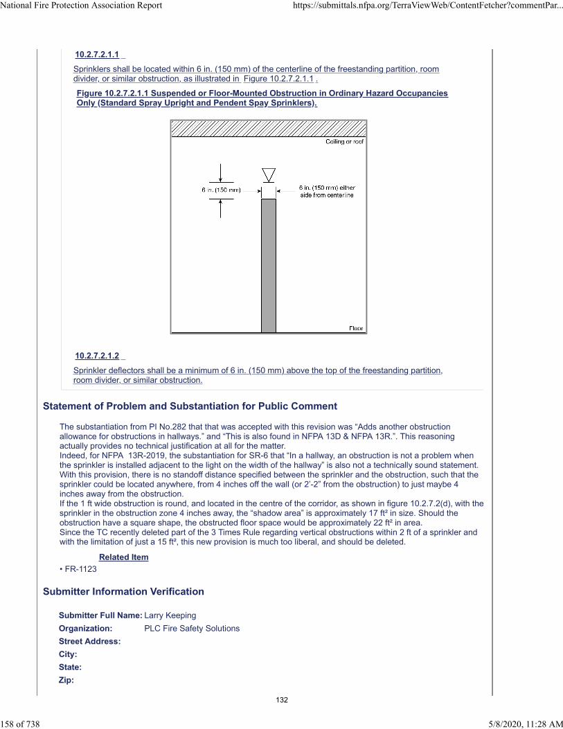
10.2.7.2.1.1
Sprinklers shall be located within 6 in. (150 mm) of the centerline of the freestanding partition, roomdivider, or similar obstruction, as illustrated in Figure 10.2.7.2.1.1 .
Figure 10.2.7.2.1.1 Suspended or Floor-Mounted Obstruction in Ordinary Hazard OccupanciesOnly (Standard Spray Upright and Pendent Spay Sprinklers).
10.2.7.2.1.2
Sprinkler deflectors shall be a minimum of 6 in. (150 mm) above the top of the freestanding partition,room divider, or similar obstruction.
Statement of Problem and Substantiation for Public Comment
The substantiation from PI No.282 that that was accepted with this revision was “Adds another obstruction allowance for obstructions in hallways.” and “This is also found in NFPA 13D & NFPA 13R.”. This reasoning actually provides no technical justification at all for the matter.Indeed, for NFPA 13R-2019, the substantiation for SR-6 that “In a hallway, an obstruction is not a problem when the sprinkler is installed adjacent to the light on the width of the hallway” is also not a technically sound statement.With this provision, there is no standoff distance specified between the sprinkler and the obstruction, such that the sprinkler could be located anywhere, from 4 inches off the wall (or 2’-2” from the obstruction) to just maybe 4 inches away from the obstruction. If the 1 ft wide obstruction is round, and located in the centre of the corridor, as shown in figure 10.2.7.2(d), with the sprinkler in the obstruction zone 4 inches away, the “shadow area” is approximately 17 ft² in size. Should the obstruction have a square shape, the obstructed floor space would be approximately 22 ft² in area.Since the TC recently deleted part of the 3 Times Rule regarding vertical obstructions within 2 ft of a sprinkler and with the limitation of just a 15 ft², this new provision is much too liberal, and should be deleted.
Related Item
• FR-1123
Submitter Information Verification
Submitter Full Name: Larry Keeping
Organization: PLC Fire Safety Solutions
Street Address:
City:
State:
Zip:
National Fire Protection Association Report https://submittals.nfpa.org/TerraViewWeb/ContentFetcher?commentPar...
158 of 738 5/8/2020, 11:28 AM
132

Submittal Date: Thu Apr 23 17:04:54 EDT 2020
Committee: AUT-AAC
National Fire Protection Association Report https://submittals.nfpa.org/TerraViewWeb/ContentFetcher?commentPar...
159 of 738 5/8/2020, 11:28 AM
133
Public Comment No. 339-NFPA 13-2020 [ Section No. 10.2.7.2 ]
10.2.7.2* Obstructions Above the Sprinkler Deflector to Sprinkler Discharge Pattern Development .
National Fire Protection Association Report https://submittals.nfpa.org/TerraViewWeb/ContentFetcher?commentPar...
160 of 738 5/8/2020, 11:28 AM
134
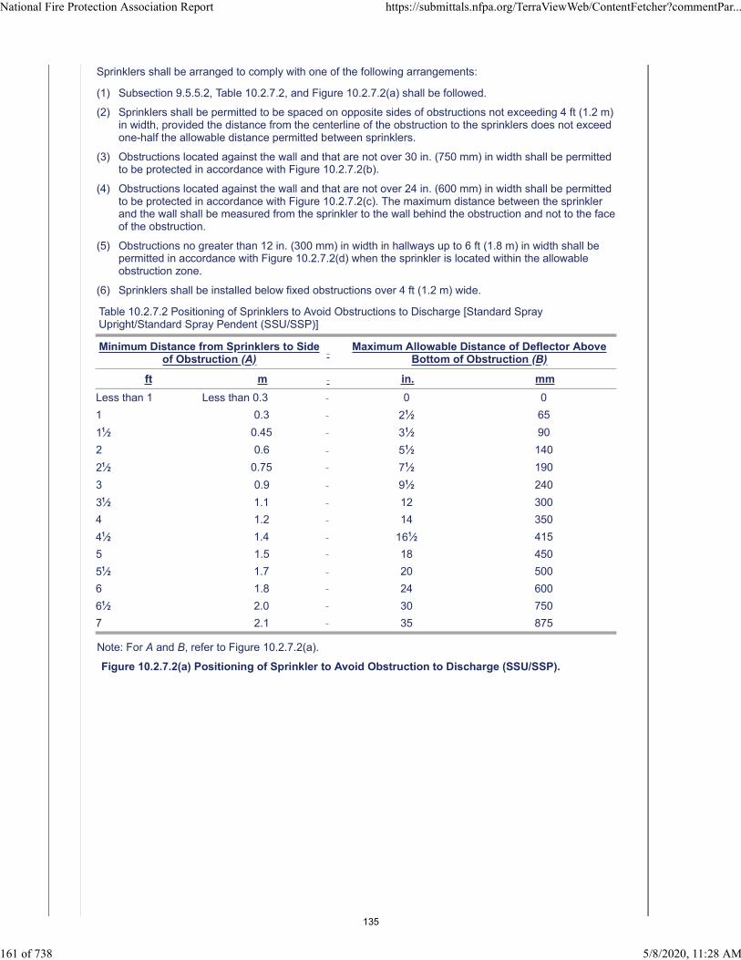
Sprinklers shall be arranged to comply with one of the following arrangements:
(1) Subsection 9.5.5.2, Table 10.2.7.2, and Figure 10.2.7.2(a) shall be followed.
(2) Sprinklers shall be permitted to be spaced on opposite sides of obstructions not exceeding 4 ft (1.2 m)in width, provided the distance from the centerline of the obstruction to the sprinklers does not exceedone-half the allowable distance permitted between sprinklers.
(3) Obstructions located against the wall and that are not over 30 in. (750 mm) in width shall be permittedto be protected in accordance with Figure 10.2.7.2(b).
(4) Obstructions located against the wall and that are not over 24 in. (600 mm) in width shall be permittedto be protected in accordance with Figure 10.2.7.2(c). The maximum distance between the sprinklerand the wall shall be measured from the sprinkler to the wall behind the obstruction and not to the faceof the obstruction.
(5) Obstructions no greater than 12 in. (300 mm) in width in hallways up to 6 ft (1.8 m) in width shall bepermitted in accordance with Figure 10.2.7.2(d) when the sprinkler is located within the allowableobstruction zone.
(6) Sprinklers shall be installed below fixed obstructions over 4 ft (1.2 m) wide.
Table 10.2.7.2 Positioning of Sprinklers to Avoid Obstructions to Discharge [Standard SprayUpright/Standard Spray Pendent (SSU/SSP)]
Minimum Distance from Sprinklers to Sideof Obstruction (A)
Maximum Allowable Distance of Deflector Above
Bottom of Obstruction (B)
ft m in. mm
Less than 1 Less than 0.3 0 0
1 0.3 21⁄2 65
11⁄2 0.45 31⁄2 90
2 0.6 51⁄2 140
21⁄2 0.75 71⁄2 190
3 0.9 91⁄2 240
31⁄2 1.1 12 300
4 1.2 14 350
41⁄2 1.4 161⁄2 415
5 1.5 18 450
51⁄2 1.7 20 500
6 1.8 24 600
61⁄2 2.0 30 750
7 2.1 35 875
Note: For A and B, refer to Figure 10.2.7.2(a).
Figure 10.2.7.2(a) Positioning of Sprinkler to Avoid Obstruction to Discharge (SSU/SSP).
National Fire Protection Association Report https://submittals.nfpa.org/TerraViewWeb/ContentFetcher?commentPar...
161 of 738 5/8/2020, 11:28 AM
135

Figure 10.2.7.2(b) Obstruction Against Wall (SSU/SSP).
Figure 10.2.7.2(c) Obstructions Against Walls (SSU/SSP).
National Fire Protection Association Report https://submittals.nfpa.org/TerraViewWeb/ContentFetcher?commentPar...
162 of 738 5/8/2020, 11:28 AM
136
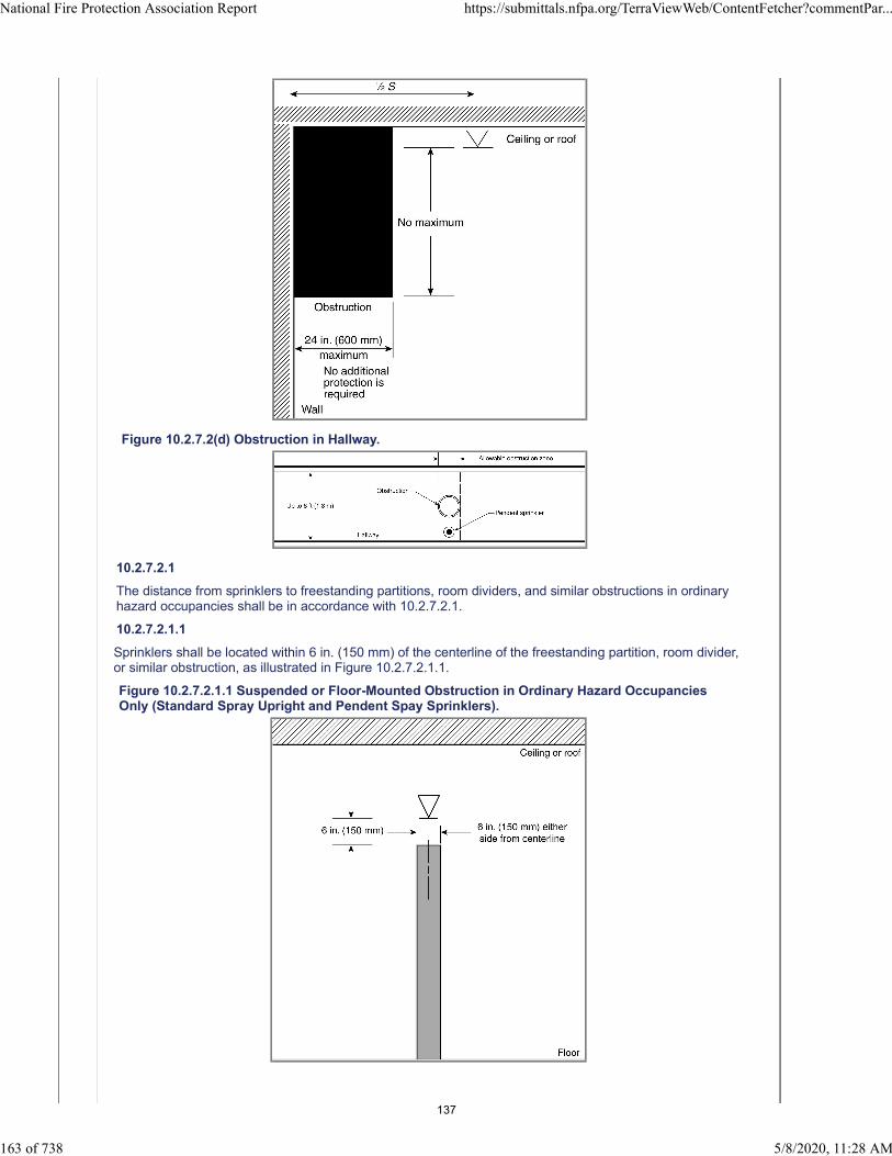
Figure 10.2.7.2(d) Obstruction in Hallway.
10.2.7.2.1
The distance from sprinklers to freestanding partitions, room dividers, and similar obstructions in ordinaryhazard occupancies shall be in accordance with 10.2.7.2.1.
10.2.7.2.1.1
Sprinklers shall be located within 6 in. (150 mm) of the centerline of the freestanding partition, room divider,or similar obstruction, as illustrated in Figure 10.2.7.2.1.1.
Figure 10.2.7.2.1.1 Suspended or Floor-Mounted Obstruction in Ordinary Hazard OccupanciesOnly (Standard Spray Upright and Pendent Spay Sprinklers).
National Fire Protection Association Report https://submittals.nfpa.org/TerraViewWeb/ContentFetcher?commentPar...
163 of 738 5/8/2020, 11:28 AM
137
10.2.7.2.1.2
Sprinkler deflectors shall be a minimum of 6 in. (150 mm) above the top of the freestanding partition, roomdivider, or similar obstruction.
Statement of Problem and Substantiation for Public Comment
This comment (and others) were developed by a NFSA Engineering and Standards Committee Task Group on Obstructions. Additional comments are being submitted on this section in separate comments. The entire Task Group Report which addresses all the comments is being uploaded in this comment. This comment is directed at an identifiable element of FR 1123 related to PI 274 which identifies three zones of influence to sprinkler obstruction: obstructions above the deflector (near ceiling), obstructions extending from the deflector to a point 18-inches below the deflector, and obstructions greater than 18-inches below the deflector. Obstructions that extend from the ceiling to the sprinkler deflector are not actually an impediment to distribution for upright and pendent style sprinklers. They may be an impediment to sprinkler sensitivity, but that is not addressed in this section. The real concern is the near ceiling obstructions that starts above the deflector but extend into a zone that negatively impacts sprinkler distribution. The historic references to “obstructions to Sprinkler Discharge Pattern Development” and “Obstructions that prevent the sprinkler discharge from reaching the hazard” adequately address the real areas of concern and the original title Obstructions to Sprinkler Discharge Pattern Development from the previous edition should be retained.
Related Public Comments for This Document
Related Comment Relationship
Public Comment No. 365-NFPA 13-2020 [Section No. 10.2.7.2 [Excluding any Sub-Sections]]
Related Item
• FR-1123
Submitter Information Verification
Submitter Full Name: Roland Asp
Organization: National Fire Sprinkler Association
Affiliation: NFSA Engineering and Engineering Committee
Street Address:
City:
State:
Zip:
Submittal Date: Tue May 05 15:54:52 EDT 2020
Committee: AUT-AAC
National Fire Protection Association Report https://submittals.nfpa.org/TerraViewWeb/ContentFetcher?commentPar...
164 of 738 5/8/2020, 11:28 AM
138

Public Comment No. 345-NFPA 13-2020 [ Section No. 10.2.7.2 [Excluding any Sub-
Sections] ]
National Fire Protection Association Report https://submittals.nfpa.org/TerraViewWeb/ContentFetcher?commentPar...
165 of 738 5/8/2020, 11:28 AM
139
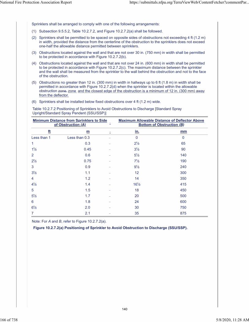
Sprinklers shall be arranged to comply with one of the following arrangements:
(1) Subsection 9.5.5.2, Table 10.2.7.2, and Figure 10.2.7.2(a) shall be followed.
(2) Sprinklers shall be permitted to be spaced on opposite sides of obstructions not exceeding 4 ft (1.2 m)in width, provided the distance from the centerline of the obstruction to the sprinklers does not exceedone-half the allowable distance permitted between sprinklers.
(3) Obstructions located against the wall and that are not over 30 in. (750 mm) in width shall be permittedto be protected in accordance with Figure 10.2.7.2(b).
(4) Obstructions located against the wall and that are not over 24 in. (600 mm) in width shall be permittedto be protected in accordance with Figure 10.2.7.2(c). The maximum distance between the sprinklerand the wall shall be measured from the sprinkler to the wall behind the obstruction and not to the faceof the obstruction.
(5) Obstructions no greater than 12 in. (300 mm) in width in hallways up to 6 ft (1.8 m) in width shall bepermitted in accordance with Figure 10.2.7.2(d) when the sprinkler is located within the allowableobstruction zone. zone and the closest edge of the obstruction is a minimum of 12 in. (300 mm) awayfrom the deflector.
(6) Sprinklers shall be installed below fixed obstructions over 4 ft (1.2 m) wide.
Table 10.2.7.2 Positioning of Sprinklers to Avoid Obstructions to Discharge [Standard SprayUpright/Standard Spray Pendent (SSU/SSP)]
Minimum Distance from Sprinklers to Sideof Obstruction (A)
Maximum Allowable Distance of Deflector Above
Bottom of Obstruction (B)
ft m in. mm
Less than 1 Less than 0.3 0 0
1 0.3 21⁄2 65
11⁄2 0.45 31⁄2 90
2 0.6 51⁄2 140
21⁄2 0.75 71⁄2 190
3 0.9 91⁄2 240
31⁄2 1.1 12 300
4 1.2 14 350
41⁄2 1.4 161⁄2 415
5 1.5 18 450
51⁄2 1.7 20 500
6 1.8 24 600
61⁄2 2.0 30 750
7 2.1 35 875
Note: For A and B, refer to Figure 10.2.7.2(a).
Figure 10.2.7.2(a) Positioning of Sprinkler to Avoid Obstruction to Discharge (SSU/SSP).
National Fire Protection Association Report https://submittals.nfpa.org/TerraViewWeb/ContentFetcher?commentPar...
166 of 738 5/8/2020, 11:28 AM
140
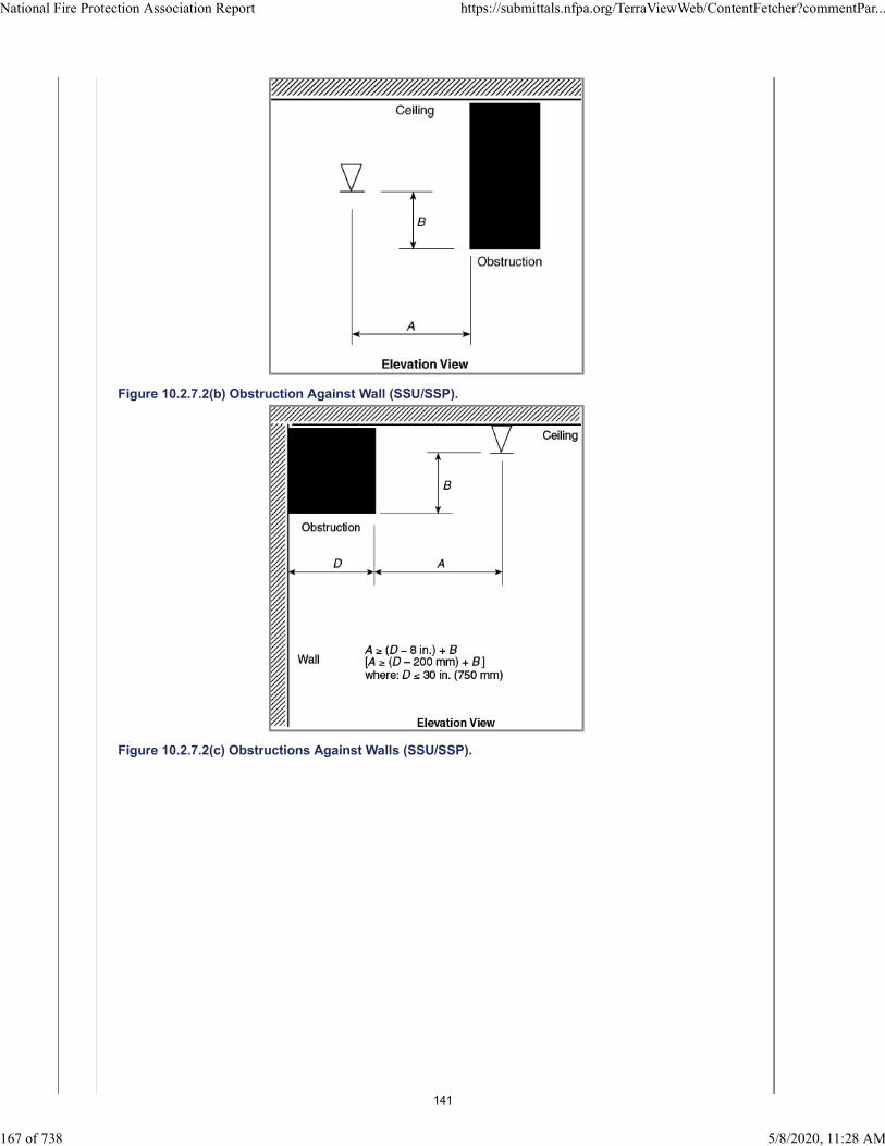
Figure 10.2.7.2(b) Obstruction Against Wall (SSU/SSP).
Figure 10.2.7.2(c) Obstructions Against Walls (SSU/SSP).
National Fire Protection Association Report https://submittals.nfpa.org/TerraViewWeb/ContentFetcher?commentPar...
167 of 738 5/8/2020, 11:28 AM
141

Figure 10.2.7.2(d) Obstruction in Hallway.
Statement of Problem and Substantiation for Public Comment
This comment (and others) were developed by a NFSA Engineering and Standards Committee Task Group on Obstructions. Additional comments are being submitted on this section in separate comments. The entire Task Group Report which addresses all the comments is being uploaded in this comment. This comment seeks to revise the language of 10.2.7.2(5) and is intended to minimize the apparent dry area that may be created by the obstruction adjacent to the sprinkler.
Related Public Comments for This Document
Related Comment Relationship
Public Comment No. 365-NFPA 13-2020 [Section No. 10.2.7.2 [Excluding any Sub-Sections]]
Public Comment No. 366-NFPA 13-2020 [Section No. 10.3.6.1.7]
Public Comment No. 367-NFPA 13-2020 [Section No. 11.2.5.1.2]
Public Comment No. 368-NFPA 13-2020 [Section No. 11.3.6.1.4]
Public Comment No. 369-NFPA 13-2020 [Section No. 12.1.10.1.2]
Public Comment No. 370-NFPA 13-2020 [Section No. 12.1.11.1.4]
Related Item
• FR-1123
Submitter Information Verification
Submitter Full Name: Roland Asp
Organization: National Fire Sprinkler Association
Affiliation: NFSA Engineering and Standards Committee
Street Address:
City:
National Fire Protection Association Report https://submittals.nfpa.org/TerraViewWeb/ContentFetcher?commentPar...
168 of 738 5/8/2020, 11:28 AM
142

State:
Zip:
Submittal Date: Tue May 05 16:43:00 EDT 2020
Committee: AUT-AAC
National Fire Protection Association Report https://submittals.nfpa.org/TerraViewWeb/ContentFetcher?commentPar...
169 of 738 5/8/2020, 11:28 AM
143

Public Comment No. 346-NFPA 13-2020 [ Section No. 10.2.7.2 [Excluding any Sub-
Sections] ]
National Fire Protection Association Report https://submittals.nfpa.org/TerraViewWeb/ContentFetcher?commentPar...
170 of 738 5/8/2020, 11:28 AM
144
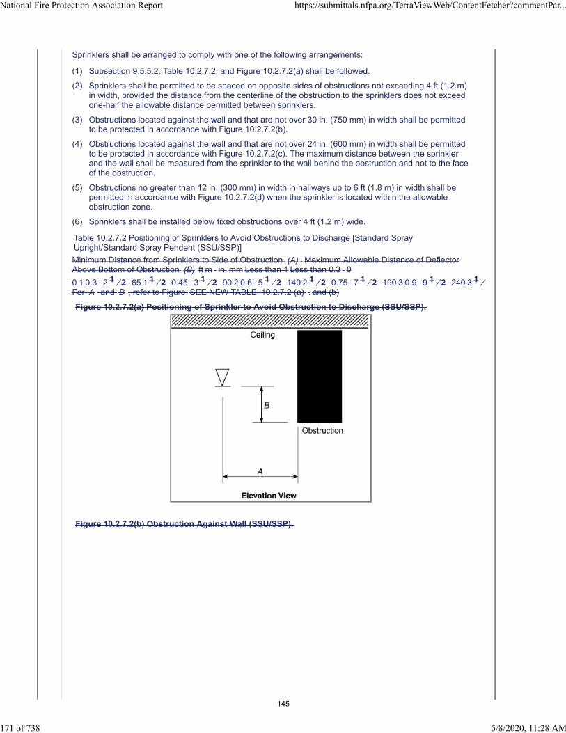
Sprinklers shall be arranged to comply with one of the following arrangements:
(1) Subsection 9.5.5.2, Table 10.2.7.2, and Figure 10.2.7.2(a) shall be followed.
(2) Sprinklers shall be permitted to be spaced on opposite sides of obstructions not exceeding 4 ft (1.2 m)in width, provided the distance from the centerline of the obstruction to the sprinklers does not exceedone-half the allowable distance permitted between sprinklers.
(3) Obstructions located against the wall and that are not over 30 in. (750 mm) in width shall be permittedto be protected in accordance with Figure 10.2.7.2(b).
(4) Obstructions located against the wall and that are not over 24 in. (600 mm) in width shall be permittedto be protected in accordance with Figure 10.2.7.2(c). The maximum distance between the sprinklerand the wall shall be measured from the sprinkler to the wall behind the obstruction and not to the faceof the obstruction.
(5) Obstructions no greater than 12 in. (300 mm) in width in hallways up to 6 ft (1.8 m) in width shall bepermitted in accordance with Figure 10.2.7.2(d) when the sprinkler is located within the allowableobstruction zone.
(6) Sprinklers shall be installed below fixed obstructions over 4 ft (1.2 m) wide.
Table 10.2.7.2 Positioning of Sprinklers to Avoid Obstructions to Discharge [Standard SprayUpright/Standard Spray Pendent (SSU/SSP)]
Minimum Distance from Sprinklers to Side of Obstruction (A) Maximum Allowable Distance of DeflectorAbove Bottom of Obstruction (B) ft m in. mm Less than 1 Less than 0.3 0
0 1 0.3 2 1 ⁄ 2 65 1 1 ⁄ 2 0.45 3 1 ⁄ 2 90 2 0.6 5 1 ⁄ 2 140 2 1 ⁄ 2 0.75 7 1 ⁄ 2 190 3 0.9 9 1 ⁄ 2 240 3 1 ⁄For A and B , refer to Figure SEE NEW TABLE 10.2.7.2 (a) . and (b)
Figure 10.2.7.2(a) Positioning of Sprinkler to Avoid Obstruction to Discharge (SSU/SSP).
Figure 10.2.7.2(b) Obstruction Against Wall (SSU/SSP).
National Fire Protection Association Report https://submittals.nfpa.org/TerraViewWeb/ContentFetcher?commentPar...
171 of 738 5/8/2020, 11:28 AM
145

Figure 10.2.7.2(c) Obstructions Against Walls (SSU/SSP).
Figure 10.2.7.2(d) Obstruction in Hallway.
Additional Proposed Changes
File Name Description Approved
Beam_Rule_Table_Format_2022.pdf
Statement of Problem and Substantiation for Public Comment
This comment (and others) were developed by a NFSA Engineering and Standards Committee Task Group on
National Fire Protection Association Report https://submittals.nfpa.org/TerraViewWeb/ContentFetcher?commentPar...
172 of 738 5/8/2020, 11:28 AM
146

Obstructions. Additional comments are being submitted on this section in separate comments. The entire Task Group Report which addresses all the comments is being uploaded in this comment. This comment seeks to revise the beam tables (Table 10.2.7.2(a) for clarity. It is the intent to use the format that is uploaded in this comment to revise all beam obstruction tables in the document.
Related Public Comments for This Document
Related Comment Relationship
Public Comment No. 365-NFPA 13-2020 [Section No. 10.2.7.2 [Excluding any Sub-Sections]]
Public Comment No. 385-NFPA 13-2020 [Global Input]
Related Item
• FR-1123
Submitter Information Verification
Submitter Full Name: Roland Asp
Organization: National Fire Sprinkler Association
Affiliation: NFSA Engineering and Standards Committee
Street Address:
City:
State:
Zip:
Submittal Date: Tue May 05 16:45:50 EDT 2020
Committee: AUT-AAC
National Fire Protection Association Report https://submittals.nfpa.org/TerraViewWeb/ContentFetcher?commentPar...
173 of 738 5/8/2020, 11:28 AM
147

Distance from Sprinkler to Side of Obstruction (A )
Allowable Distance of Deflector Above Bottom of Obstruction
(B ) [inches]
Distance from Sprinkler to Side of Obstruction (A )
Allowable Distance of Deflector Above Bottom of Obstruction
(B ) [millimeters]
Less than 1 ft 0 Less than 300 mm 01 ft or more 2-½ 300 mm or more 651 ft 6in or more 3-½ 450 mm or more 902 ft or more 5-½ 600 mm or more 1402 ft 6 in or more 7-½ 750 mm or more 1903 ft or more 9-½ 900 mm or more 2403 ft 6 in or more 12 1100 mm or more 3004 ft or more 14 1200 mm or more 3504 ft 6 in or more 16-½ 1400 mm or more 4205 ft or more 18 1500 mm or more 4505 ft 6 in or more 20 1700 mm or more 5106 ft or more 24 1800 mm or more 6006 ft 6 in or more 30 2000 mm or more 7507 ft or more 35 2100 mm or more 875
Note: For A and B , refer to Figure 10.2.7.2(a) Note: For A and B , refer to Figure 10.2.7.2(a)
Table 10.2.7.2(a) Positioning of Sprinklers to AvoidObstructions to Discharge [Standard Spray
Upright/Standard Spray Pendent (SSU/SSP)]
Table 10.2.7.2(b) Positioning of Sprinklers to AvoidObstructions to Discharge [Standard Spray
Upright/Standard Spray Pendent (SSU/SSP)]
148

149

Public Comment No. 356-NFPA 13-2020 [ Section No. 10.2.7.2 [Excluding any Sub-
Sections] ]
National Fire Protection Association Report https://submittals.nfpa.org/TerraViewWeb/ContentFetcher?commentPar...
174 of 738 5/8/2020, 11:28 AM
150
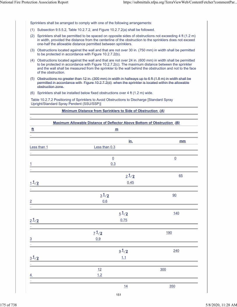
Sprinklers shall be arranged to comply with one of the following arrangements:
(1) Subsection 9.5.5.2, Table 10.2.7.2, and Figure 10.2.7.2(a) shall be followed.
(2) Sprinklers shall be permitted to be spaced on opposite sides of obstructions not exceeding 4 ft (1.2 m)in width, provided the distance from the centerline of the obstruction to the sprinklers does not exceedone-half the allowable distance permitted between sprinklers.
(3) Obstructions located against the wall and that are not over 30 in. (750 mm) in width shall be permittedto be protected in accordance with Figure 10.2.7.2(b).
(4) Obstructions located against the wall and that are not over 24 in. (600 mm) in width shall be permittedto be protected in accordance with Figure 10.2.7.2(c). The maximum distance between the sprinklerand the wall shall be measured from the sprinkler to the wall behind the obstruction and not to the faceof the obstruction.
(5) Obstructions no greater than 12 in. (300 mm) in width in hallways up to 6 ft (1.8 m) in width shall bepermitted in accordance with Figure 10.2.7.2(d) when the sprinkler is located within the allowableobstruction zone.
(6) Sprinklers shall be installed below fixed obstructions over 4 ft (1.2 m) wide.
Table 10.2.7.2 Positioning of Sprinklers to Avoid Obstructions to Discharge [Standard SprayUpright/Standard Spray Pendent (SSU/SSP)]
Minimum Distance from Sprinklers to Side of Obstruction (A)
Maximum Allowable Distance of Deflector Above Bottom of Obstruction (B)
ft m
in. mm
Less than 1 Less than 0.3
0 0
1 0.3
2 1 ⁄ 2 65
1 1 ⁄ 2 0.45
3 1 ⁄ 2 90
2 0.6
5 1 ⁄ 2 140
2 1 ⁄ 2 0.75
7 1 ⁄ 2 190
3 0.9
9 1 ⁄ 2 240
3 1 ⁄ 2 1.1
12 300
4 1.2
14 350
National Fire Protection Association Report https://submittals.nfpa.org/TerraViewWeb/ContentFetcher?commentPar...
175 of 738 5/8/2020, 11:28 AM
151

4 1 ⁄ 2 1.4
16 1 ⁄ 2 415
5 1.5
18 450
5 1 ⁄ 2 1.7
20 500
6 1.8
24 600
6 1 ⁄ 2 2.0
30 750
7 2.1
35 875
Note: For A and B, refer to Figure 10.2.7.2(a).
Figure 10.2.7.2(a) Positioning of Sprinkler to Avoid Obstruction to Discharge (SSU/SSP).
Figure 10.2.7.2(b) Obstruction Against Wall (SSU/SSP).
National Fire Protection Association Report https://submittals.nfpa.org/TerraViewWeb/ContentFetcher?commentPar...
176 of 738 5/8/2020, 11:28 AM
152

Figure 10.2.7.2(c) Obstructions Against Walls (SSU/SSP).
Figure 10.2.7.2(d) Obstruction in Hallway.
Statement of Problem and Substantiation for Public Comment
The corridor obstruction allowance conflicts with other existing obstruction allowances which clearly would not allow such an obstruction. While the risk of fire and fuel load is low in a corridor, the fire suppression would be inhibited should this condition be applied to all sprinklers in a corridor. Especially concerning would be dead end corridors where the only path of egress could be compromised. This comment would apply to all similar occurrences.
Related Item
National Fire Protection Association Report https://submittals.nfpa.org/TerraViewWeb/ContentFetcher?commentPar...
177 of 738 5/8/2020, 11:28 AM
153
• PI 282
Submitter Information Verification
Submitter Full Name: Jason Gill
Organization: Crews & Gregory Fire Sprinkler
Affiliation: AFSA
Street Address:
City:
State:
Zip:
Submittal Date: Wed May 06 07:43:50 EDT 2020
Committee: AUT-AAC
National Fire Protection Association Report https://submittals.nfpa.org/TerraViewWeb/ContentFetcher?commentPar...
178 of 738 5/8/2020, 11:28 AM
154

Public Comment No. 365-NFPA 13-2020 [ Section No. 10.2.7.2 [Excluding any Sub-
Sections] ]
National Fire Protection Association Report https://submittals.nfpa.org/TerraViewWeb/ContentFetcher?commentPar...
179 of 738 5/8/2020, 11:28 AM
155

Sprinklers shall be arranged to comply with one of the following arrangements:
(1) Subsection 9.5.5.2, Table 10.2.7.2, and Figure 10.2.7.2(a) shall be followed.
(2) Sprinklers shall be permitted to be spaced on opposite sides of obstructions not exceeding 4 ft (1.2 m)in width, provided the distance from the centerline of the obstruction to the sprinklers does not exceedone-half the allowable distance permitted between sprinklers.
(3) Obstructions located against the wall and that are not over 30 in. (750 mm) in width shall be permittedto be protected in accordance with Figure 10.2.7.2(b).
(4) Obstructions located against the wall and that are not over 24 in. (600 mm) in width shall be permittedto be protected in accordance with Figure 10.2.7.2(c). The maximum distance between the sprinklerand the wall shall be measured from the sprinkler to the wall behind the obstruction and not to the faceof the obstruction.
(5) Obstructions no greater than 12 in. (300 mm) in width in hallways up to 6 ft (1.8 m) in width shall bepermitted in accordance with Figure 10.2.7.2(d) when the sprinkler is located within the allowableobstruction zone.
(6) Sprinklers shall be installed below fixed obstructions over 4 ft (1.2 m) wide.
(7) Sprinklers shall not be required under fixed obstructions less then 4 ft (1.2 m) wide when the provisionsof Table 10.2.7.2 and Figure 10.2.7.2(a) is maintained.
Table 10.2.7.2 Positioning of Sprinklers to Avoid Obstructions to Discharge [Standard SprayUpright/Standard Spray Pendent (SSU/SSP)]
Minimum Distance from Sprinklers to Sideof Obstruction (A)
Maximum Allowable Distance of Deflector Above
Bottom of Obstruction (B)
ft m in. mm
Less than 1 Less than 0.3 0 0
1 0.3 21⁄2 65
11⁄2 0.45 31⁄2 90
2 0.6 51⁄2 140
21⁄2 0.75 71⁄2 190
3 0.9 91⁄2 240
31⁄2 1.1 12 300
4 1.2 14 350
41⁄2 1.4 161⁄2 415
5 1.5 18 450
51⁄2 1.7 20 500
6 1.8 24 600
61⁄2 2.0 30 750
7 2.1 35 875
Note: For A and B, refer to Figure 10.2.7.2(a).
Figure 10.2.7.2(a) Positioning of Sprinkler to Avoid Obstruction to Discharge (SSU/SSP).
National Fire Protection Association Report https://submittals.nfpa.org/TerraViewWeb/ContentFetcher?commentPar...
180 of 738 5/8/2020, 11:28 AM
156

Figure 10.2.7.2(b) Obstruction Against Wall (SSU/SSP).
Figure 10.2.7.2(c) Obstructions Against Walls (SSU/SSP).
National Fire Protection Association Report https://submittals.nfpa.org/TerraViewWeb/ContentFetcher?commentPar...
181 of 738 5/8/2020, 11:28 AM
157
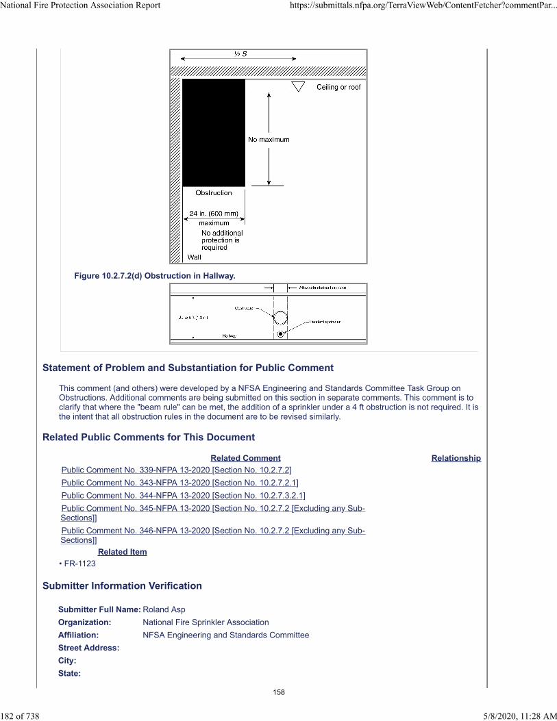
Figure 10.2.7.2(d) Obstruction in Hallway.
Statement of Problem and Substantiation for Public Comment
This comment (and others) were developed by a NFSA Engineering and Standards Committee Task Group on Obstructions. Additional comments are being submitted on this section in separate comments. This comment is to clarify that where the "beam rule" can be met, the addition of a sprinkler under a 4 ft obstruction is not required. It is the intent that all obstruction rules in the document are to be revised similarly.
Related Public Comments for This Document
Related Comment Relationship
Public Comment No. 339-NFPA 13-2020 [Section No. 10.2.7.2]
Public Comment No. 343-NFPA 13-2020 [Section No. 10.2.7.2.1]
Public Comment No. 344-NFPA 13-2020 [Section No. 10.2.7.3.2.1]
Public Comment No. 345-NFPA 13-2020 [Section No. 10.2.7.2 [Excluding any Sub-Sections]]
Public Comment No. 346-NFPA 13-2020 [Section No. 10.2.7.2 [Excluding any Sub-Sections]]
Related Item
• FR-1123
Submitter Information Verification
Submitter Full Name: Roland Asp
Organization: National Fire Sprinkler Association
Affiliation: NFSA Engineering and Standards Committee
Street Address:
City:
State:
National Fire Protection Association Report https://submittals.nfpa.org/TerraViewWeb/ContentFetcher?commentPar...
182 of 738 5/8/2020, 11:28 AM
158

Zip:
Submittal Date: Wed May 06 10:33:22 EDT 2020
Committee: AUT-AAC
National Fire Protection Association Report https://submittals.nfpa.org/TerraViewWeb/ContentFetcher?commentPar...
183 of 738 5/8/2020, 11:28 AM
159
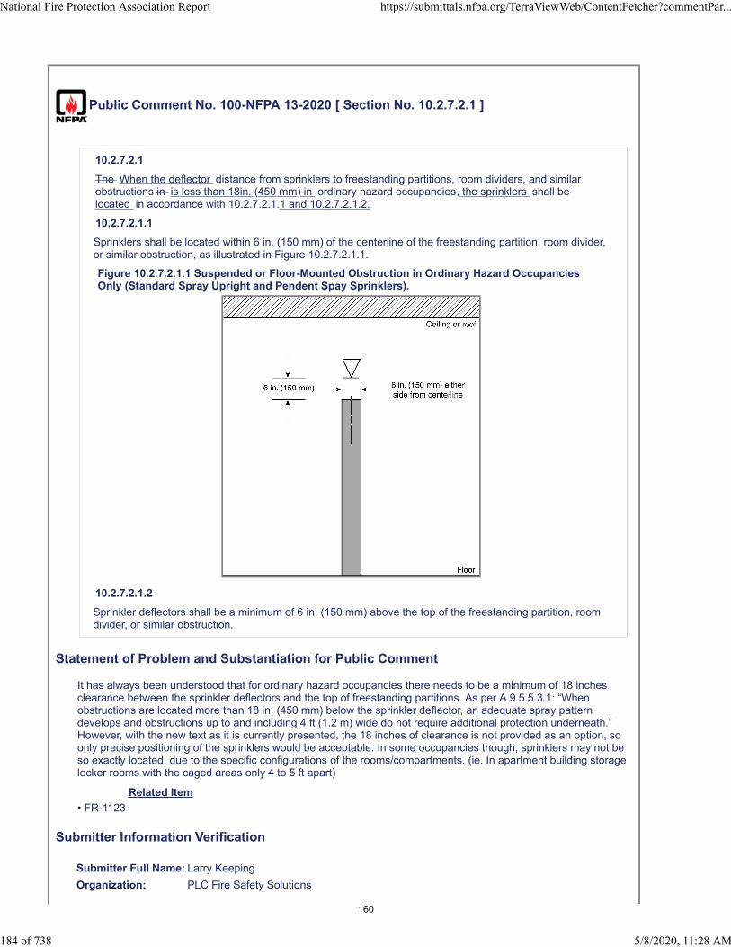
Public Comment No. 100-NFPA 13-2020 [ Section No. 10.2.7.2.1 ]
10.2.7.2.1
The When the deflector distance from sprinklers to freestanding partitions, room dividers, and similarobstructions in is less than 18in. (450 mm) in ordinary hazard occupancies, the sprinklers shall belocated in accordance with 10.2.7.2.1.1 and 10.2.7.2.1.2.
10.2.7.2.1.1
Sprinklers shall be located within 6 in. (150 mm) of the centerline of the freestanding partition, room divider,or similar obstruction, as illustrated in Figure 10.2.7.2.1.1.
Figure 10.2.7.2.1.1 Suspended or Floor-Mounted Obstruction in Ordinary Hazard OccupanciesOnly (Standard Spray Upright and Pendent Spay Sprinklers).
10.2.7.2.1.2
Sprinkler deflectors shall be a minimum of 6 in. (150 mm) above the top of the freestanding partition, roomdivider, or similar obstruction.
Statement of Problem and Substantiation for Public Comment
It has always been understood that for ordinary hazard occupancies there needs to be a minimum of 18 inches clearance between the sprinkler deflectors and the top of freestanding partitions. As per A.9.5.5.3.1: “When obstructions are located more than 18 in. (450 mm) below the sprinkler deflector, an adequate spray pattern develops and obstructions up to and including 4 ft (1.2 m) wide do not require additional protection underneath.” However, with the new text as it is currently presented, the 18 inches of clearance is not provided as an option, so only precise positioning of the sprinklers would be acceptable. In some occupancies though, sprinklers may not be so exactly located, due to the specific configurations of the rooms/compartments. (ie. In apartment building storage locker rooms with the caged areas only 4 to 5 ft apart)
Related Item
• FR-1123
Submitter Information Verification
Submitter Full Name: Larry Keeping
Organization: PLC Fire Safety Solutions
National Fire Protection Association Report https://submittals.nfpa.org/TerraViewWeb/ContentFetcher?commentPar...
184 of 738 5/8/2020, 11:28 AM
160

Street Address:
City:
State:
Zip:
Submittal Date: Thu Apr 23 16:24:57 EDT 2020
Committee: AUT-AAC
National Fire Protection Association Report https://submittals.nfpa.org/TerraViewWeb/ContentFetcher?commentPar...
185 of 738 5/8/2020, 11:28 AM
161

Public Comment No. 343-NFPA 13-2020 [ Section No. 10.2.7.2.1 ]
10.2.7.2.1
The distance from sprinklers to freestanding partitions, room dividers, and similar obstructions in ordinaryhazard occupancies shall be in accordance with 10.2.7.2.1 .
10.2.7.2.1.1
Sprinklers shall be located within 6 in. (150 mm) of the centerline of the freestanding partition, room divider,or similar obstruction, as illustrated in Figure 10.2.7.2.1.1 .
Figure 10.2.7.2.1.1 Suspended or Floor-Mounted Obstruction in Ordinary Hazard OccupanciesOnly (Standard Spray Upright and Pendent Spay Sprinklers).
10.2.7.2.1.2
Sprinkler deflectors shall be a minimum of 6 in. (150 mm) above the top of the freestanding partition, roomdivider, or similar obstruction.
Statement of Problem and Substantiation for Public Comment
NFSA E&S committee created a Obstruction Task Group and this recommendation is intended relocate the concept of Suspended or Floor-Mounted obstructions from section 10.2.7.2.1 to section 10.2.7.3.2.2. There is a separate comment submitted to accomplish this.
Related Public Comments for This Document
Related Comment Relationship
Public Comment No. 347-NFPA 13-2020 [New Section after 10.2.7.3.2.2]
Public Comment No. 365-NFPA 13-2020 [Section No. 10.2.7.2 [Excluding any Sub-Sections]]
Related Item
• FR-1123
Submitter Information Verification
National Fire Protection Association Report https://submittals.nfpa.org/TerraViewWeb/ContentFetcher?commentPar...
186 of 738 5/8/2020, 11:28 AM
162

Submitter Full Name: Roland Asp
Organization: National Fire Sprinkler Association
Affiliation: NFSA Engineering and Standards Committee
Street Address:
City:
State:
Zip:
Submittal Date: Tue May 05 16:24:20 EDT 2020
Committee: AUT-AAC
National Fire Protection Association Report https://submittals.nfpa.org/TerraViewWeb/ContentFetcher?commentPar...
187 of 738 5/8/2020, 11:28 AM
163

Public Comment No. 344-NFPA 13-2020 [ Section No. 10.2.7.3.2.1 ]
10.2.7.3.2.1
The distance from sprinklers to privacy curtains, freestanding partitions, room dividers, and similarobstructions in light hazard occupancies shall be in accordance with Table 10.2.7.3.2.1 and Figure10.2.7.3.2.1.
Table 10 SEE NEW TABLE 10 .2.7.3.2.1 Suspended or Floor-Mounted Obstructions in Light HazardOccupancies Only (SSU/SSP)
Horizontal Distance (A) Minimum Vertical Distance Below Deflector (B) in. mm 6 in. (150 mm) orless 3 75 More than 6 in. (150 mm) to 9 in. (225 mm) 4 100 More than 9 in. (225 mm) to 12 in.(300 mm) 6 150 More than 12 in. (300 mm) to 15 in. (375 mm) 8 200 More than 15 in. (375 mm) to 18 in.(450 mm) 9
1
⁄ 2 240 More than 18 in. (450 mm) to 24 in. (600 mm) 12 1 ⁄ 2 315 More than 24 in. (600 mm) to 30 in.
(750 mm) 15 1 ⁄ 2 390 More than 30 in. (750 mm) 18 450
Note: For A and B , refer to Figure 10.2.7.3.2.1.
(a0 and (b)
Figure 10.2.7.3.2.1 Suspended or Floor-Mounted Obstruction in Light Hazard Occupancies Only(SSU/SSP).
Additional Proposed Changes
File Name Description Approved
Partition_Rule_Table_Format_2022.pdf New Partition Table
Statement of Problem and Substantiation for Public Comment
This new Table Format is to provide clarity and mirrors the changes submitted to the beam obstruction tables. It is the intent that similar changes be made to other tables in the document.
Related Public Comments for This Document
Related Comment Relationship
Public Comment No. 365-NFPA 13-2020 [Section No. 10.2.7.2 [Excluding any Sub-Sections]]
Public Comment No. 385-NFPA 13-2020 [Global Input]
Related Item
National Fire Protection Association Report https://submittals.nfpa.org/TerraViewWeb/ContentFetcher?commentPar...
188 of 738 5/8/2020, 11:28 AM
164
• FR-1123
Submitter Information Verification
Submitter Full Name: Roland Asp
Organization: National Fire Sprinkler Association
Affiliation: NFSA Engineering and Standards Committee
Street Address:
City:
State:
Zip:
Submittal Date: Tue May 05 16:35:13 EDT 2020
Committee: AUT-AAC
National Fire Protection Association Report https://submittals.nfpa.org/TerraViewWeb/ContentFetcher?commentPar...
189 of 738 5/8/2020, 11:28 AM
165
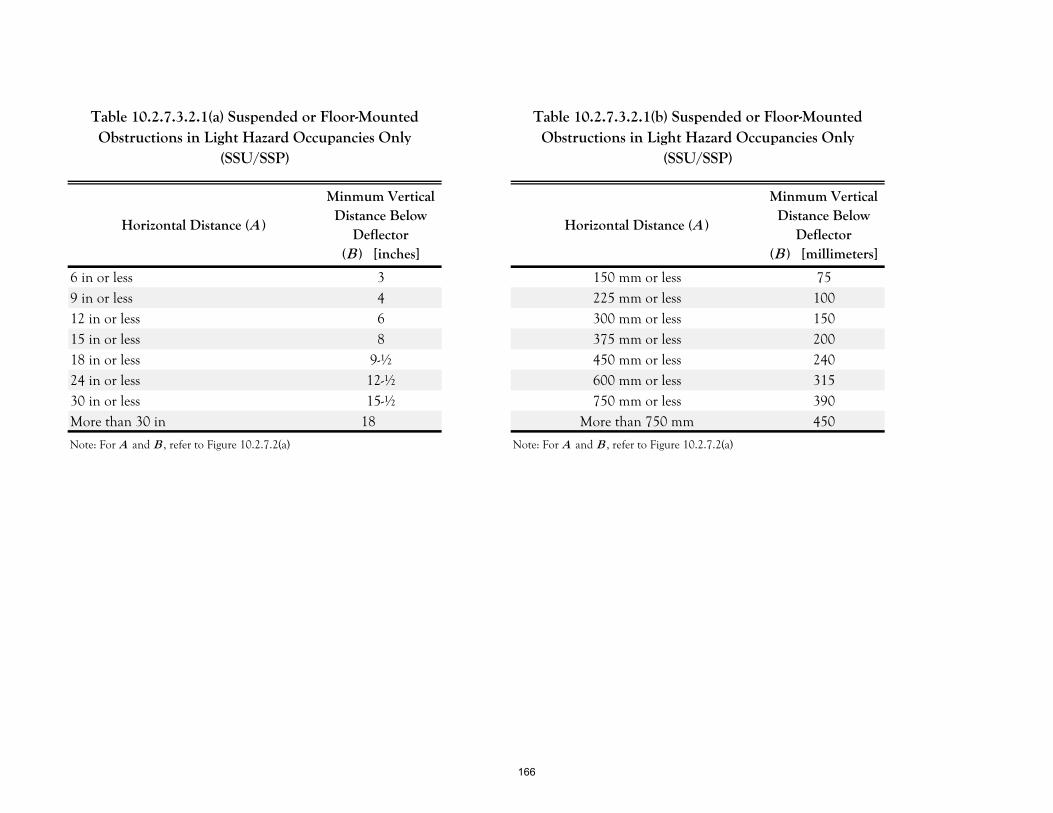
Horizontal Distance (A )
Minmum Vertical Distance Below
Deflector (B ) [inches]
Horizontal Distance (A )
Minmum Vertical Distance Below
Deflector (B ) [millimeters]
6 in or less 3 150 mm or less 759 in or less 4 225 mm or less 10012 in or less 6 300 mm or less 15015 in or less 8 375 mm or less 20018 in or less 9-½ 450 mm or less 24024 in or less 12-½ 600 mm or less 31530 in or less 15-½ 750 mm or less 390More than 30 in 18 More than 750 mm 450
Note: For A and B , refer to Figure 10.2.7.2(a) Note: For A and B , refer to Figure 10.2.7.2(a)
Table 10.2.7.3.2.1(a) Suspended or Floor-Mounted Obstructions in Light Hazard Occupancies Only
(SSU/SSP)
Table 10.2.7.3.2.1(b) Suspended or Floor-Mounted Obstructions in Light Hazard Occupancies Only
(SSU/SSP)
166

Public Comment No. 347-NFPA 13-2020 [ New Section after 10.2.7.3.2.2 ]
TITLE OF NEW CONTENT
10.2.7.3.2.2 In ordinary hazard occupancies, freestanding partitions, room dividers, and similar obstructionsshall be permitted when installed no more than 6 in. (150 mm) to the side of the centerline of the sprinklerdeflector and 6 in. (150 mm) or more below the sprinkler deflector in as illustrated in Figure 10. 2.7.3.2.2.
INSERT NEW FIGURE 10.2.7.3.2.2
Additional Proposed Changes
File Name Description Approved
OH_Partition_Rule_05_MAY_2020.pdf
Statement of Problem and Substantiation for Public Comment
This is related to PI-343 which seeks to move the Ordinary Hazard Partition language from 10.2.7.2.1 to this section with the revisions to the language which better capture the intent of this section.
Related Public Comments for This Document
Related Comment Relationship
Public Comment No. 343-NFPA 13-2020 [Section No. 10.2.7.2.1] related
Related Item
• FR-1123
Submitter Information Verification
Submitter Full Name: Roland Asp
Organization: National Fire Sprinkler Association
Affiliation: NFSA Engineering and Standards Committee
Street Address:
City:
State:
Zip:
Submittal Date: Tue May 05 16:49:37 EDT 2020
Committee: AUT-AAC
National Fire Protection Association Report https://submittals.nfpa.org/TerraViewWeb/ContentFetcher?commentPar...
190 of 738 5/8/2020, 11:28 AM
167

168
Public Comment No. 297-NFPA 13-2020 [ New Section after 10.2.8.2 ]
10.2.8.3
The clearance between the top of storage to sprinkler deflectors shall not be less than 36 in. (900 mm)where rubber tires are stored.
Statement of Problem and Substantiation for Public Comment
The clearance of 36 in. was included in the 2016 Edition as a general requirement for all rubber tire storage in 8.5.6.5. In the 2019 Edition that requirement was moved to 20.6.6.5 which would not apply to miscellaneous storage. If left uncorrected the clearance for miscellaneous rubber tire storage would be 18 in. rather than the previously required 36 in. The addition as a general requirement for all CMDA Sprinklers would correct this.
Related Item
• PI 143
Submitter Information Verification
Submitter Full Name: Tracey Bellamy
Organization: Telgian Corporation
Street Address:
City:
State:
Zip:
Submittal Date: Mon May 04 14:31:20 EDT 2020
Committee: AUT-AAC
National Fire Protection Association Report https://submittals.nfpa.org/TerraViewWeb/ContentFetcher?commentPar...
191 of 738 5/8/2020, 11:28 AM
169
Public Comment No. 195-NFPA 13-2020 [ Section No. 10.3.2 [Excluding any Sub-
Sections] ]
Sidewall sprinklers shall only be installed as follows:
(1) Light hazard occupancies with smooth, horizontal ceilings
(2) Light hazard occupancies with sloped, flat ceilings
(3) Ordinary hazard occupancies with smooth, flat ceilings where specifically listed for such use
(4) To protect areas below overhead doors
(5) At the top and bottom of elevator hoistways
(6) For the protection of steel building columns
(7) Under obstructions that require sprinklers
(8) For the protection of exterior projections and similar structures
(9) * Under cars in car stackers and car lift systems with cars stacked vertically placed under each level ofcars
A.10.3.2(9). Where sprinkler protection is provided under each level of cars, the ceilings sprinklers shouldbe designed based upon the occupancy classification of parking garages per section 4.3. Annex sectionA.4.3.3.1 indicates a suggests a classification of Ordinary hazard (Group 1) for Automobile parking andshowrooms.
Statement of Problem and Substantiation for Public Comment
This public comment resubmits the intent of PI-550 which although was not accepted at the first draft meeting, it was the basis of a committee input (CI-1126) which stated "The committee is seeking further information on the issue of car stackers / vertical car stackers and intends to revisit this subject in Second Draft."
The proposed subsection (9) would specifically allow sidewall sprinklers to be used to protect under cars in a car stacker. This is important because parking garages are typically considered to be ordinary hazard (A.4.3.3) but the addition of cars stacked vertically creates an obstruction. This comment will allow sidewall sprinklers to be installed under each level of cars while maintaining the typical ordinary hazard classification for the parking garage.The other option is no sprinklers under the cars and protect as an Extra Hazard Group 2 occupancy as suggested by section A.4.3.6(9).The proposed annex section clarifies that where sprinklers are installed beneath the obstructions caused by the cars (in stackers) the ceiling sprinklers need to be per the occupancy classification in section 4.3. Note that PC-171 recommends that parking garages remain as an example of Ordinary Hazard Group 1 occupancy
Related Public Comments for This Document
Related Comment Relationship
Public Comment No. 171-NFPA 13-2020 [Section No. A.4.3.3.1] related
Public Comment No. 196-NFPA 13-2020 [New Section after A.10.2.9.2(4)]
Related Item
• CI-1126 • PI-550
Submitter Information Verification
Submitter Full Name: Roland Asp
Organization: National Fire Sprinkler Association
Affiliation: On behalf of NFSA Engineering and Standards Committee
Street Address:
City:
State:
National Fire Protection Association Report https://submittals.nfpa.org/TerraViewWeb/ContentFetcher?commentPar...
192 of 738 5/8/2020, 11:28 AM
170

Zip:
Submittal Date: Thu Apr 30 07:28:16 EDT 2020
Committee: AUT-AAC
National Fire Protection Association Report https://submittals.nfpa.org/TerraViewWeb/ContentFetcher?commentPar...
193 of 738 5/8/2020, 11:28 AM
171

Public Comment No. 98-NFPA 13-2020 [ Section No. 10.3.4.1.4.2 ]
10.3.4.1.4.2
The lintel or soffit shall project a minimum of 4 in. (100 mm) below the deflector of the back-to-backhorizontal sidewall sprinklers.
Statement of Problem and Substantiation for Public Comment
While I agree that guidance is needed for the construction of the continuous lintels for back-to-back sidewall sprinkler installations, this proposal should not have been accepted, because no technical substantiation was provided to justify the 4 inch minimum dimension.It must be noted that for EC sidewall sprinklers, Figure A.11.3.5.1.3.2 illustrates a maximum 4 inch dimension. This discrepancy must be considered. How can the TC call for 4 inches minimum for one sprinkler in a soffit and 4 inches maximum for another similar configuration?
Related Item
• FR-1127
Submitter Information Verification
Submitter Full Name: Larry Keeping
Organization: PLC Fire Safety Solutions
Street Address:
City:
State:
Zip:
Submittal Date: Thu Apr 23 16:08:35 EDT 2020
Committee: AUT-AAC
National Fire Protection Association Report https://submittals.nfpa.org/TerraViewWeb/ContentFetcher?commentPar...
194 of 738 5/8/2020, 11:28 AM
172

Public Comment No. 127-NFPA 13-2020 [ Section No. 10.3.6.1.6 ]
10.3.6.1.6*
Obstructions on the wall opposite from the sidewall sprinkler shall be permitted where the obstruction is upto 2 ft (600 mm) deep and 2 ft (600 mm) wide. in accordance with Figure 10.3.6.1.6.
Additional Proposed Changes
File Name Description Approved
NFPA_13_Figure_10.3.6.1.6.pdf
Statement of Problem and Substantiation for Public Comment
Move annex figure and place in the body. All the other sidewall rules point to figures in the body of the standard. Makes it easier for the user.
Related Public Comments for This Document
Related Comment Relationship
Public Comment No. 128-NFPA 13-2020 [Section No. A.10.3.6.1.6]
Related Item
• PI #278
Submitter Information Verification
Submitter Full Name: Peter Schwab
Organization: Wayne Automatic Fire Sprinkler
Street Address:
City:
State:
Zip:
Submittal Date: Fri Apr 24 17:50:41 EDT 2020
Committee: AUT-AAC
National Fire Protection Association Report https://submittals.nfpa.org/TerraViewWeb/ContentFetcher?commentPar...
195 of 738 5/8/2020, 11:28 AM
173

174
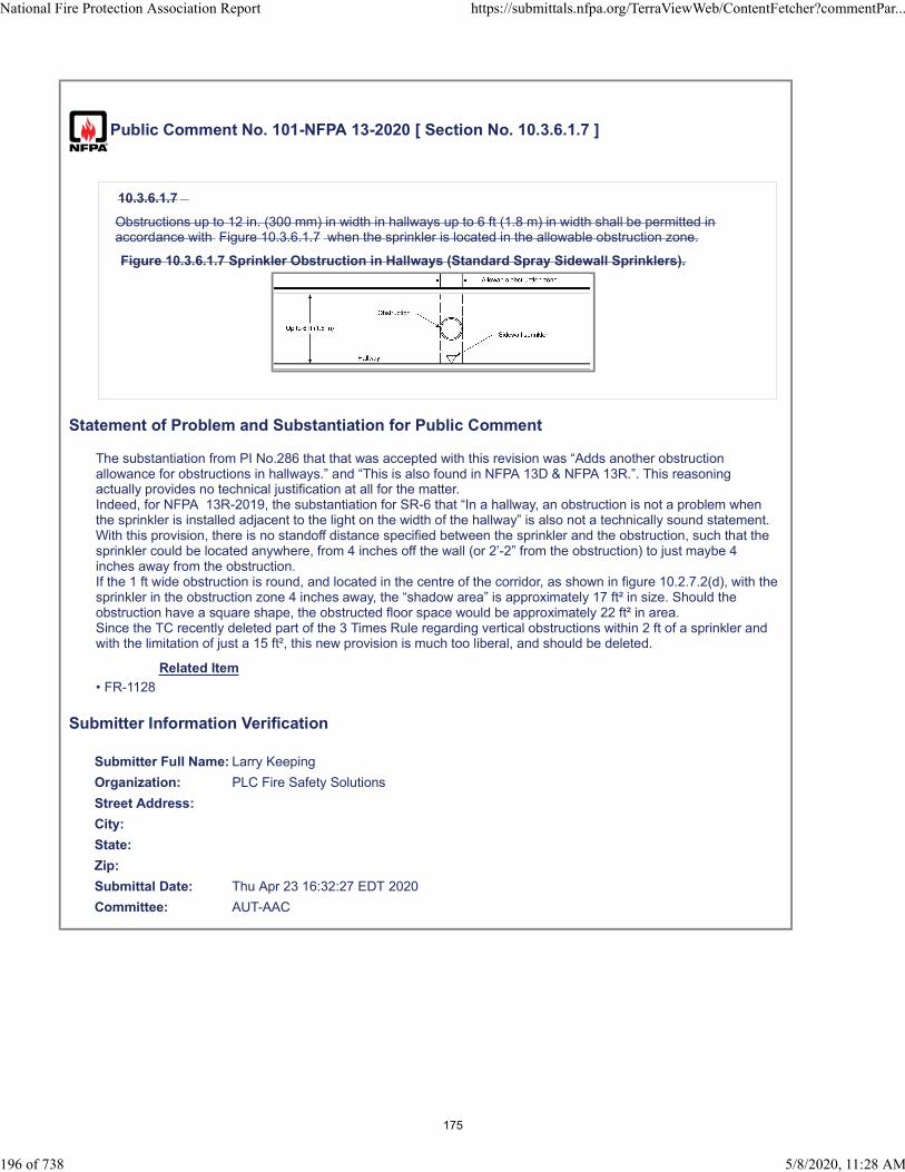
Public Comment No. 101-NFPA 13-2020 [ Section No. 10.3.6.1.7 ]
10.3.6.1.7
Obstructions up to 12 in. (300 mm) in width in hallways up to 6 ft (1.8 m) in width shall be permitted inaccordance with Figure 10.3.6.1.7 when the sprinkler is located in the allowable obstruction zone.
Figure 10.3.6.1.7 Sprinkler Obstruction in Hallways (Standard Spray Sidewall Sprinklers).
Statement of Problem and Substantiation for Public Comment
The substantiation from PI No.286 that that was accepted with this revision was “Adds another obstruction allowance for obstructions in hallways.” and “This is also found in NFPA 13D & NFPA 13R.”. This reasoning actually provides no technical justification at all for the matter.Indeed, for NFPA 13R-2019, the substantiation for SR-6 that “In a hallway, an obstruction is not a problem when the sprinkler is installed adjacent to the light on the width of the hallway” is also not a technically sound statement.With this provision, there is no standoff distance specified between the sprinkler and the obstruction, such that the sprinkler could be located anywhere, from 4 inches off the wall (or 2’-2” from the obstruction) to just maybe 4 inches away from the obstruction. If the 1 ft wide obstruction is round, and located in the centre of the corridor, as shown in figure 10.2.7.2(d), with the sprinkler in the obstruction zone 4 inches away, the “shadow area” is approximately 17 ft² in size. Should the obstruction have a square shape, the obstructed floor space would be approximately 22 ft² in area.Since the TC recently deleted part of the 3 Times Rule regarding vertical obstructions within 2 ft of a sprinkler and with the limitation of just a 15 ft², this new provision is much too liberal, and should be deleted.
Related Item
• FR-1128
Submitter Information Verification
Submitter Full Name: Larry Keeping
Organization: PLC Fire Safety Solutions
Street Address:
City:
State:
Zip:
Submittal Date: Thu Apr 23 16:32:27 EDT 2020
Committee: AUT-AAC
National Fire Protection Association Report https://submittals.nfpa.org/TerraViewWeb/ContentFetcher?commentPar...
196 of 738 5/8/2020, 11:28 AM
175

Public Comment No. 366-NFPA 13-2020 [ Section No. 10.3.6.1.7 ]
10.3.6.1.7
Obstructions up to 12 in. (300 mm) in width in hallways up to 6 ft (1.8 m) in width shall be permitted inaccordance with Figure 10.3.6.1.7 when the sprinkler is located in the allowable obstruction zone and theclosest edge of the obstruction is a minimum of 12 in . (300 mm) away from the deflector.
Figure 10.3.6.1.7 Sprinkler Obstruction in Hallways (Standard Spray Sidewall Sprinklers).
Statement of Problem and Substantiation for Public Comment
This comment (and others) were developed by a NFSA Engineering and Standards Committee Task Group on Obstructions. Additional comments are being submitted on this section in separate comments. The entire Task Group Report which addresses all the comments is being uploaded in this comment. This comment seeks to revise the language of 10.3.6.1.7) and is intended to minimize the apparent dry area that may be created by the obstruction adjacent to the sprinkler.
Related Public Comments for This Document
Related Comment Relationship
Public Comment No. 345-NFPA 13-2020 [Section No. 10.2.7.2 [Excluding any Sub-Sections]]
Public Comment No. 367-NFPA 13-2020 [Section No. 11.2.5.1.2]
Public Comment No. 368-NFPA 13-2020 [Section No. 11.3.6.1.4]
Public Comment No. 369-NFPA 13-2020 [Section No. 12.1.10.1.2]
Public Comment No. 370-NFPA 13-2020 [Section No. 12.1.11.1.4]
Related Item
• FR-1183
Submitter Information Verification
Submitter Full Name: Roland Asp
Organization: National Fire Sprinkler Association
Affiliation: NFSA Engineering and Standards Committee
Street Address:
City:
State:
Zip:
Submittal Date: Wed May 06 10:50:43 EDT 2020
Committee: AUT-AAC
National Fire Protection Association Report https://submittals.nfpa.org/TerraViewWeb/ContentFetcher?commentPar...
197 of 738 5/8/2020, 11:28 AM
176
Public Comment No. 102-NFPA 13-2020 [ Section No. 11.2.5.1.2 ]
National Fire Protection Association Report https://submittals.nfpa.org/TerraViewWeb/ContentFetcher?commentPar...
198 of 738 5/8/2020, 11:28 AM
177

11.2.5.1.2*
National Fire Protection Association Report https://submittals.nfpa.org/TerraViewWeb/ContentFetcher?commentPar...
199 of 738 5/8/2020, 11:28 AM
178

Sprinklers shall be arranged to comply with one of the following arrangements:
(1) Sprinklers shall be in accordance with 9.5.5.2, Table 11.2.5.1.2, and Figure 11.2.5.1.2(a).
(2) Sprinklers shall be permitted to be spaced on opposite sides of obstructions not exceeding 4 ft (1.2 m)in width provided the distance from the centerline of the obstruction to the sprinklers does not exceedone-half the allowable distance permitted between sprinklers.
(3) Obstructions located against the wall and that are not over 30 in. (750 mm) in width shall be permittedto be protected in accordance with Figure 11.2.5.1.2(b).
(4) Obstructions located against the wall and that are not over 24 in. (600 mm) in width shall be permittedto be protected in accordance with Figure 11.2.5.1.2(c). The maximum distance between the sprinklerand the wall shall be measured from the sprinkler to the wall behind the obstruction and not to the faceof the obstruction.
(5) Obstructions up to 12 in. (300 mm) in width in hallways up to 6 ft (1.8 m) in width shall be permitted inaccordance with Figure 11.2.5.1.2(d) when the sprinkler is located in the allowable obstruction zone.
Table 11.2.5.1.2 Position of Sprinklers to Avoid Obstructions to Discharge (Extended Coverage Uprightand Pendent Spray Sprinklers)
Minimum Distance from Sprinklers to Sideof Obstruction (A)
Maximum Allowable Distance of Deflector Above
Bottom of Obstruction (B)
ft m in. mm
Less than 1 ft Less than 0.3 0 0
1 0.3 0 0
11⁄2 0.45 1 25
2 0.6 1 25
21⁄2 0.75 1 25
3 0.9 3 75
31⁄2 1.1 3 75
4 1.2 5 125
41⁄2 1.4 7 175
5 1.5 7 175
51⁄2 1.7 7 175
6 1.8 9 225
61⁄2 2 11 275
7 2.1 14 350
71⁄2 2.3 14 350
8 2.4 15 375
81⁄2 2.6 17 425
9 2.7 19 475
91⁄2 2.9 21 525
Note: For A and B, refer to Figure 11.2.5.1.2(a).
Figure 11.2.5.1.2(a) Position of Sprinkler to Avoid Obstruction to Discharge (Extended CoverageUpright and Pendent Spray Sprinklers).
National Fire Protection Association Report https://submittals.nfpa.org/TerraViewWeb/ContentFetcher?commentPar...
200 of 738 5/8/2020, 11:28 AM
179

Figure 11.2.5.1.2(b) Obstructions Against Walls (Extended Coverage Upright and Pendent SpraySprinklers).
Figure 11.2.5.1.2(c) Obstructions Against Walls (Extended Coverage Upright and Pendent SpraySprinklers).
National Fire Protection Association Report https://submittals.nfpa.org/TerraViewWeb/ContentFetcher?commentPar...
201 of 738 5/8/2020, 11:28 AM
180
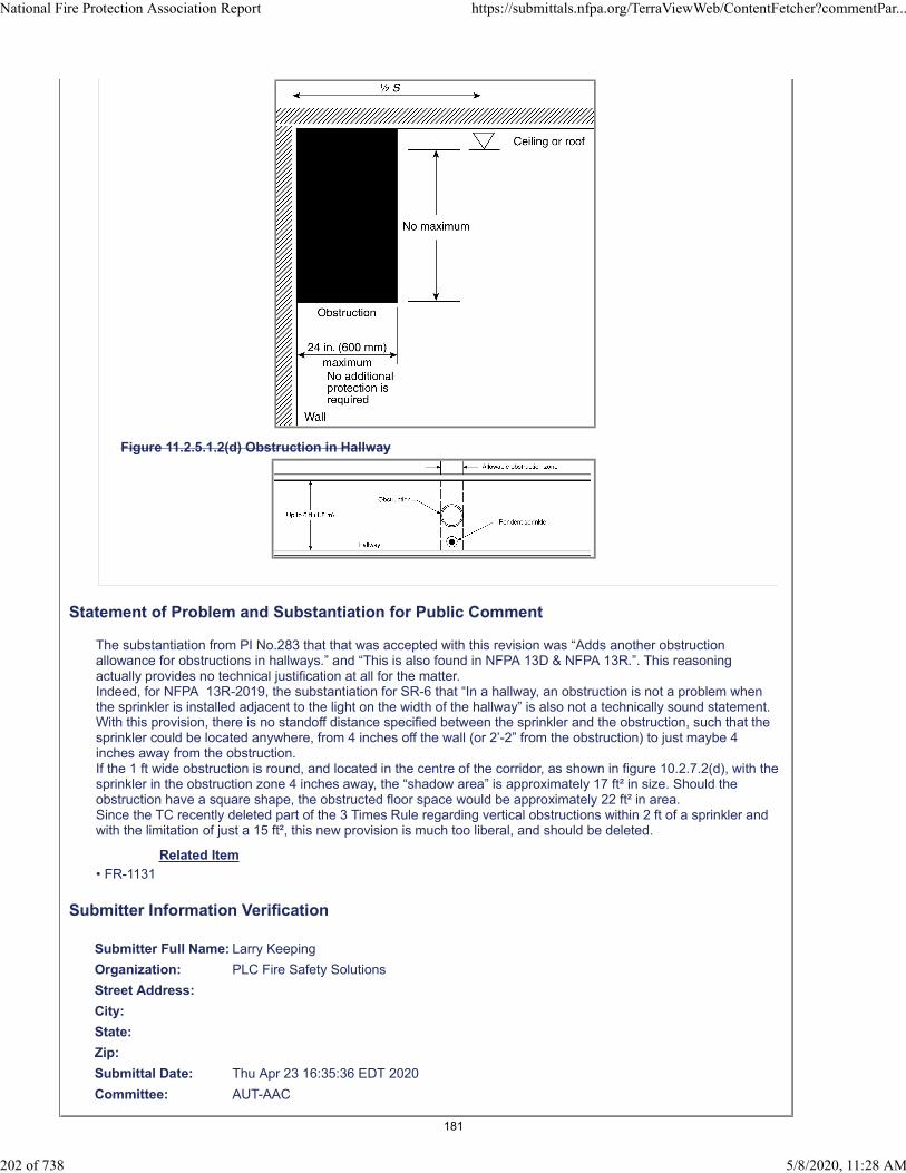
Figure 11.2.5.1.2(d) Obstruction in Hallway
Statement of Problem and Substantiation for Public Comment
The substantiation from PI No.283 that that was accepted with this revision was “Adds another obstruction allowance for obstructions in hallways.” and “This is also found in NFPA 13D & NFPA 13R.”. This reasoning actually provides no technical justification at all for the matter.Indeed, for NFPA 13R-2019, the substantiation for SR-6 that “In a hallway, an obstruction is not a problem when the sprinkler is installed adjacent to the light on the width of the hallway” is also not a technically sound statement.With this provision, there is no standoff distance specified between the sprinkler and the obstruction, such that the sprinkler could be located anywhere, from 4 inches off the wall (or 2’-2” from the obstruction) to just maybe 4 inches away from the obstruction. If the 1 ft wide obstruction is round, and located in the centre of the corridor, as shown in figure 10.2.7.2(d), with the sprinkler in the obstruction zone 4 inches away, the “shadow area” is approximately 17 ft² in size. Should the obstruction have a square shape, the obstructed floor space would be approximately 22 ft² in area.Since the TC recently deleted part of the 3 Times Rule regarding vertical obstructions within 2 ft of a sprinkler and with the limitation of just a 15 ft², this new provision is much too liberal, and should be deleted.
Related Item
• FR-1131
Submitter Information Verification
Submitter Full Name: Larry Keeping
Organization: PLC Fire Safety Solutions
Street Address:
City:
State:
Zip:
Submittal Date: Thu Apr 23 16:35:36 EDT 2020
Committee: AUT-AAC
National Fire Protection Association Report https://submittals.nfpa.org/TerraViewWeb/ContentFetcher?commentPar...
202 of 738 5/8/2020, 11:28 AM
181

Public Comment No. 367-NFPA 13-2020 [ Section No. 11.2.5.1.2 ]
National Fire Protection Association Report https://submittals.nfpa.org/TerraViewWeb/ContentFetcher?commentPar...
203 of 738 5/8/2020, 11:28 AM
182

11.2.5.1.2*
National Fire Protection Association Report https://submittals.nfpa.org/TerraViewWeb/ContentFetcher?commentPar...
204 of 738 5/8/2020, 11:28 AM
183
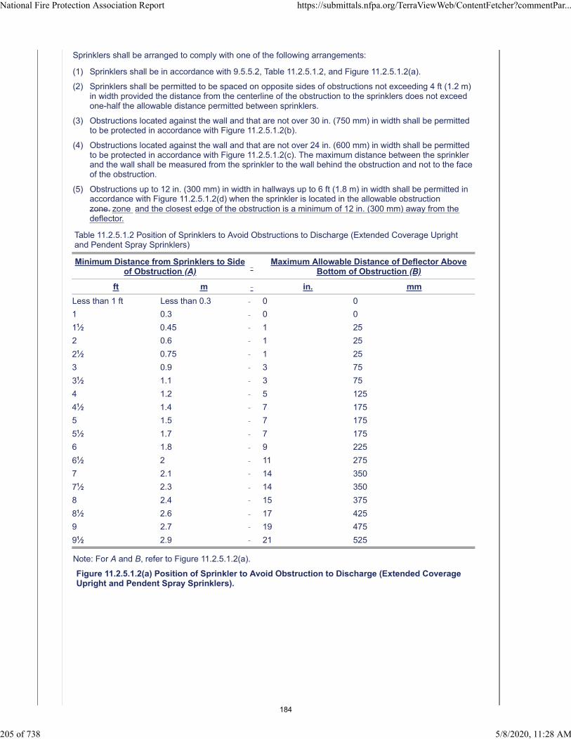
Sprinklers shall be arranged to comply with one of the following arrangements:
(1) Sprinklers shall be in accordance with 9.5.5.2, Table 11.2.5.1.2, and Figure 11.2.5.1.2(a).
(2) Sprinklers shall be permitted to be spaced on opposite sides of obstructions not exceeding 4 ft (1.2 m)in width provided the distance from the centerline of the obstruction to the sprinklers does not exceedone-half the allowable distance permitted between sprinklers.
(3) Obstructions located against the wall and that are not over 30 in. (750 mm) in width shall be permittedto be protected in accordance with Figure 11.2.5.1.2(b).
(4) Obstructions located against the wall and that are not over 24 in. (600 mm) in width shall be permittedto be protected in accordance with Figure 11.2.5.1.2(c). The maximum distance between the sprinklerand the wall shall be measured from the sprinkler to the wall behind the obstruction and not to the faceof the obstruction.
(5) Obstructions up to 12 in. (300 mm) in width in hallways up to 6 ft (1.8 m) in width shall be permitted inaccordance with Figure 11.2.5.1.2(d) when the sprinkler is located in the allowable obstructionzone. zone and the closest edge of the obstruction is a minimum of 12 in. (300 mm) away from thedeflector.
Table 11.2.5.1.2 Position of Sprinklers to Avoid Obstructions to Discharge (Extended Coverage Uprightand Pendent Spray Sprinklers)
Minimum Distance from Sprinklers to Sideof Obstruction (A)
Maximum Allowable Distance of Deflector Above
Bottom of Obstruction (B)
ft m in. mm
Less than 1 ft Less than 0.3 0 0
1 0.3 0 0
11⁄2 0.45 1 25
2 0.6 1 25
21⁄2 0.75 1 25
3 0.9 3 75
31⁄2 1.1 3 75
4 1.2 5 125
41⁄2 1.4 7 175
5 1.5 7 175
51⁄2 1.7 7 175
6 1.8 9 225
61⁄2 2 11 275
7 2.1 14 350
71⁄2 2.3 14 350
8 2.4 15 375
81⁄2 2.6 17 425
9 2.7 19 475
91⁄2 2.9 21 525
Note: For A and B, refer to Figure 11.2.5.1.2(a).
Figure 11.2.5.1.2(a) Position of Sprinkler to Avoid Obstruction to Discharge (Extended CoverageUpright and Pendent Spray Sprinklers).
National Fire Protection Association Report https://submittals.nfpa.org/TerraViewWeb/ContentFetcher?commentPar...
205 of 738 5/8/2020, 11:28 AM
184

Figure 11.2.5.1.2(b) Obstructions Against Walls (Extended Coverage Upright and Pendent SpraySprinklers).
Figure 11.2.5.1.2(c) Obstructions Against Walls (Extended Coverage Upright and Pendent SpraySprinklers).
National Fire Protection Association Report https://submittals.nfpa.org/TerraViewWeb/ContentFetcher?commentPar...
206 of 738 5/8/2020, 11:28 AM
185

Figure 11.2.5.1.2(d) Obstruction in Hallway
Statement of Problem and Substantiation for Public Comment
This comment (and others) were developed by a NFSA Engineering and Standards Committee Task Group on Obstructions. Additional comments are being submitted on this section in separate comments. The entire Task Group Report which addresses all the comments is being uploaded in this comment. This comment seeks to revise the language of 11.2.5.1.2(5) and is intended to minimize the apparent dry area that may be created by the obstruction adjacent to the sprinkler.
Related Public Comments for This Document
Related Comment Relationship
Public Comment No. 345-NFPA 13-2020 [Section No. 10.2.7.2 [Excluding any Sub-Sections]]
Public Comment No. 366-NFPA 13-2020 [Section No. 10.3.6.1.7]
Public Comment No. 368-NFPA 13-2020 [Section No. 11.3.6.1.4]
Public Comment No. 369-NFPA 13-2020 [Section No. 12.1.10.1.2]
Public Comment No. 370-NFPA 13-2020 [Section No. 12.1.11.1.4]
Related Item
• FR-1131`
Submitter Information Verification
Submitter Full Name: Roland Asp
Organization: National Fire Sprinkler Association
Affiliation: NFSA Engineering and Standards Committee
Street Address:
City:
State:
National Fire Protection Association Report https://submittals.nfpa.org/TerraViewWeb/ContentFetcher?commentPar...
207 of 738 5/8/2020, 11:28 AM
186

Zip:
Submittal Date: Wed May 06 11:02:25 EDT 2020
Committee: AUT-AAC
National Fire Protection Association Report https://submittals.nfpa.org/TerraViewWeb/ContentFetcher?commentPar...
208 of 738 5/8/2020, 11:28 AM
187
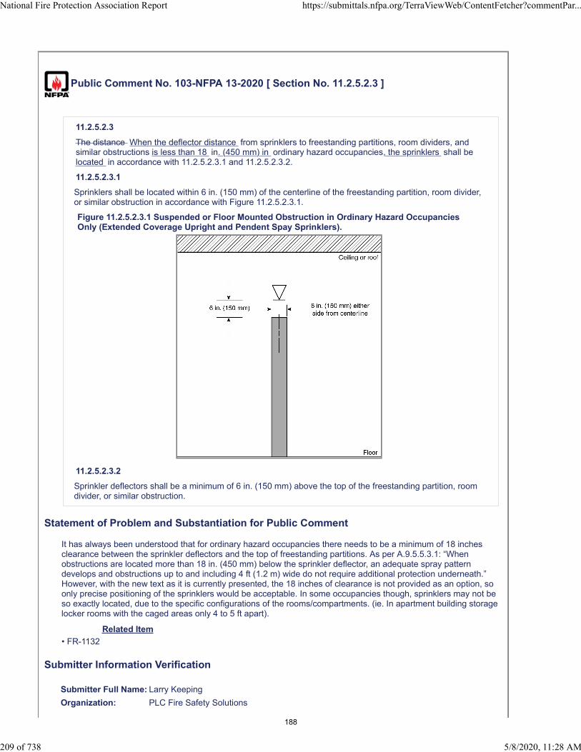
Public Comment No. 103-NFPA 13-2020 [ Section No. 11.2.5.2.3 ]
11.2.5.2.3
The distance When the deflector distance from sprinklers to freestanding partitions, room dividers, andsimilar obstructions is less than 18 in. (450 mm) in ordinary hazard occupancies, the sprinklers shall belocated in accordance with 11.2.5.2.3.1 and 11.2.5.2.3.2.
11.2.5.2.3.1
Sprinklers shall be located within 6 in. (150 mm) of the centerline of the freestanding partition, room divider,or similar obstruction in accordance with Figure 11.2.5.2.3.1.
Figure 11.2.5.2.3.1 Suspended or Floor Mounted Obstruction in Ordinary Hazard OccupanciesOnly (Extended Coverage Upright and Pendent Spay Sprinklers).
11.2.5.2.3.2
Sprinkler deflectors shall be a minimum of 6 in. (150 mm) above the top of the freestanding partition, roomdivider, or similar obstruction.
Statement of Problem and Substantiation for Public Comment
It has always been understood that for ordinary hazard occupancies there needs to be a minimum of 18 inches clearance between the sprinkler deflectors and the top of freestanding partitions. As per A.9.5.5.3.1: “When obstructions are located more than 18 in. (450 mm) below the sprinkler deflector, an adequate spray pattern develops and obstructions up to and including 4 ft (1.2 m) wide do not require additional protection underneath.” However, with the new text as it is currently presented, the 18 inches of clearance is not provided as an option, so only precise positioning of the sprinklers would be acceptable. In some occupancies though, sprinklers may not be so exactly located, due to the specific configurations of the rooms/compartments. (ie. In apartment building storage locker rooms with the caged areas only 4 to 5 ft apart).
Related Item
• FR-1132
Submitter Information Verification
Submitter Full Name: Larry Keeping
Organization: PLC Fire Safety Solutions
National Fire Protection Association Report https://submittals.nfpa.org/TerraViewWeb/ContentFetcher?commentPar...
209 of 738 5/8/2020, 11:28 AM
188

Street Address:
City:
State:
Zip:
Submittal Date: Thu Apr 23 16:38:38 EDT 2020
Committee: AUT-AAC
National Fire Protection Association Report https://submittals.nfpa.org/TerraViewWeb/ContentFetcher?commentPar...
210 of 738 5/8/2020, 11:28 AM
189

Public Comment No. 299-NFPA 13-2020 [ New Section after 11.2.6.2 ]
11.2.6.3
The clearance from the top of storage to sprinkler deflectors shall not be less than 36 in. (900 mm) whererubber tires are stored.
Statement of Problem and Substantiation for Public Comment
The clearance of 36 in. was included in the 2016 Edition as a general requirement for all rubber tire storage in 8.5.6.5. In the 2019 Edition that requirement was moved to 20.6.6.5 which would not apply to miscellaneous storage. If left uncorrected the clearance for miscellaneous rubber tire storage would be 18 in. rather than the previously required 36 in. The addition as a general requirement for all CMDA Sprinklers would correct this.
Related Item
• PI 145
Submitter Information Verification
Submitter Full Name: Tracey Bellamy
Organization: Telgian Corporation
Street Address:
City:
State:
Zip:
Submittal Date: Mon May 04 14:44:02 EDT 2020
Committee: AUT-AAC
National Fire Protection Association Report https://submittals.nfpa.org/TerraViewWeb/ContentFetcher?commentPar...
211 of 738 5/8/2020, 11:28 AM
190
Public Comment No. 286-NFPA 13-2020 [ Section No. 11.3.4.1.5 ]
11.3.4.1.5
Where sidewall extended coverage spray sprinklers are installed to protect areas below overhead doorswithin ordinary hazard occupancy spaces or rooms, listed light hazard sidewall extended coverage spraysprinklers shall be permitted and the protection area and maximum sprinkler spacing for light hazard asspecified in Table 11.3.3.2.1 shall be permitted under the overhead doors .
Statement of Problem and Substantiation for Public Comment
In the original language there is no clarification that ECLH sprinklers can be used in this application and overhead doors is repeated in the back of the sentence when it is already clarified in the front of the sentence. This language makes the new section clearer.
Related Item
• FR-1135
Submitter Information Verification
Submitter Full Name: Kevin Hall
Organization: NFSA
Affiliation: NFSA Engineering and Standards Committee
Street Address:
City:
State:
Zip:
Submittal Date: Mon May 04 14:06:36 EDT 2020
Committee: AUT-AAC
National Fire Protection Association Report https://submittals.nfpa.org/TerraViewWeb/ContentFetcher?commentPar...
212 of 738 5/8/2020, 11:28 AM
191
Public Comment No. 104-NFPA 13-2020 [ Section No. 11.3.6.1.4 ]
National Fire Protection Association Report https://submittals.nfpa.org/TerraViewWeb/ContentFetcher?commentPar...
213 of 738 5/8/2020, 11:28 AM
192

11.3.6.1.4
National Fire Protection Association Report https://submittals.nfpa.org/TerraViewWeb/ContentFetcher?commentPar...
214 of 738 5/8/2020, 11:28 AM
193

Continuous obstructions projecting from the same wall as the one on which the sidewall sprinkler ismounted shall be in accordance with one of the following arrangements:
(1) Sprinklers shall be installed in accordance with Table 11.3.6.1.4 and Figure 11.3.6.1.4(a).
(2) Sprinklers shall be permitted to be spaced on opposite sides of obstructions less than 4 ft (1.2 m) inwidth where the distance from the centerline of the obstruction to the sprinklers does not exceed one-half the allowable distance between sprinklers.
(3) Obstructions located against the wall and that are not over 30 in. (750 mm) in width shall be permittedto be protected in accordance with Figure 11.3.6.1.4(b).
(4) Obstructions located against the wall and that are not over 24 in. (600 mm) in width shall be permittedto be protected in accordance with Figure 11.3.6.1.4(c). The maximum distance between the sprinklerand the wall shall be measured from the sprinkler to the wall behind the obstruction and not to the faceof the obstruction.
(5) Obstructions with a maximum width of 12 in. (300 mm) in hallways up to 6 ft (1.8 m) in width shall bepermitted in accordance with Figure 11.3.6.1.4(d) when the sprinkler is located in the allowableobstruction zone.
Table 11.3.6.1.4 Positioning of Sprinklers to Avoid Obstructions Along Wall (Extended Coverage SidewallSpray Sprinklers)
Distance from Sidewall Sprinkler to Side ofObstruction (A)
Maximum Allowable Distance of Deflector AboveBottom of Obstruction (B)
in. mm
Less than 1 ft 6 in. (450 mm) 0 0
1 ft 6 in. (450 mm) to less than 3 ft (900 mm) 1 25
3 ft (900 mm) to less than 4 ft (1.2 m) 3 75
4 ft (1.2 m) to less than 4 ft 6 in. (1.4 m) 5 125
4 ft 6 in. (1.4 m) to less than 6 ft (1.5 m) 7 175
6 ft (1.5 m) to less than 6 ft 6 in. (2.0 m) 9 225
6 ft 6 in. (2.0 m) to less than 7 ft (2.1 m) 11 275
7 ft (2.1 m) to less than 7 ft 6 in. (2.3 m) 14 350
Note: For A and B, refer to Figure 11.3.6.1.4(a).
Figure 11.3.6.1.4(a) Positioning of Sprinkler to Avoid Obstruction Along Wall (Extended CoverageSidewall Spray Sprinklers).
Figure 11.3.6.1.4(b) Obstruction Against Wall (Extended Coverage Sidewall Spray Sprinklers).
National Fire Protection Association Report https://submittals.nfpa.org/TerraViewWeb/ContentFetcher?commentPar...
215 of 738 5/8/2020, 11:28 AM
194
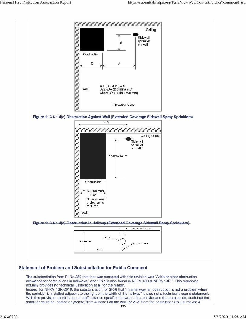
Figure 11.3.6.1.4(c) Obstruction Against Wall (Extended Coverage Sidewall Spray Sprinklers).
Figure 11.3.6.1.4(d) Obstruction in Hallway (Extended Coverage Sidewall Spray Sprinklers).
Statement of Problem and Substantiation for Public Comment
The substantiation from PI No.289 that that was accepted with this revision was “Adds another obstruction allowance for obstructions in hallways.” and “This is also found in NFPA 13D & NFPA 13R.”. This reasoning actually provides no technical justification at all for the matter.Indeed, for NFPA 13R-2019, the substantiation for SR-6 that “In a hallway, an obstruction is not a problem when the sprinkler is installed adjacent to the light on the width of the hallway” is also not a technically sound statement.With this provision, there is no standoff distance specified between the sprinkler and the obstruction, such that the sprinkler could be located anywhere, from 4 inches off the wall (or 2’-2” from the obstruction) to just maybe 4
National Fire Protection Association Report https://submittals.nfpa.org/TerraViewWeb/ContentFetcher?commentPar...
216 of 738 5/8/2020, 11:28 AM
195

inches away from the obstruction. If the 1 ft wide obstruction is round, and located in the centre of the corridor, as shown in figure 10.2.7.2(d), with the sprinkler in the obstruction zone 4 inches away, the “shadow area” is approximately 17 ft² in size. Should the obstruction have a square shape, the obstructed floor space would be approximately 22 ft² in area.Since the TC recently deleted part of the 3 Times Rule regarding vertical obstructions within 2 ft of a sprinkler and with the limitation of just a 15 ft², this new provision is much too liberal, and should be deleted
Related Item
• FR-1137
Submitter Information Verification
Submitter Full Name: Larry Keeping
Organization: PLC Fire Safety Solutions
Street Address:
City:
State:
Zip:
Submittal Date: Thu Apr 23 16:44:48 EDT 2020
Committee: AUT-AAC
National Fire Protection Association Report https://submittals.nfpa.org/TerraViewWeb/ContentFetcher?commentPar...
217 of 738 5/8/2020, 11:28 AM
196

Public Comment No. 368-NFPA 13-2020 [ Section No. 11.3.6.1.4 ]
National Fire Protection Association Report https://submittals.nfpa.org/TerraViewWeb/ContentFetcher?commentPar...
218 of 738 5/8/2020, 11:28 AM
197

11.3.6.1.4
National Fire Protection Association Report https://submittals.nfpa.org/TerraViewWeb/ContentFetcher?commentPar...
219 of 738 5/8/2020, 11:28 AM
198
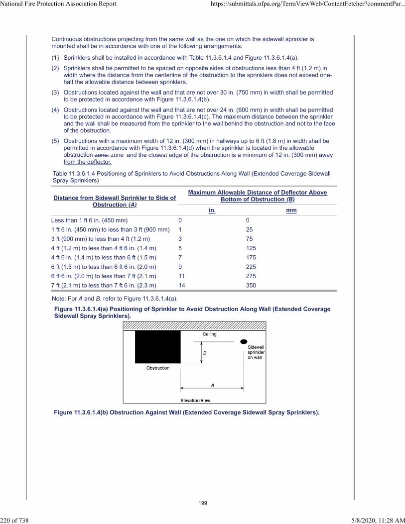
Continuous obstructions projecting from the same wall as the one on which the sidewall sprinkler ismounted shall be in accordance with one of the following arrangements:
(1) Sprinklers shall be installed in accordance with Table 11.3.6.1.4 and Figure 11.3.6.1.4(a).
(2) Sprinklers shall be permitted to be spaced on opposite sides of obstructions less than 4 ft (1.2 m) inwidth where the distance from the centerline of the obstruction to the sprinklers does not exceed one-half the allowable distance between sprinklers.
(3) Obstructions located against the wall and that are not over 30 in. (750 mm) in width shall be permittedto be protected in accordance with Figure 11.3.6.1.4(b).
(4) Obstructions located against the wall and that are not over 24 in. (600 mm) in width shall be permittedto be protected in accordance with Figure 11.3.6.1.4(c). The maximum distance between the sprinklerand the wall shall be measured from the sprinkler to the wall behind the obstruction and not to the faceof the obstruction.
(5) Obstructions with a maximum width of 12 in. (300 mm) in hallways up to 6 ft (1.8 m) in width shall bepermitted in accordance with Figure 11.3.6.1.4(d) when the sprinkler is located in the allowableobstruction zone. zone and the closest edge of the obstruction is a minimum of 12 in. (300 mm) awayfrom the deflector.
Table 11.3.6.1.4 Positioning of Sprinklers to Avoid Obstructions Along Wall (Extended Coverage SidewallSpray Sprinklers)
Distance from Sidewall Sprinkler to Side ofObstruction (A)
Maximum Allowable Distance of Deflector AboveBottom of Obstruction (B)
in. mm
Less than 1 ft 6 in. (450 mm) 0 0
1 ft 6 in. (450 mm) to less than 3 ft (900 mm) 1 25
3 ft (900 mm) to less than 4 ft (1.2 m) 3 75
4 ft (1.2 m) to less than 4 ft 6 in. (1.4 m) 5 125
4 ft 6 in. (1.4 m) to less than 6 ft (1.5 m) 7 175
6 ft (1.5 m) to less than 6 ft 6 in. (2.0 m) 9 225
6 ft 6 in. (2.0 m) to less than 7 ft (2.1 m) 11 275
7 ft (2.1 m) to less than 7 ft 6 in. (2.3 m) 14 350
Note: For A and B, refer to Figure 11.3.6.1.4(a).
Figure 11.3.6.1.4(a) Positioning of Sprinkler to Avoid Obstruction Along Wall (Extended CoverageSidewall Spray Sprinklers).
Figure 11.3.6.1.4(b) Obstruction Against Wall (Extended Coverage Sidewall Spray Sprinklers).
National Fire Protection Association Report https://submittals.nfpa.org/TerraViewWeb/ContentFetcher?commentPar...
220 of 738 5/8/2020, 11:28 AM
199

Figure 11.3.6.1.4(c) Obstruction Against Wall (Extended Coverage Sidewall Spray Sprinklers).
Figure 11.3.6.1.4(d) Obstruction in Hallway (Extended Coverage Sidewall Spray Sprinklers).
Statement of Problem and Substantiation for Public Comment
This comment (and others) were developed by a NFSA Engineering and Standards Committee Task Group on Obstructions. Additional comments are being submitted on this section in separate comments. The entire Task Group Report which addresses all the comments is being uploaded in this comment. This comment seeks to revise the language of 10.3.6.1.4(5) and is intended to minimize the apparent dry area that may be created by the obstruction adjacent to the sprinkler.
Related Public Comments for This Document
National Fire Protection Association Report https://submittals.nfpa.org/TerraViewWeb/ContentFetcher?commentPar...
221 of 738 5/8/2020, 11:28 AM
200
Related Comment Relationship
Public Comment No. 345-NFPA 13-2020 [Section No. 10.2.7.2 [Excluding any Sub-Sections]]
Public Comment No. 366-NFPA 13-2020 [Section No. 10.3.6.1.7]
Public Comment No. 367-NFPA 13-2020 [Section No. 11.2.5.1.2]
Public Comment No. 369-NFPA 13-2020 [Section No. 12.1.10.1.2]
Public Comment No. 370-NFPA 13-2020 [Section No. 12.1.11.1.4]
Related Item
• FR-1137
Submitter Information Verification
Submitter Full Name: Roland Asp
Organization: National Fire Sprinkler Association
Affiliation: NFSA Engineering and Standards Committee
Street Address:
City:
State:
Zip:
Submittal Date: Wed May 06 11:06:16 EDT 2020
Committee: AUT-AAC
National Fire Protection Association Report https://submittals.nfpa.org/TerraViewWeb/ContentFetcher?commentPar...
222 of 738 5/8/2020, 11:28 AM
201
Public Comment No. 129-NFPA 13-2020 [ Section No. 11.3.6.1.6 ]
11.3.6.1.6*
Obstructions on the wall opposite from the sidewall sprinkler shall be permitted where the obstruction is upto 2 ft (600 mm) deep and 2 ft (600 mm) wide. in accordance with Figure 11.3.6.1.6.
Additional Proposed Changes
File Name Description Approved
NFPA_13_Figure_11.3.6.1.6.pdf
Statement of Problem and Substantiation for Public Comment
Move annex figure and place in the body. All the other sidewall rules point to figures in the body of the standard. Makes it easier for the user.
Related Public Comments for This Document
Related Comment Relationship
Public Comment No. 130-NFPA 13-2020 [Section No. A.11.3.6.1.6]
Related Item
• PI#278
Submitter Information Verification
Submitter Full Name: Peter Schwab
Organization: Wayne Automatic Fire Sprinkler
Street Address:
City:
State:
Zip:
Submittal Date: Fri Apr 24 18:31:13 EDT 2020
Committee: AUT-AAC
National Fire Protection Association Report https://submittals.nfpa.org/TerraViewWeb/ContentFetcher?commentPar...
223 of 738 5/8/2020, 11:28 AM
202

203
Public Comment No. 146-NFPA 13-2020 [ New Section after 12.1.4 ]
12.1.4.1
Residential sprinklers shall be permitted to be installed adjacent to quick response sprinklers in corridors ofresidential occupancies.
Statement of Problem and Substantiation for Public Comment
This language was submitted in the first draft (PI#432). The committee response for resolution was "Based on action taken on EC and standard coverage sprinklers."
I feel that I deserve a better response for a rejection from this committee. The response did not point to any specific section, PI or FR. In many hotels, the corridors connected to the lobby are usually not separated with a door or lintel. The lobby is protected with QR sprinklers. Since there is not a separation, residential sprinklers cannot be used in those corridors as it would violate section 12.1.4.
Related Item
• PI#432
Submitter Information Verification
Submitter Full Name: Peter Schwab
Organization: Wayne Automatic Fire Sprinkler
Street Address:
City:
State:
Zip:
Submittal Date: Sat Apr 25 13:57:03 EDT 2020
Committee: AUT-AAC
National Fire Protection Association Report https://submittals.nfpa.org/TerraViewWeb/ContentFetcher?commentPar...
224 of 738 5/8/2020, 11:28 AM
204

Public Comment No. 166-NFPA 13-2020 [ Section No. 12.1.7.5 ]
12.1.7.5
The maximum distance shall be measured along the slope of the ceiling as shown in Figure 12.1.7.5(a) andFigure 12.1.7.5(b) and the maximum vertical distance from the peak shall be no more than 3 ft .
Figure 12.1.7.5(a) Maximum Distance Between Sprinklers with Sloped Ceilings — Arrangement A.
Figure 12.1.7.5(b) Maximum Distance Between Sprinklers with Sloped Ceilings — Arrangement B.
Statement of Problem and Substantiation for Public Comment
As noted by the correlating committee, the requirement for a sprinkler to be installed within 3 ft of the peak needed
National Fire Protection Association Report https://submittals.nfpa.org/TerraViewWeb/ContentFetcher?commentPar...
225 of 738 5/8/2020, 11:28 AM
205
to be clarified
Related Item
• CN-39
Submitter Information Verification
Submitter Full Name: Kevin Hall
Organization: NFSA
Affiliation: NFSA Engineering and Standards Committee
Street Address:
City:
State:
Zip:
Submittal Date: Mon Apr 27 09:55:19 EDT 2020
Committee: AUT-AAC
National Fire Protection Association Report https://submittals.nfpa.org/TerraViewWeb/ContentFetcher?commentPar...
226 of 738 5/8/2020, 11:28 AM
206

Public Comment No. 167-NFPA 13-2020 [ Section No. 12.1.7.6 ]
12.1.7.6
Where sprinklers are installed along sloped ceilings, a sprinkler shall be installed within 3 ft of the peakand the sprinklers shall maintain the minimum listed spacing, but no less than 8 ft (2.4 m), measured in theplan view from one sprinkler to another as shown in Figure 12.1.7.6(a) and Figure 12.1.7.6(b), or unlessseparated by baffles that comply with the following:
(1) Baffles shall be arranged to protect the actuating elements.
(2) Baffles shall be of solid and rigid material that will stay in place before and during sprinkler operation.
(3) Baffles shall be not less than 8 in. (200 mm) long and 6 in. (150 mm) high.
(4) The tops of baffles shall extend between 2 in. and 3 in. (50 mm and 75 mm) above the deflectors ofupright sprinklers.
(5) The bottoms of baffles shall extend downward to a level at least even with the deflectors of pendentsprinklers.
Figure 12.1.7.6(a) Minimum Distance Between Sprinklers with Sloped Ceilings — Arrangement A.
Figure 12.1.7.6(b) Minimum Distance Between Sprinklers with Sloped Ceilings — Arrangement B.
Statement of Problem and Substantiation for Public Comment
National Fire Protection Association Report https://submittals.nfpa.org/TerraViewWeb/ContentFetcher?commentPar...
227 of 738 5/8/2020, 11:28 AM
207
As noted by the correlating committee, the requirement for a sprinkler to be installed within 3 ft of the peak needed to be clarified
Related Item
• CN-39
Submitter Information Verification
Submitter Full Name: Kevin Hall
Organization: NFSA
Affiliation: NFSA Engineering and Standards Committee
Street Address:
City:
State:
Zip:
Submittal Date: Mon Apr 27 10:08:37 EDT 2020
Committee: AUT-AAC
National Fire Protection Association Report https://submittals.nfpa.org/TerraViewWeb/ContentFetcher?commentPar...
228 of 738 5/8/2020, 11:28 AM
208
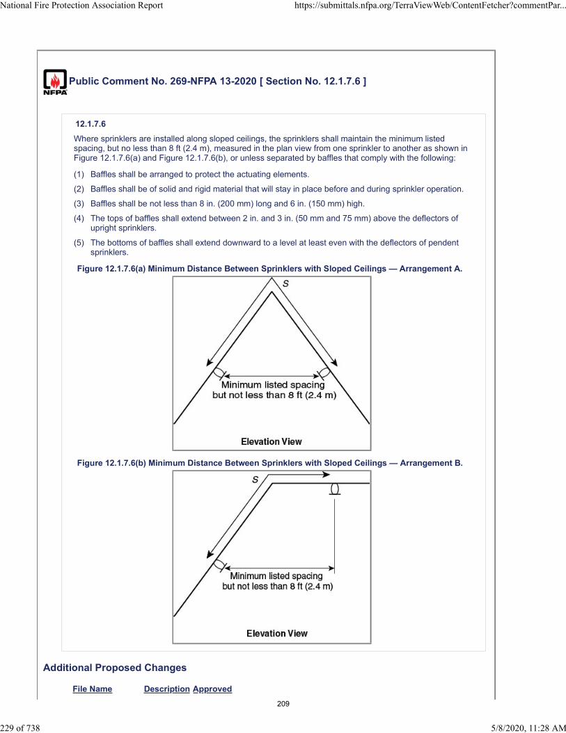
Public Comment No. 269-NFPA 13-2020 [ Section No. 12.1.7.6 ]
12.1.7.6
Where sprinklers are installed along sloped ceilings, the sprinklers shall maintain the minimum listedspacing, but no less than 8 ft (2.4 m), measured in the plan view from one sprinkler to another as shown inFigure 12.1.7.6(a) and Figure 12.1.7.6(b), or unless separated by baffles that comply with the following:
(1) Baffles shall be arranged to protect the actuating elements.
(2) Baffles shall be of solid and rigid material that will stay in place before and during sprinkler operation.
(3) Baffles shall be not less than 8 in. (200 mm) long and 6 in. (150 mm) high.
(4) The tops of baffles shall extend between 2 in. and 3 in. (50 mm and 75 mm) above the deflectors ofupright sprinklers.
(5) The bottoms of baffles shall extend downward to a level at least even with the deflectors of pendentsprinklers.
Figure 12.1.7.6(a) Minimum Distance Between Sprinklers with Sloped Ceilings — Arrangement A.
Figure 12.1.7.6(b) Minimum Distance Between Sprinklers with Sloped Ceilings — Arrangement B.
Additional Proposed Changes
File Name Description Approved
National Fire Protection Association Report https://submittals.nfpa.org/TerraViewWeb/ContentFetcher?commentPar...
229 of 738 5/8/2020, 11:28 AM
209

13_CCN_39.pdf 13_CCN_39
Statement of Problem and Substantiation for Public Comment
NOTE: This Public Comment appeared as CC Note No. 39 in the First Draft Report.
The Correlating Committee directs AUT-RSS and AUT-SSI to review residential sprinkler installation under peaked roofs and determine if the maximum 3 ft vertical distance down from peak requirement for standard spray sprinklers is also applicable to residential sprinklers. If so, add requirements to correlate residential sprinklers in NFPA 13, 13D, and 13R with the 3 ft requirement of standard spray sprinklers.
Related Item
• CCN-39
Submitter Information Verification
Submitter Full Name: CC on AUT-AAC
Organization: NFPA
Street Address:
City:
State:
Zip:
Submittal Date: Mon May 04 13:05:35 EDT 2020
Committee: AUT-AAC
National Fire Protection Association Report https://submittals.nfpa.org/TerraViewWeb/ContentFetcher?commentPar...
230 of 738 5/8/2020, 11:28 AM
210
Correlating Committee Note No. 39-NFPA 13-2019 [ Section No. 12.1.7.6 ]
Submitter Information Verification
Committee: AUT-AAC
Submittal Date: Wed Dec 18 09:42:18 EST 2019
Committee Statement
CommitteeStatement:
The Correlating Committee directs AUT-RSS and AUT-SSI to review residential sprinklerinstallation under peaked roofs and determine if the maximum 3 ft vertical distance down from peakrequirement for standard spray sprinklers is also applicable to residential sprinklers. If so, addrequirements to correlate residential sprinklers in NFPA 13, 13D, and 13R with the 3 ft requirementof standard spray sprinklers.
Ballot Results
This item has passed ballot
22 Eligible Voters
3 Not Returned
19 Affirmative All
0 Affirmative with Comments
0 Negative with Comments
0 Abstention
Not Returned
Baz, Jose R.
Hilton, Luke
Su, Joseph
Affirmative All
Bell, Kerry M.
Bellamy, Tracey D.
Browning, Chase A.
Dellasanta, Steven W.
Friedman, Michael J.
Hoffman, Alex
Hopkins, Mark
Javeri, Sultan M.
Ketner, Charles W.
Koffel, William E.
Lake, James D.
LeBlanc, John A.
Linder, Kenneth W.
Lowrey, David O.
National Fire Protection Association Report https://submittals.nfpa.org/TerraViewWeb/ContentFetcher?commentPar...
21 of 50 5/4/2020, 11:38 AM
211

Medovich, Jack A.
Palenske, Garner A.
Phillips, Lawrence Richard
Seghi, Adam
Thompson, J. Michael
National Fire Protection Association Report https://submittals.nfpa.org/TerraViewWeb/ContentFetcher?commentPar...
22 of 50 5/4/2020, 11:38 AM
212

Public Comment No. 105-NFPA 13-2020 [ Section No. 12.1.8.1.2 ]
12.1.8.1.2
Pendent-type residential sprinklers located under or adjacent to beams shall be installed in accordance withone of the following:
(1) Pendent, recessed pendent, concealed, and flush-type pendent sprinklers shall be permitted to beinstalled directly under a beam having a maximum depth of 14 in. (350 mm) with the sprinkler deflector1 in. to 2 in. (25 mm to 50 mm) below the beam, or in accordance with the manufacturer’s instructionsfor recessed or flush sprinklers if the deflector is less than 1 in. (25 mm) below the beam, as shown inFigure 12.1.8.1.2(a).
(2) Pendent sprinklers shall be permitted to be installed adjacent to beams where the vertical centerline ofthe sprinkler is no greater than 2 in. (50 mm) from the edge of the beam and with the sprinkler deflector1 in. to 2 in. (25 mm to 50 mm) below the beam, or in accordance with the manufacturer’s instructionsfor flush sprinklers if the deflector is less than 1 in. (25 mm) below the beam, as shown in Figure12.1.8.1.2(b).
Figure 12.1.8.1.2(a) Position of Sprinkler Under Beam.
Figure 12.1.8.1.2(b) Position of Sprinkler Adjacent to Beam.
Statement of Problem and Substantiation for Public Comment
It is not appropriate to bury a concealed sprinkler in a beam as proposed. Concealed sprinklers are listed as assemblies that include vented escutcheons, so that hot gases from a fire will pass through, past the sprinkler linkage, and up into the ceiling space. If the sprinklers are buried in a beam (either solid or hollow), the listing of the sprinklers will be violated because they will be installed in a closed/unvented space , and the sprinkler will most likely not activate until the fire gets very large and the hot gases entirely fill the space between the beams in order for enough heat to activate the sprinklers.The text from the 2019 edition, which this comment is attempting to restore, was only added during the previous revision cycle. When 12.1.8.1.3 was under consideration, the substantiation of PI 255 stated: “Following discussions at the first draft meeting on the installation of residential pendent sprinklers below beams, the question
National Fire Protection Association Report https://submittals.nfpa.org/TerraViewWeb/ContentFetcher?commentPar...
231 of 738 5/8/2020, 11:28 AM
213

was raised if this would also apply to concealed sprinklers. Upon review of existing test data, a recommendation was made to limit concealed sprinklers installed under beams to no greater than 4 inches in depth. This language would clarify that the previous section would not apply to concealed sprinklers”.
Related Public Comments for This Document
Related Comment Relationship
Public Comment No. 106-NFPA 13-2020 [New Section after 12.1.8.1.3]
Public Comment No. 106-NFPA 13-2020 [New Section after 12.1.8.1.3]
Related Item
• FR-1444 • FR-1145
Submitter Information Verification
Submitter Full Name: Larry Keeping
Organization: PLC Fire Safety Solutions
Street Address:
City:
State:
Zip:
Submittal Date: Thu Apr 23 16:49:41 EDT 2020
Committee: AUT-AAC
National Fire Protection Association Report https://submittals.nfpa.org/TerraViewWeb/ContentFetcher?commentPar...
232 of 738 5/8/2020, 11:28 AM
214

Public Comment No. 106-NFPA 13-2020 [ New Section after 12.1.8.1.3 ]
12.1.8.1.3 Concealed sprinklers shall not be installed in beams greater than 4 inches.
Statement of Problem and Substantiation for Public Comment
It is not appropriate to bury a concealed sprinkler in a beam as proposed. Concealed sprinklers are listed as assemblies that include vented escutcheons, so that hot gases from a fire will pass through, past the sprinkler linkage, and up into the ceiling space. If the sprinklers are buried in a beam (either solid or hollow), the listing of the sprinklers will be violated because they will be installed in a closed/unvented space , and the sprinkler will most likely not activate until the fire gets very large and the hot gases entirely fill the space between the beams in order for enough heat to activate the sprinklers.The text from the 2019 edition, which this comment is attempting to restore, was only added during the previous revision cycle. When 12.1.8.1.3 was under consideration, the substantiation of PI 255 stated: “Following discussions at the first draft meeting on the installation of residential pendent sprinklers below beams, the question was raised if this would also apply to concealed sprinklers. Upon review of existing test data, a recommendation was made to limit concealed sprinklers installed under beams to no greater than 4 inches in depth. This language would clarify that the previous section would not apply to concealed sprinklers”
Related Public Comments for This Document
Related Comment Relationship
Public Comment No. 105-NFPA 13-2020 [Section No. 12.1.8.1.2]
Public Comment No. 105-NFPA 13-2020 [Section No. 12.1.8.1.2]
Related Item
• FR-1444 • FR-1445
Submitter Information Verification
Submitter Full Name: Larry Keeping
Organization: PLC Fire Safety Solutions
Street Address:
City:
State:
Zip:
Submittal Date: Thu Apr 23 16:52:07 EDT 2020
Committee: AUT-AAC
National Fire Protection Association Report https://submittals.nfpa.org/TerraViewWeb/ContentFetcher?commentPar...
233 of 738 5/8/2020, 11:28 AM
215

Public Comment No. 107-NFPA 13-2020 [ Section No. 12.1.10.1.2 ]
National Fire Protection Association Report https://submittals.nfpa.org/TerraViewWeb/ContentFetcher?commentPar...
234 of 738 5/8/2020, 11:28 AM
216

12.1.10.1.2
National Fire Protection Association Report https://submittals.nfpa.org/TerraViewWeb/ContentFetcher?commentPar...
235 of 738 5/8/2020, 11:28 AM
217
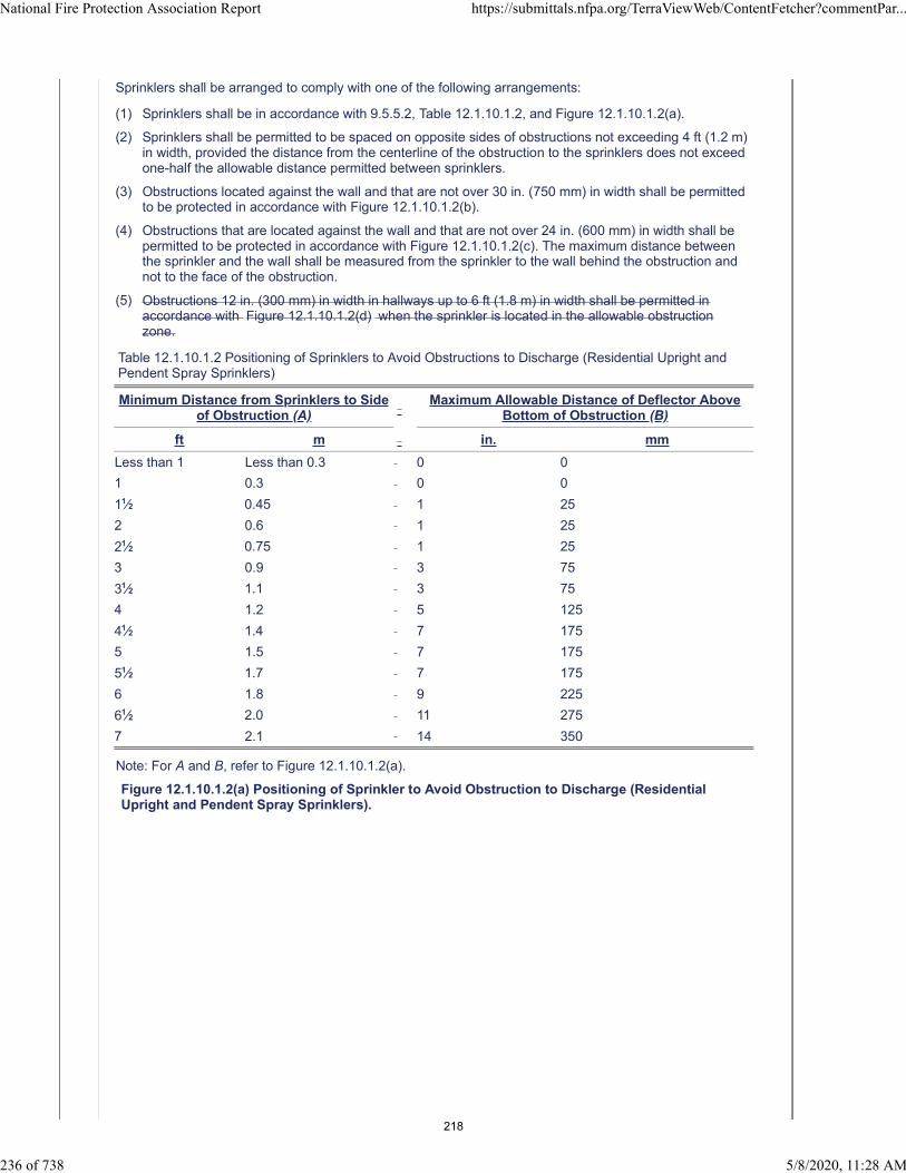
Sprinklers shall be arranged to comply with one of the following arrangements:
(1) Sprinklers shall be in accordance with 9.5.5.2, Table 12.1.10.1.2, and Figure 12.1.10.1.2(a).
(2) Sprinklers shall be permitted to be spaced on opposite sides of obstructions not exceeding 4 ft (1.2 m)in width, provided the distance from the centerline of the obstruction to the sprinklers does not exceedone-half the allowable distance permitted between sprinklers.
(3) Obstructions located against the wall and that are not over 30 in. (750 mm) in width shall be permittedto be protected in accordance with Figure 12.1.10.1.2(b).
(4) Obstructions that are located against the wall and that are not over 24 in. (600 mm) in width shall bepermitted to be protected in accordance with Figure 12.1.10.1.2(c). The maximum distance betweenthe sprinkler and the wall shall be measured from the sprinkler to the wall behind the obstruction andnot to the face of the obstruction.
(5) Obstructions 12 in. (300 mm) in width in hallways up to 6 ft (1.8 m) in width shall be permitted inaccordance with Figure 12.1.10.1.2(d) when the sprinkler is located in the allowable obstructionzone.
Table 12.1.10.1.2 Positioning of Sprinklers to Avoid Obstructions to Discharge (Residential Upright andPendent Spray Sprinklers)
Minimum Distance from Sprinklers to Sideof Obstruction (A)
Maximum Allowable Distance of Deflector AboveBottom of Obstruction (B)
ft m in. mm
Less than 1 Less than 0.3 0 0
1 0.3 0 0
11⁄2 0.45 1 25
2 0.6 1 25
21⁄2 0.75 1 25
3 0.9 3 75
31⁄2 1.1 3 75
4 1.2 5 125
41⁄2 1.4 7 175
5 1.5 7 175
51⁄2 1.7 7 175
6 1.8 9 225
61⁄2 2.0 11 275
7 2.1 14 350
Note: For A and B, refer to Figure 12.1.10.1.2(a).
Figure 12.1.10.1.2(a) Positioning of Sprinkler to Avoid Obstruction to Discharge (ResidentialUpright and Pendent Spray Sprinklers).
National Fire Protection Association Report https://submittals.nfpa.org/TerraViewWeb/ContentFetcher?commentPar...
236 of 738 5/8/2020, 11:28 AM
218
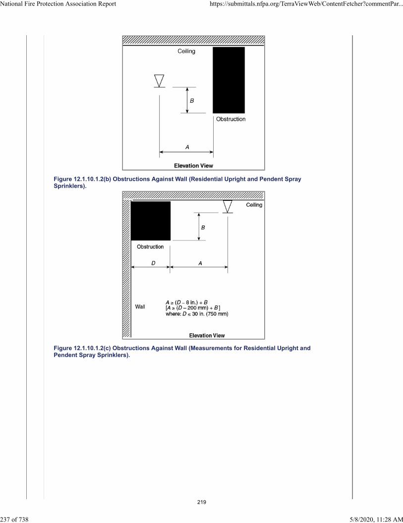
Figure 12.1.10.1.2(b) Obstructions Against Wall (Residential Upright and Pendent SpraySprinklers).
Figure 12.1.10.1.2(c) Obstructions Against Wall (Measurements for Residential Upright andPendent Spray Sprinklers).
National Fire Protection Association Report https://submittals.nfpa.org/TerraViewWeb/ContentFetcher?commentPar...
237 of 738 5/8/2020, 11:28 AM
219

Figure 12.1.10.1.2(d) Obstruction in Hallway.
Statement of Problem and Substantiation for Public Comment
The substantiation from PI No.281 that that was accepted with this revision was “Adds another obstruction allowance for obstructions in hallways.” and “This is also found in NFPA 13D & NFPA 13R.”. This reasoning actually provides no technical justification at all for the matter.Indeed, for NFPA 13R-2019, the substantiation for SR-6 that “In a hallway, an obstruction is not a problem when the sprinkler is installed adjacent to the light on the width of the hallway” is also not a technically sound statement.With this provision, there is no standoff distance specified between the sprinkler and the obstruction, such that the sprinkler could be located anywhere, from 4 inches off the wall (or 2’-2” from the obstruction) to just maybe 4 inches away from the obstruction. If the 1 ft wide obstruction is round, and located in the centre of the corridor, as shown in figure 10.2.7.2(d), with the sprinkler in the obstruction zone 4 inches away, the “shadow area” is approximately 17 ft² in size. Should the obstruction have a square shape, the obstructed floor space would be approximately 22 ft² in area.Since the TC recently deleted part of the 3 Times Rule regarding vertical obstructions within 2 ft of a sprinkler and with the limitation of just a 15 ft², this new provision is much too liberal, and should be deleted.
Related Item
• FR-1146
Submitter Information Verification
Submitter Full Name: Larry Keeping
Organization: PLC Fire Safety Solutions
Street Address:
City:
State:
Zip:
Submittal Date: Thu Apr 23 16:56:38 EDT 2020
Committee: AUT-AAC
National Fire Protection Association Report https://submittals.nfpa.org/TerraViewWeb/ContentFetcher?commentPar...
238 of 738 5/8/2020, 11:28 AM
220

Public Comment No. 369-NFPA 13-2020 [ Section No. 12.1.10.1.2 ]
National Fire Protection Association Report https://submittals.nfpa.org/TerraViewWeb/ContentFetcher?commentPar...
239 of 738 5/8/2020, 11:28 AM
221

12.1.10.1.2
National Fire Protection Association Report https://submittals.nfpa.org/TerraViewWeb/ContentFetcher?commentPar...
240 of 738 5/8/2020, 11:28 AM
222

Sprinklers shall be arranged to comply with one of the following arrangements:
(1) Sprinklers shall be in accordance with 9.5.5.2, Table 12.1.10.1.2, and Figure 12.1.10.1.2(a).
(2) Sprinklers shall be permitted to be spaced on opposite sides of obstructions not exceeding 4 ft (1.2 m)in width, provided the distance from the centerline of the obstruction to the sprinklers does not exceedone-half the allowable distance permitted between sprinklers.
(3) Obstructions located against the wall and that are not over 30 in. (750 mm) in width shall be permittedto be protected in accordance with Figure 12.1.10.1.2(b).
(4) Obstructions that are located against the wall and that are not over 24 in. (600 mm) in width shall bepermitted to be protected in accordance with Figure 12.1.10.1.2(c). The maximum distance betweenthe sprinkler and the wall shall be measured from the sprinkler to the wall behind the obstruction andnot to the face of the obstruction.
(5) Obstructions 12 in. (300 mm) in width in hallways up to 6 ft (1.8 m) in width shall be permitted inaccordance with Figure 12.1.10.1.2(d) when the sprinkler is located in the allowable obstructionzone. zone and the closest edge of the obstruction is a minimum of 12 in. (300 mm) away from thedeflector.
Table 12.1.10.1.2 Positioning of Sprinklers to Avoid Obstructions to Discharge (Residential Upright andPendent Spray Sprinklers)
Minimum Distance from Sprinklers to Sideof Obstruction (A)
Maximum Allowable Distance of Deflector AboveBottom of Obstruction (B)
ft m in. mm
Less than 1 Less than 0.3 0 0
1 0.3 0 0
11⁄2 0.45 1 25
2 0.6 1 25
21⁄2 0.75 1 25
3 0.9 3 75
31⁄2 1.1 3 75
4 1.2 5 125
41⁄2 1.4 7 175
5 1.5 7 175
51⁄2 1.7 7 175
6 1.8 9 225
61⁄2 2.0 11 275
7 2.1 14 350
Note: For A and B, refer to Figure 12.1.10.1.2(a).
Figure 12.1.10.1.2(a) Positioning of Sprinkler to Avoid Obstruction to Discharge (ResidentialUpright and Pendent Spray Sprinklers).
National Fire Protection Association Report https://submittals.nfpa.org/TerraViewWeb/ContentFetcher?commentPar...
241 of 738 5/8/2020, 11:28 AM
223

Figure 12.1.10.1.2(b) Obstructions Against Wall (Residential Upright and Pendent SpraySprinklers).
Figure 12.1.10.1.2(c) Obstructions Against Wall (Measurements for Residential Upright andPendent Spray Sprinklers).
National Fire Protection Association Report https://submittals.nfpa.org/TerraViewWeb/ContentFetcher?commentPar...
242 of 738 5/8/2020, 11:28 AM
224

Figure 12.1.10.1.2(d) Obstruction in Hallway.
Statement of Problem and Substantiation for Public Comment
This comment (and others) were developed by a NFSA Engineering and Standards Committee Task Group on Obstructions. Additional comments are being submitted on this section in separate comments. The entire Task Group Report which addresses all the comments is being uploaded in this comment. This comment is intended to minimize the apparent dry area that may be created by the obstruction adjacent to the sprinkler.
Related Public Comments for This Document
Related Comment Relationship
Public Comment No. 345-NFPA 13-2020 [Section No. 10.2.7.2 [Excluding any Sub-Sections]]
Public Comment No. 366-NFPA 13-2020 [Section No. 10.3.6.1.7]
Public Comment No. 367-NFPA 13-2020 [Section No. 11.2.5.1.2]
Public Comment No. 368-NFPA 13-2020 [Section No. 11.3.6.1.4]
Public Comment No. 370-NFPA 13-2020 [Section No. 12.1.11.1.4]
Related Item
• FR-1146
Submitter Information Verification
Submitter Full Name: Roland Asp
Organization: National Fire Sprinkler Association
Affiliation: NFSA Engineering and Standards Committee
Street Address:
City:
State:
Zip:
National Fire Protection Association Report https://submittals.nfpa.org/TerraViewWeb/ContentFetcher?commentPar...
243 of 738 5/8/2020, 11:28 AM
225

Submittal Date: Wed May 06 11:12:02 EDT 2020
Committee: AUT-AAC
National Fire Protection Association Report https://submittals.nfpa.org/TerraViewWeb/ContentFetcher?commentPar...
244 of 738 5/8/2020, 11:28 AM
226
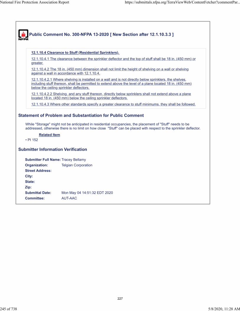
Public Comment No. 300-NFPA 13-2020 [ New Section after 12.1.10.3.3 ]
12.1.10.4 Clearance to Stuff (Residential Sprinklers).
12.1.10.4.1 The clearance between the sprinkler deflector and the top of stuff shall be 18 in. (450 mm) orgreater.
12.1.10.4.2 The 18 in. (450 mm) dimension shall not limit the height of shelving on a wall or shelvingagainst a wall in accordance with 12.1.10.4.
12.1.10.4.2.1 Where shelving is installed on a wall and is not directly below sprinklers, the shelves,including stuff thereon, shall be permitted to extend above the level of a plane located 18 in. (450 mm)below the ceiling sprinkler deflectors.
12.1.10.4.2.2 Shelving, and any stuff thereon, directly below sprinklers shall not extend above a planelocated 18 in. (450 mm) below the ceiling sprinkler deflectors.
12.1.10.4.3 Where other standards specify a greater clearance to stuff minimums, they shall be followed.
Statement of Problem and Substantiation for Public Comment
While "Storage" might not be anticipated in residential occupancies, the placement of "Stuff" needs to be addressed, otherwise there is no limit on how close "Stuff" can be placed with respect to the sprinkler deflector.
Related Item
• PI 152
Submitter Information Verification
Submitter Full Name: Tracey Bellamy
Organization: Telgian Corporation
Street Address:
City:
State:
Zip:
Submittal Date: Mon May 04 14:51:32 EDT 2020
Committee: AUT-AAC
National Fire Protection Association Report https://submittals.nfpa.org/TerraViewWeb/ContentFetcher?commentPar...
245 of 738 5/8/2020, 11:28 AM
227

Public Comment No. 108-NFPA 13-2020 [ Section No. 12.1.11.1.4 ]
National Fire Protection Association Report https://submittals.nfpa.org/TerraViewWeb/ContentFetcher?commentPar...
246 of 738 5/8/2020, 11:28 AM
228

12.1.11.1.4
National Fire Protection Association Report https://submittals.nfpa.org/TerraViewWeb/ContentFetcher?commentPar...
247 of 738 5/8/2020, 11:28 AM
229
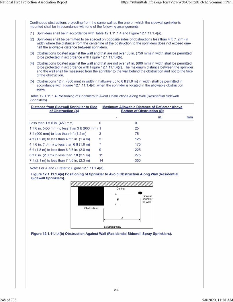
Continuous obstructions projecting from the same wall as the one on which the sidewall sprinkler ismounted shall be in accordance with one of the following arrangements:
(1) Sprinklers shall be in accordance with Table 12.1.11.1.4 and Figure 12.1.11.1.4(a).
(2) Sprinklers shall be permitted to be spaced on opposite sides of obstructions less than 4 ft (1.2 m) inwidth where the distance from the centerline of the obstruction to the sprinklers does not exceed one-half the allowable distance between sprinklers.
(3) Obstructions located against the wall and that are not over 30 in. (750 mm) in width shall be permittedto be protected in accordance with Figure 12.1.11.1.4(b).
(4) Obstructions located against the wall and that are not over 24 in. (600 mm) in width shall be permittedto be protected in accordance with Figure 12.1.11.1.4(c). The maximum distance between the sprinklerand the wall shall be measured from the sprinkler to the wall behind the obstruction and not to the faceof the obstruction.
(5) Obstructions 12 in. (300 mm) in width in hallways up to 6 ft (1.8 m) in width shall be permitted inaccordance with Figure 12.1.11.1.4(d) when the sprinkler is located in the allowable obstructionzone.
Table 12.1.11.1.4 Positioning of Sprinklers to Avoid Obstructions Along Wall (Residential SidewallSprinklers)
Distance from Sidewall Sprinkler to Sideof Obstruction (A)
Maximum Allowable Distance of Deflector AboveBottom of Obstruction (B)
in. mm
Less than 1 ft 6 in. (450 mm) 0 0
1 ft 6 in. (450 mm) to less than 3 ft (900 mm) 1 25
3 ft (900 mm) to less than 4 ft (1.2 m) 3 75
4 ft (1.2 m) to less than 4 ft 6 in. (1.4 m) 5 125
4 ft 6 in. (1.4 m) to less than 6 ft (1.8 m) 7 175
6 ft (1.8 m) to less than 6 ft 6 in. (2.0 m) 9 225
6 ft 6 in. (2.0 m) to less than 7 ft (2.1 m) 11 275
7 ft (2.1 m) to less than 7 ft 6 in. (2.3 m) 14 350
Note: For A and B, refer to Figure 12.1.11.1.4(a).
Figure 12.1.11.1.4(a) Positioning of Sprinkler to Avoid Obstruction Along Wall (ResidentialSidewall Sprinklers).
Figure 12.1.11.1.4(b) Obstruction Against Wall (Residential Sidewall Spray Sprinklers).
National Fire Protection Association Report https://submittals.nfpa.org/TerraViewWeb/ContentFetcher?commentPar...
248 of 738 5/8/2020, 11:28 AM
230

Figure 12.1.11.1.4(c) Obstruction Against Wall (Residential Sidewall Spray Sprinklers).
Figure 12.1.11.1.4(d) Obstruction in Hallway (Residential Sidewall Spray Sprinklers).
Statement of Problem and Substantiation for Public Comment
The substantiation from PI No.285 that that was accepted with this revision was “Adds another obstruction allowance for obstructions in hallways.” and “This is also found in NFPA 13D & NFPA 13R.”. This reasoning actually provides no technical justification at all for the matter.Indeed, for NFPA 13R-2019, the substantiation for SR-6 that “In a hallway, an obstruction is not a problem when the sprinkler is installed adjacent to the light on the width of the hallway” is also not a technically sound statement.With this provision, there is no standoff distance specified between the sprinkler and the obstruction, such that the sprinkler could be located anywhere, from 4 inches off the wall (or 2’-2” from the obstruction) to just maybe 4
National Fire Protection Association Report https://submittals.nfpa.org/TerraViewWeb/ContentFetcher?commentPar...
249 of 738 5/8/2020, 11:28 AM
231
inches away from the obstruction. If the 1 ft wide obstruction is round, and located in the centre of the corridor, as shown in figure 10.2.7.2(d), with the sprinkler in the obstruction zone 4 inches away, the “shadow area” is approximately 17 ft² in size. Should the obstruction have a square shape, the obstructed floor space would be approximately 22 ft² in area.Since the TC recently deleted part of the 3 Times Rule regarding vertical obstructions within 2 ft of a sprinkler and with the limitation of just a 15 ft², this new provision is much too liberal, and should be deleted.
Related Item
• FR-1149
Submitter Information Verification
Submitter Full Name: Larry Keeping
Organization: PLC Fire Safety Solutions
Street Address:
City:
State:
Zip:
Submittal Date: Thu Apr 23 16:59:35 EDT 2020
Committee: AUT-AAC
National Fire Protection Association Report https://submittals.nfpa.org/TerraViewWeb/ContentFetcher?commentPar...
250 of 738 5/8/2020, 11:28 AM
232

Public Comment No. 370-NFPA 13-2020 [ Section No. 12.1.11.1.4 ]
National Fire Protection Association Report https://submittals.nfpa.org/TerraViewWeb/ContentFetcher?commentPar...
251 of 738 5/8/2020, 11:28 AM
233

12.1.11.1.4
National Fire Protection Association Report https://submittals.nfpa.org/TerraViewWeb/ContentFetcher?commentPar...
252 of 738 5/8/2020, 11:28 AM
234
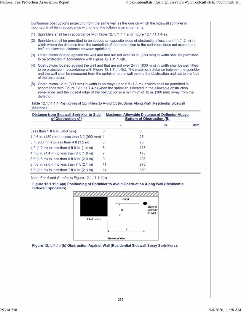
Continuous obstructions projecting from the same wall as the one on which the sidewall sprinkler ismounted shall be in accordance with one of the following arrangements:
(1) Sprinklers shall be in accordance with Table 12.1.11.1.4 and Figure 12.1.11.1.4(a).
(2) Sprinklers shall be permitted to be spaced on opposite sides of obstructions less than 4 ft (1.2 m) inwidth where the distance from the centerline of the obstruction to the sprinklers does not exceed one-half the allowable distance between sprinklers.
(3) Obstructions located against the wall and that are not over 30 in. (750 mm) in width shall be permittedto be protected in accordance with Figure 12.1.11.1.4(b).
(4) Obstructions located against the wall and that are not over 24 in. (600 mm) in width shall be permittedto be protected in accordance with Figure 12.1.11.1.4(c). The maximum distance between the sprinklerand the wall shall be measured from the sprinkler to the wall behind the obstruction and not to the faceof the obstruction.
(5) Obstructions 12 in. (300 mm) in width in hallways up to 6 ft (1.8 m) in width shall be permitted inaccordance with Figure 12.1.11.1.4(d) when the sprinkler is located in the allowable obstructionzone. zone and the closest edge of the obstruction is a minimum of 12 in. (300 mm) away from thedeflector.
Table 12.1.11.1.4 Positioning of Sprinklers to Avoid Obstructions Along Wall (Residential SidewallSprinklers)
Distance from Sidewall Sprinkler to Sideof Obstruction (A)
Maximum Allowable Distance of Deflector AboveBottom of Obstruction (B)
in. mm
Less than 1 ft 6 in. (450 mm) 0 0
1 ft 6 in. (450 mm) to less than 3 ft (900 mm) 1 25
3 ft (900 mm) to less than 4 ft (1.2 m) 3 75
4 ft (1.2 m) to less than 4 ft 6 in. (1.4 m) 5 125
4 ft 6 in. (1.4 m) to less than 6 ft (1.8 m) 7 175
6 ft (1.8 m) to less than 6 ft 6 in. (2.0 m) 9 225
6 ft 6 in. (2.0 m) to less than 7 ft (2.1 m) 11 275
7 ft (2.1 m) to less than 7 ft 6 in. (2.3 m) 14 350
Note: For A and B, refer to Figure 12.1.11.1.4(a).
Figure 12.1.11.1.4(a) Positioning of Sprinkler to Avoid Obstruction Along Wall (ResidentialSidewall Sprinklers).
Figure 12.1.11.1.4(b) Obstruction Against Wall (Residential Sidewall Spray Sprinklers).
National Fire Protection Association Report https://submittals.nfpa.org/TerraViewWeb/ContentFetcher?commentPar...
253 of 738 5/8/2020, 11:28 AM
235
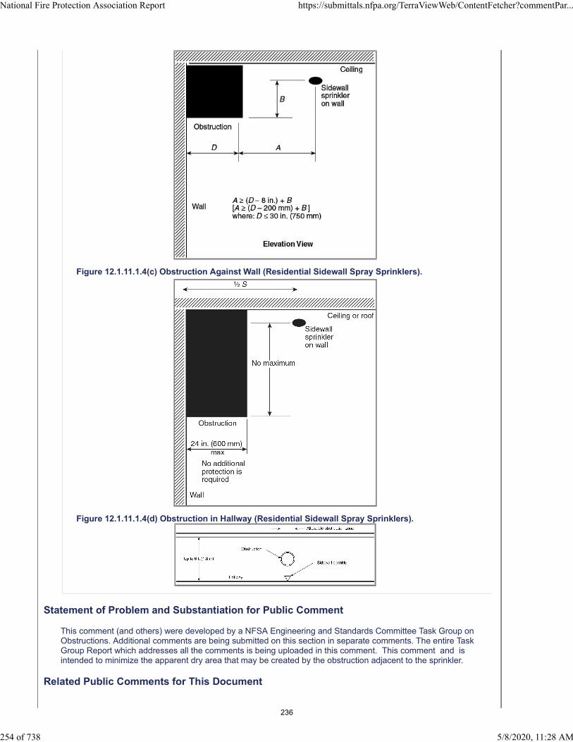
Figure 12.1.11.1.4(c) Obstruction Against Wall (Residential Sidewall Spray Sprinklers).
Figure 12.1.11.1.4(d) Obstruction in Hallway (Residential Sidewall Spray Sprinklers).
Statement of Problem and Substantiation for Public Comment
This comment (and others) were developed by a NFSA Engineering and Standards Committee Task Group on Obstructions. Additional comments are being submitted on this section in separate comments. The entire Task Group Report which addresses all the comments is being uploaded in this comment. This comment and is intended to minimize the apparent dry area that may be created by the obstruction adjacent to the sprinkler.
Related Public Comments for This Document
National Fire Protection Association Report https://submittals.nfpa.org/TerraViewWeb/ContentFetcher?commentPar...
254 of 738 5/8/2020, 11:28 AM
236

Related Comment Relationship
Public Comment No. 369-NFPA 13-2020 [Section No. 12.1.10.1.2]
Public Comment No. 345-NFPA 13-2020 [Section No. 10.2.7.2 [Excluding any Sub-Sections]]
Public Comment No. 368-NFPA 13-2020 [Section No. 11.3.6.1.4]
Public Comment No. 366-NFPA 13-2020 [Section No. 10.3.6.1.7]
Public Comment No. 367-NFPA 13-2020 [Section No. 11.2.5.1.2]
Related Item
• FR-1149
Submitter Information Verification
Submitter Full Name: Roland Asp
Organization: National Fire Sprinkler Association
Affiliation: NFSA Engineering and Standards Committee
Street Address:
City:
State:
Zip:
Submittal Date: Wed May 06 11:15:29 EDT 2020
Committee: AUT-AAC
National Fire Protection Association Report https://submittals.nfpa.org/TerraViewWeb/ContentFetcher?commentPar...
255 of 738 5/8/2020, 11:28 AM
237
Public Comment No. 131-NFPA 13-2020 [ Section No. 12.1.11.1.6 ]
12.1.11.1.6*
Obstructions on the wall opposite from the sidewall sprinkler shall be permitted where the obstruction is upto 30 in. (750 mm) deep and 30 in. (750 mm) wide. in accordance with Figure 12.1.11.1.6.
Additional Proposed Changes
File Name Description Approved
NFPA_13_Figure_12.1.11.1.6.pdf
Statement of Problem and Substantiation for Public Comment
Move annex figure and place in the body. All the other sidewall rules point to figures in the body of the standard. Makes it easier for the user.
Related Public Comments for This Document
Related Comment Relationship
Public Comment No. 132-NFPA 13-2020 [Section No. A.12.1.11.1.6]
Related Item
• PI#278
Submitter Information Verification
Submitter Full Name: Peter Schwab
Organization: Wayne Automatic Fire Sprinkler
Street Address:
City:
State:
Zip:
Submittal Date: Fri Apr 24 18:37:17 EDT 2020
Committee: AUT-AAC
National Fire Protection Association Report https://submittals.nfpa.org/TerraViewWeb/ContentFetcher?commentPar...
256 of 738 5/8/2020, 11:28 AM
238

239

Public Comment No. 301-NFPA 13-2020 [ New Section after 12.1.11.3 ]
12.1.11.4 Clearance to Stuff (Residential Sidewall Spray Sprinklers).
12.1.11.4.1 The clearance between the sprinkler deflector and the top of stuff shall be 18 in. (450 mm) orgreater.
12.1.11.4.2 The 18 in. (450 mm) dimension shall not limit the height of shelving on a wall or shelving againsta wall in accordance with 12.1.11.4.
12.1.11.4.2.1 Where shelving is installed on a wall and is not directly below sprinklers, the shelves, includingstuff thereon, shall be permitted to extend above the level of a plane located 18 in. (450 mm) below thesidewall sprinkler deflectors.
12.1.11.4.2.2 Shelving, and any stuff thereon, directly below sprinklers shall not extend above a planelocated 18 in. (450 mm) below the sidewall sprinkler deflectors.
12.1.11.4.3 Where other standards specify a greater clearance to stuff minimums, they shall be followed.
Statement of Problem and Substantiation for Public Comment
While "Storage" might not be anticipated in residential occupancies, the placement of "Stuff" needs to be addressed, otherwise there is no limit on how close "Stuff" can be placed with respect to the sprinkler deflector.
Related Item
• PI 153
Submitter Information Verification
Submitter Full Name: Tracey Bellamy
Organization: Telgian Corporation
Street Address:
City:
State:
Zip:
Submittal Date: Mon May 04 15:03:54 EDT 2020
Committee: AUT-AAC
National Fire Protection Association Report https://submittals.nfpa.org/TerraViewWeb/ContentFetcher?commentPar...
257 of 738 5/8/2020, 11:28 AM
240

Public Comment No. 145-NFPA 13-2020 [ Section No. 12.1.12.2 ]
12.1.12.2
The requirement of 12.1.12.1 shall not apply where all of the following requirements are met:
(1) The total volume of the unprotected ceiling pocket does not exceed 100 ft3 (2.8 m3).
(2) The depth of the unprotected ceiling pocket does not exceed 12 in. (300 mm).
(3) The entire floor of under the unprotected ceiling pocket is protected by any type of residentialsprinkler sidewall or pendent sprinklers at the lower ceiling elevation.
(4) The interior finish of the unprotected ceiling pocket is noncombustible or limited-combustibleconstruction.
Statement of Problem and Substantiation for Public Comment
A change was made to ceiling pockets for residential in NFPA 13 and 13R. Each committee had different language. I have submitted a comment to change the language to match NFPA 13R (See First Revision #40) as suggested by the Correlating Committee (CN#12).
Related Item
• CN#12
Submitter Information Verification
Submitter Full Name: Peter Schwab
Organization: Wayne Automatic Fire Sprinkler
Street Address:
City:
State:
Zip:
Submittal Date: Sat Apr 25 13:44:16 EDT 2020
Committee: AUT-AAC
National Fire Protection Association Report https://submittals.nfpa.org/TerraViewWeb/ContentFetcher?commentPar...
258 of 738 5/8/2020, 11:28 AM
241

Public Comment No. 270-NFPA 13-2020 [ Section No. 12.1.12.2 ]
12.1.12.2
The requirement of 12.1.12.1 shall not apply where all of the following requirements are met:
(1) The total volume of the unprotected ceiling pocket does not exceed 100 ft3 (2.8 m3).
(2) The depth of the unprotected ceiling pocket does not exceed 12 in. (300 mm).
(3) The entire floor of the unprotected ceiling pocket is protected by any type of residential sprinkler at thelower ceiling elevation.
(4) The interior finish of the unprotected ceiling pocket is noncombustible or limited-combustibleconstruction.
Additional Proposed Changes
File Name Description Approved
13_CCN_12.pdf 13_CCN_12
Statement of Problem and Substantiation for Public Comment
NOTE: This Public Comment appeared as CC Note No. 12 in the First Draft Report on First Revision No. 1151.
Consider correlating language in NFPA 13 with NFPA 13D & 13R by specifically referencing pendent and sidewall sprinklers.
Related Item
• FR-1151
Submitter Information Verification
Submitter Full Name: CC on AUT-AAC
Organization: NFPA
Street Address:
City:
State:
Zip:
Submittal Date: Mon May 04 13:10:53 EDT 2020
Committee: AUT-AAC
National Fire Protection Association Report https://submittals.nfpa.org/TerraViewWeb/ContentFetcher?commentPar...
259 of 738 5/8/2020, 11:28 AM
242
Correlating Committee Note No. 12-NFPA 13-2019 [ Section No. 12.1.12.2 ]
Submitter Information Verification
Committee: AUT-AAC
Submittal Date: Mon Dec 16 13:14:20 EST 2019
Committee Statement
CommitteeStatement:
Consider correlating language in NFPA 13 with NFPA 13D & 13R by specifically referencingpendent and sidewall sprinklers.
First Revision No. 1151-NFPA 13-2019 [Section No. 12.1.12.2]
Ballot Results
This item has passed ballot
22 Eligible Voters
3 Not Returned
19 Affirmative All
0 Affirmative with Comments
0 Negative with Comments
0 Abstention
Not Returned
Baz, Jose R.
Hilton, Luke
Su, Joseph
Affirmative All
Bell, Kerry M.
Bellamy, Tracey D.
Browning, Chase A.
Dellasanta, Steven W.
Friedman, Michael J.
Hoffman, Alex
Hopkins, Mark
Javeri, Sultan M.
Ketner, Charles W.
Koffel, William E.
Lake, James D.
LeBlanc, John A.
Linder, Kenneth W.
Lowrey, David O.
Medovich, Jack A.
National Fire Protection Association Report https://submittals.nfpa.org/TerraViewWeb/ContentFetcher?commentPar...
23 of 50 5/4/2020, 11:38 AM
243

Palenske, Garner A.
Phillips, Lawrence Richard
Seghi, Adam
Thompson, J. Michael
National Fire Protection Association Report https://submittals.nfpa.org/TerraViewWeb/ContentFetcher?commentPar...
24 of 50 5/4/2020, 11:38 AM
244

Public Comment No. 310-NFPA 13-2020 [ New Section after 13.2.6.4 ]
13.2.6.4.1 Sprinklers shall be permitted to be placed less than 8 ft (2.4 m) on center where thefollowing conditions are satisfied:
(1) Baffles shall be arranged to protect the actuating elements.
(2) Baffles shall be solid and rigid material that will stay in place before and during sprinkler operation.
(3) Baffles shall be not less than 8 in. (200 mm) long and 6 in. (150 mm) high.
(4) The tops of baffles shall extend between 2 in. and 3 in. (50 mm and 75 mm) above the deflectors ofupright sprinklers.
(5) The bottoms of baffles shall extend downward to a level at least even with the deflectors of pendentsprinklers.
Statement of Problem and Substantiation for Public Comment
Additional testing utilizing the provisions of the current UL 199 for determination of cold solder impact for sprinklers spaced closer than 8 ft will be provided with the described baffle installation at the 2nd Draft Meeting.
Related Item
• PI 156
Submitter Information Verification
Submitter Full Name: Tracey Bellamy
Organization: Telgian Corporation
Street Address:
City:
State:
Zip:
Submittal Date: Mon May 04 17:41:56 EDT 2020
Committee: AUT-AAC
National Fire Protection Association Report https://submittals.nfpa.org/TerraViewWeb/ContentFetcher?commentPar...
260 of 738 5/8/2020, 11:28 AM
245
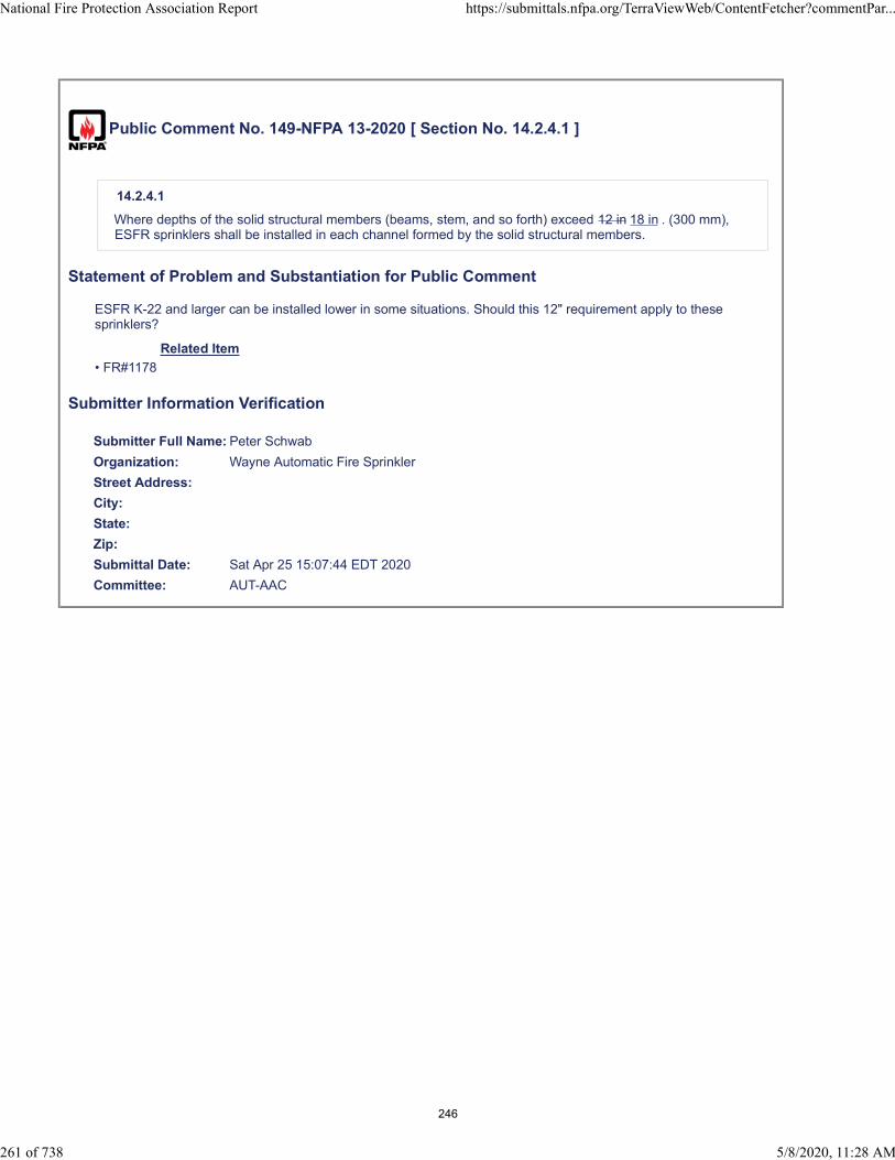
Public Comment No. 149-NFPA 13-2020 [ Section No. 14.2.4.1 ]
14.2.4.1
Where depths of the solid structural members (beams, stem, and so forth) exceed 12 in 18 in . (300 mm),ESFR sprinklers shall be installed in each channel formed by the solid structural members.
Statement of Problem and Substantiation for Public Comment
ESFR K-22 and larger can be installed lower in some situations. Should this 12" requirement apply to these sprinklers?
Related Item
• FR#1178
Submitter Information Verification
Submitter Full Name: Peter Schwab
Organization: Wayne Automatic Fire Sprinkler
Street Address:
City:
State:
Zip:
Submittal Date: Sat Apr 25 15:07:44 EDT 2020
Committee: AUT-AAC
National Fire Protection Association Report https://submittals.nfpa.org/TerraViewWeb/ContentFetcher?commentPar...
261 of 738 5/8/2020, 11:28 AM
246
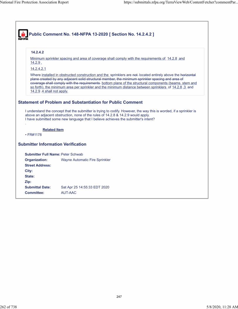
Public Comment No. 148-NFPA 13-2020 [ Section No. 14.2.4.2 ]
14.2.4.2
Minimum sprinkler spacing and area of coverage shall comply with the requirements of 14.2.8 and14.2.9 .
14.2.4.2.1
Where installed in obstructed construction and the sprinklers are not located entirely above the horizontalplane created by any adjacent solid structural member, the minimum sprinkler spacing and area ofcoverage shall comply with the requirements bottom plane of the structural components (beams, stem andso forth), the minimum area per sprinkler and the minimum distance between sprinklers of 14.2.8 .3 and14.2.9 .4 shall not apply.
Statement of Problem and Substantiation for Public Comment
I understand the concept that the submitter is trying to codify. However, the way this is worded, if a sprinkler is above an adjacent obstruction, none of the rules of 14.2.8 & 14.2.9 would apply.I have submitted some new language that I believe achieves the submitter's intent?.
Related Item
• FR#1178
Submitter Information Verification
Submitter Full Name: Peter Schwab
Organization: Wayne Automatic Fire Sprinkler
Street Address:
City:
State:
Zip:
Submittal Date: Sat Apr 25 14:55:33 EDT 2020
Committee: AUT-AAC
National Fire Protection Association Report https://submittals.nfpa.org/TerraViewWeb/ContentFetcher?commentPar...
262 of 738 5/8/2020, 11:28 AM
247

Public Comment No. 201-NFPA 13-2020 [ Section No. 14.2.4.2 ]
14.2.4.2*
Where sprinklers are not located entirely above the horizontal plane created by any adjacent solid structuralmember, the minimum sprinkler spacing and area of coverage shall comply with the requirements of 14.2.8and 14.2.9.
A.14.2.4.2 This section applies to both obstructed and unobstructed construction.
Statement of Problem and Substantiation for Public Comment
In Committee Note 21 (CN-21), the correlating committee directed the committee to clarify the intent of FR-1178 with the statement "As currently written, this section is not currently limited to obstructed construction". This proposed annex note clarifies that the intent was to apply section 14.2.4.2 to both obstructed and unobstructed construction.
Related Item
• CN-21 • FR-1178
Submitter Information Verification
Submitter Full Name: Roland Asp
Organization: National Fire Sprinkler Association
Affiliation: NFSA Engineering and Standards Committee
Street Address:
City:
State:
Zip:
Submittal Date: Fri May 01 07:21:57 EDT 2020
Committee: AUT-AAC
National Fire Protection Association Report https://submittals.nfpa.org/TerraViewWeb/ContentFetcher?commentPar...
263 of 738 5/8/2020, 11:28 AM
248

Public Comment No. 271-NFPA 13-2020 [ Section No. 14.2.4.2 ]
14.2.4.2
Where sprinklers are not located entirely above the horizontal plane created by any adjacent solidstructural member, the minimum sprinkler spacing and area of coverage shall comply with therequirements of 14.2.8 and 14.2.9.
Additional Proposed Changes
File Name Description Approved
13_CCN_21.pdf 13_CCN_21
Statement of Problem and Substantiation for Public Comment
NOTE: This Public Comment appeared as CC Note No. 21 in the First Draft Report on First Revision No. 1178.
The committee should reconsider and clarify the intent of this section. As currently written, this section is not currently limited to obstructed construction.
Related Item
• FR-1178
Submitter Information Verification
Submitter Full Name: CC on AUT-AAC
Organization: NFPA
Street Address:
City:
State:
Zip:
Submittal Date: Mon May 04 13:13:33 EDT 2020
Committee: AUT-AAC
National Fire Protection Association Report https://submittals.nfpa.org/TerraViewWeb/ContentFetcher?commentPar...
264 of 738 5/8/2020, 11:28 AM
249

Correlating Committee Note No. 21-NFPA 13-2019 [ Section No. 14.2.4.2 ]
Submitter Information Verification
Committee: AUT-AAC
Submittal Date: Mon Dec 16 13:31:14 EST 2019
Committee Statement
CommitteeStatement:
The committee should reconsider and clarify the intent of this section. As currently written, thissection is not currently limited to obstructed construction.
First Revision No. 1178-NFPA 13-2019 [Section No. 14.2.4.2]
Ballot Results
This item has passed ballot
22 Eligible Voters
3 Not Returned
19 Affirmative All
0 Affirmative with Comments
0 Negative with Comments
0 Abstention
Not Returned
Baz, Jose R.
Hilton, Luke
Su, Joseph
Affirmative All
Bell, Kerry M.
Bellamy, Tracey D.
Browning, Chase A.
Dellasanta, Steven W.
Friedman, Michael J.
Hoffman, Alex
Hopkins, Mark
Javeri, Sultan M.
Ketner, Charles W.
Koffel, William E.
Lake, James D.
LeBlanc, John A.
Linder, Kenneth W.
Lowrey, David O.
Medovich, Jack A.
National Fire Protection Association Report https://submittals.nfpa.org/TerraViewWeb/ContentFetcher?commentPar...
25 of 50 5/4/2020, 11:38 AM
250

Palenske, Garner A.
Phillips, Lawrence Richard
Seghi, Adam
Thompson, J. Michael
National Fire Protection Association Report https://submittals.nfpa.org/TerraViewWeb/ContentFetcher?commentPar...
26 of 50 5/4/2020, 11:38 AM
251
Public Comment No. 150-NFPA 13-2020 [ Section No. 14.2.6 ]
14.2.6 Temperature Ratings.
Sprinkler temperature ratings for ESFR sprinklers shall be ordinary or intermediate unless 9.4.2 requiresintermediate - or high- temperature ratings.
Statement of Problem and Substantiation for Public Comment
This section is in conflict with chapter 9. Do intermediate temperature ESFR sprinklers not work? Are these sprinklers not tested in a full scale fire test? I would assume so since there are UL and FM approved intermediate temperature sprinklers.
Related Item
• PI#39
Submitter Information Verification
Submitter Full Name: Peter Schwab
Organization: Wayne Automatic Fire Sprinkler
Street Address:
City:
State:
Zip:
Submittal Date: Sat Apr 25 15:14:09 EDT 2020
Committee: AUT-AAC
National Fire Protection Association Report https://submittals.nfpa.org/TerraViewWeb/ContentFetcher?commentPar...
265 of 738 5/8/2020, 11:28 AM
252
Public Comment No. 197-NFPA 13-2020 [ Section No. 14.2.7 ]
14.2.7 Occupancy and Hazard.
ESFR sprinklers designed to meet any criteria in Chapter 23 or 24 shall be permitted to protect light andordinary hazard occupancies.
4.2.7.1 When ESFR sprinklers are used for the protection of light or ordinary hazard occupancies,sections 14.2.8.7.1.1 through 14.2.7.1.4 shall be permitted
14.2.7.1.1 In light hazard occupancies the protection areas limitations of ESFR sprinklers meet theprotection area requirements of Table 10.2.4.2.1(a)
14.2.7.1.2 In ordinary hazard occupancies the protection areas limitations of ESFR sprinklers meet theprotection area requirements of Table 10.2.4.2.1(b)
14.2.7.1.3 In light and ordinary hazard occupancies the sprinkler spacing of ESFR sprinklers shall bemeet the sprinkler spacing requirements of section 10.2.5
14.2.7.1.4 In light and ordinary hazard occupancies the obstruction to the sprinkler discharge pattern ofESFR sprinklers shall be meet the obstruction discharge requirements of section 10.2.7.2
Statement of Problem and Substantiation for Public Comment
This comment seeks to resubmit PI-545. This PI was not accepted by the committee but should be reconsidered. The original substantiation is still applicable: Section 14.2.7 allows ESFR sprinklers designed to the criteria of Chapter 23 or 24 to be used to protect light and ordinary hazard occupancies. In light and ordinary hazard occupancies, the storage protection criteria is overkill. This proposed section will allow ESFR sprinklers to protect light and ordinary hazard occupancies using the protection area, spacing, and obstruction requirements for standard spray sprinklers. Given the characteristics of ESFR sprinklers and the hazard being protected, this will provide sufficient protection of these light and ordinary hazard areas.
Related Item
• PI-545
Submitter Information Verification
Submitter Full Name: Roland Asp
Organization: National Fire Sprinkler Association
Affiliation: On behalf NFSA Engineering and Standards Committee
Street Address:
City:
State:
Zip:
Submittal Date: Thu Apr 30 08:10:54 EDT 2020
Committee: AUT-AAC
National Fire Protection Association Report https://submittals.nfpa.org/TerraViewWeb/ContentFetcher?commentPar...
266 of 738 5/8/2020, 11:28 AM
253

Public Comment No. 60-NFPA 13-2020 [ Section No. 14.2.9.1 ]
14.2.9.1 Maximum Distance Between Sprinklers.
The maximum distance between sprinklers shall be in accordance with the following:
(1) Where the storage height is less than or equal to 25 ft (7.6 m) and the ceiling height is less than orequal to 30 ft (9.1 m), the distance between sprinklers shall be limited to not more than 12 ft (3.7 m)between sprinklers as shown in Table 14.2.8.2.1.
(2) Unless the requirements of 14.2.9.1(3) or 14.2.9.1(4) are met, where the storage height exceeds 25 ft(7.6 m) and or the ceiling height exceeds 30 ft (9.1 m), the distance between sprinklers shall belimited to not more than 10 ft (3.0 m) between sprinklers.
(3)
(4)
(5)
(6)
(7) Where branch lines are parallel to trusses and bar joists, deviations from the maximum sprinklerspacing shall be permitted to eliminate obstructions created by structural elements (such as trusses,bar joists, and wind bracing) by moving a single branch line a maximum of 1 ft (300 mm) from itsallowable spacing, provided coverage for the sprinklers on that branch line and the sprinklers on the
branch line it is moving away from does not exceed 110 ft2 (10 m2) per sprinkler where all of thefollowing conditions are met:
(8) The average actual floor area protected by the sprinklers on the moved branch line and the
sprinklers on the adjacent branch lines shall not exceed 100 ft 2 (9 m 2 ) per sprinkler.
(9) In no case shall the distance between sprinklers exceed 12 ft (3.7 m).
(10) It shall not be permitted to move a branch line where there are moved sprinklers on a branch linethat exceed the maximum sprinkler spacing.
Statement of Problem and Substantiation for Public Comment
There is a problem with the current language. There is no maximum spacing for situations where the storage height is less than or equal to 25 ft and the ceiling height is greater than 30 ft. For example, consider 25 ft high storage in a 35 ft high building. Section 14.2.9.1(1) does not apply because of the ceiling height. But the current wording of section 14.2.9.1(2) also does not apply because the storage height is 25 ft. So there is no section that covers this storage/ceiling configuration, which is quite common. The change would make the combination of sections 14.2.9.1(1) and 14.2.9.1(2) mutually exclusive and complete.
Note that without this change, the standard is inconsistent with Table 14.2.8.2.1. This table, which focuses on ceiling height, which is probably the best way to discuss the situation, limits the maximum distance between sprinklers to 10 ft when the ceiling is greater than 30 ft high, regardless of the storage height. Unfortunately, this table is not referenced by section 14.2.9 and in section 14.2.8, the charging paragraph only talks about using the table for area, not distance. So, the distance information is useless in the table.
This comment at least makes the information consistent and all encompassing.
Related Item
• FR 896
* Regardless of the storage or ceiling height arrangement, deviations from the maximum sprinklerspacing shall be permitted to eliminate obstructions created by structural elements (such as trusses,bar joists, and wind bracing) by moving a sprinkler along the branch line a maximum of 1 ft (300 mm)
from its allowable spacing, provided coverage for that sprinkler does not exceed 110 ft2 (10 m2) whereall of the following conditions are met:
The average actual floor area protected by the moved sprinkler and the adjacent sprinklers shall
not exceed 100 ft 2 (9 m 2 ).
Adjacent branch lines shall maintain the same pattern.
In no case shall the distance between sprinklers exceed 12 ft (3.7 m).
National Fire Protection Association Report https://submittals.nfpa.org/TerraViewWeb/ContentFetcher?commentPar...
267 of 738 5/8/2020, 11:28 AM
254

Submitter Information Verification
Submitter Full Name: Kenneth Isman
Organization: University of Maryland
Street Address:
City:
State:
Zip:
Submittal Date: Wed Apr 22 11:40:27 EDT 2020
Committee: AUT-AAC
National Fire Protection Association Report https://submittals.nfpa.org/TerraViewWeb/ContentFetcher?commentPar...
268 of 738 5/8/2020, 11:28 AM
255
Public Comment No. 311-NFPA 13-2020 [ New Section after 14.2.9.4 ]
14.2.9.4.1 Sprinklers shall be permitted to be placed less than 8 ft (2.4 m) on center where tehfollowing conditions are satisfied:
(1) Baffles shall be arranged to protect the actuating elements.
(2) Baffles shall be of solid and rigid materials that will stay in place before and during sprinkler operation.
(3) Baffles shall not be less than 8 in. (200 mm) long and 6 in. (150 mm) high.
(4) The tops of baffles shall extend between 2 in. and 3 in. (50 mm and 75 mm) above the deflectors ofupright sprinklers.
(5) The bottoms of baffles shall extend downward to a level at least even with the deflectors of pendentsprinklers.
Statement of Problem and Substantiation for Public Comment
Additional testing utilizing the provisions of the current UL 199 for determination of cold solder impact for sprinklers spaced closer than 8 ft will be provided with the described baffle installation at the 2nd Draft Meeting.
Related Item
• PI 157
Submitter Information Verification
Submitter Full Name: Tracey Bellamy
Organization: Telgian Corporation
Street Address:
City:
State:
Zip:
Submittal Date: Mon May 04 17:48:20 EDT 2020
Committee: AUT-AAC
National Fire Protection Association Report https://submittals.nfpa.org/TerraViewWeb/ContentFetcher?commentPar...
269 of 738 5/8/2020, 11:28 AM
256
Public Comment No. 272-NFPA 13-2020 [ Section No. 14.2.10.1.3 ]
14.2.10.1.3
Pendent sprinklers with a nominal K-factor of K-28.0 (400) shall be positioned so that deflectors are amaximum 14 in. (350 mm) and a minimum 6 in. (150 mm) below the ceiling.
Additional Proposed Changes
File Name Description Approved
13_CCN_16.pdf 13_CCN_16
Statement of Problem and Substantiation for Public Comment
NOTE: This Public Comment appeared as CC Note No. 16 in the First Draft Report on First Revision No. 1207.
Consider merging new 14.2.10.1.3 into 14.2.10.1.1, similar to the merge of existing 14.2.10.1.2 into 14.2.10.1.1 in FR-1062.
Related Item
• FR-1207
Submitter Information Verification
Submitter Full Name: CC on AUT-AAC
Organization: NFPA
Street Address:
City:
State:
Zip:
Submittal Date: Mon May 04 13:17:40 EDT 2020
Committee: AUT-AAC
National Fire Protection Association Report https://submittals.nfpa.org/TerraViewWeb/ContentFetcher?commentPar...
270 of 738 5/8/2020, 11:28 AM
257

Correlating Committee Note No. 16-NFPA 13-2019 [ New Section after 14.2.10.1.3 ]
Submitter Information Verification
Committee: AUT-AAC
Submittal Date: Mon Dec 16 13:23:20 EST 2019
Committee Statement
CommitteeStatement:
Consider merging new 14.2.10.1.3 into 14.2.10.1.1, similar to the merge of existing14.2.10.1.2 into 14.2.10.1.1 in FR-1062.
First Revision No. 1207-NFPA 13-2019 [New Section after 14.2.10.1.3]
Ballot Results
This item has passed ballot
22 Eligible Voters
3 Not Returned
19 Affirmative All
0 Affirmative with Comments
0 Negative with Comments
0 Abstention
Not Returned
Baz, Jose R.
Hilton, Luke
Su, Joseph
Affirmative All
Bell, Kerry M.
Bellamy, Tracey D.
Browning, Chase A.
Dellasanta, Steven W.
Friedman, Michael J.
Hoffman, Alex
Hopkins, Mark
Javeri, Sultan M.
Ketner, Charles W.
Koffel, William E.
Lake, James D.
LeBlanc, John A.
Linder, Kenneth W.
Lowrey, David O.
Medovich, Jack A.
National Fire Protection Association Report https://submittals.nfpa.org/TerraViewWeb/ContentFetcher?commentPar...
27 of 50 5/4/2020, 11:38 AM
258

Palenske, Garner A.
Phillips, Lawrence Richard
Seghi, Adam
Thompson, J. Michael
National Fire Protection Association Report https://submittals.nfpa.org/TerraViewWeb/ContentFetcher?commentPar...
28 of 50 5/4/2020, 11:38 AM
259

Public Comment No. 358-NFPA 13-2020 [ Section No. 14.2.11.2 ]
14.2.11.2* Isolated Obstructions Below Elevation of Sprinklers.
Sprinklers shall be arranged with respect to obstructions in accordance with one of the following:
(1) Sprinklers shall be installed below isolated noncontinuous obstructions that restrict only one sprinklerand are located below the elevation of sprinklers.
(2) Additional sprinklers shall not be required where the obstruction is 2 ft (600 mm) or less in width andthe sprinkler is located horizontally 1 ft (300 mm) or greater from the nearest edge of the obstruction.
(3) Additional sprinklers shall not be required where sprinklers are positioned with respect to the bottom ofobstructions in accordance with 14.2.11.1.
(4) Additional sprinklers shall not be required where the obstruction is 2 in. (50 mm) or less in width and islocated a minimum of 2 ft (600 mm) below the elevation of the sprinkler deflector or is positioned aminimum of 1 ft (300 mm) horizontally from the sprinkler.
(5) Sprinklers with a special obstruction allowance shall be installed according to their listing.
(6) Additional sprinklers shall not be required where the occupancy is protected in accordance with 14.2.7and obstructions comply with 9.5.5.3, provided the obstruction is located a minimum of 15 ft . from thestorage area.
Statement of Problem and Substantiation for Public Comment
As written, this omission would conflict with the hazard extension requirements. I does not make sense to extend a hazard beyond the storage area but ignore the obstruction requirements. obstructions located within the storage area and all required extended areas should be treated the same .
Related Item
• PI 23 and PI 696
Submitter Information Verification
Submitter Full Name: Jason Gill
Organization: Crews & Gregory Fire Sprinkler
Affiliation: AFSA
Street Address:
City:
State:
Zip:
Submittal Date: Wed May 06 07:58:44 EDT 2020
Committee: AUT-AAC
National Fire Protection Association Report https://submittals.nfpa.org/TerraViewWeb/ContentFetcher?commentPar...
271 of 738 5/8/2020, 11:28 AM
260
Public Comment No. 393-NFPA 13-2020 [ Section No. 14.2.11.2 ]
14.2.11.2* Isolated Obstructions Below Elevation of Sprinklers.
Sprinklers shall be arranged with respect to obstructions in accordance with one of the following:
(1) Sprinklers shall be installed below isolated noncontinuous obstructions that restrict only one sprinklerand are located below the elevation of sprinklers.
(2) Additional sprinklers shall not be required where the obstruction is 2 ft (600 mm) or less in width andthe sprinkler is located horizontally 1 ft (300 mm) or greater from the nearest edge of the obstruction.
(3) Additional sprinklers shall not be required where sprinklers are positioned with respect to the bottomof obstructions in accordance with 14.2.11.1.
(4) Additional sprinklers shall not be required where the obstruction is 2 in. (50 mm) or less in width and islocated a minimum of 2 ft (600 mm) below the elevation of the sprinkler deflector or is positioned aminimum of 1 ft (300 mm) horizontally from the sprinkler.
(5) Sprinklers with a special obstruction allowance shall be installed according to their listing.
(6) Additional sprinklers shall not be required where the occupancy is protected in accordance with 14.2.7and obstructions comply with 9.5.5.3.
Additional Proposed Changes
File Name Description Approved
14.2.11.2_-_PALENSKE.docx 14.2.11.2 - Proposed changes
ESFR_Final_Report_5.1.20._submittal_version.pdf
Statement of Problem and Substantiation for Public Comment
SEE ATTACHED WORD DOC FOR PROPOSED CHANGES.
Committee input for the submitted previously PI’s was that the test results do not support the proposed changes and the results should be revisited. These revisions submitted are intended to address the committee comments.=The proposed changes are the based upon the findings of the NFPA Research Foundation’s six year ESFR and Obstruction research project. Nine full-scale and 80 Actual Delivered Density tests were completed. Seven tests were completed with obstructions located 6 inches horizontally from the sprinkler. Six of the tests were successful. The recently completed report (final draft) is attached for documentation. The findings from the report are shown below:
• The obstruction created by an open web steel truss between the depths of 22 - 36 inches, located 6 incheshorizontally from a K14 or K17 ESFR sprinkler, should not significantly decrease sprinkler performance.• The obstruction created by a bridging member 1½ x 1½ inches in size or less, located directly below thesprinkler with an 18 inch vertical clearance (K14) or 12 inch vertical clearance (K17) should not significantlydecrease sprinkler performance. This also applies to bridging members attached to open web steel trusses.• The obstruction created by flat or round obstructions less than or equal to 12 inches in width located 6 incheshorizontally from a K17 or K14 sprinkler should not significantly decrease sprinkler performance.• The obstruction created by flat or round obstructions less than or equal to 24 inches in width located 12 incheshorizontally from a K17 or K14 sprinkler should not significantly decrease sprinkler performance.
Related Item
• 14.2.11.2
Submitter Information VerificationSubmitter Full Name: Garner Palenske
Organization: Wiss Janney Elstner Associates
Affiliation: self
Street Address:
City:
State:
National Fire Protection Association Report https://submittals.nfpa.org/TerraViewWeb/ContentFetcher?commentPar...
272 of 738 5/8/2020, 11:28 AM
261

Zip:
Submittal Date: Wed May 06 16:36:43 EDT 2020
Committee: AUT-AAC
National Fire Protection Association Report https://submittals.nfpa.org/TerraViewWeb/ContentFetcher?commentPar...
273 of 738 5/8/2020, 11:28 AM
262

PROTECTION FOR STORAGE OF CLASS I THROUGH CLASS IV COMMODITIES 13-113
14.2.8.3 Minimum Protection Area of Coverage. The mini‐ mum allowable protection area of coverage for a sprinkler (As) shall not be less than 64 ft2 (5.9 m2).
14.2.9 Sprinkler Spacing (Early Suppression Fast-Response Sprinklers).
14.2.9.1 Maximum Distance Between Sprinklers. The maxi‐ mum distance between sprinklers shall be in accordance with the following: (1) Where the storage height is less than or equal to 25 ft (7.6
m) and the ceiling height is less than or equal to 30 ft (9.1 m), the distance between sprinklers shall be limited to not more than 12 ft (3.7 m) between sprinklers as shown in Table 14.2.8.2.1.
(2) Unless the requirements of 14.2.9.1(3) or 14.2.9.1(4) are met, where the storage height exceeds 25 ft (7.6 m) and ceiling height exceeds 30 ft (9.1 m), the distance between sprinklers shall be limited to not more than 10 ft (3.0 m) between sprinklers.
(3)* Regardless of the storage or ceiling height arrangement, deviations from the maximum sprinkler spacing shall be permitted to eliminate obstructions created by structural elements (such as trusses, bar joists, and wind bracing) by moving a sprinkler along the branch line a maximum of 1 ft (300 mm) from its allowable spacing, provided cover‐ age for that sprinkler does not exceed 110 ft2 (10 m2) where all of the following conditions are met: (a) The average actual floor area protected by the
moved sprinkler and the adjacent sprinklers shall not exceed 100 ft2 (9 m2).
(b) Adjacent branch lines shall maintain the same pattern.
(c) In no case shall the distance between sprinklers exceed 12 ft (3.7 m).
(4) Where branch lines are parallel to trusses and bar joists, deviations from the maximum sprinkler spacing shall be permitted to eliminate obstructions created by structural elements (such as trusses, bar joists, and wind bracing) by moving a single branch line a maximum of 1 ft (300 mm) from its allowable spacing, provided coverage for the sprinklers on that branch line and the sprinklers on the branch line it is moving away from does not exceed 110 ft2 (10 m2) per sprinkler where all of the following conditions are met: (a) The average actual floor area protected by the
sprinklers on the moved branch line and the sprin‐ klers on the adjacent branch lines shall not exceed 100 ft2 (9 m2) per sprinkler.
(b) In no case shall the distance between sprinklers exceed 12 ft (3.7 m).
(c) It shall not be permitted to move a branch line where there are moved sprinklers on a branch line that exceed the maximum sprinkler spacing.
14.2.9.2 Maximum Distance from Walls. The distance from sprinklers to walls shall not exceed one-half of the allowable distance permitted between sprinklers as indicated in Table 14.2.8.2.1.
14.2.9.3 Minimum Distance from Walls. Sprinklers shall be located a minimum of 4 in. (100 mm) from a wall.
14.2.9.4 Minimum Distance Between Sprinklers. Sprinklers shall be spaced not less than 8 ft (2.4 m) on center.
14.2.10 Deflector Position (Early Suppression Fast-Response Sprinklers).
14.2.10.1 Distance Below Ceilings.
14.2.10.1.1 Pendent sprinklers with a nominal K-factor of K-14 (200) shall be positioned so that deflectors are a maximum 14 in. (350 mm) and a minimum 6 in. (150 mm) below the ceiling.
14.2.10.1.2 Pendent sprinklers with a nominal K-factor of K-16.8 (240) shall be positioned so that deflectors are a maxi‐ mum 14 in. (350 mm) and a minimum 6 in. (150 mm) below the ceiling.
14.2.10.1.3 Pendent sprinklers with a nominal K-factor of K-22.4 (320) and K-25.2 (360) shall be positioned so that deflectors are a maximum 18 in. (450 mm) and a minimum 6 in. (150 mm) below the ceiling.
14.2.10.1.4 Upright sprinklers with a nominal K-factor of K-14 (200) shall be positioned so that the deflector is 3 in. to 12 in. (75 mm to 300 mm) below the ceiling.
14.2.10.1.5 Upright sprinklers with a nominal K-factor of K-16.8 (240) shall be positioned so that the deflector is 3 in. to 12 in. (75 mm to 300 mm) below the ceiling.
14.2.10.1.6 With obstructed construction, the branch lines shall be permitted to be installed across the beams, but sprin‐ klers shall be located in the bays and not under the beams.
14.2.10.2 Deflector Orientation. Deflectors of sprinklers shall be aligned parallel to ceilings or roofs.
14.2.11 * Obstructions to Sprinkler Discharge (Early Suppres‐ sion Fast-Response Sprinklers).
14.2.11.1 Obstructions at or Near Ceiling.
14.2.11.1.1 Sprinklers shall be arranged to comply with Table 14.2.11.1.1 and Figure 14.2.11.1.1 for obstructions at the ceil‐ ing, such as beams, ducts, lights, and top chords of trusses and bar joists.
14.2.11.1.2 The requirements of 14.2.11.1.1 shall not apply where sprinklers are spaced on opposite sides of obstructions less than 24 in. (600 mm) wide, provided the distance from the centerline on the obstructions to the sprinklers does not exceed one-half the allowable distance between sprinklers.
14.2.11.1.3 Sprinklers with a special obstruction allowance shall be installed according to their listing.
14.2.11.2 * Isolated Obstructions Below the Elevation of Sprin‐ klers. Sprinklers shall be arranged with respect to isolated obstructions in accordance with one of the following: (1) Sprinklers shall be installed below isolated
noncontinunoncontiguous ‐ ous obstructions that restrict only one sprinkler and are located below the elevation of sprinklers such as light fixtures and unit heaters.
(2) Additional sprinklers shall not be required where one of the following conditions are met:
a) The obstruction is 1 ft (300 mm) or less in width and the sprinkler is located a minimum of 6 inches (150 mm) horizontally from the edge of the obstruction.
b) The obstruction is 2 ft (600 mm) or less in width and the sprinkler is located a minimum of 1 ft (300 mm) horizontally from the edge of the obstruction.
(2) obstruction is 2 ft (600 mm) or less in width and the sprinkler is located horizontally 1 ft (300 mm) or greater from the nearest edge of the obstruction.
(3) Additional sprinklers shall not be required where sprin‐ klers are positioned with respect to the bottom of obstruc‐ tions in aaccordance with 14.2.11.1.
Formatted: Left, Indent: First line: 0"
Formatted: Font color: Auto, Character scale: 100%
Formatted: Justified, Numbered + Level: 1 +Numbering Style: a, b, c, … + Start at: 1 + Alignment:Left + Aligned at: 0.31" + Indent at: 0.62"
Formatted: Font color: Auto, Character scale: 100%
Formatted: Justified, Indent: Left: 0.61", No bullets ornumbering
Formatted: Justified
263

2019 Edition
Copyrighted material licensed to Wiss, Janney, Elstner Associates by Clarivate Analytics (US) LLC, subscriptions.techstreet.com, downloaded on 2020-05-06 15:12:05 +0000 by Garner Palensk
e.
No further reproduction or distribution is permitted.
Formatted: Justified
264

13-114 INSTALLATION OF SPRINKLER SYSTEMS
FIGURE 14.2.11.1.1 Positioning of Sprinkler to Avoid Obstruction to Discharge (ESFR Sprinklers).
(4) Additional sprinklers shall not be required where the
obstruction is 2 in. (50 mm) or less in width and is loca‐ ted a minimum of 2 ft (600 mm) below the elevation of the sprinkler deflector or is positioned a minimum of 1 ft (300 mm) horizontally from the sprinkler.
(5) Sprinklers with a special obstruction allowance shall be installed according to their listing.
14.2.11.3 Continuous Obstructions Below Sprinklers.
14.2.11.3.1 General Continuous Obstructions. Sprinklers shall be arranged with respect to obstructions in accordance with one of the following: (1) Sprinklers shall be installed below continuous obstruc‐
tions, or they shall be arranged to comply with Table 14.2.11.1.1 for horizontal obstructions entirely below the elevation of sprinklers that restrict sprinkler discharge pattern for two or more adjacent sprinklers such as ducts, lights, pipes, and conveyors.
Table 14.2.11.1.1 Positioning of Sprinklers to Avoid Obstructions to Discharge (ESFR Sprinklers)
Maximum Allowable Distance of Deflector Above
Bottom of
(2) Additional sprinklers shall not be required where the
obstruction is 2 in. (50 mm) or less in width and is loca‐ ted a minimum of 2 ft (600 mm) below the elevation of the sprinkler deflector or is positioned a minimum of 1 ft (300 mm) horizontally from the sprinkler.
(3) Additional sprinklers shall not be required where the obstruction is 1 ft (300 mm) or less in width and located a minimum of 1 ft (300 mm) horizontally from the sprin‐ kler.
(4) Additional sprinklers shall not be required where the obstruction is 2 ft (600 mm) or less in width and located a minimum of 2 ft (600 mm) horizontally from the sprin‐ kler.
(5) Ceiling sprinklers shall not be required to comply with Table 14.2.11.1.1 where a row of sprinklers is installed under the obstruction.
14.2.11.3.2 Bottom Chords of Bar Joists or Open Trusses. ESFR sprinklers shall be positioned a minimum of 1 ft (300 mm) horizontally from the nearest edge to the bottom chord of a bar joist or open truss where the bottom chord does not exceed 1 ft (300 mm) in width.
14.2.11.3.2.1 The requirements of 14.2.11.3.2 shall not apply where upright sprinklers are located over the bottom chords of bar joists or open trusses that are 4 in. (100 mm) maximum in width.
14.2.11.3.3 * For pipes, conduits, or groups of pipes and conduit to be considered individual, they shall be separated from the closest adjacent pipe, conduit, cable tray, or similar obstructions by a minimum of three times the width of the adjacent pipe, conduit, cable tray, or similar obstruction.
14.2.11.3.4 Open Gratings. Sprinklers installed under open gratings shall be of the intermediate level/rack storage type or otherwise shielded from the discharge of overhead sprinklers.
14.2.11.3.5 Overhead Doors. Quick-response spray sprinklers shall be permitted to be utilized under overhead doors.
14.2.11.3.6 Special Obstruction Allowance. Sprinklers with a special obstruction allowance shall be installed according to their listing.
14.2.12 Clearance to Storage (Early Suppression Fast-Response Sprinklers). The clearance between the deflector and the top of storage shall be 36 in. (900 mm) or greater.
Distance from Sprinkler to Side of Obstruction (A)
Obstruction (B) [in. (mm)]
Less than 1 ft (300 mm) 0 (0) 1 ft (300 mm) to less than 1 ft 6 in. (450 mm) 11∕2 (40) 1 ft 6 in. (450 mm) to less than 2 ft (600 mm) 3 (75) 2 ft (600 mm) to less than 2 ft 6 in. (750 mm) 51∕2 (140) 2 ft 6 in. (750 mm) to less than 3 ft (900 mm) 8 (200) 3 ft (900 mm) to less than 3 ft 6 in. (1.1 m) 10 (250) 3 ft 6 in. (1.1 m) to less than 4 ft (1.2 m) 12 (300) 4 ft (1.2 m) to less than 4 ft 6 in. (1.4 m) 15 (375) 4 ft 6 in. (1.4 m) to less than 5 ft (1.5 m) 18 (450) 5 ft (1.5 m) to less than 5 ft 6 in. (1.7 m) 22 (550) 5 ft 6 in. (1.7 m) to less than 6 ft (1.8 m) 26 (650) 6 ft (1.8 m) 31 (775) Note: For A and B, refer to Figure 14.2.11.1.1.
2019 Edition
Ceiling
B
Obstruction
A
Copyrighted material licensed to Wiss, Janney, Elstner Associates by Clarivate Analytics (US) LLC, subscriptions.techstreet.com, downloaded on 2020-05-06 15:12:05 +0000 by Garner Palensk
e.
No further reproduction or distribution is permitted.
265

17
Obstructions and Early Suppression Fast
Response Sprinklers
Phase 4 Final Report
FINAL REPORT
May 1, 2020
WJE No. 2018.8439.0
PREPARED FOR:
Amanda Kimball, P.E.
Executive Director | Research Foundation
1 Batterymarch Park
Quincy, MA 02169-7471
PREPARED BY:
Wiss, Janney, Elstner Associates, Inc.
16496 Bernardo Center Drive, Suite 202
San Diego, California 92128
858.207.5461 tel
266

Obstructions and Early Suppression Fast Response Sprinklers
Phase 4 Final Report
FINAL REPORT | WJE No. 2018.8439.0 | MAY 1, 2020
ABSTRACT
Obstructions created by ceiling structural members, lighting, piping, or cable trays, can hinder Early
Suppression Fast Response (ESFR) sprinkler performance. However, ESFR sprinkler obstruction sensitivity is
largely unknown. The requirements found in the current edition of National Fire Protection Association
Standard 13, Standard for the Installation of Sprinkler Systems (NFPA 13), are considered conservative and
have created difficulties in practical application.
Acknowledging the importance of this issue, NFPA’s research affiliate, the Fire Protection Research
Foundation, embarked on a multi-year testing program which began in 2014. The fourth and final phase
of the project, which included K14 ESFR Actual Delivered Density (ADD) testing and K17 ESFR sprinkler
full-scale fire testing, was completed in September of 2019. In total, approximately 80 ADD tests and nine
full-scale fire tests were completed using K17 and K14 ESFR sprinklers.
This report presents an overall summary of the ESFR sprinkler obstruction project including the results of
the recently completed K14 ESFR testing. The reader is encouraged to read the reports from Phases 1-3 of
the project, which are available online at the Fire Protection Research Foundation website
(www.nfpa.org/News-and-Research/Resources/).
The findings of the project are as follows:
The obstruction created by an open web steel truss between the depths of 22 - 36 inches, located
6 inches horizontally from a K14 or K17 ESFR sprinkler, should not significantly decrease sprinkler
performance.
The obstruction created by a bridging member 1½ x 1½ inches in size or less, located directly
below the sprinkler with an 18 inch vertical clearance (K14) or 12 inch vertical clearance (K17)
should not significantly decrease sprinkler performance. This also applies to bridging members
attached to open web steel trusses.
The obstruction created by flat or round obstructions less than or equal to 12 inches in width
located 6 inches horizontally from a K17 or K14 sprinkler should not significantly decrease
sprinkler performance.
The obstruction created by flat or round obstructions less than or equal to 24 inches in width
located 12 inches horizontally from a K17 or K14 sprinkler should not significantly decrease
sprinkler performance.
Keywords: Early Suppression Fast Response Sprinklers, Actual Delivered Density, Obstruction.
267

Obstructions and Early Suppression Fast Response Sprinklers
Phase 4 Final Report
FINAL REPORT | WJE No. 2018.8439.0 | MAY 1, 2020
CONTENTS1
Introduction ........................................................................................................................................................ 1
Project Overview ................................................................................................................................................ 2
Obstruction Experimentation .......................................................................................................................... 4
Actual Delivered Density (ADD) Testing ...................................................................................................................................... 4
Full-Scale Fire Testing ...................................................................................................................................................................... 12
Results and Findings ....................................................................................................................................... 15
Bar Joist and Bridging Member Obstructions ........................................................................................................................ 17
Flat Obstructions................................................................................................................................................................................ 19
Conclusions ...................................................................................................................................................... 32
Acknowledgements ........................................................................................................................................ 32
APPENDIX A. Actual Delivered Density Testing of ESFR Sprinklers Obstructed by Flat
Obstructions (Phase 4), Underwriters Laboratories, April 26, 2019
APPENDIX B. ESFR Sprinklers Obstructed by Continuous Flat Obstructions (Phase 4),
Underwriters Laboratories, September 27, 2019
1 The Authors wish to thank the Research Foundation and Underwriters Laboratories for allowing use of the reports from previous
phases of this project.
268

Obstructions and Early Suppression Fast Response Sprinklers
Phase 4 Final Report
FINAL REPORT | WJE No. 2018.8439.0 | MAY 1, 2020 Page 1
INTRODUCTION
Storage occupancies have undergone significant changes since the introduction of the standard spray
sprinkler in 1956. The increased use of plastic packing material, in conjunction with the increased demand
for plastic products, creates extreme challenges for storage sprinklers. The lighter product weight allows
higher storage. In addition, the heat release rate of plastic material is much higher than that of wood or
paper products.2 The characteristics of modern storage fires include very fast fire growth rates and high
fire plume velocities.3
In the 1970’s, FM Global scientists embarked on a dedicated storage research program to address this
issue. The program explored sprinkler performance characteristics, including response time (Response
Time Index) and the relationship between the actual amount of water delivered to the fire source (Actual
Delivered Density) compared to the required amount of water delivered for fire suppression (Required
Delivered Density). These concepts were instrumental in the invention of the ESFR sprinkler in the 1980s.4
The requirements outlined in the current edition of NFPA 13 provide prescriptive language for the
placement of ESFR sprinklers in regard to obstructions in the near field. It is surmised that the
requirements are based on proprietary testing completed by FM Global. ESFR sprinkler obstruction
requirements have remained unchanged since the early development of the sprinkler. Overall, published
ESFR obstruction fire test data, prior to this project, is sparse.
In 2002, FM Global published the results of two ESFR obstruction fire tests conducted in their legacy fire
test laboratory located in Providence, Rhode Island.5 In both tests, obstructions (4 inch wide bar joist
chord and a 1½ x 1½ inch bridging member) were placed 8 inches directly below the sprinkler. The results
of the tests were considered unacceptable due to excessive sprinkler operation (29 sprinklers and 27
sprinklers in Tests No. 1 and 2, respectively) and fire propagation beyond the ignition array.
The 2019 edition of NFPA 13 includes numerous requirements for ESFR sprinkler placement with respect
to obstructions. The most problematic, as determined by a user group survey, is that of the bridging
members attached to bar joists. The early phases of this project focused on this issue. Miscellaneous
obstructions, such as lights, conduit and other structural members were studied in the later phases. A
variety of obstruction variables were explored, including horizontal placement, vertical placement, width,
and shape.
This project is unique due to the innovative use of the Actual Delivered Density (ADD) apparatus as a
scoping tool for full-scale testing. ADD testing is typically used for sprinkler listing or approval. The
2 The heat of combustion of thermoplastic polymers range between 15.5 to 46.5 kJ/g with a medium of 41.6 kJ/g, while natural
polymers (cellulose) have a significantly lower heat of combustion of 16.1 kJ/g. (Drysdale, Dougal. “An Introduction to Fire Dynamics”,
2011, Table 1.2).
3 Kung, H.C., FM Global. “Experimental Study of Actual Delivered Density for Rack Storage Fires,” Fire Safety Science- Proceedings of
the Fourth International Symposium on Safety Science and Technology (1994)
4 Kung, H. C., Victaulic. Fire Protection Engineering, Edition Q1, 2011
5 Kung, H.C., FM Global. “Effect of Ceiling Obstructions Upon the Performance of ESFR Pendent Sprinklers in 12 M High Buildings,”
International Symposium on Safety Science and Technology (2002)
269
Obstructions and Early Suppression Fast Response Sprinklers
Phase 4 Final Report
FINAL REPORT | WJE No. 2018.8439.0 | MAY 1, 2020 Page 2
technology has been around since the 1990s. ADD testing allowed the examination of approximately 80
scenarios from which nine full-scale tests were selected.
ADD testing does not account for all of the variables that can influence sprinkler performance, such as
sprinkler “skipping,” the phenomenon where sprinklers do not activate in the common circular pattern.
ADD testing provides a methodology to identify trends and identify scenarios which may pass or fail the
selected performance criteria. Given the wide range of variables included in the project scope, ADD
proved to be a reliable and consistent tool to quickly and economically simulate full-scale test outcomes.
PROJECT OVERVIEW
The work was completed in four distinctive phases, each building upon the tests conducted prior to obtain
a comprehensive view of ESFR obstruction phenomena, as guided by the selected boundary conditions.
Phase 1 consisted of a literature search in which relevant research concerning ESFR sprinkler performance
and obstruction criteria was collected and reviewed. Potential obstruction scenarios for the testing were
also identified.
Given the infinite number of sprinkler obstruction conditions that may occur, boundary conditions for the
testing were established. Survey results of NFPA 13 users worldwide showed that open web steel joists are
the most commonly used structural roof system. Bridging members, which provide lateral support for
maintaining stability under vertical loads, were identified as the most problematic ESFR sprinkler
obstruction (Figure 1).6 Discussions with leading steel joist suppliers indicated that the most common sizes
sold are in the range of 22 -36 inches in depth, with 30 inches deep being the most popular. 7
The obstruction created by an open web steel truss is dependent on the size of the bottom chord. The
upper chord is assumed to be above the sprinkler and thus out of the sprinkler spray pattern. The web of
the steel truss is minimal in size, typically ½ inch wide “L” stock and, therefore, is assumed to not influence
the sprinkler discharge pattern in a significant manner. For sprinkler obstruction purposes, the obstruction
created by the bottom chord resembles an unattached flat horizontal obstruction of the same width.
The chords are constructed of two “L” shaped members, welded or bolted together back to back. In
addition, the web is attached between the two, increasing the width by approximately ½ inch. The width
of the bottom chord is a function of the depth of the open web steel joist. Joists 22 - 30 inches deep are
provided with chords 4 ½ inches in width, and joists 36 inches deep are provided with chords 5 ½ inches
in width.
6 Palenske, Garner A., “Obstructions and ESFR Sprinklers-Phase 1,” NFPA Research Foundation 2014
7 Ibid
270
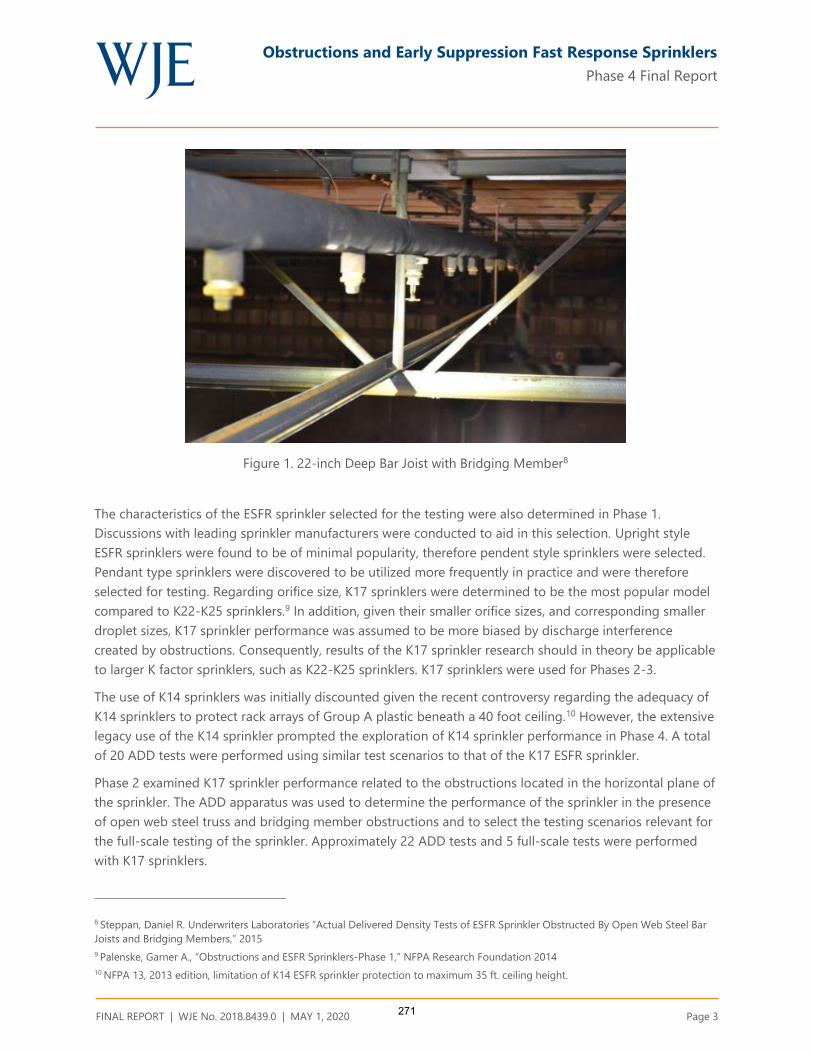
Obstructions and Early Suppression Fast Response Sprinklers
Phase 4 Final Report
FINAL REPORT | WJE No. 2018.8439.0 | MAY 1, 2020 Page 3
Figure 1. 22-inch Deep Bar Joist with Bridging Member8
The characteristics of the ESFR sprinkler selected for the testing were also determined in Phase 1.
Discussions with leading sprinkler manufacturers were conducted to aid in this selection. Upright style
ESFR sprinklers were found to be of minimal popularity, therefore pendent style sprinklers were selected.
Pendant type sprinklers were discovered to be utilized more frequently in practice and were therefore
selected for testing. Regarding orifice size, K17 sprinklers were determined to be the most popular model
compared to K22-K25 sprinklers.9 In addition, given their smaller orifice sizes, and corresponding smaller
droplet sizes, K17 sprinkler performance was assumed to be more biased by discharge interference
created by obstructions. Consequently, results of the K17 sprinkler research should in theory be applicable
to larger K factor sprinklers, such as K22-K25 sprinklers. K17 sprinklers were used for Phases 2-3.
The use of K14 sprinklers was initially discounted given the recent controversy regarding the adequacy of
K14 sprinklers to protect rack arrays of Group A plastic beneath a 40 foot ceiling.10 However, the extensive
legacy use of the K14 sprinkler prompted the exploration of K14 sprinkler performance in Phase 4. A total
of 20 ADD tests were performed using similar test scenarios to that of the K17 ESFR sprinkler.
Phase 2 examined K17 sprinkler performance related to the obstructions located in the horizontal plane of
the sprinkler. The ADD apparatus was used to determine the performance of the sprinkler in the presence
of open web steel truss and bridging member obstructions and to select the testing scenarios relevant for
the full-scale testing of the sprinkler. Approximately 22 ADD tests and 5 full-scale tests were performed
with K17 sprinklers.
8 Steppan, Daniel R. Underwriters Laboratories “Actual Delivered Density Tests of ESFR Sprinkler Obstructed By Open Web Steel Bar
Joists and Bridging Members,” 2015
9 Palenske, Garner A., “Obstructions and ESFR Sprinklers-Phase 1,” NFPA Research Foundation 2014
10 NFPA 13, 2013 edition, limitation of K14 ESFR sprinkler protection to maximum 35 ft. ceiling height.
271

Obstructions and Early Suppression Fast Response Sprinklers
Phase 4 Final Report
FINAL REPORT | WJE No. 2018.8439.0 | MAY 1, 2020 Page 4
Phase 3 introduced vertical obstruction types including 3-inch flat, 6-inch flat, 12-inch flat, 3-inch round,
6-inch round, and 1½-inch bridging members. A total of 22 ADD tests were performed using K17
sprinklers to determine which full-scale tests would be the most rigorous. Three full-scale tests were
performed.
Phase 4, as previously mentioned, focused on the performance of the K14 sprinkler in configurations
similar to those explored in Phase 3. A total of 20 ADD tests were performed to compare the performance
of K14 ESFR sprinklers to that of K17 ESFR sprinklers. One full-scale test using K17 sprinklers was
performed.
OBSTRUCTION EXPERIMENTATION
The experimentation was conducted at Underwriters Laboratories, large-scale fire test facility located in
Northbrook, Illinois, during April 2015 - September of 2019. A description of the effort is summarized
below. Additional details can be found in the complete reports located on the Fire Protection Research
Foundation’s website.
Actual Delivered Density (ADD) Testing
ADD testing has been used to quantify sprinkler performance since the development of the ESFR sprinkler
in the 1980s. The apparatus has evolved over time. Presently, a modified second generation apparatus is
used in the sprinkler listing process as defined in Underwriters Laboratories, UL 1767- Early Suppression
Fast Sprinklers. This standard prescribes minimum ADD values needed to demonstrate proper sprinkler
performance.
A third generation apparatus was designed and constructed at Underwriters Laboratories in 2005. The
apparatus consists of a fire source in the form of 12 heptane burners used to simulate a rack storage fire.
There are 48 square collection pans with dimensions of 20 inches by 20 inches used to collect water into
cylinders below the apparatus. A pressure tap located in each cylinder allows the calculation of the
amount of water in each container over time which may be used to calculate the water flux in each region
in gpm/ft2. An air duct located in the center of the apparatus provides airflow to simulate a fire plume.
Flue spaces are provided at a spacing of 6 inches between each pan configurations. The addition of flue
spaces results in a more realistic simulation because combustion occurs within the flue space and not in
open air above the apparatus. Water is sprayed on the underside of the pans to prevent warping caused
by the radiative heat from the flames.
A drawing of the apparatus is shown in Figure 2. The ADD apparatus in operation is shown in Figure 3.
272
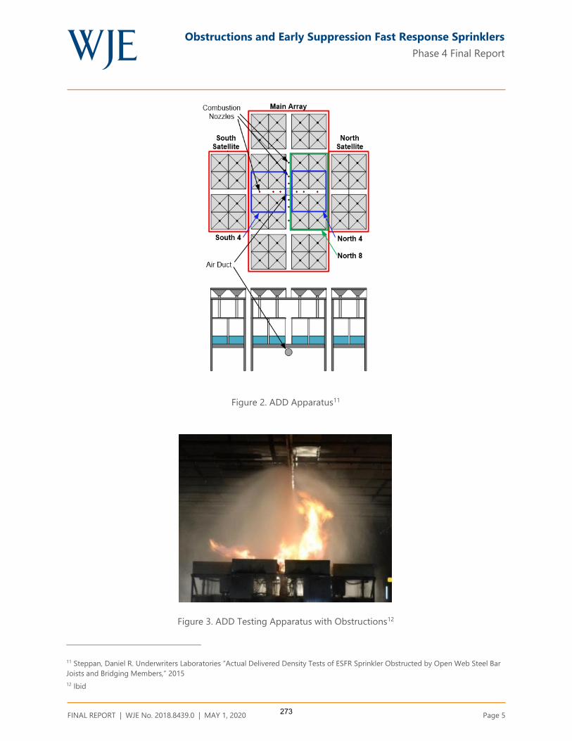
Obstructions and Early Suppression Fast Response Sprinklers
Phase 4 Final Report
FINAL REPORT | WJE No. 2018.8439.0 | MAY 1, 2020 Page 5
Figure 2. ADD Apparatus11
Figure 3. ADD Testing Apparatus with Obstructions12
11 Steppan, Daniel R. Underwriters Laboratories “Actual Delivered Density Tests of ESFR Sprinkler Obstructed by Open Web Steel Bar
Joists and Bridging Members,” 2015
12 Ibid
273

Obstructions and Early Suppression Fast Response Sprinklers
Phase 4 Final Report
FINAL REPORT | WJE No. 2018.8439.0 | MAY 1, 2020 Page 6
The third-generation apparatus is used by Underwriters Laboratories to screen fire sprinkler system
designs and, prior to this project, has been used to evaluate non-fire ESFR sprinkler obstruction sensitivity.
This new apparatus is not currently used for UL 1767 sprinkler listing. While considered more accurate
than the modified second-generation apparatus, the legacy of test data compiled with the modified
second generation apparatus makes changing the ADD apparatus problematic.13
Sprinklers can be positioned in various arrangements, directly over, centered between, or offset from the
centerline of the fire source depending on the arrangement to be simulated. The thermal link of the
sprinklers is removed, since sprinkler response time is not objective criterion of the testing protocol. The
vertical position of the sprinkler relative to the top of the ADD apparatus replicates the distance from the
top of the storage array to the ceiling sprinkler location.
Prior to use of the ADD apparatus, a calibration procedure is completed. An experimental convection heat
release rate is selected based upon the properties of the simulated fire. The apparatus is then calibrated to
match plume temperature and velocity readings from actual rack storage fire test data. The air supply
below the apparatus remains constant at 250 liters/second (66 gallons/second) and the heptane nozzle
flow rate is adjusted as needed to produce measurements comparable to that of a full-scale rack storage
fire.
Once calibrated, a pilot flame is ignited above each set of heptane nozzles. The heptane nozzles and air
supply fan are then initiated. When the fire reaches a steady state burning condition, the pump controlling
the water flow to the open sprinkler is activated to produce the desired sprinkler discharge pressure. Data
is collected a nominal 5 minutes before the termination of each test. The data is then recorded for each
collection pan, and averages are calculated based on areas of interest pertaining to the shadow created by
individual structural elements.
Dr. HC Kung compared the results of both generations of ADD apparatus to full-scale fire test results.14
Temperature and velocity measurements were taken at various locations over each apparatus. Centerline
temperatures were recorded at 3.14 ft., 8.4 ft., and 15.4 ft above the top of the apparatus. Velocity probe
measurements were taken at a 0.16 ft. radius from center line of the apparatus at all heights. Table 1
presents the results of the experimentation:
Where:
∆Tc= Fire plume centerline temperature difference from ambient temperature (F)
∆To = Fire plume off center temperature difference from ambient temperature (F)
uc= Fire plume centerline velocity(ft/sec)
ADD =Third generation apparatus data
Previous = Modified second generation apparatus
13 Discussions with Underwriters Laboratories Staff
14 Schwille, Kung, Hjohlman, Laverick, and Gardell: Actual Delivered Density Fire Test Apparatus for Sprinklers Protecting High
Commodity Storage, Fire Safety Science-Eight International Symposium, 2005.
274

Obstructions and Early Suppression Fast Response Sprinklers
Phase 4 Final Report
FINAL REPORT | WJE No. 2018.8439.0 | MAY 1, 2020 Page 7
Table 1. ADD Validation Data15
3.4 ft 8.4 ft 15.4 ft
ΔTc ΔTo uc ΔTc ΔTo uc ΔTc ΔTo uc
500 kW Fire
Fire Test 626 405 24.0 324 219 21.3 201 129 20.3
ADD 577 549 22.0 466 239 23.0 262 153 20.0
Previous 360 871 24.9 358 293 22.0 234 180 19.4
1000 kW Fire
Fire Test 1247 779 31.5 628 388 NA 324 217 24.9
ADD 826 750 32.8 680 390 29.5 390 253 23.0
Previous 790 1607 29.9 709 543 29.2 397 306 24.6
1500 kW Fire
Fire Test 1555 975 34.4 975 572 31.2 487 313 29.9
ADD 1182 1269 36.1 1058 642 36.1 612 385 29.5
Previous 1458 1854 34.1 1033 716 33.1 525 406 29.9
2000 kW Fire
Fire Test 1636 1213 35.1 1400 631 36.1 671 405 35.1
ADD 1447 1477 37.4 1348 885 38.7 795 498 33.8
Previous 1645 1918 34.4 1400 991 38.7 703 527 32.5
2500 kW Fire
Fire Test 1679 1278 35.4 1490 874 29.9 766 473 36.1
ADD 1852 1614 36.1 1569 1072 39.4 943 588 36.1
Previous 1632 2050 35.4 1555 1240 41.0 882 604 34.4
Comparison of the third generation ADD apparatus results to measurements taken during the four tier
rack storage fire tests shows that the fire plume temperatures and velocities are generally within 10% of
those measured in the rack storage fires. 16
The third generation ADD apparatus was used in the ESFR obstruction project to identify obstruction
scenarios and define boundary conditions. The apparatus was calibrated to a convective heat release rate
of 2.5 MW, which is representative of standard plastic commodity stored at a height of 30 feet in rack
storage array, beneath a 40 foot ceiling. The ESFR sprinkler was located directly above the fire, with a 14
inch deflector to ceiling clearance. This was considered the most challenging scenario for the K17 ESFR
15 Ibid
16 Ibid
275

Obstructions and Early Suppression Fast Response Sprinklers
Phase 4 Final Report
FINAL REPORT | WJE No. 2018.8439.0 | MAY 1, 2020 Page 8
sprinkler. Typical obstruction scenarios for the bar joist, bridging member, flat, and round obstructions are
shown in Figure 4 through Figure 7. ADD results are summarized in Table 2.
Figure 4. Typical ADD Testing Bar Joist Obstruction Scenario17
17 Steppan, Daniel R. Underwriters Laboratories “Actual Delivered Density Tests of ESFR Sprinkler Obstructed by Open Web Steel Bar
Joists and Bridging Members,” 2015
276

Obstructions and Early Suppression Fast Response Sprinklers
Phase 4 Final Report
FINAL REPORT | WJE No. 2018.8439.0 | MAY 1, 2020 Page 9
Figure 5. Typical ADD Testing Bridging Member Obstruction Scenario18
Figure 6. Typical ADD Testing Flat Obstruction Scenario
18 Ibid
277

Obstructions and Early Suppression Fast Response Sprinklers
Phase 4 Final Report
FINAL REPORT | WJE No. 2018.8439.0 | MAY 1, 2020 Page 10
Figure 7. Typical ADD Testing Round Obstruction Scenario19
19 Ibid
278

Obstructions and Early Suppression Fast Response Sprinklers
Phase 4 Final Report
FINAL REPORT | WJE No. 2018.8439.0 | MAY 1, 2020 Page 11
Table 2. Summary of ADD Fire Test Results
279

Obstructions and Early Suppression Fast Response Sprinklers
Phase 4 Final Report
FINAL REPORT | WJE No. 2018.8439.0 | MAY 1, 2020 Page 12
Full-Scale Fire Testing
Various obstruction arrangements were tested in full-scale based upon the information gathered in the
ADD testing and sprinkler discharge pattern analysis. The test array tested consisted of the following
configuration (Figure 8 and Figure 9).
Standard Group A plastic commodity:
30 feet of double-row rack storage and a 40-foot high ceiling
Standard 4-foot aisles with 6-inch transverse and longitudinal flue spaces provided at rack uprights
and between unit loads.
K17 ESFR sprinklers operating at 52 psi and positioned at the ceiling with 14-inch clearance between
the ceiling and the deflector.
Sprinkler spacing of 10 feet x 10 feet
Two - half igniters positioned at the base of the commodity, offset on the center of the transverse flue
space in the main array.
The following pass/fail criteria were established:
A maximum of eight sprinklers activate. This is the same criterion established for K22.4 ESFR sprinklers
for similar ceiling/storage heights with a 50 percent safety factor assuming a 12-sprinkler design.
The fire is generally contained to the ignition array. The ignition array is defined as the center stacks,
two pallet-loads long by two pallet-loads wide, of the main fuel array in which the igniters are located.
Ceiling gas temperatures are such that exposed structural steel will not be endangered (peak one-
minute average temperatures less than 1,000 °F). This is consistent with all current ESFR sprinkler test
criteria.
Full-scale testing was completed for K17 sprinklers only. Results are presented in Table 3.
280

Obstructions and Early Suppression Fast Response Sprinklers
Phase 4 Final Report
FINAL REPORT | WJE No. 2018.8439.0 | MAY 1, 2020 Page 13
Figure 8. Typical Test Array as viewed from the North20
Figure 9. Typical Test Array as viewed from the East21
20 Ibid
21 Ibid
281

Obstructions and Early Suppression Fast Response Sprinklers
Phase 4 Final Report
FINAL REPORT | WJE No. 2018.8439.0 | MAY 1, 2020 Page 14
Table 3. Summary of full scale fire test results and findings Fire Test Number Test No. 1 Test No. 2 Test No. 3 Test No. 4 Test No. 5 Test No. 6 Test No. 7 Test No. 8 Test No. 9
Test Date April 4th, 2015 April 16th, 2015 April 20th, 2015 April 22nd, 2015 April 24th, 2015 August 4th, 2016 August 9th, 2016 August 12th, 2016 September 24, 2019
Primary Obstruction 36 Inch deep steel
joist, edge of lower
chord 6 inches from
centerline of
sprinkler
30 inch deep steel
joist, edge of lower
chord 3 inches from
centerline of
sprinkler
36 inch deep steel
joist, edge of lower
chord 6 inches from
centerline of
sprinkler
36 inch deep steel
joist, edge of lower
chord 6 inches from
centerline of
sprinkler
22 inch deep steel
joist, edge of lower
chord 6 inches from
centerline of
sprinkler
1.5 inch by 1.5 inch
bridging member,
directly under
sprinkler, 12 inches
down from
deflector
12-inch wide, 3-
inch deep structural
C shape; 6 inch
offset from primary
sprinkler; 20 inches
below deflector
6-inch wide, 2-inch
deep structural C
shape; 6 inch offset
from primary
sprinkler; 20 inches
below deflector
24-inch wide, 3-inch
deep flat steel, 12
inch offset from
primary sprinkler; 22
inches below
deflector
Secondary Obstruction None None 1.5 inch by 1.5 inch
bridging member;
1.5 inch away from
sprinkler
1.5 inch by 1.5 inch
bridging member;
Centered below
sprinkler
1.5 inch by 1.5 inch
bridging member;
Centered below
sprinkler
None None None None
Length of Test (minutes) 31 32 32 32 32 32 32 32 32
First Sprinkler Operation
Time (min: sec)
0:56 1:42 1:19 1:11 1:01 1:18 1:22 1:11 1:18
Last Sprinkler Operation
Time (min: sec)
6:08 7:37 1:19 1:11 6:42 1:18 7:06 1:11 1:18
Number of Operated
Sprinklers
3 12 1 1 23 1 10 1 1
Peak Gas Temperature at
Ceiling Above Ignition (F°)
294 406 238 250 1264 242 217 240 191
Maximum 1 minute
Average Gas Temperature
at Ceiling Above Ignition
(F°)
129 256 114 115 979 143 142 122 110
Peak Steel Temperature at
Ceiling Above Ignition (F°)
128 157 86 84 248 92 138 94 80
Maximum 1 minute
Average Steel
Temperature at Ceiling
Above Ignition (F°)
126 157 85 83 246 91 137 94 80
Ignition Time of Target
Array (min: sec)
3:36 (North Target) 3:24 (North Target) N/A N/A 2:26 (North Target) N/A N/A N/A N/A
Fire Travel to Extremities
of Test Array
No No No No Yes (North Target) No
North Target Ignition No North target array
at approximately 4
minutes, 30
seconds; damaged
commodity, but the
fire did not travel to
the outer plane of
this target array.
No No
282
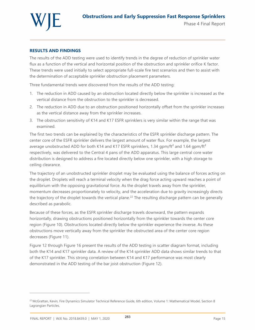
Obstructions and Early Suppression Fast Response Sprinklers
Phase 4 Final Report
FINAL REPORT | WJE No. 2018.8439.0 | MAY 1, 2020 Page 15
RESULTS AND FINDINGS
The results of the ADD testing were used to identify trends in the degree of reduction of sprinkler water
flux as a function of the vertical and horizontal position of the obstruction and sprinkler orifice K factor.
These trends were used initially to select appropriate full-scale fire test scenarios and then to assist with
the determination of acceptable sprinkler obstruction placement parameters.
Three fundamental trends were discovered from the results of the ADD testing:
1. The reduction in ADD caused by an obstruction located directly below the sprinkler is increased as the
vertical distance from the obstruction to the sprinkler is decreased.
2. The reduction in ADD due to an obstruction positioned horizontally offset from the sprinkler increases
as the vertical distance away from the sprinkler increases.
3. The obstruction sensitivity of K14 and K17 ESFR sprinklers is very similar within the range that was
examined.
The first two trends can be explained by the characteristics of the ESFR sprinkler discharge pattern. The
center core of the ESFR sprinkler delivers the largest amount of water flux. For example, the largest
average unobstructed ADD for both K14 and K17 ESFR sprinklers, 1.34 gpm/ft² and 1.64 gpm/ft²
respectively, was delivered to the Central 4 pans of the ADD apparatus. This large central core water
distribution is designed to address a fire located directly below one sprinkler, with a high storage to
ceiling clearance.
The trajectory of an unobstructed sprinkler droplet may be evaluated using the balance of forces acting on
the droplet. Droplets will reach a terminal velocity when the drag force acting upward reaches a point of
equilibrium with the opposing gravitational force. As the droplet travels away from the sprinkler,
momentum decreases proportionately to velocity, and the acceleration due to gravity increasingly directs
the trajectory of the droplet towards the vertical plane.22 The resulting discharge pattern can be generally
described as parabolic.
Because of these forces, as the ESFR sprinkler discharge travels downward, the pattern expands
horizontally, drawing obstructions positioned horizontally from the sprinkler towards the center core
region (Figure 10). Obstructions located directly below the sprinkler experience the inverse. As these
obstructions move vertically away from the sprinkler the obstructed area of the center core region
decreases (Figure 11).
Figure 12 through Figure 16 present the results of the ADD testing in scatter diagram format, including
both the K14 and K17 sprinkler data. A review of the K14 sprinkler ADD data shows similar trends to that
of the K17 sprinkler. This strong correlation between K14 and K17 performance was most clearly
demonstrated in the ADD testing of the bar joist obstruction (Figure 12).
22 McGrattan, Kevin, Fire Dynamics Simulator Technical Reference Guide, 6th edition, Volume 1: Mathematical Model, Section 8
Lagrangian Particles.
283
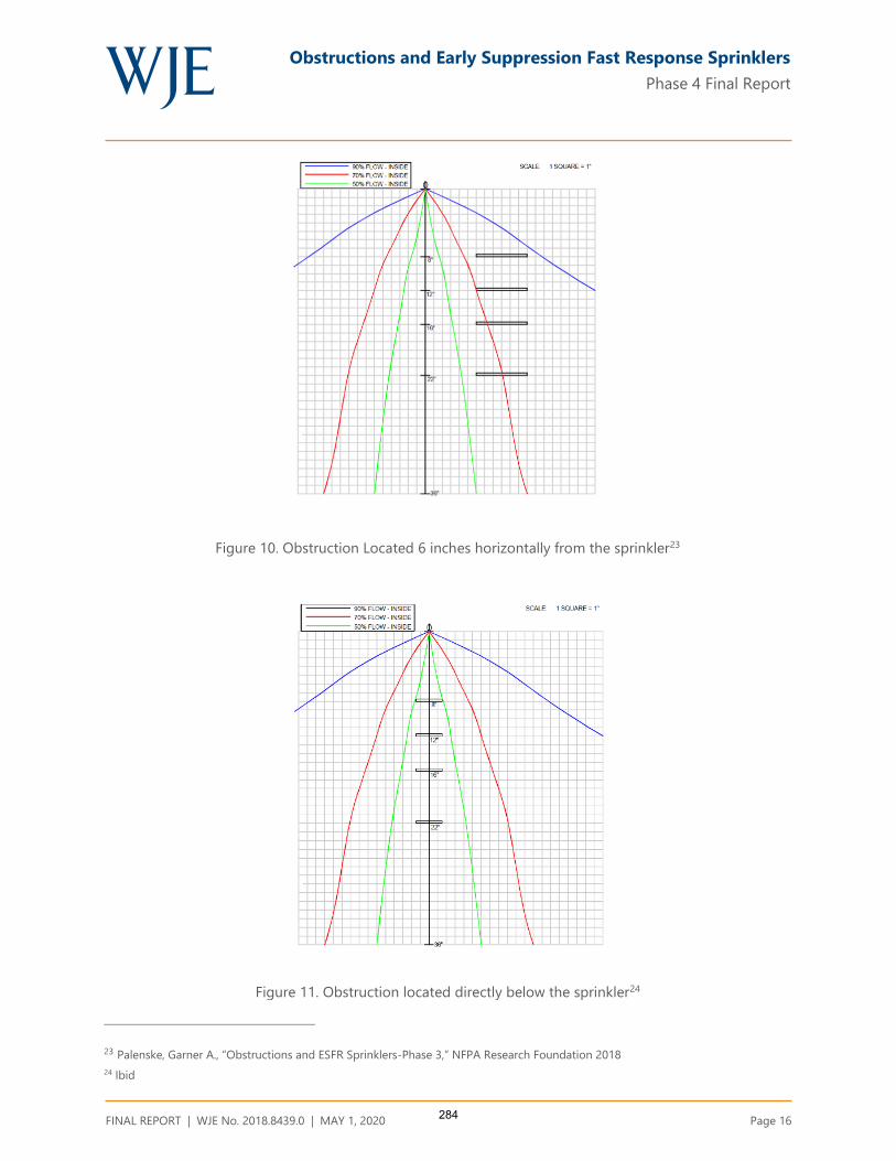
Obstructions and Early Suppression Fast Response Sprinklers
Phase 4 Final Report
FINAL REPORT | WJE No. 2018.8439.0 | MAY 1, 2020 Page 16
Figure 10. Obstruction Located 6 inches horizontally from the sprinkler23
Figure 11. Obstruction located directly below the sprinkler24
23 Palenske, Garner A., “Obstructions and ESFR Sprinklers-Phase 3,” NFPA Research Foundation 2018
24 Ibid
284
Obstructions and Early Suppression Fast Response Sprinklers
Phase 4 Final Report
FINAL REPORT | WJE No. 2018.8439.0 | MAY 1, 2020 Page 17
Bar Joist and Bridging Member Obstructions
Full-scale Test No. 1 examined the scenario of a 36 inch deep bar joist located 6 inches horizontally from
the K17 sprinkler. The 36 inch deep bar joist, when positioned horizontally from the sprinkler, is
considered the most rigorous bar joist depth within the boundary conditions established (22 -36 inch
deep bar joist) since the bottom chord is the greatest distance below the sprinkler. This test was
successful, operating only one sprinkler and meeting all other pass/fail criteria (Table 3). Given the
similarities of the K14 and K17 ADD data (Figure 12), a similar result is expected for K14 sprinklers.
Both K14 and K17 ADD data for a bridging member located directly below a sprinkler show an increase in
ADD as the bridging member moves vertically away from the sprinkler (Figure 13). However, the K14 ADD
data shows a much greater increase in ADD as the vertical separation increases. For example, with the
bridging member located 12 inches below the sprinkler, the K14 Central 4 and Central 16 pan average
ADD decreases 80% and 53%, respectively when compared to an unobstructed condition. These decreases
are much greater than the K17 sprinkler data in which the Central 4 and Central 16 pan average ADD
decreases 14% and 6%, respectively.
Full-scale Test No. 6 investigated the scenario of a 1½ x 1½ inch bridging member located 12 inches
directly below the sprinkler. This configuration resulted in acceptable performance, opening only one K17
sprinkler and meeting the other pass/fail criteria (Table 3). The K17 ADD for this scenario was 1.17 gpm/ft²
(Central 4) and 0.79 gpm/ft² (Central 16). Using linear interpolation of the K14 ADD data, an equivalent
Central 4 ADD is found at 18 inches below the sprinkler and 14 inches below for the Central 16 ADD. The
correlation in the data demonstrates that a bridging member located directly below the sprinkler provided
with an 18 inch vertical clearance (K14) or 12 inch vertical clearance (K17), will result in similar
performance.
Full-scale Test No. 4 examined the same 36 inch deep bar joist condition as Test No. 1 with the addition of
a 1 ½ x 1½ inch bridging member attached to the top of the lower chord in a perpendicular orientation.
The bridging member was located approximately 20 inches directly below the sprinkler (36 inch deep bar
joist - 14 inch ceiling deflector clearance - 2 ½ inch chord height). Note that this bridging member to
sprinkler clearance exceeds the minimum acceptable clearance established in the previous paragraph for
bridging members located directly below K14 or K17 sprinklers. This test demonstrated acceptable
performance, activating only one K17 sprinkler and meeting the other pass/fail criteria (Table 3). The K14
ADD exceeded that of the K17 ADD for this scenario (North 4 ADD =52%, North 8 ADD = 104%), therefore
a similar result is expected for K14 sprinklers.
285

Obstructions and Early Suppression Fast Response Sprinklers
Phase 4 Final Report
FINAL REPORT | WJE No. 2018.8439.0 | MAY 1, 2020 Page 18
Figure 12. Bar joist obstruction ADD results (6 inch horizontal offset from sprinkler)
Figure 13. Bridging Member Obstruction ADD Results(Directly under sprinkler)
286

Obstructions and Early Suppression Fast Response Sprinklers
Phase 4 Final Report
FINAL REPORT | WJE No. 2018.8439.0 | MAY 1, 2020 Page 19
Flat Obstructions
Obstructions of various shapes were tested in Phase 3 to determine the effect that obstruction shape has
on ADD. Test data showed that the difference in ADD between flat and round obstructions was negligible
(Table 2). Accordingly, the term “flat obstruction” as used in this report refers to both flat and round
obstructions.
The K17 sprinkler data collected for the flat obstructions positioned horizontally from the sprinkler shows
a consistent relationship of decreasing ADD with a slight sensitivity to obstruction width (Figure 14
through Figure 16). This occurs because the 6 inch horizontal offset places the majority of the obstruction
outside of the high discharge central core and thus obstructs less water. The K14 sprinkler data shows less
sensitivity to obstruction width.
Full-scale Test No. 8 examined the scenario of a 6 inch wide flat obstruction, offset horizontally 6 inches
and 20 inches below the sprinkler deflector. This test demonstrated acceptable performance, opening only
one K17 sprinkler and meeting all other pass/fail criteria (Table 3). The ADD reduction for this scenario,
North 4 -31.73% and North 8-24.36 %, is the largest reduction of all flat obstructions tested within the
established boundary conditions (3 inch- 12 inch width) using K17 sprinklers. The K14 ADD apparatus
reduction data for this scenario was -41.0% (North 4) and -48.86 % (North 8). However, the K14 sprinkler
delivered a North 4 ADD much larger than the K17 ADD, 0.68 gpm/sq. ft. vs 0.14 gpm/sq. ft., and
approximately the same for the North 8 region, 0.51 gpm/sq. ft. vs 0.60 gpm/sq. ft. Given the ADD
comparison, a similar result is expected for K14 sprinklers.
Full-scale Test No. 7 investigated the scenario of a 12 inch wide flat obstruction, offset horizontally 6
inches, and 20 inches below the sprinkler deflector. Despite having similar ADD values to the 6 inch wide
obstruction used in Test No. 7, 10 sprinklers operated, 2 sprinklers more than the pass/fail criteria. Fire
propagation and ceiling temperatures were within acceptable limits (Table 3). The reduction in the ADD
was within the acceptable range, -28.85 % North 4, and -23.08 North 8.
Review of the sprinkler operation sequence of Test No. 7 shows an unusual pattern, indicative of sprinkler
skipping phenomena (Figure 17). Sprinkler skipping can occur when a sprinkler activates significantly
sooner than a neighboring sprinkler that is closer to the fire plume.25 Sprinkler 46, closest to the fire,
operated at 1 minute, 22 seconds. Sprinkler 48 operated at 6 minutes, 30 seconds while Sprinkler 47 did
not operate at all despite the closer proximity of Sprinkler 47 to the fire location. Sprinkler 66 operated at
6 minutes, 24 seconds while Sprinkler 56 did not operate at all despite the closer proximity of Sprinkler 56
to the fire location. The performance of Sprinklers 47 and 56 are characteristic of skipping phenomena.
25 Croce, Hill, &, Xin (2005) Investigation of the Causative Mechanism of Sprinkler Skipping. Journal of Fire
Protection Engineering, Volume 15
287

Obstructions and Early Suppression Fast Response Sprinklers
Phase 4 Final Report
FINAL REPORT | WJE No. 2018.8439.0 | MAY 1, 2020 Page 20
Figure 14. Three inch flat obstruction ADD results (6 inch horizontal offset
from sprinkler)
Figure 15. Six inch flat obstruction ADD results (6 inch horizontal offset from
sprinkler)
288

Obstructions and Early Suppression Fast Response Sprinklers
Phase 4 Final Report
FINAL REPORT | WJE No. 2018.8439.0 | MAY 1, 2020 Page 21
Figure 16. Twelve inch flat obstruction ADD results (6 inch horizontal offset from
sprinkler)
289

Obstructions and Early Suppression Fast Response Sprinklers
Phase 4 Final Report
FINAL REPORT | WJE No. 2018.8439.0 | MAY 1, 2020 Page 22
Figure 17. Test No. 7 sprinkler operation sequence26
Skipping can reduce the amount of water flux delivered to the fire and, therefore, the ability of the
sprinklers to achieve suppression. Skipping is thought to be caused by the impingement of entrained and
diverted droplets from previously operated sprinklers.27 It is reasonable to suggest that the introduction of
an obstruction would cause sprinkler skipping as the amount of diverted water droplets would be altered
in a manner uncharacteristic of an unobstructed condition. Obstructions located in the near field of an
operating sprinkler can redirect or change the characteristics of the water droplets such that the droplets
are unable to penetrate the fire plume. These smaller and slower moving droplets are more likely to be
entrained and directed towards an adjacent sprinkler.
26 Steppan, Daniel R. Underwriters Laboratories “Actual Delivered Density (ADD) Tests of ESFR Sprinklers Obstructed by Open Web
Steel Bar Joists, Bridging Members, and Flat Geometries” 2019
27 Croce, Hill, &, Xin (2005) Investigation of the Causative Mechanism of Sprinkler Skipping. Journal of Fire
Protection Engineering, Volume 15
290
Obstructions and Early Suppression Fast Response Sprinklers
Phase 4 Final Report
FINAL REPORT | WJE No. 2018.8439.0 | MAY 1, 2020 Page 23
The increased width of the 12-inch flat obstruction compared to the 6-inch flat obstruction (Test No. 8)
would cause a greater amount of droplet disruption and, therefore, a greater propensity for sprinkler
skipping. Review of the video from Test No. 7 did show a greater amount of ceiling water vapor present
compared that shown in Test No. 8.
The performance of Test No. 7 met two of the three acceptable performance criteria; the fire damaged
stayed within the main array and did not burn to the back of the target array, and the ceiling temperatures
were within the acceptable range. A comparison of the main array damage in Test Nos. 7 and 8 indicates
more damage in Test No. 7, but still within an acceptable level.
The operation of 10 sprinklers in lieu of 8 complicates the categorization of the outcome of Test No. 7.
Historically, safety factors up to 2.0 have been used for sprinkler operation in full scale fire testing. 28
Typically, a 1.5 safety factor is included in the pass/fail criteria for ESFR sprinkler fire testing.29 However,
review of ESFR sprinkler approval standards shows a wide range of permissible number of operating
sprinklers. For example, UL 1767A, “Outline for Investigation for ESFR Sprinklers Having K- Factors Greater
than 14.0,” defines the acceptable number as 6 to 9 sprinklers (K22 or K25) depending on the test
specifications. FM Global “Approval Standard for ESFR Sprinklers, Class Series 2008,” defines acceptable
performance for sprinklers as the operation of 8 to 12 sprinklers (K22 or K25). Neither UL nor FM Global
approval standards require full-scale fire testing of K14 or K17 ESFR sprinklers due to their legacy
performance and comparable performance.
It is also important to note that the acceptable number of operating sprinklers applies when the sprinklers
operate in a proper sequence. All of the first ring sprinklers should operate within a few seconds before
any second or third ring sprinklers. When a different operating sequence occurs, additional sprinklers may
operate, and early suppression may still be achieved when the other pass/fail criteria are met.30As shown
in Figure 17, 5 of the 9 first ring sprinklers and 5 of 25 second ring sprinklers activated. The increased
number of sprinklers that activated in Test No. 7 is likely attributed to the sequence of sprinkler operation
caused by the skipping phenomenon previously discussed.
The scenario of non-operational sprinklers was considered in the testing protocol used in the early
development of the ESFR sprinkler. In these tests, one sprinkler located in the first ring was rendered
inoperable to simulate a plugged sprinkler.31 Current FM Global Approval Standard FM 2008, “Approval
for Quick Response Storage Sprinklers for Fire Protection”, includes the plugged sprinkler scenario in the
testing protocol for upright ESFR sprinklers.
Considering this background information, it is reasonable to conclude the results of Test No. 7
demonstrated that, despite the very rigorous condition of two inoperable or plugged sprinklers, the
sprinklers suppressed the fire and therefore, the test meets the pass/fail criteria.
28 National Fire Protection Association “Automatic Sprinkler Systems Handbook” 2016 Edition, Section 21.1.8 text and commentary
29 Ibid
30 Chicarello, Troup and Dean. “The National Quick Response Sprinkler Research Project: Large Scale Fire Test Evaluation of ESFR
Automatic Sprinklers,” Fire Protection Research Foundation Report, May 1986.
31 Yao, C. “The Development of the ESFR Sprinkler System”, Fire Safety Journal, 14, 66-73,1988
291
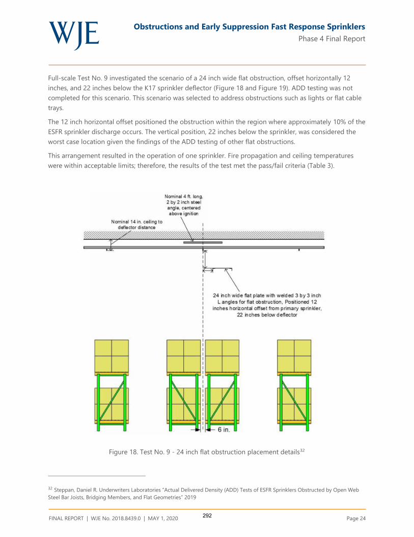
Obstructions and Early Suppression Fast Response Sprinklers
Phase 4 Final Report
FINAL REPORT | WJE No. 2018.8439.0 | MAY 1, 2020 Page 24
Full-scale Test No. 9 investigated the scenario of a 24 inch wide flat obstruction, offset horizontally 12
inches, and 22 inches below the K17 sprinkler deflector (Figure 18 and Figure 19). ADD testing was not
completed for this scenario. This scenario was selected to address obstructions such as lights or flat cable
trays.
The 12 inch horizontal offset positioned the obstruction within the region where approximately 10% of the
ESFR sprinkler discharge occurs. The vertical position, 22 inches below the sprinkler, was considered the
worst case location given the findings of the ADD testing of other flat obstructions.
This arrangement resulted in the operation of one sprinkler. Fire propagation and ceiling temperatures
were within acceptable limits; therefore, the results of the test met the pass/fail criteria (Table 3).
Figure 18. Test No. 9 - 24 inch flat obstruction placement details32
32 Steppan, Daniel R. Underwriters Laboratories “Actual Delivered Density (ADD) Tests of ESFR Sprinklers Obstructed by Open Web
Steel Bar Joists, Bridging Members, and Flat Geometries” 2019
292

Obstructions and Early Suppression Fast Response Sprinklers
Phase 4 Final Report
FINAL REPORT | WJE No. 2018.8439.0 | MAY 1, 2020 Page 25
Figure 19. Test No. 9 - 24 inch flat obstruction plan view33
The sprinkler discharge formed excessive sheeting which traveled over the obstruction edge onto the top
of the commodity and then downward along the face of the rack. The wetting of the ignition array face
contributed to the suppression of the fire. Similar behavior was noted in the other flat obstruction tests.
The magnitude of the sheeting in Test No. 9 with a 24 inch obstruction, however, was much larger
(Figure 20 through Figure 23). This is the result of the increased width of the 24 inch obstruction. The
magnitude of the shadow created by a flat obstruction increased proportionately as the width of the
obstruction was increased between a 6 in., 12 in., and 24 in. obstruction. The increased area per unit
length of the 24 inch obstruction created a greater disruption in the sprinkler water flow and thus diverted
a larger amount of water onto and over the edge of the obstruction.
33 Ibid
293

Obstructions and Early Suppression Fast Response Sprinklers
Phase 4 Final Report
FINAL REPORT | WJE No. 2018.8439.0 | MAY 1, 2020 Page 26
Figure 20. Ceiling View of Test No. 9 - 24 inch flat
obstruction34
Figure 21. Ceiling View of Test No. 7 - 12 inch flat
obstruction35
Figure 22. Floor View of Test No. 9 - 24 inch flat
obstruction36
Figure 23. Floor View of Test No. 7 - 12 inch flat
obstruction37
Figure 24 and Figure 25 show the distribution of water flux in percentage change from unobstructed
condition for 6 inch and 12 inch wide obstructions (Test 8 and Test 7 respectively). Figure 26 shows a
comparison of the change in water flux location as a function of obstruction width. It is shown that, as the
width of the obstruction increases, the shadow created by the obstruction increases in width and moves
horizontally to the right, away from the obstruction. The 6 inch obstruction resulted in a decreased water
34Ibid
35 Steppan, Daniel R. Underwriters Laboratories “Actual Delivered Density Tests of ESFR Sprinkler Obstructed by Open Web Steel Bar
Joists and Bridging Members,” 2015
36 Steppan, Daniel R. Underwriters Laboratories “Actual Delivered Density (ADD) Tests of ESFR Sprinklers Obstructed by Open Web
Steel Bar Joists, Bridging Members, and Flat Geometries” 2019
37 Steppan, Daniel R. Underwriters Laboratories “Actual Delivered Density Tests of ESFR Sprinkler Obstructed by Open Web Steel Bar
Joists and Bridging Members,” 2015
294

Obstructions and Early Suppression Fast Response Sprinklers
Phase 4 Final Report
FINAL REPORT | WJE No. 2018.8439.0 | MAY 1, 2020 Page 27
flux only in the region along the north face of the ignition array. The 12 inch obstruction resulted in
decreased water flux in the same region and in the region within the first row of collection pans inside the
north aisle. Extending this relationship to the 24 inch flat obstruction, the shadow is predicted to extend
into the north aisle, an area not critical to sprinkler performance (Figure 27).
As discussed earlier, the 24 inch obstruction is located completely in the lower water flow region, which
accounts for only approximately 10% of the sprinkler flow. Obstructions in this region are generally
considered to have minimal effect on sprinkler performance.
The water sheeting behavior which occurred could be perceived as a factor which dilutes the analysis of
outcome of the fire test. However, intentional or not, obstructions 6 inches or wider create this behavior
which can improve sprinkler performance.
Based upon this analysis, it was concluded that the fire test would have been successful with or without
the presence of excessive sheeting.
295

Obstructions and Early Suppression Fast Response Sprinklers
Phase 4 Final Report
FINAL REPORT | WJE No. 2018.8439.0 | MAY 1, 2020 Page 28
Figure 24. Test No. 8 - 6 inch flat obstruction ADD Water Flux Distribution38
38 Palenske, Garner A., “Obstructions and ESFR Sprinklers-Phase 3,” NFPA Research Foundation 2018
296
Obstructions and Early Suppression Fast Response Sprinklers
Phase 4 Final Report
FINAL REPORT | WJE No. 2018.8439.0 | MAY 1, 2020 Page 29
Figure 25. Test No. 8 - 12 inch flat obstruction ADD Water Flux Distribution39
39 Ibid
297

Obstructions and Early Suppression Fast Response Sprinklers
Phase 4 Final Report
FINAL REPORT | WJE No. 2018.8439.0 | MAY 1, 2020 Page 30
Figure 26. Test No. 8 and Test No. 7- ADD Water Flux Distribution Comparison40
40 Ibid
298

Obstructions and Early Suppression Fast Response Sprinklers
Phase 4 Final Report
FINAL REPORT | WJE No. 2018.8439.0 | MAY 1, 2020 Page 31
Figure 27. Obstruction shadow overlay
299

Obstructions and Early Suppression Fast Response Sprinklers
Phase 4 Final Report
FINAL REPORT | WJE No. 2018.8439.0 | MAY 1, 2020 Page 32
CONCLUSIONS
The ESFR Obstruction Project has made significant advancements in understanding of the effects
obstructions have on ESFR sprinkler performance. Both K14 and K17 ESFR sprinkler behavior was
investigated. Significant findings of this work are summarized as follows:
The obstruction created by an open web steel truss between the depths of 22 - 36 inches, located 6
inches horizontally from a K14 or K17 ESFR sprinkler should not significantly decrease sprinkler
performance.
The obstruction created by a bridging member 1½ x 1½ inches in size or less, located directly below
the sprinkler with an 18 inch vertical clearance (K14) or 12 inch vertical clearance (K17) does not
significantly decrease sprinkler performance. This applies to bridging members attached to open web
steel trusses.
The obstruction created by flat or round obstructions less than or equal to 12 inches in width located 6
inches horizontally from a K17 or K14 sprinkler should not significantly decrease sprinkler
performance.
The obstruction created by flat or round obstructions less than or equal to 24 inches in width located
12 inches horizontally from a K17 or K14 sprinkler should not significantly decrease sprinkler
performance.
ACKNOWLEDGEMENTS
The authors wish to thank the many people who assisted with this project. The project would not have
succeeded without their help. Special thanks to the Fire Protection Research Foundation, Project Technical
Panel, Project Sponsors, and other industry colleagues for their support and encouragement.
Garner A. Palenske, P.E.
Associate Principal
Garth N. Ornelas, P.E.
Associate
300
Obstructions and Early Suppression Fast Response Sprinklers
Phase 4 Final Report
FINAL REPORT | WJE No. 2018.8439.0 | MAY 1, 2020
APPENDIX A. ACTUAL DELIVERED DENSITY TESTING OF ESFR SPRINKLERS OBSTRUCTED BY
FLAT OBSTRUCTIONS (PHASE 4), UNDERWRITERS LABORATORIES, APRIL 26, 2019
301

ACTUAL DELIVERED DENSITY (ADD) TESTS
OF ESFR SPRINKLERS OBSTRUCTED BY
OPEN WEB STEEL BAR JOISTS, BRIDGING
MEMBERS and FLAT GEOMETRIES
Prepared by
UL LLC
Project 4788895562, NC5756
for the
Fire Protection Research Foundation
Issued: April 26, 2019
Copyright © 2019 UL LLC
302

Issued: April 26, 2019
i
Executive Summary
This report describes twenty (20) Actual Delivered Density (ADD) tests that were conducted to
develop data relative to the level of fire performance provided by a K = 14.0 and a K = 16.8 ESFR
sprinkler when the sprinklers are located closer to an obstruction than currently referenced in the
Standard for the Installation of Sprinkler Systems, NFPA 13-2019. For this test series, the
sprinklers were located in close proximity to open web ceiling steel bar joists, a steel bridging
member and flat obstructions.
The ADD apparatus consists of a fire source and a set of water collection pans. A drawing of the
top and side views of the apparatus are shown in Figure E-1. The main components of the apparatus
are 48 water collection pans and 12 heptane nozzles. The 48 water collection pans are
approximately 20 in. by 20 in. and are separated into groups of four. A group of four collection
pans, i.e., a 2x2 array, simulates the top surface of one pallet load of stored commodity. Eight
groups of four are placed in the main array, while two satellite arrays each consist of two groups of
four. The two satellite collector arrays were placed adjacent to the main array to investigate pre-
wetting characteristics. A 6 in. flue space was maintained between two adjacent simulated
commodities.
303

Issued: April 26, 2019
ii
Figure E-1. ADD Apparatus Schematic (Plan and Elevation Views)
304

Issued: April 26, 2019
iii
Figure E-2. ADD Apparatus Photograph
For all tests, the center of the ADD apparatus was located directly below the discharging sprinkler.
The top of the ADD apparatus (representing the top surface of stored commodity) was located 10 ft.
from the ceiling.
All tests were conducted with fire above the array with an equivalent total heat release rate of 2.5
MW.
The automatic sprinkler system incorporated the following features:
1. The single sprinkler was installed with the deflector positioned nominally 14 inches below the
smooth, flat, horizontal, non-combustible ceiling for two different K-factor sprinklers.
2. A single manufacturer’s nominal K = 14.0 and K=16.8 (gpm/psig1/2) pendent ESFR sprinklers
were used in the test series.
3. The K = 14.0 sprinkler system was controlled to provide a flowing pressure of 75 psig for the
sprinkler located over the fire which correlates to a nominal discharge of 121 gpm.
4. The K = 16.8 sprinkler system was controlled to provide a flowing pressure of 52 psig for the
sprinklers located over the fire which correlates to a nominal discharge of 121 gpm.
305

Issued: April 26, 2019
iv
Tests were conducted using three primary obstructions as follows:
Steel Bar Joists: 22, 30 and 36 inch deep, commercially available steel bar joists were used in
tests 3, 4 and 5.
Flat Obstructions: Tests were conducted using 3, 6 and 12 inch wide, commercial steel
structural “C” shapes for the flat obstructions. These were used in tests 6 through 14 and 17
through 20.
Bridging Member: A 1-1/2 by 1-1/2 inch “L” shaped steel member was used to simulate a
bridging member positioned parallel to the sprinkler’s branchline. This was used in tests 2, 15 and
16.
Lateral and vertical distances of these ceiling structural members to the obstructed sprinkler were
investigated as outlined in Table E1:
Table E 1 Test Obstruction Clearance
Test
Number Obstruction Used
Pendent ESFR
Sprinkler Used,
K - gpm/psig0.5
Vertical Distance
of Obstruction
Below Sprinkler
Deflector
Horizontal Distance
from Centerline of
Sprinkler to Nearest
Vertical Edge of
Obstruction
1 None (baseline) 14.0 N/A N/A
2 1-1/2 inch by 1-1/2 inch
bridging member 14.0 12 in. 6 in.
3 22 inch deep bar joist 14.0 8 in. 6 in.
4 30 inch deep bar joist 14.0 16 in. 6 in.
5 36 inch deep bar joist 14.0 22 in. 6 in.
6 3 inch flat 14.0 8 in. 6 in.
7 3 inch flat 14.0 12 in. 6 in.
8 3 inch flat 14.0 16 in. 6 in.
9 6 inch flat 14.0 8 in. 6 in.
10 6 inch flat 14.0 12 in. 6 in.
11 6 inch flat 14.0 16 in. 6 in.
12 6 inch flat 14.0 20 in. 6 in.
13 6 inch flat 14.0 22 in. 6 in.
14 6 inch flat 14.0 24 in. 6 in.
15 1-1/2 inch by 1-1/2 inch
bridging member 14.0 14 in. 0 in.
16 1-1/2 inch by 1-1/2 inch
bridging member 14.0 20 in. 0 in.
17 12 inch flat 14.0 16 in. 6 in.
18 12 inch flat 14.0 20 in. 6 in.
19 12 inch flat 16.8 8 in. 6 in.
20 12 inch flat 16.8 12 in. 6 in. N/A – Not applicable
306

Issued: April 26, 2019
v
A summary of the test parameters and results are provided in Table E-2. Refer to Figure E-1 for
pan data references.
307

Issued: April 26, 2019
vi
Table E 3 Test Parameters and Resulting Data
Test Number Obstruction UsedPendent ESFR Sprinkler Used, K - gpm/psig0.5
Vertical Distance of obstruction
below sprinkler deflector
Horizontal Offset, Tip of obstruction
to sprinkler centerline
Overall Average
Central 16 Pan
Average
Central 4 Pan
Average
South Satellite Average
North Satellite Average
West Pre-Wetting Average
East Pre-Wetting Average
North 4 South 4 North 8
in. in. in. gpm/ft2 gpm/ft2 gpm/ft2 gpm/ft2 gpm/ft2 gpm/ft2 gpm/ft2 gpm/ft2 gpm/ft2 gpm/ft2
1 none (baseline) 14.0 0 0 0.55 0.96 1.64 0.23 0.13 0.57 0.44 1.15 1.03 0.99
2 1-1/2 inch bridging member* 14.0 12 6 0.41 0.45 0.33 0.18 0.18 0.52 0.65 0.30 0.30 0.48
3 22 inch deep bar joist 14.0 8 6 0.51 0.83 1.71 0.22 0.09 0.55 0.54 0.85 1.28 0.604 30 inch deep bar joist 14.0 16 6 0.54 0.83 1.56 0.26 0.19 0.48 0.64 0.63 1.33 0.485 36 inch deep bar joist 14.0 22 6 0.49 0.78 1.38 0.19 0.20 0.47 0.55 0.50 1.22 0.49
6 3" flat 14.0 8 6 0.43 0.76 1.27 0.15 0.18 0.41 0.32 0.96 0.93 0.767 3" flat 14.0 12 6 0.50 0.80 1.60 0.21 0.19 0.45 0.53 1.05 0.94 0.758 3" flat 14.0 16 6 0.46 0.79 1.63 0.18 0.16 0.44 0.37 1.02 0.99 0.74
9 6" flat 14.0 8 6 0.56 0.96 1.88 0.27 0.18 0.43 0.55 1.22 1.16 0.9110 6" flat 14.0 12 6 0.49 0.78 1.88 0.28 0.17 0.46 0.47 1.30 0.97 0.7911 6" flat 14.0 16 6 0.43 0.74 1.71 0.23 0.15 0.40 0.35 1.41 0.92 0.7712 6" flat 14.0 20 6 0.46 0.80 1.69 0.10 0.22 0.39 0.45 1.15 0.96 0.7913 6" flat 14.0 22 6 0.45 0.73 1.64 0.16 0.19 0.41 0.45 1.13 0.88 0.7514 6" flat 14.0 24 6 0.45 0.75 1.56 0.20 0.19 0.41 0.39 1.06 0.90 0.75
15 1-1/2 inch bridging member* 14.0 14 0 0.49 0.81 0.64 0.09 0.17 0.52 0.52 0.49 0.62 0.7916 1-1/2 inch bridging member* 14.0 20 0 0.44 0.73 1.46 0.22 0.16 0.43 0.36 0.93 0.96 0.74
17 12" flat 14.0 16 6 0.45 0.76 1.61 0.20 0.24 0.39 0.35 0.76 1.37 0.5018 12" flat 14.0 20 6 0.43 0.72 1.46 0.14 0.26 0.34 0.41 0.68 1.19 0.51
19 12" flat 16.8 8 6 0.50 1.05 2.06 0.30 0.05 0.27 0.29 1.56 1.20 1.1920 12" flat 16.8 12 6 0.50 0.94 1.86 0.26 0.15 0.35 0.37 1.25 1.16 0.99
* - bridging member distance is to the top of the horizontal flat portion from the sprinkler's deflector
Test Parameters Data
308
Issued: April 26, 2019
vii
Table of Contents
1. INTRODUCTION ............................................................................................... 1
2. TEST FACILITY ................................................................................................ 1
2.1 LARGE-SCALE FIRE TEST BUILDING ................................................................................................................... 1 2.2 LARGE-SCALE FIRE TEST FACILITY .................................................................................................................... 2
3. EQUIPMENT ...................................................................................................... 3
3.1 ACTUAL DELIVERED DENSITY APPARATUS ........................................................................................................ 3 3.2 AUTOMATIC SPRINKLER SYSTEM ........................................................................................................................ 6 3.3 OBSTRUCTIONS ................................................................................................................................................... 7
3.3.1 Steel Bar Joists (Tests 3 – 5) ....................................................................................................................... 7 3.3.2 Flat Obstructions (Tests 6-14 and 17-18) .................................................................................................. 8 3.3.3 Bridging Member (Test 2, 15 and 16) ......................................................................................................... 8
4. TEST ARRAY CONFIGURATION ............................................................... 18
4.1 ADD ARRANGEMENT PLAN VIEW .....................................................................................................................18 4.2 ADD ARRANGEMENT ELEVATION VIEW AND CLEARANCE ................................................................................18
5. TEST METHOD ................................................................................................ 21
5.1 TEST PROCEDURE ...............................................................................................................................................21
6. RESULTS AND DISCUSSION ........................................................................ 22
7. SUMMARY ........................................................................................................ 24
Table of Figures
FIGURE 1 TEST FACILITY .............................................................................................................................. 2 FIGURE 2 ADD APPARATUS SCHEMATIC ..................................................................................................... 4 FIGURE 3 ADD APPARATUS PHOTOGRAPH (SHOWING FIRE BEFORE SPRINKLER DISCHARGE) .................... 5 FIGURE 4 ADD PAN NUMBERING SYSTEM ................................................................................................... 6 FIGURE 5 FLAT OBSTRUCTION DIMENSIONAL KEY ...................................................................................... 8 FIGURE 6 22 INCH DEEP JOIST DETAIL – ELEVATION VIEW (PRIOR TO CUTTING TO 30 FT. LENGTH) .......... 9 FIGURE 7 30 INCH DEEP JOIST DETAIL – ELEVATION VIEW (PRIOR TO CUTTING TO 30 FT. LENGTH) .......... 9 FIGURE 8 36 INCH DEEP JOIST DETAIL – ELEVATION VIEW (PRIOR TO CUTTING TO 30 FT. LENGTH) .......... 9 FIGURE 9 JOIST CROSS SECTION DETAIL – CLOSE UP ELEVATION VIEW .................................................. 10 FIGURE 10 TEST 3 ARRANGEMENT – ELEVATION VIEW (AS SHOWN) .......................................................... 11 FIGURE 11 TEST 4 ARRANGEMENT – ELEVATION VIEW (AS SHOWN) .......................................................... 12 FIGURE 12 TEST 5 ARRANGEMENT – ELEVATION VIEW (AS SHOWN) .......................................................... 13 FIGURE 13 3 INCH FLAT OBSTRUCTION; TEST 6, 7 AND 8 ARRANGEMENT – ELEVATION VIEW FROM EAST
14 FIGURE 14 6 INCH FLAT OBSTRUCTION; TEST 9 THROUGH 14 ARRANGEMENT – ELEVATION VIEW FROM
EAST 15 FIGURE 15 12 INCH FLAT OBSTRUCTION; TEST 17 AND 18 ARRANGEMENT – ELEVATION VIEW FROM EAST
16 FIGURE 16 1-1/2 INCH BRIDGING MEMBER OBSTRUCTION: TEST 2, 15 AND 16 ARRANGEMENT –
ELEVATION VIEW FROM EAST (TEST 2 SHOWN) ..................................................................................... 17 FIGURE 17 ADD APPARATUS – VIEW FROM EAST (TEST 4 SHOWN) ............................................................ 19 FIGURE 18 ADD APPARATUS – VIEW FROM NORTH (TEST 4 SHOWN) ......................................................... 19 FIGURE 19 TEST ARRAY PLAN VIEW - TEST SERIES .................................................................................... 20
309
Issued: April 26, 2019
viii
Tables
TABLE 1 OBSTRUCTION DETAILS ................................................................................................................ 7 TABLE 2 OBSTRUCTION DETAILS (REFER TO FIGURE 5) ............................................................................. 8 TABLE 3 TEST SERIES SUMMARY .............................................................................................................. 23
Appendix A – Raw and Summarized Data
Appendix A
FIGURE A- 1 TEST 1 – RESULTS (3D GRAPHIC–VIEW FROM NORTHEAST OF CENTRAL MAIN ARRAY ONLY) .. 2 FIGURE A- 2 TEST 2 – RESULTS (3D GRAPHIC–VIEW FROM NORTHEAST OF CENTRAL MAIN ARRAY ONLY) .. 3 FIGURE A- 3 TEST 3 – RESULTS (3D GRAPHIC–VIEW FROM NORTHEAST OF CENTRAL MAIN ARRAY ONLY) .. 4 FIGURE A- 4 TEST 4 – RESULTS (3D GRAPHIC–VIEW FROM NORTHEAST OF CENTRAL MAIN ARRAY ONLY) .. 5 FIGURE A- 5 TEST 5 – RESULTS (3D GRAPHIC–VIEW FROM NORTHEAST OF CENTRAL MAIN ARRAY ONLY) .. 6 FIGURE A- 6 TEST 6 – RESULTS (3D GRAPHIC–VIEW FROM NORTHEAST OF CENTRAL MAIN ARRAY ONLY) .. 7 FIGURE A- 7 TEST 7 – RESULTS (3D GRAPHIC–VIEW FROM NORTHEAST OF CENTRAL MAIN ARRAY ONLY) .. 8 FIGURE A- 8 TEST 8 – RESULTS (3D GRAPHIC–VIEW FROM NORTHEAST OF CENTRAL MAIN ARRAY ONLY) .. 9 FIGURE A- 9 TEST 9 – RESULTS (3D GRAPHIC–VIEW FROM NORTHEAST OF CENTRAL MAIN ARRAY ONLY) 10 FIGURE A- 10 TEST 10 – RESULTS (3D GRAPHIC–VIEW FROM NORTHEAST OF CENTRAL MAIN ARRAY ONLY) 11 FIGURE A- 11 TEST 11 – RESULTS (3D GRAPHIC–VIEW FROM NORTHEAST OF CENTRAL MAIN ARRAY ONLY) 12 FIGURE A- 12 TEST 12 – RESULTS (3D GRAPHIC–VIEW FROM NORTHEAST OF CENTRAL MAIN ARRAY ONLY) 13 FIGURE A- 13 TEST 13 – RESULTS (3D GRAPHIC–VIEW FROM NORTHEAST OF CENTRAL MAIN ARRAY ONLY) 14 FIGURE A- 14 TEST 14 – RESULTS (3D GRAPHIC–VIEW FROM NORTHEAST OF CENTRAL MAIN ARRAY ONLY) 15 FIGURE A- 15 TEST 15 – RESULTS (3D GRAPHIC–VIEW FROM NORTHEAST OF CENTRAL MAIN ARRAY ONLY) 16 FIGURE A- 16 TEST 16 – RESULTS (3D GRAPHIC–VIEW FROM NORTHEAST OF CENTRAL MAIN ARRAY ONLY) 17 FIGURE A- 17 TEST 17 – RESULTS (3D GRAPHIC–VIEW FROM NORTHEAST OF CENTRAL MAIN ARRAY ONLY) 18 FIGURE A- 18 TEST 18 – RESULTS (3D GRAPHIC–VIEW FROM NORTHEAST OF CENTRAL MAIN ARRAY ONLY) 19 FIGURE A- 19 TEST 19 – RESULTS (3D GRAPHIC–VIEW FROM NORTHEAST OF CENTRAL MAIN ARRAY ONLY) 20 FIGURE A- 20 TEST 20 – RESULTS (3D GRAPHIC–VIEW FROM NORTHEAST OF CENTRAL MAIN ARRAY ONLY) 21
310
Issued: April 26, 2019
ix
Abbreviations
°C degrees Centigrade
°F degrees Fahrenheit
psig unit of pressure; pounds per square inch gauge
gpm gallons per minute
ft. foot
in. inch
mm millimeter
cm centimeter
m meter
RTI Response time index
UL Underwriters Laboratories Inc.
Lbm Pounds mass
dno Did not operate
311

Issued: April 26, 2019
1 of 25
1. INTRODUCTION
This report describes a Verification Services Investigation conducted for the Fire Protection
Research Foundation, in accordance with the test method described herein.
The sole purpose of this Verification Services Investigation was to study the effects of specific
ceiling obstructions on both a K = 14.0 and a K = 16.8 gpm/psig0.5 pendent ESFR fire sprinkler
when subjected to a 2.5 MW fire above an Actual Delivered Density (ADD) apparatus.
The information developed from this investigation is provided to the Fire Protection Research
Foundation for their use in determining the effectiveness of the tested sprinkler system and
applied flowing pressures versus heat release rate and obstruction configuration investigated.
In no event shall UL LLC be responsible to anyone for whatever use or nonuse is made of the
information contained in this Report and in no event shall UL LLC, its employees or its agents
incur any obligations or liability for damages, including, but not limited to, consequential
damage, arising out of or in connection with the use or inability to use the information contained
in this report.
Investigations normally conducted by UL LLC involve Classification, Listing or Recognition
and Follow-Up Services of proprietary products. However, UL LLC does conduct investigations
without Classification, Listing or Recognition and Follow-Up Service when a need for test data
in the interest of public safety has been indicated. Such investigations do not result in specific
conclusions, nor any form of Recognition, Listing or Classification of the products involved. It
is on this basis that UL LLC undertook the Verification Services Investigation reported herein.
2. TEST FACILITY
The fire tests were conducted at Underwriters Laboratories large-scale fire test facility located in
Northbrook, Illinois.
2.1 Large-Scale Fire Test Building
The large-scale fire test building used for this investigation houses four fire test areas that are
used to develop data on the fire growth and fire suppression characteristics of commodities, as
well as the fire suppression characteristics of automatic water sprinkler systems. A schematic of
the test facility is shown in Figure 1.
312

Issued: April 26, 2019
2 of 25
Figure 1 Test Facility
2.2 Large-Scale Fire Test Facility
The test was conducted in the 120 by 120-ft main fire test cell that is equipped with a 100 by
100-ft adjustable height ceiling. The 10-ft perimeter between the moveable ceiling and the walls
of the test room provides for the simulation of a larger warehouse by not allowing the smoke and
heat layer from the test to be contained.
The center of the floor of the test facility is 100 by 100-ft., is smooth and flat and is surrounded
with a grated drainage trench to insure adequate water drainage from the test area. The water
from the suppression system is collected, contained and filtered through a nominal 180,000-
gallon water treatment system.
The large-scale test cell used in this investigation is equipped with an exhaust system capable of
a maximum flow of 60,000 cubic feet per minute through a smoke abatement system. Fresh air
was provided through four inlet ducts positioned along the wall of the test facility. The fresh air
was released into the room approximately 10-ft above the floor level through straightening
screens. This ventilation arrangement provides adequate air so that the fire growth occurs
naturally.
All products of combustion from the tests were contained within the test facility and processed
through a regenerative thermal oxidizing system.
Warehouse
Large Scale
Fire Test Facility
ADD Test Facility
Heat Release Calorimeter & RDD
Conditioning
Room
PDPA Test Facility
313

Issued: April 26, 2019
3 of 25
3. EQUIPMENT
3.1 Actual Delivered Density Apparatus
The ADD apparatus consists of a fire source and a set of water collection pans. A drawing of the
top and side views of the apparatus is shown in Figure 2 and a photograph of the apparatus with
the fire is shown in Figure 3. The main components of the apparatus are 48 water collection pans
and 12 heptane nozzles. The 48 water collection pans are approximately 20 in. by 20 in. and are
separated into groups of four. A group of four collection pans, i.e., a 2x2 array, simulates the top
surface of one pallet load of stored commodity. Eight groups of four are placed in the main
array, while two satellite arrays each consist of two groups of four. The two satellite collector
arrays were placed adjacent to the main array to investigate pre-wetting characteristics. A 6 in.
flue space was maintained between two adjacent simulated commodities. The numbering system
used for this test series is presented in Figure 4.
For all tests, the center of the ADD apparatus was located directly below the discharging
sprinkler. The top of the ADD apparatus (representing the top surface of stored commodity) was
located 10 ft. from the ceiling.
All tests were conducted with fire above the array with an equivalent total heat release rate of 2.5
MW.
314

Issued: April 26, 2019
4 of 25
Figure 2 ADD Apparatus Schematic
Main Array
South Satellite
North Satellite
Combustion Nozzles
Air Duct
North 4South 4
North 8
315

Issued: April 26, 2019
5 of 25
Figure 3 ADD Apparatus Photograph (showing fire before sprinkler discharge)
316

Issued: April 26, 2019
6 of 25
Figure 4 ADD Pan Numbering System
3.2 Automatic Sprinkler System
A wet pipe automatic sprinkler system was positioned below the adjustable smooth, flat non-
combustible ceiling and pressure controlled to provide a specific applied nominal flowing
pressure as defined below.
The sprinkler was supplied through a looped and gridded piping system consisting of 2 ½-in.
diameter, schedule 40 branch line. The piping system was supplied by a variable speed pump
capable of supplying an adequate pressure and flow to maintain the required applied flowing
pressure throughout the course of the test.
The automatic sprinkler system incorporated pendent ESFR sprinklers having a nominal K-factor
of 14.0 gpm/psig0.5 (tests 1 through 18) and 16.8 gpm/psig0.5 (tests 19 and 20), both with a 3/4
inch NPT inlet thread. The sprinklers were installed with the sprinkler deflector located
nominally 14 in. below the moveable ceiling.
1 2
3 4
5 6
7 8
9 10
11 12
13 14
15 16
17 18
19 20
21 22
23 24
25 26
27 28
29 30
31 32
41 42
43 44
45 46
47 48
33 34
35 36
37 38
39 40
Pan Number Designations
Leading Edge of Obstructions
Discharging Sprinkler Location
6 in.
317

Issued: April 26, 2019
7 of 25
3.3 Obstructions
3.3.1 Steel Bar Joists (Tests 3 – 5)
The commercially manufactured open web steel bar joists used for this test series had the
following characteristics as defined in Table 1.
Table 1 Obstruction Details
Truss
Depth, in. Designation
Upper Chord
Structural
Members
Nominal
Upper
Chord
Maximum
Width, in.
Lower Chord
Structural
Members
Nominal
Lower
Chord
Maximum
Width, in.
22 22 K 1/1
1-1/2 by 1-1/2 in.
back to back “L”
angle (0.160 in.
thickness)
4
2 by 2 in. back
to back “L”
angle (0.142 in.
thickness)
5
30 30 K 1/1
1-1/2 by 1-1/2 in.
back to back “L”
angle (0.142 in.
thickness)
4
2 by 2 in. back
to back “L”
angle (0.142 in.
thickness)
5
36 36 LH 1/1
2 by 2 in. back to
back “L” angle
(0.144 in.
thickness)
5
2-1/2 by 2-1/2
in. back to back
“L” angle (0.217
in. thickness)
6
The elevation view of the full length joists are shown in Figure 6, Figure 7 and Figure 8 for the
22, 30 and 36 inch deep joists, respectively. These joists were cut down to a nominal 30 ft.
length for this Actual Delivered Density test series. Figure 9 shows the cross section details of
the joists.
East and North elevation views of the joist cross sections for representative tests are shown in
Figure 10 through Figure 12.
318
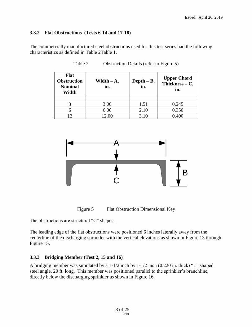
Issued: April 26, 2019
8 of 25
3.3.2 Flat Obstructions (Tests 6-14 and 17-18)
The commercially manufactured steel obstructions used for this test series had the following
characteristics as defined in Table 2Table 1.
Table 2 Obstruction Details (refer to Figure 5)
Flat
Obstruction
Nominal
Width
Width – A,
in.
Depth – B,
in.
Upper Chord
Thickness – C,
in.
3 3.00 1.51 0.245
6 6.00 2.10 0.350
12 12.00 3.10 0.400
Figure 5 Flat Obstruction Dimensional Key
The obstructions are structural “C” shapes.
The leading edge of the flat obstructions were positioned 6 inches laterally away from the
centerline of the discharging sprinkler with the vertical elevations as shown in Figure 13 through
Figure 15.
3.3.3 Bridging Member (Test 2, 15 and 16)
A bridging member was simulated by a 1-1/2 inch by 1-1/2 inch (0.220 in. thick) “L” shaped
steel angle, 20 ft. long. This member was positioned parallel to the sprinkler’s branchline,
directly below the discharging sprinkler as shown in Figure 16.
A
BC
319

Issued: April 26, 2019
9 of 25
Figure 6 22 Inch Deep Joist Detail – Elevation View (prior to cutting to 30 ft. length)
Figure 7 30 Inch Deep Joist Detail – Elevation View (prior to cutting to 30 ft. length)
Figure 8 36 Inch Deep Joist Detail – Elevation View (prior to cutting to 30 ft. length)
320

Issued: April 26, 2019
10 of 25
Figure 9 Joist Cross Section Detail – Close Up Elevation View (top position was attached at the ceiling)
22 in.
5 in.
4 in.
2 in. by 2 in. “L” angle;
0.142 in. thick
1-½ in. by 1-½ in. “L” angle;
0.160 in. thick
30 in.
5 in.
4 in.
2 in. by 2 in. “L” angle;
0.142 in. thick
1-½ in. by 1-½ in. “L” angle;
0.142 in. thick
36 in.
6 in.
5 in.
2-½ in. by 2-½ in. “L” angle;
0.217 in. thick
2 in. by 2 in. “L” angle;
0.144 in. thick
321
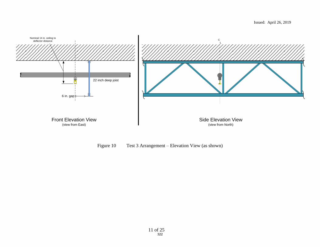
Issued: April 26, 2019
11 of 25
Figure 10 Test 3 Arrangement – Elevation View (as shown)
Nominal 14 in. ceiling to deflector distance
6 in. gap
22 inch deep joist
C L
Front Elevation View(view from East)
Side Elevation View(view from North)
322

Issued: April 26, 2019
12 of 25
Figure 11 Test 4 Arrangement – Elevation View (as shown)
Nominal 14 in. ceiling to deflector distance
6 in. gap
30 inch deep joist
C L
Front Elevation View(view from East)
Side Elevation View(view from North)
323

Issued: April 26, 2019
13 of 25
Figure 12 Test 5 Arrangement – Elevation View (as shown)
Nominal 14 in. ceiling to deflector distance
6 in. gap
36 inch deep joist
C L
Front Elevation View(view from East)
Side Elevation View(view from North)
324

Issued: April 26, 2019
14 of 25
Figure 13 3 inch Flat Obstruction; Test 6, 7 and 8 Arrangement – Elevation View From East
Nominal 14 in. ceiling to deflector distance
Obstruction offset 6 inches from centerline of the sprinkler to tip of
obstruction
3 inch obstruction positioned 8, 12 and 16 inches below
sprinkler deflector.
4 in.
4 in.
14 in.
16 in.
325

Issued: April 26, 2019
15 of 25
Figure 14 6 inch Flat Obstruction; Test 9 through 14 Arrangement – Elevation View From East
Nominal 14 in. ceiling to deflector distance
Obstruction offset 6 inches from centerline of the sprinkler to tip of
obstruction
6 inch obstruction positioned 8, 12, 16, 20, 22 and 24 inches
below sprinkler deflector.
4 in.
4 in.
14 in.
24 in.
4 in.
2 in.2 in.
326

Issued: April 26, 2019
16 of 25
Figure 15 12 inch Flat Obstruction; Test 17 and 18 Arrangement – Elevation View From East
Nominal 14 in. ceiling to deflector distance
Obstruction offset 6 inches from centerline of the sprinkler to tip of
obstruction
12 inch obstruction positioned 16 and 20 inches below
sprinkler deflector.
4 in.
14 in.
20 in.
327

Issued: April 26, 2019
17 of 25
Figure 16 1-1/2 inch Bridging Member Obstruction: Test 2, 15 and 16 Arrangement – Elevation View From East (Test 2 shown)
Nominal 14 in. ceiling to deflector distance
Obstruction directly underneath sprinkler
1-½ inch Bridging Member obstruction positioned 12, 16 and 20 inches below sprinkler
deflector. (12 in. shown)
14 in.
12 in.
328
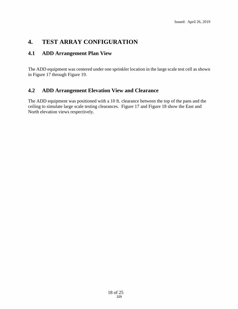
Issued: April 26, 2019
18 of 25
4. TEST ARRAY CONFIGURATION
4.1 ADD Arrangement Plan View
The ADD equipment was centered under one sprinkler location in the large scale test cell as shown
in Figure 17 through Figure 19.
4.2 ADD Arrangement Elevation View and Clearance
The ADD equipment was positioned with a 10 ft. clearance between the top of the pans and the
ceiling to simulate large scale testing clearances. Figure 17 and Figure 18 show the East and
North elevation views respectively.
329
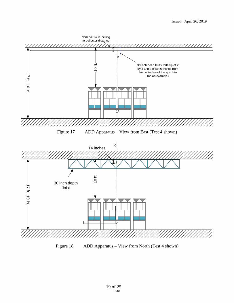
Issued: April 26, 2019
19 of 25
Figure 17 ADD Apparatus – View from East (Test 4 shown)
Figure 18 ADD Apparatus – View from North (Test 4 shown)
17 ft. 10 in.
Nominal 14 in. ceiling to deflector distance
30 inch deep truss, with tip of 2 by 2 angle offset 6 inches from the centerline of the sprinkler
(as an example)
10 ft
.
17 ft. 10 in.
30 inch depth Joist
C L14 inches
10 ft
.
330
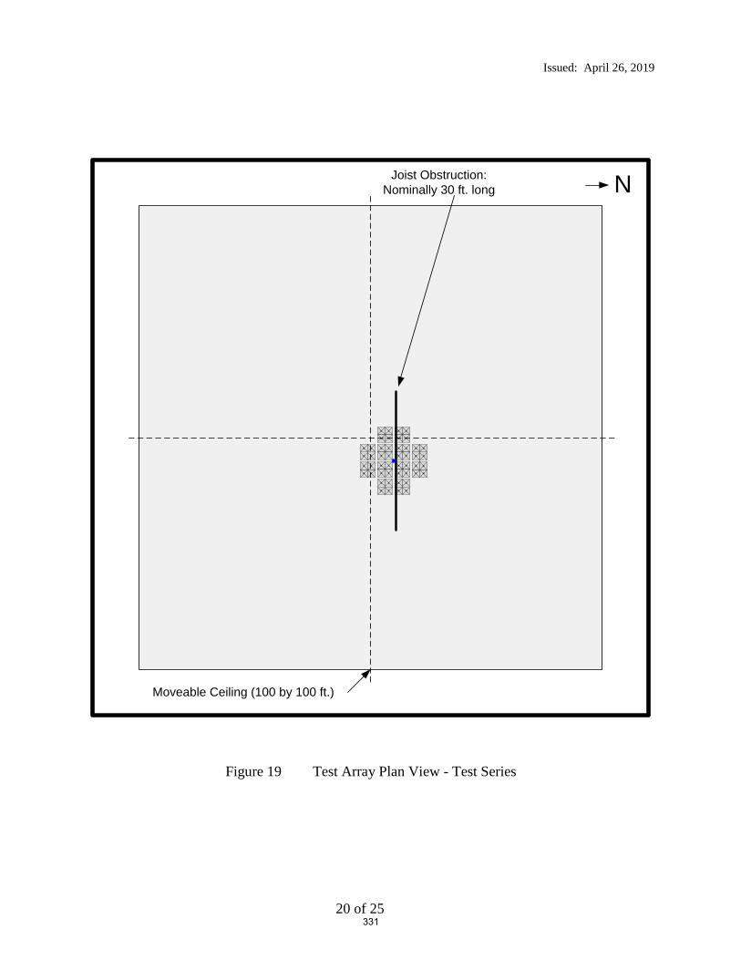
Issued: April 26, 2019
20 of 25
Figure 19 Test Array Plan View - Test Series
NJoist Obstruction:Nominally 30 ft. long
Moveable Ceiling (100 by 100 ft.)
331
Issued: April 26, 2019
21 of 25
5. TEST METHOD
5.1 Test Procedure
The test procedure consisted of the following steps:
1. Each sprinkler was pre-flowed to determine the pump speed which achieves 75 psig and 52
psig at the sprinkler for the K = 14.0 and K = 16.8 ESFR sprinkler respectively. It should be
noted that these pressures correspond to a nominal flowrate of 121 gallons per minute for both
sprinklers.
2. After setting the 2.5 MW fire above the apparatus and achieving a steady state burning
condition, the pumps were activated at the previous pump speed to achieve the desired flowing
pressures.
3. After confirming with the ADD data screens that the flow in each collection pan was steady, a
nominal 1 minute of data was captured before terminating the test.
4. The resulting data was recorded and a database was updated to show the relative performance
for the test parameters chosen.
332

Issued: April 26, 2019
22 of 25
6. RESULTS AND DISCUSSION
A total of 20 Actual Delivered Density (ADD) tests were conducted at UL LLC in Northbrook,
IL between April 2 and April 5, 2019. Table 3 provides a summary of the resulting data.
Refer to Figure 2 for pan designations in the data section.
Appendix A provides the detailed raw data for each test. Refer to Figure 4 for the individual pan
designations with respect to sprinkler and obstruction location.
333

Issued: April 26, 2019
23 of 25
Table 3 Test Series Summary
Test Number Obstruction UsedPendent ESFR Sprinkler Used, K - gpm/psig0.5
Vertical Distance of obstruction
below sprinkler deflector
Horizontal Offset, Tip of obstruction
to sprinkler centerline
Overall Average
Central 16 Pan
Average
Central 4 Pan
Average
South Satellite Average
North Satellite Average
West Pre-Wetting Average
East Pre-Wetting Average
North 4 South 4 North 8
in. in. in. gpm/ft2 gpm/ft2 gpm/ft2 gpm/ft2 gpm/ft2 gpm/ft2 gpm/ft2 gpm/ft2 gpm/ft2 gpm/ft2
1 none (baseline) 14.0 0 0 0.55 0.96 1.64 0.23 0.13 0.57 0.44 1.15 1.03 0.99
2 1-1/2 inch bridging member* 14.0 12 6 0.41 0.45 0.33 0.18 0.18 0.52 0.65 0.30 0.30 0.48
3 22 inch deep bar joist 14.0 8 6 0.51 0.83 1.71 0.22 0.09 0.55 0.54 0.85 1.28 0.604 30 inch deep bar joist 14.0 16 6 0.54 0.83 1.56 0.26 0.19 0.48 0.64 0.63 1.33 0.485 36 inch deep bar joist 14.0 22 6 0.49 0.78 1.38 0.19 0.20 0.47 0.55 0.50 1.22 0.49
6 3" flat 14.0 8 6 0.43 0.76 1.27 0.15 0.18 0.41 0.32 0.96 0.93 0.767 3" flat 14.0 12 6 0.50 0.80 1.60 0.21 0.19 0.45 0.53 1.05 0.94 0.758 3" flat 14.0 16 6 0.46 0.79 1.63 0.18 0.16 0.44 0.37 1.02 0.99 0.74
9 6" flat 14.0 8 6 0.56 0.96 1.88 0.27 0.18 0.43 0.55 1.22 1.16 0.9110 6" flat 14.0 12 6 0.49 0.78 1.88 0.28 0.17 0.46 0.47 1.30 0.97 0.7911 6" flat 14.0 16 6 0.43 0.74 1.71 0.23 0.15 0.40 0.35 1.41 0.92 0.7712 6" flat 14.0 20 6 0.46 0.80 1.69 0.10 0.22 0.39 0.45 1.15 0.96 0.7913 6" flat 14.0 22 6 0.45 0.73 1.64 0.16 0.19 0.41 0.45 1.13 0.88 0.7514 6" flat 14.0 24 6 0.45 0.75 1.56 0.20 0.19 0.41 0.39 1.06 0.90 0.75
15 1-1/2 inch bridging member* 14.0 14 0 0.49 0.81 0.64 0.09 0.17 0.52 0.52 0.49 0.62 0.7916 1-1/2 inch bridging member* 14.0 20 0 0.44 0.73 1.46 0.22 0.16 0.43 0.36 0.93 0.96 0.74
17 12" flat 14.0 16 6 0.45 0.76 1.61 0.20 0.24 0.39 0.35 0.76 1.37 0.5018 12" flat 14.0 20 6 0.43 0.72 1.46 0.14 0.26 0.34 0.41 0.68 1.19 0.51
19 12" flat 16.8 8 6 0.50 1.05 2.06 0.30 0.05 0.27 0.29 1.56 1.20 1.1920 12" flat 16.8 12 6 0.50 0.94 1.86 0.26 0.15 0.35 0.37 1.25 1.16 0.99
* - bridging member distance is to the top of the horizontal flat portion from the sprinkler's deflector
Test Parameters Data
334

Issued: April 26, 2019
24 of 25
7. SUMMARY
This report describes twenty (20) Actual Delivered Density (ADD) tests that were conducted to
develop data relative to the level of fire performance provided by a K = 14.0 and a K = 16.8
ESFR sprinkler when the sprinklers are located closer to an obstruction than currently referenced
in the Standard for the Installation of Sprinkler Systems, NFPA 13-2019. For this test series, the
sprinklers were located in close proximity to open web ceiling steel bar joists, a steel bridging
member and flat obstructions.
The ADD apparatus consists of a fire source and a set of water collection pans. A drawing of the
top and side views of the apparatus are shown in Figure 2. The main components of the
apparatus are 48 water collection pans and 12 heptane nozzles. The 48 water collection pans are
approximately 20 in. by 20 in. and are separated into groups of four. A group of four collection
pans, i.e., a 2x2 array, simulates the top surface of one pallet load of stored commodity. Eight
groups of four are placed in the main array, while two satellite arrays each consist of two groups
of four. The two satellite collector arrays were placed adjacent to the main array to investigate
pre-wetting characteristics. A 6 in. flue space was maintained between two adjacent simulated
commodities.
For all tests, the center of the ADD apparatus was located directly below the discharging
sprinkler. The top of the ADD apparatus (representing the top surface of stored commodity) was
located 10 ft. from the ceiling.
All tests were conducted with fire above the array with an equivalent total heat release rate of 2.5
MW.
The automatic sprinkler system incorporated the following features:
1. The single sprinkler was installed with the deflector positioned nominally 14 inches
below the smooth, flat, horizontal, non-combustible ceiling for two different K-factor
sprinklers.
2. A single manufacturer’s nominal K = 14.0 and K=16.8 (gpm/psig1/2) pendent ESFR
sprinklers were used in the test series.
3. The K = 14.0 sprinkler system was controlled to provide a flowing pressure of 75 psig for
the sprinkler located over the fire which correlates to a nominal discharge of 121 gpm.
4. The K = 16.8 sprinkler system was controlled to provide a flowing pressure of 52 psig for
the sprinklers located over the fire which correlates to a nominal discharge of 121 gpm.
335
Issued: April 26, 2019
25 of 25
Tests were conducted using three primary obstructions as follows:
Steel Bar Joists: 22, 30 and 36 inch deep, commercially available steel bar joists were used
in tests 3, 4 and 5.
Flat Obstructions: Tests were conducted using 3, 6 and 12 inch wide, commercial steel
structural “C” shapes for the flat obstructions. These were used in tests 6 through 14 and 17
through 20.
Bridging Member: A 1-1/2 by 1-1/2 inch “L” shaped steel member was used to simulate a
bridging member positioned parallel to the sprinkler’s branchline. This was used in tests 2, 15
and 16.
A summary of the test parameters and results for all tests are provided in Table 3.
Report By: Reviewed By:
Daniel R. Steppan Michael G. McCormick
Senior Staff Engineer Staff Engineering Associate
Product Safety Product Safety
336

Appendix A – Raw and Summarized Data
A1 of 21
APPENDIX A
Raw and Summarized Data
337

Appendix A – Raw and Summarized Data
A2 of 21
Figure A- 1 Test 1 – Results (3D graphic–view from Northeast of Central Main Array Only)
1 0.59 2 0.52 5 0.48 6 0.75 N
3 0.45 4 0.63 7 0.60 8 0.50
33 0.19 34 0.44 9 0.82 10 0.97 13 0.80 14 0.77 41 0.20 42 0.08
35 0.21 36 0.24 11 0.55 12 1.97 15 1.51 16 0.57 43 0.18 44 0.08
37 0.10 38 0.24 17 0.52 18 1.08 21 2.00 22 0.53 45 0.13 46 0.05
39 0.05 40 0.33 19 0.77 20 0.79 23 0.85 24 0.89 47 0.34 48 0.00
25 0.42 26 0.47 29 0.68 30 0.45
27 0.53 28 0.38 31 0.00 32 0.62
Density (gpm/ft2)
measured densitygpm/ft2
Overall Average 0.55Central 16 Pan Average 0.96Central 4 Pan Average 1.64South Satellite Average 0.23North Satellite Average 0.13West Pre-Wetting Average 0.57East Pre-Wetting Average 0.44
North 4 1.15South 4 1.03North 8 0.99
338

Appendix A – Raw and Summarized Data
A3 of 21
Figure A- 2 Test 2 – Results (3D graphic–view from Northeast of Central Main Array Only)
1 0.62 2 0.60 5 0.53 6 0.48 N
3 0.43 4 0.55 7 0.52 8 0.40
33 0.07 34 0.25 9 0.69 10 0.73 13 0.57 14 0.48 41 0.35 42 0.07
35 0.11 36 0.16 11 0.22 12 0.61 15 0.49 16 0.42 43 0.20 44 0.04
37 0.08 38 0.25 17 0.23 18 0.13 21 0.09 22 0.19 45 0.21 46 0.07
39 0.14 40 0.39 19 0.78 20 0.02 23 0.81 24 0.80 47 0.41 48 0.12
25 0.58 26 0.51 29 0.82 30 0.72
27 0.59 28 0.54 31 0.79 32 0.66
Density (gpm/ft2)
measured densitygpm/ft2
Overall Average 0.41Central 16 Pan Average 0.45Central 4 Pan Average 0.33South Satellite Average 0.18North Satellite Average 0.18West Pre-Wetting Average 0.52East Pre-Wetting Average 0.65
North 4 0.30South 4 0.30North 8 0.48
339

Appendix A – Raw and Summarized Data
A4 of 21
Figure A- 3 Test 3 – Results (3D graphic–view from Northeast of Central Main Array Only)
1 0.91 2 0.36 5 1.39 6 0.22 N
3 0.59 4 0.28 7 0.43 8 0.19
33 0.20 34 0.51 9 0.90 10 0.58 13 0.50 14 0.15 41 0.02 42 0.04
35 0.16 36 0.19 11 0.91 12 1.89 15 1.45 16 0.16 43 0.09 44 0.06
37 0.09 38 0.27 17 0.50 18 1.81 21 1.68 22 0.10 45 0.09 46 0.13
39 0.02 40 0.31 19 1.05 20 0.94 23 0.59 24 0.14 47 0.16 48 0.12
25 0.36 26 0.43 29 0.54 30 0.08
27 0.61 28 0.59 31 1.69 32 0.03
Density (gpm/ft2)
measured densitygpm/ft2
Overall Average 0.51Central 16 Pan Average 0.83Central 4 Pan Average 1.71South Satellite Average 0.22North Satellite Average 0.09West Pre-Wetting Average 0.55East Pre-Wetting Average 0.54
North 4 0.85South 4 1.28North 8 0.60
340

Appendix A – Raw and Summarized Data
A5 of 21
Figure A- 4 Test 4 – Results (3D graphic–view from Northeast of Central Main Array Only)
1 0.83 2 0.43 5 0.30 6 0.19 N
3 0.63 4 0.54 7 0.80 8 0.12
33 0.25 34 0.47 9 0.99 10 0.91 13 0.47 14 0.13 41 0.12 42 0.10
35 0.27 36 0.25 11 0.74 12 2.10 15 1.00 16 0.12 43 0.24 44 0.12
37 0.14 38 0.24 17 0.56 18 1.91 21 1.22 22 0.18 45 0.12 46 0.12
39 0.11 40 0.33 19 1.14 20 1.02 23 0.29 24 0.42 47 0.58 48 0.08
25 0.41 26 0.87 29 0.93 30 0.43
27 0.78 28 0.72 31 0.57 32 0.43
Density (gpm/ft2)
measured densitygpm/ft2
Overall Average 0.54Central 16 Pan Average 0.83Central 4 Pan Average 1.56South Satellite Average 0.26North Satellite Average 0.19West Pre-Wetting Average 0.48East Pre-Wetting Average 0.64
North 4 0.63South 4 1.33North 8 0.48
341

Appendix A – Raw and Summarized Data
A6 of 21
Figure A- 5 Test 5 – Results (3D graphic–view from Northeast of Central Main Array Only)
1 0.96 2 0.54 5 0.27 6 0.22 N
3 0.51 4 0.50 7 0.54 8 0.25
33 0.15 34 0.20 9 0.83 10 0.94 13 0.59 14 0.35 41 0.42 42 0.08
35 0.17 36 0.15 11 0.37 12 2.09 15 0.57 16 0.21 43 0.17 44 0.07
37 0.09 38 0.27 17 0.64 18 1.79 21 1.08 22 0.12 45 0.11 46 0.08
39 0.12 40 0.40 19 0.88 20 1.06 23 0.62 24 0.34 47 0.44 48 0.19
25 0.49 26 0.75 29 0.95 30 0.36
27 0.82 28 0.49 31 0.26 32 0.25
Density (gpm/ft2)
measured densitygpm/ft2
Overall Average 0.49Central 16 Pan Average 0.78Central 4 Pan Average 1.38South Satellite Average 0.19North Satellite Average 0.20West Pre-Wetting Average 0.47East Pre-Wetting Average 0.55
North 4 0.50South 4 1.22North 8 0.49
342

Appendix A – Raw and Summarized Data
A7 of 21
Figure A- 6 Test 6 – Results (3D graphic–view from Northeast of Central Main Array Only)
1 0.35 2 0.36 5 0.27 6 0.43 N
3 0.41 4 0.46 7 0.44 8 0.54
33 0.05 34 0.13 9 0.37 10 0.72 13 1.03 14 0.4 41 0.29 42 0.18
35 0.06 36 0.13 11 0.33 12 0.85 15 1.73 16 0.91 43 0.34 44 0.14
37 0.11 38 0.33 17 1.06 18 1.47 21 1.02 22 0.18 45 0.12 46 0.08
39 0.09 40 0.33 19 0.46 20 0.78 23 0.63 24 0.14 47 0.18 48 0.12
25 0.48 26 0.45 29 0.43 30 0.18
27 0.4 28 0.25 31 0.31 32 0.07
Density (gpm/ft2)
measured densitygpm/ft2
Overall Average 0.43Central 16 Pan Average 0.76Central 4 Pan Average 1.27South Satellite Average 0.15North Satellite Average 0.18West Pre-Wetting Average 0.41East Pre-Wetting Average 0.32
North 4 0.96South 4 0.93North 8 0.76
343

Appendix A – Raw and Summarized Data
A8 of 21
Figure A- 7 Test 7 – Results (3D graphic–view from Northeast of Central Main Array Only)
1 0.43 2 0.50 5 0.52 6 0.38 N
3 0.44 4 0.41 7 0.62 8 0.26
33 0.08 34 0.40 9 0.63 10 0.71 13 0.14 14 0.32 41 0.14 42 0.08
35 0.09 36 0.26 11 0.68 12 1.82 15 1.62 16 0.21 43 0.19 44 0.11
37 0.13 38 0.19 17 0.29 18 0.96 21 2.00 22 0.37 45 0.38 46 0.08
39 0.11 40 0.41 19 0.91 20 0.86 23 0.94 24 0.40 47 0.46 48 0.11
25 0.47 26 0.69 29 0.74 30 0.47
27 0.58 28 0.43 31 0.40 32 0.42
Density (gpm/ft2)
measured densitygpm/ft2
Overall Average 0.50Central 16 Pan Average 0.80Central 4 Pan Average 1.60South Satellite Average 0.21North Satellite Average 0.19West Pre-Wetting Average 0.45East Pre-Wetting Average 0.53
North 4 1.05South 4 0.94North 8 0.75
344
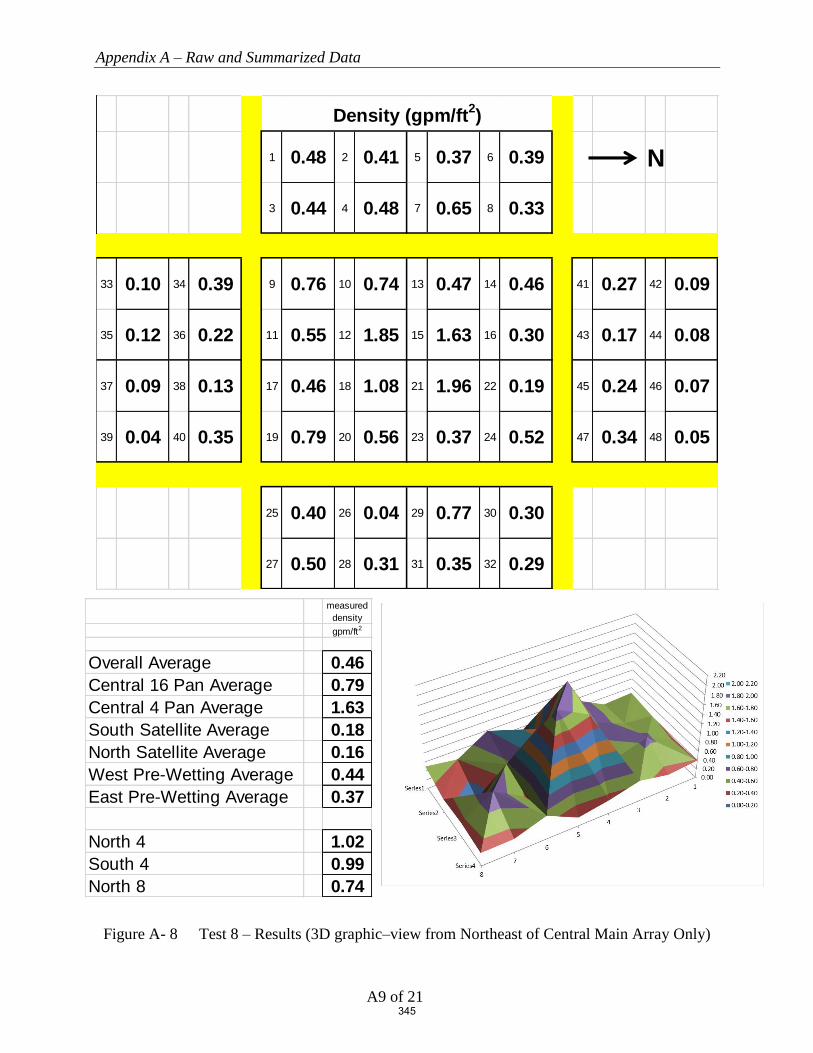
Appendix A – Raw and Summarized Data
A9 of 21
Figure A- 8 Test 8 – Results (3D graphic–view from Northeast of Central Main Array Only)
1 0.48 2 0.41 5 0.37 6 0.39 N
3 0.44 4 0.48 7 0.65 8 0.33
33 0.10 34 0.39 9 0.76 10 0.74 13 0.47 14 0.46 41 0.27 42 0.09
35 0.12 36 0.22 11 0.55 12 1.85 15 1.63 16 0.30 43 0.17 44 0.08
37 0.09 38 0.13 17 0.46 18 1.08 21 1.96 22 0.19 45 0.24 46 0.07
39 0.04 40 0.35 19 0.79 20 0.56 23 0.37 24 0.52 47 0.34 48 0.05
25 0.40 26 0.04 29 0.77 30 0.30
27 0.50 28 0.31 31 0.35 32 0.29
Density (gpm/ft2)
measured densitygpm/ft2
Overall Average 0.46Central 16 Pan Average 0.79Central 4 Pan Average 1.63South Satellite Average 0.18North Satellite Average 0.16West Pre-Wetting Average 0.44East Pre-Wetting Average 0.37
North 4 1.02South 4 0.99North 8 0.74
345

Appendix A – Raw and Summarized Data
A10 of 21
Figure A- 9 Test 9 – Results (3D graphic–view from Northeast of Central Main Array Only)
1 0.57 2 0.44 5 0.42 6 0.23 N
3 0.59 4 0.41 7 0.62 8 0.17
33 0.23 34 0.52 9 0.82 10 0.73 13 0.87 14 0.35 41 0.03 42 0.15
35 0.05 36 0.32 11 0.89 12 2.00 15 1.73 16 0.33 43 0.22 44 0.10
37 0.31 38 0.34 17 0.36 18 1.39 21 2.41 22 0.39 45 0.08 46 0.19
39 0.00 40 0.42 19 0.92 20 0.95 23 0.91 24 0.32 47 0.39 48 0.28
25 0.42 26 0.79 29 0.83 30 0.27
27 0.77 28 0.48 31 0.47 32 0.35
Density (gpm/ft2)
measured densitygpm/ft2
Overall Average 0.56Central 16 Pan Average 0.96Central 4 Pan Average 1.88South Satellite Average 0.27North Satellite Average 0.18West Pre-Wetting Average 0.43East Pre-Wetting Average 0.55
North 4 1.22South 4 1.16North 8 0.91
346

Appendix A – Raw and Summarized Data
A11 of 21
Figure A- 10 Test 10 – Results (3D graphic–view from Northeast of Central Main Array Only)
1 0.80 2 0.31 5 0.42 6 0.23 N
3 0.54 4 0.35 7 0.85 8 0.18
33 0.14 34 0.50 9 0.64 10 0.71 13 0.10 14 0.23 41 0.18 42 0.11
35 0.25 36 0.26 11 0.59 12 1.84 15 1.95 16 0.31 43 0.13 44 0.07
37 0.13 38 0.13 17 0.27 18 1.19 21 2.53 22 0.40 45 0.22 46 0.11
39 0.36 40 0.50 19 0.63 20 0.28 23 0.52 24 0.29 47 0.40 48 0.10
25 0.50 26 0.30 29 0.97 30 0.35
27 0.59 28 0.31 31 0.47 32 0.23
Density (gpm/ft2)
measured densitygpm/ft2
Overall Average 0.49Central 16 Pan Average 0.78Central 4 Pan Average 1.88South Satellite Average 0.28North Satellite Average 0.17West Pre-Wetting Average 0.46East Pre-Wetting Average 0.47
North 4 1.30South 4 0.97North 8 0.79
347

Appendix A – Raw and Summarized Data
A12 of 21
Figure A- 11 Test 11 – Results (3D graphic–view from Northeast of Central Main Array Only)
1 0.57 2 0.33 5 0.47 6 0.22 N
3 0.43 4 0.31 7 0.70 8 0.19
33 0.15 34 0.41 9 0.60 10 0.53 13 0.24 14 0.31 41 0.18 42 0.08
35 0.18 36 0.25 11 0.51 12 1.74 15 1.65 16 0.24 43 0.11 44 0.06
37 0.13 38 0.25 17 0.35 18 1.09 21 2.35 22 - 45 0.23 46 0.00
39 0.10 40 0.38 19 0.64 20 0.29 23 0.34 24 0.24 47 0.51 48 0.02
25 0.45 26 0.01 29 0.95 30 0.08
27 0.52 28 0.33 31 0.37 32 0.05
Density (gpm/ft2)
measured densitygpm/ft2
Overall Average 0.43Central 16 Pan Average 0.74Central 4 Pan Average 1.71South Satellite Average 0.23North Satellite Average 0.15West Pre-Wetting Average 0.40East Pre-Wetting Average 0.35
North 4 1.41South 4 0.92North 8 0.77
348

Appendix A – Raw and Summarized Data
A13 of 21
Figure A- 12 Test 12 – Results (3D graphic–view from Northeast of Central Main Array Only)
1 0.46 2 0.39 5 0.27 6 0.22 N
3 0.44 4 0.44 7 0.67 8 0.20
33 0.06 34 0.01 9 0.58 10 0.72 13 0.31 14 0.28 41 0.52 42 0.19
35 0.05 36 0.07 11 0.33 12 1.81 15 1.43 16 0.40 43 0.29 44 0.15
37 0.04 38 0.24 17 0.58 18 1.11 21 2.42 22 0.36 45 0.23 46 0.04
39 0.00 40 0.36 19 0.73 20 0.54 23 0.65 24 0.48 47 0.37 48 0.00
25 0.52 26 0.22 29 0.78 30 0.30
27 0.58 28 0.31 31 0.70 32 0.15
Density (gpm/ft2)
measured densitygpm/ft2
Overall Average 0.46Central 16 Pan Average 0.80Central 4 Pan Average 1.69South Satellite Average 0.10North Satellite Average 0.22West Pre-Wetting Average 0.39East Pre-Wetting Average 0.45
North 4 1.15South 4 0.96North 8 0.79
349

Appendix A – Raw and Summarized Data
A14 of 21
Figure A- 13 Test 13 – Results (3D graphic–view from Northeast of Central Main Array Only)
1 0.57 2 0.30 5 0.57 6 0.22 N
3 0.51 4 0.35 7 0.55 8 0.23
33 0.07 34 0.34 9 0.55 10 0.61 13 0.16 14 0.42 41 0.32 42 0.12
35 0.10 36 0.23 11 0.59 12 1.69 15 1.65 16 0.30 43 0.11 44 0.05
37 0.06 38 0.04 17 0.23 18 1.02 21 2.19 22 0.38 45 0.27 46 0.04
39 0.19 40 0.25 19 0.62 20 0.41 23 0.56 24 0.36 47 0.52 48 0.07
25 0.44 26 0.41 29 0.67 30 0.32
27 0.57 28 0.35 31 0.58 32 0.22
Density (gpm/ft2)
measured densitygpm/ft2
Overall Average 0.45Central 16 Pan Average 0.73Central 4 Pan Average 1.64South Satellite Average 0.16North Satellite Average 0.19West Pre-Wetting Average 0.41East Pre-Wetting Average 0.45
North 4 1.13South 4 0.88North 8 0.75
350
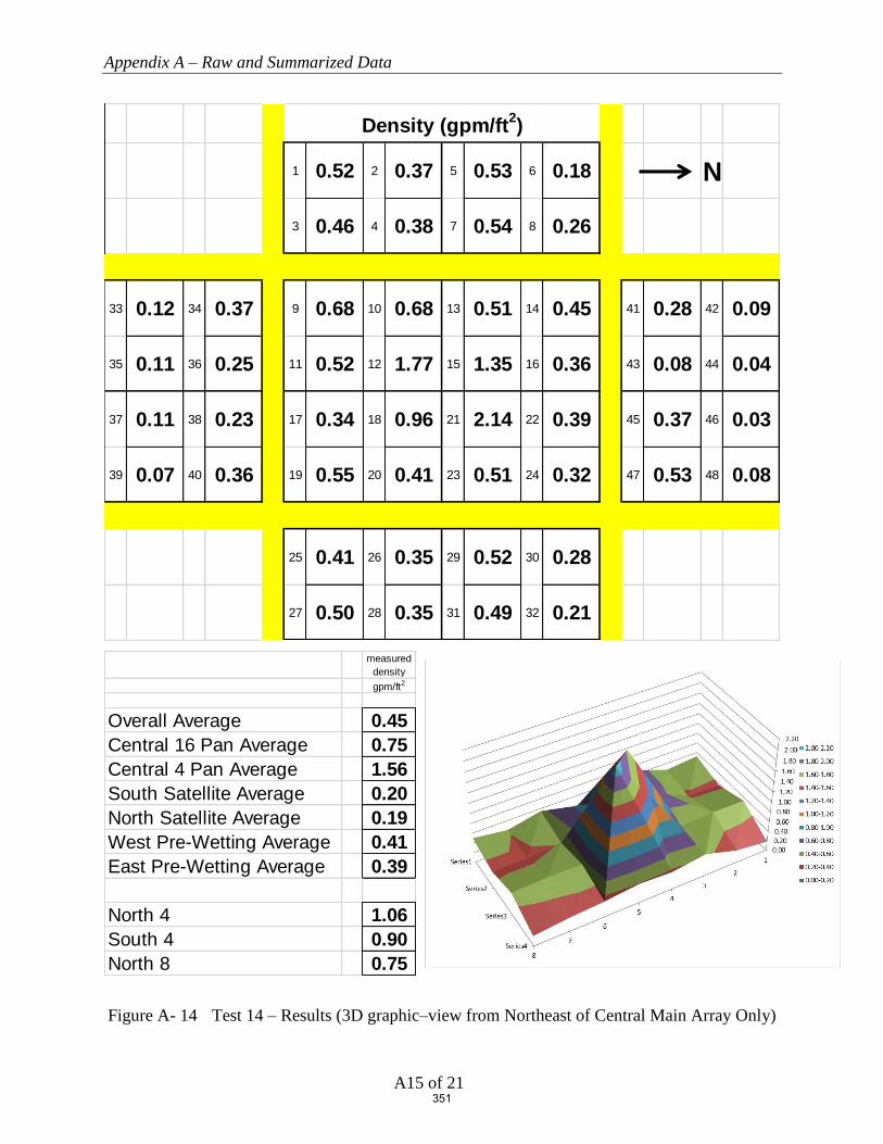
Appendix A – Raw and Summarized Data
A15 of 21
Figure A- 14 Test 14 – Results (3D graphic–view from Northeast of Central Main Array Only)
1 0.52 2 0.37 5 0.53 6 0.18 N
3 0.46 4 0.38 7 0.54 8 0.26
33 0.12 34 0.37 9 0.68 10 0.68 13 0.51 14 0.45 41 0.28 42 0.09
35 0.11 36 0.25 11 0.52 12 1.77 15 1.35 16 0.36 43 0.08 44 0.04
37 0.11 38 0.23 17 0.34 18 0.96 21 2.14 22 0.39 45 0.37 46 0.03
39 0.07 40 0.36 19 0.55 20 0.41 23 0.51 24 0.32 47 0.53 48 0.08
25 0.41 26 0.35 29 0.52 30 0.28
27 0.50 28 0.35 31 0.49 32 0.21
Density (gpm/ft2)
measured densitygpm/ft2
Overall Average 0.45Central 16 Pan Average 0.75Central 4 Pan Average 1.56South Satellite Average 0.20North Satellite Average 0.19West Pre-Wetting Average 0.41East Pre-Wetting Average 0.39
North 4 1.06South 4 0.90North 8 0.75
351

Appendix A – Raw and Summarized Data
A16 of 21
Figure A- 15 Test 15 – Results (3D graphic–view from Northeast of Central Main Array Only)
1 0.75 2 0.38 5 0.39 6 0.57 N
3 0.52 4 0.52 7 0.54 8 0.46
33 0.06 34 0.03 9 0.77 10 0.85 13 0.53 14 0.47 41 0.30 42 0.09
35 0.08 36 0.05 11 0.33 12 1.01 15 0.49 16 0.39 43 0.18 44 0.07
37 0.04 38 0.15 17 0.54 18 0.61 21 0.45 22 0.64 45 0.35 46 0.06
39 0.05 40 0.26 19 1.20 20 1.42 23 1.75 24 1.56 47 0.26 48 0.03
25 0.33 26 0.68 29 0.73 30 0.43
27 0.52 28 0.38 31 0.61 32 0.49
Density (gpm/ft2)
measured densitygpm/ft2
Overall Average 0.49Central 16 Pan Average 0.81Central 4 Pan Average 0.64South Satellite Average 0.09North Satellite Average 0.17West Pre-Wetting Average 0.52East Pre-Wetting Average 0.52
North 4 0.49South 4 0.62North 8 0.79
352
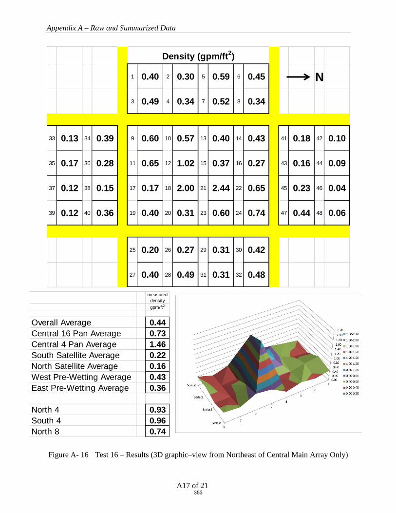
Appendix A – Raw and Summarized Data
A17 of 21
Figure A- 16 Test 16 – Results (3D graphic–view from Northeast of Central Main Array Only)
1 0.40 2 0.30 5 0.59 6 0.45 N
3 0.49 4 0.34 7 0.52 8 0.34
33 0.13 34 0.39 9 0.60 10 0.57 13 0.40 14 0.43 41 0.18 42 0.10
35 0.17 36 0.28 11 0.65 12 1.02 15 0.37 16 0.27 43 0.16 44 0.09
37 0.12 38 0.15 17 0.17 18 2.00 21 2.44 22 0.65 45 0.23 46 0.04
39 0.12 40 0.36 19 0.40 20 0.31 23 0.60 24 0.74 47 0.44 48 0.06
25 0.20 26 0.27 29 0.31 30 0.42
27 0.40 28 0.49 31 0.31 32 0.48
Density (gpm/ft2)
measured densitygpm/ft2
Overall Average 0.44Central 16 Pan Average 0.73Central 4 Pan Average 1.46South Satellite Average 0.22North Satellite Average 0.16West Pre-Wetting Average 0.43East Pre-Wetting Average 0.36
North 4 0.93South 4 0.96North 8 0.74
353

Appendix A – Raw and Summarized Data
A18 of 21
Figure A- 17 Test 17 – Results (3D graphic–view from Northeast of Central Main Array Only)
1 0.40 2 0.20 5 0.57 6 0.09 N
3 0.62 4 0.22 7 0.92 8 0.11
33 0.11 34 0.19 9 1.18 10 0.60 13 0.33 14 0.15 41 0.04 42 0.24
35 0.00 36 0.18 11 0.71 12 1.91 15 1.14 16 0.21 43 0.26 44 0.27
37 0.24 38 0.43 17 0.93 18 1.93 21 1.46 22 0.23 45 0.09 46 0.43
39 0.00 40 0.48 19 0.69 20 0.25 23 0.31 24 0.15 47 0.29 48 0.31
25 0.53 26 - 29 0.84 30 0.15
27 0.47 28 0.46 31 0.00 32 0.00
Density (gpm/ft2)
measured densitygpm/ft2
Overall Average 0.45Central 16 Pan Average 0.76Central 4 Pan Average 1.61South Satellite Average 0.20North Satellite Average 0.24West Pre-Wetting Average 0.39East Pre-Wetting Average 0.35
North 4 0.76South 4 1.37North 8 0.50
354

Appendix A – Raw and Summarized Data
A19 of 21
Figure A- 18 Test 18 – Results (3D graphic–view from Northeast of Central Main Array Only)
1 0.37 2 0.23 5 0.46 6 0.05 N
3 0.59 4 0.29 7 0.66 8 0.09
33 0.03 34 0.14 9 1.05 10 0.52 13 0.49 14 0.15 41 0.17 42 0.26
35 0.06 36 0.10 11 0.51 12 1.72 15 0.91 16 0.23 43 0.22 44 0.33
37 0.00 38 0.33 17 0.87 18 1.66 21 1.54 22 0.04 45 0.24 46 0.32
39 0.00 40 0.43 19 0.71 20 0.35 23 0.57 24 0.12 47 0.25 48 0.31
25 0.53 26 0.18 29 0.91 30 0.00
27 0.56 28 0.38 31 0.73 32 0.00
Density (gpm/ft2)
measured densitygpm/ft2
Overall Average 0.43Central 16 Pan Average 0.72Central 4 Pan Average 1.46South Satellite Average 0.14North Satellite Average 0.26West Pre-Wetting Average 0.34East Pre-Wetting Average 0.41
North 4 0.68South 4 1.19North 8 0.51
355

Appendix A – Raw and Summarized Data
A20 of 21
Figure A- 19 Test 19 – Results (3D graphic–view from Northeast of Central Main Array Only)
1 0.69 2 0.23 5 0.07 6 0.09 N
3 0.55 4 0.21 7 0.19 8 0.11
33 0.16 34 0.38 9 0.70 10 0.58 13 1.36 14 0.21 41 0.07 42 0.05
35 0.31 36 0.34 11 1.08 12 1.69 15 2.57 16 0.59 43 0.08 44 0.05
37 0.22 38 0.14 17 0.62 18 1.41 21 2.57 22 0.50 45 0.02 46 0.08
39 0.32 40 0.53 19 0.52 20 0.73 23 1.53 24 0.18 47 0.04 48 0.02
25 0.76 26 0.14 29 0.62 30 0.00
27 0.50 28 0.18 31 0.15 32 0.00
Density (gpm/ft2)
measured densitygpm/ft2
Overall Average 0.50Central 16 Pan Average 1.05Central 4 Pan Average 2.06South Satellite Average 0.30North Satellite Average 0.05West Pre-Wetting Average 0.27East Pre-Wetting Average 0.29
North 4 1.56South 4 1.20North 8 1.19
356
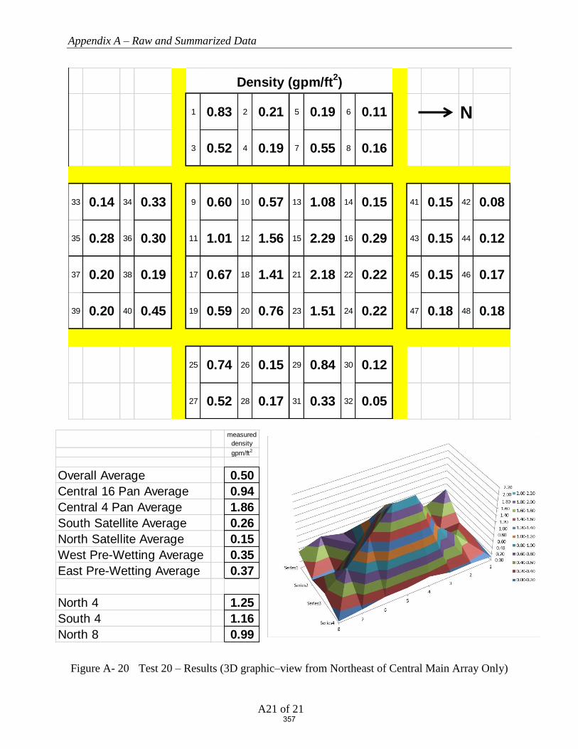
Appendix A – Raw and Summarized Data
A21 of 21
Figure A- 20 Test 20 – Results (3D graphic–view from Northeast of Central Main Array Only)
1 0.83 2 0.21 5 0.19 6 0.11 N
3 0.52 4 0.19 7 0.55 8 0.16
33 0.14 34 0.33 9 0.60 10 0.57 13 1.08 14 0.15 41 0.15 42 0.08
35 0.28 36 0.30 11 1.01 12 1.56 15 2.29 16 0.29 43 0.15 44 0.12
37 0.20 38 0.19 17 0.67 18 1.41 21 2.18 22 0.22 45 0.15 46 0.17
39 0.20 40 0.45 19 0.59 20 0.76 23 1.51 24 0.22 47 0.18 48 0.18
25 0.74 26 0.15 29 0.84 30 0.12
27 0.52 28 0.17 31 0.33 32 0.05
Density (gpm/ft2)
measured densitygpm/ft2
Overall Average 0.50Central 16 Pan Average 0.94Central 4 Pan Average 1.86South Satellite Average 0.26North Satellite Average 0.15West Pre-Wetting Average 0.35East Pre-Wetting Average 0.37
North 4 1.25South 4 1.16North 8 0.99
357

Obstructions and Early Suppression Fast Response Sprinklers
Phase 4 Final Report
FINAL REPORT | WJE No. 2018.8439.0 | MAY 1, 2020
APPENDIX B. ESFR SPRINKLERS OBSTRUCTED BY CONTINUOUS FLAT OBSTRUCTIONS (PHASE
4), UNDERWRITERS LABORATORIES, SEPTEMBER 27, 2019
358

ESFR SPRINKLERS OBSTRUCTED BY
CONTINUOUS FLAT OBSTRUCTIONS
Prepared by
UL LLC
Project 4789175773, NC5756
for the
Fire Protection Research Foundation
Issued: September 27, 2019
Copyright © 2019 UL LLC
359

Issued: September 27, 2019
i
Executive Summary
This report describes one large scale fire test that was conducted to develop data relative to the level
of fire protection provided by a specific Early Suppression Fast Response (ESFR) sprinkler when
the sprinklers are located closer to an obstruction than currently referenced in the Standard for the
Installation of Sprinkler Systems, NFPA 13-2019. For this test, the sprinklers were located in close
proximity to a long continuous structural steel flat horizontal shape.
Standard cartoned unexpanded Group A plastic test commodity was used in the investigation which
consisted of unexpanded polystyrene cups installed in separate compartments within cartons that are
placed on two way entry, hardwood pallets. The nominal external dimensions of the commodity
was 42 inches wide by 42 inches deep by 40 inches tall resting on a nominal 5 inch tall, 42 by 42
inch hardwood pallet.
The test was conducted using a nominal storage height of 30 ft of cartoned unexpanded Group A
plastic with a ceiling height of 40 ft. Nominal 32 ft. long double-row rack storage arrays were used
in the main storage array and 32 ft. long single-row racks were placed across 4 ft. aisles on both the
north and south side of the main array as targets. The test was conducted with the ignition located
at the base of the storage array and horizontally offset approximately 2 ft from the primary
obstructed sprinkler in the transverse flue space.
The automatic sprinkler system incorporated the following features:
1. One hundred (100) sprinklers were installed on 10 ft. branchline spacing with the sprinklers
spaced 10 ft. on center on each branchline. The sprinkler deflectors were positioned
nominally 14 inches below the smooth, flat, horizontal, non-combustible ceiling.
2. Nominal K=16.8 (gpm/psig1/2) pendent ESFR sprinklers in the 165 °F temperature rating were
used.
3. The sprinkler system was controlled to provide a flat flowing pressure of 52 psig for the
operating sprinklers which correlates to a nominal 1.21 gpm/ft2 discharge density.
The test was conducted using a 24 inch wide, 45 ft. long continuous flat plate steel structure
obstruction with welded “L” angles at the base for structural integrity. The 24 inch flat obstruction
was positioned with the leading vertical edge of the obstruction 12 inches away and the top
horizontal flat portion of the obstruction, 22 inches vertically downward from the sprinkler’s
deflector.
During the test, one (1) sprinkler operated. It was noted that the sprinkler’s discharge formed
vertically downward sheeting over the obstruction which significantly reduced the size of the fire.
The sheeting action of this obstruction can be seen in Figure 21 and Figure 22 in the body of the
report.
The fire was contained within the two center bays of the main array. No damage was observed at
the opposite aisle to ignition of the main double row rack storage array. No target ignition occurred.
A summary of the test parameters and results are provided in Table E1.
360

Issued: September 27, 2019
ii
Table E 1 Test Parameters and Results
Test Date September 24, 2019
Test Parameters Storage Type Double Row Rack
Commodity Type Cartoned Unexpanded Group A Plastic
(Plastic Cups in Corrugated Boxes on Hardwood Pallets)
Pallet Type 2 way entry, stringer, hardwood
Nominal Storage Height, ft. 30
Ceiling Height, ft. 40
Nominal Clearance, ft. 10
Aisle Width, ft. 4
Ignition Location Under One Sprinkler (offset)
Sprinkler Systems Ceiling Only (no in-rack sprinklers)
Sprinkler Orientation Pendent
Deflector to Ceiling, in. 14 Sprinkler Spacing, sprinkler by branchline,
ft. by ft. 10 by 10
Temperature Rating, °F 165
Sprinkler Type ESFR Nominal Sprinkler Discharge Coefficient K,
gpm/psig 0.5 16.8
Nominal Discharge Density, gpm/ft2 1.21
Nominal Discharge Pressure, psig 52
Primary Obstruction
24 inch wide, 3 inch deep flat steel obstruction,
positioned 12 inches offset from primary
sprinkler with top of obstruction positioned 22
inches below the sprinkler’s deflector
Secondary Obstruction None
Test Results
Length of Test, minutes 32:00
First Sprinkler Operation Time, min:sec 1:18
Last Sprinkler Operation Time, min:sec 1:18
Number of Operated Sprinklers 1
Approximate Time of Target Ignition Across 4 ft. Aisle, minutes
No ignition
Peak Gas Temperature at Ceiling Above Ignition, °F 191
Maximum 1 minute Average Gas Temperature at Ceiling Above Ignition, °F
110
Peak Steel Temperature at Ceiling Above Ignition, °F
80
Maximum 1 minute Average Steel Temperature at Ceiling Above Ignition, °F
80
Fire Travel to Extremities of Test Array No
361

Issued: September 27, 2019
iii
Table of Contents
1. INTRODUCTION ............................................................................................... 1
2. TEST FACILITY ................................................................................................ 1
2.1 LARGE-SCALE FIRE TEST BUILDING ................................................................................................................... 1 2.2 LARGE-SCALE FIRE TEST FACILITY .................................................................................................................... 2
3. EQUIPMENT ...................................................................................................... 3
3.1 AUTOMATIC SPRINKLER SYSTEM ........................................................................................................................ 3 3.2 AIR TEMPERATURE.............................................................................................................................................. 5
3.2.1 Air Temperature Near Sprinklers ............................................................................................................... 5 3.2.2 Air Temperature Above Ignition ................................................................................................................. 5
3.3 STEEL BEAM TEMPERATURE ............................................................................................................................... 5 3.4 VIDEO.................................................................................................................................................................. 5 3.5 DATA COLLECTION ............................................................................................................................................. 5
4. CARTONED UNEXPANDED GROUP A PLASTIC COMMODITY ......... 6
4.1 COMPONENTS ...................................................................................................................................................... 6 4.1.1 Pallets ......................................................................................................................................................... 6 4.1.2 Cups ............................................................................................................................................................ 7
4.2 COMMODITY DESCRIPTION ................................................................................................................................. 8 4.2.1 Cartoned Unexpanded Group A Plastic ..................................................................................................... 8
5. OBSTRUCTIONS ............................................................................................... 9
5.1 FLAT OBSTRUCTION ............................................................................................................................................ 9
6. TEST ARRAY CONFIGURATION ............................................................... 13
6.1 RACK ARRAY AND PLAN VIEW ..........................................................................................................................13 6.2 CEILING AND CLEARANCE ..................................................................................................................................15 6.3 TEST ARRANGEMENT .........................................................................................................................................18 6.4 IGNITION ............................................................................................................................................................22
7. TEST METHOD ................................................................................................ 23
7.1 TEST PROCEDURE ...............................................................................................................................................23 7.2 FIRE TEST PHOTOGRAPHS ..................................................................................................................................23
8. RESULTS AND DISCUSSION ........................................................................ 28
8.1 NUMBER OF OPERATING SPRINKLERS: ...............................................................................................................28 8.2 TEMPERATURE RESULTS: ...................................................................................................................................30 8.3 COMMODITY DAMAGE RESULTS: .......................................................................................................................30
9. SUMMARY ........................................................................................................ 33
362
Issued: September 27, 2019
iv
Table of Figures
FIGURE 1 TEST FACILITY .................................................................................................................................. 2 FIGURE 2 TEST ARRAY PLAN VIEW .................................................................................................................. 4 FIGURE 3 2-WAY ENTRY, HARD WOOD PALLET .............................................................................................. 6 FIGURE 4 CUT AWAY OF SINGLE BOX SHOWING CUPS .................................................................................... 7 FIGURE 5 CARTONED UNEXPANDED GROUP A PLASTIC COMMODITY ............................................................. 8 FIGURE 6 TWENTY FOUR INCH WIDE FLAT OBSTRUCTION – CROSS SECTION ................................................ 9 FIGURE 7 TWENTY FOUR INCH WIDE FLAT OBSTRUCTION – PHOTOGRAPH OF CROSS SECTION .................... 9 FIGURE 8 45 FT. LONG, 24 INCH WIDE FLAT OBSTRUCTION – PHOTOGRAPH FROM THE SOUTHWEST .......... 10 FIGURE 9– PHOTOGRAPH OF 24 INCH WIDE OBSTRUCTION FROM BELOW, SHOWING SPRINKLER OFFSET 12
INCHES TO THE RIGHT (SOUTH OF LAB TO THE RIGHT) ................................................................................ 10 FIGURE 10 TEST ARRANGEMENT – ELEVATION VIEW FROM THE EAST NEAR CEILING (UPPER TWO TIERS
AS SHOWN) ................................................................................................................................................... 11 FIGURE 11 TEST ARRANGEMENT – ELEVATION VIEW FROM THE EAST NEAR CEILING (DETAIL AROUND
OBSTRUCTION) ............................................................................................................................................. 12 FIGURE 12 TEST ARRAY PLAN VIEW – TIGHT VIEW ........................................................................................ 14 FIGURE 13 ELEVATION VIEW OF MAIN TEST ARRAY FROM THE NORTH ......................................................... 16 FIGURE 14 ELEVATION VIEW OF MAIN TEST ARRAY FROM THE EAST ............................................................ 17 FIGURE 15 ELEVATION VIEW FROM THE NORTH .............................................................................................. 19 FIGURE 16 ELEVATION VIEW FROM THE WEST ................................................................................................ 20 FIGURE 17 ELEVATION VIEW FROM THE SOUTHWEST ..................................................................................... 21 FIGURE 18 VIEW SHOWING IGNITERS IN NORTH MAIN TRANSVERSE FLUE SPACE AT BASE OF ARRAY ........ 22 FIGURE 19 FIRE TEST PHOTO PRIOR TO SPRINKLER OPERATION ................................................................. 24 FIGURE 20 FIRE TEST PHOTO IMMEDIATELY PRIOR TO SPRINKLER OPERATION ............................................. 25 FIGURE 21 PHOTOGRAPH SHOWING WATER CASCADING OVER THE TOP OF THE 24 INCH WIDE
OBSTRUCTION AFTER OPERATION – NOTE THE AMOUNT OF WATER SHEETING DOWN THE MAIN ARRAY . 26 FIGURE 22 VIEW FROM CEILING AFTER SPRINKLER OPERATION SHOWING THE OBSTRUCTION’S SHADOW
AND THE SHEETING ACTION OVER THE TOP OF THE 24 INCH WIDE OBSTRUCTION ...................................... 27 FIGURE 23 OPERATION TIMES OF SPRINKLERS (MINUTES:SECONDS) ............................................................... 29 FIGURE 24 DAMAGE ASSESSMENT - ELEVATION VIEW OF NORTH MAIN ARRAY FROM AISLE ...................... 31 FIGURE 25 DAMAGE ASSESSMENT - ELEVATION VIEW OF SOUTH MAIN ARRAY FROM AISLE ....................... 32
Tables
TABLE 1 TEST PARAMETERS AND RESULTS .................................................................................................. 34
363

Issued: September 27, 2019
v
Appendix A - Measured Data
Appendix A
FIGURE A- 1 CEILING SPRINKLERS 1 THROUGH 10 ............................................................................................ 2 FIGURE A- 2 CEILING SPRINKLERS 11 THROUGH 20 .......................................................................................... 2 FIGURE A- 3 CEILING SPRINKLERS 21 THROUGH 30 .......................................................................................... 3 FIGURE A- 4 CEILING SPRINKLERS 31 THROUGH 40 .......................................................................................... 3 FIGURE A- 5 CEILING SPRINKLERS 41 THROUGH 50 .......................................................................................... 4 FIGURE A- 6 CEILING SPRINKLERS 51 THROUGH 60 .......................................................................................... 4 FIGURE A- 7 CEILING SPRINKLERS 61 THROUGH 70 .......................................................................................... 5 FIGURE A- 8 CEILING SPRINKLERS 71 THROUGH 80 .......................................................................................... 5 FIGURE A- 9 CEILING SPRINKLERS 81 THROUGH 90 .......................................................................................... 6 FIGURE A- 10 CEILING SPRINKLERS 91 THROUGH 100 .................................................................................... 6 FIGURE A- 11 CEILING STEEL BEAM TEMPERATURE ABOVE IGNITION........................................................... 7 FIGURE A- 12 CEILING GAS TEMPERATURE ABOVE IGNITION ........................................................................ 7 FIGURE A- 13 CEILING SPRINKLER SYSTEM FLOW RATE AND PRESSURE ....................................................... 8
Appendix B - Damage Assessment Photographs
Appendix B
FIGURE B- 1 NORTH TARGET ARRAY FROM EAST END OF AISLE SPACE (NO DAMAGE) ................................... 2 FIGURE B- 2 NORTH MAIN ARRAY DAMAGE .................................................................................................... 3 FIGURE B- 3 SOUTH MAIN ARRAY DAMAGE ..................................................................................................... 4
364

Issued: September 27, 2019
vi
Abbreviations
°C degrees Centigrade
°F degrees Fahrenheit
psig unit of pressure; pounds per square inch gauge
gpm gallons per minute
ft. foot
in. inch
mm millimeter
cm centimeter
m meter
RTI Response time index
UL Underwriters Laboratories Inc.
Lbm Pounds mass
dno Did not operate
365

Issued: September 27, 2019
1 of 35
1. INTRODUCTION
This report describes a Verification Services Investigation conducted for the Fire Protection
Research Foundation, in accordance with the test method described herein.
The sole purpose of this Verification Services Investigation was to study the effects of a specific
ceiling obstruction on a specific pendent ESFR automatic fire sprinkler system.
The information developed from this investigation is provided to the Fire Protection Research
Foundation for their use in determining the effectiveness of the tested sprinkler system and
applied flowing pressures versus commodity and obstruction configuration investigated.
In no event shall UL LLC be responsible to anyone for whatever use or nonuse is made of the
information contained in this Report and in no event shall UL LLC, its employees or its agents
incur any obligations or liability for damages, including, but not limited to, consequential
damage, arising out of or in connection with the use or inability to use the information contained
in this report.
Investigations normally conducted by UL LLC involve Classification, Listing or Recognition
and Follow-Up Services of proprietary products. However, UL LLC does conduct investigations
without Classification, Listing or Recognition and Follow-Up Service when a need for test data
in the interest of public safety has been indicated. Such investigations do not result in specific
conclusions, nor any form of Recognition, Listing or Classification of the products involved. It
is on this basis that UL LLC undertook the Verification Services Investigation reported herein.
2. TEST FACILITY
The fire tests were conducted at Underwriters Laboratories large-scale fire test facility located in
Northbrook, Illinois.
2.1 Large-Scale Fire Test Building
The large-scale fire test building used for this investigation houses four fire test areas that are
used to develop data on the fire growth and fire suppression characteristics of commodities, as
well as the fire suppression characteristics of automatic water sprinkler systems. A schematic of
the test facility is shown in Figure 1.
366

Issued: September 27, 2019
2 of 35
Figure 1 Test Facility
2.2 Large-Scale Fire Test Facility
The test was conducted in the 120 by 120-ft main fire test cell that is equipped with a 100 by
100-ft adjustable height ceiling. The 10-ft perimeter between the moveable ceiling and the walls
of the test room provides for the simulation of a larger warehouse by not allowing the smoke and
heat layer from the test to be contained.
The center of the floor of the test facility is 100 by 100-ft., is smooth and flat and is surrounded
with a grated drainage trench to insure adequate water drainage from the test area. The water
from the suppression system is collected, contained and filtered through a nominal 180,000-
gallon water treatment system.
The large-scale test cell used in this investigation is equipped with an exhaust system capable of
a maximum flow of 60,000 cubic feet per minute through a smoke abatement system. Fresh air
was provided through four inlet ducts positioned along the wall of the test facility. The fresh air
was released into the room approximately 10-ft above the floor level through straightening
screens. This ventilation arrangement provides adequate air so that the fire growth occurs
naturally.
All products of combustion from the tests were contained within the test facility and processed
through a regenerative thermal oxidizing system.
Warehouse
Large Scale
Fire Test Facility
ADD Test Facility
Heat Release Calorimeter & RDD
Conditioning
Room
PDPA Test Facility
367

Issued: September 27, 2019
3 of 35
3. EQUIPMENT
3.1 Automatic Sprinkler System
A wet pipe automatic sprinkler system was positioned below the adjustable smooth, flat non-
combustible ceiling and pressure controlled to provide a specific applied nominal flowing
pressure as defined below.
The sprinklers were supplied through a looped and gridded piping system consisting of 2 ½-in.
diameter, schedule 40 branch lines. The piping system was supplied by a variable speed pump
capable of supplying an adequate pressure and flow to maintain the required applied flowing
pressure throughout the course of the test series.
The automatic sprinkler system consisted of pendent ESFR sprinklers having a nominal K-factor
of 16.8 gpm/psig0.5 in the 165°F temperature rating with a 3/4 inch NPT inlet thread. The
sprinklers were installed on 10 ft. by 10 ft. sprinkler spacing with the sprinkler deflector located
nominally 14 in. below the moveable ceiling. A schematic of the sprinkler numbering system is
shown in Figure 2.
368
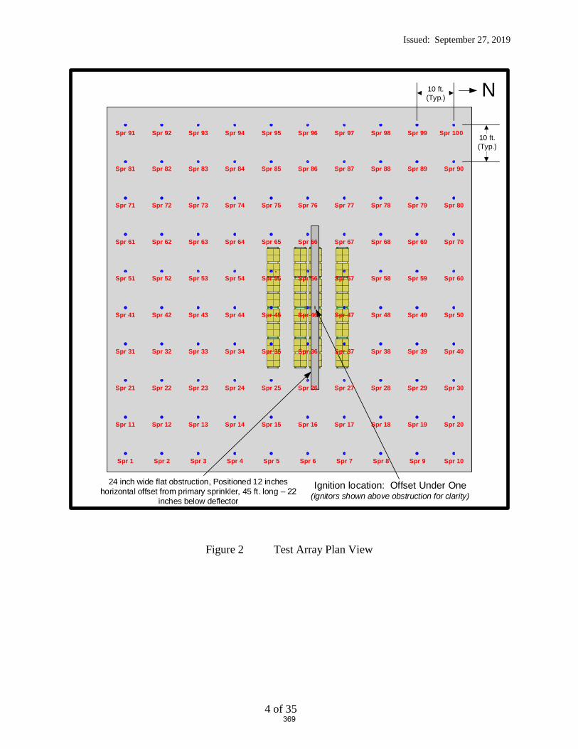
Issued: September 27, 2019
4 of 35
Figure 2 Test Array Plan View
N10 ft. (Typ.)
10 ft. (Typ.)
Ignition location: Offset Under One(ignitors shown above obstruction for clarity)
Spr 11 Spr 12 Spr 13 Spr 14 Spr 15 Spr 16 Spr 17 Spr 18 Spr 19 Spr 20
Spr 71 Spr 72 Spr 73 Spr 74 Spr 75 Spr 76 Spr 77 Spr 78 Spr 79 Spr 80
Spr 81 Spr 82 Spr 83 Spr 84 Spr 85 Spr 86 Spr 87 Spr 88 Spr 89 Spr 90
Spr 1 Spr 2 Spr 3 Spr 4 Spr 5 Spr 6 Spr 7 Spr 8 Spr 9 Spr 10
Spr 91 Spr 92 Spr 93 Spr 94 Spr 95 Spr 96 Spr 97 Spr 98 Spr 99 Spr 100
24 inch wide flat obstruction, Positioned 12 inches horizontal offset from primary sprinkler, 45 ft. long –
inches below deflector
Spr 21 Spr 22 Spr 23 Spr 24 Spr 25 Spr 27 Spr 28 Spr 29 Spr 30Spr 26
Spr 31 Spr 32 Spr 33 Spr 34 Spr 35 Spr 37 Spr 38 Spr 39 Spr 40Spr 36
Spr 41 Spr 42 Spr 43 Spr 44 Spr 45 Spr 47 Spr 48 Spr 49 Spr 50Spr 46
Spr 51 Spr 52 Spr 53 Spr 54 Spr 55 Spr 57 Spr 58 Spr 59 Spr 60Spr 56
Spr 61 Spr 62 Spr 63 Spr 64 Spr 65 Spr 67 Spr 68 Spr 69 Spr 70Spr 66
369
Issued: September 27, 2019
5 of 35
3.2 Air Temperature
3.2.1 Air Temperature Near Sprinklers
The air temperature adjacent to each sprinkler was measured with a 0.0625-in.diameter inconel
sheathed Type K thermocouple.
3.2.2 Air Temperature Above Ignition
The ceiling gas temperature above ignition was measured using the same type of thermocouples
as stated in 3.2.1. The gas temperature was measured adjacent to the steel beam described in 3.3,
with the thermocouples, positioned 6, 12, and 18 inches below the ceiling. The three
thermocouples were positioned near the ends and centered on the steel beam.
3.3 Steel Beam Temperature
A nominal 4 ft. long by 2 in. wide by 2 in. high steel angle was mounted below the ceiling above
the ignition location of the test array. The temperature of the steel beam was measured with five
Type K thermocouples embedded within the beam. The thermocouples were equally spaced
within the beam.
3.4 Video
A minimum of seven video cameras were used to record the test. Four cameras were centered on
each wall of the test cell. One camera was positioned on the observation balcony in the North
East corner of the laboratory, and two cameras were positioned on the test room floor to capture
critical events. In addition, infrared cameras were used to record the events from the South East
and North West corners of the test array.
3.5 Data Collection
All data was collected using an electronic data acquisition system at a one-second-scan rate.
370

Issued: September 27, 2019
6 of 35
4. CARTONED UNEXPANDED GROUP A PLASTIC COMMODITY
4.1 Components
4.1.1 Pallets
The fire test series was conducted using two way pallets as a base for the commodity. The kiln
dried 2-way entry white oak hard wood pallets had outside dimensions of 42 by 42 by 5 in. tall.
Photographs of a representative pallet are shown in Figure 3.
Figure 3 2-Way Entry, Hard Wood Pallet
371
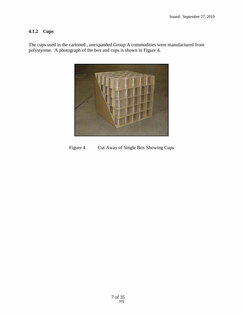
Issued: September 27, 2019
7 of 35
4.1.2 Cups
The cups used in the cartoned , unexpanded Group A commodities were manufactured from
polystyrene. A photograph of the box and cups is shown in Figure 4.
Figure 4 Cut Away of Single Box Showing Cups
372

Issued: September 27, 2019
8 of 35
4.2 Commodity Description
4.2.1 Cartoned Unexpanded Group A Plastic
The Cartoned Unexpanded Group A Plastic Commodity consisted of eight, single layer
cardboard boxes each containing 125 cups (containing 1,000 unexpanded polystyrene cups
total). Each box contained five tiers of twenty-five cups. Each tier and cup was separated by
one layer of cardboard. The nominal external dimensions of the commodity was 42 inches wide
by 42 inches deep by 40 inches tall resting on a nominal 5 inch tall, 42 by 42 inch hardwood
pallet.
The commodity is shown in Figure 5.
Figure 5 Cartoned unexpanded Group A Plastic Commodity
The test results apply only to the samples tested.
373

Issued: September 27, 2019
9 of 35
5. OBSTRUCTIONS
5.1 Flat Obstruction
The manufactured flat obstruction used in the test consisted of a 24 inch wide flat, ¼ inch thick
steel plate with two, 3 by 3 inch, 3/8 inch thick “L” angles welded to the ends as shown in Figure
6. A photograph of the cross section can be seen in Figure 7.
Three, 15 ft. long sections were positioned back to back for a 45 ft. long continuous flat
obstruction which spanned five sprinklers as shown graphically in Figure 2 and photographically
in Figure 8. The 12 inch sprinkler offset is shown in Figure 9 as viewed from below.
Figure 6 Twenty Four inch Wide Flat Obstruction – Cross Section
Figure 7 Twenty Four inch Wide Flat Obstruction – Photograph of Cross Section
374

Issued: September 27, 2019
10 of 35
Figure 8 45 ft. Long, 24 inch Wide Flat Obstruction – Photograph from the Southwest
Figure 9– Photograph of 24 inch wide Obstruction from Below, Showing Sprinkler offset 12
inches to the Right (South of lab to the right)
375

Issued: September 27, 2019
11 of 35
Figure 10 Test Arrangement – Elevation View from the East Near Ceiling (upper two tiers as shown)
376
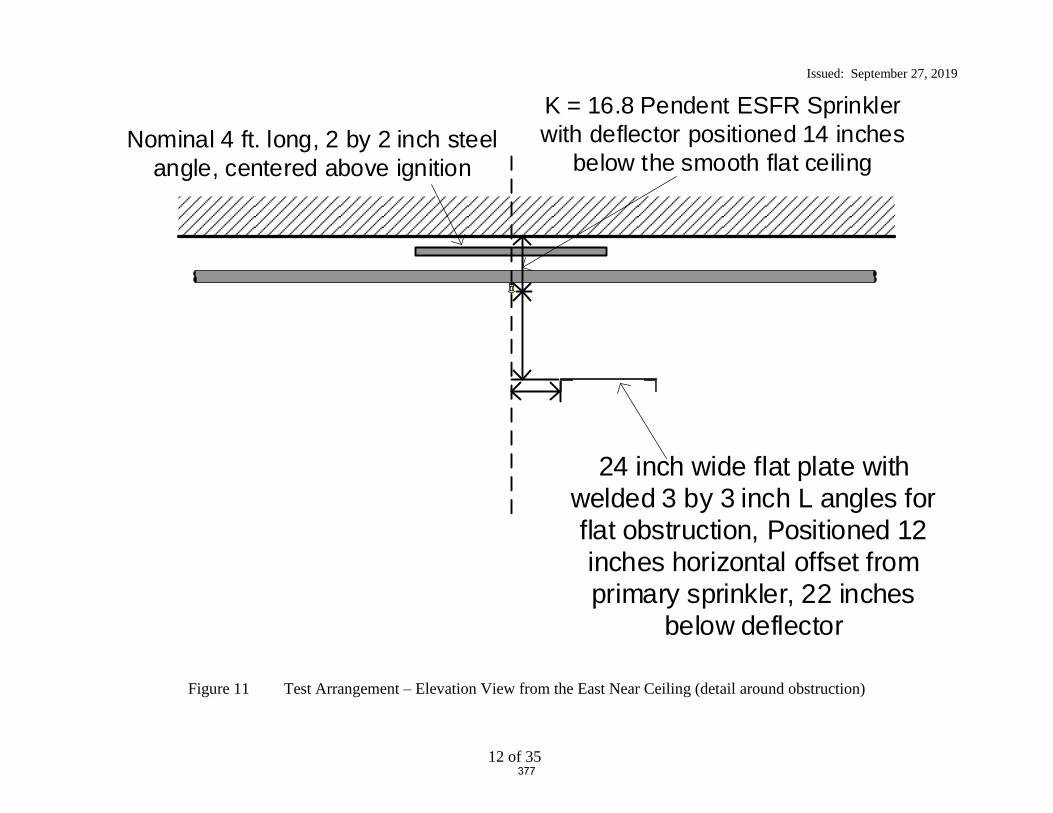
Issued: September 27, 2019
12 of 35
Figure 11 Test Arrangement – Elevation View from the East Near Ceiling (detail around obstruction)
Nominal 4 ft. long, 2 by 2 inch steel angle, centered above ignition
24 inch wide flat plate with welded 3 by 3 inch L angles for flat obstruction, Positioned 12 inches horizontal offset from primary sprinkler, 22 inches
below deflector
K = 16.8 Pendent ESFR Sprinkler with deflector positioned 14 inches
below the smooth flat ceiling
377
Issued: September 27, 2019
13 of 35
6. TEST ARRAY CONFIGURATION
6.1 Rack Array and Plan View
The racking system used for the main bay is considered open, double-row racking in accordance
with NFPA 13. Each bay of the racking system was filled with two pallet loads of the test
commodity as defined in section 4.2.
Figure 10 through Figure 12 shows the details of the rack array and their relationship to the
obstructions for the test.
378
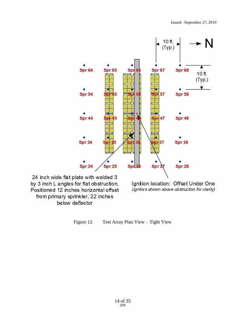
Issued: September 27, 2019
14 of 35
Figure 12 Test Array Plan View – Tight View
379

Issued: September 27, 2019
15 of 35
6.2 Ceiling and Clearance
The test laboratory’s moveable ceiling was positioned at 40 ft. from the test room floor.
A 14 inch pendent sprinkler deflector to ceiling clearance was used for all tests.
A nominal 10 ft. clearance between the ceiling and the top of the commodity was established.
Elevation views of the test arrangements are shown in Figure 13 through Figure 14.
380

Issued: September 27, 2019
16 of 35
Figure 13 Elevation View of Main Test Array from the North
381

Issued: September 27, 2019
17 of 35
Figure 14 Elevation View of Main Test Array from the East
382

Issued: September 27, 2019
18 of 35
6.3 Test Arrangement
The steel racks were loaded with the commodity as defined in section 4. The loading
arrangement is as shown in Figure 13 through Figure 14.
Photographs of the test arrangement are shown in Figure 15 through Figure 17.
383

Issued: September 27, 2019
19 of 35
Figure 15 Elevation View from the North
384

Issued: September 27, 2019
20 of 35
Figure 16 Elevation View from the West
385

Issued: September 27, 2019
21 of 35
Figure 17 Elevation View from the Southwest
386

Issued: September 27, 2019
22 of 35
6.4 Ignition
Ignition was accomplished using two half igniters.
The igniters were constructed from a 3-in. diameter by 3-in. long cellulosic bundle soaked with 4
fluid ounces of gasoline and wrapped in a polyethylene bag. The igniters were positioned
adjacent to the unexpanded plastic commodity in the transverse flue space, near the center of the
North main rack array as shown in Figure 12 and Figure 13.
The rack array was positioned such that it was centered under the obstructed sprinkler as shown
in Figure 2, Figure 13 and Figure 14.
Details of the ignition location can be seen in Figure 18.
Figure 18 View Showing Igniters in North Main Transverse Flue Space at Base of Array
387

Issued: September 27, 2019
23 of 35
7. TEST METHOD
7.1 Test Procedure
The test procedure consisted of the following steps:
1. A camera recording of the test arrangement was documented prior to test.
2. The igniters were placed as discussed previously in the “Ignition” section above.
3. The data acquisition system was started upon ignition of the igniters.
4. The test constant flowing pressure for the ceiling sprinkler system was based on adjusting the
system’s fire pump speed for the number of operated sprinklers.
5. The test proceeded for 30 minutes after the operation of the first sprinkler, rounded up to the
nearest whole minute.
6. Termination of the test after the 30 minute plus first sprinkler operation time period began
with automatic deluging of the array until which time the smoke level was diminished to the
point of visual observation of the array. Fire fighters then manually fought the fire until it
was extinguished.
7. A detailed still camera assessment of the commodity damage within the racking array took
place after the test had been completed. See Appendix B for photographs of the damage
assessment.
7.2 Fire Test Photographs
Various photographs of the initial and latter stages of the fire are shown in Figure 19 through
Figure 22.
388

Issued: September 27, 2019
24 of 35
Figure 19 Fire Test Photo Prior to Sprinkler Operation
389
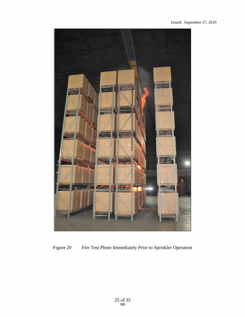
Issued: September 27, 2019
25 of 35
Figure 20 Fire Test Photo Immediately Prior to Sprinkler Operation
390

Issued: September 27, 2019
26 of 35
Figure 21 Photograph Showing Water Cascading over the top of the 24 inch wide
Obstruction after Operation – Note the amount of water sheeting down the Main Array
391

Issued: September 27, 2019
27 of 35
Figure 22 View from Ceiling After Sprinkler Operation showing the Obstruction’s Shadow
and the Sheeting action over the top of the 24 inch wide Obstruction
(view from the East)
392

Issued: September 27, 2019
28 of 35
8. RESULTS AND DISCUSSION
One large scale fire test incorporating rack storage of cartoned unexpanded Group A plastic was
conducted at UL LLC in Northbrook, IL on September 24, 2019. The following is a summary of
the resulting data.
8.1 Number of Operating Sprinklers:
Figure 23 provides the sprinkler operation time for the test.
393

Issued: September 27, 2019
29 of 35
dno: did not operate
Figure 23 Operation Times of Sprinklers (minutes:seconds)
N10 ft. (Typ.)
10 ft. (Typ.)
Ignition location: Offset Under One(ignitors shown above obstruction for clarity)
dno dno dno dno dno dno dno dno dno dno
24 inch wide flat obstruction, Positioned 12 inches horizontal offset from primary sprinkler, 45 ft. long –
inches below deflector
1:18
dno dno dno dno dno dno dno dno dno dno
dno dno dno dno dno dno dno dno dno dno
dno dno dno dno dno dno dno dno dno dno
dno dno dno dno dno dno dno dno dno
dno dno dno dno dno dno dno dno dno dno
dno dno dno dno dno dno dno dno dno dno
dno dno dno dno dno dno dno dno dno dno
dno dno dno dno dno dno dno dno dno dno
dno dno dno dno dno dno dno dno dno dno
394
Issued: September 27, 2019
30 of 35
8.2 Temperature Results:
Appendix A provides the data for the test as follows.
The individual sprinkler temperature profiles are presented in Figures 1 through 10 of the
Appendix.
Steel beam and gas temperatures above ignition are presented in Figure 11 and 12 of the
Appendix.
Sprinkler system flowing pressures and system flow rates are presented in Figure 13 of
the Appendix.
8.3 Commodity Damage Results:
The test arrangement was examined for fire test damage to the stored commodity.
The fire did not jump the 4 ft. aisle and the fire was contained within the main array. The
external damage was limited to the North portion of the main array as the South face of the main
array was not damaged.
Drawings of the extent of the damage are depicted in Figure 24 and Figure 25. Photographs of
the overall damage are illustrated in Appendix B.
395

Issued: September 27, 2019
31 of 35
Figure 24 Damage Assessment - Elevation View of North Main Array from Aisle
(ignition side)
396

Issued: September 27, 2019
32 of 35
Figure 25 Damage Assessment - Elevation View of South Main Array from Aisle
(no damage)
397

Issued: September 27, 2019
33 of 35
9. SUMMARY
This report describes one large scale fire test that was conducted to develop data relative to the
level of fire protection provided by a specific Early Suppression Fast Response (ESFR) sprinkler
when the sprinklers are located closer to an obstruction than currently referenced in the Standard
for the Installation of Sprinkler Systems, NFPA 13-2019. For this test, the sprinklers were
located in close proximity to a long continuous structural steel flat horizontal shape.
Standard cartoned unexpanded Group A plastic test commodity was used in the investigation
which consisted of unexpanded polystyrene cups installed in separate compartments within
cartons that are placed on two way entry, hardwood pallets. The nominal external dimensions of
the commodity was 42 inches wide by 42 inches deep by 40 inches tall resting on a nominal 5
inch tall, 42 by 42 inch hardwood pallet.
The test was conducted using a nominal storage height of 30 ft of cartoned unexpanded Group A
plastic with a ceiling height of 40 ft. Nominal 32 ft. long double-row rack storage arrays were
used in the main storage array and 32 ft. long single-row racks were placed across 4 ft. aisles on
both the north and south side of the main array as targets. The test was conducted with the
ignition located at the base of the storage array and horizontally offset approximately 2 ft from
the primary obstructed sprinkler in the transverse flue space.
The test was conducted using a 24 inch wide, 45 ft. long continuous flat plate steel structure
obstruction with welded “L” angles at the base for structural integrity. The 24 inch flat
obstruction was positioned with the leading vertical edge of the obstruction 12 inches away and
the top horizontal flat portion of the obstruction, 22 inches vertically downward from the
sprinkler’s deflector.
During the test, one (1) sprinkler operated. It was noted that the sprinkler’s discharge formed
vertically downward sheeting over the obstruction which significantly reduced the size of the
fire. The sheeting action of this obstruction can be seen in Figure 21 and Figure 22 in the body
of the report.
The fire was contained within the two center bays of the main array. No damage was observed
at the opposite aisle to ignition of the main double row rack storage array. No target ignition
occurred.
A summary of the test parameters and results are provided in Table 1.
398

Issued: September 27, 2019
34 of 35
Table 1 Test Parameters and Results
Test Date September 24, 2019
Test Parameters Storage Type Double Row Rack
Commodity Type Cartoned Unexpanded Group A Plastic
(Plastic Cups in Corrugated Boxes on Hardwood Pallets)
Pallet Type 2 way entry, stringer, hardwood
Nominal Storage Height, ft. 30
Ceiling Height, ft. 40
Nominal Clearance, ft. 10
Aisle Width, ft. 4
Ignition Location Under One Sprinkler (offset)
Sprinkler Systems Ceiling Only (no in-rack sprinklers)
Sprinkler Orientation Pendent
Deflector to Ceiling, in. 14 Sprinkler Spacing, sprinkler by branchline,
ft. by ft. 10 by 10
Temperature Rating, °F 165
Sprinkler Type ESFR Nominal Sprinkler Discharge Coefficient K,
gpm/psig 0.5 16.8
Nominal Discharge Density, gpm/ft2 1.21
Nominal Discharge Pressure, psig 52
Primary Obstruction
24 inch wide, 3 inch deep flat steel obstruction,
positioned 12 inches offset from primary
sprinkler with top of obstruction positioned 22
inches below the sprinkler’s deflector
Secondary Obstruction None
Test Results
Length of Test, minutes 32:00
First Sprinkler Operation Time, min:sec 1:18
Last Sprinkler Operation Time, min:sec 1:18
Number of Operated Sprinklers 1
Approximate Time of Target Ignition Across 4 ft. Aisle, minutes
No ignition
Peak Gas Temperature at Ceiling Above Ignition, °F 191
Maximum 1 minute Average Gas Temperature at Ceiling Above Ignition, °F
110
Peak Steel Temperature at Ceiling Above Ignition, °F
80
Maximum 1 minute Average Steel Temperature at Ceiling Above Ignition, °F
80
Fire Travel to Extremities of Test Array No
399
Issued: September 27, 2019
35 of 35
Report By: Reviewed By:
Daniel R. Steppan Michael G. McCormick
Senior Staff Engineer Staff Engineering Associate
Building and Life Safety Technologies Building and Life Safety Technologies
400

Appendix A – Temperature, Flow and Pressure Graphs
A-1
APPENDIX A
Temperature, Flow and Pressure Graphs
401

Appendix A – Temperature, Flow and Pressure Graphs
A-2
Figure A- 1 Ceiling Sprinklers 1 through 10
Figure A- 2 Ceiling Sprinklers 11 through 20
402

Appendix A – Temperature, Flow and Pressure Graphs
A-3
Figure A- 3 Ceiling Sprinklers 21 through 30
Figure A- 4 Ceiling Sprinklers 31 through 40
403

Appendix A – Temperature, Flow and Pressure Graphs
A-4
Figure A- 5 Ceiling Sprinklers 41 through 50
Figure A- 6 Ceiling Sprinklers 51 through 60
404

Appendix A – Temperature, Flow and Pressure Graphs
A-5
Figure A- 7 Ceiling Sprinklers 61 through 70
Figure A- 8 Ceiling Sprinklers 71 through 80
405

Appendix A – Temperature, Flow and Pressure Graphs
A-6
Figure A- 9 Ceiling Sprinklers 81 through 90
Figure A- 10 Ceiling Sprinklers 91 through 100
406
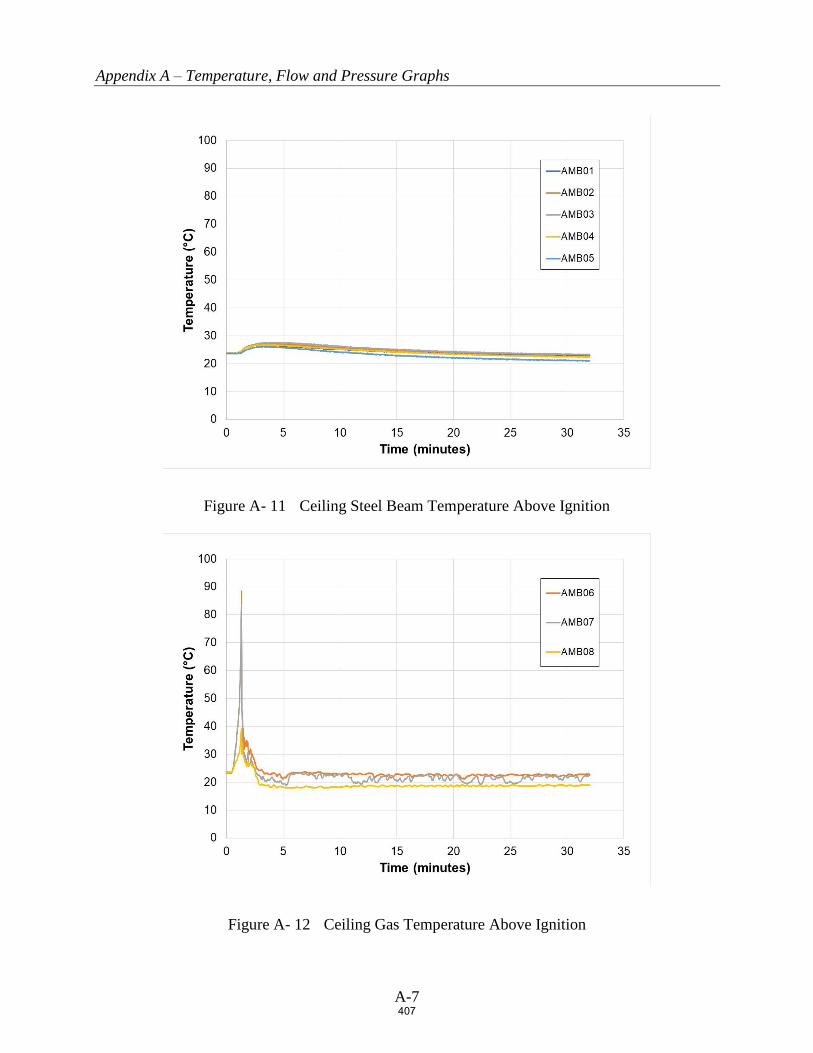
Appendix A – Temperature, Flow and Pressure Graphs
A-7
Figure A- 11 Ceiling Steel Beam Temperature Above Ignition
Figure A- 12 Ceiling Gas Temperature Above Ignition
407

Appendix A – Temperature, Flow and Pressure Graphs
A-8
Figure A- 13 Ceiling Sprinkler System Flow rate and Pressure
408

Appendix B – Damage Assessment Photographs
B-1
APPENDIX B
Damage Assessment Photographs
409

Appendix B – Damage Assessment Photographs
B-2
Figure B- 1 North Target Array from East end of Aisle Space (no damage)
410

Appendix B – Damage Assessment Photographs
B-3
Figure B- 2 North Main Array Damage
411
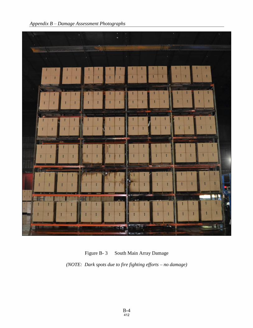
Appendix B – Damage Assessment Photographs
B-4
Figure B- 3 South Main Array Damage
(NOTE: Dark spots due to fire fighting efforts – no damage)
412

Public Comment No. 394-NFPA 13-2020 [ Section No. 14.2.11.2 ]
14.2.11.2* Isolated Obstructions Below Elevation of Sprinklers.
Sprinklers shall be arranged with respect to obstructions in accordance with one of the following:
(1) Sprinklers shall be installed below isolated noncontinuous obstructions that restrict only one sprinklerand are located below the elevation of sprinklers.
(2) Additional sprinklers shall not be required where the obstruction is 2 ft (600 mm) or less in width andthe sprinkler is located horizontally 1 ft (300 mm) or greater from the nearest edge of the obstruction.
(3) Additional sprinklers shall not be required where sprinklers are positioned with respect to the bottom ofobstructions in accordance with 14.2.11.1.
(4) The obstruction 1 1/2 in (50 mm) or less in width is located a minimum of 1 ft (300 mm) below theelevation of the sprinkler.
(5) Additional sprinklers shall not be required where the obstruction is 2 in. (50 mm) or less in width and islocated a minimum of 2 ft (600 mm) below the elevation of the sprinkler deflector or is positioned aminimum of 1 ft (300 mm) horizontally from the sprinkler.
(6) Sprinklers with a special obstruction allowance shall be installed according to their listing.
(7) Additional sprinklers shall not be required where the occupancy is protected in accordance with 14.2.7and obstructions comply with 9.5.5.3 .
Additional Proposed Changes
File Name Description Approved
ESFR_Final_Report_5.1.20._submittal_version.pdf
Statement of Problem and Substantiation for Public Comment
Committee input for the submitted previously PI’s was that the test results do not support the proposed changes and the results should be revisited. These revisions submitted are intended to address the committee comments.The proposed changes are the based upon the findings of the NFPA Research Foundation’s six year ESFR and Obstruction research project. Nine full-scale and 80 Actual Delivered Density tests were completed. Seven tests were completed with obstructions located 6 inches horizontally from the sprinkler. Six of the tests were successful. The recently completed report (final draft) is attached for documentation. The findings from the report are shown below:• The obstruction created by an open web steel truss between the depths of 22 - 36 inches, located 6 inches horizontally from a K14 or K17 ESFR sprinkler, should not significantly decrease sprinkler performance. • The obstruction created by a bridging member 1½ x 1½ inches in size or less, located directly below the sprinkler with an 18 inch vertical clearance (K14) or 12 inch vertical clearance (K17) should not significantly decrease sprinkler performance. This also applies to bridging members attached to open web steel trusses.• The obstruction created by flat or round obstructions less than or equal to 12 inches in width located 6 inches horizontally from a K17 or K14 sprinkler should not significantly decrease sprinkler performance.• The obstruction created by flat or round obstructions less than or equal to 24 inches in width located 12 inches horizontally from a K17 or K14 sprinkler should not significantly decrease sprinkler performance.
Related Item
• 14.2.11.2
Submitter Information Verification
Submitter Full Name: Garner Palenske
Organization: Wiss Janney Elstner Associates
Street Address:
City:
State:
National Fire Protection Association Report https://submittals.nfpa.org/TerraViewWeb/ContentFetcher?commentPar...
274 of 738 5/8/2020, 11:28 AM
413

Zip:
Submittal Date: Wed May 06 16:45:46 EDT 2020
Committee: AUT-AAC
National Fire Protection Association Report https://submittals.nfpa.org/TerraViewWeb/ContentFetcher?commentPar...
275 of 738 5/8/2020, 11:28 AM
414
17
Obstructions and Early Suppression Fast
Response Sprinklers
Phase 4 Final Report
FINAL REPORT
May 1, 2020
WJE No. 2018.8439.0
PREPARED FOR:
Amanda Kimball, P.E.
Executive Director | Research Foundation
1 Batterymarch Park
Quincy, MA 02169-7471
PREPARED BY:
Wiss, Janney, Elstner Associates, Inc.
16496 Bernardo Center Drive, Suite 202
San Diego, California 92128
858.207.5461 tel
415

Obstructions and Early Suppression Fast Response Sprinklers
Phase 4 Final Report
FINAL REPORT | WJE No. 2018.8439.0 | MAY 1, 2020
ABSTRACT
Obstructions created by ceiling structural members, lighting, piping, or cable trays, can hinder Early
Suppression Fast Response (ESFR) sprinkler performance. However, ESFR sprinkler obstruction sensitivity is
largely unknown. The requirements found in the current edition of National Fire Protection Association
Standard 13, Standard for the Installation of Sprinkler Systems (NFPA 13), are considered conservative and
have created difficulties in practical application.
Acknowledging the importance of this issue, NFPA’s research affiliate, the Fire Protection Research
Foundation, embarked on a multi-year testing program which began in 2014. The fourth and final phase
of the project, which included K14 ESFR Actual Delivered Density (ADD) testing and K17 ESFR sprinkler
full-scale fire testing, was completed in September of 2019. In total, approximately 80 ADD tests and nine
full-scale fire tests were completed using K17 and K14 ESFR sprinklers.
This report presents an overall summary of the ESFR sprinkler obstruction project including the results of
the recently completed K14 ESFR testing. The reader is encouraged to read the reports from Phases 1-3 of
the project, which are available online at the Fire Protection Research Foundation website
(www.nfpa.org/News-and-Research/Resources/).
The findings of the project are as follows:
The obstruction created by an open web steel truss between the depths of 22 - 36 inches, located
6 inches horizontally from a K14 or K17 ESFR sprinkler, should not significantly decrease sprinkler
performance.
The obstruction created by a bridging member 1½ x 1½ inches in size or less, located directly
below the sprinkler with an 18 inch vertical clearance (K14) or 12 inch vertical clearance (K17)
should not significantly decrease sprinkler performance. This also applies to bridging members
attached to open web steel trusses.
The obstruction created by flat or round obstructions less than or equal to 12 inches in width
located 6 inches horizontally from a K17 or K14 sprinkler should not significantly decrease
sprinkler performance.
The obstruction created by flat or round obstructions less than or equal to 24 inches in width
located 12 inches horizontally from a K17 or K14 sprinkler should not significantly decrease
sprinkler performance.
Keywords: Early Suppression Fast Response Sprinklers, Actual Delivered Density, Obstruction.
416
Obstructions and Early Suppression Fast Response Sprinklers
Phase 4 Final Report
FINAL REPORT | WJE No. 2018.8439.0 | MAY 1, 2020
CONTENTS1
Introduction ........................................................................................................................................................ 1
Project Overview ................................................................................................................................................ 2
Obstruction Experimentation .......................................................................................................................... 4
Actual Delivered Density (ADD) Testing ...................................................................................................................................... 4
Full-Scale Fire Testing ...................................................................................................................................................................... 12
Results and Findings ....................................................................................................................................... 15
Bar Joist and Bridging Member Obstructions ........................................................................................................................ 17
Flat Obstructions................................................................................................................................................................................ 19
Conclusions ...................................................................................................................................................... 32
Acknowledgements ........................................................................................................................................ 32
APPENDIX A. Actual Delivered Density Testing of ESFR Sprinklers Obstructed by Flat
Obstructions (Phase 4), Underwriters Laboratories, April 26, 2019
APPENDIX B. ESFR Sprinklers Obstructed by Continuous Flat Obstructions (Phase 4),
Underwriters Laboratories, September 27, 2019
1 The Authors wish to thank the Research Foundation and Underwriters Laboratories for allowing use of the reports from previous
phases of this project.
417

Obstructions and Early Suppression Fast Response Sprinklers
Phase 4 Final Report
FINAL REPORT | WJE No. 2018.8439.0 | MAY 1, 2020 Page 1
INTRODUCTION
Storage occupancies have undergone significant changes since the introduction of the standard spray
sprinkler in 1956. The increased use of plastic packing material, in conjunction with the increased demand
for plastic products, creates extreme challenges for storage sprinklers. The lighter product weight allows
higher storage. In addition, the heat release rate of plastic material is much higher than that of wood or
paper products.2 The characteristics of modern storage fires include very fast fire growth rates and high
fire plume velocities.3
In the 1970’s, FM Global scientists embarked on a dedicated storage research program to address this
issue. The program explored sprinkler performance characteristics, including response time (Response
Time Index) and the relationship between the actual amount of water delivered to the fire source (Actual
Delivered Density) compared to the required amount of water delivered for fire suppression (Required
Delivered Density). These concepts were instrumental in the invention of the ESFR sprinkler in the 1980s.4
The requirements outlined in the current edition of NFPA 13 provide prescriptive language for the
placement of ESFR sprinklers in regard to obstructions in the near field. It is surmised that the
requirements are based on proprietary testing completed by FM Global. ESFR sprinkler obstruction
requirements have remained unchanged since the early development of the sprinkler. Overall, published
ESFR obstruction fire test data, prior to this project, is sparse.
In 2002, FM Global published the results of two ESFR obstruction fire tests conducted in their legacy fire
test laboratory located in Providence, Rhode Island.5 In both tests, obstructions (4 inch wide bar joist
chord and a 1½ x 1½ inch bridging member) were placed 8 inches directly below the sprinkler. The results
of the tests were considered unacceptable due to excessive sprinkler operation (29 sprinklers and 27
sprinklers in Tests No. 1 and 2, respectively) and fire propagation beyond the ignition array.
The 2019 edition of NFPA 13 includes numerous requirements for ESFR sprinkler placement with respect
to obstructions. The most problematic, as determined by a user group survey, is that of the bridging
members attached to bar joists. The early phases of this project focused on this issue. Miscellaneous
obstructions, such as lights, conduit and other structural members were studied in the later phases. A
variety of obstruction variables were explored, including horizontal placement, vertical placement, width,
and shape.
This project is unique due to the innovative use of the Actual Delivered Density (ADD) apparatus as a
scoping tool for full-scale testing. ADD testing is typically used for sprinkler listing or approval. The
2 The heat of combustion of thermoplastic polymers range between 15.5 to 46.5 kJ/g with a medium of 41.6 kJ/g, while natural
polymers (cellulose) have a significantly lower heat of combustion of 16.1 kJ/g. (Drysdale, Dougal. “An Introduction to Fire Dynamics”,
2011, Table 1.2).
3 Kung, H.C., FM Global. “Experimental Study of Actual Delivered Density for Rack Storage Fires,” Fire Safety Science- Proceedings of
the Fourth International Symposium on Safety Science and Technology (1994)
4 Kung, H. C., Victaulic. Fire Protection Engineering, Edition Q1, 2011
5 Kung, H.C., FM Global. “Effect of Ceiling Obstructions Upon the Performance of ESFR Pendent Sprinklers in 12 M High Buildings,”
International Symposium on Safety Science and Technology (2002)
418

Obstructions and Early Suppression Fast Response Sprinklers
Phase 4 Final Report
FINAL REPORT | WJE No. 2018.8439.0 | MAY 1, 2020 Page 2
technology has been around since the 1990s. ADD testing allowed the examination of approximately 80
scenarios from which nine full-scale tests were selected.
ADD testing does not account for all of the variables that can influence sprinkler performance, such as
sprinkler “skipping,” the phenomenon where sprinklers do not activate in the common circular pattern.
ADD testing provides a methodology to identify trends and identify scenarios which may pass or fail the
selected performance criteria. Given the wide range of variables included in the project scope, ADD
proved to be a reliable and consistent tool to quickly and economically simulate full-scale test outcomes.
PROJECT OVERVIEW
The work was completed in four distinctive phases, each building upon the tests conducted prior to obtain
a comprehensive view of ESFR obstruction phenomena, as guided by the selected boundary conditions.
Phase 1 consisted of a literature search in which relevant research concerning ESFR sprinkler performance
and obstruction criteria was collected and reviewed. Potential obstruction scenarios for the testing were
also identified.
Given the infinite number of sprinkler obstruction conditions that may occur, boundary conditions for the
testing were established. Survey results of NFPA 13 users worldwide showed that open web steel joists are
the most commonly used structural roof system. Bridging members, which provide lateral support for
maintaining stability under vertical loads, were identified as the most problematic ESFR sprinkler
obstruction (Figure 1).6 Discussions with leading steel joist suppliers indicated that the most common sizes
sold are in the range of 22 -36 inches in depth, with 30 inches deep being the most popular. 7
The obstruction created by an open web steel truss is dependent on the size of the bottom chord. The
upper chord is assumed to be above the sprinkler and thus out of the sprinkler spray pattern. The web of
the steel truss is minimal in size, typically ½ inch wide “L” stock and, therefore, is assumed to not influence
the sprinkler discharge pattern in a significant manner. For sprinkler obstruction purposes, the obstruction
created by the bottom chord resembles an unattached flat horizontal obstruction of the same width.
The chords are constructed of two “L” shaped members, welded or bolted together back to back. In
addition, the web is attached between the two, increasing the width by approximately ½ inch. The width
of the bottom chord is a function of the depth of the open web steel joist. Joists 22 - 30 inches deep are
provided with chords 4 ½ inches in width, and joists 36 inches deep are provided with chords 5 ½ inches
in width.
6 Palenske, Garner A., “Obstructions and ESFR Sprinklers-Phase 1,” NFPA Research Foundation 2014
7 Ibid
419

Obstructions and Early Suppression Fast Response Sprinklers
Phase 4 Final Report
FINAL REPORT | WJE No. 2018.8439.0 | MAY 1, 2020 Page 3
Figure 1. 22-inch Deep Bar Joist with Bridging Member8
The characteristics of the ESFR sprinkler selected for the testing were also determined in Phase 1.
Discussions with leading sprinkler manufacturers were conducted to aid in this selection. Upright style
ESFR sprinklers were found to be of minimal popularity, therefore pendent style sprinklers were selected.
Pendant type sprinklers were discovered to be utilized more frequently in practice and were therefore
selected for testing. Regarding orifice size, K17 sprinklers were determined to be the most popular model
compared to K22-K25 sprinklers.9 In addition, given their smaller orifice sizes, and corresponding smaller
droplet sizes, K17 sprinkler performance was assumed to be more biased by discharge interference
created by obstructions. Consequently, results of the K17 sprinkler research should in theory be applicable
to larger K factor sprinklers, such as K22-K25 sprinklers. K17 sprinklers were used for Phases 2-3.
The use of K14 sprinklers was initially discounted given the recent controversy regarding the adequacy of
K14 sprinklers to protect rack arrays of Group A plastic beneath a 40 foot ceiling.10 However, the extensive
legacy use of the K14 sprinkler prompted the exploration of K14 sprinkler performance in Phase 4. A total
of 20 ADD tests were performed using similar test scenarios to that of the K17 ESFR sprinkler.
Phase 2 examined K17 sprinkler performance related to the obstructions located in the horizontal plane of
the sprinkler. The ADD apparatus was used to determine the performance of the sprinkler in the presence
of open web steel truss and bridging member obstructions and to select the testing scenarios relevant for
the full-scale testing of the sprinkler. Approximately 22 ADD tests and 5 full-scale tests were performed
with K17 sprinklers.
8 Steppan, Daniel R. Underwriters Laboratories “Actual Delivered Density Tests of ESFR Sprinkler Obstructed By Open Web Steel Bar
Joists and Bridging Members,” 2015
9 Palenske, Garner A., “Obstructions and ESFR Sprinklers-Phase 1,” NFPA Research Foundation 2014
10 NFPA 13, 2013 edition, limitation of K14 ESFR sprinkler protection to maximum 35 ft. ceiling height.
420

Obstructions and Early Suppression Fast Response Sprinklers
Phase 4 Final Report
FINAL REPORT | WJE No. 2018.8439.0 | MAY 1, 2020 Page 4
Phase 3 introduced vertical obstruction types including 3-inch flat, 6-inch flat, 12-inch flat, 3-inch round,
6-inch round, and 1½-inch bridging members. A total of 22 ADD tests were performed using K17
sprinklers to determine which full-scale tests would be the most rigorous. Three full-scale tests were
performed.
Phase 4, as previously mentioned, focused on the performance of the K14 sprinkler in configurations
similar to those explored in Phase 3. A total of 20 ADD tests were performed to compare the performance
of K14 ESFR sprinklers to that of K17 ESFR sprinklers. One full-scale test using K17 sprinklers was
performed.
OBSTRUCTION EXPERIMENTATION
The experimentation was conducted at Underwriters Laboratories, large-scale fire test facility located in
Northbrook, Illinois, during April 2015 - September of 2019. A description of the effort is summarized
below. Additional details can be found in the complete reports located on the Fire Protection Research
Foundation’s website.
Actual Delivered Density (ADD) Testing
ADD testing has been used to quantify sprinkler performance since the development of the ESFR sprinkler
in the 1980s. The apparatus has evolved over time. Presently, a modified second generation apparatus is
used in the sprinkler listing process as defined in Underwriters Laboratories, UL 1767- Early Suppression
Fast Sprinklers. This standard prescribes minimum ADD values needed to demonstrate proper sprinkler
performance.
A third generation apparatus was designed and constructed at Underwriters Laboratories in 2005. The
apparatus consists of a fire source in the form of 12 heptane burners used to simulate a rack storage fire.
There are 48 square collection pans with dimensions of 20 inches by 20 inches used to collect water into
cylinders below the apparatus. A pressure tap located in each cylinder allows the calculation of the
amount of water in each container over time which may be used to calculate the water flux in each region
in gpm/ft2. An air duct located in the center of the apparatus provides airflow to simulate a fire plume.
Flue spaces are provided at a spacing of 6 inches between each pan configurations. The addition of flue
spaces results in a more realistic simulation because combustion occurs within the flue space and not in
open air above the apparatus. Water is sprayed on the underside of the pans to prevent warping caused
by the radiative heat from the flames.
A drawing of the apparatus is shown in Figure 2. The ADD apparatus in operation is shown in Figure 3.
421

Obstructions and Early Suppression Fast Response Sprinklers
Phase 4 Final Report
FINAL REPORT | WJE No. 2018.8439.0 | MAY 1, 2020 Page 5
Figure 2. ADD Apparatus11
Figure 3. ADD Testing Apparatus with Obstructions12
11 Steppan, Daniel R. Underwriters Laboratories “Actual Delivered Density Tests of ESFR Sprinkler Obstructed by Open Web Steel Bar
Joists and Bridging Members,” 2015
12 Ibid
422

Obstructions and Early Suppression Fast Response Sprinklers
Phase 4 Final Report
FINAL REPORT | WJE No. 2018.8439.0 | MAY 1, 2020 Page 6
The third-generation apparatus is used by Underwriters Laboratories to screen fire sprinkler system
designs and, prior to this project, has been used to evaluate non-fire ESFR sprinkler obstruction sensitivity.
This new apparatus is not currently used for UL 1767 sprinkler listing. While considered more accurate
than the modified second-generation apparatus, the legacy of test data compiled with the modified
second generation apparatus makes changing the ADD apparatus problematic.13
Sprinklers can be positioned in various arrangements, directly over, centered between, or offset from the
centerline of the fire source depending on the arrangement to be simulated. The thermal link of the
sprinklers is removed, since sprinkler response time is not objective criterion of the testing protocol. The
vertical position of the sprinkler relative to the top of the ADD apparatus replicates the distance from the
top of the storage array to the ceiling sprinkler location.
Prior to use of the ADD apparatus, a calibration procedure is completed. An experimental convection heat
release rate is selected based upon the properties of the simulated fire. The apparatus is then calibrated to
match plume temperature and velocity readings from actual rack storage fire test data. The air supply
below the apparatus remains constant at 250 liters/second (66 gallons/second) and the heptane nozzle
flow rate is adjusted as needed to produce measurements comparable to that of a full-scale rack storage
fire.
Once calibrated, a pilot flame is ignited above each set of heptane nozzles. The heptane nozzles and air
supply fan are then initiated. When the fire reaches a steady state burning condition, the pump controlling
the water flow to the open sprinkler is activated to produce the desired sprinkler discharge pressure. Data
is collected a nominal 5 minutes before the termination of each test. The data is then recorded for each
collection pan, and averages are calculated based on areas of interest pertaining to the shadow created by
individual structural elements.
Dr. HC Kung compared the results of both generations of ADD apparatus to full-scale fire test results.14
Temperature and velocity measurements were taken at various locations over each apparatus. Centerline
temperatures were recorded at 3.14 ft., 8.4 ft., and 15.4 ft above the top of the apparatus. Velocity probe
measurements were taken at a 0.16 ft. radius from center line of the apparatus at all heights. Table 1
presents the results of the experimentation:
Where:
∆Tc= Fire plume centerline temperature difference from ambient temperature (F)
∆To = Fire plume off center temperature difference from ambient temperature (F)
uc= Fire plume centerline velocity(ft/sec)
ADD =Third generation apparatus data
Previous = Modified second generation apparatus
13 Discussions with Underwriters Laboratories Staff
14 Schwille, Kung, Hjohlman, Laverick, and Gardell: Actual Delivered Density Fire Test Apparatus for Sprinklers Protecting High
Commodity Storage, Fire Safety Science-Eight International Symposium, 2005.
423
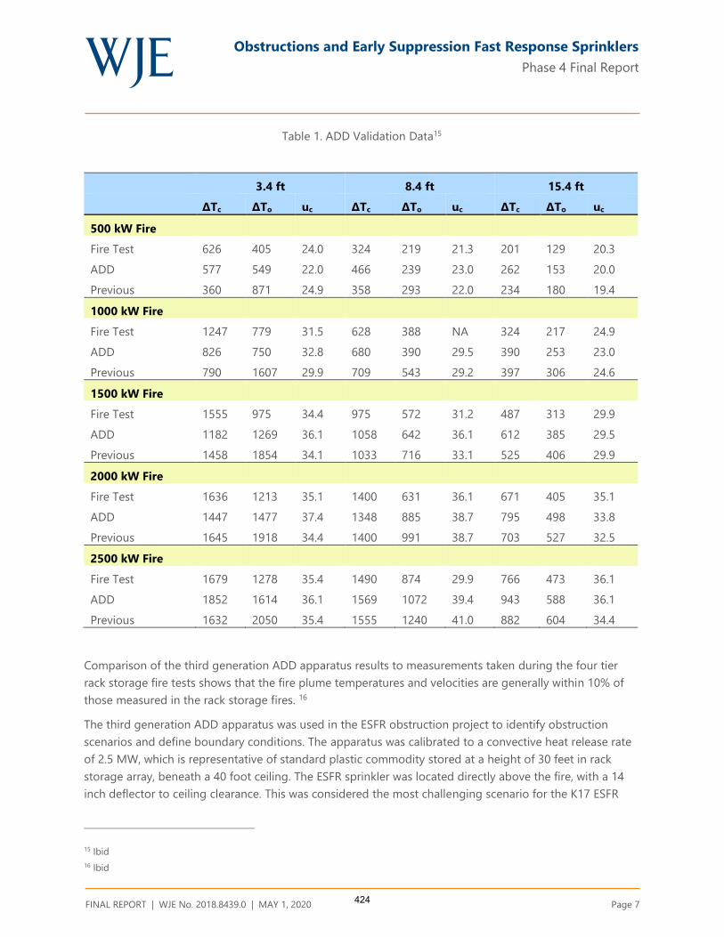
Obstructions and Early Suppression Fast Response Sprinklers
Phase 4 Final Report
FINAL REPORT | WJE No. 2018.8439.0 | MAY 1, 2020 Page 7
Table 1. ADD Validation Data15
3.4 ft 8.4 ft 15.4 ft
ΔTc ΔTo uc ΔTc ΔTo uc ΔTc ΔTo uc
500 kW Fire
Fire Test 626 405 24.0 324 219 21.3 201 129 20.3
ADD 577 549 22.0 466 239 23.0 262 153 20.0
Previous 360 871 24.9 358 293 22.0 234 180 19.4
1000 kW Fire
Fire Test 1247 779 31.5 628 388 NA 324 217 24.9
ADD 826 750 32.8 680 390 29.5 390 253 23.0
Previous 790 1607 29.9 709 543 29.2 397 306 24.6
1500 kW Fire
Fire Test 1555 975 34.4 975 572 31.2 487 313 29.9
ADD 1182 1269 36.1 1058 642 36.1 612 385 29.5
Previous 1458 1854 34.1 1033 716 33.1 525 406 29.9
2000 kW Fire
Fire Test 1636 1213 35.1 1400 631 36.1 671 405 35.1
ADD 1447 1477 37.4 1348 885 38.7 795 498 33.8
Previous 1645 1918 34.4 1400 991 38.7 703 527 32.5
2500 kW Fire
Fire Test 1679 1278 35.4 1490 874 29.9 766 473 36.1
ADD 1852 1614 36.1 1569 1072 39.4 943 588 36.1
Previous 1632 2050 35.4 1555 1240 41.0 882 604 34.4
Comparison of the third generation ADD apparatus results to measurements taken during the four tier
rack storage fire tests shows that the fire plume temperatures and velocities are generally within 10% of
those measured in the rack storage fires. 16
The third generation ADD apparatus was used in the ESFR obstruction project to identify obstruction
scenarios and define boundary conditions. The apparatus was calibrated to a convective heat release rate
of 2.5 MW, which is representative of standard plastic commodity stored at a height of 30 feet in rack
storage array, beneath a 40 foot ceiling. The ESFR sprinkler was located directly above the fire, with a 14
inch deflector to ceiling clearance. This was considered the most challenging scenario for the K17 ESFR
15 Ibid
16 Ibid
424

Obstructions and Early Suppression Fast Response Sprinklers
Phase 4 Final Report
FINAL REPORT | WJE No. 2018.8439.0 | MAY 1, 2020 Page 8
sprinkler. Typical obstruction scenarios for the bar joist, bridging member, flat, and round obstructions are
shown in Figure 4 through Figure 7. ADD results are summarized in Table 2.
Figure 4. Typical ADD Testing Bar Joist Obstruction Scenario17
17 Steppan, Daniel R. Underwriters Laboratories “Actual Delivered Density Tests of ESFR Sprinkler Obstructed by Open Web Steel Bar
Joists and Bridging Members,” 2015
425

Obstructions and Early Suppression Fast Response Sprinklers
Phase 4 Final Report
FINAL REPORT | WJE No. 2018.8439.0 | MAY 1, 2020 Page 9
Figure 5. Typical ADD Testing Bridging Member Obstruction Scenario18
Figure 6. Typical ADD Testing Flat Obstruction Scenario
18 Ibid
426

Obstructions and Early Suppression Fast Response Sprinklers
Phase 4 Final Report
FINAL REPORT | WJE No. 2018.8439.0 | MAY 1, 2020 Page 10
Figure 7. Typical ADD Testing Round Obstruction Scenario19
19 Ibid
427

Obstructions and Early Suppression Fast Response Sprinklers
Phase 4 Final Report
FINAL REPORT | WJE No. 2018.8439.0 | MAY 1, 2020 Page 11
Table 2. Summary of ADD Fire Test Results
428

Obstructions and Early Suppression Fast Response Sprinklers
Phase 4 Final Report
FINAL REPORT | WJE No. 2018.8439.0 | MAY 1, 2020 Page 12
Full-Scale Fire Testing
Various obstruction arrangements were tested in full-scale based upon the information gathered in the
ADD testing and sprinkler discharge pattern analysis. The test array tested consisted of the following
configuration (Figure 8 and Figure 9).
Standard Group A plastic commodity:
30 feet of double-row rack storage and a 40-foot high ceiling
Standard 4-foot aisles with 6-inch transverse and longitudinal flue spaces provided at rack uprights
and between unit loads.
K17 ESFR sprinklers operating at 52 psi and positioned at the ceiling with 14-inch clearance between
the ceiling and the deflector.
Sprinkler spacing of 10 feet x 10 feet
Two - half igniters positioned at the base of the commodity, offset on the center of the transverse flue
space in the main array.
The following pass/fail criteria were established:
A maximum of eight sprinklers activate. This is the same criterion established for K22.4 ESFR sprinklers
for similar ceiling/storage heights with a 50 percent safety factor assuming a 12-sprinkler design.
The fire is generally contained to the ignition array. The ignition array is defined as the center stacks,
two pallet-loads long by two pallet-loads wide, of the main fuel array in which the igniters are located.
Ceiling gas temperatures are such that exposed structural steel will not be endangered (peak one-
minute average temperatures less than 1,000 °F). This is consistent with all current ESFR sprinkler test
criteria.
Full-scale testing was completed for K17 sprinklers only. Results are presented in Table 3.
429

Obstructions and Early Suppression Fast Response Sprinklers
Phase 4 Final Report
FINAL REPORT | WJE No. 2018.8439.0 | MAY 1, 2020 Page 13
Figure 8. Typical Test Array as viewed from the North20
Figure 9. Typical Test Array as viewed from the East21
20 Ibid
21 Ibid
430
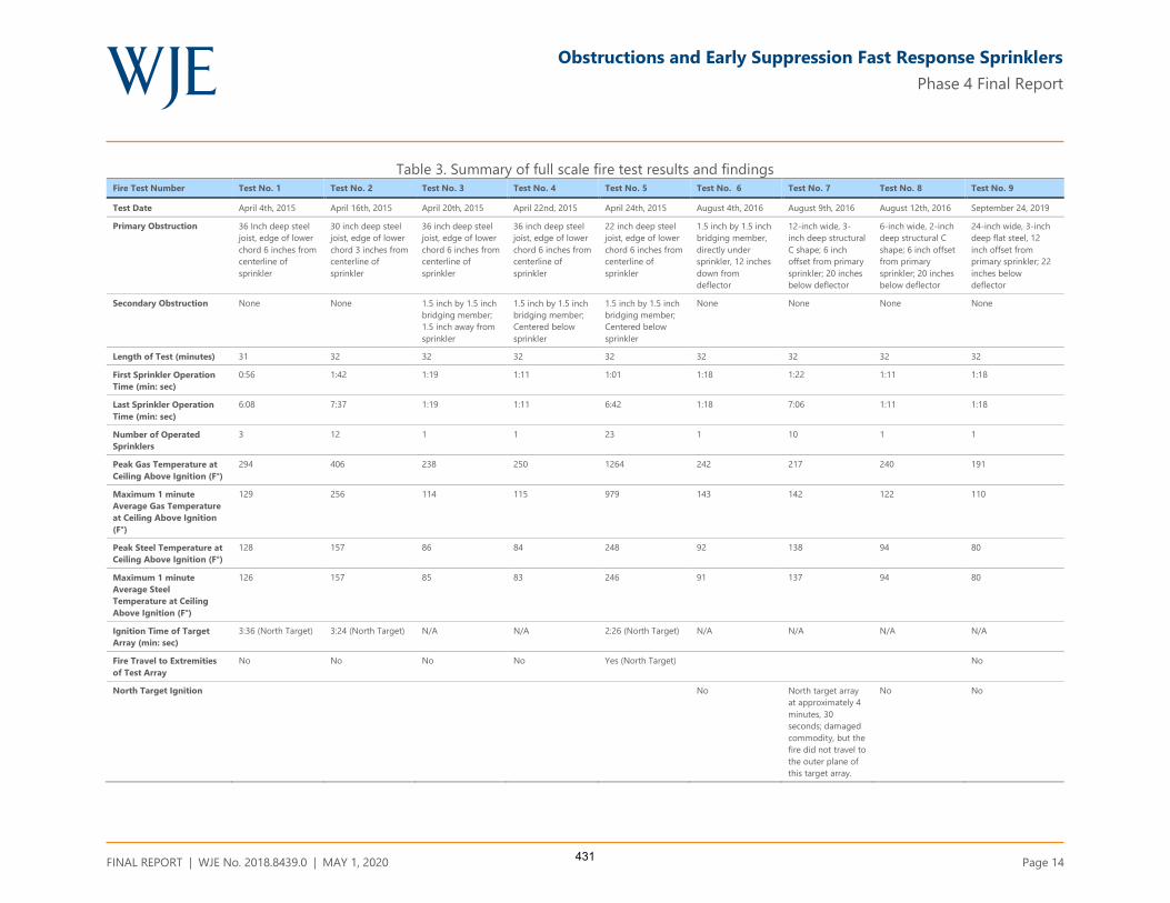
Obstructions and Early Suppression Fast Response Sprinklers
Phase 4 Final Report
FINAL REPORT | WJE No. 2018.8439.0 | MAY 1, 2020 Page 14
Table 3. Summary of full scale fire test results and findings Fire Test Number Test No. 1 Test No. 2 Test No. 3 Test No. 4 Test No. 5 Test No. 6 Test No. 7 Test No. 8 Test No. 9
Test Date April 4th, 2015 April 16th, 2015 April 20th, 2015 April 22nd, 2015 April 24th, 2015 August 4th, 2016 August 9th, 2016 August 12th, 2016 September 24, 2019
Primary Obstruction 36 Inch deep steel
joist, edge of lower
chord 6 inches from
centerline of
sprinkler
30 inch deep steel
joist, edge of lower
chord 3 inches from
centerline of
sprinkler
36 inch deep steel
joist, edge of lower
chord 6 inches from
centerline of
sprinkler
36 inch deep steel
joist, edge of lower
chord 6 inches from
centerline of
sprinkler
22 inch deep steel
joist, edge of lower
chord 6 inches from
centerline of
sprinkler
1.5 inch by 1.5 inch
bridging member,
directly under
sprinkler, 12 inches
down from
deflector
12-inch wide, 3-
inch deep structural
C shape; 6 inch
offset from primary
sprinkler; 20 inches
below deflector
6-inch wide, 2-inch
deep structural C
shape; 6 inch offset
from primary
sprinkler; 20 inches
below deflector
24-inch wide, 3-inch
deep flat steel, 12
inch offset from
primary sprinkler; 22
inches below
deflector
Secondary Obstruction None None 1.5 inch by 1.5 inch
bridging member;
1.5 inch away from
sprinkler
1.5 inch by 1.5 inch
bridging member;
Centered below
sprinkler
1.5 inch by 1.5 inch
bridging member;
Centered below
sprinkler
None None None None
Length of Test (minutes) 31 32 32 32 32 32 32 32 32
First Sprinkler Operation
Time (min: sec)
0:56 1:42 1:19 1:11 1:01 1:18 1:22 1:11 1:18
Last Sprinkler Operation
Time (min: sec)
6:08 7:37 1:19 1:11 6:42 1:18 7:06 1:11 1:18
Number of Operated
Sprinklers
3 12 1 1 23 1 10 1 1
Peak Gas Temperature at
Ceiling Above Ignition (F°)
294 406 238 250 1264 242 217 240 191
Maximum 1 minute
Average Gas Temperature
at Ceiling Above Ignition
(F°)
129 256 114 115 979 143 142 122 110
Peak Steel Temperature at
Ceiling Above Ignition (F°)
128 157 86 84 248 92 138 94 80
Maximum 1 minute
Average Steel
Temperature at Ceiling
Above Ignition (F°)
126 157 85 83 246 91 137 94 80
Ignition Time of Target
Array (min: sec)
3:36 (North Target) 3:24 (North Target) N/A N/A 2:26 (North Target) N/A N/A N/A N/A
Fire Travel to Extremities
of Test Array
No No No No Yes (North Target) No
North Target Ignition No North target array
at approximately 4
minutes, 30
seconds; damaged
commodity, but the
fire did not travel to
the outer plane of
this target array.
No No
431

Obstructions and Early Suppression Fast Response Sprinklers
Phase 4 Final Report
FINAL REPORT | WJE No. 2018.8439.0 | MAY 1, 2020 Page 15
RESULTS AND FINDINGS
The results of the ADD testing were used to identify trends in the degree of reduction of sprinkler water
flux as a function of the vertical and horizontal position of the obstruction and sprinkler orifice K factor.
These trends were used initially to select appropriate full-scale fire test scenarios and then to assist with
the determination of acceptable sprinkler obstruction placement parameters.
Three fundamental trends were discovered from the results of the ADD testing:
1. The reduction in ADD caused by an obstruction located directly below the sprinkler is increased as the
vertical distance from the obstruction to the sprinkler is decreased.
2. The reduction in ADD due to an obstruction positioned horizontally offset from the sprinkler increases
as the vertical distance away from the sprinkler increases.
3. The obstruction sensitivity of K14 and K17 ESFR sprinklers is very similar within the range that was
examined.
The first two trends can be explained by the characteristics of the ESFR sprinkler discharge pattern. The
center core of the ESFR sprinkler delivers the largest amount of water flux. For example, the largest
average unobstructed ADD for both K14 and K17 ESFR sprinklers, 1.34 gpm/ft² and 1.64 gpm/ft²
respectively, was delivered to the Central 4 pans of the ADD apparatus. This large central core water
distribution is designed to address a fire located directly below one sprinkler, with a high storage to
ceiling clearance.
The trajectory of an unobstructed sprinkler droplet may be evaluated using the balance of forces acting on
the droplet. Droplets will reach a terminal velocity when the drag force acting upward reaches a point of
equilibrium with the opposing gravitational force. As the droplet travels away from the sprinkler,
momentum decreases proportionately to velocity, and the acceleration due to gravity increasingly directs
the trajectory of the droplet towards the vertical plane.22 The resulting discharge pattern can be generally
described as parabolic.
Because of these forces, as the ESFR sprinkler discharge travels downward, the pattern expands
horizontally, drawing obstructions positioned horizontally from the sprinkler towards the center core
region (Figure 10). Obstructions located directly below the sprinkler experience the inverse. As these
obstructions move vertically away from the sprinkler the obstructed area of the center core region
decreases (Figure 11).
Figure 12 through Figure 16 present the results of the ADD testing in scatter diagram format, including
both the K14 and K17 sprinkler data. A review of the K14 sprinkler ADD data shows similar trends to that
of the K17 sprinkler. This strong correlation between K14 and K17 performance was most clearly
demonstrated in the ADD testing of the bar joist obstruction (Figure 12).
22 McGrattan, Kevin, Fire Dynamics Simulator Technical Reference Guide, 6th edition, Volume 1: Mathematical Model, Section 8
Lagrangian Particles.
432

Obstructions and Early Suppression Fast Response Sprinklers
Phase 4 Final Report
FINAL REPORT | WJE No. 2018.8439.0 | MAY 1, 2020 Page 16
Figure 10. Obstruction Located 6 inches horizontally from the sprinkler23
Figure 11. Obstruction located directly below the sprinkler24
23 Palenske, Garner A., “Obstructions and ESFR Sprinklers-Phase 3,” NFPA Research Foundation 2018
24 Ibid
433

Obstructions and Early Suppression Fast Response Sprinklers
Phase 4 Final Report
FINAL REPORT | WJE No. 2018.8439.0 | MAY 1, 2020 Page 17
Bar Joist and Bridging Member Obstructions
Full-scale Test No. 1 examined the scenario of a 36 inch deep bar joist located 6 inches horizontally from
the K17 sprinkler. The 36 inch deep bar joist, when positioned horizontally from the sprinkler, is
considered the most rigorous bar joist depth within the boundary conditions established (22 -36 inch
deep bar joist) since the bottom chord is the greatest distance below the sprinkler. This test was
successful, operating only one sprinkler and meeting all other pass/fail criteria (Table 3). Given the
similarities of the K14 and K17 ADD data (Figure 12), a similar result is expected for K14 sprinklers.
Both K14 and K17 ADD data for a bridging member located directly below a sprinkler show an increase in
ADD as the bridging member moves vertically away from the sprinkler (Figure 13). However, the K14 ADD
data shows a much greater increase in ADD as the vertical separation increases. For example, with the
bridging member located 12 inches below the sprinkler, the K14 Central 4 and Central 16 pan average
ADD decreases 80% and 53%, respectively when compared to an unobstructed condition. These decreases
are much greater than the K17 sprinkler data in which the Central 4 and Central 16 pan average ADD
decreases 14% and 6%, respectively.
Full-scale Test No. 6 investigated the scenario of a 1½ x 1½ inch bridging member located 12 inches
directly below the sprinkler. This configuration resulted in acceptable performance, opening only one K17
sprinkler and meeting the other pass/fail criteria (Table 3). The K17 ADD for this scenario was 1.17 gpm/ft²
(Central 4) and 0.79 gpm/ft² (Central 16). Using linear interpolation of the K14 ADD data, an equivalent
Central 4 ADD is found at 18 inches below the sprinkler and 14 inches below for the Central 16 ADD. The
correlation in the data demonstrates that a bridging member located directly below the sprinkler provided
with an 18 inch vertical clearance (K14) or 12 inch vertical clearance (K17), will result in similar
performance.
Full-scale Test No. 4 examined the same 36 inch deep bar joist condition as Test No. 1 with the addition of
a 1 ½ x 1½ inch bridging member attached to the top of the lower chord in a perpendicular orientation.
The bridging member was located approximately 20 inches directly below the sprinkler (36 inch deep bar
joist - 14 inch ceiling deflector clearance - 2 ½ inch chord height). Note that this bridging member to
sprinkler clearance exceeds the minimum acceptable clearance established in the previous paragraph for
bridging members located directly below K14 or K17 sprinklers. This test demonstrated acceptable
performance, activating only one K17 sprinkler and meeting the other pass/fail criteria (Table 3). The K14
ADD exceeded that of the K17 ADD for this scenario (North 4 ADD =52%, North 8 ADD = 104%), therefore
a similar result is expected for K14 sprinklers.
434

Obstructions and Early Suppression Fast Response Sprinklers
Phase 4 Final Report
FINAL REPORT | WJE No. 2018.8439.0 | MAY 1, 2020 Page 18
Figure 12. Bar joist obstruction ADD results (6 inch horizontal offset from sprinkler)
Figure 13. Bridging Member Obstruction ADD Results(Directly under sprinkler)
435
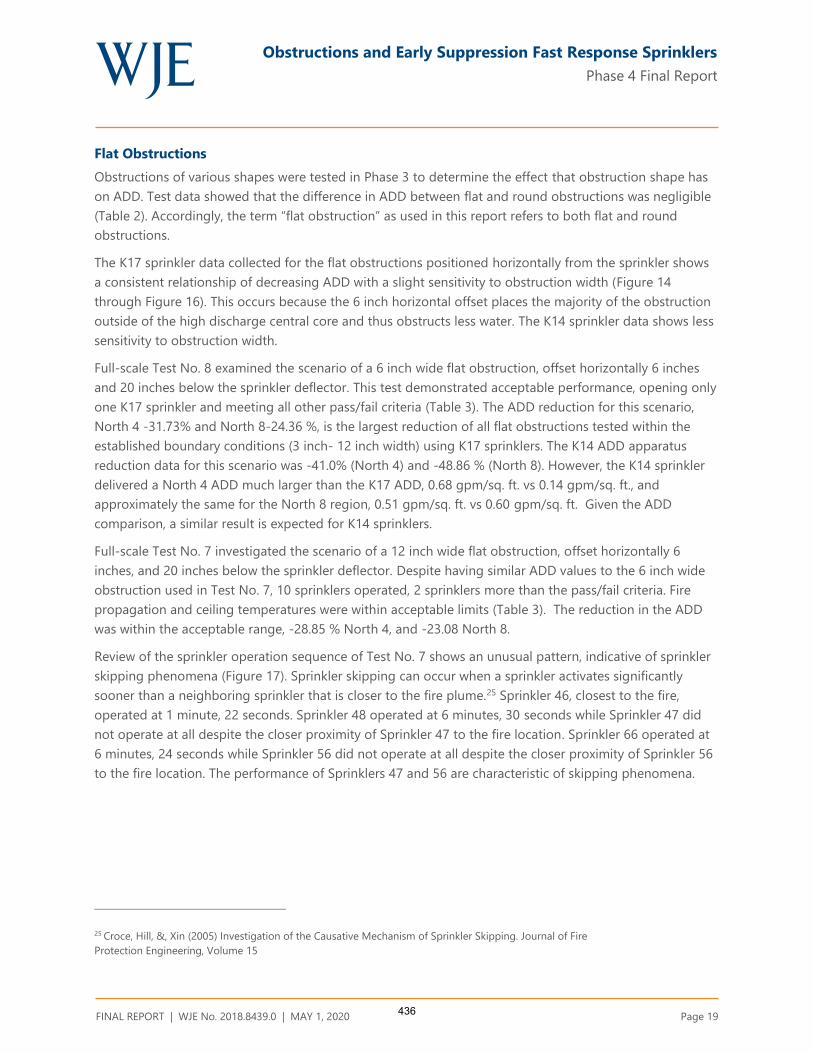
Obstructions and Early Suppression Fast Response Sprinklers
Phase 4 Final Report
FINAL REPORT | WJE No. 2018.8439.0 | MAY 1, 2020 Page 19
Flat Obstructions
Obstructions of various shapes were tested in Phase 3 to determine the effect that obstruction shape has
on ADD. Test data showed that the difference in ADD between flat and round obstructions was negligible
(Table 2). Accordingly, the term “flat obstruction” as used in this report refers to both flat and round
obstructions.
The K17 sprinkler data collected for the flat obstructions positioned horizontally from the sprinkler shows
a consistent relationship of decreasing ADD with a slight sensitivity to obstruction width (Figure 14
through Figure 16). This occurs because the 6 inch horizontal offset places the majority of the obstruction
outside of the high discharge central core and thus obstructs less water. The K14 sprinkler data shows less
sensitivity to obstruction width.
Full-scale Test No. 8 examined the scenario of a 6 inch wide flat obstruction, offset horizontally 6 inches
and 20 inches below the sprinkler deflector. This test demonstrated acceptable performance, opening only
one K17 sprinkler and meeting all other pass/fail criteria (Table 3). The ADD reduction for this scenario,
North 4 -31.73% and North 8-24.36 %, is the largest reduction of all flat obstructions tested within the
established boundary conditions (3 inch- 12 inch width) using K17 sprinklers. The K14 ADD apparatus
reduction data for this scenario was -41.0% (North 4) and -48.86 % (North 8). However, the K14 sprinkler
delivered a North 4 ADD much larger than the K17 ADD, 0.68 gpm/sq. ft. vs 0.14 gpm/sq. ft., and
approximately the same for the North 8 region, 0.51 gpm/sq. ft. vs 0.60 gpm/sq. ft. Given the ADD
comparison, a similar result is expected for K14 sprinklers.
Full-scale Test No. 7 investigated the scenario of a 12 inch wide flat obstruction, offset horizontally 6
inches, and 20 inches below the sprinkler deflector. Despite having similar ADD values to the 6 inch wide
obstruction used in Test No. 7, 10 sprinklers operated, 2 sprinklers more than the pass/fail criteria. Fire
propagation and ceiling temperatures were within acceptable limits (Table 3). The reduction in the ADD
was within the acceptable range, -28.85 % North 4, and -23.08 North 8.
Review of the sprinkler operation sequence of Test No. 7 shows an unusual pattern, indicative of sprinkler
skipping phenomena (Figure 17). Sprinkler skipping can occur when a sprinkler activates significantly
sooner than a neighboring sprinkler that is closer to the fire plume.25 Sprinkler 46, closest to the fire,
operated at 1 minute, 22 seconds. Sprinkler 48 operated at 6 minutes, 30 seconds while Sprinkler 47 did
not operate at all despite the closer proximity of Sprinkler 47 to the fire location. Sprinkler 66 operated at
6 minutes, 24 seconds while Sprinkler 56 did not operate at all despite the closer proximity of Sprinkler 56
to the fire location. The performance of Sprinklers 47 and 56 are characteristic of skipping phenomena.
25 Croce, Hill, &, Xin (2005) Investigation of the Causative Mechanism of Sprinkler Skipping. Journal of Fire
Protection Engineering, Volume 15
436
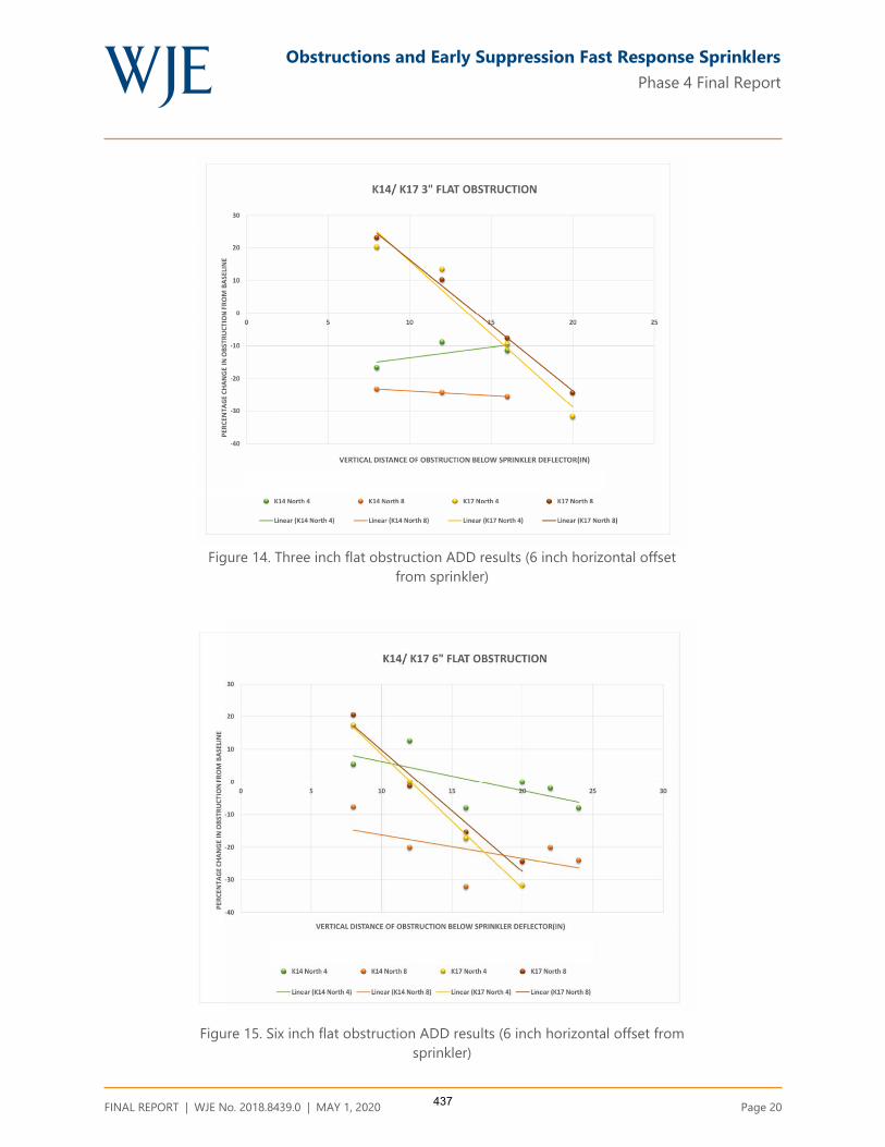
Obstructions and Early Suppression Fast Response Sprinklers
Phase 4 Final Report
FINAL REPORT | WJE No. 2018.8439.0 | MAY 1, 2020 Page 20
Figure 14. Three inch flat obstruction ADD results (6 inch horizontal offset
from sprinkler)
Figure 15. Six inch flat obstruction ADD results (6 inch horizontal offset from
sprinkler)
437

Obstructions and Early Suppression Fast Response Sprinklers
Phase 4 Final Report
FINAL REPORT | WJE No. 2018.8439.0 | MAY 1, 2020 Page 21
Figure 16. Twelve inch flat obstruction ADD results (6 inch horizontal offset from
sprinkler)
438

Obstructions and Early Suppression Fast Response Sprinklers
Phase 4 Final Report
FINAL REPORT | WJE No. 2018.8439.0 | MAY 1, 2020 Page 22
Figure 17. Test No. 7 sprinkler operation sequence26
Skipping can reduce the amount of water flux delivered to the fire and, therefore, the ability of the
sprinklers to achieve suppression. Skipping is thought to be caused by the impingement of entrained and
diverted droplets from previously operated sprinklers.27 It is reasonable to suggest that the introduction of
an obstruction would cause sprinkler skipping as the amount of diverted water droplets would be altered
in a manner uncharacteristic of an unobstructed condition. Obstructions located in the near field of an
operating sprinkler can redirect or change the characteristics of the water droplets such that the droplets
are unable to penetrate the fire plume. These smaller and slower moving droplets are more likely to be
entrained and directed towards an adjacent sprinkler.
26 Steppan, Daniel R. Underwriters Laboratories “Actual Delivered Density (ADD) Tests of ESFR Sprinklers Obstructed by Open Web
Steel Bar Joists, Bridging Members, and Flat Geometries” 2019
27 Croce, Hill, &, Xin (2005) Investigation of the Causative Mechanism of Sprinkler Skipping. Journal of Fire
Protection Engineering, Volume 15
439

Obstructions and Early Suppression Fast Response Sprinklers
Phase 4 Final Report
FINAL REPORT | WJE No. 2018.8439.0 | MAY 1, 2020 Page 23
The increased width of the 12-inch flat obstruction compared to the 6-inch flat obstruction (Test No. 8)
would cause a greater amount of droplet disruption and, therefore, a greater propensity for sprinkler
skipping. Review of the video from Test No. 7 did show a greater amount of ceiling water vapor present
compared that shown in Test No. 8.
The performance of Test No. 7 met two of the three acceptable performance criteria; the fire damaged
stayed within the main array and did not burn to the back of the target array, and the ceiling temperatures
were within the acceptable range. A comparison of the main array damage in Test Nos. 7 and 8 indicates
more damage in Test No. 7, but still within an acceptable level.
The operation of 10 sprinklers in lieu of 8 complicates the categorization of the outcome of Test No. 7.
Historically, safety factors up to 2.0 have been used for sprinkler operation in full scale fire testing. 28
Typically, a 1.5 safety factor is included in the pass/fail criteria for ESFR sprinkler fire testing.29 However,
review of ESFR sprinkler approval standards shows a wide range of permissible number of operating
sprinklers. For example, UL 1767A, “Outline for Investigation for ESFR Sprinklers Having K- Factors Greater
than 14.0,” defines the acceptable number as 6 to 9 sprinklers (K22 or K25) depending on the test
specifications. FM Global “Approval Standard for ESFR Sprinklers, Class Series 2008,” defines acceptable
performance for sprinklers as the operation of 8 to 12 sprinklers (K22 or K25). Neither UL nor FM Global
approval standards require full-scale fire testing of K14 or K17 ESFR sprinklers due to their legacy
performance and comparable performance.
It is also important to note that the acceptable number of operating sprinklers applies when the sprinklers
operate in a proper sequence. All of the first ring sprinklers should operate within a few seconds before
any second or third ring sprinklers. When a different operating sequence occurs, additional sprinklers may
operate, and early suppression may still be achieved when the other pass/fail criteria are met.30As shown
in Figure 17, 5 of the 9 first ring sprinklers and 5 of 25 second ring sprinklers activated. The increased
number of sprinklers that activated in Test No. 7 is likely attributed to the sequence of sprinkler operation
caused by the skipping phenomenon previously discussed.
The scenario of non-operational sprinklers was considered in the testing protocol used in the early
development of the ESFR sprinkler. In these tests, one sprinkler located in the first ring was rendered
inoperable to simulate a plugged sprinkler.31 Current FM Global Approval Standard FM 2008, “Approval
for Quick Response Storage Sprinklers for Fire Protection”, includes the plugged sprinkler scenario in the
testing protocol for upright ESFR sprinklers.
Considering this background information, it is reasonable to conclude the results of Test No. 7
demonstrated that, despite the very rigorous condition of two inoperable or plugged sprinklers, the
sprinklers suppressed the fire and therefore, the test meets the pass/fail criteria.
28 National Fire Protection Association “Automatic Sprinkler Systems Handbook” 2016 Edition, Section 21.1.8 text and commentary
29 Ibid
30 Chicarello, Troup and Dean. “The National Quick Response Sprinkler Research Project: Large Scale Fire Test Evaluation of ESFR
Automatic Sprinklers,” Fire Protection Research Foundation Report, May 1986.
31 Yao, C. “The Development of the ESFR Sprinkler System”, Fire Safety Journal, 14, 66-73,1988
440

Obstructions and Early Suppression Fast Response Sprinklers
Phase 4 Final Report
FINAL REPORT | WJE No. 2018.8439.0 | MAY 1, 2020 Page 24
Full-scale Test No. 9 investigated the scenario of a 24 inch wide flat obstruction, offset horizontally 12
inches, and 22 inches below the K17 sprinkler deflector (Figure 18 and Figure 19). ADD testing was not
completed for this scenario. This scenario was selected to address obstructions such as lights or flat cable
trays.
The 12 inch horizontal offset positioned the obstruction within the region where approximately 10% of the
ESFR sprinkler discharge occurs. The vertical position, 22 inches below the sprinkler, was considered the
worst case location given the findings of the ADD testing of other flat obstructions.
This arrangement resulted in the operation of one sprinkler. Fire propagation and ceiling temperatures
were within acceptable limits; therefore, the results of the test met the pass/fail criteria (Table 3).
Figure 18. Test No. 9 - 24 inch flat obstruction placement details32
32 Steppan, Daniel R. Underwriters Laboratories “Actual Delivered Density (ADD) Tests of ESFR Sprinklers Obstructed by Open Web
Steel Bar Joists, Bridging Members, and Flat Geometries” 2019
441

Obstructions and Early Suppression Fast Response Sprinklers
Phase 4 Final Report
FINAL REPORT | WJE No. 2018.8439.0 | MAY 1, 2020 Page 25
Figure 19. Test No. 9 - 24 inch flat obstruction plan view33
The sprinkler discharge formed excessive sheeting which traveled over the obstruction edge onto the top
of the commodity and then downward along the face of the rack. The wetting of the ignition array face
contributed to the suppression of the fire. Similar behavior was noted in the other flat obstruction tests.
The magnitude of the sheeting in Test No. 9 with a 24 inch obstruction, however, was much larger
(Figure 20 through Figure 23). This is the result of the increased width of the 24 inch obstruction. The
magnitude of the shadow created by a flat obstruction increased proportionately as the width of the
obstruction was increased between a 6 in., 12 in., and 24 in. obstruction. The increased area per unit
length of the 24 inch obstruction created a greater disruption in the sprinkler water flow and thus diverted
a larger amount of water onto and over the edge of the obstruction.
33 Ibid
442
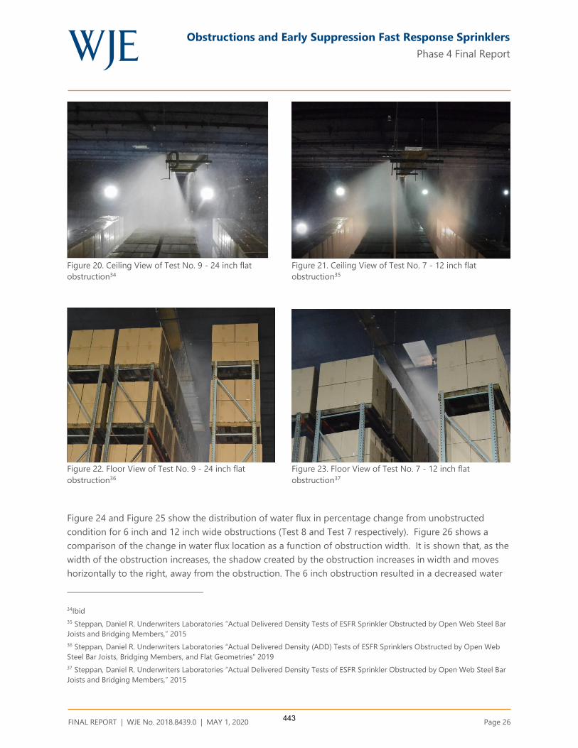
Obstructions and Early Suppression Fast Response Sprinklers
Phase 4 Final Report
FINAL REPORT | WJE No. 2018.8439.0 | MAY 1, 2020 Page 26
Figure 20. Ceiling View of Test No. 9 - 24 inch flat
obstruction34
Figure 21. Ceiling View of Test No. 7 - 12 inch flat
obstruction35
Figure 22. Floor View of Test No. 9 - 24 inch flat
obstruction36
Figure 23. Floor View of Test No. 7 - 12 inch flat
obstruction37
Figure 24 and Figure 25 show the distribution of water flux in percentage change from unobstructed
condition for 6 inch and 12 inch wide obstructions (Test 8 and Test 7 respectively). Figure 26 shows a
comparison of the change in water flux location as a function of obstruction width. It is shown that, as the
width of the obstruction increases, the shadow created by the obstruction increases in width and moves
horizontally to the right, away from the obstruction. The 6 inch obstruction resulted in a decreased water
34Ibid
35 Steppan, Daniel R. Underwriters Laboratories “Actual Delivered Density Tests of ESFR Sprinkler Obstructed by Open Web Steel Bar
Joists and Bridging Members,” 2015
36 Steppan, Daniel R. Underwriters Laboratories “Actual Delivered Density (ADD) Tests of ESFR Sprinklers Obstructed by Open Web
Steel Bar Joists, Bridging Members, and Flat Geometries” 2019
37 Steppan, Daniel R. Underwriters Laboratories “Actual Delivered Density Tests of ESFR Sprinkler Obstructed by Open Web Steel Bar
Joists and Bridging Members,” 2015
443

Obstructions and Early Suppression Fast Response Sprinklers
Phase 4 Final Report
FINAL REPORT | WJE No. 2018.8439.0 | MAY 1, 2020 Page 27
flux only in the region along the north face of the ignition array. The 12 inch obstruction resulted in
decreased water flux in the same region and in the region within the first row of collection pans inside the
north aisle. Extending this relationship to the 24 inch flat obstruction, the shadow is predicted to extend
into the north aisle, an area not critical to sprinkler performance (Figure 27).
As discussed earlier, the 24 inch obstruction is located completely in the lower water flow region, which
accounts for only approximately 10% of the sprinkler flow. Obstructions in this region are generally
considered to have minimal effect on sprinkler performance.
The water sheeting behavior which occurred could be perceived as a factor which dilutes the analysis of
outcome of the fire test. However, intentional or not, obstructions 6 inches or wider create this behavior
which can improve sprinkler performance.
Based upon this analysis, it was concluded that the fire test would have been successful with or without
the presence of excessive sheeting.
444
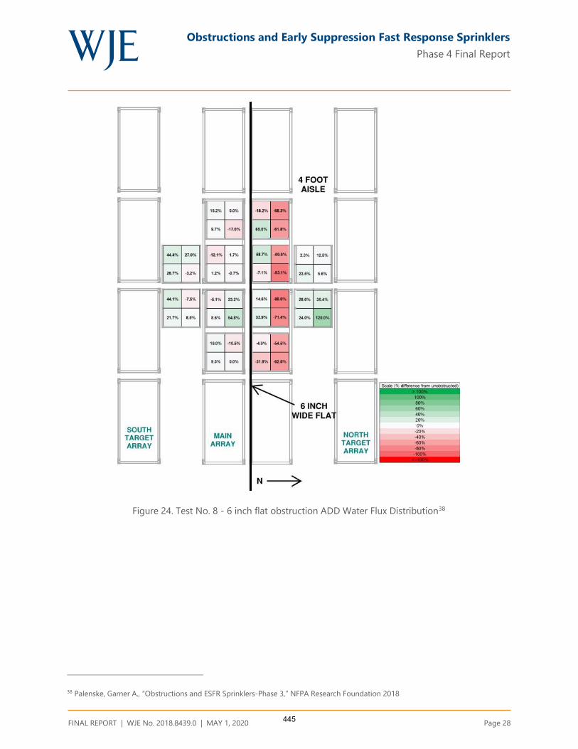
Obstructions and Early Suppression Fast Response Sprinklers
Phase 4 Final Report
FINAL REPORT | WJE No. 2018.8439.0 | MAY 1, 2020 Page 28
Figure 24. Test No. 8 - 6 inch flat obstruction ADD Water Flux Distribution38
38 Palenske, Garner A., “Obstructions and ESFR Sprinklers-Phase 3,” NFPA Research Foundation 2018
445

Obstructions and Early Suppression Fast Response Sprinklers
Phase 4 Final Report
FINAL REPORT | WJE No. 2018.8439.0 | MAY 1, 2020 Page 29
Figure 25. Test No. 8 - 12 inch flat obstruction ADD Water Flux Distribution39
39 Ibid
446

Obstructions and Early Suppression Fast Response Sprinklers
Phase 4 Final Report
FINAL REPORT | WJE No. 2018.8439.0 | MAY 1, 2020 Page 30
Figure 26. Test No. 8 and Test No. 7- ADD Water Flux Distribution Comparison40
40 Ibid
447
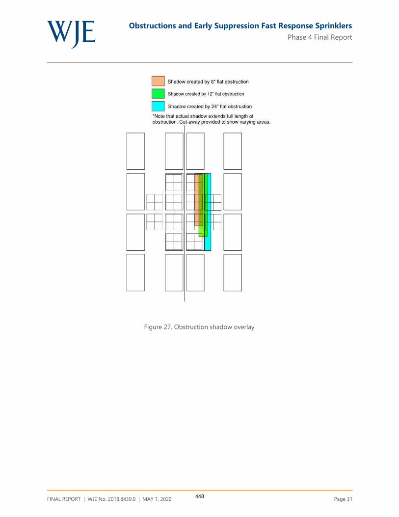
Obstructions and Early Suppression Fast Response Sprinklers
Phase 4 Final Report
FINAL REPORT | WJE No. 2018.8439.0 | MAY 1, 2020 Page 31
Figure 27. Obstruction shadow overlay
448
Obstructions and Early Suppression Fast Response Sprinklers
Phase 4 Final Report
FINAL REPORT | WJE No. 2018.8439.0 | MAY 1, 2020 Page 32
CONCLUSIONS
The ESFR Obstruction Project has made significant advancements in understanding of the effects
obstructions have on ESFR sprinkler performance. Both K14 and K17 ESFR sprinkler behavior was
investigated. Significant findings of this work are summarized as follows:
The obstruction created by an open web steel truss between the depths of 22 - 36 inches, located 6
inches horizontally from a K14 or K17 ESFR sprinkler should not significantly decrease sprinkler
performance.
The obstruction created by a bridging member 1½ x 1½ inches in size or less, located directly below
the sprinkler with an 18 inch vertical clearance (K14) or 12 inch vertical clearance (K17) does not
significantly decrease sprinkler performance. This applies to bridging members attached to open web
steel trusses.
The obstruction created by flat or round obstructions less than or equal to 12 inches in width located 6
inches horizontally from a K17 or K14 sprinkler should not significantly decrease sprinkler
performance.
The obstruction created by flat or round obstructions less than or equal to 24 inches in width located
12 inches horizontally from a K17 or K14 sprinkler should not significantly decrease sprinkler
performance.
ACKNOWLEDGEMENTS
The authors wish to thank the many people who assisted with this project. The project would not have
succeeded without their help. Special thanks to the Fire Protection Research Foundation, Project Technical
Panel, Project Sponsors, and other industry colleagues for their support and encouragement.
Garner A. Palenske, P.E.
Associate Principal
Garth N. Ornelas, P.E.
Associate
449

Obstructions and Early Suppression Fast Response Sprinklers
Phase 4 Final Report
FINAL REPORT | WJE No. 2018.8439.0 | MAY 1, 2020
APPENDIX A. ACTUAL DELIVERED DENSITY TESTING OF ESFR SPRINKLERS OBSTRUCTED BY
FLAT OBSTRUCTIONS (PHASE 4), UNDERWRITERS LABORATORIES, APRIL 26, 2019
450

ACTUAL DELIVERED DENSITY (ADD) TESTS
OF ESFR SPRINKLERS OBSTRUCTED BY
OPEN WEB STEEL BAR JOISTS, BRIDGING
MEMBERS and FLAT GEOMETRIES
Prepared by
UL LLC
Project 4788895562, NC5756
for the
Fire Protection Research Foundation
Issued: April 26, 2019
Copyright © 2019 UL LLC
451

Issued: April 26, 2019
i
Executive Summary
This report describes twenty (20) Actual Delivered Density (ADD) tests that were conducted to
develop data relative to the level of fire performance provided by a K = 14.0 and a K = 16.8 ESFR
sprinkler when the sprinklers are located closer to an obstruction than currently referenced in the
Standard for the Installation of Sprinkler Systems, NFPA 13-2019. For this test series, the
sprinklers were located in close proximity to open web ceiling steel bar joists, a steel bridging
member and flat obstructions.
The ADD apparatus consists of a fire source and a set of water collection pans. A drawing of the
top and side views of the apparatus are shown in Figure E-1. The main components of the apparatus
are 48 water collection pans and 12 heptane nozzles. The 48 water collection pans are
approximately 20 in. by 20 in. and are separated into groups of four. A group of four collection
pans, i.e., a 2x2 array, simulates the top surface of one pallet load of stored commodity. Eight
groups of four are placed in the main array, while two satellite arrays each consist of two groups of
four. The two satellite collector arrays were placed adjacent to the main array to investigate pre-
wetting characteristics. A 6 in. flue space was maintained between two adjacent simulated
commodities.
452
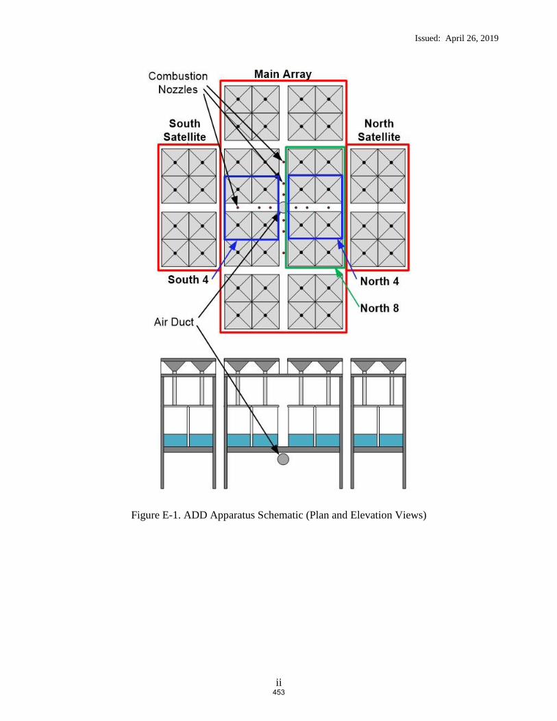
Issued: April 26, 2019
ii
Figure E-1. ADD Apparatus Schematic (Plan and Elevation Views)
453
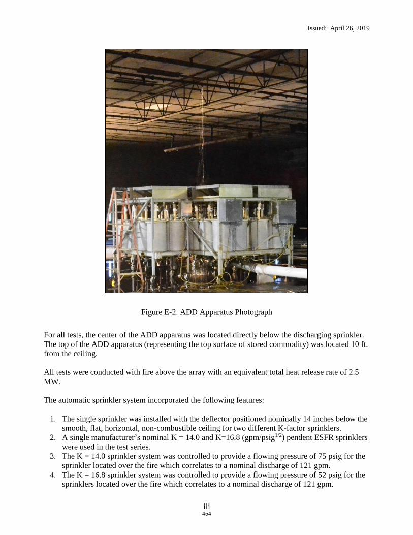
Issued: April 26, 2019
iii
Figure E-2. ADD Apparatus Photograph
For all tests, the center of the ADD apparatus was located directly below the discharging sprinkler.
The top of the ADD apparatus (representing the top surface of stored commodity) was located 10 ft.
from the ceiling.
All tests were conducted with fire above the array with an equivalent total heat release rate of 2.5
MW.
The automatic sprinkler system incorporated the following features:
1. The single sprinkler was installed with the deflector positioned nominally 14 inches below the
smooth, flat, horizontal, non-combustible ceiling for two different K-factor sprinklers.
2. A single manufacturer’s nominal K = 14.0 and K=16.8 (gpm/psig1/2) pendent ESFR sprinklers
were used in the test series.
3. The K = 14.0 sprinkler system was controlled to provide a flowing pressure of 75 psig for the
sprinkler located over the fire which correlates to a nominal discharge of 121 gpm.
4. The K = 16.8 sprinkler system was controlled to provide a flowing pressure of 52 psig for the
sprinklers located over the fire which correlates to a nominal discharge of 121 gpm.
454

Issued: April 26, 2019
iv
Tests were conducted using three primary obstructions as follows:
Steel Bar Joists: 22, 30 and 36 inch deep, commercially available steel bar joists were used in
tests 3, 4 and 5.
Flat Obstructions: Tests were conducted using 3, 6 and 12 inch wide, commercial steel
structural “C” shapes for the flat obstructions. These were used in tests 6 through 14 and 17
through 20.
Bridging Member: A 1-1/2 by 1-1/2 inch “L” shaped steel member was used to simulate a
bridging member positioned parallel to the sprinkler’s branchline. This was used in tests 2, 15 and
16.
Lateral and vertical distances of these ceiling structural members to the obstructed sprinkler were
investigated as outlined in Table E1:
Table E 1 Test Obstruction Clearance
Test
Number Obstruction Used
Pendent ESFR
Sprinkler Used,
K - gpm/psig0.5
Vertical Distance
of Obstruction
Below Sprinkler
Deflector
Horizontal Distance
from Centerline of
Sprinkler to Nearest
Vertical Edge of
Obstruction
1 None (baseline) 14.0 N/A N/A
2 1-1/2 inch by 1-1/2 inch
bridging member 14.0 12 in. 6 in.
3 22 inch deep bar joist 14.0 8 in. 6 in.
4 30 inch deep bar joist 14.0 16 in. 6 in.
5 36 inch deep bar joist 14.0 22 in. 6 in.
6 3 inch flat 14.0 8 in. 6 in.
7 3 inch flat 14.0 12 in. 6 in.
8 3 inch flat 14.0 16 in. 6 in.
9 6 inch flat 14.0 8 in. 6 in.
10 6 inch flat 14.0 12 in. 6 in.
11 6 inch flat 14.0 16 in. 6 in.
12 6 inch flat 14.0 20 in. 6 in.
13 6 inch flat 14.0 22 in. 6 in.
14 6 inch flat 14.0 24 in. 6 in.
15 1-1/2 inch by 1-1/2 inch
bridging member 14.0 14 in. 0 in.
16 1-1/2 inch by 1-1/2 inch
bridging member 14.0 20 in. 0 in.
17 12 inch flat 14.0 16 in. 6 in.
18 12 inch flat 14.0 20 in. 6 in.
19 12 inch flat 16.8 8 in. 6 in.
20 12 inch flat 16.8 12 in. 6 in. N/A – Not applicable
455

Issued: April 26, 2019
v
A summary of the test parameters and results are provided in Table E-2. Refer to Figure E-1 for
pan data references.
456
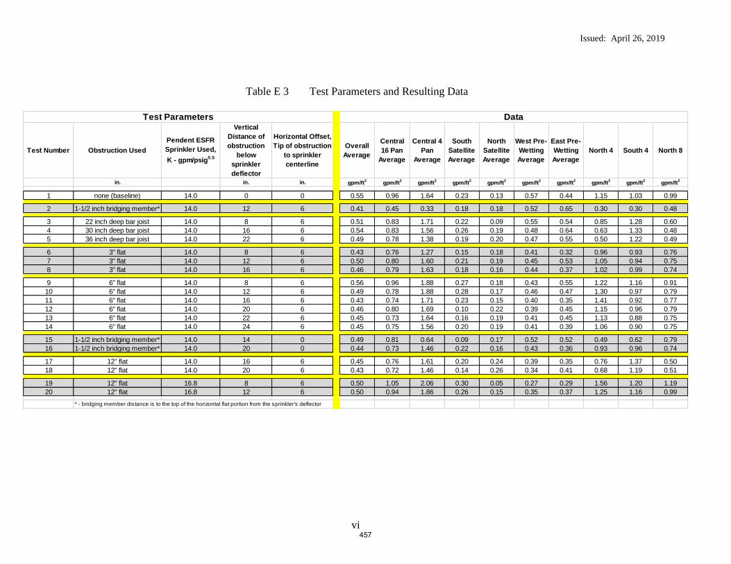
Issued: April 26, 2019
vi
Table E 3 Test Parameters and Resulting Data
Test Number Obstruction UsedPendent ESFR Sprinkler Used, K - gpm/psig0.5
Vertical Distance of obstruction
below sprinkler deflector
Horizontal Offset, Tip of obstruction
to sprinkler centerline
Overall Average
Central 16 Pan
Average
Central 4 Pan
Average
South Satellite Average
North Satellite Average
West Pre-Wetting Average
East Pre-Wetting Average
North 4 South 4 North 8
in. in. in. gpm/ft2 gpm/ft2 gpm/ft2 gpm/ft2 gpm/ft2 gpm/ft2 gpm/ft2 gpm/ft2 gpm/ft2 gpm/ft2
1 none (baseline) 14.0 0 0 0.55 0.96 1.64 0.23 0.13 0.57 0.44 1.15 1.03 0.99
2 1-1/2 inch bridging member* 14.0 12 6 0.41 0.45 0.33 0.18 0.18 0.52 0.65 0.30 0.30 0.48
3 22 inch deep bar joist 14.0 8 6 0.51 0.83 1.71 0.22 0.09 0.55 0.54 0.85 1.28 0.604 30 inch deep bar joist 14.0 16 6 0.54 0.83 1.56 0.26 0.19 0.48 0.64 0.63 1.33 0.485 36 inch deep bar joist 14.0 22 6 0.49 0.78 1.38 0.19 0.20 0.47 0.55 0.50 1.22 0.49
6 3" flat 14.0 8 6 0.43 0.76 1.27 0.15 0.18 0.41 0.32 0.96 0.93 0.767 3" flat 14.0 12 6 0.50 0.80 1.60 0.21 0.19 0.45 0.53 1.05 0.94 0.758 3" flat 14.0 16 6 0.46 0.79 1.63 0.18 0.16 0.44 0.37 1.02 0.99 0.74
9 6" flat 14.0 8 6 0.56 0.96 1.88 0.27 0.18 0.43 0.55 1.22 1.16 0.9110 6" flat 14.0 12 6 0.49 0.78 1.88 0.28 0.17 0.46 0.47 1.30 0.97 0.7911 6" flat 14.0 16 6 0.43 0.74 1.71 0.23 0.15 0.40 0.35 1.41 0.92 0.7712 6" flat 14.0 20 6 0.46 0.80 1.69 0.10 0.22 0.39 0.45 1.15 0.96 0.7913 6" flat 14.0 22 6 0.45 0.73 1.64 0.16 0.19 0.41 0.45 1.13 0.88 0.7514 6" flat 14.0 24 6 0.45 0.75 1.56 0.20 0.19 0.41 0.39 1.06 0.90 0.75
15 1-1/2 inch bridging member* 14.0 14 0 0.49 0.81 0.64 0.09 0.17 0.52 0.52 0.49 0.62 0.7916 1-1/2 inch bridging member* 14.0 20 0 0.44 0.73 1.46 0.22 0.16 0.43 0.36 0.93 0.96 0.74
17 12" flat 14.0 16 6 0.45 0.76 1.61 0.20 0.24 0.39 0.35 0.76 1.37 0.5018 12" flat 14.0 20 6 0.43 0.72 1.46 0.14 0.26 0.34 0.41 0.68 1.19 0.51
19 12" flat 16.8 8 6 0.50 1.05 2.06 0.30 0.05 0.27 0.29 1.56 1.20 1.1920 12" flat 16.8 12 6 0.50 0.94 1.86 0.26 0.15 0.35 0.37 1.25 1.16 0.99
* - bridging member distance is to the top of the horizontal flat portion from the sprinkler's deflector
Test Parameters Data
457

Issued: April 26, 2019
vii
Table of Contents
1. INTRODUCTION ............................................................................................... 1
2. TEST FACILITY ................................................................................................ 1
2.1 LARGE-SCALE FIRE TEST BUILDING ................................................................................................................... 1 2.2 LARGE-SCALE FIRE TEST FACILITY .................................................................................................................... 2
3. EQUIPMENT ...................................................................................................... 3
3.1 ACTUAL DELIVERED DENSITY APPARATUS ........................................................................................................ 3 3.2 AUTOMATIC SPRINKLER SYSTEM ........................................................................................................................ 6 3.3 OBSTRUCTIONS ................................................................................................................................................... 7
3.3.1 Steel Bar Joists (Tests 3 – 5) ....................................................................................................................... 7 3.3.2 Flat Obstructions (Tests 6-14 and 17-18) .................................................................................................. 8 3.3.3 Bridging Member (Test 2, 15 and 16) ......................................................................................................... 8
4. TEST ARRAY CONFIGURATION ............................................................... 18
4.1 ADD ARRANGEMENT PLAN VIEW .....................................................................................................................18 4.2 ADD ARRANGEMENT ELEVATION VIEW AND CLEARANCE ................................................................................18
5. TEST METHOD ................................................................................................ 21
5.1 TEST PROCEDURE ...............................................................................................................................................21
6. RESULTS AND DISCUSSION ........................................................................ 22
7. SUMMARY ........................................................................................................ 24
Table of Figures
FIGURE 1 TEST FACILITY .............................................................................................................................. 2 FIGURE 2 ADD APPARATUS SCHEMATIC ..................................................................................................... 4 FIGURE 3 ADD APPARATUS PHOTOGRAPH (SHOWING FIRE BEFORE SPRINKLER DISCHARGE) .................... 5 FIGURE 4 ADD PAN NUMBERING SYSTEM ................................................................................................... 6 FIGURE 5 FLAT OBSTRUCTION DIMENSIONAL KEY ...................................................................................... 8 FIGURE 6 22 INCH DEEP JOIST DETAIL – ELEVATION VIEW (PRIOR TO CUTTING TO 30 FT. LENGTH) .......... 9 FIGURE 7 30 INCH DEEP JOIST DETAIL – ELEVATION VIEW (PRIOR TO CUTTING TO 30 FT. LENGTH) .......... 9 FIGURE 8 36 INCH DEEP JOIST DETAIL – ELEVATION VIEW (PRIOR TO CUTTING TO 30 FT. LENGTH) .......... 9 FIGURE 9 JOIST CROSS SECTION DETAIL – CLOSE UP ELEVATION VIEW .................................................. 10 FIGURE 10 TEST 3 ARRANGEMENT – ELEVATION VIEW (AS SHOWN) .......................................................... 11 FIGURE 11 TEST 4 ARRANGEMENT – ELEVATION VIEW (AS SHOWN) .......................................................... 12 FIGURE 12 TEST 5 ARRANGEMENT – ELEVATION VIEW (AS SHOWN) .......................................................... 13 FIGURE 13 3 INCH FLAT OBSTRUCTION; TEST 6, 7 AND 8 ARRANGEMENT – ELEVATION VIEW FROM EAST
14 FIGURE 14 6 INCH FLAT OBSTRUCTION; TEST 9 THROUGH 14 ARRANGEMENT – ELEVATION VIEW FROM
EAST 15 FIGURE 15 12 INCH FLAT OBSTRUCTION; TEST 17 AND 18 ARRANGEMENT – ELEVATION VIEW FROM EAST
16 FIGURE 16 1-1/2 INCH BRIDGING MEMBER OBSTRUCTION: TEST 2, 15 AND 16 ARRANGEMENT –
ELEVATION VIEW FROM EAST (TEST 2 SHOWN) ..................................................................................... 17 FIGURE 17 ADD APPARATUS – VIEW FROM EAST (TEST 4 SHOWN) ............................................................ 19 FIGURE 18 ADD APPARATUS – VIEW FROM NORTH (TEST 4 SHOWN) ......................................................... 19 FIGURE 19 TEST ARRAY PLAN VIEW - TEST SERIES .................................................................................... 20
458

Issued: April 26, 2019
viii
Tables
TABLE 1 OBSTRUCTION DETAILS ................................................................................................................ 7 TABLE 2 OBSTRUCTION DETAILS (REFER TO FIGURE 5) ............................................................................. 8 TABLE 3 TEST SERIES SUMMARY .............................................................................................................. 23
Appendix A – Raw and Summarized Data
Appendix A
FIGURE A- 1 TEST 1 – RESULTS (3D GRAPHIC–VIEW FROM NORTHEAST OF CENTRAL MAIN ARRAY ONLY) .. 2 FIGURE A- 2 TEST 2 – RESULTS (3D GRAPHIC–VIEW FROM NORTHEAST OF CENTRAL MAIN ARRAY ONLY) .. 3 FIGURE A- 3 TEST 3 – RESULTS (3D GRAPHIC–VIEW FROM NORTHEAST OF CENTRAL MAIN ARRAY ONLY) .. 4 FIGURE A- 4 TEST 4 – RESULTS (3D GRAPHIC–VIEW FROM NORTHEAST OF CENTRAL MAIN ARRAY ONLY) .. 5 FIGURE A- 5 TEST 5 – RESULTS (3D GRAPHIC–VIEW FROM NORTHEAST OF CENTRAL MAIN ARRAY ONLY) .. 6 FIGURE A- 6 TEST 6 – RESULTS (3D GRAPHIC–VIEW FROM NORTHEAST OF CENTRAL MAIN ARRAY ONLY) .. 7 FIGURE A- 7 TEST 7 – RESULTS (3D GRAPHIC–VIEW FROM NORTHEAST OF CENTRAL MAIN ARRAY ONLY) .. 8 FIGURE A- 8 TEST 8 – RESULTS (3D GRAPHIC–VIEW FROM NORTHEAST OF CENTRAL MAIN ARRAY ONLY) .. 9 FIGURE A- 9 TEST 9 – RESULTS (3D GRAPHIC–VIEW FROM NORTHEAST OF CENTRAL MAIN ARRAY ONLY) 10 FIGURE A- 10 TEST 10 – RESULTS (3D GRAPHIC–VIEW FROM NORTHEAST OF CENTRAL MAIN ARRAY ONLY) 11 FIGURE A- 11 TEST 11 – RESULTS (3D GRAPHIC–VIEW FROM NORTHEAST OF CENTRAL MAIN ARRAY ONLY) 12 FIGURE A- 12 TEST 12 – RESULTS (3D GRAPHIC–VIEW FROM NORTHEAST OF CENTRAL MAIN ARRAY ONLY) 13 FIGURE A- 13 TEST 13 – RESULTS (3D GRAPHIC–VIEW FROM NORTHEAST OF CENTRAL MAIN ARRAY ONLY) 14 FIGURE A- 14 TEST 14 – RESULTS (3D GRAPHIC–VIEW FROM NORTHEAST OF CENTRAL MAIN ARRAY ONLY) 15 FIGURE A- 15 TEST 15 – RESULTS (3D GRAPHIC–VIEW FROM NORTHEAST OF CENTRAL MAIN ARRAY ONLY) 16 FIGURE A- 16 TEST 16 – RESULTS (3D GRAPHIC–VIEW FROM NORTHEAST OF CENTRAL MAIN ARRAY ONLY) 17 FIGURE A- 17 TEST 17 – RESULTS (3D GRAPHIC–VIEW FROM NORTHEAST OF CENTRAL MAIN ARRAY ONLY) 18 FIGURE A- 18 TEST 18 – RESULTS (3D GRAPHIC–VIEW FROM NORTHEAST OF CENTRAL MAIN ARRAY ONLY) 19 FIGURE A- 19 TEST 19 – RESULTS (3D GRAPHIC–VIEW FROM NORTHEAST OF CENTRAL MAIN ARRAY ONLY) 20 FIGURE A- 20 TEST 20 – RESULTS (3D GRAPHIC–VIEW FROM NORTHEAST OF CENTRAL MAIN ARRAY ONLY) 21
459

Issued: April 26, 2019
ix
Abbreviations
°C degrees Centigrade
°F degrees Fahrenheit
psig unit of pressure; pounds per square inch gauge
gpm gallons per minute
ft. foot
in. inch
mm millimeter
cm centimeter
m meter
RTI Response time index
UL Underwriters Laboratories Inc.
Lbm Pounds mass
dno Did not operate
460
Issued: April 26, 2019
1 of 25
1. INTRODUCTION
This report describes a Verification Services Investigation conducted for the Fire Protection
Research Foundation, in accordance with the test method described herein.
The sole purpose of this Verification Services Investigation was to study the effects of specific
ceiling obstructions on both a K = 14.0 and a K = 16.8 gpm/psig0.5 pendent ESFR fire sprinkler
when subjected to a 2.5 MW fire above an Actual Delivered Density (ADD) apparatus.
The information developed from this investigation is provided to the Fire Protection Research
Foundation for their use in determining the effectiveness of the tested sprinkler system and
applied flowing pressures versus heat release rate and obstruction configuration investigated.
In no event shall UL LLC be responsible to anyone for whatever use or nonuse is made of the
information contained in this Report and in no event shall UL LLC, its employees or its agents
incur any obligations or liability for damages, including, but not limited to, consequential
damage, arising out of or in connection with the use or inability to use the information contained
in this report.
Investigations normally conducted by UL LLC involve Classification, Listing or Recognition
and Follow-Up Services of proprietary products. However, UL LLC does conduct investigations
without Classification, Listing or Recognition and Follow-Up Service when a need for test data
in the interest of public safety has been indicated. Such investigations do not result in specific
conclusions, nor any form of Recognition, Listing or Classification of the products involved. It
is on this basis that UL LLC undertook the Verification Services Investigation reported herein.
2. TEST FACILITY
The fire tests were conducted at Underwriters Laboratories large-scale fire test facility located in
Northbrook, Illinois.
2.1 Large-Scale Fire Test Building
The large-scale fire test building used for this investigation houses four fire test areas that are
used to develop data on the fire growth and fire suppression characteristics of commodities, as
well as the fire suppression characteristics of automatic water sprinkler systems. A schematic of
the test facility is shown in Figure 1.
461
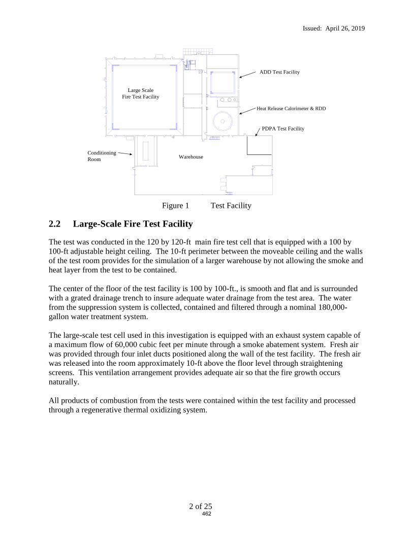
Issued: April 26, 2019
2 of 25
Figure 1 Test Facility
2.2 Large-Scale Fire Test Facility
The test was conducted in the 120 by 120-ft main fire test cell that is equipped with a 100 by
100-ft adjustable height ceiling. The 10-ft perimeter between the moveable ceiling and the walls
of the test room provides for the simulation of a larger warehouse by not allowing the smoke and
heat layer from the test to be contained.
The center of the floor of the test facility is 100 by 100-ft., is smooth and flat and is surrounded
with a grated drainage trench to insure adequate water drainage from the test area. The water
from the suppression system is collected, contained and filtered through a nominal 180,000-
gallon water treatment system.
The large-scale test cell used in this investigation is equipped with an exhaust system capable of
a maximum flow of 60,000 cubic feet per minute through a smoke abatement system. Fresh air
was provided through four inlet ducts positioned along the wall of the test facility. The fresh air
was released into the room approximately 10-ft above the floor level through straightening
screens. This ventilation arrangement provides adequate air so that the fire growth occurs
naturally.
All products of combustion from the tests were contained within the test facility and processed
through a regenerative thermal oxidizing system.
Warehouse
Large Scale
Fire Test Facility
ADD Test Facility
Heat Release Calorimeter & RDD
Conditioning
Room
PDPA Test Facility
462

Issued: April 26, 2019
3 of 25
3. EQUIPMENT
3.1 Actual Delivered Density Apparatus
The ADD apparatus consists of a fire source and a set of water collection pans. A drawing of the
top and side views of the apparatus is shown in Figure 2 and a photograph of the apparatus with
the fire is shown in Figure 3. The main components of the apparatus are 48 water collection pans
and 12 heptane nozzles. The 48 water collection pans are approximately 20 in. by 20 in. and are
separated into groups of four. A group of four collection pans, i.e., a 2x2 array, simulates the top
surface of one pallet load of stored commodity. Eight groups of four are placed in the main
array, while two satellite arrays each consist of two groups of four. The two satellite collector
arrays were placed adjacent to the main array to investigate pre-wetting characteristics. A 6 in.
flue space was maintained between two adjacent simulated commodities. The numbering system
used for this test series is presented in Figure 4.
For all tests, the center of the ADD apparatus was located directly below the discharging
sprinkler. The top of the ADD apparatus (representing the top surface of stored commodity) was
located 10 ft. from the ceiling.
All tests were conducted with fire above the array with an equivalent total heat release rate of 2.5
MW.
463
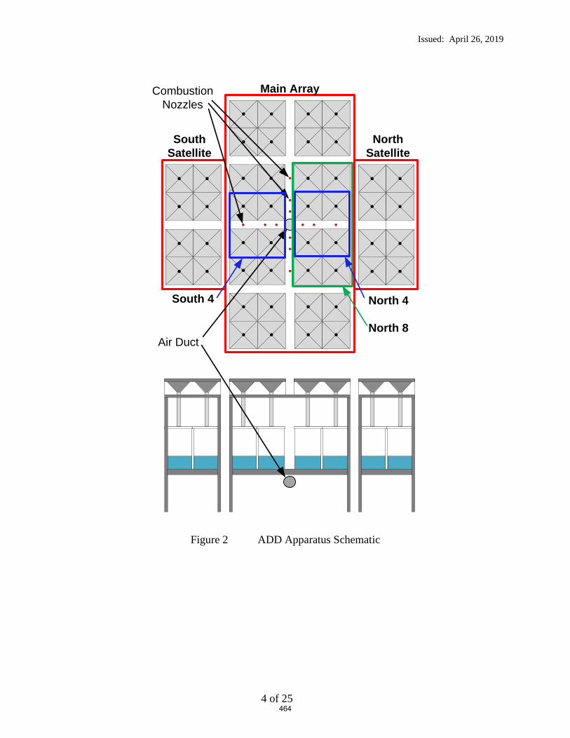
Issued: April 26, 2019
4 of 25
Figure 2 ADD Apparatus Schematic
Main Array
South Satellite
North Satellite
Combustion Nozzles
Air Duct
North 4South 4
North 8
464

Issued: April 26, 2019
5 of 25
Figure 3 ADD Apparatus Photograph (showing fire before sprinkler discharge)
465

Issued: April 26, 2019
6 of 25
Figure 4 ADD Pan Numbering System
3.2 Automatic Sprinkler System
A wet pipe automatic sprinkler system was positioned below the adjustable smooth, flat non-
combustible ceiling and pressure controlled to provide a specific applied nominal flowing
pressure as defined below.
The sprinkler was supplied through a looped and gridded piping system consisting of 2 ½-in.
diameter, schedule 40 branch line. The piping system was supplied by a variable speed pump
capable of supplying an adequate pressure and flow to maintain the required applied flowing
pressure throughout the course of the test.
The automatic sprinkler system incorporated pendent ESFR sprinklers having a nominal K-factor
of 14.0 gpm/psig0.5 (tests 1 through 18) and 16.8 gpm/psig0.5 (tests 19 and 20), both with a 3/4
inch NPT inlet thread. The sprinklers were installed with the sprinkler deflector located
nominally 14 in. below the moveable ceiling.
1 2
3 4
5 6
7 8
9 10
11 12
13 14
15 16
17 18
19 20
21 22
23 24
25 26
27 28
29 30
31 32
41 42
43 44
45 46
47 48
33 34
35 36
37 38
39 40
Pan Number Designations
Leading Edge of Obstructions
Discharging Sprinkler Location
6 in.
466

Issued: April 26, 2019
7 of 25
3.3 Obstructions
3.3.1 Steel Bar Joists (Tests 3 – 5)
The commercially manufactured open web steel bar joists used for this test series had the
following characteristics as defined in Table 1.
Table 1 Obstruction Details
Truss
Depth, in. Designation
Upper Chord
Structural
Members
Nominal
Upper
Chord
Maximum
Width, in.
Lower Chord
Structural
Members
Nominal
Lower
Chord
Maximum
Width, in.
22 22 K 1/1
1-1/2 by 1-1/2 in.
back to back “L”
angle (0.160 in.
thickness)
4
2 by 2 in. back
to back “L”
angle (0.142 in.
thickness)
5
30 30 K 1/1
1-1/2 by 1-1/2 in.
back to back “L”
angle (0.142 in.
thickness)
4
2 by 2 in. back
to back “L”
angle (0.142 in.
thickness)
5
36 36 LH 1/1
2 by 2 in. back to
back “L” angle
(0.144 in.
thickness)
5
2-1/2 by 2-1/2
in. back to back
“L” angle (0.217
in. thickness)
6
The elevation view of the full length joists are shown in Figure 6, Figure 7 and Figure 8 for the
22, 30 and 36 inch deep joists, respectively. These joists were cut down to a nominal 30 ft.
length for this Actual Delivered Density test series. Figure 9 shows the cross section details of
the joists.
East and North elevation views of the joist cross sections for representative tests are shown in
Figure 10 through Figure 12.
467

Issued: April 26, 2019
8 of 25
3.3.2 Flat Obstructions (Tests 6-14 and 17-18)
The commercially manufactured steel obstructions used for this test series had the following
characteristics as defined in Table 2Table 1.
Table 2 Obstruction Details (refer to Figure 5)
Flat
Obstruction
Nominal
Width
Width – A,
in.
Depth – B,
in.
Upper Chord
Thickness – C,
in.
3 3.00 1.51 0.245
6 6.00 2.10 0.350
12 12.00 3.10 0.400
Figure 5 Flat Obstruction Dimensional Key
The obstructions are structural “C” shapes.
The leading edge of the flat obstructions were positioned 6 inches laterally away from the
centerline of the discharging sprinkler with the vertical elevations as shown in Figure 13 through
Figure 15.
3.3.3 Bridging Member (Test 2, 15 and 16)
A bridging member was simulated by a 1-1/2 inch by 1-1/2 inch (0.220 in. thick) “L” shaped
steel angle, 20 ft. long. This member was positioned parallel to the sprinkler’s branchline,
directly below the discharging sprinkler as shown in Figure 16.
A
BC
468

Issued: April 26, 2019
9 of 25
Figure 6 22 Inch Deep Joist Detail – Elevation View (prior to cutting to 30 ft. length)
Figure 7 30 Inch Deep Joist Detail – Elevation View (prior to cutting to 30 ft. length)
Figure 8 36 Inch Deep Joist Detail – Elevation View (prior to cutting to 30 ft. length)
469

Issued: April 26, 2019
10 of 25
Figure 9 Joist Cross Section Detail – Close Up Elevation View (top position was attached at the ceiling)
22 in.
5 in.
4 in.
2 in. by 2 in. “L” angle;
0.142 in. thick
1-½ in. by 1-½ in. “L” angle;
0.160 in. thick
30 in.
5 in.
4 in.
2 in. by 2 in. “L” angle;
0.142 in. thick
1-½ in. by 1-½ in. “L” angle;
0.142 in. thick
36 in.
6 in.
5 in.
2-½ in. by 2-½ in. “L” angle;
0.217 in. thick
2 in. by 2 in. “L” angle;
0.144 in. thick
470

Issued: April 26, 2019
11 of 25
Figure 10 Test 3 Arrangement – Elevation View (as shown)
Nominal 14 in. ceiling to deflector distance
6 in. gap
22 inch deep joist
C L
Front Elevation View(view from East)
Side Elevation View(view from North)
471
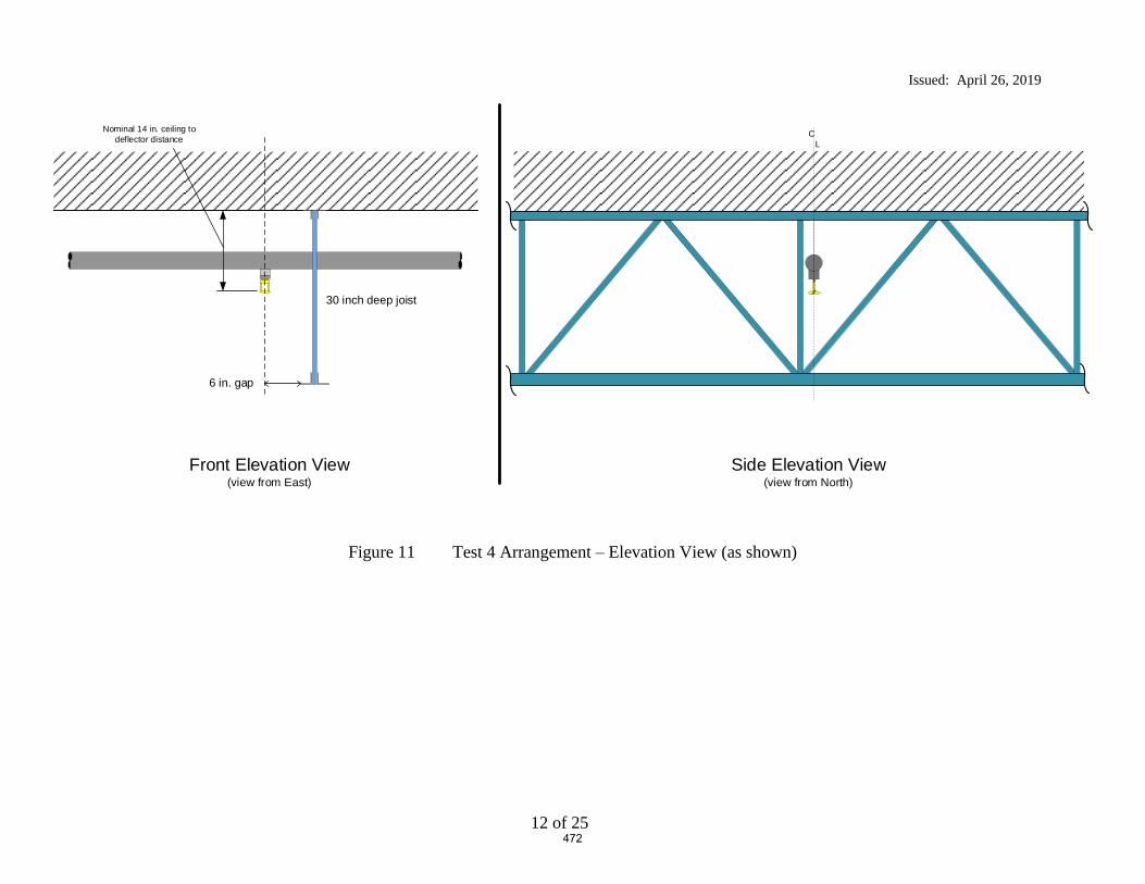
Issued: April 26, 2019
12 of 25
Figure 11 Test 4 Arrangement – Elevation View (as shown)
Nominal 14 in. ceiling to deflector distance
6 in. gap
30 inch deep joist
C L
Front Elevation View(view from East)
Side Elevation View(view from North)
472
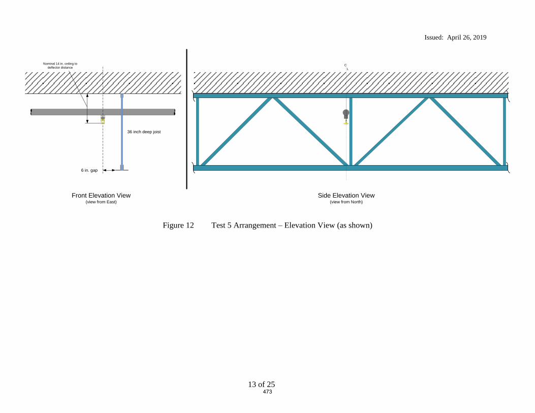
Issued: April 26, 2019
13 of 25
Figure 12 Test 5 Arrangement – Elevation View (as shown)
Nominal 14 in. ceiling to deflector distance
6 in. gap
36 inch deep joist
C L
Front Elevation View(view from East)
Side Elevation View(view from North)
473
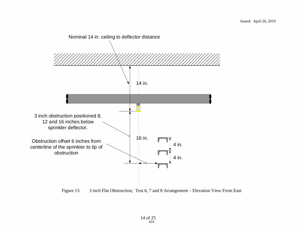
Issued: April 26, 2019
14 of 25
Figure 13 3 inch Flat Obstruction; Test 6, 7 and 8 Arrangement – Elevation View From East
Nominal 14 in. ceiling to deflector distance
Obstruction offset 6 inches from centerline of the sprinkler to tip of
obstruction
3 inch obstruction positioned 8, 12 and 16 inches below
sprinkler deflector.
4 in.
4 in.
14 in.
16 in.
474
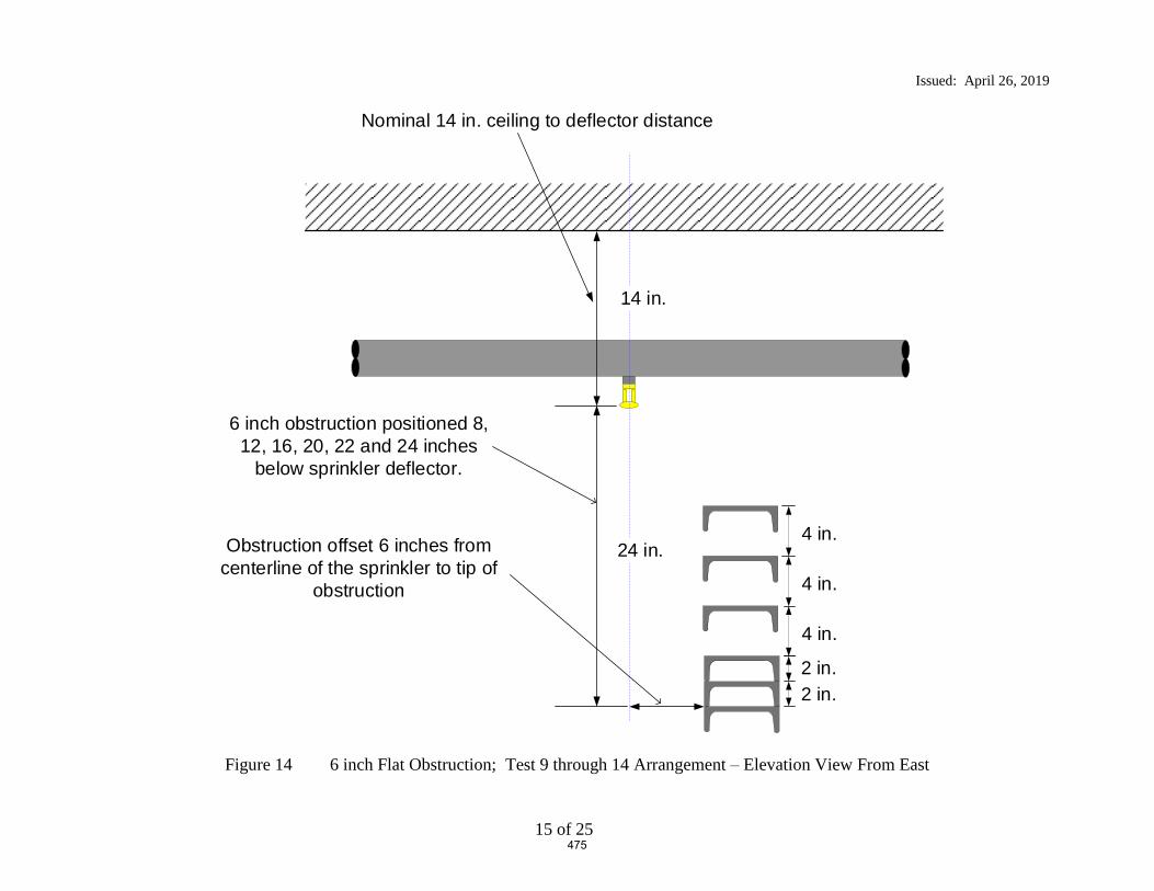
Issued: April 26, 2019
15 of 25
Figure 14 6 inch Flat Obstruction; Test 9 through 14 Arrangement – Elevation View From East
Nominal 14 in. ceiling to deflector distance
Obstruction offset 6 inches from centerline of the sprinkler to tip of
obstruction
6 inch obstruction positioned 8, 12, 16, 20, 22 and 24 inches
below sprinkler deflector.
4 in.
4 in.
14 in.
24 in.
4 in.
2 in.2 in.
475
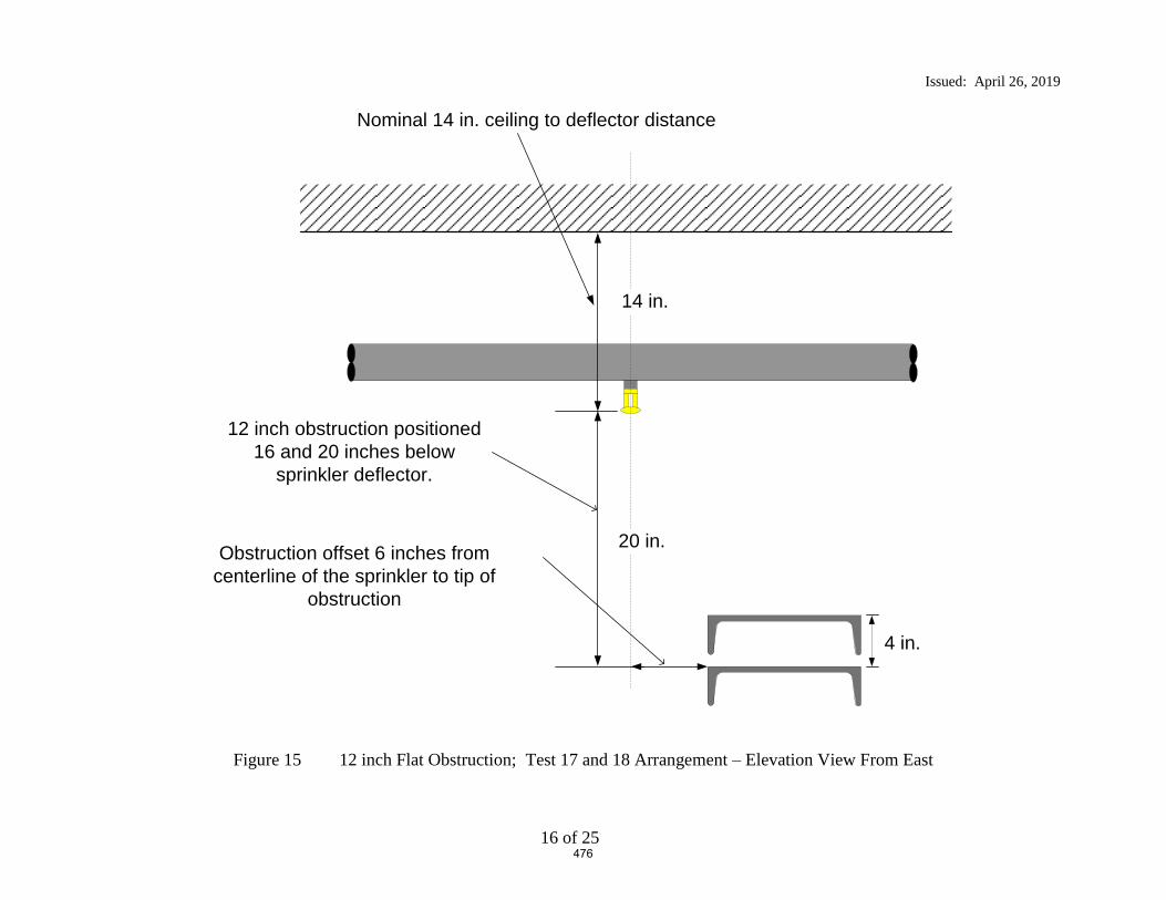
Issued: April 26, 2019
16 of 25
Figure 15 12 inch Flat Obstruction; Test 17 and 18 Arrangement – Elevation View From East
Nominal 14 in. ceiling to deflector distance
Obstruction offset 6 inches from centerline of the sprinkler to tip of
obstruction
12 inch obstruction positioned 16 and 20 inches below
sprinkler deflector.
4 in.
14 in.
20 in.
476
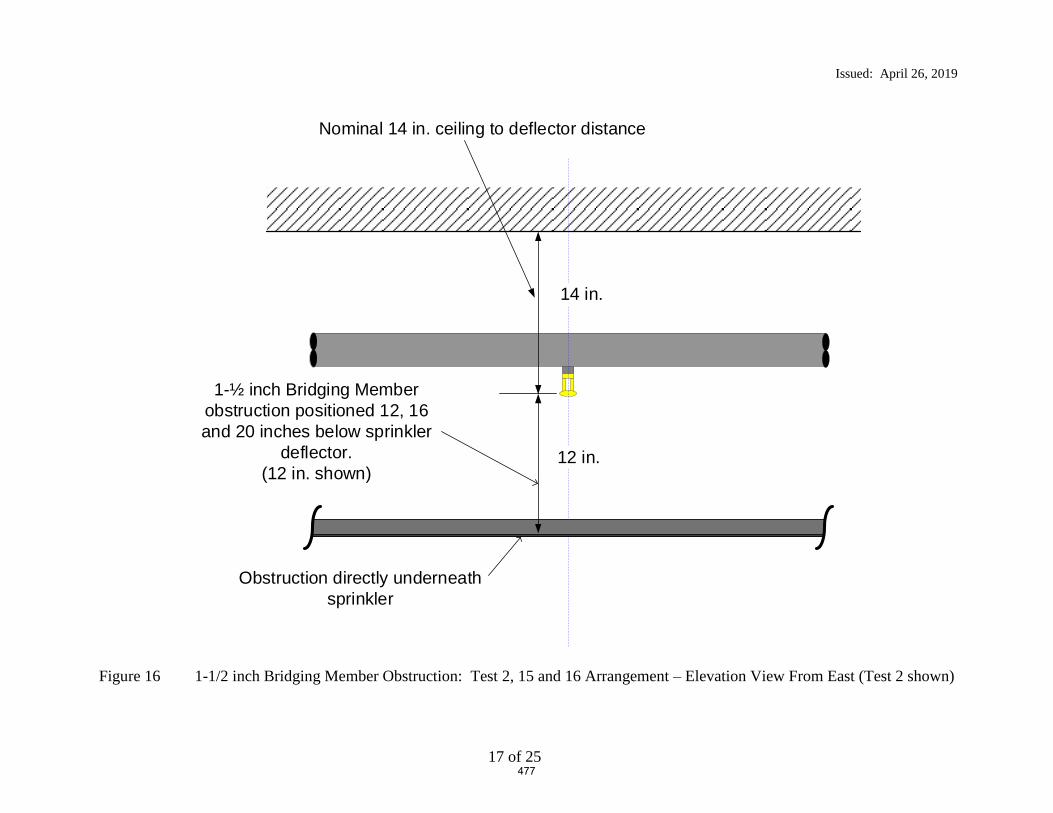
Issued: April 26, 2019
17 of 25
Figure 16 1-1/2 inch Bridging Member Obstruction: Test 2, 15 and 16 Arrangement – Elevation View From East (Test 2 shown)
Nominal 14 in. ceiling to deflector distance
Obstruction directly underneath sprinkler
1-½ inch Bridging Member obstruction positioned 12, 16 and 20 inches below sprinkler
deflector. (12 in. shown)
14 in.
12 in.
477

Issued: April 26, 2019
18 of 25
4. TEST ARRAY CONFIGURATION
4.1 ADD Arrangement Plan View
The ADD equipment was centered under one sprinkler location in the large scale test cell as shown
in Figure 17 through Figure 19.
4.2 ADD Arrangement Elevation View and Clearance
The ADD equipment was positioned with a 10 ft. clearance between the top of the pans and the
ceiling to simulate large scale testing clearances. Figure 17 and Figure 18 show the East and
North elevation views respectively.
478

Issued: April 26, 2019
19 of 25
Figure 17 ADD Apparatus – View from East (Test 4 shown)
Figure 18 ADD Apparatus – View from North (Test 4 shown)
17 ft. 10 in.
Nominal 14 in. ceiling to deflector distance
30 inch deep truss, with tip of 2 by 2 angle offset 6 inches from the centerline of the sprinkler
(as an example)
10 ft
.
17 ft. 10 in.
30 inch depth Joist
C L14 inches
10 ft
.
479

Issued: April 26, 2019
20 of 25
Figure 19 Test Array Plan View - Test Series
NJoist Obstruction:Nominally 30 ft. long
Moveable Ceiling (100 by 100 ft.)
480

Issued: April 26, 2019
21 of 25
5. TEST METHOD
5.1 Test Procedure
The test procedure consisted of the following steps:
1. Each sprinkler was pre-flowed to determine the pump speed which achieves 75 psig and 52
psig at the sprinkler for the K = 14.0 and K = 16.8 ESFR sprinkler respectively. It should be
noted that these pressures correspond to a nominal flowrate of 121 gallons per minute for both
sprinklers.
2. After setting the 2.5 MW fire above the apparatus and achieving a steady state burning
condition, the pumps were activated at the previous pump speed to achieve the desired flowing
pressures.
3. After confirming with the ADD data screens that the flow in each collection pan was steady, a
nominal 1 minute of data was captured before terminating the test.
4. The resulting data was recorded and a database was updated to show the relative performance
for the test parameters chosen.
481

Issued: April 26, 2019
22 of 25
6. RESULTS AND DISCUSSION
A total of 20 Actual Delivered Density (ADD) tests were conducted at UL LLC in Northbrook,
IL between April 2 and April 5, 2019. Table 3 provides a summary of the resulting data.
Refer to Figure 2 for pan designations in the data section.
Appendix A provides the detailed raw data for each test. Refer to Figure 4 for the individual pan
designations with respect to sprinkler and obstruction location.
482

Issued: April 26, 2019
23 of 25
Table 3 Test Series Summary
Test Number Obstruction UsedPendent ESFR Sprinkler Used, K - gpm/psig0.5
Vertical Distance of obstruction
below sprinkler deflector
Horizontal Offset, Tip of obstruction
to sprinkler centerline
Overall Average
Central 16 Pan
Average
Central 4 Pan
Average
South Satellite Average
North Satellite Average
West Pre-Wetting Average
East Pre-Wetting Average
North 4 South 4 North 8
in. in. in. gpm/ft2 gpm/ft2 gpm/ft2 gpm/ft2 gpm/ft2 gpm/ft2 gpm/ft2 gpm/ft2 gpm/ft2 gpm/ft2
1 none (baseline) 14.0 0 0 0.55 0.96 1.64 0.23 0.13 0.57 0.44 1.15 1.03 0.99
2 1-1/2 inch bridging member* 14.0 12 6 0.41 0.45 0.33 0.18 0.18 0.52 0.65 0.30 0.30 0.48
3 22 inch deep bar joist 14.0 8 6 0.51 0.83 1.71 0.22 0.09 0.55 0.54 0.85 1.28 0.604 30 inch deep bar joist 14.0 16 6 0.54 0.83 1.56 0.26 0.19 0.48 0.64 0.63 1.33 0.485 36 inch deep bar joist 14.0 22 6 0.49 0.78 1.38 0.19 0.20 0.47 0.55 0.50 1.22 0.49
6 3" flat 14.0 8 6 0.43 0.76 1.27 0.15 0.18 0.41 0.32 0.96 0.93 0.767 3" flat 14.0 12 6 0.50 0.80 1.60 0.21 0.19 0.45 0.53 1.05 0.94 0.758 3" flat 14.0 16 6 0.46 0.79 1.63 0.18 0.16 0.44 0.37 1.02 0.99 0.74
9 6" flat 14.0 8 6 0.56 0.96 1.88 0.27 0.18 0.43 0.55 1.22 1.16 0.9110 6" flat 14.0 12 6 0.49 0.78 1.88 0.28 0.17 0.46 0.47 1.30 0.97 0.7911 6" flat 14.0 16 6 0.43 0.74 1.71 0.23 0.15 0.40 0.35 1.41 0.92 0.7712 6" flat 14.0 20 6 0.46 0.80 1.69 0.10 0.22 0.39 0.45 1.15 0.96 0.7913 6" flat 14.0 22 6 0.45 0.73 1.64 0.16 0.19 0.41 0.45 1.13 0.88 0.7514 6" flat 14.0 24 6 0.45 0.75 1.56 0.20 0.19 0.41 0.39 1.06 0.90 0.75
15 1-1/2 inch bridging member* 14.0 14 0 0.49 0.81 0.64 0.09 0.17 0.52 0.52 0.49 0.62 0.7916 1-1/2 inch bridging member* 14.0 20 0 0.44 0.73 1.46 0.22 0.16 0.43 0.36 0.93 0.96 0.74
17 12" flat 14.0 16 6 0.45 0.76 1.61 0.20 0.24 0.39 0.35 0.76 1.37 0.5018 12" flat 14.0 20 6 0.43 0.72 1.46 0.14 0.26 0.34 0.41 0.68 1.19 0.51
19 12" flat 16.8 8 6 0.50 1.05 2.06 0.30 0.05 0.27 0.29 1.56 1.20 1.1920 12" flat 16.8 12 6 0.50 0.94 1.86 0.26 0.15 0.35 0.37 1.25 1.16 0.99
* - bridging member distance is to the top of the horizontal flat portion from the sprinkler's deflector
Test Parameters Data
483
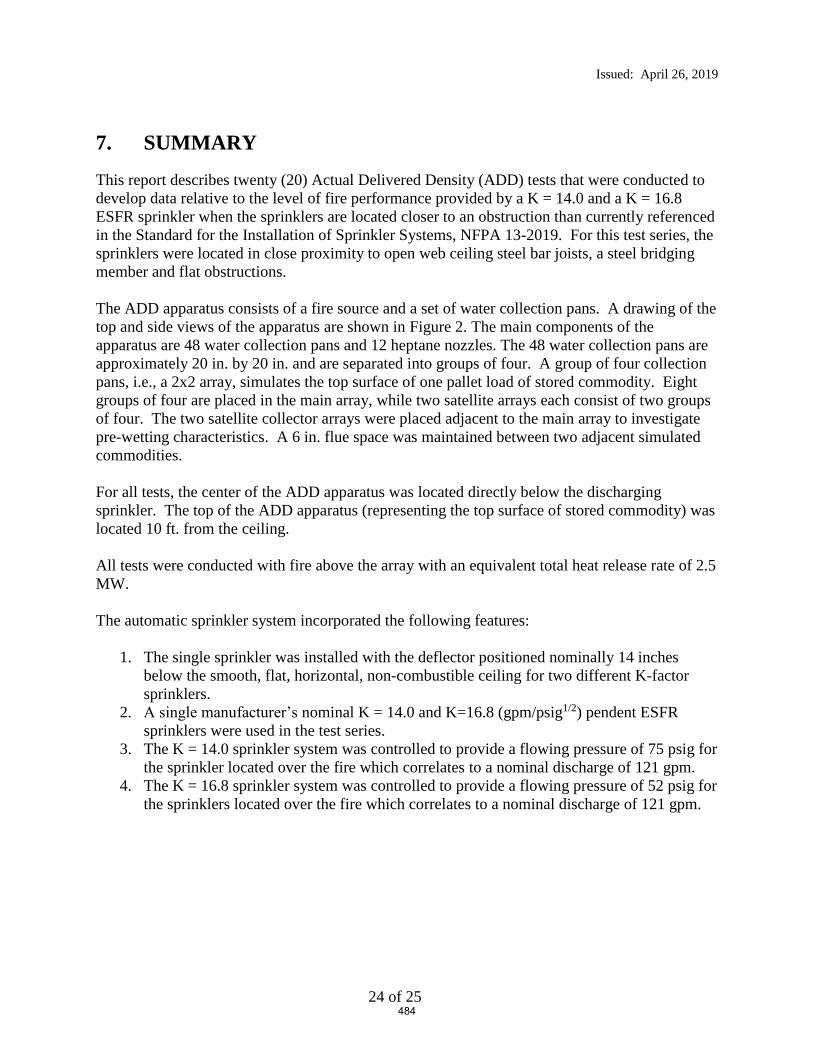
Issued: April 26, 2019
24 of 25
7. SUMMARY
This report describes twenty (20) Actual Delivered Density (ADD) tests that were conducted to
develop data relative to the level of fire performance provided by a K = 14.0 and a K = 16.8
ESFR sprinkler when the sprinklers are located closer to an obstruction than currently referenced
in the Standard for the Installation of Sprinkler Systems, NFPA 13-2019. For this test series, the
sprinklers were located in close proximity to open web ceiling steel bar joists, a steel bridging
member and flat obstructions.
The ADD apparatus consists of a fire source and a set of water collection pans. A drawing of the
top and side views of the apparatus are shown in Figure 2. The main components of the
apparatus are 48 water collection pans and 12 heptane nozzles. The 48 water collection pans are
approximately 20 in. by 20 in. and are separated into groups of four. A group of four collection
pans, i.e., a 2x2 array, simulates the top surface of one pallet load of stored commodity. Eight
groups of four are placed in the main array, while two satellite arrays each consist of two groups
of four. The two satellite collector arrays were placed adjacent to the main array to investigate
pre-wetting characteristics. A 6 in. flue space was maintained between two adjacent simulated
commodities.
For all tests, the center of the ADD apparatus was located directly below the discharging
sprinkler. The top of the ADD apparatus (representing the top surface of stored commodity) was
located 10 ft. from the ceiling.
All tests were conducted with fire above the array with an equivalent total heat release rate of 2.5
MW.
The automatic sprinkler system incorporated the following features:
1. The single sprinkler was installed with the deflector positioned nominally 14 inches
below the smooth, flat, horizontal, non-combustible ceiling for two different K-factor
sprinklers.
2. A single manufacturer’s nominal K = 14.0 and K=16.8 (gpm/psig1/2) pendent ESFR
sprinklers were used in the test series.
3. The K = 14.0 sprinkler system was controlled to provide a flowing pressure of 75 psig for
the sprinkler located over the fire which correlates to a nominal discharge of 121 gpm.
4. The K = 16.8 sprinkler system was controlled to provide a flowing pressure of 52 psig for
the sprinklers located over the fire which correlates to a nominal discharge of 121 gpm.
484

Issued: April 26, 2019
25 of 25
Tests were conducted using three primary obstructions as follows:
Steel Bar Joists: 22, 30 and 36 inch deep, commercially available steel bar joists were used
in tests 3, 4 and 5.
Flat Obstructions: Tests were conducted using 3, 6 and 12 inch wide, commercial steel
structural “C” shapes for the flat obstructions. These were used in tests 6 through 14 and 17
through 20.
Bridging Member: A 1-1/2 by 1-1/2 inch “L” shaped steel member was used to simulate a
bridging member positioned parallel to the sprinkler’s branchline. This was used in tests 2, 15
and 16.
A summary of the test parameters and results for all tests are provided in Table 3.
Report By: Reviewed By:
Daniel R. Steppan Michael G. McCormick
Senior Staff Engineer Staff Engineering Associate
Product Safety Product Safety
485

Appendix A – Raw and Summarized Data
A1 of 21
APPENDIX A
Raw and Summarized Data
486

Appendix A – Raw and Summarized Data
A2 of 21
Figure A- 1 Test 1 – Results (3D graphic–view from Northeast of Central Main Array Only)
1 0.59 2 0.52 5 0.48 6 0.75 N
3 0.45 4 0.63 7 0.60 8 0.50
33 0.19 34 0.44 9 0.82 10 0.97 13 0.80 14 0.77 41 0.20 42 0.08
35 0.21 36 0.24 11 0.55 12 1.97 15 1.51 16 0.57 43 0.18 44 0.08
37 0.10 38 0.24 17 0.52 18 1.08 21 2.00 22 0.53 45 0.13 46 0.05
39 0.05 40 0.33 19 0.77 20 0.79 23 0.85 24 0.89 47 0.34 48 0.00
25 0.42 26 0.47 29 0.68 30 0.45
27 0.53 28 0.38 31 0.00 32 0.62
Density (gpm/ft2)
measured densitygpm/ft2
Overall Average 0.55Central 16 Pan Average 0.96Central 4 Pan Average 1.64South Satellite Average 0.23North Satellite Average 0.13West Pre-Wetting Average 0.57East Pre-Wetting Average 0.44
North 4 1.15South 4 1.03North 8 0.99
487
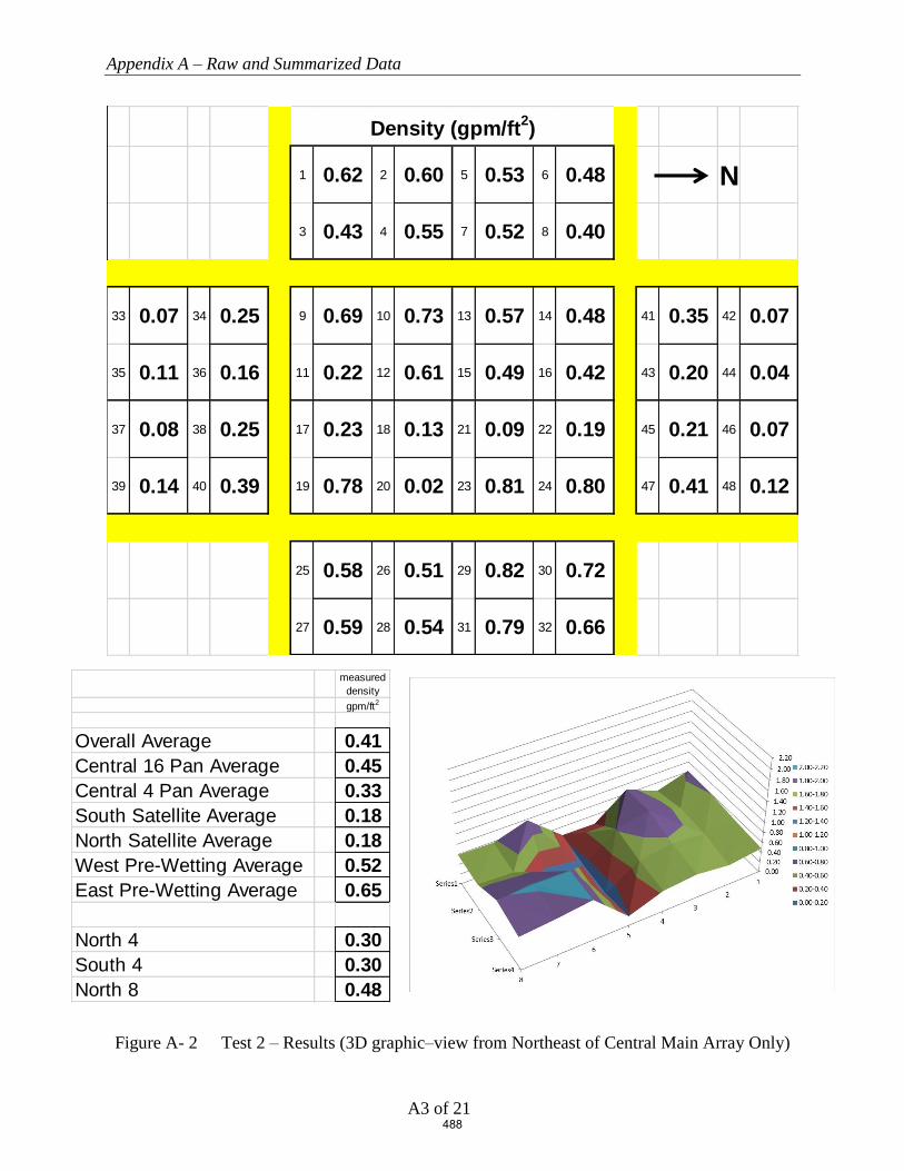
Appendix A – Raw and Summarized Data
A3 of 21
Figure A- 2 Test 2 – Results (3D graphic–view from Northeast of Central Main Array Only)
1 0.62 2 0.60 5 0.53 6 0.48 N
3 0.43 4 0.55 7 0.52 8 0.40
33 0.07 34 0.25 9 0.69 10 0.73 13 0.57 14 0.48 41 0.35 42 0.07
35 0.11 36 0.16 11 0.22 12 0.61 15 0.49 16 0.42 43 0.20 44 0.04
37 0.08 38 0.25 17 0.23 18 0.13 21 0.09 22 0.19 45 0.21 46 0.07
39 0.14 40 0.39 19 0.78 20 0.02 23 0.81 24 0.80 47 0.41 48 0.12
25 0.58 26 0.51 29 0.82 30 0.72
27 0.59 28 0.54 31 0.79 32 0.66
Density (gpm/ft2)
measured densitygpm/ft2
Overall Average 0.41Central 16 Pan Average 0.45Central 4 Pan Average 0.33South Satellite Average 0.18North Satellite Average 0.18West Pre-Wetting Average 0.52East Pre-Wetting Average 0.65
North 4 0.30South 4 0.30North 8 0.48
488

Appendix A – Raw and Summarized Data
A4 of 21
Figure A- 3 Test 3 – Results (3D graphic–view from Northeast of Central Main Array Only)
1 0.91 2 0.36 5 1.39 6 0.22 N
3 0.59 4 0.28 7 0.43 8 0.19
33 0.20 34 0.51 9 0.90 10 0.58 13 0.50 14 0.15 41 0.02 42 0.04
35 0.16 36 0.19 11 0.91 12 1.89 15 1.45 16 0.16 43 0.09 44 0.06
37 0.09 38 0.27 17 0.50 18 1.81 21 1.68 22 0.10 45 0.09 46 0.13
39 0.02 40 0.31 19 1.05 20 0.94 23 0.59 24 0.14 47 0.16 48 0.12
25 0.36 26 0.43 29 0.54 30 0.08
27 0.61 28 0.59 31 1.69 32 0.03
Density (gpm/ft2)
measured densitygpm/ft2
Overall Average 0.51Central 16 Pan Average 0.83Central 4 Pan Average 1.71South Satellite Average 0.22North Satellite Average 0.09West Pre-Wetting Average 0.55East Pre-Wetting Average 0.54
North 4 0.85South 4 1.28North 8 0.60
489
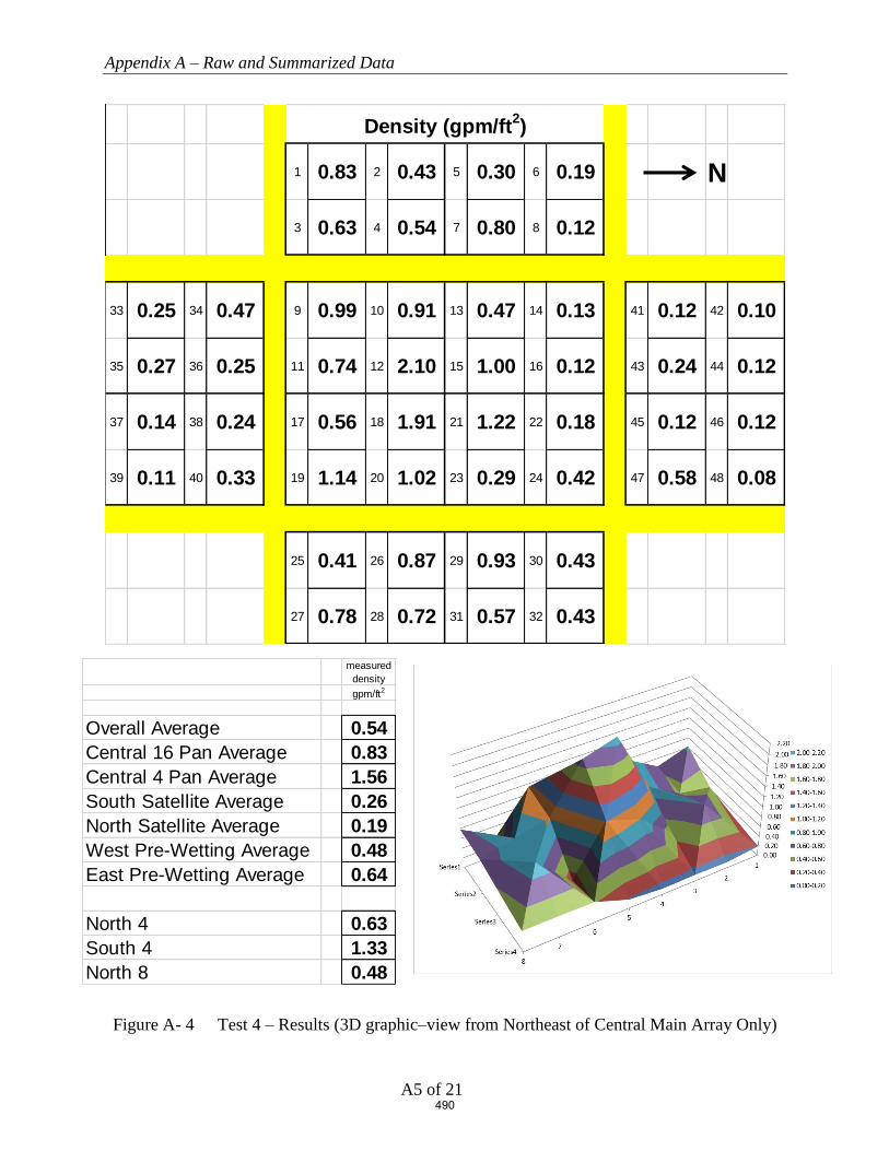
Appendix A – Raw and Summarized Data
A5 of 21
Figure A- 4 Test 4 – Results (3D graphic–view from Northeast of Central Main Array Only)
1 0.83 2 0.43 5 0.30 6 0.19 N
3 0.63 4 0.54 7 0.80 8 0.12
33 0.25 34 0.47 9 0.99 10 0.91 13 0.47 14 0.13 41 0.12 42 0.10
35 0.27 36 0.25 11 0.74 12 2.10 15 1.00 16 0.12 43 0.24 44 0.12
37 0.14 38 0.24 17 0.56 18 1.91 21 1.22 22 0.18 45 0.12 46 0.12
39 0.11 40 0.33 19 1.14 20 1.02 23 0.29 24 0.42 47 0.58 48 0.08
25 0.41 26 0.87 29 0.93 30 0.43
27 0.78 28 0.72 31 0.57 32 0.43
Density (gpm/ft2)
measured densitygpm/ft2
Overall Average 0.54Central 16 Pan Average 0.83Central 4 Pan Average 1.56South Satellite Average 0.26North Satellite Average 0.19West Pre-Wetting Average 0.48East Pre-Wetting Average 0.64
North 4 0.63South 4 1.33North 8 0.48
490
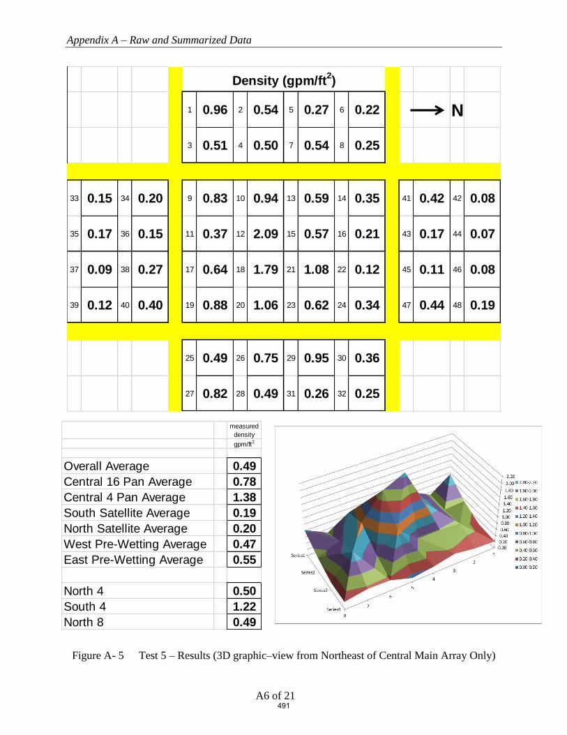
Appendix A – Raw and Summarized Data
A6 of 21
Figure A- 5 Test 5 – Results (3D graphic–view from Northeast of Central Main Array Only)
1 0.96 2 0.54 5 0.27 6 0.22 N
3 0.51 4 0.50 7 0.54 8 0.25
33 0.15 34 0.20 9 0.83 10 0.94 13 0.59 14 0.35 41 0.42 42 0.08
35 0.17 36 0.15 11 0.37 12 2.09 15 0.57 16 0.21 43 0.17 44 0.07
37 0.09 38 0.27 17 0.64 18 1.79 21 1.08 22 0.12 45 0.11 46 0.08
39 0.12 40 0.40 19 0.88 20 1.06 23 0.62 24 0.34 47 0.44 48 0.19
25 0.49 26 0.75 29 0.95 30 0.36
27 0.82 28 0.49 31 0.26 32 0.25
Density (gpm/ft2)
measured densitygpm/ft2
Overall Average 0.49Central 16 Pan Average 0.78Central 4 Pan Average 1.38South Satellite Average 0.19North Satellite Average 0.20West Pre-Wetting Average 0.47East Pre-Wetting Average 0.55
North 4 0.50South 4 1.22North 8 0.49
491

Appendix A – Raw and Summarized Data
A7 of 21
Figure A- 6 Test 6 – Results (3D graphic–view from Northeast of Central Main Array Only)
1 0.35 2 0.36 5 0.27 6 0.43 N
3 0.41 4 0.46 7 0.44 8 0.54
33 0.05 34 0.13 9 0.37 10 0.72 13 1.03 14 0.4 41 0.29 42 0.18
35 0.06 36 0.13 11 0.33 12 0.85 15 1.73 16 0.91 43 0.34 44 0.14
37 0.11 38 0.33 17 1.06 18 1.47 21 1.02 22 0.18 45 0.12 46 0.08
39 0.09 40 0.33 19 0.46 20 0.78 23 0.63 24 0.14 47 0.18 48 0.12
25 0.48 26 0.45 29 0.43 30 0.18
27 0.4 28 0.25 31 0.31 32 0.07
Density (gpm/ft2)
measured densitygpm/ft2
Overall Average 0.43Central 16 Pan Average 0.76Central 4 Pan Average 1.27South Satellite Average 0.15North Satellite Average 0.18West Pre-Wetting Average 0.41East Pre-Wetting Average 0.32
North 4 0.96South 4 0.93North 8 0.76
492

Appendix A – Raw and Summarized Data
A8 of 21
Figure A- 7 Test 7 – Results (3D graphic–view from Northeast of Central Main Array Only)
1 0.43 2 0.50 5 0.52 6 0.38 N
3 0.44 4 0.41 7 0.62 8 0.26
33 0.08 34 0.40 9 0.63 10 0.71 13 0.14 14 0.32 41 0.14 42 0.08
35 0.09 36 0.26 11 0.68 12 1.82 15 1.62 16 0.21 43 0.19 44 0.11
37 0.13 38 0.19 17 0.29 18 0.96 21 2.00 22 0.37 45 0.38 46 0.08
39 0.11 40 0.41 19 0.91 20 0.86 23 0.94 24 0.40 47 0.46 48 0.11
25 0.47 26 0.69 29 0.74 30 0.47
27 0.58 28 0.43 31 0.40 32 0.42
Density (gpm/ft2)
measured densitygpm/ft2
Overall Average 0.50Central 16 Pan Average 0.80Central 4 Pan Average 1.60South Satellite Average 0.21North Satellite Average 0.19West Pre-Wetting Average 0.45East Pre-Wetting Average 0.53
North 4 1.05South 4 0.94North 8 0.75
493

Appendix A – Raw and Summarized Data
A9 of 21
Figure A- 8 Test 8 – Results (3D graphic–view from Northeast of Central Main Array Only)
1 0.48 2 0.41 5 0.37 6 0.39 N
3 0.44 4 0.48 7 0.65 8 0.33
33 0.10 34 0.39 9 0.76 10 0.74 13 0.47 14 0.46 41 0.27 42 0.09
35 0.12 36 0.22 11 0.55 12 1.85 15 1.63 16 0.30 43 0.17 44 0.08
37 0.09 38 0.13 17 0.46 18 1.08 21 1.96 22 0.19 45 0.24 46 0.07
39 0.04 40 0.35 19 0.79 20 0.56 23 0.37 24 0.52 47 0.34 48 0.05
25 0.40 26 0.04 29 0.77 30 0.30
27 0.50 28 0.31 31 0.35 32 0.29
Density (gpm/ft2)
measured densitygpm/ft2
Overall Average 0.46Central 16 Pan Average 0.79Central 4 Pan Average 1.63South Satellite Average 0.18North Satellite Average 0.16West Pre-Wetting Average 0.44East Pre-Wetting Average 0.37
North 4 1.02South 4 0.99North 8 0.74
494
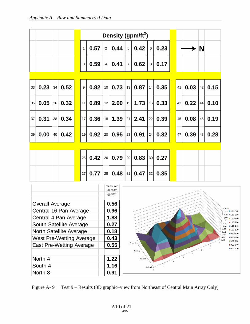
Appendix A – Raw and Summarized Data
A10 of 21
Figure A- 9 Test 9 – Results (3D graphic–view from Northeast of Central Main Array Only)
1 0.57 2 0.44 5 0.42 6 0.23 N
3 0.59 4 0.41 7 0.62 8 0.17
33 0.23 34 0.52 9 0.82 10 0.73 13 0.87 14 0.35 41 0.03 42 0.15
35 0.05 36 0.32 11 0.89 12 2.00 15 1.73 16 0.33 43 0.22 44 0.10
37 0.31 38 0.34 17 0.36 18 1.39 21 2.41 22 0.39 45 0.08 46 0.19
39 0.00 40 0.42 19 0.92 20 0.95 23 0.91 24 0.32 47 0.39 48 0.28
25 0.42 26 0.79 29 0.83 30 0.27
27 0.77 28 0.48 31 0.47 32 0.35
Density (gpm/ft2)
measured densitygpm/ft2
Overall Average 0.56Central 16 Pan Average 0.96Central 4 Pan Average 1.88South Satellite Average 0.27North Satellite Average 0.18West Pre-Wetting Average 0.43East Pre-Wetting Average 0.55
North 4 1.22South 4 1.16North 8 0.91
495

Appendix A – Raw and Summarized Data
A11 of 21
Figure A- 10 Test 10 – Results (3D graphic–view from Northeast of Central Main Array Only)
1 0.80 2 0.31 5 0.42 6 0.23 N
3 0.54 4 0.35 7 0.85 8 0.18
33 0.14 34 0.50 9 0.64 10 0.71 13 0.10 14 0.23 41 0.18 42 0.11
35 0.25 36 0.26 11 0.59 12 1.84 15 1.95 16 0.31 43 0.13 44 0.07
37 0.13 38 0.13 17 0.27 18 1.19 21 2.53 22 0.40 45 0.22 46 0.11
39 0.36 40 0.50 19 0.63 20 0.28 23 0.52 24 0.29 47 0.40 48 0.10
25 0.50 26 0.30 29 0.97 30 0.35
27 0.59 28 0.31 31 0.47 32 0.23
Density (gpm/ft2)
measured densitygpm/ft2
Overall Average 0.49Central 16 Pan Average 0.78Central 4 Pan Average 1.88South Satellite Average 0.28North Satellite Average 0.17West Pre-Wetting Average 0.46East Pre-Wetting Average 0.47
North 4 1.30South 4 0.97North 8 0.79
496

Appendix A – Raw and Summarized Data
A12 of 21
Figure A- 11 Test 11 – Results (3D graphic–view from Northeast of Central Main Array Only)
1 0.57 2 0.33 5 0.47 6 0.22 N
3 0.43 4 0.31 7 0.70 8 0.19
33 0.15 34 0.41 9 0.60 10 0.53 13 0.24 14 0.31 41 0.18 42 0.08
35 0.18 36 0.25 11 0.51 12 1.74 15 1.65 16 0.24 43 0.11 44 0.06
37 0.13 38 0.25 17 0.35 18 1.09 21 2.35 22 - 45 0.23 46 0.00
39 0.10 40 0.38 19 0.64 20 0.29 23 0.34 24 0.24 47 0.51 48 0.02
25 0.45 26 0.01 29 0.95 30 0.08
27 0.52 28 0.33 31 0.37 32 0.05
Density (gpm/ft2)
measured densitygpm/ft2
Overall Average 0.43Central 16 Pan Average 0.74Central 4 Pan Average 1.71South Satellite Average 0.23North Satellite Average 0.15West Pre-Wetting Average 0.40East Pre-Wetting Average 0.35
North 4 1.41South 4 0.92North 8 0.77
497

Appendix A – Raw and Summarized Data
A13 of 21
Figure A- 12 Test 12 – Results (3D graphic–view from Northeast of Central Main Array Only)
1 0.46 2 0.39 5 0.27 6 0.22 N
3 0.44 4 0.44 7 0.67 8 0.20
33 0.06 34 0.01 9 0.58 10 0.72 13 0.31 14 0.28 41 0.52 42 0.19
35 0.05 36 0.07 11 0.33 12 1.81 15 1.43 16 0.40 43 0.29 44 0.15
37 0.04 38 0.24 17 0.58 18 1.11 21 2.42 22 0.36 45 0.23 46 0.04
39 0.00 40 0.36 19 0.73 20 0.54 23 0.65 24 0.48 47 0.37 48 0.00
25 0.52 26 0.22 29 0.78 30 0.30
27 0.58 28 0.31 31 0.70 32 0.15
Density (gpm/ft2)
measured densitygpm/ft2
Overall Average 0.46Central 16 Pan Average 0.80Central 4 Pan Average 1.69South Satellite Average 0.10North Satellite Average 0.22West Pre-Wetting Average 0.39East Pre-Wetting Average 0.45
North 4 1.15South 4 0.96North 8 0.79
498

Appendix A – Raw and Summarized Data
A14 of 21
Figure A- 13 Test 13 – Results (3D graphic–view from Northeast of Central Main Array Only)
1 0.57 2 0.30 5 0.57 6 0.22 N
3 0.51 4 0.35 7 0.55 8 0.23
33 0.07 34 0.34 9 0.55 10 0.61 13 0.16 14 0.42 41 0.32 42 0.12
35 0.10 36 0.23 11 0.59 12 1.69 15 1.65 16 0.30 43 0.11 44 0.05
37 0.06 38 0.04 17 0.23 18 1.02 21 2.19 22 0.38 45 0.27 46 0.04
39 0.19 40 0.25 19 0.62 20 0.41 23 0.56 24 0.36 47 0.52 48 0.07
25 0.44 26 0.41 29 0.67 30 0.32
27 0.57 28 0.35 31 0.58 32 0.22
Density (gpm/ft2)
measured densitygpm/ft2
Overall Average 0.45Central 16 Pan Average 0.73Central 4 Pan Average 1.64South Satellite Average 0.16North Satellite Average 0.19West Pre-Wetting Average 0.41East Pre-Wetting Average 0.45
North 4 1.13South 4 0.88North 8 0.75
499

Appendix A – Raw and Summarized Data
A15 of 21
Figure A- 14 Test 14 – Results (3D graphic–view from Northeast of Central Main Array Only)
1 0.52 2 0.37 5 0.53 6 0.18 N
3 0.46 4 0.38 7 0.54 8 0.26
33 0.12 34 0.37 9 0.68 10 0.68 13 0.51 14 0.45 41 0.28 42 0.09
35 0.11 36 0.25 11 0.52 12 1.77 15 1.35 16 0.36 43 0.08 44 0.04
37 0.11 38 0.23 17 0.34 18 0.96 21 2.14 22 0.39 45 0.37 46 0.03
39 0.07 40 0.36 19 0.55 20 0.41 23 0.51 24 0.32 47 0.53 48 0.08
25 0.41 26 0.35 29 0.52 30 0.28
27 0.50 28 0.35 31 0.49 32 0.21
Density (gpm/ft2)
measured densitygpm/ft2
Overall Average 0.45Central 16 Pan Average 0.75Central 4 Pan Average 1.56South Satellite Average 0.20North Satellite Average 0.19West Pre-Wetting Average 0.41East Pre-Wetting Average 0.39
North 4 1.06South 4 0.90North 8 0.75
500

Appendix A – Raw and Summarized Data
A16 of 21
Figure A- 15 Test 15 – Results (3D graphic–view from Northeast of Central Main Array Only)
1 0.75 2 0.38 5 0.39 6 0.57 N
3 0.52 4 0.52 7 0.54 8 0.46
33 0.06 34 0.03 9 0.77 10 0.85 13 0.53 14 0.47 41 0.30 42 0.09
35 0.08 36 0.05 11 0.33 12 1.01 15 0.49 16 0.39 43 0.18 44 0.07
37 0.04 38 0.15 17 0.54 18 0.61 21 0.45 22 0.64 45 0.35 46 0.06
39 0.05 40 0.26 19 1.20 20 1.42 23 1.75 24 1.56 47 0.26 48 0.03
25 0.33 26 0.68 29 0.73 30 0.43
27 0.52 28 0.38 31 0.61 32 0.49
Density (gpm/ft2)
measured densitygpm/ft2
Overall Average 0.49Central 16 Pan Average 0.81Central 4 Pan Average 0.64South Satellite Average 0.09North Satellite Average 0.17West Pre-Wetting Average 0.52East Pre-Wetting Average 0.52
North 4 0.49South 4 0.62North 8 0.79
501

Appendix A – Raw and Summarized Data
A17 of 21
Figure A- 16 Test 16 – Results (3D graphic–view from Northeast of Central Main Array Only)
1 0.40 2 0.30 5 0.59 6 0.45 N
3 0.49 4 0.34 7 0.52 8 0.34
33 0.13 34 0.39 9 0.60 10 0.57 13 0.40 14 0.43 41 0.18 42 0.10
35 0.17 36 0.28 11 0.65 12 1.02 15 0.37 16 0.27 43 0.16 44 0.09
37 0.12 38 0.15 17 0.17 18 2.00 21 2.44 22 0.65 45 0.23 46 0.04
39 0.12 40 0.36 19 0.40 20 0.31 23 0.60 24 0.74 47 0.44 48 0.06
25 0.20 26 0.27 29 0.31 30 0.42
27 0.40 28 0.49 31 0.31 32 0.48
Density (gpm/ft2)
measured densitygpm/ft2
Overall Average 0.44Central 16 Pan Average 0.73Central 4 Pan Average 1.46South Satellite Average 0.22North Satellite Average 0.16West Pre-Wetting Average 0.43East Pre-Wetting Average 0.36
North 4 0.93South 4 0.96North 8 0.74
502

Appendix A – Raw and Summarized Data
A18 of 21
Figure A- 17 Test 17 – Results (3D graphic–view from Northeast of Central Main Array Only)
1 0.40 2 0.20 5 0.57 6 0.09 N
3 0.62 4 0.22 7 0.92 8 0.11
33 0.11 34 0.19 9 1.18 10 0.60 13 0.33 14 0.15 41 0.04 42 0.24
35 0.00 36 0.18 11 0.71 12 1.91 15 1.14 16 0.21 43 0.26 44 0.27
37 0.24 38 0.43 17 0.93 18 1.93 21 1.46 22 0.23 45 0.09 46 0.43
39 0.00 40 0.48 19 0.69 20 0.25 23 0.31 24 0.15 47 0.29 48 0.31
25 0.53 26 - 29 0.84 30 0.15
27 0.47 28 0.46 31 0.00 32 0.00
Density (gpm/ft2)
measured densitygpm/ft2
Overall Average 0.45Central 16 Pan Average 0.76Central 4 Pan Average 1.61South Satellite Average 0.20North Satellite Average 0.24West Pre-Wetting Average 0.39East Pre-Wetting Average 0.35
North 4 0.76South 4 1.37North 8 0.50
503
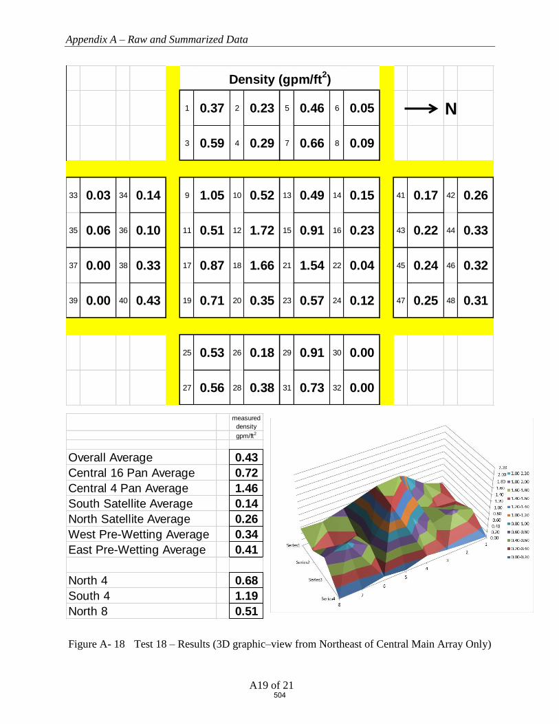
Appendix A – Raw and Summarized Data
A19 of 21
Figure A- 18 Test 18 – Results (3D graphic–view from Northeast of Central Main Array Only)
1 0.37 2 0.23 5 0.46 6 0.05 N
3 0.59 4 0.29 7 0.66 8 0.09
33 0.03 34 0.14 9 1.05 10 0.52 13 0.49 14 0.15 41 0.17 42 0.26
35 0.06 36 0.10 11 0.51 12 1.72 15 0.91 16 0.23 43 0.22 44 0.33
37 0.00 38 0.33 17 0.87 18 1.66 21 1.54 22 0.04 45 0.24 46 0.32
39 0.00 40 0.43 19 0.71 20 0.35 23 0.57 24 0.12 47 0.25 48 0.31
25 0.53 26 0.18 29 0.91 30 0.00
27 0.56 28 0.38 31 0.73 32 0.00
Density (gpm/ft2)
measured densitygpm/ft2
Overall Average 0.43Central 16 Pan Average 0.72Central 4 Pan Average 1.46South Satellite Average 0.14North Satellite Average 0.26West Pre-Wetting Average 0.34East Pre-Wetting Average 0.41
North 4 0.68South 4 1.19North 8 0.51
504

Appendix A – Raw and Summarized Data
A20 of 21
Figure A- 19 Test 19 – Results (3D graphic–view from Northeast of Central Main Array Only)
1 0.69 2 0.23 5 0.07 6 0.09 N
3 0.55 4 0.21 7 0.19 8 0.11
33 0.16 34 0.38 9 0.70 10 0.58 13 1.36 14 0.21 41 0.07 42 0.05
35 0.31 36 0.34 11 1.08 12 1.69 15 2.57 16 0.59 43 0.08 44 0.05
37 0.22 38 0.14 17 0.62 18 1.41 21 2.57 22 0.50 45 0.02 46 0.08
39 0.32 40 0.53 19 0.52 20 0.73 23 1.53 24 0.18 47 0.04 48 0.02
25 0.76 26 0.14 29 0.62 30 0.00
27 0.50 28 0.18 31 0.15 32 0.00
Density (gpm/ft2)
measured densitygpm/ft2
Overall Average 0.50Central 16 Pan Average 1.05Central 4 Pan Average 2.06South Satellite Average 0.30North Satellite Average 0.05West Pre-Wetting Average 0.27East Pre-Wetting Average 0.29
North 4 1.56South 4 1.20North 8 1.19
505

Appendix A – Raw and Summarized Data
A21 of 21
Figure A- 20 Test 20 – Results (3D graphic–view from Northeast of Central Main Array Only)
1 0.83 2 0.21 5 0.19 6 0.11 N
3 0.52 4 0.19 7 0.55 8 0.16
33 0.14 34 0.33 9 0.60 10 0.57 13 1.08 14 0.15 41 0.15 42 0.08
35 0.28 36 0.30 11 1.01 12 1.56 15 2.29 16 0.29 43 0.15 44 0.12
37 0.20 38 0.19 17 0.67 18 1.41 21 2.18 22 0.22 45 0.15 46 0.17
39 0.20 40 0.45 19 0.59 20 0.76 23 1.51 24 0.22 47 0.18 48 0.18
25 0.74 26 0.15 29 0.84 30 0.12
27 0.52 28 0.17 31 0.33 32 0.05
Density (gpm/ft2)
measured densitygpm/ft2
Overall Average 0.50Central 16 Pan Average 0.94Central 4 Pan Average 1.86South Satellite Average 0.26North Satellite Average 0.15West Pre-Wetting Average 0.35East Pre-Wetting Average 0.37
North 4 1.25South 4 1.16North 8 0.99
506

Obstructions and Early Suppression Fast Response Sprinklers
Phase 4 Final Report
FINAL REPORT | WJE No. 2018.8439.0 | MAY 1, 2020
APPENDIX B. ESFR SPRINKLERS OBSTRUCTED BY CONTINUOUS FLAT OBSTRUCTIONS (PHASE
4), UNDERWRITERS LABORATORIES, SEPTEMBER 27, 2019
507
ESFR SPRINKLERS OBSTRUCTED BY
CONTINUOUS FLAT OBSTRUCTIONS
Prepared by
UL LLC
Project 4789175773, NC5756
for the
Fire Protection Research Foundation
Issued: September 27, 2019
Copyright © 2019 UL LLC
508
Issued: September 27, 2019
i
Executive Summary
This report describes one large scale fire test that was conducted to develop data relative to the level
of fire protection provided by a specific Early Suppression Fast Response (ESFR) sprinkler when
the sprinklers are located closer to an obstruction than currently referenced in the Standard for the
Installation of Sprinkler Systems, NFPA 13-2019. For this test, the sprinklers were located in close
proximity to a long continuous structural steel flat horizontal shape.
Standard cartoned unexpanded Group A plastic test commodity was used in the investigation which
consisted of unexpanded polystyrene cups installed in separate compartments within cartons that are
placed on two way entry, hardwood pallets. The nominal external dimensions of the commodity
was 42 inches wide by 42 inches deep by 40 inches tall resting on a nominal 5 inch tall, 42 by 42
inch hardwood pallet.
The test was conducted using a nominal storage height of 30 ft of cartoned unexpanded Group A
plastic with a ceiling height of 40 ft. Nominal 32 ft. long double-row rack storage arrays were used
in the main storage array and 32 ft. long single-row racks were placed across 4 ft. aisles on both the
north and south side of the main array as targets. The test was conducted with the ignition located
at the base of the storage array and horizontally offset approximately 2 ft from the primary
obstructed sprinkler in the transverse flue space.
The automatic sprinkler system incorporated the following features:
1. One hundred (100) sprinklers were installed on 10 ft. branchline spacing with the sprinklers
spaced 10 ft. on center on each branchline. The sprinkler deflectors were positioned
nominally 14 inches below the smooth, flat, horizontal, non-combustible ceiling.
2. Nominal K=16.8 (gpm/psig1/2) pendent ESFR sprinklers in the 165 °F temperature rating were
used.
3. The sprinkler system was controlled to provide a flat flowing pressure of 52 psig for the
operating sprinklers which correlates to a nominal 1.21 gpm/ft2 discharge density.
The test was conducted using a 24 inch wide, 45 ft. long continuous flat plate steel structure
obstruction with welded “L” angles at the base for structural integrity. The 24 inch flat obstruction
was positioned with the leading vertical edge of the obstruction 12 inches away and the top
horizontal flat portion of the obstruction, 22 inches vertically downward from the sprinkler’s
deflector.
During the test, one (1) sprinkler operated. It was noted that the sprinkler’s discharge formed
vertically downward sheeting over the obstruction which significantly reduced the size of the fire.
The sheeting action of this obstruction can be seen in Figure 21 and Figure 22 in the body of the
report.
The fire was contained within the two center bays of the main array. No damage was observed at
the opposite aisle to ignition of the main double row rack storage array. No target ignition occurred.
A summary of the test parameters and results are provided in Table E1.
509
Issued: September 27, 2019
ii
Table E 1 Test Parameters and Results
Test Date September 24, 2019
Test Parameters Storage Type Double Row Rack
Commodity Type Cartoned Unexpanded Group A Plastic
(Plastic Cups in Corrugated Boxes on Hardwood Pallets)
Pallet Type 2 way entry, stringer, hardwood
Nominal Storage Height, ft. 30
Ceiling Height, ft. 40
Nominal Clearance, ft. 10
Aisle Width, ft. 4
Ignition Location Under One Sprinkler (offset)
Sprinkler Systems Ceiling Only (no in-rack sprinklers)
Sprinkler Orientation Pendent
Deflector to Ceiling, in. 14 Sprinkler Spacing, sprinkler by branchline,
ft. by ft. 10 by 10
Temperature Rating, °F 165
Sprinkler Type ESFR Nominal Sprinkler Discharge Coefficient K,
gpm/psig 0.5 16.8
Nominal Discharge Density, gpm/ft2 1.21
Nominal Discharge Pressure, psig 52
Primary Obstruction
24 inch wide, 3 inch deep flat steel obstruction,
positioned 12 inches offset from primary
sprinkler with top of obstruction positioned 22
inches below the sprinkler’s deflector
Secondary Obstruction None
Test Results
Length of Test, minutes 32:00
First Sprinkler Operation Time, min:sec 1:18
Last Sprinkler Operation Time, min:sec 1:18
Number of Operated Sprinklers 1
Approximate Time of Target Ignition Across 4 ft. Aisle, minutes
No ignition
Peak Gas Temperature at Ceiling Above Ignition, °F 191
Maximum 1 minute Average Gas Temperature at Ceiling Above Ignition, °F
110
Peak Steel Temperature at Ceiling Above Ignition, °F
80
Maximum 1 minute Average Steel Temperature at Ceiling Above Ignition, °F
80
Fire Travel to Extremities of Test Array No
510
Issued: September 27, 2019
iii
Table of Contents
1. INTRODUCTION ............................................................................................... 1
2. TEST FACILITY ................................................................................................ 1
2.1 LARGE-SCALE FIRE TEST BUILDING ................................................................................................................... 1 2.2 LARGE-SCALE FIRE TEST FACILITY .................................................................................................................... 2
3. EQUIPMENT ...................................................................................................... 3
3.1 AUTOMATIC SPRINKLER SYSTEM ........................................................................................................................ 3 3.2 AIR TEMPERATURE.............................................................................................................................................. 5
3.2.1 Air Temperature Near Sprinklers ............................................................................................................... 5 3.2.2 Air Temperature Above Ignition ................................................................................................................. 5
3.3 STEEL BEAM TEMPERATURE ............................................................................................................................... 5 3.4 VIDEO.................................................................................................................................................................. 5 3.5 DATA COLLECTION ............................................................................................................................................. 5
4. CARTONED UNEXPANDED GROUP A PLASTIC COMMODITY ......... 6
4.1 COMPONENTS ...................................................................................................................................................... 6 4.1.1 Pallets ......................................................................................................................................................... 6 4.1.2 Cups ............................................................................................................................................................ 7
4.2 COMMODITY DESCRIPTION ................................................................................................................................. 8 4.2.1 Cartoned Unexpanded Group A Plastic ..................................................................................................... 8
5. OBSTRUCTIONS ............................................................................................... 9
5.1 FLAT OBSTRUCTION ............................................................................................................................................ 9
6. TEST ARRAY CONFIGURATION ............................................................... 13
6.1 RACK ARRAY AND PLAN VIEW ..........................................................................................................................13 6.2 CEILING AND CLEARANCE ..................................................................................................................................15 6.3 TEST ARRANGEMENT .........................................................................................................................................18 6.4 IGNITION ............................................................................................................................................................22
7. TEST METHOD ................................................................................................ 23
7.1 TEST PROCEDURE ...............................................................................................................................................23 7.2 FIRE TEST PHOTOGRAPHS ..................................................................................................................................23
8. RESULTS AND DISCUSSION ........................................................................ 28
8.1 NUMBER OF OPERATING SPRINKLERS: ...............................................................................................................28 8.2 TEMPERATURE RESULTS: ...................................................................................................................................30 8.3 COMMODITY DAMAGE RESULTS: .......................................................................................................................30
9. SUMMARY ........................................................................................................ 33
511

Issued: September 27, 2019
iv
Table of Figures
FIGURE 1 TEST FACILITY .................................................................................................................................. 2 FIGURE 2 TEST ARRAY PLAN VIEW .................................................................................................................. 4 FIGURE 3 2-WAY ENTRY, HARD WOOD PALLET .............................................................................................. 6 FIGURE 4 CUT AWAY OF SINGLE BOX SHOWING CUPS .................................................................................... 7 FIGURE 5 CARTONED UNEXPANDED GROUP A PLASTIC COMMODITY ............................................................. 8 FIGURE 6 TWENTY FOUR INCH WIDE FLAT OBSTRUCTION – CROSS SECTION ................................................ 9 FIGURE 7 TWENTY FOUR INCH WIDE FLAT OBSTRUCTION – PHOTOGRAPH OF CROSS SECTION .................... 9 FIGURE 8 45 FT. LONG, 24 INCH WIDE FLAT OBSTRUCTION – PHOTOGRAPH FROM THE SOUTHWEST .......... 10 FIGURE 9– PHOTOGRAPH OF 24 INCH WIDE OBSTRUCTION FROM BELOW, SHOWING SPRINKLER OFFSET 12
INCHES TO THE RIGHT (SOUTH OF LAB TO THE RIGHT) ................................................................................ 10 FIGURE 10 TEST ARRANGEMENT – ELEVATION VIEW FROM THE EAST NEAR CEILING (UPPER TWO TIERS
AS SHOWN) ................................................................................................................................................... 11 FIGURE 11 TEST ARRANGEMENT – ELEVATION VIEW FROM THE EAST NEAR CEILING (DETAIL AROUND
OBSTRUCTION) ............................................................................................................................................. 12 FIGURE 12 TEST ARRAY PLAN VIEW – TIGHT VIEW ........................................................................................ 14 FIGURE 13 ELEVATION VIEW OF MAIN TEST ARRAY FROM THE NORTH ......................................................... 16 FIGURE 14 ELEVATION VIEW OF MAIN TEST ARRAY FROM THE EAST ............................................................ 17 FIGURE 15 ELEVATION VIEW FROM THE NORTH .............................................................................................. 19 FIGURE 16 ELEVATION VIEW FROM THE WEST ................................................................................................ 20 FIGURE 17 ELEVATION VIEW FROM THE SOUTHWEST ..................................................................................... 21 FIGURE 18 VIEW SHOWING IGNITERS IN NORTH MAIN TRANSVERSE FLUE SPACE AT BASE OF ARRAY ........ 22 FIGURE 19 FIRE TEST PHOTO PRIOR TO SPRINKLER OPERATION ................................................................. 24 FIGURE 20 FIRE TEST PHOTO IMMEDIATELY PRIOR TO SPRINKLER OPERATION ............................................. 25 FIGURE 21 PHOTOGRAPH SHOWING WATER CASCADING OVER THE TOP OF THE 24 INCH WIDE
OBSTRUCTION AFTER OPERATION – NOTE THE AMOUNT OF WATER SHEETING DOWN THE MAIN ARRAY . 26 FIGURE 22 VIEW FROM CEILING AFTER SPRINKLER OPERATION SHOWING THE OBSTRUCTION’S SHADOW
AND THE SHEETING ACTION OVER THE TOP OF THE 24 INCH WIDE OBSTRUCTION ...................................... 27 FIGURE 23 OPERATION TIMES OF SPRINKLERS (MINUTES:SECONDS) ............................................................... 29 FIGURE 24 DAMAGE ASSESSMENT - ELEVATION VIEW OF NORTH MAIN ARRAY FROM AISLE ...................... 31 FIGURE 25 DAMAGE ASSESSMENT - ELEVATION VIEW OF SOUTH MAIN ARRAY FROM AISLE ....................... 32
Tables
TABLE 1 TEST PARAMETERS AND RESULTS .................................................................................................. 34
512
Issued: September 27, 2019
v
Appendix A - Measured Data
Appendix A
FIGURE A- 1 CEILING SPRINKLERS 1 THROUGH 10 ............................................................................................ 2 FIGURE A- 2 CEILING SPRINKLERS 11 THROUGH 20 .......................................................................................... 2 FIGURE A- 3 CEILING SPRINKLERS 21 THROUGH 30 .......................................................................................... 3 FIGURE A- 4 CEILING SPRINKLERS 31 THROUGH 40 .......................................................................................... 3 FIGURE A- 5 CEILING SPRINKLERS 41 THROUGH 50 .......................................................................................... 4 FIGURE A- 6 CEILING SPRINKLERS 51 THROUGH 60 .......................................................................................... 4 FIGURE A- 7 CEILING SPRINKLERS 61 THROUGH 70 .......................................................................................... 5 FIGURE A- 8 CEILING SPRINKLERS 71 THROUGH 80 .......................................................................................... 5 FIGURE A- 9 CEILING SPRINKLERS 81 THROUGH 90 .......................................................................................... 6 FIGURE A- 10 CEILING SPRINKLERS 91 THROUGH 100 .................................................................................... 6 FIGURE A- 11 CEILING STEEL BEAM TEMPERATURE ABOVE IGNITION........................................................... 7 FIGURE A- 12 CEILING GAS TEMPERATURE ABOVE IGNITION ........................................................................ 7 FIGURE A- 13 CEILING SPRINKLER SYSTEM FLOW RATE AND PRESSURE ....................................................... 8
Appendix B - Damage Assessment Photographs
Appendix B
FIGURE B- 1 NORTH TARGET ARRAY FROM EAST END OF AISLE SPACE (NO DAMAGE) ................................... 2 FIGURE B- 2 NORTH MAIN ARRAY DAMAGE .................................................................................................... 3 FIGURE B- 3 SOUTH MAIN ARRAY DAMAGE ..................................................................................................... 4
513

Issued: September 27, 2019
vi
Abbreviations
°C degrees Centigrade
°F degrees Fahrenheit
psig unit of pressure; pounds per square inch gauge
gpm gallons per minute
ft. foot
in. inch
mm millimeter
cm centimeter
m meter
RTI Response time index
UL Underwriters Laboratories Inc.
Lbm Pounds mass
dno Did not operate
514
Issued: September 27, 2019
1 of 35
1. INTRODUCTION
This report describes a Verification Services Investigation conducted for the Fire Protection
Research Foundation, in accordance with the test method described herein.
The sole purpose of this Verification Services Investigation was to study the effects of a specific
ceiling obstruction on a specific pendent ESFR automatic fire sprinkler system.
The information developed from this investigation is provided to the Fire Protection Research
Foundation for their use in determining the effectiveness of the tested sprinkler system and
applied flowing pressures versus commodity and obstruction configuration investigated.
In no event shall UL LLC be responsible to anyone for whatever use or nonuse is made of the
information contained in this Report and in no event shall UL LLC, its employees or its agents
incur any obligations or liability for damages, including, but not limited to, consequential
damage, arising out of or in connection with the use or inability to use the information contained
in this report.
Investigations normally conducted by UL LLC involve Classification, Listing or Recognition
and Follow-Up Services of proprietary products. However, UL LLC does conduct investigations
without Classification, Listing or Recognition and Follow-Up Service when a need for test data
in the interest of public safety has been indicated. Such investigations do not result in specific
conclusions, nor any form of Recognition, Listing or Classification of the products involved. It
is on this basis that UL LLC undertook the Verification Services Investigation reported herein.
2. TEST FACILITY
The fire tests were conducted at Underwriters Laboratories large-scale fire test facility located in
Northbrook, Illinois.
2.1 Large-Scale Fire Test Building
The large-scale fire test building used for this investigation houses four fire test areas that are
used to develop data on the fire growth and fire suppression characteristics of commodities, as
well as the fire suppression characteristics of automatic water sprinkler systems. A schematic of
the test facility is shown in Figure 1.
515

Issued: September 27, 2019
2 of 35
Figure 1 Test Facility
2.2 Large-Scale Fire Test Facility
The test was conducted in the 120 by 120-ft main fire test cell that is equipped with a 100 by
100-ft adjustable height ceiling. The 10-ft perimeter between the moveable ceiling and the walls
of the test room provides for the simulation of a larger warehouse by not allowing the smoke and
heat layer from the test to be contained.
The center of the floor of the test facility is 100 by 100-ft., is smooth and flat and is surrounded
with a grated drainage trench to insure adequate water drainage from the test area. The water
from the suppression system is collected, contained and filtered through a nominal 180,000-
gallon water treatment system.
The large-scale test cell used in this investigation is equipped with an exhaust system capable of
a maximum flow of 60,000 cubic feet per minute through a smoke abatement system. Fresh air
was provided through four inlet ducts positioned along the wall of the test facility. The fresh air
was released into the room approximately 10-ft above the floor level through straightening
screens. This ventilation arrangement provides adequate air so that the fire growth occurs
naturally.
All products of combustion from the tests were contained within the test facility and processed
through a regenerative thermal oxidizing system.
Warehouse
Large Scale
Fire Test Facility
ADD Test Facility
Heat Release Calorimeter & RDD
Conditioning
Room
PDPA Test Facility
516
Issued: September 27, 2019
3 of 35
3. EQUIPMENT
3.1 Automatic Sprinkler System
A wet pipe automatic sprinkler system was positioned below the adjustable smooth, flat non-
combustible ceiling and pressure controlled to provide a specific applied nominal flowing
pressure as defined below.
The sprinklers were supplied through a looped and gridded piping system consisting of 2 ½-in.
diameter, schedule 40 branch lines. The piping system was supplied by a variable speed pump
capable of supplying an adequate pressure and flow to maintain the required applied flowing
pressure throughout the course of the test series.
The automatic sprinkler system consisted of pendent ESFR sprinklers having a nominal K-factor
of 16.8 gpm/psig0.5 in the 165°F temperature rating with a 3/4 inch NPT inlet thread. The
sprinklers were installed on 10 ft. by 10 ft. sprinkler spacing with the sprinkler deflector located
nominally 14 in. below the moveable ceiling. A schematic of the sprinkler numbering system is
shown in Figure 2.
517

Issued: September 27, 2019
4 of 35
Figure 2 Test Array Plan View
N10 ft. (Typ.)
10 ft. (Typ.)
Ignition location: Offset Under One(ignitors shown above obstruction for clarity)
Spr 11 Spr 12 Spr 13 Spr 14 Spr 15 Spr 16 Spr 17 Spr 18 Spr 19 Spr 20
Spr 71 Spr 72 Spr 73 Spr 74 Spr 75 Spr 76 Spr 77 Spr 78 Spr 79 Spr 80
Spr 81 Spr 82 Spr 83 Spr 84 Spr 85 Spr 86 Spr 87 Spr 88 Spr 89 Spr 90
Spr 1 Spr 2 Spr 3 Spr 4 Spr 5 Spr 6 Spr 7 Spr 8 Spr 9 Spr 10
Spr 91 Spr 92 Spr 93 Spr 94 Spr 95 Spr 96 Spr 97 Spr 98 Spr 99 Spr 100
24 inch wide flat obstruction, Positioned 12 inches horizontal offset from primary sprinkler, 45 ft. long –
inches below deflector
Spr 21 Spr 22 Spr 23 Spr 24 Spr 25 Spr 27 Spr 28 Spr 29 Spr 30Spr 26
Spr 31 Spr 32 Spr 33 Spr 34 Spr 35 Spr 37 Spr 38 Spr 39 Spr 40Spr 36
Spr 41 Spr 42 Spr 43 Spr 44 Spr 45 Spr 47 Spr 48 Spr 49 Spr 50Spr 46
Spr 51 Spr 52 Spr 53 Spr 54 Spr 55 Spr 57 Spr 58 Spr 59 Spr 60Spr 56
Spr 61 Spr 62 Spr 63 Spr 64 Spr 65 Spr 67 Spr 68 Spr 69 Spr 70Spr 66
518

Issued: September 27, 2019
5 of 35
3.2 Air Temperature
3.2.1 Air Temperature Near Sprinklers
The air temperature adjacent to each sprinkler was measured with a 0.0625-in.diameter inconel
sheathed Type K thermocouple.
3.2.2 Air Temperature Above Ignition
The ceiling gas temperature above ignition was measured using the same type of thermocouples
as stated in 3.2.1. The gas temperature was measured adjacent to the steel beam described in 3.3,
with the thermocouples, positioned 6, 12, and 18 inches below the ceiling. The three
thermocouples were positioned near the ends and centered on the steel beam.
3.3 Steel Beam Temperature
A nominal 4 ft. long by 2 in. wide by 2 in. high steel angle was mounted below the ceiling above
the ignition location of the test array. The temperature of the steel beam was measured with five
Type K thermocouples embedded within the beam. The thermocouples were equally spaced
within the beam.
3.4 Video
A minimum of seven video cameras were used to record the test. Four cameras were centered on
each wall of the test cell. One camera was positioned on the observation balcony in the North
East corner of the laboratory, and two cameras were positioned on the test room floor to capture
critical events. In addition, infrared cameras were used to record the events from the South East
and North West corners of the test array.
3.5 Data Collection
All data was collected using an electronic data acquisition system at a one-second-scan rate.
519
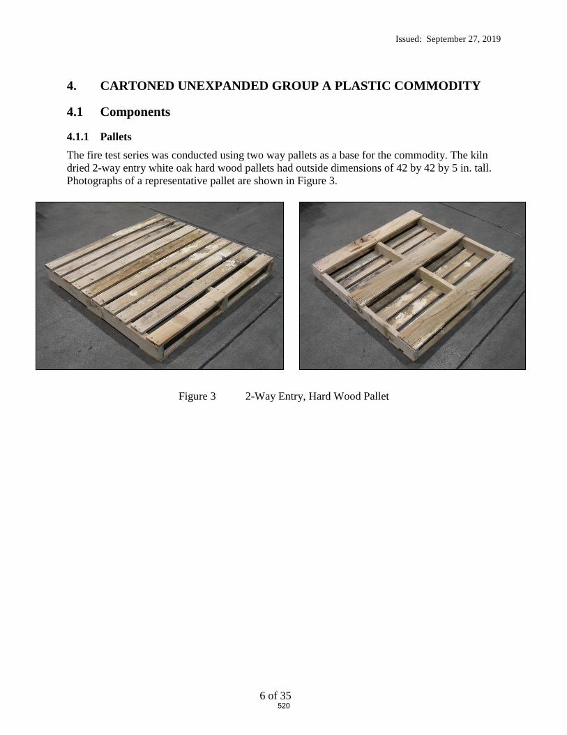
Issued: September 27, 2019
6 of 35
4. CARTONED UNEXPANDED GROUP A PLASTIC COMMODITY
4.1 Components
4.1.1 Pallets
The fire test series was conducted using two way pallets as a base for the commodity. The kiln
dried 2-way entry white oak hard wood pallets had outside dimensions of 42 by 42 by 5 in. tall.
Photographs of a representative pallet are shown in Figure 3.
Figure 3 2-Way Entry, Hard Wood Pallet
520

Issued: September 27, 2019
7 of 35
4.1.2 Cups
The cups used in the cartoned , unexpanded Group A commodities were manufactured from
polystyrene. A photograph of the box and cups is shown in Figure 4.
Figure 4 Cut Away of Single Box Showing Cups
521

Issued: September 27, 2019
8 of 35
4.2 Commodity Description
4.2.1 Cartoned Unexpanded Group A Plastic
The Cartoned Unexpanded Group A Plastic Commodity consisted of eight, single layer
cardboard boxes each containing 125 cups (containing 1,000 unexpanded polystyrene cups
total). Each box contained five tiers of twenty-five cups. Each tier and cup was separated by
one layer of cardboard. The nominal external dimensions of the commodity was 42 inches wide
by 42 inches deep by 40 inches tall resting on a nominal 5 inch tall, 42 by 42 inch hardwood
pallet.
The commodity is shown in Figure 5.
Figure 5 Cartoned unexpanded Group A Plastic Commodity
The test results apply only to the samples tested.
522

Issued: September 27, 2019
9 of 35
5. OBSTRUCTIONS
5.1 Flat Obstruction
The manufactured flat obstruction used in the test consisted of a 24 inch wide flat, ¼ inch thick
steel plate with two, 3 by 3 inch, 3/8 inch thick “L” angles welded to the ends as shown in Figure
6. A photograph of the cross section can be seen in Figure 7.
Three, 15 ft. long sections were positioned back to back for a 45 ft. long continuous flat
obstruction which spanned five sprinklers as shown graphically in Figure 2 and photographically
in Figure 8. The 12 inch sprinkler offset is shown in Figure 9 as viewed from below.
Figure 6 Twenty Four inch Wide Flat Obstruction – Cross Section
Figure 7 Twenty Four inch Wide Flat Obstruction – Photograph of Cross Section
523

Issued: September 27, 2019
10 of 35
Figure 8 45 ft. Long, 24 inch Wide Flat Obstruction – Photograph from the Southwest
Figure 9– Photograph of 24 inch wide Obstruction from Below, Showing Sprinkler offset 12
inches to the Right (South of lab to the right)
524

Issued: September 27, 2019
11 of 35
Figure 10 Test Arrangement – Elevation View from the East Near Ceiling (upper two tiers as shown)
525

Issued: September 27, 2019
12 of 35
Figure 11 Test Arrangement – Elevation View from the East Near Ceiling (detail around obstruction)
Nominal 4 ft. long, 2 by 2 inch steel angle, centered above ignition
24 inch wide flat plate with welded 3 by 3 inch L angles for flat obstruction, Positioned 12 inches horizontal offset from primary sprinkler, 22 inches
below deflector
K = 16.8 Pendent ESFR Sprinkler with deflector positioned 14 inches
below the smooth flat ceiling
526

Issued: September 27, 2019
13 of 35
6. TEST ARRAY CONFIGURATION
6.1 Rack Array and Plan View
The racking system used for the main bay is considered open, double-row racking in accordance
with NFPA 13. Each bay of the racking system was filled with two pallet loads of the test
commodity as defined in section 4.2.
Figure 10 through Figure 12 shows the details of the rack array and their relationship to the
obstructions for the test.
527

Issued: September 27, 2019
14 of 35
Figure 12 Test Array Plan View – Tight View
528

Issued: September 27, 2019
15 of 35
6.2 Ceiling and Clearance
The test laboratory’s moveable ceiling was positioned at 40 ft. from the test room floor.
A 14 inch pendent sprinkler deflector to ceiling clearance was used for all tests.
A nominal 10 ft. clearance between the ceiling and the top of the commodity was established.
Elevation views of the test arrangements are shown in Figure 13 through Figure 14.
529
Issued: September 27, 2019
16 of 35
Figure 13 Elevation View of Main Test Array from the North
530
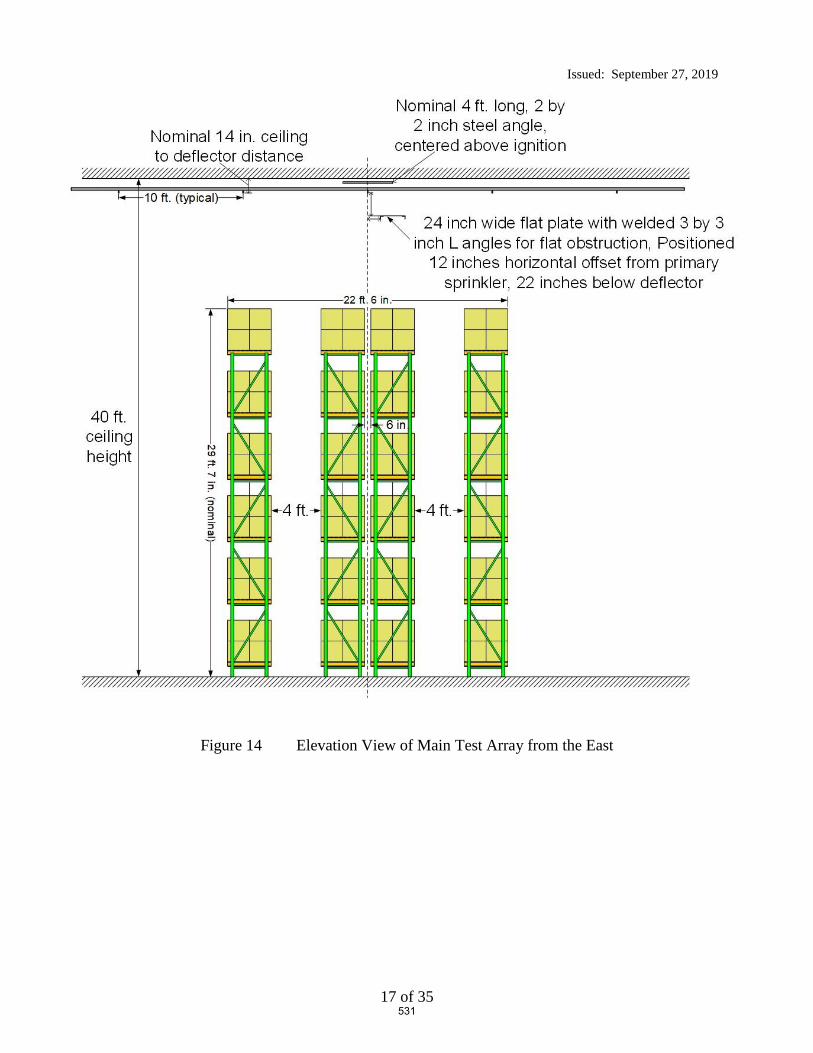
Issued: September 27, 2019
17 of 35
Figure 14 Elevation View of Main Test Array from the East
531

Issued: September 27, 2019
18 of 35
6.3 Test Arrangement
The steel racks were loaded with the commodity as defined in section 4. The loading
arrangement is as shown in Figure 13 through Figure 14.
Photographs of the test arrangement are shown in Figure 15 through Figure 17.
532

Issued: September 27, 2019
19 of 35
Figure 15 Elevation View from the North
533
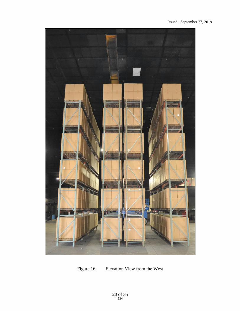
Issued: September 27, 2019
20 of 35
Figure 16 Elevation View from the West
534

Issued: September 27, 2019
21 of 35
Figure 17 Elevation View from the Southwest
535

Issued: September 27, 2019
22 of 35
6.4 Ignition
Ignition was accomplished using two half igniters.
The igniters were constructed from a 3-in. diameter by 3-in. long cellulosic bundle soaked with 4
fluid ounces of gasoline and wrapped in a polyethylene bag. The igniters were positioned
adjacent to the unexpanded plastic commodity in the transverse flue space, near the center of the
North main rack array as shown in Figure 12 and Figure 13.
The rack array was positioned such that it was centered under the obstructed sprinkler as shown
in Figure 2, Figure 13 and Figure 14.
Details of the ignition location can be seen in Figure 18.
Figure 18 View Showing Igniters in North Main Transverse Flue Space at Base of Array
536

Issued: September 27, 2019
23 of 35
7. TEST METHOD
7.1 Test Procedure
The test procedure consisted of the following steps:
1. A camera recording of the test arrangement was documented prior to test.
2. The igniters were placed as discussed previously in the “Ignition” section above.
3. The data acquisition system was started upon ignition of the igniters.
4. The test constant flowing pressure for the ceiling sprinkler system was based on adjusting the
system’s fire pump speed for the number of operated sprinklers.
5. The test proceeded for 30 minutes after the operation of the first sprinkler, rounded up to the
nearest whole minute.
6. Termination of the test after the 30 minute plus first sprinkler operation time period began
with automatic deluging of the array until which time the smoke level was diminished to the
point of visual observation of the array. Fire fighters then manually fought the fire until it
was extinguished.
7. A detailed still camera assessment of the commodity damage within the racking array took
place after the test had been completed. See Appendix B for photographs of the damage
assessment.
7.2 Fire Test Photographs
Various photographs of the initial and latter stages of the fire are shown in Figure 19 through
Figure 22.
537
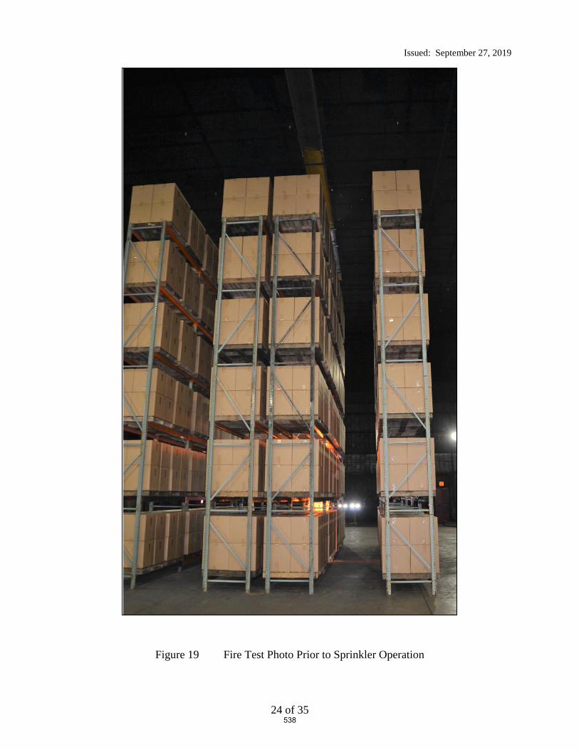
Issued: September 27, 2019
24 of 35
Figure 19 Fire Test Photo Prior to Sprinkler Operation
538

Issued: September 27, 2019
25 of 35
Figure 20 Fire Test Photo Immediately Prior to Sprinkler Operation
539

Issued: September 27, 2019
26 of 35
Figure 21 Photograph Showing Water Cascading over the top of the 24 inch wide
Obstruction after Operation – Note the amount of water sheeting down the Main Array
540
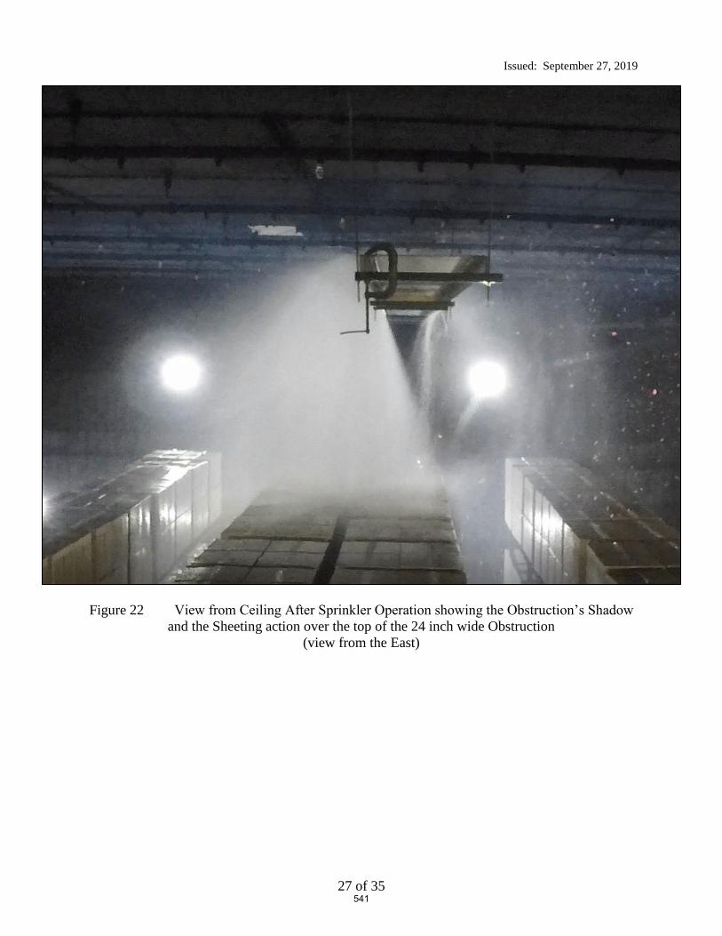
Issued: September 27, 2019
27 of 35
Figure 22 View from Ceiling After Sprinkler Operation showing the Obstruction’s Shadow
and the Sheeting action over the top of the 24 inch wide Obstruction
(view from the East)
541

Issued: September 27, 2019
28 of 35
8. RESULTS AND DISCUSSION
One large scale fire test incorporating rack storage of cartoned unexpanded Group A plastic was
conducted at UL LLC in Northbrook, IL on September 24, 2019. The following is a summary of
the resulting data.
8.1 Number of Operating Sprinklers:
Figure 23 provides the sprinkler operation time for the test.
542
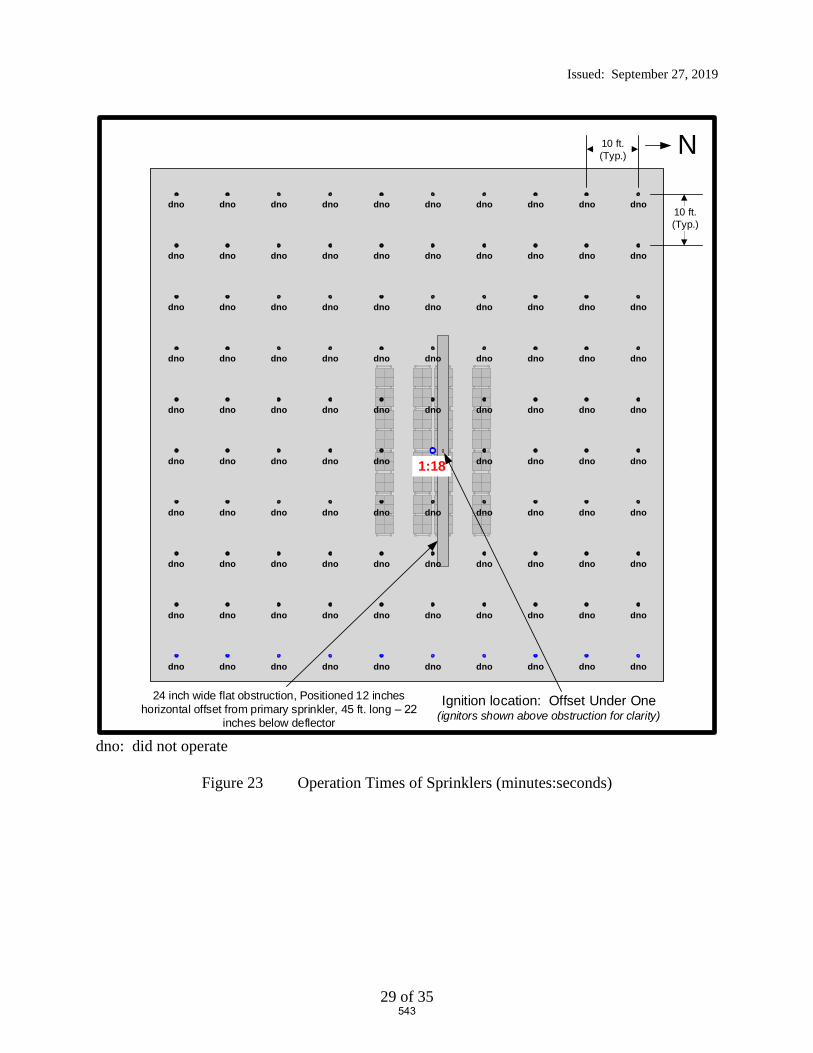
Issued: September 27, 2019
29 of 35
dno: did not operate
Figure 23 Operation Times of Sprinklers (minutes:seconds)
N10 ft. (Typ.)
10 ft. (Typ.)
Ignition location: Offset Under One(ignitors shown above obstruction for clarity)
dno dno dno dno dno dno dno dno dno dno
24 inch wide flat obstruction, Positioned 12 inches horizontal offset from primary sprinkler, 45 ft. long –
inches below deflector
1:18
dno dno dno dno dno dno dno dno dno dno
dno dno dno dno dno dno dno dno dno dno
dno dno dno dno dno dno dno dno dno dno
dno dno dno dno dno dno dno dno dno
dno dno dno dno dno dno dno dno dno dno
dno dno dno dno dno dno dno dno dno dno
dno dno dno dno dno dno dno dno dno dno
dno dno dno dno dno dno dno dno dno dno
dno dno dno dno dno dno dno dno dno dno
543

Issued: September 27, 2019
30 of 35
8.2 Temperature Results:
Appendix A provides the data for the test as follows.
The individual sprinkler temperature profiles are presented in Figures 1 through 10 of the
Appendix.
Steel beam and gas temperatures above ignition are presented in Figure 11 and 12 of the
Appendix.
Sprinkler system flowing pressures and system flow rates are presented in Figure 13 of
the Appendix.
8.3 Commodity Damage Results:
The test arrangement was examined for fire test damage to the stored commodity.
The fire did not jump the 4 ft. aisle and the fire was contained within the main array. The
external damage was limited to the North portion of the main array as the South face of the main
array was not damaged.
Drawings of the extent of the damage are depicted in Figure 24 and Figure 25. Photographs of
the overall damage are illustrated in Appendix B.
544
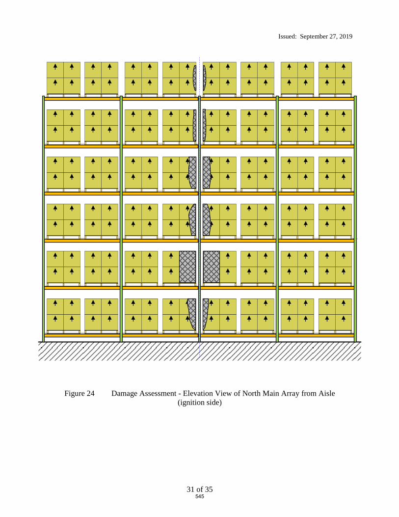
Issued: September 27, 2019
31 of 35
Figure 24 Damage Assessment - Elevation View of North Main Array from Aisle
(ignition side)
545

Issued: September 27, 2019
32 of 35
Figure 25 Damage Assessment - Elevation View of South Main Array from Aisle
(no damage)
546
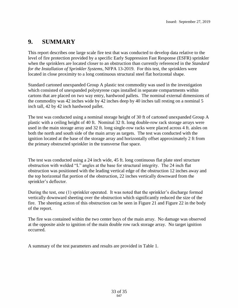
Issued: September 27, 2019
33 of 35
9. SUMMARY
This report describes one large scale fire test that was conducted to develop data relative to the
level of fire protection provided by a specific Early Suppression Fast Response (ESFR) sprinkler
when the sprinklers are located closer to an obstruction than currently referenced in the Standard
for the Installation of Sprinkler Systems, NFPA 13-2019. For this test, the sprinklers were
located in close proximity to a long continuous structural steel flat horizontal shape.
Standard cartoned unexpanded Group A plastic test commodity was used in the investigation
which consisted of unexpanded polystyrene cups installed in separate compartments within
cartons that are placed on two way entry, hardwood pallets. The nominal external dimensions of
the commodity was 42 inches wide by 42 inches deep by 40 inches tall resting on a nominal 5
inch tall, 42 by 42 inch hardwood pallet.
The test was conducted using a nominal storage height of 30 ft of cartoned unexpanded Group A
plastic with a ceiling height of 40 ft. Nominal 32 ft. long double-row rack storage arrays were
used in the main storage array and 32 ft. long single-row racks were placed across 4 ft. aisles on
both the north and south side of the main array as targets. The test was conducted with the
ignition located at the base of the storage array and horizontally offset approximately 2 ft from
the primary obstructed sprinkler in the transverse flue space.
The test was conducted using a 24 inch wide, 45 ft. long continuous flat plate steel structure
obstruction with welded “L” angles at the base for structural integrity. The 24 inch flat
obstruction was positioned with the leading vertical edge of the obstruction 12 inches away and
the top horizontal flat portion of the obstruction, 22 inches vertically downward from the
sprinkler’s deflector.
During the test, one (1) sprinkler operated. It was noted that the sprinkler’s discharge formed
vertically downward sheeting over the obstruction which significantly reduced the size of the
fire. The sheeting action of this obstruction can be seen in Figure 21 and Figure 22 in the body
of the report.
The fire was contained within the two center bays of the main array. No damage was observed
at the opposite aisle to ignition of the main double row rack storage array. No target ignition
occurred.
A summary of the test parameters and results are provided in Table 1.
547

Issued: September 27, 2019
34 of 35
Table 1 Test Parameters and Results
Test Date September 24, 2019
Test Parameters Storage Type Double Row Rack
Commodity Type Cartoned Unexpanded Group A Plastic
(Plastic Cups in Corrugated Boxes on Hardwood Pallets)
Pallet Type 2 way entry, stringer, hardwood
Nominal Storage Height, ft. 30
Ceiling Height, ft. 40
Nominal Clearance, ft. 10
Aisle Width, ft. 4
Ignition Location Under One Sprinkler (offset)
Sprinkler Systems Ceiling Only (no in-rack sprinklers)
Sprinkler Orientation Pendent
Deflector to Ceiling, in. 14 Sprinkler Spacing, sprinkler by branchline,
ft. by ft. 10 by 10
Temperature Rating, °F 165
Sprinkler Type ESFR Nominal Sprinkler Discharge Coefficient K,
gpm/psig 0.5 16.8
Nominal Discharge Density, gpm/ft2 1.21
Nominal Discharge Pressure, psig 52
Primary Obstruction
24 inch wide, 3 inch deep flat steel obstruction,
positioned 12 inches offset from primary
sprinkler with top of obstruction positioned 22
inches below the sprinkler’s deflector
Secondary Obstruction None
Test Results
Length of Test, minutes 32:00
First Sprinkler Operation Time, min:sec 1:18
Last Sprinkler Operation Time, min:sec 1:18
Number of Operated Sprinklers 1
Approximate Time of Target Ignition Across 4 ft. Aisle, minutes
No ignition
Peak Gas Temperature at Ceiling Above Ignition, °F 191
Maximum 1 minute Average Gas Temperature at Ceiling Above Ignition, °F
110
Peak Steel Temperature at Ceiling Above Ignition, °F
80
Maximum 1 minute Average Steel Temperature at Ceiling Above Ignition, °F
80
Fire Travel to Extremities of Test Array No
548

Issued: September 27, 2019
35 of 35
Report By: Reviewed By:
Daniel R. Steppan Michael G. McCormick
Senior Staff Engineer Staff Engineering Associate
Building and Life Safety Technologies Building and Life Safety Technologies
549

Appendix A – Temperature, Flow and Pressure Graphs
A-1
APPENDIX A
Temperature, Flow and Pressure Graphs
550

Appendix A – Temperature, Flow and Pressure Graphs
A-2
Figure A- 1 Ceiling Sprinklers 1 through 10
Figure A- 2 Ceiling Sprinklers 11 through 20
551
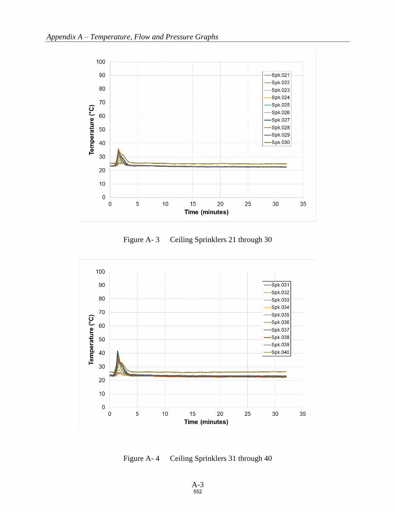
Appendix A – Temperature, Flow and Pressure Graphs
A-3
Figure A- 3 Ceiling Sprinklers 21 through 30
Figure A- 4 Ceiling Sprinklers 31 through 40
552
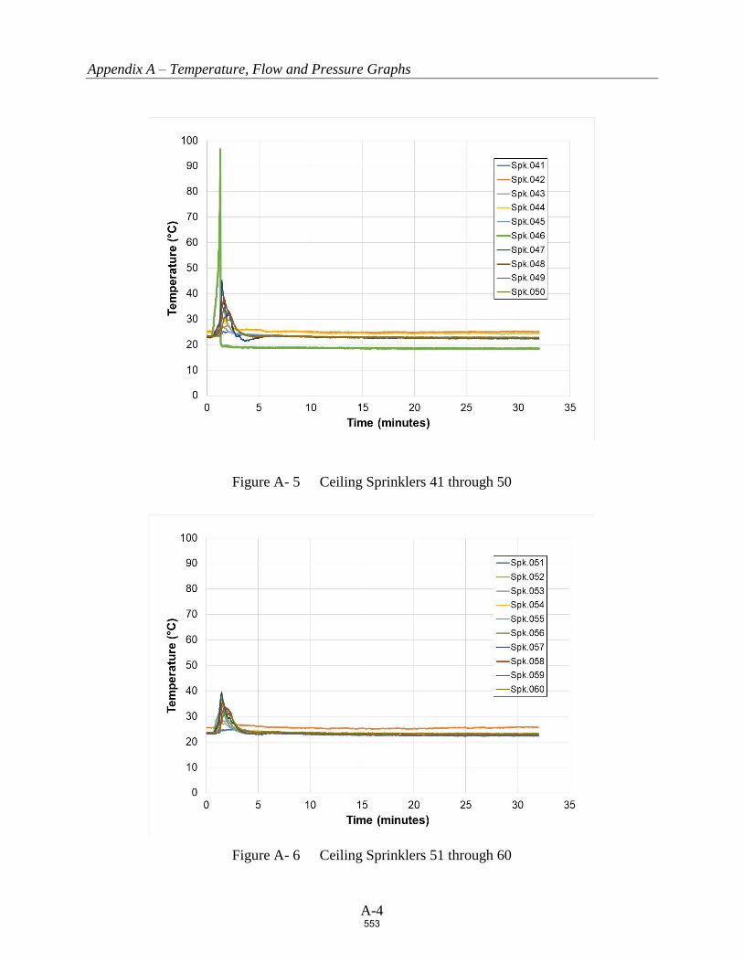
Appendix A – Temperature, Flow and Pressure Graphs
A-4
Figure A- 5 Ceiling Sprinklers 41 through 50
Figure A- 6 Ceiling Sprinklers 51 through 60
553

Appendix A – Temperature, Flow and Pressure Graphs
A-5
Figure A- 7 Ceiling Sprinklers 61 through 70
Figure A- 8 Ceiling Sprinklers 71 through 80
554

Appendix A – Temperature, Flow and Pressure Graphs
A-6
Figure A- 9 Ceiling Sprinklers 81 through 90
Figure A- 10 Ceiling Sprinklers 91 through 100
555

Appendix A – Temperature, Flow and Pressure Graphs
A-7
Figure A- 11 Ceiling Steel Beam Temperature Above Ignition
Figure A- 12 Ceiling Gas Temperature Above Ignition
556

Appendix A – Temperature, Flow and Pressure Graphs
A-8
Figure A- 13 Ceiling Sprinkler System Flow rate and Pressure
557

Appendix B – Damage Assessment Photographs
B-1
APPENDIX B
Damage Assessment Photographs
558

Appendix B – Damage Assessment Photographs
B-2
Figure B- 1 North Target Array from East end of Aisle Space (no damage)
559
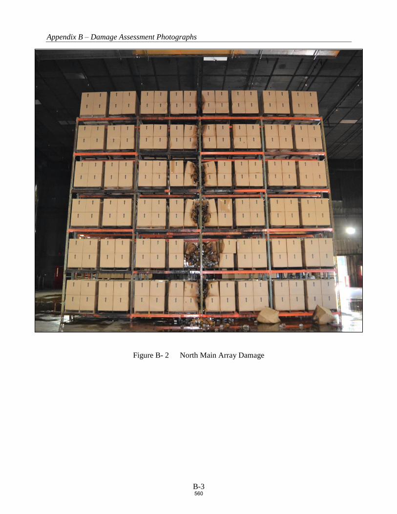
Appendix B – Damage Assessment Photographs
B-3
Figure B- 2 North Main Array Damage
560

Appendix B – Damage Assessment Photographs
B-4
Figure B- 3 South Main Array Damage
(NOTE: Dark spots due to fire fighting efforts – no damage)
561

Public Comment No. 396-NFPA 13-2020 [ Section No. 14.2.11.3 ]
14.2.11.3 Continuous Obstructions Below Sprinklers.
14.2.11.3.1 General Continuous Obstructions.
Sprinklers shall be arranged with respect to obstructions in accordance with one of the following:
(1) Sprinklers shall be installed below continuous obstructions, or they shall be arranged to comply withTable 14.2.11.1.1 for horizontal obstructions entirely below the elevation of sprinklers that restrictsprinkler discharge pattern for two or more adjacent sprinklers such as ducts, lights, pipes, andconveyors.
(2) Additional sprinklers shall not be required where the obstruction is 2 in. (50 mm) or less in width and islocated a minimum of 2 ft (600 mm) below the elevation of the sprinkler deflector or is positioned aminimum of 1 ft (300 mm) horizontally from the sprinkler.
(3) Additional sprinklers shall not be required where the obstruction is 1 ft (300 mm) or less in width andlocated a minimum of 1 ft (300 mm) horizontally from the sprinkler.
(4) Additional sprinklers shall not be required where the obstruction is 2 ft (600 mm) or less in width andlocated a minimum of 2 ft (600 mm) horizontally from the sprinkler.
(5) Ceiling sprinklers shall not be required to comply with Table 14.2.11.1.1 where a row of sprinklers isinstalled under the obstruction.
(6) Additional sprinklers shall not be required where the occupancy is protected in accordance with 14.2.7and obstructions comply with 9.5.5.3.
14.2.11.3.2 Bottom Chords of Bar Joists or Open Trusses.
ESFR sprinklers shall be positioned a minimum of 1 ft (300 mm) horizontally from the nearest edge to thebottom chord of a bar joist or open truss where the bottom chord does not exceed 1 ft (300 mm) in width.
14.2.11.3.2.1
The requirements of 14.2.11.3.2 shall not apply where upright sprinklers are located over the bottomchords of bar joists or open trusses that are 4 in. (100 mm) maximum in width.
14.2.11.3.3 Branchlines.
Upright sprinklers shall be positioned with respect to branch lines in accordance with one of the following:
(1) Attached directly to branch lines less than or equal to 4 in. (100 mm) nominal diameter
(2) Offset horizontally a minimum of 12 in. (300 mm) from the pipe
(3) Supplied by a riser nipple (sprig) to elevate the sprinkler deflector a minimum of 12 in. (300 mm) fromthe centerline of any pipe over 4 in. (100 mm) nominal in diameter
14.2.11.3.4*
For pipes, conduits, or groups of pipes and conduit to be considered individual, they shall be separatedfrom the closest adjacent pipe, conduit, cable tray, or similar obstructions by a minimum of three times thewidth of the adjacent pipe, conduit, cable tray, or similar obstruction.
14.2.11.3.5 Open Gratings.
Sprinklers installed under open gratings shall be of the intermediate level/rack storage type or otherwiseshielded from the discharge of overhead sprinklers.
14.2.11.3.6 Overhead Doors.
Quick-response spray sprinklers shall be permitted to be utilized under overhead doors.
14.2.11.3.7 Special Obstruction Allowance.
Sprinklers with a special obstruction allowance shall be installed according to their listing.
Additional Proposed Changes
File Name Description Approved
National Fire Protection Association Report https://submittals.nfpa.org/TerraViewWeb/ContentFetcher?commentPar...
276 of 738 5/8/2020, 11:28 AM
562
14.2.11.3_-_PALENSKE.docx
ESFR_Final_Report_5.1.20._submittal_version.pdf
Statement of Problem and Substantiation for Public Comment
SEE ATTACHED WORD DOC FOR PROPOSED CHANGES.
Committee input for the submitted previously PI’s was that the test results do not support the proposed changes and the results should be revisited. These revisions submitted are intended to address the committee comments.The proposed changes are the based upon the findings of the NFPA Research Foundation’s six year ESFR and Obstruction research project. Nine full-scale and 80 Actual Delivered Density tests were completed. Seven tests were completed with obstructions located 6 inches horizontally from the sprinkler. Six of the tests were successful. The recently completed report (final draft) is attached for documentation. The findings from the report are shown below:• The obstruction created by an open web steel truss between the depths of 22 - 36 inches, located 6 inches horizontally from a K14 or K17 ESFR sprinkler, should not significantly decrease sprinkler performance. • The obstruction created by a bridging member 1½ x 1½ inches in size or less, located directly below the sprinkler with an 18 inch vertical clearance (K14) or 12 inch vertical clearance (K17) should not significantly decrease sprinkler performance. This also applies to bridging members attached to open web steel trusses.• The obstruction created by flat or round obstructions less than or equal to 12 inches in width located 6 inches horizontally from a K17 or K14 sprinkler should not significantly decrease sprinkler performance.• The obstruction created by flat or round obstructions less than or equal to 24 inches in width located 12 inches horizontally from a K17 or K14 sprinkler should not significantly decrease sprinkler performance.
Related Item
• 14.2.11.3
Submitter Information Verification
Submitter Full Name: Garner Palenske
Organization: Wiss Janney Elstner Associates
Street Address:
City:
State:
Zip:
Submittal Date: Wed May 06 16:58:18 EDT 2020
Committee: AUT-AAC
National Fire Protection Association Report https://submittals.nfpa.org/TerraViewWeb/ContentFetcher?commentPar...
277 of 738 5/8/2020, 11:28 AM
563
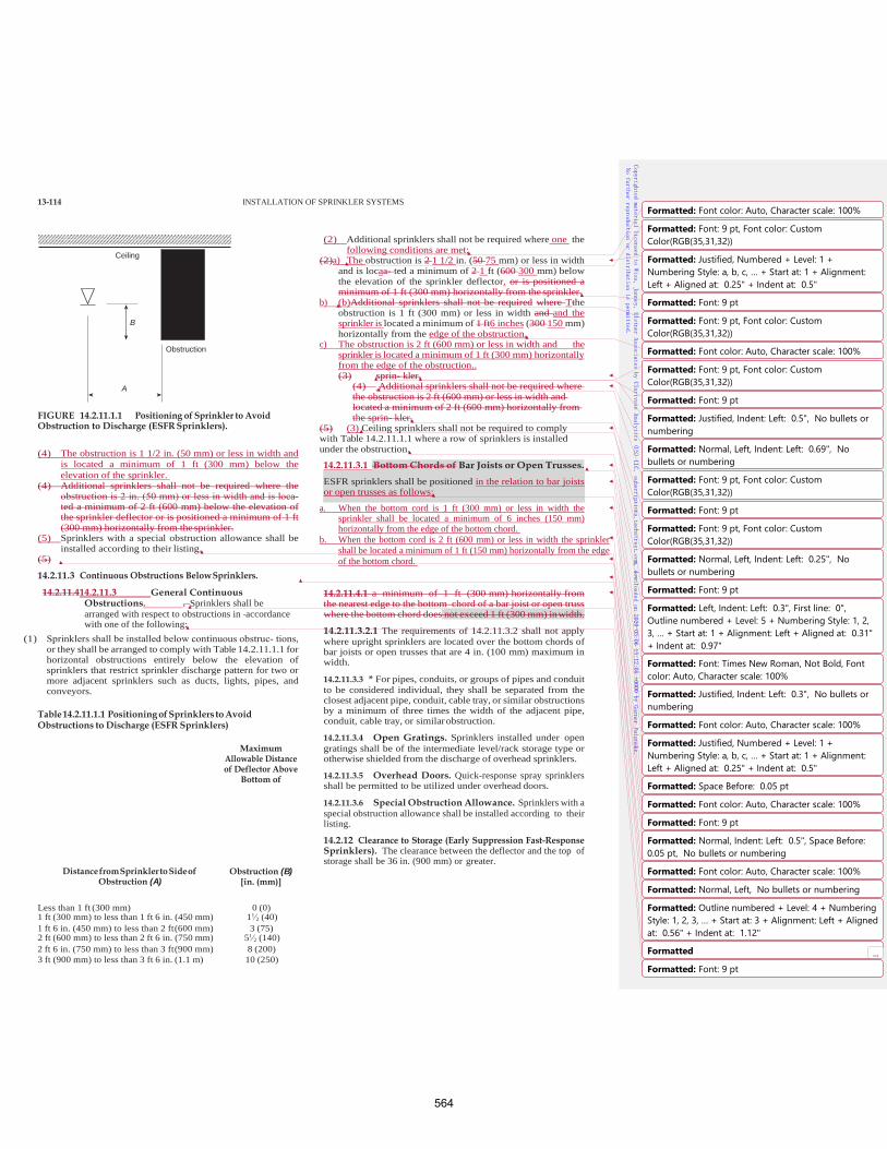
13-114 INSTALLATION OF SPRINKLER SYSTEMS
FIGURE 14.2.11.1.1 Positioning of Sprinkler to Avoid Obstruction to Discharge (ESFR Sprinklers).
(4) The obstruction is 1 1/2 in. (50 mm) or less in width and
is located a minimum of 1 ft (300 mm) below the elevation of the sprinkler.
(4) Additional sprinklers shall not be required where the obstruction is 2 in. (50 mm) or less in width and is loca‐ ted a minimum of 2 ft (600 mm) below the elevation of the sprinkler deflector or is positioned a minimum of 1 ft (300 mm) horizontally from the sprinkler.
(5) Sprinklers with a special obstruction allowance shall be installed according to their listing.
(5)
14.2.11.3 Continuous Obstructions Below Sprinklers.
14.2.11.414.2.11.3 General Continuous Obstructions. . Sprinklers shall be arranged with respect to obstructions in accordance with one of the following:
(1) Sprinklers shall be installed below continuous obstruc‐ tions, or they shall be arranged to comply with Table 14.2.11.1.1 for horizontal obstructions entirely below the elevation of sprinklers that restrict sprinkler discharge pattern for two or more adjacent sprinklers such as ducts, lights, pipes, and conveyors.
Table 14.2.11.1.1 Positioning of Sprinklers to Avoid Obstructions to Discharge (ESFR Sprinklers)
Maximum Allowable Distance of Deflector Above
Bottom of
(2) Additional sprinklers shall not be required where one the
following conditions are met: (2)a) The obstruction is 2 1 1/2 in. (50 75 mm) or less in width
and is locaa‐ ted a minimum of 2 1 ft (600 300 mm) below the elevation of the sprinkler deflector. or is positioned a minimum of 1 ft (300 mm) horizontally from the sprinkler.
b) (b)Additional sprinklers shall not be required where Tthe obstruction is 1 ft (300 mm) or less in width and and the sprinkler is located a minimum of 1 ft6 inches (300 150 mm) horizontally from the edge of the obstruction.
c) The obstruction is 2 ft (600 mm) or less in width and the sprinkler is located a minimum of 1 ft (300 mm) horizontally from the edge of the obstruction.. (3) sprin‐ kler.
(4) Additional sprinklers shall not be required where the obstruction is 2 ft (600 mm) or less in width and located a minimum of 2 ft (600 mm) horizontally from the sprin‐ kler.
(5) (3) Ceiling sprinklers shall not be required to comply with Table 14.2.11.1.1 where a row of sprinklers is installed under the obstruction.
14.2.11.3.1 Bottom Chords of Bar Joists or Open Trusses.
ESFR sprinklers shall be positioned in the relation to bar joists or open trusses as follows:
a. When the bottom cord is 1 ft (300 mm) or less in width the sprinkler shall be located a minimum of 6 inches (150 mm) horizontally from the edge of the bottom chord.
b. When the bottom cord is 2 ft (600 mm) or less in width the sprinkler shall be located a minimum of 1 ft (150 mm) horizontally from the edge of the bottom chord.
14.2.11.4.1 a minimum of 1 ft (300 mm) horizontally from the nearest edge to the bottom chord of a bar joist or open truss where the bottom chord does not exceed 1 ft (300 mm) in width.
14.2.11.3.2.1 The requirements of 14.2.11.3.2 shall not apply where upright sprinklers are located over the bottom chords of bar joists or open trusses that are 4 in. (100 mm) maximum in width.
14.2.11.3.3 * For pipes, conduits, or groups of pipes and conduit to be considered individual, they shall be separated from the closest adjacent pipe, conduit, cable tray, or similar obstructions by a minimum of three times the width of the adjacent pipe, conduit, cable tray, or similar obstruction.
14.2.11.3.4 Open Gratings. Sprinklers installed under open gratings shall be of the intermediate level/rack storage type or otherwise shielded from the discharge of overhead sprinklers.
14.2.11.3.5 Overhead Doors. Quick-response spray sprinklers shall be permitted to be utilized under overhead doors.
14.2.11.3.6 Special Obstruction Allowance. Sprinklers with a special obstruction allowance shall be installed according to their listing.
14.2.12 Clearance to Storage (Early Suppression Fast-Response Sprinklers). The clearance between the deflector and the top of storage shall be 36 in. (900 mm) or greater.
Distance from Sprinkler to Side of Obstruction (A)
Obstruction (B) [in. (mm)]
Less than 1 ft (300 mm) 0 (0) 1 ft (300 mm) to less than 1 ft 6 in. (450 mm) 11∕2 (40) 1 ft 6 in. (450 mm) to less than 2 ft (600 mm) 3 (75) 2 ft (600 mm) to less than 2 ft 6 in. (750 mm) 51∕2 (140) 2 ft 6 in. (750 mm) to less than 3 ft (900 mm) 8 (200) 3 ft (900 mm) to less than 3 ft 6 in. (1.1 m) 10 (250)
Ceiling
B
Obstruction
A
Copyrighted material licensed to Wiss, Janney, Elstner Associates by Clarivate Analytics (US) LLC, subscriptions.techstreet.com, downloaded on 2020-05-06 15:12:05 +0000 by Garner Palens
ke.
No further reproduction or distribution is permitted.
Formatted: Space Before: 0.05 pt
Formatted: Font color: Auto, Character scale: 100%
Formatted: Font: 9 pt
Formatted: Normal, Indent: Left: 0.5", Space Before: 0.05 pt, No bullets or numbering
Formatted: Outline numbered + Level: 4 + NumberingStyle: 1, 2, 3, … + Start at: 3 + Alignment: Left + Alignedat: 0.56" + Indent at: 1.12"
Formatted ...Formatted: Font: 9 pt
Formatted: Font color: Auto, Character scale: 100%
Formatted: Font: 9 pt, Font color: CustomColor(RGB(35,31,32))
Formatted: Justified, Numbered + Level: 1 +Numbering Style: a, b, c, … + Start at: 1 + Alignment:Left + Aligned at: 0.25" + Indent at: 0.5"
Formatted: Font: 9 pt
Formatted: Font: 9 pt, Font color: CustomColor(RGB(35,31,32))
Formatted: Font color: Auto, Character scale: 100%
Formatted: Font: 9 pt, Font color: CustomColor(RGB(35,31,32))
Formatted: Justified, Indent: Left: 0.5", No bullets ornumbering
Formatted: Font: 9 pt
Formatted: Normal, Left, Indent: Left: 0.69", Nobullets or numbering
Formatted: Font: 9 pt, Font color: CustomColor(RGB(35,31,32))
Formatted: Font: 9 pt
Formatted: Normal, Left, Indent: Left: 0.25", Nobullets or numbering
Formatted: Font: 9 pt, Font color: CustomColor(RGB(35,31,32))
Formatted: Font: 9 pt
Formatted: Left, Indent: Left: 0.3", First line: 0",Outline numbered + Level: 5 + Numbering Style: 1, 2,3, … + Start at: 1 + Alignment: Left + Aligned at: 0.31"+ Indent at: 0.97"
Formatted: Font: Times New Roman, Not Bold, Fontcolor: Auto, Character scale: 100%
Formatted: Justified, Indent: Left: 0.3", No bullets ornumbering
Formatted: Font color: Auto, Character scale: 100%
Formatted: Justified, Numbered + Level: 1 +Numbering Style: a, b, c, … + Start at: 1 + Alignment:Left + Aligned at: 0.25" + Indent at: 0.5"
Formatted: Font color: Auto, Character scale: 100%
Formatted: Normal, Left, No bullets or numbering
564

3 ft 6 in. (1.1 m) to less than 4 ft (1.2 m) 12 (300) 4 ft (1.2 m) to less than 4 ft 6 in. (1.4 m) 15 (375) 4 ft 6 in. (1.4 m) to less than 5 ft (1.5 m) 18 (450) 5 ft (1.5 m) to less than 5 ft 6 in. (1.7 m) 22 (550) 5 ft 6 in. (1.7 m) to less than 6 ft (1.8 m) 26 (650) 6 ft (1.8 m) 31 (775) Note: For A and B, refer to Figure 14.2.11.1.1.
2019 Edition
565

17
Obstructions and Early Suppression Fast
Response Sprinklers
Phase 4 Final Report
FINAL REPORT
May 1, 2020
WJE No. 2018.8439.0
PREPARED FOR:
Amanda Kimball, P.E.
Executive Director | Research Foundation
1 Batterymarch Park
Quincy, MA 02169-7471
PREPARED BY:
Wiss, Janney, Elstner Associates, Inc.
16496 Bernardo Center Drive, Suite 202
San Diego, California 92128
858.207.5461 tel
566
Obstructions and Early Suppression Fast Response Sprinklers
Phase 4 Final Report
FINAL REPORT | WJE No. 2018.8439.0 | MAY 1, 2020
ABSTRACT
Obstructions created by ceiling structural members, lighting, piping, or cable trays, can hinder Early
Suppression Fast Response (ESFR) sprinkler performance. However, ESFR sprinkler obstruction sensitivity is
largely unknown. The requirements found in the current edition of National Fire Protection Association
Standard 13, Standard for the Installation of Sprinkler Systems (NFPA 13), are considered conservative and
have created difficulties in practical application.
Acknowledging the importance of this issue, NFPA’s research affiliate, the Fire Protection Research
Foundation, embarked on a multi-year testing program which began in 2014. The fourth and final phase
of the project, which included K14 ESFR Actual Delivered Density (ADD) testing and K17 ESFR sprinkler
full-scale fire testing, was completed in September of 2019. In total, approximately 80 ADD tests and nine
full-scale fire tests were completed using K17 and K14 ESFR sprinklers.
This report presents an overall summary of the ESFR sprinkler obstruction project including the results of
the recently completed K14 ESFR testing. The reader is encouraged to read the reports from Phases 1-3 of
the project, which are available online at the Fire Protection Research Foundation website
(www.nfpa.org/News-and-Research/Resources/).
The findings of the project are as follows:
The obstruction created by an open web steel truss between the depths of 22 - 36 inches, located
6 inches horizontally from a K14 or K17 ESFR sprinkler, should not significantly decrease sprinkler
performance.
The obstruction created by a bridging member 1½ x 1½ inches in size or less, located directly
below the sprinkler with an 18 inch vertical clearance (K14) or 12 inch vertical clearance (K17)
should not significantly decrease sprinkler performance. This also applies to bridging members
attached to open web steel trusses.
The obstruction created by flat or round obstructions less than or equal to 12 inches in width
located 6 inches horizontally from a K17 or K14 sprinkler should not significantly decrease
sprinkler performance.
The obstruction created by flat or round obstructions less than or equal to 24 inches in width
located 12 inches horizontally from a K17 or K14 sprinkler should not significantly decrease
sprinkler performance.
Keywords: Early Suppression Fast Response Sprinklers, Actual Delivered Density, Obstruction.
567

Obstructions and Early Suppression Fast Response Sprinklers
Phase 4 Final Report
FINAL REPORT | WJE No. 2018.8439.0 | MAY 1, 2020
CONTENTS1
Introduction ........................................................................................................................................................ 1
Project Overview ................................................................................................................................................ 2
Obstruction Experimentation .......................................................................................................................... 4
Actual Delivered Density (ADD) Testing ...................................................................................................................................... 4
Full-Scale Fire Testing ...................................................................................................................................................................... 12
Results and Findings ....................................................................................................................................... 15
Bar Joist and Bridging Member Obstructions ........................................................................................................................ 17
Flat Obstructions................................................................................................................................................................................ 19
Conclusions ...................................................................................................................................................... 32
Acknowledgements ........................................................................................................................................ 32
APPENDIX A. Actual Delivered Density Testing of ESFR Sprinklers Obstructed by Flat
Obstructions (Phase 4), Underwriters Laboratories, April 26, 2019
APPENDIX B. ESFR Sprinklers Obstructed by Continuous Flat Obstructions (Phase 4),
Underwriters Laboratories, September 27, 2019
1 The Authors wish to thank the Research Foundation and Underwriters Laboratories for allowing use of the reports from previous
phases of this project.
568
Obstructions and Early Suppression Fast Response Sprinklers
Phase 4 Final Report
FINAL REPORT | WJE No. 2018.8439.0 | MAY 1, 2020 Page 1
INTRODUCTION
Storage occupancies have undergone significant changes since the introduction of the standard spray
sprinkler in 1956. The increased use of plastic packing material, in conjunction with the increased demand
for plastic products, creates extreme challenges for storage sprinklers. The lighter product weight allows
higher storage. In addition, the heat release rate of plastic material is much higher than that of wood or
paper products.2 The characteristics of modern storage fires include very fast fire growth rates and high
fire plume velocities.3
In the 1970’s, FM Global scientists embarked on a dedicated storage research program to address this
issue. The program explored sprinkler performance characteristics, including response time (Response
Time Index) and the relationship between the actual amount of water delivered to the fire source (Actual
Delivered Density) compared to the required amount of water delivered for fire suppression (Required
Delivered Density). These concepts were instrumental in the invention of the ESFR sprinkler in the 1980s.4
The requirements outlined in the current edition of NFPA 13 provide prescriptive language for the
placement of ESFR sprinklers in regard to obstructions in the near field. It is surmised that the
requirements are based on proprietary testing completed by FM Global. ESFR sprinkler obstruction
requirements have remained unchanged since the early development of the sprinkler. Overall, published
ESFR obstruction fire test data, prior to this project, is sparse.
In 2002, FM Global published the results of two ESFR obstruction fire tests conducted in their legacy fire
test laboratory located in Providence, Rhode Island.5 In both tests, obstructions (4 inch wide bar joist
chord and a 1½ x 1½ inch bridging member) were placed 8 inches directly below the sprinkler. The results
of the tests were considered unacceptable due to excessive sprinkler operation (29 sprinklers and 27
sprinklers in Tests No. 1 and 2, respectively) and fire propagation beyond the ignition array.
The 2019 edition of NFPA 13 includes numerous requirements for ESFR sprinkler placement with respect
to obstructions. The most problematic, as determined by a user group survey, is that of the bridging
members attached to bar joists. The early phases of this project focused on this issue. Miscellaneous
obstructions, such as lights, conduit and other structural members were studied in the later phases. A
variety of obstruction variables were explored, including horizontal placement, vertical placement, width,
and shape.
This project is unique due to the innovative use of the Actual Delivered Density (ADD) apparatus as a
scoping tool for full-scale testing. ADD testing is typically used for sprinkler listing or approval. The
2 The heat of combustion of thermoplastic polymers range between 15.5 to 46.5 kJ/g with a medium of 41.6 kJ/g, while natural
polymers (cellulose) have a significantly lower heat of combustion of 16.1 kJ/g. (Drysdale, Dougal. “An Introduction to Fire Dynamics”,
2011, Table 1.2).
3 Kung, H.C., FM Global. “Experimental Study of Actual Delivered Density for Rack Storage Fires,” Fire Safety Science- Proceedings of
the Fourth International Symposium on Safety Science and Technology (1994)
4 Kung, H. C., Victaulic. Fire Protection Engineering, Edition Q1, 2011
5 Kung, H.C., FM Global. “Effect of Ceiling Obstructions Upon the Performance of ESFR Pendent Sprinklers in 12 M High Buildings,”
International Symposium on Safety Science and Technology (2002)
569

Obstructions and Early Suppression Fast Response Sprinklers
Phase 4 Final Report
FINAL REPORT | WJE No. 2018.8439.0 | MAY 1, 2020 Page 2
technology has been around since the 1990s. ADD testing allowed the examination of approximately 80
scenarios from which nine full-scale tests were selected.
ADD testing does not account for all of the variables that can influence sprinkler performance, such as
sprinkler “skipping,” the phenomenon where sprinklers do not activate in the common circular pattern.
ADD testing provides a methodology to identify trends and identify scenarios which may pass or fail the
selected performance criteria. Given the wide range of variables included in the project scope, ADD
proved to be a reliable and consistent tool to quickly and economically simulate full-scale test outcomes.
PROJECT OVERVIEW
The work was completed in four distinctive phases, each building upon the tests conducted prior to obtain
a comprehensive view of ESFR obstruction phenomena, as guided by the selected boundary conditions.
Phase 1 consisted of a literature search in which relevant research concerning ESFR sprinkler performance
and obstruction criteria was collected and reviewed. Potential obstruction scenarios for the testing were
also identified.
Given the infinite number of sprinkler obstruction conditions that may occur, boundary conditions for the
testing were established. Survey results of NFPA 13 users worldwide showed that open web steel joists are
the most commonly used structural roof system. Bridging members, which provide lateral support for
maintaining stability under vertical loads, were identified as the most problematic ESFR sprinkler
obstruction (Figure 1).6 Discussions with leading steel joist suppliers indicated that the most common sizes
sold are in the range of 22 -36 inches in depth, with 30 inches deep being the most popular. 7
The obstruction created by an open web steel truss is dependent on the size of the bottom chord. The
upper chord is assumed to be above the sprinkler and thus out of the sprinkler spray pattern. The web of
the steel truss is minimal in size, typically ½ inch wide “L” stock and, therefore, is assumed to not influence
the sprinkler discharge pattern in a significant manner. For sprinkler obstruction purposes, the obstruction
created by the bottom chord resembles an unattached flat horizontal obstruction of the same width.
The chords are constructed of two “L” shaped members, welded or bolted together back to back. In
addition, the web is attached between the two, increasing the width by approximately ½ inch. The width
of the bottom chord is a function of the depth of the open web steel joist. Joists 22 - 30 inches deep are
provided with chords 4 ½ inches in width, and joists 36 inches deep are provided with chords 5 ½ inches
in width.
6 Palenske, Garner A., “Obstructions and ESFR Sprinklers-Phase 1,” NFPA Research Foundation 2014
7 Ibid
570

Obstructions and Early Suppression Fast Response Sprinklers
Phase 4 Final Report
FINAL REPORT | WJE No. 2018.8439.0 | MAY 1, 2020 Page 3
Figure 1. 22-inch Deep Bar Joist with Bridging Member8
The characteristics of the ESFR sprinkler selected for the testing were also determined in Phase 1.
Discussions with leading sprinkler manufacturers were conducted to aid in this selection. Upright style
ESFR sprinklers were found to be of minimal popularity, therefore pendent style sprinklers were selected.
Pendant type sprinklers were discovered to be utilized more frequently in practice and were therefore
selected for testing. Regarding orifice size, K17 sprinklers were determined to be the most popular model
compared to K22-K25 sprinklers.9 In addition, given their smaller orifice sizes, and corresponding smaller
droplet sizes, K17 sprinkler performance was assumed to be more biased by discharge interference
created by obstructions. Consequently, results of the K17 sprinkler research should in theory be applicable
to larger K factor sprinklers, such as K22-K25 sprinklers. K17 sprinklers were used for Phases 2-3.
The use of K14 sprinklers was initially discounted given the recent controversy regarding the adequacy of
K14 sprinklers to protect rack arrays of Group A plastic beneath a 40 foot ceiling.10 However, the extensive
legacy use of the K14 sprinkler prompted the exploration of K14 sprinkler performance in Phase 4. A total
of 20 ADD tests were performed using similar test scenarios to that of the K17 ESFR sprinkler.
Phase 2 examined K17 sprinkler performance related to the obstructions located in the horizontal plane of
the sprinkler. The ADD apparatus was used to determine the performance of the sprinkler in the presence
of open web steel truss and bridging member obstructions and to select the testing scenarios relevant for
the full-scale testing of the sprinkler. Approximately 22 ADD tests and 5 full-scale tests were performed
with K17 sprinklers.
8 Steppan, Daniel R. Underwriters Laboratories “Actual Delivered Density Tests of ESFR Sprinkler Obstructed By Open Web Steel Bar
Joists and Bridging Members,” 2015
9 Palenske, Garner A., “Obstructions and ESFR Sprinklers-Phase 1,” NFPA Research Foundation 2014
10 NFPA 13, 2013 edition, limitation of K14 ESFR sprinkler protection to maximum 35 ft. ceiling height.
571
Obstructions and Early Suppression Fast Response Sprinklers
Phase 4 Final Report
FINAL REPORT | WJE No. 2018.8439.0 | MAY 1, 2020 Page 4
Phase 3 introduced vertical obstruction types including 3-inch flat, 6-inch flat, 12-inch flat, 3-inch round,
6-inch round, and 1½-inch bridging members. A total of 22 ADD tests were performed using K17
sprinklers to determine which full-scale tests would be the most rigorous. Three full-scale tests were
performed.
Phase 4, as previously mentioned, focused on the performance of the K14 sprinkler in configurations
similar to those explored in Phase 3. A total of 20 ADD tests were performed to compare the performance
of K14 ESFR sprinklers to that of K17 ESFR sprinklers. One full-scale test using K17 sprinklers was
performed.
OBSTRUCTION EXPERIMENTATION
The experimentation was conducted at Underwriters Laboratories, large-scale fire test facility located in
Northbrook, Illinois, during April 2015 - September of 2019. A description of the effort is summarized
below. Additional details can be found in the complete reports located on the Fire Protection Research
Foundation’s website.
Actual Delivered Density (ADD) Testing
ADD testing has been used to quantify sprinkler performance since the development of the ESFR sprinkler
in the 1980s. The apparatus has evolved over time. Presently, a modified second generation apparatus is
used in the sprinkler listing process as defined in Underwriters Laboratories, UL 1767- Early Suppression
Fast Sprinklers. This standard prescribes minimum ADD values needed to demonstrate proper sprinkler
performance.
A third generation apparatus was designed and constructed at Underwriters Laboratories in 2005. The
apparatus consists of a fire source in the form of 12 heptane burners used to simulate a rack storage fire.
There are 48 square collection pans with dimensions of 20 inches by 20 inches used to collect water into
cylinders below the apparatus. A pressure tap located in each cylinder allows the calculation of the
amount of water in each container over time which may be used to calculate the water flux in each region
in gpm/ft2. An air duct located in the center of the apparatus provides airflow to simulate a fire plume.
Flue spaces are provided at a spacing of 6 inches between each pan configurations. The addition of flue
spaces results in a more realistic simulation because combustion occurs within the flue space and not in
open air above the apparatus. Water is sprayed on the underside of the pans to prevent warping caused
by the radiative heat from the flames.
A drawing of the apparatus is shown in Figure 2. The ADD apparatus in operation is shown in Figure 3.
572

Obstructions and Early Suppression Fast Response Sprinklers
Phase 4 Final Report
FINAL REPORT | WJE No. 2018.8439.0 | MAY 1, 2020 Page 5
Figure 2. ADD Apparatus11
Figure 3. ADD Testing Apparatus with Obstructions12
11 Steppan, Daniel R. Underwriters Laboratories “Actual Delivered Density Tests of ESFR Sprinkler Obstructed by Open Web Steel Bar
Joists and Bridging Members,” 2015
12 Ibid
573
Obstructions and Early Suppression Fast Response Sprinklers
Phase 4 Final Report
FINAL REPORT | WJE No. 2018.8439.0 | MAY 1, 2020 Page 6
The third-generation apparatus is used by Underwriters Laboratories to screen fire sprinkler system
designs and, prior to this project, has been used to evaluate non-fire ESFR sprinkler obstruction sensitivity.
This new apparatus is not currently used for UL 1767 sprinkler listing. While considered more accurate
than the modified second-generation apparatus, the legacy of test data compiled with the modified
second generation apparatus makes changing the ADD apparatus problematic.13
Sprinklers can be positioned in various arrangements, directly over, centered between, or offset from the
centerline of the fire source depending on the arrangement to be simulated. The thermal link of the
sprinklers is removed, since sprinkler response time is not objective criterion of the testing protocol. The
vertical position of the sprinkler relative to the top of the ADD apparatus replicates the distance from the
top of the storage array to the ceiling sprinkler location.
Prior to use of the ADD apparatus, a calibration procedure is completed. An experimental convection heat
release rate is selected based upon the properties of the simulated fire. The apparatus is then calibrated to
match plume temperature and velocity readings from actual rack storage fire test data. The air supply
below the apparatus remains constant at 250 liters/second (66 gallons/second) and the heptane nozzle
flow rate is adjusted as needed to produce measurements comparable to that of a full-scale rack storage
fire.
Once calibrated, a pilot flame is ignited above each set of heptane nozzles. The heptane nozzles and air
supply fan are then initiated. When the fire reaches a steady state burning condition, the pump controlling
the water flow to the open sprinkler is activated to produce the desired sprinkler discharge pressure. Data
is collected a nominal 5 minutes before the termination of each test. The data is then recorded for each
collection pan, and averages are calculated based on areas of interest pertaining to the shadow created by
individual structural elements.
Dr. HC Kung compared the results of both generations of ADD apparatus to full-scale fire test results.14
Temperature and velocity measurements were taken at various locations over each apparatus. Centerline
temperatures were recorded at 3.14 ft., 8.4 ft., and 15.4 ft above the top of the apparatus. Velocity probe
measurements were taken at a 0.16 ft. radius from center line of the apparatus at all heights. Table 1
presents the results of the experimentation:
Where:
∆Tc= Fire plume centerline temperature difference from ambient temperature (F)
∆To = Fire plume off center temperature difference from ambient temperature (F)
uc= Fire plume centerline velocity(ft/sec)
ADD =Third generation apparatus data
Previous = Modified second generation apparatus
13 Discussions with Underwriters Laboratories Staff
14 Schwille, Kung, Hjohlman, Laverick, and Gardell: Actual Delivered Density Fire Test Apparatus for Sprinklers Protecting High
Commodity Storage, Fire Safety Science-Eight International Symposium, 2005.
574

Obstructions and Early Suppression Fast Response Sprinklers
Phase 4 Final Report
FINAL REPORT | WJE No. 2018.8439.0 | MAY 1, 2020 Page 7
Table 1. ADD Validation Data15
3.4 ft 8.4 ft 15.4 ft
ΔTc ΔTo uc ΔTc ΔTo uc ΔTc ΔTo uc
500 kW Fire
Fire Test 626 405 24.0 324 219 21.3 201 129 20.3
ADD 577 549 22.0 466 239 23.0 262 153 20.0
Previous 360 871 24.9 358 293 22.0 234 180 19.4
1000 kW Fire
Fire Test 1247 779 31.5 628 388 NA 324 217 24.9
ADD 826 750 32.8 680 390 29.5 390 253 23.0
Previous 790 1607 29.9 709 543 29.2 397 306 24.6
1500 kW Fire
Fire Test 1555 975 34.4 975 572 31.2 487 313 29.9
ADD 1182 1269 36.1 1058 642 36.1 612 385 29.5
Previous 1458 1854 34.1 1033 716 33.1 525 406 29.9
2000 kW Fire
Fire Test 1636 1213 35.1 1400 631 36.1 671 405 35.1
ADD 1447 1477 37.4 1348 885 38.7 795 498 33.8
Previous 1645 1918 34.4 1400 991 38.7 703 527 32.5
2500 kW Fire
Fire Test 1679 1278 35.4 1490 874 29.9 766 473 36.1
ADD 1852 1614 36.1 1569 1072 39.4 943 588 36.1
Previous 1632 2050 35.4 1555 1240 41.0 882 604 34.4
Comparison of the third generation ADD apparatus results to measurements taken during the four tier
rack storage fire tests shows that the fire plume temperatures and velocities are generally within 10% of
those measured in the rack storage fires. 16
The third generation ADD apparatus was used in the ESFR obstruction project to identify obstruction
scenarios and define boundary conditions. The apparatus was calibrated to a convective heat release rate
of 2.5 MW, which is representative of standard plastic commodity stored at a height of 30 feet in rack
storage array, beneath a 40 foot ceiling. The ESFR sprinkler was located directly above the fire, with a 14
inch deflector to ceiling clearance. This was considered the most challenging scenario for the K17 ESFR
15 Ibid
16 Ibid
575

Obstructions and Early Suppression Fast Response Sprinklers
Phase 4 Final Report
FINAL REPORT | WJE No. 2018.8439.0 | MAY 1, 2020 Page 8
sprinkler. Typical obstruction scenarios for the bar joist, bridging member, flat, and round obstructions are
shown in Figure 4 through Figure 7. ADD results are summarized in Table 2.
Figure 4. Typical ADD Testing Bar Joist Obstruction Scenario17
17 Steppan, Daniel R. Underwriters Laboratories “Actual Delivered Density Tests of ESFR Sprinkler Obstructed by Open Web Steel Bar
Joists and Bridging Members,” 2015
576
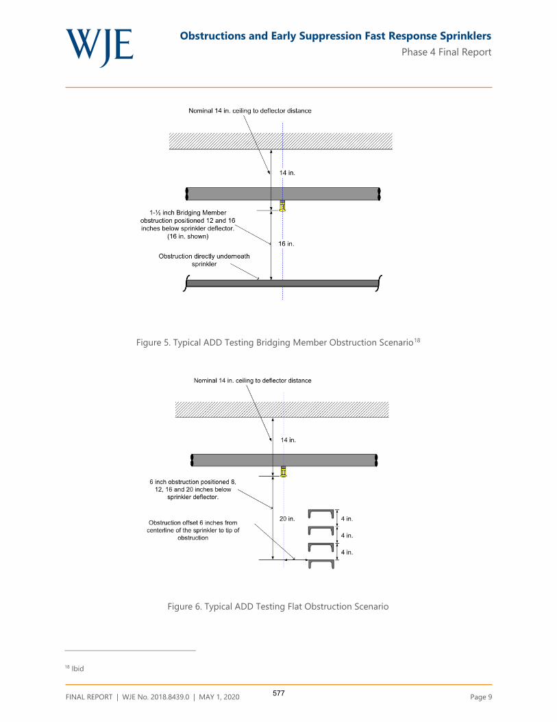
Obstructions and Early Suppression Fast Response Sprinklers
Phase 4 Final Report
FINAL REPORT | WJE No. 2018.8439.0 | MAY 1, 2020 Page 9
Figure 5. Typical ADD Testing Bridging Member Obstruction Scenario18
Figure 6. Typical ADD Testing Flat Obstruction Scenario
18 Ibid
577
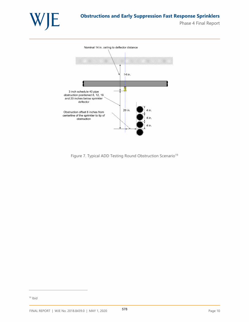
Obstructions and Early Suppression Fast Response Sprinklers
Phase 4 Final Report
FINAL REPORT | WJE No. 2018.8439.0 | MAY 1, 2020 Page 10
Figure 7. Typical ADD Testing Round Obstruction Scenario19
19 Ibid
578

Obstructions and Early Suppression Fast Response Sprinklers
Phase 4 Final Report
FINAL REPORT | WJE No. 2018.8439.0 | MAY 1, 2020 Page 11
Table 2. Summary of ADD Fire Test Results
579
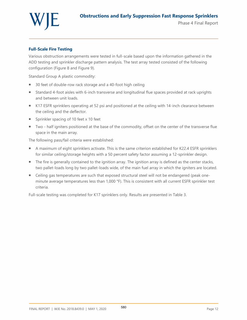
Obstructions and Early Suppression Fast Response Sprinklers
Phase 4 Final Report
FINAL REPORT | WJE No. 2018.8439.0 | MAY 1, 2020 Page 12
Full-Scale Fire Testing
Various obstruction arrangements were tested in full-scale based upon the information gathered in the
ADD testing and sprinkler discharge pattern analysis. The test array tested consisted of the following
configuration (Figure 8 and Figure 9).
Standard Group A plastic commodity:
30 feet of double-row rack storage and a 40-foot high ceiling
Standard 4-foot aisles with 6-inch transverse and longitudinal flue spaces provided at rack uprights
and between unit loads.
K17 ESFR sprinklers operating at 52 psi and positioned at the ceiling with 14-inch clearance between
the ceiling and the deflector.
Sprinkler spacing of 10 feet x 10 feet
Two - half igniters positioned at the base of the commodity, offset on the center of the transverse flue
space in the main array.
The following pass/fail criteria were established:
A maximum of eight sprinklers activate. This is the same criterion established for K22.4 ESFR sprinklers
for similar ceiling/storage heights with a 50 percent safety factor assuming a 12-sprinkler design.
The fire is generally contained to the ignition array. The ignition array is defined as the center stacks,
two pallet-loads long by two pallet-loads wide, of the main fuel array in which the igniters are located.
Ceiling gas temperatures are such that exposed structural steel will not be endangered (peak one-
minute average temperatures less than 1,000 °F). This is consistent with all current ESFR sprinkler test
criteria.
Full-scale testing was completed for K17 sprinklers only. Results are presented in Table 3.
580

Obstructions and Early Suppression Fast Response Sprinklers
Phase 4 Final Report
FINAL REPORT | WJE No. 2018.8439.0 | MAY 1, 2020 Page 13
Figure 8. Typical Test Array as viewed from the North20
Figure 9. Typical Test Array as viewed from the East21
20 Ibid
21 Ibid
581

Obstructions and Early Suppression Fast Response Sprinklers
Phase 4 Final Report
FINAL REPORT | WJE No. 2018.8439.0 | MAY 1, 2020 Page 14
Table 3. Summary of full scale fire test results and findings Fire Test Number Test No. 1 Test No. 2 Test No. 3 Test No. 4 Test No. 5 Test No. 6 Test No. 7 Test No. 8 Test No. 9
Test Date April 4th, 2015 April 16th, 2015 April 20th, 2015 April 22nd, 2015 April 24th, 2015 August 4th, 2016 August 9th, 2016 August 12th, 2016 September 24, 2019
Primary Obstruction 36 Inch deep steel
joist, edge of lower
chord 6 inches from
centerline of
sprinkler
30 inch deep steel
joist, edge of lower
chord 3 inches from
centerline of
sprinkler
36 inch deep steel
joist, edge of lower
chord 6 inches from
centerline of
sprinkler
36 inch deep steel
joist, edge of lower
chord 6 inches from
centerline of
sprinkler
22 inch deep steel
joist, edge of lower
chord 6 inches from
centerline of
sprinkler
1.5 inch by 1.5 inch
bridging member,
directly under
sprinkler, 12 inches
down from
deflector
12-inch wide, 3-
inch deep structural
C shape; 6 inch
offset from primary
sprinkler; 20 inches
below deflector
6-inch wide, 2-inch
deep structural C
shape; 6 inch offset
from primary
sprinkler; 20 inches
below deflector
24-inch wide, 3-inch
deep flat steel, 12
inch offset from
primary sprinkler; 22
inches below
deflector
Secondary Obstruction None None 1.5 inch by 1.5 inch
bridging member;
1.5 inch away from
sprinkler
1.5 inch by 1.5 inch
bridging member;
Centered below
sprinkler
1.5 inch by 1.5 inch
bridging member;
Centered below
sprinkler
None None None None
Length of Test (minutes) 31 32 32 32 32 32 32 32 32
First Sprinkler Operation
Time (min: sec)
0:56 1:42 1:19 1:11 1:01 1:18 1:22 1:11 1:18
Last Sprinkler Operation
Time (min: sec)
6:08 7:37 1:19 1:11 6:42 1:18 7:06 1:11 1:18
Number of Operated
Sprinklers
3 12 1 1 23 1 10 1 1
Peak Gas Temperature at
Ceiling Above Ignition (F°)
294 406 238 250 1264 242 217 240 191
Maximum 1 minute
Average Gas Temperature
at Ceiling Above Ignition
(F°)
129 256 114 115 979 143 142 122 110
Peak Steel Temperature at
Ceiling Above Ignition (F°)
128 157 86 84 248 92 138 94 80
Maximum 1 minute
Average Steel
Temperature at Ceiling
Above Ignition (F°)
126 157 85 83 246 91 137 94 80
Ignition Time of Target
Array (min: sec)
3:36 (North Target) 3:24 (North Target) N/A N/A 2:26 (North Target) N/A N/A N/A N/A
Fire Travel to Extremities
of Test Array
No No No No Yes (North Target) No
North Target Ignition No North target array
at approximately 4
minutes, 30
seconds; damaged
commodity, but the
fire did not travel to
the outer plane of
this target array.
No No
582

Obstructions and Early Suppression Fast Response Sprinklers
Phase 4 Final Report
FINAL REPORT | WJE No. 2018.8439.0 | MAY 1, 2020 Page 15
RESULTS AND FINDINGS
The results of the ADD testing were used to identify trends in the degree of reduction of sprinkler water
flux as a function of the vertical and horizontal position of the obstruction and sprinkler orifice K factor.
These trends were used initially to select appropriate full-scale fire test scenarios and then to assist with
the determination of acceptable sprinkler obstruction placement parameters.
Three fundamental trends were discovered from the results of the ADD testing:
1. The reduction in ADD caused by an obstruction located directly below the sprinkler is increased as the
vertical distance from the obstruction to the sprinkler is decreased.
2. The reduction in ADD due to an obstruction positioned horizontally offset from the sprinkler increases
as the vertical distance away from the sprinkler increases.
3. The obstruction sensitivity of K14 and K17 ESFR sprinklers is very similar within the range that was
examined.
The first two trends can be explained by the characteristics of the ESFR sprinkler discharge pattern. The
center core of the ESFR sprinkler delivers the largest amount of water flux. For example, the largest
average unobstructed ADD for both K14 and K17 ESFR sprinklers, 1.34 gpm/ft² and 1.64 gpm/ft²
respectively, was delivered to the Central 4 pans of the ADD apparatus. This large central core water
distribution is designed to address a fire located directly below one sprinkler, with a high storage to
ceiling clearance.
The trajectory of an unobstructed sprinkler droplet may be evaluated using the balance of forces acting on
the droplet. Droplets will reach a terminal velocity when the drag force acting upward reaches a point of
equilibrium with the opposing gravitational force. As the droplet travels away from the sprinkler,
momentum decreases proportionately to velocity, and the acceleration due to gravity increasingly directs
the trajectory of the droplet towards the vertical plane.22 The resulting discharge pattern can be generally
described as parabolic.
Because of these forces, as the ESFR sprinkler discharge travels downward, the pattern expands
horizontally, drawing obstructions positioned horizontally from the sprinkler towards the center core
region (Figure 10). Obstructions located directly below the sprinkler experience the inverse. As these
obstructions move vertically away from the sprinkler the obstructed area of the center core region
decreases (Figure 11).
Figure 12 through Figure 16 present the results of the ADD testing in scatter diagram format, including
both the K14 and K17 sprinkler data. A review of the K14 sprinkler ADD data shows similar trends to that
of the K17 sprinkler. This strong correlation between K14 and K17 performance was most clearly
demonstrated in the ADD testing of the bar joist obstruction (Figure 12).
22 McGrattan, Kevin, Fire Dynamics Simulator Technical Reference Guide, 6th edition, Volume 1: Mathematical Model, Section 8
Lagrangian Particles.
583

Obstructions and Early Suppression Fast Response Sprinklers
Phase 4 Final Report
FINAL REPORT | WJE No. 2018.8439.0 | MAY 1, 2020 Page 16
Figure 10. Obstruction Located 6 inches horizontally from the sprinkler23
Figure 11. Obstruction located directly below the sprinkler24
23 Palenske, Garner A., “Obstructions and ESFR Sprinklers-Phase 3,” NFPA Research Foundation 2018
24 Ibid
584

Obstructions and Early Suppression Fast Response Sprinklers
Phase 4 Final Report
FINAL REPORT | WJE No. 2018.8439.0 | MAY 1, 2020 Page 17
Bar Joist and Bridging Member Obstructions
Full-scale Test No. 1 examined the scenario of a 36 inch deep bar joist located 6 inches horizontally from
the K17 sprinkler. The 36 inch deep bar joist, when positioned horizontally from the sprinkler, is
considered the most rigorous bar joist depth within the boundary conditions established (22 -36 inch
deep bar joist) since the bottom chord is the greatest distance below the sprinkler. This test was
successful, operating only one sprinkler and meeting all other pass/fail criteria (Table 3). Given the
similarities of the K14 and K17 ADD data (Figure 12), a similar result is expected for K14 sprinklers.
Both K14 and K17 ADD data for a bridging member located directly below a sprinkler show an increase in
ADD as the bridging member moves vertically away from the sprinkler (Figure 13). However, the K14 ADD
data shows a much greater increase in ADD as the vertical separation increases. For example, with the
bridging member located 12 inches below the sprinkler, the K14 Central 4 and Central 16 pan average
ADD decreases 80% and 53%, respectively when compared to an unobstructed condition. These decreases
are much greater than the K17 sprinkler data in which the Central 4 and Central 16 pan average ADD
decreases 14% and 6%, respectively.
Full-scale Test No. 6 investigated the scenario of a 1½ x 1½ inch bridging member located 12 inches
directly below the sprinkler. This configuration resulted in acceptable performance, opening only one K17
sprinkler and meeting the other pass/fail criteria (Table 3). The K17 ADD for this scenario was 1.17 gpm/ft²
(Central 4) and 0.79 gpm/ft² (Central 16). Using linear interpolation of the K14 ADD data, an equivalent
Central 4 ADD is found at 18 inches below the sprinkler and 14 inches below for the Central 16 ADD. The
correlation in the data demonstrates that a bridging member located directly below the sprinkler provided
with an 18 inch vertical clearance (K14) or 12 inch vertical clearance (K17), will result in similar
performance.
Full-scale Test No. 4 examined the same 36 inch deep bar joist condition as Test No. 1 with the addition of
a 1 ½ x 1½ inch bridging member attached to the top of the lower chord in a perpendicular orientation.
The bridging member was located approximately 20 inches directly below the sprinkler (36 inch deep bar
joist - 14 inch ceiling deflector clearance - 2 ½ inch chord height). Note that this bridging member to
sprinkler clearance exceeds the minimum acceptable clearance established in the previous paragraph for
bridging members located directly below K14 or K17 sprinklers. This test demonstrated acceptable
performance, activating only one K17 sprinkler and meeting the other pass/fail criteria (Table 3). The K14
ADD exceeded that of the K17 ADD for this scenario (North 4 ADD =52%, North 8 ADD = 104%), therefore
a similar result is expected for K14 sprinklers.
585

Obstructions and Early Suppression Fast Response Sprinklers
Phase 4 Final Report
FINAL REPORT | WJE No. 2018.8439.0 | MAY 1, 2020 Page 18
Figure 12. Bar joist obstruction ADD results (6 inch horizontal offset from sprinkler)
Figure 13. Bridging Member Obstruction ADD Results(Directly under sprinkler)
586

Obstructions and Early Suppression Fast Response Sprinklers
Phase 4 Final Report
FINAL REPORT | WJE No. 2018.8439.0 | MAY 1, 2020 Page 19
Flat Obstructions
Obstructions of various shapes were tested in Phase 3 to determine the effect that obstruction shape has
on ADD. Test data showed that the difference in ADD between flat and round obstructions was negligible
(Table 2). Accordingly, the term “flat obstruction” as used in this report refers to both flat and round
obstructions.
The K17 sprinkler data collected for the flat obstructions positioned horizontally from the sprinkler shows
a consistent relationship of decreasing ADD with a slight sensitivity to obstruction width (Figure 14
through Figure 16). This occurs because the 6 inch horizontal offset places the majority of the obstruction
outside of the high discharge central core and thus obstructs less water. The K14 sprinkler data shows less
sensitivity to obstruction width.
Full-scale Test No. 8 examined the scenario of a 6 inch wide flat obstruction, offset horizontally 6 inches
and 20 inches below the sprinkler deflector. This test demonstrated acceptable performance, opening only
one K17 sprinkler and meeting all other pass/fail criteria (Table 3). The ADD reduction for this scenario,
North 4 -31.73% and North 8-24.36 %, is the largest reduction of all flat obstructions tested within the
established boundary conditions (3 inch- 12 inch width) using K17 sprinklers. The K14 ADD apparatus
reduction data for this scenario was -41.0% (North 4) and -48.86 % (North 8). However, the K14 sprinkler
delivered a North 4 ADD much larger than the K17 ADD, 0.68 gpm/sq. ft. vs 0.14 gpm/sq. ft., and
approximately the same for the North 8 region, 0.51 gpm/sq. ft. vs 0.60 gpm/sq. ft. Given the ADD
comparison, a similar result is expected for K14 sprinklers.
Full-scale Test No. 7 investigated the scenario of a 12 inch wide flat obstruction, offset horizontally 6
inches, and 20 inches below the sprinkler deflector. Despite having similar ADD values to the 6 inch wide
obstruction used in Test No. 7, 10 sprinklers operated, 2 sprinklers more than the pass/fail criteria. Fire
propagation and ceiling temperatures were within acceptable limits (Table 3). The reduction in the ADD
was within the acceptable range, -28.85 % North 4, and -23.08 North 8.
Review of the sprinkler operation sequence of Test No. 7 shows an unusual pattern, indicative of sprinkler
skipping phenomena (Figure 17). Sprinkler skipping can occur when a sprinkler activates significantly
sooner than a neighboring sprinkler that is closer to the fire plume.25 Sprinkler 46, closest to the fire,
operated at 1 minute, 22 seconds. Sprinkler 48 operated at 6 minutes, 30 seconds while Sprinkler 47 did
not operate at all despite the closer proximity of Sprinkler 47 to the fire location. Sprinkler 66 operated at
6 minutes, 24 seconds while Sprinkler 56 did not operate at all despite the closer proximity of Sprinkler 56
to the fire location. The performance of Sprinklers 47 and 56 are characteristic of skipping phenomena.
25 Croce, Hill, &, Xin (2005) Investigation of the Causative Mechanism of Sprinkler Skipping. Journal of Fire
Protection Engineering, Volume 15
587

Obstructions and Early Suppression Fast Response Sprinklers
Phase 4 Final Report
FINAL REPORT | WJE No. 2018.8439.0 | MAY 1, 2020 Page 20
Figure 14. Three inch flat obstruction ADD results (6 inch horizontal offset
from sprinkler)
Figure 15. Six inch flat obstruction ADD results (6 inch horizontal offset from
sprinkler)
588
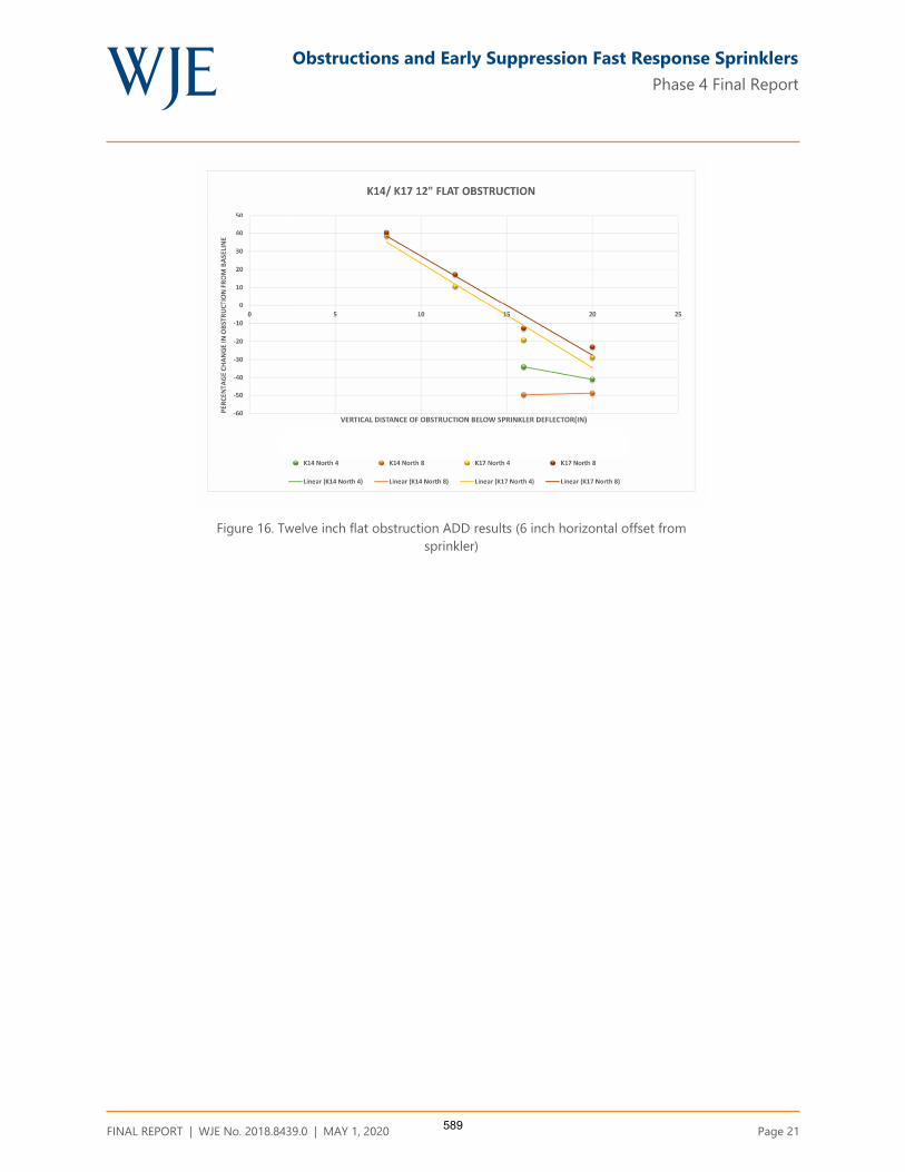
Obstructions and Early Suppression Fast Response Sprinklers
Phase 4 Final Report
FINAL REPORT | WJE No. 2018.8439.0 | MAY 1, 2020 Page 21
Figure 16. Twelve inch flat obstruction ADD results (6 inch horizontal offset from
sprinkler)
589
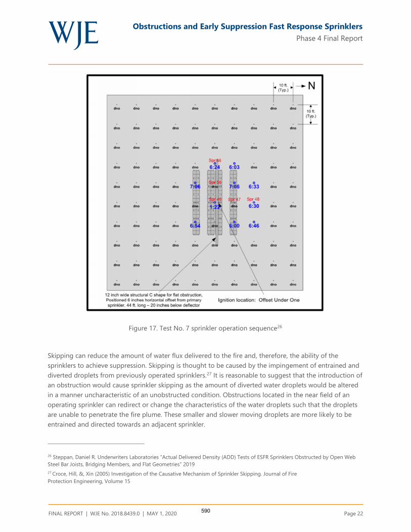
Obstructions and Early Suppression Fast Response Sprinklers
Phase 4 Final Report
FINAL REPORT | WJE No. 2018.8439.0 | MAY 1, 2020 Page 22
Figure 17. Test No. 7 sprinkler operation sequence26
Skipping can reduce the amount of water flux delivered to the fire and, therefore, the ability of the
sprinklers to achieve suppression. Skipping is thought to be caused by the impingement of entrained and
diverted droplets from previously operated sprinklers.27 It is reasonable to suggest that the introduction of
an obstruction would cause sprinkler skipping as the amount of diverted water droplets would be altered
in a manner uncharacteristic of an unobstructed condition. Obstructions located in the near field of an
operating sprinkler can redirect or change the characteristics of the water droplets such that the droplets
are unable to penetrate the fire plume. These smaller and slower moving droplets are more likely to be
entrained and directed towards an adjacent sprinkler.
26 Steppan, Daniel R. Underwriters Laboratories “Actual Delivered Density (ADD) Tests of ESFR Sprinklers Obstructed by Open Web
Steel Bar Joists, Bridging Members, and Flat Geometries” 2019
27 Croce, Hill, &, Xin (2005) Investigation of the Causative Mechanism of Sprinkler Skipping. Journal of Fire
Protection Engineering, Volume 15
590

Obstructions and Early Suppression Fast Response Sprinklers
Phase 4 Final Report
FINAL REPORT | WJE No. 2018.8439.0 | MAY 1, 2020 Page 23
The increased width of the 12-inch flat obstruction compared to the 6-inch flat obstruction (Test No. 8)
would cause a greater amount of droplet disruption and, therefore, a greater propensity for sprinkler
skipping. Review of the video from Test No. 7 did show a greater amount of ceiling water vapor present
compared that shown in Test No. 8.
The performance of Test No. 7 met two of the three acceptable performance criteria; the fire damaged
stayed within the main array and did not burn to the back of the target array, and the ceiling temperatures
were within the acceptable range. A comparison of the main array damage in Test Nos. 7 and 8 indicates
more damage in Test No. 7, but still within an acceptable level.
The operation of 10 sprinklers in lieu of 8 complicates the categorization of the outcome of Test No. 7.
Historically, safety factors up to 2.0 have been used for sprinkler operation in full scale fire testing. 28
Typically, a 1.5 safety factor is included in the pass/fail criteria for ESFR sprinkler fire testing.29 However,
review of ESFR sprinkler approval standards shows a wide range of permissible number of operating
sprinklers. For example, UL 1767A, “Outline for Investigation for ESFR Sprinklers Having K- Factors Greater
than 14.0,” defines the acceptable number as 6 to 9 sprinklers (K22 or K25) depending on the test
specifications. FM Global “Approval Standard for ESFR Sprinklers, Class Series 2008,” defines acceptable
performance for sprinklers as the operation of 8 to 12 sprinklers (K22 or K25). Neither UL nor FM Global
approval standards require full-scale fire testing of K14 or K17 ESFR sprinklers due to their legacy
performance and comparable performance.
It is also important to note that the acceptable number of operating sprinklers applies when the sprinklers
operate in a proper sequence. All of the first ring sprinklers should operate within a few seconds before
any second or third ring sprinklers. When a different operating sequence occurs, additional sprinklers may
operate, and early suppression may still be achieved when the other pass/fail criteria are met.30As shown
in Figure 17, 5 of the 9 first ring sprinklers and 5 of 25 second ring sprinklers activated. The increased
number of sprinklers that activated in Test No. 7 is likely attributed to the sequence of sprinkler operation
caused by the skipping phenomenon previously discussed.
The scenario of non-operational sprinklers was considered in the testing protocol used in the early
development of the ESFR sprinkler. In these tests, one sprinkler located in the first ring was rendered
inoperable to simulate a plugged sprinkler.31 Current FM Global Approval Standard FM 2008, “Approval
for Quick Response Storage Sprinklers for Fire Protection”, includes the plugged sprinkler scenario in the
testing protocol for upright ESFR sprinklers.
Considering this background information, it is reasonable to conclude the results of Test No. 7
demonstrated that, despite the very rigorous condition of two inoperable or plugged sprinklers, the
sprinklers suppressed the fire and therefore, the test meets the pass/fail criteria.
28 National Fire Protection Association “Automatic Sprinkler Systems Handbook” 2016 Edition, Section 21.1.8 text and commentary
29 Ibid
30 Chicarello, Troup and Dean. “The National Quick Response Sprinkler Research Project: Large Scale Fire Test Evaluation of ESFR
Automatic Sprinklers,” Fire Protection Research Foundation Report, May 1986.
31 Yao, C. “The Development of the ESFR Sprinkler System”, Fire Safety Journal, 14, 66-73,1988
591

Obstructions and Early Suppression Fast Response Sprinklers
Phase 4 Final Report
FINAL REPORT | WJE No. 2018.8439.0 | MAY 1, 2020 Page 24
Full-scale Test No. 9 investigated the scenario of a 24 inch wide flat obstruction, offset horizontally 12
inches, and 22 inches below the K17 sprinkler deflector (Figure 18 and Figure 19). ADD testing was not
completed for this scenario. This scenario was selected to address obstructions such as lights or flat cable
trays.
The 12 inch horizontal offset positioned the obstruction within the region where approximately 10% of the
ESFR sprinkler discharge occurs. The vertical position, 22 inches below the sprinkler, was considered the
worst case location given the findings of the ADD testing of other flat obstructions.
This arrangement resulted in the operation of one sprinkler. Fire propagation and ceiling temperatures
were within acceptable limits; therefore, the results of the test met the pass/fail criteria (Table 3).
Figure 18. Test No. 9 - 24 inch flat obstruction placement details32
32 Steppan, Daniel R. Underwriters Laboratories “Actual Delivered Density (ADD) Tests of ESFR Sprinklers Obstructed by Open Web
Steel Bar Joists, Bridging Members, and Flat Geometries” 2019
592

Obstructions and Early Suppression Fast Response Sprinklers
Phase 4 Final Report
FINAL REPORT | WJE No. 2018.8439.0 | MAY 1, 2020 Page 25
Figure 19. Test No. 9 - 24 inch flat obstruction plan view33
The sprinkler discharge formed excessive sheeting which traveled over the obstruction edge onto the top
of the commodity and then downward along the face of the rack. The wetting of the ignition array face
contributed to the suppression of the fire. Similar behavior was noted in the other flat obstruction tests.
The magnitude of the sheeting in Test No. 9 with a 24 inch obstruction, however, was much larger
(Figure 20 through Figure 23). This is the result of the increased width of the 24 inch obstruction. The
magnitude of the shadow created by a flat obstruction increased proportionately as the width of the
obstruction was increased between a 6 in., 12 in., and 24 in. obstruction. The increased area per unit
length of the 24 inch obstruction created a greater disruption in the sprinkler water flow and thus diverted
a larger amount of water onto and over the edge of the obstruction.
33 Ibid
593

Obstructions and Early Suppression Fast Response Sprinklers
Phase 4 Final Report
FINAL REPORT | WJE No. 2018.8439.0 | MAY 1, 2020 Page 26
Figure 20. Ceiling View of Test No. 9 - 24 inch flat
obstruction34
Figure 21. Ceiling View of Test No. 7 - 12 inch flat
obstruction35
Figure 22. Floor View of Test No. 9 - 24 inch flat
obstruction36
Figure 23. Floor View of Test No. 7 - 12 inch flat
obstruction37
Figure 24 and Figure 25 show the distribution of water flux in percentage change from unobstructed
condition for 6 inch and 12 inch wide obstructions (Test 8 and Test 7 respectively). Figure 26 shows a
comparison of the change in water flux location as a function of obstruction width. It is shown that, as the
width of the obstruction increases, the shadow created by the obstruction increases in width and moves
horizontally to the right, away from the obstruction. The 6 inch obstruction resulted in a decreased water
34Ibid
35 Steppan, Daniel R. Underwriters Laboratories “Actual Delivered Density Tests of ESFR Sprinkler Obstructed by Open Web Steel Bar
Joists and Bridging Members,” 2015
36 Steppan, Daniel R. Underwriters Laboratories “Actual Delivered Density (ADD) Tests of ESFR Sprinklers Obstructed by Open Web
Steel Bar Joists, Bridging Members, and Flat Geometries” 2019
37 Steppan, Daniel R. Underwriters Laboratories “Actual Delivered Density Tests of ESFR Sprinkler Obstructed by Open Web Steel Bar
Joists and Bridging Members,” 2015
594

Obstructions and Early Suppression Fast Response Sprinklers
Phase 4 Final Report
FINAL REPORT | WJE No. 2018.8439.0 | MAY 1, 2020 Page 27
flux only in the region along the north face of the ignition array. The 12 inch obstruction resulted in
decreased water flux in the same region and in the region within the first row of collection pans inside the
north aisle. Extending this relationship to the 24 inch flat obstruction, the shadow is predicted to extend
into the north aisle, an area not critical to sprinkler performance (Figure 27).
As discussed earlier, the 24 inch obstruction is located completely in the lower water flow region, which
accounts for only approximately 10% of the sprinkler flow. Obstructions in this region are generally
considered to have minimal effect on sprinkler performance.
The water sheeting behavior which occurred could be perceived as a factor which dilutes the analysis of
outcome of the fire test. However, intentional or not, obstructions 6 inches or wider create this behavior
which can improve sprinkler performance.
Based upon this analysis, it was concluded that the fire test would have been successful with or without
the presence of excessive sheeting.
595

Obstructions and Early Suppression Fast Response Sprinklers
Phase 4 Final Report
FINAL REPORT | WJE No. 2018.8439.0 | MAY 1, 2020 Page 28
Figure 24. Test No. 8 - 6 inch flat obstruction ADD Water Flux Distribution38
38 Palenske, Garner A., “Obstructions and ESFR Sprinklers-Phase 3,” NFPA Research Foundation 2018
596

Obstructions and Early Suppression Fast Response Sprinklers
Phase 4 Final Report
FINAL REPORT | WJE No. 2018.8439.0 | MAY 1, 2020 Page 29
Figure 25. Test No. 8 - 12 inch flat obstruction ADD Water Flux Distribution39
39 Ibid
597

Obstructions and Early Suppression Fast Response Sprinklers
Phase 4 Final Report
FINAL REPORT | WJE No. 2018.8439.0 | MAY 1, 2020 Page 30
Figure 26. Test No. 8 and Test No. 7- ADD Water Flux Distribution Comparison40
40 Ibid
598

Obstructions and Early Suppression Fast Response Sprinklers
Phase 4 Final Report
FINAL REPORT | WJE No. 2018.8439.0 | MAY 1, 2020 Page 31
Figure 27. Obstruction shadow overlay
599

Obstructions and Early Suppression Fast Response Sprinklers
Phase 4 Final Report
FINAL REPORT | WJE No. 2018.8439.0 | MAY 1, 2020 Page 32
CONCLUSIONS
The ESFR Obstruction Project has made significant advancements in understanding of the effects
obstructions have on ESFR sprinkler performance. Both K14 and K17 ESFR sprinkler behavior was
investigated. Significant findings of this work are summarized as follows:
The obstruction created by an open web steel truss between the depths of 22 - 36 inches, located 6
inches horizontally from a K14 or K17 ESFR sprinkler should not significantly decrease sprinkler
performance.
The obstruction created by a bridging member 1½ x 1½ inches in size or less, located directly below
the sprinkler with an 18 inch vertical clearance (K14) or 12 inch vertical clearance (K17) does not
significantly decrease sprinkler performance. This applies to bridging members attached to open web
steel trusses.
The obstruction created by flat or round obstructions less than or equal to 12 inches in width located 6
inches horizontally from a K17 or K14 sprinkler should not significantly decrease sprinkler
performance.
The obstruction created by flat or round obstructions less than or equal to 24 inches in width located
12 inches horizontally from a K17 or K14 sprinkler should not significantly decrease sprinkler
performance.
ACKNOWLEDGEMENTS
The authors wish to thank the many people who assisted with this project. The project would not have
succeeded without their help. Special thanks to the Fire Protection Research Foundation, Project Technical
Panel, Project Sponsors, and other industry colleagues for their support and encouragement.
Garner A. Palenske, P.E.
Associate Principal
Garth N. Ornelas, P.E.
Associate
600

Obstructions and Early Suppression Fast Response Sprinklers
Phase 4 Final Report
FINAL REPORT | WJE No. 2018.8439.0 | MAY 1, 2020
APPENDIX A. ACTUAL DELIVERED DENSITY TESTING OF ESFR SPRINKLERS OBSTRUCTED BY
FLAT OBSTRUCTIONS (PHASE 4), UNDERWRITERS LABORATORIES, APRIL 26, 2019
601
ACTUAL DELIVERED DENSITY (ADD) TESTS
OF ESFR SPRINKLERS OBSTRUCTED BY
OPEN WEB STEEL BAR JOISTS, BRIDGING
MEMBERS and FLAT GEOMETRIES
Prepared by
UL LLC
Project 4788895562, NC5756
for the
Fire Protection Research Foundation
Issued: April 26, 2019
Copyright © 2019 UL LLC
602
Issued: April 26, 2019
i
Executive Summary
This report describes twenty (20) Actual Delivered Density (ADD) tests that were conducted to
develop data relative to the level of fire performance provided by a K = 14.0 and a K = 16.8 ESFR
sprinkler when the sprinklers are located closer to an obstruction than currently referenced in the
Standard for the Installation of Sprinkler Systems, NFPA 13-2019. For this test series, the
sprinklers were located in close proximity to open web ceiling steel bar joists, a steel bridging
member and flat obstructions.
The ADD apparatus consists of a fire source and a set of water collection pans. A drawing of the
top and side views of the apparatus are shown in Figure E-1. The main components of the apparatus
are 48 water collection pans and 12 heptane nozzles. The 48 water collection pans are
approximately 20 in. by 20 in. and are separated into groups of four. A group of four collection
pans, i.e., a 2x2 array, simulates the top surface of one pallet load of stored commodity. Eight
groups of four are placed in the main array, while two satellite arrays each consist of two groups of
four. The two satellite collector arrays were placed adjacent to the main array to investigate pre-
wetting characteristics. A 6 in. flue space was maintained between two adjacent simulated
commodities.
603

Issued: April 26, 2019
ii
Figure E-1. ADD Apparatus Schematic (Plan and Elevation Views)
604

Issued: April 26, 2019
iii
Figure E-2. ADD Apparatus Photograph
For all tests, the center of the ADD apparatus was located directly below the discharging sprinkler.
The top of the ADD apparatus (representing the top surface of stored commodity) was located 10 ft.
from the ceiling.
All tests were conducted with fire above the array with an equivalent total heat release rate of 2.5
MW.
The automatic sprinkler system incorporated the following features:
1. The single sprinkler was installed with the deflector positioned nominally 14 inches below the
smooth, flat, horizontal, non-combustible ceiling for two different K-factor sprinklers.
2. A single manufacturer’s nominal K = 14.0 and K=16.8 (gpm/psig1/2) pendent ESFR sprinklers
were used in the test series.
3. The K = 14.0 sprinkler system was controlled to provide a flowing pressure of 75 psig for the
sprinkler located over the fire which correlates to a nominal discharge of 121 gpm.
4. The K = 16.8 sprinkler system was controlled to provide a flowing pressure of 52 psig for the
sprinklers located over the fire which correlates to a nominal discharge of 121 gpm.
605

Issued: April 26, 2019
iv
Tests were conducted using three primary obstructions as follows:
Steel Bar Joists: 22, 30 and 36 inch deep, commercially available steel bar joists were used in
tests 3, 4 and 5.
Flat Obstructions: Tests were conducted using 3, 6 and 12 inch wide, commercial steel
structural “C” shapes for the flat obstructions. These were used in tests 6 through 14 and 17
through 20.
Bridging Member: A 1-1/2 by 1-1/2 inch “L” shaped steel member was used to simulate a
bridging member positioned parallel to the sprinkler’s branchline. This was used in tests 2, 15 and
16.
Lateral and vertical distances of these ceiling structural members to the obstructed sprinkler were
investigated as outlined in Table E1:
Table E 1 Test Obstruction Clearance
Test
Number Obstruction Used
Pendent ESFR
Sprinkler Used,
K - gpm/psig0.5
Vertical Distance
of Obstruction
Below Sprinkler
Deflector
Horizontal Distance
from Centerline of
Sprinkler to Nearest
Vertical Edge of
Obstruction
1 None (baseline) 14.0 N/A N/A
2 1-1/2 inch by 1-1/2 inch
bridging member 14.0 12 in. 6 in.
3 22 inch deep bar joist 14.0 8 in. 6 in.
4 30 inch deep bar joist 14.0 16 in. 6 in.
5 36 inch deep bar joist 14.0 22 in. 6 in.
6 3 inch flat 14.0 8 in. 6 in.
7 3 inch flat 14.0 12 in. 6 in.
8 3 inch flat 14.0 16 in. 6 in.
9 6 inch flat 14.0 8 in. 6 in.
10 6 inch flat 14.0 12 in. 6 in.
11 6 inch flat 14.0 16 in. 6 in.
12 6 inch flat 14.0 20 in. 6 in.
13 6 inch flat 14.0 22 in. 6 in.
14 6 inch flat 14.0 24 in. 6 in.
15 1-1/2 inch by 1-1/2 inch
bridging member 14.0 14 in. 0 in.
16 1-1/2 inch by 1-1/2 inch
bridging member 14.0 20 in. 0 in.
17 12 inch flat 14.0 16 in. 6 in.
18 12 inch flat 14.0 20 in. 6 in.
19 12 inch flat 16.8 8 in. 6 in.
20 12 inch flat 16.8 12 in. 6 in. N/A – Not applicable
606

Issued: April 26, 2019
v
A summary of the test parameters and results are provided in Table E-2. Refer to Figure E-1 for
pan data references.
607

Issued: April 26, 2019
vi
Table E 3 Test Parameters and Resulting Data
Test Number Obstruction UsedPendent ESFR Sprinkler Used, K - gpm/psig0.5
Vertical Distance of obstruction
below sprinkler deflector
Horizontal Offset, Tip of obstruction
to sprinkler centerline
Overall Average
Central 16 Pan
Average
Central 4 Pan
Average
South Satellite Average
North Satellite Average
West Pre-Wetting Average
East Pre-Wetting Average
North 4 South 4 North 8
in. in. in. gpm/ft2 gpm/ft2 gpm/ft2 gpm/ft2 gpm/ft2 gpm/ft2 gpm/ft2 gpm/ft2 gpm/ft2 gpm/ft2
1 none (baseline) 14.0 0 0 0.55 0.96 1.64 0.23 0.13 0.57 0.44 1.15 1.03 0.99
2 1-1/2 inch bridging member* 14.0 12 6 0.41 0.45 0.33 0.18 0.18 0.52 0.65 0.30 0.30 0.48
3 22 inch deep bar joist 14.0 8 6 0.51 0.83 1.71 0.22 0.09 0.55 0.54 0.85 1.28 0.604 30 inch deep bar joist 14.0 16 6 0.54 0.83 1.56 0.26 0.19 0.48 0.64 0.63 1.33 0.485 36 inch deep bar joist 14.0 22 6 0.49 0.78 1.38 0.19 0.20 0.47 0.55 0.50 1.22 0.49
6 3" flat 14.0 8 6 0.43 0.76 1.27 0.15 0.18 0.41 0.32 0.96 0.93 0.767 3" flat 14.0 12 6 0.50 0.80 1.60 0.21 0.19 0.45 0.53 1.05 0.94 0.758 3" flat 14.0 16 6 0.46 0.79 1.63 0.18 0.16 0.44 0.37 1.02 0.99 0.74
9 6" flat 14.0 8 6 0.56 0.96 1.88 0.27 0.18 0.43 0.55 1.22 1.16 0.9110 6" flat 14.0 12 6 0.49 0.78 1.88 0.28 0.17 0.46 0.47 1.30 0.97 0.7911 6" flat 14.0 16 6 0.43 0.74 1.71 0.23 0.15 0.40 0.35 1.41 0.92 0.7712 6" flat 14.0 20 6 0.46 0.80 1.69 0.10 0.22 0.39 0.45 1.15 0.96 0.7913 6" flat 14.0 22 6 0.45 0.73 1.64 0.16 0.19 0.41 0.45 1.13 0.88 0.7514 6" flat 14.0 24 6 0.45 0.75 1.56 0.20 0.19 0.41 0.39 1.06 0.90 0.75
15 1-1/2 inch bridging member* 14.0 14 0 0.49 0.81 0.64 0.09 0.17 0.52 0.52 0.49 0.62 0.7916 1-1/2 inch bridging member* 14.0 20 0 0.44 0.73 1.46 0.22 0.16 0.43 0.36 0.93 0.96 0.74
17 12" flat 14.0 16 6 0.45 0.76 1.61 0.20 0.24 0.39 0.35 0.76 1.37 0.5018 12" flat 14.0 20 6 0.43 0.72 1.46 0.14 0.26 0.34 0.41 0.68 1.19 0.51
19 12" flat 16.8 8 6 0.50 1.05 2.06 0.30 0.05 0.27 0.29 1.56 1.20 1.1920 12" flat 16.8 12 6 0.50 0.94 1.86 0.26 0.15 0.35 0.37 1.25 1.16 0.99
* - bridging member distance is to the top of the horizontal flat portion from the sprinkler's deflector
Test Parameters Data
608

Issued: April 26, 2019
vii
Table of Contents
1. INTRODUCTION ............................................................................................... 1
2. TEST FACILITY ................................................................................................ 1
2.1 LARGE-SCALE FIRE TEST BUILDING ................................................................................................................... 1 2.2 LARGE-SCALE FIRE TEST FACILITY .................................................................................................................... 2
3. EQUIPMENT ...................................................................................................... 3
3.1 ACTUAL DELIVERED DENSITY APPARATUS ........................................................................................................ 3 3.2 AUTOMATIC SPRINKLER SYSTEM ........................................................................................................................ 6 3.3 OBSTRUCTIONS ................................................................................................................................................... 7
3.3.1 Steel Bar Joists (Tests 3 – 5) ....................................................................................................................... 7 3.3.2 Flat Obstructions (Tests 6-14 and 17-18) .................................................................................................. 8 3.3.3 Bridging Member (Test 2, 15 and 16) ......................................................................................................... 8
4. TEST ARRAY CONFIGURATION ............................................................... 18
4.1 ADD ARRANGEMENT PLAN VIEW .....................................................................................................................18 4.2 ADD ARRANGEMENT ELEVATION VIEW AND CLEARANCE ................................................................................18
5. TEST METHOD ................................................................................................ 21
5.1 TEST PROCEDURE ...............................................................................................................................................21
6. RESULTS AND DISCUSSION ........................................................................ 22
7. SUMMARY ........................................................................................................ 24
Table of Figures
FIGURE 1 TEST FACILITY .............................................................................................................................. 2 FIGURE 2 ADD APPARATUS SCHEMATIC ..................................................................................................... 4 FIGURE 3 ADD APPARATUS PHOTOGRAPH (SHOWING FIRE BEFORE SPRINKLER DISCHARGE) .................... 5 FIGURE 4 ADD PAN NUMBERING SYSTEM ................................................................................................... 6 FIGURE 5 FLAT OBSTRUCTION DIMENSIONAL KEY ...................................................................................... 8 FIGURE 6 22 INCH DEEP JOIST DETAIL – ELEVATION VIEW (PRIOR TO CUTTING TO 30 FT. LENGTH) .......... 9 FIGURE 7 30 INCH DEEP JOIST DETAIL – ELEVATION VIEW (PRIOR TO CUTTING TO 30 FT. LENGTH) .......... 9 FIGURE 8 36 INCH DEEP JOIST DETAIL – ELEVATION VIEW (PRIOR TO CUTTING TO 30 FT. LENGTH) .......... 9 FIGURE 9 JOIST CROSS SECTION DETAIL – CLOSE UP ELEVATION VIEW .................................................. 10 FIGURE 10 TEST 3 ARRANGEMENT – ELEVATION VIEW (AS SHOWN) .......................................................... 11 FIGURE 11 TEST 4 ARRANGEMENT – ELEVATION VIEW (AS SHOWN) .......................................................... 12 FIGURE 12 TEST 5 ARRANGEMENT – ELEVATION VIEW (AS SHOWN) .......................................................... 13 FIGURE 13 3 INCH FLAT OBSTRUCTION; TEST 6, 7 AND 8 ARRANGEMENT – ELEVATION VIEW FROM EAST
14 FIGURE 14 6 INCH FLAT OBSTRUCTION; TEST 9 THROUGH 14 ARRANGEMENT – ELEVATION VIEW FROM
EAST 15 FIGURE 15 12 INCH FLAT OBSTRUCTION; TEST 17 AND 18 ARRANGEMENT – ELEVATION VIEW FROM EAST
16 FIGURE 16 1-1/2 INCH BRIDGING MEMBER OBSTRUCTION: TEST 2, 15 AND 16 ARRANGEMENT –
ELEVATION VIEW FROM EAST (TEST 2 SHOWN) ..................................................................................... 17 FIGURE 17 ADD APPARATUS – VIEW FROM EAST (TEST 4 SHOWN) ............................................................ 19 FIGURE 18 ADD APPARATUS – VIEW FROM NORTH (TEST 4 SHOWN) ......................................................... 19 FIGURE 19 TEST ARRAY PLAN VIEW - TEST SERIES .................................................................................... 20
609

Issued: April 26, 2019
viii
Tables
TABLE 1 OBSTRUCTION DETAILS ................................................................................................................ 7 TABLE 2 OBSTRUCTION DETAILS (REFER TO FIGURE 5) ............................................................................. 8 TABLE 3 TEST SERIES SUMMARY .............................................................................................................. 23
Appendix A – Raw and Summarized Data
Appendix A
FIGURE A- 1 TEST 1 – RESULTS (3D GRAPHIC–VIEW FROM NORTHEAST OF CENTRAL MAIN ARRAY ONLY) .. 2 FIGURE A- 2 TEST 2 – RESULTS (3D GRAPHIC–VIEW FROM NORTHEAST OF CENTRAL MAIN ARRAY ONLY) .. 3 FIGURE A- 3 TEST 3 – RESULTS (3D GRAPHIC–VIEW FROM NORTHEAST OF CENTRAL MAIN ARRAY ONLY) .. 4 FIGURE A- 4 TEST 4 – RESULTS (3D GRAPHIC–VIEW FROM NORTHEAST OF CENTRAL MAIN ARRAY ONLY) .. 5 FIGURE A- 5 TEST 5 – RESULTS (3D GRAPHIC–VIEW FROM NORTHEAST OF CENTRAL MAIN ARRAY ONLY) .. 6 FIGURE A- 6 TEST 6 – RESULTS (3D GRAPHIC–VIEW FROM NORTHEAST OF CENTRAL MAIN ARRAY ONLY) .. 7 FIGURE A- 7 TEST 7 – RESULTS (3D GRAPHIC–VIEW FROM NORTHEAST OF CENTRAL MAIN ARRAY ONLY) .. 8 FIGURE A- 8 TEST 8 – RESULTS (3D GRAPHIC–VIEW FROM NORTHEAST OF CENTRAL MAIN ARRAY ONLY) .. 9 FIGURE A- 9 TEST 9 – RESULTS (3D GRAPHIC–VIEW FROM NORTHEAST OF CENTRAL MAIN ARRAY ONLY) 10 FIGURE A- 10 TEST 10 – RESULTS (3D GRAPHIC–VIEW FROM NORTHEAST OF CENTRAL MAIN ARRAY ONLY) 11 FIGURE A- 11 TEST 11 – RESULTS (3D GRAPHIC–VIEW FROM NORTHEAST OF CENTRAL MAIN ARRAY ONLY) 12 FIGURE A- 12 TEST 12 – RESULTS (3D GRAPHIC–VIEW FROM NORTHEAST OF CENTRAL MAIN ARRAY ONLY) 13 FIGURE A- 13 TEST 13 – RESULTS (3D GRAPHIC–VIEW FROM NORTHEAST OF CENTRAL MAIN ARRAY ONLY) 14 FIGURE A- 14 TEST 14 – RESULTS (3D GRAPHIC–VIEW FROM NORTHEAST OF CENTRAL MAIN ARRAY ONLY) 15 FIGURE A- 15 TEST 15 – RESULTS (3D GRAPHIC–VIEW FROM NORTHEAST OF CENTRAL MAIN ARRAY ONLY) 16 FIGURE A- 16 TEST 16 – RESULTS (3D GRAPHIC–VIEW FROM NORTHEAST OF CENTRAL MAIN ARRAY ONLY) 17 FIGURE A- 17 TEST 17 – RESULTS (3D GRAPHIC–VIEW FROM NORTHEAST OF CENTRAL MAIN ARRAY ONLY) 18 FIGURE A- 18 TEST 18 – RESULTS (3D GRAPHIC–VIEW FROM NORTHEAST OF CENTRAL MAIN ARRAY ONLY) 19 FIGURE A- 19 TEST 19 – RESULTS (3D GRAPHIC–VIEW FROM NORTHEAST OF CENTRAL MAIN ARRAY ONLY) 20 FIGURE A- 20 TEST 20 – RESULTS (3D GRAPHIC–VIEW FROM NORTHEAST OF CENTRAL MAIN ARRAY ONLY) 21
610

Issued: April 26, 2019
ix
Abbreviations
°C degrees Centigrade
°F degrees Fahrenheit
psig unit of pressure; pounds per square inch gauge
gpm gallons per minute
ft. foot
in. inch
mm millimeter
cm centimeter
m meter
RTI Response time index
UL Underwriters Laboratories Inc.
Lbm Pounds mass
dno Did not operate
611

Issued: April 26, 2019
1 of 25
1. INTRODUCTION
This report describes a Verification Services Investigation conducted for the Fire Protection
Research Foundation, in accordance with the test method described herein.
The sole purpose of this Verification Services Investigation was to study the effects of specific
ceiling obstructions on both a K = 14.0 and a K = 16.8 gpm/psig0.5 pendent ESFR fire sprinkler
when subjected to a 2.5 MW fire above an Actual Delivered Density (ADD) apparatus.
The information developed from this investigation is provided to the Fire Protection Research
Foundation for their use in determining the effectiveness of the tested sprinkler system and
applied flowing pressures versus heat release rate and obstruction configuration investigated.
In no event shall UL LLC be responsible to anyone for whatever use or nonuse is made of the
information contained in this Report and in no event shall UL LLC, its employees or its agents
incur any obligations or liability for damages, including, but not limited to, consequential
damage, arising out of or in connection with the use or inability to use the information contained
in this report.
Investigations normally conducted by UL LLC involve Classification, Listing or Recognition
and Follow-Up Services of proprietary products. However, UL LLC does conduct investigations
without Classification, Listing or Recognition and Follow-Up Service when a need for test data
in the interest of public safety has been indicated. Such investigations do not result in specific
conclusions, nor any form of Recognition, Listing or Classification of the products involved. It
is on this basis that UL LLC undertook the Verification Services Investigation reported herein.
2. TEST FACILITY
The fire tests were conducted at Underwriters Laboratories large-scale fire test facility located in
Northbrook, Illinois.
2.1 Large-Scale Fire Test Building
The large-scale fire test building used for this investigation houses four fire test areas that are
used to develop data on the fire growth and fire suppression characteristics of commodities, as
well as the fire suppression characteristics of automatic water sprinkler systems. A schematic of
the test facility is shown in Figure 1.
612

Issued: April 26, 2019
2 of 25
Figure 1 Test Facility
2.2 Large-Scale Fire Test Facility
The test was conducted in the 120 by 120-ft main fire test cell that is equipped with a 100 by
100-ft adjustable height ceiling. The 10-ft perimeter between the moveable ceiling and the walls
of the test room provides for the simulation of a larger warehouse by not allowing the smoke and
heat layer from the test to be contained.
The center of the floor of the test facility is 100 by 100-ft., is smooth and flat and is surrounded
with a grated drainage trench to insure adequate water drainage from the test area. The water
from the suppression system is collected, contained and filtered through a nominal 180,000-
gallon water treatment system.
The large-scale test cell used in this investigation is equipped with an exhaust system capable of
a maximum flow of 60,000 cubic feet per minute through a smoke abatement system. Fresh air
was provided through four inlet ducts positioned along the wall of the test facility. The fresh air
was released into the room approximately 10-ft above the floor level through straightening
screens. This ventilation arrangement provides adequate air so that the fire growth occurs
naturally.
All products of combustion from the tests were contained within the test facility and processed
through a regenerative thermal oxidizing system.
Warehouse
Large Scale
Fire Test Facility
ADD Test Facility
Heat Release Calorimeter & RDD
Conditioning
Room
PDPA Test Facility
613
Issued: April 26, 2019
3 of 25
3. EQUIPMENT
3.1 Actual Delivered Density Apparatus
The ADD apparatus consists of a fire source and a set of water collection pans. A drawing of the
top and side views of the apparatus is shown in Figure 2 and a photograph of the apparatus with
the fire is shown in Figure 3. The main components of the apparatus are 48 water collection pans
and 12 heptane nozzles. The 48 water collection pans are approximately 20 in. by 20 in. and are
separated into groups of four. A group of four collection pans, i.e., a 2x2 array, simulates the top
surface of one pallet load of stored commodity. Eight groups of four are placed in the main
array, while two satellite arrays each consist of two groups of four. The two satellite collector
arrays were placed adjacent to the main array to investigate pre-wetting characteristics. A 6 in.
flue space was maintained between two adjacent simulated commodities. The numbering system
used for this test series is presented in Figure 4.
For all tests, the center of the ADD apparatus was located directly below the discharging
sprinkler. The top of the ADD apparatus (representing the top surface of stored commodity) was
located 10 ft. from the ceiling.
All tests were conducted with fire above the array with an equivalent total heat release rate of 2.5
MW.
614

Issued: April 26, 2019
4 of 25
Figure 2 ADD Apparatus Schematic
Main Array
South Satellite
North Satellite
Combustion Nozzles
Air Duct
North 4South 4
North 8
615
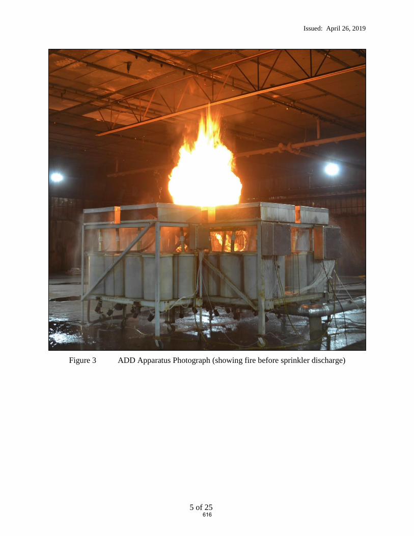
Issued: April 26, 2019
5 of 25
Figure 3 ADD Apparatus Photograph (showing fire before sprinkler discharge)
616

Issued: April 26, 2019
6 of 25
Figure 4 ADD Pan Numbering System
3.2 Automatic Sprinkler System
A wet pipe automatic sprinkler system was positioned below the adjustable smooth, flat non-
combustible ceiling and pressure controlled to provide a specific applied nominal flowing
pressure as defined below.
The sprinkler was supplied through a looped and gridded piping system consisting of 2 ½-in.
diameter, schedule 40 branch line. The piping system was supplied by a variable speed pump
capable of supplying an adequate pressure and flow to maintain the required applied flowing
pressure throughout the course of the test.
The automatic sprinkler system incorporated pendent ESFR sprinklers having a nominal K-factor
of 14.0 gpm/psig0.5 (tests 1 through 18) and 16.8 gpm/psig0.5 (tests 19 and 20), both with a 3/4
inch NPT inlet thread. The sprinklers were installed with the sprinkler deflector located
nominally 14 in. below the moveable ceiling.
1 2
3 4
5 6
7 8
9 10
11 12
13 14
15 16
17 18
19 20
21 22
23 24
25 26
27 28
29 30
31 32
41 42
43 44
45 46
47 48
33 34
35 36
37 38
39 40
Pan Number Designations
Leading Edge of Obstructions
Discharging Sprinkler Location
6 in.
617

Issued: April 26, 2019
7 of 25
3.3 Obstructions
3.3.1 Steel Bar Joists (Tests 3 – 5)
The commercially manufactured open web steel bar joists used for this test series had the
following characteristics as defined in Table 1.
Table 1 Obstruction Details
Truss
Depth, in. Designation
Upper Chord
Structural
Members
Nominal
Upper
Chord
Maximum
Width, in.
Lower Chord
Structural
Members
Nominal
Lower
Chord
Maximum
Width, in.
22 22 K 1/1
1-1/2 by 1-1/2 in.
back to back “L”
angle (0.160 in.
thickness)
4
2 by 2 in. back
to back “L”
angle (0.142 in.
thickness)
5
30 30 K 1/1
1-1/2 by 1-1/2 in.
back to back “L”
angle (0.142 in.
thickness)
4
2 by 2 in. back
to back “L”
angle (0.142 in.
thickness)
5
36 36 LH 1/1
2 by 2 in. back to
back “L” angle
(0.144 in.
thickness)
5
2-1/2 by 2-1/2
in. back to back
“L” angle (0.217
in. thickness)
6
The elevation view of the full length joists are shown in Figure 6, Figure 7 and Figure 8 for the
22, 30 and 36 inch deep joists, respectively. These joists were cut down to a nominal 30 ft.
length for this Actual Delivered Density test series. Figure 9 shows the cross section details of
the joists.
East and North elevation views of the joist cross sections for representative tests are shown in
Figure 10 through Figure 12.
618

Issued: April 26, 2019
8 of 25
3.3.2 Flat Obstructions (Tests 6-14 and 17-18)
The commercially manufactured steel obstructions used for this test series had the following
characteristics as defined in Table 2Table 1.
Table 2 Obstruction Details (refer to Figure 5)
Flat
Obstruction
Nominal
Width
Width – A,
in.
Depth – B,
in.
Upper Chord
Thickness – C,
in.
3 3.00 1.51 0.245
6 6.00 2.10 0.350
12 12.00 3.10 0.400
Figure 5 Flat Obstruction Dimensional Key
The obstructions are structural “C” shapes.
The leading edge of the flat obstructions were positioned 6 inches laterally away from the
centerline of the discharging sprinkler with the vertical elevations as shown in Figure 13 through
Figure 15.
3.3.3 Bridging Member (Test 2, 15 and 16)
A bridging member was simulated by a 1-1/2 inch by 1-1/2 inch (0.220 in. thick) “L” shaped
steel angle, 20 ft. long. This member was positioned parallel to the sprinkler’s branchline,
directly below the discharging sprinkler as shown in Figure 16.
A
BC
619

Issued: April 26, 2019
9 of 25
Figure 6 22 Inch Deep Joist Detail – Elevation View (prior to cutting to 30 ft. length)
Figure 7 30 Inch Deep Joist Detail – Elevation View (prior to cutting to 30 ft. length)
Figure 8 36 Inch Deep Joist Detail – Elevation View (prior to cutting to 30 ft. length)
620

Issued: April 26, 2019
10 of 25
Figure 9 Joist Cross Section Detail – Close Up Elevation View (top position was attached at the ceiling)
22 in.
5 in.
4 in.
2 in. by 2 in. “L” angle;
0.142 in. thick
1-½ in. by 1-½ in. “L” angle;
0.160 in. thick
30 in.
5 in.
4 in.
2 in. by 2 in. “L” angle;
0.142 in. thick
1-½ in. by 1-½ in. “L” angle;
0.142 in. thick
36 in.
6 in.
5 in.
2-½ in. by 2-½ in. “L” angle;
0.217 in. thick
2 in. by 2 in. “L” angle;
0.144 in. thick
621

Issued: April 26, 2019
11 of 25
Figure 10 Test 3 Arrangement – Elevation View (as shown)
Nominal 14 in. ceiling to deflector distance
6 in. gap
22 inch deep joist
C L
Front Elevation View(view from East)
Side Elevation View(view from North)
622

Issued: April 26, 2019
12 of 25
Figure 11 Test 4 Arrangement – Elevation View (as shown)
Nominal 14 in. ceiling to deflector distance
6 in. gap
30 inch deep joist
C L
Front Elevation View(view from East)
Side Elevation View(view from North)
623

Issued: April 26, 2019
13 of 25
Figure 12 Test 5 Arrangement – Elevation View (as shown)
Nominal 14 in. ceiling to deflector distance
6 in. gap
36 inch deep joist
C L
Front Elevation View(view from East)
Side Elevation View(view from North)
624

Issued: April 26, 2019
14 of 25
Figure 13 3 inch Flat Obstruction; Test 6, 7 and 8 Arrangement – Elevation View From East
Nominal 14 in. ceiling to deflector distance
Obstruction offset 6 inches from centerline of the sprinkler to tip of
obstruction
3 inch obstruction positioned 8, 12 and 16 inches below
sprinkler deflector.
4 in.
4 in.
14 in.
16 in.
625

Issued: April 26, 2019
15 of 25
Figure 14 6 inch Flat Obstruction; Test 9 through 14 Arrangement – Elevation View From East
Nominal 14 in. ceiling to deflector distance
Obstruction offset 6 inches from centerline of the sprinkler to tip of
obstruction
6 inch obstruction positioned 8, 12, 16, 20, 22 and 24 inches
below sprinkler deflector.
4 in.
4 in.
14 in.
24 in.
4 in.
2 in.2 in.
626

Issued: April 26, 2019
16 of 25
Figure 15 12 inch Flat Obstruction; Test 17 and 18 Arrangement – Elevation View From East
Nominal 14 in. ceiling to deflector distance
Obstruction offset 6 inches from centerline of the sprinkler to tip of
obstruction
12 inch obstruction positioned 16 and 20 inches below
sprinkler deflector.
4 in.
14 in.
20 in.
627

Issued: April 26, 2019
17 of 25
Figure 16 1-1/2 inch Bridging Member Obstruction: Test 2, 15 and 16 Arrangement – Elevation View From East (Test 2 shown)
Nominal 14 in. ceiling to deflector distance
Obstruction directly underneath sprinkler
1-½ inch Bridging Member obstruction positioned 12, 16 and 20 inches below sprinkler
deflector. (12 in. shown)
14 in.
12 in.
628

Issued: April 26, 2019
18 of 25
4. TEST ARRAY CONFIGURATION
4.1 ADD Arrangement Plan View
The ADD equipment was centered under one sprinkler location in the large scale test cell as shown
in Figure 17 through Figure 19.
4.2 ADD Arrangement Elevation View and Clearance
The ADD equipment was positioned with a 10 ft. clearance between the top of the pans and the
ceiling to simulate large scale testing clearances. Figure 17 and Figure 18 show the East and
North elevation views respectively.
629

Issued: April 26, 2019
19 of 25
Figure 17 ADD Apparatus – View from East (Test 4 shown)
Figure 18 ADD Apparatus – View from North (Test 4 shown)
17 ft. 10 in.
Nominal 14 in. ceiling to deflector distance
30 inch deep truss, with tip of 2 by 2 angle offset 6 inches from the centerline of the sprinkler
(as an example)
10 ft
.
17 ft. 10 in.
30 inch depth Joist
C L14 inches
10 ft
.
630

Issued: April 26, 2019
20 of 25
Figure 19 Test Array Plan View - Test Series
NJoist Obstruction:Nominally 30 ft. long
Moveable Ceiling (100 by 100 ft.)
631

Issued: April 26, 2019
21 of 25
5. TEST METHOD
5.1 Test Procedure
The test procedure consisted of the following steps:
1. Each sprinkler was pre-flowed to determine the pump speed which achieves 75 psig and 52
psig at the sprinkler for the K = 14.0 and K = 16.8 ESFR sprinkler respectively. It should be
noted that these pressures correspond to a nominal flowrate of 121 gallons per minute for both
sprinklers.
2. After setting the 2.5 MW fire above the apparatus and achieving a steady state burning
condition, the pumps were activated at the previous pump speed to achieve the desired flowing
pressures.
3. After confirming with the ADD data screens that the flow in each collection pan was steady, a
nominal 1 minute of data was captured before terminating the test.
4. The resulting data was recorded and a database was updated to show the relative performance
for the test parameters chosen.
632

Issued: April 26, 2019
22 of 25
6. RESULTS AND DISCUSSION
A total of 20 Actual Delivered Density (ADD) tests were conducted at UL LLC in Northbrook,
IL between April 2 and April 5, 2019. Table 3 provides a summary of the resulting data.
Refer to Figure 2 for pan designations in the data section.
Appendix A provides the detailed raw data for each test. Refer to Figure 4 for the individual pan
designations with respect to sprinkler and obstruction location.
633
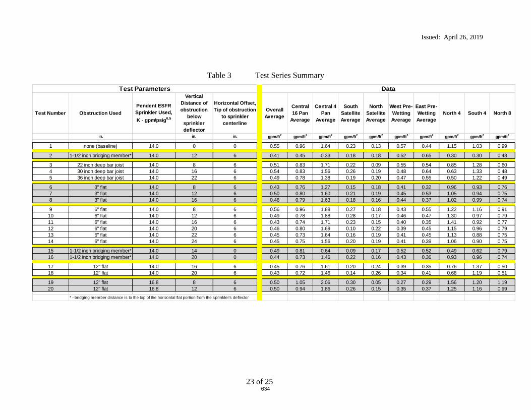
Issued: April 26, 2019
23 of 25
Table 3 Test Series Summary
Test Number Obstruction UsedPendent ESFR Sprinkler Used, K - gpm/psig0.5
Vertical Distance of obstruction
below sprinkler deflector
Horizontal Offset, Tip of obstruction
to sprinkler centerline
Overall Average
Central 16 Pan
Average
Central 4 Pan
Average
South Satellite Average
North Satellite Average
West Pre-Wetting Average
East Pre-Wetting Average
North 4 South 4 North 8
in. in. in. gpm/ft2 gpm/ft2 gpm/ft2 gpm/ft2 gpm/ft2 gpm/ft2 gpm/ft2 gpm/ft2 gpm/ft2 gpm/ft2
1 none (baseline) 14.0 0 0 0.55 0.96 1.64 0.23 0.13 0.57 0.44 1.15 1.03 0.99
2 1-1/2 inch bridging member* 14.0 12 6 0.41 0.45 0.33 0.18 0.18 0.52 0.65 0.30 0.30 0.48
3 22 inch deep bar joist 14.0 8 6 0.51 0.83 1.71 0.22 0.09 0.55 0.54 0.85 1.28 0.604 30 inch deep bar joist 14.0 16 6 0.54 0.83 1.56 0.26 0.19 0.48 0.64 0.63 1.33 0.485 36 inch deep bar joist 14.0 22 6 0.49 0.78 1.38 0.19 0.20 0.47 0.55 0.50 1.22 0.49
6 3" flat 14.0 8 6 0.43 0.76 1.27 0.15 0.18 0.41 0.32 0.96 0.93 0.767 3" flat 14.0 12 6 0.50 0.80 1.60 0.21 0.19 0.45 0.53 1.05 0.94 0.758 3" flat 14.0 16 6 0.46 0.79 1.63 0.18 0.16 0.44 0.37 1.02 0.99 0.74
9 6" flat 14.0 8 6 0.56 0.96 1.88 0.27 0.18 0.43 0.55 1.22 1.16 0.9110 6" flat 14.0 12 6 0.49 0.78 1.88 0.28 0.17 0.46 0.47 1.30 0.97 0.7911 6" flat 14.0 16 6 0.43 0.74 1.71 0.23 0.15 0.40 0.35 1.41 0.92 0.7712 6" flat 14.0 20 6 0.46 0.80 1.69 0.10 0.22 0.39 0.45 1.15 0.96 0.7913 6" flat 14.0 22 6 0.45 0.73 1.64 0.16 0.19 0.41 0.45 1.13 0.88 0.7514 6" flat 14.0 24 6 0.45 0.75 1.56 0.20 0.19 0.41 0.39 1.06 0.90 0.75
15 1-1/2 inch bridging member* 14.0 14 0 0.49 0.81 0.64 0.09 0.17 0.52 0.52 0.49 0.62 0.7916 1-1/2 inch bridging member* 14.0 20 0 0.44 0.73 1.46 0.22 0.16 0.43 0.36 0.93 0.96 0.74
17 12" flat 14.0 16 6 0.45 0.76 1.61 0.20 0.24 0.39 0.35 0.76 1.37 0.5018 12" flat 14.0 20 6 0.43 0.72 1.46 0.14 0.26 0.34 0.41 0.68 1.19 0.51
19 12" flat 16.8 8 6 0.50 1.05 2.06 0.30 0.05 0.27 0.29 1.56 1.20 1.1920 12" flat 16.8 12 6 0.50 0.94 1.86 0.26 0.15 0.35 0.37 1.25 1.16 0.99
* - bridging member distance is to the top of the horizontal flat portion from the sprinkler's deflector
Test Parameters Data
634

Issued: April 26, 2019
24 of 25
7. SUMMARY
This report describes twenty (20) Actual Delivered Density (ADD) tests that were conducted to
develop data relative to the level of fire performance provided by a K = 14.0 and a K = 16.8
ESFR sprinkler when the sprinklers are located closer to an obstruction than currently referenced
in the Standard for the Installation of Sprinkler Systems, NFPA 13-2019. For this test series, the
sprinklers were located in close proximity to open web ceiling steel bar joists, a steel bridging
member and flat obstructions.
The ADD apparatus consists of a fire source and a set of water collection pans. A drawing of the
top and side views of the apparatus are shown in Figure 2. The main components of the
apparatus are 48 water collection pans and 12 heptane nozzles. The 48 water collection pans are
approximately 20 in. by 20 in. and are separated into groups of four. A group of four collection
pans, i.e., a 2x2 array, simulates the top surface of one pallet load of stored commodity. Eight
groups of four are placed in the main array, while two satellite arrays each consist of two groups
of four. The two satellite collector arrays were placed adjacent to the main array to investigate
pre-wetting characteristics. A 6 in. flue space was maintained between two adjacent simulated
commodities.
For all tests, the center of the ADD apparatus was located directly below the discharging
sprinkler. The top of the ADD apparatus (representing the top surface of stored commodity) was
located 10 ft. from the ceiling.
All tests were conducted with fire above the array with an equivalent total heat release rate of 2.5
MW.
The automatic sprinkler system incorporated the following features:
1. The single sprinkler was installed with the deflector positioned nominally 14 inches
below the smooth, flat, horizontal, non-combustible ceiling for two different K-factor
sprinklers.
2. A single manufacturer’s nominal K = 14.0 and K=16.8 (gpm/psig1/2) pendent ESFR
sprinklers were used in the test series.
3. The K = 14.0 sprinkler system was controlled to provide a flowing pressure of 75 psig for
the sprinkler located over the fire which correlates to a nominal discharge of 121 gpm.
4. The K = 16.8 sprinkler system was controlled to provide a flowing pressure of 52 psig for
the sprinklers located over the fire which correlates to a nominal discharge of 121 gpm.
635

Issued: April 26, 2019
25 of 25
Tests were conducted using three primary obstructions as follows:
Steel Bar Joists: 22, 30 and 36 inch deep, commercially available steel bar joists were used
in tests 3, 4 and 5.
Flat Obstructions: Tests were conducted using 3, 6 and 12 inch wide, commercial steel
structural “C” shapes for the flat obstructions. These were used in tests 6 through 14 and 17
through 20.
Bridging Member: A 1-1/2 by 1-1/2 inch “L” shaped steel member was used to simulate a
bridging member positioned parallel to the sprinkler’s branchline. This was used in tests 2, 15
and 16.
A summary of the test parameters and results for all tests are provided in Table 3.
Report By: Reviewed By:
Daniel R. Steppan Michael G. McCormick
Senior Staff Engineer Staff Engineering Associate
Product Safety Product Safety
636

Appendix A – Raw and Summarized Data
A1 of 21
APPENDIX A
Raw and Summarized Data
637
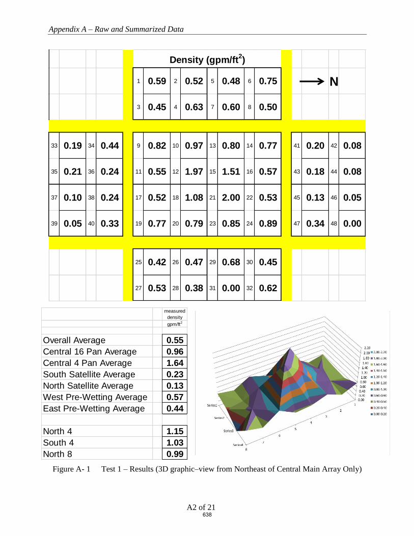
Appendix A – Raw and Summarized Data
A2 of 21
Figure A- 1 Test 1 – Results (3D graphic–view from Northeast of Central Main Array Only)
1 0.59 2 0.52 5 0.48 6 0.75 N
3 0.45 4 0.63 7 0.60 8 0.50
33 0.19 34 0.44 9 0.82 10 0.97 13 0.80 14 0.77 41 0.20 42 0.08
35 0.21 36 0.24 11 0.55 12 1.97 15 1.51 16 0.57 43 0.18 44 0.08
37 0.10 38 0.24 17 0.52 18 1.08 21 2.00 22 0.53 45 0.13 46 0.05
39 0.05 40 0.33 19 0.77 20 0.79 23 0.85 24 0.89 47 0.34 48 0.00
25 0.42 26 0.47 29 0.68 30 0.45
27 0.53 28 0.38 31 0.00 32 0.62
Density (gpm/ft2)
measured densitygpm/ft2
Overall Average 0.55Central 16 Pan Average 0.96Central 4 Pan Average 1.64South Satellite Average 0.23North Satellite Average 0.13West Pre-Wetting Average 0.57East Pre-Wetting Average 0.44
North 4 1.15South 4 1.03North 8 0.99
638

Appendix A – Raw and Summarized Data
A3 of 21
Figure A- 2 Test 2 – Results (3D graphic–view from Northeast of Central Main Array Only)
1 0.62 2 0.60 5 0.53 6 0.48 N
3 0.43 4 0.55 7 0.52 8 0.40
33 0.07 34 0.25 9 0.69 10 0.73 13 0.57 14 0.48 41 0.35 42 0.07
35 0.11 36 0.16 11 0.22 12 0.61 15 0.49 16 0.42 43 0.20 44 0.04
37 0.08 38 0.25 17 0.23 18 0.13 21 0.09 22 0.19 45 0.21 46 0.07
39 0.14 40 0.39 19 0.78 20 0.02 23 0.81 24 0.80 47 0.41 48 0.12
25 0.58 26 0.51 29 0.82 30 0.72
27 0.59 28 0.54 31 0.79 32 0.66
Density (gpm/ft2)
measured densitygpm/ft2
Overall Average 0.41Central 16 Pan Average 0.45Central 4 Pan Average 0.33South Satellite Average 0.18North Satellite Average 0.18West Pre-Wetting Average 0.52East Pre-Wetting Average 0.65
North 4 0.30South 4 0.30North 8 0.48
639

Appendix A – Raw and Summarized Data
A4 of 21
Figure A- 3 Test 3 – Results (3D graphic–view from Northeast of Central Main Array Only)
1 0.91 2 0.36 5 1.39 6 0.22 N
3 0.59 4 0.28 7 0.43 8 0.19
33 0.20 34 0.51 9 0.90 10 0.58 13 0.50 14 0.15 41 0.02 42 0.04
35 0.16 36 0.19 11 0.91 12 1.89 15 1.45 16 0.16 43 0.09 44 0.06
37 0.09 38 0.27 17 0.50 18 1.81 21 1.68 22 0.10 45 0.09 46 0.13
39 0.02 40 0.31 19 1.05 20 0.94 23 0.59 24 0.14 47 0.16 48 0.12
25 0.36 26 0.43 29 0.54 30 0.08
27 0.61 28 0.59 31 1.69 32 0.03
Density (gpm/ft2)
measured densitygpm/ft2
Overall Average 0.51Central 16 Pan Average 0.83Central 4 Pan Average 1.71South Satellite Average 0.22North Satellite Average 0.09West Pre-Wetting Average 0.55East Pre-Wetting Average 0.54
North 4 0.85South 4 1.28North 8 0.60
640

Appendix A – Raw and Summarized Data
A5 of 21
Figure A- 4 Test 4 – Results (3D graphic–view from Northeast of Central Main Array Only)
1 0.83 2 0.43 5 0.30 6 0.19 N
3 0.63 4 0.54 7 0.80 8 0.12
33 0.25 34 0.47 9 0.99 10 0.91 13 0.47 14 0.13 41 0.12 42 0.10
35 0.27 36 0.25 11 0.74 12 2.10 15 1.00 16 0.12 43 0.24 44 0.12
37 0.14 38 0.24 17 0.56 18 1.91 21 1.22 22 0.18 45 0.12 46 0.12
39 0.11 40 0.33 19 1.14 20 1.02 23 0.29 24 0.42 47 0.58 48 0.08
25 0.41 26 0.87 29 0.93 30 0.43
27 0.78 28 0.72 31 0.57 32 0.43
Density (gpm/ft2)
measured densitygpm/ft2
Overall Average 0.54Central 16 Pan Average 0.83Central 4 Pan Average 1.56South Satellite Average 0.26North Satellite Average 0.19West Pre-Wetting Average 0.48East Pre-Wetting Average 0.64
North 4 0.63South 4 1.33North 8 0.48
641

Appendix A – Raw and Summarized Data
A6 of 21
Figure A- 5 Test 5 – Results (3D graphic–view from Northeast of Central Main Array Only)
1 0.96 2 0.54 5 0.27 6 0.22 N
3 0.51 4 0.50 7 0.54 8 0.25
33 0.15 34 0.20 9 0.83 10 0.94 13 0.59 14 0.35 41 0.42 42 0.08
35 0.17 36 0.15 11 0.37 12 2.09 15 0.57 16 0.21 43 0.17 44 0.07
37 0.09 38 0.27 17 0.64 18 1.79 21 1.08 22 0.12 45 0.11 46 0.08
39 0.12 40 0.40 19 0.88 20 1.06 23 0.62 24 0.34 47 0.44 48 0.19
25 0.49 26 0.75 29 0.95 30 0.36
27 0.82 28 0.49 31 0.26 32 0.25
Density (gpm/ft2)
measured densitygpm/ft2
Overall Average 0.49Central 16 Pan Average 0.78Central 4 Pan Average 1.38South Satellite Average 0.19North Satellite Average 0.20West Pre-Wetting Average 0.47East Pre-Wetting Average 0.55
North 4 0.50South 4 1.22North 8 0.49
642

Appendix A – Raw and Summarized Data
A7 of 21
Figure A- 6 Test 6 – Results (3D graphic–view from Northeast of Central Main Array Only)
1 0.35 2 0.36 5 0.27 6 0.43 N
3 0.41 4 0.46 7 0.44 8 0.54
33 0.05 34 0.13 9 0.37 10 0.72 13 1.03 14 0.4 41 0.29 42 0.18
35 0.06 36 0.13 11 0.33 12 0.85 15 1.73 16 0.91 43 0.34 44 0.14
37 0.11 38 0.33 17 1.06 18 1.47 21 1.02 22 0.18 45 0.12 46 0.08
39 0.09 40 0.33 19 0.46 20 0.78 23 0.63 24 0.14 47 0.18 48 0.12
25 0.48 26 0.45 29 0.43 30 0.18
27 0.4 28 0.25 31 0.31 32 0.07
Density (gpm/ft2)
measured densitygpm/ft2
Overall Average 0.43Central 16 Pan Average 0.76Central 4 Pan Average 1.27South Satellite Average 0.15North Satellite Average 0.18West Pre-Wetting Average 0.41East Pre-Wetting Average 0.32
North 4 0.96South 4 0.93North 8 0.76
643
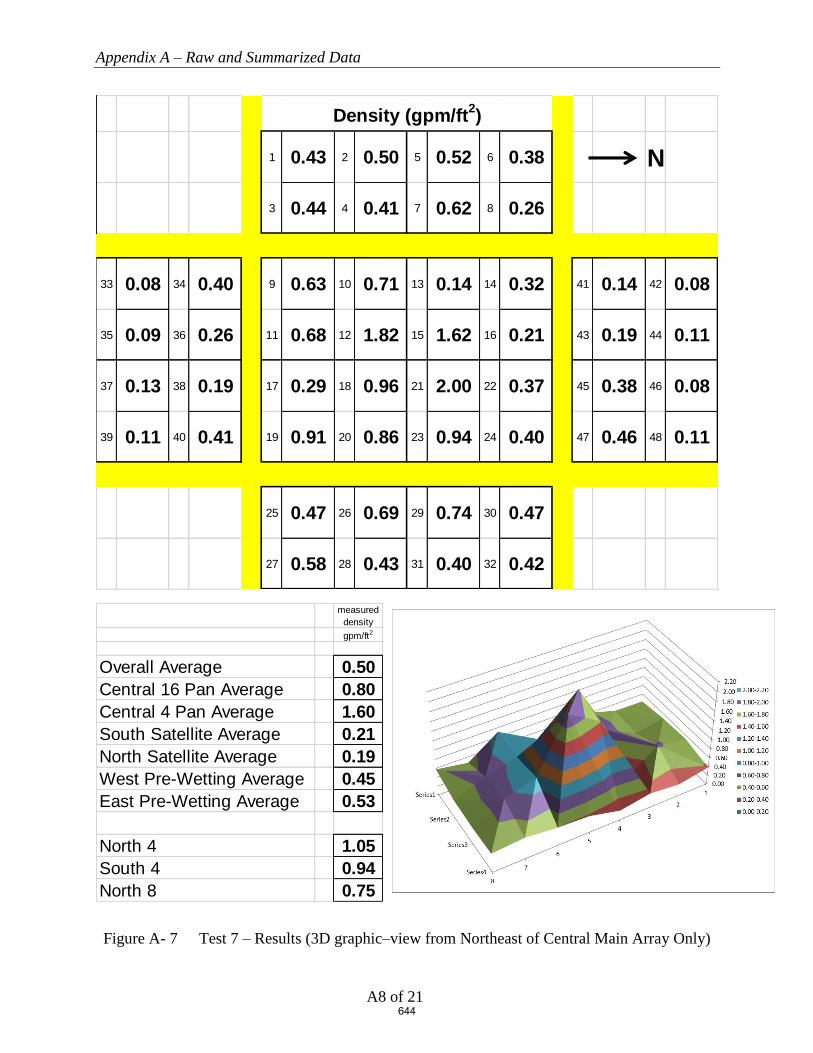
Appendix A – Raw and Summarized Data
A8 of 21
Figure A- 7 Test 7 – Results (3D graphic–view from Northeast of Central Main Array Only)
1 0.43 2 0.50 5 0.52 6 0.38 N
3 0.44 4 0.41 7 0.62 8 0.26
33 0.08 34 0.40 9 0.63 10 0.71 13 0.14 14 0.32 41 0.14 42 0.08
35 0.09 36 0.26 11 0.68 12 1.82 15 1.62 16 0.21 43 0.19 44 0.11
37 0.13 38 0.19 17 0.29 18 0.96 21 2.00 22 0.37 45 0.38 46 0.08
39 0.11 40 0.41 19 0.91 20 0.86 23 0.94 24 0.40 47 0.46 48 0.11
25 0.47 26 0.69 29 0.74 30 0.47
27 0.58 28 0.43 31 0.40 32 0.42
Density (gpm/ft2)
measured densitygpm/ft2
Overall Average 0.50Central 16 Pan Average 0.80Central 4 Pan Average 1.60South Satellite Average 0.21North Satellite Average 0.19West Pre-Wetting Average 0.45East Pre-Wetting Average 0.53
North 4 1.05South 4 0.94North 8 0.75
644

Appendix A – Raw and Summarized Data
A9 of 21
Figure A- 8 Test 8 – Results (3D graphic–view from Northeast of Central Main Array Only)
1 0.48 2 0.41 5 0.37 6 0.39 N
3 0.44 4 0.48 7 0.65 8 0.33
33 0.10 34 0.39 9 0.76 10 0.74 13 0.47 14 0.46 41 0.27 42 0.09
35 0.12 36 0.22 11 0.55 12 1.85 15 1.63 16 0.30 43 0.17 44 0.08
37 0.09 38 0.13 17 0.46 18 1.08 21 1.96 22 0.19 45 0.24 46 0.07
39 0.04 40 0.35 19 0.79 20 0.56 23 0.37 24 0.52 47 0.34 48 0.05
25 0.40 26 0.04 29 0.77 30 0.30
27 0.50 28 0.31 31 0.35 32 0.29
Density (gpm/ft2)
measured densitygpm/ft2
Overall Average 0.46Central 16 Pan Average 0.79Central 4 Pan Average 1.63South Satellite Average 0.18North Satellite Average 0.16West Pre-Wetting Average 0.44East Pre-Wetting Average 0.37
North 4 1.02South 4 0.99North 8 0.74
645

Appendix A – Raw and Summarized Data
A10 of 21
Figure A- 9 Test 9 – Results (3D graphic–view from Northeast of Central Main Array Only)
1 0.57 2 0.44 5 0.42 6 0.23 N
3 0.59 4 0.41 7 0.62 8 0.17
33 0.23 34 0.52 9 0.82 10 0.73 13 0.87 14 0.35 41 0.03 42 0.15
35 0.05 36 0.32 11 0.89 12 2.00 15 1.73 16 0.33 43 0.22 44 0.10
37 0.31 38 0.34 17 0.36 18 1.39 21 2.41 22 0.39 45 0.08 46 0.19
39 0.00 40 0.42 19 0.92 20 0.95 23 0.91 24 0.32 47 0.39 48 0.28
25 0.42 26 0.79 29 0.83 30 0.27
27 0.77 28 0.48 31 0.47 32 0.35
Density (gpm/ft2)
measured densitygpm/ft2
Overall Average 0.56Central 16 Pan Average 0.96Central 4 Pan Average 1.88South Satellite Average 0.27North Satellite Average 0.18West Pre-Wetting Average 0.43East Pre-Wetting Average 0.55
North 4 1.22South 4 1.16North 8 0.91
646

Appendix A – Raw and Summarized Data
A11 of 21
Figure A- 10 Test 10 – Results (3D graphic–view from Northeast of Central Main Array Only)
1 0.80 2 0.31 5 0.42 6 0.23 N
3 0.54 4 0.35 7 0.85 8 0.18
33 0.14 34 0.50 9 0.64 10 0.71 13 0.10 14 0.23 41 0.18 42 0.11
35 0.25 36 0.26 11 0.59 12 1.84 15 1.95 16 0.31 43 0.13 44 0.07
37 0.13 38 0.13 17 0.27 18 1.19 21 2.53 22 0.40 45 0.22 46 0.11
39 0.36 40 0.50 19 0.63 20 0.28 23 0.52 24 0.29 47 0.40 48 0.10
25 0.50 26 0.30 29 0.97 30 0.35
27 0.59 28 0.31 31 0.47 32 0.23
Density (gpm/ft2)
measured densitygpm/ft2
Overall Average 0.49Central 16 Pan Average 0.78Central 4 Pan Average 1.88South Satellite Average 0.28North Satellite Average 0.17West Pre-Wetting Average 0.46East Pre-Wetting Average 0.47
North 4 1.30South 4 0.97North 8 0.79
647
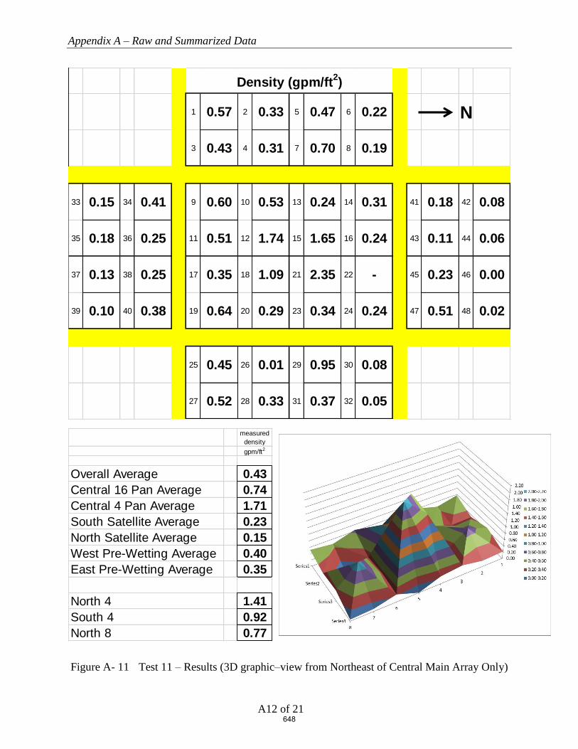
Appendix A – Raw and Summarized Data
A12 of 21
Figure A- 11 Test 11 – Results (3D graphic–view from Northeast of Central Main Array Only)
1 0.57 2 0.33 5 0.47 6 0.22 N
3 0.43 4 0.31 7 0.70 8 0.19
33 0.15 34 0.41 9 0.60 10 0.53 13 0.24 14 0.31 41 0.18 42 0.08
35 0.18 36 0.25 11 0.51 12 1.74 15 1.65 16 0.24 43 0.11 44 0.06
37 0.13 38 0.25 17 0.35 18 1.09 21 2.35 22 - 45 0.23 46 0.00
39 0.10 40 0.38 19 0.64 20 0.29 23 0.34 24 0.24 47 0.51 48 0.02
25 0.45 26 0.01 29 0.95 30 0.08
27 0.52 28 0.33 31 0.37 32 0.05
Density (gpm/ft2)
measured densitygpm/ft2
Overall Average 0.43Central 16 Pan Average 0.74Central 4 Pan Average 1.71South Satellite Average 0.23North Satellite Average 0.15West Pre-Wetting Average 0.40East Pre-Wetting Average 0.35
North 4 1.41South 4 0.92North 8 0.77
648

Appendix A – Raw and Summarized Data
A13 of 21
Figure A- 12 Test 12 – Results (3D graphic–view from Northeast of Central Main Array Only)
1 0.46 2 0.39 5 0.27 6 0.22 N
3 0.44 4 0.44 7 0.67 8 0.20
33 0.06 34 0.01 9 0.58 10 0.72 13 0.31 14 0.28 41 0.52 42 0.19
35 0.05 36 0.07 11 0.33 12 1.81 15 1.43 16 0.40 43 0.29 44 0.15
37 0.04 38 0.24 17 0.58 18 1.11 21 2.42 22 0.36 45 0.23 46 0.04
39 0.00 40 0.36 19 0.73 20 0.54 23 0.65 24 0.48 47 0.37 48 0.00
25 0.52 26 0.22 29 0.78 30 0.30
27 0.58 28 0.31 31 0.70 32 0.15
Density (gpm/ft2)
measured densitygpm/ft2
Overall Average 0.46Central 16 Pan Average 0.80Central 4 Pan Average 1.69South Satellite Average 0.10North Satellite Average 0.22West Pre-Wetting Average 0.39East Pre-Wetting Average 0.45
North 4 1.15South 4 0.96North 8 0.79
649

Appendix A – Raw and Summarized Data
A14 of 21
Figure A- 13 Test 13 – Results (3D graphic–view from Northeast of Central Main Array Only)
1 0.57 2 0.30 5 0.57 6 0.22 N
3 0.51 4 0.35 7 0.55 8 0.23
33 0.07 34 0.34 9 0.55 10 0.61 13 0.16 14 0.42 41 0.32 42 0.12
35 0.10 36 0.23 11 0.59 12 1.69 15 1.65 16 0.30 43 0.11 44 0.05
37 0.06 38 0.04 17 0.23 18 1.02 21 2.19 22 0.38 45 0.27 46 0.04
39 0.19 40 0.25 19 0.62 20 0.41 23 0.56 24 0.36 47 0.52 48 0.07
25 0.44 26 0.41 29 0.67 30 0.32
27 0.57 28 0.35 31 0.58 32 0.22
Density (gpm/ft2)
measured densitygpm/ft2
Overall Average 0.45Central 16 Pan Average 0.73Central 4 Pan Average 1.64South Satellite Average 0.16North Satellite Average 0.19West Pre-Wetting Average 0.41East Pre-Wetting Average 0.45
North 4 1.13South 4 0.88North 8 0.75
650

Appendix A – Raw and Summarized Data
A15 of 21
Figure A- 14 Test 14 – Results (3D graphic–view from Northeast of Central Main Array Only)
1 0.52 2 0.37 5 0.53 6 0.18 N
3 0.46 4 0.38 7 0.54 8 0.26
33 0.12 34 0.37 9 0.68 10 0.68 13 0.51 14 0.45 41 0.28 42 0.09
35 0.11 36 0.25 11 0.52 12 1.77 15 1.35 16 0.36 43 0.08 44 0.04
37 0.11 38 0.23 17 0.34 18 0.96 21 2.14 22 0.39 45 0.37 46 0.03
39 0.07 40 0.36 19 0.55 20 0.41 23 0.51 24 0.32 47 0.53 48 0.08
25 0.41 26 0.35 29 0.52 30 0.28
27 0.50 28 0.35 31 0.49 32 0.21
Density (gpm/ft2)
measured densitygpm/ft2
Overall Average 0.45Central 16 Pan Average 0.75Central 4 Pan Average 1.56South Satellite Average 0.20North Satellite Average 0.19West Pre-Wetting Average 0.41East Pre-Wetting Average 0.39
North 4 1.06South 4 0.90North 8 0.75
651
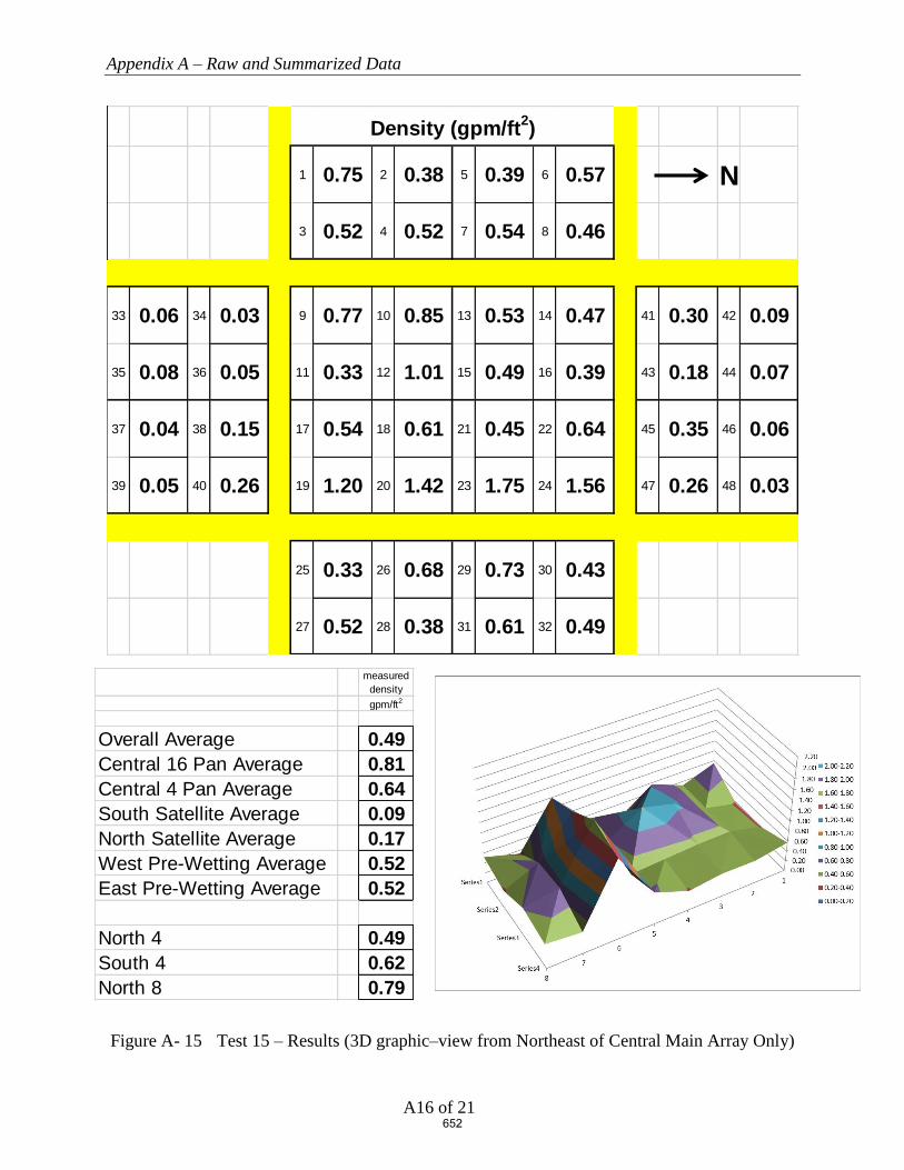
Appendix A – Raw and Summarized Data
A16 of 21
Figure A- 15 Test 15 – Results (3D graphic–view from Northeast of Central Main Array Only)
1 0.75 2 0.38 5 0.39 6 0.57 N
3 0.52 4 0.52 7 0.54 8 0.46
33 0.06 34 0.03 9 0.77 10 0.85 13 0.53 14 0.47 41 0.30 42 0.09
35 0.08 36 0.05 11 0.33 12 1.01 15 0.49 16 0.39 43 0.18 44 0.07
37 0.04 38 0.15 17 0.54 18 0.61 21 0.45 22 0.64 45 0.35 46 0.06
39 0.05 40 0.26 19 1.20 20 1.42 23 1.75 24 1.56 47 0.26 48 0.03
25 0.33 26 0.68 29 0.73 30 0.43
27 0.52 28 0.38 31 0.61 32 0.49
Density (gpm/ft2)
measured densitygpm/ft2
Overall Average 0.49Central 16 Pan Average 0.81Central 4 Pan Average 0.64South Satellite Average 0.09North Satellite Average 0.17West Pre-Wetting Average 0.52East Pre-Wetting Average 0.52
North 4 0.49South 4 0.62North 8 0.79
652

Appendix A – Raw and Summarized Data
A17 of 21
Figure A- 16 Test 16 – Results (3D graphic–view from Northeast of Central Main Array Only)
1 0.40 2 0.30 5 0.59 6 0.45 N
3 0.49 4 0.34 7 0.52 8 0.34
33 0.13 34 0.39 9 0.60 10 0.57 13 0.40 14 0.43 41 0.18 42 0.10
35 0.17 36 0.28 11 0.65 12 1.02 15 0.37 16 0.27 43 0.16 44 0.09
37 0.12 38 0.15 17 0.17 18 2.00 21 2.44 22 0.65 45 0.23 46 0.04
39 0.12 40 0.36 19 0.40 20 0.31 23 0.60 24 0.74 47 0.44 48 0.06
25 0.20 26 0.27 29 0.31 30 0.42
27 0.40 28 0.49 31 0.31 32 0.48
Density (gpm/ft2)
measured densitygpm/ft2
Overall Average 0.44Central 16 Pan Average 0.73Central 4 Pan Average 1.46South Satellite Average 0.22North Satellite Average 0.16West Pre-Wetting Average 0.43East Pre-Wetting Average 0.36
North 4 0.93South 4 0.96North 8 0.74
653
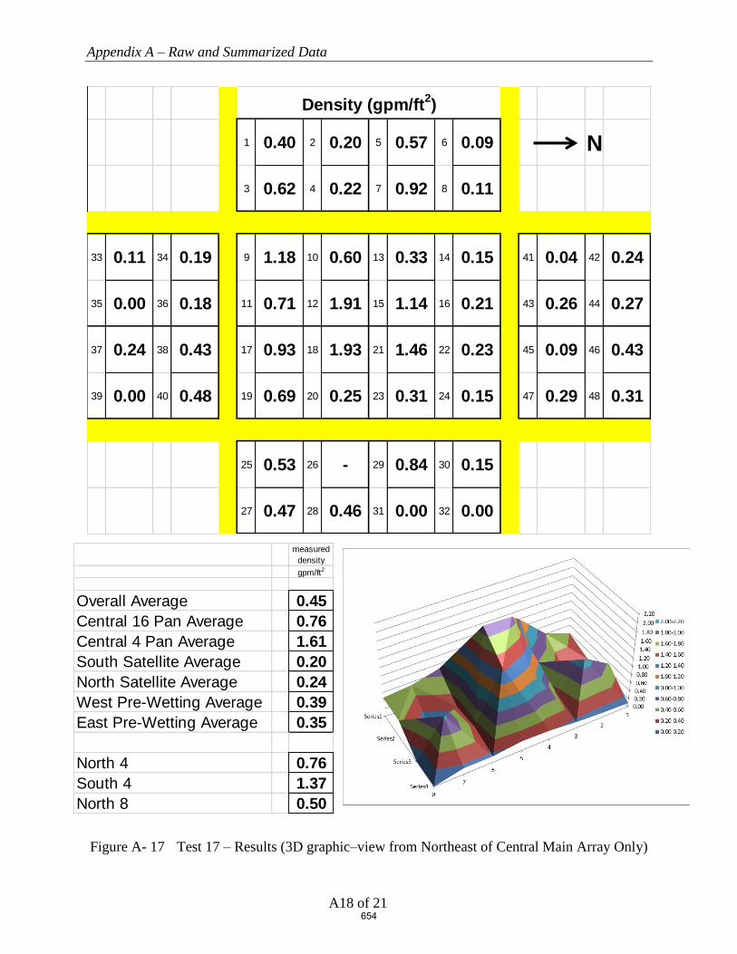
Appendix A – Raw and Summarized Data
A18 of 21
Figure A- 17 Test 17 – Results (3D graphic–view from Northeast of Central Main Array Only)
1 0.40 2 0.20 5 0.57 6 0.09 N
3 0.62 4 0.22 7 0.92 8 0.11
33 0.11 34 0.19 9 1.18 10 0.60 13 0.33 14 0.15 41 0.04 42 0.24
35 0.00 36 0.18 11 0.71 12 1.91 15 1.14 16 0.21 43 0.26 44 0.27
37 0.24 38 0.43 17 0.93 18 1.93 21 1.46 22 0.23 45 0.09 46 0.43
39 0.00 40 0.48 19 0.69 20 0.25 23 0.31 24 0.15 47 0.29 48 0.31
25 0.53 26 - 29 0.84 30 0.15
27 0.47 28 0.46 31 0.00 32 0.00
Density (gpm/ft2)
measured densitygpm/ft2
Overall Average 0.45Central 16 Pan Average 0.76Central 4 Pan Average 1.61South Satellite Average 0.20North Satellite Average 0.24West Pre-Wetting Average 0.39East Pre-Wetting Average 0.35
North 4 0.76South 4 1.37North 8 0.50
654

Appendix A – Raw and Summarized Data
A19 of 21
Figure A- 18 Test 18 – Results (3D graphic–view from Northeast of Central Main Array Only)
1 0.37 2 0.23 5 0.46 6 0.05 N
3 0.59 4 0.29 7 0.66 8 0.09
33 0.03 34 0.14 9 1.05 10 0.52 13 0.49 14 0.15 41 0.17 42 0.26
35 0.06 36 0.10 11 0.51 12 1.72 15 0.91 16 0.23 43 0.22 44 0.33
37 0.00 38 0.33 17 0.87 18 1.66 21 1.54 22 0.04 45 0.24 46 0.32
39 0.00 40 0.43 19 0.71 20 0.35 23 0.57 24 0.12 47 0.25 48 0.31
25 0.53 26 0.18 29 0.91 30 0.00
27 0.56 28 0.38 31 0.73 32 0.00
Density (gpm/ft2)
measured densitygpm/ft2
Overall Average 0.43Central 16 Pan Average 0.72Central 4 Pan Average 1.46South Satellite Average 0.14North Satellite Average 0.26West Pre-Wetting Average 0.34East Pre-Wetting Average 0.41
North 4 0.68South 4 1.19North 8 0.51
655

Appendix A – Raw and Summarized Data
A20 of 21
Figure A- 19 Test 19 – Results (3D graphic–view from Northeast of Central Main Array Only)
1 0.69 2 0.23 5 0.07 6 0.09 N
3 0.55 4 0.21 7 0.19 8 0.11
33 0.16 34 0.38 9 0.70 10 0.58 13 1.36 14 0.21 41 0.07 42 0.05
35 0.31 36 0.34 11 1.08 12 1.69 15 2.57 16 0.59 43 0.08 44 0.05
37 0.22 38 0.14 17 0.62 18 1.41 21 2.57 22 0.50 45 0.02 46 0.08
39 0.32 40 0.53 19 0.52 20 0.73 23 1.53 24 0.18 47 0.04 48 0.02
25 0.76 26 0.14 29 0.62 30 0.00
27 0.50 28 0.18 31 0.15 32 0.00
Density (gpm/ft2)
measured densitygpm/ft2
Overall Average 0.50Central 16 Pan Average 1.05Central 4 Pan Average 2.06South Satellite Average 0.30North Satellite Average 0.05West Pre-Wetting Average 0.27East Pre-Wetting Average 0.29
North 4 1.56South 4 1.20North 8 1.19
656

Appendix A – Raw and Summarized Data
A21 of 21
Figure A- 20 Test 20 – Results (3D graphic–view from Northeast of Central Main Array Only)
1 0.83 2 0.21 5 0.19 6 0.11 N
3 0.52 4 0.19 7 0.55 8 0.16
33 0.14 34 0.33 9 0.60 10 0.57 13 1.08 14 0.15 41 0.15 42 0.08
35 0.28 36 0.30 11 1.01 12 1.56 15 2.29 16 0.29 43 0.15 44 0.12
37 0.20 38 0.19 17 0.67 18 1.41 21 2.18 22 0.22 45 0.15 46 0.17
39 0.20 40 0.45 19 0.59 20 0.76 23 1.51 24 0.22 47 0.18 48 0.18
25 0.74 26 0.15 29 0.84 30 0.12
27 0.52 28 0.17 31 0.33 32 0.05
Density (gpm/ft2)
measured densitygpm/ft2
Overall Average 0.50Central 16 Pan Average 0.94Central 4 Pan Average 1.86South Satellite Average 0.26North Satellite Average 0.15West Pre-Wetting Average 0.35East Pre-Wetting Average 0.37
North 4 1.25South 4 1.16North 8 0.99
657

Obstructions and Early Suppression Fast Response Sprinklers
Phase 4 Final Report
FINAL REPORT | WJE No. 2018.8439.0 | MAY 1, 2020
APPENDIX B. ESFR SPRINKLERS OBSTRUCTED BY CONTINUOUS FLAT OBSTRUCTIONS (PHASE
4), UNDERWRITERS LABORATORIES, SEPTEMBER 27, 2019
658

ESFR SPRINKLERS OBSTRUCTED BY
CONTINUOUS FLAT OBSTRUCTIONS
Prepared by
UL LLC
Project 4789175773, NC5756
for the
Fire Protection Research Foundation
Issued: September 27, 2019
Copyright © 2019 UL LLC
659

Issued: September 27, 2019
i
Executive Summary
This report describes one large scale fire test that was conducted to develop data relative to the level
of fire protection provided by a specific Early Suppression Fast Response (ESFR) sprinkler when
the sprinklers are located closer to an obstruction than currently referenced in the Standard for the
Installation of Sprinkler Systems, NFPA 13-2019. For this test, the sprinklers were located in close
proximity to a long continuous structural steel flat horizontal shape.
Standard cartoned unexpanded Group A plastic test commodity was used in the investigation which
consisted of unexpanded polystyrene cups installed in separate compartments within cartons that are
placed on two way entry, hardwood pallets. The nominal external dimensions of the commodity
was 42 inches wide by 42 inches deep by 40 inches tall resting on a nominal 5 inch tall, 42 by 42
inch hardwood pallet.
The test was conducted using a nominal storage height of 30 ft of cartoned unexpanded Group A
plastic with a ceiling height of 40 ft. Nominal 32 ft. long double-row rack storage arrays were used
in the main storage array and 32 ft. long single-row racks were placed across 4 ft. aisles on both the
north and south side of the main array as targets. The test was conducted with the ignition located
at the base of the storage array and horizontally offset approximately 2 ft from the primary
obstructed sprinkler in the transverse flue space.
The automatic sprinkler system incorporated the following features:
1. One hundred (100) sprinklers were installed on 10 ft. branchline spacing with the sprinklers
spaced 10 ft. on center on each branchline. The sprinkler deflectors were positioned
nominally 14 inches below the smooth, flat, horizontal, non-combustible ceiling.
2. Nominal K=16.8 (gpm/psig1/2) pendent ESFR sprinklers in the 165 °F temperature rating were
used.
3. The sprinkler system was controlled to provide a flat flowing pressure of 52 psig for the
operating sprinklers which correlates to a nominal 1.21 gpm/ft2 discharge density.
The test was conducted using a 24 inch wide, 45 ft. long continuous flat plate steel structure
obstruction with welded “L” angles at the base for structural integrity. The 24 inch flat obstruction
was positioned with the leading vertical edge of the obstruction 12 inches away and the top
horizontal flat portion of the obstruction, 22 inches vertically downward from the sprinkler’s
deflector.
During the test, one (1) sprinkler operated. It was noted that the sprinkler’s discharge formed
vertically downward sheeting over the obstruction which significantly reduced the size of the fire.
The sheeting action of this obstruction can be seen in Figure 21 and Figure 22 in the body of the
report.
The fire was contained within the two center bays of the main array. No damage was observed at
the opposite aisle to ignition of the main double row rack storage array. No target ignition occurred.
A summary of the test parameters and results are provided in Table E1.
660

Issued: September 27, 2019
ii
Table E 1 Test Parameters and Results
Test Date September 24, 2019
Test Parameters Storage Type Double Row Rack
Commodity Type Cartoned Unexpanded Group A Plastic
(Plastic Cups in Corrugated Boxes on Hardwood Pallets)
Pallet Type 2 way entry, stringer, hardwood
Nominal Storage Height, ft. 30
Ceiling Height, ft. 40
Nominal Clearance, ft. 10
Aisle Width, ft. 4
Ignition Location Under One Sprinkler (offset)
Sprinkler Systems Ceiling Only (no in-rack sprinklers)
Sprinkler Orientation Pendent
Deflector to Ceiling, in. 14 Sprinkler Spacing, sprinkler by branchline,
ft. by ft. 10 by 10
Temperature Rating, °F 165
Sprinkler Type ESFR Nominal Sprinkler Discharge Coefficient K,
gpm/psig 0.5 16.8
Nominal Discharge Density, gpm/ft2 1.21
Nominal Discharge Pressure, psig 52
Primary Obstruction
24 inch wide, 3 inch deep flat steel obstruction,
positioned 12 inches offset from primary
sprinkler with top of obstruction positioned 22
inches below the sprinkler’s deflector
Secondary Obstruction None
Test Results
Length of Test, minutes 32:00
First Sprinkler Operation Time, min:sec 1:18
Last Sprinkler Operation Time, min:sec 1:18
Number of Operated Sprinklers 1
Approximate Time of Target Ignition Across 4 ft. Aisle, minutes
No ignition
Peak Gas Temperature at Ceiling Above Ignition, °F 191
Maximum 1 minute Average Gas Temperature at Ceiling Above Ignition, °F
110
Peak Steel Temperature at Ceiling Above Ignition, °F
80
Maximum 1 minute Average Steel Temperature at Ceiling Above Ignition, °F
80
Fire Travel to Extremities of Test Array No
661

Issued: September 27, 2019
iii
Table of Contents
1. INTRODUCTION ............................................................................................... 1
2. TEST FACILITY ................................................................................................ 1
2.1 LARGE-SCALE FIRE TEST BUILDING ................................................................................................................... 1 2.2 LARGE-SCALE FIRE TEST FACILITY .................................................................................................................... 2
3. EQUIPMENT ...................................................................................................... 3
3.1 AUTOMATIC SPRINKLER SYSTEM ........................................................................................................................ 3 3.2 AIR TEMPERATURE.............................................................................................................................................. 5
3.2.1 Air Temperature Near Sprinklers ............................................................................................................... 5 3.2.2 Air Temperature Above Ignition ................................................................................................................. 5
3.3 STEEL BEAM TEMPERATURE ............................................................................................................................... 5 3.4 VIDEO.................................................................................................................................................................. 5 3.5 DATA COLLECTION ............................................................................................................................................. 5
4. CARTONED UNEXPANDED GROUP A PLASTIC COMMODITY ......... 6
4.1 COMPONENTS ...................................................................................................................................................... 6 4.1.1 Pallets ......................................................................................................................................................... 6 4.1.2 Cups ............................................................................................................................................................ 7
4.2 COMMODITY DESCRIPTION ................................................................................................................................. 8 4.2.1 Cartoned Unexpanded Group A Plastic ..................................................................................................... 8
5. OBSTRUCTIONS ............................................................................................... 9
5.1 FLAT OBSTRUCTION ............................................................................................................................................ 9
6. TEST ARRAY CONFIGURATION ............................................................... 13
6.1 RACK ARRAY AND PLAN VIEW ..........................................................................................................................13 6.2 CEILING AND CLEARANCE ..................................................................................................................................15 6.3 TEST ARRANGEMENT .........................................................................................................................................18 6.4 IGNITION ............................................................................................................................................................22
7. TEST METHOD ................................................................................................ 23
7.1 TEST PROCEDURE ...............................................................................................................................................23 7.2 FIRE TEST PHOTOGRAPHS ..................................................................................................................................23
8. RESULTS AND DISCUSSION ........................................................................ 28
8.1 NUMBER OF OPERATING SPRINKLERS: ...............................................................................................................28 8.2 TEMPERATURE RESULTS: ...................................................................................................................................30 8.3 COMMODITY DAMAGE RESULTS: .......................................................................................................................30
9. SUMMARY ........................................................................................................ 33
662

Issued: September 27, 2019
iv
Table of Figures
FIGURE 1 TEST FACILITY .................................................................................................................................. 2 FIGURE 2 TEST ARRAY PLAN VIEW .................................................................................................................. 4 FIGURE 3 2-WAY ENTRY, HARD WOOD PALLET .............................................................................................. 6 FIGURE 4 CUT AWAY OF SINGLE BOX SHOWING CUPS .................................................................................... 7 FIGURE 5 CARTONED UNEXPANDED GROUP A PLASTIC COMMODITY ............................................................. 8 FIGURE 6 TWENTY FOUR INCH WIDE FLAT OBSTRUCTION – CROSS SECTION ................................................ 9 FIGURE 7 TWENTY FOUR INCH WIDE FLAT OBSTRUCTION – PHOTOGRAPH OF CROSS SECTION .................... 9 FIGURE 8 45 FT. LONG, 24 INCH WIDE FLAT OBSTRUCTION – PHOTOGRAPH FROM THE SOUTHWEST .......... 10 FIGURE 9– PHOTOGRAPH OF 24 INCH WIDE OBSTRUCTION FROM BELOW, SHOWING SPRINKLER OFFSET 12
INCHES TO THE RIGHT (SOUTH OF LAB TO THE RIGHT) ................................................................................ 10 FIGURE 10 TEST ARRANGEMENT – ELEVATION VIEW FROM THE EAST NEAR CEILING (UPPER TWO TIERS
AS SHOWN) ................................................................................................................................................... 11 FIGURE 11 TEST ARRANGEMENT – ELEVATION VIEW FROM THE EAST NEAR CEILING (DETAIL AROUND
OBSTRUCTION) ............................................................................................................................................. 12 FIGURE 12 TEST ARRAY PLAN VIEW – TIGHT VIEW ........................................................................................ 14 FIGURE 13 ELEVATION VIEW OF MAIN TEST ARRAY FROM THE NORTH ......................................................... 16 FIGURE 14 ELEVATION VIEW OF MAIN TEST ARRAY FROM THE EAST ............................................................ 17 FIGURE 15 ELEVATION VIEW FROM THE NORTH .............................................................................................. 19 FIGURE 16 ELEVATION VIEW FROM THE WEST ................................................................................................ 20 FIGURE 17 ELEVATION VIEW FROM THE SOUTHWEST ..................................................................................... 21 FIGURE 18 VIEW SHOWING IGNITERS IN NORTH MAIN TRANSVERSE FLUE SPACE AT BASE OF ARRAY ........ 22 FIGURE 19 FIRE TEST PHOTO PRIOR TO SPRINKLER OPERATION ................................................................. 24 FIGURE 20 FIRE TEST PHOTO IMMEDIATELY PRIOR TO SPRINKLER OPERATION ............................................. 25 FIGURE 21 PHOTOGRAPH SHOWING WATER CASCADING OVER THE TOP OF THE 24 INCH WIDE
OBSTRUCTION AFTER OPERATION – NOTE THE AMOUNT OF WATER SHEETING DOWN THE MAIN ARRAY . 26 FIGURE 22 VIEW FROM CEILING AFTER SPRINKLER OPERATION SHOWING THE OBSTRUCTION’S SHADOW
AND THE SHEETING ACTION OVER THE TOP OF THE 24 INCH WIDE OBSTRUCTION ...................................... 27 FIGURE 23 OPERATION TIMES OF SPRINKLERS (MINUTES:SECONDS) ............................................................... 29 FIGURE 24 DAMAGE ASSESSMENT - ELEVATION VIEW OF NORTH MAIN ARRAY FROM AISLE ...................... 31 FIGURE 25 DAMAGE ASSESSMENT - ELEVATION VIEW OF SOUTH MAIN ARRAY FROM AISLE ....................... 32
Tables
TABLE 1 TEST PARAMETERS AND RESULTS .................................................................................................. 34
663

Issued: September 27, 2019
v
Appendix A - Measured Data
Appendix A
FIGURE A- 1 CEILING SPRINKLERS 1 THROUGH 10 ............................................................................................ 2 FIGURE A- 2 CEILING SPRINKLERS 11 THROUGH 20 .......................................................................................... 2 FIGURE A- 3 CEILING SPRINKLERS 21 THROUGH 30 .......................................................................................... 3 FIGURE A- 4 CEILING SPRINKLERS 31 THROUGH 40 .......................................................................................... 3 FIGURE A- 5 CEILING SPRINKLERS 41 THROUGH 50 .......................................................................................... 4 FIGURE A- 6 CEILING SPRINKLERS 51 THROUGH 60 .......................................................................................... 4 FIGURE A- 7 CEILING SPRINKLERS 61 THROUGH 70 .......................................................................................... 5 FIGURE A- 8 CEILING SPRINKLERS 71 THROUGH 80 .......................................................................................... 5 FIGURE A- 9 CEILING SPRINKLERS 81 THROUGH 90 .......................................................................................... 6 FIGURE A- 10 CEILING SPRINKLERS 91 THROUGH 100 .................................................................................... 6 FIGURE A- 11 CEILING STEEL BEAM TEMPERATURE ABOVE IGNITION........................................................... 7 FIGURE A- 12 CEILING GAS TEMPERATURE ABOVE IGNITION ........................................................................ 7 FIGURE A- 13 CEILING SPRINKLER SYSTEM FLOW RATE AND PRESSURE ....................................................... 8
Appendix B - Damage Assessment Photographs
Appendix B
FIGURE B- 1 NORTH TARGET ARRAY FROM EAST END OF AISLE SPACE (NO DAMAGE) ................................... 2 FIGURE B- 2 NORTH MAIN ARRAY DAMAGE .................................................................................................... 3 FIGURE B- 3 SOUTH MAIN ARRAY DAMAGE ..................................................................................................... 4
664
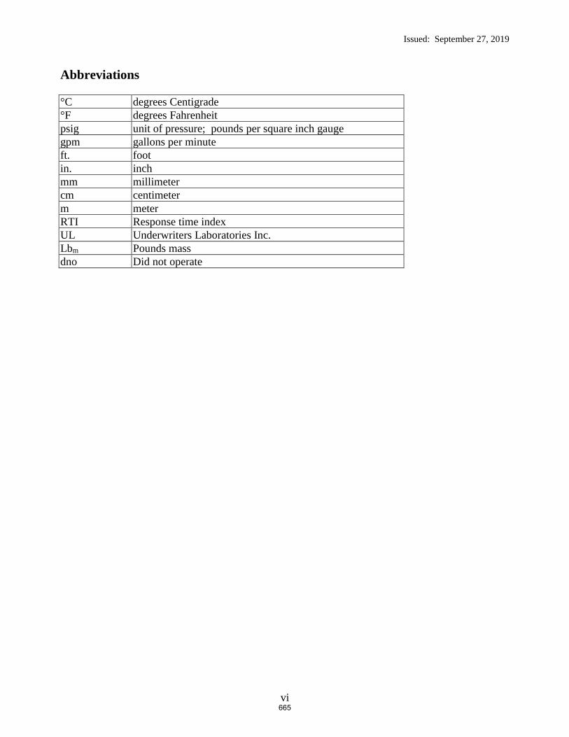
Issued: September 27, 2019
vi
Abbreviations
°C degrees Centigrade
°F degrees Fahrenheit
psig unit of pressure; pounds per square inch gauge
gpm gallons per minute
ft. foot
in. inch
mm millimeter
cm centimeter
m meter
RTI Response time index
UL Underwriters Laboratories Inc.
Lbm Pounds mass
dno Did not operate
665

Issued: September 27, 2019
1 of 35
1. INTRODUCTION
This report describes a Verification Services Investigation conducted for the Fire Protection
Research Foundation, in accordance with the test method described herein.
The sole purpose of this Verification Services Investigation was to study the effects of a specific
ceiling obstruction on a specific pendent ESFR automatic fire sprinkler system.
The information developed from this investigation is provided to the Fire Protection Research
Foundation for their use in determining the effectiveness of the tested sprinkler system and
applied flowing pressures versus commodity and obstruction configuration investigated.
In no event shall UL LLC be responsible to anyone for whatever use or nonuse is made of the
information contained in this Report and in no event shall UL LLC, its employees or its agents
incur any obligations or liability for damages, including, but not limited to, consequential
damage, arising out of or in connection with the use or inability to use the information contained
in this report.
Investigations normally conducted by UL LLC involve Classification, Listing or Recognition
and Follow-Up Services of proprietary products. However, UL LLC does conduct investigations
without Classification, Listing or Recognition and Follow-Up Service when a need for test data
in the interest of public safety has been indicated. Such investigations do not result in specific
conclusions, nor any form of Recognition, Listing or Classification of the products involved. It
is on this basis that UL LLC undertook the Verification Services Investigation reported herein.
2. TEST FACILITY
The fire tests were conducted at Underwriters Laboratories large-scale fire test facility located in
Northbrook, Illinois.
2.1 Large-Scale Fire Test Building
The large-scale fire test building used for this investigation houses four fire test areas that are
used to develop data on the fire growth and fire suppression characteristics of commodities, as
well as the fire suppression characteristics of automatic water sprinkler systems. A schematic of
the test facility is shown in Figure 1.
666
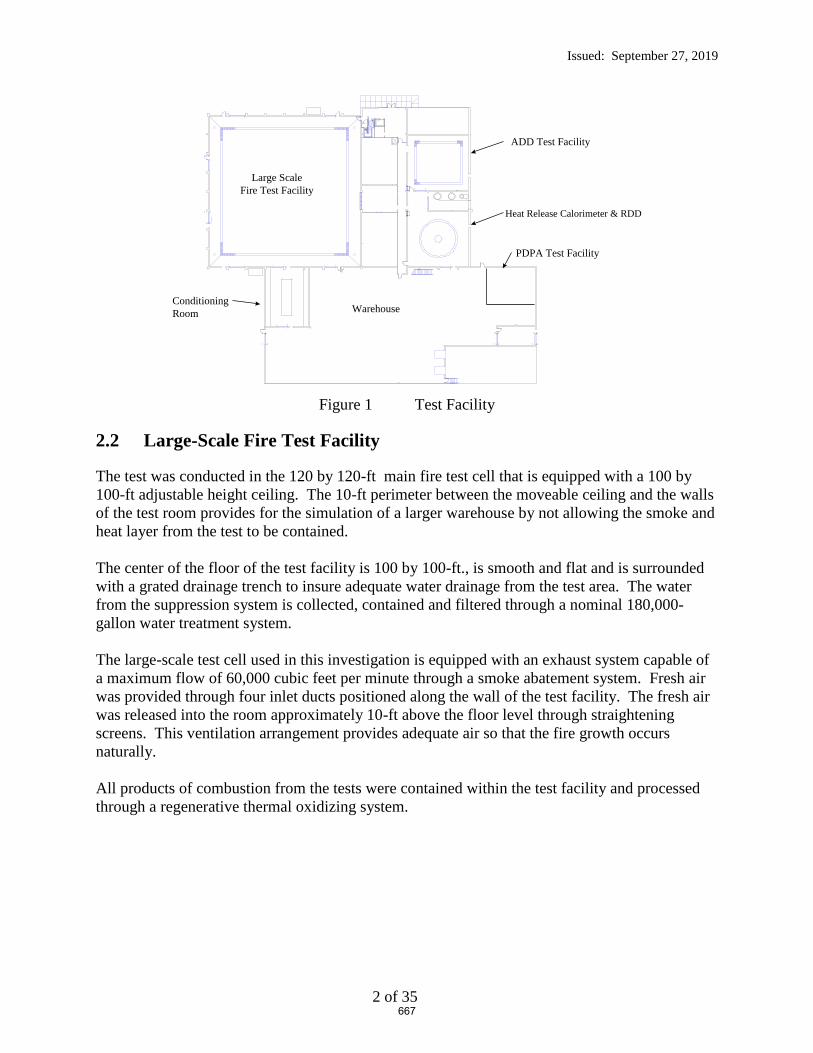
Issued: September 27, 2019
2 of 35
Figure 1 Test Facility
2.2 Large-Scale Fire Test Facility
The test was conducted in the 120 by 120-ft main fire test cell that is equipped with a 100 by
100-ft adjustable height ceiling. The 10-ft perimeter between the moveable ceiling and the walls
of the test room provides for the simulation of a larger warehouse by not allowing the smoke and
heat layer from the test to be contained.
The center of the floor of the test facility is 100 by 100-ft., is smooth and flat and is surrounded
with a grated drainage trench to insure adequate water drainage from the test area. The water
from the suppression system is collected, contained and filtered through a nominal 180,000-
gallon water treatment system.
The large-scale test cell used in this investigation is equipped with an exhaust system capable of
a maximum flow of 60,000 cubic feet per minute through a smoke abatement system. Fresh air
was provided through four inlet ducts positioned along the wall of the test facility. The fresh air
was released into the room approximately 10-ft above the floor level through straightening
screens. This ventilation arrangement provides adequate air so that the fire growth occurs
naturally.
All products of combustion from the tests were contained within the test facility and processed
through a regenerative thermal oxidizing system.
Warehouse
Large Scale
Fire Test Facility
ADD Test Facility
Heat Release Calorimeter & RDD
Conditioning
Room
PDPA Test Facility
667

Issued: September 27, 2019
3 of 35
3. EQUIPMENT
3.1 Automatic Sprinkler System
A wet pipe automatic sprinkler system was positioned below the adjustable smooth, flat non-
combustible ceiling and pressure controlled to provide a specific applied nominal flowing
pressure as defined below.
The sprinklers were supplied through a looped and gridded piping system consisting of 2 ½-in.
diameter, schedule 40 branch lines. The piping system was supplied by a variable speed pump
capable of supplying an adequate pressure and flow to maintain the required applied flowing
pressure throughout the course of the test series.
The automatic sprinkler system consisted of pendent ESFR sprinklers having a nominal K-factor
of 16.8 gpm/psig0.5 in the 165°F temperature rating with a 3/4 inch NPT inlet thread. The
sprinklers were installed on 10 ft. by 10 ft. sprinkler spacing with the sprinkler deflector located
nominally 14 in. below the moveable ceiling. A schematic of the sprinkler numbering system is
shown in Figure 2.
668
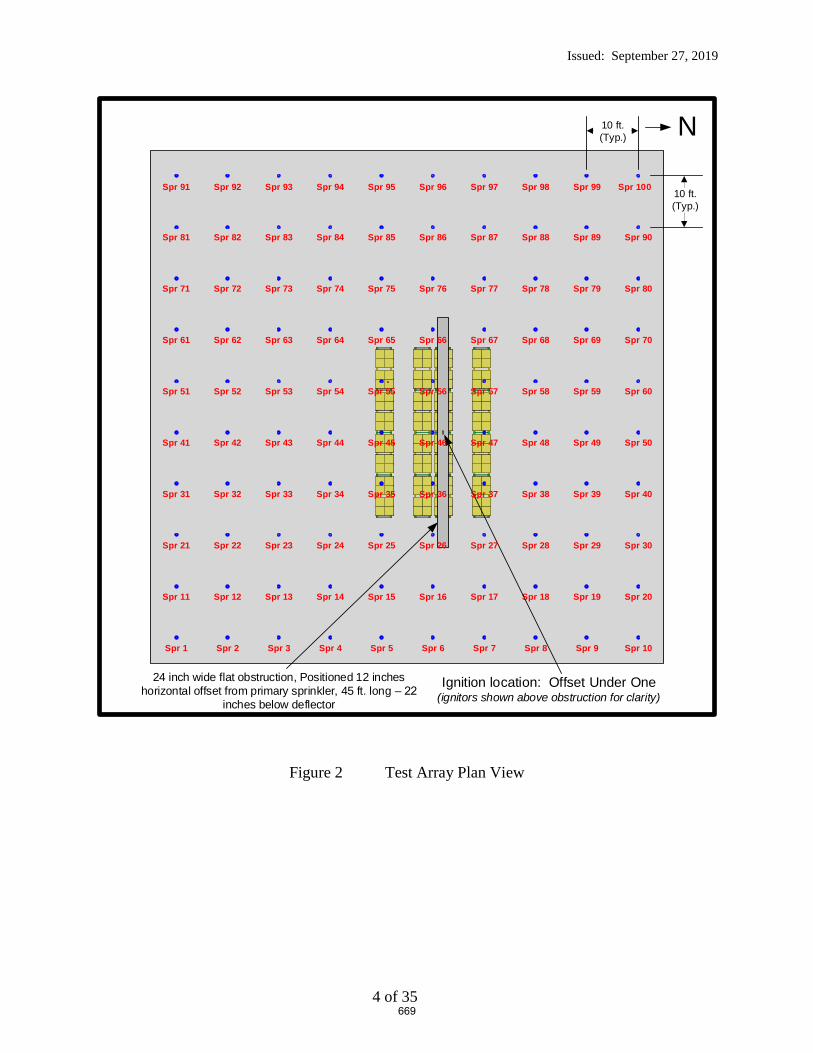
Issued: September 27, 2019
4 of 35
Figure 2 Test Array Plan View
N10 ft. (Typ.)
10 ft. (Typ.)
Ignition location: Offset Under One(ignitors shown above obstruction for clarity)
Spr 11 Spr 12 Spr 13 Spr 14 Spr 15 Spr 16 Spr 17 Spr 18 Spr 19 Spr 20
Spr 71 Spr 72 Spr 73 Spr 74 Spr 75 Spr 76 Spr 77 Spr 78 Spr 79 Spr 80
Spr 81 Spr 82 Spr 83 Spr 84 Spr 85 Spr 86 Spr 87 Spr 88 Spr 89 Spr 90
Spr 1 Spr 2 Spr 3 Spr 4 Spr 5 Spr 6 Spr 7 Spr 8 Spr 9 Spr 10
Spr 91 Spr 92 Spr 93 Spr 94 Spr 95 Spr 96 Spr 97 Spr 98 Spr 99 Spr 100
24 inch wide flat obstruction, Positioned 12 inches horizontal offset from primary sprinkler, 45 ft. long –
inches below deflector
Spr 21 Spr 22 Spr 23 Spr 24 Spr 25 Spr 27 Spr 28 Spr 29 Spr 30Spr 26
Spr 31 Spr 32 Spr 33 Spr 34 Spr 35 Spr 37 Spr 38 Spr 39 Spr 40Spr 36
Spr 41 Spr 42 Spr 43 Spr 44 Spr 45 Spr 47 Spr 48 Spr 49 Spr 50Spr 46
Spr 51 Spr 52 Spr 53 Spr 54 Spr 55 Spr 57 Spr 58 Spr 59 Spr 60Spr 56
Spr 61 Spr 62 Spr 63 Spr 64 Spr 65 Spr 67 Spr 68 Spr 69 Spr 70Spr 66
669

Issued: September 27, 2019
5 of 35
3.2 Air Temperature
3.2.1 Air Temperature Near Sprinklers
The air temperature adjacent to each sprinkler was measured with a 0.0625-in.diameter inconel
sheathed Type K thermocouple.
3.2.2 Air Temperature Above Ignition
The ceiling gas temperature above ignition was measured using the same type of thermocouples
as stated in 3.2.1. The gas temperature was measured adjacent to the steel beam described in 3.3,
with the thermocouples, positioned 6, 12, and 18 inches below the ceiling. The three
thermocouples were positioned near the ends and centered on the steel beam.
3.3 Steel Beam Temperature
A nominal 4 ft. long by 2 in. wide by 2 in. high steel angle was mounted below the ceiling above
the ignition location of the test array. The temperature of the steel beam was measured with five
Type K thermocouples embedded within the beam. The thermocouples were equally spaced
within the beam.
3.4 Video
A minimum of seven video cameras were used to record the test. Four cameras were centered on
each wall of the test cell. One camera was positioned on the observation balcony in the North
East corner of the laboratory, and two cameras were positioned on the test room floor to capture
critical events. In addition, infrared cameras were used to record the events from the South East
and North West corners of the test array.
3.5 Data Collection
All data was collected using an electronic data acquisition system at a one-second-scan rate.
670

Issued: September 27, 2019
6 of 35
4. CARTONED UNEXPANDED GROUP A PLASTIC COMMODITY
4.1 Components
4.1.1 Pallets
The fire test series was conducted using two way pallets as a base for the commodity. The kiln
dried 2-way entry white oak hard wood pallets had outside dimensions of 42 by 42 by 5 in. tall.
Photographs of a representative pallet are shown in Figure 3.
Figure 3 2-Way Entry, Hard Wood Pallet
671

Issued: September 27, 2019
7 of 35
4.1.2 Cups
The cups used in the cartoned , unexpanded Group A commodities were manufactured from
polystyrene. A photograph of the box and cups is shown in Figure 4.
Figure 4 Cut Away of Single Box Showing Cups
672
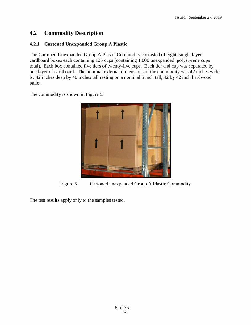
Issued: September 27, 2019
8 of 35
4.2 Commodity Description
4.2.1 Cartoned Unexpanded Group A Plastic
The Cartoned Unexpanded Group A Plastic Commodity consisted of eight, single layer
cardboard boxes each containing 125 cups (containing 1,000 unexpanded polystyrene cups
total). Each box contained five tiers of twenty-five cups. Each tier and cup was separated by
one layer of cardboard. The nominal external dimensions of the commodity was 42 inches wide
by 42 inches deep by 40 inches tall resting on a nominal 5 inch tall, 42 by 42 inch hardwood
pallet.
The commodity is shown in Figure 5.
Figure 5 Cartoned unexpanded Group A Plastic Commodity
The test results apply only to the samples tested.
673
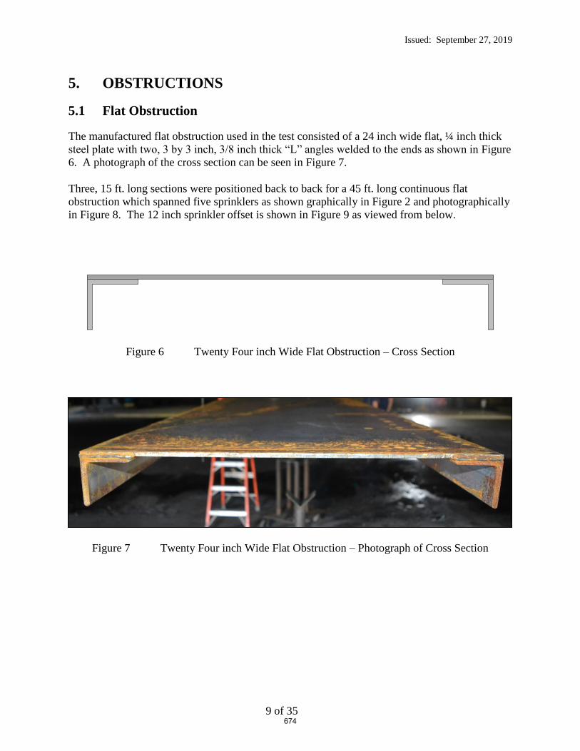
Issued: September 27, 2019
9 of 35
5. OBSTRUCTIONS
5.1 Flat Obstruction
The manufactured flat obstruction used in the test consisted of a 24 inch wide flat, ¼ inch thick
steel plate with two, 3 by 3 inch, 3/8 inch thick “L” angles welded to the ends as shown in Figure
6. A photograph of the cross section can be seen in Figure 7.
Three, 15 ft. long sections were positioned back to back for a 45 ft. long continuous flat
obstruction which spanned five sprinklers as shown graphically in Figure 2 and photographically
in Figure 8. The 12 inch sprinkler offset is shown in Figure 9 as viewed from below.
Figure 6 Twenty Four inch Wide Flat Obstruction – Cross Section
Figure 7 Twenty Four inch Wide Flat Obstruction – Photograph of Cross Section
674

Issued: September 27, 2019
10 of 35
Figure 8 45 ft. Long, 24 inch Wide Flat Obstruction – Photograph from the Southwest
Figure 9– Photograph of 24 inch wide Obstruction from Below, Showing Sprinkler offset 12
inches to the Right (South of lab to the right)
675

Issued: September 27, 2019
11 of 35
Figure 10 Test Arrangement – Elevation View from the East Near Ceiling (upper two tiers as shown)
676

Issued: September 27, 2019
12 of 35
Figure 11 Test Arrangement – Elevation View from the East Near Ceiling (detail around obstruction)
Nominal 4 ft. long, 2 by 2 inch steel angle, centered above ignition
24 inch wide flat plate with welded 3 by 3 inch L angles for flat obstruction, Positioned 12 inches horizontal offset from primary sprinkler, 22 inches
below deflector
K = 16.8 Pendent ESFR Sprinkler with deflector positioned 14 inches
below the smooth flat ceiling
677
Issued: September 27, 2019
13 of 35
6. TEST ARRAY CONFIGURATION
6.1 Rack Array and Plan View
The racking system used for the main bay is considered open, double-row racking in accordance
with NFPA 13. Each bay of the racking system was filled with two pallet loads of the test
commodity as defined in section 4.2.
Figure 10 through Figure 12 shows the details of the rack array and their relationship to the
obstructions for the test.
678

Issued: September 27, 2019
14 of 35
Figure 12 Test Array Plan View – Tight View
679

Issued: September 27, 2019
15 of 35
6.2 Ceiling and Clearance
The test laboratory’s moveable ceiling was positioned at 40 ft. from the test room floor.
A 14 inch pendent sprinkler deflector to ceiling clearance was used for all tests.
A nominal 10 ft. clearance between the ceiling and the top of the commodity was established.
Elevation views of the test arrangements are shown in Figure 13 through Figure 14.
680

Issued: September 27, 2019
16 of 35
Figure 13 Elevation View of Main Test Array from the North
681

Issued: September 27, 2019
17 of 35
Figure 14 Elevation View of Main Test Array from the East
682

Issued: September 27, 2019
18 of 35
6.3 Test Arrangement
The steel racks were loaded with the commodity as defined in section 4. The loading
arrangement is as shown in Figure 13 through Figure 14.
Photographs of the test arrangement are shown in Figure 15 through Figure 17.
683

Issued: September 27, 2019
19 of 35
Figure 15 Elevation View from the North
684

Issued: September 27, 2019
20 of 35
Figure 16 Elevation View from the West
685
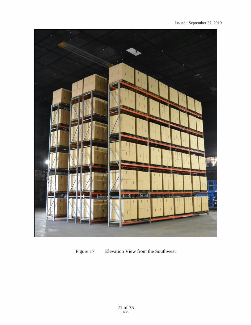
Issued: September 27, 2019
21 of 35
Figure 17 Elevation View from the Southwest
686
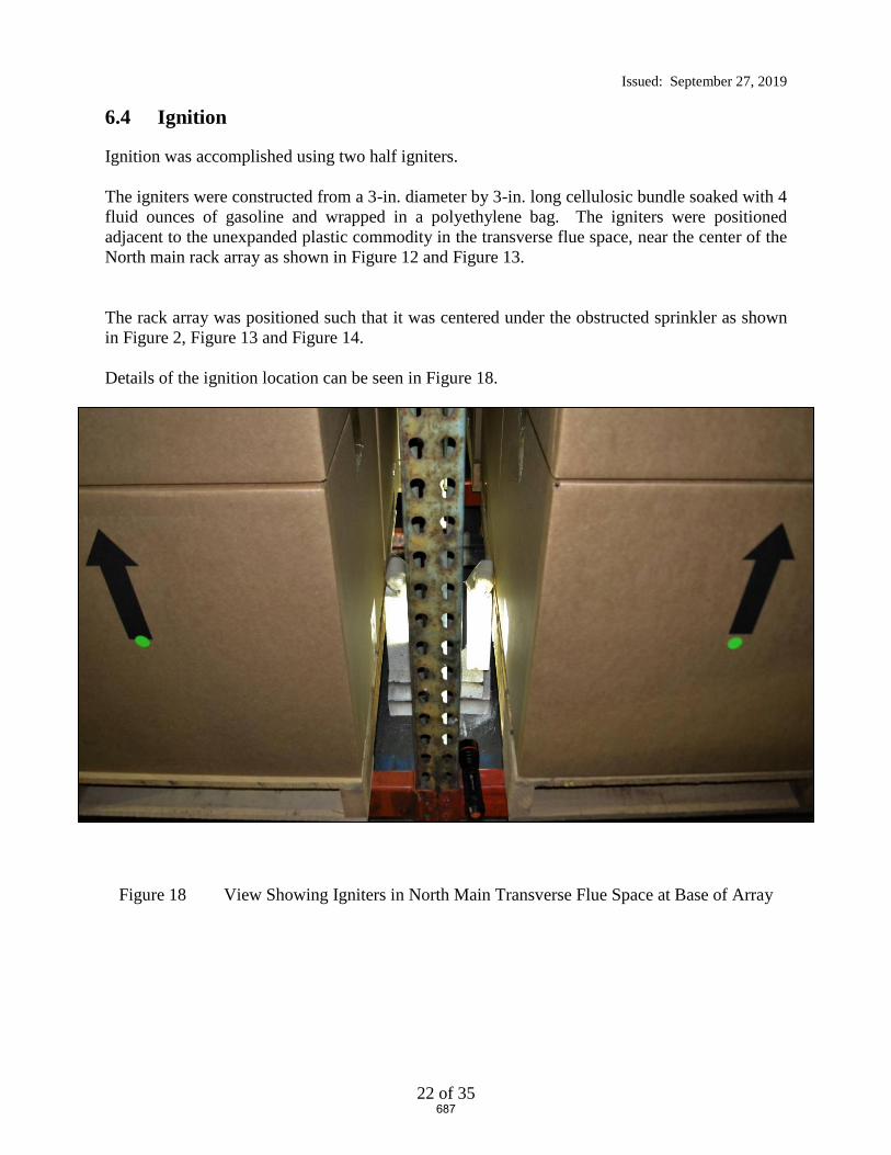
Issued: September 27, 2019
22 of 35
6.4 Ignition
Ignition was accomplished using two half igniters.
The igniters were constructed from a 3-in. diameter by 3-in. long cellulosic bundle soaked with 4
fluid ounces of gasoline and wrapped in a polyethylene bag. The igniters were positioned
adjacent to the unexpanded plastic commodity in the transverse flue space, near the center of the
North main rack array as shown in Figure 12 and Figure 13.
The rack array was positioned such that it was centered under the obstructed sprinkler as shown
in Figure 2, Figure 13 and Figure 14.
Details of the ignition location can be seen in Figure 18.
Figure 18 View Showing Igniters in North Main Transverse Flue Space at Base of Array
687
Issued: September 27, 2019
23 of 35
7. TEST METHOD
7.1 Test Procedure
The test procedure consisted of the following steps:
1. A camera recording of the test arrangement was documented prior to test.
2. The igniters were placed as discussed previously in the “Ignition” section above.
3. The data acquisition system was started upon ignition of the igniters.
4. The test constant flowing pressure for the ceiling sprinkler system was based on adjusting the
system’s fire pump speed for the number of operated sprinklers.
5. The test proceeded for 30 minutes after the operation of the first sprinkler, rounded up to the
nearest whole minute.
6. Termination of the test after the 30 minute plus first sprinkler operation time period began
with automatic deluging of the array until which time the smoke level was diminished to the
point of visual observation of the array. Fire fighters then manually fought the fire until it
was extinguished.
7. A detailed still camera assessment of the commodity damage within the racking array took
place after the test had been completed. See Appendix B for photographs of the damage
assessment.
7.2 Fire Test Photographs
Various photographs of the initial and latter stages of the fire are shown in Figure 19 through
Figure 22.
688

Issued: September 27, 2019
24 of 35
Figure 19 Fire Test Photo Prior to Sprinkler Operation
689

Issued: September 27, 2019
25 of 35
Figure 20 Fire Test Photo Immediately Prior to Sprinkler Operation
690
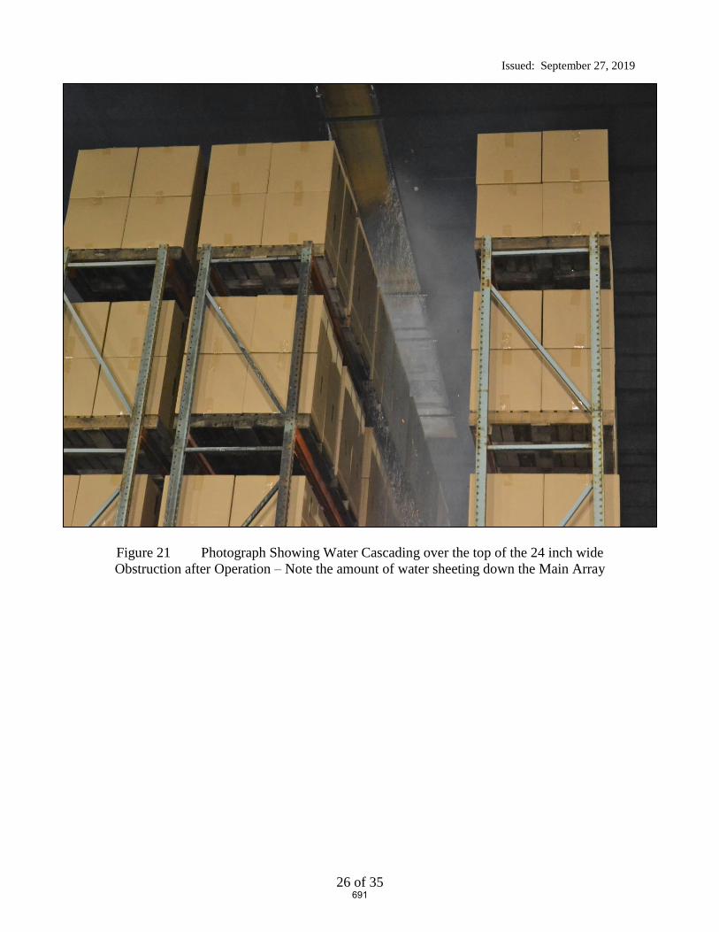
Issued: September 27, 2019
26 of 35
Figure 21 Photograph Showing Water Cascading over the top of the 24 inch wide
Obstruction after Operation – Note the amount of water sheeting down the Main Array
691

Issued: September 27, 2019
27 of 35
Figure 22 View from Ceiling After Sprinkler Operation showing the Obstruction’s Shadow
and the Sheeting action over the top of the 24 inch wide Obstruction
(view from the East)
692
Issued: September 27, 2019
28 of 35
8. RESULTS AND DISCUSSION
One large scale fire test incorporating rack storage of cartoned unexpanded Group A plastic was
conducted at UL LLC in Northbrook, IL on September 24, 2019. The following is a summary of
the resulting data.
8.1 Number of Operating Sprinklers:
Figure 23 provides the sprinkler operation time for the test.
693

Issued: September 27, 2019
29 of 35
dno: did not operate
Figure 23 Operation Times of Sprinklers (minutes:seconds)
N10 ft. (Typ.)
10 ft. (Typ.)
Ignition location: Offset Under One(ignitors shown above obstruction for clarity)
dno dno dno dno dno dno dno dno dno dno
24 inch wide flat obstruction, Positioned 12 inches horizontal offset from primary sprinkler, 45 ft. long –
inches below deflector
1:18
dno dno dno dno dno dno dno dno dno dno
dno dno dno dno dno dno dno dno dno dno
dno dno dno dno dno dno dno dno dno dno
dno dno dno dno dno dno dno dno dno
dno dno dno dno dno dno dno dno dno dno
dno dno dno dno dno dno dno dno dno dno
dno dno dno dno dno dno dno dno dno dno
dno dno dno dno dno dno dno dno dno dno
dno dno dno dno dno dno dno dno dno dno
694

Issued: September 27, 2019
30 of 35
8.2 Temperature Results:
Appendix A provides the data for the test as follows.
The individual sprinkler temperature profiles are presented in Figures 1 through 10 of the
Appendix.
Steel beam and gas temperatures above ignition are presented in Figure 11 and 12 of the
Appendix.
Sprinkler system flowing pressures and system flow rates are presented in Figure 13 of
the Appendix.
8.3 Commodity Damage Results:
The test arrangement was examined for fire test damage to the stored commodity.
The fire did not jump the 4 ft. aisle and the fire was contained within the main array. The
external damage was limited to the North portion of the main array as the South face of the main
array was not damaged.
Drawings of the extent of the damage are depicted in Figure 24 and Figure 25. Photographs of
the overall damage are illustrated in Appendix B.
695

Issued: September 27, 2019
31 of 35
Figure 24 Damage Assessment - Elevation View of North Main Array from Aisle
(ignition side)
696
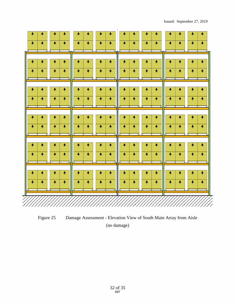
Issued: September 27, 2019
32 of 35
Figure 25 Damage Assessment - Elevation View of South Main Array from Aisle
(no damage)
697

Issued: September 27, 2019
33 of 35
9. SUMMARY
This report describes one large scale fire test that was conducted to develop data relative to the
level of fire protection provided by a specific Early Suppression Fast Response (ESFR) sprinkler
when the sprinklers are located closer to an obstruction than currently referenced in the Standard
for the Installation of Sprinkler Systems, NFPA 13-2019. For this test, the sprinklers were
located in close proximity to a long continuous structural steel flat horizontal shape.
Standard cartoned unexpanded Group A plastic test commodity was used in the investigation
which consisted of unexpanded polystyrene cups installed in separate compartments within
cartons that are placed on two way entry, hardwood pallets. The nominal external dimensions of
the commodity was 42 inches wide by 42 inches deep by 40 inches tall resting on a nominal 5
inch tall, 42 by 42 inch hardwood pallet.
The test was conducted using a nominal storage height of 30 ft of cartoned unexpanded Group A
plastic with a ceiling height of 40 ft. Nominal 32 ft. long double-row rack storage arrays were
used in the main storage array and 32 ft. long single-row racks were placed across 4 ft. aisles on
both the north and south side of the main array as targets. The test was conducted with the
ignition located at the base of the storage array and horizontally offset approximately 2 ft from
the primary obstructed sprinkler in the transverse flue space.
The test was conducted using a 24 inch wide, 45 ft. long continuous flat plate steel structure
obstruction with welded “L” angles at the base for structural integrity. The 24 inch flat
obstruction was positioned with the leading vertical edge of the obstruction 12 inches away and
the top horizontal flat portion of the obstruction, 22 inches vertically downward from the
sprinkler’s deflector.
During the test, one (1) sprinkler operated. It was noted that the sprinkler’s discharge formed
vertically downward sheeting over the obstruction which significantly reduced the size of the
fire. The sheeting action of this obstruction can be seen in Figure 21 and Figure 22 in the body
of the report.
The fire was contained within the two center bays of the main array. No damage was observed
at the opposite aisle to ignition of the main double row rack storage array. No target ignition
occurred.
A summary of the test parameters and results are provided in Table 1.
698
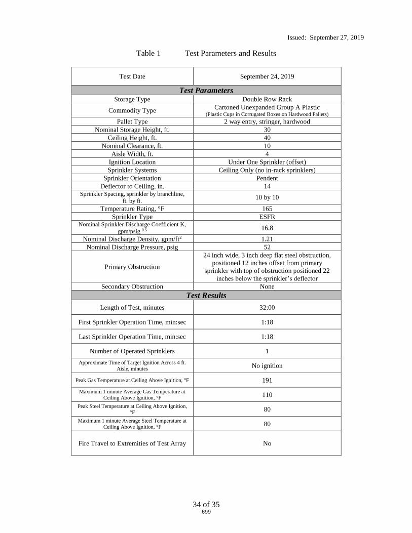
Issued: September 27, 2019
34 of 35
Table 1 Test Parameters and Results
Test Date September 24, 2019
Test Parameters Storage Type Double Row Rack
Commodity Type Cartoned Unexpanded Group A Plastic
(Plastic Cups in Corrugated Boxes on Hardwood Pallets)
Pallet Type 2 way entry, stringer, hardwood
Nominal Storage Height, ft. 30
Ceiling Height, ft. 40
Nominal Clearance, ft. 10
Aisle Width, ft. 4
Ignition Location Under One Sprinkler (offset)
Sprinkler Systems Ceiling Only (no in-rack sprinklers)
Sprinkler Orientation Pendent
Deflector to Ceiling, in. 14 Sprinkler Spacing, sprinkler by branchline,
ft. by ft. 10 by 10
Temperature Rating, °F 165
Sprinkler Type ESFR Nominal Sprinkler Discharge Coefficient K,
gpm/psig 0.5 16.8
Nominal Discharge Density, gpm/ft2 1.21
Nominal Discharge Pressure, psig 52
Primary Obstruction
24 inch wide, 3 inch deep flat steel obstruction,
positioned 12 inches offset from primary
sprinkler with top of obstruction positioned 22
inches below the sprinkler’s deflector
Secondary Obstruction None
Test Results
Length of Test, minutes 32:00
First Sprinkler Operation Time, min:sec 1:18
Last Sprinkler Operation Time, min:sec 1:18
Number of Operated Sprinklers 1
Approximate Time of Target Ignition Across 4 ft. Aisle, minutes
No ignition
Peak Gas Temperature at Ceiling Above Ignition, °F 191
Maximum 1 minute Average Gas Temperature at Ceiling Above Ignition, °F
110
Peak Steel Temperature at Ceiling Above Ignition, °F
80
Maximum 1 minute Average Steel Temperature at Ceiling Above Ignition, °F
80
Fire Travel to Extremities of Test Array No
699

Issued: September 27, 2019
35 of 35
Report By: Reviewed By:
Daniel R. Steppan Michael G. McCormick
Senior Staff Engineer Staff Engineering Associate
Building and Life Safety Technologies Building and Life Safety Technologies
700

Appendix A – Temperature, Flow and Pressure Graphs
A-1
APPENDIX A
Temperature, Flow and Pressure Graphs
701
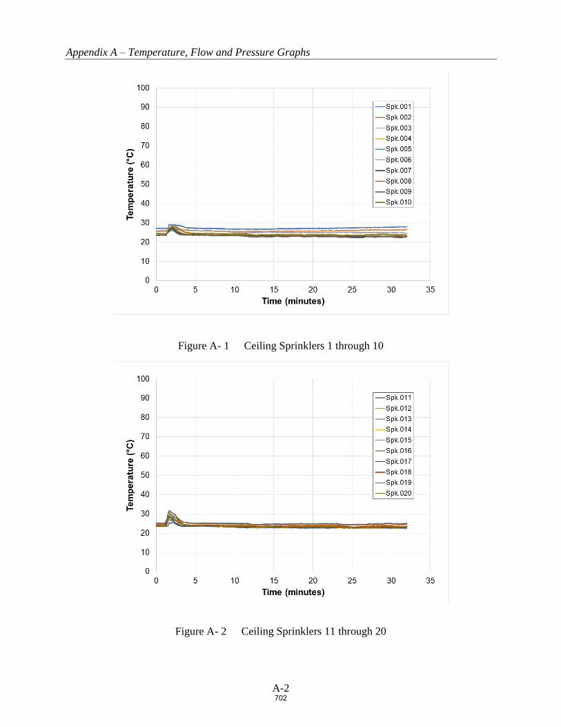
Appendix A – Temperature, Flow and Pressure Graphs
A-2
Figure A- 1 Ceiling Sprinklers 1 through 10
Figure A- 2 Ceiling Sprinklers 11 through 20
702

Appendix A – Temperature, Flow and Pressure Graphs
A-3
Figure A- 3 Ceiling Sprinklers 21 through 30
Figure A- 4 Ceiling Sprinklers 31 through 40
703

Appendix A – Temperature, Flow and Pressure Graphs
A-4
Figure A- 5 Ceiling Sprinklers 41 through 50
Figure A- 6 Ceiling Sprinklers 51 through 60
704

Appendix A – Temperature, Flow and Pressure Graphs
A-5
Figure A- 7 Ceiling Sprinklers 61 through 70
Figure A- 8 Ceiling Sprinklers 71 through 80
705
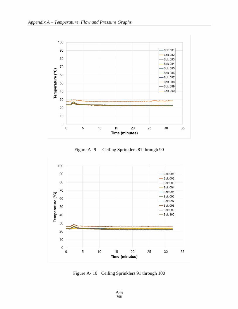
Appendix A – Temperature, Flow and Pressure Graphs
A-6
Figure A- 9 Ceiling Sprinklers 81 through 90
Figure A- 10 Ceiling Sprinklers 91 through 100
706
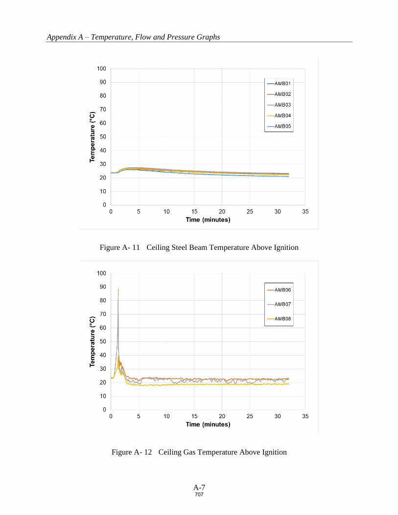
Appendix A – Temperature, Flow and Pressure Graphs
A-7
Figure A- 11 Ceiling Steel Beam Temperature Above Ignition
Figure A- 12 Ceiling Gas Temperature Above Ignition
707

Appendix A – Temperature, Flow and Pressure Graphs
A-8
Figure A- 13 Ceiling Sprinkler System Flow rate and Pressure
708

Appendix B – Damage Assessment Photographs
B-1
APPENDIX B
Damage Assessment Photographs
709
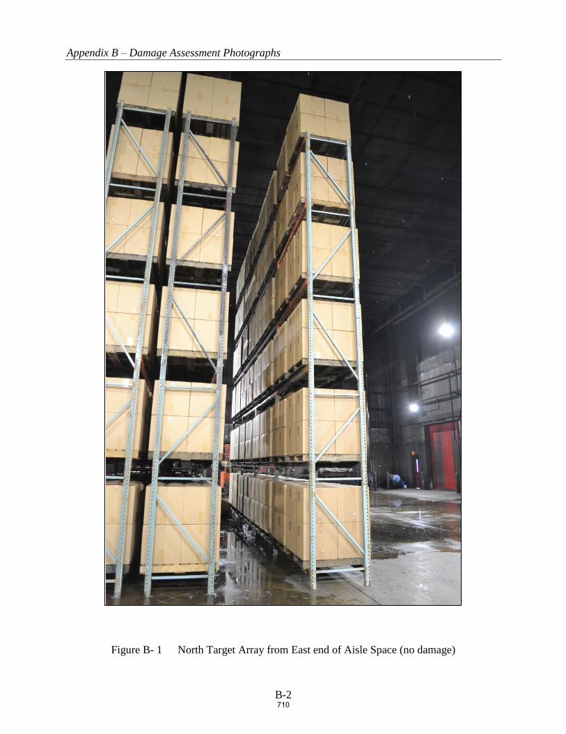
Appendix B – Damage Assessment Photographs
B-2
Figure B- 1 North Target Array from East end of Aisle Space (no damage)
710

Appendix B – Damage Assessment Photographs
B-3
Figure B- 2 North Main Array Damage
711

Appendix B – Damage Assessment Photographs
B-4
Figure B- 3 South Main Array Damage
(NOTE: Dark spots due to fire fighting efforts – no damage)
712
Public Comment No. 151-NFPA 13-2020 [ Section No. 14.2.11.3.1 ]
14.2.11.3.1 General Continuous Obstructions.
Sprinklers shall be arranged with respect to obstructions in accordance with one of the following:
(1) Sprinklers shall be installed below continuous obstructions, or they shall be arranged to comply withTable 14.2.11.1.1 for horizontal obstructions entirely below the elevation of sprinklers that restrictsprinkler discharge pattern for two or more adjacent sprinklers such as ducts, lights, pipes, andconveyors.
(2) Additional sprinklers shall not be required under conveyors with rollers where the openings betweenrollers are a minimum 50 percent open and there is no storage below the conveyor.
(3) Additional sprinklers shall not be required where the obstruction is 2 in. (50 mm) or less in width and islocated a minimum of 2 ft (600 mm) below the elevation of the sprinkler deflector or is positioned aminimum of 1 ft (300 mm) horizontally from the sprinkler.
(4) Additional sprinklers shall not be required where the obstruction is 1 ft (300 mm) or less in width andlocated a minimum of 1 ft (300 mm) horizontally from the sprinkler.
(5) Additional sprinklers shall not be required where the obstruction is 2 ft (600 mm) or less in width andlocated a minimum of 2 ft (600 mm) horizontally from the sprinkler.
(6) Ceiling sprinklers shall not be required to comply with Table 14.2.11.1.1 where a row of sprinklers isinstalled under the obstruction.
(7) Additional sprinklers shall not be required where the occupancy is protected in accordance with 14.2.7and obstructions comply with 9.5.5.3.
Statement of Problem and Substantiation for Public Comment
Currently when there is an obstruction utilizing ESFR sprinklers at the ceiling, ESFR sprinklers are required belowobstructions. Many times there are conveyors that are utilized in ESFR protected systems. Providing ESFRprotection below conveyors with rollers, especially ones low to the ground/floor is unwarranted. There may besome concern with accumulation of debris or low piled storage below these conveyors. However with ESFRprotection above, this should not be an issue.
Related Item
• PI#328
Submitter Information Verification
Submitter Full Name: Peter Schwab
Organization: Wayne Automatic Fire Sprinkler
Street Address:
City:
State:
Zip:
Submittal Date: Sat Apr 25 15:38:36 EDT 2020
Committee: AUT-AAC
National Fire Protection Association Report https://submittals.nfpa.org/TerraViewWeb/ContentFetcher?commentPar...
278 of 738 5/8/2020, 11:28 AM
713

Public Comment No. 374-NFPA 13-2020 [ Section No. 14.2.11.3.1 ]
14.2.11.3.1 General Continuous Obstructions. Obstructions that are Located Directly Above Storage
Sprinklers shall be arranged with respect to obstructions in accordance with one of the following:
(1) Sprinklers shall be installed below continuous obstructions, or they shall be arranged to comply withTable 14.2.11.1.1 for horizontal obstructions entirely below the elevation of sprinklers that restrictsprinkler discharge pattern for two or more adjacent sprinklers such as ducts, lights, pipes, andconveyors.
(2) Additional sprinklers shall not be required where the obstruction is 2 in. (50 mm) or less in width and islocated a minimum of 2 ft (600 mm) below the elevation of the sprinkler deflector or is positioned aminimum of 1 ft (300 mm) horizontally from the sprinkler.
(3) Additional sprinklers shall not be required where the obstruction is 1 ft (300 mm) or less in width andlocated a minimum of 1 ft (300 mm) horizontally from the sprinkler.
(4) Additional sprinklers shall not be required where the obstruction is 2 ft (600 mm) or less in width andlocated a minimum of 2 ft (600 mm) horizontally from the sprinkler.
(5) Ceiling sprinklers shall not be required to comply with Table 14.2.11.1.1 where a row of sprinklers isinstalled under the obstruction.
(6) Additional sprinklers shall not be required where the occupancy is protected in accordance with 14.2.7and obstructions comply with 9.5.5.3.
Statement of Problem and Substantiation for Public Comment
Open conveyors and similar features are common in warehouses with ESFR sprinkler systems and the protection criteria is not consistent in different jurisdictions. Some jurisdictions require protection under all open obstructions and others allow sprinklers to be omitted.This issue needs to be addressed. Public Input clarifies the conditions where these features are considered a solid obstruction and sprinkler protection is requiredunderneath. It is important to not that this new section is limited to areas with no storage below.Note this comment is resubmitting PI 510 which shows this comment was resolved but my notes show that the committee did take action on this concept.Note there are two additional comments on this concept.
Related Public Comments for This Document
Related Comment Relationship
Public Comment No. 375-NFPA 13-2020 [New Section after 14.2.11.3.7]
Public Comment No. 376-NFPA 13-2020 [New Section after 14.2.11.3.7]
Related Item
• FR-1065
Submitter Information Verification
Submitter Full Name: Roland Asp
Organization: National Fire Sprinkler Association
Affiliation: NFSA Engineering and Standards Committee
Street Address:
City:
State:
Zip:
Submittal Date: Wed May 06 11:37:13 EDT 2020
Committee: AUT-AAC
National Fire Protection Association Report https://submittals.nfpa.org/TerraViewWeb/ContentFetcher?commentPar...
279 of 738 5/8/2020, 11:28 AM
714
Public Comment No. 375-NFPA 13-2020 [ New Section after 14.2.11.3.7 ]
New Section after 14.2.11.3
14.2.11.4 Unless the requirements of 14.2.11.4.1 and 14.2.11.4.2 are met, continuous
obstructions located a minimum of 36" below sprinklers without high piled storage
located underneath shall require sprinkler protection
14.2.11.4.1 The continuous obstruction is 4 ft wide or less
14.2.11.4.2 Sprinklers are not required below conveyor systems that are a minimum
of 70 % open, or below roller-type conveyors that are at least 50 % open. If these
conditions cannot be met, treat conveyors as a solid obstruction
Statement of Problem and Substantiation for Public Comment
Open conveyors and similar features are common in warehouses with ESFR sprinkler systems and the protection criteria is not consistent in different jurisdictions. Some jurisdictions require protection under all open obstructions and others allow sprinklers to be omitted. This issue needs to be addressed. Public Input clarifies the conditions where these features are considered a solid obstruction and sprinkler protection is required underneath. It is important to note that this new section is limited to areas with no storage below.Note this comment is resubmitting PI 511 which shows this comment was resolved but my notes show that the committee did take action on this concept.
Related Public Comments for This Document
Related Comment Relationship
Public Comment No. 374-NFPA 13-2020 [Section No. 14.2.11.3.1]
Public Comment No. 376-NFPA 13-2020 [New Section after 14.2.11.3.7]
Related Item
• FR-1065
Submitter Information Verification
Submitter Full Name: Roland Asp
Organization: National Fire Sprinkler Association
Affiliation: NFSA Engineering and Standards Committee
Street Address:
City:
State:
Zip:
Submittal Date: Wed May 06 11:51:07 EDT 2020
Committee: AUT-AAC
National Fire Protection Association Report https://submittals.nfpa.org/TerraViewWeb/ContentFetcher?commentPar...
280 of 738 5/8/2020, 11:28 AM
715

Public Comment No. 376-NFPA 13-2020 [ New Section after 14.2.11.3.7 ]
TITLE OF NEW CONTENT
4.2.11.4.3 Continous Obstructions. Quick-response spray sprinklers shall be permitted to be utilized underconveyors with without high piled storage located underneath
Statement of Problem and Substantiation for Public Comment
This section is related to the proposed new section 14.2.11.4 which deals with obstructionwith no high piled storage underneath. If sprinklers are required under these obstructions,quick response sprinklers should be adequate as there is no storage below. Note that theexisting section 14.2.11.3.5 already states that overhead doors are permitted to beprotected with QR sprinklers underneath, regardless of if there is storage below.
Related Public Comments for This Document
Related Comment Relationship
Public Comment No. 374-NFPA 13-2020 [Section No. 14.2.11.3.1]
Public Comment No. 375-NFPA 13-2020 [New Section after 14.2.11.3.7]
Related Item
• FR-1065
Submitter Information Verification
Submitter Full Name: Roland Asp
Organization: National Fire Sprinkler Association
Affiliation: NFSA Engineering and Standards Committee
Street Address:
City:
State:
Zip:
Submittal Date: Wed May 06 12:23:36 EDT 2020
Committee: AUT-AAC
National Fire Protection Association Report https://submittals.nfpa.org/TerraViewWeb/ContentFetcher?commentPar...
281 of 738 5/8/2020, 11:28 AM
716
Public Comment No. 152-NFPA 13-2020 [ Section No. 16.2.1.1 [Excluding any Sub-
Sections] ]
When a threaded sprinkler is removed from a fitting or welded outlet, it shall not be reinstalled except aspermitted by 16.2.1.1.1.
Statement of Problem and Substantiation for Public Comment
There are now grooved sprinklers that can be removed without applying any torque to the sprinkler. The committee's statement once again points to a section that has no bearing on this matter (Fire Department Connections).
Related Item
• PI#287
Submitter Information Verification
Submitter Full Name: Peter Schwab
Organization: Wayne Automatic Fire Sprinkler
Street Address:
City:
State:
Zip:
Submittal Date: Sat Apr 25 16:10:16 EDT 2020
Committee: AUT-AAC
National Fire Protection Association Report https://submittals.nfpa.org/TerraViewWeb/ContentFetcher?commentPar...
282 of 738 5/8/2020, 11:28 AM
717

Public Comment No. 392-NFPA 13-2020 [ Section No. 16.3.9.6 [Excluding any Sub-
Sections] ]
Nonmetallic pipe listed for light hazard occupancies shall be permitted to be installed in ordinary hazard
rooms of otherwise light hazard occupancies where the room does not exceed 400 ft 800 ft 2 (37 m 74 m 2).
Statement of Problem and Substantiation for Public Comment
This change correlates with revisions taken in NFPA 13R.
Related Item
• PI 689 • NFPA 13R FR-43
Submitter Information Verification
Submitter Full Name: Mark Fessenden
Organization: Johnson Controls
Street Address:
City:
State:
Zip:
Submittal Date: Wed May 06 16:36:03 EDT 2020
Committee: AUT-AAC
National Fire Protection Association Report https://submittals.nfpa.org/TerraViewWeb/ContentFetcher?commentPar...
283 of 738 5/8/2020, 11:28 AM
718

Public Comment No. 48-NFPA 13-2020 [ Section No. 16.4.1.4 [Excluding any Sub-
Sections] ]
Listed heat-tracing systems shall be permitted in accordance with 16.4.1.4.1 and 16.4.1.4.2.
Add new Annex text as follows:
16.4.1.4 * Listed heat-tracing systems shall be permi ed in accordance with 16.4.1.4.1 and 16.4.1.4.2.
A.16.4.1.4 Requirements for heat tracing and associated controls intended for the fire protec on applica on can befound in UL 515A, Outline of Inves ga on for Electrical Resistance Trace Hea ng and Associated Controls for Use InSprinkler and Standpipe Systems. Also, since heat tracing has the poten al to overheat sprinklers and systempiping as well as adversely impact the sprinkler discharge characteris cs, hea ng tracing used for branch lines isrequired to be specifically listed for this use.
Statement of Problem and Substantiation for Public Comment
Heat tracing systems are listed for a large number of different applications. This revision provides a reference to the requirements that are applicable to the use on fire protection systems. The reference to this standard is consistent with the approach taken for a large number of other standards. Refer to Annex F. Also, information as to why it is important to require a specific listing for heat tracing for branch lines is provided.
Related Item
• Public Input 527
Submitter Information Verification
Submitter Full Name: Kerry Bell
Organization: UL LLC
Street Address:
City:
State:
Zip:
Submittal Date: Fri Apr 17 14:12:44 EDT 2020
Committee: AUT-AAC
National Fire Protection Association Report https://submittals.nfpa.org/TerraViewWeb/ContentFetcher?commentPar...
284 of 738 5/8/2020, 11:28 AM
719
Public Comment No. 274-NFPA 13-2020 [ Section No. 16.4.3 ]
16.4.3* Protection of Piping in Hazardous Areas.
16.4.3.1
Private service main aboveground piping shall not pass through hazardous areas and shall be located sothat it is protected from mechanical and fire damage.
16.4.3.2
Private service main aboveground piping shall be permitted to be located in hazardous areas protected byan automatic sprinkler system.
Additional Proposed Changes
File Name Description Approved
13_CCN_10.pdf 13_CCN_10
Statement of Problem and Substantiation for Public Comment
NOTE: This Public Comment appeared as CC Note No. 10 in the First Draft Report on First Revision No. 1075.
Coordinate requirements for nail plates with NFPA 13D, Section 5.2.3.3.
Related Item
• FR-1075
Submitter Information Verification
Submitter Full Name: CC on AUT-AAC
Organization: NFPA
Street Address:
City:
State:
Zip:
Submittal Date: Mon May 04 13:21:11 EDT 2020
Committee: AUT-AAC
National Fire Protection Association Report https://submittals.nfpa.org/TerraViewWeb/ContentFetcher?commentPar...
285 of 738 5/8/2020, 11:28 AM
720

Correlating Committee Note No. 10-NFPA 13-2019 [ New Section after 16.4.3 ]
Submitter Information Verification
Committee: AUT-AAC
Submittal Date: Mon Dec 16 11:54:22 EST 2019
Committee Statement
Committee Statement: Coordinate requirements for nail plates with NFPA 13D, Section 5.2.3.3.
First Revision No. 1075-NFPA 13-2019 [New Section after 16.4.3]
Ballot Results
This item has passed ballot
22 Eligible Voters
3 Not Returned
19 Affirmative All
0 Affirmative with Comments
0 Negative with Comments
0 Abstention
Not Returned
Baz, Jose R.
Hilton, Luke
Su, Joseph
Affirmative All
Bell, Kerry M.
Bellamy, Tracey D.
Browning, Chase A.
Dellasanta, Steven W.
Friedman, Michael J.
Hoffman, Alex
Hopkins, Mark
Javeri, Sultan M.
Ketner, Charles W.
Koffel, William E.
Lake, James D.
LeBlanc, John A.
Linder, Kenneth W.
Lowrey, David O.
Medovich, Jack A.
Palenske, Garner A.
National Fire Protection Association Report https://submittals.nfpa.org/TerraViewWeb/ContentFetcher?commentPar...
29 of 50 5/4/2020, 11:38 AM
721

Phillips, Lawrence Richard
Seghi, Adam
Thompson, J. Michael
National Fire Protection Association Report https://submittals.nfpa.org/TerraViewWeb/ContentFetcher?commentPar...
30 of 50 5/4/2020, 11:38 AM
722

Public Comment No. 275-NFPA 13-2020 [ Section No. 16.9.7 ]
16.9.7* Pressure-Reducing Valves.
16.9.7.1
In portions of systems where the potential exists for normal (nonfire condition) water pressure in excess of175 psi (12 bar) and all components are not listed for pressures equal to or greater than the maximumpotential water pressure, a listed pressure-reducing valve shall be installed and set for an outlet pressurenot exceeding 10 psi (0.7 bar) below the minimum rated pressure of any component within that portion ofthe system at the maximum inlet pressure.
16.9.7.1.1
The pressure on the inlet side of the pressure-regulating device shall not exceed the rated workingpressure of the device.
16.9.7.2
Pressure gauges shall be installed on the inlet and outlet sides of each pressure-reducing valve.
16.9.7.3*
A listed relief valve of not less than 1⁄2 in. (15 mm) in size shall be provided on the discharge side of thepressure-reducing valve set to operate at a pressure not exceeding the rated pressure of the componentsof the system.
16.9.7.4
A listed indicating valve shall be provided on the inlet side of each pressure-reducing valve, unless thepressure-reducing valve meets the listing requirements for use as an indicating valve.
16.9.7.5
Means shall be provided downstream of all pressure-reducing valves for flow tests at sprinkler systemdemand.
Additional Proposed Changes
File Name Description Approved
13_CCN_7.pdf 13_CCN_7
Statement of Problem and Substantiation for Public Comment
NOTE: This Public Comment appeared as CC Note No. 7 in the First Draft Report on First Revision No. 1358.
Correlating Committee directs AUT-SSI to review 16.9.7 PRV requirements along with NFPA 14 PRV requirements and annex material to see if closer alignment is needed.NFPA 14 has requirements for a pressure switch, manual bypass in case the valve fails closed, and annex language that discusses low flow conditions. These are applicable conditions to sprinkler systems as well.
Related Item
• FR-1358
Submitter Information Verification
Submitter Full Name: CC on AUT-AAC
Organization: NFPA
Street Address:
City:
State:
Zip:
Submittal Date: Mon May 04 13:24:54 EDT 2020
National Fire Protection Association Report https://submittals.nfpa.org/TerraViewWeb/ContentFetcher?commentPar...
286 of 738 5/8/2020, 11:28 AM
723

Committee: AUT-AAC
National Fire Protection Association Report https://submittals.nfpa.org/TerraViewWeb/ContentFetcher?commentPar...
287 of 738 5/8/2020, 11:28 AM
724
Correlating Committee Note No. 7-NFPA 13-2019 [ Section No. 16.9.8 ]
Submitter Information Verification
Committee: AUT-AAC
Submittal Date: Mon Dec 16 10:52:06 EST 2019
Committee Statement
CommitteeStatement:
Correlating Committee directs AUT-SSI to review 16.9.7 PRV requirements along with NFPA 14PRV requirements and annex material to see if closer alignment is needed.
NFPA 14 has requirements for a pressure switch, manual bypass in case the valve fails closed,and annex language that discusses low flow conditions. These are applicable conditions tosprinkler systems as well.
First Revision No. 1358-NFPA 13-2019 [Section No. 16.9.8]
Ballot Results
This item has passed ballot
22 Eligible Voters
3 Not Returned
18 Affirmative All
1 Affirmative with Comments
0 Negative with Comments
0 Abstention
Not Returned
Baz, Jose R.
Hilton, Luke
Su, Joseph
Affirmative All
Bell, Kerry M.
Bellamy, Tracey D.
Browning, Chase A.
Dellasanta, Steven W.
Friedman, Michael J.
Hoffman, Alex
Hopkins, Mark
Javeri, Sultan M.
Ketner, Charles W.
Koffel, William E.
LeBlanc, John A.
Linder, Kenneth W.
Lowrey, David O.
National Fire Protection Association Report https://submittals.nfpa.org/TerraViewWeb/ContentFetcher?commentPar...
31 of 50 5/4/2020, 11:38 AM
725

Medovich, Jack A.
Palenske, Garner A.
Phillips, Lawrence Richard
Seghi, Adam
Thompson, J. Michael
Affirmative with Comment
Lake, James D.
Committee Statement reads "encase". I believe this should be "in case the valve fails"
National Fire Protection Association Report https://submittals.nfpa.org/TerraViewWeb/ContentFetcher?commentPar...
32 of 50 5/4/2020, 11:38 AM
726

Public Comment No. 282-NFPA 13-2020 [ Section No. 16.9.7.5 ]
16.9.7.5
Means One or more test connections shall be provided downstream of all pressure-reducing valves for theperformance of flow tests at sprinkler system demand as required by this standard and NFPA 25 .
16.9.7.5.1 A 2 1 ∕ in. (65 mm) hose valve shall be provided downstream of the pressure reducing valve for every 250
gpm (950 L/min) of flow rate required by the system demand.
16.9.7.5.2* Existing hose connections downstream of the pressure reducing valve shall be allowed to be utilized.
16.9.7.5.3* Other means shall be permitted as long as the system doesn’t require modification to perform the test.
Statement of Problem and Substantiation for Public Comment
For many cycles this requirement has been in the standard and yet very few new systems are being installed with a realistic “means” to perform this test. Sprinkler contractors seem to be ignoring this requirement or assuming someone will have to figure out how to do it later. Unless prescriptive requirements are included it is unlikely the “means” will be provided.The technical committee accepted the concepts of including prescribed means by moving the text submitted in PI 556 to the annex. Unfortunately, the annex text is for guidance only, is unenforceable, and will do little to make contractors comply with this requirement. Also, the annex text was attached to the wrong section. It should have been attached to section 16.9.7.5 and not 16.9.7.
Related Public Comments for This Document
Related Comment Relationship
Public Comment No. 284-NFPA 13-2020 [Section No. A.16.9.7]
Public Comment No. 289-NFPA 13-2020 [New Section after A.16.9.7.3]
Related Item
• PI 556 FR 1358
Submitter Information Verification
Submitter Full Name: Terry Victor
Organization: Johnson Controls
Street Address:
City:
State:
Zip:
Submittal Date: Mon May 04 13:56:04 EDT 2020
Committee: AUT-AAC
National Fire Protection Association Report https://submittals.nfpa.org/TerraViewWeb/ContentFetcher?commentPar...
288 of 738 5/8/2020, 11:28 AM
727
Public Comment No. 37-NFPA 13-2020 [ Section No. 16.10.3 [Excluding any Sub-
Sections] ]
Piping Dry pipe and pre-action systems. All piping shall be pitched at least 1/2 inch per 10 feet to drainas stated in 16 . 10.3.1 through 16.10.3.3 .
Statement of Problem and Substantiation for Public Comment
The intent of this change is to ensure adequate and proper pitch exists so as to reduce the amount of corrosion and build up of the products of corrosion in dry and pre action systems mains. It will also simplify this section by removing unnecessary sub sections, additions and or exemptions dependent on conditions. In both the standard and real world applications there has been an increased focus on corrosion and the products of corrosion in systems and the problems related to them. As far back as I could find, in the 1969 edition of NFPA 13 section 3214 it states " On dry pipe systems sprinkler pipe on branch lines shall be pitched at least 1/2 inch in 10 feet and the pipe of cross mains and feed mains shall be given a pitch of not less than 1/4 inch in 10 feet. A pitch of 3/4 inch to 1 inch should be provided for short branch lines and 1/2 inch in 10 feet for cross and feed mains in refrigerated areas and in buildings of light construction where floor may settle under heavy loads." I believe that with the exception of changing the word "should" to "shall" and the addition of "pre-action systems", this section remained basically the same for about a quarter of a century. In my original PI statement a number of examples and concerns were listed including the issue of buildings settling which in itself seemed to be enough of a concern to warrant inclusion in the standard all the way back at least to the '69 edition of NFPA 13 over a half century ago. I do not believe the committee resolution and statement addressed the intent of the original PI or the bulk of the original substantiation. The accumulation of water and products of corrosion and the continued increase of accumulation once the process begins appears to be made worse in mains installed under the 1/4 inch in 10 ft. VS. the required 1/2 inch per 10 ft. already required for branch lines and mains in refrigerated spaces. This also streamlines the standard and makes it easier to understand. Why are there two different pitch requirements? Why should there be a different pitch required for branch lines vs. mains, why a different pitch for mains in refrigerated spaces vs. those only subject to freezing six or eight months out of the year, and isn't corrosion worse in a system that isn't always below 32 degrees. If 1/2 inch for 10 feet is the right pitch for all branch lines and mains in refrigerators and freezers why isn't it right for all applications even if the mains may not be exposed to freezing temperatures for a few months out of the year? If a resolution of this PC is considered on a basis of "lack of technical substantiation to support this change", I would submit that this is not a new requirement so much as a return to the original intent or objective of the standard that continues to work for lines and mains in refrigerated spaces and that should provide a base for substantiation. Also see FM Global Research Technical Report titled Corrosion and Corrosion Mitigation in Fire Protection Systems 2nd edition July 2014 sections 4.3.1.2, 5.3 and 6.2. If this is written up as 16.10.3, then we can eliminate 16.10.3.1, 16.10.3.2 and 16.10.3.3 all together along with 8.8.2.3.Thank you for your consideration.
Related Item
• PI #228
Submitter Information Verification
Submitter Full Name: David Baron
Organization: Global Fire Protection Company
Street Address:
City:
State:
Zip:
Submittal Date: Mon Mar 30 17:01:50 EDT 2020
Committee: AUT-AAC
National Fire Protection Association Report https://submittals.nfpa.org/TerraViewWeb/ContentFetcher?commentPar...
289 of 738 5/8/2020, 11:28 AM
728
Public Comment No. 193-NFPA 13-2020 [ New Section after 16.10.3.3 ]
New sec on 16.10.3.4
16.10.3.4 Nitrogen Supply for Increased C-Value
16.10.3.4.1 Where nitrogen is used to allow for increased c-value in accordance with Table 28.2.4.8.1, the nitrogensupply shall be in in accordance with 16.10.3.4.2 through 16.10.3.4.6.
16.10.3.4.2 Nitrogen shall be from an approved nitrogen generator permanently installed.
16.10.3.4.3 The generator shall be capable of supplying at least 98% nitrogen concentra on throughout the system.
16.10.3.4.4 A means of verifying nitrogen concentra on shall be provided for each system where increased c-value isused.
16.10.3.4.5 The system control valve shall be provided with a permanently marked weather-proof metal or rigidplas c sign indica ng the use of nitrogen gas in the system.
16.10.3.4.5.1 The control valve sign shall be secured with corrosion-resistant wire, chain, or other approved means.
16.10.3.4.6 The nitrogen generator shall be maintained in accordance with chapter 32.
Statement of Problem and Substantiation for Public Comment
The purpose of the values in the Hazen-Williams C Values table is to account for internal pipe conditions expected in the future under various circumstances. Numerous independent studies have come to the same conclusion regarding the benefits of using nitrogen as a supervisory gas to slow corrosion in dry and preaction sprinkler systems. The table should reflect the most current data available, and that is that the use of nitrogen as a supervisory gas will dramatically reduce the amount of corrosion and improve pipe wall integrity, therefore justifying a c-value higher than when it is not used.
Other design standards such as the DoD’s Unified Facilities Criteria already recognize a higher c-value for nitrogen. FM has stated that they will be including a higher c-value in the next edition of their data sheets based on their research.
During the first draft, the technical committee brought up several concerns with the original proposal. Each have each been addressed in Public Comments to chapters 16 and 28. In addition, Public Inputs to the next edition of NFPA 25 have been submitted to address the ongoing maintenance of both the nitrogen generator and the nitrogen concentration in the system.
Related Public Comments for This Document
Related Comment Relationship
Public Comment No. 192-NFPA 13-2020 [Section No. 28.2.4.8.1]
Public Comment No. 194-NFPA 13-2020 [Section No. 29.6.2]
Related Item
• PI No. 602
Submitter Information Verification
Submitter Full Name: Jason Webb
Organization: Potter Electric Signal Company
Street Address:
City:
State:
National Fire Protection Association Report https://submittals.nfpa.org/TerraViewWeb/ContentFetcher?commentPar...
290 of 738 5/8/2020, 11:28 AM
729

Zip:
Submittal Date: Wed Apr 29 16:22:59 EDT 2020
Committee: AUT-AAC
National Fire Protection Association Report https://submittals.nfpa.org/TerraViewWeb/ContentFetcher?commentPar...
291 of 738 5/8/2020, 11:28 AM
730

Public Comment No. 319-NFPA 13-2020 [ Section No. 16.10.4.2 ]
16.10.4.2 *
Drain connections for system supply risers and mains shall be sized as shown in Table 16.10.4.2.
Table 16.10.4.2 Drain Size
Riser or Main Size Size of Drain Connection
in. mm in. mm
Up to 2 Up to 50 3⁄4 or larger 20 or larger
21⁄2, 3, 31⁄2 65, 80, 90 11⁄4 or larger 32 or larger
4 and larger 100 and larger 2 or larger 50 or larger
A.16.10.4.2
Sizing the main drain connection so that it can flow the sprinkler system demand flow rate provides a practical means
for performing the forward flow test of the backflow device as required by 16.14.5.1
Statement of Problem and Substantiation for Public Comment
This annex section was new to the 2016 edition, and dropped from the 2019 edition with no substantiation. It appears to have been lost in the reorganization and should be retained.
For this cycle, I submitted this issue as PI 482, and it was resolved as part of FR 1082. The TC needs to substantiate why this was removed, or reinsert this annex for A.16.10.4.2 . Simply bundling it into another revision is inappropriate if it then slips through the cracks (PC 72 last cycle), and then when it is mentioned again next cycle (PI 482 this cycle) it gets resolved without being addressed by the committee
Related Item
• FR1082 • PI 482
Submitter Information Verification
Submitter Full Name: Chase Browning
Organization: Chase A. Browning Consulting
Street Address:
City:
State:
Zip:
Submittal Date: Mon May 04 19:55:14 EDT 2020
Committee: AUT-AAC
National Fire Protection Association Report https://submittals.nfpa.org/TerraViewWeb/ContentFetcher?commentPar...
292 of 738 5/8/2020, 11:28 AM
731
Public Comment No. 154-NFPA 13-2020 [ Section No. 16.10.5.2.3 ]
16.10.5.2.3
Where the capacity of trapped sections of pipes in wet systems is less than 5 gal (20 L), one of thefollowing arrangements shall be provided:
(1) An auxiliary drain shall consist of a nipple and cap or plug not less than 1⁄2 in. (15 mm) in size.
(2) An auxiliary drain shall not be required for trapped sections less than 5 gal (20 L) where the systempiping can be drained by removing a single pendent sprinkler.
(3) Where flexible couplings, flexible sprinkler connection hoses or other easily separated connections areused, the nipple and cap or plug shall be permitted to be omitted.
Statement of Problem and Substantiation for Public Comment
PI #216 attempted to clarify that we can have trapped water in a flex drop (flexible sprinkler hose connection) without a drain. The committee indicate that (3) already addressed it. This comment clarifies both.
Related Item
• PI#216
Submitter Information Verification
Submitter Full Name: Peter Schwab
Organization: Wayne Automatic Fire Sprinkler
Street Address:
City:
State:
Zip:
Submittal Date: Sat Apr 25 16:45:51 EDT 2020
Committee: AUT-AAC
National Fire Protection Association Report https://submittals.nfpa.org/TerraViewWeb/ContentFetcher?commentPar...
293 of 738 5/8/2020, 11:28 AM
732
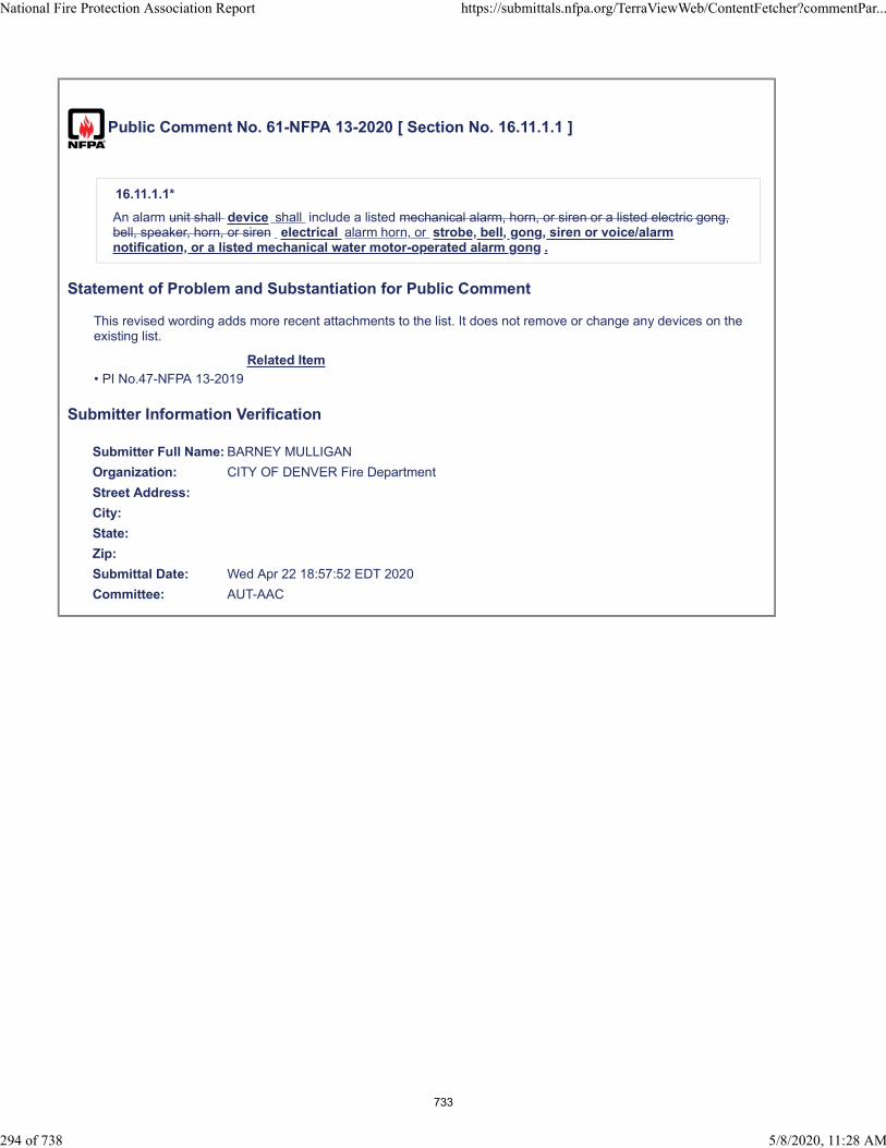
Public Comment No. 61-NFPA 13-2020 [ Section No. 16.11.1.1 ]
16.11.1.1*
An alarm unit shall device shall include a listed mechanical alarm, horn, or siren or a listed electric gong,bell, speaker, horn, or siren electrical alarm horn, or strobe, bell, gong, siren or voice/alarmnotification, or a listed mechanical water motor-operated alarm gong .
Statement of Problem and Substantiation for Public Comment
This revised wording adds more recent attachments to the list. It does not remove or change any devices on the existing list.
Related Item
• PI No.47-NFPA 13-2019
Submitter Information Verification
Submitter Full Name: BARNEY MULLIGAN
Organization: CITY OF DENVER Fire Department
Street Address:
City:
State:
Zip:
Submittal Date: Wed Apr 22 18:57:52 EDT 2020
Committee: AUT-AAC
National Fire Protection Association Report https://submittals.nfpa.org/TerraViewWeb/ContentFetcher?commentPar...
294 of 738 5/8/2020, 11:28 AM
733

Public Comment No. 62-NFPA 13-2020 [ Section No. 16.11.1.2 ]
16.11.1.2*
Outdoor water Exterior water motor-operated or electrically operated bells shall be weatherproofed andguarded.
Statement of Problem and Substantiation for Public Comment
"Exterior" is preferred over "outdoor", as generally used in the sprinkler codes.
Related Item
• PI No.47-NFPA 13-2019
Submitter Information Verification
Submitter Full Name: BARNEY MULLIGAN
Organization: CITY OF DENVER Fire Department
Street Address:
City:
State:
Zip:
Submittal Date: Wed Apr 22 19:20:01 EDT 2020
Committee: AUT-AAC
National Fire Protection Association Report https://submittals.nfpa.org/TerraViewWeb/ContentFetcher?commentPar...
295 of 738 5/8/2020, 11:28 AM
734
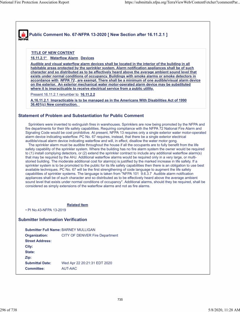
Public Comment No. 67-NFPA 13-2020 [ New Section after 16.11.2.1 ]
TITLE OF NEW CONTENT
16.11.2.1* Waterflow Alarm Devices
Audible and visual waterflow alarm devices shall be located in the interior of the building in allhabitable areas protected by the sprinkler system. Alarm notification appliances shall be of suchcharacter and so distributed as to be effectively heard above the average ambient sound level thatexists under normal conditions of occupancy. Buildings with smoke alarms or smoke detectors inaccordance with NFPA 72 , are exempt. There shall be a minimum of one audible/visual alarm deviceon the exterior. An exterior mechanical water motor-operated alarm device may be substitutedwhere it is impracticable to receive electrical service from a public utility.
Present 16.11.2.1 renumber to 16.11.2.2
A.16.11.2.1 Impracticable is to be managed as in the Americans With Disabilities Act of 199036.401(c) New construction.
Statement of Problem and Substantiation for Public Comment
Sprinklers were invented to extinguish fires in warehouses. Sprinklers are now being promoted by the NFPA and fire departments for their life safety capabilities. Requiring compliance with the NFPA 72 National Fire Alarm and Signaling Code would be cost prohibitive. At present, NFPA 13 requires only a single exterior water motor-operated alarm device indicating waterflow. PC No. 67 requires, instead, that there be a single exterior electrical audible/visual alarm device indicating waterflow and will, in effect, disallow the water motor gong. The sprinkler alarm must be audible throughout the house if all the occupants are to fully benefit from the life safety capability of the sprinkler system. Where the building has no fire alarm system the owner would be required to (1) install complying detectors, or (2) extend the sprinkler contract to include any additional waterflow alarm(s) that may be required by the AHJ. Additional waterflow alarms would be required only in a very large, or multi-storied building. The moderate additional cost for alarm(s) is justified by the marked increase in life safety. If a sprinkler system is to be promoted to the public for its life safety capabilities then there is an obligation to use best available techniques. PC No. 67 will be the first strengthening of code language to augment the life safety capabilities of sprinkler systems. The language is taken from "NFPA 101 9.6.3.7 Audible alarm notification appliances shall be of such character and so distributed as to be effectively heard above the average ambient sound level that exists under normal conditions of occupancy". Additional alarms, should they be required, shall be considered as simply extensions of the waterflow alarms and not as fire alarms.
Related Item
• PI No.43-NFPA 13-2019
Submitter Information Verification
Submitter Full Name: BARNEY MULLIGAN
Organization: CITY OF DENVER Fire Department
Street Address:
City:
State:
Zip:
Submittal Date: Wed Apr 22 20:21:31 EDT 2020
Committee: AUT-AAC
National Fire Protection Association Report https://submittals.nfpa.org/TerraViewWeb/ContentFetcher?commentPar...
296 of 738 5/8/2020, 11:28 AM
735
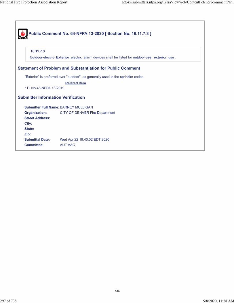
Public Comment No. 64-NFPA 13-2020 [ Section No. 16.11.7.3 ]
16.11.7.3
Outdoor electric Exterior electric alarm devices shall be listed for outdoor use exterior use .
Statement of Problem and Substantiation for Public Comment
"Exterior" is preferred over "outdoor", as generally used in the sprinkler codes.
Related Item
• PI No.48-NFPA 13-2019
Submitter Information Verification
Submitter Full Name: BARNEY MULLIGAN
Organization: CITY OF DENVER Fire Department
Street Address:
City:
State:
Zip:
Submittal Date: Wed Apr 22 19:40:02 EDT 2020
Committee: AUT-AAC
National Fire Protection Association Report https://submittals.nfpa.org/TerraViewWeb/ContentFetcher?commentPar...
297 of 738 5/8/2020, 11:28 AM
736
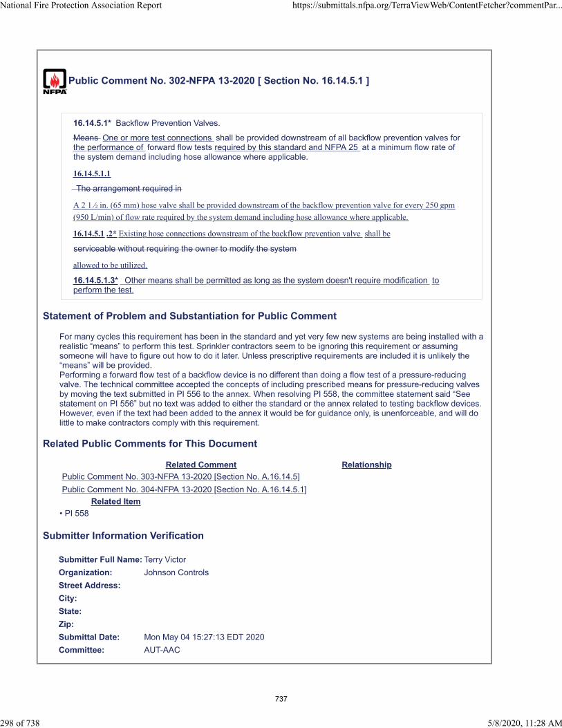
Public Comment No. 302-NFPA 13-2020 [ Section No. 16.14.5.1 ]
16.14.5.1* Backflow Prevention Valves.
Means One or more test connections shall be provided downstream of all backflow prevention valves forthe performance of forward flow tests required by this standard and NFPA 25 at a minimum flow rate ofthe system demand including hose allowance where applicable.
16.14.5.1.1
The arrangement required in
A 2 1 ∕ in. (65 mm) hose valve shall be provided downstream of the backflow prevention valve for every 250 gpm
(950 L/min) of flow rate required by the system demand including hose allowance where applicable.
16.14.5.1 .2* Existing hose connections downstream of the backflow prevention valve shall be
serviceable without requiring the owner to modify the system
allowed to be utilized.
16.14.5.1.3* Other means shall be permitted as long as the system doesn't require modification toperform the test.
Statement of Problem and Substantiation for Public Comment
For many cycles this requirement has been in the standard and yet very few new systems are being installed with a realistic “means” to perform this test. Sprinkler contractors seem to be ignoring this requirement or assuming someone will have to figure out how to do it later. Unless prescriptive requirements are included it is unlikely the “means” will be provided.Performing a forward flow test of a backflow device is no different than doing a flow test of a pressure-reducing valve. The technical committee accepted the concepts of including prescribed means for pressure-reducing valves by moving the text submitted in PI 556 to the annex. When resolving PI 558, the committee statement said “See statement on PI 556” but no text was added to either the standard or the annex related to testing backflow devices. However, even if the text had been added to the annex it would be for guidance only, is unenforceable, and will do little to make contractors comply with this requirement.
Related Public Comments for This Document
Related Comment Relationship
Public Comment No. 303-NFPA 13-2020 [Section No. A.16.14.5]
Public Comment No. 304-NFPA 13-2020 [Section No. A.16.14.5.1]
Related Item
• PI 558
Submitter Information Verification
Submitter Full Name: Terry Victor
Organization: Johnson Controls
Street Address:
City:
State:
Zip:
Submittal Date: Mon May 04 15:27:13 EDT 2020
Committee: AUT-AAC
National Fire Protection Association Report https://submittals.nfpa.org/TerraViewWeb/ContentFetcher?commentPar...
298 of 738 5/8/2020, 11:28 AM
737
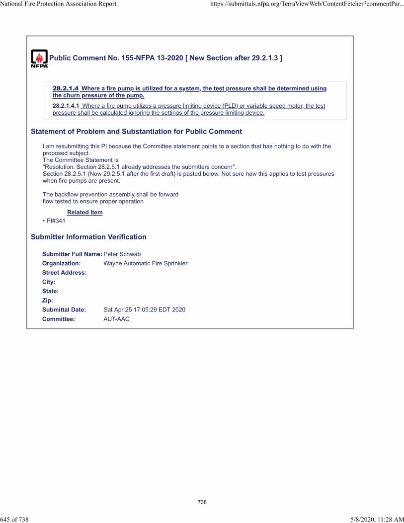
Public Comment No. 155-NFPA 13-2020 [ New Section after 29.2.1.3 ]
28.2.1.4 Where a fire pump is utilized for a system, the test pressure shall be determined usingthe churn pressure of the pump.
28.2.1.4.1 Where a fire pump utilizes a pressure limiting device (PLD) or variable speed motor, the testpressure shall be calculated ignoring the settings of the pressure limiting device.
Statement of Problem and Substantiation for Public Comment
I am resubmitting this PI because the Committee statement points to a section that has nothing to do with the proposed subject.The Committee Statement is"Resolution: Section 28.2.5.1 already addresses the submitters concern".Section 28.2.5.1 (Now 29.2.5.1 after the first draft) is pasted below. Not sure how this applies to test pressures when fire pumps are present.
The backflow prevention assembly shall be forwardflow tested to ensure proper operation
Related Item
• PI#341
Submitter Information Verification
Submitter Full Name: Peter Schwab
Organization: Wayne Automatic Fire Sprinkler
Street Address:
City:
State:
Zip:
Submittal Date: Sat Apr 25 17:05:29 EDT 2020
Committee: AUT-AAC
National Fire Protection Association Report https://submittals.nfpa.org/TerraViewWeb/ContentFetcher?commentPar...
645 of 738 5/8/2020, 11:28 AM
738
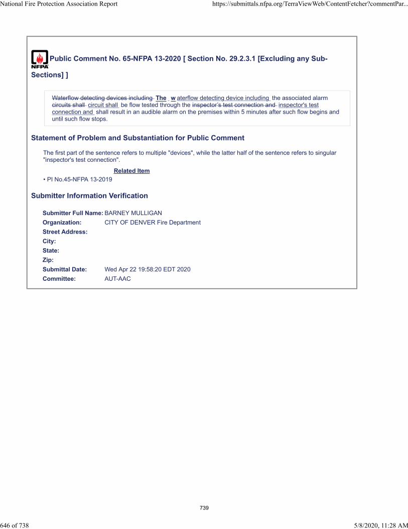
Public Comment No. 65-NFPA 13-2020 [ Section No. 29.2.3.1 [Excluding any Sub-
Sections] ]
Waterflow detecting devices including The w aterflow detecting device including the associated alarmcircuits shall circuit shall be flow tested through the inspector’s test connection and inspector's testconnection and shall result in an audible alarm on the premises within 5 minutes after such flow begins anduntil such flow stops.
Statement of Problem and Substantiation for Public Comment
The first part of the sentence refers to multiple "devices", while the latter half of the sentence refers to singular "inspector's test connection".
Related Item
• PI No.45-NFPA 13-2019
Submitter Information Verification
Submitter Full Name: BARNEY MULLIGAN
Organization: CITY OF DENVER Fire Department
Street Address:
City:
State:
Zip:
Submittal Date: Wed Apr 22 19:58:20 EDT 2020
Committee: AUT-AAC
National Fire Protection Association Report https://submittals.nfpa.org/TerraViewWeb/ContentFetcher?commentPar...
646 of 738 5/8/2020, 11:28 AM
739

Public Comment No. 330-NFPA 13-2020 [ Section No. 29.2.3.5 ]
29.2.3.5 Operating Test for Control Valves.
All control valves shall be fully closed and opened operated from their normal position to the off normalposition and returned to the normal position under system water pressure to ensure proper operation.
Statement of Problem and Substantiation for Public Comment
This was submitted under PI 677. The technical committee resolved this PI. The technical committee statement stated this issue was already covered by the standard. Given normally closed control valves are not frequently installed in sprinkler system but they are installed in some systems. This change accounts for normally closed control valves while still covering normally open control valves.
Related Item
• PI 677
Submitter Information Verification
Submitter Full Name: John Denhardt
Organization: American Fire Sprinkler Association
Street Address:
City:
State:
Zip:
Submittal Date: Tue May 05 12:52:22 EDT 2020
Committee: AUT-AAC
National Fire Protection Association Report https://submittals.nfpa.org/TerraViewWeb/ContentFetcher?commentPar...
647 of 738 5/8/2020, 11:28 AM
740

Public Comment No. 246-NFPA 13-2020 [ New Section after 29.2.5 ]
TITLE OF NEW CONTENT
29.2.7 Automated Inspection and Testing Devices and Equipment.
29.2.7.1 Automated inspection and testing devices and equipment installed on the sprinkler system shall be tested to
ensure the desired result of the automated inspection or test is realized.
29.2.7.1.1 Automated inspection devices and equipment shall be tested to verify that the image received allows for an
effective visual examination of the system or component being inspected.
29.2.7.1.2 Automated testing devices and equipment shall be tested to verify that they produce the same action as
required by this standard to test a device.
29.2.7.1.2.1 The testing shall discharge water where required by this standard and NFPA 25.
29.2.7.2 Testing shall verify that failure of automated inspection and testing devices and equipment does not impair
the operation of the system unless indicated by an audible and visual trouble signal in accordance with NFPA 72 or
other applicable fire alarm code .
29.2.7.3 Testing shall verify that failure of a system or component to pass automated inspection and testing devices
and equipment results in an audible and visual trouble signal in accordance with NFPA 72 or other applicable fire
alarm code .
29.2.7.4 Testing shall verify that failure of automated inspection and testing devices and equipment results in an
audible and visual trouble signal in accordance with NFPA 72 or other applicable fire alarm code .
Statement of Problem and Substantiation for Public Comment
FR 1371 moved sections 28.3.1.1 through 28.3.4 (2019 edition numbering) to chapter 7 section 7.9, since the text contained requirements for system components. In addition, the rest of section 28.3 was deleted even though that wasn’t supposed to be the action of the FR (see response to PI 171). As a result there isn’t any test criteria for automated inspection and testing devices and equipment in chapter 29. This PC adds back the section on testing Automated Inspection and Testing Devices and Equipment that was inadvertently deleted and provides more specific test criteria for these devices and equipment back into chapter 29.
Related Public Comments for This Document
Related Comment Relationship
Public Comment No. 243-NFPA 13-2020 [Section No. 7.9.1 [Excluding any Sub-Sections]]
Public Comment No. 244-NFPA 13-2020 [Section No. 7.9.1.2.1]
Related Item
• PI 170 FR 1371
Submitter Information Verification
Submitter Full Name: Terry Victor
Organization: Johnson Controls
Street Address:
City:
State:
Zip:
Submittal Date: Mon May 04 10:49:43 EDT 2020
Committee: AUT-AAC
National Fire Protection Association Report https://submittals.nfpa.org/TerraViewWeb/ContentFetcher?commentPar...
648 of 738 5/8/2020, 11:28 AM
741
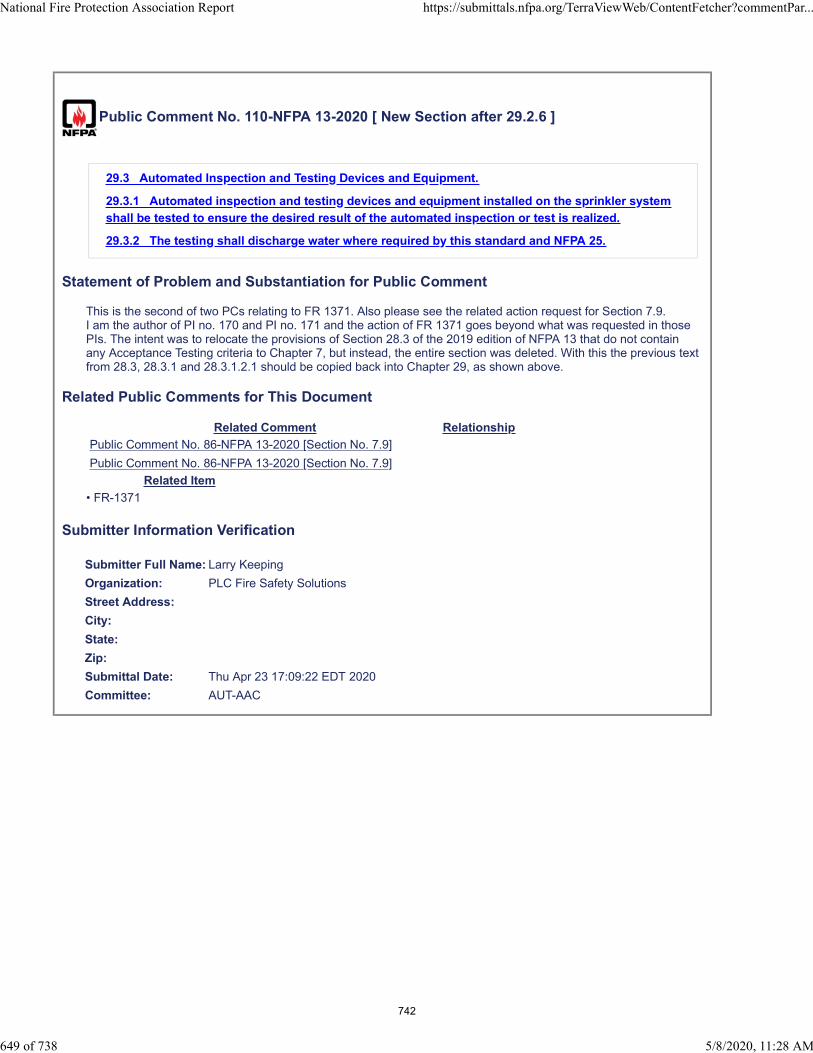
Public Comment No. 110-NFPA 13-2020 [ New Section after 29.2.6 ]
29.3 Automated Inspection and Testing Devices and Equipment.
29.3.1 Automated inspection and testing devices and equipment installed on the sprinkler system
shall be tested to ensure the desired result of the automated inspection or test is realized.
29.3.2 The testing shall discharge water where required by this standard and NFPA 25.
Statement of Problem and Substantiation for Public Comment
This is the second of two PCs relating to FR 1371. Also please see the related action request for Section 7.9.I am the author of PI no. 170 and PI no. 171 and the action of FR 1371 goes beyond what was requested in those PIs. The intent was to relocate the provisions of Section 28.3 of the 2019 edition of NFPA 13 that do not contain any Acceptance Testing criteria to Chapter 7, but instead, the entire section was deleted. With this the previous text from 28.3, 28.3.1 and 28.3.1.2.1 should be copied back into Chapter 29, as shown above.
Related Public Comments for This Document
Related Comment Relationship
Public Comment No. 86-NFPA 13-2020 [Section No. 7.9]
Public Comment No. 86-NFPA 13-2020 [Section No. 7.9]
Related Item
• FR-1371
Submitter Information Verification
Submitter Full Name: Larry Keeping
Organization: PLC Fire Safety Solutions
Street Address:
City:
State:
Zip:
Submittal Date: Thu Apr 23 17:09:22 EDT 2020
Committee: AUT-AAC
National Fire Protection Association Report https://submittals.nfpa.org/TerraViewWeb/ContentFetcher?commentPar...
649 of 738 5/8/2020, 11:28 AM
742
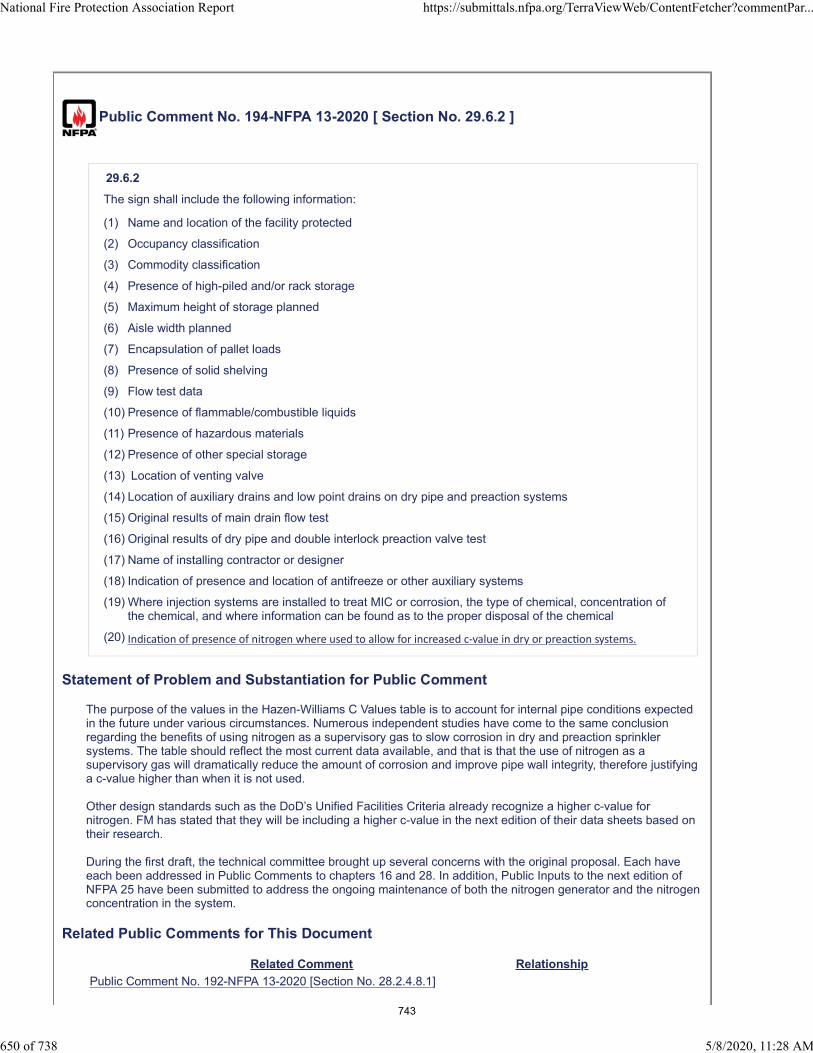
Public Comment No. 194-NFPA 13-2020 [ Section No. 29.6.2 ]
29.6.2
The sign shall include the following information:
(1) Name and location of the facility protected
(2) Occupancy classification
(3) Commodity classification
(4) Presence of high-piled and/or rack storage
(5) Maximum height of storage planned
(6) Aisle width planned
(7) Encapsulation of pallet loads
(8) Presence of solid shelving
(9) Flow test data
(10) Presence of flammable/combustible liquids
(11) Presence of hazardous materials
(12) Presence of other special storage
(13) Location of venting valve
(14) Location of auxiliary drains and low point drains on dry pipe and preaction systems
(15) Original results of main drain flow test
(16) Original results of dry pipe and double interlock preaction valve test
(17) Name of installing contractor or designer
(18) Indication of presence and location of antifreeze or other auxiliary systems
(19) Where injection systems are installed to treat MIC or corrosion, the type of chemical, concentration ofthe chemical, and where information can be found as to the proper disposal of the chemical
(20) Indica on of presence of nitrogen where used to allow for increased c-value in dry or preac on systems.
Statement of Problem and Substantiation for Public Comment
The purpose of the values in the Hazen-Williams C Values table is to account for internal pipe conditions expected in the future under various circumstances. Numerous independent studies have come to the same conclusion regarding the benefits of using nitrogen as a supervisory gas to slow corrosion in dry and preaction sprinkler systems. The table should reflect the most current data available, and that is that the use of nitrogen as a supervisory gas will dramatically reduce the amount of corrosion and improve pipe wall integrity, therefore justifying a c-value higher than when it is not used.
Other design standards such as the DoD’s Unified Facilities Criteria already recognize a higher c-value for nitrogen. FM has stated that they will be including a higher c-value in the next edition of their data sheets based on their research.
During the first draft, the technical committee brought up several concerns with the original proposal. Each have each been addressed in Public Comments to chapters 16 and 28. In addition, Public Inputs to the next edition of NFPA 25 have been submitted to address the ongoing maintenance of both the nitrogen generator and the nitrogen concentration in the system.
Related Public Comments for This Document
Related Comment Relationship
Public Comment No. 192-NFPA 13-2020 [Section No. 28.2.4.8.1]
National Fire Protection Association Report https://submittals.nfpa.org/TerraViewWeb/ContentFetcher?commentPar...
650 of 738 5/8/2020, 11:28 AM
743

Public Comment No. 193-NFPA 13-2020 [New Section after 16.10.3.3]
Related Item
• PI No. 802
Submitter Information Verification
Submitter Full Name: Jason Webb
Organization: Potter Electric Signal Company
Street Address:
City:
State:
Zip:
Submittal Date: Wed Apr 29 16:28:35 EDT 2020
Committee: AUT-AAC
National Fire Protection Association Report https://submittals.nfpa.org/TerraViewWeb/ContentFetcher?commentPar...
651 of 738 5/8/2020, 11:28 AM
744

Public Comment No. 156-NFPA 13-2020 [ Section No. 30.3.2 [Excluding any Sub-
Sections] ]
When a threaded sprinkler is removed from a fitting or welded outlet, it shall not be reinstalled except aspermitted by 30.3.2.1.
Statement of Problem and Substantiation for Public Comment
There are sprinklers available that have grooved connections and can be removed without applying torque to the sprinkler
Related Item
• FR#1364
Submitter Information Verification
Submitter Full Name: Peter Schwab
Organization: Wayne Automatic Fire Sprinkler
Street Address:
City:
State:
Zip:
Submittal Date: Sat Apr 25 17:19:06 EDT 2020
Committee: AUT-AAC
National Fire Protection Association Report https://submittals.nfpa.org/TerraViewWeb/ContentFetcher?commentPar...
652 of 738 5/8/2020, 11:28 AM
745

Public Comment No. 298-NFPA 13-2020 [ New Section after 30.6 ]
Additional Proposed Changes
File Name Description Approved
Chapter_30_-_CMDA_Requirements.docx
Removes the existing system modification and evaluation requirements from Chapter 21 and relocates them to Chapter 30
Statement of Problem and Substantiation for Public Comment
Reinsert existing system requirements removed from Chapter 21 by PC 228, 292, 294, 295, and 296.Existing system and modification requirements from Chapter 21 should be located in Chapter 30
Related Public Comments for This Document
Related Comment Relationship
Public Comment No. 296-NFPA 13-2020 [Section No. 21.4.1.7.1]
Public Comment No. 295-NFPA 13-2020 [Section No. 21.4.1.5]
Public Comment No. 294-NFPA 13-2020 [Section No. 21.4.1.3.2]
Public Comment No. 292-NFPA 13-2020 [Section No. 21.4.1.2.2]
Public Comment No. 288-NFPA 13-2020 [Section No. 21.2.2.3]
Public Comment No. 288-NFPA 13-2020 [Section No. 21.2.2.3]
Public Comment No. 292-NFPA 13-2020 [Section No. 21.4.1.2.2]
Public Comment No. 294-NFPA 13-2020 [Section No. 21.4.1.3.2]
Public Comment No. 295-NFPA 13-2020 [Section No. 21.4.1.5]
Public Comment No. 296-NFPA 13-2020 [Section No. 21.4.1.7.1]
Related Item
• FR-1334
Submitter Information Verification
Submitter Full Name: Kevin Hall
Organization: NFSA
Affiliation: NFSA Engineering and Standards Committee
Street Address:
City:
State:
Zip:
Submittal Date: Mon May 04 14:33:10 EDT 2020
Committee: AUT-AAC
National Fire Protection Association Report https://submittals.nfpa.org/TerraViewWeb/ContentFetcher?commentPar...
653 of 738 5/8/2020, 11:28 AM
746
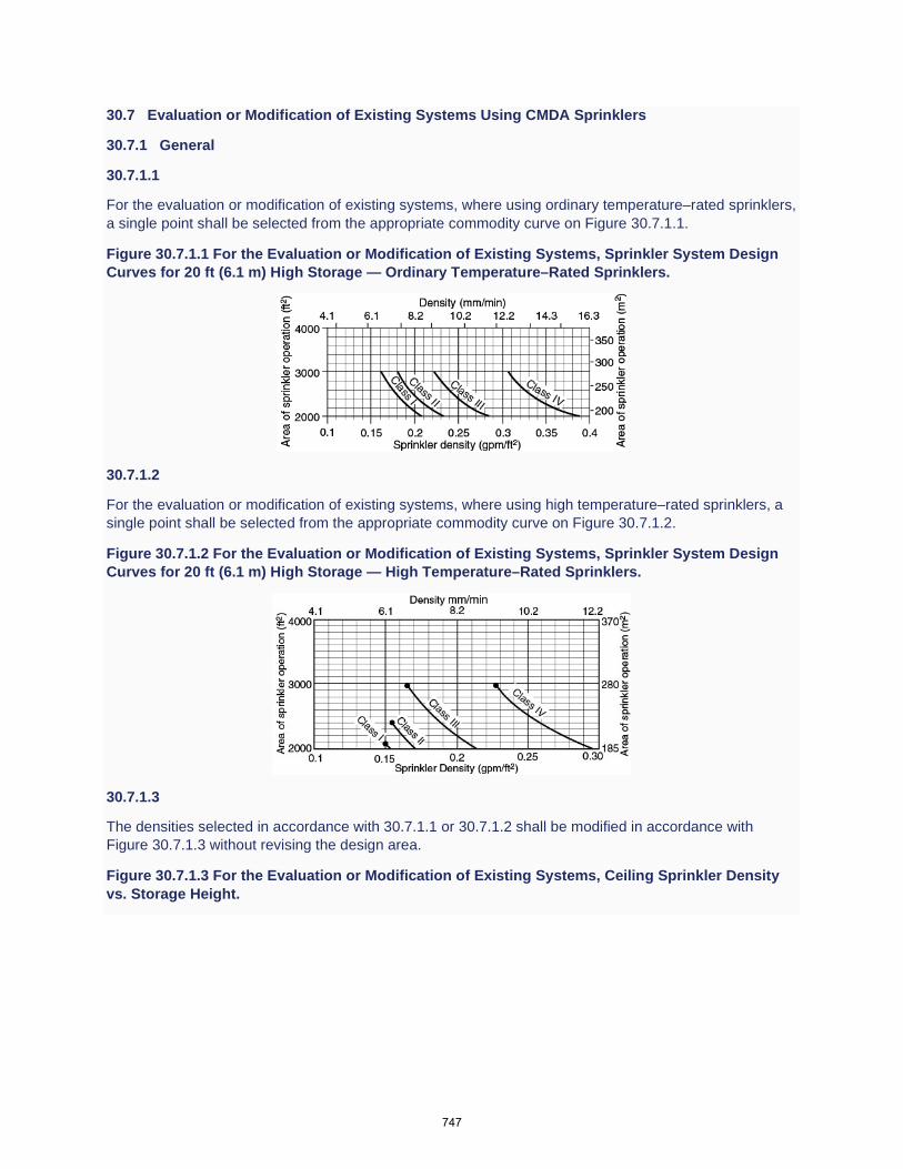
30.7 Evaluation or Modification of Existing Systems Using CMDA Sprinklers
30.7.1 General
30.7.1.1
For the evaluation or modification of existing systems, where using ordinary temperature–rated sprinklers, a single point shall be selected from the appropriate commodity curve on Figure 30.7.1.1.
Figure 30.7.1.1 For the Evaluation or Modification of Existing Systems, Sprinkler System Design Curves for 20 ft (6.1 m) High Storage — Ordinary Temperature–Rated Sprinklers.
30.7.1.2
For the evaluation or modification of existing systems, where using high temperature–rated sprinklers, a single point shall be selected from the appropriate commodity curve on Figure 30.7.1.2.
Figure 30.7.1.2 For the Evaluation or Modification of Existing Systems, Sprinkler System Design Curves for 20 ft (6.1 m) High Storage — High Temperature–Rated Sprinklers.
30.7.1.3
The densities selected in accordance with 30.7.1.1 or 30.7.1.2 shall be modified in accordance with Figure 30.7.1.3 without revising the design area.
Figure 30.7.1.3 For the Evaluation or Modification of Existing Systems, Ceiling Sprinkler Density vs. Storage Height.
747

30.7.1.4
In the case of metal bin boxes with face areas not exceeding 16 ft2 (1.5 m2) and metal closed shelves with face areas not exceeding 16 ft2 (1.5 m2), the area of application shall be permitted to be reduced by 33 percent, provided the minimum requirements of 30.7.1.5 and 30.7.1.6 are met.
30.7.1.5
For storage greater than 12 ft (3.7 m), the design density shall not be less than 0.15 gpm/ft2 (6.1 mm/min), and the design area shall not be less than 2000 ft2 (185 m2) for wet systems or 2600 ft2 (240 m2) for dry systems for any commodity, class, or group.
30.7.1.6
For storage greater than 12 ft (3.7 m), the sprinkler design density for any given area of operation for a Class III or Class IV commodity, calculated in accordance with 21.2.2, shall not be less than the density for the corresponding area of operation for ordinary hazard Group 2.
30.7.1.7
For back-to-back shelf storage, the design density shall be taken from Figure 30.7.1.1 for storage greater than 12 ft (3.7 m) and up to 15 ft (4.6 m) with no reduction for design density referenced in Figure 30.7.1.3.
30.7.1.8
For the evaluation or modification of an existing system with storage height over 12 ft (3.7 m) up to and including 25 ft (7.6 m) protected with ceiling sprinklers only, densities obtained from design curves shall be adjusted in accordance with Figure 21.4.1.7.1.
Figure 30.7.1.8 Evaluation or Modification of Existing System’s Ceiling Sprinkler Density vs. Storage Height.
748
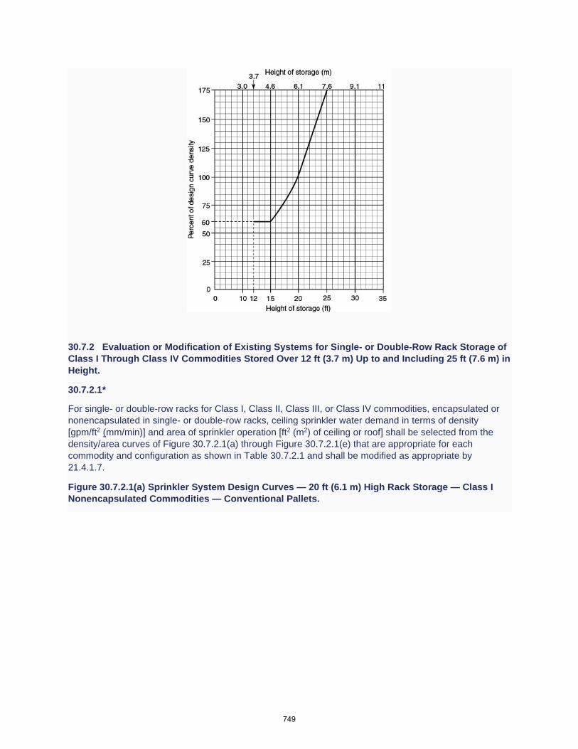
30.7.2 Evaluation or Modification of Existing Systems for Single- or Double-Row Rack Storage of Class I Through Class IV Commodities Stored Over 12 ft (3.7 m) Up to and Including 25 ft (7.6 m) in Height.
30.7.2.1*
For single- or double-row racks for Class I, Class II, Class III, or Class IV commodities, encapsulated or nonencapsulated in single- or double-row racks, ceiling sprinkler water demand in terms of density [gpm/ft2 (mm/min)] and area of sprinkler operation [ft2 (m2) of ceiling or roof] shall be selected from the density/area curves of Figure 30.7.2.1(a) through Figure 30.7.2.1(e) that are appropriate for each commodity and configuration as shown in Table 30.7.2.1 and shall be modified as appropriate by 21.4.1.7.
Figure 30.7.2.1(a) Sprinkler System Design Curves — 20 ft (6.1 m) High Rack Storage — Class I Nonencapsulated Commodities — Conventional Pallets.
749

Figure 30.7.2.1(b) Sprinkler System Design Curves — 20 ft (6.1 m) High Rack Storage — Class II Nonencapsulated Commodities — Conventional Pallets.
Figure 30.7.2.1(c) Sprinkler System Design Curves — 20 ft (6.1 m) High Rack Storage — Class III Nonencapsulated Commodities — Conventional Pallets.
750
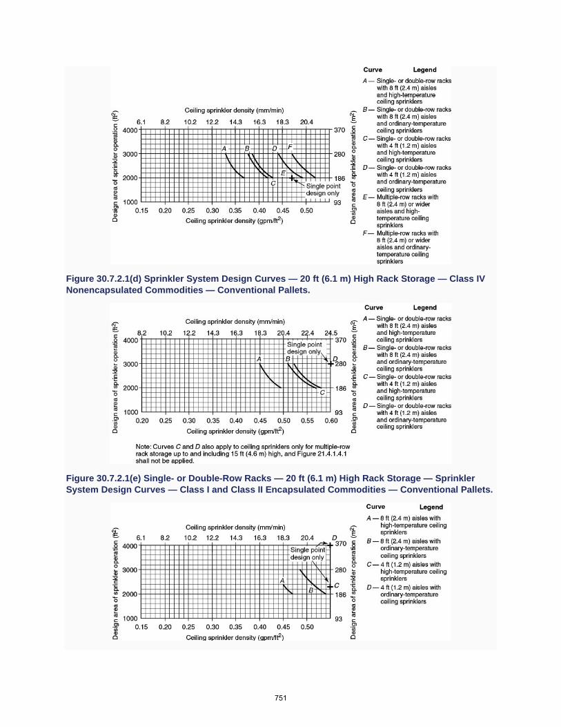
Figure 30.7.2.1(d) Sprinkler System Design Curves — 20 ft (6.1 m) High Rack Storage — Class IV Nonencapsulated Commodities — Conventional Pallets.
Figure 30.7.2.1(e) Single- or Double-Row Racks — 20 ft (6.1 m) High Rack Storage — Sprinkler System Design Curves — Class I and Class II Encapsulated Commodities — Conventional Pallets.
751
Table 30.7.2.1 Single- or Double-Row Racks — Storage Height Over 12 ft (3.7 m) Up to and Including 25 ft (7.6 m)
[Insert Table 21.4.1.2.2.1]
30.7.2.2
The requirements in 30.7.2.1 shall apply to portable racks arranged in the same manner as single- or double-row racks.
30.7.3 Evaluation or Modification of Existing Systems — Rack Depth Up to and Including 16 ft (4.9), Aisles 8 ft (2.4) or Wider, Storage Height Over 12 ft (3.7 m) Up to and Including 25 ft (7.6 m).
30.7.3.1 Multiple-Row Racks — Rack Depth Up to and Including 16 ft (4.9 m) with Aisles 8 ft (2.4 m) or Wider.
For Class I, Class II, Class III, or Class IV commodities, encapsulated or nonencapsulated, ceiling sprinkler water demand in terms of density [gpm/ft2 (mm/min)] and area of sprinkler operation [ft2 (m2) of ceiling or roof] shall be selected from the density/area curves of Figure 30.7.2.1(a) through Figure 30.7.2.1(e) that are appropriate for each commodity and configuration as shown in Table 30.7.3.1 and shall be modified as appropriate by 21.4.1.7.
Table 30.7.3.1 Multiple-Row Racks — Rack Depth Up to and Including 16 ft (4.9 m), Aisles 8 ft (2.4 m) or Wider, and Storage Height Over 12 ft (3.7 m) Up to 25 ft (7.6 m)
[Insert Table 21.4.1.3.2.1]
30.7.3.2
The protection criteria in accordance with 30.7.3.1 shall apply to portable racks arranged in the same manner as multiple-row racks.
30.7.4 Evaluation or Modification of Existing Systems — Rack Depth Over 16 ft (4.9 m) or Aisles More Narrow Than 8 ft (2.4 m), Storage Height Over 12 ft (3.7 m) Up to and Including 25 ft (7.6 m).
30.7.4.1
For Class I, Class II, Class III, or Class IV commodities, encapsulated or nonencapsulated, ceiling sprinkler water demand in terms of density [gpm/ft2 (mm/min)] and area of sprinkler operation [ft2 (m2) of ceiling or roof] shall be selected from the density/area curves of Figure 30.7.2.1(a) through Figure 30.7.2.1(e) that are appropriate for each commodity and configuration as shown in Table 30.7.4.1 and shall be modified as appropriate by 21.4.1.7.
Table 30.7.4.1 Multiple-Row Racks — Rack Depth Over 16 ft (4.9 m) or Aisles Narrower Than 8 ft (2.4 m), Storage Height Over 12 ft (3.7 m) Up to and Including 25 ft (7.6 m)
[Insert Table 21.4.1.5.1]
30.7.4.2
The protection criteria in accordance with 30.7.4.1 shall apply to portable racks arranged in the same manner as multiple-row racks.
752

Public Comment No. 327-NFPA 13-2020 [ New Section after 30.6.7 ]
Evaluation of Cartoned Commodities.
Where K-11.2 or larger sprinklers are installed, the requirements of 20.3.1.5 shall not apply.
Statement of Problem and Substantiation for Public Comment
As noted in the affirmative comment from Bell, large orifice sprinklers still perform adequately in fire testing scenarios.
Related Public Comments for This Document
Related Comment Relationship
Public Comment No. 326-NFPA 13-2020 [Section No. 20.3.1.5]
Related Item
• FR-1257
Submitter Information Verification
Submitter Full Name: Kevin Hall
Organization: NFSA
Affiliation: NFSA Engineering and Standards Committee
Street Address:
City:
State:
Zip:
Submittal Date: Tue May 05 10:12:07 EDT 2020
Committee: AUT-AAC
National Fire Protection Association Report https://submittals.nfpa.org/TerraViewWeb/ContentFetcher?commentPar...
654 of 738 5/8/2020, 11:28 AM
753

Public Comment No. 81-NFPA 13-2020 [ New Section after A.3.3.190 ]
TITLE OF NEW CONTENT
A.3.3.191 Shadow Area. Water is not required to fall on every square inch of floor space of theoccupancy. This definition establishes a term that will be used to address the rules for acceptable dryspaces that occur when walls interfere with the residential sprinkler’s spray pattern. Angled walls, wingwalls, and slightly indented walls can disrupt water discharging from a sprinkler, which does not travel onlyin an absolute straight line, as if it were beams of light. Where small (typically triangular) shadowed areasare formed on the floor adjacent to the wall, these shadowed areas are purely on paper and do not take intoaccount the dynamic variables of sprinkler discharge. In order to be acceptable, the shadow area needs tobe within the coverage area of a sprinkler, meaning that water would discharge to the space directly if thestructural or architectural feature was not there. The purpose of the shadow area is not to replace anyexisting obstruction requirements. Instead, the shadow area concept has been added to the standard toprovide clarity to specific situations in which walls form non-rectangular-shaped rooms, as shown in FigureA.9.1.1(3)(a) and Figure A.9.1.1(3)(b).
Statement of Problem and Substantiation for Public Comment
The proposed definition from FR 1020 was taken from directly NFPA 13R, but with no disrespect to that standard, shadow areas are not necessarily dry floor areas. They are just not directly impinged upon by the sprinkler discharge.
To complement the revised definition offered here, the Annex text about Shadow Areas from NFPA 13R contains valuable information on the subject and should be adopted, along with the definition.
Please note, because the Shadow Area applications in NFPA 13 are limited to residential sprinklers, text was added to both the revised definition and to the Annex text to specify residential sprinklers.
Related Public Comments for This Document
Related Comment Relationship
Public Comment No. 78-NFPA 13-2020 [Section No. 3.3.191]
Related Item
• FR-1020
Submitter Information Verification
Submitter Full Name: Larry Keeping
Organization: PLC Fire Safety Solutions
Street Address:
City:
State:
Zip:
Submittal Date: Thu Apr 23 14:35:18 EDT 2020
Committee: AUT-AAC
National Fire Protection Association Report https://submittals.nfpa.org/TerraViewWeb/ContentFetcher?commentPar...
655 of 738 5/8/2020, 11:28 AM
754
Public Comment No. 71-NFPA 13-2020 [ Section No. A.7.1.1 ]
National Fire Protection Association Report https://submittals.nfpa.org/TerraViewWeb/ContentFetcher?commentPar...
674 of 738 5/8/2020, 11:28 AM
755

A.7.1.1
National Fire Protection Association Report https://submittals.nfpa.org/TerraViewWeb/ContentFetcher?commentPar...
675 of 738 5/8/2020, 11:28 AM
756

Included among items requiring listing are sprinklers, some pipe and some fittings, hangers, alarm devices,valves controlling flow of water to sprinklers, supervisory switches, and electrically operated solenoidvalves. Products are typically investigated in accordance with published standards. Examples of standardsused to investigate several products installed in sprinkler systems are referenced in Table A.7.1.1. Thistable does not include a comprehensive list of all product standards used to investigate products installed insprinkler systems.
Table A.7.1.1 Examples of Standards for Sprinkler System Products
Category Standard
SprinklersANSI/UL 199, Automatic Sprinklers forFire Protection Service
FM 2000, Automatic Control Mode Sprinklersfor Fire Protection
ANSI/UL 1626, Residential Sprinklers for FireProtection Service
FM 2030, Residential Automatic Sprinklers
ANSI/UL 1767, Early-Suppression Fast-Response Sprinklers
FM 2008, Suppression Mode ESFRAutomatic Sprinklers
FM 1632, Telescoping Sprinkler Assembliesfor Use in Fire Protection Systems forAnechoic Chambers
Antifreeze andCorrosion Control
UL 2901,
Outline forAntifreeze Solutions for Use in FireSprinkler Systems
UL 2901A, Outline for CorrosionControl Additives for Use in FireSprinkler Systems
ValvesANSI/UL 193, Alarm Valves for FireProtection Service
FM 1041, Alarm Check Valves
ANSI/UL 260, Dry Pipe and Deluge Valves forFire Protection Service
FM 1021, Dry Pipe Valves
FM 1020, Automatic Water Control Valves
UL 262, Gate Valves for Fire ProtectionService
FM 1120, 1130, Fire Service Water ControlValves (OS & Y and NRS Type Gate Valves)
ANSI/UL 312, Check Valves for FireProtection Service
FM 1210, Swing Check Valves
UL 1091, Butterfly Valves for Fire ProtectionService
FM 1112, Indicating Valves (Butterfly or BallType)
ANSI/UL 1468, Direct Acting PressureReducing and Pressure Restricting Valves
ANSI/UL 1739, Pilot-Operated Pressure-Control Valves for Fire Protection Service
FM 1362, Pressure Reducing Valves
FM 1011/1012/1013, Deluge and PreactionSprinkler Systems
National Fire Protection Association Report https://submittals.nfpa.org/TerraViewWeb/ContentFetcher?commentPar...
676 of 738 5/8/2020, 11:28 AM
757
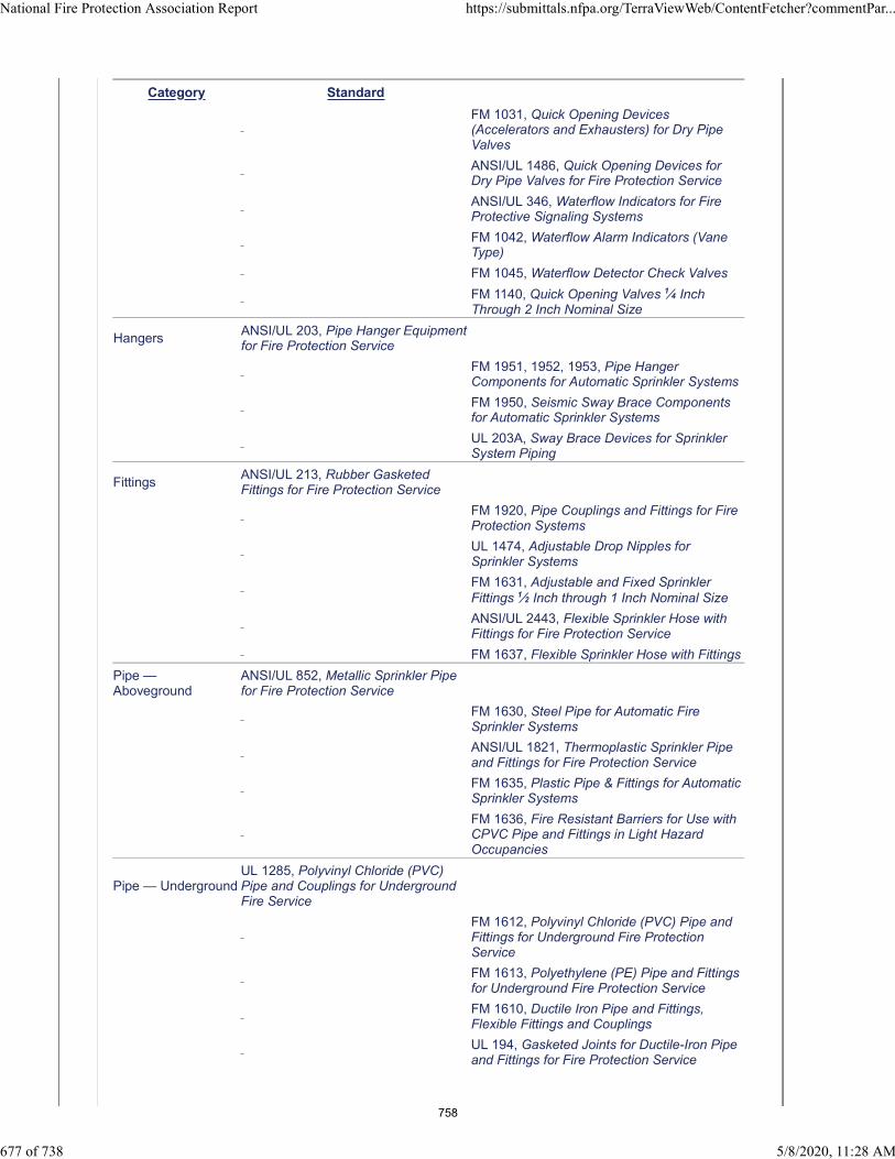
Category Standard
FM 1031, Quick Opening Devices(Accelerators and Exhausters) for Dry PipeValves
ANSI/UL 1486, Quick Opening Devices forDry Pipe Valves for Fire Protection Service
ANSI/UL 346, Waterflow Indicators for FireProtective Signaling Systems
FM 1042, Waterflow Alarm Indicators (VaneType)
FM 1045, Waterflow Detector Check Valves
FM 1140, Quick Opening Valves 1⁄4 InchThrough 2 Inch Nominal Size
HangersANSI/UL 203, Pipe Hanger Equipmentfor Fire Protection Service
FM 1951, 1952, 1953, Pipe HangerComponents for Automatic Sprinkler Systems
FM 1950, Seismic Sway Brace Componentsfor Automatic Sprinkler Systems
UL 203A, Sway Brace Devices for SprinklerSystem Piping
FittingsANSI/UL 213, Rubber GasketedFittings for Fire Protection Service
FM 1920, Pipe Couplings and Fittings for FireProtection Systems
UL 1474, Adjustable Drop Nipples forSprinkler Systems
FM 1631, Adjustable and Fixed SprinklerFittings 1⁄2 Inch through 1 Inch Nominal Size
ANSI/UL 2443, Flexible Sprinkler Hose withFittings for Fire Protection Service
FM 1637, Flexible Sprinkler Hose with Fittings
Pipe —Aboveground
ANSI/UL 852, Metallic Sprinkler Pipefor Fire Protection Service
FM 1630, Steel Pipe for Automatic FireSprinkler Systems
ANSI/UL 1821, Thermoplastic Sprinkler Pipeand Fittings for Fire Protection Service
FM 1635, Plastic Pipe & Fittings for AutomaticSprinkler Systems
FM 1636, Fire Resistant Barriers for Use withCPVC Pipe and Fittings in Light HazardOccupancies
Pipe — UndergroundUL 1285, Polyvinyl Chloride (PVC)Pipe and Couplings for UndergroundFire Service
FM 1612, Polyvinyl Chloride (PVC) Pipe andFittings for Underground Fire ProtectionService
FM 1613, Polyethylene (PE) Pipe and Fittingsfor Underground Fire Protection Service
FM 1610, Ductile Iron Pipe and Fittings,Flexible Fittings and Couplings
UL 194, Gasketed Joints for Ductile-Iron Pipeand Fittings for Fire Protection Service
National Fire Protection Association Report https://submittals.nfpa.org/TerraViewWeb/ContentFetcher?commentPar...
677 of 738 5/8/2020, 11:28 AM
758
Category Standard
FM 1620, Pipe Joints and Anchor Fittings forUnderground Fire Service Mains
Statement of Problem and Substantiation for Public Comment
The UL 2901 Outline for antifreeze systems has been published as a standard since the first draft meeting. UL 2901A, Outline of Investigation for Corrosion Control Additives for Use in Fire Sprinkler Systems, has been published for evaluating corrosion control chemicals. The reference to these standards is consistent with the approach taken for a large number of other standards. Refer to Annex F.
Related Item
• PI 526 and PI 528
Submitter Information Verification
Submitter Full Name: Jeff Hebenstreit
Organization: UL LLC
Street Address:
City:
State:
Zip:
Submittal Date: Thu Apr 23 13:04:53 EDT 2020
Committee: AUT-AAC
National Fire Protection Association Report https://submittals.nfpa.org/TerraViewWeb/ContentFetcher?commentPar...
678 of 738 5/8/2020, 11:28 AM
759
Public Comment No. 216-NFPA 13-2020 [ Section No. A.7.2.4 ]
A.7.2.4
Information regarding the highest temperature that can be encountered in any location in a particularinstallation can be obtained by use of a thermometer that will register the highest temperature encountered;it should be hung for several days in the location in question, with the plant equipment in operation thatproduce heat .
Statement of Problem and Substantiation for Public Comment
Proposed language better reflects what is to be in operation.
Related Item
• PI 290 and FR 1025
Submitter Information Verification
Submitter Full Name: Tracey Bellamy
Organization: Telgian Corporation
Street Address:
City:
State:
Zip:
Submittal Date: Sat May 02 16:52:20 EDT 2020
Committee: AUT-AAC
National Fire Protection Association Report https://submittals.nfpa.org/TerraViewWeb/ContentFetcher?commentPar...
679 of 738 5/8/2020, 11:28 AM
760

Public Comment No. 222-NFPA 13-2020 [ Section No. A.8.6 ]
A.8.6
In cold climates and areas where the potential for freezing of pipes is a concern, options other thanantifreeze are available. Such options include installing the pipe in warm spaces, tenting insulation over thepiping [as illustrated in Figure A.8 9 .3 9 .1(a) through Figure A.8 9 .3 9 .1(e f ) of NFPA 13D], listed heattracing, and the use of dry pipe systems and preaction systems.
Statement of Problem and Substantiation for Public Comment
Editorial Correction of the referenced links from NFPA 13D
Related Item
• Editorial Correction of References
Submitter Information Verification
Submitter Full Name: Tracey Bellamy
Organization: Telgian Corporation
Street Address:
City:
State:
Zip:
Submittal Date: Sun May 03 12:15:54 EDT 2020
Committee: AUT-AAC
National Fire Protection Association Report https://submittals.nfpa.org/TerraViewWeb/ContentFetcher?commentPar...
680 of 738 5/8/2020, 11:28 AM
761
Public Comment No. 223-NFPA 13-2020 [ Section No. A.9.1 ]
A.9.1
The installation requirements are specific for the normal arrangement of structural members. There will bearrangements of structural members not specifically detailed by the requirements. By applying the basicprinciples, layouts for such construction can vary from specific illustrations, provided the maximumsspecified for the spacing and location of sprinklers ( see Section 8.4 ) are not exceeded.
Where buildings or portions of buildings are of combustible construction or contain combustible material,standard fire barriers should be provided to separate the areas that are sprinkler protected from adjoiningunsprinklered areas. All openings should be protected in accordance with applicable standards, and nosprinkler piping should be placed in an unsprinklered area unless the area is permitted to be unsprinkleredby this standard.
Water supplies for partial systems should be designed with consideration to the fact that in a partial systemmore sprinklers might be opened in a fire that originates in an unprotected area and spreads to thesprinklered area than would be the case in a completely protected building. Fire originating in anonsprinklered area might overpower the partial sprinkler system.
Where sprinklers are installed in corridors only, sprinklers should be spaced up to the maximum of 15 ft(4.6 m) along the corridor, with one sprinkler opposite the center of any door or pair of adjacent doorsopening onto the corridor, and with an additional sprinkler installed inside each adjacent room above thedoor opening. Where the sprinkler in the adjacent room provides full protection for that space, an additionalsprinkler is not required in the corridor adjacent to the door.
Statement of Problem and Substantiation for Public Comment
The reference to 8.4 is no longer correct. This criteria is located in multiple locations within the Standard. Deletion of the reference and reliance on the stated criteria of not exceeding the allowable spacing and location criteria stands on its own with the need for a specific reference.
Related Item
• Editorial Correction
Submitter Information Verification
Submitter Full Name: Tracey Bellamy
Organization: Telgian Corporation
Street Address:
City:
State:
Zip:
Submittal Date: Sun May 03 12:18:52 EDT 2020
Committee: AUT-AAC
National Fire Protection Association Report https://submittals.nfpa.org/TerraViewWeb/ContentFetcher?commentPar...
681 of 738 5/8/2020, 11:28 AM
762

Public Comment No. 147-NFPA 13-2020 [ Section No. A.9.1.1(3) ]
A.9.1.1(3)
Notwithstanding the obstruction rules provided in Chapter 8, it is not intended or expected that water willfall on the entire floor space of the occupancy.
When obstructions or architectural features interfere with the sprinkler’s spray pattern, such as columns,angled walls, wing walls, slightly indented walls, and various soffit configurations, shadowed areas canoccur. Where small shadowed areas are formed on the floor adjacent to their referenced architecturalfeatures, these shadowed areas are purely on paper and do not take into account the dynamic variables ofsprinkler discharge. Examples of shadow areas are shown in Figure A.9.1.1(3)(a) and Figure A.9.1.1(3)(b).
Figure A.9.1.1(3)(a) Shadow Area in Corridor.
Figure A.9.1.1(3)(b) Example of Shadow Area.
Statement of Problem and Substantiation for Public Comment
Remove the text 2ft 0 in (600 mm) max language and dimension line. This figure was copied from NFPA 13R which allows up to a 2'-0" recess behind the sprinkler.
Related Item
• FR #1020
Submitter Information Verification
Submitter Full Name: Peter Schwab
Organization: Wayne Automatic Fire Sprinkler
Street Address:
City:
State:
Zip:
National Fire Protection Association Report https://submittals.nfpa.org/TerraViewWeb/ContentFetcher?commentPar...
682 of 738 5/8/2020, 11:28 AM
763

Submittal Date: Sat Apr 25 14:10:39 EDT 2020
Committee: AUT-AAC
National Fire Protection Association Report https://submittals.nfpa.org/TerraViewWeb/ContentFetcher?commentPar...
683 of 738 5/8/2020, 11:28 AM
764

Public Comment No. 224-NFPA 13-2020 [ Section No. A.9.1.1(3) ]
A.9.1.1(3)
Notwithstanding the obstruction rules provided in Chapter 8 Chapters 9 through 14 , it is not intended orexpected that water will fall on the entire floor space of the occupancy.
When obstructions or architectural features interfere with the sprinkler’s spray pattern, such as columns,angled walls, wing walls, slightly indented walls, and various soffit configurations, shadowed areas canoccur. Where small shadowed areas are formed on the floor adjacent to their referenced architecturalfeatures, these shadowed areas are purely on paper and do not take into account the dynamic variables ofsprinkler discharge. Examples of shadow areas are shown in Figure A.9.1.1(3)(a) and Figure A.9.1.1(3)(b).
Figure A.9.1.1(3)(a) Shadow Area in Corridor.
Figure A.9.1.1(3)(b) Example of Shadow Area.
Statement of Problem and Substantiation for Public Comment
Correction of an editorial reference. The obstruction rules are now in Chapters 9 through 14.
Related Item
• Editorial Correction
Submitter Information Verification
Submitter Full Name: Tracey Bellamy
Organization: Telgian Corporation
Street Address:
City:
State:
Zip:
Submittal Date: Sun May 03 12:23:41 EDT 2020
National Fire Protection Association Report https://submittals.nfpa.org/TerraViewWeb/ContentFetcher?commentPar...
684 of 738 5/8/2020, 11:28 AM
765

Committee: AUT-AAC
National Fire Protection Association Report https://submittals.nfpa.org/TerraViewWeb/ContentFetcher?commentPar...
685 of 738 5/8/2020, 11:28 AM
766
Public Comment No. 95-NFPA 13-2020 [ Section No. A.9.2.4.2 ]
A.9.2.4.2
This requirement to install sprinklers on exterior balconies, attached exterior desks, and ground floor patiosserving dwelling units is consistent with the requirements in the International Building Code and NFPA13R.
Statement of Problem and Substantiation for Public Comment
This is the third of four PCs relating to FR 1099. Also please see the related action request for deletion of Section 9.2.4.2.This text has been inserted into the wrong part of Chapter 9. Section 9.2 is for “Allowable Sprinkler Omission Locations”, but as written the subject is about when sprinklers are specifically required. With this, the text should be relocated to a new Section 9.3.20, to follow the provisions for Exterior Projections and the accompanying Annex text should be renumbered as a new A.9.3.20.Further, neither the Building Codes nor NFPA 13R call for sprinklers below the eaves/soffits of the roofs of buildings (residential or otherwise). Therefore, instead of the incorrect references to roofs and decks, the text suggested for 9.3.20.1 has been revised to reference balconies and the corresponding overhangs instead.
Related Public Comments for This Document
Related Comment Relationship
Public Comment No. 93-NFPA 13-2020 [Section No. 9.2.4.2]
Public Comment No. 94-NFPA 13-2020 [New Section after 9.3.20]
Public Comment No. 96-NFPA 13-2020 [New Section after A.9.3.20.1]
Public Comment No. 93-NFPA 13-2020 [Section No. 9.2.4.2]
Public Comment No. 94-NFPA 13-2020 [New Section after 9.3.20]
Public Comment No. 96-NFPA 13-2020 [New Section after A.9.3.20.1]
Related Item
• FR-1099
Submitter Information Verification
Submitter Full Name: Larry Keeping
Organization: PLC Fire Safety Solutions
Street Address:
City:
State:
Zip:
Submittal Date: Thu Apr 23 15:51:37 EDT 2020
Committee: AUT-AAC
National Fire Protection Association Report https://submittals.nfpa.org/TerraViewWeb/ContentFetcher?commentPar...
686 of 738 5/8/2020, 11:28 AM
767

Public Comment No. 158-NFPA 13-2020 [ Section No. A.9.2.5.1 ]
A.9.2.5.1
Portable wardrobe units, such as those typically used in nursing homes and mounted to the wall, do notrequire sprinklers to be installed in them. Although the units are attached to the finished structure, thisstandard views those units as pieces of furniture rather than as a part of the structure; thus, sprinklers arenot required.
Statement of Problem and Substantiation for Public Comment
See Public Comment No. 157. This annex language belongs in section A.9.2.9 which addresses wardrobe units.
Related Public Comments for This Document
Related Comment Relationship
Public Comment No. 157-NFPA 13-2020 [Section No. A.9.2.9]
Related Item
• FR#1353
Submitter Information Verification
Submitter Full Name: Peter Schwab
Organization: Wayne Automatic Fire Sprinkler
Street Address:
City:
State:
Zip:
Submittal Date: Sat Apr 25 18:03:37 EDT 2020
Committee: AUT-AAC
National Fire Protection Association Report https://submittals.nfpa.org/TerraViewWeb/ContentFetcher?commentPar...
687 of 738 5/8/2020, 11:28 AM
768

Public Comment No. 157-NFPA 13-2020 [ Section No. A.9.2.9 ]
A.9.2.9
Furniture includes such items as portable wardrobe units, lockers, cabinets, or trophy cases.
Portable wardrobe units, such as those typically used in nursing homes and mounted to the wall, do notrequire sprinklers to be installed in them. Although the units are attached to the finished structure, thisstandard views these units as pieces of furniture rather than as a part of the structure; thus, sprinklers arenot required.
Statement of Problem and Substantiation for Public Comment
This language belongs in this annex section which references wardrobe units. In the first draft it was placed in the annex for section A.9.2.5.1 which references closets in hotels and motels. A separate PC has been submitted to delete that section.
Related Public Comments for This Document
Related Comment Relationship
Public Comment No. 158-NFPA 13-2020 [Section No. A.9.2.5.1]
Related Item
• FR#1353
Submitter Information Verification
Submitter Full Name: Peter Schwab
Organization: Wayne Automatic Fire Sprinkler
Street Address:
City:
State:
Zip:
Submittal Date: Sat Apr 25 17:52:55 EDT 2020
Committee: AUT-AAC
National Fire Protection Association Report https://submittals.nfpa.org/TerraViewWeb/ContentFetcher?commentPar...
688 of 738 5/8/2020, 11:28 AM
769
Public Comment No. 337-NFPA 13-2020 [ Section No. A.9.2.10.1 ]
A.9.2.10.1
These spaces are similar to hearing testing booths,pumping stations, phone booths, safe spaces, or podsand are not used for storage.. Miscellaneous furniture, wastebaskets and other non storage items areallowed in the space.
Statement of Problem and Substantiation for Public Comment
The revised text should make the application of this allowance easier to understand.
Related Item
• FR 1102
Submitter Information Verification
Submitter Full Name: John Denhardt
Organization: American Fire Sprinkler Association
Street Address:
City:
State:
Zip:
Submittal Date: Tue May 05 15:14:01 EDT 2020
Committee: AUT-AAC
National Fire Protection Association Report https://submittals.nfpa.org/TerraViewWeb/ContentFetcher?commentPar...
689 of 738 5/8/2020, 11:28 AM
770

Public Comment No. 141-NFPA 13-2020 [ Section No. A.9.3.6.3 ]
A.9.3.6.3
Passenger elevator cars that have been constructed in accordance with ASME A17.1, Safety Code forElevators and Escalators, Rule 204.2a (under A17.1a-1985 and later editions of the code) have limitedcombustibility. Materials exposed to the interior of the car and the hoistway, in their end-use composition,are limited to a flame spread index of 0 to 75 and a smoke-developed index of 0 to 450, when tested inaccordance with ASTM E84, Standard Test Method of Surface Burning Characteristics of BuildingMaterials .
Statement of Problem and Substantiation for Public Comment
Either remove this section or relocate it if Public Comment 140 is accepted.
Related Public Comments for This Document
Related Comment Relationship
Public Comment No. 140-NFPA 13-2020 [Section No. 9.3.6]
Related Item
• PI#257
Submitter Information Verification
Submitter Full Name: Peter Schwab
Organization: Wayne Automatic Fire Sprinkler
Street Address:
City:
State:
Zip:
Submittal Date: Fri Apr 24 21:16:10 EDT 2020
Committee: AUT-AAC
National Fire Protection Association Report https://submittals.nfpa.org/TerraViewWeb/ContentFetcher?commentPar...
690 of 738 5/8/2020, 11:28 AM
771

Public Comment No. 228-NFPA 13-2020 [ Section No. A.9.3.6.3 ]
A.9.3.6.3 4
Passenger elevator cars that have been constructed in accordance with ASME A17.1, Safety Code forElevators and Escalators, Rule 204.2a (under A17.1a-1985 and later editions of the code) have limitedcombustibility. Materials exposed to the interior of the car and the hoistway, in their end-use composition,are limited to a flame spread index of 0 to 75 and a smoke-developed index of 0 to 450, when tested inaccordance with ASTM E84, Standard Test Method of Surface Burning Characteristics of BuildingMaterials.
Statement of Problem and Substantiation for Public Comment
Relocate Annex material to correct section.
Related Item
• Global FCR 41
Submitter Information Verification
Submitter Full Name: Tracey Bellamy
Organization: Telgian Corporation
Street Address:
City:
State:
Zip:
Submittal Date: Sun May 03 14:42:14 EDT 2020
Committee: AUT-AAC
National Fire Protection Association Report https://submittals.nfpa.org/TerraViewWeb/ContentFetcher?commentPar...
691 of 738 5/8/2020, 11:28 AM
772
Public Comment No. 96-NFPA 13-2020 [ New Section after A.9.3.20.1 ]
A.9.3.20 This requirement to install sprinklers on exterior balconies, attached exterior desks, and
ground floor patios serving dwelling units is consistent with the requirements in the International
Building Code and NFPA 13R.
Statement of Problem and Substantiation for Public Comment
This is the fourth of four PCs relating to FR 1099. Also please see the related action request for deletion of Section 9.2.4.2.This text has been inserted into the wrong part of Chapter 9. Section 9.2 is for “Allowable Sprinkler Omission Locations”, but as written the subject is about when sprinklers are specifically required. With this, the text should be relocated to a new Section 9.3.20, to follow the provisions for Exterior Projections and the accompanying Annex text should be renumbered as a new A.9.3.20.Further, neither the Building Codes nor NFPA 13R call for sprinklers below the eaves/soffits of the roofs of buildings (residential or otherwise). Therefore, instead of the incorrect references to roofs and decks, the text suggested for 9.3.20.1 has been revised to reference balconies and the corresponding overhangs instead.
Related Public Comments for This Document
Related Comment Relationship
Public Comment No. 93-NFPA 13-2020 [Section No. 9.2.4.2]
Public Comment No. 94-NFPA 13-2020 [New Section after 9.3.20]
Public Comment No. 95-NFPA 13-2020 [Section No. A.9.2.4.2]
Public Comment No. 93-NFPA 13-2020 [Section No. 9.2.4.2]
Public Comment No. 94-NFPA 13-2020 [New Section after 9.3.20]
Public Comment No. 95-NFPA 13-2020 [Section No. A.9.2.4.2]
Related Item
• FR-1099
Submitter Information Verification
Submitter Full Name: Larry Keeping
Organization: PLC Fire Safety Solutions
Street Address:
City:
State:
Zip:
Submittal Date: Thu Apr 23 15:53:58 EDT 2020
Committee: AUT-AAC
National Fire Protection Association Report https://submittals.nfpa.org/TerraViewWeb/ContentFetcher?commentPar...
692 of 738 5/8/2020, 11:28 AM
773
Public Comment No. 232-NFPA 13-2020 [ Section No. A.9.3.20.1 ]
A.9.3.20.1
Sprinkler protection under exterior projections should not be required to spray beyond the support beam onthe exterior edge of the exterior projection. An additional line of sprinklers on the exterior edge is notrequired due to obstruction rules. This is considered a reasonable level of protection since sprinklers arelocated between the structure and the exterior edge.
Statement of Problem and Substantiation for Public Comment
Delete incorrect Annex material. It has nothing to do with electric rooms. Material is covered in A.9.3..9.1 for exterior projections.
Related Item
• Editorial Correction
Submitter Information Verification
Submitter Full Name: Tracey Bellamy
Organization: Telgian Corporation
Street Address:
City:
State:
Zip:
Submittal Date: Sun May 03 14:49:59 EDT 2020
Committee: AUT-AAC
National Fire Protection Association Report https://submittals.nfpa.org/TerraViewWeb/ContentFetcher?commentPar...
693 of 738 5/8/2020, 11:28 AM
774

Public Comment No. 235-NFPA 13-2020 [ New Section after A.9.4.2.7 ]
A.9.5.3.2.3
Furniture includes such items as portable wardrobe units, lockers, cabinets, and trophy cases.
Statement of Problem and Substantiation for Public Comment
Move furniture examples to the Annex that same as was done for 9.2.9.
Related Item
• FR 1120
Submitter Information Verification
Submitter Full Name: Tracey Bellamy
Organization: Telgian Corporation
Street Address:
City:
State:
Zip:
Submittal Date: Sun May 03 14:59:56 EDT 2020
Committee: AUT-AAC
National Fire Protection Association Report https://submittals.nfpa.org/TerraViewWeb/ContentFetcher?commentPar...
694 of 738 5/8/2020, 11:28 AM
775

Public Comment No. 240-NFPA 13-2020 [ New Section after A.9.4.2.7 ]
A.9.5.1.3
Small areas created by architectural features include items such as planter box windoes, bay windoes,wing walls, and similar features.
Statement of Problem and Substantiation for Public Comment
The criteria is currently included as a nonenforceable part of A.9.5.5.2. 1st the location as part of 9.5.5.2 does not appear to be appropriate since this is a floor coverage issue which is better suited under 9.5.1 as opposed to an obstruction issue under 9.5.5.2. 2nd the provisions of the Annex are intended to offer explanation of a provision of the Standard or a recommendation. As written the current Annex A.9.5.5.2 provides compliance direction to needs to be included as part of the mandatory provisions of the Standard. The movement of a list of examples to the Annex is proposed to meet the manual of style.
Related Item
• FR 1122
Submitter Information Verification
Submitter Full Name: Tracey Bellamy
Organization: Telgian Corporation
Street Address:
City:
State:
Zip:
Submittal Date: Mon May 04 09:35:45 EDT 2020
Committee: AUT-AAC
National Fire Protection Association Report https://submittals.nfpa.org/TerraViewWeb/ContentFetcher?commentPar...
695 of 738 5/8/2020, 11:28 AM
776

Public Comment No. 239-NFPA 13-2020 [ Section No. A.9.5.5.2 ]
A.9.5.5.2
Where of a depth that will obstruct the spray discharge pattern, girders, beams, or trusses forming narrowpockets of combustible construction along walls can require additional sprinklers. In light and ordinaryhazard occupancies, small areas created by architectural features such as planter box windows, baywindows, wing walls, and similar features can be evaluated as follows: Where no additional floor area iscreated by the architectural feature, no additional sprinkler protection is required.
Where additional floor area is created by an architectural feature, no additional sprinkler protection isrequired, provided all of the following conditions are met:
(1) The floor area does not exceed 18 ft 2 (1.7 m 2 ).
(2) The floor area is not greater than 2 ft (600 mm) in depth at the deepest point of the architecturalfeature to the plane of the primary wall where measured along the finished floor.
(3) The floor area is not greater than 9 ft (2.7 m) in length where measured along the plane of theprimary wall.
Measurement from the deepest point of the architectural feature to the sprinkler should not exceed themaximum listed spacing of the sprinkler. When no additional floor space is created, the hydraulic design isnot required to consider the area created by the architectural feature. Where the obstruction criteriaestablished by this standard are followed, sprinkler spray patterns will not necessarily get water to everysquare foot of space within a room.
Statement of Problem and Substantiation for Public Comment
The criteria is currently included as a nonenforceable part of A.9.5.5.2. 1st the location as part of 9.5.5.2 does not appear to be appropriate since this is a floor coverage issue which is better suited under 9.5.1 as opposed to an obstruction issue under 9.5.5.2. 2nd the provisions of the Annex are intended to offer explanation of a provision of the Standard or a recommendation. As written the current Annex A.9.5.5.2 provides compliance direction to needs to be included as part of the mandatory provisions of the Standard.
Related Item
• FR 1122
Submitter Information Verification
Submitter Full Name: Tracey Bellamy
Organization: Telgian Corporation
Street Address:
City:
State:
Zip:
Submittal Date: Mon May 04 09:33:31 EDT 2020
Committee: AUT-AAC
National Fire Protection Association Report https://submittals.nfpa.org/TerraViewWeb/ContentFetcher?commentPar...
696 of 738 5/8/2020, 11:28 AM
777

Public Comment No. 242-NFPA 13-2020 [ Section No. A.9.5.5.3.2 ]
A.9.5.5.3.2
Where obstructions are located more than 18 in. (450 mm) below the sprinkler deflector, an adequatespray pattern develops and obstructions up to and including 4 ft (1.2 m) wide do not require additionalprotection underneath. Examples are ducts, decks, open grate flooring, catwalks, cutting tables, overheaddoors, soffits, ceiling panels, and other similar obstructions. A conference table is an example of anobstruction that is not fixed in place.
Statement of Problem and Substantiation for Public Comment
The current Annex material is a repeat of that contained in A.9.5.5.3.1 where is it appropriately located and should be deleted here. The additional of the conference table example of an obstruction that is not fixed in place is needed to meet the Manual of Style.
Related Item
• FR 1122
Submitter Information Verification
Submitter Full Name: Tracey Bellamy
Organization: Telgian Corporation
Street Address:
City:
State:
Zip:
Submittal Date: Mon May 04 09:54:12 EDT 2020
Committee: AUT-AAC
National Fire Protection Association Report https://submittals.nfpa.org/TerraViewWeb/ContentFetcher?commentPar...
697 of 738 5/8/2020, 11:28 AM
778
Public Comment No. 196-NFPA 13-2020 [ New Section after A.10.2.9.2(4) ]
A.10.3.2(9)
Where sprinkler protection is provided under each level of cars, the ceilings sprinklers should be designedbased upon the occupancy classification of parking garages per section 4.3. Annex section A.4.3.3.1indicates a suggests a classification of Ordinary hazard (Group 1) for Automobile parking and showrooms.
Statement of Problem and Substantiation for Public Comment
This is the annex section that goes along with PI-195.
Related Public Comments for This Document
Related Comment Relationship
Public Comment No. 195-NFPA 13-2020 [Section No. 10.3.2 [Excluding any Sub-Sections]]
Related Item
• CI-1126 • PI-550
Submitter Information Verification
Submitter Full Name: Roland Asp
Organization: National Fire Sprinkler Association
Affiliation: On behalf of NFSA Engineering and Standards Committee
Street Address:
City:
State:
Zip:
Submittal Date: Thu Apr 30 07:56:55 EDT 2020
Committee: AUT-AAC
National Fire Protection Association Report https://submittals.nfpa.org/TerraViewWeb/ContentFetcher?commentPar...
698 of 738 5/8/2020, 11:28 AM
779
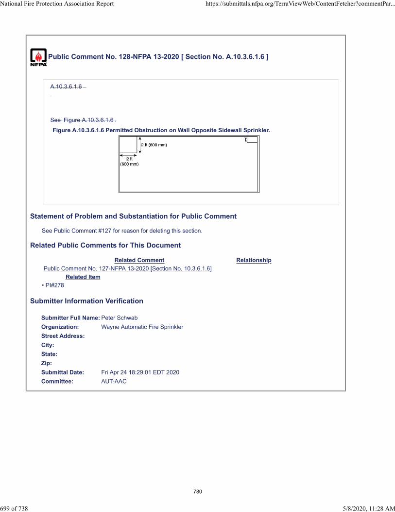
Public Comment No. 128-NFPA 13-2020 [ Section No. A.10.3.6.1.6 ]
A.10.3.6.1.6
See Figure A.10.3.6.1.6 .
Figure A.10.3.6.1.6 Permitted Obstruction on Wall Opposite Sidewall Sprinkler.
Statement of Problem and Substantiation for Public Comment
See Public Comment #127 for reason for deleting this section.
Related Public Comments for This Document
Related Comment Relationship
Public Comment No. 127-NFPA 13-2020 [Section No. 10.3.6.1.6]
Related Item
• PI#278
Submitter Information Verification
Submitter Full Name: Peter Schwab
Organization: Wayne Automatic Fire Sprinkler
Street Address:
City:
State:
Zip:
Submittal Date: Fri Apr 24 18:29:01 EDT 2020
Committee: AUT-AAC
National Fire Protection Association Report https://submittals.nfpa.org/TerraViewWeb/ContentFetcher?commentPar...
699 of 738 5/8/2020, 11:28 AM
780

Public Comment No. 130-NFPA 13-2020 [ Section No. A.11.3.6.1.6 ]
A.11.3.6.1.6
See Figure A.11.3.6.1.6 .
Figure A.11.3.6.1.6 Permitted Obstruction on Wall Opposite EC Sidewall Sprinkler.
Statement of Problem and Substantiation for Public Comment
See Public Comment 129 for reason for deleting this section.
Related Public Comments for This Document
Related Comment Relationship
Public Comment No. 129-NFPA 13-2020 [Section No. 11.3.6.1.6]
Related Item
• PI#278
Submitter Information Verification
Submitter Full Name: Peter Schwab
Organization: Wayne Automatic Fire Sprinkler
Street Address:
City:
State:
Zip:
Submittal Date: Fri Apr 24 18:34:16 EDT 2020
Committee: AUT-AAC
National Fire Protection Association Report https://submittals.nfpa.org/TerraViewWeb/ContentFetcher?commentPar...
700 of 738 5/8/2020, 11:28 AM
781
Public Comment No. 144-NFPA 13-2020 [ Section No. A.12.1.1 ]
A.12.1.1
The response and water distribution pattern of listed residential sprinklers have been shown by extensivefire testing to provide better control than spray sprinklers in residential occupancies. These sprinklers areintended to prevent flashover in the room of fire origin, thus improving the chance for occupants to escapeor be evacuated.
The protection area for residential sprinklers is defined in the listing of the sprinkler as a maximum squareor rectangular area. Listing information is presented in even increments from 12 ft to 20 ft (3.7 m to 6.1 m).When a sprinkler is selected for an application, its area of coverage must be equal to or greater than boththe length and width of the hazard area. For example, if the hazard to be protected is a room 13 ft 6 in.(4.1 m) wide and 17 ft 6 in. (5.3 m) long, a sprinkler that is listed to protect a rectangular area of 14 ft × 18 ft(4.3 m × 5.5 m) or a square area of 18 ft × 18 ft (5.5 m × 5.5 m) must be selected. The flow used in thecalculations is then selected as the flow required by the listing for the selected coverage.
Residential sprinklers can only be used in corridors that lead to dwelling units. However, the corridors thatlead to dwelling units can also lead to other hazards that are not dwelling units and can still be protectedwith residential sprinklers. An example would be in a hotel occupancy where the corridor immediatelyleading to the guest rooms also has doors to rooms such as conference rooms, housekeeping closets,laundry rooms, back of house offices, etc.
Statement of Problem and Substantiation for Public Comment
In the first draft, I submitted PI No.'s 434 & 436 in regards to using residential sprinklers in corridors. The resolution pointed to the language in the annex. I have modified this language to be more explanatory.
Related Item
• PI#436 • PI#434
Submitter Information Verification
Submitter Full Name: Peter Schwab
Organization: Wayne Automatic Fire Sprinkler
Street Address:
City:
State:
Zip:
Submittal Date: Sat Apr 25 13:16:25 EDT 2020
Committee: AUT-AAC
National Fire Protection Association Report https://submittals.nfpa.org/TerraViewWeb/ContentFetcher?commentPar...
701 of 738 5/8/2020, 11:28 AM
782
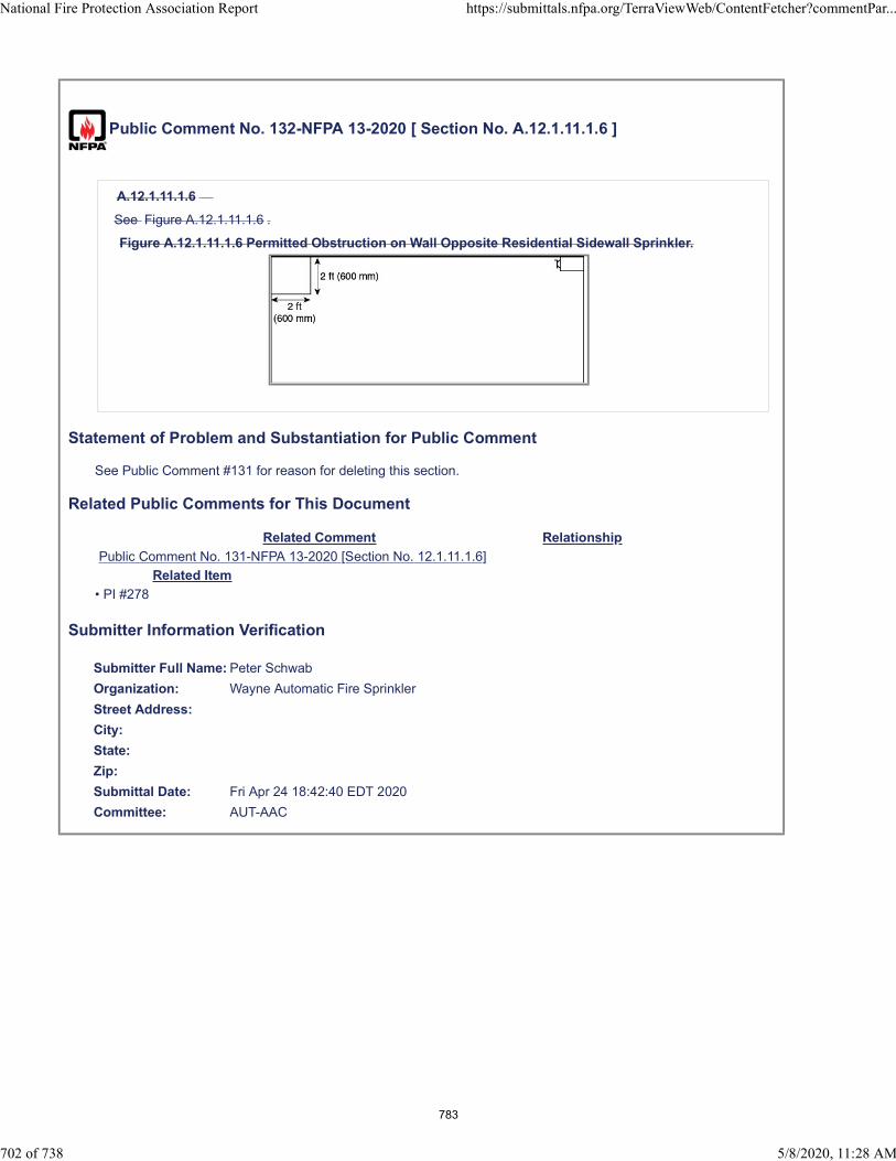
Public Comment No. 132-NFPA 13-2020 [ Section No. A.12.1.11.1.6 ]
A.12.1.11.1.6
See Figure A.12.1.11.1.6 .
Figure A.12.1.11.1.6 Permitted Obstruction on Wall Opposite Residential Sidewall Sprinkler.
Statement of Problem and Substantiation for Public Comment
See Public Comment #131 for reason for deleting this section.
Related Public Comments for This Document
Related Comment Relationship
Public Comment No. 131-NFPA 13-2020 [Section No. 12.1.11.1.6]
Related Item
• PI #278
Submitter Information Verification
Submitter Full Name: Peter Schwab
Organization: Wayne Automatic Fire Sprinkler
Street Address:
City:
State:
Zip:
Submittal Date: Fri Apr 24 18:42:40 EDT 2020
Committee: AUT-AAC
National Fire Protection Association Report https://submittals.nfpa.org/TerraViewWeb/ContentFetcher?commentPar...
702 of 738 5/8/2020, 11:28 AM
783

Public Comment No. 381-NFPA 13-2020 [ Section No. A.15.3.1 ]
National Fire Protection Association Report https://submittals.nfpa.org/TerraViewWeb/ContentFetcher?commentPar...
703 of 738 5/8/2020, 11:28 AM
784

A.15.3.1
National Fire Protection Association Report https://submittals.nfpa.org/TerraViewWeb/ContentFetcher?commentPar...
704 of 738 5/8/2020, 11:28 AM
785
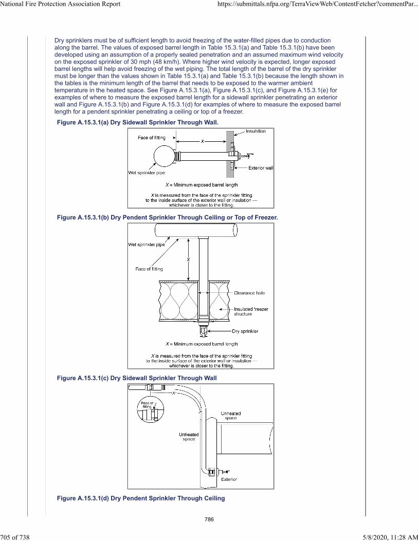
Dry sprinklers must be of sufficient length to avoid freezing of the water-filled pipes due to conductionalong the barrel. The values of exposed barrel length in Table 15.3.1(a) and Table 15.3.1(b) have beendeveloped using an assumption of a properly sealed penetration and an assumed maximum wind velocityon the exposed sprinkler of 30 mph (48 km/h). Where higher wind velocity is expected, longer exposedbarrel lengths will help avoid freezing of the wet piping. The total length of the barrel of the dry sprinklermust be longer than the values shown in Table 15.3.1(a) and Table 15.3.1(b) because the length shown inthe tables is the minimum length of the barrel that needs to be exposed to the warmer ambienttemperature in the heated space. See Figure A.15.3.1(a), Figure A.15.3.1(c), and Figure A.15.3.1(e) forexamples of where to measure the exposed barrel length for a sidewall sprinkler penetrating an exteriorwall and Figure A.15.3.1(b) and Figure A.15.3.1(d) for examples of where to measure the exposed barrellength for a pendent sprinkler penetrating a ceiling or top of a freezer.
Figure A.15.3.1(a) Dry Sidewall Sprinkler Through Wall.
Figure A.15.3.1(b) Dry Pendent Sprinkler Through Ceiling or Top of Freezer.
Figure A.15.3.1(c) Dry Sidewall Sprinkler Through Wall
Figure A.15.3.1(d) Dry Pendent Sprinkler Through Ceiling
National Fire Protection Association Report https://submittals.nfpa.org/TerraViewWeb/ContentFetcher?commentPar...
705 of 738 5/8/2020, 11:28 AM
786

Figure A.15.3.1(e) Dry Sidewall Sprinkler Through Wall.
Statement of Problem and Substantiation for Public Comment
The note in figure (e) about the fitting needs to be added to figures (a) and (b). This is a common mistake and adding the note might prevent an issue.
Related Item
• FR 1070
Submitter Information Verification
Submitter Full Name: John Denhardt
Organization: American Fire Sprinkler Association
Street Address:
City:
State:
Zip:
Submittal Date: Wed May 06 14:48:44 EDT 2020
Committee: AUT-AAC
National Fire Protection Association Report https://submittals.nfpa.org/TerraViewWeb/ContentFetcher?commentPar...
706 of 738 5/8/2020, 11:28 AM
787
Public Comment No. 168-NFPA 13-2020 [ Section No. A.15.5 ]
A.15.5
It is not the intent of this section to require the use of attic sprinklers. Special rules for use of standardspray sprinklers used in attics are addressed in 10.2.6.1.4 . Attic sprinklers can also have the followingcharacteristics/limitations:
(1) Intermediate temperature rating
(2) For use in light hazard only
(3) For use in wet or dry systems
(4) For use with CPVC or steel pipe
Statement of Problem and Substantiation for Public Comment
FR 1199 does not add any value to the standard as it describes a product that is already listed for a specific use.
Related Item
• FR-1199
Submitter Information Verification
Submitter Full Name: Kevin Hall
Organization: NFSA
Affiliation: NFSA Engineering and Standards Committee
Street Address:
City:
State:
Zip:
Submittal Date: Mon Apr 27 10:28:46 EDT 2020
Committee: AUT-AAC
National Fire Protection Association Report https://submittals.nfpa.org/TerraViewWeb/ContentFetcher?commentPar...
707 of 738 5/8/2020, 11:28 AM
788
Public Comment No. 236-NFPA 13-2020 [ Section No. A.16.2.1.1 ]
A.16.2.1.1
Sprinklers should be permitted to be reinstalled when the sprinkler being removed from the system remainsattached to the original fitting or welded outlet or can be removed by a grooved connection , provided carehas been taken to ensure the sprinkler has not been damaged. Flexible hose connections are considered afitting.
In new installations, where sprinklers are installed on pendent drop nipples or sidewall sprinklers prior tofinal cut-back, protective caps and/or straps should remain in place until after the drop nipple has been cutto fit to the final ceiling elevation.
Statement of Problem and Substantiation for Public Comment
The concern here is a wrench being directly applied to the sprinkler to remove it. Removing a sprinkler that is attached to a drop is inherently more difficult than removing a sprinkler by itself with more cause for issue. If removing a sprinkler with a drop attached to it is acceptable, then removing a sprinkler by itself should be acceptable if the concern for directly applying a wrench to the sprinkler can be removed by using a coupling instead of a threaded connection.
Related Item
• FR-1364
Submitter Information Verification
Submitter Full Name: Kevin Hall
Organization: NFSA
Affiliation: NFSA Engineering and Standards Committee
Street Address:
City:
State:
Zip:
Submittal Date: Mon May 04 08:25:06 EDT 2020
Committee: AUT-AAC
National Fire Protection Association Report https://submittals.nfpa.org/TerraViewWeb/ContentFetcher?commentPar...
708 of 738 5/8/2020, 11:28 AM
789
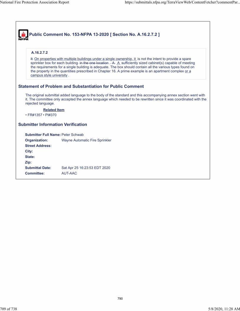
Public Comment No. 153-NFPA 13-2020 [ Section No. A.16.2.7.2 ]
A.16.2.7.2
It On properties with multiple buildings under a single ownership, it is not the intent to provide a sparesprinkler box for each building in the one location . A A sufficiently sized cabinet(s) capable of meetingthe requirements for a single building is adequate. The box should contain all the various types found onthe property in the quantities prescribed in Chapter 16. A prime example is an apartment complex or acampus style university .
Statement of Problem and Substantiation for Public Comment
The original submittal added language to the body of the standard and this accompanying annex section went with it. The committee only accepted the annex language which needed to be rewritten since it was coordinated with the rejected language.
Related Item
• FR#1357 • PI#370
Submitter Information Verification
Submitter Full Name: Peter Schwab
Organization: Wayne Automatic Fire Sprinkler
Street Address:
City:
State:
Zip:
Submittal Date: Sat Apr 25 16:23:53 EDT 2020
Committee: AUT-AAC
National Fire Protection Association Report https://submittals.nfpa.org/TerraViewWeb/ContentFetcher?commentPar...
709 of 738 5/8/2020, 11:28 AM
790
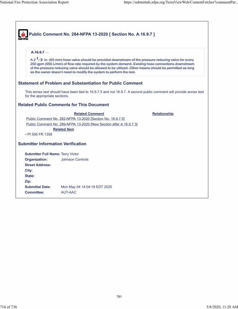
Public Comment No. 284-NFPA 13-2020 [ Section No. A.16.9.7 ]
A.16.9.7
A 2 1 ⁄ 2 in. (65 mm) hose valve should be provided downstream of the pressure reducing valve for every250 gpm (950 L/min) of flow rate required by the system demand. Existing hose connections downstreamof the pressure reducing valve should be allowed to be utilized. Other means should be permitted as longas the owner doesn’t need to modify the system to perform the test.
Statement of Problem and Substantiation for Public Comment
This annex text should have been tied to 16.9.7.5 and not 16.9.7. A second public comment will provide annex text for the appropriate sections.
Related Public Comments for This Document
Related Comment Relationship
Public Comment No. 282-NFPA 13-2020 [Section No. 16.9.7.5]
Public Comment No. 289-NFPA 13-2020 [New Section after A.16.9.7.3]
Related Item
• PI 556 FR 1358
Submitter Information Verification
Submitter Full Name: Terry Victor
Organization: Johnson Controls
Street Address:
City:
State:
Zip:
Submittal Date: Mon May 04 14:04:19 EDT 2020
Committee: AUT-AAC
National Fire Protection Association Report https://submittals.nfpa.org/TerraViewWeb/ContentFetcher?commentPar...
710 of 738 5/8/2020, 11:28 AM
791
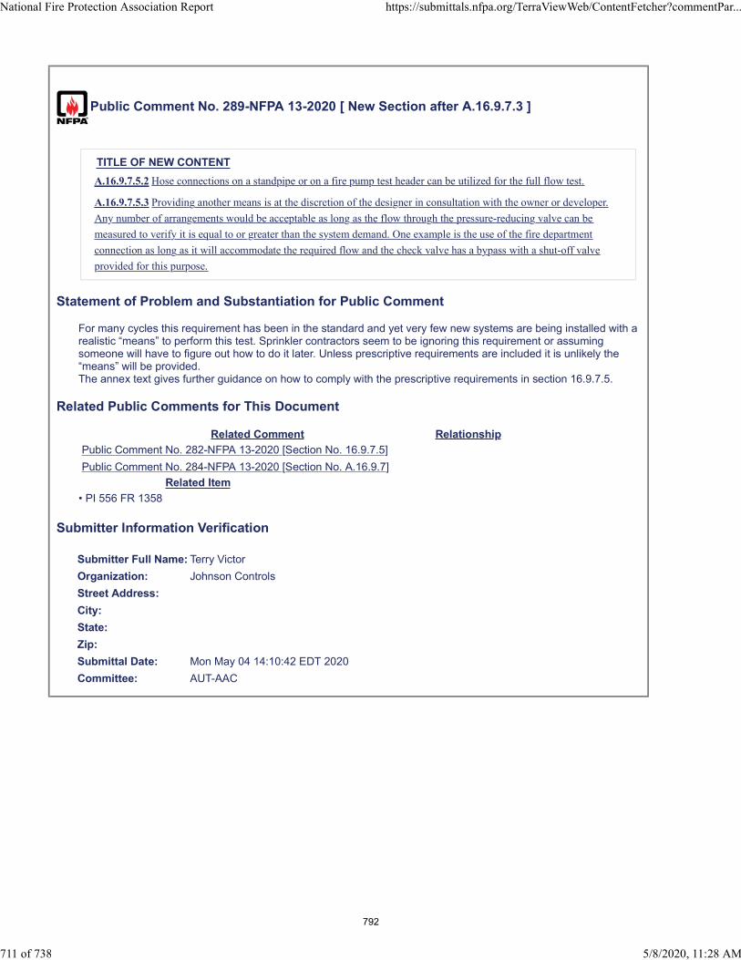
Public Comment No. 289-NFPA 13-2020 [ New Section after A.16.9.7.3 ]
TITLE OF NEW CONTENT
A.16.9.7.5.2 Hose connections on a standpipe or on a fire pump test header can be utilized for the full flow test.
A.16.9.7.5.3 Providing another means is at the discretion of the designer in consultation with the owner or developer.
Any number of arrangements would be acceptable as long as the flow through the pressure-reducing valve can be
measured to verify it is equal to or greater than the system demand. One example is the use of the fire department
connection as long as it will accommodate the required flow and the check valve has a bypass with a shut-off valve
provided for this purpose.
Statement of Problem and Substantiation for Public Comment
For many cycles this requirement has been in the standard and yet very few new systems are being installed with a realistic “means” to perform this test. Sprinkler contractors seem to be ignoring this requirement or assuming someone will have to figure out how to do it later. Unless prescriptive requirements are included it is unlikely the “means” will be provided.The annex text gives further guidance on how to comply with the prescriptive requirements in section 16.9.7.5.
Related Public Comments for This Document
Related Comment Relationship
Public Comment No. 282-NFPA 13-2020 [Section No. 16.9.7.5]
Public Comment No. 284-NFPA 13-2020 [Section No. A.16.9.7]
Related Item
• PI 556 FR 1358
Submitter Information Verification
Submitter Full Name: Terry Victor
Organization: Johnson Controls
Street Address:
City:
State:
Zip:
Submittal Date: Mon May 04 14:10:42 EDT 2020
Committee: AUT-AAC
National Fire Protection Association Report https://submittals.nfpa.org/TerraViewWeb/ContentFetcher?commentPar...
711 of 738 5/8/2020, 11:28 AM
792
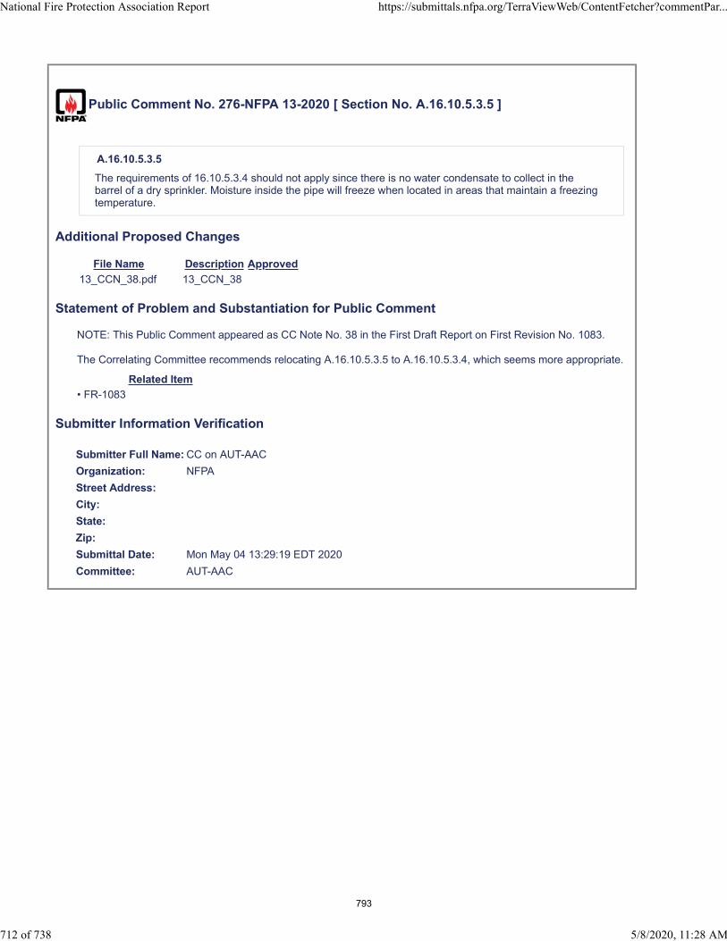
Public Comment No. 276-NFPA 13-2020 [ Section No. A.16.10.5.3.5 ]
A.16.10.5.3.5
The requirements of 16.10.5.3.4 should not apply since there is no water condensate to collect in thebarrel of a dry sprinkler. Moisture inside the pipe will freeze when located in areas that maintain a freezingtemperature.
Additional Proposed Changes
File Name Description Approved
13_CCN_38.pdf 13_CCN_38
Statement of Problem and Substantiation for Public Comment
NOTE: This Public Comment appeared as CC Note No. 38 in the First Draft Report on First Revision No. 1083.
The Correlating Committee recommends relocating A.16.10.5.3.5 to A.16.10.5.3.4, which seems more appropriate.
Related Item
• FR-1083
Submitter Information Verification
Submitter Full Name: CC on AUT-AAC
Organization: NFPA
Street Address:
City:
State:
Zip:
Submittal Date: Mon May 04 13:29:19 EDT 2020
Committee: AUT-AAC
National Fire Protection Association Report https://submittals.nfpa.org/TerraViewWeb/ContentFetcher?commentPar...
712 of 738 5/8/2020, 11:28 AM
793

Correlating Committee Note No. 38-NFPA 13-2019 [ Section No. 16.10.5.3.5 ]
Submitter Information Verification
Committee: AUT-AAC
Submittal Date: Wed Dec 18 09:17:42 EST 2019
Committee Statement
CommitteeStatement:
The Correlating Committee recommends relocating A.16.10.5.3.5 to A.16.10.5.3.4, whichseems more appropriate.
First Revision No. 1083-NFPA 13-2019 [Section No. 16.10.5.3.5]
Ballot Results
This item has passed ballot
22 Eligible Voters
3 Not Returned
19 Affirmative All
0 Affirmative with Comments
0 Negative with Comments
0 Abstention
Not Returned
Baz, Jose R.
Hilton, Luke
Su, Joseph
Affirmative All
Bell, Kerry M.
Bellamy, Tracey D.
Browning, Chase A.
Dellasanta, Steven W.
Friedman, Michael J.
Hoffman, Alex
Hopkins, Mark
Javeri, Sultan M.
Ketner, Charles W.
Koffel, William E.
Lake, James D.
LeBlanc, John A.
Linder, Kenneth W.
Lowrey, David O.
Medovich, Jack A.
National Fire Protection Association Report https://submittals.nfpa.org/TerraViewWeb/ContentFetcher?commentPar...
33 of 50 5/4/2020, 11:38 AM
794

Palenske, Garner A.
Phillips, Lawrence Richard
Seghi, Adam
Thompson, J. Michael
National Fire Protection Association Report https://submittals.nfpa.org/TerraViewWeb/ContentFetcher?commentPar...
34 of 50 5/4/2020, 11:38 AM
795
Public Comment No. 66-NFPA 13-2020 [ Section No. A.16.11.1.2 ]
A.16.11.1.2
All alarm apparatus should be so located and installed that all parts are accessible for inspection, removal,and repair, and such apparatus should be substantially supported.
The water A water motor-operated gong bell mechanism should be protected from weather-relatedelements such as rain, snow, or ice. To the extent practicable, it should also be protected from otherinfluencing factors such as birds or other small animals that might attempt to nest in such a device.
Statement of Problem and Substantiation for Public Comment
The revised wording is more in keeping with that generally used in the sprinkler codes.
Related Item
• PI No.49-NFPA 13-2019
Submitter Information Verification
Submitter Full Name: BARNEY MULLIGAN
Organization: CITY OF DENVER Fire Department
Street Address:
City:
State:
Zip:
Submittal Date: Wed Apr 22 20:13:19 EDT 2020
Committee: AUT-AAC
National Fire Protection Association Report https://submittals.nfpa.org/TerraViewWeb/ContentFetcher?commentPar...
713 of 738 5/8/2020, 11:28 AM
796

Public Comment No. 303-NFPA 13-2020 [ Section No. A.16.14.5 ]
A.16.14.5
Where backflow prevention devices are installed, they should be in an accessible location to provide forinspection, testing, service and maintenance. When a backflow prevention device is retroactively installedon a pipe schedule system, the revised hydraulic calculation still follows the pipe schedule method of19.3.2 with the inclusion of friction loss for the device.
Statement of Problem and Substantiation for Public Comment
The location of a BFP should also take into consideration the inspections and tests required by NFPA 25. The text in the annex that gives guidance for retroactively installed BFPs and the hydraulic calculation procedure is a better fit for this section.
Related Public Comments for This Document
Related Comment Relationship
Public Comment No. 302-NFPA 13-2020 [Section No. 16.14.5.1]
Public Comment No. 304-NFPA 13-2020 [Section No. A.16.14.5.1]
Related Item
• PI 558
Submitter Information Verification
Submitter Full Name: Terry Victor
Organization: Johnson Controls
Street Address:
City:
State:
Zip:
Submittal Date: Mon May 04 15:38:32 EDT 2020
Committee: AUT-AAC
National Fire Protection Association Report https://submittals.nfpa.org/TerraViewWeb/ContentFetcher?commentPar...
714 of 738 5/8/2020, 11:28 AM
797

Public Comment No. 304-NFPA 13-2020 [ Section No. A.16.14.5.1 ]
A.16.14.5.1
System demand refers to flow rate and pressure. This test is only concerned with testing at the proper flowrate.The full flow test of the backflow prevention valve can be performed with a test header or otherconnection downstream of the valve. A bypass around the check valve in the fire department connectorline with a control valve in the normally closed position can be an acceptable arrangement. When flow to avisible drain cannot be accomplished, closed loop flow can be acceptable if
a flowmeter or site glass is incorporated into the system to ensure flow. When a backflow prevention deviceis retroactively installed on a pipe schedule system, the revised hydraulic calculation still follows the pipeschedule method of 19.2.2 with the inclusion of friction loss for the deviceA.16.14.5.1.2 Hose connections on a standpipe or on a fire pump test header can be utilized for the full flow test.
A.16.14.5.1.3 Providing another means is at the discretion of the designer in consultation with the owner or developer.
Any number of arrangements would be acceptable as long as the flow through the backflow prevention valve can be
measured to verify it is equal to or greater than the system demand. One example is the use of the fire department
connection as long as it will accommodate the required flow and the check valve has a bypass with a shut-off valve
provided for this purpose .
Statement of Problem and Substantiation for Public Comment
For many cycles this requirement has been in the standard and yet very few new systems are being installed with a realistic “means” to perform this test. The revised and added annex text aligns with the changes proposed to this section by the related public comment.The technical committee accepted the concepts of including prescribed means for pressure-reducing valves by moving the text submitted in PI 556 to the annex. When resolving PI 558 with the same language for backflow devices, the committee statement said “See statement on PI 556” but no text was added to either the standard or the annex related to testing backflow devices.
Related Public Comments for This Document
Related Comment Relationship
Public Comment No. 302-NFPA 13-2020 [Section No. 16.14.5.1]
Public Comment No. 303-NFPA 13-2020 [Section No. A.16.14.5]
Related Item
• PI 558
Submitter Information Verification
Submitter Full Name: Terry Victor
Organization: Johnson Controls
Street Address:
City:
State:
Zip:
Submittal Date: Mon May 04 15:52:12 EDT 2020
Committee: AUT-AAC
National Fire Protection Association Report https://submittals.nfpa.org/TerraViewWeb/ContentFetcher?commentPar...
715 of 738 5/8/2020, 11:28 AM
798

Public Comment No. 39-NFPA 13-2020 [ Section No. F.1.2.6 ]
F.1.2.6 ASTM Publications.
ASTM International, 100 Barr Harbor Drive, P.O. Box C700, West Conshohocken, PA 19428-2959.
ASTM A126, Standard Specification for Gray Iron Castings for Valves, Flanges and Pipe Fittings, 2004,reapproved 2014.
ASTM A135/A135M, Standard Specification for Electric-Resistance-Welded Steel Pipe, 2009, reapproved2014.
ASTM A197/A197M, Standard Specification for Cupola Malleable Iron, 2000, reapproved 2015.
ASTM A307, Standard Specification for Carbon Steel Bolts, Studs, Threaded Rod 60,000 psi TensileStrength, 2014.
ASTM A603, Standard Specification for Zinc-Coated Steel Structural Wire Rope, 1998, reapproved 2014.
ASTM A1023/A1023M, Standard Specification for Stranded Carbon Steel Wire Ropes for GeneralPurposes, 2015.
ASTM C136/C136M, Standard Test Method for Sieve Analysis of Fine and Coarse Aggregates, 2014.
ASTM C635/C635M, Standard Specification for the Manufacture, Performance, and Testing of MetalSuspension Systems of Acoustical Tile and Lay-In Panel Ceilings, 2017.
ASTM C636/C636M, Standard Practice for Installation of Metal Ceiling Suspension Systems for AcousticalTile and Lay-In Panels, 2013.
ASTM D2487, Standard Practice for Classification of Soils for Engineering Purposes (Unified SoilClassification System), 2017.
ASTM E8/E8M, Structural Test Method for Tension Testing of Metallic Materials, 2016.
ASTM E84, Standard Test Method of Surface Burning Characteristics of Building Materials, 2018a 2020 .
ASTM E119, Standard Test Methods for Fire Tests of Building Construction and Materials, 2018b 2019 .
ASTM E580/E580M, Standard Practice for Installation of Ceiling Suspension Systems for Acoustical Tileand Lay-in Panels in Areas Subject to Earthquake Ground Motions, 2017.
ASTM F437, Standard Specification for Threaded Chlorinated Poly (Vinyl Chloride) (CPVC) Plastic PipeFittings, Schedule 80, 2015.
ASTM F438, Standard Specification for Socket-Type Chlorinated Poly (Vinyl Chloride) (CPVC) Plastic PipeFittings, Schedule 40, 2017.
ASTM F439, Standard Specification for Socket-Type Chlorinated Poly (Vinyl Chloride) (CPVC) Plastic PipeFittings, Schedule 80, 2013.
ASTM F442/F442M, Standard Specification for Chlorinated Poly (Vinyl Chloride) (CPVC) Plastic Pipe(SDR-PR), 2013.
ASTM F2164, Standard Practice for Field Leak Testing of Polyethylene (PE) and Crosslinked Polyethylene(PEX) Pressure Piping Systems Using Hydrostatic Pressure, 2018.
Statement of Problem and Substantiation for Public Comment
updating ASTM fire standards
Related Item
• FR1192 •
Submitter Information Verification
Submitter Full Name: Marcelo Hirschler
Organization: GBH International
Street Address:
National Fire Protection Association Report https://submittals.nfpa.org/TerraViewWeb/ContentFetcher?commentPar...
737 of 738 5/8/2020, 11:28 AM
799

City:
State:
Zip:
Submittal Date: Wed Apr 01 14:19:59 EDT 2020
Committee: AUT-AAC
National Fire Protection Association Report https://submittals.nfpa.org/TerraViewWeb/ContentFetcher?commentPar...
738 of 738 5/8/2020, 11:28 AM
800