Nanoparticle-doped lubricants: Potential of Inorganic ...
181
HAL Id: tel-01149050 https://tel.archives-ouvertes.fr/tel-01149050 Submitted on 6 May 2015 HAL is a multi-disciplinary open access archive for the deposit and dissemination of sci- entific research documents, whether they are pub- lished or not. The documents may come from teaching and research institutions in France or abroad, or from public or private research centers. L’archive ouverte pluridisciplinaire HAL, est destinée au dépôt et à la diffusion de documents scientifiques de niveau recherche, publiés ou non, émanant des établissements d’enseignement et de recherche français ou étrangers, des laboratoires publics ou privés. Nanoparticle-doped lubricants : Potential of Inorganic Fullerene-like (IF-) molybdenum disulfide for automotive applications Pierre Rabaso To cite this version: Pierre Rabaso. Nanoparticle-doped lubricants: Potential of Inorganic Fullerene-like (IF-) molybde- num disulfide for automotive applications. Materials and structures in mechanics [physics.class-ph]. INSA de Lyon, 2014. English. NNT : 2014ISAL0103. tel-01149050
-
Upload
khangminh22 -
Category
Documents
-
view
0 -
download
0
Transcript of Nanoparticle-doped lubricants: Potential of Inorganic ...

HAL Id: tel-01149050https://tel.archives-ouvertes.fr/tel-01149050
Submitted on 6 May 2015
HAL is a multi-disciplinary open accessarchive for the deposit and dissemination of sci-entific research documents, whether they are pub-lished or not. The documents may come fromteaching and research institutions in France orabroad, or from public or private research centers.
L’archive ouverte pluridisciplinaire HAL, estdestinée au dépôt et à la diffusion de documentsscientifiques de niveau recherche, publiés ou non,émanant des établissements d’enseignement et derecherche français ou étrangers, des laboratoirespublics ou privés.
Nanoparticle-doped lubricants : Potential of InorganicFullerene-like (IF-) molybdenum disulfide for
automotive applicationsPierre Rabaso
To cite this version:Pierre Rabaso. Nanoparticle-doped lubricants : Potential of Inorganic Fullerene-like (IF-) molybde-num disulfide for automotive applications. Materials and structures in mechanics [physics.class-ph].INSA de Lyon, 2014. English. �NNT : 2014ISAL0103�. �tel-01149050�

N° d’ordre 2014 ISAL 0103 Année 2014
Thèse
Nanoparticle-doped lubricants: potential of
Inorganic Fullerene-like (IF-) molybdenum disulfide
for automotive applications
Présentée devant
L’Institut National des Sciences Appliquées de Lyon
Ecole doctorale des Sciences pour l’Ingénieur de Lyon:
Mécanique, Energétique, Génie Civil, Acoustique (MEGA)
Spécialité : Mécanique
Pour obtenir
Le grade de docteur
Par
Pierre RABASO
Ingénieur INSA Lyon
Soutenue le 13 novembre 2014 devant la commission d’examen composée de :
Pr. Fabrice DASSENOY LTDS – Ecole Centrale de Lyon Directeur de thèse Dr. Moussa DIABY PSA Peugeot Citroën Encadrant industriel Pr. Rob DWYER-JOYCE University of Sheffield Rapporteur Pr. Michel FILLON Institut Pprime – Université de Poitiers Président du jury Pr. Christophe GEANTET IRCELYON – CNRS Membre invité Pr. Mitjan KALIN University of Ljubljana Rapporteur Pr. Fabrice VILLE LaMCoS – INSA Lyon Directeur de thèse
Laboratoires de recherche :
LaMCoS – INSA Lyon LTDS – Ecole Centrale de Lyon
Cette thèse est accessible à l'adresse : http://theses.insa-lyon.fr/publication/2014ISAL0103/these.pdf © [P. Rabaso], [2014], INSA de Lyon, tous droits réservés

Cette thèse est accessible à l'adresse : http://theses.insa-lyon.fr/publication/2014ISAL0103/these.pdf © [P. Rabaso], [2014], INSA de Lyon, tous droits réservés

INSA Direction de la Recherche - Ecoles Doctorales – Quinquennal 2011-2015
SIGLE ECOLE DOCTORALE NOM ET COORDONNEES DU
RESPONSABLE
CHIMIE
CHIMIE DE LYON http://www.edchimie-lyon.fr Sec : Renée EL MELHEM Bat Blaise Pascal 3e etage 04 72 43 80 46 Insa : R. GOURDON
M. Jean Marc LANCELIN Université de Lyon – Collège Doctoral Bât ESCPE 43 bd du 11 novembre 1918 69622 VILLEURBANNE Cedex Tél : 04.72.43 13 95 [email protected]
E.E.A.
ELECTRONIQUE, ELECTROTECHNIQUE, AUTOMATIQUE http://edeea.ec-lyon.fr Sec : M.C. HAVGOUDOUKIAN [email protected]
M. Gérard SCORLETTI Ecole Centrale de Lyon 36 avenue Guy de Collongue 69134 ECULLY Tél : 04.72.18 60.97 Fax : 04 78 43 37 17 [email protected]
E2M2
EVOLUTION, ECOSYSTEME, MICROBIOLOGIE, MODELISATION http://e2m2.universite-lyon.fr Sec : Safia AIT CHALAL Bat Darwin - UCB Lyon 1 04.72.43.28.91 Insa : H. CHARLES
Mme Gudrun BORNETTE CNRS UMR 5023 LEHNA Université Claude Bernard Lyon 1 Bât Forel 43 bd du 11 novembre 1918 69622 VILLEURBANNE Cédex Tél : 06.07.53.89.13 e2m2@ univ-lyon1.fr
EDISS
INTERDISCIPLINAIRE SCIENCES-SANTE http://www.ediss-lyon.fr Sec : Safia AIT CHALAL Hôpital Louis Pradel - Bron 04 72 68 49 09 Insa : M. LAGARDE [email protected]
Mme Emmanuelle CANET-SOULAS INSERM U1060, CarMeN lab, Univ. Lyon 1 Bâtiment IMBL 11 avenue Jean Capelle INSA de Lyon 696621 Villeurbanne Tél : 04.72.68.49.09 Fax :04 72 68 49 16 [email protected]
INFOMATHS
INFORMATIQUE ET MATHEMATIQUES http://infomaths.univ-lyon1.fr Sec :Renée EL MELHEM Bat Blaise Pascal 3e etage [email protected]
Mme Sylvie CALABRETTO LIRIS – INSA de Lyon Bat Blaise Pascal 7 avenue Jean Capelle 69622 VILLEURBANNE Cedex Tél : 04.72. 43. 80. 46 Fax 04 72 43 16 87 [email protected]
Matériaux
MATERIAUX DE LYON http://ed34.universite-lyon.fr Sec : M. LABOUNE PM : 71.70 –Fax : 87.12 Bat. Saint Exupéry [email protected]
M. Jean-Yves BUFFIERE INSA de Lyon MATEIS Bâtiment Saint Exupéry 7 avenue Jean Capelle 69621 VILLEURBANNE Cedex Tél : 04.72.43 83 18 Fax 04 72 43 85 28 [email protected]
MEGA
MECANIQUE, ENERGETIQUE, GENIE CIVIL, ACOUSTIQUE http://mega.universite-lyon.fr Sec : M. LABOUNE PM : 71.70 –Fax : 87.12 Bat. Saint Exupéry [email protected]
M. Philippe BOISSE INSA de Lyon Laboratoire LAMCOS Bâtiment Jacquard 25 bis avenue Jean Capelle 69621 VILLEURBANNE Cedex Tél :04.72 .43.71.70 Fax : 04 72 43 72 37 [email protected]
ScSo
ScSo* http://recherche.univ-lyon2.fr/scso/ Sec : Viviane POLSINELLI Brigitte DUBOIS Insa : J.Y. TOUSSAINT
Mme Isabelle VON BUELTZINGLOEWEN Université Lyon 2 86 rue Pasteur 69365 LYON Cedex 07 Tél : 04.78.77.23.86 Fax : 04.37.28.04.48 [email protected]
*ScSo : Histoire, Géographie, Aménagement, Urbanisme, Archéologie, Science politique, Sociologie, Anthropologie
Cette thèse est accessible à l'adresse : http://theses.insa-lyon.fr/publication/2014ISAL0103/these.pdf © [P. Rabaso], [2014], INSA de Lyon, tous droits réservés

Cette thèse est accessible à l'adresse : http://theses.insa-lyon.fr/publication/2014ISAL0103/these.pdf © [P. Rabaso], [2014], INSA de Lyon, tous droits réservés

“And this I believe: that the free, exploring mind of the individual human is the most valuable thing in the world.”
- John Steinbeck
Cette thèse est accessible à l'adresse : http://theses.insa-lyon.fr/publication/2014ISAL0103/these.pdf © [P. Rabaso], [2014], INSA de Lyon, tous droits réservés

Cette thèse est accessible à l'adresse : http://theses.insa-lyon.fr/publication/2014ISAL0103/these.pdf © [P. Rabaso], [2014], INSA de Lyon, tous droits réservés

i
Foreword
This work results from a collaboration between the laboratory of Contact and Structure
Mechanics (LaMCoS) from INSA Lyon (France), the laboratory of Tribology and System
Dynamics (LTDS) from Ecole Centrale de Lyon (France) and the car manufacturer PSA Peugeot
Citroën.
The PhD took place in the doctoral school MEGA (Mechanics, Energetics, Civil Engineering,
Acoustics), and was funded by the National Agency for Research and Technology (ANRT) through
an Industrial Research Convention (CIFRE).
PhD supervisors LaMCoS Fabrice VILLE LTDS Fabrice DASSENOY PSA Peugeot Citroën Moussa DIABY
Reviewers University of Sheffield (UK) University of Ljubljana (Slovenia)
Rob DWYER-JOYCE Mitjan KALIN
LaMCoS Director David DUREISSEIX Head of the SMC* team Philippe VELEX
LTDS Director Denis MAZUYER Head of the TPCDI** team Thierry LE MOGNE
INSA Lyon Director Eric MAURINCOMME Director of Research Jean-François GERARD
Ecole Centrale de Lyon Director Frank DEBOUCK Director of Research Jean-Pierre BERTOGLIO
MEGA doctoral school Director Philippe BOISSE
PSA Peugeot Citroën
Chairman of the Managing Board Carlos TAVAREZ Director of Research & Development Gilles LE BORGNE Scientific Director Sylvain ALLANO Head of the TLPA*** team Vanina SABATHIER
* Contacts and Mechanical Systems
** Tribology, Physico-Chemistry and Interface Dynamics
*** Tribology, Industrial liquids and Assemblies
Cette thèse est accessible à l'adresse : http://theses.insa-lyon.fr/publication/2014ISAL0103/these.pdf © [P. Rabaso], [2014], INSA de Lyon, tous droits réservés

ii
Cette thèse est accessible à l'adresse : http://theses.insa-lyon.fr/publication/2014ISAL0103/these.pdf © [P. Rabaso], [2014], INSA de Lyon, tous droits réservés

iii
Acknowledgments I am very grateful to the members of my jury for assessing my work on the day of my defense.
Thank you Pr. Michel Fillon for presiding this jury, and Pr. Christophe Géantet for responding to
my invitation. I would also like to give particular thanks to my reviewers, Pr. Rob Dwyer-Joyce and
Pr. Mitjan Kalin, for reading this manuscript in great detail and for coming all the way to Lyon on
November 13th.
Je retrouve désormais la langue de Molière pour remercier chaleureusement mes directeurs de
thèse Pr. Fabrice Ville et Pr. Fabrice Dassenoy, ainsi que mon encadrant chez PSA Peugeot Citroën
Dr. Moussa Diaby. Vous avez tous les trois su vous montrer disponibles et pédagogues, su
m’orienter tout en préservant ma liberté, et su m’apprendre énormément tout en m’écoutant. Vous
avez su créer une atmosphère de travail alliant à la perfection sérieux et bonne humeur, et su me
considérer non comme un étudiant mais comme un véritable collègue. Quelle chance pour moi
d’avoir pu travailler avec vous !
Merci également à Jérôme Cavoret, Vincent Baudin, Thierry Le Mogne, Béatrice Vacher et
Michel Belin pour l’aide précieuse - que dis-je, inestimable - qu’ils m’ont apportée sur les différents
dispositifs expérimentaux durant toute ma thèse. De l’usinage de pièces pour la HFRR à la
calibration de la MTM en passant par le profilomètre optique, de l’XPS au TEM sans oublier la
Nanovisu, ce travail n’aurait jamais vu le jour sans vous. Merci pour tout ce que m’avez appris,
pour votre patience et pour votre gentillesse.
Je souhaite aussi remercier l’ensemble des personnes avec qui j’ai été amené à collaborer chez
PSA Peugeot Citroën, durant cette thèse mais également lors de mon stage de fin d’études
d’ingénieur. Votre accueil sur le site de Belchamp a été formidable, et j’ai beaucoup appris à vos
côtés. Merci à Pavel Afanasiev de IRCELYON pour la synthèse de l’ensemble des nanoparticules
étudiées lors de ces travaux, ainsi qu’à PCS Instruments pour les réponses à mes nombreuses
questions et à Powertrib pour la réalisation des essais de fatigue présentés à la fin de ce manuscrit.
Merci à tous mes collègues du LaMCoS et du LTDS, présents et passés, qui ont rendu chaque
journée agréable de par leur bonne humeur. Merci tout particulièrement à mes supers co-bureau,
Arnaud (« p’tite pause ? »), Marion (« chocolat ? ») et Jérôme (« Djobi ? »), ainsi qu’à mes quasi-co-
bureau Matthieu (« café ? ») et Nina (« sucre ? »). Un clin d’œil également aux doctorants des autres
bureaux, étages, voire bâtiments avec qui j’ai eu le plaisir de partager davantage que le quotidien du
laboratoire : Charlotte, Nico L., Vincent, Nico V., Jean-David et les « anciens » Florian et Rudy. Je
voudrais aussi remercier Paula, Imène, Sophie, Catia et Modestino pour m’avoir toujours accueilli
avec le sourire et fait une place dans leur bureau lorsque je venais au LTDS. Merci également aux
services informatiques et aux secrétariats pour leur assistance, et notamment à Sophie – promis,
cette fois j’arrête de venir te déranger ! Merci enfin à Yann, Jean-Philippe et Christophe de l’ECAM
pour les conseils que vous avez pu m’apporter au cours de nos nombreuses discussions.
Un grand merci à l’ensemble des personnes présentes à ma soutenance de thèse, ce fut un réel
plaisir de vous présenter mon travail et votre venue n’a fait que rendre cette journée encore plus
mémorable. « Last but not least », un grand merci à ma famille et à mes amis qui ont été présents
tout au long de ces trois années, notamment à mes colocataires Mag puis Stéphane (« p’tit mario ? »)
et à mes parents qui m’ont toujours conseillé, soutenu et encouragé dans mes choix.
Cette thèse est accessible à l'adresse : http://theses.insa-lyon.fr/publication/2014ISAL0103/these.pdf © [P. Rabaso], [2014], INSA de Lyon, tous droits réservés

iv
Cette thèse est accessible à l'adresse : http://theses.insa-lyon.fr/publication/2014ISAL0103/these.pdf © [P. Rabaso], [2014], INSA de Lyon, tous droits réservés

v
Abstract
The growing environmental concerns, along with the continuous increase in the price of fossil
fuels, have highly motivated car manufacturers worldwide to improve the efficiency of their
vehicles. The tribological properties of engine and gearbox lubricants have a significant impact on
the global efficiency of vehicles, as they contribute to reducing friction in many contacts and allow
the downsizing of various components by providing their surfaces with anti-wear protection. The
recent breakthroughs in nanoparticle synthesis have opened new prospects in terms of lubricant
additivation, with the discovery of the excellent friction and wear reducing properties of
nanoparticles such as Inorganic Fullerene-like (IF-) molybdenum or tungsten disulfides.
The tribological potential of IF-MoS2 for automobile applications was investigated in this
work. The respective influences of nanoparticle size and structure were first of all studied, revealing
that poorly crystalline nanoparticles were more efficient in maintaining low-friction tribofilms on
steel substrates in severe boundary lubrication regimes regardless of size (for the range studied).
All the nanoparticles tested however showed similar performances when proper oil recirculation
was ensured, providing a continuous feeding of the contact in nanoparticles.
The IF-MoS2 nanoparticles lost their lubricating abilities when added to fully-formulated
lubricants. This behavior was attributed to the presence of dispersants in the oil, which dispersed
the nanoparticles effectively but prevented them from forming tribofilms on the rubbing surfaces.
The well-dispersed IF-MoS2 were shown to enter the contact and exfoliate, but an excessive
adsorption of the dispersants on the released MoS2 platelets and/or the steel surfaces is thought to
prevent tribofilm adhesion. A balance between nanoparticle dispersion and tribological
performance was then found, by using very low concentrations of dispersants.
The behavior of nanoparticle-doped oils in various scenarios related to automobile
applications was finally explored. The IF-MoS2 provided significant friction and wear reduction at
ambient temperature and in milder rolling/sliding test conditions, for smooth and rough surfaces.
The risks related to the presence of nanoparticles in the oil in full-film lubrication regimes were
partially lifted, with no significant influence on friction witnessed for all the test conditions
considered. The ability of IF-MoS2 nanoparticles to protect steel surfaces from surface-initiated
Rolling Contact Fatigue was finally shown.
Keywords: IF-MoS2 nanoparticles, lubricant additives, boundary lubrication, friction, wear, dispersants,
Rolling Contact Fatigue.
Cette thèse est accessible à l'adresse : http://theses.insa-lyon.fr/publication/2014ISAL0103/these.pdf © [P. Rabaso], [2014], INSA de Lyon, tous droits réservés

vi
Cette thèse est accessible à l'adresse : http://theses.insa-lyon.fr/publication/2014ISAL0103/these.pdf © [P. Rabaso], [2014], INSA de Lyon, tous droits réservés

vii
Résumé
Les enjeux environnementaux actuels, ainsi que la hausse continue du prix du pétrole, ont
incité les constructeurs automobiles du monde entier à améliorer le rendement de leurs véhicules.
Les propriétés tribologiques des lubrifiants des moteurs et boîtes de vitesses ont une influence
considérable sur le rendement global des véhicules. Ils réduisent en effet le frottement généré par
un grand nombre de contacts, et permettent parfois la réduction de la taille de différents
composants en leur conférant une meilleure résistance à l’usure. Les avancées récentes en termes
de synthèse de nanoparticules ont ouvert de nouvelles perspectives en termes d’additivation de
lubrifiants avec, par exemple, la découverte des excellentes propriétés tribologiques des
nanoparticules inorganiques de type fullerène comme le disulfure de molybdène ou de tungstène.
L’objectif de ce manuscrit est d’évaluer le potentiel tribologique des nanoparticules IF-MoS2
dans l’optique d’une application automobile. L’influence de la taille et de la structure des
nanoparticules a d’abord été étudiée. Les nanoparticules peu cristallines se sont révélées être plus
aptes à maintenir un tribofilm performant sur des surfaces en acier dans des conditions de
lubrification limite, indépendamment de leur taille. Toutes les nanoparticules testées ont cependant
atteint des performances équivalentes lorsqu’une recirculation de l’huile était imposée, permettant
de maintenir une alimentation continue du contact en nanoparticules.
Une fois incorporées dans une formulation d’huile complète, les nanoparticules IF-MoS2
perdent leurs propriétés tribologiques. Les dispersants contenus dans l’huile, bien que permettant
une bonne dispersion des IF-MoS2, semblent responsables de leur inefficacité en empêchant la
formation de tribofilms sur les surfaces antagonistes. Une fois correctement dispersées, les
nanoparticules pénètrent toujours le contact et se retrouvent bien exfoliées. Une adsorption
excessive des dispersants sur les feuillets de MoS2 ainsi libérés et/ou sur les surfaces en acier semble
nuire à l’adhésion du tribofilm. Un équilibre entre dispersion des nanoparticules et performance
tribologique a ensuite été trouvé, en utilisant de très faibles concentrations de dispersants.
Le comportement des huiles dopées en nanoparticules dans des conditions plus proches d’une
application automobile a finalement été exploré. Les IF-MoS2 ont permis une réduction
significative du frottement et de l’usure à température ambiante et en roulement/glissement, à la
fois pour des surfaces lisses et rugueuses. Les risques associés à la présence de nanoparticules dans
l’huile dans les régimes de lubrification en film complet ont été partiellement levés. Aucun impact
significatif n’a en effet été constaté sur le coefficient de frottement pour l’ensemble des conditions
d’essais retenues. Le potentiel des nanoparticules IF-MoS2 pour la protection des surfaces soumises
à la fatigue de contact a enfin été démontré.
Mots clés: nanoparticules IF-MoS2, additifs, lubrification limite, frottement, usure, dispersants, fatigue de
contact.
Cette thèse est accessible à l'adresse : http://theses.insa-lyon.fr/publication/2014ISAL0103/these.pdf © [P. Rabaso], [2014], INSA de Lyon, tous droits réservés

viii
Cette thèse est accessible à l'adresse : http://theses.insa-lyon.fr/publication/2014ISAL0103/these.pdf © [P. Rabaso], [2014], INSA de Lyon, tous droits réservés

ix
Table of contents
LIST OF FIGURES .................................................................................................................... 1
LIST OF TABLES ..................................................................................................................... 4
NOMENCLATURE ................................................................................................................... 5
INTRODUCTION ..................................................................................................................... 7
1) STATE OF THE ART ........................................................................................................... 9
1. 1. AUTOMOTIVE LUBRICATION ....................................................................................................... 11
1. 1. 1. ENVIRONMENTAL ISSUES AND REGULATIONS ....................................................................................... 11
1. 1. 2. FROM MECHANICAL SYSTEMS TO TRIBOLOGICAL CONTACTS: THE DIFFERENT LUBRICATION REGIMES .............. 13
1. 1. 3. COMPOSITION OF CURRENT LUBRICANTS ............................................................................................ 15
1. 2. A BRIEF HISTORY OF NANOPARTICLE-DOPED LUBRICANTS ................................................................... 22
1. 2. 1. DIFFERENT CHEMICAL NATURES ......................................................................................................... 22
1. 2. 2. METAL DICHALCOGENIDES OF DIFFERENT SHAPES AND STRUCTURES ........................................................ 24
1. 2. 3. FOCUS ON INORGANIC FULLERENE-LIKE (IF-) MOS2 NANOPARTICLES ...................................................... 30
1. 2. 4. PARTICLE CONTAMINATION OF LUBRICANTS AND ASSOCIATED RISKS ........................................................ 33
1. 3. OBJECTIVES AND CHALLENGES OF THE PRESENT WORK ...................................................................... 37
2) EXPERIMENTAL TECHNIQUES AND METHODOLOGIES ............................................................... 39
2. 1. OVERALL METHODOLOGY .......................................................................................................... 41
2. 2. TRIBOLOGICAL TESTING ............................................................................................................. 42
2. 2. 1. HIGH-FREQUENCY RECIPROCATING RIG (HFRR) .................................................................................. 42
2. 2. 2. MINI-TRACTION MACHINE (MTM) ................................................................................................... 43
2. 2. 3. NANOVISU TEST RIG (NTR) .............................................................................................................. 45
2. 2. 4. MICRO-PITTING RIG (MPR) ............................................................................................................. 46
2. 3. CHARACTERIZATION AND ANALYSIS .............................................................................................. 47
2. 3. 1. SENSOFAR OPTICAL PROFILOMETER ................................................................................................... 47
2. 3. 2. ZETASIZER NANO ZS GRANULOMETER................................................................................................ 48
2. 3. 3. VISCOMETER .................................................................................................................................. 48
2. 3. 4. X-RAY PHOTOELECTRON SPECTROSCOPY (XPS) ................................................................................... 49
2. 3. 5. HIGH-RESOLUTION TRANSMISSION ELECTRON MICROSCOPY (HR-TEM) ................................................. 50
3) SYNTHESIS OF EFFICIENT IF-MOS2: INFLUENCE OF NANOPARTICLE SIZE AND STRUCTURE .................... 51
3. 1. INTRODUCTION ....................................................................................................................... 53
3. 2. NANOPARTICLE SYNTHESIS AND CHARACTERIZATION ........................................................................ 53
3. 2. 1. DIFFERENT TYPES OF NANOPARTICLES TESTED ...................................................................................... 53
3. 2. 2. HR-TEM OBSERVATIONS AND CHEMICAL ANALYSIS .............................................................................. 54
Cette thèse est accessible à l'adresse : http://theses.insa-lyon.fr/publication/2014ISAL0103/these.pdf © [P. Rabaso], [2014], INSA de Lyon, tous droits réservés

x
3. 3. TRIBOLOGICAL TESTING OF THE IF-MOS2 NANOPARTICLES ................................................................. 58
3. 3. 1. INFLUENCE OF NANOPARTICLE SIZE AND STRUCTURE ............................................................................. 58
3. 3. 2. EFFECTS OF THE OIL FLOW ON NANOPARTICLE STARVATION OF THE CONTACT ............................................ 62
3. 3. 3. TRIBOFILM ANALYSIS ....................................................................................................................... 67
3. 3. 4. TRIBOLOGICAL PROPERTIES OF COMMERCIAL H-MOS2 MICROPARTICLES .................................................. 75
3. 4. CONCLUSIONS ........................................................................................................................ 78
4) TRIBOLOGICAL BEHAVIOR OF IF-MOS2 IN THE PRESENCE OF DISPERSANTS ..................................... 81
4. 1. INTRODUCTION ....................................................................................................................... 83
4. 1. 1. NANOPARTICLE SEDIMENTATION AND COLLOIDAL INTERACTION ENERGIES IN NANOPARTICLE SUSPENSIONS .... 83
4. 1. 2. PRESENCE OF DISPERSANTS ON THE OIL AND IMPACT ON IF-MOS2-RELATED FRICTION REDUCTION ............... 85
4. 2. UNDERSTANDING THE EFFECTS OF DISPERSANTS ON NANOPARTICLE LUBRICATION ................................... 87
4. 2. 1. TRIBOLOGICAL BEHAVIOR AND TRIBOFILM FORMATION ......................................................................... 87
4. 2. 2. IN-VIVO CONTACT VISUALIZATION AND NANOPARTICLE OBSERVATIONS .................................................... 91
4. 3. FINDING THE BALANCE BETWEEN NANOPARTICLE DISPERSION AND PERFORMANCE ................................... 95
4. 3. 1. ESTIMATION OF THE QUANTITY OF DISPERSANTS NEEDED ....................................................................... 95
4. 3. 2. TRIBOLOGICAL EFFECT AND XPS PROFILES ........................................................................................... 96
4. 4. CONCLUSIONS ........................................................................................................................ 99
5) AIMING FOR AUTOMOTIVE APPLICATIONS ........................................................................... 101
5. 1. INTRODUCTION ...................................................................................................................... 103
5. 2. EXPLORING THE DIFFERENT LUBRICATION REGIMES .......................................................................... 103
5. 2. 1. BOUNDARY LUBRICATION: INFLUENCE OF TEMPERATURE ..................................................................... 103
5. 2. 2. MIXED LUBRICATION: BEHAVIOR IN ROLLING-SLIDING CONDITIONS ........................................................ 107
5. 2. 3. FULL-FILM LUBRICATION AND ASSOCIATED RISKS ................................................................................ 110
5. 3. REAL-LIFE APPLICATIONS .......................................................................................................... 113
5. 3. 1. ROUGH SURFACES ......................................................................................................................... 113
5. 3. 2. POTENTIAL FOR COMPONENTS SUBJECT TO FATIGUE ........................................................................... 117
5. 4. CONCLUSIONS ....................................................................................................................... 121
CONCLUSIONS .................................................................................................................... 123
APPENDIX A - THEORY OF HERTZ ............................................................................................ 127
APPENDIX B - ELASTOHYDRODYNAMIC LUBRICATION .................................................................... 129
APPENDIX C - REPEATABILITY OF THE TEST RESULTS ...................................................................... 131
APPENDIX D - RESUME ETENDU .............................................................................................. 135
BIBLIOGRAPHY ................................................................................................................... 153
SCIENTIFIC CONTRIBUTIONS ................................................................................................... 161
Cette thèse est accessible à l'adresse : http://theses.insa-lyon.fr/publication/2014ISAL0103/these.pdf © [P. Rabaso], [2014], INSA de Lyon, tous droits réservés

1
List of Figures FIGURE 1.1. EVOLUTION OF POLLUTING EMISSIONS AND THEIR SOURCES (IPCC SYNTHESIS REPORT, 2007) ................................. 11
FIGURE 1.2. RELATIVE EVOLUTION OF CO, HC+NOX AND PM EUROPEAN............................................................................ 12
FIGURE 1.3. ESTIMATION OF THE MAIN SOURCES OF ENERGY LOSS AND CORRESPONDING CO2 EMISSIONS FOR A TYPICAL DIESEL 1.6L
ENGINE AND GEARBOX (VALUES EXTRACTED FROM INTERNAL PSA PEUGEOT CITROËN DATA) ........................................... 12
FIGURE 1.4. MAIN ENGINE COMPONENTS IN A RECIPROCATING INTERNAL COMBUSTION ENGINE [4] .......................................... 13
FIGURE 1.5. TYPICAL STRIBECK CURVE AND THE ASSOCIATED LUBRICATION REGIMES ............................................................... 13
FIGURE 1.6. TRANSITIONS BETWEEN THE DIFFERENT LUBRICATION REGIMES ON GEAR TEETH FOR MILD (LEFT) AND MORE SEVERE
(RIGHT) OPERATING CONDITIONS ......................................................................................................................... 15
FIGURE 1.7. EXAMPLES OF EXISTING TYPES OF NANOPARTICLES [10,23,51,56,64] ............................................................... 22
FIGURE 1.8. VISUAL ASPECT AND STRUCTURE OF MO-S-I NANOFIBERS (LEFT) AND ASSOCIATED FRICTION REDUCTION (RIGHT) ........ 23
FIGURE 1.9. EXAMPLES OF "CARBON ONIONS" ................................................................................................................ 23
FIGURE 1.10. FIRST FULLERENE-LIKE NANOPARTICLES SYNTHESIZED IN 1992 ......................................................................... 24
FIGURE 1.11. HOLLOW NANOTUBES AND NANOSPHERES SYNTHESIZED IN [30] AND [31] ........................................................ 24
FIGURE 1.12. EXAMPLE OF A NANOTUBE SYNTHESIZED BY NATH ET AL (MO0.94W0.06S2) ......................................................... 24
FIGURE 1.13. MOS2 MWNT (LEFT) AND ASSOCIATED FRICTION REDUCTION FOR SMOOTH (CENTER) AND ROUGH (RIGHT) CONTACT
SURFACES ........................................................................................................................................................ 25
FIGURE 1.14. IF-WS2 STUDIED IN [35]: CLOSED NANOPARTICLES WITH MANY CONCENTRIC LAYERS........................................... 25
FIGURE 1.15. IF-TIS2 SYNTHESIZED BY MARGOLIN ET AL (LEFT) AND IF-WS2 PRODUCED BY YANG ET AL (RIGHT) ......................... 26
FIGURE 1.16. FRICTION AND WEAR REDUCTIONS OBSERVED FOR THE CONTACT BETWEEN TWO POROUS MATERIALS IN THE CASE OF
"CLASSICAL" (2H-WS2) AND NANOPARTICLE (IF-WS2) LUBRICATION ......................................................................... 26
FIGURE 1.17. TEM OBSERVATION OF AN IF-WS2 NANOPARTICLE AFTER HIGH-LOAD TRIBOLOGICAL TESTING ............................... 26
FIGURE 1.18. FRICTION REDUCTION FOR DIFFERENT IF-WS2 CONCENTRATIONS (LEFT, 1.12 GPA) AND CONTACT PRESSURES (RIGHT,
1WT%) .......................................................................................................................................................... 27
FIGURE 1.19. IF-WS2 EXFOLIATION AS OBSERVED BY LESHCHINSKY ET AL (LEFT) AND JOLY-POTTUZ ET AL (TOP RIGHT), AND
SCHEMATIZED BEHAVIOR OF FULLERENE-LIKE NANOPARTICLES UNDER HYDROSTATIC (A) AND UNI-AXIAL (B) PRESSURES ......... 27
FIGURE 1.20. EXFOLIATION (LEFT) AND ROLLING/SLIDING (RIGHT) OF AN IF-WS2 NANOPARTICLE IN A HR SEM .......................... 28
FIGURE 1.21. PROGRESSIVE FORMATION OF 2H-WS2 PLATELETS FROM THE EXFOLIATION OF IF-WS2 NANOPARTICLES OBSERVED
USING IN-SITU RAMAN ANALYSIS .......................................................................................................................... 28
FIGURE 1.22. INFLUENCE OF OIL AGITATION BEFORE TESTING (LEFT) AND MECHANICAL EXCITATION OF THE CONTACT (RIGHT) - 1. BASE
OIL WITH NO EXCITATION; 2. DOPED OIL WITH NO EXCITATION; 3. DOPED OIL WITH EXCITATION AND 4. BASE OIL WITH
EXCITATION ..................................................................................................................................................... 29
FIGURE 1.23. FRICTION COEFFICIENTS FOR IF-MOXW(1-X)S2 NANOPARTICLES OF VARYING STOICHIOMETRY (CONTACT PRESSURE OF
1.12 GPA)...................................................................................................................................................... 29
FIGURE 1.24. NUMERICAL MODEL (LEFT) AND HR-TEM OBSERVATION (RIGHT) OF A MULTI-WALL WS2 NANOTUBE ..................... 30
FIGURE 1.25. TEM IMAGES OF IF-MOS2 NANOPARTICLES (WITH NO OXIDE, LEFT, AND A RESIDUAL OXIDE CORE, RIGHT) AND
PERFORMANCES IN BOUNDARY LUBRICATION (DEPENDING ON CONTACT PRESSURE, LEFT, AND COMPARED TO IF-WS2 AND 2H-
MOS2, RIGHT) ................................................................................................................................................. 31
FIGURE 1.26. CRYSTALLINE (LEFT) AND POORLY CRYSTALLINE (CENTER) IF-MOS2 AND ASSOCIATED TRIBOLOGICAL PERFORMANCES
(RIGHT) .......................................................................................................................................................... 32
FIGURE 1.27. SEDIMENTATION TESTS AND RESULTING AGGLOMERATION STATE FOR RHENIUM DOPED IF-(RE)MOS2 (LEFT) AND
COMMON IF-MOS2 (RIGHT) ............................................................................................................................... 32
FIGURE 1.28. ROLLING/SLIDING OF AN INDIVIDUAL IF-MOS2 AND PARTIAL EXFOLIATION DURING AN IN-SITU HR TEM EXPERIMENT 33
FIGURE 1.29. COMPRESSION OF AN INDIVIDUAL IF-MOS2 DURING IN-SITU HR-TEM EXPERIMENTS .......................................... 33
FIGURE 1.30. FORCE BALANCE ON A PARTICLE AND ESTIMATION OF THE NEEDED FRICTION COEFFICIENT FOR PARTICLE ENTRAPMENT 34
FIGURE 1.31. NUMBER OF PARTICLES ENTERING THE CONTACT DEPENDING ON THEIR SIZE AND THE ROLLING VELOCITY .................. 35
FIGURE 1.32. PARTICLE PASSING THROUGH A PURE ROLLING EHD CONTACT ......................................................................... 35
Cette thèse est accessible à l'adresse : http://theses.insa-lyon.fr/publication/2014ISAL0103/these.pdf © [P. Rabaso], [2014], INSA de Lyon, tous droits réservés

2
FIGURE 1.33. PREDICTION OF THE TRAJECTORY OF A 20 µM PARTICLE WHEN IT IS RANDOMLY PLACED BEFORE AN EHD CONTACT
(HC=0.3 µM) ................................................................................................................................................... 35
FIGURE 1.34. TRI-DIMENSIONAL MODEL FOR THE SIMULATION OF PARTICLE ENTRAPMENT ....................................................... 36
FIGURE 1.35. CONDITIONS NEEDED FOR PARTICLE ENTRAPMENT IN AN EHD CONTACT FOR GIVEN CONTACT CONFIGURATIONS (CONVEX
FOR THE TOP-RIGHT GRAPH, CONFORMAL ELSEWHERE) ............................................................................................ 36
FIGURE 2.1. OVERVIEW OF THE METHODOLOGY AND MAIN EXPERIMENTAL TECHNIQUES USED .................................................. 41
FIGURE 2.2. SCHEMATIC (LEFT) AND PICTURE (RIGHT, SOURCE PCS INSTRUMENTS) OF THE HFRR ............................................. 42
FIGURE 2.3. SCHEMATIC (LEFT) AND PICTURE (RIGHT) OF THE MTM (SOURCE: PCS INSTRUMENTS) .......................................... 44
FIGURE 2.4. SCHEMATIC OF THE NTR ............................................................................................................................ 45
FIGURE 2.5. SCHEMATIC OF THE MPR ........................................................................................................................... 46
FIGURE 2.6. METHODOLOGY FOR THE QUANTIFICATION OF WEAR ON LOWER HFRR SPECIMENS ............................................... 47
FIGURE 2.7. SCHEMATIC REPRESENTATION OF GRANULOMETRY MEASUREMENT BY DLS .......................................................... 48
FIGURE 3.1. TYPICAL SIZE DISTRIBUTION OF THE NANOPARTICLES (SC IF-MOS2 SHOWN HERE) ................................................. 54
FIGURE 3.2. HR-TEM IMAGES OF LC (A) AND LPC (B) IF-MOS2 NANOPARTICLES ................................................................. 55
FIGURE 3.3. HR-TEM IMAGES OF SC (A) AND SPC (B) IF-MOS2 NANOPARTICLES ................................................................. 56
FIGURE 3.4. MOLYBDENUM 3D SPECTRA MEASURED BY XPS FOR THE (A) LC, (B) LPC, (C) SC AND (D) SPC IF-MOS2 .................. 57
FIGURE 3.5. SULFUR 2P SPECTRA MEASURED BY XPS FOR THE (A) LC, (B) LPC, (C) SC AND (D) SPC IF-MOS2 ............................. 58
FIGURE 3.6. FRICTION COEFFICIENTS OF THE LC AND LPC NANOPARTICLES DURING THE HFRR TEST .......................................... 59
FIGURE 3.7. FRICTION COEFFICIENTS OF THE SC AND SPC NANOPARTICLES DURING THE HFRR TEST .......................................... 60
FIGURE 3.8. COMPARED FRICTION COEFFICIENTS FOR THE FOUR TYPES OF NANOPARTICLES TESTED ............................................ 60
FIGURE 3.9. 3D MEASUREMENTS OF THE WEAR SCARS OBTAINED FOR THE FOUR DIFFERENT TYPES OF IF-MOS2 NANOPARTICLES .... 61
FIGURE 3.10. MAXIMUM DEPTHS AND WEAR VOLUMES OF THE SCARS OBTAINED FOR THE DIFFERENT TYPES OF IF-MOS2 .............. 61
FIGURE 3.11. TOP VIEW OF THE HFRR SET-UP ................................................................................................................ 63
FIGURE 3.12. FACILITATED EXFOLIATION OF POORLY CRYSTALLINE IF-MOS2 UNDER A GIVEN LOAD AND SHEAR STRESS .................. 63
FIGURE 3.13. TRIBOLOGICAL BEHAVIOR OF LC NANOPARTICLES FOR 2 OPERATING CONDITIONS (10 HZ AND 20 HZ) .................... 63
FIGURE 3.14. FULL-LENGTH AND INTERRUPTED TEST USING 1WT% LC IF-MOS2 IN ORDER TO COMPARE THE SURFACES DURING AND
AFTER TESTING ................................................................................................................................................. 64
FIGURE 3.15. WEAR SCARS CORRESPONDING TO THE 20 HZ HFRR TEST WITH 1WT% LC IF-MOS2 AFTER 17 MINUTES (LEFT) AND 4
HOURS (RIGHT) ................................................................................................................................................ 65
FIGURE 3.16. XPS ANALYSES OF THE WEAR SCARS AFTER 17 MINUTES (TOP SPECTRA) AND 4 HOURS (BOTTOM SPECTRA) OF TESTING -
..................................................................................................................................................................... 65
FIGURE 3.17. PERFORMANCE OF LC-TYPE IF-MOS2 ENHANCED BY MODIFYING THE OIL FLOW AROUND THE CONTACT .................. 66
FIGURE 3.18. EFFECT OF OIL STIRRING ON THE MEASUREMENT OF THE FRICTION COEFFICIENT .................................................. 66
FIGURE 3.19. XPS SPECTRA OF MOLYBDENUM (LEFT) AND SULFUR (RIGHT) FOR THE SPC IF-MOS2 ........................................... 67
FIGURE 3.20. XPS SPECTRA OF MOLYBDENUM (LEFT) AND SULFUR (RIGHT) FOR THE LPC IF-MOS2 ........................................... 68
FIGURE 3.21. XPS SPECTRA OF MOLYBDENUM (LEFT) AND SULFUR (RIGHT) FOR THE SC IF-MOS2 ............................................ 69
FIGURE 3.22. XPS SPECTRA OF MOLYBDENUM (LEFT) AND SULFUR (RIGHT) FOR THE LC IF-MOS2 ............................................. 69
FIGURE 3.23. POSSIBLE SCENARIOS FOR THE LOSS OF TRIBOLOGICAL PERFORMANCE OF THE MORE CRYSTALLINE IF-MOS2 AND THE
PRESENCE OF HIGHER QUANTITIES OF IRON SULFIDES AT THE SURFACE OF THE CORRESPONDING WEAR SCARS ...................... 70
FIGURE 3.24. POSITIONING OF THE FIB CROSS-SECTIONS FOR THE SPC (TOP) AND LC (BOTTOM) IF-MOS2 WEAR SCARS (SECTIONS
NOT TO SCALE) ................................................................................................................................................. 70
FIGURE 3.25. FIB CROSS-SECTION OF THE WEAR SCAR AT THE END OF THE HFRR TEST FOR THE PAO+1% SPC IF-MOS2 BLEND .... 71
FIGURE 3.26. EDX ANALYSES AT DIFFERENT LOCATIONS OF THE WEAR SURFACE FOR THE SPC IF-MOS2 ..................................... 72
FIGURE 3.27. FIB CROSS-SECTION OF THE WEAR SCAR AT THE END OF THE HFRR TEST FOR THE PAO+1% LC IF-MOS2 BLEND ..... 73
FIGURE 3.28. EDX ANALYSES AT DIFFERENT LOCATIONS OF THE WEAR SURFACE FOR THE LC IF-MOS2 ...................................... 73
FIGURE 3.29. EDX MAPS OF THE MAIN ELEMENTS PRESENT ON THE FIB CROSS-SECTION OF THE WEAR SCAR FOR THE LC IF-MOS2 . 74
FIGURE 3.30. HR-TEM IMAGES OF THE BULK MOS2 PARTICLES (LEFT) AND THEORETICAL ATOMIC STRUCTURE OF MOS2 (RIGHT) ... 75
FIGURE 3.31. XPS SPECTRA OF MOLYBDENUM (RIGHT) AND SULFUR (LEFT) OF THE BULK MOS2 PARTICLES ................................ 76
FIGURE 3.32. COMPARISON OF THE FRICTION REDUCING PROPERTIES OF H-MOS2 PARTICLES AND IF-MOS2 NANOPARTICLES ......... 76
FIGURE 3.33. WEAR SCARS AFTER THE HFRR TESTING OF (A) LPC IF-MOS2, (B) LC IF-MOS2 AND (C) H-MOS2 ......................... 77
Cette thèse est accessible à l'adresse : http://theses.insa-lyon.fr/publication/2014ISAL0103/these.pdf © [P. Rabaso], [2014], INSA de Lyon, tous droits réservés

3
FIGURE 3.34. FULL-LENGTH AND INTERRUPTED TEST USING 1WT% H-MOS2 PARTICLES IN ORDER TO COMPARE THE SURFACES DURING
AND AFTER TESTING........................................................................................................................................... 77
FIGURE 3.35. XPS ANALYSES OF THE WEAR SCARS AFTER 18 000 (TOP SPECTRA) AND 144 000 (BOTTOM SPECTRA) CYCLES OF
TESTING - MO 3D (LEFT) AND S 2P (RIGHT) ENERGY PEAKS ....................................................................................... 78
FIGURE 4.1. FORCES ACTING ON A PARTICLE SEDIMENTING IN A FLUID MEDIUM ..................................................................... 83
FIGURE 4.2. VAN DER WAALS INTERACTION ENERGIES FOR IF-MOS2 OF DIFFERENT SIZES ........................................................ 85
FIGURE 4.3. COMPARED PERFORMANCES OF A PAO BASE OIL WITH AND WITHOUT IF-MOS2 AND A FULLY FORMULATED OIL (TEST
CONDITIONS GIVEN IN TABLE 3.3)........................................................................................................................ 86
FIGURE 4.4. TRIBOLOGICAL TESTING OF A NANOPARTICLE-DOPED FULLY FORMULATED COMMERCIAL LUBRICANT .......................... 86
FIGURE 4.5. TRIBOLOGICAL TESTING OF A PAO BASE OIL CONTAINING VARIOUS CONCENTRATIONS OF IF-MOS2 AND DISPERSANTS . 87
FIGURE 4.6. NANOPARTICLE AGGLOMERATE SIZE DISTRIBUTIONS FOR THE OILS CONTAINING 1% IF-MOS2 WITH (A) NO DISPERSANT
AND (B) WITH 5% DISPERSANT ............................................................................................................................ 88
FIGURE 4.7. HFRR TESTING OF THE BASE OIL CONTAINING IF-MOS2 AND/OR DISPERSANTS ..................................................... 89
FIGURE 4.8. WEAR SCARS FOR THE HFRR TESTS SHOWED ON FIGURE 4.7: PAO + 5% DISP. (LEFT), PAO + 5% DISP. + 1% IF-MOS2
(CENTER) AND PAO + 1% IF-MOS2 (RIGHT) ......................................................................................................... 89
FIGURE 4.9. XPS SPECTRA OF MO 3D, S 2P, C 1S AND O 1S OBTAINED ON THE WEAR SCARS SHOWN ON FIGURE 4.8 .................. 90
FIGURE 4.10. ION ETCHING PROFILES BY XPS OF THE WEAR SURFACES RESULTING FROM THE TEST ON FIGURE 4.7 PAO + DISPERSANT
(BLUE), PAO + DISPERSANT + IF-MOS2 (RED), PAO + IF-MOS2 (GREEN)................................................................... 90
FIGURE 4.11. NANOVISU TESTS FOR THE NANOPARTICLE-DOPED BASE OIL (1 WT%) WITH (RIGHT) AND WITHOUT (LEFT) DISPERSANTS
(5%) .............................................................................................................................................................. 93
FIGURE 4.12. NANOPARTICLES COLLECTED AFTER TRIBOLOGICAL TESTING IN THE PRESENCE OF DISPERSANTS – ............................ 94
FIGURE 4.13. DAMAGED NANOPARTICLES COLLECTED ON THE WEAR SCAR AFTER HFRR TESTING IN THE PRESENCE OF DISPERSANTS 94
FIGURE 4.14. SCHEMATIC TOP VIEW OF A NANOPARTICLE COVERED IN DISPERSANT MOLECULES (HEXAGONAL PACKING) ................ 95
FIGURE 4.15. NANOPARTICLE AGGLOMERATE SIZE DISTRIBUTION FOR THE LUBRICANT CONTAINING 0.05WT% OF DISPERSANTS ..... 96
FIGURE 4.16. TRIBOLOGICAL PERFORMANCE OF THE IF-MOS2-DOPED BASE OIL CONTAINING 0.05 WT% OF DISPERSANTS ............. 97
FIGURE 4.17. NANOVISU TEST FOR THE PAO BASE OIL CONTAINING 1WT% IF-MOS2 AND 0.05WT% DISPERSANTS ..................... 98
FIGURE 4.18. NANOPARTICLE AGGLOMERATE SIZE DISTRIBUTION AT THE END OF THE TRIBOLOGICAL TEST (PAO BASE OIL CONTAINING
1WT% IF-MOS2 AND 5WT% DISPERSANTS) .......................................................................................................... 99
FIGURE 5.1. HFRR TESTING OF THE LC AND SPC IF-MOS2 UNDER AMBIENT TEMPERATURE .................................................. 104
FIGURE 5.2. COMPARISON OF THE WEAR SCARS OBTAINED FOR THE PAO BASE OIL ALONE (LEFT), THE PAO+1WT% SPC IF-MOS2
(CENTER) AND THE PAO+1WT% LC IF-MOS2 (RIGHT) .......................................................................................... 104
FIGURE 5.3. MO 3D (LEFT) AND S 2P (RIGHT) ENERGY PEAKS FOUND AFTER XPS ANALYSIS ON THE WEAR SCAR AFTER HFRR TESTING
FOR THE PAO+1WT% SPC IF-MOS2 BLEND AT AMBIENT TEMPERATURE ................................................................... 105
FIGURE 5.4. ION ETCHING PROFILES BY XPS OF THE WEAR SURFACES RESULTING FROM THE TESTING OF THE PAO + 1WT% SPC IF-
MOS2 AT 30°C (LEFT) AND 80°C (RIGHT) .......................................................................................................... 105
FIGURE 5.5. HFRR TESTING OF PAO 2 AT 30°C (BLUE) AND PAO 4/40 AT 117°C (RED) WITH AND WITHOUT 1 WT% SPC IF-MOS2
................................................................................................................................................................... 106
FIGURE 5.6. MAXIMUM DEPTH AND WORN VOLUME OF THE WEAR SCARS AFTER THE HFRR TESTS SHOWN ON FIGURE 5.5 ......... 106
FIGURE 5.7. MO 3D (LEFT) AND S 2P (RIGHT) SPECTRA MEASURED ON THE WEAR SCARS OF THE PAO2+IF-MOS2 TEST CARRIED OUT
AT 30°C (TOP) AND THE PAO4/40+IF-MOS2 TEST CARRIED OUT AT 117°C (BOTTOM) .............................................. 107
FIGURE 5.8. MAPPING OF THE STRIBECK CURVES DEPICTING THE INFLUENCE OF IF-MOS2 ON FRICTION IN MIXED LUBRICATION (A)
PAO ALONE BEFORE RUNNING-IN; (B) PAO ALONE AFTER RUNNING-IN; (C) PAO + IF-MOS2 AFTER RUNNING-IN ............ 109
FIGURE 5.9. TYPICAL SURFACE TOPOGRAPHIES AND PROFILES OBTAINED AT 10% (1) AND 50% (2) SRR FOR THE PAO ALONE (A) AND
THE PAO + IF-MOS2 (B). RQ VALUES WERE DETERMINED TAKING INTO ACCOUNT ONLY THE WEAR SCAR. ....................... 110
FIGURE 5.10. TRACTION CURVES IN FULL-FILM LUBRICATION CONDITIONS: PAO BASE OIL (DOTTED LINES) AND PAO + IF-MOS2 (FULL
LINES), TESTS AT 30°C (BLUE, LEFT) AND 80°C (YELLOW/RED, RIGHT), 0.2 M.S-1 (TOP) AND 2 M.S-1 (BOTTOM) ............... 112
FIGURE 5.11. STRIBECK CURVES IN FULL-FILM LUBRICATION CONDITIONS: PAO BASE OIL (DOTTED LINES) AND PAO + IF-MOS2 (FULL
LINES), TESTS AT 30°C (BLUE, LEFT) AND 80°C (YELLOW/RED, RIGHT), 10% SRR (TOP) AND 20% SRR (BOTTOM) ........... 112
FIGURE 5.12. SURFACE TOPOGRAPHY AND PROFILE FOR ROUGH MTM DISCS ...................................................................... 113
Cette thèse est accessible à l'adresse : http://theses.insa-lyon.fr/publication/2014ISAL0103/these.pdf © [P. Rabaso], [2014], INSA de Lyon, tous droits réservés

4
FIGURE 5.13. MAPPING OF THE STRIBECK CURVES DEPICTING THE INFLUENCE OF IF-MOS2 IN THE PRESENCE OF ROUGH SURFACES (A)
PAO ALONE BEFORE RUNNING-IN; (B) PAO ALONE AFTER RUNNING-IN; (C) PAO + IF-MOS2 AFTER RUNNING-IN ............ 114
FIGURE 5.14. TYPICAL SURFACE TOPOGRAPHIES AND PROFILES OBTAINED AT 10% (1) AND 50% (2) SRR FOR THE PAO ALONE (A)
AND THE PAO + IF-MOS2 (B). RQ VALUES WERE DETERMINED TAKING INTO ACCOUNT ONLY THE WEAR SCAR. ................. 115
FIGURE 5.15. REPRESENTATIVE STRIBECK CURVES MEASURED DURING THE FOUR SERIES OF TESTS ON THE MTM (LEFT) AND
TRANSITIONS BETWEEN THE DIFFERENT LUBRICATION REGIMES (RIGHT) ..................................................................... 116
FIGURE 5.16. EVOLUTION OF THE FRICTION COEFFICIENTS DURING THE MPR TESTING OF THE PAO BASE OIL ALONE (LEFT) AND THE
PAO CONTAINING 1 WT% IF-MOS2 (RIGHT) ....................................................................................................... 118
FIGURE 5.17. 3D TOPOGRAPHIES AND PROFILES OF THE SURFACES RESULTING FROM THE MPR TESTING OF THE PAO (LEFT) AND PAO
+ 1 WT% IF-MOS2 (RIGHT) .............................................................................................................................. 118
FIGURE 5.18. TYPICAL IMAGES OBSERVED AT EACH MONITORING STEP OF THE MPR TESTS FOR THE PAO BASE OIL ALONE (LEFT) AND
THE NANOPARTICLE-DOPED PAO (RIGHT) ............................................................................................................ 119
FIGURE 5.19. POSSIBLE STAGES OF CRACK INITIATION AND PROPAGATION FOR THE PAO ALONE (TOP) AND FOR THE NANOPARTICLE-
DOPED PAO (BOTTOM) ................................................................................................................................... 120
FIGURE 5.20. CROSS-SECTION OF THE ROLLER TESTED WITH THE PAO + 1 WT% IF-MOS2 .................................................... 121
FIGURE 5.21. CROSS-SECTIONS OF THE ROLLER TESTED WITH THE PAO BASE OIL ................................................................. 121
List of Tables
TABLE 1.1. COMPARISON OF THE PROPERTIES FOR THE DIFFERENT NATURES OF MINERAL OILS [9] ............................................. 16
TABLE 1.2. API CLASSIFICATION OF BASE OILS [11] .......................................................................................................... 17
TABLE 1.3. EFFECT OF VI IMPROVER (DYNAMIC VISCOSITY, HERE IN CP, IS USED FOR LOW TEMPERATURES WHILE THE KINEMATIC
VISCOSITY, HERE IN CST, IS QUOTED FOR THE HIGH TEMPERATURE PART OF THE SAE CLASSIFICATION) [12] ........................ 19
TABLE 1.4. MOST COMMON ADDITIVES IN MODERN LUBRICANTS LISTED BY CATEGORY [12] ..................................................... 21
TABLE 2.1. COMPOSITION OF THE AISI 52100 (100CR6) STEEL USED FOR THE HFRR AND MTM TESTS ................................... 42
TABLE 2.2. TEST PARAMETERS ON THE PCS INSTRUMENTS HFRR ....................................................................................... 43
TABLE 2.3. TEST PARAMETERS ON THE PCS INSTRUMENTS MTM ....................................................................................... 44
TABLE 2.4. CONTACT RADII AND MAXIMUM HERTZIAN PRESSURES FOR THE TWO MTM BALL DIAMETERS UNDER DIFFERENT LOADS . 44
TABLE 2.5. RANGE AND PRECISION OF THE MEASUREMENTS MADE BY THE CAV-2100 VISCOMETER .......................................... 49
TABLE 3.1. MAIN CHARACTERISTICS OF THE FOUR TYPES OF IF-MOS2 NANOPARTICLES SYNTHESIZED ......................................... 54
TABLE 3.2. MEASURED ENERGIES FOR THE MAIN MO AND S PEAKS ..................................................................................... 57
TABLE 3.3. HFRR TEST CONDITIONS USED HEREAFTER ...................................................................................................... 58
TABLE 3.4. DEPTHS AND VOLUMES OF THE WEAR SCARS OBTAINED AFTER TRIBOLOGICAL TESTING ............................................. 61
TABLE 4.1. TEST CONDITIONS USED FOR THE NANOVISU TESTS ........................................................................................... 92
TABLE 5.1. MTM TEST PROCEDURE FOR THE EVALUATION OF THE POTENTIAL OF IF-MOS2 NANOPARTICLES IN MIXED LUBRICATION
................................................................................................................................................................... 108
TABLE 5.2. THEORETICAL CENTRAL FILM THICKNESSES (DOWSON-HIGGINSON) FOR THE DIFFERENT OPERATING CONDITIONS USED 111
Cette thèse est accessible à l'adresse : http://theses.insa-lyon.fr/publication/2014ISAL0103/these.pdf © [P. Rabaso], [2014], INSA de Lyon, tous droits réservés

5
Nomenclature
a Major semi-axis of contact area [m]
b Minor semi-axis of contact area [m]
hc Central film thickness [m]
hm Minimum film thickness [m]
w Load [N]
x Rolling direction [-]
y Direction transverse to rolling [-]
AW Anti-Wear
DLS Dynamic Light Scattering
Ei Young modulus of material i [Pa]
E* Equivalent Young Modulus E*=[(1-ν12)/E1+(1-ν2
2)/E2 ]-1 [Pa]
EDX Energy-Dispersive X-ray spectroscopy
EHL Elasto-Hydrodynamic Lubrication
EP Extreme Pressure
FIB Focused Ion Beam
FM Friction Modifier
HD HydroDynamic
HFRR High-Frequency Reciprocating Rig
HR-TEM High-Resolution Transmission Electron Microscopy
IF-MoS2 Inorganic Fullerene-like Molybdenum disulfide
IF-WS2 Inorganic Fullerene-like Tungsten disulfide
LC Large Crystalline
LpC Large, poorly Crystalline
MoDTC Molybdenum Dithio-Carbamates
MPR Micro-Pitting Rig
MTM Mini-Traction Machine
NTR Nanovisu Test Rig
Cette thèse est accessible à l'adresse : http://theses.insa-lyon.fr/publication/2014ISAL0103/these.pdf © [P. Rabaso], [2014], INSA de Lyon, tous droits réservés

6
Ph Maximum hertzian pressure [Pa]
PAO PolyAlphaOlefin
Ri Radius of curvature in the i direction [m]
Rai Arithmetic average surface roughness of surface i [m]
Rqi Root mean square surface roughness of surface i [m]
RCF Rolling Contact Fatigue
SC Small Crystalline
SpC Small, poorly Crystalline
SRR Slide-to-Roll Ratio [SRR=Us/Ur]
T Temperature [°C]
Ui Velocity of i [m.s-1]
Ur Rolling velocity [Ur=(U1+U2)/2]
Us Sliding velocity [Us=|U2-U1|]
Vi Volume of i [m3]
XPS X-ray Photoelectron Spectroscopy
ZnDTP Zinc Dialkyldithiophosphates
η Dynamic viscosity [Pa.s-1]
λ Film thickness ratio [-]
νi Poisson’s ratio of material i [-]
ρi Volumetric mass density of material i [kg.m-3]
υ Kinematic viscosity [m2.s-1]
Фi Diameter of i [m]
Cette thèse est accessible à l'adresse : http://theses.insa-lyon.fr/publication/2014ISAL0103/these.pdf © [P. Rabaso], [2014], INSA de Lyon, tous droits réservés

7
Introduction
Driving to work on a rainy day, packing the trunk with goods for the family, getting away for
the weekend or leaving on holiday with the kids: we often favor our car over other means of
transportation to get from point A to point B easily, quickly and comfortably. According to INSEE
(National Institute of Statistics and Economics), more than 82% of French households owned a
car in 2008. These vehicles are mostly powered by fossil fuels, therefore contributing significantly
to the global greenhouse gas emissions. The growing environmental concerns, along with the
continuous increase in the price of petrol, have motivated car manufacturers worldwide to improve
the efficiency of their vehicles while maintaining competitive performances. From hybrid fuel
technologies to more aerodynamic car profiles, this race for efficiency has sometimes led to a
complete structural remodeling of recent vehicles. Countless other improvements, often more
discreet, are also continuously being developed to reduce vehicle consumption and gas emissions
such as innovative tires, cleaner exhausts, or optimized combustion chambers. Many manufacturers
have moreover adopted a downsizing policy for their engines and gearboxes, in order to reduce
the weight of their vehicles. Reducing the size of contacting components is however likely to
increase their friction and wear. Although adapted solutions can be found to protect specific
surfaces or reduce friction locally (geometrical modifications, stronger materials or surface coatings
for example), the oil properties will affect the tribological performance of all lubricated contacts.
This work results from a collaboration between LaMCoS, LTDS and PSA Peugeot Citroën,
and investigates the potential of nanoparticle-doped lubricants for automobile applications. The
very first Inorganic Fullerene-like (IF-) nanoparticles, such as those studied here, were synthesized
less than twenty years ago. In recent years, their addition to base oils has been shown to provide
exceptional benefits in terms of friction and wear reduction for severe mechanical contacts.
Fullerene-like nanoparticles furthermore hold many advantages over current additives. They are
consumed only when needed inside the most severe contacts and are theoretically chemically inert,
providing interesting prospects in terms of additive durability. The particle structure of these
phosphorus-free additives may also prevent them from entering the combustion chamber along
with oil residues, participating in the reduction of polluting emissions. The lubrication mechanisms
associated to the outstanding tribological performance of these nanoparticles have been studied
extensively, but the ideal test conditions chosen to understand their behavior are not representative
of their potential in complex, real-life mechanical systems.
The aim of this study was to address some of the many issues remaining before eventually
incorporating Inorganic Fullerene-like nanoparticles in fully formulated lubricants. The two first
chapters of this manuscript are devoted to providing the reader with sufficient information for a
full understanding of the following sections. Chapter One describes the basics of automobile
lubrication and proposes a state of the art concerning nanoparticle lubrication. The experimental
techniques and methodologies used throughout this work are then exposed in Chapter Two. This
includes general information about the different tribometers and test procedures, as well as the
description of the various observation and characterization techniques used to analyze the test
samples.
Cette thèse est accessible à l'adresse : http://theses.insa-lyon.fr/publication/2014ISAL0103/these.pdf © [P. Rabaso], [2014], INSA de Lyon, tous droits réservés

8
The incorporation of nanoparticles in future lubricant formulations can be seen as a three-step
process, as schematized below. The first step, addressed in Chapter Three, is to determine which
parameters will affect the efficiency of these additives. Nanoparticles of different sizes and
structures were tested, so as to be able to differentiate the influences of these two properties on
their tribological performance. Surface analyses and cross-sections provided further understanding
of the test results, by revealing the structure, composition and evolution of the tribofilms formed
on the surfaces.
The second step of the process is to be able to include the nanoparticles in the lubricant while
guaranteeing their compatibility with the other oil additives, as well as a proper dispersion and a
low sedimentation rate. This challenge, faced in Chapter Four, was made difficult by the initial
finding that the nanoparticles lost all of their tribological properties when added to a fully-
formulated lubricant. An investigation was then carried out to understand the cause of this
performance loss, by combining surface analysis and observation techniques.
The final step in the development of nanoparticle-doped lubricants is to determine their
potential in a complex environment such as a car. Chapter Five provides a glimpse of the behavior
of such oils in various real-life scenarios, with tribological testing under various temperatures and
contact conditions. The influence of surface roughness was also addressed, as well as the
performance of the nanoparticles in applications subject to fatigue. The risks related to the presence
of nanoparticles in the oil for specific contacts were finally investigated.
Cette thèse est accessible à l'adresse : http://theses.insa-lyon.fr/publication/2014ISAL0103/these.pdf © [P. Rabaso], [2014], INSA de Lyon, tous droits réservés

9
Chapter One
1) State of the Art
Cette thèse est accessible à l'adresse : http://theses.insa-lyon.fr/publication/2014ISAL0103/these.pdf © [P. Rabaso], [2014], INSA de Lyon, tous droits réservés

10
The first chapter of this work introduces the reader to automotive lubricants and to their recent doping with
specific nanoparticles. The influence of engine and gearbox oils on the efficiency of vehicles is first described through
environmental considerations and tribological aspects. The composition of modern, fully formulated oils is then
detailed, along with the particular role of the chosen base oils and the different additives. A brief history of the
relatively recent nanoparticle-doped lubricants is then proposed, in order to provide the reader with an overview of the
existing solutions and their limitations.
Cette thèse est accessible à l'adresse : http://theses.insa-lyon.fr/publication/2014ISAL0103/these.pdf © [P. Rabaso], [2014], INSA de Lyon, tous droits réservés
Automotive lubrication
11
1. 1. Automotive lubrication
1. 1. 1. Environmental issues and regulations
There has been a wide debate in recent years regarding the influence of human presence on
the climate changes observed in the last decades. Whether or not parameters other than the
exponential growth of industrial activities have contributed to the average temperature rise, the
continuous increase in polluting emissions is undeniable. The Intergovernmental Panel on Climate
Change (IPCC) recently provided a report in which the evolution of the anthropogenic emissions
and their sources were synthesized (Figure 1.1). The results were unambiguous: the worldwide
greenhouse gas (GHG) emissions increased from 28.7 to 49.0 CO2-equivalent gigatonnes per year
between 1970 and 2004. Although many human activities are responsible for these GHG
(deforestation, decay, agriculture, waste, energy supply…), the use of fossil fuels alone represented
more than half of the total emissions (56.6 %). These fuels are used to provide energy in many
sectors, but transportation alone caused 13.1% of the global GHG emissions in 2004.
Following the United Nations Framework Convention on Climate Change (UNFCCC, also
known as the “Earth Summit” and signed in 1992), many nations committed to undertaking strong
measures to reduce their greenhouse gas emissions. In the European Union, emission standards
were set to limit the exhaust emissions of new vehicles. These regulations currently concern
nitrogen oxides (NOx), hydrocarbons (HC), carbon monoxide (CO) and particulate matters (PM),
and are adapted to the different vehicle types and motorizations. Lower limits have continuously
been applied since the first standard (Euro 1) in 1992. The latest Euro 6 standard will be effective
by the end of 2014. For the diesel engines of passenger cars, CO emission limits have been reduced
from 2.72 to 0.5 g/km in those 22 years, and HC+Nox and PM emission limits have decreased
from 0.97 to 0.17 g/km and 0.14 to 0.005 g/km respectively (see Figure 1.2). The nature and
quantity of emissions due to a given vehicle depends on many factors, such as the type of fuel and
lubricant used or the quality of the exhaust line. GHG emissions are however directly linked to the
fuel consumption, as they originate from the combustion of the diesel or petrol.
Figure 1.1. Evolution of polluting emissions and their sources (IPCC synthesis report, 2007) (a) Global annual emissions of anthropogenic GHGs from 1970 to 2004
(b) Share of the different GHGs in the total emissions of 2004 (in terms of CO2-eq.) (c) Share of different sectors in total GHG emissions of 2004 (in terms of CO2-eq.)
Cette thèse est accessible à l'adresse : http://theses.insa-lyon.fr/publication/2014ISAL0103/these.pdf © [P. Rabaso], [2014], INSA de Lyon, tous droits réservés

State of the Art
12
From a customer’s perspective, reducing the fuel consumption of new vehicles has also
become a real sales argument in recent years. Apart from the general concern for the environment,
the decreasing amount of fossil fuels left on the planet causes a continuous increase in their price.
Improving the efficiency of new vehicles has therefore become a priority for most car
manufacturers, who have been analyzing and working on all potential sources of energy loss. The
quality of the combustion taking place in the combustion chamber has for example been widely
studied in order to optimize the quantity of fuel effectively used [1–3]. Many companies have also
adopted the “Down-sizing” strategy, which consists in preserving – or even increasing – the power
of their vehicles while decreasing the size (and therefore mass) of as many components of the
engine and gearbox as possible. Reducing friction in mechanical contacts has furthermore become
an important issue for car manufacturers, as attested by the many collaborations with tire
manufacturers to develop resistant low-friction tires to mount on new vehicles. The main sources
of mechanical energy loss however reside in engines and gearboxes, as shown on Figure 1.3. Many
solutions exist to reduce friction in these contacts, such as using different materials, coatings,
geometries or varying the surface finish. Although lubricant formulation has been widely
Figure 1.2. Relative evolution of CO, HC+NOx and PM European emission limits from 1992 (Euro 1 standard) to 2014 (Euro 6 standard)
Figure 1.3. Estimation of the main sources of energy loss and corresponding CO2 emissions for a typical Diesel 1.6L engine and gearbox (values extracted from internal PSA Peugeot Citroën data)
Cette thèse est accessible à l'adresse : http://theses.insa-lyon.fr/publication/2014ISAL0103/these.pdf © [P. Rabaso], [2014], INSA de Lyon, tous droits réservés

Automotive lubrication
13
overlooked in the early years of automobile history, it has now been recognized as a key parameter
in vehicle efficiency. The friction-reducing properties of the oil will indeed affect all the lubricated
contacts of the system, albeit differently depending on the lubrication regime and film thicknesses
involved.
1. 1. 2. From mechanical systems to tribological contacts: the different lubrication regimes
The choice of an engine or gearbox oil is made difficult by the variety of contacts to lubricate.
The main components and associated contacts of common internal combustion engines are shown
on Figure 1.4 [4]. These contacts operate at varying temperatures, and have different geometries
and operating conditions (surface velocities, contact pressures, amount of sliding…).
Depending on the lubricant film thicknesses involved for each contact, they are said to operate
in one or several lubrication regimes. These are best depicted by the Stribeck curve (Figure 1.5),
which plots the friction coefficient as a function of a dimensionless number sometimes referred to
as the Hersey number [5], which depends on the lubricant viscosity, the contact velocity and the
contact pressure. Varying Hersey numbers affect the film thickness of the oil, which will have direct
consequences on the friction generated inside the contact.
Figure 1.4. Main engine components in a reciprocating internal combustion engine [4]
Figure 1.5. Typical Stribeck curve and the associated lubrication regimes
Cette thèse est accessible à l'adresse : http://theses.insa-lyon.fr/publication/2014ISAL0103/these.pdf © [P. Rabaso], [2014], INSA de Lyon, tous droits réservés

State of the Art
14
Three main lubrication regimes are generally considered:
HydroDynamic (HD) lubrication. For high lubricant viscosities, high velocities and/or
low contact pressures, the oil film is thick enough to fully separate the contacting surfaces and
therefore supports all the load. There is no (adhesive) wear occurring on the surfaces, and the
friction coefficients are generally very low as they only originate from the shearing of the fluid. In
this lubrication regime, friction will therefore increase for more viscous fluids and thicker film
thicknesses.
Mixed lubrication. This lubrication regime constitutes the transition between the
HydroDynamic and Boundary regimes, and is characterized by increasing friction for lower
viscosities, lower velocities and/or higher contact pressures. As the film thickness drops below the
height of the surface roughness, an increasing number of direct contacts occurs between both
surfaces. The load is then supported by both the fluid and the surface asperities, and wear starts
occurring.
Boundary lubrication. For low lubricant viscosities, low velocities and/or high contact
pressures, little to no lubricant separates the surfaces. This is the most severe lubrication regime,
characterized by high friction and wear. The presence of the lubricant however remains vital, as
the oil dissipates part of the heat generated by the surfaces and provides the contact with friction
and wear-reducing additives.
For highly loaded contacts in the HydroDynamic regimes, the elastic deformation of the
surfaces may become significant. The lubrication regime is then ElastoHydroDynamic (EHD), and
is generally associated with non-conformal contacts and very thin film thicknesses. The full
separation of the surfaces, along with the low amount of fluid subjected to shearing, results in the
minimum friction point on the Stribeck curve (shown on Figure 1.5). This lubrication regime is
therefore of great interest in terms of contact efficiency, and most bearings are designed to operate
under the corresponding Hersey number. The term “full-film lubrication” is often used to designate
both HD and EHD contacts.
A simple tool, called the film thickness ratio (or parameter), can be used to predict the
lubrication regime of a given contact. It is defined by the ratio between the film thickness and the
mean surface roughness, as follows:
1 2
2 2q q
h
R R
(1)
where λ is the film thickness ratio, h is the film thickness calculated for smooth surfaces and
Rqi is the root mean square roughness of surface i.
The value of lambda gives an indication on the separation of the surfaces, and therefore on
the severity of the contact. Different definitions of λ can be found in the literature depending on
the application, with h for example chosen either as the minimum (hm) or central (hc) film thickness.
When calculating the film thickness ratio using hc, the following cases are generally considered [6]:
λ ≥ 3: the film thickness exceeds the surface roughness, full-film lubrication is
ensured.
Cette thèse est accessible à l'adresse : http://theses.insa-lyon.fr/publication/2014ISAL0103/these.pdf © [P. Rabaso], [2014], INSA de Lyon, tous droits réservés

Automotive lubrication
15
1 ≤ λ < 3: the film thickness is of the same order of magnitude as the surface
roughness, resulting in mixed lubrication.
λ < 1: the film thickness is smaller than the surface roughness, resulting in boundary
lubrication.
All of the lubrication regimes presented above are met in automotive applications. Most
conformal contacts, such as found in thrust or journal bearings, generally operate in the HD regime
[5]. Boundary or mixed lubrication contacts are however common in the valve train, the piston-
ring assembly and the transmission clutch [4]. Many contacts are furthermore prone to transitions
between the different lubrication regimes, as illustrated on Figure 1.6 in the case of gears [7].
The engine or gearbox lubricant chosen must therefore be able to minimize friction for the
widest range of lambda values possible. The general trend among car manufacturers today is to
choose low-viscosity oils, which is the only solution to reduce friction in the HydroDynamic regime
for a given set of operating conditions. As a direct consequence, friction and wear tend to increase
in all boundary/mixed lubricated contacts. In order to counteract this effect, new and more
efficient additives are constantly being sought to protect the surfaces and provide low-friction
interfaces in these severe contacts.
1. 1. 3. Composition of current lubricants
Three different natures of lubricants exist: liquid (vegetal/animal, mineral and synthetic), semi-
solid (grease, paraffin, vaseline, wax…) and solid (lamellar, polymeric, soft metals, oxides…). The
use of liquid lubricants is however more widespread (more than 95% of the market [8]). They are
also the main source of lubrication in automotive engines and gearboxes, although additional
solutions such as solid coatings are often used for additional benefits. Although the primary
function of liquid lubricants is to separate the surfaces in order to reduce friction and wear, it also
plays a predominant role in cooling the mechanical system by absorbing part of the heat generated
in the contacts. Liquid lubricants finally contribute to the riddance of particle contaminants, by
washing away any wear debris issued from the interface between two surfaces.
Current commercial liquid lubricants are mostly made of base oil, either natural or synthetic.
The base oil alone however rarely meets all the requirements of the lubricant, and is therefore
enriched with additives to comply with the specifications in terms of viscosity, friction, ageing,
oxidation, foaming, etc.
The different base oils can be divided into three categories:
Vegetable oils. These oils are extracted from plants, such as rapeseed. They are currently
extensively studied for their biodegradable properties, and could be of interest for outdoor
Figure 1.6. Transitions between the different lubrication regimes on gear teeth for mild (left) and more severe (right) operating conditions
Cette thèse est accessible à l'adresse : http://theses.insa-lyon.fr/publication/2014ISAL0103/these.pdf © [P. Rabaso], [2014], INSA de Lyon, tous droits réservés

State of the Art
16
applications presenting risks of polluting the environment (agricultural machinery for example).
They are however not used for automotive applications because of their low stability in terms of
oxidation for high-temperature applications.
Mineral oils. Mineral oils are extracted from the petroleum fractions formed during the
distillation of crude oils. The result is a mixture of many hydrocarbons with a small amount of
oxygen, sulfur and nitrogen-based residues. Depending on the nature of the crude oil, the
hydrocarbons contained in the base oil can be either mainly paraffinic, naphthenic or aromatic [9].
This will affect various properties of the oil such as their Viscosity Index (VI, measures the drop
in viscosity when temperature rises from 40 to 100°C: low VIs indicates a very viscous oil at low
temperatures and very fluid at high temperatures), their resistance to oxidation, their compatibility
with elastomers, their solvent power and their pour point (Table 1.1). Most European refineries
produce mainly paraffinic mineral oils, and the naphthenic-based mineral oils are slowly
disappearing mostly because of their higher price, higher toxicity, lower availability and behavior at
high temperatures [8]. The aromatic hydrocarbons in mineral oils are furthermore reduced to the
maximum during the refining process, given their low performances (Table 1.1).
Type of oil
Property
Paraffinic Naphthenic Aromatic
Pour point Bad (-9/-18°C) Very low Very low (-73/-20°C)
VI High (≈ 100) Low (0<VI<60) Very low (<0)
Resistance to oxidation Good Not as good Bad
Solvent power Medium to low Fairly high Very high
Compatibility with elastomers Good Not as good Bad
Table 1.1. Comparison of the properties for the different natures of mineral oils [9]
Synthetic oils. Synthetic base oils were originally developed to handle the temporary
lack of mineral oils on the market [10]. There are many different types of synthetic base oils: they
can be produced from a number of components (olefins, aromatics, alcohols, acids, halogenated
compounds…) and using a variety of techniques (polymerization, esterification, alkylation,
fluorination…). In the automotive industry, the most commonly used synthetic oils are
undoubtedly polyalphaolefins (PAOs). Their chemical structure resembles the best hydrocarbons
found in mineral oils, making them ideal candidates for applications where the latter are usually
used. All PAOs are given a number indicating their kinematic viscosity at 100°C in mm².s-1 (PAO
4, PAO 8…). They do not contain any aromatic compounds nor impurities, and exhibit very good
properties compared to those presented in Table 1.1 for mineral oils. PAOs stand out by their very
high VIs (from 120 up to 170 for the more viscous oils) and for the wide range of viscosities they
can achieve (from PAO 2 to PAO 100). Their pour points are furthermore very low (between -60
and -70°C for the most common PAOs), and they are also very resistant to thermo-oxidation and
neutral towards elastomers. Being very apolar, they have a very low solvent power. This is beneficial
in terms of foaming, aeration and demulsification but is detrimental in terms of additive solubility.
This last aspect can however be compensated by adding small quantities of ester in the oil (3 to
15%).
The American Petroleum Institute (API) currently classifies mineral and synthetic base oils
into 5 groups, depending on their saturated hydrocarbon (HC) content, their sulfur content and
their VI [11]. All mineral oils belong to the groups 1 - 3, while the synthetic base oils belong to
Cette thèse est accessible à l'adresse : http://theses.insa-lyon.fr/publication/2014ISAL0103/these.pdf © [P. Rabaso], [2014], INSA de Lyon, tous droits réservés

Automotive lubrication
17
groups 4 - 5 (Table 1.2).
Table 1.2. API classification of base oils [11]
As of today, the use of synthetic and semi-synthetic (mixtures of synthetic and mineral) base
oils has become nearly systematic in the automotive industry because of their better thermal
stability and resistance to oxidation (among others).
In fully formulated lubricants, the properties of the base oil are enhanced by the presence of
many additives in their composition. The nature of the base oil may however have an influence on
additive performance, by affecting their solubility and/or their response [12]. A base oil with high
solubility characteristics may indeed retain certain surface active additives in solution, preventing
them from adsorbing or reacting chemically with the surfaces. An excessively poor solubility of the
additives, on the other hand, may cause the additives to separate from the oil before fulfilling their
role. Before refining, base oils often contain natural sulfur, nitrogen and phenolic inhibitors as well
as undesirable materials. These natural inhibitors contribute to providing unrefined stocks with a
good resistance to oxidation, but are removed because they interfere with additive performance.
Surface protecting additives are furthermore known to be less efficient when the base oil possesses
a strong aromaticity [13]. The performance of the additives will also depend on the viscosity of the
base oil, as they will be more mobile – and thus more active – in a less viscous media.
The nature of the additives added in the lubricant formulation will therefore greatly depend
on the base oil. Synthetic hydrocarbons, such as polyalphaolefins, often exhibit poor solubility
characteristics but excellent additive response. Esters are however excellent solvents (when they
don’t react with the additives to form precipitates) and may vary in additive response. Optimal
solubility and additive response can be sought by mixing these synthetic base oils with each other
or with mineral oils.
The base oil generally constitutes between 75 and 95% in mass of a lubricant, the rest of the
formulation consisting in additives of different natures [14]. The main types of additives are the
following:
Boundary lubrication additives. In the most severe lubrication regimes, when surface
separation is near non-existent, these additives adsorb or react chemically with the surfaces to form
protective films on the steel substrate. There are different types of boundary lubrication additives,
fulfilling different functions. Friction reducers form low shear-strength films on the surfaces,
ensuring a reduction of the friction taking place at the interface. Friction Modifiers (FM) have a
very similar behavior, but their primary function is to avoid stick-slip (uneven friction) in
components immerged in the oil [15]. In the transmission, for instance, FM ensure smooth gear
shifting at low velocities while maintaining sufficient friction under regular conditions to prevent
clutch slippage. Fully formulated lubricants generally contain under 2% in mass of friction reducers
Group Type Saturated HC
content (wt%)
Sulfur content
(wt%)
VI
I HC < 90 > 0,03 80 ≤ VI ≤ 120
II HC ≥ 90 ≤ 0,03 80 ≤ VI ≤ 120
III HC ≥ 90 ≤ 0,03 ≥ 120
IV All hydrogenated polyalphaolefins (PAOs)
V Others (esters, PIB, DAB, PAG, alkylnaphthalens etc.)
Cette thèse est accessible à l'adresse : http://theses.insa-lyon.fr/publication/2014ISAL0103/these.pdf © [P. Rabaso], [2014], INSA de Lyon, tous droits réservés

State of the Art
18
and FM [14]. Molybdenum dithio-carbamates (MoDTC) are most often used in automobile
applications, due to their capacity to form excellent friction-reducing MoS2 films on steel surfaces.
Under the high temperatures generated by severe metal-metal contacts, Extreme Pressure (EP)
additives release sulfur and/or chlorine, forming friction-reducing metal sulfide and/or chloride
films on the substrate. More importantly, these films resist to very high loads and prevent surface
adhesion and welding up to very high temperatures (800-850°C for sulfides and 600-650°C for
chlorides [16]).
EP additives are a particular type of Anti-Wear (AW) additives, which define all the surface-
protecting compounds. Other AW additives are very reactive chemically, less labile and more
thermally stable. The most common AW additives for automotive engines are zinc
dialkyldithiophosphates (ZnDTP), which are also good oxidation inhibitors. Anti-Wear additives
are generally found in concentrations varying from 0.5 to 2 wt% in current lubricants [14].
Because of their action on the contacting surfaces, friction-reducing, Extreme-Pressure, Anti-
Wear and other boundary lubrication additives often fulfill several roles at once.
Rust and corrosion inhibitors. These additives are generally named “rust inhibitors”
when aiming to reduce the humid corrosion of ferrous metals and “corrosion inhibitors” when
fighting the acid or sulfur corrosion of non-ferrous metals such as copper alloys [16]. Rust
inhibitors are polar compounds, and act by forming a waterproof film by adsorption on the
surfaces. The polar, hydrophobic group of the compound attaches to the surface while the
hydrocarbon chain of the compound is directed towards the lubricant. The surface has then
changed from hydrophilic to hydrophobic and is said to have been “passivated”. The most
common rust inhibitors for engines are organometallic detergents such as calcium or magnesium
sulfates, as well as barium-based detergents. Corrosion inhibitors may also act by surface
passivation (formation of a protective film on the surface), or by deactivating corrosive
contaminants in the lubricant (such as the sulfur liberated by some EP additives at moderate
temperatures) through the formation of stable chemical compounds [12]. Low concentrations of
rust and corrosion inhibitors are used in fully formulated oils, typically under 1 wt% [14].
Oxidation inhibitors. For temperatures above 50-60°C, the presence of oxidation
inhibitors in fully formulated lubricants becomes essential to slow down the oxidation of
hydrocarbons and other constituents of the lubricant. The reaction of free radicals with oxygen
eventually leads to the formation of new free radicals and hydroperoxides. The oxidation rate then
increases as these free-radicals are formed faster than they are used. The polymerization of oxygen
compounds can cause lubricant thickening and the formation of sludge and deposits [12]. The role
of the oxidation inhibitors is to interfere with these mechanisms. This can be achieved by (a)
deactivating the free radicals with radical inhibitors (phenolic compounds, aromatic amines,
phenates…), (b) metal deactivation or surface passivation to reduce the catalytic action of metals
(these additives then also act as corrosion inhibitors) or (c) the destruction of the hydroperoxides
responsible for the propagation of the chain reaction of oxidation [16]. Zinc dithiophosphates
(ZnDTC) are very effective in decomposing these hydroperoxides into stable compounds, and are
therefore often used in engines both as AW additives and oxidation inhibitors. Typical
concentrations of oxidation inhibitors in engine lubricants are below 1 wt% [14].
Detergents and dispersants. The role of these additives is to ensure the cleanliness of
Cette thèse est accessible à l'adresse : http://theses.insa-lyon.fr/publication/2014ISAL0103/these.pdf © [P. Rabaso], [2014], INSA de Lyon, tous droits réservés

Automotive lubrication
19
the lubricant and of the surfaces. Detergents, more active for hotter lubricant temperatures,
prevent deposits from adhering to the surfaces. The primary function of dispersants is to maintain
insoluble materials (soot, wear debris, external contaminants…) in suspension and non-
agglomerated until they are removed by the oil filter. Although detergents also have a dispersing
effect, dispersants are vital to preserve sedimentation and slow down sludge deposit under ambient
temperatures and under cold start/stop conditions. The three main types of detergents are calcium-
or magnesium-based alkylsulfonates (very detergent, moderately dispersant and also rust
inhibitors), alkyl phenates (less detergent than sulfonates but also oxidation and wear inhibitors)
and alkyl salicylates (also less detergent than sulfonates but anti-wear too) [15]. Barium-based
detergents (alkylphosphonates and alkylthiophosphonates) have been used in the past for their
combined detergent, anti-wear and anti-oxidation properties but are being abandoned due to their
poor thermal stability and their toxicity.
The most widely used types of dispersants (alkenyl succinimides and succinate esters) consist
of a polar, lipophobic group (sometimes referred to as the “head”) which adsorbs on insoluble
impurities (solid or liquid) and of a long, non-polar, lipophilic hydrocarbon chain (the “tail”) which
is oil-miscible. Dispersants more or less active can be used depending on the tendency of the oil to
form sludge in a given environment, but strongly polar materials have proved detrimental in terms
of anti-wear film formation [14]. Alkenyl succinimides, for instance, alter the AW and oxidation
inhibiting properties of ZnDTP. One solution to this problem consists in treating the succinimides
with boric acid in order to obtain borate succinimides, which interact less with ZnDTP [15].
Relatively high concentrations of detergents and dispersants are used in commercial lubricants.
Detergent contents can vary from 3 to 8% in petrol engines and from 4 to 12% in diesel engines,
while dispersants concentrations can reach up to 6 and 8% for these two fuels respectively [15].
VI improvers. The viscosity of oils is very sensitive to changes in temperature: the
viscosity of a high-quality mineral oil may decrease by a factor of 400 between -5°C (cold starting
temperature) and 120°C (lubricant temperature reached in some parts of the engine) [14]. While
high viscosities are generally desirable at high temperatures to ensure sufficient film thicknesses
and therefore prevent wear, excessive viscosities at low temperatures will generate great power
losses and can even prevent certain mechanical systems from operating. The viscosity of a typical
SAE 40 viscosity grade oil is for example adapted to engine lubrication at 100°C (14.0 cSt) but is
far too viscous to operate under very cold temperatures. An SAE 10W oil, compatible with extreme
temperatures, will on the other hand not be viscous enough to protect the engine under an
operating temperature of 100°C. The addition of VI improvers will result in so-called “multigrade”
lubricants, with suitable viscosities for low temperatures and sufficient viscosities for engine
lubrication under more common operating conditions (Table 1.3).
SAE viscosity grade VI improver Viscosity VI
cSt at 100°C cP at -18°C
40 No 14.0 15 000 100
10W No 6.5 2 000 100
10W40 Yes 14.0 2 350 145
Table 1.3. Effect of VI improver (dynamic viscosity, here in cP, is used for low temperatures while the kinematic viscosity, here in cSt, is quoted for the high temperature part of the SAE classification) [12]
To achieve this, VI improvers consist in polymers that are increasingly oil-miscible at higher
Cette thèse est accessible à l'adresse : http://theses.insa-lyon.fr/publication/2014ISAL0103/these.pdf © [P. Rabaso], [2014], INSA de Lyon, tous droits réservés

State of the Art
20
temperatures. As a result, the polymer macromolecules are closed up at low temperatures and
occupy a small volume fraction of the oil. For higher temperatures, the interactions between the
VI improvers and the oil increase drastically, causing the polymer chains of the additive to unfold
and the macromolecules to expand. The friction between the larger polymers results in a significant
increase in the viscosity of the oil. Depending on the Viscosity Index needed, VI improvers can
account for up to 15% of the lubricant formulation [15].
Emulsifiers and Demulsifiers. Emulsifiers are used to stabilize oil-in-water or water-
in-oil emulsions. These compounds exhibit a structure similar to dispersants, with a polar,
hydrophilic group and a lipophilic hydrocarbon chain. The presence of water in lubricants is
sometimes desired to improve cooling, due to its high specific heat and thermal conductivity [12].
For applications where water contamination of the lubricant is an issue (marine or industrial
applications for example), demulsifiers are used to create unstable emulsions and therefore separate
oil and water.
Foam decomposers. Contact between the many surface active additives found in
lubricants (dispersants, detergents, rust inhibitors…) and air may lead to foaming. This tendency
can be greatly reduced by adding low concentrations (under 50 ppm) of foam decomposers to the
oil formulation. These additives must be insoluble in the oil (such as high molar-mass silicones),
have a lower surface tension than the oil and have high dispersing capacities (for storage). A poorly
cohesive insoluble film will then form at the oil-air interface, removing the foam [15]. The presence
of excessive amounts of foam decomposers in the lubricant may however have the opposite effect
and favor foam formation.
Pour Point Depressants (PPDs). Paraffinic hydrocarbons contained in mineral oils
tend to crystallize in a lattice-like structure at relatively high temperatures (-6 to -18°C), called pour
points, under which the lubricant loses its ability to flow. PPDs co-crystallize with the paraffin,
modifying the growth of the structure and lowering the pour point of the lubricant. These additives,
including polymethacrylates, alkylated naphthalene or phenol polymers and chlorinated polymers,
are typically found in concentrations under 0.5 % [14]. They are useless for naphtenic and synthetic
oils, as their pour point depends only on their viscosity and not on a crystallization process.
Others (tackiness agents, seal swell/anti-swell agents, dyes). Various other types
of additives can be found in lubricants, depending on the desired application. For open
mechanisms (chainsaws, bare gears, motorbike chains…), tackiness agents provide oils with
adhesive properties to prevent them from splashing. Lubricants can furthermore affect contacting
elastomers, potentially inducing swelling, shrinking, hardening, softening or cracking of seals.
Depending on the nature of the base oil used, seal swell or anti-swell agents may be used to reduce
these effects. Finally, different dyes can be added to lubricant formulations for identification or
marketing purposes. These dyes must not affect the other additives, and must be oil-miscible,
stable, and effective under low concentrations.
The most common additives for the main categories presented above are listed in Table 1.4.
Elaborating a lubricant formulation to meet given specifications consists in finding the balance
between one or several base oils and the right additives. This is made even more complicated by
the potential interactions between additives, as most are active chemicals and can lead to the
Cette thèse est accessible à l'adresse : http://theses.insa-lyon.fr/publication/2014ISAL0103/these.pdf © [P. Rabaso], [2014], INSA de Lyon, tous droits réservés

Automotive lubrication
21
formation of new compounds. Some additives furthermore have several functions (AW and anti-
oxidant properties of ZnDTP for example), while others may compete to achieve their role. Wear
and rust inhibitors, for instance, both need to adsorb on metal surfaces to fulfill their function and
one may therefore prevent the other from being fully active. The ratio between MoDTC and
ZnDTP concentrations in the lubricant must also be carefully chosen to optimize both friction and
wear reduction [17]. Boundary lubrication additives in general need a limited solubility in order to
leave the bulk of the lubricant and interact with friction surfaces. The presence of excessive
amounts of dispersants and/or detergents in the oil is therefore likely to hold these additives in
solution and reduce their effectiveness.
BOUNDARY LUBRICATION (FM, EP, AW…)
CORROSION INHIBITORS
OXIDATION INHIBITORS
DETERGENTS VI IMPROVERS
Metal dialkyl/ diaryl dithiophosphates
Zinc and other dithiophosphates
Zinc dithiophosphates
Metal sulfonates Ethylene-propylene
copolymers
Alkyl phosphates Metal sulfonates Metal
dithiocarbamates Overbased metal
sulfonates Polymethacrylates
Phosphorized fats and olefins
Overbased metal sulfonates
Hindered phenols Metal phenate
sulfides
Styrene isoprene/butadiene/
maleic ester copolymers
Phospho-sulfurized fats and olefins
Metal phenate sulfides
Phenol sulfides Overbased metal phenate sulfides
Polyisobutylenes
Sulfurized olefins/paraffins/fats/
fat derivatives/ carboxylic acids
Overbased metal phenate sulfides
Metal phenol sulfides
Metal salicylates EMULSIFIERS
Chlorinated fats/fat derivatives/
carboxylic acids Fatty acids Metal salicylates
Metal thiophosphonates
Soaps of fats and fatty acids
Fatty acids/other carboxylic acids and their
metal salts
Acide phosphate esters
Aromatic amines DISPERSANTS Low-molecular weight Na and Ca sulfonates/
naphthenates
Esters of fatty acids Chlorinated was Phospho-sulfurized
fats and olefins Polyamine
succinimides DEMULSIFIERS
Oxidized paraffins and oils
Amines
Sulfurized olefins/fats/fat
derivatives/ paraffins/
carboxylic acids
Hydroxy benzyl polamines
High-molecular weight Ca and Mg sulfonates
Organic molybdenum compounds/
molybdenum disulfide
2,4-Bis (alkyldithio)-1,3,4-thiadiazoles
Disalieylal-1,2-propane diamine
¨Polyamine succinamides
Alkylene oxide derivatives
Graphite
Alkyl succinic acids
2,4-Bis (alkyldithio)-1,3,4-thiadiazoles
Polyhydroxy succinic esters
Heavy metal soaps
Borate dispersions Dilauryl selenide Polyamine amide
imidazolines
Table 1.4. Most common additives in modern lubricants listed by category [12]
In recent years, the discovery of nanoparticle synthesis techniques has widened considerably
the scope of possibilities in terms of lubricant additivation. Boundary lubrication additives, in
particular, could greatly benefit from the different tribofilm-forming mechanism of nanoparticles
additives. The molecular form of MoDTC and ZnDTP, for example, allows them to potentially
adsorb on any steel surface they meet. Nanoparticles are on the other hand chemically inert, and
deliver the active additives only when damaged by the contacting surfaces. This implies additive
consumption exclusively inside high-friction contacts, where they are the most needed. This
mechanism also implies that tribofilm adsorption does not (in theory) depend on the temperature
of the lubricant, meaning they hold high potential under ambient or even cold temperatures. The
limited liberation of chemical compounds (including sulfur) in the lubricant is also expected to
Cette thèse est accessible à l'adresse : http://theses.insa-lyon.fr/publication/2014ISAL0103/these.pdf © [P. Rabaso], [2014], INSA de Lyon, tous droits réservés
State of the Art
22
reduce polluting emissions for engine applications if piston-ring assemblies can prevent whole
nanoparticles from reaching the combustion chamber.
A brief history of nanoparticle synthesis and of the successive discoveries regarding their
tribological potential is proposed in the next section.
1. 2. A brief history of nanoparticle-doped lubricants
Different types of nanoparticles exist, varying in their composition, structure and size. The
two main geometries are spherical and tubular nanoparticles (also called “nanotubes” or
“nanofibers”, Figure 1.7).
Nanoparticles of various chemical compositions have shown great tribological potential
throughout the years for both geometries (spherical and tubular). The following paragraphs
describe these various particles and their tribological potential, before focusing more specifically
on the nanoparticles studied in this work and on the risks associated with the presence of particles
in lubricants.
1. 2. 1. Different chemical natures
Many different nanoparticle compositions and shapes have been tested in the past. Tubular
Mo-S-I nanoparticles have for example shown interesting tribological properties, as shown by L.
Joly-Pottuz [18,19]. These nanofibers (shown on Figure 1.8) form an MoS2 tribofilm similar to
those formed using bulk, hexagonal MoS2 when passing through the contact, providing important
friction reduction in boundary lubrication regimes. They are however also effective under ambient
temperatures and after a low number of cycles, and contain less sulfur.
carbon onions IF-WS2 IF-MoS2
WS2 and C nanotubes (nanofibers)
Figure 1.7. Examples of existing types of nanoparticles [10,23,51,56,64]
Cette thèse est accessible à l'adresse : http://theses.insa-lyon.fr/publication/2014ISAL0103/these.pdf © [P. Rabaso], [2014], INSA de Lyon, tous droits réservés

A brief history of nanoparticle-doped lubricants
23
Carbon-base nanotubes were also studied, such as those presented by Dassenoy et al in 2004
[20]. These nanotubes were only made of one external sheet (SWNTs – Single-Wall carbon
NanoTubes), as opposed to MWNT (Multi-Wall carbon NanoTubes). Their tribological properties
also proved very interesting, particularly for the mixed/boundary lubrication regimes. For tests
carried out under the same operating conditions as for the Mo-S-I nanotubes described earlier, the
SWNT did not reduce friction as much but revealed better anti-wear properties. Carbon MWNT
were studied by Chauveau et al in 2012 [21] for ElastoHydroDynamic (EHD) lubrication regimes.
Their addition to the base oil, even in low concentrations, created a local increase of the lubricant
film thickness. In-situ contact observations obtained by interferometry showed that the contact
could be compared to a “particle aggregate filter”, with a decreasing number of aggregates passing
through the contact for increasing sliding ratios.
Among the carbon-based nanoparticles, “carbon onions” have also shown great tribological
promises, both in terms of friction and wear reduction. Joly-Pottuz et al exposed the efficiency of
these particles (Figure 1.9) in 2008 [22,23], their performance being attributed to their spherical
shape, their chemical inertness and their very small size. It is indeed possible to obtain carbon
onions under 10 nm in diameter, which is smaller than any other type of spherical nanoparticle
synthesized today.
Nanoparticles based on other elements, such as copper or titanium, have also been studied.
Wang et al, for example, evaluated the performances of CuO and TiO2 nanoparticles [24]. These
additives achieved maximal friction reductions of approximately 18% in the test conditions
considered. Fe, Cu and Co nanoparticles were studied by Padgurskas et al [25], with maximal
friction and wear reduction for the Cu particles.
For severe boundary lubrication regimes, the most efficient nanoparticles found in the
literature however appear to be metal dichalcogenides (MX2 compounds with M=Mo, W, Nb, Ta,
Ti, Zr, Hf, Re… and X=S, Se, Te…), as they have the ability to form low-friction tribofilms on
the contacting surfaces.
Figure 1.8. Visual aspect and structure of Mo-S-I nanofibers (left) and associated friction reduction (right)
Figure 1.9. Examples of "carbon onions"
Cette thèse est accessible à l'adresse : http://theses.insa-lyon.fr/publication/2014ISAL0103/these.pdf © [P. Rabaso], [2014], INSA de Lyon, tous droits réservés

State of the Art
24
1. 2. 2. Metal dichalcogenides of different shapes and structures
Knowing the high lubricating properties of metal dichalcogenide coatings [26], different
methods for the synthesis of nanoparticles of this nature were explored. A major breakthrough was
achieved by Tenne et al in 1992 [27], with the very first synthesis of spherical nanoparticles with a
fullerene (C60)-like structure (shown on Figure 1.10). This was first achieved for layered
semiconductor tungsten disulphide (WS2), before being extended to molybdenum disulphide
(MoS2) the following year [28]. These nanoparticles have a closed structure, and withhold many
concentric layers.
Other types of metal dichalcogenide particles were studied, such as the highly dispersed MoS2
prepared by P. Afanasiev et al in 1999 using reactions between (NH4)2MoS4 and N2H4 or
NH2OH.H2SO4 followed by thermal treatments under nitrogen [29]. In 2000, the same compounds
were used to obtain (NH3OH)3.9MoS4.8 [30], which produces highly dispersed MoS2 nanotubes
upon crystallization (Figure 1.11, left). Two years later, reactions using the (NH4)2Mo2S12 precursor
produced MoSx compounds (5 < x < 6). These MoS5, MoS5.6 and MoS6 compounds have structures
similar to MoS3 but with more S-S bonds. A thermal decomposition of MoS5.6 produces hollow
MoS2 nanospheres [31], as shown in Figure 1.11 (right).
Alternative particle geometries, such as nanofibers, were also explored. Nath et al presented
the formation of tubular nanoparticles combining molybdenum and tungsten, Mo(1-x)WwS2, from
solid solution precursors (NH4)2MoS4 and (NH4)2WS4 in 2002 [32]. These nanotubes consist of a
variable number of external sheets and contain many structural defects (Figure 1.12).
Figure 1.12. Example of a nanotube synthesized by Nath et al (Mo0.94W0.06S2)
Figure 1.11. Hollow nanotubes and nanospheres synthesized in [30] and [31]
Figure 1.10. First fullerene-like nanoparticles synthesized in 1992
Cette thèse est accessible à l'adresse : http://theses.insa-lyon.fr/publication/2014ISAL0103/these.pdf © [P. Rabaso], [2014], INSA de Lyon, tous droits réservés

A brief history of nanoparticle-doped lubricants
25
The lubricating properties of MoS2 MWNT was recently explored by Kalin et al [33,34] for
very severe contact conditions, in the presence of both smooth and rough surfaces (Figure 1.13).
Important friction reduction was observed for boundary and mixed lubrication regimes, before
being reduced to nil for the least severe lubrication regimes. Surfaces analyses carried out after the
tests revealed the formation of an MoS2 tribofilm in the contact, which highly reduces friction
when opposing asperities come in contact.
Alongside the advances made in terms of nanoparticle synthesis by the end of the 1990s,
Rapoport et al showed the tribological benefit of using metal dichalcogenides as Inorganic
Fullerene-like (IF-) nanoparticles in 1999, by comparing the wear resulting from tests carried out
with a base oil containing either IF-WS2 nanoparticles, 2H-MoS2 platelets or 2H-WS2 platelets [35].
The spherical shape of the nanoparticles, as well as their chemical inertness, were then thought to
be the main reasons for their good tribological properties (Figure 1.14).
The processes used for the synthesis of fullerene-like nanoparticles were greatly improved at
the beginning of this new century. In 2000, Feldman et al proposed a method for a large-scale
synthesis of IF-WS2, capable of producing uniform nanoparticles with a controlled structure [36].
Their tribological potential also became increasingly obvious throughout the years, especially for
the smaller particles. Margolin et al synthesized perfectly spherical TiS2 nanoparticles in 2005 [37],
with diameters comprised between 60 and 80 nm (Figure 1.15, left). Yang et al, on the other hand,
used a new synthesis process in 2006 to form IF-WS2 with temperatures not exceeding 650°C [38].
These particles have a mean diameter of 50 nm. These two types of nanoparticles (shown on
Figure 1.15, right), added to a base oil, showed interesting friction reduction properties.
Among all the nanoparticles synthesized until today, two types stand out by their tribological
potential in terms of friction and wear: spherical fullerene-like molybdenum and tungsten disulfide
Figure 1.13. MoS2 MWNT (left) and associated friction reduction for smooth (center) and rough (right) contact surfaces
Figure 1.14. IF-WS2 studied in [35]: closed nanoparticles with many concentric layers
Cette thèse est accessible à l'adresse : http://theses.insa-lyon.fr/publication/2014ISAL0103/these.pdf © [P. Rabaso], [2014], INSA de Lyon, tous droits réservés

State of the Art
26
nanoparticles (IF-MoS2 and IF-WS2), which exhibit very similar behaviors. Rapoport et al showed,
in 2001 and 2002 [39–41], that the incorporation of IF-WS2 nanoparticles in porous matrices based
on bronze, iron and an iron-nickel alloy reduced considerably friction and wear of the surfaces,
even under high loads. The same authors then studied the contact between two porous media,
lubricated by nanoparticle-doped oils and greases [42]. The benefits in terms of friction and wear
were then more important (Figure 1.16) than those observed in the presence of classical additives
(2H-WS2).
In 2003, Rapoport et al showed that the potential of this type of nanoparticles becomes more
important for increasingly severe lubrication regimes [43]. A pin-on-disc tribometer was used to
create mixed lubrication conditions for a steel-steel contact lubricated by IF-WS2-doped oil. This
study gave the first hints as to the lubrication mechanism associated to fullerene-like nanoparticles:
the final shape of the nanoparticles which suffered the lowest contact pressures was preserved,
whereas the nanoparticles which bore the higher loads were damaged (Figure 1.17). From these
observations, the authors suggested that this degradation could lead to the formation of a low-
friction protective tribofilm on the opposing surfaces.
Figure 1.17. TEM observation of an IF-WS2 nanoparticle after high-load tribological testing
Figure 1.15. IF-TiS2 synthesized by Margolin et al (left) and IF-WS2 produced by Yang et al (right)
Figure 1.16. Friction and wear reductions observed for the contact between two porous materials in the case of "classical" (2H-WS2) and nanoparticle (IF-WS2) lubrication
Cette thèse est accessible à l'adresse : http://theses.insa-lyon.fr/publication/2014ISAL0103/these.pdf © [P. Rabaso], [2014], INSA de Lyon, tous droits réservés

A brief history of nanoparticle-doped lubricants
27
Rapoport et al also studied the use of these particles in the case of friction between two ceramic
materials, in 2005 [44,45]. Significant friction and wear reduction was also observed in this case,
particularly for the higher loads. The nanoparticles were found to have no effect when the
separation between the contact surfaces was smaller than the size of the IF-WS2. Their behavior
was however different in the case of pores and surface roughness (with sizes larger than the particle
diameter), which allowed nanoparticle entry in the contact and in the valleys of the rough surfaces,
protecting them from direct contact.
In 2005 also, Joly-Pottuz et al tried to find out more about the potential of IF-WS2
nanoparticles in the case of boundary lubrication [46], particularly depending on their concentration
in the base oil and the suffered contact pressures (Figure 1.18). In addition to the significant wear
reduction obtained, this study showed that an optimal nanoparticle concentration exists, over
which friction will not continue to decrease (1wt% for the conditions presented in the study). This
article also revealed that the size of this type of nanoparticles was all the more reduced for severe
contact conditions, which led the authors to believe that the exfoliation of these nanoparticles
under mechanical solicitation is the main mechanism associated to this lubrication mode.
This exfoliation mechanism had incidentally been foreseen by Leshchinsky et al in 2004, during
comparative compression tests carried out on IF-WS2 nanoparticles and 2H-WS2 platelets [47]. The
IF-WS2 remained intact (elastic deformation) for the lowest pressures (under 300 MPa) but were
damaged when submitted to higher pressures (Figure 1.19). This phenomenon was also observed
by Joly-Pottuz et al in 2006 [48], during hydrostatic and uni-axial compressions of IF-WS2
nanoparticles. In the case of hydrostatic pressures, the IF-WS2 withstand pressures up to 20 GPa
Figure 1.18. Friction reduction for different IF-WS2 concentrations (left, 1.12 GPa) and contact pressures (right, 1wt%)
Figure 1.19. IF-WS2 exfoliation as observed by Leshchinsky et al (left) and Joly-Pottuz et al (top right), and schematized behavior of fullerene-like nanoparticles under hydrostatic (a) and uni-axial (b) pressures
Cette thèse est accessible à l'adresse : http://theses.insa-lyon.fr/publication/2014ISAL0103/these.pdf © [P. Rabaso], [2014], INSA de Lyon, tous droits réservés

State of the Art
28
without damage, whereas a uni-axial compression of approximately 1 GPa is enough to partly
exfoliate the nanoparticles (Figure 1.19).
In 2010, Tevet et al succeeded in estimating the mechanical resistance of WS2 nanoparticles of
different sizes and shapes by carrying out nano-compression tests using an AFM (Atomic Force
Microscopy) tip mounted in a HR-SEM (High Resolution Scanning Electron Microscope).
Although this mechanical property is difficult to estimate, the order of magnitude of the
compressive strength of the different particles tested was between 1 and 2 GPa [49]. The next year,
the same authors carried out rolling/sliding tests of individual IF-WS2 nanoparticles in a HR-SEM
[50]. These two studies underlined the co-existence of several operating modes for the
nanoparticles: under moderate compression loads (under 1 GPa), the nanoparticles deform and
roll/slide in the contact without suffering damage; whereas higher pressures induce nanoparticle
exfoliation, creating platelets likely to form a tribofilm on the surfaces (Figure 1.20).
In order to prove that the nanoparticle exfoliation took place during sliding contacts, Joly-
Pottuz et al imagined an in-situ analysis of the IF-WS2 additives using Raman spectroscopy in 2007
[51]. The formation of 2H-WS2 from IF-WS2 nanoparticles was confirmed by comparing the
spectra of 2H-WS2 platelets to those of IF-WS2 before the tribological test, and after 1 and 4
minutes of friction (Figure 1.21).
Although these different studies have brought a better understanding of the behavior of
individual nanoparticles when submitted to compression and shear stresses, the issue of ensuring
Figure 1.20. Exfoliation (left) and rolling/sliding (right) of an IF-WS2 nanoparticle in a HR SEM
Figure 1.21. Progressive formation of 2H-WS2 platelets from the exfoliation of IF-WS2 nanoparticles observed using in-situ Raman analysis
Cette thèse est accessible à l'adresse : http://theses.insa-lyon.fr/publication/2014ISAL0103/these.pdf © [P. Rabaso], [2014], INSA de Lyon, tous droits réservés

A brief history of nanoparticle-doped lubricants
29
proper dispersions of the particles in the oil has not yet been resolved. Nanoparticles are therefore
not likely to pass through tribological contacts individually, but rather in an agglomerated state. In
recent years, Tenne et al studied the influence of IF-WS2 agglomeration and sedimentation on
friction and wear [52,53]. It was shown that agitating the oil before testing effectively reduced the
size of the agglomerates, which improved their tribological results and made them more
reproducible for long agitation times (Figure 1.22, left). Other tests were carried out while
imposing mechanical oscillations to the contact, in order to favor the entrapment of the smaller
agglomerates by the opposing surfaces. These contact excitations led to spectacular friction
reduction (Figure 1.22, right).
Unsure of which of the IF-WS2 or the IF-MoS2 held more potential, Dassenoy et al published
a comparative study in 2010 in which the tribological performances of MoxW(1-x)S2 nanoparticles of
different stoichiometry were studied, ranging from IF-MoS2 to IF-WS2 and including IF-
Mo0,8W0,2S2, IF-Mo0,5W0,5S2 and IF-Mo0,2W0,8S2 [54]. All of these nanomaterials proved very effective
in boundary lubrication regimes. For a given concentration, the IF-MoS2 produced the lowest
friction as well as smaller wear rates for various contact pressures (Figure 1.23). The synthesis of
these different types of nanoparticles however affected their size, crystallinity and structure, which
are likely to influence their tribological behavior. The IF-MoS2 ranked third (out of five) in terms
of nanoparticle size and quantity of defects in their structure, but were also the less crystalline of
all the nanoparticles tested. This parameter, as well as their chemical nature, may also have affected
their frictional performance.
Figure 1.23. Friction coefficients for IF-MoxW(1-x)S2 nanoparticles of varying stoichiometry (contact pressure of 1.12 GPa)
Figure 1.22. Influence of oil agitation before testing (left) and mechanical excitation of the contact (right) - 1. base oil with no excitation; 2. doped oil with no excitation; 3. doped oil with excitation and 4. base oil with excitation
Cette thèse est accessible à l'adresse : http://theses.insa-lyon.fr/publication/2014ISAL0103/these.pdf © [P. Rabaso], [2014], INSA de Lyon, tous droits réservés

State of the Art
30
Besides these many advances in terms of nanoparticle synthesis, their intrinsic properties were
also studied. Schuffenhauer et al, for instance, examined the stability of different types of fullerene-
like nanoparticles by carrying out thermal analyses of IF-NbS2, IF-MoS2 and IF-WS2 under oxidant
and inert atmospheres [55]. This study revealed that the stability of the fullerene-like nanoparticles
was comparable to that of the bulk material regarding oxidation. The IF-MoS2 and IF-WS2
nanoparticles were also more stable than the IF-NbS2, in addition to their greater tribological
potential.
The recent evolution of imaging techniques helped providing a better understanding of the
structure of the nanoparticles. Bar-Sadan et al [56] used a High-Resolution Transmission Electron
Microscope (HR-TEM) to reveal the atomic structure of WS2 nanotubes and confirm the validity
of existing numerical models (Figure 1.24).
Today, the synthesis of nanotubes and fullerene-like nanoparticles is well mastered, and it is
possible to create nanoparticles of different compositions, sizes and structures. The latest advances
in terms of nanoparticle synthesis concern the doping of nanoparticles with other chemical
elements. Yadgarov et al, for example, have published a doping method for nanotubes and
fullerene-like MS2 nanoparticles (S=Mo or W) by replacing a small quantity (under 1%) of Mo or
W atoms by Nb or Re atoms [57]. This type of doping makes it possible to alter the nanoparticle
behavior, by modifying their electric, optical and magnetic properties. These changes may have
consequences on their tribological potential, by affecting their tendency to agglomerate for
example. More information regarding advances made in terms of nanoparticle synthesis may be
found in reviews written by Reshef Tenne [58,59]
1. 2. 3. Focus on Inorganic Fullerene-like (IF-) MoS2 nanoparticles
The tribological benefits of molybdenum-based additives have been known for a long time.
In addition to their use in oils, particularly in MoDTC, they have been widely used as solid
lubricants such as coatings, for instance. Wahl et al, for example, explored the behavior of MoS2
coatings on steel substrates in 1998 [60]. This lubrication mode is extensively used for aerospace
applications, where liquid lubricants cannot be used.
Alongside the advances made in the field of nanoparticle synthesis, Chhowalla et al tried, in
2000, to deposit IF-MoS2 on steel substrates [61]. Their closed structure, ensuring chemical
inertness, reduced their interactions with oxygen and made this coating more efficient in a humid
environment. The excellent tribological behavior of metallic coatings impregnated with IF-MoS2
nanoparticles was later confirmed by Rosentsveig et al [62].
Figure 1.24. Numerical model (left) and HR-TEM observation (right) of a multi-wall WS2 nanotube
Cette thèse est accessible à l'adresse : http://theses.insa-lyon.fr/publication/2014ISAL0103/these.pdf © [P. Rabaso], [2014], INSA de Lyon, tous droits réservés

A brief history of nanoparticle-doped lubricants
31
The first incorporations of IF-MoS2 nanoparticles in lubricants in order to reduce friction
appeared at the beginning of the 21st century [63]. These new additives were added to a
polyalphaolefin (PAO) and to a mineral base oil, and proved efficient in both cases. Different
morphologies were found for the IF-MoS2 collected on the wear scars after testing (spherical,
flattened or exfoliated), suggesting that different mechanisms may occur to provide low friction.
The authors evoked the possibility of nanoparticles rolling inside the contact, but also of sliding
between flattened IF-MoS2 or slipping between individual unwrapped MoS2 sheets.
After witnessing the tribological benefits attributed to the use of IF-WS2 nanoparticles, both
the performances of the molybdenum and tungsten disulfide nanoparticles were later compared
[64]. The IF-MoS2 nanoparticles proved increasingly efficient for more severe contact conditions
(Figure 1.25). IF-MoS2 and IF-WS2 had similar characteristics and very close performances, but
the molybdenum-based nanoparticles once again proved slightly more effective in the test
conditions used.
The following year, in 2010, Lahouij et al studied the chemical interactions between platelets
originating from the exfoliation of IF-MoS2 and the contact surfaces [65]. To achieve this, an IF-
MoS2-doped oil was used to lubricate boundary lubrication contacts between different materials:
steel, alumina and DLC. If important friction reduction was obtained in the case of steel surfaces,
the use of the IF-MoS2 nanoparticles did not affect friction significantly in the case of alumina or
DLC. Surface analyses carried out on the wear scars revealed the presence of molybdenum and
sulfur on the steel surfaces, but none was detected on the alumina and DLC surfaces. Focused Iron
Beam (FIB) cross sections were then made to observe and further characterize the tribofilms
formed on the steel surfaces. This study highlights the possible importance of the role played by
iron oxide on the steel surface, as the adhesion of the MoS2 tribofilm may originate from S - O,
Mo - O and Fe - S bonding.
More recently, in 2012, Lahouij et al showed the influence of the structure of the IF-MoS2
nanoparticles on their tribological behavior, by comparing the performances of poorly crystalline
particles (containing more structural defects) with more crystalline particles [66]. Nanoparticles
Figure 1.25. TEM images of IF-MoS2 nanoparticles (with no oxide, left, and a residual oxide core, right) and performances in boundary lubrication (depending on contact pressure, left, and compared to IF-WS2 and 2H-MoS2, right)
Cette thèse est accessible à l'adresse : http://theses.insa-lyon.fr/publication/2014ISAL0103/these.pdf © [P. Rabaso], [2014], INSA de Lyon, tous droits réservés

State of the Art
32
containing more structural defects are likely to exfoliate more easily, creating more 2H-MoS2
platelets when passing through the contact. These poorly crystalline nanoparticles achieved better
friction and wear reduction than the more crystalline nanoparticles, in the case of a boundary
lubrication steel-steel contact (Figure 1.26). Because of the synthesis processes used, these poorly
crystalline nanoparticles were however also significantly smaller than the more crystalline ones,
which makes it difficult to conclude on the separate influences of size and crystallinity of the
nanoparticles.
In recent years, Rapoport et al have investigated doping IF-MoS2 nanoparticles with rhenium
atoms [67]. This technique consists replacing a small amount (under 1at.%) of Mo atoms by Re
atoms, which modifies the electrical properties of the nanoparticles by decreasing their resistance.
The authors suggest that this doping provides the nanoparticles with a negative charge, establishing
mutual repulsion between all of them. This effect was verified by sedimentation tests, which
revealed that Re-doped IF-MoS2 were less agglomerated at the end of the test (Figure 1.27). For
given test conditions (mixed lubrication), non-doped IF-MoS2 nanoparticles produced an average
friction coefficient of 0.04 whereas the doped IF-(Re)MoS2 nanoparticles achieved a value of 0.015,
along with negligible wear.
With the discovery of the tribological potential of IF-MoS2 and the numerous applications
considered, understanding precisely the mechanisms associated to nanoparticle lubrication became
vital. If the formation of MoS2 tribofilms on the contact surfaces attests of the exfoliation of the
IF-MoS2 in severe lubrication regimes, some authors suggest a possible rolling/sliding of the
Figure 1.26. Crystalline (left) and poorly crystalline (center) IF-MoS2 and associated tribological performances (right)
Figure 1.27. Sedimentation tests and resulting agglomeration state for rhenium doped IF-(Re)MoS2 (left) and common IF-MoS2 (right)
Cette thèse est accessible à l'adresse : http://theses.insa-lyon.fr/publication/2014ISAL0103/these.pdf © [P. Rabaso], [2014], INSA de Lyon, tous droits réservés

A brief history of nanoparticle-doped lubricants
33
nanoparticles inside of the contact for milder contact conditions, which would then act as “nano-
scale ball bearings”. In order to investigate this possibility, Lahouij et al succeeded in isolating
individual IF-MoS2 and carrying out compression and shear tests on them in a HR-TEM. The
resulting in-situ observations, first of a kind, displayed the evidence for both the rolling and the
sliding of the nanoparticle in the contact, depending on the load imposed. Occasional exfoliation
of the nanoparticle when submitted to sliding was also clearly visible (Figure 1.28).
This experimental set-up was then used to study more specifically the exfoliation process of
fullerene-like nanoparticles [68]. It was shown that the nanoparticles could deform plastically when
submitted to pure compression (Figure 1.29), and that exfoliation only took place under the
combined solicitations of compression and shear.
The authors observed rolling/sliding of the nanoparticles for milder loads, confirming that
this phenomenon may participate in reducing friction in the case of lightly loaded contacts. The
nanoparticles rolled in the contact without exfoliating when exposed to an estimated pressure of
20 MPa, whereas sliding and exfoliation of the nanoparticle was observed for a pressure of 90 MPa.
The adhesive forces between de nanoparticles and the walls may be the cause of this difference in
behaviors despite the very low pressures applied.
1. 2. 4. Particle contamination of lubricants and associated risks
The presence of undesirable particles in lubricants usually accelerates the wear rates of gearbox
and/or engine components. The hardest particles, such as combustion soot or wear debris for
example, may indeed create indents on the contact surfaces. These defects are the source of local
Figure 1.28. Rolling/sliding of an individual IF-MoS2 and partial exfoliation during an in-situ HR TEM experiment
Figure 1.29. Compression of an individual IF-MoS2 during in-situ HR-TEM experiments
Cette thèse est accessible à l'adresse : http://theses.insa-lyon.fr/publication/2014ISAL0103/these.pdf © [P. Rabaso], [2014], INSA de Lyon, tous droits réservés

State of the Art
34
pressure spikes, which often precipitates wear phenomena. Inorganic Fullerene-like nanoparticles
are however easily deformable (see part 1. 2. 3 ), and are therefore not likely to affect the steel
surfaces when passing through the contact.
The presence of particles in the oil, whatever their nature, may however cause other issues.
While studying graphite dispersions in oil in 1981, Cusano and Sliney showed that particle
accumulation could take place at the contact entry under rolling/sliding conditions [69]. This
accumulation may starve the contact by reducing the oil flow passing through it, which in turn may
increase wear drastically. Wan and Spikes then studied, in 1987, the behavior of various particles
suspended in lubricants in rolling/sliding EHD contacts [70]. The general tendency was the same
for all the particles tested (copper, glass, graphite and MoS2 of different shapes and sizes): for pure
rolling and sliding ratios up to approximately 0.7 (depending on the size and concentration of the
particles tested), the particles passed through the contact. They were able to pass through contacts
with film thicknesses up to a hundred times smaller than their diameter, due to the deformations
of both the particles and the surfaces. The authors witnessed particle agglomeration at the contact
entry for higher sliding ratios, creating progressive contact starvation until the agglomerated
particles were forced into the contact, often damaging the surfaces. A simple bi-dimensional model
was then created by the authors in order to determine which conditions would lead the particles to
pass through the contact. This model took into account all the forces applied on a particle when it
reaches the two opposing surfaces. An approximation of the friction coefficient needed between
the particle and the surfaces for particle entrapment may then be found, depending on the particle
size and the film thickness (Figure 1.30). Although this study remains fairly basic, as it does not
take fluid effects and particle inertia into account, an estimation of the particles likely to
agglomerate at the entry of a given contact may still be given.
In 1996, Dwyer-Joyce and Heymer published a quantitative study on solid particle entrapment
in EHD contacts [71]. The number of particles passing through the contact was estimated from
the quantity of indents found on the surfaces. In the test conditions considered (pure rolling,
particle sizes between 1 and 32 µm), the particle concentration in the contact was sometimes several
times higher than the particle concentration in the oil. The larger particles were furthermore more
prone to contact entrapment, and increasing speeds were found to reduce the number of particles
passing through the contact (Figure 1.31).
As computers were not yet powerful enough for the development of efficient numerical
simulations such as CFD (Computational Fluid Dynamics) models, most of the studies on particle
contamination in lubricants in the late 1990s were experimental. In 1996 also, Cann et al [72] made
Figure 1.30. Force balance on a particle and estimation of the needed friction coefficient for particle entrapment
Cette thèse est accessible à l'adresse : http://theses.insa-lyon.fr/publication/2014ISAL0103/these.pdf © [P. Rabaso], [2014], INSA de Lyon, tous droits réservés

A brief history of nanoparticle-doped lubricants
35
direct observations of particle entry and deformation in pure rolling EHD contacts (Figure 1.32).
Optical interferometry was used with a silica layer/chromium disc, offering better visualization of
the particles passing through the contact than the usual semi-reflective chromium coatings.
Alongside the development of these innovative experimental techniques, some authors have
tried to simulate theoretically the behavior of particles entering a contact. In 1998, Nikas et al, for
instance, proposed a more detailed approach than the one used by Spikes et al (Figure 1.30), taking
into account not only the friction forces between the particle and the surfaces but also the fluid
forces and the inertia of the particles [73]. The model predicts the trajectory of particles of a given
size and nature arriving near a contact, for a given load, oil viscosity and rolling speed (Figure
1.33). This numerical approach makes it possible to predict which operating conditions are likely
to cause particle agglomeration at the entry of the contact, inducing risks of oil starvation. Many
conclusions arose from the practical case presented in this study. For example, the friction forces
between the particles and the contacting surfaces were found to be significantly bigger than the
fluid forces and the inertia of the particles (negligible mass), so they are responsible for the behavior
Figure 1.31. Number of particles entering the contact depending on their size and the rolling velocity
Figure 1.32. Particle passing through a pure rolling EHD contact
Figure 1.33. Prediction of the trajectory of a 20 µm particle when it is randomly placed before an EHD contact (hc=0.3 µm)
Cette thèse est accessible à l'adresse : http://theses.insa-lyon.fr/publication/2014ISAL0103/these.pdf © [P. Rabaso], [2014], INSA de Lyon, tous droits réservés

State of the Art
36
of the particles once they come in contact with the surfaces.
With the advances in the field of computing, the same author presented a new, three-
dimensional model in 2006 [74]. This model simulates particle entrapment in the case of elliptical
rolling/sliding contacts, for conformal or convex surface geometries and dry or lubricated
conditions (Figure 1.34). A parametric study using this model was published the following year
[75], in which the conditions needed for particle entrapment were described for different particles
and contact conditions.
To illustrate the type of results that can be obtained using this numerical method, Figure 1.35
shows the conditions for which a particle will enter the contact depending on load (top) and on
the friction coefficients between the particle and the opposing surfaces (bottom), for a given
contact configuration (in terms of speed, sliding ratio, oil viscosity…). The top graphs, for example,
give the maximum particle diameter for them to be necessarily forced in through the contact when
Figure 1.34. Tri-dimensional model for the
simulation of particle entrapment
Figure 1.35. Conditions needed for particle entrapment in an EHD contact for given contact configurations (convex for the top-right graph, conformal elsewhere)
Cette thèse est accessible à l'adresse : http://theses.insa-lyon.fr/publication/2014ISAL0103/these.pdf © [P. Rabaso], [2014], INSA de Lyon, tous droits réservés

Objectives and challenges of the present work
37
arriving at the centerline (solid line) and the minimum diameters over which the particles will be
unconditionally rejected (dotted line) depending on the contact load, for a conformal (left) and
convex (right) contact. For both cases, increasing loads (implying thinner film thicknesses) will
increase the particle diameter for which they will be unconditionally rejected from the contact, and
decrease the one under which they will necessarily pass through the contact.
The two bottom graphs on Figure 1.35 show a surface representing the friction coefficients
needed between the particles and each surface in order for the particles to either enter in or be
rejected from the contact. These types of calculations may be of great interest in the case of contacts
between two surfaces of different natures. A more detailed description of the phenomena occurring
in the case of particle contamination of mechanical contacts, as well as the associated risks, may be
found in the review published by Nikas in 2010 [76].
Even though these results are not directly applicable in the case of nanoparticle lubrication,
they highlight the reality of the risks inherent to the use of solid additives in lubricants. For future
use on common vehicles, the behavior of the nanoparticles should be fully understood, in particular
in the surroundings of full-film contacts.
1. 3. Objectives and challenges of the present work
Although they are continuously being improved, most of the additives found in modern
lubricants have been used for many decades. The development of disruptive lubricant technologies
is essential to further increase the efficiency of future vehicles, as the oil properties will affect most
contacts responsible for power losses in engines and gearboxes.
The discovery of novel nanoparticle synthesis techniques has opened new prospects for
innovative oil formulations. The friction and wear reducing capacities of nanoparticle-doped
lubricants has been vastly explored in recent years, and their large potential has become all the
more obvious with the wider understanding of their operating mechanisms. As of today, Inorganic
Fullerene-like nanoparticles are known to be increasingly effective for the more severe contact
conditions, and to form low-shear strength tribofilms on rubbing metal surfaces through the
exfoliation of their outer nano-layers. Most studies reported in the literature focus on the
lubricating mechanisms related to these additives and are therefore often carried out in the simplest
operating conditions possible, with small lubricant volumes (no problems related to nanoparticle
dispersion), few cycles achieved (limiting the number of phenomena occurring in time), smooth
surfaces (more control over the film thickness ratio and the evolution of the surfaces) and simple
contact geometries.
The main objective of this study is to evaluate the potential of nanoparticle-doped lubricants
in real-life applications such as automobile engines and/or gearboxes. Inorganic Fullerene-like
molybdenum disulfide (IF-MoS2) nanoparticles were chosen, as they appear to be among the most
efficient in the literature. A number of issues are to be addressed, such as the dispersion of the
nanoparticles, their incorporation in formulated oils, their durability (in time and for high cycle
numbers) and their behavior when faced to rough surfaces and to the variety of lubrication regimes
met in complex mechanical systems.
Cette thèse est accessible à l'adresse : http://theses.insa-lyon.fr/publication/2014ISAL0103/these.pdf © [P. Rabaso], [2014], INSA de Lyon, tous droits réservés

State of the Art
38
The present work was segmented into three sections to face these challenges. The first step
was to determine which characteristics influence the performance of IF-MoS2 nanoparticles in
severe boundary lubrication regimes, taking into account high cycle numbers and splash lubrication
(Chapter Three). The second step was to incorporate these additives in fully formulated
lubricants, and to determine if and how interactions with other additives could affect their
lubricating mechanism (Chapter Four). Real-life aspects were then considered, such as the
behavior of nanoparticle-doped oils in different lubrication regimes (for varying temperatures,
contact conditions and surface roughness) and when facing fatigue issues (Chapter Five).
Cette thèse est accessible à l'adresse : http://theses.insa-lyon.fr/publication/2014ISAL0103/these.pdf © [P. Rabaso], [2014], INSA de Lyon, tous droits réservés

39
Chapter Two
2) Experimental Techniques and
Methodologies
Cette thèse est accessible à l'adresse : http://theses.insa-lyon.fr/publication/2014ISAL0103/these.pdf © [P. Rabaso], [2014], INSA de Lyon, tous droits réservés

40
This chapter presents the main experimental test rigs and characterization techniques used throughout this
work. Focus is first made on four different tribometers, exploited to test the friction and wear reducing properties of
the IF-MoS2 nanoparticles. Together, these test rigs make it possible to explore a wide range of operating conditions
and lubrication regimes, from simple configurations to more complex real-life applications. Complementary techniques
were used to quantify the resulting wear on the specimens and to characterize, observe, and analyze the oil media, as
well as the nanoparticles and the tribofilms formed on the worn surfaces.
Cette thèse est accessible à l'adresse : http://theses.insa-lyon.fr/publication/2014ISAL0103/these.pdf © [P. Rabaso], [2014], INSA de Lyon, tous droits réservés

Overall methodology
41
2. 1. Overall methodology
The aim of the present work is to achieve a better understanding of nanoparticle-doped
lubricants and their tribological properties; and to – hopefully – bring this recent technology one
step closer to reducing friction and wear in mechanical systems such as engines and/or gearboxes.
Although the tribological testing of the lubricants is essential to evaluate the benefits resulting
from the addition of nanoparticles in the oil, many other techniques are needed to fully understand
the phenomena occurring during the lubrication of two contacting surfaces. The composition of
the nanoparticle-doped lubricant, as well as its rheological properties, should for example be
considered. This includes its viscosity, but also the nature of the nanoparticle additives (chemical
composition, concentration, shape, structure…) and their agglomeration state. Experimental set-
ups of different natures will then provide information on the friction and wear generated by the
use of a given blend for different contact conditions, simulating their use in various real-life
applications. Different lubrication regimes can for example be considered, by varying the load, the
surface velocities, the temperature, the surface roughness… Further steps are then often needed
to fulfill the understanding of the results obtained. In-situ visualizations of the contact and
observations of the nanoparticles after testing can for instance provide information on the action
of the IF-MoS2 in the contact, and analyzing the wear scar will indicate the presence and nature of
tribofilms on the contacting surfaces.
This chapter describes the main experimental techniques used throughout this work. A brief
summary of the general methodology is also shown on Figure 2.1.
pre
-tes
tin
g
char
acte
riza
tio
ns
po
st-t
esti
ng
char
acte
riza
tio
ns
trib
olo
gic
al
test
ing
other additives
IF-MoS2
- shape, structure? HR-TEM - chemical composition? XPS
base oil
- viscosity?
lubricant
- viscosity? - granulometry? DLS
friction/wear
reduction?
boundary lubrication
- HFRR - Nanovisu
mixed & full-film
lubrication - MTM
« real-life » conditions
- MTM (rough) - MPR (fatigue)
« laboratory conditions »
wear scar
- amount of wear? Profilometer - surface composition? XPS - tribofilm structure? FIB + HR-TEM
IF-MoS2
- exfoliation? HR-TEM
lubricant
- granulometry? DLS
Figure 2.1. Overview of the methodology and main experimental techniques used
Cette thèse est accessible à l'adresse : http://theses.insa-lyon.fr/publication/2014ISAL0103/these.pdf © [P. Rabaso], [2014], INSA de Lyon, tous droits réservés

Experimental Techniques and Methodologies
42
2. 2. Tribological Testing
Unless specified otherwise, the base oil used for the tribological tests was a blend of PAO 4
and PAO 40 provided by LUBRIZOL, with a viscosity of 9.3 cSt at 100°C and 54.0 cSt at 40°C.
2. 2. 1. High-Frequency Reciprocating Rig (HFRR)
A PCS Instruments HFRR (High Frequency Reciprocating Rig) was used to evaluate the
friction and wear reducing properties of the nanoparticles in severe boundary lubrication
conditions. The test consists in a pure-sliding reciprocating motion between a ball and a disc, as
shown on Figure 2.2. The system provides friction and average film measurements, and the
resulting wear on the specimens can be quantified using appropriate measurement techniques (refer
to 2. 3. 1 ). The friction coefficient is deduced from the friction force generated between the ball
and the disc during the test, which is measured by a piezoelectric force transducer placed against
the heater block supporting the lower specimen holder. The film formation can be assessed
qualitatively through the changes in electrical contact potential. This measurement was however
not used in this work, as the surface separation was almost inexistent in the chosen test conditions
and the electrical properties of MoS2 nanoparticles and tribofilms are not well known.
The load is applied by suspending a given number (ranging from 1 to 10) of small weights
(100g each) to the top specimen holder, resulting in loads ranging from 0.98 N to 9.81 N. The
frequency and stroke of the reciprocating motion can be adjusted, from 10 Hz to 200 Hz on a
length ranging from 20 µm to 2.0 mm. The bottom specimen holder also serves as a recipient for
the 2 mL of lubricant needed for each test, which can be heated up to 150°C by the heater block
placed beneath it. The specimens used are a 6.00 mm diameter ball (top specimen) and a flat disc
(bottom specimen), both made of polished AISI 52100 (100Cr6, composition shown in Table 2.1)
steel (Ra < 50 nm for the ball and Ra < 20 nm for the disc).
Element C Cr Fe Mn P S Si
wt % 0.98 - 1.1 1.3 - 1.6 96.5 - 97.3 0.25 - 0.45 < 0.025 < 0.025 0.15 - 0.30
Table 2.1. Composition of the AISI 52100 (100Cr6) steel used for the HFRR and MTM tests
As the full friction reduction potential of IF-MoS2 nanoparticles is only achieved for the most
severe contact conditions, the maximal load of 9.81 N was used for all the HFRR tests. Under
these conditions, the contact radius and maximum hertzian pressures are determined by the
following equations (see Appendix A for details):
Figure 2.2. Schematic (left) and picture (right, source PCS Instruments) of the HFRR
Cette thèse est accessible à l'adresse : http://theses.insa-lyon.fr/publication/2014ISAL0103/these.pdf © [P. Rabaso], [2014], INSA de Lyon, tous droits réservés

Tribological Testing
43
(2)
(3)
Low surface velocities were also needed in order to maintain a severe boundary lubrication
regime, implying small stroke lengths and low frequencies. The stroke length was set to 1 mm for
all tests in order to preserve a high enough (stroke length) / (contact radius) ratio and avoid fretting
conditions, while still making it possible to achieve a high number of cycles in a sufficiently short
amount of time. The frequencies used were 10 Hz and 20 Hz respectively, implying average
velocities of respectively 0.02 m.s-1 and 0.04 m.s-1.
This rig provides very repeatable test results (Appendix C. 1). The main test parameters, along
with the corresponding technical solutions used to apply and/or measure them are given in Table
2.2.
Parameter Technical solution (operating range)
Ap
pli
ed
Stroke length/Frequency electromagnetic vibrator (20 µm – 2.0 mm / 10 – 200 Hz)
Normal load hanging weights (0 - 1.0 kg)
Temperature two 24V, 15W cartridge heaters (ambient to 150°C)
Measu
red
Stroke length/Frequency Linear Variable Differential Transformer (LVDT)
Friction force piezoelectric force transducer (Up to 10.0 N)
Film variation changes in electric contact potential
Temperature platinum RTD probe
Table 2.2. Test parameters on the PCS Instruments HFRR
Before each test, both specimens (ball and disc) as well as all the detachable rig parts (upper
and lower specimen holder, screws, hex keys, tweezers) were thoroughly rinsed and cleaned in an
ultrasonic bath. This operation was repeated using three different solvents: first ethyl acetate, then
ethanol and finally heptane. All the blends were thoroughly mixed using a magnetic agitator before
testing. The ultrasonic bath was deliberately not used for the mixing, so as to obtain dispersions
representative of real-life test conditions.
2. 2. 2. Mini-Traction Machine (MTM)
A second PCS Instruments test rig, the Mini-Traction Machine (MTM), was used to evaluate
the potential of the IF-MoS2 nanoparticles in milder rolling/sliding conditions (Figure 2.3). A ball
is loaded against a disc, both being mounted on rotating shafts driven independently to create the
desired Slide-to-Roll Ratio (SRR). Various types of friction measurements can be made using this
rig, such as traction curves (varying SRR for a given rolling speed), Stribeck curves (varying rolling
velocity, load or temperature for a given SRR) or evolution of the friction coefficient in time (for
a given set of operating conditions). A wide range of loads, velocities and temperatures can be
defined to perform these tests (Table 2.3). The simple configuration of the rig allows for an
excellent repeatability of the tests (Appendix C. 2).
25
3 3 9.81 1,422 ² 2 5.75 10
h
wP GPa
a
3 2533
* 11
3 9.81 3 10 1 0.33 5.75 104 2 2.11 10wR
a mE
Cette thèse est accessible à l'adresse : http://theses.insa-lyon.fr/publication/2014ISAL0103/these.pdf © [P. Rabaso], [2014], INSA de Lyon, tous droits réservés

Experimental Techniques and Methodologies
44
Table 2.3. Test parameters on the PCS Instruments MTM
The standard specimens are made of super finished AISI 52100 (100Cr6, composition shown
in Table 2.1) steel, and the discs can be either smooth (mirror finish, Ra < 0.01 µm) or rough (Ra
> 0.1 µm). Two different ball diameters are available: ¾” (19.05 mm) and ½” (12.70 mm), so as to
reach higher contact pressures for a given load (Table 2.4). The wide range of operating conditions
available on the MTM makes it possible to carry out tests in all lubrication regimes, ranging from
boundary to full-film EHL contacts.
The original MTM set-up requires 35 mL of oil per test, but a mini-pot assembly was used to
reduce the lubricant sample volume to 4 mL and facilitate the cleaning of the rig. All tests were
carried out by following the same cleaning procedure as for the HFRR tests, with three successive
rinses and ultrasonic baths of all specimens and detachable parts in ethyl acetate, ethanol and
heptane. All the blends tested on the MTM were mixed using a magnetic agitator only.
Parameter Technical solution (operating range and precision)
Ap
pli
ed
Velocity/SRR direct current motor (-4 – 4 m.s-1 / 0 – 100%)
Normal load imposed displacement (0 – 75 N)
Temperature electrical resistance (ambient to 150°C)
Measu
red
Velocity/SRR tachymeter (+/- 2 mm.s-1 below 100 mm.s-1 +/- 2% above)
Normal load load sensor (+/- 1 N)
Friction force piezoelectric force transducer (+/- 0.2 N)
Temperature thermocouples (+/- 0.5°C)
Load 6N 16N 45N 55N 75N
Ball diameter ½” ¾” ½” ¾” ½” ¾” ½” ¾” ½” ¾”
a (µm) 62.7 71.8 85.1 97.4 122.7 140.5 131.2 150.2 145.5 166.6
Ph (GPa) 0.73 0.56 1.01 0.77 1.43 1.09 1.53 1.16 1.69 1.29
Table 2.4. Contact radii and maximum hertzian pressures for the two MTM ball diameters under different loads
Figure 2.3. Schematic (left) and picture (right) of the MTM (source: PCS Instruments)
Cette thèse est accessible à l'adresse : http://theses.insa-lyon.fr/publication/2014ISAL0103/these.pdf © [P. Rabaso], [2014], INSA de Lyon, tous droits réservés

Tribological Testing
45
2. 2. 3. Nanovisu Test Rig (NTR)
The Nanovisu Test Rig (NTR) is a tribometer designed and developed at LTDS. It was used
in order to obtain real-time visualizations of the contact. This rig reproduces the pure sliding
reciprocating conditions of the HFRR, but a sapphire flat is used instead of steel to be able to
visualize the contact during the test (Figure 2.4). A microscope is focused on the ball surface, and
the images are recorded by a CCD (Charge-Coupled Device) camera. The friction coefficient
between the ball and the flat is also recorded, but is not representative of real-life contacts as one
surface is made of sapphire.
The mechanical properties of sapphire differ from steel, so the load must be adjusted to obtain
a maximum hertzian pressure similar to the HFRR tests. Considering Young’s modulus and
Poisson’s ratio of sapphire to be respectively Esapph=460 GPa and νszpph=0.35, the equivalent
Young’s modulus of the contact is:
(4)
The load w may be extracted from equations (2) and (3) as follows:
(5)
In order to obtain a contact pressure similar to the HFRR tests, the load was set to 5 N. The
resulting contact area was however somewhat smaller, with a contact radius of 41 µm (instead of
the 57.5 µm determined previously). The stroke and frequency of the test can be set to match the
sapphire flat
contact zone
steel ball
Figure 2.4. Schematic of the NTR
1 122 2 2*
9 9
11 1 0,3 1 0,35 161211.10 460.10
sapphsteel
steel sapph
E GPaE E
32 2
33
* *
23 3 33 9 23 3 2*
2*2 9
3 3
3 32 24 4
38 1.42 10 0.0034 5.127 6 6 161.10
h
h
h
wP w
wR R
E E
RP
P REw N
E
Cette thèse est accessible à l'adresse : http://theses.insa-lyon.fr/publication/2014ISAL0103/these.pdf © [P. Rabaso], [2014], INSA de Lyon, tous droits réservés

Experimental Techniques and Methodologies
46
HFRR tests, but the vibrations induced on the rig are then too important to acquire steady images.
Lower speeds were therefore preferred, and a stroke length of 2 mm with a frequency of 0.75 Hz
(mean velocity of 3 mm.s-1) was used. Given the nature of the test and the small number of cycles
achieved, lubrication is ensured by depositing a single droplet of oil on the ball surface before the
beginning of the test. This droplet was collected from a well-agitated flask just before the beginning
of the test. All the detachable parts, as well as the ball and the sapphire disc were thoroughly cleaned
using heptane before each test.
2. 2. 4. Micro-Pitting Rig (MPR)
The influence of nanoparticle-doped oils on the fatigue life of lubricated components was
evaluated using another PCS Instruments test rig, the MPR (Micro-Pitting Rig). The set-up consists
in loading a single roller with 3 discs, so as to achieve a large number of cycles on this specimen in
short periods of time (Figure 2.5). The surface velocity of the discs is higher, ensuring faster crack
propagation on the roller [77].
The tests were performed by Powertrib, using a method specifically developed to screen for
the FZG C/9/90 pitting test (namely the “20h Powertrib MPR Pitting Test method”). It consists
in a 20-hour test with three evenly spaced monitoring steps, during which the weight loss and wear
track width of the roller are measured and the surfaces are examined using optical microscopy. The
test may be interrupted before completion in the case of large pit formation, detected by measuring
the vibration level in the rig with an accelerometer. This method was however slightly adapted for
the purpose of the study, with an oil temperature of 80°C and an additional monitoring step added
after 2.5 hours of testing. All tests showed very good repeatability (Appendix C. 3).
All samples (test roller and counter discs) were made of case hardened 16MnCr5 steel, with a
Ra roughness comprised between 0.1 and 0.2 µm. The surface hardnesses were 680 HV (57.7 HRC)
for the barrel and 750 HV (60.5 HRC) for the three counter discs.
test roller
counter discs
lubricant
sample
Figure 2.5. Schematic of the MPR
Cette thèse est accessible à l'adresse : http://theses.insa-lyon.fr/publication/2014ISAL0103/these.pdf © [P. Rabaso], [2014], INSA de Lyon, tous droits réservés

Characterization and Analysis
47
2. 3. Characterization and Analysis
2. 3. 1. Sensofar Optical Profilometer
The topography of the wear scars presented in this work was obtained using an optical
Sensofar PLu neox profilometer. The resulting measurements were analyzed using the
MountainsMap Topography XT software, providing information on the depth, volume, length and
width of the scars. The same methodology was applied for quantifying the wear on all HFRR lower
specimens (see Figure 2.6). The choice of analyzing the flat surface instead of the ball was made
so as to reveal any plastic deformation occurring during the test.
The filling of non-measured points may be needed for acquisitions where local slopes are too
steep to be measured optically. These points are then given a value based on interpolations of
surrounding point measurements. The second step (form removal) is used to ensure that the
resulting wear scar representation is perfectly horizontal, which is difficult to achieve during the
acquisition. It is then possible to set thresholds above and under the mean surface (flat surface
outside the contact zone) in order to quantify the volumes of plastically deformed matter and of
the scar. The final criteria chosen to quantify the wear were the maximum depth of the scar, and
the volume of steel lost during the test. This worn volume was obtained by subtracting the
plastically deformed matter (total volume above the mean surface) to the volume of the scar (total
volume below the mean surface).
raw measurement
non-measured
points filled in
form removed,
excluding wear scar
zoomed in on
wear scar
threshold above
mean surface
volume above
surface & max.
height
threshold below
mean surface
volume below
surface & max.
depth
profile extraction
(scar width)
profile extraction
(scar length)
Figure 2.6. Methodology for the quantification of wear on lower HFRR specimens
Cette thèse est accessible à l'adresse : http://theses.insa-lyon.fr/publication/2014ISAL0103/these.pdf © [P. Rabaso], [2014], INSA de Lyon, tous droits réservés

Experimental Techniques and Methodologies
48
2. 3. 2. Zetasizer Nano ZS Granulometer
The agglomeration state of the nanoparticles in the oil was evaluated by Dynamic Light
Scattering (DLS). A Malvern Zetasizer ZS with NIBS (Non-Invasive Back Scattering, detection
angle of 173°) was used, allowing for precise measurements of small nanoparticles over a wide
range of particle concentrations.
All the particles in the oil are subjected to Brownian motion, and move randomly throughout
the fluid with a velocity depending on their size. When hit by an incident light source, the detection
of the backscattered light gives information on their velocity, and therefore on their size according
to the Stokes-Einstein equation for spherical particles:
3
kTd
D with 2 2x Dt (6)
where d is the particle diameter in nm; k is the Boltzmann constant 1.3806488x10⁻²³ J.K-1;
T is the absolute temperature in K; η is the dynamic viscosity in cP; D is the diffusion coefficient in cm2.s-1;
t is the time and 2x is the mean squared distance travelled by the particle in cm2.s-1 during time t.
The only physical parameters that are needed for the measurements are then the dynamic
viscosity and the refractive index of the solvent media at a given temperature. The placing of the
detector at an angle of 173° results in a much larger analyzed volume then when placed at 90°, and
makes it possible to measure much smaller particles (under 1 nm).
As the IF-MoS2 concentration in the oil resulted in a totally opaque media, large dilutions
(order of magnitude of 1/1000) were done in the base oil before placing the sample in the Zetasizer
in order to obtain a transparent medium and therefore be able to quantify the back-scattered light.
2. 3. 3. Viscometer
The viscosities of the different oils used in this study were measured using a CANNON
CAV-2100 viscometer. This instrument consists in vertical tubes, inside which the flow rate of the
oil sample is measured by electronically timing the liquid meniscus as it moves between thermistor
sensors. The bath temperatures of the tubes as well as the flow rate are measured with great
precision (Table 2.5). A wide range of calibration tests were initially done on the instrument with
Cell
Laser Detector
Focusing lens
Oil sample
Scattered light
Incident light
Detection zone
Figure 2.7. Schematic representation of granulometry measurement by DLS
Cette thèse est accessible à l'adresse : http://theses.insa-lyon.fr/publication/2014ISAL0103/these.pdf © [P. Rabaso], [2014], INSA de Lyon, tous droits réservés

Characterization and Analysis
49
a number of oils of known viscosity in order to relate the flow rate to a given viscosity. The
viscometer provides three measurements per sample, and the final value of the measured flow rate
is the average of the two closest ones.
Measurement Precision Technical solution
Flow rate (0,5 cSt ≤ υ ≤ 5000 cSt) ± 0.001 second Electronic timing
Temperature (20°C ≤ T ≤ 100°C) ± 0.01 °C Thermistor sensor
Temperature (100°C < T ≤ 150°C) ± 0.03 °C Thermistor sensor
Table 2.5. Range and precision of the measurements made by the CAV-2100 viscometer
All the measurements carried out in this thesis were carried out at 40 and 100°C, and the
viscosity for any given temperature was then extrapolated when necessary, using the following
relationship [78]:
log(log( 0.8)) log( )A B T (7)
where υ is the kinematic viscosity in cSt, T is the temperature in K and
A and B are two constants to be determined for each oil.
2. 3. 4. X-Ray Photoelectron Spectroscopy (XPS)
X-Ray Photoelectron Spectroscopy (XPS) was used to analyze the chemical composition of
the nanoparticle powders and of the extreme surface of the wear scars obtained after tribological
testing. This technique provides information on the elements present in the sample, as well as on
their chemical environment.
XPS measurements rely on the photoelectric effect, which is the emission of electrons by the
atoms hit by incident photons. The measured kinetic energy of the emitted electrons depends on
the energy of the incident X-ray (which is known, in the keV range) and of the binding energy
needed to free them from their element:
B CE h E (8)
where EB is the binding energy for a given element, hv is the energy of the incident photon
(h is the Planck constant and v is the frequency of the photon) and EC is the energy of the emitted photon.
The energy of incident photons will depend on the source used, generally Al Kα (1486.6 eV)
or Mg Kα (1253.6 eV). The photons emitted by the photoelectric effect have low kinetic energies
(< 1500 eV), which prevents them from exiting the sample if their source atom is further than 3-5
nm from the surface of the sample. This technique can therefore only provide extreme surface
analyses, which is most convenient for tribofilm characterization. XPS analysis is furthermore
possible on insulating materials, but the accumulation of positive charges at the surface will
decrease the kinetic energy of the emitted electrons, resulting in a shifting of the acquired spectra.
These positive charges can be neutralized by electrons in order to reduce this effect.
An Ulvac-PHI Versaprobe II system, with a high power monochromatized Al Kα X-ray source
(hv=1486.68eV) was used. The X-ray beam was focused on the samples (tribofilms or nanoparticle
powder) and areas of 100µm x 100µm were probed. A survey scan was first recorded in order to
identify the chemical elements present in the probed area. Scans were then recorded at some
Cette thèse est accessible à l'adresse : http://theses.insa-lyon.fr/publication/2014ISAL0103/these.pdf © [P. Rabaso], [2014], INSA de Lyon, tous droits réservés

Experimental Techniques and Methodologies
50
selected peaks in order to get complete information on the chemical composition (chemical
bonding) of the sample. The resolution of the XPS was 0.2 eV, and the position of C1s peak (284.8
eV) was considered as the reference for charge correction. A flood gun was used for charge
compensation. The XPS analyses were performed in several areas, in order to verify the
repeatability of the results. The software MultiPack was used to analyze the XPS spectra obtained
from the scans. Quantitative analyses of the peaks were performed using peak area sensitivity
factors. An XPS handbook and online databases were used to attribute the binding energies to the
different chemical species.
The chemical analyses of the tribofilms were performed after rinsing the samples with n-
heptane and placing them in an ultrasonic bath of n-heptane for 10 minutes. The nanoparticle
powders were deposited on a copper tape before placing them in the XPS for analysis.
2. 3. 5. High-Resolution Transmission Electron Microscopy (HR-TEM)
High-Resolution Transmission Electron Microscopy (HR-TEM) provided high quality images
of the nanoparticles tested throughout this work. An electron beam (of known energy) is focused
on the observed sample, and the energy loss of the transmitted beam corresponds to the absorption
of part of the primary electrons in the sample. The resulting images are then of chemical nature,
with the darker zones corresponding to either thicker parts of the sample or elements of higher
atomic number. A JEOL 2010F operating with an accelerating voltage of 200 kV was used in this
work. This TEM is equipped with an Energy-dispersive X-ray spectrometer (EDX), providing the
elemental composition of the surfaces through the detection of the characteristic X-rays emitted
by the sample while under the incident electron beam.
The observations of the nanoparticles were achieved by diluting the IF-MoS2 in n-heptane and
depositing a single drop of the resulting blend on a carbon-covered copper micro-grid. For the
observation of nanoparticles having been submitted to tribological testing, the micro-grid was
placed upside-down on the wear scar. A drop of heptane was then deposited on the micro-grid:
when drying off, the nanoparticles remaining on the steel surface adhered onto the micro-grid.
Cette thèse est accessible à l'adresse : http://theses.insa-lyon.fr/publication/2014ISAL0103/these.pdf © [P. Rabaso], [2014], INSA de Lyon, tous droits réservés

51
Chapter Three
3) Synthesis of efficient IF-MoS2:
influence of nanoparticle size and
structure
Cette thèse est accessible à l'adresse : http://theses.insa-lyon.fr/publication/2014ISAL0103/these.pdf © [P. Rabaso], [2014], INSA de Lyon, tous droits réservés

52
The first step in formulating an efficient nanoparticle-doped lubricant is to determine which properties the
nanoparticle additives should possess in order to achieve maximum friction and wear reduction. Inorganic Fullerene-
like (IF-) MoS2 nanoparticles were selected as the main constituents of the oil, as they have shown great tribological
potential in the past. The influence of their size and structure on their lubricating behavior however remains unknown,
and will be studied in this chapter. Four different types of IF-MoS2 nanoparticles were synthesized and tested, and
the results made it possible to clearly differentiate the influences of nanoparticle size and crystallinity on their ability
to form efficient friction-reducing tribofilms on steel surfaces.
Cette thèse est accessible à l'adresse : http://theses.insa-lyon.fr/publication/2014ISAL0103/these.pdf © [P. Rabaso], [2014], INSA de Lyon, tous droits réservés

Introduction
53
3. 1. Introduction
The outstanding friction reducing abilities of Inorganic Fullerene-like (IF-) MoS2 nanoparticles
have been reported many times before [63–65], and the main lubrication mechanism associated
with their tribological performances in severe boundary lubrication regimes is well known. After
being entrapped by the contacting surfaces and forced through the contact, the combined stresses
of compression and shear lead to nanoparticle exfoliation. The liberated hexagonal 2H-MoS2
nanosheets then adhere to the steel surfaces, forming a low-friction tribofilm inside the contact
[68]. From these observations, it has been shown that the tribological potential of the nanoparticles
depends on their internal structure: poorly crystalline particles (i.e. containing many structural
defects) will be less resistant and exfoliate faster, therefore facilitating tribofilm formation [66].
According to the literature, and considering this exfoliation mechanism taking place in the
boundary lubrication regime, the general agreement today is that the synthesis of smaller fullerene-
like nanoparticles will improve friction reduction by increasing the probability of the nanoparticles
passing through the contact. Some studies have comforted this idea, such as the interesting results
presented in [66] for small (20 – 50 nm) and poorly crystalline IF-MoS2 nanoparticles. The larger
and less efficient IF-MoS2 nanoparticles tested in the same operating conditions were however also
more crystalline, which makes it difficult to conclude on the influence of nanoparticle size alone.
The benefits in reducing the size of IF-WS2 aggregates has also been shown, either by an effective
mixing of the oil before testing [53,79] or by grafting the appropriate dispersants on the
nanoparticles [80].
The beneficial effect of reducing nanoparticle size however remains an assumption, as no
study has yet compared the tribological performances of similar IF-MoS2 varying only in size. In
this chapter, the tribological behavior of four types of IF-MoS2 nanoparticles of different sizes and
degrees of crystallinity was explored, by comparing their friction and wear reduction capacities
under severe boundary lubrication conditions. The results obtained during these tests made it
possible to differentiate the influences of nanoparticle size and crystallinity. Oil recirculation was
also shown to be of great importance for real-life conditions, with splash lubrication taking place
in non-negligible volumes of lubricant. The relative importance of nanoparticle size and structure
in these lubricating conditions are discussed in the light of these results.
3. 2. Nanoparticle synthesis and characterization
3. 2. 1. Different types of nanoparticles tested
All the nanoparticles presented in this thesis were synthesized at IRCELYON (CNRS, France).
The synthesis is a two-step process. The first step is the preparation of nanoparticles of an
amorphous MoSx (x > 3) compound by chemical reaction of ammonium heptamolybdate and
sulfur in ethylene glycol under reflux. The process was similar to the preparation described in [31],
but the cellulose was replaced by an equivalent amount of starch in the reaction mixture. The
reaction conditions were modified to obtain particles of different sizes, by changing the order of
addition of the reactants, the duration and the temperature of the reaction. In order to obtain large
particles, the reactants were added simultaneously before heating the mixture for 4 h at the boiling
point of ethylene glycol. The smaller particles were obtained by adding the solution of ammonium
heptamolybdate subsequently in four equal portions with an interval of five minutes, before heating
Cette thèse est accessible à l'adresse : http://theses.insa-lyon.fr/publication/2014ISAL0103/these.pdf © [P. Rabaso], [2014], INSA de Lyon, tous droits réservés

Synthesis of efficient IF-MoS2: influence of nanoparticle size and structure
54
the reaction mixture for one hour only at 180 °C. After the reaction, the mixture was cooled down
to room temperature and diluted by a twofold excess of ethanol. The amorphous compound was
then extracted by centrifugation, washed and dried.
The second step consisted in treating the MoSx powder in a quartz reactor under a flow with
a mixture of hydrogen and H2S. The thermal treatment step results in the formation of crystalline
MoS2, and eventually of the IF-MoS2 nanoparticles. This second step may be carried out at different
temperatures, lower temperatures leading to the formation of less crystallized nanoparticles,
containing more structural defects. An overview of the characteristics of the four types of IF-MoS2
synthesized is given in Table 3.1.
The synthesis of these four types of IF-MoS2 covers all the possible combinations between
nanoparticles of two different sizes and two different structures, so as to be able to differentiate
the influence of each parameter on their lubricating performances. The same reactants and similar
processes were furthermore used for the synthesis of all the batches, theoretically leading to
identical chemical compositions for all nanoparticles.
The visual aspect (shape and structure) as well as the chemical nature of the nanoparticles were
verified experimentally, and the results are shown in the next section.
3. 2. 2. HR-TEM observations and chemical analysis
The four types of nanoparticles described in Table 3.1 were observed using HR-TEM, and a
narrow particle size distribution was noted (Figure 3.1).
Designation Average Diameter (nm) Treatment temperature (°C)
LpC (Large, poorly Crystalline) 350 400
LC (Large Crystalline) 350 700
SpC (Small, poorly Crystalline) 150 400
SC (Small Crystalline) 150 700
Table 3.1. Main characteristics of the four types of IF-MoS2 nanoparticles synthesized
Figure 3.1. Typical size distribution of the nanoparticles (SC IF-MoS2 shown here)
Cette thèse est accessible à l'adresse : http://theses.insa-lyon.fr/publication/2014ISAL0103/these.pdf © [P. Rabaso], [2014], INSA de Lyon, tous droits réservés

Nanoparticle synthesis and characterization
55
The rather large size (300-400 nm) of the LpC and LC particles was confirmed, and their good
sphericity was revealed (Figure 3.2). The high-temperature (700 °C) thermal treatment carried out
at the end of the synthesis process of the LC IF-MoS2 improved the fullerene-like aspect of the
structure, which is composed of long and concentric atomic layers. Some defects can however be
observed in the nanoparticle structure, with some discontinuities between the layers. The lower
temperature (400 °C) used for the thermal treatment of the LpC nanoparticle resulted in short
MoS2 layers (4-6 nm in length), stacked in a seemingly chaotic manner.
The differences between the smaller SC and SpC nanoparticles are similar to those witnessed
between the previous LC and LpC nanoparticles, with long and concentric atomic layers clearly
visible in the first case and short and randomly stacked atomic layers in the other (Figure 3.3).
Both types of particles treated at 400 °C have so many structural defects that they do not have
a visual fullerene-like aspect. For the sake of simplicity, the term “IF-MoS2” will however still
include these LpC and SpC particles throughout this chapter, even though they are simply spherical
and poorly crystalline MoS2 nanoparticles.
The average diameter of the SC and SpC nanoparticles observed was approximately 150 nm,
representing an average diameter reduction by 2.33 compared to the LC and LpC IF-MoS2.
Considering perfectly spherical nanoparticles, this would imply a reduction by 12.65 in terms of
volume.
To put these notions into perspective, the order of magnitude of the number of both small
and large nanoparticles contained in 1 mL of oil was determined with the following hypotheses:
(a)
(b)
Figure 3.2. HR-TEM images of LC (a) and LpC (b) IF-MoS2 nanoparticles
Cette thèse est accessible à l'adresse : http://theses.insa-lyon.fr/publication/2014ISAL0103/these.pdf © [P. Rabaso], [2014], INSA de Lyon, tous droits réservés

Synthesis of efficient IF-MoS2: influence of nanoparticle size and structure
56
- the IF-MoS2 are all perfectly spherical and of equal size (for a given sample);
- the mass concentration of IF-MoS2 in the oil was 1%;
- all the IF-MoS2 have the same density;
- the IF-MoS2 are not agglomerated and their dispersion in the oil is optimal;
- ΦSC,SpC = 150 nm, ΦLC,LpC = 350 nm, ρIF-MoS2 = 5000 kg.m-3, ρoil = 830 kg.m-3.
Under these conditions, 1 mL of base oil weights 0,83 g and therefore contains 8,3.10-3 g of
IF-MoS2 nanoparticles. The total volume of MoS2 nanoparticles in the oil is then:
2
69 38.3 10 1.66 10 m
5000MoSV
(9)
Depending on the nanoparticle size, this volume of MoS2 results in the following quantity of
IF-MoS2:
2 2
,3,
,43
MoS MoS
SC SpC
SC SpCSC SpC
V VN
Vr
2 2
,3,L
,43
MoS MoS
LC LpC
LC pCLC LpC
V VN
Vr
9
,9 3
1.66 104 (75 10 )3
SC SpCN
9
,9 3
1.66 104 (175 10 )3
LC LpCN
11
, 9.4 10SC SpCN 10
, 7.4 10LC LpCN
(a)
(b)
Figure 3.3. HR-TEM images of SC (a) and SpC (b) IF-MoS2 nanoparticles
Cette thèse est accessible à l'adresse : http://theses.insa-lyon.fr/publication/2014ISAL0103/these.pdf © [P. Rabaso], [2014], INSA de Lyon, tous droits réservés

Nanoparticle synthesis and characterization
57
Reducing the diameter of the IF-MoS2 therefore increases their quantity in the oil by
approximately 12.7 for a given mass concentration. This size reduction may therefore not only
affect the properties of single nanoparticles, but also their agglomeration and their availability
throughout the oil medium.
The chemical composition of the IF-MoS2 was verified using X-Ray Photoelectron
Spectroscopy, as described in paragraph 2. 3. 4. The molybdenum (Mo 3d) and sulfur (S 2p) energy
peaks for the four types of nanoparticles are shown on Figure 3.4 and Figure 3.5, respectively.
The main Mo 3d5/2 and S 2p3/2 peaks clearly have the same energies for all four types of IF-
MoS2, confirming that they are of identical nature (Table 3.2). The Mo 3d5/2 peaks are found at
approximately 229.8 eV and the S 2p3/2 at 162.7 eV, which are typical energy peaks corresponding
to molybdenum sulfide species.
nanoparticle type
LC LpC SC SpC
Mo 3d5/2 229.8 eV 229.8 eV 229.9 eV 229.8 eV
S 2p3/2 162.7 eV 162.6 eV 162.8 eV 162.7 eV
S 2s 227.0 eV 227.0 eV 227.1 eV 227.0 eV
Table 3.2. Measured energies for the main Mo and S peaks
The surface of the LC and SpC nanoparticles appeared to be somewhat oxidized, with Mo –
O species found at 232.5 eV and 233.9 eV for the LC IF-MoS2 and 234.4 eV for the SpC IF-MoS2.
This was confirmed with the observation of S – O species at 169.1 eV and 170.3 eV (LC IF-MoS2),
and 168.7 eV and 170.7 eV (SpC). Partial oxidation of the surface may have occurred due to air
exposure before the XPS experiments. This did however not appear to be due to the nanoparticle
synthesis process or to the many defects in the nanoparticles (structure not as well closed), as both
the LC and SpC were found to be oxidized but not the LpC and SC nanoparticles.
Small energy contributions were finally found at 164.1 eV (SpC) and 163.8 eV (LpC), which
were attributed to a small excess of sulfur in the poorly crystalline nanoparticles.
(a) (b)
(c) (d)
Figure 3.4. Molybdenum 3d spectra measured by XPS for the (a) LC, (b) LpC, (c) SC and (d) SpC IF-MoS2
Cette thèse est accessible à l'adresse : http://theses.insa-lyon.fr/publication/2014ISAL0103/these.pdf © [P. Rabaso], [2014], INSA de Lyon, tous droits réservés

Synthesis of efficient IF-MoS2: influence of nanoparticle size and structure
58
3. 3. Tribological testing of the IF-MoS2 nanoparticles
3. 3. 1. Influence of nanoparticle size and structure
The four types of IF-MoS2 nanoparticles presented in the previous section were tested on the
High-Frequency Reciprocating Rig (HFRR) described in 2. 2. 1. The test conditions summarized
in Table 3.3 lead to particularly severe boundary lubrication, with a high number of cycles achieved
and splash lubrication taking place in a non-negligible volume of oil. This was chosen in order to
assess the tribological potential of the IF-MoS2 nanoparticles for conditions closer to real-life
applications; as opposed to the many studies focusing on the lubrication mechanism associated to
the IF-MoS2 where the tests are often short (low number of cycles) and lubrication is ensured by a
single droplet of oil deposited on the contact surfaces before testing [22,44,46,54,63–66].
Load (N) 10
Maximum hertzian pressure (GPa) 1.4
Stroke length (mm) 1
Frequency (Hz) 10
Number of cycles (-) 144 000
Oil capacity (mL) 2
IF-MoS2 concentration (wt%) 1
Base oil PAO
kinematic viscosity at 40°C (cSt) 54.0
kinematic viscosity at 100°C (cSt) 9.3
Material AISI 52100 (100Cr6)
Ra (ball, nm) < 50
Ra (flat, nm) < 20
Temperature (°C) 80
Table 3.3. HFRR test conditions used hereafter
(a) (b)
(c) (d)
Figure 3.5. Sulfur 2p spectra measured by XPS for the (a) LC, (b) LpC, (c) SC and (d) SpC IF-MoS2
Cette thèse est accessible à l'adresse : http://theses.insa-lyon.fr/publication/2014ISAL0103/these.pdf © [P. Rabaso], [2014], INSA de Lyon, tous droits réservés

Tribological testing of the IF-MoS2 nanoparticles
59
The addition of 1wt% of nanoparticles in the PAO base oil did not change its viscosity. Under
these conditions, the average velocity of the ball is 0.02 m.s-1. This value leads to a theoretical
central film thickness hc (see Appendix B) of 2.7 nm. The film thickness parameter (described in
part 1. 1. 2 ) is then under 0.05, confirming the severity of the lubrication regime.
The evolution of the friction coefficient for the large (LpC and LC) IF-MoS2 nanoparticles
during the 4 hour HFRR test is shown on Figure 3.6.
Under these operating conditions, the reference test for the PAO oil produced a fairly constant
friction coefficient of 0.2. Both types of large nanoparticles showed great friction reduction
abilities, with a friction coefficient quickly dropping to 0.06. The LpC and LC nanoparticles showed
similar behaviors at the beginning of the test, with the associated friction coefficient decreasing
progressively before reaching minimum friction and stabilizing during approximately 75 000 cycles.
The test results then differed, as the friction coefficient remained stable throughout the 144 000
cycles for the LpC IF-MoS2-doped base oil, but started increasing continuously for the LC
nanoparticle-doped PAO. The sudden raise in the coefficient of friction observed after
approximately 85 000 cycles may be due to a progressive wearing out of the tribofilm formed on
the friction surfaces, slowly increasing the coefficient of friction back to the value obtained for the
base oil only.
The smaller SC and SpC IF-MoS2 nanoparticles were tested with the same operating
conditions, and the results are shown on Figure 3.7.
The tribological behavior of these smaller SC and SpC nanoparticles was strikingly similar to
that of the LC and LpC nanoparticles tested before. Both types of IF-MoS2 decreased the friction
coefficient abruptly at the beginning of the test, which then stabilized between 0.06 and 0.07. While
the small and poorly crystalline SpC nanoparticles maintained the friction coefficient stable
throughout the 144 000 cycles of the test, the more crystalline IF-MoS2 were once again effective
only for a limited number of cycles, as the friction coefficient started increasing after 85 000 cycles
until it reached the value obtained for the base oil alone.
The extreme friction reduction abilities of IF-MoS2 nanoparticles in severe boundary
lubrication regimes have been shown before, but for milder test conditions. The test results
Figure 3.6. Friction coefficients of the LC and LpC nanoparticles during the HFRR test
Cette thèse est accessible à l'adresse : http://theses.insa-lyon.fr/publication/2014ISAL0103/these.pdf © [P. Rabaso], [2014], INSA de Lyon, tous droits réservés

Synthesis of efficient IF-MoS2: influence of nanoparticle size and structure
60
depicted in Figure 3.6 and Figure 3.7 highlight the efficiency of IF-MoS2 nanoparticles under
conditions more likely to be encountered in real-life applications, with a high number of cycles
achieved and splash lubrication taking place in a small volume of oil. All four nanoparticle types
proved to be very effective additives, by reducing friction by approximately 70% compared to the
base oil alone for a high number of cycles (75 000 cycles of maximum friction reduction for the
least durable type of IF-MoS2).
When comparing the tribological results for both sets of nanoparticles (large and small), it
becomes clear that their crystallinity is the main parameter dictating their effectiveness,
predominant over particle size (Figure 3.8). Both types of poorly crystalline nanoparticles (large
and small) indeed produced a very low friction coefficient throughout the whole test, whereas both
types of more crystalline IF-MoS2 (large and small) were only effective until 85 000 cycles were
reached. For these LC and SC nanoparticles, the friction coefficient then rose steadily throughout
the test before reaching the value obtained for the base oil alone, behavior attributed to the
progressive wearing out of the tribofilm.
As a complement to the friction coefficients recorded for the LC, LpC, SC and SpC
nanoparticle types, the corresponding wear scars were measured (see section 2. 3. 1 ) and compared
Figure 3.7. Friction coefficients of the SC and SpC nanoparticles during the HFRR test
Figure 3.8. Compared friction coefficients for the four types of nanoparticles tested
Cette thèse est accessible à l'adresse : http://theses.insa-lyon.fr/publication/2014ISAL0103/these.pdf © [P. Rabaso], [2014], INSA de Lyon, tous droits réservés

Tribological testing of the IF-MoS2 nanoparticles
61
using optical profilometry (Figure 3.9). The corresponding quantities (the maximum scar depth
measured, the measured scar volume, the measured volume of deformed matter and the calculated
worn volume) are reported in Table 3.4. For the sake of clarity, the criteria chosen to quantify the
wear were also plotted on Figure 3.10.
Criteria
Test
Max. depth
(µm)
Scar volume
(.103 µm3)
Deformed volume
(.103 µm3)
Worn volume
(.103 µm3)
PAO alone 13.6 3 037 25 3 012
LC IF-MoS2 3.3 254 43 211
LpC IF-MoS2 1.6 136 43 93
SC IF-MoS2 2.5 263 30 233
SpC IF-MoS2 1.2 106 27 79
Table 3.4. Depths and volumes of the wear scars obtained after tribological testing
Figure 3.9. 3D measurements of the wear scars obtained for the four different types of IF-MoS2 nanoparticles
Figure 3.10. Maximum depths and wear volumes of the scars obtained for the different types of IF-MoS2
Cette thèse est accessible à l'adresse : http://theses.insa-lyon.fr/publication/2014ISAL0103/these.pdf © [P. Rabaso], [2014], INSA de Lyon, tous droits réservés

Synthesis of efficient IF-MoS2: influence of nanoparticle size and structure
62
In addition to their friction reduction properties, all the IF-MoS2 nanoparticles reduced wear
significantly during the tests. Compared to the PAO base oil alone, the more crystalline
nanoparticles (large and small) reduced the maximum depth of the wear scar by 4.5 on average,
and the worn volume by nearly 14. Both types of poorly crystalline particles were even more
effective in reducing wear (maximum depth of the wear scar reduced by nearly 10 on average, and
worn volume reduced by approximately 35), which is consistent with the friction results showed
previously.
3. 3. 2. Effects of the oil flow on nanoparticle starvation of the contact
For the nanoparticle sizes and morphologies studied, the crystallinity was shown not have a
significant influence on the minimum friction coefficient achieved, but it had a great impact on the
durability of the additive during the test. Assuming that the nature of the formed friction-reducing
tribofilms is identical for all the nanoparticles, two hypotheses first come to mind to explain this
result:
(a) the LC and SC nanoparticles were consumed faster than the LpC and SpC during the test;
(b) after 85 000 cycles, the LC and SC stop entering the contact and/or agglomerate at the
contact entry, causing oil starvation.
A full consumption of the nanoparticle additives could have occurred during the test, due to
a lack of nanoparticles and/or because the oil flow favored the passage of some types of IF-MoS2
through the contact. As discussed previously, the quantity of nanoparticles in the oil however
depends on their size, as does their inertia and, consequently, their reaction to the oil flow. Once
inside the contact, the poorly crystalline nanoparticles are more fragile, and more prone to
exfoliation for given loads and shear stresses. Their consumption rate may therefore be higher than
the more resistant crystalline IF-MoS2.
Hypothesis (a) could therefore have been relevant if the nanoparticle size had an influence on
their durability, and/or if the poorly crystalline nanoparticles had proved less durable. This
hypothesis is however not acceptable in the case where large and small poorly crystalline IF-MoS2
exhibited higher performances than the more crystalline nanoparticles of both sizes.
For the nanoparticles to stop entering the contact and/or to induce oil starvation, they must
be drawn away by the oil flow and/or agglomerate at contact entry without being trapped by the
surfaces. For a given nanoparticle shape and composition, these phenomena will depend solely on
their size. Hypothesis (b) should therefore also be dismissed.
In order to explain the shorter effectiveness of the LC and SC additives, a schematic top view
of the HFRR set-up is shown on Figure 3.11. The reciprocating motion of the ball (upper
specimen) on the flat (lower specimen) is thought to progressively draw the nanoparticles away
from the contact, causing it to be starved in nanoparticles as the test goes on. This will slow down
tribofilm formation, until it wears off faster than it regenerates. Friction then starts rising as the
tribofilm wears off.
Considering that all IF-MoS2 have the same density, it seems safe to assume that
nanoparticles of same size will behave similarly when subjected to the oil flow during the HFRR
test. The durability of the poorly crystalline nanoparticles, compared to the more crystalline ones
Cette thèse est accessible à l'adresse : http://theses.insa-lyon.fr/publication/2014ISAL0103/these.pdf © [P. Rabaso], [2014], INSA de Lyon, tous droits réservés

Tribological testing of the IF-MoS2 nanoparticles
63
(either large or small), indicates that fewer of these particles are needed to form and maintain the
tribofilm on the specimen surface. This is consistent with their bigger ability to exfoliate under the
combined efforts of normal pressure and shear reported in the literature [66] and schematized on
Figure 3.12.
In order to verify the hypothesis of a progressive nanoparticle starvation of the contact,
another HFRR test was carried out on the LC sample (PAO + 1wt% LC) but with a higher
frequency (20 Hz instead of the 10 Hz used before and reported in Table 3.3). The duration of
the test was unchanged (4 hours), which lead to a greater number of cycles than previously (288 000
instead of 144 000). As the stroke remained the same, the average velocity of the ball on the disc
was doubled, leading to milder contact conditions. Under these new conditions, the theoretical
central film thickness hc was 4.2 nm, leading to a film thickness ratio of approximately 0.07.
IF-MoS2 nanoparticles
lower specimen holder
lubricant
lower speciment (flat)
upper specimen (ball)
Figure 3.11. Top view of the HFRR set-up
Figure 3.12. Facilitated exfoliation of poorly crystalline IF-MoS2 under a given load and shear stress
Figure 3.13. Tribological behavior of LC nanoparticles for 2 operating conditions (10 Hz and 20 Hz)
Cette thèse est accessible à l'adresse : http://theses.insa-lyon.fr/publication/2014ISAL0103/these.pdf © [P. Rabaso], [2014], INSA de Lyon, tous droits réservés

Synthesis of efficient IF-MoS2: influence of nanoparticle size and structure
64
In these conditions, the base oil alone produced a coefficient of friction averaging 0.19, while
the addition of 1wt% of LC permitted a minimum coefficient of friction of 0.07 (Figure 3.13).
This lower efficiency in terms of friction reduction was predictable as fullerene-like
nanoparticles are known to be most efficient for more severe lubrication regimes, their exfoliation
(and thus tribofilm formation) being then facilitated [64]. The maximum friction reduction did
however not last long, as the coefficient of friction started increasing progressively after only 1100
seconds (22 000 cycles). This result confirms that the nature of the test tends to progressively starve
the contact in nanoparticles, phenomenon occurring faster if the frequency of the reciprocating
motion is increased. The reducing number of nanoparticles passing through the contact is thought
to slow down tribofilm regeneration until it is either worn off or damaged, resulting in an increase
in friction. In order to verify this hypothesis, this last HFRR test was repeated and interrupted after
17 minutes (1020 seconds), in order to compare the surface compositions during maximum friction
reduction and at the end of the test (Figure 3.14).
The wear scars corresponding to these two tests are shown on Figure 3.15. Most of the wear
took place during the second part of the test, which is consistent with the hypothesis of a
progressive wearing off or damaging of the tribofilm. The worn volume at the end of the test was
approximately three times larger than for the same test carried out at 10 Hz (660.103 µm3 compared
to the 211.103 µm3 reported in Table 3.4), although the contact conditions were less severe due
to a higher average surface velocity. This may be due to the higher number of cycles achieved
during the 4 hours of the test but also to the reduced durability of the tribofilm, as the minimum
friction coefficient was only maintained during 1 100 seconds at 20 Hz (20 400 cycles out of 288
000) instead of 8 500 seconds at 10 Hz (85 000 cycles out of 144 000).
XPS analyses were carried out on these worn surfaces to confirm that the increase in friction
was due to a deterioration of the tribofilm, reinforcing the hypothesis of a progressive starving of
the contact in nanoparticles during the test. The results for the molybdenum (Mo 3d) and sulfur (S
2p) energy peaks are shown on Figure 3.16. After 17 minutes of testing (top spectra), Mo 3d5/2
peaks corresponding to Mo – S species appear at 229.8 eV, which was also the energy peak of the
MoS2 found in the nanoparticles (see Table 3.2). The corresponding S 2p3/2 peak was found at
162.0 eV, confirming the presence of a MoS2 tribofilm on the wear surface. The shifting of this
Figure 3.14. Full-length and interrupted test using 1wt% LC IF-MoS2 in order to compare the surfaces during and after testing
Cette thèse est accessible à l'adresse : http://theses.insa-lyon.fr/publication/2014ISAL0103/these.pdf © [P. Rabaso], [2014], INSA de Lyon, tous droits réservés

Tribological testing of the IF-MoS2 nanoparticles
65
peak towards the lower energies (from 162.7 eV for the LC IF-MoS2 to 162.0) may indicate the
presence of iron sulfides, and Mo – O species were also found at 232.2 eV. These S – Fe and Mo
– O bonds are consistent with the presence of an MoS2 tribofilm on an Fe substrate [65], as
described later in this work (see 3. 3. 3. Tribofilm analysis). After the end of the four hour test,
the very low intensities made it difficult to distinguish the Mo 3d and S 2p peaks (bottom spectra
on Figure 3.16). The atomic concentrations of iron compared to molybdenum and sulfur
(Fe/(Fe+Mo+S) ratio) increased from 26 at.% after 17 minutes of testing to 68 at.% at the end of
test, confirming the deterioration of the MoS2 tribofilm.
These analyses confirm the formation of an MoS2 tribofilm from the IF-MoS2 at the beginning
of the tribological tests. Due to the reciprocating nature of the HFRR, a progressive starvation of
the contact in nanoparticles occurs during the tests, until the tribofilm can no longer regenerate
and is progressively damaged, resulting in an increase in friction. The benefit in using less crystalline
nanoparticles was then confirmed, as fewer are needed to maintain an effective tribofilm on the
friction surfaces.
These tests showed that the efficiency of IF-MoS2-induced friction reduction depends partly
on the nature of the nanoparticle, but also of the oil flow around the contact. An additional test
was carried out in order to verify if the performance of the less efficient LC nanoparticles could be
enhanced by creating an artificial oil recirculation. This was achieved by stirring manually the oil in
the bottom specimen holder of the HFRR with a clean steel rod during the first and third hour of
the test. The result is shown on Figure 3.17, where the friction coefficients are compared for the
stirred and unstirred LC-doped base oil. The manual stirring of the oil affected the measurement
of the friction force, but a reference test carried out in the same conditions on the base oil alone
Figure 3.15. Wear scars corresponding to the 20 Hz HFRR test with 1wt% LC IF-MoS2 after 17 minutes (left) and 4 hours (right)
Figure 3.16. XPS analyses of the wear scars after 17 minutes (top spectra) and 4 hours (bottom spectra) of testing - Mo 3d (left) and S 2p (right) energy peaks
Cette thèse est accessible à l'adresse : http://theses.insa-lyon.fr/publication/2014ISAL0103/these.pdf © [P. Rabaso], [2014], INSA de Lyon, tous droits réservés

Synthesis of efficient IF-MoS2: influence of nanoparticle size and structure
66
showed that the average friction coefficient remained the same for the stirred and unstirred oil
(Figure 3.18). During the first hour of the test, stirring the oil continuously stabilized the average
friction coefficient to its lowest level, at 0.07. Recirculating the oil ensured a continuous feeding of
the contact in nanoparticles, which is thought to have maintained a homogeneous tribofilm on the
contact surfaces. When the stirring stopped after 72 000 cycles, the friction coefficient remained
stable for approximately half an hour (36 000 cycles) before increasing drastically. This behavior is
due to a wearing out of the tribofilm, due to a progressive starvation of the contact in nanoparticles.
The maximum friction reduction achieved during this second hour of the test may have lasted
longer than for the reference test with no stirring (36 000 cycles instead of approximately 20 000
cycles) because the contact was well fed in IF-MoS2 for 72 000 cycles during the first hour, which
most likely led to the formation of a thicker and more homogeneous tribofilm. The lubricant was
stirred again during the third hour of the test, which led to an immediate and significant reduction
of the friction coefficient back to its lowest value of 0.07. Friction then remained low throughout
the test, including during the fourth hour (cycles 216 000 through 288 000). After 216 000 cycles,
the combined two hours of stirring seemingly permitted the formation of a tribofilm thick and
homogeneous enough to withstand 72 000 cycles, despite its partial degradation during the second
hour of the test.
Figure 3.17. Performance of LC-type IF-MoS2 enhanced by modifying the oil flow around the contact
Figure 3.18. Effect of oil stirring on the measurement of the friction coefficient
Cette thèse est accessible à l'adresse : http://theses.insa-lyon.fr/publication/2014ISAL0103/these.pdf © [P. Rabaso], [2014], INSA de Lyon, tous droits réservés

Tribological testing of the IF-MoS2 nanoparticles
67
For the range of MoS2 nanoparticle studied, these tribological tests show that similar friction
coefficients may be obtained regardless of size or crystallinity. In the case where a continuous
feeding of the contact in nanoparticles is ensured, for instance through the stirring of the oil, the
maximum friction reduction proved stable even for the larger and more crystalline nanoparticles.
However IF-MoS2 containing more structural defects (either large or small) are more efficient, as
fewer are needed to create and maintain a friction-reducing tribofilm on the contact surfaces. These
less crystalline nanoparticles will therefore prove more beneficial in applications where oil
recirculation is not ensured such as alternating contacts in finite volumes of oil, or droplet
lubrication prior to testing.
3. 3. 3. Tribofilm analysis
In order to attribute the differences in nanoparticle performance to their size and morphology
alone, the wear surfaces were analyzed by XPS and the compositions of the observed tribofilms
were compared to the chemical nature of the IF-MoS2 recorded previously (Figure 3.4 and Figure
3.5).
The molybdenum (Mo 3d) and sulfur (S 2p) spectra for the poorly crystalline nanoparticles
are shown on Figure 3.19 (small IF-MoS2) and Figure 3.20 (large IF-MoS2). At the end of the
HFRR tests (Figure 3.8), both the Mo 3d5/2 and the S 2p3/2 peaks corresponding to MoS2 (229.8
eV and 162.3 eV for the SpC and 229.9 eV and 162.4 eV for the LpC) can be found on the wear
scar, indicating the adhesion of a tribofilm on the wear surfaces. The slight shifting of the S 2p3/2
peaks towards the lower energies (from 162.7 eV to 162.3 eV) may be due to the presence of iron
sulfides. Both surface analyses also revealed peaks corresponding to Mo(VI) and S(VI) species, at
232.7 eV and 169.0 eV in the case of the SpC and 232.5 eV and 168.6 eV for the LpC. These
observations are consistent with those made in [65], where two hypotheses are made regarding the
adhesion of an MoS2 tribofilm on a steel substrate. After finding molybdenum and sulfur oxidized
species and iron sulfide on a worn surface after IF-MoS2 testing, the authors evoked the possibilities
Figure 3.19. XPS spectra of molybdenum (left) and sulfur (right) for the SpC IF-MoS2 (a) Powder and (b) Tribofilm after 144 000 cycles
(a)
(b)
Cette thèse est accessible à l'adresse : http://theses.insa-lyon.fr/publication/2014ISAL0103/these.pdf © [P. Rabaso], [2014], INSA de Lyon, tous droits réservés

Synthesis of efficient IF-MoS2: influence of nanoparticle size and structure
68
of either (a) a tribofilm adhesion through the bonding of molybdenum and sulfur with the oxygen
found in the native surface oxide layer of the steel, or (b) a quasi-immediate wearing off of the
oxide layer at the beginning of the test, followed by S – Fe interactions and an oxidization of the
tribofilm after its adhesion. A quantification of Fe, Mo and S on the surface revealed an atomic
ratio (Fe) / (Fe + Mo + S) of 15% and 17% for the SpC and LpC nanoparticles respectively,
confirming the possible presence of small amounts of iron sulfides in the tribofilm. In the case of
the poorly crystalline LpC and SpC IF-MoS2, the low friction at the end of the tribological tests
suggests that the tribofilms found on the wear scar surfaces remain relatively thick and
homogeneous, which is consistent with the high concentrations of molybdenum and sulfur (when
compared to iron) found on the surface.
The molybdenum (Mo 3d) and sulfur (S 2p) spectra for the more crystalline SC and LC
nanoparticles are shown on Figure 3.21 and Figure 3.22 respectively. The analysis carried out on
the wear scars after HFRR testing revealed low intensities for the molybdenum and sulfur energy
peaks. The atomic ratio (Fe) / (Fe + Mo + S) for these analyses were 44% (SC) and 35% (LC),
which confirms that a smaller amount of MoS2 was found on the worn surface. This is consistent
with the results shown on Figure 3.8, where the friction coefficient for these more crystalline
nanoparticles had increased drastically before the end of the test. The composition of the tribofilm
was however similar to those formed when using the poorly crystalline nanoparticles, with the main
Mo 3d5/2 and S 2p3/2 energy peaks corresponding to the Mo – S species found at 229.5 eV and
161.8 eV for the SC IF-MoS2 (Figure 3.21(b)) and 229.5 eV and 162.1 eV for the LC IF-MoS2
(Figure 3.22(b)). The Mo – O and S – O species observed previously were visible again, with
energy peaks found at 232.1 eV and 166.8 eV (small IF-MoS2, Figure 3.21(b)) on one hand, and
231.9 eV and 167.7 eV (large IF-MoS2, Figure 3.22(b)) on the other.
A more important shifting of the main sulfur energy peaks towards the lower bonding energies
(from 162.8 eV to 161.8 eV for the SC IF-MoS2 and from 162.7 eV to 162.1 eV for the LC IF-
MoS2) was observed for these more crystalline nanoparticles. The higher concentration of iron
found on these surfaces may therefore be due to higher quantities of iron sulfides in the tribofilm,
(a)
(b)
Figure 3.20. XPS spectra of molybdenum (left) and sulfur (right) for the LpC IF-MoS2 (a) Powder and (b) Tribofilm after 144 000 cycles
Cette thèse est accessible à l'adresse : http://theses.insa-lyon.fr/publication/2014ISAL0103/these.pdf © [P. Rabaso], [2014], INSA de Lyon, tous droits réservés

Tribological testing of the IF-MoS2 nanoparticles
69
altering its lubricating properties. As more wear took place during the testing of the SC and LC IF-
MoS2, these Fe – S species may be due to the embedding of wear particles in the tribofilm [81], as
schematized on Figure 3.23(a) (the tribofilm was only drawn on the flat surface for the sake of
clarity, but is in reality present on both steel surfaces). These iron sulfides could also have been
formed from the interactions between the sulfur contained in the exfoliated MoS2 sheets and the
Fe atoms of the substrate, enabling the adhesion of the tribofilm. A progressive wearing off of the
tribofilm during the HFRR tests would explain why more iron sulfide can be observed for the SC
and LC nanoparticles (Figure 3.23(b)). In this scenario, the fact that iron sulfide was only found
at the surface when part of the tribofilm has been worn off would suggest that it may be – at least
partly – responsible for the adhesion of the MoS2 tribofilm on the steel substrate. It would then
remain to be determined whether the Mo – O and S – O bonding by the oxidized species is essential
Figure 3.21. XPS spectra of molybdenum (left) and sulfur (right) for the SC IF-MoS2 (a) Powder and (b) Tribofilm after 144 000 cycles
(b)
(a)
(a)
(b)
Figure 3.22. XPS spectra of molybdenum (left) and sulfur (right) for the LC IF-MoS2 (a) Powder and (b) Tribofilm after 144 000 cycles
Cette thèse est accessible à l'adresse : http://theses.insa-lyon.fr/publication/2014ISAL0103/these.pdf © [P. Rabaso], [2014], INSA de Lyon, tous droits réservés

Synthesis of efficient IF-MoS2: influence of nanoparticle size and structure
70
to the adhesion of the tribofilm, or if the oxidization of the MoS2 tribofilm occurs after its adhesion
to the surface. This adhesion does not seem to depend on the initial oxidation level of the IF-MoS2
nanoparticles, as similar tribofilms were formed after using either small, oxidized, poorly crystalline
IF-MoS2 ; small, poorly oxidized, crystalline IF-MoS2 ; large, poorly oxidized, poorly crystalline IF-
MoS2 ; or large, oxidized, crystalline IF-MoS2.
In order to investigate the degradation of the tribofilm leading to the increase in friction
observed at the end of the HFRR tests in the case of the more crystalline nanoparticles (see Figure
3.8), cross-sections were extracted from the wear scars (Figure 3.9) resulting from the testing of
the SpC and LC IF-MoS2. The cross-sections were taken from the center of the wear scars using
the Focused Ion Beam (FIB) technique (Figure 3.24). The resulting lamellas showed a 10 µm wide
area of the extreme surface of the scars.
TEM images of the cross-section of the wear scar obtained for the more efficient SpC
nanoparticles are shown on Figure 3.25. The lamella was covered with a thin platinum layer and a
thicker tungsten carbide layer to protect the surface (WC and Pt layers shown on Figure 3.25(a)).
The tribofilm was found to cover the whole surface of the cross-section, with a thickness varying
between 30 and 100 nm. The extreme surface of the tribofilm exhibited large layers of MoS2
platelets, arranged parallel to the surface (Figure 3.25(d)). These layers were significantly larger
than the MoS2 platelets found in the nanoparticle structure (Figure 3.3(b)), implying that the MoS2
liberated during the exfoliation of the nanoparticles was rearranged due to the shear in the contact
Figure 3.23. Possible scenarios for the loss of tribological performance of the more crystalline IF-MoS2 and the presence of higher quantities of iron sulfides at the surface of the corresponding wear scars
(a)
(b)
Figure 3.24. Positioning of the FIB cross-sections for the SpC (top) and LC (bottom) IF-MoS2 wear scars (sections not to scale)
Cette thèse est accessible à l'adresse : http://theses.insa-lyon.fr/publication/2014ISAL0103/these.pdf © [P. Rabaso], [2014], INSA de Lyon, tous droits réservés

Tribological testing of the IF-MoS2 nanoparticles
71
to form these parallel layers. This rearrangement explains the good friction reducing properties of
the MoS2 tribofilm, as the friction between the two original steel counterparts evolves into friction
between parallel MoS2 layers, which exhibit low resistance to shear [26]. Some layers of MoS2
however seem to have been trapped in the tribofilm without having suffered modifications after
their exfoliation from their nanoparticles, as pointed out on Figure 3.25(c). These unscathed layers
were always found at some distance from the extreme surface. This observation implies that the
shear occurring in the contact is responsible for orienting the layers parallel to the surface.
At high magnifications, the tribofilm was often found to be composed of two layers. The top
layer, nearest to the surface, appeared close to white on the TEM images and consisted of what
resembled parallel MoS2 platelets. Between this top layer and the substrate was a darker
intermediate layer, which did not contain any platelets. Energy-dispersive X-ray spectroscopy
(EDX) was carried out on the FIB cross-section to obtain the elemental composition of the
tribofilm. The numbers on Figure 3.26(a) and Figure 3.26(b) indicate the location of the different
analyses, and the relative atomic concentrations of molybdenum, sulfur, oxygen and iron are
reported on the adjacent graph for each analysis.
Locations 1 and 7 of Figure 3.26(a) as well as 1 and 2 of Figure 3.26(b) were chosen inside
the top layer. The corresponding analyses revealed high contents of molybdenum, sulfur and
oxygen and fairly low amounts of iron. This composition is consistent with the XPS analysis
showed on Figure 3.19, and confirms that the top layer of the tribofilm consists of MoS2 platelets
as well as M – O and S – O species.
Pt
(a) (b)
(c) (d)
Figure 3.25. FIB cross-section of the wear scar at the end of the HFRR test for the PAO+1% SpC IF-MoS2 blend
Cette thèse est accessible à l'adresse : http://theses.insa-lyon.fr/publication/2014ISAL0103/these.pdf © [P. Rabaso], [2014], INSA de Lyon, tous droits réservés

Synthesis of efficient IF-MoS2: influence of nanoparticle size and structure
72
The intermediate layer described previously was also analyzed (locations 2 to 6 on Figure
3.26(a) and 3-4 on Figure 3.26(b)), and revealed much higher concentrations of iron, although
molybdenum and sulfur were still found in small quantities. This layer may therefore still contain
MoS2, but is most likely composed of iron oxides and possibly iron sulfides. Its presence may result
from the modification of the native iron oxide layer by the bonding of the MoS2 (through S – Fe
and Mo – O species, as suggested in [65]). The native iron oxide layer could also have been partly
worn off during the first cycles of the friction test, and this intermediate layer could then result
from a bonding of the sulfur found in the MoS2 platelets with the iron of the substrate. The
presence of large quantities of oxygen would then result from the oxidation of the tribofilm during
its formation. The composition found at location 4 on Figure 3.26(b), which was in the
intermediate layer but close to the steel substrate, could reinforce this hypothesis. Sulfur was indeed
detected but not molybdenum, possibly indicating the presence of iron sulfides which could have
enabled the adhesion of the tribofilm. The low amount of sulfur found could however also indicate
that molybdenum was also present, but in quantities too low to be detected by the EDX analysis.
The FIB cross-section of the wear scar for the more crystalline LC nanoparticles revealed a
totally different morphology of the surface. Images of the lamella are shown on Figure 3.27, on
which the protective platinum layer was indicated to locate the extreme surface. Large portions of
the cross-section were not at all covered by a tribofilm, leaving the bare substrate reach the surface.
Other parts of the lamella, on the other hand, contained large areas resembling the intermediate
Figure 3.26. EDX analyses at different locations of the wear surface for the SpC IF-MoS2
(a)
(b)
Cette thèse est accessible à l'adresse : http://theses.insa-lyon.fr/publication/2014ISAL0103/these.pdf © [P. Rabaso], [2014], INSA de Lyon, tous droits réservés

Tribological testing of the IF-MoS2 nanoparticles
73
layer of the tribofilm observed previously (Figure 3.26). These areas were unevenly distributed
and of different sizes. Figure 3.27(a) and (b) show a film with a thickness varying between 50 and
100 nm, whereas Figure 3.27(c) reveals seemingly identical areas reaching depths up to 1 µm. No
MoS2 platelets (such as the ones shown on Figure 3.25(d)) were found throughout the entire cross-
section.
This film was furthermore sometimes found to be trapped inside the substrate, such as shown
on Figure 3.28. Several EDX analyses were carried on this image in order to verify the composition
of the different areas. The darker areas (locations 1, 3 and 5) consisted mostly of steel, with very
high contents of iron. Traces of molybdenum (location 1) and sulfur (locations 1 and 3) were also
0.1 µm
Figure 3.27. FIB cross-section of the wear scar at the end of the HFRR test for the PAO+1% LC IF-MoS2 blend
Pt layer
(a) (b)
(c)
Figure 3.28. EDX analyses at different locations of the wear surface for the LC IF-MoS2
Cette thèse est accessible à l'adresse : http://theses.insa-lyon.fr/publication/2014ISAL0103/these.pdf © [P. Rabaso], [2014], INSA de Lyon, tous droits réservés

Synthesis of efficient IF-MoS2: influence of nanoparticle size and structure
74
found, attesting of a reaction with the MoS2 from the nanoparticles. Locations 2 and 4 were chosen
inside the lighter areas, which appeared to be mostly iron oxides. Low contents of molybdenum
and sulfur were also found, with a stoichiometry close to MoS2. This composition was similar to
the ones found on locations 5 and 6 on Figure 3.26(a), which were at the limit between the
intermediate layer of the tribofilm and the substrate.
To confirm that molybdenum and sulfur were found below the surface of the wear scar, several
EDX maps tracing Mo, S, Fe, Cr, O and Pt were carried out on the FIB cross-section (Figure
3.29). The edge of the sample is made visible by the platinum layer, whereas steel can be recognized
by the high concentrations in iron and localized chromium. These images clearly reveal areas
containing large amounts of molybdenum, sulfur and oxygen trapped inside the steel substrate.
Figure 3.29. EDX maps of the main elements present on the FIB cross-section of the wear scar for the LC IF-MoS2
(a)
(b)
(c)
Cette thèse est accessible à l'adresse : http://theses.insa-lyon.fr/publication/2014ISAL0103/these.pdf © [P. Rabaso], [2014], INSA de Lyon, tous droits réservés

Tribological testing of the IF-MoS2 nanoparticles
75
The absence of a tribofilm on large portions of the extreme surface, as well as the change in
composition of the tribofilm in the remaining areas (with the absence of MoS2 platelets) explains
the much higher friction coefficient recorded at the end of the HFRR test for the LC IF-MoS2
compared to the SpC nanoparticles. These TEM observations also provide indications regarding
the evolution of the tribofilm in the case of the more crystalline nanoparticles. The surface was
indeed likely to resemble the one observed for the SpC IF-MoS2 during the beginning of the test,
when maximum friction reduction was achieved (cycles 10 000 to 90 000 on Figure 3.8). The
sufficient amount of LC nanoparticles then entering the contact ensured the formation of an
efficient MoS2 tribofilm, with MoS2 layers aligned parallel to the surface providing great friction
and wear reduction. The progressive starvation of the contact in IF-MoS2, combined to the lower
exfoliating capacities of the more crystalline nanoparticles, then led to fewer MoS2 platelets
reaching the contact surfaces. As the regeneration of the tribofilm was slowed down, the continued
rubbing of the surfaces most likely caused a progressive wear of the top layer of the tribofilm
(locations 1 and 7 on Figure 3.26(a)), as previously proposed on Figure 3.23(b). As the tribofilm
formed was not homogeneous and of equal initial thickness throughout the surface, this wearing
off led to steel-steel contacts in some places while others were still covered by a tribofilm with a
composition similar to that of the intermediate layer observed on Figure 3.26(a) (locations 2 – 6).
The increasing number of steel-steel contacts would then lead to a progressive rise in friction and
wear as adhesion (through localized micro-welding) would be likely to take place. This could in
turn lead to the covering of the remaining tribofilm by steel through the smearing of the surface,
which would explain why traces of sulfur and molybdenum were found as deep as 1 µm beneath
the extreme surface at the end of the test with the LC nanoparticles.
3. 3. 4. Tribological properties of commercial h-MoS2 microparticles
The results shown in this chapter so far indicate that the main parameter governing the
efficiency of IF-MoS2 nanoparticles is their crystallinity, regardless of size. The IF-MoS2 generating
the most friction reduction were the SpC and LpC nanoparticles, which did not have a “fullerene-
like” aspect due to their many structural defects. In the light of these results, the use of perfectly
engineered fullerene-like nanoparticles seems questionable. A recent study by Kogovsek et al [82]
Figure 3.30. HR-TEM images of the bulk MoS2 particles (left) and theoretical atomic structure of MoS2 (right)
Cette thèse est accessible à l'adresse : http://theses.insa-lyon.fr/publication/2014ISAL0103/these.pdf © [P. Rabaso], [2014], INSA de Lyon, tous droits réservés

Synthesis of efficient IF-MoS2: influence of nanoparticle size and structure
76
furthermore suggests that the chemical nature of the additives affects friction reduction much more
significantly than their size or shape, as similar tribological test results were obtained for many
different kinds of MoS2 micro- and nanoparticles (nanotubes, 2µm platelets and 10µm platelets).
To check these hypotheses, the tribological performances of bulk MoS2 particles were compared
to those of the poorly crystalline IF-MoS2 tested before. These particles consisted in micrometric
assemblies of MoS2 platelets (Figure 3.30). XPS analysis was carried out on the MoS2 powder
(Figure 3.31), revealing their purity. The Mo 3d5/2 energy peak was found at 229.8 eV and the S
2p3/2 and S 2s peaks at 162.5 eV and 227.2 eV respectively, which attests of a composition similar
to the IF-MoS2 nanoparticles. The h-MoS2 was added to the PAO base oil tested previously, with
a weight concentration of 1%. The operating conditions used were the same as those described in
Table 3.3.
The h-MoS2 proved much less effective than the IF-MoS2 nanoparticles in boundary
lubrication, with a minimum coefficient of friction achieved of 0.09 instead of 0.06 (Figure 3.32).
These particles were also less efficient in time, as the maximum friction reduction only lasted for a
few cycles before friction started increasing back to the value achieved with the base oil alone. The
IF-MoS2 were also more effective in reducing wear, as the corresponding wear scars were
significantly smaller than the one obtained when using the h-MoS2 (Figure 3.33).
In order to attribute this behavior to the size and structure of the MoS2 particles alone, XPS
analyses were carried out on the wear surfaces at the end of the test and at the moment of maximum
friction reduction. To achieve this, the test with the PAO + 1wt.% h-MoS2 blend was repeated and
interrupted after 18 000 cycles (Figure 3.34).
Figure 3.31. XPS spectra of molybdenum (right) and sulfur (left) of the bulk MoS2 particles
Figure 3.32. Comparison of the friction reducing properties of h-MoS2 particles and IF-MoS2 nanoparticles
Cette thèse est accessible à l'adresse : http://theses.insa-lyon.fr/publication/2014ISAL0103/these.pdf © [P. Rabaso], [2014], INSA de Lyon, tous droits réservés

Tribological testing of the IF-MoS2 nanoparticles
77
The analyses carried out on the wear scars at the end of both tests reported on the figure above
are shown on Figure 3.35. An MoS2 tribofilm was found on the surface after 18 000 cycles (top
spectra), with Mo 3d5/2 and S 2p3/2 peaks corresponding to Mo - S found at respectively 229.7 eV
and 161.9 eV. Mo – O species were also found, with another Mo 3d5/2 energy peak appearing at
232.8 eV. This surface composition is very similar to those obtained when using IF-MoS2
nanoparticles (Figure 3.19 to Figure 3.22). The shifting of the S 2p3/2 peak towards the lower
energies (from 162.5 eV for the h-MoS2 powder to 161.9 eV for the tribofilm) may indicate the
presence of significant quantities of iron sulfides. The relative concentration of iron compared to
molybdenum and sulfur (Fe/(Fe+Mo+S) ratio) was 45 at.%, which is much higher than the 16
at.% measured on average at the end of the tests carried out using the SpC and LpC IF-MoS2.
These two observations are consistent with the higher friction coefficient resulting from the use of
h-MoS2 particles, which do not appear to form a tribofilm as thick and/or homogeneous as the IF-
MoS2 in these conditions.
(a) (b)
(c)
Figure 3.33. Wear scars after the HFRR testing of (a) LpC IF-MoS2, (b) LC IF-MoS2 and (c) h-MoS2
Figure 3.34. Full-length and interrupted test using 1wt% h-MoS2 particles in order to compare the surfaces during and after testing
Cette thèse est accessible à l'adresse : http://theses.insa-lyon.fr/publication/2014ISAL0103/these.pdf © [P. Rabaso], [2014], INSA de Lyon, tous droits réservés

Synthesis of efficient IF-MoS2: influence of nanoparticle size and structure
78
At the end of the 4h test (144 000 cycles achieved on Figure 3.34), the Mo 3d5/2 and S 2p3/2
peaks previously measured were barely – or not – distinguishable (bottom spectra on Figure 3.35).
The relative concentration of iron compared to molybdenum and sulfur had then increased to 82
at.%, confirming that very low quantities of Mo and S remained on the surface.
This final test on h-MoS2 (micro-) particles confirmed the benefits in using nano-sized
nanoparticles for reducing friction and wear in severe boundary lubrication regimes. For equal
weight concentrations, the availability of these bigger micro-particles in and near the contact is
thought to be too low to ensure permanent tribofilm regeneration. Nanoparticles may also pass
through the contact more easily because of their reduced size. For similar contact conditions, this
results in the formation of thinner and/or more heterogeneous tribofilms and therefore to higher
friction and wear. These tribofilms are furthermore likely to be worn off the contact surfaces
prematurely, leading to less durable performances. For real-life applications, the use of IF-MoS2
nanoparticles over MoS2 microparticles is thought to hold many more advantages: their low mass
and small size should facilitate their dispersion in the oil media and reduce the risks related to
clogging, and their spherical and closed structure are more likely to reduce chemical interactions
with other additives or surfaces outside the contact area.
3. 4. Conclusions
Four types of IF-MoS2 of different sizes and morphologies were tested in severe conditions
under pure sliding (boundary lubrication regime, splash lubrication with 2 mL of oil and high
number of cycles). All IF-MoS2 proved very effective in reducing friction and wear, with the most
efficient nanoparticles maintaining maximum friction reduction (from 0.20 to 0.06) for more than
140 000 cycles.
In the conditions studied, nanoparticle size and morphology did not impact the minimum
friction coefficient reached. The presence of structural defects in the nanoparticles did however
affect their effectiveness in time, as the poorly crystalline IF-MoS2 (not “fullerene-like”) maintained
minimum friction over a significantly higher number of cycles, regardless of their size. The
facilitated exfoliation of these nanoparticles under the combined actions of normal pressure and
shear is thought to facilitate tribofilm formation and regeneration when a fewer number of
nanoparticles is available in the contact.
The efficiency of the more crystalline fullerene-like nanoparticles in time was found to match
Figure 3.35. XPS analyses of the wear scars after 18 000 (top spectra) and 144 000 (bottom spectra) cycles of testing - Mo 3d (left) and S 2p (right) energy peaks
Cette thèse est accessible à l'adresse : http://theses.insa-lyon.fr/publication/2014ISAL0103/these.pdf © [P. Rabaso], [2014], INSA de Lyon, tous droits réservés

Conclusions
79
that of the less crystalline IF-MoS2, as long as proper oil recirculation is ensured during the test.
The deterioration of the tribofilm after a given number of cycles is thought to be due to a
progressive starvation of the contact in nanoparticles, which can be avoided by maintaining a
homogeneous dispersion of the IF-MoS2 in the oil. This may be achieved by mixing the oil, or by
using adequate dispersants.
XPS analyses were carried out on all the IF-MoS2 powders and on the wear scars after
tribological testing. Although some nanoparticles seemed more oxidized than others, this did not
seem to affect the tribochemistry of the contact as all the tribofilms formed on the surfaces had
similar chemical compositions. In the case of the more crystalline nanoparticles, the higher atomic
concentration of iron relative to Mo and S and the bigger shifting of the sulfur peaks towards lower
energies suggested higher quantities of iron sulfides on the wear surfaces. The observation of FIB
cross-sections of the wear surfaces for both the poorly crystalline and the more crystalline
nanoparticles revealed the evolution of the surface during the HFRR tests. A 50 – 100 nm tribofilm
first forms on the surface, consisting of two main layers. The top, thinner layer is made of MoS2
platelets arranged parallel to the surface, providing low friction in the contact. An intermediate
layer, containing iron oxides and sulfides, links it to the substrate. In the case of the more crystalline
IF-MoS2, their difficulty to exfoliate combined to the starvation of the contact in nanoparticles
leads to a progressive wearing off of the tribofilm and to the apparition of steel-steel contacts,
increasing the friction and wear in the contact.
As size did not affect nanoparticle efficiency for a given morphology (for diameters ranging
from 150 nm to 350 nm and in the test conditions used), the tribological performance of bulk MoS2
microparticles was compared to those of the IF-MoS2. This test confirmed the interest of using
nano-sized particles, as the MoS2 microparticles produced higher friction and wear than the IF-
MoS2. The poorer availability of these significantly bigger particles in and around the contact (for
a given weight concentration) is thought to be responsible for their lower performances.
Cette thèse est accessible à l'adresse : http://theses.insa-lyon.fr/publication/2014ISAL0103/these.pdf © [P. Rabaso], [2014], INSA de Lyon, tous droits réservés

80
Cette thèse est accessible à l'adresse : http://theses.insa-lyon.fr/publication/2014ISAL0103/these.pdf © [P. Rabaso], [2014], INSA de Lyon, tous droits réservés

81
Chapter Four
4) Tribological behavior of IF-MoS2 in
the presence of dispersants
Cette thèse est accessible à l'adresse : http://theses.insa-lyon.fr/publication/2014ISAL0103/these.pdf © [P. Rabaso], [2014], INSA de Lyon, tous droits réservés

82
The objective of the previous chapter was to determine which parameters were influential in the synthesis
of efficient MoS2 nanoparticle additives. The second step in formulating an efficient nanoparticle-doped lubricant is
to study the interactions between the IF-MoS2 and the other additives present in the oil. In this chapter, the IF-MoS2
were found to lose their friction-reducing properties in the presence of the succinimide-based dispersants commonly used
in automotive lubricants. An experimental investigation was carried out to understand the reason of this lack of
effectiveness by combining surface analyses, contact observations and nanoparticle observations.
Cette thèse est accessible à l'adresse : http://theses.insa-lyon.fr/publication/2014ISAL0103/these.pdf © [P. Rabaso], [2014], INSA de Lyon, tous droits réservés

Introduction
83
4. 1. Introduction
The work presented in Chapter Three has confirmed the potential of IF-MoS2 nanoparticle
additives in severe boundary lubrication conditions, but a number of issues are still to be addressed
before exploiting this new technology effectively in industrial applications. As of today, the main
difficulty concerns the optimal dispersion of the nanoparticles in liquid media. This step is however
crucial, as nanoparticle agglomeration may result in many flaws, such as obstructions and contact
starvation [73]. The results presented previously (3. 3. 2. Effects of the oil flow on nanoparticle
starvation of the contact) also highlight the importance of a proper dispersion of the
nanoparticles, in order to guarantee additive availability throughout the media for large volumes of
oil.
In automotive lubricants, the use of succinimide-based dispersants is widespread to avoid the
agglomeration of particle contaminants (wear debris, soot particles, external contamination…) and
the solubilization of non-miscible liquids. They are generally added in relatively large quantities in
the lubricant formulation, so as to effectively disperse all future particles in the oil.
This introduction will first focus on the phenomena leading to particle sedimentation and
agglomeration, before exposing the impact of succinimide-based dispersants on IF-MoS2-doped
lubricants. An experimental investigation is then carried out to understand the effects of the
dispersants on the three main phases of the mechanism related to nanoparticle lubrication, namely
(i) the passing of the nanoparticles inside the contact, (ii) the exfoliation of these nanoparticles and
(iii) the formation of a friction-reducing tribofilm from the adhesion of the exfoliated MoS2
platelets on the steel surfaces.
4. 1. 1. Nanoparticle sedimentation and colloidal interaction energies in nanoparticle suspensions
When added to a fluid medium, nanoparticles are submitted to different types of motions.
First witnessed by Robert Brown and proven theoretically by Albert Einstein in 1905 [83], the
Brownian movement is the random motion of the particles resulting from the numerous collisions
with the surrounding fluid molecules. The nanoparticles are also prone to sedimentation, as
schematized on Figure 4.1.
The drag force Fd exerted on a spherical particle in a viscous
fluid was derived by Stokes in 1851 as:
6d pF rU (10)
where η is the dynamic viscosity of the fluid (Pa.s-1), r is the radius of the
particle (m) and Up is the particle velocity (m.s-1).
This law is valid for individual, homogeneous particles with
smooth surfaces in a laminar flow and very small Reynolds
numbers (Re < 1, which is verified here given the very small
size of the nanoparticles).
The force due to gravity is given by the difference of the
weight of the particle and its buoyancy:
Fd
Fg
Figure 4.1. Forces acting on a particle sedimenting in a fluid medium
Cette thèse est accessible à l'adresse : http://theses.insa-lyon.fr/publication/2014ISAL0103/these.pdf © [P. Rabaso], [2014], INSA de Lyon, tous droits réservés

Tribological behavior of IF-MoS2 in the presence of dispersants
84
34 ( )3g p fF r g (11)
where ρp and ρf are the volumetric mass densities of the particle and the fluid respectively (kg.m-3),
and g is the gravitational acceleration (9,81 m.s-2).
The steady-state settling velocity of the particles can then be determined from the force
balance Fd = Fg, and is given by:
22( )9
p f
s
grU
(12)
Assuming a volumetric mass of MoS2 of 5000 kg.m3 and the volumetric mass and dynamic
viscosity of the PAO base oil at 25 °C, the settling velocity of the SpC IF-MoS2 considered in this
chapter would be:
292(5000 823) 9.81 75 10
0.59 nm/s9 0.087sU
In these conditions, the settling of all the nanoparticles contained in a 10cm-high flask (not
taking wall effects into account) would take approximately 1.7x10⁸ seconds, equivalent to nearly 5.5
years. In reality, sedimentation occurs much faster because of the agglomeration of individual
nanoparticles. As the settling velocity is dependent on r 2, the formation of large agglomerates will
drastically reduce the sedimentation time.
While studying Al2O3 nanoparticle suspensions in 2007, K. Lu summarized the colloidal
interaction energies leading to particle agglomeration [84]. The total interaction energy ET(h) for
such suspensions was found to be:
( ) ( ) ( ) ( ) ( )T vdw es ster depE h E h E h E h E h (13)
where h is the separation distance between the nanoparticles, Evdw(h) is the van der Waals interaction energy
(attractive), Ees(h) the electrostatic energy (repulsive), Ester(h) the steric energy (repulsive) and Edep(h) the depletion
energy (attractive).
An electric double layer can be formed on the nanoparticles using electrolytes, creating a
repulsive energy Ees(h) between two close particles. The use of dispersants may also achieve this
by forming an adsorbed polymer layer on the nanoparticle surface, source of a steric repulsion
Ester(h). The presence of small particles in the oil may however cause attractive depletion forces
between the larger nanoparticles.
In the case of IF-MoS2 nanoparticles dispersed in a PAO base oil with no other additives, it
can be assumed that the electrostatic, steric and depletion energies are negligible. The total
interaction energy between two nanoparticles is then reduced to van des Waals interactions, derived
by Gregory as being [85]:
5.32 100( ) 1 ln 1
12 100 5.32vdw
Ar hE h
h h
(14)
where A is the Hamaker constant.
Cette thèse est accessible à l'adresse : http://theses.insa-lyon.fr/publication/2014ISAL0103/these.pdf © [P. Rabaso], [2014], INSA de Lyon, tous droits réservés

Introduction
85
A commonly used approximation for the Hamaker constant for van der Waals attractions
between two solids 1 and 2 in a medium 3 [86] was proposed by Israelachvili in 1992:
123 11 33 22 33A A A A A (15)
In the case of two IF-MoS2 nanoparticles separated by PAO oil, this relation becomes:
2
2
MoS PAOA A A (16)
J. Polesel-Maris et al. estimated AMoS2 to be 2 eV (3.2x10⁻¹⁹ J) [87], while for typical hydrocarbon
oils Aoil ≈ 5.5x10⁻²⁰ J. From equation (14), the Hamaker constant for the IF-MoS2 in the base oil is
then approximately 1.1x10⁻¹⁹ J. The van der Waals interaction energies can then be determined
depending on nanoparticle size and separation distance (Figure 4.2).
Even though these calculations were made using a number of hypothesis, this result clearly
shows that the attractive energies leading to particle agglomeration are significant only at close
range, and become much greater for larger particles or agglomerates. Particle agglomeration and
sedimentation are closely linked, as equation (10) shows that the settling velocity also depends
greatly on particle/agglomerate size (the radius is squared). Larger agglomerates will therefore
approach other agglomerates faster, leading to higher attractive energies between these
agglomerates and to the formation of even larger agglomerates, which will in turn settle faster.
The use of dispersant additives to counterbalance the van der Waals attractive energies
between individual nanoparticles is therefore vital to prevent agglomeration and slow down particle
sedimentation.
4. 1. 2. Presence of dispersants on the oil and impact on IF-MoS2-related friction reduction
The IF-MoS2 nanoparticles tested in the previous chapter led to tremendous friction reduction
in particularly severe contact conditions (boundary lubrication regime during a high number of
cycles). To illustrate their extreme friction reducing capacities, the results obtained using the base
oil alone (PAO) and the IF-MoS2-doped base oil (PAO+1wt% SpC IF-MoS2) were compared to
the performance of a recent, fully-formulated gearbox oil in the same test conditions (given in
Figure 4.2. Van der Waals interaction energies for IF-MoS2 of different sizes
Cette thèse est accessible à l'adresse : http://theses.insa-lyon.fr/publication/2014ISAL0103/these.pdf © [P. Rabaso], [2014], INSA de Lyon, tous droits réservés

Tribological behavior of IF-MoS2 in the presence of dispersants
86
Table 3.3). The viscosities of both oils were comparable, with viscosities of 8.0 cSt at 100°C (51.1
cSt at 40°C) for the commercial lubricant and 9.3 cSt at 100°C (54.0 cSt at 40°C) for the PAO base
oil.
Although this commercial lubricant exhibited a lower friction than the PAO oil throughout
the test (Figure 4.3), the nanoparticle-doped base oil proved to be much more efficient, by
reducing the coefficient of friction to 0.06 at the end of the test instead of 0.16 for the fully
formulated oil. In an attempt to benefit from the additives in the commercial oil and achieve better
friction reduction, this commercial lubricant was then doped with different concentrations
(0.5wt%, 1wt% and 2wt%) of IF-MoS2 and tested in the same conditions. Surprisingly, all tests
revealed very similar results (Figure 4.4). Under the operating conditions used, the benefits due to
the addition of IF-MoS2 in the oil were totally lost when using a fully formulated lubricant instead
of the PAO base oil used previously.
Since the IF-MoS2 proved efficient in the absence of other additives in the oil, (at least) one
of the additives contained in the commercial oil may prevent the lubrication mechanism associated
to the IF-MoS2 (exfoliation in the contact and formation of a lubricating tribofilm) from taking
Figure 4.3. Compared performances of a PAO base oil with and without IF-MoS2 and a fully formulated oil (test conditions given in Table 3.3)
Figure 4.4. Tribological testing of a nanoparticle-doped fully formulated commercial lubricant
Cette thèse est accessible à l'adresse : http://theses.insa-lyon.fr/publication/2014ISAL0103/these.pdf © [P. Rabaso], [2014], INSA de Lyon, tous droits réservés

Understanding the effects of dispersants on nanoparticle lubrication
87
place. Among the additives contained in a fully formulated oil, dispersants are likely to interact with
the MoS2 nanoparticles, as they are specifically designed - and used - to keep all particles contained
in the lubricant (wear debris, soots, external contamination…) suspended and well dispersed.
In order to test the possible effects of dispersants on nanoparticle-doped lubricants, dispersant
concentrations similar to those found in commercial automotive oils were added to the PAO base
oil. The resulting dispersant/IF-MoS2 ratios ranged from 0.5 to 10. The dispersant used was
provided by a major additive company, and is similar to those currently used in common
automotive lubricants. They are succinimide-based and consist in a polar, lipophilic molecular
group connected to a longer, non-polar, oil-miscible molecular chain. The lipophilic groups of the
dispersants will tend to cover the whole surface of the particles contained in the lubricant, while
the oil-miscible chains will ensure the proper dispersion of the particles. The four formulations
(dispersant/IF-MoS2 ratios of 0.5, 1, 5 and 10) produced exactly the same friction coefficient
throughout the tribological test (Figure 4.5). This result confirmed that the dispersants were (at
least partly) responsible for the lack of improvement witnessed on Figure 4.4 when adding IF-
MoS2 to the commercial oil.
The influence of the presence of dispersants on the lubrication mechanisms involved in
nanoparticle lubrication will be investigated in this chapter.
4. 2. Understanding the effects of dispersants on nanoparticle lubrication
4. 2. 1. Tribological behavior and tribofilm formation
In order to better understand the effects of dispersants on nanoparticle lubrication, three oil
formulations were considered: (a) the PAO base oil containing 1% nanoparticles and no dispersant,
(b) the PAO base oil containing 5% dispersant and no nanoparticles, and (c) the PAO base oil
containing both 1% IF-MoS2 and 5% dispersant. The IF-MoS2 used throughout this chapter are
the SpC nanoparticles shown on Figure 3.3.
To test the quality of the dispersion obtained when adding dispersants to the oil, DLS
measurements were carried out on the two PAO samples containing 1% IF-MoS2 (with and
without dispersant). When no dispersant was used, the average agglomerate size was 422 nm, with
Figure 4.5. Tribological testing of a PAO base oil containing various concentrations of IF-MoS2 and dispersants
Cette thèse est accessible à l'adresse : http://theses.insa-lyon.fr/publication/2014ISAL0103/these.pdf © [P. Rabaso], [2014], INSA de Lyon, tous droits réservés

Tribological behavior of IF-MoS2 in the presence of dispersants
88
agglomerates ranging from 200 nm to 1 µm (Figure 4.6). The addition of 5% dispersant resulted
in a thinner size distribution and reduced the mean agglomerate size to 174 nm, which is close to
the mean nanoparticle size. This result confirms that common dispersants are effective in
dispersing IF-MoS2 nanoparticles properly.
As mentioned previously (part 3. 3. 1 ), the presence of 1wt% of IF-MoS2 in the PAO base oil
did not modify its viscosity. The addition of dispersants, on the other hand, had an influence: the
viscosities measured at 40°C and 100°C rose from 54.0 cSt (PAO alone) to 71.3 cSt (PAO + disp.)
and from 9.3 cSt (PAO alone) to 11.7 cSt (PAO + disp.) respectively.
The PAO base oil containing 5% dispersant was submitted to the same tribological test than
the PAO + 1% IF-MoS2 (Figure 4.3) and the PAO + 1% IF-MoS2 + 5% dispersant (Figure 4.5,
test conditions given in Table 3.3). As expected from the testing of the different dispersant/IF-
MoS2 ratios (Figure 4.5), the presence of nanoparticles in the base oil did not have any effect on
the friction coefficient when dispersants were used (Figure 4.7). This additional test also revealed
that the slight decrease of the friction coefficient obtained with the different dispersant/IF-MoS2
ratios (Figure 4.5) compared to the PAO base oil alone (Figure 4.3) was solely due to the
dispersants. Although their presence may have various effects on the contact (adsorption on the
rubbing surfaces, dispersion of the wear debris…), their influence on the oil viscosity is most likely
to have reduced the friction coefficient. The presence of 5% dispersant in the PAO increased the
viscosity from 14.8 cSt to 18.9 cSt at the test temperature (80°C), which may have contributed to
a slightly better surface separation.
The wear scars obtained for these three tests are shown on Figure 4.8. The wear was
comparable for both tests carried out in the presence of dispersants (with and without the IF-MoS2
nanoparticles), and was greatly reduced when the IF-MoS2 were used alone.
The main friction and wear reducing mechanism occurring during lubrication by fullerene-like
nanoparticles is the formation of a tribofilm on the contacting surfaces, resulting from the
exfoliation of the nanoparticles passing through the contact. The absence of any friction reduction
and the higher wear when both IF-MoS2 and dispersants are added to the base oil may then be due
to the non-formation of a lubricating tribofilm on the rubbing counterparts. To verify this, XPS
(a)
(b)
Figure 4.6. Nanoparticle agglomerate size distributions for the oils containing 1% IF-MoS2 with (a) no dispersant and (b) with 5% dispersant
Cette thèse est accessible à l'adresse : http://theses.insa-lyon.fr/publication/2014ISAL0103/these.pdf © [P. Rabaso], [2014], INSA de Lyon, tous droits réservés

Understanding the effects of dispersants on nanoparticle lubrication
89
analyses were carried out on the wear scars at the end of these three tests, and the spectra obtained
for molybdenum (Mo 3d), sulfur (S 2p), carbon (C 1s) and oxygen (O 1s) are shown on Figure
4.9.
For the oil containing no dispersants and providing significant friction reduction (PAO + 1%
IF-MoS2), the Mo 3d5/2 and the S 2p3/2 peaks corresponding to MoS2 (229.8 eV and 162.3 eV
respectively) can be found on the wear scar, indicating the adhesion of a tribofilm on the contacting
surfaces. Mo(VI) and S(VI) species were also found at 232.7 eV and 169.0 eV respectively, which
is consistent with the O – Mo species detected at 530.7 eV and the O – S species found at 531.9
eV.
The XPS spectra obtained when analyzing the wear scars corresponding to the two other oils
(PAO + 5% dispersant and PAO + 1% IF-MoS2 + 5% dispersant) showed many similarities, with
little to no energy peaks detected in the Mo 3d and the S 2p regions and identical results for the C
1s and O1s spectra. O – C species were found at 531.4 eV, which was confirmed by the energy
peaks corresponding to C – O and C = O species measured at 286.0 eV and 288.4 eV. For these
two oils, O – Fe species were found at 529.8 eV in the O 1s region. These peaks indicate the
presence of a layer of iron oxides at the extreme surface of the wear scars when dispersants were
used, instead of the MoS2 tribofilm previously found for the blend containing no dispersants. The
absence of O – Fe and O – C species on the spectra corresponding to the PAO + 1wt% IF-MoS2
blend moreover suggests that the absence of dispersants resulted in the formation of an MoS2
tribofilm thick enough to conceal any native oxides possibly remaining at the surface of the
substrate.
Figure 4.7. HFRR testing of the base oil containing IF-MoS2 and/or dispersants
Figure 4.8. Wear scars for the HFRR tests showed on Figure 4.7: PAO + 5% disp. (left), PAO + 5% disp. + 1% IF-MoS2 (center) and PAO + 1% IF-MoS2 (right)
Cette thèse est accessible à l'adresse : http://theses.insa-lyon.fr/publication/2014ISAL0103/these.pdf © [P. Rabaso], [2014], INSA de Lyon, tous droits réservés

Tribological behavior of IF-MoS2 in the presence of dispersants
90
In the presence of dispersants, these analyses reveal identical extreme surface compositions
whether or not the oil contained IF-MoS2 nanoparticles, with no sign of an MoS2 tribofilm formed
at the surface. These results most likely indicate that tribofilm adhesion did not occur on the steel
substrate during the test. As XPS analysis only covers the extreme surface (depth of a few
nanometers), the similarities between the spectra recorded for both tests containing dispersants
(with and without IF-MoS2) could however also suggest that the molybdenum and/or sulfur did
react with the substrate during the test, but that the resulting layer was then covered by dispersant
molecules and/or wear debris. In order to eliminate this possibility, in-depth profiles were carried
out by XPS using ion etching on the wear surfaces resulting from these three friction tests (Figure
4.10).
The profile measured for the wear scar corresponding to the test with no dispersants clearly
revealed the tribofilm, with decreasing intensities of the energy peaks corresponding to
molybdenum and sulfur and a higher intensity of iron for increasing depths (depending on the
Figure 4.9. XPS spectra of Mo 3d, S 2p, C 1s and O 1s obtained on the wear scars shown on Figure 4.8
Figure 4.10. Ion etching profiles by XPS of the wear surfaces resulting from the test on Figure 4.7 PAO + dispersant (blue), PAO + dispersant + IF-MoS2 (red), PAO + IF-MoS2 (green)
Cette thèse est accessible à l'adresse : http://theses.insa-lyon.fr/publication/2014ISAL0103/these.pdf © [P. Rabaso], [2014], INSA de Lyon, tous droits réservés

Understanding the effects of dispersants on nanoparticle lubrication
91
sputter time). The profiles corresponding to both tests containing dispersants (with and without
the IF-MoS2) were very similar, with no molybdenum nor sulfur detected and a high quantity of
iron found at all analyzed depths. These profiles clearly indicate that no MoS2 tribofilm adhesion
takes place during the tribological tests when dispersants are added to the oil to disperse the IF-
MoS2 nanoparticles.
The formation of this tribofilm in the case of boundary lubrication using IF-MoS2 is a three-
step process: (i) the nanoparticles must enter and pass through the contact, (ii) when in the contact,
the IF-MoS2 should be submitted to the normal pressure and shear of the surfaces and exfoliate,
creating free MoS2 layers in the contact and (iii) these layers must react chemically with the steel
surfaces to create the low friction tribofilm [65]. In the presence of dispersants, one or several of
these three steps does not seem to take place.
In the case of an optimal dispersion of the nanoparticles, several phenomena could potentially
reduce the quantity of particles passing through the contact. The absence of agglomerates could
for example modify particle entrapment conditions. The flow of individual particles around and
near the contact may also be modified, as their reduced mass (compared to agglomerates) will
change their inertia in the oil.
If these well-dispersed nanoparticles do enter the contact, their exfoliation may not take place
in the same way as for agglomerated particles. The ratio between their size and the surface
separation will indeed be smaller, so that individual nanoparticles may not suffer the same amounts
of compression and shear for mixed lubrication regimes (supposing some local gaps subsist
between both surfaces in the contact).
Finally, if the IF-MoS2 enter the contact and are exfoliated, the presence of succinimide-based
dispersants in the oil may affect the tribochemistry of the contact. The dispersant molecules could
indeed excessively adsorb on the steel surfaces, and/or encapsulate the MoS2 platelets released
during nanoparticle exfoliation. In these conditions, the chemical bonding that is thought to be
responsible for the adhesion of MoS2 tribofilms on the surface (between the molybdenum and
sulfur of MoS2 and the oxygen and iron found in the native iron oxide layer [65]) may not take
place.
4. 2. 2. In-vivo contact visualization and nanoparticle observations
The three steps mentioned above must be investigated to understand why the IF-MoS2 lose
their effectiveness in the presence of dispersants. The previous section revealed that the adhesion
of an MoS2 tribofilm did not take place in these conditions. The two remaining questions will be
answered in this section, namely: do the IF-MoS2 enter the contact in the presence of dispersants?
If so, are the well-dispersed IF-MoS2 exfoliated in the contact?
Two NTR tests (refer to 2. 2. 3. for details) were carried out to observe the contact lubricated
by IF-MoS2-doped lubricant with and without dispersants, in pure-sliding reciprocating conditions
(test parameters summarized in Table 4.1). The image was focused on the surface of the ball in
order to observe the interactions of the IF-MoS2 with steel.
Figure 4.11 compiles 6 images for each test: the initial (before the beginning of the test) and
final (at the end of the test) contact zones, as well as one image extracted from the video at regular
Cette thèse est accessible à l'adresse : http://theses.insa-lyon.fr/publication/2014ISAL0103/these.pdf © [P. Rabaso], [2014], INSA de Lyon, tous droits réservés

Tribological behavior of IF-MoS2 in the presence of dispersants
92
intervals (every 100 cycles of the test). In the absence of dispersants (column on the left), the
nanoparticle agglomerates are clearly visible. They coalesce at the entry of the contact (on either
side depending on the direction of motion), and can be seen passing through it. A film can be seen
forming rapidly on the surface of the ball and progressively covering the whole contact zone. This
is consistent with the tribological result obtained on Figure 4.7 and the XPS measurements shown
on Figure 4.9, where the presence of an MoS2 tribofilm on the surface explained the spectacular
friction reduction observed.
The same test, but carried out with dispersants in the oil, is shown on the column on the right
of Figure 4.11. The nanoparticles, in a seemingly less agglomerated state, can also be seen passing
through the contact. Their adhesion to the steel surface of the ball however appears to be altered:
the layer is not formed as fast and does not appear to be as thick as for the oil not containing any
dispersants. The XPS analysis carried out after the HFRR test in the presence of dispersants
furthermore suggests that this layer was totally removed while cleaning the sample (n-heptane rinse
followed by a ten-minute ultrasonic bath in n-heptane), implying that no chemical bonding took
place. This was not the case for the blend without dispersants, as an MoS2 tribofilm was found on
the surface after the HFRR sample had been submitted to the same cleaning procedure before the
XPS analysis.
These test results confirm that the presence of dispersants in the oil does not prevent the
nanoparticles from entering the contact, but does not bring an answer to whether these
nanoparticles exfoliate in the contact or not.
To pursue this investigation further, nanoparticles were collected from the wear scar at the
end of the HFRR test with the oil containing dispersants, and the samples were observed using
High-Resolution Transmission Electron Microscopy (HR-TEM). Figure 4.12 shows what appears
to be an intact nanoparticle (on the right) alongside a damaged nanoparticle, which has clearly
passed through the contact and suffered partial exfoliation (Figure 4.12(b)). One whole part of the
particle was ripped away from its core (Figure 4.12(a)), and MoS2 platelets can be seen near the
nanoparticle (Figure 4.12(c)). These loose MoS2 platelets seem to remain enclosed in a coating
surrounding both nanoparticles, which may consist of remaining dispersant. More evidence of
damaged nanoparticles were found on the grid (highlighted on Figure 4.13), confirming that the
nanoparticles were effectively exfoliated when passing through the contact, even when in a well-
dispersed state.
These two experiments show that well-dispersed nanoparticles enter the contact and exfoliate,
forming the MoS2 platelets needed for the formation of a tribofilm on the contact surfaces. The
Load (N) 5
Maximum hertzian pressure (GPa) 1.4
Stroke length (mm) 2
Frequency (Hz) 0.75
Number of cycles (-) 500
Material (ball) AISI 52100 (100Cr6)
Material (flat) sapphire
Temperature (°C) ambiant
Table 4.1. Test conditions used for the Nanovisu tests
Cette thèse est accessible à l'adresse : http://theses.insa-lyon.fr/publication/2014ISAL0103/these.pdf © [P. Rabaso], [2014], INSA de Lyon, tous droits réservés

Understanding the effects of dispersants on nanoparticle lubrication
93
chemical bonding needed to secure the adhesion of this tribofilm does however not seem to
happen. This could be caused by an excessive adsorption of the dispersants on the steel surfaces,
and/or by a complete coating of the exfoliated platelets in dispersants, preventing Mo – O, S – O
cycle 0 cycle 0
cycle 100
cycle 200
cycle 300
cycle 400
cycle 500
cycle 100
cycle 200
cycle 300
cycle 400
cycle 500 Figure 4.11. Nanovisu tests for the nanoparticle-doped base oil (1 wt%) with (right)
and without (left) dispersants (5%)
Cette thèse est accessible à l'adresse : http://theses.insa-lyon.fr/publication/2014ISAL0103/these.pdf © [P. Rabaso], [2014], INSA de Lyon, tous droits réservés

Tribological behavior of IF-MoS2 in the presence of dispersants
94
and S – Fe bonding to occur between the MoS2 and the iron oxide of the surfaces.
As of today, most studies concerning nanoparticle-doped lubricants did not consider
dispersants. The great friction-reducing properties of these additives were therefore most likely
obtained for agglomerated nanoparticles, modifying their flow in the oil and their entrapment
conditions at contact entry. The results shown in this chapter indicate that the dispersion of the
nanoparticles in itself is not responsible for their lack of effectiveness in the presence of dispersants.
This observation raises interesting prospects, as the use of different dispersant additives or
dispersing methods such as particle polarization could disperse the IF-MoS2 while maintaining their
tribological properties.
The need for dispersants in automotive lubricants is however vital in order to disperse any
particle contaminants in the oil. As succinimide-based dispersants continue to be widely used for
this purpose, their compatibility with IF-MoS2 nanoparticles remains of great interest.
Figure 4.13. Damaged nanoparticles collected on the wear scar after HFRR testing in the presence of dispersants
(a) (b) (c)
Figure 4.12. Nanoparticles collected after tribological testing in the presence of dispersants – damaged (left) and intact (right) IF-MoS2
Cette thèse est accessible à l'adresse : http://theses.insa-lyon.fr/publication/2014ISAL0103/these.pdf © [P. Rabaso], [2014], INSA de Lyon, tous droits réservés

Finding the balance between nanoparticle dispersion and performance
95
4. 3. Finding the balance between nanoparticle dispersion and performance
4. 3. 1. Estimation of the quantity of dispersants needed
The role of dispersants in commercial engine and gearbox oils is to prevent all particle
contaminants (wear debris, soot, external particles…) from agglomerating. As these contaminants
will appear gradually in the oil, dispersants must initially be added in excess to the lubricant. In the
case of nanoparticle lubrication, the test results presented in this work suggest that this excessive
quantity of dispersants may be detrimental. A quick estimation of the quantity of dispersant needed
to fully disperse 1wt% of IF-MoS2 was made, by using the following hypotheses (Figure 4.14):
a. The IF-MoS2 are all perfectly spherical and have the same size;
b. The hydrophobic groups of the dispersant molecules are all identical and perfectly
spherical;
c. The surface of each nanoparticle is covered at 90.7% by these hydrophobic groups,
which are then arranged in a hexagonal lattice around the nanoparticle (densest arrangement
possible, with a density of 2 3 );
d. ΦIF-MoS2=150 nm; Φsucc.=1 nm; ρPAO= 0.83 g/cm3; ρIF-MoS2= 5 g/cm3; ρsucc.= 1.4 g/cm3.
By using these simple hypotheses, the number of IF-MoS2 contained in one liter of oil is:
2 2 2
2
2 2 22 2
3
% %43
IF MoS IF MoS PAO IF MoS PAO
IF MoS
IF MoS IF MoS IF MoSIF MoS IF MoS
M M MN
m vr
(17)
2
1439 6
3 0.01 830 9.39 104 75 10 5 10
IF MoSN
where NIF-MoS2 and MIF-MoS2 are the number and total mass of IF-MoS2 in one liter of PAO,
mIF-MoS2, vIF-MoS2 and rIF-MoS2 are the mass, volume and radius of an individual IF-MoS2,
and %IF-MoS2 and ρIF-MoS2 are the weight concentration and volumetric mass of the IF-MoS2.
The number of dispersant molecules needed to completely recover these IF-MoS2
nanoparticles is then:
2 2 2 2 2
2
. 2. . .
4IF MoS a IF MoS IF MoS a IF MoS IF MoS a
disp
disp disp disp
S d N s d N r dN
s s r
(18)
Figure 4.14. Schematic top view of a nanoparticle covered in dispersant molecules (hexagonal packing)
Cette thèse est accessible à l'adresse : http://theses.insa-lyon.fr/publication/2014ISAL0103/these.pdf © [P. Rabaso], [2014], INSA de Lyon, tous droits réservés
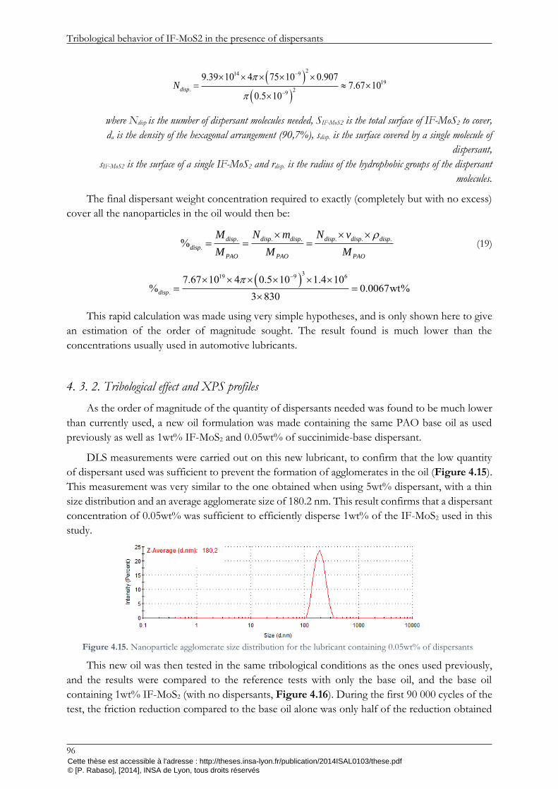
Tribological behavior of IF-MoS2 in the presence of dispersants
96
214 919
. 29
9.39 10 4 75 10 0.9077.67 10
0.5 10dispN
where Ndisp is the number of dispersant molecules needed, SIF-MoS2 is the total surface of IF-MoS2 to cover,
da is the density of the hexagonal arrangement (90,7%), sdisp. is the surface covered by a single molecule of
dispersant,
sIF-MoS2 is the surface of a single IF-MoS2 and rdisp. is the radius of the hydrophobic groups of the dispersant
molecules.
The final dispersant weight concentration required to exactly (completely but with no excess)
cover all the nanoparticles in the oil would then be:
. . . . . .
.% disp disp disp disp disp disp
disp
PAO PAO PAO
M N m N v
M M M
(19)
319 9 6
.
7.67 10 4 0.5 10 1.4 10% 0.0067wt%
3 830disp
This rapid calculation was made using very simple hypotheses, and is only shown here to give
an estimation of the order of magnitude sought. The result found is much lower than the
concentrations usually used in automotive lubricants.
4. 3. 2. Tribological effect and XPS profiles
As the order of magnitude of the quantity of dispersants needed was found to be much lower
than currently used, a new oil formulation was made containing the same PAO base oil as used
previously as well as 1wt% IF-MoS2 and 0.05wt% of succinimide-base dispersant.
DLS measurements were carried out on this new lubricant, to confirm that the low quantity
of dispersant used was sufficient to prevent the formation of agglomerates in the oil (Figure 4.15).
This measurement was very similar to the one obtained when using 5wt% dispersant, with a thin
size distribution and an average agglomerate size of 180.2 nm. This result confirms that a dispersant
concentration of 0.05wt% was sufficient to efficiently disperse 1wt% of the IF-MoS2 used in this
study.
This new oil was then tested in the same tribological conditions as the ones used previously,
and the results were compared to the reference tests with only the base oil, and the base oil
containing 1wt% IF-MoS2 (with no dispersants, Figure 4.16). During the first 90 000 cycles of the
test, the friction reduction compared to the base oil alone was only half of the reduction obtained
Figure 4.15. Nanoparticle agglomerate size distribution for the lubricant containing 0.05wt% of dispersants
Cette thèse est accessible à l'adresse : http://theses.insa-lyon.fr/publication/2014ISAL0103/these.pdf © [P. Rabaso], [2014], INSA de Lyon, tous droits réservés

Finding the balance between nanoparticle dispersion and performance
97
for the nanoparticle-doped oil with no dispersant, with a friction coefficient averaging 0.13. After
90 000 cycles, the friction coefficient suddenly dropped and stabilized to approximately 0.06, which
is close to the maximum friction reduction obtained in the absence of dispersants. Additional
testing showed that this behavior was repeatable, although the number of cycles achieved until the
drop in friction may vary.
The NTR was used to visualize the contact when lubricated with this oil, in the same
conditions as used previously (Table 4.1). After the first 500 cycles (column on the left), the results
were similar to those obtained in the presence of 5% dispersant: the particles were seen passing
through the contact, but did not seem to form a thick film on the steel surface of the ball (Figure
4.17). The test was then continued for an extra 1500 cycles (column on the right).
Substantial film adhesion then started taking place between 750 and 1000 cycles, and the ball
surface then resembled the one obtained during the test without dispersants, with a seemingly thick
film progressively covering most of the contact area. This behavior is consistent with the one
observed for the HFRR friction test (Figure 4.16): the presence of the dispersant in the oil, even
in low concentrations, appears to prevent the adhesion of the MoS2 film on the surface during a
given number of cycles. A sudden change then occurs, and the MoS2 platelets released by the IF-
MoS2 are suddenly able to form an efficient friction-reducing tribofilm on the contacting surfaces.
This behavior may be due to a small excess in dispersants remaining in this new oil formulation,
which could prevent tribofilm formation at the beginning of the test by adsorbing on the steel
surface and/or by enveloping the MoS2 platelets released from the nanoparticles. These residual
dispersant molecules may have been consumed after a consequent number of cycles, by the wear
of the surfaces and/or after having dispersed the many wear debris and MoS2 platelets released in
the contact. From this moment onwards, the absence of free dispersant molecules in the oil seems
to permit tribofilm formation, even though - in this scenario - the nanoparticles entering the contact
would still be likely to be covered in dispersant molecules.
To verify the proper dispersion of the IF-MoS2 nanoparticles when this maximum friction was
achieved in the presence of dispersants, a final DLS measurement was carried out on an oil sample
containing 1wt% IF-MoS2 and 0.05wt% dispersant, collected at the end of the HFRR test shown
on Figure 4.16. The results were very similar to those obtained before the test, with an average
Figure 4.16. Tribological performance of the IF-MoS2-doped base oil containing 0.05 wt% of dispersants
Cette thèse est accessible à l'adresse : http://theses.insa-lyon.fr/publication/2014ISAL0103/these.pdf © [P. Rabaso], [2014], INSA de Lyon, tous droits réservés

Tribological behavior of IF-MoS2 in the presence of dispersants
98
size of 181.5 nm (Figure 4.18). This measurement confirms that a balance between friction
reduction and presence of dispersants was found, although it could only be achieved after a
“running-in” period which may have consumed all the excess dispersant found in the oil.
cycle 1500
cycle 0
cycle 1000
cycle 750
cycle 100
cycle 200 cycle 1250
cycle 300
cycle 400 cycle 1750
cycle 2000 cycle 500
Figure 4.17. Nanovisu test for the PAO base oil containing 1wt% IF-MoS2 and 0.05wt% dispersants
Cette thèse est accessible à l'adresse : http://theses.insa-lyon.fr/publication/2014ISAL0103/these.pdf © [P. Rabaso], [2014], INSA de Lyon, tous droits réservés

Conclusions
99
4. 4. Conclusions
In this chapter, Inorganic Fullerene-like (IF-)MoS2 nanoparticles were added to a fully
formulated commercial lubricant in an attempt to reduce friction in severe boundary lubrication
regimes. This addition had no effect on the behavior of the oil, even though the nanoparticles used
exhibited outstanding friction and wear reduction capacities when used with a PAO base oil alone.
The excess in dispersants used in the commercial oil to prevent the agglomeration of particle
contaminants was found to be - at least partly - responsible for the lack of effectiveness of the IF-
MoS2.
When dispersants are present in the oil, XPS analysis revealed identical extreme surface
compositions whether or not nanoparticles were added to the oil, implying that the lubrication
mechanism leading to the formation of a low-friction tribofilm on the surfaces did not take place.
This lubrication mechanism is a three-step process, all of which may be affected by the presence
of dispersants in the nanoparticle-doped oil:
Step 1. The nanoparticles enter the contact;
Step 2. The nanoparticles exfoliate under the combined pressure and shear of the opposing
surfaces;
Step 3. The newly formed MoS2 platelets react with the surface to form a low-friction and
wear-reducing tribofilm.
Real-time observations of the contact revealed the passing of nanoparticles in the contact,
confirming that the reduced size and inertia of the particle agglomerates did not prevent them from
reaching the contact entry nor from being entrapped by the surfaces. HR-TEM observations of
nanoparticles collected on the wear scar at the end of friction tests showed many damaged and
exfoliated nanoparticles, as well as released MoS2 platelets, which seemed to be trapped in a coating
possibly made of dispersant molecules. From these results, the presence of dispersants in the oil
was found not to affect the steps 1 & 2 mentioned above, implying that well-dispersed
nanoparticles could also provide important friction reduction. The presence of succinimide-based
dispersants rather seemed to prevent the tribo-chemical reactions between the nanoparticles and
the surfaces from taking place, leading to the absence of tribofilm adhesion. This may be due to an
excessive adsorption of the dispersant on the contact surfaces, and/or to the full covering of the
liberated MoS2 in dispersant molecules.
A much lower concentration of dispersants than currently used in common commercial
lubricants was found to correctly disperse the nanoparticles in the oil, while also permitting
Figure 4.18. Nanoparticle agglomerate size distribution at the end of the tribological test (PAO base oil containing 1wt% IF-MoS2 and 5wt% dispersants)
Cette thèse est accessible à l'adresse : http://theses.insa-lyon.fr/publication/2014ISAL0103/these.pdf © [P. Rabaso], [2014], INSA de Lyon, tous droits réservés

Tribological behavior of IF-MoS2 in the presence of dispersants
100
significant friction reduction after the completion of the first 90 000 cycles. Contact observations
confirmed that the MoS2 only started adhering to the surface after a running-in period. The
potential excess in dispersants present in the oil at the beginning of the test may have been
consumed during the first part of the test, by encapsulating the wear debris and the numerous
platelets of MoS2 liberated by the exfoliation of the nanoparticles, and/or by the progressive
wearing off of the steel surface on which they adsorb.
These results are promising in terms of finding the right balance between nanoparticle
dispersion and optimal friction reduction, but seem to imply that a very precise dosing of the
dispersant molecules is necessary in order to fully disperse the nanoparticles while leaving no excess
in dispersants in the oil.
Cette thèse est accessible à l'adresse : http://theses.insa-lyon.fr/publication/2014ISAL0103/these.pdf © [P. Rabaso], [2014], INSA de Lyon, tous droits réservés

101
Chapter Five
5) Aiming for automotive applications
Cette thèse est accessible à l'adresse : http://theses.insa-lyon.fr/publication/2014ISAL0103/these.pdf © [P. Rabaso], [2014], INSA de Lyon, tous droits réservés

102
Part of the difficulty in creating a fully-formulated lubricant containing nanoparticle additives has been
shown in the previous section. Achieving this goal will however be vain if the performance of such lubricants does not
meet expectations in complex mechanical systems. This chapter focuses on particular aspects linked to the use of IF-
MoS2 in real-life applications: their behavior under a variety of conditions was studied, such as ambient temperatures
and different lubrication regimes. Component-orientated benefits were also investigated, by testing their friction and
wear reducing potential for rough surfaces and their influence on Rolling Contact Fatigue.
Cette thèse est accessible à l'adresse : http://theses.insa-lyon.fr/publication/2014ISAL0103/these.pdf © [P. Rabaso], [2014], INSA de Lyon, tous droits réservés

Introduction
103
5. 1. Introduction
The ultimate objective in the development of nanoparticle-doped lubricants is to be able to
use them efficiently in real-life applications, such as automotive engines and/or gearboxes. The
exceptional tribological properties of IF-MoS2 nanoparticles when added to different base oils were
detailed in the literature, as synthesized in Chapter One. The work presented in Chapter Three
confirmed this potential and showed that nanoparticle size and agglomeration were not necessarily
an issue if proper oil recirculation was ensured, as friction and wear reduction were maintained for
a significant number of cycles.
In order to industrialize the use of nanoparticles, many challenges remain to be faced. The
results presented in Chapter Four highlight the incompatibility of IF-MoS2 with excessive
amounts of succinimide-based dispersants, although the dispersion of the nanoparticles in itself
does not seem to be the cause of their lack of effectiveness in oils containing dispersants. The main
difficulty in formulating commercial lubricants containing nanoparticles may therefore reside in
finding dispersing agents capable of dispersing both the nanoparticles and particle contaminants,
while not interfering with tribofilm formation.
This step will however be of limited interest if nanoparticle-doped lubricants are finally found
to be inefficient – or even detrimental – in complex mechanical systems. The aim of this chapter
is to provide an insight on the potential of IF-MoS2 nanoparticles in various scenarios met in
automotive engines and/or gearboxes. The lubrication regimes encountered for different
components will first of all be explored so as to establish the behavior of IF-MoS2 nanoparticles
for contact conditions less severe than boundary lubrication. The effects of nanoparticle-doped
lubricants on rough contacts will then be studied, given the rarity of perfectly smooth surfaces in
mass-produced vehicles. A final series of tests will then be carried out to investigate the possible
influence of IF-MoS2 on crack initiation and propagation, which is of particular interest in the case
of high-cycle components prone to fatigue such as gears.
5. 2. Exploring the different lubrication regimes
5. 2. 1. Boundary lubrication: Influence of temperature
All tribological tests presented in this work so far were carried out at 80°C, which is a typical
operating temperature for automotive contacts. Additives must however be active for a wide range
of temperatures in order to ensure the effectiveness of the lubricant at all times. The first few miles
of every trip are for example particularly critical for motorized vehicles, as the oil requires some
time to reach its optimal temperature. The adhesion and composition of tribofilms formed by many
current boundary additives indeed depend on temperature, and are generally less efficient under
ambient temperature.
Because of their lubricating mechanism, Inorganic Fullerene-like nanoparticles are thought to
be equally active regardless of temperature. The formation of protective and low-shear strength
tribofilms depends solely on the exfoliation of the nanoparticles, which is a mechanical process
induced by the combined effects of shear and normal pressure of the contacting surfaces. To verify
this, the HFRR tests carried out in section 3. 3. (Tribological testing of the IF-MoS2
Cette thèse est accessible à l'adresse : http://theses.insa-lyon.fr/publication/2014ISAL0103/these.pdf © [P. Rabaso], [2014], INSA de Lyon, tous droits réservés

Aiming for automotive applications
104
nanoparticles) on the LC and SpC IF-MoS2 (Table 3.1, p.54) were repeated under a temperature
of 30°C (complete test conditions given in Table 3.3, p.58).
The friction coefficients obtained during the four hour tests (144 000 cycles) are showed on
Figure 5.1. For both types of nanoparticles, the addition of 1 wt% of IF-MoS2 in the PAO base
oil only provided a slight decrease in friction during the test. The change in viscosity induced by
this lower temperature (from 14.8 cSt at 80°C to 83.3 cSt at 30°C) however reduced the severity of
the test by creating better surface separation, as attested by the lower friction coefficient obtained
with the PAO base oil alone (from 0.20 at 80°C to 0.13 at 30°C on average). The reduced
effectiveness of the nanoparticles under ambient temperature may therefore simply be due to the
milder contact conditions (as in 3. 3. 2, where the velocity of the ball was increased) rather than to
their inability to form a tribofilm on the surfaces. This assumption was partly confirmed by the
significant reduction of the wear occurring when IF-MoS2 were added to the PAO (Figure 5.2).
XPS analyses were carried out on the wear surfaces in order to verify the capacity of the IF-
MoS2 to form tribofilms on the surfaces at ambient temperature (Figure 5.3). Main Mo 3d5/2 and
S 2p3/2 energy peaks corresponding to Mo – S species were found at 229.3 eV and 161.1 eV
respectively, revealing the presence of an MoS2 tribofilm on the surface. The composition of the
surface of this tribofilm was however somewhat different than after the tests carried out at 80°C
(3. 3. 3. Tribofilm analysis, p.67), with more intense energy peaks found for the Mo – O and S –
O species (Mo 3d5/2 at 232.6 eV and S 2p3/2 at 168.8 eV respectively). This could imply that either
the test temperature or the milder contact conditions were sufficient to form a protective
intermediate tribofilm layer (such as the one visible on the FIB cross-sections on p.72), but not
Figure 5.1. HFRR testing of the LC and SpC IF-MoS2 under ambient temperature
Figure 5.2. Comparison of the wear scars obtained for the PAO base oil alone (left), the PAO+1wt% SpC IF-MoS2 (center) and the PAO+1wt% LC IF-MoS2 (right)
Cette thèse est accessible à l'adresse : http://theses.insa-lyon.fr/publication/2014ISAL0103/these.pdf © [P. Rabaso], [2014], INSA de Lyon, tous droits réservés

Exploring the different lubrication regimes
105
severe enough to induce an effective adhesion of parallel MoS2 nano-sheets (providing low friction)
on top of this intermediate layer.
This was confirmed by comparing the XPS profiles carried out on the wear scar for the PAO
+ 1wt% SpC IF-MoS2 tested at 80°C (Figure 4.10, p. 90) with profiles acquired on the wear scar
for the same blend tested at 30°C (Figure 5.4).
The intensity of the Mo 3d profile was found to be much closer to that of the O 1s profile in
the early stages of the sputtering, indicating a more oxidized tribofilm. Although the precise
thicknesses of the tribofilms are difficult to estimate from these analyses given their thinness and
the approximate precision of the sputter rate, the tribofilm formed at 30°C seemed thinner due to
a more rapid decrease of the intensity of the Mo 3d profile relative to Fe 2p3 in the same etching
conditions. Sulfur, which presented a low profile intensity even in the case of a thick, homogeneous
tribofilm at 80°C was not detected during the measurement of the profiles for the test carried out
at 30°C.
These results indicate that the tribofilm formed under ambient temperature (all other test
conditions being identical) was thinner than the one formed at 80°C, and contained more oxide
species. This is in accordance with the tribofilm formation of MoDTC, as reported in the literature
[17].
To verify the influence of temperature on the tribofilm-forming capacity of IF-MoS2
nanoparticles regardless of viscosity, extra HFRR tests were carried out with two different PAO
base oils. The first one was the PAO 4 and PAO 40 blend used in this study so far (9.3 cSt at 100°C
and 54.0 cSt at 40°C), and the other was a PAO 2 (theoretical viscosity of 1.7 cSt at 100°C and 5.1
Figure 5.3. Mo 3d (left) and S 2p (right) energy peaks found after XPS analysis on the wear scar after HFRR testing for the PAO+1wt% SpC IF-MoS2 blend at ambient temperature
Figure 5.4. Ion etching profiles by XPS of the wear surfaces resulting from the testing of the PAO + 1wt% SpC IF-MoS2 at 30°C (left) and 80°C (right)
Cette thèse est accessible à l'adresse : http://theses.insa-lyon.fr/publication/2014ISAL0103/these.pdf © [P. Rabaso], [2014], INSA de Lyon, tous droits réservés

Aiming for automotive applications
106
cSt at 40°C). Both base oils were then tested on the HFRR in the same conditions as previously
except for the temperature (117°C and 30°C for the PAO 4/40 and PAO 2 respectively), leading
to an identical theoretical viscosity of 6.7 cSt for both oils. Given this very low viscosity, both base
oils produced very high friction coefficient when tested alone. The addition of 1 wt% SpC IF-MoS2
produced significant friction reduction in both cases, with friction coefficients dropping from
approximately 0.355 (base oil alone) to 0.075 (with the IF-MoS2) at the end of the test (Figure 5.5).
Wear reduction was also substantial in both cases, confirming the potential of IF-MoS2
nanoparticles at ambient temperature for severe boundary lubrication regimes (Figure 5.6).
Although the friction coefficients for both base oils containing 1 wt% IF-MoS2 were fairly
similar at the end of each test, the friction reduction was slightly greater for the PAO4/40 tested
at 117°C throughout the test (0.07 instead of 0.085 on average). This could be due to a slight
difference in viscosity between both oils at the chosen temperatures or to thermal effects unrelated
to the use of the nanoparticles, as the PAO 2 also produced a slightly higher friction coefficient
than the PAO 4/40 throughout the test when tested alone. A precise measurement of the
Figure 5.5. HFRR testing of PAO 2 at 30°C (blue) and PAO 4/40 at 117°C (red) with and without 1 wt% SpC IF-MoS2
Figure 5.6. Maximum depth and worn volume of the wear scars after the HFRR tests shown on Figure 5.5
Cette thèse est accessible à l'adresse : http://theses.insa-lyon.fr/publication/2014ISAL0103/these.pdf © [P. Rabaso], [2014], INSA de Lyon, tous droits réservés

Exploring the different lubrication regimes
107
viscosities of these base oils at 30°C (for the PAO 2) and 117°C (for the PAO 4/40) would be
needed to confirm this hypothesis. The test temperature may also have had an influence on the
composition of the tribofilm, modifying its tribological properties. To verify this, XPS analyses
were carried out on the two wear scars resulting from the testing of the PAO 2 and the PAO 4/40
with 1 wt% IF-MoS2. The main Mo 3d and S 2p spectra for both measurements are shown on
Figure 5.7. Both tribofilms showed similar compositions, with high-intensity Mo – S energy peaks
revealing MoS2 tribofilms similar to those formed at 80°C with the PAO 4/40 base oil used
throughout this work (showed in 3. 3. 3).
These analyses show that IF-MoS2 are effective in forming friction-reducing MoS2 tribofilms
regardless of temperature, as long as the contact undergoes severe boundary lubrication. This
characteristic is a significant advantage over most friction-reducing additives, which require thermal
activation to be fully effective. The test carried out at 30°C with the PAO 4/40 base oil however
revealed that tribofilm formation is altered when surface separation is increased, reducing the
tribological potential of IF-MoS2-doped base oils. The objective of the next section is to estimate
whether or not these additives can be beneficial under milder contact conditions.
5. 2. 2. Mixed lubrication: behavior in rolling-sliding conditions
All the tribological tests presented in this study so far were carried out in pure-sliding
conditions with a high contact pressure, leading to severe boundary lubrication. If the friction and
wear reducing properties of IF-MoS2 nanoparticles were already known in these conditions, their
behavior in milder contact conditions and when partial rolling takes place in the contact is vital
prior to their use in automotive lubricants.
In order to cover a wide range of operating conditions, a series of Stribeck curves were plotted
for different Slide-to-Roll Ratios (SRRs) on the Mini-Traction Machine (MTM). The lubricant
consisted of the same PAO4/40 base oil as for the rest of this work, with and without 1 wt% of
LC IF-MoS2 (Table 3.1, p.54). Both specimens used (ball and disc) were smooth, with measured
Rq roughness parameters between 1 and 4 nm on the disc.
Figure 5.7. Mo 3d (left) and S 2p (right) spectra measured on the wear scars of the PAO2+IF-MoS2 test carried out at 30°C (top) and the PAO4/40+IF-MoS2 test carried out at 117°C (bottom)
Cette thèse est accessible à l'adresse : http://theses.insa-lyon.fr/publication/2014ISAL0103/these.pdf © [P. Rabaso], [2014], INSA de Lyon, tous droits réservés

Aiming for automotive applications
108
For the testing of the PAO base oil alone, two Stribeck curves (rolling velocity decreasing
from 2 m.s-1 to 0.02 m.s-1 to delay surface alteration at low velocities) were plotted. A running-in
period of 30 minutes was carried out between the two Stribeck curves, at minimum rolling velocity
(0.02 m.s-1) and with the same SRR than for the rest of the test. When in the presence of IF-MoS2
nanoparticles, the first step (initial Stribeck curve) was skipped in order to avoid centrifugation of
the IF-MoS2 at high velocities which would modify the feeding of the contact in IF-MoS2 for the
rest of the test. The final Stribeck curve was plotted for increasing velocities from 0.02 m.s-1 to 2
m.s-1 for the same reason.
A temperature of 80°C and a contact pressure of 1.4 GPa (load of 45 N) were chosen for all
the tests, as these conditions are representative of automotive applications and similar to those
used for the HFRR tests reported throughout this work. The theoretical central film thickness (see
Appendix B) is identical for all SRRs and varies from approximately 0.12 µm to 5 nm for rolling
velocities ranging from 2 m.s-1 to 0.02 m.s-1. Considering the initial surface roughness, these
conditions lead to film thickness ratios varying from λ=28 to λ=1. A transition between the full-
film and mixed lubrication regime should therefore take place during these tests.
Step Description Temperature
(°C) Contact Pressure
(GPa) Rolling Velocity
(m.s-1) SRR (%)
Duration (min)
1 * Stribeck curve
80 1.4 2 > VR > 0.02 x ** -
2 Running-in 0.02 x ** 30 3 Stribeck curve 2 > VR > 0.02 x ** -
* this step was skipped for the testing of the PAO containing the IF-MoS2 * * these steps were repeated for SRRs of 10, 20, 30, 40 and 50%
Table 5.1. MTM test procedure for the evaluation of the potential of IF-MoS2 nanoparticles in mixed lubrication
The five Stribeck curves obtained for the different SRRs (ranging from 10 to 50%) can be
plotted as a surface, representing the friction coefficient as a function of the rolling velocity and
the SRR. The resulting maps are shown on Figure 5.8.
Typical surface topographies and surface profiles obtained at the end of the tests for low (10%)
and high (50%) SRRs are furthermore shown on Figure 5.9 to account for the wear suffered by
the discs during these tests. The Rq roughness parameter was determined for these profiles, taking
into account only the width of the wear scar.
At the beginning of the test, the PAO produced very typical Stribeck curves (Figure 5.8(a)):
the friction coefficient decreased steadily for rolling velocities ranging from 2.0 m.s-1 to
approximately 0.3 m.s-1 (full-film lubrication), before rising abruptly for lower velocities (mixed
lubrication). The transition between these two regimes appeared at slightly higher velocities for
higher SRRs, most probably due to film thinning caused by local thermal effects and/or to an
increased deterioration of the surface roughness. The friction coefficient was higher for the higher
SRRs over the whole range of velocities covered, due to the increased shearing of the oil film in
the HD regime and of the surfaces in mixed lubrication.
After the running period with the base oil alone (Figure 5.8(b)), the friction coefficients were
very similar to the initial measurements in the full-film lubrication regime. The wear of the surfaces
(Figure 5.9 (A1) and (A2)) may indeed have induced slight changes in the contact pressure, but
the contact conditions were otherwise identical. The friction coefficients recorded in the mixed
lubrication regime were however somewhat larger than before running-in for the higher SRRs. This
Cette thèse est accessible à l'adresse : http://theses.insa-lyon.fr/publication/2014ISAL0103/these.pdf © [P. Rabaso], [2014], INSA de Lyon, tous droits réservés

Exploring the different lubrication regimes
109
can be explained by a larger damaging of the wear surfaces under high slip, revealed by the deeper
and, more importantly, rougher grooves than for low SRRs. At 50% SRR for instance, the
roughness (Rq parameter) of the surface was indeed increased by ten, with a final roughness of the
wear scar of approximately 50 nm.
In the presence of 1 wt% of IF-MoS2 nanoparticles, the final Stribeck curves revealed a
behavior identical to the initial curve for the PAO in the full-film lubrication regime. Friction
coefficients were however greatly reduced in the mixed lubrication regime, with final values
comprised between 0.045 and 0.065 for all SRRs. This result implies that the IF-MoS2 were
successful in forming an effective tribofilm on the surfaces, even under milder contact conditions
with as little as 10% SRR. Once formed, this tribofilm provided greater friction reduction for the
higher Slide-to-Roll Ratios. For the minimum rolling velocity tested (0.02 m.s-1), the reduction was
of 16% (from 0.057 to 0.048) at 10% SRR and 46% (from 0.117 to 0.063) at 50% SRR compared
to the initial set of Stribeck curves (measured before running-in). This is furthermore consistent
with the results obtained on the HFRR with an identical mean velocity but pure sliding (200 %
SRR), where the order of magnitude of the friction reduction approached 70% (from 0.2 to 0.06).
The maximum friction coefficients obtained for the higher SRRs (40% and 50%) were nearly
identical, with values of 0.064 and 0.063 respectively. This friction coefficient is very close to the
one obtained for pure sliding on the HFRR, which would suggest that MoS2 tribofilms resulting
from the use of IF-MoS2 nanoparticles provide a limit to the friction coefficient achievable for a
given set of operating conditions, regardless of the amount of shear in the contact. This limit seems
(a) (b)
(c)
Figure 5.8. Mapping of the Stribeck curves depicting the influence of IF-MoS2 on friction in mixed lubrication (a) PAO alone before running-in; (b) PAO alone after running-in;
(c) PAO + IF-MoS2 after running-in
Cette thèse est accessible à l'adresse : http://theses.insa-lyon.fr/publication/2014ISAL0103/these.pdf © [P. Rabaso], [2014], INSA de Lyon, tous droits réservés

Aiming for automotive applications
110
to be obtained for SRRs as low as 40%, over which friction remains constant as long as the tribofilm
is unharmed.
The presence of IF-MoS2 nanoparticles also provided great wear reduction, as the surfaces
were mostly undamaged at the end of the tests for all SRRs tested. The wear scars exhibited a
single, shallow groove to the most (the images shown on Figure 5.9(B1) and (B2) picture the most
damaged zones of their respective wear scars). The average surface roughness Rq was furthermore
only slightly altered for the higher SRRs (8 nm for 50% SRR, measured outside the groove) and
unscathed for lower Slide-to-Roll ratios.
For the operating conditions tested in this section, the use of IF-MoS2 proved beneficial in the
mixed lubrication regime and did not affect the behavior of the oil in full-film lubrication. There is
however a true risk of contact starvation, and therefore of a drastic increase in friction and wear,
linked to the presence of particles in the oil (see part 1. 2. 4, p. 33). Extra tests covering a wider
range of contact conditions were carried out in the next section in order to further investigate this
risk.
5. 2. 3. Full-film lubrication and associated risks
The presence of particles (soot, wear debris, external contaminants…) in engine or gearbox
lubricant may lead to contact starvation and premature wear, as described in 1. 2. 4. Particle
contamination of lubricants and associated risks. Although the nanoparticles studied in this
(A1) (A2)
(B2) (B1)
Figure 5.9. Typical surface topographies and profiles obtained at 10% (1) and 50% (2) SRR for the PAO alone (A) and the PAO + IF-MoS2 (B). Rq values were determined taking into account only the wear scar.
Cette thèse est accessible à l'adresse : http://theses.insa-lyon.fr/publication/2014ISAL0103/these.pdf © [P. Rabaso], [2014], INSA de Lyon, tous droits réservés

Exploring the different lubrication regimes
111
work are significantly smaller than most particle contaminants found in lubricants, their relatively
high concentration in the oil and their tendency to agglomerate (when used without dispersants)
constitutes a real risk for the surfaces. Despite providing great friction and wear reduction in
boundary lubrication regimes, they would not be viable additives if they were to generate wear and
power losses in milder contact conditions.
In order to investigate the risks linked to the use of nanoparticle in full-film lubrication
regimes, a series of MTM tests were carried out for a variety of operating conditions. All tests were
carried out with the PAO base oil alone, and repeated for the PAO + 1 wt% IF-MoS2 (LC type,
averaging 350 nm in diameter). The specimens had smooth surfaces during all tests.
Traction (varying SRR) and Stribeck (varying rolling velocity) curves were plotted for different
temperatures (30°C and 80°C), contact pressures (0.73, 1.01 and 1.53 GPa), rolling velocities
(traction curves measured at 0.2 and 1 m.s-1) and Slide-to-Roll Ratios (Stribeck curves measured at
10% and 20% SRR). All traction curves had an SRR varying from 0% to 30%, while the rolling
velocity ranged from 0.2 m.s1 to 2 m.s-1 for the Stribeck curves. These operating conditions led to
a wide spectrum of film thicknesses, as reported in Table 5.2. The smallest theoretical central film
thickness during these tests was 25 nm (for 1.53 GPa, 0.2 m.s-1 and 80°C), resulting in a film
thickness ratio λ of 3.5 (assuming a surface roughness Rq=5 nm) and a surface separation
approximately 14 times smaller than the diameter of the nanoparticles. The largest central film
thickness was 550 nm (0.73 GPa, 2 m.s-1 and 30°C), which is larger than individual nanoparticles
and ensures a λ ratio over 75.
Temperature 30°C 80°C
Rolling velocity 0.2 m.s-1 2 m.s-1 0.2 m.s-1 2 m.s-1
Contact pressure
0.73 GPa 118 nm 550 nm 29 nm 136 nm
1.01 GPa 110 nm 515 nm 27 nm 127 nm
1.53 GPa 101 nm 474 nm 25 nm 117 nm
Table 5.2. Theoretical central film thicknesses (Dowson-Higginson) for the different operating conditions used
In the absence of IF-MoS2 nanoparticles (dotted lines on Figure 5.10), the traction curves
exhibited a very typical behavior. Increasing contact pressures lead to higher friction coefficients
for all conditions tested. The reduction of the oil viscosity due to a higher lubricant temperature
led to a drop in friction, as the viscous friction of the thinner oil film decreased. At 30°C, an
increase of the rolling velocity from 0.2 m.s-1 to 1 m.s-1 led to a slight increase in friction as the oil
film was thicker. At 80°C, however, the lower friction obtained at 1 m.s-1 suggested that mixed
lubrication was reached for a rolling velocity of 0.2 m.s-1. This was confirmed by the Stribeck curves
plotted in these conditions (Figure 5.11). At high temperature, a rise in friction was indeed
observed under approximately 1 m.s-1 for both contact pressures and SRRs tested, attesting of the
transition from the full-film to the mixed lubrication regime. All Stribeck curves plotted for the
PAO base oil alone also showed a very foreseeable behavior, with higher friction coefficients
measured for higher SRRs and for the thicker oil films induced by lower temperatures or higher
rolling velocities.
The presence of 1 wt% IF-MoS2 in the base oil had little to no effect on the friction coefficient,
as plotted in full lines on Figure 5.10 and Figure 5.11. Identical traction and Stribeck curves were
obtained under all contact conditions under 30°C and for most measurements points under 80°C.
A slight increase in friction was noticed for the higher SRRs under thin film conditions (rolling
Cette thèse est accessible à l'adresse : http://theses.insa-lyon.fr/publication/2014ISAL0103/these.pdf © [P. Rabaso], [2014], INSA de Lyon, tous droits réservés

Aiming for automotive applications
112
velocity of 0.2 m.s-1). No wear was recorded on the discs after the testing of both blends, although
the surface roughness was slightly altered by the transition in the mixed lubrication regime (Rq
averaging 10 nm in the wear scar).
From these tests, IF-MoS2 appear to be harmless in full-film lubrication regimes. Further
testing for broader contact conditions and/or numerical simulations would be needed to extend
this claim. Specific attention should furthermore be given to the case of very thin films with high
Figure 5.11. Stribeck curves in full-film lubrication conditions: PAO base oil (dotted lines) and PAO + IF-MoS2 (full lines), tests at 30°C (blue, left) and 80°C (yellow/red, right), 10% SRR (top) and 20% SRR (bottom)
Figure 5.10. Traction curves in full-film lubrication conditions: PAO base oil (dotted lines) and PAO + IF-MoS2 (full lines), tests at 30°C (blue, left) and 80°C (yellow/red, right), 0.2 m.s-1 (top) and 2 m.s-1 (bottom)
Cette thèse est accessible à l'adresse : http://theses.insa-lyon.fr/publication/2014ISAL0103/these.pdf © [P. Rabaso], [2014], INSA de Lyon, tous droits réservés

Real-life applications
113
Slide-to-Roll ratios, as it appeared to be more at risk with a slight raise in friction during these tests.
Endurance tests could for example be performed, by maintaining stable conditions for an extended
duration to verify that nanoparticle agglomeration at contact entry does not appear in time. This
type of test could however prove difficult to perform on an MTM as the rotation of the disc may
induce centrifugal effects on the IF-MoS2 and their potential agglomerates, leading them away from
the contact.
While particle agglomeration at contact entry leads to oil starvation in the case of contaminants
such as soot and wear debris, the resulting effect might not be as detrimental in the case of IF-
MoS2. The results showed in the previous section (5. 2. 2. Mixed lubrication: behavior in rolling-
sliding conditions) indeed show that tribofilm formation can also occur in the case of severe
rolling/sliding conditions. Oil starvation due to the agglomeration of IF-MoS2 at contact entry in
full-film lubrication regimes may therefore lead to nanoparticle entrapment and exfoliation. In the
case where the use of nanoparticles would be found to induce oil starvation in a number of engine
or gearbox contacts, their use might therefore not be abandoned altogether.
5. 3. Real-life applications
5. 3. 1. Rough surfaces
Surfaces as smooth as those studied in this work so far are rare in real-life applications.
Although they may be found in specific components such as bearings, many surfaces operating in
severe lubrication regimes (where the use of IF-MoS2 might hold an interest) have a non-negligible
roughness. In order to investigate the performance of nanoparticle-doped lubricants in these
conditions, a series of tests was carried out on the MTM with rough discs using the same operating
conditions as presented in part 5. 2. 2 (Table 5.1, p. 107). The initial surface roughness of the discs
is showed on Figure 5.12. All discs had an Rq roughness parameter between 0.11 and 0.15 µm,
with an average of 0.13. Considering a surface roughness of Rq = 5 nm for the (smooth) ball, the
chosen operating conditions lead to a maximum lambda ratio of 1, which was its lowest value in
the presence of smooth surfaces (part 5. 2. 2). The initial surface roughness should therefore lead
Figure 5.12. Surface topography and profile for rough MTM discs
Cette thèse est accessible à l'adresse : http://theses.insa-lyon.fr/publication/2014ISAL0103/these.pdf © [P. Rabaso], [2014], INSA de Lyon, tous droits réservés

Aiming for automotive applications
114
to mixed/boundary lubrication during the measurements of the first Stribeck curves (before
running-in).
This was confirmed during the testing of the PAO base oil alone, as reported on Figure
5.13(a). The friction coefficient measured for all SRRs at the beginning of the test was much higher
than for smooth surfaces (Figure 5.8(a)) for all the conditions tested, and barely reached values
smaller than 0.1 for the highest velocities. At low SRR, the friction coefficient increased
progressively as the lubrication regime became more severe for lower rolling velocities. The friction
coefficient did not change noticeably for decreasing velocities until approximately 0.5 m.s-1 for the
higher SRRs (40% and 50%), which may be due to a progressive decrease in surface roughness due
to wear during the first stages of the test. Under 0.5 m.s-1, the thinning of the oil film led to drastic
increases in friction for all SRRs. The highest friction coefficients were obtained at the lowest
velocity for all tests (0.02 m.s-1) and had similar values (0.15 - 0.16) for SRRs ranging from 20% to
50%. A higher value (0.18) was however recorded for the test carried out at 10%. This could
confirm that more wear took place at higher SRR, resulting in lower film thickness ratios (due to a
reduced surface roughness) and therefore milder contact conditions.
After the running-in period, the friction coefficients for the PAO base alone at high velocities
(over 1.5 m.s-1) were very similar to the measurements carried out for the same test but with smooth
surfaces. Their values were indeed under 0.05, attesting of full-film lubrication. The transition to
mixed lubrication then took place for velocities under 1.5 m.s-1 on average, and the friction
coefficients then increased significantly until reaching their maximum values for the lowest rolling
velocities. These maximum friction coefficients were similar before and after running-in for SRRs
(a) (b)
(c)
Figure 5.13. Mapping of the Stribeck curves depicting the influence of IF-MoS2 in the presence of rough surfaces (a) PAO alone before running-in; (b) PAO alone after running-in; (c) PAO + IF-MoS2 after running-in
Cette thèse est accessible à l'adresse : http://theses.insa-lyon.fr/publication/2014ISAL0103/these.pdf © [P. Rabaso], [2014], INSA de Lyon, tous droits réservés

Real-life applications
115
ranging from 20 to 50%, which suggests that most of the wear took place during the measurement
of the initial Stribeck curve (before running-in). The final maximum friction coefficient at 10%
SRR, on the other hand, was significantly lower than before running-in, implying that the surface
roughness was mostly modified during the running-in period.
The topographies and surface profiles of the final wear scars for the testing of the PAO base
oil alone at 10% and 50% SRR are shown on Figure 5.14(A1) and (A2). A large amount of wear
was observed in both cases, with a much deeper wear track at high SRR. This resulted in the
reduction of the surface roughness inside the track with Rq values of 23 nm and 42 nm for 10%
and 50% SRR respectively. These smoother surfaces are consistent with the final Stribeck curves
(after running-in), which displayed a delayed transition from the full-film to the mixed lubrication
regimes.
After the running-in period, the oil containing 1 wt% IF-MoS2 produced friction coefficients
comparable to the PAO alone at 2 m.s-1. The transition from full-film lubrication to mixed
lubrication however seemed to occur for higher velocities, with friction coefficients increasing for
velocities under 2 m.s-1. This behavior indicates that the surface roughness was reduced during the
running-in, but not as much as for the PAO base oil alone. This was confirmed by the observations
of the wear scars at 10% and 50% SRR (Figure 5.14(B1) and (B2)), which showed barely
distinguishable grooves and Rq parameters of 63 nm inside the contact area.
All Stribeck curves plotted for the PAO+IF-MoS2 had similar trends, with a maximum friction
coefficient measured between 0.08 and 0.2 m.s-1 depending on the SRR. Friction then decreased
Figure 5.14. Typical surface topographies and profiles obtained at 10% (1) and 50% (2) SRR for the PAO alone (A) and the PAO + IF-MoS2 (B). Rq values were determined taking into account only the wear scar.
(A1) (A2)
(B1) (B2)
Cette thèse est accessible à l'adresse : http://theses.insa-lyon.fr/publication/2014ISAL0103/these.pdf © [P. Rabaso], [2014], INSA de Lyon, tous droits réservés

Aiming for automotive applications
116
drastically for lower speeds as severe boundary lubrication was reached. Compared to the initial set
of Stribeck curves plotted for the PAO base oil alone, the friction coefficient measured for the
PAO + IF-MoS2 was lower for all the velocities tested except for a small range located on average
between 0.2 and 0.5 m.s-1. As mentioned previously, this may however be due to a premature
wearing of the surface in the case of the base oil alone, leading to milder contact conditions.
Overall, tribofilm formation seemed to have taken place during the running-in period in the
presence of IF-MoS2, as the surfaces were only slightly altered at the end of test compared to the
PAO base alone. Although this tribofilm proved effective in the most severe contact conditions
tested, friction remained high in the early (least severe) stages of the mixed lubrication regime.
A sketch of the average Stribeck curves obtained for the four series of tests carried out on the
MTM (PAO with and without IF-MoS2 for smooth and rough surfaces) is shown on Figure 5.15.
The behaviors of the initial curves (before running-in) of the tests with the base oil alone are drawn
along with those of the final curves (after running-in) of the tests with the PAO + IF-MoS2, in
order to compare the influence of the MoS2 tribofilm on friction for rough surfaces, as the wear
polished the contact surface during the running-in with the PAO base oil alone. The respective
positions of the red and blue curves (for rough surfaces) are given for a different surface roughness,
as the surface was altered in the case of the PAO + IF-MoS2 (most likely before tribofilm
formation).
Although all the operating conditions and surface roughnesses tested led to tribofilm
formation during the running-in period, the IF-MoS2 proved inefficient in terms of friction
reduction for rough surfaces in the milder mixed lubrication regimes. A sudden change in behavior
occurred for the lower velocities, when they became increasingly effective for the more severe
contact conditions. This threshold may occur at the transition between the mixed and boundary
lubrication regimes, when the thinning of the oil films allows for larger asperity deformation and
more continuous metal-metal contacts (transition 1 on Figure 5.15). In the case of smooth
surfaces, this transition is likely to occur faster for a given set of operating conditions as smaller
asperity deformation is needed, which would explain why immediate friction reduction was
obtained after the transition (2 on Figure 5.15) from the full-film lubrication regime.
For rough surfaces, the IF-MoS2 did not provide friction reduction as important as for the
Figure 5.15. Representative Stribeck curves measured during the four series of tests on the MTM (left) and transitions between the different lubrication regimes (right)
Cette thèse est accessible à l'adresse : http://theses.insa-lyon.fr/publication/2014ISAL0103/these.pdf © [P. Rabaso], [2014], INSA de Lyon, tous droits réservés

Real-life applications
117
smooth surfaces tested previously. This should however be put on the account of excellent anti-
wear properties, which helped to maintain significant surface roughness through a severe running-
in period. Friction reduction was furthermore achieved in the most severe lubrication regime,
which is consistent with the results obtained by Kalin et al [34] in the case of MoS2 nanotubes.
Contrarily to the IF-MoS2, these nanotubes however also provided significant friction reduction in
the mixed lubrication regime. The authors add that MoS2 nanotubes were observed on the surfaces
after testing, which could imply that their geometry favors their retention in the valleys of the
surface roughness. This phenomenon would then be likely to accelerate the transition from the
full-film to the boundary lubrication regime, explaining the different behaviors witnessed for the
IF-MoS2 and the MoS2 nanotubes. Additional testing would however be needed to ascertain this
hypothesis.
5. 3. 2. Potential for components subject to fatigue
Rolling Contact Fatigue (RCF) is a common failure mode for repeatedly loaded components
under high contact pressures, such as roller bearings or gears. Surface deterioration due to RCF is
a three-step process: the cyclic loading first leads to crack initiation, which then propagates until it
reaches the surface. A wear debris is then formed and ejected, forming a crater on the surface.
These craters are alternatively referred to as “spalls”, “pits”, “micropits” or even “flakes” in the
literature, as their definition has not been standardized. The nomenclature used in this work is
(arguably) the most common, and has been proposed among others by Olver [88]:
spalling refers to subsurface-initiated RCF;
pitting refers to surface-initiated RCF;
micropitting refers to the formation of shallow pits.
Subsurface-initiated cracking, leading to the formation of spalls, generally occurs in the
maximum shear stress region. Cracks initiate at material heterogeneities such as porosity or small
non-metallic inclusions (alumina, carbides…) [89]. Spalling is however becoming less of an issue
nowadays, given the continuous improvement of steel cleanliness. Spalls are more commonly
found in bearings, as they are loaded heavily and have relatively smooth surfaces.
The combined effects of surface roughness, repeated loading, and high Slide-to-Roll Ratios,
on the other hand, favor the initiation of cracks at (or near) the surface in the case of gears. If the
propagation of these cracks depends in part on the material properties [90], the lubricant has been
shown to penetrate surface-related cracks [91] and impact their evolution [77]. The typical
inclination of these cracks (20° - 30° depending on the SRR) usually leads to the apparition of
shallow micropits, which may then precipitate the formation of larger and deeper pits [89].
In order to investigate the influence of nanoparticle-doped lubricants on RCF, comparative
tests were carried out for the PAO 4/40 base oil alone and for a blend of the same PAO containing
1 wt% of SpC IF-MoS2. The small IF-MoS2 (average diameter of 150 nm) were chosen to test the
possible influence of nanoparticle penetration inside the cracks. The tests were carried out by
PowerTrib (test described in 2. 2. 4, p.46). They were set to run for 20 hours or to stop before
completion in the case of large pit formation, detected through sudden variations in the acceleration
signal. Although the PAO base oil provided a low friction coefficient (under 0.06) during the test,
Cette thèse est accessible à l'adresse : http://theses.insa-lyon.fr/publication/2014ISAL0103/these.pdf © [P. Rabaso], [2014], INSA de Lyon, tous droits réservés

Aiming for automotive applications
118
the friction reduction when using IF-MoS2 nanoparticles was significant enough to attest of
tribofilm formation (Figure 5.16).
A typical image of the roller surfaces obtained for the PAO base oil alone (left) and the PAO
+ IF-MoS2 (right) is shown on Figure 5.18 for each monitoring step of the tests (2.5h, 5h, 10h,
15h and 20h). During the testing of the PAO alone, crack initiation sites were spotted after the 2.5
first hours and then progressively propagated during the test to finally form large micropits after
20 hours. Other initiation sites appeared throughout the test, and the final surface of the disc
exhibited many micropits around its circumference.
The beginning of the test for the PAO + IF-MoS2 was very similar, with a few crack initiation
sites visible after 2.5 hours. The following monitoring steps however showed no visible evolution
of the surface whatsoever, with no extra initiation sites nor propagation of the existing crack sites.
Although such a site was purposely shown on Figure 5.18, few other sites were visible around the
wear track.
3D images and surface profiles of the final surfaces for each lubricant are shown on Figure
5.17. The evolution of the cracking into a characteristic V-shaped micropit is clearly visible for the
PAO alone, with a depth of approximately 10 µm. The micropit was confirmed to be at a much
earlier stage in the case of the PAO + IF-MoS2, with a reduced area and a maximum depth of 2
µm. The formation of an MoS2 tribofilm on the surface in the early stages of the fatigue test may
have prevented the apparition of new crack initiation sites after the first monitoring steps. A slight
Figure 5.16. Evolution of the friction coefficients during the MPR testing of the
PAO base oil alone (left) and the PAO containing 1 wt% IF-MoS2 (right)
PAO PAO + 1 wt% IF-MoS2
Figure 5.17. 3D topographies and profiles of the surfaces resulting from the MPR testing of the PAO (left) and PAO + 1 wt% IF-MoS2 (right)
Cette thèse est accessible à l'adresse : http://theses.insa-lyon.fr/publication/2014ISAL0103/these.pdf © [P. Rabaso], [2014], INSA de Lyon, tous droits réservés

Real-life applications
119
2.5 h
5 h
10 h
15 h
20 h
Figure 5.18. Typical images observed at each monitoring step of the MPR tests for the PAO base oil alone (left) and the nanoparticle-doped PAO (right)
Cette thèse est accessible à l'adresse : http://theses.insa-lyon.fr/publication/2014ISAL0103/these.pdf © [P. Rabaso], [2014], INSA de Lyon, tous droits réservés

Aiming for automotive applications
120
but sudden decrease in friction was observed at the end of the first 3 hours of the test, which may
correspond to the formation of this tribofilm.
The different stages of the test for the two lubricants were sketched on Figure 5.19 according
to this scenario. For the PAO base oil alone, the cyclic loading led to crack initiation and
propagation, resulting in the formation of the large micropits observed previously. In the presence
of IF-MoS2, the tribofilm is thought to have formed after the initiation of the first few cracks at
(or near) the surface. This tribofilm then seems to have prevented further crack initiation, by
reducing the friction (and therefore shear stresses) between asperities and/or by being less brittle
than steel. The tribofilm could therefore have remained undamaged where cracks would have
initiated through the steel in the same conditions. The formation of this tribofilm over the existing
initiation sites is furthermore likely to have prevented (or at least limited) lubricant seepage inside
the cracks, which is thought to apply high hydraulic pressure on the crack lips and therefore to be
responsible for the mode I propagation of surface-related cracks [77].
Cross-sections of both rollers were extracted with a cutoff wheel and observed by Scanning
Electron Microscopy (SEM). For the specimen lubricated with the PAO alone, the many micropits
found showed extensive crack propagation and branching (Figure 5.21). Cracks as long as 30 µm
were found under the surface, suggesting that propagation was an ongoing process at the end of
the experiment. Prolonged testing could therefore have led to the formation of larger and deeper
pits.
Cross-sections of the roller lubricated with the nanoparticle-doped PAO exhibited very
little cracking, and damaged sites proved difficult to find. A micropit very similar to the ones shown
previously (Figure 5.17 and Figure 5.18) is pictured on Figure 5.20. It is approximately 2 µm
deep, and shows no sign of crack propagation. No other cracks were noticed on the roller,
confirming that the presence of the IF-MoS2 in the oil was effective in preventing crack initiation
and propagation, increasing the resistance of the roller to RCF. The formation of the MoS2
tribofilm at the surface is thought to be the main reason for this beneficial effect. Further
experiments would be needed to fully understand the interactions of IF-MoS2 with crack formation
and propagation, such as closer observations of the cracks to determine if a tribofilm is formed
inside the micropits or if the nanoparticles penetrate inside the freshly initiated cracks.
1 2 3
crack initiation
crack initiation tribofilm formation no further initiation nor propagation
crack propagation micropit formation
Figure 5.19. Possible stages of crack initiation and propagation for the PAO alone (top)
and for the nanoparticle-doped PAO (bottom)
Cette thèse est accessible à l'adresse : http://theses.insa-lyon.fr/publication/2014ISAL0103/these.pdf © [P. Rabaso], [2014], INSA de Lyon, tous droits réservés

Conclusions
121
5. 4. Conclusions
After the investigations on nanoparticle morphology and interactions with dispersants
presented in the two previous chapters, the aim of this final section was to provide the reader with
some insight regarding the potential of IF-MoS2 additives for automotive applications.
Figure 5.21. Cross-sections of the roller tested with the PAO base oil
Figure 5.20. Cross-section of the roller tested with the PAO + 1 wt% IF-MoS2
Cette thèse est accessible à l'adresse : http://theses.insa-lyon.fr/publication/2014ISAL0103/these.pdf © [P. Rabaso], [2014], INSA de Lyon, tous droits réservés

Aiming for automotive applications
122
The IF-MoS2 nanoparticle were first of all shown to be capable of forming efficient MoS2
tribofilms on steel surfaces at ambient temperatures, as long as the contact still undergoes severe
boundary lubrication despite the increase in oil viscosity. This proves to be a significant advantage
over all current additives requiring thermal activation to be fully active.
The behavior of the IF-MoS2 was then investigated in milder rolling/sliding conditions than
the pure sliding used so far in this work. Tribofilm was shown to adhere to the surfaces and provide
significant friction and wear reduction even for Slide-to-Roll Ratios as small as 10%. For a given
mean surface velocity (0.02 m.s-1), identical friction coefficients were furthermore measured at 40%
SRR, 50% SRR and 200% SRR (on the HFRR). This suggests that IF-MoS2 nanoparticles provide
a maximum friction coefficient regardless of slip (for a given set of operating conditions), and that
this threshold may be reached for SRRs as low as 40%.
The risks of contact starvation associated to the incorporation of nanoparticles in the oil in
the full-film regime were furthermore evaluated by a series of tests covering a wide range of film
thicknesses. The IF-MoS2 appeared to be harmless in the conditions tested, although further testing
and/or numerical simulations would be needed to generalize this claim.
The potential of IF-MoS2 nanoparticles when confronted to rough surfaces was then studied.
Great wear reduction was observed during the tests, again for SRRs as low as 10%. The
preservation of the surface roughness however lead to more severe contact conditions after
running-in (compared to the base oil alone), which was not beneficial in terms of friction in the
mixed lubrication regime. For surfaces with comparable surface roughnesses, the IF-MoS2 only
provided significant friction reduction in the most severe conditions tested. This reduction in
friction is thought to occur only in the boundary lubrication regime, when the deformation of the
asperities is large enough to ensure continuous tribofilm-tribofilm contact between the surfaces.
The influence of IF-MoS2 on the resistance of the surfaces to RCF was finally investigated.
The addition of nanoparticles in the lubricant formulation greatly improved the fatigue life of the
specimens. Only a few crack initiation sites were formed at the beginning of the test, and no
subsequent crack initiation nor propagation were then noticed for further cycling. The formation
of the MoS2 tribofilm after the beginning of the test is thought to have prevented crack initiation
altogether, and stopped the propagation of the existing cracks.
The results presented in this chapter show the extent of the potential of IF-MoS2 for real-life
applications, such as automotive engines or gearboxes. Their presence in future lubricants could
improve vehicle efficiency and component lifespan, by reducing friction and wear in a number of
contacts operating in various lubrication regimes.
Cette thèse est accessible à l'adresse : http://theses.insa-lyon.fr/publication/2014ISAL0103/these.pdf © [P. Rabaso], [2014], INSA de Lyon, tous droits réservés

123
Conclusions
The potential of Inorganic Fullerene-like molybdenum disulfide nanoparticles for automotive
applications has been investigated throughout this work. Although many issues remain to be
addressed, progress has been made regarding the understanding of these nanoscale additives and
how they may significantly reduce friction and wear in different types of contacts.
A state of the art on nanoparticle lubrication was first of all exposed in Chapter One,
depicting the various types of nanoparticles and their characteristics. Although nanoparticles of
different nature have shown interesting tribological properties, Inorganic Fullerene-like metal
dichalcogenides, and molybdenum disulfide in particular, stand out by their outstanding friction
and wear reducing capacities in the most severe lubrication regimes. These nanoparticles have been
shown to exfoliate when submitted to a sufficient amount of combined normal pressure and shear,
liberating MoS2 nanosheets inside the contact. These nanosheets are then thought to react
chemically with the substrate, forming low-friction protective tribofilms on the rubbing surfaces.
Despite the understanding of the main lubrication mechanism associated to nanoparticle
lubrication, many uncertainties were found to remain before considering the incorporation of IF-
MoS2 in future automobile lubricants.
Chapter Two was dedicated to the presentation of the many experimental techniques and
methodologies used during this study, with vital information for a full understanding of the results
presented in chapters three to five. These chapters are each dedicated to one of the successive steps
needed to formulate an efficient nanoparticle-doped lubricant for automotive applications, namely:
the identification of the parameters governing the efficiency of the nanoparticles, the dispersion of
these nanoparticles in the oil, and the resulting tribological potential for real-life applications.
The main objective of Chapter Three was to differentiate the respective influences of the size
and structure of the fullerene-like nanoparticles on their tribological performance. To achieve this,
four different types of IF-MoS2 were synthesized and tested in severe boundary lubrication
conditions. All the nanoparticles produced an identical maximum friction reduction, regardless of
size or crystallinity. The less crystalline nanoparticles, both large and small, were however found to
be more efficient as fewer are needed inside the contact to maintain a homogeneous and effective
tribofilm. Observations and analyses of the formed tribofilms furthermore revealed two layers. The
top, friction-reducing layer was found to contain high contents of molybdenum disulfide, with
MoS2 sheets oriented in the direction of sliding at the extreme surface. The intermediate layer,
found between this top layer and the substrate, contained higher amounts of oxygen and possibly
iron sulfides. This layer may therefore result from the presence of a native iron oxide layer on the
sample, which may play an important role in the adhesion of the MoS2 tribofilm on steel surfaces.
The less efficient, more crystalline IF-MoS2 were then found to match the performances of the less
crystalline nanoparticles when proper oil recirculation was imposed, ensuring a permanent feeding
of the contact in nanoparticles. This result may be of importance for industrial applications, as
nanoparticle-doped lubricants could prove efficient in systems with sufficient oil recirculation even
without achieving an ideal dispersion of the additives. For applications with minimal oil stirring, an
optimal dispersion of the nanoparticles seems needed to ensure durable friction and wear
Cette thèse est accessible à l'adresse : http://theses.insa-lyon.fr/publication/2014ISAL0103/these.pdf © [P. Rabaso], [2014], INSA de Lyon, tous droits réservés

124
reduction. In both cases (sufficient oil recirculation or ideal dispersion of the nanoparticles), the
size and structure of the IF-MoS2 should have little to no effect on their tribological performance
(in the ranges studied here). Succeeding in the synthesis of very small nanoparticles (under 50 nm
in diameter) with perfectly engineered fullerene-like structures does therefore not seem of primary
interest for industrial use. For identical mass concentrations, the benefits of using nanoscale
particles over significantly larger microparticles was however shown.
Having witnessed the high tribological potential of the IF-MoS2 when added to a base oil
alone, their addition to a fully-formulated lubricant was tested in Chapter Four. This new
formulation exhibited similar performances than the non-doped oil, and the lack of effectiveness
of the IF-MoS2 was shown to be – at least partly – due to the presence of dispersants in the
lubricant. An experimental investigation was then carried out in order to understand how these
additives prevented the nanoparticles from reducing friction and wear. The newly dispersed IF-
MoS2 were found to enter the contact and exfoliate, but failed in forming a tribofilm on the steel
surfaces. This behavior was attributed to the adsorption of the dispersants on the exfoliated
nanosheets and/or the friction surfaces, preventing a chemical bonding of the MoS2 onto the
substrate. A balance between nanoparticle dispersion and good tribological performance was finally
found, but for dispersant concentrations much lower than commonly used in commercial
lubricants. Once the nanoparticles dispersed, the lack of remaining dispersant molecules in the oil
enables tribofilm adhesion. The lubricant is however then thought to lose its dispersing properties,
which remains an issue for industrial applications. These results are nevertheless encouraging, as
the dispersion of the nanoparticles was shown not to be responsible for their lack of efficiency. In
other words, alternative dispersing agents or processes should succeed in dispersing the IF-MoS2
while guaranteeing their efficiency, as optimally-dispersed nanoparticles are able to enter the
contact and exfoliate.
The final chapter of this work, Chapter Five, was dedicated to exploring the potential of IF-
MoS2 nanoparticles in a wide range of scenarios related to automotive lubrication. These additives
first of all formed highly efficient tribofilms on steel surfaces at ambient temperatures. The IF-
MoS2 were then shown to provide significant friction and wear reduction in relatively mild rolling-
sliding conditions, even for Slide-to-Roll Ratios (SRRs) as low as 10%. For a given contact pressure,
mean surface velocity and temperature, the nanoparticles moreover provided similar friction
coefficients at 40%, 50% and 200% SRR. The friction resulting from MoS2 tribofilms may therefore
become independent of the amount of sliding occurring in the contact above a given threshold
(40% SRR here). In similar test conditions, the nanoparticles greatly reduced wear in the case of
rough surfaces. The preservation of the surface roughness was however detrimental in terms of
friction in the milder conditions tested, as the transition from the full-film to the mixed lubrication
regime occurred at higher velocities. Friction reduction was however observed for the lower
velocities, when the boundary lubrication regime was thought to ensure a sufficiently continuous
contact between the surfaces for the tribofilm to be efficient. The risks of contact starvation related
to the presence of nanoparticles in the oil was furthermore investigated in the case of full-film
lubrication, and no detrimental effect was found for the wide range of conditions considered. The
high potential of IF-MoS2 in increasing the resistance of components to Rolling Contact Fatigue
(RCF) was finally shown. The fatigue life of the specimens was greatly improved when lubricated
with nanoparticle-doped oil, which was attributed to the absence of crack initiation and
propagation once the tribofilm had been formed on the surfaces.
Cette thèse est accessible à l'adresse : http://theses.insa-lyon.fr/publication/2014ISAL0103/these.pdf © [P. Rabaso], [2014], INSA de Lyon, tous droits réservés

125
This work shows the extent of the potential of IF-MoS2 nanoparticles for automotive engines
and gearboxes. Their presence in future lubricants is likely to increase vehicle efficiency and
component lifespan, by reducing friction and wear in a large number of contacts. Several issues
however remain to be addressed before considering the formulation of a commercial IF-MoS2-
doped oil.
The biggest challenge in order to maximize the efficiency of the IF-MoS2 in various
environments is, arguably, to ensure an optimal dispersion of the nanoparticles in the fluid while
maintaining their efficiency. As shown previously, this can be achieved by using low amounts of
dispersants to fully disperse the additives while leaving little to no excess dispersant molecules in
the oil. The resulting formulation is however not exploitable for industrial applications, having lost
its ability to disperse particle contaminants (wear debris, soots…).
Aside from their increasing lubrication capacities in the more severe lubrication regimes, the
use of IF-MoS2 instead of more common Friction Modifiers (FM) is thought to be beneficial in
terms of additive durability. These nanoparticles are indeed theoretically chemically inert and are
consumed only when needed inside severe contacts. This aspect could be investigated further by
comparing the friction reducing capacities of a given concentration of IF-MoS2 and MoDTC, for
example, during high-cycle tribological tests. Although theoretically stable, the durability of the IF-
MoS2 nanoparticles in time could also be studied using various ageing techniques.
The results presented in this work minimize the risks associated to the presence of
nanoparticles in the oil in the case of full-film contacts. The tests were however carried out in a
wide but limited range of operating conditions, which is not sufficient to eliminate the possibility
of contact starvation altogether. Numerical simulations or more extensive testing, including film
thickness measurements and/or contact visualizations, could bring a better understanding to the
flow of nanoparticles near and inside fully-lubricated contacts.
A glimpse of the potential of IF-MoS2 nanoparticles in protecting steel surfaces from RCF was
shown in this work, but additional testing and surface characterizations are needed to fully
understand how they prevent surface-initiated pitting. The test results shown here seem to indicate
that the initiation of cracks at the surface stops occurring as soon as a tribofilm is formed on the
substrate, which would need confirmation. The IF-MoS2 also seemed to prevent the propagation
of existing surface-initiated cracks, which could imply either that the additives interact with the
crack lips or that a tribofilm was formed inside the micropits.
Component-oriented testing would finally be necessary in order to estimate the true potential
of nanoparticle-doped lubricants at the scale of a whole vehicle. Meshing tests could for example
be considered to simulate the lubrication of a gearbox, while considerable friction and wear
reduction might also be observed in the valve train. These tests are however quite difficult to
achieve, given the large volumes of oil (and therefore quantity of nanoparticles) needed.
Other, less technical aspects may also have to be considered before commercializing the very
first nanoparticle-doped oil. The sanitary risks related to the use of nanoparticles, even dispersed
in oil, will for example have to be totally and undoubtedly excluded. From a marketing viewpoint,
the black aspect of nanoparticle-doped oils may also refrain customers from buying such
lubricants… unless they can be convinced to choose a darker oil for a brighter future.
Cette thèse est accessible à l'adresse : http://theses.insa-lyon.fr/publication/2014ISAL0103/these.pdf © [P. Rabaso], [2014], INSA de Lyon, tous droits réservés

126
Cette thèse est accessible à l'adresse : http://theses.insa-lyon.fr/publication/2014ISAL0103/these.pdf © [P. Rabaso], [2014], INSA de Lyon, tous droits réservés

127
Appendix A - Theory of Hertz Considering perfectly rigid and smooth counter parts, the static loading of a surface onto
another will often result in a point or line contact. In reality however, the surfaces will deform
elastically to form a contact surface, generating a contact pressure at the interface. Heinrich Hertz
was the first to propose a solution for these types of contact, which are now commonly referred
to as “hertzian contacts” [92].
In the case of a point contact between non-conformal bodies 1 and 2, the area, contact
pressure and elastic deformation of the contact can be estimated if the geometry (local curvature
radii of the surfaces) and the material properties (Young’s modulus E and Poisson’s ratio ν) of both
surfaces are known.
The maximum contact pressure Ph and the deformation δ for an elliptical contact of major
semi-axis a and minor semi-axis b can be approximated by the following equations [93] :
where R’ and R’’ are the major and minor relative radii of curvature, respectively
(1 2
1 1 1' ' 'R R R and
1 2
1 1 1'' '' ''R R R ),
Ri’ and Ri’’ are the maximum and minimum radius of curvature of surface i at the contact,
Re is the equivalent radius of curvature given by ' "eR R R ,
w is the load (given in N),
and E* is the equivalent Young’s modulus given by 2 2
1 2*
1 2
1 11E E E
.
In the case of a contact between a sphere of radius R1=R and a flat counter-surface (R2=∞),
the contact surface is circular of radius a (Figure A. 1.) and these equations are reduced to:
2/3'''
a R
b R
*
34
ewRab
E
2 1/3*
3 2
3 62h
e
w wEP
ab R
2
1/32
*
916 e
w
R E
1/3
*
34wR
aE
2 1/3*
2 3 2
3 62h
w wEP
a R
2
1/32 2
*
916
a w
R RE
Figure A.1. Hertzian contact between a sphere and a flat surface
R
w
a
δ
Cette thèse est accessible à l'adresse : http://theses.insa-lyon.fr/publication/2014ISAL0103/these.pdf © [P. Rabaso], [2014], INSA de Lyon, tous droits réservés

128
Cette thèse est accessible à l'adresse : http://theses.insa-lyon.fr/publication/2014ISAL0103/these.pdf © [P. Rabaso], [2014], INSA de Lyon, tous droits réservés

129
Appendix B - Elastohydrodynamic lubrication Elastohydrodynamic lubrication (EHL) is a full-film lubrication regime occurring for highly
loaded contacts, resulting in very thin oil films. The high pressures generated in the oil film greatly
increase the viscosity of the lubricant, resulting in large elastic deformations. Any EHL contact can
be made equivalent to either a cylinder-on-flat, ellipse-on-flat or sphere-on-flat configuration using
the equivalent radii of curvature described in Appendix A. The cross-section of such a contact
along the entraining direction is schematized in Figure B. 1.
The geometry of the surfaces creates a pressure build-up in the fluid at contact entry, enabling
surface separation. In the central zone of the contact, the high viscosity of the oil results in a near-
constant film thickness hc and a pressure distribution close to the Hertzian case [94]. The sudden
drop in pressure met by the oil at contact exit causes the formation of a geometrical constriction
of the surfaces to ensure a constant mass flow. This restriction creates a minimum film thickness
hm and a characteristic spike in the pressure field.
In the case of a point contact, Hamrock and Dowson proposed expressions of the minimum
and central film thickness in which the ellipticity ratio was considered [95–97]. These formulae
were shown to provide good approximations for a wide range of contacts, and are widely used
today. The film thickness depends on the velocity of the surfaces, the material properties as well as
the load applied to the contact. The following dimensionless parameters were defined to take these
into account:
where η0 is the dynamic viscosity at ambient pressure (in Pa.s-1), u is the rolling velocity (1 2 2u u , in m.s-1),
E’ is the reduced Young’s modulus given by 2 2
1 2
1 2
1 12'E E E
(in Pa), R is the reduced radius of curvature
in the rolling direction (in m), α is the piezoviscous coefficient (in Pa-1) and w is the load (in N).
contact surfaces
pressure field
u1
u2
hm hc
central zone contact exit contact entry
Figure B. 1. Typical EHL contact and corresponding pressure field
0
'u
UE R
'G E 2'
wW
E R
Cette thèse est accessible à l'adresse : http://theses.insa-lyon.fr/publication/2014ISAL0103/these.pdf © [P. Rabaso], [2014], INSA de Lyon, tous droits réservés

130
The following dimensionless central and minimum film thicknesses can then be derived from
these parameters:
0.67 0.53 0.067 0.73
0.68 0.49 0.073 0.68k
2.69 (1 0.61 )
3.63 (1 )
k
c
m
H U G W e
H U G W e
where k is the ellipticity ratio (k=a/b with a>b).
The absolute minimum and central film thicknesses can finally be deduced from the reduced
radius of curvature as follows:
cc
hH
R m
m
hH
R
Cette thèse est accessible à l'adresse : http://theses.insa-lyon.fr/publication/2014ISAL0103/these.pdf © [P. Rabaso], [2014], INSA de Lyon, tous droits réservés

131
Appendix C - Repeatability of the test results C. 1. Repeatability of the HFRR tests
The simple ball-on-flat configuration of the HFRR set-up provides the test results with great
repeatability for short tests. For high-cycle and/or severe testing conditions, the higher wear and
therefore amount of debris may slightly alter the repeatability of the results.
To illustrate this, the results for identical tests carried out on the PAO base oil alone in the
conditions described in Table 3.3 (p. 58) but at a frequency of 20 Hz are shown on Figure C. 1.
At 30°C, all the tests showed perfect repeatability during the 4 hours. For more severe conditions,
the friction curves however drifted slightly apart after approximately 5000 seconds (100 000 cycles).
The severity of the test conditions also affected the stability of the friction coefficient, most likely
due to a high amount of wear debris passing through the contact.
When testing nanoparticle-doped lubricants, the repeatability of the tests is affected by the
dispersion of the nanoparticles and/or nanoparticle agglomerates in the oil. For high-cycle testing,
the availability of the nanoparticle additives near the contact may indeed differ from a test to the
PAO - 80°C
PAO - 30°C
Figure C. 1. Repeatability of the test results for the PAO base alone tested at 30°C and 80°C
Figure C. 2. Repeatability of the test results for the PAO + 1wt% SpC IF-MoS2
Cette thèse est accessible à l'adresse : http://theses.insa-lyon.fr/publication/2014ISAL0103/these.pdf © [P. Rabaso], [2014], INSA de Lyon, tous droits réservés

132
other. This did not affect the results significantly for the most efficient (poorly crystalline)
nanoparticles, as lower quantities of IF-MoS2 were shown to maintain effective tribofilms on the
contact surfaces. Four identical tests for the PAO + 1 wt% SpC IF-MoS2 (conditions given in
Table 3.3) are for example illustrated on Figure C. 2. The measured friction was identical during
the first 4000 seconds, before showing slight variations throughout the rest of the test.
The reduced durability of the performances of the more crystalline IF-MoS2 during the HFRR
tests was showed to come from the progressive starvation of the contact in nanoparticles. The
moment of the test when this occurs may vary from a test to the other, as illustrated on Figure C.
3. Four identical tests (conditions given in Table 3.3) for the PAO + 1 wt% LC IF-MoS2 are
shown. Similar minimum friction coefficients are achieved at the beginning of all tests, before rising
abruptly between 4000 and 9000 seconds. The general trend of the results is however similar for
all tests, with a maximum friction reduction achieved and stabilized in the early stages of the tests
before suddenly rising significantly before completion.
All the HFRR tests presented in this work were repeated, and the results shown are the most
representative of all the results for the sake of clarity.
C. 2. Repeatability of the MTM tests
The results obtained on the MTM are also made very repeatable by the simple nature of the
test. In full-film lubrication regimes, the absence of wear provides the rig with a near-perfect
repeatability. Four identical tests carried out with the PAO base oil are for instance shown on
Figure C. 4, with traction and Stribeck curves plotted at 80°C for different loads. The results show
only a very slight variation from one test to the other. As the presence of IF-MoS2 in the base oil
had little to no effect on the tribological results (see part 5. 2. 3), their testing also proved very
repeatable.
Figure C. 3. Repeatability of the test results for the PAO + 1wt% LC IF-MoS2
Cette thèse est accessible à l'adresse : http://theses.insa-lyon.fr/publication/2014ISAL0103/these.pdf © [P. Rabaso], [2014], INSA de Lyon, tous droits réservés

133
C. 3. Repeatability of the MPR tests
The repeatability of fatigue test results is always difficult to achieve, given the number of
parameters influencing crack initiation and propagation. The MPR rig was designed to minimize
these deviations, with a simple test configuration and the preparation of very similar test samples
(discs and barrels). The test method used by PowerTrib for the tests presented in this work was
furthermore specifically designed for an optimal repeatability of the results.
Given the relatively large volume of lubricant needed to carry out each test (150 mL), the tests
showed in part 5. 3. 2 were only carried out twice. The results were however very repeatable, and
the difference observed between the behaviors of both oils was significant enough to be presented
in this work. The friction coefficient measured during all four tests are showed on Figure C. 5.
The results are strictly identical for the testing of the PAO alone, and vary slightly at the end of the
testing of the PAO + 1wt% IF-MoS2. This variation may be due to changes in nanoparticle
availability throughout the oil during the test, as observed on the HFRR (Figure C. 2.). The main
objective of these tests was to evaluate the potential effects of the presence of IF-MoS2 in the oil
on crack initiation and propagation, and the influence discussed in this work was also very
Figure C. 4. Repeatability of the MTM results for the PAO base oil alone
Cette thèse est accessible à l'adresse : http://theses.insa-lyon.fr/publication/2014ISAL0103/these.pdf © [P. Rabaso], [2014], INSA de Lyon, tous droits réservés

134
repeatable. The evolution of a typical section of the barrel for the base oil alone and for the PAO
+ 1 wt% IF-MoS2 during both runs are shown on Figure C. 6 and Figure C. 7 respectively.
For the PAO base oil alone, the apparition of crack initiation zones and their evolution into
micropits occurred at the same rate throughout the test. The density and size of the micropits
around the wear track were furthermore similar at the end of both tests. When 1 wt% IF-MoS2
were added to the base oil, rare crack initiation sites were spotted in the early stages of both tests,
but showed no signs of evolution throughout the tests.
Figure C. 5. Repeatability of the friction measurements during the MPR tests for the PAO alone (left) and the PAO + 1wt% IF-MoS2 (right)
Figure C. 6. Evolution of the contact surface during both MPR runs on the PAO base oil alone
Figure C. 7. Evolution of the contact surface during both MPR runs on the PAO + 1wt% IF-MoS2
Cette thèse est accessible à l'adresse : http://theses.insa-lyon.fr/publication/2014ISAL0103/these.pdf © [P. Rabaso], [2014], INSA de Lyon, tous droits réservés

135
Appendix D - Résumé étendu Ce manuscrit de thèse ayant été rédigé en langue anglaise, un résumé étendu des travaux et des
principaux résultats est proposé en français dans cette annexe finale.
D. 1. Introduction
De nos jours, l’automobile reste largement considérée comme le mode de transport offrant le
meilleur compromis entre facilité, rapidité, confort et autonomie de déplacement. Les contraintes
environnementales actuelles, ainsi que la hausse perpétuelle du prix des énergies fossiles, incitent
les constructeurs automobiles à améliorer sans cesse le rendement de leurs véhicules. De
nombreuses pistes sont explorées pour réduire la consommation des voitures actuelles, allant du
développement de technologies hybrides à l’amélioration de l’aérodynamique des véhicules en
passant par l’optimisation des chambres de combustion des moteurs. La composition et le
comportement des lubrifiants utilisés dans les moteurs et les boîtes de vitesses ont un rôle
déterminant dans cette recherche d’efficacité, puisqu’ils influent directement sur le frottement
généré au sein de chaque contact lubrifié.
L’objectif de ce travail de thèse, fruit d’une collaboration entre le LaMCoS, le LTDS et PSA
Peugeot Citroën, est d’évaluer le potentiel de lubrifiants dopés aux nanoparticules dans le cadre
d’une application automobile. Les nanoparticules Inorganiques de type Fullerène (IF-) présentent
en effet un fort potentiel tribologique, à la fois en tant que réducteur de frottement que d’usure.
Après un état de l’art portant sur les fondamentaux de la lubrification automobile et sur l’historique
des lubrifiants dopés aux nanoparticules, ce manuscrit aborde les trois étapes fondamentales
permettant d’entrevoir une formulation de lubrifiants dopés aux nanoparticules, à savoir : (a) la
synthèse de nanoparticules performantes ; (b) leur incorporation dans une huile totalement
formulée et (c) le potentiel des huiles dopées dans des conditions se rapprochant d’une application
automobile.
D. 2. Etat de l’art
Bien qu’il subsiste des débats au sujet des facteurs influents sur le réchauffement climatique,
l’utilisation d’énergies fossiles par l’Homme contribue de manière importante à l’émission de gaz à
effets de serre. En 2004, le secteur des transports représentait à lui seul 13.1% des émissions
globales de la planète. Depuis le début des années 1990, de nombreuses mesures internationales
ont été prises pour limiter les émissions polluantes. Les normes dites « Euro », notamment, fixent
les seuils maximaux autorisés pour l’émission de différents composés (CO, HC, NOx et micro-
particules) pour chaque type de véhicule commercialisé. Au-delà de ces contraintes légales, la
réduction de la consommation des véhicules (qui est intimement liée à la quantité d’émissions
polluantes) est désormais devenue un véritable argument de vente face à la perpétuelle hausse du
prix des carburants. Alors que de nombreuses actions sont prises par les constructeurs pour
optimiser le rendement de leurs véhicules (évolution des pneumatiques, aérodynamique,
allègement…), le frottement au sein du GMP (Groupe Moto-Propulseur, consitué du moteur et de
la boîte de vitesses) demeure une source de perte de puissance considérable (voir Figure D. 2. 1).
Cette thèse est accessible à l'adresse : http://theses.insa-lyon.fr/publication/2014ISAL0103/these.pdf © [P. Rabaso], [2014], INSA de Lyon, tous droits réservés

136
Bien que ce problème puisse être abordé de différentes manières (géométries et matériaux des
composants, revêtements ou traitements de surface…), les lubrifiants utilisés jouent un rôle
déterminant dans le rendement global du GMP et sa résistance aux phénomènes d’usure. Ils
agissent en effet sur un grand nombre de contacts, et contribuent au refroidissement et au nettoyage
(via l’élimination des contaminants particulaires tels que les débris d’usure et les suies de
combustion par exemple) des contaminants de l’ensemble du système.
Etant donné la variété des éléments lubrifiés, la formulation finale de l’huile doit être
performante pour une large étendue de conditions de contact. Les différents régimes de
lubrification potentiellement rencontrés peuvent être décrits par la courbe de Stribeck, comme
illustré sur la Figure D. 2. 2. Le lubrifiant doit alors être capable de limiter les pertes par frottement
ainsi que l’usure dans tous les scénarii rencontrés, allant d’un régime de lubrification limite (aucune
séparation des surfaces) à une lubrification en film complet (absence de contact direct entre les
surfaces antagonistes).
Afin de répondre à ces critères et de couvrir une étendue de conditions de fonctionnement de
plus en plus large, les lubrifiants actuels ont une formulation complexe. L’huile de base, pouvant
être soit végétale, minérale et/ou synthétique, est ainsi enrichie d’additifs anti-rouille, anti-
corrosion, anti-oxidants, anti-mousse, détergents, dispersants, modificateurs de viscosité,
émulsifiants, etc. Les additifs anti-usure, réducteurs de frottement et extrême-pression ont quant à
eux pour objectif de protéger les surfaces et de diminuer les pertes par frottement dans les contacts
se trouvant en régime de lubrification mixte/limite. Ils forment généralement des films protecteurs
à faible résistance au cisaillement, appelés tribofilms, sur les substrats par adsorption ou par réaction
chimique avec la surface.
Les récentes découvertes en termes de synthèse de nanoparticules ont considérablement élargi
les possibilités d’additivation de lubrifiants, notamment en ce qui concerne les additifs réducteurs
de frottement et anti-usure. Certaines nanoparticules présentent en effet de nombreux avantages
Figure D. 2. 1. Estimation des principales sources de pertes d’énergie et émissions de CO2 correspondantes pour un moteur Diesel 1.6L classique et sa boîte de vitesses (valeurs extraites de
données PSA Peugeot Citroën)
Cette thèse est accessible à l'adresse : http://theses.insa-lyon.fr/publication/2014ISAL0103/these.pdf © [P. Rabaso], [2014], INSA de Lyon, tous droits réservés

137
par rapport aux additifs conventionnels, de par leur caractère chimiquement inerte et leur
mécanisme de lubrification impliquant la libération de composés actifs directement et
exclusivement au sein du contact.
Il existe aujourd’hui de nombreux types de nanoparticules, de différentes compositions,
formes, structures et tailles (Figure D. 2. 3). Les principales géométries de nanoparticules sont
sphérique et tubulaire (ces dernières étant communément appelées « nanofibres » ou « nanotubes »),
toutes deux ayant montré des propriétés intéressantes lorsqu’incorporées dans un lubrifiant ou
déposées sur une surface. La possibilité de synthétiser des nanoparticules de carbone sphériques
de très petite taille (environnant 10 nm de diamètre pour les « onions de carbone ») et des nanotubes
Figure D. 2. 2. Courbe de Stribeck et régimes de lubrification associés
carbon onions IF-WS2 IF-MoS2
WS2 and C nanotubes (nanofibers)
Figure D. 2. 3. Exemples des différents types de nanoparticules existants [10,23,51,56,64]
Cette thèse est accessible à l'adresse : http://theses.insa-lyon.fr/publication/2014ISAL0103/these.pdf © [P. Rabaso], [2014], INSA de Lyon, tous droits réservés

138
de carbone au nombre de parois contrôlé (allant de une à plus d’une dizaine) a en effet permis
d’obtenir des réductions de frottement parfois spectaculaires. Les nanoparticules ayant laissé
entrevoir le plus gros potentiel tribologique semblent cependant être celles appartenant à la famille
des dichalcogénures métalliques (composés MX2 avec M-Mo, W, Nb, Ta, Ti, Zr, Hf, Re… et X=S,
Se, Te…), notamment dans le cas des disulfures de molybdène (MoS2) et de tungstène (WS2).
En 1992, Pr. Tenne parvint à synthétiser pour la première fois des nanoparticules inorganiques
de type fullerène, avec une structure particulière rappelant celle du fullerène C60. Les couches de
WS2 ou de MoS2, selon le cas, sont alors concentriques et parallèles entre elles, procurant aux
nanoparticules des propriétés spécifiques. Ces nanoparticules (IF-MoS2 et IF-WS2) ont par la suite
exhibé des performances tribologiques remarquables pour les conditions de contact les plus
sévères. Il a depuis été montré que ces nanoparticules s’exfoliaient sous les sollicitations combinées
de la pression et du cisaillement, libérant des feuillets de MoS2 ou de WS2 au sein du contact. Ces
feuillets réagissent alors avec les surfaces pour former des tribofilms protecteurs et à bas coefficient
de frottement (Figure D. 2. 4).
Depuis leur découverte, les nanoparticules inorganiques de type fullerène ont fait l’objet de
nombreuses études, permettant par exemple de mieux comprendre l’influence de leur
concentration dans l’huile ou de la pression de contact exercée. Le nombre de défauts structurels
présents au sein des nanoparticules, parfois plus simplement désigné comme leur « cristallinité »,
semble par ailleurs avoir une influence sur leurs performances tribologique puisqu’il est susceptible
de modifier leur capacité à être exfoliées (Figure D. 2. 5). Les procédés de synthèse utilisés dans
Figure D. 2. 4. Exfoliation d’IF-WS2 telle qu’observée par Leshchinsky et al (gauche) et Joly-Pottuz et al (en haut à droite), et comportement schématique de nanoparticules de type fullerène sous pression hydrostatique (a) et uni-axiale (b)
Figure D. 2. 5. IF-MoS2 cristalline (gauche) et peu cristalline (centre), et performance tribologique associée (droite)
Cette thèse est accessible à l'adresse : http://theses.insa-lyon.fr/publication/2014ISAL0103/these.pdf © [P. Rabaso], [2014], INSA de Lyon, tous droits réservés

139
cette étude n’avait cependant pas permis d’obtenir des nanoparticules de tailles identiques, rendant
impossible la différentiation des influences respectives de la taille et de la cristallinité des
nanoparticules sur leurs performances.
Si une additivation des lubrifiants par des nanoparticules inorganiques de type fullerène parait
très prometteuse pour les contacts les plus sévères, la présence de corps solides dans les huiles peut
également avoir des effets indésirables. Le rôle des dispersants est justement d’éviter
l’agglomération des contaminants particulaires (débris d’usure, suies de combustion, contaminants
extérieurs…) afin de pouvoir les éliminer via les filtres prévus à cet effet. Outre les risques évidents
d’indentation des surfaces, l’accumulation de particules à l’entrée des contacts habituellement
lubrifiés en film complet peut en effet provoquer leur sous-alimentation, entraînant une forte
hausse du frottement et des risques d’usure accrus (Figure D. 2. 6).
Afin de pouvoir envisager une éventuelle utilisation de nanoparticules pour une application
automobile, il est ainsi primordial de s’assurer que ces additifs ne présenteront pas de risques pour
certains composants du moteur et/ou de la boîte de vitesses.
D. 3. Influence de la taille et de la structure des nanoparticules IF-MoS2
La première étape à accomplir avant d’envisager une formulation de lubrifiants dopés aux IF-
MoS2 consiste à comprendre l’influence des propriétés intrinsèques aux nanoparticules sur leur
comportement tribologique. S’il a déjà été démontré que la présence de nombreux défauts
structurels au sein des nanoparticules favorise la formation de tribofilms en facilitant leur
exfoliation, il est généralement admis qu’une réduction de leur taille sera également bénéfique
puisqu’elle favorisera le passage des nanoparticules dans le contact. Aucune étude n’a cependant
permis de différentier les influences respectives de la cristallinité et de la taille des nanoparticules.
Quatre types de nanoparticules, variant de par leur taille et leur cristallinité, ont été synthétisés
dans cette étude (voir Figure D. 3. 1) : larges et cristallines (LC), larges et peu cristallines (LpC),
petites et cristallines (SC) et petites et peu cristallines (SpC). Pour une concentration massique
donnée, la différence de taille entre les petites IF-MoS2 (150 nm de diamètre) et les plus larges (350
nm) résulte en une quantité de petites nanoparticules (SC et SpC) environ 13 fois plus importante
dans l’huile que pour les plus larges. Une analyse des IF-MoS2 par XPS a révélé des compositions
Figure D. 2. 6. Prédiction de la trajectoire d’une particule de 20 µm lorsqu’elle est placée aléatoirement en amont d’un contact EHD (hc=0.3 µm)
Cette thèse est accessible à l'adresse : http://theses.insa-lyon.fr/publication/2014ISAL0103/these.pdf © [P. Rabaso], [2014], INSA de Lyon, tous droits réservés

140
chimiques très similaires, confirmant que la méthode de synthèse utilisée permet de ne varier que
la taille et la structure des nanoparticules.
Le comportement tribologique de ces quatre types de nanoparticules lorsqu’incorporées dans
une huile de base synthétique (PAO) a ensuite été comparé sur HFRR (High Frequency
Reciprocating Rig), dans des conditions de contact sévères (régime de lubrification limite et nombre
de cycles élevé). Toutes les IF-MoS2 testées ont permis d’obtenir une réduction spectaculaire de
l’usure et du coefficient de frottement par rapport à l’huile de base seule, de 0.2 à 0.06 environ (voir
Figure D. 3. 1. Images HR-TEM des nanoparticules IF-MoS2 de type LC (a), LpC (b), SC (c) et SpC (d)
(a) (b)
(c) (d)
Figure D. 3. 2. Comparaison des coefficients de frottement obtenus pour les quatre types de nanoparticules testées
Cette thèse est accessible à l'adresse : http://theses.insa-lyon.fr/publication/2014ISAL0103/these.pdf © [P. Rabaso], [2014], INSA de Lyon, tous droits réservés

141
Figure D. 3. 2).
Ces résultats mettent clairement en évidence l’influence de la cristallinité des nanoparticules
testées, indépendamment de leur taille. Les IF-MoS2 peu cristallines, à la fois petites et larges (SpC
et LpC) ont en effet permis de maintenir un frottement faible durant la totalité des essais, tandis
que les deux types d’IF-MoS2 plus cristallines (SC et LC) semblent perdre de leur efficacité en cours
d’essai. Des essais supplémentaires, couplés à des analyses de surface par XPS, ont permis de
constater que des tribofilms de même nature étaient formés sur les surfaces en début d’essai pour
les quatre types de nanoparticules. La nature alternative de l’essai provoque ensuite une sous-
alimentation progressive du contact en cours d’essai. Dans le cas des nanoparticules plus
cristallines, la réduction du nombre d’IF-MoS2 pénétrant dans le contact ne suffit alors plus à
maintenir un tribofilm homogène et performant. L’efficacité accrue des nanoparticules peu
cristallines est alors mis en évidence, puisque leur facilité d’exfoliation permet de maintenir un
coefficient de frottement et une usure faible malgré un nombre réduit d’IF-MoS2 dans le contact
(et ce indépendamment de la taille des nanoparticules). Etant donné les bonnes performances en
frottement obtenues avec les IF-MoS2 les plus larges et cristallines en début d’essai, l’alimentation
du contact en nanoparticules parait être le facteur le plus influent sur leurs performances. Cette
hypothèse a été confirmée par des essais lors desquels une recirculation d’huile était imposée par
agitation de l’huile (Figure D. 3. 3). Il est alors possible de maintenir un tribofilm homogène sur
les surfaces et de garantir de bonnes performances tribologiques, quelle que soit la taille et la
cristallinité des nanoparticules utilisées.
L’ensemble des tribofilms formés en surface par les quatre types de nanoparticules a été
analysé par XPS et comparé aux analyses faites sur les IF-MoS2 seules afin de garantir que les
différences de comportement observées ne soient pas d’ordre chimique. Tous les tribofilms
attestent de compositions similaires, avec toutefois des quantités réduites de molybdène et de
soufre sur les surfaces en fin d’essai pour les particules les plus cristallines. Les spectres des IF-
MoS2 de type LC et SC laissent par ailleurs entrevoir la possibilité d’une présence de sulfates de fer
à l’extrême surface des traces d’usure, confirmant la dégradation des tribofilms en fin d’essai. Des
coupes FIB (Focused Ion Beam) ont alors été effectuées sur les échantillons correspondants aux
particules LC (cristallines) et SpC (peu cristallines) afin d’observer la morphologie des surfaces
Figure D. 3. 3. Performance accrue des IF-MoS2 de type LC lors de la modification du flux d’huile aux alentours du contact
Cette thèse est accessible à l'adresse : http://theses.insa-lyon.fr/publication/2014ISAL0103/these.pdf © [P. Rabaso], [2014], INSA de Lyon, tous droits réservés

142
correspondantes en fin d’essai.
Dans le cas des nanoparticules SpC, ayant produit un faible coefficient de frottement durant
toute la longueur de l’essai, les observations réalisées par MET (Microscope Electronique à
Transmission) montrent un tribofilm homogène d’une épaisseur comprise entre 30 et 100 nm
(Figure D. 3. 4). Il est par ailleurs possible de distinguer les feuillets de MoS2 dans la partie
supérieure du tribofilm, orientés de façon parallèle à la surface et procurant le faible frottement en
cours d’essai. Pour les IF-MoS2 de type LC, en revanche, ces observations ont révélé une surface
Pt
(a) (b)
(c) (d)
Figure D. 3. 4. Coupe FIB de la trace d’usure résultante de l’essai HFRR du mélange PAO+1% IF-MoS2 SpC
Figure D. 3. 5. Analyses EDX réalisées en différents points de la coupe FIB de la trace d’usure correspondant à l’essai des IF-MoS2 de type LC
Cette thèse est accessible à l'adresse : http://theses.insa-lyon.fr/publication/2014ISAL0103/these.pdf © [P. Rabaso], [2014], INSA de Lyon, tous droits réservés

143
très hétérogène, où des zones ayant pu appartenir au tribofilm se retrouvent piégées à l’intérieur du
substrat suite à une usure importante (Figure D. 3. 5). Ces observations, couplées à des analyses
chimiques de type XPS et EDX, ont permis de reconstituer l’évolution des tribofilms en cours
d’essai pour les IF-MoS2 de différentes cristallinités ; allant de leur formation à leur dégradation en
passant par les mécanismes d’adhésion possibles.
L’ensemble des résultats présentés dans cette section met en avant l’absence d’une quelconque
influence de la taille des nanoparticules sur leur comportement tribologique, pour les conditions de
contact et la gamme de tailles considérées et en l’absence de dispersants dans l’huile (provoquant
une agglomération inévitable des IF-MoS2). Leurs performances ont donc été comparées à celles
d’une même concentration massique de micro-particules h-MoS2 de composition chimique
identique, dans les mêmes conditions de contact (Figure D. 3. 6). Malgré la formation d’un
tribofilm de composition chimique identique que pour les IF-MoS2, ces additifs présentent des
performances nettement inférieures avec une réduction de frottement moindre et une usure accrue.
Ces résultats sont mis sur le compte d’une éventuelle plus grande difficulté à pénétrer au sein du
contact, et surtout à leur moins grande disponibilité dans l’huile. La taille des particules ne semble
ainsi pas influer sur leurs performances tant que celle-ci demeure assez faible (de l’ordre de la
centaine de nanomètres).
D. 4. Comportement tribologique des IF-MoS2 en présence de dispersants
Le chapitre précédent constitue une première étape en vue d’une formulation de lubrifiant
dopé aux nanoparticules, puisqu’il apporte des informations sur les paramètres intrinsèques aux IF-
MoS2 ayant une influence sur leur potentiel tribologique. Il faut par la suite incorporer ces
nanoparticules dans des formulations d’huiles complètes, et déterminer comment elles se
comportent en présence d’autres additifs. Les premiers essais tribologiques effectués en ce sens
dans le Chapitre IV montrent que la présence de nanoparticules dans une huile totalement formulée
n’apporte aucune diminution du coefficient de frottement. Parmi les additifs présents dans ce
lubrifiant, les dispersants sont par nature les plus à même d’interagir avec les IF-MoS2, puisque leur
rôle est d’éviter toute agglomération de particules présentes dans l’huile. Des essais supplémentaires
ont donc été réalisés en incorporant seulement des IF-MoS2 et des dispersants (de type succinimide,
Figure D. 3. 6. Comparaison des propriétés tribologiques de particules h-MoS2 et de nanoparticules IF-MoS2
Cette thèse est accessible à l'adresse : http://theses.insa-lyon.fr/publication/2014ISAL0103/these.pdf © [P. Rabaso], [2014], INSA de Lyon, tous droits réservés

144
largement utilisés dans le secteur automobile) dans l’huile de base utilisée dans le chapitre
précédent. La présence de nanoparticules dans l’huile n’a alors encore une fois eu aucun impact sur
le frottement en cours d’essai, et ce pour tous les ratios IF-MoS2/dispersants testés.
Afin de comprendre l’influence de ces dispersants de type succinimide sur l’action tribologique
des IF-MoS2, trois formulations de référence ont été considérées (Figure D. 4. 1) : huile de base
avec dispersants (sans IF-MoS2, en bleu) ; huile de base avec IF-MoS2 (sans dispersants, en vert) et
huile de base avec IF-MoS2 et dispersants (en rouge).
La capacité des dispersants à empêcher l’agglomération des nanoparticules a tout d’abord été
vérifiée par DLS (Dynamic Light Scattering, voir Figure D. 4. 2). Lorsque les IF-MoS2 sont
incorporées dans l’huile de base sans dispersants, des agglomérats pouvant atteindre 1 µm se
forment, avec une taille moyenne estimée à environ 420 nm. La présence de dispersants réduit
considérablement la taille de ces agglomérats qui sont alors compris entre 100 et 400 nm avec une
moyenne à 174 nm, soit une taille très proche des nanoparticules individuelles (aux alentours de
150 nm de diamètre).
(a)
(b)
Figure D. 4. 2. Distribution des tailles d’agglomérats de nanoparticules SpC pour les huiles contenant 1% IF-MoS2 sans dispersant (a) et avec 5% de dispersant (b)
Figure D. 4. 1. Essais HFRR de l’huile de base contenant des IF-MoS2 et/ou des dispersants
Cette thèse est accessible à l'adresse : http://theses.insa-lyon.fr/publication/2014ISAL0103/these.pdf © [P. Rabaso], [2014], INSA de Lyon, tous droits réservés

145
Afin de tenter de comprendre l’absence de gain en frottement obtenu par les nanoparticules
en présence de dispersants, des analyses de surface comparatives ont été menées par XPS sur les
traces d’usure des trois essais de référence montrés précédemment. Tandis que les spectres révèlent
la présence d’un tribofilm MoS2 dans le cas de la formulation ne comportant pas de dispersants
(conformément aux résultats décrits dans le chapitre précédent), les deux analyses restantes (huiles
contenant des dispersants, avec et sans IF-MoS2) exhibent des compositions de surface identiques.
Afin de vérifier que ces mesures ne correspondent pas à une éventuelle adsorption excessive des
dispersants sur le substrat, pouvant potentiellement masquer des traces d’une réaction du MoS2
avec la surface, des profils ont été réalisés par abrasion ionique pour déterminer la composition
élémentaire des quelques premières dizaines de nanomètres de la surface (Figure D. 4. 3).
Ces résultats montrent clairement que le MoS2 provenant des nanoparticules n’a pas réagi avec
le substrat pour former un tribofilm lorsque l’huile contenait des dispersants de type succinimide.
Etant donné le mécanisme de lubrification associé aux nanoparticules, trois hypothèses ont été
émises pour expliquer cette absence de tribofilm :
(a) la dispersion des IF-MoS2 ne leur permet pas de pénétrer au sein du contact
(modification du flux des nanoparticules aux alentours du contact et/ou des conditions de piégeage
des IF-MoS2 par les surfaces antagonistes) ;
(b) les IF-MoS2 non-agglomérées pénètrent au sein du contact mais ne parviennent pas à
être exfoliées ;
(c) les nanoparticules pénètrent dans le contact et sont exfoliées, mais la présence de
dispersants modifie la tribochimie du contact et empêche l’adhésion du tribofilm.
Afin de répondre à ces interrogations, plusieurs techniques expérimentales ont été employées.
Le passage des nanoparticules dispersées au sein du contact a tout d’abord été confirmé en
observant le contact en cours d’essai à l’aide d’un disque en saphir (Figure D. 4. 4). Ces images
ont de plus révélé une différence d’aspect de la surface de la bille (en acier), laissant entrevoir une
influence des dispersants sur l’adhésion du tribofilm MoS2.
Des nanoparticules ont également été prélevées sur la trace d’usure à la fin de l’essai HFRR
correspondant à l’huile contenant à la fois des dispersants et des nanoparticules (courbe rouge sur
la Figure D. 4. 1). Des observations au MET ont révélé des nanoparticules ayant subi une
exfoliation partielle dans le contact, libérant des feuillets de MoS2 (Figure D. 4. 5). A l’issue de
Figure D. 4. 3. Profils XPS réalisés par abrasion ionique sur les traces d’usure correspondants aux essais montrés sur la Figure D. 4. 1 : PAO + dispersant (bleu), PAO + dispersant + IF-MoS2 (rouge), PAO + IF-MoS2 (vert)
Cette thèse est accessible à l'adresse : http://theses.insa-lyon.fr/publication/2014ISAL0103/these.pdf © [P. Rabaso], [2014], INSA de Lyon, tous droits réservés

146
l’essai HFRR, les nanoparticules ainsi que les feuillets libérés semblent par ailleurs être pris dans ce
qui pourrait être du dispersant.
Ces résultats montrent que les nanoparticules, même correctement dispersées, parviennent à
pénétrer au sein du contact et à être exfoliées par les surfaces antagonistes. La libération de feuillets
de MoS2 au sein du contact a donc bien lieu, ce qui permet l’adhésion d’un tribofilm lorsque l’huile
ne contient pas de dispersants. La cause de la non-formation de ce tribofilm semble donc être de
nature tribo-chimique, une adsorption excessive des dispersants sur les surfaces de contact et/ou
sur les feuillets libérés lors de l’exfoliation des nanoparticules pouvant empêcher les réactions
chimiques permettant l’adhésion du tribofilm (Mo – O et S – Fe notamment).
Dans les huiles automobiles, les dispersants sont initialement présents en excès dans la
formulation, afin de pouvoir disperser par la suite l’ensemble des contaminants pénétrant dans le
lubrifiant. Dans la suite de ce chapitre, il a été montré qu’une concentration de dispersants
Figure D. 4. 4. Essais Nanovisu de l’huile de base dopée aux nanoparticules (1 wt%) avec (doite) et sans (gauche) dispersants (5%)
(a) (b) (c)
Figure D. 4. 5. Nanoparticules prélevées après essai tribologique en présence de dispersants – IF-MoS2 endommagée (gauche) et intacte (droite)
Cette thèse est accessible à l'adresse : http://theses.insa-lyon.fr/publication/2014ISAL0103/these.pdf © [P. Rabaso], [2014], INSA de Lyon, tous droits réservés

147
beaucoup plus faible (0,05%) que celles habituellement employées (3 – 5%) permettait de disperser
efficacement le pourcent massique d’IF-MoS2 incorporées dans l’huile de base.
L’essai de cette nouvelle formulation d’huile (PAO + 0,05% dispersants + 1% IF-MoS2)
permet d’obtenir des gains en frottement comparables à ceux obtenus en l’absence de dispersants,
à l’issue des premières dizaines de milliers de cycles lors desquels la faible quantité de dispersants
en excès dans l’huile pourrait être monopolisée par la libération progressive de feuillets de MoS2 et
par l’apparition de débris d’usure (Figure D. 4. 6). Il semble dès lors possible d’obtenir un
compromis entre dispersion des nanoparticules et performance tribologique, en incorporant dans
l’huile la quantité exacte de dispersants nécessaires à la dispersion des nanoparticules (sans excès).
La formulation résultante perdrait alors cependant ses capacités dispersives, ce qui demeure
problématique pour le secteur automobile.
Les résultats obtenus dans ce chapitre montent cependant que la dispersion des nanoparticules
n’est en soi pas un obstacle à la formation de tribofilm, puisque les nanoparticules dispersées
parviennent à pénétrer au sein du contact et à y être exfoliées. Il est cependant nécessaire de
poursuivre la recherche d’un dispersant adéquat, n’empêchant pas les feuillets de MoS2 de réagir
chimiquement avec le substrat.
D. 5. En prévision d’une application sur véhicule
Les résultats exposés dans les deux chapitres précédents ont permis de déterminer quels types
de nanoparticules IF-MoS2 avaient le plus grand potentiel tribologique, et de mesurer les difficultés
liées à leur incorporation dans des lubrifiants totalement formulés. Afin que ces travaux ne
demeurent pas vains, il est toutefois nécessaire de s’assurer que la présence de nanoparticules dans
les huiles détient un véritable potentiel sur véhicule, dans un environnement parfois très différent
de ceux rencontrés sur les tribomètres de laboratoire. Ce chapitre a pour but d’explorer ce potentiel
dans une vaste gamme de conditions, pour des températures, des états de surface et des régimes de
lubrification différents de ceux testés jusqu’à présent.
L’influence de la température de l’huile sur la capacité des IF-MoS2 à réduire le frottement et
Figure D. 4. 6. Performance tribologique de l’huile de base dopée aux IF-MoS2 et contenant 0,05 wt% de dispersants
Cette thèse est accessible à l'adresse : http://theses.insa-lyon.fr/publication/2014ISAL0103/these.pdf © [P. Rabaso], [2014], INSA de Lyon, tous droits réservés

148
l’usure a d’abord été évaluée. Pour des conditions d’essai identiques, les performances des
nanoparticules sont réduites à température ambiante, malgré la formation de tribofilm sur les
surfaces antagonistes. Ce résultat peut cependant être expliqué par la viscosité accrue de l’huile,
réduisant la sévérité de l’essai. Des huiles de base de différentes viscosités ont par la suite été
utilisées afin de réaliser des essais HFRR à des températures différentes, tout en conservant des
Figure D. 5. 1. Essai HFRR d’une PAO 2 à 30°C (bleu) et de la PAO 4/40 à 117°C (rouge) avec et sans 1 wt% IF-MoS2 SpC
(a) (b)
(c)
Figure D. 5. 2. Représentation surfacique des courbes de Stribeck montrant l’influence des IF-MoS2 sur le frottement en régime de lubrification mixte
(a) PAO seule avant rodage; (b) PAO seule après rodage;
(c) PAO + IF-MoS2 après rodage.
Cette thèse est accessible à l'adresse : http://theses.insa-lyon.fr/publication/2014ISAL0103/these.pdf © [P. Rabaso], [2014], INSA de Lyon, tous droits réservés

149
viscosités comparables (Figure D. 5. 1). Des gains en frottement similaires ainsi que des tribofilms
de même composition ont alors été obtenus à température ambiante et à 117°C, confirmant le fort
potentiel lubrifiant des nanoparticules à température ambiante tant que les conditions de contact
demeurent sévères.
Si la capacité des IF-MoS2 à réduire le frottement et l’usure est exacerbée dans les régimes de
lubrification les plus sévères, leur comportement n’a jusqu’à présent pas été étudié dans des
conditions plus représentatives de la multitude de contacts rencontrés sur véhicule. Des essais
MTM (Mini-Traction Machine) ont permis d’évaluer leur potentiel dans différentes conditions de
roulement-glissement et pour une large étendue d’épaisseurs de films d’huile, allant du régime de
lubrification mixte à une lubrification en film complet (Figure D. 5. 2). La capacité des IF-MoS2 à
former des tribofilms pour des SRR (Slide-to-Roll Ratio) aussi faibles que 10% a été constatée,
permettant des gains en frottement conséquents en régime de lubrification mixte et une réduction
drastique de l’usure des surfaces. A vitesse égale, les coefficients de frottement obtenus à 40%, 50%
et 200% (sur HFRR) de SRR étaient par ailleurs identiques, laissant présager d’un plafond de
frottement maximal obtenu (une fois le tribofilm de MoS2 formé) à partir de 40% de glissement
(SRR). Le comportement des lubrifiants non dopé (huile de base seule) et dopé (contenant des
nanoparticules) était de plus similaire en film complet, permettant d’écarter en partie le risque d’une
éventuelle sous-alimentation due à l’agglomération de nanoparticules en entrée de contact.
Afin d’évaluer ce risque plus précisément, de nombreuses courbes de traction (mesure du
coefficient de frottement en fonction du glissement) et de Stribeck (mesure du coefficient de
frottement en fonction de la vitesse de roulement) ont par la suite été tracées en comparant les
résultats obtenus avec et sans nanoparticules dans l’huile de base. Ces essais ont permis de couvrir
une large gamme de conditions en régime de lubrification hydrodynamique, en variant la
température, la pression de contact, la vitesse de roulement et le taux de glissement. La présence
de nanoparticules dans l’huile n’a eu aucune influence néfaste pour l’ensemble des conditions
Figure D. 5. 3. Courbes de traction (haut) et de Stribeck (bas) dans des conditions de lubrification en film complet : PAO seule (pointillés) et PAO + IF-MoS2 (lignes continues), essais à 30°C (bleu) et à 80°C (jaune/rouge)
Cette thèse est accessible à l'adresse : http://theses.insa-lyon.fr/publication/2014ISAL0103/these.pdf © [P. Rabaso], [2014], INSA de Lyon, tous droits réservés

150
testées (exemples de résultats illustrés sur la Figure D. 5. 3).
Les performances tribologiques des nanoparticules ont ensuite été évaluées en présence de
surfaces rugueuses, en suivant le même protocole d’essai qu’utilisé lors des essais précédents
(résultats présentés sur la Figure D. 5. 2). En présence d’IF-MoS2, l’huile permet une réduction
considérable de l’usure pour l’ensemble des conditions testées (Figure D. 5. 4). La faible réduction
de frottement obtenue lors de ces essais est à mettre sur le compte d’une conservation remarquable
de la rugosité des surfaces, au contraire du rodage important prenant place en présence de l’huile
de base seule.
La présence de nanoparticules dans les lubrifiants parait avoir des bienfaits considérables en
termes de frottement et d’usure dans l’ensemble des conditions de contact testées jusqu’à présent,
sans sembler présenter de risques pour les composants lubrifiés en film complet. La dernière série
d’essais réalisée dans le cadre de cette étude a pour but d’évaluer le comportement de ces additifs
face aux phénomènes de fatigue de contact, notamment rencontrés dans les engrenages de boîte
de vitesses. Pour ce faire, des essais MPR (Micro-Pitting Rig) comparatifs ont été effectués sur
l’huile de base seule et contenant des nanoparticules. La présence de nanoparticules dans l’huile a
considérablement amélioré la résistance des galets à la fatigue de contact (Figure D. 5. 5). Le suivi
de l’évolution des surfaces en cours d’essai a par ailleurs permis de constater que le comportement
des surfaces en présence des deux formulations était comparable lors des premiers cycles, jusqu’à
la formation de tribofilm dans le cas de l’huile dopée aux nanoparticules. L’initiation de fissures de
fatigue en surface n’a alors plus lieu, et aucune propagation des fissures existantes n’est à déplorer
Figure D. 5. 4. Topographies et profils de surface mesurés à l’issue des essais réalisés à 10% (1) et 50% (2) de SRR pour la PAO seule (A) et la PAO + IF-MoS2 (B). Les valeurs de Rq sont déterminées en ne prenant
en compte que la trace d’usure.
(A1) (A2)
(B1) (B2)
Cette thèse est accessible à l'adresse : http://theses.insa-lyon.fr/publication/2014ISAL0103/these.pdf © [P. Rabaso], [2014], INSA de Lyon, tous droits réservés

151
pendant le reste de l’essai. Des coupes longitudinales des pistes d’usure ont permis de distinguer
les micro-écailles obtenues en fin d’essai, celles correspondant à l’huile de base seule présentant des
signes de propagation au contraire de celles obtenues en présence de nanoparticules (Figure D. 5.
6).
L’ensemble des résultats présentés dans ce chapitre montrent le fort potentiel des lubrifiants
dopés aux IF-MoS2 pour des applications automobiles, avec des performances tribologiques
importantes dans une variété de conditions susceptibles d’être rencontrées dans un moteur ou une
boîte de vitesses. Il sera désormais nécessaire d’effectuer des essais sur des bancs orientés
composants, reproduisant fidèlement les contacts, afin d’estimer les véritables gains qu’il sera
possible d’obtenir sur véhicule.
D. 6. Conclusions
Ce travail a permis de confirmer le fort potentiel des nanoparticules inorganiques de type
fullerène pour des applications automobiles. Après un état des lieux retraçant l’histoire de
l’utilisation des nanoparticules en tribologie, l’influence de leur taille et de leur cristallinité sur leur
capacité de formation de tribofilms a été étudiée. Si le diamètre des nanoparticules n’a pas eu
d’impact sur leurs performances (pour la gamme de taille considérée), la présence de défauts
Figure D. 5. 5. Topographies 3D et profils des surfaces résultantes des essais MPR pour la PAO seule (gauche) et la PAO + 1 wt% IF-MoS2 (droite)
Figure D. 5. 6. Coupe du galet testé en présence de PAO seule (gauche) et de PAO + 1 wt% IF-MoS2 (droite)
Cette thèse est accessible à l'adresse : http://theses.insa-lyon.fr/publication/2014ISAL0103/these.pdf © [P. Rabaso], [2014], INSA de Lyon, tous droits réservés

152
structurels au sein des nanoparticules en augmente l’efficacité en permettant la formation et le
maintien d’un tribofilm performant sur les surfaces malgré une alimentation moindre du contact
en nanoparticules. Lorsqu’une recirculation de l’huile est assurée, en revanche, les nanoparticules
de toutes les tailles et cristallinités testées ont atteint des performances équivalentes.
Le chapitre suivant explore le comportement des nanoparticules lorsqu’incorporées dans des
huiles totalement formulées, et apporte des éléments de compréhension quant à l’absence de gains
en frottement constatée en présence de dispersants de type succinimides. Une fois dispersées, les
nanoparticules parviennent à pénétrer au sein du contact et à être exfoliées, conditions nécessaires
à la formation du tribofilm. Une adsorption excessive des dispersants sur les feuillets de MoS2 ainsi
libérés et/ou sur le substrat semble cependant empêcher les réactions tribo-chimiques nécessaires
à l’adhésion du tribofilm. Un équilibre entre dispersion des nanoparticules et performance
tribologique a finalement été trouvé, mais pour des concentrations de dispersants très faibles. La
formulation résultante perd alors ses propriétés dispersives, ce qui demeure problématique pour
une application automobile.
Le dernier chapitre de ce manuscrit explore le comportement des nanoparticules dans
différentes conditions de contact se rapprochant d’une application sur véhicule. Les nanoparticules
apportent des gains en frottement et en usure pour une large variété de contacts, notamment à
température ambiante, pour des taux de glissement relativement faibles et en présence de surfaces
rugueuses. Les risques liés à la présence de corps solides dans le lubrifiant pour les contacts lubrifiés
en film complet ont par ailleurs été partiellement levés, aucune hausse du coefficient de frottement
n’ayant été relevée pour la large étendue de conditions de contact testées. Le potentiel des
nanoparticules pour améliorer la résistance des composants à la fatigue de contact a enfin été
entrevu.
Si ce travail permet d’envisager le dopage de lubrifiants avec des nanoparticules dans un futur
proche, des interrogations subsistent pour en assurer une efficacité maximale. Différents
dispersants ou détergents devront être testés afin de trouver celui offrant le meilleur compromis
entre dispersion des nanoparticules et performance tribologique. La durabilité des nanoparticules
(dans le temps et pour un nombre de cycles élevé) pourra également être étudiée et comparée à
celle des additifs classiques, de type MoDTC. Le comportement des IF-MoS2 dans les contacts
lubrifiés en film complet devra également être étudié plus en détail, à l’aide de simulations
numériques par exemple, pour écarter tout risque de sous-alimentation de contact sur véhicule.
L’étude des mécanismes d’action des IF-MoS2 face aux phénomènes de fatigue pourrait par ailleurs
être approfondie, et des essais sur des bancs orientés composants donneront enfin une estimation
réaliste des gains en frottement et en usure qu’il sera possible d’envisager sur véhicule.
Cette thèse est accessible à l'adresse : http://theses.insa-lyon.fr/publication/2014ISAL0103/these.pdf © [P. Rabaso], [2014], INSA de Lyon, tous droits réservés

153
Bibliography
[1] Risi, A. De, Donateo, T., and Laforgia, D., 2003, “Optimization of the Combustion Chamber of Direct Injection Diesel Engines,” SAE Tech. Pap. 2003-01-1064.
[2] Torres, A. H. P., 2011, “Methods of optimizing combustion in a combustion chamber,” United States Patent Application Publication n°US2011/0114059 A1.
[3] Rajamani, V. K., Schoenfeld, S., and Dhongde, A., 2012, “Parametric Analysis of Piston Bowl Geometry and Injection Nozzle Configuration using 3D CFD and DoE,” SAE Tech. Pap. 2012-01-0700.
[4] Kapoor, A., Tung, S. C., Schwartz, S. E., Priest, M., and Dwyer-Joyce, R. S., 2001, “Automotive Tribology,” Modern Tribology Handbook (vol. II, ch. 32), B. Bhushan, ed., CRC Press.
[5] Hamrock, B. J., Schmid, S. R., and Jacobson, B. O., 2004, Fundamentals of Fluid Film Lubrication, Marcel Dekker, Inc.
[6] Dowson, D., 1995, “Elastohydrodynamic and micro-elastohydrodynamic lubrication,” Wear, 190, pp. 125–138.
[7] Olver, A. V, 2002, “Gear lubrication - a review,” Proc. Inst. Mech. Eng. Part J-Journal Eng. Tribol., 216, pp. 255–267.
[8] Ayel, J., 1997, “Lubrifiants - Constitution,” Techniques de l’Ingénieur, pp. 1–17.
[9] Born, M., and Ayel, J., 1998, Lubrifiants et fluides pour l’automobile, Technip.
[10] Chauveau, V., 2010, “Le pouvoir lubrifiant des nanotubes de carbone,” PhD Thesis, Ecole Centrale de Lyon.
[11] Ayel, J., 1998, “Lubrifiants pour moteurs thermiques - Normes générales,” Techniques de l’Ingénieur, pp. 1–16.
[12] Booser, E. R., ed., 1988, Handbook of Lubrication (Theory and Practice of Tribology), CRC Press.
[13] Ayel, J., 1996, “Lubrifiants - Propriétés et caractéristiques,” Techniques de l’Ingénieur, pp. 1–17.
[14] Taylor, C. M., 1993, “Engine Tribology,” Tribol. Ser., 26.
[15] Ayel, J., 2002, “Lubrifiants - Additifs à action physique ou physiologique,” Techniques de l’Ingénieur, pp. 1–18.
[16] Ayel, J., 2001, “Lubrifiants - Additifs à action chimique,” Techniques de l’Ingénieur, pp. 1–18.
[17] Morina, A., Neville, A., Priest, M., and Green, J. H., 2006, “ZDDP and MoDTC interactions in boundary lubrication - The effect of temperature and ZDDP/MoDTC ratio,” Tribol. Int., 39(12), pp. 1545–1557.
[18] Joly-Pottuz, L., Dassenoy, F., Martin, J. M., Vrbanic, D., Mrzel, a., Mihailovic, D., Vogel, W., and Montagnac, G., 2005, “Tribological properties of Mo-S-I nanowires as additive in oil,” Tribol. Lett., 18(3), pp. 385–393.
Cette thèse est accessible à l'adresse : http://theses.insa-lyon.fr/publication/2014ISAL0103/these.pdf © [P. Rabaso], [2014], INSA de Lyon, tous droits réservés

154
[19] Dassenoy, F., Joly-Pottuz, L., Martin, J. M., Vrbanic, D., Mrzel, a., Mihailovic, D., Vogel, W., and Montagnac, G., 2007, “Tribological performances of Mo6S3I6 nanowires,” J. Eur. Ceram. Soc., 27(2-3), pp. 915–919.
[20] Joly-Pottuz, L., Dassenoy, F., Vacher, B., Martin, J. M., and Mieno, T., 2004, “Ultralow friction and wear behaviour of Ni/Y-based single wall carbon nanotubes (SWNTs),” Tribol. Int., 37(11-12), pp. 1013–1018.
[21] Chauveau, V., Mazuyer, D., Dassenoy, F., and Cayer-Barrioz, J., 2012, “In situ film-forming and friction-reduction mechanisms for carbon-nanotube dispersions in lubrication,” Tribol. Lett., 47(3), pp. 467–480.
[22] Joly-Pottuz, L., Vacher, B., Ohmae, N., Martin, J. M., and Epicier, T., 2008, “Anti-wear and Friction Reducing Mechanisms of Carbon Nano-onions as Lubricant Additives,” Tribol. Lett., 30(1), pp. 69–80.
[23] Joly-Pottuz, L., Matsumoto, N., Kinoshita, H., Vacher, B., Belin, M., Montagnac, G., Martin, J. M., and Ohmae, N., 2008, “Diamond-derived carbon onions as lubricant additives,” Tribol. Int., 41(2), pp. 69–78.
[24] Wu, Y. Y., Tsui, W. C., and Liu, T. C., 2007, “Experimental analysis of tribological properties of lubricating oils with nanoparticle additives,” Wear, 262(7-8), pp. 819–825.
[25] Padgurskas, J., Rukuiza, R., Prosyčevas, I., and Kreivaitis, R., 2013, “Tribological properties of lubricant additives of Fe, Cu and Co nanoparticles,” Tribol. Int., 60, pp. 224–232.
[26] Martin, J.-M., Donnet, C., and Le Mogne, T., 2000, “Superlubricity of molybdenum disulphide,” Tribol. Int., 33(2), pp. 148–149.
[27] Tenne, R., Margulis, L., Genut, M., and Hodes, G., 1992, “Polyhedral and cylindrical structures of tungsten disulphide,” Nature, 360, pp. 444–446.
[28] Margulis, L., Salitra, G., Tenne, R., and Talianker, L., 1993, “Nested fullerene-like structures,” Nature, 365, pp. 113–114.
[29] Afanasiev, P., Xia, G.-F., Berhault, G., Jouguet, B., and Lacroix, M., 1999, “Surfactant-Assisted Synthesis of Highly Dispersed Molybdenum Sulfide,” Chem. Mater., 11(11), pp. 3216–3219.
[30] Afanasiev, P., Geantet, C., Thomazeau, C., and Jouget, B., 2000, “Molybdenum polysulfide hollow microtubules grown at room temperature from solution,” Chem. Commun., (12), pp. 1001–1002.
[31] Afanasiev, P., and Bezverkhy, I., 2002, “Synthesis of MoSx (5 > x > 6) amorphous sulfides and their use for preparation of MoS2 monodispersed microspheres,” Chem. Mater., 14(6), pp. 2826–2830.
[32] Nath, M., Mukhopadhyay, K., and Rao, C. N. R., 2002, “Mo1-xWxS2 nanotubes and related structures,” Chem. Phys. Lett., 352, pp. 163–168.
[33] Kalin, M., Kogovšek, J., and Remškar, M., 2012, “Mechanisms and improvements in the friction and wear behavior using MoS2 nanotubes as potential oil additives,” Wear, 280-281, pp. 36–45.
[34] Kogovšek, J., Remškar, M., Mrzel, a., and Kalin, M., 2013, “Influence of surface roughness and running-in on the lubrication of steel surfaces with oil containing MoS2 nanotubes in all lubrication regimes,” Tribol. Int., 61, pp. 40–47.
Cette thèse est accessible à l'adresse : http://theses.insa-lyon.fr/publication/2014ISAL0103/these.pdf © [P. Rabaso], [2014], INSA de Lyon, tous droits réservés

155
[35] Rapoport, L., Feldman, Y., Homyonfer, M., Cohen, H., Sloan, J., Hutchison, J. ., and Tenne, R., 1999, “Inorganic fullerene-like material as additives to lubricants: structure–function relationship,” Wear, 225-229, pp. 975–982.
[36] Feldman, Y., Zak, a., Popovitz-Biro, R., and Tenne, R., 2000, “New reactor for production of tungsten disulfide hollow onion-like (inorganic fullerene-like) nanoparticles,” Solid State Sci., 2(6), pp. 663–672.
[37] Margolin, A., Popovitz-Biro, R., Albu-Yaron, A., Rapoport, L., and Tenne, R., 2005, “Inorganic fullerene-like nanoparticles of TiS2,” Chem. Phys. Lett., 411(1-3), pp. 162–166.
[38] Yang, H., Liu, S., Li, J., Li, M., Peng, G., and Zou, G., 2006, “Synthesis of inorganic fullerene-like WS2 nanoparticles and their lubricating performance,” Nanotechnology, 17(5), pp. 1512–1519.
[39] Rapoport, L., Lvovsky, M., Lapsker, I., Leshinsky, V., Volovik, Y., Feldman, Y., Zak, A., and Tenne, R., 2001, “Slow Release of Fullerene-Like WS2 Nanoparticles as a Superior Solid Lubrication Mechanism in Composite Matrices,” Adv. Eng. Mater., 3(1-2), pp. 71–75.
[40] Rapoport, L., Lvovsky, M., Lapsker, I., Leshchinsky, W., Volovik, Y., Feldman, Y., and Tenne, R., 2001, “Friction and wear of bronze powder composites including fullerene-like WS2 nanoparticles,” Wear, 249(1-2), pp. 149–156.
[41] Rapoport, L., Leshchinsky, V., Lvovsky, M., Nepomnyashchy, O., Volovik, Y., and Tenne, R., 2002, “Friction and wear of powdered composites impregnated with WS2 inorganic fullerene-like nanoparticles,” Wear, 252(5-6), pp. 518–527.
[42] Rapoport, L., Leshchinky, V., Volovik, Y., Lvovsky, M., Nepomnyashchy, O., Feldman, Y., Popovitz-Biro, R., and Tenne, R., 2003, “Modification of contact surfaces by fullerene-like solid lubricant nanoparticles,” Surf. Coatings Technol., 163-164, pp. 405–412.
[43] Rapoport, L., Leshchinsky, V., Lapsker, I., Volovik, Y., Nepomnyashchy, O., Lvovsky, M., Popovitz-Biro, R., Feldman, Y., and Tenne, R., 2003, “Tribological properties of WS2 nanoparticles under mixed lubrication,” Wear, 255(7-12), pp. 785–793.
[44] Rapoport, L., Nepomnyashchy, O., Lapsker, I., Verdyan, a., Soifer, Y., Popovitz-Biro, R., and Tenne, R., 2005, “Friction and wear of fullerene-like WS2 under severe contact conditions: friction of ceramic materials,” Tribol. Lett., 19(2), pp. 143–149.
[45] Rapoport, L., Nepomnyashchy, O., Lapsker, I., Verdyan, a., Moshkovich, a., Feldman, Y., and Tenne, R., 2005, “Behavior of fullerene-like WS2 nanoparticles under severe contact conditions,” Wear, 259(1-6), pp. 703–707.
[46] Joly-Pottuz, L., Dassenoy, F., Belin, M., Vacher, B., Martin, J. M., and Fleischer, N., 2005, “Ultralow-friction and wear properties of IF-WS2 under boundary lubrication,” Tribol. Lett., 18(4), pp. 477–485.
[47] Leshchinsky, V., Popovitz-Biro, R., Gartsman, K., Rosentsveig, R., Rosenberg, Y., Tenne, R., and Rapoport, L., 2004, “Behavior of solid lubricant nanoparticles under compression,” J. Mater. Sci., 39(13), pp. 4119–4129.
[48] Joly-Pottuz, L., Martin, J. M., Dassenoy, F., Belin, M., Montagnac, G., Reynard, B., and Fleischer, N., 2006, “Pressure-induced exfoliation of inorganic fullerene-like WS2 particles in a Hertzian contact,” J. Appl. Phys., 99(2), p. 023524.
Cette thèse est accessible à l'adresse : http://theses.insa-lyon.fr/publication/2014ISAL0103/these.pdf © [P. Rabaso], [2014], INSA de Lyon, tous droits réservés

156
[49] Tevet, O., Goldbart, O., Cohen, S. R., Rosentsveig, R., Popovitz-Biro, R., Wagner, H. D., and Tenne, R., 2010, “Nanocompression of individual multilayered polyhedral nanoparticles.,” Nanotechnology, 21(36), p. 365705.
[50] Tevet, O., Von-Huth, P., Popovitz-Biro, R., Rosentsveig, R., Wagner, H. D., and Tenne, R., 2011, “Friction mechanism of individual multilayered nanoparticles,” Proc. Natl. Acad. Sci., 108(50), pp. 19901–19906.
[51] Joly-Pottuz, L., Martin, J. M., Belin, M., Dassenoy, F., Montagnac, G., and Reynard, B., 2007, “Study of inorganic fullerenes and carbon nanotubes by in situ Raman tribometry,” Appl. Phys. Lett., 91(15), p. 153107.
[52] Perfiliev, V., Moshkovith, A., Verdyan, A., Tenne, R., and Rapoport, L., 2006, “A new way to feed nanoparticles to friction interfaces,” Tribol. Lett., 21(2), pp. 89–93.
[53] Moshkovith, A., Perfiliev, V., Verdyan, A., Lapsker, I., Popovitz-Biro, R., Tenne, R., and Rapoport, L., 2007, “Sedimentation of IF-WS2 aggregates and a reproducibility of the tribological data,” Tribol. Int., 40(1), pp. 117–124.
[54] Tannous, J., Dassenoy, F., Bruhács, A., and Tremel, W., 2009, “Synthesis and Tribological Performance of Novel MoxW1−xS2 (0 ≤ x ≤ 1) Inorganic Fullerenes,” Tribol. Lett., 37(1), pp. 83–92.
[55] Schuffenhauer, C., Wildermuth, G., Felsche, J., and Tenne, R., 2004, “How stable are inorganic
fullerene-like particles ? Thermal analysis (STA) of inorganic fullerene-like NbS2, MoS2, and WS2 in oxidizing and inert atmospheres in comparison with bulk material,” Phys. Chem. Chem. Phys., 6, pp. 3991–4002.
[56] Bar Sadan, M., Heidelmann, M., Houben, L., and Tenne, R., 2009, “Inorganic WS2 nanotubes revealed atom by atom using ultra-high-resolution transmission electron microscopy,” Appl. Phys. A, 96(2), pp. 343–348.
[57] Yadgarov, L., Rosentsveig, R., Leitus, G., Albu-Yaron, A., Moshkovich, A., Perfilyev, V., Vasic, R., Frenkel, A. I., Enyashin, A. N., Seifert, G., Rapoport, L., and Tenne, R., 2011, “Controlled Doping of MS2 (M=W, Mo) Nanotubes and Fullerene-like Nanoparticles.,” Angew. Chem. Int. Ed. Engl., 51(1148), pp. 1148–1151.
[58] Tenne, R., 2003, “Advances in the synthesis of inorganic nanotubes and fullerene-like nanoparticles.,” Angew. Chem. Int. Ed. Engl., 42(42), pp. 5124–5132.
[59] Bar-Sadan, M., Kaplan-Ashiri, I., and Tenne, R., 2007, “Inorganic fullerenes and nanotubes: Wealth of materials and morphologies,” Eur. Phys. J. Spec. Top., 149(1), pp. 71–101.
[60] Wahl, K. J., Belin, M., and Singer, I. L., 1998, “A triboscopic investigation of the wear and friction of MoS2 in a reciprocating sliding contact,” Wear, 214(2), pp. 212–220.
[61] Chhowalla, M., and Amaratunga, G. A. J., 2000, “Thin films of fullerene-like MoS2 nanoparticles with ultra-low friction and wear,” Nature, 407(September), pp. 164–167.
[62] Rosentsveig, R., Margolin, A., Gorodnev, A., Popovitz-Biro, R., Feldman, Y., Rapoport, L., Novema, Y., Naveh, G., and Tenne, R., 2009, “Synthesis of fullerene-like MoS2 nanoparticles and their tribological behavior,” J. Mater. Chem., 19(25), pp. 4368–4374.
Cette thèse est accessible à l'adresse : http://theses.insa-lyon.fr/publication/2014ISAL0103/these.pdf © [P. Rabaso], [2014], INSA de Lyon, tous droits réservés

157
[63] Cizaire, L., Vacher, B., Le Mogne, T., Martin, J. M., Rapoport, L., Margolin, a., and Tenne, R., 2002, “Mechanisms of ultra-low friction by hollow inorganic fullerene-like MoS2 nanoparticles,” Surf. Coatings Technol., 160(2-3), pp. 282–287.
[64] Rosentsveig, R., Gorodnev, A., Feuerstein, N., Friedman, H., Zak, A., Fleischer, N., Tannous, J., Dassenoy, F., and Tenne, R., 2009, “Fullerene-like MoS2 Nanoparticles and Their Tribological Behavior,” Tribol. Lett., 36(2), pp. 175–182.
[65] Tannous, J., Dassenoy, F., Lahouij, I., Mogne, T., Vacher, B., Bruhács, A., and Tremel, W., 2011, “Understanding the Tribochemical Mechanisms of IF-MoS2 Nanoparticles Under Boundary Lubrication,” Tribol. Lett., 41(1), pp. 55–64.
[66] Lahouij, I., Vacher, B., Martin, J.-M., and Dassenoy, F., 2012, “IF-MoS2 based lubricants: Influence of size, shape and crystal structure,” Wear, 296(1-2), pp. 558–567.
[67] Rapoport, L., Moshkovich, a., Perfilyev, V., Laikhtman, a., Lapsker, I., Yadgarov, L., Rosentsveig, R., and Tenne, R., 2012, “High Lubricity of Re-Doped Fullerene-Like MoS2 Nanoparticles,” Tribol. Lett., 45(2), pp. 257–264.
[68] Lahouij, I., Dassenoy, F., Vacher, B., and Martin, J.-M., 2012, “Real Time TEM Imaging of Compression and Shear of Single Fullerene-Like MoS2 Nanoparticle,” Tribol. Lett., 45(1), pp. 131–141.
[69] Cusano, C., and Sliney, H. E., 1981, “Dynamics of solid dispersions in oil during the lubrication of point contacts, Part I - Graphite,” ASLE Trans., 25(2), pp. 183–189.
[70] Wan, G. T. Y., and Spikes, H. A., 1987, “The Behavior of Suspended Solid Particles in Rolling and Sliding EHD Contacts,” STLE Trans., 31(1), pp. 12–21.
[71] Dwyer-Joyce, R. S., and Heymer, J., 1996, “The Entrainment of Solid Particles into Rolling Elastohydrodynamic Contacts,” Tribol. Ser., 31, pp. 135–140.
[72] Cann, P. M. E., Hamer, J. C., Sayles, R. S., Spikes, H. A., and Ioannides, E., 1996, “Direct Observation of particle entry and deformation in a rolling EHD contact,” Tribol. Ser., 31, pp. 127–134.
[73] Nikas, G. K., Sayles, R. S., and Ioannides, E., 1998, “Effects of debris particles in sliding/rolling elastohydrodynamic contacts,” Proc. Inst. Mech. Eng. Part J-Journal Eng. Tribol., 212(J5), pp. 333–343.
[74] Nikas, G. K., 2006, “A mechanistic model of spherical particle entrapment in elliptical contacts,” Proc. Inst. Mech. Eng. Part J J. Eng. Tribol., 220(6), pp. 507–522.
[75] Nikas, G. K., 2007, “Effects of operating conditions and friction on the entrapment of spherical debris particles in elliptical contacts,” Proc. Inst. Mech. Eng. Part J J. Eng. Tribol., 221(6), pp. 727–741.
[76] Nikas, G. K., 2010, “A state-of-the-art review on the effects of particulate contamination and related topics in machine-element contacts,” Proc. Inst. Mech. Eng. Part J J. Eng. Tribol., 224(5), pp. 453–479.
[77] Kaneta, M., and Murakami, Y., 1987, “Effects of oil hydraulic pressure on surface crack growth in rolling / sliding contact,” Tribol. Int., 20(4), pp. 210–217.
Cette thèse est accessible à l'adresse : http://theses.insa-lyon.fr/publication/2014ISAL0103/these.pdf © [P. Rabaso], [2014], INSA de Lyon, tous droits réservés

158
[78] Seeton, C. J., 2006, “Viscosity–temperature correlation for liquids,” Tribol. Lett., 22(1), pp. 67–78.
[79] Moshkovith, A., Perfiliev, V., Lapsker, I., Fleischer, N., Tenne, R., and Rapoport, L., 2006, “Friction of fullerene-like WS2 nanoparticles: effect of agglomeration,” Tribol. Lett., 24(3), pp. 225–228.
[80] Aralihalli, S., and Biswas, S. K., 2012, “Grafting of Dispersants on MoS2 Nanoparticles in Base Oil Lubrication of Steel,” Tribol. Lett., 49(1), pp. 61–76.
[81] Njiwa, P., Hadj-Aïssa, A., Afanasiev, P., Geantet, C., Bosselet, F., Vacher, B., Belin, M., Le Mogne, T., and Dassenoy, F., 2014, “Tribological properties of new MoS2 nanoparticles prepared by seed-assisted solution technique,” Tribol. Lett., 55, pp. 473-481.
[82] Kogovšek, J., and Kalin, M., 2014, “Various MoS2-, WS2- and C-Based Micro- and Nanoparticles in Boundary Lubrication,” Tribol. Lett., 53(3), pp. 585–597.
[83] Einstein, A., 1905, “On the movement of small particles suspended in stationary liquids required by the molecular-kinetic theory of heat,” Ann. Phys., 17, pp. 549–560.
[84] Lu, K., 2008, “Theoretical analysis of colloidal interaction energy in nanoparticle suspensions,” Ceram. Int., 34(6), pp. 1353–1360.
[85] Gregory, J., 1981, “Approximate expressions for retarded van der Waals interaction,” J. Colloid Interface Sci., 83(1), pp. 138–145.
[86] Lefèvre, G., and Jolivet, A., 2009, “Calculation of Hamaker constants applied to the deposition of metallic oxide particles at high temperature,” Proc. Int. Conf. Heat Exch. Fouling an Clean. VIII, pp. 120–124.
[87] Polesel-Maris, J., Guo, H., Zambelli, T., and Gauthier, S., 2006, “Mapping van der Waals forces with frequency modulation dynamic force microscopy.,” Nanotechnology, 17(16), pp. 4204–11.
[88] Olver, A. V., 2005, “The Mechanism of Rolling Contact Fatigue: An Update,” Proc. Inst. Mech. Eng. Part J J. Eng. Tribol., 219(5), pp. 313–330.
[89] Santus, C., Beghini, M., Bartilotta, I., and Facchini, M., 2012, “Surface and subsurface rolling contact fatigue characteristic depths and proposal of stress indexes,” Int. J. Fatigue, 45, pp. 71–81.
[90] Rabaso, P., Gauthier, T., Diaby, M., and Ville, F., 2013, “Rolling Contact Fatigue: Experimental Study of the Influence of Sliding, Load, and Material Properties on the Resistance to Micropitting of Steel Discs,” Tribol. Trans., 56(2), pp. 203–214.
[91] Meheux, M., Minfray, C., Ville, F., Mogne, T. L., Lubrecht, a a, Martin, J. M., Lieurade, H. P., and Thoquenne, G., 2010, “Effect of lubricant additives in rolling contact fatigue,” Proc. Inst. Mech. Eng. Part J-Journal Eng. Tribol., 224(J9), pp. 947–955.
[92] Hertz, H., 1881, “Über die Berührung fester elastischer Körper,” J. für die reine und Angew. Math., 92, pp. 156–171.
[93] Johnson, K. L., 1985, Contact Mechanics, Cambridge University Press.
[94] Dowson, D., and Ehret, P., 1999, “Past, present and future studies in elastohydrodynamics,” Proc. Inst. Mech. Eng. Part J J. Eng. Tribol., 213(5), pp. 317–333.
Cette thèse est accessible à l'adresse : http://theses.insa-lyon.fr/publication/2014ISAL0103/these.pdf © [P. Rabaso], [2014], INSA de Lyon, tous droits réservés

159
[95] Hamrock, B. J., and Dowson, D., 1976, “Isothermal Elastohydrodynamic lubrication of point contacts. I - Theoretical Formulation,” Trans. ASME F, J. Tribol., 98(4), pp. 223–229.
[96] Hamrock, B. J., and Dowson, D., 1976, “Isothermal Elastohydrodynamic lubrication of point contacts. II - Ellipticity parameter results,” Trans. ASME F, J. Tribol., 98(3), pp. 375–383.
[97] Hamrock, B. J., and Dowson, D., 1977, “Isothermal Elastohydrodynamic lubrication of point contacts. III - Fully Flooded Results,” Trans. ASME F, J. Tribol., 99(2), pp. 264–276.
Cette thèse est accessible à l'adresse : http://theses.insa-lyon.fr/publication/2014ISAL0103/these.pdf © [P. Rabaso], [2014], INSA de Lyon, tous droits réservés

160
Cette thèse est accessible à l'adresse : http://theses.insa-lyon.fr/publication/2014ISAL0103/these.pdf © [P. Rabaso], [2014], INSA de Lyon, tous droits réservés

161
Scientific contributions
List of Articles
Rabaso, P., Dassenoy, F., Ville, F., Diaby, M., Vacher, B., Le Mogne, T., Belin, M.,
Cavoret, J., 2014, “An investigation on the reduced ability of IF-MoS2 nanoparticles to
reduce friction and wear in the presence of dispersants”, Tribol. Lett., 55, pp. 503-516.
Rabaso, P., Ville, F., Dassenoy, F., Diaby, M., Afanasiev, P., Cavoret, J., Vacher, B., Le
Mogne, T., 2014, Boundary lubrication: influence of the size and structure of Inorganic
Fullerene-like MoS2 nanoparticles on friction and wear reduction, Accepted for publication
in Wear.
List of Oral presentations
Rabaso, P., Ville, F., Dassenoy, F., Diaby, M., Cavoret, J., Le Mogne, T., Vacher, B.,
“Nanoparticle-doped lubricants: synthesis of efficient nanoparticles and behaviour in
various lubrication regimes”, 41st Leeds-Lyon Symposium on Tribology, Leeds, UK,
2014.
Rabaso, P., Ville, F., Dassenoy, F., Diaby, M., Afanasiev, P., Vacher, B., Le Mogne, T.,
Cavoret, J., “Synthesis of efficient nanoparticles for boundary lubrication: influence of
size and structure of Inorganic Fullerene-like (IF-) MoS2 nanoparticles”, STLE 69th
Annual Meeting & Exhibition, Lake Buena Vista, USA, 2014.
Rabaso, P., Ville, F., Dassenoy, F., Diaby, M., “Reduced efficiency of nanoparticle-
doped lubricants in the presence of dispersants: an investigation”, 1st African
Conference in Tribology (ACT), Marrakesh, Morocco, 2014. * Winner of the award for best
oral presentation by a young researcher *
Rabaso, P., Ville, F., Dassenoy, F., Diaby, M., “Nanoparticle-doped lubricants:
tribological behaviour in different lubrication regimes and synthesis of efficient
nanoparticles”, 1st Porto-Lyon Tribology Workshop, Porto, Portugal, 2013.
Diaby, M., Rabaso, P., Bordes, J.-M., Laurent, F., “Les leviers de baisse des pertes
mécaniques dans les groups motopropulseurs : synergies et antagonisms”, 25èmes
Journées Internationales Francophones de Tribologie (JIFT), Ecully, France, 2014.
List of Posters
Rabaso, P., Ville, F., Dassenoy, F., Cavoret, J., Vacher, B., Le Mogne, T., Belin, M.,
Diaby, M., “Tribological behavior of Inorganic Fullerene-like (IF-) MoS2 nanoparticles
in the presence of dispersants”, STLE 69th Annual Meeting & Exhibition, Lake Buena
Vista, USA, 2014.
Rabaso, P., Ville, F., Dassenoy, F., Diaby, M., “Friction and wear reduction in severe
lubrication regimes: synthesis of efficient MoS2 nanoparticles”, 40th Leeds-Lyon
Symposium on Tribology & Tribochemistry Forum 2013, Ecully, France, 2013.
Cette thèse est accessible à l'adresse : http://theses.insa-lyon.fr/publication/2014ISAL0103/these.pdf © [P. Rabaso], [2014], INSA de Lyon, tous droits réservés

162
Cette thèse est accessible à l'adresse : http://theses.insa-lyon.fr/publication/2014ISAL0103/these.pdf © [P. Rabaso], [2014], INSA de Lyon, tous droits réservés

Cette thèse est accessible à l'adresse : http://theses.insa-lyon.fr/publication/2014ISAL0103/these.pdf © [P. Rabaso], [2014], INSA de Lyon, tous droits réservés

FOLIO ADMINISTRATIF
THESE SOUTENUE DEVANT L'INSTITUT NATIONAL DES SCIENCES APPLIQUEES DE LYON
Nom : RABASO Date de Soutenance : 13 novembre 2014
Prénom : Pierre
Titre : Nanoparticle-doped lubricants: potential of Inorganic Fullerene-like (IF-) molybdenum disulfide for
automotive applications
Nature : Doctorat Numéro d'ordre : 2014 ISAL 2014
Ecole doctorale : MEGA (Mécanique, Energétique, Génie Civil, Acoustique)
Spécialité : Mécanique
Résumé :
Les enjeux environnementaux actuels, ainsi que la hausse continue du prix du pétrole, ont incité les constructeurs
automobiles du monde entier à améliorer le rendement de leurs véhicules. Les propriétés tribologiques des lubrifiants des
moteurs et boites de vitesses ont une influence considérable sur le rendement global des véhicules. Ils réduisent en effet le
frottement généré par un grand nombre de contacts, et permettent parfois la réduction de la taille de différents composants en
leur conférant une meilleure résistance à l’usure. Les avancées récentes en termes de synthèse de nanoparticules ont ouvert de
nouvelles perspectives en termes d’additivation de lubrifiants avec, par exemple, la découverte des excellentes propriétés
tribologiques des nanoparticules inorganiques de type fullerène comme le disulfure de molybdène ou de tungstène. L’objectif
de ce manuscrit est d’évaluer le potentiel tribologique des nanoparticules IF-MoS2 dans l’optique d’une application automobile.
L’influence de la taille et de la structure des nanoparticules a d’abord été étudiée. Les nanoparticules peu cristallines se
sont révélées être plus apte à maintenir un tribofilm performant sur des surfaces en acier dans des conditions de lubrification
limite, indépendamment de leur taille. Toutes les nanoparticules testées ont cependant atteint des performances équivalentes
lorsqu’une recirculation de l’huile était imposée, permettant de maintenir une alimentation continue du contact en nanoparticules.
Une fois incorporées dans une formulation d’huile complète, les nanoparticules IF-MoS2 perdent leurs propriétés
tribologiques. Les dispersants contenus dans l’huile, bien que permettant une bonne dispersion des IF-MoS2, semblent
responsables de leur inefficacité en empêchant la formation de tribofilms sur les surfaces antagonistes. Une fois correctement
dispersées, les nanoparticules pénètrent toujours le contact et se retrouvent bien exfoliées. Une adsorption excessive des
dispersants sur les feuillets de MoS2 ainsi libérés et/ou sur les surfaces en acier semble nuire à l’adhésion du tribofilm. Un
équilibre entre dispersion des nanoparticules et performance tribologique a ensuite été trouvé, en utilisant de très faibles
concentrations de dispersants.
Le comportement des huiles dopées en nanoparticules dans des conditions plus proches d’une application automobile a
finalement été exploré. Les IF-MoS2 ont permis une réduction significative du frottement et de l’usure à température ambiante
et en roulement/glissement, à la fois pour des surfaces lisses et rugueuse. Les risques associés à la présence de nanoparticules
dans l’huile dans les régimes de lubrification en film complet ont été partiellement levés. Aucun impact significatif n’a en effet
été constaté sur le coefficient de frottement pour l’ensemble des conditions d’essais retenues. Le potentiel des nanoparticules
IF-MoS2 pour la protection des surfaces soumises à la fatigue de contact a enfin été démontré.
Mots-Clés : nanoparticules IF-MoS2, additifs, lubrification limite, frottement, usure, dispersants, fatigue de contact.
Laboratoire(s) de recherche : Laboratoire de Mécanique des Contacts et des Structures (LaMCoS, INSA Lyon)
Laboratoire de Tribologie et Dynamique des Systèmes (LTDS, Ecole Centrale Lyon)
Directeurs de these : Fabrice DASSENOY (LTDS)
Fabrice VILLE (LaMCoS)
Président de jury : Michel FILLON
Composition du jury : Fabrice DASSENOY, Moussa DIABY, Rob DWYER-JOYCE, Michel FILLON,
Christophe GEANTET, Mitjan KALIN, Fabrice VILLE
Cette thèse est accessible à l'adresse : http://theses.insa-lyon.fr/publication/2014ISAL0103/these.pdf © [P. Rabaso], [2014], INSA de Lyon, tous droits réservés