Military Aerospace Fluids and Lubricants Workshop - Defense ...
865
AFRL-RX-WP-TP-2008-4200 MILITARY AVIATION FLUIDS AND LUBRICANTS WORKSHOP 2006 (POSTPRINT) Ed Snyder, Lois Gschwender, and Angela Campo Nonstructural Materials Branch Nonmetallic Materials Division JUNE 2006 Approved for public release; distribution unlimited. See additional restrictions described on inside pages STINFO COPY AIR FORCE RESEARCH LABORATORY MATERIALS AND MANUFACTURING DIRECTORATE WRIGHT-PATTERSON AIR FORCE BASE, OH 45433-7750 AIR FORCE MATERIEL COMMAND UNITED STATES AIR FORCE
-
Upload
khangminh22 -
Category
Documents
-
view
5 -
download
0
Transcript of Military Aerospace Fluids and Lubricants Workshop - Defense ...

AFRL-RX-WP-TP-2008-4200
MILITARY AVIATION FLUIDS AND LUBRICANTS WORKSHOP 2006 (POSTPRINT) Ed Snyder, Lois Gschwender, and Angela Campo Nonstructural Materials Branch Nonmetallic Materials Division JUNE 2006
Approved for public release; distribution unlimited. See additional restrictions described on inside pages
STINFO COPY
AIR FORCE RESEARCH LABORATORY MATERIALS AND MANUFACTURING DIRECTORATE
WRIGHT-PATTERSON AIR FORCE BASE, OH 45433-7750 AIR FORCE MATERIEL COMMAND
UNITED STATES AIR FORCE

1
___________ Pall Aeropower Corporation 10540 Ridge Road New Port Richey, FL 34654 USA 727.849.9999 phone 727.815.3115 fax www.pall.com June 10, 2008 Lois Gschwender Wright Patterson AFB 2941 P St., Suite 1 Wright Patterson AFB, OH 45433-7750 Subject: Data Rights Waiver for Pall Presentation dated June 20, 2006 Reference: Pall Total Contamination Management Workshop Dear Ms. Gschwender: Pall Aeropower Corporation hereby waives its Data Rights to all contents of the presentation for referenced document. The Government is granted an unlimited nonexclusive license to use, modify, reproduce, release, perform, and display or disclose this report and the data contained herein. The report has been reviewed and we grant approval for public release, distribution unlimited. Sincerely, Joseph Hahn Sales Manager
Wedeven Associates, Inc 5072 West Chester Pike, P O Box 646
Edgemont, Pa 19028 Tel: 610-356-7161 FAX: 610-325-0687
www.wedeven.com June 12, 2008 Lois Gschwender AFRL/MLBT BLDG 654 RM 136 2941 Hobson Way Wright Patterson AFB, OH 45433-7750 Subject: Contract Number FA 8650-04-C-05034 Phase II SBIR Dear Lois: Wedeven Associates, Inc. hereby waives its SBIR Data Rights to all contents of the final report for subject contract. The Government is granted an unlimited nonexclusive license to use, modify, reproduce, release, perform, and display or disclose this report and the data contained herein. The report has been reviewed and we grant approval for public release, distribution unlimited. Please feel free to contact me should you require any additional information. Sincerely,
Lavern Wedeven President

i
REPORT DOCUMENTATION PAGE Form Approved OMB No. 0704-0188
The public reporting burden for this collection of information is estimated to average 1 hour per response, including the time for reviewing instructions, searching existing data sources, searching existing data sources, gathering and maintaining the data needed, and completing and reviewing the collection of information. Send comments regarding this burden estimate or any other aspect of this collection of information, including suggestions for reducing this burden, to Department of Defense, Washington Headquarters Services, Directorate for Information Operations and Reports (0704-0188), 1215 Jefferson Davis Highway, Suite 1204, Arlington, VA 22202-4302. Respondents should be aware that notwithstanding any other provision of law, no person shall be subject to any penalty for failing to comply with a collection of information if it does not display a currently valid OMB control number. PLEASE DO NOT RETURN YOUR FORM TO THE ABOVE ADDRESS.
1. REPORT DATE (DD-MM-YY) 2. REPORT TYPE 3. DATES COVERED (From - To)
June 2006 Conference Paper Postprint 20 June 2006 – 22 June 2006 4. TITLE AND SUBTITLE
MILITARY AVIATION FLUIDS AND LUBRICANTS WORKSHOP 2006 (POSTPRINT)
5a. CONTRACT NUMBER In-house
5b. GRANT NUMBER
5c. PROGRAM ELEMENT NUMBER 62102F
6. AUTHOR(S)
Ed Snyder, Lois Gschwender, and Angela Campo 5d. PROJECT NUMBER
4347 5e. TASK NUMBER
RG 5f. WORK UNIT NUMBER
M06R1000 7. PERFORMING ORGANIZATION NAME(S) AND ADDRESS(ES) 8. PERFORMING ORGANIZATION
REPORT NUMBER Nonstructural Materials Branch (AFRL/RXBT) Nonmetallic Materials Division Materials and Manufacturing Directorate Wright-Patterson Air Force Base, OH 45433-7750 Air Force Materiel Command, United States Air Force
AFRL-RX-WP-TP-2008-4200
9. SPONSORING/MONITORING AGENCY NAME(S) AND ADDRESS(ES)
Air Force Research Laboratory
10. SPONSORING/MONITORING AGENCY ACRONYM(S)
Materials and Manufacturing Directorate Wright-Patterson Air Force Base, OH 45433-7750 Air Force Materiel Command United States Air Force
AFRL/RXBT 11. SPONSORING/MONITORING AGENCY REPORT NUMBER(S) AFRL-RX-WP-TP-2008-4200
12. DISTRIBUTION/AVAILABILITY STATEMENT Approved for public release; distribution unlimited.
13. SUPPLEMENTARY NOTES Conference proceedings from the Military Aviation Fluids and Lubricants Workshop 2006, held in Fairborn, OH, 20 – 22 June 2006. PAO Case Number and clearance date: AFRL/WS 07-2067, 04 Oct 2007. This is a work of the U.S. Government and is not subject to copyright protection in the United States. Paper contains color.
14. ABSTRACT The 2006 Military Aviation Fluids and Lubricants Workshop was comprised of various topics such as current lubricant research and conditions of lubricants in the field. This year there was an extensive update on hydraulic fluid purification, the background of this topic was discussed in detail along with field testing of purifiers that was ongoing at the time. Progress reports on the SBIR engine oil additive programs were presented. The Navy presented their data on the usage of MIL-PRF-32104 as a corrosion resistant grease. Current research in the coolant and solvent areas was also discussed.
15. SUBJECT TERMS
16. SECURITY CLASSIFICATION OF: 17. LIMITATION OF ABSTRACT:
SAR
18. NUMBER OF PAGES
870
19a. NAME OF RESPONSIBLE PERSON (Monitor) a. REPORT Unclassified
b. ABSTRACT Unclassified
c. THIS PAGE Unclassified
Lois Gschwender 19b. TELEPHONE NUMBER (Include Area Code)
N/A
Standard Form 298 (Rev. 8-98) Prescribed by ANSI Std. Z39-18

Military Aviation Fluids and Lubricants
Workshop
Hope Hotel and Conference CenterFairborn, Ohio
20 – 22 June 2006
The following presentations are cleared for Public Release
AFRL-WS 07-2067
1

Military Aviation Fluids and Lubricants Workshop Hope Hotel and Conference Center
Fairborn, Ohio 20 – 22 June 2006
AGENDA
Tuesday, 20 June 20060700 - 0800 Registration
0800 Session I Hydraulics, Ed Snyder Chair
0800 – 0815 Welcome and Introductory Remarks - Mr. Robert Rapson, Materials and Manufacturing Directorate, Air Force Research Laboratory
0815 – 0830 Overview, Ed Snyder, AFRL 0830 – 0900 Air Force Lubricant Specifications and Conversions, Lois Gschwender,
AFRL0900 – 0915 Air Force Petroleum Office, Mel Regoli and Glenna Dulsky 0915 – 0930 Joint Service Hydraulics Manual, Megan Goold, NAVAIR 0930 – 1000 Elimination of Barium Containing Fluids in DoD Aircraft Systems, Lois
Gschwender, AFRL 1000 – 1015 Break
1015 – 1045 US Army Hydraulic Contamination Control Program, Ken Wegrzyn, presented by Matthew Boenker, Avion, Army Aviation Command
1045 – 1115 Air Force Hydraulics Activity at Tinker AFB, Mel Louthan
1115 – 1200 Hydraulic Pump Health Monitoring, Shashi Sharma, AFRL/MLBT; and Bruce Pilvelait, Creare
1200 – 1315 Lunch
1315 Session II Hydraulic Fluid Contamination, Shashi Sharma, Chair
1315 – 1350 Overview, Al Herman, ASC Aging Aircraft Systems Squadron 1350 – 1405 Hydraulic Test Stand Modification at Eglin, Eddie Preston, Warner Robins
ALC1405 – 1420 Hydraulic Fluid Purification Decision Brief, Eddie Preston, Warner Robins
ALC1420 – 1440 Environmental Aspects of Hydraulic Fluid Purification (HFP), Don Streeter,
ASC Pollution Prevention Branch 1440 – 1515 Analytical Data on Aircraft and Mule Hydraulic Fluid Samples, George
Fultz, University of Dayton Research Institute
1515 – 1530 Break
1
2

1530 – 1600 Used Hydraulic Fluid Purification (UHFP), Capt John Yerger, AMC Battle Lab
1600 – 1615 Purifier Briefing, Gary Rosenberg, Pall Corporation 1615 – 1630 Purifier Briefing, Dave Sweetland, Malabar Corporation
1630 Adjourn
Wednesday, 21 June 20060730 - 0800 Registration
0800 Session III Hydraulic Fluid Purification, Lois Gschwender, Session Chair
0800 – 0820 HFP Requirements, Al Herman, ASC Aging Aircraft Systems Squadron 0820 – 0930 Service Evaluation Program, Kevin Hibbs, Randy Barnett
0930 – 0945 Break
0945 – 1005 Canadian Air Force Hydraulic Fluid Purification, Ghislain Boivin, Canadian Ministry of Defense
1005 – 1020 In-Line Hydraulic Fluid Contamination Multi-Sensor, Kenneth Heater, METSS Corporation
1020 – 1030 Air Sensor Program, Ed Snyder, AFRL 1030 – 1050 Cleaning Efficiency Study of Malabar and Pall Portable Fluid Purifiers, Ed
Snyder, AFRL 1050 – 1115 F-15 Hydraulic System Fluid Contamination Prevention, Hugh Darsey, WR-
ALC 330 FSG/LFEF, This presentation was not cleared for public release. It will not be included on the workshop CD.
1115 – 1145 HFP Implementation, Al Herman, ASC Aging Aircraft Systems Squadron
1145 – 1300 Lunch
1300 Session IV-A, AMC Hydraulic Maintenance Issues, MSgt Kurt Hinxman Chair No Detailed Agenda
1300 Session IV-B, Engine Oils,Ed Snyder, Chair
1300 – 1345 Enhanced 5 cSt Oil Development for High Performance Gas Turbines, Lewis Rosado, Lynne Nelson and Nelson Forster, AFRL
1345 – 1430 Advanced Helicopter Transmission Lubricant, Eric Hille, NAVAIR
1430 – 1500 Engine Oil Requirements for Future Engines, Curtis Genay, Pratt & Whitney
2
, g y,This presentation was not cleared for public release. It will not be included on the workshop CD.
3

1500 – 1515 Break
1515 – 1530 Small Business Innovation Research Program, Gas Turbine Engine Oil Additives for Advanced Bearing Steel, Lois Gschwender, AFRL
1530 – 1550 New and Innovative Gas turbine Engine Oil Additive Technology, Rich Sapienza/Bill Ricks, METSS
1550 – 1615 SBIR Phase II Additives for Corrosion Resistant Steels, Vern Wedeven, Wedeven Associates
1615 – 1645 Discussion
1645 Adjourn
3
4

Thursday, 22 June 2006
0730 – 0800 Registration
0800 Session V Greases/Solvents, Lois Gschwender, Chair
0800 – 0840 Development and Evaluation of Multi-Purpose, Moisture-Resistant, High Load Carrying Polyalphaolefin Based Grease, MIL-PRF-32014, Lois Gschwender
0840 – 0925 Navy Testing of MIL-PRF-32014, Chris Medic, NAVAIR 0925 – 0945 Screening Test Results for Low Cost Alternatives for the F100 Nozzle
Actuator Grease, Angela Campo, AFRL 0945 – 1015 High Temperature Lubricant Phase II Status Report, Rich Sapienza and
Bill Ricks, METSS
1015 – 1030 Break
1030 – 1050 The Future of Solvent Usage in the Air Force, Angela Campo, AFRL 1050 – 1130 PAO Coolant MIL-PRF-87252 Past and Current Activities, Lois
Gschwender, AFRL
1130 Adjourn
4
5

Distribution Statement A: Approved for public release distribution is unlimited.
Materials & Manufacturing DirectorateBob Rapson
Military Aircraft Hydraulic Fluids and Lubricants
WorkshopWelcome and Introductory Remarks
6

2Distribution Statement A: Approved for public release distribution is unlimited.
Military Aircraft Hydraulic Fluids Military Aircraft Hydraulic Fluids and Lubricants Workshopand Lubricants Workshop
• Purpose of Workshop– To bring together
• Researchers• Fluid and hardware manufacturers• Users
– To provide an update on high interest topics– To provide a forum for discussion
7
3Distribution Statement A: Approved for public release distribution is unlimited.
Military Aircraft Hydraulic Fluids Military Aircraft Hydraulic Fluids and Lubricants Workshopand Lubricants Workshop
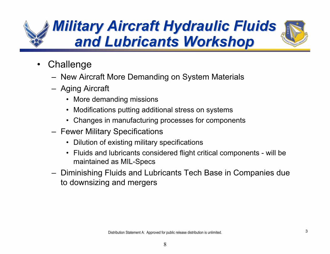
• Challenge– New Aircraft More Demanding on System Materials– Aging Aircraft
• More demanding missions• Modifications putting additional stress on systems• Changes in manufacturing processes for components
– Fewer Military Specifications• Dilution of existing military specifications• Fluids and lubricants considered flight critical components - will be
maintained as MIL-Specs– Diminishing Fluids and Lubricants Tech Base in Companies due
to downsizing and mergers
8

4Distribution Statement A: Approved for public release distribution is unlimited.
Air Force Research LaboratoryAir Force Research Laboratory
• Air Force– Provide air and space superiority to defend the nation
against all enemy threats– Global vigilance, reach, and power
• Research Laboratory– Provide technology options to senior leadership– Develop technology for weapon systems– Spur innovation and rapidly provide solutions to
current problems
9

5Distribution Statement A: Approved for public release distribution is unlimited. 5Distribution Statement A: Approved for public release distribution is unlimited.
Materials & ManufacturingDirectorate• Nonmetallic Materials• Metals, Ceramics & NDE• Manufacturing Technology• Integration & Operations• Survivability & Sensors
Materials• Systems Support• Air Base Technologies
WhereWhere the Materials and the Materials and Manufacturing (ML)Manufacturing (ML) DirectorateDirectorate FitFitss
AF Major Commands• Air Combat Command• AF Space Command• AF Special Ops Command• AF Materiel Command• Air Mobility Command• Pacific Air Forces• USAF in Europe
AF Research Laboratory• AF Office of Scientific Research• Air Vehicles• Directed Energy• Human Effectiveness• Information• Materials & Manufacturing• Munitions• Propulsion• Sensors• Space Vehicles
AF Materiel Command• AF Research Laboratory• Product Centers• Test Centers• Logistics Centers• Specialty Centers
10

6Distribution Statement A: Approved for public release distribution is unlimited.
ML Mission / VisionML Mission / Vision
MISSIONPlan and execute the USAF program
for materials and manufacturing in the areas of basic research, exploratory
development, advanced development and industrial preparedness. Provide
responsive support to Air Force product centers, logistics centers, and operating commands to solve system and deployment related problems and
to transfer expertise
VISIONAerospace materials and
manufacturing leadership for the Air Force and the nation
Distribution Statement A: Approved for public release distribution is unlimited. (AFRL-WS 06-1402)
11

Distribution Statement A: Approved for public release distribution is unlimited.
Vision / Governing PhilosophyVision / Governing Philosophy
• Provide leadership for research, development and support for aerospace materials and manufacturing processes, and airbase and environmental technology
- Be the best for selected technical areas-- A first class in-house program-- First class experts/consultants
- Be “One Phone Call Away” from the best in other technical areas
-- A broad based contractual program-- Active in the technical communities
• Exceed customer’s expectations
12

8Distribution Statement A: Approved for public release distribution is unlimited.
Resources to Accomplish Resources to Accomplish thethe MLML MissionMission
LOCATIONS:• Wright-Patterson AFB• Tyndall AFB• Program Offices in GA, OK, UT• Collocates at TDs, SPOs, Centers
As of April 2006
• Revenue - $378M /year• People - 1150 Gov’t & Ctr• 15/35 buildings
(owned/occupied)• 385,000 net square feet• 215 Lab modules• Designed specifically for
aerospace materials, processes and airbase technologies R&D
13

9Distribution Statement A: Approved for public release distribution is unlimited.
MLML Unique Facilities & EquipmentUnique Facilities & Equipment
World Unique Capabilities in One PlaceWorld Unique Capabilities in One Place
Pilot Scale Composite Prepreg
Space Coatings Environment Test and Research
Optical Crystal Characterization
Robotics and Remote Transport
Secondary Ion Mass Spectroscopy (SIMS)
Materials Processing
Confocal Brillouin Imaging Spectometer
Dual Beam Focused Ion Beam
Blast Range and Fire Pit
Laser Hardened Materials Evaluation Laboratory
Laser Deposition Tribology LaboratoryMolecular Beam Epitaxy (MBE) LaboratoryOptical Measurements LaboratoryConfocal Brillouin Imaging SpectometerElastomers LaboratoryFluid and Lubricant Development and Characterization LabOpto-Electronic Polymer Physics LaboratorySpace Coatings Environment Test and ResearchSpace Combined Environment FacilityMechanics of Composites Test LaboratoryMorphology LaboratoryMolecular Modeling LaboratoryPilot Scale Composite PrepregPolymer Synthesis LaboratoryPolymer Processing and Characterization LaboratoryComposites Processing LaboratoryCeramic Composite Research LaboratoryExperimental Materials Processing LaboratoryBlast Range and Fire PitHigh Temperature Materials LaboratoryMaterials Characterization FacilityMetallurgical Research LaboratoryMaterials Behavior Research Laboratory
Non-destructive Evaluation (NDE) Research LaboratoryElectron Optics LaboratoryLaser Hardened Materials Evaluation LaboratorySecondary Ion Mass Spectroscopy (SIMS)Failure Analysis & Analytical Support LaboratoryElectronic Failure Analysis FacilityMaterials Compatibility/Coatings Research FacilitySystems Support Nondestructive Inspection LaboratoryRobotics and Remote TransportMaterials Test and Evaluation LaboratoryProduct Affordability Realization TestbedCoatings/Corrosion Research LaboratoryDual Beam Focused Ion BeamHigh Cycle Fatigue LaboratoryCoatings Technology Integration OfficeComposites Characterization FacilityOptical Crystal CharacterizationElectrostatic Discharge Control LaboratoryHolographic Two-Photon-Induced Photopolymerization LabMaterials Degradation Test FacilityMaterials Processing LaboratoryVirtual Reality for Materials Design FacilityElectrical Characterization Facility
14

10Distribution Statement A: Approved for public release distribution is unlimited.
Materials / Processes to Enable Materials / Processes to Enable Air Force CapabilityAir Force Capability
Faster, farther, more survivable, more sustainable, more affordable……Faster, farther, more survivable, more sustainable, more affordable……
Shape the Shape the FutureFuture
Deliver on Deliver on CommitmentsCommitments
Reshape TodayReshape Today’’ssBattlesBattles
All Enabled By Enduring Materials/Processes CompetenciesAll Enabled By Enduring Materials/Processes Competencies
15

11Distribution Statement A: Approved for public release distribution is unlimited.
MLML’’s Enduring Competenciess Enduring CompetenciesFoundations of Our S&T BaseFoundations of Our S&T Base
Core Technology Areas
16

12Distribution Statement A: Approved for public release distribution is unlimited.
CTA 6CTA 6Tribology and CoatingsTribology and Coatings
• Advanced Fluids and Lubes Materials and Processes
• Fluids and Lubes Health Monitoring• Solid Lubricants and Wear Resistant
Materials and Processes• MEMS and Nano Contact Lubrication• Health Monitoring of Aircraft Components• Space Protective Coatings• Space Lubricant Technology • Optical Characterization of Materials• Multispectral Coatings for Signature Control• High Performance Multifunctional Aircraft
Coatings• Corrosion Control and Pretreatment
RECENT TECH HIGHLIGHTS:• Rapid process gap/fastener filler transitioned to
F-35• Environmentally safe corrosion preventative
primer transitioned to F-15 fleet• Hydraulic fluid purification on flightline ground
cart
• POSS polyimide coating formulated for space tethers
• Multi-environment, wear resistant coating under evaluation for JSF and launch vehicle applications
17

13Distribution Statement A: Approved for public release distribution is unlimited.
Military Aviation Hydraulic Fluids Military Aviation Hydraulic Fluids and Lubricants Workshopand Lubricants Workshop
• MLBT Fluids and Lubricants Group Mission:– Research, development, and transition of new base fluids and
additives to meet changing Air Force requirements– Provide quick reaction field support for fluids and lubricant and
lubrication related problems– Maintain and Support
• Fluids and lubricant military specifications• Non-government standards• MIL-handbook• TOs
18

14Distribution Statement A: Approved for public release distribution is unlimited.
Military Aviation Hydraulic Fluids Military Aviation Hydraulic Fluids and Lubricants Workshopand Lubricants Workshop
People• MLBT Fluids and Lubricants Group
– Interdisciplinary team of mechanical and materials engineers– Long heritage in fluids and lubricants research, development and
technology transition– Extensive experience in fluids and lubricants chemistry and
performance• Developed large number of fluids and lubricants and transitioned
them into DoD systems• Significant background in working fluid and lubricant related field
problems
19

15Distribution Statement A: Approved for public release distribution is unlimited.
Military Aviation Hydraulic Fluids Military Aviation Hydraulic Fluids and Lubricants Workshopand Lubricants Workshop
Capabilities• MLBT Fluids and Lubricants Group Has Outstanding
Analytical and Test Facilities– Unique Hydraulic Pump Test Facility– Unique Grazing Angle Infrared Microscope– High Speed Bearing Tester– Lubricity Test Equipment– Extreme Temperature Rheological Property Capability– In-House Fluid and Component Analysis Capability - e.g., XPS,
ICP, SEM, XRD, TEM
20

16Distribution Statement A: Approved for public release distribution is unlimited.
Pump Stand Slide HerePump Stand Slide Here
21

17Distribution Statement A: Approved for public release distribution is unlimited.
Military Aviation Hydraulic Fluids Military Aviation Hydraulic Fluids and Lubricants Workshopand Lubricants Workshop
Interactions• MLBT Fluids and Lubricants Group Participates in Non-Government
Standards Organizations and International Standardization Activities– American Society for Testing and Materials (ASTM)– Society of Automotive Engineers Aerospace Fluid Power and Control
Technologies Committee (SAE A-6)– Society of Tribologists and Lubrication Engineers (STLE)– International Standards Organization (ISO)– North Atlantic Treaty Organization (NATO)– Air and Space Interoperability Council (ASIC)
• MLBT Fluids and Lubricants Group Works Collaboratively with Other Government Agencies– Army, Navy, NASA, DLA, FAA, International
• and Industry– Prime contractors, component designers and suppliers, and fluid
suppliers
22

18Distribution Statement A: Approved for public release distribution is unlimited.
Fluids and Lubes
Fluids and Lubes
International
Aircraft and Component Mfrs
OEMsSuppliers
Air ForceArmyNavyDLANASAEPAFAA
NATOASICDEA
SAE-E-34STLE
SAE A-6ASTM
Euro-Fighter (Daimler-Chrysler)
German MODUK MOD
Canada MODSuppliers
National
Military Aviation Hydraulic Fluids Military Aviation Hydraulic Fluids and Lubricants Workshopand Lubricants Workshop
23

19Distribution Statement A: Approved for public release distribution is unlimited.
Military Aircraft Hydraulic Fluids Military Aircraft Hydraulic Fluids and Lubricants Workshopand Lubricants Workshop
Value of the Workshop• Provides opportunity for improved communication between
AFRL/MLBT, the warfighter, program offices, other government agencies and industry
• Provides status of newer technology and an opportunity for feedback
• Provides opportunity to learn of new requirements, issues that would help the warfighter
• Provides opportunity to establish new and enhance existing relationships
• Provides awareness of skills and capabilities available at MLBT to provide support for field problems in fluid and lubricant technology
MLBT is DoD’s One Stop Shop for Fluid and Lubricant Research, Development, Transition and Field Support
Use Good Science to Solve Field ProblemsUse Good Science to Solve Field Problems
24

20Distribution Statement A: Approved for public release distribution is unlimited.
CarlCarl ““EdEd”” SnyderSnyderScientific AchievementScientific Achievement
• Leadership: Established ML as Fluids & Lubricants Center of Excellence
– Fellow of Society of Tribologists and Lubrication Engineers– Chair of SAE Fluids Panel for Aerospace Power and Control Tech.– Provides US position related to F&L to NATO, allies, and the Air
and Space Interoperability Committee• Communication and Reporting
– 15 patents; 150 publications; presentations at international venues– SAE LLoyd L. Winthrop Distinguished Speaker Award
• Technical Problem Solving– High Temp fluids and lubes; ultra-low volatility lubes for space– Fire resistant hydraulic fluids; stuck servo-valves; radar coolant– Grease for F-107 engine bearing; stuck servovalves in UH-1 helicopters
• Air Force Impact– His F&Ls are used in 98% of AF a/c and 100% of USA and USN a/c– His dielectric coolant for radar systems is used in 99% of AF and 100% of USN a/c– Reduced fire damage (~$45M/yr savings); longer overhaul intervals
2006 AFRL Fellow
25

21Distribution Statement A: Approved for public release distribution is unlimited.
26

Air Force Research Laboratory
Materials and Manufacturing Directorate
Wright-Patterson Air Force Base, Ohio
27

ML Fluids and Lubricants Team
• One Stop Shopping for Fluids and Lubricants in Air Force
• Research
• Development
• Prepare and Maintain Specifications
• Qualify Products to Specifications
• Maintain Qualified Products Lists
• Transition New Materials to the Field
• Solve Field Problems
28

ML Fluids and Lubricants Team
• Areas of Responsibility
• Hydraulic Fluids
• Purification
• Greases
• Liquid Lubricants
• Coolants
• Solvents
Aircraft and Spacecraft
29

ML Fluids and Lubricants Team
Personnel:
• Ed Snyder - Team Leader
• Lois Gschwender - Senior Research Materials Engineer
• Angela Campo – Chemist
• Shashi Sharma - Mechanical Engineer (1/2 Time)
• 5 On-Site Contractor Personnel
• 3 Professionals
• 2 Technicians
• External Contract With Phoenix Chemical Laboratory
30

ML Fluids and Lubricants TeamFire Resistant Hydraulic Fluids
• MIL-PRF-83282
• MIL-PRF-87257
31

ML Fluids and Lubricants Team
Coolanol 25R (MIL-PRF-47220) MIL-PRF-87252 (PAO)
Hydrolytically Stable Coolant
32

ML Fluids and Lubricants TeamNearly Universal Grease
Corrosion Rate Evaluation Procedure Coupons,
300M steel, distilled water, 45 min
MIL-PRF- 32014 MIL-PRF-81322 Braycote 807RP
MIL-PRF-81322 MIL-PRF-32014
33

ML Fluids and Lubricants Team
• New Fluids and Lubes Development• Field Problem Solving
– Stuck Servovalves– Prematurely Clogged Filters– Engine Oil Foaming– Hydraulic Fluid Contamination
• Fluid and Lubricant Specifications & QPLs– Hydraulic Fluids– Greases– Liquid Lubricants
34
Air Force Lubricant Specifications & Conversions
Lois GschwenderAFRL/MLBTJune 20 2006
35

Specifications (AFRL/MLBT)• Hydraulic Fluid*
– MIL-PRF-27601 (hi temp PAO) One company qualified - EHA fluid?
– MIL-PRF-87257 (PAO)– MIL-PRF-5606 (mineral oil)
• *Qualified Products List on these• Available through ASSIST
• http://assist.daps.dla.mil.quicksearch
36

Specifications (AFRL/MLBT)• Coolant*
– MIL-PRF-87252 (PAO, dielectric)
• Lubricating Oils*– MIL-PRF-6085 (instrument)– MIL-PRF-6086 (gear)– MIL-PRF-7870 (general purpose)
• Fastener Lubricant– MIL-L-87132 (cetyl alcohol)
• Thread compound– MIL-PRF-83483 (antiseize, MoS2)
* Qualified Products List on these
37
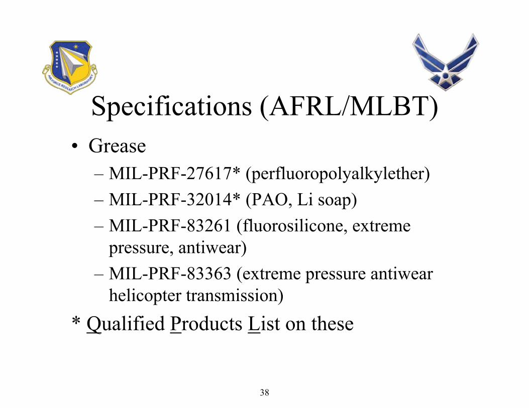
Specifications (AFRL/MLBT)• Grease
– MIL-PRF-27617* (perfluoropolyalkylether)– MIL-PRF-32014* (PAO, Li soap)– MIL-PRF-83261 (fluorosilicone, extreme
pressure, antiwear)– MIL-PRF-83363 (extreme pressure antiwear
helicopter transmission)* Qualified Products List on these
38

Air Force Hydraulic Fluid Specifications
• MIL-PRF-5606H mineral oil hydraulic fluid – extensive revisions but no change in basic materials or properties –should be “invisible” to aircraft– Dated 7 June 2002– Remains inactive for new design
• Lots of re-qualification activity on MIL-PRF-5606 due to base stock supplier and quality changes– Base fluid properties problematic
• Density• Seal Swell
39

Air Force Hydraulic Fluid Specifications
• MIL-PRF-5606 extensive revisions including• Barium limit 10 ppm max, ASTM D 5185• Up to 3% antiwear additive allowed• Many test method changes (no effect on properties)
– Solvents, etc.
– Interchangeability with other fluids statement– Notes section 6 more extensive
40

Air Force Hydraulic Fluid Specifications
• MIL-PRF-5606 extensive revisions– Amendment 2
• Lists MIL-PRF-87257 and MIL-PRF-83282 for new design• Adds rubber swell to list of conformance tests
– Amendment 3 – in tri-service coordination• Sampling plan eliminated (belongs in contracts, not spec)• Contamination
– Delete filtration times– Go to polypropylene filters for gravimetric analysis – better
repeatability
41

Air Force Hydraulic Fluid Specifications
• MIL-PRF-87257 extensive revisions in April 2004 but no change in basic materials or properties –should be “invisible” to aircraft– New requirements
• Bulk modulus per ASTM D6793• Barium limit 10 ppm max• Biodegradability limit of Class I max
– Format changes• Consolidated requirements and tables into comprehensive table
I and revised table II• Hyperlinks in electronic version goes directly to footnotes in
tables
42

Air Force Hydraulic Fluid Specifications
• MIL-PRF-87257 extensive revisions– Changed requirements
• Lowered flash point to 160oC due to use of automatic equipment that has a lower data bias
• Added referee particle count method• Raised thermal stability test to 200oC and allowed
use of test tube to conduct test• Changed temperature range in scope from “–54oC to
135oC” to “–54oC to 200oC” to allow use in EHAs
43

Air Force Hydraulic Fluid Specifications
• MIL-PRF-87257 extensive revisions– Changed filter material in gravimetric
procedure to polypropylene and added two stacked filter method – better repeatability
– Changed limit in gravimetric particulate test to 1.0 mg/100 ml fluid max
– Require only 1 gallon of final formulation –additives on request only
– Current fluids grandfathered
44

Air Force Grease Specification
• MIL-PRF-27617 – perfluoropolyalkylether based greases– Type I, –65-300oF– Type II, -40 to 400oF– Type III, -30 to 400oF– Type IV, –100 to 400oF– Type V, -100 to 450oF (none currently qualified)
45

Air Force Grease Specification
• MIL-PRF-27617 is expensive ~$200 to $1000/lb• Has some wear and corrosion issues• Should only be used where hydrocarbon based
greases are unacceptable – LOX & GOX– Extreme temperature
• Specification in pretty good shape, not high priority for revision
46

Air Force Grease Specification
• MIL-PRF-32014 Multipurpose, Nearly Universal Grease– Currently working on extensive spec revisions– This grease currently in Cruise Missile F-107 engine,
C-5 and C/KC-135 landing gear and C/KC-135 wheel bearings
– Navy flight testing since Feb 2006• Nose wheel bearing• Rotodome
– Nye Lubricants, Rheolube 374A and Air BP, Braycote 3214 qualified products on QPL
47

Air Force Coolant Specification
• MIL-PRF-87252 coolant, Amendment 1 Dec. 04 – Changed to -54oC to 200oC temperature range
due to advanced system predictions• All qualified products tested and passed 200oC, 100
hour thermal stability test
48

Air Force Specifications• Qualified Product Lists
– QPL-5606-31, 17 January 2003– QPL-6085-15, 6 January 2003– QPL-6086-13, 10 February 2003– QPL-32014-2, Amendment 1, 1 August 2003– QPL-27617-8 (perfluoropolyalkylether grease), 26 May
2004– QPL-87252, 6 January 2005– QPL-87257, 12 February 1996
• Products requested to be re-qualified every 5 years
49

Air Force Specifications
• Any issues or concerns with military specifications we control, please contact AFRL/MLBT
50

Recent Conversions…
• MIL-PRF-87257 approved for use in B-52 aircraft– T.O.s and job guides changed
• Flying on MIL-PRF-5606/MIL-PRF-87257 mixtures
– Landing gear struts using MIL-PRF-5606• Recently changed from O-ring to T-ring seal design –
tested at Hill AFB• MIL-PRF-87257service testing on one aircraft LG• Expecting to convert landing gear ~ 1 year
51

Recent Conversions…
• B-2 and trainers only aircraft using flammable MIL-PRF-5606
• MIL-PRF-32014 grease – Replaced MIL-PRF-81322 for main landing
gear in C-5 and KC/C–135 aircraft– Looking for wheel bearing test– UK evaluating for military applications– Looking for new application opportunities
52

AFRLAFRLFLUIDS & LUBES FLUIDS & LUBES
WORKSHOPWORKSHOPJune 2006June 2006
Air Force Petroleum OfficeAir Force Petroleum Office
V. M. RegoliDet 3, WR-ALC/AFTT
I n t e g r i t y - S e r v i c e - E x c e l l e n c e
Developing, Fielding, and Sustaining America’s Aerospace Fuels
53

2
What We Do
Strategically focus the efforts of the Air Force Fuels communityto develop, mature and enhance core competencies in order to deliver state of the art technical support and service to the warfighter.
Maintain an Air Force Fuels Service Control Point (SCP) that is mission concentrated, agile, flexible and warfighter focused; which provides mission critical materiel, services and information with minimal infrastructure, manpower and costs.
54

3
Laboratory Locations
Vandenberg AFB CAVandenberg AFB CA
WrightWright--Patterson OHPatterson OH
Vandenberg AFB CAVandenberg AFB CACape Canaveral AFS FLCape Canaveral AFS FL
WrightWright--Patterson OHPatterson OHRAF Mildenhall UKRAF Mildenhall UK
Al Udeid, QA
Kadena AB Kadena AB JAJA
55

4
• Aviation product testing:– JP-5, JP-7, JP-8, JPTS, JP-10, Jet-A, RP-1, PF-1, aviation gas– Diesel fuel, heating fuel, mogas, E-85, biodiesel fuel
• Packaged petroleum products & chemicals– Lubricating oils– Hydraulic fluids– Greases– Corrosion prevention compounds– Aircraft cleaning compounds– Anti/Deicing fluids
Related Products
56
5
• T.O. 42B2-1-3, Fluids For Hydraulic Equipment
• Hydraulic Fluid Testing
• International Coordination
Hydraulic Fluid(Responsibilities)
57

6
ScopeCover the types, use, quality control, and dispositionof used hydraulic fluids
PurposeClarify the use and disposition of hydraulic fluid usedin the Air Force inventory
T.O. 42B2-1-3
58

7
Hydraulic Fluid Testing
• Lot Acceptance (for DLA)– MIL-PRF-83282– MIL-PRF-5606– MIL-PRF-87257
• Shelf-Life Extension– DLA (SLES)– AF (Shelf-Life/Retest)
• T.O. 42B-1-1
• A/C Incident / Mishap
59

8
Hydraulic Fluid Testing (Sampling)
• Results Only Good As Sample Received
– Sampling is Critical• Sample Technique• Container Cleanliness
– Questionable Receipts• Samples are received with fuel smell• Over packed in vermiculite
60

9
International Coordination
• Air and Space Interoperability Council (ASIC)
- Air Std 15/03 Minimum Quality Surveillance Petroleum Products
- Air Std 15/04 Allowable Deterioration Limits for Stored Fuels, Lubricants and Associated Products
- Air Std 15/07 Guide Specifications for Petroleum Base (H515 & C-635) & Polyalphaolefin (H-537, H-538 & H-544) Aviation Hydraulic Fluids
- Air Std 15/09 Interchangeability Chart of Standardized Aviation Furls Lubricants and Associated Products
61

10
International Coordination
• North Atlantic Treaty Organization (NATO)
– STANG 1110 Deterioration Limits for NATO Armed Forces Fuels, Lubricantsand Associated Products
– STANG 1135 Interchangeability of Fuels, Lubricants and Associated Products used by the Armed Forces of the North Atlantic Treaty Nations
62

11
Change
• DLA Privatization– Acceptance Testing– Shelf-Life
• Depot Storage• USAF Storage• WRM
• Joint Tech Order– Aviation Hydraulics Manual
63

Joint Service Hydraulics Manual
Military Aviation Fluids and Lubricants Workshop20-22 June 2006
Megan GooldAIR-4.9.7.2
Naval Air Depot Cherry Point NC
NAVAIR Public Release 06-0028, Distribution A – Approved for public release; distribution unlimited
64

Overview
• Purpose
• History
• Current/Future Events
• Final Product
• Points of Contact
65

Purpose
• Develop a Multi-Agency Joint Series Working Group to establish a multi-agency aviation hydraulics manual.
66
History
• February 18, 2005 – Preliminary Plan of Action and Milestone (POA&M) sent to team members
• May 25-26, 2005 – Joint General Series Working Group Meeting
• November 11, 2005 – Preliminary draft of NAVAIR 01-1A-17 distributed for gap analysis
67

Current/Future Events
• May – August 2006 : Data incorporation and final review
• September 2006: Publication and Distribution
68

Final Product
• Joint Service Hydraulics Manual– NAVAIR 01-1A-17– T.O. 42B-1-12– TM 1-1500-204-23-2
• 17 Work Packages– Joint Packages – Navy Use Only
69

Points of ContactNavyMegan Goold, NAVAIR-4.9.7.2, Cherry Point, NC, 252-464-9767
Air ForceLois Gschwender, AFRL/MLBT, Wright-Patterson AFB, Ohio, 937-255-7530
Ed Snyder, AFRL/MLBT, Wright-Patterson AFB, Ohio, 937-255-9036
Conchita Allen, AF Petroleum Office, Wright-Patterson AFB, Ohio, 937-255-8038
MSgt Kurt Hinxman, Scott AFB, 619-229-2630
ArmyKenneth Wegrzyn, US Army, 256-313-9137
70

Questions
71

ELIMINATION OF BARIUM CONTAINING FLUIDS IN DoD
AIRCRAFT SYSTEMS
Lois GschwenderAFRL/MLBT
WPAFB
72

ELIMINATION OF BARIUM CONTAINING FLUIDS IN DoD
AIRCRAFT SYSTEMSOutline
The problem BackgroundProgram matrixResults
Jar testsPump tests
Summary
73

The Problem• DoD has traditionally used fluids containing
barium dinonylnaphthalene sulfonate (BSN) for component storage.– Spent fluid is a hazardous waste– Documented problems of operational
aircraft with BSN contamination• Army helicopters• Navy F-18s• Air Force T-38
– Logistics/footprint
74

The Problem
• T.O. 42B2-1-3 formerly described storage and shipping with rust inhibited fluid and then flushing and draining with the operational fluid prior to use.
• Some parts cannot have all of the rust inhibited fluid drained.
• The fluids look the same so draining may not be done.
75

Background - Definition of Fluids
• The rust inhibited fluids contain ~3% BSN (1500 ppm Ba). Stability < 225oF.
• EPA limit is 100 mg/l (120 ppm) water soluble Ba for hazardous disposal (EPA Handbook CFR, 261.24)
Base stock Non-inhibited Rust inhibited
Mineral oil MIL-PRF-5606 MIL-PRF-6083
PAO oil MIL-PRF-83282 MIL-PRF-46170
76

Background• Aircraft components were stored with 4
different fluids at the start of program *– MIL-PRF-5606: B1B, C-130, C-135, E-3, E-4,
E-6, F-5, P3C, U2R– MIL-PRF-83282: F-110 (F-16, actuator), F404,
H60, H64, S60– MIL-PRF-6083: C-5A/B, F-117, F16– MIL-PRF-46170: AV8, C17, S3A, F15, E2C,
F18, H53, H60, S60, V22* Information from Parker Aerospace
77

Other reasons to change
• No documented reason for using inhibited fluid
• Component inventory going down - short shelf time for components
• Logistics - two fewer fluids in AF inventory– “Footprint” reduction
• Cost savings - charges from component suppliers and overhaulers
78

Hypothesis
Operational fluids work fine as component storage fluidsNo documented part corrosion with operational fluidsLaboratory tests indicated synthetic fluids more corrosion resistant than MIL-PRF-5606
79
AF Suggestion - 1995
• F-22 will not use rust inhibited fluid in component/armament for less than one year storage
• Resistance in AF to eliminate storage fluid across the board– Concern about potential corrosion problems – No documented storage studies
80

Program
• Needed well planned storage program to validate hypothesis– Pollution Prevention program proposed and
funded, FY00 to FY04
81

Program Test Matrix• Queried MAJCOMs: HQ AMC, AFSOC/LG;
SPOs, ASC, SSMs about test protocol– Real time storage, not heated to accelerate– Both rust inhibited and operational fluids– Submerged and drained parts– As received and water added to fluid– Room temperature and humidity monitoring– Component (pump) test after storage
• Two part program developed
82

Program Test Matrix, Part I, Jars– Selected corrosion- prone, 52100
steel tapered bearings - Timken Bearing Co.- and used F-16 pump pistons in jar storage
– Submerged parts• Two water levels
– MIL-PRF-5606, 83282 and –87257 fluids, 100 & 350 ppm water
– MIL-PRF-6083 and -46170 fluids, 220 and 400 ppm water
– Dip & drain parts• Higher water level only• Parts dipped, drained, then put into jars
83

Program Test Matrix, Part I• Jar tests set up April 2000
– Visual observations monthly– Jar with specific test conditions (fluid and water
200/400 ppm level) off yearly for three years– Dip and drain jars also observed
84

Program Test Matrix, Part II– 3 year pump storage begun June and July 2000 – F-16 EPU pumps purchased for storage and then pump
testing after storage– Three fluids in stored pumps: MIL-PRF-83282, MIL-
PRF-87257 and MIL-PRF-46170– Water added to fluids, 300 ppm– Constant measurement of temperature and humidity– Post test examination, photography and analysis, as
needed– Pump tests conducted on certain pumps at 3 years
85

Results, Jar Tests
86

PART I JAR TEST RESULTSYear
Operational Fluids 1 2 3MIL-PRF- Green = No change
8328287257 Yellow = Slight stain5606
Red = StainStorage FluidsMIL-PRF-
46170SubmergedDip & Drain
6083
87

88

Jar Test Results Summary
• Jar tests with – Operational fluid – no changes– MIL-PRF-46170 – staining– MIL-PRF-6083 – no changes
89

Results, Pump Tests
90

F-16 EPU pump, Eaton (Vickers) PV3-075-15
91

92

Part II Pump Storage Results
• 3 year pump storage begun June and July 2000 (300ppm water added)– Yearly inspection of MIL-PRF-83282 and MIL-
PRF-87257 filled pumps - no changes– Yearly inspection of MIL-PRF-46170 filled pump
- main bearing resisted turning, discoloration of metal, gel observed
93

CHEMICAL REACTION MARKS ON SHAFT BEARING BALL
MIL-PRF-46170 + 300 ppm water, 1 year storage
94

Part II Pump Results
• Pumps stored with 300 ppm water, drained and filled with fresh fluid
• MIL-PRF-83282– Run 500 hours– Teardown inspection showed little wear– Parts shiny
95

Part II Pump Test Results
• MIL-PRF-87257– Piston defect caused pump failure at 275 hours– No rust or other indication of fluid related problem
• Two more PV3075-15 pumps put into storage with MIL-PRF-87257 for 3 years to assure pump failure was an anomaly
• Since no corrosion was observed with MIL-PRF-83282 and MIL-PRF-87257, MIL-PRF-46170 stored pump was not tested
96

Pump Test Results
• Pump tests with– MIL-PRF-83282
• Storage – no change• Run 500 hrs, no corrosion
– MIL-PRF-87257• Storage – no change• Run 275 hrs, piston failure, no corrosion
– MIL-PRF-46170• Storage, staining, rough turning, gel formed• Not pump tested
97

Summary
98

Expected Payoff / Summary• Using operational fluid for component storage will
– Reduce hazardous waste stream– Eliminate source of operational problems– Consolidate number of fluids used
• Storage program assures users that parts won’t rust on the shelf
• Save charges passed on by component suppliers and overhaulers
99

Post Script• Final technical report on storage program AFRL-
ML-WP-TR-2004-4279• Technical paper, Trib. Trans., 1, 2006, by
Gschwender, et al.• Individual aircraft TO’s are being changed• Army and Navy also adopted use of operational
fluid for component storage, based on ML work• Specification for storage fluid MIL-PRF-46170,
Type II has been cancelled – recommend using operational fluid when asked
100

For O 1
US Army Hydraulic Contamination
Control Program
US Army Hydraulic Contamination
Control Program
In-Progress Report to
USAF Hydraulic Contamination Workshop
21 June 2006
In-Progress Report to
USAF Hydraulic Contamination Workshop
21 June 2006
Ken WegrzynHCCP Technical Lead & IPT Chair
Ken WegrzynHCCP Technical Lead & IPT Chair
101

2
Hydraulics ContaminationTest Evaluation Program
Objective of HHCP (initial):– To understand the contamination control issues related to
unexplained malfunctions of the controls and find a solution
– To reduce safety risk associated with malfunctionsExtended Objective:
– To improve mission readiness & reduce maintenance costs
– Reduce leakage rates which is one of the main reasons for aircraft downtime and maintenance activities based on 2410 data
– Improve the current 30+ year old MIL-F-8815 specification to include real operating conditions
– Update the current test procedures and insert state of the art technologies to insure repeatability of filter performance
– Develop Industry and Tri-service support to develop more robust filter element performance specs
102

3
Plan of Attack
• Field sampling to assess the current condition of hydraulic fluid in aircraft
• Review aviation maintenance practices• Review the current specs Mil-F-8815• Review associated components that are
sensitive to contaminants or affect the contamination levels in the system– Indicators– Servo valves– Filters themselves– Operating environment
103

4
4.5%
10.5%
60.5%
18.1%
6.5%
0%
10%
20%
30%
40%
50%
60%
70%
1 2 3 4 5+
% S
ampl
es
USN, USMC & USCG Ground Aircraft Class 5
USN, USMC & USCG Ground Aircraft Class 5
Class 4 ConsideredMax Acceptable
Class 4 ConsideredMax Acceptable
NAVAIR Class ~ Increasing Contamination
Army HelicopterHydraulic Fluid Samples (FY01)
Class 3 ConsideredIPT Goal
Class 3 ConsideredIPT Goal
104

5
Field Induced Contamination
Unserviced AGSE Desiccant(Should Be Blue)
Unserviced AGSE Desiccant(Should Be Blue)
105

6
ContaminatedHydraulic Components
CH-47D Integrated Lower Control Actuator (ILCA) Components
106

7
Electrical5%
Mechanical Operation
20%
Leaking59%
Mechanical Wear16%
Failure Code
Annual Helicopter Cost26 Critical Hydraulic Parts
CCSS Annual Demand & Average Overhaul Cost (FY04)
UH-601396 A/C
AH-64742 A/C
CH-47429 A/C
OH-58D382 A/C
$25.9M
$3.3M
$5.3
$11.2M
Total = $45.7M
Per Fleet
$12,400
$8,800
$15,100
$18,500UH-60
AH-64
CH-47
OH-58D
Per A/C
2410 Failure Codes (FY04)
Per industry data, 75% of failures are
due to contamination.
CCSS Annual Demand & Average O/H Cost
107

8
Current Filtration is Ineffective
• Fiberglass element filters are effected by:– Changes in flow– Pump ripple– Filter Vibration/aircraft system induced
• These dynamic effects allow trapped contamination to re-enter flow stream.
The smallest images displayed are 20 microns.Army helicopters have 5 micron ‘absolute’ filters.
CH-47D Sample (FY01)
108

9
Fiberglass Filters are Not Effective in Dynamic Environments
Increased Flow(1.5 x Nominal)Time: 40 Sec
• Flow rate changes cause trapped particles to re-entrain in fluid.• Similar results are produced by:
– Pressure changes – Helicopter vibrations– Pump pulsation (ripple) – Fluid temperature changes
Steady Flow (1.5 x Nominal)Time: 80 Sec
Steady Flow (Nominal)
Time: 0 - 30 Sec
Downstreamof Filter
Upstreamof Filter
Dynamic Test at SSI (FY01)
109
10
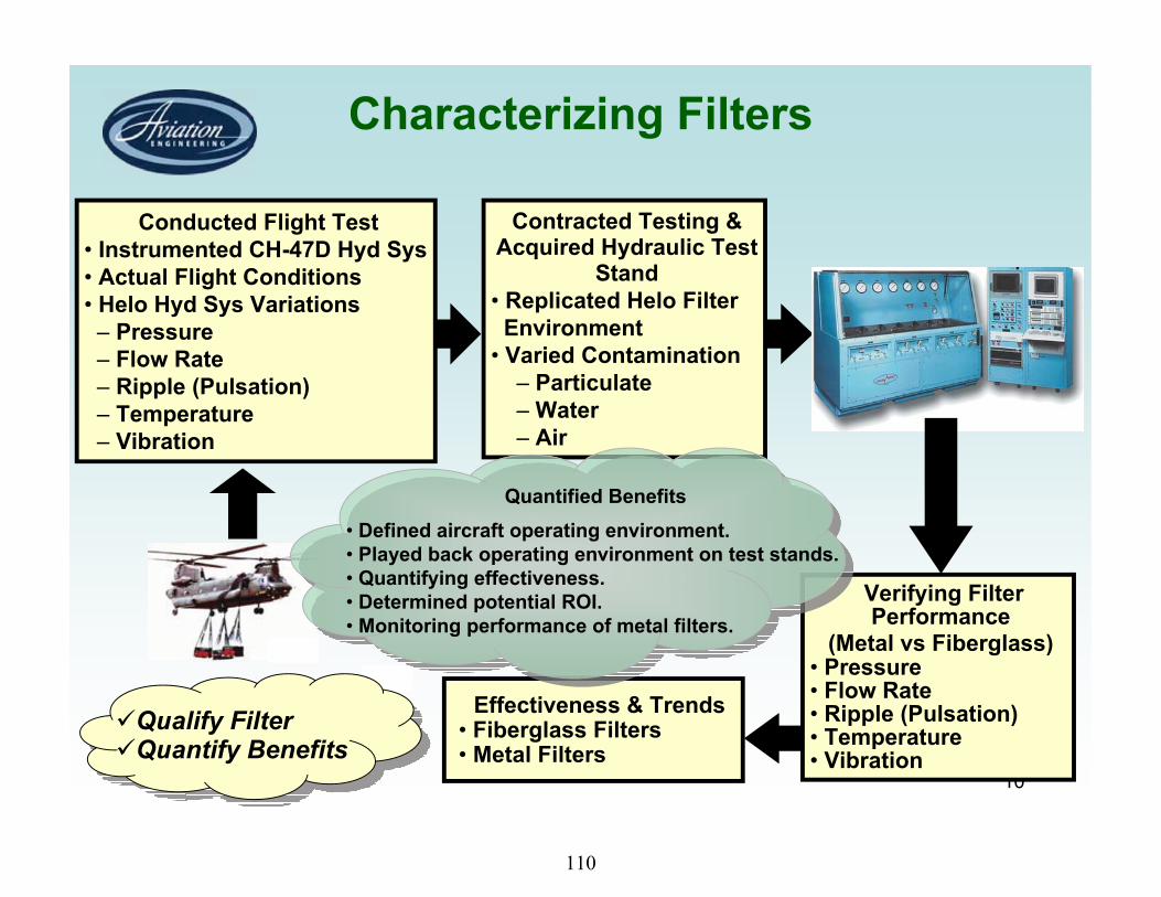
Characterizing Filters
Effectiveness & Trends• Fiberglass Filters• Metal Filters
Contracted Testing & Acquired Hydraulic Test
Stand• Replicated Helo Filter
Environment • Varied Contamination
– Particulate– Water– Air
Conducted Flight Test• Instrumented CH-47D Hyd Sys• Actual Flight Conditions• Helo Hyd Sys Variations
– Pressure– Flow Rate– Ripple (Pulsation)– Temperature– Vibration
Qualify FilterQuantify Benefits
Verifying Filter Performance
(Metal vs Fiberglass)• Pressure• Flow Rate• Ripple (Pulsation)• Temperature• Vibration
Quantified Benefits• Defined aircraft operating environment.• Played back operating environment on test stands. • Quantifying effectiveness.• Determined potential ROI.• Monitoring performance of metal filters.
110

0.0
0.5
1.0
1.5
2.0
2.5
1 2 3 4 5 6 7
Nor
mal
ized
$$
Cos
t
Source: Franklin Research Institute Report 1-B2116-4 (10/64)Source: Franklin Research Instn itute Report 1-t B2
Goal: Never exceed Class 3. Avg = 2.85
48% Cost Reduction
NAVAIR Class ~ Increasing Contamination1 2 3 4 5 6
Safety and Economic Benefits of Improving Fluid Cleanliness
Annual cost of UH-60 critical hydraulic components:Overhaul & replace: $25.9MCost due to contamination: 75%Savings for achieving initial goal:
$ = $25.9M(75%)(48%) = $9.32M per year
ReadinessRisk
Safety of Flight Risk
AOAP Avg = 4.76
FY01 Samples:60+% Class 5
111

12
Actions Taken to Improve Fielded Aircraft Contamination Control
• Evaluated and implemented use of Pall hydraulic fluid purifier on CH-47.
• Evaluated, modified and demonstrated hand-pumped, filtered fluid dispensers (AGSE PM procured dispensers).
• Evaluated and demonstrated inline water monitor and particle counter (Monitored water and particulate contamination).
112

13
Actions Taken to Improve Fielded Aircraft Contamination Control
• Improved the cleanliness and serviceability of the Aviation Ground Power Unit.
• Evaluated and demonstrated AGPU end caps and ‘runaround’ block to keep hoses and fittings clean (AGSE PM procured aluminum fittings).
• Replaced 3 and 10 micron AGPU filters with 2 and 5 micron filter elements, respectively.
113

14
Hydraulics ContaminationTest Evaluation Program
Objective of HHCP (initial):– To understand the contamination control issues related to
unexplained malfunctions of the controls and find a solution
– To reduce safety risk associated with malfunctionsExtended Objective:
– To improve mission readiness & reduce maintenance costs
– Reduce leakage rates which is one of the main reasons for aircraft downtime and maintenance activities based on 2410 data
– Improve the current 30+ year old MIL-F-8815 specification to include real operating conditions
– Update the current test procedures and insert state of the art technologies to insure repeatability of filter performance
– Develop Industry and Tri-service support to develop more robust filter element performance specs
114

15
Hydraulic Filter Testing
115

16
Downstream Particles Between 5 and 10 Microns
0
100
200
300
400
500
600
700
800
900
1000
0 5 10 15 20 25 30
Cumulative Test Time (Minutes)
Part
icle
s/m
l
FiberglassMedia
MetalMediaFlow Surge
NAVAIRClass 5
NAVAIRClass 1
NAVAIRClass 3
Particle SheddingComparison of Fiberglass & Metal FiltersNAVAIR Dynamic Test Results (FY02)
116

17
Hydraulic Filter Testing• How well do the present filters perform using current specs?
– All filters pass current MIL-F-8815 spec– We still have high usage rates on critical hydraulic components and issues with
high leakage rates and high maintenance on pumps and actuators which are sensitive to contamination
• Some bench test data and field oil samples data suggest that we may have worse than normal cleanliness levels in aircraft during helicopter working conditions
– Do we have bench test data? – Is there a more robust filter that is cost effective?– Can we separate more robust filters from non-robust filters using any approved
/published test procedure?– If not, does it require a new test procedure? – Is there one test procedure available in the industry that truly replicates Army’s
environment?– Is the test procedure easily repeatable at other labs? – Do we rank filters based on realistic environmental test or assumed test
conditions. Is this verifiable?
117

18
Tests Performed
• 628 Bubble Point Tests• 231 Immersion Tests• 155 Cold Start Tests• 11 Flow Fatigue Tests• 11 Collapse Tests• 9 Media Migration Tests• 34 ISO-23369 Cyclic Multi-pass Tests• 18 ARP-4205 Dynamic Response Tests• 46 DFE Tests• Total Tests Over 1143
118

19
UH-60 Current FilterPerformance
Downstream Particle Counts - A026
1
10
100
10000:
01:3
5
0:11
:12
0:20
:49
0:30
:26
0:40
:08
0:49
:57
0:59
:36
1:09
:16
1:18
:49
1:28
:26
1:38
:00
1:47
:35
1:57
:06
2:06
:38
2:16
:32
2:26
:39
Time
Parti
cles
/m 4 Micron5 Micron6 Micron14 Micron
119

20
UH-60 Vendor 2 FilterPerformance
Downstream Particle Counts - C748
1
10
100
0:00
:35
0:07
:43
0:14
:56
0:22
:10
0:29
:21
0:36
:31
0:43
:42
0:50
:51
0:58
:00
1:05
:07
1:12
:14
1:19
:37
1:27
:12
1:34
:40
1:42
:29
1:50
:06
Time
Parti
cles
/m 4 Micron5 Micron6 Micron14 Micron
120

21
DFE®-Dynamic Filter Efficiency Test
DFE trademark of SSI Labs,
PistonPump
Test filter w/no vibration
121

22
Upstream Challenge Maintained ConstantFor DFE Filter Test Duration
Upstream Counts vs Time
DFE Tests W/O Vibration
0.11
10100
100010000
0:01
:34
0:10
:39
0:19
:47
0:28
:53
0:38
:01
0:47
:12
0:56
:43
1:06
:22
1:15
:54
1:25
:38Pa
rtilc
es #
/ml >
6 m
i
upcount3
AR050233, C719, Pre-Conditioned - Industrial Piston Pump 1800 rpm, 1000 psi, term pressure: 300 psid,
180 deg F, flow 1.5 to 6 gpm
122

23
Validation DFE w/o Vibration Tests Downstream Counts Follow 3mg/l Upstream Challenge
1.5 to 6 gpm, 1000 psi upstream, 300 psid,175 deg F
Downstream Particle Counts - Validation
1
10
100
1000
10000
0:02
:31
0:09
:07
0:16
:04
0:23
:07
0:30
:07
0:37
:19
0:45
:20
0:52
:53
1:00
:19
1:07
:40
1:14
:52
1:22
:05
1:29
:46
1:36
:59
1:44
:12
4 Micron5 Micron6 Micron7 Micron10 Micron14 Micron20 Micron
AR050141
123

24
Comparison of DFE w/o VibrationTypical Results
UH-60 FiltersBM vs Robust Media
Downstream Particle Counts - A026
1
10
100
1000
0:01
:35
0:11
:12
0:20
:49
0:30
:26
0:40
:08
0:49
:57
0:59
:36
1:09
:16
1:18
:49
1:28
:26
1:38
:00
1:47
:35
1:57
:06
2:06
:38
2:16
:32
2:26
:39
Time
Parti
cles
/m 4 Micron5 Micron6 Micron14 Micron
Downstream Particle Counts - C748
1
10
100
0:00
:35
0:07
:43
0:14
:56
0:22
:10
0:29
:21
0:36
:31
0:43
:42
0:50
:51
0:58
:00
1:05
:07
1:12
:14
1:19
:37
1:27
:12
1:34
:40
1:42
:29
1:50
:06
Time
Parti
cles
/m 4 Micron5 Micron6 Micron14 Micron
Bill of Material Robust Media
DFE: Registered trademark of SSI
124

25
Shaker Table Arrangement at SwRI
Courtesy SwRI
125

26
Cyclic Efficiency Test w/Vibration,160 Deg F, ISO-23369 & SAE-4205
126

27
Validation Under Dynamic ConditionsISO-23369 w/ Vibration And 160 Deg F
Upstream Challenge Maintained Constant3mg/l - 1.5 to 6 gpm - 4 min cycle.
Tested at SwRI @ 3 mg/liter
127

28
Validation Under Dynamic ConditionsISO-23369 w/ Vibration And 160 Deg F
Downstream Follows Constant Upstream Challenge
Tested at SwRI @ 3 mg/liter
128

29
Micron Sizes at 99.5 % and 99.9 % Efficiency
ISO 23369 vs SAE 4205 vs DFEMIL-F-8815 (Current Filters)
ISO 23369 w/Vibration
Efficiency
SAE4205w/vib High to
LowLow to High
Avg.(Alpha)
99.5% 15.88 5.27 4.68 4.35 14.42
99.9% 20.58 8.27 6.22 5.77 >20
DFEw/novib
129

30
Comparison of Test Methods23369 w/vib vs 4205 w/vib vs DFE
MIL-F-8815 Qualified Element
1
10
100
1000
10000
0 5 10 15
Micron Sizes
Filtr
atio
n R
atio
BM-H/L 23369
BM-4205-G. Avg
BM-DFE
BM: Bill of Materials - Current Filters
130

31
ISO Fine vs ISO MedSAE 4205 Dynamic Efficiency Test – 100 deg F
AH-64 - BM -1.5 to 6 gpm, 0.1 HZ
No Measurable Efficiency Difference
Test Location: SwRi
BM: Bill of Materials
ISO FINE vs ISO MED SAE 4205 w/no vib - 100 deg F Dynamic Efficiency Test Performance
110
1001000
0 10 20 30
> Micron Size
Filtr
atio
n R
atio ISOFINE
ISOMED
FT341, FT343
131

32
Future Action Plan• Replace ISO Fine Test Dust with ISO Medium in SAE 4205. The
answers are approximately the same with the more widely used ISOMedium dust
• Mil-F-8815 and Dynamic Test Procedures require some improvements - Army testing revealed deficiencies – Corrected them in Army testing – All of them can be improved w/o major cost penalty – All improvements have positive impact on repeatability
• Review the test procedures and conduct round-robin tests to zero-in on right test conditions for dynamic filter testing
• Vibration should be considered as a candidate in dynamic testing
132

33
Metal Media FilterQualification Effort
• Completed Dynamic Filter Efficiency (DFE) Testing at Scientific Services, Inc. (SSI)– Test status & results being reviewed
• Completed Testing at Southwest Research Institute (SwRI)– MIL-PRF-8815D– ISO 23369– SAE 4205
• Performed Comparison of Filter Element Performance– Significant Improvement Shown with Robust Media Filter Elements– Plan to conduct field validation on selected robust filter elements to
assess the improvement
133

34
Path Ahead
• Complete hydraulic test stand data analysis• Qualify metal media filters for use in aircraft• Obtain Flight Test Data at ATTC Ft. Rucker for new Robust
media filters on UH-60/AH-64 and CH47• Develop Mil Std or SAE spec for dynamic filter testing • Update model to track HCCP O&S cost savings• Quantify current HCCP cost savings• Complete AED/RTTC hydraulic filter test stand (HFTS)
validation/operation/performance• Improve AGSE to include particle counters/water sensors
134

35
AED HCCP Opportunities
• Create an AED/RTTC Hydraulics Center-of-Excellence. • Leverage in-house T&E capability to identify and implement
improvements in hydraulic system cleanliness. • Develop the infrastructure to support Army Aviation platform
stakeholders in improving safety, readiness, and cost.• PMs• AED/HCCP IPT• Warfighter
135

36
Questions?
136

37
Army Tests
BACK-UP SLIDES
137

Air Force Hydraulics ActivityTinker AFB
Mel J. Louthan848 CBSG/ENWH
Tinker AFB OK
138

Tinker AFB Hydraulics ActivitiesTinker AFB Hydraulics Activities
• Depot Conversion to MIL-PRF-83282
• F-16 Hydraulic System Conversion to 5 Micron Filtration
• Engine-Driven Hydraulic Pumps
• Hydraulic Filter Testing
139

Tinker AFB Hydraulics ActivitiesTinker AFB Hydraulics Activities
• Depot Conversion to MIL-PRF-83282– Upon cancellation of MIL-PRF-46170 shop
converted to MIL-PRF-83282– Most test equipment working with no noticeable
change in performance• Hydraulic Pump Shop has three test stands that work the
fluid very hard at high temperatures• Hydraulic fluid appears to “break down” and becomes
discolored• Additional testing will be performed to determine what is
occurring with the hydraulic fluid
140

Tinker AFB Hydraulics ActivitiesTinker AFB Hydraulics Activities
• F-16 Hydraulic System Conversion to 5 Micron Filtration– Hydraulic system originally had 15 micron elements– Condition of returned hydraulic components
highlighted need to improve filtration– Study conducted to determine effects of reducing
the filtration level to 5 microns• No adverse impact to the system was noted
– After approval DLA initiated initial buy• No stock was on-hand of the 15 micron elements• Returned hydraulic assets after implementation show
marked improvement in wear surfaces– Looking to Implement on other USAF platforms
• Currently investigating F-15
141

Tinker AFB Hydraulics ActivitiesTinker AFB Hydraulics Activities
• Engine-Driven Hydraulic Pumps– Failure trend indicates three primary failure modes
• Case Overpressurization• Cavitation• Pump Overheat
– Case Overpressurization• Front housing split• No change in material properties
– Cavitation• Piston Shoe exhibits evidence of cavitation damage• Cylinder Block occasionally has cavitation damage• Implementing case drain bleed process
– Pump Overheat• Some returned pumps exhibit evidence of heat
discoloration
142

Tinker AFB Hydraulics ActivitiesTinker AFB Hydraulics Activities
• Hydraulic Filter Testing– Project is to determine new test media and test
procedures for USAF performance specifications– Efforts underway to equip an independent test
facility (ARINC)– Test plan is being developed
• All currently qualified elements will be tested• Initial draft of test plan has completed review• Final test plan will be coordinated with industry• Test plan based on SAE variable flow testing document• MIL-PRF-83860, MIL-PRF-83861, and associated QPLs will
be updated
143

Tinker AFB Hydraulics ActivitiesTinker AFB Hydraulics Activities
Questions?
144

An In-Line Aircraft Pump Health Monitoring System
Shashi K. Sharma, PhDAir Force Research Laboratory,
Wright-Patterson AFB Ohio, [email protected]
(937) 255-9029
Bruce R. Pilvelait, PhDCREARE, Inc.,
Hanover, New Hampshire, [email protected]
(603) 643-3800
20 June 2006
145

2
In-Line Health Monitoring System for Aircraft hydraulic Pumps
Need for health monitoring of hydraulic pumps
Concept Overview
Pump Health Monitoring System (PHMS) status
-Initial development under Air Force SBIR Program
-Adaptation to Army pump
Summary
146
3
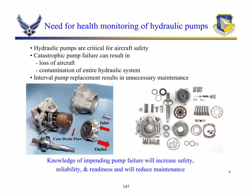
• Hydraulic pumps are critical for aircraft safety• Catastrophic pump failure can result in
- loss of aircraft- contamination of entire hydraulic system
• Interval pump replacement results in unnecessary maintenance
Need for health monitoring of hydraulic pumps
Case Drain Flow
Outlet
Inlet
Knowledge of impending pump failure will increase safety, reliability, & readiness and will reduce maintenance
147

4
Concept Overview
Noise
VibrationsLarge amount of data needed to sort out various frequenciesPlacement/performance of sensors is an issue
Oil Analysis – particles, chemistryNot very effective for hydraulic systems
Variations in input signalMotor current and voltage – limited to motor driven pumps
Variations in output signalPressures, Flows, Temperatures
148

5
Symptoms of a failing pump
• Pump Noise • Case drain flow increases• Case drain temperature rises• Pressure and flow fluctuations
Concept Overview
149

6
• When pump is nearing failure, case drain flow and pump outlet pressure signals exhibit high frequency noise - thought to be due to wobbly motion of the shaft/cylinder-block
Time
Pump OutletPressure
Case DrainFlow
Healthy Pump
Start ofPump Failure
Case Drain Flow
Outlet
Inlet
Concept Overview
150

Signal Noise
Normal SignalPV3-075-15 pump test data
Concept Overview
151

Pump Outlet Flow Case-Drain Flow Torque Pump Outlet Temperature
Figure 14. Test 38, Test parameters at ~ 1500 hours
Signal Noise Signal Shift
Normal Signal
ABEX model AP12V-17 test data
Concept Overview
152

9
AFRL MLBT Pump Test Facility
PHMS
Pump Stand
Outlet Pressure
Case Drain Flow, Press. and Temp.
153

10
0
200
400
600
800
1000
8 9 15 20 24 25 26 28 29
Test
Hou
rs
Test Number
M50
AISI 52100Bearings
Onset of Bearing Failure in CTFE Pump Tests
Onset ofSignal Noise• After the onset of signal
noise, the pump still has ~10% of its remaining useful life
• In-line monitoring system being developed to predict pump failure based upon this concept
Concept Overview
154

11
An In-Line Aircraft Pump Health Monitoring System(PHMS)
Need for health monitoring of hydraulic pumps
Concept Overview
Pump Health Monitoring System (PHMS) status
-Initial development under Air Force SBIR Program
-Adaptation to Army pump
Summary
155

1
DisassembledPump
Goals of this program– Develop an in-line monitoring system (aircraft)– Utilize easy to observe signals– Diagnose failures in real time, in-situ– Allow for a future prognostic capability
Our approach– Demonstrate feasibility with simulations and a prototype
(done)– Gather seeded fault data to refine prototype (done)
Use AFRL pump test dataUse commercial pump data
– Finalize embedded prototype (final tests pending)– Evaluate a broader selection of pumps (in process)
Overview
156

2
Pump Outlet Pressure,Case Drain FlowCase Drain Temp
New Pump
PHMS
Aged Pump
Pump OK
Pump Failing
Initial Development
PHMS (Pump Health Monitoring System) acquires and stores the baseline characteristics of a new pump
As the pump ages, PHMS algorithms continually compare the pump characteristics to the baseline and determine health of the pump
Can be used as a stand-alone or integrated into the Vehicle Health Management System
157

3
DisassembledPump
H1
H10
H2
O1
ON
O2
Input Layer(40 nodes)
Output Layer(N nodes)
Hidden Layer(10 nodes)
OutletPressure
(DC, 18 harmonics)
I1,0
I1,1
I1,18
Case DrainPressure
(DC, 18 harmonics)
I2,0
I2,1
I2,18
Main Flow(DC only)
Case DrainFlow(DC only)
I3,0
I4,0
W1,0,2
W1,0,1
W1,0,10
Y1,1
Y1,N
Y1,2
Y10,N
Y10,1
Y10,2
Output Mode #1(good pump)
Output Mode #N(enlarged cylinder)
Output Mode #2(bearing score)
W4,0,10
W4,0,2
W4,0,1
knijkijn YWIO
for i = 1 to 4; j = 0 to 18;k = 1 to 10; n = 1 to N
+1 : indicates mode n- 1 : indicates NOT mode n
Initial Development: Software Algorithms
158

4
DisassembledPump
Parker Industrial Hydraulic Pump– PVP16 pump (3,000 psi, 8 gpm, 3,000 rpm, 17 hp)– Successfully classified bearing faults and cylinder erosion using seeded faults– Used these tests to establish algorithms
Eaton Aerospace Aircraft Pump– Using MLBT test facility and PV3-075-15– Successfully classified bearing faults– Identified cavitation-induced erosion of port plate
Parker-Abex Aircraft Pump– Pending: components and facility availability
Developed embedded PHMS module– Sensors, hardware, software
Initial Development: Phase II Results
159

5
DisassembledPump
Main Pressure FFTMean = 215.883
File: p2-60hz valve10.0 7-17-03
0
1
2
3
4
5
6
7
0 200 400 600 800 1000 1200 1400
Frequency (Hz)
Am
plitu
de (p
sig)
Main Pressure FFTMean = 195.207
File: p2-60hz valve10.0 8-6-03
0
1
2
3
4
5
6
7
0 200 400 600 800 1000 1200 1400
Frequency (Hz)
Am
plitu
de (p
sig)
Pump #2—No Fault Pump #2—Small ScoreMain Pressure FFT
Mean = 192.480File: p2-60Hz valve 10.0 7-30-03
0
2
4
6
8
10
12
14
16
18
20
0 200 400 600 800 1000 1200 1400
Frequency (Hz)
Am
plitu
de (p
sig)
Main Pressure FFTMean = 19.7778
File: p2-60hz valve10.0 7-25-03
0
0.2
0.4
0.6
0.8
1
1.2
1.4
1.6
0 200 400 600 800 1000 1200 1400
Frequency (Hz)
Am
plitu
de (p
sig)
Pump #2—Large Score Pump #2—Oversize Cylinder
Typical Pump Data (83 Hz Drive)
Rotational harmonic frequencies vary with pump state.
160

6
DisassembledPump
Eaton Aerospace (Vicker’s) PV3-075-15
0 0.02 0.04 0.06 0.08 0.1 0.12 0.14 0.16 0.18 0.2
C/D Flow: DC Main Flow: DC C/D P res s : DC
5th
10th
15th
Outlet P res s : DC
5th
10th
15th
GoodWorn bearing Spalled bearing
Training weights show important features
161

7
DisassembledPump
Cav
itatio
n O
utpu
t Nod
e S
tate
Inlet Pressure (psig)
Eaton PV3-075-15 PumpCavitation Detection
10 20 30 40 50 60 70 80 90-1
-0.8
-0.6
-0.4
-0.2
0
0.2
0.4
0.6
0.8
1
Cavitation Detected
PV3-075-15 Cylinder Block Face
Damage
162

8
DisassembledPump
0 0.05 0.1 0.15 0.2 0.25
C/D Flow: DCMain Flow: DCC/D P res s : DC
5th
10th
15th
Main P res : DC
5th
10th
15th
PVP16 Industrial Pump Results
GoodBearing Score Eroded Cylinder
163

9
DisassembledPump
good
worn mainbearing
spalledbearing
cavitation
post-cavitation
w 5
w 4
w3
w2
w1
> 0.5
else< 0.5
Neural Net Output Threshold Weights LED Output
Creating a good/bad pump classifier
n
kkk tows
1
0 200 400 600 800 1000 1200 1400 1600 1800 2000-1
0
1
good
good
0.99
9826
wor
n m
ain
bear
ing
-0.9
9999
5
spal
led
bear
ing
-0.9
9996
5
cavi
tatio
n-0
.998
496
post
-cav
itatio
n-0
.999
674
Neural Net Output
0 200 400 600 800 1000 1200 1400 1600 1800 2000-1
0
1
wor
n m
ain
bear
ing
good
-0.9
9997
4
wor
n m
ain
bear
ing
-0.5
3245
2
spal
led
bear
ing
-0.9
7456
9
cavi
tatio
n-0
.981
315
post
-cav
itatio
n-0
.995
840
0 200 400 600 800 1000 1200 1400 1600 1800 2000-1
0
1
spal
led
bear
ing
good
-0.9
9967
9
wor
n m
ain
bear
ing
-0.9
2926
2
spal
led
bear
ing
0.97
2874
cavi
tatio
n-0
.999
994
post
-cav
itatio
n-0
.997
697
0 200 400 600 800 1000 1200 1400 1600 1800 2000-1
0
1
cavi
tatio
n
good
-1.0
0000
0
wor
n m
ain
bear
ing
-1.0
0000
0
spal
led
bear
ing
-1.0
0000
0
cavi
tatio
n1.
0000
00
post
-cav
itatio
n-1
.000
000
0 200 400 600 800 1000 1200 1400 1600 1800 2000-1
0
1
post
-cav
itatio
n
good
-1.0
0000
0
wor
n m
ain
bear
ing
0.62
8028
spal
led
bear
ing
-1.0
0000
0
cavi
tatio
n-0
.999
909
post
-cav
itatio
n1.
0000
00
time (sec)
Failure
Unknown
Good
Good Pump Bad Pump
164

10
DisassembledPump
Co-funded by U.S. Army and Air Force OSDInvestigating applicability to Army’s PV3-075-20 pumpPV3-075-20 is similar to PV3-075-15– Mounting hardware– Other changes to suit aircraft installation
Thus far we have tested good and rebuilt pumpsResults include:– PV3-075-15 algorithms work with PV3-075-20 pumps– Good and rebuilt pumps classified as good– Good and rebuilt pumps can be discriminated (if desired)
Further work on piston shoe and other failures pending
Adaptation to Army Pump
165

11
DisassembledPump
Output Node Value
Good +0.73
Worn Bearing -0.99
Spalled Bearing -0.83
Cavitation -0.95
Post-Cavitation -0.12
Phase II SBIR Follow-on Work
Result #1: The existing algorithms correctlyclassify the new and rebuilt PV3-075-20 pumps as being similar to the good PV3-075-15 pumps.
Rebuilt PV3-075-20 Pump
Output Node Output Node Value
Good +0.32
Worn Bearing -0.99
Spalled Bearing -0.97
Cavitation -0.99
Post-Cavitation -0.42
New PV3-075-20 Pump
166

12
DisassembledPump
Phase II SBIR Follow-on Work
Result #2: The optimizer provides a clear indication that the pumps are “good”.
Failure
Unknown
Good4865412
New (92 % Certainty)Failure
Unknown
GoodSnubber Data using First Optimizer
5292966
Rebuilt (85 % Certainty)
167

13
DisassembledPump
Phase II SBIR Follow-on Work
Result #3: New algorithms, with the new data included in the training, can now correctly classify all the PV3-075-20 and PV3-075-15 pump states.
-1
0
1
good
good
-0.0
1485
3
wor
n m
ain
bear
ing
-1.0
0000
0
spal
led
bear
ing
-0.9
9955
2
cavi
tatio
n-0
.999
863
post
-cav
itatio
n-0
.999
956
good
-20
-1.0
0000
0
rebu
ilt-20
-0.9
9273
6
-1
0
1
wor
n m
ain
bear
ing
good
-0.9
8683
8
wor
n m
ain
bear
ing
0.12
8068
spal
led
bear
ing
-0.9
9761
3
cavi
tatio
n-0
.999
877
post
-cav
itatio
n-0
.999
908
good
-20
-1.0
0000
0
rebu
ilt-20
-1.0
0000
0
-1
0
1
spal
led
bear
ing
good
-1.0
0000
0
wor
n m
ain
bear
ing
-0.7
3304
7
spal
led
bear
ing
0.99
9733
cavi
tatio
n-0
.999
993
post
-cav
itatio
n-0
.999
995
good
-20
-0.9
9994
5
rebu
ilt-20
-1.0
0000
0
-1
0
1
cavi
tatio
n
good
-0.9
9933
8
wor
n m
ain
bear
ing
-1.0
0000
0
spal
led
bear
ing
-0.9
9371
3
cavi
tatio
n0.
9999
68
post
-cav
itatio
n-1
.000
000
good
-20
-1.0
0000
0
rebu
ilt-20
-1.0
0000
0
-1
0
1
post
-cav
itatio
n
good
-0.4
5816
5
wor
n m
ain
bear
ing
-0.9
9849
2
spal
led
bear
ing
-0.9
7260
8
cavi
tatio
n-1
.000
000
post
-cav
itatio
n0.
9999
91
good
-20
-1.0
0000
0
rebu
ilt-20
-1.0
0000
0
-1
0
1
good
-20
good
-1.0
0000
0
wor
n m
ain
bear
ing
-0.9
9993
7
spal
led
bear
ing
-0.9
9999
8
cavi
tatio
n-1
.000
000
post
-cav
itatio
n-0
.999
999
good
-20
0.99
9986
rebu
ilt-20
-0.9
9914
7
0 500 1000 1500 2000 2500 3000-1
0
1
rebu
ilt-2
0
good
-0.9
9916
6
wor
n m
ain
bear
ing
-0.9
9995
4
spal
led
bear
ing
-0.9
9998
5
cavi
tatio
n-0
.998
461
post
-cav
itatio
n-0
.999
980
good
-20
-0.9
9974
2
rebu
ilt-20
0.99
9236
time (sec)
168

14
DisassembledPump
• Two possible pathsVia airframe manufacturers or operators
Via pump manufacturers
• Possible output typesAnnunciator
Wireless/wired PHMS data to ground support
1553 bus data interface to VHM
• Other user applicationsPiston pumps such as fuel pumps
Neural networks can be applied to other health monitors
Transition Path
169

15
DisassembledPump
• In-line health monitoring of aircraft hydraulic pumpsA concept based on pressure and flow fluctuations developed
Monitoring system under development using the SBIR contract
Bearing failures successfully detected
Adaptation to Army pump successful thus far (work ongoing)
• ImpactReplace pumps for cause paradigm shiftImproved safety, reliability, readiness & maintainabilityAll systems impacted: DOD, Airlines and IndustrialAdaptable to other piston pumps (e.g. fuel pumps)
Summary
170

Aging AircraftAging AircraftSystems SquadronSystems Squadron
Keep‘em flying & Keep‘em relevant
Hydraulic Fluid PurificationHydraulic Fluid PurificationOVERVIEWOVERVIEWJune 2006June 2006
Al HermanACSSW/AASS/OBDSN 785-7210 Ext 3915Email: [email protected]
Dominant Air Power: Design For Tomorrow…Deliver Today
171

2
Dominant Air Power: Design For Tomorrow…Deliver Today
Overview
• Aging Aircraft Systems Squadron• HFP Team / Background• History• Air Force Qualifications• Purification Equipment
PallMalabarContamination Multi Sensor
172

3
Dominant Air Power: Design For Tomorrow…Deliver Today
Aging Aircraft Systems Squadron
Our MissionThe Aging Aircraft Systems Squadron develops and fields products that enhance USAF aircraft fleet availability and mission capability while reducing total ownership cost.
Our ObjectiveOur job is to develop, acquire, and field cross-enterprise materiel solutions that enhance fleet availability and mission capability. We deliver systems/products that provide the AF means to reduce total ownership costs.
Our CustomersACC, AETC, AFMC, AFRC, AFSPC, AFSOC, AMC, ANG, PACAF, USAFE, and the ALCs
173

4
Dominant Air Power: Design For Tomorrow…Deliver Today
HQ AFMC
HFP Team
HFP
AFRL/MLBT HQ AMC AASS/OB
ASC/ENVV
AMC Battlelab
ASC/EN
AFOTEC
WR-ALC
HQ ACC
HQ AFRC
HQ ANGHQ AETC
HQ AFSOC
OC/ALC
OO/ALC
HQ USAFE HQ PACAF
CTC
PALL
UDRI
MALABAR
METSS
174

5
Dominant Air Power: Design For Tomorrow…Deliver Today
HFP Support
HFPMLBT SensorDevelopment
Program
WR-ALC F-15Cooperative
Program
Barium freeHydraulic Storage
Program
AFOTECPhase I & IIPrograms
AMC BattlelabProgram
GREENHydraulicsProgram
Hydraulic FluidSamplingProgram
ARMYCH-47
Program
NAVY Acft &SubmarineProgram WR-ALC
New MuleProgram
175

6
Dominant Air Power: Design For Tomorrow…Deliver Today
• Initial Requirement:• Sep 1998 Executive Order 13101, Greening the Government through Waste Prevention, Recycling, and Federal Acquisition Section 101.
“It is the national policy to prefer pollution prevention, whenever feasible.”
• AFMC-pollution prevention program • Reduce hydraulic fluid waste stream
• Evaluate purification and demonstrate use in field
Background
176

7
Dominant Air Power: Design For Tomorrow…Deliver Today
WHY HFP?
• Man-hours required to drain and flush– Contaminated systems require drain and flush
to purge system
• Large Mobility/Supply Footprint• Large Hydraulic Fluid Waste Stream
– Pollution Prevention for Environment– High Cost of Waste Disposal
• Significant Cost Savings
177

8
Dominant Air Power: Design For Tomorrow…Deliver Today
HFP Return on Investment
• Savings in new fluid procurement (AF)/ALL FLUIDS– Estimated 0.9M gal X $10/Gal X .90 = $8.1M
• Savings in used fluid disposal cost– Estimated 0.8M gal X $1.50/gal = $1.2M
• Total savings = $9.3M Annually • 5 Year ROI ratio = 62:1 (9.3 X5 = 46.5/750K)• Calculated savings does NOT consider
savings as a result of component life extensions
178

9
Dominant Air Power: Design For Tomorrow…Deliver Today
Navy HFP
• Purifying hydraulic fluid on equipment used to service Aircraft (F-14 / F-18)
• Many years of HFP on Submarines– Fluid disposal was an issue– Limited space to carry new and used fluid
179

10
Dominant Air Power: Design For Tomorrow…Deliver Today
Army HFPCH-47 goes through phase every 18 months
• 480 CH-47s in the Army
• 480 X 0.667 = 307 = Number of aircraft in phase annually
• Prior to purification / 53 gals hydraulic fluid required per aircraft
• After purification / 1 gal hydraulic fluid required per aircraft
• 52 gallons saved per aircraft
• 307 X 52 = 15,964 Gals x $10 Avg = $159,640.00 Savings per year
180

11
Dominant Air Power: Design For Tomorrow…Deliver Today
• Phase I ( Apr 00 – Jun 03)– AFOTEC, ASC/ENVV, AFRL/MLBT, HQ AMC, ASC/AAA– Research and validate methods and procedures for HFP
• Phase II ( Mar 04 – Jun 04)– AFOTEC, ASC/ENVV, AFRL/MLBT, HQ AMC, ASC/AAA– Conduct Operational Utility Testing on existing Hyd Mules– Technical Order Change
• Phase III ( Jan 04 – Sep 07)– AFRL/MLBT, ALC’s, MAJCOM, ASC/SPO’s, AAA & ENVV– Sampling program to determine purification standards– Authorize use of purified fluid in aircraft via T.O. changes and letters of
authorization– Conduct field service evaluation
• SE Development and Fielding (Jan 00 – Sep 10)– WR-ALC/LES, HQ-ACC/LGM– Develop Malabar and T.O.s– Field Malabar Mule as replacement – Field Malabar and Pall Portables
HFP Program
181

12
Dominant Air Power: Design For Tomorrow…Deliver Today
USAF Phase I
• AFOTEC Reviewed 13 test reports of Pall Portable Fluid Purifier (PPFP) conducted by:– US Army, US Navy, & US Air Force– 15 years of tests– Tests MIL-H-87257, 83282, 5606, & 46170
• Findings: AFOTEC & AFRL– Water reduction capability satisfactory in all tests– Particulate reduction capability satisfactory in all tests– Purification did not impact physical properties (i.e.
viscosity, lubricity, fluid foaming)– Purification can bring fluid to spec standards in 2 to 4
hours (depending on contamination)
182

13
Dominant Air Power: Design For Tomorrow…Deliver Today
USAF Phase II (Mar 04 – Jun 04)Det 1 AFOTEC
• Conducted Operational Utility Evaluation– Used Mules from Kirtland AFB
• 58th SOW• 150th FW
• Mules were used to service F-16, H-53, & C-130
183

14
Dominant Air Power: Design For Tomorrow…Deliver Today
USAF Phase III (Jan 04-Sep 10)
• HQ AMC HFP Champion – Conduct Aircraft Sampling Program
– 15 Different Aircraft - 53 Bases, 562 Samples
- Aerospace Ground Equipment- 53 Bases, 216 Mule Samples
– Develop Hydraulic Fluid Standards– Conduct Field Service Evaluations– AFRL, Aging Aircraft Systems Squadron
(AASS), MAJCOMs & ALC Involvement
184

15
Dominant Air Power: Design For Tomorrow…Deliver TodayMalabar Purification Unit
NSN 4920-01-380-7460, 3 System, Diesel Engine Driven.
NSN 4920-01-380-4744, 3 System, Electric Motor Driven.
NSN 4920-01-434-1081, 2 System, Diesel Engine Driven.
NSN 4920-01-434-3206, 2 System, Electric Motor Driven.
Pall Hydraulic Fluid Purifier
- Purification-- Particulate Reduction
- Water Reduction-- Free & Dissolved
Air Reduction-- Solvent Removal-- Synergistic Effects
- Filtration-- Particulate Reduction
Purification Equipment
185

16
Dominant Air Power: Design For Tomorrow…Deliver Today
• How the purifiers work:– Create large fluid surface area using a spinning
disk or by misting– Partial vacuum to remove volatiles– High efficiency fine filter– Some use absorption/adsorption to remove
water
• Effective in removing• Particulate Contamination• Moisture• Solvents • Air (Entrained and Dissolved)
- Spongy flight controls- Pump cavitation- Fluid over-temp
• Portable and built-in configurations Malabar Portable Purifier
Pall Portable Purifier
Hydraulic Fluid Purification
186

17
Dominant Air Power: Design For Tomorrow…Deliver Today
HFP Equipment (Cont’d)• Pall Portable
– With Water Sensor– Without Water Sensor– In Use for Service Eval
MALABAR PALL
P/N 885200-1
• Malabar Portable– With Water Sensor– Without Water Sensor– In Use for Service Eval
4330-01-470-1855P/N PE0107812H83T.O. 35M15-2-9-1
Air Force Without Water Sensor
4330-01-522-2007P/N PE0107812HW83Army Manual In Work
Army With Water Sensor
P/N 885200-3CommercialManual
187

18
Dominant Air Power: Design For Tomorrow…Deliver Today
Hydraulic Fluid Multi-Sensor
• Currently No Field Capability to Analyze Hydraulic Fluid for Water and Particulate Contamination
• Current Fluid Inspection is Visual Only• Requires Sample sent to the Air Force Petroleum
Lab at WPAFB
• Affects all aircraft, all platforms and all Mules• Need on-site sensor for detection of water and
particulate contamination in hydraulic fluids
188

19
Dominant Air Power: Design For Tomorrow…Deliver Today
• Impact of no sensor– Sample analysis cost is about $100 per sample– Shipping and analysis time causes equipment
and aircraft down time– Hydraulic fluid purification initiative drives the
need for the sensor technology
• MAJCOM Coordination:– HQ AMC/A44JS requested sensor
Hydraulic Fluid Multi-Sensor
189
20
Dominant Air Power: Design For Tomorrow…Deliver Today
• Develop in-line, real-time, field-level multi-sensor
• Deliver Sensors with operating instructions
• Six (6) units to be delivered at completion of contract for field service evaluation
• Solution is cross-cutting on all Weapon Systems
Sensor Solution
190

21
Dominant Air Power: Design For Tomorrow…Deliver Today
• Implementation issues– Additional units paid for by the user ($3-5K each)– Operation manual will be provided with sensor
• What are the benefits?– Decreased analysis and shipping times will provide
better aircraft/equipment availability (3-4 days saved)– Maintenance manhours are reduced by eliminating
unnecessary drain and flush of Mules– Base level Hydraulic fluid contamination detection
capability saves Lab analysis cost
Solution Approach
191

22
Dominant Air Power: Design For Tomorrow…Deliver Today
Conclusion
• Tested Effectiveness of Purification• Tested / Qualified Equipment Purification
Capabilities• Sampled Aircraft & Hydraulic Test Stands
(mules)• Authorized Use of Purified Hydraulic Fluid• Service Evaluations in Process• Multi-Sensor Development in Work• READY FOR HFP IMPLEMENTATION
192

23
Dominant Air Power: Design For Tomorrow…Deliver Today
Hydraulic Fluid Purification
QUESTIONS?
193

Hydraulic Test Stand Modification at Eglin Presented by: Eddie Preston
194

Hydraulic Fluid Purification
“Purity” can be measured in three areas:– Particulate– Water– Air
Achieving PurityCan be achieved by two methods:– Onboard purifier– Stand Alone purifier
195

Achieving PurityOnboard purifier– On-board purifier is a good choice for new acquisition,
poor choice for existing mules. – Large dollar value (30k+ each) to add on-board
purifier to existing mules.
Stand Alone purifier– A good choice for the existing mules; however,
existing mules need to be modified with connections. (1-1.5k each not including 3 micron filter change)
– One stand alone purifier can service multiple mules separately.
196

Maintaining PurityParticulate– Replace existing filters on the mules from current 5
micron hydraulic filters with 3 micron absolute filter elements
Water– Add a reservoir vent filter/dryer.
Air– The only way to remove air is purify regularly.– Modify mules with purifier connections.
197

Portable Hydraulic Stands Modified4920-01-143-12033 System Diesel Engine Model Number TTU-228/E-1B9 UNITS on hand total for the 33d AGE FlightManufacturer- Hydraulics International Inc.One unit modified
4920-01-044-59263 System Electric Model Number A/M27T-2A6 UNITS on hand total for the 33d AGE FlightManufacturer- ACL FILCOOne unit modified
198

3 System Diesel Modfor Purifier Attachments
Square Tank Method
199

3 System Diesel ModVent Dryer
Vent Dryer FittingUnvented FillerCap
Vent DryerMounted OnInside WallOf HTS
Pall Purifier Hooked Up To HTS
200
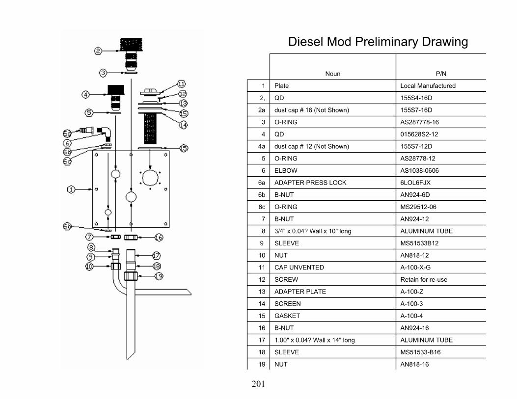
Diesel Mod Preliminary Drawing
Noun P/N
1 Plate Local Manufactured
2, QD 155S4-16D
2a dust cap # 16 (Not Shown) 155S7-16D
3 O-RING AS287778-16
4 QD 015628S2-12
4a dust cap # 12 (Not Shown) 155S7-12D
5 O-RING AS28778-12
6 ELBOW AS1038-0606
6a ADAPTER PRESS LOCK 6LOL6FJX
6b B-NUT AN924-6D
6c O-RING MS29512-06
7 B-NUT AN924-12
8 3/4" x 0.04? Wall x 10" long ALUMINUM TUBE
9 SLEEVE MS51533B12
10 NUT AN818-12
11 CAP UNVENTED A-100-X-G
12 SCREW Retain for re-use
13 ADAPTER PLATE A-100-Z
14 SCREEN A-100-3
15 GASKET A-100-4
16 B-NUT AN924-16
17 1.00" x 0.04? Wall x 14" long ALUMINUM TUBE
18 SLEEVE MS51533-B16
19 NUT AN818-16
201

3 System Electric Modfor Purifier Attachments
Round Tank Method
Existing End Cap
New ManufacturedEnd Cap
Hydraulic Reservoir End ViewEnd Cap Removed
Hydraulic Reservoir End View New Manufactured End Cap Installed
202

Electric Mod Preliminary Drawing
Noun P/N
1 Plate Local Manufactured
2 QD 155S4-16D
2a dust cap # 16 (Not Shown) 155S7-16D
3 O-RING AS287778-16
4 1.00" x 0.04? Wall x 14" long ALUMINUM TUBE
5 SLEEVE MS51533-B16
6 NUT AN818-16
7 QD 015628S2-12
7a Dust cap # 12 (Not Shown) 155S7-12D
8 O-RING AS28778-12
9 3/4" x 0.04? Wall x 10" long ALUMINUM TUBE
10 SLEEVE MS51533B12
11 NUT AN818-12
203

3 System Electric ModVent Dryer
New Spacer ForVent Dryer Fitting
New Spacer ForVent Dryer Installed
Vent DryerMounted OnInside WallOf HTSFitting For
Vent Dryer
204

Electric Mod Preliminary Drawing
Noun P/N
159 Reservoir
170 Replace existing cap with un-vented cap A-100-X-G
171 SCREW Bench Stock
172 SCREEN A-100-3
173 GASKET A-100-4
Adapter Ring Local Manufactured
90 Deg Elbow 3/8" NPT x 3/8" hose barb TBD
1/2" OD x 3/8" ID Hose (not shown) polybutylene
Pall Filter Vent (not shown) TBD
Pall Filter Vent Bracket (not shown) TBD
Pall Filter Vent Hose adapter (not shown) TBD
205
Additional Requirements
• TCTO / IOS– Requires drawings and funding for parts and
services.– VAL-VER of each TCTO / IOS.– Current TO’s require new procedures and IPB
changes.
206

Hydraulic Fluid Purification Decision BriefBy: Eddie Preston
207

Overview
• Findings– Aircraft issues that justify a requirement
• F-16• F-15• B-1
• Recommendations
208

F-16 TCTO 15 Micron to 5 Micron
209

F-16 TCTO 15 Micron to 5 Micron
210

F-15
• High air content• High Water• High Particulate• Recent concept demonstration performed
successfully at Eglin AFB.
211

B-1 Issues
• Landing Gear Strut Contamination. • B-1 found failed high pressure filters
during mule inspection. • Ellsworth had 4 high pressure filters that were split apart. • AFTO 22 to have the filters changed every two years was
disapproved by ACC.
• B-1 SPO inquired about the 1067 being submitted by F-15 SPO.
212

Mules in the Field
331 331 331 331 331 295 248 201 201 201
180 180180 180 180
161135
109 109 109
177 177177 177 177
158
133
108 108 108
158 158158 158
158
141
119
97 97 97
103 103103 103 29
120240
360480
600720
840 840 840
0%
10%
20%
30%
40%
50%
60%
70%
80%
90%
100%
FY 10 FY 11 FY 12 FY 13 FY 14 FY 15 FY 16 FY 17 FY 18 FY 19
UHTS-5927-5926-2039-1203-4762
213

Recommendations
• Change 5 Micron HPF to 3 Micron HPF in top 5 legacy HTS.
• Fund Mod top 5 legacy stands w/ Purifier QD’s.• Allow SPOs to fund mod for other NSN’s as
requested.
* Pall Purifier has been added to shop TA and several Aircraft TA’s.
214

Hydraulic Fluid Purification Environmental Aspects
Mr. Don StreeterASC/ENVVASC HFP Environmental [email protected]: 785-3550 Comm 937 255-3550
215

Drivers: DoDD 4715.1E/DoDI 4715.4, AFPD 32-70 /AFI 32-7086,HMRPP Need 530, Executive Order 13101, 40 CFR 279, T.O. 42B2-1-3
Description: Pollution Prevention Project Initiated to Evaluate Feasibility of Purifying and Reusing Hydraulic Fluid in the Most Effective Way Possible and to Reduce the Waste Stream as Much as is Feasible Without Significantly Increasing Ground Crew Demands or Degrading Aircraft Readiness, and Performance
Weapon Systems and Stakeholders: All SPOS/Wings that have Aircraft that Use and/or Dispose of Large Amounts of Hydraulic Fluid, All SPOs that want to Save Money and Improve Aircraft Hydraulic System, Ground Support Equipment and Ground Crew Performance
Why Hydraulic Fluid Purification (HFP)?
216
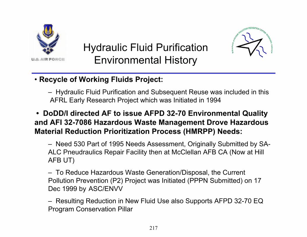
• Recycle of Working Fluids Project:– Hydraulic Fluid Purification and Subsequent Reuse was included in this AFRL Early Research Project which was Initiated in 1994
• DoDD/I directed AF to issue AFPD 32-70 Environmental Quality and AFI 32-7086 Hazardous Waste Management Drove Hazardous Material Reduction Prioritization Process (HMRPP) Needs:
– Need 530 Part of 1995 Needs Assessment, Originally Submitted by SA-ALC Pneudraulics Repair Facility then at McClellan AFB CA (Now at Hill AFB UT)
– To Reduce Hazardous Waste Generation/Disposal, the Current Pollution Prevention (P2) Project was Initiated (PPPN Submitted) on 17 Dec 1999 by ASC/ENVV
– Resulting Reduction in New Fluid Use also Supports AFPD 32-70 EQ Program Conservation Pillar
Hydraulic Fluid Purification Environmental History
217

• Executive Order 13101 Greening the Government Through Waste Prevention Recycling and Federal Acquisition
– Pollution Prevention and Source Reduction Preferred Whenever Feasible– Mandates Reuse/Recycle of Waste Materials Whenever Feasible– Disposal Employed Only as a Last Resort
– Comprehensive 25 page Code of Federal Regulations Document• Promulgates the Legal Standards for the Management of Waste Oil
– P2 Project Minimizes Need to Manage Unusable Waste Oil, Maximizes need to Properly Segregate/Manage Oil to be Purified and Reused
• T.O. 42B2-1-3 Hydraulic Fluid Standard Technical Order– Document that was Changed 6 Jun 2004 to Allow Hydraulic Fluid Purification by Stating that Fluid Purified by Air Force Qualified Purifiers with Approval from the Responsible Wing/Program Office of Record for the Aircraft System using the Fluid
Hydraulic Fluid Purification Environmental History (con’t)
• 40 CFR 279 Standards for the Management of Used Oil
218

• Stakeholders:– Wings/SPOs that have Aircraft that Use and/or Dispose of Large Amounts (55 gal or Larger Drums/Tanks) of New/Waste Hydraulic Fluid,
– Wings/SPOs that have Aircraft (A/C) Hydraulic System and/or Ground Support Equipment (GSE) Contamination Problems
– Wings/SPOs that have Hydraulics (A/C & GSE) Maintenance Problems
• Excessive Contamination, Component: Leakage, Failures and Subsequent Replacement
– Wings/SPOs that have A/C Hydraulic System Performance Problems
• Erratic Flight Control Actuator, Brake or Landing Gear Operation
• The Product : Purified Hydraulic Fluid– All of the Above Stakeholders Require New MIL-SPEC Compliant or Purified Hydraulic Fluid to Resolve Above Problems
Hydraulic Fluid Purification Who and What?
219

• Benefits– Decreased Fluid Consumption and Reuse/Recycle of Fluid Usually Disposed of as Hazardous Waste Main Objective of ASC/ENVV HFP Environmental Initiative
• Less Manpower will be Required to Manage and Handle Waste Materials
– Environmental Aspects only Part of Expected Savings, Other Benefits Include:
• Reduced Hydraulic System Maintenance/Extended MTBF for Hydraulic Systems
• Extended Hydraulic Component Life
– Potential to Save Millions of $ in Component Replacement Costs
Hydraulic Fluid Purification Why Else? Not Just Environmental
220

• Benefits (con’t)• Improved Aircraft Performance
– Smooth Operation of Hydraulic Components • Better Flight Control, Landing Gear, & Brake System Operation/Response
– Deployment Footprint is Minimized and Disposal Problems can be Greatly Reduced
• Both New Fluid Carried In and Waste Fluid Carried Out can be Greatly Reduced if Purifiers are Deployed
• Disposal Problems that are Worse in Foreign Countries than in the US can be Minimized as Well
Hydraulic Fluid Purification Why Else? Not Just Environmental
(con’t)
221

• Conclusion– HFP is a Great Way to Comply with Current DoD and Air Force Environmental Policy and Should Be a Mandatory Air Force Requirement
– HFP Has Many Other Significant Benefits Which Go Way Beyond its Environmental Scope, and Will Make the Process Essential to the Warfighter
Hydraulic Fluid Purification Environmental Aspects
222

George FultzUniversity of Dayton Research Institute.
Analytical Data On AircraftAnd Mule Hydraulic Fluid Samples
223

Hydraulic Fluid Sampling Program• Objective: Analyze hydraulic fluid from operational aircraft and hydraulic test stands (mules) for particulate, water and chlorinated solvent contamination
• Primary purpose was to develop a realistic standard for maximum contamination levels in operational hydraulic systems
• This will serve as a guideline for establishing cleanliness standards for hydraulic fluid purification for both servicing equipment as well as aircraft
• Only current standard is for new hydraulic fluid – not realistic for in-use hydraulic fluid
224

AIRCRAFT AND MULE SAMPLES
•Aircraft•572 Kits Scheduled
•572 Kits Sent
•560 Received and Analyzed
•Mules• 218 Kits Scheduled
• 218 Kits Sent
• 191 Received and Analyzed
225

HELICOPTER & MULE SAMPLES
•Helicopter•86 Kits Scheduled
•73 Kits Sent
•52 Received and Analyzed
•Helicopter Mules• 38 Kits Scheduled
• 38 Kits Sent
• 30 Received and Analyzed
226

DATA DETERMINED ON EACH SAMPLE
• PARTICULATE COUNT (FTM 791C 3012)• WATER CONTENT
ASTM D 6304• BARIUM CONTENT
ASTM D 5185• CHLORINE
CAPILLARY GAS CHROMATOGRAPHY
227

PARTICULATE COUNT BYAUTOMATIC PARTICLE COUNTER
FED-STD-791 Method 3012
Calibrated by Manufacturer Every Six Months
228

229

NAS 1638MAXIMUM CONTAMINATION LEVEL OF 100 ML SAMPLES
Micron Range 00 0 1 2 3 4 55 -15 125 250 500 1,000 2,000 4,000 8,00015 - 25 22 44 88 176 352 704 1,40825 - 50 4 8 16 32 64 128 25350 -100 1 2 3 6 11 22 45>100 0 0 1 1 2 4 8
Micron Range 6 7 8 9 10 11 125 -15 16,000 32,000 64,000 12,800 256,000 512,000 1,024,00015 - 25 2,816 5,632 11,264 22,528 45,056 90,112 180,22425 - 50 506 1,012 2,025 4,050 8,100 16,200 32,40050 -100 90 180 360 720 1,440 2,800 5,600>100 16 32 64 128 256 512 1,024
Contamination Class
Contamination Class
230

Coulometric Water Apparatus
REASONABLE LIMIT LESS THAN 300 PPM
231

ASTM D 6304Coulometric Karl Fisher Titration
• Water in the range of 10 – 20,000 ppm• A sample is injected into the titration vessel
of a coulometric Karl Fischer apparatus• Injection can be done either by mass or
volume.• Fisher reaction (pyridine and chloroform
free) detected coulometrically.
232

BARIUM CONTENT BY ICP
REASONABLE LIMIT LESS THAN 20 PPM
233
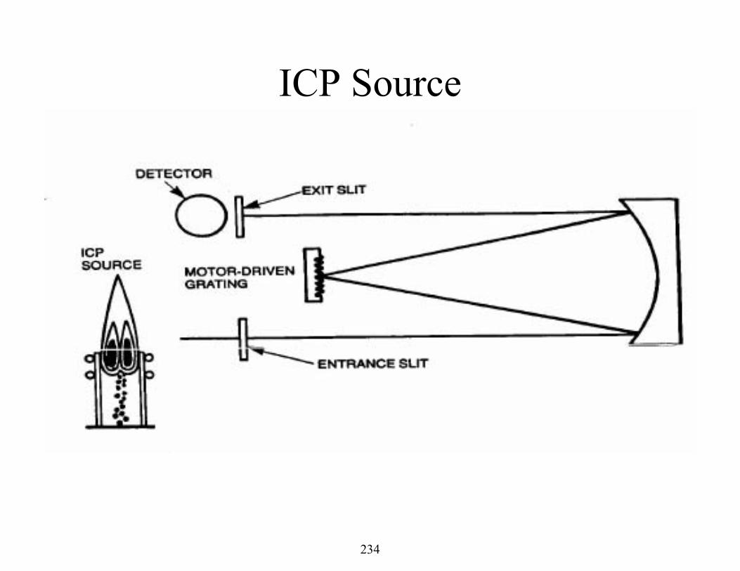
ICP Source
234

CHLORINE BY GAS CHROMATOGRAPHY
REASONABLE LIMIT LESS THAN 200 PPM
235

Electron Capture Detector (ECD)
236

Chromatograms of Chlorine (Freon)
min0 0.5 1 1.5 2 2.5
Hz
0100020003000400050006000
ECD2 B, (BASECL\3DA.D)
200 ppm chlorine
min0 0.5 1 1.5 2 2.5
Hz
0100020003000400050006000
ECD2 B, (BASECL\CL-2.D)
74 ppm chlorine
min0 0.5 1 1.5 2 2.5
Hz
0100020003000400050006000
ECD2 B, (BASECL\BS-2.D)
15 ppm chlorine
237

Particle Counts, Water, & Barium Results From Various Groups of
Aircraft & Associated Mules
238

What is a Mule?
239

What is a Mule?
240

What is a Mule?• From Wikipedia, the free encyclopedia & Steve
Gunderson (UDRI)
• Multifunction Utility/Logistics and Equipment(MULE) vehicle is an autonomous ground vehicle developed by for the Lockheed-Martin
?????
241

What is a Mule?
242

10 B1 = 40 SAMPLES
243

3 B-2 = 10 SAMPLES
244

9 U-2 (NINE SAMPLES)
245

Bomber & U2 Aircraft + MulesAverage Results for Particle Count
0
2
4
6
8
10
12
14
10 B-1s 3 B-2s 9 U-2s
Aircraft
MulesNAS 8 Average of 191 mules
NAS 7 Average of 560 aircraft
40 S
ampl
es
8 Sa
mpl
es
10 S
ampl
es
8 Sa
mpl
es
9 Sa
mpl
es
9 Sa
mpl
es
246

Bomber & U2 Aircraft + MulesAverage Results for Water
0
50
100
150
200
250
10 B-1s 3 B-2s 9 U-2s
PPM
Aircraft
Mules
182 ppm Average of 560 aircraft
190 ppm Average of 191 mules
40 S
ampl
es
8 Sa
mpl
es
10 S
ampl
es
8 Sa
mpl
es
9 Sa
mpl
es
9 Sa
mpl
es
247

Bomber & U2 Aircraft + MulesAverage Results for PPM Barium
0
2
4
6
8
10
12
14
16
18
20
10 B-1s 3 B-2s 9 U-2s
PP
M B
ariu
m
Aircraft
Mules
16 ppm Average of 191 mules l
18 ppm Average of 560 aircraft
40 S
ampl
es
8 Sa
mpl
es
10 S
ampl
es
8 Sa
mpl
es
9 Sa
mpl
es 9 Sa
mpl
es
248

28 KC 135 (56 SAMPLES)
249

14 C-5 (56 SAMPLES)
250

13 C-17 (52 SAMPLES)
251

24 C-130 (72 SAMPLES)
252

Average Particle Count (NAS 1638)Cargo Aircraft
0
2
4
6
8
10
12
28 KC135s 14 C-5s 13 C-17s 24 C-130s
Aircraft
Mules
56 S
ampl
es
19 S
ampl
es
56 S
ampl
es
17 S
ampl
es
52 S
ampl
es
4 Sa
mpl
es
72 S
ampl
es
8 Sa
mpl
es
NAS 8 Average of 191 mules
NAS 7 Average of 560 aircraft
253

Average Water ContentCargo Aircraft
0
50
100
150
200
250
300
28 KC135s 14 C-5s 13 C-17s 24 C-130s
PPM
Aircraft
Mules56
Sam
ples
19 S
ampl
es
56 S
ampl
es
17 S
ampl
es
52 S
ampl
es
4 Sa
mpl
es
72 S
ampl
es
8 Sa
mpl
es
190 ppm Average of 191 mules
182 ppm Average of 560 aircraft
254

Average Barium Content Cargo Aircraft
0
2
4
6
8
10
12
14
16
18
20
28 KC135s 14 C-5s 13 C-17s 24 C-130s
Bari
um P
PM
Aircraft
Mules
56 S
ampl
es
19 S
ampl
es
56 S
ampl
es
17S
ampl
es
52 S
ampl
es
4 S
ampl
es
72 S
ampl
es
8 S
ampl
es
18 ppm Average of 560 aircraft samples
16 ppm Average of 191 mules l
255

16 A-10 (32 SAMPLES)
256

6 F-22 (12 SAMPLES)
257
29 F-15 (87 SAMPLES)
258

43 F-16 (85 SAMPLES)
259

Average Particle Content (NAS 1638) Fighter Aircraft
0
2
4
6
8
10
12
16 A-10 6 F-22 29 F-15 43 F-16
Aircraft
Series28 ppm Average of 191 mules
7 PPM Average of 560 aircraft
32 S
ampl
es
23 S
ampl
es
12 S
ampl
es
8 Sa
mpl
es
87 S
ampl
es
23 S
ampl
es
85 S
ampl
es
17 S
ampl
es
260

Average Water ContentFighter Aircraft
0
50
100
150
200
250
300
16 A-10 6 F-22 29 F-15 43 F-16
PPM
Aircraft
Mules
190 ppm Average of 191 mules
182 ppm Average of 560
32 S
ampl
es
23 S
ampl
es
12 S
ampl
es
8 Sa
mpl
es
87Sa
mpl
es
23 S
ampl
es
85 S
ampl
es
17 S
ampl
es
261

Average Barium Content Fighter Aircraft
0
5
10
15
20
25
30
35
40
45
50
16 A-10 6 F-22 29 F-15 43 F-16
Bari
um P
PM
Aircraft
Mules
18 ppm Average of 560 aircraft samples16 ppm Average of 191 mules
l
32 S
ampl
es
23 S
ampl
es
12 S
ampl
es
8 Sa
mpl
es 87 S
ampl
es
23 S
ampl
es
85 S
ampl
es
17 S
ampl
es
262

14 UH-1 (28 SAMPLES)
263

4 HH-60 (5 SAMPLES)
264

7 MH-53 (61 SAMPLES)
265

Average Particle Count (NAS 1638)Helicopters
0
2
4
6
8
10
12
14 UH-1N 4 HH-60 7 MH-53
Helicopter
Mules28
Sam
ples
19 S
ampl
es
12 S
ampl
es
5 Sa
mpl
es
21 S
ampl
es
1 Sa
mpl
es
61 S
ampl
es
25 S
ampl
es
8 Avg Mules
9 Avg Helicopters
266

Average Water (PPM)Helicopters
0
50
100
150
200
250
300
350
400
14 UH-1N 4 HH-60 7 MH-53
PPM
Helicopter
Mules
28 S
ampl
es
19 S
ampl
es
12 S
ampl
es
5 Sa
mpl
es
21 S
ampl
es
1 Sa
mpl
es
61 S
ampl
es
25 S
ampl
es
162 Avg Mules
260 Avg Helicopters
267

Average Barium (PPM)Helicopters
0
2
4
6
8
10
12
14
14 UH-1N 4 HH-60 7 MH-53
PPM
Helicopter
Mules
28 S
ampl
es
19 S
ampl
es
12 S
ampl
es
5 Sa
mpl
es
21Sa
mpl
es
1 Sa
mpl
es
61 S
ampl
es
25 S
ampl
es
5 Avg Helicopters
5 Avg Mules
268

16 T-37 (16 SAMPLES)
AVERAGESPC = 10 WATER = 199
BARIUM = 2
269

0
100
200
300
400
500
600
Water Barium Particulate
FailedPassedTotal
Num
ber o
f Airc
raft
Sam
ples
Aircraft Samples Using Previous Described Limits6/19/06
270

-20
5
30
55
80
105
130
155
180
205
230
Water Barium Particulate
FailedPassedTotal
Num
ber o
f Mul
e Sa
mpl
esMule Samples Using Previous Described Limits
6/19/06
271

Particle Count Scatter
0
2
4
6
8
10
12
14
0 100 200 300 400 500 600
Samples
Aircraft
Mules
8 Avg
7 Avg
9 Old Limit
272

Water Scatter
0
100
200
300
400
500
600
700
800
900
1000
0 100 200 300 400 500 600
Sample Number
PPM
Aircraft
Mules
300 Old Limit
Avg Mules - 190
Avg Aircraft- 182
273

Barium Scatter
0
20
40
60
80
100
120
140
0 100 200 300 400 500 600
Samples
PPM
Aircraft
Mules
Mules - 16
20 Old LimitAcft - 16
274

New Vs OldAll Aircraft
Particle Count Water Barium
Original Limits 9 300 20
Average 7 190 17
Std Dev 2 77 18
All Mules
Particle Count Water Barium
Original Limits 9 300 20
Average 8 186 15
Std Dev 2 92 15
275

Summary• First broad range A/C and mule sampling
program• A lot of data scatter, but achieved
meaningful statistics, because of number of samples (Over 800 samples from 14 different Aircraft and associated mules)
• Established a baseline for future purification work
276

Making Innovation Practical for Rapid Global Mobility
Air Mobility Battlelab
2/9/2007 1
Used HydraulicFluid Purification (UHFP)
After Initiative Briefing
Capt John Yerger 22 Jun 06
DSN 650-7608
277

2Transforming today’s technology into solutions for today’s warfighter
Overview
YesterdayHow we came on board
TodayProject results
TomorrowRecommendations
Awareness video
Note: Slide 5 is updated as of 21 Sep 06 to reflect completed CBA for Charleston AFB
278

3Transforming today’s technology into solutions for today’s warfighter
Yesterday
Mission Statement: AMB will use commercially available purifying equipment to demonstrate the capability to collect, purify and return waste hydraulic fluid to aircraft operations
Objectives:Waste drum purification processCost-benefit analysisTechnical Orders and publications review for required changes Awareness video
279

4Transforming today’s technology into solutions for today’s warfighter
Yesterday
Participants:USAF Hydraulic Fluid Purification IPT AFRL/MLBTNational Defense Center for Environmental Excellence (CTC)OG-ALC, Hill AFB, UT (ALC)Selfridge ANG, MI (KC-135)Dover AFB, DE (C-5)Springfield AFB, OH (F-16)Charleston AFB, SC (C-17)
Methods of Securing Participation:SOW – Concurrent Technologies CorporationMOA – HFP IPT
280

5Transforming today’s technology into solutions for today’s warfighter
Today – Demonstration Results
Objective #1: Calculate life cycle costs/benefits of purifying waste hydraulic fluid
AF wide, save ~ $25M over 15-yrs (Case 3)ALC, Hill AFB, save ~ $130,000 annually (Case 2)
ROI – under 6 monthsOperational Unit, Charleston MXG, (Case 1)
ROI – under 12 monthsAF procures 380,000 gal per year (MIL-PRF-87257,83282,5606)
Cost over $3,000,000CBA included: equipment cost, maintenance, manpower
13 parameters and assumptions
281

6Transforming today’s technology into solutions for today’s warfighter
Today – Demonstration Results
UHFP Implementation Risk AreasFluid procurement requirements with UHFP (Scenario A)
Case 1 (AD Base level, Charleston C-17)Case 2 (Depot level, Hill ALC)Case 3 (AF-wide)
Future regulations prohibit burning of used fluid (Scenario B)Fluid testing require to ensure proper segregation (Scenario C)
Sensitivity Analysis using Monte Carlo SimulationPresented using standard financial indicators
Net Present Value: the sum of all costs and benefits resulting from UHFP during a 15 year period (in today’s $)Payback Period: Time period required to recoup all UHFP equipment costs (due to annual operating savings)
282

7Transforming today’s technology into solutions for today’s warfighter
Today – Demonstration Results
Frequency Chart
.000
.003
.006
.010
.013
0
31.75
63.5
95.25
127
393,465 432,109 470,753 509,398 548,042
10,000 Trials 25 Outliers
Forecast: 15 Year NPV - Malabar Equipment
Number or trials or calculations
conductedValues outside
the graphic display
Minimum expected value ($)Maximum expected value ($)
There is a 0.010
probability that the value
$393,465 will occur
Case 1 Scenario A: 15-Year NPV Probability Distribution for Malabar Equipment
During the 10,000 trials,
this value occurred 127
times.
The mean (average) value of this distribution is $470,400 – this is given in
the value as the mean result
283

8Transforming today’s technology into solutions for today’s warfighter
Today – Demonstration Results
Objective #2: Develop a waste hydraulic fluid purification process
AFRL analysis validates both single barrel and barrel-to-barrel procedures purify fluid to acceptable mil-spec levelsUsed a Pall purifier and a 55 gallon drum with 83282; introduced a slurry of natural Arizona road dust; under ambient temperatures5 different runs in total; 2 barrel-to-barrel, 3 single barrelFluid preparation
Before test sampled 3 depths: ~2” from top, middle, ~2” from bottomDetermined baseline
Mixed in slurry; reached NAS 1638 Class 12 Added distilled water; middle sample read 600-700 ppmAllowed to settle for 72 hoursSamples taken every 24 hours from 3 depths to document kinetics of settling process
284

9Transforming today’s technology into solutions for today’s warfighter
Today – Demonstration Results
Barrel-to-barrelInlet/suction tube attached to collection barrel with QD’s and pipe 32”in length, 1” in diameter, positioned ~2” from bottomOutlet/discharge tube attached to clean drum with QD’s and pipe 12” in length ¾” in diameter pipe Purifier operated for 20 minutes, completing transferSamples taken from 3 levels upon transfer
Water and particulate reduced by ~ 50%Inlet/suction pipe cleaned and moved to second barrelPurifier operated with samples take every 15 minutes for first hour, then every hour until minimum requirements met (NAS 1638 Class 5 for particulates and/or <1.0 mg/mL and <100 ppm water)Purifier met 2 hour time lineA second run was accomplished
285

10Transforming today’s technology into solutions for today’s warfighter
Today – Demonstration Results
Single barrelAdditional 6 gallons added to replace fluid not transferred and fluid removed during samplingSample taken from middle of barrel, then contaminated and mixedPurification began immediately with no wait time for settlementInlet/suction pipe and outlet/discharge same as previous testPurifier operated with samples take every 15 minutes for first hour, then every hour until minimum requirements met (NAS 1638 Class 5 for particulates and/or <1.0 mg/ml and <100 ppm water)Test repeated with outlet/discharge tube attached to pipes 18” and 24”in length; ~ 1 gallon of new fluid required due to sampling lossPurifier met 2 hour timeline
286

11Transforming today’s technology into solutions for today’s warfighter
Today – Demonstration Results
Captured used hydraulic fluid can be purifiedEither single barrel or barrel-to-barrel configuration
Human control factors must be in place to mitigate contamination
Testing of fluid should be completed prior to purificationRegardless of controls, contamination of open fluids is possibleThis decision should be left to local commanders
287

12Transforming today’s technology into solutions for today’s warfighter
Today – Demonstration Results
Objective #3: Develop/recommend AFI/technical data procedure changes
Research identified 36 applicable publicationsReview results recommend 7 publications for changes
Objective #4: Develop a USAF hydraulic purification training and education awareness program
Video completed, focused on cradle-to-grave handling of hydraulic fluid as a resource and not as wasteVideo target audience will be aircraft maintenance annual block training and AETC maintenance school houses
288

13Transforming today’s technology into solutions for today’s warfighter
Tomorrow - Recommendations
Integration:IPT members coordinate AFMC approvalMAJCOM functionals coordinate implementation
CONOPS: Purifier item manager adopt developed procedures for waste drum purification
Possibly use Environmental Allowance Standards and Item Coding amended accordingly
Funding: Cost is under $20K per unitMost installations/units could only require a single unit housed in AGE
Awareness Video:Integrate into block trainingIntegrate into AETC school houses
289

14Transforming today’s technology into solutions for today’s warfighter
Awareness Video
“Sorry, no popcorn”
Video
290

Making Innovation Practical for Rapid Global Mobility
Air Mobility Battlelab
2/9/2007 15
Questions?
Capt John Yerger20 Jun 06
DSN 650-7608
291

Gary RosenbergMarketing ManagerPall Aeropower CorporationJune 20, 2006
292

2PROPRIETARY TO PALL AEROPOWER CORPORATION
Hydraulic System TCM
• Hydraulic System Contamination• System Contamination Sources• Recommended Solutions• Field Demonstrated Results
Presentation Outline
293

3PROPRIETARY TO PALL AEROPOWER CORPORATION
Contaminated Hydraulic Systems Reported in 2004:
Aircraft Sampling:Particulate 23% Class 9 or AboveWater 35% 200 ppm or Above
Mule Sampling:Particulate 33% Class 9 or AboveWater 34% 200 ppm or Above
Hydraulic System Contamination Reduces Service Life.
Hydraulic System TCM
294

4PROPRIETARY TO PALL AEROPOWER CORPORATION
Particulate
Water
• Accelerated component wear or failure– Pumps, Motors, Actuators, Valves
Hydraulic System Contamination
ContaminationImpacts System Performance:
• Accelerated bearing fatigue– Pumps, Motors
• Fluid breakdown• Surface Corrosion
Air
• Pump cavitation, increased fluid temperature– Pumps, Motors, Actuators, Valves
• Fluid oxidation• Reduced fluid stiffness
295

5PROPRIETARY TO PALL AEROPOWER CORPORATION
Field Surveys conducted at Robins AFB, Eglin AFB and Jacksonville National GuardIdentified issues with:
– Aircraft In-System Protection– Portable Hydraulic Test Stands– Portable Service Carts– Bulk oil distribution
Hydraulic System TCM
296

6PROPRIETARY TO PALL AEROPOWER CORPORATION
Sources of Aircraft System Contamination
Maintenance
Environment
Operation
Manufacture
297

7PROPRIETARY TO PALL AEROPOWER CORPORATION
All Sources of System Contamination
Maintenance
Environment
Normal Wear
Manufacture
Bulk OilReplenishment
298

8PROPRIETARY TO PALL AEROPOWER CORPORATION
Aircraft Hydraulic System Filter Upgrade:
Replace: With:15 Micron absolute 5 Micron absolute
ACC552F1605
–Flush system with ground cart fitted with MIL-F-81836 filtration prior to new filter installation–Improve aircraft cleanliness to NAS1638 Class 5 or better
Hydraulic System TCM
299

9PROPRIETARY TO PALL AEROPOWER CORPORATION
Existing Discharge FilterParticulate
MIL-F-27656Non-Bypass5 micron to 150 psid18 micon to 4500 psid
Hydraulic System TCM
Open Reservoir VentWater and Particulate
Existing Equipment
300

10PROPRIETARY TO PALL AEROPOWER CORPORATION
Open Reservoir VentWater and ParticulateExisting Discharge Filter
Particulate
MS28720-1250 psi Bypass150 psid Collapse30 micron
Hydraulic System TCM
Existing Equipment
301

11PROPRIETARY TO PALL AEROPOWER CORPORATION
Improve Discharge FilterControl Particulate
MIL-F-81836Non-Bypass3 micron to 5000 psid
Adapt to MIL-F-81836
Hydraulic System TCM
Protect Reservoir VentControl Water and Particulate
302

12PROPRIETARY TO PALL AEROPOWER CORPORATION
Protect Reservoir VentControl Water and Particulate
Upgrade Discharge FilterControl Particulate
MS28720-12 EnvelopeNon-Bypass3 micron filter5000 psi Collapse
Hydraulic System TCM
303

13PROPRIETARY TO PALL AEROPOWER CORPORATION
Hydraulic System TCM
304

14PROPRIETARY TO PALL AEROPOWER CORPORATION
40 Years of Oil Purification Experience
Water, Air & Particulate Removal
Portable Fluid Purifier
• Small, light-weight, energy efficient and highly mobile
• Designed to maximize ease of use, economy, reliability, and maintainability
• Operates unattended for extended periods of time with built-in safety features
• Can be used to clean:– Portable Test Stands– Service Carts– Back-shop Test Benches– Bulk Oil Distribution
305

15PROPRIETARY TO PALL AEROPOWER CORPORATION
Portable Fluid Purifier
• Removal of contaminants without the degradation of the working properties of the fluid being purified
• Does not use any fluid damaging processes:– High Vacuum– High Temperature– Desiccant Materials
Tested & Certified
306

16PROPRIETARY TO PALL AEROPOWER CORPORATION
Portable Hydraulic Test Standsand
Stationary Test Benches
•Upgrade GSE High Pressure Filters:3 micron MIL-F-81836
NSN: 4330-01-047-1118using Adapter:NSN: 4920-01-046-8190
•Use a Pall Portable Fluid Purifier to:
Remove Air, Water, Particulate and Solvents
NSN: 4330-01-522-2007
•Monitor system for water contaminationWater Sensor
NSN: 9390-01-508-6464
•Protect vents from ambient contaminantsReservoir Vent Filter/DryerNSN: 4330-01-287-4060
Hydraulic System TCM
307

17PROPRIETARY TO PALL AEROPOWER CORPORATION
Portable HydraulicService Carts
•Replace Discharge Filter Assembly:Non-bypass Filter Housing with
3 micron M81836/4-8 Filter Element
•Protect vents from ambient contaminantsReservoir Vent Filter/DryerNSN: 4330-01-287-4060
•Use a Pall Portable Fluid Purifier to:
Remove Air, Water, Particulate and Solvents
NSN: 4330-01-522-2007
•Monitor system for water contaminationWater Sensor
NSN: 9390-01-508-6464
Hydraulic System TCM
308

18PROPRIETARY TO PALL AEROPOWER CORPORATION
Hydraulic System TCM
309

19PROPRIETARY TO PALL AEROPOWER CORPORATION
TCM of GSE was demonstrated at Eglin AFB with the following aircraft system results:
Particulate: NAS1638 Class 5 or BetterWater: 100 PPM or LessAir: 75% Reduction by Volume
Hydraulic System TCM
310

20PROPRIETARY TO PALL AEROPOWER CORPORATION
Improved Support Equipment
Integrated Fluid Purifier and Portable Test Stand:
+
311

21PROPRIETARY TO PALL AEROPOWER CORPORATION
Integrated Purifier and Test Stand
Includes:• Upgraded• Filter Elements
• Reservoir Vent Filter Dryer
• Fluid Purifier
Integrated Test Stand operated for the Hydraulics IPTat Robins AFB
312

22PROPRIETARY TO PALL AEROPOWER CORPORATION
Practice Total Contamination Control
Aircraft Systems– Use GSE which has been upgraded with vent
protection, MIL-F-81836 filtration and has been cleaned with a portable fluid purifier.
– Flush aircraft system to remove manufacturing and assembly debris as well as air prior to initial aircraft operation
– Upgrade filters from 15 micron to 5 micron
313
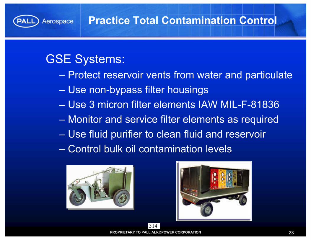
23PROPRIETARY TO PALL AEROPOWER CORPORATION
Practice Total Contamination Control
GSE Systems:– Protect reservoir vents from water and particulate– Use non-bypass filter housings– Use 3 micron filter elements IAW MIL-F-81836– Monitor and service filter elements as required– Use fluid purifier to clean fluid and reservoir– Control bulk oil contamination levels
314

FLUID PURIFICATION BRIEFING
MALABARINTERNATIONAL
Military Aviation
Fluid & Lubes
Workshop
20 - 22 June, 2006
Hope Hotel
Wright-Patterson AFB
315

MALABARINTERNATIONAL
FLUID PURIFICATION BRIEFING; 16-18 November 2004
Established in 1935 as “Malabar Machine Co.” in East Los Angeles, we were considered at quality Machine Shop attracting business from several large aviation firms. In a couple short years, our relationship with Lockheed Aircraft Company in Burbank produced the first Aircraft “Tripod” Jack and Patented Locknut. Malabar was very busy during the War Years manufacturing a variety of Aircraft Jacks for B-29’s, B-24’s, DC-3’s, DC-4’s, etc.
Our History . . .
After WWII, we spent a short time as a Division of MENASCO Manufacturing Company and added Railroad and Automotive Jacks to the product line. The early 1950’s started a series of changes in ownership and a relocation to the Bay Area.
316

MALABARINTERNATIONAL
FLUID PURIFICATION BRIEFING; 16-18 November 2004
In 1968 MALABAR was acquired by E.D. Sweetland (“Gene”) of the Sweetland Company a west coast distributor of hydraulic and pneumatic components.
In 1978, MALABAR moved to Simi Valley, California, our current location.
In 1993, Gene passed away, with E. D.Sweetland Jr (“Dave”) assuming responsibility as Chairman & CEO.
MALABAR expanded its facility in 2001for production of an anticipated 600 of the HTS units. We have added a total of 25,000 Sq. Ft. which includes new administration offices, HTS Test Cell,and increased space for inventory and assembly activities. Malabar International is fully staffed “In-House “for all Manufacturing, Engineering, Test, Contract Administration, Quality Control, and Sales/Marketing Requirements.
317

MALABARINTERNATIONAL
FLUID PURIFICATION BRIEFING; 16-18 November 2004
Machine Shop Area which includes CNC and Manual Machine Tools of varying Vertical and Horizontal capability.
Welding and Fabrication Area with Full Overhead Crane Capability.
318

MALABARINTERNATIONAL
FLUID PURIFICATION BRIEFING; 16-18 November 2004
Test Facilities
225 Ton Dynamic Hydraulic Jack Test Fixture
HTS Test Cell
319

USAF Automated Hydraulic Test Stand
• In 2000 Malabar was awarded a contract for approximately 600 test stands with purification systems.
MALABARINTERNATIONAL
FLUID PURIFICATION BRIEFING; 16-18 November 2004
Each test stand includes a purification system to comply with Executive Order 13101 “Greening the Government”
320

MALABARINTERNATIONAL
FLUID PURIFICATION BRIEFING; 16-18 November 2004
FLUID PURIFICATION CAPABILITY
• Vacuum Distillate Process
• Fluid is sprayed under pressure into a vacuum chamber and circulated through a 2μ absolute particulate filter.
• Fluid Contaminants are removed and fluid is returned to “Original” Properties.
321

MALABARINTERNATIONAL
FLUID PURIFICATION BRIEFING; 16-18 November 2004
FLUID PURIFICATION PROCESS
• Remove dissolved air to less than 8% from 12%
• Remove dissolved water to less than 100 PPM* from 600 PPM *ref: MIL-PRF-5606 fluid
• Remove chlorinated solvents to less than 50 PPM from 300 PPM
• Remove particulates to ISO 16/14/11 (NAS 5) from ISO 22/20/17 (NAS 11)
• Test sample: 40 gallons of contaminated fluid• Test run: 8 hours at WP-AFRL
322

HTS Control Panel
• AIR BLEED SIGHT GLASS
• OPERATOR KEYPAD
MALABARINTERNATIONAL
FLUID PURIFICATION BRIEFING; 16-18 November 2004
• VACUUM FLUORESCENTDISPLAY
• PURIFICATION ON/OFF
• PURIFICATION INDICATOR
• A/C FILL SWITCHES
323

HTS Purification Subsystem• MAIN RESERVOIR
• FILL/PURIFICATION FILTER
• VACUUM RESERVOIR
• FILL/PURIFICATION SUCTION LINE
• FILL/PURIFICATION VALVE MANIFOLD
• PRESSURE TRANSDUCER MANIFOLD
• FILL/PURIFICATION PUMP and MOTOR, VACUUM PUMP
MALABARINTERNATIONAL
FLUID PURIFICATION BRIEFING; 16-18 November 2004
324

MALABAR Model 8852Stand-Alone Fluid Purification Unit
MALABARINTERNATIONAL
FLUID PURIFICATION BRIEFING; 16-18 November 2004
Current Users:• Lockheed Martin-MIL-PRF-83282-MIL-PRF-87257
• NASA-MIL-L-23699
• WP-AFRL-2 test units
325

MALABARINTERNATIONAL
FLUID PURIFICATION BRIEFING; 16-18 November 2004
Model 8852 Control Panel
• VACUUM(in Hg)
• OPTIONALPARTICLECOUNTER(3 digit ISO Code)
• OIL PRESSURE(PSIG)
• WATER (PPM)
• OIL TEMPERATURE(˚F) • PROGRAMMING
KEYSPROGRAMMEDPARAMETER LIGHTS
(GREEN - GO)
326

Model 8852 Specification:FEATURES:• Rugged and compact construction• Available in three configurations:
- Stationary- Portable (with 4 inch casters)- Mobile (with tow handle and 10 inch foam filled tires rated for 20 MPH)
• Multiple fluid pass operation• Multi-fluid capability:
- Aircraft hydraulic fluids- Lubricating oils and industrial fluids
• Low watt density heater• Microprocessor control including:
- Digital displays- Transducers- Start-up and safety shutdown protocols- Programmable go/no go set points
• Automatic level, flow, temperature and vacuum control
• Audio and Visual alarms• Dual power choices:
- 120/240 VAC, 1 phase or 12/24 VDC• Limited warranty: 1 year
SPECIFICATIONS• Flow Rate : 4 GPM• Process Rate : 1 GPM• Operating Pressure : 100 PSIG• Ambient Temperature : -20°C to +55°• Maximum Viscosity : 2500 SSU• Power Consumption : 2.5 KW• Power Supply Options : 120V, 50/60 Hz, 1 Ph
230V, 50/60 Hz, 1 Ph24 VDC
• Fluid Immersion Heater : 1000 watt (15 watts/sq. in)
• Vacuum System : 27.5 in. Hg maximum• Processing Reservoir : 8 gallons, stainless steel• System Alarms : Filter condition, Low vacuum,
High pressure and High temperature
• Electrical Compliance : Stationary - NEMA 4Portable - NEMA 4 and NEC article 513
MALABARINTERNATIONAL
FLUID PURIFICATION BRIEFING; 16-18 November 2004
327

Air Force Research Laboratory Testing
• PUMP TEST• Completed January
2002• Confirmed Malabar
Process does not degrade Fluid Properties
• PURIFICATION TESTING
• Completed July 2003• Validated
ContaminationRemoval
• Met or Exceeded WR-ALC Purchase DescriptionRequirements.
MALABARINTERNATIONAL
FLUID PURIFICATION BRIEFING; 16-18 November 2004
328

WPAFB AFRL Purification Testing – JULY 2003
MALABARINTERNATIONAL
FLUID PURIFICATION BRIEFING; 16-18 November 2004
329

MALABAR Model HTS 2/DDISSOLVED AIR REMOVAL RATE
0
2
4
6
8
10
12
14
0 1 2 3 4 5 6 7 8
TEST HOURS
% A
IR b
y G
AS
CHR
OM
ATO
GRA
PH
7/10/2003
7/16/2003
7/18/2003
(START) (STOP)
Specification Acceptance Level: 8% DISSOLVED AIR
MALABARINTERNATIONAL
FLUID PURIFICATION BRIEFING; 16-18 November 2004
330

MALABARINTERNATIONAL
FLUID PURIFICATION BRIEFING; 16-18 November 2004
MALABAR Model HTS 2/DCHLORINATED SOLVENT REMOVAL RATE
0
50
100
150
200
250
300
350
0 1 2 3 4 5 6 7 8
TEST HOURS
CH
LOR
INE
(PP
M)
7/10/037/16/03
7/18/03
(START) (STOP)
Specification Acceptance Level: 50 PPM Chlorine
331

MALABAR Model HTS 2/D
MALABARINTERNATIONAL
FLUID PURIFICATION BRIEFING; 16-18 November 2004
PARTICULATE REMOVAL RATE SAMPLED at PT13 OUTLET
0
2
4
6
8
10
12
0 1 2 3 4 5 6 7 8
TEST HOURS
NAS
163
8 PA
RTI
CU
LATE
LEV
EL B
Y
AUTO
MAT
IC C
OU
NTE
R7/10/03
7/16/03
7/18/03
Specification Acceptance Level: NAS 1638 LEVEL 5
(STOP)(START)
332
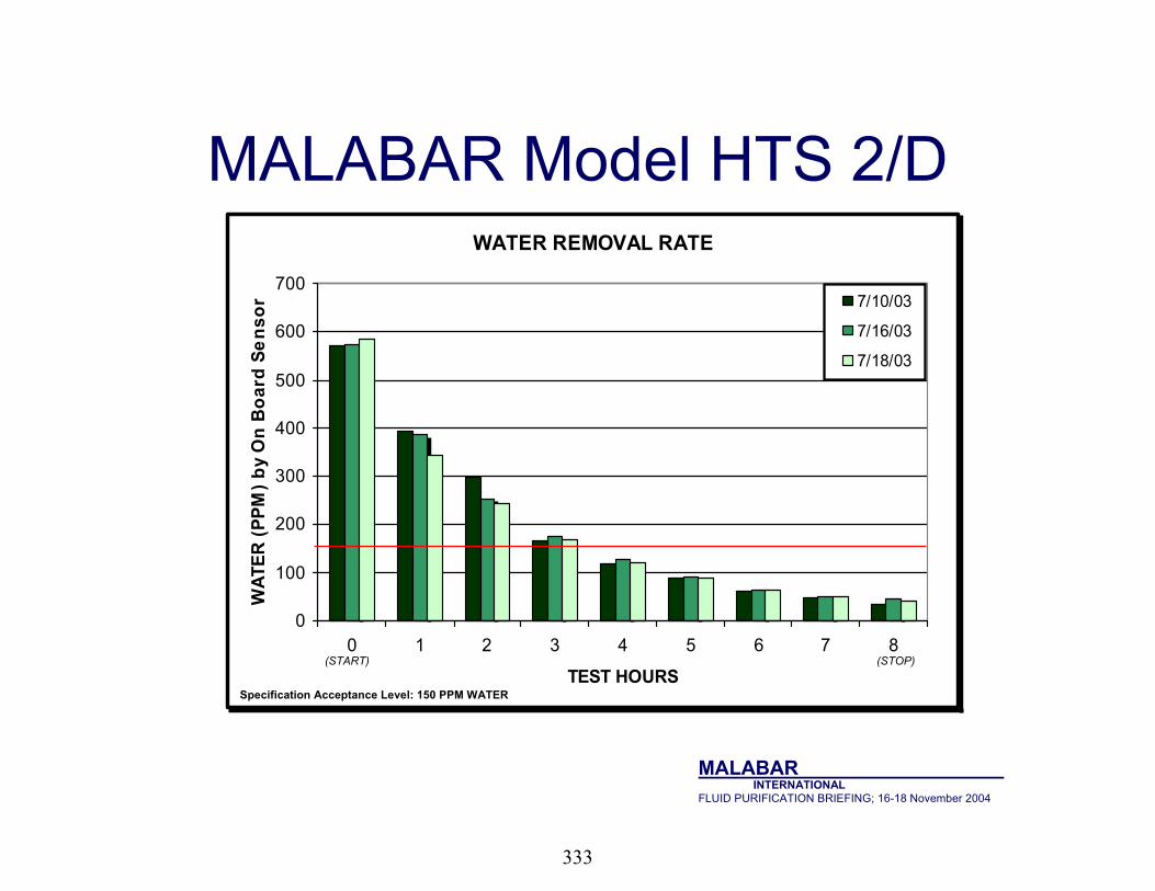
MALABAR Model HTS 2/D
MALABARINTERNATIONAL
FLUID PURIFICATION BRIEFING; 16-18 November 2004
(STP)
WATER REMOVAL RATE
0
100
200
300
400
500
600
700
0 1 2 3 4 5 6 7 8
TEST HOURS
WAT
ER (P
PM) b
y O
n B
oard
Sen
sor 7/10/03
7/16/03
7/18/03
(START) (STOP)
Specification Acceptance Level: 150 PPM WATER
333

U S A F
WPAFB - AFRLMaterials andManufacturing Directorate
Test Dates: 7/10, 7/16, 7/18, 2003
MALABARINTERNATIONAL
FLUID PURIFICATION BRIEFING; 16-18 November 2004
334

MALABARINTERNATIONAL
FLUID PURIFICATION BRIEFING; 16-18 November 2004
MALABARINTERNATIONAL
220 West Los Angeles AvenuePost Office Box 367
Simi Valley, California 93062 USAPHONE: (805) 581-1200 FFAX: (805) 584-1624
EMAIL: [email protected]: www.malabar.com
335

Dominant Air Power: Design For Tomorrow…Deliver Today
Keep‘em flying & Keep‘em relevant
Aging Aircraft Systems SquadronAging Aircraft Systems Squadron
Hydraulic Fluid PurificationHydraulic Fluid PurificationRequirementsRequirements
June 2006June 2006
Al HermanACSSW/AASS/OBDSN 785-7210 Ext 3915Email: [email protected]
336

Dominant Air Power: Design For Tomorrow…Deliver Today
HFP IPT REQUIREMENTS
• Purpose
• Objectives
• Operation
• Membership
• Goals
• Service Evaluation
337

Dominant Air Power: Design For Tomorrow…Deliver Today
HFP IPT
• PurposeThe Hydraulic Fluid Purification (HFP) Integrated Process Team (IPT) was established to take the common commercial practice of HFP, and conduct a formal three-phase USAF evaluation effort as a pollution prevention project in order to validate HFP and implement purified hydraulic fluid use in USAF aircraft and aerospace ground equipment (AGE)
338

Dominant Air Power: Design For Tomorrow…Deliver Today
• ObjectiveBring together those parties responsible for pollution prevention, aircraft/AGE engineering authority, aircraft hydraulic fluid specification, and aircraft/AGE maintenance to evaluate, discuss, and implement HFP
Reduce the second largest fluid waste stream in the USAF by providing timely, thorough, and factual data to the USAF aerospace community to support and implement aircraft/AGE hydraulic fluid purification
HFP IPT
339

Dominant Air Power: Design For Tomorrow…Deliver Today
HFP IPT
• Operation Principal Members– HFP IPT Manager – Lead Command Executive Agent – Air Force Research Lab – MDS Aircraft Engineering Authority
340

Dominant Air Power: Design For Tomorrow…Deliver Today
HFP IPT Duties•HFP IPT Manager
• Chair HFP IPT meetings at mutually agreed upon location• Provide HFP IPT progress reports on action items• Present the HFP program to the aircraft/AGE SPOs
•Lead Command (AMC) Executive Agent• Assist the IPT manager and interface with MAJCOMs
• Air Force Research Lab (AFRL)• Provide Technical Support for hydraulic fluid
sampling/analysis• Provide Technical Support for purification equipment
evaluation/qualification• Each MDS Aircraft Engineering Authority
• Provide feedback and assistance to ensure the IPT addresses their concerns, to expedite implementation of fluid purification on their MDS
• Provide endorsement/declination letters to show support/non-support for the HFP program
341

Dominant Air Power: Design For Tomorrow…Deliver Today
HFP IPT
• Membership– Voting Members Of The HFP IPT
• AASS/OB• MAJCOM Functional Managers• AFRL/MLBT• ASC/ENV• WR-ALC/LESG• AMWC/WCB Air Mobility Battlelab• Aircraft System Wings
342

Dominant Air Power: Design For Tomorrow…Deliver Today
HFP IPT
• Advisory Agencies – Aircraft System Program Offices
• WR-ALC/LTEM (C-5/C-141)• WR-ALC/LBRSM (C-130)• ASC/VFM and WR-ALC/LFEF(F-15)• ASC/YCE (C-17)• OC-ALC/LCRM (KC-135)• ASC/YPV (F-16)• ASC/YFABU (F/A-22)• OC-ALC/PSBEF (B-1)• OC-ALC/PFLR (B-2)• OC-ALC/LHRH (B-52)• OO-ALC/LCEM (T37/38)• WR-ALC/LUH (MH-53/HH-60/H-1)• NAVAIR (CV-22)
343

Dominant Air Power: Design For Tomorrow…Deliver Today
HFP IPT
• Specific Goals • Evaluate HFP equipment/process • Evaluate contamination levels in aircraft, AGE
hydraulic test stands (HTS) and hydraulic servicing carts
• Educate and inform the USAF aerospace community
344

Dominant Air Power: Design For Tomorrow…Deliver Today
HFP IPT
• Evaluate HFP equipment/process– Ensure the HFP process effectively removes
contamination– Ensure the HFP process does not degrade fluid
properties– Qualify specific HFP equipment for authorized use by
the USAF– Ensure future AGE compatibility for purification
equipment interface– Improve mission capable rates, war fighting capability,
and flight safety– Reduce maintenance burden– Reduce overall hydraulic fluid procurement and
disposal costs
345

Dominant Air Power: Design For Tomorrow…Deliver Today
HFP IPT
• Evaluate operational (in-service) hydraulic fluid contamination levels in aircraft and AGE hydraulic test stands (HTS) and hydraulic servicing carts– Determine operational contamination levels. – Determine a baseline for purification– Establish an in-service fluid cleanliness standard for
aircraft, HTS, and other applicable AGE– Quantify expected overall cleanliness improvement
gained through HFP– Minimize HFP manpower impact
346

Dominant Air Power: Design For Tomorrow…Deliver Today
HFP IPT
• Educate and inform the USAF community
– Provide HFP information to: pollution prevention office, aircraft program engineering, MAJCOM aircraft hydraulic functional managers, and aircraft maintainers
– Disseminate findings from laboratory research and testing
– Perform field demonstrations of purification equipment
347

Dominant Air Power: Design For Tomorrow…Deliver Today
HFP IPT
• Establish HFP guidelines and procedures
– General T.O.s– AGE T.O.s– Applicable AFIs– Weapon system specific technical orders – Identify TAs
348

Dominant Air Power: Design For Tomorrow…Deliver Today
Service Evaluation Plan
Complete a 2 Year Service EvaluationUse portable purifier to purify mulesSample Mules and Aircraft before and after purification is implementedPurify all mules upon receipt of portable purifiers and after use on aircraftPurify after major hydraulic component change (WUC tracked in MDC)Purify whenever contamination is suspected (in lieu of drain & flush)
349

Dominant Air Power: Design For Tomorrow…Deliver Today
Service Eval Goal
Our Goal is to evaluate:Reductions in waste stream by implementing HFPReduction in new fluid procurementsImpact on maintenance workload as a result of HFPImprovements in component lifeImprovements in hydraulic system performance
350

Dominant Air Power: Design For Tomorrow…Deliver Today
Field Requirements• Request Field Units complete the
following:– Provide a record of prior hydraulic fluid
procurements (One year prior to purification)– Provide a record of prior waste disposal (One
year prior to purification)– Track and report replacement of serially
controlled hydraulic components– Track and record new hydraulic fluid
procurements– Track and record disposal of waste hydraulic
fluid
351

Dominant Air Power: Design For Tomorrow…Deliver Today
Field Requirements (Cont’d)
• Request Field Units complete the following:– Provide feedback on ease of use and
maintenance of the portable purifier– Provide feedback on parts required for the
portable purifier– Provide feedback on functionality and
usefulness of the portable purifier– Provide feedback on the impact on
maintenance man-hours of hydraulic systems
352

Dominant Air Power: Design For Tomorrow…Deliver Today
Field Requirements (Cont’d)
• Cost savings initiative:– Track Hours to operate purifiers– Materials or supplies requirements– Fluid life extension– Increase/Decrease in aircraft O&M $$$$ (if
possible)
353

Dominant Air Power: Design For Tomorrow…Deliver Today
Lessons Learned
• Document implementation experiences• Processes Developed• Identify T.O. Changes• Share lessons learned with USAF
354

Dominant Air Power: Design For Tomorrow…Deliver Today
Service Evaluations
QUESTIONS?
355

Hydraulic Fluid Purification
927 ARW Aircraft Charts
KEVIN HIBBS927 MXGDSN: 273-5179
356

OVERVIEW• Procedures• Particle and water count• Aircraft and Mule Results• Results of initial samples indicate some samples
may have been improperly taken. Or Mule contaminating our aircraft.
• Easy to contaminate sample when taken • Shop Test Stand• Barrel Sampling
357
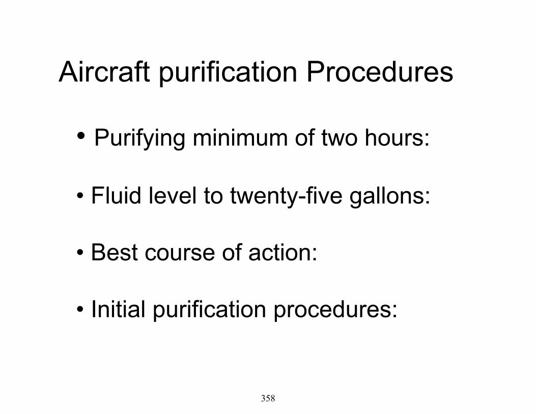
Aircraft purification Procedures
• Purifying minimum of two hours:
• Fluid level to twenty-five gallons:
• Best course of action:
• Initial purification procedures:
358

Tracking
• AFTO form 22 submitted:
• Landing gear sample results
• Mule Samples
• Aircraft Samples
• Waste Drum Samples
359

NAS 1638 P Count A/C 63-8044
0123456789
101112131415
9 M
ar 0
5 R
24 J
ul 0
5 R
15 A
ug 0
5 R
30 S
ep 0
5 R
9 M
ar 0
5 L
24 J
ul 0
5 L
9 S
ep 0
5 L
Samples
NA
S C
lass
• Right System particle level high, Multi sensor would have been a great benefit.
• Second samples may have been contaminated during sampling or contaminated by the mule
360

Water A/C 63-8044
0255075
100125150175200225250275300325350
9 M
ar 0
5 R
24 J
uly
05 R
15 A
ug 0
5 R
30 S
ep 0
5 R
9 M
ar 0
5 L
24 J
yly
05 L
09 S
ep 0
5 L
Samples
Wat
er L
imit
• Water levels are increasing, we are trying to figure out why.
• Levels remain well within acceptable levels.
Water level in test stand for these test were between 70 and 74 PPM.
361

NAS 1638 P Count A/C 62-3557
0123456789
101112131415
16 M
ar 0
5 R
31 A
ug 0
5 R
16 M
ar 0
5 L
31 A
ug 0
5 L
Samples
NA
S C
lass
• This was one of the first aircraft we purified• We experimented with different purification cycle times
362

Water A/C 62-3557
0255075
100125150175200225250275300325350
16 M
ar 0
5 R
31 A
ug 0
5 R
16 m
ar 0
5 L
31 A
ug 0
5 L
Samples
Wat
er L
imit
• We were above the PPM limit on the right side, did come down.
• We feel that both sides could be better.
363

NAS 1638 Particle Count A/C 62-3580
0123456789
101112131415
10 M
ar 0
5 R
10 M
ar 0
5 R
10 M
ar 0
5 L
24 A
ug 0
5 L
Samples
NA
S C
lass
• This aircraft was initially clean, the results still show that purification works
364

Water A/C 62-3580
0255075
100125150175200225250275300325350
10 M
ar 0
5 R
24 A
ug 0
5 R
10 M
ar 0
5 L
24 A
ug 0
5 L
Samples
Wat
er L
imit
365

Aircraft Summary• Our aircraft do not look to bad. • If we keep our mules clean we should be
able to maintain clean aircraft. • We believe that an NAS class of 6 or
better on each aircraft is possible.• The increases in our water PPM levels is
still in research and testing
366

Aircraft Summary (Cont)
• Component life enhancement willcome using purified fluid
• Life extension results will not beseen for some time
• Particle sensor is needed to give realtime indication when fluid is purified
367

Test Stand Samples(Mule)
Single system unitsTwo Diesel, one Elect
Particle and Water count
368

Introduction
• How we modify the mules?• How we connect to the purifier?• How long did we purify test stands?• Different methods?
369

Connection is to the inlet side of the purifier.Permanently mounted
Mule run around system connections
370

Muledrain shut off valve
Purifier connection
Samplevalveconnection
371

Vent Hole
372

Vent hole
373

NEC “national Electrical Code Book 2002 para.513 Motor needs to be 18” off floor.
Inletconnection
Outletconnection
374

Outletconnection
Inletconnection
375

This is the inlet connection to the purifier unit from the elect mule Item goes into the reservoir fill neck.
Also connection for drum purification if ever authorized.
376

Elect Mule connections proposed
377
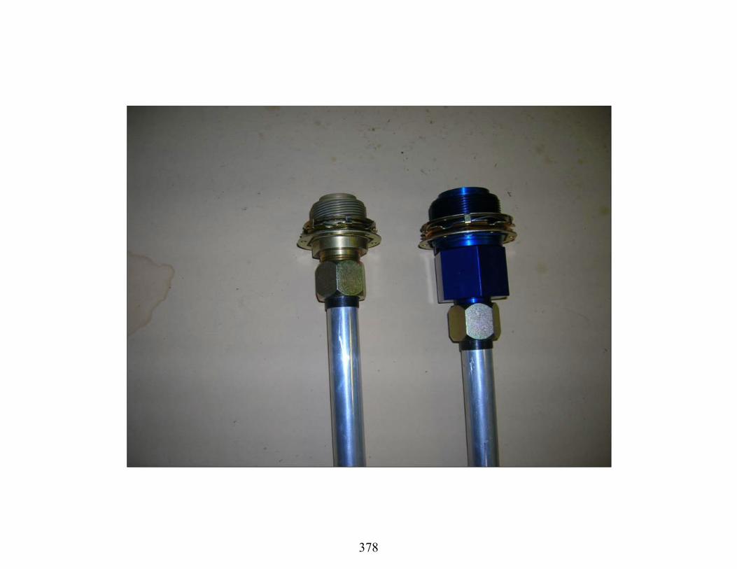
378

Elect Mule purification connections proposed
379

NAS 1638 P Count AGM019 D
0123456789
101112131415
9-M
ar-0
51-
Aug-
0515
-Aug
-05
2-Se
p-05
20-J
an-0
620
-Jan
-06
8-Fe
b-06
AGM
019
Samples
NAS
Cla
ss
Purified 4 hours
PossibleSampledWrong
Sampled same day before and after purification. Low water level was the
determining factor to stop purifier.
Multi Sensor will help us to know the particle level
before we quit purification
• Particle count remaining high with 2 hour purification• Switching to using the runaround system for 15-20 minutes prior to and during the purification process.
380

Water Count PPM AGM019 D
255075
100125150175200225250275300325
9-M
ar-0
5
01-A
ug-0
5
15-A
ug-0
5
31-A
ug-0
5
20-J
an-0
6
20-J
an-0
6
28-F
eb-0
6
Sam
ple
8
Prior to and after purification. 150 ppm and 54 ppm after 2 hours
After 4 hours of purification 33 ppm
Again the purifier is doing a good job Keeping water levels below 80 PPM
381

NAS 1638 Particle Count AGM027 D
0123456789
101112131415
9-M
ar-0
5
20-M
ar-0
5
20-J
an-0
6
20-J
an-0
6
28-F
eb-0
6
2-M
ar-0
6
AG
M02
7Samples
NA
S C
lass
The multi sensor will certainly help us to know when theparticle levels are down in the mule. Give us a better product.
This is a diesel mule, we were having better luck on keeping it clean at two hours. The last two results were with using the runaround system with purification for the first time.
Mule connected to aircraft, with purifier connected to Mule and run at the same time NAS class 5
382
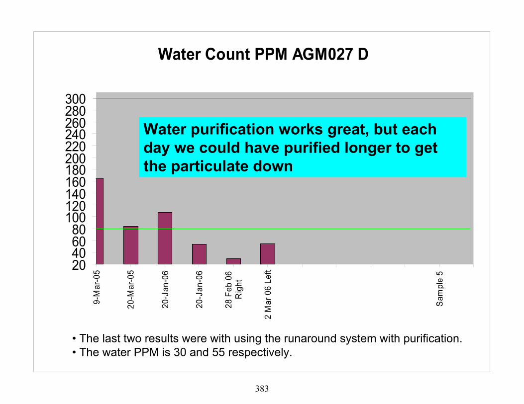
Water Count PPM AGM027 D
20406080
100120140160180200220240260280300
9-M
ar-0
5
20-M
ar-0
5
20-J
an-0
6
20-J
an-0
6
28 F
eb 0
6R
ight
2 M
ar 0
6 Le
ft
Sam
ple
5
Water purification works great, but each day we could have purified longer to get the particulate down
• The last two results were with using the runaround system with purification. • The water PPM is 30 and 55 respectively.
383

NAS 1638 P Count AGM046 E
0123456789
101112131415
9-M
ar-0
5
17-M
ar-0
5
4-A
ug-0
5
31-A
ug-0
5
MU
LE IN
ITIA
L
1ST
HA
LF H
OU
R
2ND
HA
LF H
OU
R
3RD
HA
LF H
OU
R
4TH
HA
LF H
OU
R
Samples
NA
S C
lass
New purification procedures 24 March 06. run mule and purifier together but not connected to A/C
384

Water Count PPM AGM046 E
20406080
100120140160180200220240260280300
9-M
ar-0
5
17-M
ar-0
5
1-A
ug-0
5
9-A
ug-0
5
31-A
ug-0
5
MU
LE IN
ITIA
L
1ST
HA
LFH
OU
R
2ND
HA
LFH
OU
R
3RD
HA
LFH
OU
R
4TH
HA
LFH
OU
R
AGM046
New purification procedures 24 March 06. run mule and purifier together but not connected to A/C Initial 119ppm end 45ppm
385

Mule Summary
• Lessons learned? • What we would like to do? • How could things be easier/better?
386

Hydraulic Shop Test Stand
Particle and water count
387
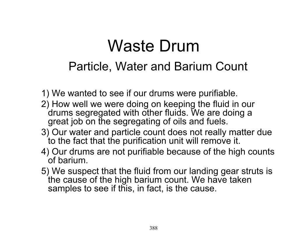
Waste DrumParticle, Water and Barium Count
1) We wanted to see if our drums were purifiable. 2) How well we were doing on keeping the fluid in our
drums segregated with other fluids. We are doing a great job on the segregating of oils and fuels.
3) Our water and particle count does not really matter due to the fact that the purification unit will remove it.
4) Our drums are not purifiable because of the high counts of barium.
5) We suspect that the fluid from our landing gear struts is the cause of the high barium count. We have taken samples to see if this, in fact, is the cause.
388

NAS 1638 P Count
0123456789
101112131415
DR
UM
1
DR
UM
2
DR
UM
3
Samples
NA
S C
lass
The purifier could clean this.
Drum # 3 lab counter couldn't read that high
389

Water
0255075
100125150175200225250275300325350
Dru
m 1
Dru
m 2
Dru
m 3
Samples
Wat
er L
imit
The purifier could clean this
Drum 3 has 639 PPM
390

BARIUM
0
50
100
150
200D
rum
1
Dru
m 2
Dru
m 3
Dru
m 4
Samples
Bar
ium
Lim
it
20 ppm Max
The purifier cannot remove barium.
Drum 2 is 661 PPM
Drum 3 is 591 PPM
391

CONCLUSION
• Barium is coming from MIL-PRF-6083. located within our landing gear hydraulic struts, and components.
• If we can control the use of 46170 and 6083 we could control the drum fluids and purify them.
392

• We must drain components that are servicedwith 46170 and 6083.
• We have to get the depots to stop using 46170and 6083. Received two struts dated Mar 06with 6083 fluid in them.
393

LANDING GEAR SAMPLE RESULTS.
394
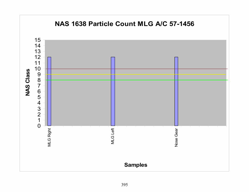
NAS 1638 Particle Count MLG A/C 57-1456
0123456789
101112131415
MLG
Rig
ht
MLG
Lef
t
Nos
e G
ear
Samples
NA
S C
lass
395

Water MLG Struts A/C 57-1456
0255075
100125150175200225250275300325350
MLG
Rig
ht
MLG
Lef
t
Nos
e G
ear
Samples
Wat
er L
imit
RightPPM512
LeftPPM467
NLG239
396

BARIUM MLG A/C 57-1456
0
50
100
150
200
MLG
Rig
ht
MLG
Lef
t
Nos
e G
ear
Samples
Bar
ium
Lim
it
20 ppm Max
yellow line is Haz wast
MLG R 2106 PPM
MLG L 2153 PPM
NLG 1113 PPM
397

NAS 1638 Particle Count MLG A/C 62-3528
0123456789
101112131415
MLO
#
MLG
Rig
ht
MLG
Lef
t
Nos
e G
ear
Samples
NA
S C
lass
Nose gear to dirty to read
398

Water MLG Struts A/C 62-3528
0255075
100125150175200225250275300325350
MLG
Rig
ht
MLG
Lef
t
Nos
e G
ear
Samples
Wat
er L
imit
399

BARIUM MLG A/C 62-3528
0
50
100
150
200
MLG
Rig
ht
MLG
Lef
t
Nos
e G
ear
Samples
Bar
ium
Lim
it
20 ppm Max
yellow line is Haz wast
Nose gear 515 ppm
Rt & Lt gear has 939 ppm
400

NAS 1638 P Count MLG A/C 63-8014
0123456789
101112131415
MLG
Rig
ht
MLG
Lef
t
Nos
e G
ear
Samples
NA
S C
lass
Strut change 17 April 06
401

Water MLG Struts A/C 63-8014
100
200
300
400
500
600
700
MLG
Rig
ht
MLG
Lef
t
Nos
e G
ear
Samples
Wat
er L
imit
402

BARIUM MLG A/C 63-8014
0
50
100
150
200
MLG
Rig
ht
MLG
Lef
t
Nos
e G
ear
Samples
Bar
ium
Lim
it
20 ppm Max
yellow line is Haz wast
both over 1900 ppm
403

• During our ISO inspections. We must drain alllanding gear struts for the KC 135. When drainingand refilling our struts with 87257 fluid, we seem tobe getting the 6083 fluid levels down but not eliminated. We still have high counts of Bariumwithin the landing gear system.
• 6083 and 46170 fluid is not purifiable and has to berendered as a waste fluid.
• We now need to segregate our hydraulic fluids fromour landing gear and aircraft system until we get ridof 46170 and 6083 form all components, and out ofthe struts and Air Force aircraft and componentsystems.
CONCLUSION
404

• By eliminating 6083 and 46170 fluid, this will reduceour hydraulic fluid waste stream.
• There is no written guidance that we can find onacceptable barium percentages within the aircrafthydraulic system.
405

QUESTIONS ? ? ?
406

Aircraft purification ProceduresWe started these procedures by first purifying the test stand for a minimum of two hours, never going over four hours, maintaining the test stand water PPM below 100 PPM before terminating procedures. We purify the day prior to using the test stand on the aircraft, if possible. We always purify the test stand after each use on any aircraft system. We have noted that we may have been doing our test stand purification procedure improperly. We were not mixing the test stand reservoir fluid prior to purifying. We were under the impression that when we connected to the bottom of the reservoir, that we were in fact at the bottom. We have since learned that there is a stand off pipe of one inch, this is not letting us get all the particles or water off the bottom test stand reservoir. It seems that the purification unit does not mix the fluid as well as we were anticipating. So we are having to mix the fluid with the runaround system on the test stand as we purify or prior to purification.
Our initial test stand set up was to set the test stand reservoir fluid level to twenty-five gallons. This would allow us to drain the aircraft reservoir into the test stand without overfilling. By draining the aircraft reservoir into the test stand reservoir, we increase our total fluid quantity to thirty gallons. By allowing us to drain the aircraft reservoir directly into the test stand, on certain procedures, we are reducing our hydraulic fluid waste stream. This can cause another problem with the overfilling of the test stand reservoir on certain occasions, if the fluid level within the test stand is not properly set.
We determined that our initial best course of action was to take initial samples of all aircraft prior to purification, then go through and purify and sample all aircraft again. Look at the results, re-accomplish any aircraft that was an NAS class eight or higher or with a water count above 200ppm. One thing we did forget to look at the test stand sample results. This could have caused some of our aircraft to have increased particle and water counts. We then proceeded to purify all aircraft during their ISO inspection, and anytime we connect to an aircraft we will drain the aircraft reservoir into a purified test stand, then run our operational check on the affected system only. Then we refill the aircraft reservoir and re-purify the test stand prior to its reuse. We had some problems with this, due to improperly educating our counter parts on the flight line of the proper sequence of events that needed to be followed.
407

The actual procedures we use to run the aircraft for initial purification process was to hook up and operate two purified test stands one to the right system and the other to the left system. We would cycle the following system through five times, flaps, inboard and outboard spoilers, brakes, rudder, boom hoist, boom telescoping, forward and aft AR pumps for five minutes each and simulated gear retraction, using 3000psi at 10 to 20 GPM. Initially it only took twenty minutes to run each system. We felt that this was not enough time, so for the initial purification process, we ran each hydraulic system for one hour, not to exceed operating limits of each sub system.
One of our standard practices that we set up was to take a sample from the aircraft when we drained the aircraft reservoir into a purified test stand, then ops check aircraft system and re-fill system reservoir. This sample would be taken after the aircraft next flight.
We do not track which test stand we use on which aircraft. We have considered cross contamination as a condition that could result with this action, especially if we do not purify the test stand after each use when draining the aircraft reservoir into the test stand.
408

Tracking
We are currently tracking our waste disposal, fluid procurement, component failures/replacements and drum fluid quality (mixing of compatible oils within the drum). From 2004 thru 2005 we found that since starting our purification process we have reduced our purchase of hydraulic fluid by 162 gallons and reduced our waste stream by 83 gallons. We are tracking component failures by the quarter but don’t expect any real or true results until well after this test has been concluded.
AFTO Form 22 & 1067 submitted and status
We found that within the KC135 job guide, the current particle count table for hydraulic fluid, did not match the recommended NAS class 1638 particle count. We have submitted an AFTO form 22 and was approved to change to align with the NAS table. Initially we had no procedures or SPO approval to drain the aircraft reservoir into the test stand and reuse this fluid. We have submitted an AFTO form 22 and it was approved, to allow use of this fluid without purifying the fluid prior to reusing it on a different aircraft. We also submitted AFTO form 22 on both style of test stands, on how to purify the mule prior to it’s use and a test stand purification procedure. Along with that we also submitted an AF form 1067 on permanent test stand connections needed to allow hook up of the purifier and purification of our mules. We have not heard back on these items as of today.
We are taking samples of our waste drums to see how well we were doing on segregation of our oils and fuel from our waste hydraulic fluid. According to the lab we are doing a fine job of keeping all of our waste drums oil segregated, and indeed we would be able to purify our drums but we also found out something that we were not expecting on the drums and I will discuss this information later in the briefing.
409

Mule information
We saw how the test stands were initially being connected. We felt that having to connect and disconnect every time you wanted to purify the test stand would not work. We wanted something that was going to be quick and easy, it needed to be able to attach to the aircraft and purifier without having to add or disconnect any plumping, it also had to be versatile so if we can purifier drums we would be able to connect to them with zero effort. So we came up with the following connections, (show next five slides) each quick disconnect is the same style and size used on the KC135 aircraft. Initially we used the return hose on the test stand as the return from the purifier unit and it worked great, but when we went to purifying and run the test stand on an aircraft at the same time, that set up would not work. So we came up with the reservoir cap idea. This was the cats meow, we could not ask for anything better, other than another permanent connection on the front of the test stand going back into the reservoir. There were some initial problems with the cap design, at first we did not have an extension pipe attached, so it would leak fluid out of the vent hole when we were running. We figured that the incoming fluid was to close to the vent hole and the air was catching and forcing the fluid back out. So we added a six inch tube and this corrected the problem.
We also used the same type connections on the purifier unit. Our connections were in place and we’re moving forward looking for better things. Initially we started purifying the test stands for four hours, this proved to be not working as we are finding out with our samples. We were also not using the runaround system prior to purification. As you will be able to see on our next few slides we were having problems keeping the test stands clean. We had two different methods of connecting the purifier unit to the test stand. Since we had no connection mounted onto the elect test stand we had to remove the cap and metal screen, we then used the connection made for the drum purification process for the inlet to the purifier unit and the return line on the test stand for the return. This worked great, only concern was the time it took to remove and reinstall cap and screen, due to it has seven bolts that needed to be removed and reinstalled each time. On the diesel test stand we used a connection that was mounted onto the test stand as the inlet for the purifier unit and the return line on the test stand for the return, We did seem to get a better cleaning job on the elect test stand than with the diesel test stands.
410

Earlier this month we tried a different purification method, we used a diesel test stand for this test. We needed to find out if we could in fact bring down the water within our aircraft systems, we proceeded to connect the test stand to the aircraft, then connect the purifier unit to the test stand, (this is where we ran into the problem with the return connection and went to the reservoir cap return) we ran the test stand and cycled the fluid, we turned on the purifier unit at the same time to get the water level down below 70ppm, then ran the aircraft system watching the water level on the purification unit making sure that it did not go above 100ppm. We took test stand samples prior to and after purification, we also will be taking samples of the aircraft system after it’s next flight. The sample information received back on the test stand is very encouraging. We also have the complete procedures on this if you would like to review them.
411

Mule conclusion
• We have learned that water and particles are not removed at the same rate, a particle / water counter is definitely needed for field operations.
• Circulation of fluid; We were not aware that there is a stand off pipe of one inch connected to the drain valve where we made our connections to hook the inlet of the purifier to, we’re not getting to the sludge or particles from the bottom of thetest stand reservoir. We need to use the runaround system for the mixing of the fluid in the mule reservoir each time we purify the test stand. It seems that the purifier unit will not mix the fluid enough for the short amount of time (4 hours) we run the system. We need to add in the tech-orders, that if you are not purifying the test stand at the same time you are using test stand to run aircraft systems, then you need to use the runaround system for 15-20 minutes while purifying test stand. Or something like that.
• We needed to have a better understanding of how the test stand actually worked. I was under the impression that every time we ran the test stand on the aircraft that we were actually mixing the fluid within the two reservoirs, found out I was wrong and had to re-accomplish purification on one aircraft.
• Definitely need permanent hook up connections on the test stand, and a permanent sample port connection.
• We needed to keep better records, like recording initial and ending water PPM from the start
• Things we are looking to do or concluded that it’s not practical for the KC135 aircraft;1. we are going to try to find out how long we need to run the purifier unit and the runaround system. We will take an initial water reading and sample of the test stand, run the runaround system for 15 minuets at the same time we are purifying it, stop the purifying process at thirty minutes take a water reading and another sample, restart the purifier unit and run for another thirty minutes, take another water reading and sample. continue this process for a total of two hours and check our results. Then connect to another test stand and perform the same checks until all mules are at a NAS class 5 or better.2. We were looking at trying to hook the purifier directly to the aircraft reservoir, we have come to the conclusion that usingthe purifier in this manner would not give us our best results, due to we would only be cleaning approximately seven gallons of fluid out of twenty seven. 3. We also look at the possibility of purifying our landing gear struts due to the high water and particle samples. We have determined that it is indeed needed, but is not practical due to the struts would have to be redesigned. We have no way of getting the fluid out and back into the struts.
412
Hydraulic Fluid PurificationHydraulic Fluid Purification
As Of December 2006As Of December 2006
178178thth Fighter Wing MXS/MXMGFighter Wing MXS/MXMG
413

Hydraulic Service CartsHydraulic Service Carts
WaterWater
0
20
40
60
80
100
120
Water test 1 Water test 2 Water test 3
SC-4SC-5SC-6
414

Hydraulic Service CartsHydraulic Service Carts
0
5
10
15
20
25
H o urs OfP urif icat io n
N A S1638 8-M ar-06N A S1638 12A pr06 N A S1638 3Jan07
SC -4SC -5SC -6
ParticulateParticulateHours of PurificationHours of Purification
415

Hydraulic Mules Hydraulic Mules WaterWaterHours ofHours ofPurificationPurification
0
50
100
150
200
T est 1 T est 2 T est 3 T est 4 T est 5 H o urs
T -1T -2T -3T -4T -5
416

Hydraulic Mules Hydraulic Mules
0123456789
101112
N A S16388M ar06
N A S163812A pr06
N A S16388M ay06
N A S163826M ay06
N A S 16383Jan07
T -1T -2T -3T -4T -5
ParticulateParticulate
417

Hydraulic Mules & Malabar Samples Hydraulic Mules & Malabar Samples WaterWaterHours ofHours ofPurificationPurification
0102030405060708090
100
Init ia l 2 H o urs 6 H o urs 16 H o urs
M alabar 2T -2M alabar 3T -3
418

Hydraulic Mules & Malabar Samples Hydraulic Mules & Malabar Samples
012345678
N A S1638 Init ia l N A S1638 2H o urs
N A S1638 6H o urs
N A S1638 16H o urs
M alabar 2T -2M alabar 3T -3
ParticulateParticulateHours of PurificationHours of Purification
419

Aircraft FAircraft F--16 Water Content 16 Water Content
255075
100125150175200225
craft A
craft B
craft C
craft D
craft E
craft F
craft G
craft H
craft I
craft J
craft K
sys A Mar-06sys B Mar- 063-D Column 3sys A sys B
420

255075
100125150175200225
craft Lcraft Mcraft Ncraft Ocraft Pcraft Qcraft Rcraft Scraft T
sys AMar-06
sys BMar- 06
3-DColumn 3
sys A
sys B
Aircraft F-16 Water Content
421

Aircraft FAircraft F--16 Particulate & Barium16 Particulate & Barium
0
5
10
15
20
25
30
35
craft A (A
)
( B)
craft B (A
)
(B)
craft C (A
)
(B)
craft D (A
)
(B)
craft E (A
)
(B)
craft F (A)
(B)
craft G (A
)
(B)
craft H (A
)
(B)
craft I (A
)
(B)
craft J (A)
(B)
craft K (A
)
(B)
NAS 1638NavyBarium3-D Column 4NAS 1638NavyBarium
422

0
5
10
15
20
25
30
35
40
craft L (A)
(B)
craft M (A
)
(B)
craft N (A
)
(B)
craft O (A
)
(B)
craft P (A)
(B)
craft Q (A
)
(B)
craft R (A
)
(B)
craft S (A)
(B)
craft T (A)
(B)
NAS 1638NavyBariumNAS 1638NavyBariumNAS 1638
Aircraft FAircraft F--16 Particulate & Barium16 Particulate & Barium
423

Received Hydraulic purification system on 14 March 2006Received Hydraulic purification system on 14 March 2006
Unit needs to be marked with outlet and inletUnit needs to be marked with outlet and inlet
Bigger casters and tow handleBigger casters and tow handle
Unit Elect. Pump needs to be 18Unit Elect. Pump needs to be 18”” or more from the ground for or more from the ground for safety in hanger.safety in hanger.
Emergency switch to shut down the system if unit over fills.Emergency switch to shut down the system if unit over fills.
Unit manual needs more information on the operation and Unit manual needs more information on the operation and calibration procedure, and a theory of operation for trouble calibration procedure, and a theory of operation for trouble shooting purposes.shooting purposes.
Unit needs real time for the particulate count I.A.W. NAS1638 Unit needs real time for the particulate count I.A.W. NAS1638 (currently has ISO). Spoke with Malabar they said there is a (currently has ISO). Spoke with Malabar they said there is a conversion chart.conversion chart.
We have found that the water ppm is fairly accurate.We have found that the water ppm is fairly accurate.
424

Personnel in the phase docks have been stating that they are getPersonnel in the phase docks have been stating that they are getting the flight ting the flight controls and gear swings done in half the time.controls and gear swings done in half the time.
After around 320 hrs. of operation the low level switch was sticAfter around 320 hrs. of operation the low level switch was sticking, we called and king, we called and Malabar sent a new switch no other problems after replacement.Malabar sent a new switch no other problems after replacement.
After around 350 hrs. of operation the ISO indicators on the conAfter around 350 hrs. of operation the ISO indicators on the control panel started trol panel started reading reading ““9999”” and would not reset back to and would not reset back to ““00”” so we could get some type of indication so we could get some type of indication on how dirty the fluid was, talked to Malabar and was told to foon how dirty the fluid was, talked to Malabar and was told to follow calibration llow calibration instruction in the book but the book is not clear on how to fix instruction in the book but the book is not clear on how to fix the problem.the problem.
On June 14 2006 after 396.25 hrs. of operation the vacuum pump sOn June 14 2006 after 396.25 hrs. of operation the vacuum pump stopped working all topped working all of the relays are working and there is power going to the capaciof the relays are working and there is power going to the capacitor and the motor, tor and the motor, the motor is not locked up but it does not work. We talked to Althe motor is not locked up but it does not work. We talked to Al and he is getting with and he is getting with Malabar to bring a lap top for trouble shooting and recalibratioMalabar to bring a lap top for trouble shooting and recalibration to correct the n to correct the problem.problem.
In July of 2006 the problem with the vacuum pump was found to beIn July of 2006 the problem with the vacuum pump was found to be a loose wire at a loose wire at the vacuum relay it was repaired and purification resumed.the vacuum relay it was repaired and purification resumed.
As of December 19 2006 the purifier has 814.50 hrs.As of December 19 2006 the purifier has 814.50 hrs.
Testing of hydraulic fluid from five mules and three hydraulic sTesting of hydraulic fluid from five mules and three hydraulic service carts was sent ervice carts was sent to the lab on Dec. 19 testing on the fto the lab on Dec. 19 testing on the f--16 aircraft will resume Jan. 2007 and all power 16 aircraft will resume Jan. 2007 and all power point slides will be updated as we receive the test results backpoint slides will be updated as we receive the test results back from the lab.from the lab.
425

Quality Engineering Test Establishment (QETE)
Hydraulic Fluid Purification Initiative
G. BoivinJune 06
426

Hydraulic Fluid Purification• Background• Objective• Pall Purifier• Implementation Plan• Additional Benefits
427

Background• The CF consumes 19,000 liters of hydraulic fluid
per year• $130,000 in procurement per year• Reasons for Fluid Disposal
– Contamination (Water, Particulate)– Maintenance
• Aircraft 2nd line• HTS Scheduled maintenance
• 100% of used hydraulic fluid is disposed of as waste
• Thousands of Base dollars spent on disposing of HazMat (>50% of the procurement cost)
428

Background
• Hydraulic Fluids used by the CF: • Mil-PRF-5606 • Mil-PRF-83282 • AS 1241
• Hydraulic Fluid Contamination Limits:• Particulates from NAS class 6 to 9• Water from 100 ppm to 3000 ppm
429

ObjectiveDetermine the most suitable way to implement the fluid purifiers without compromising the Ground Support Equipment and aircraft systems airworthiness by using purified fluid.
430

Pall Purifier
431

Implementation Plan•Baseline GSE and aircraft hydraulic systems to determine the state of the fluid in service by sampling 50% of the GSE and 15-20 aircraft (at one selected location).•Identify the most suitable way of using the fluid purifiers•Optimize maintenance practices to minimize fluid losses during maintenance activities•Purify systematically all GSEs•Establish a monitoring program to quantify the impact of the purification units on the hydraulic fluid condition.
432

Fluid Base lining
• To determine fluid condition prior to purifying• Sample 50% of the Base Mil-PRF-83282 HTS’
in service• Sample 15 aircraft (CF18)• Analyze Fluid:
• Properties:– Viscosity– Acidity (TAN)– Lubricity (4-Ball)
• Contaminants:– Water – Particulate
433

HTS - Fluid Base lining PC (NAS
1638)Water(ppm)
Viscosity@40C (cSt)
TANMg KOH/g
6 Max 150 Max 14 Min 0.2 Max0.0130.0210.0070.0250.0190.0290.0250.0230.0240.02
GE-5046 HTS 400 6 151 15.96GE-5240 HTS 400 5 199 15.92GE-5044 HTS 400 4 132 16.75GE-5270 HTS 400 5 163 15.81GE-5068 HTS 500 4 166 15.51GE-5280 HTS 400 5 184 16.22GE-5246 HTS 400 4 147 15.73GE-5248 HTS 400 2 182 15.77GE-5244 HTS 500 5 154 16.27GE-5313 HTS 500 4 190 16.37
Serial # Item
Aircraft Baselining in Progress434

When to Use the Purifiers• Suspected HTS contamination
• Water level >200 ppm or cloudy
• At scheduled HTS maintenance prior to returning HTS into service
• During aircraft periodic• During major hydraulic component (s)
replacement• Before HTS and aircraft deployment
Not during routine HTS operation
435

How to Use the Purifiers “GSE Hook up”
436

How to Use the Purifiers “Aircraft Hook up”
Not authorized to connect directly Purifier to aircraft hydraulic system (s)
437

Particulate Content Monitoring
438

Water Content Monitoring
439

Fluid Monitoring Program• Pre and Post purification results will be
tracked to monitor additive and properties degradation over time
• From this data a top up rate will be established to maintain optimum fluid performance (if required)
440

Additional BenefitsAir Removal
441

Entrapped air in aircraft hydraulic systems after maintenance may require up to 2-3 days to be purged.
442

Leads to pressure fluctuations in aircraft actuators
443

Leads to false reservoir level indication when the system is pressurized
444

Air Content Monitoring
•Quantification of entrapped and dissolved air (Bulk Modulus)•Modifications of GSE to optimize air removal:
•Improve diffuser in reservoir to reduce turbulence•Place reservoir under partial vacuum (trial)•Increase reservoir capacity
•Use of Pall Purifiers (20-22 in of Hg vacuum)
445

446

Way Ahead
• Complete Base Lining of aircraft• Complete GSE modifications to hook up Purifiers• Introduce Purifiers at 2nd CF18 Base• Consider other fleets/other fluids for purification
447

Ghislain Boivin, Lead Engineer- Integrated Health Monitoring: [email protected], 819-994-6538
Pierre Poitras, Senior Chemist, Tactical Aerospace Fluids: [email protected], 819-997-8769
Quality Engineering Test Establishment
448

©METSS Corporation
InIn--Line Hydraulic Fluid Line Hydraulic Fluid Contamination MultiContamination Multi--SensorSensor
Phase II Enhancement ProgramPhase II Enhancement Program
METSS CorporationMETSS Corporation300 Westdale Ave300 Westdale Ave
Westerville, OH 43082Westerville, OH 43082
Kenneth HeaterKenneth Heater449

©METSS Corporation
Problem StatementProblem StatementCondition of aircraft hydraulic fluids is criticalCondition of aircraft hydraulic fluids is critical to to maintaining hydraulic fluid systemsmaintaining hydraulic fluid systems•• detrimental effects to systems and componentsdetrimental effects to systems and components•• can lead to premature failure and flight riskscan lead to premature failure and flight risks
Hydraulic fluid purification program implemented to Hydraulic fluid purification program implemented to maintain fluid integrity and eliminate wastemaintain fluid integrity and eliminate wasteCurrent condition monitoring techniques require Current condition monitoring techniques require sampling and offsampling and off--site analysissite analysis•• Time delaysTime delays•• Sampling errorsSampling errors•• CostlyCostly
New methods are needed to support field purification.New methods are needed to support field purification.450

©METSS Corporation
Program ObjectiveProgram ObjectiveDevelopment of Hydraulic Fluid Development of Hydraulic Fluid
Contamination MultiContamination Multi--SensorSensor
Field monitoring capability to support flightField monitoring capability to support flight--line line use and preuse and pre--flight analysisflight analysisInIn--line contamination monitor for ground support line contamination monitor for ground support equipment, including next generation hydraulic equipment, including next generation hydraulic fluid purification systems fluid purification systems
Both capabilities will ensure aircraft hydraulic Both capabilities will ensure aircraft hydraulic fluid is of sufficient quality to support flight fluid is of sufficient quality to support flight operations in a safe and effective manner.operations in a safe and effective manner.
451

©METSS Corporation
MultiMulti--Sensor RequirementsSensor Requirements
Simple to useSimple to use
RealReal--time feedbacktime feedbackCompact and able to integrate with existing fluid Compact and able to integrate with existing fluid purifier systemspurifier systemsOperational fluid temperature range of Operational fluid temperature range of ––4040°°F to 130F to 130°°FFEasy to calibrate and maintainEasy to calibrate and maintainAffordable ($3500Affordable ($3500--$5000)$5000)Robust & reliableRobust & reliable
452

©METSS Corporation
Impurity TargetsImpurity Targets
Particulate MatterParticulate Matter•• Classify particulate contamination according to Classify particulate contamination according to
NAS 1638 specifications (5 to 100+ NAS 1638 specifications (5 to 100+ μμm)m)Water ContentWater Content•• 100 ppm requirement100 ppm requirement
»» Allowable water concentration of MILAllowable water concentration of MIL--PRFPRF--5606 5606 and MILand MIL--PRFPRF--87257 are 100 ppm and 300 ppm, 87257 are 100 ppm and 300 ppm, respectively respectively
•• Match laboratory analysis performanceMatch laboratory analysis performanceEntrained Air Sensor Entrained Air Sensor •• Possible integration of 3Possible integration of 3rdrd party sensorparty sensor
453

©METSS Corporation
METSS Program EmphasisMETSS Program EmphasisTake advantage of proven technologiesTake advantage of proven technologies•• Decrease risk to Decrease risk to DoDDoD•• Faster technology developmentFaster technology development•• Technology transfer faster and easierTechnology transfer faster and easier•• Commercial pathways easier to define/supportCommercial pathways easier to define/support
Technologies EmployedTechnologies Employed•• Water ContentWater Content
»» FTIR Spectroscopy FTIR Spectroscopy •• Particulate MatterParticulate Matter
»» PAMAS PAMAS -- joint development/qualification effort based on joint development/qualification effort based on adaptation of existing prototype based on light extinction adaptation of existing prototype based on light extinction principlesprinciples
454

©METSS Corporation
First Generation First Generation HFMS PrototypeHFMS Prototype
455

©METSS Corporation
MultiMulti--Sensor Prototype Sensor Prototype Technical SpecificationsTechnical Specifications
Electrical power supply: Electrical power supply: •• 120VAC approx. 10W120VAC approx. 10W
Hydraulic supply:Hydraulic supply:•• Oily liquidsOily liquids•• Viscosities up to 1000 Viscosities up to 1000 cStcSt•• Temperature Temperature --2020ooC to C to
100100ooCC•• Oil compatible with Viton Oil compatible with Viton
seals and polyamide hosesseals and polyamide hoses
Particle Sensor:Particle Sensor:•• Orifice: 500 Orifice: 500 μμm x 500 m x 500 μμmm•• Max. concentration @ 7% Max. concentration @ 7%
coincidence: 24,000 coincidence: 24,000 parts/mlparts/ml
•• Max. pressure: 250 barMax. pressure: 250 barWater Sensor:Water Sensor:•• Orifice: 1270 Orifice: 1270 μμmm•• Max. concentration >500 Max. concentration >500
ppmppm•• Max. pressure: ~14 barMax. pressure: ~14 bar
456

©METSS Corporation
First Generation First Generation Water Sensor PrototypeWater Sensor Prototype
Nicolet 800 FTIR & Raman Miniaturized Water Sensor
457

©METSS Corporation
Basics of OperationBasics of Operation
Transmission Spectra of MIL-PRF-83282 Containing Water
0
10
20
30
40
50
60
70
3200330034003500360037003800Wavenumber (cm-1)
% T
rans
mis
sion
0 ppm 75 ppm 150 ppm 225 ppm 300 ppm 450 ppm
Hydrogen Bonded Water
Baseline
EsterMonomericWater
458

©METSS Corporation
S
Water Sensor Prototype Water Sensor Prototype ––Basic ConceptBasic Concept
BroadbandSource
Flow Cell
Detectors w/Filters
Micro-processor
Correlation Data
SH2O
SREF
Water Concentration (ppm)
459

©METSS Corporation
Water Sensor Performance Water Sensor Performance Calculated Calculated vsvs Actual (Actual (RoycoRoyco 782)782)
Sample IDCalculated
Concentration (Sensor)
Actual Concentration (KF Analysis)
Δ Conc.
CCCC--373373 140 ppm140 ppm 141 ppm141 ppm --1 ppm1 ppm
CCCC--374374 84 ppm84 ppm 103 ppm103 ppm --19 ppm19 ppm
CCCC--375375 237 ppm237 ppm 241 ppm241 ppm --4 ppm4 ppm
460

©METSS Corporation
MultiMulti--Sensor Prototype Sensor Prototype Water Sensor Detector ResponseWater Sensor Detector Response
y = 0.8048x + 99.815R2 = 0.9916
50
100
150
200
250
300
350
400
0 50 100 150 200 250 300 350 400
Water Concentration (ppm)
Det
ecto
r O
utpu
t (m
V)
461

©METSS Corporation
MultiMulti--Sensor Prototype Sensor Prototype Projected Projected Water Sensor ResponseWater Sensor Response
0.150.2
0.250.3
0.350.4
0.450.5
0 50 100 150 200 250 300 350
Water Concentration (ppm)
Peak
Are
a
Aeroshell 31 Brayco 882 Royco 782Linear (Aeroshell 31) Linear (Brayco 882) Linear (Royco 782)
462

©METSS Corporation
First Generation First Generation Particle Sensor DesignParticle Sensor Design
Old
New
463

©METSS Corporation
Particle Counting Particle Counting Basic ConceptBasic Concept
Laser
Correlation Data
Micro-processor
time
mV
Particle Counts (NAS, ISO)
Collimating Optics
FPA Detector
Flow Cell
464

©METSS Corporation
Comparison of ISO, NAS Comparison of ISO, NAS and SAE Classesand SAE Classes
ISO 4406:1999 NAS 1638 SAE/AS4059D
ISO 4μm
ISO 6 μm
ISO 14 μm NAS SAE
ASAE
BSAE
CSAE
DSAE
ESAE
F
Lab Lab UnitUnit 2020 1818 1414 1010 1010 1010 88 99 77
77
55
HX50HX505050--99 2020 1818 1414 1010 1010 1010 88 99 55
Unit
465

©METSS Corporation
Particle Counter PerformanceParticle Counter PerformancePamasPamas Calibration SuspensionCalibration Suspension
0.1
1
10
100
1000
10000
100000
0 20 40 60 80Size (microns)
Part
icle
Cou
nt
HX5050-9Lab Unit
466

©METSS Corporation
Enhancement ObjectiveEnhancement Objective
467

©METSS Corporation
Enhancement Program Enhancement Program OverviewOverview
Water Sensor ImprovementsWater Sensor ImprovementsParticle counter IntegrationParticle counter IntegrationField Prototype DevelopmentField Prototype DevelopmentField Testing and EvaluationField Testing and EvaluationAdditional Sensor ImprovementsAdditional Sensor ImprovementsCommercial Manufacture of UnitsCommercial Manufacture of Units
468

©METSS Corporation
Water Sensor DevelopmentWater Sensor Development
Four filters/detectorsFour filters/detectors•• More sophisticated algorithms which will More sophisticated algorithms which will
compensate for variability between fluid types compensate for variability between fluid types and electronic driftand electronic drift
Automatic temperature compensation within Automatic temperature compensation within detectorsdetectors10x improvement in source output10x improvement in source outputRugged flow cell with fixed pathRugged flow cell with fixed path--lengthlengthReduced size and complexityReduced size and complexity
469

©METSS Corporation
Second GenerationSecond GenerationWater SensorWater Sensor
3.5”
3.0”
3.0”
470

©METSS Corporation
Second GenerationSecond GenerationWater Sensor Water Sensor -- OperationOperation
Transmission Spectra of MIL-PRF-83282 Containing Water
0
10
20
30
40
50
60
70
3200330034003500360037003800Wavenumber (cm-1)
% T
rans
mis
sion
0 ppm 75 ppm 150 ppm 225 ppm 300 ppm 450 ppm
MonomericWater
Ester
Baseline
Hydrogen Bonded Water
471

©METSS Corporation
Second GenerationSecond GenerationWater Sensor Water Sensor -- Projected OutputProjected Output
0
0.5
1
1.5
2
2.5
0 50 100 150 200 250 300 350 400 450
782 standard
777 Standard
882 Standard
A 31 Standard
Target Water Concentration (ppm)
Peak
Are
a @
377
0 cm
-1
472

©METSS Corporation
PAMAS Particle CounterPAMAS Particle Counter
Flow rate compensationFlow rate compensation•• Input flow rate can be variable within 5 to 50 Input flow rate can be variable within 5 to 50
ml/minml/min•• Support variable system integration Support variable system integration
requirementsrequirements
Integrated circuitryIntegrated circuitry•• Circuit design modified to support integration Circuit design modified to support integration
with HFMS designwith HFMS design
473

©METSS Corporation
System IntegrationSystem IntegrationSensor integrationSensor integration•• Water sensor Water sensor •• Particle counter Particle counter •• Environmental sensorsEnvironmental sensors•• RS232 and analog inputs for other sensorsRS232 and analog inputs for other sensors
OutputOutput•• RealReal--time displaytime display•• Automatic data loggingAutomatic data logging•• Removable flash memory card for data storageRemovable flash memory card for data storage•• Automatic system check at power upAutomatic system check at power up
Mechanical/ElectricalMechanical/Electrical•• 110 V AC operation110 V AC operation•• Fittings for input/outputFittings for input/output•• Sample collectionSample collection•• Robust design and footprintRobust design and footprint474

©METSS Corporation
Field PrototypeField Prototype
475

©METSS Corporation
StatusStatusSystem board design completedSystem board design completed•• Currently being populatedCurrently being populated
Display menus programmedDisplay menus programmedUser interfacing programming completed User interfacing programming completed Sensor modules built and ready for integrationSensor modules built and ready for integration•• Fine tuning water content algorithmFine tuning water content algorithm•• Testing to be initiated at WPAFB in JuneTesting to be initiated at WPAFB in June
Integration and testing by end of JuneIntegration and testing by end of June66--month field testingmonth field testingIntegrate user feedbackIntegrate user feedbackCommercial deploymentCommercial deployment
476

©METSS Corporation
Thank You.Thank You.
477

Sensor for Measurement of Air in Hydraulic Fluid
478

FY06 SBIR TopicAir Sensor for Hydraulic Fluids
• Many operational aircraft have problems with excessive air trapped in the hydraulic systems. Excessive air causes spongy flight controls, cavitation of hydraulic components and overheated hydraulic fluid.
• Purifiers are used effectively to remove air and other contaminants but there is currently not a sensor to determine the level of air in hydraulic fluids.
• This program will investigate technology to provide an in-line air sensor for use with purifiers or test stands.
479

Air Sensor for Hydraulic Fluids
• Three phase I SBIR contracts recently awarded– 3 different approaches– All show great promise– Plan to integrate into multi-sensor currently
under development by METSS– Initially will be a hand held stand-alone sensor
• Could be installed on purifiers or test stands later
480

Cleaning Efficiency Study of Malabar and Pall Portable Fluid Purifiers
Ed Snyder and Lois GschwenderAFRL/MLBT
George Fultz and Tim JennyUniversity of Dayton Research Institute
481

Portable Purifiers – Cleaning Efficiency Study
• Two major requirements for hydraulic fluid purifiers– Not harm fluid quality– Remove harmful contaminants
• Particulate• Water• Air
482

• Both the Malabar and the Pall Portable Fluid Purifiers were found by extensive hydraulic pump tests to not adversely affect hydraulic fluid quality as a result of repeated purification cycles
• Baseline cleaning effectiveness studies had not been conducted
• This study was to investigate the ability of each purifier to remove particulate, water and air
Portable Purifiers – Cleaning Efficiency Study
483

Portable Purifiers – Cleaning Efficiency Study
• The objective of the program was to determine the time required to reduce:– Particulate from NAS 1638 class 12 to <5– Water from 600 ppm to <100 ppm– Air from 12% to < 8%
• Also studied was the ability of the purifiers to remove JP-8 fuel
• The efficiency was studied for both vented and unvented systems
484

Portable Purifiers – Cleaning Efficiency Study
M O V A B LE P IS TO N
R E S E R V O IR
E X C H A N G E R 2
E X C H A N G E R 1
S T IR P U M P
S P E C IM E N P U R IF IE R
S A M P L IN G S E P TU M
S A M P L IN G P O R T & A IR B L E E D
P U R IF IE R S H U N T & B Y P A S S V A LV E
Schematic of Pumping Loop
485

• Fluid Quantity: 25 gallons• Fluid: MIL-PRF-83282• Particulate contamination: NAS 1638 Class 12• Water Content: ~600 ppm• Air Content: ~12%• Time: 5 Hours
Portable Purifiers – Cleaning Efficiency Study
486

Portable Purifiers – Cleaning Efficiency Study
• Unvented (Closed) System
487

Portable Purifiers – Cleaning Efficiency StudyPall Purifier
488

Portable Purifiers – Cleaning Efficiency StudyMalabar Purifier
489

Portable Purifiers – Cleaning Efficiency Study
Dissolved Air Removal - Closed System
11.8
1.91.5 1.3
2.0
11.8
3.2
1.3 1.2 1.1
0.0
2.0
4.0
6.0
8.0
10.0
12.0
14.0
0 1 2 3 4
Purification Hours
Pall Malabar
% A
ir by
GC
Target
490

Portable Purifiers – Cleaning Efficiency Study
Particulate Removal - Closed System
12
45
4 4
12
45 5 5
0
2
4
6
8
10
12
14
0 1 2 3 4
Purification Hours
Pall Malabar
NA
S 16
38 C
lass
Target
491

Portable Purifiers – Cleaning Efficiency Study
Water Removal - Closed System
725
98 9365 52
720
295
207
14496
0
100
200
300
400
500
600
700
800
0 1 2 3 4
Purification Hours
Pall Malabar
Wat
er p
pm
Target 100 ppm
492

Portable Purifiers – Cleaning Efficiency Study
JP8 Removal
01
2345
678
91011
121314
15161718
1920
0 1 2 3 4 5 6 7 8
Purification Hours
% J
P8 b
y G
C
Pall Malabar
493

Portable Purifiers – Cleaning Efficiency Study
• Vented System
494

Portable Purifiers – Cleaning Efficiency StudyPall Purifier
Vent
495

Portable Purifiers – Cleaning Efficiency StudyMalabar Purifier
Vent
496

Portable Purifiers – Cleaning Efficiency Study
Dissolved Air Removal - Vented System
11.5
3.6
2.11.5
1.8
12.8
3.7
2.32.7
2.4
0.0
2.0
4.0
6.0
8.0
10.0
12.0
14.0
0 1 2 3 4
Purification Hours
% A
ir by
GC
Malibar Pall
Target
497

Portable Purifiers – Cleaning Efficiency Study
Particulate Removal- Vented System
12
10
4
6
5
12
5 5 5 5
0
2
4
6
8
10
12
14
0 1 2 3 4
Purification Hours
NA
S 16
38
Malabar Pall
498

Portable Purifiers – Cleaning Efficiency Study
Water Removal - Vented System
746
370320
278307
184
1020
107 9559 55
0
200
400
600
800
1000
1200
0 1 2 3 4 5
Purification Hours
PPM
Wat
er
Malabar Pall
Target
499

Portable Purifiers – Cleaning Efficiency StudyConclusions
• Both the Malabar and the Pall fluid purifiers removed air,particulate and water from contaminated MIL-PRF-83282
• Neither purifier was effective at removing JP-8 fuel
• For air, both purifiers reduced the air content of the hydraulic fluid from ~12% to < 4% in 1 hour for both vented and unvented conditions
• For particulates, both purifiers reduced the particulatelevels from NAS 1638 Class 12 to < Class 5
• Unvented Systems – Both within 1 hour
• Vented Systems – Malabar – 2 hours; Pall – 1 hour
500

Portable Purifiers – Cleaning Efficiency StudyConclusions
• For water removal, the Pall purifier was much more efficient than the Malabar purifier for both the vented and unvented systems
• The Pall purifier reduced the water content to < 100ppm within 1 hour for both vented and unventedsystems
• The Malabar purifier required 4 hours to reduce the water content to < 100 ppm for the unvented system and over 4 hours for the vented system
501

Portable Purifiers – Cleaning Efficiency StudyConclusions
• While both the Malabar and Pall purifiers remove air and particulate equally well, the Pall purifier is superior in water removal
• This presentation is included on the AASS/OB web-site along with the list of approved portable hydraulic fluid purifiers for Air Force use.
502

1
Dominant Air Power: Design For Tomorrow…Deliver Today
Aging AircraftAging AircraftSystems SquadronSystems Squadron
Keep‘em flying & Keep‘em relevant
Hydraulic Fluid PurificationHydraulic Fluid PurificationImplementationImplementation
June 2006June 2006
Al HermanACSSW/AASS/OBDSN 785-7210 Ext 3915Email: [email protected]
Dominant Air Power: Design For Tomorrow…Deliver Today
503

2
Dominant Air Power: Design For Tomorrow…Deliver Today
Overview
• Authorization to Use Purified Fluid• Status:
• General Hydraulic T.O.• Aircraft T.O.• Table of Allowance• Equipment Availability, Mod, Use
• Implementation Issues• Sample Analysis• Improvements
504

3
Dominant Air Power: Design For Tomorrow…Deliver Today
Steps To Field
1. Aircraft SPO approve use of purified fluid2. Add purifier to Applicable Table of
Allowance3. Purchase Purifiers
– Unit Funded– MAJCOM Funded
4. Modify hydraulic mule to add quick disconnects to connect purifier
5. Add purification procedures and frequencies to the hydraulic mule T.O.
505

4
Dominant Air Power: Design For Tomorrow…Deliver Today
HFP Authorization & Use Status(MIL-PRF-5606, MIL-PRF-83282, MIL-PRF-87257)
• Status on authorization to use purified hydraulic fluid on ALL USAF aircraft
1. Hydraulic General T.O. Authorizes Use Provided• Applicable aircraft SPO approved use• Only approved purifiers are used (Pall & Malabar)
2. Aircraft Status
MalabarPall
Malabar Mule
506

5
Dominant Air Power: Design For Tomorrow…Deliver Today
HFP AUTHORIZED
• Use of purified hydraulic fluid has been authorized for most aircraft in the Air Force.
• Those aircraft that currently have not approved use of purified hydraulic fluid are evaluating for benefits.
507

6
Dominant Air Power: Design For Tomorrow…Deliver Today
Pall Portable Purifier
From Reservoir Drain
To Reservo
ir FillHydraulic Test Stand (Mule)
Mule Purification Process
Malabar PortablePurifier
508

7
Dominant Air Power: Design For Tomorrow…Deliver Today
Pall Portable Purifier
To Reservoir Fill
Hydraulic Test Stand (Mule)
Aircraft Purification Process
Pressure LineReturn Line
Malabar PortablePurifier
From Reservoir Drain
509

8
Dominant Air Power: Design For Tomorrow…Deliver Today
Purifier Table of Allowance
• Table of Allowances (TAs) has been updated to allow field purchase of portable purifiers• TA 772 - AGE • TA 355 - AIRCRAFT
• Unit queries AFEMS to add purifier to their applicable organization ID
510

9
Dominant Air Power: Design For Tomorrow…Deliver Today
Purifier Purchases
• Purchase portable purifiers
• Field Units fund / Immediate• MAJCOMs fund / Immediate• WR-ALC fund / 2-3 years (POM)
511

10
Dominant Air Power: Design For Tomorrow…Deliver Today
Mule Modification
• Technical Order Change Required by Warner Robins 542 SEVSG/GBZFA• Identify how to modify mules to allow connection of portable
purifier and identify purification frequency• Modification schedule dependent on method of
implementation• TCTO –
• WR-ALC POM for funding support (2-3 year delay)• Completion in 90 days after funding• Field funded TCTO
• Operational Supplement –• Field funds the modification (immediate implementation)• Completion driven by purification decision• May be limited by CNC capability
512
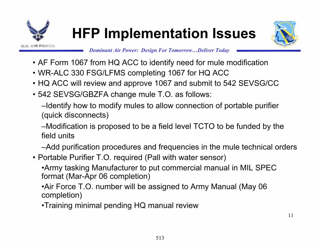
11
Dominant Air Power: Design For Tomorrow…Deliver Today
HFP Implementation Issues
• AF Form 1067 from HQ ACC to identify need for mule modification • WR-ALC 330 FSG/LFMS completing 1067 for HQ ACC• HQ ACC will review and approve 1067 and submit to 542 SEVSG/CC• 542 SEVSG/GBZFA change mule T.O. as follows:
–Identify how to modify mules to allow connection of portable purifier (quick disconnects)–Modification is proposed to be a field level TCTO to be funded by the field units–Add purification procedures and frequencies in the mule technical orders
• Portable Purifier T.O. required (Pall with water sensor)•Army tasking Manufacturer to put commercial manual in MIL SPEC format (Mar-Apr 06 completion)•Air Force T.O. number will be assigned to Army Manual (May 06 completion)•Training minimal pending HQ manual review
513

12
Dominant Air Power: Design For Tomorrow…Deliver Today
ISSUES
• FY06 provisioned quantities for stock listed purifier low– Procurement requires MIPR direct to Army
Item Manager for direct buy from manufacturer• Currently field lacks capability to analyze
hydraulic fluid– Aging Aircraft Systems Squadron and AFRL
developing Multi Sensor to provide field levelanalysis capability
514

13
Dominant Air Power: Design For Tomorrow…Deliver Today
HFP Sample Support
• Sample analysis required to support service evaluations and implementation until multi sensor is available– Selfridge ANGB / Apr 05 – Apr 07– Jacksonville ANGB / Dec 05 – Dec 07– Springfield ANGB / Mar 06 – Mar 07
515

14
Dominant Air Power: Design For Tomorrow…Deliver Today
HFP Improvements
• Multi sensor OT & E will be completed at existing service evaluation locations – Sample Analysis Support / Jun 06 – Nov 06– Stand alone Multi Sensor available for
procurement (Jun 07)– Incorporate multi sensor in Malabar mule
production models (WR-ALC/LESGS) (Jun 07)HQ ACC will need to fund this
– Incorporate multi sensor in all mules undergoing overhaul (WR-ALC/LESGS) (Jun 07)
– Incorporate multi sensor in portable purifiers
516

15
Dominant Air Power: Design For Tomorrow…Deliver Today
Hydraulic Fluid Purification
QUESTIONS?
517

Enhanced 5 cSt Oil Development for High Performance Gas Turbines
Military Aviation Fluids and Lubricants Workshop,Fairborn, OHJune 21, 2006
Lewis Rosado, Ph.D.Lynne M. Nelson
Nelson H. Forster, Ph.D.
Propulsion DirectorateAir Force Research Laboratory
518

2
Enhanced Ester Objective
• The objective of this program is to restore the performance margin for the next generation aircraft engine lubricants
• Candidate oils should have thermal stability equal to HTS + boundary lubrication equivalent to MIL-PRF-23699 STD oils, or better, with current and new generation of materials:
• M50, P675, 9310, P53
• Introduce no issues in the engine (e.g. fully compatible with existing elastomers)
• Both CI and non CI oils are desired for evaluation
• Maintain a 13,000 cSt / -40 F oil requirement for full compatibility with legacy systems
519

3
Comprehensive Oil and Material Qualification Plan - Developed by P&W & USAF
•Auto-ignition Temp
Property Evaluation
TRL 3
Performance Characterization
TRL 3
Element TestingTRL 3
Sub-scale TestingTRL 4
Full-scale TestingTRL 5
Engine Test Full-scale
TRL 6
Engine Cert. & Flight
TRL 7 & 8
• P-V Coefficient
•Traction Coefficient
Physical Props• Density
• Specific Heat• Thermal Conductivity• Vapor Pressure• Evaporation Loss• Foaming• Refractive Index• Color
Chemical Props • Total Acid Number
• Electrical Conductivity• Odor• Toxicity
• Trace Metals
Flammability•Flash Point
Oil Life• Ox–corr stability
• Thermal Stability / corrosivity
Corrosion• Stress Corrosion (Compressor Alloys)
• Hot Corrosion (Turbine Alloys)• Bearing Alloys
Legacy Oil Compatibility•Mix - Aging
TribologicalAssessment• Load Carrying
• Performance Map w/ Adhesive wear• Oil shut off-
• Surface initiated fatigue
ElastomerCompatibility• Hardness
• Swell
• Compression Set• Tensile and elongation
TribologicalAssessment• Rolling contact fatigue (surface & subsurface
• Cage Land Testing
DepositionResistance
• Vapor Phase coker
• Vapor / Liquid phase (HTDT) • Liquid Phase(HLPS)
• Formulator proprietary tests vs baseline oils
• Carbon particulate at elevated pressure • Existing deposit washing
TribologicalAssessment
• Ryder Gear Test
• USN Bearingdeposition test
T63 Engine
• 250 Hours w/ hot shutdowns • Standard TJR defines oil sampling and test regimen
ControlledService Use• AMT• Commercial Use• Engine Inspections• Filter Inspections
Viscosity• 40C, 100C, 200C• Viscosity @ -40oF
• Pour Point
Oil Companies
AFRL/PRTM
AFRL/MLBT
USN
Color Code
OEMs
Wedeven Assoc.
• Spall propagation
TBD
• Temp-visc coefficient
Auto-ignition temp
• Mini-simulator
DepositionResistance
Initial Round-robin planned(AFRL/PRTM, USN, P&W)
• Four candidate oils currently undergoing TRL 3 evaluation• AFRL/PRTM has received one 55 gal drum of one candidate
520

4
Elastomer Testing
Generic Type Specification Trade Name Part Number Test Temperature
Fluorocarbon AMS 7276 (AMS- R-83248)
Viton-A ™ Parker V1164-75
175 +/- 2 C1
Fluorocarbon AMS-R-83485 Viton GLT ™ Parker V0835-75
200 +/- 2 C
Perfluoroelastomer
AMS 7275 KalrezTM TBD2 TBD
Fluorosilicone AMS 3383 TBD 121 +/- 2 C
Nitrile AMS-R-25732 TBD 135 +/- 2 C
•Swell (ASTM D471), tensile strength/elongation (ASTM D412 and D1414), compression set (ASTM 395), hardness (ASTM D1415)•70, 240, 500 hour tests
1Revised temperature from 200oC to 175oC since last SAE E-34 presentation2Dupont-Dow planned for initial testing
More Comprehensive Elastomer Evaluation:
521

5
Next Steps for Oil/Elastomer Testing
• Elastomer Round Robin began Mar 06 – Phase I : 70 hrs, 175o C
- utilizing C&O glassware- Viton A elastomers- BP 2197, MJO 254, MJO II, Reference Oil 300– 240 and 500 hr phases to be run by Oct 2006; test
method finalized in Nov 06.
• Selection of reference Viton-A and GLT materials– Material should be available to anyone
• Database generated will be used to establish limits in the Draft Oil Requirements and eventual Specification
522

6BP2197 MJOII
Means and 95.0 Percent LSD Intervals
Oil
0
3
6
9
12
15
18
Vol
Chn
ge %
Preliminary ANOVA ResultsUDRI Results
BP2197 MJOII
Means and 95.0 Percent LSD Intervals
Oil
-77
-67
-57
-47
-37
-27
-17
Chn
ge T
ensi
le %
HTS 23699
Std 23699
BP2197 MJOII
Means and 95.0 Percent LSD Intervals
Oil
7.7
9.7
11.7
13.7
15.7
Com
pr S
et %
Std vs HTS Oil (AF o-ring source, AF data & compressed O-rings only)
Std 23699
HTS 23699
HTS 23699
Std 23699
523

7
Test ConditionsOil Flow rate: 400 ml/minOil capacity: 2000 ml
Test Temps (oF):Sump Bearing Hot Spot428 527 572
Test Duration: 100hrs
Overall Rating Test 1 Test 2MJO II 55.7 63.5Higher Coking 129 116.6Grade 3 oil
Switch to stainless steel test heads - Apr 06
BP 2197 – May 06
Oil Deposition -Mini-Simulator Rig
524

8
Load Capacity
Tribology/Load Capacity:
– WA Scuffing Load Capacity using Modified Test Protocol, Min value load stage is 22 (consistent with STD 23699 oil)
– WA testing will use - M50 and M50 NiL baseline, P675 and P53 as advanced materials
Ryder Gear Testing:
– Target is consistent with a high load gear oil, minimum is consistent with STD 23699 oil
525

9
TRL 3 Oil Qualification Testing
Four candidate oils currently undergoing TRL 3 testing
AFRL/PRTM plans to complete properties testing/C&O by May 06
526

10
CHARACTERISTIC REQUIREMENT Baseline Oil P&W OILCOMPANY
USAF/PRTM
USAF/MLBT USN
VISCOSITY (ASTM D2532)
@ -40C (-40F), Max13,000 cSt, Max 11,990 N/A 10,981 11,524 ? N/A
Percent Change After 72 Hrs @ -40C (-40F) +/- 6%, Max N/A 1.2 (3 hr) 0.27 (3
hr) ? N/A
VISCOSITY (ASTM D445)@ 40C (104F) 23.0 cSt, Min 26.71 N/A 26.53 26.67 ? N/A
@ 100C (212F) 4.90 to 5.40 cSt 5.23 N/A 5.21 5.24 ? N/A
@ 200C (392F) REPORT cSt N/A N/A N/A ? N/A
POUR POINT (ASTM D97) -54C ( -65F) -57 N/A -57 N/A N/A N/A
PRESSURE - VISCOSITY COEFFICIENT (WAM) REPORT N/A N/A ? N/A N/A
TRACTION COEFFICIENT (WEDEVEN) WEDEVEN ASSOCIATES
DENSITY (ASTM D891B) REPORT 0.9957 N/A 0.9957 ? N/A N/A
5 Pts From 150 to 300 C mm Hg N/A N/A N/A N/A
150C 2.5 2.7 N/A N/A N/A N/A
175C 4.0 4.0 N/A N/A N/A N/A
200C 6.5 6.5 N/A N/A N/A N/A
225C 9.0 10.0 N/A N/A N/A N/A
250C 13.7 16.8 N/A N/A N/A N/A
275C 21.6 27.9 N/A N/A N/A N/A
300C 31.1 37.4 N/A N/A N/A N/A
EVAPORATION LOSS (ASTM D92)6.5 Hrs @ 204C (400F) 10% (weight), Max 1.99 N/A 1.53 N/A N/A N/A
VAPOR PRESSURE (ASTM D2879)
527
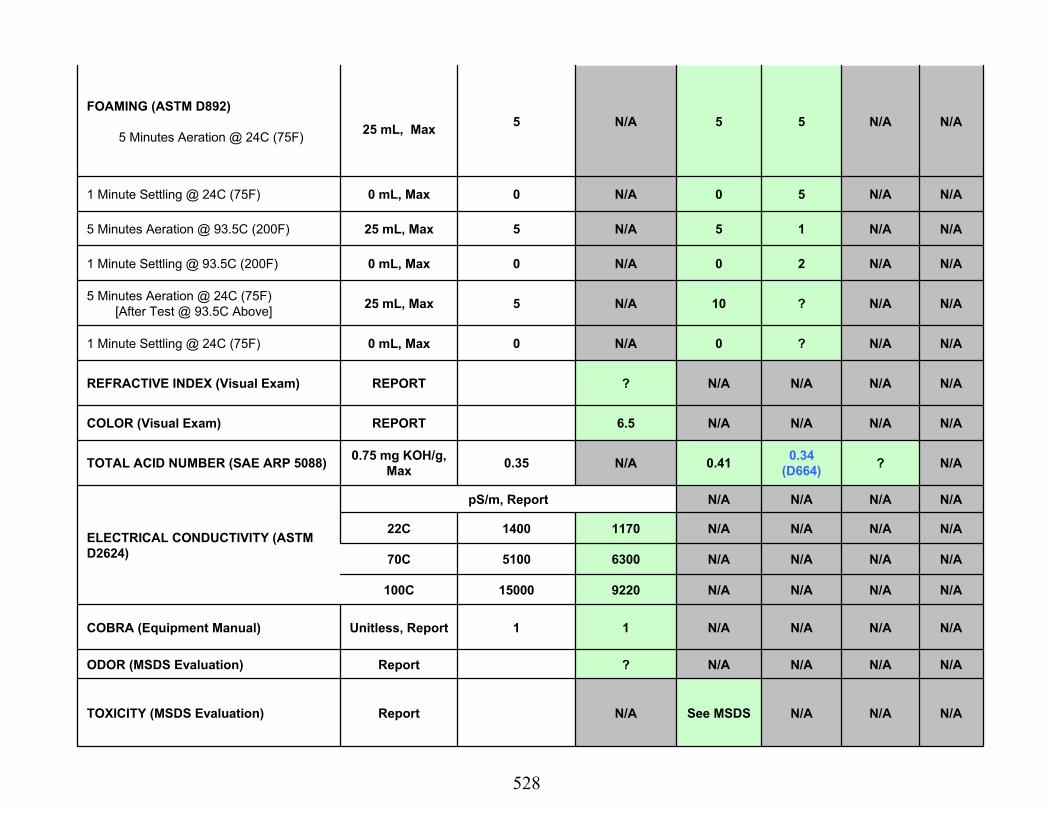
11
FOAMING (ASTM D892)
5 Minutes Aeration @ 24C (75F) 25 mL, Max 5 N/A 5 5 N/A N/A
1 Minute Settling @ 24C (75F) 0 mL, Max 0 N/A 0 5 N/A N/A
5 Minutes Aeration @ 93.5C (200F) 25 mL, Max 5 N/A 5 1 N/A N/A
1 Minute Settling @ 93.5C (200F) 0 mL, Max 0 N/A 0 2 N/A N/A
5 Minutes Aeration @ 24C (75F)[After Test @ 93.5C Above] 25 mL, Max 5 N/A 10 ? N/A N/A
1 Minute Settling @ 24C (75F) 0 mL, Max 0 N/A 0 ? N/A N/A
REFRACTIVE INDEX (Visual Exam) REPORT ? N/A N/A N/A N/A
COLOR (Visual Exam) REPORT 6.5 N/A N/A N/A N/A
TOTAL ACID NUMBER (SAE ARP 5088) 0.75 mg KOH/g, Max 0.35 N/A 0.41 0.34
(D664) ? N/A
pS/m, Report N/A N/A N/A N/A
22C 1400 1170 N/A N/A N/A N/A
70C 5100 6300 N/A N/A N/A N/A
100C 15000 9220 N/A N/A N/A N/A
COBRA (Equipment Manual) Unitless, Report 1 1 N/A N/A N/A N/A
ODOR (MSDS Evaluation) Report ? N/A N/A N/A N/A
TOXICITY (MSDS Evaluation) Report N/A See MSDS N/A N/A N/A
ELECTRICAL CONDUCTIVITY (ASTM D2624)
528

12
TRACE METAL CONTENT (Oil Co - ASTM D5185 and P&W -Rotrode A.E.)
Fe (Rotrode in parenthesis)
2 ppm, Max 0.14 (<1) <1 ? N/A N/A
Al 2 ppm, Max 0.07 (<1) <1 ? N/A N/A
Cr 2 ppm, Max 0.07 (<1) <1 ? N/A N/A
Ag 1 ppm, Max 0.08 (<1) <1 ? N/A N/A
Cu 1 ppm, Max 0.09 (<1) <1 ? N/A N/A
Sn 11 ppm, Max 1.39 (4) 3 ? N/A N/A
Mg 2 ppm, Max 0.35 (<1) <1 ? N/A N/A
Ni 2 ppm, Max 0.09 (<1) <1 ? N/A N/A
Ti 1 ppm, Max 0.18 (1) 1 ? N/A N/A
Si 2 ppm, Max 2.28 (1) 1 ? N/A N/A
Pb TBD ppm, Max 0.12 (<1) <1 ? N/A N/A
Zn TBD ppm, Max 1.01 (<1) <1 ? N/A N/A
FLASH POINT (ASTM D92) 246C (475F), Min 261 N/A ? N/A N/A
AUTOGENOUS IGNITION TEMPERATURE (ASTM E659)
350C (662F), Max N/A ? N/A ?
THERMAL STABILITY & CORROSIVITY (FED STD 791C Method 3411)
Viscosity ChangeTBD %, Max
-0.22N/A N/A ? N/A
Total Acid Number Change TBD mg KOH/g, Max 1.29 N/A N/A ? N/A
Metal Weight Change TBD mg/cm2, Max -0.17 N/A N/A ? N/A
529

13
SEDIMENT AND ASH(FED STD 791C Method 3010)
Visual Undissolved Water
0, Max 0 N/A ? N/A N/A N/A
Sediment Through 1.2 Micron Filter Membrane 10 mg/L, Max 0.96 N/A ? N/A N/A N/A
Total Ash Content 1 mg/L, Max Not Run N/A ? N/A N/A N/A
STRESS CORROSION (MCL E205)Compressor Alloys
metallographic
cross section? N/A N/A N/A N/A
HOT CORROSION (PWA 36700)Turbine Alloys
< / = 2 tenths of a mil attack
@ 500X
PASS -All Results
<0.2mil
PASS -All Results
<0.2milN/A N/A N/A N/A
BEARING CORROSION (EIS)Report
Method UnderDevelopment
? N/A N/A N/A N/A
MIX - AGING TESTS (FTM 3403 Mod 3)
MIL-PRF-23699 Class STD (2)
REPORT, Volume of Sediment
? N/A N/A N/A N/A
MIL-PRF-23699 Class HTS (2)REPORT, Volume of Sediment
? N/A N/A N/A N/A
MIL-PRF-23699 Class C/I (2)REPORT, Volume of Sediment
? N/A N/A N/A N/A
MIL-PRF-7808 Grade 4 (1)REPORT, Volume of Sediment
? N/A N/A N/A N/A
Enhanced Ester Candidates (4)REPORT, Volume of Sediment
? N/A N/A N/A N/A
LOAD CARRYING Load Stage WEDEVEN ASSOCIATES
PERFORMANCE MAP W/ ADHESIVE WEAR WEDEVEN ASSOCIATES
OIL SHUT OFF WEDEVEN ASSOCIATES
SURFACE INITIATED FATIGUE WEDEVEN ASSOCIATES
530
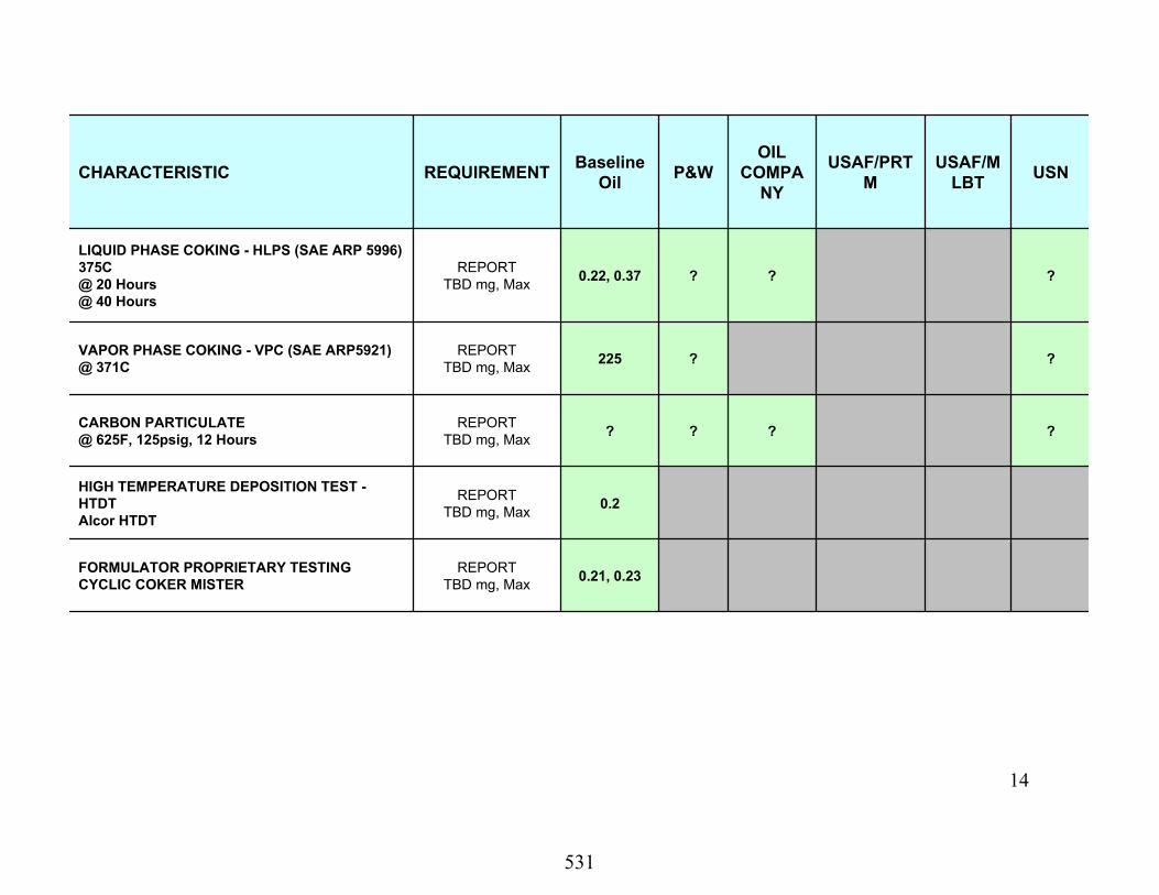
14
CHARACTERISTIC REQUIREMENT Baseline Oil P&W
OILCOMPA
NY
USAF/PRTM
USAF/MLBT USN
LIQUID PHASE COKING - HLPS (SAE ARP 5996)375C@ 20 Hours@ 40 Hours
REPORTTBD mg, Max 0.22, 0.37 ? ? ?
VAPOR PHASE COKING - VPC (SAE ARP5921)@ 371C
REPORTTBD mg, Max 225 ? ?
CARBON PARTICULATE @ 625F, 125psig, 12 Hours
REPORTTBD mg, Max ? ? ? ?
HIGH TEMPERATURE DEPOSITION TEST -HTDTAlcor HTDT
REPORTTBD mg, Max 0.2
FORMULATOR PROPRIETARY TESTINGCYCLIC COKER MISTER
REPORTTBD mg, Max 0.21, 0.23
531

15
T63 Engine Testing
Increasing thermal stress cycles and total run time for oil qualification based on USN HTS T63 test procedure:
– Previous 131 cycles 80 minute duration
– New requirement 200 cycles 75 minutes duration
– Previous total engine run time 175 hours
– New requirement 250 hours
Sample Temperatures
•Oil in 300oF
•Cruise condition - No 6 & 7 brg 385oF, No 8 brg 375oF
•Soak back - No 6 & 7 brg 670oF, No 8 560oF
Status
127 hrs on rerun of BP 2197; will begin T63 test on 1st enhanced candidate ~ Jun 06
532

16
T63 Test ScheduleCOMMEN
TS1 2 3 4 5 6 7 8 9 10 11 12 1 2 3 4 5 6 7 8 9 10 11 12 1 2 3 4 5 6 7 8 9 10 11 12 1 2 3 4 5 6 7 8 9 10 11 12 1 2 3 4 5 6 7 8 9 10 11 12
SBIR Ph I Additive Identification and Feasibility at Wedeven
AF SBIR Ph II (ML-PR) Wedeven Enhanced Additive Development (5cSt basestock)
Enhanced HTS Development by Oil Companies
T63 Engine Testing (250 hours/test) **
Baseline AirBP 2197 HTS oil Complete
Baseline Exxon-Mobil 254 Complete
Repeat baseline 2197
Candidate #1
Candidate #2
HTS-C/I candidate #3
Alt Chemistry candidate #4
HTS-C/I candidate #5
** Oil Samples will be drawn daily for UDRI analysis: viscosity, TAN, COBRA, wear metal analysis
VAATE-I Demos
Engine Tests
Enhanced HTS Oil - T63 Engine Test Schedule2004 20082005 2006 2007
533

17
40 mm Bearing Testing - Beyond Target Requirements
• Prior research by Nixon et. al., and Trivedi et. al., indicate lubricant anti-wear additives can have a significant negative or positive effect on bearing life
• In addition to fatigue life, new anti-wear additives should be checked for the effect on spall/crack propagation
• 10,000 rpm• 450 ksi max Hertzian stress• Test Temperatures
- 375ºF (191ºC) bearing temp- 350ºF (177ºC) oil in temp
• Suspend at 3000 hrs• Currently running AirBP2197 baseline
with M50 and P675 hybrid bearings Six additional test heads added to existing 8 Will be used for oil-bearing life testing
Bearing test heads with insulated head and oil supply lines for high temp operation
534

18
40 mm Bearing Test Schedule
535

19
Overall Program Schedule
• TRL 1 - 3 testing complete with 4 initial candidates August 2006– O/C, coking, basic oil properties completed by May 2006 (WA load capacity
- Aug 06; elastomer screening - Oct 06)
• TRL 4 - 6 testing planned for Jun – Dec 2006; requires a 55-gallon drum of sample; working to line up additional candidates – 40 mm bearing life and spall propagation, Deposition in vapor and liquid
phase, Ryder gear, bearing deposition testing, T63 engine testing
– RR/LW F136 engine gearbox testing CY07
• TRL 7 Engine demos
– P&W XTC68/LF1 (4th Q CY08) & GEAE-RR/LW XTE78/LF1 (4th Q CY08)
• TRL 8– Oil Spec 2007 - 2009
– Transition the oil to the field 2008 - 2010 with wide distribution to military engines/aircraft
536

Eric J. HilleNaval Air Systems CommandAIR - 4.4.2.2
“Advanced Helicopter Transmission Lubricant”
NAVAIR Report at Wright-Patterson AFBJune 2006
537

Slide 29-Feb-07 UNCLASSIFIED – DISTRIBUTION UNLIMITED
- Our Business Card -
• NAVAIR, Propulsion & Power Group, Patuxent River MD
– Doug Mearns - 301.757.3421• Fuels and Lubricants Head
– Eric Hille - 301.757.3414• AHTL Development and Tribology• Lubricants and Gas Path Cleaner Fleet Support
– Jim McDonnell - 301.757.3413• MIL-PRF-23699 Qualification• Lubricants Fleet Support
– Oscar Meza - 301.757.3409• ESDP (“Engineer & Scientist Development Program”) • Lubricant Deposition Methods and Testing
538

Slide 39-Feb-07 UNCLASSIFIED – DISTRIBUTION UNLIMITED
Propulsion Systems Evaluation Facility
539

Slide 49-Feb-07 UNCLASSIFIED – DISTRIBUTION UNLIMITED
Navy Lubes Group - Background
• MIL-PRF-23699 and DOD-PRF-85734– In-house product qualification (QPL’s) for turbine and gearbox oils– Service performance and Fleet support– Development of new product performance requirements
• Full Spec Testing Capabilities– Physical, chemical, analytical analysis– Bench test simulators and T63 turboshaft engine test
• Ties to DOD / Industry / Allied Militaries– Common specification goals– Identifying emerging technologies – Development of new test methods
540

Slide 59-Feb-07 UNCLASSIFIED – DISTRIBUTION UNLIMITED
Gearbox Oils - Historical
• Prior to 1986…– Navy helicopter transmissions operated on gas turbine engine oils
(MIL-PRF-23699, MIL-PRF-7808 types)– Marginal performance in relation to these oils’ deficient degree of
load carrying capabilities
• In 1986…– Navy implemented DOD-PRF-85734 class of oils– Viewed as an “interim” oil to increase operating life – Provided MIL-PRF-23699 type oils with enhanced additives– Relieved recurring fleet problems (e.g. AH-1T upper mast bearing
micro pitting)– “Optimum” oil envisioned, target properties investigated
541

Slide 69-Feb-07 UNCLASSIFIED – DISTRIBUTION UNLIMITED
“AHTL”
• Advanced Helicopter Transmission Lubricant, aka:– “AHTL”– “Nine centistoke oil (9 cSt)”– “Optimum oil”
• Intentions:– Replace 5 cSt DOD-PRF-85734 oil for all Navy power drive systems
with oil intended to further extend gear and bearing life– Reduce high temperature “engine oil” features to allow for an oil
tailored specifically for helicopter systems– Maintain compatibility with MIL-PRF-7808, MIL-PRF-23699, MIL-
PRF-85734, hardware, elastomers– Provide design parameter for future drive systems
542

Slide 79-Feb-07 UNCLASSIFIED – DISTRIBUTION UNLIMITED
AHTL Development
• Properties:– Higher viscosity, 9 cSt versus 5 cSt measured at 100 deg C
• suitable for use in normal gearbox operating ranges – Good to –32 deg C (13,000 cSt)
• Coincides with Army limit• Tradeoff from –40 deg C (5 cSt), -60 deg C (3 cSt)• But, additional benefits at upper end of viscosity / temp chart
– Corrosion inhibition– Substantial increase in load carrying capacity as measured by the
Ryder Gear test…
543

Slide 89-Feb-07 UNCLASSIFIED – DISTRIBUTION UNLIMITED
U. S. Navy Ryder Gear Test
Test Spur Gears
Helical LoadingGears
ScuffingMeasurement
Control Console
544

Slide 99-Feb-07 UNCLASSIFIED – DISTRIBUTION UNLIMITED
U. S. Navy Ryder Gear Test
545

Slide 109-Feb-07 UNCLASSIFIED – DISTRIBUTION UNLIMITED
U. S. Navy Ryder Gear Test
546

Slide 119-Feb-07 UNCLASSIFIED – DISTRIBUTION UNLIMITED
U. S. Navy Ryder Gear Test Results for Selected Herco A, Batch 4 Gears
1
10
100
10 20 30 40 50 60 70 80 90 100
Load (ppi)
% S
cuff
"A" Side Run
"B" Side Run
22.5% Scuff Failure
Absolute Rating (ppi):
(11.5 x 57.8 lbs) / 0.249 in = 2669 ppi
(11.5 x 62.2 lbs) / 0.249 in = 2873 ppi
Avg 2 = 2771 ppi
547

Slide 129-Feb-07 UNCLASSIFIED – DISTRIBUTION UNLIMITED
U. S. Navy Ryder Gear Test Results for Selected MIL-PRF-23699, Batch 4 Gears
1
10
100
10 20 30 40 50 60 70 80 90 100
Load (ppi)
% S
cuff
"A" Side Run
"B" Side Run
22.5% Scuff Failure
Absolute Rating (avg 2) = 2935 ppi
Relative Rating (% Herco A) = 110%
548

Slide 139-Feb-07 UNCLASSIFIED – DISTRIBUTION UNLIMITED
U. S. Navy Ryder Gear Test Results for Selected DOD-PRF-85734, Batch 4 Gears
1
10
100
10 20 30 40 50 60 70 80 90 100Load (ppi)
% S
cuff
"A" Side Run
"B" Side Run
22.5% Scuff Failure
Absolute Rating (avg 2) = 4074 ppi
Relative Rating (% Herco A) = 147%
549

Slide 149-Feb-07 UNCLASSIFIED – DISTRIBUTION UNLIMITED
U. S. Navy Ryder Gear Test Summary, Tifco "Batch 4" Gears
2000
2500
3000
3500
4000
4500
5000
Abso
lute
Rat
ing,
ppi
HTS Oils Standard / C.I. Oils DOD OilsHerco A
(avg 8) (avg 4) (avg 8) (avg 4) (avg 2) (avg 4) (avg 2) (avg 2) (avg 4)
550

Slide 159-Feb-07 UNCLASSIFIED – DISTRIBUTION UNLIMITED
U. S. Navy Ryder Gear Test Results for Selected AHTL, Historical Data
1
10
100
10 20 30 40 50 60 70 80 90 100Load (ppi)
% S
cuff
"A" Side Run
"B" Side Run
22.5% Scuff Failure
Test Oil Temp = 100 C (up from Std 74 C)
Absolute Rating (avg 2) = 4427, extrapolated
Rel. Rating (% Herco A at 100 C) = 222%
551

Slide 169-Feb-07 UNCLASSIFIED – DISTRIBUTION UNLIMITED
Additional AHTL Testing
• Long-Term Fatigue Testing…successful– NASA Spur Gear Testing – 8X life improvement over DOD oil – Timken Tapered Roller Bearing Fatigue Testing – equal life
• Component Ground Tests…operationally successful(temperatures / pressures) – CH-46 fwd / aft transmission at Cherry Point – SH-60 Main transmission at Pensacola – CH-53 nose / tail rotor / intermediate gearboxes at Pax River – Boeing CH-47 engine transmission test (combining gearbox) – Bell M412HP (UH-1N type) main trans / 42 degree gearbox / tail
rotor
552

Slide 179-Feb-07 UNCLASSIFIED – DISTRIBUTION UNLIMITED
AHTL Flight Test Status
• Flight evaluation continues with one CH-53E at Pax – Initiated in December 02– Switched to 2nd “qualified” lubricant in March 05 – About 350 hours of total flight time on each of six gearboxes– No detergency issues
553

Slide 189-Feb-07 UNCLASSIFIED – DISTRIBUTION UNLIMITED
AHTL Flight Test Status (Cont’d)
• Filtration Evaluation– Finalized Flight Test Plan to convert Main GB’s 10 micron oil filter to
a newer 3 micron upgrade used for fleet aircraft– Verify suitable oil system operations (temps, pressures) – Brief ground/flight test is imminent
• Expanded CH-53E flight evaluation– Follows successful 3 micron evaluation – 5 additional aircraft at Pax – “drop-in” conversion– Monitor lubricant performance under fleet flight training profile– One year evaluation…then…first steady customer?
554

Slide 199-Feb-07 UNCLASSIFIED – DISTRIBUTION UNLIMITED
“AHTL” Current Status
• Specification / Qualified Products List– Still a draft Navy specification – No MILSPEC designation until customer emerges in the Fleet– Two-product draft QPL– Spec parameters were streamlined with U.K.’s and published as an
ASCC Air Standard 15/19 dated 18 July 2002
• Further AHTL Implementation– U. S. Army’s H-60 contract with Sikorsky now underway to evaluate
higher viscosity effects on oil system (e.g. thermal lockouts, bypasses), suggest oil system modifications, will lead to “qualifying”AHTL for H-60 model
555

Slide 209-Feb-07 UNCLASSIFIED – DISTRIBUTION UNLIMITED
In Closing…
• The AHTL will provide substantial cost savings…
– a Sikorsky cost benefit analysis estimates an overall 16% reduction in the per-flight-hour cost of maintaining the transmission and drive systems for all U. S. Navy and Marine Corps helicopters.
556

1
The Need For A Synergist Approach
For The Development Of Advanced Aerospace Lubricants
Curtis Genay
Lubricants Technologist
Pratt & Whitney
USAF FLUIDS WORKSHOP 2006
557

2
Future Propulsion System Lubrication Considerations
Mechanical System Design Issues
Bearing Materials Development
Future Lubricant Requirements
= Need For Synergistic Approach
USAF FLUIDS WORKSHOP 2006
558

3
A Bearing Is Not a Component A Bearing Is Not a Component It Is a System !It Is a System !
The Bearing / Lubricant SystemUSAF FLUIDS WORKSHOP 2006
559

4
Bearing Contact Ellipse Is Where All the Action OccursBearing Contact Ellipse Is Where All the Action Occurs
Load at the Ball / Race Contact Is an Elliptical Pressure Area
The Bearing / Lubricant SystemUSAF FLUIDS WORKSHOP 2006
560

5
The Tribology of a Bearing: Synergy Between Material, The Tribology of a Bearing: Synergy Between Material, Lubricant & DesignLubricant & Design -- Ratio.Ratio.
Ratio > 1 Full EHD LubricationRatio < 1 Boundary Lubrication
Interacting Surfaces & Lubricant:
Thickness of Lubricant Film
Thickness of Surface AsperityRatio =
The Bearing / Lubricant SystemUSAF FLUIDS WORKSHOP 2006
561

6
Lubricating CharacteristicsLubricating Characteristics
Pressure - Viscosity:The Secret to Load Bearing Capability
Anti-wear Additive:The Secret to
Boundary Lubrication
Metal Substrate
OXIDE
Adsorbed Film
0Pressure, ksi
50102
103
104
105
Vis
cosi
ty, c
p
25
USAF FLUIDS WORKSHOP 2006The Bearing / Lubricant System
562

7
So, A Bearing Is Not A Component So, A Bearing Is Not A Component It Is A System.It Is A System.
USAF FLUIDS WORKSHOP 2006The Bearing / Lubricant System
And Thus, There Is Much to Consider...And Thus, There Is Much to Consider...
563

8
Solutions Needed to Address Safety and Durability Issues
USAF FLUIDS WORKSHOP 2006The Bearing / Lubricant System
Bearings Are #1 DoD Safety Issue
$-
$100
$200
$300
$400
Bearin
gsTu
rbine
sFan
/ Com
pFue
l Sys
Drive S
ys
Oil Sys
Combu
stors
Cla
ss A
&B
Cos
ts ($
M)
NavyArmyAF
564

9
Bearing Material Needs:• Hardness• Strength• Toughness• Corrosion Resistance• Wear Resistance• Temperature Capability
USAF FLUIDS WORKSHOP 2006The Bearing / Lubricant System
~ 90% of All Bearing Failures Today are Surface Related (Corrosion, Debris, & Handling Damage)
565

10
Bearing Material Requirements Into the Next MillenniumBearing Material Requirements Into the Next Millennium
AISI52100
Bea
ring
Life
M50 M50NiL
Goal
M50 M50NiL
AISI52100
Bea
ring
Spee
d Goal
M50M50NiL
AISI52100
Adh
esiv
e W
ear
Res
ista
nce
Year
200
0
Goal
M50M50NiL
AISI52100
Abr
asiv
e W
ear
Res
ista
nce
Goal
AISI52100
Cor
rosi
onR
esis
tanc
eM50 M50
NiL
Year
200
0
Goal
AISI440C
M50M50NiL
AISI52100
Tem
pera
ture
Goal
Year
200
0Ye
ar 2
000
Year
200
0Ye
ar 2
000
USAF FLUIDS WORKSHOP 2006The Bearing / Lubricant System
566

11
Si3N4 Hybrid Bearings Enable High Speeds
Si3N4 Lowers Ball Centrifugal Loads & Frictional Heating
1.8 2.82.22.0 2.4 2.61.6 3.0
Bearing DN, X106
Rel
ativ
e Li
fe0.5
1.0
0
Si3N4
M50
STATE OF THE ART
HIGHSPEED
Pyrowear 675 / Si3N4 FullScale Bearing Successfully Ran at 675°F ( 357°C)
USAF FLUIDS WORKSHOP 2006
567

12
Gas Turbine Challenges For Ester Based LubricantsGas Turbine Challenges For Ester Based Lubricants
Advanced Aircraft Engine Designs Require Improved Performance And “Life” (Higher – Hotter – Faster):Higher Compression RatiosHigher Combustion TemperaturesHigher Turbine Inlet TemperaturesReduced Cooling AirHigher Rotor and Gear Speeds
Consequence: Increased Thermal and Tribological Demands on the Engine Lubrication System Challenges For Formulators
Aircraft Turbine Engine Lubricants
USAF FLUIDS WORKSHOP 2006
568

13
Enhanced Oils Needed to Meet Demanding RequirementsEnhanced Oils Needed to Meet Demanding RequirementsIncreased System Thermal Capacity
Higher ThermalStability
Increased Oil Out Capability
Enable all Stainless Bearing
Better Boundary FilmFormation
Surface Reactant withStainless Steel
Enhanced HTS
Turbo Oil
Mitigate Adhesive Wear
Adsorbed film
Cr Oxide
Increased System Thermal Capacity
Higher ThermalStability
Increased Oil Out Capability
Enable all Stainless Bearing
Better Boundary FilmFormation
Surface Reactant withStainless Steel
Enhanced HTS
Turbo Oil
Mitigate Adhesive Wear
Adsorbed film
Cr Oxide
USAF FLUIDS WORKSHOP 2006Aircraft Turbine Engine Lubricants
569

14
Adhesive Wear Defended by Boundary Lubrication• Occurs During: Start-up, Shut-down & High G Maneuvers• Molecular Boundary Layers Form Last Line of Defense• Influenced by Materials, Surface Treatments & Roughness
Anti-wear Additive Used to Mitigate Adhesive Wear• Additive Chemically Reacts With Bearing Surface to Form
Chemically Adsorbed Film• Required When Bearing Contact Areas Preclude the Formation or
Maintenance of Effective Lubricant Film (EHD)
• Additive Film Protect Bearing Surface From Excessive Wear
Boundary Lubrication - Basic PrinciplesUSAF FLUIDS WORKSHOP 2006
570

15
TCP In All Currently Approved Aircraft Lubricant FormulationsProperties/Characteristics:
Practically Colorless, Odorless LiquidBoiling Point 420°C (788°F)Non-volatile, CombustibleTypically Blended in Oil at 1-3 Wt. %
Reacts Readily With Current Bearing Steels (M50, etc.)Does Not React Easily With Stainless Bearing SteelsOther Chemistries Being Investigated Under a USAF SBIR
Boundary Lubrication - Tricresyl Phosphate (TCP)
TCP
USAF FLUIDS WORKSHOP 2006
571

16
Material-Lubricant Synergistic Factors
Oil Additive Content
CorrosionInhibitionM
ater
ial-L
ubri
cant
Syne
rgis
tic F
acto
r
Thermal-OxidativeStability
Lubricity
TC
P A
nti-w
ear
Eff
ectiv
enes
sSteel Corrosion
Resistance
StainlessSteel
Non-Stainless
Steel
USAF FLUIDS WORKSHOP 2006
572

17
Critical Properties Of The Lubricant
Viscosity & - Heat GenerationDensity - Lubrication System Pressure
- Component Size & System Weight- Pump-ability
Foaming - Engine Pump Operability (Cavitation)Characteristics - Tank Size
- Component Speeds- Lubricant Cooling Capacity
Vapor Pressure - Compartment Pressure & Operability- Fluid Losses- Pump Performance
USAF FLUIDS WORKSHOP 2006
573

18
Elastomer / Material - System IntegrityCompatibility
Auto-Ignition - Bearing Compartment OperatingTemperature Temperature
- System Weight
USAF FLUIDS WORKSHOP 2006Critical Properties Of The Lubricant
Specific Heat & - Heat Exchanger SizeThermal Conductivity
574

19
Enabling Technology Required For Improved Bearings:
Boundary Lubrication of Corrosion Resistant Bearing Steals
Potential Approaches:
Use Si3N4 Rolling Elements - Hybrid Bearings
More Chemically Reactive Anti-Wear Additives
Bearing Surface Treatments To Increase Reactivity To TCP
Synergy Between Bearing Material and Lubricant Tribological Properties a Necessity for Advanced Aircraft Gas Turbine Engine Mechanical Component Systems Into
the Next Millennium !
USAF FLUIDS WORKSHOP 2006Material-Lubricant Synergistic Factors
575

20
Material / Lubricant Synergism
Questions??Questions??
USAF FLUIDS WORKSHOP 2006
576

Small Business Innovative ResearchProgram, “Gas Turbine Engine Oil Additives for AdvancedBearing Steel”
June 2006
Lois Gschwender, Program ManagerAir Force Materials Directorate, Materials
Laboratory, Wright-Patterson AFB 937-255-7530, [email protected]
577

Gas Turbine Engine Oil Additivesfor Advanced Bearing Steel
• Unique opportunity to make significant advancements in anti-wear additives for new steels for a variety of GTO applications
578

Gas Turbine Engine Oil Additives for Advanced Bearing
Steel– Program focused on Pyrowear 675– These additives must be effective as lubricity
additives while not increasing the deposit-formingtendencies of the lubricant formulations when they experience high temperatures in gas turbine engines nor adversely effect the oil stability
– They must remain in solution at effective concentrations over the desired operational temperature range of the GTO and, in general, allow the formulation to meet existing military GTO specifications (backwards compatible)
579

Gas Turbine Engine Oil Additives for Advanced
Bearing Steel• Phase I: Included the initial demonstration
of novel additive technology for use in high temperature GTOs with advanced bearing steels. Candidate additives and formulations from industry were explored.The formulations demonstrated good performance in boundary lubrication compared to baseline, currently used MIL-PRF-7808 Grade 4 with M50 steel.
580

Gas Turbine Engine Oil Additives for Advanced Bearing Steel
• Phase I SBIR• Tier 1 - Contractors requested samples from
industry – focus on wear properties– Additives - New and developmental– Base fluids - Used to blend the new additives– Formulations – Candidates for the requirements
• Phase II SBIR– METSS Corp. and Wedeven Associates were invited
to and prepared Phase II proposals– Both awarded
581

Small Business InnovativeResearch Program (SBIR)
• Two Phase II contractors– METSS Corp.,
PI Dr. Richard Sapienza, Mr. William Ricks, 614-797-2200
– Wedeven Associates, Inc., PI Dr. Vern Wedeven, 610-356-7161
• Industry support
582

Gas Turbine Engine Oil Additives for Advanced Bearing Steel
• METSS Corp. strengths are in chemical additive synthesis and tribological additive/steel chemical mechanisms of reactions
• Wedeven Associates strengths are in tribological testing, lubrication regimes and close ties with bearing /engine companies
• Both strengths are needed to provide successful technology development and transition
583

Gas Turbine Engine Oil Additives for Advanced Bearing
Steel• Phase II SBIR
– Tier 2 formulation assessments• Stability, coking and all other critical performance
tests (down select)– Tier 3
• Subject successful formulations to boundary lubrication and rolling/sliding lubrication and compared to currently-used steels.
• Bearing tests with new bearing steels
584

Wedeven,11 candidates
METSS,5 candidates
Send to METSS
Send to Wedeven
Tier 2 Assessments
WAMCoke, staticUDRI
Solubility OC, 4-ballviscosity
Coke,HLPS, vaporphase, Navy
Coke, PCL& METSS
Thermalstability
Elastomercompatibility
Flow chart for Phase II additive down-selection
Tier 3 and 4 Optimized additivesystem(s) ready forfurther investigation
585

Gas Turbine Engine Oil Additivesfor Advanced Bearing Steel
• Program issues– Lack of corrosion-resistant new steel for test
specimens• 440C has served well as a substitute• P675 is a moving target, but finally have samples
– Test methods• Fidelity to real application not proven• Deposition tests – several methods• Poor reproducibility (lab to lab agreement)
– Elastomer– Oxidation-Corrosion
• Are amines acceptable due to potential silicone/fluorosilicone interaction?
586
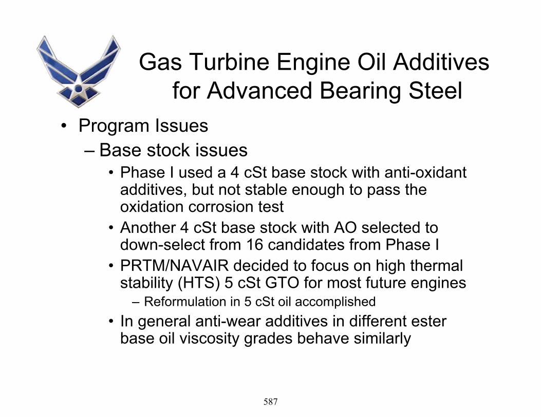
Gas Turbine Engine Oil Additivesfor Advanced Bearing Steel
• Program Issues– Base stock issues
• Phase I used a 4 cSt base stock with anti-oxidant additives, but not stable enough to pass the oxidation corrosion test
• Another 4 cSt base stock with AO selected to down-select from 16 candidates from Phase I
• PRTM/NAVAIR decided to focus on high thermal stability (HTS) 5 cSt GTO for most future engines
– Reformulation in 5 cSt oil accomplished• In general anti-wear additives in different ester
base oil viscosity grades behave similarly
587

Task 9T63 enginetest with best candidate (M50)
Task 1WAM Load Capacity
Screening Tests (P675)(58 candidates)
Task 4Performance Mapping
(WAM3) baseline+ 6 candidates
PW Engine demo ~ Oct 2008
SBIR Additive Phase II Testing Plan
Task 2Compatibility/Coking
PCL: Oxid-CorrCoking (D3711)
ARDL: Elastomer comp
Task 5Surf initiated fatigue (WAMhs)baseline + 4 candidates
(Task 7)*Oil-out (WAM4) baseline oil + 4 candidates
Task 6RCF (Ball-on-rod) baseline oil + 2-4 candidates
Task 840 mm P675 bearingTests (PRTM)1 baseline oil2 candidates
Tier 1Tier 2
Tier 3
Tier 1.5LiquidHLPS
QinetiQ
* Task 7 TBD depending on time and funding
Baseline
Tier 4M50, 2197P675, 2197
Gate
VaporVPCNavy
Task 3 Coking
PW full-scale bearing tests with
P675 (2007)
4 Phase II suppliers
3 primary candidates+ 6 backups
Phase III
588

FY06 Phase I SBIR Contracts –Novel Additives for
Perfluoropolyalkylethers for Silicon Nitride Bearing Elements
• Phase I contractors– METSS Corporation– Luna Innovations, Inc.
589

MET
SS
New and Innovative Gas Turbine Engine Oil Additive Technology
Richard SapienzaWilliam Ricks
METSS Corporation
June 21, 2006Work done under
Air Force Contract No. FA8650-04-C-5029
590

MET
SS
The Problem• Advanced high-chrome steels in engine bearings should provide:
higher operating temperatures higher speed capabilitiesimproved corrosion fatigue resistance
• However, they have experienced significantly shorter life than anticipated in performance tests conducted using current gas turbine engine oils (GTOs) which utilize synthetic polyol ester basestocks .
• Their chemistry does not interact in the same way with the lubricious coating additives.
591

MET
SSGTO Lubricant Development Requires
• The gas turbine engine oil is required to lubricate not only theengine bearings but also other engine components such as the gears that may be made out of conventional steels. Thus, the development of successful new GTO lubricant additives requires – an understanding of the chemical and physical properties of
the material to be lubricated or which will interact with the lubricant
– an understanding of lubricant basestock and additives; their interactions and synergies
– a well-defined strategy for testing and evaluating the candidate materials relevant to the performance requirements of the fluid
592

MET
SSCarbon and Chromium Effects
• The chromium is crucial in promoting the formation of a Cr-rich passive film on the surface of stainless steels
• With increasing chromium, the steels become increasingly resistant to aggressive solutions
• The carbon is added for the same purpose as in ordinary steels to make the alloy stronger
• Carbon and Chromium are less chemically reactive than iron surface
593

MET
SS
Reaction of Antiwear Additives• On Conventional Low Chromium Steels
– antiwear additives react chemically with the iron surface• a lubricious coating on steel surfaces under boundary lubrication
– produce soft films of inorganic metallic chlorides, sulfides andphosphides.• films shear easily where any asperities meet and thus protect the
base metal.• On advanced steels
– It has been postulated that the high-chromium content does not provide the proper reactive iron surface necessary for interaction with the aryl phosphate (TCP) to form an iron-phosphorus surface film
594

MET
SSMETSS Concept for High Chrome Steel
Additives
• There are different “active sites” for additive interaction• Based upon the poisoning characteristics of conventional
iron/chrome oxide high temperature water-gas shift catalysts– catalyst is strongly deactivated by sulfur – alkaline materials promote phosphorus poisoning– Some nitrogen was also found to be deposited
• Idea was poisoning for the catalyst occurs due to strongly coordinated species at active sites could this insight help select additives that would bond similarly with high chrome steels.
595

MET
SSMETSS Program
Identify needs, evaluate existing fluidsSelect candidate alternative materialsDevelop testing and evaluation programConduct iterative formulation, testing, and optimization
tiered approach to testing• simple screening tests to eliminate poor performers• more advanced tests to optimize formulations • final qualification tests to select best performers
Partner with Manufacturers - provide max feedback ; Work with AF-seek max informationTransition technology to military and commercial market applications.
Goal - Identify several candidates that exhibit better antiwear properties than either the current TCP additive or the current finished fluid.
596

MET
SSLubricant Materials Selection
• METSS obtained samples of two base fluids from ExxonMobil :– Fluid A. MCP 2433, a synthetic polyol ester basestock fluid
containing no additives. • used as primarily the carrier for the candidate lubricant additives • one control was Fluid A with current tricresyl phosphate antiwear
additive.
– Fluid B. RM284A, a MIL-PRF-7808 Grade 4 fluid, fully compounded with all additives, including the aryl phosphate.
• Fluid B was used as one of the controls• METSS found suppliers and additive technology to prepare fluids.
• Lubrication performance with M-50 steel served as baseline comparison of the additives. 440C steel used to simulate advanced high-chrome bearing steels.
597

MET
SSTypical Elemental Composition of
Selected Bearing Steels
15.20.400.381.08Cronidur 30
13.00.40-0.07Pyrowear 675
17.01.00 max-1.10440C
4.000.25 max.-0.80M50
1.450.25-1.0052100
Chromium %Silicon %Nitrogen %Carbon %Material
598

MET
SSIndustrial Participants
• Acheson Colloids• Akzo Nobel• Albemarle• Chevron Texaco• Ciba-Geigy• Crompton• Dover Chemical• Elco Corporation• Ethyl Corporation
• ExxonMobil• Great Lakes Chemical• King Industries• Lockhart Chemical• Lubrizol Corporation• Nyco America• Hatco Corporation• Rohm & Haas• RT Vanderbilt• Uniqema
599

MET
SSAdditive Chemistry Summary
• The lubricious coating additives of current gas turbine engine oil (GTOs) chemistry do not interact with advanced high-chrome steels in engine bearings in the same way as conventional steels.– Different “active sites” for additive interaction
• from Surface Analysis - No P was found with TCP
• Lower oxidation state P chemistry is effective in alkaline environments in providing high-chrome steel surface reaction.– Large anti-wear improvements measured.
• An anti-oxidant anti-wear additive synergism demonstrated. – Amines act as phosphate conversion coating accelerators– Anti-oxidant functionality reduces acid formation
• An optimize corrosion-oxidation stability of the new additive systems is needed to meet the mil-spec requirements.
– Phosphorus-nitrogen complexes show high effectiveness on high chrome steels• However adverse effects of amines or amino-functionality on fluorocarbon and
fluorosilicone elastomers found.
600

MET
SS
Development StepsGrade 4 GTO with aryl phosphate additiveLow chrome-content bearings based on
52100 and M-50
Type 4 with advanced additivesMIL-PRF-7808 testing basis
ExxonMobil RM284A standardReadily available high-chrome steel - 440C
Grade 5 GTO with developed additives MIL-PRF-23699 testing
ABP 2197 standardAdvanced high-chrome steel Pyrowear 675
and silicon nitride bearings
Phase I
Phase II
601

MET
SS
Testing and Evaluation - Tier 1• Physical and Chemical Properties• Mixture Compatibility• Low Temperature Stability and Viscosity @ -40oC• Four Ball Wear Testing
– ASTM D4172 - relative antiwear properties – determination of coefficient of friction– test matrix include friction and wear testing with M50 and
440C steel balls, – ball-on-disk configuration to evaluate the friction wear
properties of the candidate lubricant formulations on disks fabricated from advanced steel.
602

MET
SSTesting and Evaluation - Tier 2
• Corrosion-Oxidation Stability (ASTM D4636)– Determines the ability to resist oxidation and tendency to
corrode various metals– Measure changes in fluid viscosity, acid number, sludge,
metals appearance and weight change– 40 hours @ 220oC with dry air flow
• Elastomer Compatibility (FTM 3604 and 3432)– Measure changes in elastomer volume, hardness, tensile
strength and elongation after fluid exposure.– NBR-H aged 168 hours @ 70oC– FKM aged 72 hours @ 175oC– FVMQ aged 72 hours @ 150oC
603

MET
SSTesting and Evaluation - Tier 2
(continued)
• Coking Tendency(ASTM D3711)– Determines the tendency to form coke deposits for both liquid and
vapor contact with surfaces at elevated temperatures
– 100 ml aged 5 hours @ 300oC with 50 ml/min flow
• Thermal Stability & Corrosivity (FTM 3411)– 96 Hours @ 274oC in sealed evacuated glass tube with steel– Measure changes in fluid viscosity & acid number, metal weight
change.
• Additional Tribology Testing– an attempt at correlating laboratory friction and wear performance
with anticipated performance in the field• WAM Testing - Load Stage Failure
604

MET
SSWAM Load Stage Failure
0 5 10 15 20 25 30
WA028
WA031
WA041
WA034
WA035
WA036
12I10
12I20
12I39
WA147
Base F
Minimum Performance for
SBIR Additive13.5
Minimum Performance forEnhanced 5 cSt.
22.0
605

MET
SS
D3711 Coking Tendency - Gross Deposit, mg
0
20
40
60
80
100
120
140
160
180
WA028WA031WA041WA034WA035WA036BASE FBASE I12I1012I2039I201I20
WA147
Liquid Vapor
Commercial Grade 5 HTS
TCP Control
606

MET
SSCorrosion-Oxidation Stability Test Results
0
48
1216
2024
28
BASE FBASE I1I2012I1012I20WA028WA034WA036WA041WA147
Viscosity @ 40C Change, % TAN Change, mg KOH/g
Viscosity Change = 25 max
TAN Change = 4 max
Commercial Grade 5 HTS
TCP Control
607

MET
SSThermal Stability & Corrosivity
-6.0
-4.0
-2.0
0.0
2.0
4.0
6.0
BASE F
BASE I
12I10
12I20
WA028
WA034
WA036
WA041
Viscosity Change. % TAN Change, mg KOH/gTAN Change = 6.0 max.
Viscosity Change = 5.0 max.
109
608

MET
SSNBR-H Elastomer Compatibility
-50
-40
-30
-20
-10
0
10
BASE FBASE I1I20
12I10
12I20
WA028WA034WA036WA041
Tensile Change, % Elongation Change, %
Maximum Change = 50%
609

MET
SSFKM Elastomer Compatibility
-50
-40
-30
-20
-10
0
BASE FBASE I1I20
12I10
12I20
WA028WA034WA036WA041
Tensile Change, % Elongation Change, %
Maximum Change = 50%
610
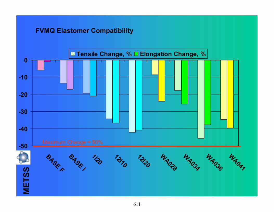
MET
SSFVMQ Elastomer Compatibility
-50
-40
-30
-20
-10
0
BASE FBASE I1I20
12I10
12I20
WA028WA034WA036WA041
Tensile Change, % Elongation Change, %
Maximum Change = 50%
611

MET
SSSummary of Progress • New and innovative gas turbine engine oil additive technology is being
developed to achieve the greatest benefit from the performance advantages provided by the advanced bearing steels.
• The new lubricant formulations have demonstrated performance comparable to baseline data obtained for the current MIL-PRF-7808 Grade 4 GTO.
• The new lubricant anti-wear additives are effective on both advanced Pyrowear 675 as well as conventional steels and have demonstrated high temperature stability.
• The new additive formulations are suitable for MIL-PRF-23699 Type 5 fluids with enhanced antiwear performance .
• These synthetic lubricant formulations use commercially available products.– Air BP; ExxonMobil; Lubrizol; METSS
612

MET
SSDown Selection
• Work with AF Propulsion and Materials to establish a relative weighting system for fluid test parameters. – Most important parameters receive highest weight factor– Least important parameters receive lowest weight factor.
• Rate candidate fluids according to test results and weight factors to achieve an overall score for each.
• Assist in selection of best candidate technologies for subsequent T-63 engine testing program.
613

MET
SSThanks and Acknowledgements
• METSS
– Bill Ricks; Joe Sanders; Ann Banks
• SBIR program technical partners– Timken Technical Services– Wedeven Associates – POC: L. Gschwender and Ed Snyder , AFRL/MLBT
• SBIR program commercialization partners– Nyco America
• Outside testing laboratories– Phoenix Chemical– UEC– NAVAIR– UTC– AFRL
614

1
SBIR Phase IIAdditives for Corrosion-Resistant Steels
Status Briefingfor
Military Aviation Fluids and Lubricants Workshop
Hope Hotel and Conference CenterFairborn, OH
21 June 2006
Vern WedevenWedeven Associates, Inc.
Air Force Contract No. FA8650-04-C-05034
615

2
SBIR Phase II Additives forCorrosion-Resistant Steels
Outline• Project Scope• Testing approach• Tribology Performance Targets• Additive Tribology Screening • Down-selections• Tribology Performance Mapping Status• Contact Fatigue• Coking Test Results
616

3
SBIR Additive – Objective
CompatibilityOxid-Corr Elastomer
O-CPhoenix
D471ARDL
Thermalstability
PhoenixRCFUES
WearScuffing SurfaceFatigue
WAM8/9WA, Inc.
WAM8WA, Inc.
WAMhsWA, Inc.
Tribology
VPCNavy
Liquid VaporHLPS
QinetiQD3711
Phoenix
Mixed
Coking
Objective: significant boost in tribology forcorrosion resistant steels with noloss in coking or compatibilityattributes (HTS type)
617

4
Task 9T63 enginetest with best candidate (M50)
Task 1WAM Load Capacity
Screening Tests (P675)(58 candidates)
Task 4Performance Mapping
(WAM3) baseline+ 6 candidates
PW Engine demo ~ Oct 2008
SBIR Additive Phase II Testing Plan
Current date: 12-17-05
Task 2Compatibility/Coking
PCL: Oxid-CorrCoking (D3711)
ARDL: Elastomer comp
Task 5Surf initiated fatigue (WAMhs)baseline + 4 candidates
(Task 7)*Oil-out (WAM4) baseline oil + 4 candidates
Task 6RCF (Ball-on-rod) baseline oil + 2-4 candidates
Task 840 mm P675 bearingTests (PRTM)1 baseline oil2 candidates
Tier 1Tier 2
Tier 3
Tier 1.5LiquidHLPS
QinetiQ
* Task 7 TBD depending on time and funding
Baseline
Tier 4M50, 2197P675, 2197
Gate
VaporVPCNavy
Task 3 Coking
PW full-scale bearing tests with
P675 (2007)
Phase II participants
• Major oil suppliers• Additive suppliers• Small businesses
In conjunctionwith AF/NavyEnhanced 5 cStOil Program
Phase III
618

5
Tribology Strategy
Tribology Performance Level(contact stress, rolling/sliding speed, temperature)
• Wear• Scuffing• Surf fatigue
9310, Pyrowear 53, P675 (low temp temper) M50, M50NiL Pyrowear 675
Lubricant(tribology attributes)
Brg/Gear Mat’ls
DesignStress, speed, temp
P675
GoalRisk
Design level
Compatibility
619

6
Tribology Strategy
Tribology Performance Level(contact stress, rolling/sliding speed, temperature)
• Wear• Scuffing• Surf fatigue
9310, Pyrowear 53, P675 (low temp temper) M50, M50NiL Pyrowear 675
Lubricant(HTS/CI oils)
Brg/Gear Mat’ls
DesignStress, speed, temp
P675
GoalRisk
HTS/CI oils, stainless steels
Need systemsapproach
Design level
620

7
• Wear• Scuffing (historical, mature)• Fatigue
Baseline Tribology Testing – Approach
Life & durability
Load & power limit
Stress & power transmitted
621

8
Lubr mechanismsHydrodynamic & EHDMicro-EHDBoundary lubr. (surface film)
Failure mechanismsWear (polishing, corrosive
adhesive, abrasive)Scuffing (micro, macro)Fatigue (micro-pitting, pitting)
Sliding velocity
Entraining velocity
Degree of asperity penetration (h/ )
Contact temp (Tc = Tbulk + Tflash)
Contact Stress (asperity stress)
Link toservice
conditions
Five Key Tribology Parametersfor Oil/Material Evaluation
622

9
Tribology TestingSuite of three types of machines cover current test methods
WAMhs
• Surface fatigue• Debris tolerance
• Abrasive wear• Oil-out
WAM8/9
Cage-land sliding contact
Rolling/sliding contact High Stress rolling/sliding
• Scuffing, adhesive wear• Performance mapping
WAMsc-2
623

10Load Stage
0 2 4 6 8 10 12 14 16 18 20 22 24 26 28 30 32
Aver
age
Trac
tion
Coe
ffici
ent
0.00
0.01
0.02
0.03
0.04
0.05
0.06
0.07
0.08
0.09
0.10 Run File: naa.runBall: 9310, Ra = .25 m (10 μin)Disc: 9310, Ra = .15 m (6 μin)Entraining Velocity: 5.72 m/s (225 in/sec)Sliding Velocity: 8.78 m/s (346 in/sec)Velocity Vector Angle (Z): 75°
<S
Lower bound reference,polished surfaces, STD oil
Failure criteria(avg. of all tests)
Basestocks(6 oils)
HTS OilsMIL-PRF-23699
(4 oils)STD Oils
MIL-PRF-23699(5 oils)
CI OilsMIL-PRF-23699
(4 oils)
Qualified product types and basestocks
DOD OilsDOD-L-85734
(2 oils)all tests suspended
Grade 4MIL-PRF-7808
(2 oils)
Historical trends in oil lubricating performance
Grade 3MIL-PRF-7808
(1 oil)2 of 2 tests suspended
Master Chart for Oil Scuffing Performance
BasestocksDOD-PRF-85734High Load Oils
STD 5 cStOils
HTS 5 cStOils
CI 5 cStOils (old)
Grade 47808 Oils Grade 3
7808 Oil
624

11
WAM High Speed Load Capacity Test Method
Load Stage0 2 4 6 8 10 12 14 16 18 20 22 24 26 28 30 32
Load
(lbs
.), T
empe
ratu
re (°
C)
0
20
40
60
80
100
120
140
160
180
200
220
240
260
Trac
tion
Coe
ffici
ent
0.00
0.01
0.02
0.03
0.04
0.05
0.06
0.07
0.08
0.09
0.10Run File: naa.run6Lube: as notedBall: as noted, Ra=12 μin.Disc: as noted, Ra=6 μin.Entraining Velocity: 158.10 in/sec. (instead of 225 in/sec)Sliding Velocity: 345.03 in/sec.Temperature: Ambient to friction generated temperature levelVelocity Vector Angle (Z): 95°
W/Testing/SBIR-Add/Project/WAMLCC/AVG/RM284A M50 & 440C.jnb
Lower bound reference,polished surfaces, STD oil
Failure criteria(avg. of all tests)
(Modified Test Protocol)
M50/M50MIL-PRF-7808 Grade 4 Oil
Oil A2 tests
(ADD186-ADD187)
440C/440CMIL-PRF-7808 Grade 4 Oil
Oil A2 tests
(ADD185-ADD188)
Mimimum perflevel equivalentto M50 mat'ls
Ref Grade 4 Oil(Oil A)
with 440C mat'ls
Note: Failure stages with Std protocol are: M50/M50: 17 440C/440C: 8 P675/P675: 12.7
P675/P675Mil-PRF-7808 Grade 4
Oil B2 tests
(SBAD49-SBAD50)
P675/P675MIL-PRF-7808 Grade 4
OIl A2 tests
(SBAD47-SBAD48)
MIL-PRF-7808 Grade 4 Oils
P675 steel comparableto 440C (???); Grade 4Oil A similar to Oil B
Baseline Testing – Minimum Performance
PerfGoal
?
625
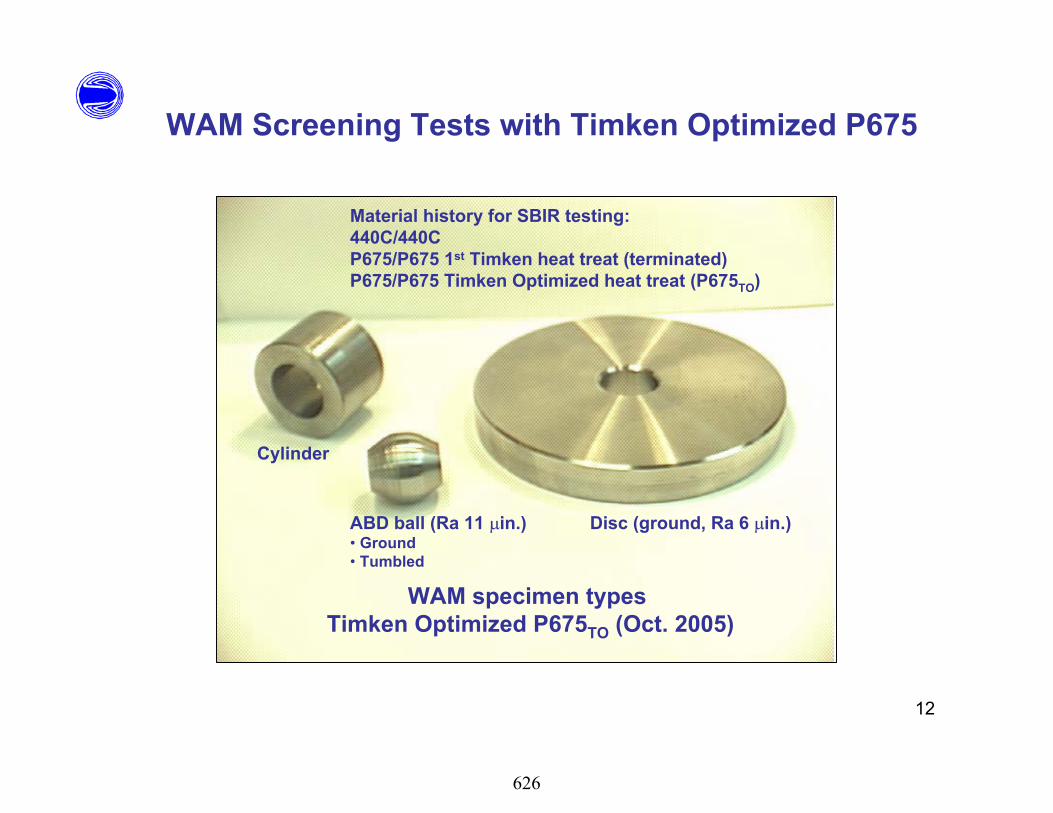
12
WAM Screening Tests with Timken Optimized P675
WAM specimen types Timken Optimized P675TO (Oct. 2005)
ABD ball (Ra 11 in.)• Ground• Tumbled
Disc (ground, Ra 6 in.)
Cylinder
Material history for SBIR testing:440C/440CP675/P675 1st Timken heat treat (terminated)P675/P675 Timken Optimized heat treat (P675TO)
626

13
WA111 (4 cSt)WA112 (4 cSt)WA113 (4 cSt)WA114 (4 cSt)WA115 (4 cSt)WA010WA011WA012WA013WA014WA024 (4 cSt)WA025 (4 cSt)WA034WA035 (CI)WA036 (CI)
#1 WA034#2 WA036 (CI)#3 WA035 (CI)
Supplier A Formulations and Down-Selections
(15)
WAM load capacity screening tests
These oils evaluated for:Oxid-corr, elastomer compatand coking (D3711)
627

14
WAM Screening Tests with Timken Optimized P675
WAM High Speed Load Capacity Test Method(Modified Test Protocol)
Run Time (seconds)0 150 300 450 600 750 900 1050 1200 1350 1500 1650 1800
Trac
tion
Coe
ffici
ent
-0.02
0.00
0.02
0.04
0.06
0.08
0.10
0.12
0.14
Load
(lbs
.), T
empe
ratu
re (°
C)
0
20
40
60
80
100
120
140
160
180
200
220
Vertical Load
Traction Coefficient
Test: SBAD121 - SBAD122Lube: ALO-16360Ball: 64-18, P675, Ra= 10-12μin.Disc: 18-37b, P675, Ra=6 μinEntraining Velocity: 158 in/sec.Sliding Velocity: 345 in/sec.Temperature: Ambient Velocity Vector Angle (Z): 95°
Disc Temperature
Ball Temperature
SBAD121
SBAD122
Perf goal forEnhanced 5 cStMin. perf for
SBIR Additive
Avg failurestage 29.5
No. 1 Candidate WA034 (HTS)
Avg. failureStage 29
Low traction coeff.reflects mild wear
Supplier A Priority Candidates
628

15
WAM High Speed Load Capacity Test MethodModified Test Protocol
Load Stage0 2 4 6 8 10 12 14 16 18 20 22 24 26 28 30 32
Load
(lbs
.), T
empe
ratu
re (°
C)
0
20
40
60
80
100
120
140
160
180
200
220
240
260
Trac
tion
Coe
ffici
ent
0.00
0.01
0.02
0.03
0.04
0.05
0.06
0.07
0.08
0.09
0.10Run file: Naa6.runLube: As notedBall: P675 to, Ra=9.5-10 μin.Disc: P675 to, Ra=6 μin.Entraining Velocity: 158 in/sec.Sliding Velocity: 345 in/sec.Temperature: Ambient Velocity Vector Angle (Z): 95°
W/Testing/SBIR04-05/Project/WAMLCC/.jnb
Lower bound reference,polished surfaces, STD oil
Failure criteria(avg. of all tests)
WA035P675to/P675to
(3 tests)(SBAD113 - SBAD115)
WA036P675to/P675to
(2 tests)(SBAD123 - SBAD124)
WA034P675to/P675to
(2 tests)(SBAD121 - SBAD122)
WAM Screening Tests with Timken Optimized P675
Perf goal forEnhanced 5 cSt
Min. perf forSBIR Additive
No. 2WA036
No. 1WA034
No. 3WA035
Supplier A Priority Candidates
629

16
WA001 (4 cSt)WA002 (4 cSt)WA003 (4 cSt)WA004 (4 cSt)WA005 (4 cSt)WA006 (4 cSt)WA007 (4 cSt)WA008 (4 cSt)WA009 (4 cSt)WA017 (4 cSt)WA018 (4 cSt)WA019 (4 cSt)WA020 (4 cSt)WA021 (4 cSt)WA022 (4 cSt)WA023 (4 cSt)WA026 (4 cSt)WA027 (4 cSt)
#1 WA041#2 WA028#3 WA031WA051 is backupfor WA041
Supplier B Formulations and Down-Selections
(40)
WA028WA029WA030WA031WA032WA033
WA037 (CI)WA038 (CI)WA040 (CI)WA041WA042 (CI)WA043 (CI)WA044WA045 (CI)WA046 (CI)WA047
Tested by WA, Inc.outside of SBIR
WA048WA049WA050WA051WA052WA0
WAM load capacity screening tests
These oil evaluated for:Oxid-corr, elastomer compatand coking (D3711)
630

17
WAM High Speed Load Capacity Test MethodModified Test Protocol
Run Time (seconds)0 150 300 450 600 750 900 1050 1200 1350 1500 1650 1800
Trac
tion
Coe
ffici
ent
-0.02
0.00
0.02
0.04
0.06
0.08
0.10
0.12
0.14
Load
(lbs
.), T
empe
ratu
re (°
C)
0
20
40
60
80
100
120
140
160
180
200
220
Traction Coefficient
Test: SBAD137 - SBAD138Lube: 05-49801 (WA041)Ball: 31-18, P675, Ra= 10-12μin.Disc: 18-28b, P675, Ra=6 μinEntraining Velocity: 158 in/sec.Sliding Velocity: 345 in/sec.Temperature: Ambient Velocity Vector Angle (Z): 95°
w/testing/sbir-ADD/Projest/LCCjnb
Disc Temperature
Ball Temperature
SBAD138
SBAD137
Vertical Load
Avg failurestage 24.5
No. 1 CandidateWA041 (HTS)
Perf goal forEnhanced 5 cSt
Min. perf forSBIR Additive
WAM Screening Tests with Timken Optimized P675Supplier B Priority Candidates
631

18
WAM High Speed Load Capacity Test MethodModified Test Protocol
Load Stage0 2 4 6 8 10 12 14 16 18 20 22 24 26 28 30 32
Load
(lbs
.), T
empe
ratu
re (°
C)
0
20
40
60
80
100
120
140
160
180
200
220
240
260
Trac
tion
Coe
ffici
ent
0.00
0.01
0.02
0.03
0.04
0.05
0.06
0.07
0.08
0.09
0.10Run file: Naa6.runLube: As notedBall: P675 to, Ra=9.5-10 μin.Disc: P675 to, Ra=6 μin.Entraining Velocity: 158 in/sec.Sliding Velocity: 345 in/sec.Temperature: Ambient Velocity Vector Angle (Z): 95°
W/Testing/SBIR04-05/Project/WAMLCC/.jnb
Lower bound reference,polished surfaces, STD oil
Failure criteria(avg. of all tests)
WA028P675to/P675to
(2 tests)(SBAD125 - SBAD126)
WA051P675to/P675to
(2 tests)(SBAD157 - SBAD158)
WA031P675to/P675to
(2 tests)(SBAD129 - SBAD130)
WA041P675to/P675to
(2 tests)(SBAD137 - SBAD138)
WAM Screening Tests with Timken Optimized P675
Supplier B Priority Candidates
No. 1WA041
No. 3WA031
WA051(backup)
No. 2WA028
Min. perf forSBIR Additive
Perf goal forEnhanced 5 cSt
632

19
WA101 (4 cSt)WA102 (4 cSt)WA103 (4 cSt)WA104 (4 cSt)WA105 (4 cSt)WA106 (4 cSt)WA122 (4 cSt)WA123 (4 cSt)WA124 (4 cSt)WA125 (4 cSt)WA126 (4 cSt)WA127 (4 cSt)WA128 (4 cSt)WA129 (4 cSt)WA131 (4 cSt)WA132 (4 cSt)WA133 (4 cSt)WA134 (4 cSt)WA135 (4 cSt)
No down-selected formulations,except for WA144, which wasboosted by WA, Inc. to passscuffing testNew WA/Supplier C formulation is WA147
Supplier C Formulations and Down-Selections
(28)
WA136 (4 cSt) (WA141)WA137 (4 cSt) (WA142)WA138 (4 cSt)WA139 (4 cSt) (WA143)WA140 (4 cSt)
WA144WA145WA146
Total formulations evaluated: 84(not including METSS)
WAM load capacity screening tests
Oils WA136, WA137 & WA139 evaluated for:Oxid-corr, elastomer compat and coking (D3711)Results: problems with WA137 & WA139
Chemistry of WA136,WA137 & WA139 put inNyco 5 cSt ref base oil
633

20
WAM High Speed Load Capacity Test MethodModified Test Protocol
Run Time (seconds)0 150 300 450 600 750 900 1050 1200 1350 1500 1650 1800
Trac
tion
Coe
ffici
ent
-0.02
0.00
0.02
0.04
0.06
0.08
0.10
0.12
0.14
Load
(lbs
.), T
empe
ratu
re (°
C)
0
20
40
60
80
100
120
140
160
180
200
220
Vertical Load
Traction Coefficient
Test: SBAD161 - SBAD162 and SBAD165Lube: WA144Ball: P675to, Ra=9.5-10 μin.Disc: 18-45b, P675to, Ra=6 μin.Entraining Velocity: 158.10 in/sec.Sliding Velocity: 345.03 in/sec.Temperature: Ambient Velocity Vector Angle (Z): 95°
wamlcc/sbir-add/modifiedtestprotocol/DOD.jnb
Ball Temperature
Disc Temperature
SBAD161
SBAD162SBAD165
WAM Screening Tests with Timken Optimized P675
Avg failurestage 13
Perf goal forEnhanced 5 cStMin. perf for
SBIR Additive
WA144 (HTS)
Supplier C Candidate
634

21
WAM High Speed Load Capacity Test MethodModified Test Protocol
Run Time (seconds)0 150 300 450 600 750 900 1050 1200 1350 1500 1650 1800
Load
(lbs
.), T
empe
ratu
re (°
C)
0
20
40
60
80
100
120
140
160
180
200
220
Trac
tion
Coe
ffici
ent
-0.02
0.00
0.02
0.04
0.06
0.08
0.10
0.12
0.14
Vertical Load
Traction Coefficient
Tests: SBAD166 and SBAD167Lube: WA147 = WA144 + WA, Inc. booster Ball: P675to, Ra=9.5-10 μin.Disc: 18-45b, P675to, Ra=6 μin.Entraining Velocity: 158.10 in/sec.Sliding Velocity: 345.03 in/sec.Temperature: Ambient Velocity Vector Angle (Z): 95°
wamlcc/sbir-add/modifiedtestprotocol/DOD.jnb
Ball Temperature
Disc Temperature
SBAD166
SBAD167
Test terminated toprovide surface forchemical analysis
Min. performanceload stage 13.5
Perf goalload stage 22
Initiation of lossof boundary film
WA/Supplier C oil WA147 100x
Disc track; test SBAD167
WAM Screening Tests with Timken Optimized P675WA, Inc./Supplier C Candidate
WA147 alsopasses coking& compatibilitytests
Avg failurestage ~25
635

22
?12E2012I2039I2012I10
#1 12I1012I2039I20
METSS Formulations and Down-Selections
WAM load capacity screening tests
These oils evaluated for:Oxid-corr, elastomer compatand coking (D3711)
636

23
WAM High Speed Load Capacity Test MethodModified Test Protocol
Run Time (seconds)0 150 300 450 600 750 900 1050 1200 1350 1500 1650 1800
Trac
tion
Coe
ffici
ent
-0.02
0.00
0.02
0.04
0.06
0.08
0.10
0.12
0.14
Load
(lbs
.), T
empe
ratu
re (°
C)
0
20
40
60
80
100
120
140
160
180
200
220
Vertical Load
Traction Coefficient
Test: SBAD148 & SBAD149Lube: 12I10 Ball: 22-18, P675to, Ra=9.5-10 μin.Disc: 18-28a, P675to, Ra=6 μin.Entraining Velocity: 158.10 in/sec.Sliding Velocity: 345.03 in/sec.Temperature: Ambient Velocity Vector Angle (Z): 95°
wamlcc/sbir-add/modifiedtestprotocol/DOD.jnb
Ball Temperature
Disc Temperature
SBAD148
SBAD149
No. 1 Candidate12I10
Goal for 5 cSt Enhanced Oilprogram
Min. performancefor SBIR additiveprogram
WAM Screening Tests with Timken Optimized P675METSS Candidates
High traction Plan to retest
637

24
WAM High Speed Load Capacity Test MethodModified Test Protocol run with P675TO/P675TO
Load Stage0 2 4 6 8 10 12 14 16 18 20 22 24 26 28 30 32
Load
(lbs
.), T
empe
ratu
re (°
C)
0
20
40
60
80
100
120
140
160
180
200
220
240
260
Trac
tion
Coe
ffici
ent
0.00
0.01
0.02
0.03
0.04
0.05
0.06
0.07
0.08
0.09
0.10
Run file: Naa6.runLube: As notedBall: P675, Ra=10-12 μin.Disc: P675, Ra=6 μin.Entraining Velocity: 158 in/sec.Sliding Velocity: 345 in/sec.Temperature: Ambient Velocity Vector Angle (Z): 95°
W/Testing/SBIR04-05/Project/WAMLCC/.jnb
Lower bound reference,polished surfaces, STD oil
Failure criteria(avg. of all tests) WA041
(2 tests)(SBAD137-138)
WA034 (2 tests)
(SBAD121-122)
12I10 1%(2 tests)
(SBAD148 -149)
WA036 (2 tests)
(SBAD123-124)WA141(2 tests)
(SBAD131-132)
WA142(2 tests)
(SBAD133-134)
WA143(2 tests)
(SBAD135-136)
WA144 (3 tests)(SBAD161-162 & 165)
WA048(2 tests)
(SBAD139-140)
WA049(2 tests)
(SBAD141-142)
WA050(2 tests)
(SBAD155-156)
WA051(2 tests)
(SBAD157-158)
WA052(2 tests)
(SBAD159-160)
BPTO25(2 tests)
(SBAD116-118)(Test suspended)
Royco 555(2 tests)
(SBAD119-120)
BP 2197(3 tests)
(SBAD150-152)
MJ II(2 tests)
(SBAD153-154)
12I20 2%(2 tests)
(SBAD144 -145)
39I20 (2 tests)
(SBAD146 -147)
WAM Screening Tests with Timken Optimized P675Monster Graph – All oils tested with P675TO
Perf goal
Min. perf
8 candidatespass performancegoal
Traction variationimplies significantchemical effect onwear (& surfacefatigue)
638

25
Task 9T63 enginetest with best candidate (M50)
Task 1WAM Load Capacity
Screening Tests (P675)(58 candidates)
Task 4Performance Mapping
(WAM3) baseline+ 6 candidates
PW Engine demo ~ Oct 2008
SBIR Additive Phase II Going Forward Plan
Source No. of candidatesOil suppliers 6 WA/Supplier C 1METSS 3Ref oils (2197, MJO II) 2Total 12
(max.)
Current date: 12-17-05
Task 2Compatibility/Coking
PCL: Oxid-CorrCoking (D4711)
ARDL: Elastomer comp
Task 5Surf initiated fatigue (WAMhs)baseline + 4 candidates
(Task 7)*Oil-out (WAM4) baseline oil + 4 candidates
Task 6RCF (Ball-on-rod) baseline oil + 2-4 candidates
Task 840 mm P675 bearingTests1 baseline oil2 candidatesApprox 6
candidates,+ 2 baseline
Tier 1Tier 2
Tier 3
Tier 1.5LiquidHLPS
QinetiQ
* Task 7 TBD depending on time and funding
Baseline
Tier 4M50, 2197P675, 2197
Gate
VaporVPCNavy
Task 3 Coking
PW full-scale bearing tests with
P675 (2007)
In conjunctionwith AF/NavyEnhanced 5 cStOil Program
639

26
Coking Tests at QinetiQ
HLPS – liquid phase
Tube distance, mm
Tem
p. °C
HLPS 320 Instrument
640

27
QinetiQ HLPS Coking Tests (Instrument FLE669)
Time, Hours0 10 20 30 40 50 60
Dep
osit,
mg
0.0
0.1
0.2
0.3
0.4
0.5
0.6
12I10 (2 tests)
WA034 (2 tests)
WA041 (2 tests)
20 and 40 hrs at 375 °C
Ref Oil: BPTO 2197(Avg of 2 tests)
12I20 (2 tests)
AS5780 limit for HTS oils (40 hrs)
WA028 (2 tests)WA036 (2 tests)
Current date: 6-12-06
WA147 (2 tests)
All candidates pass HLPS coking tests
Coking Tests at QinetiQ
641

28
Coking Tests at U.S. Navy
Vapor Phase Coking
343 °C nominal tube temperature data
642

29
U.S. Navy Vapor Phase Coking Tests
Test Oil Avg. deposit (3 tests), mg Air BP 2197 (ref HTS) 21223699 “Dirty Oil” (DLA04-1075) 332
12I10 30512I20 355WA034 172WA036 178WA041 206*WA028 224
* Red deposits on flask not counted in this number
343 °C nominal tube temperature data
Wedeven SBIR Additive Project Air Force Contract No. FA8650-04-C-05034
May 22, 2006
Four of six oils tested so far pass
643

30
Task 9T63 enginetest with best candidate (M50)
Task 1WAM Load Capacity
Screening Tests (P675)(58 candidates)
Task 4Performance Mapping
(WAM3) baseline+ 6 candidates
PW Engine demo ~ Oct 2008
SBIR Additive Phase II Going Forward Plan
Source No. of candidatesOil supplies 6WA/Supplier C 1METSS 3Ref oils 2Total 12
Current date: 12-17-05
Task 2Compatibility/Coking
PCL: Oxid-CorrCoking (D3711)
ARDL: Elastomer comp
Task 5Surf initiated fatigue (WAMhs)baseline + 4 candidates
(Task 7)*Oil-out (WAM4) baseline oil + 4 candidates
Task 6RCF (Ball-on-rod) baseline oil + 2-4 candidates
Task 840 mm P675 bearingtests (375 F)1 baseline oil (PRTM)2 candidates
Approx 6 candidates,+ 2 baseline
Tier 1Tier 2
Tier 3
Tier 1.5LiquidHLPS
QinetiQ
* Task 7 TBD depending on time and funding
Baseline
Tier 4M50, 2197P675, 2197
Gate
VaporVPCNavy
Task 3 Coking
PW full-scale bearing tests with
P675 (2007)
In conjunctionwith AF/NavyEnhanced 5 cStOil Program
644

31
Performance Mapping
<PerformanceMap>
300 KSI STRESS
Mixed-film lubr.region
"HG" 9310 Ball (Ra=10), 9310 Disc (Ra=6)
PERFORMANCE MAP
EHD region
Severe wearand scuffing region
0 25 50 75 100 125 150 175 200 225 2500
50
100
150
200
250
300
350
400
450
500
550
600
650
700
750
800
850
900
50°100°
150°200°
250°
temperatureMeasured ball
Scuff
S, S
lidin
g V
eloc
ity (i
n/se
c)
R, Entraining Velocity (in/sec)
Scuff
Scuff
DOD-L-85734 Oil PE-5-L1761
Scuffing boundarywithout load additive
OX26
DOD-L-85734 (PE-5-L1761)
Us,
Slid
ing
Velo
city
, in/
sec
Ue, Entraining, in/secUe, Entraining, in/sec
Goal is boundary lubricationequivalent to STD 5 cSt oil or better
(DOD-PRF-85734 oils?)Single oil for engine
and gearbox!!!
645

32
Impact of Corrosion Resistant Materials on Boundary Lubrication
Ue, Entraining Velocity (in/sec)0 50 100 150 200
Us,
Slid
ing
Vel
ocity
(in/
sec)
0
100
200
300
400
500
600
700
C30/C307808 Grade 3
EHD
Mixed filmregion
Severe wear &scuffing region
Lube: 7808 Grade 3C30 Ball: Ra<1C30 Disc: Ra=6 in.Stress: 282 KSI
C30 ball C30 disc 50x50x
646

33
WAM3 Upgraded forAutomated Performance Mapping
• Upgraded electronics• High precision positioning (x-y mode)• WinWAM software• Significant savings in test time• Greater differentiation in oil attributes
• Design and manufacture of parts under SBIR Test Method contract F33615-01-C-2118• Final assembly and checkout under SBIR Additive contract FA8650-04-C-5034
Y
X
“Stayon
track”
XY control• Stiffer mounts
and linkages• Linear encoders for
position feedback
Simplified androbust electronics
WA, Inc. designed& fabricated WAMSystem Control Board
WAM8
647

34
Entraining Velocity, in/sec
0 50 100 150 200
Slid
ing
Velo
city
, in/
sec
0
100
200
300
400
500
600
700
800
900
1000
EHD LubricationBoundary LubricationScuffin
g/SevereWear
WAM Performance MapEntraining Velocity and Sliding Velocity Conditions
Slow Speed Test Ue = 23 -> 0 in/sec(140 minutes poss.) Us = 14 -> 176 insec
Skew = 33.7-> 90 -> 0
Medium Speed Test Ue = 123.5->7.84(170 minutes poss.) Us = 50.24 -> 850 in/sec
Skew = 23 -> 90 -> 0
High speed Test Ue = 185.33 -> 19.86 in/sec(130 minutes poss.) Us = 100.36 -> 1200 in/sec
Skew = 30.3 -> 90 -> 3.8
Slow Speed Line
MediumSpeed Line
High Speed Line
1 Map = 3 test lines
Slow Speed
Medium Speed
High Speed
Automated Performance Mapping
Three testing lines coverlubrication & failure regimens
648

35
WAM8 Medium Speed Scuffing
Run Time (seconds)0 500 1000 1500 2000 4500 5000 5500 6000
Trac
tion
Coe
ffici
ent
0.00
0.02
0.04
0.06
0.08
0.10
0
100
200
300
400
500
Tem
pera
ture
°C
0
25
50
75
100
125
150
175
200
225
250
Traction Coefficient
Test: WAM80086Lube: BP-2197Ball: 36-18b, P675to, Ra= 10-12 μin.Disc: 18-33b, 3.4 t.d., P675to, Ra=6 μin.Load: 75 lbStress: 282 KSITemperature: Ambient
Sliding Velocity(Us)
Ue @ scuff = 80.85"/secUs @ scuff = 331.70"/sec
Ball Temperature
Disc Temperature
Ball removed for documentation
Us,
Ue,
(m/s
ec)
Entraining Velocity(Ue)
Mixed–filmlubrication
EHD Scuffingfailure
Automated Performance Mapping
Boundarylubr film; lightpolishing wear
Scuffing
Example test plot: Part A and B
P675BP2197
649

36
WAM8 High Speed Scuffing
Run Time (seconds)0 500 1000 1500 2000 6600 6800 7000 7200
Trac
tion
Coe
ffici
ent
0.00
0.02
0.04
0.06
0.08
0.10
0
100
200
300
400
500
Tem
pera
ture
°C
0
25
50
75
100
125
150
175
200
225
250
Traction Coefficient
Test: WAM80082Lube: 12I20Ball: 20-18b, P675to, Ra= 10-12 μin.Disc: 18-33a, 3.8 t.d., P675to, Ra=6 μin.Load: 75 lbStress: 282 KSITemperature: Ambient Sliding Velocity
(Us)
Entraining Velocity(Ue)
Ue @ scuff = 164"/secUs @ scuff = 240"/sec
Ball Temperature
Disc Temperature
Us,
Ue,
(m/s
ec)
Wear modereflected intraction coef
Wear on ball specimen
Automated Performance Mapping
650

37
WAM Performance MapSliding Velocity @ Scuffing Failure
Rel
ativ
e W
ear (
trac
k w
idth
) mm
0.0
0.2
0.4
0.6
0.8
1.0Low Speed Scuffing Series
12I10
High Speed Scuffing Series
Medium Speed Scuffing Series
12I20 BP-2197 BP-2197
M50/M50WA034 WA041 MJ II NX10088
**All tests run w/P675TO unless noted
No measureable wear
BP-2197
440C/440CWA036 WA028 WA147
ScuffTimken Optimized P675,except where noted
Automated Performance MappingFirst part of test evaluates wear performance
Wear depth ~0.7 m
651

38
WAM Automated Performance MapSliding Velocity @ Scuffing Failure
Slid
ing
Velo
city
@ s
cuff,
in/s
ec
0
200
400
600
800
1000Low Speed Scuffing Series
12I10
High Speed Scuffing Series
Medium Speed Scuffing Series
12I20 BP2197 BP2197(M50/M50)
No
Scuf
f
BP2197(440C/440C)
WA034 WA041 MJ II NX-10088 WA036 WA028
*All tests run with P675TO unless noted*
WA147
No
Scuf
f
Timken Optimized P675,except where noted
Automated Performance MappingSecond part of test evaluates scuffing performance
M50/M50
440C/440C
Ref base oil
652

39
Task 9T63 enginetest with best candidate (M50)
Task 1WAM Load Capacity
Screening Tests (P675)(58 candidates)
Task 4Performance Mapping
(WAM3) baseline+ 6 candidates
PW Engine demo ~ Oct 2008
SBIR Additive Phase II Going Forward Plan
Current date: 12-17-05
Task 2Compatibility/Coking
PCL: Oxid-CorrCoking (D3711)
ARDL: Elastomer comp
Task 5Surf initiated fatigue (WAMhs)baseline + 4 candidates
(Task 7)*Oil-out (WAM4) baseline oil + 4 candidates
Task 6RCF (Ball-on-rod) baseline oil + 2-4 candidates
Task 840 mm P675 bearingTests1 baseline oil2 candidates
Approx 6 candidates,+ 2 baseline
Tier 1Tier 2
Tier 3
Tier 1.5LiquidHLPS
QinetiQ
* Task 7 TBD depending on time and funding
Baseline
Tier 4M50, 2197P675, 2197
Gate
VaporVPCNavy
Task 3 Coking
PW full-scale bearing tests with
P675 (2007)
Source No. of candidatesOil suppliers 6 WA/Supplier C 1METSS 3Ref oils (2197, MJO II) 2Total 12
(max.)
In conjunctionwith AF/NavyEnhanced 5 cStOil Program
653

40
WAMhs Test – Surface Initiated Fatigue
WAMhs Test Conditions
Hertz stress = 230, 330, 430 and 530 ksi
Ue = 300 in/secUs = variable (2% - 8% slip)
Temperature = 100 °C
Z = 4.5° (skew)Time = 1200 sec
Ball Ra <1 inDisc Ra =18 in.
Status: Two primary candidates completed,plus baseline
High local asperity stresses
Ball Ra < 1 in
Disc Ra = 18 in
Optical scan of disc track
654

41
Progressive Loading SIF- M50Traction Behavior
Time, seconds0 200 400 600 800 1000 1200 1400
Trac
tion
Coe
ffici
ent
0.00
0.03
0.05
0.08
0.10
0.13
0.15Test: Wamhs 2460, 2461, 2462, 2467Oil: BP 2197, filtered and recirc.Ball: 2458-1a, Ra < 1Disc: 1-241b / 89 mm, Ra = 17 μ-inch Ent/raining Velocity: 300 in/sec% Slip: 8
SIF Test on WAMhs
load = 181 N
load = 535 N
load = 1185 N
load = 2222 N
Time, seconds0 200 400 600 800 1000 1200 1400
Trac
tion
Coe
ffici
ent
0.00
0.03
0.05
0.08
0.10
0.13
0.15Test: Wamhs 2463, 2464, 2465, 2466Oil: BP 2197, filtered and recirc.Ball: 2458-1b, Ra < 1Disc: 1-241b / 92 mm, Ra = 17 μ-inch Ent/raining Velocity: 300 in/sec% Slip: 8
SIF Test on WAMhs
load = 181 N
load = 535 N
load = 1185 N
load = 2222 N
Test temperature: 100° CTest oil: BP2197
655

42
Progressive Loading SIF- M50
Ball 2458-1a
230 ksi
430 ksi 530 ksi
330 ksi
Test temperature: 100° CTest oil: BP2197
Fatigue initiates at 330 ksi. Small “spots” at 230 ksi are most likely pre-existing finishing marks in M50 ball.
656

43
Progressive Loading SIF- M50*repeatBall 2458-1b
230 ksi
430 ksi 530 ksi
330 ksi
Fatigue initiates at 330 ksi. Small “spots” at 230 ksi are most likely pre-existing finishing marks in M50 ball.
Test temperature: 100° CTest oil: BP2197
657

44
Progressive Loading SIF- M50
Disc 1-241b / 89mm Disc 1-241b / 92mm
Ra = 10.0 in Ra = 11.5 in
Ra = 15.25 in Ra = 14.75 in
Test temperature: 100° CTest oil: BP2197
658

45Time, seconds0 200 400 600 800 1000 1200 1400
Trac
tion
Coe
ffici
ent
0.00
0.03
0.05
0.08
0.10
0.13
0.15Test: Wamhs 2574-77Oil: WA041, filtered and recirc.Ball: 41-18a, P675 TO, Ra ~1Disc: 18-48a / 82.55 mm, Ra = 17 μ-inchEnt/raining Velocity: 300 in/sec% Slip: 8
SIF Test on WAMhs
load = 181 N
load = 535 Nload = 1185 Nload = 2222 N
Progressive Loading SIF- P675Oil: WA041 (100 C)
659

46
Progressive Loading SIF- P675TO
Oil: WA041 (100 C)Ball 41-18a
230 ksi
430 ksi 530 ksi
330 ksi100X 100X
50X 50X
Prominent chemical surface film
660

47
Ra = 13 in
Ra = 17.0 in
Ball and disc specimens after final stage of SIF test (530 ksi) with P675 specimens and WA041 oil. Typical depth of surface damage on ball is ~ 4 micron. Disc shows polishing wear and a reduction in Ra from 17 μ-inch to 13 μ-inch.
Progressive Loading SIF- P675TO
Oil: WA041 (100 C)
SIF: Nored flags
661

48Time, seconds0 200 400 600 800 1000 1200 1400
Trac
tion
Coe
ffici
ent
0.00
0.03
0.05
0.08
0.10
0.13
0.15Test: Wamhs 2578-81Oil: WA034, filtered and recirc.Ball: 41-18b, P675 TO, Ra ~1Disc: 18-48n / 82.55 mm, Ra = 18 μ-inchEnt/raining Velocity: 300 in/sec% Slip: 8
SIF Test on WAMhs
load = 181 Nload = 535 Nload = 1185 Nload = 2222 N
Progressive Loading SIF- P675Oil: WA034 (100 C)
662

49
Progressive Loading SIF- P675TO
Oil: WA034 (100 C)Ball 41-18b
230 ksi
430 ksi 530 ksi
330 ksi
100X 100X
50X 50X
Prominent chemical surface film
663

50
Ra = 14 in
Ra = 18.0 in
Ball and disc specimens after final stage of SIF test (530 ksi) with P675 specimens and WA034 oil. Typical depth of surface damage on ball is ~ 4 micron. Disc shows polishing wear and a reduction in Ra from 18 μ-inch to 14 μ-inch.
Oil: WA034 (100 C)
SIF: Nored flags
664

51
Task 9T63 enginetest with best candidate (M50)
Task 1WAM Load Capacity
Screening Tests (P675)(58 candidates)
Task 4Performance Mapping
(WAM3) baseline+ 6 candidates
PW Engine demo ~ Oct 2008
SBIR Additive Phase II Going Forward Plan
Source No. of candidatesAir BP 3ExxonMobil 3Lubrizol 0WA/Lubrizol 1METSS 3Ref oils 2 (2197, MJO II)Total 13 (max.)
Current date: 12-17-05
Task 2Compatibility/Coking
PCL: Oxid-CorrCoking (D3711)
ARDL: Elastomer comp
Task 5Surf initiated fatigue (WAMhs)baseline + 4 candidates
(Task 7)*Oil-out (WAM4) baseline oil + 4 candidates
Task 6RCF (Ball-on-rod) baseline oil + 2-4 candidates
Task 840 mm P675 bearingTests1 baseline oil2 candidates
Approx 6 candidates,+ 2 baseline
Tier 1Tier 2
Tier 3
Tier 1.5LiquidHLPS
QinetiQ
* Task 7 TBD depending on time and funding
Baseline
Tier 4M50, 2197P675, 2197
Gate
VaporVPCNavy
Task 3 Coking
PW full-scale bearing tests with
P675 (2007)
In conjunctionwith AF/NavyEnhanced 5 cStOil Program
665

52
RCF Tests by UES
• PO with UES• Ball mat’l: Si3N4 (instead of M50)• Contact stress: 800 ksi • P675 rods (3/8-inch dia) – limited supply (Timken optimized)• Temperature: 350 °F• Run until spall detected or suspend at 300 hrs• Run 16 tests to spall or suspension (Weibull analysis)• Run two tests to limited times (TBD) for fatigue progression & chem anal.• P675 rods and balls to be shipped to WA, Inc. for documentation• Baseline oil: 2197• No. of candidates from SBIR Additive program: 3• Selected data to be shared with P675 supplier (Timken)• Compare data with WAM surface initiated fatigue
666

53
Task 9T63 enginetest with best candidate (M50)
Task 1WAM Load Capacity
Screening Tests (P675)(58 candidates)
Task 4Performance Mapping
(WAM3) baseline+ 6 candidates
PW Engine demo ~ Oct 2008
SBIR Additive Phase II Going Forward Plan
Current date: 12-17-05
Task 2Compatibility/Coking
PCL: Oxid-CorrCoking (D3711)
ARDL: Elastomer comp
Task 5Surf initiated fatigue (WAMhs)baseline + 4 candidates
(Task 7)*Oil-out (WAM4) baseline oil + 4 candidates
Task 6RCF (Ball-on-rod) baseline oil + 2-4 candidates
Task 840 mm P675 bearingTests1 baseline oil2 candidates
Approx 6 candidates,+ 2 baseline
Tier 1Tier 2
Tier 3
Tier 1.5LiquidHLPS
QinetiQ
* Task 7 TBD depending on time and funding
Baseline
Tier 4M50, 2197P675, 2197
Gate
VaporVPCNavy
Task 3 Coking
PW full-scale bearing tests with
P675 (2007)
Source No. of candidatesOil suppliers 6 WA/Supplier C 1METSS 3Ref oils (2197, MJO II) 2Total 12
(max.)
In conjunctionwith AF/NavyEnhanced 5 cStOil Program
667

54
Advanced Additives for Corrosion Resistant Steels
Conclusions
• Tribology, compatibility and coking tests show approx. six potential candidates oils with HTS and enhanced tribology properties
• Additional fatigue tests and coking tests are required to select two primary oils for 40 mm bearing tests with follow-on T63 engine test with one oil
• Good potential for successful next generation engine/gearbox oil
668

55
Acknowledgements
U.S. Air Force Monitor:Lois Gschwender(and Ed Snyder)
Oil suppliersAdditive suppliersEngine OEMs
Think Systematic Tribology
669

Development and Evaluation of Multi-Purpose, Moisture-
Resistant, High Load Carrying Polyalphaolefin Based Grease,
MIL-PRF-32014By
Lois Gschwender
670

Outline• Cruise Missile Problem• Grease Attributes• Selected Properties• Test Methods• Other Grease Issues
– Compatibility Data– Introduction of New Greases
• Qualification Status• Summary
671

Cruise Missile Problem
• F107 Cruise Missile engine – Missile stored for 18 months- requirement– Williams Engine Co. could not guarantee – In #1 bearing, the grease, Andok 260, reacted
with air moisture and bled out of bearings– Overhauls to re-grease costly – New grease needed
672

MIL-PRF-32014 R&D• Rigorous grease requirements
– High temperature ~175 to 225oC– High load ~135 Kg– High speed ~30,000 rpm
• Andok 260– Mineral oil base fluid– Sodium soap thickener– Additives
• Andok 260 met operational requirements but sodium soap hydrolyzed and released oil - dripped out of bearings
673

MIL-PRF-32014 R&D• AFRL with AMOCO under contract
developed improved grease– Synthetic polyalphaolefin base oil desired -
repeatable and reliable source, minor cost increase
– Several thickener systems were candidates– Candidate grease had to meet or exceeded all
operational requirements• Last 6 months in high humidity storage• Pass 30,000 rpm 203 bearing test after storage• New test methods had be be devised
674

Successful Grease Composition
• Base Oil - mixture of 6 and 40 cSt polyalphaolefin
• Thickener: Methyl 12-hydroxy stearate and lithium hydroxide monohydrate
• Antioxidants• Antiwear• Antirust• Metal deactivator
675

Advantages to This Formulation• Base oil is repeatable unlike mineral oil• Lithium soap thickener is water insoluble,
non-hygroscopic and does not react with water, unlike sodium soap thickener
• Has the latest state-of-the-art performance improving additives
• Non-proprietary• Low cost
676

MIL-PRF-32014 R&D
• Grease properties and test methods approved by– Joint Cruise Missile Program Office– Williams Engine Co.– Air Force Propulsion System Program Office– Navy Air Propulsion Center– Naval Air Development Center
677

MIL-PRF-32014 R&D
• Final validation– Engine test– > $1M– Overhaul extended to 60 mo., bearings reused most often
• Williams Engine Co., “We can’t fail this grease!”Using in other #1 engine bearings.
F-112 Advanced Cruise Missile Engine
678

MIL-PRF-32014 Attributes• Excellent water washout resistance• High load carrying• High temperature• High speed• Corrosion resistant• Low cost• Available
– Two qualified sources– No “Vanishing Vendor”
679

MIL-PRF-32014Selected Properties
Target Typical
Dirt particles, max25-125 micrometers 1000 144>125 micrometers none 0
Water resistance, max % 15 2.75
Dropping point, oC, min 200 395
680

MIL-PRF-32014Wear Properties
Target Typical
Fretting wear, mg max 6 1.3
Four ball wear, mm max 0.65 0.41
Falex spindle 204 bearing, hrs max 500 pass
High speed 203 bearing, hrs max 25 pass
High speed 203 bearing, hrs max After 6 months storage in humidity 25 pass
chamber
681

High humidity oven for 6 mo. storage test
682

High-speed 203 bearing test
4 hr at room temp, 21 hr at 115oC,1769 N load,
As received grease and after 6 mo.
storage at 71oC and 98-100% RH
683

Comparative Testing
• Three laboratory tests were performed to compare corrosion protection, water resistancy, and load capacity of MIL-PRF-81322 and MIL-PRF-32014– SRV– CREP– Water Washout (including salt water)
684

Comparative TestingProperty MIL-PRF-81322 MIL-PRF-32014
(Rheolube 374A)
Base Oil Type PAO PAOKinematic Viscosity 100ºC, cSt. 5.4 16.6Kinematic Viscosity 40ºC, cSt. 31.5 121Pour Point, ºC -62 -48Thickener Type Clay Lithium SimplexColor Red TanPenetration, 60X, 1/10 mm 305 267Dropping Point, ºC >260 273Oil Separation, 24 hrs, 100ºC, % loss 0.45 3.3Evaporation, 24 hrs, 100ºC, % loss 0.2 0.294 Ball Wear, 60 min, 1200 RPM, 40 kg, mm 0.56 0.44
685

Comparative Testing - SRV
• SRV – linear oscillating device, applying normal force and measuring friction
• 52100 steel used for ball and plate• Displacement 1mm / Frequency 50 Hz• Increase in 100N increments, failure at CoF
0.2 above steady state• Protocol per ASTM D 5706
686

687

688

Comparative Testing - SRV• MIL-PRF-32014
– 2 runs, 1900N and >2000N (max load)
• MIL-PRF-81322– 2 runs, 400N each
689

Comparative Testing - CREP• CREP – Corrosion Rate Evaluation
Procedure
• Fast, inexpensive way of examining corrosion inhibition
• 45 mins, 100C, distilled water,300M steel
690

Corrosion Rate Evaluation Procedure
691

Corrosion Rate Evaluation Procedure Coupons, 300M steel, distilled water, 45 min.
Brayco 807RP MIL-PRF-81322 Amoco -32014Amoco 32014 MIL-PRF-81322 Brayco 807RP
692

Comparative - Water Washout
• Run per ASTM D 665• First run with 100% deionized water• Also used 95/5% DI / syn. sea water
– Incorporates corrosion and any washout differences
– Must use new bearing each time
693

Comparative - Water Washout
100% DI water
Run 1 / Run 2
Conditionof Bearing
95/5% DI/sea waterRun 1 / Run 2
Conditionof
Bearing
MIL-PRF-81322Lot# B87890
1.8 / 1.5(1.7 average)
Nocorrosion
1.3 / 2.3(1.8 average)
Corrosionin raceway
MIL-PRF-32014Lot# TJ050321
2.3 / 2.7(2.5 average)
Nocorrosion
1.2 / 0.8(1.0 average)
Nocorrosion
694

Comparative - Water Washout95/5% DI/sea water
MIL-PRF-81322 MIL-PRF-32014
695

Grease Compatibility
• Greases with different thickener systems may not be compatible– MD-80 crash initially suspected cause was jack
screw failure from mixing of clay and soap thickened greases. (Later deemed improper maintenance.)
• Grease users are very concerned about grease compatibility– Not always possible to remove old grease prior
to use of new grease
696

Grease Compatibility Study
• Grease A = MIL-PRF-81322• Grease B = MIL-PRF-32014• Grease C = Brayco 807 RP• 50/50 Mix of A and B• 50/50 mix of B and C• 50/50 Mix of A and C
697

Grease Compatibility Study
• Test conducted-– Evaporation– Worked penetration, 60 & 100,000 strokes– Oil separation– Four ball wear– Copper strip corrosion– Dropping point
• No compatibility problem in mixture tests
698

Other current grease issues• Older greases were clay thickened• Newer grease are thickened in-situ with
soap based thickeners - superior properties– More stable-less oil bleed– Better lubrication
• Military Technical Orders assure product quality for DoD systems, but do not make changing to newer greases easy because TO changes are difficult
699

Aluminum Calcium Lithium Polyurea Clay All Other0
10
20
30
40
50
60
70
NLGI 1999 Grease Production By Thickener
700

Qualification Status
• Two greases qualified to MIL-PRF-32014 specification– Nye Lubricants, Rheolube 374A– AirBP, Braycote 3214
• Specification being updated to reflect test method issues
701

C-5 Landing Gear Corrosion
C-5 Landing Gear Struts ready for final assembly
703

C-5 Landing Gear Corrosion
Landing Gear parts are given cadmium, IVD, phosphate, and paint for protection against
corrosion.
704

C-5 Landing Gear Corrosion
MLG Bogie PN 4G12011
$206,359.63
705

C-5 Landing Gear Corrosion
Brake Collar PN 4G12031
706

C-5 Landing Gear Corrosion
Gudgeon Bearing PN 4G13406
707
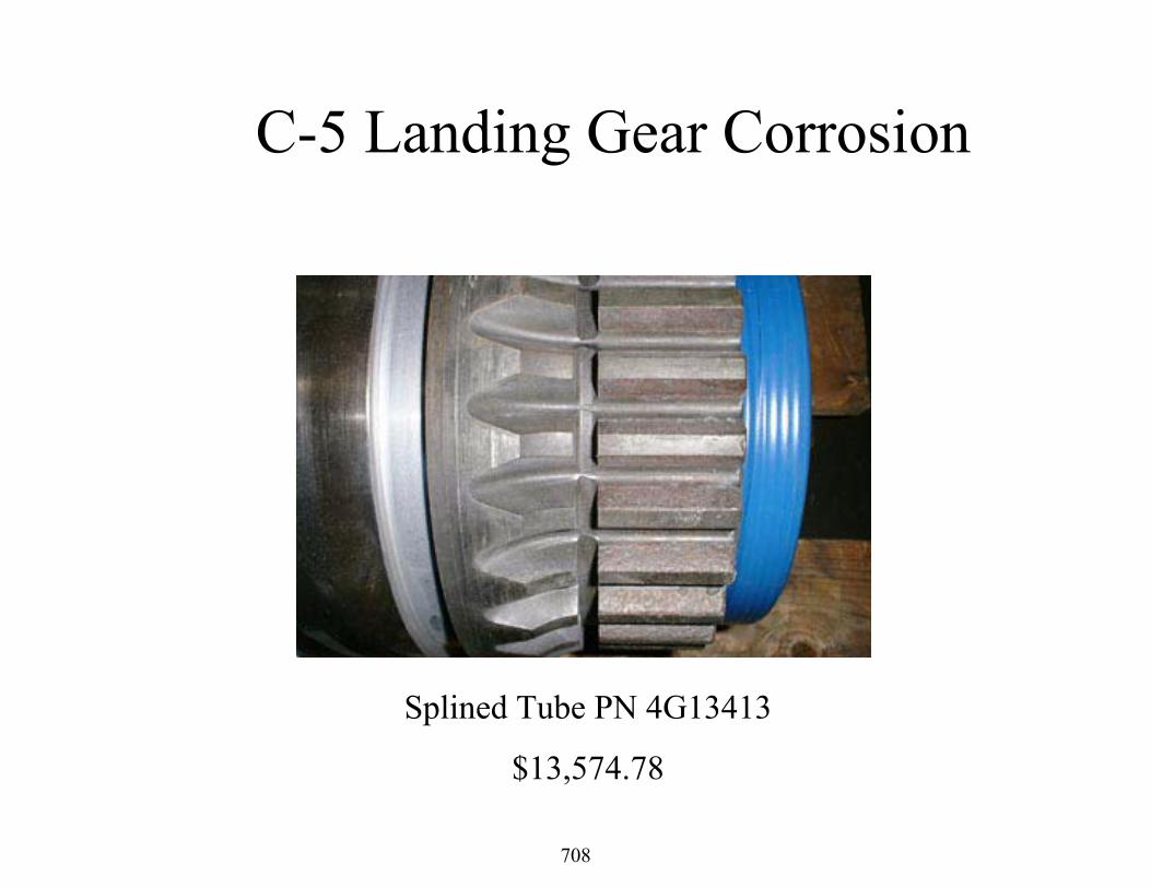
C-5 Landing Gear Corrosion
Splined Tube PN 4G13413
$13,574.78
708

C-5 Landing Gear Corrosion
Forward Axle PN 4G12030
709

C-5 Landing Gear Corrosion
Roll Pin PN 9510447
$11,582.40
710

C-5 Landing Gear Corrosion
Ball Screw Nut Bearing Balls PN BB562-1
711

C-5 Landing Gear Corrosion
Crosshead Area C from partially disassembled gear
712

C-5 Landing Gear Corrosion
Wheel Bearing Rollers
713

C-5 Landing Gear Corrosion
Yoke-Side Brace Attach Lugs
$65,488.00
714

C-5 Landing Gear Flight Test
715

C-5 Landing Gear Flight Test
• This aircraft landing gear was very susceptible to corrosion– Low alloy steel and corrosive environment– Significant rework cost and loss of service
• MIL-PRF-81322 was specified lubricant– Synthetic hydrocarbon base oil thickened
with clay
716

C-5 Landing Gear Fight Test• Side-by-side flight testing performed• Components cleaned, inspected and
photographed• One side of gearing lubed with MIL-PRF-
81322 and other with MIL-PRF-32014• After 2725 flight hours (1217 landings),
gears re-inspected
717

C-5 Landing Gear Flight test• No corrosion was observed on gears lubricated
with MIL-PRF-32014• Technical Orders were changed to MIL-PRF-
32014 for both C-5 and C/KC-135 for main landing gear
32014 81322
718

Applications• Approved applications
– F-107 Cruise Missile engine bearing– C/KC-135 and C-5 main landing gear– C/KC-135 wheel bearing– JSF low temperature engine bearing
• Potential applications– Army helicopter swash plate– A/C wheel bearings– UK military grease– Navy A/C with sea water corrosion issues
719

Summary
• MIL-PRF-32014 grease could become a multi-purpose military grease replacing many others, in some cases perfluoropolyalkylether greases
720

Navy MIL-PRF-32014 Grease Study Airframe Bearings Fleet Focus Team
Chris Medic NAVAIR Pax RiverMilitary Aviation Fluids
and Lubes Workshop June 22, 2006
721

Fleet Driver for an Improved GreasePoor corrosion/washout resistance of the current MIL-PRF-81322 lubricant is resulting in numerous corrosion failures, effecting safety, readiness, and increased cost.
Navy Specific Requirements• Steam Catapult• Shipboard Stow (Wing/Tail Fold)• Saltwater Environment/Frequent Wash Cycles
722

Planned Resolution• The Navy, in conjunction with the Air Force,
will perform extensive testing on the proven grease MIL-PRF-32014.
• Testing will consist of various bench and flight tests on numerous aircraft including the F-18, E2/C2, C-5, AHE, and JSF.
• Successful testing will result in qualification of MIL-PRF-32014 grease as a recommended substitute for MIL-PRF-81322 either across the board or for specific applications.
723

ABFFT Improved Grease TeamNational LeadershipBrian Weber (PAX Co-lead) Chris Medic (PAX Co-lead)
Logistics/Cost TeamTresmarie Wolfe
Air Force Research LabLois GschwenderEd SnyderDavid MarosokDr. Shashi Sharma
Engineering POC’sGeorge Franco (NI E2/C2)Mike Chabot (NI E2/C2)Brian Carr (NI E2/C2)Sal Piu (LKE F-18 LG)Dirk Dessel (NI F-18)Chrys Starr (NI F-18)Mike Cocca (PAX LG)Todd Standish (PAX Materials)Aldo Arena (NGC E2/C2)Joe Troutman (NAVICP) Edelia Correa (DSCR)Ned Pruitt (DSCR)
724

E2/C2 Potential SavingsComponent P/N Component Cost Usage per
yearMatl cost per
yearGRD5628 $36,921.00 21 $775,341
123SAM121-7 $10,710.00 16 $171,360 123WM0483-611 $52.09 25 $1,302
18720 $7.76 881 $6,836.00 L507949 $25.65 286 $7,336 18790 $16.47 1464 $24,112
123WM10476-511 $231.82 7 $1,623 123WM10476-513 $1,044.22 5 $5,221 123WM10475-1 $55.60 21 $1,167
123WM10478-611 $39.76 12 $477123WM10482-511 $110.86 14 $1,552
$286,394 123WM60010-2 $90,140.72 4 $360,562
$17,385 123WM10011-602 $12,336.03 3 $37,008
TOTAL COST/YEAR $1,697,676
123WM60010-1 $35,799.30 8
123WM10011-601 $8,692.87 2
725

Air Force Grease Study• AFRL with a grease manufacturer under
contract developed improved grease for use in the F-107 cruise missile engine bearings
• Rigorous requirements – long storage in uncontrolled environment would bleed oil out of grease
• Bearings now have 5 times the life (60 months) than what was originally achievable
• Saved more than $60 Millionover life of the engine
726

Improved Grease Composition• Synthetic Polyalphaolefin base oil
– mixture of 6 and 40 cSt (reliable)• Lithium Soap Thickener (non-hygroscopic)
– Methyl 12-hydroxy stearate and lithium hydroxide monohydrate (in-situ)
• Corrosion inhibitors• Antioxidants• Antiwear• Metal Deactivator
727

Grease ComparisonMIL-PRF-81322(Current)
MIL-PRF-32014(Proposed)
Color
Thickener Inorganic Clay Lithium Soap
Evaporation 10% weight loss (max)
5% weight loss (max)
Water Resistance 20% loss (max) 15% loss (max)
Steel on steel wear 0.8 mm (max) 0.65 mm (max)
728

MIL-PRF-32014 Attributes• Excellent water washout resistance• Low cost ($44/lb at low volume/low dirt) • High load carrying (135 Kg)• High temperature (225oC)• High speed (30K rpm)• Corrosion resistant• Available (2 vendors)• Non-proprietary• Compatible
Aluminum Calcium Lithium Polyurea Clay All Other0
10
20
30
40
50
60
70
NLGI 1999 Grease Production By Thickener
729

Corrosion Rate Evaluation Procedure Coupons, 300M steel, distilled water, 45 min
MIL-PRF-32014 MIL-PRF-81322 MIL-PRF-27617
730

C-5 Landing Gear Test
• Dover AFB installed 32014 grease on 2 left side MLG against control 81322 on 2 right side MLG
• Tested in service for nearly 3 years
731

732

733

734

C-5 LG Test Results
• AF approved 32014 for use in all C-5 and C-135 Landing Gear
• AF plans to qualify for use in F-16 LG as well
735

Navy Fleet Drivers
736

E2 Rotodome Bearings
• Water runs down pylon shaft through X-bearing and lower support bearing and settles in gearbox.
• The grease hydrolyzes and the bearings fail• Failure of spur gear bearing causes eccentric rotation of
spur gear which cuts through housing.
737

E2/C2 Caster Barrel
• High pressure steam from the catapult purge grease from the wheel bearings.
• The bearings seize and the spun inner bearing race on the axle can cause irreparable damage.
• Components are scrapped prior to reaching full service life.
738

E2/C2 Wing Fold Hinge Cracking
• In stow, fold joints are exposed to environment and often high pressure wash without covers.
• The grease is purged and/or hydrolyzes.• The bolt seizes in the bushing causing heavy galling and
contributes to cracks in wing fold hinge.
739

Stage 1: Field Testing• E2/C2 Nose Landing Gear
wheel bearing assembly– Spray wash test– Steam wash test
• 100 psi for 10 minutes. Repeated 3 times and held for 10 days
– Salt Water Immersion• 300 hr immersion of coated
bearing cups in salt water
740

Spray Wash Test
741

742

743

Material Tests• GC (Gas chromatography) and FTIR
(Fourier-Transform Infrared)
– Establish molecular structure and characteristics of lubricant
– MIL-PRF-32014 “Fingerprint”
– Identifies change in physical properties
• Karl-Fischer Titration (ASTM D1744)
– Determines water content in PPM
744

Side by Side Test resultsTest MIL-PRF-32014 Results MIL-PRF-81322 Results
High Pressure Spray Wash
No corrosionNo water absorption
Deep corrosion on cup and rollers2% water absorption
High Pressure Steam Wash
No corrosion1% water absorption
Deep corrosion on inner race and outer cage
2% water absorption
Salt Water Immersion
No corrosionStill serviceable
Corrosion cells formedDeep corrosion pits from .025 to
.040’’ deep
745

746

Stage 1: Field Testing• E2 Cold Soak Torque Tests (–40F)
– Rotodome Pylon Ball Bearing (14’’Dia. double bearing set, 440 CRES)
– Rotodome double “X” bearings (14’’dia crossed roller bearing)
– Rotodome Gearbox Assembly (Input drive, pinion gear, idler gear, and output spur gear)
747

Cold Soak Torque Test Results
• MIL-PRF-32014 performed well with a negligible increase in torque at low temp (gearbox input torque is throttled to 20 in-lbs)
• More torque sensitive components may need to be evaluated on a case by case basis
Component Lubricant Torque at 70ºF(in-lbs)
Break-Out Torque at -40ºF
Running Torque at -40ºF
Pylon bearing 81322 10.9 58.0 33.0
Pylon bearing 32014 14.5 43.5 36.3
X bearing 81322 6.8 67.5 27.0
X bearing 32014 13.5 81.0 40.5
Gearbox 81322 0 0.5 0.5
Gearbox 32014 0 1.5 1.5
748

• E-2C Test aircraft will be carrier deployed and tracked for a 18 month period with MIL-PRF-32014 applied to– Rotodome pylon shaft bearings– Rotodome gearbox assembly– RH Wing fold hinge lug bushings
• C-2A Test Aircraft from local squadron VRC 30 will be monitored every 4 months or 40 CATS for a 12 month flight test with MIL-PRF-32014 applied to the– RH Nose wheel bearings– RH Wing fold hinge lug bushings and locks
Stage 2: Operational Flight Testing
749

Additional Fleet Applications
750

E-2D Advanced Hawkeye • Lower Pylon Self Aligning Bearing (new design)• Rotodome Gearbox (new design)• EMIRS Deployment System• Landing Gear Components
751

Additional Fleet Applications• T-34/44 Catastrophic Wheel
Bearing failures due to corrosion– Engineering Investigation
identified possible grease deficiency
– Proposed change to MIL-PRF-32014
• JSF Upper Lift Fan Bearing and Components
752

Potential Applications• H-60 Swashplate and Tail Rotor Drive
Shaft Disconnect Bearings• H-53 Swashplate and Tail Rotor Drive
Shaft Disconnect Bearings• F-18 Landing Gear
753

Summary
It is vital that the Navy aggressively attack the Corrosion problem.Though this grease study is only a small piece of the puzzle, the potential benefits are huge.The ABFFT is dedicated to the ongoing effort to reduce corrosion failures that effect fleet safety, readiness, and cost.
754

Questions ?
755

Screening Tests Results for Screening Tests Results for Low Cost Alternative F100 Low Cost Alternative F100 Nozzle Actuator GreasesNozzle Actuator Greases
Angela Campo
Fluids and Lubricants Group
Wright-Patterson AFB
756

OutlineOutline
Brief introductionScreening testsDetails of each screening test and their resultsCost of candidate greasesConclusionRecent updates
757

IntroductionIntroductionThere was a need for a grease that was 50% of the cost of the NYE Uniflor
• Initially, cost was the main factor in choosing a new grease. But new actuator design and technology called for a better performing grease
A test matrix was developed to narrow the grease candidates from 56 to 8 samples
• 2 Standards (NYE Uniflor and Braycote 602EF)• 1 In-house, the best candidate• 4 companies’ best candidates• MIL-PRF-32014 (hydrocarbon based-high risk, high payoff)
758

Screening TestsScreening Tests
Cameron Plint TribologyEvaporation – High Temperature StabilityWAM Tribology (Wedeven AssociatesMachine)
759

Cameron PlintCameron Plint
760
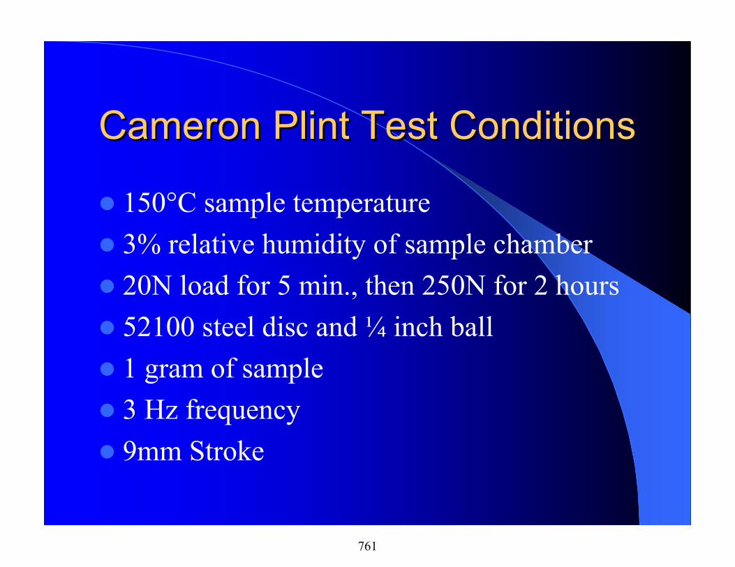
Cameron Plint Test ConditionsCameron Plint Test Conditions
150°C sample temperature3% relative humidity of sample chamber20N load for 5 min., then 250N for 2 hours52100 steel disc and ¼ inch ball1 gram of sample3 Hz frequency9mm Stroke
761

Formulation Average Scar Area (mm2)
StandardDeviation
(mm2)MIL-PRF-32014 0.15 0.01MLO-02-311 0.38 0.00MLO-02-358 0.58 0.02NYE Uniflor 0.71 0.10MLO-03-008 0.78 0.03MLO-03-007 1.02 0.14In-housecandidate
0.72 0.02
Braycote 602EF 1.23 0.10
762

Comparison of Wear ScarComparison of Wear Scar
MIL-PRF-32014
NYE Uniflor
0.15mm2
0.71mm2
763

Evaporation StudyEvaporation Study
The test was conducted at 232°C for 72 hoursMost candidates still maintained their grease texture, but one did not. MIL-PRF-32014 hardened and changed color from light tan to blackDuplicate tests
764

Evaporation DataEvaporation Data
Formulation Average % LossMIL-PRF-32014MLO-02-311NYE UniflorMLO-03-008MLO-03-007In-house candidateBraycote 602EF
49.58.4310.0310.603.171.851.37
765

WAM TribologyWAM Tribology
Test consists of six cyclesA cycle consists of an acceleration period, steady-state period, and a deceleration periodGreatest tribological activity occurs in the transitionsBraycote 602EF and NYE Uniflor used as baseline greasesMetal test specimens are phosphated and coated with MoS2
766

Explanation of a WAM CycleExplanation of a WAM Cycle
Specimens are coated with sample and heated to 100°CSurface speeds are set to zeroThe load is set to 20lbsRoller and disc specimens are accelerated to 570in/sec &220 in/sec respectivelySteady-state for 125 secondsThe roller is decelerated to –570 in/sec and the disc is decelerated to –220 in/sec respectivelyRoller and disc are then decelerated to zero in/sec
767

WAM Testing Machine WAM Testing Machine DiagramDiagram
768

WAM Ball and Disc WAM Ball and Disc ArrangementArrangement
769

WAM Average Track Width WAM Average Track Width ComparisonComparison
1.2 1.21.1 1.1
1.4 1.31.2 1.2
0
0.2
0.4
0.6
0.8
1
1.2
1.4
Track Width (mm)
MIL-P
RF-3
2014
02-3
1102
-358
NYE
Unifl
or03
-008
03-0
07In
-hou
seBr
ayco
te770

Microcracking Pitting
MLO 03-8
MLO 02-358
Braycote602EF
MLO 02-311
MIL-PRF-32014
MLO 03-7
In-house
NyeUniflor
WAM Test ResultsWAM Test Results
771

Candidate RankingCandidate RankingCameron Plint Evaporation WAM Total
MIL-PRF-32014 8 1 3 12MLO 02-311 7 5 4.5 16.5Braycote 602 EF 1 8 2 11NYE Uniflor 5 4 8 17In-house candidate 4 7 7 18MLO-02-358 6 n/a* 4.5 10.5MLO-03-7 2 6 6 14MLO-03-8 3 3 4 10
*Small supply of MLO-02-358, not enough to run evaporation.
772

Which Candidate is More Cost Which Candidate is More Cost Effective?Effective?
250
1000
214
375449
790
200
10
1000
200275
190
449
790
200
100
200
400
600
800
1000
1200
MIL-PRF-32
014
02-31
1
02-35
8NYE U
niflor
03-00
8
03-00
7
In-houseBray
cote
Formulation
Cos
t (do
llars
) as
of 2
001
1,000 lb./year10,000 lb./year
773

Results and ConclusionResults and Conclusion
Candidate, low cost greases have been developed that appear to meet the performance and price goals of the program.• While none of the greases exceed the performance
of the NYE Uniflor grease in WAM testing, some did outperform the NYE Uniflor grease in the Cameron-Plint Tribometer and in the high temperature evaporation test.
• All of the candidate greases were below the cost requirements of the program (<$500/lb)
774

ResultsResults and Conclusions and Conclusions ––contcont’’dd
The only problem with the program to date is that we were unable to identify a clearly superior candidate.
• This is due to the similarity in performance in the WAM Tribometer which is supposed to be able to discriminate between acceptable and unacceptable greases.
• It makes it difficult to select only one grease to have tested in the actuator.
If there was a way to run the component test on more than one candidate, that may identify the best low cost grease for this application.
• If they still perform similarly, we could have multiple suppliers – a very desirable situation
775

Recent UpdatesRecent Updates
The nozzle actuator test was performed on the in-house candidate and it did very well– But the base stock for this grease is no longer
availableTemperature test strips have been placed to record the max temperature of the nozzle actuator.– Depending on the results, MIL-PRF-32014 may
be an excellent alternative grease for this application
776

High Temperature Lubricant Phase II Status Report
METSS Corporation300 Westdale AvenueWesterville, OH 43082
June 22, 2006
Navy Contract No. N68335-05-C-0077
777

Advanced Lubricant Requirements• Projected operating temperatures of advanced gas turbine
engines and their accessories require a lubricant grease that
– Can endure extreme operating temperature range of roughly -40°F to +625°F
– Can remain chemically stable with no performance degradation for ~4,000 hours
– Must allow easy movement of corrosion resistant stainless steel as well as ceramic roller elements.
Current lubricants used cannot maintain viscosity throughout theentire range of operation.
778

Operational Temperature Ranges for Several Classes of Synthetic Lubricants
779

High Temperature GreasesPhase I• 14 PFPAE Grease Candidates
– Nye– DuPont
Phase II• 15 PFPAE Grease Candidates
– DuPont– Daikin
• 8 Ionic Liquids– Merck & Covalent– METSS thickened these with BN to prepare IL greases.
• 2 Polyphenyl Ethers– 5P4E and 6P5E fluids obtained through AFRL.– METSS thickened these with BN to prepare PPE greases.
780

Dupont Krytox® XHT Greases
• Fluorinated synthetic base oils, thickeners, and additives – perfluoropolyether (PFPE) greases thickened with boron nitride with
additives for antirust, antiwear, or extreme pressure performance
• Useful temperature ranges up to 360°C (680°F) for continuous use
• Resistant to oxygen, and inert to virtually all chemicals. – insoluble in most solvents
• The chief limitation is limited availability of soluble additivesMETSS is working closely with DuPont in the evaluation
781

Other Materials
• Ionic Liquids– Possible alternatives to PFPAEs as extreme temperature lubricant basestocks.– Reported to have good high and low temperature properties.
• Polyphenyl Ethers– Possible alternatives to PFPAEs as high temperature lubricants.– Reported to have good high temperature properties but low temperature use is
limited. (Similar to Pendent PFPAEs).
• Interaction of PFPAEs with Hi Temp Coatings– Under a separate SBIR, Arcomac is developing surface coatings and has
developed laboratory test equipment with extreme operating temperatures and loading conditions.
– METSS, DuPont and Arcomac have signed a 3-way confidentiality agreement.– Plan to exchange samples of lubricants and metal test specimens (balls and
disks) for testing and evaluation.
782

Testing & EvaluationTier 1 Tests
Grease Volatility
Fretting Wear
Four Ball Wear Test
CREP Corrosion Test
Tier 2 Tests
Elevated Temperature Bearings Tests
Advanced Tribology - WAM Simulation Test Methodologies
Low Temperature Properties
High Temperature Stability and Corrosivity
783
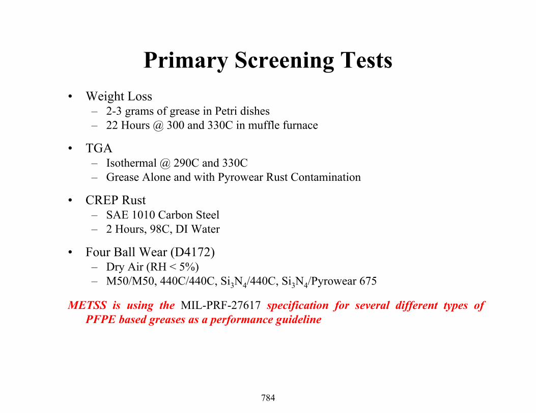
Primary Screening Tests• Weight Loss
– 2-3 grams of grease in Petri dishes– 22 Hours @ 300 and 330C in muffle furnace
• TGA– Isothermal @ 290C and 330C– Grease Alone and with Pyrowear Rust Contamination
• CREP Rust– SAE 1010 Carbon Steel – 2 Hours, 98C, DI Water
• Four Ball Wear (D4172)– Dry Air (RH < 5%)– M50/M50, 440C/440C, Si3N4/440C, Si3N4/Pyrowear 675
METSS is using the MIL-PRF-27617 specification for several different types of PFPE based greases as a performance guideline
784

PFPAE Grease Formulation Variables• PFPAE Fluid Types
– Linear vs. Pendent
• Fluid Viscosity– 220, 500, 1000 cSt.
• Thickeners– PTFE, BN, Graphite/MoS2
• Additives– Dispersed (Insoluble)
• Disodium Sebacate - DSS• Sodium Nitrite - NaNO2
• Calcium Hydroxide Ca(OH)2
– Soluble• Fluorinated Benzene Sulfonic Acid, Sodium Salt• Fluorinated Diphenyl Ether (DPE)
785

Candidate Grease Chemical CompositionMETSS
CodeFluidType
KV @ 40C,cSt.
ThickenerType
Corrosion Inhibitor Co-Additive
L Pendent PFPE 1000 BN 5% Ca(OH)2 ---
M Pendent PFPE 500 Graphite 5% Ca(OH)2 MoS2
N Pendent PFPE 500 BN --- ---
O Pendent PFPE 500 BN 5% Ca(OH)2 ---
P Pendent PFPE 1000 BN --- ---
Q Pendent PFPE 1000 Graphite 5% Ca(OH)2 MoS2
R Pendent PFPE 1000 BN 2% KBSANa ---
S Pendent PFPE 1000 Graphite 2% KBSANa ---
T Pendent PFPE 1000 Graphite 2% KBSANa MoS2
U Linear PFPE 220 PTFE --- ---
V Linear PFPE 220 BN --- ---
W Linear PFPE 220 BN 5% Ca(OH)2 ---
X Linear PFPE 220 BN 2% KBSANa ---
Y Linear PFPE 220 Graphite 5% Ca(OH)2 MoS2
Z Pendent PFPE 500 BN 2% KBSANa ---
LR1 Pendent PFPE 1000 BN2.5% Ca(OH)2
1% KBSANa---
786

Grease Evaporation Loss22 Hours @ 300oC and 330oC
0
5
10
15
20
25
L M N O P Q R S T U V W X Y Z
Grease Sample
Wei
ght L
oss,
%
300C 330C
Pendent - 1000 Pendent - 500 Linear - 220 cSt.
787

0 10 20 30 40 50 60
L
N
P
R
T
V
X
Z
IL-1
IL-3
IL-5
IL-7
PPE-1
Gre
ase
Sam
ple
Weight Loss, %
Ionic Liquids
Linear PFPAE – 220 cSt
Polyphenyl Ethers
Pendent PFPAE – 1000 cSt
Pendent PFPAE – 500 cSt
Grease Evaporation Loss After 22 Hours @ 330C
788

High Temperature and PFPAE Base Stocks
• The real “Achilles heel” of any PFPAE is its increased tendency to degrade when in contact with active metals.
• The formation of metal fluorides of aluminum, iron, titanium, etc. are thermodynamically favored over the fluorine-carbon bond, and their high free energy of formation limit the potential performance of PFPAEs at temperatures above 300oC.
• The oxidative stability of base PFPAE’s in the presence of metals has been vastly increased with Carburized Pyrowear675®.
• PFPAE has been reported to react with silicone nitride binders
789

Grease TGA Experiments
• Conducted isothermal testing a elevated temperatures to determine percent mass loss vs. time.
• Initial experiments conducted were isothermal at 290C. Subsequent testing at 330C provided better differentiation.
• Addition of Pyrowear 675 corrosion product provided further separation of candidates.
790

PW Pyrowear 675 Corrosion Product XRF*XRF - PW Pyroware 675 Corrosion Product
Z wt% Z wt% Z wt% Sum Be - F nd 29 Cu nd 52 Te nd11 Na nd 30 Zn 0.07 53 I 0.02012 Mg nd 31 Ga nd 55 Cs 0.03813 Al nd 32 Ge nd 56 Ba 0.05514 Si 0.63 33 As nd Sum La - Lu 0.53015 Px 0.04 34 Se nd 72 Hf nd16 Sx 0.00 35 Br nd 73 Ta nd17 Cl 0.50 37 Rb nd 74 W nd18 Ar 0.03 38 Sr nd 75 Re nd19 K nd 39 Y nd 76 Os nd20 Ca nd 40 Zr nd 77 Ir nd21 Sc nd 41 Nb nd 78 Pt nd22 Ti 0.02 42 Mo 0.16 79 Au nd23 V 0.01 44 Ru nd 80 Hg nd24 Cr 0.86 45 Rh nd 81 Tl nd25 Mn 0.30 46 Pd nd 82 Pb nd26 Fe 89.64 47 Ag nd 83 Bi nd27 Co 4.99 48 Cd nd 90 Th nd28 Ni 2.27 49 In nd 92 U nd
50 Sn nd 94 Pu nd51 Sb nd 95 Am nd*Data provided courtesy of DuPont.
791

Effect of PW P675 Rust Concentration on Grease L at 330oC
20
40
60
80
100
120
Wei
ght (
%)
0 100 200 300 400 500 600
Time (min)
––––––– L+PW R5 @ 330C– – – – L+PW R1 @ 330C––––– · Grease L @ 330C
Universal V3.0G TA Instrum ents
0% PW Rust
1% PW Rust
5% PW Rust
792

60
70
80
90
100
110
Wei
ght (
%)
0 100 200 300 400 500 600
Time (min)
––––––– Grease T @ 330C– – – – Grease P @ 330C––––– · Grease Q @ 330C––– – – Grease R @330C––– ––– Grease S @ 330C––––– – Grease L @ 330C
Universal V3.0G TA Instruments
Pendent 1000-cSt. Greases Without P675 Rust6.5 Hours @ 330oC
(R) BN + KBSANa(T) Graphite+MoS2+ BSANa(L) BN + Ca(OH)2(P) BN(S) Graphite + KBSANa(Q) Graphite + MoS2 + Ca(OH)2
793

60
70
80
90
100
110
Wei
ght (
%)
0 100 200 300 400 500 600
Time (min)
––––––– T+PWR1 @ 330C– – – – P+PWR1 @ 330C––––– · Q+PWR1 @ 330C––– – – R+PWR1 @ 330C––– ––– S+PWR1 @ 330C––––– – L+PWR1 @ 330C
Universal V3.0G TA Instruments
Pendent 1000-cSt. Greases With P675 Rust6.5 Hours @ 330oC
(R) BN + KBSANa
(T) Graphite+MoS2+KBSANa(L) BN + Ca(OH)2
(P) BN
(Q) Graphite+MoS2+Ca(OH)2(S) Graphite + KBSANa
794

Pendent 500-cSt. Greases Without P675 Rust6.5 Hours @ 330oC
20
40
60
80
100
Wei
ght (
%)
0 100 200 300 400 500 600
Time (min)
––––––– Grease Z @ 330C– – – – Grease N @ 330C––––– · Grease O @ 330C––– – – Grease M @ 330C
Universal V3.0G TA Instruments
(Z) BN + KBSANa(O) BN + Ca(OH)2
(N) BN
(M) Graphite+MoS2+Ca(OH)2
795

Pendent 500-cSt. Greases With P675 Rust6.5 Hours @ 330oC
20
40
60
80
100
Wei
ght (
%)
0 100 200 300 400 500 600
Time (min)
––––––– Z+PWR1 @ 330C– – – – N+PWR1 @ 330C––––– · O+PWR1 @ 330C––– – – M+PWR1 @ 330C
Universal V3.0G TA Instruments
(Z) BN + KBSANa
(O) BN + Ca(OH)2(M) Graphite+MoS2+Ca(OH)2(N) BN
796

Linear 220-cSt. Greases Without P675 Rust6.5 Hours @ 330oC
20
40
60
80
100
Wei
ght (
%)
0 100 200 300 400 500 600
Time (min)
––––––– Grease Y @ 330C– – – – Grease W @ 330C––––– · Grease X @ 330C––– – – Grease V @ 330C
Universal V3.0G TA Instruments
(X) BN + KBSANa
(V) BN(Y) Graphite+MoS2+ a(OH)2(W) BN + Ca(OH)2
797

Linear 220-cSt. Greases With P675 Rust6.5 Hours @ 330oC
20
40
60
80
100
Wei
ght (
%)
0 100 200 300 400 500 600
Time (min)
––––––– V+PWR1 @ 330C– – – – W+PWR1 @ 330C––––– · X+PWR1 @ 330C––– – – Y+PWR1 @ 330C
Universal V3.0G TA Instruments
(X) BN + KBSANa
(V) BN(Y) Graphite+MoS2+Ca(OH)2(W) BN + Ca(OH)2
798

TGA Comparison of Greases Thickened with BN and Inhibited with KBSANa
40
50
60
70
80
90
100
110
120
Wei
ght (
%)
0 100 200 300 400 500 600
Time (min)
– – – – Z+PWR1 @ 330C––––––– Grease X @ 330C––––––– Grease Z @ 330C– – – – R+PWR1 @ 330C– – – – X+PWR1 @ 330C––––––– Grease R @330C
Universal V3.0G TA Instruments
Grease R w/o PWRGrease X w/o PWRGrease R with PWR1
Grease Z w/o PWR
Grease Z with PWR1
Grease X with PWR1
R = Pendent 1000 cSt.X = Linear 220 cSt.Z = Pendent 500 cSt.
799

Isothermal TGAs (6.5 Hours @ 330C) of Fresh Grease Samples Obtained
Before Four Ball Wear Test of Si3N4 Ball on Pyrowear 675 Disks
50
60
70
80
90
100
110
Wei
ght (
%)
0 100 200 300 400 500 600
Time (min)
––––––– Grease X @ 330C– – – – Grease P @ 330C––––– · Grease R @330C––– – – Grease V @ 330C
Universal V3.0G TA Instrum ents
800

Isothermal TGAs (6.5 Hours @ 330C) of Aged Grease Samples Obtained
After Four Ball Wear Test of Si3N4 Ball on Pyrowear 675 Disks
50
60
70
80
90
100
110
Wei
ght (
%)
0 100 200 300 400 500 600
Time (min)
––––––– XSI3N4.000– – – – PSI3N4.002––––– · RSI3N4.000––– – – VSI3N4.000
Universal V3.0G TA Instruments
801

Attempts to Improve the Thermal Stability of Linear 220 cSt - BN Thickened Grease
• Obtained sample of Fluorinated Diphenyl Ether (DPE) from AFRL.
• Added to Grease V (Linear 220 cSt + BN) at 2% and 5% treat levels.
• Ran TGAs on Grease V+DPE with and without PW Pyrowear Rust. Compare with data obtained for Grease X (Linear 220cSt + KBSANa).
• Ran TGAs on DPE alone.
802

Effect of Soluble Fluorinated Additives KBSANa And DPE in Linear 220 cSt Greases
20
40
60
80
100
120
Wei
ght (
%)
0 100 200 300 400 500 600
Time (min)
– – – – X+PWR1 @ 330C––––––– Grease V @ 330C––––––– Grease X @ 330C––––––– V + DPE2 @ 330C– – – – V + DPE2 + PWR1 @ 330C––– ––– V + DPE5 + PWR1 @ 330C– – – – V+PWR1 @ 330C
Universal V3.0G TA Instruments
TGA Isothermal @ 330C
X w/o PWR
V w/o PWRV + DPE2 w/o PWR
X + PWR1
V + PWR1V + DPE2 + PWR1V + DPE5 + PWR1
803

Thermal Stability & Corrosivity Test
Modified DuPont procedure for FluidsImmerse metal Test Specimens in Grease96 Hours @ 330oCVisual Evaluation for CorrosionRating Scale• 1 = Shiny, no evidence of corrosion.• 2 = Shiny, but discolored.• 3 = Slight evidence of corrosion .• 4 = Pitting on half of surface.• 5 = Pitting on most of surface.• 6 = Corrosion flaking off ball.
804

Thermal Stability & Corrosivity Test Results
M50 = 2 440C =2 Si3N4 = 1
M50 = 6 440C = 5 Si3N4 = 1
Grease R
Grease S
P675 = 2
P675 = 5
805

Rust Preventive CharacteristicsPhoenix Chemical CREP Test
GreaseSample
CorrosionInhibitor
Numberof Tests
Average TimeTo Failure, min.
Coupon Rating at End of Test
L 5.0% Ca(OH)2 3 120 Slight Rust
R 2.0% KBSANa 3 3 Medium Rust & Stain
LR12.5% Ca(OH)21.0% KBSANa
3 9Medium Rust & Stain
LR2 5% Ca(OH)22.0% KBSANa
3 120Slight Rust
806

Accomplishments to Date
• METSS has identified 2-3 candidate greases better thermal and wear properties on conventional as well as high-chrome steels than the current formulations.
• A clearer understanding of the interactions of the grease components has emerged allowing more scientific formulation strategies.
• The results of the program clearly demonstrated the technical feasibility of developing product formulations to meet the program requirements.
807

Conclusions to Date• Basestocks
– Pendent provides better thermal stability than linear in the presence of PW Pyrowear 675 rust.
– Pendent basestock thermal stability: 1000-cSt. better than 500-cSt. – Low temperature performance may be an issue.– Ionic fluids and polyethers need more work
• Thickeners & Additives for PFPAEs– Ca(OH)2 reduces wear in four ball test.– Ca(OH)2 is best for rust protection in high humidity.– Dupont's KBSANa is best for thermal stability and corrosivity.– Combinations of KBSANa and Ca(OH)2 provide the best characteristics.– KBSANa may be an effective inhibitor for the thermal breakdown of
linear PFPAE in the presence of P675 wear debris. – DPE is too volatile to be effective - HMW analogs needed to be tested
808

To Do List forHT Lube Phase II Program
• Formulation Chemistry– Blends of Linear and Branched PFPEs?– Inorganic Base – To reduce acid formation and enhance stability– Inorganic Fluorides - Nanotribology– Soluble Fluorinated Additives– METSS to do more work in Phase II utilizing 3-roll mill for grease formulation.
• Surface Characterization– Micropitting – PFPE decomposition– Surface Analysis – Fluorides, Acid leaching– ASTM F2094-03a Standard Specification for Silicon Nitride Bearing Balls
• Additional Tests– evaluate performance of greases in ball bearings operating at elevated temperatures.– An aggressive material corrosion test designed to assess effects of salt and moisture
under long-term conditions.
• Formulation Technology and Technical Support– Jon Howell, and Carl Walther of DuPont
• Volatility limits have been lowered• Known impurities have been removed
809

Arcomac Testing• METSS plans to send samples of some of the better candidates (L, P,
R, LR2) to Arcomac for testing under conditions of high load and high temperature in a thrust bearing ball-on-disk test fixture.
• Samples are based on XHT-1000 + BN containing– No rust inhibitor– Ca(OH)2– KBSANa– Ca(OH)2 + KBSANa
• Candidate greases will be evaluated with and without the Arcomaccoating.
• Thus far, all of Arcomac’s testing has been with DuPont’s XHT-BDX grease: a 750 cSt Pendent PFAE thickened with BN and containing no additional additives. The planned tests will allow METSS to look at additives effects and their interaction with the coating.
810

Schematic of Arcomac Thrust Bearing Ball-on-Disk test Fixture Used for High Temperature PFPAE Lubricant
Compatibility Testing
811

The Future of Solvent Usage The Future of Solvent Usage in the Air Forcein the Air Force
Environmentally friendly Environmentally friendly replacements for commonly used replacements for commonly used
solventssolvents
Angela Campo
Fluids and Lubricants Group
Wright-Patterson AFB
812

Solvents 101Solvents 101
Solvents are chemical compounds that Solvents are chemical compounds that dissolve, suspend, or extract materials dissolve, suspend, or extract materials without changing the chemical composition without changing the chemical composition of the solvent or the material.of the solvent or the material.Good cleaning solvents are the following:Good cleaning solvents are the following:–– Inert to the material being cleanedInert to the material being cleaned–– Can dissolve the desired contaminantsCan dissolve the desired contaminants–– Easily removedEasily removed–– Low surface tensionLow surface tension
813

Why we need new solventsWhy we need new solvents
The US signed the Montreal Protocol in The US signed the Montreal Protocol in 1989, which banned the use of 1989, which banned the use of chlorofluorocarbons (CFC) like Freon 113chlorofluorocarbons (CFC) like Freon 113Later amendments set deadlines for other Later amendments set deadlines for other solvents, such as solvents, such as hydrochlorofluorocarbonshydrochlorofluorocarbons(HCFC).(HCFC).
814

Why do CFCWhy do CFC’’s cause ozone s cause ozone depletion?depletion?
Ozone (OOzone (O33) absorbs ultraviolet light in the ) absorbs ultraviolet light in the atmosphere and breaks down into Oatmosphere and breaks down into O22OO22 can then react with O and form Ocan then react with O and form O33 again.again.CFCCFC’’s interfere the ozone cycle by reacting with s interfere the ozone cycle by reacting with OO33 which forms products that in turn destroy more which forms products that in turn destroy more ozone molecules. ozone molecules. As the concentration of CFCAs the concentration of CFC’’s increase in the s increase in the atmosphere, it become less likely for the atmosphere, it become less likely for the remaining ozone to effectively absorb ultraviolet remaining ozone to effectively absorb ultraviolet light.light.
815

The Search for New SolventsThe Search for New Solvents
““Like dissolves likeLike dissolves like””Hard to find a good solvent that is ecoHard to find a good solvent that is eco--friendly and nonfriendly and non--toxictoxicNew solvents must be comparable in priceNew solvents must be comparable in priceSame ease of use, in other words a Same ease of use, in other words a ““drop indrop in””replacementreplacement
816
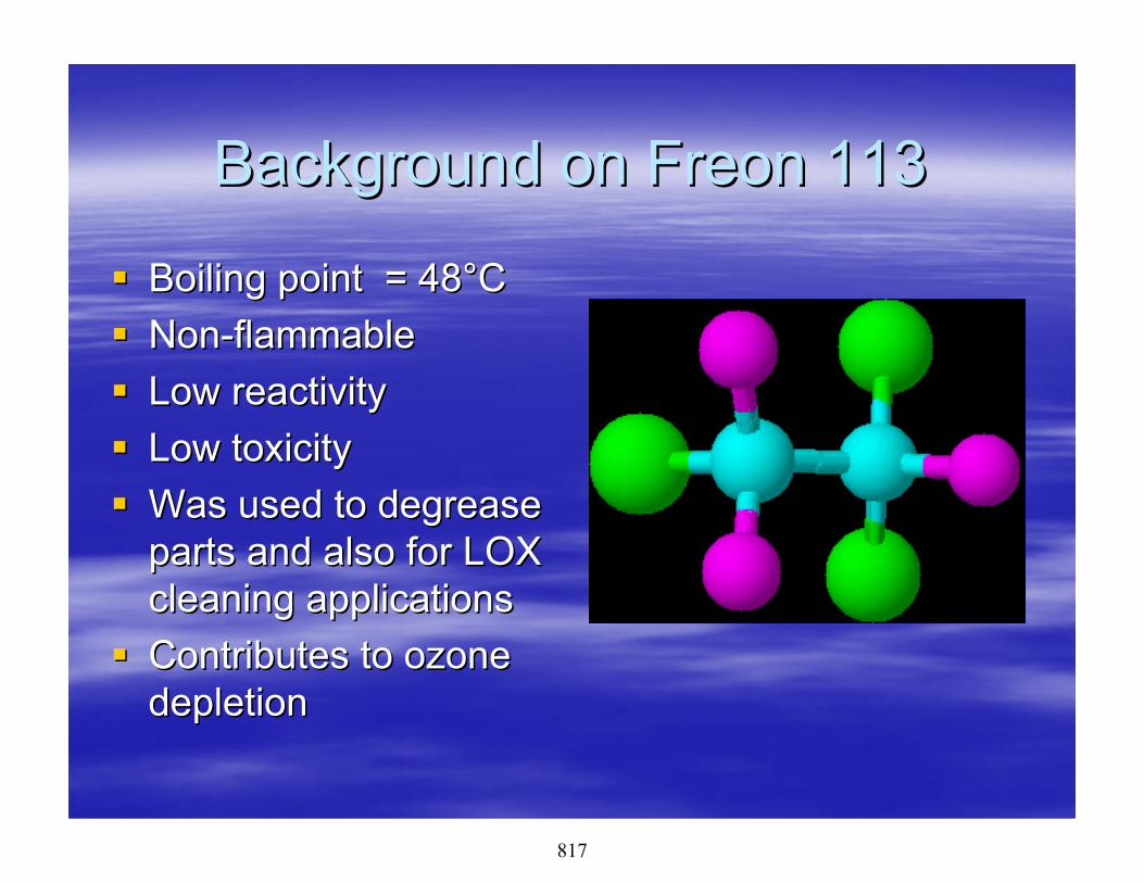
Background on Freon 113Background on Freon 113
Boiling point = 48Boiling point = 48°°CCNonNon--flammableflammableLow reactivityLow reactivityLow toxicityLow toxicityWas used to degrease Was used to degrease parts and also for LOX parts and also for LOX cleaning applicationscleaning applicationsContributes to ozone Contributes to ozone depletiondepletion
817

Could HCFCCould HCFC’’s replace Freon 113?s replace Freon 113?
HCFC = HydrochlorofluorocarbonsHCFC = HydrochlorofluorocarbonsLow reactivity, but not as low as Freon 113Low reactivity, but not as low as Freon 113Will dissolve less material than Freon 113Will dissolve less material than Freon 113Will be banned in 2030 due to adverse Will be banned in 2030 due to adverse effects on the ozone layereffects on the ozone layerUntil then, they can be used as a short term Until then, they can be used as a short term solution only. solution only.
818

AK 225AK 225AK 225 is a mixture of two AK 225 is a mixture of two HCFC solvents. It HCFC solvents. It performed very well in performed very well in cleaning testscleaning tests11Boiling point = 54Boiling point = 54°°CCLow toxicityLow toxicityCurrently in the tech order Currently in the tech order for cleaning LOX for cleaning LOX equipmentequipmentCan contribute to ozone Can contribute to ozone depletion, but to a much depletion, but to a much lesser degree than Freon lesser degree than Freon 113113
819

Candidate to replace Freon 113Candidate to replace Freon 113
PerfluorobutylPerfluorobutyl Iodide, PFBIIodide, PFBIPerformed very well in cleaning testsPerformed very well in cleaning tests11
Initial toxicity studiesInitial toxicity studies22 were encouraging, a were encouraging, a more inmore in--depth toxicology study is currently depth toxicology study is currently underwayunderwaySafe for the environment, nonSafe for the environment, non--ozoneozonedepletingdepletingWould be a drop in replacement forWould be a drop in replacement forFreon 113Freon 113
820

PFBIPFBI
Boiling point = 54Boiling point = 54°°CCDoes not contain Does not contain chlorinechlorineDoes not react with Does not react with ozoneozoneCurrently is priced Currently is priced similar to AK 225similar to AK 22533
Can be a dark pink in Can be a dark pink in colorcolor
821

The next stepThe next step
Send a purified sample for repeat LOX Send a purified sample for repeat LOX Compatibility testingCompatibility testing–– The first LOX test was completed during the initial study The first LOX test was completed during the initial study
with fluid that was not highly purified, which can alter the with fluid that was not highly purified, which can alter the results of the testresults of the test
–– PFBI passed at the 2PFBI passed at the 2ndnd highest load stage (60lb), this is highest load stage (60lb), this is considered acceptable in most cases. With purification it considered acceptable in most cases. With purification it is expected to pass at the highest load stage.is expected to pass at the highest load stage.
Find multiple commercial sources that can Find multiple commercial sources that can produce PFBI in large enough quantities.produce PFBI in large enough quantities.
822

ConclusionsConclusions
CFCCFC’’s are great solvents that have proven s are great solvents that have proven to be difficult to replaceto be difficult to replaceAK 225 is the best replacement that is AK 225 is the best replacement that is currently available, but it is a short term currently available, but it is a short term solutionsolution onlyonlyPFBI, pending toxicity testing results, has PFBI, pending toxicity testing results, has the potential to be a drop in replacement for the potential to be a drop in replacement for Freon 113 for all cleaning applicationsFreon 113 for all cleaning applications
823

ReferencesReferences1.1. AFRLAFRL--MLML--WPWP--TRTR--20032003--40404040 ““The Wipe Solvent The Wipe Solvent
ProgramProgram”” Marcie Roberts (UDRI), Lois Gschwender, Ed Marcie Roberts (UDRI), Lois Gschwender, Ed SnyderSnyder
2.2. International Journal of Toxicology International Journal of Toxicology Vol.23 Number Vol.23 Number 4/July4/July--August 2004 p. 249August 2004 p. 249--258 Darol E Dodd, Gary 258 Darol E Dodd, Gary Hoffman Hoffman ““PerfluoroPerfluoro--nn--Butyl Iodide: Acute toxicity, sub Butyl Iodide: Acute toxicity, sub chronic toxicity, and genotoxicity evaluationschronic toxicity, and genotoxicity evaluations
3.3. ““Lubricant Cleaning and Compatibility Study for Lubricant Cleaning and Compatibility Study for Candidate CFC and HCFC Solvent ReplacementsCandidate CFC and HCFC Solvent Replacements””Marcie Roberts (UDRI), Carl E Snyder (AFRL), Lois Marcie Roberts (UDRI), Carl E Snyder (AFRL), Lois Gschwender (AFRL) Gschwender (AFRL) TribologyTribology and Lubrication and Lubrication Technology Feb 2004 p. 34Technology Feb 2004 p. 34--4141
824

PAO COOLANT - MIL-PRF-87252- PAST AND CURRENT
ACTIVITIES
Lois GschwenderAFRL/MLBT, Wright-Patterson AFB
22 June 2006
825

Outline• Problem with silicate ester coolants• PAO coolant development• PAO coolant validation/flight tests
– B-1– US Navy
• AF conversion status• New interest
– High pressure switches– New system
• Conclusions
826

Problem• Silicate ester dielectric coolants (Coolanol
25R/40, MIL-C-47220) had developed serious problems in the field– React with water to produce a gel, which clogs
cooling systems, and alcohol– Gel is also an arcing source– Alcohol is a fire hazard
• Problem first appeared in the Air Force in the SR-71 (1979, Coolanol 40) and in the F-15 (1985, Coolanol 25R) and in numerous Navy systems
827

Si OROR
O
OR
R
+ H2O SiRO
OH
+ ROH(alcohol)
Si
ETC.
R = -CH2-C-CH2CH3
H
CH2CH3
ROH FLASH POINT = 134oF (57oC)
2-ETHYLBUTYL SILICATE ESTER HYDROLYSIS
OR
RO
+ H2O
+ ROH(alcohol)
RO
RO OH
OH
R= -CH2CH(C2H5)CH2CH3
828

Solution - PAO Coolant
• Materials Directorate and Naval Air Development Center developed the polyalphaolefin coolant that– Is not sensitive to water– Has a stable flash point (less flammable)– Is lower cost– Has an Air Force military spec, MIL-PRF-
87252• MIL-PRF-87252 now standard for DoD and
has commercial applications
829

Hydrolysis study: MIL-PRF-87252 vs. silicate ester
830

Chronology of Development• SR-71 had corona discharge and gelling
problems with Coolanol 40 (a higher viscosity, higher use temperature silicate ester fluid)– 1979-82: Remedial actions with Coolanol 40 &
new PAO coolant developed• Numerous systems identified problems with
Coolanol 25R: F-4, F-15, F-14, F-18– 1985: ASD task force– 1986: ASD program (Hughes: F-15, F-14)
831

Arced electrical board failure from silicate ester system
832

Chronology of Development (con’t)
• Flight testing– 1987 - 88: B1-B
program(PRAM/SAC)
– 1987 - 88: P-3 program (Navy/TI)
– 1988 - 92: F-14/F-18 (NAVAIR)
• Most aircraft converted by analogy
833

SR-71 Problems with Coolanol 40• No longer available (later reversed)• Black plague (arcing)
– Possible causes for arcing• Fluid contamination
– Free water– Particulate– System
• Fluid Hydrolysis– Alcohol lowers dielectric strength– Gel provides arcing path
834

Silicate Ester Replacement Difficulties
• Requirements only partially known– Coefficient of thermal expansion– Electrical properties– Other requirements “fuzzy”
• Commercial functional fluids contain– Many polar additives - increase conductivity,
reduce power factor
835

Critical Properties for a High Performance Fluid
• Material Compatibility Foaming tendency– System materials Lubricity– Existing coolant Viscosity/temperature
• Electrical properties Flash point stability*– Dielectric strength Thermal stability– Resistivity Commercial availability*– Power factor Cost*
• Hydrolytic Stability* Density• Hygrospopic tendency
*Critical important PAO improvements over Coolanol 40
836

Search for a Replacement Fluid• Motivation - No long term Coolanol 40
supplier & poor performance• Replacement fluid development -
approaches considered:
Mineral oilSiliconeMIL-H-83282Silahydrocarbon
Polyalphaolefin
Modified silicates-Cluster silicates - Olin Corp.-Additives - Monsanto
Halogenated fluids-Fluorinerts - 3M-Freon E - DuPont-Chlorotrifluoroethylene
837

SR-71 PAO Formulation Evaluation - Good Bench Test Results
• Stability high• Very inert towards metals, boards and
elastomers• Electrical properties high• Coefficient of thermal expansion low• Miscible and compatible with silicate esters
- conversion plus
838

SR-71 New PAO and Coolanol 40 Evaluation
Compatibility (for simple retrofit)Low temperature circulationElectronic component coolingFull electronic system evaluationLow foaming
Full system conversion approved for SR71
839

ASD/RWNA Programs (Hughes)• Evaluation for radars of F-15, F-14 and
other fighters, “F-15 R&M PAO Coolant Study,” 1 Mar 88, ASC-TR-97-5003, AD B221926
• Results– Compatibility with other electronic component
materials and with Coolanol 25R (retrofit)– Full up radar system tests– Low temperature performance
• -45oF• -65oF - issue
+(1200cSt vs. 300cSt at -65oF)
840

B-1B Problems Observed
• Silica gel formation– ICL system– ACL system– Ground support equipment– Cass
• Black particulate • Free water
841

B1-B Problems in Practice
• Radar system coolant related failures occurred every 200 hours
• Flash point fluid sampling results unacceptably low
• At any one time, 40% of B-1Bs were grounded with silicate ester related failures
• Filter replacement and system cleaning after failure cost $40K each incident
842
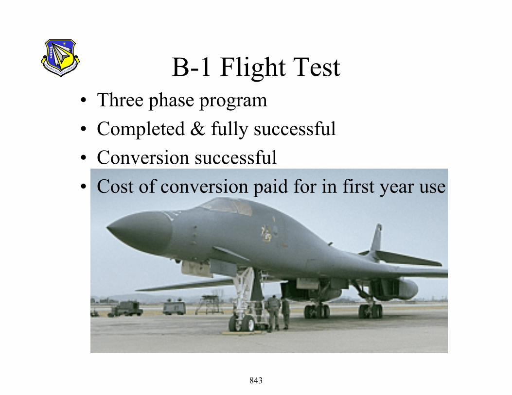
B-1 Flight Test• Three phase program• Completed & fully successful• Conversion successful• Cost of conversion paid for in first year use
843

PAO Coolant Transition
• PAO mil-spec MIL-C-87252 issued 2 Nov. 1988• B-1B flight test sampling support• Coordinate progress with other DoD agencies -
Army, Navy, DGSC (and industry)• Survey of potential users (DGSC, Kelly AFB)• Future support activities - B-2, F-16/B-1• Spec amended Dec 2004 Revision C with
amendment– Qualified product list has 8 companies
844

Navy Coolant Issues• F-18 and F-14 are
high voltage dielectric applications
• High humidity environment
• F-18, F-14 and F-15 radar fluid sampling -alarmingly low flash points
F-18
845

• Converted successfully
• Concerned about lower dielectric strength test results with MIL-PRF-87252, but not an operational problem
Navy Coolant Issues
F-14
846

Key MIL-PRF-87252 Features• Hydrolytically stable• Better heat transfer• Better lubricity• Less foaming (faster servicing)• Availability
– PAOs are made from readily available ethylene– Military fluid suppliers (e.g., Anderol, AirBP)
formulate & package
847

Key MIL-PRF-87252 Features• Availability (con’t)
– PAO is readily available at low cost ~$15/gal vs >$400/gal for Coolanol
• Handling– Toxicity very low (use normal shop procedures)– Fluid less hygroscopic– Recycling/reclamation – Pall Corp. fluid purifiers used
successfully– Disposal - can be sold as a hydrocarbon fuel oil supplement – Biodegradable - ASTM D5864 Class I
**Key features lead to lower life cycle cost**
848

A Major Systems Application Opportunity
• Now– B-1 and F-18 converted– Projected life cycle cost savings:
B-1 $947MF-18 $ 70M
$1.017B
849

PAO Coolant TransitionSystems Using Coolant
• Air Force– B-1B– EF111*– EC-130– F-15– F-16 (block 60 foreign sales)– F-22 (base-lined)– JSF (base-lined)
• Navy– F-14– F/A-18**– S-3– P-3– E/A6B– AV-8B– Mark 92 mod
850

PAO Coolant TransitionSystems Using Coolant (con’t)
• Weapons– PAVE– LANTIRN***– SPIKE– ALQ-119 Pod– Phoenix– Joint Stars*
• Army– Ground radar– Missile systems
851

PAO Coolant Transition Issues• *EF111 and Joint STARS
– Changed to conductive hoses (carbon impregnated) because PAO caused electrical streaming that did not occur with Coolanol
• **F-18– changed low temperature flow switches
• ***LANTIRN– Converting by attrition, but gel from residual silicate
ester coolant (5-9%) caused leakage pathway– Solution: Drain and fill to 100% PAO at overhaul
852

New System Interest
• New system coolant lines anticipated to be routed in high temperature area
• MIL-PRF-87252 originally tested at 175oC/100hours to meet the specification
• All products on Qualified Product List were tested at elevated temperatures
• Specification changed to require 200oC/100 hours thermal stability test. Current materials “grandfathered” i.e. did not have to re-qualify.
853

Status of silicate ester users
• F-16 and B-1 (isolated loop) - No plans to convert
854

• B-2 – Reconsidering conversion – ASC SBIR contracts to investigate alternate coolants began FY06
• Two Phase I SBIR contractors– METSS Corporation– InfoSciTex
Status of silicate ester users
855

New Interest-High Pressure Switches
• High pressure switching technology for directed energy High Power Microwave (HMP) applications
• AFRL/PR sponsored research at University of Missouri at Columbia and The Boeing Company, St. Louis Mo
• Prototype switch successfully developed
856

High Pressure SwitchesProgram goals• Voltage• Current• Rise-time• Charge transfer• Jitter• Pulse repetition rate• Pulse width• Switch lifetime
200 - 1000 kV20 - 250 kA< 50 ns~ 0.5 Coulombs/pulse<< 50 ns50 - 100 pps50 - 500 ns107 – 108 pulses
857

High Pressure Switching Technology• MIL-PRF-87252 breaks down to carbon and
hydrogen during arcing• Increased pressure (1000 to 2000 psi) helps reduce
arc-induced bubbles• Dielectric flow helps remove bubbles, carbon and
ablated electrode material from electrode stressed area– Filtering removes carbon particles– H2 gas generation has not created a hazard
• Current Univ of Missouri Columbia’s Capabilities– 150 kV, 70 ns pulses into 4.2 – 100 pps operation
858

Opportunity: Establish fundamental understanding of fluids’ breakdown characteristics for use in High Power Microwave (HPM) sources
Approaches: Evaluate different chemical classes of fluids, alone and with various concentrations of polar additives, for dielectric strength, with respect to temperature and pressure
Proposed Program:Characterization of Fluids for HMP Switch
Newly deployed PR prototype oil-filled high voltage switch
859

Other information
• PAO coolant has many commercial spin-offs - e.g., computer coolant, automobile shock absorbers
• MIL-PRF-87252 is a Class I biodegradable fluid (best) by ASTM D 5864
860

Conclusions• PAO coolant - MIL-PRF-87252 -
overcomes most of the difficulties with silicate ester coolants and has many other benefits
• Most military liquid cooled systems use MIL-PRF-87252
861