
MUCM ModLon Gateway - Niobrara R&D Corporation
22
MUCM ModLon Gateway Application Manual MUCM ModLon Gateway Installation and Programming Manual This Manual describes the MUCM application for interfacing the Cummins ModLon Gateway to a Modbus serial network. Effective: 30 January, 2005 Niobrara Research & Development Corporation P.O. Box 3418 Joplin, MO 64803 USA Telephone: (800) 235-6723 or (417) 624-8918 Facsimile: (417) 624-8920 www.niobrara.com
-
Upload
khangminh22 -
Category
Documents
-
view
4 -
download
0
Transcript of MUCM ModLon Gateway - Niobrara R&D Corporation

MUCM ModLon Gateway Application Manual
MUCM ModLon GatewayInstallation and Programming Manual
This Manual describes the MUCM application for interfacing the Cummins ModLon Gateway to a Modbus serialnetwork.
Effective: 30 January, 2005
Niobrara Research & Development CorporationP.O. Box 3418 Joplin, MO 64803 USATelephone: (800) 235-6723 or (417) 624-8918Facsimile: (417) 624-8920www.niobrara.com

Modbus and Momentum are registered trademarks of Modicon, Inc.
Brand and product names mentioned in this document are trademarks or registeredtrademarks of their respective companies.
Subject to change without notice.
© Niobrara Research & Development Corporation 2005. All Rights Reserved.

3
Contents
1 Introduction .........................................................................................................................5
2 Installation .............................................................................................................................7
Module Installation .........................................................................................................7Software Installation .......................................................................................................7Serial Connections to the MUCM ..................................................................................8
Port 1 to Modlon Gateway ......................................................................................8Port 1 to PC .............................................................................................................8Port 2 to Modbus RS-485 Network .........................................................................8
Loading the Applications into the MUCM.....................................................................9FWLOAD MUCM Firmware Update. ....................................................................9QLOAD MUCM_MODLON_APP1 ....................................................................10
Terminal Setup .............................................................................................................11
3 Modbus Operation ........................................................................................................15
Device Register List .....................................................................................................15FT-10 Option 1 ......................................................................................................15FT-10 Option 2 ......................................................................................................15FT-10 Option 3A ...................................................................................................16FT-10 Option 3B ...................................................................................................16TP/XF-78 ...............................................................................................................16
4 Examples...............................................................................................................................17
Example 1 .....................................................................................................................17
5 Testing and Troubleshooting.................................................................................19
Switches ........................................................................................................................19MUCM Lights ..............................................................................................................20Testing the Modbus Connection ...................................................................................21
4
Figures
Figure 2-1 MUCM to ModLon Gateway RS-232 (MU3 Cable) ..................................................8
Figure 2-2 MUCM to PC RS-232 (MU1 Cable) ..........................................................................8
Figure 2-3 MUCM to 2-wire Modbus Network ............................................................................9
Figure 2-4 MUCM to 4-wire Modbus Network ............................................................................9
Figure 2-5 FWLOAD ...................................................................................................................10
Figure 2-6 QLOAD of APP1 ........................................................................................................10
Figure 2-7 Hyperterminal Setup Main Screen ..............................................................................12
Figure 4-1 Example 1 Layout .......................................................................................................17
Figure 4-2 Hyperterminal Setup Main Screen ..............................................................................18
Figure 5-1 MUCM Lights and Switches ......................................................................................19
Figure 5-2 ZAPREG32 Screen ....................................................................................................22
Tables
Table 2-1 MUCM Port Default Settings ......................................................................................11

MUCM ModLon Gateway Application Manual 1 Introduction 5
1
Introduction
The Niobrara MUCM is a Modicon Momentum® compatible module that is capableof running multiple applications for performing communication translations betweenserial protocols. This document covers an application that allows the Cummins Mod-Lon gateway to be used with a standard Modbus RTU RS-485 network.
The MUCM connects to the ModLon gateway through its RS-232 port. The MUCMautomatically polls the ModLon gateway, observing its peculiar limitations on registerstarting address and count, as well as inter-character timing limitations and delays be-tween messages. This data is then presented to the RS-485 port of the MUCM to con-nect to any standard Modbus RTU network.
The MUCM is configured through its RS-232 port with a standard terminal emulatorsuch as Hyperterminal. This configuration consists of the setup for the ModLon gate-way as well as the Modbus RTU slave port. The MUCM may be configured for theTP/XF-78 or FT-10 devices with full support for Options 1, 2, 3A, and 3B.
The RS-485 port of the MUCM connects to a standard Modbus RTU network in either2-wire or 4-wire mode. The baud rate (default=9600), data bits (default=8), parity(default=NONE), and Modbus Slave Address (default = 1) may all be configuredthrough a built-in terminal server on the RS-232 port.
This MUCM application does not support a Momentum communications tophat. It isadvisable to cover the opening where a tophat would normally connect to protect theexposed circuit board. NR&D part number METH-001 is an inexpensive empty tophatcase sold for this purpose.
Only one of the two application areas are used for this data concentrator application: mucm_modlon_app1.qcm is compiled and loaded into application area 1 of theMUCM.
The MUCM contains its own power supply and needs a source of 9 to 30 Volts, AC orDC. An ideal 12VAC transformer is available from NR&D as part number TR121-ST.

6 Introduction 1 MUCM ModLon Gateway Application Manual
A complete kit may be ordered from Niobrara that includes the MUCM with this ap-plication pre-loaded, METH, MU1, MU3, and TR121-ST. The Niobrara part numberfor this kit is MCP-140.
MUCM ModLon Gateway Application Manual 2 Installation 7
2
Installation
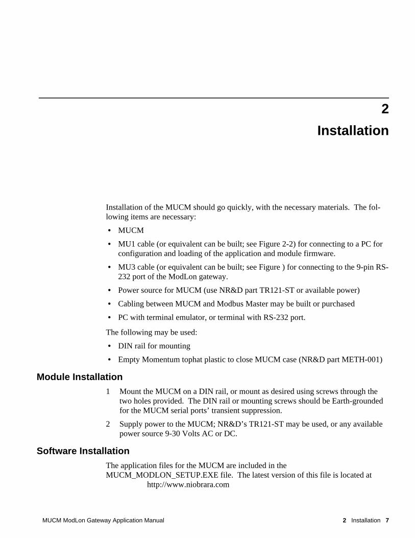
Installation of the MUCM should go quickly, with the necessary materials. The fol-lowing items are necessary:
• MUCM
• MU1 cable (or equivalent can be built; see Figure 2-2) for connecting to a PC forconfiguration and loading of the application and module firmware.
• MU3 cable (or equivalent can be built; see Figure ) for connecting to the 9-pin RS-232 port of the ModLon gateway.
• Power source for MUCM (use NR&D part TR121-ST or available power)
• Cabling between MUCM and Modbus Master may be built or purchased
• PC with terminal emulator, or terminal with RS-232 port.
The following may be used:
• DIN rail for mounting
• Empty Momentum tophat plastic to close MUCM case (NR&D part METH-001)
Module Installation1 Mount the MUCM on a DIN rail, or mount as desired using screws through the
two holes provided. The DIN rail or mounting screws should be Earth-groundedfor the MUCM serial ports’ transient suppression.
2 Supply power to the MUCM; NR&D’s TR121-ST may be used, or any availablepower source 9-30 Volts AC or DC.
Software InstallationThe application files for the MUCM are included in theMUCM_MODLON_SETUP.EXE file. The latest version of this file is located at
http://www.niobrara.com

8 Installation 2 MUCM ModLon Gateway Application Manual
Follow the link for "Application Notes", select "MUCM", and "ModLon".
Serial Connections to the MUCM
Port 1 to Modlon Gateway
Port 1 of the MUCM is RS-232 so a simple 3-wire cable is required to connect to theModlon Gateway. The Niobrara MU3 cable is used for this connection.
Figure 2-1 MUCM to ModLon Gateway RS-232 (MU3 Cable)
Port 1 to PC
The Niobrara MU1 cable is used to connect the MUCM to a standard PC-style 9-pinRS-232 serial port. For other standard connections, see the MUCM manual, or contactNR&D’s technical support.
Figure 2-2 MUCM to PC RS-232 (MU1 Cable)
Port 2 to Modbus RS-485 Network
Port 2 of the MUCM is RS-485 and supports a 4-wire or 2-wire cable network. Twisted pair cable should be used.
MUCM DB9P (male)
Tx 3
Rx 2
SG 5
RTS 7
CTS 8
MUCM DB9S (female)
Tx 2
Rx 3
SG 5
RTS 7
CTS 8
4
6

MUCM ModLon Gateway Application Manual 2 Installation 9
2-wire RS-485 slaves are supported by the MUCM by jumpering the TX+ and RX+together to make the (+) connection and the TX- and RX- together for the (-) connec-tion.
Figure 2-3 MUCM to 2-wire Modbus Network
4-wire RS-485 networks are directly supported by the MUCM. Connect the MUCMRX+ to the Master’s TX+, RX- to TX-, TX+ to RX+, and finally TX- to RX-.
Figure 2-4 MUCM to 4-wire Modbus Network
Loading the Applications into the MUCMNOTICE: If the kit MCP-140 was ordered, then the ModLon application is alreadyinstalled and this section may be skipped.
The MUCM is rapidly evolving so be sure to upgrade the firmware in the module be-fore loading the latest version of MUCM_MODLON_APP1.QCC. Most likely theQCOMPILE.EXE has been updated so be sure to use the newest version. TheMUCM-001 and MUCM-002 use different firmware files: MUCM1.FWL (orMUCM1.QCC) is for the MUCM-001; MUCM.FWL (or MUCM.QCC) is for theMUCM-002. Firmware upload is as follows:
FWLOAD MUCM Firmware Update.
If the MUCM has corrupt firmware or completely non-responsive then new firmwaremay be loaded with the program FWLOAD.
Firmware upload is as follows:
1 Move the yellow RUN/LOAD switch near the power connector to LOAD.
2 Only the 3 light should be on.
3 Connect the PC to QUCM Port 1 with a MU1 cable.
4 Locate the and start the program FWLOAD.EXE. This program may be accessedby "Start, Programs, Niobrara, MUCM, Fwload MUCM Firmware".
MUCM Slave Master
Tx+ + +
Tx- - -
Rx+
RX-
Shield Shield Shield
MUCM Slave Master
Tx+ TX+ RX+
Tx- TX- RX-
Rx+ RX+ TX+
RX- RX- TX-
Shield Shield Shield

10 Installation 2 MUCM ModLon Gateway Application Manual
5 If the above start menu link was followed, the proper MUCM.FWL file will beloaded. Otherwise, click on the Browse button and selectc:\Niobrara\Firmware\mucm.fwl for an MUCM-002 orc:\Niobrara\Firmware\mucm1.fwl for an MUCM-001.
6 Select the PC’s serial port (COM1).
7 Press START to begin the download process. If difficulty is experienced in com-pleting the download, try marking the Slow box and pressing start again.
8 When the download is completed, move the yellow LOAD/RUN switch back toRUN.
Figure 2-5 FWLOAD
QLOAD MUCM_MODLON_APP1
Figure 2-6 QLOAD of APP1
1 The RUN/LOAD switch must be in RUN.
2 Application Switches 1 (left) and 2 (right) must be in HALT.

MUCM ModLon Gateway Application Manual 2 Installation 11
3 Start QLOAD.EXE The Start Menu link is "Start, Programs, Niobrara, MUCM,Apps, ModLon, QLOAD ModLon Application 1".
4 Click on the Browse button and select the file MUCM_MODLON_APP1.QCC.
5 Select the Application 1 Radio Button.
6 Verify the following: The Modbus Serial tab is selected.
(1) The PC’s com port is selected (COM1).
(2) The baud rate is set for 9600.
(3) The Modbus Drop is set to 255.
(4) The ASCII button is NOT checked.
(5) The 8 bits button is selected.
(6) The parity is set for EVEN.
7 Press the Start Download button. QLOAD will open a progress window to showthe status of the download.
8 After downloading the application, Move Switch 1 to RUN. The RN1 lightshould be on.
Table 2-1 MUCM Port Default Settings
The MUCM will immediately start polling the gateway on the RS-232 port. If it issuccessful in communicating with the gateway then it will present the data to the RS-485 port. If the gateway is not responsive, then the MUCM will ignore Modbus RTUmessages.
The MUCM will respond to queries directed to a special Modbus slave address of 255,even if it cannot communicate with the gateway.
Terminal SetupThe setup parameters may be inspected and modified by connecting a terminal oremulator such has Hyperterminal to MUCM port 1 with an MU1 cable.
1 Connect the PC to the MUCM port 1 with the MU1 cable.
2 Move switch 2 to MEM PROT on the MUCM. All four user lights will come on.
3 Start Hyperterminal. This program is usually in Start, Programs, Accessories,Communications, Hyperterminal. Make sure the connection is for the properCOM port at 9600, N, 8, 1 and VT100 emulation.
Setting Port 1 Value Port 2 Value
Protocol Mode FT-10 Option 1 Modbus RTU Slave
Baud Rate 9600 9600
Parity NONE NONE
Data Bits 8 8
Stop Bits 1 1
Modbus Slave Address 1 1

12 Installation 2 MUCM ModLon Gateway Application Manual
Pressing ESC or Enter on the keyboard should bring up a screen as shown in Figure2-7. Pressing the "P" key will allow the two ports to be edited. Each entry to edit isadjusted by pressing the space bar or + and - keys. When the correct entry is selectedthen press the Enter key. Pressing the ESC will back out without changing the pa-rameter. Pressing the "W" key will write the setup to FLASH. The keys are not casesensitive.
Figure 2-7 Hyperterminal Setup Main Screen
The following entries may be edited for the Modlon RS-232 port:
• Mode - The default is FT-10 Option 1. The MUCM also support FT-10 Option 2,FT-10 Option 3A, FT-10 Option 3B, and TP/XF-78.
• Baud Rate - The baud rate is fixed at 9600.
• Parity - The value is fixed at NONE for the FT-10 and EVEN for the TP/XF-78.
• Data Bits - The value is fixed at 8 for the FT-10 and 7 for the TP/XF-78.
• Modbus Slave - This is the Modbus Slave address for the ModLon Gateway andshould be left at 1.
The following entries may be edited for the Modbus RTU RS-485 port:
• Mode - The only mode is Modbus RTU Slave.
• Baud Rate - The default baud rate is 9600. Other possibilities are 2400, 4800, and19200.
• Parity - The default value is NONE but may also be set to EVEN.

MUCM ModLon Gateway Application Manual 2 Installation 13
• Data Bits - The value is fixed at 8.
• Modbus Slave address defaults to 1 but may be set within the range of 1-254. This is the slave address that the MUCM responds to when queried by the Modbusmaster. This value is independent of the slave address of the ModLon gateway.
NOTE: When finished, press the "w" key to write the new settings to flash. Other-wise the new settings will be lost on the next power cycle of the MUCM.


MUCM ModLon Gateway Application Manual 3 Modbus Operation 15
3
Modbus Operation
This MUCM application uses Port 2 for Modbus communication. By default, Port 2 isset for Modbus RTU Slave, 9600 baud, 8 data bits, 1 stop bit, NONE parity.
Device Register ListThe data from the gateway is presented as Holding Registers (4x). Refer to Cumminsdocument C621b for specific register details.
FT-10 Option 1
The FT-10 GENSET data is in registers 1-49, 101-149, 201-249, 301-349, and 401-449 for the CCM-G. Pass-through writes are allowed for registers 50-51, 150-151,250-251, 350-351, and 450-451. (See Table 9 of Cummins document C621b for moredetails.)
The FT-10 Transfer Switch data is in registers 1001-1068, 1101-1168, 1201-1268,1301-1368, and 1401-1468 for the CCM-T. Pass-through writes are allowed for regis-ters 1069-1070, 1169-1170, 1269-1270, 1369-1370, and 1469-1470. (See Table 10 ofCummins document C621b for more details.)
The FT-10 Digital I/O Module data is in registers 1501-15024 and 1601-1624 for theDIM. Pass-through writes are allowed for registers 1525 and 1625. (See Table 11 ofCummins document C621b for more details.)
FT-10 Option 2
The FT-10 GENSET data is in registers 1-65, 101-165, 201-265, 301-365, and 401-465 for the CCM-G. Pass-through writes are allowed for registers 66-67, 166-167,266-267, 366-367, and 466-467. (See Table 12 of Cummins document C621b formore details.)
The FT-10 Transfer Switch data is in registers 1001-1034, 1101-1134, 1201-1234,1301-1334, and 1401-1434 for the CCM-T. Pass-through writes are allowed for regis-ters 1035-1036, 1135-1136, 1235-1236, 1335-1336, and 1435-1436. (See Table 13 ofCummins document C621b for more details.)

16 Modbus Operation 3 MUCM ModLon Gateway Application Manual
The FT-10 Digital I/O Module data is in registers 1501-15024 and 1601-1624 for theDIM. Pass-through writes are allowed for registers 1525 and 1625. (See Table 11 ofCummins document C621b for more details.)
FT-10 Option 3A
The FT-10 GENSET data is in registers 1-65, 101-165, 201-265, 301-365, 401-465,501-565, 601-665, 701-765, 801-865, and 901-965 for the CCM-G. Pass-throughwrites are allowed for registers 66-67, 166-167, 266-267, 366-367, 466-467, 566-567,666-667, 766-767, 866-867, and 966-967. (See Table 15 of Cummins documentC621b for more details.)
FT-10 Option 3B
The FT-10 Transfer Switch data is in registers 1-68, 101-168, 201-268, 301-368, 401-468, 501-568, 601-668, 701-778, 801-868, and 901-968 for the CCM-T. Pass-throughwrites are allowed for registers 69-70, 169-170, 269-270, 369-370, 469-470, 568-570,669-670, 769-770, 869-870, and 969-970. (See Table 16 of Cummins documentC621b for more details.)
TP/XF-78
The TP/XF-78 GENSET data is in registers 1001-39, 1101-1039, 1201-1239, 1301-1339, and 1401-1439. Pass-through writes are allowed for registers 1040-1042, 1140-1142, 1240-1242, 1340-1342, and 1440-1442. (See Table 6 of Cummins documentC621b for more details.)
The FT-10 CCM data is in registers 1-26, 101-126, 201-226, 301-326, and 401-426. Pass-through writes are allowed for registers 27-28, 127-128, 227-228, 327-328, and427-428. (See Table 8 of Cummins document C621b for more details.)
The FT-10 Digital I/O Module data is in registers 2001-2010 and 2101-2110 for theDIM. Pass-through writes are allowed for registers 2011 and 2111. (See Table 7 ofCummins document C621b for more details.)

MUCM ModLon Gateway Application Manual 4 Examples 17
4
Examples
Example 1Figure 4-1 shows system with a Modbus Master a Modbus Slave (Address = 1), asecond Modbus Slave (Address = 2), an MUCM, and a ModLon Gateway with twoGensets. The Modbus RTU Master has an RS-485 port and is configured for 19200baud, 8 data bits, 1 stop bit and NONE parity. The ModLon gateway is configured forFT-10 Option 1 and the generators are 0 and 1.
Figure 4-1 Example 1 Layout
MUCM
1 3 Rx1 Tx1 Rn1 Pwr 2 4 Rx2 Tx2 Rn2 ReadyTSX Momentum
Universal Communications170 UCM 200 00
Niobrara R&D Corporation9-30 VDC or AC
Tx Rx GND RTS CTS Tx+ Tx- Rx+ Rx- GND Run/LoadRS-232 RS-485
Mem R H
Mem R H
Modbus
Modbus Slave = 3RS-485 Cable
MU3 Cable
Master Slave 1
Slave 2
ModLon Gateway
Genset 0
Genset 1
Lonworks Network

18 Examples 4 MUCM ModLon Gateway Application Manual
The Modbus Master would access the MUCM at Modbus Slave address 3 and readregisters 4001 through 4049 to get the data from generator 0. Registers 40101 through40149 contain the data for generator 1.
Figure 4-2 Hyperterminal Setup Main Screen

MUCM ModLon Gateway Application Manual 5 Testing and Troubleshooting 19
5
Testing and Troubleshooting
Figure 5-1 MUCM Lights and Switches
Switches• Switch 1 controls the running of the Modlon application.
— Mem Prot - Not used.
— Run - The middle position is the normal running setting for this switch. TheRN1 light should be on and other lights may be on or flashing to indicate op-eration.
— Halt - The right position of this switch halts the application. Move to this posi-tion when loading new versions of the application with qload.
• Switch 2 turns on the terminal server for setup.
— Mem Prot - The far left position forces the unit to enable the configuration ter-minal server on the RS-232 port. The RN1 light will be on and lights 1, 2, 3,and 4 will all be on to indicate the terminal server is enabled. Connect an MU1cable to the RS-232 port to a PC and run a terminal emulator (Hyperterminal)at 9600,N,8,1, with VT100 emulation.
RN1
RN2
TX1
Run/Load
PowerSwitch 2Switch 1 Port 1 Port 2
RS-485RS-232
RX1Light 1Light 3
Light 2
Light 4RX2 TX2
Pwr
Ready

20 Testing and Troubleshooting 5 MUCM ModLon Gateway Application Manual
— Run - Not Used.
— Halt - Not Used.
• The Run/Load switch is used for loading firmware into the MUCM withFWLOAD. Normally, this switch is in RUN but is moved to LOAD before start-ing the download. Light 3 is ON when the switch is in LOAD.
MUCM LightsThe MUCM has several lights to give indication of activity of the application and se-rial ports.
• The Pwr light is green and indicates that the MUCM is powered and booted.
• The Ready light is green and indicates that the MUCM is communicating with atophat adapter. This light will not be on because the a tophat is not used.
• The green RN1 light indicates that the application is running. This lights shouldbe on when the switch 1 is in RUN or MEM PROT. If the switch is in a run posi-tion but the RN1 light is off then qload the application.
• The green RN2 light indicates that an application 2 is running. This light shouldalways be off in the ModLon application.
• The yellow Tx1 light indicates that the MUCM RS-232 port is transmitting data. This light should be occasionally flashing as the MUCM polls the ModLon gate-way.
• The yellow Rx1 light indicates that the MUCM RS-232 port is receiving data. This light should be occasionally flashing as the Modlon Gateway replies to theMUCM.
• The yellow Tx2 light indicates that the MUCM RS-485 port is transmitting data. This light should be occasionally flashing as the MUCM responds to queries fromthe Modbus Master.
• The yellow Rx2 light indicates that the MUCM RS-485 port is receiving data. This light should be occasionally flashing as the Modbus Master polls slaves onthe RS-485 network.
• Light 1 is a green light controlled by the application. Light 1 ON as long as theMUCM is receiving good replies from the ModLon gateway. This light indicatesthat the gateway is "ONLINE". If lights 1, 2, 3 are all on then the unit is in theconfiguration terminal server mode.
• Light 2 is a green light controlled by the application. Light 2 will flash when anygood Modbus message is received on the RS-485 port (even if the message is notdirected at the MUCM). If the message is intended for the MUCM then the flashwill be slightly longer and the TX2 light will also flash. If lights 1, 2, 3 are all onthen the unit is in the configuration terminal server mode.
• Light 3 is a red light controlled by the application. If light 3 is normally off butcomes on briefly to indicate that the MUCM did not receive a reply from the Mod-

MUCM ModLon Gateway Application Manual 5 Testing and Troubleshooting 21
Lon Gateway. If lights 1, 2, and 3 are all on then the unit is in the configurationterminal server mode.
• Light 4 is a red light controlled by the application. Light 4 indicates an error inthe Modbus Message. It will come on briefly if an attempt is made to read theMUCM if the ModLon gateway is offline or if there is a problem with the Modbusquery. This light may indicate a parity or framing error in the configuration of theRS-485 port. Light 4 is normally off. If lights 1, 2, 3, and 4 are all on then theunit is in the configuration terminal server mode.
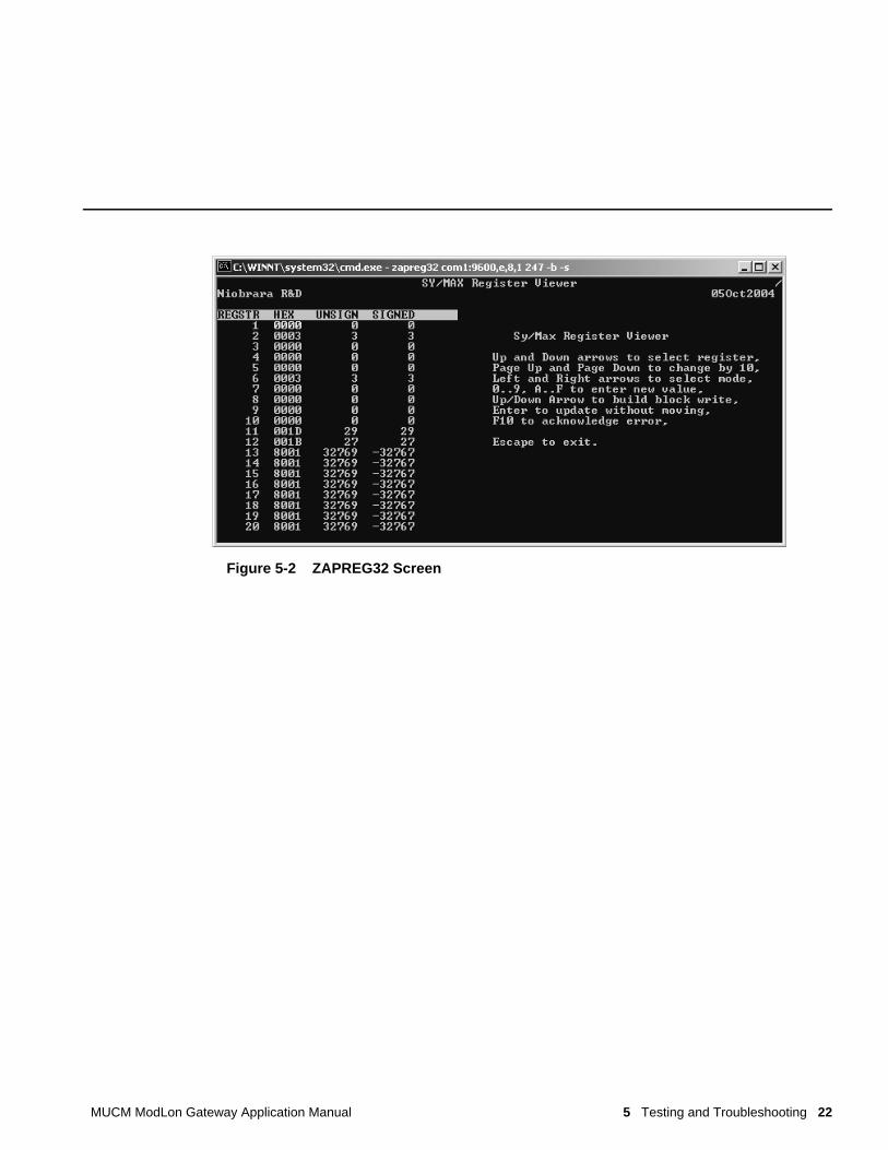
Testing the Modbus ConnectionThe program ZAPREG32.EXE may be used to quickly test the Modbus settings on theMUCM.
1 Connect the Niobrara SC912 (or some other RS-232<>RS-485 converter) cable tothe MUCM port 2 and the serial port of the PC.
2 Open a Command Prompt. On most Windows systems do a Start, Programs, Ac-cessories, Command Prompt.
3 From the command line enter the following:>zapreg32 com1:9600,n,8,1 255 -b
where com1: is the PC’s com port, 9600,n,8,1 are the settings of the MUCM’sRS-485 port, 255 is a special drop number that the MUCM will respond towhether it is talking to the gateway or not, and the -b tells zapreg to use ModbusRTU.
A screen like Figure 5-2 should appear. The left column is the Holding Registernumber, the data is shown in the HEX, SIGNED, and UNSIGNED columns. Thearrow keys and Page UP/Down may be used to move around. Values may be en-tered directly and the change occurs when the Enter key is pressed.
When finished verifying that the communication is good, press ESC and the pro-gram will exit.
To verify that the ModLon data is present, substitute the Modbus Slave address (de-fault=1) for the 255 in the command line above. If the MUCM is talking to the gate-way then the data will be displayed. If the MUCM is not talking to the gateway then"Read Reply Timeout" will be displayed on zapreg.
MUCM ModLon Gateway Application Manual 5 Testing and Troubleshooting 22
Figure 5-2 ZAPREG32 Screen