MS inglese
20
Instruction Manual MS series
-
Upload
khangminh22 -
Category
Documents
-
view
3 -
download
0
Transcript of MS inglese

InstructionManual
MS series

2
MSINDEX
1. INTRODUCTION. .................................................................................... Pag. 3
2. SYMBOLS DESCRIPTION . ................................................................. Pag. 3
3. SAFETY. ................................................................................................... Pag. 33.1 General warnings for safe operation . ........................................................ Pag. 33.2 High pressure unit safety requirements. ................................................... Pag. 33.3 Safety of operation . ......................................................................................... Pag. 43.4 General procedures for high pressure lance/gun operation . ........... Pag. 43.5 Safety of maintenance . .................................................................................. Pag. 4
4. PUMP IDENTIFICATION . ................................................................................... Pag. 5
5. TECHNICAL FEATURES . .................................................................................. Pag. 5
6. DIMENSIONS AND WEIGHT . .......................................................................... Pag. 5
7. GENERAL INFORMATION ABOUT THE PUMP USE . ....................... Pag. 67.1 Water temperature . ......................................................................................... Pag. 67.2 Max flow and pressure ratings . ................................................................... Pag. 67.3 Lowest operating rpm . ................................................................................... Pag. 6
8. CONNECTIONS AND PLUGS . ......................................................................... Pag. 6
9. PUMP INSTALLATION . ...................................................................................... Pag. 79.1 Positioning . ........................................................................................................ Pag. 79.2 Direction of rotation . ...................................................................................... Pag. 79.3 Water connections . ......................................................................................... Pag. 79.4 Suction line . ....................................................................................................... Pag. 79.5 Filtration . ............................................................................................................ Pag. 89.6 Delivery line . ...................................................................................................... Pag. 8
10. START UP AND RUNNING PROCEDURES . ............................................ Pag. 910.1 Before start up . ................................................................................................ Pag. 910.2 Starting up . ........................................................................................................ Pag. 910.3 Water leakage . .................................................................................................. Pag. 9
11. MAINTENANCE INSTRUCTIONS . ............................................................... Pag. 1011.1 Crank mechanism maintenance . ................................................................ Pag. 1011.2 Fluid end maintenance . .................................................................................. Pag. 1011.3 Pumping unit maintenance . .......................................................................... Pag. 12
12. SCREW CALIBRATION . ...................................................................................... Pag. 14
13. MAINTENANCE TOOLS . .................................................................................... Pag. 14
14. PUMP STOPPED FOR LONG TIME . ............................................................ Pag. 14
15. PRECAUTIONS AGAINST FREEZING . ...................................................... Pag. 14
16. WARRANTY TERMS . ........................................................................................... Pag. 14
17. EXPLODED VIEWS AND PART LIST . ......................................................... Pag. 15
18. TROUBLE SHOOTING . ....................................................................................... Pag. 19

3
MS1. INTRODUCTION
Pratissoli MS high pressure water plunger pumps havebeen designed for long life industrial duties and providedthey are correctly installed and mantained will give longtime trouble free operation. Read and understand thismanual before using your pump: it contains thenecessary information for the correct installation, useand maintenance as well as some practical suggestionsfor trouble shooting.
When receiving your pump make sure of the good stateof the supply and that no items are missing.Any missing item or damage should be reported beforeinstalling and starting the pump.
2. SYMBOLS DESCRIPTION
WarningPotential danger
Read carefully and understand the manualbefore operating the pump
Dangerhigh voltage
DangerWear protective mask.
DangerWear goggles.
DangerWear protective gloves.
DangerWear safety boots
3. SAFETY
3.1 General warnings for safe operationThe misuse of an high pressure water unit and the non-observance of the pump installation and maintenanceinstructions may cause serious damages and/or injuriesto people or properties or both.Any Manufacturer/Operator requested to assemble/usean high pressure water unit should be competent to doso, should have the necessary knowledge on every highpressure component installed in the unit and on theprecautions to be taken in order to guarantee the largestsafety margins during operation. No precaution, so faras is reasonably practicable, should be left out in theinterest of safety, both from the Manufacturer and theOperator.
3.2 High pressure unit safety requirements
1. a safety valve should be installed in any deliveryline and should be sized to discharge or by-passthe entire pump flow rate.
2. high pressure unit components, with particular regardfor those units working outside, should beadequately protected against rain, frost and heat.
3. electric components and wirings should be providedwith an adequate degree of protection, able to protectthem against spray coming from any direction. Theyshould also be suitable for working in a wetenvironment.
4. high pressure hoses and any other accessory underpressure should be sized in accordance with themax unit working pressure and must always workwithin the safety margins indicated by the hose/accessory Manufacturer.
5. high pressure hose ends should be fastened to asteady body in order to prevent them from dangeroussweeping around, should they burst or come off theirend fittings.
6. proper safety guards should be provided toadequately cover transmission joints, pulleys, belts,auxiliary drives.

4
MS
3.3 Safety of operationThe access into the area where an high pressure unit isworking should be strictly prohibited to unauthorisedpersonnel. The area should be suitably enclosed andits perimeter, so far as is reasonably practicable,cordoned off and proper warning notices displayed inprominent positions.Personnel authorised to enter that area should have beenpreviously trained to do so and informed on the risksarising from failures, misuse and any unforaseeablecircumstance which may occur during operation. Beforestarting the pump unit and bringing it up to pressure theOperator is requested to carry out the following checks:1. make sure that a correct water supply to the pump
is provided.2. make sure that water inlet filters are properly clean.3. electrical components and wirings, with special
emphasis on connections, junction boxes, switchesand supply cables should be free from externaldamages (i.e. exposed and broken wires) andadequately protected against water.
4. high pressure hose should not show apparentexternal wear and the fittings at both ends shouldbe free from signs of erosion or corrosion.
5. make sure that all fluids (lubricating oil for pumpand engine, cooling water, hydraulic fluids) are atproper level and in good condition.
6. make sure the safety guards are in good conditions.
The work should stop immediately and the pressure mustbe released in the event that leakages become apparentor if any person becomes aware of any change incondition or any hazard existing or being introduced.Any failure must be promptly reported and then checkedby competent personnel.
3.4 General procedures for high pressureguns/lances operation.
1. the Operator should take reasonable care of thesafety of himself and of other persons who may beaffected by his acts or omission at work. His actionsshould be always governed by his good sense andresponsability.
2. The Operator should wear suitable waterproofprotective clothings, having regard to the type of workbeing undertaken. The clothing set should includeadequate hand protections, suitable boots able toensure proper grip on wet floors, helmet providedwith full face shield, waterproof garment providingfull cover to the Operator, including his arms.As most of water jets produce noise levels in excess
of 90 dB(A) suitable ear protection is advised.Note: it must be emphasised that whereas protectiveclothing provides adequate protection against spray andflying particles, it does not constitute completeprotection against the direct impact of the water jet.Additional protections in the form of suitable metalshields or barriers may be necessary for certain jettingoperations.3. in most jetting operations it is an accepted practise
to employ a team of Operators consisting of twomembers at least, in order to provide mutualassistance in case of need and to rotate their dutiesin case of long and heavy work. While the firstOperator holds the gun, the second Operator attendsthe pump unit, keeping close watch on the firstOperator for signs of difficulties or fatigues, andwatching the sorrounding area for intrusion by otherpersons or unsafe situations. If required, he will shutoff the pressure until it is safe to continue.
4. the area in which the work is to proceed should beclear of loose items and debris to prevent trippingand slipping hazards.
5. the water jet should be directed only and alwaysagainst the workpiece, even during preliminaroperating tests prior to starting work.
6. where applicable, proper side shields should besuitably placed to safeguard personnel andequipment against contact with grit or particlesremoved by the water jet.
7. on no account must the Operator be distractedduring operation until the jet has been stopped.Personnel having reason to enter the water jettingarea should wait until the jet is stopped and hispresence known.
8. each team member must always be aware of theactions and intentions of other team members inorder to prevent any dangerous misunderstandingoccuring during jetting operation.
9. the pump unit should not be started and brought upto pressure unless each team member is in hisdesignated position, the nozzle directed to theworkpiece and the lance or gun securely held.
3.5 Safety of maintenance.Apart from the working pressure regulation no attemptshould be made to adjust any nut, hose, fitting, ect,while that part of the system is under pressure. Thepump should be stopped and any pressure in the linereleased prior to make any adjustment.1. the high pressure water unit should be mantained
in accordance with the Manufacturer’s instructions.2. the unit should be maintained only by competent
personnel.3. service and maintenance should be carried out with
proper tools in order to prevent any damage on highpressure connections and fittings.
4. use of other than original spare parts is strictlyforbidden.
5
MS
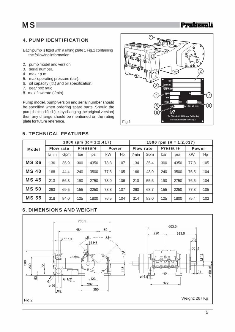
Model Flow rate Pressure Power
MS 36
MS 40
MS 45
MS 50
MS 55
l/min Gpm bar psi kW Hp
136 35,9 300 4350 78,8 107 134 35,4 300 4350 77,3 105
168 44,4 240 3500 77,3 105 166 43,9 240 3500 76,5 104
213 56,3 190 2750 78,0 106 210 55,5 190 2750 76,5 104
263 69,5 155 2250 78,8 107 260 68,7 155 2250 77,3 105
318 84,0 125 1800 76,5 104 314 83,0 125 1800 75,4 103
Fig.1
6. DIMENSIONS AND WEIGHT
Fig.2
5. TECHNICAL FEATURES
Flow rate Pressure Powerl/min Gpm bar psi kW Hp
1800 rpm (R = 1:2,417) 1500 rpm (R = 1:2,037)
2
8
3
5
7
6
4
Weight: 267 Kg
4. PUMP IDENTIFICATION
Each pump is fitted with a rating plate 1 Fig.1 containingthe following information:
2. pump model and version.3. serial number.4. max r.p.m.5. max operating pressure (bar).6. oil capacity (ltr.) and oil specification.7. gear box ratio8. max flow rate (l/min).
Pump model, pump version and serial number shouldbe specified when ordering spare parts. Should thepump be modified (i.e. by changing the original version)then any change should be mentioned on the ratingplate for future reference.
6
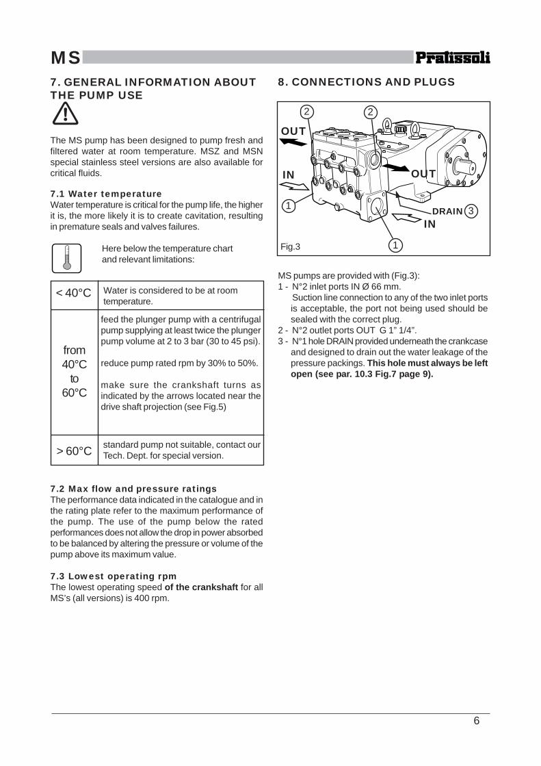
MS8. CONNECTIONS AND PLUGS
MS pumps are provided with (Fig.3):1 - N°2 inlet ports IN Ø 66 mm.
Suction line connection to any of the two inlet portsis acceptable, the port not being used should besealed with the correct plug.
2 - N°2 outlet ports OUT G 1” 1/4”.3 - N°1 hole DRAIN provided underneath the crankcase
and designed to drain out the water leakage of thepressure packings. This hole must always be leftopen (see par. 10.3 Fig.7 page 9).
7. GENERAL INFORMATION ABOUTTHE PUMP USE
The MS pump has been designed to pump fresh andfiltered water at room temperature. MSZ and MSNspecial stainless steel versions are also available forcritical fluids.
7.1 Water temperatureWater temperature is critical for the pump life, the higherit is, the more likely it is to create cavitation, resultingin premature seals and valves failures.
Here below the temperature chartand relevant limitations:
7.2 Max flow and pressure ratingsThe performance data indicated in the catalogue and inthe rating plate refer to the maximum performance ofthe pump. The use of the pump below the ratedperformances does not allow the drop in power absorbedto be balanced by altering the pressure or volume of thepump above its maximum value.
7.3 Lowest operating rpmThe lowest operating speed of the crankshaft for allMS’s (all versions) is 400 rpm.
Fig.3
INDRAIN
IN OUT
OUT
< 40°C
from40°C
to60°C
> 60°C
feed the plunger pump with a centrifugalpump supplying at least twice the plungerpump volume at 2 to 3 bar (30 to 45 psi).
reduce pump rated rpm by 30% to 50%.
make sure the crankshaft turns asindicated by the arrows located near thedrive shaft projection (see Fig.5)
standard pump not suitable, contact ourTech. Dept. for special version.
Water is considered to be at roomtemperature.
2 2
1
1 3

7
MS9. PUMP INSTALLATION
9.1 PositioningThe pump should be installed flat on a rigid base bymeans of the four feet Ø 16,5 mm.The base should be rigid enough to avoid anymisalignment of flexing of the pump/transmissioncoupling axis due to the torque involved during operation.On no account should the pump be installed in sucha way its fluid end rests on the base where the pumpis mounted. The fluid end should be left free andnot subjected to any force (Fig.4).
9.2 Direction of rotationThe fig. 5 shows the correct direction of rotation lookingat the pump from the fluid end side. Two arrows stampedon the crankcase nearby the crankshaft provide theinformation as well.
Fig.4
Fig.5
FLUID END
LX sideanti
clockwise
RX sideclockwise
9.3 Water connectionsIn order to isolate the high pressure equipment from thepump vibrations it is suggested, where applicable, touse flexible hoses for both suction and delivery lines atleast for the first length. The flexible suction hose mustbe rigid enough to prevent it from collapsing during thesuction stroke, when a partial vacuum may occur.
9.4 Suction linePlunger pumps are not self priming therefore a positivesuction head should always be provided.Information for the correct suction line:1. Internal diameter should be at least 66 mm. in any
point, possibly larger, depending of the drop inpressure due to the length and shape of the line.
2. should be as straight as possible, minimizingchanges in size and direction and positioned in sucha way to allow air pockets and bubbles to escape.
3. should be perfectly airtight.4. should be completely free from 90° elbows, diameter
reductions, counter slopes, “T” connections andshould not be connected to other pipelines.
5. should be positioned in such a way to prevent thepipe emptying after the pump stops.
6. do not use high pressure flexible hoses for thesuction line.
7. do not use high pressure hydraulic fittings like 90°elbows, high pressure adaptors, high pressure 3 or4 ways nipples and so on.
8. do not install any kind of detergent injetor along thesuction line.
9. do not install standing valves, check valves or otherkind of one-way valves.
10. make sure that the feed tank capacity and the waterminimum level do not give rise to turbulence at thetank outlet port, which, in turn, might createcavitation at the pump.
11. do not connect the by-pass line from the valve directlyto the pump suction line.
12. the water flow from the valve should be directed backin the tank. Make sure that the by-pass and tankfeeding flows do not give rise to turbulence at thetank outlet port, which, in turn, might createcavitation at the pump. Proper baffle plates shouldbe provided inside the tank.
13. before connecting the suction line to the pump inletport make sure the pipe is perfectly clean inside.

8
MS
Fig.6
TANKVALVE
PUMP HEADFILTER
BY-PASS LINE
BUFFLEPLATE
90° CURVESVALVE
DIAMETERREDUCTIONS
BY-PASS BACK TO INLET LINE
“T” CONNECTIONS
COUNTER SLOPES
POSITIVE SUCTION HEAD
NEGATIVE SUCTION HEAD !!
9.5 FiltrationAll pumps require a suitable filter.The filter should be installed as close as possible to thepump, should allow easy inspection and have thefollowing characteristics:
1. the filter capacity should be at least three times therated pump volume.
2. filter port diameters should not be smaller than thepump inlet ports.
3. filtration degree in between 50 and 80 mesh (360200 microns).
IMPORTANT NOTE: in order to properly safeguard thepump it is very important to plan cleaning of the filterwith a frequency depending on the water quality,filtration degree and number of hours of eachapplication.
9.6 Delivery lineFor a correct delivery line comply with the followinginstructions:
1. the first length of delivery hose should be flexible inorder to isolate the pump vibrations from the rest ofthe system.
2. use only high pressure hoses and fittings able toguarantee the largest possible safety margins inany working conditions.
3. a suitable relief valve should be installed in thedelivery line.
4. use glycerin filled pressure gauges, being the mostsuitable for pulsating loads.
5. When designing the delivery line, take into properaccount the unavoidable drop in pressure, due toits length and size.
6. If necessary, the effects of the pump pulsations canbe reduced by installing a proper pulsation dampenerin the pressure line.

9
MS
Fig.7
hole G1/2”
10. START UP AND RUNNINGPROCEDURES
10.1 Before start upBefore start up make sure that the following conditionshave been complied with:1. suction line should be connected: the pump must
never run dry.2. suction line must be perfectly air-tight.3. any ON-OFF valve in between pump and water
source should be open and make sure the watergets into the pump freely.
4. set the pressure line in dump mode in order to letthe air in the pump get out easily thus facilitatingthe pump priming.
5. make sure all suction/delivery line connections arefully tightened.
6. Joint alignment, belt tightening and PTO shaftinclination tolerances should remain within thevalues indicated by the trasmission Manufacturer.
7. make sure of the correct oil level.
Note: in case the pump has not run for a long periodcheck the suction and delivery valves for scaling (seepar.11.2).
10.2 Starting up1. pump and motor/engine should start offload, set
the regulating valve to zero or set the pressure linein dump mode by means of proper dumping devices.
2. when starting the pump up for the first time or afterevery wiring re-connection check for the properdirection of rotation.
3. check that the rotating speed does not exceed therated value.
4. before putting the pump under pressure let it run forsome time until the oil flows freely.
5. before stopping the pump release the pressure fromthe system by operating the dump device or byreleasing the regulating valve and reduce rpm to aminimum (diesel applications).
Note: in case of feeding by a cetrifugal pump, makesure that the plunger pump startss only when the correctinlet pressure is provided.
10.3 Water leakageDuring operation a small amount of water (a few drops aminute) is released from the pump fluid end; this leakageis designed to provide lubrication of the pressurepackings. The leakage is drained out of the pump througha hole in the lower cover (Fig.7).This hole must always be left open.

10
MS11. MAINTENANCE INSTRUCTIONS
11.1 Crank mechanism maintenance.Check oil level on a weekly basis by means of the twooil dipsticks (1, Fig.8) provided with notches for minand max level.
If necessary, top up from the oil plug 3, Fig.8.Check the oil when cold and change the oil when stillhot (pump still at working temperature).In order to drain the oil from the pump remove themagnetic plug 2, Fig.8.At every oil change clean the magnetic plug 2 Fig.8 andcheck the lower cover of Fig.7 for grease sediments ordeposits.
Oil should be changed at least once a year.
Recommended oils:
11 3
Fig.82
BRAND TYPEAGIP ACER 220ARAL MOTANOL HP 220AVIA AVILUB RSL 220BP ENERGOL HL 220CASTROL ALPHA ZN 220ESSO NUTO 220FINA SOLNA 220IP HYDRUS 220MOBIL DTE OIL BBSHELL TELLUS C 220TEXACO REGOL OIL 220TOTAL CORTIS 220
11.2 Fluid end maintenanceThe fluid end does not require periodical maintenance.Service operations are limited to the valves inspectionand/or replacement, when necessary.In order to remove the valves:
Loose and remove the valve cover screws 1,Fig.9.
Tighten the two grub screws 1, Fig.10 of each valvecover till the complete valve unit moves upwards enoughto allow easy extraction.
Valve components of eachvalve unit are pressedtogether in one single blockand therefore they can beeasily serviced, replacedand installed back in place.Separating the variouscomponents of the valveunit is carried out bymeans of simple tools asshown in Fig. 11, 12, 13 ofthe next page.
1
Fig.10
1
Fig.9
OIL CHANGES hours Q.tyLt.
Oiltype
1° change ISO220
1050
further changes 500
11
MS
Fig.12
Fig.13
Fig.11
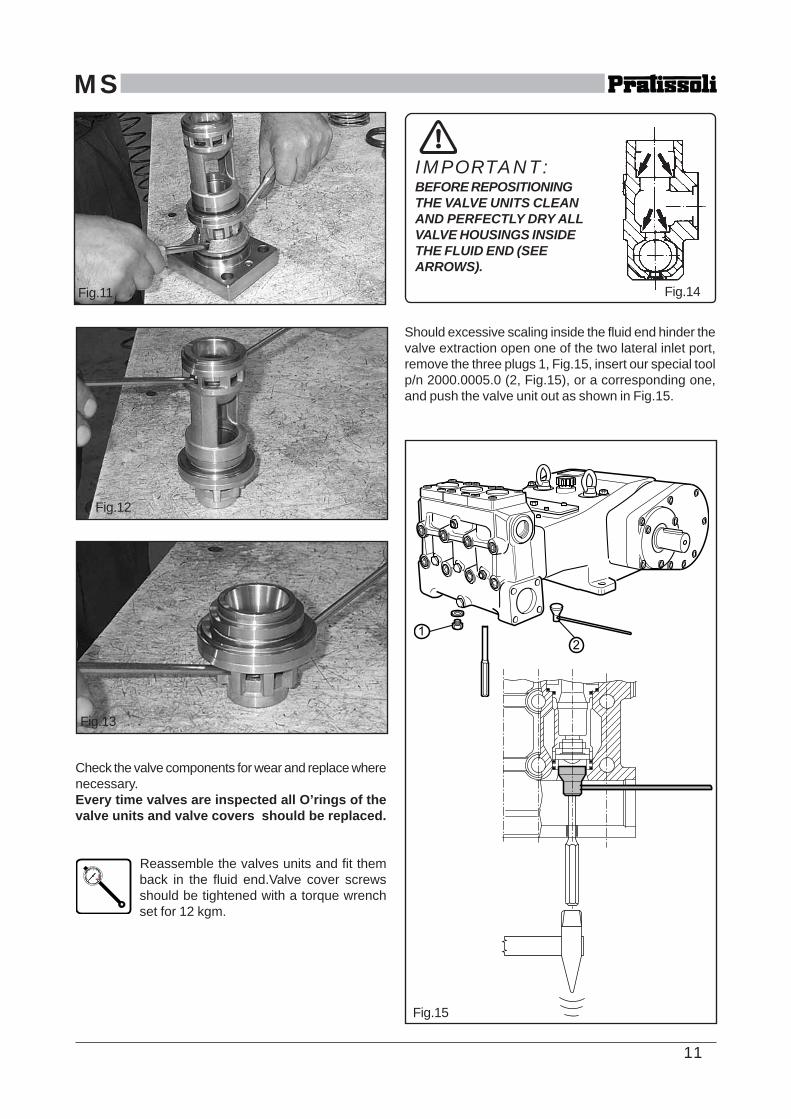
Should excessive scaling inside the fluid end hinder thevalve extraction open one of the two lateral inlet port,remove the three plugs 1, Fig.15, insert our special toolp/n 2000.0005.0 (2, Fig.15), or a corresponding one,and push the valve unit out as shown in Fig.15.
Fig.15
Check the valve components for wear and replace wherenecessary.Every time valves are inspected all O’rings of thevalve units and valve covers should be replaced.
Reassemble the valves units and fit themback in the fluid end.Valve cover screwsshould be tightened with a torque wrenchset for 12 kgm.
Fig.14
IMPORTANT:BEFORE REPOSITIONINGTHE VALVE UNITS CLEANAND PERFECTLY DRY ALLVALVE HOUSINGS INSIDETHE FLUID END (SEEARROWS).
12
MS
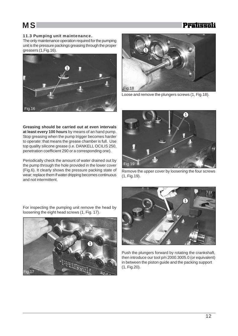
Loose and remove the plungers screws (1, Fig.18).
Remove the upper cover by loosening the four screws(1, Fig.19).
Push the plungers forward by rotating the crankshaft,then introduce our tool p/n 2000.3005.0 (or equivalent)in between the piston guide and the packing support(1, Fig.20).
11.3 Pumping unit maintenance.The only maintenance operation required for the pumpingunit is the pressure packings greasing through the propergreasers (1,Fig.16).
Greasing should be carried out at even intervalsat least every 100 hours by means of an hand pump.Stop greasing when the pump trigger becomes harderto operate: that means the grease chamber is full. Usetop quality silicone grease (i.e. DANKELL OCILIS 250,penetration coefficient 290 or a corresponding one).
Periodically check the amount of water drained out bythe pump through the hole provided in the lower cover(Fig.6). It clearly shows the pressure packing state ofwear; replace them if water dripping becomes continuousand not intermittent.
For inspecting the pumping unit remove the head byloosening the eight head screws (1, Fig. 17).
1
Fig.16
Fig.17
Fig.19
1
1
Fig.18
Fig.20
1
1

13
MS
Separate the pumping unit components and check themfor wear. Pressure packing replacements is carried outby hands without need of special tools (Fig.24)A little bit of grease helps sliding the packings into thepacking support. Pressure packings and O’ringsshould always be replaced at every disassemblingof the pumping unit.
In order to fit the new scraper in place shape it manuallyas shown in Fig.25.VERY IMPORTANT! the scraper is provided with aninternal lip which performs the correct scraping effectonly if oriented towards the fluid end. See window insideFig.25.Put the pumping unit components together and fit themback in the pump crankcase.Tighten the plunger screws(1, Fig.18) with a torque wrench set for 10 Kgm.Grease the pressure packings through the greasers(2, Fig.23) by means of a hand pump. Stop greasingwhen the pump trigger becomes hard to operate: thatmeans the grease chamber is full.Head back in place, head screws tightened at 25 Kgm.
With the tool in place, rotate the crankshaft until thepacking support is pushed out together with plungersand cylinders (Fig.21 and Fig.22).
Repeat the operation for each pumping unit.
Remove the wipers from the piston guides (1,Fig.23).
Fig.24
Fig.21
Fig.22
1
Fig.23
Fig.25TOWARDS THE FLUID ENDscraping lip
2
14
MS12. SCREW CALIBRATION
Screw calibration is to be carried out bymeans of a torque wrench only:
DESCRIPTION Kgm.valve cover screws 12head screws 25plunger screws 10connecting rod screws 7,5
13. MAINTENANCE TOOLS
The following tools are designed to facilitatemounting and dismounting operations ofsome pump components:
for disassembling:- packing support extractor cod. 2000.3005.0
- main gear (gear box) cod. 2000.3002.0
- valve extractor cod. 2000.0005.0
14. PUMP STOPPED FOR LONGTIME
Before starting the pump up for the very firsttime after a long period from the date ofshipment check for the correct oil level,check the valves as indicated in the chapter11 and then comply with the startingprocedures indicated in the chapter 10.When a long inactivity is scheduled drainthe entire suction and delivery line and thenrun the pump dry only for a few secondsin order to drain out the water collected insidethe fluid end.
15. PRECAUTIONS AGAINSTFREEZING
In the risk of freezing the followingprecautions should be taken:
:
- after use drain the entire suction and delivery lines(filter included) by means of discharging devices,provided and positioned specifically for this purposealong the lowest point of the lines.
- run the pump only for a few seconds in order todrain the water collected inside the fluid end
Or, when applicable- add a recommended amount of anti-freeze into the
water tank and run the pump until the anti-freezeworks all through the system.
If a pump is frozen or appears frozen ON NO ACCOUNTSHOULD THE PUMP BE OPERATED until the entiresystem has been thawed out.
16. WARRANTY TERMSPratissoli products are warranted to be free from defectsin workmanship and material for 12 months from thedate of shipment. This warranty is limited to repairing orreplacing products which Manufacturer’s investigationshows were defective at the time of shipment. Allproducts subject to this warranty shall be returned freeof any freight charges to Pratissoli Pompe division ofInterpump Group S.p.a., via Felice Cavallotti 33,42100 Reggio Emilia, Italy.The express warranty set forth herein is in lieu of allother warranties, express or implied, including withoutlimitation any warranties of merchantability of fitnessfor a particular purpose and all such warranties arehereby disclaimed and excluded by the Manufacturer.Repair or replacement of defective products as providedabove is the sole and exclusive remedy providedhereunder and the Manufacturer shall not be liable forany further loss, damages or expenses, includingincidental or consequential damages, directly orindirectly arising from the sale or use of this product.For items not manufactured by Pratissoli Pompe, thewarranty terms applied will be those of the originalManufacturer. The use of other than Pratissoli originalspare parts automatically voids the warranty.
15
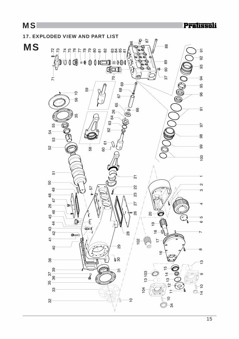
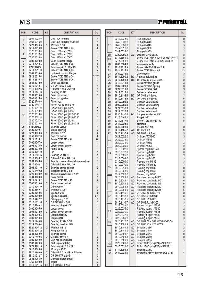
MS17. EXPLODED VIEW AND PART LIST
MS
16
MS

17
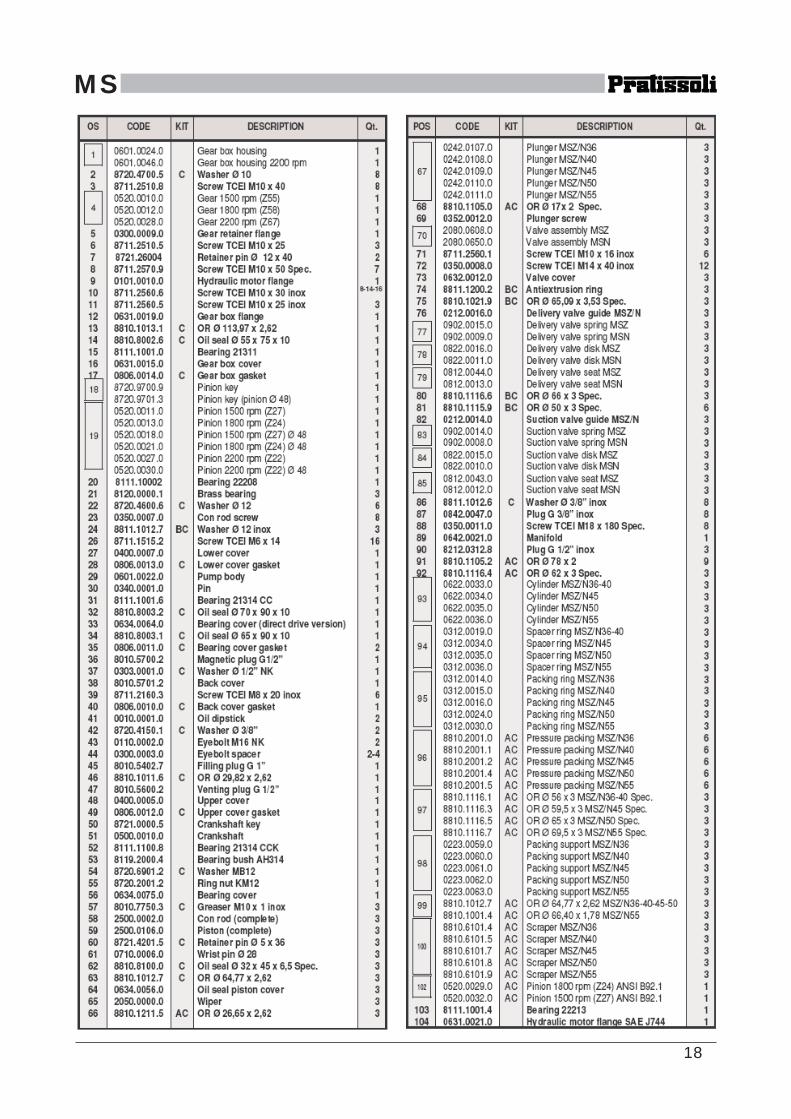
MS17. EXPLODED VIEW AND PART LIST
MSZMSN
18
MS

19
MS18. TROUBLE SHOOTING
THE PUMP DOES NOT PRODUCE ANYNOISE: the pump is not primed and isrunning dry !- no water in the inlet line.- the valves are blocked.- the pressure line is closed and does not
allow the air to get out the fluid end.
THE PUMP KNOCKS:- air suction.- insufficient feeding.- bends, elbows and fittings along the
suction line throttle the amount of waterwhich passes through.
- too small inlet filter.- dirty inlet filter.- the feeding pump, where provided, is notof the suitable type or provides insufficientpressure or volume.- the pump is not primed due to insufficientfeeding or the delivery line is closed duringstart up.- the pump is not primed because somevalves are stuck (i.e. pump inactivity for longtime).- jammed or worn-out valves.- worn-out pressure packings.- the pressure regulating valves do not workproperly.- clearance in the drive system.- r.p.m. are higher than rated.
.
THE PUMP DOES NOT DELIVER THERATED VOLUME:- insufficient feeding (due to the cause listedabove).- r.p.m. are less than rated.- excesive amount of water by-passed bythe pressure regulating valve.- worn out valves.- excessive leakage from pressurepackings.
INSUFFICIENT PUMP PRESSURE:- the nozzle is (or has become) too large.- r.p.m. are less than rated.- excessive leakage from pressurepackings.- excessive amount of water by-passed bythe pressure regulating valve or faulty valveoperation.- worn out valves.
EXCESSIVE WATER LEAKAGE FROMTHE PUMP:- pressure packings are excessively wornout (due to normal wear or excessivecavitation).- worn out plungers.
OVERHEATED PUMP:- the direction of rotation is not correct.- pump is overloaded (pressure or rpm overthe rated values).- the oil level is too low or the oil is not of asuitable type or fully used.- water in the oil.- excessive belt tension or incorrectalignment of the joint (where provided) .- excessive inclination of the pump duringoperation.
PIPE VIBRATIONS OR KNOCKINGS:- air suction.- the pressure regulating valve does not workproperly.- the by-pass line is undersized.- jammed up valves.- drive transmission motion is irregular.
A Division of the INTERPUMPGROUP S.p.A
Via F. Cavallotti, 33 - 42100 Reggio Emilia - Italy -Tel. +39 0522 276511 - Fax +39 0522 51140 - E-mail: [email protected]