MonArc2 - The Validation Centre (TVC) Ltd
43
The Validation Centre (TVC) Limited UNIT 15, BRINELL WAY, HARFREY’S INDUSTRIAL ESTATE, GREAT YARMOUTH, NORFOLK, NR31 0LU, UK | 01493 443800 01493 443900 [email protected] WWW.TVCALX.CO.UK MonArc2 INSTRUCTION MANUAL V1.4
-
Upload
khangminh22 -
Category
Documents
-
view
1 -
download
0
Transcript of MonArc2 - The Validation Centre (TVC) Ltd
The Validation Centre (TVC) Limited UNIT 15, BRINELL WAY, HARFREY’S INDUSTRIAL ESTATE, GREAT YARMOUTH, NORFOLK, NR31 0LU, UK |
01493 443800 01493 443900 [email protected] WWW.TVCALX.CO.UK
MonArc2 INSTRUCTION MANUAL
V1.4
Page | 1
Contents
1.0 Introduction 2 1.1 Warnings and precautions 2 - 3 1.2 Primary parameters 3 1.3 Secondary parameters 4 1.4 Average and totalled parameters 4 - 5 1.5 Components and functions 5
Figure 1 Transducers and connections layout 5 - 6 Figure 2 Front panel layout 6 Figure 3a GFM2 to MonArc2 (connected) 7 Figure 3b NFM2 to MonArc2 (connected) 8 Figure 3c MonArc2 gas port connection 8
2.0 Operating instructions 9 2.1 Pre-checks and installation 9 2.2 Operating sequence with Auto Run No. deactivated 10 – 13 2.3 Operating sequence with Auto Run No. activated 13 – 16 2.4 Gas flow 17 – 18 2.5 Setup menu 18 – 23 2.6 Options 23 – 24 2.7 Battery status 24 2.8 Battery charging 25
Figures 4a and 4b MonArc2 to welding set connections 26, 27
3.0 Servicing 28 3.1 Changing printer paper 28 – 29 3.2 Changing ink ribbon 30 3.3 Printer life 30 3.4 Current probe zero 30 – 33 3.5 Changing wire feed speed encoder idler wheels 33 – 34
4.0 Software 34 4.1 Software installation 34 – 35 4.2 Software operation 35 – 40 4.3 PC requirements 40
5.0 Troubleshooting and spares 41 5.1 Fault and diagnosis 41 – 42 5.2 Recommended spares 42
6.0 Additional user information 42 6.1 Calibration 42 6.2 Equipment disposal 42
Page | 2
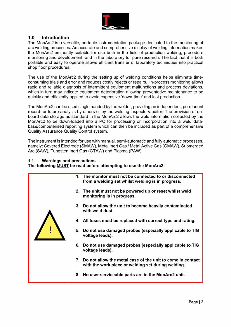
1.0 Introduction The MonArc2 is a versatile, portable instrumentation package dedicated to the monitoring of arc welding processes. An accurate and comprehensive display of welding information makes the MonArc2 eminently suitable for use both in the field of production welding, procedure monitoring and development, and in the laboratory for pure research. The fact that it is both portable and easy to operate allows efficient transfer of laboratory techniques into practical shop floor procedures. The use of the MonArc2 during the setting up of welding conditions helps eliminate time-consuming trials and error and reduces costly rejects or repairs. In-process monitoring allows rapid and reliable diagnosis of intermittent equipment malfunctions and process deviations, which in turn may indicate equipment deterioration allowing preventative maintenance to be quickly and efficiently applied to avoid expensive ‘down-time’ and lost production. The MonArc2 can be used single handed by the welder, providing an independent, permanent record for future analysis by others or by the welding inspector/auditor. The provision of on-board data storage as standard in the MonArc2 allows the weld information collected by the MonArc2 to be down-loaded into a PC for processing or incorporation into a weld data-base/computerised reporting system which can then be included as part of a comprehensive Quality Assurance Quality Control system. The instrument is intended for use with manual, semi-automatic and fully automatic processes, namely: Covered Electrode (SMAW), Metal Inert Gas / Metal Active Gas (GMAW), Submerged Arc (SAW), Tungsten Inert Gas (GTAW) and Plasma (PAW). 1.1 Warnings and precautions The following MUST be read before attempting to use the MonArc2:
1. The monitor must not be connected to or disconnected from a welding set whilst welding is in progress.
2. The unit must not be powered up or reset whilst weld monitoring is in progress.
3. Do not allow the unit to become heavily contaminated with weld dust.
4. All fuses must be replaced with correct type and rating.
5. Do not use damaged probes (especially applicable to TIG voltage leads).
6. Do not use damaged probes (especially applicable to TIG voltage leads).
7. Do not allow the metal case of the unit to come in contact with the work piece or welding set during welding.
8. No user serviceable parts are in the MonArc2 unit.
!

Page | 3
1.1.1 Current Clamp Positioning TIG and certain inverter power sources will cause damage to the current clamp if not positioned correctly. NB: Placing the current clamp directly next to the power source, or in very close proximity, will damage the Hall Effect sensor! The most common causes of damage to the current clamp are caused by the following and positioning of the clamp should be checked before welding commences:
1. Incorrect positioning of the clamp, i.e. clamp is too close to the power source.
2. Poor centralisation of the cable through the clamp.
3. Placing the MAL III unit on the workpiece.
4. Placing of the current clamp om the workpiece.
5. Failure to check or zero the current clamp on a regular basis.
6. Physical damage, e.g. standing on or dropping something heavy onto the clamp
7. In rare cases, connection of the battery charger can cause issues, however, this is
highly unlikely.
1.2 Primary parameters The 3 parameters of primary importance displayed on the MonArc2 display are: 1.2.1 Welding current This is the main parameter controlling heat input and weld penetration in all processes and is closely related to weld metal deposition rate for consumable electrode systems. The current is measured by using a hall effect current probe clamped around the cable carrying the total weld current. The display reads a true representation of the current drawn by the welding station (either average AC to 1280 Amperes or DC up to 2000 Amperes). 1.2.2 Arc voltage Arc voltage, the electrical representation of arc length, is particularly important in controlling weld bead surface profile and has a significant effect on heat input. It is measured by connecting the sensing leads across the arc gap as close to the arc as possible. Capable of measuring either average AC up to 99.9 Volts or DC up to 99.9 Volts. NB: When measuring AC voltage and current the MonArc2 will display and print the mean average value. To convert to RMS, multiply by a factor of 1.1. 1.2.3 Wire feed speed (optional) Changes in wire feed speed during a weld process can critically affect weld heat input. To measure this an encoder is used whose precision pulsed output is directly proportional to rotation. The encoder is clipped on to the welding wire and the system is capable of measuring speeds up to 30 metres per minute.

Page | 4
1.3 Secondary parameters The secondary parameters are: 1.3.1 Shielding gas flow rate The shielding gas flow rate can be measured using either a Pea Shooter type flow tube or digital flow meter such as the TVC Nozzle Flow Meter (NFM2) prior to commencing welding. For continuous inline gas monitoring use the TVC Gas Flow Meter (GFM2). The operator can then enter the measured flow rate which will be recorded by the MonArc2 within the header data. When the weld is completed the MonArc2 will calculate the gas consumed using the operator entered flow rate and the arc time. The gas consumed value will then be included within the MonArc2 summary data. 1.3.2 Travel speed The MonArc2 will calculate the travel speed based on the operator entered weld length and arc time. The travel speed will then be included within the MonArc2 summary data. 1.4 Average and totalled parameters The calculation of the averages and totals of the welding parameters are printed in the weld summary at the end of the weld, these comprise of: 1.4.1 Overall averages During welding, these three main parameters are averaged and printed at the user selectable print rate. At the end of the weld the summary printed will show maximum, minimum and average readings of voltage, current and wire speed (optional). 1.4.2 Total values of the cumulative parameters The cumulative parameters are: Arc energy Arc energy is expressed in kilojoules (kJ). It is calculated from the average values of the current, voltage and the arc time. The total for arc energy is then printed in the weld summary. The range is 1 – 9999KJ – 2%. Wire payoff (optional) Wire payoff, the total quantity of wire consumed in MIG/MAG or submerged arc weld, is expressed in either metres or inches. The quantity of wire consumed relates directly to the volume of weld metal deposited. The total is printed in the weld summary. The range is 0 – 9999m – 2.5%. Arc time Arc time is expressed in seconds and can be divided into the length of the run to reproduce a Travel speed (mm or inches per second). Travel Speed affects weld quality and production rates. Arc Time is printed in the weld summary. The range is 0.2 to 9999 secs – 0.1%. Gas consumed The total quantity of Gas Consumed during gas shielded welding processes, can be expressed in either imperial or metric measurements. For the purpose of this manual, metric units will be described; for a full list of units used please see Section 2.5.11. The volume gas consumed relates directly to the volume of weld metal deposited. The gas consumed total is calculated using the user entered Gas Flow Rate and the Arc Time, it is printed in the weld summary. The range is 0 – 9999 Litres.
Page | 5
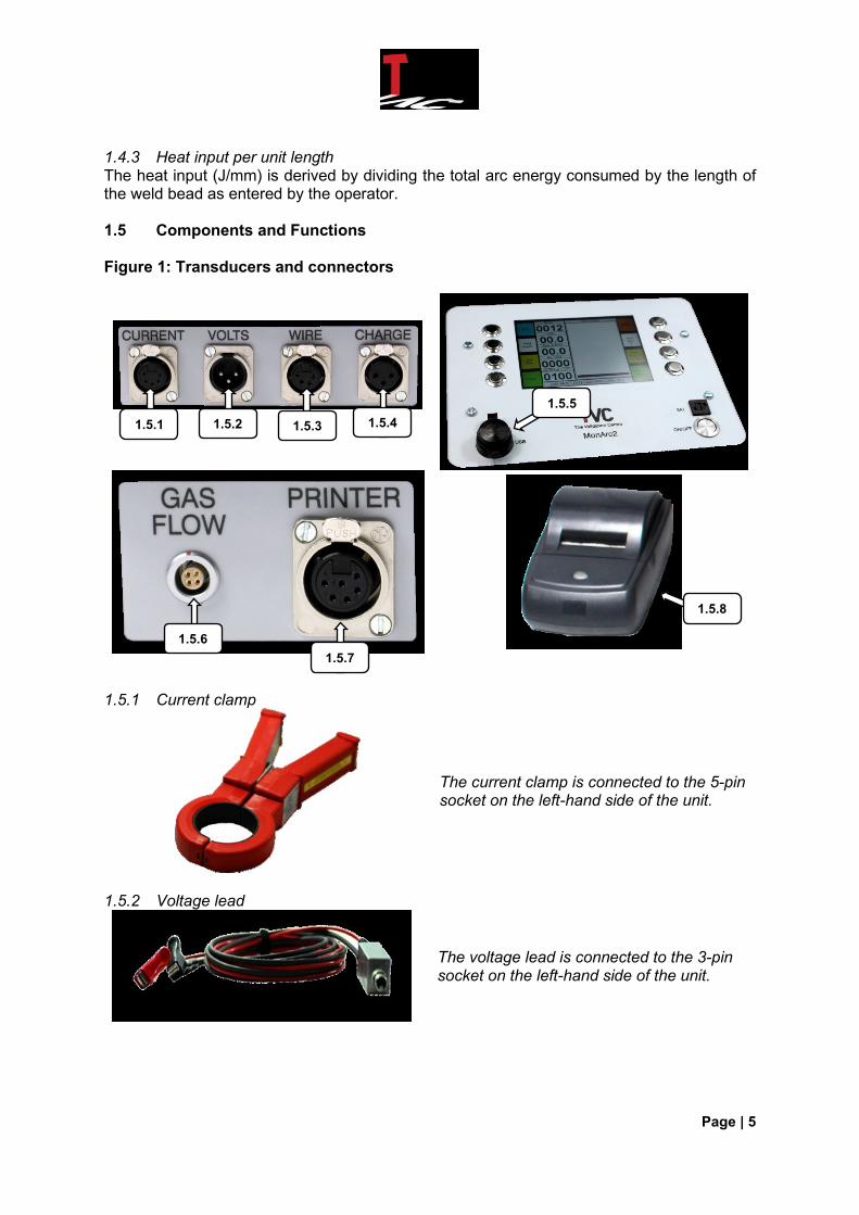
1.4.3 Heat input per unit length The heat input (J/mm) is derived by dividing the total arc energy consumed by the length of the weld bead as entered by the operator. 1.5 Components and Functions Figure 1: Transducers and connectors
1.5.1 Current clamp
The current clamp is connected to the 5-pin socket on the left-hand side of the unit.
1.5.2 Voltage lead
The voltage lead is connected to the 3-pin socket on the left-hand side of the unit.
1.5.1
1.5.8
1.5.5
1.5.4 1.5.3 1.5.2
1.5.6
1.5.7

Page | 6
1.5.3 Wire feed speed (optional)
The wire feed speed encoder is connected to the 4-pin socket on the left-hand side of the unit.
1.5.4 Battery charger The 3-stage battery charger is connected to the 3-pin socket on the left-hand side of the unit.
1.5.5 USB The USB socket with protective cover is located on the front panel of the MonArc2.
NB: Always ensure that the MonArc2 unit is switched off when connecting or disconnecting the USB pen stick. 1.5.6 Gas flow port The gas flow port is located on the right-hand side of the unit. 1.5.7 Printer connection socket The connection for the optional hard copy printer is located on the right-hand side of the unit. 1.5.8 Hard copy printer The hard copy printer is located on the right-hand side of the unit. For additional information on the hard copy printer, please see Section 3 in this manual. Figure 2: Front panel layout
A1 MonArc2 display screen A2 Menu selection push buttons A3 USB socket A4 Fuse (20mm / 3 amp) A5 On / Off button
A2
A4
A5
A3
A1
A2
Page | 7
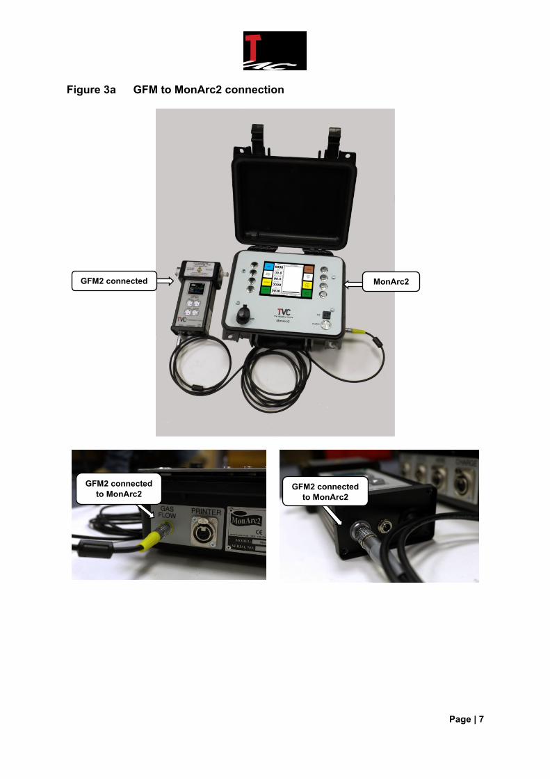
Figure 3a GFM to MonArc2 connection
GFM2 connected
to MonArc2
GFM2 connected
to MonArc2
MonArc2 GFM2 connected
Page | 8
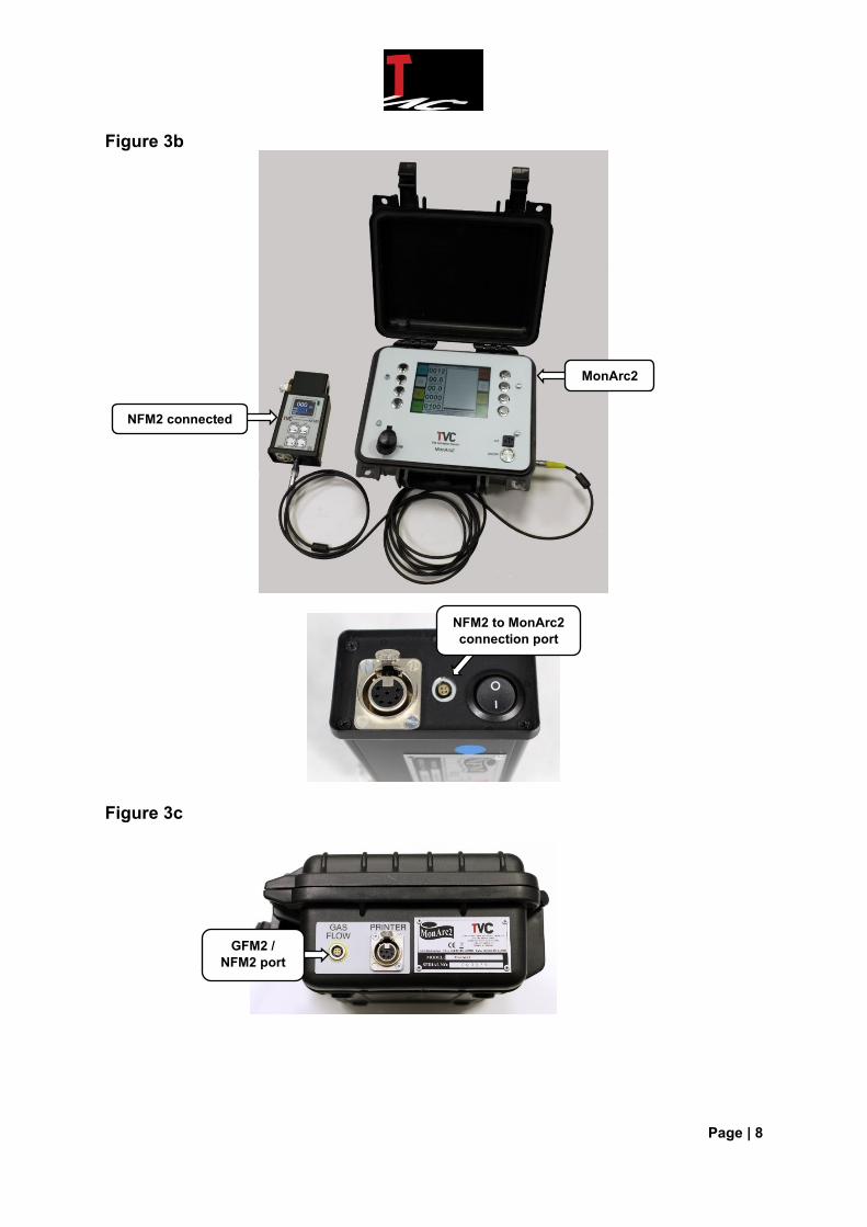
Figure 3b
Figure 3c
GFM2 /
NFM2 port
MonArc2
NFM2 connected
NFM2 to MonArc2
connection port

Page | 9
2.0 Operating instructions for standard MonArc2 (no options) 2.1 Pre-checks and installation 2.1.1 Firmly press the on / off button (A5; Fig 2) to ‘On’.
‘Off’ position ‘On’ position
2.1.2 Check the battery status; this is displayed at the bottom of the main menu screen next to the date and time. If there is enough battery charge, proceed with setting up the MonArc2. If the battery level is low, recharge the unit. For information on the battery status display and battery charging instructions, refer to Section’s 2.7 and 2.8. 2.1.3 Switch the MonArc2 off by firmly pressing the on / off button (Fig 2; A3) to ‘Off’. 2.1.4 If the optional hard copy printer is fitted, then check the amount of paper available to carry out welding operation; if insufficient refer to Section 3.1. 2.1.5 Connect current clamp to current socket (Fig. 1; 1.5.1) and clamp hall effect probe over the earth return welding cable ensuring that the correct polarity is observed. For further details on connecting the MonArc2 correctly, see connection drawings, Figures 3a and 3b, at the end of this section. 2.1.6 Connect voltage cable to voltage socket (Fig 1; 1.5.2) and connect the black clip to the work piece earth and the red clip as close to the welding arc as possible for negative earth welding, reverse the connections for positive earth welding. NB: It is very important to connect the clip as close as possible to the welding arc as there can be a considerable voltage drop between the welding set output terminals and the welding head. See Figures 3a and 3b for typical connection points.
Page | 10
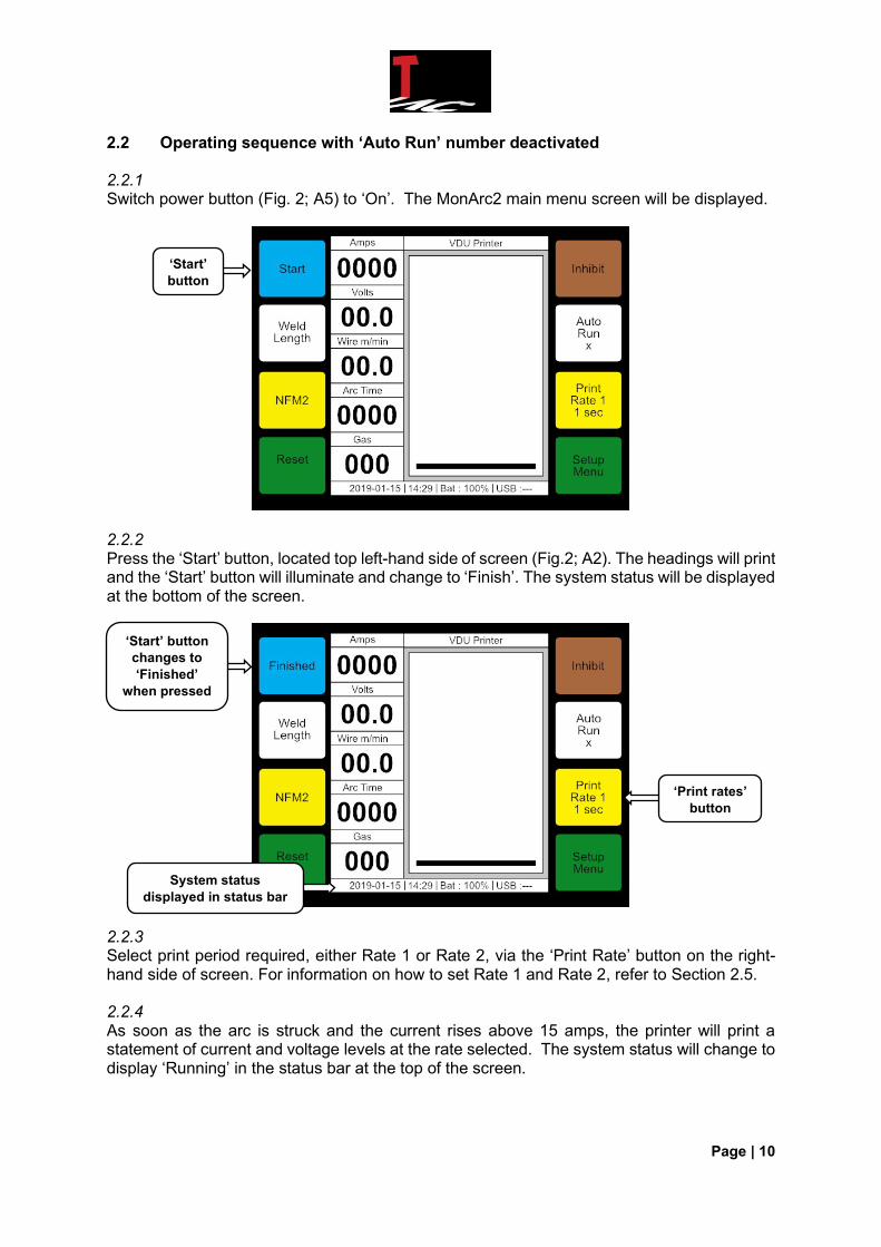
2.2 Operating sequence with ‘Auto Run’ number deactivated 2.2.1 Switch power button (Fig. 2; A5) to ‘On’. The MonArc2 main menu screen will be displayed.
2.2.2 Press the ‘Start’ button, located top left-hand side of screen (Fig.2; A2). The headings will print and the ‘Start’ button will illuminate and change to ‘Finish’. The system status will be displayed at the bottom of the screen.
2.2.3 Select print period required, either Rate 1 or Rate 2, via the ‘Print Rate’ button on the right-hand side of screen. For information on how to set Rate 1 and Rate 2, refer to Section 2.5. 2.2.4 As soon as the arc is struck and the current rises above 15 amps, the printer will print a statement of current and voltage levels at the rate selected. The system status will change to display ‘Running’ in the status bar at the top of the screen.
‘Start’
button
‘Print rates’
button
System status
displayed in status bar
‘Start’ button
changes to
‘Finished’
when pressed
Page | 11
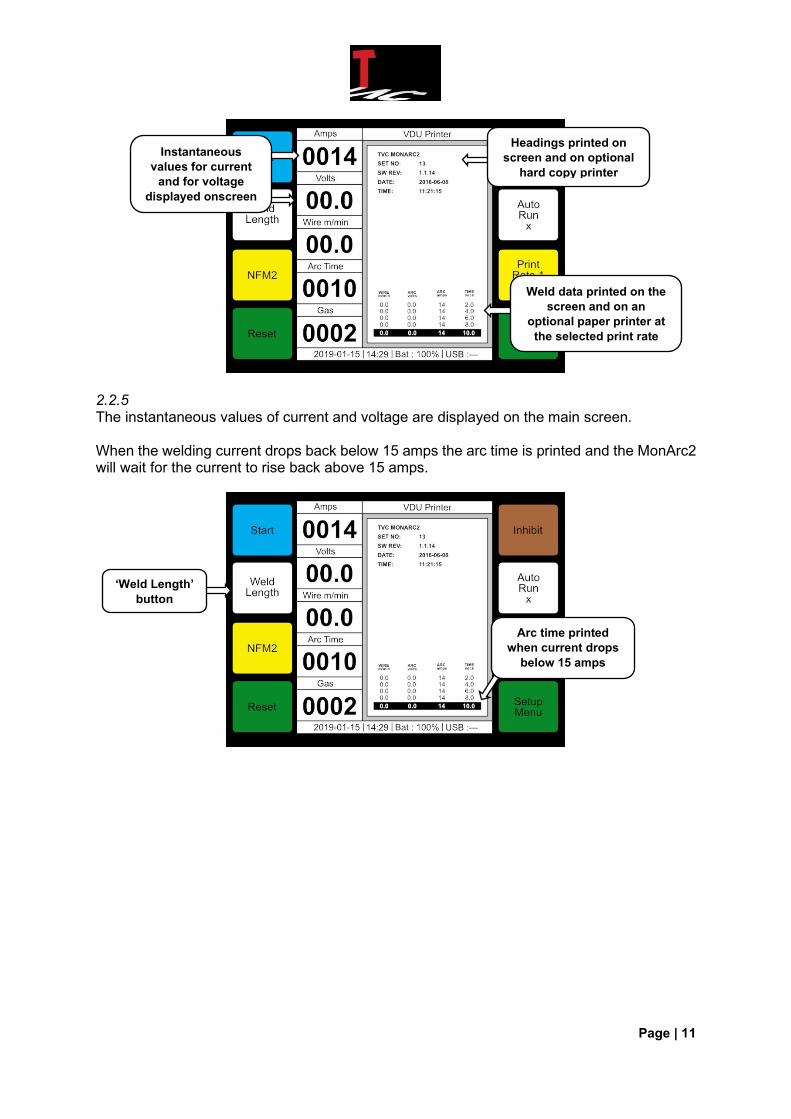
2.2.5 The instantaneous values of current and voltage are displayed on the main screen. When the welding current drops back below 15 amps the arc time is printed and the MonArc2 will wait for the current to rise back above 15 amps.
Instantaneous
values for current
and for voltage
displayed onscreen
‘Weld Length’
button
Arc time printed
when current drops
below 15 amps
Headings printed on
screen and on optional
hard copy printer
Weld data printed on the
screen and on an
optional paper printer at
the selected print rate
Page | 12
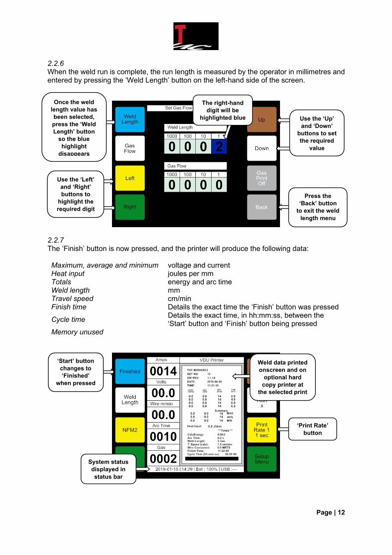
2.2.6 When the weld run is complete, the run length is measured by the operator in millimetres and entered by pressing the ‘Weld Length’ button on the left-hand side of the screen.
2.2.7 The ‘Finish’ button is now pressed, and the printer will produce the following data: Maximum, average and minimum voltage and current Heat input joules per mm Totals energy and arc time Weld length mm Travel speed cm/min Finish time Details the exact time the ‘Finish’ button was pressed
Cycle time Details the exact time, in hh:mm:ss, between the ‘Start’ button and ‘Finish’ button being pressed
Memory unused
Once the weld
length value has
been selected,
press the ‘Weld
Length’ button
so the blue
highlight
disappears
Use the ‘Left’
and ‘Right’
buttons to
highlight the
required digit
The right-hand
digit will be
highlighted blue
Press the
‘Back’ button
to exit the weld
length menu
Use the ‘Up’
and ‘Down’
buttons to set
the required
value
‘Print Rate’
button
‘Start’ button
changes to
‘Finished’
when pressed
System status
displayed in
status bar
Weld data printed
onscreen and on
optional hard
copy printer at
the selected print
rate(S)
Page | 13
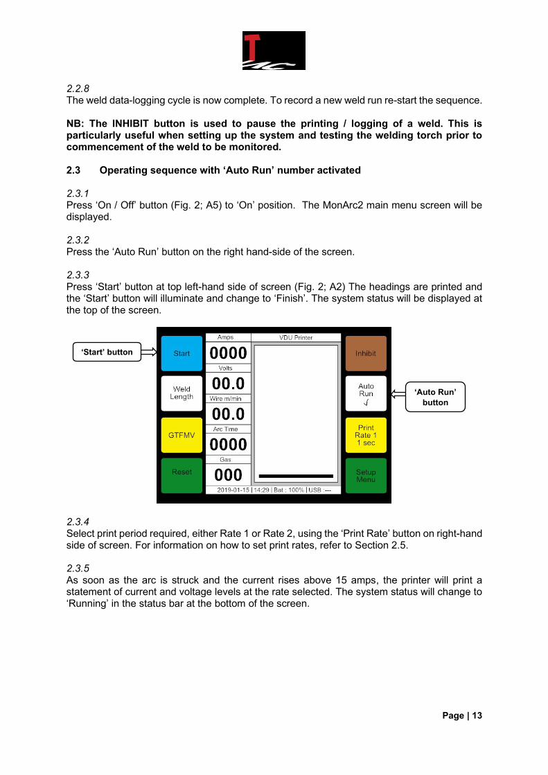
2.2.8 The weld data-logging cycle is now complete. To record a new weld run re-start the sequence. NB: The INHIBIT button is used to pause the printing / logging of a weld. This is particularly useful when setting up the system and testing the welding torch prior to commencement of the weld to be monitored. 2.3 Operating sequence with ‘Auto Run’ number activated 2.3.1 Press ‘On / Off’ button (Fig. 2; A5) to ‘On’ position. The MonArc2 main menu screen will be displayed. 2.3.2 Press the ‘Auto Run’ button on the right hand-side of the screen. 2.3.3 Press ‘Start’ button at top left-hand side of screen (Fig. 2; A2) The headings are printed and the ‘Start’ button will illuminate and change to ‘Finish’. The system status will be displayed at the top of the screen.
2.3.4 Select print period required, either Rate 1 or Rate 2, using the ‘Print Rate’ button on right-hand side of screen. For information on how to set print rates, refer to Section 2.5. 2.3.5 As soon as the arc is struck and the current rises above 15 amps, the printer will print a statement of current and voltage levels at the rate selected. The system status will change to ‘Running’ in the status bar at the bottom of the screen.
‘Auto Run’
button
‘Start’ button
Page | 14
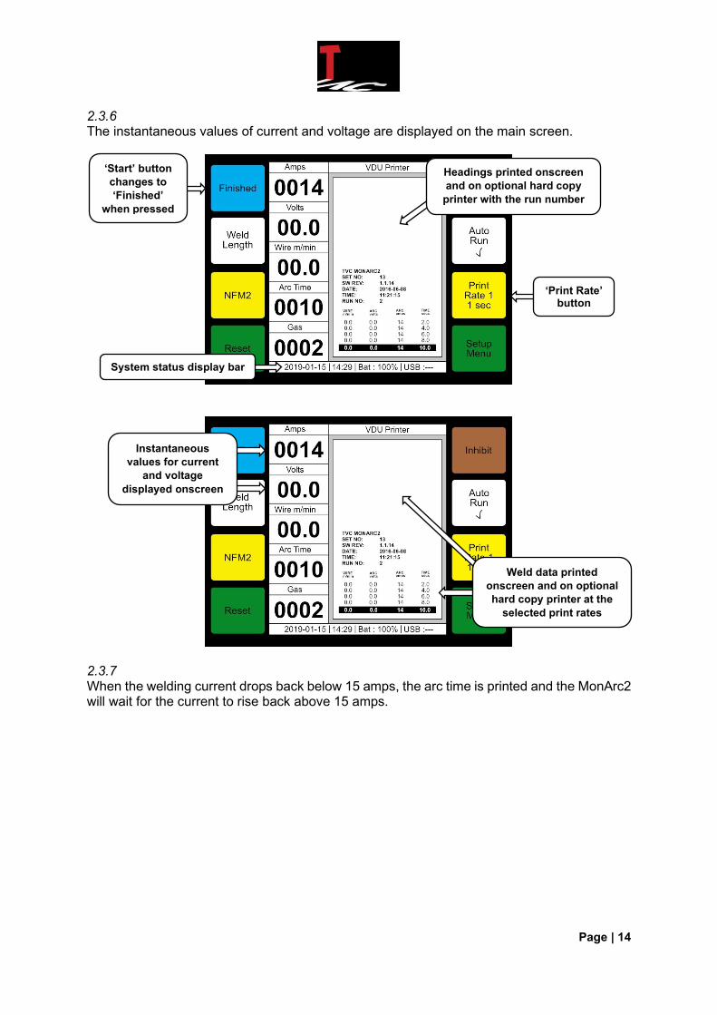
2.3.6 The instantaneous values of current and voltage are displayed on the main screen.
2.3.7
When the welding current drops back below 15 amps, the arc time is printed and the MonArc2 will wait for the current to rise back above 15 amps.
‘Start’ button
changes to
‘Finished’
when pressed
System status display bar
‘Print Rate’ button
Headings printed onscreen
and on optional hard copy
printer with the run number
Instantaneous
values for current
and voltage
displayed onscreen
Weld data printed
onscreen and on optional
hard copy printer at the
selected print rates
Page | 15
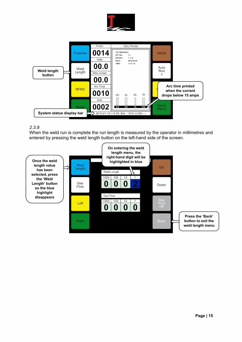
2.3.8 When the weld run is complete the run length is measured by the operator in millimetres and entered by pressing the weld length button on the left-hand side of the screen.
Arc time printed
when the current
drops below 15 amps
System status display bar
Weld length button
Once the weld
length value
has been
selected, press
the ‘Weld
Length’ button
so the blue
highlight
disappears
Press the ‘Back’
button to exit the
weld length menu
On entering the weld
length menu, the
right-hand digit will be
highlighted in blue
Page | 16
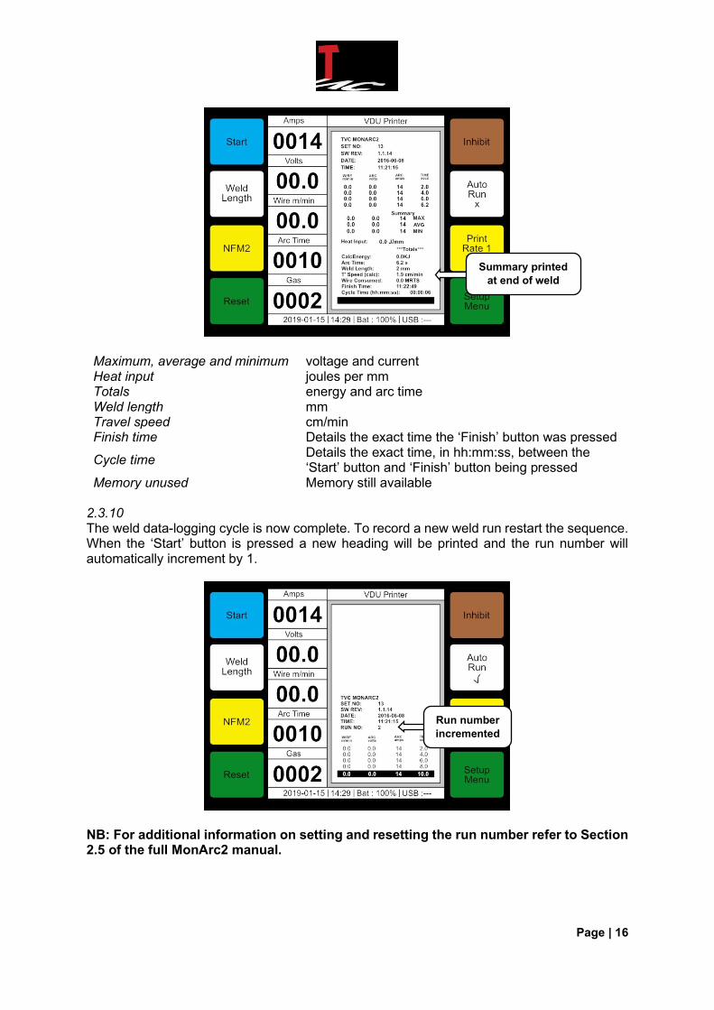
Maximum, average and minimum voltage and current Heat input joules per mm Totals energy and arc time Weld length mm Travel speed cm/min Finish time Details the exact time the ‘Finish’ button was pressed
Cycle time Details the exact time, in hh:mm:ss, between the ‘Start’ button and ‘Finish’ button being pressed
Memory unused Memory still available 2.3.10 The weld data-logging cycle is now complete. To record a new weld run restart the sequence. When the ‘Start’ button is pressed a new heading will be printed and the run number will automatically increment by 1.
NB: For additional information on setting and resetting the run number refer to Section 2.5 of the full MonArc2 manual.
Run number
incremented
Summary printed
at end of weld
Page | 17
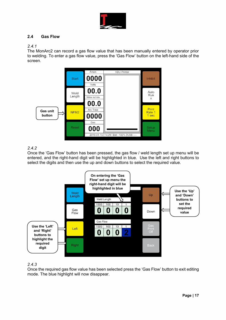
2.4 Gas Flow 2.4.1 The MonArc2 can record a gas flow value that has been manually entered by operator prior to welding. To enter a gas flow value, press the ‘Gas Flow’ button on the left-hand side of the screen.
2.4.2 Once the ‘Gas Flow’ button has been pressed, the gas flow / weld length set up menu will be entered, and the right-hand digit will be highlighted in blue. Use the left and right buttons to select the digits and then use the up and down buttons to select the required value.
2.4.3 Once the required gas flow value has been selected press the ‘Gas Flow’ button to exit editing mode. The blue highlight will now disappear.
Gas unit
button
Use the ‘Left’
and ‘Right’
buttons to
highlight the
required
digit
On entering the ‘Gas
Flow’ set up menu the
right-hand digit will be
highlighted in blue Use the ‘Up’
and ‘Down’
buttons to
set the
required
value
Page | 18
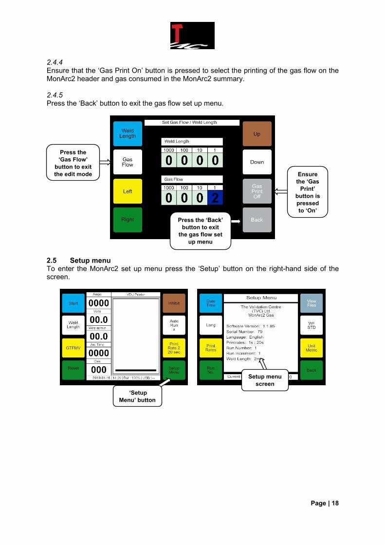
2.4.4 Ensure that the ‘Gas Print On’ button is pressed to select the printing of the gas flow on the MonArc2 header and gas consumed in the MonArc2 summary. 2.4.5 Press the ‘Back’ button to exit the gas flow set up menu.
2.5 Setup menu To enter the MonArc2 set up menu press the ‘Setup’ button on the right-hand side of the screen.
Press the
‘Gas Flow’
button to exit
the edit mode
Press the ‘Back’
button to exit
the gas flow set
up menu
Ensure
the ‘Gas
Print’
button is
pressed
to ‘On’
Setup menu
screen
‘Setup
Menu’ button
Page | 19
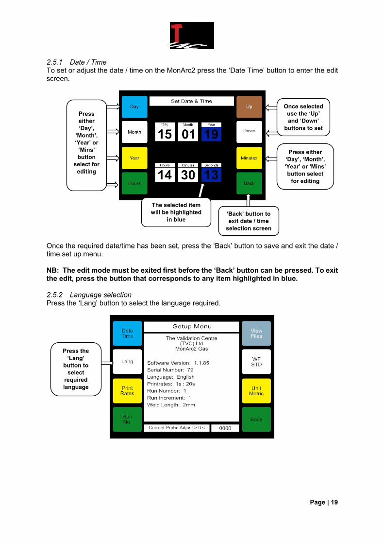
2.5.1 Date / Time To set or adjust the date / time on the MonArc2 press the ‘Date Time’ button to enter the edit screen.
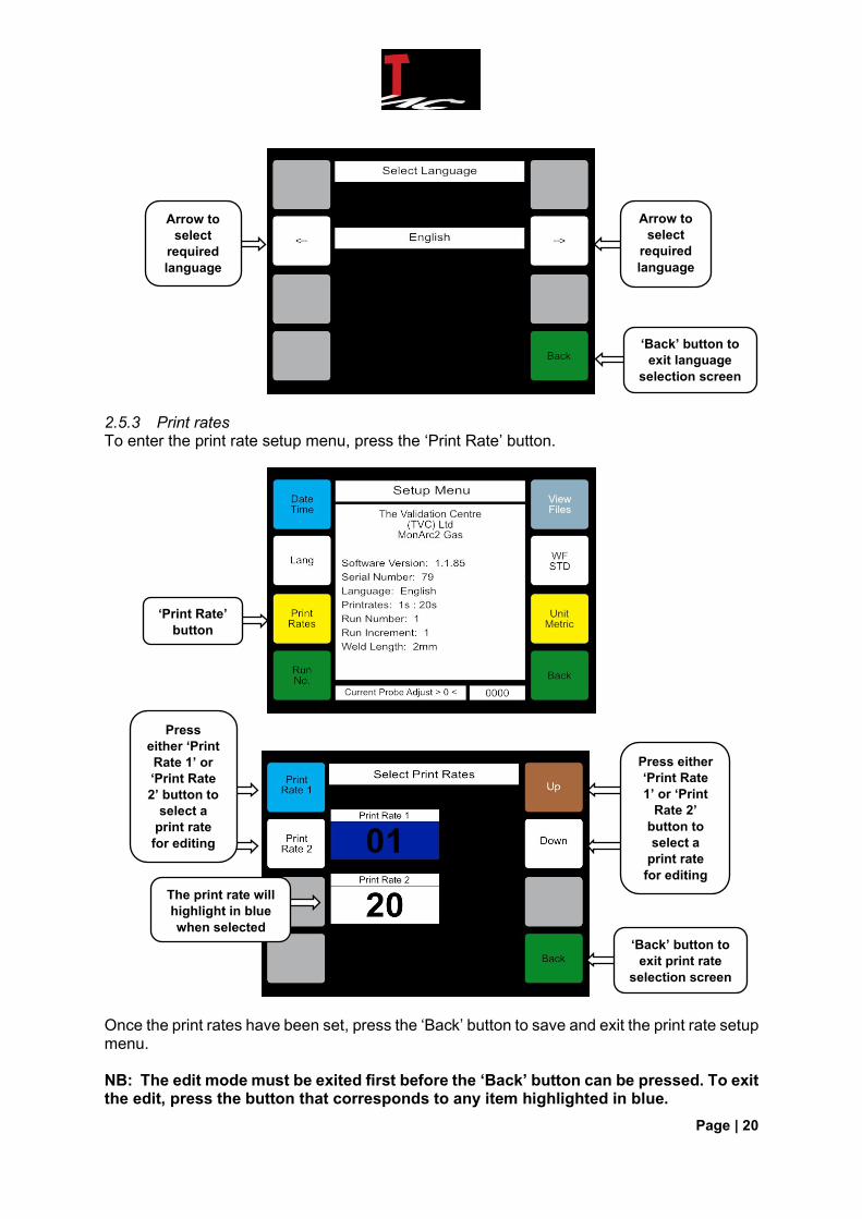
Once the required date/time has been set, press the ‘Back’ button to save and exit the date / time set up menu. NB: The edit mode must be exited first before the ‘Back’ button can be pressed. To exit the edit, press the button that corresponds to any item highlighted in blue. 2.5.2 Language selection Press the ‘Lang’ button to select the language required.
The selected item
will be highlighted
in blue
Press
either
‘Day’,
‘Month’,
‘Year’ or
‘Mins’
button
select for
editing
Press either
‘Day’, ‘Month’,
‘Year’ or ‘Mins’
button select
for editing
Once selected
use the ‘Up’
and ‘Down’
buttons to set
Press the
‘Lang’
button to
select
required
language
‘Back’ button to
exit date / time
selection screen
Page | 20
2.5.3 Print rates To enter the print rate setup menu, press the ‘Print Rate’ button.
Once the print rates have been set, press the ‘Back’ button to save and exit the print rate setup menu. NB: The edit mode must be exited first before the ‘Back’ button can be pressed. To exit the edit, press the button that corresponds to any item highlighted in blue.
Arrow to
select
required
language
Arrow to
select
required
language
‘Back’ button to
exit language
selection screen
Press
either ‘Print
Rate 1’ or
‘Print Rate
2’ button to
select a
print rate
for editing
The print rate will
highlight in blue
when selected
Press either
‘Print Rate
1’ or ‘Print
Rate 2’
button to
select a
print rate
for editing
‘Back’ button to
exit print rate
selection screen
‘Print Rate’
button
Page | 21
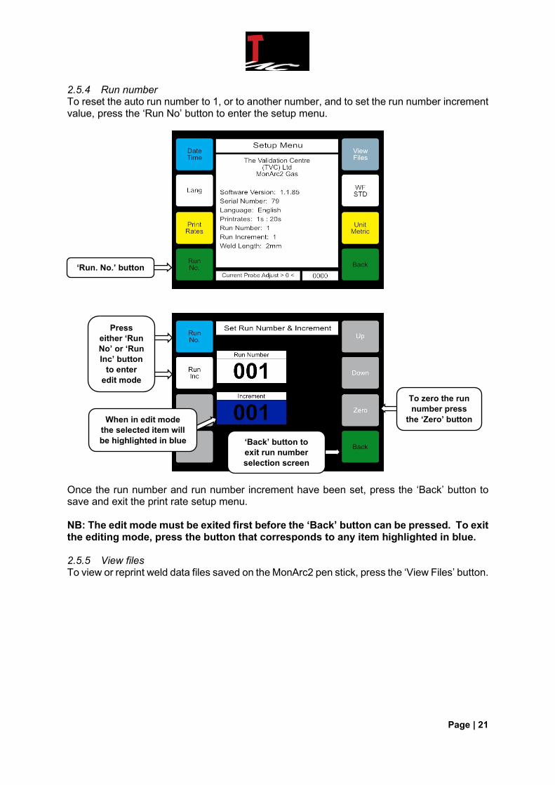
2.5.4 Run number To reset the auto run number to 1, or to another number, and to set the run number increment value, press the ‘Run No’ button to enter the setup menu.
Once the run number and run number increment have been set, press the ‘Back’ button to save and exit the print rate setup menu. NB: The edit mode must be exited first before the ‘Back’ button can be pressed. To exit the editing mode, press the button that corresponds to any item highlighted in blue. 2.5.5 View files To view or reprint weld data files saved on the MonArc2 pen stick, press the ‘View Files’ button.
‘Run. No.’ button
To zero the run
number press
the ‘Zero’ button When in edit mode
the selected item will
be highlighted in blue
Press
either ‘Run
No’ or ‘Run
Inc’ button
to enter
edit mode
‘Back’ button to
exit run number
selection screen
Page | 22
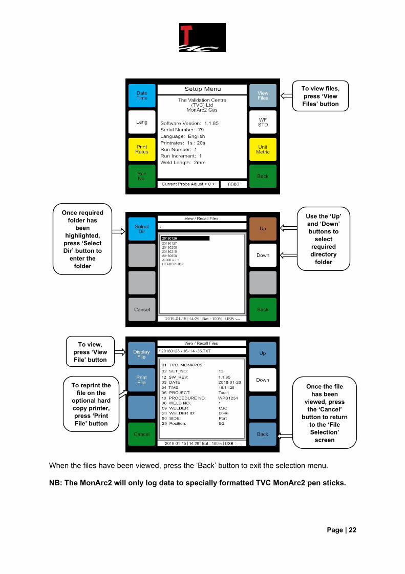
When the files have been viewed, press the ‘Back’ button to exit the selection menu. NB: The MonArc2 will only log data to specially formatted TVC MonArc2 pen sticks.
To view,
press ‘View
File’ button
Once required
folder has
been
highlighted,
press ‘Select
Dir’ button to
enter the
folder
To view files,
press ‘View
Files’ button
Use the ‘Up’
and ‘Down’
buttons to
select
required
directory
folder
Once the file
has been
viewed, press
the ‘Cancel’
button to return
to the ‘File
Selection’
screen
To reprint the
file on the
optional hard
copy printer,
press ‘Print
File’ button
Page | 23
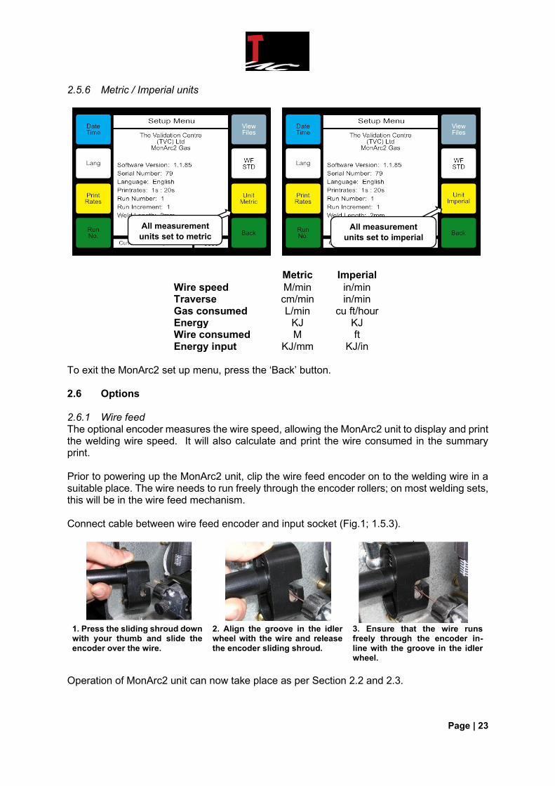
2.5.6 Metric / Imperial units
Metric Imperial
Wire speed M/min in/min Traverse cm/min in/min Gas consumed L/min cu ft/hour Energy KJ KJ Wire consumed M ft Energy input KJ/mm KJ/in
To exit the MonArc2 set up menu, press the ‘Back’ button. 2.6 Options 2.6.1 Wire feed The optional encoder measures the wire speed, allowing the MonArc2 unit to display and print the welding wire speed. It will also calculate and print the wire consumed in the summary print. Prior to powering up the MonArc2 unit, clip the wire feed encoder on to the welding wire in a suitable place. The wire needs to run freely through the encoder rollers; on most welding sets, this will be in the wire feed mechanism. Connect cable between wire feed encoder and input socket (Fig.1; 1.5.3).
1. Press the sliding shroud down with your thumb and slide the encoder over the wire.
2. Align the groove in the idler wheel with the wire and release the encoder sliding shroud.
3. Ensure that the wire runs freely through the encoder in-line with the groove in the idler wheel.
Operation of MonArc2 unit can now take place as per Section 2.2 and 2.3.
All measurement
units set to metric All measurement
units set to imperial
Page | 24
NB: Ensure that the correct size grooved idler wheel is fitted to the encoder prior to attachment to the wire feeder. There are four diameter ranges available:
Groove Depth (mm) Wire Diameter Range (mm) 0.5 0.6 to 1.6 1.0 1.0 to 2.8 1.6 1.6 to 4.5 2.1 2.0 to 6.0
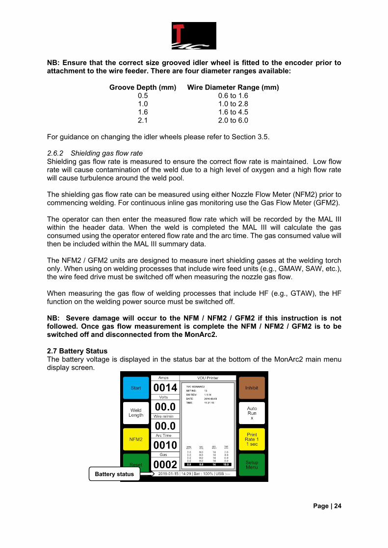
For guidance on changing the idler wheels please refer to Section 3.5. 2.6.2 Shielding gas flow rate Shielding gas flow rate is measured to ensure the correct flow rate is maintained. Low flow rate will cause contamination of the weld due to a high level of oxygen and a high flow rate will cause turbulence around the weld pool. The shielding gas flow rate can be measured using either Nozzle Flow Meter (NFM2) prior to commencing welding. For continuous inline gas monitoring use the Gas Flow Meter (GFM2). The operator can then enter the measured flow rate which will be recorded by the MAL III within the header data. When the weld is completed the MAL III will calculate the gas consumed using the operator entered flow rate and the arc time. The gas consumed value will then be included within the MAL III summary data. The NFM2 / GFM2 units are designed to measure inert shielding gases at the welding torch only. When using on welding processes that include wire feed units (e.g., GMAW, SAW, etc.), the wire feed drive must be switched off when measuring the nozzle gas flow. When measuring the gas flow of welding processes that include HF (e.g., GTAW), the HF function on the welding power source must be switched off. NB: Severe damage will occur to the NFM / NFM2 / GFM2 if this instruction is not followed. Once gas flow measurement is complete the NFM / NFM2 / GFM2 is to be switched off and disconnected from the MonArc2. 2.7 Battery Status The battery voltage is displayed in the status bar at the bottom of the MonArc2 main menu display screen.
Battery status

Page | 25
2.8 Battery charging The battery is a 12V lead-acid rechargeable. The nominal displayed battery level when fully charged is approximately 100%. When the battery voltage drops below 11V the battery level will be at approximately 20%. When the battery voltage drops to 10.5V, the MonArc2 unit will automatically switch off to preserve the battery. NB: The battery should be recharged before it drops to 10.5V. The battery can be charged overnight using the 2240 3-step charger. Ensure the MonArc2 is switched ‘Off’. Connect the 3-step charger to the MonArc2 charger input socket (Fig. 1; 1.5.4). Connect the charger to a suitable mains supply and the charger LED will show one of the following colours:
Red LED Bulk Charge The charger is in constant current mode.
Yellow LED Balancing charge The charger is in timer mode. The battery is normally between 80 and 95% charged when the LED changes to yellow.
Green LED Float Charge
The charger is in constant float mode. The battery is normally 100% charged. The charger can remain connected for up to 6 months in this state. The charger will revert to the timer mode if loaded.
Once fully charged, disconnect the charger from the mains supply prior to disconnecting the charger from the MonArc2 unit.
Page | 26
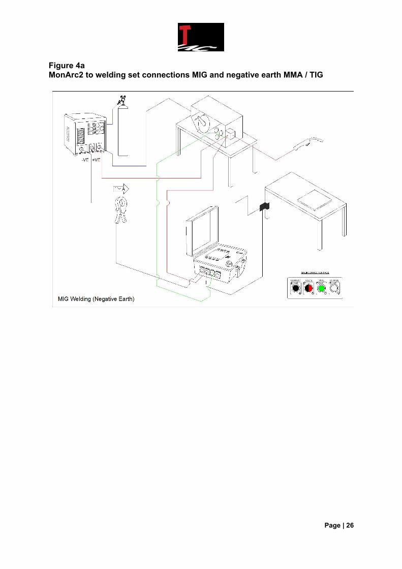
Figure 4a MonArc2 to welding set connections MIG and negative earth MMA / TIG

Page | 27
Figure 4b
MonArc2 to welding set connections positive earth MMA / TIG
Page | 28
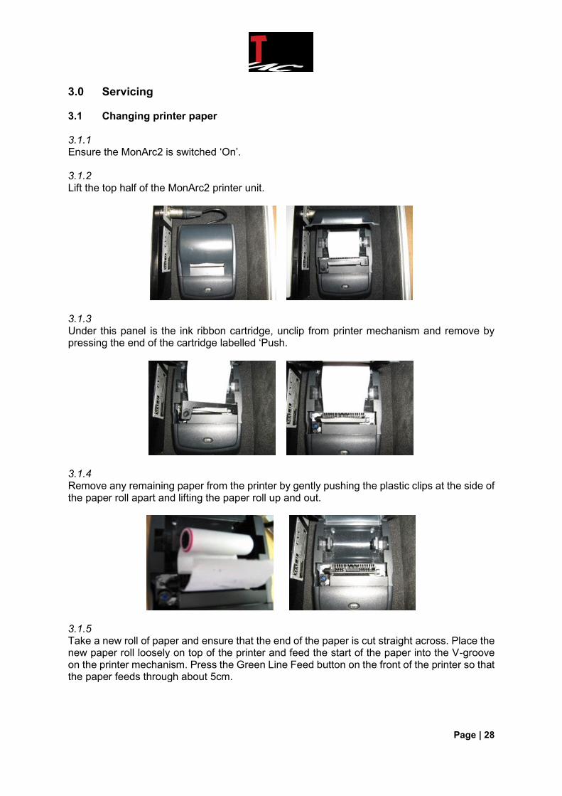
3.0 Servicing 3.1 Changing printer paper 3.1.1 Ensure the MonArc2 is switched ‘On’. 3.1.2 Lift the top half of the MonArc2 printer unit.
3.1.3 Under this panel is the ink ribbon cartridge, unclip from printer mechanism and remove by pressing the end of the cartridge labelled ‘Push.
3.1.4 Remove any remaining paper from the printer by gently pushing the plastic clips at the side of the paper roll apart and lifting the paper roll up and out.
3.1.5 Take a new roll of paper and ensure that the end of the paper is cut straight across. Place the new paper roll loosely on top of the printer and feed the start of the paper into the V-groove on the printer mechanism. Press the Green Line Feed button on the front of the printer so that the paper feeds through about 5cm.
Page | 29
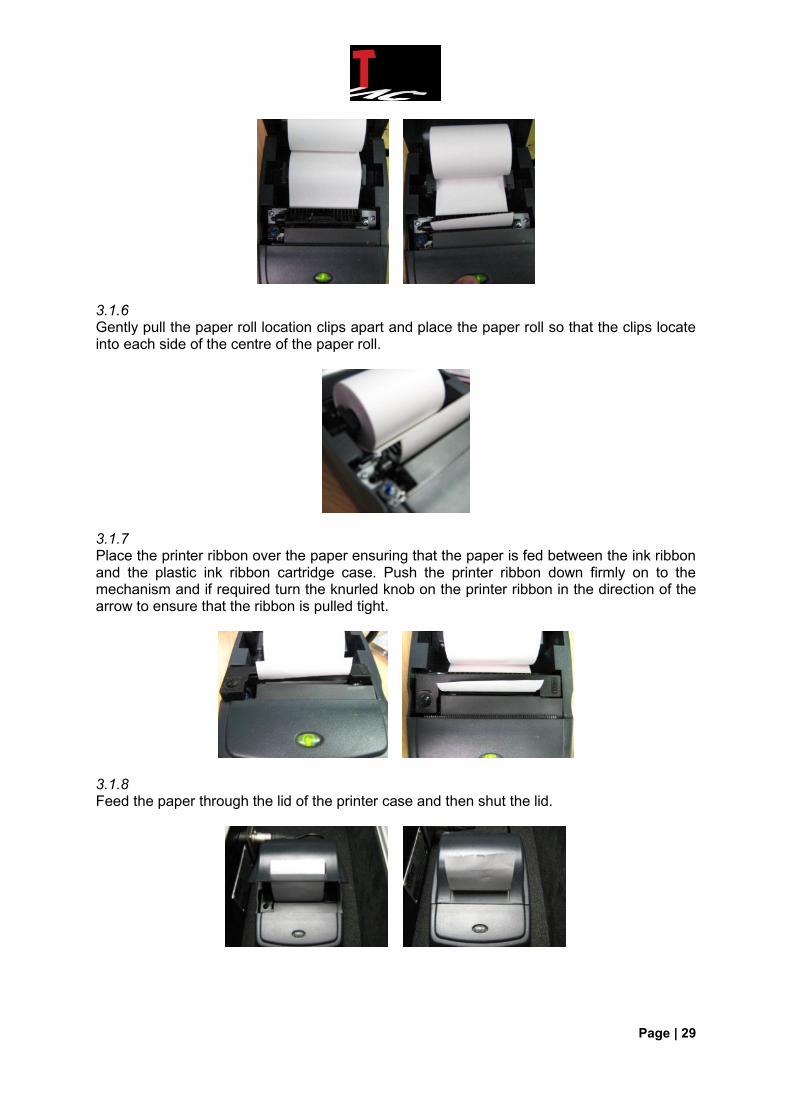
3.1.6 Gently pull the paper roll location clips apart and place the paper roll so that the clips locate into each side of the centre of the paper roll.
3.1.7 Place the printer ribbon over the paper ensuring that the paper is fed between the ink ribbon and the plastic ink ribbon cartridge case. Push the printer ribbon down firmly on to the mechanism and if required turn the knurled knob on the printer ribbon in the direction of the arrow to ensure that the ribbon is pulled tight.
3.1.8 Feed the paper through the lid of the printer case and then shut the lid.
Page | 30
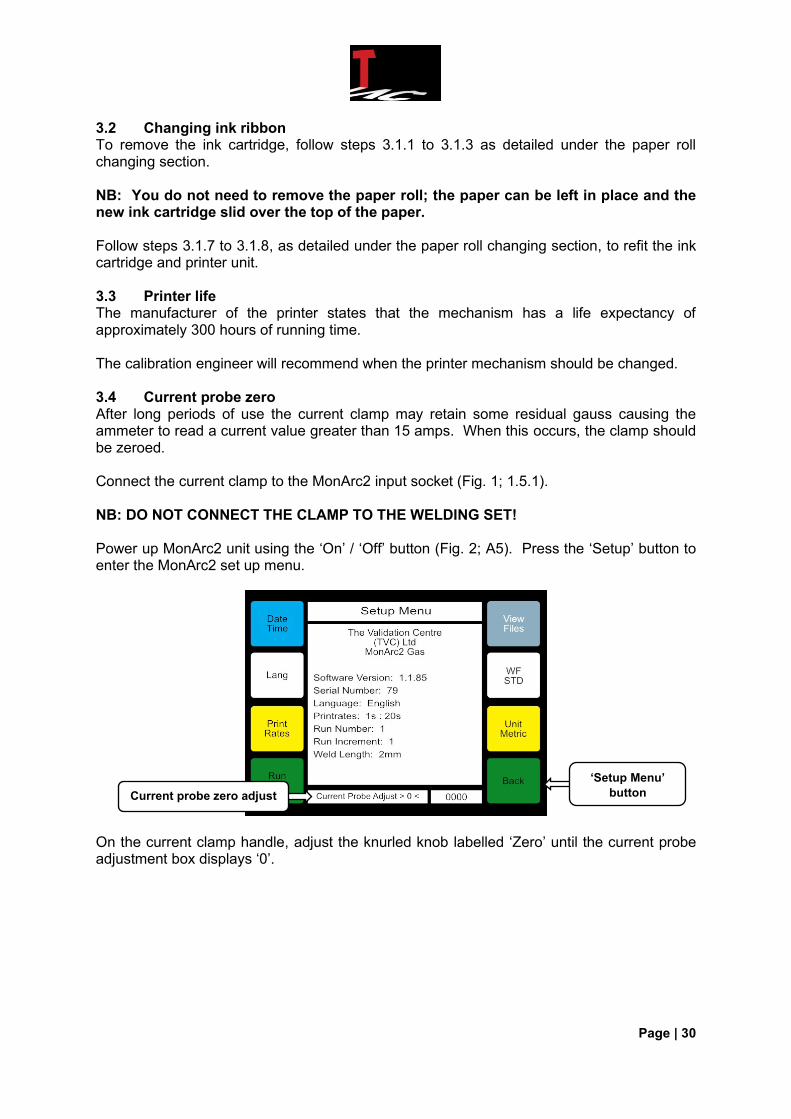
3.2 Changing ink ribbon To remove the ink cartridge, follow steps 3.1.1 to 3.1.3 as detailed under the paper roll changing section. NB: You do not need to remove the paper roll; the paper can be left in place and the new ink cartridge slid over the top of the paper. Follow steps 3.1.7 to 3.1.8, as detailed under the paper roll changing section, to refit the ink cartridge and printer unit. 3.3 Printer life The manufacturer of the printer states that the mechanism has a life expectancy of approximately 300 hours of running time. The calibration engineer will recommend when the printer mechanism should be changed. 3.4 Current probe zero After long periods of use the current clamp may retain some residual gauss causing the ammeter to read a current value greater than 15 amps. When this occurs, the clamp should be zeroed. Connect the current clamp to the MonArc2 input socket (Fig. 1; 1.5.1). NB: DO NOT CONNECT THE CLAMP TO THE WELDING SET! Power up MonArc2 unit using the ‘On’ / ‘Off’ button (Fig. 2; A5). Press the ‘Setup’ button to enter the MonArc2 set up menu.
On the current clamp handle, adjust the knurled knob labelled ‘Zero’ until the current probe adjustment box displays ‘0’.
Current probe zero adjust
‘Setup Menu’
button
Page | 31
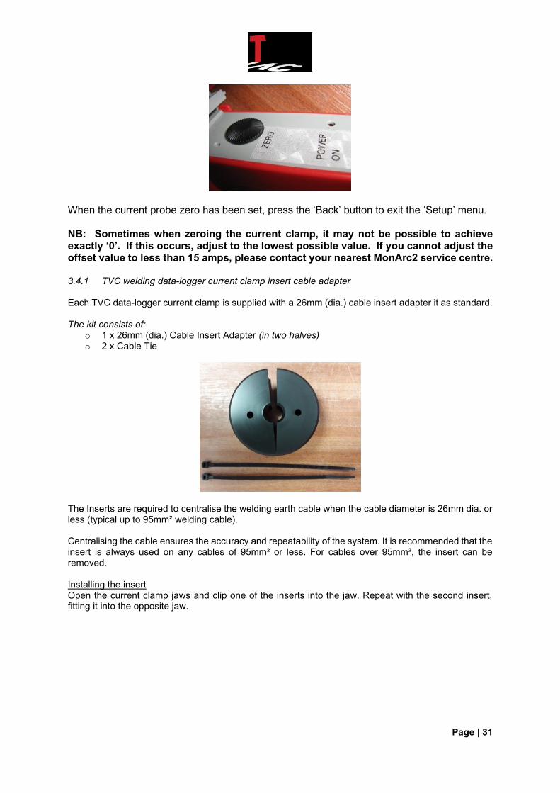
When the current probe zero has been set, press the ‘Back’ button to exit the ‘Setup’ menu. NB: Sometimes when zeroing the current clamp, it may not be possible to achieve exactly ‘0’. If this occurs, adjust to the lowest possible value. If you cannot adjust the offset value to less than 15 amps, please contact your nearest MonArc2 service centre. 3.4.1 TVC welding data-logger current clamp insert cable adapter Each TVC data-logger current clamp is supplied with a 26mm (dia.) cable insert adapter it as standard. The kit consists of:
o 1 x 26mm (dia.) Cable Insert Adapter (in two halves) o 2 x Cable Tie
The Inserts are required to centralise the welding earth cable when the cable diameter is 26mm dia. or less (typical up to 95mm² welding cable). Centralising the cable ensures the accuracy and repeatability of the system. It is recommended that the insert is always used on any cables of 95mm² or less. For cables over 95mm², the insert can be removed. Installing the insert Open the current clamp jaws and clip one of the inserts into the jaw. Repeat with the second insert, fitting it into the opposite jaw.

Page | 32
Ensure that the inserts are aligned with each jaw. Leave a small gap at the top and bottom of the clamp jaws so the clamp can open and shut smoothly. The jaws should shut correctly, touching each other and leaving no gap between the jaws.
Once the inserts have been fitted correctly, fit the cable ties through the hole in the insert and around the outer section of the clamp jaw. This will ensure that the insert is secured in place.
The welding earth cable should be aligned with the centre hole in the clamp insert.
Page | 33
As standard, all new clamps are supplied with the 26mm insert. For applications where smaller diameter, low current cables are used (i.e., 13mm dia. 25mm² or less), a 13mm insert can be supplied. The insert part numbers for reordering are: ALX/1003: 13mm Insert for 13mm Diameter (25mm²) cables and under
ALX/1004: 26mm Insert for 26mm Diameter (95mm²) cables and under
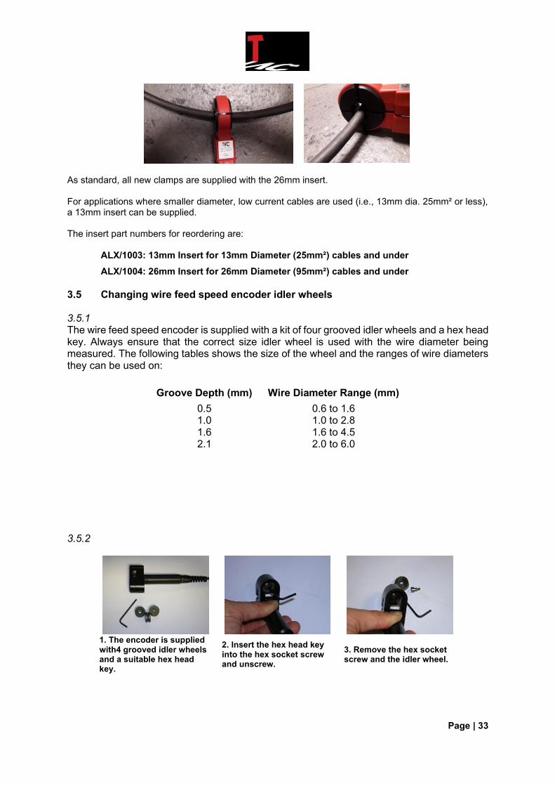
3.5 Changing wire feed speed encoder idler wheels 3.5.1 The wire feed speed encoder is supplied with a kit of four grooved idler wheels and a hex head key. Always ensure that the correct size idler wheel is used with the wire diameter being measured. The following tables shows the size of the wheel and the ranges of wire diameters they can be used on:
Groove Depth (mm) Wire Diameter Range (mm)
0.5 0.6 to 1.6 1.0 1.0 to 2.8 1.6 1.6 to 4.5 2.1 2.0 to 6.0
3.5.2
1. The encoder is supplied with4 grooved idler wheels and a suitable hex head key.
2. Insert the hex head key into the hex socket screw and unscrew.
3. Remove the hex socket screw and the idler wheel.
Page | 34
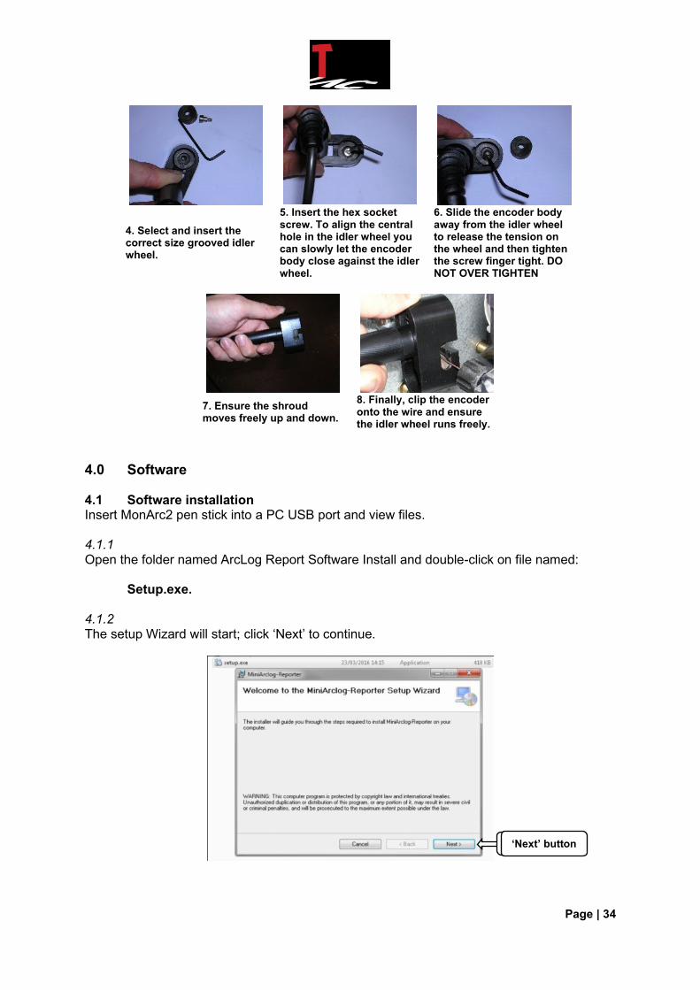
4. Select and insert the correct size grooved idler wheel.
5. Insert the hex socket screw. To align the central hole in the idler wheel you can slowly let the encoder body close against the idler wheel.
6. Slide the encoder body away from the idler wheel to release the tension on the wheel and then tighten the screw finger tight. DO NOT OVER TIGHTEN
7. Ensure the shroud moves freely up and down.
8. Finally, clip the encoder onto the wire and ensure the idler wheel runs freely.
4.0 Software 4.1 Software installation Insert MonArc2 pen stick into a PC USB port and view files. 4.1.1 Open the folder named ArcLog Report Software Install and double-click on file named: Setup.exe. 4.1.2 The setup Wizard will start; click ‘Next’ to continue.
‘Next’ button ‘Next’ button
Page | 35
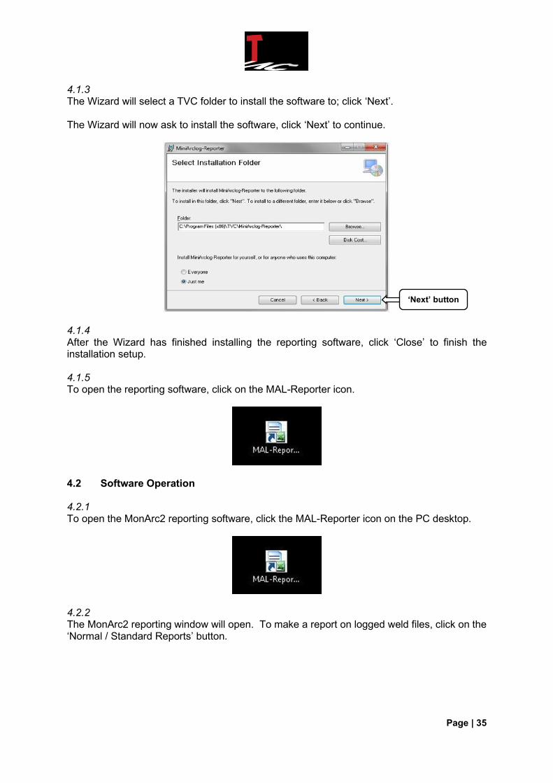
4.1.3 The Wizard will select a TVC folder to install the software to; click ‘Next’. The Wizard will now ask to install the software, click ‘Next’ to continue.
4.1.4 After the Wizard has finished installing the reporting software, click ‘Close’ to finish the installation setup. 4.1.5 To open the reporting software, click on the MAL-Reporter icon.
4.2 Software Operation 4.2.1 To open the MonArc2 reporting software, click the MAL-Reporter icon on the PC desktop.
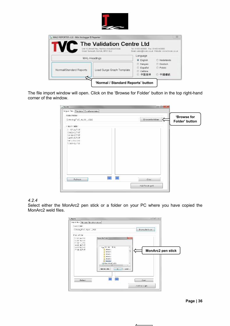
4.2.2 The MonArc2 reporting window will open. To make a report on logged weld files, click on the ‘Normal / Standard Reports’ button.
‘Next’ button
Page | 36
The file import window will open. Click on the ‘Browse for Folder’ button in the top right-hand corner of the window.
4.2.4 Select either the MonArc2 pen stick or a folder on your PC where you have copied the MonArc2 weld files.
‘Normal / Standard Reports’ button
‘Browse for
Folder’ button
MonArc2 pen stick
Page | 37
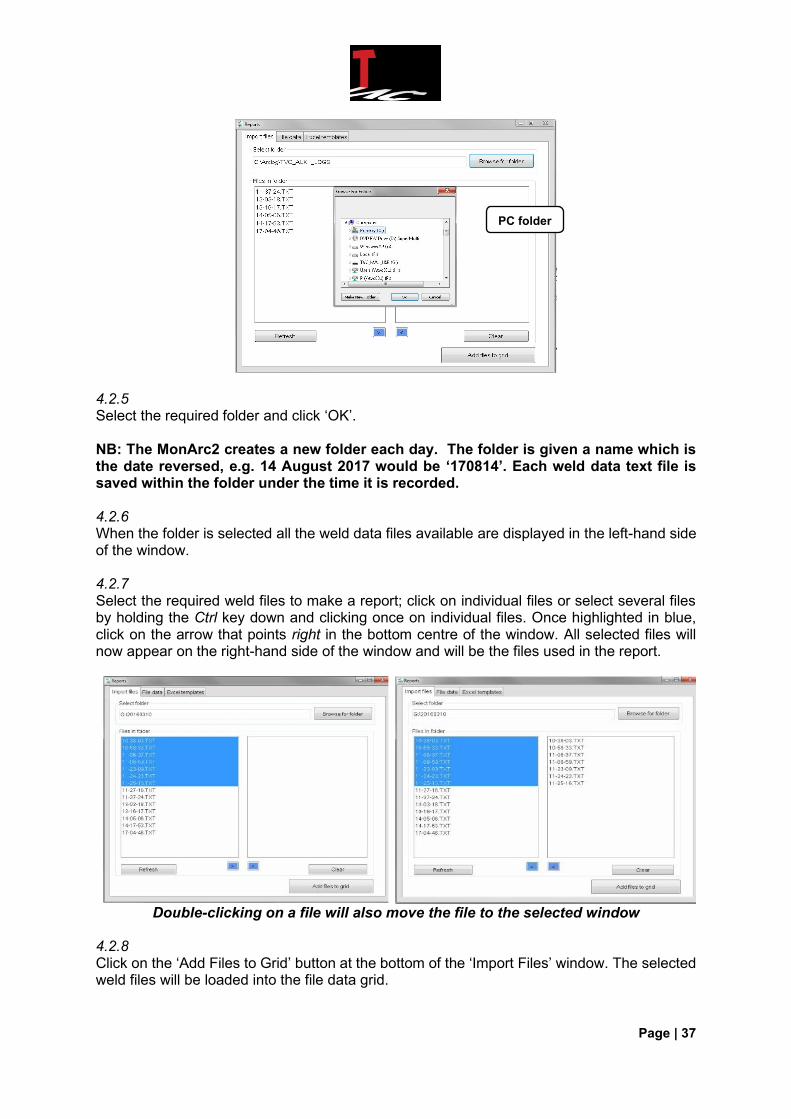
4.2.5 Select the required folder and click ‘OK’. NB: The MonArc2 creates a new folder each day. The folder is given a name which is the date reversed, e.g. 14 August 2017 would be ‘170814’. Each weld data text file is saved within the folder under the time it is recorded. 4.2.6 When the folder is selected all the weld data files available are displayed in the left-hand side of the window. 4.2.7 Select the required weld files to make a report; click on individual files or select several files by holding the Ctrl key down and clicking once on individual files. Once highlighted in blue, click on the arrow that points right in the bottom centre of the window. All selected files will now appear on the right-hand side of the window and will be the files used in the report.
Double-clicking on a file will also move the file to the selected window
4.2.8 Click on the ‘Add Files to Grid’ button at the bottom of the ‘Import Files’ window. The selected weld files will be loaded into the file data grid.
PC folder
Page | 38
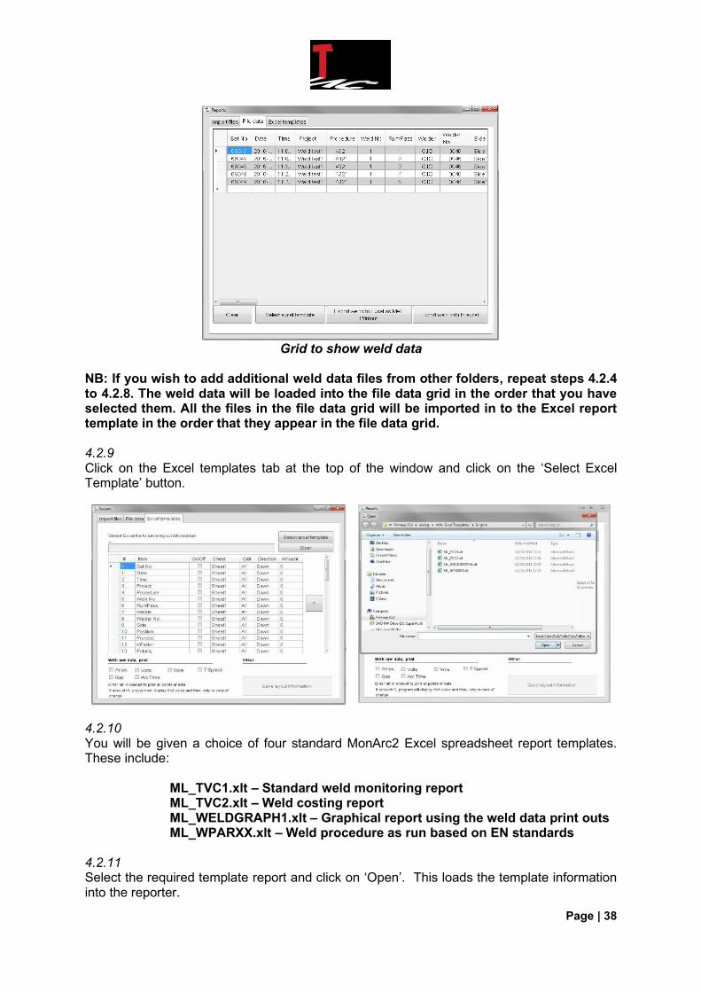
Grid to show weld data
NB: If you wish to add additional weld data files from other folders, repeat steps 4.2.4 to 4.2.8. The weld data will be loaded into the file data grid in the order that you have selected them. All the files in the file data grid will be imported in to the Excel report template in the order that they appear in the file data grid. 4.2.9 Click on the Excel templates tab at the top of the window and click on the ‘Select Excel Template’ button.
4.2.10 You will be given a choice of four standard MonArc2 Excel spreadsheet report templates. These include: ML_TVC1.xlt – Standard weld monitoring report ML_TVC2.xlt – Weld costing report ML_WELDGRAPH1.xlt – Graphical report using the weld data print outs ML_WPARXX.xlt – Weld procedure as run based on EN standards 4.2.11 Select the required template report and click on ‘Open’. This loads the template information into the reporter.
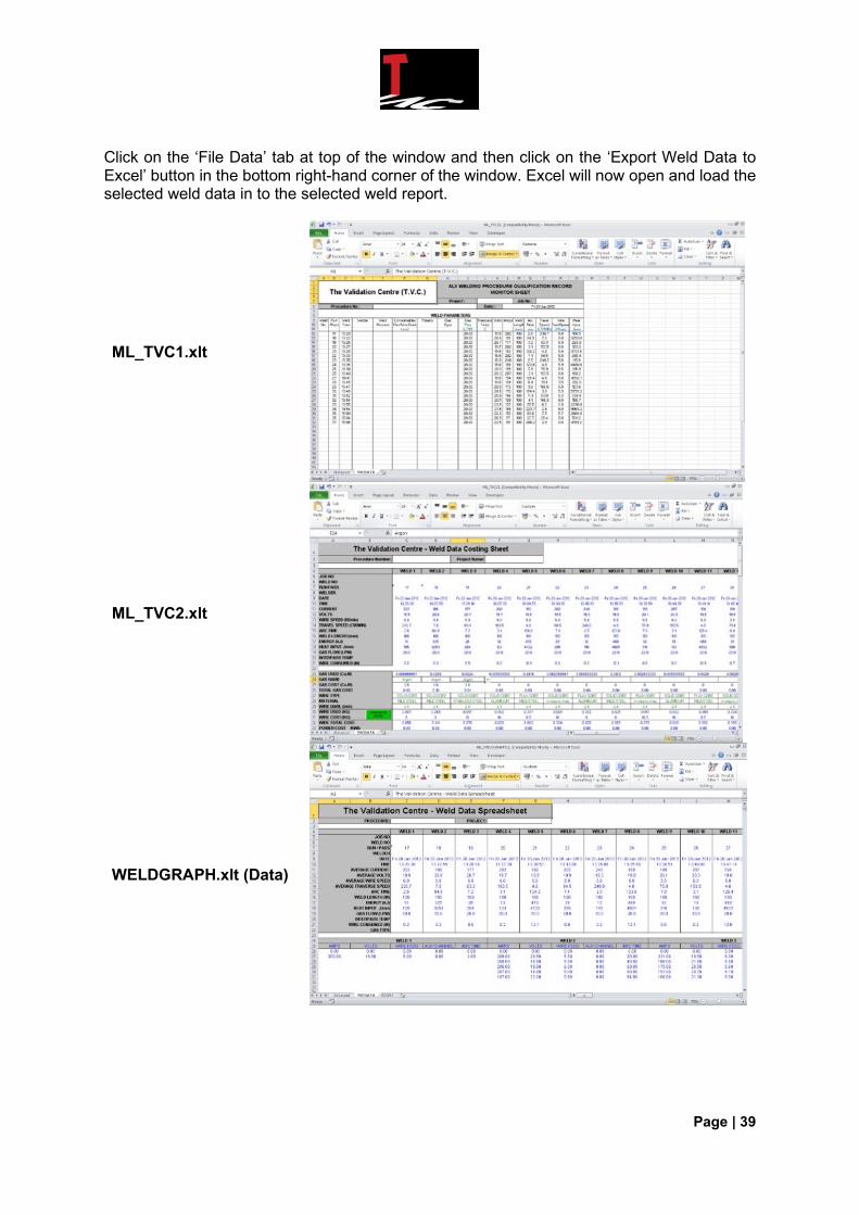
Page | 39
Click on the ‘File Data’ tab at top of the window and then click on the ‘Export Weld Data to Excel’ button in the bottom right-hand corner of the window. Excel will now open and load the selected weld data in to the selected weld report.
ML_TVC1.xlt
ML_TVC2.xlt
WELDGRAPH.xlt (Data)
Page | 40
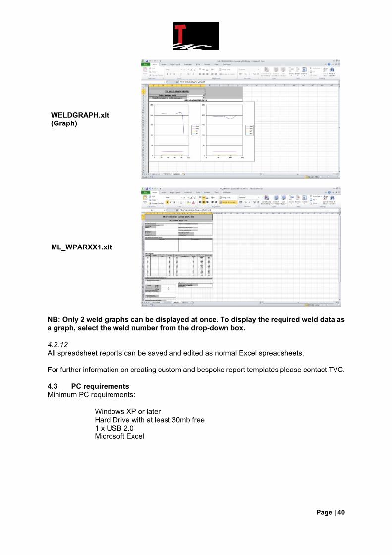
WELDGRAPH.xlt (Graph)
ML_WPARXX1.xlt
NB: Only 2 weld graphs can be displayed at once. To display the required weld data as a graph, select the weld number from the drop-down box. 4.2.12 All spreadsheet reports can be saved and edited as normal Excel spreadsheets. For further information on creating custom and bespoke report templates please contact TVC. 4.3 PC requirements Minimum PC requirements: Windows XP or later Hard Drive with at least 30mb free 1 x USB 2.0 Microsoft Excel

Page | 41
5.0 Troubleshooting and spares 5.1 Fault finding diagnosis This section is an operator guide to the most common faults that may be encountered whilst using an MonArc2; it is by no means an exhaustive list of all faults that may occur. 5.1.1 Fault: MonArc2 will not power up
1. Check the fuse on the front panel – if blown, replace and retry.
2. Place the battery on charge for about an hour (this will give enough charge to be able to power up the unit assuming the battery is flat). If the unit will now power up the problem was a flat battery, place battery on charge for a further two hours before using.
5.1.2 Fault: MonArc2 unit will not power down (on / off switch inoperative) With the on / off switch into the ‘off’ position, remove the unit fuse. The fuse is located next to the control switch group. Removal of the fuse will normally cause the unit to power down correctly. The fault is a sticking switch; if the problem becomes a regular occurrence, return the unit for repair and servicing. 5.1.3 Fault: MonArc2 unit powers up but starts printing weld data immediately This is because the current clamp needs to be zeroed. Refer to Section 3.4 for this procedure. 5.1.4 Fault: No current reading Check that the current clamp has been clamped around the correct cable. Ensure that the red Led on the inside of the current clamp handle is illuminated when the clamp is connected to the MonArc2 and switched on. 5.1.5 Fault: No voltage reading/low voltage reading Check that the connections have been made to the correct points, and that the connection points are clean and not corroded/dirty. If the voltage reading is incorrect (unusually low) check both connections have been made. The voltage input to the MonArc2 is a differential input and can read a spurious voltage if only one contact has been correctly made. 5.1.6 Fault: Wire feed reading unstable or non-existent Check the encoder and connections for signs of damage and check that the connections have been correctly made. If there is no obvious damage and all connections are secure do the following:
a. Check that the correct size grooved idler wheel is fitted to the encoder. See Section 3.5 for further information on wheel sizes and fitting.
b. Remove the shroud from the encoder, by removing the idler wheel and then by sliding
the encoder body out of the shroud.
c. Check that the drive roller has not become loose on the shaft of the encoder.
d. Check that the rollers are not heavily worn – if so, replace the drive and idler rollers. If none of the above applies, return the unit for investigation / repair.
Page | 42
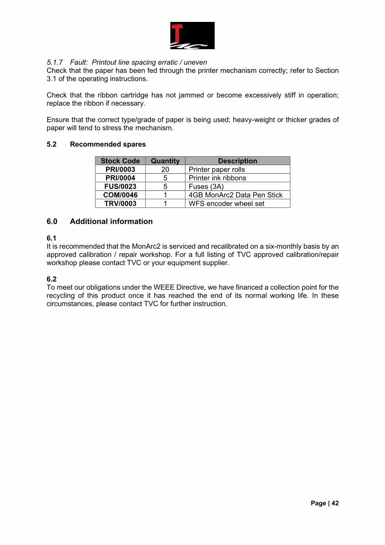
5.1.7 Fault: Printout line spacing erratic / uneven Check that the paper has been fed through the printer mechanism correctly; refer to Section 3.1 of the operating instructions. Check that the ribbon cartridge has not jammed or become excessively stiff in operation; replace the ribbon if necessary. Ensure that the correct type/grade of paper is being used; heavy-weight or thicker grades of paper will tend to stress the mechanism. 5.2 Recommended spares
Stock Code Quantity Description
PRI/0003 20 Printer paper rolls
PRI/0004 5 Printer ink ribbons
FUS/0023 5 Fuses (3A)
COM/0046 1 4GB MonArc2 Data Pen Stick
TRV/0003 1 WFS encoder wheel set
6.0 Additional information 6.1 It is recommended that the MonArc2 is serviced and recalibrated on a six-monthly basis by an approved calibration / repair workshop. For a full listing of TVC approved calibration/repair workshop please contact TVC or your equipment supplier. 6.2 To meet our obligations under the WEEE Directive, we have financed a collection point for the recycling of this product once it has reached the end of its normal working life. In these circumstances, please contact TVC for further instruction.