Quality control of fibrinogen secretion in the molecular pathogenesis of congenital afibrinogenemia
Upload
independentCategory
view
0download
0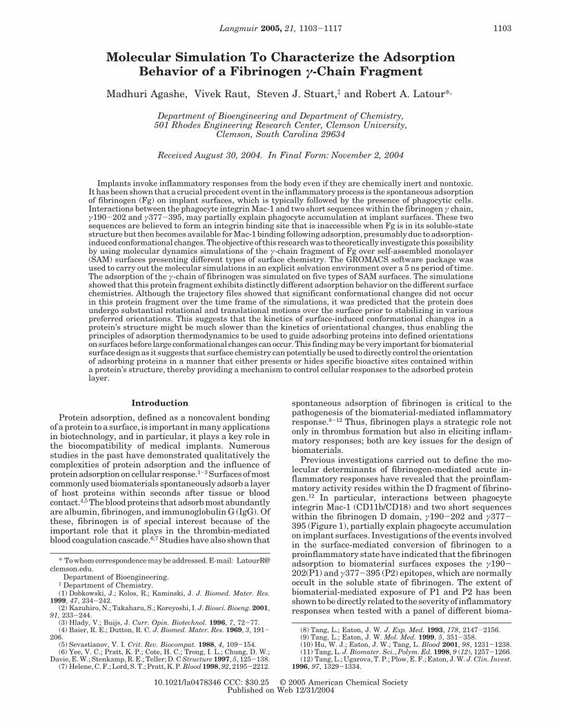
Molecular Simulation To Characterize the AdsorptionBehavior of a Fibrinogen γ-Chain Fragment
Madhuri Agashe,† Vivek Raut,† Steven J. Stuart,‡ and Robert A. Latour*,†
Department of Bioengineering and Department of Chemistry,501 Rhodes Engineering Research Center, Clemson University,
Clemson, South Carolina 29634
Received August 30, 2004. In Final Form: November 2, 2004
Implants invoke inflammatory responses from the body even if they are chemically inert and nontoxic.It has been shown that a crucial precedent event in the inflammatory process is the spontaneous adsorptionof fibrinogen (Fg) on implant surfaces, which is typically followed by the presence of phagocytic cells.Interactions between the phagocyte integrin Mac-1 and two short sequences within the fibrinogen γ chain,γ190-202 and γ377-395, may partially explain phagocyte accumulation at implant surfaces. These twosequences are believed to form an integrin binding site that is inaccessible when Fg is in its soluble-statestructure but then becomes available for Mac-1 binding following adsorption, presumably due to adsorption-induced conformational changes. The objective of this research was to theoretically investigate this possibilityby using molecular dynamics simulations of the γ-chain fragment of Fg over self-assembled monolayer(SAM) surfaces presenting different types of surface chemistry. The GROMACS software package wasused to carry out the molecular simulations in an explicit solvation environment over a 5 ns period of time.The adsorption of the γ-chain of fibrinogen was simulated on five types of SAM surfaces. The simulationsshowed that this protein fragment exhibits distinctly different adsorption behavior on the different surfacechemistries. Although the trajectory files showed that significant conformational changes did not occurin this protein fragment over the time frame of the simulations, it was predicted that the protein doesundergo substantial rotational and translational motions over the surface prior to stabilizing in variouspreferred orientations. This suggests that the kinetics of surface-induced conformational changes in aprotein’s structure might be much slower than the kinetics of orientational changes, thus enabling theprinciples of adsorption thermodynamics to be used to guide adsorbing proteins into defined orientationson surfaces before large conformational changes can occur. This finding may be very important for biomaterialsurface design as it suggests that surface chemistry can potentially be used to directly control the orientationof adsorbing proteins in a manner that either presents or hides specific bioactive sites contained withina protein’s structure, thereby providing a mechanism to control cellular responses to the adsorbed proteinlayer.
Introduction
Protein adsorption, defined as a noncovalent bondingof a protein to a surface, is important in many applicationsin biotechnology, and in particular, it plays a key role inthe biocompatibility of medical implants. Numerousstudies in the past have demonstrated qualitatively thecomplexities of protein adsorption and the influence ofproteinadsorptiononcellular response.1-3 Surfacesofmostcommonly used biomaterials spontaneously adsorb a layerof host proteins within seconds after tissue or bloodcontact.4,5 The blood proteins that adsorb most abundantlyare albumin, fibrinogen, and immunoglobulin G (IgG). Ofthese, fibrinogen is of special interest because of theimportant role that it plays in the thrombin-mediatedblood coagulation cascade.6,7 Studies have also shown that
spontaneous adsorption of fibrinogen is critical to thepathogenesis of the biomaterial-mediated inflammatoryresponse.8-12 Thus, fibrinogen plays a strategic role notonly in thrombus formation but also in eliciting inflam-matory responses; both are key issues for the design ofbiomaterials.
Previous investigations carried out to define the mo-lecular determinants of fibrinogen-mediated acute in-flammatory responses have revealed that the proinflam-matory activity resides within the D fragment of fibrino-gen.12 In particular, interactions between phagocyteintegrin Mac-1 (CD11b/CD18) and two short sequenceswithin the fibrinogen D domain, γ190-202 and γ377-395 (Figure 1), partially explain phagocyte accumulationon implant surfaces. Investigations of the events involvedin the surface-mediated conversion of fibrinogen to aproinflammatory state have indicated that the fibrinogenadsorption to biomaterial surfaces exposes the γ190-202(P1) and γ377-395 (P2) epitopes, which are normallyoccult in the soluble state of fibrinogen. The extent ofbiomaterial-mediated exposure of P1 and P2 has beenshown to be directly related to the severity of inflammatoryresponses when tested with a panel of different bioma-
* To whom correspondence may be addressed. E-mail: [email protected].
† Department of Bioengineering.‡ Department of Chemistry.(1) Dobkowski, J.; Kolos, R.; Kaminski, J. J. Biomed. Mater. Res.
1999, 47, 234-242.(2) Kazuhiro, N.; Takaharu, S.; Koreyoshi, I. J. Biosci. Bioeng. 2001,
91, 233-244.(3) Hlady, V.; Buijs, J. Curr. Opin. Biotechnol. 1996, 7, 72-77.(4) Baier, R. E.; Dutton, R. C. J. Biomed. Mater. Res. 1969, 3, 191-
206.(5) Sevastianov, V. I. Crit. Rev. Biocompat. 1988, 4, 109-154.(6) Yee, V. C.; Pratt, K. P.; Cote, H. C.; Trong, I. L.; Chung, D. W.;
Davie, E. W.; Stenkamp, R. E.; Teller; D. C Structure 1997, 5, 125-138.(7) Helene, C. F.; Lord, S. T.; Pratt, K. P. Blood 1998, 92, 2195-2212.
(8) Tang, L.; Eaton, J. W. J. Exp. Med. 1993, 178, 2147-2156.(9) Tang, L.; Eaton, J. W. Mol. Med. 1999, 5, 351-358.(10) Hu, W. J.; Eaton, J. W.; Tang, L. Blood 2001, 98, 1231-1238.(11) Tang, L. J. Biomater. Sci., Polym. Ed. 1998, 9 (12), 1257-1266.(12) Tang, L.; Ugarova, T. P.; Plow, E. F.; Eaton, J. W. J. Clin. Invest.
1996, 97, 1329-1334.
1103Langmuir 2005, 21, 1103-1117
10.1021/la0478346 CCC: $30.25 © 2005 American Chemical SocietyPublished on Web 12/31/2004
terials.10 Thrombin-mediated conversion of fibrinogen tofibrin also exposes these same epitopes. Thus phagocytesmay recognize fibrinogen adherent to medical implantsas fibrinandrespondby launchinga series of inflammatoryand wound-healing responses normally initiated by fibrinclot formation.
Although previous studies have effectively identifiedmacrophage recognition of the P1, P2 epitopes of fibrinogenas an initiating factor for inflammatory responses againstbiomaterials, the actual molecular mechanisms leadingto the exposure of these epitopes are still unclear. Onehypothesis is that interactions between the adsorbedfibrinogen and the implant surface induce conformationalchanges to occur in the protein, causing the exposure ofthe aforementioned P1 and P2 epitopes.10 If the actualmolecular mechanisms responsible for this behavior couldbe understood and predicted as a function of the chemistryof an adsorbent surface, then it is possible that a surfacecould be designed to adsorb fibrinogen in a manner toprevent the P1, P2 epitopes from being exposed and thusminimize the severity of the inflammatory responseagainst implanted biomaterials.
Whilemuchhasbeen learned fromfibrinogenadsorptionfrom experimental studies, these studies have been limitedin terms of their ability to provide details of the interactionstaking place at the molecular level and this level ofunderstanding is necessary if the conformational behaviorfollowing adsorption is to be controlled and used to directbiological response. On the other hand, molecular simula-tion presents one of the most direct approaches totheoretically investigate interactions at themolecular leveland address the effect of surface chemistry on theadsorption behavior of proteins.14,15 Because of the size ofthe systems that need to be modeled, such simulationwork requires the use of empirical force field methods.16
Advances in computational power and techniques inmolecular simulations over the past several decades haveled to the development of a variety of force fields, severalof which have been specifically developed to simulateprotein behavior in aqueous solution, e.g., AMBER,CHARMM, GROMACS, and OPLS.17-20
The objective of this study was to use a protein forcefield to investigate the adsorption behavior of a 30 kDaγ chain fragment of fibrinogen as a function of surfacechemistry presented by an alkanethiol self-assembledmonolayer surface. Molecular dynamics (MD) simulationswere carried out with explicit solvation over 5 ns of timeusing the GROMACS molecular simulation program toinvestigate the adsorption behavior of the γ chain offibrinogen on five different surface chemistries: -CH3,-OH, -NH2, -COOH, and -(O-CH2-CH2)2-OH (oligo-ethylene glycol, OEG). Simulation results show thatdistinctly different adsorption behavior is exhibited foreach type of surface chemistry, and specific molecularinteractions that characterize the interaction of peptideresidues with each type of surface are presented. Mostimportantly, the simulations predict that the proteinfragment undergoes substantial rotational and transla-tional motions over the surface prior to settling on apreferred orientation over the surface. This finding haspotentially profound implications for protein adsorptionin that it suggests that surface chemistry may be used tocontrol protein orientation prior to inducing conforma-tional changes in the protein structure. While much workremains to be done to validate a given protein force fieldfor simulation of protein adsorption behavior, the presentstudy serves to demonstrate how surface chemistryinfluences the adsorption patterns of a γ chain fragmentof fibrinogen as predicted using the GROMACS molecularsimulation program and force field.
Materials and Methods
Computational Environment. Calculations wereperformed on a 2.66 GHz Beowulf cluster computer systemwith GROMACS (v. 3.1.4) software.21,22 The GROMACSMD simulation package was selected for use in thesestudies because the GROMACS force field was specificallydeveloped for the simulation of biomolecules, such as
(13) Ugarova, T. P.; Solovjov, D. A.; Zhang, L.; Loukinov, D. I.; Yee,V. C.; Medved, L. V.; Plow, E. F. J. Biol. Chem. 1998, 273, 22519-22527.
(14) Raffaini, G.; Ganazzoli, F. Langmuir 2003, 19, 3403-3412.(15) Cristina, M.; Martins, L.; Ratner, B. D.; Barbosa, M. A. J. Biomed.
Mater. Res. 2003, 67A, 158-171.(16) Leach, A. R. In Molecular Modelling. Principles and Applications;
Pearson Education Ltd.: Harlow, U.K., 1996; pp 131-206.(17) Brooks, B. R.; Bruccoleri, R. E.; Olafson, B. D.; States, D. J.;
Swaminathan, S.; Karplus, M. J. Comput. Chem. 1983, 4, 187-217.
(18) MacKerell, A. D. J.; Brooks, B.; Brooks, C. L. I.; Nilsson, L.;Roux, B.; Won, Y.; Karplus, M. In Encyclopedia of ComputationalChemistry; John Wiley & Sons: New York, 1998; Vol. 1 A-D, pp 271-277.
(19) Pitt, W. G.; Weaver, D. R. J. Colloid Interface Sci. 1997, 185,258-264.
(20) Lindahl, E.; Hess, B.; van der Spoel, D. J. Mol. Model. 2001, 7,306-317.
(21) Berendsen, H. J. C.; van der Spoel, D.; van Drunen, R. Comput.Phys. Commun. 1995, 91, 43-56.
(22) van der Spoel, D.; van Buuren, A. R.; Apol, E.; Meulenhoff, P.J.; Tielman, D. P.; Sijbers, A. L. T. M.; Hess, B.; Feenstra, K. A.; LIndahl,E.; van Druen, R.; Berendsen, H. J. C. GROMACS User Manual version3.1.1; Nijenborgh 4, 9747 AG: Groningen, The Netherlands, 2002.
Figure 1. Spatial positioning of γ190-202 and γ377-395 in the three-dimensional structure of the fibrinogen γ-module with theγ190-202 and γ380-390 regions colored in red and blue, respectively.13 (A) The ribbon diagram of the fibrinogen γ-module (γ144-402) based upon its crystal structure.6 (B) Space-filled model of the γ-module with exposed P1 and P2 residues highlighted. (Adaptedfrom ref 13, with permission).
1104 Langmuir, Vol. 21, No. 3, 2005 Agashe et al.
proteins, and it is freely available from the GROMACShomepage Internet site (www.gromacs.org) with ac-companying program documentation and an e-mail-baseduser support group. The GROMACS MD program is alsovery fast with parallel computing capability and providesflexible tools for data analysis. Simulations were run ondedicated processors (two CPUs per simulation) with acalculation time of about 5-7 days per nanosecond ofsimulation for the selected protein-surface system.GROMACS program tools were used for both running theMD simulations and data analysis. The initial molecularmodels were prepared using Web Lab Viewer Pro and theBuilder Module in InsightII 2000.1 (Accelrys, San Diego).VMD software23 was used for visualization of the trajec-tories generated by GROMACS.
Molecular Models of Materials.The crystal structureof a 30 kDa C-terminus γ-chain fragment of fibrinogen(γFg) was obtained from the Protein Data Bank (PDBID# 1FID)6 and further processed in preparation for oursimulations, which involved the removal of noncovalentlybonded heterogeneous atoms (e.g., oxygen atoms frombound water molecules) and the addition of hydrogens tocomplete valence requirements of the crystal structure’sheavy atoms. In addition, because this is a proteinfragment, the downloaded structure had an incompleteterminal residue (leucine, #402), which was also removed.In its final form, the γFg model had a net charge of -3e. This protein model is particularly relevant for thesestudies because it contains only two disulfide cross-linksbetween adjacent cysteine residues. Thus, its tertiarystructure is predominantly stabilized by secondary bond-ing interactions, which the functional groups of anadsorbent surface will compete with to potentially induceprotein unfolding and spreading on the surface, withpossible exposure of the P1-P2 epitopes.
Surfaces for γFg adsorption were modeled to representalkanethiol self-assembled monolayers (SAMs) with vary-ing surface chemical functionalities. These surfaces werederived from molecular models of S-(CH2)15-CH3 al-kanethiol SAMs on a simulated gold (111) surface planemodeled by Latour and co-workers in previous studiesinvestigating midchain peptide residue adsorption to SAMsurfaces.24-27 To vary the surface chemistry, the terminal
methyl groups of the alkanethiol molecules were replacedby other selected functional groups, namely, -OH, -NH2/NH3
+, -COOH/COO-, or -(O-CH2-CH2)2-OH (OEG).The lower portion of the alkanethiol molecules was thentruncated so as to provide an overall SAM surface layerthat was about 10 Å thick. In this way surfaces with fivedifferent surface chemistries were generated that had thechemical characteristics as presented in Table 1.
Individual chains that were used to form the functionalunit of each SAM surface are shown in Figure 2. EachchainhadastructureCH3-(CH2) 8-R,whereRrepresentsthe specific terminal function group shown in Table 1. Torepresent these surfaces in GROMACS, new residue typescorresponding to the individual chains of each type of SAMhad to first be defined in the GROMACS residue topologyfiles (.rtf files) using predefined atom types in the atomtype parameter (.atp) file. Table 2 lists the predefinedatom types that were used for defining these new residuetypes. All hydrogens connected to alkane chains wereincluded with the parent carbons as united atoms, andonly hydrogens connected to the polar or charged func-tional groups, i.e., in (OH, NH2, NH3
+, COOH, and OEG),were modeled explicitly, consistent with the principlesbehind the GROMACS potential and the guidelinesprovided in the GROMACS documentation.22 Startingconfigurations of the OEG-terminated residue chains were
(23) Humphrey, W.; Dalke, A.; Schulten, K. J. Mol. Graphics 1996,14, (1), 33-38.
(24) Basalyga, D. M.; Latour, R. A. J. Biomed. Mater. Res. 2002, 64A,120-130.
(25) Latour, R. A.; Rini, C. J. J. Biomed. Mater. Res. 2002, 60, 564-577.
(26) Latour, R. A.; Hench, L. L. Biomaterials 2002, 23, 4633-4648.(27) Wilson, K.; Stuart, S. J.; Garcia, A.; Latour, R. A. J. Biomed.
Mater. Res. 2004, 69A, 686-698.
Figure 2. Individual chains on the SAM surface with different functionalization: (A) CH3 terminated; (B) OH terminated; (C)COOH, COO- terminated; (D) NH2, NH3
+ terminated; (E) trans OEG; (F) gauche OEG (torsional angles set as: C-O-C-C ) 70°,C-C-O-C ) 70° , O-C-C-O ) 60°).28,29
Table 1. Characteristic Functionalities of theSAM Surfaces
functionalityterminalgroup (R) charge state
hydrophobic CH3 neutral (nonpolar)neutral hydrophilic OH neutral (polar)positively charged NH2/NH3
+ neutral (polar)/+1negatively charged COOH/COO- neutral (polar)/-1nonadhesive control OEG neutral (polar)
Table 2. Predefined Atom Types Used To Define the NewAtom Types Needed To Represent the SAM Surfaces in
GROMACS
atomname
mass(amu) atom type
O 15.9994 CARBONYL OXYGEN (CdO)OM 15.9994 CARBOXYL OXYGEN (COs)OA 15.9994 HYDROXYL OXYGEN (OH)N 14.0067 PEPTIDE NITROGEN (N OR NH)NT 14.0067 TERMINAL NITROGEN (NH2)NL 14.0067 TERMINAL NITROGEN (NH3)C 12.011 BARE CARBON (PEPTIDE,CdO,CsN)C1 12.011 ALIPHATIC CH-GROUPC2 12.011 ALIPHATIC CH2-GROUPC3 12.011 ALIPHATIC CH3-GROUPHO 1.008 HYDROXYL HYDROGEN
Adsorption Behavior of a Fibrinogen Fragment Langmuir, Vol. 21, No. 3, 2005 1105
represented in both a trans conformation and a gauche(helical) conformation as shown in structures E and F ofFigure 2, respectively, for reasons explained below. Thetrans structure represents the lowest energy configurationof the OEG chain in a vacuum as represented by theGROMACS force field equation, while evidence suggeststhat helical conformations may actually be more stable inaqueous solution.28,29
To create charged surfaces with set pK values, two typesof residues were created. For the positively chargedsurface, one residue had an NH3
+ terminal group with acharge of +1 e and the other had a NH2 terminal groupthat was neutral. Similarly, to create the negativelycharged SAM, one residue with a COO- end group and acharge of -1 e was created, and another was created withan uncharged COOH end group. Charged surfaces werethen constructed using a mix of these two residues suchthat 1 out of every 20 chains had a charged terminal group.This protonation/deprotonation ratio was selected basedon work by Creager et al.30 and represents surface pKvalues of 8.7 and 6.1 for the COOH and NH2 surfaces,respectively. Partial charges for the SAM residues, exceptfor the (-O-CH2-CH2-) segment of OEG, were based onamino acid definitions with similar side-chain functionalgroups, while the partial charges for the (-O-CH2-CH2-)segment of OEG, which were not available in GROMACS,were obtained from the AMBER force field.31 AMBER wasselected as an appropriate force field for this designationbecause it is a class I force field like GROMACS withsimilar functional form and parametrization.32 Table 3provides the parameters for the terminal groups of theindividual SAM residues. The single chains thus obtainedwere iteratively expanded as shown in Figure 3 to createSAM surfaces with sufficiently large surface area to modelthe adsorption behavior of the γFg protein fragment.
We anticipated that the OEG chains initially positionedin the trans configuration would transition to the helicalconfiguration during the simulation as the OEG groupsbecame solvated with water. In preliminary studies,however, this transition was not observed to occur; ratherthe OEG chains maintained their trans configurationthroughout the simulations with only relatively moderatetorsional angle fluctuations about this state. A separateset of simulations was then conducted with the OEG chainsinitially positioned in the helical conformation. In this
case, the OEG chains were observed to transition back tothe trans conformation within about 100 ps, with the transconformation then maintained for the rest of the simula-tion. Protein adsorption behavior was unexpectedlypredicted to occur differently for these two differentstarting OEG conformations, and results are presentedfor both of these starting OEG conformations to demon-strate these differences in the simulated behavior. Thisbehavior illustrates one of the limitations of the use of aprotein force field to represent a system that it was notpreviously parametrized to represent (i.e., protein ad-sorption to an OEG-functionalized SAM surface). Analternative to this would have been to combine forcefield potentials that were specifically developed to rep-resent alkanethiol SAM surfaces33,34 and OEG functionalgroups35,36 with the GROMACS potential then still usedfor the protein in solution in a single simulation. However,unless specifically balanced to function together, the useof different force field potentials to represent differentphases in the same simulation can also be expected tohave problems in accurately representing molecular
(28) Wang, R. L. C.; Kreuzer, H.; Grunze, M.; Pertsin, A. J. Phys.Chem. Chem. Phys. 2002, 2, 1721-1727.
(29) Rigby, D.; Sun, H.; Eichinger, B. E. Polym. Int. 1997, 44, 311-330.
(30) Creager, S. E.; Clarke, J. Langmuir 1994, 10, 3675-3683.(31) Weiner, S. J.; Kollman, P. A.; Case, D. A.; Singh, U. C.; Ghio,
C.; Alagona, G.; Profeta, J. S.; Weiner, P. J. Am. Chem. Soc. 1984, 106,765-784.
(32) MacKerell, A. D. J. In Encyclopedia of Computational Chemistry;Schleyer, P. v. R., Ed.; John Wiley & Sons: New York, 1998; Vol. 3M-P, pp 2191-2200.
(33) Hautman, J.; Bareman, J. P.; Mar, W.; Klein, M. L. J. Chem.Soc., Faraday Trans. 1991, 87 (13), 2031-2037.
(34) Mar, W.; Klein, M. L. Langmuir 1994, 10, 188-196.(35) Smith, G. D.; Jaffe, R. L.; Yoon, D. Y. J. Phys. Chem. 1993, 97,
12752.(36) Smith, G. D.; Borodin, O.; Bedrov, D. J. Comput. Chem. 2002,
23, 1480-1488.
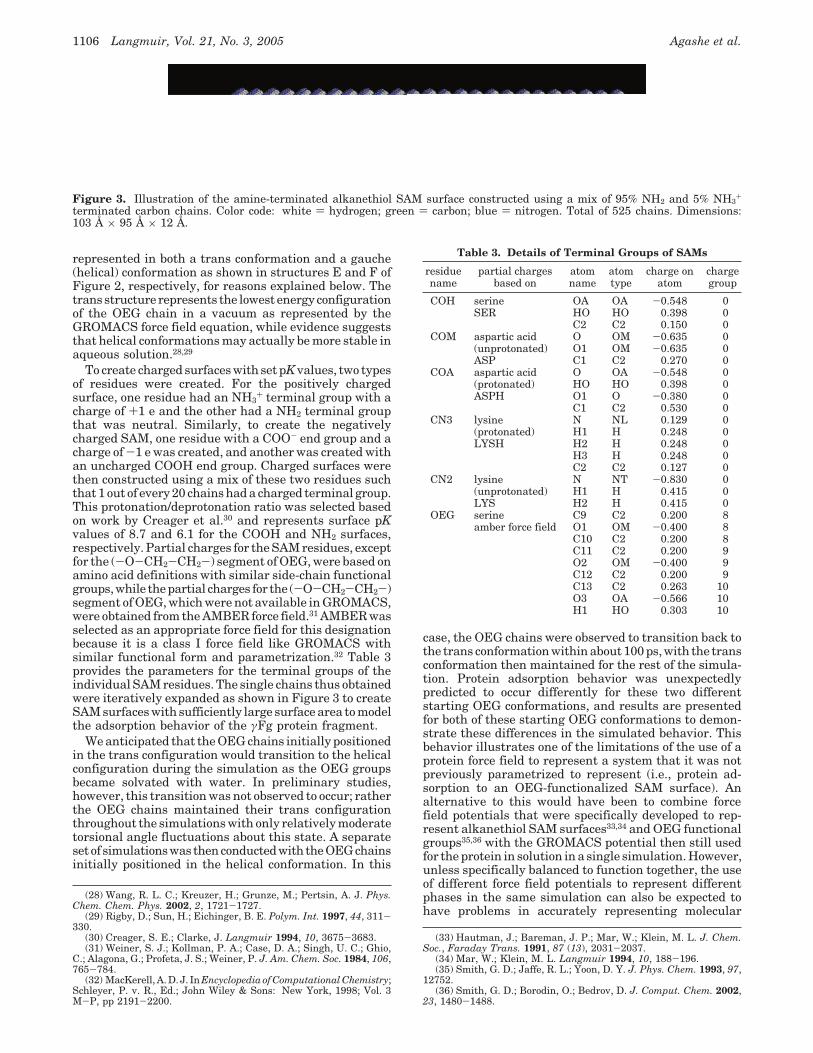
Figure 3. Illustration of the amine-terminated alkanethiol SAM surface constructed using a mix of 95% NH2 and 5% NH3+
terminated carbon chains. Color code: white ) hydrogen; green ) carbon; blue ) nitrogen. Total of 525 chains. Dimensions:103 Å × 95 Å × 12 Å.
Table 3. Details of Terminal Groups of SAMs
residuename
partial chargesbased on
atomname
atomtype
charge onatom
chargegroup
COH serine OA OA -0.548 0SER HO HO 0.398 0
C2 C2 0.150 0COM aspartic acid O OM -0.635 0
(unprotonated) O1 OM -0.635 0ASP C1 C2 0.270 0
COA aspartic acid O OA -0.548 0(protonated) HO HO 0.398 0ASPH O1 O -0.380 0
C1 C2 0.530 0CN3 lysine N NL 0.129 0
(protonated) H1 H 0.248 0LYSH H2 H 0.248 0
H3 H 0.248 0C2 C2 0.127 0
CN2 lysine N NT -0.830 0(unprotonated) H1 H 0.415 0LYS H2 H 0.415 0
OEG serine C9 C2 0.200 8amber force field O1 OM -0.400 8
C10 C2 0.200 8C11 C2 0.200 9O2 OM -0.400 9C12 C2 0.200 9C13 C2 0.263 10O3 OA -0.566 10H1 HO 0.303 10
1106 Langmuir, Vol. 21, No. 3, 2005 Agashe et al.
behavior, especially at the interface between the separatephases. This represents an inherent problem with em-pirical force field methods. Given this situation, we electedto simulate protein adsorption behavior using a singleforce field potential with minimal modifications for boththe protein solution and the adsorbent surface phases andto evaluate the results to identify possible inaccuracies inthe simulated molecular behavior. These studies thusrepresent first steps toward the eventual development ofmolecular simulation methods that will enable proteinadsorption behavior to be accurately simulated for a widerange of functionalized surfaces.
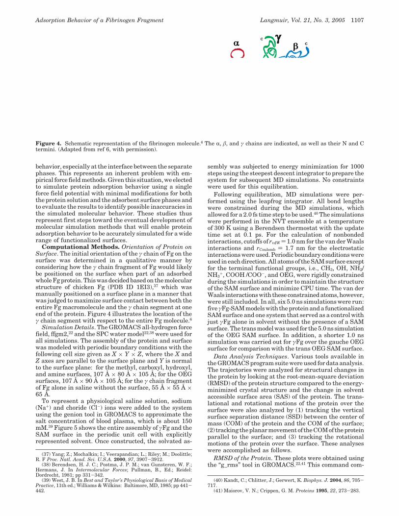
Computational Methods. Orientation of Protein onSurface. The initial orientation of the γ chain of Fg on thesurface was determined in a qualitative manner byconsidering how the γ chain fragment of Fg would likelybe positioned on the surface when part of an adsorbedwhole Fg protein. This was decided based on the molecularstructure of chicken Fg (PDB ID 1EI3),37 which wasmanually positioned on a surface plane in a manner thatwas judged to maximize surface contact between both theentire Fg macromolecule and the γ chain segment at oneend of the protein. Figure 4 illustrates the location of theγ chain segment with respect to the entire Fg molecule.6
Simulation Details. The GROMACS all-hydrogen forcefield, ffgm2,22 and the SPC water model22,38 were used forall simulations. The assembly of the protein and surfacewas modeled with periodic boundary conditions with thefollowing cell size given as X × Y × Z, where the X andZ axes are parallel to the surface plane and Y is normalto the surface plane: for the methyl, carboxyl, hydroxyl,and amine surfaces, 107 Å × 80 Å × 105 Å; for the OEGsurfaces, 107 Å × 90 Å × 105 Å; for the γ chain fragmentof Fg alone in saline without the surface, 55 Å × 55 Å ×65 Å.
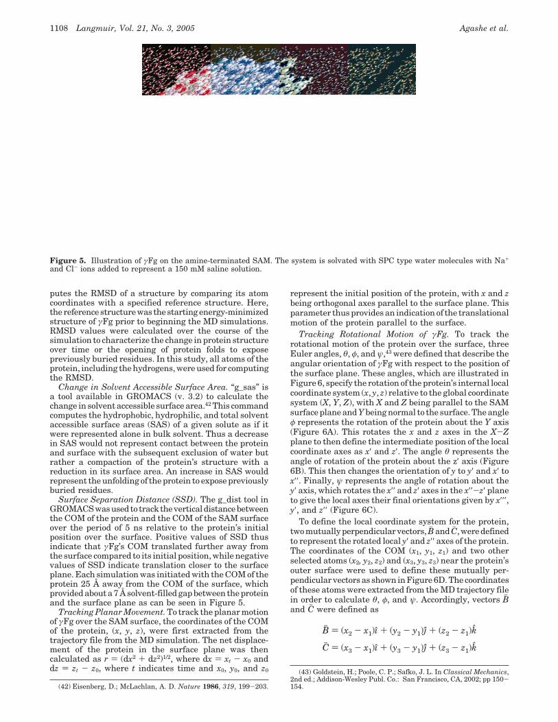
To represent a physiological saline solution, sodium(Na+) and choride (Cl-) ions were added to the systemusing the genion tool in GROMACS to approximate thesalt concentration of blood plasma, which is about 150mM.39 Figure 5 shows the entire assembly of γFg and theSAM surface in the periodic unit cell with explicitlyrepresented solvent. Once constructed, the solvated as-
sembly was subjected to energy minimization for 1000steps using the steepest descent integrator to prepare thesystem for subsequent MD simulations. No constraintswere used for this equilibration.
Following equilibration, MD simulations were per-formed using the leapfrog integrator. All bond lengthswere constrained during the MD simulations, whichallowed for a 2.0 fs time step to be used.40 The simulationswere performed in the NVT ensemble at a temperatureof 300 K using a Berendsen thermostat with the updatetime set at 0.1 ps. For the calculation of nonbondedinteractions, cutoffs of rvdW ) 1.0 nm for the van der Waalsinteractions and rCoulomb ) 1.7 nm for the electrostaticinteractions were used. Periodic boundary conditions wereused in each direction. All atoms of the SAM surface exceptfor the terminal functional groups, i.e., CH3, OH, NH2/NH3
+, COOH /COO-, and OEG, were rigidly constrainedduring the simulations in order to maintain the structureof the SAM surface and minimize CPU time. The van derWaals interactionswith theseconstrainedatoms,however,were still included. In all, six 5.0 ns simulations were run:five γFg-SAM models with the protein and a functionalizedSAM surface and one system that served as a control withjust γFg alone in solvent without the presence of a SAMsurface. The trans model was used for the 5.0 ns simulationof the OEG SAM surface. In addition, a shorter 1.0 nssimulation was carried out for γFg over the gauche OEGsurface for comparison with the trans OEG SAM surface.
Data Analysis Techniques. Various tools available inthe GROMACS program suite were used for data analysis.The trajectories were analyzed for structural changes inthe protein by looking at the root-mean-square deviation(RMSD) of the protein structure compared to the energy-minimized crystal structure and the change in solventaccessible surface area (SAS) of the protein. The trans-lational and rotational motions of the protein over thesurface were also analyzed by (1) tracking the verticalsurface separation distance (SSD) between the center ofmass (COM) of the protein and the COM of the surface;(2) tracking the planar movement of the COM of the proteinparallel to the surface; and (3) tracking the rotationalmotions of the protein over the surface. These analyseswere accomplished as follows.
RMSD of the Protein. These plots were obtained usingthe “g_rms” tool in GROMACS.22,41 This command com-
(37) Yang; Z.; Mochalkin; I.; Veerapandian; L.; Riley; M.; Doolittle;R. F Proc. Natl. Acad. Sci. U.S.A. 2000, 97, 3907-3912.
(38) Berendsen, H. J. C.; Postma, J. P. M.; van Gunsteren, W. F.;Hermans, J. In Intermolecular Forces; Pullman, B., Ed.; Reidel:Dordrecht, 1981; pp 331-342.
(39) West, J. B. In Best and Taylor’s Physiological Basis of MedicalPractice, 11th ed.; Williams & Wilkins: Baltimore, MD, 1985; pp 441-442.
(40) Kandt, C.; Chlitter, J.; Gerwert, K. Biophys. J. 2004, 86, 705-717.
(41) Maiorov, V. N.; Crippen, G. M. Proteins 1995, 22, 273-283.
Figure 4. Schematic representation of the fibrinogen molecule.6 The R, â, and γ chains are indicated, as well as their N and Ctermini. (Adapted from ref 6, with permission).
Adsorption Behavior of a Fibrinogen Fragment Langmuir, Vol. 21, No. 3, 2005 1107
putes the RMSD of a structure by comparing its atomcoordinates with a specified reference structure. Here,the reference structure was the starting energy-minimizedstructure of γFg prior to beginning the MD simulations.RMSD values were calculated over the course of thesimulation to characterize the change in protein structureover time or the opening of protein folds to exposepreviously buried residues. In this study, all atoms of theprotein, including the hydrogens, were used for computingthe RMSD.
Change in Solvent Accessible Surface Area. “g_sas” isa tool available in GROMACS (v. 3.2) to calculate thechange in solvent accessible surface area.42 This commandcomputes the hydrophobic, hydrophilic, and total solventaccessible surface areas (SAS) of a given solute as if itwere represented alone in bulk solvent. Thus a decreasein SAS would not represent contact between the proteinand surface with the subsequent exclusion of water butrather a compaction of the protein’s structure with areduction in its surface area. An increase in SAS wouldrepresent the unfolding of the protein to expose previouslyburied residues.
Surface Separation Distance (SSD). The g_dist tool inGROMACSwasusedto tracktheverticaldistancebetweenthe COM of the protein and the COM of the SAM surfaceover the period of 5 ns relative to the protein’s initialposition over the surface. Positive values of SSD thusindicate that γFg’s COM translated further away fromthe surface compared to its initial position, while negativevalues of SSD indicate translation closer to the surfaceplane. Each simulation was initiated with the COM of theprotein 25 Å away from the COM of the surface, whichprovided about a 7 Å solvent-filled gap between the proteinand the surface plane as can be seen in Figure 5.
Tracking Planar Movement. To track the planar motionof γFg over the SAM surface, the coordinates of the COMof the protein, (x, y, z), were first extracted from thetrajectory file from the MD simulation. The net displace-ment of the protein in the surface plane was thencalculated as r ) (dx2 + dz2)1/2, where dx ) xt - x0 anddz ) zt - z0, where t indicates time and x0, y0, and z0
represent the initial position of the protein, with x and zbeing orthogonal axes parallel to the surface plane. Thisparameter thus provides an indication of the translationalmotion of the protein parallel to the surface.
Tracking Rotational Motion of γFg. To track therotational motion of the protein over the surface, threeEuler angles, θ, φ, and ψ,43 were defined that describe theangular orientation of γFg with respect to the position ofthe surface plane. These angles, which are illustrated inFigure 6, specify the rotation of the protein’s internal localcoordinate system (x, y, z) relative to the global coordinatesystem (X, Y, Z), with X and Z being parallel to the SAMsurface plane and Y being normal to the surface. The angleφ represents the rotation of the protein about the Y axis(Figure 6A). This rotates the x and z axes in the X-Zplane to then define the intermediate position of the localcoordinate axes as x′ and z′. The angle θ represents theangle of rotation of the protein about the z′ axis (Figure6B). This then changes the orientation of y to y′ and x′ tox′′. Finally, ψ represents the angle of rotation about they′ axis, which rotates the x′′ and z′ axes in the x′′-z′ planeto give the local axes their final orientations given by x′′′,y′, and z′′ (Figure 6C).
To define the local coordinate system for the protein,two mutually perpendicular vectors, Bh and Ch , were definedto represent the rotated local y′ and z′′ axes of the protein.The coordinates of the COM (x1, y1, z1) and two otherselected atoms (x2, y2, z2) and (x3, y3, z3) near the protein’souter surface were used to define these mutually per-pendicular vectors as shown in Figure 6D. The coordinatesof these atoms were extracted from the MD trajectory filein order to calculate θ, φ, and ψ. Accordingly, vectors Bhand Ch were defined as
(42) Eisenberg, D.; McLachlan, A. D. Nature 1986, 319, 199-203.
(43) Goldstein, H.; Poole, C. P.; Safko, J. L. In Classical Mechanics,2nd ed.; Addison-Wesley Publ. Co.: San Francisco, CA, 2002; pp 150-154.
Figure 5. Illustration of γFg on the amine-terminated SAM. The system is solvated with SPC type water molecules with Na+
and Cl- ions added to represent a 150 mM saline solution.
Bh ) (x2 - x1)ı + (y2 - y1)j + (z2 - z1)k
Ch ) (x3 - x1)ı + (y3 - y1)j + (z3 - z1)k
1108 Langmuir, Vol. 21, No. 3, 2005 Agashe et al.
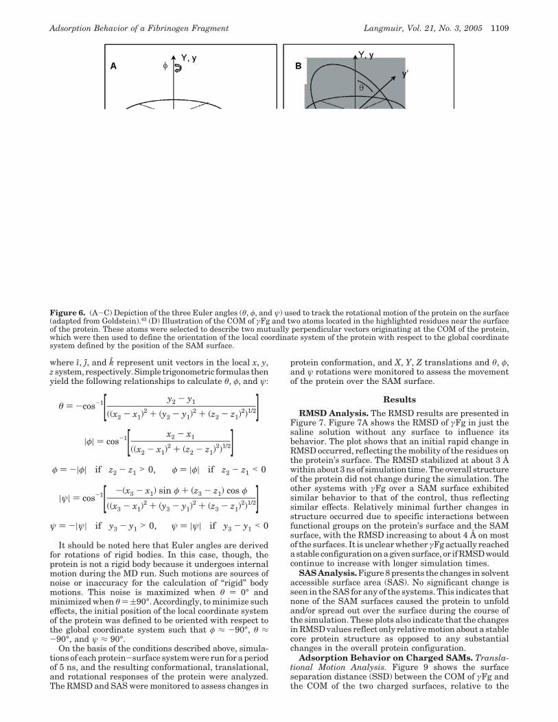
where ı, j, and k represent unit vectors in the local x, y,z system, respectively. Simple trigonometric formulas thenyield the following relationships to calculate θ, φ, and ψ:
It should be noted here that Euler angles are derivedfor rotations of rigid bodies. In this case, though, theprotein is not a rigid body because it undergoes internalmotion during the MD run. Such motions are sources ofnoise or inaccuracy for the calculation of “rigid” bodymotions. This noise is maximized when θ ) 0° andminimized when θ ) (90°. Accordingly, to minimize sucheffects, the initial position of the local coordinate systemof the protein was defined to be oriented with respect tothe global coordinate system such that φ ≈ -90°, θ ≈-90°, and ψ ≈ 90°.
On the basis of the conditions described above, simula-tions of each protein-surface system were run for a periodof 5 ns, and the resulting conformational, translational,and rotational responses of the protein were analyzed.The RMSD and SAS were monitored to assess changes in
protein conformation, and X, Y, Z translations and θ, φ,and ψ rotations were monitored to assess the movementof the protein over the SAM surface.
Results
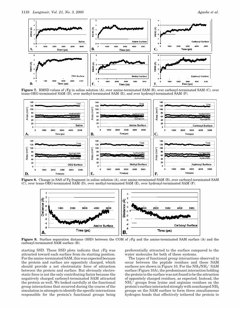
RMSD Analysis. The RMSD results are presented inFigure 7. Figure 7A shows the RMSD of γFg in just thesaline solution without any surface to influence itsbehavior. The plot shows that an initial rapid change inRMSD occurred, reflecting the mobility of the residues onthe protein’s surface. The RMSD stabilized at about 3 Åwithin about 3 ns of simulation time. The overall structureof the protein did not change during the simulation. Theother systems with γFg over a SAM surface exhibitedsimilar behavior to that of the control, thus reflectingsimilar effects. Relatively minimal further changes instructure occurred due to specific interactions betweenfunctional groups on the protein’s surface and the SAMsurface, with the RMSD increasing to about 4 Å on mostof the surfaces. It is unclear whether γFg actually reacheda stable configuration on a given surface, or if RMSD wouldcontinue to increase with longer simulation times.
SAS Analysis. Figure 8 presents the changes in solventaccessible surface area (SAS). No significant change isseen in the SAS for any of the systems. This indicates thatnone of the SAM surfaces caused the protein to unfoldand/or spread out over the surface during the course ofthe simulation. These plots also indicate that the changesin RMSD values reflect only relative motion about a stablecore protein structure as opposed to any substantialchanges in the overall protein configuration.
Adsorption Behavior on Charged SAMs. Transla-tional Motion Analysis. Figure 9 shows the surfaceseparation distance (SSD) between the COM of γFg andthe COM of the two charged surfaces, relative to the
Figure 6. (A-C) Depiction of the three Euler angles (θ, φ, and ψ) used to track the rotational motion of the protein on the surface(adapted from Goldstein).43 (D) Illustration of the COM of γFg and two atoms located in the highlighted residues near the surfaceof the protein. These atoms were selected to describe two mutually perpendicular vectors originating at the COM of the protein,which were then used to define the orientation of the local coordinate system of the protein with respect to the global coordinatesystem defined by the position of the SAM surface.
θ ) -cos-1[ y2 - y1
((x2 - x1)2 + (y2 - y1)
2 + (z2 - z1)2)1/2]
|φ| ) cos-1[ x2 - x1
((x2 - x1)2 + (z2 - z1)
2)1/2]φ ) -|φ| if z2 - z1 > 0, φ ) |φ| if z2 - z1 < 0
|ψ| ) cos-1[ -(x3 - x1) sin φ + (z3 - z1) cos φ
((x3 - x1)2 + (y3 - y1)
2 + (z3 - z1)2)1/2]
ψ ) -|ψ| if y3 - y1 > 0, ψ ) |ψ| if y3 - y1 < 0
Adsorption Behavior of a Fibrinogen Fragment Langmuir, Vol. 21, No. 3, 2005 1109
starting SSD. These SSD plots indicate that γFg wasattracted toward each surface from its starting position.For the amine-terminated SAM, this was expected becausethe protein and surface are oppositely charged, whichshould provide a net electrostatic force of attractionbetween the protein and surface. But obviously electro-static force is not the only contributing factor because thenegatively charged carboxyl-terminated SAM attractedthe protein as well. We looked carefully at the functionalgroup interactions that occurred during the course of thesimulation in attempts to identify the specific interactionsresponsible for the protein’s functional groups being
preferentially attracted to the surface compared to thewater molecules for both of these systems.
The types of functional group interactions observed tooccur between the peptide residues and these SAMsurfaces are shown in Figure 10. For the NH2/NH3
+ SAMsurface (Figure 10A), the predominant interaction holdingthe protein to the surface was not found to be the attractionof oppositely charged residues, as expected. Instead, theNH3
+ groups from lysine and arginine residues on theprotein’s surface interacted strongly with noncharged NH2groups on the SAM surface to form three simultaneoushydrogen bonds that effectively tethered the protein to
Figure 7. RMSD values of γFg in saline solution (A), over amine-terminated SAM (B), over carboxyl-terminated SAM (C), overtrans-OEG-terminated SAM (D), over methyl-terminated SAM (E), and over hydroxyl-terminated SAM (F).
Figure 8. Change in SAS of Fg fragment in saline solution (A), over amine-terminated SAM (B), over carboxyl-terminated SAM(C), over trans-OEG-terminated SAM (D), over methyl-terminated SAM (E), over hydroxyl-terminated SAM (F).
Figure 9. Surface separation distance (SSD) between the COM of γFg and the amine-terminated SAM surface (A) and thecarboxyl-terminated SAM surface (B).
1110 Langmuir, Vol. 21, No. 3, 2005 Agashe et al.
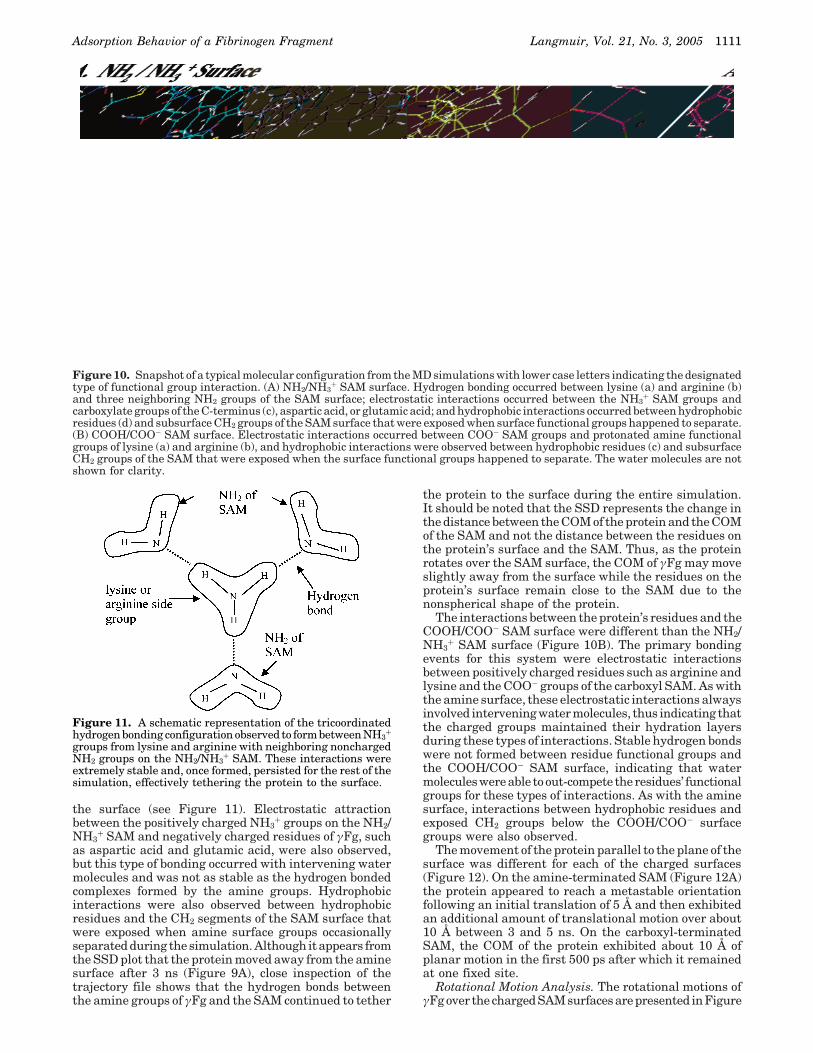
the surface (see Figure 11). Electrostatic attractionbetween the positively charged NH3
+ groups on the NH2/NH3
+ SAM and negatively charged residues of γFg, suchas aspartic acid and glutamic acid, were also observed,but this type of bonding occurred with intervening watermolecules and was not as stable as the hydrogen bondedcomplexes formed by the amine groups. Hydrophobicinteractions were also observed between hydrophobicresidues and the CH2 segments of the SAM surface thatwere exposed when amine surface groups occasionallyseparated during the simulation. Although it appears fromthe SSD plot that the protein moved away from the aminesurface after 3 ns (Figure 9A), close inspection of thetrajectory file shows that the hydrogen bonds betweenthe amine groups of γFg and the SAM continued to tether
the protein to the surface during the entire simulation.It should be noted that the SSD represents the change inthe distance between the COM of the protein and the COMof the SAM and not the distance between the residues onthe protein’s surface and the SAM. Thus, as the proteinrotates over the SAM surface, the COM of γFg may moveslightly away from the surface while the residues on theprotein’s surface remain close to the SAM due to thenonspherical shape of the protein.
The interactions between the protein’s residues and theCOOH/COO- SAM surface were different than the NH2/NH3
+ SAM surface (Figure 10B). The primary bondingevents for this system were electrostatic interactionsbetween positively charged residues such as arginine andlysine and the COO- groups of the carboxyl SAM. As withthe amine surface, these electrostatic interactions alwaysinvolved intervening water molecules, thus indicating thatthe charged groups maintained their hydration layersduring these types of interactions. Stable hydrogen bondswere not formed between residue functional groups andthe COOH/COO- SAM surface, indicating that watermoleculeswereable toout-compete theresidues’ functionalgroups for these types of interactions. As with the aminesurface, interactions between hydrophobic residues andexposed CH2 groups below the COOH/COO- surfacegroups were also observed.
The movement of the protein parallel to the plane of thesurface was different for each of the charged surfaces(Figure 12). On the amine-terminated SAM (Figure 12A)the protein appeared to reach a metastable orientationfollowing an initial translation of 5 Å and then exhibitedan additional amount of translational motion over about10 Å between 3 and 5 ns. On the carboxyl-terminatedSAM, the COM of the protein exhibited about 10 Å ofplanar motion in the first 500 ps after which it remainedat one fixed site.
Rotational Motion Analysis. The rotational motions ofγFg over the charged SAM surfaces are presented in Figure
Figure 10. Snapshot of a typical molecular configuration from the MD simulations with lower case letters indicating the designatedtype of functional group interaction. (A) NH2/NH3
+ SAM surface. Hydrogen bonding occurred between lysine (a) and arginine (b)and three neighboring NH2 groups of the SAM surface; electrostatic interactions occurred between the NH3
+ SAM groups andcarboxylate groups of the C-terminus (c), aspartic acid, or glutamic acid; and hydrophobic interactions occurred between hydrophobicresidues (d) and subsurface CH2 groups of the SAM surface that were exposed when surface functional groups happened to separate.(B) COOH/COO- SAM surface. Electrostatic interactions occurred between COO- SAM groups and protonated amine functionalgroups of lysine (a) and arginine (b), and hydrophobic interactions were observed between hydrophobic residues (c) and subsurfaceCH2 groups of the SAM that were exposed when the surface functional groups happened to separate. The water molecules are notshown for clarity.
Figure 11. A schematic representation of the tricoordinatedhydrogen bonding configuration observed to form between NH3
+
groups from lysine and arginine with neighboring nonchargedNH2 groups on the NH2/NH3
+ SAM. These interactions wereextremely stable and, once formed, persisted for the rest of thesimulation, effectively tethering the protein to the surface.
Adsorption Behavior of a Fibrinogen Fragment Langmuir, Vol. 21, No. 3, 2005 1111
13. As shown, the protein undergoes relatively largerotational motion over these SAM surfaces during thecourse of the 5.0 ns simulations, with θ, φ, and ψ varyingby about 20-50°. From the MD trajectory files, it wasapparent that the rotational motions of γFg reflected arolling of the protein over the SAM surface, which alsoresulted in the translational motions of the COM of γFgas shown in Figure 12.
Adsorption Behavior on the Hydrophobic Methyl-TerminatedSAM. TranslationalMotion Analysis.Figure14A shows the separation distance between the proteinsegment’s COM and the methyl-terminated SAM surfacerelative to the starting separation distance. The proteinexhibited some initial movement away from the surfacebut then was attracted more closely to the surface, andafter about 3 ns it attained a relatively stable orientationthat was closer to the surface than the starting position.Figure 14B shows the planar motion of the protein on themethyl-terminated SAM with the COM of the proteintranslating over the surface, again primarily due to therolling motion of the protein over the surface.
Rotational Motion Analysis. As previously noted, theRMSD plot shown in Figure 7E clearly indicates that γFgdid not unfold on the methyl-terminated SAM during the5 ns simulation as might be expected on a hydrophobicsurface. Instead, an analysis of the trajectory file showsthat during this time period γFg only rotated over on thesurface, apparently toward some local minimum energyposition while forming various hydrophobic interactionsbetween the hydrophobic side chains of the protein’sresidues and the terminal methyl end groups of the SAMsurface, as illustrated in Figure 15. Initially, the proteinresidues close to the SAM surface were primarily hydro-philic in nature, and thus they retained their hydrationlayers instead of adsorbing to the hydrophobic surfacegroups. The protein then rolled over the surface until itoriented itself with several hydrophobic residues facingthe surface. The position of the protein then stabilizedwith the side chains of hydrophobic residues, like alanineand valine, lying close to the surface forming stablehydrophobic interactions with CH3 terminal groups of theSAM surface (Figure 16). Only the hydrophobic portions
Figure 12. Planar motions of the COM of γFg over the surface plane of the amine-terminated SAM (A) and the surface planeof the carboxyl-terminated SAM (B).
Figure 13. Rotational motions of the COM of γFg over the amine-terminated SAM surface (A-C) and the carboxyl-terminatedSAM surface (D-F).
Figure 14. Translational motions of the COM of γFg on the methyl-terminated SAM surface: (A) change in surface separationdistance (SSD); (B) motion parallel to the surface plane.
1112 Langmuir, Vol. 21, No. 3, 2005 Agashe et al.
of the side chains of the protein were observed to interactstrongly with the methyl surface, whereas the hydrophilicfunctional groups of the protein residues remainedhydrated and well separated from the surface.
Plots for the rotational motions of γFg on the methylSAM surface are presented in Figure 17, with the largestrotation represented by a θ rotation of 50°. As shown inFigure 17, γFg exhibited an initial rolling motion thatwas most pronounced between 0 and 1.25 ns. After thisinitial rolling, it attained a more stable orientation andbegan settling down on the SAM surface with relatively
little rotational motion exhibited for the rest of thesimulation.
Adsorption Behavior on Hydrophilic Hydroxyl-Terminated SAMs. Translational Analysis. Figure 18Ashows the separation distance between the proteinsegment’s COM and the hydroxyl-terminated SAM surfacerelative to the starting separation distance. As is apparentfrom this plot, the protein is not attracted to the surface,but slowly moves away from the SAM surface over thecourse of the 5 ns simulation. Detailed analysis of thetrajectory indicates that while some initial hydrogen
Figure 15. Illustration of the γ chain rolling on the hydrophobic SAM: (A) the protein at 0.50 ns; (B) the protein at 1.25 ns. Thedegree of rotation can be judged qualitatively by the change in the position of the random loop of the C-terminus of γFg that extendsout from the left side of the protein.
Figure 16. Trajectory snapshot of the protein segment over the methyl-terminated SAM surface with the hydrophobic side chainsof various peptide residues forming hydrophobic interactions with the terminal CH3 groups of the SAM surface: (a) side chainsof alanine residues; (b) CH2 groups of the side chain of a lysine residue. Note that hydrophilic functional groups of the proteinresidues remain hydrated and positioned away from surface.
Figure 17. Rotational motions of the COM of γFg over the methyl terminated SAM surface.
Figure 18. Translational motions of the COM of γFg on the hydroxyl-terminated SAM surface: (A) change in initial surfaceseparation distance (SSD); (B) motion parallel to the surface plane.
Adsorption Behavior of a Fibrinogen Fragment Langmuir, Vol. 21, No. 3, 2005 1113
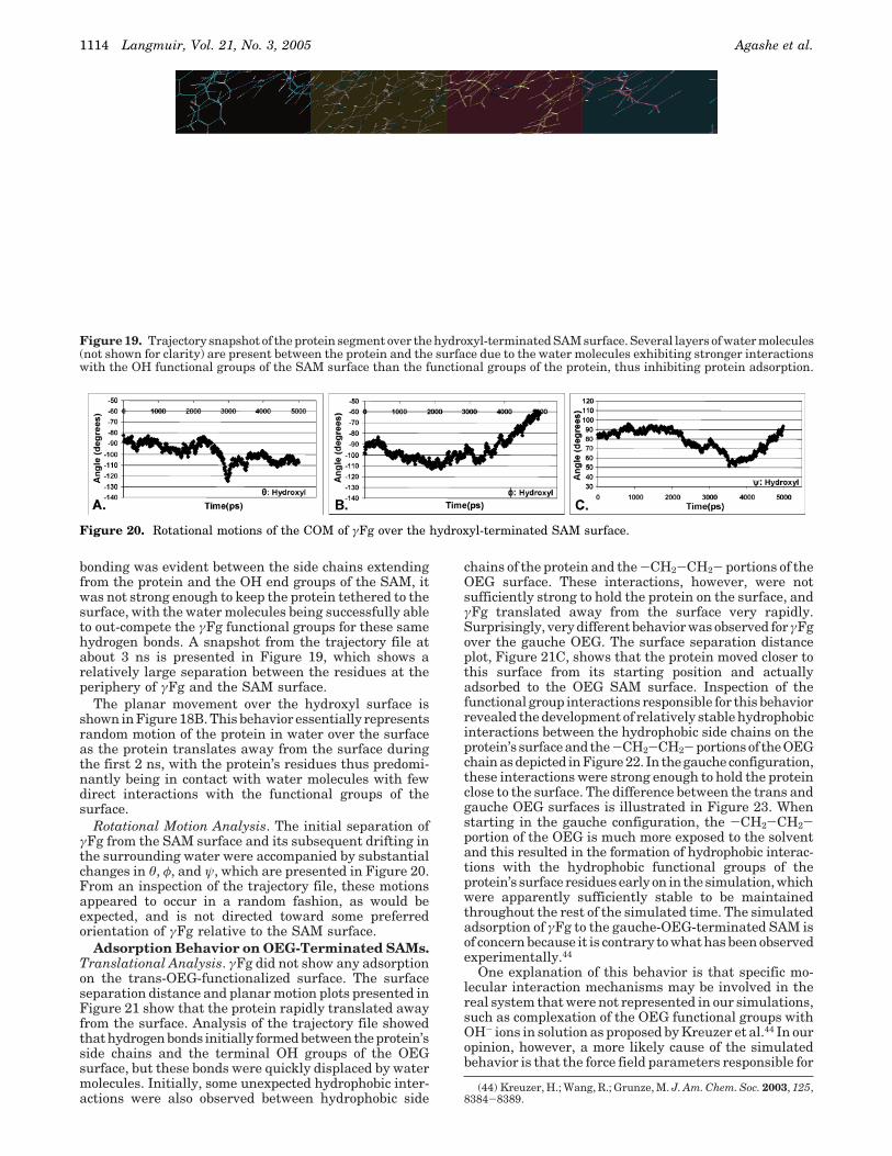
bonding was evident between the side chains extendingfrom the protein and the OH end groups of the SAM, itwas not strong enough to keep the protein tethered to thesurface, with the water molecules being successfully ableto out-compete the γFg functional groups for these samehydrogen bonds. A snapshot from the trajectory file atabout 3 ns is presented in Figure 19, which shows arelatively large separation between the residues at theperiphery of γFg and the SAM surface.
The planar movement over the hydroxyl surface isshown in Figure 18B. This behavior essentially representsrandom motion of the protein in water over the surfaceas the protein translates away from the surface duringthe first 2 ns, with the protein’s residues thus predomi-nantly being in contact with water molecules with fewdirect interactions with the functional groups of thesurface.
Rotational Motion Analysis. The initial separation ofγFg from the SAM surface and its subsequent drifting inthe surrounding water were accompanied by substantialchanges in θ, φ, and ψ, which are presented in Figure 20.From an inspection of the trajectory file, these motionsappeared to occur in a random fashion, as would beexpected, and is not directed toward some preferredorientation of γFg relative to the SAM surface.
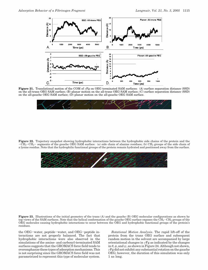
Adsorption Behavior on OEG-Terminated SAMs.Translational Analysis. γFg did not show any adsorptionon the trans-OEG-functionalized surface. The surfaceseparation distance and planar motion plots presented inFigure 21 show that the protein rapidly translated awayfrom the surface. Analysis of the trajectory file showedthat hydrogen bonds initially formed between the protein’sside chains and the terminal OH groups of the OEGsurface, but these bonds were quickly displaced by watermolecules. Initially, some unexpected hydrophobic inter-actions were also observed between hydrophobic side
chains of the protein and the -CH2-CH2- portions of theOEG surface. These interactions, however, were notsufficiently strong to hold the protein on the surface, andγFg translated away from the surface very rapidly.Surprisingly, very different behavior was observed for γFgover the gauche OEG. The surface separation distanceplot, Figure 21C, shows that the protein moved closer tothis surface from its starting position and actuallyadsorbed to the OEG SAM surface. Inspection of thefunctional group interactions responsible for this behaviorrevealed the development of relatively stable hydrophobicinteractions between the hydrophobic side chains on theprotein’s surface and the -CH2-CH2- portions of the OEGchain as depicted in Figure 22. In the gauche configuration,these interactions were strong enough to hold the proteinclose to the surface. The difference between the trans andgauche OEG surfaces is illustrated in Figure 23. Whenstarting in the gauche configuration, the -CH2-CH2-portion of the OEG is much more exposed to the solventand this resulted in the formation of hydrophobic interac-tions with the hydrophobic functional groups of theprotein’s surface residues early on in the simulation, whichwere apparently sufficiently stable to be maintainedthroughout the rest of the simulated time. The simulatedadsorption of γFg to the gauche-OEG-terminated SAM isof concern because it is contrary to what has been observedexperimentally.44
One explanation of this behavior is that specific mo-lecular interaction mechanisms may be involved in thereal system that were not represented in our simulations,such as complexation of the OEG functional groups withOH- ions in solution as proposed by Kreuzer et al.44 In ouropinion, however, a more likely cause of the simulatedbehavior is that the force field parameters responsible for
(44) Kreuzer, H.; Wang, R.; Grunze, M. J. Am. Chem. Soc. 2003, 125,8384-8389.
Figure 19. Trajectory snapshot of the protein segment over the hydroxyl-terminated SAM surface. Several layers of water molecules(not shown for clarity) are present between the protein and the surface due to the water molecules exhibiting stronger interactionswith the OH functional groups of the SAM surface than the functional groups of the protein, thus inhibiting protein adsorption.
Figure 20. Rotational motions of the COM of γFg over the hydroxyl-terminated SAM surface.
1114 Langmuir, Vol. 21, No. 3, 2005 Agashe et al.
the OEG-water, peptide-water, and OEG-peptide in-teractions are not properly balanced. The fact thathydrophobic interactions were also observed in thesimulations of the amine- and carboxyl-terminated SAMsurfaces suggests that the GROMACS force field tends tooveremphasize these typesofadsorptionmechanisms.Thisis not surprising since the GROMACS force field was notparametrized to represent this type of molecular system.
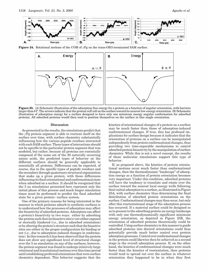
Rotational Motion Analysis. The rapid lift-off of theprotein from the trans OEG surface and subsequentrandom motion in the solvent are accompanied by largeorientational changes in γFg as indicated by the changesin θ, φ, and ψ, as shown in Figure 24. Although not shown,γFg did not exhibit any substantial rotation on the gaucheOEG; however, the duration of this simulation was only1 ns long.
Figure 21. Translational motion of the COM of γFg on OEG terminated SAM surfaces: (A) surface separation distance (SSD)on the all-trans OEG SAM surface; (B) planar motion on the all-trans OEG SAM surface; (C) surface separation distance (SSD)on the all-gauche OEG SAM surface; (D) planar motion on the all-gauche OEG SAM surface.
Figure 22. Trajectory snapshot showing hydrophobic interactions between the hydrophobic side chains of the protein and the-CH2-CH2- segments of the gauche OEG SAM surface: (a) side chain of alanine residues; (b) CH2 groups of the side chain ofa lysine residue. Note that the hydrophilic functional groups of the protein remain hydrated and positioned away from the surface.
Figure 23. Illustrations of the initial geometry of the trans (A) and the gauche (B) OEG molecular configurations as shown bytop views of the SAM surfaces. Note that the helical conformation of the gauche OEG surface exposes the CH2-CH2 groups of theOEG molecules causing hydrophobic interactions to occur between the OEG and hydrophobic functional groups of the protein’sresidues.
Adsorption Behavior of a Fibrinogen Fragment Langmuir, Vol. 21, No. 3, 2005 1115
Discussion
As presented in the results, the simulations predict thatthe γFg protein segment is able to reorient itself on thesurface over time, with surface chemistry substantiallyinfluencing how the various peptide residues interactedwith each SAM surface. These types of interactions shouldnot be specific to the particular protein segment that wasmodeled, but rather, because all proteins are essentiallycomposed of the same set of the 20 naturally occurringamino acids, the predicted types of behavior on thedifferent surfaces should be generally applicable toessentially all proteins. Differences can be expected, ofcourse, due to the specific types of peptide residues andthe secondary through quaternary structural organizationthat make up a given protein, with these differencesinfluencing its final orientational and conformational statewhen adsorbed on a surface. It should be recognized thatthe 5 ns simulations presented here represent only theinitial phase of this process and much longer simulationtimes must be performed to predict the final adsorbedstate for a given protein-surface system.
One of the primary reasons for being interested in themanner in which proteins adsorb to synthetic surfaces isto understand how the processes of adsorption may affectthe bioactivity of adsorbed proteins. Adsorption can affecta protein’s bioactivity in two ways: either by adsorbingthe protein such that its bioactive site(s) are either exposedor sterically hindered (i.e., due to adsorbed orientation)orbyaltering theprotein’s structuresuchthat thebioactivesites are either in the proper configuration for binding ornot (i.e., due to adsorption-induced changes in conforma-tion). In this research it has been observed that the proteindoes not show any significant level of structural changeover the 5 ns simulation on any of the surfaces; however,the protein segment was found to undergo relatively largerotational and translational motions over this time perioduntil establishing preferred orientations that were surfacechemistry dependent. This behavior suggests that the
kinetics of orientational changes of a protein on a surfacemay be much faster than those of adsorption-inducedconformational changes. If true, this has profound im-plications for surface design because it indicates that theorientation of proteins on a surface can be manipulatedindependently from protein conformational changes, thusproviding two time-separable mechanisms to controladsorbed protein bioactivity by the manipulation of surfacechemistry. While this is not a novel concept, the resultsof these molecular simulations support this type ofbehavior.
If, as proposed above, the kinetics of protein orienta-tional motions occur much faster than conformationalchanges, then the thermodynamic “landscape” of adsorp-tion energy as a function of protein orientation becomesvery important. Under this condition, adsorbed proteinswill have the tendency to translate and rotate over thesurface toward the nearest local energy wells followingtheir initial adsorption to a surface, as illustrated in Figure25A, with surface chemistry thus determining the finaldistribution of adsorbed protein orientations on thesurface. Conformational changes may then occur, but onlyafter this reorientational stage of the adsorption processhas occurred. If a material surface could be designed soas to present to the adsorbing protein an energy landscapewith only one thermodynamically significant minimumenergy orientation, as depicted in Figure 25B, theorientation of adsorbed proteins theoretically could becontrolled.Usingsurfacechemistry in thismanner toguideadsorbed proteins into desired orientations could thuspotentially provide much better control over proteinadsorption processes. Control over conformational changesin the protein could likewise then be achieved as a secondstage in the overall adsorption process. If, on the otherhand, the kinetics of conformational changes were muchfaster than the kinetics of reorientation, then proteinswould tend to spread out over the surface in whateverorientation they happened to be in when they first
Figure 24. Rotational motions of the COM of γFg on the trans-OEG-terminated SAM surface.
Figure 25. (A) Schematic illustration of the adsorption free energy for a protein as a function of angular orientation, with barrierslarger than kT. The arrows indicate that the protein will roll on the surface toward its nearest low-energy orientation. (B) Schematicillustration of adsorption energy for a surface designed to have only one minimum energy angular conformation for adsorbedproteins. All adsorbed proteins would then tend to position themselves on the surface in this single orientation.
1116 Langmuir, Vol. 21, No. 3, 2005 Agashe et al.
adsorbed without time to reorient, and surface chemistrycould have little effect on the orientation of adsorbedproteins. The former behavior, which is supported by thisresearch, provides a much more desirable situation interms of the potential to control the behavior of adsorbedproteins and their subsequent bioactivity by the rationaldesign of surface chemistry.
ConclusionsThis research was undertaken with the initial objective
of examining the adsorption behavior γFg as a functionof surface chemistry in order to investigate how adsorptionmay cause the P1-P2 epitopes to become exposed forpossible integrin binding. The changes in RMSD and SASover the 5 ns time scale of the simulations, however, werenot found to be substantially different than those for thesame protein fragment in bulk aqueous solution, thusindicating that the adsorption processes did not induceany significant levels of conformational change in theprotein segment over this time scale. However, the resultsof these simulations do suggest that following initialadsorption, γFg undergoes substantial surface-inducedrotational and translational motions until relatively stablelow-energy adsorbed orientations are achieved. It mustbe emphasized, however, that the modeled protein seg-ment only represents a portion of Fg and its adsorptionbehavior certainly can be expected to be substantiallyinfluenced by the other portions of the Fg structure, suchas its R and â chains. As molecular simulation methodsand computational power continue to improve over time,the entire Fg molecule should be able to be simulated andthese effects should be able to be directly considered.Despite these current limitations, the observation thatthe kinetics that control changes in adsorbed proteinorientation may be much faster than the kinetics thatcontrol adsorbed protein conformation is of great relevancebecause it suggests that surface chemistry may be usedto control the orientation of adsorbed proteins indepen-
dently from adsorbed conformation, thus providing twotime-separable mechanisms to influence adsorbed proteinbioactivity.
These statements, however, must be tempered by therealization that none of the currently available force fieldshave been validated for the simulation of protein adsorp-tion behavior to synthetic material surfaces. While proteinadsorption simulations can and are being performed, theresults of such simulations are usually so complex thatthey cannot be directly validated by experiment, exceptthrough very qualitative measures. Thus, at this time,the simulation results obtained from this research canonly be presented as the molecular behavior predicted bythe GROMACS force field. Further research is clearlyneeded. Most importantly, force fields must be validatedfor peptide-surface functional group interactions beforemolecular simulation can be confidently used as a predic-tive tool for materials surface design to control proteinadsorption behavior. Our laboratory group is activelyworking to directly address these issues.
While much development work is still needed, molecularsimulations have enormous potential to complementexperimental studies as we strive to understand thecomplexities of protein-surface interactions, and how tocontrol them, so that the inherent bioactivity of proteinscan be effectively harnessed for numerous applications inbiotechnology, nanotechnology, and biomedical engineer-ing.
Acknowledgment. We thank NSF (award numberEPS-0296165), the State of South Carolina, and ClemsonUniversity for providing the funding support for thisproject. We also thank the NSF Center for AdvancedEngineering Fibers and Films (CAEFF), Ms. CoreyFerrier, and Mr. Tim Shelling at Clemson University forcomputer system support.
LA0478346
Adsorption Behavior of a Fibrinogen Fragment Langmuir, Vol. 21, No. 3, 2005 1117
Copyright © 2022 FDOKUMEN