MODFLOW-USG: the New Possibilities in Mine Hydrogeology Modelling (or What is Not Written in the...
10
1 23 Mine Water and the Environment Journal of the International Mine Water Association (IMWA) ISSN 1025-9112 Mine Water Environ DOI 10.1007/s10230-014-0273-9 MODFLOW-USG: the New Possibilities in Mine Hydrogeology Modelling (or What is Not Written in the Manuals) David Krčmář & Ondra Sracek
-
Upload
independent -
Category
Documents
-
view
2 -
download
0
Transcript of MODFLOW-USG: the New Possibilities in Mine Hydrogeology Modelling (or What is Not Written in the...
1 23
Mine Water and the EnvironmentJournal of the International Mine WaterAssociation (IMWA) ISSN 1025-9112 Mine Water EnvironDOI 10.1007/s10230-014-0273-9
MODFLOW-USG: the New Possibilities inMine Hydrogeology Modelling (or What isNot Written in the Manuals)
David Krčmář & Ondra Sracek

1 23
Your article is protected by copyright and
all rights are held exclusively by Springer-
Verlag Berlin Heidelberg. This e-offprint is
for personal use only and shall not be self-
archived in electronic repositories. If you wish
to self-archive your article, please use the
accepted manuscript version for posting on
your own website. You may further deposit
the accepted manuscript version in any
repository, provided it is only made publicly
available 12 months after official publication
or later and provided acknowledgement is
given to the original source of publication
and a link is inserted to the published article
on Springer's website. The link must be
accompanied by the following text: "The final
publication is available at link.springer.com”.
TECHNICAL COMMUNICATION
MODFLOW-USG: the New Possibilities in Mine HydrogeologyModelling (or What is Not Written in the Manuals)
David Krcmar • Ondra Sracek
Received: 6 December 2013 / Accepted: 5 March 2014
� Springer-Verlag Berlin Heidelberg 2014
Abstract Geological heterogeneity associated with lay-
ers, open mine voids, tectonic faults and fractures can all
make modelling difficult, particularly for mine dewatering.
This heterogeneity is difficult to represent with the tradi-
tional MODFLOW structured grid. A new version of
MODFLOW, called MODFLOW-USG (for UnStructured
Grid), supports a wide variety of structured and unstruc-
tured grid types (Panday et al. in MODFLOW-USG version
1: an unstructured grid version of MODFLOW for simu-
lating groundwater flow and tightly coupled processes
using a control volume finite-difference formulation.
USGS, Reston, 2013) that provide flexibility for modelling
difficult geologic structures. This communication compares
aspects of MODFLOW and MODFLOW-USG, and uses
the Gbely lignite deposit as an example of a situation for
which MODFLOW-USG could be applied.
Keywords Lignite deposit � Model setup � MODFLOW �Unstructured grid
Introduction
MODFLOW is a very popular software program, and is
commonly used in the field of mine hydrogeology. How-
ever, MODFLOW is challenged by complicated geology,
heterogeneities, and artificial structures such as mine voids
that cause flow field changes relative to the surrounding
geological environment.
A typical application is to model water inflow. Singh
and Reed (1988) give descriptions of analytical and
empirical methods for evaluating surface water inflows into
a mine, and Toran and Bradbury (1988) tested the ability of
a ground water flow model to predict the impacts of
underground mining on ground water system. Dewatering
was simulated using a drain package. The drain option
allows variation of dewatering rates and ‘‘turns off’’ auto-
matically when the groundwater head falls below the drain
level, giving this option an advantage over placing dewa-
tering wells in the model. The number and locations of
drains can also be varied between stress periods in a single
run, allowing the sequential addition or reduction of drains
as mining progresses. However, the drain package option
can cause significant problems if improper grid spacing is
applied around the mine workings (Zaidel et al. 2010).
Their simulations showed that seepage rates can be accu-
rately predicted by either applying grid spacing that is
much finer than the diameter of the mine openings or by
using a coarser grid with grid sizes exceeding the charac-
teristic width of openings by a factor of three.
Water discharge from abandoned mines is another situ-
ation that is modelled, due to issues of water resource
degradation (Brown et al. 1998; Flakova et al. 2012; Hiller
et al. 2012; Luo et al. 2012; Moldovan et al. 2008; Ond-
rejkova et al. 2013). Flow in open mine voids is often tur-
bulent, which makes standard modelling tools inappropriate
Electronic supplementary material The online version of thisarticle (doi:10.1007/s10230-014-0273-9) contains supplementarymaterial, which is available to authorized users.
D. Krcmar (&)
Department of Hydrogeology, Faculty of Natural Sciences,
Comenius University in Bratislava, Mlynska Dolina,
84215 Bratislava, Slovak Republic
e-mail: [email protected]
O. Sracek
Department of Geology, Faculty of Science, Palacky University,
17. listopadu 12, 77146 Olomouc, Czech Republic
123
Mine Water Environ
DOI 10.1007/s10230-014-0273-9
Author's personal copy
for predicting groundwater rebound. The scale of the
problem is important, requiring different approaches; water
balance calculations are used at very large scales, while
three dimensional (3D) pipe networks routed through var-
iably saturated porous medium are used at small scales
(Adams and Younger 2001). Case studies of mine dewa-
tering and rebound are presented in Rapantova et al. (2007).
Flow through tectonic faults also needs to be modelled.
A fault may have different functions, e.g. it can act as a
barrier to ground water flow or it can act as a preferential
flow path, usually in a vertical direction. Water flow along
faults has been simulated to model flows to a well
(Anderson 2006), into active mines (Lianchong et al. 2011;
Wu et al. 2003), and into abandoned mines (Frolik et al.
2004). Faults are often simulated in MODFLOW with the
horizontal flow barrier (HFB) package (Hsieh and Freckl-
eton 1993), where conductivity and width of the HFB is
specified. However, this approach does not allow simula-
tion of vertical flow within faults.
MODFLOW USG: the New Features
The US Geological Survey (USGS) developed MODFLOW
based on a structured grid (rectangular finite difference grid),
in which each cell is connected to six neighbouring cells.
Connections are easily determined by row, column, and layer
numbering. However, irregular boundaries cannot be fitted
precisely with a rectangular grid. If high accuracy is
required, a large refinement is necessary, which requires a
large numbers of cells for the model setup. There are also
problems when grid resolution refinement is only needed in
some parts of the modelling domain. Row and column width
can vary, but the dimensions of a particular row or column
have to be the same through the entire modelling domain.
Efforts to deal with this limitation led to the development of a
nested grid approach. Nested grids usually use a parent grid
with coarse resolution and child grids with fine resolution,
which are then coupled in an iterative manner.
A new version of MODFLOW–MODFLOW USG
(UnStructured Grid, Panday et al. 2013) was developed
based on an unstructured grid approach (control volume
finite differences, or integrated finite differences). This
approach allows the user to create flexible grids of virtually
any shape, which can be refined in areas of interest.
Groundwater flow is then simulated at all grid connections
using fully implicit solutions with a single matrix.
MODFLOW-USG also supports packages that transfer
water between different grid nesting levels, such as the
Stream Flow Routing Package or the connected linear
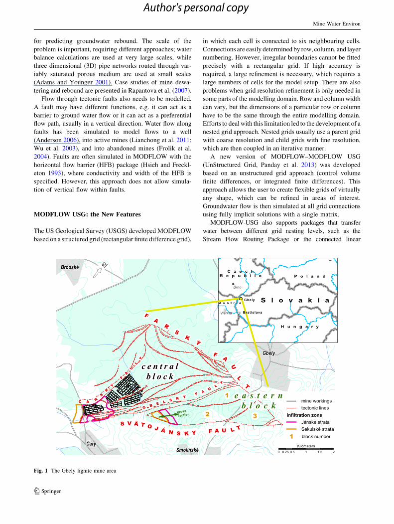
Fig. 1 The Gbely lignite mine area
Mine Water Environ
123
Author's personal copy

network (CLN) Package. The new CLN package is roughly
equivalent to the Multi Node Well Package or MODFLOW-
Surfact’s Fracture Well Package, but it is much more general
(Rumbaugh 2011). The CLN package also replicates some of
the capabilities of the Conduit Flow Process module for
MODFLOW-2005 (Shoemaker et al. 2008). The CLN cells
can represent wells, pipes, fractures, underground excava-
tions, tunnels, rivers, or other linear features, and CLN cells
can be vertical, horizontal, or tilted. The formulation is gen-
eral enough that different types of features can transmit water
into each other. For instance, pipes can transmit water to/from
open channel features, which have small cross sectional areas
relative to groundwater cells, without requiring groundwater
cell refinement (Panday et al. 2013).
Case Study: Gbely Lignite Deposit
Significant lignite deposits are found in the northern part of
the Vienna basin, intruding from Austria into southern
Moravia (Czech Republic) and the southeast tip of Slovakia.
The Dubnany coal seam is part of the youngest (Pontian)
sediments of the Vienna basin. There are two main mine
sites, one near Hodonın in the Czech Republic and another
near Kuty and Gbely in the Slovak Republic. The Gbely
deposit is a part of the Kuty trough, tectonically bounded by
the Farsky fault in the north (amplitude of tectonic
Late Panonian, Záhorské strata: gray clays and sandy clays
Early Pontian, Sekulské strata:
sandy aquifers and clay aquitards
Pontian Dub an coal seam with clay layers
Late Pontian, Jánske strata:
sandy aquifers and clay aquitards
Dacian, Gbelké strata: green, brown and
patchy clays
Quarternary sediments
South NorthINFILTRATION ZONEFig. 2 Schematic
representation of the Dubnany
seam around the infiltration
zone (for location, see Fig. 1)
fau
lt
coal seam
aquifer
aquitard
layer 1
layer 2
layer 3layer 4
layer 5
layer 6
layer 7
layer 8layer 9
Fig. 4 Model grid, northern part
movement along tectonics80 (m)
movement along tectonics60 (m)connected
tectonic blocks
-10 m asl
180 m asl
1
23
blocknumber
Fig. 3 3D view of the Eastern
lifted block (only position of
coal seam is displayed)
Mine Water Environ
123
Author's personal copy
movement approximately 300 m), the Svatojansky fault in
the northeast, and the Cary fault in the west. The Gbelsky
fault splits the deposit into two parts: a central block and the
eastern lifted block. There are also smaller inner faults with
tectonic movements up to 50 m (Fig. 1).
The Gbely deposit consists of marine clay sediments of
the Late Panonian Zahorsky strata. Early Pontian Sekulske
strata are above the marine clay and comprise two sandy
aquifers (1–15 m thick) separated by a clay aquitard
(1–28 m thick). A clay aquitard is also present directly
below and above the coal seam. The thickness of the coal
seam is relatively uniform and varies from 3.5 to 5.6 m.
Late Pontian Janske strata are above the coal seam and
comprise three sandy aquifers (6–20 m thick) separated by
clay aquitards (0–20 m). In some areas, aquitards are not
evolved and aquifers are connected. The Dacian Gbelske
strata are above the Janske strata, forming an impervious
layer and separating the coal seam from Quaternary
fau
lt
layer 1
layer 2
layer 3
layer 4
layer 5
layer 6
layer 7
layer 8
layer 9
layer 1
layer 2
layer 3
layer 4
layer 5
layer 6
layer 7
layer 8
layer 9
flow of wateralong layers
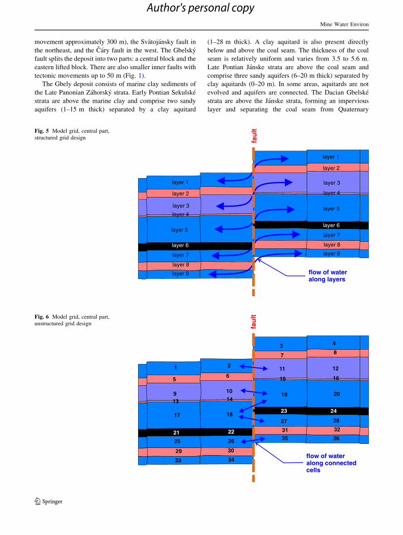
Fig. 5 Model grid, central part,
structured grid design
fau
lt
2
3 4
6
7 8
10
11 12
14
15 16
18
19 20
22
2423
26
27 28
30
31 32
1
5
913
17
21
25
29
33 34
35 36
flow of wateralong connected cells
Fig. 6 Model grid, central part,
unstructured grid design
Mine Water Environ
123
Author's personal copy

sediments. However, the coal seam reaches the surface in
the south (Fig. 2), allowing precipitation to infiltrate
through the Quaternary sediments (aeolian sand and sandy
or clayey loams) and provide recharge for aquifers (Fig. 1).
The eastern lifted block is divided by inner faults into
three sub-blocks. In the north, along the Farsky fault, sub-
blocks are connected. In the south, the sub-blocks rise
along inner tectonic faults, with variable amounts of uplift
(Fig. 3).
The Gbely mine workings are currently active in the
central block and there are plans to mine the eastern block.
Active mined areas are progressing towards the north
(Fig. 1). Mine workings have to be dewatered because of
inflow from overlaying and underlying sandy aquifers.
Recent exploration has been conducted to determine an
optimal dewatering plan for the eastern block. The
MODFLOW-USG with its new capabilities seems to be a
great tool for fulfilling the project goals. This article tries to
emphasise its benefits in the model setup.
In a typical MODFLOW (i.e. using a finite difference
grid) approach, connections between neighbouring cells are
determined by row, column, and layer numbering. This
fact, that flow is directed only, for example, by the layer
number is not particularly emphasised in the manual, and
occurs even if the cells are not physically connected in the
model setup. An inexperienced user could easily fall in
trouble in complicated geological settings. This paper tries
to show how to deal with or overcome such situations.
In the northern Gbely area, there is no problem with the
classical approach because the sub-blocks are physically
connected (Fig. 4). The model grid can consist of layers
representing the aquifer, aquitards, and the coal seam. The
only unknown would be the hydraulic properties of the
fault zone, which could act as a hydraulic barrier; this
could be represented in the model by an HFB element.
Further south, blocks are shifted upwards along tectonic
faults, and the magnitude of vertical movement is different
for each block. In such a case, we face problems with the
classical finite grid approach (Fig. 5) as the model incor-
rectly assumes that water is transmitted along layers with
the same numbers. In the classical approach, ‘‘dummy’’
layers could be added on both sides, and the layers
renumbered so as to guarantee the expected water flows.
This method is cumbersome and could result in errors in
the model design. Using MODFLOW-USG and its
unstructured grid, we can directly specify connections
between cells in all directions (Fig. 6). Cells may have
more neighbouring cells along one principal direction, e.g.
cell no. 18 on its right hand side has two neighbouring
cells, no. 19 and no. 27, and water flow is split between
flow of wateralong layers
fau
lt
Fig. 7 Model grid, southern part
pinching of layers reaching surface
pinching of inner layers
Fig. 8 Representation of layer
pinching with unstructured grid
Mine Water Environ
123
Author's personal copy
them. The model also considers contact areas between
connected cells and calculates correct water flow accord-
ingly, which is not possible with the classical approach.
This fact is not usually mentioned in the manual. Fault
zones can be represented in the same way as in the classical
approach with an HFB element.
Even further south, the blocks (model layers) are totally
disconnected. In the classical approach, the model is still
transmitting water along layers with the same number,
which is inaccurate (Fig. 7).
Pinching out of layers poses another problem. In Fig. 2,
two cases of pinching out appear, one where layers reach
the surface and the other inside the Janske strata where
aquifers are connected. Again, the classical approach has
problems representing such phenomena, but an unstruc-
tured grid can include pinching out in the grid design
(Fig. 8).
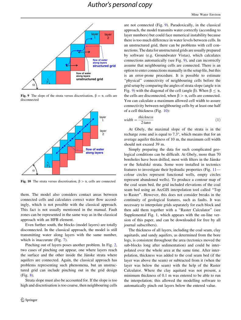
Strata slope must also be accounted for. If the slope is too
high and discretisation is too coarse, then neighbouring cells
are not connected (Fig. 9). Paradoxically, in the classical
approach, the model transmits water correctly (according to
layer numbers) but could face numerical instability because
there is too much difference in water levels between cells. In
an unstructured grid, there can be problems with cell con-
nections. The data for unstructured grids are usually prepared
by software (e.g. Groundwater Vistas), which calculates
connections automatically (see Fig. 9), and can incorrectly
assume that neighbouring cells are connected. There is an
option to enter connections manually in the setup file, but this
is an error-prone procedure. It is possible to estimate
‘‘physical’’ connectivity of neighbouring cells before the
grid setup by comparing the angles of strata slope (angle a in
Fig. 9) with the diagonal of the cell (angle b). When b B a,
the cells are disconnected, when b[a, cells are connected.
You can calculate a maximum allowed cell width to assure
connectivity between neighbouring cells by at least one half
of a cell thickness (Fig. 10):
width ¼ thickness
2 tanað1Þ
At Gbely, the maximal slope of the strata is in the
recharge zone and is equal to 7.3�, which means that for an
average aquifer thickness of 10 m, the maximum cell width
should not exceed 39 m.
Simply preparing the data for such complicated geo-
logical conditions can be difficult. At Gbely, more than 70
boreholes have been drilled, most with filters in the Janske
or the Sekulske strata. Some were installed in tectonics
features to investigate their hydraulic properties (Fig. 11—
colour circles represent functional wells, empty circles
represent abandoned wells). To produce a contour map of
the coal seam bed, the grid included elevations of the coal
seam bed using an ArcGIS interpolation tool called ‘‘Top
to Raster’’. However, this does not consider breaks in the
continuity of geological features, such as faults. It was
necessary to interpolate grids separately for each block and
then add them together with a ‘‘Raster Calculator’’ (see
Supplemental Fig. 1, which appears with the on-line ver-
sion of this paper, and can be downloaded for free by all
journal subscribers).
The thickness of all layers, including the coal seam, clay
aquitards, and sandy aquifers, as determined from the bore
logs, is consistent throughout the area (tectonics moved the
sub-blocks long after sedimentation) and could be inter-
polated over the whole area at the same time. After inter-
polation, thickness was added to the coal seam bed (if the
layer was above the seam) or subtracted from it (when the
layer was below the seam) with the help of the Raster
Calculator. Where the clay aquitard was not present, a
minimum thickness of 0.1 m was entered to be able to run
the interpolation; this allowed the modelling software to
automatically pinch out layers below the entered value.
flow of wateralong layersstructured grid
α β
layer1
layer2
flow of wateralong layersunstructured grid
Fig. 9 The slope of the strata versus discretisation, b = a, cells are
disconnected
α β
layer1
layer2
flow of wateralong layers
Fig. 10 The strata versus discretisation, b[a, cells are connected
Mine Water Environ
123
Author's personal copy

Conclusion
Modelling water flow in mine workings represents a
challenging problem. We can deal with many complicated
features, such as discontinuities (geological faults, mine
openings, etc.), steep and uneven slopes, or pinching out of
layers. This paper describes possible problems that could
arise by creating a model setup with the classical approach,
using the Gbely lignite deposit as an illustrative example.
The problem is how to represent the features and water
flow in the model correctly. If the cells are physically
disconnected in the model, modelling software may not
know that and could transfer water inappropriately. The
other problem is discretisation. Users should be aware of
errors that could develop due to coarse discretisation of the
model domain. We recommend that you estimate the
maximal cell width based on the slope of the strata and
thickness of the layer. Doing this, you can evaluate correct
discretisation of the model. In the software manuals, spe-
cial cases such as these are not usually fully covered and it
was our goal to describe them using real case examples.
This paper also tried to introduce the new MODFLOW-
USG, which is a great tool for complicated conditions, with
many improvements over the classical structured grid
approach. MODFLOW-USG is very useful for modelling
water flow in mined areas because it deals more appropri-
ately with many problems that the classical approach strug-
gled with. But there are also some cases, as we can see in the
case of rough discretisation, when automatic creation of
connections between cells could fail. So deep understanding
of the whole process is vital; we can all learn the most by
solving real life problems and by sharing our knowledge.
Acknowledgments The research was performed with the help of
funds from the Ministry of Education, Science, Research and Sport of
the Slovak Republic under contract VEGA 1/0921/11, ‘‘Optimization
of mine discharge with help of numerical modeling’’.
References
Adams R, Younger PL (2001) A strategy for modelling ground water
rebound in abandoned deep mine systems. Ground Water
39(2):249–261
Anderson EI (2006) Analytical solutions for flow to a well through a
fault. Adv Water Res 29:1790–1803. doi:10.1016/j.advwatres.
2005.12.010
Fig. 11 Map of wells and coal seam bed contours
Mine Water Environ
123
Author's personal copy

Brown PL, Guerin M, Hankin SI, Lowson RT (1998) Uranium and
other contaminant migration in groundwater at a tropical
Australian uranium mine. J Contam Hydrol 35:295–303
Flakova R, Zenisova Z, Sracek O, Krcmar D, Ondrejkova I, Chovan
M, Lalinska B, Fendekova M (2012) The behavior of arsenic and
antimony at Pezinok mining site, southwestern part of the Slovak
Republic. Environ Earth Sci 66:1043–1057. doi:10.1007/s12665-
011-1310-7
Frolik A, Gzyl G, Kura K (2004) A simple 1D MODFLOW model for
a part of a mine undergoing closure in Silesia, Poland. Proc Int
Mine Water Assoc Symp 2:247–250
Hiller E, Lalinska B, Chovan M, Jurkovic L, Klimko T, Jankular M,
Hovoric R, Sottnık P, Flakova R, Zenisova Z, Ondrejkova I
(2012) Arsenic and antimony contamination of waters, stream
sediments and soils in the vicinity of abandoned antimony mines
in the Western Carpathians, Slovakia. Appl Geochem
7(3):598–614. doi:10.1016/j.apgeochem.2011.12.005
Hsieh PA, Freckleton JR (1993) Documentation of a computer
program to simulate horizontal-flow barriers using the U.S.
Geological Survey modular three-dimensional finite-difference
ground-water flow model. USGS Open-File Report 92–477,
Reston, VA, USA
Lianchong L, Tianhong Y, Zhengzhao L, Wancheng Z, Chunan T
(2011) Numerical investigation of groundwater outbursts near
faults in underground coal mines. Int J Coal Geol 85:276–288.
doi:10.1016/j.coal.2010.12.006
Luo J, Diersch HJG, Monninkhoff LMM (2012) 3D modeling of
saline groundwater flow and transport in a flooded salt mine in
Stassfurt, Germany. Mine Water Environ 31:104–111. doi:10.
1007/s10230-012-0181-9
Moldovan BJ, Hendry MJ, Harrington GA (2008) The arsenic source
term for an in-pit uranium mine tailings facility and its long-term
impact on the regional groundwater. Appl Geochem
23:1437–1450. doi:10.1016/j.apgeochem.2007.12.037
Ondrejkova I, Zenisova Z, Flakova R, Krcmar D, Sracek O (2013)
The distribution of antimony and arsenic in waters of the
Dubrava abandoned mine site, Slovak Republic. Mine Water
Environ 32:207–221. doi:10.1007/s10230-013-0229-5
Panday S, Langevin ChD, Niswonger RG, Ibaraki M, Hughes JD
(2013) MODFLOW–USG version 1: an unstructured grid
version of MODFLOW for simulating groundwater flow and
tightly coupled processes using a control volume finite-differ-
ence formulation. Ch 45, Section A, Groundwater Book 6,
Modeling Techniques. USGS, Reston, VA, USA
Rapantova N, Grmela A, Vojtek D, Halir J, Michalek B (2007)
Ground water flow modelling applications in mining hydroge-
ology. Mine Water Environ 26:264–270. doi:10.1007/s10230-
007-0017-1
Rumbaugh JO (2011) Tutorial manual for groundwater vistas.
Version 6, Environmental Simulations, Reinholds, PA, USA
Shoemaker, WB, Kuniansky EL, Birk S, Bauer S, Swain ED (2008)
Documentation of a conduit flow process (CFP) for MOD-
FLOW–2005: USGS Techniques and Methods 6-A24, Reston,
VA, USA
Singh RN, Reed SM (1988) Mathematical modelling for estimation of
mine water inflow to a surface mining operation. Int J Mine
Water 7(3):1–34
Toran L, Bradbury KR (1988) Ground-water flow model of
drawdown and recovery near an underground mine. Ground
Water 26(6):724–733
Wu Q, Wang M, Wu X (2003) Investigations of groundwater bursting
into coal mine seam floors from fault zones. Int J Rock Mech
Min 41:557–571. doi:10.1016/j.ijrmms.2003.01.004
Zaidel J, Markham B, Bleiker D (2010) Simulating seepage into mine
shafts and tunnels with MODFLOW. Ground Water 48(3):1–11.
doi:10.1111/j.1745-6584.2009.00659.x
Mine Water Environ
123
Author's personal copy