Modelling channelized surface drainage of supraglacial lakes
15
Modelling channelized surface drainage of supraglacial lakes J. KINGSLAKE, 1,2 F. NG, 2 A. SOLE 2 1 British Antarctic Survey, Natural Environment Research Council, Cambridge, UK 2 Department of Geography, University of Sheffield, Sheffield, UK Correspondence: J. Kingslake <[email protected]> ABSTRACT. Supraglacial lakes can drain to the bed of ice sheets, affecting ice dynamics, or over their surface, relocating surface water. Focusing on surface drainage, we first discuss observations of lake drainage. In particular, for the first time, lakes are observed to drain >70 km across the Nivlisen ice shelf, East Antarctica. Inspired by these observations, we develop a model of lake drainage through a channel that incises into an ice-sheet surface by frictional heat dissipated in the flow. Modelled lake drainage can be stable or unstable. During stable drainage, the rate of lake-level drawdown exceeds the rate of channel incision, so discharge from the lake decreases with time; this can prevent the lake from emptying completely. During unstable drainage, discharge grows unstably with time and always empties the lake. Model lakes are more prone to drain unstably when the initial lake area, the lake input and the channel slope are larger. These parameters will vary during atmospheric-warming-induced ablation-area expansion, hence the mechanisms revealed by our analysis can influence the dynamic response of ice sheets to warming through their impact on surface-water routing and storage. KEYWORDS: Antarctic glaciology, glacier hydrology, glacier modelling, ice-sheet modelling, remote sensing 1. INTRODUCTION Supraglacial lakes form where meltwater collects in topo- graphic depressions on the surface of glaciers, ice sheets and ice shelves (Reynolds, 1981; Echelmeyer and others, 1991; Lüthje and others, 2006; Sundal and others, 2009; Selmes and others, 2011; Sergienko, 2013). These lakes are important because they lower surface albedo, increasing the absorption of incoming radiation (Lüthje and others, 2006; Tedesco and others, 2012); they can drain to the bed of glaciers and ice sheets, influencing ice dynamics and subglacial drainage system development (Van der Veen, 2007; Das and others, 2008; Cowton and others, 2013; Joughin and others, 2013); and they play a role in ice-shelf disintegration (Scambos and others, 2003, 2009; Banwell and others, 2013; MacAyeal and Sergienko, 2013). Here we focus on the drainage of supraglacial lakes across the surface of ice masses, a process that changes the size and spatial distribution of lakes. Because surface-to-bed lake drainage is the only way of creating new pathways through to the bed of cold, thick ice sheets, the size and spatial distribution of lakes plays a crucial but poorly understood role in determining which parts of an ice sheet are exposed to enhanced basal sliding caused by injections of surface water to the bed. We model the drainage of a supraglacial lake via a supraglacial channel that forms by melting due to the turbulent dissipation of heat by the water flow in the channel. Surface water can also flow through firn (Forster and others, 2014), as a sheet or through systems of many small channels. We focus on drainage through a single channel because observations suggest that this is a common mechanism by which lakes drain (see, e.g., Tedesco and others, 2013) and because much of the theory needed to model this phenomenon can be borrowed from the well- developed field of open-channel hydrology (see, e.g., Henderson, 1966). Previous work has taken a similar approach (Walder and Costa, 1996; Raymond and Nolan, 2000; Mayer and Schuler, 2005; Vincent and others, 2010). The novelty here is our more generally applicable model of channel hydrol- ogy and our detailed analysis of the physical controls on the surface drainage of supraglacial lakes on ice sheets. Walder and Costa (1996) modelled lake drainage through an ice–rock breach, and Raymond and Nolan (2000) adapted their model to describe surface lake drainage on alpine, debris-covered glaciers and introduce the concept of stable and unstable drainage. During stable drainage, the discharge from the lake decreases with time; during unstable drainage it increases with time. Raymond and Nolan (2000) established the following criterion for unstable drainage: the initial incision rate of the channel must exceed the initial rate of lake-surface lowering. Using this criterion, they showed that a critical lake area exists above which drainage, initiated by a lake overtopping its bank, is unstable. This critical lake area was shown to depend on the temperature of the lake. Both Raymond and Nolan (2000) and Mayer and Schuler (2005), who used Raymond and Nolan’s (2000) model to reconstruct the drainage of an ice-marginal lake in southern Greenland, assumed a constant channel width much greater than the depth of the channel water flow. Vincent and others (2010) followed Walder and Costa (1996) in assuming that water flow is controlled by a transition through critical flow. All four studies simplified the calculation of flow depth, either by assuming that the flow is wide and shallow or that it is controlled by a critical flow transition. We make neither assumption. Instead we determine the flow depth by applying Bernoulli’s equation and a force balance to water as it flows out of the lake into the channel. This allows us to apply our model to scenarios where simplifications made by previous authors are not valid, for example where low channel slope makes critical flow unlikely. However, when critical flow does occur, our Journal of Glaciology, Vol. 61, No. 225, 2015 doi: 10.3189/2015JoG14J158 185
-
Upload
antarctica -
Category
Documents
-
view
1 -
download
0
Transcript of Modelling channelized surface drainage of supraglacial lakes

Modelling channelized surface drainage of supraglacial lakes
J. KINGSLAKE,1,2 F. NG,2 A. SOLE2
1British Antarctic Survey, Natural Environment Research Council, Cambridge, UK2Department of Geography, University of Sheffield, Sheffield, UK
Correspondence: J. Kingslake <[email protected]>
ABSTRACT. Supraglacial lakes can drain to the bed of ice sheets, affecting ice dynamics, or over theirsurface, relocating surface water. Focusing on surface drainage, we first discuss observations of lakedrainage. In particular, for the first time, lakes are observed to drain >70 km across the Nivlisen iceshelf, East Antarctica. Inspired by these observations, we develop a model of lake drainage through achannel that incises into an ice-sheet surface by frictional heat dissipated in the flow. Modelled lakedrainage can be stable or unstable. During stable drainage, the rate of lake-level drawdown exceeds therate of channel incision, so discharge from the lake decreases with time; this can prevent the lake fromemptying completely. During unstable drainage, discharge grows unstably with time and alwaysempties the lake. Model lakes are more prone to drain unstably when the initial lake area, the lake inputand the channel slope are larger. These parameters will vary during atmospheric-warming-inducedablation-area expansion, hence the mechanisms revealed by our analysis can influence the dynamicresponse of ice sheets to warming through their impact on surface-water routing and storage.
KEYWORDS: Antarctic glaciology, glacier hydrology, glacier modelling, ice-sheet modelling, remotesensing
1. INTRODUCTIONSupraglacial lakes form where meltwater collects in topo-graphic depressions on the surface of glaciers, ice sheets andice shelves (Reynolds, 1981; Echelmeyer and others, 1991;Lüthje and others, 2006; Sundal and others, 2009; Selmesand others, 2011; Sergienko, 2013). These lakes areimportant because they lower surface albedo, increasingthe absorption of incoming radiation (Lüthje and others,2006; Tedesco and others, 2012); they can drain to the bedof glaciers and ice sheets, influencing ice dynamics andsubglacial drainage system development (Van der Veen,2007; Das and others, 2008; Cowton and others, 2013;Joughin and others, 2013); and they play a role in ice-shelfdisintegration (Scambos and others, 2003, 2009; Banwelland others, 2013; MacAyeal and Sergienko, 2013).
Here we focus on the drainage of supraglacial lakesacross the surface of ice masses, a process that changes thesize and spatial distribution of lakes. Because surface-to-bedlake drainage is the only way of creating new pathwaysthrough to the bed of cold, thick ice sheets, the size andspatial distribution of lakes plays a crucial but poorlyunderstood role in determining which parts of an ice sheetare exposed to enhanced basal sliding caused by injectionsof surface water to the bed.
We model the drainage of a supraglacial lake via asupraglacial channel that forms by melting due to theturbulent dissipation of heat by the water flow in thechannel. Surface water can also flow through firn (Forsterand others, 2014), as a sheet or through systems of manysmall channels. We focus on drainage through a singlechannel because observations suggest that this is a commonmechanism by which lakes drain (see, e.g., Tedesco andothers, 2013) and because much of the theory needed tomodel this phenomenon can be borrowed from the well-developed field of open-channel hydrology (see, e.g.,Henderson, 1966).
Previous work has taken a similar approach (Walder andCosta, 1996; Raymond and Nolan, 2000; Mayer andSchuler, 2005; Vincent and others, 2010). The novelty hereis our more generally applicable model of channel hydrol-ogy and our detailed analysis of the physical controls on thesurface drainage of supraglacial lakes on ice sheets.
Walder and Costa (1996) modelled lake drainage throughan ice–rock breach, and Raymond and Nolan (2000)adapted their model to describe surface lake drainage onalpine, debris-covered glaciers and introduce the concept ofstable and unstable drainage. During stable drainage, thedischarge from the lake decreases with time; during unstabledrainage it increases with time. Raymond and Nolan (2000)established the following criterion for unstable drainage: theinitial incision rate of the channel must exceed the initialrate of lake-surface lowering. Using this criterion, theyshowed that a critical lake area exists above which drainage,initiated by a lake overtopping its bank, is unstable. Thiscritical lake area was shown to depend on the temperatureof the lake. Both Raymond and Nolan (2000) and Mayer andSchuler (2005), who used Raymond and Nolan’s (2000)model to reconstruct the drainage of an ice-marginal lake insouthern Greenland, assumed a constant channel widthmuch greater than the depth of the channel water flow.Vincent and others (2010) followed Walder and Costa(1996) in assuming that water flow is controlled by atransition through critical flow. All four studies simplifiedthe calculation of flow depth, either by assuming that theflow is wide and shallow or that it is controlled by a criticalflow transition.
We make neither assumption. Instead we determine theflow depth by applying Bernoulli’s equation and a forcebalance to water as it flows out of the lake into the channel.This allows us to apply our model to scenarios wheresimplifications made by previous authors are not valid, forexample where low channel slope makes critical flowunlikely. However, when critical flow does occur, our
Journal of Glaciology, Vol. 61, No. 225, 2015 doi: 10.3189/2015JoG14J158 185
model describes it with equations similar to Walder andCosta’s (1996). Furthermore we extend Raymond andNolan’s (2000) analysis of stable and unstable drainage,explaining the physical origin of these two styles of drainageand how and why some parameters affect stability whileothers do not.
Our study is motivated by several observations of surfacelake drainage presented in Section 2. In Section 3 wepresent our model equations describing the hydraulics ofwater flow through a channel and the time evolution of lakedepth and channel incision. In Section 4 we examine themodel analytically to investigate the controls on drainagestability, and in Section 5 we present the results of numericalsimulations using the model to demonstrate its behaviourand sensitivity to key parameters. In Section 6 we discuss theimplications of our findings in relation to hypothesizedfuture changes in the ablation area of the Greenland icesheet and our new observations from East Antarctica.
2. SURFACE DRAINAGE IN WEST GREENLANDAND EAST ANTARCTICAIn this section we motivate our theoretical study withobservations of well-studied large-scale lake drainage inWest Greenland and similar but previously unreporteddrainage in East Antarctica.
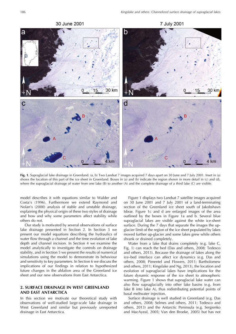
Figure 1 displays two Landsat 7 satellite images acquiredon 30 June 2001 and 7 July 2001 of a land-terminatingsection of the Greenland ice sheet south of JakobshavnIsbræ. Figure 1c and d are enlarged images of the areaoutlined by the boxes in Figure 1a and b. Several bluesupraglacial lakes are visible against the white ice-sheetsurface. During the 7 days that separate the images the up-glacier limit of the region of the ice sheet populated by lakesmoved further up-glacier and some lakes grew while othersshrank or drained completely.
Water from a lake that drains completely (e.g. lake C,Fig. 1) can reach the bed (Das and others, 2008; Tedescoand others, 2013). Because the drainage of lakes along theice–bed interface can affect ice dynamics (e.g. Das andothers, 2008; Pimentel and Flowers, 2011; Bartholomewand others, 2011; Kingslake and Ng, 2013), the location andevolution of supraglacial lakes have implications for thefuture dynamic response of the ice sheet to atmosphericwarming. Figure 1 shows that supraglacial lake water canalso flow supraglacially into other lake basins (e.g. fromlake B into lake A), thus redistributing potential points ofbasal meltwater injection.
Surface drainage is well studied in Greenland (e.g. Dasand others, 2008; Selmes and others, 2011; Tedesco andothers, 2013) and the Antarctic Peninsula (e.g. Sergienkoand MacAyeal, 2005; Van den Broeke, 2005) but has not
Fig. 1. Supraglacial lake drainage in Greenland. (a, b) Two Landsat 7 images acquired 7 days apart on 30 June and 7 July 2001. Inset in (a)shows the location of this part of the ice sheet in Greenland. Boxes in (a) and (b) indicate the region shown in more detail in (c) and (d),where the supraglacial drainage of water from one lake (B) to another (A) and the complete drainage of a third lake (C) are visible.
Kingslake and others: Channelized surface drainage of supraglacial lakes186

been widely reported for Antarctica. Figure 2 displaysModerate Resolution Imaging Spectroradiometer (MODIS)and Landsat images of the Nivlisen ice shelf, DronningMaud Land, East Antarctica (70°68’ S, 12°09’ E) acquired inDecember 2006 (Scambos and others, 1996). Lakes form onthe ice sheet’s flank near the grounding line (source lakes,
Fig. 2a) before rapidly draining, spreading meltwater acrossthe ice shelf.
Figure 2a was acquired on 5 January 2008 after severalweeks of melt and drainage. The preceding temporalevolution of this drainage is shown in detail in Figure 2b–g,with the time separation between images indicated. The
Fig. 2. Surface drainage in East Antarctica. (a) MODIS optical satellite image acquired on 5 January 2008 (Scambos and others, 1996)showing source lakes, 100m surface contours (in white), the grounding line (in grey) and the Nivlisen ice shelf partially flooded withmeltwater. Inset plots peak monthly mean temperatures recorded at Novolazarevskaya station during nine austral summers. (b–g) SixMODIS and Landsat images showing the time evolution of the 2007/08 flood. Red arrows indicate the flood wavefront, and the timesseparating the image acquisitions are shown between panels (dates are day/month/year). In (g) floodwater completely covers the previousyear’s refrozen flood path. The bandings in (c), (d), (f) and (g) are artefacts introduced by a malfunction in the Landsat satellite.
Kingslake and others: Channelized surface drainage of supraglacial lakes 187

meltwater wavefront (red arrows) propagates across the shelfat average velocities of 1.7–6.8mmin–1 along paths createdby the previous year’s refrozen floodwater. Water travels upto 70 km and floods an area of �260 km2 (�3.3% of the iceshelf’s area). More images (acquired between 2002 and2009, not displayed) show that this phenomenon occursnearly every year. The images also reveal high interannualvariability in flood extent. In austral summers beginning in2002, 2004, 2005, 2006 and 2007 significant flooding wasobserved. In contrast, no flood was observed in imageryobtained during austral summer 2008/09. Meteorologicalobservations from the Novolazarevskaya research station(Fig. 2a) show that this summer was the coolest in the studyperiod, with monthly mean surface air temperature �–1°C.Trusel and others’ (2012) study of Antarctic radar back-scatter, which indicates surface melting, also indicates lowmelt during austral summer 2008/09 in this region.
Surface drainage on Nivlisen is extensive and sensitive totemperature. The importance of ice-shelf surface lakes hasbeen demonstrated by the disintegration of the AntarcticPeninsula ice shelves (e.g. Scambos and others, 2003) andthese new observations from East Antarctica further motivateour efforts to model and understand the surface drainage ofsupraglacial lakes.
3. MODEL FORMULATIONFigure 3 shows the geometry of our surface drainage model.A supraglacial lake drains through a channel incised into anice-sheet surface, the lateral position of which does notchange. We ignore the along-channel spatial dimension,assuming that the water discharge out of the lake iscontrolled by a single, stationary point in the channel nearthe lake, labelled ‘lake outlet’ in Figure 3. The followingsubsections derive model equations describing lake-levelevolution, energy and force balances in the turbulentlyflowing water, critical flow and the incision of the channel.
3.1. Lake evolutionThe lake has volume VL, surface area AL and depth hL. Thesechange with time and are related by the hypsometryparameterization
hLhLi
� �pL¼ VL
VLi, ð1Þ
where ALi, VLi and hLi are the lake’s reference area, volumeand depth, respectively, related by ALi =pLVLi/hLi (Clarke,
1982; Ng and Björnsson, 2003). Vertically walled lakes aredescribed by a lake-shape parameter pL = 1, bowl-shapedlakes by 1<pL < 3, conical lakes by pL = 3 and lakes shapedlike a musical horn by pL > 3 (Clarke, 1982). For example,Kingslake (2013, fig. 7.8) shows that the hypsometry of asupraglacial lake surveyed in Greenland by Georgiou andothers (2009) can be parameterized by Eqn (1) usingpL� 1.5. Lake depth evolves with time t due to a meltwaterinput Qin (assumed constant) and outflow through thechannel Q according to
dhLdt
¼ 1ALi
hLihL
� �pL�1Qin �Qð Þ: ð2Þ
This lake-level evolution equation is derived by combinedwater mass conservation in the lake, dVL/dt=Qin –Q, withEqn (1) (see Kingslake, 2013, ch. 2). We neglect melting ofice within the lake and its impact on lake volume and shape(Tedesco and others, 2012).
3.2. Bernoulli’s equationThe following derivation can be found in many open-channel hydraulics textbooks (e.g. Henderson, 1966). Weinclude the details here for completeness. We assume thatall the water in the lake flows along open streamlines thatextend from within the body of the lake, where we assumethe water is stagnant, out along the channel. We applyBernoulli’s equation to the water as it flows along such astreamline that lies on the water’s surface and the centre lineof the channel (Henderson, 1966):
zþ u2
2g¼ constant, ð3Þ
where g is the acceleration due to gravity (9.8m s–2), u is thesurface velocity of the flow and z is the height of the waterabove an arbitrary datum, which we take as the lake bed(Fig. 3). This can be thought of as a statement of theconservation of energy in the flowing water that neglects theenergy used in enlarging the channel through melt. Weassume that there are no closed streamlines on the surface inthe lake. We denote the surface velocity of the water in thechannel at the lake outlet by v, the height of the channelbottom above the lake bed by hC and the depth of flow inthe channel by D. Applying Eqn (3) at the lake end of thestreamline, where u=0 and z= hL, and in the channel at thelake outlet, where u= v and z=hC +D, yields
hL ¼ hC þDð Þ þ v2
2g: ð4Þ
We assume uniform, pseudo-steady plug flow in the lakeoutlet, i.e. that the flow changes relatively slowly in thealong-channel direction and over time and the flow velocityis uniform across the cross section of the flow. We alsoassume that the channel has a rectangular cross-section withconstant width w. Hence, the water discharge at the lakeoutlet is
Q ¼ vwD ð5Þand Eqn (4) becomes
hL � hC ¼ Dþ Q2
2gw2D2 : ð6Þ
The solid curve in Figure 4 plots the discharge Q as afunction of the depth of flow D as defined by Eqn (6).This classic curve from open-channel flow theory (e.g.Henderson, 1966) has two branches with dD/dQ<0 and
Fig. 3. Schematic of the surface lake drainage model geometry(a) before drainage (initial conditions) and (b) during drainage.
Kingslake and others: Channelized surface drainage of supraglacial lakes188

dD/dQ>0, corresponding to subcritical and supercriticalflow, respectively (corresponding to Fr<1 and Fr>1, wherethe Froude number Fr is given by Fr= v(gD)–0.5). They meetat a critical point (C) where D=DC and discharge is at amaximum, QC. Maximizing Q with respect to D bydifferentiating Eqn (6) reveals how DC is related to hL, hCand QC:
DC ¼ 23ðhL � hCÞ and QC ¼
ffiffiffiffiffiffiffiffiffiffiffiffiffiffiffigw2D3
C
q: ð7Þ
3.3. Force balanceTo complete the model’s description of water flow at thelake outlet, we balance the forces acting on a slab of waterof unit along-channel length, unit width and height D. Weparameterize the shear stress �F exerted on the water by theice with the Darcy–Weisbach equation,
�F ¼ 18fR�wv2, ð8Þ
where fR is the channel’s hydraulic roughness and �w is thedensity of water. The along-channel gravitational drivingstress is
�G ¼ �wgD�b, ð9Þwhere �b is the along-channel slope, which we assumeconstant and uniform. Again assuming steady flow, weequate �F and �G. Eliminating v between the result andEqn (5) and rearranging for Q yields an expression for thedischarge in terms of the channel slope, the channel width,the depth of flow and the channel roughness:
Q ¼ffiffiffiffiffiffiffiffiffiffiffi8g�bfR
swD
32: ð10Þ
The dashed and dotted curves in Figure 4 plot thisdischarge–flow-depth relationship using two alternativepairs of values for the slope and hydraulic roughness ofthe channel. The channel corresponding to the dotted curveis steeper and smoother than that corresponding to thedashed curve. Points A and B, where these curves interceptthe solid ‘Bernoulli curve’, indicate the discharge Q anddepth of flow D, which obey the force-balance equation(Eqn (9)) and Bernoulli’s equation (Eqn (6)) in each channel.
3.4. Subcritical and supercritical flowPoints A and B lie on the subcritical and supercriticalbranches of the Bernoulli curve respectively; depending onthe characteristics of the channel, flow can be subcritical orsupercritical. When flow is supercritical at some positionalong a flow path, hydrologists usually assume that dis-charge is controlled by a transition from subcritical tosupercritical flow somewhere upstream. At such a transition,flow is critical, and discharge and flow depth can be easilycalculated by maximizing discharge with respect to flowdepth (e.g. Eqn (7)).
We adopt a similar approach here to deal with super-critical flow conditions. When the solution to the Bernoulliand force-balance equations indicates supercritical flow weassume that the flow is controlled by a transition to criticalflow at the lake outlet and calculate discharge with Eqn (7).
3.5. Channel incisionHeat transferred from the turbulently flowing water to theice melts and enlarges the channel. We assume the laketemperature is 0°C, so that the only source of heat is
frictional dissipation in the flowing water. The ice massmelted per unit length of the channel per unit time, m, is
m ¼ �FvwL
ð11Þ
(e.g. Walder and Costa, 1996), where L is the specific latentheat of fusion of ice (334 kJ kg–1). For simplicity we assumethat melting occurs in the channel bottom but not at thesides. This is motivated by other studies that make the samesimplification (e.g. Mayer and Schuler, 2005; Vincent andothers, 2010) and the fact that at present it is unclear howbest to apportion frictional melting between the channel’sbottom and sides. Accordingly, the rate of change of theheight of the channel bottom above the lake bed is given by
dhCdt
¼ � fR�w8L�i
v3: ð12Þ
Equations (2), (5), (6), (7), (10) and (12) complete the model.They describe respectively the time evolution of lake level,the relationship between discharge and flow velocity,Bernoulli’s equation in the water flowing from the lake intothe channel, the characteristics of critical flow, the balanceof the frictional and gravitational forces in the flowing water,and the rate of channel incision.
The model assumes that (1) drainage is controlled entirelyby the flow through one point in the channel near the lake,labelled ‘lake outlet’ in Figure 3; (2) flow at the lake outletcan be assumed to be steady and uniform, i.e. the flowchanges relatively slowly in time and along the channel;(3) we can ignore the energy used in melting whenconsidering the balance of potential and kinetic energy inthe water as it flows out of the lake into the lake outlet;(4) melt is restricted to and distributed evenly across thefloor of the channel such that the channel’s width and slopeare constant; and (5) energy dissipated as heat by the waterflowing through the lake outlet is used locally for melting.
These assumptions are restrictive but analysis of themodel still yields useful mechanistic insights into drainage.
4. DRAINAGE STABILITYWe will demonstrate how supraglacial drainage of a lakecan be either stable or unstable. As shown by Raymond andNolan (2000), the origin of the two styles of drainage is the
Fig. 4. Depth of flow D as a function of discharge Q according toBernoulli’s equation (Eqn (6); solid curve) and the force-balanceequation (Eqn (9); dashed and dotted curves). The two force-balance curves correspond to two alternative pairs of values for theslope and hydraulic roughness of the channel.
Kingslake and others: Channelized surface drainage of supraglacial lakes 189

competition between the channel incision rate and the lakelowering rate. We take the analysis further and show howstable drainage remains bounded and may stop before thelake has emptied completely, while unstable drainage growsunboundedly with time, completely emptying the lake. Wealso explain why some model parameters affect drainagestability while others do not, and analyse the drainage ofthree idealized lakes: (1) a vertically sided lake that receivesno input of water (pL = 1, Qin = 0), (2) a non-vertically sidedlake that also receives no input (pL > 1, Qin = 0), and (3) avertically sided lake that receives a constant water input(pL = 1, Qin > 0). We restrict this section’s analyses toconsidering subcritical flow conditions and show later in anumerical sensitivity analysis that this is appropriate for awide range of realistic parameter values.
We define � as the height difference between the lake’ssurface and the bottom of the channel (� =hL –hC) (Fig. 3)and begin by deriving an expression for the time evolutionof �. Recasting the Bernoulli and force–balance equations(Eqns (6) and (10)) in terms of the flow velocity v (usingEqn (5)) and rearranging both for the flow depth D yields
D ¼ � � v2
2gð13Þ
and
D ¼ v2fR8g�b
: ð14Þ
Eliminating D between the two equations above andrearranging yields the following expression relating the flowvelocity and the height difference �:
v2 ¼ �2g
1þ fR4�b
: ð15Þ
Eliminating v between this and the channel-incision equa-tion (Eqn (12)) yields
dhCdt
¼ ���32, ð16Þ
where
� ¼ fR�w8L�i
2g
1þ fR4�b
0B@
1CA
32
: ð17Þ
Using Q= vwD, Eqn (14) is expressed as
Q ¼ v3wfR8g�b
: ð18Þ
Then eliminating v between this expression and Eqn (15)reveals how discharge Q depends on �:
Q ¼ ��32, ð19Þ
where
� ¼ 2g
1þ fR4�b
0B@
1CA
32
wfR8g�b
: ð20Þ
Substituting this into Eqn (2) yields
dhLdt
¼ 1ALi
hLihL
� �pL�1Qin � ��
32
h i: ð21Þ
The model has been reduced to a pair of ordinarydifferential equations for hL and hC (Eqns (16) and (21)).
An expression for the time evolution of � is obtained bydifferencing dhL=dt and dhC=dt to give
d�dt
¼ 1ALi
hLihL
� �pL�1Qin � ��
32
� �þ ��
32: ð22Þ
This equation incorporates the two competing mechanismsthat control lake drainage: changes in the lake level due toan imbalance between the meltwater input Qin and thedischarge through the channel (the first term on the right)and downward incision of the channel into the ice surfacethrough frictional melting (the second term on the right).Armed with this equation, the equation for the timeevolution of hC,
dhCdt
¼ ���32, ð23Þ
and the definitions of � and �,
� ¼ 2g
1þ fR4�b
0B@
1CA
32
fR�w8L�i
, � ¼ 2g
1þ fR4�b
0B@
1CA
32
wfR8g�b
, ð24Þ
we consider three idealized lakes, chosen to simplify theanalysis and allow us to demonstrate the physics ofchannelized supraglacial drainage as described by ourmodel.
The first idealized lake receives no water input from itssurroundings and is vertically sided (Section 4.1). We willshow that such a lake can drain stably, with dischargedecreasing with time, or unstably, with discharge increasingwith time. Applying the model to such a simplified lakeallows the physical controls on its behaviour to be analysed,but it is probably not representative of real supraglaciallakes. The second idealized scenario we analyse is drainagefrom a lake with hypsometry such that its surface areadecreases during drainage. We show that when suchdrainage is initially unstable it stabilizes after the surfacearea has decreased sufficiently. Finally, a vertically sidedlake is supplied with an input of water, which we showalways causes the lake to empty completely.
4.1. A vertically sided lake with no inputFor a vertically sided lake (pL = 1) that receives no waterinput (Qin = 0), Eqn (22) reduces to
d�dt
¼ �32 �� �
ALi
� �: ð25Þ
4.1.1. The drainage stability parameterConsider the initiation of lake drainage shown in Figure 3. Asnow dam in the channel fails when the lake is a height �0above the channel bottom (� = �0) and lake drainage begins;this initiation mechanism has been observed in Greenland(Tedesco and others, 2013). Equation (25) determines how �changes with time as drainage progresses. Of particularsignificance is the quantity in parentheses in Eqn (25), the signof which determines whether � increases or decreases withtime. We call this quantity the ‘drainage stability parameter’,
� ¼ �� �
ALi: ð26Þ
If � is positive, d�=dt is also positive and � increasesunstably with time. Physically, the channel incises the icesurface more rapidly than the lake’s surface is drawn downby the water flowing out through the channel. A positive
Kingslake and others: Channelized surface drainage of supraglacial lakes190

feedback operates between � and @�=@t because dischargeQ increases with � (Eqn (19)). Discharge grows unboundedlywith time, so we call this drainage unstable. Vertically sidedlakes that drain unstably will always empty completely. Incontrast, if � is negative, � andQ always decrease with time.Physically, the lake’s surface, which is initially higher thanthe channel (by a distance �0), is drawn down more rapidlythan the channel is incised, which causes the depth of flowto decrease over time. Note that, if � is negative butsufficiently close to zero, the lake can still empty before thedecreasing Q has had time to reach zero (this will be shownin Section 4.1.3). This style of drainage, which does notgrow unboundedly with time, we call stable.
The importance of the stability parameter � can be seenmore directly after integrating Eqn (25) to yield expressionsfor the time evolution of the height difference � and, usingEqn (19), the discharge Q:
� ¼ 1
1ffiffiffiffiffi�0
p � � t2
!2 , ð27Þ
Q ¼ �
1ffiffiffiffiffi�0
p � � t2
!3 : ð28Þ
When � > 0, the terms in the denominators on the right ofEqns (27) and (28) decrease with time, causing � and Q to‘blow up’ in finite time tb ¼ 2=ð� ffiffiffiffiffi
�0p Þ; of course, the lake
runs out of water before this. Conversely, when � < 0, � andQ decrease with time, and drainage can halt before all thewater has been evacuated from the lake. Figure 5 depictsthese two drainage styles and shows the time evolution ofdischarge as defined by Eqn (28) for several different valuesof �.
4.1.2. Physical controls on stabilityClearly, how much and how rapidly water escapes from thelake during drainage depends strongly on the stability ofdrainage. We now examine what controls stability, with theaim of understanding how the physical conditions on an icesheet’s surface could affect water transfer between supra-glacial lakes.
From Eqn (26), the stability parameter � depends on thereference surface area ALi. In fact, in plotting Figure 5 weused ALi to vary �. (Note that, because we are considering avertically sided lake, lake area AL equals its reference valueALi always, but more generally ALi is the initial lake area.)Equation (26) shows that increasing ALi encourages unstabledrainage. Physically, this is because, for a given outflow, thechannel incision rate is independent of the lake’s surfacearea (Eqn (23)), whereas, the larger the lake’s area is, theslower its level drops. Because the rates of lake-surfacedrawdown and channel incision compete to control theoutlet flow depth and hence how discharge evolves, a largerlake area encourages unstable drainage.
To understand the other physical controls on drainagestability, we use the definitions of � and � (Eqn (24)) toexpand � (Eqn (26)):
� ¼ fR�w8L�i
2g
1þ fR4�b
0B@
1CA
32
1� ð�iL=�wgÞwALi�b
� �: ð29Þ
Increasing the channel slope �b increases the water flowvelocity, which increases channel-incision and lake-draw-down rates. This manifests as an increase in the quantityoutside the square brackets in Eqn (29) and increases therate at which discharge Q changes with time (Q increases ordecreases with time, depending on drainage stability).However, for the lake-drawdown rate this increase isslightly compensated for by a decrease in flow depth causedby the increase in �b and the hydraulics of open-channelflow (as described here by the Darcy–Weisbach equation).This effect manifests as a decrease in the second term in thesquare brackets. Hence the net effect of increasing �b is topromote unstable drainage.
In contrast, increasing the channel width w promotesstable drainage. The channel-incision rate is independent ofw, but increasing w accelerates lake drawdown by in-creasing the discharge through the channel for a given flowvelocity (Eqn (5)), stabilizing drainage.
Interestingly, the hydraulic roughness fR is absent fromthe square brackets in Eqn (33) and hence does not affectdrainage stability. Decreasing fR increases the flow velocity,which affects both channel incision and lake drawdown.Decreasing fR decreases flow depth, compensating for theincrease in discharge from the faster-flowing water. How-ever, this is balanced by a corresponding decrease inchannel-incision rate due to a decrease in the shear stress �b(Eqn (8)) and hence a drop in the heat dissipation that incisesthe channel.
Note that the height of the snow dam when it fails, �0 (theinitial value of �) does not appear in the definition of � (Eqn(29)) and so it has no effect on drainage stability. It does,however, affect the initial discharge and hence how fast thelake empties and, during stable drainage, whether it emptiesat all.
Table 1 summarizes the effects that increases in the initiallake area ALi, the channel slope �b, the channel width w,the channel roughness fR and the intial flow depth in thechannel �0 have on the lake-level drawdown rate, thechannel-incision rate and drainage stability.
4.1.3. Stable but complete drainageDuring stable drainage (�<0) the discharge decreases tozero asymptotically with time. Drainage may end (�! 0)
Fig. 5. Time evolution of channel discharge corresponding to sixvalues of the drainage stability parameter � calculated usingEqn (32). The six stability parameters have been calculated usingthe initial lake areas, ALi, shown and the following typical values forother parameters: fR = 0.25, wC =2m, �b = 0.01 and pL = 1.
Kingslake and others: Channelized surface drainage of supraglacial lakes 191

before the lake is empty; alternatively, the lake may emptycompletely before � reaches zero. To understand thesealternatives, we use the expressions for dhC=dt and d�=dt inEqns (23) and (25) to examine how model solutions movethrough hC–� phase space.
Figure 6 plots several solution trajectories in the hC–�phase space, each corresponding to a different value of �.Examples of both stable (�< 0) and unstable (�> 0)trajectories are plotted. Their gradients are determined bydividing Eqn (23) by Eqn (25) to give
dhCd�
¼ dhCdt
dtd�
¼ ���32
�32 �� �
ALi
� � ¼ � �
�: ð30Þ
This equation and Figure 6 show that, during stabledrainage, dhC/d� >0, and whether or not the lake emptiescompletely is determined by the magnitude of this gradient.When dhC/d� is sufficiently small, the solution trajectory inFigure 6 meets the vertical axis (where � =0) and drainagehalts while there is still water in the lake. When dhC/d� islarge, the trajectory meets the horizontal axis (where hC = 0)and the lake empties.
As the channel bottom height is initially hLi – �0 (Fig. 3),Eqn (30) and Figure 6 show that its final height, hfinal, isgiven by
hfinal ¼ hLi � �0ð Þ þ �0�
�: ð31Þ
The lake will empty completely if hfinal = 0. The criticalvalue of � just sufficient to empty the lake as both dischargeand � reach zero, �C, is given by
�C ¼ � �
hLi�0
� 1� � : ð32Þ
A stability parameter � which obeys �C��� 0 will result instable but complete drainage.
4.2. A non-vertically sided lake with no water inputReal supraglacial lakes are not vertically sided. Usually, thefuller a lake is, the larger its area is (Fig. 3), with ahypsometry parameter pL > 1. We examine the drainage ofsuch lakes here. Still ignoring water input to the lake(Qin = 0), with pL 6¼ 1, Eqn (22) becomes
d�dt
¼ �32 �� �
ALi
hLihL
� �pL�1 !
ð33Þ
or
d�dt
¼ �32~�, ð34Þ
where
~� ¼ �� �
ALi
hLihL
� �pL�1ð35Þ
is a generalized stability parameter (it reduces to � whenpL = 1). This parameter accounts for the effect of the lake’sdecreasing area as it drains, given instantaneously byALi hL=hLið ÞpL�1. How does the new hypsometry affect lakestability? Initially the lake depth is equal to its referencevalue hLi, so ~�=�; whether a lake is initially stable orunstable does not depend on its shape. However, as the lakedrains, hL decreases, so the lake area decreases, reducing ~�.Before the lake empties, ~� will always drop below zerobecause hL appears in the denominator of the second termon the right of Eqn (35). When this happens drainage willstabilize. This stabilization can halt drainage altogether or, ifit occurs when hC is already close to zero, merely slow thefinal stages of drainage. These two possibilities are illus-trated in Figure 7, which sketches how model trajectories inhC–� phase space depend on the lake-shape parameter pL.Trajectories were calculated by forward Euler time steppingof Eqns (23) and (33) using values of model parameters thatlead to initially unstable drainage and – except the shape
Table 1. Summary of the impact of varying key model parameters on lake-surface drawdown rate, channel incision rate and drainagestability
The impact of increasing each parameter on:
Model parameter Lake-surface drawdown rate Channel incision rate Drainage stability
Initial lake area, ALi Decrease None DecreaseChannel width, w Increase None IncreaseChannel slope, �b Increase (but partially compensated for
by decrease in D)Increase Decrease
Channel hydraulic roughness, fR Increase (but partially compensated forby decrease in D)
Increase (but partially compensated forby decrease in �b)
None
Initial flow depth in the channel, �0 Increase Increase None
Fig. 6.Model trajectories in hC–� phase space corresponding to fivedifferent values for the drainage stability parameter �. The criticalstability parameter �C is defined in Eqn (36). The lake is verticallysided (pL = 1).
Kingslake and others: Channelized surface drainage of supraglacial lakes192

parameter pL – do not change between calculations. Notethat because we use the same ALi and hLi for eachcalculation but vary pL, we are implicitly adjusting VLibetween calculations in order to compare lakes with thesame initial area but different shapes.
When pL > 1, trajectories are deflected from the straighttrajectory corresponding to pL = 1. This deflection increaseswith time during each simulation and with pL whencomparing between simulations. If pL is sufficiently high,drainage is halted before the channel bottom is incised tothe lake bed.
Physically, the lake area decreases as the lake depthdecreases, so the lake-drawdown rate for a given dischargeis increased without any corresponding change in thechannel incision rate. This stabilizes drainage by allowingthe lake drawdown to ‘catch up’ with channel incision. Thiseffect is enhanced for more ‘horn-shaped’ lakes with higherpL values.
4.3. A vertically sided lake with a water inputWe now return to the vertically sided lake (pL = 1) andconsider what happens if it receives water from itssurroundings (Qin > 0). In this scenario, Eqn (22) becomes
d�dt
¼ Qin
ALiþ ��
32: ð36Þ
We now demonstrate how this equation shows that, unlikein the case Qin = 0, drainage cannot cease before the lakeempties. Suppose that �>0. In this case the right-hand sideof Eqn (36) is always positive, so drainage is unstable,discharge increases unboundedly with time and the lakeempties completely. Suppose now that �< 0. Ifj��3=2j > jQin=ALij, � decreases because d�=dt< 0 (Eqn(36)). Alternatively, if |��3=2j < jQin=ALij, � increases be-cause d�=dt>0 (Eqn (36)). Hence when �<0, � relaxestowards a positive value (–Qin/ALi�)2/3. The input to the lakemaintains the lake’s surface height above the channelbottom’s height, so stable drainage and channel incisioncontinues until the lake empties completely.
To understand this stable but complete drainage wecompare the discharge corresponding to a depth of flow� = (–Qin/ALi�)2/3 with the input to the lake Qin. FromEqn (19),
Q ¼ ��32 ð37Þ
so the discharge after � has reached (–Qin/ALi�)2/3 is
Q ¼ ��Qin
ALi�: ð38Þ
From the definition of � (Eqn (26)), this becomes
Q ¼ Qin
1� �ALi�
: ð39Þ
When �<0, �ALi/� <1, and hence 0< (1 –�ALi/�) < 1. So,from Eqn (39), Q>Qin and the lake drains. Furthermore, therate of lake-surface drawdown is dhL=dt ¼ Qin �Qð Þ=ALi,or, using Eqn (39),
dhLdt
¼ Qin
ALi1� 1
1� �ALi�
0B@
1CA: ð40Þ
The higher the input to the lake, the faster it drains because ahigher input maintains a deeper flow in the channel thatcauses more rapid incision. This analytical result only holds
for stable drainage, when the discharge has relaxed to(–Qin/ALi�)2/3. Numerical sensitivity analysis of the model(Kingslake, 2013), more extensive than that reported in thenext section, suggests that this result also applies duringunstable drainage.
4.4. SummaryIn our model, supraglacial drainage from a vertically sidedsurface lake that receives no water input (pL = 1, Qin = 0)evolves in one of three ways depending on the stabilityparameter �. When �< –�/(hLi/�0 – 1), lake drainage isstable (i.e. lake level is drawn down faster than the channelis incised) and halts when water remains in the lake. When–�/(hLi/�0 – 1)���0, drainage is still stable but results inthe complete emptying of the lake. And when �>0,drainage is unstable and discharge increases unstably withtime because the channel is incised faster than lake level isdrawn down. Increasing lake area, increasing channel slopeand decreasing channel width all promote unstable drain-age. The hydraulic roughness of the channel does not affectdrainage stability, but it does affect the magnitude of � andhence the rate at which discharge changes with time.
The drainage of more realistically shaped lakes withpL > 1 is governed by the same physics except that, asdrainage progresses, a modified stability parameter, whichtakes account of the lake’s shape, decreases and stabilizesdrainage. This can halt drainage before the lake empties.
When a lake is supplied with water by its surroundings, itmay drain stably or unstably but it always drains completely.The larger the water supply the faster the lake empties.
5. NUMERICAL SIMULATIONSWe now solve the full model numerically, taking intoaccount the possibility of critical flow at the lake outlet, firstto demonstrate the drainage scenarios examined in theprevious section and second to perform a numericalsensitivity analysis. Characteristics of the model revealedby the numerical analysis that could not be examinedanalytically in the previous section include the areas of
Fig. 7. Model trajectories in hC–� phase space corresponding to 11different equally spaced values of the lake-shape parameters pLbetween 1 and 3. In all cases initially the lake-stability parameter~� >0. The rightmost curve corresponds to pL = 1 and the othercurves correspond to progressively larger values of pL. Thetrajectories corresponding to the three highest pL values interceptthe hC axis, so drainage is halted before the lake empties.
Kingslake and others: Channelized surface drainage of supraglacial lakes 193

parameter space that cause critical flow, the unstable butincomplete drainage caused by very slow increases indischarge and how areas of model parameter space corres-ponding to unstable and stable drainage compare withobservations of lakes in Greenland.
We numerically step the lake depth and the channel-bottom height forward in time by solving Eqns (12) and (16)with the Euler method. At each time step, we determine ifflow is subcritical or supercritical by evaluating whether theforce-balance curve (dashed and dotted curves, Fig. 4)intercepts the line D=DC (the horizontal solid line, Fig. 4) tothe left or right of point C. If flow is supercritical wecalculate the depth of flow and discharge in the lake outletusing Eqn (7). Alternatively, if flow is subcritical wedetermine these quantities by solving the Bernoulli andforce-balance equations (Eqns (6) and (10)) simultaneouslyusing the Newton–Raphson method.
Simulations start with a full lake (hL =hLi) and terminatewhen the lake has emptied (hL� 0) or discharge becomesvery low (Q�0.002m3 s–1). Again we assume that drainagebegins by the mechanical failure of a dam of water-saturatedsnow in the channel. This initial condition is implementedby starting the simulation with the level of the bottom of thechannel a distance �0 below the lake surface elevation(Fig. 3a).
5.1. Simulating stable and unstable drainageWe present the results of four simulations numbered 1–4.Simulations 1 and 2 use vertically sided lakes with no inputand demonstrate stable and unstable drainage, respectively.Simulation 3 shows how a vertically sided lake drains stablyand empties completely when it is supplied with an input of
water, and simulation 4 shows how initially unstabledrainage can stabilize and halt before the lake emptieswhen the lake is not vertically sided.
We use a typical value for the reference lake depthhLi = 10m (Georgiou and others, 2009) and estimate anappropriate hydraulic roughness coefficient from publisheddata. Mernild and others (2006) calculated Manning rough-ness coefficients, n0, between 0.036 and 0.058m–1/3 s insupraglacial streams, with an average value of 0.050m–1/3 s.The roughness coefficient fR is related to n0 by fR = 8gn02/RH1/3
(Clarke, 2003, his eqn 24), where the hydraulic radius RH isthe ratio of the flow’s cross-sectional area and wettedperimeter. Hence, we use fR = 0.25 in our simulations.
Figure 8 shows lake discharge hydrographs and timeseries of lake level and channel-bottom height fromsimulations 1 and 2. Both simulations assume a verticallysided lake (pL = 1) that receives no water input (Qin = 0) anddrains through a 2m wide channel (wC= 2). Drainageinitiates when a 1m high snow dam fails (�0 = 1m). The left-hand panels (Fig. 8a and c) display results from simulation 1,which uses a lake area of 1 km2 and a channel slope of 0.01,and the right-hand panels (Fig. 8b and d) plot results fromsimulation 2, which uses a larger lake area of 3 km2 and alarger channel slope of 0.03.
The smaller lake drains stably and the larger lake drainsunstably. The discharge from the smaller lake (simulation 1)is initially 2.8m3 s–1 and decreases with time throughout thesimulation (Fig. 8a). As �<�C (from Eqns (26) and (32)),�= –2.4�10–6m–1/2 s–1 and �C= –5.1� 10–8 m–1/2 s–1), thelake level drops faster than the channel incises (Fig. 8c) andafter 100 days the lake level has dropped <1m and thesimulation stops when Q=0.002m3 s–1. Discharge from the
Fig. 8. Numerical model simulations demonstrating stable and unstable drainage. The top panels (a, b) plot hydrographs and the bottompanels (c, d) plot lake-level and channel-height time series, from simulations using two vertically sided lakes with different surface areas andchannel slopes. The left-hand plots (a, c; simulation 1) show results for a small lake (ALi = 1 km2) with a gently sloping channel (�b = 0.01).The right-hand plots (b, d; simulation 2) show results for a larger lake (ALi = 3 km2) with a steeper channel (�b = 0.03). The small lake drainsstably and the large lake drains unstably. Both simulations use Qin = 0m3 s–1, wC= 2m, �0 = 1m and fR = 0.25.
Kingslake and others: Channelized surface drainage of supraglacial lakes194

larger lake (simulation 2) is initially 3.4m3 s–1 and increasesthroughout the simulation (Fig. 8b). As �= 5.3�10–7m–1/2 s–1, the channel incises faster than the lake leveldrops (Fig. 8d). After 22 days the channel has reached thelake bed and the lake will soon empty completely.
Figure 9 shows lake-level and channel-height time seriesand discharge hydrographs from simulations 3 and 4, whichuse the same initial lake area and channel slope assimulations 1 and 2, respectively.
In simulation 3 the smaller lake is supplied with a waterinput Qin = 5m3 s–1. This causes the channel discharge Q toapproach a value greater than Qin (�5.97m3 s–1, Eqn (38))and the lake drains stably and completely.
In simulation 4 the shape of the larger lake is altered so thatits surface area decreases as it drains (pL = 3). Figure 9b and dshow the results. For the first 11 days, discharge increases. Itthen peaks and begins to fall. This stabilization occurs at themoment the modified stability parameter ~� drops belowzero. The decreasing lake surface area accelerates lakedrawdown, allowing the lake level to catch up with channelincision. Drainage ends after �40 days (Fig. 9d).
5.2. Numerical stability sensitivity analysisTo complete the numerical investigation of the model, weexplore its sensitivity to three physical parameters: the initiallake area ALi, the channel slope �b and the height, �0, atwhich the snow dam in the channel fails. These werechosen as interesting parameters to consider because ALiand �b may vary systematically across ice sheets and we areinterested in emphasizing, as predicted by the analysis in
Section 4, that drainage stability is independent of �0. Werefer the reader to Kingslake (2013) for a more extensiveexploration of these and other parameter sensitivities usingthe same model.
We conduct multiple year-long model simulations whilevarying ALi, �b and �0 systematically between simulations,and after each simulation we record the final depth of thelake, hfinal, and, if the lake empties completely, the timetaken for this to occur, TE.
Between 2005 and 2009, Selmes and others (2011)observed mean and maximum Greenland lake areas of 0.8and 17 km2, so to bracket these observations we vary ALi
between 0.05 and 30 km2. Similarly we vary �b between0.005 and 0.1 and �0 between 0.1 and 3m to encompassrealistic ranges for these parameters. Note that one mightexpect lower channel slopes on ice shelves. All simulationsuse Qin = 0m3 s–1, wC = 2m and pL = 1.
Figure 10 shows how hfinal and TE vary with ALi, �b and�0. Each row of plots corresponds to a set of simulationswhere two of the parameters are varied and the third is keptconstant. Two regions of parameter space are evident, onewhere hfinal > 0m and TE is not defined, corresponding toincomplete drainage, and another where hfinal = 0m and13� TE� 365 days, corresponding to complete drainage.
The results show, as predicted in Section 4, thatincreasing ALi and �b decreases the stability of drainage.Also, �0 does not affect drainage stability, but it doesincrease the rate at which a lake drains, and decreases theamount of water left in the lake after stable drainage hashalted before the lake is completely empty.
Fig. 9. Numerical model simulations demonstrating how drainage evolution is affected by meltwater input to the lake (Qin > 0) and a lakewhose surface area decreases as it drains (pL > 1). The left-hand plots (a, c; simulation 3) show results for a small lake (ALi = 1 km2) with agently sloping channel (�b = 0.01) that receives a water inputQin = 5m3 s–1. The right-hand plots (b, d; simulation 4) show results for a largerlake (ALi = 3 km2) with a steeper channel (�b = 0.03) whose surface area decreases with depth, pL = 3. Both simulations use w=2m, �0 = 1mand fR = 0.25.
Kingslake and others: Channelized surface drainage of supraglacial lakes 195

Also plotted in each panel in Figure 10 are solid greencurves evaluated using Eqn (29) with �=0, which separateregions of stable and unstable drainage. These critical-parameter curves and the boundaries between incompleteand complete drainage (visible as the edges of the regionswhere TE is not defined in Fig. 10b, d and f) are approxi-mately aligned; stable drainage often leads to incompletedrainage. However, in one small region of parameter spaceadjacent to the critical-parameter curves (e.g. Fig. 10f),drainage is stable but complete. This style of drainage wasdiscussed in Section 4.1. It occurs when the stabilityparameter � is negative but close to zero (more preciselywhen –�/(hLi /�0 – 1)���0).
Conversely, in another region adjacent to the criticalparameter curves (e.g. Fig. 10d), drainage is unstable butresults in incomplete drainage. This was not discussed
above. It is an artefact of the finite length of simulations(1 year). In these simulations discharge increases very slowlywith time because � is small and positive. Hence, after onemodel year the lake is not completely empty.
The lake areas observed by Selmes and others (2011)bracket our modelled boundaries between stable andunstable drainage (Fig. 10). For example, according to ourmodel with this choice of parameters, a lake whose area isALi = 0.8 km2, the mean area observed by Selmes and others(2011), will drain stably regardless of �b, whereas a lakewhose area is their largest observed (ALi = 17 km2) woulddrain unstably through a channel with �b > 0.003.
The boundary of the region in parameter space corres-ponding to simulations that involve critical flow is visible inFigure 10a, b and f as a kink in the otherwise smoothcontours at �b� 0.032. For a wide range of channel slopes
Fig. 10. The results of exploring the model’s sensitivity to the initial lake area ALi, the channel slope �b and the height at which the snow damin the channel fails, �0. Filled contour maps show how final lake depth (a, c, e; left column) and the time taken to empty the lake (b, d, f; rightcolumn) vary with these parameters. In all simulations Qin = 0m3 s–1, wC= 2m and pL = 1. Solid green lines separate regions correspondingto stable and unstable drainage (plotted using Eqn (29) with �=0). Green dotted and dashed lines in (a–d) indicate the mean and maximumareas of lakes reported by Selmes and others (2011). Crosses indicate locations in each parameter space of simulations 1 and 2 (Fig. 8).
Kingslake and others: Channelized surface drainage of supraglacial lakes196

our model simulates subcritical flow. When �b > 0.032, flowis critical and drainage does not depend on �b. This isexpected, as the equations that describe critical flow(Eqn (7)) do not involve �b.
6. DISCUSSIONUsing a simple model we have examined how the surfacedrainage of a supraglacial lake evolves after it initiates in apre-existing channel. This evolution can be stable orunstable and depends on a competition between drawdownof the lake’s surface and channel incision. Drainageinstability increases with the lake’s area and the channel’sslope, and decreases with the channel’s width. Lakehypsometry also affects stability, with lakes whose surfacearea decreases during drainage promoting stability. Drain-age stability is not affected by the channel’s hydraulicroughness, the lake’s initial depth or the height of the snowdam in the channel, the failure of which initiates drainage.Irrespective of whether a lake that receives a water inputfrom its surroundings drains stably or unstably, it willalways empty completely. We have shown analytically that,in the stable case, a higher input causes a higher lakedischarge. Kingslake’s (2013) numerical sensitivity analysissuggests that this increase in discharge with lake input alsooccurs in the unstable case.
Previous authors (Walder and Costa, 1996; Vincent andothers, 2010) have simplified the determination of flowdepth in channels draining lakes by assuming critical flowat the lake outlet. In contrast, our numerical sensitivityanalysis suggests that subcritical conditions dominate for awide range of parameter values and our analytical examin-ation of the model considered only subcritical flow. Thisexamination could be repeated for the critical flow regime,which may be dominant in some situations. As critical flowis independent of the channel slope and the hydraulicroughness, some aspects of our analysis related to theseparameters will be irrelevant. However, key processes, suchas the competition between lake level and channel incision,and the influence of parameters such as lake area, lakeinput and channel width, will be qualitatively similar.
Field observations (e.g. Mayer and Schuler, 2005;Tedesco and others, 2013) and remote-sensing surveys (e.g. Selmes and others, 2011; Johansson and others, 2013) oflakes and lake-drainage events could be used to test ourmodel and constrain its parameters (e.g. channel hydraulicroughness fR). However, several model limitations need tobe considered.
The model ignores along-channel spatial variations andthe lake water’s sensible heat. Developing the model toinclude along-channel variation could reveal dynamicsassociated with a melt–slope–discharge feedback that couldoperate along channels. The lake’s sensible heat will affectthe lake’s shape and contribute to channel incision; itsinclusion in the model may be necessary to simulatedrainage realistically (Tedesco and others, 2012).
We have assumed a constant channel width. Althoughprevious work (e.g. Mayer and Schuler, 2005; Vincent andothers, 2010) justified this assumption with observations ofdeep, vertical-walled supraglacial channels, it may beinvalid when this width is less than the flow depth and aphysical explanation for these observations is presentlylacking. A potentially related consideration is the mech-anism by which drainage initiates. In our model we initiate
drainage by snow-dam failure. An alternative mechanism isthe overtopping of the lake’s basin in the absence of a pre-existing channel. After initial sheet flow, a feedbackbetween melt and flow depth would form a channel.Two-dimensional modelling of this process may help usunderstand how it influences channel width and howdrainage evolves after it is initiated in this way.
We have also assumed that the lake drains through asingle channel. Our approach could be applied to drainagethrough two or more channels. In such an extension thedischarge through N identical channels would be N timesthe drainage through an isolated channel. However,because channels are unlikely to be identical, some willgrow more rapidly than others. The discharge through thesechannels may increase at the expense of the dischargethrough the more slowly growing channels, until all the lakeoutflow is concentrated in one channel. This feedbackmechanism may explain why lakes are often observed todrain through one large channel (e.g. Figs 1 and 2).
The model assumes that the only mechanism affectingthe elevation of the channel bottom is frictional melting bythe flowing water. In reality, ice flow – both the large-scaleflow of the ice sheet through the lake basin and small-scaleflow induced by the presence of the channel – may alsocontribute. Upward flow of the ice sheet as it leaves the lakebasin will tend to raise the bottom of the channel (Darnelland others, 2013), and small-scale flow around the channelwill raise the channel bottom and decrease channel width(Jarosch and Gudmundsson, 2012). We ignored thesepotentially complex dynamics, but they may be crucial formulti-year channel evolution (Darnell and others, 2013)and the formation of englacial drainage systems fromsurface channels (Jarosch and Gudmundsson, 2012).
Despite limitations of our model, our results haveimplications for our understanding of the Greenland icesheet. A concern among glaciologists is that atmosphericwarming could increase the area of the ice sheet populatedby supraglacial lakes, resulting in a corresponding increasein the area of the bed that receives injections of meltwaterfrom the surface. This would affect ice dynamics (Lüthje andothers, 2006; Bartholomew and others, 2011). It is thiscoupling between surface melt and ice dynamics that themechanisms highlighted by our analysis may influence.
Lüthje and others (2006) suggested that lakes will tend tobe larger as the area of the ice sheet populated by lakesexpands inland because of lower mean ice-surface slopeshigher on the ice sheet. In terms of the surface drainagesimulated by our model, such a shift in elevation corres-ponds to movement through the model’s parameter space.Specifically, an increase in mean lake area increases thepropensity of lakes to drain unstably, enhancing therelocation of surface water to lower elevations and limitingthe availability of meltwater for injection to the bed.However, lower average surface gradients higher on theice sheet imply lower channel slopes, which have theopposite effect according to our theory. Alternatively, lakearea and channel slope may both be controlled by large-scale surface roughness, itself dependent on basal topog-raphy, local surface processes and ice-flow dynamics. Howother factors such as lake shape, channel width and lakeinput may change under atmospheric warming scenarios isalso currently unclear.
Surface drainage not only relocates water, but alsodirectly throttles the drainage of lake water to the bed of
Kingslake and others: Channelized surface drainage of supraglacial lakes 197

ice sheets and reduces an ice sheet’s dynamic response tolake drainage. Tedesco and others (2013) report fieldobservations of a supraglacial lake draining relatively slowlyto the bed of the Greenland ice sheet by delivering waterover the ice sheet’s surface via a surface channel to a nearbymoulin. They measured the ice sheet’s dynamic response tothis event and to another, more rapid drainage event, whichincluded no surface drainage. During the more rapid event,water was delivered directly from the lake bottom to the bedof the ice sheet via hydrofracture and the creation of newmoulins. The ice sheet’s dynamic response to the slowerevent that included surface drainage was less than half of itsresponse to the more rapid event. Our model could be usedin future work to examine the coupling between lakedrainage and ice dynamics in scenarios such as this wheresurface drainage plays a crucial role.
Our new observations of extensive surface drainage inEast Antarctica (Fig. 2) allow speculation on mechanismsaffecting drainage stability in this system. The most rapiddrainage appears to originate from several of the largestlakes positioned near the grounding line on the ice-sheetflank, where the surface slope is greatest. This is consistentwith our theory.
How other important factors such as lake shape, channelslope and lake input evolve over time in this system maydepend on whether lakes are advected with ice flow orform in topographic depressions created by ice dynamicsand remain geographically stationary, as they do inGreenland. For example, if lake-bed ablation decreaseswith increasing water depth, an advected lake’s walls willsteepen as shallower areas preferentially ablate. Thiscorresponds to a decrease in the lake-shape parameter pLand the stability of drainage. Furthermore, as a lake isadvected with ice flow, local ice surface slope and thelake’s catchment may increase over time. This would alsodecrease the stability of drainage.
Lakes may be formed in the blue-ice area (to the lowerright of Fig. 2a) and advected towards the grounding lineover many years, becoming increasingly unstable until inputis sufficient to cause the rapid drainage we observe.
Regardless of whether lakes are advected with ice flow,variation in lake input will affect the timing and rate of lakedrainage through the mechanisms highlighted by ourmodelling. This may help to explain the interannualvariability seen in drainage extent and will be investigatedin future work.
7. CONCLUSIONSWe have developed a model of the surface drainage ofsupraglacial lakes. The model yields qualitative results thathighlight and physically explain important and previouslyunrecognized controls on ice-sheet surface hydrology. Lakesare more prone to drain unstably, which often empties themcompletely, when initial lake area, lake input and channelslope are larger. Also, when lakes are supplied with an inputof water they always drain completely and do so faster whensupplied with a larger input. We have discussed thesefindings in relation to the well-studied supraglacial drainagesystem in the ablation area of the Greenland ice sheet andpreviously unreported surface lake-drainage phenomena inEast Antarctica. Future work will focus on improving themodel and applying it quantitatively to these systems tounderstand their variability and predict their future.
ACKNOWLEDGEMENTSJ. Kingslake acknowledges the support of a University ofSheffield PhD studentship and the British Antarctic SurveyPolar Science for Planet Earth programme. Meteorologicaldata from Novolazarevskaya station, Nivlisen, were ob-tained from the Russian Federation NADC, Arctic and Ant-arctic Research Institute (AARI), www.aari.nw.ru/projects/Antarctic/data/Catalogue.html (last accessed on 17 October2014). We thank Bernd Kulessa, Ian Willis and threeanonymous reviewers for useful comments that improvedthe paper.
REFERENCESBanwell AF, MacAyeal DR and Sergienko OV (2013) Breakup of
the Larsen B Ice Shelf triggered by chain reaction drainage ofsupraglacial lakes. Geophys. Res. Lett., 40(22), 5872–5876 (doi:10.1002/2013gl057694)
Bartholomew ID and 6 others (2011) Seasonal variations inGreenland Ice Sheet motion: inland extent and behaviour athigher elevations. Earth Planet. Sci. Lett., 307(3–4), 271–278(doi: 10.1016/j.epsl.2011.04.014)
Clarke GKC (1982) Glacier outburst floods from ‘Hazard Lake’,Yukon Territory, and the problem of flood magnitude prediction.J. Glaciol., 28(98), 3–21
Clarke GKC (2003) Hydraulics of subglacial outburst floods: newinsights from the Spring–Hutter formulation. J. Glaciol., 49(165),299–313 (doi: 10.3189/172756503781830728)
Cowton T and 7 others (2013) Evolution of drainage systemmorphology at a land-terminating Greenlandic outlet glacier.J. Geophys. Res., 118(F1), 29–41 (doi: 10.1029/2012JF002540)
Darnell KN, Amundson JM, Cathles LM and MacAyeal DR (2013)The morphology of supraglacial lake ogives. J. Glaciol., 59(215),533–544 (doi: 10.3189/2013JoG12J098)
Das SB and 6 others (2008) Fracture propagation to the base of theGreenland Ice Sheet during supraglacial lake drainage. Science,320(5877), 778–781 (doi: 10.1126/science.1153360)
Echelmeyer K, Clarke TS and Harrison WD (1991) Surficialglaciology of Jakobshavns Isbræ, West Greenland: Part I. Surfacemorphology. J. Glaciol., 37(127), 368–382
Forster RR and 12 others (2014) Extensive liquid meltwater storagein firn within the Greenland ice sheet. Nature Geosci., 7(2),95–98 (doi: 10.1038/ngeo2043)
Georgiou S, ShepherdA,McMillanMandNienowP (2009) Seasonalevolution of supraglacial lake volume from ASTER imagery. Ann.Glaciol., 50(52), 95–100 (doi: 10.3189/172756409789624328)
Henderson FM (1966) Open channel flow. Macmillan, LondonJarosch AH and Gudmundsson MT (2012) A numerical model for
meltwater channel evolution in glaciers. Cryosphere, 6(2), 493–503 (doi: 10.5194/tc-6-493-2012)
Johansson AM, Jansson P and Brown IA (2013) Spatial andtemporal variations in lakes on the Greenland Ice Sheet.J. Hydrol., 476, 314–320 (doi: 10.1016/j.jhydrol.2012.10.045)
Joughin I and 9 others (2013) Influence of ice-sheet geometry andsupraglacial lakes on seasonal ice-flow variability. Cryosphere,7(4), 1185–1192 (doi: 10.5194/tc-7-1185-2013)
Kingslake J (2013) Modelling ice-dammed lake drainage. (PhDthesis, University of Sheffield)
Kingslake J and Ng F (2013) Modelling the coupling of flooddischarge with glacier flow during jökulhlaups. Ann. Glaciol.,54(63 Pt 1), 25–31 (doi: 10.3189/2013AoG63A331)
Lüthje M, Pedersen LT, Reeh N and Greuell W (2006) Modelling theevolution of supraglacial lakes on the West Greenland ice-sheetmargin. J. Glaciol., 52(179), 608–618 (doi: 10.3189/172756506781828386)
MacAyeal DR and Sergienko OV (2013) The flexural dynamics ofmelting ice shelves. Ann. Glaciol., 54(63 Pt 1), 1–10 (doi:10.3189/2013AoG63A256)
Kingslake and others: Channelized surface drainage of supraglacial lakes198

Mayer C and Schuler TV (2005) Breaching of an ice dam atQorlortossup tasia, south Greenland. Ann. Glaciol., 42,297–302 (doi: 10.3189/172756405781812989)
Mernild SH, Hasholt B and Liston GE (2006) Water flowthrough Mittivakkat Glacier, Ammassalik Island, SE Greenland.Geogr. Tidsskr., 106(1), 25–43 (doi: 10.1080/00167223.2006.10649543)
Ng F and Björnsson H (2003) On the Clague–Mathews relation forjökulhlaups. J. Glaciol., 49(165), 161–172 (doi: 10.3189/172756503781830836)
Pimentel S and Flowers GE (2011) A numerical study of hydro-logically driven glacier dynamics and subglacial flooding. Proc.R. Soc. London, Ser. A, 467(2126), 537–558 (doi: 10.1098/rspa.2010.0211)
Raymond CF and Nolan M (2000) Drainage of a glacial lake throughan ice spillway. IAHS Publ. 264 (Symposium at Seattle 2000 –Debris-Covered Glaciers), 199–207
Reynolds JM (1981) Lakes on George VI Ice Shelf, Antarctica. PolarRec., 20(128), 425–432
Scambos T, Bohlander J and Raup B (1996) Images of Antarctic iceshelves [2002–2010]. National Snow and Ice Data Center,Boulder, CO. Digital media: http://nsidc.org/data/iceshelves_images/index_modis.html
Scambos T, Hulbe C and Fahnestock M (2003) Climate-induced iceshelf disintegration in the Antarctic Peninsula. In Domack EW,Burnett A, Leventer A, Conley P, KirbyM and Bindschadler R eds.Antarctic Peninsula climate variability: a historical and paleo-environmental perspective. (Antarctic Research Series 79) Ameri-can Geophysical Union, Washington, DC, 79–92
Scambos T and 7 others (2009) Ice shelf disintegration by platebending and hydro-fracture: satellite observations and modelresults of the 2008 Wilkins ice shelf break-ups. Earth Planet. Sci.Lett., 280(1–4), 51–60 (doi: 10.1016/j.epsl.2008.12.027)
Selmes N, Murray T and James TD (2011) Fast draining lakes on theGreenland Ice Sheet. Geophys. Res. Lett., 38(15), L15501 (doi:10.1029/2011GL047872)
Sergienko OV (2013) Glaciological twins: basally controlledsubglacial and supraglacial lakes. J. Glaciol., 59(213), 3–8(doi: 10.3189/2013JoG12J040)
Sergienko O and MacAyeal DR (2005) Surface melting on LarsenIce shelf, Antarctica. Ann. Glaciol., 40, 215–218 (doi: 10.3189/172756405781813474)
Sundal AV, Shepherd A, Nienow P, Hanna E, Palmer S andHuybrechts P (2009) Evolution of supra-glacial lakes across theGreenland Ice Sheet. Remote Sens. Environ., 113(10),2164–2171 (doi: 10.1016/j.rse.2009.05.018)
Tedesco M and 7 others (2012) Measurement and modeling ofablation of the bottom of supraglacial lakes in western Green-land. Geophys. Res. Lett., 39(2), L02502 (doi: 10.1029/2011GL049882)
Tedesco M, Willis IC, Hoffman MJ, Banwell AF, Alexander P andArnold NS (2013) Ice dynamic response to two modes of surfacelake drainage on the Greenland ice sheet. Environ. Res. Lett.,8(3), 034007 (doi: 10.1088/1748-9326/8/3/034007)
Trusel LD, Frey KE and Das SB (2012) Antarctic surface meltingdynamics: enhanced perspectives from radar scatterometerdata. J. Geophys. Res., 117(F2), F02023 (doi: 10.1029/2011JF002126)
Van den Broeke M (2005) Strong surface melting preceded collapseof Antarctic Peninsula ice shelf. Geophys. Res. Lett., 32(12),L12815 (doi: 10.1029/2005GL023247)
Van der Veen CJ (2007) Fracture propagation as means of rapidlytransferring surface meltwater to the base of glaciers. Geophys.Res. Lett., 34(1), L01501 (doi: 10.1029/2006GL028385)
Vincent C, Auclair S and Le Meur E (2010) Outburst flood hazardfor glacier-dammed Lac de Rochemelon, France. J. Glaciol.,56(195), 91–100 (doi: 10.3189/002214310791190857)
Walder JS and Costa JE (1996) Outburst floods from glacier-dammed lakes: the effect of mode of lake drainage on floodmagnitude. Earth Surf. Process. Landf., 21(8), 701–723 (doi:10.1002/(SICI)1096–9837(199608)21:8<701::AID-ESP615>3.0.CO;2-2)
MS received 20 August 2014 and accepted in revised form 26 October 2014
Kingslake and others: Channelized surface drainage of supraglacial lakes 199