
Modeling Optical Properties of Combustion Soot emitted in the ...
157
HAL Id: tel-01662442 https://tel.archives-ouvertes.fr/tel-01662442 Submitted on 13 Dec 2017 HAL is a multi-disciplinary open access archive for the deposit and dissemination of sci- entific research documents, whether they are pub- lished or not. The documents may come from teaching and research institutions in France or abroad, or from public or private research centers. L’archive ouverte pluridisciplinaire HAL, est destinée au dépôt et à la diffusion de documents scientifiques de niveau recherche, publiés ou non, émanant des établissements d’enseignement et de recherche français ou étrangers, des laboratoires publics ou privés. Modeling Optical Properties of Combustion Soot emitted in the Troposphere Carlos Garcia Fernandez To cite this version: Carlos Garcia Fernandez. Modeling Optical Properties of Combustion Soot emitted in the Tropo- sphere. Astrophysics [astro-ph]. Université de Franche-Comté, 2015. English. NNT: 2015BESA2040. tel-01662442
-
Upload
khangminh22 -
Category
Documents
-
view
1 -
download
0
Transcript of Modeling Optical Properties of Combustion Soot emitted in the ...

HAL Id: tel-01662442https://tel.archives-ouvertes.fr/tel-01662442
Submitted on 13 Dec 2017
HAL is a multi-disciplinary open accessarchive for the deposit and dissemination of sci-entific research documents, whether they are pub-lished or not. The documents may come fromteaching and research institutions in France orabroad, or from public or private research centers.
L’archive ouverte pluridisciplinaire HAL, estdestinée au dépôt et à la diffusion de documentsscientifiques de niveau recherche, publiés ou non,émanant des établissements d’enseignement et derecherche français ou étrangers, des laboratoirespublics ou privés.
Modeling Optical Properties of Combustion Sootemitted in the Troposphere
Carlos Garcia Fernandez
To cite this version:Carlos Garcia Fernandez. Modeling Optical Properties of Combustion Soot emitted in the Tropo-sphere. Astrophysics [astro-ph]. Université de Franche-Comté, 2015. English. �NNT : 2015BESA2040�.�tel-01662442�

❯♥✐✈❡rs✐té ❞❡ ❋r❛♥❝❤❡✲❈♦♠té
➱❝♦❧❡ ❞♦❝t♦r❛❧❡ ❈❛r♥♦t P❛st❡✉r
■♥❙❚❊❈▲❛ ❍❛✈❛♥❛ ✲ ❈✉❜❛
❚❤ès❡ ❞❡ ❉♦❝t♦r❛t
♣rés❡♥té❡ ♣❛r
❈❛r❧♦s ●❛r❝í❛ ❋❡r♥á♥❞❡③
♣♦✉r ♦❜t❡♥✐r ❧❡ ❣r❛❞❡ ❞❡
❉♦❝t❡✉r ❞❡ ❧✬❯♥✐✈❡rs✐té ❞❡ ❋r❛♥❝❤❡✲❈♦♠té ❡♥ P❤②s✐q✉❡
❡t ❝❡❧✉✐ ❞❡
❉♦❝t♦r ❡♥ ❈✐❡♥❝✐❛s ❋ís✐❝❛s ✲❈✉❜❛
▼♦❞❡❧✐♥❣ ♦♣t✐❝❛❧ ♣r♦♣❡rt✐❡s ♦❢
❝♦♠❜✉st✐♦♥ s♦♦t
❡♠✐tt❡❞ ✐♥ t❤❡ ❚r♦♣♦s♣❤❡r❡
❚❤ès❡ ❡♥ ❝♦✲t✉t❡❧❧❡ ✐♥t❡r♥❛t✐♦♥❛❧❡ ❞✐r✐❣é❡ ♣❛r
❙②❧✈❛✐♥ P✐❝❛✉❞ ❡t ❏❡sús ❘✉❜❛②♦ ❙♦♥❡✐r❛
s♦✉t❡♥✉❡ ❧❡ ✷✻ ♥♦✈❡♠❜r❡ ✷✵✶✺
❏✉r② ✿
Prés✐❞❡♥t ✿ ❏❡❛♥✲❇❛♣t✐st❡ ❘❡♥❛r❞ ❉✐r❡❝t❡✉r ❞❡ ❘❡❝❤❡r❝❤❡ ❈◆❘❙✱ ❖r❧é❛♥s
❘❛♣♣♦rt❡✉rs ✿ ▲✉❝ ❍❡♥r❛r❞ Pr♦❢❡ss❡✉r✱ ❯♥✐✈❡rs✐té ❞❡ ◆❛♠✉r
❏érô♠❡ ❨♦♥ ▼❛îtr❡ ❞❡ ❈♦♥❢ér❡♥❝❡s ❍❉❘✱ ■◆❙❆ ❞❡ ❘♦✉❡♥
❊①❛♠✐♥❛t❡✉rs ✿ ▼✐❝❤❡❧ ❉❡✈❡❧ Pr♦❢❡ss❡✉r ✲ ❊◆❙▼▼ ❇❡s❛♥ç♦♥
❙②❧✈❛✐♥ P✐❝❛✉❞ ❉✐r❡❝t❡✉r ❞❡ ❘❡❝❤❡r❝❤❡ ❈◆❘❙✱ ❇❡s❛♥ç♦♥
❏❡s✉s ❘✉❜❛②♦ ❙♦♥❡✐r❛ Pr♦❢❡ss❡✉r✱ ■♥❙❚❊❈✱ ▲❛ ❍❛✈❛♥❛
■♥✈✐té ❏❡❛♥✲❈❧❛✉❞❡ ❘❛②❡③ Pr♦❢❡ss❡✉r é♠ér✐t❡✱ ❯♥✐✈❡rs✐té ❞❡ ❇♦r❞❡❛✉①

UNIVERSITY NAME (IN BLOCK CAPITALS)
Abstract
Faculty NameDepartment or School Name
Doctor of Philosophy
Thesis Title
by John Smith

Contents
Abstract i
Acknowledgements iv
Contents v
List of Figures ix
List of Tables xiv
Abbreviations xvi
Symbols xviii
1 Introduction 1
1.1 Some important areas of research in AtmosphericChemistry . . . . . . . . . . . . . . . . . . . . . . . . . . . . . 2
1.1.1 Previous studies in Besancon . . . . . . . . . . . . . . 3
2 Environmental context 7
2.1 Impact of Aerosol on climate . . . . . . . . . . . . . . . . . . 7
2.2 Carbonaceous aerosol . . . . . . . . . . . . . . . . . . . . . . 11
2.2.1 Impact of air transport . . . . . . . . . . . . . . . . . 13
2.2.2 Soot particle formation . . . . . . . . . . . . . . . . . 15
2.2.3 Morphology . . . . . . . . . . . . . . . . . . . . . . . . 16
2.2.4 Chemical composition . . . . . . . . . . . . . . . . . . 21
2.2.5 Reactivity . . . . . . . . . . . . . . . . . . . . . . . . . 23
2.2.6 Optical properties . . . . . . . . . . . . . . . . . . . . 27
3 Elements of Computational Quantum Chemistry 41
3.1 General problem . . . . . . . . . . . . . . . . . . . . . . . . . 42
iii

Contents iv
3.1.1 The Variation Method . . . . . . . . . . . . . . . . . . 45
3.2 Ab initio methods . . . . . . . . . . . . . . . . . . . . . . . . 47
3.2.1 General presentation . . . . . . . . . . . . . . . . . . . 47
3.2.2 The Restricted and Unrestricted Hartree-Fock Models 50
3.3 DFT . . . . . . . . . . . . . . . . . . . . . . . . . . . . . . . . 52
3.3.1 Functionals . . . . . . . . . . . . . . . . . . . . . . . . 54
3.4 Basis set . . . . . . . . . . . . . . . . . . . . . . . . . . . . . . 56
3.5 Conclusion . . . . . . . . . . . . . . . . . . . . . . . . . . . . 57
4 First-Principle Study of the Interaction between NO, Cl,
and HCl and Large Carbonaceous Clusters Modeling the
Soot Surface 61
4.1 General problem . . . . . . . . . . . . . . . . . . . . . . . . . 62
4.2 Computational details . . . . . . . . . . . . . . . . . . . . . . 64
4.3 Results for the adsorption of NO on carbonaceous surfaces . . 66
4.3.1 Adsorption of NO on the Face of Perfect Carbona-ceous Clusters . . . . . . . . . . . . . . . . . . . . . . 66
4.3.2 Interaction of NO with the Edge of CarbonaceousClusters. . . . . . . . . . . . . . . . . . . . . . . . . . . 70
4.3.3 Discussion . . . . . . . . . . . . . . . . . . . . . . . . . 76
4.4 Results for the adsorption of chlorinated species on carbona-ceous surfaces . . . . . . . . . . . . . . . . . . . . . . . . . . . 77
4.4.1 Adsorption of HCl on the face of a perfect carbona-ceous cluster . . . . . . . . . . . . . . . . . . . . . . . 77
4.4.2 Reaction of HCl on a defective carbonaceous clusterand of Cl on a perfect carbonaceous cluster . . . . . . 79
4.4.3 Reaction of HCl on carbonaceous cluster with a singlevacancy site . . . . . . . . . . . . . . . . . . . . . . . . 82
4.5 Conclusions . . . . . . . . . . . . . . . . . . . . . . . . . . . . 84
5 Optical Properties of soot 91
5.1 Atmospheric interest . . . . . . . . . . . . . . . . . . . . . . . 92
5.2 Model . . . . . . . . . . . . . . . . . . . . . . . . . . . . . . . 94
5.2.1 Principle of the PDI model . . . . . . . . . . . . . . . 94
5.2.2 parametrization of carbon polarizabilities in the PDImodel . . . . . . . . . . . . . . . . . . . . . . . . . . . 96
5.3 Results for fullerenes . . . . . . . . . . . . . . . . . . . . . . . 99
5.3.1 Parameters and validation . . . . . . . . . . . . . . . . 99
5.3.2 Fullerenes of increasing radius . . . . . . . . . . . . . . 101
5.4 Results for soot nanoparticles . . . . . . . . . . . . . . . . . . 104
5.4.1 Soot nanoparticle models . . . . . . . . . . . . . . . . 104
5.4.2 Mass absorption coefficient of soot nanoparticles . . . 107

Contents v
5.4.3 Comparison with analytical approaches . . . . . . . . 110
5.4.4 Influence of the internal structure . . . . . . . . . . . . 112
5.5 Absorption and extinction curves of PAHs in the interstellarmedium . . . . . . . . . . . . . . . . . . . . . . . . . . . . . . 115
5.6 Conclusions . . . . . . . . . . . . . . . . . . . . . . . . . . . . 120
6 Conclusions and perspectives 129
A Appendix A 135
B Appendix B 137

1.3
Acknowledgements
I thank my supervisors, Sylvain Picaud and Jesus Rubayo Soneira for thesupport, the knowledge and the professional guidance given during this 3years.
I am particularly grateful to professors Michel Devel, Marie-Therese Rayezand Jean-Claude Rayez for their efforts to give me a solid background incomputational quantum chemistry. Without you, this thesis work wouldnot have been possible. I am also very grateful to MT Rayez and JC Rayezfor their hospitality during my stays in Bordeaux.
I am also thankful to Carole Heritier and Eliane Soudagne for their assis-tance.
I am thankful to the French Government and to the Conseil Regional deFranche-Comte for the financial support of my shared PhD studies.
And of course, I want to thank my family and my friends who have beenthe main motivation to achieve this result.
iv

List of Figures
2.1 Earth’s energy balance scheme [2]. . . . . . . . . . . . . . . . 8
2.2 Estimated values of radiative forcing for major compoundssupposed to participate in climate change [7]. . . . . . . . . . 10
2.3 Direct and indirect effects of aerosols [7]. . . . . . . . . . . . . 11
2.4 radiative forcing of the air traffic emissions in 1992 and fore-casts for 2050 [1]. . . . . . . . . . . . . . . . . . . . . . . . . . 13
2.5 Schematic representation of a soot particle structure [47]. . . 15
2.6 Different stages of the soot particles formation [46]. Left, theprecursor formation process, particularly PAHs; right, parti-cle formation and agglomeration as function of time. . . . . . 16
2.7 HRTEM images illustrating the nanostructure of ultra-finesoot particles [62]. Left: soot from a 4% engine power level;right: soot from an 85% engine power level. . . . . . . . . . . 18
2.8 Soot particles viewed in a TEM [63]. . . . . . . . . . . . . . . 18
2.9 soot aggregate emitted from a SaM146 engine.size distribu-tion of primary particles emitted from a SaM146 engine [16]. 19
2.10 Mobility size distributions of particles generated from theCAST burner under different combustion conditions. Thelegend shows measured EC/TC ratios for these particles [67]. 20
2.11 TEM pictures of combustion particles generated under (a)C/O ratio = 0.22 and (b) C/O ratio = 0.6 [67]. . . . . . . . . 21
2.12 Raman spectrum of a soot nanoparticle [63]. . . . . . . . . . . 22
2.13 Carbon sp2/sp3 ratio of JP-8 derived soot at 4, 65, and 85%engine power levels [61]. . . . . . . . . . . . . . . . . . . . . . 22
2.14 Calculating radiative transfer [19]. . . . . . . . . . . . . . . . 27
2.15 Complex refractive index for different carbonaceous material[19]. . . . . . . . . . . . . . . . . . . . . . . . . . . . . . . . . 29
3.1 Quantum chemistry framework. . . . . . . . . . . . . . . . . . 43
3.2 HFR main approximation . . . . . . . . . . . . . . . . . . . . 51
3.3 Example of Gaussian basis nomenclature. . . . . . . . . . . . 58
vii

List of Figures viii
4.1 Structure of the various CnHm carbonaceous clusters consid-ered in the present work. . . . . . . . . . . . . . . . . . . . . . 65
4.2 Optimized structures calculated for the adsorption of NO onthe face of a C54H18 cluster using the 6-31G basis set andthe (a) ωB97X–D or (b) LSDA functional. Both top and sideviews of the system are shown. N, O, C, and H atoms arerepresented by blue, red,gray, and white balls, respectively. . 68
4.3 Optimized structures calculated with the DFT method forthe chemisorption of NO on the edge of the defective C54H17
clusters using the 6-31G basis set and the ωB97X-D func-tional. Binding through either a C-N (a) or a C-O (b) bondis shown. N, O, C, and H atoms are represented by blue, red,gray, and white balls, respectively. The two different adsorp-tion sites considered in the calculations see text are indicatedby numbers 1 and 2 in the left panel. . . . . . . . . . . . . . . 71
4.4 (a) Singly occupied MO π∗ and (b) doubly occupied MO π∗
of NO (the red ball is the oxygen atom). Both MOs havebeen obtained directly from a simple AM1 calculation . . . . 73
4.5 Optimized structures calculated for the adsorption of HCl onthe face of a C24H12 cluster using the 6-311G++(d,p) basisset and (a) the BHandHLYP and (b) the ωB97X–D functional 77
4.6 Mulliken analysis of the charge distributions for the a) C24H12
b) HCl and c) C24H12HCl using the 6-311G++(d,p) basis setand the ωB97X–D functional . . . . . . . . . . . . . . . . . . 79
4.7 Optimized structures calculated with the BHandHLYP func-tional and the 6-311G++(d,p) basis set for the chemisorptionof HCl on the edge of the defective C24H11 cluster or Cl onC24H12. The two stable structures obtained for the productC24H12Cl are shown. . . . . . . . . . . . . . . . . . . . . . . . 81
4.8 Optimized structure calculated with the BHandHLYP func-tional and the 6-311G++(d,p) basis set for the chemisorptionof HCl on a monovacancy created on a carbonaceous cluster(here, the product of the reaction HCl + C79H22 is shown) . . 84
5.1 Comparison between the experimental Loss function Im(−1/ǫ)(black curve) for a cristal of (a) C60 and (b) C70 [46] and thetheoretical curves computed with three different sets of opti-cal constants derived from graphite data; red, green and bluecurves correspond to parametrizations from Ref.[40, 41, 42]and Ref.[43] (for optical and for EELS data), respectively. . . 101

List of Figures ix
5.2 Comparison between the photoabsorption cross section cal-culated for a C60 fullerene (red curve) and that reported by[50] (blue curve). Calculations have been performed by usingthe graphite optical constants given by Draine et al.[40, 41, 42].102
5.3 Computed mass absorption cross section (MAC) for the icosa-hedral C60,C240,C540,C960 and the triacontahedral C180, C320,C1280
fullerenes. . . . . . . . . . . . . . . . . . . . . . . . . . . . . . 103
5.4 Computed mass absorption cross section (MAC, in m2/g)obtained when using isotropic (green curve) and anisotropic(red curve) atomic polarizabilities for (a) C60 and (b) C1280
fullerenes. . . . . . . . . . . . . . . . . . . . . . . . . . . . . . 104
5.5 (a) Simplified representation of a soot aggregate made of ag-glomerated primary nanoparticles with, on the right hand sideof the figure, a picture of the the Sunits nanoparticle contain-ing 2147 C atoms that is used to model a primary nanopar-ticle of soot in the present approach. Additional models forthese primary particles, based on the Sholes nanoparticles, arealso shown at the bottom of the figure where (b), (c) and (d)correspond to Sholes nanoparticles containing 2133, 2206 and3774 C atoms, respectively. See text for the definition of theSunits and Sholes nanoparticles. . . . . . . . . . . . . . . . . . 106
5.6 (a) MAC curves (in m2/g) computed for various carbonaceousnanoparticles as a function of the wavelength (in nm). Blue,green, red and black curves correspond to Sunits and Sholeswith 2133, 2207, and 3774 carbon atoms, respectively. (b)Influence of the chemical composition on the Sholes (2133 Catoms) MAC curve : red and orange curves correspond toconsideration of anisotropic (solid line) and isotropic (crosses)carbon polarizabilities in the calculations, respectively. . . . . 107
5.7 Comparison between the MAC curves (in m2/g) computed asa function of wavelength (in nm) by using either analytical(full curves) or PDI approach (dotted curves) for various car-bonaceous nanoparticles : (a) Buckyonion C240@C540@C960@C1500corresponding to Sholes containing either 2207 or 2133 atoms(pink curves) and buckyonion C540@C960@C1500@C2160corresponding to Sholes containing 3774 atoms (light blue curves).(b) Sholes containing 2207 and 2133 atoms (green and redcurves, respectively), (b) Sholes containing 3774 atoms (blackcurve), and (d) Sunits containing 2147 atoms (blue curve). . . 111

List of Figures x
5.8 (a) Structure of the Sholes soot nanoparticle containing 1970C atoms and including a small piece of graphite at its center(represented in red for clarity); (b) Example of a small pieceof graphite that can been included at the center of the sootparticles for the calculations of the MAC curves; (c) Exam-ple of randomly distributed small dehydrogenated PolycyclicAromatic Hydrocarbons that can been included at the centerof the soot particles for the calculations of the MAC curves. . 113
5.9 Comparison between the MAC curves (in m2/g) computedas a function of wavelength (in nm) for two carbonaceousnanoparticles with (crosses) and without (solid lines) a smallpiece of graphite added at their center. Blue and red curvescorrespond to Sholes particles with 1843 and 3774 carbonatoms, respectively. . . . . . . . . . . . . . . . . . . . . . . . . 114
5.10 Extinction efficiencies of the dehydrogenated molecules [59]. . 116
5.11 Extinction efficiencies of the dehydrogenated molecules . . . . 117
5.12 Computed absorption cross section (Cabs 10−22 m2) obtained
when using a PDI method (red curve) vs the results providedby Malloci et all obtained with TD-DFT.[58] . . . . . . . . . 118
5.13 Relative abundance of different hydrogenation states for threePAHs as a function of their position in an interstellar cloud:comparaison between data coming from TD-DFT and DDA/PDIcalculations. . . . . . . . . . . . . . . . . . . . . . . . . . . . . 119

List of Tables
5.1 Morphological details of the soot nanoparticles considered inthe calculations and the corresponding computed MAC valuesfor 3 different wavelengths. Rin corresponds to the radius ofthe internal cavity defined by the inner layer of the nanopar-ticle whereas Rout represents the radius of the nanoparticle,defined by its outer layer. Note that Ciso/C represent theproportion of C atoms represented by isotropic polarizabili-ties vs. the total number of C atoms in the nanoparticle. . . . 107
5.2 Morphological details of the soot nanoparticles considered inthe calculations and the corresponding computed MAC valuesfor 3 different wavelengths. Rin corresponds to the radius ofthe internal cavity defined by the inner layer of the nanopar-ticle whereas Rout represents the radius of the nanoparticle,defined by its outer layer Note that Ciso/C represent the pro-portion of C atoms represented by isotropic polarizabilitiesvs. the total number of C atoms in the nanoparticle. . . . . . 114
A.1 Required data to analyze the two reactions mentioned aboveand for the similar reactions involving benzene insteade ofcoronene (ROHF: Restricted open shell Hartree-Fock;ROHF1/2 electron: ROHF minus the self repulsion of the two halfelectrons on the highest molecular orbital). . . . . . . . . . . 135
xv

Abbreviations
IPCC Intergovernmental Panel on Climate ChangeBC Black carbonOC Organic carbonBrC Brown carbonEC Elemental carbonUV UltravioletIR InfraredPAH Polycyclic aromatic hydrocarbonsHULIS Humic-like substancesHIM Helium-ion microscopyHRTEM High resolution transmission electron microscopyTEM Transmission electron microscopyXREDS X-ray energy dispersive spectrometryXPS X-ray photoelectron spectroscopyPES Potential energy surfaceDDA discrete dipole approximationFDTD Finite difference time domainPDI Point dipole interactionDFT Density functional theoryTISE Time-Independent Schrodinger EquationHF Hartree-FockMO Molecular orbitalLDA Local density approximation
xvii

Symbols
µm 10−6mnm 10−9mA 10−10m
H Hamiltonian operatorλ wavelengthǫ electric permittivity
xviii

For/Dedicated to/To my. . .
x

Chapter 1
Introduction
During the last decades growing attention has been paid to the atmosphereand atmospheric science. In the early 70s, work of Molina, Rowland, Crutzenand many others drew people’s attention to environment related problems.They pointed out that human activities can have disastrous consequenceson the growth of the ozone hole, and therefore on our environment. It wasevidenced that a change in the human attitude to the Earth is inevitableto maintain the balance of the biosphere. The first great success of theendeavours for the protection of the atmosphere was the approval of theMontreal Protocol, which was the first international environmental treatythat banned the production of industrial chemicals reducing the ozone layer.In 1995 it was the first time the Nobel Committee recognised research intoman-made impacts on the environment: The Nobel Prize of Crutzen, Molinaand Rowland in chemistry showed clearly that atmospheric science shouldhave accentuated importance in the 21st century.
Atmospheric chemistry is mainly an experimental science that generally aimsat understanding the basic mechanisms in the atmosphere. Atmosphericprocesses, however, are difficult to study experimentally. The possibilitiesare quite limited because the experiments should be performed under con-trolled atmospheric conditions and the measurement of different chemicalspecies should be carried out at the same time. Theoretical methods andparticularly simulation techniques can thus complement and support theexperimental understanding. Numerical methods have already been usedsuccessfully in numerous cases to reduce extremely complicated reactionmechanisms by finding the key processes and species. Theoretical methodsenable to create models by identifying the major features and elements of theprocess studied. Successful predictions made by the model can support itsvalidity. With computer simulation techniques, one can go further becauseit is possible to perform ”experimental simulations” based on theoretical
1

Chapter 1. Introduction 2
models that can reveal a lot of details hidden from the experimentalists ornot easily accessible to experiments. Atomistic simulations allow one to ob-serve the microscopic details of the process studied and, which is at leastas much or more important, make it possible to compute ensemble averageson the model system with the least possible approximation. The fact thatmany of the largest supercomputers in the world are dedicated to atomisticsimulations in connection with drug development and protein research is aproof of the strategic importance of this area.
1.1 Some important areas of research in Atmo-
spheric
Chemistry
As much of atmospheric chemistry research deals with the reactivity in thegas phase, knowledge of reaction mechanisms has greatly increased in recentyears. In particular, the analysis of the degradation of volatile organic com-pounds (VOCs) in the troposphere was a hot topic for many research teams.Review articles of Warmeck [1], Finlayson-Pitts and Pitts [2] and Saunderset al. [3] are an excellent summary on this topic.
However, it is now established that heterogeneous processes also contributeto the chemical evolution of many species [4] and the influence of solid andliquid particles on physical-chemistry properties of the atmosphere is thesubject of many recent studies.
Among these particles, there are:
- mineral dust like silicates from the weathering of rocks, desert expanses,volcanic debris, cement industrial emissions, plaster work, urban construc-tion, etc;
- ice particles constituting the high clouds, the liquid water droplets in cloudsof lower altitude;
- organic aerosols that result predominantly from pyrolytic processes (in-dustrial emissions, automobiles and domestic garbage incineration, fires inforests, etc ...). These organic aerosol may be primary particles resultingfrom aggregation of complex organic molecules of low volatility or secondaryaerosols consisting of organic molecules from complex chemical and photo-chemical processes [5]. Carboxylic acids are among the main constituents ofthese secondary organic aerosol [6];

Chapter 1. Introduction 3
- soot is another type of solid particles resulting from incomplete combustionprocess in diesel engines or aircraft engines. In a general way, the constitu-tion of soot may be likened to more or less graphitized carbon core that maybe coated by organic layers[7, 8]. This organic layer may consist of severalfamilies of hydrocarbons: linear or cyclic alkanes and polycyclic aromatichydrocarbons (PAHs), often accompanied by their nitrated and oxygenatedderivates [9, 10, 11, 12, 13].
1.1.1 Previous studies in Besancon
Theoretical research work on the soot nanoparticles subject started in Be-sancon in 2004, as part of a collaboration with researchers of the Pablo deOlavide university, Seville. The main goal of this study was to model theinfluence of a hydrophilic group on the water/ graphite surface interactionby combining quantum chemical calculations [14] and classical moleculardynamics [15].
Due to the importance and interest of soot nanoparticles in the scientificcommunity, the group of Besancon developed in the following years a set ofmodeling activities in four main directions :
i) the first research axis is devoted to modeling the chemical characteristicsof soot particles as well as their impact on the adsorption of water molecules.The goal was to understand how a carbon particle can behave like a highlyhydrophilic substrate whereas the graphitic carbon is well known to be ratherhydrophobic. The methods used here are mainly those of quantum chem-istry. While previous studies [14], [16] considered only perfect graphiticsurfaces, Oubal et al. [18] were recently interested in modeling surfacescontaining carbon vacancies (i.e., missing carbon atom in the structure ofthe graphitic layer) to better quantify the impact of such defects on the hy-drophilic properties of these surfaces. This axis was part of the PhD worksof B. Collignon (2003-2006)[9] and M. Oubal (2008-2011) [18].
ii) a second axis of research is devoted to the characterization, at the molec-ular level, of the interaction between soot and polycyclic aromatic hydrocar-bons (PAHs) molecules. As the use of a quantum approach for such a largesystem (PAHs + soot particle) looked forbidden, the Besancon’s team devel-oped a simplified method (SE-D method), based on a semi-empirical poten-tial to represent the electrostatic part of the interaction, to which is addedan indispensable dispersion contribution to obtain a realistic description ofthe PAHs / soot interactions. This work was done in close collaborationwith the ISM in Bordeaux (mainly JC and MT Rayez), in the framework ofthe theses of B. Collignon (2003-2006)[9] and G. Hantal (2007-2010)[20].

Chapter 1. Introduction 4
iii) the third axis of research is focused on modeling the effect of soot mor-phology on their hydrophilicity. This work was done mainly in collabora-tion with P. Jedlovzsky (University of Eger, Hungary) and was the subjectof the theses of F. Moulin (2004-2007)[19] and G. Hantal (2007-2010) [20].It is based both on a calculation code specifically designed to build carbononion-like structures, such as those observed experimentally in soot particles[Delhaye, 2007] and the use of the Monte Carlo method in the grand canon-ical ensemble to simulate the influence of these structures on the trappingof water molecules.
iv) finally, a fourth axis is devoted to the calculation of the optical propertiesof primary soot nanoparticles considering their atomic characteristics. Thiswork aims at linking the observable optical properties of soot to their intrin-sic properties such as chemical composition, porosity, roughness. This workis done in collaboration with M. Devel of the Femto-ST Institute (Besancon)and has been initiated during the PhD of F. Moulin (2004-2007)[19].
My own work is clearly a continuation of the previous works done in Be-sancon. It is thus partly devoted to the modeling of the electromagneticproperties of soot nanoparticles on the basis of the preliminary works ofF. Moulin, M.R. Vanacharla, and R. Langlet. My work initially aimed atfocusing on the optical properties of soot particles modified by adsorptionof atmospheric species. It thus includes a part devoted to quantum chem-istry, in order to characterize the adsorption properties of some relevantatmospheric gases and the subsequent modifications of the soot surface.However, as it will be explained in the manuscript, calculating the opticalproperties of such modified carbonaceous particles is facing the problem ofthe knowledge of the atomic polarizabilities and of their dependence withfrequency (dynamic polarizabilities) for atoms other than the carbon atoms.Although we have explored some ways for overcoming this problem (not de-tailed in this manuscript), the work done here is finally focusing on purecarbon particles, only. The simulation of the electromagnetic properties ofthese particles have been done in the framework of a close collaborationwith Michel Devel, who has written the ”polarscat” code that I have usedfor the present calculations. This code is based on a modification of theusual implementation of the DDA method, to take into account the atomicstructure of the particles considered in the calculations. My work is alsopartly devoted to the characterization of the ageing of soot nanoparticlesby means of quantum calculations, devoted here to the adsorption of chlori-nated species. Moreover, it is mandatory to mention that my PhD work hasbeen done in the framework of a shared supervision between S. Picaud atBesancon and J. Rubayo-Soneira at La Havana. As a consequence, I spentonly part of the three PhD years at UTINAM (24 months), the other 12months being devoted to my teaching duties at InSTEC (Cuba).

Bibliography
[1] P. Warmeck, Chemistry of the natural atmosphere, International Geo-physics Series Vol 41, Academic, New York, 1988.
[2] B.J. Finlayson-Pitts, J.N. Pitts Jr., Chemistry of the Upper and Loweratmosphere, Academic, San Diego, 2000.
[3] S. Saunders, M. Jenkin, R. Derwent, M. Pilling, Atmos. Chem. Phys.3 (2003) 161.
[4] J.N. Crowley, M. Ammann, R.A. Cox, R.G. Hynes, M.E. Jenkin, A.Mellouki, M.J. Rossi, J. Troe, T.J. Wallington, Atmos. Chem. Phys.10 (2010) 9059.
[5] S.P. Sander et al., JPL publication 10-6, Jet Propulsion Laboratory,Pasadena, 2011
[6] H. Satsumabayashi, H. Kurita, Y. Yokouchi, H. Ueda, Atmos. Envi-ron.(1990), 24,1443.
[7] Z. Krivacsy, Z. Sarvari, D. Temesi, S. Nyeki, S. Kleefeld, S.G. Jennings,Atmos. Environ. 35 (2001) 6231
[8] J. Viidanoja, M. Sillanpaa, J. Laakia, V. Kerminen, R. Hillano, P.Aarno, T. Kosentalo, Atmos. Environ. 36 (2002) 1943.
[9] C. J. Halsall, P.J. Coleman, K.C. Jones, Environ. Sci. Technol. 28(1994) 2380.
[10] E. Leotz-Gartziandia, These, Universite Paris VII, 1998.
[11] E. Leotz-Gartziandia, V. Tatry, P. Carlier, Polycyclic Aromatic Com-pounds,20 (2000) 245.
[12] M. Odabasi, N. Vardar, A. Sofuoglu, Y. Tasdemir, T.M. Holsen, TheScience of the Total Environment, 227 (1999) 57
[13] Y. Liu, L. Zhu, X. Shen, Environ. Sci. Technol. 35 (2001) 840
5

Chapter 1. Introduction 6
[14] S. Hamad, J.A. Mejias, S. Lago, S. Picaud and P.N.M. Hoang, J. Phys.Chem. B, 108 (2004) 5405
[15] S. Picaud, P.N.M. Hoang, S. Hamad, J.A. Mejias, and S. Lago, J.Phys. Chem., B 108 (2008) 5410.
[16] B. Collignon, P.N.M. Hoang, S. Picaud, D. Liotard, M.T. Rayez, J.C.Rayez, J. Mol. Struct. Theochem., 772 (2006) 1
[17] B. Collignon, Modelisation a l’echelle moleculaire des suies emises parles avions et de leur interaction avec les molecules environnantes. PhDThesis, Universite de Franche-Comte, 2006
[18] M.Oubal, Etude theorique de la reactivite des particules de suie emisespar les avions. PhD Thesis, Universite de Franche-Comte, 2011
[19] F. Moulin, Modelisation morphologique des suies emises par les avions.PhD Thesis, Universite de Franche-Comte, 2007
[20] G. Hantal, Modelisation de l’adsorption sur des particules solides dansl’atmosphere. PhD Thesis, Universite de Franche-Comte, 2010

Chapter 2
Environmental context
Atmospheric aerosols consist of solid bodies suspended in air. These solidbodies have a radius changing from a few nanometers to hundreds of mi-crometers. Among them, soot particles are of the major representativesof fine atmospheric aerosols that are considered to have a radius less than1 µm. Such fine aerosols originate almost exclusively from condensationof precursor gases. Besides soot particles, organic and sulfate aerosol (H2
SO4 H2O) particles are also important components. First, aerosols manifestthemselves basically in scattering solar radiation, which causes the reductionof visibility. Another impact is the perturbation of climate, which arises bychanging the albedo of the atmosphere. The impacts arising from scatter-ing/absorbing solar radiation are usually reflected in the so called ‘radiativeforcing’ effect.
2.1 Impact of Aerosol on climate
It now seems certain that human activities contribute significantly to climatechange. Indeed, in recent years, meteorological data and calculations clearlyshow that human activity is the main factor of the global warming observedon the surface of the Earth and oceans since the end of the 19th century.The estimate of this warming is (0.6 ± 0.2)◦ C for the twentieth century(Third Report of the IPCC 2001 [1, 2]).
Regarding our future, the climate community appears virtually unanimousabout the continuation of this warming trend. However, given the complex-ity of climate systems and the lack of knowledge in some areas of physicalchemistry of the atmosphere, uncertainties remain high with regard to themagnitude of the global warming. Thus, a more precise quantification of the
7

Chapter 2. Environmental context 8
human activities effects on climate appears more necessary than ever. Forexample, the emission of an increasing amount of aerosols in the atmospherecan lead to major changes in our climate, especially increasing the globalaverage temperature of the Earth’s surface.
Globally, the climate is determined by the Earths energy balance or radiationbalance [3]. On average, the Earth + atmosphere system loses energy byradiation into space almost equally as it receives energy from the sun, whichleads to the conservation of the Earth’s surface temperature. Therefore,reflection, absorption and emission properties of Earth play a crucial role inthe energy balance.
Figure 2.1: Earth’s energy balance scheme [2].
In general (see Fig 2.1), the solar energy flow received by the Earth System+ atmosphere (on top of the atmosphere) has an averaged value of 342W.m−2. Part of this energy is directly reflected by the atmosphere (77W.m−2), particularly by clouds and aerosols, and the Earth’s surface (30W.m−2). This fraction of solar energy that is directly reflected back intospace by the Earth is the albedo (ratio of the solar energy reflected onthe incident solar energy) from Earth and it represents about 30% of thereceived energy. In adition, about 67 W.m−2 are directly absorbed by theatmosphere, especially in the ultraviolet range. For example, stratosphericozone absorbs about 3 % of the solar energy flow. The remaining fractionof solar energy (about 168 W.m−2) is absorbed by the Earth’s surface.
In return, Earth’s surface emits radiation whose total energy correspondsto a flux of about 492 W.m−2. As an important part (390 W.m−2) is in theinfrared range (above 10 µm), the corresponding wavelengths are absorbed

Chapter 2. Environmental context 9
by the gases in the atmosphere (in particular H2O, CO2, CH4 ...) whichthen emit radiation in all directions. Then, part of this energy re-emittedby the Earth is trapped as heat in the atmosphere, some is reflected backto the space and the remaining part is retransmitted to the ground. Thislatter contribution represents a flow of energy of about 324 W.m−2. At theend, losses and energy gains offset each other, at the Earth’s surface andthe atmosphere even if there are difference between, for example, the northand the south poles (convection effect).
If we admit that the Earth behaves as a black body and using the Stefan’slaw, the flow of energy transmitted to the ground (390 W.m−2) correspondsto an Earth’s average temperature of about 288 K. However, the amountof energy that actually receive the Earth + atmosphere system is approxi-mately 240 W.m−2 that only corresponds to a temperature of about 255 K.The 33 K difference is commonly called greenhouse effect [3, 4].
Certain phenomena can alter the energy balance as, for instance, a majorvolcanic eruption which would result in the production of a huge amountof dust increasing the Earth’s albedo. Thus, since the beginning of theindustrial age, increasing the amount of CO2 in the atmosphere has beencorrelated with a significant increase of the average temperature at Earth’ssurface, leading to the famous global warming phenomenon. However, anincrease in sea temperature also affects the solubility of gases, and suchfeedback effect makes exact predictions on the influence of anthropogenicemissions on the global warming very difficult to establish.
In general, these changes of the energy balance correspond to the radiativeforcing of the climate system [5, 6]. Radiative forcing is a quantity measuredor calculated in W.m−2 that results in either a warming (positive forcing)or cooling (negative forcing) of the Earth’s surface. However, as previouslymentioned, this radiative forcing is often difficult to quantify because of theintrication of many effects, complicated by the wide variety of moleculesinvolved in atmospheric processes.
Figure 2.2 shows the estimated radiative forcing values for the main com-pounds that are supposed to participate in climate change [7]. As we can see,because of their positive radiative forcing, greenhouse gases such as carbondioxide CO2, methane CH4, or nitrous oxide N2O are related to an increasein temperature.
Aerosols are another major cause of radiative forcing as well. Their sizes,concentrations and chemical compositions are however highly variable. Inaddition, some aerosols are emitted directly into the atmosphere while oth-ers are the result of complex physico-chemical evolution of other compoundsin the atmosphere. Thus, the influence of aerosols on the radiative forcing

Chapter 2. Environmental context 10
Figure 2.2: Estimated values of radiative forcing for major compounds sup-posed to participate in climate change [7].
is hard to evaluate and, although the radiative forcing due to aerosols isconsidered on average as negative (fig 2.2), large uncertainties are still re-maining.
There is two types of aerosol effects on radiative forcing: the direct andthe indirect effects. Direct effects are the mechanisms by which aerosolsabsorb and scatter light. Optical properties like single scattering albedo,extinction and scattering phase function coefficient computed as a functionof the wavelengths, relative humidity, geographical distributions and verticaland horizontal concentrations are key parameters to determine these effects[6, 8, 9].
The indirect effect arises from the mechanisms by which aerosols modifythe microphysical properties of clouds. These properties are related to theefficiency of aerosols to act as nuclei in the condensation processes of watervapor. The nucleating properties depend on the size, the chemical composi-tion of aerosols, and on their surrounding [9]. Microphysical properties have,

Chapter 2. Environmental context 11
for example, an influence on the size and number of water droplets. Thiseffect is called ’first indirect effect’ [6], cloud albedo effect [10], or Twomeyeffect [11]. The effects concerning cloud height, or lifetime are called secondindirect effect [6] cloud ’lifetime effect’ [10] or ’Albrecht effect’ [12]. Theseeffects are summarized in Figure 2.3.
Figure 2.3: Direct and indirect effects of aerosols [7].
2.2 Carbonaceous aerosol
Recent studies have shown that endothelial cells treated with flame gener-ated carbon nanoparticles exhibit increased tendency of cell death [13] andthat toxicity of flame soot appears to increase with oxidation in the ambientair [14]. Thus, there is a strong impact of soot on the air quality [15, 16]and their sub-micrometer size is now a matter of questions regarding theireffect on human health [17, 18].
Moreover, the radiative forcing due to carbonaceous particles, particularlythose emitted by aircraft, has been the subject of many discussions. How-ever, many uncertainties remain to quantify its direct or indirect effects andthe term ’soot’ is used for a wide range of light absorbing carbon [19] hav-ing different morphologies, chemical composition and optical properties asresults of a wide variety of production sources.
Thus, despite according to chemists truly elemental carbon has five main or-dered forms, namely graphite, diamond, nanotubes, graphene, and C60-like(buckminsterfullerene or buckyballs), there exists in the literature a certainvariability in the definition of Strongly Absorbing Carbon particles, whichleads to confusing terminology and thereby some difficulties in comparingdifferent studies.

Chapter 2. Environmental context 12
Graphite consists of sp2 bonded carbon in planar layers, and diamond con-tains sp3 bonded carbon in crystalline form. In contrast, many differentnames are used to represent carbonaceous systems that exhibits extensivearrays of sp2 and sp3 bonds: elemental carbon, graphitic carbon, black car-bon, amorphous carbon, organic carbon, brown carbon, etc. Among those,black carbon (BC) is the most strongly absorbing aerosol material in the at-mosphere [19]. Most of aerosol BC is anthropogenic in origin and originatesfrom combustion of fossil fuel, biogenic fuel, and biomass burning [20, 21].
In recent years, there has been increasing evidence that organic carbon (OC)can also have appreciable light absorption, especially in the UV region [22,23]. This light absorbing OC is commonly referred to as brown carbon(BrC) because the stronger absorption toward shorter wavelengths givesrise to brownish colors [24, 25].
Aerosol BrC originates from various sources such as biomass burning [26] ,smoldering combustion [27], and natural biogenic emissions [28]. BrC canbe also formed as secondary aerosol from heterogeneous reactions, e.g., ofgaseous isoprene on acidic particles [29].
BrC is thought to have molecular structures similar to polycyclic aromatichydrocarbons (PAH) or humic-like substances (HULIS) but there is stilla high degree of uncertainty regarding its exact chemical composition andorigin [30]. Compared to graphite-like BC, BrC has a lower degree of graphi-tization which means that its optical gap between filled valence band andunfilled conduction band is larger, and the absorption is shifted to shorterwavelengths. However, full characterizations incorporating chemical andphysical analysis are scarce. Particularly, there is still insufficient data onoptical properties of BrC compared to that of BC.
Indeed, in many studies, soot or black carbon terms are used interchangeablyto describe a black substance produced from combustion, composed almostexclusively of carbon and having a morphology and a chemical compositionresulting from the aggregation of primary particles. It is made of graphiticlayers with a very small percentage of other species [31, 32, 33, 34, 35].
Soot when emitted by aircraft also have an impact on the global radiativeforcing by promoting the formation of condensation trails (contrails) thatmay evolve in artificial cirrus clouds [36]. Uncertainties about the propertiesand amounts of combustion soot continue to impact our understanding ofits climate effects [37]. Estimates of different radiative forcings associatedwith aviation related compounds are given in Figure 2.4 for the years 1992and 2050.

Chapter 2. Environmental context 13
Figure 2.4: radiative forcing of the air traffic emissions in 1992 and forecastsfor 2050 [1].
Nevertheless, one can see in Figure 2.2 that the direct influence of aircraftcontrails (0.01W.m−2) seems negligible compared to other effects, but as wewill see later the indirect effects of these contrails are very poorly estimated.
2.2.1 Impact of air transport
Concerns about the impact of air traffic are directly related to releasedcompounds by aircraft. This is particularly true for commercial aircraft thatfly in areas between high troposphere and lower stratosphere where they arethe single direct source of pollutants. Indeed, kerosene is a mixture of sulfurcontaining hydrocarbons and alkanes with chemical formula CnH2n+2, and

Chapter 2. Environmental context 14
n ranging from 10 to 14. Its combustion in the aircraft engine produce watervapour and other air pollutants such as CO2, NOx, SOx, CO and also soot.
Greenhouse gases like CO2 and H2O absorb IR radiation and contribute toglobal warming. Some gases such as NOx can destroy a fraction of strato-spheric ozone, reducing the UV protection and increasing concentration ofground-level ozone, which increases the IR absorption and promote globalwarming. SOx is a source of H2SO4 (the cause of acid rain) and can alterthe radiative properties of cirrus (cooling).
Natural cirrus clouds are optically almost transparent to UV-visible lightallowing the passage of most of the UV light towards the ground. However,they absorb efficiently the infrared radiation emitted by the Earth and re-emit it in all directions. Then, some of these radiations is therefore sentto the ground. The absorption of infrared radiation seems favored in thecase of fine cirrus contrails promoting a positive radiative forcing. However,there are still relatively few studies that have finally quantized the impactof this artificial cloud cover [38, 39, 40, 41].
The study of Sausen et al. (2005) gives an estimate of the direct radiativeforcing due to condensation trails emitted by the air traffic of the orderof 0.01 W.m−2 [41]. However, this estimate does not take into accountthe effect of cirrus induced by contrails. Other authors estimate that theradiative forcing of cirrus cloudiness induced by aircraft contrails ranges from0 to 0.04 W.m−2 [1]. Uncertainty in these estimates introduce significantuncertainties in modeling and determination of global values. Moreover,contrails can mix with natural clouds making it very difficult to differentiatebetween the effects induced by artificial cirrus and those from natural cirrus.
The estimate of the ratio between cloudiness induced by air traffic and con-trails and natural clouds varies from 1.8 to over 10 [42, 43], which givesan idea of the uncertainties in the measurement of the impact of artificialcirrus.
It should be noted that tentative accurate measurements of the real impactof artificial cirrus have been made by comparing the induced effects in aircorridors to those observed outside [44, 39]. Thus, it was shown that thesurface of sky covered by contrails is estimated to be 8% of that covered bynatural clouds in the main air lanes. In the middle latitudes of the northernhemisphere, the radiative forcing of these contrails was then estimated at0.1 W.m−2.

Chapter 2. Environmental context 15
2.2.2 Soot particle formation
Soot nanoparticles are mainly composed of carbon atoms arising from thecombustion of fuel at high temperature under conditions where the amountof oxygen is insufficient to convert all the fuel into CO2 and H2O [19]. Itis accepted that the soot particle formation process begins with a gas-solidphase transition corresponding to the formation of soot precursors. Thus,radicals like C2, C3, C2H, C4H2 ... who fit together to build long linearcarbon chains, lead to the formation of polycyclic aromatic hydrocarbons(PAH compounds carbon-based and hydrogen having several benzene rings)by addition reactions of small molecules and in particular the addition ofacetylene (C2H2) [45, 46].
Figure 2.5: Schematic representation of a soot particle structure [47].
The continued growth of these PAHs allow the appearance of the primarysoot particles whose size is typically of the order of tens of nm. Then, becauseof their high reactivity, due to chemical and structural defects, they canevolve by attachment of gaseous species, to form particles of larger sizes (upto about 50 nm) [48, 49]. These elementary carbon nanoparticles issued fromcombustion processes are constituted by large aromatic structures (sheets ofthe order of 2 to 4 nm), stacked together on concentric layers separated bydistances greater than the interlayer distance in graphite (between 3.4 and3.8 A). (see an illustration of this structure on Fig. 2.5).
These elementary particles can then be agglomerated by coagulation physi-cal processes that result in aggregates of sizes up to more than 50 micronsaccording to transmission electron microscopy measurements [46, 50].
To summarize, the soot formation process is illustrated in Figure 2.6.
However, it is important to note that the soot particle formation processis strongly dependent on the combustion conditions, the fuel type and theshape of the combustion chamber. Thus, the structural properties of thesoot nanoparticles are related with the combustion mode as well as with thefuel composition.

Chapter 2. Environmental context 16
Figure 2.6: Different stages of the soot particles formation [46]. Left, theprecursor formation process, particularly PAHs; right, particle formationand agglomeration as function of time.
2.2.3 Morphology
The first difficulty when seeking to experimentally characterize the sootemitted by aircraft is to collect them in different production conditions (dif-ferent phases of flight and power regime of the aircraft engine). This facthas led many groups to use soot from combustion (e.g. soot flames) as a firstapproximation to model the real soot nanoparticles. However, even in thecase of laboratory production, kerosene is an expensive fuel and other hydro-carbon mixtures are frequently used to represent the full range of productsthat may arise during the combustion of kerosene.
These different soot production techniques from different fuels obviously leadto a large variety of results on the atomic properties, size, porosity, or evenchemical composition (percentage of oxygen atoms, presence or absence ofsulfur atoms and type of oxygenated groups present in the soot)[51, 52, 53,54].
Furthermore, it has been shown by Delhaye et al.[55] that the way of col-lecting the soot, the media on which they are fixed before analysis, and thetechnique used to analyze it (scanning electron or transmission electron mi-croscopies) also have a significant influence on the measured properties of

Chapter 2. Environmental context 17
the soot. In particular, the apparent size of the primary particles consti-tuting the soot seems strongly dependent on the microscopy technique used[55].
Information about morphology and chemical composition of nascent soot iscritical to a description of the surface area and the kinetics of surface reac-tions [56, 57]. Recently, Helium-ion microscopy (HIM) was used to probethe morphological and size evolution of nascent soot in ethylene flames.Compared to electron microscopy, HIM allows for better contrast and sur-face sensitivity, and soot particles as small as 2 nm could be recognized[58]. The results shows that soot collected in a burner-stabilized ethyleneflame exhibits quite irregular shapes and structures even for those just afew nanometers in size, suggesting that some degree of aggregation startsas soon as soot nucleates, as predicted by earlier simulation [59]. The im-ages taken for soot collected from different heights (i.e. growth times) wereanalyzed with respect to their geometrical parameters, specifically circular-ity, sphericity, and fractal dimension. While variations of these parametersover the collected samples were not large, comparison with representativereal particle shapes and illustrative simple geometrical shapes indicates thatnascent particles in these flames have no well defined shape in agreementwith a conceptual assumption that particles are not spherical at their origin,but that lesser-defined structures arise at all phases of the nucleation andearly growth process [60].
Moreover, the characteristics of soot from aircraft engines depend on themanufacturing process [61]. For example, particle nanostructure observed inthe high resolution electron microscopy (HRTEM) images (Fig. 2.7) suggestsparticle composition high in organic carbon at low engine power level (4%).The short disconnected and randomly oriented lamellae (where recognizable)are of a size consistent with few (2-4) ring PAHs. The high proportion ofedge sites suggests termination under atmospheric exposure by H-atoms.
In contrast the particles produced at high power (85%) demonstrate graphiticstructure with lamellae of extended length and order. Both features are char-acteristics of a carbonaceous particle that contain mainly elemental carbon,consistent with the bulk elemental analysis as reported by Corporan et al.[62].
Another experimental result obtained after the analysis of a kerosene flameindicates the presence of primary particles with a diameter of 30 to 50 nm[63]. In this case, these carbon particles have an onion-like structure withgraphitic nanocrystals stacked on successive layers [63, 64, 65] (fig 2.5).
In 2007, D. Delhaye developed a technique to collect soot by collisions be-hind a commercial aircraft engine, which has been tested with two types

Chapter 2. Environmental context 18
Figure 2.7: HRTEM images illustrating the nanostructure of ultra-fine sootparticles [62]. Left: soot from a 4% engine power level; right: soot from an85% engine power level.
Figure 2.8: Soot particles viewed in a TEM [63].
of engines (CFM56-5C and CFM56-5B). The analysis of the collected sootshown spherical elementary particles whose basic elements were graphiticmicrocrystals with some carbon sheets stacked together like the successiveskins in an onion like structure [55]. The size distribution of these particleswas characterized by mean diameter around 20-25 nm, with a significantnumber of particle size under 10 nm. In addition, these elementary parti-cles agglomerate to form aggregates, containing among 30 to 60 elementaryparticles in average, and a fractal dimension around 1.8. This indicates that

Chapter 2. Environmental context 19
they have a lacey structure rather than a compact shape, for which the frac-tal dimension would be around 3. The average gyration diameter of theseaggregates was around a few tens of nm depending on the motor type.
Recently, D. Delhaye et all have shown an experimental characterization ofthe morphology, structure and chemical properties of soot particles emittedfrom various aircraft engines (CFM56-5C, -7B, SaM-146), and a combus-tor [16, 66]. The soot nanoparticles were collected by direct impaction onelectron microscope grids and analyzed by using Transmission electron mi-croscopy (TEM) to determine the aggregates fractal dimension as well assoot primary particles and aggregates size distributions. The morphology,structure and texture of primary particles were also determined in additionto the elemental composition by means of X-ray energy dispersive spectrom-etry (XREDS). They show that irrespective of the aircraft engine considered,soot aggregates exhibit a fractal morphology (Fig. 2.9) and are composedof primary particles with diameter values distributed between 5 to 60 nmfollowing a lognormal law (cf. Fig. Fig. 2.9). These particles show a tur-bostratic texture and are mainly made of C, O and traces of S. Carbonaceouscristallites that compose the soot particles have typical in-plane extensionsof 2 nm and interplanar distances larger or equal to 0.36 nm.
Figure 2.9: soot aggregate emitted from a SaM146 engine.size distributionof primary particles emitted from a SaM146 engine [16].

Chapter 2. Environmental context 20
Moreover, the variability of optical properties of combustion particles gen-erated from a propane diffusion flame under varying fuel to air (C/O) ratioswas studied with a three-wavelength nephelometer, a particle soot absorp-tion photometer, and an integrating sphere photometer [67]. Information onparticle size distribution, morphology, and elemental carbon to total carbon(EC/TC) ratios were obtained from scanning mobility particle sizer mea-surements, transmission electron microscopy analysis, and thermal-opticalanalysis.
Please note, that the terminology used in the above mentioned work followsPetzold et al [68] where the term black carbon (BC) is used as a qualita-tive term for light-absorbing carbonaceous substances, black carbon massdetermined by optical absorption methods is referred to as equivalent blackcarbon (EBC), and the term elemental carbon (EC) is used in thermochem-ical classification.
Particles generated under low C/O (0.22) ratios were >100 nm in mobil-ity diameter and of high elemental carbon fraction (EC/TC=0.77) and lowbrown carbon to equivalent black carbon (BrC/EBC) ratios (0.01), whilethose produced under high C/O (0.60) ratios had smaller mobility diam-eters (<50 nm), low elemental carbon fraction (EC/TC=0.09) and highBrC/EBC ratio >100 (Fig. 2.10). Figure 2.11 shows TEM pictures of sam-pled particles. Particles generated under a low C/O ratio were fractal-likeaggregates with D=1.74±0.08 and a=5-6 nm, while those generated undera high C/O ratio were nearly spherical in shape.
Figure 2.10: Mobility size distributions of particles generated from theCAST burner under different combustion conditions. The legend showsmeasured EC/TC ratios for these particles [67].

Chapter 2. Environmental context 21
Figure 2.11: TEM pictures of combustion particles generated under (a) C/Oratio = 0.22 and (b) C/O ratio = 0.6 [67].
2.2.4 Chemical composition
As already mentioned before, soot aircraft are mainly composed of carbonatoms. However, studies based on the use of X-ray spectrometry showed thatprimary particles, collected at the outlet of commercial aircraft engines, alsocontain a small fraction of oxygen atoms (generally less than 3% in atomicpercent), and very small traces of sulfur atoms (atomic percentage of sulfurof less than 0.5%) [55].
It is interesting to note that the soot collected in the combustion chamber ofa D30KU engine contains an amount of sulfur slightly higher [35] althoughthis can not be attributed to differences in the atomic composition of the fuelused in the different experiments. So it seems that it is rather the differencesin combustion conditions in the different engines that are responsible for thesulfur contents measured in the soot. Trace amounts of iron and copper werealso detected, probably arising from wear of metal engine parts.
Further analysis by infrared and Raman spectroscopy evidenced the vibra-tion bands related aromatic structures (bands D) CC stretching vibration inthe graphite (G-band) and signals corresponding to CH2 and CH3 aliphaticgroups (that could be located for instance on the boundaries of the graphitic

Chapter 2. Environmental context 22
Figure 2.12: Raman spectrum of a soot nanoparticle [63].
sheets). Bands of oxygenated groups were also evidenced, mainly associatedto the vibration of the OH (hydroxyl) and C=O (carbonyl or carboxyl)bonds. [63, 55].
Figure 2.13: Carbon sp2/sp3 ratio of JP-8 derived soot at 4, 65, and 85%engine power levels [61].
Another interesting information results from the relationship between en-gine power level and soot composition. Figure 2.13 taken from Ref. [61]shows X-ray photoelectron spectroscopy (XPS) data for three selected enginepower levels. Here, deconvolution has been applied to the high-resolutionspectrum about the C1s position at 284.5 eV to resolve the carbon sp2 ,sp3 hybridization components and oxygen functional groups. A monotonictrend with engine power is observed for increasing sp2 content at the expenseof sp3 bonded carbon. These results are also consistent with the trend of

Chapter 2. Environmental context 23
increasing black-to-organic carbon content with power level, as reported byAnderson et al [62].
2.2.5 Reactivity
The adsorption of a particular gas onto a soot particle is strongly dependenton the properties of the gas molecules and on the soot surface.
Soot particles exhibit a large specific surface area, ∼ 100 m2g−1 , whichsuggests a high potential for heterogeneous interactions with atmospherictrace gases. Consequently, there have been many attempts to evaluate theimportance of chemical transformations of atmospheric constituents on sootparticle surfaces, especially those involving O3 and NOx [71]. Other work hasfocused on the heterogeneous reactions of various atmospheric oxidants withPAHs [74, 75, 76, 77]. PAHs degradation on soot particles in the presence ofelectromagnetic radiation has also been studied [74][78]. Furthermore, thekey role of carbonaceous aerosols as condensation nucleus of ice particleshave lead to an exhaustive understanding of their aging condition and hy-drophilicity. The adsorption on soot of toxic gases such as hydrogen chloride(HCl) issued from the burning of polivinyl chloride in fire situations has alsobeen studied[79].
An exhaustive list of the molecules that can interact with soot would thuscontain at least:
Polar Molecules: In the case of polar molecules (e.g., H2O, HF, HCl, HBr,CO, NH3, NO, and HCHO), atom electronegativity and molecular structureresult in a molecular dipole moment. Such molecules are preferentially ad-sorbed at sites with unpaired electrons and at sites where oxygenated groupsare present. In addition to the weaker van der Waals forces that control thephysisorption of non-polar molecules, polar molecules are likely to be held byhydrogen bonding [69]. Also, molecules with high dipole moments are pref-erentially adsorbed over, and may even displace, those with smaller dipolemoments [70, 71].
Paramagnetic Molecules: Paramagnetic molecules such as O2 , NO2,and NO have unpaired electrons with parallel spins. Since many chemicalfunctionalities on the soot particle surface may also contain unpaired elec-trons, the interaction of this type of adsorbate molecule with these sites willbe strong. The presence of paramagnetic molecules in the soot environmentis expected to affect the adsorption properties of the soot toward other ad-sorbates, at least for those that may be adsorbed by the same sites. Study

Chapter 2. Environmental context 24
of the adsorption of these gases on soot in combination with other diamag-netic or paramagnetic gases has provided insights into the coadsorption ofmultiple adsorbates [72].
Aromatic Molecules: Aromatic adsorbates, such as benzene and toluenefor instance, interact most strongly with carbonyl groups (C=O, carbon-oxygen double bond) on the soot surface [70]. The affinity of aromaticadsorbates is thus enhanced by an increase in the number of carbonyl groups,that may arise from soot aging for instance.
Other Organic Compounds: Non-polar paraffinic compounds are hy-drophobic in nature and adsorb preferentially on carbonaceous surfaces freefrom surface oxides [70]. Such surfaces preferentially adsorb hydrocarbonvapors relative to water vapor [71]. Unsaturated organic compounds arepreferred to saturated compounds on polar surfaces [73].
In theoretical simulations it is often possible to avoid modeling the wholesoot nanoparticle, since reactivity is generally related to chemical interac-tion at a given point of the soot surface. Thus, for reactivity studies, it isimportant to accurately model the immediate vicinity of the site where thereactivity takes place. Then, using small carbon clusters in the correspond-ing quantum chemistry framework would appear to be sufficiently relevantin most cases.
Water adsorption on pure graphite or graphene sheets without any surfacedefects has been the subject of several academic studies. For instance, ina recent study, Rubes et al. made use of DFT/CC (coupled cluster) calcu-lations to simulate interactions of H2O with carbonaceous aggregate, as afunction of the increasing size of these aggregates [80]. The water adsorptionenergy on pure graphite and graphene was estimated to be ∼ −15.0 kJ/moland −13.3 kJ/mol respectively.
Furthermore, Jordan et al [81] published a study on H2O/graphite inter-action, by using a DFT/SAPT (”symmetry adapted perturbation theory”)method, which provides better results than those published by the MP2method previously used [82](∼ -24 kJ/mol). In this study, the calculatedinteraction energy was equal to −11.3 kJ/mol, closer to commonly acceptedvalues of studies based on classical models (around −10 kJ/mol) [83] and tothe experimentally measured value of about −15 kJ/mol [84].
Anyway, these results show that, in the lack of defect, a perfect graphitesurface or a graphene sheet may attract only very few water molecules. Thehydrophilicity of soot surfaces might thus come from the presence of surfacedefects at the soot surface, particularly defects resulting from the oxidationof the surfaces.

Chapter 2. Environmental context 25
Adsorption of molecular or atomic oxygen on graphene was studied by usinga single, infinite, plane of graphite, or a large carbon aggregate, the edgesof which being saturated by hydrogen atoms. Thus, Li et al. modeledthe oxidation of C12H24 and C54H12 aggregates to compare experimental vstheoretical results of graphene oxide. Their results showed that, as in thecase of an infinite graphite surface, the attack of an oxygen atom leads to theformation of an epoxy-like structure, with a computed adsorption energy of−55,34 kJ/mol [85, 86] or −73,79 kJ/mol [87] depending on the functionalused in the DFT method [88]. Then, the adsorption of additional oxygenatoms on the surface takes place on sites close to the one where the firstatom is adsorbed, because of the breaking of the underlying C-C bonds.This process, also experimentally observed, is known as unzipping (i.e., aprogressive tearing of the graphite sheet).
Another event that can cause a strong soot-water affinity are the ”structural”defects. Among them, the most common one is the atomic vacancy, i.e., thelack of one (monoatomic vacancy) or several (multi-vacancy) carbon atomsin the considered carbon structure. Many studies have been published onthese subject to describe their structural, electronic and magnetic properties,most of them being focused on mono [89] or divacancy sites [90].
Detailed studies of larger multivacancies (also observed experimentally by[91]) were recently published [92, 93]. In general, these theoretical studieshave shown that carbon surfaces vacancies are stabilized by the formationof one or more pentadienic/pentagonal cycles adjacent to the vacancy anda slight deformation of the surface out of the plane.
Furthermore, the presence of dangling bonds on the edges of the vacancy siteallows to consider a stronger reactivity than on a perfect surface. Thus, theadsorption of a water molecule has been studied by computational quantumchemistry methods on a carbon surface comprising a single [94] or a doubleatom vacancy [95]. This work showed that H2O can be dissociated leading tothe formation of a C = O (ketone-like) group on the edge of the monoatomicvacancy and a C-O-C (ether-like) group on the edge of a diatomic one.
Although this H2O dissociation reaction is exothermic (−36,9 kJ/mol forthe monoatomic defect [96]), it is characterized by a relatively large energybarrier (20,75 kJ/mol) to overcome from an initial physisorbed local mini-mum in the potential energy surface (PES) [94]. However, it is importantto note that, again, significant differences were obtained in the results de-pending on the type of theoretical method, functionals and graphitic surfaceconsidered.

Chapter 2. Environmental context 26
In addition, perfect and defective graphite surfaces were used to model theinteraction of nitrated species like HNO3 and NO2 with soot, through quan-tum molecular dynamics simulations (within the Car Parrinello scheme)[97, 98] that helped to better understand the surface oxidation mechanismsby these molecules.
Finally, a series of studies on the adsorption of water aggregates on function-alized carbon surfaces has been developed in Besancon during the last 10years [99, 100, 101]. In these studies, relatively large systems were consid-ered by using, for instance, the ONIOM method that combines a high-levelquantum method restricted to the heart of the system studied, to a semi-empirical description of the remaining surface. These studies focused oncarbon surfaces having an OH or a COOH group anchored on the face or onthe edge of the carbon system and they showed that i) the water moleculesaffinity is always greater at the edge sites than on the face surface and ii)that a COOH group is more attractive than an OH group.
Moreover, these quantum chemistry studies were used to build a classi-cal potential model for describing the interaction between water and thefunctionalized carbon surface interaction, which was then used in molec-ular dynamics simulation to characterize the influence of different randomdistributions of OH and COOH sites on the water-functionalized graphite in-teraction, as a function of temperature and coverage rate of water molecules[102, 103, 104]. The results confirmed that a COOH site is always muchmore attractive for water than an OH site, and that very low temperatures(200 K) have to be considered for an efficient trapping of the water moleculesin the OH vicinity, when these OH sites are competing with COOH sites intheir neighborhood.
Recently, defects at the surface of carbon clusters have been modeled bysingle atomic vacancies on which water molecules have been approached.The results of the quantum calculations evidence dissociative chemisorptionof the first adsorbed water molecule, resulting in the modification of thecarbonaceous clusters with formation of a ketone-like structure at their sur-face. The corresponding reaction is however characterized by a substantialactivation barrier from the initial physisorbed state, as already evidenced oninfinite graphite and graphene surfaces [96, 94]. Moreover, although the va-cancy site at the carbonaceous surface may dissociate a first incoming watermolecule, this dissociation results in the saturation of the vacancy site whichthen behaves as a ketone-like site, i.e. as a quite weak nucleation center foradditional water molecules. Indeed, the values of the mean adsorption en-ergy per water molecule show that the affinity of such ketone-like site wassimilar to that previously found on an epoxide-like site [105], and weakerthan that on a OH site [100]. It was also much weaker than the affinitybetween a COOH site and water [99, 100, 101].

Chapter 2. Environmental context 27
2.2.6 Optical properties
Accurate information about light scattering properties of small particlesis important in several fields of science and engineering, such as atmo-spheric optics, oceanography, meteorology, pollution assessment, aerosol sci-ence and technology, electrical engineering, astrophysics, colloidal chemistry,biophysics, and particle sizing.
Moreover, the assumption that optical properties and radiative effects ofatmospheric trace species may be predicted from their concentrations andchemical composition, is fundamental for modeling how anthropogenic ac-tivities may induce climate evolutions. Indeed, in a general way, the use oftransport models to calculate climatic effects of any species relies on twoimplicit assumptions:
1. There is a predictable relationship between emission (generation of newparticles) and spatially distributed atmospheric concentration. This rela-tionship is governed by advection, chemical transformation, and removal.
2. There is a predictable relationship between atmospheric concentrationand its effects on radiative transfer. This relationship involves the opticalproperties of the species.
As it is shown in fig 2.14, starting parameters such as the wavelength ofthe incident wave, morphological details and the complex refractive indexof the particles allow to compute optical properties like, for instance, ab-sorption and scattering cross sections. Then, combining these results withthe concentration of light absorbing particles, allows to estimate changes inthe atmospheric radiative transfer. Within this framework, global climatemodels may predict the effect of aerosols on atmospheric radiative balance.
In this context, the role of carbonaceous particles in determining whetheraerosols warm or cool the atmosphere is still not clear in spite of a large bodyof research works. Indeed, accurate extinction (absorption + scattering)cross section values (which could be used with the species concentration topredict changes in intensity) depend on the particle morphology and on thematerial refractive index [19].
Figure 2.14: Calculating radiative transfer [19].

Chapter 2. Environmental context 28
Hence, the quality of the approximations made for the choice of opticalproperties (refractive index) used to compute the effects of aerosols is veryimportant for radiative transfer models in simulation codes of the globalatmospheric radiative balance. An accurate evaluation of the optical indexof soot particles as a function of their morphology and chemical structure isthus very desirable for the estimation of the climate forcing. Indeed, opticalindices for small molecules such as CO2 are very well known, while for sootnanoparticles they remain uncertain/inaccurate due to the large variety ofmorphologies itself due to the large number of possible combustion sources(cf. Fig 2.15).
Depending on the size of the soot particles, the models used in the envi-ronmental literature to compute the optical cross sections are mainly theRayleigh scattering model for small particles, Mie theory or geometrical op-tics for the bigger particles. Each model is applied within its validity areaaccording to the value of the parameter:
β =πDp
λ, (2.1)
whereDp is the particle diameter and λ the wavelength of the incident beam.Thus,
1. if β >> 1 geometrical optic can be used;
2. if β ≈ 1 Mie’s theory is used, which gives the exact solution to Maxwellequations for scattering and absorption by spherical particles;
3. if β << 1 (as it will be the case in my work), Rayleigh scattering modelis used. In this model, the electromagnetic field of the incident wave isestimated to be quasi-uniform throughout the particle. It creates an oscil-lating dipole in phase with the incident wave, like a molecular dipole. Thescattered wave is then the wave emitted by this oscillating dipole.
In addition to Mie exact solution to Maxwell equations for the sphericalproblem, some simple analytical formulas can be used to estimate the opti-cal extinction cross-sections of small spherical carbon particles consideringseveral geometrical arrangement and their complex refractive index [107].Other methods employed in atmospheric modeling are the volume-equivalentsphere approach and the Maxwell–Garnett mixing theory approach [19]. Inthe volume equivalent sphere approach, the absorption properties of sootparticles are calculated using Mie or Rayleigh theory for a volume equivalentsphere. The refractive index of this volume equivalent sphere is assumed tobe equal to the bulk refractive index of the material composing the sphere.

Chapter 2. Environmental context 29
Figure 2.15: Complex refractive index for different carbonaceous material[19].
In the mixing-theory approach, the effective permittivity of a sphere en-closing the soot particles is determined using the Maxwell–Garnett mixingrule using the permittivities of soot and its volume and the permittivity

Chapter 2. Environmental context 30
of the ambient atmosphere and the complementary volume. The absorp-tion properties of the effective sphere are then determined by using Mie’s orRayleigh’s results. These methods have the advantage to be quite simple.However, they poorly characterize the radiative properties of soot. Hence,it is suspected that the structural details of the soot particles have indeedto be considered.
In fact, more involved exact solutions to Maxwell equations can be used forthat purpose. Among these, the T-matrix method is a powerful asymptot-ically exact technique for computing light scattering by rotationally sym-metric particles [117, 108]. It is based on the expansion of the solution toMaxwell equations using a (truncated) basis of spherical vector wave func-tions and boundary conditions on the surface of the particle, that lead to asimplified expression of the scattered field outside the particle as a surfaceintegral. Its applicability to particles with very large size parameters andvarious aspect ratios, and also the use of a highly efficient analytical methodfor computing orientationally averaged optical cross sections and scatteringmatrix elements certainly make T-matrix codes a very powerful tool for com-puting the scattering of light by randomly oriented rotationally symmetricparticles based on directly solving Maxwell’s equations. However, althoughthe method is theoretically applicable to any particle shape (using an infi-nite basis), an obvious disadvantage of the corresponding codes is that mostpractical implementations of the technique deal with solids of revolution.So, they are mainly applicable to spheroids, finite circular cylinders, andChebyshev particles [109].
In contrast, computer codes based on numerical approaches such as the dis-crete dipole approximation (DDA) [110] or the finite difference time domain(FDTD) method [111] can be used with arbitrarily shaped particles. Sev-eral research groups have implemented a DDA code for their own use. Somecodes are publicly available, either freely or commercially, for instance, thecommercially available SIRRI, the publicly available DDSCAT and ADDAor ZDD (available for its developers) [112]. The DDA codes usually solvean integral form of Maxwell equations for an in incident plane wave (hencea single frequency) by discretizing the volume of the scatterer on a Carte-sian grid and identifying the scattering of each subvolume element as thescattering of a single induced dipole (i.e. Rayleigh’s approximation for eachdiscretization element). All these induced dipoles must first be determinedself-consistently for each incident wave and geometrical configuration of thescatterer, which can be quite time consuming. For this self-consistent deter-mination, a key ingredient is the effective polarizability of each discretiza-tion element, which is computed using the (complex) refractive index of the

Chapter 2. Environmental context 31
material in the discretization element (thus allowing for completely inho-mogeneous scatterers). All the measurable optical quantities can latter becomputed from these dipoles.
However, none of these methods takes into account the exact positions of theatoms in the system under consideration, and, as a consequence, they cannotaccount for the influence of the atomistic structure of the nanoparticles ontheir spectroscopic signals. Thus, in this work and as explained in a nextchapter, an atomistic point dipole interaction method (PDI) similar to DDAbut based on the use of atoms as discretization elements (hence with somepeculiarities in the determination of the effective polarizabilities) is used tocalculate the optical properties of nanoparticles made of pure carbon.
Moreover, as mentioned before, soot is commonly observed to be made of alarge number of inter-connected nearly spherical primary particles (monomers).Despite the random distribution of these spherical monomers within an ag-gregate, morphology of soot fairly follows a fractal law [113]. Thus, in addi-tion to the Multi-Sphere T-Matrix (MSTM) method [114] and several DDAcodes implementations [112] a common approximate model used in the visi-ble region to compute the optical properties of soot is the Rayleigh–Debye–Ganstheory (RDG) [115] applicable to the fractal soot structures [116].
However, it should be noted that in my PhD work, only optical properties of”primary” soot nanoparticles have been computed by means of the PDI ap-proach, the extension to large aggregates being thus one of the perspectivesof this work.

Bibliography
[1] J. Penner, D. Lister, D. Griggs, D. Dokken, and M. McFarland, IPCCSpecial Report, Aviation and the global atmosphere (Cambridge Uni-versity Press, 1999).
[2] A. P. M. Baede, E. Ahlonsou, Y. Ding, and D. Schimel, IPCC ThirdAssessment Report - Climate Change 2001 : The Scientific Basis(Cambridge University Press, 2001), chap. The Climate System : anOverview, 2001 pp. 85–98.
[3] J. H. Seinfeld and S. N. Pandis, Atmospheric chemistry and physics.Wiley,1998.
[4] A. Miller, Meteorology, Merril Books, Colombus, Ohio, 1966.
[5] V. Ramaswamy, O. Boucher, J. Haigh, D. Hauglustaine, J. Haywood,G. Myhre, T. Nakajima, G. Shi, and S. Solomon, Third AssessmentReport of the Intergovernmental Panel on Climate Change : ClimateChange 2001.The Scientific Basis (Cambridge University Press, Cam-bridge, 2001), chap. Radiative Forcing of Climate Change,2001, pp.349-416.
[6] V. Ramaswamy, M.-L. Chanin, J. Angell, J. Barnett, D. Gaffen, M.Gelman, P. Keckhut, Y. Koshelkov, K. Labitzke, J.-J. Lin, et al.,Reviews of Geophysics,2001 , 39(1), 71.
[7] P. Forster, V. Ramaswamy, P. Artaxo, T. Berntsen, R. Betts, D. Fa-hey, J. Haywood, J. Lean, D. Lowe, G. Myhre, et al., Fourth As-sessment Report of the Intergovernmental Panel on Climate Change,Climate Change 2007 : The Physical Science Basis (Cambridge Uni-versity Press, Cambridge, United Kingdom and New York, NY, USA.,2007), chap. Changes in Atmospheric Constituents and in RadiativeForcing,2007, pp. 130-234.
[8] J. Haywood and O. Boucher, Reviews of Geophysics,2000 , 38(4), 513.
32

Chapter 2. Environmental context 33
[9] J. Penner, D. Hegg, and R. Leaitch, Environmental Science and Tech-nology,2001 , 35(15), 332A.
[10] U. Lohmann and J. Feichter, Atmospheric Chemistry andPhysics,2005, 5, 715.
[11] S. Twomey, Journal of Atmospheric Sciences,1977 , 34, 1149.
[12] B. Albrecht, Science,1989, 245, 1227.
[13] Pedata, N. Bergamasco, A. D’Anna, et al.,Toxicol. Lett.,2013, 219,307-314.
[14] L. Holder, B.J. Carter, R. Goth-Goldstein, D.Lucas, C.P. Koshland,Atmos. Pollut. Res.,2012 , 3,25-31.
[15] Lee, D.S., G. Pitari, V. Grewe, K. Gierens, J.E. Penner, A. Petzold,M.J. Prather, U. Schumann, A. Bais, T. Berntsen, D. Iachetti, L.L.Lim, R. Sausen (2010).Transport impacts on atmosphere and climate:Aviation. Atmos. Env.,2010 , 44 (37) 4678-4734.
[16] Delhaye, D Ferry. Morphology and structure of soot emitted fromvarious aircraft engines. International Aerosol Conference 2014, Oct2014, BUSAN, South Korea.
[17] Ferry D., C. Rolland, D. Delhaye, F. Barlesi, P. Robert, P. Bongrand,J. Vitte, Jet exhaust particles alter human dendritic cell maturation.Inflamm. Res.,2011, 60 (3) 255-263.
[18] A. Sgro, A. Simonelli, L. Pascarella, P. Minutolo, D. Guarnieri, N.Sannolo, P. Netti, A. D’Anna, Environ. Sci. Technol.,2009 ,43,2608-2613.
[19] Tami C. Bond, Robert W. Bergstrom, Aerosol Science and Technol-ogy,2006 , 40:27-67.
[20] Ramanathan, V., and Carmichael, G., Global and Regional ClimateChanges Due to Black Carbon. Nat. Geosci.2008, 1:221-227
[21] Bond, T. C., Doherty, S. J., Fahey, D. W., Forster, P. M., Berntsen,T., DeAngelo, B. J., Bounding the Role of Black Carbon in the Cli-mate System: A Scientific Assessment. J. Geophys. Res. Atmos.2013,118:5380-5552.
[22] Hoffer, A., Gelencser, A., Guyon, P., Kiss, G., Schmid, O., Frank, G.P.,Optical Properties of Humic-Like Substances (HULIS) in Biomass-Burning Aerosols. Atmos. Chem. Phys.2006 , 6:3563-3570.

Chapter 2. Environmental context 34
[23] Schnaiter, M., Gimmler, M., Llamas, I., Linke, C., Jaeger, C., andMutschke, H., Strong Spectral Dependence of Light Absorption byOrganic Carbon Particles Formed by Propane Combustion. Atmos.Chem. Phys.2006, 6:2981-2990.
[24] Andreae, M. O., and Gelencser, A., Black Carbon or Brown Carbon?The Nature of Light-Absorbing Carbonaceous Aerosols. Atmos. Chem.Phys.2006, 6:3131-3148.
[25] Alexander, D. T. L., Crozier, P. A., and Anderson, J. R. , BrownCarbon Spheres in East Asian Outflow and Their Optical Properties.Science,2008, 321:833-836.
[26] Lewis, K., Arnott, W. P., Moosmuller, H., and Wold, C. E. . StrongSpectral Variation of Biomass Smoke Light Absorption and SingleScattering Albedo Observed with a Novel Dual-Wavelength Photoa-coustic Instrument. J. Geophys. Res.2008, 113:D16203.
[27] Chakrabarty, R. K., Moosmuller, H., Chen, L. W. A., Lewis, K.,Arnott, W. P., Mazzoleni, C., Brown Carbon in Tar Balls from Smol-dering Biomass Combustion. Atmos. Chem. Phys. 2010, 10:6363-6370.
[28] Graber, E. R., and Rudich, Y. , Atmospheric HULIS: How Humic-Like Are They? A Comprehensive and Critical Review. Atmos. Chem.Phys.,2006, 6:729-753.
[29] Limbeck, A., Kulmala, M., and Puxbaum, H., Secondary OrganicAerosol Formation in the Atmosphere via Heterogeneous Reactionof Gaseous Isoprene on Acidic Particles. Geophys. Res. Lett.2003,30(19), 1996, doi:10.1029/2003GL017738.
[30] Moosmuller, H., Chakrabarty, R. K., and Arnott, W. P., Aerosol LightAbsorption and Its Measurement: A Review. J. Quant. Spectrosc.Radiat. Transfer,2009,110:844-878.
[31] A. Oberlin, Chemistry and Physics of Carbon,1989,22, 1.
[32] M. Wentzel, H. Gorzawski, K.-H. Naumann, H. Saathoff, and S. Wein-bruch, Journal of Aerosol Science, 2003 34(10), 1347.
[33] M. P osfai, J. Anderson, P. Buseck, and H. Sievering, Journal of Geo-physical Research D : Atmospheres 1999 104(D17), 21685.
[34] W. Grieco, J. Howard, L. Rainey, and J. Vander Sande, Carbon.2000,38(4), 597.
[35] D. Ferry, J. Suzanne, S. Nitsche, O. Popovitcheva, and N. Shonija,Journal of Geophysical Research. 2002, 107, 4734.

Chapter 2. Environmental context 35
[36] Schumann U., P. Jebberger , C. Voigt . Contrail ice particles in aircraftwakes and their climatic importance. Geophys. Res. Lett. 2013,40 (11)2867-2872.
[37] M.O. Andreae, V. Ramanathan, Science. 2013, 340 ,280-281.
[38] F. Stordal, G. Myhre, W. Arlander, T. Svendby, E. Stordal, W.Rossow, and D. Lee, Atmospheric Chemistry and Physics Discus-sions,2004, 4, 6473.
[39] F. Stordal, G. Myhre, E. Stordal, W. Rossow, D. Lee, D. Arlander, andT. Svendby, Atmospheric Chemistry and Physics. 2005, 5(8), 2155.
[40] S. Marquart, M. Ponater, F. Mager, and R. Sausen, Journal of Cli-mate. 2003, 16(17), 2890.
[41] R. Sausen, I. Isaksen, V. Grewe, D. Hauglustaine, D. Lee, G. Myhre,M. Kohler, G. Pitari, U. Schumann, F. Stordal, et al., MeteorologischeZeitschrift. 2005, 14(4), 555.
[42] P. Minnis, J. Ayers, R. Palikonda, and D. Phan, Journal of Climate.2004, 17(8), 1671.
[43] H. Mannstein and U. Schumann, Meteorologische Zeitschrift. 2005,14(4), 549.
[44] C. Zerefos, K. Eleftheratos, D. Balis, P. Zanis, G. Tselioudis, and C.Meleti, Atmospheric Chemistry and Physics. 2003, 3, 1633.
[45] I.M. Kennedy, Prog. Energy Combust. Sci. 1997, 23, 95.
[46] H. Richter and J.B. Howard, Prog. Energy Combust. Sci. 2000,26,565.
[47] F. Douce, Etude de la formation des particules de suie a partir de con-stituants representatifs du gazole, Ph.D. thesis, Universite d’Orleans2001.
[48] J.T. McKinnon and J.B. Howard, The roles of PAH and acetylene insoot nucleation and growth, Proceeding oft he 24th Symposium (In-ternational) on Combustion, The Combustion Institute.1992, p.965.
[49] M. Frenklach, On surface growth mechanism of soot particles, Pro-ceeding of the 26th Symposium (International) on Combustion, TheCombustion Institute.1996, p. 2285.
[50] R. Dhaubhadel, F. Pierce, A. Chakrabarti, C.M. Sorensen, Phys. Rev.2006, E73, 011404.
Chapter 2. Environmental context 36
[51] Popovicheva et al., Aerosol and Air Quality Research. 2014, 14: 1392-1401.
[52] R.L. Vander Wal, A.J. Tomasek, Combust. Flame. 2003, 134, 1-9.
[53] C. Han, Y. Liu, J. Ma, H. He, J. Chem. Phys. 2012, 137, 084507.
[54] R.L. Vander Wal, A. Strzelec, T.J. Toops, C.S. Daw, C.L. Genzale,Fuel. 2013, 113, 522-526.
[55] D. Delhaye, PhD Thesis, Universite d’Aix-Marseille II, 2007
[56] A. D’Anna, Proc. Combust. Inst. 2009, 32,593-613.
[57] H. Wang, Proc. Combust. Inst. 2011, 33, 41-67.
[58] M. Schenk, S. Lieb, H. Vieker, et al., ChemPhysChem. 2013, 14,3248-3254.
[59] M. Balthasar, M. Frenklach, Proc. Combust. Inst. 2005,30,1467-1475.
[60] Marina Schenk et all.Proceedings of the Combustion Institute. 2015,35,1879-1886.
[61] Randy L. Vander Wal, Vicky M. Bryg, Chung-HsuanHuang.Combustion and Flame. 2014, 161, 602-611
[62] B.E. Anderson, A.J. Beyersdorf, C.H. Hudgins, J.V. Plant, K.L.Thornhill, E.L. Winstead, L.D. Ziemba, R. Howard, E. Corporan, R.C.Miake-Lye, S.C. Herndon, M. Timko, E. Woods, W. Dodds, B. Lee, G.Santoni, P. Whitefield, D. Hagen, P. Lobo, W.B. Knighton, D. Bulzan,K. Tacina, C. Wey, R.L. Vander Wal, A. Bhargava, Alternative Avia-tion Fuel Experiment (AAFEX), 2011. NASA/TM- 2011-217059.
[63] O.B. Popovicheva, N.M. Persiantseva, B.V. Kuznetsov, T.A.Rakhmanova, N.K. Shonija, J. Suzanne, D. Ferry, J. Phys. Chem.2003, 107, 10046.
[64] O.B. Popovicheva, A. Starik, Atmos. Oceanic. Phys. 2007, 43,147.
[65] B. Demirdjian, D. Ferry, J. Suzanne, O.B. Popovicheva, N.M. Per-siantseva, N.K. Shonija, J. Atmos. Chem. 2007, 56, 83.
[66] Petzold, A., R. Marsh, M. Johnson, M. Miller, Y. Sevcenco, D. Del-haye, A. Ibrahim, P. Williams, H. Bauer, A. Crayford, W.D. Bachalo,D. Raper. Evaluation of methods for measuring particulate matteremissions from gas turbines. Environ. Sci. Technol. 2011, 45, (8),3562-3568.

Chapter 2. Environmental context 37
[67] J. Kim,H. Bauer,T. Dobovicnik,R. Hitzenberger,D. Lottin, D. Ferry,and A. Petzold,Assessing Optical Properties and Refractive Index ofCombustion Aerosol Particles Through Combined Experimental andModeling Studies, Aerosol Science and Technology. 2015, 49, 340-350.
[68] Petzold, A., Ogren, J. A., Fiebig, M., Laj, P., Li, S. M., Baltensperger,U., Recommendations for Reporting Black Carbon Measurements. At-mos. Chem. Phys. 2013, 13, 8365-8379.
[69] K.U. Goss and S.J. Eisenreich, Sorption of Volatile Organic Com-pounds to Particles from a Combustion Source at Different Tempera-tures and Relative Humidities, Atmospheric Environment, vol. 31, no.17, 1997, pp. 2827-2834.
[70] J.T. Cookson, Jr., Adsorption Mechanisms: The Chemistry of OrganicAdsorption on Activated Carbon, in Carbon Adsorption Handbook,P.N. Cheremisinoff and F. Ellerbusch, Eds., Ann Arbor, MI: Ann Ar-bor Science Publ. Inc 1978, pp. 241-279.
[71] D.J. Lary, D.E. Shallcross, and R. Toumi, Carbonaceous Aerosols andTheir Potential Role in Atmospheric Chemistry, Journal of Geophysi-cal Research-Atmospheres, vol. 104, no. D13, 1999, pp. 15,929-15,940.
[72] A.R. Chughtai, M.M.O. Atteya, J. Kim, B.K. Konowalchuk, and D.M.Smith, Adsorption and Adsorbate Interaction at Soot Particle Sur-faces, Carbon, vol. 36, no. 11, 1998, pp. 1573-1589.
[73] P.N. Cheremisinoff and A.C. Morresi, Carbon Adsorption Applica-tions, in Carbon Adsorption Handbook, P.N. Cheremisinoff and F.Ellerbusch, Eds., Ann Arbor, MI: Ann Arbor Science Publ.,Inc. 1978,pp. 1-53
[74] Esteve W, Budzinski H, Villenave E .Relative rate constants for theheterogeneous reactions of NO2 and OH radicals with PAHs adsorbedon carbonaceous particles Part 2: PAHs adsorbed on diesel particulateexhaust SRM 1650a. Atmos Environ,2006, 40 (2):201-211.
[75] Gross S, Bertram AK ,Reactive uptake of NO3 , N2O5 , NO2 , HNO3, and O3 on three types of PAH surfaces. J Phys Chem A, 2008 ,112(14):3104-3113.
[76] Kahan TF, Kwamena NOA, Donaldson DJ. Heterogeneous ozonationkinetics of PAHs on organic films. Atmos Environ, 2006, 40(19):3448-3459.
[77] Mmereki BT, Donaldson DJ. Direct observation of the kinetics ofan atmospherically important reaction at the air-aqueous interface.J Phys Chem A, 2003, 107(50):11038–11042.

Chapter 2. Environmental context 38
[78] Kamens RM, Karam H, Guo JH, Perry JM, Stockburger L . Thebehavior of oxygenated PAHs on atmospheric soot particles. EnvironSci Technol, 1989, 23(7):801-806.
[79] Kathryn M. Butler and George W. Mulholland. Generation and Trans-port of Smoke Components. Fire Technology, 2004, 40, 149-176.
[80] M. Rubes, P. Nachtigall, J. Vondrasek, and O. Bludsky, J. Phys.Chem. C, 2009, 113, 8412.
[81] G.R. Jenness and K.D. Jordan, J. Phys. Chem. C, 2009, 113, 10242.
[82] D. Feller and K.D. Jordan, J. Phys. Chem. A. 2000, 104, 9971.
[83] K. Karapetian, K.D. Jordan, Water in confined geometries; V. Buch,J.P. Devlin, Eds.; Springer Verlag : Berlin, 2003.
[84] N.N. Avgul, A.V. Kieslev, Chemistry and Physics of Carbon; P.L.Walker, Ed.; Dekker : New York, 1970, vol. 6
[85] J.L. Li, K.N. Kudin, M.J. McAllister, R.K. Prud homme, I.A. Aksay,R. Car, Phys. Rev. Lett. 2006, 96 ,176101.
[86] H.C. Schniepp, J.L. Li, M.J. McAllister, H. Sai, M. Herrera-Alonso,D.H. Adamson, R.K. Prud homme, R. Car, D.A. Saville, and I.A.Aksay, J. Phys. Chem. B, 2006, 110 ,8535.
[87] K.A. Mkhoyan, A.W. Contryman, J. Silcox, D.A. Stewart, G. Eda, C.Mattevi, S. Miller, and M. Chhowalla, Nano Lett. 2009, 9, 1058.
[88] Y. Ferro, A. Allouche, F. Marinelli, C. Brosset, Surf. Sci. 2004, 559,158.
[89] H. Tachikawa, H. Kawabata, J. Phys. Chem. C. 2009, 113, 7603.
[90] V.A. Coleman, R. Knut, O. Karis, H. Grennberg, U. Jansson, R. Quin-lan, B.C. Holloway, B. Sanyal, and O. Eriksson, J. Phys. D: Appl.Phys. 2008, 41, 062001.
[91] Z. Tang, M. Hasegawa, T. Shimamura, Y. Nagai, T. Chiba, Y. Kawa-zoe, M. Takenaka, E. Kuramoto, and T. Iwata, Phys. Rev. Lett. 1999,82, 2532.
[92] K. Yamashita, M. Saito, T. Oda, Jpn. J. Appl. Phys. 2006, 45 , 6534.
[93] M. Saito, K. Yamashita, T. Oda, Jpn. J. Appl. Phys. 2007, 47, L1185.
[94] P. Cabrera Sanfelix and G.R. Darling, J. Phys. Chem. C. 2007, 111,18258.

Chapter 2. Environmental context 39
[95] B. Sanyal, O. Eriksson, U. Jansson, H. Grennberg, Phys. Rev. B,2009, 79, 113409.
[96] A. Allouche, Y. Ferro, Carbon. 2006, 44, 3320.
[97] A. Rodriguez-Fortea, M. Iannuzzi, M. Parrinello, J. Phys. Chem. C.2007, 111, 2251.
[98] A. Rodriguez-Fortea and M. Iannuzzi, J. Phys. Chem. C. 2008, 112,19642.
[99] S. Hamad, J.A. Mejias, S. Lago, S. Picaud and P.N.M. Hoang, J. Phys.Chem. B, 2004, 108, 5405.
[100] B. Collignon, P.N.M. Hoang, S. Picaud and J.C. Rayez, Chem. Phys.Lett. 2005,406 ,431.
[101] B. Collignon, P.N.M. Hoang, S. Picaud, and J.C. Rayez, Comp. Lett.2005, 1, 277.
[102] S. Picaud, P.N.M. Hoang, S. Hamad, J.A. Mejias, and S. Lago, J.Phys. Chem. B. 2004, 108, 5410.
[103] S. Picaud, B. Collignon, P.N.M. Hoang, and J.C. Rayez, J. Phys.Chem. B. 2006 ,110, 8398.
[104] S. Picaud, B. Collignon, P.N.M. Hoang, and J.C. Rayez, Phys. Chem.Chem. Phys. 2008, 10, 6998.
[105] M. Oubal, S. Picaud, J.C. Rayez, M.T. Rayez, Carbon. 2010, 48,1570.
[106] M. Oubal,S. Picaud, J.C. Rayez, M.T. Rayez. Surface Science. 2010,604, 1666-1673.
[107] B. Michel, Th. Henning, C. Jager, U. Kreibig.Optical extinction byspherical carbonaceous particles. Carbon 1999, 37, 391–400
[108] Mishchenko M, Larry D, Mackowski D. T-Matrix computations oflight scattering by nonspherical particles: A review. J. Quant. Spec-trosc.Radial. Transfer 1996 Vol. 55, No. 5, pp. 535-515.
[109] Mishchenko M, Larry D. Travis. Capabilities and limitations of a cur-rent Fortran implementation of the T-Matrix method for randomlyoriented, rotationally simetric scatterers.J. Quant. Spectrosc. Radiat.Transfer 1998 Vol. 60, No. 3, pp. 309-324.
[110] Draine, B. T. and Flatau, P. J., J. Opt. Soc. Am. A, 1994, 11, 1491-1499.

Chapter 2. Environmental context 40
[111] Kunz, K. S. and Luebbers, R. J., 1he Finite Difference 1ime DomainMethod for Electromagnetics, CRC Press, Boca Raton, FL, 1993.
[112] Antti Penttilaa, Evgenij Zubkoa, Kari Lummea, Karri Muinonena,Maxim A. Yurkin, Bruce Draine, Jussi Rahola, Alfons G. Hoekstra,Yuri Shkuratov.Comparison between discrete dipole implementationsand exact techniques.Journal of Quantitative Spectroscopy RadiativeTransfer. 2007, 106, 417–436
[113] Forrest S, Witten Jr T. Long-range correlations in smoke-particle ag-gregates. J Phys A: Math General 1979, 12(5), L109.
[114] Mackowski D, Mishchenko M. A multiple sphere t-matrix fortran codefor use on parallel computer clusters. J Quant Spectrosc Radiat Transf2011;112(13):2182–92.
[115] Bohren C, Huffman D. Absorption and scattering of light by smallparticles. New York: John Wiley Sons; 2008.
[116] Dobbins R, Megaridis C. Absorption and scattering of light by poly-disperse aggregates. Appl Opt 1991, 30(33), 4747–54.
[117] Waterman P. Matrix formulation of electromagnetic scattering. Pro-ceedings of the IEEE 1965, 53, 805-812

Chapter 3
Elements of Computational
Quantum Chemistry
Molecular modelling is a collective term that refers to theoretical methodsand computational techniques to model or mimic the behaviour of molecules.These techniques are used in the fields of computational chemistry, compu-tational biology and materials science for studying molecular systems rang-ing from small chemical systems to large biological molecules and materialassemblies.
A frequently used distinction is to divide molecular modelling techniquesinto molecular graphics and computational chemistry:
Molecular graphics provides for the visualization of molecular structures andtheir properties: ability to display structures in a variety of styles, with vi-sual aids to move the structures interactively in 3D. The graphics part of themodelling system also provides an interface to the computational chemistrytools, allowing calculations to be defined and run and then analyzed whencomplete.
Computational chemistry carry out calculation of stable structures and prop-erties, by using:
i) Molecular Mechanics (MM): a classical approach to calculate the energyof a structure. The molecule is treated essentially as a set of charged pointmasses (the atoms) which are coupled together with springs. It provides noinformation on the electronic structure.
ii) Quantum Mechanics (QM): Starting with a specified nuclear geometry,quantum mechanics calculations concern the resolution of Time-IndependentSchrodinger Equation (TISE) for this arrangement of nuclei. This yields
41

Chapter 3. Quantum chemistry 42
both the energy of the molecule and the associated wave function fromwhich electronic properties, such as electron density, can be calculated.
In this chapter, the reader will find some basic concepts of the formalismof computational chemistry. However, the interest is not to enter into thedetails of this subject but rather to establish a clear framework for a correctunderstanding of the simulations developed along this PhD thesis work. Theresults will be discussed in the next chapter. For a better understanding ofthis techniques, I recommend a series of books and research papers [1, 2, 3].
3.1 General problem
The ultimate goal of most quantum chemical approaches is the solution ofthe time-independent, non-relativistic Schrodinger equation (TISE)
HΨi(~x1, ~x2, · · · , ~xN , ~R1, ~R2, · · · , ~RM ) = EiΨi(~x1, ~x2, · · · , ~xN , ~R1, ~R2, · · · , ~RM )(3.1)
where H is the Hamiltonian operator for a molecular system consisting ofM nuclei and N electrons in the absence of magnetic or electric field. H isa differential operator representing the total energy:
H = −1
2
N∑
i=1
∇2i−
1
2
M∑
A=1
1
MA∇2
A−N∑
i=1
M∑
A=1
ZA
riA+
N−1∑
i=1
N−1∑
j>1
1
rij+
M−1∑
A=1
M−1∑
B>A
ZAZB
RAB
(3.2)
Here, A and B run over theM nuclei while i and j denote the N electrons ofthe system. The first two terms describe the kinetic energy of the electronsand nuclei respectively, where the Laplacian operator ∇2
q is defined as a sumof differential operators (in cartesian coordinates)
∇2q =
∂2
∂x2q+
∂2
∂y2q+
∂2
∂z2q(3.3)
and MA is the mass of nucleus A (expressed in multiples of the mass of anelectron when using atomic units). The remaining three terms define thepotential energy of the Hamiltonian and represent the attractive electrostaticinteraction between the nuclei and the electrons and the repulsive potentialdue to the electron-electron and nucleus-nucleus interactions, respectively.

Chapter 3. Quantum chemistry 43
H = Tel + TNu + VNu−el + Vel−el + VNu−Nu (3.4)
The rpq term (and similarly Rpq) is the distance between the particles p and
q, i.e., rpq = |~rp− ~rq| and Ψi(~x1, ~x2, · · · , ~xN , ~R1, ~R2, · · · , ~RM ) stands for thewave function of the ith state of the system, which depends on the 3N spatialcoordinates {~rj}, and the N spin coordinates {Sj} of the electrons, whichare collectively termed {xj} and the 3M spatial coordinates of the nuclei,
{~RI}. The wave function Ψi contains all information that can possibly beknown about the quantum system at hand. Finally, Ei is the numericalvalue of the energy of the state described by Ψi.
Figure 3.1: Quantum chemistry framework.
This Hamiltonian operator contains a large number of terms even for a sys-tem as simple as one water molecule. This 10-electron and 3-nucleus systemleads to 13 kinetic terms, 30 electron-nucleus attractive potential terms, 45electron-electron repulsive potential and 3 nucleus-nucleus potential terms.At the end, we would have to take into account 91 terms to solve the TISE,even for such a simple system !
A way to make this task easier relies on the fact that the two sets of variables,electronic coordinates and nuclei coordinates do not have the same status.

Chapter 3. Quantum chemistry 44
Even for the lightest nucleus, the proton 1H , the mass is roughly 1800 largerthan the mass of an electron. For a nucleus like carbon, the mass ratio wellexceeds 20,000. Since both particles experience the same kind of forces(Coulombic in nature), the nuclei move much slower than the electrons.
The practical consequence of this fact is that we can (at least in most ofthe situations) take the extreme point of view and consider the electronsas moving in the field of fixed nuclei. Indeed, the kinetic energy is vanish-ingly small and then the potential energy due to nucleus-nucleus repulsionis merely a constant.
Thus, the complete Hamiltonian given in equation 3.2 reduces to the so-called electronic Hamiltonian
Hel = Tel + VNu−el + Vel−el (3.5)
Then, the eigenvalues Uk of the Schrodinger electronic equation:
HelΨk(~x1, ~x2, · · · , ~xN , ~R1, ~R2, · · · , ~RM ) = UkΨk(~x1, ~x2, · · · , ~xN , ~R1, ~R2, · · · , ~RM )(3.6)
depend on the nuclei coordinates since this equation is solved for all thegeometries of the molecular system. They are considered as a potentialaveraged over the electronic motions. They form what we call the set ofpotential energy surfaces (PES) which will be used in a second step aspotential terms in a Schrodinger equation for the motion of the nuclei (ro-tation, vibration and of course reactivity), With this notation, U1 denotesthe lowest PES of the molecule.
This resolution in two steps is an approximate way to solve the TISE dueto Born and Oppenheimer [4]. It is called the Born-Oppenheimer (BO)approximation or the Born-Oppenheimer separation. This is in mathematicsa classical procedure to solve differential equations with two sets of variablesof which the range and the speed of variation are very different. We solve theproblem of the fast variables first and then use the solutions of this first setto determine the solutions of the second set. Of course, the method leadsto approximate solutions since it always remains some couplings betweenthe two sets of variables. This resolution can be improved by taking intoaccount explicitely the coupling between the two sets. In this case we usewhat we call calculations beyond the BO approximation.
Chapter 3. Quantum chemistry 45
3.1.1 The Variation Method
The analytical resolution of the Time-Independent Schrodinger Equation(TISE) can only be performed exactly for some specific one-particle prob-lems like the particle in a box, the harmonic oscillator or the rigid rotor. Aslong as we have to deal with polyelectronic systems the presence of electron-electron repulsion terms in the Hamiltonian operator prevents analyticalresolution of TISE. Only numerical solutions are accessible within a reason-able computing time.
To perform calculations governed by a numerical convergence with respectto given experimental data, it is important to get a convenient criterion ofconvergence.
Such a criterion is usually based on the total energy of the system. In-deed, the variation theorem states that given a system described by a time-independent Hamiltonian, then for any Ψ normalized well-behaving (contin-uous everywhere and quadratic integrable) trial function that satisfies theboundary conditions of the problem, it can be demonstrated, by expandingΨ in terms of the set of orthonormalized eigenfunctions of H, that
W ≡∫
DqΨ∗.H.Ψdτ ≥ E0 (3.7)
where E0 is the ground-state energy and Dq is the integration domain ofthe variables q of the problem.
In other words, W is always larger than E0, the equality being satisfied onlywhen Ψ = Ψ0 is the exact solution of the ground state of the system i.e.,when Ψ0 is eigenvalue of H associated with the eigenvalue E0 : HΨ0 =E0Ψ0.
The variation method associated with this theorem is the method to find thebest functional which leads to W = E0. When I write the best functionaland not the best function, I claim the best function in nature, not the bestfunction of a given kind. Pratically, this research is out of range. Then, thebest functional is replaced by the best function of a given type. To do that,a set of flexible parameters is introduced in Ψ (flexible means that they canvary) and we find the best set of parameters which leads to the lowest valueof the variational integral W . When this minimization is achieved, we haveobtained the best function of the type chosen. However, the energy W isalways an upper limit of E0 due to the variation theorem.
A priori, the variation theorem concerns only the energy of the ground stateof the system or at the very most, the lowest state of a given symmetry. The

Chapter 3. Quantum chemistry 46
use of a trial function which depends only on linear parameters increasesfantastically the power of this method, since we are now able to get anupper limit of all the states of the system, not only the lowest one (McDonald’s theorem [5]).
Let see how it works. The trial function Ψtrial is now expressed as a linearcombination of n independent well-behaving functions fi as:
Ψtrial =
n∑
i=1
ckfi (3.8)
The parameters are the coefficients ck. The best representation of the elec-tronic wavefunction describing the nth state of the system, is given by theminimization of the variational integral according to :
δW
δck= 0 k = 1, . . . , n (3.9)
This minimization leads to a set of n linear homogeneous equations with theunknown coefficients c1, . . . , cn
n∑
k=1
[Hik − SikW ]ck = 0 k = 1, . . . , n (3.10)
with
Hik = 〈f∗i |H|fk〉 and Sik = 〈f∗i |fk〉 (3.11)
To get a nontrivial solution of this set of n linear homogeneous equations,the determinant built on the coefficients ck of this set should vanish. We geta polynomial equation of nth degree inW (often called the secular equation)which has n real roots W0 ≤W1 ≤W2 ≤ · · · ≤Wn−1.
det(Hik − SikW ) = 0 (3.12)
The n roots of this equation are upper bonds for the true energies E0, . . . , En−1
of the n lowest states [5]:
E0 ≤W0, E1 ≤W1, . . . , En−1 ≤Wn−1 (3.13)

Chapter 3. Quantum chemistry 47
and having found the roots Wk, we substitute them one at a time into theset of equations, which we then solve to get the c’s. In fact, we get onlyn− 1 linearly independent equations (if there is no degeneracy between theWk) which lead to the ratio of each coefficient ci over for instance c0. Thenormalization of the wavefunction is the nth relation which allows to de-termine all the coefficients. For each root Wk, we find a set of coefficientsc1(k), . . . , cn(k). Finally, the use of these n sets of coefficients in the expres-sion of Ψ provides approximate wave functions for the n lowest states.
3.2 Ab initio methods
3.2.1 General presentation
As shown in 3.1, computational chemistry is based on different quantum-chemical methods that aim at solving the molecular Schrodinger equationassociated with the molecular Hamiltonian. Methods that do not includeany empirical or semi-empirical parameters in their equations, being deriveddirectly from theoretical principles, with no inclusion of experimental dataare the so called ab initio methods.
Practically it is impossible to solve equation 3.9 by searching through allacceptable N -electron wave functions. Then, we need to define a suitablesubset, which offers a physically reasonable approximation to the exact wavefunction without being unmanageable in practice.
In the Hartree-Fock scheme (HF) the simplest, yet physically sound approx-imation to the complicated many-electron wave function is used. It consistsof approximating the real N -electron wave function by an antisymmetrizedproduct of N one-electron wave functions χi(~xi) in order to obey the Pauliprinciple. This product is usually referred to as a Slater determinant, ΨSD
(strictly speaking, this statement applies only to closed-shell systems of non-degenerate point group symmetry, otherwise the wave function consists of alinear combination of a few Slater determinants):
Ψ0 ≈ ΨSD =1√N !
∣∣∣∣∣∣∣∣∣
χ1(~x1) χ2(~x1) · · · χN (~x1)χ1(~x2) χ2(~x2) · · · χN (~x2)
......
. . ....
χ1(~xN ) χ2(~xN ) · · · χN (~xN )
∣∣∣∣∣∣∣∣∣
(3.14)
where the one-electron functions χi(~xi) are called spin orbitals, and arecomposed of a spatial orbital ψi(r) and one of the two spin functions, α(s)or β(s).

Chapter 3. Quantum chemistry 48
χ(~x) = ψ(~r)σ(s) σ = α, β (3.15)
The research of the best Slater determinant corresponds to the research ofthe best spin orbitals i.e. the best spatial functions ψ(~r) which minimizethe variational integral :
W =< ΨSD|H|ΨSD > . (3.16)
When the minimum of W is reached, Wmin = EHF and it is called theHartree-Fock limit.
Practically, the optimum spin-orbitals χ(~r) must satisfy the so-called Hartree-Fock equations
fχi = εiχi i = 1, 2...N (3.17)
These N equations have the appearance of an eigenvalue problem, where εiare the eigenvalues of the operator f .
The εi have the physical interpretation of orbital energies and the Fockoperator f is an effective one-electron operator defined as:
fi = −1
2∇2
i −M∑
A=1
ZA
riA+ VHF (i) (3.18)
The first two terms are the kinetic energy and the potential energy dueto the electron-nucleus attraction. VHF (i) is the Hartree-Fock potential.It is the average repulsive potential experienced by the ith electron due tothe remaining N − 1 electrons. Thus, the two-electron repulsion operator1/rij in the Hamiltonian is replaced by the one electron operator VHF (i)where the electron-electron repulsion is taken into account only in an averageway (mean field approximation). Explicitly, VHF has the following twocomponents:
VHF (~x1) =N∑
j
(2Jj(~x1)− Kj(~x1)) (3.19)
where J is the Coulomb operator and represents the potential that an elec-tron at position ~x1 experiences due to the average charge distribution of

Chapter 3. Quantum chemistry 49
another electron in spin orbital χj and K is the exchange operator who hasno classical interpretation (consequence of the Pauli principle) defining theelectron exchange energy due to the antisymmetry of the total N -electronwave function.
We see from these definitions that f actually depends on the wavefunctionsof all the electrons. To proceed, we have to guess the initial form of thewavefunctions, use them to express the Coulomb and exchange operators,and solve the Hartree-Fock equations. That process is then continued usingthe newly found wavefunctions until each cycle of calculation leaves theenergies and wavefunctions unchanged to within a chosen criterion. This isthe origin of the term self-consistent field (SCF) for this type of procedure.
In 1929, Hartree with the help of his father performed numerically (by hand)this procedure for the Helium atom. Making the assumption that averageelectronic self-consistent field is expected to be radial, the spatial orbitalsare now written as a product of a spherical harmonic function (well knownfunctions in Mathematics) by a radial function. The 3D atomic problem isnow reduced to the determination of a function of r.
However the molecular problem cannot be solved in this way. In 1951Roothaan proposed a method [7, 8], now called Hartree-Fock-Roothaan(HFR), in which the molecular orbitals are developped linearly in a finitebasis set of Q selected a priori monoelectronic functions χp:
ψi = ci1χ1 + ci2χ2 + · · ·+ ciQχQ =
Q∑
p=1
cipχp (3.20)
which when put into Eq. 3.17 gives the well known Roothaan equations:
FC = SCε (3.21)
where F and S are the matrices which represent respectively the Fock op-erator f and the so-called overlap matrix S, both in the basis {χp}Q.
Finally, it is interesting to mention the Koopmans theorem (Koopmans,1934) which gives some physical interpretation of the energy εHOMO of thehighest occupied molecular orbital (HOMO).
This theorem states that this orbital energy εHOMO is a good approximationof the first ionization energy IE1 of the system : −εHOMO ≈ IE1. How canwe justify this property ?

Chapter 3. Quantum chemistry 50
The first ionization energy IE1 of a molecule M (or an atom) is the differencebetween the energy of the ion M+ and the energy of M : IE1 = EM+ −EM .If we admit i) that the quantity EM can be estimated realistically by theHartree-Fock method and ii) that the quantity EM+ calculated as EM butfrom the Slater determinant (N−1)×(N−1) obtained from the determinantN × N in which the row associated with the HOMO and the N th columncorresponding to theN th electron have been removed. From this calculation,it is easy to prove that IE1 ≈ E(HF,M),M+ − EHF,M = εHOMO.
We see that two levels of approximations are introduced : i) we assume thatthe HF energy of M is the true energy and ii) we assume the HF MO ofM+ are the same as those of M. In spite of these crude approximations, theagreement between theory and experience is quite acceptable.
Thus, the main difference between the exact energy E0 of the electronicwavefunction (non relativistic) and the EHF remains in the size of the basisset introduced in 3.20 and the effect of the electronic correlation energy termEcorr introduced in the HF formalism because the exact function describingthe ground state of an atomic or molecular system cannot be expressed bya Slater determinant, i.e., as an antisymmetrized product of monelectronicfunctions. In other words, the Slater determinant is only the exact wavefunction of N non-interacting particles moving in the field of the effectivepotential VHF .
However, in the context of traditional wave function based ab initio quantumchemistry a large variety of computational schemes have been developed toevaluate the correlation energy. Here, we only mention the two importantfamilies of this kind of refined post Hartree-Fock schemes : a perturbativemethod through the Moller-Plesset scheme and a variation approach : theConfiguration Interaction method (CI). Of course, these methods are moreaccurate than the HF approach but they are rather time consuming. More-over, they become difficult to use conveniently when dealing with systemscontaining a large number of atoms, namely, more than 100.
3.2.2 The Restricted and Unrestricted Hartree-Fock Models
Frequently we are dealing with systems having an even number of electronspaired to give an overall singlet, so-called closed shell systems. The vastmajority of all normal compounds, such as water, methane or most otherground state species in organic or inorganic chemistry, belongs to this class.In these instances the Hartree-Fock solution is usually characterized by hav-ing doubly occupied spatial orbitals, i. e., two spin orbitals χp and χq sharethe same spatial orbital ψp connected with an α and a β spin function,respectively, and have the same orbital energy. If we impose this double

Chapter 3. Quantum chemistry 51
Figure 3.2: HFR main approximation
occupancy right from the start, we arrive at the restricted Hartree-Fockapproximation, RHF for short.
Situations where the RHF picture is inadequate correspond to any systemcontaining an odd number of electrons or systems with an even number ofelectrons, but where not all of these electrons occupy pairwise spatial orbital,i. e., open-shell situations, such as the triplet ground states of methylene,CH2 (X3B1), or of the oxygen molecule (X3Σ−
g ).
There are two possibilities for treating such species within the Hartree-Fockapproximation. Either we stay as close as possible to the RHF pictureand doubly occupy all spatial orbitals with the only exception being theexplicitly singly occupied ones, or we completely forgot the notion of doublyoccupied spatial orbitals and allow each spin orbital to have its own spatialpart. The former is the restricted open-shell HF scheme (ROHF) while thelatter is the much more popular unrestricted Hartree-Fock variant (UHF).In UHF the α and β orbitals do not share the same effective potential butexperience different potentials, V α
HF and V βHF . As a consequence, the α and
β orbitals differ in their spatial characteristics and have different orbitalenergies. The UHF scheme affords equations that are much simpler thantheir ROHF counterparts.
Particularly, the ROHF wave function is usually composed not of a singleSlater determinant, but corresponds to a limited linear combination of a few

Chapter 3. Quantum chemistry 52
determinants where the expansion coefficients are determined by the sym-metry of the state. On the other hand, in the UHF scheme we are alwaysdealing with single-determinantal wave functions. However, the major dis-advantage of the UHF technique is that unlike the true and also the ROHFwave function, a UHF Slater determinant is no longer an eigenfunction ofthe total spin operator S2. The more the 〈S2〉 expectation value of a Slaterdeterminant deviates from the eigenvalue, i. e., S(S + 1) where S is thespin quantum number representing the total spin of the system, the morethis unrestricted determinant is contaminated by functions corresponding tostates of higher spin multiplicity. Note that it is also possible to project theUHF function on the eigenfunctions of S2 to get the proper spin componentsand calculate their energy.
3.3 DFT
A technique that has gained considerable ground in recent years to becomeone of the most widely used technics for the calculation of molecular struc-ture is density functional theory (DFT). Its advantages include less compu-tational time, and, in some cases (particularly d-metal complexes), betteragreement with experimental values than from Hartree-Fock procedures.
The central focus of DFT is the electron density, ρ, a function of only 3spatial coordinates, rather than the wavefunction Ψ, a function of 4N co-ordinates for a N -electron system. The functional part of the name comesfrom the fact that the energy of the molecule is a function of the electrondensity, written E[ρ], and the electron density is itself a function of position,ρ(r), and in mathematics a function of a function is called a functional. Theexact ground-state energy of an N -electron molecule is
E[ρ] = EK + Ep,el−nu + Ep,el−el + Exc[ρ], (3.22)
where EK is the total electron kinetic energy, Ep,el−nu the electron-nucleuspotential energy, Ep,el−el the electron-electron potential energy, and Exc[ρ]the exchange-correlation energy, which takes into account all the effects dueto spin. The orbitals used to construct the electron density from
ρ(r) =
N∑
i=1
|ψi(r)|2, (3.23)
are calculated from the Kohn–Sham equations, which are found by applyingthe variation theorem to the electron energy, and looks like the Hartree-Fock

Chapter 3. Quantum chemistry 53
equations except for a term VXC , which is called the exchange-correlationpotential:
(−1
2∇2 +
[−
M∑
A=1
ZA
riA+
∫ρ(~r2)
r12d~r2 + Vxc(~r1)
)]ψi = εiψi i = 1, . . . , N,
(3.24)
where the exchange–correlation potential is the functional derivative of theexchange–correlation energy:
Vxc =δExc(ρ)
δρ. (3.25)
The KS equations can be written with an effective potential, leading toone-particle equations where VKS is the one-particle KS potentia, solutionofl:
(−1
2∇2 + Vks(~r1)
)ψi = εiψi i = 1, . . . , N. (3.26)
In other words, we deal with a set of N non-interacting particles moving inan effective potential VKS which is the sum of the Hartree-Fock potential,the external potential and the exchange-correlation potential:
Vks =
∫ρ(~r2)
r12d~r2 −
M∑
A=1
ZA
riA+ Vxc = Vhf + Vext + Vxc. (3.27)
Note that the non local exchange operator K of eq 3.18 in the HF methodhas been now replaced by the local exchange correlation potential Vxc. Nev-ertheless, the two approaches HF and KS provide one-electron equations fordescribing a polyelectronic system.
As in the HF method the Kohn–Sham equations are solved iteratively andself-consistently. Departing with a guessed electron density the exchange-correlation potential is calculated by assuming an approximate form of thedependence of the exchange–correlation energy on the electron density andevaluating the functional derivative in eq 3.25. Then, the Kohn–Sham equa-tions are solved to obtain an initial set of orbitals. Then this set of orbitalsis used to obtain a better approximation to the electron density from eq 3.23and the process is repeated until the density and the exchange–correlationenergy are constant to within a priori given tolerance.

Chapter 3. Quantum chemistry 54
Strictly speaking the KS orbitals do not have any physical significance. Sim-ilarly the KS eigenvalues εi do not have strict physical meaning, except theenergy of highest occupied KS orbital which is still an estimation of minusthe ionization energy. As in HF theory, the total electronic energy is notthe sum of the orbital energies εi.
It is important to stress that if the exact form of Exc and Vxc were known(which is unfortunately not the case) the KS approach would lead to theexact ground state energy since no approximation is introduced in the for-malism. Then, the search for an accurate Exc is still the greatest challengeof DFT.
3.3.1 Functionals
The local density approximation (LDA) is the basis of all approximateexchange-correlation functional. LDA makes use of the uniform electron gasmodel defined by a constant electron density anywhere in a infinite volume.
This is a model in which electrons move on a positive charge distribution(positive cores) such that the total ensemble is electrically neutral. Thecentral idea of LDA is to write the Exc functional as:
ELDAxc [ρ] =
∫ρ(~r)εxc(ρ(~r))d~r, (3.28)
where εxc(ρ(~r)) represents the exchange-correlation energy per particle ofan uniform electron gas of density ρ. Indeed, the energy per particle isweighted by the probability ρ(~r) that there is an electron at position r.Then, the energy per particle εXC can be further split into exchange andcorrelation contributions taking the exchange part functional derived fromthe Slater approximation but with the inconvenient that no such explicitexpression is known for the correlation part. Thus, to solve this problemseveral authors have proposed analytical expressions based on interpola-tion/parameterization schemes.
The LDA is a very drastic approximation for atomic and molecular systemswhere the density is certainly not constant. Despite this fact, LDA approx-imation is surprisingly not so bad to reproduce some molecular propertiessuch as equilibrium structures, harmonic frequencies, charges and dipolemoments. Its main failure is that LDA often gives overestimated values ofbond energies or atomic ionization energies.
A rational step to go beyond the LDA is to use, not only the density ρ(r) ata particular point r but also the gradient of the charge density in order to

Chapter 3. Quantum chemistry 55
account for the non-homogeneity of the true electron density. This is whatwe call the generalized gradient approximation (GGA).
In the GGA framework, the exchange terme (x) of the Exc functional isdefined as:
EGGAx [ρ] = ELDA
xc [ρ]−∫ρ(~r)F (s)(ρ
4
3 (~r))d~r, (3.29)
where the s variable has to be understood as a local inhomogeneity parame-ter that assumes large values not only for large gradients, but also in regionsof small densities, such as the exponential tails far from the nuclei.
s(~r) =|∇ρ(~r)|ρ
4
3 (~r). (3.30)
Some well known and widely used examples of the function F was proposedby Becke in 1988 (B88) [9] with the parameter β = 0.0042 fitted on exactHF exchange calculations on rare gas atoms:
F =βs2
1 + 6βs sinh−1s. (3.31)
Following the same idea, hybrid functionals incorporate some exact (Hartree-Fock) exchange as:
EHY Bx = aEHF
x + (1− a)EGGAx . (3.32)
Specifically in this class we found the most popular and multireferenced, inrecent years, B3LYP functional from A.D. Becke [10].
EB3LY Pxc = aEHF
x + (1− a)EGGAx + bEB88
x + cELY Pc + (1− c)ELDA
c , (3.33)
where a, b, and c are semi-empirical coefficients fitted to reproduce experi-mental atomization and ionization energies.

Chapter 3. Quantum chemistry 56
3.4 Basis set
In modern computational chemistry, quantum chemical calculations are typ-ically performed using a finite set of basis functions composed of a finite num-ber of atomic orbitals, centered at each atomic nucleus within the molecule.
ψi(r) =
Q∑
p=1
cipχp(r). (3.34)
These atomic orbitals χp(r) are well described with Slater-type orbitals(STOs), since STOs decay exponentially with distance from the nuclei, de-scribing the long-range overlap between atoms, and reaching a maximum atthe nucleus. However, STOs are not convenient for evaluating multicenterintegrals.
Happily, it was later realized that these Slater-type orbitals could in turnbe approximated as linear combinations of Gaussian orbitals. This led tohuge computational time saving and a considerable advance for the imple-mentation and use of modern softwares, because the use of Gaussian-typeorbitals (GTOs) ensures analytical solutions for all integrals appearing inHF method.
In this section the reader can find some support information to becomefamiliar with the general nomenclature used in the next chapter for theatom basis set employed.
Moreover, as all calculations were performed with the Gaussian09 packageI present some examples of the Gaussian basis set proposed by Pople andDunning.
The notation for the split-valence basis sets arising from the group of JohnPople [11] is:
N − n1n2 +G(x), (3.35)
where core orbitals (first term) are described by one contracted function(GTO) developed over N primitive Gaussian functions as:
AO(core) = GTO =N∑
i=1
aiχGi . (3.36)

Chapter 3. Quantum chemistry 57
Afterward, valence orbitals are composed of two basis functions GTO1 andGTO2 developed over n1 and n2 primitive Gaussian functions respectively:
AO(valence) = c1GTO1 + c2GTO2 = c1
n1∑
i=1
aiχGi + c2
n2∑
i=1
biχGi . (3.37)
In addition, we can add polarization functions that enable to describe moleculeswith a charge flow between atoms having different electronegativities. Thus,writing (d,p) instead (x) in eq. 3.35 set d orbitals on all non hydrogen atomsand p orbitals added on all hydrogen atoms. The + symbol add diffusefunctions required for an accurate description of the outermost part of theelectronic density and therefore allows to reproduce properties associatedwith the less bound electrons.
Furthermore, correlation consistent (cc) polarized basis sets developed byDunning [12] are one of the most widely used because they are designedto converge systematically to the complete-basis-set (CBS) limit using em-pirical extrapolation techniques. Valence (V) X-zeta orbitals are settingthrough the D(double) T(triple) and so on label.
aug − cc− pV XZ (3.38)
Indeed, polarization functions are already included (p) while diffuse fun-tions can be added by using the keyword aug (augmented) or d-aug (doubleaugmented).
In fig 3.3 an example of the pope basis set used to describe the acetonitrilemolecule CH3CN including diffuse and polarization effects is shown.
3.5 Conclusion
DFT is presently one of the most successful approach for electronic struc-ture calculations due to a good computationally price/performance relation.Supported by the computer power increase and important developments inthe accuracy of news exchange correlation functional, DFT has often re-placed old semiempirical methods in electronic structure studies, becomingsimulation of very large systems a reality. An important remark is thatDFT is an exact theory and KS method is an exact way of doing it. Theirperformances comes from our choice of the Exc[ρ] potential.

Chapter 3. Quantum chemistry 58
GAUSSIANBASISSETS
Poplebasissets
coreorbitals valenceorbitalsC 1s 2s,2px,2py,2pzC 1s 2s,2px,2py,2pzN 1s 2s,2px,2py,2pzH / 1sH / 1sH / 1stotal 3 15
Example:acetonitrilemoleculeCH3CN
Polarizedtriple-zetabasissetwithdiffuses6-311+G(d,p)– alsonoted6-311+G**1contractedGaussianfunc) onusedper coreorbital3contractedGaussianfunc) onsusedpervalenceorbital5dorbitalsaddedonall non-hydrogenatoms3porbitalsaddedonall hydrogenatoms3sporbitalsaddedonall non-hydrogenatomsNbasis=3×1+15×3+5x3+3x3+3x3=81basisfunc%ons
Figure 3.3: Example of Gaussian basis nomenclature.
Where DFT goes wrong? In multireference problems or highly correlatedsystems, because self-interaction corrections are rather difficult to implementin DFT. Another disadvantage is that basic DFT completely neglects dis-persion interactions and functionals needs to be improved by empirical cor-rections, DFT-D, vdW-DF or RPA (Random phase approximation). Also,excited states cannot be found by DFT by usual methods, it requires time-dependent DFT (TDDFT).
Finally, I want to point out that, for all the above-mentioned reasions, tosimulate the interaction of graphene surfaces with tropospherically relevantmolecules and obtaining accurate results for the lowest energy state of thesystem, I have mainly used DFT rather than HF approaches during myPhD Work. Indeed, most of the time, DFT has guaranted a very goodcompromise between accuracy and computational cost.

Bibliography
[1] J.P. Lowe and K. Peterson, Quantum Chemistry, 3rd ed. Elsevier Aca-demic Press 2006
[2] A. Szabo and N.S. Ostlund, Modern Quantum Chemistry, McGraw-Hill 1989, Dover 1996
[3] R.G. Parr, Quantum Theory of Molecular Electronic Structure, Ben-jamin 1963
[4] Max Born. J. Robert Oppenheimer. Annalen der Physik (in German)389 (20): 457-484 (1927)
[5] MacDONALD, J. K. L. .Successive Approximations by the Rayleigh-Ritz Variation Method. Phys.Rev. 40;830:1933.
[6] D. R. Hartree.The Calculation of Atomic Structures. Repts. Progr.Phys. 1948;11;113
[7] C. C.J. Roothaan, Revs. Modern Phys. 1951;23; 69
[8] C.C.J.Roothaan.Self-Consistent Field Theory for open shells of elec-tronic systems.Revs. Modern Phys. 1960,32,9.
[9] A. D. Becke, “Density-functional exchange-energy approximation withcorrect asymptotic-behavior,” Phys. Rev. A, 38 (1988) 3098-100.
[10] A. D. Becke, Density-functional thermochemistry. III. The role of ex-act exchange. J. Chem. Phys.;1993,98:5648-52.
[11] Ditchfield, R.; Hehre, W.J.; Pople, J. A. Self-Consistent Molecular-Orbital Methods. IX. An Extended Gaussian-Type Basis forMolecular-Orbital Studies of Organic Molecules. J. Chem. Phys.1971;54 (2): 724–728
[12] Dunning, Thomas H. Gaussian basis sets for use in correlated molec-ular calculations. I. The atoms boron through neon and hydrogen. J.Chem. Phys. 1989; 90 (2): 1007–1023
59

Chapter 3. Quantum chemistry 60
to be removed

Chapter 4
First-Principle Study of the
Interaction between NO, Cl,
and HCl and Large
Carbonaceous Clusters
Modeling the Soot Surface
In this chapter first-principle calculations are performed to characterize theadsorption of NO, Cl, and HCl molecules on large carbonaceous clustersmodeling the surface of soot. Possible adsorption on the face and on theedges of perfect and defective clusters is considered in the calculations. Itis shown that the first situation corresponds to physisorption and requirestaking into account long-range dispersion interactions in the calculations. Incontrast, interaction of NO with the unsaturated edge of a defective clusterleads preferentially to a C-N rather than to a C-O chemical binding. Thisindicates that soot may be an efficient sink for NO in the troposphere only ifit contains a high number of unsaturated carbon atoms. Similar calculationsfor Cl and HCl on defective carbonaceous surfaces are still in progress andonly preliminary results will be presented here.
From a more fundamental point of view, this study also clearly evidencesthat quantum calculations have to be carefully conducted when consideringthe interaction between radical species and carbonaceous surfaces. Problemsencountered with the choice of the functional used in density functional the-ory approaches as well as with the size of the basis set, spin multiplicity, andspin contamination have to be systematically addressed before any relevantconclusion can be drawn.
61

Chapter 4. Applications of quantum methods 62
4.1 General problem
As already stated in the previous chapters, combustion-derived solid parti-cles are suspected to have a non-negligible impact on the Earth’s radiativebalance by accounting for both a direct effect due to light absorption andan indirect effect because of their activation as ice and cloud condensationnuclei[1].
These particles, mainly made of carbon atoms, are currently one of thelargest sources of uncertainties in understanding the fossil fuel burning im-pact on climate, mostly due to the high natural variability of their sources,conditions of combustion, and fuel compositions[2].
Widely accepted structural models for combustion carbonaceous particlesassume the presence of graphene sheets, whose stacking on concentric spheresof different radii results in typical onion-like structures containing also otherelements (mainly oxygen) besides carbon due to partial oxidation [3] anddefects like edges or atom vacancies formed during the recombination ofsoot precursors[4]. Furthermore, characterizing the ability of these graphenesheets to trap water molecules and to promote chemical reactions, especiallywith atmospheric oxidants, is a preliminary step toward a better under-standing of the impact of the particles emitted by engines on atmosphericchemistry and climate evolutions.
In a series of recent papers, the group in Besancon used theoretical ap-proaches based on either classical simulation methods [5, 6, 7] or first-principle calculations [8, 9, 10, 11, 12, 13] to characterize the interactionbetween carbonaceous surfaces and surrounding molecules including water,polycyclic aromatic hydrocarbons (PAHs), and various atmospheric oxidants(atomic and molecular oxygen,ozone). The results of these studies haveshown that pure and defective carbonaceous surfaces may chemically inter-act with the surrounding molecules, leading to the formation of oxygenatedgroups (mainly phenol, carbonyl, carboxyl, and ether-and epoxy-like groups)anchored at the surface that can participate in the hydrophilic behavior ofsoot together with specific structural characteristics such as pores of varioussizes.
Although a wide variety of atmospheric molecules have been considered inthese studies, the adsorption of nitrogen oxide species were not at all char-acterized. NO, N2O, and, more generally, NxOy species are usually formedduring high-temperature combustion of fuels and coals or electrical storms,and they are involved in several environmental problems, including strato-spheric ozone depletion, the formation of acid rain, and climatic changes be-cause they also act as greenhouse effect gases[14]. Depletion of these NxOy

Chapter 4. Applications of quantum methods 63
species in the atmosphere occurs through a variety of processes, includingnitrate aerosol formation, photo-chemical reactions, and also reduction oncarbonaceous surfaces[15]. A thorough theoretical characterization of theinteraction between nitrate oxides and the surface of soot is thus of greatinterest to better understand fundamental processes involved in atmosphericchemistry. Furthermore, several theoretical studies have been recently de-voted to the interaction between nitrogen oxides and carbonaceous surfaces,most of them considering interactions with the unsaturated edges of car-bon clusters [16, 17, 18] or with atom vacancies at the surface of graphite[19, 20] because the bare surface of carbon materials is expected to be lessreactive[21].
Similarly, theoretical studies devoted to the characterization of the interac-tion between chlorinated (and, more generally, halogenated) species andlarge carbonaceous surfaces are very scarce and recent in the literature[22, 23, 24, 25, 26, 27]. This is surprising because the interaction of chlori-nated species with soot surface is a quite old question, related to the trans-port of irritant gases into the lungs during/after combustion of polyvinylchloride in domestic or industrial fires [28]. Indeed, it has been long inferredthat smoke aerosols including soot could be particularly effective in trans-porting hydrogen chloride past the respiratory defenses [29]. More recently,experimental analyses have actually shown that small chlorinated speciescan be efficiently trapped at the surface of soot, and that they may evenmodify the hydrophilicity of soot [30].
Here, we have thus chosen to characterize the interaction between NO, Cl,and HCl, and carbonaceous clusters modeling the surface of soot becausethese species have not been considered much in the literature, at least froma theoretical point of view. Moreover, the few studies especially devoted tothe adsorption of NO on a perfect carbonaceous surface (i.e., a surface with-out any defect) have led to significantly different results especially in termsof adsorption energies [31, 32, 33], the calculated values being in addition farfrom the heat of adsorption experimentally measured at low temperature ongraphitized carbon (values between 2.9 and 4.3 kcal/mol)[34]. Indeed, whilethe strong interaction between NO and a defective carbonaceous surface issupposed to be well-described theoretically by standard quantum methods,the interaction with the surface of perfect carbonaceous surfaces is expectedto be mainly governed by dispersion interactions leading to physisorption.The same assumption can also be made for the adsorption of HCl on perfectcarbonaceous surfaces. Calculating such weak interactions is still challeng-ing, and as a consequence, besides their atmospheric interests, the NO/sootand HCl/soot systems can also be used as test systems to compare varioustheoretical approaches.

Chapter 4. Applications of quantum methods 64
The computational methods used in this work and the details of the calcu-lations are briefly given in section 4.2.
The results are presented in section 4.3, and 4.4 and their atmospheric im-plications are discussed in section 4.3.3.
Finally, the main conclusions are summarized in section 4.5. Note thatthe results obtained in this PhD work for NO have been published in theJournal of Physical Chemistry A (C. Garcia-Fernandez, S. Picaud, M.T.Rayez, J.C. Rayez, and J. Rubayo-Soneira. First-Principles Study of theInteraction between NO and Large Carbonaceous Clusters Modeling theSoot Surface. J. Phys. Chem. A 2014; 118:1443-1450.) whereas a paperpresenting the results for the chlorinated species is currently being written.
4.2 Computational details
Like in the previous papers[8, 9, 10, 11, 12], the soot surface has been mod-eled by large carbonaceous clusters, the edges of which are saturated byhydrogen atoms. These clusters will be referred as the CnHm clusters withn = 24, 54, 96, and 150 and the corresponding values for m = 12, 18, 24, 30(see Fig 4.1).
Because adsorption on carbonaceous clusters can a priori occurs on faces oron edges of the clusters, we have analyzed both occurrences. Moreover, whenconsidering adsorption on the edge of the clusters, defect sites frequentlyexist (even more than on the face). Here, we have modeled such defects byremoving one hydrogen atom at the edge of the considered cluster, leavingthus one unsaturated bond at the surface.
In this work, I use quantum chemical calculations to characterize both theequilibrium structures of the adsorbed species at various sites of the car-bonaceous surfaces and the binding energy of the adsorbed molecule thatwas defined as:
∆Eads = E[CnHm −M ]− E[CnHm]− E[M ], (4.1)
where E[M ] is the energy of the isolated species (M =NO, Cl or HCl),E[CnHm] is the total energy of the optimized CnHm cluster in the absenceof the adsorbate, and E[CnHm−M ] is the energy of the interacting system.The adsorption energy ∆Eads accounts not only for the bonding energy butalso for the energy difference coming from all possible structural changes(i.e.,deformation) of the carbonaceous cluster and of the molecule/radicalupon adsorption.
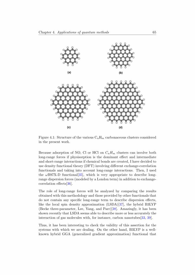
Chapter 4. Applications of quantum methods 65
Figure 4.1: Structure of the various CnHm carbonaceous clusters consideredin the present work.
Because adsorption of NO, Cl or HCl on CnHm clusters can involve bothlong-range forces if physisorption is the dominant effect and intermediateand short-range interactions if chemical bonds are created, I have decided touse density functional theory (DFT) involving different exchange-correlationfunctionals and taking into account long-range interactions. Then, I usedthe ωB97X-D functional[35], which is very appropriate to describe long-range dispersion forces (modeled by a London term) in addition to exchange-correlation effects[36].
The role of long-range forces will be analyzed by comparing the resultsobtained with this methodology and those provided by other functionals thatdo not contain any specific long-range term to describe dispersion effects,like the local spin density approximation (LSDA)[37], the hybrid B3LYP(Becke three-parameter, Lee, Yang, and Parr)[38]. Amazingly, it has beenshown recently that LSDA seems able to describe more or less accurately theinteraction of gas molecules with, for instance, carbon nanotubes[33, 39].
Thus, it has been interesting to check the validity of this assertion for thesystems with which we are dealing. On the other hand, B3LYP is a well-known hybrid GGA (generalized gradient approximation) functional that

Chapter 4. Applications of quantum methods 66
has been used to characterize the interaction of NO both with the face [31]and with the edges[16, 18] of carbonaceous systems. In the case of chlori-nated species, I also used the half-and-half functional (BHandHLYP) [41]that has been proved in the literature to be well-suited for the characteriza-tion of Cl adsorption on benzene molecule [42].
Because the treatment of open-shell systems like the NO and Cl radicals con-sidered here may require an unrestricted methodology (it is not of coursethe unique solution), spin contamination problems can occur because thesesystems may have numerous high-spin electronic states. Moreover, this spincontamination could considerably affect geometry optimization and the cal-culated adsorption energy on the surface[17].
To analyze the importance of such situations, I have used restricted open-shell DFT (RO-DFT), a method that does not allow, by definition, any spincontamination, in parallel with an unrestricted DFT approach[40]. It is in-teresting to note that the unrestricted DFT method was shown to have amuch smaller spin contamination than ab initio unrestricted Hartree-Fock(UHF) approach[17]. Therefore, to complete these analyses, I have also com-pared the results obtained by DFTmethods to those provided by standard ab
initio molecular orbital (MO) open-shell methodologies like UHF, restrictedopen-shell Hartree-Fock (ROHF)[44], and the Møller-Plesset second-order(MP2) method that takes into account a part of the correlation energy[45].
Concerning now the basis sets used, the large number of atoms in the var-ious CnHm clusters considered here leads to a selection of basis set sizesthat represents a good compromise between accuracy and computationalefficiency, even when dealing with 150 carbon atoms. Thus, the 6-31G,6-31+G, 6-31G(d,p), and cc-pVDZ basis sets, were retained.
All of the calculations have been carried out by using the Gaussian 09 quan-tum chemistry package[46], and all stable geometries have been calculatedwith a tight criterion for geometry optimization.
4.3 Results for the adsorption of NO on carbona-
ceous surfaces
4.3.1 Adsorption of NO on the Face of Perfect Carbonaceous
Clusters
We started this study by a detailed analysis of the adsorption characteristicsof NO on the face of carbonaceous clusters without any defect.

Chapter 4. Applications of quantum methods 67
The first series of calculations was performed using the ωB97X − D func-tional [35] that takes into account the dispersion effects in the calculationof the interaction energy between NO and the carbonaceous surface. Thecorresponding results are presented in Table 1 as a function of the size ofthe carbonaceous cluster and the basis set used. Note that because we haveperformed a full optimization of the NO-CnHm system, the adsorption geom-etry discussed below corresponds to the absolute minimum of the potentialenergy surface. The values displayed in Table 1 show that the optimizedgeometry of the NO-CnHm systems does not significantly depend on thesize of the carbonaceous cluster or the basis set used in the calculations.In the corresponding equilibrium geometry (Figure 4.2-a), the NO radicalis adsorbed nearly parallel to the carbonaceous surface, the N atom beingslightly closer to the surface than the O atom (the tilt angle is equal toabout 15➦ with respect to the carbon plane). In this position, the N and Oatoms are located nearly above a C atom (top site) and above the center ofa carbon hexagon (hollow site), respectively.
The molecule-surface distance (N-C) is around 3.1 A. In contrast, the ad-sorption energy increases (in absolute value) from 2.94 to 5.05 kcal/molwhen increasing the size of the CnHm cluster and when changing the basisset. However, because the calculations for the C150H30 cluster are very time-consuming, especially when using the 6-31+G basis set that contains diffusefunctions, the results given in Table 1 indicate that the C54H18 and C96H24
cluster could be a good compromise between accuracy and calculation timewhen characterizing adsorption on large carbonaceous systems such as thosefound in the soot structure.
The weak interaction between NO and the carbonaceous surface can beillustrated by a Mulliken analysis of the charge distribution. The valuesgiven in Table 2 clearly show that physisorption of NO is accompanied by avery weak charge transfer between the surface and the adsorbed molecule.

Chapter 4. Applications of quantum methods 68
Figure 4.2: Optimized structures calculated for the adsorption of NO on theface of a C54H18 cluster using the 6-31G basis set and the (a) ωB97X–Dor (b) LSDA functional. Both top and side views of the system are shown.N, O, C, and H atoms are represented by blue, red,gray, and white balls,respectively.
This charge transfer slightly modifies the charge distribution of the surfacein the vicinity of the adsorption site, the atoms located far from this sitebeing unaffected by adsorption.
When using the LSDA functional, that is, a DFT method that does notcontain any specific long-range dispersion term, I calculate an adsorptionenergy value of about −6.7 kcal/mol for the C54H18 cluster with the 6-31Gbasis set. The NO radical is adsorbed nearly parallel to the carbonaceouscluster, as shown previously using the ωB97X-D functional, but the molec-ular center of the mass-surface distance is equal to about 2.8 A instead of3.1 A, and the N atom is now adsorbed above the center of a C-C bond (seeFigure 4.2b, associated with LSDA). In contrast, when using the B3LYPfunctional, the calculated adsorption energy is much weaker (about −0.3kcal/mol), and the NO-surface distance is much larger (around 3.5 A ) thanwhen using LSDA. Note that very similar results are obtained when usingdifferent basis sets (6-31G, 6-31+G, and cc-pVDZ). Moreover, as expectedfor these calculations on physisorbed systems, the spin contamination ob-tained when using the unrestricted DFT method remains very weak becausethe corresponding average (S2) value is equal to at most 0.7553~2, a valuevery close to the S2 eigeinvalue S(S + 1) ~2 = 0.75 ~
2.

Chapter 4. Applications of quantum methods 69
These analyses are in agreement with the theoretical results already pub-lished in the literature [31, 33] and confirm that a functional like B3LYP isunable to give reasonable values for the adsorption energy of the NO/graphite-like system because the corresponding results are quite far from the experi-mental values (between −2.9 and −4.3 kcal/mol)[34]. In fact, as evidencedhere, B3LYP strongly underestimates the binding energy, whereas the LSDAfunctional overestimates it, as already mentioned, for instance, in ref [47].Note that the GGA functional [48] has also been shown to underestimatethe adsorption energy (-0.7 kcal/mol) when compared to the experimentalvalues[32].
To check the influence of structural defects on the NO adsorption, I havealso performed additional calculations by considering a C96H24 cluster thatcontains one Stone-Wales defect [49] because such a defect has been shown

Chapter 4. Applications of quantum methods 70
to strongly impact the adsorption of NO2 on graphene, leading to thechemisorption of this molecule, accompanied by a significant change of thesurface geometry upon adsorption[50]. A Stone-Wales defect consists of twopentagon-heptagon pairs in the hexagonal network and is one of the most fre-quently observed defective structures in carbon nanotubes and graphene[49].
However, calculations performed here with the ωB97X-D functional stilllead to a physisorption process, characterized by an adsorption energy valuevery close to that obtained on the perfect surface. This indicates that NOinteracts weakly with the face of a carbonaceous surface, even when it con-tains a crystallographic defect. Such a feature is in fact similar to what hasbeen evidenced for NH3 and H2CO interacting with a Stone-Wales defect ongraphene and which has been related to the weak electron orbital overlapbetween these molecules and the defective surface[50, 51].
As a conclusion of this study on NO adsorption on the face of a carbona-ceous cluster, the binding energy values obtained here with the ωB97X-Dfunctional are consistent with the experimental data obtained at very lowtemperature and submonolayer coverage[34], irrespective of the cluster sizeconsidered in the calculations. This supports the hypothesis of a physisorp-tion process for NO on CnHm clusters, mainly governed by the dispersioninteractions. The approach used here thus represents a significant improve-ment compared to previous studies on similar systems.
Finally, it is important to mention that the optimization procedure for suchsystems was never an easy task, irrespective of the functionals and basissets used. Indeed, due to the geometry of the carbonaceous surface and itsweak interaction with NO, there are many nearly equivalent adsorption sitesat the surface, characterized by small energy wells. As a consequence, thepotential energy surface for NO appears very weakly corrugated, preventingthus a fast numerical minimum-energy search.
4.3.2 Interaction of NO with the Edge of Carbonaceous Clus-
ters.
After considering adsorption of NO on the face of the CnHm clusters, Ihave also investigated the possible adsorption at the edges of the perfectcarbonaceous clusters. However, starting from an initial position close toa cluster edge, the optimization procedure always leads ultimately to theadsorption of NO on the face of the cluster. Clearly, the presence of the Hatoms appears to prevent adsorption of the NO radical at the edges of thecarbonaceous cluster.

Chapter 4. Applications of quantum methods 71
Then, I studied adsorption on a defective cluster created by removing oneH atom, thus leaving one dangling bond at the cluster edge. For open-shellstructures, I have performed calculations using the RO-DFT method withboth RO-ωB97X-D and RO-B3LYP functionals and various basis sets. Inaddition, unrestricted DFT (U-ωB97X-D,U-B3LYP) calculations have alsobeen performed to investigate the influence of spin contamination.
Figure 4.3: Optimized structures calculated with the DFT method for thechemisorption of NO on the edge of the defective C54H17 clusters using the6-31G basis set and the ωB97X-D functional. Binding through either a C-N(a) or a C-O (b) bond is shown. N, O, C, and H atoms are represented byblue, red, gray, and white balls, respectively. The two different adsorptionsites considered in the calculations see text are indicated by numbers 1 and2 in the left panel.
The results obtained on the C54H17 cluster with the 6-31G basis set aregiven in Table 3, and the corresponding adsorption geometries are illustratedin Figure 4.3. Note that two different sites have been considered in thecalculations corresponding to two different positions of the missing H atomat the edge (see Figure 4.3a), but the two situations lead to very similarresults due to the symmetry of the carbonaceous cluster. These resultsshow that NO strongly interacts with such a defective cluster, preferentiallyby forming a C-N (Figure 4.3a) rather than a C-O (Figure 4.3b) bond, the

Chapter 4. Applications of quantum methods 72
corresponding binding energies being equal to about −60 kcal/mol in thefirst situation and around −30 kcal/mol in the second one, irrespective of thefunctional used. Indeed, calculations performed with ωB97X-D and B3LYPgive very similar results, thus indicating that the dispersion effects do notplay any significant role in the situations considered here. Moreover, spincontamination in these DFT calculations appears rather weak, as indicatedby the S2 values given in Table 3. Note that the adsorption of NO on thedefective edge of the carbonaceous cluster is a barrierless process betweentwo radicals, and no transition state has been searched along the reactionpath.
Moreover, it is also interesting to mention that, in the first case (i.e., C-Nbonding), the final stable C54H17NO system corresponds to a singlet state,whereas in the latter situation (C-O bonding), the most stable C54H17ONsystem is found to be in a triplet state. These conclusions can be ratio-nalized by a simple MO analysis, which has been checked here using thesemiempirical AM1 method applied to the NO + C6H5 system used as aproxy for the more general NO + CnHm systems. Let us consider the shapeof the π MOs of NO radical (see Figure 4.4a and 4.4b). In its electronicground state, the doubly occupied π MO displays a larger coefficient on theoxygen site than that on the nitrogen site because oxygen is more electroneg-ative than nitrogen (Figure 4.4a). It is the reverse for the singly occupiedπ∗ MO (Figure 4.4b). Then, when considering the reaction of NO with a σaromatic radical, like the phenyl radical C6H5, the formation of C6H5-NOrather than C6H5-ON is expected. To get C6H5-ON, one electron must bepromoted from the doubly occupied π (or σ , see below) MO to the singlyoccupied π∗ MO in such a way that the remaining electron on the π (or σ,see below) MO can be paired with its phenyl partner. Now, the two electronsguided by the two-fold-degenerate π∗ MO of NO have the propensity to bein the same spin state rather than be paired according to the well-knownHund rule. Such a situation favors a triplet rather than a singlet state. Thisanalysis is in accordance with the fact that the angles C-N-O in C6H5-N-Oand C-O-N in C6H5-O-N are around 120➦. Then, it is actually the NO πorbitals that mainly govern the bonding.
To be more precise, we should mention that the AM1 energy ordering ofthe doubly occupied MOs in NO places the σ MO slightly above the πones. Irrespective of this ordering, there are two possible promotions of oneelectron to the π∗ MO, either from a σ or from a π MO. The two first excitedstates of NO are, respectively, 4Πi (38440 cm−1) and 2Σ+ (43965.7 cm−1)(see ref [52]).
The configuration σππ does not correlate with a 4Π state but with a 2Σσ+
one. On the contrary, the configuration πππ correlates with a 4Π state. Theallowed electron-dipole A2Σ+ ← X2Πr transition argues for the π∗ ← σ

Chapter 4. Applications of quantum methods 73
Figure 4.4: (a) Singly occupied MO π∗ and (b) doubly occupied MO π∗
of NO (the red ball is the oxygen atom). Both MOs have been obtaineddirectly from a simple AM1 calculation
promotion. Anyway, there is a mixture between these two possible eventsbecause the angle C-O-N is neither 180 nor 90➦.
In conclusion, we can note that the formation of C6H5-NO is expected tooccur from the ground state of NO. In contrast, C6H5-ON requires that NObe promoted in a specific excited state, for instance, by an ad hoc radiation.We do not know if such processes have already been observed experimentally,but it would be a good test to reinforce the present analysis.
When dealing with this simplified NO + C6H5 system, energy calculationsperformed at the DFT level show that the binding energy value in the C6H5
system is about twice (in absolute value) the value obtained for the C6H5-ON, system irrespective of the basis set used in the calculations (here, thecalculations have been conducted with the 6-31G, 6-31G(d,p), cc–pVDZbasis sets; Table 4). This conclusion being very similar to that obtainedfor the larger C54H17 system. I have performed additional calculations tocharacterize the influence of the size of the carbonaceous system on the

Chapter 4. Applications of quantum methods 74
results. As evidenced by the values given in Table 5, it turns out that thesize of the surface does not strongly influence the binding energy value ofNO, indicating thus that the reactivity with the defective cluster mainlydepends on the local environment of the adsorbed NO species. Moreover,as already mentioned, the size of the basis set does not have any significantinfluence on the results.
For comparison, Hartree-Fock calculations for the same systems as thoseconsidered in the DFT calculationswe were also performed, using a simi-lar procedure (i.e., restricted, RO, or unrestricted calculations according tothe situation) and the same basis sets. The corresponding results are givenin Tables 3, 4, and 5, where it can be seen that HF and DFT approacheslead to strongly different values of the binding energies. For instance, thebinding energy calculated for the formation of a C-N bond between NO andthe C54H17 cluster is equal to −31.8 kcal/mol only with the HF approach,that is, a value that is about half of the one obtained in DFT calculations(Table 3). Worse, the formation of a C-O bond seems to be slightly favoredin the HF approach, the corresponding binding energy value being around−34.9 kcal/mol. This conclusion is at odds with the MO orbital analysispresented above and clearly indicates a failure of the calculations at the HFlevel with the modest 6-31G basis set. Indeed, using larger basis sets seemsto favor the C-N rather than the C-O binding, as evidenced in Table 4, inagreement with the conclusions drawn from the DFT results. Moreover, itshould be noted that the results obtained with an unrestricted methodology

Chapter 4. Applications of quantum methods 75
are characterized by a larger spin contamination than the corresponding un-restricted DFT calculations, in accordance with previously published studiesfor similar substrates[17].
Note that using a more accurate method, namely, the post-HF MP2 [45],leads to larger (absolute) values of the binding energy between NO and thedefective cluster. For instance, the binding energy calculated in the singletstate for the C54H17-NO system is equal to −49.6 kJ/mol, that is, 50% largerthan the value obtained at the HF level for the same system.
However, such sophisticated methods are very time-consuming for the largesystems considered here, and DFT approaches thus appear as a good com-promise between accuracy and tractability of the calculations.
Finally, calculations based on the (classical) reactive ReaxFF force field[53, 54] have been also carried out using the LAMMPS package [55] forcomparison with the quantum results presented above. The optimization ofthe NO + CnHm−1 systems confirms that the C-N is favored with respectto the C-O binding, the corresponding energies being equal to about −60and −40 kJ/mol, respectively. It is interesting to note that not only theconclusions but also the binding energy values are in good agreement withthe results obtained from DFT approaches. This indicates that the ReaxFFclassical reactive potential might be accurate enough to investigate adsorp-tion processes on carbonaceous systems. Of course, such a conclusion hasto be confirmed by additional tests on other adsorbed species. Anyway, thisconclusion may be very interesting especially for studying much larger sys-tems (large soot nanoparticles, for instance) for which quantum approachesare totally prohibited due to their expected huge computational cost.
Unfortunately, the present results cannot be directly compared to the resultsavailable in the literature because the systems considered are not strictlyequivalent. Indeed, both Kyotani et al.[16] and Montoya et al.[17] inves-tigated the adsorption of NO on zigzag and armchair sites located at theedges of unsaturated carbonaceous clusters, that is, they do not consider anyhydrogen atom in the vicinity of the possible adsorption sites. The resultingsystems thus favored a parallel adsorption of NO, with a binding by both Nand O atoms. However, it can be noted that among the various structuresoptimized by Kyotani et al.[16] and corresponding to local minima of thepotential energy surface, a perpendicular C-NO configuration is much morefavored than a C-ON one (see Figure4.3 and Table 4 of ref [16]), as obtainedin the present paper. The binding energy calculated by Kyotani et al. forthis C-NO structure is equal to −48 kJ/mol, a value slightly lower (in ab-solute value) than the one calculated here using however a different level oftheory.

Chapter 4. Applications of quantum methods 76
4.3.3 Discussion
Depletion of NxOy species by adsorption on carbonaceous surfaces is animportant open question in atmospheric sciences [15]. This work was thusfocused on the interaction between NO and carbonaceous clusters (CnHm),modeling the surfaces that are likely present in soot nanoparticles. I madeuse of quantum approaches to investigate the NO-CnHm system and foundthe following results: NO is physisorbed on the face of carbonaceous clusterseven when they contain a Stone-Wales crystallographic defect. Although thepresent work is formally based on a more rigorous approach than previousstudies [31],[33], especially because it takes into account the dispersion inter-actions in the DFT calculations, the conclusion remains similar; the inter-action energy of NO on carbonaceous surfaces without any dangling bond isequal to a few kJ/mol (calculated at 0 K), and as a consequence, NO wouldnot be efficiently trapped on such surfaces in atmospheric conditions.
This conclusion is in accordance with experimental results obtained at lowtemperature and low coverage[34]. It should be mentioned that I do notinvestigate here the influence of coverage on the adsorption process for tworeasons; first, the experimental results showed that the adsorption energyis almost constant up to monolayer coverage and that adsorption is notaccompanied by dimerization[34]; second, in the troposphere, it is unlikelythat two NO species can be adsorbed in a close vicinity due to their quitelow concentration.
It is interesting to note that Xu et al.[31] also studied the dissociative ad-sorption reaction of NO on graphite, which turns out to be a very complexprocess, characterized by very high energy barriers (more than 70 kcal/mol)along the corresponding reaction path. Although I do not find any evidencefor such chemisorption in our optimization procedure (based on a differenttheoretical approach), it is worth noting that it does not change the rel-evance of the present conclusions in the atmospheric context. Indeed, thehigh barrier calculated by Xu et al.,[31] if confirmed by further experimentalor theoretical works, cannot be overcome at tropospheric temperatures.
The situation is completely different when a dangling bond is created at thesurface, for instance, by leaving an unsaturated C atom at the edge of thecarbonaceous cluster. In this situation, our calculations evidenced a stronginteraction between NO and the surface, leading to a chemisorption processwithout any barrier along the reaction path. This conclusion is in accordancewith previous works based on different models for the unsaturated surfaceedges [16],[17] and also with theoretical studies devoted to adsorption of NOon graphite surfaces containing monovacancy defects, that is, a surface thatalso contains a dangling bond [20]. Such a situation is likely occurring in real

Chapter 4. Applications of quantum methods 77
soot nanoparticles, and the corresponding defect sites formed, for instance,during the recombination of soot precursors [4], thus can be efficient trappingsites for NO in the troposphere.
4.4 Results for the adsorption of chlorinated species
on carbonaceous surfaces
4.4.1 Adsorption of HCl on the face of a perfect carbona-
ceous cluster
The adsorption of HCl on a perfect carbonaceous surface modeled eitherby the coronene (C24H12) or the circumcorone (C54H18) molecules has beencharacterized by using the DFTmethod with the ωB97x-D (b) and BHandHLYP(a) functionals, as explained in the first part of this chapter.
[ ] [ ]
Figure 4.5: Optimized structures calculated for the adsorption of HCl onthe face of a C24H12 cluster using the 6-311G++(d,p) basis set and (a) theBHandHLYP and (b) the ωB97X–D functional
First, let us comment the results obtained on the coronene molecule. Asit is shown in Fig 4.5, the BHandHLYP (a) and ωB97x-D (b) functionalslead to different results although in both cases the HCl molecule is foundto adsorb vertically above a carbon site with the hydrogen atom pointingtowards the carbonaceous surface. However, when using the BHandHLYPfunctional, HCl is located near the edge of the corenene molecule whereasit is adsorbed on a C of the central hexagon when using the ωB97x-D func-tional. Note that this adsorption geometry perpendicular to the surface,unlike the NO orientation on graphene, is due to the large electronegative
a b

Chapter 4. Applications of quantum methods 78
difference between the H and Cl atoms. Quantitatively, the BHandHLYPfunctional leads to an H-C distance of around 2.5 A with an adsorptionenergy equal to −2.3 kcal/mol whereas the ωB97x-D gives 2.3 A and −5.6kcal/mol. The different results between the two functionals (different posi-tions and energies) come from the dispersion term (explicitely respresentedby an analytical form) in the ωB97x-D functional which tends to favor con-figurations corresponding to the maximum number of nearest neighbors.This results is confirmed when considering a larger cluster like C54H18. In-deed, in this case, the HCl position using the ωB97x-D functional is againfound to be on top of a C atom of the central hexagon, whereas it is still ontop of a cluster edge when using the BHandHLYP. Nonetheless, without anyavailable experimental information, it is quite risky to discriminate betweenthe different results obtained using different functionals. However, for suchmolecular systems where physisorption is expected, a functional taking intoaccount the dispersion interaction should certainly be preferred.
For this adsorption process, the results of the Mulliken charge calculations(given in Fig 4.6 for C24H12 (a), HCl (b) and C24H12HCl (c)) with theωB97x-D functional, clearly show that the presence of HCl modifies locallybut significantly the D6h symmetry of the charge density on C24H12. Then,there is a small charge transfer from HCl to the cluster, especially near thecarbon atom on which the molecule is adsorbed. Indeed, this carbon atomwhich is initially neutral (black color) in C24H12 becomes negatively charged(red color) in the adduct. Note that, although the carbon atoms saturatedby hydrogen atoms at the edges of the cluster are negatively charged, thepresence of these hydrogen atoms leads to a repulsion with the hydrogen ofthe HCl molecule, thus excluding these carbon atoms as possible adsorptionsites.

Chapter 4. Applications of quantum methods 79
[ ] [ ]
[ ]
Figure 4.6: Mulliken analysis of the charge distributions for the a) C24H12 b)HCl and c) C24H12HCl using the 6-311G++(d,p) basis set and the ωB97X–Dfunctional
4.4.2 Reaction of HCl on a defective carbonaceous cluster
and of Cl on a perfect carbonaceous cluster
Furthemore, I have considered the adsorption process of the HCl moleculeon a carbonaceous cluster containing a defect created by removing one Hatom, thus leaving one dangling bond at the edge of the cluster. In thissituation, chemisorption becomes a likely process and using a functionalincluding explicit dispersion term is no more mandatory as shown whenconsidering the case of NO on defective carbonaceous clusters (see above).In contrast, it remains still interesting to compare the results obtained withtwo different functionals. Thus, I characterized the adsorption process withthe B3LYP and BHandHLYP functionals that have been previously usedin the literature for discribing the bonding between chlorinated species andsmall PAHs[42].
Moreover, it is interesting to note that the expected reaction
a b
c

Chapter 4. Applications of quantum methods 80
CnHm−1 +HCl→ CnHmCl (4.2)
may a priori have the same final product as the following reaction
CnHm + Cl→ CnHmCl. (4.3)
Thus, I also characterized the adsorption process of Cl on a perfect car-bonaceous cluster. Note that both cases, HCl on CnHm−1 and Cl on CnHm,corresponds to open-shell systems with the same number of electrons.
Then, the structures of the separated reactants (C24H12, Cl, C24H11, HCl)and of the products of their interactions were optimized by using the large6-311G++(d,p) basis set. Again, the coronene molecule is chosen as anexample of small carbonaceous cluster for the following discussion.
The first interesting result is that when using the BHandHLYP functional,two stable structures (here named σ and π) were found for the final productof both reactions. In contrast, with the B3LYP functional, only one ofthese minima was reached, illustrating thus the importance of the choiceof a functional when performing DFT calculations. These two structures,ilustred in Fig 4.7 a) σ and b) π have almost the same energy value (totalenergy of the system) being the π structure a little bit more stable (by lessthan 2 kcal/mol) than the σ, with a Cl-C distances of 2.51 A and 1.93A respectively.

Chapter 4. Applications of quantum methods 81
[ σ]
[π]
Figure 4.7: Optimized structures calculated with the BHandHLYP func-tional and the 6-311G++(d,p) basis set for the chemisorption of HCl onthe edge of the defective C24H11 cluster or Cl on C24H12. The two stablestructures obtained for the product C24H12Cl are shown.
In fact, the energy difference of less than 2 kcal/mol between these twostructures must be considered carefully because their respective stabilitycomes from the competition process between the change of Cl-C bond length(2.61 to 1.93 A) and the lost of aromaticity when passing from a π likestructure to a σ one. Then, it is actually difficult to predict a priori whichof these two tendencies is the most probable, and we can reasonably admitthat both structures have more or less the same energy. This result isconsistent with those published by Platz et all [42] who, in a study forbenzene as aromatic reactant instead of coronene, shown in addition thatonly the BHandHLYP functional leads to a full set of optimized structuresirrespective of the size of the basis set used. Moreover, Platz et al. discussedsome experimental arguments based on UV-visible spectroscopy, ESR andkinetics, to justify that the π like structure is the global minima of the fullpotential energy surface for the system benzene+Cl.
Chapter 4. Applications of quantum methods 82
With the global minimum already known, an interesting question concernsthe energy character ∆Eads of the two reactions 4.2 and 4.3 when using theBHandHLYP functional and the 6-311G++(d,p) basis set. Then, taking asfinal product the π configuration, the corresponding binding energies wereequal to -23.7 kcal/mol for the reaction C24H11 + HCl and -7.1 kcal/mol forthe C24H12 + Cl.
These quite puzzling energy difference can be explained by using experi-mental (thermodynamics tables) and some selected theoretical data fromthe evaluation of heats of formation with the AM1 semiempirical method[56] (for more details, see the appendix A). But for short, considering thatin both reaction there is formation of a Cl-C bound, it is easy to realize thatthis energetic difference of about 15 kcal/mol comes from the energy gainedwhen, on the one hand breaking a Cl-H bound (103 kcal/mol) and, on theother hand, creating a C-H bond (CnHm−1–H) in the carbonaceous cluster(113 kcal/mol). Nevertheless, this comparison is not immediate because ourDFT calculations provides energy differences at 0K without any zero pointenergy (ZPE) correction whereas AM1 and experimental values correspondto enthalpie values at 298K.
Another important result is that I also performed similar DFT calculationswith the quite small 6-31G basis set, to evaluate the accuracy of much shorter(in terms of computing time) calculations. The main conclusion is that sucha difference of about 10-15 kcl/mol can only be obtained when using a largebasis set like the 6-311G++(d,p) including polarization effects irrespectiveof the functional used. Indeed, the smaller basis set leads to much largerdifferences, mainly as a result of a very poor energetic description of theH-Cl bond.
4.4.3 Reaction of HCl on carbonaceous cluster with a single
vacancy site
Another interesting configuration from a theoretical point view is the pre-cense of defects on the carbon surfaces. Thus, in this section, a monovacancyis modeled by removing one central carbon atom in a cluster made of 30 fusedbenzene rings arranged in a single atomic layer. The defective particle thuscontain 79 carbon atoms with the edges of this carbonaceous cluster beingsaturated by hydrogen atoms (C79H22 cluster).
It should be noted that removing a C atom from a perfect carbonaceoussurface is the simplest way to simulate a defective surface, despite it isan unlikely process in realistic atmospheric conditions because of the highactivation energy required by the corresponding process [43]. However, car-bon atom vacancies have been evidenced in atomistic simulations of soot

Chapter 4. Applications of quantum methods 83
formation, coming from incomplete recombination of small soot precursors(typically CnHm with small n and m values) [4]. In that sense, the defectivecluster optimized here can be considered as a realistic model of defectivesurfaces that might exist in soot.
Then, based on the results of the previous section, DFT calculations withthe BHandHLYP functional and the 6-311G++(d,p) were performed to op-timize the structure of the corresponding defective particle (C79H22) and toinvestigate the interaction of HCl with the resulting defective carbonaceouscluster.
Lets first comment the most stable structure found for the reactants. Theatomic vacancy created is surrounded by three carbon atoms, each having adangling sp2 bond corresponding to 3 unpaired σ electrons and one unpairedπ electron. For the C79H22 cluster, two of the three carbon atoms carryingan unpaired electron tend to reform a single bond, and a five-membered ringis consequently stabilized in the defective cluster. Moreover, a σ danglingbond is localized on the third atom around the vacancy site, and the presenceof this dangling bond together with that of the five-membered ring finallyleads to a loss of planarity for the optimized structure of the C79H22 defectivecluster with a small increase of the first nearest-neighbor distances aroundthe vacancy site (1.68 A instead of 1.42 A in perfect graphite).
Then, the optimization procedure starting from the HCl molecule locatedright above the carbon vacancy leads to the dissociative chemisorption ofthe HCl molecule, and ends with the chemisorption of the H atom on oneC atom around the vacancy with a C-H distance equal to 1.05 A, and thechemisorption of the Cl atom on top of a C atom of the unsaturated hexag-onal ring, with a C-Cl bond length equal to 1.9 A. In this configuration, theCl-H distance is finally equal to 2.27 A, and the binding energy calculatedas the energy difference between the product of the reaction and the tworeactants separated from each other, is equal to -36.5 kcal/mol. This indi-cates that chemisorption of HCl on such defective surface is an exothermicprocess that should be possible in fire situations (see the Introduction partof this chapter), although I did not characterize the energy barriers alongthe corresponding reaction path.
It is interesting to mention that this adsorption process is however lessexothermic than the chemisorption of H2O on the same surface (bindingenergy equal to ) which leads to the dissociation of the water molecule anda resulting binding energy of more that 300 kJ/mol [11]. Indeed, the nextinteresting step for our study would be the characterization of the adsorp-tion process on the chlorinated carbonaceous surface, in order to help atinterpreting experimental observations showing that, for soot produced byfuels containing chlorine (PVC, electrical cables, electrical equipment), the

Chapter 4. Applications of quantum methods 84
Figure 4.8: Optimized structure calculated with the BHandHLYP functionaland the 6-311G++(d,p) basis set for the chemisorption of HCl on a monova-cancy created on a carbonaceous cluster (here, the product of the reactionHCl + C79H22 is shown)
.
amount of water sorbed on the surface of soot (determined using sorptionbalance) is much larger than on soot without Cl [30].
4.5 Conclusions
The goal of this study was first to investigate the adsorption of NO, Cland HCl molecules on perfect carbonaceous clusters, mainly by using DFTapproaches. Here, it has been shown that the interaction of these moleculeswith a perfect carbonaceous surface corresponds to a physisorption processthat requires using a functional taking into account the dispersion effects. Inthis way, ωB97X-D seems to represent an accurate functional for studyingphysisorption on weakly interacting systems such as those considered here.
In a second step, I have used various theoretical approaches to characterizethe interaction between NO, Cl and HCl species and the defective edges orfaces of carbonaceous clusters because such a situation could also model thesurfaces that can be found in soot nano-particles[4].

Chapter 4. Applications of quantum methods 85
In contrast with the adsorption on the face, interaction of NO with the edgeof a defective cluster leads to chemical bonding, with a net preference for aC-N rather than a C-O binding that can be explained on the basis of simpletheoretical chemistry considerations. Similarly, the adsorption of HCl ona carbon monovacancy leads to a chemisorption process resulting in thedissociation of the HCl molecule. Both studies show the specific role thatmay play the defects in carbonaceous structures regarding the adsorption ofatmospheric species.
The first conclusion of this work is thus that soot may be an efficient sinkfor NO and chlorinated species in the troposphere only if it contains a suf-ficiently high number of defective sites, mainly unsaturated carbon atoms.Moreover, besides its atmospheric interest, this study is clearly evidencethat quantum calculations (both at the DFT and HF levels of theory) haveto be carefully conducted when considering the interaction between atmo-spheric species and carbonaceous surfaces, although these systems mightappear quite simple at first glance. Problems encountered with system size,functional type, size of the basis set, spin contamination, and spin multi-plicity should be thus systematically carefully addressed before any credibleconclusion can be drawn.

Bibliography
[1] Chung, S.H., Seinfeld J.H. Global Distribution and Climate Forcingof Carbonaceous Aerosols. J Geophys Res 2002;107:4407.
[2] Chen, Y.; Penner, J.E. Uncertainty Analysis for Estimates of the FirstIndirect Aerosol Effect. Atmos. Chem. Phys. 2005;5:2935-2948.
[3] Demirdjian, B.; Ferry, D.; Suzanne, J.; Popovicheva,O.B.;Persiantseva, N.M.; Shonija, N.K. Heterogeneities in theMicro-structure and Composition of Aircraft Engine CombustorSoot:Impact on the Water Uptake. J. Atmos. Chem. 2007;56:83-103.
[4] Violi, A. Modeling of Soot Particle Inception in Aromatic andAliphatic Premixed Flames. Combust. Flame 2004;139:279-287.
[5] Picaud, S.; Hoang, P.N.M.; Hamad, S.; Mejias, J.A.; Lago, S. A The-oretical Study of the Adsorption of Water on a Model Soot Surface.II. Molecular Dynamics Simulations. J. Phys. Chem. B 2004;108:5410-5415.
[6] Moulin, F.; Picaud, S.; Hoang, P.N.M.; Jedlovszky, P. Grand Canon-ical Monte Carlo Simulation of the Adsorption Isotherms of WaterMolecules on Model Soot Particles. J. Chem. Phys. 2007; 127:164719.
[7] Hantal, G.; Picaud, S.; Hoang, P.N.M.; Voloshin, V.P.; Medvedev,N.N.; Jedlovszky, P. Water Adsorption Isotherms on Porous Onion-Like Carbonaceous Particles. Simulations with the Grand CanonicalMonte Carlo Method. J. Chem. Phys. 2010; 133:144702/1-144702/12.
[8] Hamad, S.; Mejias, J.A.; Lago, S.; Picaud, S.; Hoang, P.N.M. A The-oretical Study of the Adsorption of Water on a Model Soot Surface. I.Quantum Chemical Calculations. J. Phys. Chem. B 2004; 108: 5405-5409.
[9] Collignon, B.; Picaud, S.; Hoang, P.N.M.; Liotard, D.; Rayez, M.T.;Rayez, J.C. A Semi-Empirical Potential Model for Calculating the
86

Chapter 4. Applications of quantum methods 87
Interactions between Large Aromatic Molecules and Soot Surfaces. J.Mol. Struct.; THEOCHEM 2006; 772: 1-12.
[10] Oubal, M.; Picaud, S.; Rayez, M.T.; Rayez, J.C. A Theoretical Char-acterization of the Interaction of Water with Oxidized CarbonaceousClusters.Carbon 2010; 48: 1570-1579.
[11] Oubal, M.; Picaud, S.; Rayez, M.T.; Rayez, J.C. Interaction of WaterMolecules with Defective Carbonaceous Clusters: An Ab Initio Study.Surf. Sci. 2010; 604: 1666-1673.
[12] Oubal, M.; Picaud, S.; Rayez, M.T.; Rayez, J.C. Water Adsorptionon Oxidized Single Atomic Vacancies Present at the Surface of SmallCarbonaceous Nanoparticles Modeling Soot. Chem. Phys. Chem. 2010;11: 4088-4096.
[13] Oubal, M.; Picaud, S.; Rayez, M.T.; Rayez, J.C. Adsorption of At-mospheric Oxidants at Divacancy Sites of Graphene: A DFT Study.Comput. Theor. Chem. 2013; 1016: 22-27.
[14] Finlayson-Pitts, B.J.; Pitts, Jr., J. Chemistry of the Upper and LowerAtmosphere. Theory, Experiments, and Applications; Academic Press:San Diego, CA; 2000: p 17.
[15] Seinfeld, J.H.; Pandis, S.N. Atmospheric Chemistry and Physics. FromAir Pollution to Climate Change; Wiley: New York, 1998: p 259.
[16] Kyotani, T.; Tomita, A. Analysis of the Reaction of Carbon withNO/N2O Using Ab Initio Molecular Orbital Theory. J. Phys. Chem.B 1999; 103: 3434-3441.
[17] Montoya, A.; Truong, T. N.; Sarofim, A. F. Spin Contamination inHartree-Fock and Density Functional Theory Wavefunctions in Mod-eling of Adsorption on Graphite. J. Phys. Chem. A 2000; 104:6108-6110.
[18] Zhu, Z.H.; Finnerty, J.; Lu, G.Q.; Yang, R.T. Opposite Roles of O2 inNO- and N2O-Carbon Reactions: An Ab Initio Study. J. Phys. Chem.B 2001; 105: 821-830.
[19] Ghigo, G.; Maranzana, A.; Tonachini, C.; Zicovich-Wilson, C.M.;Causa, M. Modeling Soot and Its Functionalization under AtmosphericCombustion Conditions by Density Functional Theory within Molecu-lar (Polycyclic-Aromatic-Hydrocarbon-like) and Periodic Methodolo-gies. J. Phys. Chem. B 2004; 108: 3215-3223.

Chapter 4. Applications of quantum methods 88
[20] Xu, S.C.; Irle, S.; Lin, M.C. Quantum Chemical Prediction of ReactionPathways and Rate Constants for Reactions of NO and NO2 withMonovacancy Defects on Graphite (0001) Surfaces. J. Phys. Chem. C2010; 114: 8375-8382.
[21] Smith, D.M.; Welch, W.F.; Graham, S.M.; Chughtai, A.R.; Wicke,B.G.; Grady, K.A. Reaction of Nitrogen Oxides with Black Carbon:An FT-IR Study. Appl. Spectrosc. 1988; 42: 674-680.
[22] D.W. Boukhvalov and M.I. Katsnelson. Chemical functionalization ofgraphene. J. Phys.: Condens. Matter 2009; 21:344205.
[23] Y. G. Zhou, X. T. Zu, F. Gao, H. F. Lv, and H. Y. Xiao. Adsorption-induced magnetic properties and metallic behavior of graphene.App.Phys. Lett. 2009; 95:123119.
[24] P.V.C. Medeiros, A.J.S. Mascarenhas, F. de Brito Mota and C.M.C deCastilho. A DFT study of halogen atoms adsorbedon graphene layers.Nanotechnology 2010; 21:485701.
[25] M. Ijas, P. Havu, and A. Harju. Fracturing graphene by chlorination:A theoretical viewpoint.Phys. Rev. 2012; 85:035440.
[26] M. Yang, L. Zhou, J. Wang, Z. Liu, and Z. Liu. Evolutionary Chlo-rination of Graphene: From Charge-Transfer Complex to CovalentBonding and Nonbonding. J. Phys. Chem. C 2012; 116:844–850.
[27] D.B. Karki and N.P. Adhikari. First-principles study of the stability ofgraphene and adsorption of halogen atoms (F, Cl and Br) on hydrogenpassivated graphene.Int. J. Modern Phys. B 2014; 28:1450141.
[28] J.P. Stone, R.N. Hazlett, J. Enoch Johnson, and H.W. Carhart. Thetransport of hydrogen chloride by soot from burning polyvinyl chlo-ride. J. Fire and Flammability 1973; 4:42-51.
[29] E.A. Ramskill. Toxicity aspects and application of the naval protectivegas mask to shipboard fires. Section VIII of Naval Research LaboratoryMemorandum Report 1816 (1967).
[30] F.-X. Ouf. Private communication (2015).
[31] Xu, S.C.; Irle, S.; Musaev, D.G.; Lin, M.C. Quantum Chemical Pre-diction of Reaction Pathways and Rate Constants for Dissociative Ad-sorption of COx and NOx on Graphite (0001) Surface. J. Phys. Chem.B 2006; 110: 21135-21144.
[32] Leenaerts, O.; Partoens, B.; Peeters, F.M. Adsorption of H2O,NH3,CO, NO2, and NO on Graphene: A First-Principles Study. Phys. Rev.B 2008; 77: 125416.

Chapter 4. Applications of quantum methods 89
[33] Zhang, Y.H.; Chen, Y.B.; Zhou, K.G.; Liu, C.H.; Zeng, J.; Zhang,H.L.; Peng, Y. Improving Gas Sensing Properties of Graphene by In-troducing Dopants and Defects: A First-Principles Study. Nanotech-nology 2009; 20: 1885504.
[34] Brown, C.E.; Hall, P.G. Physical Adsorption of Nitric Oxide onGraphite and Silica and Adsorption of Gases on Nitric Oxide Pread-sorbed on Carbon. J. Colloid Interface Sci. 1973; 42: 334-341.
[35] Chai, J.D.; Head-Gordon, M. Long-Range Corrected Hybrid DensityFunctionals with Damped Atom-Atom Dispersion Corrections. Phys.Chem. Chem. Phys. 2008; 10: 6615-6620.
[36] Klimes, J.; Michaelides, A. Perspective: Advances and Challenges inTreating van der Waals Dispersion Forces in Density Functional The-ory. J. Chem. Phys. 2012; 137: 120901.
[37] Vosko, S.H.; Wilk, L.; Nusair, M. Accurate Spin-Dependent ElectronLiquid Correlation Energies for Local Spin Density Calculations: ACritical Analysis. Can. J. Phys. 1980; 58: 1200-1211.
[38] Becke, A.D. Density-Functional Thermochemistry III. The Role of Ex-act Exchange. J. Chem. Phys. 1993; 98: 5648-52.
[39] Tournus, F.; Charlier, J.C. Ab Initio Study of Benzene Adsorption onCarbon Nanotubes. Phys. Rev. B 2005; 71: 165421.
[40] Jacob, C.R.; Reiher, M. Spin in Density-Functional Theory. Int. J.Quantum Chem. 2012; 112: 3661-3684.
[41] Becke, A.D. A new mixing of Hartree-Fock and local density-functionaltheories. J. Chem. Phys. 1993; 98:1372-1377.
[42] Tsao, M.-L., Hadad, C.M., and Platz, M.S. Computational Studyof the Halogen Atom-Benzene Complexes. J. Am. Chem. Soc. 2003;125:8390-8399.
[43] A.A. El-Barbary, R.H. Telling, C.P. Ewels, M.I. Heggie, P.R. Briddon,Phys. Rev. B (2003) 68 144107.
[44] Lauderdale, W.J.; Stanton, J.F.; Gauss, J.; Watts, J.D.; Bartlett,R.J. Many-Body Perturbation Theory with a Restricted Open-ShellHartree-Fock Reference. Chem. Phys. Lett. 1991; 187: 21-28.
[45] Head-Gordon, M.; Pople, J.A.; Frisch, M.J. MP2 Energy Evaluationby Direct Methods. Chem. Phys. Lett. 1988; 153: 503.

Chapter 4. Applications of quantum methods 90
[46] Frisch, M.J.; Trucks, G.W.; Schlegel, H.B.; Scuseria, G.E.; Robb,M.A.; Cheeseman, J.R.; Scalmani, G.; Barone, V.; Mennucci, B.;Petersson, G.A.; et al. Gaussian 09, Revision D.01; Gaussian, Inc.:Wallingford; CT; 2009.
[47] Kohanoff, J. Electronic Structure Calculations for Solids andMolecules; Cambridge University Press: Cambridge, U.K.; 2006: p82.
[48] Perdew, J.P.; Burke, K.; Ernzerhof, M. Generalized Gradient Approx-imation Made Simple. Phys. Rev. Lett. 1996; 77: 3865-3868.
[49] Banhart, F.; Kotakoski, J.; Krasheninnikov, A.V. Structural Defectsin Graphene. ACS Nano 2011; 5: 26.
[50] Zhang, Y.H.; Zhou, K.G.; Xie, K.F.; Gou, X.C.; Zeng, J.; Zhang, H.L.;Peng, Y. Effects of Stone-Wales Defect on the Interactions BetweenNH3, NO2 and Graphene. J. Nanosci. Nanotechnol. 2010; 10: 1.
[51] Qin, X.; Meng, Q.; Zhao, W. Effects of Stone-Wales Defect uponAdsorption of Formaldehyde on Graphene Sheet with or without AlDopant: A First-Principle Study. Surf. Sci. 2011; 605: 930.
[52] Huber, K.P.; Herzberg, G. Molecular Spectra and Molecular Struc-ture IV. Constants of Diatomic Molecules; van Nostrand ReinholdCompany: New York; 1979.
[53] van Duin, A.C.T.; Dasgupta, S.; Lorant, F.; Goddard, W.A., III.ReaxFF: A Reactive Force Field for Hydrocarbons. J. Phys. Chem. A2001; 105: 9396-9409.
[54] Chenoweth, K.; van Duin, A.C.T.; Goddard, W.A., III. ReaxxFF Re-active Force Field for Molecular Dynamics Simulations of HydrocarbonOxidation. J. Phys. Chem. A 2008; 112: 1040-1053.
[55] Plimpton, S. Fast Parallel Algorithms for Short-Range Molecular Dy-namics. J. Comput. Phys. 1995; 117: 1-19.
[56] Dewar, M.J.S.; Zoebisch, E.G.; Healy, E.F.; Stewart, J.J.P. AM1: ANew General Purpose Quantum Mechanical Molecular Model. J. Am.Chem. Soc. 1985; 107: 3902-3909.

Chapter 5
Optical Properties of soot
Scattering of electromagnetic waves by any system is related to the hetero-geneity of that system: heterogeneity on the molecular scale or on the scaleof aggregations of many molecules. Although in practice we have severalkinds of heterogeneity, the nature of the physical phenomenon is always thesame for all systems. Matter is composed of discrete electric charges that,in presence of an electromagnetic wave, are set into oscillatory motion bythe electric field of the incident wave. Accelerated electric charges radiateelectromagnetic energy in all directions; it is this secondary radiation thatis called the radiation scattered by the obstacle. Thus,
Scattering = excitation+ reradiation. (5.1)
In addition, to reradiating electromagnetic energy, the excited elementarycharges may transform part of the incident electromagnetic energy into otherforms as for instance, thermal energy. This process is called absorption.
Absorption = excitation+ transfer. (5.2)
When an arbitrary particle is illuminated by a beam of light that can bemodeled by a plane wave with specified characteristics (wavelength, polar-ization state), the amount and angular distribution of the light scatteredby the particle, as well as the amount absorbed, depend in a detailed wayon the nature of the particle, that is, its shape, size, porosity and chemicalcomposition.
This fact leads us to the direct and inverse problems in the theory of theinteraction of an electromagnetic wave with a small particle. Using a dragon
91
Chapter 5. Optical Properties of soot 92
analogy, as Bohren and Huffman in their celebrated book[1], these problemsare:
The direct problem: Knowing the dragon, describe his tracks or, given a par-ticle of specified shape, size and chemical composition, which is illuminatedby a beam of specified irradiance, polarization, and frequency, determinethe field everywhere.
The inverse problem: Knowing the tracks, describe the dragon or, by asuitable analysis of the scattered field, describe the particle(s) that is/areresponsible for the scattering.
This chapter aims at clarifying some subtle aspects of the interaction oflight with soot nanoparticles. Note that as mentioned in chapter (2), sootis mainly made of strongly absorbing carbon so that scattering can usuallybe neglected with respect to absorption. Hence, we will concentrate on theabsorption properties of soot.
One of the main goals during this PhD thesis is to provide information thatallows to connect the two problems mentioned before, by using simulationmethods to compute the absorption spectrum of model soot nanoparticles,starting from well defined morphological details, in order to build a databaseof results that will help interpreting experimental results.
The advantage of the method described in this chapter is that using anatomistic framework combined with particle construction allows to isolatecertain variables to study the influence of particle features such as atomicpositions (hence porosity or rugosity) or chemical composition, onto thespectroscopic signals of the particle.
5.1 Atmospheric interest
As already mentioned in the Introduction part of this manuscript, carbona-ceous particles emitted by combustion processes are suspected to have anon-negligible impact on the Earth’s radiative balance[2]. First, they havedirect effects because they scatter and absorb solar and thermal infraredradiation, thus modifying the Earth’s albedo. Second, they have an indirecteffect because these particles may act as ice and cloud condensation nu-clei thus impacting the local and global radiative properties of clouds[3, 4].These particles, together with the other atmospheric aerosols, are currentlyone of the largest sources of uncertainties in understanding climate evolutionand in quantifying the amplitude of temperature changes[5]. This mainlycomes from the high natural variability of the sources of carbonaceous par-ticles due to different conditions of combustion and fuel compositions[6].

Chapter 5. Optical Properties of soot 93
Generally, carbonaceous particles consist of a complex mixture of chemicalcompounds and are usually divided (somewhat artificially) into two frac-tions. The black (or elemental) carbon (BC) fraction is strongly absorbingvisible and near-IR light. BC concentrations are therefore usually deter-mined by light-absorption measurements. In contrast, the organic fraction(OC) of the aerosol represents an aggregate of hundreds of individual com-pounds exhibiting a wide range of chemical and thermodynamic properties.Because of this complexity, aerosol OC content is usually determined fromthe difference between total carbon and BC contents[6], where the totalcarbon is usualy determined by conversion to CO2 which is then easily mea-sured.
As already noted, widely accepted structural models for BC combustionparticles are based on fractal particles coming from agglomeration of pri-mary carbonaceous nanoparticles. These models assume that the primarynanoparticles are made of small pieces of graphene sheets, whose stacking onconcentric spheres of different radii results in typical onion-like structures[7].These primary nanoparticles may also contain a very small fraction of otheratoms (mainly oxygen) besides carbon, due to partial oxidation[8]. Theyalso contain defects like edges or atom vacancies formed during the recom-bination of soot precursors[9], leading thus to different ratios of aromaticto aliphatic carbon atoms. In addition, they can be also coated by variousorganic and aromatic species due to aging in the atmosphere.
Owing to this complexity, a detailed understanding of both direct and in-direct climatic effects of carbonaceous particles remains challenging and re-quires the characterization of the interaction of these particles with electro-magnetic radiations, as a function of the geometrical and chemical charac-teristics of the nanoparticles constituting the carbonaceous fraction of theaerosols.
In this respect, theoretical approaches at the atomic scale can give detailson the involved processes that are not directly accessible to experimentalprobes. They can also help at interpreting experimental information anddata coming from observations.
In a recent series of papers[10, 11, 12, 13], researchers from UTINAM havebeen interested in characterizing the indirect effect of soot on climate. Theythus modeled soot surfaces and their interaction with water to characterizethe influence of the structural and chemical details on the ability of sootnanoparticles to act as ice and cloud condensation nuclei. Here, I ratherfocus on the direct effect, i.e., on the relation between the soot nanostructureand its interaction with solar radiation, on the basis of a preliminary work[14,15].

Chapter 5. Optical Properties of soot 94
Indeed, although the study of light absorption by carbonaceous particlesis not a new field (see for instance the reviews by Sorensen[16] and Bondet al.[17]), a direct relation between the atomistic characteristics of theseparticles and their effect on climate is still missing. For instance, simplifiedmacroscopic models are still widely used based on the Mie theory (exactsolution of Maxwell equations)[18, 1], that assumes single (or aggregatesof) homogeneous spherical particles. More sophisticated approaches arealso able to take into account heterogeneity[19, 20] or irregularly shapedparticles[21]. Alternatively, powerful numerical methods such as the discretedipole approximation (DDA)[22, 23, 24] or the T-matrix method[25] arenow largely disseminated for computing scattering of radiation by smallparticles of arbitrary shape and by periodic structures. However, none ofthese methods allows a direct connection between the atomic compositionof carbonaceous particles and their absorption/extinction properties.
In the following, a method to calculate the absorption properties of car-bonaceous primary nanoparticles is thus presented, directly based on theknowledge of the positions and polarizability of the atoms constituting theparticle. This method is more specifically used to calculate the mass spe-cific absorption cross section coefficient (MAC) of primary soot nanoparti-cles modeled at the atomic scale and it is described in Section 2. Then,the accuracy of the parameters used to represent the carbon atom polar-izability is checked by comparison with experimental results obtained forthe C60 molecule in Section 3. In the same section, the results for fullerenemolecules of increasing radius are also given to investigate the influence ofthe particle size on the MAC calculations. In Section 4, the approach usedto model soot particles at the atomic scale is detailed and the correspondingMAC curves are calculated in the UV spectral range. Finally, conclusionsare given and further developments of this work are discussed in Section 5.Note that the method and most of the results presented in this chapter havebeen published in the paper ”Calculations of the mass absorption cross sec-tions for carbonaceous nanoparticles modeling soot” (C. Garcıa-Fernandez,S.Picaud, M.Devel. Journal of Quantitative Spectroscopy and RadiativeTransfer 2015; 164:69–81).
5.2 Model
5.2.1 Principle of the PDI model
In this study, I chose to calculate two experimentaly relevant properties,i.e., the absorption cross section Cabs and the mass specific absorption cross
Chapter 5. Optical Properties of soot 95
section coefficient (MAC) defined as the ratio of Cabs to the total mass ofthe nanostructure.
Following the work of Draine[23], Cabs for a nanograin made of N atoms can
be related to the imaginary part of the dynamic polarizability tensor↔αi (ω)
of each atom i as[23] :
Cabs(ω) =4πk
|E0(ω)|2N∑
i=1
{Im[~µi(ω).(
↔αi)
−1(ω))∗~µi(ω)∗]− 2
3k3~µi(ω).~µi(ω)
∗
},
(5.3)
where ~E0(ω) is the external homogeneous electric field applied to the system,~µi is the dipole moment induced on the ith atom by that applied field andk = 2π/λ is the wavenumber associated to the incident light of wavelengthλ.
To compute the ~µi, I use the Point Dipole Interaction (PDI) model[26]according to which this dipole can be directly computed from the knowledgeof the atomic polarizabilities and of the local electric field ~Eloc(~ri, ω) atposition ~ri.
Note that the PDI model is in fact similar to the discrete dipole approxima-tion (DDA) method[22, 23, 24]. However, DDA is used at a scale at whichthe continuum approximation is valid. Thus, in DDA, effective polarizabili-ties derived from a combination of the material local dielectric susceptibilityand the volume of the discretization element through a Clausius-Mossotti-like relation (with radiative corrections) are used. In contrast, as it will beexplained below, PDI requires the knowledge of the exact positions ~ri ofthe atoms constituting the nanostructure under investigation and of theirpolarizabilities. Note that these atomic polarizabilities can either be derivedfrom ab initio Time Dependent Density Functional Theory (TD-DFT) cal-culations or from Clausius-Mossotti-like relations but with depolarizationfactors adapted to the symmetries of the true atomic lattice and not to theorthorhombic lattice used in the discretization procedure of DDA.
In the PDI model, the local electric field is thus written, as in DDA, asthe sum of the external field ~E0(ω) and of the electric field created at theposition ~ri by the dipoles induced on the other atoms of the carbonaceousnanostructure. Hence, the individual dipoles can be computed by solvingthe following linear system of equations:

Chapter 5. Optical Properties of soot 96
∀i = 1, ..., N ~µi, (ω) =↔αi (ω) ~E0(ω) +
N∑
j 6=i=1
↔αi (ω)
↔T
(2)(~ri, ~rj , ω)~µj(ω) ,
(5.4)
where↔T
(2)is the electric field propagator in vacuum that is written as[15]
↔T
(2)(~ri, ~rj 6=i, ω) = −
1
ǫ0
(~∇~ri ⊗ ~∇~ri +
ω2
c2↔I
)(− ei
ωc|~ri−~rj |
4π |~ri − ~rj |
), (5.5)
where↔I is the identity tensor.
The calculation of the absorption cross section for the carbonaceous nanos-tructures considered here thus requires the knowledge of the exact positions~ri of the atoms constituting this nanostructure. In this respect, the PDImethod thus differs from the usual implementations of the Discrete DipoleApproximation (DDA) method [22, 23] that are rather based on the scat-tering of dipoles on a regular cartesian grid to allow use of fast Fouriertransform (FFT) algorithms. Note that despite this arbitrary discretizationof the volume of the nanostructure under consideration, DDA approachesare much often used in the literature especially because of the wide dissemi-nation of corresponding open source codes[24, 27, 28, 29], in contrast to thePDI method for which no general code is available. As the exact atomic po-sitions are often not known in many carbonaceous structures, especially thesoot systems investigated here, the PDI method thus could appear irrelevantat first sight. However, these positions can be defined in model systems suchas those used in the present work and the exact relation between the opticalproperties of a carbonaceous nanostructure and its atomic details can bedirectly computed, without any assumption on the global geometry of thesystem under study. In a similar way, combining this PDI approach withexperimental measurements could allow optical methods to be an uniqueprobe for examining the intimate structure of such carbonaceous systems,if distinctive features broader than the resolution of the instrument can befound.
5.2.2 parametrization of carbon polarizabilities in the PDI
model
Eq. 5.4 also requires the knowledge of the atomic polarizability tensors↔αi (ω) associated with the atoms present in the nanostructure under study.

Chapter 5. Optical Properties of soot 97
Considering that the carbonaceous nanostructures investigated here can a
priori be made of different hybridized carbon atoms (depending on the localenvironment of the carbon atoms in the system) different atomic polariz-ability tensors for the corresponding C atoms must be defined.
Initially, it was envisaged that the polarizability tensors for any kind ofatoms present in organic molecules or soot could be obtained by a fittingprocedure. This would have consisted in using as input data the polar-izability tensors of a group of small molecules computed by DFT and asmodel data the polarizability tensors of the same molecules computed usingPDI with the polarizability tensor elements for each atom with a differentchemical nature and hybridization state as parameters (see e.g. [30]). Thisprocedure was to be applied for each frequency. Then, we realized that theDFT code we had at hand could not give us reliable results for complex po-larizabilities near absorption peaks and that we should use TD-DFT codessuch as those used by Malloci et al. to fill their database of spectroscopicproperties of polycyclic aromatic hydrocarbons[31]. In the meantime, wehad decided to use a less sophisticated approach described hereafter.
In this work, we have made the approximation that carbon atoms that aresurrounded by three nearest neighbors can be treated as sp2 hybridized car-bons and given an anisotropic polarizability tensor derived from the polar-izability tensor of C atoms in graphite, as computed from frequency depen-dent permittivities given by Draine[32], even if the carbon network is locallycurved. More precisely, to compute the polarizability tensor of such a car-bon atom surrounded by three nearest neighbors, we use the the coordinatesof the 3 neighbors to define a local frame with two unit vectors parallel tothe plane tangent to the one defined by the three nearest neighbors and oneunit vector perpendicular to this plane[33]. Indeed, in this local frame, theatomic polarizability tensors are diagonal (and anisotropic) with two paral-lel (αlocal
i,|| ) and one perpendicular components (αlocali,⊥ ). For coherence with
previous works done at UTINAM [14, 15], I use here a convention which isat the opposite of that usually used for graphite in which perpendicular andparallel directions are defined with respect to the c-axis (perpendicular thususually means parallel to the graphite surface plane, whereas here it meansperpendicular to the local plane of 3 nearest neighbors).
The atomic polarizability tensors can then be computed in the nanostructureglobal frame (~ux; ~uy; ~uz) by simple geometric transformations, as:
↔αi= R−1 ↔
αlocal
i (ω) ·R (5.6)
by using the rotation matrix R that connects the local frame to the globalframe.

Chapter 5. Optical Properties of soot 98
However, carbonaceous nanostructures may also contain C atoms that arenot surrounded by three carbons. For instance, C atoms located at boundarysites or at defect edges of the nanostructure may have only one or twocarbon neighbors. For these atoms, which cannot be considered at all as sp2
hybridized carbons, isotropic polarizability tensors are rather defined, beingcharacterized in a first approximation by the value αiso
i = (2αlocali,|| +αlocal
i,⊥ )/3.
In both cases (three nearest neighbors or not), the polarizabilities should beregularized in order to compute the field created on one atom by a dipoleon a nearest neighbor. Indeed, in that case, the dipolar approximationis not valid since electronic clouds of these two atoms interpenetrate eachother. If that effect is not taken into account, polarization catastrophes canoccur (see e.g. [34]). To avoid this, several regularization procedures havebeen proposed, among which the convolution of the electric field propagatorintroduced in Eq.5.4, by one spherically symmetric function(s) representingan approximated radial distribution function (RDF) of the electrons aroundthe nucleus of the atom at ~rj which induced dipole creates the field at ~ri [35].The special case of a Gaussian RDF was already presented in [36]. Later,Mayer introduced a propagator regularized by 2 Gaussian RDFs, in case ofanother induced dipole being at ~ri[37]. The expression in these papers arestatic approximations that are valid in the limit that the wavelength of theincoming plane wave is much bigger than the distance between the 2 atomswhich is always valid in our case.
A cornerstone in any DDA code results from the choice of a formula for theeffective polarizability values that are used to calculate the dipoles (phys-ical and theoretical problem). Similarly, in the PDI approach, a way tocompute the frequency-dependent polarizabilities for each atom must bedefined. Since we could not do it with plain DFT, we followed the samepath than in DDA and computed atomic polarizabilities from the atomicpolarizabilities of carbon atoms in graphite (cf. above) themselves de-rived from parametrizations of graphite complex permittivities, through anadapted Clausius−Mossotti relation, using depolarization factors originallycomputed by Senet for the static case[38] and later confirmed by Andersenand Bonderup[39]. This will be detailed in the next paragraph.

Chapter 5. Optical Properties of soot 99
5.3 Results for fullerenes
5.3.1 Parameters and validation
Here, the main goal is to compute the optical properties of carbonaceousnanostructures modeling soot nanoparticles. As mentioned above, this re-quires the prior knowledge of the atomic polarizability tensors
↔αi (ω) asso-
ciated with the C atoms forming the nanoparticles, and thus it depends onthe values assigned to the (αlocal
i,|| ) and αlocali,⊥ components. In addition, the
polarizability tensors may be isotropic or anisotropic depending on the localneighboring of the C atoms (i.e., depending in this approach on the numberof next neighbor C atoms).
To calculate these polarizability tensors, different sets of dielectric constantvalues available in the literature for carbon atoms in graphite[40, 41, 42, 43]were tested, the conversion from dielectric constant to polarizability beingdone through the generalized Clausius−Mossotti relation as:
N
V
αlocali,a (ω)
ǫ0=
ǫi,a(ω)− 1
1 +Ba(ǫi,a(ω)− 1). (5.7)
where the index a labels one of the three principal directions defining thelocal basis frame and N/V is the atomic density. The coefficients Ba are thedepolarization factors assumed here to be equal to those of graphite, i.e.,B⊥ = −0.606 and B// = 0.803 [38, 39]. Note that taking B⊥ = B// = 1
3 inEq. 5.7 would lead to the usual Clausius−Mossotti relation[44, 45].
Of course, these electric susceptibility parametrizations (and thus, the po-larizability values used here) have been optimized for graphite and theirapplication to soot could be questionable although soot nanoparticles areactually made of graphite-like nanoclusters[7].
Thus, to investigate the transferability of these parameters to round shapednanostructures such as soot nanoparticles, the polarizability per unit vol-ume of the C60 and C70 fullerenes were calculated using the three setsof parameters. This calculation has been based on the PDI approach[26],where the polarizability of the carbonaceous nanostructure is directly com-puted from the knowledge of the atomic polarizabilities through the followingequations[14, 15] :
~µ(ω) =↔α (ω) ~E0(ω) =
N∑
i=1
~µi(ω) =N∑
i=1
↔αi (ω) ~Eloc(~ri, ω) (5.8)

Chapter 5. Optical Properties of soot 100
where ~µ is the total electrical dipole moment of the carbonaceous nanos-tructure,
↔α (ω) is the dynamical polarizability tensor of the carbonaceous
nanostructure containing N carbon atoms and ~E0(ω) is the external homo-geneous electric field applied to the system. ~µi is the dipole induced on atomi by the local electric field ~Eloc(~ri, ω) at its location ~ri (Eq. 5.4).
↔αi defines
the dynamical polarizability tensor of atom i calculated as mentioned aboveusing parameters coming from graphite data. Then, imposing an unit field~E0 successively along the three coordinate axes (~ux, ~uy; ~uz) of the global
frame, we can easily get the three columns of the polarizability tensor↔α of
the carbonaceous nanostructure from Eq. 5.8.
The application of graphite data to predict properties of fullerenes has beenalready discussed in detail by Andersen and Bonderup[39] which pointedout some inconsistency between various sets of data, especially concerningthe values for ǫ⊥. However, due to the lack of any reliable set of parametersspecially suited for carbon atoms in curved structures such as soot nanopar-ticles, using parameters optimized for graphite still remains unavoidable.
The polarizability values calculated with the three selected sets of parame-ters have then been used to determine the function Im(−1/ǫ), through theusual Clausius−Mossotti relation
∑
i
Niαi =3ǫ0(ǫr − 1)
ǫr + 2(5.9)
where Ni represent the number of constituent elements by unit volume, with
1/Ni ≈ 703, 34A3
by molecule in a cubic face centered (cfc) crystal of C60
of lattice parameter a = 14.117 A.
The theoretical curves are given in Fig 5.1 for both C60 (Fig 5.1a) and C70 (Fig 5.1b) fullerenes together with the corresponding experimental curves [46]for comparison. The theoretical curves in Fig 5.1 exhibit two broad peaksthat can be related to the experimental peaks characterizing collective exci-tations of valence electrons. For the two fullerenes considered here, the firstpeak (corresponding to π plasmon[47]) has its maximum between 6 and 7 eV,whereas for the second peak (which corresponds to σ + π plasmon[47]) themaximum is obtained between 22 and 28 eV, depending on the parametriza-tion that is used in the calculations.
The comparison with the experimental curves shows that the three differentparametrizations used here appear to be quite relevant for describing thefeatures below 8 eV, although the results obtained with the parametersgiven by Draine et al[40, 41, 42] seems slightly more accurate than thoseissued from Djurisic’s work[43]. In contrast, theoretical results obtained byusing optical constants coming from EELS and ellipsometry[43] seems to

Chapter 5. Optical Properties of soot 101
better reproduce the experimental features above 8 eV, although a smallshift (of around 2 eV) is evidenced for the maximum position of the mainpeak. Note that, as expected, some resonances related to excitations from πto π∗ orbitals for the C60 and C70 molecules (peaks below 5 eV) [48] cannotbe accounted for by any parametrization optimized for graphite where suchtransitions are not possible due to symmetry considerations.
To conclude, it appears that the parameters given by Draine et al.[40, 41, 42]for graphite can also be used with reasonable confidence to get at leastqualitative results for fullerenes, and more generally spherical carbonaceousparticles[20, 39], especially when restricting the calculations to the visibleand near-UV zone, as in the following.
[ ] 0
0.2
0.4
0.6
0.8
1
1.2
1.4
1.6
1.8
0 5 10 15 20 25 30
Im(-
1/ε
)
Energy(eV) [ ] 0
0.2
0.4
0.6
0.8
1
1.2
1.4
1.6
1.8
0 5 10 15 20 25 30
Im(-
1/ε
)
Energy(eV)
Figure 5.1: Comparison between the experimental Loss function Im(−1/ǫ)(black curve) for a cristal of (a) C60 and (b) C70 [46] and the theoreticalcurves computed with three different sets of optical constants derived fromgraphite data; red, green and blue curves correspond to parametrizationsfrom Ref.[40, 41, 42] and Ref.[43] (for optical and for EELS data), respec-tively.
5.3.2 Fullerenes of increasing radius
In this section, the interaction of isolated fullerene molecules with light hasbeen simulated, in order to study their optical properties in the UV zone, asa function of their increasing size. As the extinction cross section is mainlydominated by absorption, I first seek to compare the photoabsorption crosssection Cabs for a C60 fullerene with the experimental data reported in theliterature[49, 50] before extending the study to larger fullerenes. The com-parison given in Fig 5.2 between our theoretical results and the experimentalcurve shows that our approach reproduces quite well the main peak positionaround 6 eV, as already evidenced in the previous section when calculatingIm(−1/ǫ). Again this figure points out that calculations based on the opti-cal constants derived from graphite data cannot reproduce some of the C60
resonances below 5 eV.
a b

Chapter 5. Optical Properties of soot 102
0
1
2
3
4
5
6
2 3 4 5 6 7 8 9
Cabs (
10
-22 m
2)
Energy (eV)
Figure 5.2: Comparison between the photoabsorption cross section calcu-lated for a C60 fullerene (red curve) and that reported by [50] (blue curve).Calculations have been performed by using the graphite optical constantsgiven by Draine et al.[40, 41, 42].
Then, calculations are extended to larger fullerenes, namely C240, C540, C960
that are icosahedral fullerenes like C60, and C180, C320 and C1280 that aretriacontahedral fullerenes. The corresponding results are given in Fig 5.3in the visible and near-UV range, i.e., typically between 150 and 550 nm(corresponding to the [2.3 - 8.3] eV range). Note that we used wavelengthsin nm for the x axis of the MAC curves (and not energies as in the Cabs
case), for coherence with the corresponding literature.
The curves in Fig 5.3 show that the maximum position of the resonance peakis shifted to high wavelength values (by about 45 nm) and that its maximumintensity increases when the size of the fullerenes increases. An interestingconsequence of these two features is that for wavelengths lower than approxi-mately 200 nm the mass specific absorption cross section (MAC) of fullerenesdecreases with their radius, whereas it increases for larger wavelengths.
These results are in accordance with those of previous works that used eithera simplified model[51] or an approach based on the PDI method[52] for thecalculations of dynamical polarizabilities of fullerenes.

Chapter 5. Optical Properties of soot 103
0
10
20
30
40
50
60
70
100 150 200 250 300 350 400 450 500 550
Ma
c (
m2/g
)
λ(nm)
128096054032024018060
Figure 5.3: Computed mass absorption cross section (MAC) for the icosahe-dral C60,C240,C540,C960 and the triacontahedral C180, C320,C1280 fullerenes.
Because in this model we can use either isotropic or anisotropic polarizabil-ity tensors to describe C atoms, depending for instance on their number ofneighbors, it was interesting to study the influence of such a choice on theMAC curves calculated for different fullerenes. Of course, in such structures,the C atoms are all surrounded by 3 neighbors as in graphite, and consid-ering that they could be represented by isotropic polarizability may appearsurprising at first sight. Nevertheless, this allows the characterization of theinfluence of the parametrization on our results by comparing MAC curvesobtained for the same nanostructure but for two different representations ofthe polarizability tensors of the C atoms.
As an illustration, the corresponding results are given in Fig 5.4 for thesmallest (C60) and the largest (C1280) fullerenes considered here.
Interestingly, for C60, both isotropic and anisotropic polarizability tensorsgive similar MAC curves, especially when considering the position of theresonance peak around 200 nm. In contrast, for C1280, not only strong dif-ferences in the MAC intensity but also a large shift of the resonance peak(of about 30 nm) are obtained when using different hypotheses for the po-larizability tensor of the C atoms. This could be related to the fact that, forsuch large fullerene, each C atom and its three nearest neighbors are approx-imately located in the same plane, as in graphite, thus enhancing the influ-ence of the differences between isotropic and anisotropic parametrization.Moreover, this indicates that, at least in this approach and for large struc-tures, sp2 hybridized carbon atoms will lead to much stronger absorptionthan C atoms represented by isotropic polarizabilities resulting from an av-erage of the anisotropic values. Interestingly, this could give us an useful tool

Chapter 5. Optical Properties of soot 104
to discriminate between strongly and weakly absorbing carbons in furthermodeling, and thus would help, for instance, at representing the differencesexperimentally evidenced between elemental and organic carbons[53].
[C60] 0
5
10
15
20
25
30
35
100 150 200 250 300 350 400 450 500 550
Mac (
m2/g
)
λ(nm)
[C1280] 0
10
20
30
40
50
60
70
100 150 200 250 300 350 400 450 500 550
Mac (
m2/g
)
λ(nm)
Figure 5.4: Computed mass absorption cross section (MAC, in m2/g) ob-tained when using isotropic (green curve) and anisotropic (red curve) atomicpolarizabilities for (a) C60 and (b) C1280 fullerenes.
5.4 Results for soot nanoparticles
5.4.1 Soot nanoparticle models
The results presented above have shown that parameters optimized forgraphite can reasonably well reproduce the optical properties of fullerenes,in accordance with previous conclusions[20, 39]. The transferability of theseparameters to various carbonaceous systems can thus justify using them formodeling the MAC of soot nanoparticles. As mentioned above, calculatingthe MAC with the PDI approach requires not only the knowledge of theatomic polarizabilities (taken here as equal to those of carbons in graphite)but also of the atom positions in the carbonaceous nanostructures.
Thus in this study, four different primary soot nanoparticles have been used,on the basis of a previous work devoted to water adsorption on soot[10, 13].
(a)
(b)

Chapter 5. Optical Properties of soot 105
Such approach allows us to evaluate qualitatively the dependence of sootoptical properties on particle morphology at the atomic scale.
The first nanoparticle is generated by randomly scattering small clusters of19 carbon atoms on concentric spheres arranged in an onion-like structure[10].This small cluster, referred below as the C19 unit, is made of five fused ben-zene rings. One hundred and thirteen of these C19 units (corresponding toa total number of 2147 carbon atoms) have been randomly scattered on thesurface of four concentric spheres of increasing radii (from 9.6 to 20.7 A),the separation between two successive spheres being equal to 3.4 A, in ac-cordance with experimental observations for combustion soot [54]. For thescattering of the C19 units on the surface of these spheres, a minimum dis-tance of 3.80 A has been imposed between the nearest neighboring carbonatoms of two adjacent units on the same sphere. The relative orientations oftwo adjacent C19 units have been randomly distributed. The correspondingprimary soot nanoparticle, referred hereafter as the Sunits soot nanoparticleis shown in Fig. 5.5a.
In addition to this empirically generated primary soot nanoparticle, threeother nanoparticles have been built starting from the optimized structuresof carbon buckyonions (i.e., multi-shell fullerenes) containing four carbonlayers arranged in a concentric way just as Sunits. However, to model thepresence of holes and nanopores in the (defective) structure of primary sootnanoparticles, C atoms have been randomly removed from the initial bucky-onion structure. Then, the resulting structures have been relaxed in a molec-ular dynamics simulation run performed at 298 K on the canonical N,V,T,ensemble, in which the adaptative intermolecular reactive empirical bondorder (AIREBO) potential has been used to describe the carbon–carboninteractions[55]. It is worth noting that the corresponding structures arethus not based on a random scattering of units of same size (as Sunits) butrather on a random distribution of holes. These particles will be referredbelow as Sholes soot nanoparticles.
Two of these Sholes soot nanoparticles have been based on the structure ofthe four-shell C240@C540@C960@C1500 fullerene, relaxed after removing1033 and 1107 carbon atoms, respectively, to model different localizationof carbon atoms in similar structures. They contain 2207 and 2133 carbonatoms respectively, and are characterized by an external radius of about 22A. These Sholes nanoparticles are thus similar to Sunits with respect to thetotal number of C atoms, although they are slightly larger in size. The maindifference comes from the size of the internal cavity, which is determined hereby the radius of the smallest fullerene (C240 ) embedded in the buckyonion.It it indeed twice smaller for the two Sholes (radius value equal to about 4.3A) than for the Sunits soot nanoparticles (radius value equal to about 9.6 A).The third Sholes soot nanoparticle is thus based on the structure of the larger

Chapter 5. Optical Properties of soot 106
four-shell C540@C960@C1500@C2160 fullerene, i.e., a buckyonion that ischaracterized by an internal cavity of size similar to the one in Sunits, butit contains a much larger number of C atoms. However, it was not possibleto get any stable structure when removing a too large number of atomsin this buckyonion. So, an Sholes soot nanoparticle containing 3774 carbonatoms was chosen. The relaxed structures of the three Sholes nanoparticlesare shown in Fig. 5.5b,c,d.
Figure 5.5: (a) Simplified representation of a soot aggregate made of agglom-erated primary nanoparticles with, on the right hand side of the figure, apicture of the the Sunits nanoparticle containing 2147 C atoms that is used tomodel a primary nanoparticle of soot in the present approach. Additionalmodels for these primary particles, based on the Sholes nanoparticles, arealso shown at the bottom of the figure where (b), (c) and (d) correspond toSholes nanoparticles containing 2133, 2206 and 3774 C atoms, respectively.See text for the definition of the Sunits and Sholes nanoparticles.
Of course, building soot models as described above is completely arbi-trary. Nevertheless, the primary nanoparticles generated this way presentthe main geometric characteristics of soot collected in flames[62] or emittedby aircraft[8], i.e., graphite-type layers arranged in an onion-like structure,although they are somewhat smaller (about 4 − 4.5 nanometers of diameterhere). Indeed, considering larger particles in this PDI calculations wouldbe rather time consuming without any further approximations[15] and we

Chapter 5. Optical Properties of soot 107
thus choose to limit the present work to nanoparticles containing a relativelysmall number of carbon atoms.
Note that many different particles can be generated using this procedure.However, the calculations have been restricted to only four particles, as anillustration of the approach presented here. Moreover, as it will be shownbelow, this (limited) set of examples is nevertheless sufficient to show howthe absorption properties can be related to the atomistic structure of sootnanoparticles.
5.4.2 Mass absorption coefficient of soot nanoparticles
In this section, the calculation of the mass absorption coefficient is presentedfor the four nanoparticles generated above and considered as independentnanoparticles, where the attention is focused on how spectroscopic infor-mation could be used to differentiate morphological information on sootnanoparticles at an atomistic scale. This differs from a lot of previous ex-perimental and theoretical studies which were carried out by consideringmorphology dependence of absorption as a function of the fractal structuresof soot aggregates, thus not considering individual nanoparticles[17, 67, 68,69, 70].
The corresponding results are shown in Fig 5.6. Information concerningthe geometrical characteristics of the nanoparticles considered as well as theposition of the main peak in the MAC curves are given in Table 5.1 togetherwith the calculated MAC values for three different wavelengths.
[ ] 0
5
10
15
20
25
30
100 150 200 250 300 350 400 450 500 550
Mac (
m2/g
)
λ(nm)
Sunits 2147Sholes 2207Sholes 2133Sholes 3774
[ ] 0
5
10
15
20
25
30
100 150 200 250 300 350 400 450 500 550
Mac (
m2/g
)
λ(nm)
Figure 5.6: (a) MAC curves (in m2/g) computed for various carbonaceousnanoparticles as a function of the wavelength (in nm). Blue, green, redand black curves correspond to Sunits and Sholes with 2133, 2207, and 3774carbon atoms, respectively. (b) Influence of the chemical composition onthe Sholes (2133 C atoms) MAC curve : red and orange curves correspondto consideration of anisotropic (solid line) and isotropic (crosses) carbonpolarizabilities in the calculations, respectively.
a b

Chapter 5. Optical Properties of soot 108
As shown in Fig. 5.6a, in the UV zone, the MAC curves for the soot nanopar-ticles are characterized by a large absorption peak, the maximum of whichbeing shifted by about 20 nm from Sunits to the largest Sholes (containing3774 C atoms).
This can be related to what has been obtained for fullerenes, i.e., the positionof the resonance peak is shifted to high wavelength values when the size ofthe nanoparticles increases. However, a shift of 7 nm is also obtained fortwo particles of similar size and built on a similar initial structure (Sholescontaining 2207 and 2133 atoms). This indicates that not only the size butalso the structure of the nanoparticle at the atomic level may influence theposition of the absorption peak.
In fact, a careful analysis of the differences between the soot nanostructuresconsidered here shows that, besides size and number of atoms, these parti-cles also differ by the ratio between isotropic and anisotropic carbons, i.e.,carbons having three (anisotropic) or less than three (isotropic) next neigh-bors. Regarding this criterion, the maximum of the absorption peak shiftsto higher wavelengths when increasing the number of anisotropic carbons.In other words, because the anisotropic vs. isotropic character is definedhere with respect to the graphite polarizability values (i.e., anisotropic car-bons are characterized by the polarizability tensor of graphite atoms), suchan effect in the absorption spectrum could be somehow related to the ratiobetween aromatic-like and aliphatic-like carbons in the nanoparticle.
structure atoms Rin (A) Rout (A) Ciso/C peak position (nm) Mac (250 nm) m2/g Mac (405 nm) m2/g Mac (550 nm) m2/g
Sunit 2147 9.6 20.73 0.60 207 13.53 5.57 3.07
Shole
2207 4.3 22.32 0.45 214 15.89 8.34 6.102133 4.5 22.58 0.30 221 20.61 9.25 6.233774 8.2 23.50 0.18 226 25.30 10.29 7.02
Table 5.1: Morphological details of the soot nanoparticles considered in thecalculations and the corresponding computed MAC values for 3 differentwavelengths. Rin corresponds to the radius of the internal cavity definedby the inner layer of the nanoparticle whereas Rout represents the radius ofthe nanoparticle, defined by its outer layer. Note that Ciso/C represent theproportion of C atoms represented by isotropic polarizabilities vs. the totalnumber of C atoms in the nanoparticle.
To illustrate this influence on the MAC calculations, Fig. 5.6b shows theresults obtained when considering only one specific soot nanoparticle (Sholeswith 2133 atoms, for instance), but changing the parameters assigned to thecarbon atoms. For illustration, we could consider the limiting (unrealistic)case for which all carbons are represented by the same isotropic polarizabilitytensor (orange curve). The MAC spectrum obtained in this case stronglydiffers from the one calculated for the initial particle containing only 30 %of isotropic carbons (red curve). Indeed, it is characterized by a double

Chapter 5. Optical Properties of soot 109
peak, the maximum of which being shifted by 22 nm from the maximumcalculated for the initial Sholes particle. This results clearly indicates thatthe chemical composition of the soot nanoparticle, modeled here by atomswith different types of polarizability tensors, may have a sufficiently stronginfluence on the MAC signals to allow detection of chemical differences byusing spectroscopic measurements, especially in the spectral region of theresonance peak.
However, coming back to realistic nanoparticles (Fig. 5.6a) and regardingthe MAC values at a given wavelength (and not only the position of the ab-sorption peak at its maximum value), it clearly appears that the amplitudesof the differences calculated for different soot particles strongly depends onthe spectral range. Indeed, Fig. 5.6a and values given in Table 5.1 for threedifferent wavelengths clearly show that above about 350 nm, the MAC val-ues are similar for the three Sholes nanoparticles which however differ by thesize of their internal cavity, the number of carbon atoms and their ratio ofisotropic to anisotropic carbons (i.e., their chemical composition). This indi-cates that, in this spectral region, differences in soot composition would nothave any strongly visible influence on the MAC values. It should be notedhowever that differences in MAC values are evidenced between Sholes andSunits nanoparticles in this spectral range, without any clear and definiteexplanation for this results that may deserve more detailed investigations.Sunits is indeed sligthly smaller than the other particles and it contains avery high proportion of graphite-type atoms (i.e., C atoms with 3 next neigh-bors). Anyway it does not correspond to any relaxed structure and, in thatsense, this nanoparticle is certainly less realistic than the others.
These findings can be compared to the results issued from a compilation ofvarious data indicating that, at 550 nm, there is a consistent mean valueof 7.5 ± 1.2 m2/g for the MAC of fresh light-absorbing carbon over a widerange of data available in the literature[17]. Interestingly, this value is notfar from the one calculated here for the three Sholes nanoparticles (about6.45 ± 0.5 m2/g at 550 nm) whereas it is about twice that calculated forSunits.
Such a semi-quantitative agreement between these results based on an em-pirical modeling of soot nanoparticles and experimental or theoretical valuesobtained from other approaches reinforces the conclusion that, in this regionof the spectrum, MAC values certainly do not significantly differ from oneexample of soot to another.
To summarize, the results obtained here indicate that MAC measurementscould give information on the atomic details of soot nanoparticles only ifthey are performed in a well-suited wavelength range, i.e., at wavelengths

Chapter 5. Optical Properties of soot 110
typically between 200 and 350 nm (when considering the nanoparticles mod-eled here).
5.4.3 Comparison with analytical approaches
To evaluate the improvement given by the PDI approach and the atomisticdescription of the primary soot nanoparticles, we have also compared theresults obtained in the present work with those calculated by using analyticalmodels based on classical macroscopic electromagnetic theory, following theideas of Michel et al[20].
First, it should be noted that carbonaceous materials are strong absorbersof electromagnetic radiation and thus scattering is negliglible. As a conse-quence, the analytical approach can be restricted to extinction propertiesthat can be characterized by the extinction per volume calculated, for aspherical particle made of carbonaceous continuum material without atomicstructure, with a central empty void, as[66]
ηext = 3kIm
[(1− ρ)(ǫ⊥u+ − 1)(ǫ⊥u− − 1)
(ǫ⊥u− − 1)(ǫ⊥u+ + 2)− ρ(ǫ⊥u+ − 1)(ǫ⊥u− + 2)
](5.10)
where
u± = ±
√1 + 8ǫ///ǫ⊥ ∓ 1
2; ρ =
(Rin
Rout
)u+−u−
(5.11)
and ǫ⊥ and ǫ// are the parallel and perpendicular components of the dielec-tric tensor of carbon atoms in graphite, following the convention used in thepresent paper (see Section 2). Rin is the radius of the internal void whereasRout represents the radius of the entire nanoparticle.
Two types of spherical particles have been considered for comparison be-tween PDI and analytical approaches, namely the primary soot nanopar-ticles Sunits and Sholes on the one hand and, on the other hand, the cor-responding bucky-onions of fullerene that have been used to build thesenanoparticles. The analytical calculations have been performed by consid-ering spherical particles characterized by internal (Rin) and external (Rout
) radii similar to those of the Sholes, Sunits and buckyonions considered forthe comparison. Moreover, in the analytical model, we have taken a carbondensity equal to one carbon atom per 1.8788 A3, similar to that of graphite.

Chapter 5. Optical Properties of soot 111
As it can be seen on Fig. 5.7a, the PDI and analytical approaches givevery similar results when considering bucky-onion fullerenes. This first con-clusion not only clearly supports the accuracy of the PDI approach usedhere but also confirms that the analytical approach based on macroscopicelectromagnetic theory could be safely used for modeling the optical an-swer of homogeneous spherical particules. In contrast, the MAC curves aresignificantly different when considering the more realistic Sholes and Sunitsprimary soot nanoparticles, thus illustrating the role of the atomic defectsin the structure of soot. Indeed, for these Sholes and Sunits nanoparticles,both intensities and positions of the resonance peaks differ between the PDIand analytical approaches. More interestingly, for the Sholes nanoparticles(which are much less spherical than Sunits due to the local rearrangement ofthe structure around defect sites upon optimization), MAC values at largewavelengths differ by almost a factor two between the two approaches, thevalues obtained using the PDI approach being much closer to the experi-mental measurements than the values given by the analytical approach.
[ ] 0
5
10
15
20
25
30
35
40
45
100 150 200 250 300 350 400 450 500 550
Mac (
m2/g
)
λ(nm) [ ] 0
5
10
15
20
25
30
35
40
45
100 150 200 250 300 350 400 450 500 550
Mac (
m2/g
)
λ(nm)
[ ] 0
5
10
15
20
25
30
35
40
45
100 150 200 250 300 350 400 450 500 550
Mac (
m2/g
)
λ(nm) [ ] 0
5
10
15
20
25
30
35
40
45
100 150 200 250 300 350 400 450 500 550
Mac (
m2/g
)
λ(nm)
Figure 5.7: Comparison between the MAC curves (in m2/g) com-puted as a function of wavelength (in nm) by using either analytical(full curves) or PDI approach (dotted curves) for various carbonaceousnanoparticles : (a) Buckyonion C240@C540@C960@C1500 correspondingto Sholes containing either 2207 or 2133 atoms (pink curves) and buckyonionC540@C960@C1500@C2160 corresponding to Sholes containing 3774 atoms(light blue curves). (b) Sholes containing 2207 and 2133 atoms (green andred curves, respectively), (b) Sholes containing 3774 atoms (black curve),and (d) Sunits containing 2147 atoms (blue curve).
a b
c d
c

Chapter 5. Optical Properties of soot 112
Such differences between the analytical and PDI approaches can be unam-biguously related to the presence of defects in the atomistic structure ofour soot models. They clearly emphasize the limits of the classical macro-scopic electromagnetic theory for calculating the optical properties of defec-tive structure that cannot be considered simply as homogeneous sphericalparticles.
Finally, it is interesting to note that such conclusions have already beenreached in a previous work performed at Besancon [14] although they werebased on the calculations of the total polarizability of the nanoparticles forthree incident energies, only.
5.4.4 Influence of the internal structure
In the previous section, only onion-like particles of soot presenting an emptyinternal cavity have been considered, for instance, the Sholes cavity definedby the size of the smallest embedded fullerene. In reality, the central regionof the onion can also be filled with carbon atoms characterized by moreor less well-organized structures[63, 64, 65]. The influence of such carbonnanostructures located inside the inner cavity has been studied theoreti-cally by Henrard et al. [66] and Michel et al. [20], for instance, by usinganalytical approaches. It has been proved to have an important effect onthe optical properties of the soot nanoparticle, depending on the disorderedvs. crystalline character of these carbons[20, 66].Thus, in this PhD work, Iused the PDI approach to calculate the MAC of primary soot nanoparticlesfilled with various carbonaceous nanostructures, on the basis of an atomisticdescription of the corresponding particles.
For instance, I present here the results obtained when considering as initialstructures the bukyonions C540@C960@C1500 and C540@C960@C1500@C2160relaxed after removing 1157 and 1386 carbon atoms, respectively. The MACof these two particles has thus been calculated before and after adding attheir center a small piece of graphite or an identical number of carbon atomsdistributed on small dehydrogenated Polycyclic Aromatic Hydrocarbons (d-PAHs) randomly arranged at the center of the particles, for comparison (cf.Fig. 5.8). Note that the final structure of the nanoparticles modeled thisway was not relaxed because this would have re-organized the internal partof the particle. Thus, the non-relaxed particles modeled here have to beconsidered as ideal cases, only. An important feature to mention is that ge-ometries for the nanostructures embedded at the center of the nanoparticlesdo not change the global ratio between anisotropic and isotropic C atoms(in other words, the ratio between C atoms having three next neighbors andthe other C atoms).


Chapter 5. Optical Properties of soot 114
0
5
10
15
20
25
30
100 150 200 250 300 350 400 450 500 550
Ma
c (
m2/g
)
λ(nm)
Sholes 1843Sholes + graphite
Sholes 3774Sholes + graphite
Figure 5.9: Comparison between the MAC curves (in m2/g) computed asa function of wavelength (in nm) for two carbonaceous nanoparticles with(crosses) and without (solid lines) a small piece of graphite added at theircenter. Blue and red curves correspond to Sholes particles with 1843 and3774 carbon atoms, respectively.
In contrast Fig.5.9 shows that including a carbonaceous nanostructure (graphiteor d-PAHS) at the center of a primary soot nanoparticle leads to a shift tolower wavelengths (by 11 nm and 4 nm, respectively, for the two nanopar-ticles considered here) of the maximum of the MAC resonance peak. LowerMAC values are also calculated for the filled nanoparticles at high wave-lengths (i.e., larger than about 220 nm). These conclusions are similar tothose previously obtained, on the basis of analytical approaches, for theextinction curves of soot nanoparticles[20].
Considering that both the size and the ratio of isotropic vs. anisotropiccarbons are the same for a given empty or filled nanoparticle, the shift andlowering of the MAC curves can be attributed to the filling of the inner partof the nanoparticles. The present results thus confirm that the characteris-tics of the inner region of the primary soot nanoparticles may significantlyaffect their optical properties. However, although the expected differencesin the MAC curves might be used to discriminate between filled and emptyparticles, it appears that they cannot give unambiguous information on thestructuration of the carbon atoms inside the soot nanoparticles. In thatsense, using atomistic simulations based on realistic force field models suchas the AIREBO potential[55] used here could be of great interest to discrim-inate between different models of internal structure of soot nanoparticles,based on their relative stability in the calculations.

Chapter 5. Optical Properties of soot 115
structure atoms Rin (A) Rout (A) Ciso/C peak position (nm) Mac 250 nm m2/g Mac 405 nm m2/g Mac 550 nm m2/g
1843 9.5 22.58 0.34 229 19.97 9.73 6.74
Shole
1970 − 22.58 0.34 218 18.68 9.14 6.273774 8.2 23.50 0.18 226 25.30 10.29 7.023888 − 23.50 0.19 222 23.41 10.12 6.70
Table 5.2: Morphological details of the soot nanoparticles considered in thecalculations and the corresponding computed MAC values for 3 differentwavelengths. Rin corresponds to the radius of the internal cavity definedby the inner layer of the nanoparticle whereas Rout represents the radius ofthe nanoparticle, defined by its outer layer Note that Ciso/C represent theproportion of C atoms represented by isotropic polarizabilities vs. the totalnumber of C atoms in the nanoparticle.
5.5 Absorption and extinction curves of PAHs in
the interstellar medium
Astronomical observations of the interstellar medium (ISM) indicate activecarbon chemistry particularly involving large carbon species (tens to thou-sands of atoms) at the boundary between large molecules and small solidgrains. Spectroscopic properties of these species in the middle infrared re-gion (5-15 microns) indicate that polycyclic aromatic hydrocarbon molecules(PAHs) could be a good model for the study of interstellar species. Thus,in addition to the chemical reactivity and the health impact of these species(already mentioned in this manuscript), the absorption/extinction proper-ties of PAHs gained much attention in astrophysics community, especiallyfor tentative interpretations of the broad absorption band at 2175 A.
Thus, in the astrophysics team at UTINAM laboratory, the evolution ofPAHs and of their aggregates in the interstellar medium (ISM) is studiedby Dr. Julien Montillaud, on the basis of numerical simulation tools. Fromthe astrochemical point of view, an important goal is to predict the photo-stability of PAHs in the interstellar medium. A species can be consideredas photostable as long as it can conserve some of its peripheral H-atoms.When a PAH looses all its H-atoms, one is left with a carbon cluster, whichusually presents a wealth of isomers [56] whose spectra cannot account forthe astronomical spectra.
In addition to the physicochemical properties of these species, J. Montillaudsimulates the chemical kinetics of the formation of PAH aggregates in theISM taking into account the specific physical conditions in this extremelydilute medium together with the high density of energetic photons (includingfar ultraviolet). Consideration of photodissociation events initiated by themultiple absorption of UV photons allows J. Montillaud to predict the spatialand temporal evolution of the charge and hydrogenation state of the PAH

Chapter 5. Optical Properties of soot 116
species in the ISM, as well as to provide constraints on their size distribution.He has also shown that physicochemical properties of interstellar PAHs areconsistent with the idea that they may be the precursors of interstellarfullerenes, recently identified in some regions of the ISM.
An important step of this research is the computation of how much energycan be absorbed independently by the PAHs. Then, an accurate value oftheir photochemical properties depends on the knowledge of each PAH’sabsorption cross section. However, although some cross section values areprovided by databases like those of the Nasa Ames [57] and of Malloci [58],which are based on some experimental measurements, on the use of the DDAor of the TD-DFT methodologies, the corresponding studies are not an easytask. For that reason, a method like the PDI presented here, could be usedto complement the calculations where more accurate methodologies startsto be computationally forbidden.
Thus, we decided first to test the validity of our PDI approach by consid-ering the same systems as those previously studied by Duley et al. [59]who investigated the extinction related to small carbon particles consist-ing of aromatic rings similar to those of polycyclic aromatic hydrocarbon(PAH) molecules, but with varying degrees of hydrogenation, ionization,and amount of defects. In the work of Duley, extinction produced by var-ious particles (see fig 5.10) were calculated using the DDA formalism withoptical constants adapted from those of graphite to the considered species.
Figure 5.10: Extinction efficiencies of the dehydrogenated molecules [59].

Chapter 5. Optical Properties of soot 117
Then, to perform the comparison between the results of the PDI and thoseof the DDA approaches, instead of the already discussed mass absorptioncoefficient (MAC) we rather compute a geometric cross section coefficientQext, defined by the extension cross section Cext normalized by a geometricfactor, following the ideas presented in Ref. [59].
Our results, presented in Fig 5.11, show a qualitatively good agreement withthe DDA results of Duley et al. (Fig 5.10) [59], especially when consideringthe position of the extinction peaks of the different species. The coronenecurve is centered around the maximum position of the absorption feature(2175 Aor 4.59 λ−1) and a small shift for the differents species is calculated,as a function of their geometry. Note that a quantitative comparison be-tween our results and those of Duley would depend on the parameters usedto derive the polarizability values of the carbon atoms and on the methodchosen to compute the geometric cross section. Nevertheless, the qualita-tive agreement obtained here represents an encouraging indication on theaccuracy of our PDI approach when applied to PAH properties.
0.01
0.02
0.03
0.04
0.05
0.06
0.07
0.08
0.09
0.1
2.5 3 3.5 4 4.5 5 5.5 6 6.5 7
Qext
λ−1
(µm-1
)
Coronene C24
Benzo[ghi] perylene C22
Dibenzo Coronene C30
Benzo Coronene C27
Benzo[cd] pyrene C19
Pyrene C16
Figure 5.11: Extinction efficiencies of the dehydrogenated molecules

Chapter 5. Optical Properties of soot 118
[ Coronene C24H12]-1
0
1
2
3
4
5
6
7
8
0 5 10 15 20
Ca
bs (
10
-22 m
2)
Energy (eV)
TD-DFT
PDI
[Circumcoronene
C54H18] 0
2
4
6
8
10
12
14
0 5 10 15 20
Ca
bs (
10
-22 m
2)
Energy (eV)
TD-DFT
PDI
[Circumovalene
C66H20] 0
2
4
6
8
10
12
14
16
0 5 10 15 20
Ca
bs (
10
-22 m
2)
Energy (eV)
TD-DFT
PDI
Figure 5.12: Computed absorption cross section (Cabs 10−22 m2) obtainedwhen using a PDI method (red curve) vs the results provided by Malloci etall obtained with TD-DFT.[58]
Thus, absorption cross sections for some PAH species have been calculatedby using the PDI method (with carbon polarizabilities derived from graphite,considering all carbon atoms as anisotropic) and compared with the resultsprovided by Malloci et al. ([58]) on the basis of TD-DFT calculations. Theresults of this comparison is given in fig 5.12.
As it is shown, the UV absorption spectrum provided by Malloci et all [58]on the basis of TD-DFT simulations (fig 5.12 a) are characterized by strongpeaks that are connected to discrete π − π∗ transitions rather than by thebroad giant resonance typical of the plasmon absorption in graphite. Thiscan be easily understood by the fact that in hydrocarbons of finite size,collective excitations are not possible [60].
When compared to the TD-DFT results, the two absorption peaks calculatedwith the PDI method for the coronene molecule (fig 5.12 a) are significantlyshifted to the low energy values. Moreover, as already emphasized in theprevious sections, the parameters used in our PDI method cannot accountfor the discrete π − π∗ transitions because they are derived from graphite.However, as the molecule size increases, fig 5.12 ( b,c) clearly shows a muchbetter agreement between the curves obtained from the two methods (PDIand TD-DFT) and they even seem to converge for large systems, at leastup to the energy region of 11 ev.
Coronene
Circumcoronene
Circumovalene


Chapter 5. Optical Properties of soot 120
noting that the astrochemical model used by J. Montillaud predicts mostlythe same species to dominate at a given position irrespective of the crosssections (TD-DFT or PDI) used. In other words, the differences betweenthe TD-DFT and PDI cross sections lead to minor differences in the astro-chemical calculations, only. This conclusion is very interesting for furtherwork because it means that our PDI method can be a valuable alternative toquantum approaches for providing the astrochemical community with UVabsorption cross sections. In addition, the efficiency of the PDI methodmakes it computationaly competitive to compute absorption cross sectionsfor a large amount of species, especially large molecules like PAHs that arenot included yet in the astronomical databases.
5.6 Conclusions
In this work, an atomistic approach to calculate the MAC curves of car-bonaceous particles modeling primary soot nanoparticles and the extinctioncross sections of PAH molecules has been used. The model is based onthe knowledge of the atomic positions and polarizabilities inside the nanos-tructure under study. First, the fact that polarizability values coming fromgraphite data can be satisfactorily used to calculate the optical properties ofround-shaped carbonaceous structures such as fulllerenes and carbon bucky-onions was confirmed. Then, various primary soot nanoparticles were builtand used to compare their calculated MAC to study the influence of theiratomistic characteristics on their optical properties.
The approach used here differs from the widely used implementations ofthe DDA method[22, 23] because it is based on the location of the atomsconstituting the nanoparticles instead of on arbitrary chosen discretizationvolumes. This implies that the exact positions of the atoms inside the nanos-tructure and their atomic polarizability have to be known as input data ofthe calculations. But, it has the great advantage to give an exact routebetween these data and the optical characteristics of the nanoparticles con-sidered. In other words, this method could be used to extract an atomisticinformation on such nanoparticles, from their optical characteristics.
These results clearly show that the chemical composition of the soot nanopar-ticle may have a sufficiently strong influence on the MAC curves to allowdetection of chemical differences by using UV-visible spectroscopic measure-ments. However, MAC measurements could give information on the atomicdetails of the nanoparticles only if they are performed in a well-suited wave-length range, i.e., at wavelengths typically between 200 and 350 nm. In amore general way, the calculations show that MAC values as well as dif-ferences between MAC curves corresponding to different nanoparticles may

Chapter 5. Optical Properties of soot 121
strongly vary with wavelength. In that sense, measurements at a givenwavelength only is certainly not representative of the whole curves and thusshould be considered with caution.
I have also compared the results obtained using the PDI approach to thosededuced from classical macroscopic eletromagnetic theory. Significant dif-ferences have been evidenced between the PDI and analytical approachesas soon as defects are introduced in the atomistic structure of the primarynanoparticles of soot, that thus cannot be considered simply as homogeneousspherical particles.
Moreover, soot is made of aggregates rather than of isolated primary nanopar-ticles and, from an experimental point of view, the measured optical prop-erties could also depend on the size, shape and fractal dimension of theseaggregates. In addition, not only absorption but also extinction proper-ties could be used to get more information on the characteristics of soot.Indeed, it has been recently shown, on the basis of comparison betweenexperimental measurements and T-matrix calculations, that mass extinc-tion cross sections (MEC) are much more sensitive to aggregate morphologythan MAC measurements[69] although this conclusion is quite controversialbecause it appears contrary to recent modeling studies where both MACand MEC displayed morphology dependence[68]. Using some additional ap-proximations in the PDI model, the electric permittivities of soot aggregateswere calculated, few years ago at Besancon, showing that the dominant effectgoverning permittivity variations with energy is the chemical composition ofthe primary particles rather than the fractal dimension of the aggregate[15].The translation of this conclusion in terms of absorption and extinctionproperties of soot aggregates certainly deserves detailed investigations, inconnection with the controversy mentioned above[68, 69]. Calculations ofMAC and MEC curves for aggregates of primary particles are thus manda-tory and will thus be one of the main immediate perspective of my PhDwork.
It is worth mentioning that carbonaceous particles in the Troposphere can berapidly surrounded by other species, especially water molecules, after theiremission. Provided that the dynamic polarizability tensors of the adsorbedatoms/molecules are known, the PDI method presented here could be easilyused to quantify the influence of aging on the soot optical characteristics.
Finally, I have also shown that polarizability values coming from graphitedata can be satisfactorily used to calculate the extinction/absorption prop-erties of large PAH molecules such as those encountered in the interstellarmedium. Moreover, the results of the astrochemical model developped byJ. Montillaud has been proved to be almost the same when including thecross sections issued from the PDI approach rather than those calculated by

Chapter 5. Optical Properties of soot 122
more sophisticated TD-DFT methods. Thus, our PDI approach can inter-estingly complement quantum approaches for providing the astrochemicalcommunity with UV absorption cross sections of large PAHs, especially whenconsidering those that are not yet included in the astronomical databases.

Bibliography
[1] Bohren CF, Huffman DR. Absorption and scattering of light by smallparticles. 1983. John Wiley and Sons, New York.
[2] Chung, SH, Seinfeld JH. Global Distribution and Climate Forcing ofCarbonaceous Aerosols. J Geophys Res 2002;107:4407.
[3] Haywood J, Boucher O. Estimates of the direct and indirect radia-tive forcing due to tropospheric aerosols. A review. Rev Geophys2000;38:513-43.
[4] Lohmann U, Feichter J. Global indirect aerosol effects: a review. At-mos Chem Phys 2005;5:715–37.
[5] Fuzzi S, Andreae MO, Huebert BJ, Kulmala M, Bond TC, Boy M, Do-herty SJ, Guenther A, Kanakidou M, Kawamura K, Kerminen VM,Lohmann U, Russell LM, Poschl U. Critical assessment of the currentstate of scientific knowledge, terminology, and research needs concern-ing the role of organic aerosols in the atmosphere, climate, and globalchange. Atmos Chem Phys 2006;6:2017–38.
[6] Chen Y, Penner JE. Uncertainty Analysis for Estimates of the FirstIndirect Aerosol Effect. Atmos Chem Phys 2005;5:2935-48.
[7] Combustion Generated Fine Carbonaceous Particles. Bockhorn H,D’Anna A, Sarofim AF, Wang H, editors. Karlsruhe: KIT ScientificPublishing; 2009.
[8] Demirdjian B, Ferry D, Suzanne J, Popovicheva OB, Persiantseva NM,Shonija NK. Heterogeneities in the Microstructure and Compositionof Aircraft Engine Combustor Soot: Impact on the Water Uptake. JAtmos Chem 2007;56:83-103.
[9] Violi A. Modeling of Soot Particle Inception in Aromatic and AliphaticPremixed Flames. Combust Flame 2004;139:279-87.
123

Chapter 5. Optical Properties of soot 124
[10] Moulin F, Picaud S, Hoang PNM, Partay L, Jedlovszky P. A grandcanonical Monte Carlo simulation study of water adsorption on amodel soot particle. Mol Sim 2006;32:487-493.
[11] Moulin F, Picaud S, Hoang PNM, Partay LB, Jedlovszky P. AGrand Canonical Monte Carlo simulation of the aggregation of wa-ter molecules on chemically modified soot particles. Comp Lett2008;4:105-16.
[12] Oubal M, Picaud S, Rayez MT, Rayez JC. Water adsorption on oxi-dized single atomic vacancies present at the surface of small carbona-ceous nanoparticles modeling soot. Chem Phys Chem 2010;11:4088-96.
[13] Hantal G, Picaud S, Hoang PNM, Voloshin VP, Medvedev NN,Jedlovszky P. Water adsorption isotherms on porous onion-like car-bonaceous particles. Simulations with the Grand Canonical MonteCarlo method. J Chem Phys 2010;133:144702.
[14] Moulin F, Devel M, Picaud S. Optical properties of soot nanoparticles.J. Quant. Spectrosc. Radiat. Transfer 2008;109:1791-1801.
[15] Langlet R, Vanacharla MR, Picaud S, Devel M. Bottum-up multi-stepapproach to study the relations between the structure and the opticalproperties of carbon soot nanoparticles. J. Quant. Spectrosc. Radiat.Transfer 2009;110:1615-27.
[16] Sorensen CM. Light scattering by fractal aggregates: A review.Aerosol Sci Technol 2001;35:648-87.
[17] Bond TC, Bergstrom R. Light absorption by carbonaceous particles:an investigative review. Aerosol Sci Technol 2006;40:27-67.
[18] Mie G. Beitrage zur Optik Truber Medien, Speziell Kolloidaler Met-allosungen. Annalen der Physik 1908;25:377-445.
[19] Keller D, Bustamante C. Theory of the interaction of light with largeinhomogeneous molecular aggregates. I. Absorption. J Chem Phys1986;84:2961-71.
[20] Michel B, Henning Th, Jager, Kreibig U. Optical extinction by spher-ical carbonaceous particles. Carbon 1999;37:391-400.
[21] Michel B. Statistical method to calculate extinction by small irregu-larly shaped particles. J Opt Soc Am 1995;12:2471-81.
[22] Purcell EM, Pennypacker CR. Scattering and Absorption of Light byNonspherical Dielectric Grains. Astrophys J 1973;186:705-14.

Chapter 5. Optical Properties of soot 125
[23] Draine BT. The Discrete-Dipole Approximation and its Applicationto Interstellar Graphite Grains. Astrophys J 1988;333:848-72.
[24] Draine BT, Flatau PJ. Discrete dipole approximation for scatteringcalculations. J Opt Soc Am A 1994;11:1491-99.
[25] Mishchenko MI, Travis LD, Mackowski DW. T-matrix computations oflight scattering by nonspherical particles: A review. J Quant SpectroscRadiat Transfer 1996;55:535-75.
[26] Applequist J, Carl JR, Fung K-K. An Atom-Dipole Interaction Modelfor Molecular Polarizability, Application to Polyatomic Molecules andDetermination of Atom Polarizabilities. J Am Chem Soc 1972;94:2952-60.
[27] McDonald J, Golden A, Jennings G. OpenDDA: a novel high-performance computational framework for the discrete dipole approx-imation. Int J High Perf Comp Appl 2009;23: 42–61
[28] Yurkin MA, Hoekstra AG. The discrete-dipole-approximation codeADDA: capabilities and known limitations. J. Quant. Spectrosc. Ra-diat. Transfer 2011;112: 2234–47.
[29] Choliy VY. The discrete dipole approximation code DDscat.C++: fea-tures, limitations and plans. Adv Astron Space Phys 2013;3:66–70.
[30] Jensen L, Astrand PO, Mikkelsen KV. An Atomic Capaci-tance–Polarizability Model for the Calculation of Molecular DipoleMoments and Polarizabilities. International Journal of QuantumChemistry. 2001;84:513–522.
[31] Malloci G, Joblin C, Mulas G. On-line database of the spectralproperties of polycyclic aromatic hydrocarbons. Chemical Physics.2007;332:353–359.
[32] Draine BT. Tabulated optical properties of graphite and silicate grains.The Astrophysical Journal Supplement Series. 1985;57:587-594.
[33] Devel M, Girard C, Joachim C. Computation of electrostatic fields inlow-symmetry systems: application to STM configurations. Phys RevB 1996;53:13159-68.
[34] Langlet L, Devel M, Lambin, Ph. Computation of the static polariz-abilities of multi-wall carbon nanotubes and fullerites using a Gaussianregularized point dipole interaction model. Carbon 2006;44:2883-2895.
[35] Thole BT. Molecular Polarizabilities Calculated with a ModifiedDipole Interaction. Chem. Phys. 1981;59:341-350.

Chapter 5. Optical Properties of soot 126
[36] Mahanty J, Ninham BW. Dispersion forces, Academic Press (1976)
[37] Mayer A, Lambin P, Langlet R. Charge-dipole model to compute thepolarization of fullerenes. Appl. Phys. lett. 2006;89:063117
[38] Senet P, Henrard L, Lambin P, Lucas AA. A one parameter model ofthe UV spectra of carbon. In: Kuzmany H, Fink J, Lehring M, RothS, editors. Proceedings of the international winterschool on electronicproperties of novel materials. Progress in fullerene research, vol. 393.Singapore: World Scientific; 1994.
[39] Andersen J, Bonderup E. Classical dielectric models of fullerenes andestimation of heat radiation. Eur Phys J D 2000;11:435-48.
[40] Draine BT, Lee HM. Optical properties of interstellar graphite andsilicate grains. Astrophys J 1984;285:89-108.
[41] Laor A, Draine BT. Spectroscopic constraints on the properties of dustin active galactic nuclei. Astrophys J 1993;402:441-68.
[42] Draine BT. Scattering by interstellar dust grains. II. X-rays. AstrophysJ 2003;598:1026-37.
[43] Djurisik A, Li EH. Optical properties of graphite. J Appl Phys1999;85:7404-10.
[44] Mossotti, O. F. (1850). Mem. di mathem. e fisica in Modena. 24 11.p. 49.
[45] Clausius, R. (1879). Die mechanische Ugrmetheorie. 2. p. 62.
[46] Sohmen E, Fink J, Kratschmer W. Electron energy-loss spectroscopystudies on C60 and C70 fullerite. Z Phys B - Condensed Matter1992;86:87-92.
[47] Kuzuo R, Terauchi M, Tanaka M, Saito Y, Shinohara H. Electron-energy-loss spectra of crystallite C84. Phys Rev B 1994;49:5054-57.
[48] Saito S, Oshiyama A. Cohesive Mechanism and Energy Bands of SolidC60. Phys Rev Lett 1991;66:2637-40.
[49] Smith AL. Comparison of the ultraviolet absorption cross section ofC60 buckminsterfulleren in the gas phase and in hexane solutions. JPhys B 1996;29:4975-80.
[50] Berkowitz J. Sum rules and the photoabsorption cross sections of C60.J Chem Phys 1999;111:1446-53.

Chapter 5. Optical Properties of soot 127
[51] Iglesias-Groth S. Fullerenes and buckyonions in the interstellarmedium. Astrophys J 2004;608:L37-L40.
[52] Mayer A, Lambin Ph, AAstrand PO. An electrostatic interac-tion model for frequency-dependent polarizability: methodologyand applications to hydrocarbons and fullerenes. Nanotechnology2008;19:025203.
[53] Andreae MO, Gelencser A. Black carbon or brown carbon? Thenature of light-absorbing carbonaceous aerosols. Atmos Chem Phys2006;6:3131-48.
[54] Shaddix CR, Williams TC. Soot structure and dimensionless extinc-tion coefficient in diffusion flames: implications for index of refrac-tion. In Bockhorn H, D’Anna A, Sarofim AF and Wang H, editors.Combustion Generated Fine Carbonaceous Particles. KIT ScientificPublishing; 2009: pp. 17-33.
[55] Stuart SJ, Tutein AB, Harrison JA. A reactive potential for hydrocar-bons with intermolecular interactions. J Chem Phys 2000;112:6472-6486.
[56] P. R. C. Kent, M. D. Towler, R. J. Needs, and G. Rajagopal. Carbonclusters near the crossover to fullerene stability. Phys. Rev. B 62, pag15394, 2000.
[57] Boersma et al., Astrophysical Journal Supplement Series, 211:8(12pp), 2014.
[58] G. Malloci, C. Joblin, G. Mulas. On-line database of the spectral prop-erties of polycyclic aromatic hydrocarbons, Chem. Phys. 332, 353-359(2007)
[59] W. W. Duley,S. Seahra. Graphite, Polycyclic Aromatic Hydrocarbons,and the 2175 Aextinction feature.The Astrophysical Journal, Novem-ber 10; 507 : 874-888, 1998.
[60] W. W. Duley. A plasmon resonance in dehidrogenated coronene(C24Hx) and its cationsand the origin of the interestellar axtintionband at 217.5 nm.The Astrophysical Journal, March 10, 639:L59–L62,2006.
[61] J. Montillaud, C. Joblin, and D. Toublanc.Evolution of polycyclic aro-matic hydrocarbons in photodissociation regions Hydrogenation andcharge states. Astronomy and Astrophysics. 552, A15, 2013.
[62] Grieco WJ, Howard JB, Rainey LC, Van der Sande JB. Fullereniccarbon in combustion-generated soot. Carbon 2000;38:597-614.

Chapter 5. Optical Properties of soot 128
[63] de Heer WA, Ugarte D. Carbon onions produced by heat treatment ofcarbon soot and their relation to the 217.5 nm interstellar absorptionfeature. Chem Phys Lett 1993;207:480-86.
[64] Banhart F, Ajayan PM. Carbon onions as nanoscopic pressure cellsfor diamond formation. Nature 1996;382:433-35.
[65] Popovicheva OB, Persiantseva NM, Kuznetsov BV, Rakhmanova TA,Shonija NK, Suzanne J, Ferry D. Microstructure and water absorba-bility of aircraft combustor soots and kerosene flame soots: towardan aircraft-generated soot laboratory surrogate. J Phys Chem A2003;107:10046-54.
[66] Henrard L, Lucas A, Lambin P. On the 2175 A absorption band ofhollow onion-like carbon particles. Astrophys J 1993;406:92-96.
[67] Liu L, Mishchenko MI, Arnott WP. A study of radiative propertiesof fractal soot aggregates using the superposition T-matrix method. JQuant Spectrosc Radiat Transfer 2008;109:2656-63.
[68] Scarnato BV, Vahidinia S, Richard DT, Kirchstetter TW. Effects of in-ternal mixing and aggregate morphology on optical properties of blackcarbon using a discrete dipole approximation model. Atmos ChemPhys 2013;13:5089-101.
[69] Radney JG, You R, Ma X, Conny J, Hodges JT, Zachariah MR, Zang-meister CD. Dependence of Soot Optical Properties on Particle Mor-phology: Measurements and Model Comparisons. Environ Sci Technol2014;48:3169-76.
[70] Prasanna S, Riviere Ph, Soufiani A. Effect of fractal parameters onabsorption properties of soot in the infrared region. J Quant SpectroscRadiat Transfer 2014;148:141-55.

Chapter 6
Conclusions and perspectives
In this thesis, I have presented a series of theoretical studies aiming at char-acterizing, at a molecular level, chemical and optical properties of soot modelnanoparticles which are abundant in the atmosphere and which represent amajor source of uncertainties in the current climate models.
The in situ study of these soot particles are particularly complex, leaving thelaboratory studies as a necessary step to understand the phenomena involvedin the influence of soot on the atmosphere. In particular, modeling thesoot particles and their interactions with surrounding molecules representsan essential path to improve our knowledge on these systems. Modelingsoot also relates to their optical response before and after ageing in theatmosphere.
Thus, in a first steep, I simulated reactivity processes between various car-bonaceous surfaces and some chemical species present in the atmosphere byusing different levels of theory (ab initio, DFT, and semi-empirical meth-ods) and by using the commercial computational chemistry code Gaussian09.The aim of this first part of my work was to complement information previ-ously obtained on the ageing of soot in contact with atmospheric oxidantsby considering here the interaction with the nitrated and chlorinated speciesthat are also present in various environments, such as, for instance, fire emis-sions. This work was carried out in the framework of a collaborative projectdeveloped with Prof. Jean-Claude Rayez and Dr. Marie-Therese Rayez ofthe Molecular Science Institute of Bordeaux.
Then, because of the importance of the atmospheric species depletion byadsorption on carbonaceous surfaces, my first work was focused on the in-teraction between NO and HCl with carbonaceous clusters (CnHm) mod-eling the surfaces that are likely present in soot nanoparticles. Differents
129

Chapter 6. Conclusions and perspectives 130
quantum approaches were thus used to investigate the NO-CnHm and HCl-CnHm systems showing that the interaction energy of these molecules isquite small, equal to a few kJ/mol (calculated at 0 K), and corresponds toa physisorption process. As a consequence, these species would not be effi-ciently trapped on such perfect surfaces in atmospheric conditions. However,the situation is completely different when a dangling bond is created at thesurface by leaving an unsaturated C atom at the edge of the carbonaceouscluster or when there is a carbon monovacancy site in this cluster. Indeed, inthis situation, the results of my calculations evidenced a strong interactionbetween the adsorbed species and the surface, leading to a chemisorptionprocess and the possible dissociation of the adsorbed molecule. Such a sit-uation is likely occurring in real soot nanoparticles, and the correspondingdefect sites formed, for instance, during the recombination of soot precur-sors, are thus expected to be efficient trapping sites for different moleculesin the troposphere.
Then, I determined the optical properties of model soot nanoparticles byusing the Point Dipole Interaction (PDI) method based on an atomisticdescription of the target. The corresponding numerical simulations wereconducted by using the Polarscat code developed by Prof. Michel Develin Besancon (FEMTO-st Institute). In the framework of this second axisof research, my results clearly show that polarizability values coming fromgraphite data can be satisfactorily used to calculate the optical properties ofround-shaped carbonaceous structures such as fullerenes and carbon bucky-onions. Also, my PhD work shows that chemical composition of the sootnanoparticle may have a sufficiently strong influence on the MAC curves toallow detection of chemical differences on soot by using UV-visible spectro-scopic measurements. However, MAC measurements could give informationon the atomic details of the nanoparticles only if they are performed in awell-suited wavelength range, i.e., at wavelengths typically between 200 and350 nm. In addition, significant differences have been evidenced betweenthe PDI and analytical approaches as soon as defects are introduced in theatomistic structure of the primary nanoparticles of soot, that thus cannotbe considered simply as homogeneous spherical particles as in many atmo-spheric models. On the basis of the examples of nanoparticles simulated inthis work, we may infer that spectroscopic signals strongly depend on thedetails of the atomistic structure of the nanoparticles investigated, at leastin a suitable range of wavelengths. Then, it appears mandatory to takeinto account an atomistic description of these nanoparticles when calculat-ing their electromagnetic properties, as it is done in the PDI method usedin Besancon. Such a theoretical approach, coupled to experimental investi-gations, could thus be very useful to better characterize the morphologicaldetails of the primary soot nanoparticles.

Chapter 6. Conclusions and perspectives 131
Finally, I have also shown that the polarizability values coming from graphitedata can be satisfactorily used to calculate the extinction/absorption prop-erties of large PAH molecules such as those encountered in the interstellarmedium. Moreover, the results of the astrochemical model developed by J.Montillaud has been proved to be almost the same when including the crosssections issued from the PDI approach instead of those calculated by moresophisticated TD-DFT methods. Thus, our PDI approach can also inter-estingly complement quantum approaches for providing the astrochemicalcommunity with UV absorption cross sections of large PAHs, especially whenconsidering those that are not yet included in the astronomical databases.
In the literature, there is a series of papers devoted to the study of the effectof surface roughness on the scattering of wavelength-scale particles. For in-stance, Li et al. [1] applied a finite-difference time-domain (FDTD) methodfor spheres with surface roughness in a form of positive and negative Gaus-sian spikes, whereas Nousiainen et al. [2] used the DDA method for similarsystems. In addition, Zubko et al. [3] used DDA to study the dependenceof scattered intensity and linear polarization on a shallow layer of surfaceroughness on irregular, wavelength-scale Gaussian particles. Nevertheless,none of these methods takes into account the exact positions of the atoms inthe system under consideration. Thus, among the perspectives of this work,the most immediate seems to take advantage of the fact that PDI methoddo not make any approximation on the particle shape (because it considersthe exact atomic positions) to investigate the impact of surface roughnesson scattering properties of different primary soot nanoparticles. It shouldbe noted, that in the last 15th Electromagnetic and Light Scattering Con-ference, a series of contributions on this topics pointed out the importanceof developing research works in this direction.
Similarly, the Polarscat code allows the calculations of the phase angles andof the polarization degrees. This information could be very useful to dis-criminate between different nanoparticles morphologies and it is often usedin experiments for in situ characterization. However, preliminary numericaltests have shown that the present version of our code is strongly limited withrespect to the size of the nanoparticles that can be considered. Indeed, be-cause of the atomistic description, the computational time is very high andit appears that only a few thousands of atoms can be reasonably includedin the present calculations. This corresponds typically to particles of sizeless than 5 nm. Unfortunately, it seems that such very small particles arevery difficult to characterize in laboratory experiments and discussions withJ.B. Renard have been started on this topics, in the framework of a collab-orative projet granted by the CNRS-LEFE program. To summarize, fromthe theoretical point of view, the perspective of my work will be to increasethe size of the particles that can be considered (certainly by modifying the

Chapter 6. Conclusions and perspectives 132
corresponding algorithms), whereas from the experimental point of view, itis to decrease their size !
As mentioned in the chapter dedicated to the optical properties of sootnanoparticles, recent experimental measurements and T-matrix calculations[4] have shown, that only the mass extinction cross sections (MEC) presentssensitivity to the aggregate morphology. Nevertheless, this conclusion isquite controversial because it appears contrary to other recent modelingstudies [5] where both MAC and MEC displayed morphology dependence.Then, even if our PDI method have some constraint with respect to thesimulation of large particules, we are confident in its possible extension tolarger systems like the soot aggregates. Indeed, some modifications of thePolarscat code have been already tested in the preliminary work of Langletet al [6] devoted to the calculation of the polarizability of aggregates of Sunitsprimary particles. The next step will be now to modify this code to solve thescattering problem. Nevertheless, because our PDI method is a DDA basedcode, we do not expect significant differences with respect to the previouslypublished results using DDA, mainly because the absorption properties aresuspected to depend on the structure of the primary particles and not onthe morphology of the aggregates. Anyway, as mentioned before, otherexperimental observables like the polarization degree and the phase anglescould be used to discriminate between different nanoparticles morphologiesand thus, developing the PDI method for the corresponding calculationswould be very useful.
Finally, it is important to recall here that one of the initial goal of this PhDwas to characterize the effect of ageing on the electromagnetic properties ofsoot primary particles. It is thus important to modify our models of pri-mary soot nanoparticles by including chemical elements other than C thatare issued from various adsorption processes. However, in the frameworkof the PDI approach, the complex dynamical polarizabilities of such atomshave to be known. Unfortunately, we are not aware of the availability ofsuch parameteres in the literature, which means that they have to be cal-culated or fitted from experimental measurements, which is certainly notan easy task. From a theoretical point of view, various approaches can beundertaken on this way, mainly based on quantum chemistry calculations.However, when considering the oxygen atom which is certainly one of themost abundant species in soot besides C and H, the dynamical polarizabil-ity should not be calculated only for an isolated oxygen atom, but ratherfor an O atom included in various chemical groups that may be present onsoot, such as hydroxyl, carbonyl, acid ... Moreover, both real and imaginaryparts of the polarizability have to be computed. But, the Gaussian code forinstance, only gives the real part of these polarizabilities, and although it

Chapter 6. Conclusions and perspectives 133
is always possible to recalculate the imaginary part by using the Kramers-Kronig relations, the calculations of the real part should be done on a verylarge (theoretically, infinite) range of frequencies which appears as a verytedious task. Moreover, even for simple molecules such as small PAHs, pre-liminary tests performed in collaboration with J.-C. Rayez and M.-T. Rayezevidenced some convergence problems in the calculations of polarizabilitieswith Gaussian, especially near resonances. Another possibility will be thusto use TD-DFT approaches, but again, such methods have to be tested onvarious types of oxygenated species before any inclusions of the results in ourPDI code. Nonetheless, considering that all these polarizability parametersare known, simulation could be carried out to reproduce some experimentalresults, correlating the position of the absorption peaks with the amount ofoxygen atoms adsorbed on the system.
Finally, as explained in Chapter 2, the knowledge of the optical index and ofthe electrical suceptibility is mandatory to make theoretical predictions onthe influence of carbonaceous particles on the changes in the atmosphericradiative transfer. However, at the current state of the PDI code, the cal-culations of these variables requires the use of the Clausius Mossoti relation(see appendix B) to obtain the relative permititvity ǫr (or the optical indexm), from the computed polarizability α for the studied system. For that rea-son, only symmetric systems like the previously described fcc crystal of C60
could be computed at present. For systems of arbitrary shape, the keypointis in fact to find a theoretical solution for computing the macroscopic fieldof the soot nanoparticle, which cannot be approximated as the arithmeticaverage of the local fields felt by each atom as evidenced by preliminarytests performed in the last weeks of my PhD work.

Bibliography
[1] Li C, Kattawar GW, Yang P. Effects of surface roughness on lightscattering by small particles. JQSRT 2004;89:123-31.
[2] Timo Nousiainen, Karri Muinonen. Surface-roughness effects onsingle-scattering properties of wavelength-scale particles. Journal ofQuantitative Spectroscopy and Radiative Transfer 106 (2007) 389–397
[3] Zubko E, Muinonen K, Nousiainen T, Shkuratov Y, Videen G. Influ-ence of surface roughness on scattering properties of wavelength-sizeparticles simulating regolith grains. In: Vernadsky Institute-BrownUniversity Microsymposium 42 on Comparative Planetology; Vernad-sky Institute, Moscow, Russia, October 10–12, 2005. p. 2 contributionm42 71.
[4] Radney JG, You R, Ma X, Conny J, Hodges JT, Zachariah MR, Zang-meister CD. Dependence of Soot Optical Properties on Particle Mor-phology: Measurements and Model Comparisons. Environ Sci Technol2014;48:3169-76.
[5] Scarnato BV, Vahidinia S, Richard DT, Kirchstetter TW. Effects of in-ternal mixing and aggregate morphology on optical properties of blackcarbon using a discrete dipole approximation model. Atmos ChemPhys 2013;13:5089-101.
[6] Langlet R, Vanacharla MR, Picaud S, Devel M. Bottum-up multi-stepapproach to study the relations between the structure and the opticalproperties of carbon soot nanoparticles. J. Quant. Spectrosc. Radiat.Transfer 2009;110:1615-27.
134

Appendix A
Appendix A
As mentioned in section 4.4.2, an interesting question concerns the energyof the reactions: C24H12 + Cl and C24H11 + HCl when using the large basisset 6-311G++(d,p) and the BHandHLYP functional. Then, for the σ and πfinal states of the product C24H12Cl, we saw that the surface reaction withHCl was more exoergic than that involving only Cl.
C24H12 + Cl = σ: -5.5 Kcal/mol C24H12 + Cl = π : -7.1 Kcal/molC24H11 + HCl = σ:-22.0 Kcal/mol C24H11 + HCl = π : -23.7 Kcal/mol
Then, let us try to interpret these energy differences comparing these resultswith experimental and theoretical data of the similar processes but involvingbenzene instead of coronene. The choice of this simple model is due to thedisponibility of experimental values for this small cluster. In addition, likethe chimisorbtion processes have a local character, the use of such a systemseems not compromise the physical reality of the concerned phenomenon.
To do that, we will use thermodynamics tables coupled to a reliable theo-retical evaluation of heats of formation from the AM1 method proposed byDewar. The AM1 methodology as a reference for heat of formation at 298Kis justified by the good quality generally provided for this kind of infor-mation. A situation somewhat natural since this semi-empirical approachhas been built for this purpose. However, the following analyze will onlyconsider the σ state because it was not possible to describe the C6H6Cl πstructure with the AM1 methodology, by using only electron valence shell.
135

Appendix. Appendix A 136
∆H0f,298
experimental (Kcal/mol) AM1-ROHF(Kcal/mol) AM1-ROHF 1/2 e (Kcal/mol)
H 52.1 - -Cl 28.99 - -HCl -22.1 -24.6 -C6H6 19.8 -22.0 -C6H5 80.7 76.3 79.5C6H6Cl - 33.1 34.1
Table A.1: Required data to analyze the two reactions mentioned aboveand for the similar reactions involving benzene insteade of coronene (ROHF:Restricted open shell Hartree-Fock;ROHF 1/2 electron: ROHF minus theself repulsion of the two half electrons on the highest molecular orbital).
Indeed, the ∆Eads were computed combining the experimental and theoret-ical (when there was not experimental data) values from table A.1 :
∆Eads = C6H6Cl + C6H6 + CL = -14.7 Kcal/mol∆Eads = C6H6Cl + C6H5 + HCL = -24.5 Kcal/mol
Although the comparison is not inmediate since DFT provides results at0K without any ZPE correction whereas AM1 and experimental values areenthalpies at 298K, for this simple model also remain an energy difference.Then, it is clear that reactions between CnHm−1 + HCl are always moreexoergic than CnHm + Cl, the difference liying around 10 Kcal/mol in av-erage.

Appendix B
Appendix B
A cornerstone in any DDA code results from the choice of the polarizabil-ity values that are used to calculate the dipoles (physical and theoreticalproblem). Similarly, in the PDI approach, an atomic polarizability mustbe defined for each atomic dipole either from the complex refractive indexm = n+ ik ; m2 = ǫ or from fits of ab initio molecular polarizabilities.
In physics, the Clausius-Mossotti relation [1, 2] connects the relative permit-tivity ǫr of a dielectric (perfect, homogeneous and isotropic) material to thepolarizability α of the atoms or molecules constituting the dielectric. Therelative permittivity is a bulk (macroscopic) property and polarizability is amicroscopic property of matter; hence this relation bridges the gap between adirectly-observable macroscopic property and a microscopic molecular prop-erty.
It might be simply assumed that the field experienced by a dipole is justthe average macroscopic electric field. However, at a microscopic level wewould clearly expect the electric field to vary with position, so an actualdipole within the material may well experience a rather different electricfield. Then, we should improve the model to get a more reliable connectionbetween macroscopic measurements and microscopic models by taking intoaccount the ’local field effects’.
We assume that the actual E-field seen by a dipole, i.e., its local field, ~Elocal
is given by the sum
~Elocal = ~Emacro + ~Elor + ~Esph, (B.1)
where ~Emacro is the average macroscopic field, ~Elor is the so-called ”Lorentz”field due to polarization charge on the surface of a ficticious spherical cavity
137

Appendix. Appendix B 138
within the material and centred on the considered dipole, and ~Esph is thecontribution from material inside the ”removed” sphere but excluding thecentral dipole (on the assumption that the field of the central dipole doesnot act on itself).
Then, if the cavity is sufficiently large that there is a macroscopically smoothpolarization charge density on its surface, the resultant field at the centercan be straightforwardly evaluated and the results is:
~Elor =~P
3ǫ0. (B.2)
Furthermore, for a cubic system because of the high symmetry, all dipoleson opposite sides within the sphere can be paired off to give a net zero fieldat the center of the cavity ~Esph = 0 (see e.g. Kittel for a detailed argument)and thus:
~Elocal = ~Emacro +~P
3ǫ0. (B.3)
Then, if we employ the standard form, ~P = ǫ0χ~Emacro, the expression forthe local field becomes
~Elocal = ~Emacro +ǫ0χ~Emacro
3ǫ0= ~Emacro(1 +
χ
3), (B.4)
where χ = ǫr − 1 is the electric susceptibility. As a consequence, we canwrite
~Elocal =(ǫr + 2)
3~Emacro. (B.5)
Now, inserting this definition of ~Elocal and the atomic polarizability α via~p = α~Eloc in
~P =∑
i
Ni~pi =∑
i
Niαi~Elocal = ǫ0χ~Emacro, (B.6)
where Ni represent the number of constituent elements ni by volume unit,we end up with that is known as Clausius-Mossotti relationship between thematerial dielectric constant ǫ and the total polarizability α of its constituent:

Appendix. Appendix B 139
∑
i
Niαi =3ǫ0(ǫr − 1)
ǫr + 2(B.7)
note that 1/Ni ≈ 8, 788A3by atom for graphite and 1/Ni ≈ 703, 34A
3by
molecule in a cubic face center (cfc) cristal of C60. Furthemore, it should bementioned that for the more complex anisotropic case, depolarization factorscould be computed, as shown by P. Senet [3] and confirmed by Andersenand Bonderup for graphite [4].

Bibliography
[1] Mossotti, O. F. (1850). Mem. di mathem. e fisica in Modena. 24 11.p. 49.
[2] Clausius, R. (1879). Die mechanische Ugrmetheorie. 2. p. 62.
[3] Senet P, Henrard L, Lambin P, Lucas AA. A one parameter model ofthe UV spectra of carbon. In: Kuzmany H, Fink J, Lehring M, RothS, editors. Proceedings of the international winterschool on electronicproperties of novel materials. Progress in fullerene research, vol. 393.Singapore: World Scientific; 1994.
[4] Andersen J, Bonderup E. Classical dielectric models of fullerenes andestimation of heat radiation. Eur Phys J D 2000, 11, 435-48.
140

Contents v
1

Modélisation de la réponse optique des particules de suie émises dans la Troposphère
Ce travail concerne la modélisation, à l’échelle moléculaire, de l’interaction entre des nanoparticules carbonées et le rayonnement électromagnétique. Le but est d’aider à la compréhension des propriétés optiques des particules de suie afin de mieux quantifier l’i nfluence des suies sur l’atmosphère et le climat. L’étude de l’interaction rayonnement/particules de suie fraîche a été effectuée par la méthode PDI ; il a été montré que : i) le coefficient d’absorption massique (MAC) des particules de suie dépend de la répartition des atomes dans la particule et de leurs liaisons, en particulier entre 200 et 350 nm ; ii) le MAC diffère selon que le cœur de la particule carbonée est occupé ou non par des plans graphitiques ; iii) un modèle analytique n’est pas adapté pour calculer le MAC d’une nanoparticule carbonée présentant des défauts structuraux. De plus, des méthodes de chimie quantique ont été utilisées pour caractériser le vieillissement des suies. Les résultats montrent que : i) NO, Cl, et HCl sont physisorbées sur une surface carbonée parfaite alors que sur une surface défective, ces espèces sont chimisorbées et conduisent à une modification de la surface ; ii) la présence de Cl conduit à un piégeage fort des molécules d’eau supérieur à celui obtenu lorsqu’un site oxygéné est présent sur la surface carbonée, expliquant ainsi le caractère hydrophile des suies émises lors d’incendies dans des milieux industriels. Enfin, la méthode PDI a été appliquée au calcul de la polarisabilité de HAP afin d’interpréter des spectres d’absorption des grains carbonés du milieu interstellaire, en incluant des molécules pour lesquelles aucune donnée n’était actuellement disponible.
Mots clés:
Suie, propriétés optiques à l’échelle nanométrique, coefficient d’absorption massique (MAC), PDI (Point Dipole Interaction), DDA (Discrete Dipole Approximation), Espèces chlorées, Adsorption, Modélisation
Modeling Optical Properties of Combustion Soot emitted in the Troposphere
This work concerns the modeling, at the molecular level, of the interaction between carbonaceous particles of nanometric size and the electromagnetic radiation. The goal is to improve our understanding of the optical properties of soot particles, to better quantify the influence of soot on the atmosphere and on climate change. The study of the interaction between radiation and fresh soot particles was carried out using the point dipole interaction method; it has been shown that: i) the mass absorption coefficient (MAC) of these soot nanoparticles may significantly depend on their atomistic details, especially between 200 and 350 nm; ii) the MAC depends on whether the heart of the carbonaceous particle is occupied or not by graphite planes; iii) an analytical model is not suitable for calculating the MAC of carbonaceous nanoparticles having structural defects. In addition, quantum chemical methods have been used to characterize the ageing of soot. The results obtained are i) NO, Cl, and HCl are physisorbed on a perfect carbonaceous surface whereas on a defective surface, these species are chemisorbed and lead to a modification of the surface; ii) on a carbonaceous surface, the presence of adsorbed Cl atoms leads to a strong trapping of the surrounding water molecules. This may be related to the highly hydrophilic nature of soot emitted during fires in industrial environments. Finally, the PDI method was applied to calculate the polarizability of PAHs to help at interpreting the absorption spectra of carbonaceous grains in the interstellar medium, including molecules for which no data was currently available.
Keywords:
Soot, Optical properties at the nanometer scale, Mass Absorption Coefficient (MAC), PDI (Point Dipole Interaction), DDA (Discrete Dipole Approximation), Chlorinated species, Adsorption, Modeling