Modeling human corneal polarization properties and comparison with PS-OCT measurements
9
Modeling human corneal polarization properties and comparison with PS-OCT measurements Félix Fanjul-Vélez *a,b , Michael Pircher b , Bernhard Baumann b , Erich Götzinger b , José Luis Arce- Diego *a , Christoph K. Hitzenberger *b a Applied Optical Techniques Group, TEISA Department, University of Cantabria Av. de los Castros S/N, 39005 Santander (Spain) b Center for Biomedical Engineering and Physics, Medical University of Vienna Währinger Straße 13, 1090 Vienna (Austria) ABSTRACT Polarization sensitive optical techniques such as Scanning Laser Polarimetry (SLP) or Polarization Sensitive Optical Coherence Tomography (PS-OCT) must take into account corneal polarization changes when imaging the eye fundus. Information about corneal structure is also basic in the diagnosis of corneal disorders. Histological analysis shows that cornea is layered, with fibrils oriented at varying angles. However, this information does not refer to fibril orientation in a macrostructural sense. In this work, we propose a corneal structural model with different fibril arrangements and compare them with in vivo and in vitro PS-OCT measurements. The model is based on a stack of lamellae, represented by Jones theory. Each lamella has a preferred fast axis orientation according to the fibril structure and a birefringence. Optical radiation is parallel to the eye optical axis. A third of the lamellae are arbitrarily oriented. Several fibril configurations were modeled: preferentially horizontal and vertical fibrils; preferentially vertical and radial fibrils; circularly and radially oriented fibrils; and a configuration in which fibrils form arcs that join opposite points of a cross defined over the corneal surface. We also modeled the rotation of the previous configurations and compared them with PS-OCT measurements of in vitro tilted corneas. Keywords: corneal structure, corneal polarization properties, corneal modeling, PS-OCT, corneal disorders 1. INTRODUCTION Knowledge of corneal structure is important for many biomedical techniques applied to the eye. Polarization sensitive optical techniques such as Scanning Laser Polarimetry (SLP) [1] and Polarization Sensitive Optical Coherence Tomography (PS-OCT) [2], among others, must take into account corneal polarization changes when imaging the eye fundus, for instance by means of compensation techniques of the images obtained [3]. Information about corneal structure is also basic in the diagnosis of corneal disorders, because a better interpretation of the polarization images can be done. Many attempts have been made in order to explain corneal structure and consequently its polarization properties. Histological analysis [4] of the cornea shows that this tissue is layered, with fibrils whose orientation is not totally random. In general fibrils in successive layers are thought to be oriented at nearly orthogonal angles, but there are also some fibrils with a 45° angle. However, the information extracted with this technique refers to the microstructural properties of the cornea, and not to fibril orientation in a macrostructural sense. Fibrils distribution and orientation can be extracted also from cornea X-ray measurements [5]. The results postulate the existence of horizontal and vertical fibrils, and even the inclusion of some circumferentially oriented fibrils at the periphery. Modeling corneal polarization properties is the object of a great number of papers, mainly due to the fact that measurements of the polarization properties of the cornea are contradictory. Some authors considered that cornea behaves like a biaxial crystal [6,7], while others used a model of stacked lamellae that resembles the histological structure of the cornea [8]. However, the contradiction remains in some aspects, and the actual corneal structure is not completely clear. * [email protected] ; [email protected] ; [email protected] Ophthalmic Technologies XIX, edited by Fabrice Manns, Per G. Söderberg, Arthur Ho Proc. of SPIE Vol. 7163, 71630K · © 2009 SPIE CCC code: 1605-7422/09/$18 · doi: 10.1117/12.808995 Proc. of SPIE Vol. 7163 71630K-1
-
Upload
independent -
Category
Documents
-
view
2 -
download
0
Transcript of Modeling human corneal polarization properties and comparison with PS-OCT measurements
Modeling human corneal polarization properties and comparison with PS-OCT measurements
Félix Fanjul-Vélez*a,b, Michael Pircherb, Bernhard Baumannb, Erich Götzingerb, José Luis Arce-
Diego*a, Christoph K. Hitzenberger*b aApplied Optical Techniques Group, TEISA Department, University of Cantabria
Av. de los Castros S/N, 39005 Santander (Spain) bCenter for Biomedical Engineering and Physics, Medical University of Vienna
Währinger Straße 13, 1090 Vienna (Austria)
ABSTRACT
Polarization sensitive optical techniques such as Scanning Laser Polarimetry (SLP) or Polarization Sensitive Optical Coherence Tomography (PS-OCT) must take into account corneal polarization changes when imaging the eye fundus. Information about corneal structure is also basic in the diagnosis of corneal disorders. Histological analysis shows that cornea is layered, with fibrils oriented at varying angles. However, this information does not refer to fibril orientation in a macrostructural sense. In this work, we propose a corneal structural model with different fibril arrangements and compare them with in vivo and in vitro PS-OCT measurements. The model is based on a stack of lamellae, represented by Jones theory. Each lamella has a preferred fast axis orientation according to the fibril structure and a birefringence. Optical radiation is parallel to the eye optical axis. A third of the lamellae are arbitrarily oriented. Several fibril configurations were modeled: preferentially horizontal and vertical fibrils; preferentially vertical and radial fibrils; circularly and radially oriented fibrils; and a configuration in which fibrils form arcs that join opposite points of a cross defined over the corneal surface. We also modeled the rotation of the previous configurations and compared them with PS-OCT measurements of in vitro tilted corneas.
Keywords: corneal structure, corneal polarization properties, corneal modeling, PS-OCT, corneal disorders
1. INTRODUCTION Knowledge of corneal structure is important for many biomedical techniques applied to the eye. Polarization sensitive optical techniques such as Scanning Laser Polarimetry (SLP) [1] and Polarization Sensitive Optical Coherence Tomography (PS-OCT) [2], among others, must take into account corneal polarization changes when imaging the eye fundus, for instance by means of compensation techniques of the images obtained [3]. Information about corneal structure is also basic in the diagnosis of corneal disorders, because a better interpretation of the polarization images can be done.
Many attempts have been made in order to explain corneal structure and consequently its polarization properties. Histological analysis [4] of the cornea shows that this tissue is layered, with fibrils whose orientation is not totally random. In general fibrils in successive layers are thought to be oriented at nearly orthogonal angles, but there are also some fibrils with a 45° angle. However, the information extracted with this technique refers to the microstructural properties of the cornea, and not to fibril orientation in a macrostructural sense. Fibrils distribution and orientation can be extracted also from cornea X-ray measurements [5]. The results postulate the existence of horizontal and vertical fibrils, and even the inclusion of some circumferentially oriented fibrils at the periphery. Modeling corneal polarization properties is the object of a great number of papers, mainly due to the fact that measurements of the polarization properties of the cornea are contradictory. Some authors considered that cornea behaves like a biaxial crystal [6,7], while others used a model of stacked lamellae that resembles the histological structure of the cornea [8]. However, the contradiction remains in some aspects, and the actual corneal structure is not completely clear.
* [email protected]; [email protected]; [email protected]
Ophthalmic Technologies XIX, edited by Fabrice Manns, Per G. Söderberg, Arthur HoProc. of SPIE Vol. 7163, 71630K · © 2009 SPIE
CCC code: 1605-7422/09/$18 · doi: 10.1117/12.808995
Proc. of SPIE Vol. 7163 71630K-1
mm 0,0 = 0,0 mm
mmU,1 01mm
PS-OCT is a variant of OCT that allows the extraction of polarization properties of tissues. The implementation used here gives the retardation and fast axis orientation of the scanned area [9]. The measurement beam is always parallel to the eye optical axis, and PS-OCT images of the cornea are extracted. In this work, we propose a corneal structural model with different fibril arrangements and compare them with PS-OCT measurements. In section 2 we discuss about corneal structure. Results of histology or X-ray measurements are reviewed. Afterwards section 3 describes the model employed. This model assumes that the cornea is composed of a stack of lamellae, which can be represented by means of Jones matrices. Each lamella has a preferred fast axis orientation according to the fibril structure analyzed. We include the influence of the corneal curvature, so birefringence and fast axis orientation in each lamella are properly corrected at each point in the cornea according to this fact. Optical radiation is considered always parallel to the eye optical axis. As fibril orientation is not completely deterministic according to histological results, we include arbitrarily oriented fibrils, a third of the total number of lamellae, intercalated between the preferentially oriented ones. Once the model is described, several fibril configurations are considered in section 4: preferentially horizontal and vertical fibrils; preferentially vertical and radial fibrils; circularly and radially oriented fibrils; and finally a configuration in which fibrils form arcs that join opposite points of a cross defined over the corneal surface. At each point a combined fast axis orientation and retardation of the stack was extracted by Jones theory [10]. In a previous work [11] some PS-OCT measurements of in vitro tilted corneas were made, and we also modeled the rotation of the previous configuration. These results are compared with in vivo and in vitro PS-OCT measurements of the human cornea. The appropriateness of each fibril configuration is discussed based on this comparison and some conclusions are extracted.
2. HUMAN CORNEAL STRUCTURE As it was stated in the introduction, human corneal structure is not sufficiently clear to our knowledge. In this section we refer some approaches that give information on or propose a particular structure for this tissue.
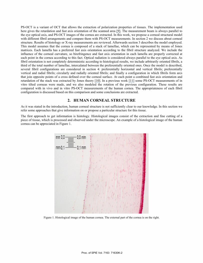
The first approach to get information is histology. Histological images consist of the extraction and fine cutting of a piece of tissue, which is processed and observed under the microscope. An example of a histological image of the human cornea can be appreciated in Figure 1.
Figure 1. Histological image of the human cornea. The external part of the cornea is on the right.
Proc. of SPIE Vol. 7163 71630K-2
In this image, several layers of the cornea are visible. From right to left, that is, from the outside to the inside of the cornea, we can distinguish several layers. First we find the no keratinized squamous epithelium (in bright pink). Afterwards it follows the Bowman membrane, that makes a border with corneal stroma (in light pink). This corneal stroma is formed mainly by layers of collagen fibrils. The last parts are the Descemet membrane, which is not clearly visible in this image, and finally the corneal endothelium, which is just a unicellular mitochondria layer. This structure shows that the dominant layer in the cornea could be the corneal stroma, due to its greater thickness. As a consequence the fibril arrangement in this layer is very interesting. Polarization properties of this tissue could be obtained if this pattern is known. Collagen fibrils organization was studied by means of electron microscopy [4]. The results show that fibrils are disposed in layers, where they maintain a particular orientation. In successive layers the orientation changes in an arbitrary way, and there are also some interlaced fibrils that go from one layer to the next one. Any case the problem is that these histological images or the electron microscopy ones provide information of the microscopic structure, and we would need a someway macroscopic approach to deal with corneal polarization behaviour.
Another approach to observe corneal structure is X-ray scattering. By means of this technique the orientation of the fibrils can be estimated. There are several papers that deal with it. In general they postulate that in the central cornea (excluding limbus) there are preferred fibril orientations in the directions superior-inferior and nasal-temporal. However, they find the existence of an annulus of fibrils in the limbus area, that they describe as a usual annulus of fibrils [12], as an interlaced pattern of fibrils of the cornea and the sclera [13] or even as four fibril arcs that make a rhomboidal form in the most recent one [5]. The authors postulate as a cause of this rhomboidal form the fact that the corneal curvature is different that the curvature of the sclera and so additional fibrils are needed in order to maintain this form. This would explain the existence of the annular fibrils but not the asymmetry. As they also observed asymmetry, the proposed explanation deals with the curvature of the cornea itself, which does not remain constant.
Based on this information, corneal structure is not completely defined. The knowledge of fibril orientation in the corneal stroma would be of great interest in polarization applications. The polarization model we used is explained in next section.
3. POLARIZATION MODEL OF THE CORNEA Once the anatomical justification is provided, we build a theoretical model of the polarization characteristics of the human cornea. There are some attempts in the literature to model the cornea. One measures Mueller matrices at different points in the cornea and concludes that it behaves like a biaxial crystal [6]. Other one models the cornea as a stack of birefringent plates that simulate the lamellae [8]. It uses quasirandom and preferential orientation approaches for the plates and the Jones calculus. However, it uses a transmission approach, it does not take into account dicrhoism and normal incidence is assumed. Another approach to cornea modeling is the analysis of the scattering properties of the fibrils itself [14]. The increased complexity of this model makes it perhaps more accurate (fibril diameter could be fixed for instance). However, this complexity reduces the applicability.
In this work, we employ a Jones calculus approach. We model each layer of the corneal stroma as a retarder with a fast axis orientation and a retardation. The Jones matrix of this configuration can be written in this way:
( ) ( ) ( )i i i iL A B Aθ α θ= − , (1)
where ( )iA θ is a linear rotator of fast axis iθ , and ( )iB α is a linear retarder of retardation 2 iα . These matrices can be expressed as
( )cos sinsin cos
i ii
i i
Aθ θ
θθ θ
⎛ ⎞= ⎜ ⎟−⎝ ⎠
(2)
( ) 00
i
i
j
i j
eB
e
α
αα−
⎛ ⎞= ⎜ ⎟⎝ ⎠
, (3)
Proc. of SPIE Vol. 7163 71630K-3
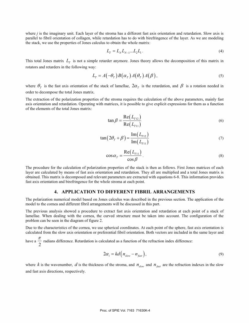
where j is the imaginary unit. Each layer of the stroma has a different fast axis orientation and retardation. Slow axis is parallel to fibril orientation of collagen, while retardation has to do with birefringence of the layer. As we are modeling the stack, we use the properties of Jones calculus to obtain the whole matrix:
1 2 1...T N NL L L L L−= . (4)
This total Jones matrix TL is not a simple retarder anymore. Jones theory allows the decomposition of this matrix in rotators and retarders in the following way:
( ) ( ) ( ) ( )T T T TL A B A Aθ α θ β= − , (5)
where Tθ is the fast axis orientation of the stack of lamellae, 2 Tα is the retardation, and β is a rotation needed in order to decompose the total Jones matrix.
The extraction of the polarization properties of the stroma requires the calculation of the above parameters, mainly fast axis orientation and retardation. Operating with matrices, it is possible to give explicit expressions for them as a function of the elements of the total Jones matrix:
( )( )
12
11
Retan
ReT
T
LL
β = (6)
( ) ( )( )
12
11
Imtan 2
ImT
TT
LL
θ β+ = (7)
( )11Re
coscos
TT
Lα
β= . (8)
The procedure for the calculation of polarization properties of the stack is then as follows. First Jones matrices of each layer are calculated by means of fast axis orientation and retardation. They all are multiplied and a total Jones matrix is obtained. This matrix is decomposed and relevant parameters are extracted with equations 6-8. This information provides fast axis orientation and birefringence for the whole stroma at each point.
4. APPLICATION TO DIFFERENT FIBRIL ARRANGEMENTS The polarization numerical model based on Jones calculus was described in the previous section. The application of the model to the cornea and different fibril arrangements will be discussed in this part.
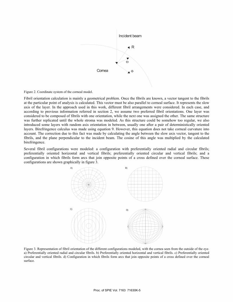
The previous analysis showed a procedure to extract fast axis orientation and retardation at each point of a stack of lamellae. When dealing with the cornea, the curved structure must be taken into account. The configuration of the problem can be seen in the diagram of figure 2.
Due to the characteristics of the cornea, we use spherical coordinates. At each point of the sphere, fast axis orientation is calculated from the slow axis orientation or preferential fibril orientation. Both vectors are included in the same layer and
have a 2π
radians difference. Retardation is calculated as a function of the refraction index difference:
( )2 i slow fastkd n nα = − , (9)
where k is the wavenumber, d is the thickness of the stroma, and slown and fastn are the refraction indexes in the slow and fast axis directions, respectively.
Proc. of SPIE Vol. 7163 71630K-4
Incident beam
Cornea
R
Θ
Φ
Figure 2. Coordinate system of the corneal model.
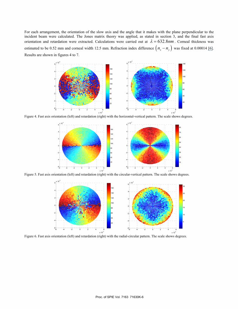
Fibril orientation calculation is mainly a geometrical problem. Once the fibrils are known, a vector tangent to the fibrils at the particular point of analysis is calculated. This vector must be also parallel to corneal surface. It represents the slow axis of the layer. In the approach used in this work, different fibril arrangements were considered. In each case, and according to previous information referred in section 2, we assume two preferred fibril orientations. One layer was considered to be composed of fibrils with one orientation, while the next one was assigned the other. The same structure was further replicated until the whole stroma was modeled. As this structure could be somehow too regular, we also introduced some layers with random axis orientation in between, usually one after a pair of deterministically oriented layers. Birefringence calculus was made using equation 9. However, this equation does not take corneal curvature into account. The correction due to this fact was made by calculating the angle between the slow axis vector, tangent to the fibrils, and the plane perpendicular to the incident beam. The cosine of this angle was multiplied by the calculated birefringence.
Several fibril configurations were modeled: a configuration with preferentially oriented radial and circular fibrils; preferentially oriented horizontal and vertical fibrils; preferentially oriented circular and vertical fibrils; and a configuration in which fibrils form arcs that join opposite points of a cross defined over the corneal surface. These configurations are shown graphically in figure 3.
A) B)
C) D)
Figure 3. Representation of fibril orientation of the different configurations modeled, with the cornea seen from the outside of the eye. a) Preferentially oriented radial and circular fibrils. b) Preferentially oriented horizontal and vertical fibrils. c) Preferentially oriented circular and vertical fibrils. d) Configuration in which fibrils form arcs that join opposite points of a cross defined over the corneal surface.
Proc. of SPIE Vol. 7163 71630K-5
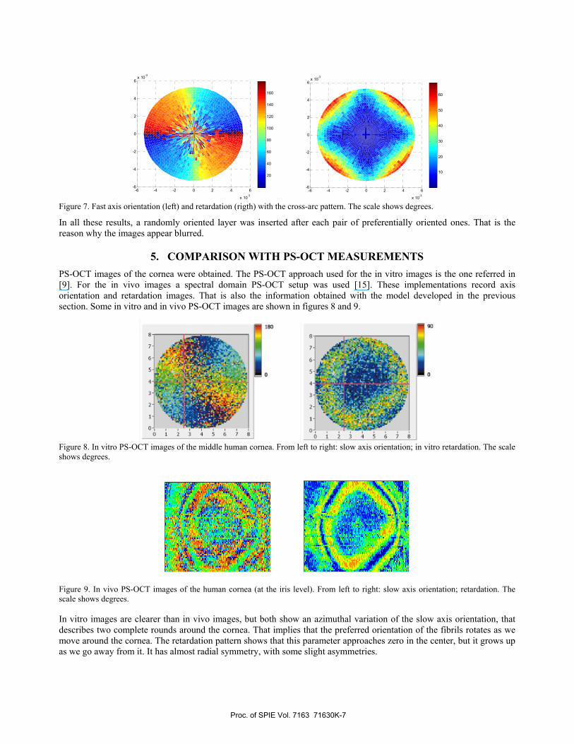
For each arrangement, the orientation of the slow axis and the angle that it makes with the plane perpendicular to the incident beam were calculated. The Jones matrix theory was applied, as stated in section 3, and the final fast axis orientation and retardation were extracted. Calculations were carried out at 632.8nmλ = . Corneal thickness was
estimated to be 0.52 mm and corneal width 12.5 mm. Refraction index difference ( )x yn n− was fixed at 0.00014 [6].
Results are shown in figures 4 to 7.
Figure 4. Fast axis orientation (left) and retardation (right) with the horizontal-vertical pattern. The scale shows degrees.
Figure 5. Fast axis orientation (left) and retardation (right) with the circular-vertical pattern. The scale shows degrees.
Figure 6. Fast axis orientation (left) and retardation (right) with the radial-circular pattern. The scale shows degrees.
-6 -4 -2 0 2 4 6
x 10-3
-6
-4
-2
0
2
4
6x 10⁻³
5
10
15
20
25
30
-6 -4 -2 0 2 4 6
x 10-3
-6
-4
-2
0
2
4
6x 10⁻³
20
40
60
80
100
120
140
160
-6 -4 -2 0 2 4 6
x 10-3
-6
-4
-2
0
2
4
6x 10⁻³
10
20
30
40
50
60
70
80
-6 -4 -2 0 2 4 6
x 10-3
-6
-4
-2
0
2
4
6x 10⁻³
20
40
60
80
100
120
140
160
-6 -4 -2 0 2 4 6
x 10-3
-6
-4
-2
0
2
4
6x 10⁻³
20
40
60
80
100
120
140
-6 -4 -2 0 2 4 6
x 10-3
-6
-4
-2
0
2
4
6x 10⁻³
20
40
60
80
100
120
140
160
Proc. of SPIE Vol. 7163 71630K-6
lc
0
F0
0123 4 4,78
Figure 7. Fast axis orientation (left) and retardation (rigth) with the cross-arc pattern. The scale shows degrees.
In all these results, a randomly oriented layer was inserted after each pair of preferentially oriented ones. That is the reason why the images appear blurred.
5. COMPARISON WITH PS-OCT MEASUREMENTS PS-OCT images of the cornea were obtained. The PS-OCT approach used for the in vitro images is the one referred in [9]. For the in vivo images a spectral domain PS-OCT setup was used [15]. These implementations record axis orientation and retardation images. That is also the information obtained with the model developed in the previous section. Some in vitro and in vivo PS-OCT images are shown in figures 8 and 9.
Figure 8. In vitro PS-OCT images of the middle human cornea. From left to right: slow axis orientation; in vitro retardation. The scale shows degrees.
Figure 9. In vivo PS-OCT images of the human cornea (at the iris level). From left to right: slow axis orientation; retardation. The scale shows degrees. In vitro images are clearer than in vivo images, but both show an azimuthal variation of the slow axis orientation, that describes two complete rounds around the cornea. That implies that the preferred orientation of the fibrils rotates as we move around the cornea. The retardation pattern shows that this parameter approaches zero in the center, but it grows up as we go away from it. It has almost radial symmetry, with some slight asymmetries.
-6 -4 -2 0 2 4 6
x 10-3
-6
-4
-2
0
2
4
6x 10
-3
10
20
30
40
50
60
-6 -4 -2 0 2 4 6
x 10-3
-6
-4
-2
0
2
4
6x 10⁻³
20
40
60
80
100
120
140
160
Proc. of SPIE Vol. 7163 71630K-7
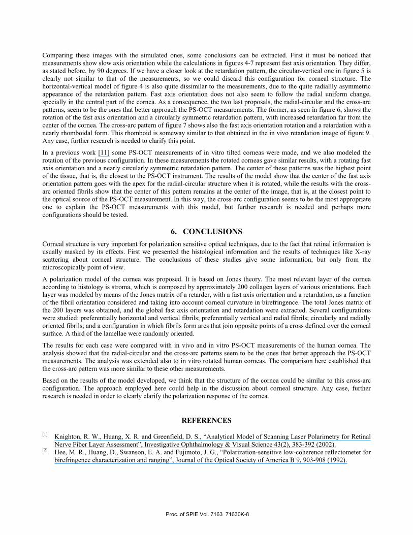
Comparing these images with the simulated ones, some conclusions can be extracted. First it must be noticed that measurements show slow axis orientation while the calculations in figures 4-7 represent fast axis orientation. They differ, as stated before, by 90 degrees. If we have a closer look at the retardation pattern, the circular-vertical one in figure 5 is clearly not similar to that of the measurements, so we could discard this configuration for corneal structure. The horizontal-vertical model of figure 4 is also quite dissimilar to the measurements, due to the quite radiallly asymmetric appearance of the retardation pattern. Fast axis orientation does not also seem to follow the radial uniform change, specially in the central part of the cornea. As a consequence, the two last proposals, the radial-circular and the cross-arc patterns, seem to be the ones that better approach the PS-OCT measurements. The former, as seen in figure 6, shows the rotation of the fast axis orientation and a circularly symmetric retardation pattern, with increased retardation far from the center of the cornea. The cross-arc pattern of figure 7 shows also the fast axis orientation rotation and a retardation with a nearly rhomboidal form. This rhomboid is someway similar to that obtained in the in vivo retardation image of figure 9. Any case, further research is needed to clarify this point.
In a previous work [11] some PS-OCT measurements of in vitro tilted corneas were made, and we also modeled the rotation of the previous configuration. In these measurements the rotated corneas gave similar results, with a rotating fast axis orientation and a nearly circularly symmetric retardation pattern. The center of these patterns was the highest point of the tissue, that is, the closest to the PS-OCT instrument. The results of the model show that the center of the fast axis orientation pattern goes with the apex for the radial-circular structure when it is rotated, while the results with the cross-arc oriented fibrils show that the center of this pattern remains at the center of the image, that is, at the closest point to the optical source of the PS-OCT measurement. In this way, the cross-arc configuration seems to be the most appropriate one to explain the PS-OCT measurements with this model, but further research is needed and perhaps more configurations should be tested.
6. CONCLUSIONS Corneal structure is very important for polarization sensitive optical techniques, due to the fact that retinal information is usually masked by its effects. First we presented the histological information and the results of techniques like X-ray scattering about corneal structure. The conclusions of these studies give some information, but only from the microscopically point of view.
A polarization model of the cornea was proposed. It is based on Jones theory. The most relevant layer of the cornea according to histology is stroma, which is composed by approximately 200 collagen layers of various orientations. Each layer was modeled by means of the Jones matrix of a retarder, with a fast axis orientation and a retardation, as a function of the fibril orientation considered and taking into account corneal curvature in birefringence. The total Jones matrix of the 200 layers was obtained, and the global fast axis orientation and retardation were extracted. Several configurations were studied: preferentially horizontal and vertical fibrils; preferentially vertical and radial fibrils; circularly and radially oriented fibrils; and a configuration in which fibrils form arcs that join opposite points of a cross defined over the corneal surface. A third of the lamellae were randomly oriented.
The results for each case were compared with in vivo and in vitro PS-OCT measurements of the human cornea. The analysis showed that the radial-circular and the cross-arc patterns seem to be the ones that better approach the PS-OCT measurements. The analysis was extended also to in vitro rotated human corneas. The comparison here established that the cross-arc pattern was more similar to these other measurements.
Based on the results of the model developed, we think that the structure of the cornea could be similar to this cross-arc configuration. The approach employed here could help in the discussion about corneal structure. Any case, further research is needed in order to clearly clarify the polarization response of the cornea.
REFERENCES
[1] Knighton, R. W., Huang, X. R. and Greenfield, D. S., “Analytical Model of Scanning Laser Polarimetry for Retinal Nerve Fiber Layer Assessment”, Investigative Ophthalmology & Visual Science 43(2), 383-392 (2002).
[2] Hee, M. R., Huang, D., Swanson, E. A. and Fujimoto, J. G., “Polarization-sensitive low-coherence reflectometer for birefringence characterization and ranging”, Journal of the Optical Society of America B 9, 903-908 (1992).
Proc. of SPIE Vol. 7163 71630K-8
[3] Pircher, M., Götzinger, E., Baumann, B. and Hitzenberger, C. K., “Corneal birefringence compensation for polarization sensitive optical coherence tomography of the human retina”, Journal of Biomedical Optics 12(4), 041210-1, 10 (2007).
[4] Komai, Y. and Ushiki, T., “The three-dimensional organization of collagen fibrils in the human cornea and sclera”, Investigative Ophthalmology & Visual Science 32(8), 2244-2258 (1991).
[5] Aghamohammadzadeh, H., Newton, R. H. and Meek, K. M., “X-Ray scattering used to map the preferred collagen orientation in the human cornea and limbus”, Structure 12, 249-256 (2004).
[6] Van Blokland, G. J. and Verhelst, S. C., “Corneal polarization in the living human eye explained with a biaxial model”, Journal of the Optical Society of America A 4(1), 82-90 (1987).
[7] Knighton, R. W., Huang, X. R. and Cavuoto, L. A., “Corneal birefringence mapped by scanning laser polarimetry”, Optics Express 16(18), 13738-13751 (2008).
[8] Donohue, D. J., Stoyanov, B. J., McCally, R. L. and Farrell, R. A., “Numerical modeling of the cornea’s lamellar structure and birefringence properties”, Journal of the Optical Society of America A 12(7), 1425-1438 (1995).
[9] Hitzenberger, C. K., Götzinger, E., Sticker, M., Pircher, M. and Fercher, A., “Measurement and imaging of birefringence and optic axis orientation by phase resolved polarization sensitive optical coherence tomography”, Optics Express 9(13), 780-790 (2001).
[10] Hurwitz, H. and Jones, R. C., “A new calculus for the treatment of optical systems. II. Proof of three general equivalence theorems”, Journal of the Optical Society of America 31, 493-499 (1941).
[11] Götzinger, E., Pircher, M., Sticker, M., Fercher, A. F. and Hitzenberger, C. K., “Measurement and imaging of birefringent properties of the human cornea with phase-resolved, polarization-sensitive optical coherence tomography”, Journal of Biomedical Optics 9(1), 94-102 (2004).
[12] Newton, R. H. and Meek, K. M., “Circumcorneal annulus of collagen fibrils in the human limbus”, Investigative Ophthalmology & Visual Science 39, 1125-1134 (1998).
[13] Newton, R. H. and Meek, K. M., “The integration of the corneal and limbal fibrils in the human eye”, Biophysical Journal 75, 2508-2512 (1998).
[14] Izotova, V. F, Maksimova, I. L, Nefedov, I. S. and Romanov, S. V., “Investigation of Mueller matrices of anisotropic nonhomogeneous layers in application to an optical model of the cornea”, Applied Optics 36, 164-169 (1997).
[15] Götzinger, E., Pircher, M. and Hitzenberger, C. K., "High speed spectral domain polarization sensitive optical coherence tomography of the human retina", Optics Express 13, 10217-10229 (2005).
Proc. of SPIE Vol. 7163 71630K-9


![[PS] V15N02 ART 03 Segregación](https://static.fdokumen.com/doc/165x107/631acabafd704e1d390a4a44/ps-v15n02-art-03-segregacion.jpg)