This General Bid B - PS-PhilGEPS
82
RR.Road,CristobalSt.,Paco,Manila www.ps-philgeps.gov.ph 8 290-6300 / 8 290-6400 Republic of the Philippines Department of Budget and M PROCUREMENT SERVI PHILIPPINE GOVERNM BIDS AND AWARDS COM THE MALOLOS-CLARK PROJECT SOUTH LIN ELECTRICAL AND MECHA TO ALL PROSPECTIVE BID This General Bid Bulletin is iss for the above-mentioned Proje Bulletin for details: 1. Annex “A” - Clari 2. Annex “B” - Adde 3. Annex “C” - Not A All other portions of the Biddin and/or clarifications shall rem Revisions/amendments/clarific Bidding Documents of this Pro For your guidance and inform DBM Compound, Gen www.philgeps.gov.ph (02) 8 640 6906 | 8 64 Management ICE - MENT ELECTRONIC PROCUREMENT SYSTEM MMITTEE General Bid Bulletin No. 27 14 September 2021 RAILWAY PROJECT AND THE NORTH-S NE COMMUTER PACKAGE CP NS-01: PRO ANICAL SYSTEMS AND TRACK WORKS ( DDERS: sued to amend/clarify certain provisions in th ect. Please refer to the attached Annexes of ification to the Bidding Documents endum to the Bidding Documents with “Atta Applicable ng Documents not affected by these revision main unchanged. cations made herein shall be conserved as an oject. mation. For the Bids and Awa ENGR. JAIME M. NA Chairpers neral Solano Street, San Miguel, Manila 40 6907 | 8 640 6908 | 8 640 6909 M SOUTH RAILWAY OCUREMENT OF (IFB No: 21-040-3) he Bidding Documents this General Bid achment 1” ns, amendments n integral part of the ards Committee AVARRETE, JR son SIGNATURE REDACTED
-
Upload
khangminh22 -
Category
Documents
-
view
1 -
download
0
Transcript of This General Bid B - PS-PhilGEPS

RR.Road,CristobalSt.,Paco,Manila www.ps-philgeps.gov.ph 8 290-6300 / 8 290-6400
Republic of the Philippines Department of Budget and ManagementPROCUREMENT SERVICE PHILIPPINE GOVERNMENT ELECTRONIC PROCUREMENT SYSTEMBIDS AND AWARDS COMMITTEE
THE MALOLOS-CLARK RAILWAY PROJECT AND THE NORTHPROJECT SOUTH LINE COMMUTER PACKAGE CP NS
ELECTRICAL AND MECHANICAL SYSTEMS AND TRACK WORKS
TO ALL PROSPECTIVE BIDDERS: This General Bid Bulletin is issufor the above-mentioned Project. Please refer to the attached Annexes of this General Bid Bulletin for details:
1. Annex “A” - Clarification to the Bidding Documents2. Annex “B” - Addendum to the Bidding Documents with “3. Annex “C” - Not Applicable
All other portions of the Bidding Documents not affected by these revisions, amendments and/or clarifications shall remain unchanged. Revisions/amendments/clarifications Bidding Documents of this Project. For your guidance and information.
DBM Compound, General Solano Street, www.philgeps.gov.ph (02) 8 640 6906 | 8 640 6907 | 8 640 6908 | 8 640 6909
Department of Budget and Management PROCUREMENT SERVICE - PHILIPPINE GOVERNMENT ELECTRONIC PROCUREMENT SYSTEMBIDS AND AWARDS COMMITTEE
General Bid Bulletin No. 27
14 September 2021
CLARK RAILWAY PROJECT AND THE NORTH-SOUTH RAILWAY PROJECT SOUTH LINE COMMUTER PACKAGE CP NS-01: PROCUREMENT OF
ELECTRICAL AND MECHANICAL SYSTEMS AND TRACK WORKS (IFB No: 21
TO ALL PROSPECTIVE BIDDERS:
This General Bid Bulletin is issued to amend/clarify certain provisions in the Bidding Documents mentioned Project. Please refer to the attached Annexes of this General Bid
Clarification to the Bidding Documents Addendum to the Bidding Documents with “Attachment 1Not Applicable
All other portions of the Bidding Documents not affected by these revisions, amendments and/or clarifications shall remain unchanged.
Revisions/amendments/clarifications made herein shall be conserved as an integral part of the Bidding Documents of this Project.
For your guidance and information.
For the Bids and Awards Committee
ENGR. JAIME M. NAVARRETE, JR Chairperson
DBM Compound, General Solano Street, San Miguel, Manila
(02) 8 640 6906 | 8 640 6907 | 8 640 6908 | 8 640 6909
PHILIPPINE GOVERNMENT ELECTRONIC PROCUREMENT SYSTEM
SOUTH RAILWAY 01: PROCUREMENT OF
(IFB No: 21-040-3)
ed to amend/clarify certain provisions in the Bidding Documents mentioned Project. Please refer to the attached Annexes of this General Bid
Attachment 1”
All other portions of the Bidding Documents not affected by these revisions, amendments
made herein shall be conserved as an integral part of the
For the Bids and Awards Committee
ENGR. JAIME M. NAVARRETE, JR Chairperson
SIGNATURE REDACTED
PDFescape
Highlight

Annex A

Page 1 of 37
PACKAGE CP NS-01: E&M SYSTEMS AND TRACK WORKS
General Bid Bulletin No. 27 Annex A
Item No.
Volume Section No. Page No.
Clause No. / Title Reference Text
Clarification Request Proposed Revised
Text (if any)
Response
1 GBB No.22
DRG No. MCRP-DWG-PSS-1001
REV 07
This drawing shows electric utility company
supplying for SS No21, SS No22 and Depot as
follows.
SS No21 > CEDC,
SS No22 > CEDC,
Depot > MERALCO
In above case, if all substations (SS No21, SS
No22, Depot and SP), feed power to OCS, the
border of both electric companies’ supply
cannot be separated at section.
Please clarify if it's acceptable.
The Depot substation is under the
jurisdiction of CEDC as stated in Clause
4.1.1 ERT page 361. Please refer to revised
drawing in Annex B.
2 Volume II. Part2
Employer's Requirements (ER)
c) Technical Requirements (ERT)
4) Power Supply System, ERT-382,
ERT-418, 4.4.5 BP(Battery Post),
4.1.3 System Overview (9) TSS
equipment 5)Re-generating power
absorbing equipment,
Please provide the starting voltage of Brake
Blending (Re-generation Brake and Mechanical
Brake) at rolling stock, to adopt the effective
characteristics and setting voltage of
regenerative power absorption device (Battery
post, Braking resistor unit).
The starting voltage of brake blending
would be greater than 900 Vdc.
3 GENERAL We understand that the Replies to Queries,
Addenda and General Bid Bulletins form part of
Where possible revisions to the contract
documents will be made to reflect the
responses to GBB’s. Where the responses

Page 2 of 37
PACKAGE CP NS-01: E&M SYSTEMS AND TRACK WORKS General Bid Bulletin No. 27
Annex A Item No.
Volume Section No. Page No.
Clause No. / Title Reference Text
Clarification Request Proposed Revised
Text (if any)
Response
the Contract Document.
Kindly confirm.
to GBB’s cannot be accurately reflected by
changes to the contract documents a
separate annex to the contract will be
made to contain such GBB’s
4 Part-1
Section - IV, BF-259, SCHEDULE 3:
LIST OF JAPANESE ORIGIN, GOODS
AND SERVICES [WITH PRICES]
We understand that the bidder shall specify the
details of Goods and Services which will be
Procured from Japan in the Table provided in
Schedule-3.
However, we understand that the bidder shall
be allowed to enter the amount for these Good
& Services in any of the currencies allowed in
the bid, i.e, JPY, USD, EURO, PHP or any
combination of the 4 currencies.
Kindly confirm.
Reference to the ITB 19.1:
"The currency(ies) of the Bid shall be as
described below:
The unit rates and prices shall be quoted by
the Bidder in the Price Schedule separately
in the following currencies:
(i) for those inputs to the Works that the
Bidder expects to supply from within the
Employer’s country, in Philippine Peso, the
name of the currency of the Employer’s
country, and further referred to as “the
local currency”; and
(ii) for those inputs to the Works that the
Bidder expects to supply from outside the
Employer’s country (referred to as “the
foreign currency requirements”), in
Japanese Yen and/or United States Dollars
and/or Euro.
5 Part-2
Section – VI, ERG - 183, MMSP
We understand that the scope of work of NS-01
Contractor in MMSP Depot Test Track is only to
Bidder's understanding is incorrect. CP 106
is E&M contractor for MMSP line as well as
Page 3 of 37
PACKAGE CP NS-01: E&M SYSTEMS AND TRACK WORKS General Bid Bulletin No. 27
Annex A Item No.
Volume Section No. Page No.
Clause No. / Title Reference Text
Clarification Request Proposed Revised
Text (if any)
Response
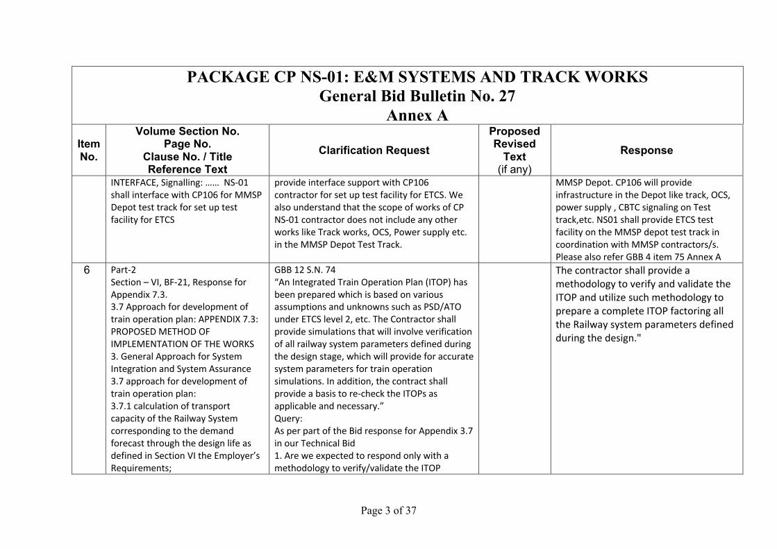
INTERFACE, Signalling: …… NS-01
shall interface with CP106 for MMSP
Depot test track for set up test
facility for ETCS
provide interface support with CP106
contractor for set up test facility for ETCS. We
also understand that the scope of works of CP
NS-01 contractor does not include any other
works like Track works, OCS, Power supply etc.
in the MMSP Depot Test Track.
MMSP Depot. CP106 will provide
infrastructure in the Depot like track, OCS,
power supply , CBTC signaling on Test
track,etc. NS01 shall provide ETCS test
facility on the MMSP depot test track in
coordination with MMSP contractors/s.
Please also refer GBB 4 item 75 Annex A
6 Part-2
Section – VI, BF-21, Response for
Appendix 7.3.
3.7 Approach for development of
train operation plan: APPENDIX 7.3:
PROPOSED METHOD OF
IMPLEMENTATION OF THE WORKS
3. General Approach for System
Integration and System Assurance
3.7 approach for development of
train operation plan:
3.7.1 calculation of transport
capacity of the Railway System
corresponding to the demand
forecast through the design life as
defined in Section VI the Employer’s
Requirements;
GBB 12 S.N. 74
“An Integrated Train Operation Plan (ITOP) has
been prepared which is based on various
assumptions and unknowns such as PSD/ATO
under ETCS level 2, etc. The Contractor shall
provide simulations that will involve verification
of all railway system parameters defined during
the design stage, which will provide for accurate
system parameters for train operation
simulations. In addition, the contract shall
provide a basis to re-check the ITOPs as
applicable and necessary.”
Query:
As per part of the Bid response for Appendix 3.7
in our Technical Bid
1. Are we expected to respond only with a
methodology to verify/validate the ITOP
The contractor shall provide a methodology to verify and validate the ITOP and utilize such methodology to prepare a complete ITOP factoring all the Railway system parameters defined during the design."
Page 4 of 37
PACKAGE CP NS-01: E&M SYSTEMS AND TRACK WORKS General Bid Bulletin No. 27
Annex A Item No.
Volume Section No. Page No.
Clause No. / Title Reference Text
Clarification Request Proposed Revised
Text (if any)
Response
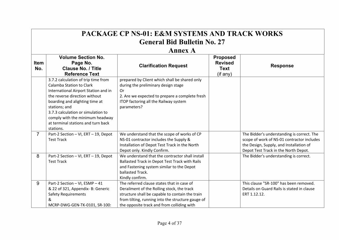
3.7.2 calculation of trip time from
Calamba Station to Clark
International Airport Station and in
the reverse direction without
boarding and alighting time at
stations; and
3.7.3 calculation or simulation to
comply with the minimum headway
at terminal stations and turn back
stations.
prepared by Client which shall be shared only
during the preliminary design stage
Or
2. Are we expected to prepare a complete fresh
ITOP factoring all the Railway system
parameters?
7 Part-2 Section – VI, ERT – 19, Depot
Test Track
We understand that the scope of works of CP
NS-01 contractor includes the Supply &
Installation of Depot Test Track in the North
Depot only. Kindly Confirm.
The Bidder's understanding is correct. The
scope of work of NS-01 contractor includes
the Design, Supply, and Installation of
Depot Test Track in the North Depot.
8 Part-2 Section – VI, ERT – 19, Depot
Test Track
We understand that the contractor shall install
Ballasted Track in Depot Test Track with Rails
and Fastening system similar to the Depot
ballasted Track.
Kindly confirm.
The Bidder's understanding is correct.
9 Part-2 Section – VI, ESMP – 41
& 22 of 321, Appendix- B: Generic
Safety Requirements
&
MCRP-DWG-GEN-TK-0101, SR-100:
The referred clause states that in case of
Derailment of the Rolling stock, the track
structure shall be capable to contain the train
from tilting, running into the structure gauge of
the opposite track and from colliding with
This clause "SR-100" has been removed.
Details on Guard Rails is stated in clause
ERT 1.12.12.

Page 5 of 37
PACKAGE CP NS-01: E&M SYSTEMS AND TRACK WORKS General Bid Bulletin No. 27
Annex A Item No.
Volume Section No. Page No.
Clause No. / Title Reference Text
Clarification Request Proposed Revised
Text (if any)
Response
Track structure shall be capable to
contain the train path in the event of
derailment
(Containment from tilting, running
into the structure gauge of the
opposite track and from colliding
with bridge/tunnel equipment).
&
TYPICAL CROSS SECTION FOR
ELEVATED SECTION (TANGENT)
bridge/tunnel equipment.
This requirement essentially means provision
of a derailment guard or Guard rail.
However, none of the Track cross section
drawings show such arrangement of either a
derailment Guard or guard rails.
We also refer to similar track structures from
similar projects like Jakarta MRT, Ho Chi Minh
City Metro etc. where no such derailment guard
or Gurad rails are used.
Also in our experience, for a Ballasteless Track
form using PSC sleepers, there is never a
provison of derailment Guard or Guard rail.
Therefore we are unable to understand the
intent of refered Safety requirement “SR100”.
So we request you to clary the requirement.
Kindly specify if it is only applicable for areas
with sharp curves.
Kindly clarify.
10 Part-2 Section – VI, ESMP – 41,
Appendix- B: Generic Safety
Requirements, SR-100: Track
structure shall be capable to contain
the train path in the event of
Further to our query above,
It is understood that the derailment
containment can only be provided away from
the sleeper edges, thereby increasing the
distance between the running rail face and the
This clause "SR-100" has been removed.
Details on Guard Rails is stated in clause
ERT 1.12.12.

Page 6 of 37
PACKAGE CP NS-01: E&M SYSTEMS AND TRACK WORKS General Bid Bulletin No. 27
Annex A Item No.
Volume Section No. Page No.
Clause No. / Title Reference Text
Clarification Request Proposed Revised
Text (if any)
Response
derailment
(Containment from tilting, running
into the structure gauge of the
opposite track and from colliding
with bridge/tunnel equipment).
derailment containment edge.
This implies that the minimum distance
between the rail and derailment containment
can be to the order of 500mm.
In such a design, there is no way to contain the
derailed train away from the civil equipment's
and structure gauge of the adjacent track. This
would mean that check rails or guard rails need
to be provided on the sleepers which is a very
expensive system.
We request the employer to confirm on this
requirement of derailment containment as to
what provisions should be taken by the bidder
in the design.
We once again request you to clary the
requiremen and specify if it is only applicable
for areas with sharp curves.
Kindly clarify.
11 Part-2 Section – VI
&
GBB – 2, ERT-1
&
29/127, 1.1.1.(4), Sections of the
Main Line tracks and junctions on
We understand from the response to queries
provided in GBB No.2, that the employer has
not identified any sections where differential
settlement may occur. The requirement is
specified only to cover for such unlikely
scenarios during the execution stage.
There are no identified sections where
differential settlement will occur. The
interfaces between Civil contractors should
be followed as stated in ERT 1.28.
Page 7 of 37
PACKAGE CP NS-01: E&M SYSTEMS AND TRACK WORKS General Bid Bulletin No. 27
Annex A Item No.
Volume Section No. Page No.
Clause No. / Title Reference Text
Clarification Request Proposed Revised
Text (if any)
Response
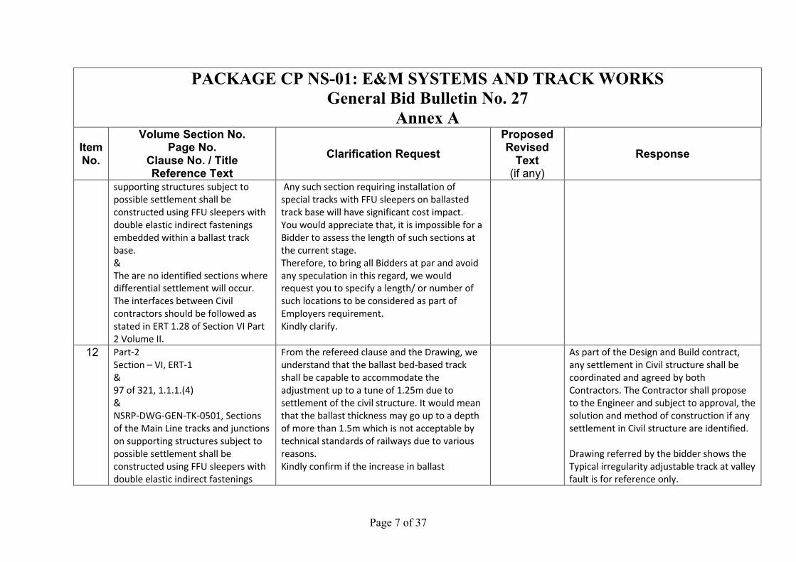
supporting structures subject to
possible settlement shall be
constructed using FFU sleepers with
double elastic indirect fastenings
embedded within a ballast track
base.
&
The are no identified sections where
differential settlement will occur.
The interfaces between Civil
contractors should be followed as
stated in ERT 1.28 of Section VI Part
2 Volume II.
Any such section requiring installation of
special tracks with FFU sleepers on ballasted
track base will have significant cost impact.
You would appreciate that, it is impossible for a
Bidder to assess the length of such sections at
the current stage.
Therefore, to bring all Bidders at par and avoid
any speculation in this regard, we would
request you to specify a length/ or number of
such locations to be considered as part of
Employers requirement.
Kindly clarify.
12 Part-2
Section – VI, ERT-1
&
97 of 321, 1.1.1.(4)
&
NSRP-DWG-GEN-TK-0501, Sections
of the Main Line tracks and junctions
on supporting structures subject to
possible settlement shall be
constructed using FFU sleepers with
double elastic indirect fastenings
From the refereed clause and the Drawing, we
understand that the ballast bed-based track
shall be capable to accommodate the
adjustment up to a tune of 1.25m due to
settlement of the civil structure. It would mean
that the ballast thickness may go up to a depth
of more than 1.5m which is not acceptable by
technical standards of railways due to various
reasons.
Kindly confirm if the increase in ballast
As part of the Design and Build contract,
any settlement in Civil structure shall be
coordinated and agreed by both
Contractors. The Contractor shall propose
to the Engineer and subject to approval, the
solution and method of construction if any
settlement in Civil structure are identified.
Drawing referred by the bidder shows the
Typical irregularity adjustable track at valley
fault is for reference only.

Page 8 of 37
PACKAGE CP NS-01: E&M SYSTEMS AND TRACK WORKS General Bid Bulletin No. 27
Annex A Item No.
Volume Section No. Page No.
Clause No. / Title Reference Text
Clarification Request Proposed Revised
Text (if any)
Response
embedded within a ballast track
base.
thickness is expected to compensate the
settlement in the civil structure.
13 Part-2 Section – VI, ERT-1, 1.1.1.(4),
Sections of the Main Line tracks and
junctions on supporting structures
subject to possible settlement shall
be constructed using FFU sleepers
with double elastic indirect
fastenings embedded within a
ballast track base.
From the referred clause, we understand that
having double elastic fastening system on
ballast bed track is non-proven and reduces the
elasticity of the track to unacceptable levels.
Kindly confirm if such a solution is mandatory or
suggest any other alternate solution to
accommodate such high level of settlement in
the civil structure
The Contractor may propose to the
Engineer and subject to approval, the
proven solution and method of
construction if any settlement in Civil
structure are identified.
14 Part-2 Section – VI, MCRP-DWG-
GEN-TK-0227, Typical Layout for #10
Crossover.
In the referred drawing, it is shown that the
Epoxy grout has to be provided at the rail seat
of the Outer rail only and the rest of the portion
of the sleepers are without any support.
We understand that the epoxy grout has to be
provided throughout the length of the sleeper.
Kindly confirm.
The Bidder's understanding is incorrect.
Epoxy grout is needed in areas where rails,
crossing, and fastening positions of the
turnouts. Epoxy grout maybe needed in
some areas of the turnouts depending on
site condition.
15 Part-2 Section – VI, 58/321, HCRP-
DWG-GEN-TK-0205, TYPICAL
DETAILS FOR MONO-BLOCK PSC
CONCRETE SLEEPER FOR
BALLASTLESS TRACK
In the referred drawing, typical details of Mono-
Block PSC sleepers for Ballastless Track are
provided.
We understand that the reinforcement details
provided as ¢ 13 Prestressed Steel Rod is same
as ¢ 13 Prestressed Steel strands.
Kindly confirm.
The Bidder's understanding is incorrect.
Prestressed Steel Rod is different from
Prestressed Steel Strand

Page 9 of 37
PACKAGE CP NS-01: E&M SYSTEMS AND TRACK WORKS General Bid Bulletin No. 27
Annex A Item No.
Volume Section No. Page No.
Clause No. / Title Reference Text
Clarification Request Proposed Revised
Text (if any)
Response
16 Part-2 Section – VI, 58/321, HCRP-
DWG-GEN-TK-0205, TYPICAL
DETAILS FOR MONO-BLOCK PSC
CONCRETE SLEEPER FOR
BALLASTLESS TRACK
Kindly confirm whether the bidder has to follow
the same drawing to supply PSC sleepers
required for the main line or the bidder can
propose different design of PSC sleepers
complying to all the tender conditions related
to the PSC sleepers.
The Bidder may propose a PSC sleeper
design and subject to the Engineer's review
and approval following the requirements
stated in ERT 1.14 Prestressed Concrete
Sleeper. The Contractor shall interface with
other NSCR Trackwork contractor for the
design of the sleeper for uniformity of the
whole NSCR line.
17 7.2.1.2, ERT-619, Limited Express
Ticketing System, There is mention
of Ticket Validator
Developing software for Ticket Validator is in
scope or not.
Please confirm.
Please refer to GBB24 Item 7 response.
18 7.7.1.3, ERT-627, System Operation
Requirement, Personalized Staff card
issuance
Personalized staff SVC - What type of Stored
value for staffs, Will they have to top up these
cards as general passengers, and will AG deduct
money from these cards as well, can they use
this card in TVM, HT and POS ?
Kindly confirm.
Please refer to GBB24 Item 9 response
Page 10 of 37
PACKAGE CP NS-01: E&M SYSTEMS AND TRACK WORKS General Bid Bulletin No. 27
Annex A Item No.
Volume Section No. Page No.
Clause No. / Title Reference Text
Clarification Request Proposed Revised
Text (if any)
Response
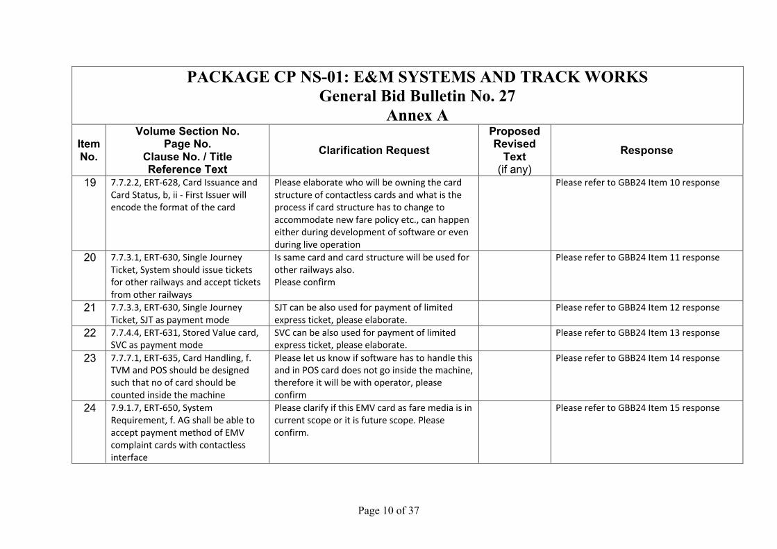
19 7.7.2.2, ERT-628, Card Issuance and
Card Status, b, ii - First Issuer will
encode the format of the card
Please elaborate who will be owning the card
structure of contactless cards and what is the
process if card structure has to change to
accommodate new fare policy etc., can happen
either during development of software or even
during live operation
Please refer to GBB24 Item 10 response
20 7.7.3.1, ERT-630, Single Journey
Ticket, System should issue tickets
for other railways and accept tickets
from other railways
Is same card and card structure will be used for
other railways also.
Please confirm
Please refer to GBB24 Item 11 response
21 7.7.3.3, ERT-630, Single Journey
Ticket, SJT as payment mode
SJT can be also used for payment of limited
express ticket, please elaborate.
Please refer to GBB24 Item 12 response
22 7.7.4.4, ERT-631, Stored Value card,
SVC as payment mode
SVC can be also used for payment of limited
express ticket, please elaborate.
Please refer to GBB24 Item 13 response
23 7.7.7.1, ERT-635, Card Handling, f.
TVM and POS should be designed
such that no of card should be
counted inside the machine
Please let us know if software has to handle this
and in POS card does not go inside the machine,
therefore it will be with operator, please
confirm
Please refer to GBB24 Item 14 response
24 7.9.1.7, ERT-650, System
Requirement, f. AG shall be able to
accept payment method of EMV
complaint cards with contactless
interface
Please clarify if this EMV card as fare media is in
current scope or it is future scope. Please
confirm.
Please refer to GBB24 Item 15 response

Page 11 of 37
PACKAGE CP NS-01: E&M SYSTEMS AND TRACK WORKS General Bid Bulletin No. 27
Annex A Item No.
Volume Section No. Page No.
Clause No. / Title Reference Text
Clarification Request Proposed Revised
Text (if any)
Response
25 7.9.3.3, ERT-655, System
Requirement, i. POS should be able
to top-up SVC with EMV based card
The assumption is the external credit/debit card
payment device with payment application will
be provided by customer. Please confirm
Please refer to GBB24 Item 16 response
26 7.9.3.3, ERT-656, System
Requirement, l. It should be possible
to configure machine (POS) by
parameter as EFO or a POS
What are the requirements and functionalities
of EFO?
Please confirm.
Please refer to GBB24 Item 17 response
27 7.7.9.3, ERT-637, QR Code Payment,
The mobile application shall be
integrated with mobile wallet linked
to the pre-paid account
Is it bank scope to provide the API for
integration with wallet?
Please confirm.
Please refer to GBB24 Item 18 response
28 7.7.12.3, ERT-639, Revenue Data, For
any interchange paid-to-paid links,
the revenue data shall be considered
to show the amount of the other
railway separately
We are assuming interchange information will
be provided to us and revenue data bifurcation
will be reflected on report only.
Please confirm the understanding.
Please refer to GBB24 Item 19 response
29 7.7.3.1 (a)
Fare Structure, ERT-630, Fare
Structure, a) The system shall
support graduated fare structure. It
shall be flexible enough to support
zone (or partly zoned) fare structure.
What is exactly meant here by "partly zoned"?
Please kindly elaborate.
Please refer to GBB24 Item 20 response
30 7.7.3.1 (d)
Fare Structure, ERT-630, Fare
For each type of Fare Media there will be
separate Fare Structure? Example there will be
Please refer to GBB24 Item 21 response

Page 12 of 37
PACKAGE CP NS-01: E&M SYSTEMS AND TRACK WORKS General Bid Bulletin No. 27
Annex A Item No.
Volume Section No. Page No.
Clause No. / Title Reference Text
Clarification Request Proposed Revised
Text (if any)
Response
Structure, d) The system shall be
able to support at least 16 types of
fare within one version for SJT,
which is for future discount. Each
type of fare shall be able to support
256 fare stages, which is for future
increase of lines or stations including
operated by another business
operator.
different Fare Table for SJT and SVC?
Kindly confirm.
31 7.7.9.1, ERT-637, QR Code Payment,
The AFC system shall include a QR
code payment system. The QR code
system provisions shall include, but
shall not be limited to, the following
facilities:
There will a customer Mobile application to
generate this QR Codes. Now QR code will be
generated for SVC or there should be provision
to link SVC and generate QR Code and Use that
QR code as Fare media for travel.
Please confirm.
Please refer to GBB24 Item 22 response
32 7.7.10.3, ERT-638, Card Stock
Management, Theoretical amount of
valid card shall be calculated in the
central clearing house system.
It is understood that AFC-CC will not do Stock
Take of Cards. It will only exchange card counts
with CCHS.
Kindly confirm this understanding.
Please refer to GBB24 Item 23 response
33 Ch.3 Telecommunication.pdf, ,
Clause No. 3.11.2.2 Table No.
3.11.2.2 ERT-246, Interface with
Architecture
Request to mark the location of Telecom
Equipment Room in each station building
layouts & Substation layouts of complete
Package.
This is a Civil/Architecture interface.
The IFC drawings of the Stations and Depot
Buildings/ Layout can be found on DOTr's
Website, within each corresponding Civil
Packages. The Telecom Equipment room
Page 13 of 37
PACKAGE CP NS-01: E&M SYSTEMS AND TRACK WORKS General Bid Bulletin No. 27
Annex A Item No.
Volume Section No. Page No.
Clause No. / Title Reference Text
Clarification Request Proposed Revised
Text (if any)
Response
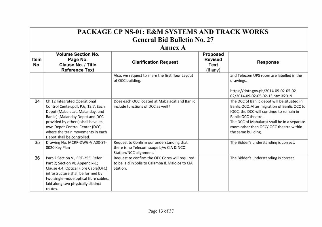
Also, we request to share the first floor Layout
of OCC building.
and Telecom UPS room are labelled in the
drawings.
https://dotr.gov.ph/2014-09-02-05-02-
02/2014-09-02-05-02-13.html#2019
34 Ch.12 Integrated Operational
Control Center.pdf, P.6, 12.7, Each
Depot (Mabalacat, Malanday, and
Banlic) (Malanday Depot and DCC
provided by others) shall have its
own Depot Control Center (DCC)
where the train movements in each
Depot shall be controlled.
Does each OCC located at Mabalacat and Banlic
include functions of DCC as well?
The DCC of Banlic depot will be situated in
Banlic OCC. After migration of Banlic OCC to
IOCC, the DCC will continue to remain in
Banlic OCC theatre.
The DCC of Mabalacat shall be in a separate
room other than OCC/IOCC theatre within
the same building.
35 Drawing No. MCRP-DWG-VIA00-ST-
0020 Key Plan
Request to Confirm our understanding that
there is no Telecom scope b/w CIA & NCC
Station/NCC alignment.
The Bidder's understanding is correct.
36 Part-2 Section VI, ERT-255, Refer
Part 2; Section VI; Appendix-1;
Clause 4.4; Optical Fibre Cable(OFC)
infrastructure shall be formed by
two single-mode optical fibre cables,
laid along two physically distinct
routes.
Request to confirm the OFC Cores will required
to be laid in Solis to Calamba & Malolos to CIA
Station.
The Bidder's understanding is correct.
Page 14 of 37
PACKAGE CP NS-01: E&M SYSTEMS AND TRACK WORKS General Bid Bulletin No. 27
Annex A Item No.
Volume Section No. Page No.
Clause No. / Title Reference Text
Clarification Request Proposed Revised
Text (if any)
Response
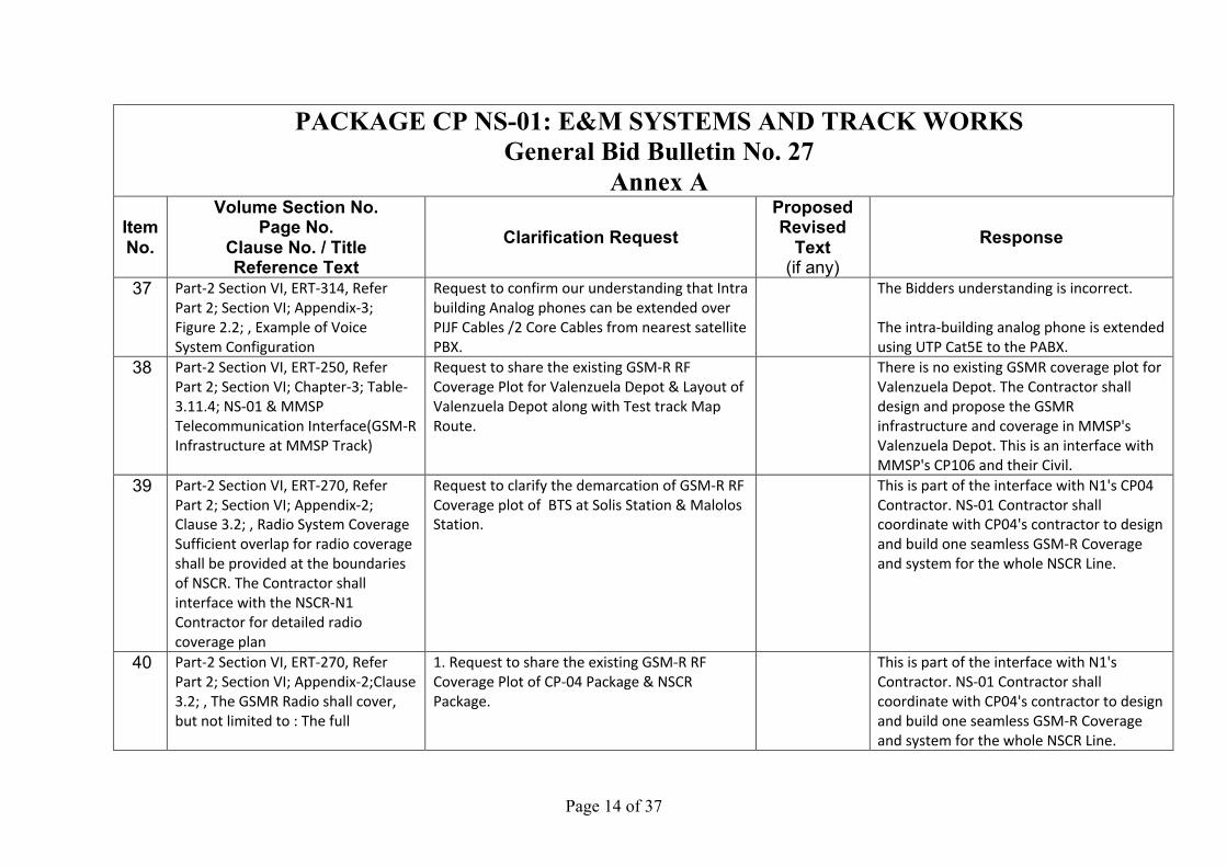
37 Part-2 Section VI, ERT-314, Refer
Part 2; Section VI; Appendix-3;
Figure 2.2; , Example of Voice
System Configuration
Request to confirm our understanding that Intra
building Analog phones can be extended over
PIJF Cables /2 Core Cables from nearest satellite
PBX.
The Bidders understanding is incorrect.
The intra-building analog phone is extended
using UTP Cat5E to the PABX.
38 Part-2 Section VI, ERT-250, Refer
Part 2; Section VI; Chapter-3; Table-
3.11.4; NS-01 & MMSP
Telecommunication Interface(GSM-R
Infrastructure at MMSP Track)
Request to share the existing GSM-R RF
Coverage Plot for Valenzuela Depot & Layout of
Valenzuela Depot along with Test track Map
Route.
There is no existing GSMR coverage plot for
Valenzuela Depot. The Contractor shall
design and propose the GSMR
infrastructure and coverage in MMSP's
Valenzuela Depot. This is an interface with
MMSP's CP106 and their Civil.
39 Part-2 Section VI, ERT-270, Refer
Part 2; Section VI; Appendix-2;
Clause 3.2; , Radio System Coverage
Sufficient overlap for radio coverage
shall be provided at the boundaries
of NSCR. The Contractor shall
interface with the NSCR-N1
Contractor for detailed radio
coverage plan
Request to clarify the demarcation of GSM-R RF
Coverage plot of BTS at Solis Station & Malolos
Station.
This is part of the interface with N1's CP04
Contractor. NS-01 Contractor shall
coordinate with CP04's contractor to design
and build one seamless GSM-R Coverage
and system for the whole NSCR Line.
40 Part-2 Section VI, ERT-270, Refer
Part 2; Section VI; Appendix-2;Clause
3.2; , The GSMR Radio shall cover,
but not limited to : The full
1. Request to share the existing GSM-R RF
Coverage Plot of CP-04 Package & NSCR
Package.
This is part of the interface with N1's
Contractor. NS-01 Contractor shall
coordinate with CP04's contractor to design
and build one seamless GSM-R Coverage
and system for the whole NSCR Line.
Page 15 of 37
PACKAGE CP NS-01: E&M SYSTEMS AND TRACK WORKS General Bid Bulletin No. 27
Annex A Item No.
Volume Section No. Page No.
Clause No. / Title Reference Text
Clarification Request Proposed Revised
Text (if any)
Response
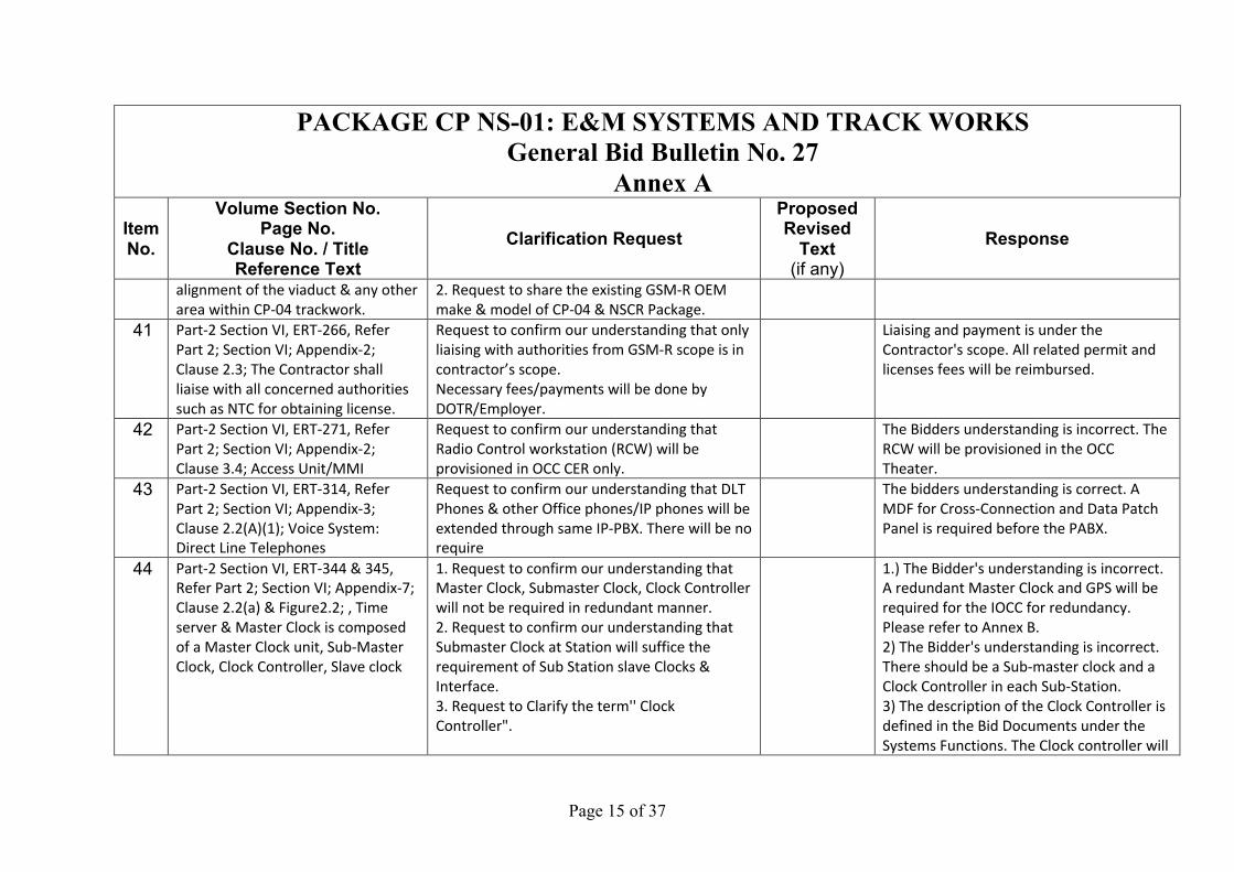
alignment of the viaduct & any other
area within CP-04 trackwork.
2. Request to share the existing GSM-R OEM
make & model of CP-04 & NSCR Package.
41 Part-2 Section VI, ERT-266, Refer
Part 2; Section VI; Appendix-2;
Clause 2.3; The Contractor shall
liaise with all concerned authorities
such as NTC for obtaining license.
Request to confirm our understanding that only
liaising with authorities from GSM-R scope is in
contractor’s scope.
Necessary fees/payments will be done by
DOTR/Employer.
Liaising and payment is under the
Contractor's scope. All related permit and
licenses fees will be reimbursed.
42 Part-2 Section VI, ERT-271, Refer
Part 2; Section VI; Appendix-2;
Clause 3.4; Access Unit/MMI
Request to confirm our understanding that
Radio Control workstation (RCW) will be
provisioned in OCC CER only.
The Bidders understanding is incorrect. The
RCW will be provisioned in the OCC
Theater.
43 Part-2 Section VI, ERT-314, Refer
Part 2; Section VI; Appendix-3;
Clause 2.2(A)(1); Voice System:
Direct Line Telephones
Request to confirm our understanding that DLT
Phones & other Office phones/IP phones will be
extended through same IP-PBX. There will be no
require
The bidders understanding is correct. A
MDF for Cross-Connection and Data Patch
Panel is required before the PABX.
44 Part-2 Section VI, ERT-344 & 345,
Refer Part 2; Section VI; Appendix-7;
Clause 2.2(a) & Figure2.2; , Time
server & Master Clock is composed
of a Master Clock unit, Sub-Master
Clock, Clock Controller, Slave clock
1. Request to confirm our understanding that
Master Clock, Submaster Clock, Clock Controller
will not be required in redundant manner.
2. Request to confirm our understanding that
Submaster Clock at Station will suffice the
requirement of Sub Station slave Clocks &
Interface.
3. Request to Clarify the term'' Clock
Controller".
1.) The Bidder's understanding is incorrect.
A redundant Master Clock and GPS will be
required for the IOCC for redundancy.
Please refer to Annex B.
2) The Bidder's understanding is incorrect.
There should be a Sub-master clock and a
Clock Controller in each Sub-Station.
3) The description of the Clock Controller is
defined in the Bid Documents under the
Systems Functions. The Clock controller will

Page 16 of 37
PACKAGE CP NS-01: E&M SYSTEMS AND TRACK WORKS General Bid Bulletin No. 27
Annex A Item No.
Volume Section No. Page No.
Clause No. / Title Reference Text
Clarification Request Proposed Revised
Text (if any)
Response
drive the connection from Sub-Master
Clock to each Slave Clock if Master Clock
fails to work.
45 Power Supply, Package CP NS-01:
E&M Systems and track works,
General Bid bulletin No. 15 Annex-B
attachment-1, Traction Power
feeding system (MCRP-DWG-PSS-
1001)
At the air section in front of line side battery
post, Bidder understands that rolling stock shall
cross these air gaps by lowering pantographs or
by switching OFF the CB in rolling stock inorder
to avoid arcing during bridging of air section by
pantograph due to presence of different
voltages on either sections.
Please confirm bidder's understanding.
Bidder understanding is incorrect. The
hazard associated to the Rolling Stock and
the catenary air gaps shall be addressed
through the interface process during
project implementation.
46 Power Supply, Package CP NS-01:
E&M Systems and track works,
General Bid bulletin No. 15 Annex-A,
Item No. 20
The Response to GBB 15 Annex-A Item 20 states
that the Substation Battery Post and the
Wayside or Trackside Battery Post serves a
common purpose.
It is clarified that the Battery Post installation is
required in anticipation of the reported
frequent power outage for the north section.
Battery posts are located in substations and
along trackside (at boundaries of different
Previous response remains pending
submission of the battery post traction
power simulation studies. Control strategy
(only voltage regulation & regeneration) of
the TSS battery post and BP at wayside
(emergency operation) is yet to determine
and validated by the contractor based on
their study. N2 scenario should also be
considered by the contractor. Please refer

Page 17 of 37
PACKAGE CP NS-01: E&M SYSTEMS AND TRACK WORKS General Bid Bulletin No. 27
Annex A Item No.
Volume Section No. Page No.
Clause No. / Title Reference Text
Clarification Request Proposed Revised
Text (if any)
Response
distribution utilities).
You may appreciate that the Bidder needs to
assess the Size of these Battery posts.
Therefore, it is important for us to understand
which Battery posts are meant to serve the
purposed on only voltage regulation &
regeneration and which Battery posts are
meant for emergency rescue operation.
In order to arrive at the sizing of the Battery
posts, we need to understand the emergency
rescue operation in case of the power
outages/adjacent TSS failure scenario.
We would like to explain this understanding
taking an example case of failure of SS No.11 (at
42km370)
When SS No11 fails, the section between SS10
& SS11 is fed by SS10. But due to the distance,
SS10 cannot feed power upto BP1 air section.
Therefore the trains affected between SS
No11(42km 370) and BP1 (44km 350) needs
rescue operation.
We understand that in such scenario the train in
between SS11 and BP1 shall be moved to
Calumpit and Apalit stations using the battery
to Clause 4.1.3 1) i, ii, iii of ERT 364 and
clause 4.1.3 7) of ERT 367.
Page 18 of 37
PACKAGE CP NS-01: E&M SYSTEMS AND TRACK WORKS General Bid Bulletin No. 27
Annex A Item No.
Volume Section No. Page No.
Clause No. / Title Reference Text
Clarification Request Proposed Revised
Text (if any)
Response
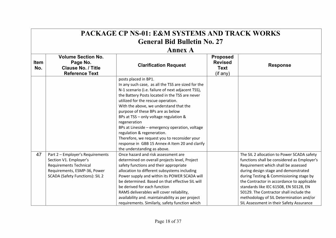
posts placed in BP1.
In any such case, as all the TSS are sized for the
N-1 scenario (i.e. failure of next adjacent TSS),
the Battery Posts located in the TSS are never
utilized for the rescue operation.
With the above, we understand that the
purpose of these BPs are as below
BPs at TSS – only voltage regulation &
regeneration
BPs at Lineside – emergency operation, voltage
regulation & regeneration.
Therefore, we request you to reconsider your
response in GBB 15 Annex-A Item 20 and clarify
the understanding as above.
47 Part 2 – Employer’s Requirements
Section V1. Employer’s
Requirements Technical
Requirements, ESMP-36, Power
SCADA (Safety Functions): SIL 2
Once hazard and risk assessment are
determined on overall projects level, Project
safety functions and their appropriate
allocation to different subsystems including
Power supply and within its POWER SCADA will
be determined. Based on that effective SIL will
be derived for each function
RAMS deliverables will cover reliability,
availability and. maintainability as per project
requirements. Similarly, safety function which
The SIL 2 allocation to Power SCADA safety
functions shall be considered as Employer's
Requirement which shall be assessed
during design stage and demonstrated
during Testing & Commissioning stage by
the Contractor in accordance to applicable
standards like IEC 61508, EN 50128, EN
50129. The Contractor shall include the
methodology of SIL Determination and/or
SIL Assessment in their Safety Assurance
Page 19 of 37
PACKAGE CP NS-01: E&M SYSTEMS AND TRACK WORKS General Bid Bulletin No. 27
Annex A Item No.
Volume Section No. Page No.
Clause No. / Title Reference Text
Clarification Request Proposed Revised
Text (if any)
Response
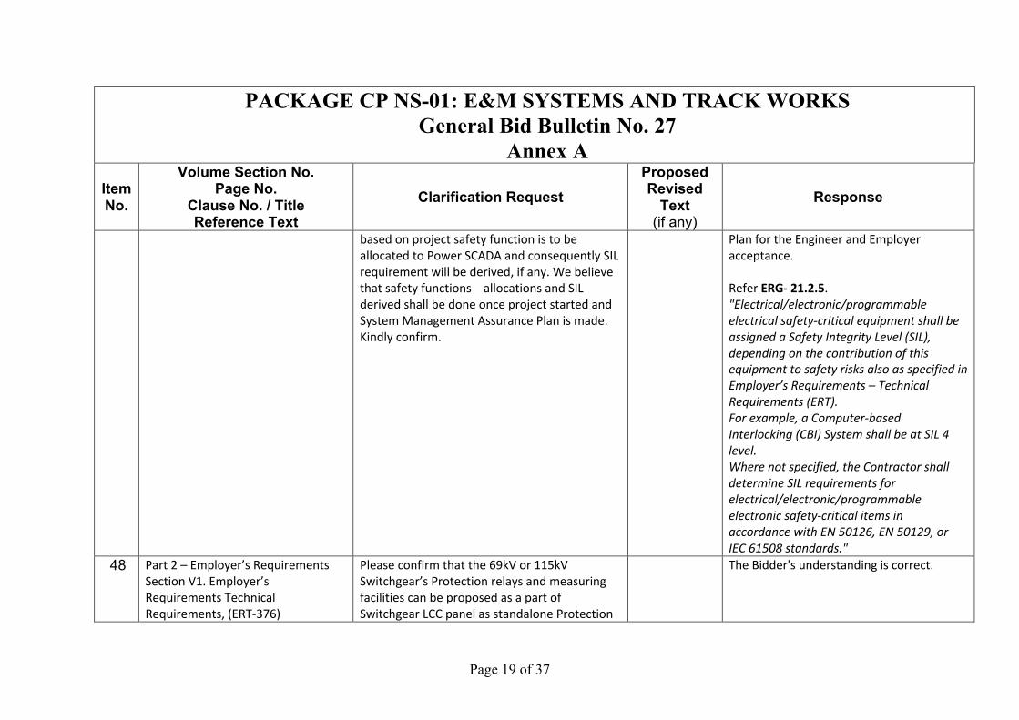
based on project safety function is to be
allocated to Power SCADA and consequently SIL
requirement will be derived, if any. We believe
that safety functions allocations and SIL
derived shall be done once project started and
System Management Assurance Plan is made.
Kindly confirm.
Plan for the Engineer and Employer
acceptance.
Refer ERG- 21.2.5.
"Electrical/electronic/programmable electrical safety-critical equipment shall be assigned a Safety Integrity Level (SIL), depending on the contribution of this equipment to safety risks also as specified in Employer’s Requirements – Technical Requirements (ERT). For example, a Computer-based Interlocking (CBI) System shall be at SIL 4 level. Where not specified, the Contractor shall determine SIL requirements for electrical/electronic/programmable electronic safety-critical items in accordance with EN 50126, EN 50129, or IEC 61508 standards."
48 Part 2 – Employer’s Requirements
Section V1. Employer’s
Requirements Technical
Requirements, (ERT-376)
Please confirm that the 69kV or 115kV
Switchgear’s Protection relays and measuring
facilities can be proposed as a part of
Switchgear LCC panel as standalone Protection
The Bidder's understanding is correct.
Page 20 of 37
PACKAGE CP NS-01: E&M SYSTEMS AND TRACK WORKS General Bid Bulletin No. 27
Annex A Item No.
Volume Section No. Page No.
Clause No. / Title Reference Text
Clarification Request Proposed Revised
Text (if any)
Response
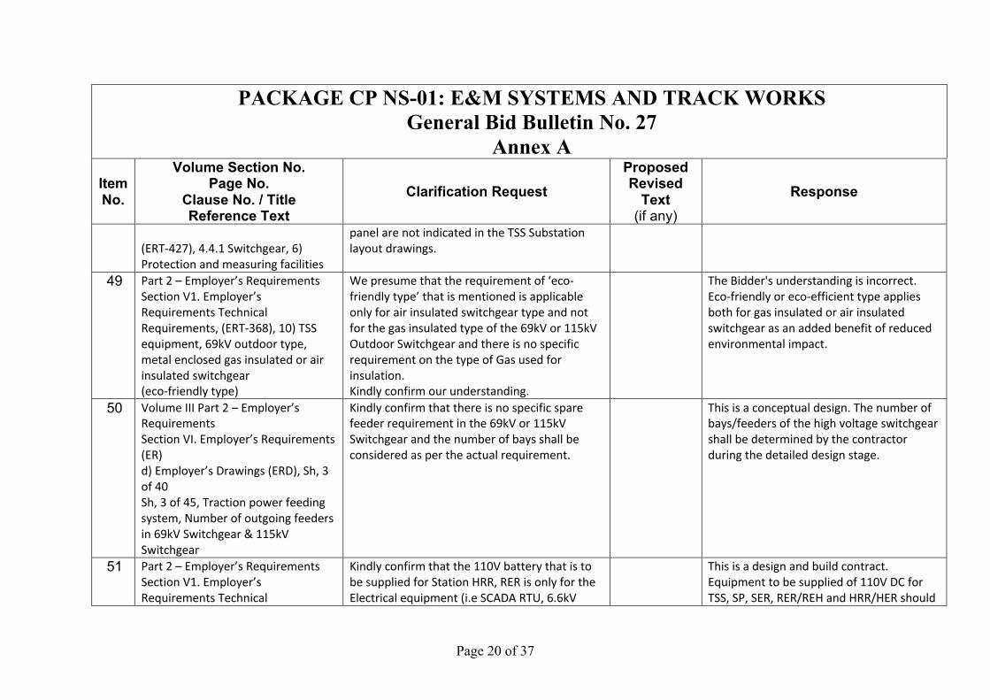
(ERT-427), 4.4.1 Switchgear, 6)
Protection and measuring facilities
panel are not indicated in the TSS Substation
layout drawings.
49 Part 2 – Employer’s Requirements
Section V1. Employer’s
Requirements Technical
Requirements, (ERT-368), 10) TSS
equipment, 69kV outdoor type,
metal enclosed gas insulated or air
insulated switchgear
(eco-friendly type)
We presume that the requirement of ‘eco-
friendly type’ that is mentioned is applicable
only for air insulated switchgear type and not
for the gas insulated type of the 69kV or 115kV
Outdoor Switchgear and there is no specific
requirement on the type of Gas used for
insulation.
Kindly confirm our understanding.
The Bidder's understanding is incorrect.
Eco-friendly or eco-efficient type applies
both for gas insulated or air insulated
switchgear as an added benefit of reduced
environmental impact.
50 Volume III Part 2 – Employer’s
Requirements
Section VI. Employer’s Requirements
(ER)
d) Employer’s Drawings (ERD), Sh, 3
of 40
Sh, 3 of 45, Traction power feeding
system, Number of outgoing feeders
in 69kV Switchgear & 115kV
Switchgear
Kindly confirm that there is no specific spare
feeder requirement in the 69kV or 115kV
Switchgear and the number of bays shall be
considered as per the actual requirement.
This is a conceptual design. The number of
bays/feeders of the high voltage switchgear
shall be determined by the contractor
during the detailed design stage.
51 Part 2 – Employer’s Requirements
Section V1. Employer’s
Requirements Technical
Kindly confirm that the 110V battery that is to
be supplied for Station HRR, RER is only for the
Electrical equipment (i.e SCADA RTU, 6.6kV
This is a design and build contract.
Equipment to be supplied of 110V DC for
TSS, SP, SER, RER/REH and HRR/HER should

Page 21 of 37
PACKAGE CP NS-01: E&M SYSTEMS AND TRACK WORKS General Bid Bulletin No. 27
Annex A Item No.
Volume Section No. Page No.
Clause No. / Title Reference Text
Clarification Request Proposed Revised
Text (if any)
Response
Requirements, ERT-476, 5.6.4 DC
Battery and Charger, Battery Units
(NiCad: Nickel-Cadmium
rechargeable battery)
1) For the HRR, RER in stations
Switchgear, distribution transformer & 400-
230V switchgear) that is located inside the HRR/
RER and there is no specific requirement to
consider any other loads.
be determined by the system contractor
with the interface parties during the
detailed design stage .
52 Volume III Part 2 – Employer’s
Requirements
Section VI. Employer’s Requirements
(ER)
d) Employer’s Drawings (ERD),
MCRP-DWG-C/C-PSS-2101 to 2112
Sh. 19 of 40 to sh. 29 of 40
& Sh. 30 of 40, Substation Layout,
110V Battery & Charger
We observe that the Battery dimension that is
indicated in the Substation layout drawing will
not be adequate for the rating of the Battery
that will be required for the Substation.
Kindly clarify if it is possible to change the
Substation control building dimension to
accommodate the actual dimension of the
Battery racks.
The substation equipment shall fit within
the buildings and space provided. Should
any amended to the building design be
necessary and costs associated with the
change shall be paid by the NS-01
contractor.
53 Volume III Part 2 – Employer’s
Requirements
Section VI. Employer’s Requirements
(ER)
d) Employer’s Drawings (ERD),
MCRP-DWG-C/C-PSS-2101 to 2112
Sh. 19 of 40 to sh. 29 of 40
& Sh. 30 of 40, Substation Layout,
Kindly clarify the requirement for Control &
Protection panels of 69kV Switchgear, we
observe that the Control & Protection panel is
not indicated in the Substation layout drawing
for Substations SS No. S10 to S21, whereas it is
indicated for S22.
If it is to be located inside the building the space
will not be adequate for the same in SS No. S10
to S21 Substations.
This is a design and build project. The
contractor should determine the suitable
control and protection panel of the 69kV
Switchgear during the detailed design
stage. The contractor should proposed a
suitable size of panel that would fit in the
building space provided. Otherwise costs
associated with the change shall be paid by
the NS-01 contractor.
Page 22 of 37
PACKAGE CP NS-01: E&M SYSTEMS AND TRACK WORKS General Bid Bulletin No. 27
Annex A Item No.
Volume Section No. Page No.
Clause No. / Title Reference Text
Clarification Request Proposed Revised
Text (if any)
Response
Control & Protection Panel for 69kV
Switchgear
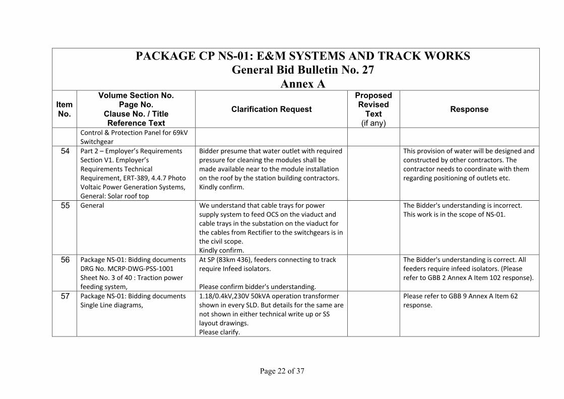
54 Part 2 – Employer’s Requirements
Section V1. Employer’s
Requirements Technical
Requirement, ERT-389, 4.4.7 Photo
Voltaic Power Generation Systems,
General: Solar roof top
Bidder presume that water outlet with required
pressure for cleaning the modules shall be
made available near to the module installation
on the roof by the station building contractors.
Kindly confirm.
This provision of water will be designed and
constructed by other contractors. The
contractor needs to coordinate with them
regarding positioning of outlets etc.
55 General We understand that cable trays for power
supply system to feed OCS on the viaduct and
cable trays in the substation on the viaduct for
the cables from Rectifier to the switchgears is in
the civil scope.
Kindly confirm.
The Bidder's understanding is incorrect.
This work is in the scope of NS-01.
56 Package NS-01: Bidding documents
DRG No. MCRP-DWG-PSS-1001
Sheet No. 3 of 40 : Traction power
feeding system,
At SP (83km 436), feeders connecting to track
require Infeed isolators.
Please confirm bidder's understanding.
The Bidder's understanding is correct. All
feeders require infeed isolators. (Please
refer to GBB 2 Annex A Item 102 response).
57 Package NS-01: Bidding documents
Single Line diagrams,
1.18/0.4kV,230V 50kVA operation transformer
shown in every SLD. But details for the same are
not shown in either technical write up or SS
layout drawings.
Please clarify.
Please refer to GBB 9 Annex A Item 62
response.
Page 23 of 37
PACKAGE CP NS-01: E&M SYSTEMS AND TRACK WORKS General Bid Bulletin No. 27
Annex A Item No.
Volume Section No. Page No.
Clause No. / Title Reference Text
Clarification Request Proposed Revised
Text (if any)
Response
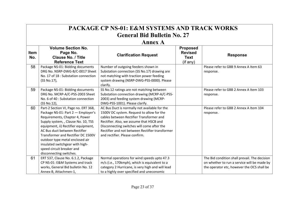
58 Package NS-01: Bidding documents
DRG No. NSRP-DWG-B/C-0017 Sheet
No. 17 of 18 : Substation connection
(SS No.17),
Number of outgoing feeders shown in
Substation connection (SS No.17) drawing are
not matching with traction power feeding
system drawing (NSRP-DWG-PSS-0000). Please
clarify.
Please refer to GBB 9 Annex A Item 63
response.
59 Package NS-01: Bidding documents
DRG No. MCRP-A/C-PSS-2003 Sheet
No. 6 of 40 : Substation connection
(SS No.12),
SS No.12 ratings are not matching between
Substation connection drawing (MCRP-A/C-PSS-
2003) and feeding system drawing (MCRP-
DWG-PSS-1001). Please clarify.
Please refer to GBB 2 Annex A Item 103
response.
60 Part-2 Section VI, Page no. ERT 368,
Package NS-01: Part 2 — Employer's
Requirements, Chapter 4, Power
Supply system, , Clause No. 10, TSS
equipment, ii) Rectifier equipment,
AC Bus duct between Rectifier
Transformer and Rectifier DC 1500V
outdoor type metal enclosed air
insulated switchgear with high-
speed circuit breaker and
disconnecting switches.
AC Bus Duct is normally not available for the
1500V DC system. Request to allow for the
cables between Rectifier Transformer and
Rectifier. Also, we assume that HSCB and
Disconnecting switches will come after the
Rectifier and not between Rectifier transformer
and rectifier. Please confirm.
Please refer to GBB 2 Annex A Item 104
response.
61 ERT 537, Clause No. 6.1.2, Package
CP NS-01: E&M Systems and track
works, General Bid bulletin No. 12
Annex-B, Attachmen-1,
Normal operations for wind speeds upto 47.3
m/s (i.e., 170kmph), which is equivalent to a
category 2 Hurricane, is very high and will lead
to a highly over specified and uneconomic
The Bid condition shall prevail. The decision
on whether to run a service will be made by
the operator etc, however the OCS shall be

Page 24 of 37
PACKAGE CP NS-01: E&M SYSTEMS AND TRACK WORKS General Bid Bulletin No. 27
Annex A Item No.
Volume Section No. Page No.
Clause No. / Title Reference Text
Clarification Request Proposed Revised
Text (if any)
Response
Operation regulations for wind
speed:
a) Normal train speed for wind
speed of less or equal to 47.3 m/s
b) Train operation stopped for wind
speed of more than 47.3 m/s
system design.
In similar projects like Dhaka metro
(Bangladesh) and Ho chi Minh metro (Vietnam),
this train operations are regulated/stopped
after wind speed of 30m/s. In Delhi Metro,
(DMRC), the train operation are regulated
/stopped at wind speed of 25 m/s.
Request you to reconsider the specified
requirement.
designed to support operation at the stated
operational wind speed.
62 ERT 564, 1.Package NS-01: Part 2 —
Employer's Requirements, Chapter
6, table 6.2.2, item 1.5,ERT 563
2.Package NS-01: Part 2 —
Employer's Requirements, Chapter
6, table 6.2.3,ERT 564
3.Package CP NS-01: E&M Systems
and track works, General Bid bulletin
No. 12 Query No. 51,
1. Design ambient pressure -
1013hPa
2. Example of Wind loads at the wind
speed of 54m/s against structures,
etc: Lines: Two feeders bundled -
2200N/m2 and Others - 1800N/m2
We understand that design wind pressure for
OCS supports, conductor, insulators shall be as
per table 6.2.3 and all remaining environmental
conditions are as per table 6.2.2. Please confirm
Bidder understanding.
The Bidder's understanding is correct.

Page 25 of 37
PACKAGE CP NS-01: E&M SYSTEMS AND TRACK WORKS General Bid Bulletin No. 27
Annex A Item No.
Volume Section No. Page No.
Clause No. / Title Reference Text
Clarification Request Proposed Revised
Text (if any)
Response
3. The OCS shall be designed in
accordance with Table 6.2.2 Ambient
Conditions and Usage Environments.
However, the OCS shall remain
operational up to the wind speeds
stated in Clause 6.1.2.
63 Part-2 Section VI, Page nos. ERT 545
and 584, Package NS-01: Part 2 —
Employer's Requirements, Chapter
6, OCS, , Contract clauses:
i) 6.1.4.1 (6) TR- OCS Page No. 545
"Cantilever: It is an insulated
swiveling type structure member,
comprising
of assorted sizes of metal tubes
(lightweight and non-corrosive), to
support and to keep the OCS in
position to facilitate current
collection by pantograph at all speed
without doing the structural
member damage.
ii) 6.4.13 TR- OCS Page No. 584
" b) Material Grade: STK 490, SS400,
CAC 702 (pull-off arm & ear), SS400
Please confirm whether aluminium light weight
tubes can be proposed.
Please refer to GBB no. 2 Item 137.

Page 26 of 37
PACKAGE CP NS-01: E&M SYSTEMS AND TRACK WORKS General Bid Bulletin No. 27
Annex A Item No.
Volume Section No. Page No.
Clause No. / Title Reference Text
Clarification Request Proposed Revised
Text (if any)
Response
(drop bracket), SUS304 (fitting);
c) Pole surface: Hot dip galvanized;"
64 Part-2 Section VI, ERT-246, Refer
Table 3.11.2.2,
Request you to kindly elaborate the Interface
protocol along with interface locations for
synchronisation of PSD System with Clock
system through Master/Sub Master Clock (if
required)
Interface protocol along with interface locations
required for PSD System.
Bandwidth requirement if Ethernet ports are
required along with detailed port calculation
Sub System wise.
The Clock is provided by NS01 under
Telecommunication system. The contractor
shall interface within NS01 systems to
decide protocol and location of clock
interface as required.
65 General, Prototype Test What is the specific scope of the prototype
components?
Do we need to consider the prototype test for
FH, HH-1.5 m and HH – 1.2/1.3 m.
Please confirm.
The Bidder's understanding is correct.
66 Part-2 Section VI, General Please share the missing FTI station drawing. FTI station is being designed. The
contractor shall interface and obtain
drawings from Civil contractor.
67 General, SR-58 The entire
construction and glazing of the PSD
System shall withstand the pressure
from
For the purpose of structural dimensioning,
please share the wind pressure for the storm to
be considered.
The contractor shall propose the wind
pressure for the storm to be considered
based on the local historical data and
Philippines National Guidelines and Codes,

Page 27 of 37
PACKAGE CP NS-01: E&M SYSTEMS AND TRACK WORKS General Bid Bulletin No. 27
Annex A Item No.
Volume Section No. Page No.
Clause No. / Title Reference Text
Clarification Request Proposed Revised
Text (if any)
Response
non-stop train and the wind
pressure from tropical storm.
at the design stage, for the approval of the
Engineer.
68 Part-2 Section VI Request you to share the information for NSCR
MMS system for the Interface
a. What is the Application software used as
NSCR MMS system
b. What is the database and version used by the
software
c. How many interface touch points are
required to be considered
d. How many Inbound and Outbound touch
points
e. What are the supported interface
communication protocols by the NSCR MMS
system
f. Vendor of NSCR MMS System to be available
during interface discussion and development
It's under Contractor responsibility to
propose the suitable application software.
For requirement details, please refer to
Section 11: Computerized Maintenance
Management System. All the touch points
detail can be proposed by Contractor and
subject to the Engineer's approval in design
development phase.
69 Part-2 Section VI Please elaborate, while Balnic depot OCC
Migration
a. When IOCC is constructed and ready for
operations, Whether the Maximo software
data from the depot instance to be migrated to
IOCC.
b. Development and Test environments will be
It's under Contractor responsibility to
propose the suitable application software.
Both application and data server for CMMS
provided in the Mabalacat Depot and Banlic
Depot shall be in dual redundant
configuration. However, the equipment at
Banlic Depot will be decommissioned and
Page 28 of 37
PACKAGE CP NS-01: E&M SYSTEMS AND TRACK WORKS General Bid Bulletin No. 27
Annex A Item No.
Volume Section No. Page No.
Clause No. / Title Reference Text
Clarification Request Proposed Revised
Text (if any)
Response
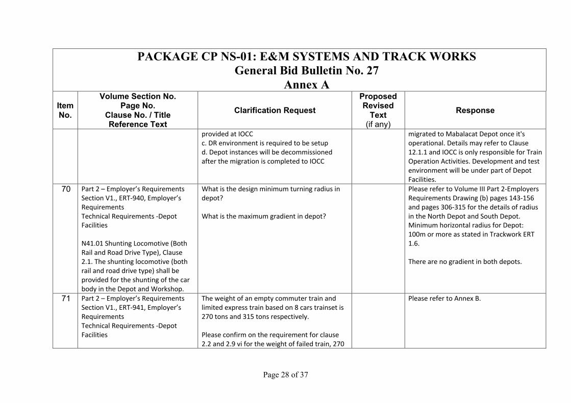
provided at IOCC
c. DR environment is required to be setup
d. Depot instances will be decommissioned
after the migration is completed to IOCC
migrated to Mabalacat Depot once it's
operational. Details may refer to Clause
12.1.1 and IOCC is only responsible for Train
Operation Activities. Development and test
environment will be under part of Depot
Facilities.
70 Part 2 – Employer’s Requirements
Section V1., ERT-940, Employer’s
Requirements
Technical Requirements -Depot
Facilities
N41.01 Shunting Locomotive (Both
Rail and Road Drive Type), Clause
2.1. The shunting locomotive (both
rail and road drive type) shall be
provided for the shunting of the car
body in the Depot and Workshop.
What is the design minimum turning radius in
depot?
What is the maximum gradient in depot?
Please refer to Volume III Part 2-Employers
Requirements Drawing (b) pages 143-156
and pages 306-315 for the details of radius
in the North Depot and South Depot.
Minimum horizontal radius for Depot:
100m or more as stated in Trackwork ERT
1.6.
There are no gradient in both depots.
71 Part 2 – Employer’s Requirements
Section V1., ERT-941, Employer’s
Requirements
Technical Requirements -Depot
Facilities
The weight of an empty commuter train and
limited express train based on 8 cars trainset is
270 tons and 315 tons respectively.
Please confirm on the requirement for clause
2.2 and 2.9 vi for the weight of failed train, 270
Please refer to Annex B.

Page 29 of 37
PACKAGE CP NS-01: E&M SYSTEMS AND TRACK WORKS General Bid Bulletin No. 27
Annex A Item No.
Volume Section No. Page No.
Clause No. / Title Reference Text
Clarification Request Proposed Revised
Text (if any)
Response
N41.02 Shunting Locomotive (Engine
Type), Clause 2.2. Contractor shall
supply diesel locomotive (1 units)
along with one flat car suitable for
mainline operations having
maximum 2.95m wide, to recover
failed train, 270t, on 3.5%
downgrade.
Clause 2.9. Major performance of
the shunting locomotive shall be as
follows; the Contractor shall confirm
the type of coupler to the Rolling
Stock Contractor:
i. Type: diesel locomotive,
ii. Track gauge: 1,435 mm,
iii. Coupler: the couplers of rolling
stock at both ends, (to be supplied
by Rolling stock
contractor CP NS-02)
iv. The locomotive envelope to
follow rolling stock and structure
gauge drawing MCRPDWG-GEN-TK-
0020 Rev 6 or latest.
tons, 315 tons, 338 tons or 394 tons to recover
on 3.5% downgrade.
Page 30 of 37
PACKAGE CP NS-01: E&M SYSTEMS AND TRACK WORKS General Bid Bulletin No. 27
Annex A Item No.
Volume Section No. Page No.
Clause No. / Title Reference Text
Clarification Request Proposed Revised
Text (if any)
Response
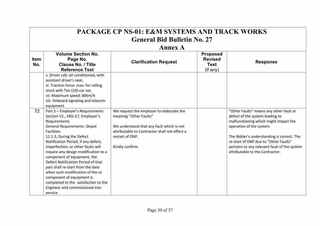
v. Driver cab: air conditioned, with
assistant driver’s seat,
vi. Traction force: max. for rolling
stock with Ten (10)-car set,
vii. Maximum speed: 80km/h
viii. Onboard signaling and telecom
equipment
72 Part 2 – Employer’s Requirements
Section V1., ERG-57, Employer’s
Requirements
General Requirements -Depot
Facilities
11.1.3, During the Defect
Notification Period, if any defect,
imperfection, or other faults will
require any design modification to a
component of equipment, the
Defect Notification Period of that
part shall re-start from the date
when such modification of the or
component of equipment is
completed to the satisfaction to the
Engineer and commissioned into
service.
We request the employer to elaborate the
meaning “Other Faults”
We understand that any fault which is not
attributable to Contractor shall not effect a
restart of DNP.
Kindly confirm.
"Other Faults" means any other fault or
defect of the system leading to
malfunctioning which might impact the
operation of the system.
The Bidder's understanding is correct. The
re-start of DNP due to "Other Faults"
pertains to any relevant fault of the system
attributable to the Contractor.
Page 31 of 37
PACKAGE CP NS-01: E&M SYSTEMS AND TRACK WORKS General Bid Bulletin No. 27
Annex A Item No.
Volume Section No. Page No.
Clause No. / Title Reference Text
Clarification Request Proposed Revised
Text (if any)
Response
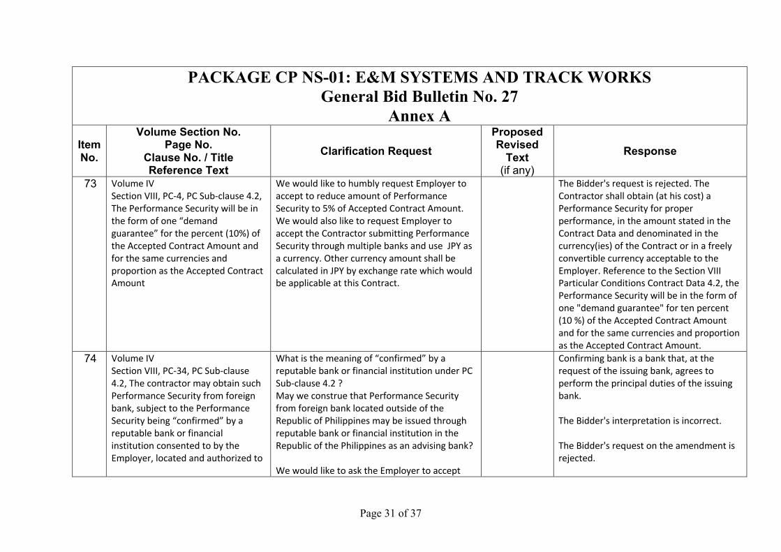
73 Volume IV
Section VIII, PC-4, PC Sub-clause 4.2,
The Performance Security will be in
the form of one “demand
guarantee” for the percent (10%) of
the Accepted Contract Amount and
for the same currencies and
proportion as the Accepted Contract
Amount
We would like to humbly request Employer to
accept to reduce amount of Performance
Security to 5% of Accepted Contract Amount.
We would also like to request Employer to
accept the Contractor submitting Performance
Security through multiple banks and use JPY as
a currency. Other currency amount shall be
calculated in JPY by exchange rate which would
be applicable at this Contract.
The Bidder's request is rejected. The
Contractor shall obtain (at his cost) a
Performance Security for proper
performance, in the amount stated in the
Contract Data and denominated in the
currency(ies) of the Contract or in a freely
convertible currency acceptable to the
Employer. Reference to the Section VIII
Particular Conditions Contract Data 4.2, the
Performance Security will be in the form of
one "demand guarantee" for ten percent
(10 %) of the Accepted Contract Amount
and for the same currencies and proportion
as the Accepted Contract Amount.
74 Volume IV
Section VIII, PC-34, PC Sub-clause
4.2, The contractor may obtain such
Performance Security from foreign
bank, subject to the Performance
Security being “confirmed” by a
reputable bank or financial
institution consented to by the
Employer, located and authorized to
What is the meaning of “confirmed” by a
reputable bank or financial institution under PC
Sub-clause 4.2 ?
May we construe that Performance Security
from foreign bank located outside of the
Republic of Philippines may be issued through
reputable bank or financial institution in the
Republic of the Philippines as an advising bank?
We would like to ask the Employer to accept
Confirming bank is a bank that, at the
request of the issuing bank, agrees to
perform the principal duties of the issuing
bank.
The Bidder's interpretation is incorrect.
The Bidder's request on the amendment is
rejected.
Page 32 of 37
PACKAGE CP NS-01: E&M SYSTEMS AND TRACK WORKS General Bid Bulletin No. 27
Annex A Item No.
Volume Section No. Page No.
Clause No. / Title Reference Text
Clarification Request Proposed Revised
Text (if any)
Response
do business in the Republic of the
Philippines
replacement of words from “confirmed” to
“advised”
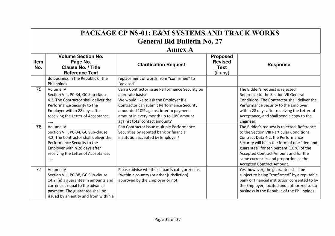
75 Volume IV
Section VIII, PC-34, GC Sub-clause
4.2, The Contractor shall deliver the
Performance Security to the
Employer within 28 days after
receiving the Letter of Acceptance,
…..
Can a Contractor issue Performance Security on
a prorate basis?
We would like to ask the Employer if a
Contractor can submit Performance Security
amounted 10% against interim payment
amount in every month up to 10% amount
against total contact amount?
The Bidder's request is rejected.
Reference to the Section VII General
Conditions, The Contractor shall deliver the
Performance Security to the Employer
within 28 days after receiving the Letter of
Acceptance, and shall send a copy to the
Engineer.
76 Volume IV
Section VIII, PC-34, GC Sub-clause
4.2, The Contractor shall deliver the
Performance Security to the
Employer within 28 days after
receiving the Letter of Acceptance,
…..
Can Contractor issue multiple Performance
Securities by reputed bank or financial
institution accepted by Employer?
The Bidder's request is rejected. Reference
to the Section VIII Particular Conditions
Contract Data 4.2, the Performance
Security will be in the form of one "demand
guarantee" for ten percent (10 %) of the
Accepted Contract Amount and for the
same currencies and proportion as the
Accepted Contract Amount.
77 Volume IV
Section VIII, PC-38, GC Sub-clause
14.2, (ii) a guarantee in amounts and
currencies equal to the advance
payment. The guarantee shall be
issued by an entity and from within a
Please advise whether Japan is categorized as
“within a country (or other jurisdiction)
approved by the Employer or not.
Yes, however, the guarantee shall be
subject to being “confirmed” by a reputable
bank or financial institution consented to by
the Employer, located and authorized to do
business in the Republic of the Philippines.
Page 33 of 37
PACKAGE CP NS-01: E&M SYSTEMS AND TRACK WORKS General Bid Bulletin No. 27
Annex A Item No.
Volume Section No. Page No.
Clause No. / Title Reference Text
Clarification Request Proposed Revised
Text (if any)
Response
country (or other jurisdiction)
approved by the Employer
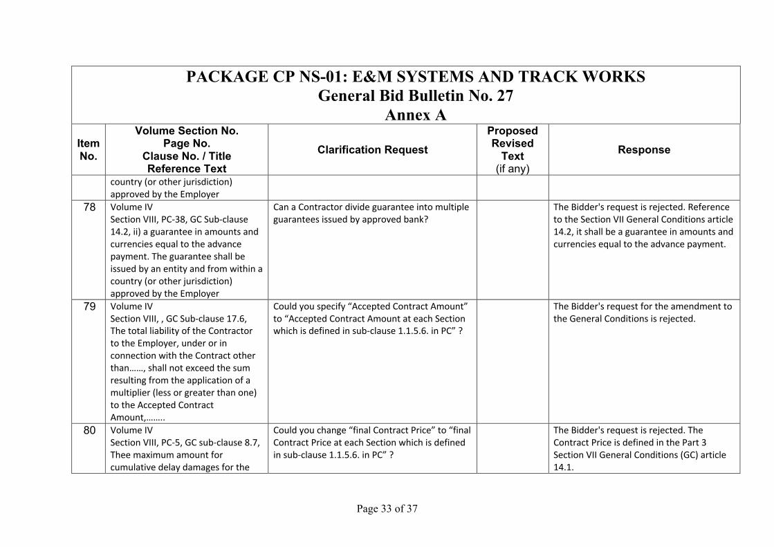
78 Volume IV
Section VIII, PC-38, GC Sub-clause
14.2, ii) a guarantee in amounts and
currencies equal to the advance
payment. The guarantee shall be
issued by an entity and from within a
country (or other jurisdiction)
approved by the Employer
Can a Contractor divide guarantee into multiple
guarantees issued by approved bank?
The Bidder's request is rejected. Reference
to the Section VII General Conditions article
14.2, it shall be a guarantee in amounts and
currencies equal to the advance payment.
79 Volume IV
Section VIII, , GC Sub-clause 17.6,
The total liability of the Contractor
to the Employer, under or in
connection with the Contract other
than……, shall not exceed the sum
resulting from the application of a
multiplier (less or greater than one)
to the Accepted Contract
Amount,……..
Could you specify “Accepted Contract Amount”
to “Accepted Contract Amount at each Section
which is defined in sub-clause 1.1.5.6. in PC” ?
The Bidder's request for the amendment to
the General Conditions is rejected.
80 Volume IV
Section VIII, PC-5, GC sub-clause 8.7,
Thee maximum amount for
cumulative delay damages for the
Could you change “final Contract Price” to “final
Contract Price at each Section which is defined
in sub-clause 1.1.5.6. in PC” ?
The Bidder's request is rejected. The
Contract Price is defined in the Part 3
Section VII General Conditions (GC) article
14.1.
Page 34 of 37
PACKAGE CP NS-01: E&M SYSTEMS AND TRACK WORKS General Bid Bulletin No. 27
Annex A Item No.
Volume Section No. Page No.
Clause No. / Title Reference Text
Clarification Request Proposed Revised
Text (if any)
Response
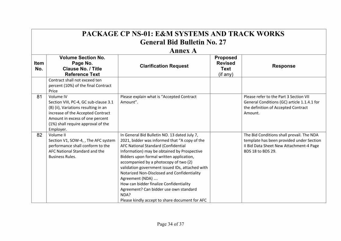
Contract shall not exceed ten
percent (10%) of the final Contract
Price
81 Volume IV
Section VIII, PC-4, GC sub-clause 3.1
(B) (ii), Variations resulting in an
increase of the Accepted Contract
Amount in excess of one percent
(1%) shall require approval of the
Employer.
Please explain what is “Accepted Contract
Amount”.
Please refer to the Part 3 Section VII
General Conditions (GC) article 1.1.4.1 for
the definition of Accepted Contract
Amount.
82 Volume II
Section V1, SOW-4, , The AFC system
performance shall conform to the
AFC National Standard and the
Business Rules.
In General Bid Bulletin NO. 13 dated July 7,
2021, bidder was informed that “A copy of the
AFC National Standard (Confidential
Information) may be obtained by Prospective
Bidders upon formal written application,
accompanied by a photocopy of two (2)
validation government issued IDs, attached with
Notarized Non-Disclosed and Confidentiality
Agreement (NDA) ….
How can bidder finalize Confidentiality
Agreement? Can bidder use own standard
NDA?
Please kindly accept to share document for AFC
The Bid Conditions shall prevail. The NDA
template has been provided under Section
II Bid Data Sheet New Attachment-4 Page
BDS 18 to BDS 29.
Page 35 of 37
PACKAGE CP NS-01: E&M SYSTEMS AND TRACK WORKS General Bid Bulletin No. 27
Annex A Item No.
Volume Section No. Page No.
Clause No. / Title Reference Text
Clarification Request Proposed Revised
Text (if any)
Response
National Standard without any restriction to
bidder.
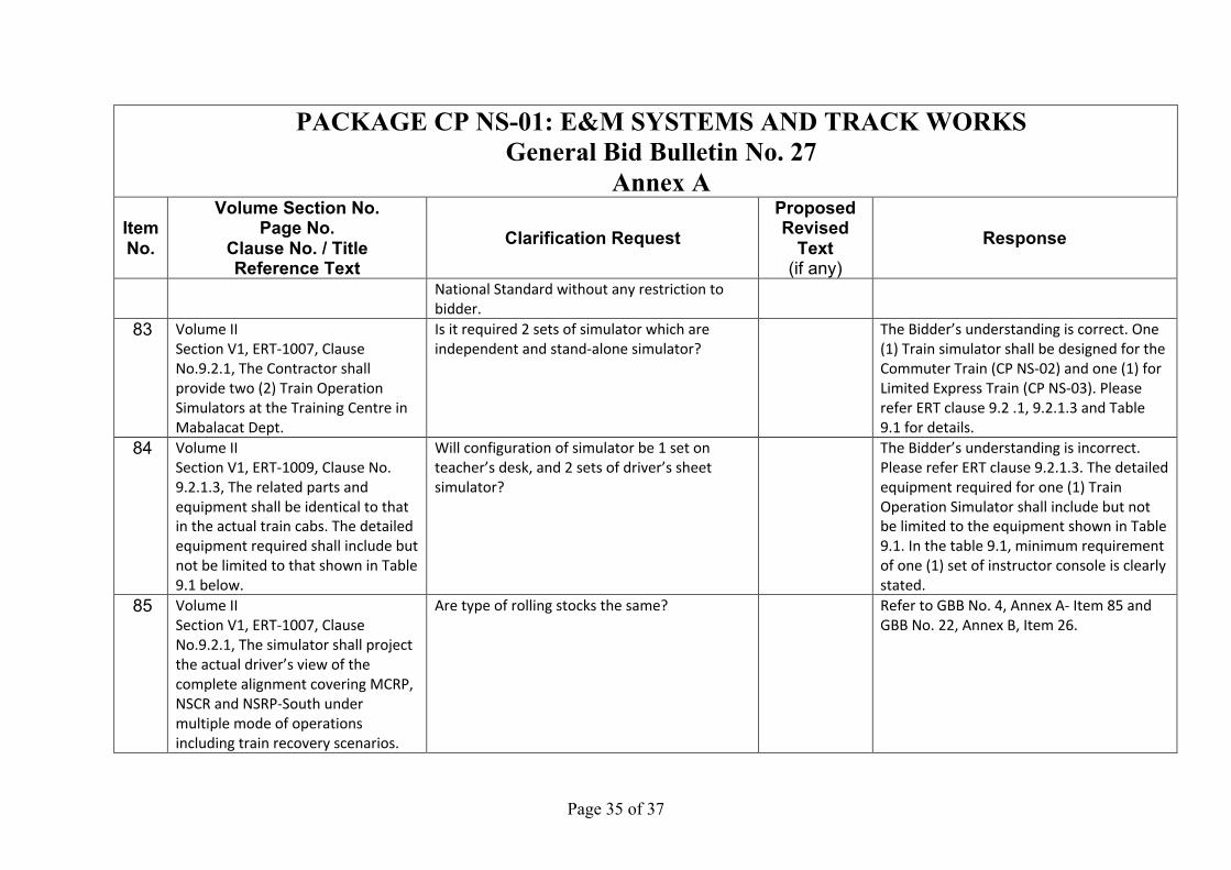
83 Volume II
Section V1, ERT-1007, Clause
No.9.2.1, The Contractor shall
provide two (2) Train Operation
Simulators at the Training Centre in
Mabalacat Dept.
Is it required 2 sets of simulator which are
independent and stand-alone simulator?
The Bidder’s understanding is correct. One
(1) Train simulator shall be designed for the
Commuter Train (CP NS-02) and one (1) for
Limited Express Train (CP NS-03). Please
refer ERT clause 9.2 .1, 9.2.1.3 and Table
9.1 for details.
84 Volume II
Section V1, ERT-1009, Clause No.
9.2.1.3, The related parts and
equipment shall be identical to that
in the actual train cabs. The detailed
equipment required shall include but
not be limited to that shown in Table
9.1 below.
Will configuration of simulator be 1 set on
teacher’s desk, and 2 sets of driver’s sheet
simulator?
The Bidder’s understanding is incorrect.
Please refer ERT clause 9.2.1.3. The detailed
equipment required for one (1) Train
Operation Simulator shall include but not
be limited to the equipment shown in Table
9.1. In the table 9.1, minimum requirement
of one (1) set of instructor console is clearly
stated.
85 Volume II
Section V1, ERT-1007, Clause
No.9.2.1, The simulator shall project
the actual driver’s view of the
complete alignment covering MCRP,
NSCR and NSRP-South under
multiple mode of operations
including train recovery scenarios.
Are type of rolling stocks the same? Refer to GBB No. 4, Annex A- Item 85 and
GBB No. 22, Annex B, Item 26.

Page 36 of 37
PACKAGE CP NS-01: E&M SYSTEMS AND TRACK WORKS General Bid Bulletin No. 27
Annex A Item No.
Volume Section No. Page No.
Clause No. / Title Reference Text
Clarification Request Proposed Revised
Text (if any)
Response
86 Volume II
Section V1, ERT-1007, Clause
No.9.2.1, The simulator shall project
the actual driver’s view of the
complete alignment covering MCRP,
NSCR and NSRP-South under
multiple mode of operations
including train recovery scenarios.
Is the signaling system the same in all sections? The Bidder's understanding is correct. The
Signaling System in MCRP, NSCR and NSRP-
South section is same.
87 Volume II
Section V1, ERT-1007, Clause
No.9.2.1, The simulator shall project
the actual driver’s view of the
complete alignment covering MCRP,
NSCR and NSRP-South under
multiple mode of operations
including train recovery scenarios.
Is it necessary for Contractor to provide new data base for displayed video?
The Bid conditions shall prevail.
88 Volume II
Section V1, ERT-1007, Clause
No.9.2.1, The simulator shall project
the actual driver’s view of the
complete alignment covering MCRP,
NSCR and NSRP-South under
multiple mode of operations
including train recovery scenarios.
Can Contractor provide training video for each section separately and will not provide training video in whole sections?
This is a design and build contract.
Contractor can propose the training video
details at design finalization stage for
Engineer's approval.
Page 37 of 37
PACKAGE CP NS-01: E&M SYSTEMS AND TRACK WORKS General Bid Bulletin No. 27
Annex A Item No.
Volume Section No. Page No.
Clause No. / Title Reference Text
Clarification Request Proposed Revised
Text (if any)
Response
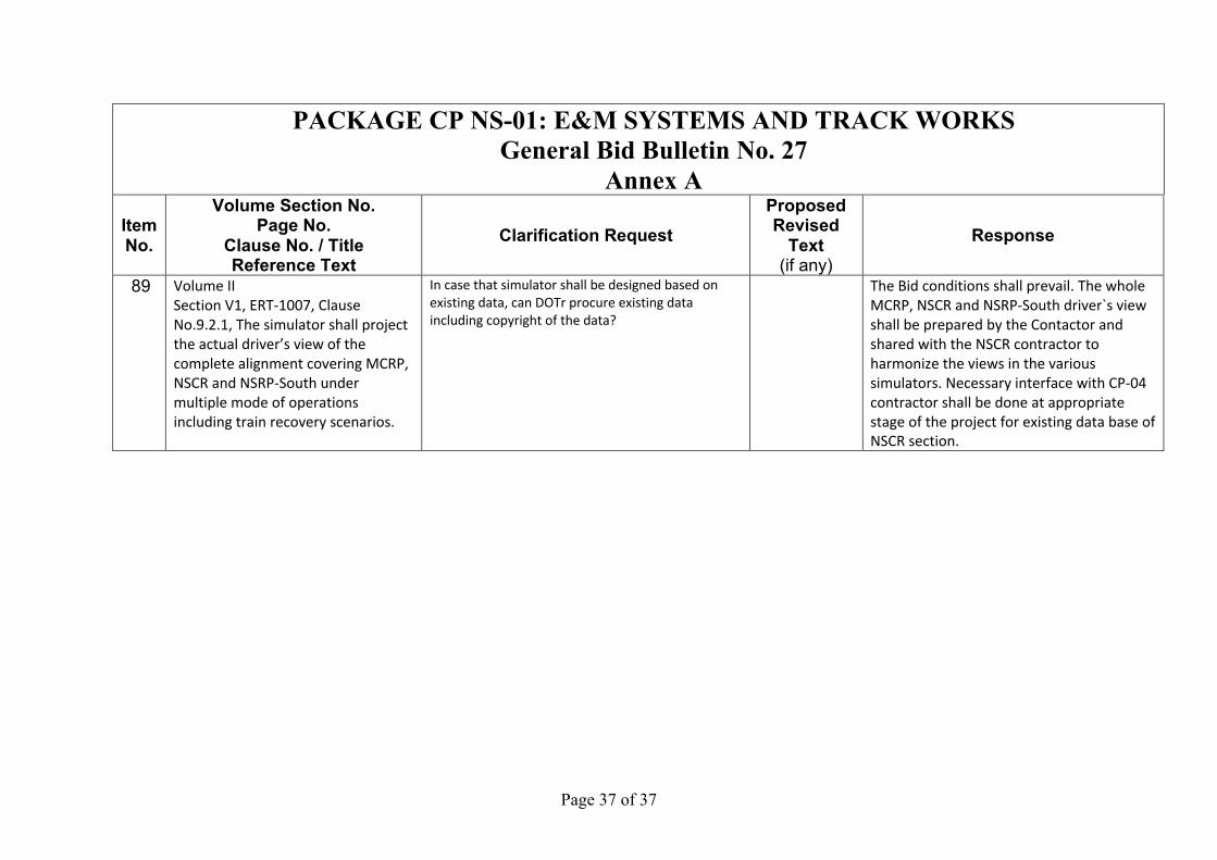
89 Volume II
Section V1, ERT-1007, Clause
No.9.2.1, The simulator shall project
the actual driver’s view of the
complete alignment covering MCRP,
NSCR and NSRP-South under
multiple mode of operations
including train recovery scenarios.
In case that simulator shall be designed based on existing data, can DOTr procure existing data including copyright of the data?
The Bid conditions shall prevail. The whole
MCRP, NSCR and NSRP-South driver`s view
shall be prepared by the Contactor and
shared with the NSCR contractor to
harmonize the views in the various
simulators. Necessary interface with CP-04
contractor shall be done at appropriate
stage of the project for existing data base of
NSCR section.

Annex B

Page 2 of 5
PACKAGE CP NS-01: E&M SYSTEMS AND TRACK WORKS General Bid Bulletin No. 27
Annex B ITEM NO. REFERENCE/CLAUSE/
SECTION REVISIONS / AMENDMENTS
Volume II Part 2 – Employer’s Requirements 1 Part 2 Section VI General
Requirements ERG22 Revised Section (2) Safety for Third Parties.
2 ERT-347:3) Master Clock Unit
Added Statement: “The Master Clock and GPS shall be redundant when the IOCC becomes functional.”
3 ERG-188- MMSP Interface.
Added Statement -CP106 Column: “MMSP’s Master clock system to be installed at FTI & Bicutan stations for respective MMSP Rail Systems utilization.”
4 ERG 5 Clause 2.2 Staff Experience requirements added. 5 ERG 12 . Clause 4.1.5.
Added Clause added regarding contractors plans :” 4.1.4.4.1.5. All plans shall follow the processes stated in, and be coordinate with, the Engineers Procedures.”
6 ERG 19 Clause 4.5.11 Approval requirements expanded for “Subcontractors”. 7 ERG 77. Clause 16.6 New clause added regarding need for communications equipment 8 ERT 1080 Clause 12.2.1,
and 12.2.1 11) and 12.2.3. Clauses amended to specifically state an integrated system and all equipment are to be supplied under contract NS-01.
SBT changed to Solis-Blumentritt-Tutuban. Three phases changed to multiple phases. 9 APPENDIX 6 -
ENGINEERING SAFETY MANAGEMENT PLAN, ERG, Part-2 Section – VI
The clause "SR-100" has been removed from Appendix B Generic Safety Requirements.
10 Chapter 8, Clause 8.9.3.3 Page ERT-709
Revised Clause 8.9.3.3. to read as:

Page 3 of 5
8.9.3.3. Contractor shall supply diesel locomotives (2 units) along with one flat car suitable for mainline operations having maximum 2.95m wide, to recover failed train, 315t, on 3.5% gradient.
11 Chapter 8, Part A of Appendix 8.1, N15.01 Work Lift Platform, Page ERT-790
Added description on clause 2.3 and 4(iv) as below: 2.3. Two lifting platforms shall be installed on the floor along the sides of the car body in each booth. Traveling rails shall be provided in the floor to maintain a constant clearance between the platform and the train. 4(iv). Embedment of traveling rails for work lift platform, floor loading (t/m2) and floor flatness.
12 Chapter 8, Part A of Appendix 8.1, N15.02 Car Body Washing Booth, Page ERT-791
Revised/added description clause 2.5 and 4(vi) as below: 2.5. Floor embedded rail for car body moving will be provided through the booth by the Contractor. 4(vi). Embedment of traveling rails for work lift platforms and track rails for car body moving, floor loading (t/m2) and floor flatness.
13 Chapter 8, Part A of Appendix 8.1, N15.03 Car Body Painting Booth, Page ERT-792
Revised/added description clause 2.5 and 4(vi) as below: 2.5. Floor embedded rail for car body moving will be provided through the booth by the Contractor. 4(vi). Embedment of traveling rails for work lift platforms and track rails for car body moving, floor loading (t/m2) and floor flatness.
14 Chapter 8, Part A of Appendix 8.1, N15.04 Car Body Drying Booth (Include Fuel Tank),
Revised/added description on clause 2.5 and 4(iv) as below: 2.5. Floor embedded rail for car body moving will be provided through the booth by the Contractor.
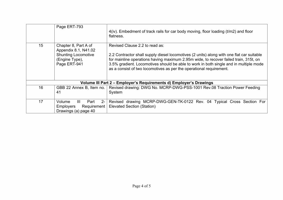
Page 4 of 5
Page ERT-793 4(iv). Embedment of track rails for car body moving, floor loading (t/m2) and floor flatness.
15 Chapter 8, Part A of Appendix 8.1, N41.02 Shunting Locomotive (Engine Type), Page ERT-941
Revised Clause 2.2 to read as:
2.2 Contractor shall supply diesel locomotives (2 units) along with one flat car suitable for mainline operations having maximum 2.95m wide, to recover failed train, 315t, on 3.5% gradient. Locomotives should be able to work in both single and in multiple mode as a consist of two locomotives as per the operational requirement.
Volume III Part 2 – Employer’s Requirements d) Employer’s Drawings 16 GBB 22 Annex B, Item no.
41 Revised drawing: DWG No. MCRP-DWG-PSS-1001 Rev.08 Traction Power Feeding System
17 Volume III Part 2-Employers Requirement Drawings (a) page 40
Revised drawing MCRP-DWG-GEN-TK-0122 Rev. 04 Typical Cross Section For Elevated Section (Station)
Annex B – Attachment 1

The Malolos – Clark Railway Project and the North South Railway Project-South Line (Commuter) CP NS-01: E&M Systems and Track Works
Part 2 – Employer’s Requirements Section V1. Employer’s Requirements
General Requirements
ERG-22
proper retaining wall prevents the collapse of an excavated ditch/pit that may damage an adjacent rail roadbed structure.
Where temporary storages of the construction material and equipment are adjacently located along the railway track, proper clearance between the storages and track shall be kept. This clearance means allocating the storage out of the area of a roadbed level in principle. If the storage will inevitably overlap the roadbed level, the storage shall also be considered that stored goods will not interfere with the train operation in case of a load collapse and scatter.
(2) Safety for Third Parties
It is essential that the hoarding will isolate the construction works from any third party interfacing. The hoarding will consist of existing PNR’s fencing and supported by temporary barriers such as crowd control and traffic barrier. These temporary barriers would be arranged at locations that the third-party individuals could easily enter the works site. Such entry points should be equipped with noticeable information boards and picket guards to ensure that individuals entering the site are well informed.
The traffic diversion for the loading and unloading of materials/equipment into site premises shall be managed in safe manner. The traffic diversion shall consist of traffic barriers, markings, signs, and impact attenuators as necessary. In addition, the traffic personnel shall guide construction working vehicles and direct traffic flow on the road. The management plan of this traffic diversion shall also include obtaining consent from the relevant authorities to mitigate the traffic jam due to the relevant works.
Any utilities that will be affected by the construction works shall be protected. This protection shall comply with the regulations of the relevant authorities such as electricity, telecommunication, water supply, sewerage, gas, and the lands owned by PNR itself. Before executing the protection works, each alignment condition shall carefully be identified with visual inspections and official registers. Especially, underground lines shall ensure the identification accompanied by the trial trench if that alignment condition would be controversial between the record and on-site conditions. This trial trench should also observe to detect abandoned lines with surveillance of the relevant authorities.
(3) Safety organization for prevention of railway accidentsThe security organization for the works in the railway roadbed level shall be establishedin accordance with PNR’s safety regulation. This organization provisionally assigns thefollowing responsible personnel:
1) A Superintendent who is responsible for this organization for the prevention ofaccidents. He is obligated to arrange preventive measures and communicates withthe relevant department such as stations, operation controls, and maintenance incase of emergency.
2) A Foreman who is responsible for the safety instruction and working proceduresof their laborer,
3) A Railway Watchman who is responsible of the approaching/passing train tomotion the personnel for confirming their perception and evacuation, and
4) A Laborer who is instructed to execute the works by the superintendent/foremanconsidering the safety precautions such as the railway track entry, site ambulation,track crossing, prohibition of solo works, and evacuation from theapproaching/passing train.
GBB No. 27
The Malolos – Clark Railway Project and the North South Railway Project-South Line (Commuter) CP NS-01: E&M Systems and Track Works
Part 2 – Employer’s Requirements Section V1. Employer’s Requirements
General Requirements
ERG-22
proper retaining wall prevents the collapse of an excavated ditch/pit that may damage an adjacent rail roadbed structure.
Where temporary storages of the construction material and equipment are adjacently located along the railway track, proper clearance between the storages and track shall be kept. This clearance means allocating the storage out of the area of a roadbed level in principle. If the storage will inevitably overlap the roadbed level, the storage shall also be considered that stored goods will not interfere with the train operation in case of a load collapse and scatter.
(2) Safety for Third Parties
It is essential that the hoarding will isolate the construction works from any third party interfacing with MCRP. The hoarding will consist of existing PNR’s fencing and supported by temporary barriers such as crowd control and traffic barrier. These temporary barriers would be arranged at locations that the third-party individuals could easily enter the works site. Such entry points should be equipped with noticeable information boards and picket guards to ensure that individuals entering the site are well informed.
The traffic diversion for the loading and unloading of materials/equipment into site premises shall be managed in safe manner. The traffic diversion shall consist of traffic barriers, markings, signs, and impact attenuators as necessary. In addition, the traffic personnel shall guide construction working vehicles and direct traffic flow on the road. The management plan of this traffic diversion shall also include obtaining consent from the relevant authorities to mitigate the traffic jam due to the relevant works.
Any utilities that will be affected by the construction works shall be protected. This protection shall comply with the regulations of the relevant authorities such as electricity, telecommunication, water supply, sewerage, gas, and the lands owned by PNR itself. Before executing the protection works, each alignment condition shall carefully be identified with visual inspections and official registers. Especially, underground lines shall ensure the identification accompanied by the trial trench if that alignment condition would be controversial between the record and on-site conditions. This trial trench should also observe to detect abandoned lines with surveillance of the relevant authorities.
(3) Safety organization for prevention of railway accidentsThe security organization for the works in the railway roadbed level shall be establishedin accordance with PNR’s safety regulation. This organization provisionally assigns thefollowing responsible personnel:
1) A Superintendent who is responsible for this organization for the prevention ofaccidents. He is obligated to arrange preventive measures and communicates withthe relevant department such as stations, operation controls, and maintenance incase of emergency.
2) A Foreman who is responsible for the safety instruction and working proceduresof their laborer,
3) A Railway Watchman who is responsible of the approaching/passing train tomotion the personnel for confirming their perception and evacuation, and
4) A Laborer who is instructed to execute the works by the superintendent/foremanconsidering the safety precautions such as the railway track entry, site ambulation,track crossing, prohibition of solo works, and evacuation from the
GBB No. 27

The Malolos – Clark Railway Project and the North South Railway Project-South Line (Commuter) CP NS-01: E&M Systems and Track Works
Part 2 – Employer’s Requirements Section V1. Employer’s Requirements
Technical Requirements - Telecommunications
ERT-347
The antenna shall be waterproof and weather-resistant against direct sunlight, wind, rain, etc.
The antenna shall be installed in an appropriate position that can be confirmed with the eyes. Also, the support of the antenna has a strong structure and the safety rate of wind pressure load is double.
3) Master clock unit
The Master clock unit shall have a GPS receiver function, to acquire accurate time from the GPS.
The Master clock unit converts the signal received from the GPS into SNTP. The Master clock unit distributes time to the systems and the Slave clock of OCC. The Master Clock and GPS shall be redundant when the IOCC becomes functional.
The Master clock unit has crystal (quartz) inside and can hold the exact time by itself.
The Master clock unit distributes time to all sub- Master clock units via the Backbone system.
Network time synchronization over the data network shall be using SNTP, with an accuracy of ± 0.1 s/day to the reference.
4) Sub-Master clock unit
The sub-master clock unit synchronizes with the Master clock unit and distributes the time to the Slave clock.
The sub-Master clock unit has crystal (quartz) inside, and it is possible to hold accurate time by itself.
Network time synchronization over the data network shall be using SNTP, with an accuracy of ± 0.1 s/day to the reference.
5) Clock controller
The Clock controller is necessary when the Slave clock does not have the function of receiving the time directly from the network.
The Clock controller is installed at the OCC and at the stations to make it easy to add and replace the Slave clock.
The Clock controller receives the time from the sub-Master clock unit and multicasts the time to the Slave clock.
Since the clock controller controls the Slave clock, it is not necessary to allocate IP addresses to individual Slave clock at the time of addition or replacement of the Slave clock.
The power of the clock controller shall be powered by PoE conforming to IEEE802.3af.
6) Slave clock
The Slave clock receives the time transmitted from the Master clock unit or the sub- Master clock unit and displays the time in analog or digital form.
The Slave clock is connected to the Master clock unit or the sub- Master clock unit via LAN.
The Slave clock shall have an automatic adjustment function. When the signal is restored after the signal has been interrupted due to a failure of the Master clock unit or the sub Master clock unit or disconnection of the cable, the accurate time must be displayed automatically and immediately.
The Slave clock has a crystal (quartz) inside and the time should be held independently by itself, even if the signal from the Master clock unit or sub- Master clock unit is lost.
GBB No. 27
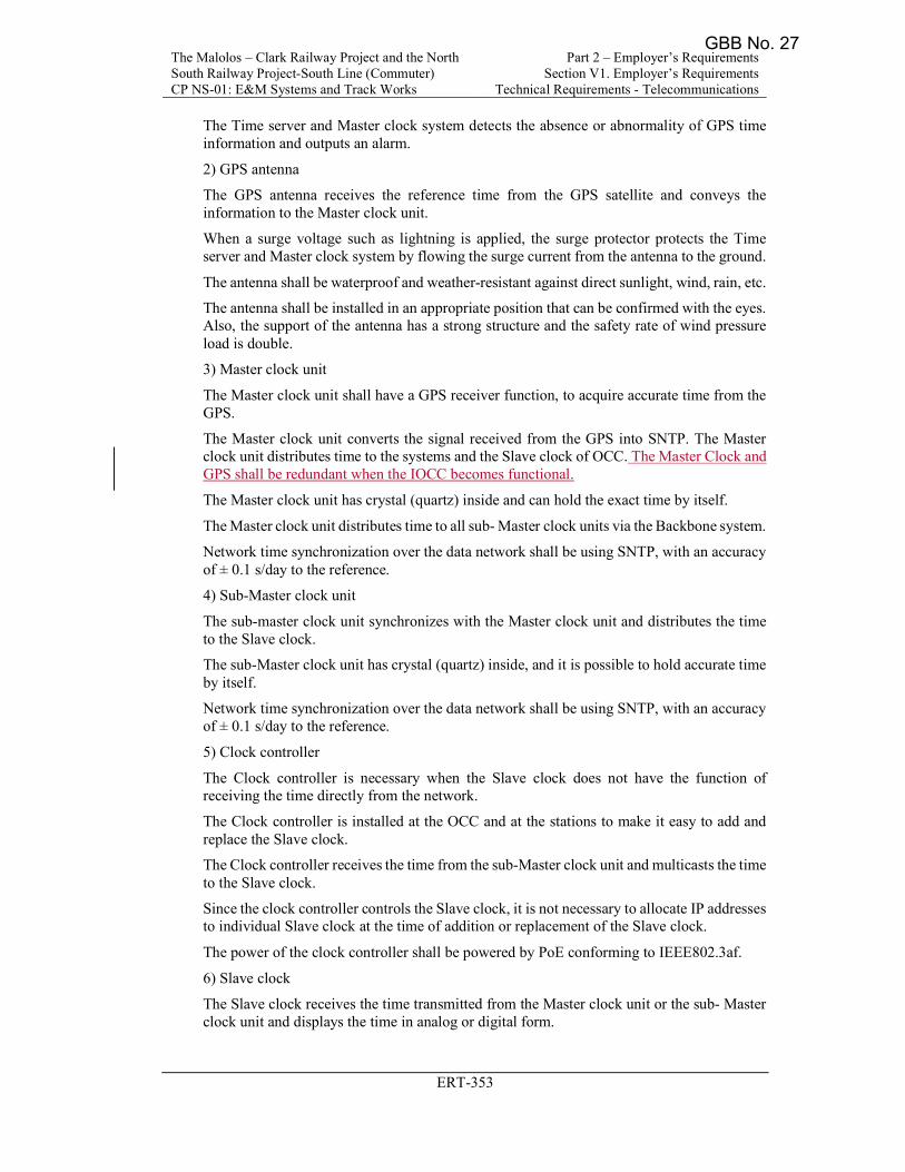
The Malolos – Clark Railway Project and the North South Railway Project-South Line (Commuter) CP NS-01: E&M Systems and Track Works
Part 2 – Employer’s Requirements Section V1. Employer’s Requirements
Technical Requirements - Telecommunications
ERT-353
The Time server and Master clock system detects the absence or abnormality of GPS time information and outputs an alarm.
2) GPS antenna
The GPS antenna receives the reference time from the GPS satellite and conveys the information to the Master clock unit.
When a surge voltage such as lightning is applied, the surge protector protects the Time server and Master clock system by flowing the surge current from the antenna to the ground.
The antenna shall be waterproof and weather-resistant against direct sunlight, wind, rain, etc.
The antenna shall be installed in an appropriate position that can be confirmed with the eyes. Also, the support of the antenna has a strong structure and the safety rate of wind pressure load is double.
3) Master clock unit
The Master clock unit shall have a GPS receiver function, to acquire accurate time from the GPS.
The Master clock unit converts the signal received from the GPS into SNTP. The Master clock unit distributes time to the systems and the Slave clock of OCC. The Master Clock and GPS shall be redundant when the IOCC becomes functional.
The Master clock unit has crystal (quartz) inside and can hold the exact time by itself.
The Master clock unit distributes time to all sub- Master clock units via the Backbone system.
Network time synchronization over the data network shall be using SNTP, with an accuracy of ± 0.1 s/day to the reference.
4) Sub-Master clock unit
The sub-master clock unit synchronizes with the Master clock unit and distributes the time to the Slave clock.
The sub-Master clock unit has crystal (quartz) inside, and it is possible to hold accurate time by itself.
Network time synchronization over the data network shall be using SNTP, with an accuracy of ± 0.1 s/day to the reference.
5) Clock controller
The Clock controller is necessary when the Slave clock does not have the function of receiving the time directly from the network.
The Clock controller is installed at the OCC and at the stations to make it easy to add and replace the Slave clock.
The Clock controller receives the time from the sub-Master clock unit and multicasts the time to the Slave clock.
Since the clock controller controls the Slave clock, it is not necessary to allocate IP addresses to individual Slave clock at the time of addition or replacement of the Slave clock.
The power of the clock controller shall be powered by PoE conforming to IEEE802.3af.
6) Slave clock
The Slave clock receives the time transmitted from the Master clock unit or the sub- Master clock unit and displays the time in analog or digital form.
GBB No. 27

The Malolos – Clark Railway Project and the North South Railway Project-South Line (Commuter) CP NS-01: E&M Systems and Track Works
Part 2 – Employer’s Requirements Section V1. Employer’s Requirements
General Requirements
ERG-188
Discipline MMSP INTERFACE NS-01 CP106 NS-01 CP107
with CP106 for all Telecom Systems works. NS-01 will facilitate and provide all Telecom Systems work terminations for CP106 either or both at FTI and Bicutan Stations.
NS-01 will provide connectivity for the Backbone, Radio Systems (GSM-R), PABX, PA System.
NS-01 will supply, install, test, and commission the clocks for FTI and Bicutan stations. Excluding the clocks on FTI’s MMSP Platform.
NS-01 shall interface with CP106 for their Banlic Depot TETRA infrastructure requirements.
NS-01 shall provide Backbone Facilities for the TETRA Radio Infrastructure to be connected from Banlic Depot to the Backbone Switch at Bicutan.
with NS-01 for all Telecom Systems works. CP106 will terminate all Telecom Systems work termination to NS-01 either or both at FTI and Bicutan Stations.
CP106 will supply all equipment to connect to the NSCR backbone system.
CP106 will supply, install, test, and commission the equipment for Millimeter-wave, Backbone Radio System (CBTC), PABX, PIDS.
MMSP’s Master clock system to be installed at FTI & Bicutan stations for respective MMSP Rail Systems utilization.
CP106 shall interface with NS-01 for their Valenzuela Depot Test and Transfer Track for GSMR infrastructure requirements.
CP106 shall provide Backbone
commission GSM-R radio on CP107 Rolling stock. For this purpose, NS-01 shall develop an interface matrix for all related aspects with CP107 matrix and interface at all stages of the project with NS-01
NS01 shall supply on board Telecom equipment for Driving Operation Simulator and interface with CP107 as stipulated in the Signaling clause (below).
(Please refer to Clause 2.26.10.2.4 in the Signalling Bidding Documents.)
matrix and interface at all stages of the project with NS-01.
CP107 will install the GSM-R onboard equipment succeeding trains following the installation on the initial rolling stock.
CP107 and NS01 shall coordinate on the on board Telecom equipment for the Driving Operation Simulator.
(Please refer to Clause 2.26.10.2.4 in the Signalling Bidding Documents.)
GBB No. 27
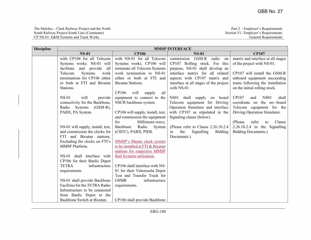
The Malolos – Clark Railway Project and the North South Railway Project-South Line (Commuter) CP NS-01: E&M Systems and Track Works
Part 2 – Employer’s Requirements Section V1. Employer’s Requirements
General Requirements
ERG-188
Discipline MMSP INTERFACE NS-01 CP106 NS-01 CP107
with CP106 for all Telecom Systems works. NS-01 will facilitate and provide all Telecom Systems work terminations for CP106 either or both at FTI and Bicutan Stations. NS-01 will provide connectivity for the Backbone, Radio Systems (GSM-R), PABX, PA System. NS-01 will supply, install, test, and commission the clocks for FTI and Bicutan stations. Excluding the clocks on FTI’s MMSP Platform. NS-01 shall interface with CP106 for their Banlic Depot TETRA infrastructure requirements. NS-01 shall provide Backbone Facilities for the TETRA Radio Infrastructure to be connected from Banlic Depot to the Backbone Switch at Bicutan.
with NS-01 for all Telecom Systems works. CP106 will terminate all Telecom Systems work termination to NS-01 either or both at FTI and Bicutan Stations. CP106 will supply all equipment to connect to the NSCR backbone system. CP106 will supply, install, test, and commission the equipment for Millimeter-wave, Backbone Radio System (CBTC), PABX, PIDS. MMSP’s Master clock system to be installed at FTI & Bicutan stations for respective MMSP Rail Systems utilization. CP106 shall interface with NS-01 for their Valenzuela Depot Test and Transfer Track for GSMR infrastructure requirements. CP106 shall provide Backbone
commission GSM-R radio on CP107 Rolling stock. For this purpose, NS-01 shall develop an interface matrix for all related aspects with CP107 matrix and interface at all stages of the project with NS-01 NS01 shall supply on board Telecom equipment for Driving Operation Simulator and interface with CP107 as stipulated in the Signaling clause (below).
(Please refer to Clause 2.26.10.2.4 in the Signalling Bidding Documents.)
matrix and interface at all stages of the project with NS-01. CP107 will install the GSM-R onboard equipment succeeding trains following the installation on the initial rolling stock. CP107 and NS01 shall coordinate on the on board Telecom equipment for the Driving Operation Simulator.
(Please refer to Clause 2.26.10.2.4 in the Signalling Bidding Documents.)
GBB No. 27

The Malolos – Clark Railway Project and the North
South Railway Project-South Line (Commuter)
CP NS-01: E&M Systems and Track Works
Part 2 – Employer’s Requirements
Section V1. Employer’s Requirements
General Requirements
ERG-5
Contractor identifies as being at risk, and any action required to be undertaken by the
Engineer shall support the Mobilization Program.
2.2. Mobilization Requirements
Mobilization shall consist of preparatory and execution works and operations, including but not necessarily limited to, those necessary for the movement of personnel, equipment,
supplies, and incidentals to the work site; for the establishment of offices, buildings, and
other facilities necessary to commence work on the Project; and for other work and operations which must be performed, or costs incurred prior to beginning work on the
various contract items on the project site.
Mobilization shall include providing submittals as detailed in Appendix 4 and elsewhere in this document. This will include the proposed Organization Chart and Curriculum
Vitae’s of all key staff that shall be submitted for approval by the Engineer. Staff shall
possess the minimum experience requirements as stated below:
Position Total Work
Experience
Experience in Railway
Project
1. Project Manager (PM)
1-PM for all sections
20 years 10 years for E&M
systems works and 2
projects as PM or Deputy
Project Manager (DPM)
or similar position
2. Section Manager
Minimum 2 Managers:
1 for Section 1 and 2
1 for Section 3 and 4
20 years 10 years as E&M systems
engineer and 2 projects as
Deputy Project Manager (DPM) or similar
position.
3. Manager for System
Integration
Minimum 1 Manager
20 years 10 years as E&M systems
engineer and 2 projects as
integrator
4. Technical Director (Railway
System)
Minimum 1 Manager
15 years 10 years as E&M systems
engineer and 2 projects as
manager
5. Track Works Engineer
Minimum 1 Manager
15 years 10 years as Track Works
engineer in Railway
Project
6. Signaling Engineer
Minimum 2 Engineers:
1 for Section 1 and 2
1 for Section 3 and 4
15 years 10 years as Signaling
engineer
GBB No. 27
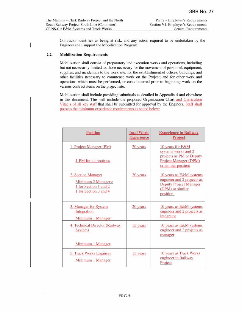
The Malolos – Clark Railway Project and the North
South Railway Project-South Line (Commuter)
CP NS-01: E&M Systems and Track Works
Part 2 – Employer’s Requirements
Section V1. Employer’s Requirements
General Requirements
ERG-5
Contractor identifies as being at risk, and any action required to be undertaken by the
Engineer shall support the Mobilization Program.
2.2. Mobilization Requirements
Mobilization shall consist of preparatory and execution works and operations, including but not necessarily limited to, those necessary for the movement of personnel, equipment,
supplies, and incidentals to the work site; for the establishment of offices, buildings, and
other facilities necessary to commence work on the Project; and for other work and operations which must be performed, or costs incurred prior to beginning work on the
various contract items on the project site.
Mobilization shall include providing submittals as detailed in Appendix 4 and elsewhere in this document. This will include the proposed Organization Chart and Curriculum
Vitae’s of all key staff that shall be submitted for approval by the Engineer. Staff shall
possess the minimum experience requirements as stated below:
Position Total Work
Experience
Experience in Railway
Project
1. Project Manager (PM)
1-PM for all sections
20 years 10 years for E&M
systems works and 2
projects as PM or Deputy
Project Manager (DPM)
or similar position
2. Section Manager
Minimum 2 Managers:
1 for Section 1 and 2
1 for Section 3 and 4
20 years 10 years as E&M systems
engineer and 2 projects as
Deputy Project Manager
(DPM) or similar
position.
3. Manager for System
Integration
Minimum 1 Manager
20 years 10 years as E&M systems
engineer and 2 projects as
integrator
4. Technical Director (Railway
System)
Minimum 1 Manager
15 years 10 years as E&M systems
engineer and 2 projects as
manager
5. Track Works Engineer
Minimum 1 Manager
15 years 10 years as Track Works
engineer in Railway
Project
GBB No. 27
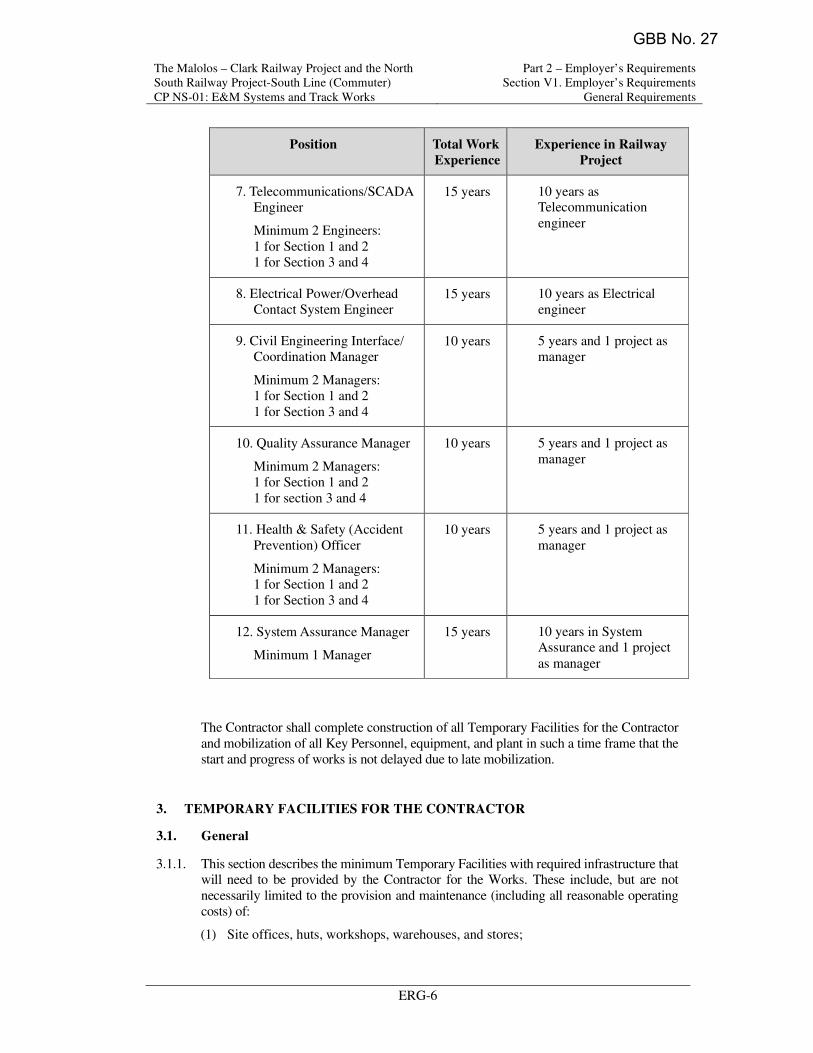
The Malolos – Clark Railway Project and the North
South Railway Project-South Line (Commuter)
CP NS-01: E&M Systems and Track Works
Part 2 – Employer’s Requirements
Section V1. Employer’s Requirements
General Requirements
ERG-6
Position Total Work
Experience
Experience in Railway
Project
7. Telecommunications/SCADA
Engineer
Minimum 2 Engineers:
1 for Section 1 and 2
1 for Section 3 and 4
15 years 10 years as Telecommunication
engineer
8. Electrical Power/Overhead
Contact System Engineer 15 years 10 years as Electrical
engineer
9. Civil Engineering Interface/
Coordination Manager
Minimum 2 Managers:
1 for Section 1 and 2
1 for Section 3 and 4
10 years 5 years and 1 project as
manager
10. Quality Assurance Manager
Minimum 2 Managers:
1 for Section 1 and 2
1 for section 3 and 4
10 years 5 years and 1 project as
manager
11. Health & Safety (Accident
Prevention) Officer
Minimum 2 Managers: 1 for Section 1 and 2
1 for Section 3 and 4
10 years 5 years and 1 project as
manager
12. System Assurance Manager
Minimum 1 Manager
15 years 10 years in System Assurance and 1 project
as manager
The Contractor shall complete construction of all Temporary Facilities for the Contractor
and mobilization of all Key Personnel, equipment, and plant in such a time frame that the
start and progress of works is not delayed due to late mobilization.
3. TEMPORARY FACILITIES FOR THE CONTRACTOR
3.1. General
3.1.1. This section describes the minimum Temporary Facilities with required infrastructure that will need to be provided by the Contractor for the Works. These include, but are not
necessarily limited to the provision and maintenance (including all reasonable operating
costs) of:
(1) Site offices, huts, workshops, warehouses, and stores;
GBB No. 27
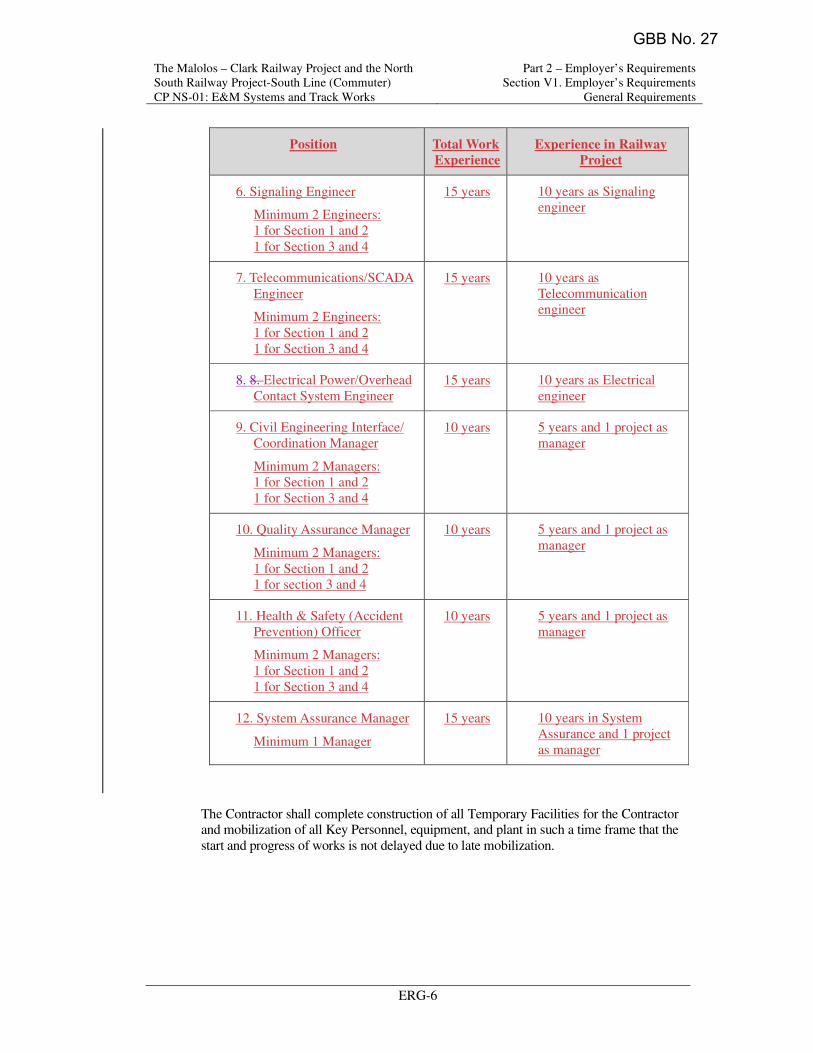
The Malolos – Clark Railway Project and the North
South Railway Project-South Line (Commuter)
CP NS-01: E&M Systems and Track Works
Part 2 – Employer’s Requirements
Section V1. Employer’s Requirements
General Requirements
ERG-6
Position Total Work
Experience
Experience in Railway
Project
6. Signaling Engineer
Minimum 2 Engineers:
1 for Section 1 and 2
1 for Section 3 and 4
15 years 10 years as Signaling
engineer
7. Telecommunications/SCADA
Engineer
Minimum 2 Engineers:
1 for Section 1 and 2
1 for Section 3 and 4
15 years 10 years as
Telecommunication
engineer
8. 8. Electrical Power/Overhead
Contact System Engineer
15 years 10 years as Electrical
engineer
9. Civil Engineering Interface/
Coordination Manager
Minimum 2 Managers:
1 for Section 1 and 2
1 for Section 3 and 4
10 years 5 years and 1 project as
manager
10. Quality Assurance Manager
Minimum 2 Managers:
1 for Section 1 and 2
1 for section 3 and 4
10 years 5 years and 1 project as
manager
11. Health & Safety (Accident
Prevention) Officer
Minimum 2 Managers:
1 for Section 1 and 2
1 for Section 3 and 4
10 years 5 years and 1 project as
manager
12. System Assurance Manager
Minimum 1 Manager
15 years 10 years in System
Assurance and 1 project
as manager
The Contractor shall complete construction of all Temporary Facilities for the Contractor and mobilization of all Key Personnel, equipment, and plant in such a time frame that the
start and progress of works is not delayed due to late mobilization.
GBB No. 27

The Malolos – Clark Railway Project and the North
South Railway Project-South Line (Commuter)
CP NS-01: E&M Systems and Track Works
Part 2 – Employer’s Requirements
Section V1. Employer’s Requirements
General Requirements
ERG-12
4.1.2. The plans and documents shall be coordinated with each other and shall collectively define, describe and encompass the Contractor's proposed methods, procedures,
processes, organization, and sequencing of activities to meet the requirements of the
Employer’s Requirement - Technical Requirements (ERT) in respect of the subjects listed.
4.1.3. The respective Plans shall be submitted for the Engineer’s Approval as per the
submission schedule furnished in Table 4-1 of Appendix 4 attached hereto.
4.1.4. All Plans shall be updated and resubmitted at an interval of between 6 to 12 months as approved by the Engineer.
4.1.5. All plans shall follow the processes stated in, and be coordinate with, the Engineers
Procedures.
4.2. Project Management Plan
4.2.1. The Contractor shall submit a Project Management Plan, which shall provide a clear overview of the Contractor's organization, the management system, and methods to be
used for completion of the Works. The organization resources for the design,
procurement, manufacture, installation, testing and commissioning, and setting to work, shall be clearly defined.
4.2.2. The Contractor shall submit the Project Management Plan for the Engineer’s Approval
as per schedule of Table 4-1 of Appendix 4 attached to hereto. The Engineer will review the Contractor's Project Management Plan and will have the right to require the
Contractor to make amendments as deemed necessary. The Contractor shall submit a
detailed revised plan within 15 days of the review of the Engineer. The Project Management Plan shall include;
(1) A diagram showing the organizational structure for the management of the Contract,
with locations, names, and position titles of Key Personnel and their line and staff relationship. The diagram shall include associate organizations and subcontractors
and show clearly the individuals and lines of responsibility linking the various
groups. It shall also identify the persons designated as contacts with the Engineer.
All Key Personnel and those holding senior positions, as designated by the Engineer,
shall be given a Notice of No Objection prior to their engagement and mobilization.
Approval may be withdrawn at any time in the event of incompetence, non-
performance, or misconduct. Any person so removed shall be replaced without delay
by a substitute given a Notice of No Objection by the Engineer. The Contractor shall
not be entitled to any claim for any expenses whatsoever incurred by him in respect
of any direction given by the Engineer under this Clause nor any claim for extension of time arising from this Clause. All Key Personnel shall be employed on a full-time
basis until the issuance of the final Taking Over Certificate or such other time as the
Engineer may instruct.
(2) The names, qualifications, positions, and current resumes of key executive,
supervisory, and engineering staff to be employed full-time for the works, separately
for principals and subcontractors.
(3) A narrative describing the sequence, nature, and inter-relationship of the main
Contract activities including timing for exchange of information.
(4) The Deputy Project Manager shall coordinate activities of the design offices and manufacturing works. The Deputy Project Manager shall be responsible to the
Project Manager for all works executed outside the Republic of the Philippines and
GBB No. 27

The Malolos – Clark Railway Project and the North
South Railway Project-South Line (Commuter)
CP NS-01: E&M Systems and Track Works
Part 2 – Employer’s Requirements
Section V1. Employer’s Requirements
General Requirements
ERG-12
series of Contractor’s Management Plans shall be developed.
4.1.2. The plans and documents shall be coordinated with each other and shall collectively
define, describe and encompass the Contractor's proposed methods, procedures,
processes, organization, and sequencing of activities to meet the requirements of the
Employer’s Requirement - Technical Requirements (ERT) in respect of the subjects
listed.
4.1.3. The respective Plans shall be submitted for the Engineer’s Approval as per the
submission schedule furnished in Table 4-1 of Appendix 4 attached hereto.
4.1.4. All Plans shall be updated and resubmitted at an interval of between 6 to 12 months as
approved by the Engineer.
4.1.4.4.1.5. All plans shall follow the processes stated in, and be coordinate with, the Engineers Procedures.
4.2. Project Management Plan
4.2.1. The Contractor shall submit a Project Management Plan, which shall provide a clear
overview of the Contractor's organization, the management system, and methods to be
used for completion of the Works. The organization resources for the design,
procurement, manufacture, installation, testing and commissioning, and setting to work,
shall be clearly defined.
4.2.2. The Contractor shall submit the Project Management Plan for the Engineer’s Approval as per schedule of Table 4-1 of Appendix 4 attached to hereto. The Engineer will review
the Contractor's Project Management Plan and will have the right to require the
Contractor to make amendments as deemed necessary. The Contractor shall submit a
detailed revised plan within 15 days of the review of the Engineer. The Project
Management Plan shall include;
(1) A diagram showing the organizational structure for the management of the Contract, with locations, names, and position titles of Key Personnel and their line and staff
relationship. The diagram shall include associate organizations and subcontractors
and show clearly the individuals and lines of responsibility linking the various
groups. It shall also identify the persons designated as contacts with the Engineer.
All Key Personnel and those holding senior positions, as designated by the Engineer,
shall be given a Notice of No Objection prior to their engagement and mobilization.
Approval may be withdrawn at any time in the event of incompetence, non-
performance, or misconduct. Any person so removed shall be replaced without delay
by a substitute given a Notice of No Objection by the Engineer. The Contractor shall
not be entitled to any claim for any expenses whatsoever incurred by him in respect of any direction given by the Engineer under this Clause nor any claim for extension
of time arising from this Clause. All Key Personnel shall be employed on a full-time
basis until the issuance of the final Taking Over Certificate or such other time as the Engineer may instruct.
(2) The names, qualifications, positions, and current resumes of key executive,
supervisory, and engineering staff to be employed full-time for the works, separately
for principals and subcontractors.
(3) A narrative describing the sequence, nature, and inter-relationship of the main
Contract activities including timing for exchange of information.
(4) The Deputy Project Manager shall coordinate activities of the design offices and
GBB No. 27

The Malolos – Clark Railway Project and the North
South Railway Project-South Line (Commuter)
CP NS-01: E&M Systems and Track Works
Part 2 – Employer’s Requirements
Section V1. Employer’s Requirements
General Requirements
ERG-19
during which they will be prepared and the subsequent period and manner in which
they will be stored;
(6) Quality Control Points and Quality Hold Points during verification, surveillance,
tests, trial, and commissioning activities;
(7) Procedure for maintenance of records of inspection/tests.
4.5.6. The Quality Assurance System shall be applied without prejudice to, or without in any
way limiting, any Quality Assurance System that the Contractor already maintains.
4.5.7. The Contractor shall maintain the Quality Assurance Management Plan updated during the course of the execution of the Contract. All amendments to the original and approved
Quality Assurance Management Plan shall be notified to the Engineer. The quality plan
shall comprise:
(1) A Management Quality Plan for control of management related activities;
(2) A Design Quality Plan for control of design-related activities;
(3) A Manufacturing (including Inspection and Testing) Quality Plan for the control of related activities;
(4) Testing and Commissioning (including Integrated Testing and Commissioning)
Quality Plan.
4.5.8. The Contractor shall submit a detailed organization chart identifying the responsibilities, authority, and interrelation of all personnel who manage, perform, and verify work
involving quality in respect of all the Quality Plans. The organization chart shall be
specific to this Contract. The chart shall identify the Quality Management Representative who shall act as the Quality Coordinator for the Contractor in all dealings with the
Engineer.
4.5.9. The Contractor shall audit all the activities in each Quality Plan at quarterly intervals or other such intervals as the Engineer may require ensuring the continuing suitability and
effectiveness of the quality management system. The Contractor shall make available
upon request any document, which relates to his recent internal audits.
4.5.10. The Engineer will require compliance audits of the Contractor's and suppliers’ quality system to be conducted. Not less than two (2) weeks a notice will be given by the
Engineer. During audits, the Contractor shall provide suitably qualified staff to
accompany the auditors.
4.5.11. All suppliers and subcontractors used by the contractor shall be given a Notice of No
Objection prior to the commencement of the manufacture and commencement of their
works. A detailed submission for each supplier and subcontractor shall be made which shall include as a minimum, scope of works, company organization, experience in
supplying product or service, and quality management systems. Supplier familiarization
visits, Quality Inspections at the manufacturer’s facilities, First Article inspections, Type
Tests, Routines Tests, and Factory Acceptance Tests shall be undertaken for all material
and equipment to be supplied for this contract. For all these inspections and tests a
maximum of four people will attend from the Employer and Engineer. All costs
associated with these inspections either offshore or onshore including transportation,
accommodation, insurances, expense, etc. for the Employers and Engineers staff shall be
borne by the Contractor.
GBB No. 27
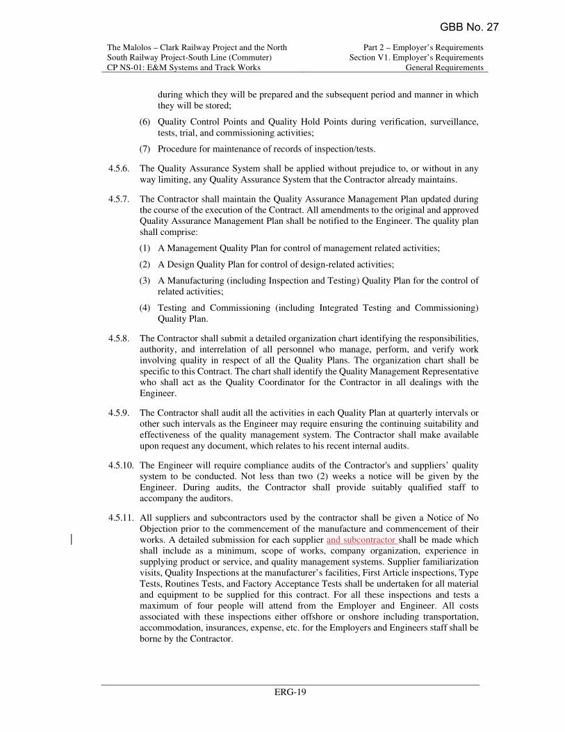
The Malolos – Clark Railway Project and the North
South Railway Project-South Line (Commuter)
CP NS-01: E&M Systems and Track Works
Part 2 – Employer’s Requirements
Section V1. Employer’s Requirements
General Requirements
ERG-19
during which they will be prepared and the subsequent period and manner in which
they will be stored;
(6) Quality Control Points and Quality Hold Points during verification, surveillance,
tests, trial, and commissioning activities;
(7) Procedure for maintenance of records of inspection/tests.
4.5.6. The Quality Assurance System shall be applied without prejudice to, or without in any
way limiting, any Quality Assurance System that the Contractor already maintains.
4.5.7. The Contractor shall maintain the Quality Assurance Management Plan updated during the course of the execution of the Contract. All amendments to the original and approved
Quality Assurance Management Plan shall be notified to the Engineer. The quality plan
shall comprise:
(1) A Management Quality Plan for control of management related activities;
(2) A Design Quality Plan for control of design-related activities;
(3) A Manufacturing (including Inspection and Testing) Quality Plan for the control of related activities;
(4) Testing and Commissioning (including Integrated Testing and Commissioning)
Quality Plan.
4.5.8. The Contractor shall submit a detailed organization chart identifying the responsibilities, authority, and interrelation of all personnel who manage, perform, and verify work
involving quality in respect of all the Quality Plans. The organization chart shall be
specific to this Contract. The chart shall identify the Quality Management Representative who shall act as the Quality Coordinator for the Contractor in all dealings with the
Engineer.
4.5.9. The Contractor shall audit all the activities in each Quality Plan at quarterly intervals or other such intervals as the Engineer may require ensuring the continuing suitability and
effectiveness of the quality management system. The Contractor shall make available
upon request any document, which relates to his recent internal audits.
4.5.10. The Engineer will require compliance audits of the Contractor's and suppliers’ quality system to be conducted. Not less than two (2) weeks a notice will be given by the
Engineer. During audits, the Contractor shall provide suitably qualified staff to
accompany the auditors.
4.5.11. All suppliers and subcontractors used by the contractor shall be given a Notice of No
Objection prior to the commencement of the manufacture and commencement of their
works. A detailed submission for each supplier and subcontractor shall be made which shall include as a minimum, scope of works, company organization, experience in
supplying product or service, and quality management systems. Supplier familiarization
visits, Quality Inspections at the manufacturer’s facilities, First Article inspections, Type
Tests, Routines Tests, and Factory Acceptance Tests shall be undertaken for all material
and equipment to be supplied for this contract. For all these inspections and tests a
maximum of four people will attend from the Employer and Engineer. All costs
associated with these inspections either offshore or onshore including transportation,
accommodation, insurances, expense, etc. for the Employers and Engineers staff shall be
borne by the Contractor.
GBB No. 27
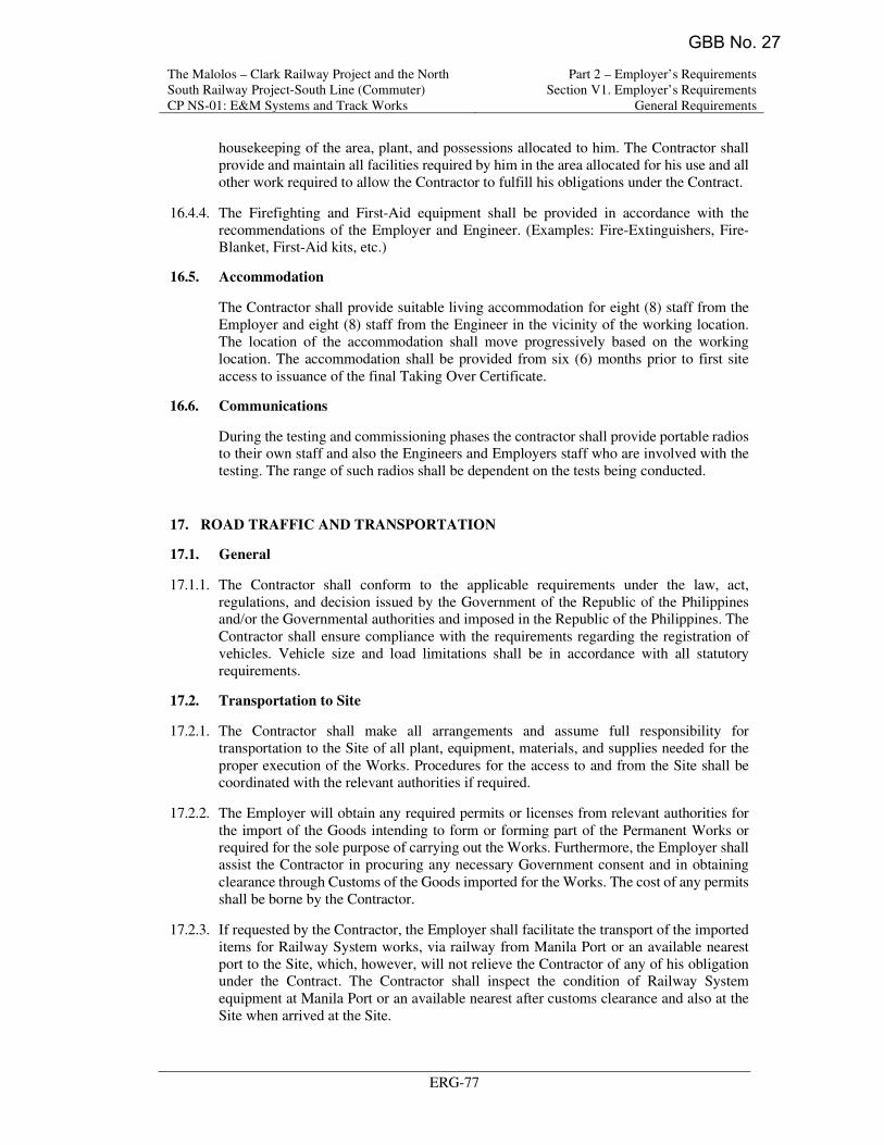
The Malolos – Clark Railway Project and the North
South Railway Project-South Line (Commuter)
CP NS-01: E&M Systems and Track Works
Part 2 – Employer’s Requirements
Section V1. Employer’s Requirements
General Requirements
ERG-77
housekeeping of the area, plant, and possessions allocated to him. The Contractor shall
provide and maintain all facilities required by him in the area allocated for his use and all
other work required to allow the Contractor to fulfill his obligations under the Contract.
16.4.4. The Firefighting and First-Aid equipment shall be provided in accordance with the
recommendations of the Employer and Engineer. (Examples: Fire-Extinguishers, Fire-
Blanket, First-Aid kits, etc.)
16.5. Accommodation
The Contractor shall provide suitable living accommodation for eight (8) staff from the
Employer and eight (8) staff from the Engineer in the vicinity of the working location.
The location of the accommodation shall move progressively based on the working
location. The accommodation shall be provided from six (6) months prior to first site
access to issuance of the final Taking Over Certificate.
16.6. Communications
During the testing and commissioning phases the contractor shall provide portable radios
to their own staff and also the Engineers and Employers staff who are involved with the
testing. The range of such radios shall be dependent on the tests being conducted.
17. ROAD TRAFFIC AND TRANSPORTATION
17.1. General
17.1.1. The Contractor shall conform to the applicable requirements under the law, act,
regulations, and decision issued by the Government of the Republic of the Philippines
and/or the Governmental authorities and imposed in the Republic of the Philippines. The
Contractor shall ensure compliance with the requirements regarding the registration of
vehicles. Vehicle size and load limitations shall be in accordance with all statutory
requirements.
17.2. Transportation to Site
17.2.1. The Contractor shall make all arrangements and assume full responsibility for
transportation to the Site of all plant, equipment, materials, and supplies needed for the
proper execution of the Works. Procedures for the access to and from the Site shall be
coordinated with the relevant authorities if required.
17.2.2. The Employer will obtain any required permits or licenses from relevant authorities for
the import of the Goods intending to form or forming part of the Permanent Works or
required for the sole purpose of carrying out the Works. Furthermore, the Employer shall
assist the Contractor in procuring any necessary Government consent and in obtaining
clearance through Customs of the Goods imported for the Works. The cost of any permits
shall be borne by the Contractor.
17.2.3. If requested by the Contractor, the Employer shall facilitate the transport of the imported
items for Railway System works, via railway from Manila Port or an available nearest
port to the Site, which, however, will not relieve the Contractor of any of his obligation
under the Contract. The Contractor shall inspect the condition of Railway System
equipment at Manila Port or an available nearest after customs clearance and also at the
Site when arrived at the Site.
GBB No. 27

The Malolos – Clark Railway Project and the North
South Railway Project-South Line (Commuter)
CP NS-01: E&M Systems and Track Works
Part 2 – Employer’s Requirements
Section V1. Employer’s Requirements
General Requirements
ERG-77
17.4.3.16.4.3. If lighting is not provided in the specific areas allocated to the Contractor, he should
make his own arrangements. The Contractor shall be solely responsible for the security
and housekeeping of the area, plant, and possessions allocated to him. The Contractor
shall provide and maintain all facilities required by him in the area allocated for his use
and all other work required to allow the Contractor to fulfill his obligations under the
Contract.
17.4.4.16.4.4. The Firefighting and First-Aid equipment shall be provided in accordance with the
recommendations of the Employer and Engineer. (Examples: Fire-Extinguishers, Fire-
Blanket, First-Aid kits, etc.)
17.5.16.5. Accommodation
The Contractor shall provide suitable living accommodation for eight (8) staff from the
Employer and eight (8) staff from the Engineer in the vicinity of the working location.
The location of the accommodation shall move progressively based on the working
location. The accommodation shall be provided from six (6) months prior to first site
access to issuance of the final Taking Over Certificate.
16.6. Communications
During the testing and commissioning phases the contractor shall provide portable radios
to their own staff and also the Engineers and Employers staff who are involved with the
testing. The range of such radios shall be dependent on the tests being conducted.
18.17. ROAD TRAFFIC AND TRANSPORTATION
18.1.17.1. General
18.1.1.17.1.1. The Contractor shall conform to the applicable requirements under the law, act,
regulations, and decision issued by the Government of the Republic of the Philippines
and/or the Governmental authorities and imposed in the Republic of the Philippines. The
Contractor shall ensure compliance with the requirements regarding the registration of
vehicles. Vehicle size and load limitations shall be in accordance with all statutory
requirements.
18.2.17.2. Transportation to Site
18.2.1.17.2.1. The Contractor shall make all arrangements and assume full responsibility for
transportation to the Site of all plant, equipment, materials, and supplies needed for the
proper execution of the Works. Procedures for the access to and from the Site shall be
coordinated with the relevant authorities if required.
18.2.2.17.2.2. The Employer will obtain any required permits or licenses from relevant authorities
for the import of the Goods intending to form or forming part of the Permanent Works or
required for the sole purpose of carrying out the Works. Furthermore, the Employer shall
assist the Contractor in procuring any necessary Government consent and in obtaining
clearance through Customs of the Goods imported for the Works. The cost of any permits
shall be borne by the Contractor.
18.2.3.17.2.3. If requested by the Contractor, the Employer shall facilitate the transport of the
imported items for Railway System works, via railway from Manila Port or an available
nearest port to the Site, which, however, will not relieve the Contractor of any of his
GBB No. 27

The Malolos – Clark Railway Project and the North
South Railway Project-South Line (Commuter)
CP NS-01: E&M Systems and Track Works
Part 2 – Employer’s Requirements
Section V1. Employer’s Requirements
Technical Requirements – IOCC
ERT - 1070
12 \INTEGRATED OPERATIONAL CONTROL CENTER
AND DEPOT CONTROL CENTER
Introduction
The complete E & M systems for the Clark International Airport to Calamba line will ultimately
be controlled from an Integrated Operations Control Center (IOCC) located at Mabalacat Depot
provided by the Contractor. The contractor shall take the lead in the interface of the IOCC. The
existing OCC theatre at Mabalacat will be designed and upgraded to IOCC. Therefore, the
Mabalacat OCC shall be designed keeping in view the future requirement of IOCC and adequate
provision for all facilities will be provided from the beginning for use of the Mabalacat theatre
as IOCC at later stage.
As the railway is progressively commissioned, the various control and monitoring functions
will be implemented from individual OCC’s and then ultimately migrated to the IOCC as
follows:
i) NSCR will initially be controlled from an OCC at Malanday Depot in Valenzuela,
ii) MCRP will initially be controlled from the OCC at Mabalacat Depot.
iii) NSRP – South will initially be controlled from an OCC at Banlic.
The control of system from Malolos to Solis which is controlled from the OCC within Malanday
Depot will eventually be transferred to the Integrated Control Center (IOCC) located in
Mabalacat Depot, The Contractor shall allow provision for the seamless switchover of control
from the OCC in Malanday to the Integrated Operation Control Center. The Contractor shall
submit in their design how this will be achieved in coordination with the NSCR E&M System
Contractor.
Each Depot (Mabalacat and Banlic) shall have its own Depot Control Center (DCC). The
Contractor shall provide E&M facilities in the Depot for efficient operations and management.
Scope of Works
The Contractor shall supply all workstations and systems to combine and consolidate all E&M
railway control systems along the route between CIA and Calamba to allow central integrated
control of all sections of the line from Calamba to CIA from the IOCC at Mabalacat. which
includes:
1. An Integrated ATS and OCC to unify the operational control and monitoring of the three
lines N1, N2 and SC
2. Power Supply monitoring and control
3. Passenger Information Displays and PA system
4. Centralized Radio Management and dispatcher for complete line
5. Centralized alarms for disaster management
6. Common video wall to cover display of track layout with train status, Power SCADA and
CCTV
7. Centralized trackside alarms management
8. NMS for all subsystems
9. Suitable positions and seating arrangement for all IOCC functions
10. Centralized CMMS
11. Also included to be integrated are systems outside of the E&M systems like BMS which
uses the Backbone Transmission Network. The Contractor shall integrate the Central BMS
GBB No. 27

The Malolos – Clark Railway Project and the North
South Railway Project-South Line (Commuter)
CP NS-01: E&M Systems and Track Works
Part 2 – Employer’s Requirements
Section V1. Employer’s Requirements
Technical Requirements – IOCC
ERT - 1071
which is provided by other contractors that resides in each OCC for N1, N2, and SC shall
be combined and consolidate to the IOCC. The Contractor shall supply all necessary
equipment to fully integrate and consolidate all of the Control and Monitoring Systems that
can be combined such as the P-SCADA and BMS which shall all be integrated at the IOCC.
12. PABX and Landline telephones for communication with all stations, Depots and adjacent
railway/MRTS lines
13. Backbone requirements for all operational systems for N1, N2 and SC to be connected to
IOCC.
The contractor shall comply with the requirements covered in other chapters of ERT.
The Contractor shall prepare and implement the requirements of a detailed Migration Plan
covering strategy, timeline, testing, and decommissioning during the transfer of the OCC
functions to the IOCC. The IOCC shall be commissioned progressively as the sections are
connected so as to form contiguous line from CIA station/Mabalacat Depot towards South. The
IOCC shall connect to N1 section and then SC section (which has multiple phases: For example:
Calamba-Alabang, Solis-Blumentritt-Tutuban and Blumentritt to FTI etc). IOCC work shall be
completed with the completion of last phase of the line.
All migration works shall be coordinated and agreed with the O&M Concessionaire. Redundant
equipment from the decommissioned OCC’s shall be returned to the Employer. The migration
plan shall be submitted to the Engineer for approval.
Following the migration, the integrated combined consoles and displays shall cover the
complete railways from CIA to Calamba.
Effective inter-disciplinary checks will be required to ensure the objectives for integration are
realized.
Provisions of the space and associated works should be planned, to accommodate various
equipment in the IOCC. Ergonomic studies will be required as part of the design of the IOCC
which shall cover the likes of desk layout, lighting levels, and environment designs. These
studies and all designs shall be submitted to the Engineer for approval.
Provisions shall be made in the IOCC to accommodate the future requirements for the extension
to New Clark City.
The System equipment, rooms and E&M facilities design and installation shall also be in line
and compliant with the RAMS Project requirements as defined in the ERG.
The functionality of the operating systems shall be driven by operational requirements. This
Technical Specifications for IOCC systems equipment have been developed to international
norms and standards. Other Equivalent standards shall also be allowed subject to review by the
Engineer.
The Contractor shall propose all designs and functionality required to effectively operate the
line. The Contractor shall submit suitable designs and plans for undertaking this work, at detail
design stage, for the review of the Engineer.
The contractor shall design and supply all furniture, accessories, finishes as detailed in the
document.
The contractor shall comply to requirements of DCC for managing operations within the Depot
for all Depot operations.
GBB No. 27
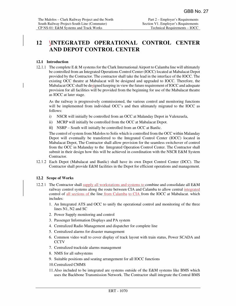
The Malolos – Clark Railway Project and the North
South Railway Project-South Line (Commuter)
CP NS-01: E&M Systems and Track Works
Part 2 – Employer’s Requirements
Section V1. Employer’s Requirements
Technical Requirements – IOCC
ERT - 1070
12 \INTEGRATED OPERATIONAL CONTROL CENTER
AND DEPOT CONTROL CENTER
Introduction
The complete E & M systems for the Clark International Airport to Calamba line will ultimately
be controlled from an Integrated Operations Control Center (IOCC) located at Mabalacat Depot
provided by the Contractor. The contractor shall take the lead in the interface of the IOCC. The
existing OCC theatre at Mabalacat will be designed and upgraded to IOCC. Therefore, the
Mabalacat OCC shall be designed keeping in view the future requirement of IOCC and adequate
provision for all facilities will be provided from the beginning for use of the Mabalacat theatre
as IOCC at later stage.
As the railway is progressively commissioned, the various control and monitoring functions
will be implemented from individual OCC’s and then ultimately migrated to the IOCC as
follows:
i) NSCR will initially be controlled from an OCC at Malanday Depot in Valenzuela,
ii) MCRP will initially be controlled from the OCC at Mabalacat Depot.
iii) NSRP – South will initially be controlled from an OCC at Banlic.
The control of system from Malolos to Solis which is controlled from the OCC within Malanday
Depot will eventually be transferred to the Integrated Control Center (IOCC) located in
Mabalacat Depot, The Contractor shall allow provision for the seamless switchover of control
from the OCC in Malanday to the Integrated Operation Control Center. The Contractor shall
submit in their design how this will be achieved in coordination with the NSCR E&M System
Contractor.
Each Depot (Mabalacat and Banlic) shall have its own Depot Control Center (DCC). The
Contractor shall provide E&M facilities in the Depot for efficient operations and management.
Scope of Works
The Contractor shall supply all workstations and systems to combine and consolidate all E&M
railway control systems along the route between CIA and Calamba to allow central integrated
control of all sections of the line from Calamba to CIA from the IOCC at Mabalacat. which
includes:
1. An Integrated ATS and OCC to unify the operational control and monitoring of the three
lines N1, N2 and SC
2. Power Supply monitoring and control
3. Passenger Information Displays and PA system
4. Centralized Radio Management and dispatcher for complete line
5. Centralized alarms for disaster management
6. Common video wall to cover display of track layout with train status, Power SCADA and
CCTV
7. Centralized trackside alarms management
8. NMS for all subsystems
9. Suitable positions and seating arrangement for all IOCC functions
10. Centralized CMMS
11. Also included to be integrated are systems outside of the E&M systems like BMS which
uses the Backbone Transmission Network. The Contractor shall integrate the Central BMS
GBB No. 27

The Malolos – Clark Railway Project and the North
South Railway Project-South Line (Commuter)
CP NS-01: E&M Systems and Track Works
Part 2 – Employer’s Requirements
Section V1. Employer’s Requirements
Technical Requirements – IOCC
ERT - 1071
which is provided by other contractors that resides in each OCC for N1, N2, and SC shall
be combined and consolidate to the IOCC. The Contractor shall supply all necessary
equipment to fully integrate and also consolidate allny of the Control and Monitoring
Systems that can be combined such as like the P-SCADA and BMS and which shall all be
integrated at the IOCC. it also to the IOCC.
12. PABX and Landline telephones for communication with all stations, Depots and adjacent
railway/MRTS lines
12.13. Backbone requirements for all operational systems for N1, N2 and SC to be connected
to IOCC.
The contractor shall comply with the requirements covered in other chapters of ERT.
The Contractor shall prepare and implement the requirements of a detailed Migration Plan
covering strategy, timeline, testing, and decommissioning during the transfer of the OCC
functions to the IOCC. The IOCC shall be commissioned progressively as the sections are
connected so as to form contiguous line from CIA station/Mabalacat Depot towards South. The
IOCC shall connect to N1 section and then SC section (which has multiple3 phases: For
example: Calamba-Alabang, Solis-Blumentritt-Tutuban and Alabang-Blumentritt to FTI etc).
IOCC work shall be completed with the completion of last phase of the line.
All migration works shall be coordinated and agreed with the O&M Concessionaire. Redundant
equipment from the decommissioned OCC’s shall be returned to the Employer. The migration
plan shall be submitted to the Engineer for approval.
Following the migration, the integrated combined consoles and displays shall cover the
complete railways from CIA to Calamba.
Effective inter-disciplinary checks will be required to ensure the objectives for integration are
realized.
Provisions of the space and associated works should be planned, to accommodate various
equipment in the IOCC. Ergonomic studies will be required as part of the design of the IOCC
which shall cover the likes of desk layout, lighting levels, and environment designs. These
studies and all designs shall be submitted to the Engineer for approval.
Provisions shall be made in the IOCC to accommodate the future requirements for the extension
to New Clark City.
The System equipment, rooms and E&M facilities design and installation shall also be in line
and compliant with the RAMS Project requirements as defined in the ERG.
The functionality of the operating systems shall be driven by operational requirements. This
Technical Specifications for IOCC systems equipment have been developed to international
norms and standards. Other Equivalent standards shall also be allowed subject to review by the
Engineer.
The Contractor shall propose all designs and functionality required to effectively operate the
line. The Contractor shall submit suitable designs and plans for undertaking this work, at detail
design stage, for the review of the Engineer.
The contractor shall design and supply all furniture, accessories, finishes as detailed in the
document.
The contractor shall comply to requirements of DCC for managing operations within the Depot
for all Depot operations.
GBB No. 27

The Malolos – Clark Railway Project and the North South Railway Project-South Line (Commuter) CP NS-01: E&M Systems and Track Works
Part 2 – Employer’s Requirements Section V1. Employer’s Requirements
General Requirements
ESMP-42
Serial No.
Safety Requirement Description Subsystem
SR-95 The system shall include signage throughout the network to provide assistance, direction and warning to passengers and operations personnel to support normal, degraded and emergency operations. Signage shall include the following types: · Way finding signage: · System identification signs · Station name signs · Directional signs · Travel information displays · Metro network map · Local area map · Descriptive signs · Emergency exit signs · Trackside and tunnel signage · Other facility way finding signage · Warning, mandatory and prohibition signs Signage may also be complimented by the use of the passenger information and public address systems.
SYS, CIV
SR-96 The fire detection and alarm system Manual call points for outdoor mounting shall have IP-65 enclosure protection and in explosion hazardous areas shall have explosion proof protection.
MEP, TEL
SR-97 Automatic fire detection shall be provided along the tunnel trainway and inside technical rooms located within tunnel sections.
MEP, TEL
SR-98 “Cant” and "gradient Cant" will be applied to curve and transition curve. TRK
SR-99 Gauges and Clearances shall be in alignment with RS cross-section and kinematic envelope.
TRK
SR-100 - -
SR-101 Buffer stops shall be capable for the rolling stock weight to stop without major damage.
TRK
SR-102 The desirable minimum main TD 'track distance' (distance between two track distance center lines) shall be 4.00 m for higher operational speeds >100 km/h.
TRK, CIV
SR-103 To provide control and monitoring of Tunnel Ventilation system (TVS) during fire situation to ensure tenable environment conditions can be maintained.
MEP
SR-104 Provide necessary smoke control to achieve tenable conditions for passenger evacuation during emergency (fire) conditions in the tunnels, trackways and stations as per NFPA 130 specification or an equivalent international standard requirement. Cross-passageways shall also remain free of smoke during a tunnel fire incident.
MEP, CIV, SYS
SR-105 The Power SCADA (Safety Functions) shall be SIL 2 Power
GBB No. 27

The Malolos – Clark Railway Project and the North South Railway Project-South Line (Commuter) CP NS-01: E&M Systems and Track Works
Part 2 – Employer’s Requirements Section V1. Employer’s Requirements
General Requirements
ESMP-50
Serial No.
Safety Requirement Description Subsystem
SR-95 The system shall include signage throughout the network to provide assistance, direction and warning to passengers and operations personnel to support normal, degraded and emergency operations. Signage shall include the following types: · Way finding signage: · System identification signs · Station name signs · Directional signs · Travel information displays · Metro network map · Local area map · Descriptive signs · Emergency exit signs · Trackside and tunnel signage · Other facility way finding signage · Warning, mandatory and prohibition signs Signage may also be complimented by the use of the passenger information and public address systems.
SYS, CIV
SR-96 The fire detection and alarm system Manual call points for outdoor mounting shall have IP-65 enclosure protection and in explosion hazardous areas shall have explosion proof protection.
MEP, TEL
SR-97 Automatic fire detection shall be provided along the tunnel trainway and inside technical rooms located within tunnel sections.
MEP, TEL
SR-98 “Cant” and "gradient Cant" will be applied to curve and transition curve. TRK
SR-99 Gauges and Clearances shall be in alignment with RS cross-section and kinematic envelope.
TRK
SR-100 Track structure shall be capable to contain the train path in the event of derailment (Containment from tilting, running into the structure gauge of the opposite track and from colliding with bridge/tunnel equipment).
TRK
SR-101 Buffer stops shall be capable for the rolling stock weight to stop without major damage.
TRK
SR-102 The desirable minimum main TD 'track distance' (distance between two track distance center lines) shall be 4.00 m for higher operational speeds >100 km/h.
TRK, CIV
SR-103 To provide control and monitoring of Tunnel Ventilation system (TVS) during fire situation to ensure tenable environment conditions can be maintained.
MEP
SR-104 Provide necessary smoke control to achieve tenable conditions for passenger evacuation during emergency (fire) conditions in the tunnels, trackways and stations as per NFPA 130 specification or an equivalent international standard requirement. Cross-passageways shall also remain free of smoke during a tunnel fire incident.
MEP, CIV, SYS
SR-105 The Power SCADA (Safety Functions) shall be SIL 2 Power
GBB No. 27

8.9.3.3. Contractor shall supply diesel locomotives (2 units) along with one flat car suitable for
mainline operations having maximum 2.95m wide, to recover failed train, 315270t, on
3.5% gradientdowngrade.
8.9.3.4. Locomotives shall be fully equipped for emergency responses.
8.9.3.5. Contractor shall supply adaptors for tight lock couplers to couple to work trains.
8.9.3.6. Flat car: Contractor shall supply flat car with side boards to carry tools, re-railing
equipment and emergency response equipment, 15m length, 2.95m wide, with platform
1.10m above T.O.R.
8.9.3.7. Contractor shall supply and install tight lock couplers on both ends flat car (free issue).
8.9.3.8. It is assumed that the fuel supply equipment (N41-03) is used for the shunting Diesel
locomotive (N41-02).
8.9.3.9. Common use (N61 and S61):
These facilities are used commonly in/outside of the depot/workshop area for the works
concerned with rolling stock maintenance and accidents.
8.9.3.10. Tools:
a. These equipment/facilities are used commonly for the works concerned with
rolling stock maintenance and accidents.
b. These tools can be provided by general commercial tool suppliers.
c. The contractor shall confirm to the interface contractor to resolve the interface
problems as specified in Technical Requirement and Section 19 of ERG.
8.9.3.11. Other tools/equipment/facilities for rolling stock maintenance that is assumed not
to procure at general commercial markets are treated as special tools and test
equipment of the railway system and rolling stock.
8.9.3.12. These Special tools and test equipment are to be planned and supplied in close
consultation and interfacing with Rolling Stock supplier at appropriate time with
approval of Engineer. Special tools and test equipment of the rolling stock shown in
Table 8.13 are indicative only. Actual requirement and specifications shall be reviewed
and finalized as per the maintenance requirement of the Rolling stock supplier.
GBB No. 27

8.9.3.3. Contractor shall supply diesel locomotives (2 units) along with one flat car suitable for
mainline operations having maximum 2.95m wide, to recover failed train, 315t, on 3.5%
gradient.
8.9.3.4. Locomotives shall be fully equipped for emergency responses.
8.9.3.5. Contractor shall supply adaptors for tight lock couplers to couple to work trains.
8.9.3.6. Flat car: Contractor shall supply flat car with side boards to carry tools, re-railing
equipment and emergency response equipment, 15m length, 2.95m wide, with platform
1.10m above T.O.R.
8.9.3.7. Contractor shall supply and install tight lock couplers on both ends flat car (free issue).
8.9.3.8. It is assumed that the fuel supply equipment (N41-03) is used for the shunting Diesel
locomotive (N41-02).
8.9.3.9. Common use (N61 and S61):
These facilities are used commonly in/outside of the depot/workshop area for the works
concerned with rolling stock maintenance and accidents.
8.9.3.10. Tools:
a. These equipment/facilities are used commonly for the works concerned with
rolling stock maintenance and accidents.
b. These tools can be provided by general commercial tool suppliers.
c. The contractor shall confirm to the interface contractor to resolve the interface
problems as specified in Technical Requirement and Section 19 of ERG.
8.9.3.11. Other tools/equipment/facilities for rolling stock maintenance that is assumed not
to procure at general commercial markets are treated as special tools and test
equipment of the railway system and rolling stock.
8.9.3.12. These Special tools and test equipment are to be planned and supplied in close
consultation and interfacing with Rolling Stock supplier at appropriate time with
approval of Engineer. Special tools and test equipment of the rolling stock shown in
Table 8.13 are indicative only. Actual requirement and specifications shall be reviewed
and finalized as per the maintenance requirement of the Rolling stock supplier.
GBB No. 27
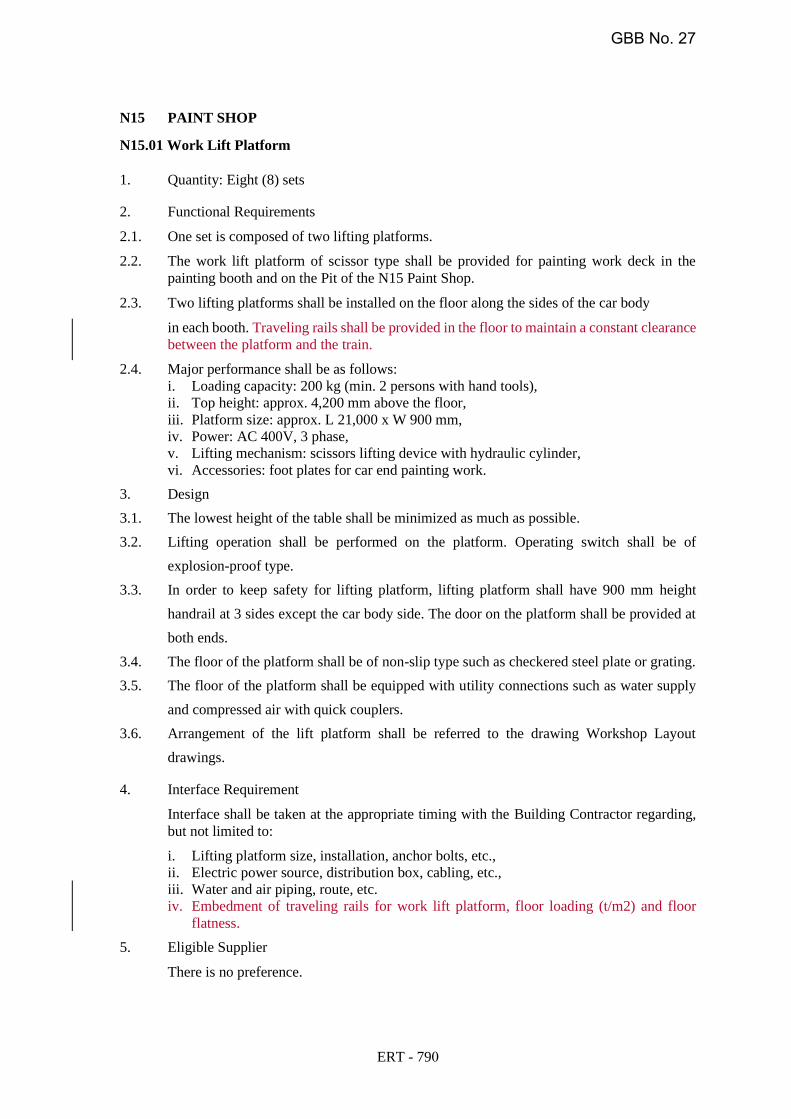
N15 PAINT SHOP
N15.01 Work Lift Platform
1. Quantity: Eight (8) sets
2. Functional Requirements
2.1. One set is composed of two lifting platforms.
2.2. The work lift platform of scissor type shall be provided for painting work deck in the
painting booth and on the Pit of the N15 Paint Shop.
2.3. Two lifting platforms shall be installed on the floor along the sides of the car body
in each booth. Traveling rails shall be provided in the floor to maintain a constant clearance
between the platform and the train.
2.4. Major performance shall be as follows:
i. Loading capacity: 200 kg (min. 2 persons with hand tools),
ii. Top height: approx. 4,200 mm above the floor,
iii. Platform size: approx. L 21,000 x W 900 mm,
iv. Power: AC 400V, 3 phase,
v. Lifting mechanism: scissors lifting device with hydraulic cylinder,
vi. Accessories: foot plates for car end painting work.
3. Design
3.1. The lowest height of the table shall be minimized as much as possible.
3.2. Lifting operation shall be performed on the platform. Operating switch shall be of
explosion-proof type.
3.3. In order to keep safety for lifting platform, lifting platform shall have 900 mm height
handrail at 3 sides except the car body side. The door on the platform shall be provided at
both ends.
3.4. The floor of the platform shall be of non-slip type such as checkered steel plate or grating.
3.5. The floor of the platform shall be equipped with utility connections such as water supply
and compressed air with quick couplers.
3.6. Arrangement of the lift platform shall be referred to the drawing Workshop Layout
drawings.
4. Interface Requirement
Interface shall be taken at the appropriate timing with the Building Contractor regarding,
but not limited to:
flatness.
5. Eligible Supplier
There is no preference.
i. Lifting platform size, installation, anchor bolts, etc.,
ii. Electric power source, distribution box, cabling, etc.,
iii. Water and air piping, route, etc.
iv. Embedment of traveling rails for work lift platform, floor loading (t/m2) and floor
ERT - 790
GBB No. 27

N15 PAINT SHOP
N15.01 Work Lift Platform
1. Quantity: Eight (8) sets
2. Functional Requirements
2.1. One set is composed of two lifting platforms.
2.2. The work lift platform of scissor type shall be provided for painting work deck in the
painting booth and on the Pit of the N15 Paint Shop.
2.3. Two lifting platforms shall be installed on the floor along the sides of the car body
in each booth. Traveling rails shall be provided in the floor to maintain a constant clearance
between the platform and the train.
2.4. Major performance shall be as follows:
i. Loading capacity: 200 kg (min. 2 persons with hand tools),
ii. Top height: approx. 4,200 mm above the floor,
iii. Platform size: approx. L 21,000 x W 900 mm,
iv. Power: AC 400V, 3 phase,
v. Lifting mechanism: scissors lifting device with hydraulic cylinder,
vi. Accessories: foot plates for car end painting work.
3. Design
3.1. The lowest height of the table shall be minimized as much as possible.
3.2. Lifting operation shall be performed on the platform. Operating switch shall be of
explosion-proof type.
3.3. In order to keep safety for lifting platform, lifting platform shall have 900 mm height
handrail at 3 sides except the car body side. The door on the platform shall be provided at
both ends.
3.4. The floor of the platform shall be of non-slip type such as checkered steel plate or grating.
3.5. The floor of the platform shall be equipped with utility connections such as water supply
and compressed air with quick couplers.
3.6. Arrangement of the lift platform shall be referred to the drawing Workshop Layout
drawings.
4. Interface Requirement
Interface shall be taken at the appropriate timing with the Building Contractor regarding,
but not limited to:
i. Lifting platform size, installation, anchor bolts, etc.,
ii. Electric power source, distribution box, cabling, etc.,
iii. Water and air piping, route, etc.
iv. Embedment of traveling rails for work lift platform, floor loading (t/m2) and floor
flatness.
5. Eligible Supplier
There is no preference.
ERT - 790
GBB No. 27

N15.02 Car Body Washing Booth
1. Quantity: One (1) set
2. Functional Requirements
2.1. The car body washing booth shall be provided for the prevention of spray scattering by car
body washing in the N15 Paint Shop.
2.2. The car body washing booth shall be composed of, but not limited to:
i. Booth,
ii. Ventilation device of push-pull in the booth,
iii. Air washing and dust collecting device.
2.3. The booth shall be equipped with the following facilities at minimum:
i. Fresh air discharge outlet in the ceiling,
ii. Air outlet at the floor,
iii. Underfloor water pool,
iv. Air duct with exhaust fan,
v. Traveling rails for the work lift platforms,
vi. Car body transfer device.
2.4. Air mean velocity shall be about 0.2 m/sec. at 1.5 m above the floor.
2.5. Floor embedded rail for car body moving will be provided through the booth by the
Building Contractor.
2.6. Car body data of EMU is described below; the Contractor shall confirm to the Rolling Stock
Contractor:
i. Track gauge: 1,435 mm,
ii. Size: L 19,500 mm x W 2,950 mm x H 3,800 mm,
iii. Net weight: max. 40 ton.
3. Design
3.1. The booth size shall be within approx. L 30,000 x W 6,000 x H 7,000 mm.
3.2. Working lift platforms (N15.01) for painting work shall be integrated in the booth.
3.3. The pit cover (floor grating) shall be provided and installed.
3.4. Arrangement of the Car body washing booth shall be referred to the Workshop Layout
drawings.
4. Interface Requirement
Interface shall be taken at the appropriate timing with the Building Contractor regarding,
but not limited to:
5. Eligible Supplier
There is no preference.
i. Floor pit structure and size,
ii. Booth size, installation, anchor bolts, floor finishing work,
iii. Electric power source, distribution box, cabling, etc.
iv. Water piping, route, supply piping, drainage, etc.
v. Duct, size, support, route, wall penetration, opening finishing, etc.
vi. Embedment of traveling rails for work lift platforms and track rails for car body moving, floor loading (t/m2) and floor flatness.
ERT - 791
GBB No. 27

N15.02 Car Body Washing Booth
1. Quantity: One (1) set
2. Functional Requirements
2.1. The car body washing booth shall be provided for the prevention of spray scattering by car
body washing in the N15 Paint Shop.
2.2. The car body washing booth shall be composed of, but not limited to:
i. Booth,
ii. Ventilation device of push-pull in the booth,
iii. Air washing and dust collecting device.
2.3. The booth shall be equipped with the following facilities at minimum:
i. Fresh air discharge outlet in the ceiling,
ii. Air outlet at the floor,
iii. Underfloor water pool,
iv. Air duct with exhaust fan,
v. Traveling rails for the work lift platforms,
vi. Car body transfer device.
2.4. Air mean velocity shall be about 0.2 m/sec. at 1.5 m above the floor.
2.5. Floor embedded rail for car body moving will be provided through the booth by the
Contractor.
2.6. Car body data of EMU is described below; the Contractor shall confirm to the Rolling Stock
Contractor:
i. Track gauge: 1,435 mm,
ii. Size: L 19,500 mm x W 2,950 mm x H 3,800 mm,
iii. Net weight: max. 40 ton.
3. Design
3.1. The booth size shall be within approx. L 30,000 x W 6,000 x H 7,000 mm.
3.2. Working lift platforms (N15.01) for painting work shall be integrated in the booth.
3.3. The pit cover (floor grating) shall be provided and installed.
3.4. Arrangement of the Car body washing booth shall be referred to the Workshop Layout
drawings.
4. Interface Requirement
Interface shall be taken at the appropriate timing with the Building Contractor regarding,
but not limited to:
i. Floor pit structure and size,
ii. Booth size, installation, anchor bolts, floor finishing work,
iii. Electric power source, distribution box, cabling, etc.
iv. Water piping, route, supply piping, drainage, etc.
v. Duct, size, support, route, wall penetration, opening finishing, etc.
vi. Embedment of traveling rails for work lift platforms and track rails for car body
moving, floor loading (t/m2) and floor flatness.
5. Eligible Supplier
There is no preference.
ERT - 791
GBB No. 27
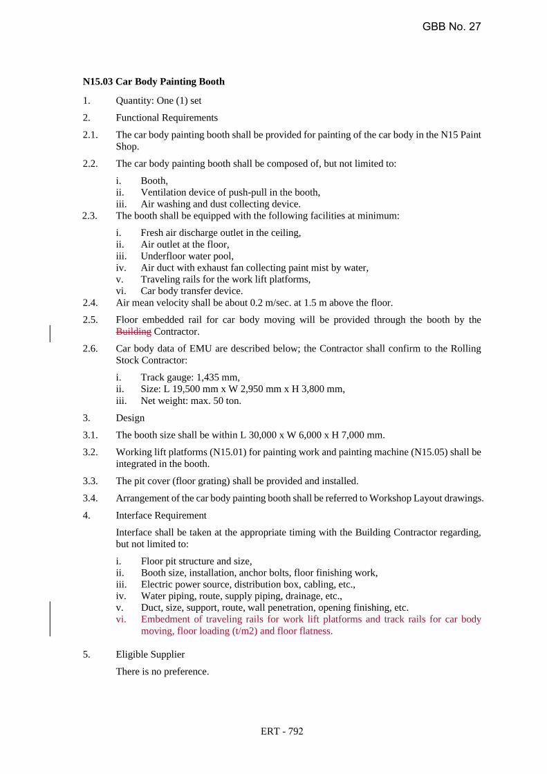
N15.03 Car Body Painting Booth
1. Quantity: One (1) set
2. Functional Requirements
2.1. The car body painting booth shall be provided for painting of the car body in the N15 Paint
Shop.
2.2. The car body painting booth shall be composed of, but not limited to:
i. Booth,
ii. Ventilation device of push-pull in the booth,
iii. Air washing and dust collecting device.
i. Fresh air discharge outlet in the ceiling,
ii. Air outlet at the floor,
iii. Underfloor water pool,
iv. Air duct with exhaust fan collecting paint mist by water,
v. Traveling rails for the work lift platforms,
vi. Car body transfer device.
2.4. Air mean velocity shall be about 0.2 m/sec. at 1.5 m above the floor.
2.5. Floor embedded rail for car body moving will be provided through the booth by the
Building Contractor.
2.6. Car body data of EMU are described below; the Contractor shall confirm to the Rolling
Stock Contractor:
i. Track gauge: 1,435 mm,
ii. Size: L 19,500 mm x W 2,950 mm x H 3,800 mm,
iii. Net weight: max. 50 ton.
3. Design
3.1. The booth size shall be within L 30,000 x W 6,000 x H 7,000 mm.
3.2. Working lift platforms (N15.01) for painting work and painting machine (N15.05) shall be
integrated in the booth.
3.3. The pit cover (floor grating) shall be provided and installed.
3.4. Arrangement of the car body painting booth shall be referred to Workshop Layout drawings.
4. Interface Requirement
Interface shall be taken at the appropriate timing with the Building Contractor regarding,
but not limited to:
moving, floor loading (t/m2) and floor flatness.
5. Eligible Supplier
There is no preference.
i. Floor pit structure and size,
ii. Booth size, installation, anchor bolts, floor finishing work,
iii. Electric power source, distribution box, cabling, etc.,
iv. Water piping, route, supply piping, drainage, etc.,
v. Duct, size, support, route, wall penetration, opening finishing, etc.
vi. Embedment of traveling rails for work lift platforms and track rails for car body
ERT - 792
2.3. The booth shall be equipped with the following facilities at minimum:
GBB No. 27
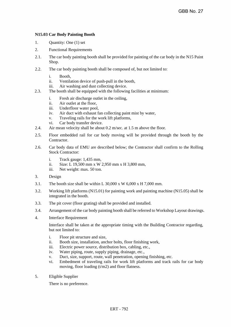
N15.03 Car Body Painting Booth
1. Quantity: One (1) set
2. Functional Requirements
2.1. The car body painting booth shall be provided for painting of the car body in the N15 Paint
Shop.
2.2. The car body painting booth shall be composed of, but not limited to:
i. Booth,
ii. Ventilation device of push-pull in the booth,
iii. Air washing and dust collecting device.
2.3. The booth shall be equipped with the following facilities at minimum:
i. Fresh air discharge outlet in the ceiling,
ii. Air outlet at the floor,
iii. Underfloor water pool,
iv. Air duct with exhaust fan collecting paint mist by water,
v. Traveling rails for the work lift platforms,
vi. Car body transfer device.
2.4. Air mean velocity shall be about 0.2 m/sec. at 1.5 m above the floor.
2.5. Floor embedded rail for car body moving will be provided through the booth by the
Contractor.
2.6. Car body data of EMU are described below; the Contractor shall confirm to the Rolling
Stock Contractor:
i. Track gauge: 1,435 mm,
ii. Size: L 19,500 mm x W 2,950 mm x H 3,800 mm,
iii. Net weight: max. 50 ton.
3. Design
3.1. The booth size shall be within L 30,000 x W 6,000 x H 7,000 mm.
3.2. Working lift platforms (N15.01) for painting work and painting machine (N15.05) shall be
integrated in the booth.
3.3. The pit cover (floor grating) shall be provided and installed.
3.4. Arrangement of the car body painting booth shall be referred to Workshop Layout drawings.
4. Interface Requirement
Interface shall be taken at the appropriate timing with the Building Contractor regarding,
but not limited to:
i. Floor pit structure and size,
ii. Booth size, installation, anchor bolts, floor finishing work,
iii. Electric power source, distribution box, cabling, etc.,
iv. Water piping, route, supply piping, drainage, etc.,
v. Duct, size, support, route, wall penetration, opening finishing, etc.
vi. Embedment of traveling rails for work lift platforms and track rails for car body
moving, floor loading (t/m2) and floor flatness.
5. Eligible Supplier
There is no preference.
ERT - 792
GBB No. 27
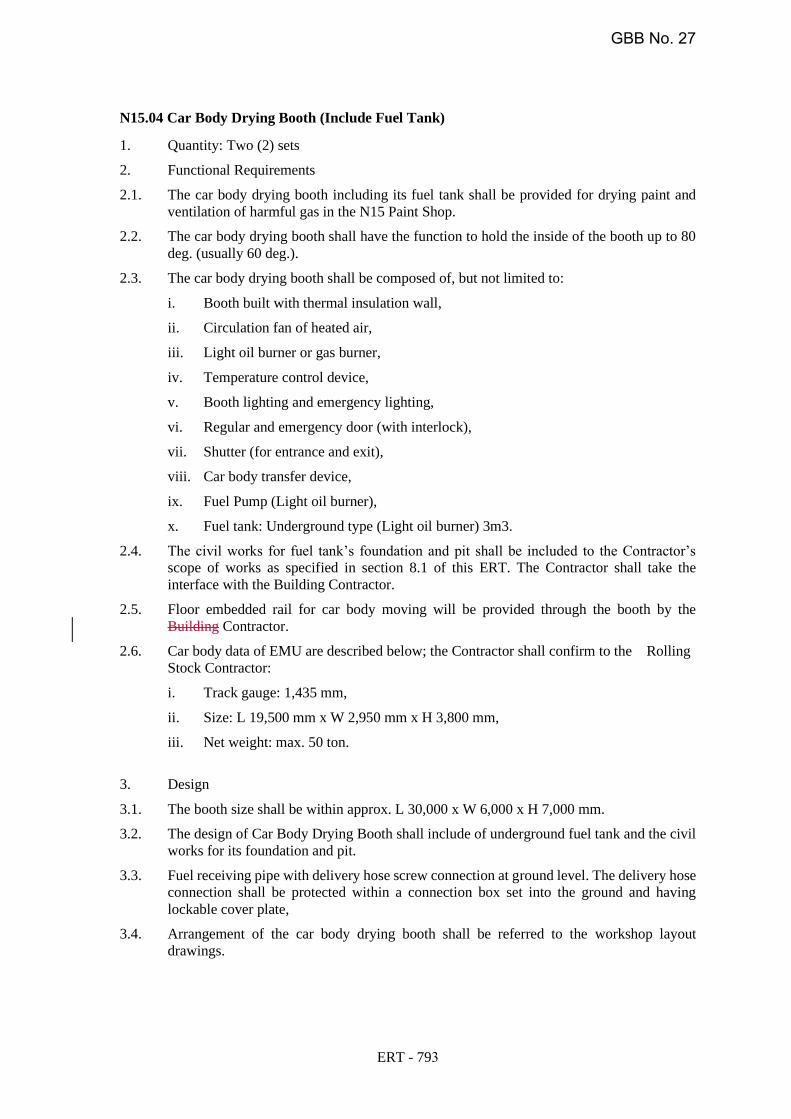
N15.04 Car Body Drying Booth (Include Fuel Tank)
1. Quantity: Two (2) sets
2. Functional Requirements
2.1. The car body drying booth including its fuel tank shall be provided for drying paint and
ventilation of harmful gas in the N15 Paint Shop.
2.2. The car body drying booth shall have the function to hold the inside of the booth up to 80
deg. (usually 60 deg.).
2.3. The car body drying booth shall be composed of, but not limited to:
i. Booth built with thermal insulation wall,
ii. Circulation fan of heated air,
iii. Light oil burner or gas burner,
iv. Temperature control device,
v. Booth lighting and emergency lighting,
vi. Regular and emergency door (with interlock),
vii. Shutter (for entrance and exit),
viii. Car body transfer device,
ix. Fuel Pump (Light oil burner),
x. Fuel tank: Underground type (Light oil burner) 3m3.
2.4. The civil works for fuel tank’s foundation and pit shall be included to the Contractor’s
scope of works as specified in section 8.1 of this ERT. The Contractor shall take the
interface with the Building Contractor.
2.5. Floor embedded rail for car body moving will be provided through the booth by the
Building Contractor.
2.6. Car body data of EMU are described below; the Contractor shall confirm to the Rolling
Stock Contractor:
i. Track gauge: 1,435 mm,
ii. Size: L 19,500 mm x W 2,950 mm x H 3,800 mm,
iii. Net weight: max. 50 ton.
3. Design
3.1. The booth size shall be within approx. L 30,000 x W 6,000 x H 7,000 mm.
3.2. The design of Car Body Drying Booth shall include of underground fuel tank and the civil
works for its foundation and pit.
3.3. Fuel receiving pipe with delivery hose screw connection at ground level. The delivery hose
connection shall be protected within a connection box set into the ground and having
lockable cover plate,
3.4. Arrangement of the car body drying booth shall be referred to the workshop layout
drawings.
ERT - 793
GBB No. 27
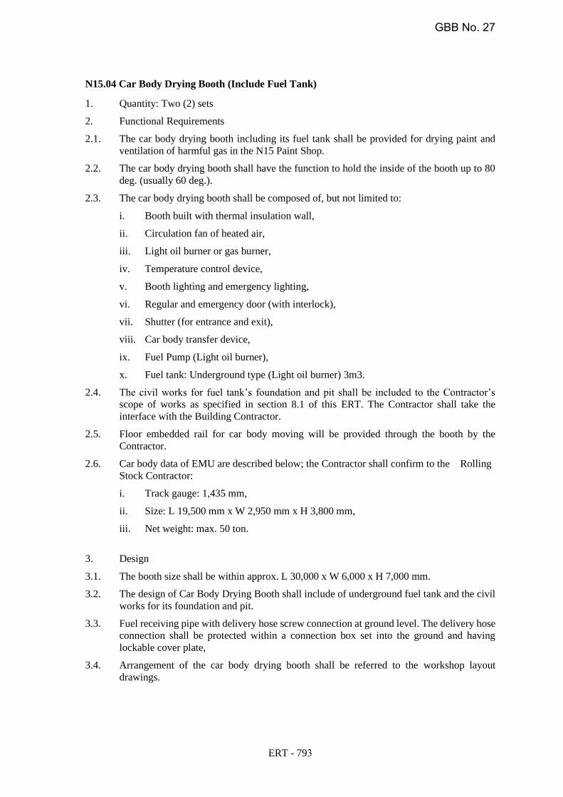
N15.04 Car Body Drying Booth (Include Fuel Tank)
1. Quantity: Two (2) sets
2. Functional Requirements
2.1. The car body drying booth including its fuel tank shall be provided for drying paint and
ventilation of harmful gas in the N15 Paint Shop.
2.2. The car body drying booth shall have the function to hold the inside of the booth up to 80
deg. (usually 60 deg.).
2.3. The car body drying booth shall be composed of, but not limited to:
i. Booth built with thermal insulation wall,
ii. Circulation fan of heated air,
iii. Light oil burner or gas burner,
iv. Temperature control device,
v. Booth lighting and emergency lighting,
vi. Regular and emergency door (with interlock),
vii. Shutter (for entrance and exit),
viii. Car body transfer device,
ix. Fuel Pump (Light oil burner),
x. Fuel tank: Underground type (Light oil burner) 3m3.
2.4. The civil works for fuel tank’s foundation and pit shall be included to the Contractor’s
scope of works as specified in section 8.1 of this ERT. The Contractor shall take the
interface with the Building Contractor.
2.5. Floor embedded rail for car body moving will be provided through the booth by the
Contractor.
2.6. Car body data of EMU are described below; the Contractor shall confirm to the Rolling
Stock Contractor:
i. Track gauge: 1,435 mm,
ii. Size: L 19,500 mm x W 2,950 mm x H 3,800 mm,
iii. Net weight: max. 50 ton.
3. Design
3.1. The booth size shall be within approx. L 30,000 x W 6,000 x H 7,000 mm.
3.2. The design of Car Body Drying Booth shall include of underground fuel tank and the civil
works for its foundation and pit.
3.3. Fuel receiving pipe with delivery hose screw connection at ground level. The delivery hose
connection shall be protected within a connection box set into the ground and having
lockable cover plate,
3.4. Arrangement of the car body drying booth shall be referred to the workshop layout
drawings.
ERT - 793
GBB No. 27
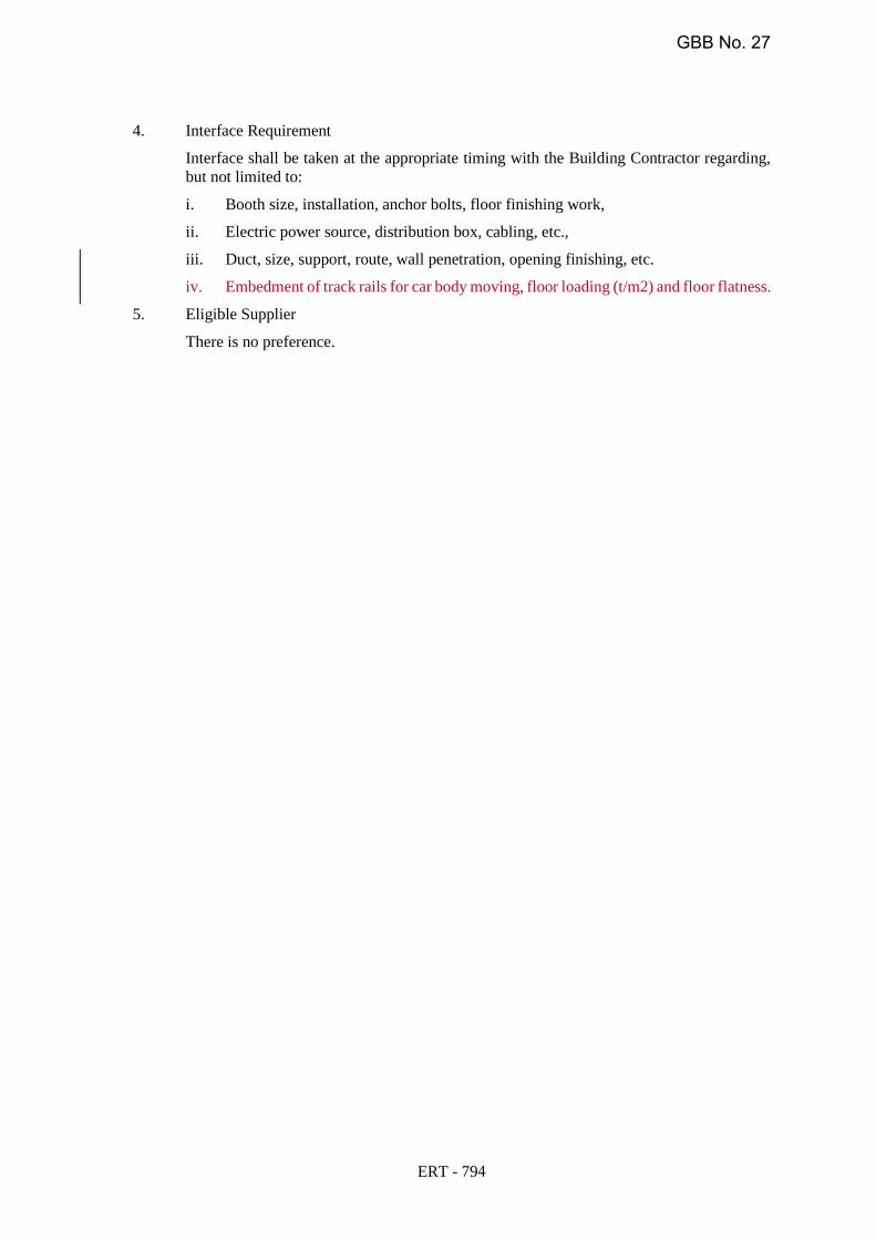
4. Interface Requirement
Interface shall be taken at the appropriate timing with the Building Contractor regarding,
but not limited to:
5. Eligible Supplier
There is no preference.
i. Booth size, installation, anchor bolts, floor finishing work,
ii. Electric power source, distribution box, cabling, etc.,
iii. Duct, size, support, route, wall penetration, opening finishing, etc.
iv. Embedment of track rails for car body moving, floor loading (t/m2) and floor flatness.
ERT - 794
GBB No. 27

4. Interface Requirement
Interface shall be taken at the appropriate timing with the Building Contractor regarding,
but not limited to:
i. Booth size, installation, anchor bolts, floor finishing work,
ii. Electric power source, distribution box, cabling, etc.,
iii. Duct, size, support, route, wall penetration, opening finishing, etc.
iv. Embedment of track rails for car body moving, floor loading (t/m2) and floor flatness.
5. Eligible Supplier
There is no preference.
ERT - 794
GBB No. 27

N41.02 Shunting Locomotive (Engine Type)
1. Quantity: One (1) set
2. Functional Requirements
2.1. The shunting locomotive (engine type) shall be provided for the shunting of the rolling
stock in the Depot/Workshop and during rescue operation of a failed Trainset on mainline.
2.2. Contractor shall supply diesel locomotives (2 units) along with one flat car suitable for
mainline operations having maximum 2.95m wide, to recover failed train, 315270t, on
3.5% gradientdowngrade. Locomotives should be able to work in both single and in
multiple mode as a consist of two locomotives as per the operational requirement.
2.3. Locomotives shall be fully equipped for emergency responses.
2.4. Contractor shall supply adaptors for tight lock couplers to couple to work trains.
2.5. Space for Onboard Signaling and Telecom equipment shall be provided by doing proper
interfacing with Signaling and Telecom contractor for equipment installation details.
2.6. All onboard Signaling and Telecom Equipment along with cables and wire harness will be
provided by Signaling and Telecom sub-contractors.
2.7. Installation will be done by Locomotive manufacture by doing necessary interface.
Commissioning will be done jointly with Signaling and Telecom contractors.
2.8. The shunting locomotive shall be stored in the shunting locomotive shed supplied by the
Building Contractor.
2.9. Major performance of the shunting locomotive shall be as follows; the Contractor shall
confirm the type of coupler to the Rolling Stock Contractor:
i. Type: diesel locomotive,
ii. Track gauge: 1,435 mm,
iii. Coupler: the couplers of rolling stock at both ends,(to be supplied by Rolling stock
contractor CP NS-02)
iv. The locomotive envelope to follow rolling stock and structure gauge drawing MCRP-
DWG-GEN-TK- 0020 Rev 6 or latest.
v. Driver cab: air conditioned, with assistant driver’s seat,
vi. Traction force: max. for rolling stock with Ten (10)-car set,
vii. Maximum speed without load: 80km/h
viii. Onboard signaling and telecom equipment
3. Design
3.1. The shunting locomotive can be operated by single driver. The shunting locomotive shall
be equipped with the following features, but not limited to:
i. Wide windows for wide and clear view from the cab for safe operation,
ii. Bi-directional operation
iii. Visually checking of the coupling status in the cab,
iv. Decks and handrails at both end for marshalling staff,
v. Remote releasing of coupling.
3.2. The following accessories shall be included, but not limited to:
i. Standard accessories,
ii. Maintenance tool kit.
4. Interface Requirement
ERT - 941
GBB No. 27
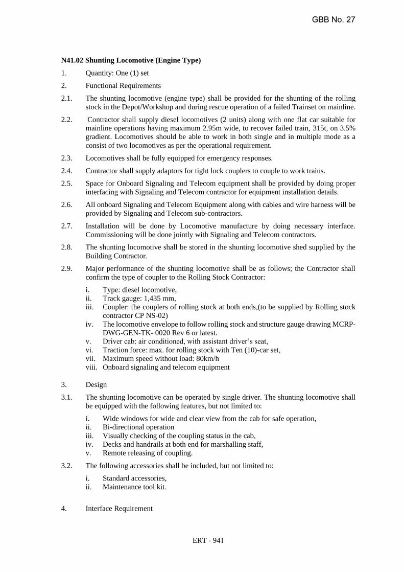
N41.02 Shunting Locomotive (Engine Type)
1. Quantity: One (1) set
2. Functional Requirements
2.1. The shunting locomotive (engine type) shall be provided for the shunting of the rolling
stock in the Depot/Workshop and during rescue operation of a failed Trainset on mainline.
2.2. Contractor shall supply diesel locomotives (2 units) along with one flat car suitable for
mainline operations having maximum 2.95m wide, to recover failed train, 315t, on 3.5%
gradient. Locomotives should be able to work in both single and in multiple mode as a
consist of two locomotives as per the operational requirement.
2.3. Locomotives shall be fully equipped for emergency responses.
2.4. Contractor shall supply adaptors for tight lock couplers to couple to work trains.
2.5. Space for Onboard Signaling and Telecom equipment shall be provided by doing proper
interfacing with Signaling and Telecom contractor for equipment installation details.
2.6. All onboard Signaling and Telecom Equipment along with cables and wire harness will be
provided by Signaling and Telecom sub-contractors.
2.7. Installation will be done by Locomotive manufacture by doing necessary interface.
Commissioning will be done jointly with Signaling and Telecom contractors.
2.8. The shunting locomotive shall be stored in the shunting locomotive shed supplied by the
Building Contractor.
2.9. Major performance of the shunting locomotive shall be as follows; the Contractor shall
confirm the type of coupler to the Rolling Stock Contractor:
i. Type: diesel locomotive,
ii. Track gauge: 1,435 mm,
iii. Coupler: the couplers of rolling stock at both ends,(to be supplied by Rolling stock
contractor CP NS-02)
iv. The locomotive envelope to follow rolling stock and structure gauge drawing MCRP-
DWG-GEN-TK- 0020 Rev 6 or latest.
v. Driver cab: air conditioned, with assistant driver’s seat,
vi. Traction force: max. for rolling stock with Ten (10)-car set,
vii. Maximum speed without load: 80km/h
viii. Onboard signaling and telecom equipment
3. Design
3.1. The shunting locomotive can be operated by single driver. The shunting locomotive shall
be equipped with the following features, but not limited to:
i. Wide windows for wide and clear view from the cab for safe operation,
ii. Bi-directional operation
iii. Visually checking of the coupling status in the cab,
iv. Decks and handrails at both end for marshalling staff,
v. Remote releasing of coupling.
3.2. The following accessories shall be included, but not limited to:
i. Standard accessories,
ii. Maintenance tool kit.
4. Interface Requirement
ERT - 941
GBB No. 27
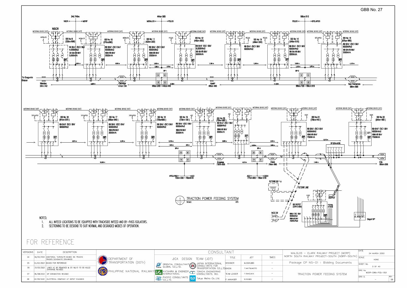
GBB No. 27
GCR - LAP42
Polygon
GCR - LAP42
Polygon
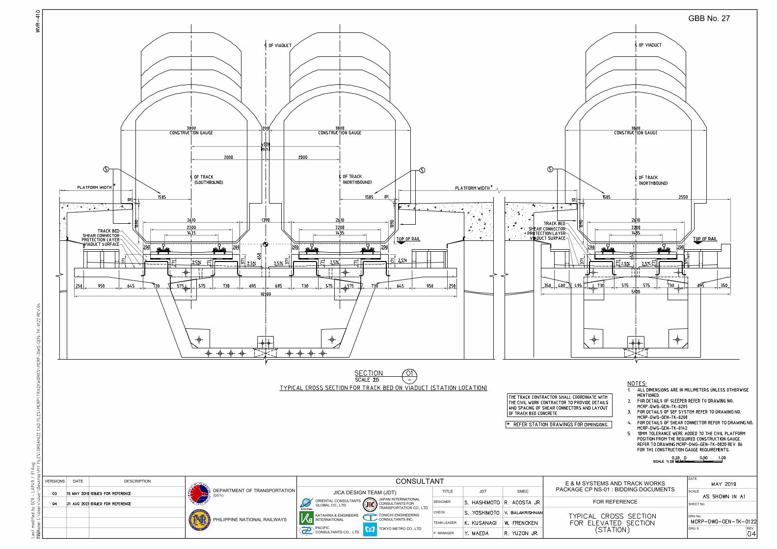
E & M SYSTEMS AND TRACK WORKSPACKAGE CP NS-01 : BIDDING DOCUMENTS
FOR REFERENCE
PHILIPPINE NATIONAL RAILWAYSTEAM LEADER
P. MANAGER
SMEC
VERSIONS DATE DESCRIPTION CONSULTANTTITLE
CHECK
DESIGNER
JICA DESIGN TEAM (JDT)
DATE
SCALE
SHEET No.
DRG No.
JAPAN INTERNATIONALCONSULTANTS FORTRANSPORTATION CO., LTD.
DRG S.
ORIENTAL CONSULTANTSGLOBAL CO., LTD.
DEPARTMENT OF TRANSPORTATION(DOTr)
PACIFICCONSULTANTS CO., LTD.
TONICHI ENGINEERINGCONSULTANTS INC.
KATAHIRA & ENGINEERSINTERNATIONAL
JDT
TOKYO METRO CO., LTD REV
GBB No. 27