Modeling and Simulation of the Defuzzification Stage Using Xilinx System Generator and Simulink
11
O. Castillo et al. (Eds.): Soft Computing for Hybrid Intel. Systems, SCI 154, pp. 333–343, 2008. springerlink.com © Springer-Verlag Berlin Heidelberg 2008 Modeling and Simulation of the Defuzzification Stage Using Xilinx System Generator and Simulink Gabriel Lizárraga 1,a , Roberto Sepúlveda 1 , Oscar Montiel 1 , and Oscar Castillo 2 1 Centro de Investigación y Desarrollo de Tecnología Digital (CITEDI) del IPN. Av. del Parque No.1310, Mesa de Otay, 22510, Tijuana, BC, México [email protected], {o.montiel,r.sepulveda}@ieee.org 2 Division of Graduate Studies and Research, Calzada Tecnológico S/N, Tijuana, México [email protected] a M.S. Student of CITEDI Abstract. Nowadays, there is an increasing interest in using FPGA devices to design digital controller, and a growing interest in control systems based on fuzzy logic where the Defuzzification stage is of primordial importance. In this work we are presenting the design, modeling and simulation of a fixed point defuzzification VHDL method. The modeling and simulation of this stage is realized in Simulink through the Xilinx System Generator, and a second inference system was implemented with Matlab code. Comparative analysis of both systems and result are shown. 1 Introduction Since the development of digital technology, there has been a trend in manufacturing products sharing the common goals of being smaller in integration, highly efficient in power consumption, faster regarding processing speed, and others. Several technolo- gies have emerged and dead in the last 40 years following the Moore’s Law crawling to be ever smaller in size. Alternative but parallel ways to develop high performance applications is to use VLSI programmable devices with the idea of developing the ap- plications in software. In this field, the use of devices such as Field Programmable Gate Array (FPGA) is a very good option because this technology offers appealing characteristics for designers, some of them are the high scale of integration, low power consumption, the existence of high level languages to develop and simulate the application code, and reprogrammability. Nowadays, there is an increasing interest in using FPGA devices to design digital controllers, and a growing interest in control systems based on fuzzy logic, since they allow compensating inaccuracies in the data from the instrumentation systems, such as noise. This work is about digital fuzzy controllers, it is focused in the Defuzzifica- tion stage which is of primordial importance in this kind of controllers. There are several works around this topic; however it is well known that designing of functional VHDL modules involves a several step process where it is common to write VHDL simulation test benches to make exhaustive simulations, in [1] is given simulation code to achieve this task.
-
Upload
independent -
Category
Documents
-
view
4 -
download
0
Transcript of Modeling and Simulation of the Defuzzification Stage Using Xilinx System Generator and Simulink
O. Castillo et al. (Eds.): Soft Computing for Hybrid Intel. Systems, SCI 154, pp. 333–343, 2008. springerlink.com © Springer-Verlag Berlin Heidelberg 2008
Modeling and Simulation of the Defuzzification Stage Using Xilinx System Generator and Simulink
Gabriel Lizárraga1,a, Roberto Sepúlveda1, Oscar Montiel1, and Oscar Castillo2
1 Centro de Investigación y Desarrollo de Tecnología Digital (CITEDI) del IPN. Av. del Parque No.1310, Mesa de Otay, 22510, Tijuana, BC, México [email protected], {o.montiel,r.sepulveda}@ieee.org 2 Division of Graduate Studies and Research, Calzada Tecnológico S/N, Tijuana, México [email protected] a M.S. Student of CITEDI
Abstract. Nowadays, there is an increasing interest in using FPGA devices to design digital controller, and a growing interest in control systems based on fuzzy logic where the Defuzzification stage is of primordial importance. In this work we are presenting the design, modeling and simulation of a fixed point defuzzification VHDL method. The modeling and simulation of this stage is realized in Simulink through the Xilinx System Generator, and a second inference system was implemented with Matlab code. Comparative analysis of both systems and result are shown.
1 Introduction
Since the development of digital technology, there has been a trend in manufacturing products sharing the common goals of being smaller in integration, highly efficient in power consumption, faster regarding processing speed, and others. Several technolo-gies have emerged and dead in the last 40 years following the Moore’s Law crawling to be ever smaller in size. Alternative but parallel ways to develop high performance applications is to use VLSI programmable devices with the idea of developing the ap-plications in software. In this field, the use of devices such as Field Programmable Gate Array (FPGA) is a very good option because this technology offers appealing characteristics for designers, some of them are the high scale of integration, low power consumption, the existence of high level languages to develop and simulate the application code, and reprogrammability.
Nowadays, there is an increasing interest in using FPGA devices to design digital controllers, and a growing interest in control systems based on fuzzy logic, since they allow compensating inaccuracies in the data from the instrumentation systems, such as noise. This work is about digital fuzzy controllers, it is focused in the Defuzzifica-tion stage which is of primordial importance in this kind of controllers.
There are several works around this topic; however it is well known that designing of functional VHDL modules involves a several step process where it is common to write VHDL simulation test benches to make exhaustive simulations, in [1] is given simulation code to achieve this task.
334 G. Lizárraga et al.
In this case the Defuzzification stage was simulated using the Software Xilinx Sys-tem Generator (XSG) [2], which is a software tool that creates and verify hardware designs for Xilinx FPGA's[3,4].
One of the contributions of this work is that we are giving an alternative way to test the final VHDL module avoiding writing a VHDL test bench.
In [1] was proposed a deffuzzified architecture that handles fixed point with arith-metic for real values. In contrast, we are proposing the use of a modified high per-formance fixed point architecture for positive numbers, and make at the final stage the conversion to real numbers. Moreover, comparative numerical analysis is achieved.
This paper is organized as follows, Section 2 presents in a general context the de-fuzzification method using VHDL, it is explained trough an easy example how the Defuzzification stage works; in Section 3 it is presented the experimental set up, as well as the software tools used; Section 4 discusses the experiments and results with a VHDL Simulink model of the Defuzzification stage using Xilinx System Generator and shows the evaluation of the operation of this stage with the remaining stages of the fuzzy system created in Matlab/Simulink, with three cases of study. Section 5 presents the conclusions of this work.
2 General Contexts
Fuzzy logic is a mathematical method to obtain approximate reasoning, emulating the human brain mechanism from facts described using natural language with uncertainty. A Fuzzy Inference System (FIS) is based on fuzzy logic and consists of three stages which are called: Fuzzification, Inference and Defuzzification.
The Fuzzification stage transforms the crisp values to fuzzy values [5,6,7]. The In-ference Engine is the core of the fuzzy logic system, here are proposed rules of the form IF-THEN that describe the behavior of a system [8,9]. The Defuzzification stage, involves extracting a crisp numerical value from a fuzzy set [1, 10, 11].
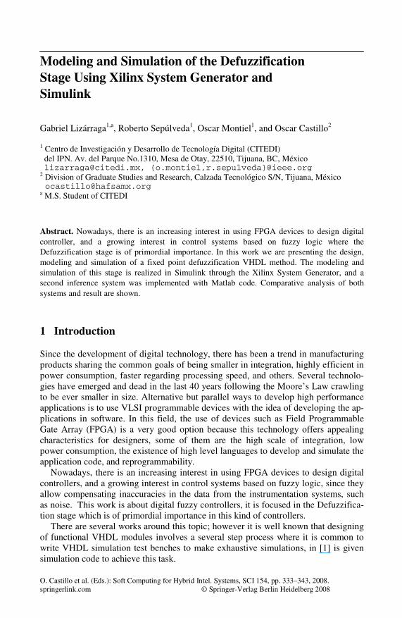
The explanation of this work is made using a two input and one output FIS. Figure 1 shows the general scheme of the FIS with the three stages, Fuzzification, Inference and Defuzzification.
Fig. 1. Fuzzy Inference System
Modeling and Simulation of the Defuzzification Stage Using Xilinx System 335
The fuzzy controller has two inputs and one output, the first ones are connected to the Fuzzification stage which produces a fuzzy output for each evaluation. A fuzzy outputs has two values, the membership grade and the linguistic value, that are repre-sented in this work as ge values for the input In1, and gde for the input In2 arranged in order according how the linguistic values are ordered in their universe of discourse; in this way, for a five membership function we have ge1, ge2,…, ge5 and gde1, gde2,…, gde5 respectively, that are the Inference Engine inputs. The output values of the Infer-ence Engine named as o1, o2, o3, o4 and C1, C2, C3, C4 are the four possible grades of activation with their respective consequent values. The Defuzzication stage using the o’s values and C’s tags produces a crisp value using the Height defuzzification method.
Considering that the FIS is going to be used in a dc speed control application, we can set some parameters in order to make numeric calculation to compare the VHDL implementation against the code developed in Matlab. In this controller, there are two inputs called error and cerror (change of error). Each input has five membership func-tions, where two are trapezoidal and three are of triangular type. The output has five membership functions, two trapezoidal type and three triangular type. The universe of discourse for inputs and outputs is in the range [-80, +80].
2.1 Defuzzification Method for Fuzzy System Using VHDL Code
Defuzzification stage is in many practical applications an essential step, especially where the fuzzy inference system is going to be use as a controller, where it is neces-sary to have a crisp output value instead of having a fuzzy set.
There are several methods to achieve this task, and their selection usually depends on the application and processing capacity available. The method used in this work is known as Height [10] that calculates a weighted average value which is a good option for a FPGA implementation. A remarkable characteristic is that its performance de-pends on how symmetrical the MFs are [12, 13, 14].
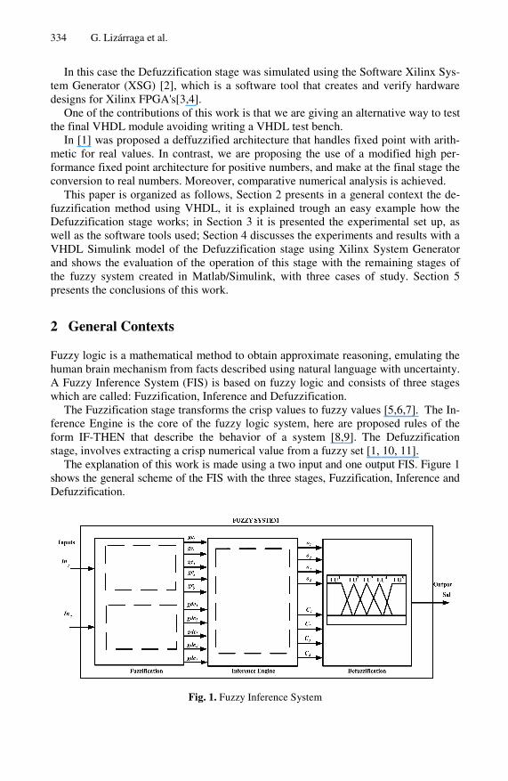
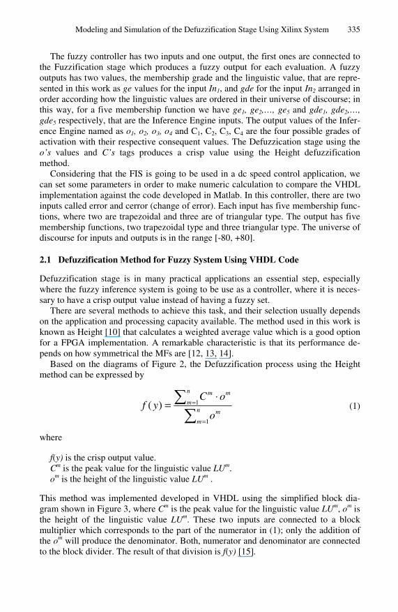
Based on the diagrams of Figure 2, the Defuzzification process using the Height method can be expressed by
∑∑
=
=⋅
= n
m
m
n
m
mm
o
oCyf
1
1)( (1)
where f(y) is the crisp output value. Cm is the peak value for the linguistic value LUm. om is the height of the linguistic value LUm .
This method was implemented developed in VHDL using the simplified block dia-gram shown in Figure 3, where Cm is the peak value for the linguistic value LUm, om is the height of the linguistic value LUm. These two inputs are connected to a block multiplier which corresponds to the part of the numerator in (1); only the addition of the om will produce the denominator. Both, numerator and denominator are connected to the block divider. The result of that division is f(y) [15].
336 G. Lizárraga et al.
Fig. 2. Distribution possibility of an output condition
Fig. 3. Block diagram of Height defuzzification method
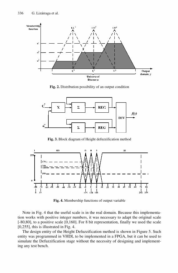
Fig. 4. Membership functions of output variable
Note in Fig. 4 that the useful scale is in the real domain. Because this implementa-tion works with positive integer numbers, it was necessary to adapt the original scale [-80,80], to a positive scale [0,160]. For 8 bit representation, finally we used the scale [0,255], this is illustrated in Fig. 4.
The design entity of the Height Defuzzification method is shown in Figure 5. Such entity was programmed in VHDL to be implemented in a FPGA, but it can be used to simulate the Defuzzification stage without the necessity of designing and implement-ing any test bench.
Modeling and Simulation of the Defuzzification Stage Using Xilinx System 337
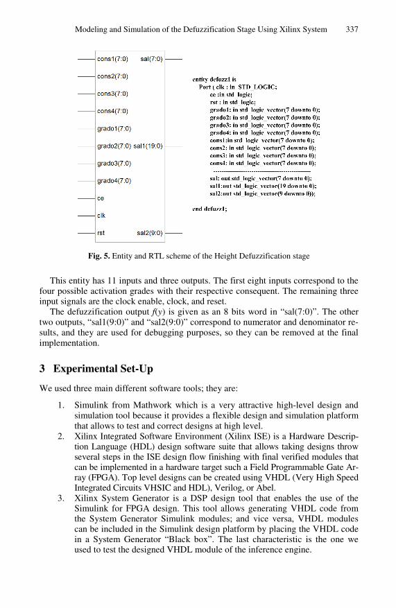
Fig. 5. Entity and RTL scheme of the Height Defuzzification stage
This entity has 11 inputs and three outputs. The first eight inputs correspond to the four possible activation grades with their respective consequent. The remaining three input signals are the clock enable, clock, and reset.
The defuzzification output f(y) is given as an 8 bits word in “sal(7:0)”. The other two outputs, “sal1(9:0)” and “sal2(9:0)” correspond to numerator and denominator re-sults, and they are used for debugging purposes, so they can be removed at the final implementation.
3 Experimental Set-Up
We used three main different software tools; they are:
1. Simulink from Mathwork which is a very attractive high-level design and simulation tool because it provides a flexible design and simulation platform that allows to test and correct designs at high level.
2. Xilinx Integrated Software Environment (Xilinx ISE) is a Hardware Descrip-tion Language (HDL) design software suite that allows taking designs throw several steps in the ISE design flow finishing with final verified modules that can be implemented in a hardware target such a Field Programmable Gate Ar-ray (FPGA). Top level designs can be created using VHDL (Very High Speed Integrated Circuits VHSIC and HDL), Verilog, or Abel.
3. Xilinx System Generator is a DSP design tool that enables the use of the Simulink for FPGA design. This tool allows generating VHDL code from the System Generator Simulink modules; and vice versa, VHDL modules can be included in the Simulink design platform by placing the VHDL code in a System Generator “Black box”. The last characteristic is the one we used to test the designed VHDL module of the inference engine.
338 G. Lizárraga et al.
To make this set-up works, it is very important to have the adequate versions of each software tool. In this case we have the next setting:
1. Matlab/Simulink version is: 7.1 (R14). 2. Xilinx ISE Project Navigator: Release version 8.2.03i, application version
1.34. 3. Xilinx System Generator: v8.2.
4 Experiments and Results
Two experimental Simulink models were created to achieve a comparative test. The difference between them is in the Defuzzification stage since we are interested in test-ing it. In the first system, the Defuzzification stage was coded in VHDL and the other two fuzzy stages using models from Fuzzy Logic Toolbox. In the second one, the
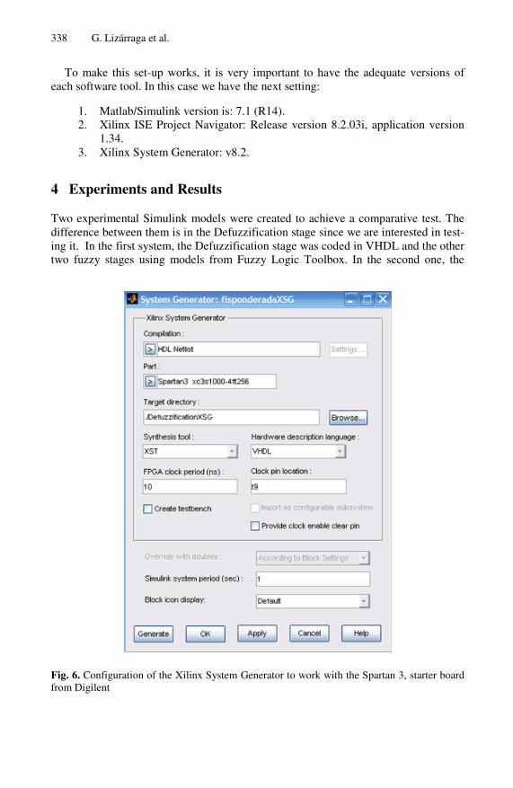
Fig. 6. Configuration of the Xilinx System Generator to work with the Spartan 3, starter board from Digilent
Modeling and Simulation of the Defuzzification Stage Using Xilinx System 339
whole system was designed with the Fuzzy Logic Toolbox. Several comparative experiments were made with both models.
4.1 VHDL Simulink Model Using Xilinx System Generator
In Fig. 6 is presented the necessary configuration for the FPGA Spartan 3. These ex-periments were made considering that the final implementation will be achieved in the development starter board Spartan 3 from Digilent.
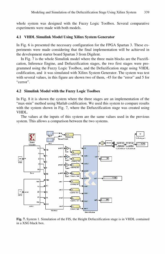
In Fig. 7 is the whole Simulink model where the three main blocks are the Fuzzifi-cation, Inference Engine, and Defuzzification stages, the two first stages were pro-grammed using the Fuzzy Logic Toolbox, and the Defuzification stage using VHDL codification, and it was simulated with Xilinx System Generator. The system was test with several values, in this figure are shown two of them, -45 for the “error” and 5 for “cerror”.
4.2 Simulink Model with the Fuzzy Logic Toolbox
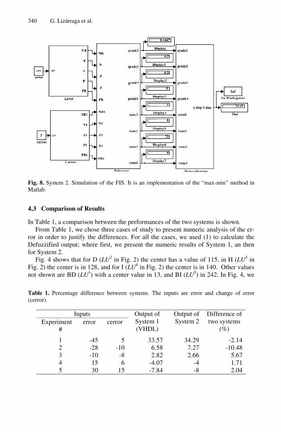
In Fig. 8 it is shown the system where the three stages are an implementation of the “max-min” method using Matlab codification. We used this system to compare results with the system shown in Fig. 7, where the Defuzzification stage was created using VHDL.
The values at the inputs of this system are the same values used in the previous system. This allows a comparison between the two systems.
Fig. 7. System 1. Simulation of the FIS, the Height Defuzzification stage is in VHDL contained in a XSG black box.
340 G. Lizárraga et al.
Fig. 8. System 2. Simulation of the FIS. It is an implementation of the “max-min” method in Matlab.
4.3 Comparison of Results
In Table 1, a comparison between the performances of the two systems is shown. From Table 1, we chose three cases of study to present numeric analysis of the er-
ror in order to justify the differences. For all the cases, we used (1) to calculate the Defuzzified output; where first, we present the numeric results of System 1, an then for System 2.
Fig. 4 shows that for D (LU2 in Fig. 2) the center has a value of 115, in H (LU3 in Fig. 2) the center is in 128, and for I (LU4 in Fig. 2) the center is in 140. Other values not shown are BD (LU1) with a center value in 13, and BI (LU5) in 242. In Fig. 4, we
Table 1. Percentage difference between systems. The inputs are error and change of error (cerror).
Inputs Experiment
# error cerror
Output of System 1 (VHDL)
Output of System 2
Difference of two systems
(%)
1 -45 5 33.57 34.29 -2.14 2 -28 -10 6.58 7.27 -10.48 3 -10 -8 2.82 2.66 5.67 4 15 6 -4.07 -4 1.71 5 30 15 -7.84 -8 2.04
Modeling and Simulation of the Defuzzification Stage Using Xilinx System 341
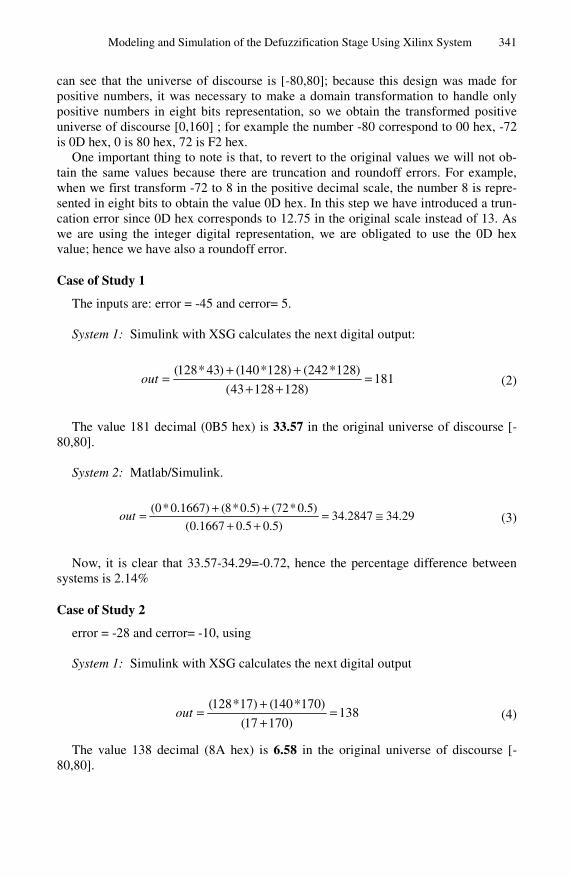
can see that the universe of discourse is [-80,80]; because this design was made for positive numbers, it was necessary to make a domain transformation to handle only positive numbers in eight bits representation, so we obtain the transformed positive universe of discourse [0,160] ; for example the number -80 correspond to 00 hex, -72 is 0D hex, 0 is 80 hex, 72 is F2 hex.
One important thing to note is that, to revert to the original values we will not ob-tain the same values because there are truncation and roundoff errors. For example, when we first transform -72 to 8 in the positive decimal scale, the number 8 is repre-sented in eight bits to obtain the value 0D hex. In this step we have introduced a trun-cation error since 0D hex corresponds to 12.75 in the original scale instead of 13. As we are using the integer digital representation, we are obligated to use the 0D hex value; hence we have also a roundoff error.
Case of Study 1
The inputs are: error = -45 and cerror= 5. System 1: Simulink with XSG calculates the next digital output:
181)12812843(
)128*242()128*140()43*128(=
++++
=out (2)
The value 181 decimal (0B5 hex) is 33.57 in the original universe of discourse [-80,80].
System 2: Matlab/Simulink.
29.342847.34)5.05.01667.0(
)5.0*72()5.0*8()1667.0*0( ≅=++
++=out (3)
Now, it is clear that 33.57-34.29=-0.72, hence the percentage difference between systems is 2.14%
Case of Study 2
error = -28 and cerror= -10, using System 1: Simulink with XSG calculates the next digital output
138)17017(
)170*140()17*128(=
++
=out (4)
The value 138 decimal (8A hex) is 6.58 in the original universe of discourse [-80,80].
342 G. Lizárraga et al.
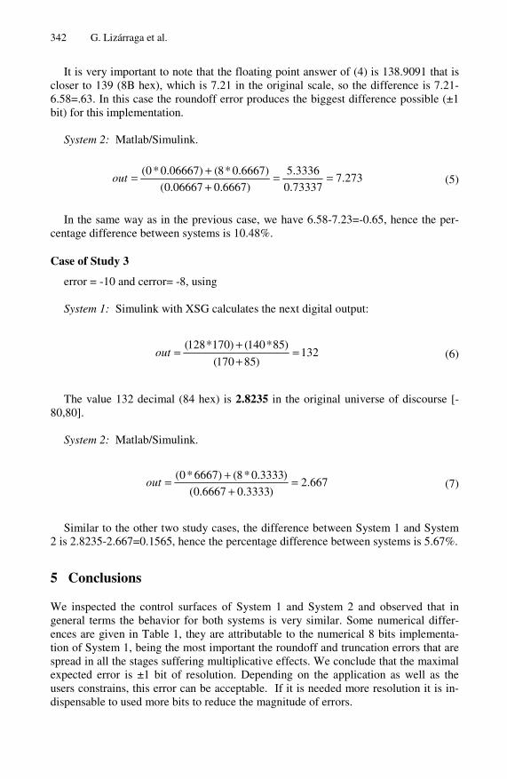
It is very important to note that the floating point answer of (4) is 138.9091 that is closer to 139 (8B hex), which is 7.21 in the original scale, so the difference is 7.21-6.58=.63. In this case the roundoff error produces the biggest difference possible (±1 bit) for this implementation.
System 2: Matlab/Simulink.
273.773337.0
3336.5
)6667.006667.0(
)6667.0*8()06667.0*0( ==++=out (5)
In the same way as in the previous case, we have 6.58-7.23=-0.65, hence the per-centage difference between systems is 10.48%.
Case of Study 3
error = -10 and cerror= -8, using System 1: Simulink with XSG calculates the next digital output:
132)85170(
)85*140()170*128(=
++
=out (6)
The value 132 decimal (84 hex) is 2.8235 in the original universe of discourse [-
80,80]. System 2: Matlab/Simulink.
667.2)3333.06667.0(
)3333.0*8()6667*0( =+
+=out (7)
Similar to the other two study cases, the difference between System 1 and System
2 is 2.8235-2.667=0.1565, hence the percentage difference between systems is 5.67%.
5 Conclusions
We inspected the control surfaces of System 1 and System 2 and observed that in general terms the behavior for both systems is very similar. Some numerical differ-ences are given in Table 1, they are attributable to the numerical 8 bits implementa-tion of System 1, being the most important the roundoff and truncation errors that are spread in all the stages suffering multiplicative effects. We conclude that the maximal expected error is ±1 bit of resolution. Depending on the application as well as the users constrains, this error can be acceptable. If it is needed more resolution it is in-dispensable to used more bits to reduce the magnitude of errors.
Modeling and Simulation of the Defuzzification Stage Using Xilinx System 343
In general terms, considering the chosen resolution, both systems behave very similar, so we can conclude that the developed VHDL code to implement the De-fuzzification stage will work fine in the final implementation in an FPGA.
References
[1] Cirstea, M.N., Dinu, A.: Neural and Fuzzy Logic Control of Drives and Power Systems, Newnes (2002)
[2] Manual of Xilinx System Generator, http://www.xilinx.com [3] Lee, C.-C.: Fuzzy Logic Toolbox. For Use with Matlab, User Guide, Version (2000) [4] Moctezuma, J.C., Torres, C.: Estudio sobre la implementación de redes neuronales artifi-
ciales usando Xilinx System Generator. XII Taller Hiberchip, IWS (2006) [5] Roger Jang, J., Tsai Sun, C., Mizutani, E.: Neuro-Fuzzy and Soft Computing. In: A com-
putational Approach to Learning and Machine Intelligence. Prentice-Hall, Englewood Cliffs (1997)
[6] Zadeh, L.A.: A Fuzzy-Set-Theoretic Interpretation of Linguistic Hedge. Journal of Cy-bernetics 2, 434 (1972)
[7] Bojadziev, G., Bojadziev, M.: Fuzzy Sets, Fuzzy Logic, Applications. World Scientific, Singapore (1995)
[8] Ross, T.J.: Fuzzy logic with engineering applications, 2nd edn. John Wiley and Sons, Chichester (2004)
[9] Zhang, R., Phillis, A., Kouikoglou, V.S.: Fuzzy Control of Queuing Systems. Springer, Heidelberg (2005)
[10] Driankov, D., Hellendoorn, H.: An Introduction to Fuzzy Control, 2nd edn. Springer, Heidelberg (1996)
[11] Mamdani, E.H.: Applications of fuzzy algorithms for control of simple dynamic plant. In: Proc. IEE, vol. 121(12) (1974)
[12] Poorani, S., Urmila Priya, T.V.S.: FPGA Based Fuzzy Logic Controller for Electric Vehi-cle. Journal of the Institution of Engineers 45(5) (2005)
[13] Brown, S., Vranesic, Z.: Fundamentals of Digital Logic with VHDL Design. McGraw-Hill, New York
[14] Sivanandam, S.N., Sumathi, S.: Introduction to Fuzzy Logic Using Matlab. Springer, Heidelberg (2006)
[15] Sanchez-Solano, S., Cabrera, A., Jimenez, C., Jimenez, P., Castillo, I.B., Barros, A.: Im-plementación sobre FPGA de Sistemas Difusos Programables. In: IBERCHIP 2003. Workshop IBERCHIP La Habana, Cuba (2003)