
MODELING AND SIMULATION OF HYDRAULIC-ENERGY SAVING SYSTEM: AN OVERVIEW
10
INTERNATIONAL JOURNAL OF RESEARCH IN AERONAUTICAL AND MECHANICAL ENGINEERING Vol.1 Issue.8, December 2013. Pgs: 10-19 G. K. GANGWAR, MADHULIKA TIWARI 10 ISSN (ONLINE): 2321-3051 INTERNATIONAL JOURNAL OF RESEARCH IN AERONAUTICAL AND MECHANICAL ENGINEERING MODELING AND SIMULATION OF HYDRAULIC-ENERGY SAVING SYSTEM: AN OVERVIEW G. K. GANGWAR 1* , MADHULIKA TIWARI 2 1* M.Tech, ME & MME Dept., Indian School of Mines, Dhanbad, India. Email: [email protected] 2 Lecturer, ME Dept., LDC Institute of Technical Education, Allahabad, India. Email: [email protected] 1* Address- Room No. D-423, Jasper Hostel, ISM Dhanbad-826004, Jharkhand, India, Mo No-+91- 8582088089 Email: [email protected] Abstract Based on the systematic of the well-known closed circuit mobile transmissions, a new hydrostatic transmission system, to be applied in power hydraulics, is introduced in this paper. There are multiple ways of conserving the energy of a vehicle to improve efficiency. The use of flywheel technology or hydraulic accumulator or both, an effective means of conserving energy in hybrid vehicles. This paper presents the introduction, mathematical modeling and review of the engineering and mechanics of the flywheel, and will clarify how flywheel and hydraulic accumulator energy storage work and how they can be applied to hybrid vehicles. Keywords: Flywheel; Accumulator; MATLAB; HST System; hydraulic machines. 1. INTRODUCTION Hybrid drive train systems are becoming increasingly prevalent in Automotive and Commercial Vehicle applications and have also been introduced for the 2009 Formula1 motorsport season. The F1 development has the clear intent of directing technical development in motors port to impact the key issue of fuel efficiency in mainstream vehicles. In order to promote all technical developments, the type of system (electrical, mechanical, hydraulic, etc.) For the F1 application has not been specified Development of energy-saving systems for industrial and mobile applications has been an interesting Issue in the previous decade. Several systems have been proposed and generally termed hybrid systems. The electric hybrid systems have the advantages of improved control, high efficiency, and high specific energy. However, the low specific power and the high price were disadvantages of these systems. Depending upon the equipment employed, they have been classified as: Electric hybrid systems Mechanical hybrid systems Hydraulic hybrid system
-
Upload
independent -
Category
Documents
-
view
0 -
download
0
Transcript of MODELING AND SIMULATION OF HYDRAULIC-ENERGY SAVING SYSTEM: AN OVERVIEW

INTERNATIONAL JOURNAL OF RESEARCH IN AERONAUTICAL AND MECHANICAL ENGINEERING
Vol.1 Issue.8,
December 2013.
Pgs: 10-19
G. K. GANGWAR, MADHULIKA TIWARI 10
ISSN (ONLINE): 2321-3051
INTERNATIONAL JOURNAL OF RESEARCH IN AERONAUTICAL AND MECHANICAL ENGINEERING
MODELING AND SIMULATION OF HYDRAULIC-ENERGY SAVING
SYSTEM: AN OVERVIEW
G. K. GANGWAR1*, MADHULIKA TIWARI2
1*M.Tech, ME & MME Dept., Indian School of Mines, Dhanbad, India. Email: [email protected] 2Lecturer, ME Dept., LDC Institute of Technical Education, Allahabad, India.
Email: [email protected] 1*Address- Room No. D-423, Jasper Hostel, ISM Dhanbad-826004, Jharkhand, India, Mo No-+91-
8582088089 Email: [email protected]
Abstract
Based on the systematic of the well-known closed circuit mobile transmissions, a new hydrostatic transmission system, to be applied in power hydraulics, is introduced in this paper. There are multiple ways of conserving the energy of a vehicle to improve efficiency. The use of flywheel technology or hydraulic accumulator or both, an effective means of conserving energy in hybrid vehicles. This paper presents the introduction, mathematical modeling and review of the engineering and mechanics of the flywheel, and will clarify how flywheel and hydraulic accumulator energy storage work and how they can be applied to hybrid vehicles.
Keywords: Flywheel; Accumulator; MATLAB; HST System; hydraulic machines.
1. INTRODUCTION Hybrid drive train systems are becoming increasingly prevalent in Automotive and Commercial Vehicle applications and have also been introduced for the 2009 Formula1 motorsport season. The F1 development has the clear intent of directing technical development in motors port to impact the key issue of fuel efficiency in mainstream vehicles. In order to promote all technical developments, the type of system (electrical, mechanical, hydraulic, etc.) For the F1 application has not been specified Development of energy-saving systems for industrial and mobile applications has been an interesting Issue in the previous decade. Several systems have been proposed and generally termed hybrid systems. The electric hybrid systems have the advantages of improved control, high efficiency, and high specific energy. However, the low specific power and the high price were disadvantages of these systems.
Depending upon the equipment employed, they have been classified as:
� Electric hybrid systems � Mechanical hybrid systems � Hydraulic hybrid system

INTERNATIONAL JOURNAL OF RESEARCH IN AERONAUTICAL AND MECHANICAL ENGINEERING
Vol.1 Issue.8,
December 2013.
Pgs: 10-19
G. K. GANGWAR, MADHULIKA TIWARI 11
The following is a list of system specifications for the kinetic energy recovery system that has been used in Formula 1 cars
Table 1: Specification of Formula 1 cars
Serial No
Parameters Specification
1 Power 60 Kw 2 System Weight 25 kg 3 Flywheel Weight 5 kg 4 CVT Weight 5 kg 5 Flywheel Diameter 200 mm 6 Flywheel Length 100 mm 7 Efficiency >70% round trip 8 Flywheel Max Speed 64500 rpm
A significant outcome of this action is renewed interest and development of mechanical hybrid systems comprising a high speed composite flywheel and a full-toroidal traction drive Continuously Variable Transmission (CVT).A flywheel based mechanical hybrid has few system components, low system costs, low weight and dispenses with the energy state changes of electrical systems producing a highly efficient and power dense hybrid system. Due to the system simplicity, the mechanical hybrid delivers a measured 72% ‘round trip’ efficiency in approximately half the package, half the weight and a quarter of the cost of an electric hybrid system. Hybrid systems using flywheels have been considered Advantageous for some vehicle applications because of their low cost, robustness, endurance and high specific energy. In addition, their high speed with higher specific energy and power flywheel systems have been studied, which reduces the gap between the theory and applications of flywheel systems. The difficulty in continuously variable transmission (CVT) control and the dynamics problem of a high-speed flywheel were remaining issues of mechanical hybrid systems.
The main features of hydraulic hybrid system are: � rapid recovery of energy � high efficiency, energy density & power transfer � cost effective � small package � low weight and � minimal degradation in performance over use
The proposed system has the high specific energy of the flywheel storage system. The specific energy of the system was higher than that of the hydraulic hybrid system using hydraulic accumulator, which was important for mobile applications.
2. Main Circuit The main circuit consists the following components:
• Two clutches
• Two flywheels
• Three check valves
• One directional control valve
• Two pressure relief valves
• Two accumulators
• One boost pump
• Two variable pump-motor combinations
The main circuit is closed circuit which is shown by fig.1 with the all above components:

INTERNATIONAL JOURNAL OF RESEARCH IN AERONAUTICAL AND MECHANICAL ENGINEERING
Vol.1 Issue.8,
December 2013.
Pgs: 10-19
G. K. GANGWAR, MADHULIKA TIWARI 12
Figure 1: Proposed hydraulic circuit
2.1 Description of Proposed System
The proposed system consists of two variable displacement hydraulic pump/motor units (��1,��2 ), two
electric clutches (CL1, CL2), a directional 4/3 valve, two hydraulic accumulators (HP, LP), and a flywheel FL1. The high pressure accumulator and FL1 function as an energy storage system. In the proposed hydrostatic drive system, two types of energy storages are employed. The first is a mechanical type and the second is a hydraulic type of energy storage system. Thus, the hybrid system under study can be classified as a hydro mechanical hybrid system. Accumulator LP functions as a tank with low pressure. The electric motor functions as a primary power source. By engaging or disengaging the two electric clutches the system is powered by either FL1 or the electric motor. Depending upon the position of the directional control valve, the power is supplied by the HP accumulator. By controlling the displacements of the hydraulic pump/motors, the clutches, and the directional control valve the system is able to work in two distinct modes called the braking and the driving modes. The braking mode is defined when the load functions as a power source and the driving mode is defined when the load is driven by the system. Energy is transferred from the driven part to the primary part in the braking mode. While in the driving mode, energy is transferred from the primary part, which will be the electric motor, the high-pressure accumulator or the flywheel FL1, to the driven part.
3. Literature Survey
Hydraulic hybrid Transmission system with accumulator and flywheel is an essential part of modern machinery drive technology. In common terminology, whenever there is a variable displacement pump or motor in a pump-motor system with accumulator and flywheel, it is called hydraulic energy saving system. In specific terms, a hydraulic hybrid system is a case of energy transmission where the oil input device is a positive displacement pump and the output element is the same kind of motor, both of which are designed with matching physical and operational characteristics with optimum energy transmission. For applications where efficiency, wide adjustability and ability to hold constant speed at all loads are the main concern, a hydraulic energy saving drive is the best solution.
Triet H.H. et.al [1] in the present paper, a novel hydraulic energy recovery system was presented with modelling, simulation, and experimentation on the test rig. The system has been developed based on a traditional closed-loop hydrostatic transmission (HST) with novel energy storage, including a hydraulic accumulator and a flywheel. The control strategy for the proposed system has also been designed. The experimental results implied that the proposed system could be applied for mobile applications. Experiments were done with the test rig for a modified ten-mode profile, which showed that the system saved about 48 per cent of energy supplied from the primary power source when compared with a traditional HST. Lin C.C. et.al [2] proposed the Power Management Strategy for a Parallel Hybrid Electric Truck. Designing the power management strategy for HEV(Heavy Earth Vehicles) by extracting rules from the Dynamic
INTERNATIONAL JOURNAL OF RESEARCH IN AERONAUTICAL AND MECHANICAL ENGINEERING
Vol.1 Issue.8,
December 2013.
Pgs: 10-19
G. K. GANGWAR, MADHULIKA TIWARI 13
Programming(DP) results has the clear advantage of being near-optimal, accommodating multiple objectives, and systematic. Hybrid vehicle techniques have been widely studied recently because of their potential to significantly improve the fuel economy and drivability of future ground vehicles. In this paper, we will present a procedure for the design of a near-optimal power management strategy. The design procedure starts by defining a cost function, such as minimizing a combination of fuel consumption and selected emission species over a driving cycle. By analyzing the DP results, an improved rule-based control strategy was developed. The improved rule-based control law, even given its simple structure, reduces its performance gap to the theoretically optimal (DP) results by 50–70%. Triet H.H. et.al [3] have been developed the Design and control of a closed-loop hydraulic energy-regenerative system. A novel hydraulic energy-saving method was developed from modeling through simulation and finally to experimental validation This paper presents an approach to the problem of controlling the electricity generation of series hybrid electric vehicles (SHEVs) and proposes an algorithm with the goal to minimize fuel consumption. Starting from the knowledge of the vehicle electric generator consumption maps, as well as information on the vehicle battery behavior, and on some overall parameters characterizing the expected trip, the algorithm is able to define: whether to continuously keep the generator in the ON state or not; when to, if is the case, switch the generator ON or OFF; the instantaneous power to be delivered by the electric generator when in ON state. Adopting such parameters enables avoiding to previously knowing the battery losses on a given trip and offers the possibility to update the control according to online measures. Addresses are also given on how to online assess the trip parameters to be used as inputs for the algorithm. Douglas C. et.al [4] have developed a mechanical kinetic energy recovery system (KERS) utilizing a high speed carbon filament flywheel and a Torotrak full-toroidal traction drive Continuously Variable Transmission for use both within F1 and motorsport but also for mainstream automotive Applications This paper describes the Formula 1 system and the development of road car systems covering the energy storage requirements, system efficiencies, energy savings and hence fuel economy and performance improvements..
World pump [5] it is A European steel manufacturer .it done a test on hydraulic system to see the amount of energy saving, tests were carried out to establish if a drive would be a viable option for controlling energy consumption with PID (Proportional, integral and differential controller) .after the test it is found that 70% energy saving was successfully reached..
Guzzella, L. et.al [6] proposed A. Vehicle propulsion systems with its modeling and optimization. In this paper the longitudinal behavior of road vehicles is analyzed. The main aim of the analysis to minimization of the fuel and energy consumption. Most approaches to this problem enhance the complexity of the vehicle system by adding components such as electrical motors or storage devices. Such a complex system can only be designed by means of mathematical models. This text gives an introduction to the modeling and optimization problems typically encountered when designing new propulsion systems for passenger cars.
Shen, S. et.al [7] have been developed the Analysis and control of a flywheel hybrid vehicular powertrain. A new concept for a CVT powertrain, called the ZI powertrain, is presented and analyzed. The extra flywheel in this powertrain can resolve the drive ability problems of conventional powertrains that are controlled to maximize fuel economy. This paper analyzes a concept for a novel powertrain with an additional flywheel. This article explained that Vehicular powertrains with an internal combustion engine, an electronic throttle valve, and a continuously variable transmission offer much freedom in controlling the engine speed and torque. This can be used to improve fuel economy by operating the engine in fuel-optimal operating points. The flywheel plays a part only in transient situations by (partly) compensating the engine inertia, making it possible to optimize fuel economy in stationary situations without losing drive ability in transients. Two control strategies are discussed. The first one focuses on the engine and combines feedback linearization with proportional control of the CVT ratio. All controllers are designed, using a simple model of the powertrain. They have been evaluated by simulations with an advanced model. The main drawbacks of this approach are the low drive ability and, possibly, an inverse response of the vehicle acceleration after a kick-down of the drive pedal.

INTERNATIONAL JOURNAL OF RESEARCH IN AERONAUTICAL AND MECHANICAL ENGINEERING
Vol.1 Issue.8,
December 2013.
Pgs: 10-19
G. K. GANGWAR, MADHULIKA TIWARI 14
Bin WU et.al [8] have been proposed the Optimal Power Management for a Hydraulic Hybrid Delivery Truck. Hydraulic hybrid propulsion and energy storage components demonstrate characteristics that are very different from their electric counterparts, thus requiring unique control strategies. An optimal control problem for power management of the Hydraulic Hybrid Medium Truck System is formulated and solved by using Dynamic Programming (DP) algorithm to minimize the fuel consumption. The Hydraulic Hybrid Vehicle is modelled in the MATLAB/SIMULINK environment to facilitate system integration and control studies. A Dynamic Programming (DP) algorithm is used to obtain optimal control actions for gear shifting and power splitting between the engine and the hydraulic motor over a representative urban driving schedule. Features of optimal trajectories are then studied to derive implementable rules. System behavior demonstrates that the new control strategy takes advantage of high power density and efficiency characteristics of hydraulic components, and minimizes disadvantages of low energy density, to achieve enhanced overall efficiency. Depending on the efficiency of the particular hydraulic pump/motor, the practical control strategy derived from DP results enables fuel economy increase of the HHV truck over the conventional counterpart between 28% and 48%. Triet H.H. Et.al [9] have been developed A novel energy-saving hydraulic system based on an HST/hydraulic accumulator combination was investigated through analysis and modeling. The system improves the efficiency of the primary power source. The accumulator is used in a novel way to recover the kinetic energy without reversion of fluid flow. Both variable displacement hydraulic pump /motors are used when the system operates in the flow coupling configuration so as to enable it to meet the difficult requirements of some industrial and mobile applications. The validation of model indicated that the energy recovery potential of the system varied from 32% to 66% depending on the pump/motor displacement. A greater motor displacement ratio corresponded to a greater energy recovery potential.
4. Mathematical Modeling
4.1 Hydraulic Motor The volumetric efficiency, mechanical efficiency, actual flow rate and actual torque of the hydraulic motor are expressed by the equations from (1) to (4) respectively:
ηv = αDmaxωαDmaxω+Qloss
………… ………………………………………………………………………. (1)
ηt =�����Δ�−���
�����Δ� …………………………….………………………………………..………….... (2)
!� = !"ηv
…………………………………………………………………………………………….. (3)
�� = ηt�����Δ� ……………………………………………………………………………………. (4)
4.2 Hydraulic Pump The volumetric efficiency, mechanical efficiency, ideal flow rate and ideal torque of the hydraulic pump are expressed by the following equations from (5) to (8) respectively:
ηv = αDmaxω−QlossαDmaxω
…………………………………………………………………………...………. (5)
η# = $%&'()*$%&'()*+,-.//
……………………………………………………………………………………. (6)
!" = αDmaxω …………………….…………………………………………………..……………… (7)
�" = �����Δ� ………………………………………………………………………..……………… (8)

INTERNATIONAL JOURNAL OF RESEARCH IN AERONAUTICAL AND MECHANICAL ENGINEERING
Vol.1 Issue.8,
December 2013.
Pgs: 10-19
G. K. GANGWAR, MADHULIKA TIWARI 15
4.3 Electro-Hydraulic Displacement Control Mechanism The Electro-Hydraulic Mechanism is used for controlling of a variable displacement hydraulic machine. Although the mathematical model of the Electro-Hydraulic mechanism is a fifth-order system, in practical applications a reduced-order model is usually used the first-order system is used in this study which is also give right and accurate result as given by equation (9).
0123 = 45/6
�7 + 85/6
�………………………………………………………………………………..…… (9)
4.4 Accumulator The hydraulic accumulator is a device which stored the hydraulic energy in form of pressure. The hydraulic accumulator here is modeled based on its physical attributes. In the current paper, the Van der Waals’ equation is employed to model the hydraulic accumulator. This is a simple but sufficiently exact model for the present domain of operation. The compression of an accumulator is considered as isothermal process ( �9 =:�; 2�;2) and expansion is assumed to be adiabatic process (�9< = :�; 2�;2). The gas pressure in the accumulator is expressed by the following equation (10)
=> + �?; 9⁄ A2B 19 − ;C3 = ;D� ……… ………………………………………………………..….(10)
The energy restored in the hydraulic accumulator is estimated by the equation (11).
E� = F G ∆>I2 ……………………………………………………………………………………..... (11)
4.5 The Connecting Lines In this study, the losses attributable to the length of the pipes are ignored because the losses in the hose pipes are less. The continuity equation means mass flow rate is constant through pipe (ρVА= constant), is used to model the pressure of the fluid in the hoses. Depending upon the configurations of the drive system, two distinct configurations are modeled.
4.5.1 Flow Coupling Configuration To avoid the complex calculations, the pressure drop in the check valves is neglected in the driving line, so
the pressures before and after a check valve are same. In case of driving mode, the Pressures >1 in J1 (high
pressure line) and >2in J2 are expressed by the continuity equations (12) and (13) respectively.
KLMNOPNQ = !OR + !S8 + !ST − !U8 − !VR ………………………………………………..…….…….(12)
KLMNOWNQ = !VX + !SY + !SZ − !UT − !OX .. …………………………………………………………...(13)
4.5.2 Pressure Coupling Configuration
In this mode the high pressurized fluid supply through the high pressure accumulator (HP).The pressure in the high-pressure line is similar to the gas pressure in HP, and the pressure in the low-pressure line is similar to the gas pressure in LP. The gas pressure or the fluid pressure in the pressure coupling configuration is determined by the accumulator’s parameters and the flow rate into it. The flow rate into the high accumulator is expressed by equation (14).
!R = ?!OR − !U8 − !VRA ……………………………………………………………………….… (14)
The gas volume can be estimated from the Flow rate into the accumulator using the given equation (15).

INTERNATIONAL JOURNAL OF RESEARCH IN AERONAUTICAL AND MECHANICAL ENGINEERING
Vol.1 Issue.8,
December 2013.
Pgs: 10-19
G. K. GANGWAR, MADHULIKA TIWARI 16
9 = 9[R − F !RI2Q[ ……………………………………………………………………………..……. (15)
The above equation is valid when 9 \ 9[R or the high pressure accumulator is empty the gas pressure in the accumulator is equal to the pre-charge gas pressure.
4.6 Flywheel
The flywheel is a mechanical device which is used to store the kinetic energy The rotational or kinetic energy of the flywheel can be calculated using equation (16) E = ½ J ω² ………………………………………………………………………………..….……….. (16) and the moment of inertia is calculated as J = ½ m (r1² - r2²) ………………….……… (17) The dynamic equation of the flywheel is obtained by applying Newton’s second law, as in below equation (18).
�� = ] 7̂ + _^ + �`� …………………………………………………………………….………… (18) The recovered efficiency is defined as the ratio of the kinetic difference of FL1 and that of FL2 before and after braking, which is expressed by the following equation (19).
ab =E"+1E"
c 100 …………………………………………………………………………………….. (19)
Where
EX+8 = 8T ]^VRe,X+8
T
E" =12 ]^0"
2
The energy supplied by the electric motor is estimated by equation (20).
E = F �OR^I2Q[ ……………………………………………………………………………………… (21)
5. Simulation And Results
From a number of literatures review the following experimental, simulation curve show the validation of hydraulic energy-saving system.
Figure 2: overall efficiency of system with pressure

INTERNATIONAL JOURNAL OF RESEARCH IN AERONAUTICAL AND MECHANICAL ENGINEERING
Vol.1 Issue.8,
December 2013.
Pgs: 10-19
G. K. GANGWAR, MADHULIKA TIWARI 17
Time in sec
Figure 3: variation of system pressure with time
Figure 4: overall efficiency of system with speed
Figure 5: electro-hydraulic mechanism control with time
6. Conclusion
I. In the present paper, a hydraulic energy saving system presented with modelling based on a number literature review. The experimental validation and simulation confirmed that the system is a promising energy-saving system for mobile applications. Experiments were done which showed that the system saved about 48 per cent of energy supplied from the power source when compared with a simple and traditional HST.
II. With the using of hybrid system in real applications, such as an excavator, road vehicles, passenger-
cars etc. a huge reduction in fuel consumption and exhaust fumes can be achieved. Thus, there is increase in the initial cost of vehicle due to the use of hydraulic accumulators, flywheels and variable displacement hydraulic pumps/ motors can be compensated for by reducing fuel consumption. Environmental benefits will also be realized.

INTERNATIONAL JOURNAL OF RESEARCH IN AERONAUTICAL AND MECHANICAL ENGINEERING
Vol.1 Issue.8,
December 2013.
Pgs: 10-19
G. K. GANGWAR, MADHULIKA TIWARI 18
References
[1] Triet H.H. and K. K. Ahn “Comparison and assessment of a hydraulic energy saving system for hydrostatic drives” Journal of Systems and Control Engineering; Sage Publication: DOI: 10.1243/09596518JSCE1055, 5 August 2010.
[2] Lin C.C., Huei Peng and Jessy W. Grizzle, Fellow, IEEE, and Jun-Mo Kang’ “Power Management Strategy for a Parallel Hybrid Electric Truck” IEEE Transactions on Control Systems Technology, Vol. 11, No. 6, November 2003.
[3] Triet H.H and K K Ahn “Design and control of a closed-loop hydraulic energy-regenerative system” Automation in Construction 22 (2012) 444–458.
[4] Douglas C. and Chris Brockbank “Mechanical Hybrid system comprising a flywheel and CVT for Motorsport & mainstream automotive applications” 09PFL-0922: SAE International 2008.
[5] World Pumps. A European steel manufacturer. Variable speed drives energy savings for hydraulic systems july2009.
[6] Guzzella, L. and Sciarretta, “A Vehicle propulsion systems: introduction to modeling and optimization”, 2007, pp. 13–41 (Springer).
[7] Shen, S. and Veldpaus, F. E. “Analysis and control of a flywheel hybrid vehicular powertrain”. IEEE Trans., Control Systems Technol., 2004, 12(5), 645–660.
[8] Bin W.U., Lin C.C., Zoran F., H. Peng and D. Assanis “Optimal Power Management for A Hydraulic Hybrid Delivery Truck” Proceedings of the 2001 American Control Conference, Arlington, VA, June 2001, pp.2878-2883. [9] Triet H.H. and K. K. Ahn “Modeling and simulation of hydrostatic transmission system with energy regeneration using hydraulic accumulator.” Journal of Mechanical Science and Technology 24 (5) (2010) 1163-1175
A Brief Author Biography G. K Gangwar- I am a student of M.Tech in ISM, Dhanbad. I have completed my B.Tech in Mechanical Engineering in 2012 from FGIET, Raebareli, Uttar Pradesh, India. Madhulika Tiwari –She is brilliant student form childhood. She has completed Diploma in Mechanical Engineering in 2008 from IERT-Allahabad, and B.Tech in Mechanical Engineering in 2012 from FGIET, Raebareli, Uttar-Pradesh, India. Now she is lecturer in LDC Institute of Technical Education, Allahabad.
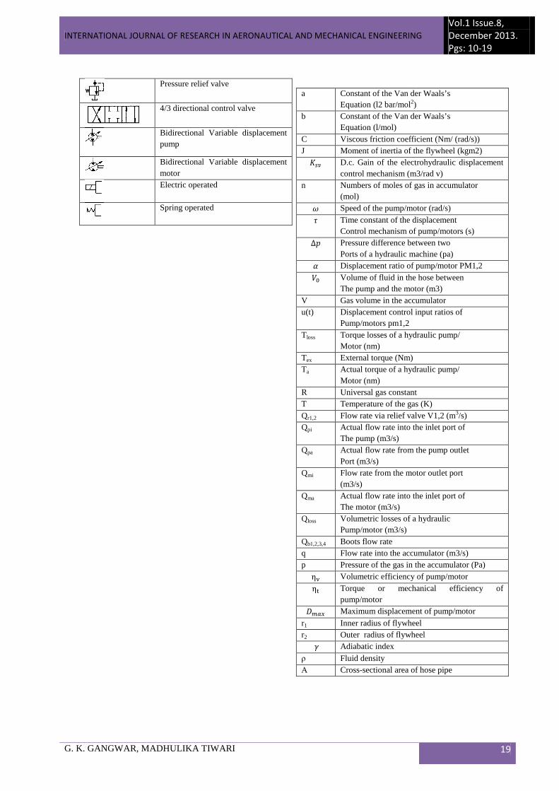
Symbols and Notations
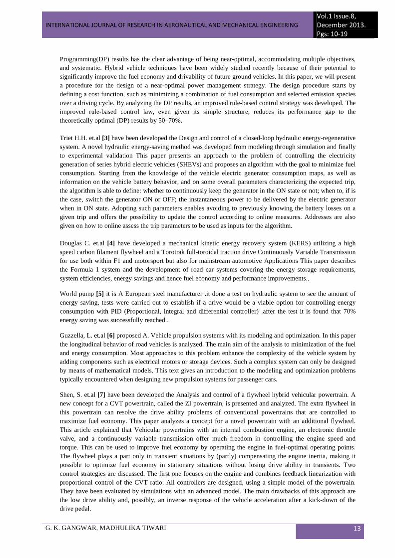
Symbols Description HST Hydrostatic transmission CVT Continuously Variable Transmission Q Flow CPS Constant Pressure System CL Clutch FL Flywheel PM Pump/motor set
Electric motor
Accumulator, gas charged
Check valve
INTERNATIONAL JOURNAL OF RESEARCH IN AERONAUTICAL AND MECHANICAL ENGINEERING
Vol.1 Issue.8,
December 2013.
Pgs: 10-19
G. K. GANGWAR, MADHULIKA TIWARI 19
Pressure relief valve
4/3 directional control valve
Bidirectional Variable displacement pump
Bidirectional Variable displacement motor
Electric operated
Spring operated
a Constant of the Van der Waals’s Equation (l2 bar/mol2)
b Constant of the Van der Waals’s Equation (l/mol)
C Viscous friction coefficient (Nm/ (rad/s)) J Moment of inertia of the flywheel (kgm2)
fgh D.c. Gain of the electrohydraulic displacement control mechanism (m3/rad v)
n Numbers of moles of gas in accumulator (mol)
^ Speed of the pump/motor (rad/s) i Time constant of the displacement
Control mechanism of pump/motors (s)
∆> Pressure difference between two Ports of a hydraulic machine (pa)
� Displacement ratio of pump/motor PM1,2
9[ Volume of fluid in the hose between The pump and the motor (m3)
V Gas volume in the accumulator u(t) Displacement control input ratios of
Pump/motors pm1,2 Tloss Torque losses of a hydraulic pump/
Motor (nm) Tex External torque (Nm) Ta Actual torque of a hydraulic pump/
Motor (nm) R Universal gas constant T Temperature of the gas (K) Qr1,2 Flow rate via relief valve V1,2 (m3/s) Qpi Actual flow rate into the inlet port of
The pump (m3/s) Qpa Actual flow rate from the pump outlet
Port (m3/s) Qmi Flow rate from the motor outlet port
(m3/s) Qma Actual flow rate into the inlet port of
The motor (m3/s) Qloss Volumetric losses of a hydraulic
Pump/motor (m3/s) Qb1,2,3,4 Boots flow rate q Flow rate into the accumulator (m3/s) p Pressure of the gas in the accumulator (Pa)
ηj Volumetric efficiency of pump/motor
η# Torque or mechanical efficiency of pump/motor
�VRe Maximum displacement of pump/motor
r1 Inner radius of flywheel r2 Outer radius of flywheel
k Adiabatic index
ρ Fluid density А Cross-sectional area of hose pipe