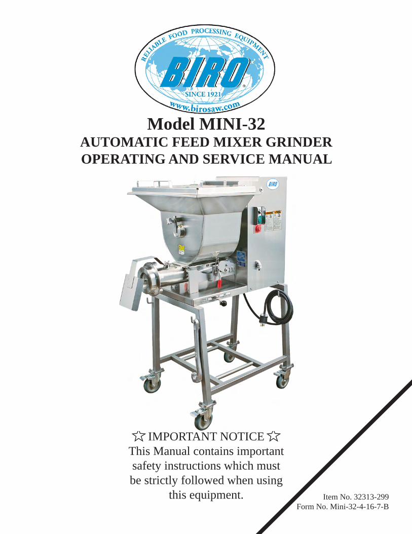
Model MINI-32 - Berkel Midwest
32
Item No. 32313-299 Form No. Mini-32-4-16-7-B Model MINI-32 AUTOMATIC FEED MIXER GRINDER OPERATING AND SERVICE MANUAL IMPORTANT NOTICE This Manual contains important safety instructions which must be strictly followed when using this equipment.
-
Upload
khangminh22 -
Category
Documents
-
view
0 -
download
0
Transcript of Model MINI-32 - Berkel Midwest
Item No. 32313-299Form No. Mini-32-4-16-7-B
Model MINI-32AUTOMATIC FEED MIXER GRINDEROPERATING AND SERVICE MANUAL
IMPORTANT NOTICEThis Manual contains important safety instructions which mustbe strictly followed when using
this equipment.


TABLE OF CONTENTS:
NOTICE TO OWNERS AND OPERATORS . . . . . . . . . . . . . . . . . . . . . . . . . . . . . . . . . . . . . . . . . . . . . .
PAGE
SAFETY TIPS . . . . . . . . . . . . . . . . . . . . . . . . . . . . . . . . . . . . . . . . . . . . . . . . . . . . . . . . . . . . . . . . . . . . . .
INSTALLATION . . . . . . . . . . . . . . . . . . . . . . . . . . . . . . . . . . . . . . . . . . . . . . . . . . . . . . . . . . . . . . . . . . . .
CLEANING . . . . . . . . . . . . . . . . . . . . . . . . . . . . . . . . . . . . . . . . . . . . . . . . . . . . . . . . . . . . . . . . . . . . . . . .
1
2
3
7OPERATION . . . . . . . . . . . . . . . . . . . . . . . . . . . . . . . . . . . . . . . . . . . . . . . . . . . . . . . . . . . . . . . . . . . . . . .
8
MOTOR WIRING AND ELECTRICAL REQUIREMENTS . . . . . . . . . . . . . . . . . . . . . . . . . . . . . . . . . . 4
PRE-OPERATION . . . . . . . . . . . . . . . . . . . . . . . . . . . . . . . . . . . . . . . . . . . . . . . . . . . . . . . . . . . . . . . . . . . 5
PARTS LOCATION . . . . . . . . . . . . . . . . . . . . . . . . . . . . . . . . . . . . . . . . . . . . . . . . . . . . . . . . . . . . . . . . . . 6
REMOVAL & INSTALLATION INSTRUCTIONS . . . . . . . . . . . . . . . . . . . . . . . . . . . . . . . . . . . . . . . . . 9
MAINTENANCE & LUBRICATION . . . . . . . . . . . . . . . . . . . . . . . . . . . . . . . . . . . . . . . . . . . . . . . 10 - 12
PARTS LIST DIAGRAMS . . . . . . . . . . . . . . . . . . . . . . . . . . . . . . . . . . . . . . . . . . . . . . . . . . . . . . . 13 - 18
FASTENERS & LOCATIONS . . . . . . . . . . . . . . . . . . . . . . . . . . . . . . . . . . . . . . . . . . . . . . . . . . . . . . . . . 19
OPERATOR’S NOTES . . . . . . . . . . . . . . . . . . . . . . . . . . . . . . . . . . . . . . . . . . . . . . . . . . . . . . . . . . . . . . 27
ELECTRICAL SCHEMATICS . . . . . . . . . . . . . . . . . . . . . . . . . . . . . . . . . . . . . . . . . . . . . . . . . . . . 21 - 23
FOOTSWITCHES, PNEUMATIC & ELECTRIC . . . . . . . . . . . . . . . . . . . . . . . . . . . . . . . . . . . . . 24 - 25
SAFETY LABEL LOCATIONS . . . . . . . . . . . . . . . . . . . . . . . . . . . . . . . . . . . . . . . . . . . . . . . . . . . . . . . 26
OPERATOR SIGNATURE PAGE . . . . . . . . . . . . . . . . . . . . . . . . . . . . . . . . . . . . . . . . . . . . . . . . . . . . . . 28
LIMITED WARRANTY . . . . . . . . . . . . . . . . . . . . . . . . . . . . . . . . . . . . . . . . . . . . . . . . . . . . . . . . . . . . . 29
OPERATOR’S NOTES . . . . . . . . . . . . . . . . . . . . . . . . . . . . . . . . . . . . . . . . . . . . . . . . . . . . . . . . . . . . . . 20
NOTICE TO OWNERS AND OPERATORS
BIRO’s products are designed to process food products safely and efficiently. Unless the opera-tor is properly trained and supervised, however, there is the possibility of a serious injury. It is the responsibility of the owner to assure that this machine is used properly and safely, strictly following the instructions contained in this Manual and any requirements of local law.
Warnings related to possible damage are indicated by:
BIRO also has provided warning labels on the equipment. If any warning label, instruction label or Manual becomes misplaced, damaged, or illegible, please contact your nearest Distributor or BIRO directly for a replacement.
Remember, however, this Manual or the warning labels do not replace the need to be alert and to use your common sense when using this equipment.
- NOTE -
A copy of this manual is included with each MODEL MINI-32 MIXER GRINDER.The descriptions and illustrations contained in this manual are not binding.
The manufacturer reserves the right to introduce any modification without updating the manual.
1
No one should use or service this machine without proper training and supervision. All operators should be thoroughly familiar with the procedures contained in this Manual. Even so, BIRO cannot anticipate every circumstance or environment in which its products will be used. You, the owner and operator, must remain alert to the hazards posed by the function of this equipment particularly the ROTATING GRINDING AUGER and the ROTATING MIXING PADDLE, which can severely injure an inattentive operator amputating fingers and limbs. No one under eighteen (18) years of age should operate this equipment. If you are uncertain about a particular task, ask your supervisor.
This Manual contains a number of safe practices in the SAFETY TIPS section. Additional warn-ings are placed throughout the Manual. Warnings relate to your personal safety are indicated by:
or

2
SAFETY TIPS
ROTATING GRINDING AUGER & ROTATING MIXING PADDLETO AVOID SERIOUS PERSONAL INJURY
• NEVER Touch This Machine without Training and Authorization by Your Supervisor.• NEVER Place Hands into Machine Input or Output Openings.• NEVER Open Machine During Operation.• ONLY Use a Qualified Electrician to Install According to Local Building Codes: Machine MUST Be Properly Grounded.
• ALWAYS Connect to PROPER Voltage & Phase.• ONLY Install on Level, Non-Skid Surface in a Clean, Well-Lighted Work Area Away from Children and Visitors.
• ALWAYS Lock Machine Castors After Moving This Machine.• NEVER Use This Machine For Non-Food Products.• NEVER Operate Machine With Product Mixer Safety Cover Open or Removed or Magnetic Interlock Switch By-Passed.
• ALWAYS Turn Off, Unplug Machine From Power Source and Perform Lockout/Tagout Procedure to this Machine BEFORE Attempting to Unjam or Unclog, Cleaning or Servicing.
• NEVER Leave Machine Unattended While Grinder is Running.• NEVER Alter This Machine From its Original Form as Shipped From Factory. DO NOT Operate Machine With Missing Parts.
• PROMPTLY REPLACE Any Worn or Illegible Warning Labels.• ALWAYS Read Operation and Service Manual BEFORE Operating, Cleaning, or Servicing. • USE ONLY BIRO Parts and Accessories Properly Installed.
INSTALLATION
TO AVOID SERIOUS PERSONAL INJURY, PROPERLY INSTALLEQUIPMENT IN ADEQUATE WORK AREA
3
• ALWAYS Connect to Proper Voltage & Phase.
• NEVER Operate Machine With Product Mixer Safety Cover Open or Removed or Magnetic Interlock Switch By-Passed.
• ALWAYS Use Qualified Technician and Electrician for Installation.
• ALWAYS Install Equipment in Work Area with Adequate Light and Space Away From Children and Visitors.
• ONLY Operate on a Solid, Level, Non-Skid Surface.
• ALWAYS Lock Machine Castors After Moving Machine.
• NEVER Bypass, Alter, or Modify This Equipment in Any Way From Its Original Condition.
• NEVER Operate Without all Warning Labels Attached and Owner/Operator Manual Available to the Operator.
• USE ONLY BIRO Parts and Accessories Properly Installed.
UNCRATING AND SET UP
1. Read this Manual thoroughly before installation and operation. Do not proceed with installation and operation if you have any questions or do not understand anything in this Manual. Contact your local Distributor, or BIRO first.
2. Remove all banding, shipping carton, and all equipment from inside the tub. Then take machine off shipping pallet.
3. Install machine on a level, non-skid surface in a well-lighted work area away from children and visitors.
4. This machine is complete except for knife and plate. There is a bowl shipping plug (cardboard) placed in the output end of the grinding bowl to retain the grinding auger during shipment. REMOVE THE BOWL SHIPPING PLUG AND THE GRINDING AUGER.
5. After checking and making sure the power supply is correct, plug in your machine. NEVER OPERATE MACHINE WITH PRODUCT MIXER SAFETY COVER OPEN OR HOPPER REMOVED. (Machine will not run with cover open.)6. Machine must be properly grounded. Use qualified electrician to install according to local building codes.
MOTOR WIRING AND ELECTRICAL REQUIREMENTS1. Interchange of motor current is made in motor outlet box. Leads are properly marked. Changing instructions are on the motor plate or inside junction box cover.
NOTE TO OWNER AND ELECTRICIAN: IF THIS MACHINE IS NOT CORD AND PLUG CONNECTED TO THE ELECTRICAL SUPPLY SOURCE, THEN IT SHOULD BE EQUIPPED WITH, OR CONNECTED TO, A LOCKABLE, MANUALLY-OPERATED DISCONNECT SWITCH (OSHA 1010.147)
4
2. All grinders are wired 208-230 volts unless otherwise specified. Be sure motor specifications (voltage, cycle, phase) match power supply line. Be sure line voltage is up to specification.
3. Connect leads to machine in a manner that will be approved by local electrical inspectors.
4. Rated voltage of the unit shall be identical with full supply voltage.
5. Voltage drop on the supply line shall not exceed 10% of full supply voltage.
7. The feederline conductor shall only be used for the supply of one unit of the relevant horsepower. For connections of more than one unit on the same feederline, a local electrician will have to be consulted to determine the proper conductor size.
6. The feederline conductor size in the raceway from the branch circuit to the unit must be correct to assure adequate voltage under heavy starting and short overload conditions.
8. The size of the electrical wiring required from the power source to the mixer grinder/chopper is a MINIMUM OF No. 12 WIRE.
9. The BIRO Manufacturing Company is not responsible for permanent wiring, connection or installation.
MOTOR SPECIFICATIONS
HP KW VOLTS HZ PH AMPS 3 2.2 208/230 60 3 11/9.8 3 2.2 208/230 60 1 19/17 3 2.2 460 60 3 4.9 2.5 1.9 380 50 3 4.4

5
10. The start stop switch and the Auger Engage Lever are located on the right side of the machine when facing the grinding bowl. The start stop switch will activate the mixer paddles. The start stop switch will also activate the grinding auger, only when the Auger Engage Lever is engaged, or in the “Grind” position. To disengage the grinding operation move the Auger Engage Lever to the “Mix” position. The tank and hopper cover interlock switches are located in the motor compartment. When the safety cover is raised the machine will stop operation.
11. Turn the toggle hand/foot selector switch to the hand position and move the Auger Engage Lever to “Grind”to activate the grinding drive shaft. Push the green start button. CHECK THE ROTATION OF THE AUGER DRIVE SHAFT; ROTATION MUST BE COUNTER-CLOCKWISE as indicated by the rotation decal affixed to the grinding bowl.
ONLY HAND TIGHTEN END RETAINING RING
15. Check placement of all warning labels and be sure anyone who is to operate this MINI-32 MIXER GRINDER has read and fully understands the manual. Machine is now ready for trained operators to process product.
16. Use meat deflector attached to grinding bowl to eliminate meat splatter.
17. Contact your local distributor if you have any questions or problems with the installation or operation of this machine.
12. If machine runs clockwise(backwards), it must be rewired to correct rotation, otherwise serious irreparable damage may occur to the grinding components.
PRE-OPERATION AND AUGER ROTATION CHECKROTATION MUST ONLY BE CHECKED WITH THE
GRINDING AUGER REMOVED, otherwise serious irreparabledamage may occur to grinding components.
13. Check operation of optional footswitch if equipped. Plug footswitch cord into fitting on control panel. Turn selector to foot. The machine will operate with pressure on the footswitch treadle. Releasing the treadle stops the machine.
14. Insert auger assembly into the grinding bowl and fully engage the auger into the drive shaft. Place knife first (sharp edges out) then grinding plate into end of grinding bowl. The grinding plate slides over the knife drive pin, and is held from rotating during operation by three pins in the grinding bowl. Install the end retaining ring.
For best results, use knife and plate as a set. Do not operate machinefor any period of time without product in the grinding bowl. This will
cause heating and dulling of the knife and plate.
PARTS LOCATION
6
AUGER DRIVE ENGAGE LEVER
ENGAGED DISENGAGED
OPERATION
• NEVER Place Hands into Machine Input or Output Openings.
• ONLY Properly Trained Personnel Should Use This Equipment.
7
• NEVER Open Machine During Operation.
• NEVER Operate Machine With Product Mixer Safety Cover Opened or Hopper Removed or Magnetic Interlock Switch By-Passed.
• ALWAYS Turn Off and Unplug Machine from Power Source and Perform Lockout/Tagout Procedure to This Machine BEFORE Unjamming, Unclogging, Cleaning or Servicing or When Not in Use.
• NEVER Operate Without All Warning Labels Attached and Owner/Operator Manual Available to the Operator.
• DO NOT Wear Gloves While Operating.
• DO NOT Tamper With, Bypass, Alter, or Modify This Equipment in Any Way From Its Original Condition.
• NEVER Leave Machine Unattended While the Grinder is Running.
A. TO PROCESS PRODUCT1. Before starting the mixer grinder, have a container for receiving ground product at the output end of the grinding bowl.2. FIRST GRIND
3. SECOND GRIND
4. Unplug machine from power source and perform lockout/tagout procedures.
a. Fill Product Hopper (Maximum 55 Pounds), and close Product Mixer Safety Cover.
b. With the Auger Engage Lever disengaged, in the “Mix” postion and the selector switch in hand postion, push the green start button. During this mix operation, seasonings may be added through the sight holes in the Product Mixer Safety Cover.
c. After the desired mix, engage the Auger Engage Lever by moving it into the “Grind” position to operate the grinding auger and grind out the product.
b. Push the green start button with the selector switch in hand position and engage the Auger Engage Lever by moving it to the “Grind” position to feed first grind. It is recommended to use a breaker plate with a 3/8” diameter or larger holes. c. Push the red stop button and disengage the Auger by moving the Auger Engage Lever to the “Mix” position when all product has been ground out.
a. Fill Product Hopper (Maximum 55 Pounds), and close Product Mixer Safety Cover.
d. Push the red stop button and disengage the grinder by moving the Auger Engage Lever to “Mix” when all product has been ground out.
ROTATING GRINDING AUGER & ROTATING MIXING PADDLETO AVOID SERIOUS PERSONAL INJURY
8
DO’s DON’Ts• Always keep knife & plate as matched set. • Always keep the knife & plate sharp.
• Always install the knife & plate in correct sequence, knife 1st, then plate.
• Always inspect the plates making sure all holes are clear - that there are no cracks.
• Always keep knives & plates lubricated in storage and when starting machine.
• Always check for straightness by laying the knife on the plate before inserting in machine.
• Always use coolant when sharpening plates.
• Never, never mix different knives to different plates.• Never, never over tighten the bowl retaining ring on the machine.
• Never, never hit the plate against anything to clean the holes.
• Never, never run the grinder without product. Product is a natural lubricant. Heat can build up so fast that cold product could crack the plate.
• Never, never throw the knives & plates.
CLEANING
• ALWAYS Turn Off, Unplug Machine From Power Source and Perform Lockout/Tagout Procedure to this Machine BEFORE Cleaning or Servicing.
• ONLY Use Recommended Cleaning Equipment, Materials, and Procedures.
• NEVER Spray Water or Other Liquid Substances Directly at Motor, Power Switch or any Other Electrical Components.
• ALWAYS Thoroughly Clean Equipment at Least Daily.
CLEANING THE MINI-32 MIXER-GRINDER
l. Disconnect mixer grinder from power-source and perform lockout/tagout procedures.
2. Remove grinding bowl end ring, breaker plate, knife and grinding auger.
3. Remove mixing paddle, hopper and grinding bowl assembly from machine (see instruction on page 9).
4. Machine is now ready to be cleaned using warm soapy water and rinsed with clean water. Machine may be cleaned by power spray washing, taking care not to spray directly at any electrical controls.
5. After machine has been cleaned and allowed to air dry, all exposed metal surfaces should be coated with a good food grade light oil or grease.
BEFORE CLEANING OR SERVICING
6. Never wash the clear hopper cover with abrasive cleaners. Use a soft cloth and warm soapy water only.
9
REMOVAL & INSTALLATION INSTRUCTIONS
PADDLE REMOVAL:Remove mixing paddle by first locating and lifting up on the hopper lock down clamps releasing them from the hopper. Next loosen the paddle lock knob (four point knob located at the front of the hopper). Then turn the locking lever clockwise approximately ¼ turn and remove to unlock the paddle shaft from the hopper. Slide paddle shaft toward front of hopper and lift drive end up and out to remove paddle.
PADDLE INSTALLATION:Install paddle shaft by first connecting the driven end of the paddle shaft to the driver hub. Insert the locking lever and tighten the paddle lock knob.
HOPPER REMOVAL:After the paddle shaft has been removed, be sure the hopper lock down clamps have been lifted and lock down rods extracted from the hopper anchor releasing them from the hopper. The hopper is now ready for removal.
HOPPER INSTALLATION:Place the hopper on top of the grinding bowl assembly with the lock arm retainer facing toward the front of the machine. Connect the hopper lock down rods to the hopper anchors and lower the lock down handles to lock the hopper in place.
AUGER ASSEMBLY REMOVAL:Loosen the retaining ring and remove knife and plate. Now the auger can be pulled out from grinding bowl.
GRINDING BOWL ASSEMBLY REMOVAL:After the paddle shaft, hopper, retaining ring and auger assembly have been extracted, the grinding bowl can be removed by lifting the output end of the assembly and pushing toward the cabinet. Next lift the bowl lock hooks and seperate the bowl assembly from the machine.
10
MAINTENANCE
LUBRICATION
1. MOTOR: The grinder motor has pre-lubricated motor bearings. These bearings should be re-lubricated annually with a good grade of bearing grease. Do not over-grease.
2. ROLLER CHAIN AND DRIVE SPROCKETS: The main drive chain has been pre-lubricated at the factory to protect it against dirt and moisture. Chain life will vary appreciably depending upon its lubrication. The better the lubrication, the longer the chain life.
• ALWAYS Turn Off, Unplug Machine From Power Source and Perform Lockout/Tagout Procedure to this Machine BEFORE Servicing.
• NEVER Touch This Machine without Training and Authorization by Your Supervisor.
• NEVER Place Hands into Machine Input or Output Openings.
• NEVER Bypass, Alter, or Modify This Equipment in Any Way From Its Original Condition.
• PROMPTLY REPLACE Any Worn or Illegible Warning Labels.
• USE ONLY GENUINE BIRO Parts and Accessories Properly Installed.
ROTATING GRINDING AUGER & ROTATING MIXING PADDLETO AVOID SERIOUS PERSONAL INJURY
Lubrication effectivness will vary with the amount of lubricant and frequency of application. Ideally, a lubricant film should always be present between the working parts. Manually lubricate the chain as often as is needed (possibly once a week). NEVER exceed three months without lubricating. Lubricating just the outside of the chain does little good. Apply lubrication on the inside of the chain span so that it will work through the moving parts and joints by centrifugal force as the chain rotates and reaches the area where one surface “scrubs” another. Recommended types of chain lubricant are those with Molybdenum Disulphide or Graphite added. Also bonded lubricants such as Dow Corning Molykote 321R or equivalent are excellent for open chains. The lubricant should be of a viscosity whereby it will “flow” somewhat and penetrate the internal working sufaces. Thick stiff greases are of little value because they cannot work into moving parts of the chain.
a. Unplug mixer/grinder from power source and perform lockout/tagout procedures.
b. Remove rear drive or access cover.
c. Spray or brush lubricant on inside of chain, slowly and carefully turning the large sprocket by hand.
d. Reinstall rear drive cover.

11
LUBRICATION CONTINUED FOR GEAR REDUCERS1. Factory Filling The speed reducers are oil filled at the factory to the proper level for the standard mounting position. The oil level should be checked and adjusted (if necessary) prior to operation, using the oil level plug provided and while the unit is oriented in its operating position.2. Oil Changing
OIL SHOULD BE CHANGED MORE OFTEN IF THE REDUCER IS USED IN A SEVERE ENVIRONMENT
(i.e., DUSTY, HUMID)
Therefore, when changing to a different oil, it is recommended that the housing be completely drained and thoroughly flushed with a light flushing oil prior to refilling with the appropriate lubricant. The oil level should be rechecked after a short period of operation and adjusted, if necessary.
A. Initial Oil Change The oil in a new speed reducer should be changed at the end of 250 hours of operation. (30 days for 8 hour per day service, 15 days for 16 hour service, 10 days for 24 hour service.) All standard reducers ordered from the factory are filled with lubricant to operate within a 30° to 100° F ambient temperature range. B. Subsequent Oil Changes Under normal conditions, after the initial oil change, the oil should be changed after every 2500 hours of operation, or every six months, whichever occurs first. Under severe conditions (rapid temperature changes, moist, dirty, or corrosive environment) it may be necessary to change oil at intervals of one to three months. Periodic examination of oil samples taken from the unit will help establish the appropriate interval.
C. Synthetic Oils
3. Overfilling or Underfilling If a speed reducer is overfilled with oil, the energy in churning the excessive oil can result in overheating. If this occurs, shut down the drive, remove the oil level plug and allow oil to drain until oil ceases to drain from the level hole, reinstall the oil level plug and restart the drive. If the speed reducer is underfilled, the resultant friction can cause overheating and possible damage. If this occurs, fill the speed reducer to the oil level plug hole and check the gearing for excessive wear. NOTE: Oil capacity is 32 ounces.
4. Oil Seals
A. When installing a new seal, cover the keyway and any other surface discontinuity with smooth tape to protect the seal lip from being damaged.B. A sealant should be used between the O.D. of the seal and the I.D. of the bore into which the seal is installed. The seal bore should also be free of any burrs, nicks, or scratches. C. Be sure that the seal is not cocked in the bore. The outer face of the seal should be flush with the surface into which it is mounted.
WHEN CHANGING OIL FOR ANY REASON,DO NOT MIX DIFFERENT OILS IN THE REDUCER.
OILS SHOULD BE COMPATIBLE WITH VITON SEAL MATERIAL.®
Synthetic lubricants can be advantageous over mineral oils in that they generally are more stable, have a longer life, and operate over a wider temperature range. These oils are appropriate for any application but are especially useful when units are subjected to low start-up temperatures or high operating temperatures. Use of synthetics can cause problems if they are not compatible with the seals or the conventional lubricants they replace. For continuous duty at normal ambient temperatures (-10° to 105°F) we recommend the use of Mobile SHC 634 which is compatible with the standard compounded oil shipped in our product and the Viton seal material used through size 252.®
Although the speed reducer uses high quality oil seals and precision ground shafts to provide a superior seal contact surface, it is possible that circumstances beyond the speed reducer’s control can cause oil seal leakage (damage during shipment or installation, etc.) When replacing a shaft oil seal, using the following suggestions will help to insure leak- free operation and long seal life:
12
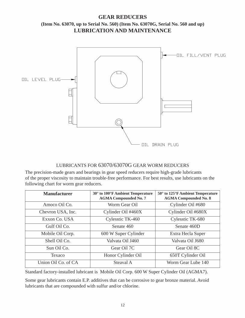
GEAR REDUCERS(Item No. 63070, up to Serial No. 560) (Item No. 63070G, Serial No. 560 and up)
LUBRICATION AND MAINTENANCE
LUBRICANTS FOR 63070/63070G GEAR WORM REDUCERSThe precision-made gears and bearings in gear speed reducers require high-grade lubricants of the proper viscosity to maintain trouble-free performance. For best results, use lubricants on the following chart for worm gear reducers.
Standard factory-installed lubricant is Mobile Oil Corp. 600 W Super Cylinder Oil (AGMA7).
Some gear lubricants contain E.P. additives that can be corrosive to gear bronze material. Avoidlubricants that are compounded with sulfur and/or chlorine.
Manufacturer 30° to 100°F Ambient TemperatureAGMA Compounded No. 7
50° to 125°F Ambient TemperatureAGMA Compounded No. 8
Amoco Oil Co.Chevron USA, Inc.
Exxon Co. USAGulf Oil Co.
Mobile Oil Corp.Shell Oil Co.Sun Oil Co.
TexacoUnion Oil Co. of CA
Worm Gear OilCylinder Oil #460XCylesstic TK-460
Senate 460600 W Super Cylinder
Valvata Oil J460Gear Oil 7C
Honor Cylinder OilSteaval A
Cylinder Oil #680Cylinder Oil #680XCylesstic TK-680
Senate 460DExtra Hecla SuperValvata Oil J680
Gear Oil 8C650T Cylinder Oil
Worm Gear Lube 140
1
2
3
4
5
67
8
9
10
1118
20
17
13
16
12
pulled out for clarity 1519
4
21
2223
14
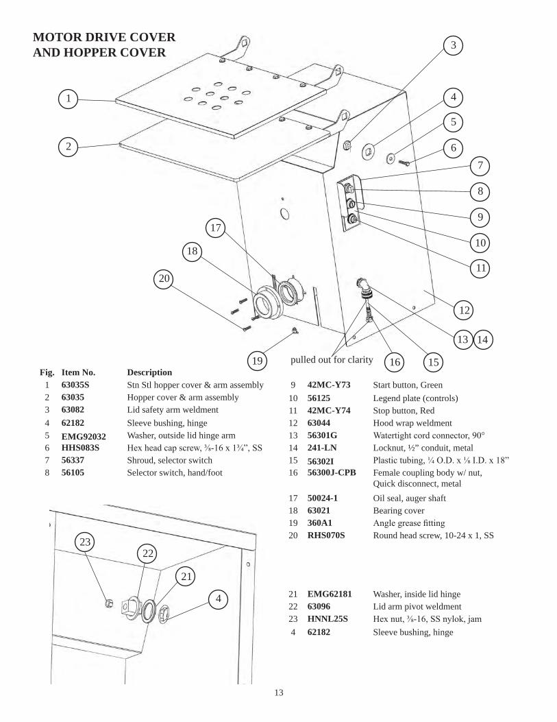
DescriptionItem No.63035S Stn Stl hopper cover & arm assembly63035 Hopper cover & arm assembly63082 Lid safety arm weldment62182 Sleeve bushing, hingeEMG92032 Washer, outside lid hinge armHHS083S Hex head cap screw, ⅜-16 x 1¾”, SS56337 Shroud, selector switch56105 Selector switch, hand/foot
Fig.12345678
42MC-Y73 Start button, Green56125 Legend plate (controls)42MC-Y74 Stop button, Red63044 Hood wrap weldment56301G Watertight cord connector, 90°241-LN Locknut, ½” conduit, metal
910111213141516
56302I Plastic tubing, ¼ O.D. x ⅛ I.D. x 18”56300J-CPB Female coupling body w/ nut,
Quick disconnect, metal50024-1 Oil seal, auger shaft63021 Bearing cover360A1 Angle grease fitting
17181920 RHS070S Round head screw, 10-24 x 1, SS
EMG62181 Washer, inside lid hinge63096 Lid arm pivot weldmentHNNL25S Hex nut, ⅜-16, SS nylok, jam62182 Sleeve bushing, hinge
2122234
MOTOR DRIVE COVERAND HOPPER COVER
13
14A
14A
7
1
2
3
4
19 17
15
18
16 17
9
11 1012
14
1
9
23
24
20
14
21
22
5 6
13
8
25
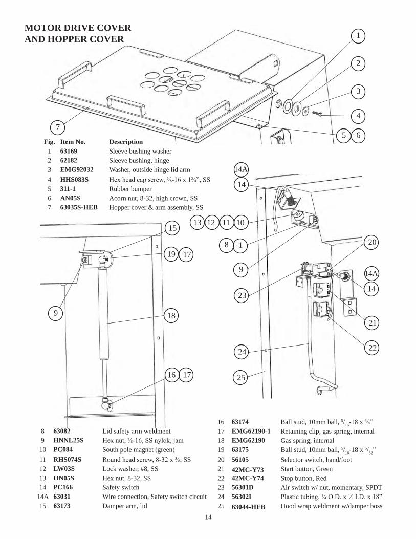
DescriptionItem No.63169 Sleeve bushing washer62182 Sleeve bushing, hingeEMG92032 Washer, outside hinge lid armHHS083S Hex head cap screw, ⅜-16 x 1¾”, SS311-1 Rubber bumperAN05S Acorn nut, 8-32, high crown, SS 63035S-HEB Hopper cover & arm assembly, SS
Fig.1234567
EMG62190-1 Retaining clip, gas spring, internalEMG62190 Gas spring, internal63175 Ball stud, 10mm ball, 5/16-18 x 5/32”56105 Selector switch, hand/foot42MC-Y73 Start button, Green42MC-Y74 Stop button, Red56301D Air switch w/ nut, momentary, SPDT56302I Plastic tubing, ¼ O.D. x ⅛ I.D. x 18”
171819202122232425 63044-HEB Hood wrap weldment w/damper boss
63174 Ball stud, 10mm ball, 5/16-18 x ⅜”16
MOTOR DRIVE COVERAND HOPPER COVER
63082 Lid safety arm weldmentHNNL25S Hex nut, ⅜-16, SS nylok, jamPC084 South pole magnet (green)RHS074S Round head screw, 8-32 x ⅝, SSLW03S Lock washer, #8, SSHN05S Hex nut, 8-32, SS
63031 Wire connection, Safety switch circuit63173 Damper arm, lid
8910111213
14A15
PC166 Safety switch14
14
15
32
4
7 8 916 17
1
18
19
13
14
13
14
15
11 12
10
6
5
14 19
20 21
63027-A Bushing, multi hole, .25 DIA63027-B Cord grip, 90°, ½”224-11 Cord grip connector, 90°, ½”, .25-.375224-5 Cord grip connector, 90°, ½”, .50-.625241-LN Locknut, ½” conduit, metalHHS020S Hex head screw ¼-20 x ⅜”, SSLW10S Lock washer, ¼”, SSHN15S Hex nut, ¼-20, SS
2345678910 226EE-GO11K Contactor, LS11K, 24 V Coil
63094-1 Electrical box weldment, s/n 500 on1DescriptionItem No.Fig.
11 226EE-OL12M Overload, B18K-M, 8-12 A
63028 Din rail, 2⅜” longRHS060S Round head screw, 10-24 x ⅜”, SS63026 Transformer, 100VA, 208-460/24 SECEMG92014 Fuse block, din rail typeEMG90552 Fuse, 3A, time delayPC162-1 Central control unit, 24 VDCBLK323 End barrierPC148 Bridge rectifier, AC-DC volts
131415161718192021 RHS062S Round head screw, 10-24 x ⅝”, SS
H281EE-51 Overload, B18K-K, 4-6.3 A12DescriptionItem No.Fig.
ELECTRICAL BOX
16
MOTOR-DRIVE UNIT AND
COMPONENTS
Fig. Item No. Description
1234111212A12B132929A3133
15026-02 Double roller chain, 49"15029 Double chain master link20050-10 #40 Roller chain, 80 pitch
#40 Roller chain master link, #40-C/L20050-01Paddle locking thumb screw53568
53852 Lock arm assembly w/bushingsThrust bearing53517-1
53594 Radial bushing56302 Foot switch assembly w/6' tubing63036 Hopper assembly
34
63036-1-HEB Hopper assembly, HEB style63041 Sprocket, D40B35
Sprocket, D40B15F-0163043Back access panel63045
Fig. Item No. Description
Motor,3HP 200/60HZ/3PHMotor, 3HP/200/208V/60HZ/1PHMotor, 3HP/208/230/460V/60HZ/3PHMixer paddle assembly, curved bladeMixer paddle assembly, round bladeGear reducer, #B224 GroveGear reducer, #924 Winsmithtable top leg (optional)
Cart assembly w/castersTiming belt
Paddle spacerRing wrenchCaster w/swivel lock
39 63057
72 63136H340PC175124
115
6307063070G6307363073-26309963099-163099-2
46A
54A54B
54
45A46
45
6304963055
3738
35 63047 Timing pulley, 48H100SKTaper lock, SK, 1" (Winsmith reducer)63048-0136Taper lock, SK, 3/4" (Grove reducer)63048-0336A
14688135 4-point knob, 3/8-16 threadWS077S136 Weld stud, 3/8-16 X 1-1/2"63048137 Timing pulley, 18H100QD, 18 TEETH63048-02138 Taper lock, SH 7/8"
124A S.S. Caster w/swivel lockPC175S-1
DescriptionItem No.15026-02 Double roller chain, 49”15029 Double chain master link20050-10 #40 Roller chain, 80 pitch20050-01 #40 Roller chain master link, #40-C/L
Fig.1234
53568 Mixer paddle lock wing bolt53852 Lock arm assembly w/ bushings53517-1 Thrust bearing53594 Radial bearing
1112
12A12B
56304 Footswitch assembly w/ 6’ tubing63036 Hopper assembly, up to s/n: 48963036-1-HEB Hopper assembly, HEB style63041 Sprocket, D40B35
1329
29A31
63043 Sprocket, D40B15F-0163045 Back access panel63047 Timing pulley, 48H100SK63048-01 Taper lock, SK, 1” (Winsmith reducer)
33343536
63048-03 Taper lock, SK, ¾” (Grove reducer)36A63049 Timing belt37
63055 Cart assembly w/ casters38DescriptionItem No.
63057 Table top leg, (Optional)63070 Gear reducer, Winsmith up to s/n 56063070G Gear reducer, Grove s/n 561 on63073 Mixer paddle, round blade
Fig.
3945
45A46
63073-2 Mixer paddle, curved blade63099 Motor, 3HP, 208-230/460V-60Hz-3PH63099-3 Motor, 3HP, 208-230/460V-60Hz-3PH63099-4 Motor, 3HP, 208-230/460V-60Hz-3PH
46A54
54A54B
63136 Paddle spacerH340 Ring WrenchPC175-1 Caster w/ swivel lockPC175S-1 SS Caster w/ swivel lock
72115124
124A14688 4-point knob, ⅜-16 threadWS077S Weld stud, ⅜-16 x 1½”63048 Timing pulley, 18H100QD, 18 tooth63048-02 Taper lock bushing, SH ⅞”
135136137138
MOTOR-DRIVE UNITAND
COMPONENTS
17
Fig. Item No. Description5681014
1516
1718192021222425
2830324041
424344
TRANSMISSIONMOUNTINGASSEMBLY
117116114113108107106767574737170686766656459585756554948
Fig. Item No. Description20665 Key, 1/4 x 1/4 x 1-1/8 S.S.20665-01 Key, 1/4 x 1/4 x 1-3/4 S.S.
O-Ring, 1.25 I.D.3031550029 Washer, brass (used up to s/n 499)
Base plate (used up to s/n 499)6300514A 63005-1 Base plate (used on s/n 500-on)
63007 Shaft bearing retainer, front63008 Shaft bearing retainer, rear
(used up to s/n 499)16A 63008-1 Shaft bearing retainer, rear
(used on s/n 500-on)63009 Frame side plate63010 Bowl lock side spacer63011 Gear box top plate63014 Auger drive shaft63015 Main drive shaft63016 Bearing retainer, main shaft
Spacer, mixer drive shaft6301963020 Spacer, plastic, mixer drive shaft
25A 63020-1 Spacer, sealed, mixer drive shaft
Mixer drive shaft6303363040 72T sprocket #40B72-01
22T sprocket #D40B226304263062 Linkage pivot arm
Linkage arm63063
63065 Spacer, thrust bearing63066 Thrust bearing63067 Spacer, main drive shaft
(used up to s/n 499)
47
(used on s/n 646-on)
63081-01 Bowl support bracket, LH63081-02 Bowl support bracket, RH63084 Hopper latch rod
Drive clutch, squire drive5606456065 Driving clutch, motor output56211-1 Engagement lever bushing56214 Clutch engagement lever, LH63104 Link engagement handle56215 Clutch engagement lever, RH63119 Clutch engagement shaft56127-1 Woodruff keyMC-21R2 Lock handle groove pin
Shoulder bolt, 3/8-16 x 1/2SSB50PSChain tensioner63126
63127 Tensioner block63139-01 Bowl lock hook, LH
Bowl lock hook, RH63139-0263140 Hopper latch
Bowl adjusting pin63141Bearing83017Bearing83032Key, 3/8 x 3/8 x 1-1/2 lg.83080-07Pivot arm knob90509
PCM570 V-Ring sealFW07S Flat washer, 3/8
Light jam nut, 3/8-16 HN30SHN35S Heavy jam nut, 3/8-16 118
119 Set screw, 5/16-18 X 5/16 lg., knurled cup point SSS17KLSSS20 Set screw, 3/8-16 X 3/8 lg., knurled cup point 120
63063-1 Spring, clutch linkage arm41A
DescriptionItem No.20665 Key, ¼ x ¼ x 1⅛”20665-01 Key, ¼ x ¼ x 1¾”30315 O-Ring, 1.25 I.D.50029 Washer, brass (up to s/n: 499)
Fig.56810
63005 Base plate (up to s/n: 499)63005-1 Base plate (used s/n: 500 on)63007 Shaft bearing retainer, front63008 Shaft bearing retainer, rear (up to s/n 499)
1414A1516
63008-1 Shaft bearing retainer, rear (s/n 500 on)63009 Frame side plate
16A17
63010 Bowl lock mount spacer, sides63011 Gear box mount plate, top63014 Grinder socket shaft63015-1 Auger drive shaft w/ shoulder
18192021
63016 Bearing mount, auger drive shaft2263019 Spacer, mixer drive shaft2463020 Spacer, mixer drive shaft (up to s/n 645)63020-1 Spacer, mixer drive shaft (s/n 646 on)
2525A
63033 Mixer drive shaft63040 Sprocket, 72 tooth, #40B72-0163042 Sprocket, 22 tooth, #D40B22
283032
63062 Linkage pivot arm4063063 Linkage arm4163063-1 Spring, clutch linkage arm63065 Spacer, thrust bearing
41A42
63066 Thrust bearing, auger drive shaft4363067 Spacer, auger drive shaft44
DescriptionItem No.
63081-01 Bowl support bracket, LH
63081-02 Bowl support bracket, RH63084 Hold down rod56064 Driven clutch, square drive
Fig.
47
484955
56065 Driving clutch, motor output56211-1 Driven clutch engagment lever bushing56214 Clutch engagement lever, LH63104 Link engagement handle
56575859
56215 Clutch engagement lever, RH63119 Clutch engagement shaft56127-1 Woodruff keyMC-21R2 Lock handle groove pin
64656667
SSB50PS Shoulder bolt, ⅜-16 x ½”63126 Bracket, chain tensioner63127 Tension block63185-01 Bowl lock hook, LH
68707173
63185-02 Bowl lock hook, RH7463140 Hopper latch7563141 Bowl adjusting pin83017 Bearing, auger drive shaft
76106
83032 Bearing, mixer shaft83080-07 Key, ⅜ x ⅜ x 1½”90509 Plastic ball knobPCM570 V-Ring seal
107108113114
FW07S Flat washer, ⅜”116HN30S Hex nut, light jam, ⅜-16, SS117HN35S Hex nut, ⅜-16, SSSSS17KL Set screw, knurled cup point, 5/16-16 x ⅜”
118119
SSS20 Set screw, knurled cup point, ⅜-16 x ⅜”120
TRANSMISSIONMOUNTING ASSEMBLY

18
BOWL & WORM ASSEMBLY
DescriptionItem No.63017 Bowl hook stud, 2 required54278-CTN Auger assemblyHK48 Knife drive pin54278B Square drive insert
Fig.2360
60A60B
54278C Auger shear pin FHS33S Shear pin screws, ¼-20 x ½”, SS56049 Bowl & plate pinsWN20S Wing nut, ⅜-16, SS
60C60D61
61ASSS45S Stud, ⅜-16 x 1”, SSHR42/48 Ring57159 Auger drive shaft sealHP48 Bowl plate pin, 3 required
61B626364
57159K Auger drive shaft seal kit57160 Seal retainerFHS26S Flat head screw, 10-32 x ¾”, SS52392 Product splash shield
6969A69B114
52392-HEB Product splash shield115
19
FASTENERS & LOCATIONS
4 ea.
Base Plate (63005) to Cart Assembly (63055)
HHS088S Hex head screw, ⅜-16 x 2¼”, SS
HN25S Hex nut, ⅜-16, heavy, SS, w/ loctite
Item No.
LW20S Lock washer, ⅜”, SS
HHS058S Hex head screw, 5/16-18 x ⅞”, SS
FW10S Flat washer, 5/16, SS
Item No.
LW15S Lock washer, 5/16”, SS
Frame Side Plates (2 ea. 63009) to Base Plate (63005)
HHS075S Hex head screw, ⅜-16 x 1¼”, SSItem No.
LW20S Lock washer, ⅜”, SS
Frame Side Plates (2 ea. 63009) to BearingMount- auger drive shaft- rear (63016)
Bowl Support Brackets (LH 63081-01 & RH63081-02) to Bowl Lock Mount Spacer (2 ea.
HHS090S Hex head screw, ⅜-16 x 2½”, SSItem No.
LW20S Lock washer, ⅜”, SS
63010) to Frame Side Plates (2 ea. 63009) toBearing Mount-auger drive shaft-front (63016)
Bowl Support Brackets (LH 63081-01 & RH63081-02) to Bowl Lock Mount Spacer (2 ea.
HHS090S Hex head screw, ⅜-16 x 2½”, SSItem No.
LW20S Lock washer, ⅜”, SS
63010) to Frame Side Plates (2 ea. 63009) toShaft Bearing Retainer-front (63007)
HHS075S Hex head screw, ⅜-16 x 1¼”, SSItem No.
LW20S Lock washer, ⅜”, SS
Frame Side Plates (2 ea. 63009) to Shaft Bearing Retainer-rear (63008 or 63008-1)
HHS055S Hex head screw, 5/16-18 x ¾”, SS
FW10S Flat washer, 5/16, SS
Item No.
LW15S Lock washer, 5/16”, SS
Bracket, Chain Tensioner (63126) to Shaft Bearing Retainer-rear (63008 or 63008-1)
HHS060S Hex head screw, 5/16-18 x 1”, SS
FW10S Flat washer, 5/16, SS
Item No.
LW15S Lock washer, 5/16”, SS
Motor (63099 or 63099-3 or 63099-4) to ShaftBearing Retainer-rear (63008 or 63008-1)
Bowl Hook Stud (63017) to Bowl (56049)
HHS129S Hex head screw, ½-13 x 2”, SS w/ loctiteItem No.
HHS070S Hex head screw, ⅜-16 x 1”, SS
HN25S Hex nut, ⅜-16, heavy, SS
Item No.
LW20S Lock washer, ⅜”, SS
Bowl Support Brackets (LH 63081-01 & RH63081-02) to Base Plate (63005)
HHS075S Hex head screw, ⅜-16 x 1¼”, SSItem No.
LW20S Lock washer, ⅜”, SS
Gear Box Mount Plate-top (63011) to Shaft Bearing Retainer-front & rear (63007 & 63008 or 63008-1)
HHS110S Hex head screw, ½-13 x 1”, SSItem No.
Gear Reducer (63070 or 63070G) to Gear BoxMount Plate-top (63011)
LW30S Lock washer, ½”, SS
HHS126S Hex head screw, ½-13 x 1¼”, SSItem No.
Bowl Lock Hook-LH (63185-01) to Bowl Support Bracket-LH (63081-01)
LW30S Lock washer, ½”, SS
HHS126S Hex head screw, ½-13 x 1¼”, SSItem No.
Bowl Lock Hook-RH (63185-02) to Bowl Support Bracket-RH (63081-02)
LW30S Lock washer, ½”, SS
RHS09S Hex head screw, 10-32 x ⅜”, SSItem No.
Hopper Latch (2 ea. 63140) to Bowl SupportBrackets LH & RH (LH 63081-01 & RH 63081-02)
4 ea. 4 ea.
4 ea. 4 ea. 8 ea.
4 ea. 4 ea.
4 ea. 4 ea.
4 ea. 4 ea.
4 ea. 4 ea.
2 ea. 2 ea. 2 ea.
4 ea. 4 ea. 8 ea.
2 ea.
2 ea. 2 ea. 2 ea.
4 ea. 4 ea.
4 ea. 4 ea.
1 ea. 1 ea.
1 ea. 1 ea.
8 ea. (w/ loctite)

20
- OPERATOR’S NOTES -
21
Before Serial No. 783

22
Serial No. 783 on

23
24
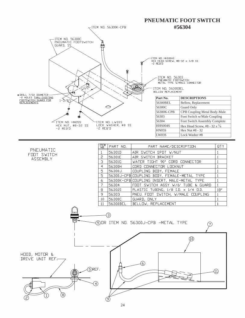
PNEUMATIC FOOT SWITCH#56304
Part No.56300BEL
DESCRIPTIONS
56300C56300K-CPB5630356304HHS004SHN05SLW03S
Bellow, ReplacementGuard OnlyCPB Coupling Metal Body-MaleFoot Switch w/Male CouplingFoot Switch Assembly CompleteHex Head Screw, #8 - 32 x ⅜Hex Nut #8 - 32Lock Washer #8
25
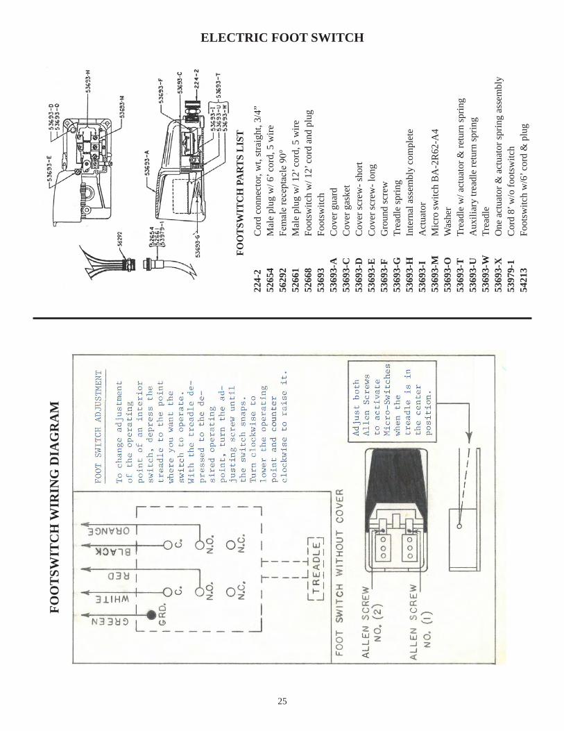
ELECTRIC FOOT SWITCHFO
OT
SWIT
CH
WIR
ING
DIA
GR
AM
FOO
TSW
ITC
H P
AR
TS
LIS
T
224-
2C
ord
conn
ecto
r, w
t, st
raig
ht, 3
/4”
5265
4M
ale
plug
w/ 6
’ cor
d, 5
wire
5629
2Fe
mal
e re
cept
acle
90°
5266
1M
ale
plug
w/ 1
2’ c
ord,
5 w
ire52
668
Foot
switc
h w
/ 12’
cor
d an
d pl
ug53
693
Foot
switc
h53
693-
A
Cov
er g
uard
5369
3-C
Cov
er g
aske
t53
693-
DC
over
scre
w- s
hort
5369
3-E
Cov
er sc
rew
- lon
g53
693-
FG
roun
d sc
rew
5369
3-G
Trea
dle
sprin
g53
693-
HIn
tern
al a
ssem
bly
com
plet
e53
693-
IA
ctua
tor
5369
3-M
Mic
ro sw
itch
BA
-2R
62-A
453
693-
OW
ashe
r53
693-
TTr
eadl
e w
/ act
uato
r & re
turn
sprin
g53
693-
UA
uxili
ary
tread
le re
turn
sprin
g53
693-
WTr
eadl
e53
693-
XO
ne a
ctua
tor &
act
uato
r spr
ing
asse
mbl
y53
979-
1C
ord
8’ w
/o fo
otsw
itch
5421
3Fo
otsw
itch
w/6
’ cor
d &
plu
g
26
#H653-E #H653-SP
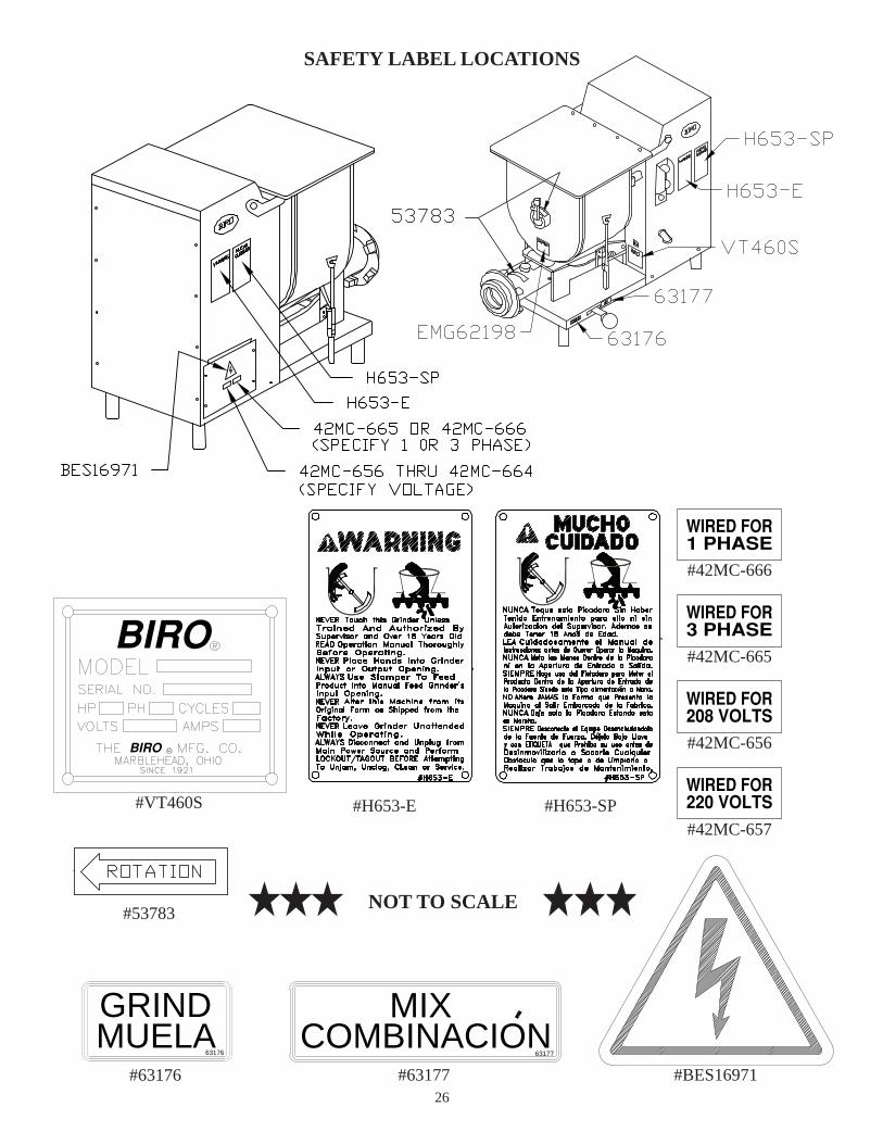
SAFETY LABEL LOCATIONS
#53783
1 PHASEWIRED FOR
3 PHASEWIRED FOR
208 VOLTSWIRED FOR
220 VOLTSWIRED FOR
#42MC-657
#42MC-656
#42MC-665
#42MC-666
BIRO
BIRO
#VT460S
63176
GRINDMUELA
#6317663177
MIXCOMBINACION
#63177 #BES16971
NOT TO SCALE

27
- OPERATOR’S NOTES -

OPERATOR’S SIGNATURE PAGE
MY SIGNATURE ATTESTS THAT I HAVE COMPLETELY READ AND UNDERSTAND THIS MANUAL. I REALIZE THAT THIS MACHINE, IF OPERATED CARELESSLY, CAN CAUSE SERIOUS INJURY TO MYSELF AND OTHERS.
NAME (PRINT) SIGNATURE SUPERVISOR’SINITIALS
DATE
WARNINGREAD AND UNDERSTAND THIS ENTIRE
MANUAL BEFORE SIGNING BELOW
28
29
LIMITED WARRANTY
WARRANTY: The BIRO Manufacturing Company warrants that the BIRO MINI-32 Grinder will be free from defects in material and workmanship under normal use and with recommended service. BIRO will replace defective parts, which are covered by this limited warranty, provided that the defective parts are authorized for return, shipping charges prepaid, to a designated factory for inspection and/or testing.
DURATION OF WARRANTY: The warranty period for all parts covered by this limited warranty is one (1) year from date of Inspection/Demonstration as advised on the returned Warranty Registration card, or eighteen (18) months from original factory shipping date, whichever date occurs first, except as noted below.
PARTS NOT COVERED BY WARRANTY: The following are not covered by this limited warranty: wearable parts in the grinding system such as the bowl, bowl pin, ring, auger, drive shaft, knife drive pin, plate and knife. This limited warranty does not apply to machines sold as used, rebuilt, modified, or altered from the original construction in which the machine was shipped from the factory. Water contaminated electrical systems are not covered under this limited warranty. BIRO is not responsible for electrical connection of equipment, ad-justments to switch components or any other electrical requirements, which must be performed only by a certi-fied electrician. BIRO is not responsible for service charges or labor required to replace any part covered by this limited warranty or for any damages resulting from misuse, abuse, lack of proper or recommended service.
EXCLUSION OF WARRANTIES AND LIMITATION OF REMEDIES: BIRO gives no warranties other than those expressly stated in this limited warranty. THE IMPLIED WARRANTY OF MERCHANTABILITY, THE IMPLIED WARRANTY OF FITNESS FOR PROCESSING OF FOOD PRODUCTS, AND ALL OTHER IMPLIED WARRANTIES ARE SPECIFICALLY EXCLUDED. BIRO IS NOT LIABLE FOR CONSEQUEN-TIAL OR INCIDENTAL DAMAGES, EXPENSES OR LOSSES. THE REMEDIES PROVIDED IN THIS BIRO LIMITED WARRANTY ARE PURCHASER’S SOLE AND EXCLUSIVE REMEDIES AGAINSTBIRO.
REGISTRATION CARDS: You must sign, date and complete the warranty registration card supplied with each machine. The warranty card must be returned to The Biro Manufacturing Company for proper registration. If no warranty card is returned to BIRO, the warranty period will begin from the date the machine was originally shipped from the factory.
HOW TO GET SERVICE:1. Contact the entity from whom you purchased the machine; or2. Consult the yellow pages of the phone directory for the nearest authorized dealer; or3. Contact Biro Mfg. Company for the authorized service entity in your area.
BIRO MANUFACTURING COMPANY1114 W. Main St.
Marblehead, OH 43440 U.S.A.Ph: 419-798-4451 Fax: 419-798-9106
E-mail: [email protected]; www.birosaw.com
Item No. 32313-299Form No. Mini-32-4-16-7-B