Model EX686B01 Vibration Switch Installation and Operating ...
59
Model EX686B01 Vibration Switch Installation and Operating Manual For assistance with the operation of this product, contact PCB Piezotronics, Inc. Toll-free: 800-959-4464 24-hour SensorLine: 716-684-0001 Fax: 716-684-3823 E-mail: [email protected] Web: www.imi-sensors.com
-
Upload
khangminh22 -
Category
Documents
-
view
2 -
download
0
Transcript of Model EX686B01 Vibration Switch Installation and Operating ...

Model EX686B01
Vibration Switch
Installation and Operating Manual
For assistance with the operation of this product,contact PCB Piezotronics, Inc.
Toll-free: 800-959-446424-hour SensorLine: 716-684-0001
Fax: 716-684-3823E-mail: [email protected]
Web: www.imi-sensors.com

The information contained in this document supersedes all similar information that
may be found elsewhere in this manual. Service – Due to the sophisticated nature of the sensors and associated instrumentation provided by PCB Piezotronics, user servicing or repair is not recommended and, if attempted, may void the factory warranty. Routine maintenance, such as the cleaning of electrical connectors, housings, and mounting surfaces with solutions and techniques that will not harm the physical material of construction, is acceptable. Caution should be observed to ensure that liquids are not permitted to migrate into devices that are not hermetically sealed. Such devices should only be wiped with a dampened cloth and never submerged or have liquids poured upon them. Repair – In the event that equipment becomes damaged or ceases to operate, arrangements should be made to return the equipment to PCB Piezotronics for repair. User servicing or repair is not recommended and, if attempted, may void the factory warranty. Calibration – Routine calibration of sensors and associated instrumentation is recommended as this helps build confidence in measurement accuracy and acquired data. Equipment calibration cycles are typically established by the users own quality regimen. When in doubt about a calibration cycle, a good “rule of thumb” is to recalibrate on an annual basis. It is
also good practice to recalibrate after exposure to any severe temperature extreme, shock, load, or other environmental influence, or prior to any critical test. PCB Piezotronics maintains an ISO- 9001 certified metrology laboratory and offers calibration services, which are accredited by A2LA to ISO/IEC 17025, with full traceability to SI through N.I.S.T. In addition to the normally supplied calibration, special testing is also available, such as: sensitivity at elevated or cryogenic temperatures, phase response, extended high or low frequency response, extended range, leak testing, hydrostatic pressure testing, and others. For information on standard recalibration services or special testing, contact your local PCB Piezotronics distributor, sales representative, or factory customer service representative. Returning Equipment – Following these procedures will ensure that your returned materials are handled in the most expedient manner. Before returning any equipment to PCB Piezotronics, contact your local distributor, sales representative, or factory customer service representative to obtain a Return Warranty, Service, Repair, and Return Policies and Instructions Materials Authorization (RMA) Number. This RMA number should be clearly marked on the outside of all package(s) and on the packing
Service, Repair, and Return
Policies and Instructions

list(s) accompanying the shipment. A detailed account of the nature of the problem(s) being experienced with the equipment should also be included inside the package(s) containing any returned materials. A Purchase Order, included with the returned materials, will expedite the turn-around of serviced equipment. It is recommended to include authorization on the Purchase Order for PCB to proceed with any repairs, as long as they do not exceed 50% of the replacement cost of the returned item(s). PCB will provide a price quotation or replacement recommendation for any item whose repair costs would exceed 50% of replacement cost, or any item that is not economically feasible to repair. For routine calibration services, the Purchase Order should include authorization to proceed and return at current pricing, which can be obtained from a factory customer service representative. Contact Information – International customers should direct all inquiries to their local distributor or sales office. A
complete list of distributors and offices can be found at www.pcb.com. Customers within the United States may contact their local sales representative or a factory customer service representative. A complete list of sales representatives can be found at www.pcb.com. Toll-free telephone numbers for a factory customer service representative, in the division responsible for this product, can be found on the title page at the front of this manual. Our ship to address and general contact numbers are: PCB Piezotronics, Inc. 3425 Walden Ave. Depew, NY14043 USA Toll-free: (800) 828-8840 24-hour SensorLineSM: (716) 684-0001 Website: www.pcb.com
E-mail: [email protected]

PCB工业监视和测量设备 - 中国RoHS2公布表
PCB Industrial Monitoring and Measuring Equipment - China RoHS 2 Disclosure Table
部件名称
有害物质
铅 (Pb) 汞
(Hg)
镉
(Cd) 六价铬 (Cr(VI)) 多溴联苯 (PBB) 多溴二苯醚 (PBDE)
住房 O O O O O O
PCB板 X O O O O O
电气连接器 O O O O O O
压电晶体 X O O O O O
环氧 O O O O O O
铁氟龙 O O O O O O
电子 O O O O O O
厚膜基板 O O X O O O
电线 O O O O O O
电缆 X O O O O O
塑料 O O O O O O
焊接 X O O O O O
铜合金/黄铜 X O O O O O
本表格依据 SJ/T 11364 的规定编制。
O: 表示该有害物质在该部件所有均质材料中的含量均在 GB/T 26572 规定的限量要求以下。
X: 表示该有害物质至少在该部件的某一均质材料中的含量超出 GB/T 26572 规定的限量要求。
铅是欧洲RoHS指令2011/65/ EU附件三和附件四目前由于允许的豁免。
CHINA RoHS COMPLIANCE

DOCUMENT NUMBER: 21354 DOCUMENT REVISION: D ECN: 46162
Component Name Hazardous Substances
Lead (Pb)
Mercury (Hg)
Cadmium (Cd)
Chromium VI Compounds (Cr(VI))
Polybrominated Biphenyls (PBB)
Polybrominated Diphenyl Ethers (PBDE)
Housing O O O O O O
PCB Board X O O O O O
Electrical Connectors
O O O O O O
Piezoelectric Crystals
X O O O O O
Epoxy O O O O O O
Teflon O O O O O O
Electronics O O O O O O
Thick Film Substrate
O O X O O O
Wires O O O O O O
Cables X O O O O O
Plastic O O O O O O
Solder X O O O O O
Copper Alloy/Brass X O O O O O
This table is prepared in accordance with the provisions of SJ/T 11364.
O: Indicates that said hazardous substance contained in all of the homogeneous materials for this part is below the limit requirement of GB/T 26572.
X: Indicates that said hazardous substance contained in at least one of the homogeneous materials for this part is above the limit requirement of GB/T 26572. Lead is present due to allowed exemption in Annex III or Annex IV of the European RoHS Directive 2011/65/EU.

PAGE 1
SE
NS
OR
S A
ND
INS
TR
UM
EN
TA
TIO
N F
OR
MA
CH
INE
CO
ND
ITIO
N M
ON
ITO
RIN
G
686-Series Smart Vibration Switch
Operating Guide with Enclosed Warranty Information
3425 Walden Avenue, Depew, New York 14043-2495
Phone (716) 684-0003
Fax (716) 684-3823
Toll Free Line 1-800-959-4IMI
MANUAL NUMBER: 40112 MANUAL REVISION: G ECO: 49766 ECN NUMBER: 47032

PAGE 2
SE
NS
OR
S A
ND
INS
TR
UM
EN
TA
TIO
N F
OR
MA
CH
INE
CO
ND
ITIO
N M
ON
ITO
RIN
G
Table of Contents
Introduction ...................................................................................................................................................... Page 3
General Features Operating Principles ........................................................................................................................................ Page 4
Benefits of Solid State Relays Installation ........................................................................................................................................................ Page 5
Direct Adhesive Mount Standard Stud Mount Adhesive Stud Mount Magnetic Mount
Wiring ............................................................................................................................................................... Page 9
Legend Indicating a High Level of Vibration in a Motor Indicating High Levels of Vibration Simultaneously in Series (Such as Fan & Motor) Constant Siren Alarming in the Event of High Vibration Levels Two Switches in Parallel to Monitor Two Aces Simultaneously on Same Motor Three Switches in Parallel to Monitor Three Motors Simultaneously Automatic Machinery Shutdown Using an External Electromechanical Relay Automatic Machinery Shutdown Using External Electromechanical Relay While Monitoring 2 Axes Switch and External Latching for Automatic Machinery Shutdown Both Alarm Siren and Automatic Machinery Shutdown Using Two Switches Automatic Machinery Shutdown Based on Normally Open Solid State Relay Automatic Machinery Shutdown of a Three Phase Electrical Motor Based on a N.O. Solid-State Relay
Programming Software .................................................................................................................................. Page 21 Program Installation
Running the Software Programming Sections Reading and Writing Parameters Parameter Options Execution of Delays
Magnetically Adjustable Vibration Threshold (MAVT™) .............................................................................. Page 29
MAVT™ Procedure Factory-Programmed Ordering Guide ........................................................................................................... Page 30 Battery-Powered Signal Conditioner ............................................................................................................. Page 31
Calibration Cable ........................................................................................................................................... Page 31 Magnet Clip .................................................................................................................................................... Page 31 Cable Ordering Information ........................................................................................................................... Page 32 ESD Sensitivity .............................................................................................................................................. Page 33 Warranty, Service & Return Procedure ......................................................................................................... Page 34 Customer Service .......................................................................................................................................... Page 34

PAGE 3
SE
NS
OR
S A
ND
INS
TR
UM
EN
TA
TIO
N F
OR
MA
CH
INE
CO
ND
ITIO
N M
ON
ITO
RIN
G
Introduction
The 686-Series Smart Vibration Switch is a low-cost electronic vibration switch designed to monitor vibration levels on rotating machinery (ie. fans and cooling towers) and trip an alarm or shut down machinery when a specified vibration limit is exceeded. An onboard accelerometer with precision, microprocessor-controlled electronics ensures reliable operation and accuracy. The switch contains a two-pin MIL connector for easy drop-in replacement of mechanical vibration switches and a reliable solid state relay. Multiple units can be installed in a loop configuration for economical installation and expanded protection of critical machinery. This versatile switch can be used to replace more expensive electronic vibration switches where separate vibration output is not required and to replace troublesome mechanical vibration switches. Every Smart Switch is factory-programmed. See Page 28 for more information. General Features
Fully USB-programmable from any PC (with optional USB Programmer Kit).
Hermetically-sealed, stainless steel housing for use in corrosive environments.
Imbedded piezoelectric accelerometer for improved accuracy and frequency response.
Small footprint and single ¼-28 stud mounting.
Solid state (AC/DC) relay.
Universal AC or DC power.
Magnetically Adjustable Vibration Threshold (MAVT™).
Connects with industry standard MIL-C-5015 connector or integral cable.
Programmable features o Alarm threshold level o Normally Open (NO) or Normally Closed (NC) relay o Latching or non-latching relay o Delays
Power on Startup Operational
o Residual vibration level
Intrinsically-safe versions available (EX prefix) o CSA

PAGE 4
SE
NS
OR
S A
ND
INS
TR
UM
EN
TA
TIO
N F
OR
MA
CH
INE
CO
ND
ITIO
N M
ON
ITO
RIN
G
Operating Principles
The Smart Switch operates over just two wires. It installs in series with any load (ie. annunciator, PLC or relay coil). To energize itself, the vibration switch scavenges power from the load’s power source. When the alarm threshold is exceeded, the switch is activated and the load’s power circuit is completed to facilitate the desired alarm or shutdown.
Figure 1 – Block Diagram
Benefits of Solid State Relays A solid state relay is an electronic component that functions in the same way as an electromechanical relay, but without any moving parts. A solid state relay offers the most reliable switch action, especially for vibration applications where moving relay components run a greater risk of malfunction. They are purely electronic devices composed of a low current control side and a high current load side for switching action.

PAGE 5
SE
NS
OR
S A
ND
INS
TR
UM
EN
TA
TIO
N F
OR
MA
CH
INE
CO
ND
ITIO
N M
ON
ITO
RIN
G
Installation
When choosing a mounting method, consider closely the advantages and disadvantages of each technique. Typical mounting types are stud, direct adhesive, adhesive mounting base and magnetic mounting base.
Note: For a complete list of product specifications, see the “Specification Sheet” and “Outline Drawing” at the end of this Manual. Direct Adhesive Mount Procedure
For restrictions of space or for convenience, most sensors (with the exception of integral stud models) can be adhesive-mounted directly to the machine surface.
Step 1: Prepare a smooth, flat mounting surface. A minimum surface finish of 63 µin (0.0016 mm)
generally works best.
Step 2: Place a small portion of adhesive on the underside of the sensor. Firmly press down on the top of
the assembly to displace any adhesive. Be aware that excessive amounts of adhesive can make sensor
removal difficult.
Figure 2 – Direct Adhesive Mounting

PAGE 6
SE
NS
OR
S A
ND
INS
TR
UM
EN
TA
TIO
N F
OR
MA
CH
INE
CO
ND
ITIO
N M
ON
ITO
RIN
G
Standard Stud Mount Procedure
This mounting technique requires smooth, flat contact surfaces for proper operation and is recommended for permanent and/or secure installations. Stud mounting is also recommended when testing at high frequencies. Note: Do not attempt mounting on curved, rough or uneven surfaces, as the potential for misalignment and
limited contact surface may significantly reduce the sensor’s upper operating frequency range.
¼-28 Stud ¼-28 Captive Screw
A (in) 0.250 0.250
B (in) 0.350 0.350
Torque (ft-lb) 2 to 5 2 to 5
Step 1: First, prepare a smooth, flat mounting surface and then drill and tap a mounting hole in the center
of this area. A precision-machined mounting surface with a minimum finish of 63 µin (0.0016 mm) is
recommended. (If it is not possible to properly prepare the machine surface, consider using an adhesive
mounting pad as a possible alternative.) Inspect the area, checking that there are no burrs or other
foreign particles interfering with the contact surface.
Step 2: Wipe clean the mounting surface and spread on a light film of grease, oil or similar coupling fluid
prior to installation. Adding a coupling fluid improves vibration transmissibility by filling small voids in the
mounting surface and increasing the mounting stiffness. For semi-permanent mounting, substitute epoxy
or another type of adhesive.
Step 3: Hand-tighten the sensor/mounting stud to the machine, and then secure the sensor with a torque
wrench to the mounting surface by applying the recommended mounting torque (see enclosed
specification data sheet for proper mounting torque). It is important to use a torque wrench during this
step. Under-torqueing the sensor may not adequately couple the device; over-torqueing may result in
stud failure and possibly permanent damage.
Figure 3 – Mounting Surface Preparation Figure 4 – Mounting Surface Lubrication

PAGE 7
SE
NS
OR
S A
ND
INS
TR
UM
EN
TA
TIO
N F
OR
MA
CH
INE
CO
ND
ITIO
N M
ON
ITO
RIN
G
Adhesive Stud Mount Procedure Adhesive mounting is often used for temporary installation or when the machine surface cannot be adequately prepared for stud mounting. Adhesives like hot glue or wax work well for temporary mounts; two-part epoxies and quick-bonding gels provide a more permanent mount.
Note: Adhesively mounted sensors often exhibit a reduction in high-frequency range. Generally, smooth
surfaces and stiff adhesives provide the best frequency response. Contact the factory for recommended epoxies.
This method involves attaching a base to the machine surface, then securing the sensor to the base. This allows
for easy removal of the accelerometer.
Step 1: Prepare a smooth, flat mounting surface. A minimum surface finish of 63 µin (0.0016 mm)
generally works best.
Step 2: Stud-mount the sensor to the appropriate adhesive mounting base according to the guidelines set
forth in Steps 2 and 3 of the Standard Stud Mount Procedure.
Step 3: Place a small portion of adhesive on the underside of the mounting base. Firmly press down on
the assembly to displace any extra adhesive remaining under the base.
Figure 5 – Adhesive Installation of Mounting Base

PAGE 8
SE
NS
OR
S A
ND
INS
TR
UM
EN
TA
TIO
N F
OR
MA
CH
INE
CO
ND
ITIO
N M
ON
ITO
RIN
G
Magnetic Mount Procedure
Magnetic mounting provides a convenient means for making portable measurements and is commonly used for machinery monitoring and other portable or trending applications.
Note: The correct magnet choice and an adequately prepared mounting surface are critical for obtaining reliable measurements, especially at high frequencies. Poor installations can cause as much as a 50% drop in the sensor frequency range.
Not every magnet is suitable for all applications. For example, rare earth magnets are commonly used because
of their high strength. Flat magnets work well on smooth, flat surfaces, while dual-rail magnets are required for
curved surfaces. In the case of non-magnetic or rough surfaces, it is recommended that the user first weld, epoxy
or otherwise adhere a steel mounting pad to the test surface. This provides a smooth and repeatable location for
mounting.
Figure 6 – Magnet Types
Step 1: After choosing the correct magnet, inspect the unit to verify that the mounting surfaces are flat
and smooth.
Step 2: Stud-mount the accelerometer to the appropriate magnet according to the guidelines set forth in
Steps 2 and 3 of the Standard Stud Mount Procedure.
Step 3: Prepare a smooth, flat mounting surface. A minimum surface finish of 63 µin [0.0016 mm]
generally works best. After cleaning the surface and checking for burrs, wipe on a light film of silicone
grease, machine oil or similar-type coupling fluid.
Step 4: Mount the magnet/sensor assembly to the prepared test surface by gently “rocking” or “sliding” it
into place.
Note: Magnetically mounting accelerometers carelessly has the potential to generate very high (and very
damaging) g levels. To prevent damage, install the assembly gently. If unsure, please contact the factory for
assistance.

PAGE 9
SE
NS
OR
S A
ND
INS
TR
UM
EN
TA
TIO
N F
OR
MA
CH
INE
CO
ND
ITIO
N M
ON
ITO
RIN
G
Wiring
On the following pages are eleven different wiring scenarios for the Smart Switch. The wiring legend below is
applicable to all wiring diagrams.
Figure 7 – Wiring Diagrams Legend For those wiring scenarios that suggest the use of an external electromechanical relay, IMI suggests Omron general purpose relays as listed below. Visit www.omron.com for more information.
Attribute Omron Model Number
MJN2C- AC120
MJN2C- AC240
MJN2C- DC12
MJN2C- DC24
MJN2C- DC110
Contact Form 2 Form C (DPDT)
Relay Rated Resistive Load 10 A @ 240 VAC/28 VDC
Service Life- Electrical (Min @Rated Loads)
100,000 operations “average”
Relay Max Resistive Switching Capacity
2400 VA, 280 W
240 VAC 12 VDC 24 VDC 110 VDC
Coil Nominal Voltage 120 VAC 1.2 W
Coil Power Consumption 1.7 VA
Coil Type Non-Latching
Seal Type Unsealed
Termination Style Socket Mount
Operating Temperature Range -45 to +60 C
with no icing or condensation -45 to +70 C
with no icing or condensation
Dielectric Strength (AC for 1 min)
2500 VAC
Approved Standards UL, CSA

PAGE 10
SE
NS
OR
S A
ND
INS
TR
UM
EN
TA
TIO
N F
OR
MA
CH
INE
CO
ND
ITIO
N M
ON
ITO
RIN
G
Indicating a High Level of Vibration in a Motor
Figures 8 and 9 – Indicating a High Level of Vibration in a Motor Pushing the Start pushbutton closes the M contacts and starts the motor. If the start-up delay option for the switch is enabled, the Smart Switch will not trip regardless of the vibration level during the specified delay time. After this delay, the vibration switch will be activated. If the vibration level exceeds the alarm threshold for a time period greater than the specified operational delay time, the relay will trip. This action will close the contact to the pilot lamp. Since the NL (non-latching) option is specified, the pilot lamp will illuminate only while alarm threshold is exceeded. Should the vibration level drop below the alarm threshold value (based also on the specified hysteresis), the pilot lamp will turn off.
PAGE 11
SE
NS
OR
S A
ND
INS
TR
UM
EN
TA
TIO
N F
OR
MA
CH
INE
CO
ND
ITIO
N M
ON
ITO
RIN
G
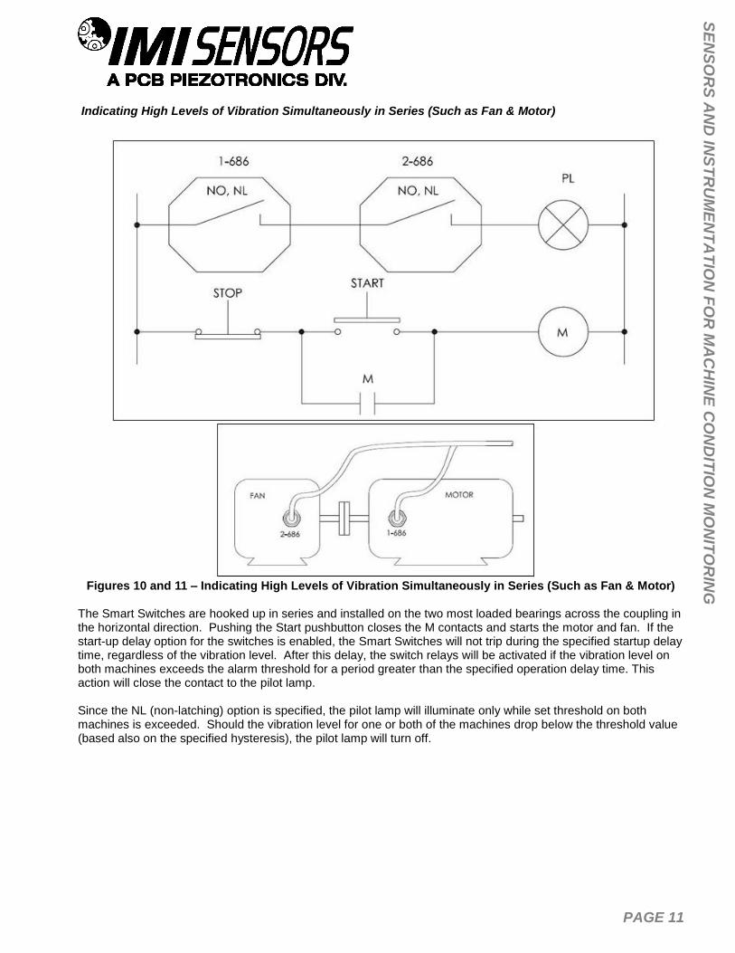
Indicating High Levels of Vibration Simultaneously in Series (Such as Fan & Motor)
Figures 10 and 11 – Indicating High Levels of Vibration Simultaneously in Series (Such as Fan & Motor)
The Smart Switches are hooked up in series and installed on the two most loaded bearings across the coupling in the horizontal direction. Pushing the Start pushbutton closes the M contacts and starts the motor and fan. If the start-up delay option for the switches is enabled, the Smart Switches will not trip during the specified startup delay time, regardless of the vibration level. After this delay, the switch relays will be activated if the vibration level on both machines exceeds the alarm threshold for a period greater than the specified operation delay time. This action will close the contact to the pilot lamp. Since the NL (non-latching) option is specified, the pilot lamp will illuminate only while set threshold on both machines is exceeded. Should the vibration level for one or both of the machines drop below the threshold value (based also on the specified hysteresis), the pilot lamp will turn off.

PAGE 12
SE
NS
OR
S A
ND
INS
TR
UM
EN
TA
TIO
N F
OR
MA
CH
INE
CO
ND
ITIO
N M
ON
ITO
RIN
G
Constant Siren Alarming in the Event of High Vibration Levels
Figure 12 – Constant Siren Alarming in the Event of High Vibration Levels
The Smart Switch is hooked up for automatic constant siren alarming when the alarm threshold level is exceeded. Pushing the Start pushbutton closes the M contact and starts the motor. If the start-up delay option for the switches is enabled, the Smart Switches will not trip during the specified startup delay time, regardless of the vibration level. After this delay, the switch relay will be activated if the vibration level exceeds the alarm threshold for a period greater than the specified operational delay time. This action will close the contact to the alarm siren and activate it. Since the LA (latching) option is specified, the alarm siren will be constantly energized after this high vibration event, even if the vibration level should drop below the alarm threshold. The Reset pushbutton should be engaged to de-energize the alarm siren and return the system to its original monitoring condition.

PAGE 13
SE
NS
OR
S A
ND
INS
TR
UM
EN
TA
TIO
N F
OR
MA
CH
INE
CO
ND
ITIO
N M
ON
ITO
RIN
G
Using Two Switches in Parallel to Monitor Two Axes Simultaneously on Same Motor
Figures 13 and 14 – Using Two Switches in Parallel to Monitor Two Axes Simultaneously on Same Motor
The Smart Switches are hooked up in parallel and installed on the motor in horizontal and vertical directions. Pushing the Start pushbutton closes the M contact and starts the motor. If the start-up delay option for the switches is enabled, then during the specified startup delay time, the switches will not trip regardless of the vibration level. After this delay, the alarm siren will be activated if either of the switches experiences a vibration level over the alarm threshold lasting greater than the specified operation delay time.

PAGE 14
SE
NS
OR
S A
ND
INS
TR
UM
EN
TA
TIO
N F
OR
MA
CH
INE
CO
ND
ITIO
N M
ON
ITO
RIN
G
Since the NL (non-latching) option is specified, the alarm siren will sound while alarm threshold on one or both switches is exceeded. Should the vibration level for both switches drop below the alarm threshold value (based also on the specified hysteresis), the alarm siren will turn off.

PAGE 15
SE
NS
OR
S A
ND
INS
TR
UM
EN
TA
TIO
N F
OR
MA
CH
INE
CO
ND
ITIO
N M
ON
ITO
RIN
G
Using Three Switches in Parallel to Monitor Three Motors Simultaneously
Figures 15 and 16 – Using Three Switches in Parallel to Monitor Three Motors Simultaneously
The three Smart Switches are hooked up in parallel and installed on each motor in the horizontal direction. This provides an economical solution for monitoring a group of machinery while only having to run one cable. Pushing any Start pushbutton will close the corresponding M contact and start the motor. If the start-up delay option for the switches is enabled, then during the specified startup delay time, the switches will not trip; regardless of the vibration level. After this delay, the pilot lamp will be illuminated if any of the switches experience a vibration level over the alarm threshold value lasting greater than the specified operational delay time. Since the NL (non-latching) option is specified, the pilot lamp will illuminate while alarm threshold on any of the switches is exceeded. When the vibration level for all switches drops below their alarm threshold value (based also on the specified hysteresis), the pilot lamp will turn off.

PAGE 16
SE
NS
OR
S A
ND
INS
TR
UM
EN
TA
TIO
N F
OR
MA
CH
INE
CO
ND
ITIO
N M
ON
ITO
RIN
G
Automatic Machinery Shutdown Using an External Electromechanical Relay
Figures 17 and 18 – Automatic Machinery Shutdown Using an External Electromechanical Relay
The Smart Switch is hooked up for automatic motor shutdown when the alarm threshold level is exceeded. The switch should be mounted in the horizontal direction on the bearing carrying the most load. Pushing the Start pushbutton closes the M contact and starts the motor. If the start-up delay option for the switches is enabled, the Smart Switches will not trip during the specified startup delay time, regardless of the vibration level. After this delay, the switch relay will be activated if the vibration level exceeds the alarm threshold for a period greater than the specified operational delay time. This action will close the contact and send a voltage to the RL relay coil. This will open the RL1 and close the RL2 contacts, shut down the motor, and light the pilot lamp. Since the LA (latching) option is enabled, the RL coil will be constantly energized after this event; even if the vibration level drops below the alarm threshold value after shutdown. The Reset pushbutton should be pushed to reset the switch and close the RL1 and RL2 contacts before restarting the motor.

PAGE 17
SE
NS
OR
S A
ND
INS
TR
UM
EN
TA
TIO
N F
OR
MA
CH
INE
CO
ND
ITIO
N M
ON
ITO
RIN
G
Automatic Machinery Shutdown Using an External Electromechanical Relay While Monitoring 2 Axes
Figures 19 and 20 – Automatic Machinery Shutdown Using an External Electromechanical Relay While
Monitoring 2 Axes The Smart Switches are hooked up in parallel for automatic motor shutdown when the alarm threshold level is exceeded on either switch. The switches should be mounted in the horizontal and vertical direction at the bearing carrying the most load. Pushing the Start pushbutton closes the M contact and starts the motor. If the start-up delay option for the switches is enabled, the Smart Switches will not trip during the specified startup delay time, regardless of the vibration level. After this delay, the switch relay will be activated if the vibration level of either switch exceeds the alarm threshold for a period greater than the specified operational delay time. This action will close the contact and send a voltage to the RL relay coil. This will open the RL contacts and shut down the motor. Since the LA (latching) option is specified, the RL coil will be constantly energized after this event; even if the vibration level drops below the alarm threshold value after shutdown. The Reset pushbutton should be pushed to reset the switch and close the RL contacts before restarting the motor.

PAGE 18
SE
NS
OR
S A
ND
INS
TR
UM
EN
TA
TIO
N F
OR
MA
CH
INE
CO
ND
ITIO
N M
ON
ITO
RIN
G
Using the Switch and External Latching for Automatic Machinery Shutdown
Figure 21 – Using the Switch and External Latching for Automatic Machinery Shutdown
The Smart Switches are hooked up for automatic motor shutdown in case of high vibration levels on critical machinery. Since RL2 contacts are normally closed, pushing the Start pushbutton closes the M contact and starts the motor. If the start-up delay option for the switches is enabled, the Smart Switches will not trip during the specified startup delay time, regardless of the vibration level. After this delay, the switch relay will be activated if the vibration level of either switch exceeds the alarm threshold for a period greater than the specified operational delay time. This action will close the contacts and send a voltage to the RL relay coil. This will open the RL2 contacts and shut down the motor. Since the LA (latching) option is specified, the RL1 contacts are used for external latching. Closing of RL1 provides constant coil energizing after the shutdown event. Therefore, when the vibration level drops below the alarm threshold level after shutdown, the closed RL1 contacts still energize the RL coil and keep RL2 in the open position. The Reset pushbutton should be pushed to reset the 2-wire switch, close the RL2 contacts and open the RL1 contacts before restarting the motor.

PAGE 19
SE
NS
OR
S A
ND
INS
TR
UM
EN
TA
TIO
N F
OR
MA
CH
INE
CO
ND
ITIO
N M
ON
ITO
RIN
G
Both Alarm Siren and Automatic Machinery Shutdown Using Two Switches
Figure 22 – Both Alarm Siren and Automatic Machinery Shutdown Using Two Switches
The Smart Switches are hooked up for providing alarm siren and automatic motor shutdown when the alarm threshold levels are exceeded. To accomplish this, the two switches have two different threshold values; one for alarm and one for shutdown. Pushing the Start pushbutton closes the M contact, and since RL2 contacts are normally closed, starts the motor. If the start-up delay option for the switch is enabled, the switch will not trip regardless of the vibration level during the specified delay time. After this delay, if the vibration level exceeds the alarm threshold for the alarm switch, it will be activated and apply a voltage to the alarm siren. Since the NL (non- latching) option is specified for this switch, the alarm siren will be energized until the vibration level falls below the alarm threshold value (based also on the specified hysteresis). If the vibration level exceeds the shutdown alarm threshold, the second vibration switch will be activated and apply a voltage to the RL relay coil. This will open the RL contacts and shut down the motor. Since the LA (latching) option is specified, the RL coil will be constantly energized after this event; even though the vibration level will drop below the alarm threshold value after shutdown. The Reset pushbutton should be pushed to reset the switch and close the RL contacts before restarting the motor.

PAGE 20
SE
NS
OR
S A
ND
INS
TR
UM
EN
TA
TIO
N F
OR
MA
CH
INE
CO
ND
ITIO
N M
ON
ITO
RIN
G
Automatic Machinery Shutdown Based on Normally Open Solid-State Relay
Figure 23 – Automatic Machinery Shutdown Based on Normally Open Solid-State Relay
The Smart Switch is hooked up to provide automatic motor shutdown when the alarm threshold level is exceeded. Pushing the Start pushbutton closes the M contact, and since the switch is Normally Closed, the solid state relay will be energized and the RL contacts will be closed. This will start the motor. If the start-up delay option is enabled, the switch will not trip regardless of the vibration level during the specified delay time. After this delay, if the vibration level exceeds the alarm threshold, it will be activated, thereby opening its contacts and de-energizing the solid state relay input. This will open the RL contacts and shut down the motor. Since the LA (latching) option is specified, the solid state relay input will be constantly de-energized after this event even if the vibration level drops below the alarm threshold value after shutdown. The Reset pushbutton should be pushed to reset the switch and close the RL contacts before restarting the motor.

PAGE 21
SE
NS
OR
S A
ND
INS
TR
UM
EN
TA
TIO
N F
OR
MA
CH
INE
CO
ND
ITIO
N M
ON
ITO
RIN
G
Automatic Machinery Shutdown of Three-Phase Electrical Motor Based on a N.O. Solid State Relay
Figure 24 – Automatic Machinery Shutdown of 3-Phase Electrical Motor Based on a N.O. Solid State Relay
The Smart Switch is hooked up to provide automatic motor shutdown when the alarm threshold level is exceeded using a normally open three channel solid state relay. Since the Smart Switch is normally closed, closing the Start Switch will energize the solid state relay. This will cause the RL1, RL2, and RL3 contacts to close and start the motor. If the start-up delay option for the switch is enabled, the switch will not trip regardless of the vibration level during the specified delay time. After this delay, if the vibration level exceeds the alarm threshold, it will be activated, thereby opening its contacts and de-energizing the solid state relay input. This will open the RL1, RL2, & RL3 contacts and shut down the motor. Since the LA (latching) option is specified, the solid state relay input will be constantly de-energized after this event; even if the vibration level drops below the alarm threshold value after shutdown. The Reset pushbutton should be pushed to reset the switch and close the RL1, RL2, & RL3 contacts before restarting the motor. This will start the motor immediately without using the Start pushbutton.

PAGE 22
SE
NS
OR
S A
ND
INS
TR
UM
EN
TA
TIO
N F
OR
MA
CH
INE
CO
ND
ITIO
N M
ON
ITO
RIN
G
Programming Software
The Smart Switch can be user-programmed with the optional Model 600A29 Programming Kit. The kit includes USB programmer cable/dongle (Model 070A100), software (Model EE225), terminal block/integral cable adapter (Model 042M17) and magnet clip (Model 080A214). The software can also be downloaded from IMI’s website, www.pcb.com. This software must be installed prior to connecting the Smart Switch to the computer using the USB programmer cable. The software includes both the drivers and user interface needed for programming the Smart Switch. During initial installation, you may need administrative rights for the computer in order to install the drivers. Once installed, administrative rights are not required for use.
Figure 25 – Model 600A29 USB Programmer Kit
Program Installation
Installing the Software and USB Driver: Insert the software CD provided into the CD drive. The software will start the installation automatically if your PC is set to auto-install applications. If not, browse the CD and click on Setup.exe to start the installation process. The default installation directory is C:\PCB\EE225. It is recommended to use the default setting.
The installer will first install the software and then the WinUSB device driver. This device driver is required for the programmer software to communicate with the 070A100 USB programmer cable included in the programmer kit.
The following screens will be displayed when the installer starts. Click the Next button to proceed from step to step.
Figure 26 – Install Location Screen

PAGE 23
SE
NS
OR
S A
ND
INS
TR
UM
EN
TA
TIO
N F
OR
MA
CH
INE
CO
ND
ITIO
N M
ON
ITO
RIN
G
Figure 27 – National Instruments Software License Agreement
Figure 28 – Installation Verification Screen
Figure 29 – Installation Complete Screen

PAGE 24
SE
NS
OR
S A
ND
INS
TR
UM
EN
TA
TIO
N F
OR
MA
CH
INE
CO
ND
ITIO
N M
ON
ITO
RIN
G
After the software completes, the USB driver installer will start automatically. The initial USB installer will look similar to the one below.
Figure 30 – WinUSB Driver Installation Screen
The drivers will now be properly installed and you should get the following screen. Click “Finish”. The software is now ready to use.
Figure 31 – WinUSB Driver Installation Complete Screen

PAGE 25
SE
NS
OR
S A
ND
INS
TR
UM
EN
TA
TIO
N F
OR
MA
CH
INE
CO
ND
ITIO
N M
ON
ITO
RIN
G
Running the Software Connect the USB programmer cable to the Smart Switch. Hold a magnet to the indicated MAVT™ point on the Smart Switch. Wait about 2 seconds. While keeping the magnet against the Smart Switch, connect the USB programmer cable to a USB port on the PC. Run the software from the Start | All Programs | PCB EE225 Software menu item. Initially the screen will appear as in Error! Reference source not found. with a yellow bar and status indicating ‘Initializing…’ followed by the message: “Connecting to USB Dongle…”.
Figure 32 – Software While Connecting to USB Programmer Cable
Once the connection is made the bar at the top of the screen will turn green and the status will indicate “USB Connection Success - Select a device”. If the software and USB programmer cable fail to connect, remove and reinsert the USB programmer cable.
Figure 33 – Software After Connecting to USB Programmer Cable

PAGE 26
SE
NS
OR
S A
ND
INS
TR
UM
EN
TA
TIO
N F
OR
MA
CH
INE
CO
ND
ITIO
N M
ON
ITO
RIN
G
To select a device, click on the Device Select pull down menu and select the device you’d like to program. In this case, select 686.
Figure 34 – Device Selection
Once a product is selected, the software will prompt you to confirm connection of the sensor to the PC using the USB programmer cable. Click OK to proceed.
Figure 35 – Sensor Connection Screen
While the software is establishing communication with the sensor, the status will display ‘Checking Status…’ and the colored indicator box next to the status will alternate between red and yellow. This will take approximately 15 seconds. Once communication is established, the indicator box will turn green and the software will read the sensor’s current settings and data. The fields presented in the main body of the screen will be specific to the selected sensor.

PAGE 27
SE
NS
OR
S A
ND
INS
TR
UM
EN
TA
TIO
N F
OR
MA
CH
INE
CO
ND
ITIO
N M
ON
ITO
RIN
G
Programming Sections The screen has two sections:
Actual 686 Settings – This section shows the settings currently programed in the sensor.
686 Settings to Write – This section shows the options for programming the sensor.
Figure 36 – Typical Smart Switch Screen After Successful Parameter Read
Reading and Writing Parameters
Reading Parameters - To read the current sensor settings, click the Read Parameters button. This operation takes approximately 45 seconds to complete.
Transferring Actual Settings to Settings to Write Field - Use the ‘>>>’ button to transfer all Actual Settings to the Settings to Write fields.
Writing Parameters- Select the appropriate mode and enter any pertinent parameter information. Click the Set Parameters button. This causes the settings to be sent to the sensor and then read back and displayed in the Actual 686 Settings.
Figure 37 – Transferring Actual Settings to Settings to Write Field

PAGE 28
SE
NS
OR
S A
ND
INS
TR
UM
EN
TA
TIO
N F
OR
MA
CH
INE
CO
ND
ITIO
N M
ON
ITO
RIN
G
Parameter Options The software presents one read-only parameter (Actual Vibration) and several parameters that can be programmed to optimize performance of the Smart Switch. At any point during the programming process, the values can be changed between imperial and metric measurements by clicking the Units dropdown in the top navigation menu and then selecting the appropriate measurement type.
Parameter Description Acceptable Value(s)
Actual Vibration Actual vibration (ips pk) being sensed by the switch at time when Read Parameters button is clicked.
N/A
MAVT™
Capability to determine and set the alarm threshold value automatically by the Smart Switch based on the actual vibration level measured by it. For more information about the MAVT™ feature, see page 16.
Enabled Disabled
Alarm Threshold Vibration level at which the relay will change state. 0.25- 5.0 ips pk
6.35-127 mm/s pk
Hysteresis
Percentage that actual vibration must fall below the alarm threshold in order for a non-latching relay to automatically reset itself. Hysteresis prevents a relay from continually changing states when the vibration level is hovering around the alarm threshold level.
3% 6% 10%
Relay Contacts- Normal State
State in which the relay stays when not tripped. Normally Open
Normally Closed
Relay Contacts- Reset State
How the relay operates once actual vibration falls below the alarm threshold.
Latching: Relay to latch or stay in the alarm state until manually reset regardless of the vibration level.
Non-Latching Relay automatically resets once the vibration level falls below the alarm threshold (hysteresis) level.
Latching Non-Latching
Power On Delay
Specified time period immediately after power is applied to the switch during which the relay will not trip regardless of the vibration level. Prevents a relay trip during high transient vibration levels that may occur during a normal machine startup.
3 sec 20 sec
Operation Delay
Specified time period for which actual vibration must constantly exceed the Alarm Threshold before the relay changes state. Prevents a relay trip as a result of a short transient spike in vibration level that may not even be caused by a machine fault.
1-60 sec
Startup Delay- Status
Specified time period immediately after power is applied to the equipment being monitored during which the relay will not trip regardless of vibration level.
Enabled Disabled
Startup Delay- Time Period
Time period during which vibration is ignored. 1-60 sec 1-30 min
Startup Delay- Startup Alarm Threshold
Maximum vibration ignored during the time period. Calculated as a multiple of the Alarm Threshold.
2x 4x 8x
Blocked (All vibration)
Startup Delay- Residual Vibration Level
Minimum vibration level that, once surpassed at equipment startup, triggers the countdown of the Startup Delay Time Period.
Dependent (Threshold %) Independent (Value)
Max 40% of Threshold

PAGE 29
SE
NS
OR
S A
ND
INS
TR
UM
EN
TA
TIO
N F
OR
MA
CH
INE
CO
ND
ITIO
N M
ON
ITO
RIN
G
Unless otherwise specified, the Smart Switch comes from the factory with a set of default parameters. The specific set of parameters depends on the last alphanumeric character in the model number.
Last Alphanumeric Character
1 2 3 4 X
Para
mete
r
MAVT™
Enabled
Custom, Customer-
Specific Configuration
Alarm Threshold
0.60 ips
Hysteresis 6%
Relay Contacts- Normal State
Normally Open
Normally Closed
Normally Open
Normally Closed
Relay Contacts- Reset State
Latching Latching Non-Latching Non-Latching
Power On Delay 3 sec
Operation Delay 6 sec
Startup Delay- Status
Enabled
Startup Delay- Time Period
3 sec
Startup Delay- Startup Alarm Threshold
2x
Startup Delay- Residual Vibration Level
Dependent 5% of Threshold
Execution of Delays

PAGE 30
SE
NS
OR
S A
ND
INS
TR
UM
EN
TA
TIO
N F
OR
MA
CH
INE
CO
ND
ITIO
N M
ON
ITO
RIN
G
Magnetically Adjustable Vibration Threshold (MAVT™) Magnetically Adjustable Vibration Threshold (MAVT™) is a Smart Switch selectable feature via USB programming. This unique capability allows the alarm threshold value to be determined and set automatically by the Smart Switch based on the actual vibration level being measured by it. This convenient feature permits any machine to be protected by a vibration switch within seconds without knowing anything about its vibration levels. The Smart Switch has no accessible mechanical adjustments (ie. screw pots or DIP switches) that are found on other style electronic vibration switches. However, when the MAVT™ option is selected, the hermetically-sealed switch becomes adjustable through magnetic actuation. By touching a specified location on the housing with a strong permanent magnet for 2 seconds, an internal microprocessor is actuated that initiates the test sequence. Note: The magnet clip (Model 080A214) is a supplied accessory when the Smart Switch is ordered from the factory with the optional 600A29 USB Switch Programmer Kit.
Figure 38 – Magnet Clip
MAVT™ Procedure Be absolutely sure you do not have the switch connected to the machine’s trip circuit during this procedure as the trip relay is activated several times during the procedure and will cause the machine to shut down and turn on several times. This could cause damage to your machinery.
1. Mount the Smart Switch on the machine that the switch will monitor. Be sure that the machine is operating in a steady state condition. If it is not operating, turn the machine on and allow enough time for the vibration level to normalize before going to the next step.
2. Connect the switch to the power supply using an appropriate cable. Since the Smart Switch operates off universal power, any power supply that outputs 24-240 VDC or 24-240 VAC, 50/60 Hz will work. A simple 24V power supply/signal conditioner (Model 480C02) will also work well and has the added advantage of visually indicating when the calibration process has been completed via its built-in meter. Allow 30 seconds for the switch to power up.
3. Touch the permanent magnet to the target on the side of the switch for approximately 2 seconds to initiate the process.
4. The alarm threshold calibration process takes approximately 30 seconds. (The amount of time needed varies based on the difference between the previous and new alarm threshold values.) During this process, the unit will measure the average vibration amplitude, set the alarm threshold value to two times this average value and store this value in a non-volatile memory. The relay contacts open and close repeatedly during this process.
5. Disconnect the Smart Switch from the power supply. 6. The switch can now be permanently installed on the machine for protection.

PAGE 31
SE
NS
OR
S A
ND
INS
TR
UM
EN
TA
TIO
N F
OR
MA
CH
INE
CO
ND
ITIO
N M
ON
ITO
RIN
G
Factory Programmed Ordering Guide
Figure 39 – Ordering Guide

PAGE 32
SE
NS
OR
S A
ND
INS
TR
UM
EN
TA
TIO
N F
OR
MA
CH
INE
CO
ND
ITIO
N M
ON
ITO
RIN
G
Battery-Powered Signal Conditioner
Power supply/signal conditioner (Model 480C02) is for use with the Smart Switch when determining the alarm threshold level using the MAVT™ feature. The built-in meter indicates when the process is complete. See www.pcb.com for product details.
Figure 40 – Battery Powered Signal Conditioner
Calibration Cable
The calibration cable (Model 052BR010AC) is a 10 foot, twisted-pair, shielded cable with a 2-Pin MIL type connector terminating to a BNC plug for use with 480C02 power supply and Smart Switch.
Figure 41 – Calibration Cable
Magnet Clip
The magnet clip (Model 080A214) is supplied as part of the optional 600A29 USB Programmer Kit or can be ordered separately for use with the MAVT™.

PAGE 33
SE
NS
OR
S A
ND
INS
TR
UM
EN
TA
TIO
N F
OR
MA
CH
INE
CO
ND
ITIO
N M
ON
ITO
RIN
G
Figures 42 and 43 – Magnet Clip with and without Smart Switch

PAGE 34
SE
NS
OR
S A
ND
INS
TR
UM
EN
TA
TIO
N F
OR
MA
CH
INE
CO
ND
ITIO
N M
ON
ITO
RIN
G
Cable Ordering Information
Go to www.pcb.com for complete information on cables. IMI Part Number: 052 BR 010 BZ
Cable Model Series 052 Polyurethane, Shielded, Twisted Pair 048 Armored Polyurethane, Shielded, Twisted Pair Switch Connector Type AE 2 socket MIL type with environmental boot BP 2 socket MIL type high temp with strain relief BR 2 socket MIL type molded composite BQ 2 socket MIL type molded composite, right angle Cable Length 010 10 feet 020 20 feet 030 30 feet 040 40 feet 050 50 feet XXX Any length Cable termination BZ Blunt Cut (Consult factory for additional options)

PAGE 35
SE
NS
OR
S A
ND
INS
TR
UM
EN
TA
TIO
N F
OR
MA
CH
INE
CO
ND
ITIO
N M
ON
ITO
RIN
G
Warning 1 – ESD sensitivity
The power supply/signal conditioner should not be opened by anyone other than qualified service
personnel. This product is intended for use by qualified personnel who recognize shock hazards and are familiar
with the safety precautions required to avoid injury.
Warning 2 – ESD sensitivity
This equipment is designed with user safety in mind; however, the protection provided by the equipment may be
impaired if the equipment is used in a manner not specified by PCB Piezotronics, Inc.
Caution 1 – ESD sensitivity
Cables can kill your equipment. High voltage electrostatic discharge (ESD) can damage electrical devices.
Similar to a capacitor, a cable can hold a charge caused by triboelectric transfer, such as that which occurs in the
following:
Laying on and moving across a rug,
Any movement through air,
The action of rolling out a cable, and/or
Contact with a non-grounded person.
The PCB solution for product safety:
Connect the cables only with the AC power off.
Temporarily “short” the end of the cable before attaching it to any signal input or output.
Caution 2 – ESD sensitivity
ESD considerations should be made prior to performing any internal adjustments on the equipment. Any
piece of electronic equipment is vulnerable to ESD when opened for adjustments. Internal adjustments should
therefore be done ONLY at an ESD-safe work area. Many products have ESD protection, but the level of
protection may be exceeded by extremely high voltage.

PAGE 36
SE
NS
OR
S A
ND
INS
TR
UM
EN
TA
TIO
N F
OR
MA
CH
INE
CO
ND
ITIO
N M
ON
ITO
RIN
G
Warranty
IMI instrumentation is warranted against defective material and workmanship for 1 year unless otherwise
expressly specified. Damage to instruments caused by incorrect power or misapplication, is not covered by
warranty. If there are any questions regarding power, intended application, or general usage, please consult with
your local sales contact or distributor. Batteries and other expendable hardware items are not covered by
warranty.
Service
Because of the sophisticated nature of IMI instrumentation, field repair is typically NOT recommended and may
void any warranty. If factory service is required, return the instrumentation according to the “Return Procedure”
stated below. A repair and/or replacement quotation will be provided prior to servicing at no charge. Before
returning the unit, please consult a factory IMI applications engineer concerning the situation as certain problems
can often be corrected with simple on-site procedures.
Return Procedure
To expedite returned instrumentation, contact a factory IMI applications engineer for a RETURN MATERIAL
AUTHORIZATION (RMA) NUMBER. Please have information available such as model and serial number. Also,
to insure efficient service, provide a written description of the symptoms and problems with the equipment to a
local sales representative or distributor, or contact IMI if none are located in your area.
Customers outside the U.S. should consult their local IMI distributor for information on returning equipment. For
exceptions, please contact the International Sales department at IMI to request shipping instructions and an RMA.
For assistance, please call (716) 684-0003, or fax us at (716) 684-3823. You may also receive assistance via e-
mail at [email protected] or visit our web site at www.pcb.com.
Customer Service
IMI, a division of PCB Piezotronics, guarantees Total Customer Satisfaction. If, at any time, for any reason, you
are not completely satisfied with any IMI product, IMI will repair, replace, or exchange it at no charge. You may
also choose to have your purchase price refunded.
IMI offers to all customers, at no charge, 24-hour phone support. This service makes product or application
support available to our customers, day or night, seven days a week. When unforeseen problems or emergency
situations arise, call the IMI Hot Line at (716) 684-0003, and an application specialist will assist you.

Model Number 686B0X SMART VIBRATION SWITCH
Revision: B
ECN #: 39883
[2]
Performance ENGLISH SI Alarm Threshold(± 10 %) 0.25 to 5 in/sec pk 4.5 to 90 mm/s rms Frequency Range(± 3 dB) 420 to 60 kcpm 7 to 1000 Hz Hysteresis(% < Alarm Threshold) 3; 6; or 10 % 3; 6; or 10 % [1]Residual Vibration Level(Reference) Dependent or Independent Dependent or Independent [1]Residual Vibration Level(% Alarm Threshold) 1 to 40 % 1 to 40 % [1]MAVT(Sets Alarm Threshold to 2X actual vibration) Enabled or Disabled Enabled or Disabled [1]Transverse Sensitivity <7 % <7 % Power On Delay(± 1 sec) 3 or 20 sec 3 or 20 sec [1]Startup Delay(± 1 sec or 1 min)(Time) 1 to 60 sec or 1 to 30 min 1 to 60 sec or 1 to 30 min [1]Startup Delay(x Alarm Threshold) x2; x4; x8; Blocked x2; x4; x8; Blocked [1]Startup Delay(Active) Enabled or Disabled Enabled or Disabled [1]Operational Delay(± 1 sec) 1 to 60 sec 1 to 60 sec [1]Relay(Type) SPST, Form A or B
MOSFET SPST, Form A or B
MOSFET
Relay(Latching) Latching / Non-Latching Latching / Non-Latching Relay(Contacts) Normally Open / Closed Normally Open / Closed Environmental Temperature Range(Operating) -40 to 185 °F -40 to 85 °C Temperature Range(Storage) -40 to 257 °F -40 to 125 °C Overload Limit(Shock) 5000 g pk 49,050 m/s² pk Enclosure Rating IP68 IP68 Electrical Power Required 24 to 240 V DC/AC 50/60 Hz 24 to 240 V DC/AC 50/60 Hz Current Rating(Relay Closed) 500 mA 500 mA Leak Current(Relay Open) ≤ 1 mA ≤ 1 mA Electrical Isolation(Case) >108 Ohm >108 Ohm Physical Size (Hex x Height) 1.25 in x 2.6 in 1.25 in x 66 mm Weight 5.2 oz 148 gm Mounting Torque 3 to 5 ft-lb 4 to 7 Nm Mounting Thread 1/4-28 Female 1/4-28 Female Sensing Element(Internal) Piezoelectric Accelerometer Piezoelectric Accelerometer Housing Material Stainless Steel Stainless Steel Sealing Welded Hermetic Welded Hermetic Electrical Connector 2-Pin MIL-C-5015 2-Pin MIL-C-5015 Electrical Connection Position Top Top
All specifications are at room temperature unless otherwise specified. In the interest of constant product improvement, we reserve the right to change specifications without notice.
OPTIONAL VERSIONS Optional versions have identical specifications and accessories as listed for the standard model
except where noted below. More than one option may be used.
EX - Hazardous Area Approval- contact factory for specific approvals Current Rating(Relay Closed) 100 mA 100 mA Hazardous Area Approval Cl I, Div 2, Groups A, B, C, D;
Ex nL IICT3, AEx nA IICT3 Cl I, Div 2, Groups A, B, C, D;
Ex nL IICT3, AEx nA IICT3 Power Required 10 to 30 VDC 10 to 30 VDC Relay(Capacity) 10 to 30 VDC, 100 mA 10 to 30 VDC, 100 mA M - Metric Mount Supplied Accessory : Model M081A61 Mounting Stud 1/4-28 to M6 X 1 (1)
NOTES:[1] USB Programmable - See configuration sheet supplied with switch for exact setting.[2] See PCB Declaration of Conformance PS023 or PS060 for details.
SUPPLIED ACCESSORIES: Model 081A41 Mounting stud 1/4-28 socket head set screw brass tip stainless steel 5/8" long (1)
Entered: AP Engineer: do Sales: EGY Approved: BAM Spec Number: Date: 9/4/2012 Date: 9/4/2012 Date: 9/4/2012 Date: 9/4/2012 40110
3425 Walden Avenue, Depew, NY 14043
Phone: 800-959-4464 Fax: 716-684-3823 E-Mail: [email protected]

1
1
2
2
A A
B B
CODEIDENT. NO.
52681
DWG. NO.
SCALE: SHEET
DRAWN CHECKED ENGINEER
TITLE
UNLESS OTHERWISE SPECIFIED TOLERANCES ARE:DIMENSIONS IN MILLIMETERS
[ IN BRACKETS ]
ANGLES 2 DEGREES
3425 WALDEN AVE. DEPEW, NY 14043(716) 684-0001 E-MAIL: [email protected]
DIMENSIONS IN INCHES
ANGLES 2 DEGREES
FILLETS AND RADII .003 - .005
FILLETS AND RADII 0.07 - 0.13
OUTLINE DRAWING
401111 OF 1FULL
MODEL 686B & 686C SERIESVIBRATION SWITCH
DECIMALS XX ±.03XXX ±.010
DECIMALS X ± 0.8XX ± 0.25
KRM 7/11/17 JDM 7/11/17 BAM 7/11/17
4011
1PCB Piezotronics Inc. claims proprietary rights inthe information disclosed hereon. Neither it nor anyreproduction thereof will be disclosed to otherswithout the written consent of PCB Piezotronics Inc.
REVISIONSREV DESCRIPTION DIN
B REVISED TITLE 46960
1.25 [31.8] HEX
1.34 [34.1]PINS ARE BI-POLAR
2.6 [66]
.20 [5.1]
.80 [20.3]
1.87 [47.5]
.920 [23.37]
1.240 [31.50]
MIL-C-5015 CONNECTOR2 PIN RECEPTACLE
1/4-28 UNF - 2B .21[1/4-28 UNF - 2B 5.3]


PCB PIEZOTRONIC5 IMI5EN5OR5 A POD PIEZOTRONICS ON.
EU Declaration of Conformity PS060 In Accordance with ISO/IEC 17050
Manufacturer: PCB Piezotronics, Inc. Authorized PCB Piezotronics Europe GmbH 3425 Walden Avenue European Porschestrasse 20-30 Depew, New York 14043 USA Representative: 41836 HUckelhoven,Germany
Certifies that type of equipment: ICP Industrial Sensor(s)
Whose Product Models Include: EX602Dxx, EX603Cxx, EX606Bxx, EX607Axx, EX608Axx Series Note: "xx" is a place holder for two numbers.
For example: EX602D01 Industrial Vibration Sensor These letters and numbers are included in the model numbers of the series. For details see the related data sheets.
This declaration is applicable to all Sensor(s) of the above series which have the CE & (EX) ATEX mark on their data sheets and where those data sheets refer to this declaration of conformity. The data sheets for all model numbers referenced above, which include the CE & (EX) ATEX mark on such data sheets and refer to this Declaration of Conformity are hereby incorporated by reference into this Declaration.
Conform to the following EU 2014/30/EU EMC Directive Directive(s) when installed per 2014/34/EU ATEX Directive product documentation: 2011/65/EU Rol-IS Directive
Standards to which Conformity is Declared:
Harmonized Standards EN 61326-1:2013 Electrical Equipment for Measurement, Control and Laboratory Use- EMC EN 61326-2-3: 2013 Electrical Equipment for Measurement, Control and Laboratory Use- EMC EN 61010-1:2010 Safety Requirements for Electrical Equipment for Measurement, Control,
and Laboratory Use - Part 1: General Requirements EN 60079-0 :2012+ General Explosive Atmosphere A 11:2013 EN 60079-11 2012 Intrinsic safe, i EN 50581:2012 Technical documentation for the assessment of electrical and electronic
products with respect to the restriction of hazardous substances
Emissions Test EN 55011:2009+ Industrial, scientific and medical (ISM) radio frequency equipment- Standards A1:201 0 Electromagnetic disturbance characteristics- Limits and methods of
Measurement Class B
Other Standards EN 61000-4-2:2001 Electrostatic discharge (ESD) Applied (non-OJEU) EN 61000-4-3:2006 Radiated, radio-frequency, electromagnetic field immunity Immunity Test EN 61000-4-4:2004 Electrical fast transient (EFT) I Burst immunity Standards EN 61000-4-5:2005 Surge immunity
EN 61000-4-6:2006. Immunity to RF conducted line disturbances EN 61000-4-8:2001 Power frequency magnetic field immunity
Test Reports EMC Reports GM29028c, GM29030c, GM29032c, GM29045c Safety Reports GM29029s, GM29031s, GM29033s, GM29046s
EC Type Examination ATEX Certification LCIE 06 ATEX 6033 X Ex ia IIC T4 Ga, Ill G
Voluntary Certification Voluntary Type LCIE 06 ATEX 6032 X Examination Ex nA IC T4 Gc, II 3 G Certificate
Other International lECEx Certification lECEx LCIE 13.0045 X Certifications Ex ia lIC T4 Ga
Ex nA IICT4 Gc Notified Body Name Laboratoire Central des Industries Electriques (0081)
Notified Body's ____ FONTENAY-AUX-ROSES (Head Office) Address _______ 33, avenue du Général Leclerc
oil
______ FR- 92260 Fontenay-aux-Roses Tel. : + 33140956060
____
Fax: + 33 140 95 86 56
I, the undersigned, hereby declare that the equipment specified above conforms to the above Directive(s) Standard(s)
Place: Depew, NY Date: 07/20/2017
- ISO 9001 Certified PCB Piezotronics, Inc. Phone: 716-684-0001 FAX: 716-684-0987 PSO6O REV. J 07/20/2017 1of 2

PCB PIEZOTRONIC5 A PCB PIOTRONICS DM IMI5EN5OR5
Signature: Lo - 0 Name: Carrie Termin
Title: Regulatory Affairs and Product Certification Specialist
- ISO 9001 Certified PCB Piezotronics, Inc. Phone: 716-684-0001 FAX: 716-684-0987
PS060 REV. J 07/20/2017 2 of 2

Lr 1 8 2B
1 ATTESTATION DEXAMEN DE TYPE 1 VOLUNTARY TYPE EXAMINATION VOLONTAIRE CERTIFICATE
2 Appareil destine a être utilisé en atmospheres explosibles 2 Equipment intended for use in potentially explosive (Directive 94/9/CE) atmospheres (Directive 94/9/EC)
3 Numéro de l'attestation d'examen de type 3 Type Examination Certificate number LCIE 10 ATEX 1008 X LCIE 10 ATEX 1008 X
4 Appareil 4 Equipment Capteur de vibrations Vibration sensors
Type: EX686B series Type: EX686B series
5 Demandeur: PCB Piezotronics 5 applicant: PCB Piezotronics Adresse: 3425 Walden Avenue Address: 3425 Walden Avenue
Depew, New York 14043 USA Depew, New York 14043 USA
7 Cet appareil et ses variantes éventuelles acceptées sont 7 This equipment and any acceptable variation thereto is décrits dans lannexe de la présente attestation et dans les specified in the schedule to this certificate and the documents descriptifs cites en référence. documents therein referred to.
8 Le LCIE certifie que cet appareil est conforme aux. exigences 8 LCIE certifies that this equipment has been found to comply essentielles de sCcurité et de sante pour la conception with the essential Health and Safety Requirements that relate dappareils, Olectriques de catégorie 3 ou non électriques de to the design of equipment, of category 3 electrical or catégorie 2 et 3, destinés a être utilisés en atmospheres categories 2 and 3 non electrical, which is intended for use in explosibles, données dans l'annexe II de la directive 94/9/CE potentially explosive atmospheres, given in Annex II of the du Parlement européen et du Conseil du 23 mars 1994. Directive 94/9/EC of the European Parliament and Council of
23 March 1994.
Les rOsultats des verifications et essais figurent dans le rapport confidentiel No 93796/586962.
9 Le respect des exigences essentielles de sécurité et de sante est assure par la conformité a: - EN 60079-0 (2006) - EN 60079-15 (2005)
10 Le signe X lorsqu'il est place a la suite du numéro de lattestation, indique que cet appareil est soumis aux conditions spOciales pour une utilisation sOre, mentionnées dans lannexe de la prOsente attestation.
11 Cette attestation dexamen de type concerne uniquement la conception, les verifications et essais de I appareil de spécifié, conformOment a lannexe VIII la directive 94/9/CE. Des exigences supplémentaires de la directive sont applicables pour la fabrication et la fourniture de lappareil. Ces dernières ne sont pas couvertes par la présente attestation.
12 Le marquage do l'appareil doit comporter les informations détaillées au point 15.
Fontenay-aux-Roses, le 9 aoOt 2010
The examination and test results are recorded in confidential report No 93796/586962.
9 Compliance with the Essential Health and Safety Requirements has been assured by reference to: - EN 60079-0 (2006) - EN 60079-15 (2005)
10 If the sign X is placed after the certificate number, it indicates that the equipment is subject to special conditions for safe use specified in the schedule to this certificate.
11 This type examination certificate relates only to the design, examination and tests of this specified equipment, in accordance with annex VIII to the directive 94/9/EC. Further requirements of the Directive may apply to the manufacturing process and supply of this equipment. These are not covered by this certificate.
12 The marking of the equipment shall include information as detailed at 15.
Le responsable de certification ATEX ATEX certification manager
3T. L(\N ?c,
VI-9 L
Soul le texto en trancais peut engager la rosponsabilité du LCIE. Ce document no pout être reproduit que dens son intégralité, sans aucune modification The LCIEs liability applies only on the French text. This document may only be reproduced in its entirety and without any change
Page 1su3
.
03-Attestation do type votontairo - rev3.DOC
r'zslrsi rv( <rsss-:sl l 5 I 1
tlr ltsrl Its tsh, tIrs is if s
i(l( (I uss'(srs S

13 ANNEXE
14 ATTESTATION D'EXAMEN DE TYPE VOLONTAIRE
LCIE 10 ATEX 1008 X
15 DESCRIPTION DE L'APPAREIL Capteur de vibrations Type: EX686B series
13 SCHEDULE
14 VOLUNTARY TYPE EXAMINATION CERTIFICATE
LCIE 10 ATEX 1008 X
15 DESCRIPTION OF EQUIPMENT Vibrations sensor
Type : EX686B series
Le capteur de vibrations piezo-électrique utilise un cristal The model piezoelectric vibration sensor utilize a crystal to pour convertir une mesure de vibration mécanique en un convert a mechanical vibration measurement into an electric signal electrique. signal. Le capteur est en une seule partie, consistant en une The sensor is 1-piece assembly, consisting of a sealed metal enveloppe métallique étanche, contenant un ensemble housing, containing the piezo-crystal assembly and the charge piézo-cristal et un amplificateur. amplifier.
Paramètres spécifigues du ou des modes de protection Specific parameters of the mode(s) of protection concerned: concernés: 12-30VDC ou 24VDCNAC-24OVDCNAC 12-30VDC or 24VDCNAC-24OVDCNAC Le marguage dolt Otre: The marking shall be: Modèles EX68613xxxxxxx: Models EX68613xxxxxxx:
PCB Piezotronics Adresse: Type: EX68613xxxxxxx (1) Numéro de fabrication: Date de fabrication: Gil 3G ExnLllCT3 LCIE 10 ATEX 1008 X T amb: -54°C a + 85°C (1) complété avec le modèle
Modèles EX686137xxxxxx et EX686Bvvvvvv6:
PCB Piezotronics Adresse: Type: EX686137xxxxxx ou EX686Byyyyyy6 (1) NumOro de fabrication: AnnOe de fabrication:
ll 3G Ex nA II T3 LCIE 10 ATEX 1008 X T amb : -54°C a + 85°C (1) complété avec Ic modéle
L'appareil dolt Ogalement comporter Ic marquage normalement prévu par les normes de construction qui Ic concerne.
PCB Piezotronics Address: Type: EX686Bxxxxxxx (1) Serial number: Year of construction:
ll 3G ExnL llCT3 LCIE 10 ATEX 1008 X T amb: -54°C to + 85°C (1) completed with the model
Models EX686B7xxxxxx and yyyyy:
PCB Piezotronics Address: Type: EX686137xxxxxx or EX686Byyyyyy6 (1) Serial number: ... Year of construction: Gil 3G ExnA II T3 LCIE 10 ATEX 1008 X T amb: -54°C to + 85°C (1) completed with the model
The equipment shall also bear the usual marking required by the manufacturing standards applying to such equipment.
16 DOCUMENTS DESCRIPTIFS 16 DESCRIPTIVE DOCUMENTS Dossier technique no 44999 rév.NR du 16/12/09. Technical file no 44999 rev.NR dated 12/16/09. Ce document comprend 8 rubriques (16 pages). This file includes 8 items (16 pages).
17 CONDITIONS SPECIALES POUR LINE UTILISATION 17 SPECIAL CONDITIONS FOR SAFE USE SURE Temperature ambiante d'utilisation : -54°C a +85°C. Operating ambient temperature: -54°C to +85°C
Le materiel ne doit être raccordé qu'a un équipement dont The apparatus must be only connected to an equipment whose les paramétres électriques sont compatibles aux valeurs electrical parameters are compatible with the values mentioned mentionnées au paragraphe 15. clause 15.
Seul Ia texte en lrançais pout engager la responsabilité du LCIE. Ce document ne pout être reproduit que dane son intégralité, sans aucune modification The LclE's liability applies only on the French text. This document may only be reproduced in its entirely and without any change
Page 2sur3 03-Attestation do type votontairo - rev3,DOC

p
13 ANNEXE (suite)
14 ATTESTATION D'EXAMEN DE TYPE VOLONTAIRE
LCIE 10 ATEX 1008 X
18 EXIGENCES ESSENTIELLES DE SECURITE ET DE SANTE
Couvertes par les normes IistOes au point 9.
19 VERIFICATIONS ET ESSAIS INDIVIDUELS
Chaque appareil dolt être soumis a un essal de rigidité diOlectrique pendant 1 minute sous iine tension sinusoIdale de 50 Hz et d'une valeur de 1500V appliquée entre les fils de raccordement et le corps de lappareil.
20 CONDITIONS DECERTIFICATION
Les dOtenteurs dattestations d'examen de type doivent également satisfaire les exigences de contrôle de production telles que définies au paragraphe 5 de lannexe VIII de la directive 94/9/CE.
13 SCHEDULE (continued) 14 VOLUNTARY TYPE EXAMINATION
CERTIFICATE
LCIE 10 ATEX 1008 X
18 ESSENTIAL HEALTH AND SAFETY REQUIREMENTS
Covered by standards listed at 9.
19 ROUTINE VERIFICATIONS AND TESTS
Each apparatus must be submitted to a dielectric strength test during 1 minute, with a sine-shaped voltage at 50 Hz of 1500 V r.m.s. between the wires of the cable and the body of the apparatus.
20 CONDITIONS OF CERTIFICATION
Holders of type examination certificates are also required to comply with the production control requirements defined in paragraph 5 of annex VIII of directive 94/9/EC.
Seut le lexte en français peut engager la responsabilité du LCIE. Ce document no pout élro reproduit que dons son intégralitO, sans aucune modification The LCIE's liability applies only on the French text. This document may only be reproduced in its entirety and without any change
Page 3 sur 3 03Attestation do type volontaire - rev3.DOC


lholtz
Text Box
42932 NR

A TUVRheinland ® Precisely Right.
Certificado de Conformidade Acreditado - d e s d e 1993
Certificado n°: TUV 12.2154 Revisão: 01 Válido ate: 26/02/2019
Emitido em 26/02/2016
Produto:
Marca:
Solicitante:
Fabricante:
Fornecedor I Representante Legal:
SENSOR DE vIBRAcAo Serie EX 686B
PCB
PCB Piezotronics Inc. 3425 Walden Avenue 14043 - Depew, NY - USA
PCB Piezotronics Inc. 3425 Walden Avenue 14043 - Depew, NY - USA
Não aplicável.
Normas Técnicas I Regulamento:
Esquema de certificacao:
Laboratório, NO do relatório de ensaios e data:
ABNT NBR IEC 60079-0:2008; ABNT NBR IEC 60079-11:2009; Portaria INMETRO n° 179 de 18/05/2010.
Modelo corn Avaliação do Sistema de Gestão da Qualidade do Fabricante e Ensaios no Produto, conforme cláusula 6.1 do Regulamento de Avaliação da Conformidade, anexo a Portaria no 179 do INMETRO, publicada em 18 de maio de 2010.
LCIE - Laboratoire Central des Industries Electriques. LCIE n° 93796/586962 de 30/0712010
RelatOrio de Auditoria e data Auditoria realizada em 14/04/2016 orIa/ ec'
Notas: "A validade deste Certificado de Conformidade está atrelada a realização das avaliaçöes de manutenção e tratamento de possIveis näo conformidades de acordo corn as orientaçöes do OCP previstas no RAC especIfico. Para verificação da condição atualizada de regularidade deste Certificado de Conformidade deve ser consultado o banco de dados de produtos e servicos certificados do Inmetro".
Este certificado está vinculado a proposta 0400112.0 de 21/11/2012.
~-JaIp" Z:51- Igor Moreno "Este documento é composto de 03 páginas e é válido quando exibido
Gerente de Certificacao corn todas as suas páginas. Demais informaçöes e notas estão contidas nas páginas subsequentes."
TÜV 12.2154 - Revisin 01- 26/02/2016 - Pdgina ide 3 Endereco Escritório: Rua Libero Badaró, 293, 092 andar, Centro, 530 Paulo, CEP: 01009-000 / Endereco Sede: Av. Netuno, 32- 22 and. SI.04, Alphaville - Santana de Parnaiba, 50o Paulo, CEP: 06541-015 CNPJ 01.950.467/0001-65 - Tel. 55 11 3514.5700 www.tuv.com.br 700-CE-033-05

TUVRheinland ® Precisely Right.
Certificado de Conformidade d e s d e 1993
Certificado n°: TIJV 12.2154 Revisão: 01 Válido ate: 26/02/2019
Emitido em 26/02/2016
Especificaçöes:
o sensor de vibracão modelo Ex 686B utiliza urn cristal para converter a mediço de vibraço mecânica ern urn sinai
elétrico. o sensor é consiste de urn invólucro metálico selado, no interior do invólucro está localizado o conjunto do cristal-piezo e o amplificador.
CaracterIstica elétrica:
Tenso: 12-30 Vcc 24-240 Vca
Análise e ensaios realizados:
As análises e os ensaios realizados encontrarn-se no relatório técnico n° TUV 12.2154.
Documentação descritiva do produto:
- Relatório de ensaios n° 93796/586962 de 30/07/2010;
Documento Páginas Descrição Rev. Data
40112 36 Operating Guide with Enclosed Warranty Information C -
54943-1 1 Approval Assembly models EX686B7X & EX686BXX)OO(X6 0 -
54943-2 1 Etching Drawing Models EX686B7X & EX686BXX)OO(X6 0 -
54944-1 1 Approval Assembly Model EX686BXXXXXXX 0 -
54944-2 1 Etching Drawing Models EX686BXXXXXXX 0 -
44170-1 1 Approval Assembly Model EX686BXXXXXXX 0 10/06/2009
44170-2 1 Etching Drawing Models EX686BXXXXXXX 0 10/06/2009
44171-1 1 Approval Assembly models EX686B7X & EX686B)O(XXXX6 0 10/06/2009
44171-2 1 Etching Drawing Models EX686B7X & EX686B)000(XX6 0 10/06/2009
44999 2 Technical File 0 -
45000 1 Descriptive Notice 0 -
39481 5 Approval Electrical Assembly and Schematic 0 25/09/2008
39482 2 Approval PC Board Assembly 0 25/09/2008
41229 1 Approval Radiator Drawing 0 -
39484 1 BI-Morph Sensor Assembly 0 25/09/2008
TUV 12,2154 - Revislo 01— 25/02/2016 - Página 2 de 3
Endereco Escritório: Rua Libero Badaró, 293, 090 andar, Centro, 53o Paulo, CEP: 01009-000 / Endereco Sede: Av. Netuno, 32 -20 and. Sl.04, Alphaville - Santana de Parnaiba, SSo Paulo, CEP: 06541-015 CNPJ 01.950.467/0001-65 - Tel. 55 11 3514.5700 www.tuv.com.br 700-CE-033-05

A TUVRheinland® lrs Precisely Right.
Certificado de Conformidade
Certificado n°: TUV 12.2154 Revisão: 01 Válido ate: 26/02/2019
Emitido em 26/02/2016
Marcação:
Os sensores de vibraço modelos EX 686B foram aprovados nos ensalos e análises, nos termos das normas adotadas, devendo receber a marcaço, levando-se em consideraço o item observacães.
ExicIICT3Gc -54 °C:!~ 7:5+85 °C
Observaçöes:
1. Este certificado de conformidade é válido para os produtos de modelo e tipo idêntico ao protótipo ensalado. Qualquer modificaco de projeto ou utiIizaço de componentes e materials diferentes daqueles descritos na documentação deste processo, sem autorizaço prévia da TUV Rheinland, invalidará o certificado.
2. E responsabilidade do fabricante assegurar que os produtos fabricados estejam de acordo com as especificaçöes do protótipo ensalado, através de inspeçöes visuals e dimensionais.
3. Os produtos devem ostentar, na sua superfIcie externa e em local visIvel, a Marca de Conformidade e as caracterIsticas técnicas da mesma de acordo com as especificaçóes da ABNT NBR IEC 60079-0 / ABNT NBR IEC 60079-1 I ABNT NBR IEC 60079-11 e Regulamento de Avaliaço da Conformidade, anexo a Portaria no. 179 do INMETRO, publicada em 18 de Maio de 2010. Esta rnarcaço deve ser legIvel e durável, levando-se em conta possivel corrosão quImica.
4. As atividades de instalaço, inspeço, manutenço, reparo, revisão e recuperaço dos produtos so de responsabilidade do usuário e devem ser executadas de acordo com os requisitos das normas técnicas vigentes e corn as recomendaçöes do fabricante.
Natureza das revisôes/Data
Revisão 00: 26/02/2013 - Certificação Inicial; Revisao 01: 07/06/2016 - Revalidação.
TUV 12.2114 - Rev43o 01— 26/02/2016 - Pgina 3 de 3 Endereco Escritório: Rua Libero Badard, 293, 090 andar, Centro, 53o Paulo, CEP: 01009-000 / Endereco Sede: Av. Netuno, 32-20 and. 51.04, Alphaville - Santana de Parnaiba, S90 Paulo, CEP: 06541-015 CNPJ 01.950.467/0001-65 -Tel. 55 113514.5700 www.tuv.com.br 700-CE-033-05

Certificaoo de Produto TUVRheinland®
Precisely Right.
OCP 0004 A c r e d i t a d o d e s d e 1993
Certificado de Conformidade
Certificado n°: TUV 12.2154
Prod uto: , ijcto
Tipo I Modelo: -
Solicitante: tante
Fabricante:
Normas Técnicas:
Válido ate: 26/02/2016
SENSOR DE VIBRAçAo
SERIE EX 686B
PCB Piezotronics Inc. 3425 Walden Avenue 14043 - Depew, NY - USA
PCB Piezotronics Inc. 3425 Walden Avenue 14043 - Depew, NY - USA
ABNT NBR IEC 60079-0:2008, ABNT NBR IEC 60079-11:2009
Laboratório de Ensaio: LCIE - Laboratoire Central des Industries Electriques
NO do Relatório de Ensaio: LCIE no 93796/586962 de 30/07/2010 e de Ens
Observaçaes:
Portaria: tion/Regulación Of/cia!
Data de Emissão: orgamiento
Certificado ernitido corn base no Modelo corn Avaliação do Sistema de Gestão da Qualidade do Fabricante e Ensaios no Produto, conforrne cláusula 6.1 do Regularnento de Avaliação da Conformidade, anexo a Portaria no 179 do INMETRO, publicada em 18 de Maio de 2010
INMETRO n° 179 de 18/05/2010
São Paulo, 27 de Fevereiro de 2013.
Arnaldo Barbulio Fliho /Igor Moreno Executivo Senior -erente de Certificaçao
Eodereco Escritono. Rua Libero Badaro, 293, 091 andar, Centro. São Paulo, CEP: 01009-000 / Enderego Sede: An. Netuno, 32- 10 andar, Alphaville - Santana de Parnaiba, São Paulo, CEP' 06541-015 1/3
CNPJ 01.950.467/0001-65 - Tel. 55 11 3514.5700 ..................r P0-403-02

Certificaoo de Produto
/ TUVRheinlancl® - Precisely Right.
OCP 0004 A c r e d i t a d o
d e s d e 1993
Certificado de Conformidade
Certificado no: TUV 12.2154 Válido ate: 26/02/2016
Especificaçöes:
o sensor de vibração modelo Ex 686B utiliza urn cristal para converter a mediço de vibraço rnecânica em urn sinai elétrico.
o sensor é consiste de urn invóiucro metálico selado, no interior do invólucro está localizado o conjunto do cristal-piezo e o amplificador.
CaracterIstica elétrica:
Tensão: 12-30 Vcc 24-240 Vca
Análise e ensaios realizados:
As análises e os ensaios realizados encontrarn-se no relatório técnico n° TUV 12.2154.
Documentaçao descritiva do produto:
- Reiatório de ensaios n° 93796/586962 de 30/07/2010;
Documento Descriçao Rev. Data 40112 7
PAginas
36 Operating Guide with Enclosed Warranty Information C -
54943-1 1 Approval Assembly models EX686B7X & EX686BXXXXXX6 0
0
0
0
0
0
0
-
-
-
-
10/06/2009
10/06/2009
10/06/2009
54943-2 1 Etching Drawing Models EX686B7X & EX686BXXXXXX6
54944-1 1 Approval Assembly Model EX686BXXXXXXX
54944-2 1 Etching Drawing Models EX686BXXXXXXX
44170-1 1 Approval Assembly Model EX686BXXXXXXX
44170-2 1 Etching Drawing Models EX686BXXXXXXX
44171-1 1 Approval Assembly models EX686B7X & EX686BXXXXXX6
44171-2 1 Etching Drawing Models EX686B7X & EX686BXXXXXX6 0
0
0
0
10/06/2009
-
-
25/09/2008
44999 2 Technical File
45000 1 Descriptive Notice EH 39481 5 Approval Electrical Assembly and Schematic
39482 2 Approval PC Board Assembly
Approval Radiator Drawing
0 25/09/2008 41229 1
0 -
39484 1 BI-Morph Sensor Assembly 0 25/09/2008
Endereço Esc6t6no. Rua Libero Badaro, 293, 090 andar, Centro, São Paulo, CEP: 01009-000 / Endereço Sede: Av. Netuno, 32- lo andar, Alphaoilie - Santana de Parnaiba, São Paulo, CEP 06541-010
2/3 CNPJ 01.950.467/0001-65 - Tel. 55 11 3514.5700 u-:-,:u. :':' FO-403-02

Certificeloo de Produto TUVRheinland®
Precisely Right.
S OCP 0004
A c r e d i t do
d e s d e 1993
Certificado de Conformidade
Certificado no: TUV 12.2154 Válido ate: 26/02/2016
Marcação:
Os sensores de vibraço modelos EX 686B foram aprovados nos ensaios e análises, nos termos das normas adotadas, devendo receber a marcaço, levando-se em consideraço o item observaçôes.
Ex ic IIC T3 Gc -54 °C:!~ 7:!~+85°C
0bservaç6es:
1. Este certificado de conformidade é válido para os produtos de modelo e tipo idêntico ao protótipo ensaiado. Qualquer rnodificaço de projeto ou utilizaço de componentes e materiais diferentes daqueles descritos na docurnentaço deste processo, sem autorizaçäo prévia da TUV Rheinland, invalidará o certificado.
2. E responsabilidade do fabricante assegurar que os produtos fabricados estejarn de acordo corn as especificaçöes do protótipo ensaiado, através de inspeçöes visuais e dirnensionais.
3. Os produtos devern ostentar, na sua superfIcie externa e em local visIvel, a Marca de Conformidade e as caracterIsticas técnicas da mesma de acordo corn as especificaçöes da ABNT NBR IEC 60079-0 I ABNT NBR IEC 60079-1 I, ABNT NBR IEC 60079-11 e Regularnento de Avaliaçâo da Conformidade, anexo a Portaria no. 179 do INMETRO, publicada em 18 de Maio de 2010. Esta marcação deve ser legIvel e durável, levando-se em conta possIvel corroso quImica.
4. As atividades de instalação, inspeço, manutenção, reparo, revisäo e recuperação dos produtos sao de responsabilidade do usuário e devem ser executadas de acordo com os requisitos das norrnas técnicas vigentes e corn as recornendaçöes do fabricante.
Histórico:
26/02/2013 - Certificação Inicial - Efetivaço;
3/3 Endereço Escritono: Rua Libero 6adar6, 293, 09 andar, Centro, São Paulo, CEP: 01009-000 / Endereco Sede: Av. Netuno, 32- 1 andar, Aiphuville - Santana de Parnaiba, São Paulo, CEP' 06541-015 CNPJ 01.950.467/0001-65 - Tel. 55 11 3514.5700 H FO-403-02