
Model-based software synthesis
11
I) By expressing the contents of a knowledge base as fomnal models,you can synthesize systems in real-time payallel- computing environments. The authors apply their technique to a signal- processing system. Model-Based Software Synthesis BEN ABBOT, TED BAPTY, CSABA BlEGL, GABOR URSAI, and JANOS S z T i P m o v r n , Vanderbilt University challenging problems in software engi- neering is to build high-performance re- active systems - systems characterized by continuous interaction with their en- vironment. T h e behavior of such sys- tems, which are found in process moni- toring and control and real-time signal-processing, is typically complex, concurrent, and nondeterministic, tnak- ing them difficult to build. We have found automatic software synthesis to be a promising solution to this prohlem. Vanderbilt University's Measurement and Computing Systems Group, ofwhich we are members, has ap- plied software synthesis to the Comput- er-Assisted, Dynamic Data-Monitoring and -Analysis System. Caddmas is a large-scale, parallel-instrumentation sys- tem developed in cooperation with the US Ax Force at Arnold Engineering De- 07407459/93/05W/W42/$03 W D IEEE velopment Center. Its software is a com- plex, real-time signal-processing system that runs on a heterogeneous network of nearly 100 processors. In its current con- figuration, it provides more than 0.2 Gflops of sustained computing perfor- mance. T h e group's research was driven by the need for practical instrumentation and signal processing in applications that de- mand a complex synthesis system. From h s research, we developed a model-based approach to software synthesis - in which domain knowledge is expressed as formal models - and created a real-time execution environment that automatically generates a macro-dataflow computation from declarative models. Central to our approach is the Multigraph Architecture, developed by the group over the last sev- eral years, whch provides the framework for model-based synthesis in real-time,
-
Upload
independent -
Category
Documents
-
view
4 -
download
0
Transcript of Model-based software synthesis
I) By expressing the contents o f a knowledge base as fomnal models, you can synthesize systems in real-time payallel- compu ting environments. The authors apply their technique t o a signal- processing system.
Model-Based Software Synthesis BEN ABBOT, TED BAPTY, CSABA BlEGL, GABOR U R S A I , and JANOS SzTiPmovrn, Vanderbilt University
challenging problems in software engi- neering is to build high-performance re- active systems - systems characterized by continuous interaction with their en- vironment. The behavior of such sys- tems, which are found in process moni- toring and control and real-time signal-processing, is typically complex, concurrent, and nondeterministic, tnak- ing them difficult to build.
We have found automatic software synthesis to be a promising solution to this prohlem. Vanderbilt University's Measurement and Computing Systems Group, ofwhich we are members, has ap- plied software synthesis to the Comput- er-Assisted, Dynamic Data-Monitoring and -Analysis System. Caddmas is a large-scale, parallel-instrumentation sys- tem developed in cooperation with the US Ax Force at Arnold Engineering De-
07407459/93/05W/W42/$03 W D IEEE
velopment Center. Its software is a com- plex, real-time signal-processing system that runs on a heterogeneous network of nearly 100 processors. In its current con- figuration, it provides more than 0.2 Gflops of sustained computing perfor- mance.
The group's research was driven by the need for practical instrumentation and signal processing in applications that de- mand a complex synthesis system. From h s research, we developed a model-based approach to software synthesis - in which domain knowledge is expressed as formal models - and created a real-time execution environment that automatically generates a macro-dataflow computation from declarative models. Central to our approach is the Multigraph Architecture, developed by the group over the last sev- eral years, whch provides the framework for model-based synthesis in real-time,
parallel-computing environments. Our study involved turbine-engine
testing, but model-based synthesis is suit- able for a large class of signal-processing, instnunentation, and control problems.
The important characteristics of our model-based approach are to constrain the application domain by limiting the do- main search space and to use automatic synthesis methods related to transforma- tional and knowledge compilation. The novelty of our approach stems from the use of a macro-dataflow computation model in the Multigraph Architecture, which lets us express the complexity of process interaction and synchronization in terms of a graph.
WHY MODEL-BASED SYNTHESIS?
David Hare1 recently pointed out that models provide a more effective way to develop large, reliable, real-time software systems because they help engineers man- age complexity.1 Model-based synthesis, part of the larger discipline of knowledge- based software engineering, integrates ar- tificial intelligence and software engineer- ing by supporting specification methods, software synthesis, and analysis with appli- cation-specific knowledge formahzed into models. In Michael Lowry’s categories of software-synthesis techmques,2 model- based synthesis is closely related to appli- cation-specific software synthesis and knowledge compilation.
Model-based synthesis works well when software and hardware require- ments and specifications are constantly changing. It has four fundamental charac- teristics:
+ It represen8 applicatim-.pec$c knowl- edge in fmmal multiqelt modek. This char- acteristic differentiates model-based syn- thesis from purely transformational systems, in which the knowledge base is represented as a collection of transforma- tion rules. The model-based approach ex- ploits system hierarchy. A hierarchical structure is effective because it limits the complexity visible to the system designer at any one time and reduces the search space during model interpretation.
+ It ures model inteqwetws that aw Jper j ic
to the targetystem. In model-based synthe- sis, model interpretation processes the model database’s contents and synthesizes and integrates the target-system compo- nents. iModel interpretation is similar to knowledge compilation because in both instances the generated program is sepa- rate fiom the generation method. How- ever, the needs of dynamic software syn- thesis introduce major differences. For example, in dynamic synthesis, you can re- start interpretation on any level and you can use different interpreters for different types of subsystems.
+ It lets you dynamically resynthesize a running system without changing aqthing but the relevant compmentr. This character- istic is the most important and the one that sets model-based synthesis apart from other application-specific software syn- thesis. Dynamic software synthesis is pos- sible because we focus on a domain and represent extensive domain knowledge. The model-based method’s generality stems from our use of customizable model-building tools.
MULTIGRAPH ARCHITECTURE
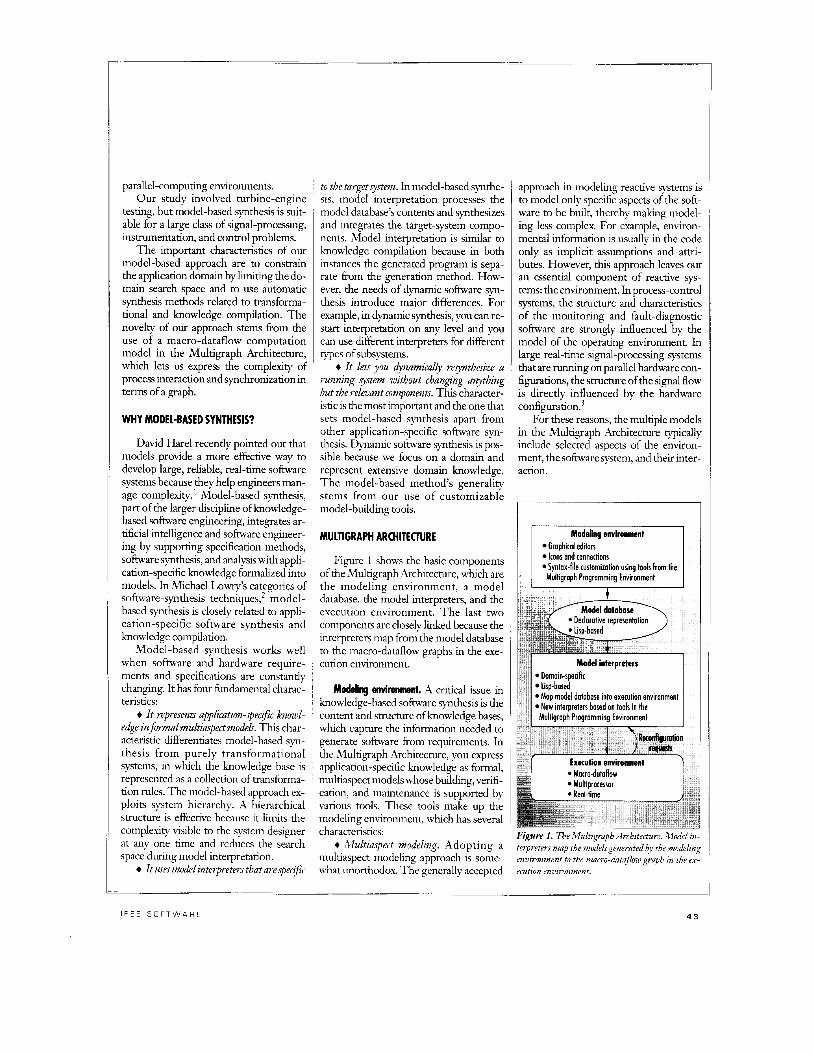
Figure 1 shows the basic components of the Multigraph Architecture, which are the modeling environment, a model database, the model interpreters, and the execution environment. The last two components are closely linked because the interpreters map from the model database to the macro-dataflow graphs in the exe- cution environment.
Modeling d m m m t . A critical issue in knowledge-based software synthesis is the content and structure of knowledge bases, whch capture the information needed to generate software from requirements. In the Multigraph Architecture, you express application-specific knowledge as formal, multiaspect models whose building, verifi- cation, and maintenance is supported by various tools. These tools make up the modeling environment, which has several characteristics:
+ lWultiaspect modeling. Adopting a multiaspect modeling approach is some- what unorthodox. The generally accepted
approach in modeling reactive systems is to model only specific aspects of the soft- ware to be built, thereby making model- ing less complex. For example, environ- mental information is usually in the code only as implicit assumptions and attri- butes. However, thls approach leaves out an essential component of reactive sys- tems: the environment. In process-control systems, the structure and characteristics of the monitoring and fault-diagnostic software are strongly influenced by the model of the operating environment. In large real-time signal-processing systems that are running on parallel hardware con- figurations, the structure ofthe signal flow is directly influenced by the hardware configuration.3
For these reasons, the multiple models in the Multigraph Archtecture typically include selected aspects of the environ- ment, the software system, and their inter- action.
Graphical editors Icons and connections Syntax-file customizotion using tools from the Multigraph Programming Environment
Model interpreters Domain-specific Lisp-bored Map model database into execution environment New interpreters bored on tools in the
Multigraph Programming Environment
Execution environment
Figure 1. The Multigraph Archzterture Model tn- telpreterr map the modelsgenerated the madeltng envirmment to the macro-htaflmu graph m the ex-
enition envwonmmt
I E E E S O F T W A R E
Control ---- Reod/write ---
I ,
I
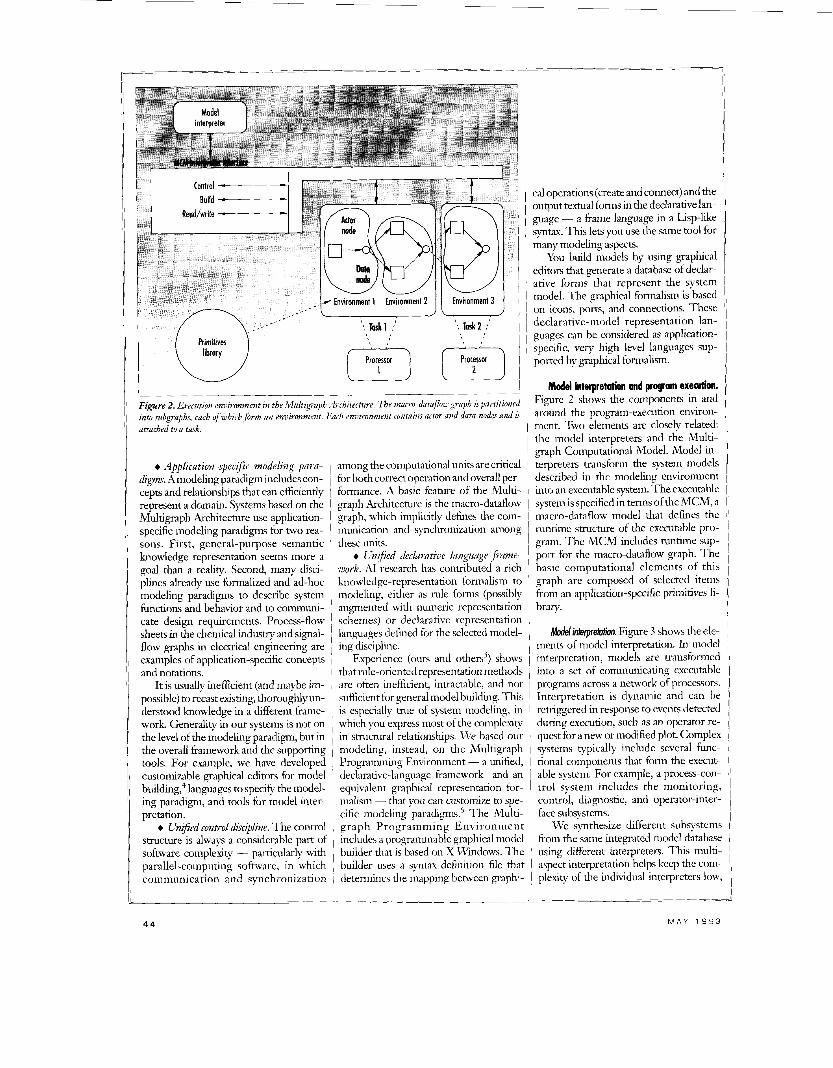
Figzcre 2. Execzition envirmment in the Multigraph Architecture. The mmro-data@ graph is partitioned into subgraphs, each o f which fonn an environment. Euch envimnment contaim actor and data nodes and is attached to a task.
Rodd interpretation and program exenrtion. Figure 2 shows the components in and around the program-execution environ- ment. Two elements are closely related:
+ Application-specific modeling para- digms. Amodeling paradigm includes con- cepts and relationships that can efficiently represent a domain. Systems based on the Multigraph Archtecture use application- specific modehg paradigms for two rea- sons. First, general-purpose semantic knowledge representation seems more a goal than a re&ty. Second, many disci- plines already use formalized and ad-hoc modehg paradigms to describe system functions and behavior and to communi- cate design requirements. Process-flow sheets in the chemical industry and signal- flow graphs in electrical engineering are examples of application-specific concepts and notations.
It is usually inefficient (and maybe im- possible) to recast existing, thoroughlyun- derstood knowledge in a different frame- work. Generality in our systems is not on the level of the modeling paradigm, but in the overall hamework and the supporting tools. For example, we have developed customizable graphical editors for model buildmg,’ languages to specify the model- ing paradigm, and tools for model inter- pretation.
t Unified control discipline. The control smcture is always a considerable part of software comdexitv - particularly with
1 -
plexity of the individual interpreters low,
among the computational units are critical for both correct operation and overall per- formance. A basic feature of the Multi- graph Architecture is the macro-dataflow graph, which implicitly defines the com- munication and synchronization among these units.
+ Unified declaratizv language pame- work. AI research has contributed a rich knowledge-representation formalism to modeling, either as rule forms (possibly augmented with numeric representation schemes) or declarative representation languages defmed for the selected model- ing discipline.
Experience (ours and others’) shows that rule-oriented representation methods are often inefficient, intractable, and not sufficient for general model building. T h s is especially true of system modeling, i r i
which you express most of the complexly in structural relationships. We based ow- modeling, instead, on the Multigraph Programming Environment - a unified, declarative-language framework and an equivalent graphical representation for- malism - that you can customize to spe- cific modeling paradigms6 The Multi- graph Programming Environment includes a progrdmniable graphcal model builder that is based on X Windows. The
I
A , %
cal operations (create and connect) and the output textual forms in the declarative lan- guage - a frame language in a Lisp-like syntax. T h ~ s lets you use the same tool for many modeling aspects.
You build models by using graphical editors that generate a database of declar- ative forms that represent the system model. The graphical formalism is based on icons, ports, and connections. These declarative-model representation lan- guages can be considered as application- specific, very high level languages sup- ported by graphlcal formalism.
the model interpreters and the Multi- graph Computational Model. Model in- terpreters transform the system models described in the modehg environment into an executable system. The executable system is specified in terms of the MCM, a macro-dataflow model that defines the runtime structure of the executable pro- gram. The MCM includes runtime sup- port for the macro-dataflow graph. The basic computational elements of this graph are composed of selected itenis from an application-specific primitives li- brary.
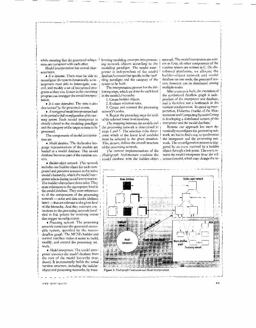
Moddinterpretotion. Figure 3 shows the ele- ments of model interpretation. In model interpretation, models are transformed into a set of communicating executable programs across a network of processors. Interpretation is dynamic and can be retriggered in response to events detected during execution, such as an operator re- quest for a new or modified plot. Complex systems typically include several func- tional components that form the execut- able system. For example, a process-con- trol system includes the monitoring, control, diagnostic, and operator-inter- face subsystems.
We synthesize different subsystems from the same integrated model database using different interpreters. This multi- asDect interpretation helps keep the com-
while ensuring that the generated subsys- tems are consistent with each other.
Model interpretation has several char- acteristics:
+ It is dynamic. Users must be able to reconfigure the system dynamically, so in- terpreters must able to interrogate, con- trol. and modifv a set of interpreted pro-
Ths , m turn, defines the overall structure
forming modeling concepts into process- ing-network objects according to the modeling paradigm. The model inter- preter is independent of the model database’s content but specific to the mod- eling paradigm and the category of the system to be built.
The interpretation process has the fol-
’ work. The reconfiguraaon process is mg-
graks as they i n . Events in &e exeiting 1 lowing steps,which aredone for each level program can retrigger the model interpre- ’ in the model’s hierarchy: tation. I 1. Create builder objects.
+ It is mte-dependent. The state is also I 2. Evaluate selection rules. determined by the generated events. 1 3 . Create and connect the processing
+ A retrigered model interpretation leads I network‘s nodes. to thepartial o r 9 1 reconfiguration of the run- I 4. Repeat the preceding steps for each zing system. Each model interpreter is 1 of the selected lower level modules. closely related to the modehg paradigm The mapping between the models and and the category of the target system to be 1 the processing network is determined in generated. 1 steps 2 and 3. The selection rules deter-
The components of model interpreta- i mine which of the lower level modules tion are 1 must be selected in the given situation.
+ Model database. The declarative lan- guage representations of the models are loaded as a model database. T h s model database becomes part of the runtime sys- tem.
+ Builder-object neizwk. Tins network includes one builder object for each com- pound and primitive instance in the active model’s herarchy, which the model inter- preter selects during model interpretation. The builder objects have three roles. They store references to the appropriate level in the model database. They store references to all the components of the processing network - actor and data nodes (defined later) - that are relevant to the given level of the hierarchy. And they maintain con- nections to the processing network (mod- eled as h k points) for receiving events that trigger reconfiguration.
+ Procesing netulwk. The processing network constitutes the generated execut- able system, specified by the macro- dataflow graph. The MCM’s builder and control interface makes it easier to build, modify, and control the processing net- work.
+ Model interpreters. The model inter- preter traverses the model database from the root of the model hierarchy (top- down). It incrementally builds the actual runtime structure, including the builder- object and processing networks, by trans-
network The model interpreters are writ- ten in Lisp; all other components of the runtime system are written in C. On dis- tributed platforms, we allocate the builder-object network and model database on one node; the generated S ~ S -
tern, however, can be dismbuted among multiple nodes.
After a system is built, the execution of the synthesized dataflow graph is inde- pendent of the interpreter and database, and is therefore not a bottleneck in the runtime configuration. To speed up inter- pretation, Hubertus Franke of the Mea- surement and Computing Systems Group is developing a distributed version of the interpreter and the model d a t a b ~ e . ~
Because our approach lets users dy- namically reconfigure the processing net- work, we had to find a way to synchronize the interpreter and the processing net-
Figure 3. Multiqaph Cnnputatrmzal Model tntgretatton.
- _ _ ~ _ ~~ ~
45
lection of the component5 in the active model's hierarchy. To replace a running processing module, the model interpreter follows thls protocol: I
1. Complete interpretanon of the new 1 module and build the new processing net- I work. I
2 . Block the input data nodes of the old ' processing network using the available ~
1 references and MCM 1 calls.
Caddmas was created to analyze all data related to testing new and redesigned turbine engines. During a typical test (about 10 hours), testers run an in- strumented version of a turbine engine through various operational maneuvers (like acceleration, deceleration or throttle snap) while the e n p e is in a test cell (like a wind tunnel), which simulates altitude, atmospheric, and air-speed conditions. To analyze dynamic vibrations of internal components, testers attach strain gauges and other stress sensors to the turbine blades.
In a typical test, an engine may have several hundred stress sensors alongwith a variety of temperature, pressure, acceler- ometer, flow, and revolutions-per-second sensors. Stress sensors can generate signals with bandwidths in the tens of kilohertz.
Traditionally, testers analyze thls data off-line. They record most of the raw in- formation onto analog tapes and digitize it into conventional computers for analysis. Data processing is extremely com- putationally intensive, so they can analyze only a selected portion of the data. The analysis typically delays final results for several weeks, u h c h means that testers cannot do any timely planning and evalu-
clude $all (data is present), ifany, or based on a real-time event. MCM calls let actor scripts receive input tokens, access their context, and propagate output tokens.
Data nodes provide a queuing and asyn- chronous connection function between actor nodes. Consequently, the dataflow graph in the Multigraph Architecture looks slightly different from a classic
dataflow graph because it contains data nodes,
I
1
DATAFLOW 1s ~ tations intheold process- I A GRAPH, SO 1 3. Complete the al- ' ready scheduled compu-
which are passive, provid- ing only queuing func- tions. ~ n y number of
processing network. provide a simple interface 6. Destroy the old processing network. , for the model interpreters to control, Willem BIokland describes the details build, and monitor an executing graph.
of different reconfiguration methods and 1 Envi?pomnentF protect system resources related synchronization methods8 I and help prioritize sections of the dataflow
I graph. All actor nodes are assigned to an Muhisroph CompUtonbn/ Mode/. The MCM 1 environment. Only one actor per environ-
provides an interface to build, modify, 1 ment is executed at any one time. Envi- monitor, and control an asynchronous ronments of the same priority are serviced macro-dataflow graph. The dataflow I in a round-robin fashion. graph contains actor nodes, data nodes, Tmks provide a generic interface to and their connections. It is partitioned , computational resources. In a multi- into subgraphs, which constitute multiple taslung environment, they are simply the environments. Each environment is then , different processing threads available to attached to a task. The environments and the I\IICM. In a multiprocessor system, tasks make up the execution structure, as- I they are the processors themselves. signingsubgraphs to particular resource^.^ The MCM completes all functions re-
Actwnodes are the computational oper- lated to actor and data nodes, sets the pri- ators of the dataflow graph. Associated ority of environments, and attaches envi- with an actor are ronments to tasks. The use of distinct
+ schedulerrtute, whch can be inactive, actor nodes and data nodes lets model in- active, ready, or running; ' terpreters build, control, and monitor the
+ script, a reentrant algorithm ex- ' dataflow graph. The task and environ- pressed in a procedural or numeric lan- ment concepts keep the implementation page, usually incorporated from a primi- of the underlying system hidden from the
' uves library; user. + context, astaticlocal-memorysection We had several reasons for using the
for state and builder-initialized variables; MCM-based dataflow graph as an inter- + Z/Opo??s, the YO data streams; and mediate layer between the declarative + conid principle, which determines ~ models and actual program execution.
First, it let us decrease interpreter com- plexity by increasing the complexity of the
what criteria will be used to decide when an actor should be executed. These in-
ing network using MCM calls.
4. Disconnect the old processing network and connect the new process- ing network.
5. Enable the interface data nodes of the new
ation on-line.
IT IS EASY TO MAP PROGRAM EXECUTION TO PARAUEL I ARCHITECWRES.
I
actor output ports may be connected to a data node. A data node may be con- nected to any number of actor input ports. Data nodes may be enabled or disabled and have a speci- fied length. Data nodes
basic computational blocks. Second, be- cause the graph structure implicitly de- tines the dependencies among actor nodes, the interpreters do not have to pro- duce a schedule for ordering operations. The MCM determines execution order at runtime. Finally, because dataflow is a graph model representing data dependen- cies amongthe computational units, wecan map program execution onto parallel archi- tectures - both shared-memory and dis- tributed -in a straightforward manner.
APPLICATION
4 6

many channels. The spectral information is accumulated and processed into several types of computationally intensive, cali- brated engineering diagrams. A graphical user interface lets testers configure the data-processing and visualization screens interactively.
Testers can select the nuniber ofvisible windows on a screen, the contents of each plot window, and the parameters of each
Caddmas was a good test for model- based synthesis because it has the real- world interaction typical of reactive sys- tems, yet it has unstable testing demands. I t is characterized by
+ Changing software requirements En- gine capabilities are constantly improving, so testing scenarios are updated test by test. When a new test is scheduled, the engine manufacturer’s aeroinechanical engineers specify the number, types, and accuracy of the plots desired. Caddmas had to be open and scalable to meet these changing and unknown needs. New data- analysis techniques that produce new types of plots would have to be plugged into the software. Wind- tunnel air time used dur-
plot.
ing engine testing drives the overall test cost, so Caddmas would have to serve a real-time environ- ment. The integrity and efficiency of the gener- ated software would be crucial, yet the software for each test had to be unique.
high-speed bidirectional serial communia- tion hnks (20 Mbps) accessible through in- dependent direct-memory-access engines.
The computational blocks include an integer digital-signal processor for ana- log/digital conversion, threshold-alarm generation, antialias filtering, and down sampling; a transputer with a floating- point digital-signal processor providing 38 Mflops; a graphical processor; a generic transputer for general-purpose opera- tions; and an MS-DOS PC for the user interface, software development, and sys- tem construction.
+ Chungzng .pc$cutimis. The number and type of plots to be generated and the accuracy requirements change during the test period. The number of alternatives is too high to prebdld all the possible alter- natives. It would be unacceptable to shut down, rebuild, aid load the new version during a running test.
Modding environment. We had to model two aspects of Caddmas: signal flow and hardware structure. T h e signal-flow model declares the structure and possible
alternatives of instrumen- tation scenarios. T h e
(ADDMAS WAS ha r dw a r e - s t ru c t u r e model declares the hard-
A GOOD TEST ware architecture and aI-
BE(AUSE In ternatives possible in light of available resources and
TESTING their capabilities.
DEMANDS ARE U% defined a unique declarative language for
UNSTABLE. each modeling aspect
Changing hardwaye configurations. Caddmas hardware would be constantly changing according to the number of available processors, computa- tional demand, channel capacity, and pro- cessing requirements. Thus, its hardware had to be reconfigurable. Caddmas’s hardware is a set of building blocks that can be plugged together to create the de- sired architecture. The current Caddmas prototype can process 24 channels of stress, pressure, accelerometer, and other data at bandwidths up to 10 kHz on-line and gap-free. Inmos transputers provide message-passing. Each transputer has four
I _
using the declarative-lan- guage tools of the Multi-
graph Prograinnung Environment. We also generated interpreters for the two models using these tools.
Sgm/-flowmode/ing. The sipal-flow model is built from modules that have three kinds of interfaces. The signulinterface connects the module in the signal flow. The Jpecifi- c h m interface contains the module re- quirements, including performance on the hardware. The dyiumic-conwol interface defines the dynamic-control parameters. The box on pp. 48-49 describes part of the signal-flow model from Caddmas.
--_______j i (defprimitive <name>
(interface (<input-signals> -> <output-signals>) ( <specification-lkb) ( <dynamic-control-
parameters) 1
(body (<primitive-name>) (<discipline>) (<environmenb))
I Figure 4. The siplal-flow ntodel’s declaration of a wimitive.
The modules can be primitive or com- pound. Primitive modules represent the elementary computation units and define their interfaces. The primitive module can be a subroutine, device h.andler, or inter- face to a hardware accelerator.
Figure 4 is the signal-flow model's dec- laration of a primitive. The lists after the key word “interface” specify the signal in- terface, the specifidon interface, and the dynamic-control interface. The symbols following the key word “body” determine the features of the computation unit itself.
<primitive-name> identifies the sub- routine to be invoked from the primitives library. The subroutine can be written in C, Fortran, or Lisp. <discipline> specifies whether the control principle of the actor node is lfall or ifany. <environmenb dehes the system resource (task or processor) that wdl execute the primitive operation.
Compound modules are composed of other modules that may be either primi- tives or other compounds. Their primary purpose is to represent knowledge about building specific pieces of signal-flow graphs. To represent knowledge buildmg, you must know the reasonable level of flexibility in defining possible alternatives and how the alternatives and the selection rules are structured.
Real-time signal-processing systems generally have strict operational con- straints. The number of structural altema- tives for implementing a specific h c t i o n is usually quite limited. The various alter- natives must be thoroughly tested for per- formance and runtime behavior. As a re- sult, we introduce enough limitations in the representation to keep the selection
I E E E S O F T W A R E
(or planning) process manageable whde their connections. Flexibility is achieved not losing all flexihility. ' by introducing the possibility that each
An important limitation is that the I unit can be implemented by various rnod- functional architecture of a compound 1 ules having the same functionality, but structure is fixed. It is described by the I with different specifications. After receiv- declaration of the functional units and ing the requirements through the specifi-
cation interface, the selection rules select the appropriate implementation module for the functional units and determine the external specifications for them. Because the selected modules on the lower level may also have an internal structure with
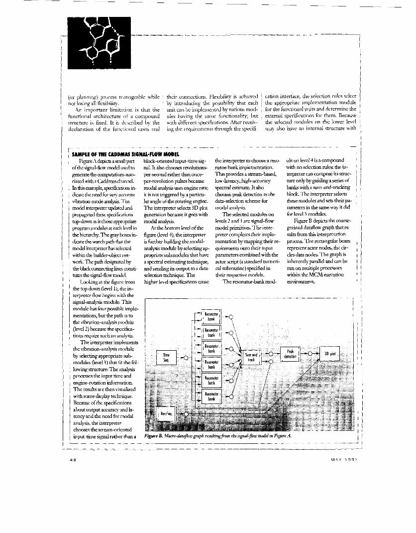
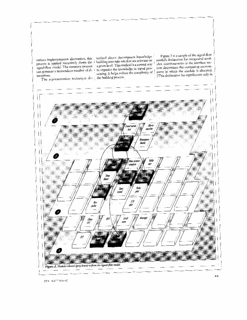
SAMPLE OF THE CADDMAS SIGNAMLOW MODEL Figure A depia a small part
of the signal-flow model used to generate the computations asso- ciated with a Caddmas channel.
dicate the need for very accurate vibration-mode analysis. The model interpreter updated and propagated these speci6cations topdown as it chose appropriate program m d e s at each level in the hierarchy. The gray boxes in- dicate the search path that the model interpreter has selected within the builder-object net- work The path designated by the black connecting h e s consti- tutes the signal-flow model.
Looking at the figure from the top down (level l), the in- terpreter flow begins ~ i t h the signal-analysis module. This module has four possible imple- mentations, but the path is to the vibrationanalysis module (level 2) because the specifica- tions require such an analysis.
the vibration-analysis module by selecdng appropriate sub- modules (level 3) that fit the fol- lowing s~[uctw-e: The analysa processes the input time and engine-rotation information. The results are then visualized with some display technique. Became of the specifications about output accuracy and la- tency and the need for modal analysis, the interpreter chooses the stream-oriented input-time signal rather than a
In dlis example, specifications in-
The interpreter implements
block-oriented input-time sig- nal. It also chooses revolutions- per-second rather than once- per-revolution pulses because modal analysis uses engine rate; it is not triggered by a panicu- lar angle of the rotating engine. The interpreter selects 3D plot generation because it goes with modal analysis.
At the bottom level of the figure (level 41, the interpreter is further building the modal- analysis module by selecting ap- propriate submodules that have a spectral estimating technique, and sending its output to a dam- selection technique. The higher level specifications cause
the interpreter to choose a reso- nator-bank implementation. This provides a stream-based, low-latency, high-accuracy spectral estimate. It also chooses peak detection as the data-selection scheme for modal analysis.
The selected modules on levels 2 and 3 are signal-flow model primitives. The inter- preter completes their imple- mentation by mapping their re- quirements onto their input parameters combined with the actor script (a standard numeri- cal subroutine) specified in their respective models.
The resonator-bank mod-
ule on level 4 is a compound with no selection rules; the in- terpreter can compose its strut- ture only by guiding a series of banks with a sum-and-traclung I block. The interpreter selects 1 these modules and sets their pa- I mete r s in the same way it did 1
I for level 3 modules. Figure B depicts the coarse- ,
grained dataflow graph that re- 1 sults from this interpretation 1
process. The rectangular boxes I I represent actor nodes, the cir-
cles data nodes. The graph is inherently parallel and can be I run on multiple processors I within the MCM execution 1
I environment. I
i I
I
I 1 Figwe B. Mm-dataflow graph resultingfwm the signaGfrw model in Figure A.
!I I1
!!
I E E E S O F T W A R E
11 various implementation alternatives, this ~ scribed above decomposes knowledge ~
Figure 5 is a sarllple of the signal-flow

(defcompound <name>
<output-signals>) (interface (<input-signals> -->
(<specification-lisb) (<dynamic-control-
parame ten>) (<environment>))
(<specifications>))
specifications>))
(<selection des->)
(connections (<signals>)
(l3nkpoints (&st of link-point
(structure (<list of units.))
(body (<S-expressions>)) - ~ _ _ _ _
Figure 5. 7he s iLq id f lox niorlt~l~v cleclaration of a compound.
7 v -
(defcpu a a m e i @&points (dinkpoint-liso)) (specification (<specification-lisb)))
(parts (cpart-liso)) (connections (<connection-lisb)))
(defmpr <name->
L I
Figure 6. Defivitions Of'procr~sroi: link point, and multiprocessor iu the .2.ltrltipio~-l~.ssu7. Description L a n p g e .
can be used for various initializations at
multiprocessor and inulticomputer im- plementations.) The connections specify the symbols that are used to declare the
+ a hardware wiring list and test pro-
Hadwre-structure modeling. We u se d th e Multiprocessor Description Language'" to model the hardware structure. The hardware-structure model shows the dis- tributed-processor configuration to the level of detail that lets you generate the routing system and the resource-alloca- tion model.
Figure 6 gives the MPDL templates, which show three types ofcomponents: pro- cessors (cpu), link points @&), and multi- processors (mpr). Processors, the basic buildmg blocks, are characterized by a set of attributes, including type, memory size and unique resources. Processors can have hnk points to interconnectthem ina given topol- ogy. Multiprocessors are aggegates of pro- cessors comprising other multiprocessors, processors, and link points.
Model interpreters. The interpretation of signal-flow model structures starts by de- 6ning a set of requirements (in th~s case, the desired engineering plots) for the top- level modules.
Interpretation then proceeds recur- sively. T h e specifications propagate downward and the interpreter uses the se- lection rules to choose the appropriate modules for the functional units on the consecutive levels of the hierarchy. Figure A in the box on pp. 48-49 illustrates this
+ communication maps that tell pro- cessors how to talk to each other, includ- ing processor hops.
Once the hardware archtecture is set, the signal-flow model's interpretation continues where it left off. The interpreter builds a new dataflow graph on the execu- tion environment under the MCM. It does &s by traversing the signal-flow model and instantiating the basic compu- tational elements as actor nodes and inter- connections as data nodes.
At t h~s point, the generated real-time system is ready for execution. Computa- tions produce results as specified in the signal-flow model - including on-line plots, data monitoring, and hard-copy output - without the interpreter inter- vening.
Execution proceeds until an event oc- curs. An event is user input that changes the desired outputs. It triggers a reevalua- tion of the signal-flow model's specifica- tion, causing the interpreter to pass through the affected subhierarchy once more but with a different selection crite- rion ( w i t h the bounds of the current hardware architecture). The interpreter notes changes to the specification model and begins to reinterpret the MPDL models.
If the interpreter is reinterpreting dur- ing o n - h e processing, it cannot do any- thing but modify the communications maps, because the hardware architecture is typically changed after the system shuts down. The required communication pat- terns implemented in the running system - the new communication maps - in- cluding processor hopping, are downloaded. The interpreter preserves all zurrently used maps so as not to interrupt the executing system.
At this point, the interpreter is ready to modify the executing computational graph. It creates the disjoint subgraph of the new components and completes the internal connections once again. It then connects the output points of the new disjoint subgraph to the existing and running computation graph, although the points do not yet have inputs. Next, it switches the data-source connections from the old subgraphs to the new sub-
1
~
1
~
the added advantage of malung it easy to ' among signal-processing actor;. incorporate an existing subroutine library , + ,440del and model-interpretatimz mer- by simply adding MCM actor script stubs 1 head. For the 24-channel Caddmas, it took that wrap the entry points of the library ~ us approximately two
1993, we will be applying the synthesis techruque to a system based primarily on Texas Instruments' new TMS32OC40 parallel digital-signal processor. The main task in that effort is to port the core MCM routines (dataflow scheduler and inter- face) and the primitives library. We must also modify the hardware models to pro- vide six communication ports instead of four. After h s , however, we again expect the synthesis technique to be directly ap- plicable.
In the last decade, we have used model- based synthesis in several embedded ap- plications, including instrumentation: process monitoring and diagnosis: and signal processing.2 Although our method
can be applied in other areas, we found it particu-
THE SAME
TO A 48-CHANNEL
i prelinked die possible actor scripts for 1 clone host running in 32- ' Caddmas into a single module to be ~ bit mode. After synthesis, ~ loaded onto a transputer for an additional I we stored the builder-ob- i 300 Kbytes ofcode space. However, ifsyn- ~ ject network as a Lisp I thesidresynthesis time is not as important database that requires ap- 1 as saved memory, the MCM lets you dy- i proximately 3 Mbytes of
TECHNIQUE
larly advantageous in syn- thesizing large, reactive systems. We have learned several important lessons:
+ Application-specific modeling p a r a d i p greatly simplifi sojiwaye moakling. In embedded systems, they let you represent the software's conceptual structure using concepts
1 memory is managed by the actor scripts as calculated and displaying new ones. Re- 1 their context. moving 24 current plots and adding 24 , + Computational-graph size. The larg- new ones takes about one second. I est Caddmas specification thus far is 24 I
I strain gauges, 16 transient parameters, 1
e have described the knowledge- W representation and compilation ~ three printers, and three interactive dis- i plays. For thls specification, the synthe- I 1 sized computation graph has more than ~ techques in our model-based, automatic ~
250 instances of actors spread across 83 software-synthesis environment, which ~ processors. we used to build Caddmas, a system with
and relationships that characterize the environment as well as the software itself.
+ Model-based synthesis is suitable for gezerating pardel program. In many ap- plications, the software's conceptual smcture is inherently concurrent; signal- flow graphs are an example. Signal-flow models preserve thls natural concurrency, so it is easy to transform them into parallel programs. In fact, it is easier than trans- forming a sequential signal-processing system into a parallel one.
+ There is U close relationship between the emironment urd the stmcture and parame- t e n of sojiwa7-e cmnponents. This relation- ship means that you can use software, en- vironment, and interrelationshp models to test the multiaspect models you have created for completeness and accuracy.
The basic dilemma of application-spe- cific software synthesis is that the more the environment supports the application's specific needs, the less useful the results
I E E E S O F T W A R E 5 1
will be in other areas. Much of our current work is directed toward solving tlus diffi- culty. Specifically, we are attempting to introduce metalevel abstraction to for- mally represent the modeling paradigm and model interpretation. For a new do- main, the developer would provide formal
models to describe the required paradigm From these metamodels describing tht necessary declarative languages and corre- sponding interpretation, the synthesis s y ~ - tem would automatically generate the neu domain-specific graphcal editor, declara- tive language, and interpreter. +
ACKNOWLEDGMENTS We thank the US Air Force and other Caddmas team members: Greg Sordsuonl ofthe Arnold Engineer-
ing Development Center, Tom Tihbals and Terr). Have? of Sverdrup Technolo@-, and Bruce Bornar of the UN- versity ofTennessee Space Institute.
This work was supported in part by the US .%I Force Office of Scientific Research/Ar Force .Materiel Command contract F49620-90-C-0076.
REFEWNCES 1. D. Harel, ”Bitingthe Silver Bullet,” Lbmprrrel; Jan. IW?, pp. H-10. 2 . M. Lowry, “Software Engineering in the ’Tivent);-First Centun-,” inz4irro7?urting Sofhiai-e Der@, M. low^
3. B. Abbott et al., “Experiences Using Model-based Techniques for the Ilevelopment of a Large Parallel h- and R. McCarmey, eds., M I T Press, Cambridge, IIass., I99 1, pp. 627.654,
suunientation System,” Aoc. Con$ Sip1 Pr-oressii~gApp/rcutzons and Zchnolog, DSP &SOC., Newton, ,Mass., 1992,pp. 573-582.
4. G. Karsai, “Declarative Programming Using Visual Tools,“ Tech. Report 89 -003, Measurement and Com- puting Systems Laboratoly, Vanderbilt Cniversit);, Nashville, Tenn., lY8Y.
5. T. Laffey et al., “Real-Time Knowledge-Based Systems,” Alhlaguzine, Spring 1989, pp. 2745. 6. G. Karsai, “Declarative Programmng Techniques for F.ngineering Problems.” doctoral dissertanon, EE
7. H. Franke, “Programming Environment for Alodel-Based Sptems,” doctoral dissertation, EE Dept.,
8. W. Blokland, “SmcturaUy .4daptive S>~teins,” doctoral dissertahon, EF Ilept.. Vanderbilt Vnwerwt);,
9. J. Sztipanovits, K Karsai, and C. Biegl. “C;rdph .Ilodel-Rased 4pproach to the Representation, Interpreta-
10. A. Ledeczi et al., “Modeling Parallel Hardbvare .kchite~mres,” Aai. Cm$ Sipd P~oce~.~rng~4pp/icutiolna,ld
Dept., Vanderbilt University, Nashville, Tenn., 1988.
Vanderbilt University, Nashville, Tenn., 1992.
Nashville, Tenn., 1991.
tion and Execution of Signal Processing Systems,” h~t’/.T. hteNt,genr , ~ v . ~ c ~ ~ J , Mar. 1Y88, pp. 269-280.
Technology, DSP .&SOC., Newton, Mass., 1992, pp. 274-281.
Ben Abbott is a PhD ~andiclate in electrical engmeermgat Vandcrbilr Uruversit)’? \lea surement and Compunng S\steins Laboraton He IS the prmcipal miesngator on the Caddinas and other parallel-mauuinentauon projects His pnmaryinterest is the use of model-based software qmthesi5 to inanage the complemty of programming large insuu- mentauon systems
electrical engineenng from Vanderbilt Universin He 15 a member of Tau Beta Ph and the North American Transputer User\ Cmup
I I I
ibhott receiied a BS in computer science froin Texas ?eih Untversitv and an MS m
I, l i
Ted Bapty i s a i s a PhD cdndlddte in electrical rngtneenng at Vanderhilt Cni\ersity’s \leasurement and Compunng %steins Laboraton Hi\ research interests are in tools fo developing large scale parallel instrumentan~in w~tein\, parallel hdrdware, and digitdl-sil nal processmg
Baon received a B\ from the Uruiersitv of Pennnl\ania and an \I3 fromVanderbil I‘ I
1 ,
Universi& -both in electrical engmeenng He I$ a meinber ot the IFEE, Eta Kappa NI and North American Iransputer Usen Group
I I
Csaba Biegl is a research as- sistant professor in elecuical engineering at Vanderbilt University. His research in- terests include real-time s ) ~ -
terns, model-based systems, robotics, and graphics pro- gramming.
an MS fiom the Technical Biegl received a BS and
Jniversity of Budapest and a PhD from Vanderbilt Jniversity - all in electrical engineering. He is a nember of the IEEE.
Gabor Karsai is a research assistant professor in electri- cal engineering at Vanderbilt University. His research interests include the design and implemenra- tion of advanced software systems for real-time, and intelligent control s]..stems.
Karsai received a BSc and an iMSc from the Technical University of Budapest and a PhD from Vanderhilt University - all in elecm- cal engineering. He is a member ofthe IEEE and In- ternational Seural Setwork Society.
Janos Sztipanovits is a pro- fessor of electrical engineer- ing at Vanderbilt Univer- sity. His current research focuses on suucnrraUy adap- tive processing systems and the model-based synthesis of large-scale real-dme sys- tems. He has coauthored two books and published
nore than 100 technical papers on elecmcal engineer- ng.
Sztipanovits received a BSc and an MSc in elemi- .al engineering from the Technical Univeniy of Buda- ,est. He also received a CandTechSc from the 3ungarian Academyof Sciences. He is a senior mem- ier of the IEF,E and chairman of the Robotics and Au- omation Society’s lechnicd Committee on Intelligent nsmmens and Measureinent Systems.
Address questions about th is article to .4hbott a t 3 Dept., Vanderbilt University, Nashville, T N i 7 2 3 5; Internet a [email protected].