mobile-Notes - WordPress.com
37
Company LOGO MECHANICAL ENGINEERING DEPARTMENT DJJ 20053 mobile-Notes Version 1.0 Unauthorized copying, sharing or distribution of this copyrighted material is strictly prohibited. If you are interested to purchase this e-Book, please write to : [email protected] SITI HAJAR BINTI MOHD NOH K.M.WONG HELLY SUHAILLA BT SOLAIMAN
-
Upload
khangminh22 -
Category
Documents
-
view
1 -
download
0
Transcript of mobile-Notes - WordPress.com
Company
LOGO
MECHANICAL ENGINEERING DEPARTMENT DJJ 20053
mobile-Notes Version 1.0
Unauthorized copying, sharing or distribution of this copyrighted material is strictly prohibited.
If you are interested to purchase this e-Book, please write to : [email protected]
SITI HAJAR BINTI MOHD NOH K.M.WONG HELLY SUHAILLA BT SOLAIMAN
Published by:
Politeknik Port Dickson
KM14, Jalan Pantai,
71050 Si Rusa,
Negeri Sembilan
SYNOPSIS ELECTRICAL TECHNOLOGY exposes students to basic electrical
circuit concepts, the application of electromagnetism in electrical
machines and transformers. The course focuses on the different
types of electrical circuits, the relationship between current and
voltage including the resistance. It also provides the skills on the
methods of constructing basic circuits and operation of electrical
machines and transformers. This course also exposes the students
to the demonstration of experiments in Electrical Engineering.
eISBN NO:
AUGUST 2020
DJJ20053 – ELECTRICAL TECHNOLOGYCopyrighted 2020 *Port Dickson Polytechnic Mechanical Engineering Department * All Right Reserved
Company
LOGOTitle Page
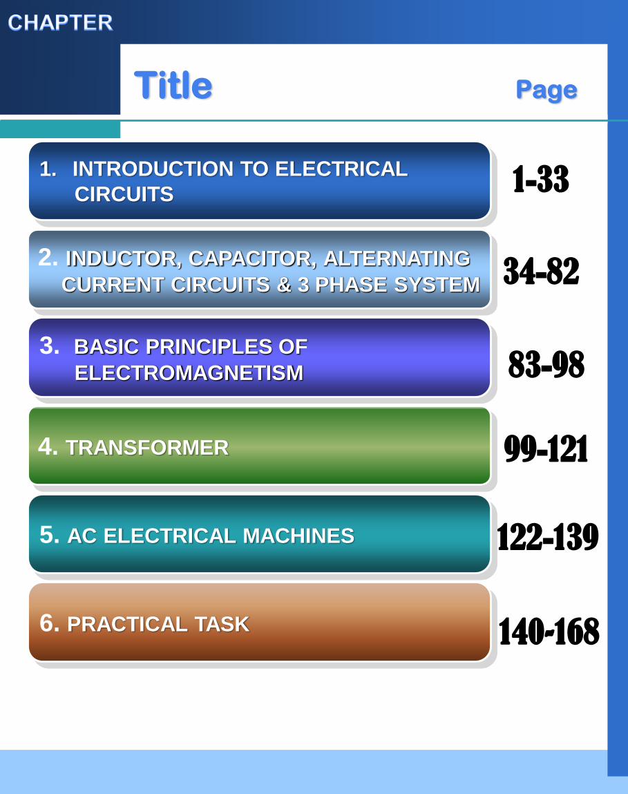
1. INTRODUCTION TO ELECTRICAL
CIRCUITS
2. INDUCTOR, CAPACITOR, ALTERNATING
CURRENT CIRCUITS & 3 PHASE SYSTEM
5. AC ELECTRICAL MACHINES
3. BASIC PRINCIPLES OF
ELECTROMAGNETISM
4. TRANSFORMER
6. PRACTICAL TASK
1-33
34-82
83-98
99-121
122-139
140-168
CHAPTER 1INTRODUCTION TO ELECTRICAL CIRCUIT
(CLO 1)
Explain the principles and fundamental of electrical
circuits, electromagnetism, transformers and
electrical machines (C2,PLO1)
(CLO2)
Solve the problem related to electrical circuits,
electromagnetism, transformers and electrical
machine. (C3,PLO1)
(CLO3)
Organize appropriately experiments in groups
according to the Standard Operating Procedures.
(P4,PLO5)
Company
LOGO
1
Company
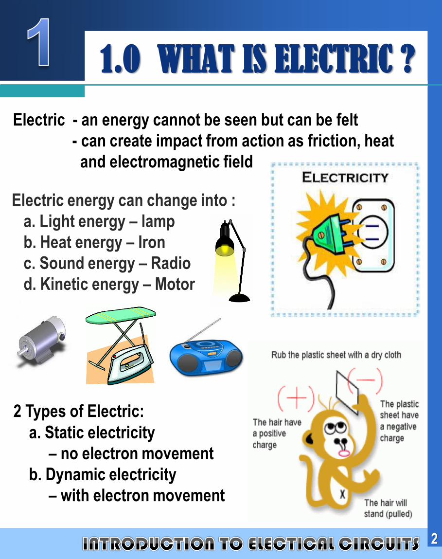
LOGO1.0 WHAT IS ELECTRIC ?
Electric - an energy cannot be seen but can be felt
- can create impact from action as friction, heat
and electromagnetic field
Electric energy can change into :
a. Light energy – lamp
b. Heat energy – Iron
c. Sound energy – Radio
d. Kinetic energy – Motor
2 Types of Electric:
a. Static electricity
– no electron movement
b. Dynamic electricity
– with electron movement
2
Company
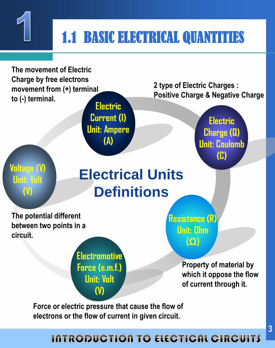
LOGO1.1 BASIC ELECTRICAL QUANTITIES
Electromotive
Force (e.m.f.)
Unit: Volt
(V)
Electrical Units
Definitions
Electric
Charge (Q)
Unit: Coulomb
(C)
Electric
Current (I)
Unit: Ampere
(A)
Voltage (V)
Unit: Volt
(V)
Resistance (R)
Unit: Ohm
(Ω)
Force or electric pressure that cause the flow of
electrons or the flow of current in given circuit.
The movement of Electric
Charge by free electrons
movement from (+) terminal
to (-) terminal.
2 type of Electric Charges :
Positive Charge & Negative Charge
The potential different
between two points in a
circuit.
Property of material by
which it oppose the flow
of current through it.
3
Company
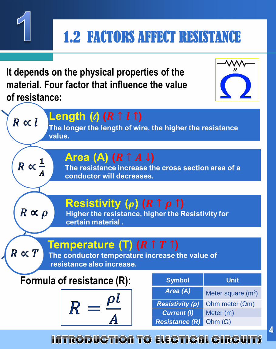
LOGO1.2 FACTORS AFFECT RESISTANCE
It depends on the physical properties of the
material. Four factor that influence the value
of resistance:
Formula of resistance (R):
4
Symbol Unit
Area (A) Meter square (m2)
Resistivity (ρ) Ohm meter (Ωm)
Current (l) Meter (m)
Resistance (R) Ohm (Ω)

Company
LOGO1.2 PROBLEM SOLVING
Example 1 :
Calculate the resistance for the Aluminum wire that has
1.5km length, the diameter is 10mm and the resistivity is
0.025 .m.
Solution :
Given,
Formula,
Where,
477.06
1054.78
)3
105.1)(6
10025.0(
x
xxR
mxd 31010
mx 3105.1
mx 610025.0
AR
261054.78
2)
2
31010
(2
)2
( mxxd
A
5
Company
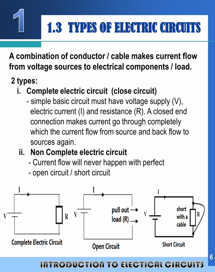
LOGO 1.3 TYPES OF ELECTRIC CIRCUITS
A combination of conductor / cable makes current flow
from voltage sources to electrical components / load.
2 types:
i. Complete electric circuit (close circuit)
- simple basic circuit must have voltage supply (V),
electric current (I) and resistance (R). A closed end
connection makes current go through completely
which the current flow from source and back flow to
sources again.
ii. Non Complete electric circuit
- Current flow will never happen with perfect
- open circuit / short circuit
6
Company
LOGO
7
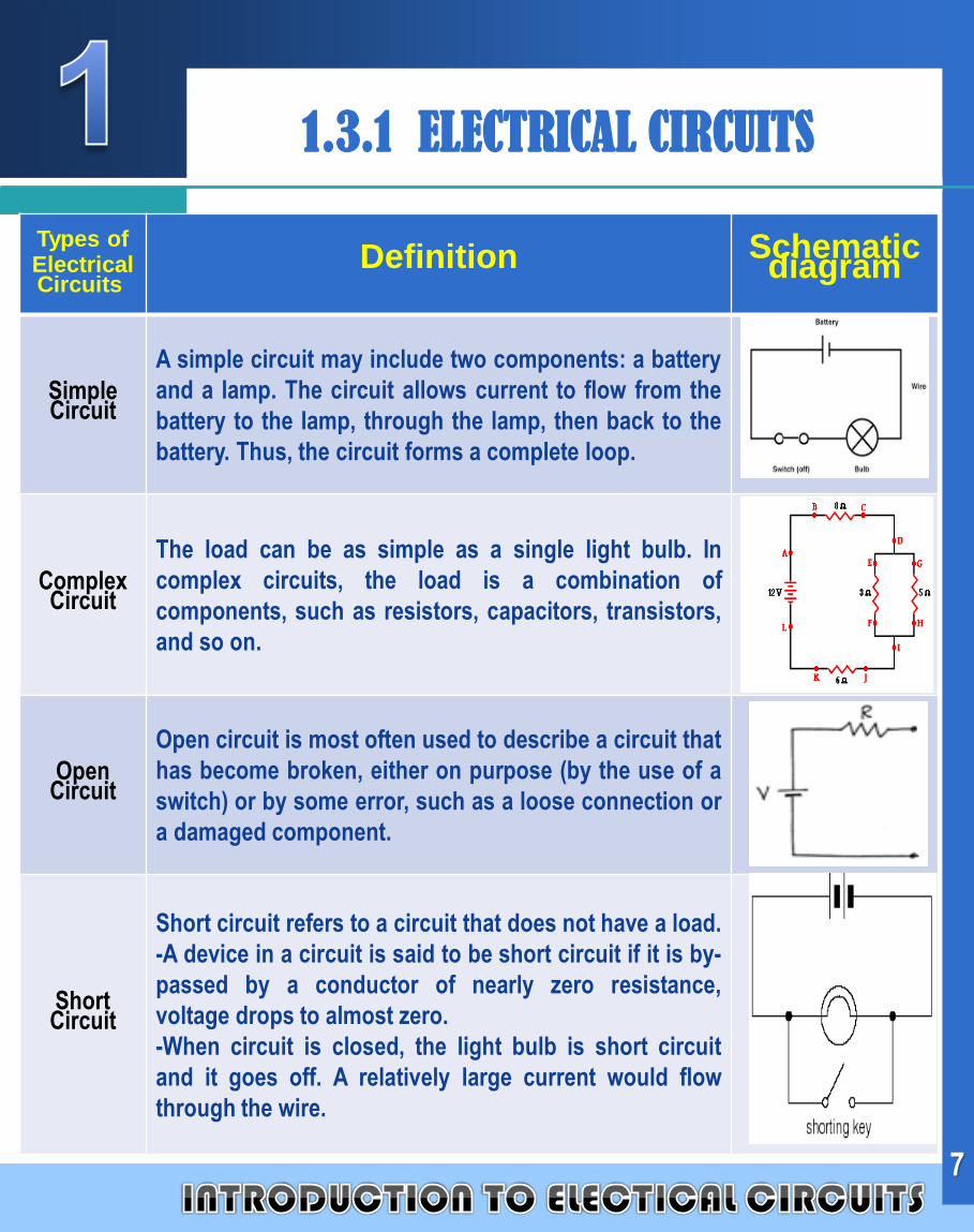
1.3.1 ELECTRICAL CIRCUITS
Types of Electrical Circuits
Definition Schematic diagram
Simple Circuit
A simple circuit may include two components: a battery
and a lamp. The circuit allows current to flow from the
battery to the lamp, through the lamp, then back to the
battery. Thus, the circuit forms a complete loop.
Complex Circuit
The load can be as simple as a single light bulb. In
complex circuits, the load is a combination of
components, such as resistors, capacitors, transistors,
and so on.
Open Circuit
Open circuit is most often used to describe a circuit that
has become broken, either on purpose (by the use of a
switch) or by some error, such as a loose connection or
a damaged component.
Short Circuit
Short circuit refers to a circuit that does not have a load.
-A device in a circuit is said to be short circuit if it is by-
passed by a conductor of nearly zero resistance,
voltage drops to almost zero.
-When circuit is closed, the light bulb is short circuit
and it goes off. A relatively large current would flow
through the wire.
Company
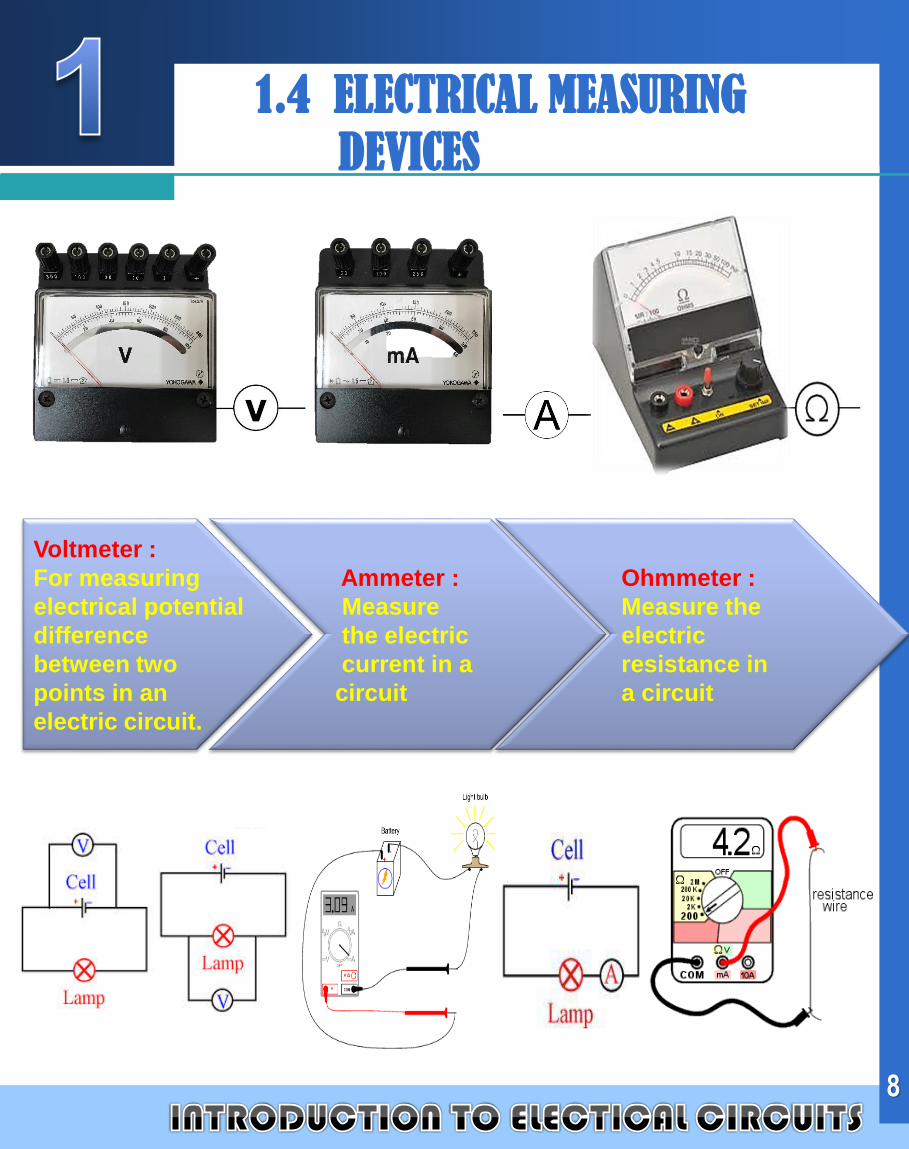
LOGO 1.4 ELECTRICAL MEASURING
DEVICES
Voltmeter :
For measuring
electrical potential
difference
between two
points in an
electric circuit.
Ammeter :
Measure
the electric
current in a
circuit
Ohmmeter :
Measure the
electric
resistance in
a circuit
8
Company
LOGO
9
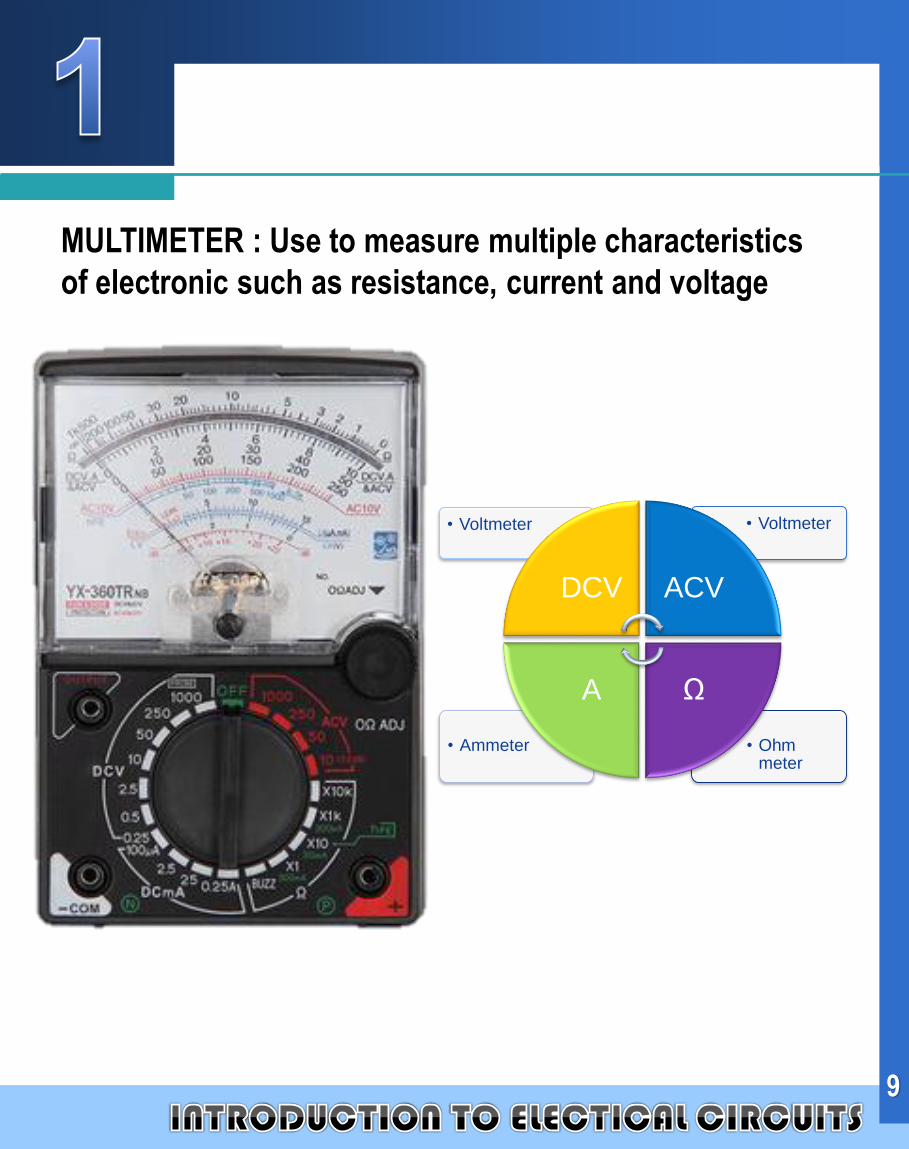
MULTIMETER : Use to measure multiple characteristics
of electronic such as resistance, current and voltage
• Ohm meter
• Ammeter
• Voltmeter• Voltmeter
DCV ACV
ΩA
Company
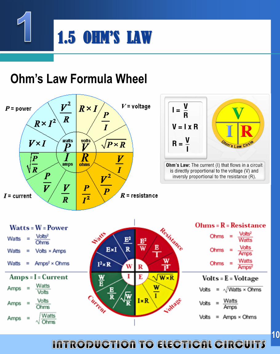
LOGO1.5 OHM’S LAW
Ohm’s Law Formula Wheel
10
Company
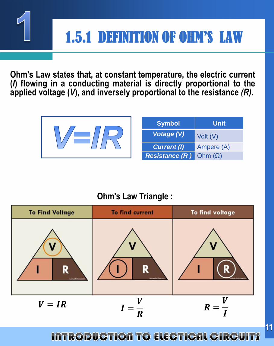
LOGO1.5.1 DEFINITION OF OHM’S LAW
Ohm's Law states that, at constant temperature, the electric current(I) flowing in a conducting material is directly proportional to theapplied voltage (V), and inversely proportional to the resistance (R).
11
Symbol Unit
Votage (V) Volt (V)
Current (I) Ampere (A)
Resistance (R ) Ohm (Ω)
Ohm's Law Triangle :
Company
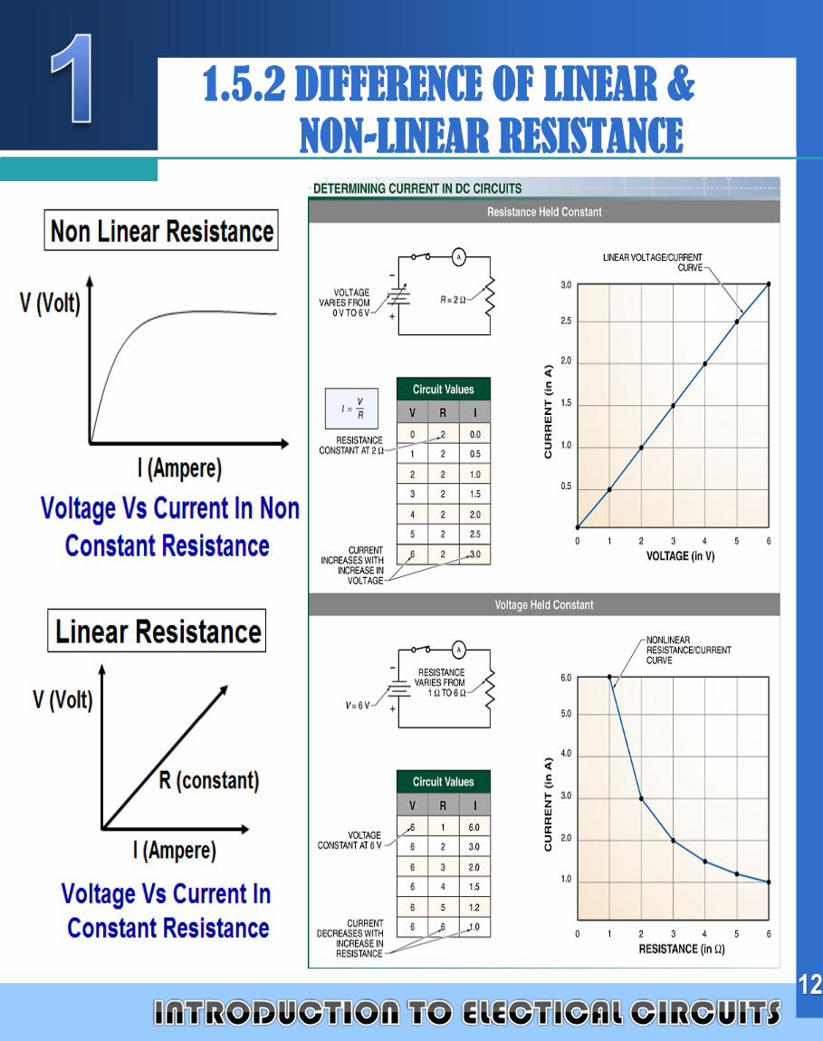
LOGO 1.5.2 DIFFERENCE OF LINEAR &
NON-LINEAR RESISTANCE
12
Company
LOGO
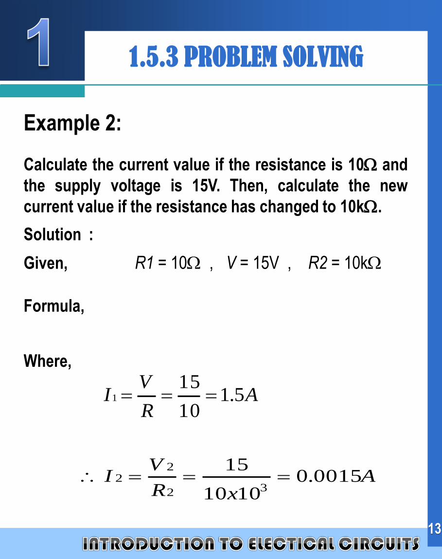
Example 2:
Calculate the current value if the resistance is 10 and
the supply voltage is 15V. Then, calculate the new
current value if the resistance has changed to 10k.
Solution :
Given, R1 = 10 , V = 15V , R2 = 10k
Formula,
Where,
AR
VI 5.1
10
151
AxR
VI 0015.0
1010
15
32
22
1.5.3 PROBLEM SOLVING
13
Company
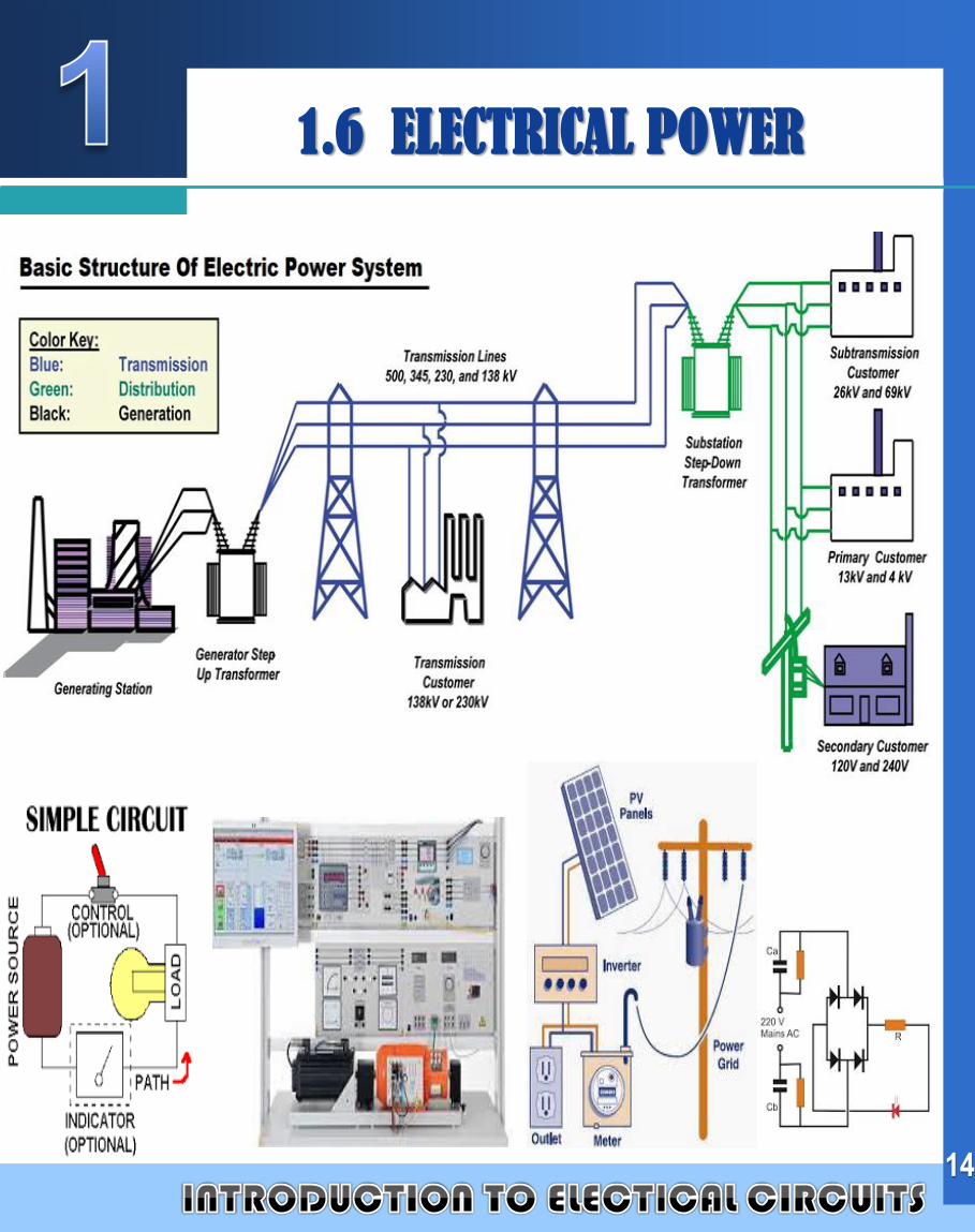
LOGO1.6 ELECTRICAL POWER
14
Company
LOGO
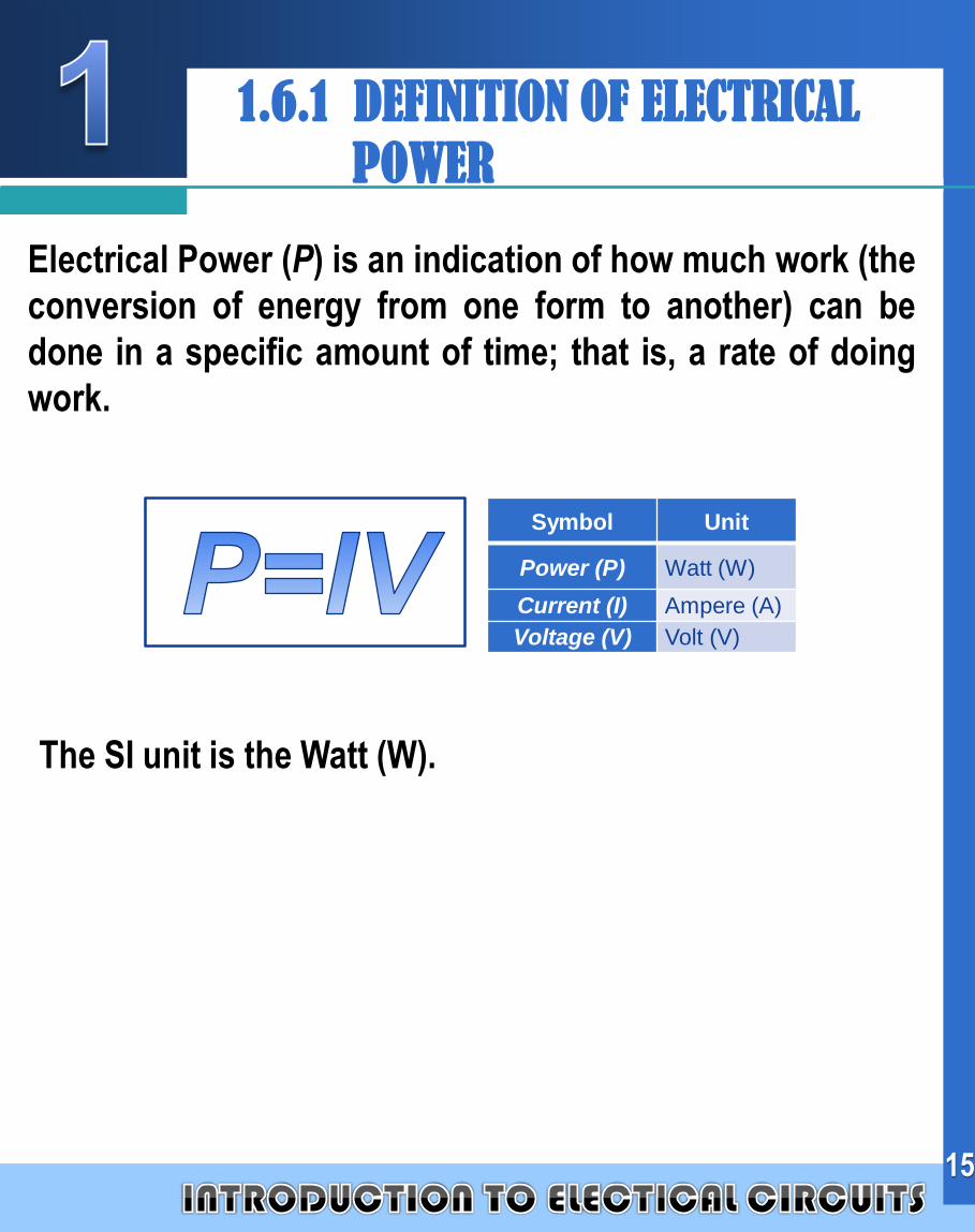
The SI unit is the Watt (W).
15
1.6.1 DEFINITION OF ELECTRICAL
POWER
Electrical Power (P) is an indication of how much work (the
conversion of energy from one form to another) can be
done in a specific amount of time; that is, a rate of doing
work.
Symbol Unit
Power (P) Watt (W)
Current (I) Ampere (A)
Voltage (V) Volt (V)
Company
LOGO
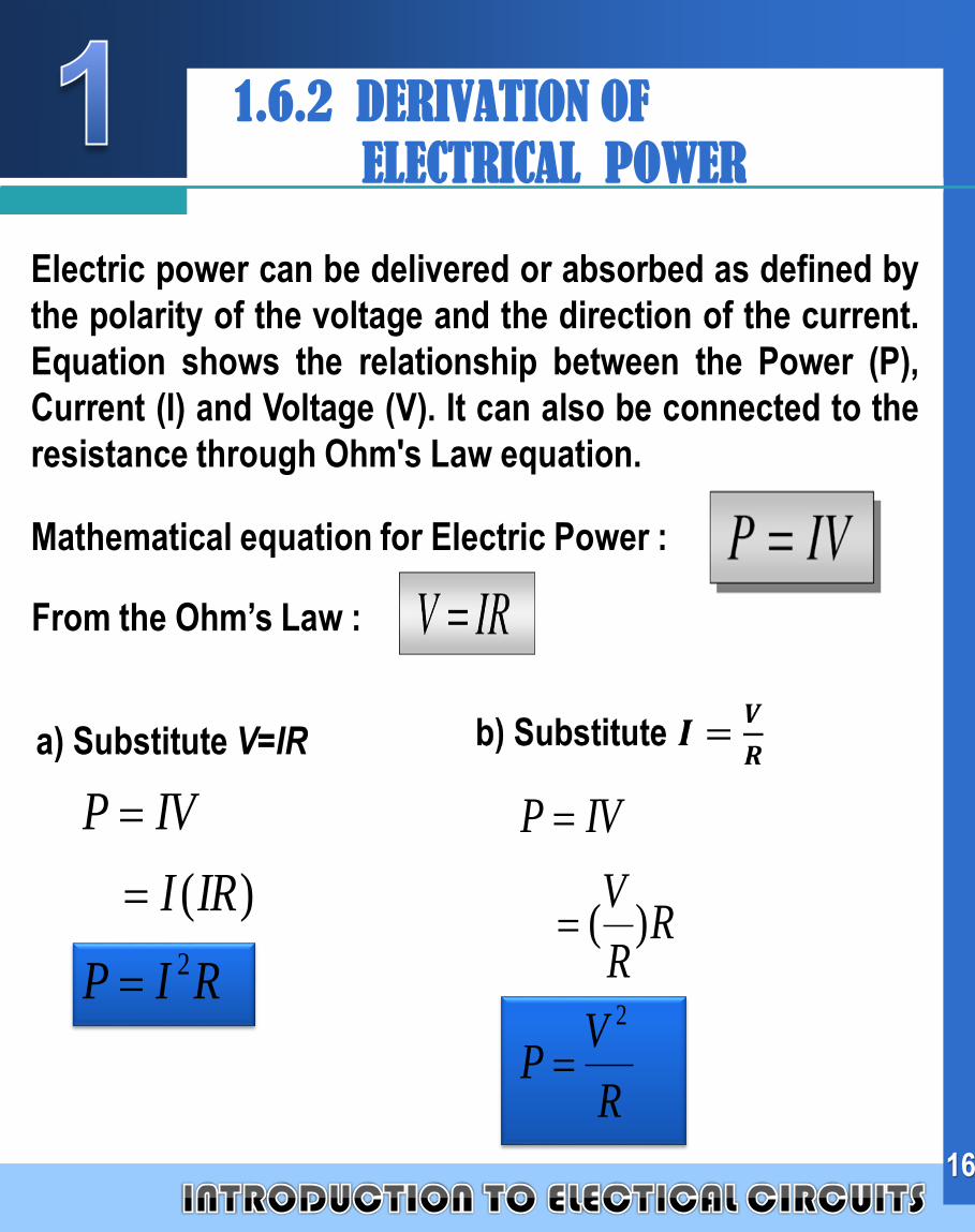
Electric power can be delivered or absorbed as defined by
the polarity of the voltage and the direction of the current.
Equation shows the relationship between the Power (P),
Current (I) and Voltage (V). It can also be connected to the
resistance through Ohm's Law equation.
Mathematical equation for Electric Power :
From the Ohm’s Law :
RIP
IRI
IVP
2
)(
R
VP
RR
V
IVP
2
)(
16
1.6.2 DERIVATION OF
ELECTRICAL POWER
a) Substitute V=IR
Company
LOGO
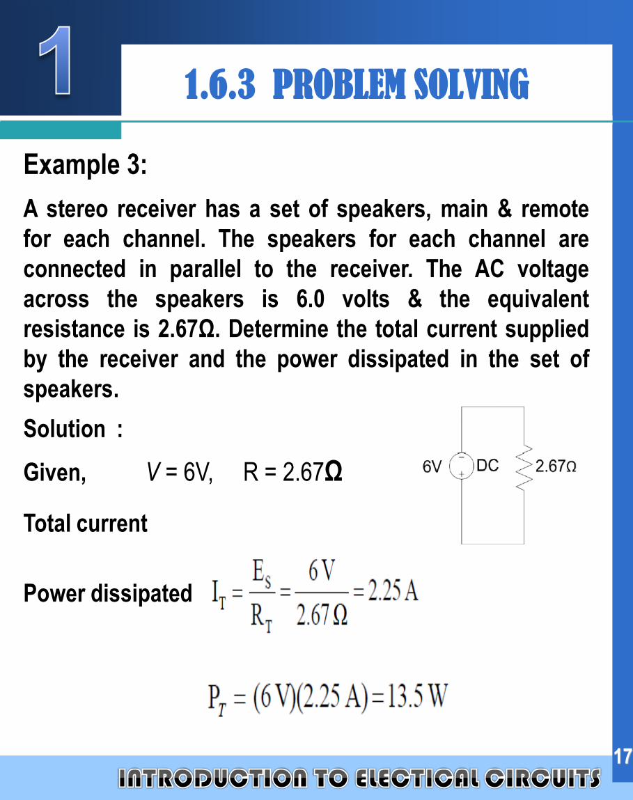
Example 3:
A stereo receiver has a set of speakers, main & remote
for each channel. The speakers for each channel are
connected in parallel to the receiver. The AC voltage
across the speakers is 6.0 volts & the equivalent
resistance is 2.67Ω. Determine the total current supplied
by the receiver and the power dissipated in the set of
speakers.
Solution :
Given, V = 6V, R = 2.67Ω
Total current
Power dissipated
17
1.6.3 PROBLEM SOLVING
Company
LOGO1.7 ELECTRICAL ENERGY
18
Company
LOGO
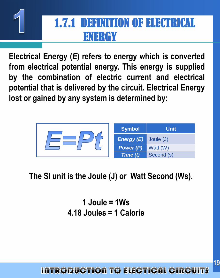
Electrical Energy (E) refers to energy which is converted
from electrical potential energy. This energy is supplied
by the combination of electric current and electrical
potential that is delivered by the circuit. Electrical Energy
lost or gained by any system is determined by:
19
1.7.1 DEFINITION OF ELECTRICAL
ENERGY
Symbol Unit
Energy (E) Joule (J)
Power (P) Watt (W)
Time (t) Second (s)
The SI unit is the Joule (J) or Watt Second (Ws).
1 Joule = 1Ws
4.18 Joules = 1 Calorie
Company
LOGO
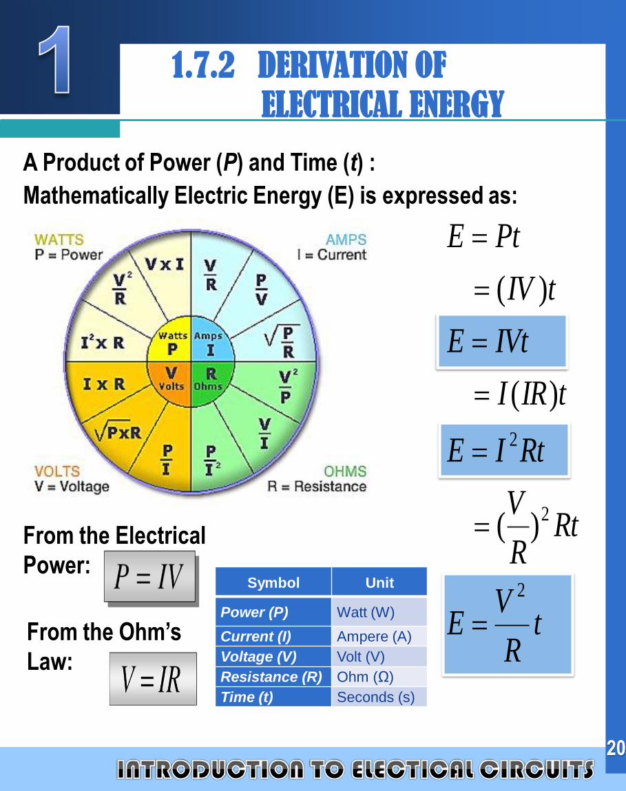
A Product of Power (P) and Time (t) :
Mathematically Electric Energy (E) is expressed as:
20
1.7.2 DERIVATION OF
ELECTRICAL ENERGY
Symbol Unit
Power (P) Watt (W)
Current (I) Ampere (A)
Voltage (V) Volt (V)
Resistance (R) Ohm (Ω)
Time (t) Seconds (s)
tR
VE
RtR
V
RtIE
tIRI
IVtE
tIV
PtE
2
2
2
)(
)(
)(
From the Ohm’s
Law:
From the Electrical
Power:
Company
LOGO
21
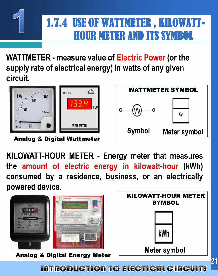
1.7.4 USE OF WATTMETER , KILOWATT-
HOUR METER AND ITS SYMBOL
WATTMETER - measure value of Electric Power (or the
supply rate of electrical energy) in watts of any given
circuit.
Analog & Digital Wattmeter
WATTMETER SYMBOL
Symbol
KILOWATT-HOUR METER - Energy meter that measures
the amount of electric energy in kilowatt-hour (kWh)
consumed by a residence, business, or an electrically
powered device.
Analog & Digital Energy Meter
KILOWATT-HOUR METER
SYMBOL
Meter symbol
Meter symbol
Company
LOGO
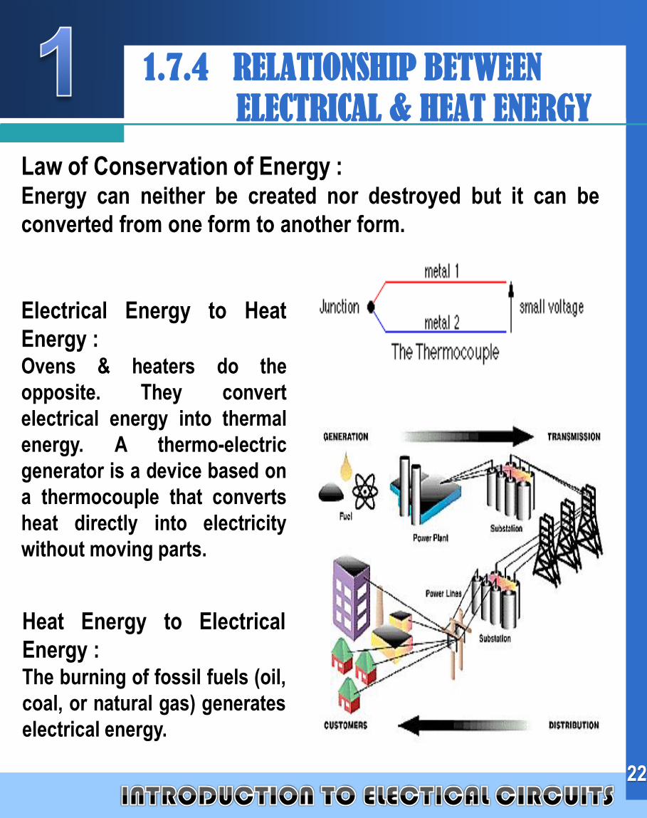
Law of Conservation of Energy :Energy can neither be created nor destroyed but it can be
converted from one form to another form.
22
1.7.4 RELATIONSHIP BETWEEN
ELECTRICAL & HEAT ENERGY
Electrical Energy to Heat
Energy :Ovens & heaters do the
opposite. They convert
electrical energy into thermal
energy. A thermo-electric
generator is a device based on
a thermocouple that converts
heat directly into electricity
without moving parts.
Heat Energy to Electrical
Energy :The burning of fossil fuels (oil,
coal, or natural gas) generates
electrical energy.
Company
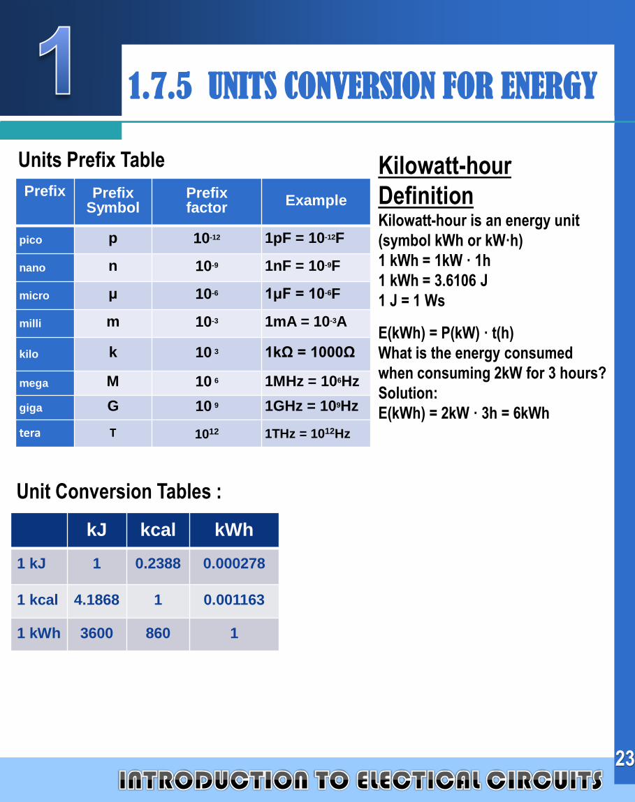
LOGO1.7.5 UNITS CONVERSION FOR ENERGY
Prefix PrefixSymbol
Prefixfactor
Example
pico p 10-12 1pF = 10-12F
nano n 10-9 1nF = 10-9F
micro μ 10-6 1μF = 10-6F
milli m 10-3 1mA = 10-3A
kilo k 10 3 1kΩ = 1000Ω
mega M 10 6 1MHz = 106Hz
giga G 10 9 1GHz = 109Hz
tera T 1012 1THz = 1012Hz
Units Prefix Table
kJ kcal kWh
1 kJ 1 0.2388 0.000278
1 kcal 4.1868 1 0.001163
1 kWh 3600 860 1
Kilowatt-hour
DefinitionKilowatt-hour is an energy unit
(symbol kWh or kW·h)
1 kWh = 1kW · 1h
1 kWh = 3.6106 J
1 J = 1 Ws
E(kWh) = P(kW) · t(h)
What is the energy consumed
when consuming 2kW for 3 hours?
Solution:
E(kWh) = 2kW · 3h = 6kWh
Unit Conversion Tables :
23
Company
LOGO
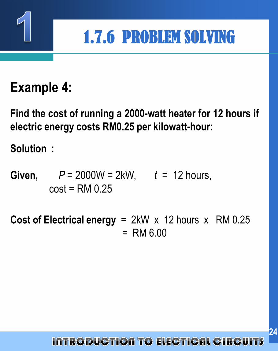
Example 4:
Find the cost of running a 2000-watt heater for 12 hours if
electric energy costs RM0.25 per kilowatt-hour:
Solution :
Given, P = 2000W = 2kW, t = 12 hours,
cost = RM 0.25
Cost of Electrical energy = 2kW x 12 hours x RM 0.25
= RM 6.00
24
1.7.6 PROBLEM SOLVING
Company
LOGO
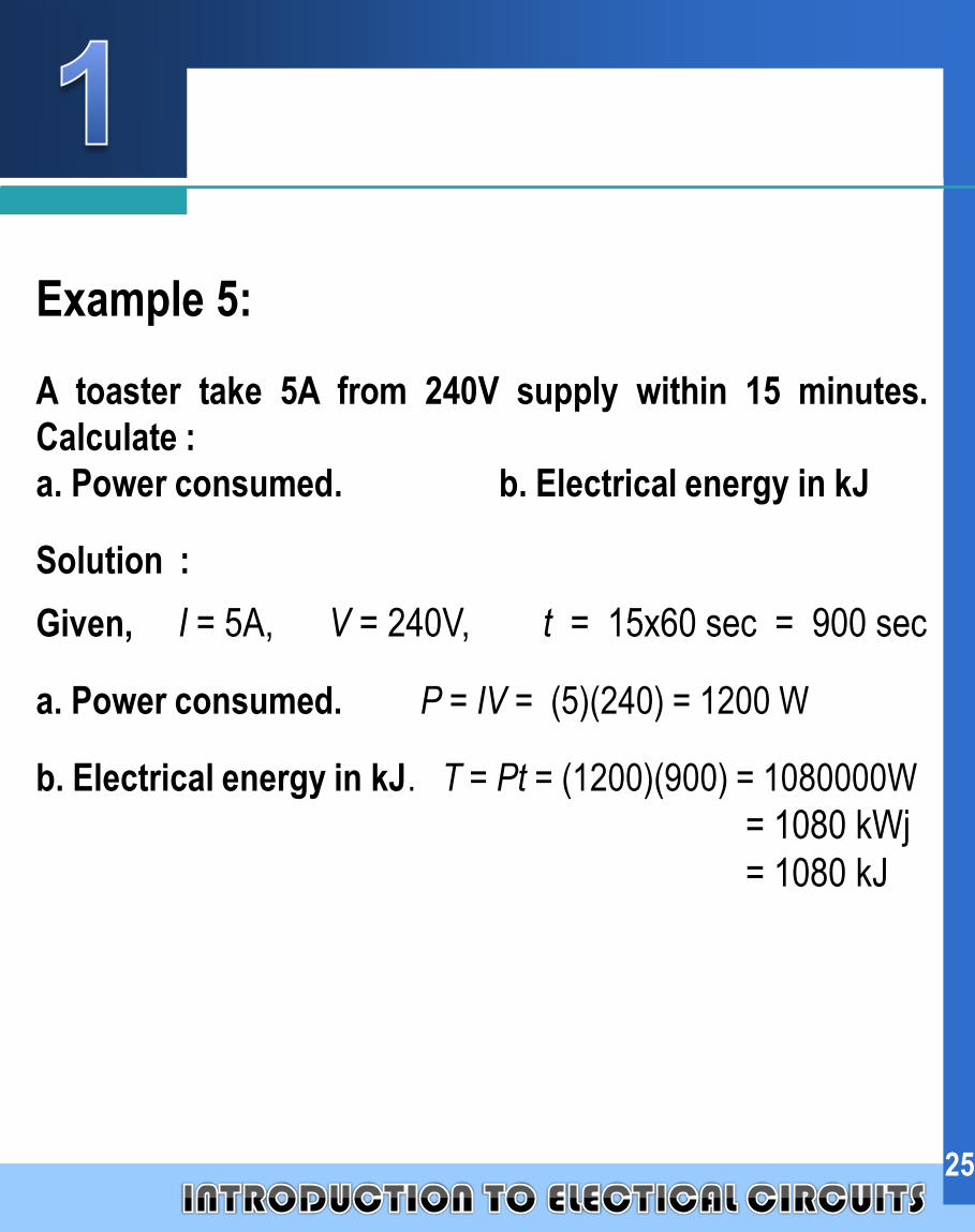
Example 5:
A toaster take 5A from 240V supply within 15 minutes.
Calculate :
a. Power consumed. b. Electrical energy in kJ
Solution :
Given, I = 5A, V = 240V, t = 15x60 sec = 900 sec
a. Power consumed. P = IV = (5)(240) = 1200 W
b. Electrical energy in kJ. T = Pt = (1200)(900) = 1080000W
= 1080 kWj
= 1080 kJ
25
Company
LOGO
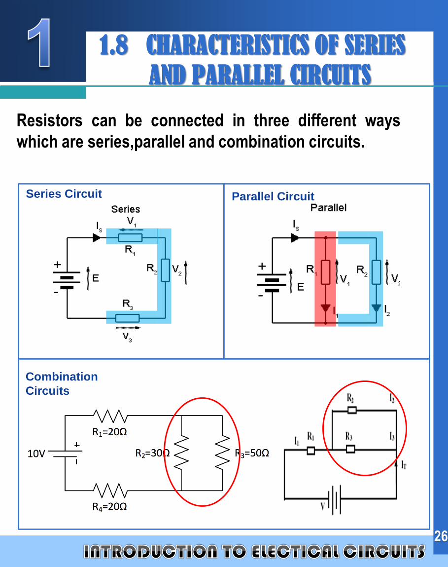
Resistors can be connected in three different ways
which are series,parallel and combination circuits.
Series Circuit Parallel Circuit
Combination
Circuits
26
1.8 CHARACTERISTICS OF SERIES
AND PARALLEL CIRCUITS
Company
LOGO 1.8.1 FORMULAS USED IN
SERIES & PARALLEL CIRCUITS
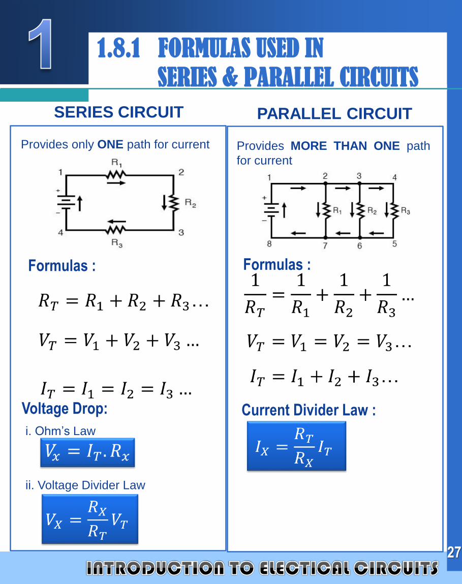
Provides only ONE path for current Provides MORE THAN ONE path
for current
27
SERIES CIRCUIT PARALLEL CIRCUIT
Formulas : Formulas :
Voltage Drop: Current Divider Law :
i. Ohm’s Law
ii. Voltage Divider Law
Company
LOGO
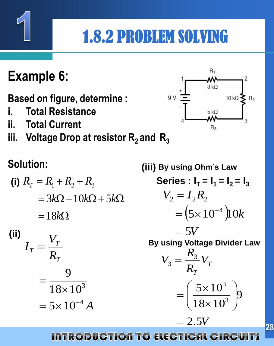
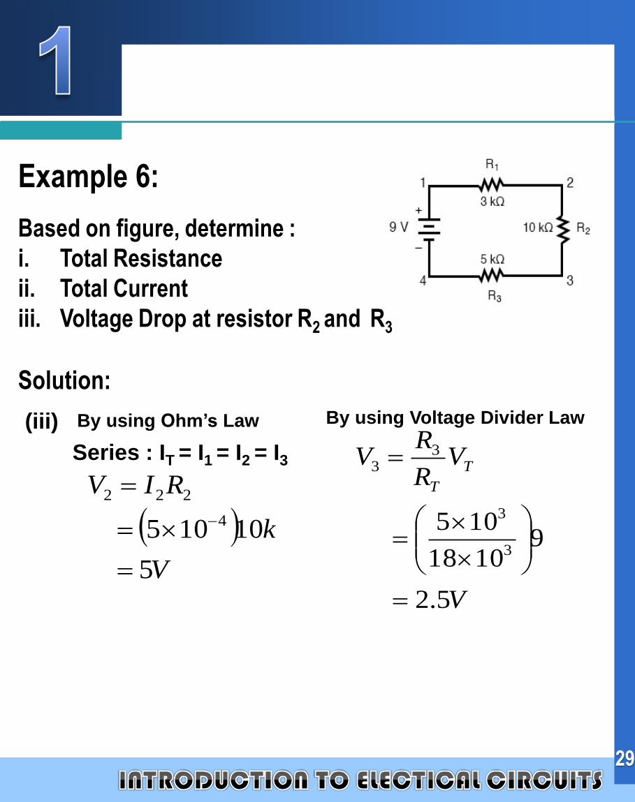
Example 6:
Based on figure, determine :
i. Total Resistance
ii. Total Current
iii. Voltage Drop at resistor R2 and R3
Solution:
28
1.8.2 PROBLEM SOLVING
(i)
A
R
VI
T
TT
4
3
105
1018
9
k
kkk
RRRRT
18
5103
321
(ii)
(iii)
V
k
RIV
5
10105 4
222
V
VR
RV T
T
5.2
91018
1053
3
33
Series : IT = I1 = I2 = I3
By using Voltage Divider Law
By using Ohm’s Law
Company
LOGO
Example 6:
Based on figure, determine :
i. Total Resistance
ii. Total Current
iii. Voltage Drop at resistor R2 and R3
Solution:
29
(iii)
V
k
RIV
5
10105 4
222
V
VR
RV T
T
5.2
91018
1053
3
33
Series : IT = I1 = I2 = I3
By using Voltage Divider LawBy using Ohm’s Law
Company
LOGO
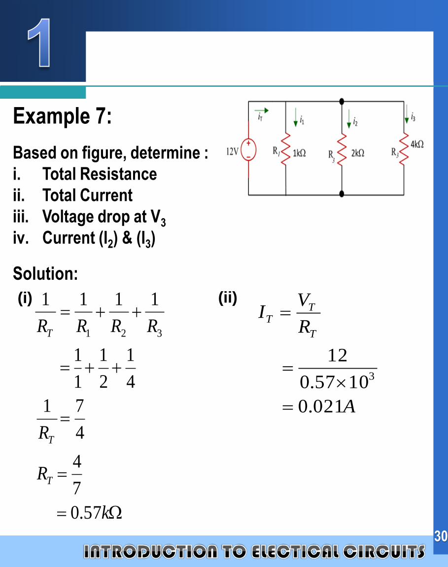
Example 7:
Based on figure, determine :
i. Total Resistance
ii. Total Current
iii. Voltage drop at V3
iv. Current (I2) & (I3)
Solution:
30
(i)
A
R
VI
T
TT
021.0
1057.0
123
k
R
R
RRRR
T
T
T
57.0
7
4
4
71
4
1
2
1
1
1
1111
321
(ii)
Company
LOGO
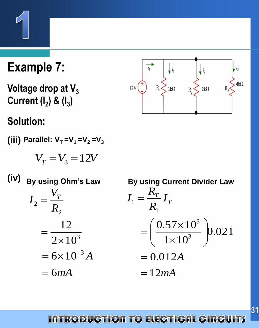
Example 7:
Voltage drop at V3
Current (I2) & (I3)
Solution:
31
(iv)
(iii)
VVVT 123
mA
A
IR
RI T
T
12
012.0
021.0101
1057.03
3
1
1
Parallel: VT =V1 =V2 =V3
mA
A
R
VI T
6
106
102
12
3
3
2
2
By using Current Divider LawBy using Ohm’s Law
Company
LOGO
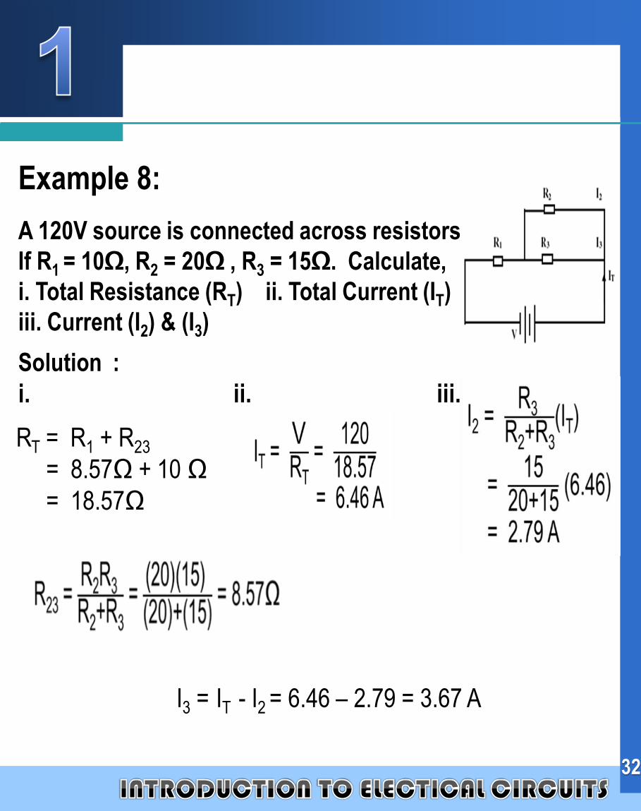
Example 8:
A 120V source is connected across resistors.
If R1 = 10Ω, R2 = 20Ω , R3 = 15Ω. Calculate,
i. Total Resistance (RT) ii. Total Current (IT)
iii. Current (I2) & (I3)
Solution :
i. ii. iii.
RT = R1 + R23
= 8.57Ω + 10 Ω
= 18.57Ω
I3 = IT - I2 = 6.46 – 2.79 = 3.67 A
32

Company
LOGO
Example 9 :
Determine the
(a) total resistance of the circuit
(b) total current flow
(c) current of I1 and I2(d) voltage drop across R3 and R4
Solution :
33
(a) (b)
(c) (d)