mk4/5xr video gaming machine - Index of
291
-
Upload
khangminh22 -
Category
Documents
-
view
3 -
download
0
Transcript of mk4/5xr video gaming machine - Index of


TM
NEW SOUTH WALESNEW SOUTH WALESNEW SOUTH WALESNEW SOUTH WALES
MK4/5XRMK4/5XRMK4/5XRMK4/5XRVIDEO GAMING MACHINEVIDEO GAMING MACHINEVIDEO GAMING MACHINEVIDEO GAMING MACHINE
SERVICE MANUALAM-1121032-01
JUBILEE GAMING TECHNOLOGY,A DIVISION OF ARISTOCRAT LEISURE INDUSTRIES PTY LTD (ACN 001 660 715)71 Longueville Road, Lane Cove NSW 2066, Australia. Telephone: (612) 9413 6300
PO Box 808, Lane Cove NSW 1595, Australia. Fax: (612) 9420 1326
II Introduction
© Aristocrat Leisure Industries Pty Ltd 2000
The gaming machine described in this document may be covered by patents and registered designs. Thisdocument is protected by copyright. No part of it may be reproduced or copied without the writtenpermission of Aristocrat Leisure Industries Pty Ltd, Australia. This document is not for use in countrieswhere gaming machines are prohibited by law.
Aristocrat Leisure Industries Pty Ltd reserves the right to change, without notice, the design orspecification of the gaming machine covered by this document. Additional information is available fromtime to time in the form of technical bulletins. New editions of this document may change its contents.
WARNINGThis is a Class A product. In a domesticenvironment, this product may cause radiointerference, in which case the user may berequired to take adequate action.
CAUTIONAll functions of the machine are controlled bycomplex electronics. Unqualified personnelmust not interfere with any mechanisms orcontrols as this may permanently damagethe machine and lead to expensive repairsor component replacement, and will renderthe warranty void.
IImmppoorrttaanntt SSaaffeettyy IInnffoorrmmaattiioonn
This document contains important information about the use of the equipment and hazardsinvolved in owning and operating the equipment to which it relates. The equipment can be veryhazardous if used other than in accordance with this document.
Inform Yourself and Your StaffYou must read this document before using the equipment or opening any part of the equipment. Ensure yourstaff do too.
The equipment itself is marked with important warning labels detailing dangers.
♦ Check for warning labels whenever opening any part of the equipment.♦ Read and comply with all warning labels you see when operating or opening the equipment.♦ Under no circumstances remove or alter any warning label.
Be CarefulIf you don’t follow the directions in this manual and on warning labels you increase the risk of thefollowing things occurring:
♦ serious personal injury, including electrocution and amputation. Unless you are a trained technician, tamperingwith the machine can kill you.
♦ serious damage to the equipment;♦ serious damage to other equipment;♦ serious damage to the premises housing the equipment;

NSW MK4/5XR Video Service Manual Record of Amendments
Introduction III
Record of Amendments
AmendmentNumber
Amendment Date Insertion Date Your Initials

Record of Amendments NSW MK4/5XR Video Service Manual
IV Introduction
AmendmentNumber
Amendment Date Insertion Date Your Initials

NSW MK4/5XR Video Service Manual Table of Contents
Introduction V
Aristocrat Jubilee MK4/5XR Manuals
Operator Manual
Primarily intended for operators of AristocratMk4/5XR Video Gaming Machines. The OperatorManual:
• gives a general overview of the hardware andsoftware
• provides procedures for daily operations andsimple maintenance.
Service Manual
Primarily intended for service technicians. TheService Manual:
• gives a general overview of the hardware andsoftware
• provides instructions for installation and faultfinding
• describes in detail each of the majorcomponents of the machine.
Parts Catalogue
Primarily intended for operators and servicetechnicians. It enables operators and servicetechnicians to order machine parts. The PartsCatalogue:
• shows an illustration of each of thecomponents of the machine
• links each illustration with a part number.

Table of Contents NSW MK4/5XR Video Service Manual
VI Introduction
This page intentionally left blank
NSW MK4/5XR Video Service Manual Table of Contents
Introduction VII
Foreword
How To Use This Manual
Purpose of the ManualThis manual provides procedures for the servicing and maintenance ofAristocrat’s Jubilee Mk4/5XR Series Video Gaming Machine. It covers areas ofmachine operation that must be carried out by licensed technicians.
User of the ManualThe manual is aimed at technicians who need to understand detailed andtechnically complex aspects of the machine to service and maintain it.
Warnings, Cautions and Notes
WARNINGA warning immediately precedes anoperating procedure or maintenance practicewhich, if not correctly followed, could resultin personal injury or loss of life.
CAUTIONA caution immediately precedes anoperating procedure or maintenance practicewhich, if not strictly observed, could result indamage to or destruction of the equipment,or corruption of the data.
NoteA note immediately precedes or follows anoperating procedure, maintenance practiceor condition which requires highlighting.
Units of Measure
The manual uses the international system of units. The following conversion isprovided for the convenience of readers.
1 W = 3.41241 Btu/hour 1 Btu/hour = 0.2930711 W1 kJ = 0.948 Btu 1 Btu = 1.06 kJ.
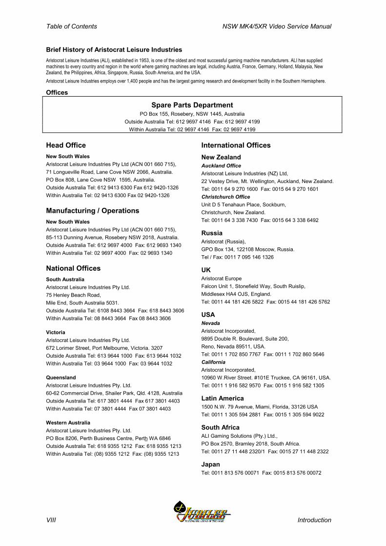
Table of Contents NSW MK4/5XR Video Service Manual
VIII Introduction
Brief History of Aristocrat Leisure IndustriesAristocrat Leisure Industries (ALI), established in 1953, is one of the oldest and most successful gaming machine manufacturers. ALI has suppliedmachines to every country and region in the world where gaming machines are legal, including Austria, France, Germany, Holland, Malaysia, NewZealand, the Philippines, Africa, Singapore, Russia, South America, and the USA.Aristocrat Leisure Industries employs over 1,400 people and has the largest gaming research and development facility in the Southern Hemisphere.
Offices
Spare Parts DepartmentPO Box 155, Rosebery, NSW 1445, Australia
Outside Australia Tel: 612 9697 4146 Fax: 612 9697 4199Within Australia Tel: 02 9697 4146 Fax: 02 9697 4199
Head OfficeNew South WalesAristocrat Leisure Industries Pty Ltd (ACN 001 660 715),71 Longueville Road, Lane Cove NSW 2066, Australia.PO Box 808, Lane Cove NSW 1595, Australia.Outside Australia Tel: 612 9413 6300 Fax 612 9420-1326Within Australia Tel: 02 9413 6300 Fax 02 9420-1326
Manufacturing / OperationsNew South WalesAristocrat Leisure Industries Pty Ltd (ACN 001 660 715),85-113 Dunning Avenue, Rosebery NSW 2018, Australia.Outside Australia Tel: 612 9697 4000 Fax: 612 9693 1340Within Australia Tel: 02 9697 4000 Fax: 02 9693 1340
National OfficesSouth AustraliaAristocrat Leisure Industries Pty Ltd.75 Henley Beach Road,Mile End, South Australia 5031.Outside Australia Tel: 6108 8443 3664 Fax: 618 8443 3606Within Australia Tel: 08 8443 3664 Fax 08 8443 3606
VictoriaAristocrat Leisure Industries Pty Ltd.672 Lorimer Street, Port Melbourne, Victoria. 3207Outside Australia Tel: 613 9644 1000 Fax: 613 9644 1032Within Australia Tel: 03 9644 1000 Fax: 03 9644 1032
QueenslandAristocrat Leisure Industries Pty. Ltd.60-62 Commercial Drive, Shailer Park, Qld. 4128, AustraliaOutside Australia Tel: 617 3801 4444 Fax 617 3801 4403Within Australia Tel: 07 3801 4444 Fax 07 3801 4403
Western AustraliaAristocrat Leisure Industries Pty. Ltd.PO Box 8206, Perth Business Centre, Perth WA 6846Outside Australia Tel: 618 9355 1212 Fax: 618 9355 1213Within Australia Tel: (08) 9355 1212 Fax: (08) 9355 1213
International OfficesNew ZealandAuckland OfficeAristocrat Leisure Industries (NZ) Ltd,22 Vestey Drive, Mt. Wellington, Auckland, New Zealand.Tel: 0011 64 9 270 1600 Fax: 0015 64 9 270 1601Christchurch OfficeUnit D 5 Tenahaun Place, Sockburn,Christchurch, New Zealand.Tel: 0011 64 3 338 7430 Fax: 0015 64 3 338 6492
RussiaAristocrat (Russia),GPO Box 134, 122108 Moscow, Russia.Tel / Fax: 0011 7 095 146 1326
UKAristocrat EuropeFalcon Unit 1, Stonefield Way, South Ruislip,Middlesex HA4 OJS, England.Tel: 0011 44 181 426 5822 Fax: 0015 44 181 426 5762
USANevadaAristocrat Incorporated,9895 Double R. Boulevard, Suite 200,Reno, Nevada 89511, USA.Tel: 0011 1 702 850 7767 Fax: 0011 1 702 860 5646CaliforniaAristocrat Incorporated,10960 W.River Street. #101E Truckee, CA 96161, USA.Tel: 0011 1 916 582 9570 Fax: 0015 1 916 582 1305
Latin America1500 N.W. 79 Avenue, Miami, Florida, 33126 USATel: 0011 1 305 594 2881 Fax: 0015 1 305 594 9022
South AfricaALI Gaming Solutions (Pty.) Ltd.,PO Box 2570, Bramley 2018, South Africa.Tel: 0011 27 11 448 2320/1 Fax: 0015 27 11 448 2322
JapanTel: 0011 813 576 00071 Fax: 0015 813 576 00072
Table of Contents NSW MK4/5XR Video Service Manual
x Revision 01
Table of ContentsGeneral Description 1-1
1.1 Physical Description.......................................................................1-3
1.2 Basic Operation ..............................................................................1-8
1.2.1 Play Mode.........................................................................................1-81.2.2 Operator Mode................................................................................1-10
Installation 2-12.1 Pre-Installation Requirements .......................................................2-3
2.2 Inspection on Delivery....................................................................2-5
2.3 Installation Procedure ....................................................................2-5
2.3.1 Mounting ...........................................................................................2-52.3.2 Pre-start Connections, Checks and Power Up .................................2-72.3.3 Commissioning the Machine.............................................................2-8
Machine Modes 3-13.1 Modes of Operation ........................................................................3-3
3.2 Play Mode ........................................................................................3-4
3.2.1 Player Operation...............................................................................3-53.2.2 Video Display....................................................................................3-73.2.3 Sounds and Tunes............................................................................3-83.2.4 Pushbuttons......................................................................................3-83.2.5 Machine Self-Monitoring ...................................................................3-83.2.7 Electromechanical Meters ..............................................................3-113.2.9 Audit Meters (Soft Meters)..............................................................3-13
3.3 Operator Mode ..............................................................................3-14
3.3.1 Machine Identification .....................................................................3-16
NSW MK4/5XR Video Service Manual Table of Contents
Revision 01 xi
3.3.2 Accounting Information................................................................... 3-163.3.3 Diagnostic Information Menu.......................................................... 3-213.3.4 Self Test Mode ............................................................................... 3-243.3.5 Operator Setup / Selections Mode ................................................. 3-303.3.6 Power Save Mode .......................................................................... 3-333.3.7 Current Lockup Menu – Fault Mode ............................................... 3-33
Cabinet, Door and Top Box 4-14.1 General Description ....................................................................... 4-3
4.2 Technical Description .................................................................... 4-5
4.2.1 Cabinet Door .................................................................................... 4-54.2.2 Latch Bar .......................................................................................... 4-54.2.3 Keyed Lock....................................................................................... 4-74.2.4 Cabinet Security ............................................................................... 4-74.2.5 Key Switches .................................................................................... 4-94.2.6 Bilock Locks.................................................................................... 4-104.2.7 Cash Box and Chute ...................................................................... 4-114.2.8 Logic Cage ..................................................................................... 4-114.2.9 Game Display Shelf ........................................................................ 4-124.2.10 Cabinet Door Fluorescent Lighting ................................................. 4-124.2.11 Cabinet Door Artwork ..................................................................... 4-134.2.12 Mid Trim Panel ............................................................................... 4-144.2.13 Playbuttons..................................................................................... 4-144.2.14 Top Trim Panel ............................................................................... 4-174.2.15 Monitor Mask .................................................................................. 4-184.2.16 Coin Tray ........................................................................................ 4-194.2.17 Belly Panel Door............................................................................. 4-194.2.18 Belly Panel Security........................................................................ 4-204.2.19 Top Box .......................................................................................... 4-204.2.20 Top Box Artwork ............................................................................. 4-204.2.21 Top Box Fluorescent Lighting......................................................... 4-20
4.3 General Maintenance ................................................................... 4-23

Table of Contents NSW MK4/5XR Video Service Manual
xii Revision 01
Power Supply Assembly 5-15.1 Physical Description.......................................................................5-3
5.2 Basic Operation ..............................................................................5-5
5.3 Functional Specification ................................................................5-7
5.3.1 Input Requirements ..........................................................................5-75.3.2 Output Requirements........................................................................5-75.3.3 Control Signals .................................................................................5-95.3.4 Physical Connections .......................................................................5-9
5.4 Removal and Replacement Procedures .....................................5-11
5.4.1 Fuses ..............................................................................................5-115.4.2 Power Supply Assembly .................................................................5-11
5.5 General Maintenance....................................................................5-12
Coin Handling Assembly 6-16.1 Overview..........................................................................................6-3
6.2 Basic Operation ..............................................................................6-4
6.2.1 Validation ..........................................................................................6-46.2.2 Rejected Coins .................................................................................6-56.2.3 Accepted Coins.................................................................................6-56.2.4 Alarm ................................................................................................6-66.2.5 Inhibit All ...........................................................................................6-66.2.6 Self Calibration .................................................................................6-66.2.6 Diagnostics .......................................................................................6-66.2.7 Debris Flap .......................................................................................6-6
6.3 Removal and Replacement ............................................................6-7
6.4 Clearing Coin Jams ........................................................................6-7
6.5 CN133A Coin Validator Connector Pinouts..................................6-8
NSW MK4/5XR Video Service Manual Table of Contents
Revision 01 xiii
6.6 Diverter Solenoid and Photo-Optic Sensor .................................. 6-9
6.6.1 Physical Description ......................................................................... 6-96.6.2 Basic Operation ................................................................................ 6-96.6.3 Removal and Replacement ............................................................ 6-10
6.7 Fault Finding ................................................................................. 6-11
6.8 General Maintenance ................................................................... 6-11
Bank Note Acceptor 7-17.1 Technical Description .................................................................... 7-3
7.1.1 Overview........................................................................................... 7-37.1.2 Physical Description ......................................................................... 7-37.1.3 VFM4 Non-isolated Serial Interface................................................ 7-10
7.2 Installation and Machine Conditions .......................................... 7-13
7.2.1 Configuration Setup........................................................................ 7-137.2.2 Machine Condition Indicators ......................................................... 7-13
7.3 Removal and Replacement Procedures ..................................... 7-15
7.3.1 Clearing the Bank Note Stacker ..................................................... 7-157.3.2 Bank Note Acceptor Assembly ....................................................... 7-167.3.3 Clearing Bank Note Acceptor Jams................................................ 7-16
7.4 Care and Maintenance ................................................................. 7-18
7.4.1 Troubleshooting.............................................................................. 7-187.4.2 Periodic Maintenance ..................................................................... 7-207.4.3 Video Level Calibration................................................................... 7-20
Hopper 8-18.1 Technical Description .................................................................... 8-3
8.1.1 Physical Description ......................................................................... 8-38.1.2 Basic Operation ................................................................................ 8-68.1.3 Functional Description ...................................................................... 8-78.1.4 Hopper Interface Signals .................................................................. 8-7
Table of Contents NSW MK4/5XR Video Service Manual
xiv Revision 01
8.2 Removal and Replacement ............................................................8-8
8.2.1 Removal............................................................................................8-88.2.2 Replacement.....................................................................................8-8
8.3 Clearing Coin Jams ........................................................................8-9
8.4 Disassembly and Assembly.........................................................8-10
8.4.1 Disassembly ...................................................................................8-108.4.2 Assembly ........................................................................................8-11
8.5 Fault Finding .................................................................................8-12
8.6 General Maintenance....................................................................8-13
Video Monitor 9-19.1 Ceronix Monitor - General Description .........................................9-3
9.2 Technical Description ....................................................................9-4
9.2.1 Power Supply....................................................................................9-49.2.2 Adjustment Procedures ....................................................................9-4
9.3 Removal and Replacement ............................................................9-6
9.4 General Maintenance......................................................................9-6
9.5 Degaussing .....................................................................................9-7
Electromechanical Meters 10-110.1 General Description......................................................................10-3
10.2 Functional Description.................................................................10-4
10.2.1 Serial Interface................................................................................10-410.2.2 Overcurrent Protection....................................................................10-510.2.3 Meter Drive Outputs........................................................................10-510.2.4 PCB Expansion...............................................................................10-510.2.5 Light Tower Interface ......................................................................10-510.2.6 Security Interface............................................................................10-5
NSW MK4/5XR Video Service Manual Table of Contents
Revision 01 xv
10.2.7 Meter Detection .............................................................................. 10-5
10.3 Removal and Replacement Procedures ..................................... 10-7
10.4 Connector Pin Assignment.......................................................... 10-8
10.5 General Maintenance ................................................................. 10-10
Main Board 11-111.1 Introduction................................................................................... 11-4
11.2 Physical Description .................................................................... 11-5
11.2.1 Diagrams and Component Locations ............................................. 11-5
11.3 Functional Description................................................................ 11-6
11.3.1 Main Board Functions..................................................................... 11-7
11.4 Technical Description ................................................................. 11-8
11.4.1 ARM250 Microprocessor .............................................................. 11-1011.4.2 Sound ........................................................................................... 11-1111.4.3 Video ............................................................................................ 11-1211.4.4 Reset ............................................................................................ 11-1211.4.5 Debug (Keyboard) Port................................................................. 11-1311.4.6 Debugging .................................................................................... 11-1311.4.7 External I/O Expansion................................................................. 11-1411.4.8 Mikohn Link Progressive Interface (where fitted).......................... 11-1411.4.9 Memory......................................................................................... 11-1511.4.10 Real Time Clock .......................................................................... 11-1611.4.11 Battery Backup Circuit ................................................................. 11-1611.4.12 Power Control Interface............................................................... 11-1711.4.13 SPI Bus Driver and Multiplexer Circuitry...................................... 11-1811.4.14 Printer and Mechanical Meters.................................................... 11-1911.4.15 Mechanical Switches................................................................... 11-1911.4.16 Security ....................................................................................... 11-1911.4.17 Coin Handling System................................................................. 11-2011.4.18 Hopper Interface ......................................................................... 11-21
Table of Contents NSW MK4/5XR Video Service Manual
xvi Revision 01
11.4.19 Serial Channels ...........................................................................11-2111.4.20 Bank Note Acceptor.....................................................................11-2211.4.21 Interface Board............................................................................11-22
11.5 Removal and Replacement Procedures ..................................11-23
11.6 Description of Connectors.........................................................11-24
11.6.1 Communications Configuration Board ..........................................11-2411.6.2 Optically Isolated Connector - P20 ...............................................11-2611.6.3 Miscellaneous Connector - P22....................................................11-2811.6.4 Security and I/O Expansion Connector - P21 ...............................11-30
Interface Board Part No. 410315 Issue B 12-112.1 Physical Description.....................................................................12-3
12.1.1 Diagrams and Component Locations .............................................12-3
12.2 Technical Description ..................................................................12-5
12.3 Description of Connectors...........................................................12-7
12.3.1 Main Board Connectors - P1, P2, and P3.......................................12-712.3.2 Driver Board, P4 .............................................................................12-712.3.3 LAB Comms, P5 .............................................................................12-712.3.4 Mechanical Meters, P6 ...................................................................12-712.3.5 Security - P8, P22, and P24 ...........................................................12-712.3.6 Door Signals Interface - P10 and P11 ............................................12-912.3.7 Coin Handling, P12.......................................................................12-1012.3.8 Bill Acceptor, Backlight and Security, P13 ....................................12-1112.3.9 Serial Channels - P14, P15, P17, and P18...................................12-1112.3.10 DACOM 5000, P21......................................................................12-1312.3.11 Mikohn, P16.................................................................................12-1312.3.12 SPI Channel 1, P19.....................................................................12-1412.3.13 DACOM 3000, P20......................................................................12-1412.3.14 Spare Voltage 24 V DC, P23.......................................................12-1512.3.15 Hopper, P25 ................................................................................12-1512.3.16 Video, P26...................................................................................12-15
NSW MK4/5XR Video Service Manual Table of Contents
Revision 01 xvii
12.3.17 Mechanical Switches - P27 ......................................................... 12-1612.3.18 Audit / Jackpot switch and door security, P28 ............................. 12-1612.3.19 Power Supply, P29...................................................................... 12-1712.3.20 Optional Fan DC 12 V, P30......................................................... 12-17
12.4 Removal and Replacement Procedures ................................... 12-18
I/O Driver Board - 410415 13-113.1 Physical Description .................................................................... 13-3
13.1.1 Circuit Diagrams and Component Locations .................................. 13-3
13.2 Functional Description................................................................. 13-3
13.2.1 Power Supply ................................................................................. 13-613.2.2 Pushbuttons and Lamps................................................................. 13-613.2.3 Coin Handling Interface .................................................................. 13-7
13.3 Removal and Replacement Procedures ................................... 13-10
13.4 Connector Pin Assignment........................................................ 13-11
Communications Configuration Board - 410217 14-114.1 Physical Description .................................................................... 14-3
14.2 Functional Description................................................................. 14-4
14.3 Removal and Replacement Procedures ..................................... 14-6
14.4 Connector Pin Assignments........................................................ 14-7
14.5 General Maintenance ................................................................... 14-7
LAB Communications Board - 410174 15-115.1 Technical Description .................................................................. 15-3
15.1.1 Physical Description ....................................................................... 15-315.1.2 Basic Operation .............................................................................. 15-615.1.3 LAB PSU Chassis Description........................................................ 15-7
Table of Contents NSW MK4/5XR Video Service Manual
xviii Revision 01
15.2 Removal and Replacement ........................................................15-10
15.2.1 Removal........................................................................................15-1015.2.2 Replacement.................................................................................15-10
15.3 Connector Pin Assignments......................................................15-11
15.3.1 Interface Board Slot P6.................................................................15-11
15.4 General Maintenance..................................................................15-13
Progressive Jackpot System 16-116.1 Overview........................................................................................16-3
16.2. Progressive SEI Board (410227)..................................................16-3
Machine Fault Finding 17-117.1 Fault Finding .................................................................................17-3
Games A-1Spinning Reel Games ................................................................................... A-3
Glossary
Index

NSW MK4/5XR Video Service Manual Table of Contents
Revision 01 xix
List of FiguresFigure 1-1 Mk4/5XR Series Video Gaming Machine - External View ............................. 1-5Figure 1-2 Bilock "U" Shaped Keyway and Quick Change Core Features...................... 1-7Figure 1-3 Basic Game Operation in Play Mode............................................................. 1-9Figure 2-1 Machine Dimensions...................................................................................... 2-4Figure 2-2 Machine Footprint and Clearances ................................................................ 2-6Figure 3-1 Format of Game Display................................................................................ 3-4Figure 3-2 Centre Line and Multi Line Combinations ...................................................... 3-7Figure 3-3 Typical Pushbutton Layout ............................................................................. 3-8Figure 3-4 Electromechanical Meters............................................................................ 3-12Figure 3-5 Operator Mode Menu Displays - Structure................................................... 3-15Figure 4-1 Cabinet and Cabinet Door - General Description .......................................... 4-4Figure 4-2 Latch Bar........................................................................................................ 4-6Figure 4-3 Keyed Lock Assembly.................................................................................... 4-7Figure 4-4 Photo-optic Emitter Adjustment ...................................................................... 4-8Figure 4-5 Key Switches: Removal and Replacement .................................................. 4-10Figure 4-6 Bilock "U" Shaped Keyway and Quick Change Core Features.................... 4-10Figure 4-7 Play Button Lamps ....................................................................................... 4-15Figure 4-8 Playbutton - Exploded View ......................................................................... 4-17Figure 4-9 Top Trim Panel and Monitor Mask.............................................................. 4-18Figure 4-10 Top Box...................................................................................................... 4-21Figure 5-1 Power Supply Assembly Location.................................................................. 5-3Figure 5-2 Power Supply Assembly................................................................................. 5-4Figure 5-3 Power Supply Assembly Wiring Diagram ...................................................... 5-5Figure 5-4 Low Voltage Power Distribution ..................................................................... 5-6Figure 6-1 Condor Coin Handling Assembly ................................................................... 6-3Figure 6-2 Condor Coin Validator.................................................................................... 6-5Figure 6-3 Diverter Solenoid and Photo-Optic Sensor .................................................... 6-9Figure 7-1 Bank Note Acceptor Assembly ...................................................................... 7-4Figure 7-2 Bank Note Acceptor Dual Cage Assembly .................................................... 7-5Figure 7-3 Bank Note Acceptor with open Upper Guide ................................................. 7-6Figure 7-4 Stacker............................................................................................................ 7-7Figure 7-5 Typical Mid Trim Layout ................................................................................. 7-8Figure 7-6 Input/Output Connector.................................................................................. 7-9Figure 7-7 Interconnection Diagram................................................................................ 7-9Figure 7-8 Bezel Assembly Indicators - LED Displays .................................................. 7-10Figure 7-9 VFM4 Protocol - Accept and Return Messages........................................... 7-11Figure 7-10 VFM4 Protocol - Hex Code Messages....................................................... 7-12Figure 7-11 Operator Setup Mode - Machine Options .................................................. 7-13Figure 7-12 Bank Note Acceptor - DIP Switch Location................................................ 7-19Figure 8-1 Hopper Location (Standard Disc Hopper shown) .......................................... 8-3Figure 8-2 Hopper- rear view (Standard Disc Hopper Shown)....................................... 8-4Figure 8-3 Hopper - exploded view (Standard Disc Hopper Shown).............................. 8-5Figure 8-4 Hopper Photo-optic Detector ....................................................................... 8-13Figure 9-1 Ceronix Video Monitor and Control Panel...................................................... 9-5Figure 10-1 Electromechanical Meter Board - Location ................................................ 10-3Figure 10-2 Electromechanical Meter Board - 410366 Block Diagram ......................... 10-4Figure 10-3 Electromechanical Meter Board - 410366 Component and Solder
Sides ............................................................................................................... 10-6Figure 11-1 Location of Main Board .............................................................................. 11-5Figure 11-2 System Architecture................................................................................... 11-6Figure 11-3 Main Board block diagram ......................................................................... 11-8Figure 11-4 Typical Main Board layout (not detailed) .................................................... 11-9Figure 12-1 Interface Board Component Location ........................................................ 12-4Figure 13-1 I/O Driver Board - Location ........................................................................ 13-3Figure 13-2 I/O Driver Board - Block Diagram .............................................................. 13-4Figure 13-3 I/O Driver Board 410415 - Component Layout........................................... 13-5Figure 13-4 Coin Handling Interface Signals................................................................. 13-7Figure 13-5 Timing of Coin Handling Output Signals .................................................... 13-8
Table of Contents NSW MK4/5XR Video Service Manual
xx Revision 01
Figure 14-1 Communications Configuration Board - Location ......................................14-3Figure 14-2 Communications Configuration Board - Block Diagram ............................14-4Figure 15-1 LAB Communications Board - position in logic cage .................................15-3Figure 15-2 LAB Communications Board - Component Layout ....................................15-5Figure 15-3 LAB Communications Board - Block Diagram ...........................................15-6Figure 15-4 LAB PSU Chassis ......................................................................................15-8Figure 15-5 PSU Chassis - PSU Fuse and Connector Wiring ......................................15-8Figure 15-6 LAB Communications Board and PSU Kit .................................................15-9Figure 16-1 SEI Board - data flows ...............................................................................16-4Figure 16-2 Cashcade - data flows................................................................................16-6Figure A-1 MK V Video Game Screen Example...............................................................0-4Figure A-2 MK V Pay Table Example..............................................................................0-5
List of TablesTable 1-1 Machine Modules ............................................................................................1-3Table 1-2 Machine Key Types .........................................................................................1-6Table 3-1 Operator Mode Menu ....................................................................................3-14Table 3-2 Machine Identification Display.......................................................................3-16Table 3-3 Accounting Information Menu........................................................................3-17Table 3-4 Accounting Information - Jurisdictional Meters - Screen 1............................3-17Table 3-5 Accounting Information - Jurisdictional Meters - Screen 2............................3-18Table 3-6 Accounting Information - Periodic Meters - Screen 1....................................3-18Table 3-7 Accounting Information - Periodic Meters - Screen 2....................................3-19Table 3-8 Accounting Information - Reset Periodic Meters...........................................3-19Table 3-9 Accounting Information - Game Replay ........................................................3-19Table 3-10 Accounting Information – Meters of Last Game..........................................3-20Table 3-11 Accounting Information - Game Statistics ...................................................3-20Table 3-12 Accounting Information - Gamble Statistics ................................................3-21Table 3-13 Diagnostic Information Menu.......................................................................3-21Table 3-14 Diagnostic Information - Diagnostic Meters - Screen 1...............................3-22Table 3-15 Diagnostic Information - Diagnostic Meters - Screen 2...............................3-22Table 3-16 Diagnostic Information - Error Log ..............................................................3-23Table 3-17 Diagnostic Information - Panic Log .............................................................3-23Table 3-18 Diagnostic Information - Bill Acceptor Information ......................................3-24Table 3-19 Self Test Mode Menu ..................................................................................3-24Table 3-20 Self Test Mode Requirements.....................................................................3-25Table 3-21 Self Test Mode - Lamp Test........................................................................3-25Table 3-22 Self Test Mode - Coin Entry Test ................................................................3-26Table 3-23 Self Test Mode - Hopper Test .....................................................................3-26Table 3-24 Self Test Mode - Video Monitor Test Menu.................................................3-27Table 3-25 Self Test Mode - Video Monitor Test Descriptions......................................3-27Table 3-26 Self Test Mode - Sound Effects Test ..........................................................3-28Table 3-27 Self Test Mode - Factory Test .....................................................................3-28Table 3-28 Self Test Mode.- Combination Test.............................................................3-29Table 3-29 Self Test Mode - Combination Test Result .................................................3-29Table 3-30 Operator Setup / Selections Menu ..............................................................3-30Table 3-31 Operator Setup/Selections - Machine Options Display ...............................3-31Table 3-32 Operator Setup/Selections - Real Time Clock Setup ..................................3-32Table 3-33 Operator Setup/Selections - Sound System Setup .....................................3-32Table 3-34 Operator Setup/Selections - Reel Spin Speed Setup...................................3-32Table 3-35 Operator Setup/Selections - Layout Setup..................................................3-33Table 3-36 Power Save Mode .......................................................................................3-33Table 3-37 Fault Mode - Current Active Lockup Menu..................................................3-34Table 3-38 Fault Mode - Current Active Lockup Help Screens .....................................3-35Table 6-1 Condor Validator Interface Signals..................................................................6-8Table 6-2 Fault Finding..................................................................................................6-11Table 7-1 Bank Note Acceptor Fault Finding.................................................................7-18Table 7-2 Bank Note Acceptor DIP Switch Functions ...................................................7-19
NSW MK4/5XR Video Service Manual Table of Contents
Revision 01 xxi
Table 8-1 Fault Finding.................................................................................................. 8-12Table 10-1 J1 - Main Connector to Interface Board ...................................................... 10-8Table 10-2 J2 - Meter Drive Output Interface................................................................ 10-8Table 10-3 J3 - Additional Meters Interface .................................................................. 10-9Table 10-4 J4 - Light Tower Interface ........................................................................... 10-9Table 10-5 S1 - Security Interface................................................................................. 10-9Table 11-1 Serial EEPROMs Characteristics.............................................................. 11-16Table 11-2 Power Control System Signal Lines .......................................................... 11-17Table 11-3 SPI Channel Signals ................................................................................. 11-18Table 11-4 Optical Security Sensor Assignment......................................................... 11-19Table 11-5 Mechanical Security Switch Assignment................................................... 11-20Table 11-6 Coin Handling Signals ............................................................................... 11-20Table 11-7 Hopper Control Signals ............................................................................. 11-21Table 11-8 Communications Configuration Board connector - P23............................ 11-24Table 11-9 Optically Isolated Connector - P20............................................................ 11-26Table 11-10 Miscellaneous Connector - P22 .............................................................. 11-28Table 11-11 Security and I/O Expansion Connector - P21.......................................... 11-30Table 12-1 Interface Board Connections....................................................................... 12-6Table 13-1 Coin Handling Signals - Explanation ........................................................... 13-8Table 13-2 LED Functions............................................................................................. 13-9Table 15-1 LAB Port 1 Pinout........................................................................................ 15-4Table 15-2 LAB Ports 2-6 Pinout................................................................................... 15-4Table 15-3 Interface Board Bus Connector for LAB Communications Board ............. 15-11Table 16-1 SEI Board Configurations............................................................................ 16-3Table 16-2 DIP Switch Settings..................................................................................... 16-5Table 16-3 Mikohn Interface.......................................................................................... 16-7Table 16-4 Machine Interface........................................................................................ 16-7Table 16-5 CDS Display Interface................................................................................. 16-8Table 16-6 Mikohn RS-422/485 Serial Interface ........................................................... 16-8Table 17-1 Fault Finding................................................................................................ 17-3

NSW MK4/5 Video Service Manual General Description
Revision 01 1-1
_____Chapter 1_____
General Description
1.1 Physical Description .............................................................. 1-3
1.2 Basic Operation...................................................................... 1-8
1.2.1 Play Mode ................................................................................ 1-81.2.2 Operator Mode ....................................................................... 1-10

General Description NSW MK4/5 Video Service Manual
1-2 Revision 01
List of FiguresFigure 1-1 Mk4/5XR Series Video Gaming Machine - External View..............................1-5Figure 1-2 Bilock "U" Shaped Keyway and Quick Change Core Features......................1-7Figure 1-3 Basic Game Operation in Play Mode .............................................................1-9
List of TablesTable 1-1 Machine Modules ............................................................................................1-3Table 1-2 Machine Key Types .........................................................................................1-6
NSW MK4/5 Video Service Manual General Description
Revision 01 1-3
1.1 Physical Description
Aristocrat’s Jubilee Mk4/5XR series of gaming machines have been developed tocomply with existing and future regulations and to the same technoligcal standardas the Aristocrat MVP machine.
The machine consists of existing 540 Mk4 cabinets that have been modified toaccept the high standard of the MVP electronics currently being produced byAristocrat.
The Mk4/5XR Series gaming machines feature:
• Advanced, high-performance electronics based on ARM RISC technology;• A wide range of machine options, including note and coin denominations,
communication links, and progressive systems;• A comprehensive security system;• Modular design and construction;• Simplified operation and maintenance procedures;• High resolution video displays, advanced animation and graphics, and
improved sounds and tunes.
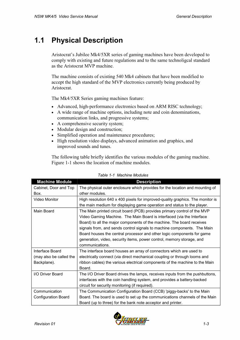
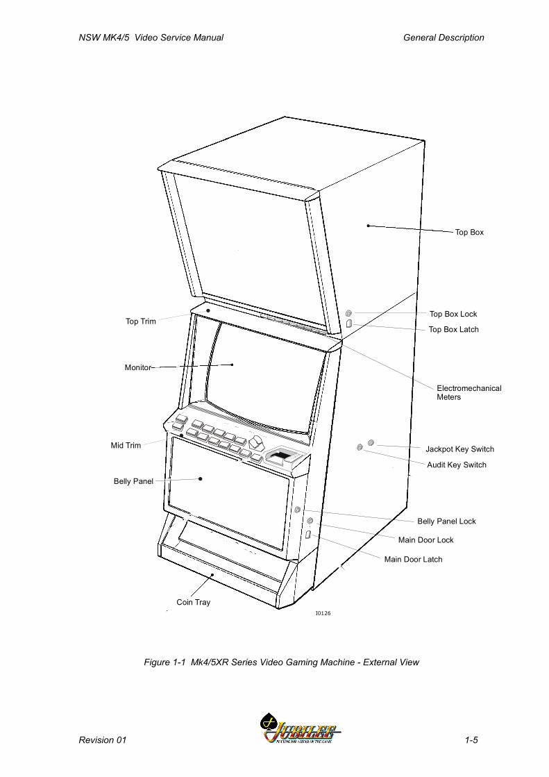
The following table briefly identifies the various modules of the gaming machine.Figure 1-1 shows the location of machine modules.
Table 1-1 Machine ModulesMachine Module Description
Cabinet, Door and TopBox.
The physical outer enclosure which provides for the location and mounting ofother modules.
Video Monitor High resolution 640 x 400 pixels for improved-quality graphics. The monitor isthe main medium for displaying game operation and status to the player.
Main Board The Main printed circuit board (PCB) provides primary control of the MVPVideo Gaming Machine. The Main Board is interfaced (via the InterfaceBoard) to all the major components of the machine. The board receivessignals from, and sends control signals to machine components. The MainBoard houses the central processor and other logic components for gamegeneration, video, security items, power control, memory storage, andcommunications.
Interface Board(may also be called theBackplane).
The interface board houses an array of connectors which are used toelectrically connect (via direct mechanical coupling or through looms andribbon cables) the various electrical components of the machine to the MainBoard.
I/O Driver Board The I/O Driver Board drives the lamps, receives inputs from the pushbuttons,interfaces with the coin handling system, and provides a battery-backedcircuit for security monitoring (if required).
CommunicationConfiguration Board
The Communication Configuration Board (CCB) 'piggy-backs' to the MainBoard. The board is used to set up the communications channels of the MainBoard (up to three) for the bank note acceptor and printer.
General Description NSW MK4/5 Video Service Manual
1-4 Revision 01
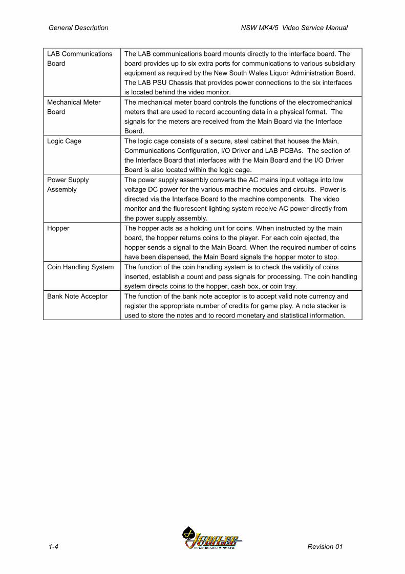
LAB CommunicationsBoard
The LAB communications board mounts directly to the interface board. Theboard provides up to six extra ports for communications to various subsidiaryequipment as required by the New South Wales Liquor Administration Board.The LAB PSU Chassis that provides power connections to the six interfacesis located behind the video monitor.
Mechanical MeterBoard
The mechanical meter board controls the functions of the electromechanicalmeters that are used to record accounting data in a physical format. Thesignals for the meters are received from the Main Board via the InterfaceBoard.
Logic Cage The logic cage consists of a secure, steel cabinet that houses the Main,Communications Configuration, I/O Driver and LAB PCBAs. The section ofthe Interface Board that interfaces with the Main Board and the I/O DriverBoard is also located within the logic cage.
Power SupplyAssembly
The power supply assembly converts the AC mains input voltage into lowvoltage DC power for the various machine modules and circuits. Power isdirected via the Interface Board to the machine components. The videomonitor and the fluorescent lighting system receive AC power directly fromthe power supply assembly.
Hopper The hopper acts as a holding unit for coins. When instructed by the mainboard, the hopper returns coins to the player. For each coin ejected, thehopper sends a signal to the Main Board. When the required number of coinshave been dispensed, the Main Board signals the hopper motor to stop.
Coin Handling System The function of the coin handling system is to check the validity of coinsinserted, establish a count and pass signals for processing. The coin handlingsystem directs coins to the hopper, cash box, or coin tray.
Bank Note Acceptor The function of the bank note acceptor is to accept valid note currency andregister the appropriate number of credits for game play. A note stacker isused to store the notes and to record monetary and statistical information.
NSW MK4/5 Video Service Manual General Description
Revision 01 1-5
DOORS, FRONT PANELS & DENOMINATION PATCHES
Monitor
Coin Tray
Top Trim
Top Box
Top Box Lock
Top Box Latch
Jackpot Key Switch
Audit Key Switch
Main Door Latch
Main Door Lock
Belly Panel Lock
ElectromechanicalMeters
I0126
Mid Trim
Belly Panel
Figure 1-1 Mk4/5XR Series Video Gaming Machine - External View

General Description NSW MK4/5 Video Service Manual
1-6 Revision 01
Machine KeysThe gaming machine requires keys for the following locks and switches toestablish effective security and correct operation. Refer to Figure 1-1 for lock andkeyswitch positions.
NoteA key may only be removed from its lock orkey switch after it has been returned to thelocked position.
Table 1-2 Machine Key TypesName Function Type
Audit KeySwitch
Enables entry to the Operator Mode Menu (seeMachine Modes).Insert the Audit Key and turn it 90° clockwise.
I0004
Cabinet DoorLock
Allows the operator to open the cabinet door.Insert the cabinet door key and turn it 180°clockwise, then lift the latch to release the door.
I0005I0005
Jackpot ResetKey Switch -also called theCancel CreditKey Switch
Allows the operator to reset the machine after amachine fault has been corrected (see MachineModes).Insert the Cancel Credit key, turn it 90° clockwisethen back again. I0006
Logic CageLock (if fitted)
Allows the operator access to the PCB logic cage.Insert the logic cage key and turn it 180°clockwise.
I0005I0005
Bank NoteAcceptorCage DoorLock(s)(optional)
Allows operator access to the bank note stacker.Turn key 180° clockwise to open.
I0005I0005
Bank NoteStacker DoorLock
Allows the operator to remove the notes from thestacker.Insert the key and turn it 90° clockwise, open thestacker door and remove the notes. I0007
Top Box DoorLock
Allows the operator to open the top box.Insert the top box key and turn it 180° clockwise,then press in the top box latch pin release thedoor. I0005I0005

NSW MK4/5 Video Service Manual General Description
Revision 01 1-7
Belly PanelDoor Lock
Allows the operator to open the belly panel door togain access to the bank note stacker. Insert thekey and turn it 180° clockwise.
I0005I0005
Bilock LocksThe gaming machines may be fitted with high-security Bilock camlocks andswitchlocks with a unique "U" shaped keyway (see Figure 1-2). The locks featurethe Quick Change Core facility whereby the keyed core of the lock is fittedseparate to the lock barrel. Locks may be rekeyed in a matter of seconds withouthaving to dismantle the lock assembly.
To remove a lock assembly, simply unscrew the large nut on the lock barrel andpull out the lock assembly.
Bilock Key Quick Change Core
Figure 1-2 Bilock "U" Shaped Keyway and Quick Change Core Features

General Description NSW MK4/5 Video Service Manual
1-8 Revision 01
1.2 Basic OperationThe functions of the gaming machine are controlled by an advanced software andhardware platform that provides operators with greater control over machinefunctions and simplifies maintenance and machine setup. New games developedwith the software provide higher quality graphics, new sounds and a wider varietyof features.
All processing is carried out on the Main Board. The Main Board contains thecentral processor and the game EPROMs which hold the software required forgame generation and video graphics. All data and control signals to and from theMain Board are distributed by the Interface Board. The Interface Board alsodistributes regulated low voltage power from the power control system.
The machine has two major modes of operation: Play mode and Operator mode.
The machine is in Play Mode when the cabinet door is closed and locked, theAudit key switch is in the OFF position and there are no fault or lock-upconditions.
The machine is in Operator Mode when the Audit key switch is in the ONposition. Operator Mode provides for a range of operational procedures, datadisplays, and specific machine functions. Normal gameplay is disabled duringOperator Mode.
1.2.1 Play ModeWhen in Play Mode, the machine:
• permits gameplay,• operates security and audit features,• runs self-checking and testing continuously,• monitors and records gameplay activities continuously,• displays comments and guidance for players, operators and technicians.
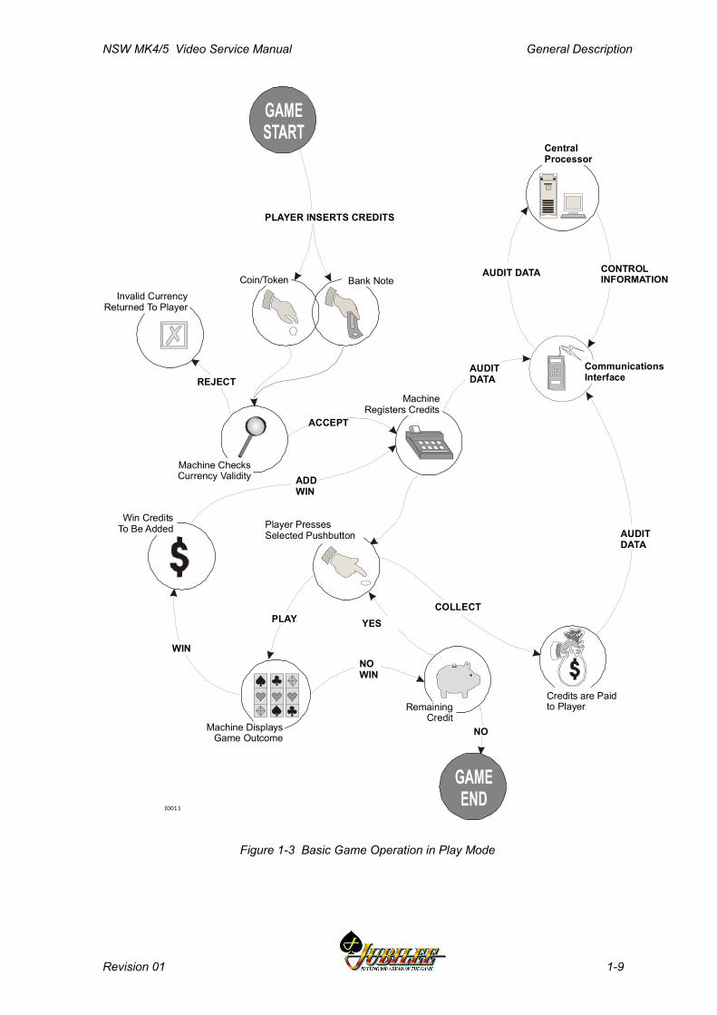
Basic machine operation in Play Mode is shown in Figure 1-3. Depending on themachine configuration, credits may be registered by inserting coins, bank notes ortokens. The machine has security features for screening the currency tendered toensure that only valid currency is accepted.
If the currency is accepted by the machine, the playbuttons on the mid trimbecome active and flash. The player may then insert more currency, play a gameby pressing one of the flashing playbuttons, or have the machine return the currentcredit total by pressing the COLLECT pushbutton. The player determines howmany credits to wager by pressing one of the BET playbuttons, and the BET meteron the display screen shows the credits wagered.
NSW MK4/5 Video Service Manual General Description
Revision 01 1-9
Coin/Token Bank Note
Machine ChecksCurrency Validity
Invalid CurrencyReturned To Player
AUDITDATA
ADDWIN
PLAYER INSERTS CREDITS
I0011
Player PressesSelected Pushbutton
Machine Registers Credits
REJECT
ACCEPT
CommunicationsInterface
AUDITDATA
COLLECT
Credits are Paid to Player
Machine DisplaysGame Outcome
Win Credits To Be Added
NOWIN
RemainingCredit
YES
NO
WIN
Central Processor
CONTROLINFORMATIONAUDIT DATA
PLAY
Figure 1-3 Basic Game Operation in Play Mode
General Description NSW MK4/5 Video Service Manual
1-10 Revision 01
Once the player starts a game by pressing one of the active playbuttons, themachine runs the game sequence and displays the outcome on the screen. If theresult is a winning combination, the player may gamble the win (if the gamblefeature is available); otherwise, the machine increments the credits won. If theresult is not a winning combination, the player may continue gameplay providedthere are credits remaining.
The machine is equipped with electronic audit (soft) meters which continuouslymonitor and record credit movement and game activity. Electromechanical metersare also fitted. The electronic audit meters are accessed through the OperatorMode. The information in these meters is used for audit calculations and securitypurposes.
If the machine encounters an abnormal condition, it alerts the operator byautomatically entering Machine Lockup. In lockup, gameplay is disabled toprevent any further player interaction and guidance information is displayed in thegame message area. The lockup condition can be identified by examining theCurrent Lockup screen which is accessed from the Operator Mode Menu. Eachlockup condition has an associated help screen that provides information on howto fix the problem and remove the lockup.
1.2.2 Operator ModeWithin Operator Mode (Audit Key ON), the following options are available:
• machine identification• accounting information• diagnostic information• self test mode• operator setup/selections• power save modetion mode• current lockup information.
In Operator Mode, the electronic audit meters and the electromechanical meters donot function. Menu selections may be used to review the machine details, selectnew configurations, and carry out machine tests. Refer to the chapter MachineModes for detailed information.
NSW MK4/5XR Video Service Manual Installation
Revision 01 2-1
________Chapter 2________
Installation
2.1 Pre-Installation Requirements ..................................................... 2-3
2.2 Inspection on Delivery .................................................................. 2-5
2.3 Installation Procedure................................................................... 2-5
2.3.1 Mounting ......................................................................................... 2-52.3.2 Pre-start Connections, Checks and Power Up................................ 2-72.3.3 Commissioning the Machine ........................................................... 2-8

Installation NSW MK4/5XR Video Service Manual
2-2 Revision 01
List of FiguresFigure 2-1 Machine Dimensions......................................................................................2-4Figure 2-2 Machine Footprint and Clearances ................................................................2-6
NSW MK4/5XR Video Service Manual Installation
Revision 01 2-3
2.1 Pre-Installation Requirements
The following items are required to install a machine:
• verification of jurisdictional approval.• a floor plan (only required for new installations).• a suitable base on which to mount the machine.• adequate clearance between the sides of adjacent machines to allow the doors
to be opened (a clearance of 180 mm is recommended).• access to mains power outlets and connection cables of peripheral devices.• machine keys (if locks are fitted).
See Figure 2-1 for machine dimensions.
WARNINGThe gaming machine is a heavy item. Toavoid personal injury, follow the nationalstandard and code of practice for manualhandling.
WARNINGThis is a Class A product. In a domesticenvironment, this product may cause radiointerference in which case the user may erequired to take adequate action.
CAUTIONThe gaming machine must be transportedand handled with care. Ensure the machineis not dropped or severely bumped.
Important NoteAll mains power wiring must be installed by aqualified electrician and comply withAustralian standard AS/NZS 3000-2000, orequivalent national/jurisdictional standardsfor mains wiring.
Installation NSW MK4/5XR Video Service Manual
2-4 Revision 01
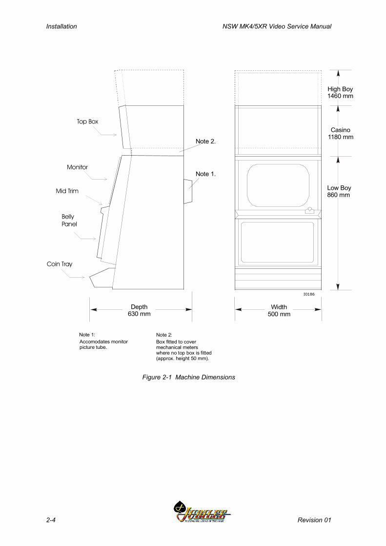
High Boy1460 mm
Depth630 mm
Casino1180 mm
Low Boy860 mm
Note 1.
Width500 mm
I0186
Coin Tray
BellyPanel
Monitor
Mid Trim
Top Box
Note 2.
Accomodates monitorpicture tube.
Box fitted to covermechanical meterswhere no top box is fitted(approx. height 50 mm).
Note 2:Note 1:
Figure 2-1 Machine Dimensions
NSW MK4/5XR Video Service Manual Installation
Revision 01 2-5
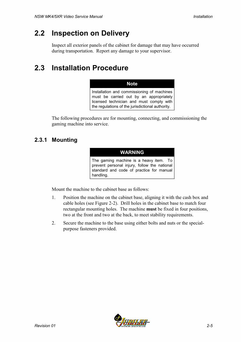
2.2 Inspection on DeliveryInspect all exterior panels of the cabinet for damage that may have occurredduring transportation. Report any damage to your supervisor.
2.3 Installation Procedure
NoteInstallation and commissioning of machinesmust be carried out by an appropriatelylicensed technician and must comply withthe regulations of the jurisdictional authority.
The following procedures are for mounting, connecting, and commissioning thegaming machine into service.
2.3.1 Mounting
WARNINGThe gaming machine is a heavy item. Toprevent personal injury, follow the nationalstandard and code of practice for manualhandling.
Mount the machine to the cabinet base as follows:
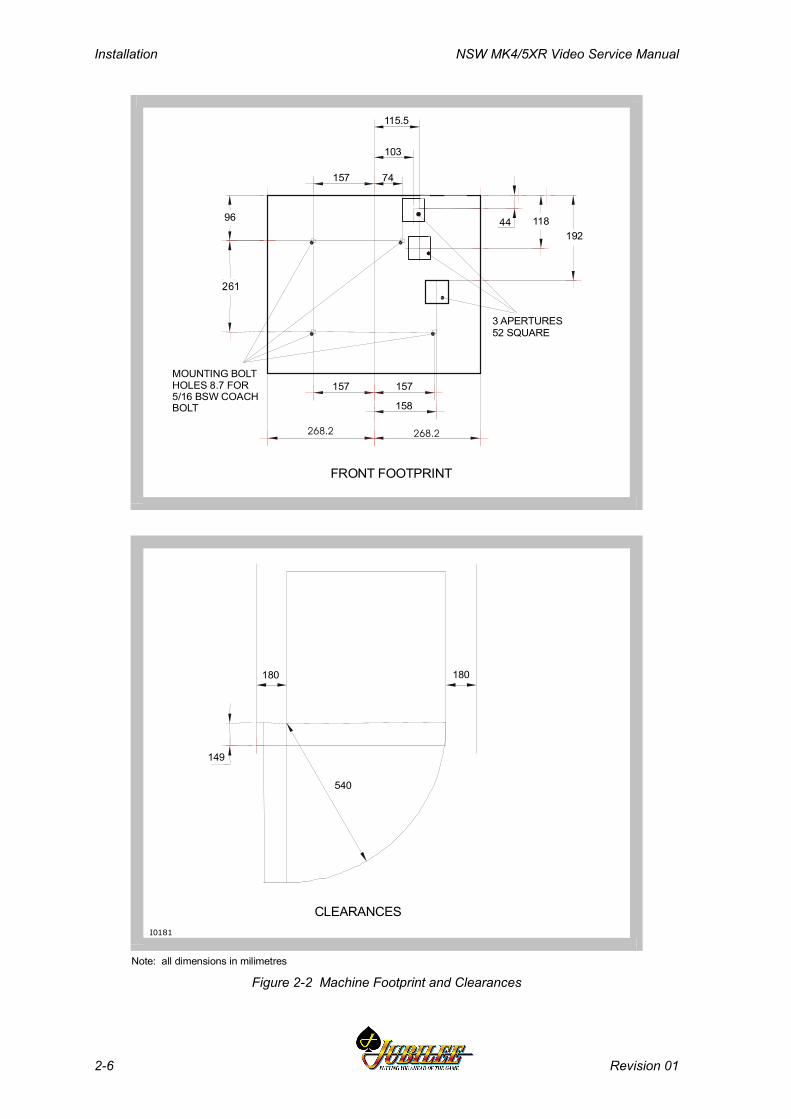
1. Position the machine on the cabinet base, aligning it with the cash box andcable holes (see Figure 2-2). Drill holes in the cabinet base to match fourrectangular mounting holes. The machine must be fixed in four positions,two at the front and two at the back, to meet stability requirements.
2. Secure the machine to the base using either bolts and nuts or the special-purpose fasteners provided.
Installation NSW MK4/5XR Video Service Manual
2-6 Revision 01
261
3 APERTURES52 SQUARE
FRONT FOOTPRINT
MOUNTING BOLTHOLES 8.7 FOR 5/16 BSW COACHBOLT
CLEARANCESI0181
Note: all dimensions in milimetres
180 180
115.5
103
74157
44 118192
96
157 157
158
268.2 268.2
540
149
Figure 2-2 Machine Footprint and Clearances

NSW MK4/5XR Video Service Manual Installation
Revision 01 2-7
2.3.2 Pre-start Connections, Checks and Power Up
Perform the following machine connections and checks:
1. Check that the Mechanical Meter Board is firmly seated in the top box or thelow boy meter cover and that the following printed circuit board assemblies(PCBAs) are firmly seated in the logic cage:
♦ Main Board♦ I/O Driver Board♦ LAB Board♦ Communications Configuration Board♦ Interface Board
NoteFor accessing PCBAs, refer to the relevant chapterin the Service Manual.
2. The machine power supply and monitor isolation transformer are set at thefactory for a mains input voltage of 240 V unless clearly labeled otherwise.Should there be a need to change the mains input voltage setting:
WARNINGMake sure the machine is disconnected frommains power before adjusting voltage settings.
CAUTIONSelecting the wrong power supply and/or monitorisolation transformer voltage will causeconsiderable damage to the power supply and/ormonitor transformer.
a. Set the voltage selector switch on the power supply for the correctmains input voltage. The switch is mounted on the metal housing ofthe power supply assembly, which is located at the back of the cabinet,in the bottom right-hand corner.
b. Where a Ceronix monitor with a manually-switched isolation mainsinput transformer is used, set the mains input switch on thetransformer to match the mains input voltage.
3. Make sure that the mains power switch is OFF. Connect the mains powercable to the machine. The power cable may enter the cabinet either via ahole in the base of the cabinet or via a hole in the rear wall of the cabinet. Ahole is provided in the base of the cabinet, near the cable entrance, to allowa clamp to be fitted to the mains cable. The purpose of this clamp is toprevent the mains power cable from being accidentally disconnected. Thisclamp should be fitted if there is a reasonable risk that the mains powercable may be accidentally disconnected.
Installation NSW MK4/5XR Video Service Manual
2-8 Revision 01
WARNINGVisually check that the insulation of the mainspower cable is sound. Check that all machineearth wires (green/yellow stripe or braid) andscrews that were moved during installation arecorrectly attached.
4. Switch ON the machine and close the main door within 5 seconds (closingthe main door within 5 seconds will ensure that the monitor automaticallydegausses correctly - refer step 5 below). The monitor and fluorescentlighting system will then be powered up. The machine will perform self-testing procedures for a few moments and any faults detected will behighlighted by a message on the video screen. To fix detected faults, referto Fault Mode in the chapter Machine Modes.
5. If the monitor exhibits colour aberrations, this may be the result of magneticinterference. Degaussing the monitor and cabinet, as described below, canremove the colour aberrations.
a. Power down the machine and wait for a 30-minute period to elapse.This time delay enables the monitor circuit varistors to coolsufficiently and create enough energy to degauss both the monitor'sferrous content and that of the cabinet.
b. Power up the machine and close the door within 5 seconds.Automatic degaussing will now occur.
c. Should colour aberrations persist, use a degaussing wand to degaussthe monitor and cabinet. Follow the standard field procedures fordegaussing-wand usage.
2.3.3 Commissioning the MachineCarry out the following procedures to commission the machine:
1. Check that the machine program type and variation match the customerorder. Use the Operator Mode menu and the options described in thechapter Machine Modes.
2. Fill the hopper as described below:
Important NoteThe procedure for filling the hopper isdependent on house rules.
a. Obtain the correct number of coins required to fill the hopper (thenumber is displayed in the Operator Mode Menu Operator Setup /Selections Machine Options display).
b. Open the cabinet door (the machine will display a Main Door Openmessage).
c. Place the coins into the hopper. Note that some jurisdictions mayrequire that the hopper be weighed and its weight recorded.
NSW MK4/5XR Video Service Manual Installation
Revision 01 2-9
d. Close and lock the cabinet door; the machine will remain in faultmode.
e. Insert the Jackpot Reset (Cancel Credit) key, turn it clockwise andback again. This will clear the lockup Hopper Empty.
f. In some markets, the hopper refill amount must be recorded in themachine memory. To do this, insert and turn the Audit Key to enterOperator Mode, select Hopper Refill and press the appropriate buttonsto record the refill amount. Turn the Audit key back to return to PlayMode.
g. Record the number of coins placed in the hopper in the refill register.
3. Where the Operator permits, monitor gameplay operations for any faults:
a. Ensure the machine accepts bank notes by inserting a valid bank note(in good condition) and confirming that it is accepted and creditedcorrectly. If the bank note is not accepted on the second attempt,repeat the test on another note. If the second bank note is alsorejected, refer to the Fault Finding section in the Bank Note Acceptorchapter.
b. Ensure the machine accepts coins by checking that coins are accepted,credited, and paid out correctly.
Retrieve bank notes and coins inserted during testing.
4. Machines operating on a network system may now be connected andinstalled onto the network. For installation procedure refer to the manual forthe particular communications network used.
5. Request an Operator to record the values of the electromechanical metersand the soft audit meters (as required by the applicable jurisdictionalauthority).
6. Log installation data as specified by the appropriate jurisdictionalrequirements.
The machine may now commence operation.

Installation NSW MK4/5XR Video Service Manual
2-10 Revision 01
Notes
NSW MK4/5XR Video Service Manual Machine Modes
Revision 01 3-1
________Chapter 3________
Machine Modes
3.1 Modes of Operation...................................................................... 3-3
3.2 Play Mode...................................................................................... 3-4
3.2.1 Player Operation............................................................................. 3-53.2.2 Video Display.................................................................................. 3-73.2.3 Sounds and Tunes ......................................................................... 3-83.2.4 Pushbuttons.................................................................................... 3-83.2.5 Machine Self-Monitoring................................................................. 3-83.2.7 Electromechanical Meters ............................................................ 3-113.2.9 Audit Meters (Soft Meters)............................................................ 3-13
3.3 Operator Mode ............................................................................ 3-14
3.3.1 Machine Identification................................................................... 3-163.3.2 Accounting Information................................................................. 3-163.3.3 Diagnostic Information Menu........................................................ 3-213.3.4 Self Test Mode ............................................................................. 3-243.3.5 Operator Setup / Selections Mode ............................................... 3-303.3.6 Power Save Mode ........................................................................ 3-333.3.7 Current Lockup Menu – Fault Mode ............................................. 3-33
Machine Modes NSW MK4/5XR Video Service Manual
3-2 Revision 01
List of Figures:Figure 3-1 Format of Game Display ................................................................................3-4Figure 3-2 Centre Line and Multi Line Combinations ......................................................3-7Figure 3-3 Typical Pushbutton Layout .............................................................................3-8Figure 3-4 Electromechanical Meters............................................................................3-12Figure 3-5 Operator Mode Menu Displays - Structure...................................................3-15
List of Tables:Table 3-1 Operator Mode Menu ....................................................................................3-14Table 3-2 Machine Identification Display.......................................................................3-16Table 3-3 Accounting Information Menu........................................................................3-17Table 3-4 Accounting Information - Jurisdictional Meters - Screen 1............................3-17Table 3-5 Accounting Information - Jurisdictional Meters - Screen 2............................3-18Table 3-6 Accounting Information - Periodic Meters - Screen 1....................................3-18Table 3-7 Accounting Information - Periodic Meters - Screen 2....................................3-19Table 3-8 Accounting Information - Reset Periodic Meters...........................................3-19Table 3-9 Accounting Information - Game Replay ........................................................3-19Table 3-10 Accounting Information – Meters of Last Game..........................................3-20Table 3-11 Accounting Information - Game Statistics ...................................................3-20Table 3-12 Accounting Information - Gamble Statistics ................................................3-21Table 3-13 Diagnostic Information Menu.......................................................................3-21Table 3-14 Diagnostic Information - Diagnostic Meters - Screen 1...............................3-22Table 3-15 Diagnostic Information - Diagnostic Meters - Screen 2...............................3-22Table 3-16 Diagnostic Information - Error Log ..............................................................3-23Table 3-17 Diagnostic Information - Panic Log .............................................................3-23Table 3-18 Diagnostic Information - Bill Acceptor Information ......................................3-24Table 3-19 Self Test Mode Menu ..................................................................................3-24Table 3-20 Self Test Mode Requirements.....................................................................3-25Table 3-21 Self Test Mode - Lamp Test........................................................................3-25Table 3-22 Self Test Mode - Coin Entry Test ................................................................3-26Table 3-23 Self Test Mode - Hopper Test .....................................................................3-26Table 3-24 Self Test Mode - Video Monitor Test Menu.................................................3-27Table 3-25 Self Test Mode - Video Monitor Test Descriptions......................................3-27Table 3-26 Self Test Mode - Sound Effects Test ..........................................................3-28Table 3-27 Self Test Mode - Factory Test .....................................................................3-28Table 3-28 Self Test Mode.- Combination Test.............................................................3-29Table 3-29 Self Test Mode - Combination Test Result .................................................3-29Table 3-30 Operator Setup / Selections Menu ..............................................................3-30Table 3-31 Operator Setup/Selections - Machine Options Display ...............................3-31Table 3-32 Operator Setup/Selections - Real Time Clock Setup ..................................3-32Table 3-33 Operator Setup/Selections - Sound System Setup .....................................3-32Table 3-34 Operator Setup/Selections - Reel Spin Speed Setup...................................3-32Table 3-35 Operator Setup/Selections - Layout Setup..................................................3-33Table 3-36 Power Save Mode .......................................................................................3-33Table 3-37 Fault Mode - Current Active Lockup Menu..................................................3-34Table 3-38 Fault Mode - Current Active Lockup Help Screens .....................................3-35
NSW MK4/5XR Video Service Manual Machine Modes
Revision 01 3-3
3.1 Modes of OperationAristocrat designers have implemented software improvements in response to MkV Series I recommendations from customers, players and service technicians.Improvements continue in development methods and in the range of features thatimprove earnings capacity. Special attention has been given to features that makethe new MVP model more user friendly, more serviceable, and more reliable. Inaddition, new data items have been added to meet jurisdictional requirements, anda design priority maintains upward compatibility for Mk V Series I games.
Improvements include:
• Operator Menu displays are shown in distinctive colours.• Four comment lines provide clearer guidance for players, operators and service
personnel — line allocation is Game Comment, Game Feature, PlayerInstruction, and Jurisdiction and Lockup Messages (see Figure 3-1).
• A single set of game sounds has been selected from Mk V Series I and earliermodels.
• Improved statistics include a Game Specific Statistics display to enable moreaccurate game and player evaluations.
• A new Quick Combination Test shows symbol positions without having to playa game.
• An expanded Game Replay display shows a 10-game history, and each gamehas jurisdictional meter readings at game start, game end, and start-of-nextgame.
• Improved Panic Log displays include date/time stamping, source program errorlocation, and user-friendly error description.
• Other improvements include a changed date/time format, enhanced MachineIdentification lines, a Quick Button Test, and new Diagnostic Meters.
The Mk4/5XR Gaming Machine is operated in two main modes, Play Mode andOperator Mode. Play Mode permits gameplay while the machine is fullyoperational and the cabinet door is closed. Operator Mode allows the operator toconfigure the machine, view audit information, carry out machine tests, and resetmachine faults. Turning the Operator Key ON switches the machine from PlayMode to Operator Mode.
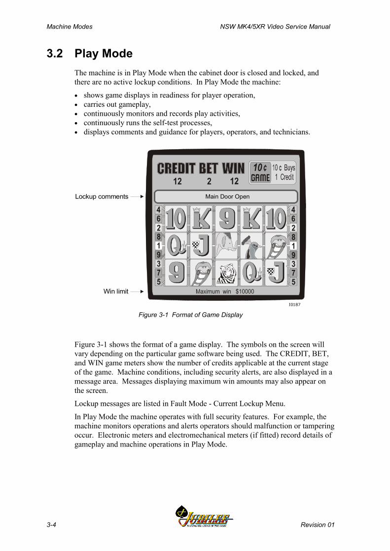
Machine Modes NSW MK4/5XR Video Service Manual
3-4 Revision 01
3.2 Play ModeThe machine is in Play Mode when the cabinet door is closed and locked, andthere are no active lockup conditions. In Play Mode the machine:
• shows game displays in readiness for player operation,• carries out gameplay,• continuously monitors and records play activities,• continuously runs the self-test processes,• displays comments and guidance for players, operators, and technicians.
I0187
lLockup comments
Win limit
Main Door Open
Figure 3-1 Format of Game Display
Figure 3-1 shows the format of a game display. The symbols on the screen willvary depending on the particular game software being used. The CREDIT, BET,and WIN game meters show the number of credits applicable at the current stageof the game. Machine conditions, including security alerts, are also displayed in amessage area. Messages displaying maximum win amounts may also appear onthe screen.
Lockup messages are listed in Fault Mode - Current Lockup Menu.
In Play Mode the machine operates with full security features. For example, themachine monitors operations and alerts operators should malfunction or tamperingoccur. Electronic meters and electromechanical meters (if fitted) record details ofgameplay and machine operations in Play Mode.
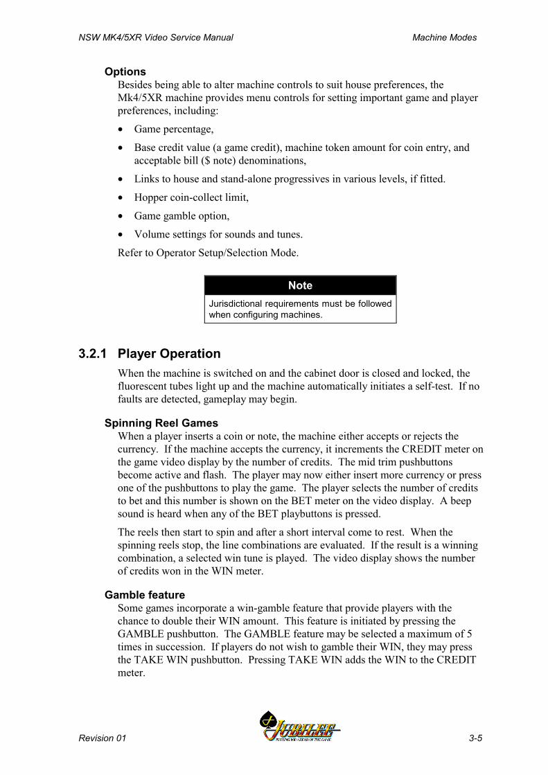
NSW MK4/5XR Video Service Manual Machine Modes
Revision 01 3-5
OptionsBesides being able to alter machine controls to suit house preferences, theMk4/5XR machine provides menu controls for setting important game and playerpreferences, including:
• Game percentage,
• Base credit value (a game credit), machine token amount for coin entry, andacceptable bill ($ note) denominations,
• Links to house and stand-alone progressives in various levels, if fitted.
• Hopper coin-collect limit,
• Game gamble option,
• Volume settings for sounds and tunes.
Refer to Operator Setup/Selection Mode.
NoteJurisdictional requirements must be followedwhen configuring machines.
3.2.1 Player OperationWhen the machine is switched on and the cabinet door is closed and locked, thefluorescent tubes light up and the machine automatically initiates a self-test. If nofaults are detected, gameplay may begin.
Spinning Reel GamesWhen a player inserts a coin or note, the machine either accepts or rejects thecurrency. If the machine accepts the currency, it increments the CREDIT meter onthe game video display by the number of credits. The mid trim pushbuttonsbecome active and flash. The player may now either insert more currency or pressone of the pushbuttons to play the game. The player selects the number of creditsto bet and this number is shown on the BET meter on the video display. A beepsound is heard when any of the BET playbuttons is pressed.
The reels then start to spin and after a short interval come to rest. When thespinning reels stop, the line combinations are evaluated. If the result is a winningcombination, a selected win tune is played. The video display shows the numberof credits won in the WIN meter.
Gamble featureSome games incorporate a win-gamble feature that provide players with thechance to double their WIN amount. This feature is initiated by pressing theGAMBLE pushbutton. The GAMBLE feature may be selected a maximum of 5times in succession. If players do not wish to gamble their WIN, they may pressthe TAKE WIN pushbutton. Pressing TAKE WIN adds the WIN to the CREDITmeter.
Machine Modes NSW MK4/5XR Video Service Manual
3-6 Revision 01
PayoutDue to the limit on the number of coins that can be held in the hopper, as well asother payout considerations, there is a limit to the number of coins that themachine can pay out. This is called the Collect Limit and is set via the OperatorMode Menu Operator Setup/Selections Machine Options screen display.
A player can collect coins up to the Collect Limit amount by pressing theCOLLECT pushbutton. When the COLLECT button is pressed, the machineprevents functions such as gameplay and entry of currency until the hopper hasdispensed the coins into the coin tray. The hopper photo-optic detector counts thecoins being dispensed. The CREDIT meter decrements to zero.
When a player presses the COLLECT pushbutton and the value of the gamecredits is greater than the Collect Limit:
• the message Call attendant - Cancel Credit $##/## is displayed ($##.## isthe value of credits to be paid out).
• the attendant hand pays the value of the credits and then resets the machineby turning the Jackpot Key ON then OFF.
• the message Credits paid out $##.## is displayed on the screen.• the CANCEL CREDIT electronic meters and electromechanical meters
record the number of credits paid out.• the game CREDIT on the screen are reset to zero.
ReservePressing the RESERVE pushbutton displays the message MACHINE RESERVEDon the screen. This allows players to reserve a machine for a short period.
Types of GamesMachines generally have one of three game types: multiplier, multiline, andmultiline-multiplier (see Figure 3-2).
Multiplier - A multiplier game allows a player to gamble more than one creditper game on a single winning line. Each additional credit gambled generallymultiplies the value of the prize by the value of the credits staked.
Multiline - A multiline game allows a player to specify up to 20 lines on which tobet for a winning combination. Up to 25 credits can be bet on each line. The wintotal is calculated by adding each of the win lines.
NSW MK4/5XR Video Service Manual Machine Modes
Revision 01 3-7
I0017
19
18
19
18
15 15
11 1113 13
12 12
14146 68 8
7 79 9
10 10
20 2017 17
1616
1 1 1
2
3
4
5
2
3
4
5
1
Figure 3-2 Centre Line and Multi Line Combinations
3.2.2 Video DisplayThe video display unit provides high-resolution graphics based on 256 colours.The unit is able to display attractive game illustrations and animations, as well asplayer messages, operator menus and information displays.
The simulated spinning reels take up most of the screen area. The area at the topof the screen displays CREDIT, BET, and WIN information, as well as the coindenomination accepted. Between these two areas is the top message display area.
The monitor may be fitted with a touchscreen that enables games to be played bytouching designated areas of the screen.
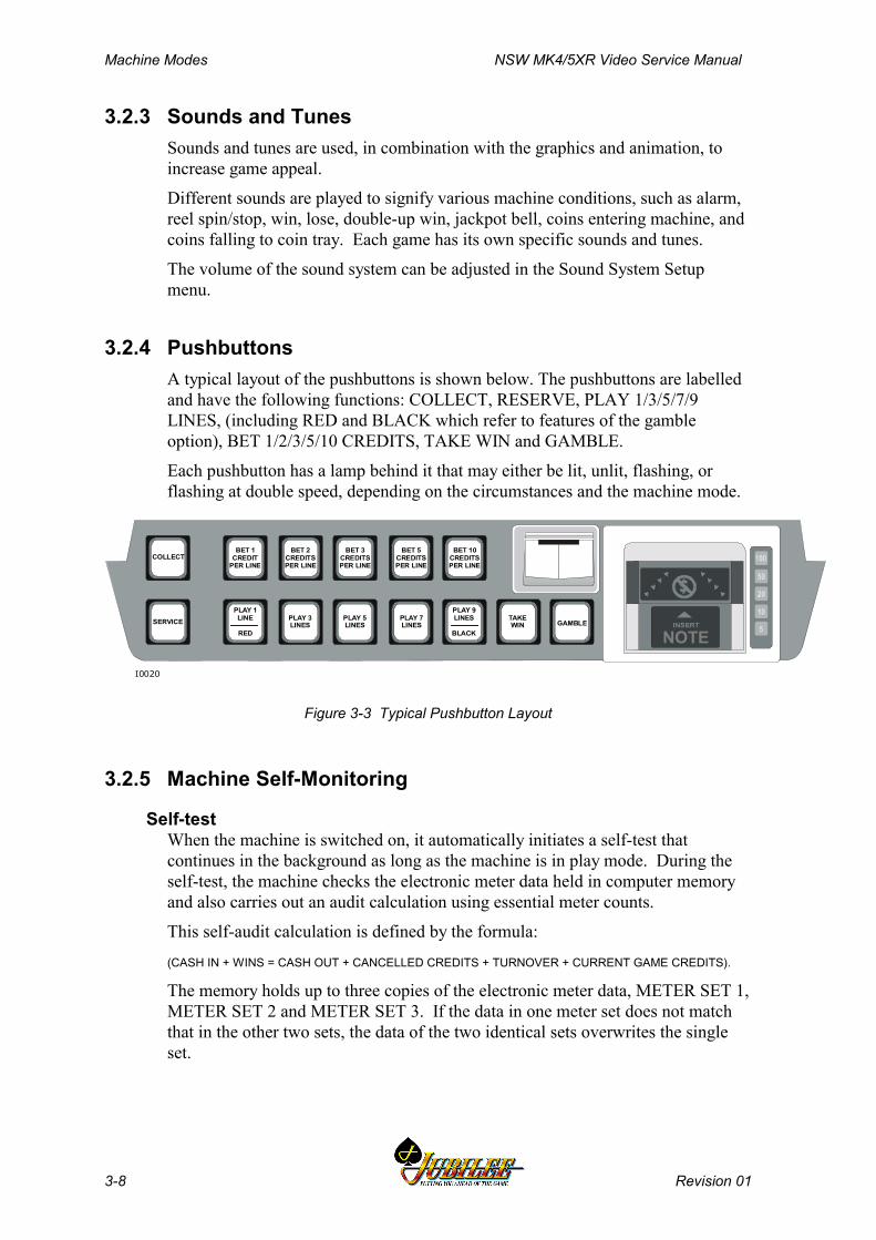
Machine Modes NSW MK4/5XR Video Service Manual
3-8 Revision 01
3.2.3 Sounds and TunesSounds and tunes are used, in combination with the graphics and animation, toincrease game appeal.
Different sounds are played to signify various machine conditions, such as alarm,reel spin/stop, win, lose, double-up win, jackpot bell, coins entering machine, andcoins falling to coin tray. Each game has its own specific sounds and tunes.
The volume of the sound system can be adjusted in the Sound System Setupmenu.
3.2.4 PushbuttonsA typical layout of the pushbuttons is shown below. The pushbuttons are labelledand have the following functions: COLLECT, RESERVE, PLAY 1/3/5/7/9LINES, (including RED and BLACK which refer to features of the gambleoption), BET 1/2/3/5/10 CREDITS, TAKE WIN and GAMBLE.
Each pushbutton has a lamp behind it that may either be lit, unlit, flashing, orflashing at double speed, depending on the circumstances and the machine mode.
I0020
NOTEGAMBLE
TAKEWIN
BET 10CREDITSPER LINE
BET 5CREDITSPER LINE
BET 3CREDITSPER LINE
BET 2CREDITSPER LINE
BET 1CREDIT
PER LINE
PLAY 9LINES
BLACK
PLAY 1LINE
RED
PLAY 3LINES
PLAY 5LINES
PLAY 7LINES
COLLECT
SERVICE
Figure 3-3 Typical Pushbutton Layout
3.2.5 Machine Self-Monitoring
Self-testWhen the machine is switched on, it automatically initiates a self-test thatcontinues in the background as long as the machine is in play mode. During theself-test, the machine checks the electronic meter data held in computer memoryand also carries out an audit calculation using essential meter counts.
This self-audit calculation is defined by the formula:
(CASH IN + WINS = CASH OUT + CANCELLED CREDITS + TURNOVER + CURRENT GAME CREDITS).
The memory holds up to three copies of the electronic meter data, METER SET 1,METER SET 2 and METER SET 3. If the data in one meter set does not matchthat in the other two sets, the data of the two identical sets overwrites the singleset.
NSW MK4/5XR Video Service Manual Machine Modes
Revision 01 3-9
SecurityWhen the machine is in play mode, it continuously operates the following securityfeatures:
Coin Validator Once in the validator, the coin passes a sensor coil that detects itsdiameter, thickness, and magnetic properties. Invalid coins are diverted to thecoin tray. For valid coins, a CSENSE output signal is generated and the coins aredirected past the validator's internal photo-optic detector and on to the coin acceptchute.
Coins passing the opto detector generate a CCREDIT output signal. For a validcoin to register, a CSENSE pulse must be followed by a CCREDIT pulse. If thiscondition is not met, a CERROR output signal is generated. This signal indicatesa Yo-Yo or a coin blockage condition depending on the width of the pulse. Onreceiving a CERROR signal, the machine locks up, the error message Yoyo orCoin Optic Fault is displayed on the screen, and the appropriate audit meter isincremented. See Section 3.3.7, Fault Mode - Current Lockup Menu.
The position of the coin diverter determines whether accepted coins are directed tothe hopper or the cash box. A photo-optic detector is used to monitor the positionof the diverter and generates the output signal CDIVPOS.
The Coin Handling Interface on the I/O Driver Board converts the output signalsCCREDIT, CSENSE, CERROR and CDIVPOS into the form required by theMain Board. The machine software then analyses these signals to determine thevalidity of inserted coins and to check for fault conditions.
If the inserted coin is valid, the appropriate credits are registered in the gameCREDIT display and gameplay may take place. The audit meters CASH IN andCREDIT in the accounting menu and the electromechanical meter CASH IN areincremented accordingly.
Note that the game display shows accumulations and totals in “credits”, whereasthe electronic meters accumulate in “dollars and cents”. The electromechanicalmeters CASH IN and CASH OUT accumulate in “dollars and cents” but onlydisplay to the “whole dollar” the cents not displayed continue in theaccumulation.
All coins go to the hopper until the coins in the hopper reach the level detectorprobe, indicating that the hopper is full. At this stage, coins are diverted to thecash box.
The machine software monitors the signals from the Coin Handling Interface andunusual conditions and faults are registered by machine lockup, video messagesand increments in the appropriate audit meters – diagnostic menus. These faultconditions are COIN ACCEPTOR FAULT, COIN OPTIC FAULT and COINDIVERTER FAULT.
If the machine software indicates that coins intended for the hopper are diverted tothe cash box, or vice versa, the CASH BOX INSTEAD HOPPER or HOPPERINSTEAD CASH BOX audit meters in the diagnostic menus are incremented.These totals allow adjustment and balancing of the hopper and cash boxcollections.
Machine Modes NSW MK4/5XR Video Service Manual
3-10 Revision 01
Hopper. If the hopper is empty and the player is in credit and presses theCOLLECT pushbutton, the machine locks up and displays a Hopper Emptymessage and the audit meter HOPPER EMPTY increments. The hopper is refilledin these circumstances according to house rules, after which gameplay mayresume.
During a payout, the hopper disc rotates and passes coins onto the coin runnerwhere they are counted by the hopper photo-optic detector. After passing thedetector, they are deposited in the coin tray for the player to collect. Also:
• the COINS OUT electromechanical meter and the CASH OUT audit meterare incremented by the amount paid out.
• the game CREDIT on the screen and the CREDIT audit meter aredecremented by the amount paid out.
• a payout message is displayed on the screen showing the value paid out.The machine monitors the hopper operation and the photo optic detector checksthe coins exiting the hopper. Unusual conditions and faults are registered byincrements in the Diagnostic Meters, video messages and machine lockups. Thesefault conditions are ILLEGAL COIN OUT, HOPPER EMPTY, HOPPERJAMMED, and HOPPER DISCONNECTED.
Bank Note Acceptor The Bank Note Acceptor consists of an optical scanningunit and a bill stacker contained in a high-security housing. During operation, theacceptor registers acceptances and rejections. Notes accepted increment theCASH IN electronic meter and electromechanical meter. Detailed information isrecorded in the Bank Note Acceptor meters, which may be accessed fromOperator Mode / Accounting Information Menu. These meters record the valueand quantity of each note accepted. A record is also kept of the last five notesaccepted.
The machine monitors the bank note acceptor operation and unusual conditionsand faults are registered by increments in the Diagnostic Meters, and by displaymessages and machine lockups. The lockups and video messages are NOTEACCEPTOR ERROR and NOTE ACCEPTOR OUT OF SERVICE. Should thebank note stacker door be open, the alarm sounds and the message NOTESTACKER REMOVED is displayed. A lockup occurs should the bank noteacceptor stacker become full. The lockup description and video message is NOTEACCEPTOR FULL.
The Machine Options menu enables the bank note acceptor to be configured ONor OFF and to recognise specific note denominations.
Door SecurityUp to eight mechanical and eight optical security switches may be used to monitorvarious door accesses.
If a door fitted with a security switch is opened while the machine is powered:
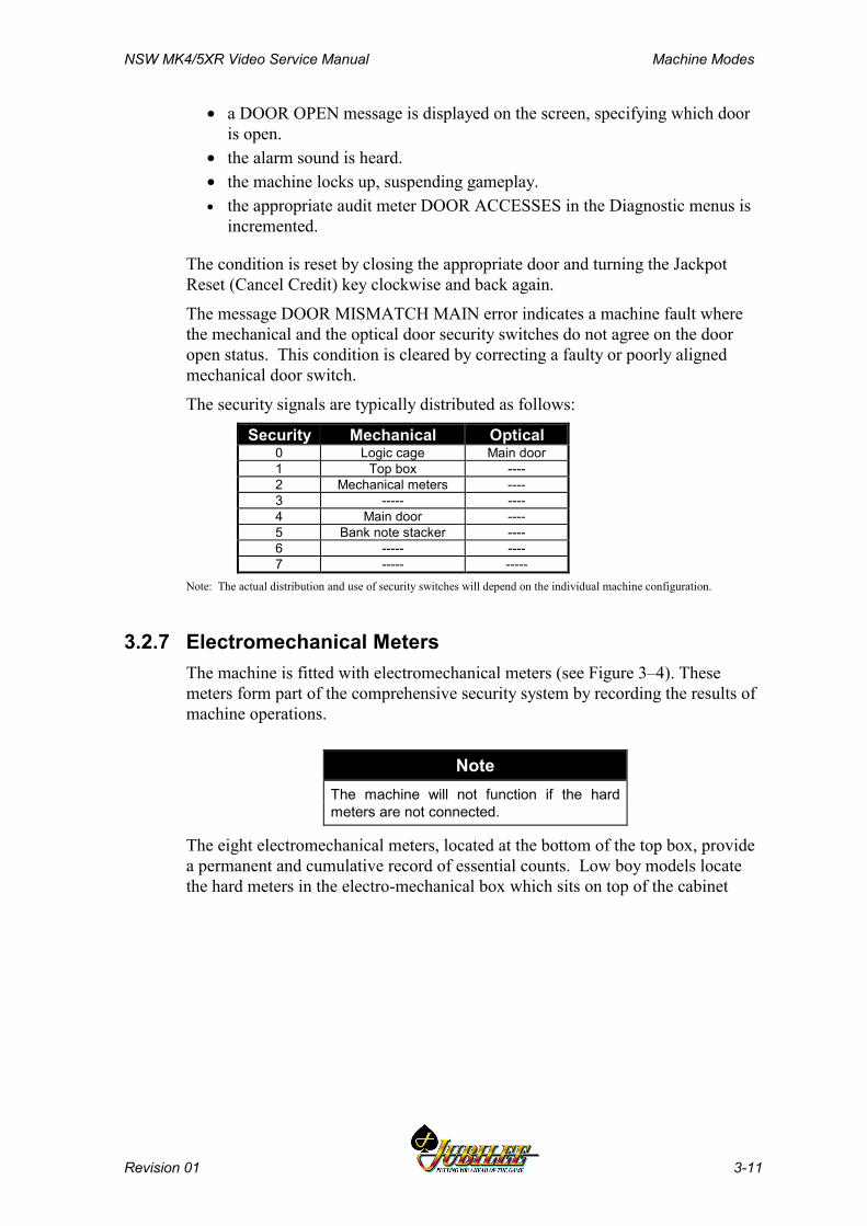
NSW MK4/5XR Video Service Manual Machine Modes
Revision 01 3-11
• a DOOR OPEN message is displayed on the screen, specifying which dooris open.
• the alarm sound is heard.• the machine locks up, suspending gameplay.• the appropriate audit meter DOOR ACCESSES in the Diagnostic menus is
incremented.
The condition is reset by closing the appropriate door and turning the JackpotReset (Cancel Credit) key clockwise and back again.
The message DOOR MISMATCH MAIN error indicates a machine fault wherethe mechanical and the optical door security switches do not agree on the dooropen status. This condition is cleared by correcting a faulty or poorly alignedmechanical door switch.
The security signals are typically distributed as follows:
Security Mechanical Optical0 Logic cage Main door1 Top box ----2 Mechanical meters ----3 ----- ----4 Main door ----5 Bank note stacker ----6 ----- ----7 ----- -----
Note: The actual distribution and use of security switches will depend on the individual machine configuration.
3.2.7 Electromechanical MetersThe machine is fitted with electromechanical meters (see Figure 3–4). Thesemeters form part of the comprehensive security system by recording the results ofmachine operations.
NoteThe machine will not function if the hardmeters are not connected.
The eight electromechanical meters, located at the bottom of the top box, providea permanent and cumulative record of essential counts. Low boy models locatethe hard meters in the electro-mechanical box which sits on top of the cabinet
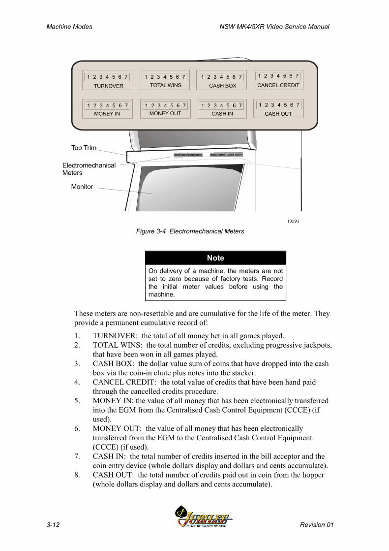
Machine Modes NSW MK4/5XR Video Service Manual
3-12 Revision 01
Top Box
Monitor
Top Trim
ElectromechanicalMeters
I0191
1 2 3 4 5 6 7 1 2 3 4 5 6 71 2 3 4 5 6 7
1 2 3 4 5 6 7 1 2 3 4 5 6 7 1 2 3 4 5 6 7 1 2 3 4 5 6 7
1 2 3 4 5 6 7
TOTAL WINS
MONEY OUTMONEY IN
CASH BOX CANCEL CREDIT
CASH IN CASH OUT
TURNOVER
Figure 3-4 Electromechanical Meters
NoteOn delivery of a machine, the meters are notset to zero because of factory tests. Recordthe initial meter values before using themachine.
These meters are non-resettable and are cumulative for the life of the meter. Theyprovide a permanent cumulative record of:
1. TURNOVER: the total of all money bet in all games played.2. TOTAL WINS: the total number of credits, excluding progressive jackpots,
that have been won in all games played.3. CASH BOX: the dollar value sum of coins that have dropped into the cash
box via the coin-in chute plus notes into the stacker.4. CANCEL CREDIT: the total value of credits that have been hand paid
through the cancelled credits procedure.5. MONEY IN: the value of all money that has been electronically transferred
into the EGM from the Centralised Cash Control Equipment (CCCE) (ifused).
6. MONEY OUT: the value of all money that has been electronicallytransferred from the EGM to the Centralised Cash Control Equipment(CCCE) (if used).
7. CASH IN: the total number of credits inserted in the bill acceptor and thecoin entry device (whole dollars display and dollars and cents accumulate).
8. CASH OUT: the total number of credits paid out in coin from the hopper(whole dollars display and dollars and cents accumulate).
NSW MK4/5XR Video Service Manual Machine Modes
Revision 01 3-13
Meter SecurityThe electromechanical meters are monitored for abnormal conditions, meters cageaccesses and meter disconnection. Detection of conditions is actioned as follows:
• game play is suspended,• the alarm sound is heard,• an appropriate lockup and operator message is actioned, being selected
from: METERS FAULTY, METERS CAGE OPEN, METERSDISCONNECTED.
• the appropriate electronic meter increments, being selected from: METERSFAULTY, METERS CAGE OPEN, and METERS DISCONNECTED.
The condition is reset when the machine condition is cleared, the lockup isremoved, and the door is closed. Refer to Table 3-37 for a listing of the CurrentLockups.
3.2.9 Audit Meters (Soft Meters)The audit meters (soft meters) record a variety of details relating to machineoperation, gameplay and player interaction, as well as a variety of statisticalcounts, security events and past games. Players have the assurance that there is arecord kept of recent win or pay situations.
When the machine is switched on, it automatically initiates a self-test thatcontinues in the background as long as the machine is in play mode. During theself-test, the machine checks the audit meter data held in memory.
Some jurisdictions require audit metering data to be stored in triplicate in threeseparate battery-backed RAM chips. In the case of a meter malfunction, wherenone of the meters sets match, the machine displays the error message 3 WAYMEMORY ERROR and the machine locks up. This message indicates a seriousmachine malfunction.
Failure in the self audit calculation also causes a machine lockup with the messageSELF AUDIT ERROR being displayed.
Resetting Metering and Self Audit ErrorsTo clear a metering or self audit error, the memory fault must be rectified andcorrect operations re-established with all corrupted meters set to zero. The lockupis removed by turning the Operator Key ON, following the on-screen guidance,and then turning the Operator Key OFF to return to gameplay. After recoveringfrom a memory error, some electronic meters are reset to zero. The informationheld in these electronic meters includes:
• Accounting Information Menu items (Jurisdictional, Periodic, Game Replay,Game / Gamble / Collect Statistics).
• Diagnostic Information Menu items (Diagnostic, Error Log, Panic Log,Bank Note Acceptor Information).
• Operator Setup / Selections Menu items (Machine Options, Real TimeClock Setup, Sound System Setup, Reel Spin Speed Setup, Layout Setup,).
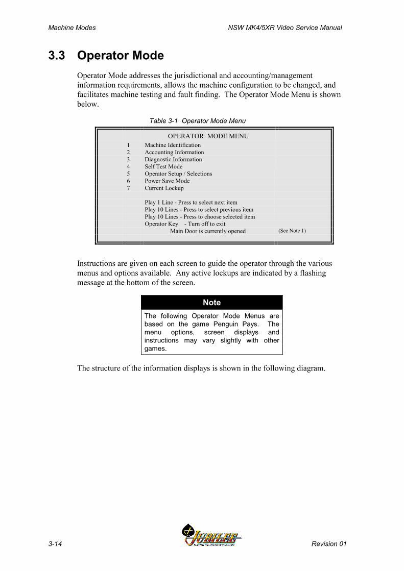
Machine Modes NSW MK4/5XR Video Service Manual
3-14 Revision 01
3.3 Operator ModeOperator Mode addresses the jurisdictional and accounting/managementinformation requirements, allows the machine configuration to be changed, andfacilitates machine testing and fault finding. The Operator Mode Menu is shownbelow.
Table 3-1 Operator Mode Menu
OPERATOR MODE MENU1 Machine Identification2 Accounting Information3 Diagnostic Information4 Self Test Mode5 Operator Setup / Selections6 Power Save Mode7 Current Lockup
Play 1 Line - Press to select next itemPlay 10 Lines - Press to select previous itemPlay 10 Lines - Press to choose selected itemOperator Key - Turn off to exit
Main Door is currently opened (See Note 1)
Instructions are given on each screen to guide the operator through the variousmenus and options available. Any active lockups are indicated by a flashingmessage at the bottom of the screen.
NoteThe following Operator Mode Menus arebased on the game Penguin Pays. Themenu options, screen displays andinstructions may vary slightly with othergames.
The structure of the information displays is shown in the following diagram.
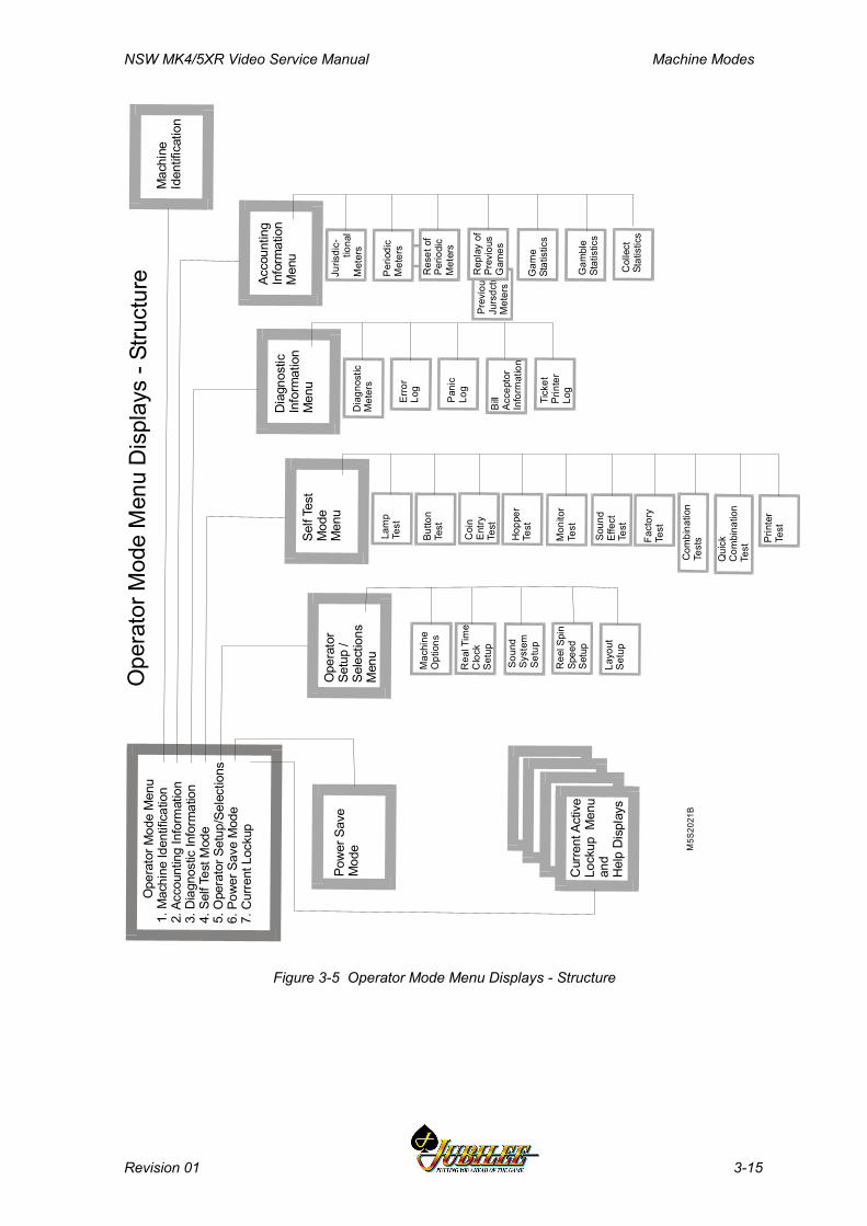
NSW MK4/5XR Video Service Manual Machine Modes
Revision 01 3-15
Prev
ious
Jurs
dctn
lM
eter
s
Ope
rato
r Mod
e M
e nu
1. M
achi
ne Id
e ntif
icat
ion
2. A
cco u
ntin
g In
form
atio
n3.
Dia
gnos
tic In
form
atio
n4.
Sel
f Te s
t Mod
e5 .
Ope
rato
r Set
up/ S
elec
tion s
6. P
ower
Sav
e M
ode
7. C
urre
nt L
ocku
pAc
cou n
ting
Info
rmat
ion
Men
u
Mac
hin e
Id
entif
icat
ion
Dia
g nos
tic
Info
rmat
ion
Men
uSe
lf Te
stM
ode
Men
uO
pera
tor
Setu
p /
Sele
c tio
nsM
enu
P ow
er S
a ve
Mo d
e
Cur
rent
Act
ive
Lock
up M
enu
and
Hel
p D
ispl
ays
Ope
rato
r Mod
e M
e nu
Dis
pla y
s - S
truc t
ure Ju
risdi
c-
ti
o nal
Met
ers
Perio
d ic
Met
ers
Dia
gno s
ticM
eter
s
Erro
rLo
g
Pani
cLo
g
Bill
Acce
ptor
Info
rmat
ion
Tick
et
P rin
ter
Log
Lam
p Te
st
Co i
n En
tryTe
st
Hop
per
Test
Soun
dEf
fect
Te
st
Mon
i tor
Test
Fact
ory
Test
Prin
ter
Test
Butto
nTe
st
Com
bina
tion
Test
s
Qui
ckC
o mbi
natio
nTe
st
Mac
hine
Opt
ions
Re a
l Tim
eC
lock
Setu
p
Soun
dSy
s tem
Se
tup
Ree
l Spi
n Sp
eed
Set u
p
Layo
utSe
t up
Res
et o
fPe
riodi
c M
eter
s
Rep
lay
o f
Pre v
ious
Gam
es
Gam
eSt
atis
tics
Gam
ble
Stat
istic
s
Col
lec t
S t
atis
tics
M5S
2021
B
Figure 3-5 Operator Mode Menu Displays - Structure
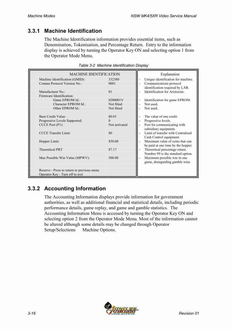
Machine Modes NSW MK4/5XR Video Service Manual
3-16 Revision 01
3.3.1 Machine IdentificationThe Machine Identification information provides essential items, such asDenomination, Tokenisation, and Percentage Return. Entry to the informationdisplay is achieved by turning the Operator Key ON and selecting option 1 fromthe Operator Mode Menu.
Table 3-2 Machine Identification Display
MACHINE IDENTIFICATION ExplanationMachine Identification (GMID): 332380 - Unique identification for machine.Comms Protocol Version No.: 0001 - Communications protocol
identification required by LAB.Manufacturer No.: 01 - Identification for Aristocrat.Firmware Identification:
Game EPROM Id.: 0200001V - Identification for game EPROM.Character EPROM Id.: Not fitted - Not used.Other EPROM Id.: Not fitted - Not used.
Base Credit Value: $0.01 - The value of one credit.Progressive Levels Supported: 0 - Progressive levels.CCCE Port (P1): Not activated - Port for communicating with
subsidiary equipment.CCCE Transfer Limit: $0 - Limit of transfer with Centralised
Cash Control equipment.Hopper Limit: $50.00 - Maximum value of coins that can
be paid at one time by the hopper.Theoretical PRT 87.17 - Theoretical percentage return.
Number 99 is the standard option.Max Possible Win Value (MPWV): 500.00 - Maximum possible win in one
game, disregarding gamble wins.
Reserve - Press to return to previous menuOperator Key - Turn off to exit
3.3.2 Accounting InformationThe Accounting Information displays provide information for governmentauthorities, as well as additional financial and statistical details, including periodicperformance details, game replay, and game and gamble statistics. TheAccounting Information Menu is accessed by turning the Operator Key ON andselecting option 2 from the Operator Mode Menu. Most of the information cannotbe altered although some details may be changed through OperatorSetup/Selections Machine Options.

NSW MK4/5XR Video Service Manual Machine Modes
Revision 01 3-17
Table 3-3 Accounting Information Menu
ACCOUNTING INFORMATION MENU2.1 Jurisdictional Meters2.2 Periodic Meters2.3 Reset of Periodic Meters2.4 Replay of Previous Games2.5 Game Statistics2.6 Gamble Statistics2.7 Collect Statistics
Play 1 Line - Press to select next itemPlay 5 Lines - Press to select previous itemPlay 10 Lines - Press to choose selected item
Reserve - Press to return to previous menuOperator Key - Turn off to exit
Jurisdictional MetersThe Jurisdictional Meters provide the financial counts of machine activity. Itemsinclude turnover, total wins and amounts inserted in the coin entry and the billacceptor devices.
Table 3-4 Accounting Information - Jurisdictional Meters - Screen 1
JURISDICTIONAL METERS ExplanationMeterSet 1
MeterSet 2
MeterSet 3
- Each meter has three sets of recordings thatare constantly compared. Differences cause ametering error.
Turnover $75.00 $75.00 $75.00 - Value bet in all games played.Total Win $15.00 $15.00 $15.00 - Value won in all games played.Cash Box $0.00 $0.00 $0.00 - Value directed to the cash box and note
stacker.Cancelled Credit $10.00 $10.00 $10.00 - Value paid other than by the hopper.Money In $0.00 $0.00 $0.00 - Not used.Money Out $0.00 $0.00 $0.00 - Not used.Cash In $100.00 $100.00 $100.00 - Value of notes and coins inserted.Cash Out $30.00 $30.00 $30.00 - Value paid out by the hopper.Miscellaneous Accrual: $0.00 $0.00 $0.00 Not usedCredit: $0.00 $0.00 $0.00 Current amount of credit available to the
player
Play 1 Line - Press to display next meter screenReserve - Press to return to previous screenOperator Key - Turn off to exit
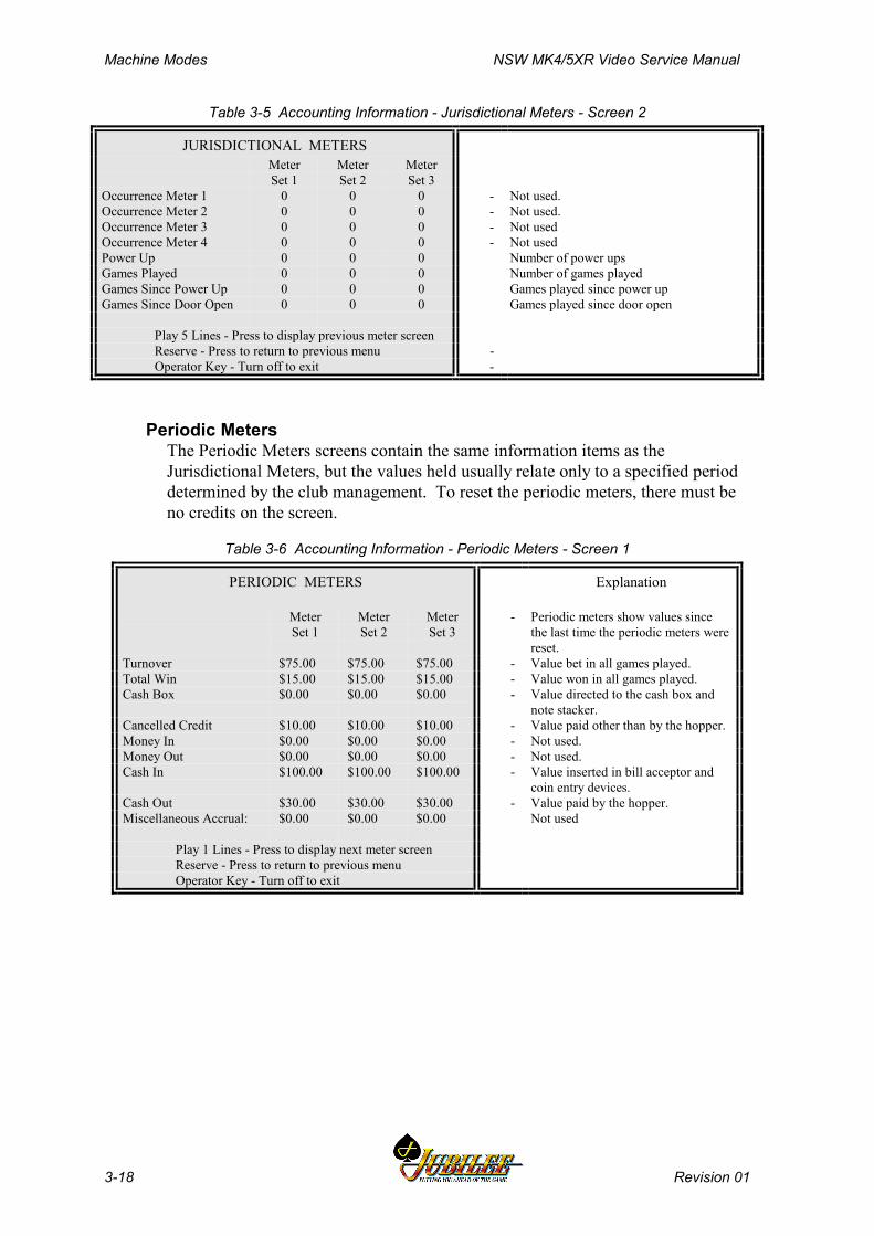
Machine Modes NSW MK4/5XR Video Service Manual
3-18 Revision 01
Table 3-5 Accounting Information - Jurisdictional Meters - Screen 2
JURISDICTIONAL METERSMeterSet 1
MeterSet 2
MeterSet 3
Occurrence Meter 1 0 0 0 - Not used.Occurrence Meter 2 0 0 0 - Not used.Occurrence Meter 3 0 0 0 - Not usedOccurrence Meter 4 0 0 0 - Not usedPower Up 0 0 0 Number of power upsGames Played 0 0 0 Number of games playedGames Since Power Up 0 0 0 Games played since power upGames Since Door Open 0 0 0 Games played since door open
Play 5 Lines - Press to display previous meter screenReserve - Press to return to previous menu -Operator Key - Turn off to exit -
Periodic MetersThe Periodic Meters screens contain the same information items as theJurisdictional Meters, but the values held usually relate only to a specified perioddetermined by the club management. To reset the periodic meters, there must beno credits on the screen.
Table 3-6 Accounting Information - Periodic Meters - Screen 1
PERIODIC METERS Explanation
MeterSet 1
MeterSet 2
MeterSet 3
- Periodic meters show values sincethe last time the periodic meters werereset.
Turnover $75.00 $75.00 $75.00 - Value bet in all games played.Total Win $15.00 $15.00 $15.00 - Value won in all games played.Cash Box $0.00 $0.00 $0.00 - Value directed to the cash box and
note stacker.Cancelled Credit $10.00 $10.00 $10.00 - Value paid other than by the hopper.Money In $0.00 $0.00 $0.00 - Not used.Money Out $0.00 $0.00 $0.00 - Not used.Cash In $100.00 $100.00 $100.00 - Value inserted in bill acceptor and
coin entry devices.Cash Out $30.00 $30.00 $30.00 - Value paid by the hopper.Miscellaneous Accrual: $0.00 $0.00 $0.00 Not used
Play 1 Lines - Press to display next meter screenReserve - Press to return to previous menuOperator Key - Turn off to exit
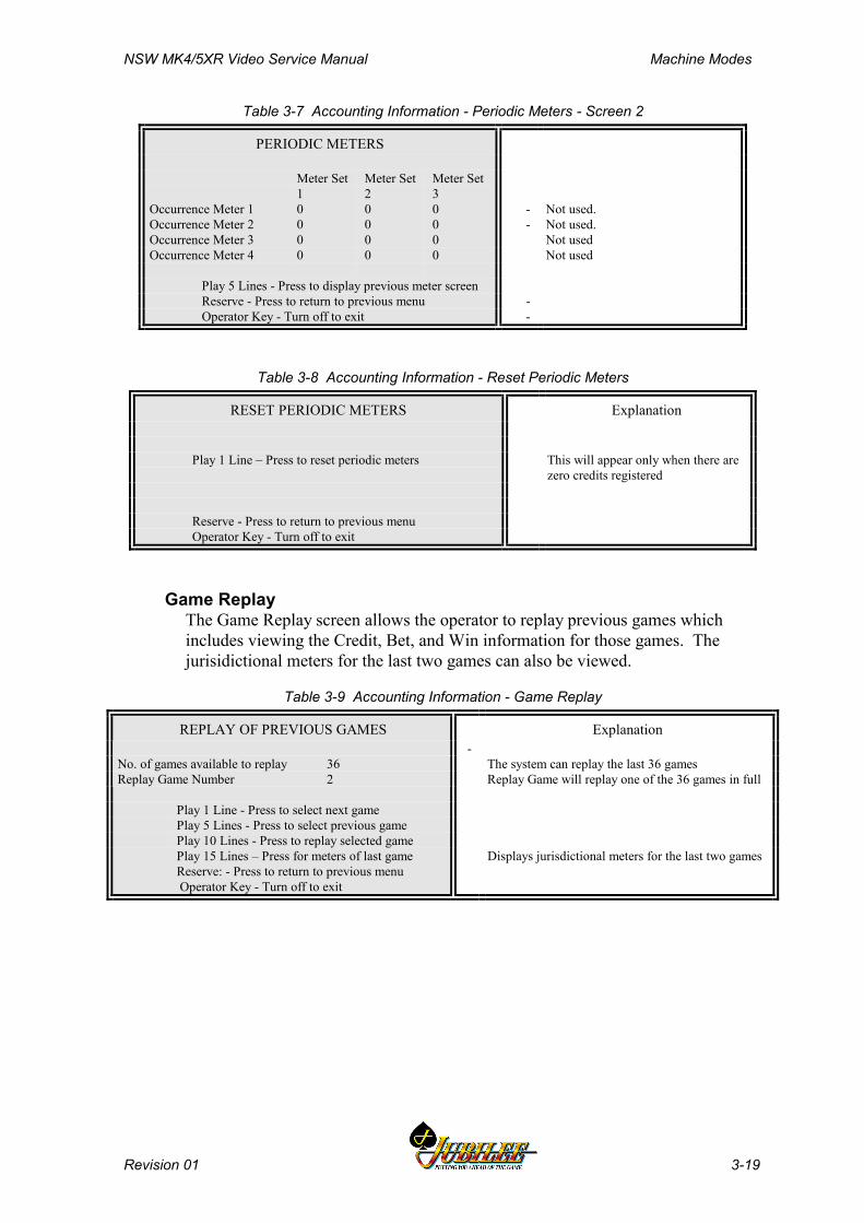
NSW MK4/5XR Video Service Manual Machine Modes
Revision 01 3-19
Table 3-7 Accounting Information - Periodic Meters - Screen 2
PERIODIC METERS
Meter Set1
Meter Set2
Meter Set3
Occurrence Meter 1 0 0 0 - Not used.Occurrence Meter 2 0 0 0 - Not used.Occurrence Meter 3 0 0 0 Not usedOccurrence Meter 4 0 0 0 Not used
Play 5 Lines - Press to display previous meter screenReserve - Press to return to previous menu -Operator Key - Turn off to exit -
Table 3-8 Accounting Information - Reset Periodic Meters
RESET PERIODIC METERS Explanation
Play 1 Line – Press to reset periodic meters This will appear only when there arezero credits registered
Reserve - Press to return to previous menuOperator Key - Turn off to exit
Game ReplayThe Game Replay screen allows the operator to replay previous games whichincludes viewing the Credit, Bet, and Win information for those games. Thejurisidictional meters for the last two games can also be viewed.
Table 3-9 Accounting Information - Game Replay
REPLAY OF PREVIOUS GAMES Explanation-
The system can replay the last 36 gamesReplay Game will replay one of the 36 games in full
No. of games available to replay 36Replay Game Number 2
Play 1 Line - Press to select next gamePlay 5 Lines - Press to select previous gamePlay 10 Lines - Press to replay selected gamePlay 15 Lines – Press for meters of last game Displays jurisdictional meters for the last two gamesReserve: - Press to return to previous menu
Operator Key - Turn off to exit
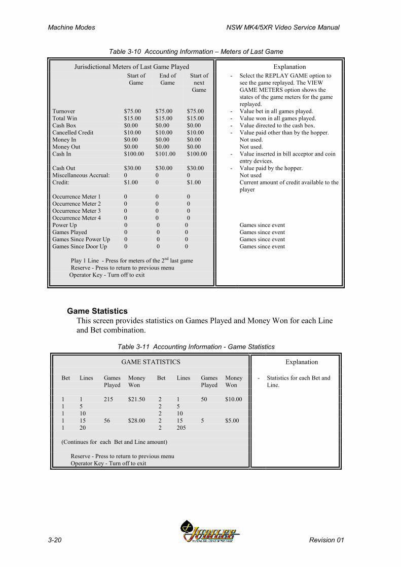
Machine Modes NSW MK4/5XR Video Service Manual
3-20 Revision 01
Table 3-10 Accounting Information – Meters of Last Game
Jurisdictional Meters of Last Game Played ExplanationStart ofGame
End ofGame
Start ofnext
Game
- Select the REPLAY GAME option tosee the game replayed. The VIEWGAME METERS option shows thestates of the game meters for the gamereplayed.
Turnover $75.00 $75.00 $75.00 - Value bet in all games played.Total Win $15.00 $15.00 $15.00 - Value won in all games played.Cash Box $0.00 $0.00 $0.00 - Value directed to the cash box.Cancelled Credit $10.00 $10.00 $10.00 - Value paid other than by the hopper.Money In $0.00 $0.00 $0.00 Not used.Money Out $0.00 $0.00 $0.00 Not used.Cash In $100.00 $101.00 $100.00 - Value inserted in bill acceptor and coin
entry devices.Cash Out $30.00 $30.00 $30.00 - Value paid by the hopper.Miscellaneous Accrual: 0 0 0 Not usedCredit: $1.00 0 $1.00 Current amount of credit available to the
playerOccurrence Meter 1 0 0 0Occurrence Meter 2 0 0 0Occurrence Meter 3 0 0 0Occurrence Meter 4 0 0 0Power Up 0 0 0 Games since eventGames Played 0 0 0 Games since eventGames Since Power Up 0 0 0 Games since eventGames Since Door Up 0 0 0 Games since event
Play 1 Line - Press for meters of the 2nd last game Reserve - Press to return to previous menu Operator Key - Turn off to exit
Game StatisticsThis screen provides statistics on Games Played and Money Won for each Lineand Bet combination.
Table 3-11 Accounting Information - Game Statistics
GAME STATISTICS Explanation
Bet Lines Games Money Bet Lines Games Money Played Won Played Won
- Statistics for each Bet andLine.
1 1 215 $21.50 2 1 50 $10.00 1 5 2 5 1 10 2 10 1 15 56 $28.00 2 15 5 $5.00 1 20 2 205
(Continues for each Bet and Line amount)
Reserve - Press to return to previous menu Operator Key - Turn off to exit
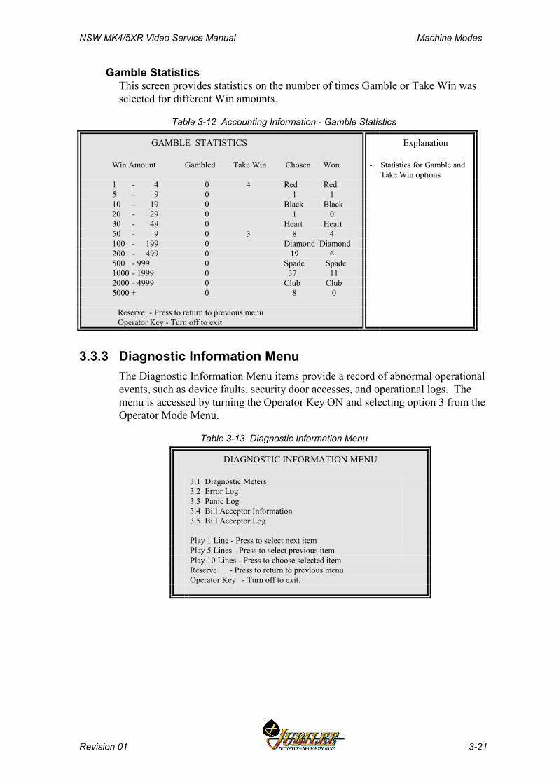
NSW MK4/5XR Video Service Manual Machine Modes
Revision 01 3-21
Gamble StatisticsThis screen provides statistics on the number of times Gamble or Take Win wasselected for different Win amounts.
Table 3-12 Accounting Information - Gamble Statistics
GAMBLE STATISTICS Explanation
Win Amount Gambled Take Win Chosen Won - Statistics for Gamble andTake Win options
1 - 4 0 4 Red Red5 - 9 0 1 110 - 19 0 Black Black20 - 29 0 1 030 - 49 0 Heart Heart50 - 9 0 3 8 4100 - 199 0 Diamond Diamond200 - 499 0 19 6500 - 999 0 Spade Spade1000 - 1999 0 37 112000 - 4999 0 Club Club5000 + 0 8 0
Reserve: - Press to return to previous menuOperator Key - Turn off to exit
3.3.3 Diagnostic Information MenuThe Diagnostic Information Menu items provide a record of abnormal operationalevents, such as device faults, security door accesses, and operational logs. Themenu is accessed by turning the Operator Key ON and selecting option 3 from theOperator Mode Menu.
Table 3-13 Diagnostic Information Menu
DIAGNOSTIC INFORMATION MENU
3.1 Diagnostic Meters3.2 Error Log3.3 Panic Log3.4 Bill Acceptor Information3.5 Bill Acceptor Log
Play 1 Line - Press to select next itemPlay 5 Lines - Press to select previous itemPlay 10 Lines - Press to choose selected itemReserve - Press to return to previous menuOperator Key - Turn off to exit.
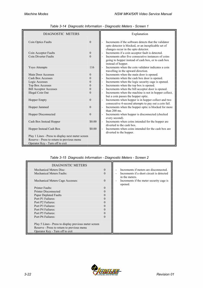
Machine Modes NSW MK4/5XR Video Service Manual
3-22 Revision 01
Table 3-14 Diagnostic Information - Diagnostic Meters - Screen 1
DIAGNOSTIC METERS Explanation
Coin Optics Faults 0 - Increments if the software detects that the validatoropto detector is blocked, or an inexplicable set ofchanges occur in the opto detector.
Coin Acceptor Faults 0 - Increments if a coin acceptor fault is detected.Coin Diverter Faults 0 - Increments after five consecutive instances of coins
going to hopper instead of cash box, or to cash boxinstead of hopper.
Yoyo Attempts 116 - Increments when the coin validator indicates a cointravelling in the upward direction.
Main Door Accesses 0 - Increments when the main door is opened.Cash Box Accesses 0 - Increments when the cash box door is opened.Logic Accesses 0 - Increments when the logic security cage is opened.Top Box Accesses 0 - Increments when the top box is opened.Bill Acceptor Accesses 0 - Increments when the bill acceptor door is opened.Illegal Coin Out 0 - Increments when the machine is not in hopper collect,
but a coin passes the hopper optic.Hopper Empty 0 - Increments when hopper is in hopper collect and two
consecutive 4-second attempts to pay out a coin fail.Hopper Jammed 0 - Increments when the hopper optic is blocked for more
than 200 ms.Hopper Disconnected 0 - Increments when hopper is disconnected (checked
every second).Cash Box Instead Hopper $0.00 - Increments when coins intended for the hopper are
diverted to the cash box.Hopper Instead Cash Box $0.00 - Increments when coins intended for the cash box are
diverted to the hopper.Play 1 Lines - Press to display next meter screenReserve - Press to return to previous menuOperator Key - Turn off to exit
Table 3-15 Diagnostic Information - Diagnostic Meters - Screen 2
DIAGNOSTIC METERSMechanical Meters Disc: 0 - Increments if meters are disconnected.Mechanical Meters Faults: 0 - Increments if a short circuit is detected
in the meters.Mechanical Meters Cage Accesses: 0 - Increments if the meter security cage is
opened.Printer Faults: 0Printer Disconnected 0Paper Deplated Faults 0Port P1 Failures: 0Port P2 Failures: 0Port P3 Failures: 0Port P4 Failures: 0Port P5 Failures: 0Port P6 Failures: 0
Play 5 Lines - Press to display previous meter screenReserve - Press to return to previous menuOperator Key - Turn off to exit
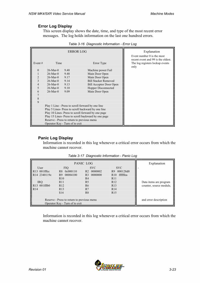
NSW MK4/5XR Video Service Manual Machine Modes
Revision 01 3-23
Error Log DisplayThis screen display shows the date, time, and type of the most recent errormessages. The log holds information on the last one hundred errors.
Table 3-16 Diagnostic Information - Error Log
ERROR LOG ExplanationEvent number 0 is the mostrecent event and 99 is the oldest.
Event # Time Error Type The log registers lockup eventsonly
0 26-Mar-0 9.48 Machine power Fail1 26-Mar-0 9.48 Main Door Open2 26-Mar-0 9.17 Main Door Open3 26-Mar-0 9.14 Bill Stacker Removed4 26-Mar-0 9.13 Bill Acceptor Door Open5 26-Mar-0 9.10 Hopper Disconnected6 26-Mar-0 9.09 Main Door Open789
Play 1 Line - Press to scroll forward by one linePlay 5 Lines- Press to scroll backward by one linePlay 10 Lines- Press to scroll forward by one pagePlay 15 Lines- Press to scroll backward by one pageReserve - Press to return to previous menuOperator Key - Turn of to exit
Panic Log DisplayInformation is recorded in this log whenever a critical error occurs from which themachine cannot recover.
Table 3-17 Diagnostic Information - Panic Log
PANIC LOG Explanation User FIQ SVC SVC -R13 001fffec R8 0c000110 R2 0000002 R9 000128d0R14 2340119c R9 00084100 R3 0000000 R10 ffffffea
R10 R4 R11 IRQ R11 R5 R12 Data items are programR13 001fffb0 R12 R6 R13 counter, source module,R14 R13 R7 R14
$14 R8 R15
and error descriptionReserve - Press to return to previous menuOperator Key - Turn of to exit
Information is recorded in this log whenever a critical error occurs from which themachine cannot recover.

Machine Modes NSW MK4/5XR Video Service Manual
3-24 Revision 01
Bank Note Acceptor InformationThis screen provides a record of the number of notes of each denominationreceived, the last five notes accepted, and the total value of notes received.
Table 3-18 Diagnostic Information - Bill Acceptor Information
BILL ACCEPTOR INFORMATION Explanation
Number of Notes Received - Information on notes input.
$ 1 Notes Received:$ 5 Notes Received: 7$ 10 Notes Received: 60$ 20 Notes Received:$ 50 Notes Received: 10$ 100 Notes Received:
TOTAL VALUE OF NOTES RECEIVED $713.50TOTAL NUMBER OF NOTES RECEIVED 77
LAST FIVE NOTES RECEIVEDLast: $5Second Last: $10Third Last: $10Fourth Last: $50Fifth Last: $50
Reserve - Press to return to previous menu Operator Key - Turn off to exit
3.3.4 Self Test ModeSelf Test Mode addresses the repair and maintenance tasks for the MVP machine.The items on the Self Test Mode Menu are designed to test various machinecomponents and features
This mode can only be accessed when player credits are zero, the main door isopen, and no other lockups are active.
The Self Test Mode Menu is accessed by first opening the main door, turning theOperator Key ON, and selecting option 4 from the Operator Mode Menu.
Table 3-19 Self Test Mode Menu
SELF TEST MODE MENU
4.1 Lamp Test 4.5 Sound Effect Test4.2 Coin Entry Test 4.6 Factory Test4.3 Hopper Test 4.7 Combination Test4.4 Monitor Test
Play 1 Line - Press to select next itemPlay 5 Lines - Press to select previous itemPlay 10 Lines - Press to choose selected itemReserve - Press to return to previous menu

NSW MK4/5XR Video Service Manual Machine Modes
Revision 01 3-25
Table 3-20 Self Test Mode Requirements
SELF TEST MODE
Entry to this mode is not permitted unless:
(a) Credit is zero(b) Main door is open(c) No other lockups active
Reserve - Press to return to previous menuOperator Key - Turn off to exit
Lamp TestThis screen allows the operator to test the pushbutton lamps, animation lamps andlight tower lamps. The state of individual lamps can be set to either on, off,flashing slow, or flashing fast. The operator can then observe the lamps to verifycorrect operation.
Table 3-21 Self Test Mode - Lamp Test
LAMP TEST Explanation- Tests lamps
Light TowerLamp #
AnimationLamp #
Player KeyLamp #
1 2 3 4 1 9 1 9 All
Win LineLamp #
2 10 3 11
2 10 3 11
1 2 3 4 5 4 12 4 12 5 13 5 13
Play LineLamp #
6 14 7 15
6 14 7 15
1 2 3 4 5 8 16 8 16
Current Function: ON OFF FLASH SLOW FLASH FAST
Play 1 Line - Press to select next lamp Play 5 Lines - Press to select previous lamp Play 15 Lines – Press to select function (on/off/flash)
Service- Press to return to previous menu
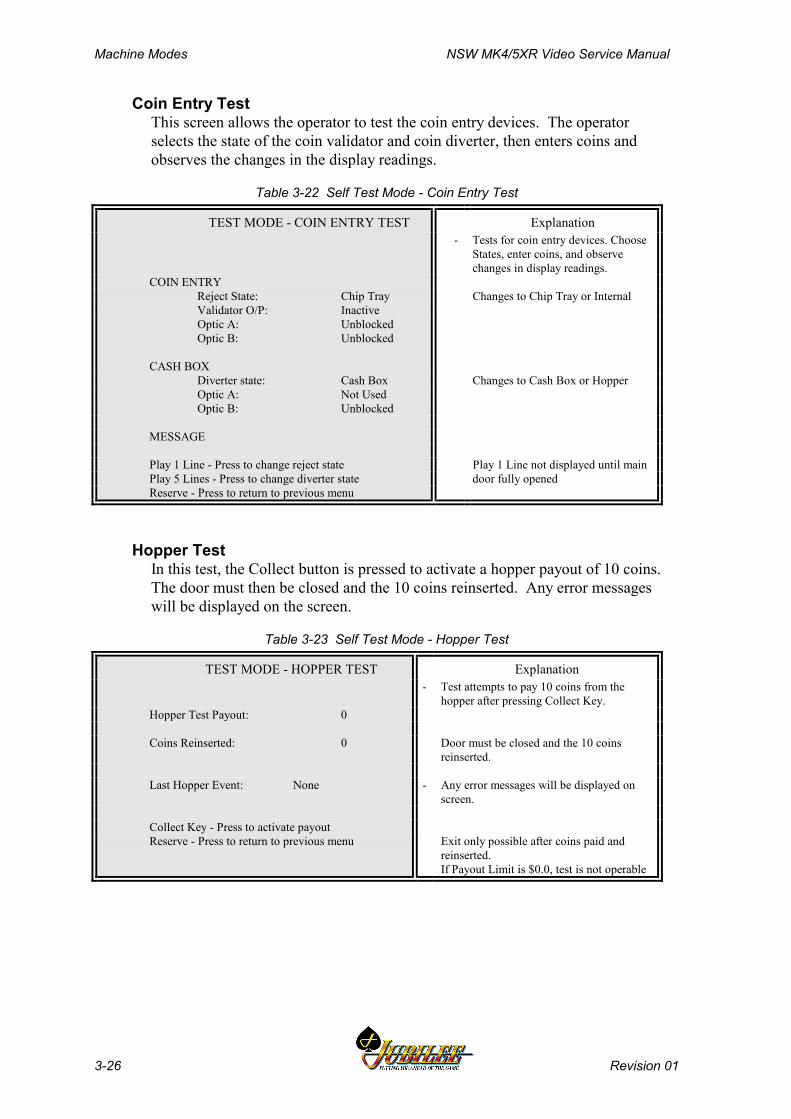
Machine Modes NSW MK4/5XR Video Service Manual
3-26 Revision 01
Coin Entry TestThis screen allows the operator to test the coin entry devices. The operatorselects the state of the coin validator and coin diverter, then enters coins andobserves the changes in the display readings.
Table 3-22 Self Test Mode - Coin Entry Test
TEST MODE - COIN ENTRY TEST Explanation- Tests for coin entry devices. Choose
States, enter coins, and observechanges in display readings.
COIN ENTRYReject State: Chip Tray Changes to Chip Tray or InternalValidator O/P: InactiveOptic A: UnblockedOptic B: Unblocked
CASH BOXDiverter state: Cash Box Changes to Cash Box or HopperOptic A: Not UsedOptic B: Unblocked
MESSAGE
Play 1 Line - Press to change reject state Play 1 Line not displayed until mainPlay 5 Lines - Press to change diverter state door fully openedReserve - Press to return to previous menu
Hopper TestIn this test, the Collect button is pressed to activate a hopper payout of 10 coins.The door must then be closed and the 10 coins reinserted. Any error messageswill be displayed on the screen.
Table 3-23 Self Test Mode - Hopper Test
TEST MODE - HOPPER TEST Explanation- Test attempts to pay 10 coins from the
hopper after pressing Collect Key.Hopper Test Payout: 0
Coins Reinserted: 0 Door must be closed and the 10 coinsreinserted.
Last Hopper Event: None - Any error messages will be displayed onscreen.
Collect Key - Press to activate payoutReserve - Press to return to previous menu Exit only possible after coins paid and
reinserted.If Payout Limit is $0.0, test is not operable
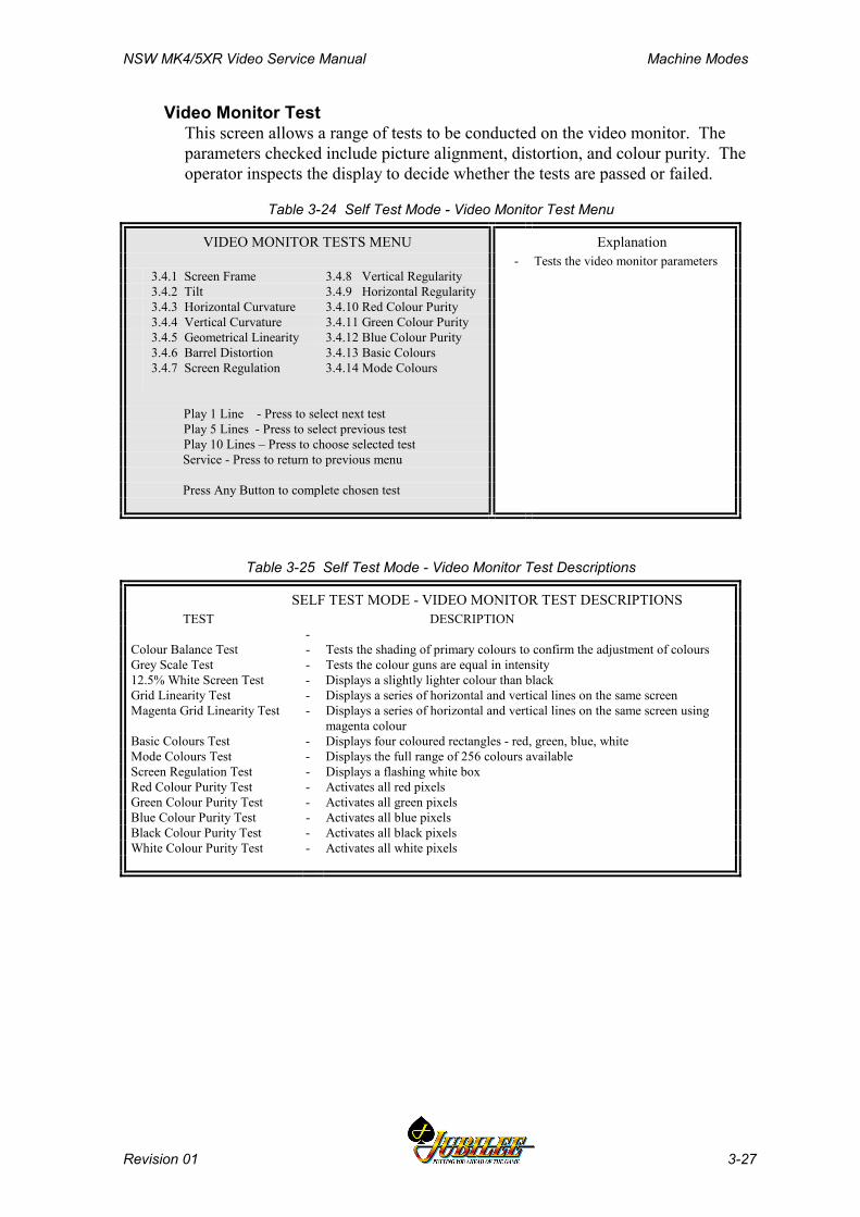
NSW MK4/5XR Video Service Manual Machine Modes
Revision 01 3-27
Video Monitor TestThis screen allows a range of tests to be conducted on the video monitor. Theparameters checked include picture alignment, distortion, and colour purity. Theoperator inspects the display to decide whether the tests are passed or failed.
Table 3-24 Self Test Mode - Video Monitor Test Menu
VIDEO MONITOR TESTS MENU Explanation- Tests the video monitor parameters
3.4.1 Screen Frame 3.4.8 Vertical Regularity3.4.2 Tilt 3.4.9 Horizontal Regularity3.4.3 Horizontal Curvature 3.4.10 Red Colour Purity3.4.4 Vertical Curvature 3.4.11 Green Colour Purity3.4.5 Geometrical Linearity 3.4.12 Blue Colour Purity3.4.6 Barrel Distortion 3.4.13 Basic Colours3.4.7 Screen Regulation 3.4.14 Mode Colours
Play 1 Line - Press to select next test Play 5 Lines - Press to select previous test Play 10 Lines – Press to choose selected test
Service - Press to return to previous menu
Press Any Button to complete chosen test
Table 3-25 Self Test Mode - Video Monitor Test Descriptions
SELF TEST MODE - VIDEO MONITOR TEST DESCRIPTIONSTEST DESCRIPTION
-Colour Balance Test - Tests the shading of primary colours to confirm the adjustment of coloursGrey Scale Test - Tests the colour guns are equal in intensity12.5% White Screen Test - Displays a slightly lighter colour than blackGrid Linearity Test - Displays a series of horizontal and vertical lines on the same screenMagenta Grid Linearity Test - Displays a series of horizontal and vertical lines on the same screen using
magenta colourBasic Colours Test - Displays four coloured rectangles - red, green, blue, whiteMode Colours Test - Displays the full range of 256 colours availableScreen Regulation Test - Displays a flashing white boxRed Colour Purity Test - Activates all red pixelsGreen Colour Purity Test - Activates all green pixelsBlue Colour Purity Test - Activates all blue pixelsBlack Colour Purity Test - Activates all black pixelsWhite Colour Purity Test - Activates all white pixels
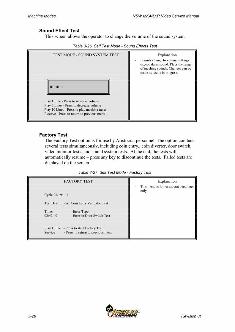
Machine Modes NSW MK4/5XR Video Service Manual
3-28 Revision 01
Sound Effect TestThis screen allows the operator to change the volume of the sound system.
Table 3-26 Self Test Mode - Sound Effects Test
TEST MODE - SOUND SYSTEM TEST Explanation- Permits change to volume settings
except alarm sound. Plays the rangeof machine sounds. Changes can bemade as test is in progress.
IIIIIIIIIII
Play 1 Line - Press to increase volumePlay 5 Lines - Press to decrease volumePlay 10 Lines - Press to play machine tunesReserve - Press to return to previous menu
Factory TestThe Factory Test option is for use by Aristocrat personnel The option conductsseveral tests simultaneously, including coin entry,, coin diverter, door switch,video monitor tests, and sound system tests. At the end, the tests willautomatically resume – press any key to discontinue the tests. Failed tests aredisplayed on the screen.
Table 3-27 Self Test Mode - Factory Test
FACTORY TEST Explanation- This menu is for Aristocrat personnel
onlyCycle Count: 1
Test Description: Coin Entry Validator Test
Time: Error Type:02:42:49 Error in Door Switch Test
Play 1 Line - Press to start Factory TestService - Press to return to previous menu
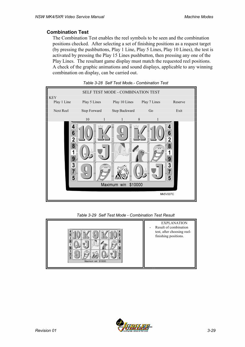
NSW MK4/5XR Video Service Manual Machine Modes
Revision 01 3-29
Combination TestThe Combination Test enables the reel symbols to be seen and the combinationpositions checked. After selecting a set of finishing positions as a request target(by pressing the pushbuttons, Play 1 Line, Play 5 Lines, Play 10 Lines), the test isactivated by pressing the Play 15 Lines pushbutton, then pressing any one of thePlay Lines. The resultant game display must match the requested reel positions.A check of the graphic animations and sound displays, applicable to any winningcombination on display, can be carried out.
Table 3-28 Self Test Mode.- Combination Test
SELF TEST MODE - COMBINATION TESTKEY Play 1 Line Play 5 Lines Play 10 Lines Play 7 Lines Reserve
Next Reel Step Forward Step Backward Go Exit
10 1 1 8 1
Table 3-29 Self Test Mode - Combination Test Result
-EXPLANATION
Result of combinationtest, after choosing reel-finishing positions.
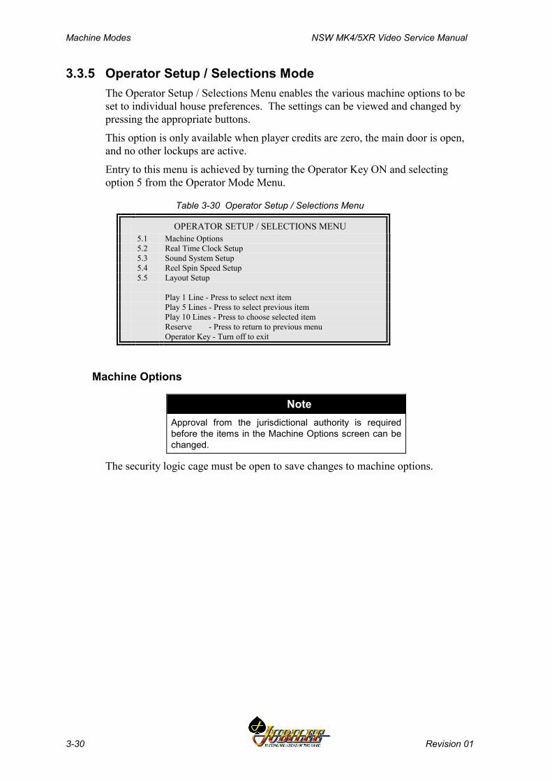
Machine Modes NSW MK4/5XR Video Service Manual
3-30 Revision 01
3.3.5 Operator Setup / Selections ModeThe Operator Setup / Selections Menu enables the various machine options to beset to individual house preferences. The settings can be viewed and changed bypressing the appropriate buttons.
This option is only available when player credits are zero, the main door is open,and no other lockups are active.
Entry to this menu is achieved by turning the Operator Key ON and selectingoption 5 from the Operator Mode Menu.
Table 3-30 Operator Setup / Selections Menu
OPERATOR SETUP / SELECTIONS MENU5.1 Machine Options5.2 Real Time Clock Setup5.3 Sound System Setup5.4 Reel Spin Speed Setup5.5 Layout Setup
Play 1 Line - Press to select next itemPlay 5 Lines - Press to select previous itemPlay 10 Lines - Press to choose selected itemReserve - Press to return to previous menuOperator Key - Turn off to exit
Machine Options
NoteApproval from the jurisdictional authority is requiredbefore the items in the Machine Options screen can bechanged.
The security logic cage must be open to save changes to machine options.
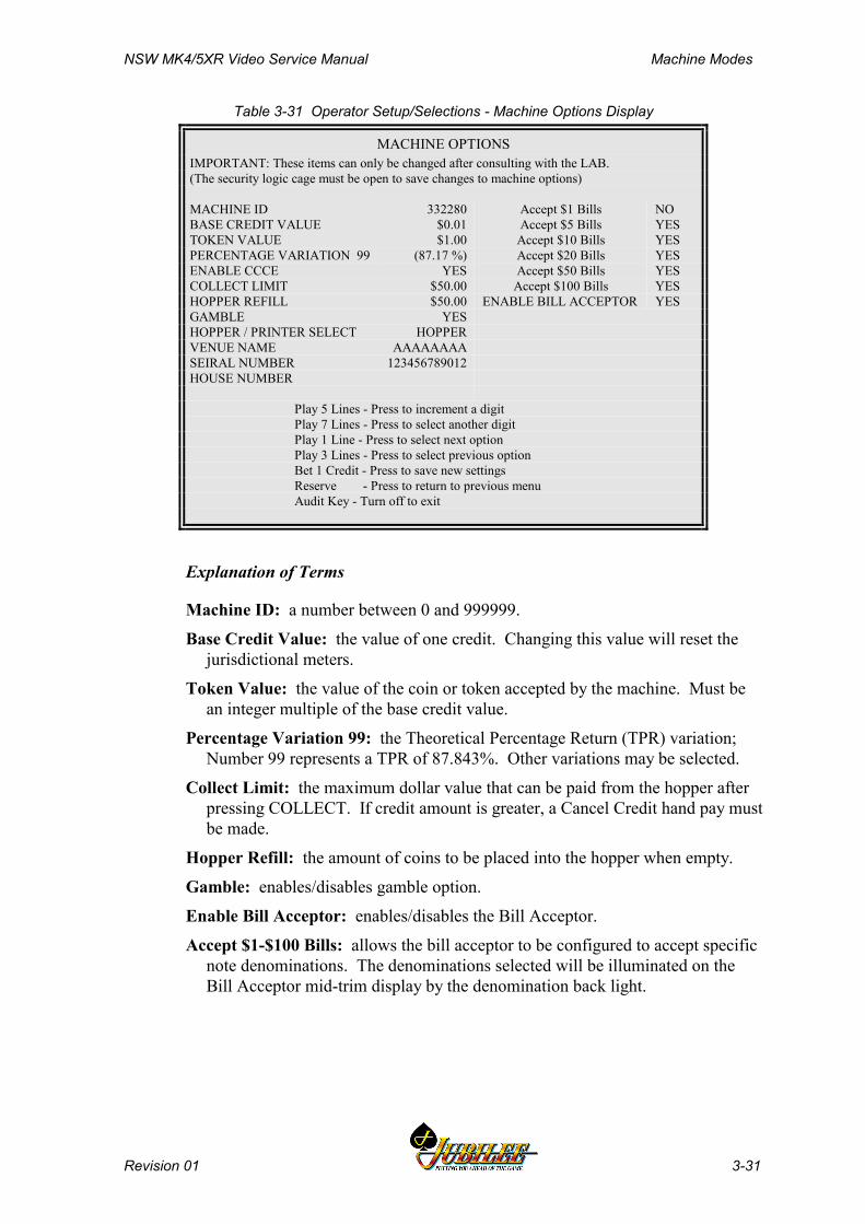
NSW MK4/5XR Video Service Manual Machine Modes
Revision 01 3-31
Table 3-31 Operator Setup/Selections - Machine Options Display
MACHINE OPTIONSIMPORTANT: These items can only be changed after consulting with the LAB.(The security logic cage must be open to save changes to machine options)
MACHINE ID 332280 Accept $1 Bills NOBASE CREDIT VALUE $0.01 Accept $5 Bills YESTOKEN VALUE $1.00 Accept $10 Bills YESPERCENTAGE VARIATION 99 (87.17 %) Accept $20 Bills YESENABLE CCCE YES Accept $50 Bills YESCOLLECT LIMIT $50.00 Accept $100 Bills YESHOPPER REFILL $50.00 ENABLE BILL ACCEPTOR YESGAMBLE YESHOPPER / PRINTER SELECT HOPPERVENUE NAME AAAAAAAASEIRAL NUMBER 123456789012HOUSE NUMBER
Play 5 Lines - Press to increment a digitPlay 7 Lines - Press to select another digitPlay 1 Line - Press to select next optionPlay 3 Lines - Press to select previous optionBet 1 Credit - Press to save new settingsReserve - Press to return to previous menuAudit Key - Turn off to exit
Explanation of Terms
Machine ID: a number between 0 and 999999.
Base Credit Value: the value of one credit. Changing this value will reset thejurisdictional meters.
Token Value: the value of the coin or token accepted by the machine. Must bean integer multiple of the base credit value.
Percentage Variation 99: the Theoretical Percentage Return (TPR) variation;Number 99 represents a TPR of 87.843%. Other variations may be selected.
Collect Limit: the maximum dollar value that can be paid from the hopper afterpressing COLLECT. If credit amount is greater, a Cancel Credit hand pay mustbe made.
Hopper Refill: the amount of coins to be placed into the hopper when empty.
Gamble: enables/disables gamble option.
Enable Bill Acceptor: enables/disables the Bill Acceptor.
Accept $1-$100 Bills: allows the bill acceptor to be configured to accept specificnote denominations. The denominations selected will be illuminated on theBill Acceptor mid-trim display by the denomination back light.

Machine Modes NSW MK4/5XR Video Service Manual
3-32 Revision 01
Real Time Clock SetupThis screen allows the real time clock to be set.
Table 3-32 Operator Setup/Selections - Real Time Clock Setup
REAL TIME CLOCK SETUP Explanation- Sets time and date.
SECOND: 06MINUTE: 38HOUR: 13
DATE: 02MONTH : MARCHYEAR: 2000
Play 1 Line - Press to choose next itemPlay 5 Lines - Press to choose previous itemPlay 10 Lines - Press to increase item valuePlay 15 Lines - Press to decrease item valueReserve - Press to return to previous menuOperator Key - Turn off to exit
Sound System SetupThis screen allows the sound volume to be set.
Table 3-33 Operator Setup/Selections - Sound System Setup
SOUND SYSTEM SETUP Explanation- Sets sound volume.
Default level is low.
IIIIIIIIIIIIII
Play 1 Line - Press to increase volume itemPlay 5 Lines - Press to decrease volume itemPlay 10 Lines - Press to play machine tunesReserve - Press to return to previous menuOperator Key - Turn off to exit
Reel Spin Speed SetupThis option enables operators to select either Fast or Slow reel spin speed.
Table 3-34 Operator Setup/Selections - Reel Spin Speed Setup
REEL SPIN SPEED SETUP Explanation-
SPEED : FAST Alters the reel spin speedbetween fast and low
Play 10 Lines - Press to select reel speedReserve - Press to return to previous menuOperator Key - Turn off to exit
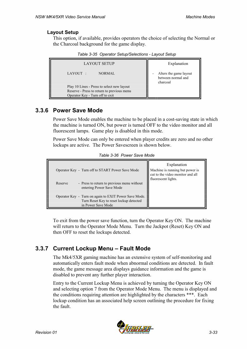
NSW MK4/5XR Video Service Manual Machine Modes
Revision 01 3-33
Layout SetupThis option, if available, provides operators the choice of selecting the Normal orthe Charcoal background for the game display.
Table 3-35 Operator Setup/Selections - Layout Setup
LAYOUT SETUP Explanation
LAYOUT : NORMAL - Alters the game layoutbetween normal andcharcoal
Play 10 Lines - Press to select new layoutReserve - Press to return to previous menuOperator Key - Turn off to exit
3.3.6 Power Save ModePower Save Mode enables the machine to be placed in a cost-saving state in whichthe machine is turned ON, but power is turned OFF to the video monitor and allfluorescent lamps. Game play is disabled in this mode.
Power Save Mode can only be entered when player credits are zero and no otherlockups are active. The Power Savescreen is shown below.
Table 3-36 Power Save Mode
ExplanationOperator Key - Turn off to START Power Save Mode Machine is running but power is
cut to the video monitor and allfluorescent lights.
Reserve - Press to return to previous menu without entering Power Save Mode
Operator Key - Turn on again to EXIT Power Save Mode. Turn Reset Key to reset lockup detected in Power Save Mode
To exit from the power save function, turn the Operator Key ON. The machinewill return to the Operator Mode Menu. Turn the Jackpot (Reset) Key ON andthen OFF to reset the lockups detected.
3.3.7 Current Lockup Menu – Fault ModeThe Mk4/5XR gaming machine has an extensive system of self-monitoring andautomatically enters fault mode when abnormal conditions are detected. In faultmode, the game message area displays guidance information and the game isdisabled to prevent any further player interaction.
Entry to the Current Lockup Menu is achieved by turning the Operator Key ONand selecting option 7 from the Operator Mode Menu. The menu is displayed andthe conditions requiring attention are highlighted by the characters ***. Eachlockup condition has an associated help screen outlining the procedure for fixingthe fault.
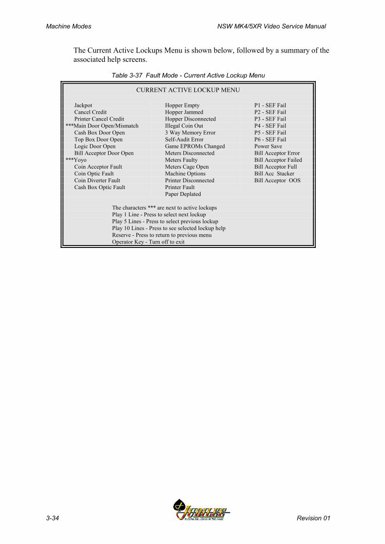
Machine Modes NSW MK4/5XR Video Service Manual
3-34 Revision 01
The Current Active Lockups Menu is shown below, followed by a summary of theassociated help screens.
Table 3-37 Fault Mode - Current Active Lockup Menu
CURRENT ACTIVE LOCKUP MENU
Jackpot Hopper Empty P1 - SEF Fail Cancel Credit Hopper Jammed P2 - SEF Fail Printer Cancel Credit Hopper Disconnected P3 - SEF Fail***Main Door Open/Mismatch Illegal Coin Out P4 - SEF Fail Cash Box Door Open 3 Way Memory Error P5 - SEF Fail Top Box Door Open Self-Audit Error P6 - SEF Fail Logic Door Open Game EPROMs Changed Power Save Bill Acceptor Door Open Meters Disconnected Bill Acceptor Error***Yoyo Meters Faulty Bill Acceptor Failed Coin Acceptor Fault Meters Cage Open Bill Acceptor Full Coin Optic Fault Machine Options Bill Acc Stacker Coin Diverter Fault Printer Disconnected Bill Acceptor OOS Cash Box Optic Fault Printer Fault
Paper Deplated
The characters *** are next to active lockupsPlay 1 Line - Press to select next lockupPlay 5 Lines - Press to select previous lockupPlay 10 Lines - Press to see selected lockup helpReserve - Press to return to previous menuOperator Key - Turn off to exit
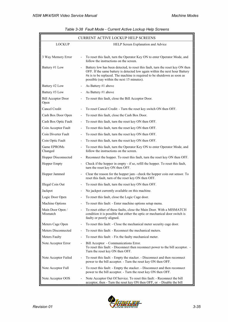
NSW MK4/5XR Video Service Manual Machine Modes
Revision 01 3-35
Table 3-38 Fault Mode - Current Active Lockup Help Screens
CURRENT ACTIVE LOCKUP HELP SCREENSLOCKUP HELP Screen Explanation and Advice
3 Way Memory Error - To reset this fault, turn the Operator Key ON to enter Operator Mode, andfollow the instructions on the screen.
Battery #1 Low - Battery low has been detected, to reset this fault, turn the reset key ON thenOFF. If the same battery is detected low again within the next hour Battery#n is to be replaced. The machine is required to be shutdown as soon aspossible (say within the next 15 minutes).
Battery #2 Low - As Battery #1 above
Battery #3 Low - As Battery #1 above
Bill Acceptor DoorOpen
- To reset this fault, close the Bill Acceptor Door.
Cancel Credit - To reset Cancel Credit: - Turn the reset key switch ON then OFF.
Cash Box Door Open - To reset this fault, close the Cash Box Door.
Cash Box Optic Fault - To reset this fault, turn the reset key ON then OFF.
Coin Acceptor Fault - To reset this fault, turn the reset key ON then OFF.
Coin Diverter Fault - To reset this fault, turn the reset key ON then OFF.
Coin Optic Fault - To reset this fault, turn the reset key ON then OFF.
Game EPROMsChanged
- To reset this fault, turn the Operator Key ON to enter Operator Mode, andfollow the instructions on the screen.
Hopper Disconnected - Reconnect the hopper. To reset this fault, turn the reset key ON then OFF.
Hopper Empty - Check if the hopper in empty - if so, refill the hopper. To reset this fault,turn the reset key ON then OFF.
Hopper Jammed - Clear the reason for the hopper jam - check the hopper coin out sensor. Toreset this fault, turn of the reset key ON then OFF.
Illegal Coin Out - To reset this fault, turn the reset key ON then OFF.
Jackpot - No jackpot currently available on this machine.
Logic Door Open - To reset this fault, close the Logic Cage door.
Machine Options - To reset this fault: - Enter machine options setup menu.
Main Door Open /Mismatch
- To reset either of these faults, close the Main Door. With a MISMATCHcondition it is possible that either the optic or mechanical door switch isfaulty or poorly aligned.
Meters Cage Open - To reset this fault: - Close the mechanical meter security cage door.
Meters Disconnected - To reset this fault: - Reconnect the mechanical meters.
Meters Faulty - To reset this fault: - Fix the faulty mechanical meter.
Note Acceptor Error - Bill Acceptor - Communications Error.To reset this fault: - Disconnect then reconnect power to the bill acceptor. -Turn the reset key ON then OFF.
Note Acceptor Failed - To reset this fault: - Empty the stacker. - Disconnect and then reconnectpower to the bill acceptor. - Turn the reset key ON then OFF.
Note Acceptor Full - To reset this fault: - Empty the stacker. - Disconnect and then reconnectpower to the bill acceptor. - Turn the reset key ON then OFF.
Note Acceptor OOS - Note Acceptor Out Of Service. To reset this fault: - Reconnect the billacceptor, then - Turn the reset key ON then OFF, or - Disable the bill
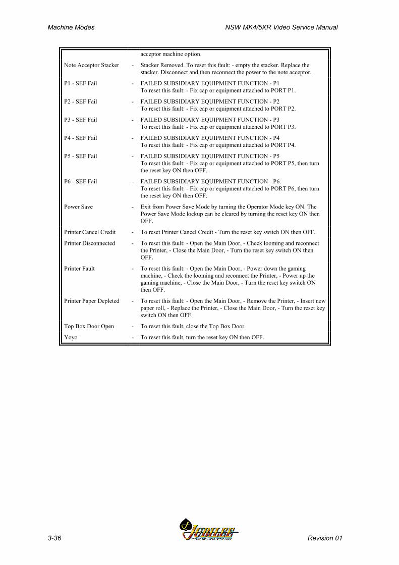
Machine Modes NSW MK4/5XR Video Service Manual
3-36 Revision 01
acceptor machine option.
Note Acceptor Stacker - Stacker Removed. To reset this fault: - empty the stacker. Replace thestacker. Disconnect and then reconnect the power to the note acceptor.
P1 - SEF Fail - FAILED SUBSIDIARY EQUIPMENT FUNCTION - P1To reset this fault: - Fix cap or equipment attached to PORT P1.
P2 - SEF Fail - FAILED SUBSIDIARY EQUIPMENT FUNCTION - P2To reset this fault: - Fix cap or equipment attached to PORT P2.
P3 - SEF Fail - FAILED SUBSIDIARY EQUIPMENT FUNCTION - P3To reset this fault: - Fix cap or equipment attached to PORT P3.
P4 - SEF Fail - FAILED SUBSIDIARY EQUIPMENT FUNCTION - P4To reset this fault: - Fix cap or equipment attached to PORT P4.
P5 - SEF Fail - FAILED SUBSIDIARY EQUIPMENT FUNCTION - P5To reset this fault: - Fix cap or equipment attached to PORT P5, then turnthe reset key ON then OFF.
P6 - SEF Fail - FAILED SUBSIDIARY EQUIPMENT FUNCTION - P6.To reset this fault: - Fix cap or equipment attached to PORT P6, then turnthe reset key ON then OFF.
Power Save - Exit from Power Save Mode by turning the Operator Mode key ON. ThePower Save Mode lockup can be cleared by turning the reset key ON thenOFF.
Printer Cancel Credit - To reset Printer Cancel Credit - Turn the reset key switch ON then OFF.
Printer Disconnected - To reset this fault: - Open the Main Door, - Check looming and reconnectthe Printer, - Close the Main Door, - Turn the reset key switch ON thenOFF.
Printer Fault - To reset this fault: - Open the Main Door, - Power down the gamingmachine, - Check the looming and reconnect the Printer, - Power up thegaming machine, - Close the Main Door, - Turn the reset key switch ONthen OFF.
Printer Paper Depleted - To reset this fault: - Open the Main Door, - Remove the Printer, - Insert newpaper roll, - Replace the Printer, - Close the Main Door, - Turn the reset keyswitch ON then OFF.
Top Box Door Open - To reset this fault, close the Top Box Door.
Yoyo - To reset this fault, turn the reset key ON then OFF.
NSW MK4/5XR Video Service Manual Cabinet, Door and Top Box
Revision 01 4-1
________Chapter 4________
Cabinet, Door and Top Box
4.1 General Description.......................................................................... 4-3
4.2 Technical Description ...................................................................... 4-5
4.2.1 Cabinet Door .............................................................................. 4-54.2.2 Latch Bar.................................................................................... 4-54.2.3 Keyed Lock ................................................................................ 4-74.2.4 Cabinet Security......................................................................... 4-74.2.5 Key Switches.............................................................................. 4-94.2.6 Bilock Locks ............................................................................. 4-104.2.7 Cash Box and Chute ................................................................ 4-114.2.8 Logic Cage ............................................................................... 4-114.2.9 Game Display Shelf ................................................................. 4-124.2.10 Cabinet Door Fluorescent Lighting........................................... 4-124.2.11 Cabinet Door Artwork ............................................................... 4-134.2.12 Mid Trim Panel ......................................................................... 4-144.2.13 Playbuttons .............................................................................. 4-144.2.14 Top Trim Panel......................................................................... 4-174.2.15 Monitor Mask............................................................................ 4-184.2.16 Coin Tray.................................................................................. 4-194.2.17 Belly Panel Door....................................................................... 4-194.2.18 Belly Panel Security ................................................................. 4-204.2.19 Top Box.................................................................................... 4-204.2.20 Top Box Artwork....................................................................... 4-204.2.21 Top Box Fluorescent Lighting................................................... 4-20
4.3 General Maintenance...................................................................... 4-23

Cabinet, Door And Top Box NSW MK4/5XR Video Service Manual
4-2 Revision 01
List of FiguresFigure 4-1 Cabinet and Cabinet Door - General Description................................................ 4-4Figure 4-2 Latch Bar............................................................................................................. 4-6Figure 4-3 Keyed Lock Assembly......................................................................................... 4-7Figure 4-4 Photo-optic Emitter Adjustment ........................................................................... 4-8Figure 4-5 Key Switches: Removal and Replacement ....................................................... 4-10Figure 4-6 Bilock "U" Shaped Keyway and Quick Change Core Features......................... 4-10Figure 4-7 Play Button Lamps ............................................................................................ 4-15Figure 4-8 Playbutton - Exploded View .............................................................................. 4-17Figure 4-9 Top Trim Panel and Monitor Mask................................................................... 4-18Figure 4-10 Top Box...........................................................................................................4-21

NSW MK4/5XR Video Service Manual Cabinet, Door and Top Box
Revision 01 4-3
4.1 General DescriptionThe gaming machine cabinet, cabinet door, and top box are of welded sheet steelconstruction, providing a strong and secure housing for the machine components.The cabinet door features a triple-latch locking mechanism. Security switchesmay be fitted to the cabinet door, the top box, and other components.
The major assemblies within the machine are detailed in separate chapters of thismanual.
The components covered in this chapter are as follows:
• cabinet door• latch bar• key switches• cabinet door security• cash box chute• logic cage• game display shelf• cabinet door fluorescent lighting• mid-trim, coin entry and playbuttons• cabinet door artwork• monitor mask• coin tray• top box door• top box fluorescent lighting and reflector• top box door artwork• top box security
Figure 4-1 shows the major components of the machine.
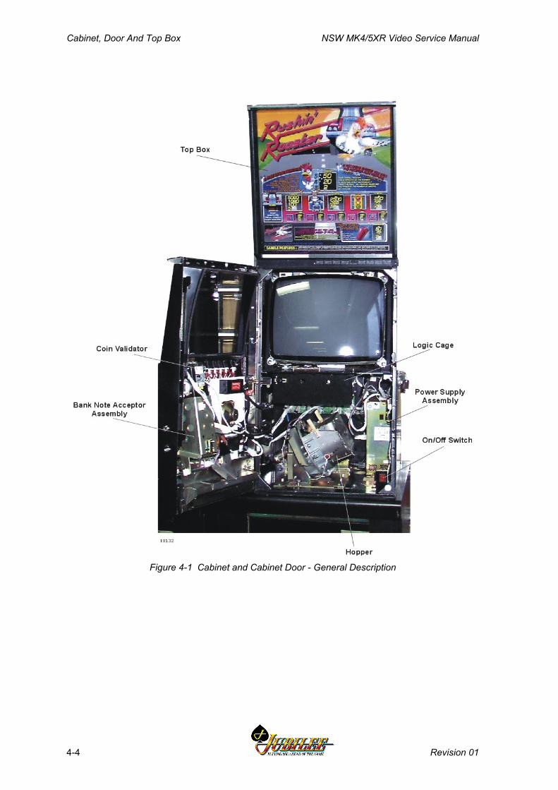
Cabinet, Door And Top Box NSW MK4/5XR Video Service Manual
4-4 Revision 01
Figure 4-1 Cabinet and Cabinet Door - General Description
NSW MK4/5XR Video Service Manual Cabinet, Door and Top Box
Revision 01 4-5
4.2 Technical DescriptionThe following sections describe the function and operation of the individualmachine components. Procedures are outlined for adjusting, removing andreplacing, and assembling and dissassembling components.
4.2.1 Cabinet DoorThe cabinet door is fabricated from sheet steel. Mountings are provided in thedoor for the lighting system, the coin handling system, the bank note acceptorassembly, the coin tray, the speaker, and other devices. A belly panel is attachedto the main door which allows independent access to the bank note stacker.
The door is mounted to the cabinet on a full length hinge on the left-hand side ofthe machine. A latch mechanism locates the door on the right-hand side. Thelatch bar is operated by a keyed lock.
Removal and Replacement Procedures:To remove the door:
1. Open the cabinet door, and switch OFF the machine.2. Disconnect all looms between the door and the rest of the machine.3. Remove the nut and bolt securing the door stay.4. Disconnect the earth wire.5. While supporting the weight of the door, remove the nuts securing the hinge
to the cabinet.
CAUTIONThe door is a heavy item; follow the nationalstandard and code of practice for manualhandling.
Replacement is a reversal of the removal procedure.
4.2.2 Latch BarTo ensure that the cabinet door closes properly, the latch bar mounting may beadjusted as follows (see Figure 4-2):
1. Open the cabinet door, and switch OFF the machine.2. Loosen the two lock nuts to allow rotation of the plastic adjustors.3. Rotate the two eccentric plastic adjustors until the door closes correctly.4. Tighten the two lock nuts just enough to hold the adjustors securely.
To remove the latch bar:
1. Open the cabinet door, and switch OFF the machine.2. Remove the bank note acceptor assembly for easy access (refer Bank Note
Acceptor chapter).3. Remove the circlip and bearing from the bearing carrier.
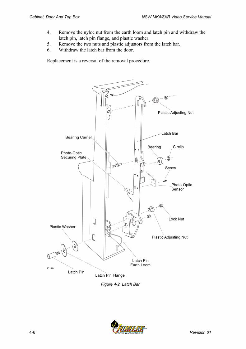
Cabinet, Door And Top Box NSW MK4/5XR Video Service Manual
4-6 Revision 01
4. Remove the nyloc nut from the earth loom and latch pin and withdraw thelatch pin, latch pin flange, and plastic washer.
5. Remove the two nuts and plastic adjustors from the latch bar.6. Withdraw the latch bar from the door.
Replacement is a reversal of the removal procedure.
Latch PinLatch Pin Flange
Plastic Adjusting Nut
Bearing Circlip
Plastic Washer
Lock Nut
Latch BarBearing Carrier
Photo-OpticSecuring Plate
Photo-OpticSensor
Screw
I0110
Plastic Adjusting Nut
Latch PinEarth Loom
Figure 4-2 Latch Bar
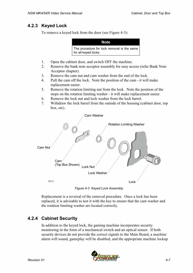
NSW MK4/5XR Video Service Manual Cabinet, Door and Top Box
Revision 01 4-7
4.2.3 Keyed LockTo remove a keyed lock from the door (see Figure 4-3):
NoteThe procedure for lock removal is the samefor all keyed locks.
1. Open the cabinet door, and switch OFF the machine.2. Remove the bank note acceptor assembly for easy access (refer Bank Note
Acceptor chapter).3. Remove the cam nut and cam washer from the end of the lock.4. Pull the cam off the lock. Note the position of the cam - it will make
replacement easier.5. Remove the rotation limiting nut from the lock. Note the position of the
stops on the rotation limiting washer - it will make replacement easier.6. Remove the lock nut and lock washer from the lock barrel.7. Withdraw the lock barrel from the outside of the housing (cabinet door, top
box, etc).
Lock
Lock Washer
Lock Nut
Cam(Top Box Shown)
Cam Nut
Rotation Limiting Washer
Cam Washer
I0111
Figure 4-3 Keyed Lock Assembly
Replacement is a reversal of the removal procedure. Once a lock has beenreplaced, it is advisable to test it with the key to ensure that the cam washer andthe rotation limiting washer are located correctly.
4.2.4 Cabinet SecurityIn addition to the keyed lock, the gaming machine incorporates securitymonitoring in the form of a mechanical switch and an optical sensor. If bothsecurity devices do not provide the correct signals to the Main Board, a machinealarm will sound, gameplay will be disabled, and the appropriate machine lockup

Cabinet, Door And Top Box NSW MK4/5XR Video Service Manual
4-8 Revision 01
message will be displayed on the monitor screen. The security sensors aremonitored by the Main Board when the machine is powered.
The mechanical door switch is mounted on the bottom corner of the cabinet,beside the mains switch box. When the door is properly closed, the switch isactivated and sends a signal to the Main Board indicating that the door is closed.
The optical sensor consists of an emitter and detector. The emitter is mounted to abracket on the right-hand side of the cabinet on a small bracket. The detector ismounted to the latch bar in the cabinet door. When the door is properly closed,the emitter and detector are aligned and a signal is sent to the Main Boardindicating that the door is closed.
Adjustment Procedures:If the door is properly closed and a Door Mismatch - Main message appears,then the optical sensor may require adjustment.
The emitter may be adjusted as follows:
1. Open the cabinet door.2. Loosen the two screws fastening the emitter to the bracket on the right hand
side of the cabinet.3. Move the emitter 1 mm in either direction.4. Tighten the screws fastening the emitter.5. Close the door and see if the Door Mismatch - Main lockup is activated.
If the optical sensor is still misaligned, repeat the above procedure.
Removal and Replacement Procedures:Optical SensorThe optical sensor (see Figure 4-4) may be removed as follows:
1. Open the cabinet door, and switch OFF the machine.2. Unplug the optical switch looms from the Interface Board.3. Remove the two screws and the clamp plate fastening the emitter to the
cabinet.4. Remove the two screws fastening the detector to the latch bar (for easy
access, remove the Bank Note Acceptor (refer to Bank Note Acceptorchapter)).
5. Remove the optical switch and looms from the machine.
Emitter
Screw
Loom
Cabinet
I0035
Figure 4-4 Photo-optic Emitter Adjustment
NSW MK4/5XR Video Service Manual Cabinet, Door and Top Box
Revision 01 4-9
To replace the optical sensor, reverse the above procedure. After replacement ofthe optical sensor, adjust its alignment as previously described.
Mechanical Door SwitchTo remove the mechanical door switch:
1. Open the cabinet door and switch OFF the machine.2. Using a flat-blade screwdriver, prise the mechanical switch from its
location.3. Unplug the switch connectors.
The switch is replaced by firmly pushing it back into position.
4.2.5 Key SwitchesThe Jackpot Reset and Audit key switches are used to access and reset themachine's software. The key switch functions are covered in detail in the chapterMachine Modes.
The key switches are fixed to a common plate mounted to the inside wall of thecabinet. The switches are connected by a loom to the Interface Board whichtransfers the switch signals to the Main Board for processing.
Removal and Replacement Procedures:Removal of the key switches is as follows (see Figure 4-5):
1. Open the cabinet door, and switch OFF the machine.2. Unplug the key-switch loom from the Interface Board.3. Remove the two nuts fastening the assembly to the cabinet wall.4. Remove the key-switch assembly from the cabinet.5. The individual key switches may be removed from the assembly:
a. Unplug or de-solder the loom from the key switch.b. Remove the lock nut and washer from the switch body.c. Pull the switch from the mounting plate.
Replacement is a reversal of the removal procedure.

Cabinet, Door And Top Box NSW MK4/5XR Video Service Manual
4-10 Revision 01
Loom
Nut (2) Washer (2) Mounting PlateCancel Credit(Jackpot) KeySwitch
Audit (Operator)Key Switch
Studs (attachedto cabinet wall)
Lock Nut (2)
Lock Washer (2)
I0036
Figure 4-5 Key Switches: Removal and Replacement
4.2.6 Bilock LocksThe gaming machines may be fitted with high-security Bilock camlocks andswitchlocks with a unique "U" shaped keyway (see Figure 4-6). The locks featurethe Quick Change Core facility whereby the keyed core of the lock is fittedseparate to the lock barrel. Locks may be rekeyed in a matter of seconds withouthaving to dismantle the lock assembly.
To remove a lock assembly, simply unscrew the large nut on the lock barrel andpull out the lock assembly.
Bilock Key Quick Change Core
Figure 4-6 Bilock "U" Shaped Keyway and Quick Change Core Features

NSW MK4/5XR Video Service Manual Cabinet, Door and Top Box
Revision 01 4-11
4.2.7 Cash Box and ChuteWhen the hopper is full, subsequent coins entered into the gaming machine arecollected in the cash box, which is located in the cabinet base. Access to the cashbox is via a locked door that may be monitored by a security switch. Theprocedure for clearing the cash box is controlled by house management. The cashbox is not a servicable item.
Coins enter the cash box via a plastic cash box chute, which is located at thebottom of the cabinet, next to the hopper.
Removal and Replacement Procedures:To remove the cash box chute:
1. Open the cabinet door, and switch OFF the machine.2. Remove the hopper (refer to the Hopper chapter).3. Remove the self-tapping screw securing the chute to the base of the cabinet.4. Pull the chute from the cash box hole in the cabinet base.
4.2.8 Logic CageThe logic cage is a steel enclosure with a hinged door in the front. The cagehouses the machine logic PCBAs. The door of the cage is fitted with a slidinglatch that also allows a security seal to be fitted. The door is fitted with amicroswitch used for signalling the machine software that the logic cage door hasbeen opened. In addition, one or two security key locks may also be fitted to thecage door.
The logic cage sits below the game display shelf. It slots into the shelf at the backand is fastened to it by three screws at the front.
Within the logic cage are brackets and plastic guides for locating the PCBAs. TheInterface Board is mounted to the cabinet at the back of the logic cage. When aPCBA is fitted into the logic cage, it travels along the guides and is aligned withthe corresponding multi-way connector on the Interface Board.
Removal and Replacement Procedures:To remove the logic cage from the cabinet:
1. Open the cabinet door, and switch OFF the machine.2. Remove the hopper from the machine (refer the Hopper chapter).3. Open the logic cage door. The door flips down and is spring loaded to stay
completely open.4. Carefully lever the PCBAs out using the extractors. Standard Electrostatic
Discharge prevention procedures should be followed when removingPCBAs. The PCBAs should be immediately placed into anti-static bags.
5. Disconnect all of the looms from the Interface Board. Make sure theconnectors are labelled to facilitate replacement.
6. Remove the three screws attaching the logic cage to the game display shelf.7. Gently pull the logic cage (and the interface board) from the machine; the
tabs at the back of the cage will disengage from the shelf.
Cabinet, Door And Top Box NSW MK4/5XR Video Service Manual
4-12 Revision 01
Replacement is a reversal of the removal procedure.
Disassembly and Assembly Procedures:To disassemble the logic cage:
1. Remove the logic cage as previously described.2. Remove the screws or nuts securing the individual components.3. The PCB guides are removed by pulling them from their location holes.
Assembly is a reversal of the disassembly procedure. When replacing the cagedoor catch, care should be taken not to overtighten the bolt as this could hinder thesliding action of the catch.
4.2.9 Game Display ShelfThe game display shelf is a pressed sheet metal assembly that provides both astrengthening cross brace to the cabinet structure and an area on which to mountthe video monitor. The logic cage also uses the game display shelf for itsmounting. The shelf is is welded to the inside of the cabinet and cannot beremoved.
4.2.10 Cabinet Door Fluorescent LightingThe cabinet door is equipped with a fluorescent lighting system for illuminatingthe belly panel artwork. Two 6 W fluorescent tubes are mounted on the reflectorpanel in the cabinet door and are accessed via the belly panel door.
NoteFluorescent tubes are 6 W to 7mm.
Each fluorescent tube is powered by an electronic ballast box, located on the doorreflector panel and accessed via the main door. The box is powered by 24 VDCand contains electronic circuitry to regulate tube current and optimise tube startingconditions. It has a connector for the fluoro loom to plug into.
Removal and Replacement Procedures:
WARNINGThe high voltage used to power the lightingsystem is potentially lethal. Ensure that themachine is switched OFF before attemptingto replace fluorescent tubes or ballasts.
NSW MK4/5XR Video Service Manual Cabinet, Door and Top Box
Revision 01 4-13
Fluorescent Tube:
WARNINGWhen the lighting system is working, thefluorescent tube and reflector become veryhot.
To replace a fluorescent tube:
1. Open the cabinet door and switch OFF the machine. Take note of theDanger and Warning guidance and act accordingly.
2. Unclip the fluorescent tube and carefully lift it from the lamp holders.3. Insert the new fluorescent tube and clip it in so that it is secure in the lamp
holders.4. Switch ON the machine, check the lighting system, and close and lock the
main door.
Ballast:To remove either of the fluorescent ballasts:
1. Open the cabinet door, and switch OFF the machine.2. Disconnect all looms from the ballast.3. Squeeze the sides of the ballast housing to disengage the plastic clips, and
remove the ballast from the reflector panel.
To replace the fluorescent ballast, reverse the above procedure.
4.2.11 Cabinet Door ArtworkThe belly panel door artwork panel is edgelit by the cabinet door fluorescentlighting system. The artwork panel displays the machine game or paytable andacts as an attraction to players.
The artwork is sandwiched between two pieces of polycarbonate which are held inplace against the belly panel door by slots along the top and bottom and retainingbrackets on each side.
Removal and Replacement Procedures:To remove the artwork panel from the belly panel door:
1. Open the main door and switch OFF the machine.2. Open the belly panel door.3. Remove retaining brackets from each side of the artwork panel.4. Carefully lift up the artwork panel and remove from the machine taking care
to clear the bottom retaining slot.
To replace the artwork, reverse the above procedure.
Cabinet, Door And Top Box NSW MK4/5XR Video Service Manual
4-14 Revision 01
4.2.12 Mid Trim PanelThe mid-trim panel is fabricated from sheet steel. The function of the trim is toact as a strengthening brace for the door assembly and to provide an area for theplaybuttons and coin entry to be mounted.
The mid-trim panel is attached to the door assembly by studs and screws. It canbe removed from the door for repair or replacement. Some game conversions onmachines require the mid-trim panel to be replaced to accommodate differentplaybutton configurations.
Removal and Replacement Procedures:To remove the mid trim panel from the door of the machine:
1. Open the cabinet door, and switch OFF the machine.2. Remove the monitor mask (refer section in this chapter)3. Remove the bank note acceptor assembly (refer Bank Note Acceptor
chapter).4. Remove the coin handling system (refer Coin Handling System chapter).5. Unplug all of the playbutton microswitches from the playbutton bodies
(refer Playbuttons section in this chapter). Mark each switch for easyidentification.
6. Remove the three screws that attach the mid trim to the door.7. Detatch the mid trim panel from the door.
Replacement is a reversal of the removal procedure.
4.2.13 PlaybuttonsThe playbuttons function as the interface between the player and the machine.Various games have different configurations of playbuttons, and the playbuttonsthemselves may be either square, double square, rectangular, or doublerectangular.
Removal and Replacement Procedures:Playbutton Lamp
WARNING
Lamp and logic looms operate on differentvoltages - incorrect wiring may damage the
machine or cause improper operation.
The playbutton lamps are wedge base,24 V DC, 3 W.
To replace a playbutton lamp, see Figure 4-7:
1. Open the cabinet door, and switch OFF the machine.2. Grasp the microswitch and lamp holder unit and pull it down, out of the
body of the playbutton.3. Pull out the faulty lamp.

NSW MK4/5XR Video Service Manual Cabinet, Door and Top Box
Revision 01 4-15
4. Push in the replacement lamp.5. Replace the microswitch and lamp holder unit by inserting it into the body
of the playbutton, then push the microswitch and lamp holder into theplaybutton body until an audible click indicates the parts are lockedtogether.
6. Switch ON the machine, close and lock the cabinet door and check thebutton lamp.
Mid Trim panel
Playbutton Body
Lampholder andMicroswitch
Lamp
Playbutton
I0189
2
1
Grey
WhiteRed/Grey
Red/Black
Playbutton WiringView from underside of playbutton
Figure 4-7 Play Button Lamps
PlaybuttonTo remove a playbutton from the mid trim panel:
1. Open the cabinet door, and switch OFF the machine.2. From the underside of the body, squeeze together the two legs of the
playbutton, then from the top of the button (play button legs still together)withdraw the lens/pushbutton assembly. The spring is loose in theplaybutton and drops away when the lens/pushbutton assembly is removed.
3. Remove the two self tapping screws securing the playbutton to the mid trimpanel.
4. Lift the playbutton from the mid trim panel.
To replace a playbutton into the mid trim panel:
1. Place the body of the button into the correct hole in the mid trim panel.2. Secure the playbutton with two self tapping screws.3. Place the spring into the lower section of the pushbutton (between the legs)
and hold it there.
Cabinet, Door And Top Box NSW MK4/5XR Video Service Manual
4-16 Revision 01
4. Squeeze the two legs together then place the pushbutton into the body of theplaybutton.
5. Push the pushbutton down into the body until the legs pop out under thebody and hold the spring and pushbutton in place.
6. Place the lamp holder and microswitch into the body and push upwards untilthe unit clips into place.
7. Confirm that all playbuttons light up correctly (see Chapter - MachineModes).
If a playbutton does not light up when it should, switch OFF the machine andcheck the connections and the bulb.
Disassembly and Assembly Procedures:To disassemble the playbutton, see Figure 4-8:
1. Remove the pushbutton assembly from the playbutton as previouslydescribed.
2. Place a small screwdriver between the lens cover and the pushbutton andprise the lens cover off.
3. Turn the pushbutton upside-down, and the lens and label will drop out.
To assemble the playbutton, see Figure 4-8:
1. Place the correct label between the lens cover and the lens making sure thelabel is the correct way up.
2. Place the lens cover, complete with label and lens, onto the pushbutton andclip into place.
3. Replace the lens/pushbutton assembly into the playbutton as previouslydescribed.
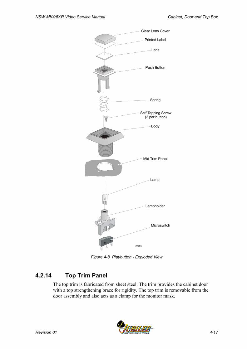
NSW MK4/5XR Video Service Manual Cabinet, Door and Top Box
Revision 01 4-17
Clear Lens Cover
Printed Label
Lens
Push Button
Spring
Body
Self Tapping Screw(2 per button)
Mid Trim Panel
Lamp
Lampholder
Microswitch
I0185
Figure 4-8 Playbutton - Exploded View
4.2.14 Top Trim PanelThe top trim is fabricated from sheet steel. The trim provides the cabinet doorwith a top strengthening brace for rigidity. The top trim is removable from thedoor assembly and also acts as a clamp for the monitor mask.
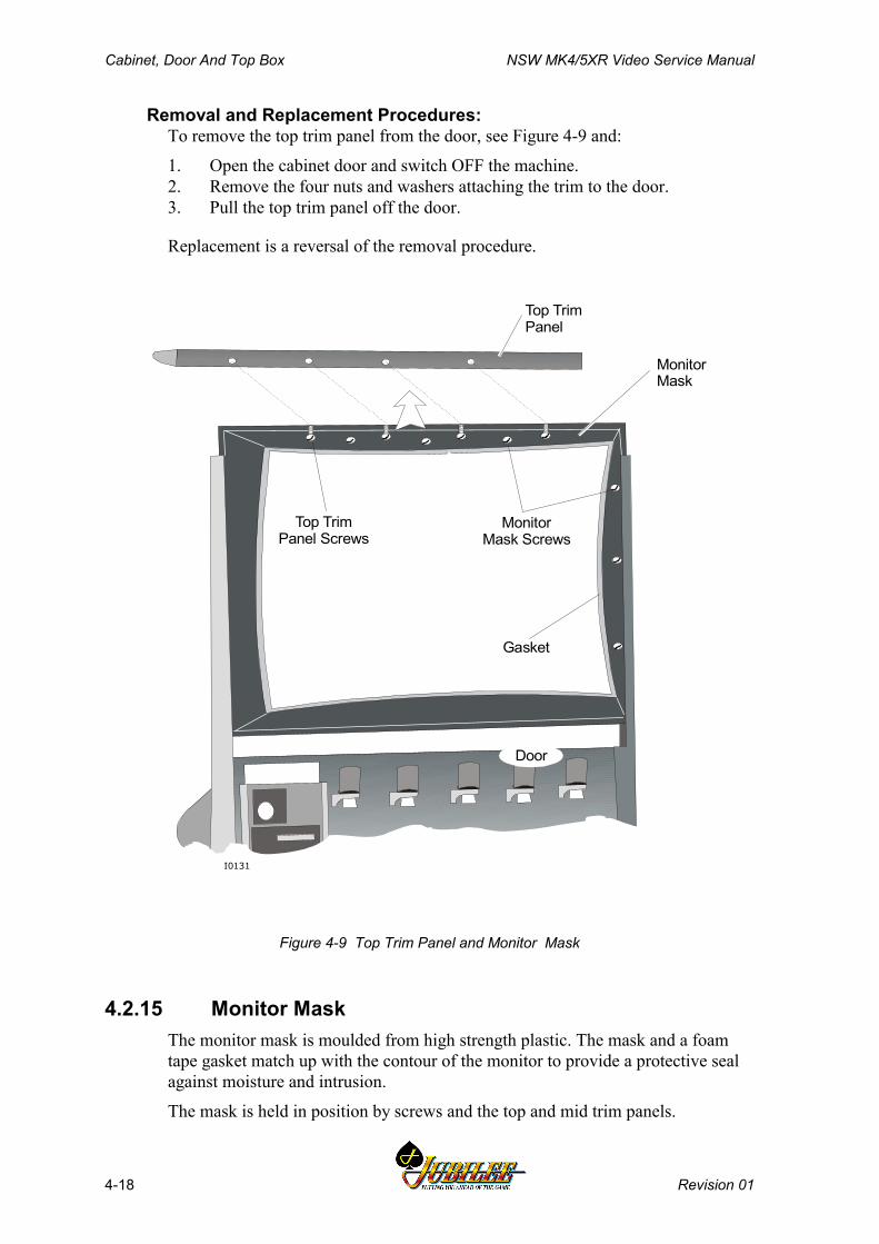
Cabinet, Door And Top Box NSW MK4/5XR Video Service Manual
4-18 Revision 01
Removal and Replacement Procedures:To remove the top trim panel from the door, see Figure 4-9 and:
1. Open the cabinet door and switch OFF the machine.2. Remove the four nuts and washers attaching the trim to the door.3. Pull the top trim panel off the door.
Replacement is a reversal of the removal procedure.
I0131
MonitorMask Screws
Top TrimPanel
MonitorMask
Door
Gasket
Top TrimPanel Screws
Figure 4-9 Top Trim Panel and Monitor Mask
4.2.15 Monitor MaskThe monitor mask is moulded from high strength plastic. The mask and a foamtape gasket match up with the contour of the monitor to provide a protective sealagainst moisture and intrusion.
The mask is held in position by screws and the top and mid trim panels.

NSW MK4/5XR Video Service Manual Cabinet, Door and Top Box
Revision 01 4-19
Removal and Replacement Procedures:To remove the monitor mask from the machine, see Figure 4-9 and:
1. Open the cabinet door and switch OFF the machine.2. Remove the top trim panel as described above.3. Remove the nuts from the top and right hand side of the mask that secure it
to the cabinet door.4. Gently manoeuvre the monitor mask out of the door.
Replacement is a reversal of the removal procedure.
4.2.16 Coin TrayThe coin tray provides a receptacle for coins or tokens that are dispensed by themachine hopper, and for coins that are rejected by the coin handling system. Thetray consists of several parts which are assembled together and bolted onto thelower section of the door.
Removal and Replacement Procedures:To remove the coin tray from the machine:
1. Open the cabinet door and switch OFF the machine.2. Remove the bank note acceptor assembly (refer Bank Note Acceptor
chapter).3. Remove the two screws that secure the coin tray to the latch bar bracket.4. Remove the two screws that secure the coin tray to the cabinet door near the
hinge. The belly panel door will have to be open to access one of thescrews.
5. Remove the two nuts from under the bank note acceptor holding cradle.6. Gently pull the coin tray from the door.
Replacement is a reversal of the removal procedure.
4.2.17 Belly Panel DoorThe belly panel door is fabricated from sheet steel and is mounted to the cabinetdoor on two high-strength hinges. The lock mechanism is located on the maindoor.
To remove the belly panel door:
1. Open the cabinet door and switch OFF the machine.2. Remove the two door stays.3. Remove door by lifting it off the two hinge pins.
NoteThe hinges and hinge pins can be removedfrom belly panel door and main doorrespectively, by removing the screwssecuring them.
Cabinet, Door And Top Box NSW MK4/5XR Video Service Manual
4-20 Revision 01
4.2.18 Belly Panel SecurityThe belly panel door provides access to the Bank Note Stacker, fluorescent tubesand the belly panel artwork. As well as a keyed lock, the belly panel door is fittedwith a mechanical security switch which signals the Main Board, when themachine is powered, that the door has been opened.
4.2.19 Top BoxThe gaming machine may be fitted with a high boy top box or a casino top box.When no top box is fitted, the machine is referred to as a low boy. The top boxprovides an area for displaying the game pay table and increases the visual impactof the machine.
The top box door is hinged at the top and is opened to gain access to the top boxlighting system. Electromechanical meters may also be housed within the top box.A key-operated latch mechanism is used to lock the top box.
To open the top box door:1. Open the cabinet door, and switch OFF the machine.2. Insert the top box key and turn it 90° clockwise.3. Push in the top box latch pin, raise the door of the top box up and push in
hinged stays to hold it open.
4.2.20 Top Box ArtworkThe polycarbonate artwork panel located in the top box door displays the gamepaytable and acts as an attraction to players. It is backlit by the top boxfluorescent lighting system.
To remove the artwork panel:
1. Open the top box as described above.2. Remove the lower trim from the top box door3. Gently slide the artwork panel out of the door.
4.2.21 Top Box Fluorescent LightingThe top box is equipped with fluorescent lighting for illuminating the top boxartwork panel. A 15 W fluorescent tube is mounted on the front of the reflectorpanel inside the top box.
NoteFluorescent tubes are 15 W to AS1201 (IEC81) standard.
The lamp is powered from the high voltage power control system via a fluorescentballast, which is mounted to the back of the reflector panel. The fluorescentballast receives 24 V DC from the power supply assembly.
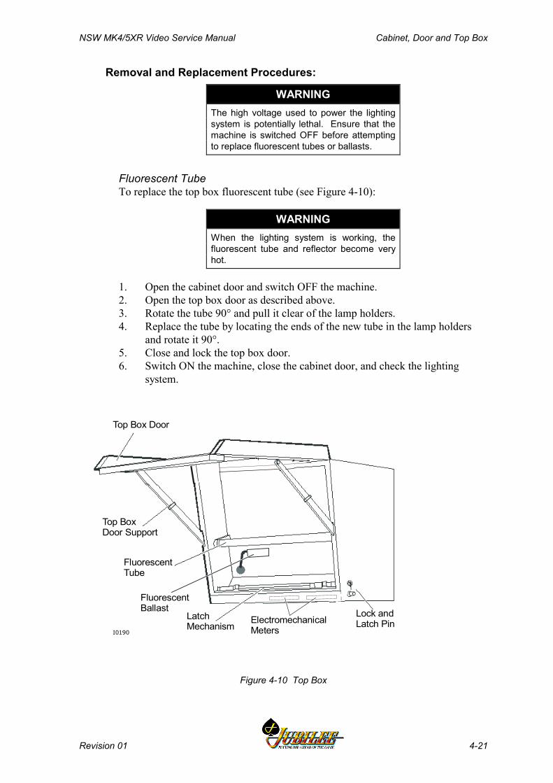
NSW MK4/5XR Video Service Manual Cabinet, Door and Top Box
Revision 01 4-21
Removal and Replacement Procedures:
WARNINGThe high voltage used to power the lightingsystem is potentially lethal. Ensure that themachine is switched OFF before attemptingto replace fluorescent tubes or ballasts.
Fluorescent TubeTo replace the top box fluorescent tube (see Figure 4-10):
WARNINGWhen the lighting system is working, thefluorescent tube and reflector become veryhot.
1. Open the cabinet door and switch OFF the machine.2. Open the top box door as described above.3. Rotate the tube 90° and pull it clear of the lamp holders.4. Replace the tube by locating the ends of the new tube in the lamp holders
and rotate it 90°.5. Close and lock the top box door.6. Switch ON the machine, close the cabinet door, and check the lighting
system.
FluorescentBallast
ElectromechanicalMeters
Lock andLatch Pin
I0190
FluorescentTube
Top BoxDoor Support
Top Box Door
LatchMechanism
Figure 4-10 Top Box
Cabinet, Door And Top Box NSW MK4/5XR Video Service Manual
4-22 Revision 01
BallastThe top box ballast is located either in front of or behind the reflector panel. Toremove the top box ballast:
1. Open the cabinet door and switch OFF the machine.2. Open the top box door as described above.3. The ballast may be lcated behind the reflector panel. If it is, remove the
reflector panel as described below.4. Disconnect all looms from the ballast.5. Squeeze the sides of the ballast housing to disengage the plastic clips, and
remove the ballast from the reflector panel.
To replace the ballast, reverse the above procedure.
Top Box Reflector PanelTo remove the top box reflector panel:
1. Open the top box as described above.2. Remove the screws securing the reflector panel to the sides of the top box.3. Carefully lift the reflector panel from the top box.4. Unplug the power loom from the fluoro loom.
To replace the reflector panel, reverse the above procedure.
NSW MK4/5XR Video Service Manual Cabinet, Door and Top Box
Revision 01 4-23
4.3 General MaintenanceFor the general maintenance of the cabinet, cabinet door and top box, thefollowing procedures should be carried out as part of regular machine servicing:
• Clean the exterior of the machine using a non-abrasive household cleaningsolution.
• Check that the cabinet door and top box door are not damaged.• Check that the cabinet earth leads are in good condition and securely
connected.• Check the condition of the artwork panels. Replace if necessary.• Check that the machine security features (eg: cabinet door photo-optic) are
functioning correctly and are not damaged.• Check the condition of the monitor mask. Replace if necessary.• Check the fluorescent lighting system works correctly. Replace any faulty
components.• Check that all playbuttons function correctly. Replace if necessary.• Check that there are no foreign objects in any of the security locks.• Check that all doors and latches close and lock correctly. Adjust if
necessary.

Cabinet, Door And Top Box NSW MK4/5XR Video Service Manual
4-24 Revision 01
Notes
NSW MK4/5XR Video Service Manual Power Supply Assembly
Revision 01 5-1
________Chapter 5________
Power Supply Assembly
5.1 Physical Description ................................................................ 5-3
5.2 Basic Operation........................................................................ 5-5
5.3 Functional Specification.......................................................... 5-7
5.3.1 Input Requirements.................................................................... 5-75.3.2 Output Requirements ................................................................. 5-7
Mains GPO .................................................................................................. 5-7Monitor Output ............................................................................................. 5-7Generic Output 24 V DC.............................................................................. 5-7Fluoro Output 24 V DC ................................................................................ 5-8Output 12 V DC............................................................................................ 5-8Overcurrent Protection................................................................................. 5-8Overvoltage Protection ................................................................................ 5-8Inrush Current .............................................................................................. 5-9
5.3.3 Control Signals ........................................................................... 5-9Low-Power Mode Signal .............................................................................. 5-9Power Fail Signal ......................................................................................... 5-9
5.3.4 Physical Connections ................................................................. 5-9External Mains Switch Outputs .................................................................... 5-9Off-Line Converter Output............................................................................ 5-9Fluorescent Lamp Outputs ........................................................................ 5-10
5.4 Removal and Replacement Procedures ............................... 5-11
5.4.1 Fuses ....................................................................................... 5-115.4.2 Power Supply Assembly........................................................... 5-11
5.5 General Maintenance ............................................................. 5-12

Power Supply Assembly NSW MK4/5XR Video Service Manual
5-2 Revision 01
List of FiguresFigure 5-1 Power Supply Assembly Location ....................................................................... 5-3Figure 5-2 Power Supply Assembly...................................................................................... 5-4Figure 5-3 Power Supply Assembly Wiring Diagram............................................................ 5-5Figure 5-4 Low Voltage Power Distribution .......................................................................... 5-6

NSW MK4/5XR Video Service Manual Power Supply Assembly
Revision 01 5-3
5.1 Physical DescriptionThe power supply assembly provides power to the electronic and electrical deviceswithin the machine. It also performs electromagnetic interference (EMI) filteringand protects the system from adverse input disturbances such as lightning andvoltage fluctuation.
The power supply metal enclosure is divided into two separate areas by an internalmetal bracket. The area on one side of the bracket accommodates the mains filter,switches, fuses, surge protection, the solid-state relay, and wiring between thecomponents mounted to the metal enclosure. The area on the other side of thebracket accommodates the off-line power supply, which consists of a switchedmode power converter PCBA.
For easy access, the mains switch is located in a separate switch box that ispositioned towards the front of the cabinet. The switch box is linked to the powersupply box using mains cable. The mains ON/OFF switch controls the power toall equipment in the cabinet, apart from any equipment that may be powered fromthe general purpose outlet (GPO). See Figure 5-1 for the location of the powersupply assembly location and Figure 5-2 for the assembly components.
Mains Switch
Power SupplyAssembly
I0043
Figure 5-1 Power Supply Assembly Location
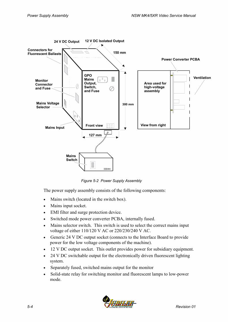
Power Supply Assembly NSW MK4/5XR Video Service Manual
5-4 Revision 01
Power Converter PCBA
MainsSwitch
127 mm
150 mm
MonitorConnectorand Fuse
Area used forhigh-voltageassembly
Ventilation
View from rightFront viewMains Input
GPOMainsOutput,Switch,and Fuse
Mains VoltageSelector
Connectors forFluorescent Ballasts
24 V DC Output 12 V DC Isolated Output
300 mm
I0044
Figure 5-2 Power Supply Assembly
The power supply assembly consists of the following components:
• Mains switch (located in the switch box).• Mains input socket.• EMI filter and surge protection device.• Switched mode power converter PCBA, internally fused.• Mains selector switch. This switch is used to select the correct mains input
voltage of either 110/120 V AC or 220/230/240 V AC.• Generic 24 V DC output socket (connects to the Interface Board to provide
power for the low voltage components of the machine).• 12 V DC output socket. This outlet provides power for subsidiary equipment.• 24 V DC switchable output for the electronically driven fluorescent lighting
system.• Separately fused, switched mains output for the monitor• Solid-state relay for switching monitor and fluorescent lamps to low-power
mode.
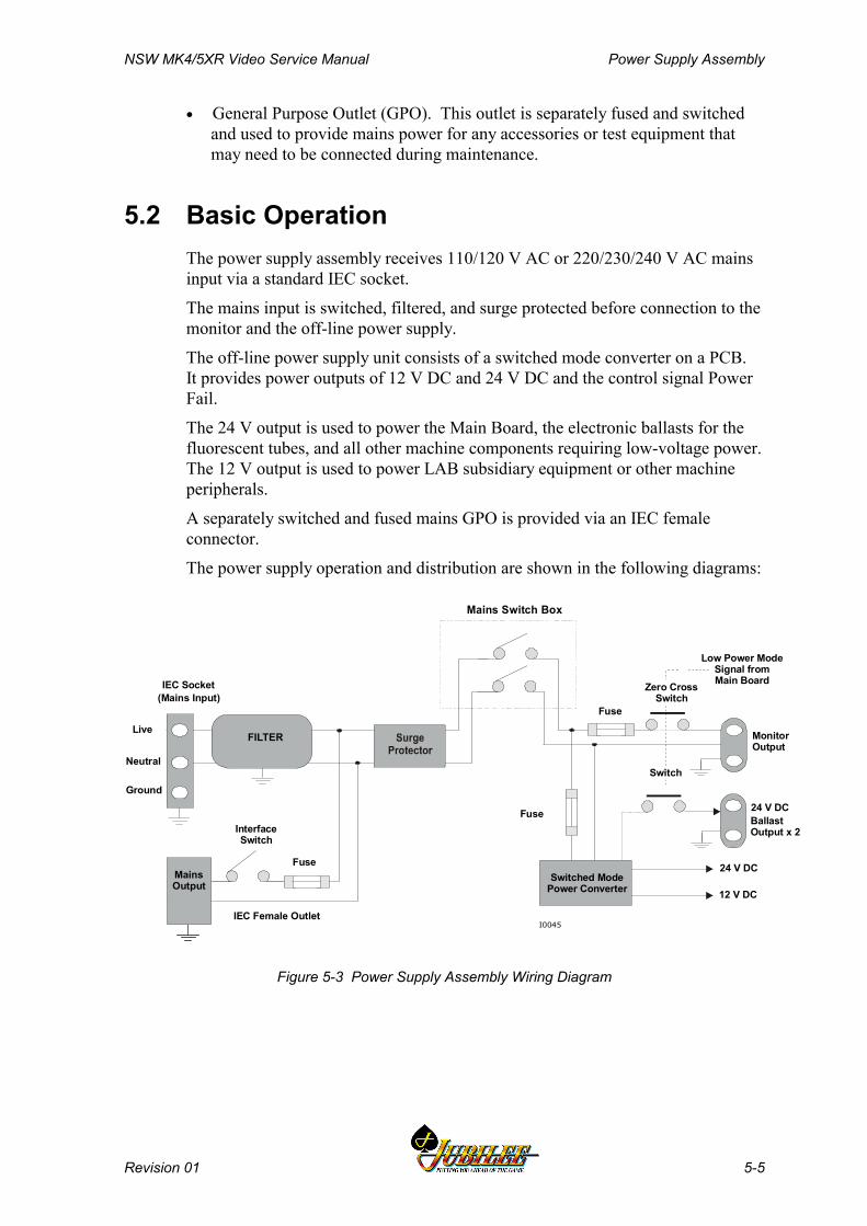
NSW MK4/5XR Video Service Manual Power Supply Assembly
Revision 01 5-5
• General Purpose Outlet (GPO). This outlet is separately fused and switchedand used to provide mains power for any accessories or test equipment thatmay need to be connected during maintenance.
5.2 Basic OperationThe power supply assembly receives 110/120 V AC or 220/230/240 V AC mainsinput via a standard IEC socket.
The mains input is switched, filtered, and surge protected before connection to themonitor and the off-line power supply.
The off-line power supply unit consists of a switched mode converter on a PCB.It provides power outputs of 12 V DC and 24 V DC and the control signal PowerFail.
The 24 V output is used to power the Main Board, the electronic ballasts for thefluorescent tubes, and all other machine components requiring low-voltage power.The 12 V output is used to power LAB subsidiary equipment or other machineperipherals.
A separately switched and fused mains GPO is provided via an IEC femaleconnector.
The power supply operation and distribution are shown in the following diagrams:
MonitorOutput
BallastOutput x 2
Zero CrossSwitch
FILTER
IEC Socket
Live
Neutral
Ground
Mains Output
InterfaceSwitch
Fuse
IEC Female Outlet
Switched ModePower Converter
(Mains Input)
I0045
24 V DC
24 V DC
12 V DC
Fuse
Fuse
Mains Switch Box
Low Power ModeSignal fromMain Board
Switch
Figure 5-3 Power Supply Assembly Wiring Diagram
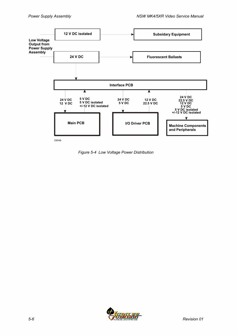
Power Supply Assembly NSW MK4/5XR Video Service Manual
5-6 Revision 01
12 V DC isolated
24 V DC
Interface PCB
Subsidary Equipment
Fluorescent Ballasts
Main PCB I/O Driver PCB
5 V DC5 V DC isolated+/-12 V DC isolated
12 V DC22.5 V DC
24 V DC12 V DC
24 V DC 5 V DC
Machine Componentsand Peripherals
24 V DC22.5 V DC
5 V DC 5 V DC isolated
12 V DC
+/-12 V DC isolated
Low VoltageOutput fromPower Supply Assembly
I0046
Figure 5-4 Low Voltage Power Distribution

NSW MK4/5XR Video Service Manual Power Supply Assembly
Revision 01 5-7
5.3 Functional Specification
WARNINGThe mains voltage selector switch must beset for the correct voltage range beforepower is connected to the machine.Selecting the wrong voltage will causeirrevocable damage to the machine.
5.3.1 Input RequirementsThe power supply assembly is designed to accept a nominal mains input voltageof either 110/120 V AC or 220/230/240 V AC. The mains input voltage definesthe monitor outlet voltage and the GPO voltage. The mains selector switch mustbe set to the correct mains input voltage before power is connected. This switch ismounted on the metal housing of the power control assembly. The input voltageranges and current requirements are as follows:
220 V AC - 10% to 240 V AC + 10%, 50 Hz at 6 A maximum (198-264 V AC)
or
110 V AC - 10% to 120 V AC + 10%, 60 Hz at 10 A maximum (99-132 V AC)
Physical ConnectionMains input is via a standard IEC socket mounted on the metal housing.
5.3.2 Output Requirements
Mains GPOVoltage and Current+0%, -2% of the input mains voltage at 0 A to 1 A.
Physical ConnectionMains output is via a standard female IEC socket. This output is separatelyswitched and fused. This fuse is externally accessible.
Monitor OutputVoltage and Current+0%, -2% of the input mains voltage at 0 A to 1.2 A.
Physical ConnectionThe monitor output is provided via a Molex Minifit Junior 6-pin connector plugmounted on the metal housing. This output is separately fused, and the fuse isexternally accessible.
Generic Output 24 V DCProvides power to the Interface Board for distribution to the Main Board, the I/ODriver Board, and other low-voltage machine components and peripherals.Maximum current is specified considering present requirements and allowing forfuture flexibility.

Power Supply Assembly NSW MK4/5XR Video Service Manual
5-8 Revision 01
Vout = +24 V DC +/-5%
Iout = 0.5 to 15.0 A continuous
Ripple = 200 mVp-p, measured at 0-20 MHz
Fluoro Output 24 V DCProvides power for the fluorescent lighting system.
Vout = +24 V DC +/-5%
Iout = 0.0 to 2.0 A continuous
Ripple = 200 mVp-p, measured at 0-20 MHz
Output 12 V DCProvides power for subsidiary equipment. Isolation of 3 kV is required betweenthis output, other secondaries and primary.
Vout = +12 V DC +/-5%
Iout = 0.0 to 3.0 A continuous
Ripple = 200 mVp-p, measured at 0-20 MHz
Overcurrent ProtectionGeneric Output 24 V - The output is limited to constant output current in therange 17.1 A to 22 A. The response time for the overcurrent circuit is between 20and 150 ms. Shorter response times can cause malfunction due to short circuitglitches.
The power will recover if the overcurrent duration is shorter than the recoverytime. If the overcurrent duration is longer than the recovery time, the powersupply shuts down and has to be switched off/on for 1-3 seconds to recover.During shutdown state, the output 24 voltage is less than 1 V DC.
Current limits are stated for no load condition in the fluoro 24 V output. Genericoutput protection includes a 2 A current margin dedicated to the fluoro lamps.Therefore, the current limits can be reduced by up to 2 A depending on the fluoroload.
Fluoro Output 24 V - The output is limited to constant output current above 2 A.The response time for the overcurrent circuit is specified in seconds. Shortertimes can cause malfunction of the electronic ballast and result in the fluoro tubenot starting. The output will recover when the overcurrent is removed.
Output 12 V - The output is limited to constant output current in the range 3.1-7 A. The power will recover when the overcurrent is removed.
Overvoltage ProtectionAll peripherals connected to the 24 V output rail are protected against anaccidental increase of the output voltage. When the voltage rises above 28±1 V,the entire power supply will shut down.

NSW MK4/5XR Video Service Manual Power Supply Assembly
Revision 01 5-9
Inrush CurrentSome peripherals exhibit significant inrush current when first powered. Thepower supply has to cope with these temporary transients and remain stable.Maximum steady-state current drawn from the 24 V output is 14.45 A. If aWestrex printer is fitted, it causes an additional current spike that increases themaximum current to 17 A. The steady-state current limitation for the output is17.1 A. Therefore, the off-line converter is capable of handling the currentdemands of normal machine operation.
5.3.3 Control Signals
Low-Power Mode SignalThis signal is generated by the Main Board and is used to switch the machine tolow-power mode.
Power Fail SignalThe power fail signal provides a warning to the system of imminent mains failure.The power supply is designed such that one full missing period of mains (50 Hz or60 Hz) cannot have any effect on the correct operation of the power supplyassembly. The PFAIL signal is generated by the power converter PCBA when theinput mains rectified voltage drops below a threshold. This feature maintains the+24 V DC output within regulation for a minimum of 25 ms following a powerfail signal. This allows enough time for mechanical meters to finish counting andfor the CPU to back up the audit data held in the machine RAM before the powershuts down.
After mains voltage recovery, PFAIL can be inactivated when the level of the24 V output reaches at least 22.5 V.
5.3.4 Physical Connections
External Mains Switch OutputsThe mains switch is connected to the power supply box via a 4-pin AMP, Mate-N-Lock compatible, universal connector. This connector is used for its high currentcapability per pin.
The pin functions of this connector are shown below.
Pin Signal Comments1 N ret Mains neutral line switched2 A ret Mains active line switched3 A Mains active line to the mains switch4 N Mains neutral line to the mains switch
Off-Line Converter OutputTwo secondary output connectors are provided: one for the 24 V DC output andthe control signals, the other for the 12 V DC output.

Power Supply Assembly NSW MK4/5XR Video Service Manual
5-10 Revision 01
The secondary output 24 V and the control signals are connected to the powersupply assembly via a Molex Minifit Junior 14-pin connector soldered directly tothe PCBA. The socket fits into an opening in the metal housing and connects, viaa loom, to the 16-way Minifit Junior connector P29 on the Interface Board.
The pin functions of the connector are as described in the following table.
Pin Function Comments1 LowPower low power mode (input)2 OUTFAIL Output 24 V correct (output)3 output 24 V power for machine, +24 V4 output 24 V power for machine, +24 V5 output 24 V power for machine, +24 V6 output 24 V power for machine, +24 V7 output 24 V power for machine, +24 V89 PFAIL mains voltage missing (output)10 output GND24 ground, +24 V11 output GND24 ground, +24 V12 output GND24 ground, +24 V13 output GND24 ground, +24 V14 output GND24 ground, +24 V
The secondary output 12 V is connected via a 4-pin Molex Minifit Juniorcompatible header soldered directly onto the power supply PCBA. The socket fitsinto an opening in the metal housing.
The pin functions of the connector are as described in the following table.
Pin Function Comments1 output 12 V isolated power, +12 V2 output GND12 ground, +12 V3 4
Fluorescent Lamp OutputsVoltage and Current24 V DC ±5% at 0 A to 2.0 A for all outputs.
Physical ConnectionsTwo 24 V outputs are provided to power the top box fluorescent lamp and thecabinet door fluorescent lamps. The electronic ballasts used provide thepossibility of daisy chaining the 24 V power rail for future adaptability. Outputsare via 4-pin Molex Minifit Junior compatible connectors, which are mounted onthe metal housing. The pin functions are shown in the table below.
Pin Signal Function1 2 GND 24 V ground, 24 V3 4 +24 V power for fluorescent lamps, +24 V
NSW MK4/5XR Video Service Manual Power Supply Assembly
Revision 01 5-11
5.4 Removal and Replacement Procedures
5.4.1 FusesThe switched mode power supply fuse is an internal non-serviceable component.If this fuse is blown, the power supply box must be shipped to the manufacturerfor service (contact the nearest Aristocrat office).
The monitor fuse and the GPO fuse are externally accessible and may be replacedas described below (see Figure 5-2):
WARNING240 V AC mains voltage is present in thepower supply assembly even when themachine is switched OFF. The mains inputcable must be unplugged before attemptingto replace a fuse.
1. Open the cabinet door, and switch OFF the mains switch and the GPOswitch.
2. Unplug the Mains Input cable from the power supply assembly.
3. Remove the fuse cap from the fuse holder by unscrewing it in ananticlockwise direction. The fuse should spring out of the holder.
4. Remove the blown fuse and insert the new fuse into the cap. Insert the fusecap into the holder, screwing it in a clockwise direction. Do not overtighten.
5. Switch ON the mains switch and the GPO switch. Check that both themonitor and the mains GPO have power. Close and lock the cabinet door.
5.4.2 Power Supply AssemblyTo remove the power supply assembly from the machine (see Figure 5-2):
WARNING240 V AC mains voltage is present in thePower Supply Assembly even when themachine is switched OFF. The mains inputcable must be unplugged before attemptingto remove the power supply assembly.
1. Open the cabinet door, and switch OFF the mains switch and the GPOswitch.
2. Remove the hopper to gain access to the power supply assembly (refer to thechapter Hopper).
3. Unplug the Mains Input cable from the power supply assembly.
4. Unplug all other looms and connectors from the power supply assembly.
Power Supply Assembly NSW MK4/5XR Video Service Manual
5-12 Revision 01
5. Remove the screw securing the earth lead from the power supply assemblyto the cabinet.
6. Unscrew the two screws that secure the power supply assembly to thecabinet base. One of these screws is positioned below the mains input plugand cannot be removed while the plug is connected.
7. Pull the power supply assembly forward and remove from the cabinet.
Replacement is a reversal of the removal procedure. Ensure that the earth lead iscorrectly replaced.
NoteRun a complete machine test after replacingthe power supply box or any power supplycomponent.
5.5 General MaintenanceThe following procedures should be carried out as part of regular machinemaintenance:
• Check that all connections to the power supply box are secure.
• Remove any dust or dirt accumulating on the power supply assembly.
NSW MK4/5XR Video Service Manual Coin Handling Assembly
Revision 01 6-1
________Chapter 6________
Coin Handling Assembly
6.1 Overview............................................................................................ 6-3
6.2 Basic Operation ................................................................................ 6-4
6.2.1 Validation ................................................................................... 6-46.2.2 Rejected Coins........................................................................... 6-56.2.3 Accepted Coins .......................................................................... 6-56.2.4 Alarm.......................................................................................... 6-66.2.5 Inhibit All..................................................................................... 6-66.2.6 Self Calibration........................................................................... 6-66.2.6 Diagnostics................................................................................. 6-66.2.7 Debris Flap................................................................................. 6-6
6.3 Removal and Replacement .............................................................. 6-7
6.4 Clearing Coin Jams .......................................................................... 6-7
6.5 CN133A Coin Validator Connector Pinouts.................................... 6-8
6.6 Diverter Solenoid and Photo-Optic Sensor .................................... 6-9
6.6.1 Physical Description ................................................................... 6-96.6.2 Basic Operation.......................................................................... 6-96.6.3 Removal and Replacement ...................................................... 6-10
6.7 Fault Finding ................................................................................... 6-11
6.8 General Maintenance...................................................................... 6-11

Coin Handling Assembly NSW MK4/5XR Video Service Manual
6-2 Revision 01
List of FiguresFigure 6-1 Condor Coin Handling Assembly ........................................................................ 6-3Figure 6-2 Condor Coin Validator ......................................................................................... 6-5Figure 6-3 Diverter Solenoid and Photo-Optic Sensor ......................................................... 6-9
List of TablesTable 6-1 Condor Validator Interface Signals....................................................................... 6-8Table 6-2 Fault Finding.......................................................................................................6-11

NSW MK4/5XR Video Service Manual Coin Handling Assembly
Revision 01 6-3
6.1 OverviewThe coin handling system (see Figure 6-1) consists of a coin validator fordetermining the validity of inserted coins, a coin diverter and coin chuting fordirecting the coins to the correct destination, and a photo-optic module formonitoring the position of the coin diverter. The handling system is fitted andadjusted at the factory to suit a specific coin denomination.
The coin entry, located on the cabinet door trim, is designed to accept a specificcoin denomination for a particular machine. It will not accept oversized or bentcoins. The coin entry ensures that the coin is directed into the validator correctly.
I0193
Player Coin Entry
Valid Coin to Hopper
Rejected Cointo Coin Tray
Coin Diverter Solenoid
Condor Condor Validator
Photo-opticSensor
Valid Coin to Cash Box
Figure 6-1 Condor Coin Handling Assembly
Coin Handling Assembly NSW MK4/5XR Video Service Manual
6-4 Revision 01
The coin validator, coin chuting and diverter solenoid are mounted to a panel onthe inside of the cabinet door. Coins inserted into the machine pass through thevalidator which compares the properties of inserted coins with preset limits storedin the validator software. The validator sends signals to the Main Board, via theInterface Board and I/O Driver Board that allow the machine software todetermine the validity of the coins. Accepted coins are directed to the acceptchute, and rejected coins are directed to the chip tray via the reject chute.
The coin diverter solenoid is powered from the 24 V DC supply. The coinvalidator receives 12 V DC derived from the 24 V DC supply using a switch moderegulator on the Driver Board.
The machine uses the Condor CN133A Validator.
6.2 Basic OperationThe following sections describe the operation of the coin chute assembly.
6.2.1 ValidationThe Condor Coin Validator CN133A (see Figure 6–2) is pre-programmed toaccept a specific coin type and cannot be reprogrammed in the field. The validatoris clearly labelled with the pre-programmed coin type.
Once in the validator, the coin passes a sensor coil that detects its diameter,thickness, and magnetic properties.
The validator uses two sets of sensors for coin discrimination: opto and inductive.This combination gives a high degree of security.
The inductive sensor pair has been designed to achieve a linear field independentof coin position. In a typical validator, the coin position relative to sensors iscritical for accurate discrimination.
Two inductive sensors are positioned on opposite sides of the coin path and areswitched between in-phase and anti-phase as the coin passes. The networkimpedance is affected by the coin thickness and conductivity. The resultingamplitude change is measured by a microcontroller and forms the basis of theinductive discrimination. The readings are compared against preset limits storedin the validator.
The opto system measures coin diameter. There are three longitudinal IR beamsacross the coin path. A 16-bit timer uses a 3-point measurement system to obtain aprecise measurement of diameter. The resulting calculation of diameter iscompared against preset limits. Like the inductive sensors, the opto sensors arepart of a closed loop system that maintains very fast triggering for accurate timing.It also ensures that slight variations which occur from mechanism to mechanism(such as component tolerance) are irrelevant.
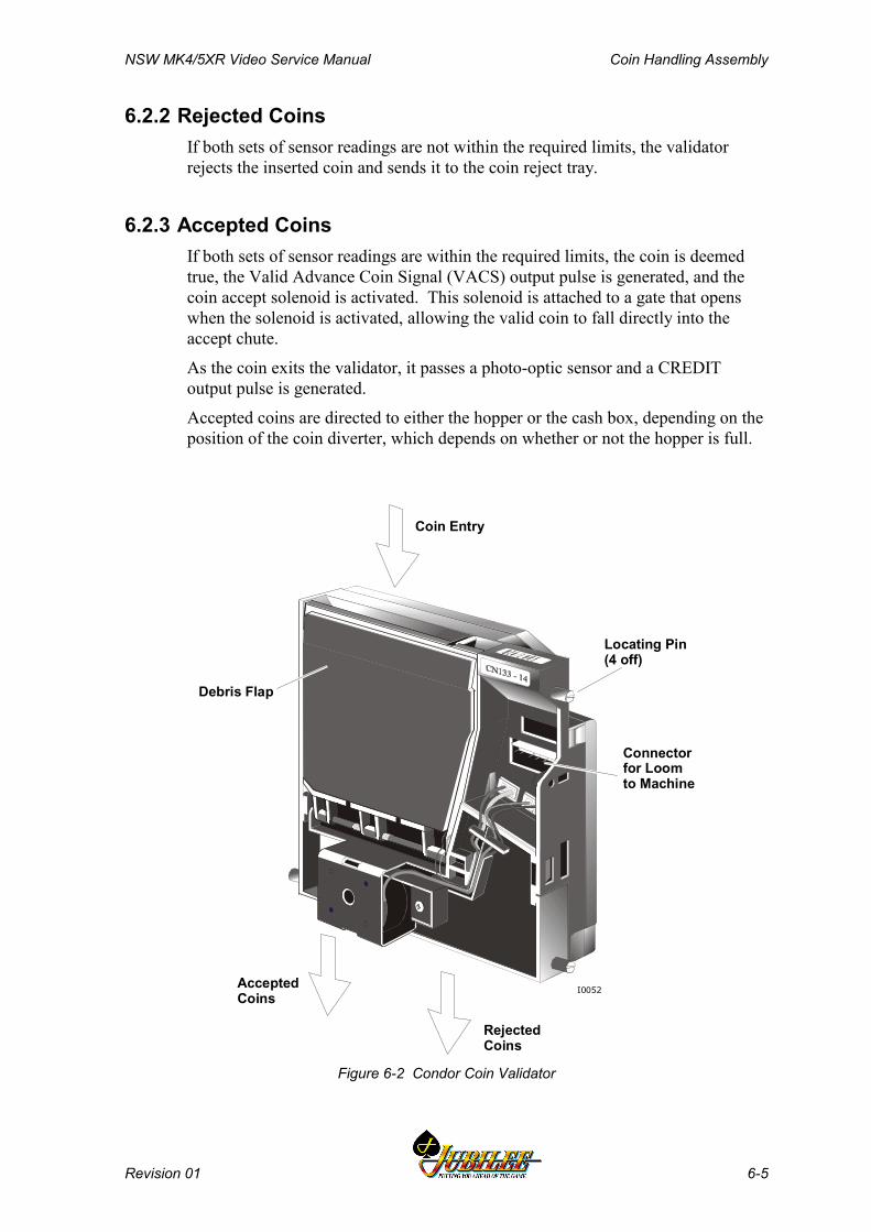
NSW MK4/5XR Video Service Manual Coin Handling Assembly
Revision 01 6-5
6.2.2 Rejected CoinsIf both sets of sensor readings are not within the required limits, the validatorrejects the inserted coin and sends it to the coin reject tray.
6.2.3 Accepted CoinsIf both sets of sensor readings are within the required limits, the coin is deemedtrue, the Valid Advance Coin Signal (VACS) output pulse is generated, and thecoin accept solenoid is activated. This solenoid is attached to a gate that openswhen the solenoid is activated, allowing the valid coin to fall directly into theaccept chute.
As the coin exits the validator, it passes a photo-optic sensor and a CREDIToutput pulse is generated.
Accepted coins are directed to either the hopper or the cash box, depending on theposition of the coin diverter, which depends on whether or not the hopper is full.
Locating Pin(4 off)
Debris Flap
Coin Entry
AcceptedCoins
RejectedCoins
Connectorfor Loomto Machine
I0052
Figure 6-2 Condor Coin Validator
Coin Handling Assembly NSW MK4/5XR Video Service Manual
6-6 Revision 01
6.2.4 AlarmIf the validator detects a coin travelling in the wrong direction (yo-yo) or a failedor blocked credit or reject optic, an Alarm output pulse is generated.
On receiving this Alarm signal:
• the gaming machine shuts down
• an alarm is sounded
• a fault message is displayed on the screen
6.2.5 Inhibit AllFor greater functionality and overall security, the host machine can send theINHIBIT ALL signal to prevent the validator from accepting any coins or tokens.
6.2.6 Self CalibrationThe validator automatically recalibrates itself in relation to its environmentapproximately every 210 seconds.
6.2.6 DiagnosticsAt power up, the validator automatically runs a self diagnostic test on thefollowing critical areas:
• Inductive Coils
• Reflective Sensors
• Diameter Opto Sensors
• Credit Opto Sensors
If there is a failure in any one of these areas, the LED on the back of the validatorwill flash red continuously and the validator will not accept any coins until poweris removed and the fault condition corrected.
6.2.7 Debris FlapThe CN133A Validator incorporates a debris flap that allows direct access to thecoin path for inspection and the clearance of coin jams.

NSW MK4/5XR Video Service Manual Coin Handling Assembly
Revision 01 6-7
6.3 Removal and ReplacementTo remove the validator:
1. Open the cabinet door and switch OFF the machine.2. Carefully unplug the loom from the validator to the Interface Board. Do not
pull on the wires.3. Push the assembly upwards to the full extent of the top locating groove.
This action causes the validator to come free of the bottom locating groove.4. Swing the bottom of the unit outwards and down to clear the coin chute
assembly.
To replace the validator, reverse the above procedure.
6.4 Clearing Coin JamsWhen a coin jams in the coin validator assembly or chuting, the machine locks upand displays one of the following fault messages: COIN ACCEPTOR FAULT,COIN OPTIC FAULT, or COIN DIVERTER FAULT.
To clear the coin jam, take the following action (see Figures 6-1 and 6-2):
1. Open the cabinet door, and switch OFF the machine.2. Carefully clear any coins from the coin chuting.3. Check for jammed coins in the validator. To remove the validator, refer to
the above procedures.4. Open the debris flap and remove any jammed coins.
CAUTIONThe debris flap is spring loaded. Close theflap gently to avoid damaging the ferrites andstandoffs.
5. Replace the validator and reconnect the looms.6. Ensure that the validator and chuting are clear by dropping a coin through
while the cabinet door is still open.7. Switch ON the machine; close and lock the main door.8. To reset the machine, turn the Jackpot Reset key ON then OFF.
Coin Handling Assembly NSW MK4/5XR Video Service Manual
6-8 Revision 01
6.5 CN133A Coin Validator Connector PinoutsThe connector J1 on the right of the validator connects to P12 on the InterfaceBoard.
The Interface Board connects P12 to the coin interface section of the I/O DriverBoard which receives the signals from the coin validator and solenoid optics andconverts them into the form required by the Main Board. For a description of thecoin handling interface refer to the I/O Driver Board chapter.
The signals to and from the coin validator are shown in the following table.
Table 6-1 Condor Validator Interface Signals
Pin Signal Description1 0V Ground2 VACS Generated when valid coin is sensed3 Alarm Yo-yo or optic blocked4 Credit Generated when valid coin exits validator5 Keyed Pin6 +12V Power from I/O Driver Board7 Inhibit Inhibit signal from host machine
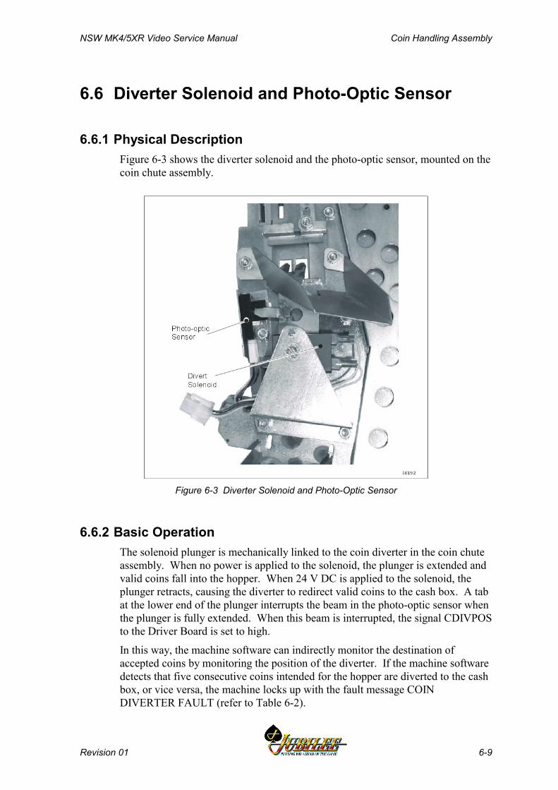
NSW MK4/5XR Video Service Manual Coin Handling Assembly
Revision 01 6-9
6.6 Diverter Solenoid and Photo-Optic Sensor
6.6.1 Physical DescriptionFigure 6-3 shows the diverter solenoid and the photo-optic sensor, mounted on thecoin chute assembly.
Figure 6-3 Diverter Solenoid and Photo-Optic Sensor
6.6.2 Basic OperationThe solenoid plunger is mechanically linked to the coin diverter in the coin chuteassembly. When no power is applied to the solenoid, the plunger is extended andvalid coins fall into the hopper. When 24 V DC is applied to the solenoid, theplunger retracts, causing the diverter to redirect valid coins to the cash box. A tabat the lower end of the plunger interrupts the beam in the photo-optic sensor whenthe plunger is fully extended. When this beam is interrupted, the signal CDIVPOSto the Driver Board is set to high.
In this way, the machine software can indirectly monitor the destination ofaccepted coins by monitoring the position of the diverter. If the machine softwaredetects that five consecutive coins intended for the hopper are diverted to the cashbox, or vice versa, the machine locks up with the fault message COINDIVERTER FAULT (refer to Table 6-2).
Coin Handling Assembly NSW MK4/5XR Video Service Manual
6-10 Revision 01
6.6.3 Removal and Replacement
Photo-optic SensorTo remove the photo-optic sensor:
1. Open the cabinet door and switch OFF the machine.2. Remove the Bank Note Acceptor (refer to Bank Note Acceptor chapter).3. Remove the connector from the bottom of the sensor4. Remove the screw that secures the sensor to the holding bracket and
manoeuvre sensor out of machine.
To replace the sensor, reverse the above procedure.
Divert SolenoidTo remove the divert solenoid:
1. Open the cabinet door and switch OFF the machine.2. Remove the screw that secures the solenoid to the holding bracket and
manoeuvre the solenoid out of machine3. Remove the two spade connectors.
To replace the solenoid, reverse the above procedure.
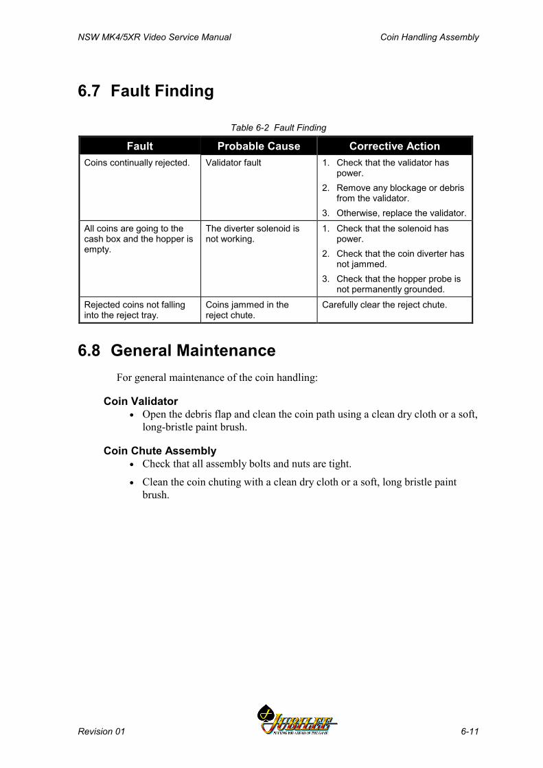
NSW MK4/5XR Video Service Manual Coin Handling Assembly
Revision 01 6-11
6.7 Fault Finding
Table 6-2 Fault Finding
Fault Probable Cause Corrective ActionCoins continually rejected. Validator fault 1. Check that the validator has
power.2. Remove any blockage or debris
from the validator.3. Otherwise, replace the validator.
All coins are going to thecash box and the hopper isempty.
The diverter solenoid isnot working.
1. Check that the solenoid haspower.
2. Check that the coin diverter hasnot jammed.
3. Check that the hopper probe isnot permanently grounded.
Rejected coins not fallinginto the reject tray.
Coins jammed in thereject chute.
Carefully clear the reject chute.
6.8 General MaintenanceFor general maintenance of the coin handling:
Coin Validator• Open the debris flap and clean the coin path using a clean dry cloth or a soft,
long-bristle paint brush.
Coin Chute Assembly• Check that all assembly bolts and nuts are tight.
• Clean the coin chuting with a clean dry cloth or a soft, long bristle paintbrush.

Coin Handling Assembly NSW MK4/5XR Video Service Manual
6-12 Revision 01
Notes
NSW MK4/5XR Video Service Manual Bank Note Acceptor
Revision 01 7-1
______Chapter 7______
Bank Note Acceptor
7.1 Technical Description.............................................................. 7-3
7.1.1 Overview .................................................................................... 7-37.1.2 Physical Description ................................................................... 7-37.1.3 VFM4 Non-isolated Serial Interface ......................................... 7-10
7.2 Installation and Machine Conditions.................................... 7-13
7.2.1 Configuration Setup ................................................................. 7-137.2.2 Machine Condition Indicators ................................................... 7-13
7.3 Removal and Replacement Procedures ............................... 7-15
7.3.1 Clearing the Bank Note Stacker ............................................... 7-157.3.2 Bank Note Acceptor Assembly................................................. 7-167.3.3 Clearing Bank Note Acceptor Jams ......................................... 7-16
7.4 Care and Maintenance ........................................................... 7-18
7.4.1 Troubleshooting ....................................................................... 7-187.4.2 Periodic Maintenance............................................................... 7-207.4.3 Video Level Calibration ............................................................ 7-20
Bank Note Acceptor NSW MK4/5XR Video Service Manual
7-2 Revision 01
List of FiguresFigure 7-1 Bank Note Acceptor Assembly............................................................................ 7-4Figure 7-2 Bank Note Acceptor Dual Cage Assembly.......................................................... 7-5Figure 7-3 Bank Note Acceptor with open Upper Guide ...................................................... 7-6Figure 7-4 Stacker ................................................................................................................. 7-7Figure 7-5 Typical Mid Trim Layout ...................................................................................... 7-8Figure 7-6 Input/Output Connector....................................................................................... 7-9Figure 7-7 Interconnection Diagram ..................................................................................... 7-9Figure 7-8 Bezel Assembly Indicators - LED Displays ....................................................... 7-10Figure 7-9 VFM4 Protocol - Accept and Return Messages................................................ 7-11Figure 7-10 VFM4 Protocol - Hex Code Messages............................................................ 7-12Figure 7-11 Operator Setup Mode - Machine Options ....................................................... 7-13Figure 7-12 Bank Note Acceptor - DIP Switch Location..................................................... 7-19
List of Tables
Table 7-1 Bank Note Acceptor Fault Finding...................................................................... 7-18Table 7-2 Bank Note Acceptor DIP Switch Functions ........................................................ 7-19
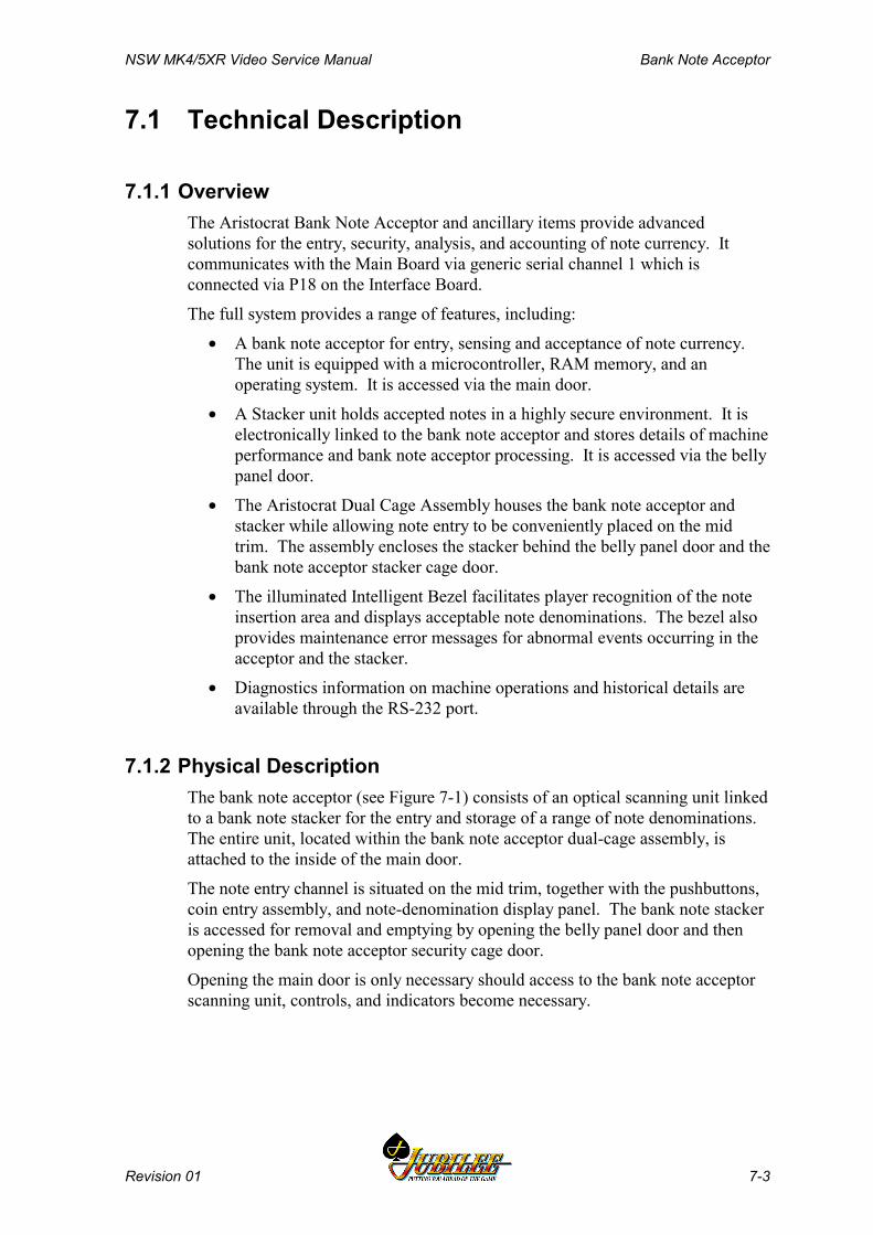
NSW MK4/5XR Video Service Manual Bank Note Acceptor
Revision 01 7-3
7.1 Technical Description
7.1.1 OverviewThe Aristocrat Bank Note Acceptor and ancillary items provide advancedsolutions for the entry, security, analysis, and accounting of note currency. Itcommunicates with the Main Board via generic serial channel 1 which isconnected via P18 on the Interface Board.
The full system provides a range of features, including:
• A bank note acceptor for entry, sensing and acceptance of note currency.The unit is equipped with a microcontroller, RAM memory, and anoperating system. It is accessed via the main door.
• A Stacker unit holds accepted notes in a highly secure environment. It iselectronically linked to the bank note acceptor and stores details of machineperformance and bank note acceptor processing. It is accessed via the bellypanel door.
• The Aristocrat Dual Cage Assembly houses the bank note acceptor andstacker while allowing note entry to be conveniently placed on the midtrim. The assembly encloses the stacker behind the belly panel door and thebank note acceptor stacker cage door.
• The illuminated Intelligent Bezel facilitates player recognition of the noteinsertion area and displays acceptable note denominations. The bezel alsoprovides maintenance error messages for abnormal events occurring in theacceptor and the stacker.
• Diagnostics information on machine operations and historical details areavailable through the RS-232 port.
7.1.2 Physical Description The bank note acceptor (see Figure 7-1) consists of an optical scanning unit linkedto a bank note stacker for the entry and storage of a range of note denominations.The entire unit, located within the bank note acceptor dual-cage assembly, isattached to the inside of the main door.
The note entry channel is situated on the mid trim, together with the pushbuttons,coin entry assembly, and note-denomination display panel. The bank note stackeris accessed for removal and emptying by opening the belly panel door and thenopening the bank note acceptor security cage door.
Opening the main door is only necessary should access to the bank note acceptorscanning unit, controls, and indicators become necessary.
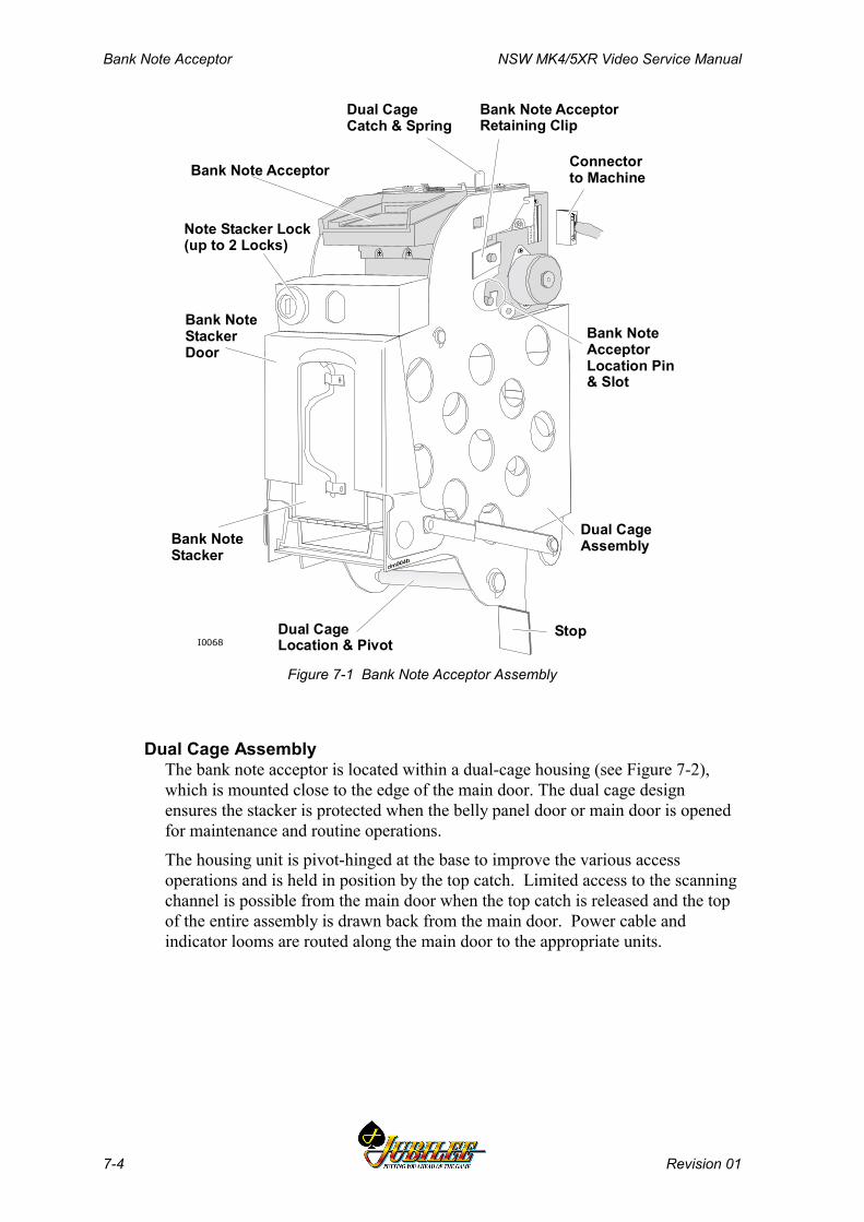
Bank Note Acceptor NSW MK4/5XR Video Service Manual
7-4 Revision 01
Note Stacker Lock(up to 2 Locks)
Bank Note AcceptorRetaining Clip
Bank NoteStackerDoor
Bank Note Acceptor
Bank NoteStacker
Dual CageCatch & Spring
Dual CageLocation & Pivot
Connectorto Machine
Bank NoteAcceptorLocation Pin& Slot
Dual CageAssembly
StopI0068
Figure 7-1 Bank Note Acceptor Assembly
Dual Cage Assembly The bank note acceptor is located within a dual-cage housing (see Figure 7-2),which is mounted close to the edge of the main door. The dual cage designensures the stacker is protected when the belly panel door or main door is openedfor maintenance and routine operations.
The housing unit is pivot-hinged at the base to improve the various accessoperations and is held in position by the top catch. Limited access to the scanningchannel is possible from the main door when the top catch is released and the topof the entire assembly is drawn back from the main door. Power cable andindicator looms are routed along the main door to the appropriate units.

NSW MK4/5XR Video Service Manual Bank Note Acceptor
Revision 01 7-5
Retainer Grooves
Outer CageTop Catch
Locking Latchand Spring
Stacker DualLocks
Inner Cage
Groove -Stacker Lock
Outer Cage
Cage Door
Inner CagePivot
Outer CageLocating Bar
I0067
Figure 7-2 Bank Note Acceptor Dual Cage Assembly
Bank Note AcceptorMechanics and Transport The bank note acceptor employs four mounting posts which locate in the dualcage assembly. The main bank note acceptor housing supports and aligns thedrive rollers and drive stepper motor while providing mounts for the othersubassemblies of the unit. The drive rollers provide power to the drive beltswhich transport the notes or coupons past the circuitry and out of the unit to thestacker.
The two drive belts are individually tensioned to assure a reliable and straightfeed.
Upper and Lower Guides The upper guide assembly of the Bank Note Acceptor supports and locates thepressure rollers that force the note to the drive belts for traction. It also supportsand locates part of the validation circuitry which examines the note as it passesthrough the unit. The upper guide clips into position on the main unit and ispivoted at its lower end. This allows the note channel to be opened so thatmaintenance and cleaning operations can be carried out and any jammed notes canbe removed.
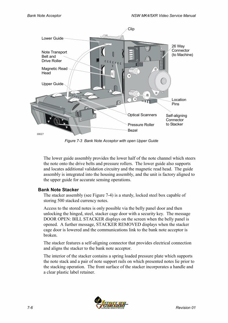
Bank Note Acceptor NSW MK4/5XR Video Service Manual
7-6 Revision 01
Upper Guide
Lower Guide
Self-aligningConnectorto Stacker
Clip
Note TransportBelt and Drive Roller
Pressure Roller
Magnetic ReadHead
Bezel
Optical Scanners
26 WayConnector(to Machine)
I0027
LocationPins
Figure 7-3 Bank Note Acceptor with open Upper Guide
The lower guide assembly provides the lower half of the note channel which steersthe note onto the drive belts and pressure rollers. The lower guide also supportsand locates additional validation circuitry and the magnetic read head. The guideassembly is integrated into the housing assembly, and the unit is factory aligned tothe upper guide for accurate sensing operations.
Bank Note StackerThe stacker assembly (see Figure 7-4) is a sturdy, locked steel box capable ofstoring 500 stacked currency notes.
Access to the stored notes is only possible via the belly panel door and thenunlocking the hinged, steel, stacker cage door with a security key. The messageDOOR OPEN: BILL STACKER displays on the screen when the belly panel isopened. A further message, STACKER REMOVED displays when the stackercage door is lowered and the communications link to the bank note acceptor isbroken.
The stacker features a self-aligning connector that provides electrical connectionand aligns the stacker to the bank note acceptor.
The interior of the stacker contains a spring loaded pressure plate which supportsthe note stack and a pair of note support rails on which presented notes lie prior tothe stacking operation. The front surface of the stacker incorporates a handle anda clear plastic label retainer.

NSW MK4/5XR Video Service Manual Bank Note Acceptor
Revision 01 7-7
Hinged Steel Door and Lock
Spring Loaded Pressure Plate
Handle
Clear PlasticLabelContainer
Stacker DriveMechanism
Blind Mate Connectorand Memory Module
Compartment for CassetteControls and Electronics
I0071
Figure 7-4 Stacker
An upper cavity is created in the box which contains the stacker drive mechanismsealed from the note compartment. The compartment contains a blind mateconnector to the bank note acceptor, and the memory module for electronicallystoring stacker identification, diagnostic and content information.
A motor/pusher plate assembly within the stacker accomplishes note stacking.The unit consists of a motor driven, slider-crank mechanism. On receipt of theappropriate signal from the bank note acceptor, the motor turns through onerevolution which cycles the pusher plate through one complete linear extension-retraction cycle. On extension, the pusher plate moves the note past the notesupport rail against the pressure plate. On retraction, the note is trapped below thesupport rail and held there by the pressure plate.
Security The note stacker is fitted with a lock, and two additional locks may be fitted to thestacker cage door. A communications link between the note stacker and the banknote acceptor is monitored by the machine software. When the stacker cage dooris lowered to gain access to the stacker, this link is broken and the machine willlock up with the error message Bill Stacker Removed being displayed on thescreen.
Note Entry Operation commences when a note of a suitable denomination, as indicated on thenote entry display, is inserted in the bank note acceptor. The note may be insertedeither end first and either face up. The unit grips the inserted note and moves itover the magnetic head and optical system.
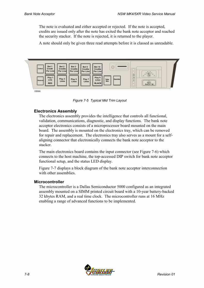
Bank Note Acceptor NSW MK4/5XR Video Service Manual
7-8 Revision 01
The note is evaluated and either accepted or rejected. If the note is accepted,credits are issued only after the note has exited the bank note acceptor and reachedthe security stacker. If the note is rejected, it is returned to the player.
A note should only be given three read attempts before it is classed as unreadable.
Collect
Reserve
Bet 3 Credits Per Line
Play 5 Lines
Bet 5 Credits Per Line
Play 7 Lines
Take Win
Gamble
Bet 2 Credits Per Line
Play 3 Lines
Bet 1 Credit Per Line
Play 1 Line
Bet 10 Credits Per Line
Play 9 Lines 5
10
20
I0066
RED BLACK
Figure 7-5 Typical Mid Trim Layout
Electronics Assembly The electronics assembly provides the intelligence that controls all functional,validation, communications, diagnostic, and display functions. The bank noteacceptor electronics consists of a microprocessor board mounted on the mainboard. The assembly is mounted on the electronics tray, which can be removedfor repair and replacement. The electronics tray also serves as a mount for a self-aligning connector that electronically connects the bank note acceptor to thestacker.
The main electronics board contains the input connector (see Figure 7-6) whichconnects to the host machine, the top-accessed DIP switch for bank note acceptorfunctional setup, and the status LED display.
Figure 7-7 displays a block diagram of the bank note acceptor interconnectionwith other assemblies.
Microcontroller The microcontroller is a Dallas Semiconductor 5000 configured as an integratedassembly mounted on a SIMM printed circuit board with a 10-year battery-backed32 kbytes RAM, and a real time clock. The microcontroller runs at 16 MHzenabling a range of advanced functions to be implemented.
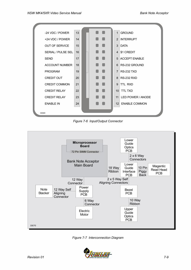
NSW MK4/5XR Video Service Manual Bank Note Acceptor
Revision 01 7-9
13
14
15
16
17
18
19
20
21
22
23
24
1 GROUND
2 INTERRUPT
3 DATA
4 $1 CREDIT
5 ACCEPT ENABLE
6 RS-232 GROUND
7 RS-232 TXD
8 RS-232 RXD
9 TTL RXD
10 TTL TXD
11 LED POWER / ANODE
12 ENABLE COMMON
-24 VDC / POWER
+24 VDC / POWER
OUT OF SERVICE
SERIAL / PULSE SEL
SEND
ACCOUNT NUMBER
PROGRAM
CREDIT OUT
CREDIT COMMON
CREDIT RELAY
CREDIT RELAY
ENABLE IN
I0069
Figure 7-6 Input/Output Connector
2 x 6 WayConnectors
18 WayRibbon
10 WayRibbon
10 PinPiggyBack
2 x 5 Way Self Aligning Connectors
MagenticRead Head
PCB
LowerGuideOptics PCB
LowerGuide
InterfacePCB
NoteStacker
PowerSupplyPCB
ElectricMotor
UpperGuideOpticsPCB
BezelPCB
I0070
6 WayConnector
12 WayConnector
12 Way SelfAligningConnector
MicroprocessorBoard
Bank Note Acceptor Main Board
72 Pin SIMM Connector
Figure 7-7 Interconnection Diagram
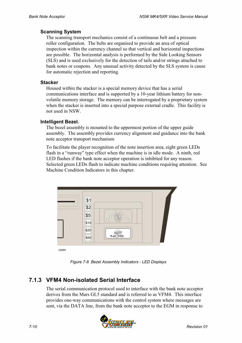
Bank Note Acceptor NSW MK4/5XR Video Service Manual
7-10 Revision 01
Scanning System The scanning transport mechanics consist of a continuous belt and a pressureroller configuration. The belts are organised to provide an area of opticalinspection within the currency channel so that vertical and horizontal inspectionsare possible. The horizontal analysis is performed by the Side Looking Sensors(SLS) and is used exclusively for the detection of tails and/or strings attached tobank notes or coupons. Any unusual activity detected by the SLS system is causefor automatic rejection and reporting.
Stacker Housed within the stacker is a special memory device that has a serialcommunications interface and is supported by a 10-year lithium battery for non-volatile memory storage. The memory can be interrogated by a proprietary systemwhen the stacker is inserted into a special purpose external cradle. This facility isnot used in NSW.
Intelligent Bezel.The bezel assembly is mounted to the uppermost portion of the upper guideassembly. The assembly provides currency alignment and guidance into the banknote acceptor transport mechanism
To facilitate the player recognition of the note insertion area, eight green LEDsflash in a “runway” type effect when the machine is in idle mode. A ninth, redLED flashes if the bank note acceptor operation is inhibited for any reason.Selected green LEDs flash to indicate machine conditions requiring attention. SeeMachine Condition Indicators in this chapter.
$1$2
$5$10
$20
$50
I0089
Figure 7-8 Bezel Assembly Indicators - LED Displays
7.1.3 VFM4 Non-isolated Serial InterfaceThe serial communication protocol used to interface with the bank note acceptorderives from the Mars GL5 standard and is referred to as VFM4. This interfaceprovides one-way communications with the control system where messages aresent, via the DATA line, from the bank note acceptor to the EGM in response to
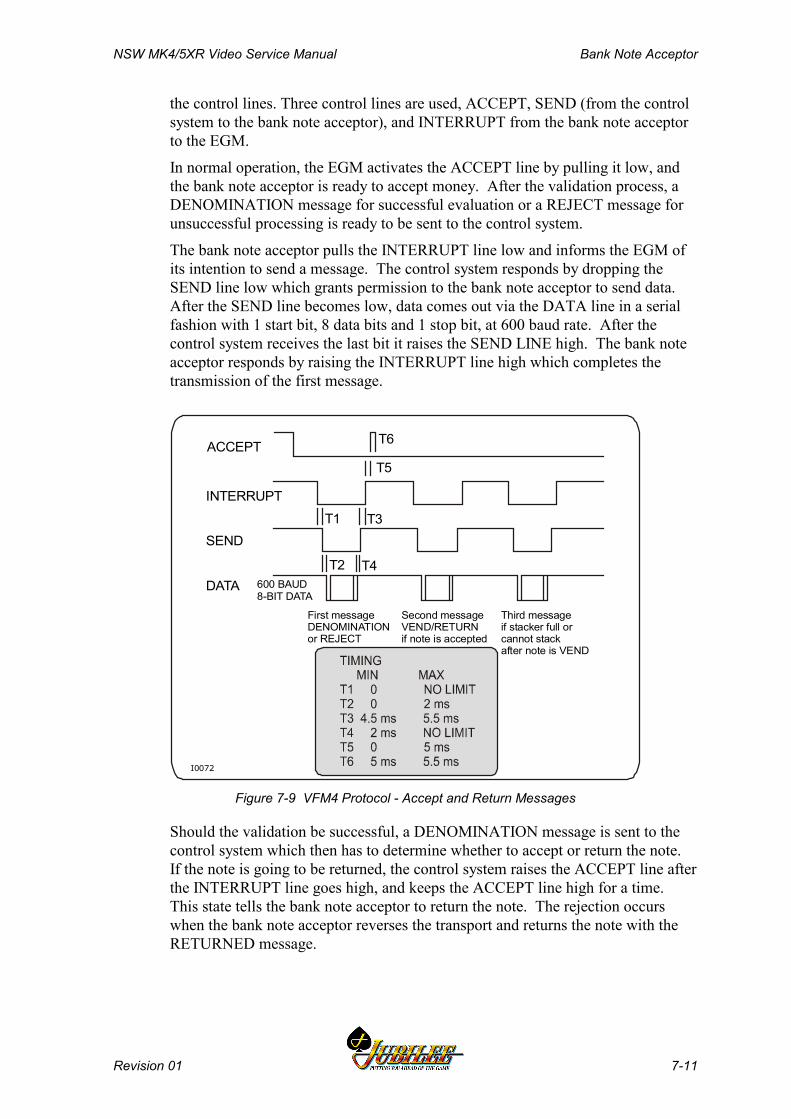
NSW MK4/5XR Video Service Manual Bank Note Acceptor
Revision 01 7-11
the control lines. Three control lines are used, ACCEPT, SEND (from the controlsystem to the bank note acceptor), and INTERRUPT from the bank note acceptorto the EGM.
In normal operation, the EGM activates the ACCEPT line by pulling it low, andthe bank note acceptor is ready to accept money. After the validation process, aDENOMINATION message for successful evaluation or a REJECT message forunsuccessful processing is ready to be sent to the control system.
The bank note acceptor pulls the INTERRUPT line low and informs the EGM ofits intention to send a message. The control system responds by dropping theSEND line low which grants permission to the bank note acceptor to send data.After the SEND line becomes low, data comes out via the DATA line in a serialfashion with 1 start bit, 8 data bits and 1 stop bit, at 600 baud rate. After thecontrol system receives the last bit it raises the SEND LINE high. The bank noteacceptor responds by raising the INTERRUPT line high which completes thetransmission of the first message.
First messageDENOMINATIONor REJECT
Second messageVEND/RETURNif note is accepted
Third messageif stacker full or cannot stackafter note is VEND
600 BAUD8-BIT DATA
ACCEPT
INTERRUPT
SEND
DATA
T6
T5
T4T2
T3T1
I0072
Figure 7-9 VFM4 Protocol - Accept and Return Messages
Should the validation be successful, a DENOMINATION message is sent to thecontrol system which then has to determine whether to accept or return the note.If the note is going to be returned, the control system raises the ACCEPT line afterthe INTERRUPT line goes high, and keeps the ACCEPT line high for a time.This state tells the bank note acceptor to return the note. The rejection occurswhen the bank note acceptor reverses the transport and returns the note with theRETURNED message.

Bank Note Acceptor NSW MK4/5XR Video Service Manual
7-12 Revision 01
If the control system decides to accept the note, the absence of the RETURNEDpulse on the ACCEPT line is interpreted by the bank note acceptor as anacceptance. The note then passed through the transport system to the stacker withthe message VEND.
In both cases, a second message, RETURN or VEND, is ready to be sent to thecontrol system by the bank note acceptor, and the same timing sequence isrepeated for the control lines. The communication session then ends.
A possible third message, STACKER FULL or FAILURE (the bank note acceptorand stacker cannot stack a note) can be sent to the control system, and the timingsequence is repeated for the message. The communication session then ends.
GL5 HEX CODE MESSAGES
$1 CREDIT$2 CREDIT$ 5 CREDIT$ 10 CREDIT$ 20 CREDIT$ 50 CREDIT$ 100 CREDITVENDRETURNEDREJECT FAILURESTACKER FULLJAM-STACKERLESSSRC STACKER REMOVEDSRC STACKER ATTACHED
81H82H83H84H85H86H87H89H8AH8BH8CH8DH8DH8EH8FH
Figure 7-10 VFM4 Protocol - Hex Code Messages
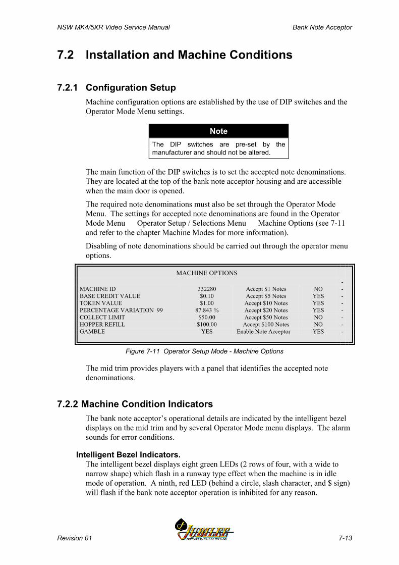
NSW MK4/5XR Video Service Manual Bank Note Acceptor
Revision 01 7-13
7.2 Installation and Machine Conditions
7.2.1 Configuration SetupMachine configuration options are established by the use of DIP switches and theOperator Mode Menu settings.
NoteThe DIP switches are pre-set by themanufacturer and should not be altered.
The main function of the DIP switches is to set the accepted note denominations.They are located at the top of the bank note acceptor housing and are accessiblewhen the main door is opened.
The required note denominations must also be set through the Operator ModeMenu. The settings for accepted note denominations are found in the OperatorMode Menu Operator Setup / Selections Menu Machine Options (see 7-11and refer to the chapter Machine Modes for more information).
Disabling of note denominations should be carried out through the operator menuoptions.
MACHINE OPTIONS-
MACHINE ID 332280 Accept $1 Notes NO -BASE CREDIT VALUE $0.10 Accept $5 Notes YES -TOKEN VALUE $1.00 Accept $10 Notes YES -PERCENTAGE VARIATION 99 87.843 % Accept $20 Notes YES -COLLECT LIMIT $50.00 Accept $50 Notes NO -HOPPER REFILL $100.00 Accept $100 Notes NO -GAMBLE YES Enable Note Acceptor YES -
Figure 7-11 Operator Setup Mode - Machine Options
The mid trim provides players with a panel that identifies the accepted notedenominations.
7.2.2 Machine Condition IndicatorsThe bank note acceptor’s operational details are indicated by the intelligent bezeldisplays on the mid trim and by several Operator Mode menu displays. The alarmsounds for error conditions.
Intelligent Bezel Indicators.The intelligent bezel displays eight green LEDs (2 rows of four, with a wide tonarrow shape) which flash in a runway type effect when the machine is in idlemode of operation. A ninth, red LED (behind a circle, slash character, and $ sign)will flash if the bank note acceptor operation is inhibited for any reason.

Bank Note Acceptor NSW MK4/5XR Video Service Manual
7-14 Revision 01
Malfunctions flash different rows of the green LEDs. The pair of LEDs nearestthe player is row number 1. The pair nearest the note entry channel is row number4. The bezel error messages are:
Row 1: Hardware fault. Row 2: Stacker full.Row 3: Jam in stacker. Row 4: Jam in currency channel.
Operator Mode Menu IndicatorsSeveral Operator Mode menu displays provide bank note acceptor informationthat addresses note entry history, machine status, accounting/audit/statistics data,and error and lockup information (refer to the chapter Machine Modes for furtherinformation).

NSW MK4/5XR Video Service Manual Bank Note Acceptor
Revision 01 7-15
7.3 Removal and Replacement Procedures
CAUTIONEnsure the power is turned off before anymaintenance procedures are carried out onthe bank note acceptor, stacker and dualcage doors.
CAUTIONThe Bank Note Acceptor is controlled bycomplex electronics. Unqualified personnelmust not interfere with the unit.
A feature of the Aristocrat bank note acceptor gaming machine is the method ofhousing the bank note acceptor. The unit is positioned within a dual cageassembly which supports the retaining pins located on each side of the bank noteacceptor assembly (see Figure 7-1). Electrical connection is through a singleconnector which supplies both power and communications. The connector iseasily accessed from the side of the unit when the main door is open.
Connection to the bank note stacker is automatically made through a blind mateconnector located at the bottom of the bank note acceptor unit.
7.3.1 Clearing the Bank Note StackerThe procedure for clearing the bank note stacker is strictly controlled by the housemanagement.
The stacker can be accessed and removed independently from the bank noteassembly by following the procedures outlined in this section.
RemovalTo remove the stacker:
1. Open the main door and turn the machine power OFF.2. Open the belly panel door.3. Unlock and pull down the stacker cage door. The lock up Stacker Removed
message occurs.4. Hold the stacker handle and withdraw the stacker from the machine.5. After the stacker is withdrawn, the stacker door must be unlocked before the
notes can be withdrawn. Each stacker may be numbered to assist accountingand control operations.
ReplacementTo replace the stacker:
1. Lock the stacker door and insert the stacker in the inner cage.
Bank Note Acceptor NSW MK4/5XR Video Service Manual
7-16 Revision 01
2. Close and lock the stacker cage door; close and lock the belly panel door.3. Turn the machine power ON; close and lock the main door.
7.3.2 Bank Note Acceptor Assembly
RemovalTo remove the bank note acceptor assembly:
1. Open the main door and turn the machine power OFF.2. Remove the 24 way connector from the left hand side of the assembly.3. Remove the two screws from the bottom of the assembly that secure the
locking plate to the cage and remove the locking plate.4. Unclamp the bank note acceptor outer cage top catch and pivot the assembly
forward.5. Carefully lift the assembly up and out of the machine.
ReplacementTo replace the bank note acceptor assembly:
1. Insert the assembly so that the dual cage location and pivot rest on theholding cradle.
2. Push the assembly back ensuring it clicks into place.3. Reconnect the connector.4. Replace the locking plate over the dual cage location & pivot and secure
with the two screws.5. Turn the machine power ON; close and lock the main door.
7.3.3 Clearing Bank Note Acceptor Jams If a jam occurs, the unit is usually able to clear itself within a short period as anautomatic process comes into effect. The unit runs the motor forward and thenreverses in an attempt to clear the jam. This routine continues for five attempts -should the jam persist, a fault message is initiated and a machine lock-up occurs.
The scanning and transport channel of the bank note acceptor passes currency in adirect process to the stacker. Should a note become lodged within the scanningchannel, see Figures 7-1 and 7-3 and complete the following steps to clear thejam:
1. Open the main door and turn the machine power OFF.2. Unclamp the bank note acceptor outer cage top catch and pivot assembly
forward.3. Open the upper guide by pushing it forward to release it from the metal
channel clip at the top of the acceptor and remove any obstruction.4. If this does not clear the jam, the acceptor will need to be removed from the
housing to enable complete access to the unit.5. Remove the connector from the left hand side of the assembly.6. Unclip the retaining clips, carefully lift up the assembly and manoeuvre it
out of the housing; remove any obstructions in the acceptor or on top of thestacker box.

NSW MK4/5XR Video Service Manual Bank Note Acceptor
Revision 01 7-17
To replace the bank note acceptor:
1. Close the upper guide and manoeuvre the unit back into the housing so that itrests on the retainer grooves.
2. Secure the unit with the retaining clips.3. Push the assembly back ensuring it clicks into place.4. Reconnect the connector.5. Turn the machine power ON; close and lock the main door.
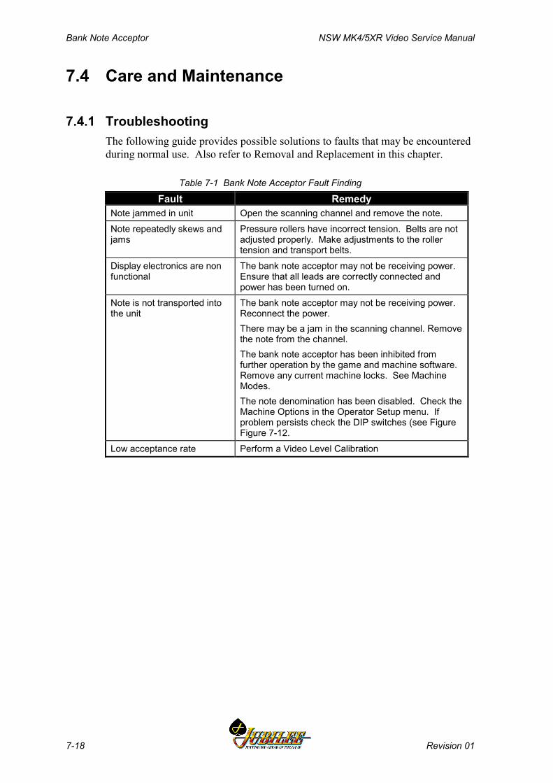
Bank Note Acceptor NSW MK4/5XR Video Service Manual
7-18 Revision 01
7.4 Care and Maintenance
7.4.1 TroubleshootingThe following guide provides possible solutions to faults that may be encounteredduring normal use. Also refer to Removal and Replacement in this chapter.
Table 7-1 Bank Note Acceptor Fault Finding
Fault RemedyNote jammed in unit Open the scanning channel and remove the note.Note repeatedly skews andjams
Pressure rollers have incorrect tension. Belts are notadjusted properly. Make adjustments to the rollertension and transport belts.
Display electronics are nonfunctional
The bank note acceptor may not be receiving power.Ensure that all leads are correctly connected andpower has been turned on.
Note is not transported intothe unit
The bank note acceptor may not be receiving power.Reconnect the power.There may be a jam in the scanning channel. Removethe note from the channel.The bank note acceptor has been inhibited fromfurther operation by the game and machine software.Remove any current machine locks. See MachineModes.The note denomination has been disabled. Check theMachine Options in the Operator Setup menu. Ifproblem persists check the DIP switches (see FigureFigure 7-12.
Low acceptance rate Perform a Video Level Calibration

NSW MK4/5XR Video Service Manual Bank Note Acceptor
Revision 01 7-19
I0127
1,2,3,4,5,6,7,8,9,10
OFF
ON
OFF
ON
Bank NoteAcceptor
DIP Switches
Figure 7-12 Bank Note Acceptor - DIP Switch Location
Table 7-2 Bank Note Acceptor DIP Switch FunctionsSwitch Position Function
1 ONOFF
Enable $100 notes.Disable $100 notes.
2 ONOFF
Enable $5 note.Disable $5 note.
3 ONOFF
Enable $10 note.Disable $10 note.
4 ONOFF
Enable $20 note.Disable $20 note.
5 ONOFF
Enable $50 note.Disable $50 note.
6 ONOFF
No function.
7 ONOFF
Display last 5 notes.Standard mode.
8 ONOFF
No function.
9 ONOFF
Service mode for video level calibration.Normal mode.
10 ONOFF
High level protocol.VFM4 protocol mode.
Bank Note Acceptor NSW MK4/5XR Video Service Manual
7-20 Revision 01
7.4.2 Periodic MaintenanceThe bank note acceptor and stacker require only a minimal amount of maintenancewhich can be provided while the units are in operating positions.
Occasional wiping of the plastic bezel surface is all that is required to removesurface deposits and smudges. A soft lint-free cloth dampened with a 90%solution of isopropyl alcohol is recommended for cleaning.
CautionCaution must be exercised not to flood thebezel area with liquids due to the electronicsin the bezel unit and because liquids mustnot seep down into the bank note acceptorunits below the bezel area.Do not use a solvent other than isopropylalcohol as permanent damage to the bezelassembly and other items may result.
Over a period of time, dirt from the surface of the notes will accumulate on thepressure rollers, drive belt surfaces and bank note acceptor optics. These areasshould be cleaned to ensure reliable operation.
To clean rollers, belt surfaces, and validation optics, proceed as follows:
1. Remove the bank note acceptor as described in Clearing Bank Note Jams inthis chapter.
2. Using a soft lint-free cloth dampened with 90% isopropyl alcohol, wipe thenote channel surfaces on both the upper and lower guides to remove anysurface dirt. Pay particular attention to the optics area and the magnetichead when removing deposits from the surfaces.
3. On the upper guide assembly, clean the surface of the pressure rollers. Thebelt surface may be cleaned by using a thumb to rotate one of the driverollers while holding the cleaning cloth against the surface of the belt.Again, caution should be used to prevent excess liquid from reaching thebank note acceptor internals.
7.4.3 Video Level CalibrationShould the bank note acceptor exhibit an unusually low level of acceptance, avideo level calibration can be performed as described below.
Video Level reference paper (Part No. CBV-1000) is required for this procedure.Do not use any other paper to perform this procedure.
Video Adjustment Procedure1. Apply power to the EGM and ensure the bank note acceptor runway lights
are operating normally.2. Locate the DIP switches at the top of the bank note acceptor (see Figure 7-
12) and turn DIP switch 9 ON (away from the front bezel).
NSW MK4/5XR Video Service Manual Bank Note Acceptor
Revision 01 7-21
NoteStep 4. must be executed within 5 secondsof Step 3.
3. Open and then close the currency channel.4. Within five seconds of step 3. above, insert the video level calibration paper
into the note entry area.5. The bank note acceptor will draw the paper in and step it out as it performs
the video calibration. The procedure is complete when the paper is fullyejected.
6. Turn DIP switch 9 OFF.7. Open and then close the currency channel.8. Test the operation of the bank note acceptor.

Bank Note Acceptor NSW MK4/5XR Video Service Manual
7-22 Revision 01
Notes
NSW MK4/5XR Video Service Manual Hopper
Revision 01 8-1
________Chapter 8________
Hopper
8.1 Technical Description ...................................................................... 8-3
8.1.1 Physical Description ................................................................... 8-38.1.2 Basic Operation.......................................................................... 8-68.1.3 Functional Description................................................................ 8-78.1.4 Hopper Interface Signals............................................................ 8-7
8.2 Removal and Replacement .............................................................. 8-8
8.2.1 Removal ..................................................................................... 8-88.2.2 Replacement .............................................................................. 8-8
8.3 Clearing Coin Jams .......................................................................... 8-9
8.4 Disassembly and Assembly........................................................... 8-10
8.4.1 Disassembly............................................................................. 8-108.4.2 Assembly.................................................................................. 8-11
8.5 Fault Finding ................................................................................... 8-12
8.6 General Maintenance...................................................................... 8-13

Hopper NSW MK4/5XR Video Service Manual
8-2 Revision 01
List of FiguresFigure 8-1 Hopper Location (Standard Disc Hopper shown)................................................ 8-3Figure 8-2 Hopper- rear view (Standard Disc Hopper Shown)............................................ 8-4Figure 8-3 Hopper - exploded view (Standard Disc Hopper Shown)................................... 8-5Figure 8-4 Hopper Photo-optic Detector............................................................................. 8-13
List of TablesTable 8-1 Fault Finding.......................................................................................................8-12
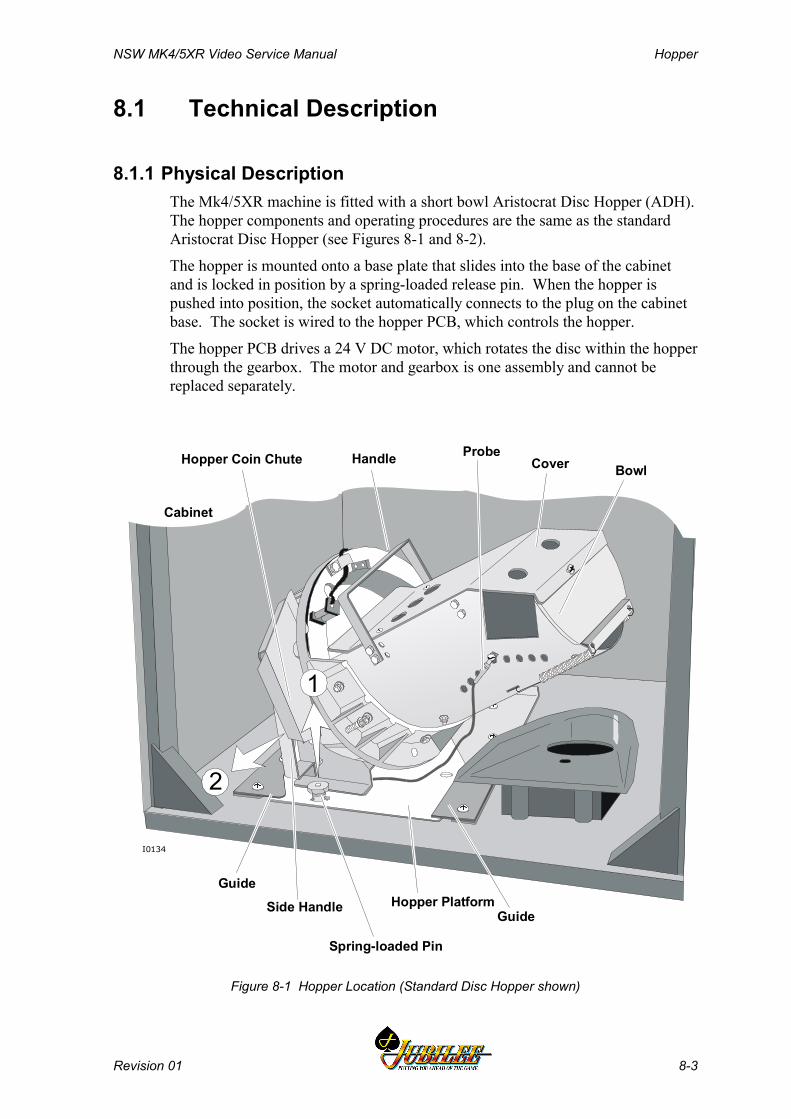
NSW MK4/5XR Video Service Manual Hopper
Revision 01 8-3
8.1 Technical Description
8.1.1 Physical DescriptionThe Mk4/5XR machine is fitted with a short bowl Aristocrat Disc Hopper (ADH).The hopper components and operating procedures are the same as the standardAristocrat Disc Hopper (see Figures 8-1 and 8-2).
The hopper is mounted onto a base plate that slides into the base of the cabinetand is locked in position by a spring-loaded release pin. When the hopper ispushed into position, the socket automatically connects to the plug on the cabinetbase. The socket is wired to the hopper PCB, which controls the hopper.
The hopper PCB drives a 24 V DC motor, which rotates the disc within the hopperthrough the gearbox. The motor and gearbox is one assembly and cannot bereplaced separately.
GuideHopper Platform
Spring-loaded Pin
Side HandleGuide
Hopper Coin Chute Handle ProbeCover Bowl
I0134
Cabinet
2
1
Figure 8-1 Hopper Location (Standard Disc Hopper shown)
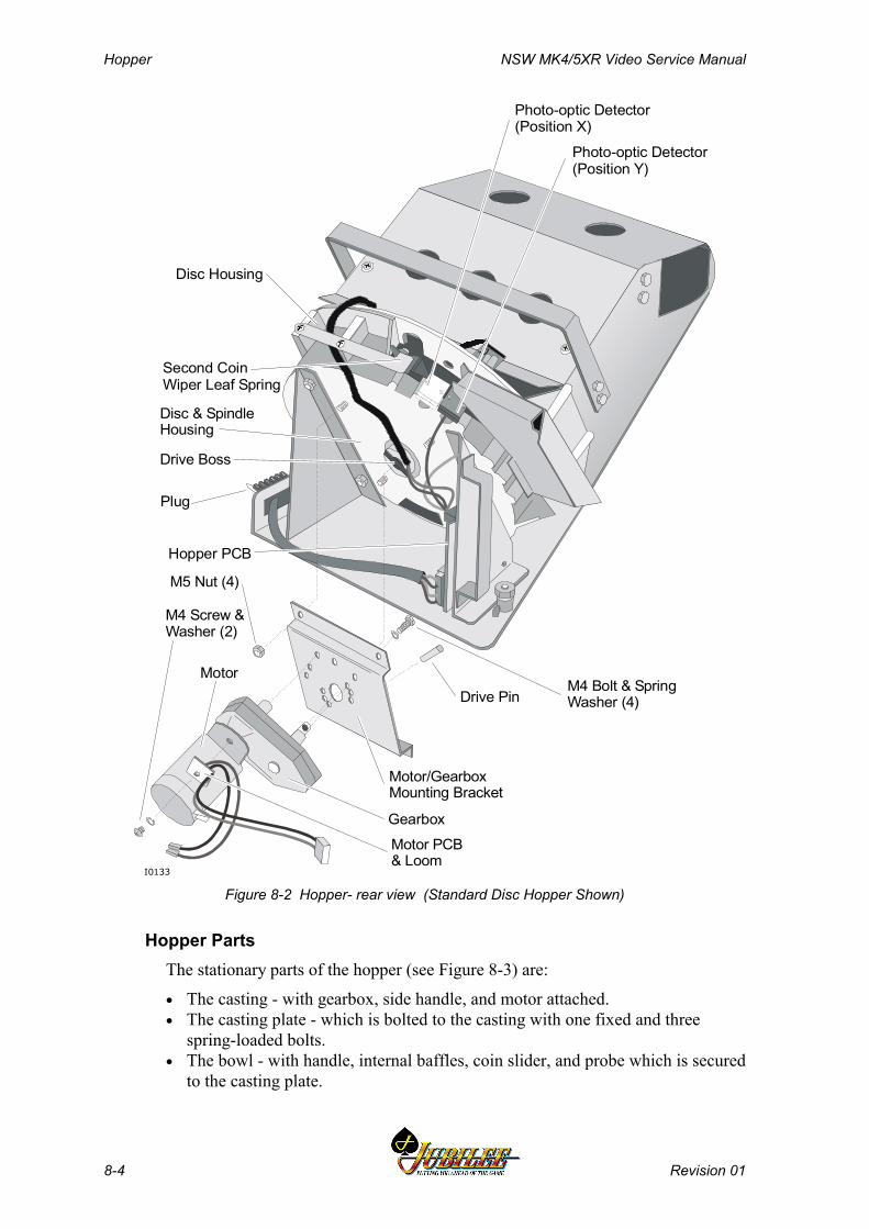
Hopper NSW MK4/5XR Video Service Manual
8-4 Revision 01
Motor/GearboxMounting Bracket
Drive Pin
Drive Boss
Disc & SpindleHousing
M4 Bolt & SpringWasher (4)
Motor PCB& Loom
M5 Nut (4)
Photo-optic Detector(Position X)
Photo-optic Detector(Position Y)
Hopper PCB
Gearbox
Motor
Plug
Second Coin Wiper Leaf Spring
Disc Housing
I0133
M4 Screw &Washer (2)
Figure 8-2 Hopper- rear view (Standard Disc Hopper Shown)
Hopper PartsThe stationary parts of the hopper (see Figure 8-3) are:
• The casting - with gearbox, side handle, and motor attached.• The casting plate - which is bolted to the casting with one fixed and three
spring-loaded bolts.• The bowl - with handle, internal baffles, coin slider, and probe which is secured
to the casting plate.
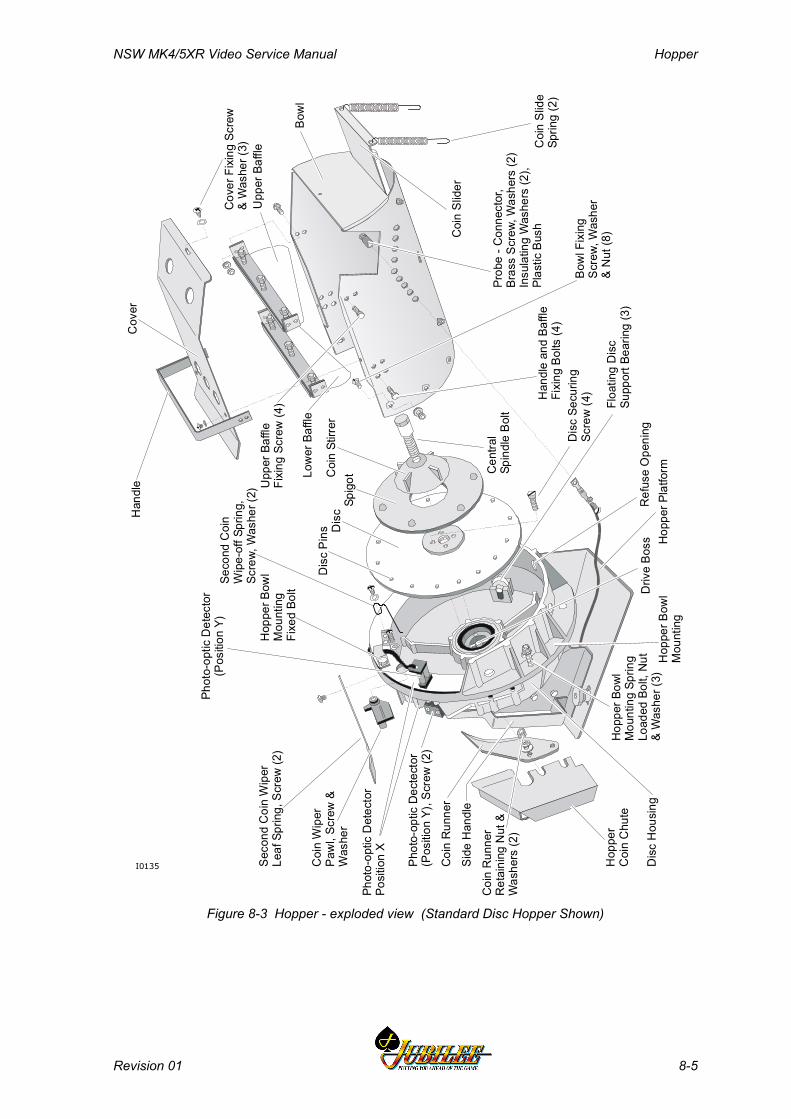
NSW MK4/5XR Video Service Manual Hopper
Revision 01 8-5
Cov
er
Upp
er B
affle
Cov
er F
ixin
g Sc
rew
& W
ashe
r (3)
Bow
l
Coi
n Sl
ider
Prob
e - C
onne
ctor
,Br
ass
Scre
w, W
ashe
rs (2
)In
sula
ting
Was
hers
(2),
Plas
tic B
ush
Bow
l Fix
ing
Scre
w, W
ashe
r&
Nut
(8)
Coi
n Sl
ide
Sprin
g (2
)H
andl
e an
d Ba
ffle
Fixi
ng B
olts
(4)
Cen
tral
Spin
dle
Bolt
Dis
c Se
curin
gSc
rew
(4)
Ref
use
Ope
ning
Driv
e Bo
ssH
oppe
r Bow
lM
ount
ing
Hop
per P
latfo
rm
Hop
per B
owl
Mou
ntin
g Sp
ring
Load
ed B
olt,
Nut
& W
ashe
r (3)
Coi
n R
unne
r
Side
Han
dle
Hop
per
Coi
n C
hute
Dis
c H
ousi
ng
Coi
n R
unne
rR
etai
ning
Nut
&W
ashe
rs (2
)
Phot
o-op
tic D
ecte
ctor
(P
ositi
on Y
), Sc
rew
(2)
Coi
n W
iper
Paw
l, Sc
rew
&W
ashe
r
Seco
nd C
oin
Wip
erLe
af S
prin
g, S
crew
(2)
Phot
o-op
tic D
etec
tor
Posi
tion
X
Coi
n St
irrer
Low
er B
affle
Upp
er B
affle
Fixi
ng S
crew
(4)
Phot
o-op
tic D
etec
tor
(Pos
ition
Y)
Hop
per B
owl
Mou
ntin
gFi
xed
Bolt
Seco
nd C
oin
Wip
e-of
f Spr
ing,
Scre
w, W
ashe
r (2)
Dis
c Pi
ns Dis
cSp
igot
Han
dle
I0135
Floa
ting
Dis
cSu
ppor
t Bea
ring
(3)
Figure 8-3 Hopper - exploded view (Standard Disc Hopper Shown)

Hopper NSW MK4/5XR Video Service Manual
8-6 Revision 01
The moving parts of the hopper, which are rotated by the motor (see Figure 8-3),are:
• the disc.• the spigot.• the coin stirrer.
The hopper PCB transmits two outputs from detectors:
• Output to the Main Board from a probe that detects when the hopper is full.• Output to the Main Board from a photo-optic detector, which detects coins as
they are dispensed from the hopper.
The photo-optic detector is mounted in one of two positions, Position X orPosition Y.
8.1.2 Basic OperationThe hopper holds and dispenses coins. Coins entering the machine are fed intothe hopper bowl or the cash box chute through the coin handling system. Coinsare fed into the cash box when the hopper is full.
The hopper dispenses coins into the coin tray when the player has credits andpresses the COLLECT pushbutton. Coins are dispensed via the hopper coin chutewhich juts out through the slot in the door reflector panel. The hopper can pay outany number of coins up to the cancel credit amount.
If the player presses the COLLECT pushbutton when the number of coins in creditis greater than the cancel credit amount, the machine locks up. The credits are paidas a book pay by the cashier, and the machine must be reset using the CancelCredit (Jackpot Reset) key.
If the player presses the COLLECT pushbutton when the number of coins in creditis below the cancel credit amount but greater than the number of coins in thehopper, all coins in the hopper are dispensed. The machine then locks up. Theattendant must refill the hopper and reset the machine before the balance of coinsis dispensed.
If the machine pays out too many coins, or not enough, the machine locks up andcannot be played until the attendant has fixed the problem.
NSW MK4/5XR Video Service Manual Hopper
Revision 01 8-7
8.1.3 Functional Description
Coin DispensingOn receiving a hopper drive signal from the Main Board, the hopper PCB startsthe hopper motor. The motor rotates the disc in an anticlockwise direction.
As the disc turns, the coins are caught between the disc pins and the edge of thespigot. If there is more than one coin between two pins on the disc, the excess iscleared by the second coin wipe-off spring. The second coin wiper pawl thenejects the payout coins from the disc into the hopper coin chute. For each coinentering the hopper coin chute, the photo-optic detector sends a signal to the MainBoard. The coin runner guides the coins into the hopper coin chute.
Each coin exiting the hopper interrupts the photo-optic detector which sends asignal to the main board via the hopper PCB and the interface board. The MainBoard counts the optic interrupts and when the correct payout number is reached,terminates the hopper drive signal to the hopper PCB. The hopper PCB stops themotor by an electronic braking action. The second coin wiper pawl prevents thenext coin from falling from the hopper disc.
Hopper Full DetectionA probe is fitted onto the hopper bowl to detect a full hopper (see Figure 8-1).When the coins reach the probe, they create an electrical circuit through the coinsto ground. The probe is monitored by the Main Board. If the probe indicates thatthe hopper is full, the software operates the diverter solenoid (situated on the frontof the inner door) which diverts the coins to the cash box. The position of theprobe in the hopper can be adjusted to alter the maximum coin level.
Coin Jamming PreventionA spigot and coin stirrer, which are friction fitted to the disc, keep the coinsmoving in the hopper bowl (see Figure 8-3). In addition, a spring-loaded coinslider prevents the hopper from jamming due to coin stacking.
Two baffles, secured with spring-loaded bolts, control the coin level in the bowl.
The casting plate is connected to the casting by four bolts. The top bolt is fixed,but the other three are spring loaded. This is to prevent serious damage to thecasting if there is a large coin jam in the bowl.
The opening on the hopper casting allows dirt and foreign objects to escape.
In the event of a coin jam, the motor will automatically stop and then restart afterabout eight seconds. If this does not remove the jam:
• the motor automatically stops.• the machine locks up.• the software displays a fault message on the video monitor.
8.1.4 Hopper Interface SignalsThe Aristocrat Disc Hopper interfaces with the Main Board via the 14-way Minifitconnector P25 on the Interface Board.

Hopper NSW MK4/5XR Video Service Manual
8-8 Revision 01
8.2 Removal and Replacement
CAUTIONAlways use the handle to lift the hopper.Never lift the hopper by the motor and theend of the bowl, as this action may bend themotor spindle.
CAUTIONAvoid handling the second coin wiper leafspring. If bent, it may cause an incorrectcoin payout and the machine to lock out.
8.2.1 Removal
To remove the hopper from the cabinet:
1. Open the cabinet door and switch OFF the machine.2. Lift the spring-loaded pin.3. Slide the hopper out of the machine.4. Lift the hopper by its handle.
NoteA Fault Tag must be placed on any faultyequipment.
8.2.2 Replacement
To replace the hopper in the cabinet:
1. Lift the hopper by its handle and slide it into the guides in the base of thecabinet.
2. Ensure that the spring-loaded pin is engaged in the retaining hole.3. Switch ON the machine; close and lock the cabinet door.
NoteThe hopper should be tested after replacing.To test the hopper, follow the hopper testprocedure outlined in the Machine Modessection.
NSW MK4/5XR Video Service Manual Hopper
Revision 01 8-9
8.3 Clearing Coin Jams
If a coin passes the hopper photo-optic detector when the player has not pressedthe COLLECT button or is not entitled to a payout, the machine locks up anddisplays the fault message ILLEGAL COIN OUT. If a coin jams in the hopperphoto-optic detector, the machine locks up and displays the fault messageHOPPER JAMMED.
CAUTIONAvoid handling the second coin wiper spring.If bent, it may cause an incorrect coinpayout.
To clear these lockups, take the following action:
1. Open the cabinet door, and switch OFF the machine.2. Clear any jammed coins from the coin chute and near the hopper photo-optic
detectors (see Figure 8-4).3. Check that the hopper coin chute is correctly aligned with the slot in the
door mounting panel.4. Switch ON the machine; close and lock the cabinet door.5. Turn the Jackpot Reset key ON then OFF to reset the machine.

Hopper NSW MK4/5XR Video Service Manual
8-10 Revision 01
8.4 Disassembly and Assembly
8.4.1 Disassembly
To disassemble the hopper (see Figure 8-3):
1. Remove the bowl assembly:a. Remove the four spring-loaded bolts that attach the casting plate to the
base of the hopper.b. Disconnect the hopper probe at the side of the bowl.c. Remove the photo-optic detector and the fixed bolt that restrains the
wire to the detector.d. Pull away the bowl (still attached to the casting plate) from the base of
the hopper.2. Remove the two coin runner retaining nuts.3. Remove the hopper coin chute.
CAUTIONIf shims are fitted under the coin runner,ensure they are not damaged whenremoving the coin runner or coin chute. Donot discard the shims.
4. Remove the coin runner.5. Remove the second coin wiper pawl.6. Remove the second coin wipe-off spring.
CAUTIONEnsure that the spring-loaded bearings donot fall out from their mountings in thecasting when removing the disc.
7. Remove the disc:a. Remove the centre bolt that holds the disc assembly in place.b. Remove the coin stirrer and spigot.c. Remove the four securing screws from the centre of the disc and
withdraw the disc from the drive boss.8. To remove the motor/gearbox unit (refer to Fig 8-3) and:
a. Disconnect the motor PCB and loom from the hopper PCB.b. Remove the nuts securing the motor/gearbox mounting bracket to the
disc and spindle housing.c. Tap out the drive pin, and remove the bolts securing the
motor/gearbox unit to the bracket.
NSW MK4/5XR Video Service Manual Hopper
Revision 01 8-11
8.4.2 Assembly
To assemble the hopper:
1. Replace the disc:a. Slide the drive shaft end of the disc into the drive boss, ensuring the
slot on the shaft engages with the drive pin in the gearbox.b. Insert the four securing screws in the centre of the disc and tighten.c. Place the second coin wiper pawl in position. Insert the screws and
tighten.d. Place the second coin wiper spring in position. Insert the two securing
set screws and tighten.e. Place the spigot and coin stirrer in position.f. Insert the centre bolt through the centre hole of the spigot and coin
stirrer and tighten onto the drive boss.g. Place the coin runner on the two studs. Screw on the two nuts and
washers, but do not tighten. Locate the point of the coin runner asclose as possible to the spigot without rubbing, and ensure freerunning of the disc underneath the coin runner. Use shims if required.
h. Slide the hopper coin chute under the two bolts holding the coinrunner and tighten the nuts.
2. Replace the bowl assembly:a. Place the bowl assembly (still attached to the casting plate) in position
on base of the hopper.b. Insert the four spring-loaded bolts into the casting plate and tighten.c. Place the photo-optic detector in position, insert the screw and tighten.d. Place the fixed bolt in position so that it restrains the wire for the
photo-optic detector, and tighten the bolt.
NoteThe hopper should be tested after servicing.To test the hopper, follow the hopper testprocedure outlined in the Machine Modessection.
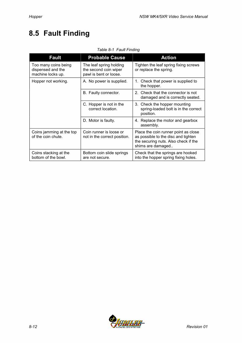
Hopper NSW MK4/5XR Video Service Manual
8-12 Revision 01
8.5 Fault Finding
Table 8-1 Fault Finding
Fault Probable Cause ActionToo many coins beingdispensed and themachine locks up.
The leaf spring holdingthe second coin wiperpawl is bent or loose.
Tighten the leaf spring fixing screwsor replace the spring.
Hopper not working. A. No power is supplied. 1. Check that power is supplied tothe hopper.
B. Faulty connector. 2. Check that the connector is notdamaged and is correctly seated.
C. Hopper is not in thecorrect location.
3. Check the hopper mountingspring-loaded bolt is in the correctposition.
D. Motor is faulty. 4. Replace the motor and gearboxassembly.
Coins jamming at the topof the coin chute.
Coin runner is loose ornot in the correct position.
Place the coin runner point as closeas possible to the disc and tightenthe securing nuts. Also check if theshims are damaged..
Coins stacking at thebottom of the bowl.
Bottom coin slide springsare not secure.
Check that the springs are hookedinto the hopper spring fixing holes.
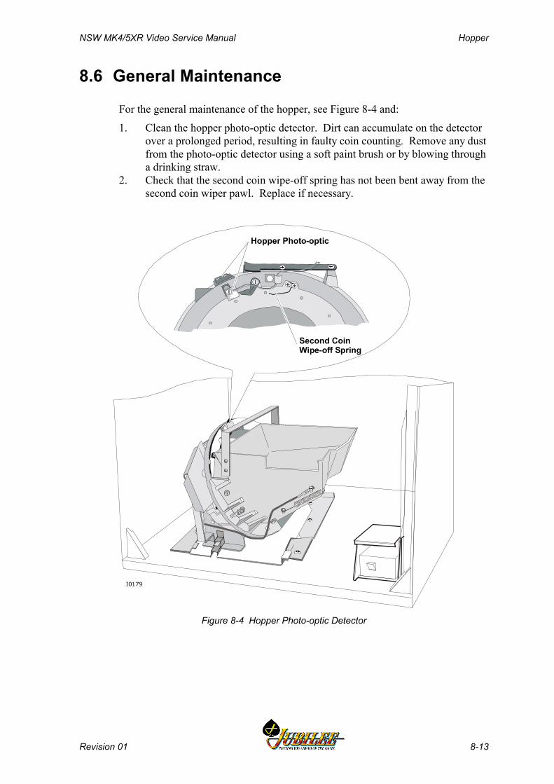
NSW MK4/5XR Video Service Manual Hopper
Revision 01 8-13
8.6 General Maintenance
For the general maintenance of the hopper, see Figure 8-4 and:
1. Clean the hopper photo-optic detector. Dirt can accumulate on the detectorover a prolonged period, resulting in faulty coin counting. Remove any dustfrom the photo-optic detector using a soft paint brush or by blowing througha drinking straw.
2. Check that the second coin wipe-off spring has not been bent away from thesecond coin wiper pawl. Replace if necessary.
Second CoinWipe-off Spring
Hopper Photo-optic
I0179
Figure 8-4 Hopper Photo-optic Detector

Hopper NSW MK4/5XR Video Service Manual
8-14 Revision 01
Notes
NSW MK4/5XR Video Service Manual Video Monitor
Revision 01 9-1
________Chapter 9________
Video Monitor
9.1 Ceronix Monitor - General Description................................... 9-3
9.2 Technical Description.............................................................. 9-4
9.2.1 Power Supply ............................................................................. 9-49.2.2 Adjustment Procedures.............................................................. 9-4
9.3 Removal and Replacement...................................................... 9-6
9.4 General Maintenance ............................................................... 9-6
9.5 Degaussing............................................................................... 9-7

Video Monitor NSW MK4/5XR Video Service Manual
9-2 Revision 01
List of FiguresFigure 9-1 Ceronix Video Monitor and Control Panel ......................................................9-5
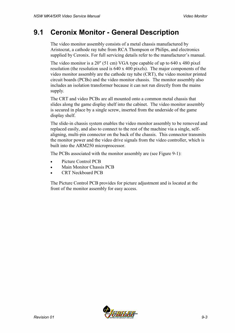
NSW MK4/5XR Video Service Manual Video Monitor
Revision 01 9-3
9.1 Ceronix Monitor - General DescriptionThe video monitor assembly consists of a metal chassis manufactured byAristocrat, a cathode ray tube from RCA Thompson or Philips, and electronicssupplied by Ceronix. For full servicing details refer to the manufacturer’s manual.
The video monitor is a 20" (51 cm) VGA type capable of up to 640 x 480 pixelresolution (the resolution used is 640 x 400 pixels). The major components of thevideo monitor assembly are the cathode ray tube (CRT), the video monitor printedcircuit boards (PCBs) and the video monitor chassis. The monitor assembly alsoincludes an isolation transformer because it can not run directly from the mainssupply.
The CRT and video PCBs are all mounted onto a common metal chassis thatslides along the game display shelf into the cabinet. The video monitor assemblyis secured in place by a single screw, inserted from the underside of the gamedisplay shelf.
The slide-in chassis system enables the video monitor assembly to be removed andreplaced easily, and also to connect to the rest of the machine via a single, self-aligning, multi-pin connector on the back of the chassis. This connector transmitsthe monitor power and the video drive signals from the video controller, which isbuilt into the ARM250 microprocessor.
The PCBs associated with the monitor assembly are (see Figure 9-1):
• Picture Control PCB• Main Monitor Chassis PCB• CRT Neckboard PCB
The Picture Control PCB provides for picture adjustment and is located at thefront of the monitor assembly for easy access.

Video Monitor NSW MK4/5XR Video Service Manual
9-4 Revision 01
9.2 Technical DescriptionFor a full technical description, refer to separate Ceronix service manual.
9.2.1 Power SupplyThe Ceronix monitor requires isolated mains input which is supplied by anisolated transformer box mounted on the inside of the monitor chassis. A powersupply regulator circuit converts the isolated mains input to the voltages requiredby the monitor.
9.2.2 Adjustment ProceduresThe Picture Control PCB is located at the front of the monitor assembly for easyaccess. It provides the following controls and adjustments for the monitor picture.
• Horizontal Raster size• Vertical Raster size• Vertical Picture position• Horizontal Picture position• Video Gain (Contrast)
These controls can be adjusted only to a limited amount. The brightness will bemaintained throughout the life of the unit by the auto-brightness circuit.
All colours are automatically adjusted by the auto bias circuit and will remainconstant throughout the life of the unit.
Pincushion distortion is automatically adjusted using the auto bias circuit.

NSW MK4/5XR Video Service Manual Video Monitor
Revision 01 9-5
HORIZONTALSIZEVERTICALSIZE
HORIZONTALPOSITION
VERTICALPOSITION
MASTER GAIN(CONTRAST)
Picture Control PCBI0105
CRT
MonitorSelf-aligningConnector
CRT Neckboard PCB
MonitorChassis
CRT EarthStrap
CRT Anode
Main MonitorChassis PCB
Figure 9-1 Ceronix Video Monitor and Control Panel
Video Monitor NSW MK4/5XR Video Service Manual
9-6 Revision 01
9.3 Removal and ReplacementTo remove the monitor assembly from the machine:
WARNINGHigh voltages are present at the rear of themonitor when the machine is ON. SwitchOFF the machine before removing themonitor.
WARNINGThe monitor assembly is a heavy item(approximately 20 kg). Care should betaken when removing the monitor assemblyto prevent personal injury or damage to themonitor.
To remove the monitor:
1. Open the cabinet door, and switch OFF the machine.2. Remove the two bolts from the underside of the game display shelf.3. Gently pull the monitor assembly from the machine. The steel frame of the
monitor assembly has openings at either side to facilitate handling.
Replacement is a reversal of the removal procedure.
9.4 General MaintenanceFor general maintenance of the video monitor:
• Remove any dust or dirt from external surfaces.• Clean the monitor screen with a soft cloth and suitable cleaning agents.• Check that all connectors are secure.• Check that all monitor assembly PCBs are secure and properly connected.• Check that the monitor and monitor mask fit correctly when the cabinet door
is closed.
NSW MK4/5XR Video Service Manual Video Monitor
Revision 01 9-7
9.5 DegaussingMagnetic interference can cause colour aberrations on the monitor screen. Torestore the colour purity of the monitor picture, the monitor and cabinet need to bedegaussed.
Note that the monitor colour aberrations can occur due to normal deliverymovements, installation operations, and through leaving the main door openduring power-up processes.
The monitor assembly is fitted with an automatic degaussing coil and circuitry thatemits a degaussing pulse during power up, provided the machine has been withoutpower for 30 minutes. This time delay enables the circuit varistors to coolsufficiently and create enough energy to degauss both the monitor's ferrouscontent and the cabinet.
To carry out degaussing:
1. Power down the machine and wait for a 30-minute period to elapse. Thistime delay enables the monitor circuit varistors to cool sufficiently andcreate enough energy to degauss both the monitor's ferrous content and thatof the cabinet.
2. Power up the machine and close the door within 5 seconds. Automaticdegaussing will now occur.
3. If the aberration persists due to the presence of a particularly strongmagnetic field, it will be necessary to make use of a degaussing wand.Follow the standard field procedures for degaussing-wand usage.

Video Monitor NSW MK4/5XR Video Service Manual
9-8 Revision 01
Notes
NSW MK4/5XR Video Service Manual Electromechanical Meters
Revision 01 10-1
______Chapter 10______
Electromechanical Meters
10.1 General Description ............................................................... 10-3
10.2 Functional Description .......................................................... 10-4
10.2.1 Serial Interface ......................................................................... 10-410.2.2 Overcurrent Protection ............................................................. 10-510.2.3 Meter Drive Outputs ................................................................. 10-510.2.4 PCB Expansion ........................................................................ 10-510.2.5 Light Tower Interface ............................................................... 10-510.2.6 Security Interface ..................................................................... 10-510.2.7 Meter Detection........................................................................ 10-5
10.3 Removal and Replacement Procedures ............................... 10-7
10.4 Connector Pin Assignment ................................................... 10-8
10.5 General Maintenance ........................................................... 10-10
Electromechanical Meters NSW MK4/5XR Video Service Manual
10-2 Revision 01
List of Figures:Figure 10-1 Electromechanical Meter Board - Location ................................................10-3Figure 10-2 Electromechanical Meter Board - 410366 Block Diagram .........................10-4Figure 10-3 Electromechanical Meter Board - 410366 Component and Solder
Sides ...............................................................................................................10-6
List of TablesTable 10-1 J1 - Main Connector to Interface Board ......................................................10-8Table 10-2 J2 - Meter Drive Output Interface................................................................10-8Table 10-3 J3 - Additional Meters Interface...................................................................10-9Table 10-4 J4 - Light Tower Interface............................................................................10-9Table 10-5 S1 - Security Interface.................................................................................10-9
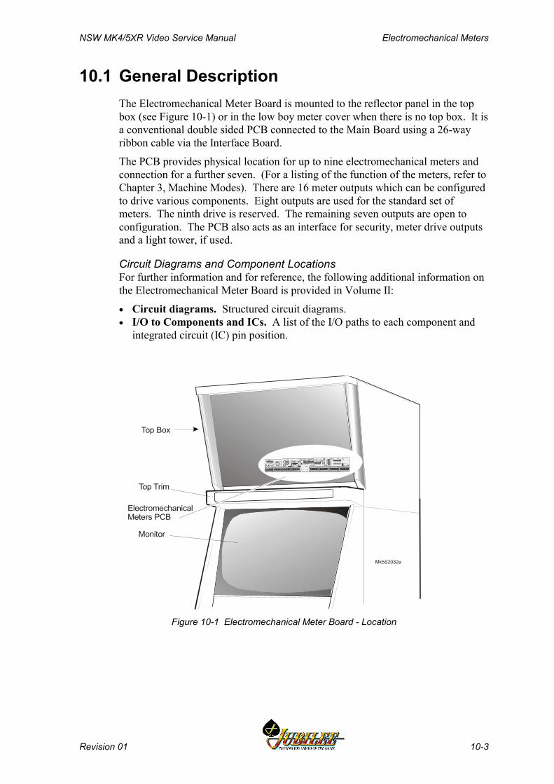
NSW MK4/5XR Video Service Manual Electromechanical Meters
Revision 01 10-3
10.1 General DescriptionThe Electromechanical Meter Board is mounted to the reflector panel in the topbox (see Figure 10-1) or in the low boy meter cover when there is no top box. It isa conventional double sided PCB connected to the Main Board using a 26-wayribbon cable via the Interface Board.
The PCB provides physical location for up to nine electromechanical meters andconnection for a further seven. (For a listing of the function of the meters, refer toChapter 3, Machine Modes). There are 16 meter outputs which can be configuredto drive various components. Eight outputs are used for the standard set ofmeters. The ninth drive is reserved. The remaining seven outputs are open toconfiguration. The PCB also acts as an interface for security, meter drive outputsand a light tower, if used.
Circuit Diagrams and Component LocationsFor further information and for reference, the following additional information onthe Electromechanical Meter Board is provided in Volume II:
• Circuit diagrams. Structured circuit diagrams.• I/O to Components and ICs. A list of the I/O paths to each component and
integrated circuit (IC) pin position.
Top Box
Monitor
Top Trim
ElectromechanicalMeters PCB
Figure 10-1 Electromechanical Meter Board - Location
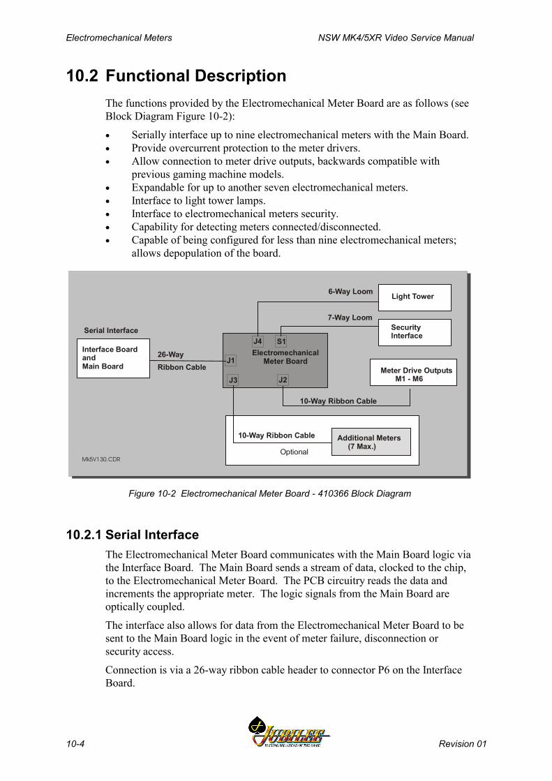
Electromechanical Meters NSW MK4/5XR Video Service Manual
10-4 Revision 01
10.2 Functional DescriptionThe functions provided by the Electromechanical Meter Board are as follows (seeBlock Diagram Figure 10-2):
• Serially interface up to nine electromechanical meters with the Main Board.• Provide overcurrent protection to the meter drivers.• Allow connection to meter drive outputs, backwards compatible with
previous gaming machine models.• Expandable for up to another seven electromechanical meters.• Interface to light tower lamps.• Interface to electromechanical meters security.• Capability for detecting meters connected/disconnected.• Capable of being configured for less than nine electromechanical meters;
allows depopulation of the board.
Mk5V130.CDR
Light Tower
SecurityInterface
7-Way Loom
6-Way Loom
10-Way Ribbon Cable
Additional Meters (7 Max.)
10-Way Ribbon Cable
Optional
26-Way Ribbon Cable
Serial Interface
Interface BoardandMain Board
ElectromechanicalMeter Board
Meter Drive Outputs M1 - M6
J1
J2J3
J4 S1
Figure 10-2 Electromechanical Meter Board - 410366 Block Diagram
10.2.1 Serial InterfaceThe Electromechanical Meter Board communicates with the Main Board logic viathe Interface Board. The Main Board sends a stream of data, clocked to the chip,to the Electromechanical Meter Board. The PCB circuitry reads the data andincrements the appropriate meter. The logic signals from the Main Board areoptically coupled.
The interface also allows for data from the Electromechanical Meter Board to besent to the Main Board logic in the event of meter failure, disconnection orsecurity access.
Connection is via a 26-way ribbon cable header to connector P6 on the InterfaceBoard.
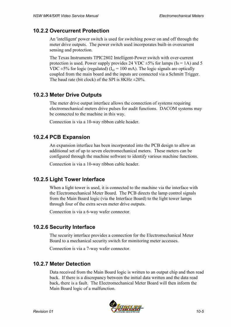
NSW MK4/5XR Video Service Manual Electromechanical Meters
Revision 01 10-5
10.2.2 Overcurrent ProtectionAn 'intelligent' power switch is used for switching power on and off through themeter drive outputs. The power switch used incorporates built-in overcurrentsensing and protection.
The Texas Instruments TPIC2802 Intelligent-Power switch with over-currentprotection is used. Power supply provides 24 VDC ±5% for lamps (Is = 1A) and 5VDC ±5% for logic (regulated) (Icc = 100 mA). The logic signals are opticallycoupled from the main board and the inputs are connected via a Schmitt Trigger.The baud rate (bit clock) of the SPI is 8KHz ±20%.
10.2.3 Meter Drive OutputsThe meter drive output interface allows the connection of systems requiringelectromechanical meters drive pulses for audit functions. DACOM systems maybe connected to the machine in this way.
Connection is via a 10-way ribbon cable header.
10.2.4 PCB ExpansionAn expansion interface has been incorporated into the PCB design to allow anadditional set of up to seven electromechanical meters. These meters can beconfigured through the machine software to identify various machine functions.
Connection is via a 10-way ribbon cable header.
10.2.5 Light Tower InterfaceWhen a light tower is used, it is connected to the machine via the interface withthe Electromechanical Meter Board. The PCB directs the lamp control signalsfrom the Main Board logic (via the Interface Board) to the light tower lampsthrough four of the extra seven meter drive outputs.
Connection is via a 6-way wafer connector.
10.2.6 Security InterfaceThe security interface provides a connection for the Electromechanical MeterBoard to a mechanical security switch for monitoring meter accesses.
Connection is via a 7-way wafer connector.
10.2.7 Meter DetectionData received from the Main Board logic is written to an output chip and then readback. If there is a discrepancy between the initial data written and the data readback, there is a fault. The Electromechanical Meter Board will then inform theMain Board logic of a malfunction.
Electromechanical Meters NSW MK4/5XR Video Service Manual
10-6 Revision 01
Opt
iona
l Mec
hani
cal
Secu
rity
Switc
h
Figure 10-3 Electromechanical Meter Board - 410366 Component and Solder Sides
NSW MK4/5XR Video Service Manual Electromechanical Meters
Revision 01 10-7
10.3 Removal and Replacement Procedures
CAUTIONWhen handling electrostatic devices (ESDs)such as PCBs, take care to avoid physicalcontact with components. Handle PCBs bytheir edges. Do not place ESD items onmetal surfaces. When handling PCBs, takecare to avoid flexing the PCB. Flexing maycause physical damage.
From the Top BoxTo remove the Electromechanical Meter Board from the top box:
1. Open the cabinet door, and turn OFF the machine.2. Remove the top box door and reflector panel (refer to the chapter - Cabinet,
Door and Top Box).3. Disconnect the looms from the Electromechanical Meter Board.4. Remove the screws securing the board.
Replacement is a reversal of the removal procedure.
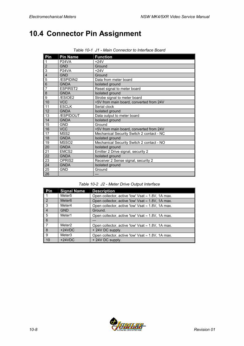
Electromechanical Meters NSW MK4/5XR Video Service Manual
10-8 Revision 01
10.4 Connector Pin Assignment
Table 10-1 J1 - Main Connector to Interface BoardPin Pin Name Function1 P24VA +24V2 GND Ground3 P24VA +24V4 GND Ground5 /ESPIDIN2 Data from meter board6 GNDA Isolated ground7 ESPIRST2 Reset signal to meter board8 GNDA Isolated ground9 /ESIOE2 Strobe signal to meter board10 VCC +5V from main board, converted from 24V11 ESCLK Serial clock12 GNDA Isolated ground13 /ESPIDOUT Data output to meter board14 GNDA Isolated ground15 GND Ground16 VCC +5V from main board, converted from 24V17 MSS2 Mechanical Security Switch 2 contact - NC18 GNDA Isolated ground19 MSSO2 Mechanical Security Switch 2 contact - NO20 GNDA Isolated ground21 EMCS2 Emitter 2 Drive signal, security 222 GNDA Isolated ground23 OPRIS2 Receiver 2 Sense signal, security 224 GNDA Isolated ground25 GND Ground26 ---
Table 10-2 J2 - Meter Drive Output InterfacePin Signal Name Description1 Meter5 Open collector, active 'low' Vsat ≈ 1.8V, 1A max.2 Meter6 Open collector, active 'low' Vsat ≈ 1.8V, 1A max.3 Meter4 Open collector, active 'low' Vsat ≈ 1.8V, 1A max.4 GND Ground.5 Meter1 Open collector, active 'low' Vsat ≈ 1.8V, 1A max.6 ---7 Meter2 Open collector, active 'low' Vsat ≈ 1.8V, 1A max.8 +24VDC + 24V DC supply.9 Meter3 Open collector, active 'low' Vsat ≈ 1.8V, 1A max.10 +24VDC + 24V DC supply.
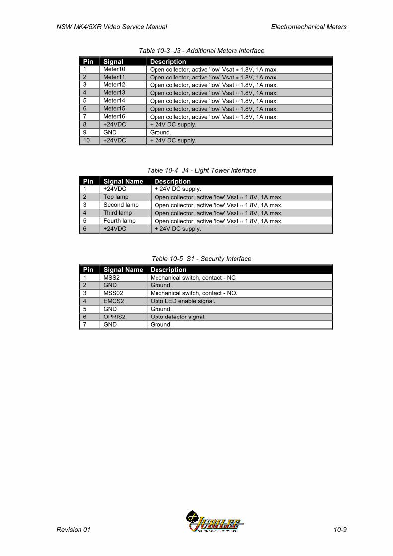
NSW MK4/5XR Video Service Manual Electromechanical Meters
Revision 01 10-9
Table 10-3 J3 - Additional Meters InterfacePin Signal Description1 Meter10 Open collector, active 'low' Vsat ≈ 1.8V, 1A max.2 Meter11 Open collector, active 'low' Vsat ≈ 1.8V, 1A max.3 Meter12 Open collector, active 'low' Vsat ≈ 1.8V, 1A max.4 Meter13 Open collector, active 'low' Vsat ≈ 1.8V, 1A max.5 Meter14 Open collector, active 'low' Vsat ≈ 1.8V, 1A max.6 Meter15 Open collector, active 'low' Vsat ≈ 1.8V, 1A max.7 Meter16 Open collector, active 'low' Vsat ≈ 1.8V, 1A max.8 +24VDC + 24V DC supply.9 GND Ground.10 +24VDC + 24V DC supply.
Table 10-4 J4 - Light Tower InterfacePin Signal Name Description1 +24VDC + 24V DC supply.2 Top lamp Open collector, active 'low' Vsat ≈ 1.8V, 1A max.3 Second lamp Open collector, active 'low' Vsat ≈ 1.8V, 1A max.4 Third lamp Open collector, active 'low' Vsat ≈ 1.8V, 1A max.5 Fourth lamp Open collector, active 'low' Vsat ≈ 1.8V, 1A max.6 +24VDC + 24V DC supply.
Table 10-5 S1 - Security InterfacePin Signal Name Description1 MSS2 Mechanical switch, contact - NC.2 GND Ground.3 MSS02 Mechanical switch, contact - NO.4 EMCS2 Opto LED enable signal.5 GND Ground.6 OPRIS2 Opto detector signal.7 GND Ground.
Electromechanical Meters NSW MK4/5XR Video Service Manual
10-10 Revision 01
10.5 General Maintenance
CAUTIONDo not attempt component level repairwithout access to a workshop facility.
For general maintenance of the Electromechanical Meter Board:
• Remove any dust or dirt from external surfaces.• Check that all connectors are in good condition and are secure.

NSW MK4/5XR Video Service Manual Main Board
Revision 01 11-1
________Chapter 11________
Main Board
410389 - double sided or410448 – single sided
11.1 Introduction..................................................................................... 11-4
11.2 Physical Description ...................................................................... 11-5
11.2.1 Diagrams and Component Locations ....................................... 11-5
11.3 Functional Description.................................................................. 11-6
11.3.1 Main Board Functions .............................................................. 11-7
11.4 Technical Description ................................................................... 11-8
11.4.1 ARM250 Microprocessor........................................................ 11-1011.4.2 Sound..................................................................................... 11-1111.4.3 Video ...................................................................................... 11-1211.4.4 Reset...................................................................................... 11-1211.4.5 Debug (Keyboard) Port .......................................................... 11-1311.4.6 Debugging.............................................................................. 11-1311.4.7 External I/O Expansion........................................................... 11-1411.4.8 Mikohn Link Progressive Interface (where fitted) ................... 11-1411.4.9 Memory .................................................................................. 11-1511.4.10 Real Time Clock..................................................................... 11-1611.4.11 Battery Backup Circuit............................................................ 11-1611.4.12 Power Control Interface.......................................................... 11-1711.4.13 SPI Bus Driver and Multiplexer Circuitry ................................ 11-1811.4.14 Printer and Mechanical Meters............................................... 11-1911.4.15 Mechanical Switches.............................................................. 11-1911.4.16 Security .................................................................................. 11-19
Main Board NSW MK4/5XR Video Service Manual
11-2 Revision 01
11.4.17 Coin Handling System............................................................11-2011.4.18 Hopper Interface.....................................................................11-2111.4.19 Serial Channels ......................................................................11-2111.4.20 Bank Note Acceptor ...............................................................11-2211.4.21 Interface Board.......................................................................11-22
11.5 Removal and Replacement Procedures.....................................11-23
11.6 Description of Connectors...........................................................11-24
11.6.1 Communications Configuration Board....................................11-2411.6.2 Optically Isolated Connector - P20 .........................................11-2611.6.3 Miscellaneous Connector - P22..............................................11-2811.6.4 Security and I/O Expansion Connector - P21.........................11-30
NSW MK4/5XR Video Service Manual Main Board
Revision 01 11-3
List of FiguresFigure 11-1 Location of Main Board ................................................................................... 11-5Figure 11-2 System Architecture........................................................................................ 11-6Figure 11-3 Main Board block diagram .............................................................................. 11-8Figure 11-4 Typical Main Board layout (not detailed) ......................................................... 11-9
List of TablesTable 11-1 Serial EEPROMs Characteristics................................................................... 11-16Table 11-2 Power Control System Signal Lines ............................................................... 11-17Table 11-3 SPI Channel Signals ...................................................................................... 11-18Table 11-4 Optical Security Sensor Assignment.............................................................. 11-19Table 11-5 Mechanical Security Switch Assignment........................................................ 11-20Table 11-6 Coin Handling Signals .................................................................................... 11-20Table 11-7 Hopper Control Signals .................................................................................. 11-21Table 11-8 Communications Configuration Board connector - P23................................. 11-24Table 11-9 Optically Isolated Connector - P20................................................................. 11-26Table 11-10 Miscellaneous Connector - P22 ................................................................... 11-28Table 11-11 Security and I/O Expansion Connector - P21............................................... 11-30

Main Board NSW MK4/5XR Video Service Manual
11-4 Revision 01
11.1IntroductionThe Main Board provides central control of the gaming machine. The board isfitted with an ARM RISC microprocessor which interfaces with other equipmentin the machine via the Interface Board.
The machine may be fitted with one of two Main Boards:
Part No. 2501-410389 or 2501-410448.
The main features of the Main Board are as follows:
• ARM RISC microprocessor operating at 12 MHz (combines CPU, memorymanagement, I/O Interface, audio and video on a single chip)
• on-board power supply regulator• audio amplifier for speaker• game EPROMS• security monitoring of machine door activities• serial channels• watchdog timer and reset• surface mounted technology• flexible design allows for future changes to the machine configuration.

NSW MK4/5XR Video Service Manual Main Board
Revision 01 11-5
11.2Physical DescriptionThe Main Board contains an ARM RISC microprocessor that interfaces with anumber of subsystems via the Interface Board. Figure 11-2 provides a blockdiagram illustrating the electronics system architecture. The system is available invarious configurations to meet specific machine requirements.
The Main Board, along with the other major PCBAs, is located within the securitylogic cage (see Figure 11-1). The logic cage is a lockable, steel box locatedunderneath the monitor shelf. It provides security and protection for the PCBAs.
The Main Board slides on guides within the cage and connects directly to theInterface Board via three 96-way DIN 41612 connectors. Connectors are providedon the Main Board for the Communications Configuration Board and an optionalmemory expansion PCBA.
Interface Board
Logic Cage
Main Board
I/O Driver Board
I/O Expansion Board or LAB Communications Board
(if fitted)
I0076
Figure 11-1 Location of Main Board
11.2.1 Diagrams and Component LocationsFor further information and for reference, the following additional information onthe Main Board is provided in Volume II:
• Circuit diagrams. Structured circuit diagrams.• Board Layout. A drawing of the Main Board showing the location of the
components.• I/O to Components and ICs. A list of the I/O paths to each component and
integrated circuit (IC) pin position.
Figure 11-4 shows component locations on the Main Board.
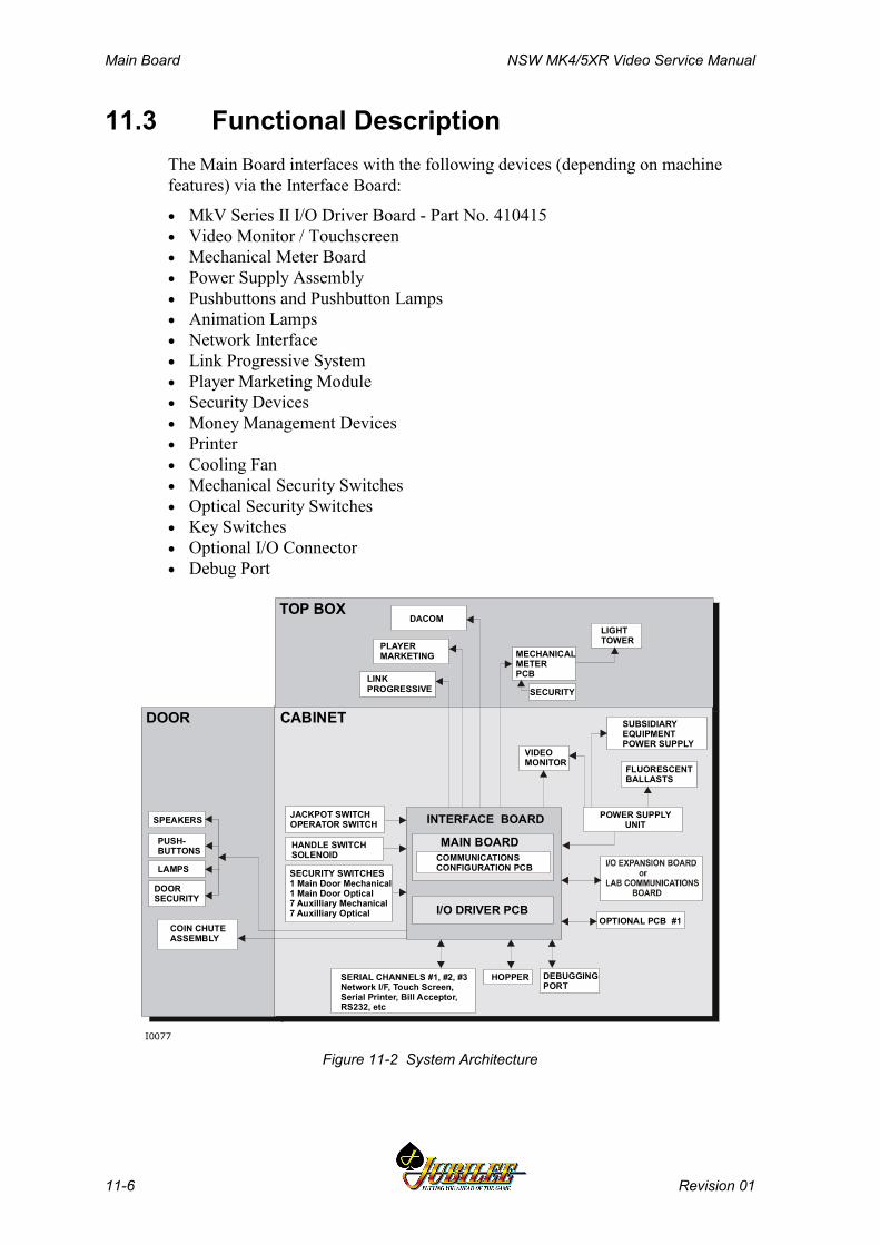
Main Board NSW MK4/5XR Video Service Manual
11-6 Revision 01
11.3 Functional DescriptionThe Main Board interfaces with the following devices (depending on machinefeatures) via the Interface Board:
• MkV Series II I/O Driver Board - Part No. 410415• Video Monitor / Touchscreen• Mechanical Meter Board• Power Supply Assembly• Pushbuttons and Pushbutton Lamps• Animation Lamps• Network Interface• Link Progressive System• Player Marketing Module• Security Devices• Money Management Devices• Printer• Cooling Fan• Mechanical Security Switches• Optical Security Switches• Key Switches• Optional I/O Connector• Debug Port
SECURITY
LIGHTTOWER
LINKPROGRESSIVE
PLAYERMARKETING
SUBSIDIARYEQUIPMENTPOWER SUPPLY
FLUORESCENTBALLASTS
VIDEOMONITOR
JACKPOT SWITCHOPERATOR SWITCH
HANDLE SWITCHSOLENOID
SECURITY SWITCHES1 Main Door Mechanical1 Main Door Optical7 Auxilliary Mechanical7 Auxilliary Optical
INTERFACE BOARD
MAIN BOARDCOMMUNICATIONSCONFIGURATION PCB
POWER SUPPLYUNIT
OPTIONAL PCB #1
SERIAL CHANNELS #1, #2, #3Network I/F, Touch Screen,Serial Printer, Bill Acceptor,RS232, etc
HOPPER DEBUGGINGPORT
DACOM
COIN CHUTEASSEMBLY
SPEAKERS
PUSH-BUTTONS
LAMPS
DOORSECURITY
DOOR CABINET
TOP BOX
I0077
I/O DRIVER PCB
MECHANICAL METERPCB
Figure 11-2 System Architecture

NSW MK4/5XR Video Service Manual Main Board
Revision 01 11-7
11.3.1 Main Board FunctionsThe Main Board has the following capabilities and functions:
• Core processor and memory.- (ARM250 32 bits RISC ASIC operating at 12 MHz).- On Board EPROMs.- External Memory Board Interface.- DRAM (a minimum of 1 Mbyte or 2 Mbyte as a build option).
• Non-volatile storage.- EEPROMs (2).- SRAM for Electronic Meters (three devices).
• LAB via the Interface Board.• Interrupt System.- Interrupt glue logic.- Timers and Operating System Tick logic.
• Coin Handling System.- Coin Chute.- Hopper Interface.
• Serial Peripheral Interface (SPI).- SPI bus driver and multiplexer circuitry.
• Internal Read/Write control registers.• Security.- Security switches (up to 8 optical and 8 mechanical switches).
• Communications.- DES Encryption IC- Four serial channels (two DUARTs). One channel is configured for FIP and
RS232; the other three are configurable for Bank Note Acceptor, SerialPrinter, Touch Screen, RS232, TTL, DACOM5000, or other signal levels.
- Mikohn Link Progressive pulse interface• Power Control System.- Onboard DC-DC converter (+24 V to +5 V).- Power supply supervisor and reset circuitry.- Interface with the Solid State Relay (SSR).- Status monitoring.
• Reset System• Diagnostics.- Circuitry for test, diagnostics and debugging (used in conjunction with the
External Memory board).• Real Time Clock (RTC).• Mechanical Switch Inputs.- Five mechanical switch inputs for Cancel Credit/Reset, Audit, Handle, etc.
• Video System.• Sound System.

Main Board NSW MK4/5XR Video Service Manual
11-8 Revision 01
11.4 Technical DescriptionThis section begins with two diagrams: a block diagram (Figure 11-3) introducingthe various functional subsystems of the Main Board and a layout diagram (Figure11-4) indicating the location of components on the Main Board. These diagramsare followed by a description of the various components of the Main Board.
This section describes the various components of the main board.
8 bit I/O
32 bit
Interrupt
VolumeControl
Parallel Port
External I/OInterface(Optional)
Audio Reset
Debug PortARM 250 PROCESSOR
Timer
UARTS
FIP Display orRS232 (Channel 0)
Bank NoteAcceptor
Watchdog
Hopper
SystemMemory
I0121
SPIInterface
PowerSupply Unit
I/O DriverBoardSecurity
MechanicalSwitches
Power Fail
Mikhon LinkProgressive
Real TimeClock
MemoryBatteryBackupCircuit
Serial Channel #1, #2, #3
Printer(Optional)
MechanicalMeters
Video
Figure 11-3 Main Board block diagram

NSW MK4/5XR Video Service Manual Main Board
Revision 01 11-9
I0079
96 W
ay C
onne
ctor
(P21
)96
Way
Con
nect
or (P
22)
96 W
ay C
onne
ctor
(P20
)
72 Pin SIMM Connector (P23)
Opto-isolators for Communications Board
96-w
ay M
emor
y Ex
pans
ion
Con
nect
or
Game EPROM sockets
Game EPROM sockets
Audi
o A
mpl
ifier
AR
M25
0M
icro
proc
esso
r
UA
RT
Cha
nnel
2an
dC
hann
el 3
UA
RT
Cha
nnel
0an
dC
hann
el 1
Glu
e Lo
gic
Encr
yptio
n IC
(410
388
only
)Pow
er S
uppl
yR
egul
ator
I/O B
uffe
rs
P2 L
ink
(EPR
OM
siz
e se
lect
ion)
Exte
rnal
Bat
tery
EPR
OM
Dec
oder
DRAM
DR
AM
DR
AM
Emul
ator
SRAM
(3 o
ff)
Back
Up
Batte
ryB
ack
Up
Bat
tery
Back
Up
Batte
ry
Exte
rnal
I/O
Buf
fers
4103
88 o
nly
Figure 11-4 Typical Main Board layout (not detailed)

Main Board NSW MK4/5XR Video Service Manual
11-10 Revision 01
11.4.1 ARM250 Microprocessor
CPUThe ARM250 microprocessor communicates with on board peripherals via a highspeed 32 bit memory bus, an 8 bit I/O bus, and a serial (SPI) interface (see Figure11-3). The ARM250 contains the following 5 major blocks within a single chip:
• the ARM250 CPU• I/O controller (IOC)• video controller (VIDC)• memory controller (MEMC)• I/O expansion block (IOEB).
The ARM250 is a complete computer system on a chip comprising a 32-bit RISCmicroprocessor, a memory controller with DRAM interface, a bit-mapped videocontroller and an I/O controller. It is suitable for wide range of cost-sensitiveembedded control, portable and consumer game applications - particularly thosewhich require a video display.
The device is designed to drive up to 4 Mbytes of DRAM directly at 12 MHz, andat this speed it can sustain approximately 10 MIPS.
I/O Data BusThe ARM250 is designed to be easily interfaced to standard 8 bit peripheral chips.The majority of the I/O is handled by the internal I/O controller, with some extrafunctionality provided by the I/O expansion block. All I/O addresses in theARM250 are memory mapped.
The peripheral address bus is simply the latched address lines. These are bufferedto reduce loading and to avoid slowing down EPROM access.
Diagnostic LEDsThe ARM250 has 4 open collector I/O bits. These are connected to 4 easilyvisible diagnostic LEDs to indicate diagnostic software status. The configurationof the circuit ensures that when the CPU is in reset, or when the software does notrun, all the LEDs will be turned on. Therefore, faulty LEDs will be easily detectedand not interpreted as incorrect diagnostic code.
Interrupt SystemThe interrupt system of the ARM250 functions with two main interrupts, FIQ andIRQ. Several external inputs are multiplexed internally to generate either a FIQ orIRQ interrupt.
FIQ is defined as the "fast interrupt" and is used for real time processing. IRQ isdefined as the "slow interrupt" and is used for slower interrupts.
Specific registers are provided to enable the programmer to read the source of theinterrupt without reading all the devices.
FIQ is of higher priority than IRQ and can interrupt an IRQ service routine. IRQcannot interrupt FIQ. The priority of different interrupts is determined in softwareafter reading the status registers.
NSW MK4/5XR Video Service Manual Main Board
Revision 01 11-11
I/O Expansion Port Interrupts.The I/O expansion port has 4 interrupts: IL0, IF, FL, and FH0 (schematicIO_IN). Pull-up/down resistors pull unused interrupts to their inactive state. EMCfiltering is provided by 1 kΩ resistors and 100 pF capacitors to prevent spuriousinterrupts.
ARM250 TimersThe ARM250 has 4 built-in timers. These run off a 2 MHz clock and can timeintervals from 500 ns to 32.768 ms. Four primary clocks exist within the board:72 MHz, 48 MHz, 25.175 MHz, and 32.768 kHz. All other clocks are derivedfrom these.
• Primary Clock. The ARM250 uses a primary clock of 72 MHz which isinternally divided to provide 36 MHz for the memory controller, 36 MHz or24 MHz for the video, 12 MHz for the CPU, 8 MHz and 2 MHz for the I/Ocontroller. The 72 MHz clock has a tight duty cycle specification of 45/55%.
• System Clock. The CPU core (ARM2aS) and memory controller (MEMC) ofthe ARM250 have an optional clock input to allow higher speed operation. A48 MHz clock on the SYSCLK input of the ARM250 is divided by 3 giving16 MHz CPU and memory operation.
• Video Clock. The video clock may be either 36 MHz, 24 MHz or an optionalexternal crystal input. The external crystal is 25.175 MHz for VGA. Theclock selected for the video clock is output on the VIDCLK pin and input onthe CLKVID pin, which are normally connected together.
• Time Clock. The real time clock chip uses a 32.768 kHz crystal to keep time.
The 8 MHz IOCLK output from the ARM250 is divided by 2 to 4 MHz for theDES encryption chip, by 512 to 15625 Hz for the SPI, and by 4096 to1953.125 Hz for the operating system timer interrupt. The 12 MHz ARM250keyboard clock output CLKKB, and the 2 MHz CLK2 IOC are not used.
11.4.2 SoundThe ARM250 has a built in stereo audio interface, requiring only filtering andamplification to drive a speaker. Sound data is accessed directly from DRAM andoutput to the audio D/A converters. The board implements a single channel ofsound, because stereo is not required.
The Main Board provides monophonic audio with the following characteristics:
• Bandwidth : 200 Hz to 5.5 kHz ±10%.• Power output: 4 W RMS.• Frequency response shape: fourth order pole at 5.5 kHz ±10%.• The volume is controllable via software with up to 16 steps.
The power amplifier features are:
• Overload protected• Short circuit protected• Connected to the +24 V DC power supply.
Main Board NSW MK4/5XR Video Service Manual
11-12 Revision 01
A separate ground for the audio system has to be provided. It is connected to thedigital ground (+5 V ground) and the power ground (+ 24 V ground) at one pointonly.
Volume ControlThe volume is controlled by software according to the setting made in theappropriate audit screen. The circuit uses a 4 bit control to give 16 levels. Thelowest level turns the sound off. The 74HC4066 switch is powered from +5 VDC, and requires that the inputs are below +5 V DC at all times. The output ofthe previous filter stage is decoupled with a 0.1 µF capacitor and biased around2.5 V DC.
Audio Power AmplifierThe TDA2006 audio power amplifier has overload/short circuit protection and ispowered from +24 V DC. The speaker output is filtered using a surface mountferrite bead and a 100 pF ceramic capacitor.
11.4.3 VideoThe ARM250 has a built in video controller which directly drives a monitor. Thevideo system conforms to the IBM VGA standard (mode 2) and gives a resolutionof 640 x 400 pixels with 8 bits per pixel.
Each video output signal from the ARM250 is a current sink with respect to thefiltered video 5 V DC supply. The RGB signals (Red, Green and Blue) generate avoltage across a sense resistor and a common super diode, formed by a PNPtransistor. The voltage across the sense circuit is converted to an output currentper colour by a PNP transistor emitter follower. The RGB monitor outputcomponents are protected from transients by a three diode circuit for each coloursignal. A 220 Ω load resistor limits the maximum unterminated voltage at eachtransistor collector; this ensures the transistor does not saturate and disturb thesense resistor signal. In normal use the RGB outputs generate an analogue 0.7 Vpeak signal into an external 75 Ω load. The sync signals have TTL levels.
11.4.4 ResetThe Main Board has 2 reset signals, RESETL and RESET. When reset is assertedit has a nominal period of 200 ms (guaranteed 140-280 ms).
• RESETL is the MAX705 reset output, valid for all supply voltages from 0-5 VDC. It is used in the battery backed circuits to prevent glitches during powerup/down, while RESET is used every where else.
• RESET is the normal active low reset, generated by buffering RESETL. It isnot valid between 0-2 V DC, as it is driven from HCMOS logic, which doesnot operate under 2.0 V DC.

NSW MK4/5XR Video Service Manual Main Board
Revision 01 11-13
Watchdog TimerThe MAX705 incorporates a watchdog timer to reset the Main Board if the CPUdoes not strobe the watchdog input periodically within the timeout interval with anI/O access to RDCS1. The watchdog timeout period is nominally 1.6 seconds,and is guaranteed to be in the range of 1.0 to 2.25 seconds. The manual resetinput (from the BTEST GAL) is asserted if the watchdog output trips (WDO) or ifthe external reset input is asserted.
The MAX705 voltage comparator also checks the battery voltage.
All devices that can be reset are reset to give the board a well defined power upstate.
• Direct write registers are reset to 0x00.• The ARM250 has 2 reset pins, RST and POR, and is reset through POR. RST
is a bidirectional pin driven from POR. When POR is asserted the CPU is resetand RST is also asserted. RST is connected to the optional memory expansionboard, which is reset by the Main Board reset, but can also reset the CPU byasserting RST.
• Peripheral I/O devices are reset• I/O Expansion interface is reset• Battery test GAL outputs are disabled.
11.4.5 Debug (Keyboard) PortThe ARM250 has a built-in serial communications port, the KART (KeyboardAsynchronous Receiver Transmitter). The KART is used only for debugging.
The data format is fixed at 8 data bits, 1 start bit, 2 stop bits and no parity. Unlikea normal UART, the KART has no data buffering.
11.4.6 Debugging
DEMONThe ARM source level software debugger DEMON requires three modificationsto the Main Board to run.
1. The watchdog must be disabled2. The DRAM emulator must be disabled, as DEMON modifies the interrupt
vectors in the first page of memory.3. The interrupt from UART U71 channel 0 must be inverted and connected to
the CPU interrupt IL2. IL2 can generate either a IRQ or FIQ, but forDEMON generates a FIQ.
The Main Board is fitted with switches to enable and disable the watchdog andDRAM emulator, as although DEMON requires these features, normal gamesoftware does not.
The memory expansion port contains a number of extra signals intended fordebugging purposes.
Main Board NSW MK4/5XR Video Service Manual
11-14 Revision 01
The CPU TEST signal implements the ARM250 tristate test mode when it isasserted. The CPU reset signal can act as both a reset from the CPU and a reset tothe CPU.
• The 72 MHz CPU clock oscillator supports the tristate enable/disable.• All nodes are accessible on the solder side of the board for ATE testing.• The ARM250 keyboard serial channel with signals KIN and KOUT is used for
a debug interface.
11.4.7 External I/O ExpansionTwo expansion interfaces are provided:
• I/O expansion through the interface board allows two general purpose 8-bit I/Oboards, and one security subsystem board to be added, using 96-way DIN41612connectors.
• The 32 bit memory expansion interface on the Main Board has a I/O port;however, this interface is primarily designed to add extra EPROM to thesystem.
I/O BoardsTwelve address lines are provided, to access 4 kbytes of I/O space on the I/Oboards. The 8 bit I/O data bus is buffered onto the I/O boards. I/O is accessedusing chip select DACK.
Peripheral PCBs take +5 V DC power from the Main Board. They may alsoderive +5 V DC from the +24 V DC supply, independent of the Main Board;however, care must be taken to avoid damage to both boards if the power supplyon either board fails.
Memory Expansion BoardThe memory expansion interface has an I/O port. The I/O select line AENprovides for 8-bit I/O expansion, which can be used to implement bank selectionpage register, or any other interface.
11.4.8 Mikohn Link Progressive Interface (where fitted)The Main Board provides an optically coupled, open-collector pulse interface to aMikohn Link Progressive system.
The output is the standard Mikohn interface:
• Switches 20 mA at 24 V.• Optically isolated.• Reverse protection diode.
NSW MK4/5XR Video Service Manual Main Board
Revision 01 11-15
11.4.9 MemoryThe Main Board has six types of memory:
• DRAM provides memory for graphics, sound and other software requirements.• DRAM Emulator.• EPROM contains the game software.• SRAM provides memory for metering.• EEPROM contains high reliability configuration data.• The Real Time Clock also contains a number of bytes of SRAM.
DRAMThe Main Board has 2 Mbyte of dynamic RAM as standard. The ARM250 canaddress a maximum of 4 Mbytes of DRAM, using its built in DRAM controller.The ARM250 directly drives the multiplexed address lines (RA[9:0]), row andcolumn (RAS, CAS[3:0]) strobes, output (OE[1:0]), and write enable(WE[1:0]) signals.
The Main Board must have at least 1 Mbyte of dynamic RAM fitted, with theother 1 Mbyte being optional. Using 4 Mbit DRAMs the maximum possible (in 4devices) is 2 Mbytes. The first bank of DRAMs is dual pitched to allow the use of16 Mbit DRAMs allowing 4 Mbytes to be fitted in only 2 chips. As this is themaximum addressable, the second bank would not be fitted.
DRAM EmulatorThe DRAM emulator logic detects an access to the interrupt vector table andsubstitutes either ROM or a fixed branch instruction (to EPROM) in place of theDRAM.
EPROMThe data bus for EPROMs is 32 bit wide. The Main Board contains sockets for 8EPROMs, which can be configured to 1, 2, or 4 Mbit chips and each is 16 bitwide. This allows a maximum of 4 Mbytes of EPROMs, which is also theARM250 addressing limit.
To expand the memory beyond 4 Mbytes, the on-board EPROMs can be replacedby an external memory PCB which sits onto the main board
Meters SRAMThe Main Board provides 32 kbytes of Static Random Access Memory (SRAM)with battery back-up for the electronic meters.
The SRAM contains machine metering information, such as money in/out, gamehistory, etc. It is critical that this data is preserved reliably, and variousjurisdictions require multiple backups of the data.
Three standard low power SRAMs are fitted to the board. The data is usuallyreplicated three times, so that each chip contains identical data. Each memory ischecked against the other to verify that the stored data is correct.
Each chip is mapped to the same address, and the chip selected depends on thebank select register. Access is mutually exclusive, increasing security with onlyone chip visible in the CPU address space at a time. If the CPU crashes and

Main Board NSW MK4/5XR Video Service Manual
11-16 Revision 01
overwrites memory only one of the three devices can be corrupted. On reset, thebank select register selects bank 0, which does not exist. The SRAMs are at banks1,2,3.
EEPROMSThe Main Board has three serial EEPROMs. The minimum requirements are 128bytes per EEPROM. The type selected is to be compatible with types providing256 byte and 512 byte depth.
Table 11-1 Serial EEPROMs Characteristics
No. Socketed Write protected Comment1 No Yes Surface mount package2 Yes No For game options, DIP package3 Yes No For network address, DIP package
Memory Expansion PortThe memory expansion port is primarily designed to add extra EPROM to theMain Board. The memory expansion PCB allows for up to 4 Mbytes of EPROMto be directly addressed together with signals to accommodate paged memory,external DRAM emulation and debug facilities. When the signal REPLACE isasserted from the expansion board it disables the on board EPROM, via addressdecode GAL U22.
The external memory PCB interfaces with the Main Board via a 96-wayDIN41612 connector.
11.4.10 Real Time ClockThe Main Board uses a Dallas DS1202 Real Time Clock (RTC). It uses astandard Dallas 3 wire interface, which is shared with the Dallas temperaturemeasuring chip. The real-time clock, meter RAM #0, and the battery-backedsecurity circuit on the I/O Driver Board are powered from the same battery.
11.4.11 Battery Backup CircuitThe Main Board has one lithium battery for the meter SRAM, Real Time Clockand the security circuit on the I/O Driver Board (refer to the chapter I/O DriverBoard for details).
WARNINGDanger of explosion if battery is incorrectlyreplaced. Replace only with the same orequivalent type
CAUTIONBattery may explode if mistreated. Do notrecharge, disassemble or dispose of in fire.
NSW MK4/5XR Video Service Manual Main Board
Revision 01 11-17
A resistor and diode combination in series prevents reverse charging of thebattery. A lithium battery can potentially explode if reverse charged.
The Main Board includes circuitry under CPU control to test the battery. The testplaces a resistor load on the battery and checks the voltage after a short delay(about 40 ms). The load is enabled from a monostable so that a fault in thesoftware will not discharge the battery.
The battery end life is at 2.0 V DC, below which the memory and logic are nolonger guaranteed to work. The test will indicate a battery fail at 2.5 V DC.
Replacing the BatteryWhen the battery is changed, power will be maintained for a limited time by thedecoupling capacitors. A connector is provided to allow for external batterybackup during battery replacement.
11.4.12 Power Control Interface
Signal inputs and outputsThe Main Board has several signal lines to interface with the power controlsystem as shown in the following table:
Table 11-2 Power Control System Signal Lines
Signal Type Comment/SSR1 Output Control signal for the solid state relay to switch to low
power mode, open collector active LOW/PFAIL Input Power Fail signal, open collector active LOW/EPSU2OVR Input Output power 24 V correct, from power supply assemblyGND Power + 24 Volt ground from the PMS
Power Lines and Grounding SchemeThe Main Board receives +24 V DC from the power control assembly, via theInterface Board.
The +24 V is supplied to the:
• I/O Driver Board• Audio power amplifier.• Coin handling modules.• Bank Note Acceptor• Printer (if fitted)• Mechanical meters• Handle (if fitted)
The Main Board uses a Switched Mode Power Supply (SMPS) to generate5 V DC and an isolated +/-12 V DC from the 24 V. The 5 V DC is used to supplythe logic circuits, as well as the I/O expansion boards and the optional securitysubsystem board. The +/-12 V DC is supplied to the generic serial channels.
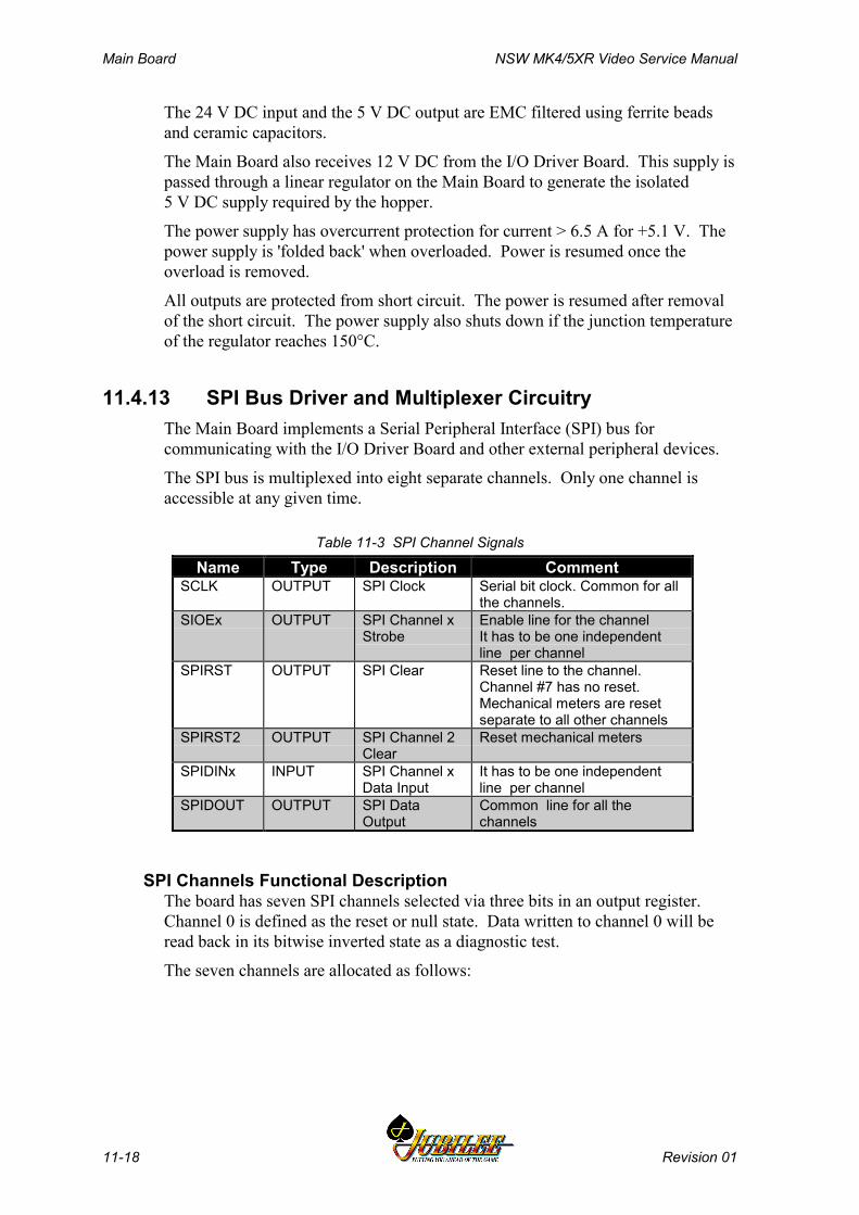
Main Board NSW MK4/5XR Video Service Manual
11-18 Revision 01
The 24 V DC input and the 5 V DC output are EMC filtered using ferrite beadsand ceramic capacitors.
The Main Board also receives 12 V DC from the I/O Driver Board. This supply ispassed through a linear regulator on the Main Board to generate the isolated5 V DC supply required by the hopper.
The power supply has overcurrent protection for current > 6.5 A for +5.1 V. Thepower supply is 'folded back' when overloaded. Power is resumed once theoverload is removed.
All outputs are protected from short circuit. The power is resumed after removalof the short circuit. The power supply also shuts down if the junction temperatureof the regulator reaches 150°C.
11.4.13 SPI Bus Driver and Multiplexer CircuitryThe Main Board implements a Serial Peripheral Interface (SPI) bus forcommunicating with the I/O Driver Board and other external peripheral devices.
The SPI bus is multiplexed into eight separate channels. Only one channel isaccessible at any given time.
Table 11-3 SPI Channel Signals
Name Type Description CommentSCLK OUTPUT SPI Clock Serial bit clock. Common for all
the channels.SIOEx OUTPUT SPI Channel x
StrobeEnable line for the channelIt has to be one independentline per channel
SPIRST OUTPUT SPI Clear Reset line to the channel.Channel #7 has no reset.Mechanical meters are resetseparate to all other channels
SPIRST2 OUTPUT SPI Channel 2Clear
Reset mechanical meters
SPIDINx INPUT SPI Channel xData Input
It has to be one independentline per channel
SPIDOUT OUTPUT SPI DataOutput
Common line for all thechannels
SPI Channels Functional DescriptionThe board has seven SPI channels selected via three bits in an output register.Channel 0 is defined as the reset or null state. Data written to channel 0 will beread back in its bitwise inverted state as a diagnostic test.
The seven channels are allocated as follows:
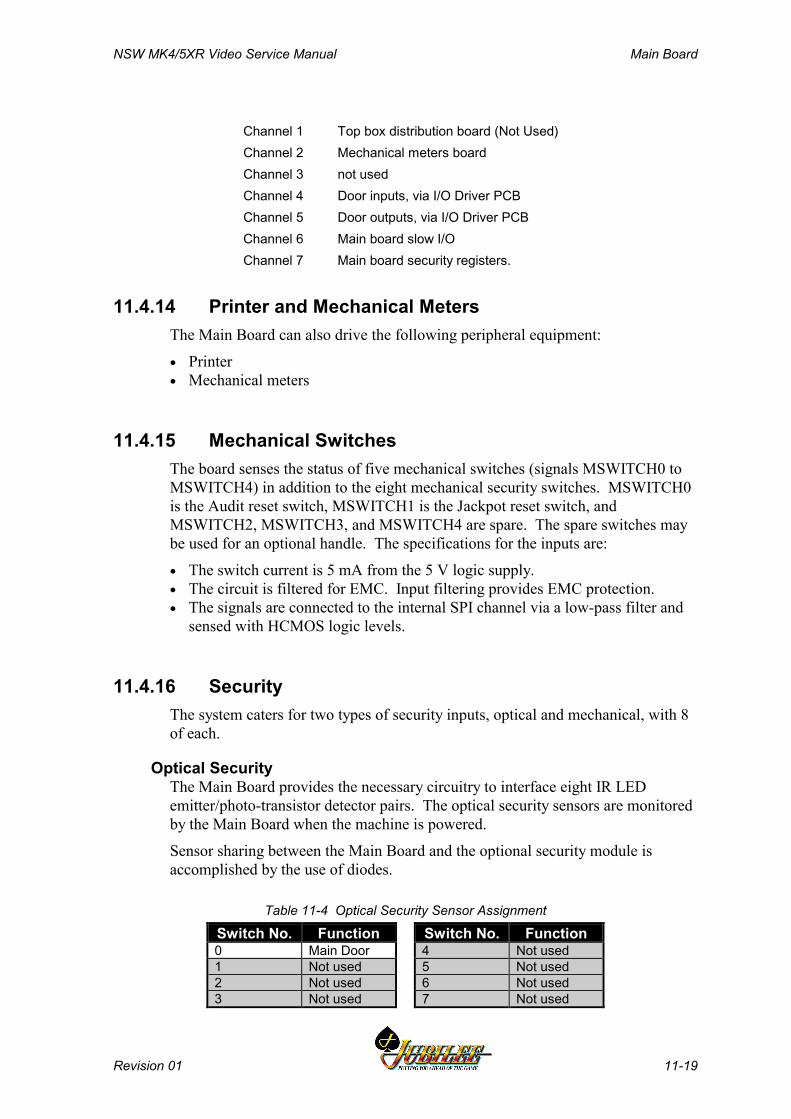
NSW MK4/5XR Video Service Manual Main Board
Revision 01 11-19
Channel 1 Top box distribution board (Not Used)Channel 2 Mechanical meters boardChannel 3 not usedChannel 4 Door inputs, via I/O Driver PCBChannel 5 Door outputs, via I/O Driver PCBChannel 6 Main board slow I/OChannel 7 Main board security registers.
11.4.14 Printer and Mechanical MetersThe Main Board can also drive the following peripheral equipment:
• Printer• Mechanical meters
11.4.15 Mechanical SwitchesThe board senses the status of five mechanical switches (signals MSWITCH0 toMSWITCH4) in addition to the eight mechanical security switches. MSWITCH0is the Audit reset switch, MSWITCH1 is the Jackpot reset switch, andMSWITCH2, MSWITCH3, and MSWITCH4 are spare. The spare switches maybe used for an optional handle. The specifications for the inputs are:
• The switch current is 5 mA from the 5 V logic supply.• The circuit is filtered for EMC. Input filtering provides EMC protection.• The signals are connected to the internal SPI channel via a low-pass filter and
sensed with HCMOS logic levels.
11.4.16 SecurityThe system caters for two types of security inputs, optical and mechanical, with 8of each.
Optical SecurityThe Main Board provides the necessary circuitry to interface eight IR LEDemitter/photo-transistor detector pairs. The optical security sensors are monitoredby the Main Board when the machine is powered.
Sensor sharing between the Main Board and the optional security module isaccomplished by the use of diodes.
Table 11-4 Optical Security Sensor Assignment
Switch No. Function Switch No. Function0 Main Door 4 Not used1 Not used 5 Not used2 Not used 6 Not used3 Not used 7 Not used

Main Board NSW MK4/5XR Video Service Manual
11-20 Revision 01
Mechanical SecurityThe system provides the necessary circuitry to interface 8 mechanical securityswitches. The mechanical security sensors are monitored by the Main Board whenthe machine is powered. There is no monitoring of the mechanical securitysystem when the power is turned off.
The mechanical security sensor interface has the following specification:
• Switch type: Single pole, changeover• Secure state: normally closed• Driving Source: +5 V DC
Table 11-5 Mechanical Security Switch Assignment
No. Function Monitored by...0 Logic Cage Main Board only when machine is powered.1 Top Box Not used.2 Mechanical Meters Main Board only when machine is powered.3 Cash Box Not used.4 Main Door Main Board only when machine is powered.5 Bank Note Stacker Main Board only when machine is powered.6 Not used Spare.7 Not used Spare.
11.4.17 Coin Handling System
Coin Chute AssemblyThe Main Board interfaces with the coin chute assembly via the I/O Driver Board.
The Main Board receives the signals "NOD1A", "NOD1B", "NOD2A", "S7ALARM", and "AUDIT" from the coin interface section of the I/O Driver Board.It sends the control signals "NEODLEDON", "NECOINBLK", and"NECOINDIV" to the I/O Driver Board, which converts these signals into theform required by the coin chuting.
All inputs have EMC R/C filtering, with a cut-off frequency of 3.4 kHz.
Coin Diverter SolenoidThe coin diverter solenoid output circuit has the following specifications:
• Switches 200 mA at 24 V• Open collector NPN (low side drive) output• Short circuit protected (up to +24 V)• Diode protected against back EMF
Table 11-6 Coin Handling Signals
Signal Name Function+24v Coin diverter solenoid power+5v Power for solenoid photo optic sensorGND GroundNOD1A Coin optic detector 1A, to Main BoardNOD1B Coin optic detector 2B, to Main BoardNOD2A Cash box optic detector, to Main Board
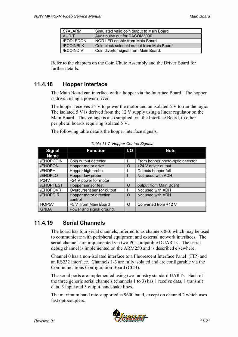
NSW MK4/5XR Video Service Manual Main Board
Revision 01 11-21
S7ALARM Simulated valid coin output to Main BoardAUDIT Audit pulse out for DACOM3000/EODLEDON NOD LED enable from Main Board./ECOINBLK Coin block solenoid output from Main Board/ECOINDIV Coin diverter signal from Main Board.
Refer to the chapters on the Coin Chute Assembly and the Driver Board forfurther details.
11.4.18 Hopper InterfaceThe Main Board can interface with a hopper via the Interface Board. The hopperis driven using a power driver.
The hopper receives 24 V to power the motor and an isolated 5 V to run the logic.The isolated 5 V is derived from the 12 V supply using a linear regulator on theMain Board. This voltage is also supplied, via the Interface Board, to otherperipheral boards requiring isolated 5 V.
The following table details the hopper interface signals.
Table 11-7 Hopper Control Signals
SignalName
Function I/O Note
/EHOPCOIN Coin output detector I From hopper photo-optic detector/EHOPON Hopper motor drive O +24 V driver output/EHOPHI Hopper high probe I Detects hopper full/EHOPLO Hopper low probe I Not used with ADHP24V +24 V power for motor/EHOPTEST Hopper sensor test O output from Main Board/EHOPOVR Overcurrent sensor output I Not used with ADH/EHOPDIR Hopper motor direction
controlO Not used with ADH
HOP5V +5 V from Main Board O Converted from +12 VGNDA Power and signal ground.
11.4.19 Serial ChannelsThe board has four serial channels, referred to as channels 0-3, which may be usedto communicate with peripheral equipment and external network interfaces. Theserial channels are implemented via two PC compatible DUART's. The serialdebug channel is implemented on the ARM250 and is described elsewhere.
Channel 0 has a non-isolated interface to a Fluorescent Interface Panel (FIP) andan RS232 interface. Channels 1-3 are fully isolated and are configurable via theCommunications Configuration Board (CCB).
The serial ports are implemented using two industry standard UARTs. Each ofthe three generic serial channels (channels 1 to 3) has 1 receive data, 1 transmitdata, 3 input and 3 output handshake lines.
The maximum baud rate supported is 9600 baud, except on channel 2 which usesfast optocouplers.
Main Board NSW MK4/5XR Video Service Manual
11-22 Revision 01
Communications Configuration BoardSerial channels 1 to 3 are configured through the Communications ConfigurationBoard (CCB) plugged into the 72 pin SIMM socket on the Main Board. The CCBconverts the opto-coupled UART I/O to any of the following signal levels:
• RS232• Current loop (Open collector)• Bank Note Acceptor interface• Serial printer• TTL compatible level• DACOM 5000• External network interface• Touchscreen• Other
Refer to the chapter Communications Configuration Board (CCB) for a detaileddescription.
11.4.20 Bank Note AcceptorThe Main Board communicates with the Bank Note Acceptor via generic serialchannel 1 which is connected via P18 on the Interface Board.
11.4.21 Interface BoardThe Main Board is connected to the Interface Board directly through three 96-waymale right-angle DIN41612 connectors as follows:
Optically Isolated ConnectorAll the I/O signals in this connector are optically coupled. It contains the UARTserial communication channels, SPI channels, Mikohn interface, hopper interface,and control signals for the power supply. It also provides connection to the powersupply for +24 V, +5 V, +12 V DC, and ±12 V.
Miscellaneous ConnectorThis connector contains the coin chute interface, video and audio signals, powercontrol system solid state relay, and the serial debug. It also connects to the +24 Vand +5 V power supply.
Security and I/O Expansion ConnectorThe connector contains both optical and mechanical security signals, mechanicalswitch signals, and I/O expansion signals. It also provides connection to the+24 V power supply.

NSW MK4/5XR Video Service Manual Main Board
Revision 01 11-23
11.5 Removal and Replacement Procedures
WARNINGTurn the machine power OFF beforeremoving PCBAs from the logic cage.
CAUTIONWhen handling electrostatic sensitivedevices (ESDs) such as PCBAs, take care toavoid physical contact with components. Donot place ESDs on metal surfaces. PCBsshould be handled by their edges. Caremust be taken to avoid flexing the PCB, asthis may lead to physical damage.
RemovalTo remove the Main Board:
1. Open the main door and switch OFF the machine.
2. Open the logic cage door.
3. Standard Electrostatic Discharge (ESD) prevention procedures should befollowed when handling PCBAs.
4. Lever the PCBA out of the runners using the board extractors, and withdrawthe board from the logic cage.
5. The PCBA should be placed in an antistatic bag immediately.
NoteA fault tag must be placed on any faultyboards.
ReplacementReplacement is a reversal of the removal procedure. Both sides of thereplacement PCBA should be inspected for any signs of physical damage.
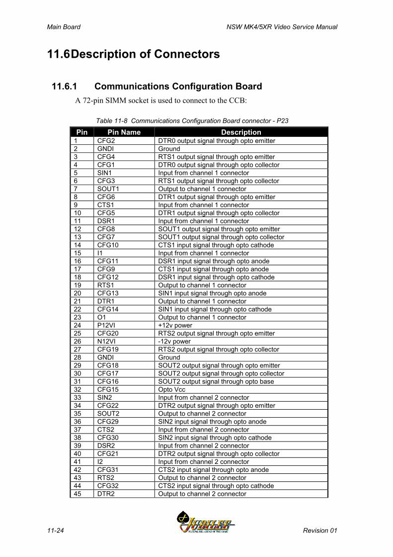
Main Board NSW MK4/5XR Video Service Manual
11-24 Revision 01
11.6Description of Connectors
11.6.1 Communications Configuration BoardA 72-pin SIMM socket is used to connect to the CCB:
Table 11-8 Communications Configuration Board connector - P23
Pin Pin Name Description1 CFG2 DTR0 output signal through opto emitter2 GNDI Ground3 CFG4 RTS1 output signal through opto emitter4 CFG1 DTR0 output signal through opto collector5 SIN1 Input from channel 1 connector6 CFG3 RTS1 output signal through opto collector7 SOUT1 Output to channel 1 connector8 CFG6 DTR1 output signal through opto emitter9 CTS1 Input from channel 1 connector10 CFG5 DTR1 output signal through opto collector11 DSR1 Input from channel 1 connector12 CFG8 SOUT1 output signal through opto emitter13 CFG7 SOUT1 output signal through opto collector14 CFG10 CTS1 input signal through opto cathode15 I1 Input from channel 1 connector16 CFG11 DSR1 input signal through opto anode17 CFG9 CTS1 input signal through opto anode18 CFG12 DSR1 input signal through opto cathode19 RTS1 Output to channel 1 connector20 CFG13 SIN1 input signal through opto anode21 DTR1 Output to channel 1 connector22 CFG14 SIN1 input signal through opto cathode23 O1 Output to channel 1 connector24 P12VI +12v power25 CFG20 RTS2 output signal through opto emitter26 N12VI -12v power27 CFG19 RTS2 output signal through opto collector28 GNDI Ground29 CFG18 SOUT2 output signal through opto emitter30 CFG17 SOUT2 output signal through opto collector31 CFG16 SOUT2 output signal through opto base32 CFG15 Opto Vcc33 SIN2 Input from channel 2 connector34 CFG22 DTR2 output signal through opto emitter35 SOUT2 Output to channel 2 connector36 CFG29 SIN2 input signal through opto anode37 CTS2 Input from channel 2 connector38 CFG30 SIN2 input signal through opto cathode39 DSR2 Input from channel 2 connector40 CFG21 DTR2 output signal through opto collector41 I2 Input from channel 2 connector42 CFG31 CTS2 input signal through opto anode43 RTS2 Output to channel 2 connector44 CFG32 CTS2 input signal through opto cathode45 DTR2 Output to channel 2 connector
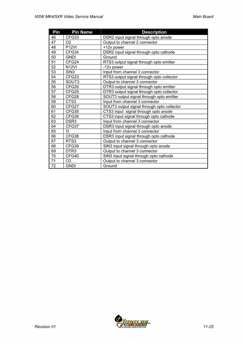
NSW MK4/5XR Video Service Manual Main Board
Revision 01 11-25
Pin Pin Name Description46 CFG33 DSR2 input signal through opto anode47 O2 Output to channel 2 connector48 P12VI +12v power49 CFG34 DSR2 input signal through opto cathode50 GNDI Ground51 CFG24 RTS3 output signal through opto emitter52 N12VI -12v power53 SIN3 Input from channel 3 connector54 CFG23 RTS3 output signal through opto collector55 SOUT3 Output to channel 3 connector56 CFG26 DTR3 output signal through opto emitter57 CFG25 DTR3 output signal through opto collector58 CFG28 SOUT3 output signal through opto emitter59 CTS3 Input from channel 3 connector60 CFG27 SOUT3 output signal through opto collector61 CFG35 CTS3 input signal through opto anode62 CFG36 CTS3 input signal through opto cathode63 DSR3 Input from channel 3 connector64 CFG37 DSR3 input signal through opto anode65 I3 Input from channel 3 connector66 CFG38 DSR3 input signal through opto cathode67 RTS3 Output to channel 3 connector68 CFG39 SIN3 input signal through opto anode69 DTR3 Output to channel 3 connector70 CFG40 SIN3 input signal through opto cathode71 O3 Output to channel 3 connector72 GNDI Ground

Main Board NSW MK4/5XR Video Service Manual
11-26 Revision 01
11.6.2 Optically Isolated Connector - P20This connector interfaces with P1 on the Interface Board.
Table 11-9 Optically Isolated Connector - P20
PIN Pin Name CommentA1 SIN1 Receive data, serial channel 1B1 N12VI -12V from main board, isolatedC1 ---A2 CTS1 Handshake Input 0, serial channel 1B2 GNDI Ground of ±12 voltage, isolatedC2 SOUT1 Transmit Data, serial channel 1A3 I1 Handshake Input 2, serial channel 1B3 P12VI +12V from main board, isolatedC3 DSR1 Handshake Input 1, serial channel 1A4 O1 Handshake Output 2, serial channel 1B4 DTR1 Handshake Output 1, serial channel 1C4 RTS1 Handshake Output 0, serial channel 1A5 SIN2 Receive data, serial channel 2B5 N12VI -12V from main board, isolatedC5 ---A6 CTS2 Handshake Input 0, serial channel 2B6 GNDI Ground of ±12 voltage, isolatedC6 SOUT2 Transmit data, serial channel 2A7 I2 Handshake Input 2, serial channel 2B7 P12VI +12V from main board, isolatedC7 DSR2 Handshake Input 1, serial channel 2A8 O2 Handshake Output 2, serial channel 2B8 DTR2 Handshake Output 1, serial channel 2C8 RTS2 Handshake Output 0, serial channel 2A9 SIN3 Receive data, serial channel 3B9 N12VI -12V from main board, isolatedC9 ---A10 CTS3 Handshake Input 0, serial channel 3B10 GNDI Ground of ±12 voltage, isolatedC10 SOUT3 Transmit data, serial channel 3A11 I3 Handshake Input 2, serial channel 3B11 P12VI +12V from main board, isolatedC11 DSR3 Handshake Input 1, serial channel 3A12 O3 Handshake Output 2, serial channel 3B12 DTR3 Handshake Output 1, serial channel 3C12 RTS3 Handshake Output 0, serial channel 3A13 ---B13 ---C13 ---A14 ---B14 ---C14 ---A15 ---B15 ---C15 ---A16 ---B16 ---C16 ---A17 /ESPIDIN2 Data from meter board

NSW MK4/5XR Video Service Manual Main Board
Revision 01 11-27
PIN Pin Name CommentB17 GNDA GroundC17 /ESPIDIN1 Data from top boxA18 /ESPIDIN5 Serial data input to main logic from serial input driver. Open
collector output.B18 GNDA GroundC18 /ESPIDIN4 Serial data input to main logic from serial output driver. Open
collector output.A19 ESPIRST SPI reset signalB19 GNDA GroundC19 /ESPIDOUT Data output to meter boardA20 ESCLK Serial clockB20 GNDA GroundC20 ESPIRST2 Reset signal to meter boardA21 /ESIOE2 Strobe signal to meter boardB21 GNDA GroundC21 /ESIOE1 Serial output enable to top boxA22 /ESIOE5 Serial output enable #5 which selects SPI output driver.B22 GNDA GroundC22 /ESIOE4 Serial output enable #4 which selects SPI input driver.A23 /EHOPOVR Overcurrent sensor output, hopperB23 GNDA GroundC23 ---A24 /EHOPHI Hopper high probe, Detects hopper full, hopperB24 GNDA GroundC24 /EHOPCOIN Coin output detector, hopperA25 /EHOPDIR Hopper motor direction, hopperB25 GNDA GroundC25 /EHOPLO Detects hopper low, hopperA26 /EHOPTEST Hopper Sensor Test output, hopperB26 GNDA GroundC26 /EHOPON Hopper motor drive, hopperA27 ---B27 GNDA GroundC27 VCC +5VA28 EPSU2SND ---B28 GNDA GroundC28 /EPSU2OVR ---A29 /ESPARE01 Spare output signalB29 GNDA GroundC29 /EHANDLE ---A30 P24VA +24VB30 GNDA GroundC30 P24VA +24VA31 EMIKOHNP Mikohn signalB31 P12V +12V from driver boardC31 P12V +12V from driver boardA32 ---B32 GNDA GroundC32 EMIKOHNN Mikohn signal

Main Board NSW MK4/5XR Video Service Manual
11-28 Revision 01
11.6.3 Miscellaneous Connector - P22This connector interfaces with P2 on the Interface Board.
Table 11-10 Miscellaneous Connector - P22
PIN Pin Name CommentA1 /ES2OVERDE Door detector on Mk4 (never used)B1 GNDD GroundC1 /EODLEDON NOD1 LED enableA2 S7ALARM S7 Alarm or Coin Validator coin validB2 /ECOINDIV Coin Divert Drive (NPN trans. to GND)C2 /ECOINBLK Coin Validator enable (switches power through NOD) / S7 InhibitA3 NOD1B NOD1 Coin output B / S7 Coin output 5B3 GNDD GroundC3 NOD1A NOD1 Coin out. A / S7 accumulator out.A4 CVP0 S7 Coin outputB4 NOD2B NOD2 Coin output BC4 NOD2A NOD2 Coin output AA5 CVP2 S7 Coin outputB5 GNDD GroundC5 CVP1 S7 Coin outputA6 /SSR1 solid state relay for ballast and monitor On/Off (LED cathode)B6 CVP4 S7 Coin outputC6 CVP3 S7 Coin outputA7 RS232TX serial 0, nonisolated transmitterB7 GNDD GroundC7 FIPOUT Serial Transmit Data outA8 RS232RX serial 0, nonisolated receiverB8 RS232RTS nonisolated handshake Output 0, serial channel 0C8 RS232CTS nonisolated handshake Input 0, serial channel 0A9 ---B9 RED Red, videoC9 REDGND red colour signal groundA10 BLUE Blue, videoB10 GREENGND blue colour signal groundC10 GREEN Green, videoA11 BLUEGND green colour signal groundB11 VSYNC Vsync, videoC11 SYNCGND synchro signal groundA12 SPEAKER Audio outputB12 ---C12 HSYNC Hsync, videoA13 SPEAKER2 Stereo speaker outputB13 SPKRGND speaker signal groundC13 P24VSND +24V, single track on PCBA14 GNDD GroundB14 VCC +5V from main board, converted from 24VC14 GNDD GroundA15 VCC +5V from main board, converted from 24VB15 GNDD GroundC15 VCC +5V from main board, converted from 24VA16 GNDD GroundB16 VCC +5V from main board, converted from 24VC16 GNDD GroundA17 VCC +5V from main board, converted from 24V
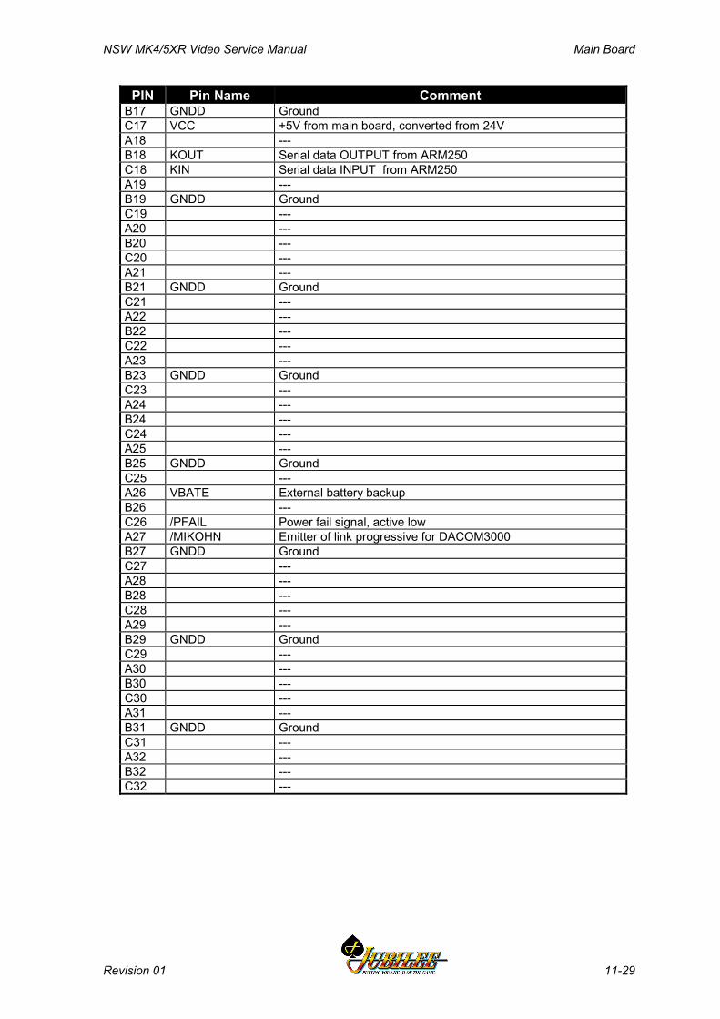
NSW MK4/5XR Video Service Manual Main Board
Revision 01 11-29
PIN Pin Name CommentB17 GNDD GroundC17 VCC +5V from main board, converted from 24VA18 ---B18 KOUT Serial data OUTPUT from ARM250C18 KIN Serial data INPUT from ARM250A19 ---B19 GNDD GroundC19 ---A20 ---B20 ---C20 ---A21 ---B21 GNDD GroundC21 ---A22 ---B22 ---C22 ---A23 ---B23 GNDD GroundC23 ---A24 ---B24 ---C24 ---A25 ---B25 GNDD GroundC25 ---A26 VBATE External battery backupB26 ---C26 /PFAIL Power fail signal, active lowA27 /MIKOHN Emitter of link progressive for DACOM3000B27 GNDD GroundC27 ---A28 ---B28 ---C28 ---A29 ---B29 GNDD GroundC29 ---A30 ---B30 ---C30 ---A31 ---B31 GNDD GroundC31 ---A32 ---B32 ---C32 ---

Main Board NSW MK4/5XR Video Service Manual
11-30 Revision 01
11.6.4 Security and I/O Expansion Connector - P21This connector interfaces with P3 on the Interface Board.
Table 11-11 Security and I/O Expansion Connector - P21
PIN Pin Name CommentA1 MSWITCH1 mech. switch, JACKPOT RESETB1 GNDD GroundC1 MSWITCH0 mech. switch, AUDIT RESETA2 MSWITCH4 mech. switch, spareB2 MSWITCH3 mech. switch, spareC2 MSWITCH2 mech. switch, spareA3 ---B3 GNDD GroundC3 ---A4 MSS0 Logic Door Security Switch 7 contact - NCB4 OPRIS0 Door security detector output, no driver/buffer exists.C4 EMCS0 door optical emitterA5 EMCS1 Emitter 1 Drive signal, security 1B5 GNDD GroundC5 MSSO0 Logic Door Security Switch 7 contact - NOA6 MSSO1 Mechanical Security Switch 1 contact - NOB6 MSS1 Mechanical Security Switch 1 contact - NCC6 OPRIS1 Receiver 1 Sense signal, security 1A7 OPRIS2 Receiver 2 Sense signal, security 2B7 GNDD GroundC7 EMCS2 Emitter 2 Drive signal, security 2A8 EMCS3 Emitter 3 Drive signal, security 3B8 MSSO2 Mechanical Security Switch 2 contact - NOC8 MSS2 Mechanical Security Switch 2 contact - NCA9 MSS3 Mechanical Security Switch 3 contact - NCB9 GNDD GroundC9 OPRIS3 Receiver 3 Sense signal, security 3A10 OPRIS4 Receiver 4 Sense signal, security 4B10 EMCS4 Emitter 4 Drive signal, security 4C10 MSSO3 Mechanical Security Switch 3 contact - NOA11 EMCS5 Emitter 5 Drive signal, security 5B11 GNDD GroundC11 MSS4 Mechanical Security Switch 4 contact - NCA12 EMCS6 Emitter 6 Drive signal, security 6B12 MSS5 Mechanical Security Switch 5 contact - NCC12 OPRIS5 Receiver 5 Sense signal, security 5A13 MSS6 Mechanical Security Switch 6 contact - NCB13 GNDD GroundC13 OPRIS6 Receiver 6 Sense signal, security 6A14 MSS7 Mechanical Security Switch 7 contact - NCB14 OPRIS7 Receiver 7 Sense signal, security 7C14 EMCS7 Emitter 7 Drive signal, security 7A15 ---B15 GNDD GroundC15 ---A16 VBAT0 Backup battery 0B16 ---C16 ---A17 RNW CPU, read not write signal
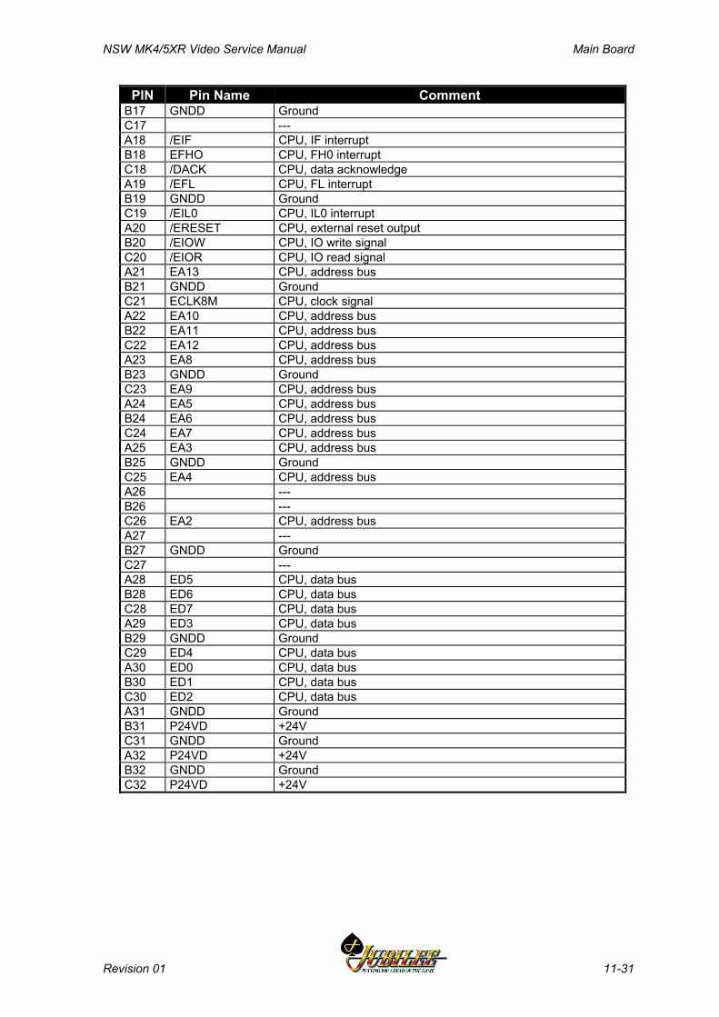
NSW MK4/5XR Video Service Manual Main Board
Revision 01 11-31
PIN Pin Name CommentB17 GNDD GroundC17 ---A18 /EIF CPU, IF interruptB18 EFHO CPU, FH0 interruptC18 /DACK CPU, data acknowledgeA19 /EFL CPU, FL interruptB19 GNDD GroundC19 /EIL0 CPU, IL0 interruptA20 /ERESET CPU, external reset outputB20 /EIOW CPU, IO write signalC20 /EIOR CPU, IO read signalA21 EA13 CPU, address busB21 GNDD GroundC21 ECLK8M CPU, clock signalA22 EA10 CPU, address busB22 EA11 CPU, address busC22 EA12 CPU, address busA23 EA8 CPU, address busB23 GNDD GroundC23 EA9 CPU, address busA24 EA5 CPU, address busB24 EA6 CPU, address busC24 EA7 CPU, address busA25 EA3 CPU, address busB25 GNDD GroundC25 EA4 CPU, address busA26 ---B26 ---C26 EA2 CPU, address busA27 ---B27 GNDD GroundC27 ---A28 ED5 CPU, data busB28 ED6 CPU, data busC28 ED7 CPU, data busA29 ED3 CPU, data busB29 GNDD GroundC29 ED4 CPU, data busA30 ED0 CPU, data busB30 ED1 CPU, data busC30 ED2 CPU, data busA31 GNDD GroundB31 P24VD +24VC31 GNDD GroundA32 P24VD +24VB32 GNDD GroundC32 P24VD +24V

Main Board NSW MK4/5XR Video Service Manual
11-32 Revision 01
Notes
NSW MK4/5XR Video Service Manual Interface Board
Revision 01 12-1
________Chapter 12________
Interface BoardPart No. 410315 Issue B
12.1 Physical Description ............................................................ 12-3
12.1.1 Diagrams and Component Locations ..................................... 12-3
12.2 Technical Description.......................................................... 12-5
12.3 Description of Connectors .................................................. 12-7
12.3.1 Main Board Connectors - P1, P2, and P3 .............................. 12-712.3.2 Driver Board, P4..................................................................... 12-712.3.3 LAB Comms, P5..................................................................... 12-712.3.4 Mechanical Meters, P6........................................................... 12-712.3.5 Security - P8, P22, and P24................................................... 12-712.3.6 Door Signals Interface - P10 and P11.................................... 12-912.3.7 Coin Handling, P12 .............................................................. 12-1012.3.8 Bill Acceptor, Backlight and Security, P13 ........................... 12-1112.3.9 Serial Channels - P14, P15, P17, and P18. ......................... 12-1112.3.10 DACOM 5000, P21 .............................................................. 12-1312.3.11 Mikohn, P16 ......................................................................... 12-1312.3.12 SPI Channel 1, P19.............................................................. 12-1412.3.13 DACOM 3000, P20 .............................................................. 12-1412.3.14 Spare Voltage 24 V DC, P23................................................ 12-1512.3.15 Hopper, P25 ......................................................................... 12-1512.3.16 Video, P26............................................................................ 12-1512.3.17 Mechanical Switches - P27 .................................................. 12-1612.3.18 Audit / Jackpot switch and door security, P28...................... 12-1612.3.19 Power Supply, P29............................................................... 12-1712.3.20 Optional Fan DC 12 V, P30.................................................. 12-17
Interface Board NSW MK4/5XR Video Service Manual
12-2 Revision 01
12.4 Removal and Replacement Procedures ........................... 12-18
List of FiguresFigure 12-1 Interface Board Component Location ........................................................12-4
List of TablesTable 12-1 Interface Board Connections.......................................................................12-6

NSW MK4/5XR Video Service Manual Interface Board
Revision 01 12-3
12.1 Physical DescriptionThe Interface Board is a single printed circuit board assembly (PCBA) mountedvertically at the base of the cabinet, partly enclosed within the logic cage. TheInterface Board is used to electrically connect the Main Board, the I/O DriverBoard, and all peripheral PCBAs and subsystems.
The Main Board and I/O Driver Board connect directly to the Interface Boardwithin the logic cage. The Communication Configuration Board and the optionalI/O Expansion Board/LAB Communications Board connect directly to the MainBoard, within the logic cage. All other PCBAs and peripherals are connected tothe Interface Board via ribbon cables or wire looms.
The component layout of the Interface Board is shown in Figure 12-1.
12.1.1 Diagrams and Component LocationsFor further information and for reference, the following additional information onthe Interface Board is provided in Volume II:
• Circuit diagrams. Structured circuit diagrams.• I/O to Components and ICs. A list of the I/O paths to each component and
integrated circuit (IC) pin position.

Interface Board NSW MK4/5XR Video Service Manual
12-4 Revision 01
I0093
Figure 12-1 Interface Board Component Location
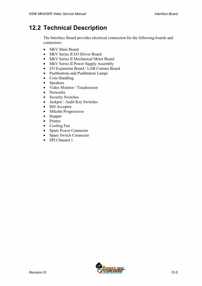
NSW MK4/5XR Video Service Manual Interface Board
Revision 01 12-5
12.2 Technical DescriptionThe Interface Board provides electrical connection for the following boards andconnectors:
• MkV Main Board• MkV Series II I/O Driver Board• MkV Series II Mechanical Meter Board• MkV Series II Power Supply Assembly• I/O Expansion Board / LAB Comms Board• Pushbuttons and Pushbutton Lamps• Coin Handling• Speakers• Video Monitor / Touchscreen• Networks• Security Switches• Jackpot / Audit Key Switches• Bill Acceptor• Mikohn Progressives• Hopper• Printer• Cooling Fan• Spare Power Connector• Spare Switch Connector• SPI Channel 1
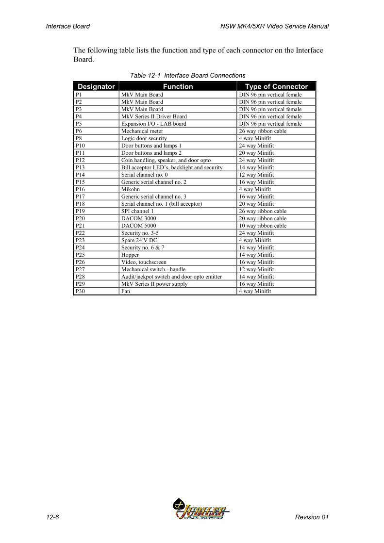
Interface Board NSW MK4/5XR Video Service Manual
12-6 Revision 01
The following table lists the function and type of each connector on the InterfaceBoard.
Table 12-1 Interface Board Connections
Designator Function Type of ConnectorP1 MkV Main Board DIN 96 pin vertical femaleP2 MkV Main Board DIN 96 pin vertical femaleP3 MkV Main Board DIN 96 pin vertical femaleP4 MkV Series II Driver Board DIN 96 pin vertical femaleP5 Expansion I/O - LAB board DIN 96 pin vertical femaleP6 Mechanical meter 26 way ribbon cableP8 Logic door security 4 way MinifitP10 Door buttons and lamps 1 24 way MinifitP11 Door buttons and lamps 2 20 way MinifitP12 Coin handling, speaker, and door opto 24 way MinifitP13 Bill acceptor LED’s, backlight and security 14 way MinifitP14 Serial channel no. 0 12 way MinifitP15 Generic serial channel no. 2 16 way MinifitP16 Mikohn 4 way MinifitP17 Generic serial channel no. 3 16 way MinifitP18 Serial channel no. 1 (bill acceptor) 20 way MinifitP19 SPI channel 1 26 way ribbon cableP20 DACOM 3000 20 way ribbon cableP21 DACOM 5000 10 way ribbon cableP22 Security no. 3-5 24 way MinifitP23 Spare 24 V DC 4 way MinifitP24 Security no. 6 & 7 14 way MinifitP25 Hopper 14 way MinifitP26 Video, touchscreen 16 way MinifitP27 Mechanical switch - handle 12 way MinifitP28 Audit/jackpot switch and door opto emitter 14 way MinifitP29 MkV Series II power supply 16 way MinifitP30 Fan 4 way Minifit
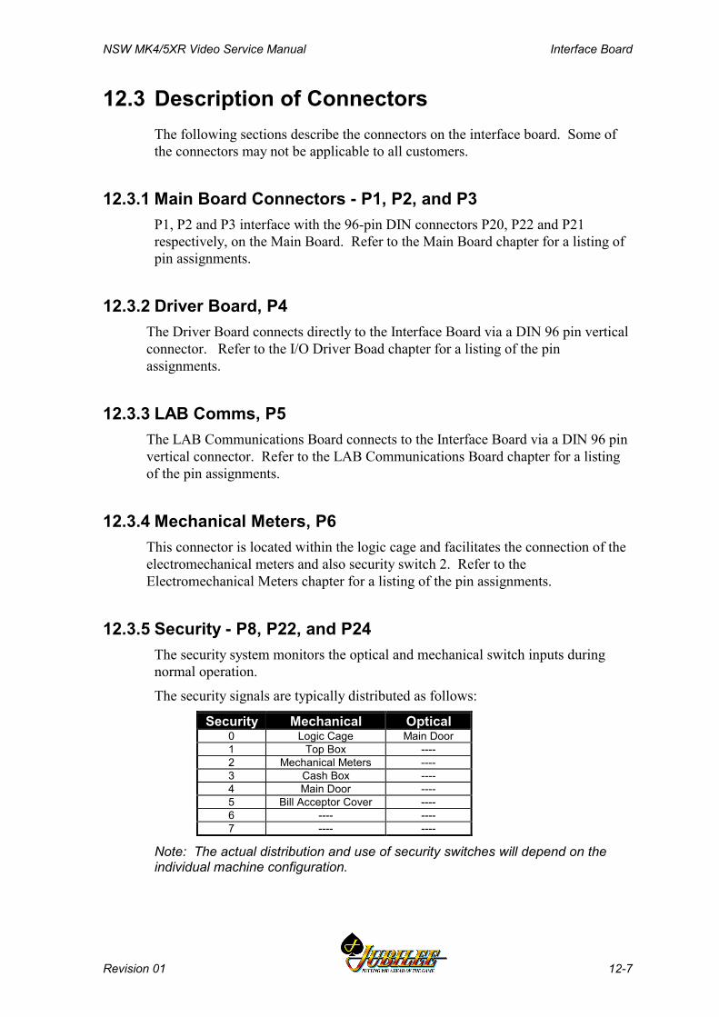
NSW MK4/5XR Video Service Manual Interface Board
Revision 01 12-7
12.3 Description of ConnectorsThe following sections describe the connectors on the interface board. Some ofthe connectors may not be applicable to all customers.
12.3.1 Main Board Connectors - P1, P2, and P3P1, P2 and P3 interface with the 96-pin DIN connectors P20, P22 and P21respectively, on the Main Board. Refer to the Main Board chapter for a listing ofpin assignments.
12.3.2 Driver Board, P4The Driver Board connects directly to the Interface Board via a DIN 96 pin verticalconnector. Refer to the I/O Driver Boad chapter for a listing of the pinassignments.
12.3.3 LAB Comms, P5The LAB Communications Board connects to the Interface Board via a DIN 96 pinvertical connector. Refer to the LAB Communications Board chapter for a listingof the pin assignments.
12.3.4 Mechanical Meters, P6This connector is located within the logic cage and facilitates the connection of theelectromechanical meters and also security switch 2. Refer to theElectromechanical Meters chapter for a listing of the pin assignments.
12.3.5 Security - P8, P22, and P24The security system monitors the optical and mechanical switch inputs duringnormal operation.
The security signals are typically distributed as follows:
Security Mechanical Optical0 Logic Cage Main Door1 Top Box ----2 Mechanical Meters ----3 Cash Box ----4 Main Door ----5 Bill Acceptor Cover ----6 ---- ----7 ---- ----
Note: The actual distribution and use of security switches will depend on theindividual machine configuration.
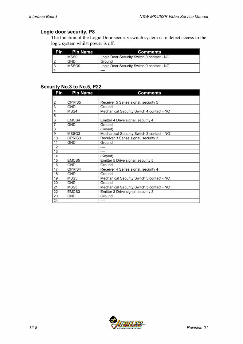
Interface Board NSW MK4/5XR Video Service Manual
12-8 Revision 01
Logic door security, P8The function of the Logic Door security switch system is to detect access to thelogic system whilst power is off.
Pin Pin Name Comments1 MSS0 Logic Door Security Switch 0 contact - NC2 GND Ground3 MSSO0 Logic Door Security Switch 0 contact - NO4 ----
Security No.3 to No.5, P22Pin Pin Name Comments
1 ----2 OPRIS5 Receiver 5 Sense signal, security 53 GND Ground4 MSS4 Mechanical Security Switch 4 contact - NC5 ----6 EMCS4 Emitter 4 Drive signal, security 47 GND Ground8 (Keyed)9 MSSO3 Mechanical Security Switch 3 contact - NO10 OPRIS3 Receiver 3 Sense signal, security 311 GND Ground12 ----13 ----14 (Keyed)15 EMCS5 Emitter 5 Drive signal, security 516 GND Ground17 OPRIS4 Receiver 4 Sense signal, security 418 GND Ground19 MSS5 Mechanical Security Switch 5 contact - NC20 GND Ground21 MSS3 Mechanical Security Switch 3 contact - NC22 EMCS3 Emitter 3 Drive signal, security 323 GND Ground24 ----
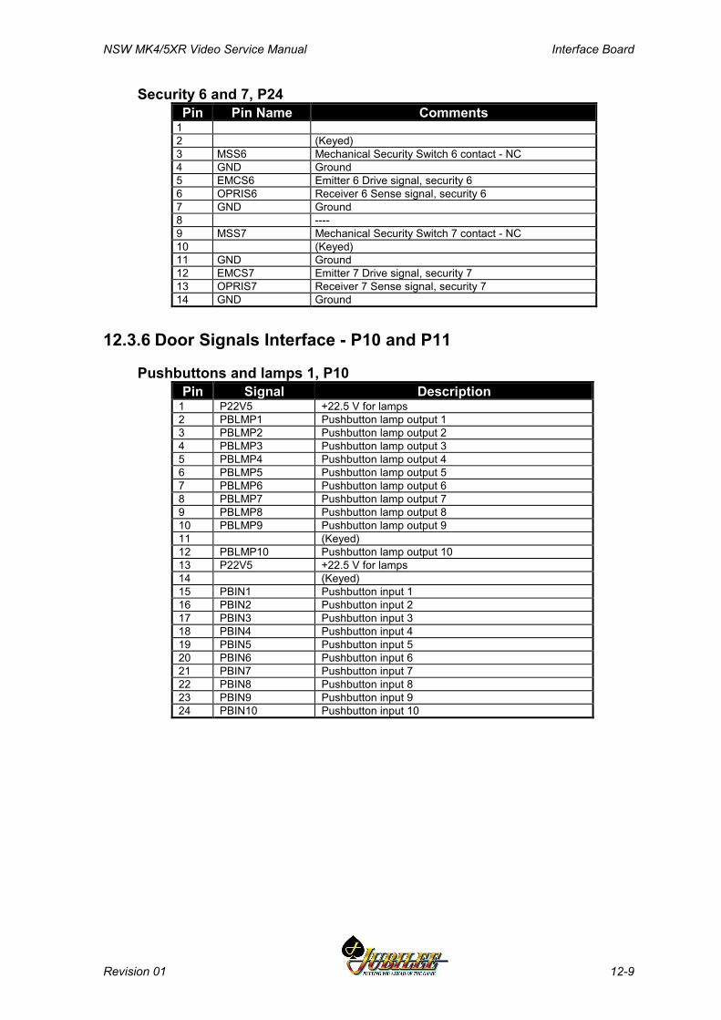
NSW MK4/5XR Video Service Manual Interface Board
Revision 01 12-9
Security 6 and 7, P24Pin Pin Name Comments
12 (Keyed)3 MSS6 Mechanical Security Switch 6 contact - NC4 GND Ground5 EMCS6 Emitter 6 Drive signal, security 66 OPRIS6 Receiver 6 Sense signal, security 67 GND Ground8 ----9 MSS7 Mechanical Security Switch 7 contact - NC10 (Keyed)11 GND Ground12 EMCS7 Emitter 7 Drive signal, security 713 OPRIS7 Receiver 7 Sense signal, security 714 GND Ground
12.3.6 Door Signals Interface - P10 and P11
Pushbuttons and lamps 1, P10Pin Signal Description
1 P22V5 +22.5 V for lamps2 PBLMP1 Pushbutton lamp output 13 PBLMP2 Pushbutton lamp output 24 PBLMP3 Pushbutton lamp output 35 PBLMP4 Pushbutton lamp output 46 PBLMP5 Pushbutton lamp output 57 PBLMP6 Pushbutton lamp output 68 PBLMP7 Pushbutton lamp output 79 PBLMP8 Pushbutton lamp output 810 PBLMP9 Pushbutton lamp output 911 (Keyed)12 PBLMP10 Pushbutton lamp output 1013 P22V5 +22.5 V for lamps14 (Keyed)15 PBIN1 Pushbutton input 116 PBIN2 Pushbutton input 217 PBIN3 Pushbutton input 318 PBIN4 Pushbutton input 419 PBIN5 Pushbutton input 520 PBIN6 Pushbutton input 621 PBIN7 Pushbutton input 722 PBIN8 Pushbutton input 823 PBIN9 Pushbutton input 924 PBIN10 Pushbutton input 10
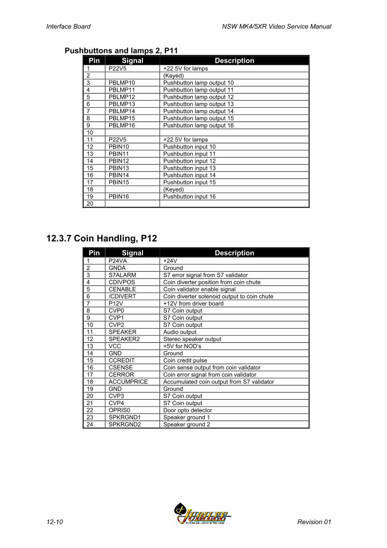
Interface Board NSW MK4/5XR Video Service Manual
12-10 Revision 01
Pushbuttons and lamps 2, P11Pin Signal Description
1 P22V5 +22.5V for lamps2 (Keyed)3 PBLMP10 Pushbutton lamp output 104 PBLMP11 Pushbutton lamp output 115 PBLMP12 Pushbutton lamp output 126 PBLMP13 Pushbutton lamp output 137 PBLMP14 Pushbutton lamp output 148 PBLMP15 Pushbutton lamp output 159 PBLMP16 Pushbutton lamp output 161011 P22V5 +22.5V for lamps12 PBIN10 Pushbutton input 1013 PBIN11 Pushbutton input 1114 PBIN12 Pushbutton input 1215 PBIN13 Pushbutton input 1316 PBIN14 Pushbutton input 1417 PBIN15 Pushbutton input 1518 (Keyed)19 PBIN16 Pushbutton input 1620
12.3.7 Coin Handling, P12Pin Signal Description
1 P24VA +24V2 GNDA Ground3 S7ALARM S7 error signal from S7 validator4 CDIVPOS Coin diverter position from coin chute5 CENABLE Coin validator enable signal6 /CDIVERT Coin diverter solenoid output to coin chute7 P12V +12V from driver board8 CVP0 S7 Coin output9 CVP1 S7 Coin output10 CVP2 S7 Coin output11 SPEAKER Audio output12 SPEAKER2 Stereo speaker output13 VCC +5V for NOD’s14 GND Ground15 CCREDIT Coin credit pulse16 CSENSE Coin sense output from coin validator17 CERROR Coin error signal from coin validator18 ACCUMPRICE Accumulated coin output from S7 validator19 GND Ground20 CVP3 S7 Coin output21 CVP4 S7 Coin output22 OPRIS0 Door opto detector23 SPKRGND1 Speaker ground 124 SPKRGND2 Speaker ground 2
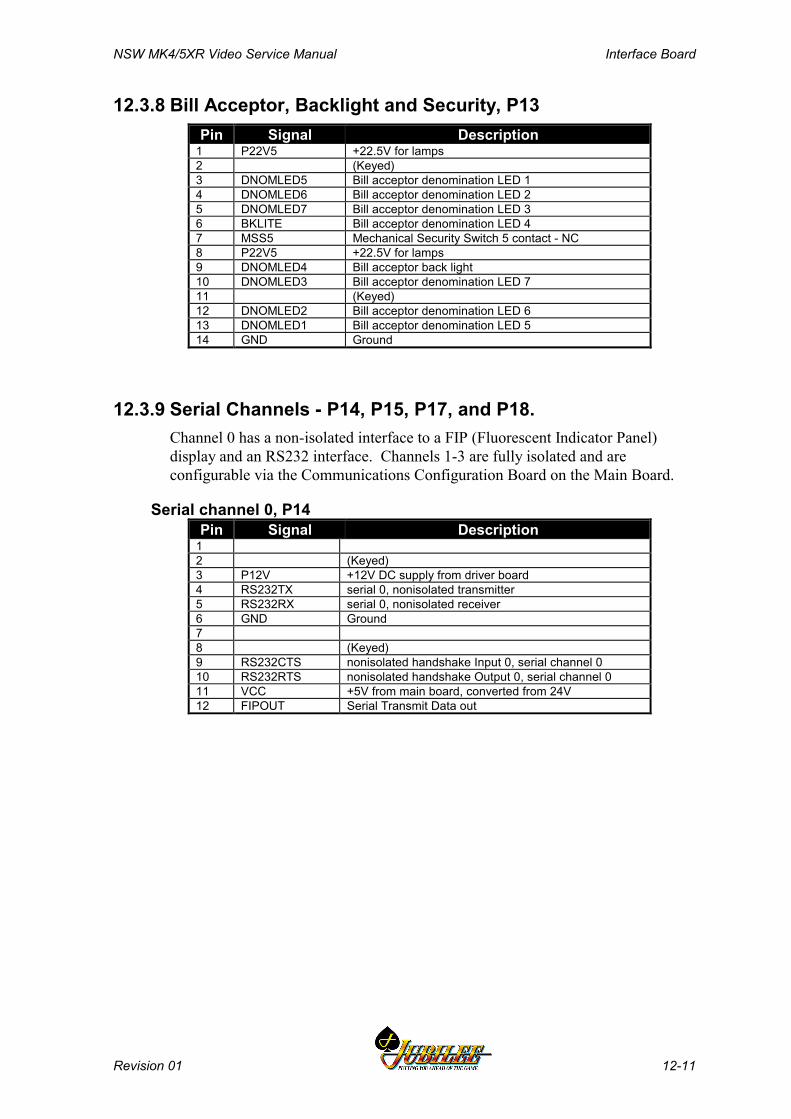
NSW MK4/5XR Video Service Manual Interface Board
Revision 01 12-11
12.3.8 Bill Acceptor, Backlight and Security, P13Pin Signal Description
1 P22V5 +22.5V for lamps2 (Keyed)3 DNOMLED5 Bill acceptor denomination LED 14 DNOMLED6 Bill acceptor denomination LED 25 DNOMLED7 Bill acceptor denomination LED 36 BKLITE Bill acceptor denomination LED 47 MSS5 Mechanical Security Switch 5 contact - NC8 P22V5 +22.5V for lamps9 DNOMLED4 Bill acceptor back light10 DNOMLED3 Bill acceptor denomination LED 711 (Keyed)12 DNOMLED2 Bill acceptor denomination LED 613 DNOMLED1 Bill acceptor denomination LED 514 GND Ground
12.3.9 Serial Channels - P14, P15, P17, and P18.Channel 0 has a non-isolated interface to a FIP (Fluorescent Indicator Panel)display and an RS232 interface. Channels 1-3 are fully isolated and areconfigurable via the Communications Configuration Board on the Main Board.
Serial channel 0, P14Pin Signal Description
12 (Keyed)3 P12V +12V DC supply from driver board4 RS232TX serial 0, nonisolated transmitter5 RS232RX serial 0, nonisolated receiver6 GND Ground78 (Keyed)9 RS232CTS nonisolated handshake Input 0, serial channel 010 RS232RTS nonisolated handshake Output 0, serial channel 011 VCC +5V from main board, converted from 24V12 FIPOUT Serial Transmit Data out
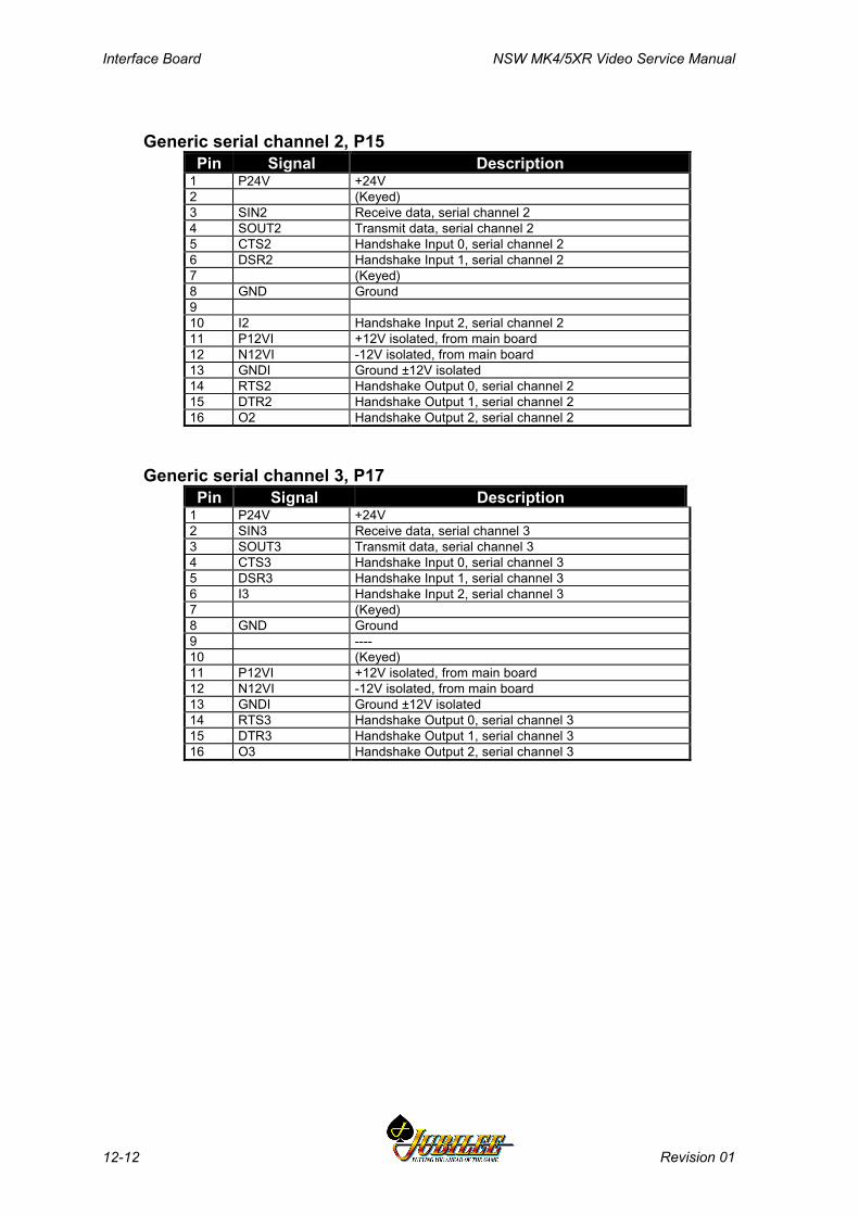
Interface Board NSW MK4/5XR Video Service Manual
12-12 Revision 01
Generic serial channel 2, P15Pin Signal Description
1 P24V +24V2 (Keyed)3 SIN2 Receive data, serial channel 24 SOUT2 Transmit data, serial channel 25 CTS2 Handshake Input 0, serial channel 26 DSR2 Handshake Input 1, serial channel 27 (Keyed)8 GND Ground910 I2 Handshake Input 2, serial channel 211 P12VI +12V isolated, from main board12 N12VI -12V isolated, from main board13 GNDI Ground ±12V isolated14 RTS2 Handshake Output 0, serial channel 215 DTR2 Handshake Output 1, serial channel 216 O2 Handshake Output 2, serial channel 2
Generic serial channel 3, P17Pin Signal Description
1 P24V +24V2 SIN3 Receive data, serial channel 33 SOUT3 Transmit data, serial channel 34 CTS3 Handshake Input 0, serial channel 35 DSR3 Handshake Input 1, serial channel 36 I3 Handshake Input 2, serial channel 37 (Keyed)8 GND Ground9 ----10 (Keyed)11 P12VI +12V isolated, from main board12 N12VI -12V isolated, from main board13 GNDI Ground ±12V isolated14 RTS3 Handshake Output 0, serial channel 315 DTR3 Handshake Output 1, serial channel 316 O3 Handshake Output 2, serial channel 3
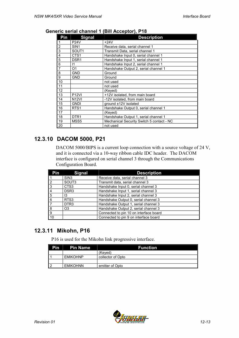
NSW MK4/5XR Video Service Manual Interface Board
Revision 01 12-13
Generic serial channel 1 (Bill Acceptor), P18Pin Signal Description
1 P24V +24V2 SIN1 Receive data, serial channel 13 SOUT1 Transmit Data, serial channel 14 CTS1 Handshake Input 0, serial channel 15 DSR1 Handshake Input 1, serial channel 16 I1 Handshake Input 2, serial channel 17 O1 Handshake Output 2, serial channel 18 GND Ground9 GND Ground10 not used11 not used12 (Keyed)13 P12VI +12V isolated, from main board14 N12VI -12V isolated, from main board15 GNDI ground ±12V isolated16 RTS1 Handshake Output 0, serial channel 117 (Keyed)18 DTR1 Handshake Output 1, serial channel 119 MSS5 Mechanical Security Switch 5 contact - NC20 not used
12.3.10 DACOM 5000, P21DACOM 5000/BIPS is a current loop connection with a source voltage of 24 V,and it is connected via a 10-way ribbon cable IDC header. The DACOMinterface is configured on serial channel 3 through the CommunicationsConfiguration Board.
Pin Signal Description1 SIN3 Receive data, serial channel 32 SOUT3 Transmit data, serial channel 33 CTS3 Handshake Input 0, serial channel 34 DSR3 Handshake Input 1, serial channel 35 I3 Handshake Input 2, serial channel 36 RTS3 Handshake Output 0, serial channel 37 DTR3 Handshake Output 1, serial channel 38 O3 Handshake Output 2, serial channel 39 Connected to pin 10 on interface board10 Connected to pin 9 on interface board
12.3.11 Mikohn, P16P16 is used for the Mikohn link progressive interface.
Pin Pin Name Function(Keyed)
1 EMIKOHNP collector of Opto
2 EMIKOHNN emitter of Opto
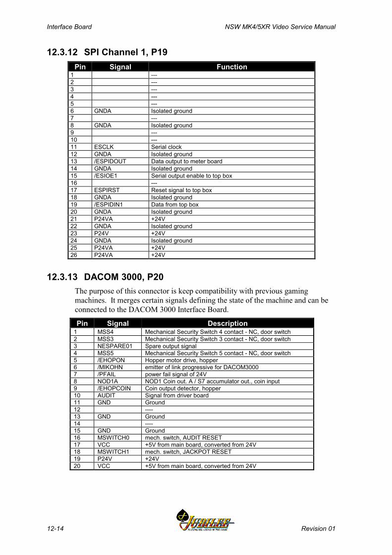
Interface Board NSW MK4/5XR Video Service Manual
12-14 Revision 01
12.3.12 SPI Channel 1, P19Pin Signal Function
1 ---2 ---3 ---4 ---5 ---6 GNDA Isolated ground7 ---8 GNDA Isolated ground9 ---10 ---11 ESCLK Serial clock12 GNDA Isolated ground13 /ESPIDOUT Data output to meter board14 GNDA Isolated ground15 /ESIOE1 Serial output enable to top box16 ---17 ESPIRST Reset signal to top box18 GNDA Isolated ground19 /ESPIDIN1 Data from top box20 GNDA Isolated ground21 P24VA +24V22 GNDA Isolated ground23 P24V +24V24 GNDA Isolated ground25 P24VA +24V26 P24VA +24V
12.3.13 DACOM 3000, P20The purpose of this connector is keep compatibility with previous gamingmachines. It merges certain signals defining the state of the machine and can beconnected to the DACOM 3000 Interface Board.
Pin Signal Description1 MSS4 Mechanical Security Switch 4 contact - NC, door switch2 MSS3 Mechanical Security Switch 3 contact - NC, door switch3 NESPARE01 Spare output signal4 MSS5 Mechanical Security Switch 5 contact - NC, door switch5 /EHOPON Hopper motor drive, hopper6 /MIKOHN emitter of link progressive for DACOM30007 /PFAIL power fail signal of 24V8 NOD1A NOD1 Coin out. A / S7 accumulator out., coin input9 /EHOPCOIN Coin output detector, hopper10 AUDIT Signal from driver board11 GND Ground12 ----13 GND Ground14 ----15 GND Ground16 MSWITCH0 mech. switch, AUDIT RESET17 VCC +5V from main board, converted from 24V18 MSWITCH1 mech. switch, JACKPOT RESET19 P24V +24V20 VCC +5V from main board, converted from 24V
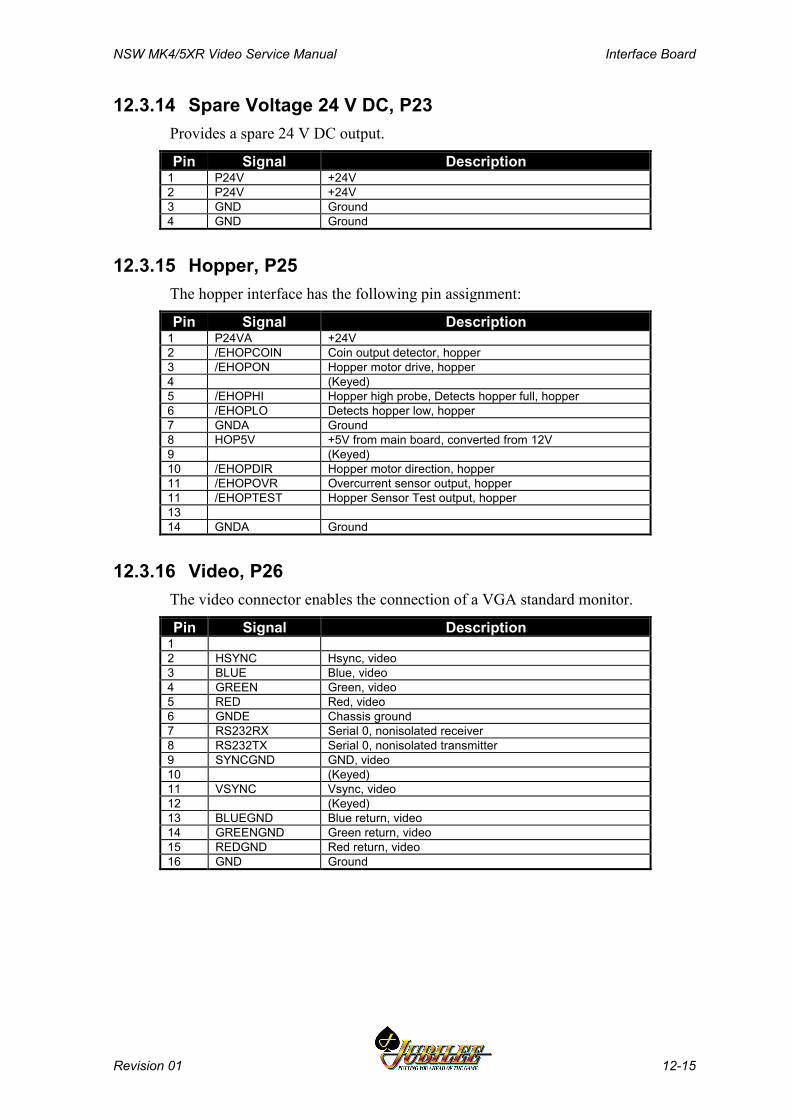
NSW MK4/5XR Video Service Manual Interface Board
Revision 01 12-15
12.3.14 Spare Voltage 24 V DC, P23Provides a spare 24 V DC output.
Pin Signal Description1 P24V +24V2 P24V +24V3 GND Ground4 GND Ground
12.3.15 Hopper, P25The hopper interface has the following pin assignment:
Pin Signal Description1 P24VA +24V2 /EHOPCOIN Coin output detector, hopper3 /EHOPON Hopper motor drive, hopper4 (Keyed)5 /EHOPHI Hopper high probe, Detects hopper full, hopper6 /EHOPLO Detects hopper low, hopper7 GNDA Ground8 HOP5V +5V from main board, converted from 12V9 (Keyed)10 /EHOPDIR Hopper motor direction, hopper11 /EHOPOVR Overcurrent sensor output, hopper11 /EHOPTEST Hopper Sensor Test output, hopper1314 GNDA Ground
12.3.16 Video, P26The video connector enables the connection of a VGA standard monitor.
Pin Signal Description12 HSYNC Hsync, video3 BLUE Blue, video4 GREEN Green, video5 RED Red, video6 GNDE Chassis ground7 RS232RX Serial 0, nonisolated receiver8 RS232TX Serial 0, nonisolated transmitter9 SYNCGND GND, video10 (Keyed)11 VSYNC Vsync, video12 (Keyed)13 BLUEGND Blue return, video14 GREENGND Green return, video15 REDGND Red return, video16 GND Ground
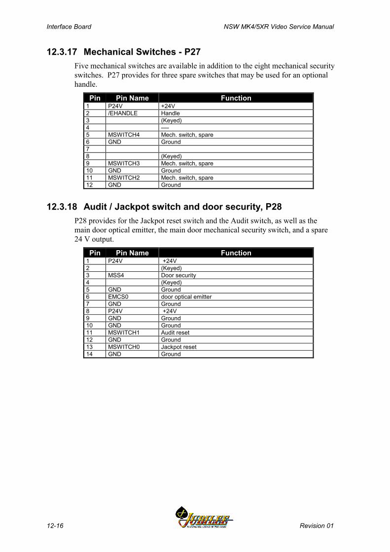
Interface Board NSW MK4/5XR Video Service Manual
12-16 Revision 01
12.3.17 Mechanical Switches - P27Five mechanical switches are available in addition to the eight mechanical securityswitches. P27 provides for three spare switches that may be used for an optionalhandle.
Pin Pin Name Function1 P24V +24V2 /EHANDLE Handle3 (Keyed)4 ----5 MSWITCH4 Mech. switch, spare6 GND Ground78 (Keyed)9 MSWITCH3 Mech. switch, spare10 GND Ground11 MSWITCH2 Mech. switch, spare12 GND Ground
12.3.18 Audit / Jackpot switch and door security, P28P28 provides for the Jackpot reset switch and the Audit switch, as well as themain door optical emitter, the main door mechanical security switch, and a spare24 V output.
Pin Pin Name Function1 P24V +24V2 (Keyed)3 MSS4 Door security4 (Keyed)5 GND Ground6 EMCS0 door optical emitter7 GND Ground8 P24V +24V9 GND Ground10 GND Ground11 MSWITCH1 Audit reset12 GND Ground13 MSWITCH0 Jackpot reset14 GND Ground

NSW MK4/5XR Video Service Manual Interface Board
Revision 01 12-17
12.3.19 Power Supply, P29Pin Signal Description
1 /SSR1 Low power mode2 (Keyed)3 /EPSU2OVR Output 24V correct4 P24VS +24V5 P24VS +24V6 P24VS +24V7 P24VS +24V8 P24VS +24V9 Future expansion10 /PFAIL Missing mains detection11 GNDS Ground12 GNDS Ground13 GNDS Ground14 GNDS Ground15 (Keyed)16 GNDS Ground
12.3.20 Optional Fan DC 12 V, P30This connector is used to power an optional fan that may be mounted to the logiccage. The purpose of this fan is to relieve possible heat dissipation problemswithin the logic cage.
Pin Signal Function12 P12V +12V DC supply from Driver Board3 (Keyed)4 GNDA Ground
Interface Board NSW MK4/5XR Video Service Manual
12-18 Revision 01
12.4 Removal and Replacement ProceduresCAUTION
When handling electrostatic sensitivedevices (ESDs) such as PCBAs, take care toavoid physical contact with components.PCBAs should be handled by their edges.ESDs should not be placed on metalsurfaces. When handling PCBAs, take careto avoid flexing the PCBA, as this may leadto permanent damage.
RemovalThe procedures for removing and replacing the Interface Board are detailed in thechapter Cabinet, under the section describing how to remove and disassemble thelogic cage.
NoteA fault tag must be placed on any faultyequipment.
Run a complete machine test after replacing the Interface Board.
NSW MK4/5XR Video Service Manual I/O Driver Board
Revision 01 13-1
______Chapter 13______
I/O Driver Board - 410415
13.1 Physical Description .............................................................. 13-3
13.1.1 Circuit Diagrams and Component Locations............................ 13-3
13.2 Functional Description .......................................................... 13-3
13.2.1 Power Supply ........................................................................... 13-613.2.2 Pushbuttons and Lamps .......................................................... 13-613.2.3 Coin Handling Interface............................................................ 13-7
13.3 Removal and Replacement Procedures ............................. 13-10
13.4 Connector Pin Assignment ................................................. 13-11
I/O Driver Board NSW MK4/5XR Video Service Manual
13-2 Revision 01
List of FiguresFigure 13-1 I/O Driver Board - Location ........................................................................13-3Figure 13-2 I/O Driver Board - Block Diagram ..............................................................13-4Figure 13-3 I/O Driver Board 410415 - Component Layout...........................................13-5Figure 13-4 Coin Handling Interface Signals.................................................................13-7Figure 13-5 Timing of Coin Handling Output Signals ....................................................13-8
List of TablesTable 13-1 Coin Handling Signals - Explanation ...........................................................13-8Table 13-2 LED Functions.............................................................................................13-9
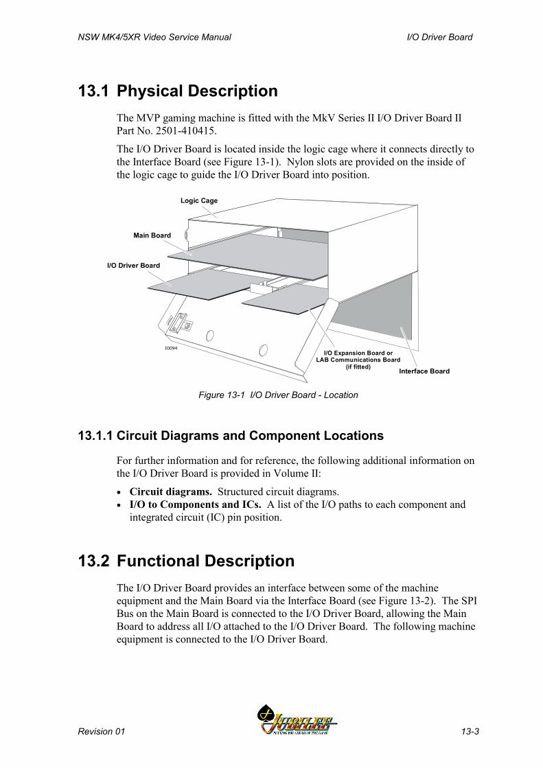
NSW MK4/5XR Video Service Manual I/O Driver Board
Revision 01 13-3
13.1 Physical DescriptionThe MVP gaming machine is fitted with the MkV Series II I/O Driver Board IIPart No. 2501-410415.
The I/O Driver Board is located inside the logic cage where it connects directly tothe Interface Board (see Figure 13-1). Nylon slots are provided on the inside ofthe logic cage to guide the I/O Driver Board into position.
Interface Board
Logic Cage
Main Board
I/O Driver Board
I/O Expansion Board or LAB Communications Board
(if fitted)
I0094
Figure 13-1 I/O Driver Board - Location
13.1.1 Circuit Diagrams and Component Locations
For further information and for reference, the following additional information onthe I/O Driver Board is provided in Volume II:
• Circuit diagrams. Structured circuit diagrams.• I/O to Components and ICs. A list of the I/O paths to each component and
integrated circuit (IC) pin position.
13.2 Functional DescriptionThe I/O Driver Board provides an interface between some of the machineequipment and the Main Board via the Interface Board (see Figure 13-2). The SPIBus on the Main Board is connected to the I/O Driver Board, allowing the MainBoard to address all I/O attached to the I/O Driver Board. The following machineequipment is connected to the I/O Driver Board.
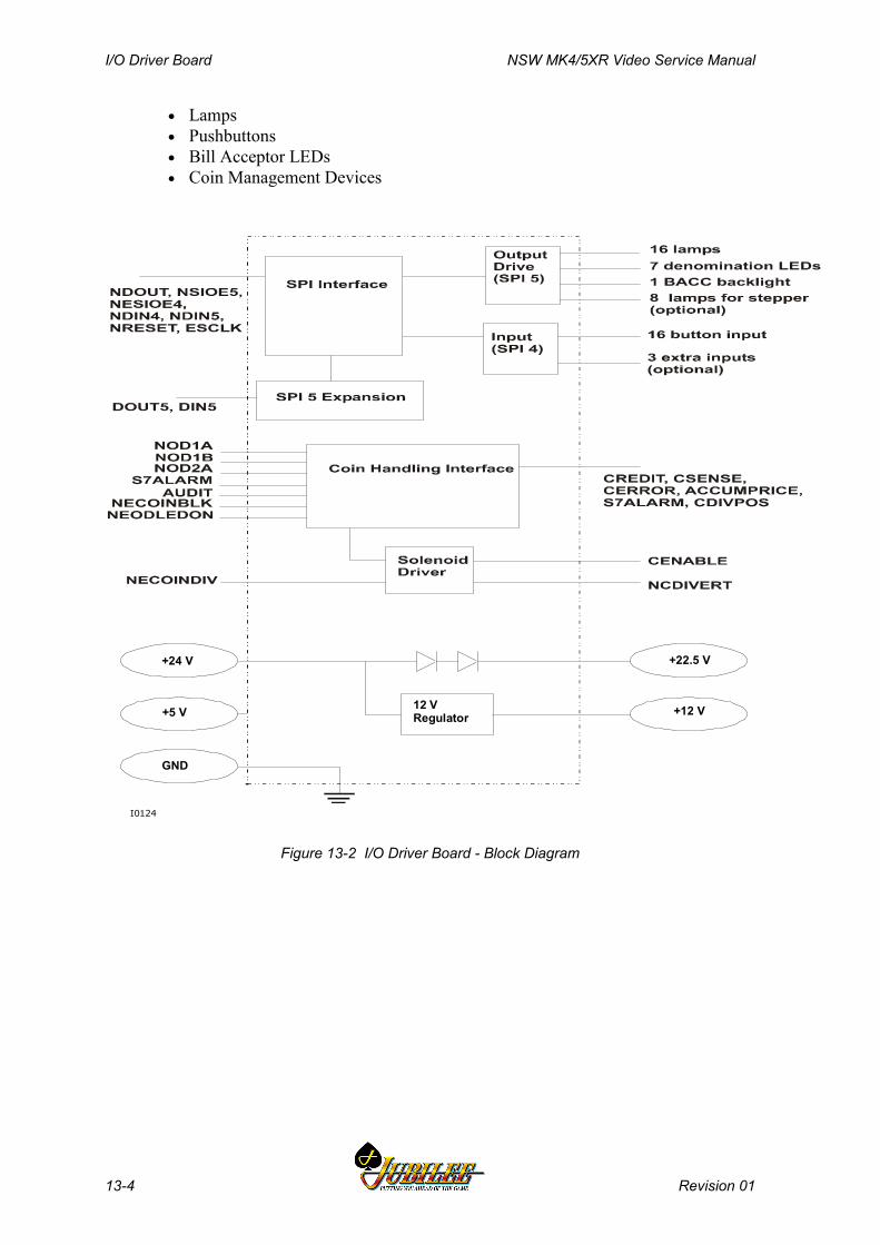
I/O Driver Board NSW MK4/5XR Video Service Manual
13-4 Revision 01
• Lamps• Pushbuttons• Bill Acceptor LEDs• Coin Management Devices
12 V Regulator
+24 V
+5 V
GND
+22.5 V
+12 V
I0124
Figure 13-2 I/O Driver Board - Block Diagram
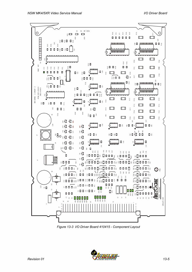
NSW MK4/5XR Video Service Manual I/O Driver Board
Revision 01 13-5
R135
R143
R166
R169
R150
R149
R148
R147
R129
R134
R133
R162
R165
R164
R157
R146
R106
R21
R20
R41
R40
R31
R30
R11
R10
R2 R3
R69
R54
R115
R127
R130
R139
C72
R131
R89
R85
R97
R96
R98
R87
R88
R90
R57
R76
R46
R56
R77
R47
R78
R83
R67
R53
R39
R29
R19
VR11
VR08
VR01 VR14
VR05
VR10
VR15
VR09
VR02 VR
13
VR04
VR12
VR16
VR06
VR03
VR07
R8
R16
R42
R26
R61
R167
R72
R81
R65
R51
R37
R27
R17
R6
R14
R44
R24
R59
R34
R74
R50
R64
R58
R75
R45
R80
C68
C60
C66
C62
C63
C51
C56
C55
C52
C7
C58
C21
C12
C26
C1
C32
C47
C46
C6
C70
C16
C17
C18
C50
C31
C43
C42
C41
C4
C11
C69
C19
C25
C30
C36
C38
C37
C35
C29
C24
C40
C61
C34
C15
C27
C10
C28
C39
C33
C45
C53
C54
C71
C57
C64
C49
C13
C22
C2
C8
C9
C3
C23
C59
C14
D18
D12
D15
D5
D8
D19
D11
D22
D3
D10
D14
D13
D17D16
D7
D6
D4
D24
LED
3
LED
2
U10
C67
C48
+
C20
+
U4U3U2
Q2
Q1
Y1
D1
U14
U13
U8
U6 U7
U9
R94
L3
J1
L4
L1
L2
R153
R123
R23
R33
R120
R125
R109
R5R1
3
R122
R121
R12
R4
R126
R108
R32
R22
R103
R124
R86
R92
R91
R63
R49
R35
R73
R60
R25
R43
R15
R7
R18
R28
R38
R52
R66
R82
R79
R62
R48
R36
D2
U15
R84
C65
R160
R163
LED
1
R9 C5
U11
U17
U12
U16
R168
R158
R140
R141
R142
R128
R159
D9
L5U1
R152
R155
R151
R145
R144
R170
R171
R156
R152
R138
R119
R113
R102
R118
R112
R101
R117
R111
R100
R116
R110
R99
NOD:2B1B1A
ISSU
EA
01
MKV
SERI
ES2
DRI
VER
2
DC
BA
110203032D
CB
A
PCBA
2501
-410
415
0801
-410
414
1996
01
23
45
67
89
REV
LEIS
URE
IND
USTR
IES
JP1
DRI
VLAY
1.C
DR
Figure 13-3 I/O Driver Board 410415 - Component Layout
I/O Driver Board NSW MK4/5XR Video Service Manual
13-6 Revision 01
13.2.1 Power SupplyThe I/O Driver Board receives 24 V DC from the power supply assembly and5 V DC from the Main Board. The 24 V DC is reduced to 22.5 V DC by voltagedropping diodes and supplied to the pushbutton lamps and switches.
A switched-mode regulator on the I/O Driver Board is used to generate 12 V DCfrom the 24 V DC supply. This voltage is supplied to the coin handling system,the Main Board, and the optional fan.
13.2.2 Pushbuttons and LampsThe I/O Driver Board drives the pushbutton lamps and receives the inputs fromthe player pushbutton switches.
Sixteen pushbutton lamp outputs are available. The lamps are rated at 24 V DCand 2 W. The lamp outputs are latched into two latches. During the power-upphase, the latches are reset to ensure all lamps are off. The lamps are driven bydrivers with short-circuit protected outputs. The I/O Driver Board sinks the lampcurrent to drive the lamps. Each driver can sink a maximum of 700 mA at24 V DC. The lamps are supplied with 22.5 V rather than 24 V to increase theirlifetime.
All lamp outputs include warm-up resistors (2.4 kΩ, 0.6 W) to protect the lampdrivers against high current peaks when the lamps are turned on.
Similarly, sixteen pushbutton switch inputs are provided. The 24 V DCpushbutton switch signals are converted to TTL levels by voltage dividers andthen input to latches. These inputs are filtered to reduce ‘bouncing’ of the signalcaused when players strike a pushbutton.
Animation lamps and light tower lamps, if fitted, are driven in the same manner.
The I/O Driver Board also provides outputs for seven bill acceptor LEDs and onebill acceptor backlight.
EMI ProtectionTransient Voltage Suppressors (TVSs) are included on all sixteen pushbuttonlamp outputs to protect against electromagnetic interference (EMI).
The board also has a 100 nF capacitor used with the NERESET signal. Thiscomponent also protects against EMI.

NSW MK4/5XR Video Service Manual I/O Driver Board
Revision 01 13-7
13.2.3 Coin Handling InterfaceA switch mode regulator on the I/O Driver Board generates 12 V DC ± 5% fromthe +24 V supply to power the coin handling system.
The coin handling system interfaces with the I/O Driver Board via the 24-pinconnector P12 on the Interface Board. This connector also distributes the signalsto the speakers and the door optical security sensor.
The coin handling interface section of the I/O Driver Board generates the signals“NOD1A”, “NOD1B”, "NOD2A", "S7 ALARM", and "AUDIT" and transfersthese to the Main Board. It receives the signals “NEODLEDON”,“NECOINBLK” and “NECOINDIV” from the Main Board and converts these intothe form required by the coin handling system.
The coin handling system used in the Mk4/5XR machines is the Condor CN133AValidator, with separate diverter and diverter position detector.
The signals to and from the coin handling assembly are shown in Figure 13-4 andexplained in Table 13-1. Timing diagrams for the output signals to the MainBoard are shown in Figure 13-5.
Main Board I/O Driver Board Coin HandlingAssemblyI0096
LED 1-3 Jumper LinkJP1
Figure 13-4 Coin Handling Interface Signals
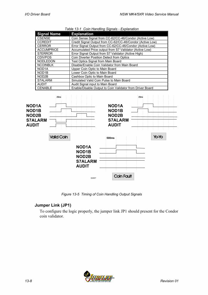
I/O Driver Board NSW MK4/5XR Video Service Manual
13-8 Revision 01
Table 13-1 Coin Handling Signals - ExplanationSignal Name ExplanationCSENSE Coin Sense Signal from CC-62/CC-46/Condor (Active Low)CCREDIT Credit Signal Output from CC-62/CC-46/Condor (Active Low)CERROR Error Signal Output from CC-62/CC-46/Condor (Active Low)ACCUMPRICE Accumulated Price output from S7 Validator (Active Low)S7ERROR Error Signal Output from S7 Validator (Active High)CDIVPOS Coin Diverter Position Detect from OpticsNODLEDON Test Optics Signal from Main BoardNCOINBLK Disable/Enable Coin Validator from Main BoardNOD1A Upper Coin Optic to Main BoardNOD1B Lower Coin Optic to Main BoardNOD2B Cashbox Optic to Main BoardS7ALARM Simulated Valid Coin Pulse to Main BoardAUDIT Audit Signal input to Main BoardCENABLE Enable/Disable Output to Coin Validator from Driver Board
NOD1ANOD1BNOD2BS7ALARMAUDIT
NOD1ANOD1BNOD2BS7ALARMAUDIT
NOD1ANOD1BNOD2BS7ALARMAUDIT
25ms 25ms
500ms Yo-YoYo-YoYo-YoYo-YoValid CoinValid CoinValid CoinValid Coin
Coin FaultCoin FaultCoin FaultCoin FaultI0097
Figure 13-5 Timing of Coin Handling Output Signals
Jumper Link (JP1)To configure the logic properly, the jumper link JP1 should present for the Condorcoin validator.

NSW MK4/5XR Video Service Manual I/O Driver Board
Revision 01 13-9
Diagnostic LEDsThree LEDs are located on the front of the board to indicate the status of certainconditions (see the table below).
Table 13-2 LED FunctionsCondition Red-LED1 Red-LED2 Green-LED
No Activity Off Off OffValid Coin to Hopper Pulse Pulse OffValid Coin to Cashbox Pulse Pulse PulseError (or Yo-Yo) Continuous Continuous OffFault Continuous Continuous Continuous
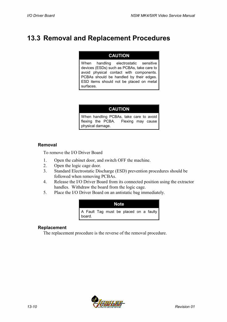
I/O Driver Board NSW MK4/5XR Video Service Manual
13-10 Revision 01
13.3 Removal and Replacement Procedures
CAUTIONWhen handling electrostatic sensitivedevices (ESDs) such as PCBAs, take care toavoid physical contact with components.PCBAs should be handled by their edges.ESD items should not be placed on metalsurfaces.
CAUTIONWhen handling PCBAs, take care to avoidflexing the PCBA. Flexing may causephysical damage.
RemovalTo remove the I/O Driver Board
1. Open the cabinet door, and switch OFF the machine.2. Open the logic cage door.3. Standard Electrostatic Discharge (ESD) prevention procedures should be
followed when removing PCBAs.4. Release the I/O Driver Board from its connected position using the extractor
handles. Withdraw the board from the logic cage.5. Place the I/O Driver Board on an antistatic bag immediately.
NoteA Fault Tag must be placed on a faultyboard.
ReplacementThe replacement procedure is the reverse of the removal procedure.

NSW MK4/5XR Video Service Manual I/O Driver Board
Revision 01 13-11
13.4 Connector Pin AssignmentA 96-way DIN41612 connector provides all inputs and outputs to the InterfaceBoard.
Pin Signal FunctionA1 GNDA Signal/power groundB1 GNDA Signal/power groundC1 AUDIT Connected to DACOM 3000A2 PBIN1 Push Button Input 1B2 /ESPIDOUT SPI Data Out from Main BoardC2 /ESIOE4 SPI Channel 4 (Door output) EnableA3 PBIN2 Push Button Input 2B3 PBIN3 Push Button Input 3C3 /ESIOE5 SPI Channel 5 (Door output) EnableA4 PBIN4 Push Button Input 4B4 PBIN5 Push Button Input 5C4 ESCLK SPI ClockA5 PBIN6 Push Button Input 6B5 PBIN7 Push Button Input 7C5 /ESPIDIN4 SPI Cannel 4 Data In to Main boardA6 PBIN8 Push Button Input 8B6 PBIN9 Push Button Input 9C6 /SPIDIN5 SPI Cannel 4 Data In to Main boardA7 PBIN10 Push Button Input 10B7 PBLMP1 Push Button Lamp Output 1C7 ESPIRST SPI Reset from Main boardA8 GNDA Signal/power groundB8 GNDA Signal/power groundC8 GNDA Signal/power groundA9 PBLMP2 Push Button Lamp Output 2B9 PBLMP3 Push Button Lamp Output 3C9 PBLMP4 Push Button Lamp Output 4A10 P22V5 +22.5 volts for lampB10 P22V5 +22.5 volts for lampC10 P22V5 +22.5 volts for lampA11 P22V5 +22.5 volts for lampB11 VCC +5 volts from Main boardC11 VCC +5 volts from Main boardA12 PBLMP5 Push Button Lamp Output 5B12 P12V +12 volts for main board and coin validatorC12 P12V +12 volts for main board and coin validatorA13 PBLMP6 Push Button Lamp Output 6B13 PBLMP7 Push Button Lamp Output 7C13 PBLMP8 Push Button Lamp Output 8A14 PBLMP9 Push Button Lamp Output 9B14 GNDA Signal/power groundC14 GNDA Signal/power groundA15 PBLMP10 Push Button Lamp Output 10B15 PBIN11 Push Button Input 11C15 MSSO0 Mechanical security switch 0 normally openA16 PBIN12 Push Button Input 12B16 PBIN13 Push Button Input 13C16 MSS0 Mechanical security switch 0 normally closedA17 PBIN14 Push Button Input 14B17 PBIN15 Push Button Input 15C17 MSSO1 Mechanical security switch 1 normally open
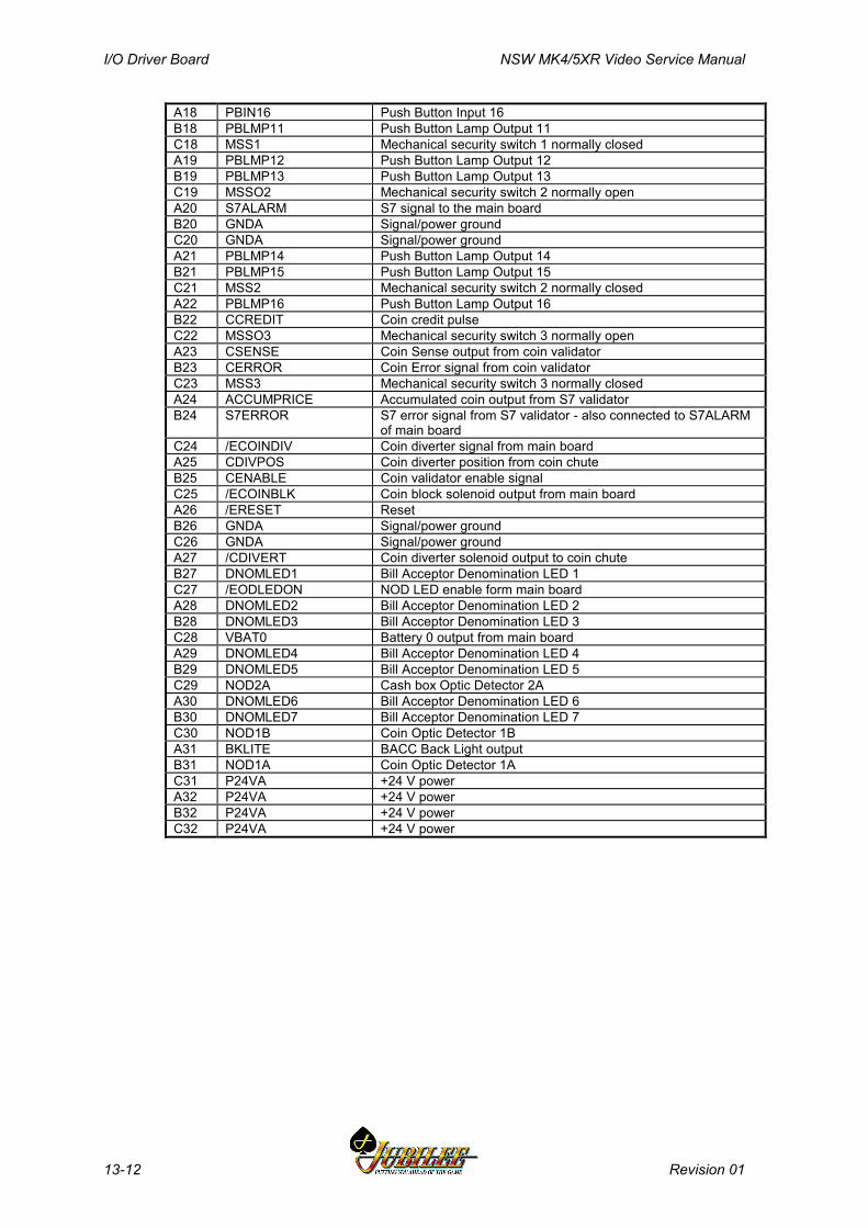
I/O Driver Board NSW MK4/5XR Video Service Manual
13-12 Revision 01
A18 PBIN16 Push Button Input 16B18 PBLMP11 Push Button Lamp Output 11C18 MSS1 Mechanical security switch 1 normally closedA19 PBLMP12 Push Button Lamp Output 12B19 PBLMP13 Push Button Lamp Output 13C19 MSSO2 Mechanical security switch 2 normally openA20 S7ALARM S7 signal to the main boardB20 GNDA Signal/power groundC20 GNDA Signal/power groundA21 PBLMP14 Push Button Lamp Output 14B21 PBLMP15 Push Button Lamp Output 15C21 MSS2 Mechanical security switch 2 normally closedA22 PBLMP16 Push Button Lamp Output 16B22 CCREDIT Coin credit pulseC22 MSSO3 Mechanical security switch 3 normally openA23 CSENSE Coin Sense output from coin validatorB23 CERROR Coin Error signal from coin validatorC23 MSS3 Mechanical security switch 3 normally closedA24 ACCUMPRICE Accumulated coin output from S7 validatorB24 S7ERROR S7 error signal from S7 validator - also connected to S7ALARM
of main boardC24 /ECOINDIV Coin diverter signal from main boardA25 CDIVPOS Coin diverter position from coin chuteB25 CENABLE Coin validator enable signalC25 /ECOINBLK Coin block solenoid output from main boardA26 /ERESET ResetB26 GNDA Signal/power groundC26 GNDA Signal/power groundA27 /CDIVERT Coin diverter solenoid output to coin chuteB27 DNOMLED1 Bill Acceptor Denomination LED 1C27 /EODLEDON NOD LED enable form main boardA28 DNOMLED2 Bill Acceptor Denomination LED 2B28 DNOMLED3 Bill Acceptor Denomination LED 3C28 VBAT0 Battery 0 output from main boardA29 DNOMLED4 Bill Acceptor Denomination LED 4B29 DNOMLED5 Bill Acceptor Denomination LED 5C29 NOD2A Cash box Optic Detector 2AA30 DNOMLED6 Bill Acceptor Denomination LED 6B30 DNOMLED7 Bill Acceptor Denomination LED 7C30 NOD1B Coin Optic Detector 1BA31 BKLITE BACC Back Light outputB31 NOD1A Coin Optic Detector 1AC31 P24VA +24 V powerA32 P24VA +24 V powerB32 P24VA +24 V powerC32 P24VA +24 V power

NSW MK4/5 Video Service Manual Communications Configuration Board
Revision 01 14-1
________Chapter 14________
Communications Configuration Board -410217
14.1 Physical Description .............................................................. 14-3
14.2 Functional Description .......................................................... 14-4
14.3 Removal and Replacement Procedures ............................... 14-6
14.4 Connector Pin Assignments ................................................. 14-7
14.5 General Maintenance ............................................................. 14-7

Communications Configuration Board NSW MK4/5 Video Service Manual
14-2 Revision 01
List of FiguresFigure 14-1 Communications Configuration Board - Location ......................................14-3Figure 14-2 Communications Configuration Board - Block Diagram ............................14-4
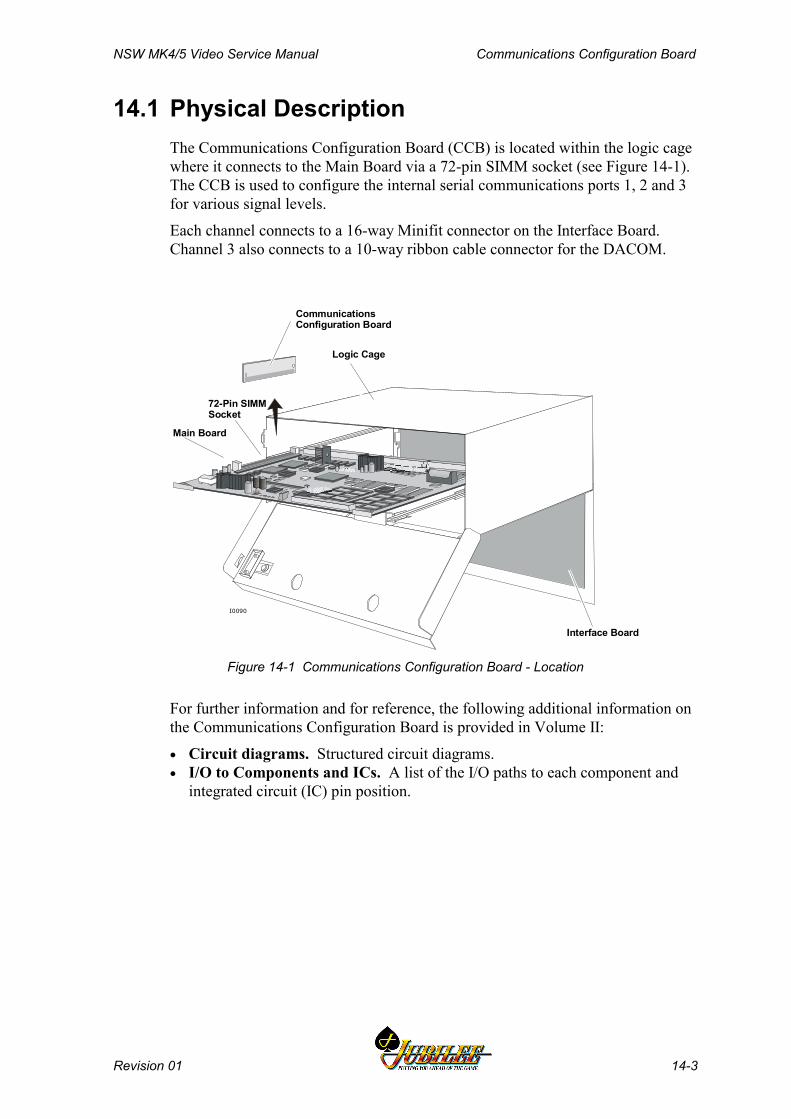
NSW MK4/5 Video Service Manual Communications Configuration Board
Revision 01 14-3
14.1 Physical DescriptionThe Communications Configuration Board (CCB) is located within the logic cagewhere it connects to the Main Board via a 72-pin SIMM socket (see Figure 14-1).The CCB is used to configure the internal serial communications ports 1, 2 and 3for various signal levels.
Each channel connects to a 16-way Minifit connector on the Interface Board.Channel 3 also connects to a 10-way ribbon cable connector for the DACOM.
Interface Board
Main Board
I0090
Logic Cage
CommunicationsConfiguration Board
72-Pin SIMMSocket
Figure 14-1 Communications Configuration Board - Location
For further information and for reference, the following additional information onthe Communications Configuration Board is provided in Volume II:
• Circuit diagrams. Structured circuit diagrams.• I/O to Components and ICs. A list of the I/O paths to each component and
integrated circuit (IC) pin position.

Communications Configuration Board NSW MK4/5 Video Service Manual
14-4 Revision 01
14.2 Functional DescriptionThe Main Board has four serial channels - 0, 1, 2 and 3. Channel 0 is reserved forcommunications with a Touchscreen interface or a Serial Keno Panel interface.Channels 1, 2 and 3 are fully isolated and can be configured using theCommunications Configuration Board.
The CCB plugs into the Main Board via a standard 72-pin SIMM socket andconverts the opto-coupled UART serial and I/O signals into the desired signallevels. There are several different CCBs used to configure the communicationschannels for different signals to suit different markets. The table below shows theconfiguration for PCBA 410217.
Channel 1 Channel 2 Channel 3Bank Note Acceptor RS232
The connectors on the Interface Board used for the serial channels are as follows:
Channel 0 Channel 1 Channel 2 Channel 3P14 P18 P15 P17
The serial channels are supplied with isolated ±12 V at 100 mA from the MainBoard, as well as +5 V to run the logic circuits.
Opto-Isolators
Serial Channel 1
Serial Channel 2
Serial Channel 3
FIP Display
DACOM/BIPS
Devices:Bank Note AcceptorIGT InterfaceRS 232RS 485DACOM 5000Touch ScreenOther...
I0091
CommunicationsConfiguration
Board
Serial Channel 0
+12 V
-12 V
Figure 14-2 Communications Configuration Board - Block Diagram
NSW MK4/5 Video Service Manual Communications Configuration Board
Revision 01 14-5
Bank Note Acceptor InterfaceThe bank note acceptor interface provides TTL/CMOS communication (serialinput only from bank note acceptor) with handshaking.
The data transfer rate is 600 baud, 8 bit data, 1 start bit, 1 stop bit and no parity.This port uses the 16-way Minifit connector P18 on the Interface Board.
The serial protocol is 'one way' in that the bank note acceptor sends to the host anASCII code, depending on the type of note inserted or the status of the bank noteacceptor. The host enables, disables or accepts the note via two control lines -ACCEPT ENABLE and SEND.
RS232 InterfaceThis interface provides RS232 communications between the Main Board and anexternal interface board. The channel has six I/O signals, including data I/O. Theopto LED drivers on the Main Board are configured to an OFF state when the lineis inactive or not connected to minimise power consumption. This port can be runat a minimum 9600 baud rate.
Communications Configuration Board NSW MK4/5 Video Service Manual
14-6 Revision 01
14.3 Removal and Replacement Procedures
CAUTIONWhen handling electrostatic devices (ESDs)such as PCBAs, take care to avoid physicalcontact with components. Handle PCBAs bytheir edges. Do not place ESD items onmetal surfaces. When handling PCBAs, takecare to avoid flexing the PCBA. Flexing maycause physical damage.
To remove the Communications Configuration Board (see Figure 14-1):
1. Open the cabinet door, and switch OFF the machine.2. Open the logic cage door.3. Standard Electrostatic Discharge (ESD) prevention procedures should be
followed when removing PCBAs.4. Release the Main Board using the extractor pins, and withdraw it from the
logic cage.5. Locate the Communications Configuration Board sitting perpendicular to
the Main Board in the top left.6. Release both of the two metal spring retainers located on each side of the
PCBA.7. Remove the board by lifting it upwards while holding the Main Board
steady.
NoteA fault tag must be placed on a faulty PCBA.
To replace the Communications Configuration Board:
1. Standard Electrostatic Discharge (ESD) prevention procedures should befollowed when replacing PCBAs.
2. Remove the replacement board from the antistatic bag.3. Inspect both sides of the board for any signs of physical damage.4. Press the Communications Configuration Board into position on the Main
Board.5. Slide the Main Board into the correct logic cage grooves and gently move
the board into position on the Interface Board. Close the logic cage door.6. Switch the machine on, and close the cabinet door.
NoteRun relevant machine tests after replacingthe Communications Configuration Board.
NSW MK4/5 Video Service Manual Communications Configuration Board
Revision 01 14-7
14.4 Connector Pin AssignmentsFor a listing of the 72 pin connector assignment to the Main Board, refer to theMain Board chapter. The pin assignments for the serial channel connectors P14,P15, P17, and P18 are listed in the relevant sections of the Interface Boardchapter.
14.5 General Maintenance
CAUTIONDo not attempt component level repairwithout access to a workshop facility.
For general maintenance of the Communications Configuration Board:
• Remove any dust or dirt from external surfaces.• Make sure that all contacts on the PCBA and in the SIMM socket on the
Main Board are clean.• Check that the connectors are in good condition and secure.

Communications Configuration Board NSW MK4/5 Video Service Manual
14-8 Revision 01
Notes
NSW MK4/5XR Video Service Manual LAB Communications Board
Revision 01 15-1
______Chapter 15______
LAB Communications Board -410174
Note:Chapter includes LAB Communications PSU Fusing and SerialInterface Card Mounting Chassis (PSU Chassis)
15.1 Technical Description............................................................ 15-3
15.1.1 Physical Description ................................................................. 15-315.1.2 Basic Operation........................................................................ 15-615.1.3 LAB PSU Chassis Description ................................................. 15-7
15.2 Removal and Replacement.................................................. 15-10
15.2.1 Removal ................................................................................. 15-1015.2.2 Replacement .......................................................................... 15-10
15.3 Connector Pin Assignments ............................................... 15-11
15.3.1 Interface Board Slot P6 .......................................................... 15-11
15.4 General Maintenance ........................................................... 15-13
LAB Communications Board NSW MK4/5XR Video Service Manual
15-2 Revision 01
List of FiguresFigure 15-1 LAB Communications Board - position in logic cage ...................................... 15-3Figure 15-2 LAB Communications Board - Component Layout ......................................... 15-5Figure 15-3 LAB Communications Board - Block Diagram ................................................ 15-6Figure 15-4 LAB PSU Chassis ........................................................................................... 15-8Figure 15-5 PSU Chassis - PSU Fuse and Connector Wiring ........................................... 15-8Figure 15-6 LAB Communications Board and PSU Kit ...................................................... 15-9
List of TablesTable 15-1 LAB Port 1 Pinout............................................................................................. 15-4Table 15-2 LAB Ports 2-6 Pinout........................................................................................ 15-4Table 15-3 Interface Board Bus Connector for LAB Communications Board .................. 15-11
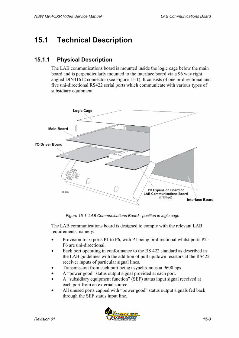
NSW MK4/5XR Video Service Manual LAB Communications Board
Revision 01 15-3
15.1 Technical Description
15.1.1 Physical DescriptionThe LAB communications board is mounted inside the logic cage below the mainboard and is perpendicularly mounted to the interface board via a 96 way rightangled DIN41612 connector (see Figure 15-1). It consists of one bi-directional andfive uni-directional RS422 serial ports which communicate with various types ofsubsidiary equipment.
Interface Board
Logic Cage
Main Board
I/O Driver Board
I/O Expansion Board or LAB Communications Board
(if fitted)I0076
Figure 15-1 LAB Communications Board - position in logic cage
The LAB communications board is designed to comply with the relevant LABrequirements, namely:
• Provision for 6 ports P1 to P6, with P1 being bi-directional whilst ports P2 -P6 are uni-directional.
• Each port operating in conformance to the RS 422 standard as described inthe LAB guidelines with the addition of pull up/down resistors at the RS422receiver inputs of particular signal lines.
• Transmission from each port being asynchronous at 9600 bps.• A “power good” status output signal provided at each port.• A “subsidiary equipment function” (SEF) status input signal received at
each port from an external source.• All unused ports capped with “power good” status output signals fed back
through the SEF status input line.
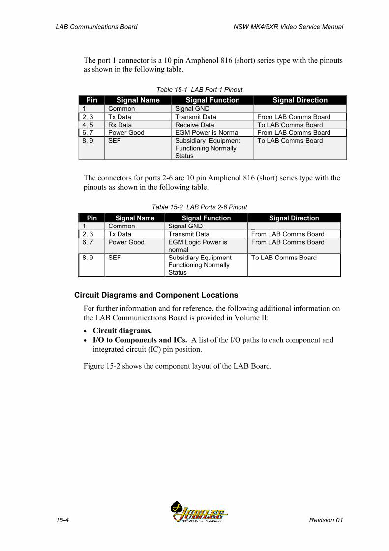
LAB Communications Board NSW MK4/5XR Video Service Manual
15-4 Revision 01
The port 1 connector is a 10 pin Amphenol 816 (short) series type with the pinoutsas shown in the following table.
Table 15-1 LAB Port 1 PinoutPin Signal Name Signal Function Signal Direction
1 Common Signal GND2, 3 Tx Data Transmit Data From LAB Comms Board4, 5 Rx Data Receive Data To LAB Comms Board6, 7 Power Good EGM Power is Normal From LAB Comms Board8, 9 SEF Subsidiary Equipment
Functioning NormallyStatus
To LAB Comms Board
The connectors for ports 2-6 are 10 pin Amphenol 816 (short) series type with thepinouts as shown in the following table.
Table 15-2 LAB Ports 2-6 PinoutPin Signal Name Signal Function Signal Direction
1 Common Signal GND _2, 3 Tx Data Transmit Data From LAB Comms Board6, 7 Power Good EGM Logic Power is
normalFrom LAB Comms Board
8, 9 SEF Subsidiary EquipmentFunctioning NormallyStatus
To LAB Comms Board
Circuit Diagrams and Component LocationsFor further information and for reference, the following additional information onthe LAB Communications Board is provided in Volume II:
• Circuit diagrams.• I/O to Components and ICs. A list of the I/O paths to each component and
integrated circuit (IC) pin position.
Figure 15-2 shows the component layout of the LAB Board.

NSW MK4/5XR Video Service Manual LAB Communications Board
Revision 01 15-5
LEIS
URE
IND
USTR
IES
C
R38
R37
R34
R33
R78
R77
C1
C2 U
1
U3
C57
R2
C56
C54
R6
R95R1
R94
R3
R4
R5
C3
MK
V LA
B C
OM
MS
BO
ARD
PCB
0801
-410
175
PCBA
250
1-41
0174
IS
SUE
R
EV
C5 C39
U6
U12
C19
U
10
C43
U16
C4
U
7
C40
U
13
C24
U
9
C46
U
15
C4
U5
C34
U11
C29
U8
C49
U14
R63
R60
R59
R55
R
69R
66R
65
R64
R
91R
88R
92
R93
R
79R
76R
80
R81
R8
5R
82R
86
R87
R
75R
72R
71
R70
R46
R45
R42
R41
R84
R83
R54
R53
R50
R49
R90
R89
R30
R20
R26
R25
R74
R73 R22
R21
R18
R17
R68
R67
R14
R13
R10
R9
R62
R61
R58
R67
C33
C32
C31
C30
C81
C50
C28
C27
C26
C25
C48
C47
C23
C22
C21
C20
C45
C44
C18
C17
C16
C15
C42
C41
C14
C13
C12
C11
C53
C52
C10
C9
C8
C7
C36
C37
C36
C35
P5 P3 P1
P6 P4 P2
I0100
Figure 15-2 LAB Communications Board - Component Layout
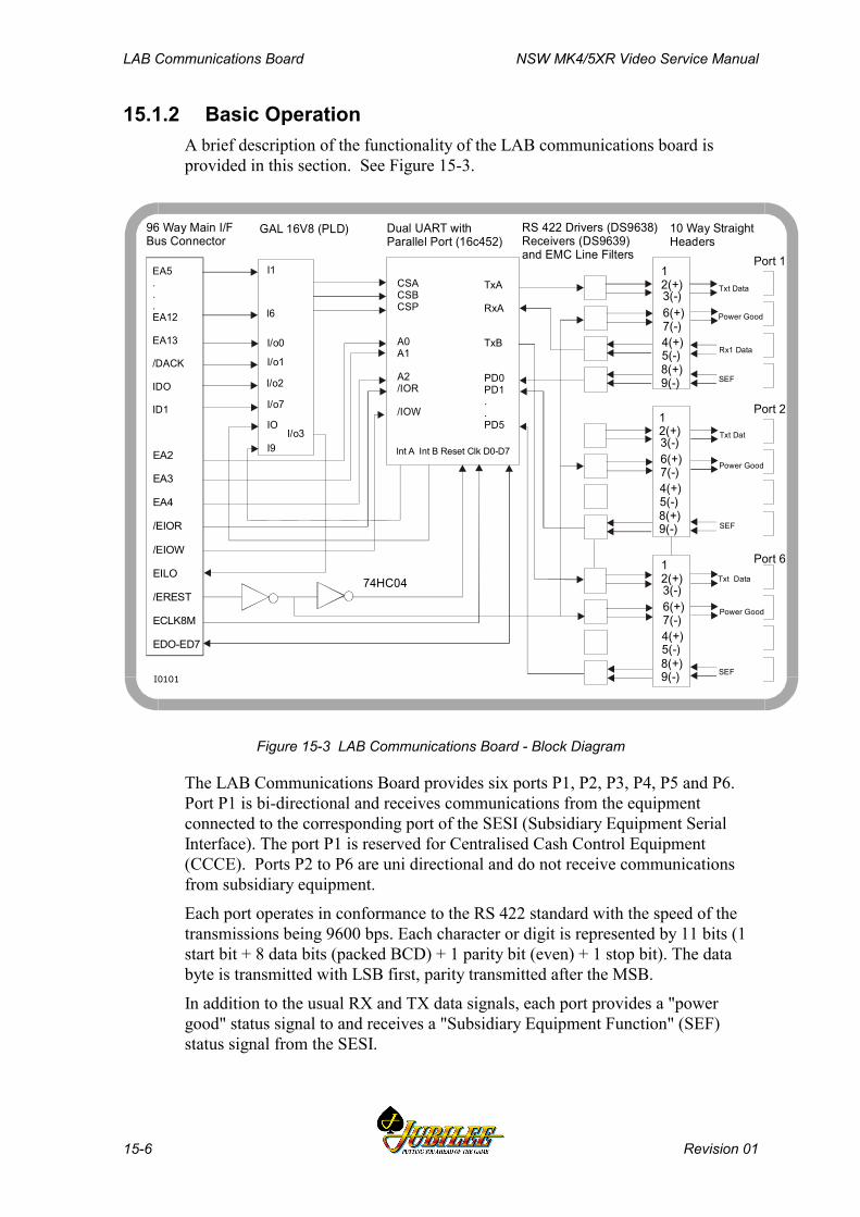
LAB Communications Board NSW MK4/5XR Video Service Manual
15-6 Revision 01
15.1.2 Basic OperationA brief description of the functionality of the LAB communications board isprovided in this section. See Figure 15-3.
EA2
EA3
EA4
/EIOR
/EIOW
EILO
/EREST
ECLK8M
EDO-ED7
EA5...EA12
EA13
/DACK
IDO
ID1
CSACSBCSP
A0A1
A2/IOR
/IOW
Int A Int B Reset Clk D0-D7
TxA
RxA
TxB
PD0PD1..PD5
I1
I6
I/o0
I/o1
I/o2
I/o7
IO
I9I/o3
SEF
Power Good
Txt Data
SEF
Power Good
Txt Dat
SEF
Rx1 Data
Power Good
Txt Data
96 Way Main I/F Bus Connector
GAL 16V8 (PLD) Dual UART with Parallel Port (16c452)
10 Way Straight Headers
RS 422 Drivers (DS9638)Receivers (DS9639)and EMC Line Filters Port 1
Port 2
Port 6
12(+)
12(+)
12(+)
3(-)
3(-)
3(-)
6(+)7(-)
6(+)7(-)
6(+)7(-)
4(+)5(-)
4(+)5(-)
4(+)5(-)
8(+)9(-)
8(+)9(-)
8(+)9(-)
74HC04
I0101
Figure 15-3 LAB Communications Board - Block Diagram
The LAB Communications Board provides six ports P1, P2, P3, P4, P5 and P6.Port P1 is bi-directional and receives communications from the equipmentconnected to the corresponding port of the SESI (Subsidiary Equipment SerialInterface). The port P1 is reserved for Centralised Cash Control Equipment(CCCE). Ports P2 to P6 are uni directional and do not receive communicationsfrom subsidiary equipment.
Each port operates in conformance to the RS 422 standard with the speed of thetransmissions being 9600 bps. Each character or digit is represented by 11 bits (1start bit + 8 data bits (packed BCD) + 1 parity bit (even) + 1 stop bit). The databyte is transmitted with LSB first, parity transmitted after the MSB.
In addition to the usual RX and TX data signals, each port provides a "powergood" status signal to and receives a "Subsidiary Equipment Function" (SEF)status signal from the SESI.

NSW MK4/5XR Video Service Manual LAB Communications Board
Revision 01 15-7
The "power good" status signal is an indication of the integrity of the powersupply level on the EGM main logic board and hence the LAB communicationsboard. The signal operates such that the differential voltage at the output of theline driver is negative (Vd = -V) whenever the main logic board and any other"sensitive" subsidiary boards (eg LAB Comms board) have "normal" powerapplied.
Under all other conditions the line driver differential voltage is positive(Vd = +V). The manufacturer of the SESI must ensure that the other power failconditions which may cause the output of the line driver to assume zero voltage orhigh impedance are detected correctly.
The SEF status signal is an indication to the gaming machine that subsidiaryequipment connected is functioning correctly or that a request has been made forplay suspension. Under "normal" conditions the SEF differential signal voltage atthe line driver output is negative (Vd = -V). A positive signal (Vd = +V) is to beinterpreted by the gaming machine as a request to suspend play. "Fail" conditionswhich may cause the output of the line driver to assume zero voltage or highimpedance must also be interpreted as a request to suspend play.
All unused ports will be "capped". In the "cap" for the connector, pins 6 and 7(power good) are linked to pins 8 and 9 (SEF) respectively so that the gamingmachine can be provided with the SEF input signal.
15.1.3 LAB PSU Chassis DescriptionThe LAB Comms PSU Fusing and Serial I/F Card Mounting Chassis (PSU chassisis located behind the video monitor and provides power connections to the sixsubsidiary equipment interfaces (third party vendor equipment). Each connection iscapable of supplying 12Vrms (nominal) AC at 0.5A.
Each output connection from the PSU chassis is protected by a 0.5A fuse.
Note that the PSU transformer (or winding) is part of the EGM main power supplytransformer via a separate winding.
The machine power supply provides the LAB Comms PSU with isolated 12 VrmsAC at 3 A, via a flying lead from the 2-way connector JP29 on the InterfaceBoard. This power is supplied from a separate winding in the machine powersupply.
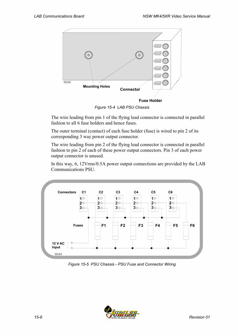
LAB Communications Board NSW MK4/5XR Video Service Manual
15-8 Revision 01
I0102
Mounting Holes Connector
Fuse HolderFigure 15-4 LAB PSU Chassis
The wire leading from pin 1 of the flying lead connector is connected in parallelfashion to all 6 fuse holders and hence fuses.
The outer terminal (contact) of each fuse holder (fuse) is wired to pin 2 of itscorresponding 3 way power output connector.
The wire leading from pin 2 of the flying lead connector is connected in parallelfashion to pin 2 of each of these power output connectors. Pin 3 of each poweroutput connector is unused.
In this way, 6, 12Vrms/0.5A power output connections are provided by the LABCommunications PSU.
123
123
F1 F2 F3 F4 F5 F6
Connectors C1 C2 C3 C4 C5 C6
Fuses
12 V ACInput
I0103
Figure 15-5 PSU Chassis - PSU Fuse and Connector Wiring
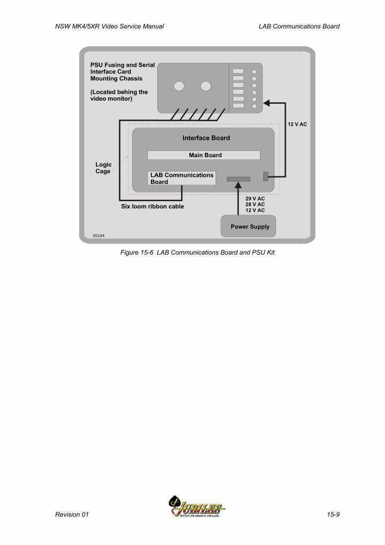
NSW MK4/5XR Video Service Manual LAB Communications Board
Revision 01 15-9
PSU Fusing and SerialInterface Card Mounting Chassis
(Located behing the video monitor)
LogicCage
Six loom ribbon cable
Main Board
LAB CommunicationsBoard
12 V AC
Interface Board
I0104
29 V AC28 V AC12 V AC
Power Supply
Figure 15-6 LAB Communications Board and PSU Kit
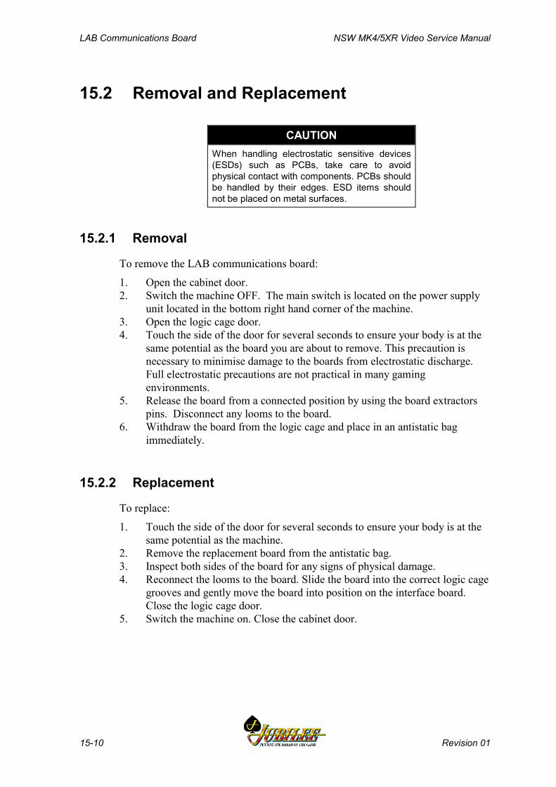
LAB Communications Board NSW MK4/5XR Video Service Manual
15-10 Revision 01
15.2 Removal and Replacement
CAUTIONWhen handling electrostatic sensitive devices(ESDs) such as PCBs, take care to avoidphysical contact with components. PCBs shouldbe handled by their edges. ESD items shouldnot be placed on metal surfaces.
15.2.1 Removal
To remove the LAB communications board:
1. Open the cabinet door.2. Switch the machine OFF. The main switch is located on the power supply
unit located in the bottom right hand corner of the machine.3. Open the logic cage door.4. Touch the side of the door for several seconds to ensure your body is at the
same potential as the board you are about to remove. This precaution isnecessary to minimise damage to the boards from electrostatic discharge.Full electrostatic precautions are not practical in many gamingenvironments.
5. Release the board from a connected position by using the board extractorspins. Disconnect any looms to the board.
6. Withdraw the board from the logic cage and place in an antistatic bagimmediately.
15.2.2 Replacement
To replace:
1. Touch the side of the door for several seconds to ensure your body is at thesame potential as the machine.
2. Remove the replacement board from the antistatic bag.3. Inspect both sides of the board for any signs of physical damage.4. Reconnect the looms to the board. Slide the board into the correct logic cage
grooves and gently move the board into position on the interface board.Close the logic cage door.
5. Switch the machine on. Close the cabinet door.
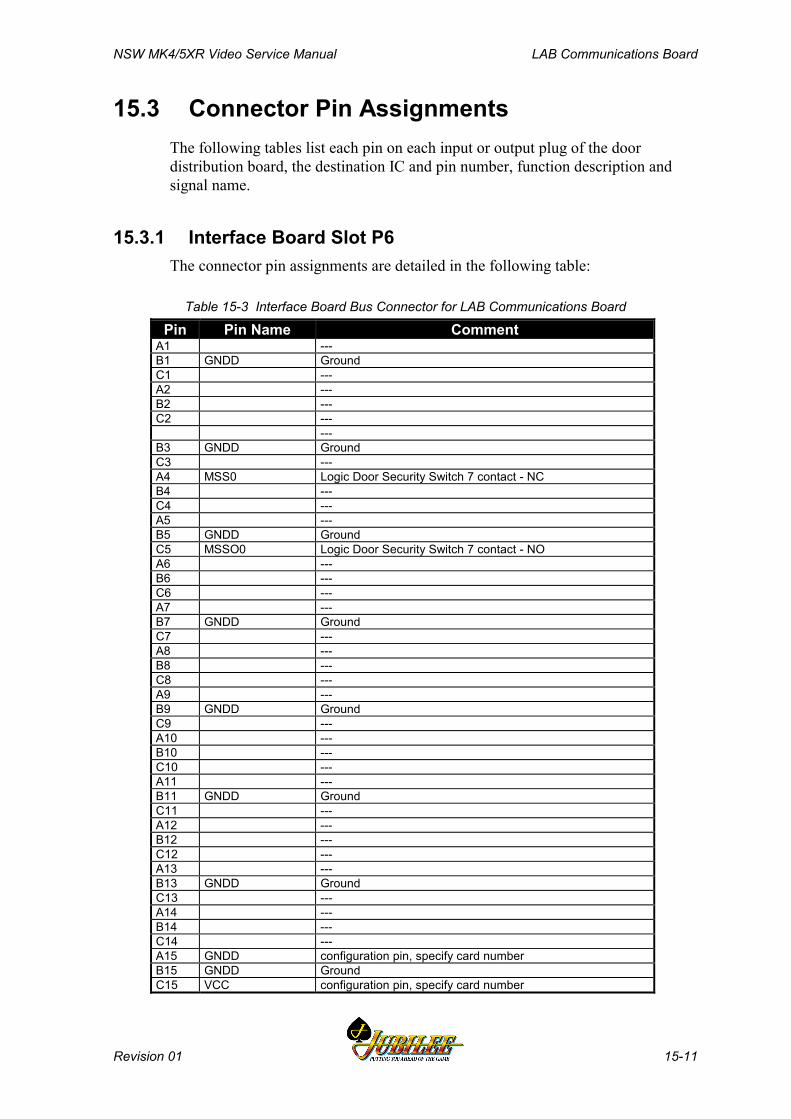
NSW MK4/5XR Video Service Manual LAB Communications Board
Revision 01 15-11
15.3 Connector Pin AssignmentsThe following tables list each pin on each input or output plug of the doordistribution board, the destination IC and pin number, function description andsignal name.
15.3.1 Interface Board Slot P6The connector pin assignments are detailed in the following table:
Table 15-3 Interface Board Bus Connector for LAB Communications Board
Pin Pin Name CommentA1 ---B1 GNDD GroundC1 ---A2 ---B2 ---C2 ---
---B3 GNDD GroundC3 ---A4 MSS0 Logic Door Security Switch 7 contact - NCB4 ---C4 ---A5 ---B5 GNDD GroundC5 MSSO0 Logic Door Security Switch 7 contact - NOA6 ---B6 ---C6 ---A7 ---B7 GNDD GroundC7 ---A8 ---B8 ---C8 ---A9 ---B9 GNDD GroundC9 ---A10 ---B10 ---C10 ---A11 ---B11 GNDD GroundC11 ---A12 ---B12 ---C12 ---A13 ---B13 GNDD GroundC13 ---A14 ---B14 ---C14 ---A15 GNDD configuration pin, specify card numberB15 GNDD GroundC15 VCC configuration pin, specify card number

LAB Communications Board NSW MK4/5XR Video Service Manual
15-12 Revision 01
A16 VCC +5V from main board, converted from 24VB16 VCC +5V from main board, converted from 24VC16 VCC +5V from main board, converted from 24VA17 RNW CPU, read not write signalB17 GNDD GroundC17 ---A18 /EIF CPU, IF interruptB18 EFHO CPU, FH0 interruptC18 /DACK CPU, data acknowledgeA19 /EFL CPU, FL interruptB19 GNDD GroundC19 /EIL0 CPU, IL0 interruptA20 /ERESET CPU, external reset outputB20 /EIOW CPU, IO write signalC20 /EIOR CPU, IO read signalA21 EA13 CPU, address busB21 GNDD GroundC21 ECLK8M CPU, clock signalA22 EA10 CPU, address busB22 EA11 CPU, address busC22 EA12 CPU, address busA23 EA8 CPU, address busB23 GNDD GroundC23 EA9 CPU, address busA24 EA5 CPU, address busB24 EA6 CPU, address busC24 EA7 CPU, address busA25 EA3 CPU, address busB25 GNDD GroundC25 EA4 CPU, address busA26 VBATE external battery backupB26 /PFAIL power fail signalC26 EA2 CPU, address busA27 ---B27 GNDD GroundC27 ---A28 ED5 CPU, data busB28 ED6 CPU, data busC28 ED7 CPU, data busA29 ED3 CPU, data busB29 GNDD GroundC29 ED4 CPU, data busA30 ED0 CPU, data busB30 ED1 CPU, data busC30 ED2 CPU, data busA31 GNDD GroundB31 ---C31 GNDD GroundA32 ---B32 GNDD GroundC32 P24VD +24V
NSW MK4/5XR Video Service Manual LAB Communications Board
Revision 01 15-13
15.4 General Maintenance
CAUTIONDo not attempt component level repairwithout access to a workshop facility.
For general maintenance of the LAB communications board:
• Remove any dust or dirt from the external surfaces.• Check that all plugs are secure.

LAB Communications Board NSW MK4/5XR Video Service Manual
15-14 Revision 01
Notes
NSW MK4/5XR Video Service Manual Progressive Jackpot System
Revision 01 16-1
______Chapter 16______
Progressive Jackpot System
16.1 Overview ................................................................................. 16-3
16.2. Progressive SEI Board (410227) ........................................... 16-3
Progressive Jackpot System NSW MK4/5XR Video Service Manual
16-2 Revision 01
List of FiguresFigure 16-1 SEI Board - data flows ...............................................................................16-4Figure 16-2 Cashcade - data flows................................................................................16-6
List of TablesTable 16-1 SEI Board Configurations............................................................................16-3Table 16-2 DIP Switch Settings.....................................................................................16-5Table 16-3 Mikohn Interface..........................................................................................16-7Table 16-4 Machine Interface........................................................................................16-7Table 16-5 CDS Display Interface .................................................................................16-8Table 16-6 Mikohn RS-422/485 Serial Interface ...........................................................16-8
NSW MK4/5XR Video Service Manual Progressive Jackpot System
Revision 01 16-3
16.1 OverviewThe Mk4/5XR gaming machines can be configured to provide for MysteryCashcade Jackpots.
In a Mystery Cashcade Jackpot system, a number of machines are linked togetherthrough a Controller, which is external to the gaming machine. As each game isplayed, pulses are sent to the Controller from each of the gaming machines,initiating the accumulation of a Cashcade Jackpot amount, which is shown on acentral display unit connected to the Controller. The jackpot is won when theCashcade Jackpot amount reaches some randomly selected value betweenpredetermined limits. The jackpot value is transmitted from the Controller to thewinning machine.
Machines may be configured to offer several different combinations of link, orcashcade jackpots. Typical configurations provide two, three, or four jackpotamounts (termed Double, Triple, or Quad Jackpots).
16.2. Progressive SEI Board (410227)
OverviewThe Subsidiary Equipment Interface (SEI) Board (Part No.410227) enables LABRS-422 Communications to be converted to DACOM 5000 signals for a MikohnCON2 pulse system. The SEI Board can also receive information back from thecontroller such that when a Mystery Cashcade Jackpot is won, the SubsidiaryEquipment Function line is activated until the jackpot is reset, causing themachine to lock up. The SEI Board allows for both Mystery Cashcade and LinkProgressive Jackpot games to be connected to the gaming machine.
The SEI Board can also be used to connect the gaming machine to a BIPs CashlessTransfer system. To support the BIPS interface, the serial ports have to provide 2-way communication ports (Mikohn CON2 controllers only require one-waycommunication ports). Figure 13-1 shows the SEI Board connections.
The SEI Board is mounted on a plate and the assembly is then mounted into thesubsidiary equipment board mounting plate.
The table below shows the possible board configurations:
Table 16-1 SEI Board ConfigurationsOption 1
Pulse Progressive systemOption 2
Serial Progressive systemOption 3
BIPs SystemP5 and P6 inputs P5 input P1 in/outputtwo DACOM 5000 inputs RS-422 in/out DACOM 5000 in/outputtwo pulse outputs CDS display output CDS display outputCDS Display outputLED out
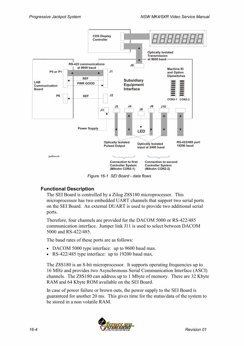
Progressive Jackpot System NSW MK4/5XR Video Service Manual
16-4 Revision 01
CDS DisplayController
LABCommunicationBoard
SEFPWR GOOD
SEFP6
P5 or P1
SubsidiaryEquipmentInterface
J1
J2
J3J4J5 J6
J8
J9
J10
Optically IsolatedPulsed Output Optically Isolated
Input at 2400 baud
Connection to firstController System(Mikohn CON2-1)
Connection to secondController System(Mikohn CON2-2)
RS-422/485 port19200 baud
CON2-1 CON2-2
Machine IDand OptionDipswitches
RS-422 communicationsat 9600 baud
LED
Optically IsolatedTransmissionat 9600 baud
jpotflow.cdr
Power Supply
Figure 16-1 SEI Board - data flows
Functional DescriptionThe SEI Board is controlled by a Zilog Z8S180 microprocessor. Thismicroprocessor has two embedded UART channels that support two serial portson the SEI Board. An external DUART is used to provide two additional serialports.
Therefore, four channels are provided for the DACOM 5000 or RS-422/485communication interface. Jumper link J11 is used to select between DACOM5000 and RS-422/485.
The baud rates of these ports are as follows:
• DACOM 5000 type interface: up to 9600 baud max.• RS-422/485 type interface: up to 19200 baud max.
The Z8S180 is an 8-bit microprocessor. It supports operating frequencies up to16 MHz and provides two Asynchronous Serial Communication Interface (ASCI)channels. The Z8S180 can address up to 1 Mbyte of memory. There are 32 KbyteRAM and 64 Kbyte ROM available on the SEI Board.
In case of power failure or brown outs, the power supply to the SEI Board isguaranteed for another 20 ms. This gives time for the status/data of the system tobe stored in a non volatile RAM.

NSW MK4/5XR Video Service Manual Progressive Jackpot System
Revision 01 16-5
Option 1 - Jackpot Pulse SystemThe Subsidiary Equipment Interface (SEI) has two connections, one to Port P5and one to Port P6 on the LAB Communications Board.
It also has two pulse outputs and two serial inputs to the two different progressivesystems Mystery Cashcade and Link Progressive. An LED is used to indicate thatpulses are being sent.
The SEI translates the LAB Communication Protocol to the M09, LinkProgressive protocol or the M00, Cashcade Jackpot Protocol, or both, dependingon how the interface is configured.
The SEI is configurable to allow for the jackpot type to be set, i.e. one LinkProgressive and one Cashcade, or two Cashcade interfaces.
The SEI has the ability to identify the machine so that they correspond to each ofthe Mikohn CON2 machine ID numbers. This is done by using DIP switches thatallow for up to 40 ID numbers for each CON2 controller. When a Cashcadejackpot is won by a machine, the SEI in that machine activates the SubsidiaryEquipment Function Line, causing the machine to lock until the jackpot is reset.
The DIP Switch settings for the two CON2 controllers are shown below.
Table 16-2 DIP Switch SettingsCON2-1 CON2-2
SWITCH Data Bit Description SWITCH Data Bit Description
1 - 6 0 - 5 Machine ID 1 - 6 0 - 5 Machine ID7 6 Spare 7 6 Spare8 7 Controller
Type8 7 Controller type
DIP switch bit 8 enables each of the CON2 interfaces to be configured as a LinkProgressive or Cashcade type controller.
The SEI has the capability of driving a CDS Display for the Link ProgressiveJackpot Prize.
Mystery CashcadeWhere the machine is configured for Mystery Cashcade jackpots without LinkedProgressive jackpots, the SEI has only one connection (to P5) on the LABCommunications Board. In addition, the CDS display is not required. A blockdiagram of a Cashcade system is shown in Figure 16-2.
Mystery Cashcade Jackpot LightA connection is provided for an external LED to advise the player the machine isstill contributing to the Cashcade Jackpot.
Option 2 - Jackpot Serial SystemAn RS-485 I/F is also implemented on the SEI Board. This allows for serialcommunication between a controller and the machine. The RS-485 Port isconnected parallel to the J10 port (DACOM 5000) and replaces the same.
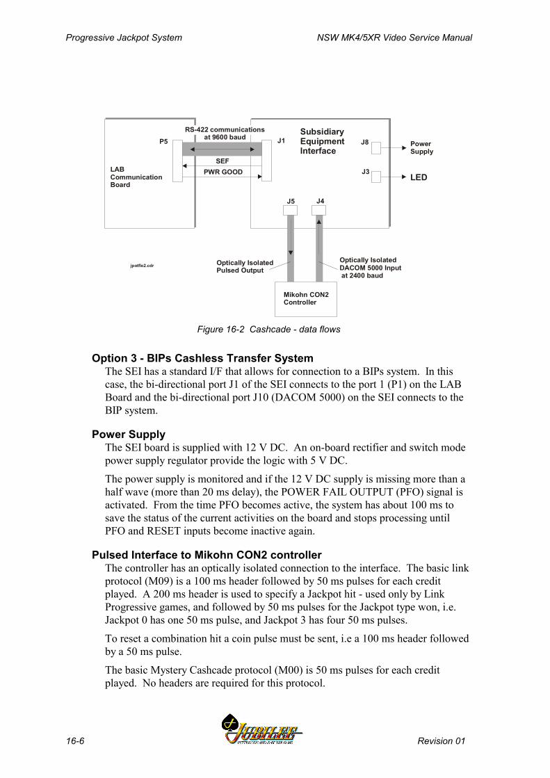
Progressive Jackpot System NSW MK4/5XR Video Service Manual
16-6 Revision 01
LABCommunicationBoard
SEFPWR GOOD
P5SubsidiaryEquipmentInterface
J1
J3
J4J5
J8
Optically IsolatedPulsed Output
Optically IsolatedDACOM 5000 Input at 2400 baud
RS-422 communicationsat 9600 baud
LED
jpotflo2.cdr
PowerSupply
Mikohn CON2Controller
Figure 16-2 Cashcade - data flows
Option 3 - BIPs Cashless Transfer SystemThe SEI has a standard I/F that allows for connection to a BIPs system. In thiscase, the bi-directional port J1 of the SEI connects to the port 1 (P1) on the LABBoard and the bi-directional port J10 (DACOM 5000) on the SEI connects to theBIP system.
Power SupplyThe SEI board is supplied with 12 V DC. An on-board rectifier and switch modepower supply regulator provide the logic with 5 V DC.
The power supply is monitored and if the 12 V DC supply is missing more than ahalf wave (more than 20 ms delay), the POWER FAIL OUTPUT (PFO) signal isactivated. From the time PFO becomes active, the system has about 100 ms tosave the status of the current activities on the board and stops processing untilPFO and RESET inputs become inactive again.
Pulsed Interface to Mikohn CON2 controllerThe controller has an optically isolated connection to the interface. The basic linkprotocol (M09) is a 100 ms header followed by 50 ms pulses for each creditplayed. A 200 ms header is used to specify a Jackpot hit - used only by LinkProgressive games, and followed by 50 ms pulses for the Jackpot type won, i.e.Jackpot 0 has one 50 ms pulse, and Jackpot 3 has four 50 ms pulses.
To reset a combination hit a coin pulse must be sent, i.e a 100 ms header followedby a 50 ms pulse.
The basic Mystery Cashcade protocol (M00) is 50 ms pulses for each creditplayed. No headers are required for this protocol.
NSW MK4/5XR Video Service Manual Progressive Jackpot System
Revision 01 16-7
Two pulsed outputs are provided via J5 and J6 on the SEI Board.
Mystery Jackpot LightA connection for an external LED is available to advise the player the machine isstill contributing to the Cashcade Jackpot. The jackpot light connects to J8 on theSEI Board.
CON2 to InterfaceThe machine receives information from the controller via an optically isolatedDACOM 5000 input.
This machine sends out the current Jackpot value, which is continuously updated,as well as the Jackpot win, and the machine ID.
Two interfaces are provided via J4 and J10 on the SEI Board.
Table 16-3 Mikohn InterfacePin Number Description
1 RxD2 COMMON3 TxD
Interface to MachineThe interface between J1 on the SEI and the machine is shown below.
Table 16-4 Machine InterfacePin Number Description
1 Common2 RX Data +3 RX Data -4 TX Data +5 TX Data -6 Power Good +7 Power Good -8 Sub. Equipment Function +9 Sub. Equipment Function -10 NC
Interface to CDS DisplayThe connection to the CDS Display controller is via a DACOM 5000 uni-directionport, as shown in the table below.
The display controller board connects to J9 on the SEI Board.
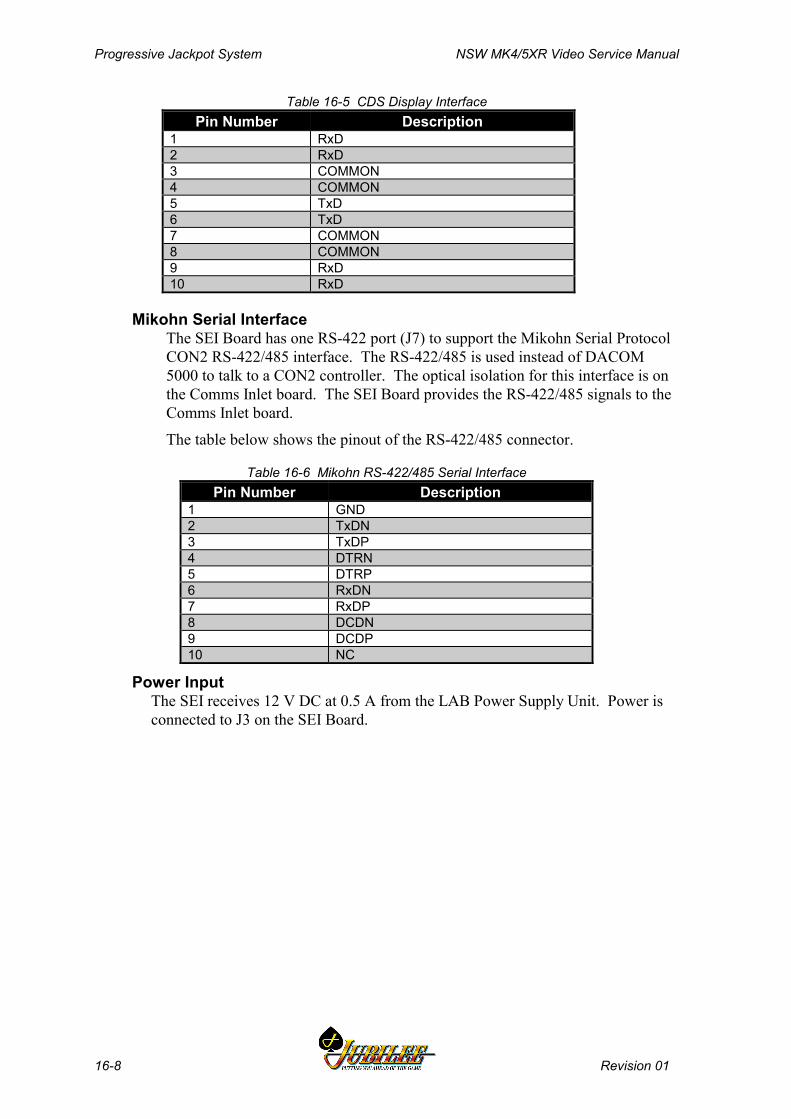
Progressive Jackpot System NSW MK4/5XR Video Service Manual
16-8 Revision 01
Table 16-5 CDS Display InterfacePin Number Description
1 RxD2 RxD3 COMMON4 COMMON5 TxD6 TxD7 COMMON8 COMMON9 RxD10 RxD
Mikohn Serial InterfaceThe SEI Board has one RS-422 port (J7) to support the Mikohn Serial ProtocolCON2 RS-422/485 interface. The RS-422/485 is used instead of DACOM5000 to talk to a CON2 controller. The optical isolation for this interface is onthe Comms Inlet board. The SEI Board provides the RS-422/485 signals to theComms Inlet board.
The table below shows the pinout of the RS-422/485 connector.
Table 16-6 Mikohn RS-422/485 Serial InterfacePin Number Description
1 GND2 TxDN3 TxDP4 DTRN5 DTRP6 RxDN7 RxDP8 DCDN9 DCDP10 NC
Power InputThe SEI receives 12 V DC at 0.5 A from the LAB Power Supply Unit. Power isconnected to J3 on the SEI Board.
NSW MK4/5XR Video Service Manual Machine Fault Finding
Revision 01 17-1
________Chapter 17________Machine Fault Finding
17.1 Fault Finding ...................................................................................... 3

Machine Fault Finding NSW MK4/5XR Video Service Manual
17-2 Revision 01
List of Tables
Table 17-1 Fault Finding..................................................................................................... 3
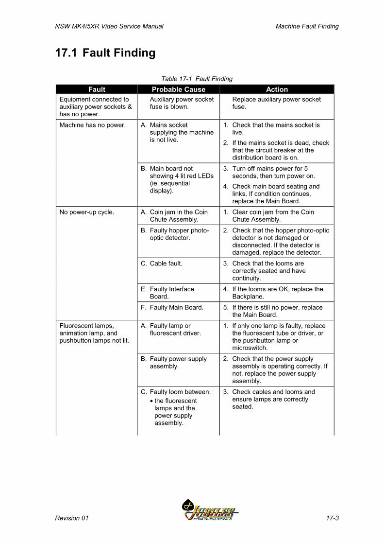
NSW MK4/5XR Video Service Manual Machine Fault Finding
Revision 01 17-3
17.1 Fault Finding
Table 17-1 Fault FindingFault Probable Cause Action
Equipment connected toauxiliary power sockets &has no power.
Auxiliary power socketfuse is blown.
Replace auxiliary power socketfuse.
Machine has no power. A. Mains socketsupplying the machineis not live.
1. Check that the mains socket islive.
2. If the mains socket is dead, checkthat the circuit breaker at thedistribution board is on.
B. Main board notshowing 4 lit red LEDs(ie, sequentialdisplay).
3. Turn off mains power for 5seconds, then turn power on.
4. Check main board seating andlinks. If condition continues,replace the Main Board.
No power-up cycle. A. Coin jam in the CoinChute Assembly.
1. Clear coin jam from the CoinChute Assembly.
B. Faulty hopper photo-optic detector.
2. Check that the hopper photo-opticdetector is not damaged ordisconnected. If the detector isdamaged, replace the detector.
C. Cable fault. 3. Check that the looms arecorrectly seated and havecontinuity.
E. Faulty InterfaceBoard.
4. If the looms are OK, replace theBackplane.
F. Faulty Main Board. 5. If there is still no power, replacethe Main Board.
Fluorescent lamps,animation lamp, andpushbutton lamps not lit.
A. Faulty lamp orfluorescent driver.
1. If only one lamp is faulty, replacethe fluorescent tube or driver, orthe pushbutton lamp ormicroswitch.
B. Faulty power supplyassembly.
2. Check that the power supplyassembly is operating correctly. Ifnot, replace the power supplyassembly.
C. Faulty loom between:• the fluorescent
lamps and thepower supplyassembly.
3. Check cables and looms andensure lamps are correctlyseated.
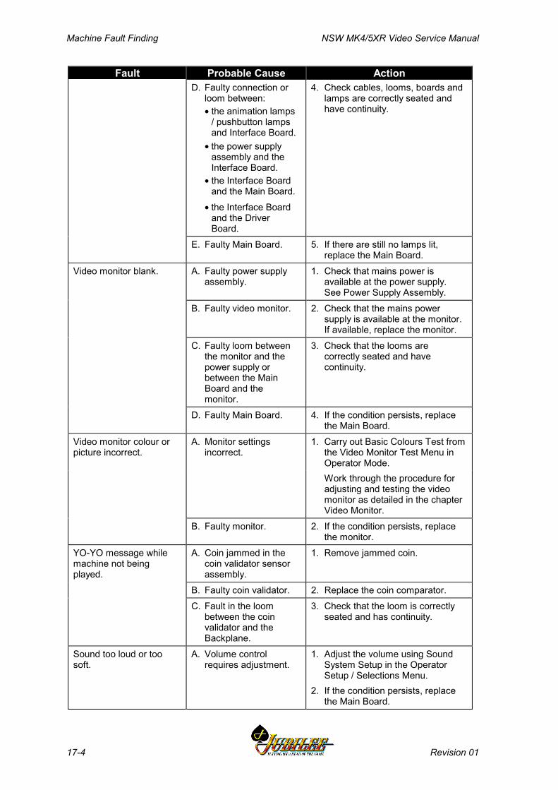
Machine Fault Finding NSW MK4/5XR Video Service Manual
17-4 Revision 01
Fault Probable Cause ActionD. Faulty connection or
loom between:• the animation lamps
/ pushbutton lampsand Interface Board.
• the power supplyassembly and theInterface Board.
• the Interface Boardand the Main Board.
• the Interface Boardand the DriverBoard.
4. Check cables, looms, boards andlamps are correctly seated andhave continuity.
E. Faulty Main Board. 5. If there are still no lamps lit,replace the Main Board.
Video monitor blank. A. Faulty power supplyassembly.
1. Check that mains power isavailable at the power supply.See Power Supply Assembly.
B. Faulty video monitor. 2. Check that the mains powersupply is available at the monitor.If available, replace the monitor.
C. Faulty loom betweenthe monitor and thepower supply orbetween the MainBoard and themonitor.
3. Check that the looms arecorrectly seated and havecontinuity.
D. Faulty Main Board. 4. If the condition persists, replacethe Main Board.
Video monitor colour orpicture incorrect.
A. Monitor settingsincorrect.
1. Carry out Basic Colours Test fromthe Video Monitor Test Menu inOperator Mode.Work through the procedure foradjusting and testing the videomonitor as detailed in the chapterVideo Monitor.
B. Faulty monitor. 2. If the condition persists, replacethe monitor.
YO-YO message whilemachine not beingplayed.
A. Coin jammed in thecoin validator sensorassembly.
1. Remove jammed coin.
B. Faulty coin validator. 2. Replace the coin comparator.C. Fault in the loom
between the coinvalidator and theBackplane.
3. Check that the loom is correctlyseated and has continuity.
Sound too loud or toosoft.
A. Volume controlrequires adjustment.
1. Adjust the volume using SoundSystem Setup in the OperatorSetup / Selections Menu.
2. If the condition persists, replacethe Main Board.
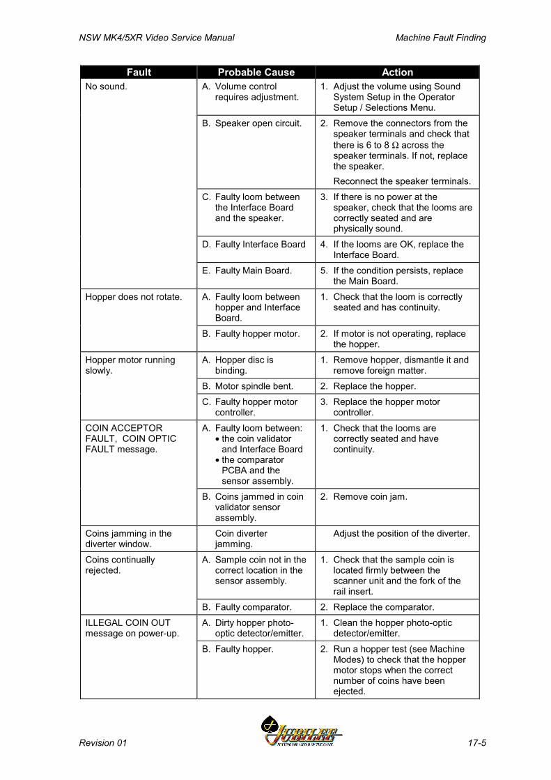
NSW MK4/5XR Video Service Manual Machine Fault Finding
Revision 01 17-5
Fault Probable Cause ActionNo sound. A. Volume control
requires adjustment.1. Adjust the volume using Sound
System Setup in the OperatorSetup / Selections Menu.
B. Speaker open circuit. 2. Remove the connectors from thespeaker terminals and check thatthere is 6 to 8 Ω across thespeaker terminals. If not, replacethe speaker.Reconnect the speaker terminals.
C. Faulty loom betweenthe Interface Boardand the speaker.
3. If there is no power at thespeaker, check that the looms arecorrectly seated and arephysically sound.
D. Faulty Interface Board 4. If the looms are OK, replace theInterface Board.
E. Faulty Main Board. 5. If the condition persists, replacethe Main Board.
Hopper does not rotate. A. Faulty loom betweenhopper and InterfaceBoard.
1. Check that the loom is correctlyseated and has continuity.
B. Faulty hopper motor. 2. If motor is not operating, replacethe hopper.
Hopper motor runningslowly.
A. Hopper disc isbinding.
1. Remove hopper, dismantle it andremove foreign matter.
B. Motor spindle bent. 2. Replace the hopper.C. Faulty hopper motor
controller.3. Replace the hopper motor
controller.COIN ACCEPTORFAULT, COIN OPTICFAULT message.
A. Faulty loom between:• the coin validator
and Interface Board• the comparator
PCBA and thesensor assembly.
1. Check that the looms arecorrectly seated and havecontinuity.
B. Coins jammed in coinvalidator sensorassembly.
2. Remove coin jam.
Coins jamming in thediverter window.
Coin diverterjamming.
Adjust the position of the diverter.
Coins continuallyrejected.
A. Sample coin not in thecorrect location in thesensor assembly.
1. Check that the sample coin islocated firmly between thescanner unit and the fork of therail insert.
B. Faulty comparator. 2. Replace the comparator.ILLEGAL COIN OUTmessage on power-up.
A. Dirty hopper photo-optic detector/emitter.
1. Clean the hopper photo-opticdetector/emitter.
B. Faulty hopper. 2. Run a hopper test (see MachineModes) to check that the hoppermotor stops when the correctnumber of coins have beenejected.
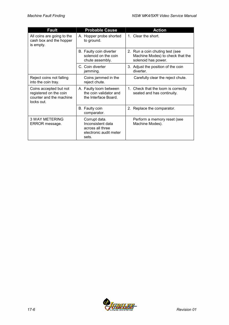
Machine Fault Finding NSW MK4/5XR Video Service Manual
17-6 Revision 01
Fault Probable Cause ActionAll coins are going to thecash box and the hopperis empty.
A. Hopper probe shortedto ground.
1. Clear the short.
B. Faulty coin divertersolenoid on the coinchute assembly.
2. Run a coin chuting test (seeMachine Modes) to check that thesolenoid has power.
C. Coin diverterjamming.
3. Adjust the position of the coindiverter.
Reject coins not fallinginto the coin tray.
Coins jammed in thereject chute.
Carefully clear the reject chute.
Coins accepted but notregistered on the coincounter and the machinelocks out.
A. Faulty loom betweenthe coin validator andthe Interface Board.
1. Check that the loom is correctlyseated and has continuity.
B. Faulty coincomparator.
2. Replace the comparator.
3 WAY METERINGERROR message.
Corrupt data.Inconsistent dataacross all threeelectronic audit metersets.
Perform a memory reset (seeMachine Modes).

NSW MK4/5XR Video Service Manual Appendix A
Revision 01 A-1
Appendix A
Games
Spinning Reel Games........................................................................................ 3

Appendix A NSW MK4/5XR Video Service Manual
A-2 Revision 01
List of Figures:Figure A-1 MK V Video Game Screen Example.................................................................. 4Figure A-2 MK V Pay Table Example................................................................................. 5
NSW MK4/5XR Video Service Manual Appendix A
Revision 01 A-3
Spinning Reel GamesThe Jubilee Mk4/5XR gaming machine is available with MkV Spinning Reelgames.
The screen displays a simulation of the reels spinning, which, after a short time'come to rest'. The resultant positions of the various symbols (refer to Fig A-1) isassessed for a winning combination.
If the resultant combination is a winner (the winning combination(s) can bechecked, if the machine has a top box, with the pay table provided on the top boxartwork, if the machine has no top box, with the pay table provided on the bellypanel artwork. Figure A-2 shows an example of a pay table), the machineresponds by flashing the corresponding symbols and by emitting 'win' sounds. Thegame software displays the amount of credits won on the screen, prompts theplayer to gamble the win (if available), then adds them to the player's credit total.This action may vary slightly depending on the software, customer and legalrequirements.
The gamble features can vary considerably between games, however, the conceptis the same. The player is given the opportunity to gamble the credits won for achance to double the total. This 'doubling up' may continue for up to five times (orpossibly more) consecutively.
If the combination is not a winner, the machine will end the game if no credits areremaining or prompt the player to continue.
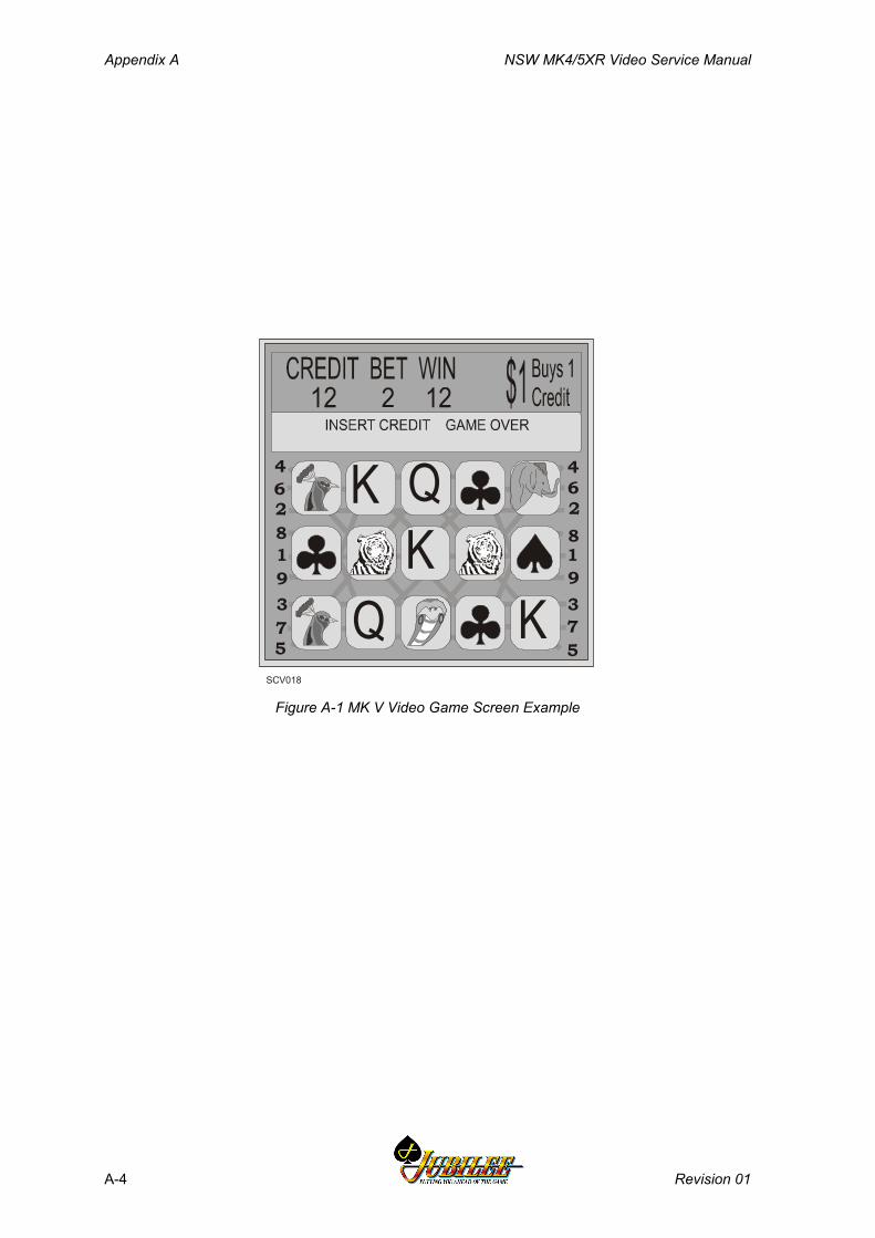
Appendix A NSW MK4/5XR Video Service Manual
A-4 Revision 01
SCV018
1
2
3
4
5
6
7
8
91
2
3
4
5
6
7
8
9
Q
QK
K
K
Figure A-1 MK V Video Game Screen Example
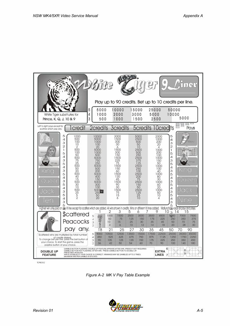
NSW MK4/5XR Video Service Manual Appendix A
Revision 01 A-5
Play up to 90 credits. Bet up to 10 credits per line.
Scattered Peacocks pay any.
Scattered wins are multiplied by total number of credits staked.To change bet per line, press the bet button of your choice. To start the game, press the payline button of your choice.
DOUBLE UP FEATURE
EXTRA LINES
Play up to 90 credits. Bet up to 10 credits per line.
Prince, K, Q, J, 10 & 9Prince, K, Q, J, 10 & 9
GAMBLE BUTTON FLASHING: DOUBLE UP FEATURE APPEARS AFTER WIN. PRESS IF NOT REQUIRED.GAMBLE BUTTON NOT FLASHING: AFTER WIN. PRESS GAMBLE BUTTON TO DOUBLE UP.PRESS RED OR BLACK.WIN IS DOUBLED IF YOUR CHOICE IS CORRECT. WINNINGS MAY BE GAMBLED UP TO 5 TIMES.MAXIMUM WIN PER GAMBLE IS $10,OOO.
500025005005010
2500500250
2500375125
2500250100
250020075
250015050
25001252510
1000500100102
5001005050075255005020500401550030105002552
20001000200204
1000200100
100015050
100010040
10008030
10006020
100050104
30001500300306
1500300150
150022575
150015060
150012045
15009030
150075156
100005000100010020
50001000500
5000750250
5000500200
5000400150
5000300100
50002505020
500 25 5 2
9000 10500 12500 13500 15000 17500 22500 25000 35000 45000 450 525 625 675 750 875 1125 1250 1750 2250 90 105 125 135 150 175 225 250 350 450 36 42 50 54 60 70 90 100 140 180
500 1000 1500 2500 3000 3500 4500 5000 7000 7500 25 50 75 125 150 175 225 250 350 375 5 10 15 25 30 35 45 50 70 75 2 4 6 10 12 14 18 20 28 30
1 2 3 5 6 7 9 10 14 15
18 21 25 27 30 35 45 50 70 90
TOPBOX2
Figure A-2 MK V Pay Table Example

Appendix A NSW MK4/5XR Video Service Manual
A-6 Revision 01
Notes
NSW MK4/5XR Video Service Manual Glossary
Revision 01 1
Glossary
ADH Aristocrat Disc Hopper.
Any pays Symbols are read anywhere on the payline, and notnecessarily left to right or right to left.
ARM250 Advanced RISC Machine - a type of integratedmicrocontroller
ASIC Application Specific Integrated Circuit
Audit key switch To display the electronic audit meters on the monitor, insertthe audit key and turn it 90° clockwise.
Audit meters See electronic and electro-mechanical meters.
Base game The game provided with the EGM as described in thepaytable and mid panel display.
Base A specially designed box unit on which the cabinet stands.The cash box is usually located securely within the base.
Bilock A range of high-security locks manufactured by theAustralian Lock Company Pty. Ltd. that features a unique“U” shaped keyway.
Book pay After the player presses the COLLECT button, the creditsare manually paid out to a player and recorded in thepayout book.
Button panel The series of buttons across the front of the cabinet that theplayer uses to control game play.
Cabinet The major cabinet or casing in which the workings of themachine are housed.
Cable channel assembly Metal channels used to route the power cables andcommunication cables to Slant Top machines. Thechannels also locate the machines.
Cancel credit When a player attempts to COLLECT a credit amountgreater than the amount that the Hopper can pay out, themachine locks up. When this occurs, the Cancel Creditprocedure allows for the player to be paid manually and thecredit on the machine cancelled to zero.
Cash box The high security compartment used to hold any coins notheld in the hopper.
Clearance The value of coins removed from the cash box, usuallydaily.
CMOS Complementary metal oxide semi-conductor.
Coin detectors See photo-optic detectors.

Glossary NSW MK4/5XR Video Service Manual
2 Revision 01
Coin jam When coins jam in the coin assembly chute.
Coin selector See coin comparator.
Coin tray The tray at the bottom of the cabinet into which payout orreject coins are deposited for collection.
Coin validator Device that senses physical and magnetic properties of acoin tendered to determine if valid and acceptable for play.
Collect cash To convert the amount shown on the CREDIT meter tocash, the player presses the COLLECT button that activatesthe hopper to pay the coins into the coin tray.
Console See base.
CPU Central processing unit.
Credit Coins inserted into the machine register as credits. Onecoin may equal more than one credit. Prizes are shown ascredits until such time as the player chooses to collectthem.
D/A Digital to analog
DES Data Encryption System
DSB Data Storage Board
ECC Error Checking and Correction
EEPROM Electrically Erasable Programmable Read Only Memory
EGM Electronic Gaming Machine
EHM Electronic Hard Meter
Electromechanicalmeters
The electromechanical meters or counters. These metersare non-resettable and are cumulative for the life of themachine.
Electronic meters The electronic audit meters that provide audit information.
EMC Electromagnetic Compatibility
EPROM Erasable programmable read only memory.
ESB EHM SPI Board
Feature game Additional game to the base game that provides variety andan additional means of winning.
Hopper refill If the hopper runs out of coins, the operator opens thecabinet and places a specific number of coins into thehopper.
House The club, casino or organisation running the games.
Hyperlink A link progressive jackpot feature.
I/O Input/output.
NSW MK4/5XR Video Service Manual Glossary
Revision 01 3
IC Integrated circuit
Illegal coin A coin which is incorrectly paid out by the hopper.
Intelligent bezel Sites the accept/reject slot for note placement on the billacceptor fascia panel.
Installation A club, casino or other place which has a number ofgaming machines.
I/O Input/output.
Jackpot key switch To reset the machine after a cashier payout or after amachine fault has been corrected, insert the J key, turn it180° clockwise and back again.
LAB New South Wales Liquor Administration Board.
LED Light emitting diode.
Left to right pay Symbols are read from left to right for prize determination.
Links A series of machines are linked together by an externalprogressive controller. Each machine contributes to acommon progressively incremented jackpot and isdisplayed separately for the player to see.
Lockup A lockup renders the machine unplayable and is triggeredeither by a malfunction, when a jackpot has been won (ifthe program permits), or when the player has pressed theCASH OUT pushbutton when there is more than the cancelcredit amount in credit.
Manual pay A book payment made for any amount in excess of thecancel credit limit of the machine.
Max bet A button that automatically bets the maximum amountpossible on a game.
Meters Electronic (soft) meters and electro-mechanical meterslocated within the machine that record and displayimportant audit information for the operator.
Microprocessor The computer component which controls and processesgame play instructions.
Multiline A game in which a player bets on additional lines tomultiply the chance of a prize.
Multiplier A game in which a player bets additional coins on any onegame to multiply the value of the prize.
Payline(s) The line or lines which indicate where the symbols mustline up for a player to win.
Payout book Book used to record hopper refill amount, jackpot amountand cancel credit amount.
Glossary NSW MK4/5XR Video Service Manual
4 Revision 01
PCBA Printed circuit board assembly.
Play button One of the illuminated buttons on the button panel, used ingame play.
PLD Programmable logic device.
Progressive jackpot This is an additional jackpot to the game's normal jackpot.This jackpot increments by a fixed percentage of themachine's turnover and is displayed separately for theplayer to see.
PROM Programmable Read Only Memory.
QCC Quick Change Core – a facility offered by Bilocks (seeabove) where the keyed core of the lock is fitted separate tothe lock barrel.
Refill Money you add to a hopper by opening the door andinserting coins, usually when the machine has run out ofcoins.
Reserve A button on the machine which allows a player to indicateto others that the machine is reserved. This reserve messageremains lit for 3 minutes.
RISC Reduced Instruction Set Computer.
Scattered pays Symbols can be above, below or on the payline to qualifyfor a prize.
SEF Subsidiary equipment function.
SESI Subsidiary equipment serial interface.
Short time out The machine locks up when a coin jams across the hopperphoto-optic detector for more than 0.5 seconds.
Soft meters See electronic meters.
SPI Serial Peripheral Interface
SRAM Static Random Access Memory.
Symbols The various designs on the reel strips. Common symbolsinclude Jacks, Kings, Aces, Cherries, and Gold Bars.
Top box The box unit on top of the cabinet which carries the gamegraphics, rules and score card.
Yo-Yo A coin travelling in reverse to its normal direction. Forexample: a coin is dangled through and withdrawn from thecoin entry slot of the machine in an attempt to cheat themachine of a coin during game play.

NSW MK4/5XR Video Service Manual Index
Revision 01 Index 1
Index
A
Accounting Information ............................. 3-16ARM RISC ................................................ 11-4ARM250 Microprocessor ........................ 11-10Artwork
main door .............................................. 4-13top box .................................................. 4-20
Audit Key ..................................................... 4-9
B
Ballast .............................................. 4-12, 4-22Bank Note Acceptor Assembly .................... 7-3
assembly replacement ............................ 7-16bank note acceptor .................................. 7-5bezel ............................................ 7-10, 7-13communications .................................... 7-10configuration ......................................... 7-13DIP switches ......................................... 7-13dual-cage housing .................................... 7-4electronics ............................................... 7-8faults ...................................................... 7-13GL5 serial interface ............................... 7-10jams ....................................................... 7-16LEDs ........................................... 7-10, 7-13main board interface ............................ 11-22maintenance ........................................... 7-20microcontroller ........................................ 7-8note entry ................................................. 7-7physical description ................................. 7-3scanning system ..................................... 7-10security .......................................... 3-10, 7-7stacker ........................................... 7-6, 7-10stacker replacement ............................... 7-15troubleshooting ...................................... 7-18video level calibration ........................... 7-20
Bank Note Acceptor Information ............... 3-24Battery Backup Circuit ............................ 11-16Belly Panel
artwork .................................................. 4-13door ....................................................... 4-19security .................................................. 4-20
Bezel ................................................ 7-10, 7-13
Bill Acceptor (see Bank Note AcceptorAssembly) ............................................... 7-3
Bilock Locks ...................................... 1-7, 4-10BIPs ........................................................... 16-3
C
Cabinet Door ............................................... 4-5artwork .................................................. 4-13latch ........................................................ 4-5lock ......................................................... 4-7photo-optic sensor .................................. 4-8security ................................................... 4-7
Cabinet maintenance ................................. 4-23Cash Box ................................................... 4-11Cash Box Chute ......................................... 4-11Cashcade Jackpots ..................................... 16-3Cashless Transfer ...................................... 16-6Cathode Ray Tube ....................................... 9-3CCB ........................................................... 14-3CCCE ........................................................ 15-6CDS Display .............................................. 16-7Coin Entry Test ......................................... 3-26Coin Handling ............................................. 6-3
I/O driver board interface ..................... 13-7main board interface ........................... 11-20maintenance .......................................... 6-11
Coin Tray .................................................. 4-19Coin Validator ............................................. 6-4
conector pinouts ...................................... 6-8diverter solenoid ..................................... 6-9fault finding .......................................... 6-11photo-optic sensor .................................. 6-9replacement ............................................. 6-7security ................................................... 3-9yoyo ........................................................ 6-6
Collect Limit ................................................ 3-6Combination Test ...................................... 3-29Communications Configuration Board 11-22,
14-3configuration ......................................... 14-4connector pin assignments .................... 14-7functional description ........................... 14-4maintenance .......................................... 14-7
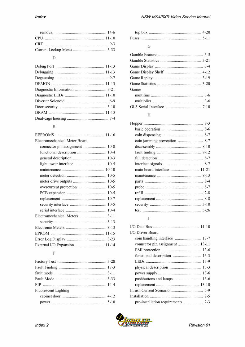
Index NSW MK4/5XR Video Service Manual
Index 2 Revision 01
removal ................................................. 14-6CPU ......................................................... 11-10CRT ............................................................. 9-3Current Lockup Menu ................................ 3-33
D
Debug Port ............................................... 11-13Debugging ................................................ 11-13Degaussing ................................................... 9-7DEMON ................................................... 11-13Diagnostic Information .............................. 3-21Diagnostic LEDs ...................................... 11-10Diverter Solenoid ......................................... 6-9Door security .............................................. 3-10DRAM ..................................................... 11-15Dual-cage housing ........................................ 7-4
E
EEPROMS ............................................... 11-16Electromechanical Meter Board
connector pin assignment ...................... 10-8functional description ............................ 10-4general description ................................ 10-3light tower interface .............................. 10-5maintenance ......................................... 10-10meter detection ...................................... 10-5meter drive outputs ................................ 10-5overcurrent protection ........................... 10-5PCB expansion ...................................... 10-5replacement ........................................... 10-7security interface ................................... 10-5serial interface ....................................... 10-4
Electromechanical Meters .......................... 3-11security .................................................. 3-13
Electronic Meters ....................................... 3-13EPROM ................................................... 11-15Error Log Display ...................................... 3-23External I/O Expansion ............................ 11-14
F
Factory Test ............................................... 3-28Fault Finding .............................................. 17-3fault mode .................................................. 3-11Fault Mode ................................................. 3-33FIP ............................................................. 14-4Fluorescent Lighting
cabinet door ........................................... 4-12power ..................................................... 5-10
top box .................................................. 4-20Fuses .......................................................... 5-11
G
Gamble Feature ........................................... 3-5Gamble Statistics ....................................... 3-21Game Display .............................................. 3-4Game Display Shelf ................................... 4-12Game Replay ............................................. 3-19Game Statistics .......................................... 3-20Games
multiline .................................................. 3-6multiplier ................................................ 3-6
GL5 Serial Interface .................................. 7-10
H
Hopper ......................................................... 8-3basic operation ........................................ 8-6coin dispensing ....................................... 8-7coin jamming prevention ........................ 8-7disassembly ........................................... 8-10fault finding .......................................... 8-12full detection ........................................... 8-7interface signals ...................................... 8-7main board interface ........................... 11-21maintenance .......................................... 8-13parts ........................................................ 8-4probe ....................................................... 8-7refill ........................................................ 2-8replacement ............................................. 8-8security ................................................. 3-10test ........................................................ 3-26
I
I/O Data Bus ............................................ 11-10I/O Driver Board
coin handling interface ......................... 13-7connector pin assignment .................... 13-11EMI protection ..................................... 13-6functional description ........................... 13-3LEDs ..................................................... 13-9physical description .............................. 13-3power supply ......................................... 13-6pushbuttons and lamps .......................... 13-6replacement ......................................... 13-10
Inrush Current Scenario ............................... 5-9Installation ................................................... 2-5
pre-installation requirements .................. 2-3
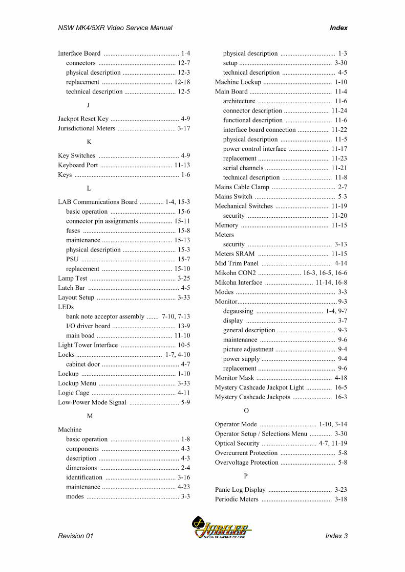
NSW MK4/5XR Video Service Manual Index
Revision 01 Index 3
Interface Board ............................................ 1-4connectors ............................................. 12-7physical description ............................... 12-3replacement ......................................... 12-18technical description .............................. 12-5
J
Jackpot Reset Key ........................................ 4-9Jurisdictional Meters .................................. 3-17
K
Key Switches ............................................... 4-9Keyboard Port .......................................... 11-13Keys ............................................................. 1-6
L
LAB Communications Board .............. 1-4, 15-3basic operation ...................................... 15-6connector pin assignments ................... 15-11fuses ...................................................... 15-8maintenance ......................................... 15-13physical description ............................... 15-3PSU ....................................................... 15-7replacement ......................................... 15-10
Lamp Test .................................................. 3-25Latch Bar ..................................................... 4-5Layout Setup .............................................. 3-33LEDs
bank note acceptor assembly ....... 7-10, 7-13I/O driver board ..................................... 13-9main boad ............................................ 11-10
Light Tower Interface ................................ 10-5Locks .................................................. 1-7, 4-10
cabinet door ............................................. 4-7Lockup ....................................................... 1-10Lockup Menu ............................................. 3-33Logic Cage ................................................. 4-11Low-Power Mode Signal ............................. 5-9
M
Machinebasic operation ........................................ 1-8components ............................................. 4-3description ............................................... 4-3dimensions .............................................. 2-4identification ......................................... 3-16maintenance ........................................... 4-23modes ...................................................... 3-3
physical description ................................ 1-3setup ...................................................... 3-30technical description ............................... 4-5
Machine Lockup ........................................ 1-10Main Board ................................................ 11-4
architecture ........................................... 11-6connector description .......................... 11-24functional description ........................... 11-6interface board connection .................. 11-22physical description .............................. 11-5power control interface ....................... 11-17replacement ......................................... 11-23serial channels ..................................... 11-21technical description ............................. 11-8
Mains Cable Clamp ..................................... 2-7Mains Switch ............................................... 5-3Mechanical Switches ............................... 11-19
security ............................................... 11-20Memory ................................................... 11-15Meters
security ................................................. 3-13Meters SRAM ......................................... 11-15Mid Trim Panel ......................................... 4-14Mikohn CON2 ......................... 16-3, 16-5, 16-6Mikohn Interface ............................ 11-14, 16-8Modes .......................................................... 3-3Monitor.......................................................... 9-3
degaussing ....................................... 1-4, 9-7display .................................................... 3-7general description .................................. 9-3maintenance ............................................ 9-6picture adjustment ................................... 9-4power supply ........................................... 9-4replacement ............................................. 9-6
Monitor Mask ............................................ 4-18Mystery Cashcade Jackpot Light ............... 16-5Mystery Cashcade Jackpots ....................... 16-3
O
Operator Mode ................................. 1-10, 3-14Operator Setup / Selections Menu ............. 3-30Optical Security ................................ 4-7, 11-19Overcurrent Protection ................................ 5-8Overvoltage Protection ................................ 5-8
P
Panic Log Display ..................................... 3-23Periodic Meters ......................................... 3-18
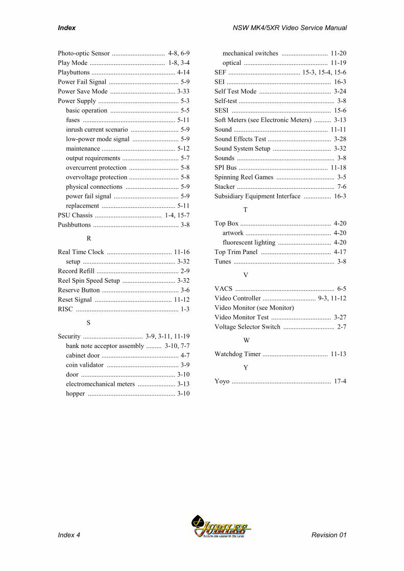
Index NSW MK4/5XR Video Service Manual
Index 4 Revision 01
Photo-optic Sensor ............................... 4-8, 6-9Play Mode ............................................ 1-8, 3-4Playbuttons ................................................. 4-14Power Fail Signal ......................................... 5-9Power Save Mode ...................................... 3-33Power Supply ............................................... 5-3
basic operation ........................................ 5-5fuses ...................................................... 5-11inrush current scenario ............................ 5-9low-power mode signal ........................... 5-9maintenance ........................................... 5-12output requirements ................................. 5-7overcurrent protection ............................. 5-8overvoltage protection ............................. 5-8physical connections ............................... 5-9power fail signal ...................................... 5-9replacement ........................................... 5-11
PSU Chassis ....................................... 1-4, 15-7Pushbuttons .................................................. 3-8
R
Real Time Clock ...................................... 11-16setup ...................................................... 3-32
Record Refill ................................................ 2-9Reel Spin Speed Setup ............................... 3-32Reserve Button ............................................. 3-6Reset Signal ............................................. 11-12RISC ............................................................ 1-3
S
Security ................................... 3-9, 3-11, 11-19bank note acceptor assembly ......... 3-10, 7-7cabinet door ............................................. 4-7coin validator .......................................... 3-9door ....................................................... 3-10electromechanical meters ...................... 3-13hopper ................................................... 3-10
mechanical switches ........................... 11-20optical ................................................. 11-19
SEF .......................................... 15-3, 15-4, 15-6SEI ............................................................. 16-3Self Test Mode .......................................... 3-24Self-test ........................................................ 3-8SESI .......................................................... 15-6Soft Meters (see Electronic Meters) .......... 3-13Sound ....................................................... 11-11Sound Effects Test ..................................... 3-28Sound System Setup .................................. 3-32Sounds ......................................................... 3-8SPI Bus .................................................... 11-18Spinning Reel Games .................................. 3-5Stacker ......................................................... 7-6Subsidiary Equipment Interface ................ 16-3
T
Top Box ..................................................... 4-20artwork .................................................. 4-20fluorescent lighting ............................... 4-20
Top Trim Panel ......................................... 4-17Tunes ........................................................... 3-8
V
VACS .......................................................... 6-5Video Controller ............................... 9-3, 11-12Video Monitor (see Monitor)Video Monitor Test ................................... 3-27Voltage Selector Switch .............................. 2-7
W
Watchdog Timer ...................................... 11-13
Y
Yoyo .......................................................... 17-4