Mixing Time for the Dead Sea Based on Water and Salt Mass Balances
12
55 VATTEN · 1 · 10 MIXING TIME FOR THE DEAD SEA BASED ON WATER AND SALT MASS BALANCES by RAED A.I. BASHITIALSHAAER 1 , KENNETH M PERSSON 1, 2 and MAGNUS LARSON 1 1 Department of Water Resources Engineering, Lund University, PO Box 118, SE-221 00 Lund, Sweden e-mail: [email protected], [email protected] 2 SYDVATTEN AB, PO Box 286, SE 201 22 Malmö, Sweden e-mail: [email protected] Abstract Water and salt mass balances for the Dead Sea were modeled. Precipitation, evaporation, river discharges, ground water flows, input/output from potash companies and salt production, and brine discharge were included in the models. The mixing time in the Dead Sea was modeled using a single-layer (well-mixed) a two-layer (stratified) system. Using the single-layer approach the water level was predicted to change from 411 m below mean sea level (bmsl) (in 1997) to 391 m and 479 m bmsl (in 2097) based on water mass balances including and excluding brine discharge, respectively, and to reach 402 m and 444 m for the two cases based on a salt mass balance. In the two-layer approach the water level after 100 years was predicted to change from 411 m bmsl (1997) to 397 m and 488 m for a water mass balance including and excluding brine discharge, respectively, and to reach 387 m and 425 m for the two cases using a salt mass balance. The water mixing time using the single-layer description increased from 58 to 116 years when excluding brine discharge. Using the two-layer approach the exchange or mixing time increased in both layers, when adding brine discharge to the system, from 1.2 to 1.7 years and 11 to 15.3 years in the upper and lower layers, respectively. Good agreement was found between the models and historical data. Key words – Dead Sea water level; Water-Salt balance; Red Sea-Dead Sea Canal (RSDSC); Single-Layer and Two-Layer system; Salinity; Mixing time; Historical comparison. VATTEN 66:55–66. Lund 2010 1. Introduction The Dead Sea is a salt lake in southwestern Asia. It is bounded on the west by Israel and the West Bank and on the east by Jordan, forming part of the Israeli, Jorda- nian and Palestinian Authority border (Figure 1). The Dead Sea is fed mainly by the Jordan River, which enters from the north. Several smaller streams also discharge into the Dead Sea, primarily from the east. The Dead Sea has no outlet. Fresh water is transported away by evaporation, which is rapid in the hot desert climate. As a result of large-scale projects by both Israel and Jordan to divert water from the Jordan River for irrigation and other water needs, the level of the Dead Sea has been falling for at least the past 50 years (Gaster, 1997– 2006). The level of the Dead Sea was 408.5 m below mean sea level (bmsl) in 1995, being the lowest water surface on earth (Al-Weshah, 2000). At the end of 1997 the water level was 411 m bmsl and the surface area 640 km 2 , (Gavrieli, 1997 & 2000). At the beginning of the last century, the level was about 390 m bmsl and had a surface area of 950 km 2 . In 1966, the Dead Sea covered an area of 940 km 2 (76 % of the lake was in the northern basin), and its total length was 76 km, with an average width of 14 km. The total volume of the water in the Dead Sea was estimated to be 142 km 3 (only 0.5 % being in the southern basin). The surface area continues to decrease due to the high rate of evaporation and decreasing water inflow. The Dead Sea is located in the northern part of the Great Rift Valley. On the east side of the lake the Moab plateau rises about 1,340 m
Transcript of Mixing Time for the Dead Sea Based on Water and Salt Mass Balances
55VATTEN · 1 · 10
Mixing TiMe for The DeaD Sea BaSeD on WaTer anD SalT MaSS BalanceS
by Raed a.I. BashItIalshaaeR 1, Kenneth M PeRsson 1, 2 and Magnus laRson 1
1 department of Water Resources engineering, lund university, Po Box 118, se-221 00 lund, swedene-mail: [email protected], [email protected]
2 sYdVatten aB, Po Box 286, se 201 22 Malmö, swedene-mail: [email protected]
abstractWater and salt mass balances for the Dead Sea were modeled. Precipitation, evaporation, river discharges, ground water flows, input/output from potash companies and salt production, and brine discharge were included in the models. The mixing time in the Dead Sea was modeled using a single-layer (well-mixed) a two-layer (stratified) system. Using the single-layer approach the water level was predicted to change from 411 m below mean sea level (bmsl) (in 1997) to 391 m and 479 m bmsl (in 2097) based on water mass balances including and excluding brine discharge, respectively, and to reach 402 m and 444 m for the two cases based on a salt mass balance. In the two-layer approach the water level after 100 years was predicted to change from 411 m bmsl (1997) to 397 m and 488 m for a water mass balance including and excluding brine discharge, respectively, and to reach 387 m and 425 m for the two cases using a salt mass balance. The water mixing time using the single-layer description increased from 58 to 116 years when excluding brine discharge. Using the two-layer approach the exchange or mixing time increased in both layers, when adding brine discharge to the system, from 1.2 to 1.7 years and 11 to 15.3 years in the upper and lower layers, respectively. Good agreement was found between the models and historical data.
Key words – Dead Sea water level; Water-Salt balance; Red Sea-Dead Sea Canal (RSDSC); Single-Layer and Two-Layer system; Salinity; Mixing time; Historical comparison.
VATTEN 66:55–66. Lund 2010
1. introduction The Dead Sea is a salt lake in southwestern Asia. It is bounded on the west by Israel and the West Bank and on the east by Jordan, forming part of the Israeli, Jorda-nian and Palestinian Authority border (Figure 1). The Dead Sea is fed mainly by the Jordan River, which enters from the north. Several smaller streams also discharge into the Dead Sea, primarily from the east. The Dead Sea has no outlet. Fresh water is transported away by evaporation, which is rapid in the hot desert climate. As a result of large-scale projects by both Israel and Jordan to divert water from the Jordan River for irrigation and other water needs, the level of the Dead Sea has been falling for at least the past 50 years (Gaster, 1997–2006).
The level of the Dead Sea was 408.5 m below mean sea level (bmsl) in 1995, being the lowest water surface on earth (Al-Weshah, 2000). At the end of 1997 the water level was 411 m bmsl and the surface area 640 km2, (Gavrieli, 1997 & 2000). At the beginning of the last century, the level was about 390 m bmsl and had a surface area of 950 km2. In 1966, the Dead Sea covered an area of 940 km2 (76 % of the lake was in the northern basin), and its total length was 76 km, with an average width of 14 km. The total volume of the water in the Dead Sea was estimated to be 142 km3 (only 0.5 % being in the southern basin). The surface area continues to decrease due to the high rate of evaporation and decreasing water inflow. The Dead Sea is located in the northern part of the Great Rift Valley. On the east side of the lake the Moab plateau rises about 1,340 m
56 VATTEN · 1 · 10
above sea level, and on the west side the Judea plateau rises to approximately half that height (Asmar, & Ergen-zinger, 2002a). Originally, the Dead Sea consisted of two basins (a northern and a southern basin) divided by the Lisan Peninsula, which extends from the eastern shore out into the lake. The maximum depth in the northern basin was 749 m bmsl, whereas the average depth in the southern basin was only 10 m (Asmar & Ergenzinger, 2002a). The level of the Dead Sea has fallen continuously since the early 1930s, at increasing rates (0.5, 0.7, 0.90, and 0.95 m/y reported in (Steinhorn, & Gat, 1983; Al- Weshah, 2000; JRV, 1996a; Abu-Jaber, 1998), respec-tively). A summary of estimated rates of evaporation as a function of salinity in the Dead Sea is presented in Table 1, based on a compilation for the period between the late
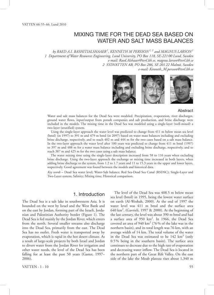
1950s and 1980 (Levy, 1984b). The salinity (Total dis-solved solids, TDS) increased during this period from 225 g/l to 279 g/l. During the past ten years, the level of the Dead Sea has fallen by more than 25 meters, and reached a level of about 416 m bmsl in 2003. Thus, the system is not pres-ently sustainable and various projects aimed at supply-ing seawater to the Dead Sea have been suggested. The Red Sea-Dead Sea Canal (RSDSC) is being considered as one alternative. The proposed layout, which may include a desalina-tion plant, is shown in Figure 1. The inflow of seawater (or reject brine from the desalination plant) into the Dead Sea will have a major impact on its limnology, geochemistry, and biology. The inflow of seawater from the proposed project (RSDSC) (density ≈ 1030 kg/m3) to the highly saline Dead Sea (density ≈ 1240 kg/m3) can be approximated by the inflow of fresh water to the seawater. The impact of such an inflow can be estimated by comparison with the inflow of fresh water during the rainy winter of 1991/2, when the level of the Dead Sea rose by 2 meters and the surface brine was diluted by up to 30 % (Beyth et al., 1993).
1.2. The chemistry of the Dead SeaWhen the runoff goes into the Dead Sea, the salt con-tent can fall from its usual 35 % to 30 % or lower (Salt Works, 2001–2006). Under normal conditions, the salinity of the Dead Sea is about nine times greater than the average salinity of the oceans. Depending on the sea-son, the salinity of the uppermost 35 m of the Dead Sea ranges between 30 % and 40 % and the temperature between 19°C and 37°C. Below a transition zone, the bottom layer of the Dead Sea consistently has a tem-perature of about 22°C, with complete saturation of halite (or sodium chloride, NaCl). Because the water is saturated, salt precipitates out of solution onto the sea floor. The Dead Sea is presently also saturated or oversatu-rated with respect to aragonite (CaCO3) and anhydrite (CaSO4) (Gavrieli et al., 1989). Mixing between the cal-cium-rich Dead Sea brine and a sulfate-rich seawater
Figure 1. Red sea-dead sea Canal layout including plan and cross-sectional view (from: JRV 1996).
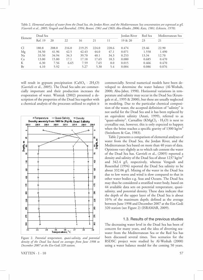
Table 1. estimated evaporation rates as a function of surface salinity in the dead sea (levy, 1984b).
TDS Level Period Data source
Evapt. rate(g/l) (m bmsl) (m/y)
225 393 1942/46 Neumann, 1958 1.70–1.75240 395 1959/60 Neev and Emery, 1967 1.47–1.65256–279 401 1979/80 Anati et al., 1987 1.30–1.54
57VATTEN · 1 · 10
will result in gypsum precipitation (CaSO4 · 2H2O) (Gavrieli et al., 2005). The Dead Sea salts are commer-cially important and their production increases the evaporation of water. Wisniak (2002) presented a de-scription of the properties of the Dead Sea together with a chemical analysis of the processes utilized to exploit it
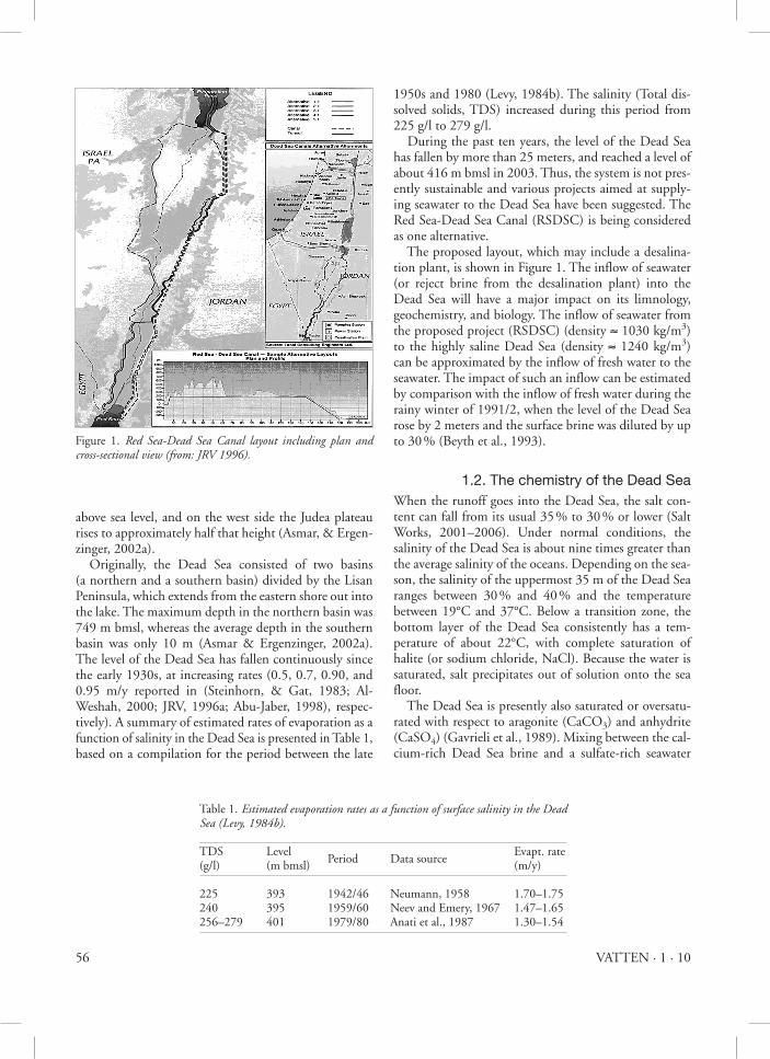
commercially. Several numerical models have been de-veloped to determine the water balance (Al-Weshah, 2000; Abu-Jaber, 1998). Horizontal variations in tem-perature and salinity may occur in the Dead Sea (Krum-galz et al., 1995 & 2000), but these are usually neglected in modeling. Due to the particular chemical composi-tion of the water, the accepted definition of “salinity” is not useful for the Dead Sea and it has been replaced by an equivalent salinity (Anati, 1999), referred to as ‘‘quasi-salinity’’. Carnallite (KMgCl3 · H2O) is next to crystallize out, however, this is only expected to happen when the brine reaches a specific gravity of 1300 kg/m3 (Steinhorn & Gat, 1983). Table 2 presents a comparison of elemental analyses of water from the Dead Sea, the Jordan River, and the Mediterranean Sea based on more than 40 years of data. Opinions vary slightly as to which salt content the water of the Dead Sea has. Gavrieli et al., (2005) reported a density and salinity of the Dead Sea of about 1237 kg/m3 and 342.4 g/l, respectively, whereas Vengosh and Rosenthal (1994) reported the Dead Sea salinity to be about 332.06 g/l. Mixing of the water in the Dead Sea due to low waves and wind is slow compared to that in other water bodies e.g. Seas and Oceans. The Dead Sea may thus be considered a stratified water body, based on 44 available data sets on potential temperature, quasi-salinity, and potential density. These data indicate that the depth of the upper layer of the Dead Sea is about 10 % of the maximum depth; defined as the average between June 1998 and December 2007 at the Ein-Gedi 320 station (see Figure 2) (ISRAMAR, 2009).
1.3. results of the previous studiesThe decreasing water level in the Dead Sea has been of concern for many years, and the idea of diverting sea-water from the Mediterranean Sea or the Red Sea has been discussed several times. Two scenarios for the RSDSC project were studied by Al-Weshah (2000) using a water balance model for the coming 50 years.
Table 2. elemental analysis of water from the dead sea, the Jordan River, and the Mediterranean sea concentration are expressed as g/l, (gavrieli et al., 2005; Vengosh and Rosenthal, 1994; Bentor, 1961 and 1969; abu-Khader, 2006; Katz, 1981; eckstein, 1970).
Element Dead Sea Jordan River Red Sea Mediterranean Sea
Ref. 19 20 22 16 21 11 19 & 20 23 21
Cl 180.8 208.0 216.0 219.25 224.0 228.6 0.474 23.46 22.90Mg 34.50 41.96 42.5 42.43 44.0 47.1 0.071 1.558 1.490Na 33.50 34.94 34.3 39.70 40.1 34.3 0.253 13.34 12.70Ca 13.00 15.80 17.1 17.18 17.65 18.3 0.080 0.685 0.470K 6.30 7.56 6.65 7.59 7.65 8.0 0.015 0.466 0.470Br 4.10 5.92 – 5.27 5.30 5.4 0.004 0.086 0.076
Figure 2. Potential temperature, quasi-salinity, and potential density of the dead sea based on averages from June 1998 to december 2007 at the ein-gedi 320 station.
58 VATTEN · 1 · 10
The first scenario assumes a diversion capacity of 70 m3/s and shows that the Dead Sea will recover its design level of 395 m bmsl in about 40 years. The second scenario assumes a diversion capacity of 60 m3/s and predicts a level of 400.5 m bmsl after about 40 years. The annual net inflow to the Dead Sea from the River Jordan falls from 175 to 60 millions cubic meter (MCM) due to the fact that Jordan is permitted to utilize 20 MCM of the river water directly and to store another 20 MCM in Lake Tiberias during the winter for consumption in the summer months (JRV, 1996a). Gavrieli and Bein (2006) assuming a diversion capac-ity of 60 m3/s and a starting elevation in 1995 of about 408.5m bmsl. After 40 years of discharge from a reverse osmosis plant the new elevation was 400.5 m bmsl (Gavrieli & Bein, 2006). In another scenario it was assumed that there was no RSDSC project, and the model showed that the level of the Dead Sea would fall to 444.4 m bmsl. Asmar and Ergenzinger (2002) mod-eled a period of 100 years between 1989 and 2088 assuming that the current conditions would prevail. However, the industrial intake increased in the year 2000 by a projected amount of about 25 %, leading to a change in water level from 406 to 460m bmsl during the study period in question.
1.4. objectives of the current study The extreme decrease in the Dead Sea water level, which is mainly caused by the reduced inflow from the Jordan River, high evaporation, low precipitation, and the in-take of water to potash companies around, has resulted in substantial damage to the development of the area around the Dead Sea. The RSDSC project has been con-sidered to be one of the most important elements in a development strategy to provide desalinated drinking water to three countries in the region. The brine dis-charge from this project is an important alternative to fill the Dead Sea that may significantly raises the level.
The aim of the present study was to investigate meth-ods for understanding the variations of water level and volume of the Dead Sea. However, it is also of interest to predict the impact of the water discharge depending on release point (discharge location for each term) and den-sity values in each term of input and output. Another task is to evaluate the mixing time (i.e. theoretical time for Dead Sea surface water to mix with the entire water body) for the Dead Sea depending on density and salin-ity of the input and output. It roughly expresses the amount of time that is needed for waters introduced into the Dead Sea to be totally mixed. Two models were developed, namely for a single-layer (well-mixed) system and for a two-layer (stratified) system, to estimate the mixing time when taking changes in the Dead Sea level and surface area into consideration.
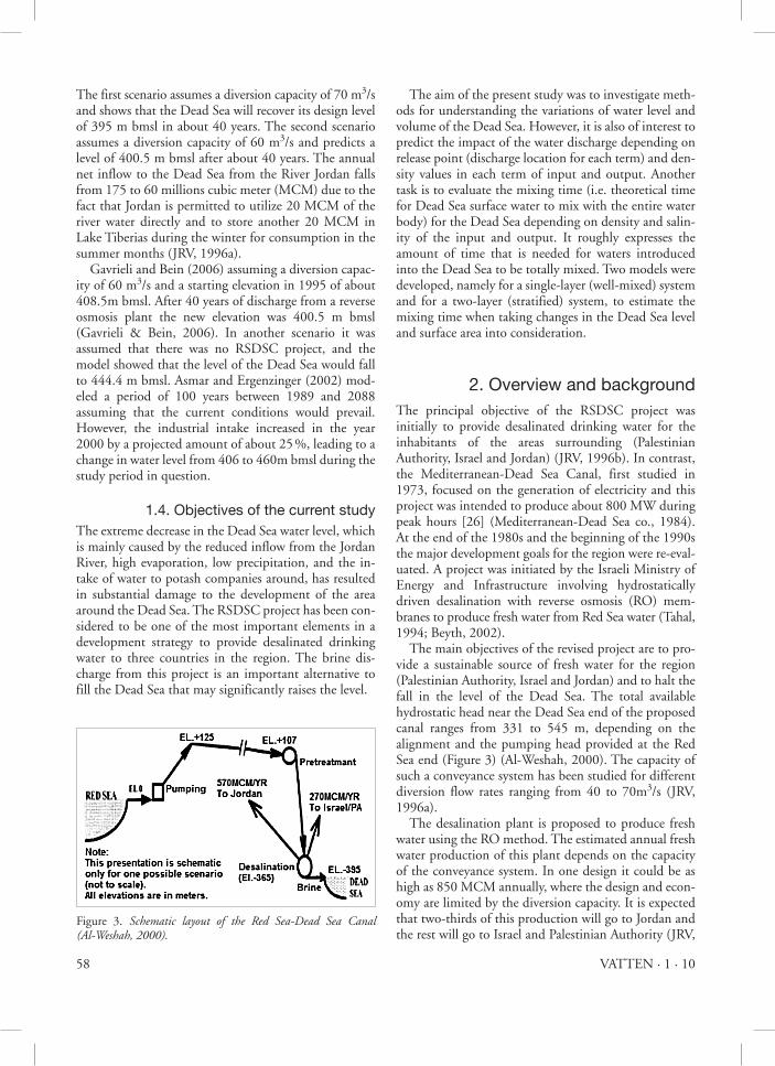
2. overview and backgroundThe principal objective of the RSDSC project was initially to provide desalinated drinking water for the inhabitants of the areas surrounding (Palestinian Authority, Israel and Jordan) (JRV, 1996b). In contrast, the Mediterranean-Dead Sea Canal, first studied in 1973, focused on the generation of electricity and this project was intended to produce about 800 MW during peak hours [26] (Mediterranean-Dead Sea co., 1984). At the end of the 1980s and the beginning of the 1990s the major development goals for the region were re-eval-uated. A project was initiated by the Israeli Ministry of Energy and Infrastructure involving hydrostatically driven desalination with reverse osmosis (RO) mem-branes to produce fresh water from Red Sea water (Tahal, 1994; Beyth, 2002). The main objectives of the revised project are to pro-vide a sustainable source of fresh water for the region (Palestinian Authority, Israel and Jordan) and to halt the fall in the level of the Dead Sea. The total available hydrostatic head near the Dead Sea end of the proposed canal ranges from 331 to 545 m, depending on the alignment and the pumping head provided at the Red Sea end (Figure 3) (Al-Weshah, 2000). The capacity of such a conveyance system has been studied for different diversion flow rates ranging from 40 to 70m3/s (JRV, 1996a). The desalination plant is proposed to produce fresh water using the RO method. The estimated annual fresh water production of this plant depends on the capacity of the conveyance system. In one design it could be as high as 850 MCM annually, where the design and econ-omy are limited by the diversion capacity. It is expected that two-thirds of this production will go to Jordan and the rest will go to Israel and Palestinian Authority (JRV,
Figure 3. schematic layout of the Red sea-dead sea Canal (al-Weshah, 2000).
59VATTEN · 1 · 10
1996a). The total dissolved solids (TDS) from the desalination plant are expected to be between 200 and 300 mg/l. It is planed to restore the level of the Dead Sea to about 400 m bmsl after approximately 50 years. Table 3 summarizes some properties of the Dead Sea and its output/input, where the river inflow represents the total water received from rivers, springs, and infiltra-tion. Dead Sea level was 390 bmsl, surface area 950 km2 and volume of 155 km3 according to the year 1997 and precipitation was found between 70–90 mm and evapo-ration between 1300–1600mm/y (Gavrieli, & Bein, 2006; Gavrieli, 2000 and 1997).
2.1. Potash and salt worksThe salt balance in the Dead Sea is significantly affected by potash and salt exploitation. In the early part of the 20th century, the Dead Sea began to attract interest from chemists who concluded that the lake was a natural deposit for potash and bromine. The Palestinian Authority Potash Company was chartered in 1929 and two more plants were established after 1934; the first plant on the north shore of the Dead Sea at Kalia and the second in the Sodom area south of the Lashon re-gion. Israel produced 1.77 million tons potash, 206,000 tons elemental bromine, 44,900 tons caustic soda, 25,000 tons magnesium metal, and sodium chloride from the Dead Sea brine in 2001. On the Jordanian side of the Dead Sea, Arab Potash Company (APC), formed in 1956, produces 2.0 million tons of potash annually, as well as sodium chloride and bromine. The power plant on the Israeli side allows the production of magne-sium metal (by a subsidiary, Dead Sea Magnesium Ltd.).
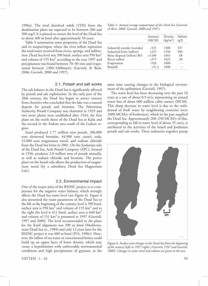
2.2. environmental impactOne of the major aims of the RSDSC project is to com-pensate for the negative water balance, which strongly affects the Dead Sea water level (see Figure 4). Figure 4 also presented the main parameters of the Dead Sea to the left at the beginning of the century, level is 390 bmsl, surface area is 950 km2 and volume of 155 km3 and to the right the level is 411 bmsl, surface area is 640 km2 and volume of 131 km3 is presented at 1997 (Gavrieli, 1997 and 2000). The level recommended in the plane for the Katif alignment was 390 m bmsl (Mediterra-nean-Dead Sea co., 1984) and only 12 years later for the RSDSC project it was 400 m bmsl (JVA, 1996c). How-ever, the inflow of sea water or concentrated brines could build up an upper layer of lower density, which may create a hypolimnion with unfavorable environmental conditions and high precipitation of gypsum, at the
same time causing changes in the biological environ-ment of the epilimnion (Gavrieli, 1997). The water level has been decreasing over the past 10 years at a rate of about 0.9 m/y, representing an annual water loss of about 600 million cubic meters (MCM). This sharp decrease in water level is due to the with-drawal of fresh water by neighboring countries (over 1000 MCM/y of freshwater), which in the past supplied the Dead Sea. Approximately 200–250 MCM/y of this, corresponding to fall in water level of about 35 cm/y, is attributed to the activities of the Israeli and Jordanian potash and salt works. These industries together pump
Table 3. annual average output/input of the dead sea (gavrieli, & Bein, 2006; gavrieli, 2000 and 1997).
Amount Density Salinity (MCM) (kg/m3) (g/l)
Industrial outtake (outtake) –531 1300 337Industrial brine (inflow) +225 1350 500Brine disposal (inflow) RO ±1100 1045 68Rivers inflow +375 1025 20Evaporation –928 1000 –Rainfall +51.2 1000 –
Figure 4. surface area changes in the dead sea from the beginning of the century (left) to 1997 (right), (gavrieli, 1997 and gavrieli, 2000). Changes in water level and volume are given in the text.
60 VATTEN · 1 · 10
400–450 MCM/y from the Dead Sea into evaporation ponds located in the southern basin, where halite and carnallite (KMgCl3·H2O) are precipitated. At the end of the process, less than 200 MCM/y of concentrated brines (density = 1.35 kg/l; TDS = 500 g/l) are returned to the Dead Sea (Gavrieli, & Bein, 2006).
3. Methodology3.1. The single-layer system
The system will be described firstly as a single-layer (also called a well-mixed system). The mathematical model used in this study is based on the LOICZ Biogeochemi-cal Modeling Guidelines and has been validated by com-paring its performance with other modeling studies of the Dead Sea (Gordon et al., 1996). The model was first employed to describe the dynamic behavior of the Dead Sea using data available in 1997 as initial conditions and simulating the evolution over a 100-year period. His-torical data from the period 1976 to 2006 were then used for comparison with simulations obtained with the model. The Dead Sea is not in a steady-state, but was assumed to be close to a steady state during the first year. Water and salt balances may have internal inputs and outputs, but this is only of concern in the two-layer approach. A general mass balance for the Dead Sea system yields:
dM/dt = S Inputs – S outputs + S (sinks) (1)
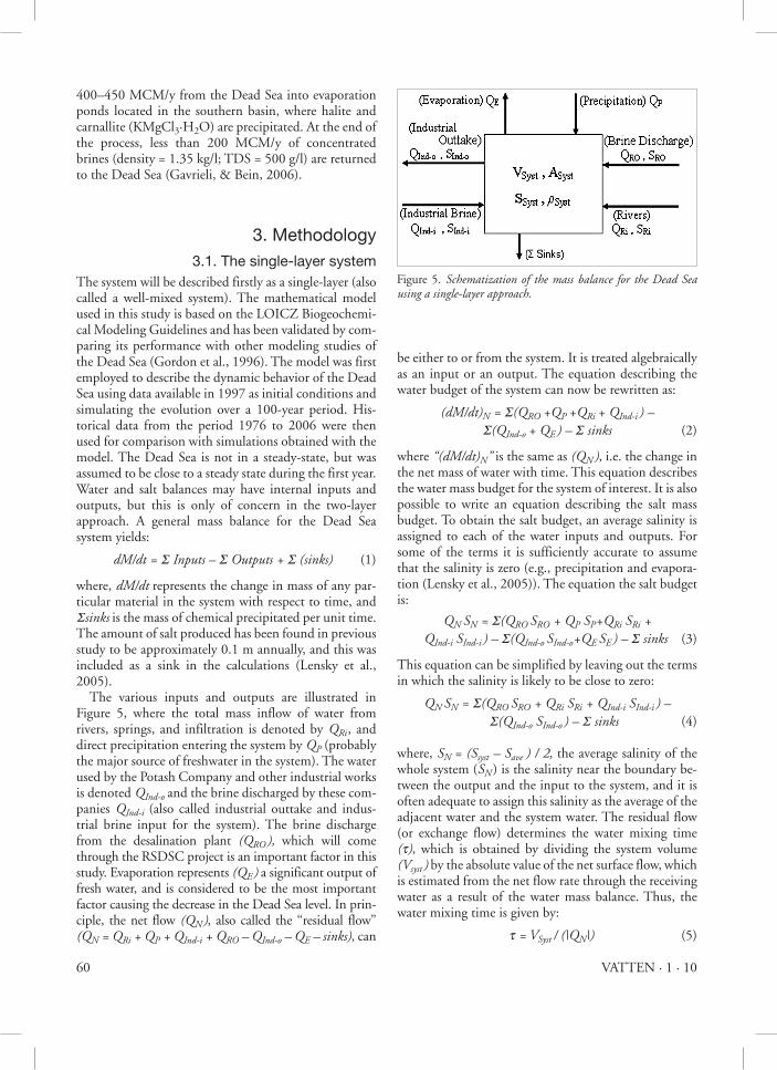
where, dM/dt represents the change in mass of any par-ticular material in the system with respect to time, and Ssinks is the mass of chemical precipitated per unit time. The amount of salt produced has been found in previous study to be approximately 0.1 m annually, and this was included as a sink in the calculations (Lensky et al., 2005). The various inputs and outputs are illustrated in Figure 5, where the total mass inflow of water from rivers, springs, and infiltration is denoted by QRi , and direct precipitation entering the system by QP (probably the major source of freshwater in the system). The water used by the Potash Company and other industrial works is denoted QInd-o and the brine discharged by these com-panies QInd-i (also called industrial outtake and indus-trial brine input for the system). The brine discharge from the desalination plant (QRo ), which will come through the RSDSC project is an important factor in this study. Evaporation represents (Qe ) a significant output of fresh water, and is considered to be the most important factor causing the decrease in the Dead Sea level. In prin-ciple, the net flow (Qn ), also called the ‘‘residual flow’’ (Qn = QRi + QP + QInd-i + QRo – QInd-o – Qe – sinks), can
be either to or from the system. It is treated algebraically as an input or an output. The equation describing the water budget of the system can now be rewritten as:
(dM/dt)n = S(QRo +QP +QRi + QInd-i ) – S(QInd-o + Qe ) – S sinks (2)
where “(dM/dt)n” is the same as (Qn ), i.e. the change in the net mass of water with time. This equation describes the water mass budget for the system of interest. It is also possible to write an equation describing the salt mass budget. To obtain the salt budget, an average salinity is assigned to each of the water inputs and outputs. For some of the terms it is sufficiently accurate to assume that the salinity is zero (e.g., precipitation and evapora-tion (Lensky et al., 2005)). The equation the salt budget is:
Qn sn = S(QRo sRo + QP sP+QRi sRi + QInd-i sInd-i ) – S(QInd-o sInd-o+Qe se ) – S sinks (3)
This equation can be simplified by leaving out the terms in which the salinity is likely to be close to zero:
Qn sn = S(QRo sRo + QRi sRi + QInd-i sInd-i ) – S(QInd-o sInd-o ) – S sinks (4)
where, sn = (ssyst – save ) / 2, the average salinity of the whole system (sn ) is the salinity near the boundary be-tween the output and the input to the system, and it is often adequate to assign this salinity as the average of the adjacent water and the system water. The residual flow (or exchange flow) determines the water mixing time (t), which is obtained by dividing the system volume (Vsyst ) by the absolute value of the net surface flow, which is estimated from the net flow rate through the receiving water as a result of the water mass balance. Thus, the water mixing time is given by:
t = Vsyst / (|Qn|) (5)
Figure 5. schematization of the mass balance for the dead sea using a single-layer approach.
61VATTEN · 1 · 10
Mixing time in Dead Sea is a calculated quantity ex-pressing the mean time that waters of inputs and out-puts (having different composition and salinity) spends to let the system returns to its characteristics. At its sim-plest this is equals to the result of dividing the Dead Sea volume by the flow in or out (net flow, QN) of the sys-tem. It roughly expresses the amount of time taken for waters introduced into the Dead Sea to be totally mixed (if possible). This water may be a result of yearly accu-mulated waters that are added to the Dead Sea, subse-quently changing the characteristics of the Dead Sea. It is important that the mixing time of the system is less than one year in order to avoid less dense (e.g. brine water) input from floating in the upper layer, as less dense fluid implies a higher evaporation rate. One exam-ple can be mentioned here. When fish is carried into the Dead Sea by the River Jordan, it dies as soon as the mix-ing with the saltier waters takes place. This mixing has a specific time. The freshwater doesn’t mix immediately with the saltwater and can float for a considerable time on the surface of the Dead Sea. Until the mixing takes place, the freshwater fish and other biota can continue to live in the floating water. Mixing is interesting.
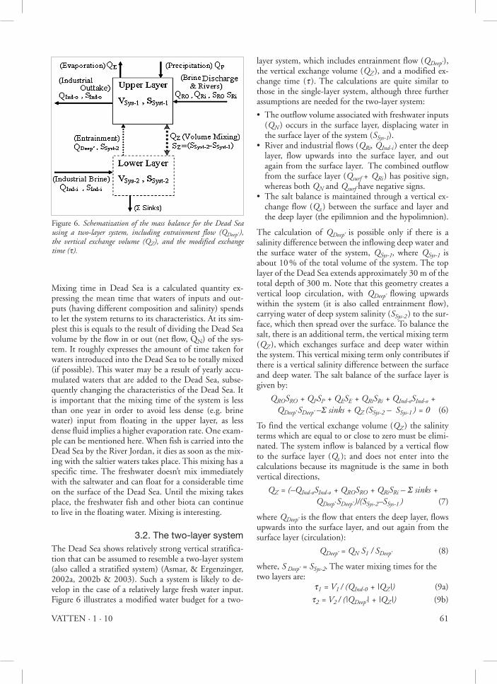
3.2. The two-layer systemThe Dead Sea shows relatively strong vertical stratifica-tion that can be assumed to resemble a two-layer system (also called a stratified system) (Asmar, & Ergenzinger, 2002a, 2002b & 2003). Such a system is likely to de-velop in the case of a relatively large fresh water input. Figure 6 illustrates a modified water budget for a two-
layer system, which includes entrainment flow (Qdeep’ ), the vertical exchange volume (QZ ), and a modified ex-change time (t ). The calculations are quite similar to those in the single-layer system, although three further assumptions are needed for the two-layer system:
• The outflow volume associated with freshwater inputs (Qn ) occurs in the surface layer, displacing water in the surface layer of the system (ssys-1).
• River and industrial flows (QRi, QInd-i ) enter the deep layer, flow upwards into the surface layer, and out again from the surface layer. The combined outflow from the surface layer (Qsurf + QRi ) has positive sign, whereas both Qn and Qsurf have negative signs.
• The salt balance is maintained through a vertical ex-change flow (Qz ) between the surface and layer and the deep layer (the epilimnion and the hypolimnion).
The calculation of Qdeep’ is possible only if there is a salinity difference between the inflowing deep water and the surface water of the system, Qsys-1, where Qsys-1 is about 10 % of the total volume of the system. The top layer of the Dead Sea extends approximately 30 m of the total depth of 300 m. Note that this geometry creates a vertical loop circulation, with Qdeep’ flowing upwards within the system (it is also called entrainment flow), carrying water of deep system salinity (ssys-2 ) to the sur-face, which then spread over the surface. To balance the salt, there is an additional term, the vertical mixing term (QZ ), which exchanges surface and deep water within the system. This vertical mixing term only contributes if there is a vertical salinity difference between the surface and deep water. The salt balance of the surface layer is given by:
QRosRo + QPsP + Qese + QRisRi + QInd-osInd-o + Qdeep’ sdeep’ –S sinks + QZ (ssys-2 – ssys-1 ) = 0 (6)
To find the vertical exchange volume (QZ ) the salinity terms which are equal to or close to zero must be elimi-nated. The system inflow is balanced by a vertical flow to the surface layer (Qz ); and does not enter into the calculations because its magnitude is the same in both vertical directions,
QZ = (–QInd-osInd-o + QRosRo + QRisRi – S sinks + Qdeep’ sdeep’ )/(ssys-2–ssys-1 ) (7)
where Qdeep’ is the flow that enters the deep layer, flows upwards into the surface layer, and out again from the surface layer (circulation):
Qdeep’ = Qn s1 / sdeep’ (8)
where, s deep’ = ssys-2. The water mixing times for the two layers are:
t1 = V1 / (QInd-0 + |QZ|) (9a)
t2 = V2 / (|Qdeep’| + |QZ|) (9b)
Figure 6. schematization of the mass balance for the dead sea using a two-layer system, including entrainment flow (Qdeep’ ), the vertical exchange volume (QZ), and the modified exchange time (t).
62 VATTEN · 1 · 10
4. results and DiscussionData for the Dead Sea were excerpt and collected from varying research to assure the accuracy of the results. This data were collected and calculated considering the changes of meteorological and hydrographical parame-ters in last 30 years (Gavrieli and Bein, 2006; Gavrieli, 1997 & 2000; Asmar & Ergenzinger, 2002b). This detail of input and output was used for the model vali-dation in the 30 years historical data.
4.1. Single-layer versus two-layerTwo different mathematical models were developed to describe the dynamic behavior of the Dead Sea based on the above-discussed mass balance equations for the single-layer and two-layer systems. The models were employed using data from 1997 and forecasts were made for a 100-year period. The two models were formulated following the LOICZ Biogeochemical Modeling Guide-lines and comparing the results with pervious studies of the Dead Sea. Based on the current conditions, the models can be used to predict the future behavior of the Dead Sea for different scenarios, including the proposed RSDSC project. The first model employed encompassed a single-layer for which the water and salt mass balances were derived. Salinity variations and water discharged from the desalination plant were taken into account with and without the proposed project. Significant vari-ations were predicted between the salinities of the out-put from and input into the system, especially when RSDSC project is considered. Tables 4 and 5 presents a single box model for a well-mixed system used to calcu-late the water and salt mass balances, giving the residual flow (Qn ) and the mixing time (t ) for: a) salinity varia-tions including RO discharge, and b) salinity variations excluding RO discharge.
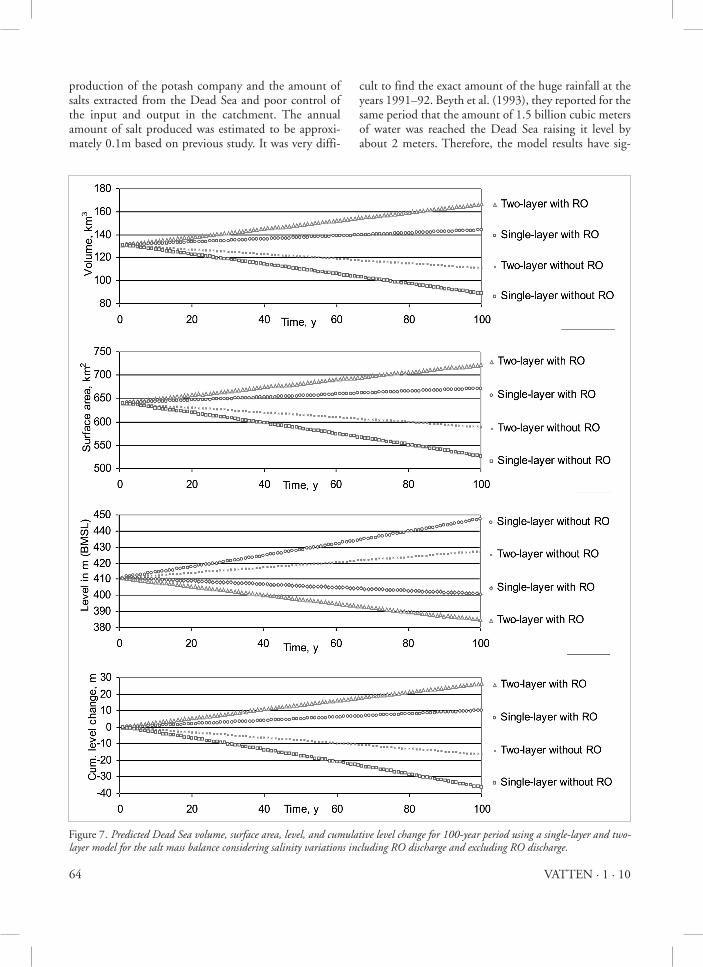
Considering the significant differences in the salini-ties and densities of the input and output and the Dead Sea itself with respect to depth, a two-layer system was judged to provide a better description of the conditions than the single-layer system. The upper layer constitutes in average of about 10 % of the total depth, and the rest of the lake constitutes a rather homogeneous lower layer, as shown in Figure 2. The mixing time, (t ), between the two layers, determined by the flow that enters the deep layer (Qdeep’ ) and the vertical exchange volume (QZ ), is an important parameter in characterizing the conditions in the Dead Sea. Table 4 shows a comparison between the results calculation obtained with the single-layer model and the two-layer model based on previously collected data for 1997 (Gavrieli, 2000). The water and salt mass balances included salinity variations with and without RO dis-charge. In these calculations, the brine disposal from the desalination plant through the RSDSC was included together with other inputs and outputs (evaporation, rainfall, industrial intake, river inflow and industrial brine). Values of volume, surface area, elevation, and cumulative levels of the Dead Sea for a 100-year period predicted by the single-layer and the two-layer are pre-sented in Figure 7.
4.2. comparisons between single and two layers
In a single-layer, over a period of 100 years, the elevation was predicted to change from 411 m bmsl (in 1997) to 391.4 m and 479 m bmsl in the cases with and without RO discharge based on a water mass balance, and to reach 401.9 m and 443.6 m bmsl in the two cases based on a salt mass balance. The discharge from the RO-plant affected the level and volume of the Dead Sea signifi-
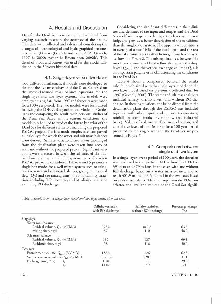
Table 4. Results from the single-layer model and two-layer model after one year.
Salinity variation Salinity variation Percentage change with RO discharge without RO discharge (%)
Singlelayer Water mass balance Residual volume, QN (MCM/y) 292.2 807.8 63.8 mixing time, t (y) 57 110 48.2 Salt mass balance Residual volume, QN (MCM/y) 132 427 69.1 Residence time, t (y) 58 116 50.0
Twolayer Entrainment volume, Qdeep’ (MCM/y) 138.3 426 62.8 Vertical exchange volume, QZ (MCM/y) 10561.2 7281 31.1 Exchange time, t (y) t1 1.18 1.68 29.8 t2 11.02 15.3 28
63VATTEN · 1 · 10
cantly. The net residual flow volumes predicted were 292.2 (with RO discharge) and 807.8MCM/y (without RO discharge), and the mixing time increased by 48.2 % when RO discharge was not included in the system. The net residual flow volumes obtained with the salt mass balance were 132 (with RO discharge) and 427 MCM/y (without RO discharge) and the mixing time increased from 58 to 116 years, which is equivalent to about 50 % when RO discharge was not included in the system. In the two-layer, after the same period the calculated elevation had changed from 411 m bmsl (in 1997) to 397 m and 488 m bmsl in the two cases (with and with-out RO discharge, respectively) based on the water mass balance, and to 387 m and 425 m bmsl based on the salt mass balance, respectively. In this model, the exchange times for the upper mixed layer are 1.2 and 1.7 years, including RO discharge and excluding RO discharge, respectively, and 11.0 and 15.3 years for the lower layer with and without RO discharge, respectively. It is found that the exchange time decreased by 29.8 % in the upper layer RO discharge was included. When the RO discharge was not included, the ex-change time increased by 28 % in the lower layer, as can be seen in Table 5. The two-layer model predicted that the amount of (QZ ) needed were about 10.56 and 7.28 (x 109m3) with and without RO discharge, respectively, which represents an increase of 31 % that will probably increase the exchange time.
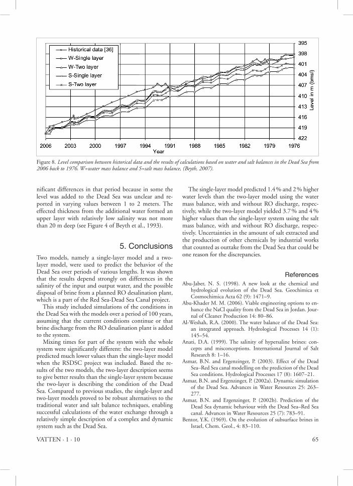
4.3. historical data comparison Comparison was also made between historical data and model results using an initial level of 420.6 m bmsl in 2006. Simulation results covering 30 years, based on water and salt mass balances, using both the single-layer and two-layer model, are presented in Figure 8. The historical data display significant variations dur-ing some years. For example, in 1991 and 1992 there was a large amount of rainfall in the Dead Sea catch-ment area resulting in a great deal of runoff into the Dead Sea. The water and salt mass balances using the single-layer model yielded water levels in 1976 of about 398.4 and 398.5 m bmsl, respectively, compared with the 399 m bmsl from historical data. Employing the two-layer model and the water and salt mass balance, a water level of about 401.9 and 400.9 m bmsl, respec-tively, were predicted for 1976, compared with the observed level 399 m bmsl. Better agreement was thus obtained when comparing historical data with the single-layer model, with both the water and salt mass balance calculations. Small differences in the results were found with the two-layer model depending on the locations of the out-put and input and the fact that water with zero or close to zero salinity was excluded, thus omitting the impact of the water with low salinity on the sea level but includ-ing all input/output in the water mass balance. Differences may also be caused by uncertainties in the
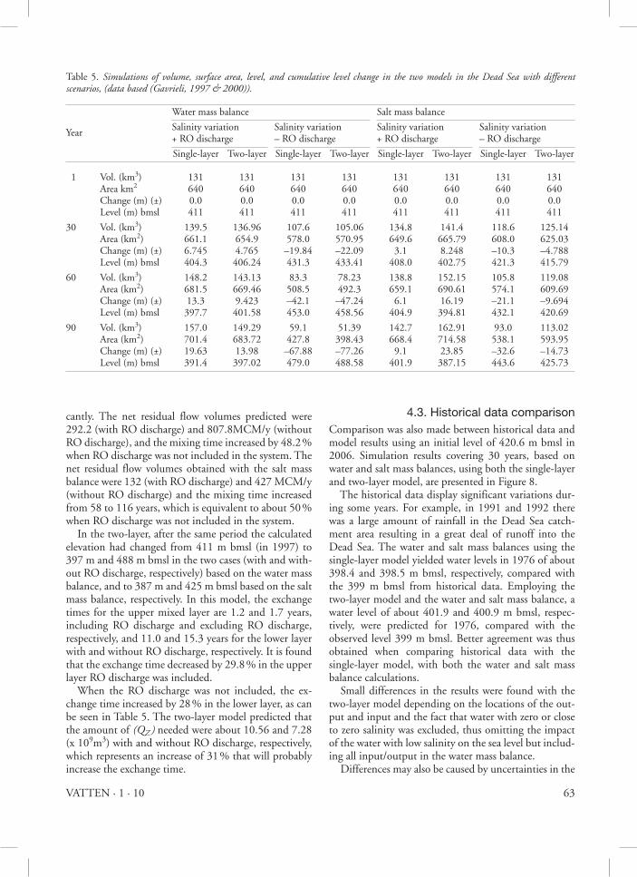
Table 5. simulations of volume, surface area, level, and cumulative level change in the two models in the dead sea with different scenarios, (data based (gavrieli, 1997 & 2000)).
Water mass balance Salt mass balance
Salinity variation Salinity variation Salinity variation Salinity variationYear + RO discharge – RO discharge + RO discharge – RO discharge
Single-layer Two-layer Single-layer Two-layer Single-layer Two-layer Single-layer Two-layer
1 Vol. (km3) 131 131 131 131 131 131 131 131 Area km2 640 640 640 640 640 640 640 640 Change (m) (±) 0.0 0.0 0.0 0.0 0.0 0.0 0.0 0.0 Level (m) bmsl 411 411 411 411 411 411 411 411
30 Vol. (km3) 139.5 136.96 107.6 105.06 134.8 141.4 118.6 125.14 Area (km2) 661.1 654.9 578.0 570.95 649.6 665.79 608.0 625.03 Change (m) (±) 6.745 4.765 –19.84 –22.09 3.1 8.248 –10.3 –4.788 Level (m) bmsl 404.3 406.24 431.3 433.41 408.0 402.75 421.3 415.79
60 Vol. (km3) 148.2 143.13 83.3 78.23 138.8 152.15 105.8 119.08 Area (km2) 681.5 669.46 508.5 492.3 659.1 690.61 574.1 609.69 Change (m) (±) 13.3 9.423 –42.1 –47.24 6.1 16.19 –21.1 –9.694 Level (m) bmsl 397.7 401.58 453.0 458.56 404.9 394.81 432.1 420.69
90 Vol. (km3) 157.0 149.29 59.1 51.39 142.7 162.91 93.0 113.02 Area (km2) 701.4 683.72 427.8 398.43 668.4 714.58 538.1 593.95 Change (m) (±) 19.63 13.98 –67.88 –77.26 9.1 23.85 –32.6 –14.73 Level (m) bmsl 391.4 397.02 479.0 488.58 401.9 387.15 443.6 425.73
64 VATTEN · 1 · 10
production of the potash company and the amount of salts extracted from the Dead Sea and poor control of the input and output in the catchment. The annual amount of salt produced was estimated to be approxi-mately 0.1m based on previous study. It was very diffi-
cult to find the exact amount of the huge rainfall at the years 1991–92. Beyth et al. (1993), they reported for the same period that the amount of 1.5 billion cubic meters of water was reached the Dead Sea raising it level by about 2 meters. Therefore, the model results have sig-
Figure 7. Predicted dead sea volume, surface area, level, and cumulative level change for 100-year period using a single-layer and two-layer model for the salt mass balance considering salinity variations including Ro discharge and excluding Ro discharge.
65VATTEN · 1 · 10
nificant differences in that period because in some the level was added to the Dead Sea was unclear and re-ported in varying values between 1 to 2 meters. The effected thickness from the additional water formed an upper layer with relatively low salinity was not more than 20 m deep (see Figure 4 of Beyth et al., 1993).
5. conclusionsTwo models, namely a single-layer model and a two-layer model, were used to predict the behavior of the Dead Sea over periods of various lengths. It was shown that the results depend strongly on differences in the salinity of the input and output water, and the possible disposal of brine from a planned RO desalination plant, which is a part of the Red Sea-Dead Sea Canal project. This study included simulations of the conditions in the Dead Sea with the models over a period of 100 years, assuming that the current conditions continue or that brine discharge from the RO desalination plant is added to the system. Mixing times for part of the system with the whole system were significantly different: the two-layer model predicted much lower values than the single-layer model when the RSDSC project was included. Based the re-sults of the two models, the two-layer description seems to give better results than the single-layer system because the two-layer is describing the condition of the Dead Sea. Compared to previous studies, the single-layer and two-layer models proved to be robust alternatives to the traditional water and salt balance techniques, enabling successful calculations of the water exchange through a relatively simple description of a complex and dynamic system such as the Dead Sea.
The single-layer model predicted 1.4 % and 2 % higher water levels than the two-layer model using the water mass balance, with and without RO discharge, respec-tively, while the two-layer model yielded 3.7 % and 4 % higher values than the single-layer system using the salt mass balance, with and without RO discharge, respec-tively. Uncertainties in the amount of salt extracted and the production of other chemicals by industrial works that counted as outtake from the Dead Sea that could be one reason for the discrepancies.
referencesAbu-Jaber, N. S. (1998). A new look at the chemical and
hydrological evolution of the Dead Sea. Geochimica et Cosmochimica Acta 62 (9): 1471–9.
Abu-Khader M. M. (2006). Viable engineering options to en-hance the NaCl quality from the Dead Sea in Jordan. Jour-nal of Cleaner Production 14: 80–86.
Al-Weshah, R.A. (2000). The water balance of the Dead Sea: an integrated approach. Hydrological Processes 14 (1): 145–54.
Anati, D.A. (1999). The salinity of hypersaline brines: con-cepts and misconceptions. International Journal of Salt Research 8: 1–16.
Asmar, B.N. and Ergenzinger, P. (2003). Effect of the Dead Sea–Red Sea canal modelling on the prediction of the Dead Sea conditions. Hydrological Processes 17 (8): 1607–21.
Asmar, B.N. and Ergenzinger, P. (2002a). Dynamic simulation of the Dead Sea. Advances in Water Resources 25: 263–277.
Asmar, B.N. and Ergenzinger, P. (2002b). Prediction of the Dead Sea dynamic behaviour with the Dead Sea–Red Sea canal. Advances in Water Resources 25 (7): 783–91.
Bentor, Y.K. (1969). On the evolution of subsurface brines in Israel, Chem. Geol., 4: 83–110.
Figure 8. level comparison between historical data and the results of calculations based on water and salt balances in the dead sea from 2006 back to 1976. W=water mass balance and s=salt mass balance, (Beyth, 2007).

66 VATTEN · 1 · 10
Bentor, Y.K. (1961). Some geochemical aspects of the Dead Sea and the question of its age. Geochim. Cosmochim. Acta, 25: 239–260.
Beyth, M. (2007). The Red Sea and the Mediterranean-Dead Sea canals project and Israeli Hydrological Service.
Beyth, M. (2002). The Red Sea and the Mediterranean Dead Sea canals project.
Beyth, M., Gavrieli, I., Anati D. and Katz, O. (1993). Effects of the December 1991–May 1992 floods on the Dead Sea vertical structure, Israel J. Earth Sci. 42: 45–47.
Eckstein, Y. (1970). Physicochemical limnology and geology of a meromictic pond on the red sea shore, Geological Survey of Israel, limnology and oceanography, Vol. 15, No. 3. pp. 363–372.
Gaster, T.H. (1997–2006). The Dead Sea Scriptures in English translation with introduction and notes, Doubleday An-chor Books, (Online Encyclopedia 2006).
Gavrieli, I. and Bein, A. (2006). Formulating A Regional Poli-cy for the Future of the Dead Sea – The “Peace Conduit” Alternative, Geological Survey of Israel.
Gavrieli, I., Amos B. and Aharon, O. (2005). The Expected Impact of the Peace Conduit Project (The Red Sea-Dead Sea Pipeline) On the Dead Sea, Mitigation and Adaptation Strategies for Global Change 10: 3–22.
Gavrieli, I. (2000). Expected effects of the infloat of seawater on the Dead Sea; GSI Current Research 12: 7–11.
Gavrieli, I. (1997). Halite deposition from the Dead Sea: 1960–1993: In book “The Dead Sea: the lake and its set-ting”, edited by Tina M. Niemi, Zvi Ben-Avraham, Joel R. Gat. Oxford University Press, Oxford, pp. 161–170.
Gavrieli, I., Starinsky A. and Bein, A. (1989). The solubility of halite as a function of temperature in the highly saline Dead Sea brine system, limnol. & oceanogr. 34: 1224–1234.
Gordon, Jr. D. C., Boudreau, P. R., Mann, K.H., Ong, J.-E., Silvert, W.L., Smith, S.V., Wattayakorn, G., Wulff F. and Yanagi, T. (1996). LOICZ Biogeochemical Modeling Guidelines. LOICZ Reports & Studies No 5: 1-96.
ISRAMAR (2009). Israel Oceanographyic and Limnology Re-search, Israel Marine Data Center: http://isramar.ocean.org.il/(last update October, 2009).
JRV (1996a). (Jordan Rift Valley). The JRV Integrated Devel-opment Study: Water Resources. The Harza JRV Group.
JRV (1996b). The Harza Group, Red Sea-Dead Sea Canal Project, Draft Prefeasibility Report, Main Report. Jordan Rift Valley Steering Committee of the Trilateral Economic Committee.
JVA (1996c). (The Jordan Valley Authori ty). Tourism devel-opment project of the East Coast of the Dead Sea. Feasibil-ity Study Report. Amman, Jordan.
Katz, A., Starinsky, A. and Taitel-Goldman, N. (1981). Solu-bilities of gypsum and halite in the Dead Sea and in its mixtures with seawater Limnol. Oceanogr., 26(4): 709–716.
Krumgalz, B.S., Hecht, A., Starinsky A. and Katz, A. (2000). Thermodynamic constraints on Dead Sea evaporation: Can the Dead Sea dry up? Chemical Geology 165: 1–11.
Krumgalz, B.S., Pogorelsky R and Pitzer, K.S. (1995). Ion in-teraction approach to calculations of volumetric properties of aqueous multiple solute electrolyte solutions. Journal of Solution Chemistry 24: 1025–38.
Lensky, N. G., Dvorkin, Y. and Lyakhovsky, V. (2005). Water, salt, and energy balances of the Dead Sea Water Resources Research, VOL. 41.
Levy, Y. (1984b). Evaporation from the Dead Sea. Mediterra-nean-Dead Sea projects’, Earth Sci. Res. Admin., Summ. Res. Surveys 5: 201–210.
Mediterranean-Dead Sea co. (1984). Mediterranean-Dead Sea Project Planning and Prefeasibility, (in Hebrew) pp. 114.
Salt Works (2001–2006). http://www.saltworks.us/shop/prod-uct.asp?idProduct=8
Steinhorn, I. and Gat, J.R. (1983). The Dead Sea. Scientific American 249: 84–91.
Tahal (1994). Mediterranean-Dead Sea Hydroelectric Project: Updating of works for reevaluation of alternatives. Sum-mary Report (in Hebrew): Prepared for the Ministry of Energy and Infrastructure: 2 vols. 1-106p., 2–64p.
Vengosh, A., and Rosenthal, E. (1994). Saline groundwater in Israel: it’s bearing on the water crisis in the country. J. Hydrol 156: 389–430.
Wisniak, J. (2002). The Dead Sea a live pool of chemicals. Indian Journal of Chemical Technology 9 (1): 79–87.