Mitigating construction safety risks using prevention through design
16
Mitigating construction safety risks using prevention through design Marta Gangolells ⁎, Miquel Casals, Núria Forcada, Xavier Roca, Alba Fuertes Technical University of Catalonia, Department of Construction Engineering, Group of Construction Research and Innovation (GRIC), C/ Colom, 11. Ed. TR5. 08222 Terrassa (Barcelona), Spain abstract article info Available online 2 April 2010 Keywords: Construction Hazards Prevention through Design Risk assessment Health and safety management Building Construction process Introduction: Research and practice have demonstrated that decisions made prior to work at construction sites can influence construction worker safety. However, it has also been argued that most architects and design engineers possess neither the knowledge of construction safety nor the knowledge of construction processes necessary to effectively perform Construction Hazards Prevention through Design (CHPtD). Method: This paper introduces a quantitative methodology that supports designers by providing a way to evaluate the safety-related performance of residential construction designs using a risk analysis–based approach. The methodology compares the overall safety risk level of various construction designs and ranks the significance of the various safety risks of each of these designs. The methodology also compares the absolute importance of a particular safety risk in various construction designs. Results: Because the methodology identifies the relevance of each safety risk at a particular site prior to the construction stage, significant risks are highlighted in advance. Thus, a range of measures for mitigating safety risks can then be implemented during on-site construction. Impact on industry: The methodology is specially worthwhile for designers, who can compare construction techniques and systems during the design phase and determine the corresponding level of safety risk without their creative talents being restricted. By using this methodology, construction companies can improve their on-site safety performance. © 2010 National Safety Council and Elsevier Ltd. All rights reserved. 1. Introduction The construction industry is statistically one of the most hazardous industries in many countries (Carter & Smith, 2006; Wang, Liu, & Chou, 2006; Camino, Ritzel, Fontaneda, & González, 2008). For example, in Spain, approximately 30% of fatal accidents in all industries between 2000 and 2006 occurred in the construction industry, killing ap- proximately 350 employees per year (Ministerio de Trabajo e Inmigración, Subsecretaría de Trabajo y Asuntos Sociales, 2006). Besides causing human tragedy, construction accidents also delay project progress, increase costs, and damage the reputation of the contractors (Wang et al., 2006). Formal identification of hazards in the workplace is one of the foundations of successful safety management (Trethewy, Atkinson, & Falls, 2003; Carter & Smith, 2006) and an essential component of occupational health and safety (OHS) legislation (Trethewy et al., 2003). However, the findings of Carter and Smith (2006) indicate that current hazard identification levels in construction projects are far from ideal. These authors identified several significant barriers to improving hazard identification: knowledge and information barriers (i.e., failure to share information across projects, lack of resources in smaller projects, subjective hazard identification and risk assessment, and reliance upon tacit knowledge), and process and procedure barriers (i.e., lack of a standardized approach, and undefined structures for tasks and hazards). Most contractors see their health and safety plans, which must include full risk assessment, as merely a burdensome requirement that they must fulfill in order to avoid government fines. As a result, they often neglect the proper implementation of these plans (Wang et al., 2006; Saurin, Formoso, & Cambraia, 2008). Since the adoption of Royal Decree 1627/1997 (transposition of Directive 92/57/EEC), Spanish building designers are legally required to consider working conditions in their designs. However, studies have shown that designers in general—not just in the construction industry—fall short of satisfying this obligation (Behm, 2005; Fadier & De la Garza, 2006; Frijters & Swuste, 2008). Some earlier studies have indicated that safety planning and control methods need to be improved even beyond what is required by regulations and standards (Saurin, Formoso, & Guimaraes, 2004). Not only contractors, but also designers, architects, and structural engineers have an influence on the health and safety of building site employees (Gambatese & Hinze, 1999; Behm, 2005; Frijters & Swuste, 2008; Gambatese, Behm, & Rajendran, 2008; Toole & Gambatese, 2008). Research conducted by Behm (2005) and Gambatese et al. (2008) demonstrated that 42.0% of construction fatalities were linked to the design of the construction safety concept. In recent years, academics and professionals have focused on the concept of Construction Hazards Prevention through Design Journal of Safety Research 41 (2010) 107–122 ⁎ Corresponding author. Tel.: +34 93 7398947; fax: +34 93 7398670. E-mail address: [email protected] (M. Gangolells). 0022-4375/$ – see front matter © 2010 National Safety Council and Elsevier Ltd. All rights reserved. doi:10.1016/j.jsr.2009.10.007 Contents lists available at ScienceDirect Journal of Safety Research journal homepage: www.elsevier.com/locate/jsr
-
Upload
independent -
Category
Documents
-
view
2 -
download
0
Transcript of Mitigating construction safety risks using prevention through design

Journal of Safety Research 41 (2010) 107–122
Contents lists available at ScienceDirect
Journal of Safety Research
j ourna l homepage: www.e lsev ie r.com/ locate / j s r
Mitigating construction safety risks using prevention through design
Marta Gangolells ⁎, Miquel Casals, Núria Forcada, Xavier Roca, Alba FuertesTechnical University of Catalonia, Department of Construction Engineering, Group of Construction Research and Innovation (GRIC), C/ Colom, 11. Ed. TR5. 08222 Terrassa (Barcelona),Spain
⁎ Corresponding author. Tel.: +34 93 7398947; fax: +E-mail address: [email protected] (M. Gang
0022-4375/$ – see front matter © 2010 National Safetydoi:10.1016/j.jsr.2009.10.007
a b s t r a c t
a r t i c l e i n f oAvailable online 2 April 2010
Keywords:Construction Hazards Prevention through DesignRisk assessmentHealth and safety managementBuildingConstruction process
Introduction: Research and practice have demonstrated that decisions made prior to work at constructionsites can influence construction worker safety. However, it has also been argued that most architects anddesign engineers possess neither the knowledge of construction safety nor the knowledge of constructionprocesses necessary to effectively perform Construction Hazards Prevention through Design (CHPtD).Method: This paper introduces a quantitative methodology that supports designers by providing a way toevaluate the safety-related performance of residential construction designs using a risk analysis–basedapproach. The methodology compares the overall safety risk level of various construction designs and ranks
the significance of the various safety risks of each of these designs. The methodology also compares theabsolute importance of a particular safety risk in various construction designs. Results: Because themethodology identifies the relevance of each safety risk at a particular site prior to the construction stage,significant risks are highlighted in advance. Thus, a range of measures for mitigating safety risks can then beimplemented during on-site construction. Impact on industry: The methodology is specially worthwhile fordesigners, who can compare construction techniques and systems during the design phase and determinethe corresponding level of safety risk without their creative talents being restricted. By using thismethodology, construction companies can improve their on-site safety performance.© 2010 National Safety Council and Elsevier Ltd. All rights reserved.
1. Introduction
The construction industry is statistically one of themost hazardousindustries inmany countries (Carter & Smith, 2006;Wang, Liu, & Chou,2006; Camino, Ritzel, Fontaneda, & González, 2008). For example, inSpain, approximately 30% of fatal accidents in all industries between2000 and 2006 occurred in the construction industry, killing ap-proximately 350 employees per year (Ministerio de Trabajo eInmigración, Subsecretaría de Trabajo y Asuntos Sociales, 2006).Besides causing human tragedy, construction accidents also delayproject progress, increase costs, and damage the reputation of thecontractors (Wang et al., 2006).
Formal identification of hazards in the workplace is one of thefoundations of successful safety management (Trethewy, Atkinson, &Falls, 2003; Carter & Smith, 2006) and an essential component ofoccupational health and safety (OHS) legislation (Trethewy et al.,2003). However, the findings of Carter and Smith (2006) indicate thatcurrent hazard identification levels in construction projects are farfrom ideal. These authors identified several significant barriers toimproving hazard identification: knowledge and information barriers(i.e., failure to share information across projects, lack of resources insmaller projects, subjective hazard identification and risk assessment,
34 93 7398670.olells).
Council and Elsevier Ltd. All rights
and reliance upon tacit knowledge), and process and procedurebarriers (i.e., lack of a standardized approach, and undefinedstructures for tasks and hazards).
Most contractors see their health and safety plans, which mustinclude full risk assessment, as merely a burdensome requirementthat they must fulfill in order to avoid government fines. As a result,they often neglect the proper implementation of these plans (Wanget al., 2006; Saurin, Formoso, & Cambraia, 2008). Since the adoptionof Royal Decree 1627/1997 (transposition of Directive 92/57/EEC),Spanish building designers are legally required to consider workingconditions in their designs. However, studies have shown thatdesigners in general—not just in the construction industry—fall shortof satisfying this obligation (Behm, 2005; Fadier & De la Garza,2006; Frijters & Swuste, 2008). Some earlier studies have indicatedthat safety planning and control methods need to be improvedeven beyond what is required by regulations and standards (Saurin,Formoso, & Guimaraes, 2004).
Not only contractors, but also designers, architects, and structuralengineers have an influence on the health and safety of building siteemployees (Gambatese & Hinze, 1999; Behm, 2005; Frijters & Swuste,2008; Gambatese, Behm, & Rajendran, 2008; Toole & Gambatese,2008). Research conducted by Behm (2005) and Gambatese et al.(2008) demonstrated that 42.0% of construction fatalities were linkedto the design of the construction safety concept.
In recent years, academics and professionals have focused onthe concept of Construction Hazards Prevention through Design
reserved.

Fig. 1. Research methodology.
108 M. Gangolells et al. / Journal of Safety Research 41 (2010) 107–122
(CHPtD), in which engineers and architects explicitly consider,during the design process, the safety of construction workers (Toole& Gambatese, 2008). As noted by Toole and Gambatese, even thougharticles on CHPtD have appeared in top construction journals, theliterature has not yet addressed the technical principles underlyingCHPtD in order to help designers better perform CHPtD and tofacilitate the development of additional CHPtD tools. Additionaltools and processes are needed in order to assist architects anddesign engineers with hazard recognition and design optimization(Gambatese, 2008).
Up until now, most publications on this subject have offeredsolutions that can be directly implemented and checklists for thesubsequent monitoring of the design. Precise advice of this sortinhibits the designer's creative process and hampers the usual designprocess (Frijters & Swuste, 2008). Other authors, such as Gambateseand Hinze (1999), have developed a repository with design sugges-tions for improving construction worker safety while in the designphase.
Even so, there has been little research on how health and safetyaspects can be interactively integrated during the design andpreparation phase. Of the papers that have provided such methods,the approaches of Carter and Smith (2006), Cheung, Cheung, and Suen(2004), Cheung, Tam, Tam, Cheung and Suen (2004), Imriyas (2009),and Seo and Choi (2008) are among the most noteworthy; however,subjective judgments often influence their accuracy. Especiallyworthwhile is the method developed by Frijters and Swuste (2008),which has proved to be an objective, albeit labor-intensive, way ofintegrating safety aspects into the design process.
This study aims to establish the necessary basis and criteria toquantitatively measure the safety performance of constructionprojects. Its objectives are, first, to provide designers with a risk-analysis-based way of evaluating the safety-related performance oftheir residential construction designs, and second, to help construc-tion companies improve their on-site safety performance.
Therefore, we have developed a quantitative methodology fordealing with potential safety risks at the pre-construction stage (inthe design, planning and preparation phases), thereby contributing tothe customization of the Safety Decision Hierarchy proposed byManuele (2006) for construction projects. This hierarchy supports theidea that it is better to eliminate safety hazards through design than tolater try to protect workers from hazards. In short, proactive hazardidentification and elimination is safer and more cost-effective thanreactive hazard management (Toole & Gambatese, 2008). Thisproactive elimination of hazards must be done by designers duringthe conceptual and detailed design of a facility (Toole & Gambatese,2008). Hazards remaining after successive redesigns must beaddressed by the contractor during the execution phase.
2. Methods
This paper presents a systematic approach for dealing withpotential safety risks at the pre-construction stage (in the design,planning, and preparation stages). The proposed methodology servesas an assessment tool for measuring the safety risk level ofconstruction projects. It also provides a consistent basis for compar-isons, future labeling, and CHPtD benchmarking between differentconstruction companies and construction sites.
Fig. 1 summarizes the methodology for predicting and assessingthe safety risks related to the construction of residential buildings.
The first step is to identify specific safety risks related to theconstruction process. The process-oriented approach requires aninventory of construction processes, activities, and stages, as well ascommon safety risks. Decisions regarding significant risks in eachconstruction process must be made based on the establishment of asignificance rating. The second step is to assess construction safetyrisks. This involves developing corresponding indicators, formulating
significance limits, and determining the overall safety risk level of aconstruction project.
2.1. Identification of safety risks related to the construction process
The first step of this methodology is to identify construction risks.For this purpose, an exhaustive, process-oriented preliminary anal-ysis, similar to that of Gangolells et al. (2009), is carried out (Fig. 2).
2.1.1. Inventory of construction processes, activities and stagesIn any process-oriented approach, the first step is to identify the
mainprocesses. As inGangolells et al. (2009), the constructionprocessesconsidered as main processes were (1) earthworks, (2) foundations,(3) structures, (4) roofs, (5) partitions and closures, (6) impermeablemembranes, (7) insulations, (8) coatings, (9) pavements, and (10) doorand window closures. Each of these main processes was separated intosmaller process steps. A total of 219 stages and activitieswereultimatelyconsidered in this initial safety review (Fig. 2).
2.1.2. Inventory of safety risksAs suggested by OHSAS 18001:2007 and OHSAS 18002:2000, this
initial review uses reports of incidents (including ill health) andaccidents that have occurred in other organizations (Fig. 2). TheOccupational Accident Report Form of the Spanish National Instituteof Safety and Hygiene at Work was used as a guide in order to initiallyidentify general safety risks (Fig. 2).
2.1.3. Determination of the significance rating of a safety risk in aparticular construction stage
OHSAS 18001:2007 defines a risk as the combination of thelikelihood of occurrence of a hazardous event and the severity of theinjury or ill health that can be caused by the event. Consideration ofrisks in terms of the probability of their occurrence and the severity oftheir consequences provides the general rationale behind safety riskassessments (Carter & Smith, 2006). Probability (P) is defined as thelikelihood of a hazard's potential being realized and initiating anincident or series of incidents that could result in harm or damage.Severity of consequences (C) is defined as the extent of harm or

Fig.
2.Iden
tification
ofco
nstruc
tion
risksin
aproc
ess-oriented
approa
chan
dnu
merical
scales
forthetw
oev
alua
tion
compo
nents:
prob
ability
ofoc
curren
ce(P
)an
dseve
rity
ofco
nseq
uenc
es(C
).So
urce:P
artially
adap
tedfrom
Gan
golells
etal.
(200
9).
109M. Gangolells et al. / Journal of Safety Research 41 (2010) 107–122

110 M. Gangolells et al. / Journal of Safety Research 41 (2010) 107–122
damage that could result from a hazard-related incident (Manuele,2006).
Neither the probability nor the severity of consequences dependon the construction project, so they can be used in this early stage todetermine significant risks that are common to every constructionprocess (Fig. 2).
A panel of academic and professional experts in the constructionfield was asked to rate construction risks in terms of probability andseverity of consequences. The consultation panel was composed ofthree architects with more than 15 years of experience as buildingdesigners, and two engineers with active experience in making safetyrisk inventories at design companies as they were in charge ofdeveloping health and safety studies to satisfy current legal require-ments stated in Royal Decree 1627/1997. Three construction projectmanagers working in construction SMEs and two internal advisers onworking conditions at construction companies were also selected tobe part of the panel of experts. Finally, the consultation panel wascomposed of four associate professors from the Technical Universityof Catalonia. The basic considerations for selecting them included abackground in construction management as well as familiarity withsafety issues.
First, the research team mailed all participants a personalizedletter outlining the nature of the research and indicating that theywould be called to arrange a meeting. During the meeting, discussionsfocussed on a survey prepared to facilitate data collection, repre-sented as a matrix whose columns were general construction risksand whose rows were construction stages. To reduce the intrusion ofsubjectivity during the identification of construction risks, a four-interval scale was developed for each of these evaluation components.The probability of occurrence ranges from low probability (improb-able) to relatively high probability (very likely or frequent). The scaleof probability was thus defined as a progression through the variouslevels of likelihood. The severity of consequences was rated by takinginto account the extent of the damage that could result from anincident.
Probability of occurrence and severity of consequences can becross-referenced. For example, during the placement of in-situconcrete, stepping on objects has a high probability of occurrencebut entails minor consequences, whereas becoming caught in adumped vehicle or machine is improbable, but would result in fatalinjuries if it were to happen. These two evaluation components cantherefore be represented graphically with the probability of occur-rence as the x-axis and the severity of consequences as the y-axis. Arisk is highly significant if it is plotted in the lower right part of thegraph (Fig. 2).
In order to calculate the significance of a risk in a specificconstruction stage, the four-grade scales for the two evaluationcomponents are converted into numerical scales (Fig. 2). Unfortu-nately, the literature provides no suitable models on which to basesuch a scoring system, so we established the system shown in Table 1.
The significance rating of a risk in a particular construction stagewas defined as follows:
SGi = Pi⋅Ci ð1Þ
Table 1Scoring system for probability of occurrence (Pi) and severity of consequences (Si).
Probability of occurrence (Pi) Severity of consequences (Si) Score
Improbable None 0Not very likely Minor 1Likely Major 2Very likely Catastrophic 3
where SGi denotes the significance rating of a risk in a specificconstruction stage i, Pi represents its probability of occurrence, and Cicorresponds to its severity of consequences.
During this initial review, a risk was considered significant in aspecific construction stage when its significance rating was equal toor greater than 3. The resulting matrix allowed us to distinguishpotential safety risks for each construction stage. In order to makefuture assessments controllable and effective, most of the construc-tion risks were aggregated with the help of the experts.
As a result of this process, 90 significant safety risks forconstruction activities were obtained in 22 different categories.Table 2 lists these specific construction risks.
2.2. Assessment of construction safety risks
The immediate causes of accidents include factors that can causean accident physically and directly, whether the accident happens ornot. These causes include unsafe conditions and unsafe acts (Jannadi &Assaf, 1998; Fang, Xie, Huang, & Li, 2004). Unsafe conditions are physicalconditions which, if left uncorrected, are likely to cause an accident.To improve safety at the work site, such conditions must be detectedbefore an accident occurs (Jannadi & Assaf, 1998). Unsafe acts are notconsidered in this paper because they cannot be assessed duringthe study, design, planning, or preparation stages of the constructionproject. In order to assess unsafe conditions, we considered exposure, avariable understood as the frequency of occurrence of the hazard-event(Fine & Kinney, 1971) or the quantitative or semi-quantitativeestimation of potentially hazardous situations to which workers areexposed during the construction process. In contrast to the evaluationcomponents mentioned above (probability of occurrence and severityof consequences), this component depends on the characteristics ofeach construction project.
2.2.1. Assessment of risk exposureTogether with a panel of experts, we developed specific indicators
to assess construction risk exposure. These indicators were based onparticular observable or measurable characteristics of a constructionproject and represented, in all cases, the variable that was beingmeasured (risk exposure). Because this methodology is intended toassess construction safety risks in advance, the indicators were alwaysbased on the information contained in the construction projectdocuments (e.g., building specifications, drawings, bill of quantities,health and safety plan, and budget).
In developing the indicators, we took into account the traitshighlighted by Manuele (2006). Therefore, most of the developedindicators are objectively quantifiable, which helpsmake the outcomeof the process independent of the people who conduct theassessment. From an administrative point of view, they are practicaland do not involve a great deal of time. They are sufficiently sensitiveto detect changes in a process, but stable if there is no change (i.e.,they produce the same results in successive applications to a singlesituation). Table 2 shows the indicators.
Some health and safety indicators are expressed in absolute terms,assuming that exposure to a particular health or safety risk is directlyrelated to the volume of work. This is the case for the risk ‘Fallsbetween different levels during work on door and window closures,’which is measured by the absolute indicator ‘Number of balconieswithout boundary walls and windows in the building.’ Otherindicators are expressed in relative terms in order to measure the‘density of hazards’ (depending on the case, input figures arereferenced to m2 of floor area, m2 of roof area, or m2 of siteoccupation). The indicator for the health and safety risk ‘Falls betweendifferent levels during floor work’ is a relative one: ‘Total perimeter ofholes measuring more than 0.40 m2 plus total perimeter of balconieswithout boundary walls per m2 of floor area.’ For the same reason,

Table 2Evaluation of health and safety risks related to residential construction designs.
CONSTRUCTION SAFETY RISK INDICATOR [P] SOURCE EX1=0 EX=1 EX=3 EX=5
FALLS BETWEEN DIFFERENT LEVELSFH-1 During small demolition operations,
earthworks and foundation work.Total perimeter with a difference in floorlevel of more than 20 cm during thedemolition, earthworks or foundationphases per m2 of site occupation [m/m2].
Drawings - P2b0.4279 0.4279≤Pb1.5269 P≥1.5269
FH-2 During structural work. Total perimeter of floors more than 20 cmhigh (from zero level) plus roof perimeterwithout boundary walls plus perimeter ofholes measuring more than 0.40 m2 perm2 of floor area [m/m2].
Drawings - Pb0.0161 0.0161≤Pb1.1715 P≥1.1715
FH-3 During roof work. Roof perimeter without boundary wallsplus perimeter of holes measuring morethan 0.40 m2 per m2 of roof area [m/m2].
Drawings P=0.0000 0.0000bPb0.2551 0.2551≤Pb0.5809 P≥0.5809
FH-4 During work on facades, partitionwalls and vertical coatings.
Total area of partition walls plus totalarea of cladding on them (parging,plastering, tiling, painting, etc.) [m2].
Drawings / bill ofquantities / budget
- Pb3,363.8 3,363.8≤Pb25,216.7 P≥25,216.7
Total area of facades plus total area ofcladding on them (parging, coating,painting, etc.) [m2].
Drawings / bill ofquantities / budget
- Pb480.39 480.39≤Pb5,273.84 P≥5,273.84
FH-5 During floor work. Total perimeter of holes measuring morethan 0.40 m2 plus total perimeter ofbalconies without boundary walls perm2 of floor area [m/m2].
Bill of quantities /budget
P=0.0000 0.0000bPb0.0708 0.0708≤Pb0.1906 P≥0.1906
FH-6 During work on door and windowclosures.
Number of balconies without boundarywalls and windows in the building [units].
Bill of quantities /budget
- Pb11.00 11.00≤Pb149.00 P≥149.00
FH-7 During work on false ceilings andceiling coatings.
Total area of cladding of structural floorsplus total area of false ceilings plus totalarea of cladding on them (parging,plastering, painting, etc.) [m2].
Bill of quantities /budget
- Pb462.0 462.0≤Pb6,411.3 P≥6,411.3
FALLS AT THE SAME LEVELFS-1 During small demolition operations
and earthworks.Site occupation [m2]. Building specifications /
drawings- Pb114.5 114.5≤Pb1,604.5 P≥1,604.5
FS-2 During reinforcement work. Weight of reinforcing bars [kg]. Bill of quantities /budget
- Prefabricatedstructures
In-situ concrete structures:Pb149,268.9
In-situ concretestructures:P≥149,268.9
Site occupation [m2]. Building specifications /drawings
- Pb114.5 114.5≤Pb1,604.5 P≥1,604.5
FS-3 During roof work. Total area of roof [m2]. Drawings - Pb70.064 70.064≤Pb628.140 P≥628.140FS-4 During work on partition walls and
vertical coatings.Total area of partition walls plus totalarea of cladding on them (parging,plastering, tiling, painting, etc.) [m2].
Drawings / bill ofquantities / budget
- Pb3,363.8 3,363.8≤Pb25,216.7 P≥25,216.7
INJURIES FROM FALLING OBJECTS DUE TO CRUMBLE OR COLLAPSEFOC-1 During earthworks. Volume of excavated and/or filled
material [m3].Bill of quantities /budget
P=0.00 0.00bPb203.56 203.56≤Pb12,361.65 P≥12,361.65
FOC-2 Due to the use of in-situ concrete. Volume of in-situ concrete [m3]. Bill of quantities /budget
P=0.00 0.00bPb154.16 154.16≤Pb2,267.75 P≥2,267.75
FOC-3 During cladding work on facades. Area of discontinuous cladding infacades [m2].
Drawings / bill ofquantities / budget
P=0.000 0.000bPb22.743 22.743≤Pb320.055 P≥320.055
FOC-4 During cladding work on partitionwalls.
Area of discontinuous cladding inpartition walls [m2].
Drawings / bill ofquantities / budget
P=0.00 0.00bPb212.79 212.79≤Pb2,050.08 P≥2,050.08
FOC-5 During false ceiling work. False ceiling area [m2]. Drawings / bill ofquantities / budget
P=0.000 0.000bPb64.482 64.482 ≤ Pb1,620.336 P≥1,620.336
(continued on next page)
111M.G
angolellset
al./Journal
ofSafety
Research41
(2010)107
–122
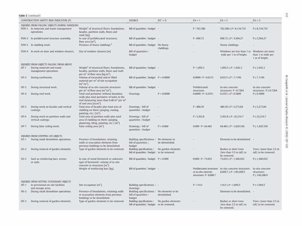
Table 2 (continued)
CONSTRUCTION SAFETY RISK INDICATOR [P] SOURCE EX1=0 EX=1 EX=3 EX=5
INJURIES FROM FALLING OBJECTS DURING HANDLINGFOH-1 In materials and waste management
operations.Weight3 of structural floors, foundations,facades, partition walls, floors androofs [kg].
Bill of quantities / budget - Pb762,380 762,380≤Pb8,134,735 P≥8,134,735
FOH-2 In prefabricated structure assembly. In case of prefabricated structures:floor area [m2].
Bill of quantities / budget - Pb690.72 690.72≤Pb5,504.27 P≥5,504.27
FOH-3 In cladding work. Presence of heavy claddings.4 Bill of quantities / budget No heavycladdings.
- Heavy claddings. -
FOH-4 In work on door and window closures. Size of window closures [m]. Bill of quantities /budget
- - Windows are less than 1 mwide per 1 m of height.
Windows are morethan 1 m wide per1 m of height.
INJURIES FROM OBJECTS FALLING FROM ABOVEOF-1 During materials and waste
management operations.Weight3 of structural floors, foundations,facades, partition walls, floors and roofsper m2 of floor area [kg/m2].
Bill of quantities / budget - Pb1,095.5 1,095.5≤Pb1,642.3 P≥1,642.3
OF-2 During earthworks. Volume of excavated and/or filledmaterial per m2 of site occupation[m3/m2].
Bill of quantities / budget P=0.0000 0.0000bPb0.6215 0.6215≤Pb7.1199 P≥7.1199
OF-3 During structural work. Volume of in-situ concrete structuresper m2 of floor area [m3/m2].
Bill of quantities / budget - Prefabricatedstructures
In-situ concretestructures: Pb0.7284
In-situ concretestructures: P≥0.7284
OF-4 During roof work. Total roof perimeter without boundarywalls plus total perimeter of holes in theroof measuring more than 0.40 m2 per m2
of roof area [m/m2].
Drawings P=0.0000 0.0000bPb0.2551 0.2551≤Pb0.5809 P≥0.5809
OF-5 During work on facades and verticalcoatings.
Total area of facades plus total area ofcladding on them (parging, coating,painting, etc.) [m2].
Drawings / bill ofquantities / budget
- Pb480.39 480.39≤Pb5,273.84 P≥5,273.84
OF-6 During work on partition walls andvertical coatings.
Total area of partition walls plus totalarea of cladding on them (parging,plastering, tiling, painting, etc.) [m2].
Drawings / bill ofquantities / budget
- Pb3,363.8 3,363.8≤Pb25,216.7 P≥25,216.7
OF-7 During false ceiling work. False ceiling area [m2]. Drawings / bill ofquantities / budget
P=0.000 0.000bPb64.482 64.482≤Pb1,620.336 P≥1,620.336
INJURIES FROM STEPPING ON OBJECTSSO-1 During small demolition operations. Presence of foundations, retaining
walls or evacuation elements fromprevious buildings to be demolished.
Building specifications /bill of quantities /budget
No elements tobe demolished.
- Elements to be demolished. -
SO-2 During removal of garden elements. Type of garden elements to be removed. Building specifications /bill of quantities / budget
No garden elementsto be removed.
- Bushes or short trees(less than 3.5 m tall) tobe removed.
Trees (more than 3.5 mtall) to be removed.
SO-3 Such as reinforcing bars, screwsor nails.
In case of wood formwork or unknowntype of formwork: volume of in-situconcrete in structures [m3].
Bill of quantities / budget P=0.000 0.000bPb73.655 73.655≤Pb1,360.652 P≥1,360.652
Weight of reinforcing bars [kg]. Bill of quantities / budget - Prefabricated structuresor in-situ concretestructures: Pb8,668.7
In-situ concrete structures:8,668.7≤Pb149,268.9
In-situ concretestructures:P≥149,268.9
INJURIES FROM HITTING STATIONARY OBJECTSHS-1 In provisional on-site facilities
and storage areas.Site occupation [m2]. Building specifications /
drawings- Pb114.5 114.5≤Pb1,604.5 P≥1,604.5
HS-2 During small demolition operations. Presence of foundations, retaining wallsor evacuation elements from previousbuildings to be demolished.
Building specifications /bill of quantities /budget
No elements to bedemolished.
- Elements to be demolished. -
HS-3 During removal of garden elements. Type of garden elements to be removed. Building specifications /bill of quantities / budget
No garden elementsto be removed.
- Bushes or short trees(less than 3.5 m tall) tobe removed.
Trees (more than 3.5 mtall) to be removed.
112M.G
angolellset
al./Journal
ofSafety
Research41
(2010)107
–122
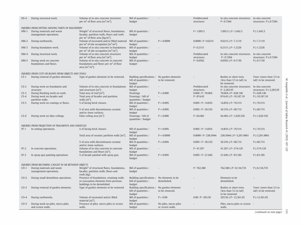
Table 2 (continued)
CONSTRUCTION SAFETY RISK INDICATOR [P] SOURCE EX1=0 EX=1 EX=3 EX=5
HS-4 During structural work. Volume of in-situ concrete structuresper m2 of floor area [m3/m2].
Bill of quantities /budget
- Prefabricatedstructures
In-situ concrete structures:Pb0.7284
In-situ concretestructures: P≥0.7284
INJURIES FROM HITTING MOVING PARTS OF MACHINERYHM-1 During materials and waste
management operations.Weight3 of structural floors, foundations,facades, partition walls, floors and roofsper m2 of floor area [kg/m2].
Bill of quantities /budget
- Pb1,095.5 1,095.5≤Pb1,642.3 P≥1,642.3
HM-2 During earthworks. Volume of excavated and/or filled materialper m2 of site occupation [m3/m2].
Bill of quantities /budget
P=0.0000 0.0000bPb0.6215 0.6215≤Pb7.1119 P≥7.1119
HM-3 During foundation work. Volume of in-situ concrete in foundationsper m2 of site occupation [m3/m2].
Bill of quantities /budget
- Pb0.2151 0.2151≤Pb1.2226 P≥1.2226
HM-4 During structural work. Volume of in-situ concrete structuresper m2 of floor area [m3/m2].
Bill of quantities /budget
- Prefabricatedstructures
In-situ concrete structures:Pb0.7284
In-situ concretestructures: P≥0.7284
HM-5 During work on concretefoundations and floors.
Volume of in-situ concrete in concretefoundations and floors per m2 of floorarea [m3/m2].
Bill of quantities /budget
- Pb0.0502 0.0502≤Pb0.1730 P≥0.1730
INJURIES FROM CUTS OR BLOWS FROM OBJECTS AND TOOLSCS-1 During removal of garden elements. Type of garden elements to be removed. Building specifications /
bill of quantities /budget
No garden elementsto be removed.
- Bushes or short trees(less than 3.5 m tall) tobe removed.
Trees (more than 3.5 mtall) to be removed.
CS-2 During work on foundation andstructure.
Volume of in-situ concrete in foundationsand structures [m3].
Bill of quantities /budget
- Prefabricatedstructures
In-situ concrete structures:Pb2,283.95
In-situ concretestructures: P≥2,283.95
CS-3 During finishing work on roofs. Total area of roof [m2]. Drawings P=0.000 0.000bPb70.064 70.064≤Pb628.140 P≥628.140CS-4 During work on facades and
partition walls.Total area of facades and partitionwalls [m2].
Drawings / bill ofquantities / budget
- Pb874.43 874.43≤Pb10,187.10 P≥10,187.10
CS-5 During work on coatings or floors. % of facing brick closure. Bill of quantities /budget
P=0.00% 0.00%bPb14.85% 14.85%≤Pb76.51% P≥76.51%
% of area with discontinuous ceramicand/or stone surfaces.
Bill of quantities /budget
P=0.00% 0.00%bPb30.33% 30.33%≤Pb60.71% P≥60.71%
CS-6 During work on false ceilings. False ceiling area [m2]. Drawings / bill ofquantities / budget
P=0.000 Pb64.482 64.482≤Pb1,620.336 P≥1,620.336
INJURIES FROM PROJECTION OF FRAGMENTS AND PARTICLESFF-1 In cutting operations. % of facing brick closure. Bill of quantities /
budgetP=0.00% 0.00%bPb14.85% 14.85%≤Pb76.51% P≥76.51%
Total area of ceramic partition walls [m2]. Bill of quantities /budget
P=0.0000 0.0000bPb238.5944 238.5944≤Pb5,201.9861 P≥5,201.9861
% of area with discontinuous ceramicand/or stone surfaces.
Bill of quantities /budget
P=0.00% 0.00%bPb30.33% 30.33%≤Pb60.71% P≥60.71%
FF-2 In concrete operations. Volume of in-situ concrete in concretefoundations and floors [m3].
Bill of quantities /budget
- Pb41.207 41.207≤Pb574.129 P≥574.129
FF-3 In spray-gun painting operations. % of facade painted with spray gun. Bill of quantities /budget
P=0.00% 0.00%bPb21.64% 21.64%≤Pb83.18% P≥83.18%
INJURIES FROM BECOMING CAUGHT IN OR BETWEEN OBJECTSCO-1 During materials and waste
management operations.Weight3 of structural floors, foundations,facades, partition walls, floors androofs [kg].
Bill of quantities /budget
- Pb762,380 762,380≤Pb8,134,735 P≥8,134,735
CO-2 During small demolition operations. Presence of foundations, retaining wallsor evacuation elements from previousbuildings to be demolished.
Building specifications /bill of quantities /budget
No elements to bedemolished.
- Elements to bedemolished.
-
CO-3 During removal of garden elements. Type of garden elements to be removed. Building specifications /bill of quantities /budget
No garden elementsto be removed.
- Bushes or short trees(less than 3.5 m tall)to be removed.
Trees (more than 3.5 mtall) to be removed.
CO-4 During earthworks. Volume of excavated and/or filledmaterial [m3].
Bill of quantities /budget
P=0.00 0.00bPb203.56 203.56≤Pb12,361.65 P≥12,361.65
CO-5 During work on piles, micro-pilesand screen walls.
Presence of piles, micro-piles or screenwalls.
Bill of quantities /budget
No piles, micro-pilesor screen walls.
- Piles, micro-piles or screenwalls.
-
(continued on next page)
113M.G
angolellset
al./Journal
ofSafety
Research41
(2010)107
–122

Table 2 (continued)
CONSTRUCTION SAFETY RISK INDICATOR [P] SOURCE EX1=0 EX=1 EX=3 EX=5
CO-6 In forming and shoring operations. Volume of in-situ concrete in structure [m3]. Bill of quantities / budget P=0.000 0.000bPb73.655 73.655≤Pb1,360.652 P≥1,360.652CO-7 In operations with scaffoldings or
working platforms.Floor area [m2]. Building
specifications /drawings
- Pb690.72 690.72≤Pb5,504.27 P≥5,504.27
INJURIES FROM BECOMING CAUGHT IN DUMPED VEHICLES OR MACHINESCV-1 During materials and waste management
operations.Weight3 of structural floors, foundations,facades, partition walls, floors and roofsper m2 of floor area [kg/m2].
Bill of quantities /budget
- Pb1,095.5 1,095.5≤Pb1,642.3 P≥1,642.3
CV-2 During earthworks. Volume of excavated and/or filledmaterial per m2 of site occupation[m3/m2].
Bill of quantities /budget
P=0.0000 0.0000bPb0.6215 0.6215≤Pb7.1199 P≥7.1199
CV-3 During foundation work. Volume of in-situ concrete in foundationsper m2 of site occupation [m3/m2].
Bill of quantities /budget
- Pb0.2151 0.2151≤Pb1.2226 P≥1.2226
CV-4 During structural work. Type of auxiliary machinery used toassemble the structure.
Health and safetyplan
- - Fixed crane Mobile crane
CV-5 During structural work. Volume of in-situ concrete in concretefoundations and floors per m2 of floorarea [m3/m2].
Bill of quantities /budget
- Pb0.0502 0.0502≤Pb0.1730 P≥0.1730
INJURIES FROM OVEREXERTION, BAD POSTURE OR REPETITIVE MOTIONOX-1 Injuries form overexertion, bad
posture or repetitive motion.All cases. - - - All cases -
INJURIES FROM EXPOSURE TO EXTREME TEMPERATURESET-1 Injuries from exposure to extreme
temperatures.Climate situation of the construction site. Building
specificationsThe construction site is notlocated in an extremely hot orcold climate area.
- The construction site islocated in an extremelyhot or cold climate area.
-
INJURIES FROM THERMAL CONTACTSTC-1 Due to specific welding operations. Type of structure. Building
specificationsThe structure of the buildingis not metallic.
- The structure of thebuilding is metallic.
-
TC-2 Due to joining waterproofmembranes.
Type of joints used with waterproofmembranes.
Buildingspecifications
Waterproof layer joints aresealed off by mechanical oradhesive means.
- Waterproof layer jointsare sealed off byapplying heat.
-
INJURIES FROM ELECTRIC CONTACTSEC-1 With active elements. All cases. - - - All cases. -EC-2 Due to breakage of underground
electric power cables.Presence of undergroundelectric power cables.
Buildingspecifications
No underground electricpower cables.
- Underground electricpower cables.
-
EC-3 Due to contact with balling pumps. Excavation level. Building specifications The excavation level does notexceed the ground-waterlevel.
- The excavation levelexceeds the ground-water level.
-
EC-4 Due to contacts with overheadelectric power lines.
Presence of overhead electric power lines. Buildingspecifications
No overhead electric powerlines.
- Overhead electricpower lines.
-
INJURIES FROM EXPOSURE TO HARMFUL OR TOXIC SUBSTANCESEH-1 During materials and waste
managementoperations.
All cases. - - - All cases. -
EH-2 During specific welding operations. Type of structure. Buildingspecifications
The structure of the buildingis not metallic.
- The structure of thebuilding is metallic.
-
EH-3 Due to the use of concrete releaseagentsat the construction site.
Use of concrete. Buildingspecifications /drawings
- Neither the structureof the building nor itsfacades are made onin-situ concrete.
The structure of thebuilding (or most of itsfacades) is made ofin-situ concrete.
The structure of thebuilding and most of itsfacades are made ofin-situ concrete.
INJURIES FROM BECOMING CAUGHT IN OR BETWEEN OBJECTS
114M.G
angolellset
al./Journal
ofSafety
Research41
(2010)107
–122

Table 2 (continued)
CONSTRUCTION SAFETY RISK INDICATOR [P] SOURCE EX1=0 EX=1 EX=3 EX=5
EH-4 Due to joining waterproofmembranes.
Type of joints used with waterproofmembranes.
Buildingspecifications
Waterproof layer joints aresealed off by mechanicalmeans.
- Waterproof layer jointsare sealed off by adhesivemeans or by applyingheat.
-
EH-5 Due to the use of synthetic paintsand varnishes.
% paints and varnishes that are synthetic. Bill of quantities /budget
P=0.000% 0.000%bPb5.151% 5.151%≤Pb43.063% P≥43.063%
EH-6 In surface-polishing operations. Presence of floor area made from naturalwood or other materials that requirepolishing.
Bill of quantities /budget
No floor area made fromnatural wood or othermaterials that requirepolishing.
- Floor area made fromnatural wood or othermaterials that requirepolishing.
-
INJURIES FROM CONTACT WITH CAUSTIC OR CORROSIVE SUBSTANCESCC-1 During work on foundations and
in-situ concrete structures.Volume of in-situ concrete in foundationsand structures [m3].
Bill of quantities /budget
- Prefabricatedstructures
In-situ concretestructures: Pb2,283.95
In-situ concretestructures: P≥2,283.95
CC-2 During work on brick closures andcoatings.
Volume of mortar [m3]. Bill of quantities /budget
P=0.000 0.000bPb71.248 71.248≤Pb541.495 P≥541.495
CC-3 During work on concretefoundations and floors.
Volume of in-situ concrete in concretefoundations and floors [m3].
Bill of quantities /budget
- Pb41.207 41.207≤Pb574.129 P≥574.129
INJURIES FROM EXPOSURE TO RADIATIONER-1 Due to specific welds. Type of structure. Building
specificationsThe structure of the buildingis not metallic.
- The structure of thebuilding is metallic.
-
INJURIES FROM FIRES AND EXPLOSIONSAC-1 Injuries from fires in areas for
storing flammable and combustiblesubstances.
Floor area [m2]. Buildingspecifications /drawings
- Pb690.72 690.72≤Pb5,504.27 P≥5,504.27
AC-2 Injuries from breakage ofunderground pipes (electric powercables, telephone lines, water pipes,or liquid or gaseous hydrocarbonpipes).
Site occupation per m2 of floor area[m2/m2].
Buildingspecifications /drawings
- Pb0.1684 0.1684≤Pb0.3376 P≥0.3376
AC-3 Injuries from breakage of receptaclescontaining harmful substances, suchas storage tanks for dangerousproducts.
Floor area [m2]. Buildingspecifications /drawings
- Pb690.72 690.72≤Pb5,504.27 P≥5,504.27
AC-4 Injuries from fires due to specificwelds.
Type of structure. Buildingspecifications
The structure of the buildingis not metallic.
- The structure of thebuilding is metallic.
-
INJURIES FROM BEING HIT OR RUN OVER BY VEHICLESHV-1 During material transport operations. Weight3 of structural floors, foundations,
facades, partition walls, floors and roofsper m2 of site occupation [kg/m2].
Bill of quantities /budget
- Pb2,878.33 2,878.33≤Pb9,545.00 P≥9,545.00
HV-2 During earthworks. Volume of excavated and/or filled materialper m2 of site occupation [m3/m2].
Bill of quantities /budget
P=0.0000 0.0000bPb0.6215 0.6215≤Pb7.1199 P≥7.1199
HV-3 During foundation work. Volume of in-situ concrete in foundationsper m2 of site occupation [m3/m2].
Bill of quantities /budget
- Pb0.2151 0.2151≤Pb1.2226 P≥1.2226
HV-4 In prefabricated structure assembly. In case of prefabricated structure: floorarea [m2].
Bill of quantities /budget
- Pb690.72 690.72≤Pb5,504.27 P≥5,504.27
INJURIES FROM TRAFFIC ACCIDENTSTA-1 Injuries from external or internal
traffic accidents.Volume of excavated and/or filledmaterial per m2 of site occupation[m3/m2].
Bill of quantities /budget
P=0.0000 0.0000bPb0.6215 0.6215≤Pb7.1199 P≥7.1199
Weight3 of structural floors, foundations,facades, partition walls, floors and roofsper m2 of site occupation [kg/m2].
Bill of quantities /budget
- Pb2,878.33 2,878.33≤Pb9,545.00 P≥9,545.00
(continued on next page)
115M.G
angolellset
al./Journal
ofSafety
Research41
(2010)107
–122

Table 2 (continued)
CONSTRUCTION SAFETY RISK INDICATOR [P] SOURCE EX1=0 EX=1 EX=3 EX=5
INJURIES FROM CONTACT WITH CHEMICAL AGENTSL-1 Dust generation in activities
involving construction machineryor transport.
Volume of excavated material per m2 offloor area [m3/m2].
Bill of quantities /budget
P=0.0000 0.0000bPb0.5554 0.5554≤Pb1.1686 P≥1.1686
L-2 Dust generation in earthworks andstockpiles.
Volume of excavated material per m2 offloor area [m3/m2].
Bill of quantities /budget
P=0.0000 0.0000bPb0.5554 0.5554≤Pb1.1686 P≥1.1686
L-3 Dust generation in activities withcutting operations.
% of facing brick closure. Bill of quantities /budget
P=0.00% 0.00%bPb14.85% 14.85%≤Pb76.51% P≥76.51%
% of area with discontinuous ceramicand/or stone surfaces.
Bill of quantities /budget
P=0.00% 0.00%bPb30.33% 30.33%≤Pb60.71% P≥60.71%
INJURIES FROM CONTACT WITH PHYSICAL AGENTSL-5 Generation of noise and vibrations
due to site activities.Time of activity, use of special machinery(road roller, graders and compactors, etc.)
Health and safetyplan/geotechnicalstudy/budget
- Normal activityduring daytime hours(8:00-20:00) and nouse of specialmachinery).
Normal activityduring daytime hours(8:00-20:00) anduse of specialmachinery).
Normal activityduring nighttimehours (20:00-8:00).
1EX: risk exposure.2P: indicator. P values can be extracted from the quantitative data available in the project documents.3Weight [kg]: 2,500·Co+150·Af+225·Aw; where Co=amount of concrete [m3], Af=floor area [m2] and Aw=wall area [m2].4Heavy claddings include ceramic and cement mortar tiles, stoneware, limestone, artificial stones and fibrocement sheets.
116M.G
angolellset
al./Journal
ofSafety
Research41
(2010)107
–122

Table 3Scoring system for risk exposure (EXi).
Risk exposure (EXi) Score
No exposure 0Low exposure 1Significant exposure 3High exposure 5
117M. Gangolells et al. / Journal of Safety Research 41 (2010) 107–122
other health and safety indicators are expressed as a percentage of atotal amount.
So as to include detailed criteria to help decision-makersdetermine whether exposure to a particular construction risk issignificant, a four-interval scale was developed (Table 3).
To help achieve a homogeneous outcome, numerical limits wereestablished between the four categories. These numerical limits wereobtained by means of a statistical analysis of 25 new-start constructionprojects. They ranged in size from a small block of two dwellings with atotalfloor area of 371 m2 to a property developmentof 93dwellings anda floor area of 12,681 m2. They also ranged from three to seven levelsabove ground and from zero to two levels below ground.
Table 4Statistical analysis for quantitative indicators.
HEALTH AND SAFETY RISKS
Total perimeter with a difference in floor level of more than 20 cm during the demolitionearthworks or foundation phases per m2 of site occupation area [m/m2].
Total perimeter of floors more than 20 cm high (from zero level) plus roof perimeterwithour boundary walls plus perimeter of holes measuring more than 0.40 m2 per m2
of floor area [m/m2].Roof perimeter without boundary walls plus perimeter of holes measuring more than0.40 m2 per m2 of roof area [m/m2].
Total area of partition walls plus total area of cladding on them (parging, plastering,tiling, painting, etc.) [m2].
Total area of facades plus total area of cladding on them (parging, coating, painting, etc.)[m2].
Total perimeter of holes measuring more than 0.40 m2 plus total perimeter ofbalconies without boundary walls per m2 of floor area [m/m2].
Number of balconies and windows in the building [units].Total area of cladding of structural floors plus total area of false ceilings plus totalarea of cladding on them (parging, plastering, tiling, painting, etc.) [m2].
Site occupation [m2].Weight of reinforcing bars [kg].Total area of roof [m2].Volume of excavated and/or filled material [m3].Volume of in-situ concrete [m3].Area of discontinuous cladding in facades [m2].Area of discontinuous cladding in partition walls [m2].False ceiling area [m2].Weight of structural floors, foundations, facades, partition walls, floors and roofs [kg].Floor area [m2].Weight of structural floors, foundations, facades, partition walls, floors and roofs per m2
of floor area [kg/m2].Volume of excavated and/or filled material per m2 of site occupation [m3/m2].Volume of in-situ concrete structures per m2 of floor area [m3/m2].Volume of in-situ concrete structures [m3].Volume of in-situ concrete in foundations per m2 of site occupation [m3/m2].Volume of in-situ concrete in concrete foundations and floors per m2 of floor area [m3/mVolume of in-situ concrete in foundations and structures [m3].Total area of facades and partition walls [m2].% of facing brick closure.% of area with discontinuous ceramic and/or stone surfaces.Total area of ceramic partition walls [m2].Volume of in-situ concrete in concrete foundations and floors [m3].% of facade painted with spray gun.% of paints and varnishes that are synthetic.Volume of mortar [m3].Weight of structural floors, foundations, facades, partition walls, floors and roofs per m2
of site occupation [kg/m2].
Because a large proportion of construction projects have signifi-cant exposure to safety risks, a 68% confidence interval [μ-σ, μ+σ]was calculated for each indicator. Thus, if an indicator was lowerthan μ-σ for a particular construction project, the exposure to thecorresponding construction safety risk was considered low. However,if the indicator was higher than μ+σ, the exposure to thecorresponding risk was considered high. Indicators within [μ-σ,μ+σ] show significant exposure.
Table 4 shows the estimated distribution for each of the quantitativeindicators considered in this analysis, aswell as themeans and standarddeviations of the corresponding distributions. Also included are theupper and lower limits of the 68% confidence interval.
However, we were unable to obtain a quantitative indicator foreach health and safety risk based on the information contained in theproject documents. Therefore, we had to include 11 qualitative healthand safety indicators, such as the indicator ‘Climate situation of theconstruction site’ for the health and safety risk ‘Injuries from exposureto extreme temperatures’ or the indicator ‘Presence of foundations,retaining walls or evacuation elements from previous buildings to bedemolished’ for the risk ‘Injuries from becoming caught in or betweenobjects during small demolition operations.’ The significance limits for
Estimateddistribution
Mean Standarddeviation
R2 Lower limit Upper limit
, Log-normal -0.0924 0.2763 0.9793 0.4279 1.5269
Log-normal -0.8616 0.9304 0.9749 0.0161 1.1715
Gaussian 0.4180 0.1629 0.9545 0.2551 0.5809
Log-normal 3.9643 0.4374 0.9543 3,363.8 25,216.7
Log-normal 3.2019 0.5203 0.9792 480.39 5,273.84
Log-normal -0.9348 0.2150 0.9706 0.0708 0.1906
Log-normal 1.5978 0.5744 0.9804 10.55 148.69Log-normal 3.2358 0.5712 0.9436 462.0 6,411.3
Log-normal 2.6321 0.5732 0.9414 114.5 1,604.5Log-normal 4.5560 0.6180 0.9501 8,668.7 149,268.9Log-normal 2.3218 0.4763 0.9736 70.064 628.140Log-normal 3.2004 0.8917 0.9430 203.56 12,361.65Log-normal 2.7718 0.5838 0.9517 154.16 2,267.75Log-normal 1.9310 0.5742 0.9521 22.743 320.055Log-normal 2.8199 0.4919 0.9332 212.79 2,050.08Log-normal 2.5095 0.7001 0.9652 64.482 1,620.336Log-normal 6.3963 0.5141 0.9659 762,380 8,134,735Log-normal 3.2900 0.4507 0.9658 690.72 5,504.27Gaussian 1,368.9 273.4 0.9696 1095.5 1,642.3
Log-normal 0.3230 0.5295 0.9306 0.6215 7.1199Gaussian - 0.5175 0.3798 0.9610 0.1267 0.7284Log-normal 2.5005 0.6333 0.9645 73.655 1,360.652Log-normal -0.2900 0.3773 0.9876 0.2151 1.2226
2]. Gaussian 0.1116 0.0614 0.9006 0.0502 0.1730Log-normal 2.7758 0.5829 0.9711 155.95 2283.95Log-normal 3.4749 0.5332 0.9080 874.43 10,187.10Gaussian 0.4568 0.3083 0.9389 14.85% 76.51%Log-normal -0.3674 0.1507 0.9546 30.33% 60.71%Log-normal 3.0469 0.6693 0.9229 238.5944 5,201.9861Log-normal 2.187 0.572 0.958 41.207 574.129Gaussian 52.4062 30.7692 0.9642 21.64% 83.18%Log-normal -0.2871 0.4611 0.9843 5.15% 43.06%Log-normal 2.2932 0.4404 0.9582 71.248 541.495Log-normal 6,211.67 3,333.33 0.9731 2,878.33 9,545.00
118 M. Gangolells et al. / Journal of Safety Research 41 (2010) 107–122
indicators expressed in qualitative terms were derived with the helpof the panel of experts.
2.2.2. Determining the overall safety level of a construction projectNumerical scores for risk exposure were assigned as shown in
Table 3. If the documents of a construction project lacked theinformation needed to make a satisfactory appraisal, high exposurewas automatically assumed (EXj=5).
If, after conducting the assessment, any construction safety risk isfound to be unacceptable (EXjN9), actions to eliminate or reduce thatrisk must be planned.
Themethodology assesses the overall safety level of a constructionproject as shown in (2).
R = ∑n
j=1EXj ð2Þ
where R is the overall safety risk level of a construction project and EXj
is the exposure corresponding to a specific construction safety risk j.The construction project with the highest sum is considered to
have the lowest safety level.
3. Alternative design options
The developed methodology is able to highlight how changingdesign decisions may affect the significance of a particular safety riskand consequently how this may affect the overall safety risk level of theconstructionproject. However, themethodologydoes not providea pre-defined list of design improvements as this could be seenbydesigners asan intrusion into their creative process. In this sense, Frijters and Swuste(2008) state that the designer's main concerns when using CHPtD toolsare that the design process should not be seriously disrupted and thattheir freedom in designing should not be impaired.
The proposed methodology is a useful tool for backing up ormaking a particular design decision. In case of senior designers,previous acquired experiences in building's design can be helpful inproposing designmodifications. In case of less-experienced designers,the methodology provides a way to facilitate a well-grounded choicebetween different design alternatives.
4. Results and discussion
To demonstrate the benefits of the methodology, this sectionapplies the model to the design process of a specific constructionproject. In this case, client's requirements include designing anisolated four-storey building with one underground car park floor.Due to urban constraints, the building's floor area cannot exceed2,241.18 m2, and it can contain a maximum of 19 dwellings.
The large range of current available alternative building materialsand techniques significantly increases the freedom of the design andconsequently the difficulty in finding the most suitable solution.Judgment of the adequacy of a particular building design is frequentlyrelated to its appearance, to the way it functions, to its cost, or to itsexecution time. The proposed methodology adds the on-site safetyperformance axis to the design decision making.
One of the first choices might lie between designing an in-situconcrete structure or a precast concrete structure. The safety risk level ofdesigning an in-situ concrete structure was found to be 36 whereas thesafety risk level of designing a precast structure was found to be 18.Appendix A shows detailed results of the safety evaluation of bothdesign alternatives. Designing a precast structure instead of an in-situconcrete structure significantly reduces the following risks: FS-2 (falls atthe same level during reinforcementwork); FOC-2 (injuries from fallingobjects due to crumble or collapse due to the use of in-situ concrete);OF-3 (injuries from objects falling from above during structural work);SO-3 (injuries from stepping on reinforcing bars, screws or nails); HS-4
(injuries from hitting stationary objects during structural work); HM-4(injuries from hitting moving parts of machinery during structuralwork); CS-2 (injuries from cuts or blows from objects and tools duringwork on foundation and structure); CO-6 (injuries from becomingcaught in or between objects in forming and shoring operations); EH-3(injuries from exposure to harmful or toxic substances due to the use ofconcrete release agents at the construction site); andCC-1 (injuries fromcontactwith caustic or corrosive substancesduringworkon foundationsand in-situ concrete structures). However, designing a precast concretestructure insteadof an in-situ concrete structure causes twoother safetyrisks: FOH-2 (injuries from falling objects during handling in pre-fabricated structure assembly) and HV-4 (injuries from being hit or runover by vehicles in prefabricated structure assembly).
The choice of roof type may also have safety implications.According to the results shown in Appendix B, executing a trafficableroof with boundary walls involves nearly half the safety risk levelrelated to the execution of a slate gable roof with a slope of 45% andwindows for ventilation. Actually, the execution of a trafficable roofwith boundary walls reduces the construction safety risks FH-3 (fallsbetween different levels during roof work) and FS-3 (falls at the samelevel during roof work). Safety risks OF-4 (injuries from objects fallingfrom above during roof work), and CS-3 (injuries from cuts or blowsfrom objects and tools during finishing work on roofs) are alsoreduced as a result of this design alternative.
Four of a number of alternative designs for the external facadesof thebuilding are taken into account. In the first three design alternatives, theexternal facades are primarily three-layer masonry walls. The firstdesign alternative includes facing brickwall, the second one has naturalstone cladding, and the third one has a single-layer mortar coating. Thefourth alternative includes designing precast concrete panels (withoutin-situ claddings). According to Appendix C, the highest safety risk levelcorresponds to the facing brick facade (37), followed by the masonrywallwithnatural stone cladding (36), and themasonrywallwith single-layer mortar coating (25). Finally, the safety risk level of designingprecast concrete panels (without in-situ claddings) is 19. Designingprecast concrete panels (without in-situ claddings) reduces some safetyrisks, such as FOC-3 (injuries from falling objects due to crumble orcollapse during cladding work on facades), FOH-3 (injuries from fallingobjects during handling in cladding work), CS-5 (injuries from cuts orblows from objects and tools during work on coatings or floors), FF-1(injuries from projection of fragments and particles in cutting opera-tions), CC-2 (injuries from contact with caustic or corrosive substanceduringwork on brick closures and coatings), and L-3 (dust generation inactivities with cutting operations).
Suppose a choice is to be made between designing balconieswith wood railings and designing balconies with boundary walls(Appendix D). The second alternative would clearly reduce risk FH-5(falls between different levels during floor work) and FH-6 (fallsbetween different levels during work on door and window closures),although in this case the exposure rating would not change.
Other minor design decisions may also have different safetyimplications. For example, designing an artificial wood floor that doesnot require polishing instead of a natural one reduces risk EH-6(injuries from exposure to harmful or toxic substances in surface-polishing operations) from 3 to 0 (Appendix E). Sealing thewaterproof layer joints mechanically instead of by applying heatreduces two other safety risks: TC-2 (injuries from thermal contactsdue to joining waterproof membranes) and EH-4 (injuries fromexposure to harmful or toxic substances due to joining waterproofmembranes) both from 3 to 0 (Appendix F).
Likewise, reducing the size of the windows could reduce risk FOH-4 (injuries from falling objects during handling in work on door andwindow closures) from 5 to 3 (Appendix G).
Appendix H includes detailed results corresponding to theassessment of those construction safety risks not dependant on theabovementioned design alternatives.

119M. Gangolells et al. / Journal of Safety Research 41 (2010) 107–122
Obviously each design alternative tends to provide different benefitsand to have different safety implications. The overall safety risk level ofthis construction project may range from 143 in the safest design(precast concrete structure, trafficable roofwithboundarywalls, precastconcrete facades, balconies with boundary walls, artificial wood floors,waterproof layer joints sealed off by mechanical means, and reducedsize of windows closures -0.80 m per 0.80 m- ) to 198 in the lowestsafety design (in-situ concrete structure, slate gable roof with slope of45% and windows for ventilation, facing brick facades, balconies withwood railings, natural wood floors, waterproof layer joints sealed off byapplying heat, and windows more than 1 m wide per 1 m of height).Designers may assume different safety risk levels in the final design asthe methodology highlights the significant remaining health and safetyrisks andmeasures can then be implemented at the construction site inorder to eliminate these risks or reduce them to an acceptable level.
5. Conclusions
This study is a step forward in the current efforts to encouragesmaller construction and design firms to adopt the CHPtD concept.Wepresented a quantitative methodology that supports designers byproviding a way to evaluate the safety-related performance ofresidential construction designs using a risk-analysis-based approach.The methodology ranks the significance of the safety risks involved ina construction design and compares the overall safety risk level ofdesigns. It also compares the absolute importance of a particularsafety risk in the various construction designs being assessed.
The methodology does not start from a standard set of health andsafety risks. Instead, the first step is a process-oriented analysis. Thisexhaustive preliminary study examines specific health and safetyaspects related to the construction process and tailored to regionalspecificities. In order to objectively assess the health and safety risksrelated to the construction of residential buildings, the second stageincludes the development of 45 performance indicators based onquantitative data available in the project documents. Significancelimits for quantitative indicators are established on the basis of astatistical analysis of 25 new-start construction projects. The outcomeof the process therefore does not depend on the peoplewho conduct it.
The strength of this methodology lies in the fact that it helpsdesigners to explicitly consider construction worker safety during the
Appendix A. Assessment of the safety-related performance of designi
CONSTRUCTION SAFETY RISK IN-
P
FS-2 Falls at the same level during reinforcement work. 10,647
FOC-2 Injuries from falling objects due to crumble or collapsedue to the use of in-situ concrete.
319
FOH-2 Injuries from falling objects during handling inprefabricated structure assembly.
No
OF-3 Injuries from objects falling from above during structural work. 0.1SO-3 Injuries from stepping on reinforcing bars, screws or nails. Un
10,HS-4 Injuries from hitting stationary objects during structural work. 0.1HM-4 Injuries from hitting moving parts of machinery during
structural work.0.1
CS-2 Injuries from cuts or blows from objects and tools duringwork on foundation and structure.
319
CO-6 Injuries from becoming caught in or between objects informing and shoring operations.
226
EH-3 Injuries from exposure to harmful or toxic substances due tothe use of concrete release agents at the construction site.
The(orma
CC-1 Injuries from contact with caustic or corrosive substancesduring work on foundations and in-situ concrete structures.
319
HV-4 Injuries from being hit or run over by vehicles inprefabricated structure assembly.
No
SAFETY RISK LEVEL 36
design process. Designers can compare construction techniques andsystems during the design phase and determine the correspondinglevel of safety risk without their creative talents being restricted. Themethodology is especially worthwhile for those less-experienceddesigners who lack the skills and knowledge required to recognizehazards and develop optimal designs.
Another key feature of this methodology is the assessment ofhealth and safety risks prior to the construction stage. Proactivehazard identification and elimination is always safer and more cost-effective than reactive hazard management.
Moreover, once a final design is reached, the methodology high-lights the significant remaining health and safety risks. A range ofmeasures can then be implemented at the construction site to elimi-nate the remaining risks or reduce them to an acceptable level. Im-proved levels of hazard identification lead to successful on-site safetymanagement.
6. Further research
Further research needs to be done so that contributing causes ofaccidents can be considered in the methodology. Manageable factorsfor promoting workplace safety performance through reasonableproject-safety efforts may also be important when predicting andassessing potential safety risks at the pre-construction stage. Futurestudies should explore the possibility of introducing a weightingsystem in order to better estimate the overall safety risk level of aconstruction design.
Further research is also needed in order to implement themethodology in a web-based information- and knowledge-manage-ment system with databases. By doing this, the time devoted to theassessment of each design could be reduced by re-using indicatorcalculations, and data collected in previous assessments could bereused in order to refine the methodology, particularly with regard tothe significance limits of the health and safety risks.
Acknowledgements
This studywas carried out as part of project number 2004/44 of theSpanish Ministry of Public Works (funded under the Spanish R&DProgramme).
ng an in-situ concrete structure or a precast structure
SITU CONCRETE STRUCTURE PRECAST CONCRETE STRUCTURE
EX P EX
725.6 3 Prefabricated structure. 1.2 3 647.2 3.74 3 93.74 1
prefabricated structures. 0 2,241.18 3
008 3 Prefabricated structure. 1known formwork: 226.000 3 0.000 0725.6 3 Prefabricated structure. 1008 3 Prefabricated structure. 1008 3 Prefabricated structure. 1
.74 3 Prefabricated structure. 1
.000 3 0.000 0
structure of the buildingmost of its facades) isde of in-situ concrete.
3 Neither the structure of thebuilding nor its facades aremade on in-situ concrete.
1
.74 3 Prefabricated structure. 1
prefabricated structures. 0 2,241.18 3
18

CONSTRUCTION SAFETY RISK FACING BRICK* MASONRY WALLSWITH NATURALSTONE CLADDING*
MASONRY WALLSWITH SINGLE-LAYERMORTAR COATING*
PRECAST CONCRETEFACADES*
P EX P EX P EX P EX
FH-4 Falls between different levels during work on facades, partition walls andvertical coatings.
9,383.5 3 9,383.5 3 9,383.5 3 9,383.5 3972.87 3 2,918,61 3 3,891,48 3 972,87 3
FOC-3 Injuries from falling objects due to crumble or collapse during claddingwork on facades.
0.000 0 972.87 5 0.000 0 0.000 0
FOH-3 Injuries from falling objects during handling in cladding work. No heavy cladding. 0 Heavy claddings. 3 No heavy cladding. 0 No heavy cladding. 0OF-5 Injuries from objects falling from above during work on facades and
vertical coatings.972.87 3 2918.61 3 3891.48 3 972.87 3
CS-5 Injuries from cuts or blows from objects and tools during work on coatingsor floors.
100.00% 5 0.00% 0 0.00% 0 0.00% 025.13% 1 40.75% 3 25.13% 1 25.13% 1
FF-1 Injuries from projection of fragments and particles in cutting operations. 100.00% 5 0.00% 0 0.00% 0 0.00% 01,020.42 3 1,020.42 3 1,020.42 3 1,020.42 325.13% 1 40.75% 3 25.13% 1 25.13% 1
FF-3 Injuries fromprojectionof fragments andparticles in spray-gunpaintingoperations. 0.00% 0 0.00% 0 100.00% 5 0.00% 0CC-2 Injuries from contact with caustic or corrosive substances during work on
brick closures and coatings.81.90 3 107.73 3 68.67 1 0.00 0
TA-1 Injuries from external or internal traffic accidents. 2.1509 3 2.1509 3 2.1509 3 2.1509 32,447.5 1 2,447.5 1 2,447.5 1 2,447.5 1
L-3 Dust generation in activities with cutting operations. 100.00% 5 0.00% 0 0.00% 0 0.00% 025.13% 1 40.75% 3 25.13% 1 25.13% 1
SAFETY RISK LEVEL 37 36 25 19
* In case of dry partition walls.
Appendix C. Assessment of the safety-related performance of designing in-situ facades (facing brick, masonry walls with natural stonecladding and masonry walls with single-layer mortar coating) or precast facades (precast concrete panels without in-situ claddings)
Appendix B. Assessment of the safety-related performance of designing a slate gable roof with a slope of 45% and windows for ventilationor a trafficable roof with boundary walls
CONSTRUCTION SAFETY RISK SLATE GABLE ROOF WITH SLOPE OF45% AND WINDOWS FOR VENTILATION
TRAFFICABLE ROOFBOUNDARY WALLS
P EX P EX
FH-2 Falls between different levels during structural work. 0.3318 3 0.2313 3FH-3 Falls between different levels during roof work. 0.1787 1 0.0000 0FS-3 Falls at the same level during roof work. 630.000 5 541.920 3OF-4 Injuries from objects falling from above during roof work. 0.1787 1 0.0000 0CS-3 Injuries from cuts or blows from objects and tools during finishing work on roofs. 630.000 5 541.920 3SAFETY RISK LEVEL 15 9
Appendix D. Assessment of the safety-related performance of designing balconies with wood railings or balconies with boundary walls
CONSTRUCTION SAFETY RISK BALCONIES WITH WOOD RAILINGS BALCONIES WITH BOUNDARY WALLS
P EX P EX
FH-5 Falls between different levels during floor work. 0.1950 5 0.1031 3FH-6 Falls between different levels during work on door and window closures. 42.00 3 30.00 3SAFETY RISK LEVEL 8 6
Appendix E. Assessment of the safety-related performance of designing natural or artificial wood floors
CONSTRUCTION SAFETY RISK NATURAL WOOD FLOORS ARTICIAL WOOD FLOORS
P EX P EX
EH-6 Injuries from exposure to harmful or toxic substancesin surface-polishing operations.
Floor are made from natural wood or othermaterials that require polishing.
3 No floor are made from natural wood orother materials that require polishing.
0
SAFETY RISK LEVEL 3 0
Appendix F. Assessment of the safety-related performance of designing waterproof layer joints sealed off by applying heat or bymechanical means
CONSTRUCTION SAFETY RISK WATERPROOF LAYER JOINTS SEALED OFF BYAPPLYING HEAT
WATERPROOF LAYER JOINTS SEALED OFF BYMECHANICAL MEANS
P EX P EX
TC-2 Injuries from thermal contacts due to joiningwaterproof membranes.
Waterproof layer joints are sealed offby applying heat.
3 Waterproof layer joints are sealed off bymechanical or adhesive means.
0
EH-4 Injuries from exposure to harmful or toxic substancesdue to joining waterproof membranes.
Waterproof layer joints are sealed offby applying heat.
3 Waterproof layer joints are sealed off bymechanical or adhesive means.
0
SAFETY RISK LEVEL 6 0
120 M. Gangolells et al. / Journal of Safety Research 41 (2010) 107–122

CONSTRUCTION SAFETY RISK WINDOW CLOSURES: 2 m wide per 2 m of height. WINDOW CLOSURES: 0.80 m wide per 0.80 m of height.
P EX P EX
FOH-4 Injuries from falling objects during handlingin work on door and window closures.
Windows are more than 1 m wide per 1 m of height. 5 Windows are less than 1 m wide per 1 m of height. 3
SAFETY RISK LEVEL 5 3
Appendix G. Assessment of the safety-related performance of designing the size of the windows
CONSTRUCTION SAFETY RISK P EX
FH-1 Falls between different levels during small demolition operations, earthworks and foundation work. 0.3634 1FH-7 Falls between different levels during work on false ceilings and ceiling coatings. 1,720.3 3FS-1 Falls at the same level during small demolition operations and earthworks. 647.2 3FOC-1 Injuries from falling objects due to crumble or collapse during earthworks. 1,392.06 3FOC-4 Injuries from falling objects due to crumble or collapse during cladding work on partition walls. 971.96 3FOC-5 Injuries from falling objects due to crumble or collapse during false ceiling work. 194.271 3OF-2 Injuries from objects falling from above during earthworks. 2.1509 3OF-7 Injuries from objects falling from above during false ceiling work. 194.271 3SO-1 Injuries from stepping on objects during small demolition operations. No elements to be demolished. 0SO-2 Injuries from stepping on objects during removal of garden elements. No garden elements to be removed. 0HS-1 Injuries from hitting stationary objects in provisional on-site facilities and storage areas. 647.2 3HS-2 Injuries from hitting stationary objects during small demolition operations. No elements to be demolished. 0HS-3 Injuries from hitting stationary objects during removal of garden elements. No garden elements to be removed. 0HM-2 Injuries from hitting moving parts of machinery during earthworks. 2.1509 3HM-3 Injuries from hitting moving parts of machinery during foundation work. 0.1448 1HM-5 Injuries from hitting moving parts of machinery during work on concrete foundations and floors. 0.0553 3CS-1 Injuries from cuts or blows from objects and tools during removal of garden elements. No garden elements to be removed. 0CS-4 Injuries from cuts or blows from objects and tools during work on facades and partition walls. 1,993.29 3CS-6 Injuries from cuts or blows from objects and tools during work on false ceilings. 194.271 3FF-2 Injuries from projection of fragments and particles in concrete operations. 123.9390 3CO-2 Injuries from becoming caught in or between objects during small demolition operations. No elements to be demolished. 0CO-3 Injuries from becoming caught in or between objects during removal of garden elements. No garden elements to be removed. 0CO-4 Injuries from becoming caught in or between objects during earthworks. 1,392.06 3CO-5 Injuries from becoming caught in or between objects during work on piles, micro-piles
and screen walls.No piles, micro-piles or screen walls. 0
CO-7 Injuries from becoming caught in or between objects in operations with scaffoldingsor working platforms.
2,241.18 3
CV-2 Injuries from becoming caught in dumped vehicles or machines during earthworks. 2.1509 3CV-3 Injuries from becoming caught in dumped vehicles or machines during foundation work. 0.1448 1CV-5 Injuries from becoming caught in dumped vehicles or machines during structural work. 0.0553 3OX-1 Injuries form overexertion, bad posture or repetitive motion. All cases. 3ET-1 Injuries from exposure to extreme temperatures. The construction site is not located in
an extremely hot or cold climate area.0
TC-1 Injuries from thermal contacts due to specific welding operations. The structure of the building is not metallic. 0EC-1 Injuries from electrical contacts with active elements. All cases. 3EC-2 Injuries from electrical contacts due to breakage of underground electric power cables. No underground electric power cables. 0EC-3 Injuries from electrical contacts due to contact with balling pumps. The excavation level does not exceed the
ground-water level.0
EC-4 Injuries from electrical contacts due to contacts with overhead electric power lines. No overhead power cables. 0EH-1 Injuries from exposure to harmful or toxic substances during materials and waste
management operations.All cases. 3
EH-2 Injuries from exposure to harmful or toxic substances during specific welding operations. The structure of the building is not metallic. 0EH-5 Injuries from exposure to harmful or toxic substances due to the use of synthetic paints and varnishes. 0.000% 0CC-3 Injuries from contact with caustic or corrosive substances during work on concrete foundations and floors. 123.9390 3ER-1 Injuries from exposure to radiation due to specific welds. The structure of the building is not metallic. 0AC-1 Injuries from fires in areas for storing flammable and combustible substances. 2,241.18 3AC-2 Injuries from breakage of underground pipes (electric power cables, telephone lines,
water pipes, or liquid or gaseous hydrocarbon pipes).0.2888 3
AC-3 Injuries from breakage of receptacles containing harmful substances, such as storage tanks for dangerousproducts.
2,241.18 3
AC-4 Injuries from fires due to specific welds. The structure of the building is not metallic. 0HV-2 Injuries from being hit or run over by vehicles during earthworks. 2.1509 3HV-3 Injuries from being hit or run over by vehicles during foundation work. 0.1448 1L-1 Dust generation in activities involving construction machinery or transport. 0.6211 3L-2 Dust generation in earthworks and stockpiles. 0.6211 3L-5 Generation of noise and vibrations due to site activities. Normal activity. 3SAFETY RISK LEVEL 88
Appendix H. Assessment of construction safety risks not dependant on the abovementioned design alternatives
121M. Gangolells et al. / Journal of Safety Research 41 (2010) 107–122

122 M. Gangolells et al. / Journal of Safety Research 41 (2010) 107–122
References
Behm, M. (2005). Linking construction fatalities to the design for construction safetyconcept. Safety Science, 43(8), 589−611.
Camino, M. A., Ritzel, D. O., Fontaneda, I., & González, O. J. (2008). Construction industryaccidents in Spain. Journal of Safety Research, 39(5), 497−507.
Carter, G., & Smith, S. (2006). Safety hazard identification on construction projects.Journal of Construction Engineering and Management, 132(2), 197−205.
Cheung, S. O., Cheung, K., & Suen, H. (2004). CSHM: Web-based safety and healthmonitoring system for construction management. Journal of Safety Research, 35(2),159−170.
Cheung, S. O., Tam, C. M., Tam, V., Cheung, K., & Suen, H. (2004). A web-basedperformance assessment system for environmental protection: WePass. Construc-tion Management and Economics, 22(9), 927−935.
Fadier, E., & De la Garza, C. (2006). Safety design: Towards a new philosophy. SafetyScience, 44(1), 55−73.
Fang, D. P., Xie, F., Huang, X. Y., & Li, H. (2004). Factor analysis-based studies onconstruction workplace safety management in China. International Journal of ProjectManagement, 22(1), 43−49.
Fine, W. T., & Kinney, W. D. (1971). Mathematical evaluation for controlling hazards.Journal of Safety Research, 3(4), 157−166.
Frijters, A. C. P., & Swuste, P. H. J. J. (2008). Safety assessment in design and preparationphase. Safety Science, 46(2), 272−281.
Gambatese, J. A. (2008). Research issues in Prevention through Design. Journal of SafetyResearch, 39(2), 153−156.
Gambatese, J. A., & Hinze, J. (1999). Addressing construction worker safety in the designphase: Designing for construction worker safety. Automation in Construction, 8(6),643−649.
Gambatese, J. A., Behm, M., & Rajendran, S. (2008). Design's role in constructionaccident causality and prevention: Perspectives from an expert panel. SafetyScience, 46(4), 675−691.
Gangolells, M., Casals, M., Gassó, S., Forcada, N., Roca, X., & Fuertes, A. (2009). Amethodology for predicting the severity of environmental impacts related to theconstruction process of residential buildings. Building and Environment, 44(3),558−571.
Imriyas, K. (2009). An expert system for strategic control of accidents and insurers' risksin building construction projects. Expert Systems with Applications, 36(2),4021−4034.
Jannadi, M. O., & Assaf, S. (1998). Safety assessment in the built environment of SaudiArabia. Safety Science, 29(1), 15−24.
Manuele, F. A. (2006). Achieving risk reduction, effectively. Process Safety andEnvironmental Protection, 84(3b), 184−190.
Ministerio de Trabajo e Inmigración, Subsecretaría de Trabajo y Asuntos Sociales.(2006). Estadística de accidentes de trabajo y enfermedades profesionales.Available at. http://www.mtas.es/Estadisticas/EAT/welcome.htm Accessed 15September 2008.
Saurin, T. A., Formoso, C. T., & Guimaraes, L. B. M. (2004). Safety and production: Anintegrated planning and control model. Construction Management and Economics,22(2), 159−169.
Saurin, T. A., Formoso, C. T., & Cambraia, F. B. (2008). An analysis of construction safety bestpractices from a cognitive systems engineering perspective. Safety Science, 46(8),1169−1183.
Seo, J. W., & Choi, H. H. (2008). Risk-based safety impact assessment methodology forunderground construction projects in Korea. Journal of Construction Engineering andManagement, 134(1), 72−81.
Toole, T. M., & Gambatese, J. A. (2008). The trajectories of prevention through design inconstruction. Journal of Safety Research, 39(2), 225−230.
Trethewy, R. W., Atkinson, M., & Falls, B. (2003). Improved hazard identification forcontractors in the construction industry. Journal of Construction Research, 4(1),71−85.
Wang, W., Liu, J., & Chou, S. (2006). Simulation-based safety evaluation modelintegrated with network schedule. Automation in Construction, 15(3), 341−354.
Marta Gangolells, PhD, is an Assistant Lecturer in the Department of ConstructionEngineering at the Technical University of Catalonia. She is a member of the Group ofConstruction Research and Innovation (GRIC) that conducts interdisciplinary researchto improve the productive processes of the construction sector companies. Herdissertation work focused on integrated safety and environmental managementsystems in construction companies.
Miquel Casals, Ph.D., is an Associate Professor in the Department of ConstructionEngineering at the Technical University of Catalonia. He currently leads the Group ofConstruction Research and Innovation and his research focuses on construction projectmanagement, mainly in the field of quality, health and safety and environmentalaspects. He has contributed to several national and international research projects,publishing several papers in refereed journals and international conferences.
Núria Forcada, PhD, is a Lecturer in the Department of Construction Engineering at theTechnical University of Catalonia. She received her PhD in document and informationmanagement in 2005 from the Technical University of Catalonia. She is now activelyinvolved in decision making systems and collaborative working environments for theconstruction industry.
Xavier Roca, PhD, has been a Lecturer of construction techniques and systems in theDepartment of Construction Engineering of the Technical University of Catalonia since2001. His expertise is on construction project management and his research addressesthe assessment of new materials in terms of time, cost, quality, health and safety andenvironment.
Alba Fuertes, PhD candidate, is an Assistant Lecturer in the Department of ConstructionEngineering at the Technical University of Catalonia. Her research interests are innovativeinformation and computing technologies applications for knowledge management,decision-making and processes improvement in construction projects.